Spooky Archaeology: Why Is Archaeology Entangled with the Paranormal?
Upload
khangminh22Category
view
1download
0
Neutron Scattering Applications and Techniques
Nikolay KardjilovGiulia Festa Editors
Neutron Methods for Archaeology and Cultural Heritage

Neutron Scattering Applications and Techniques
Series editors
Ian S. Anderson, Oak Ridge National Laboratory, Oak Ridge, TN, USAAlan J. Hurd, Los Alamos National Laboratory, Los Alamos, NM, USARobert L. McGreevy, ISIS, Didcot, UK

Neutron scattering techniques provide exceptional tools for studying the structureand dynamics of materials at the molecular level. New user facilities, instrumen-tation and software now provide the “non-expert” researcher with the opportunityof using neutron techniques to provide answers to challenging research questions inphysics, biology, chemistry, engineering and medicine that cannot be answered byany other technique. In order to maximize this potential it is crucial to provide theresearch community with an up to date series of books which describe thefundamentals of the techniques as applied in a given field, and provide recentexamples of applications to showcase the capabilities.The Neutron Scattering Applications and Techniques book series is comprehensive,covering a broad range of research topics. Its goal is to provide scientists andengineers with reference books which highlight the unique capabilities of neutrontechniques to elucidate critical questions in established and emergent areas ofscience. The books are suitable for graduate students, postdocs, and researchprofessionals in the field, and serve as a reference to both experts and (scientific)newcomers wishing to learn about the subject.
Editorial Board
Masatoshi Arai, Japan Atomic Energy AgencyShenda Baker, Harvey Mudd CollegeCollin Broholm, Johns Hopkins UniversityPatrick Gallagher, National Institute of Standards and TechnologyStephen Nagler, Oak Ridge National LaboratoryRoger Pynn, Indiana UniversityJ. Michael Rowe, National Institute of Standards and TechnologyHelmut Schober, Institut Laue-LangevinSunil Sinha, University of CaliforniaRay Teller, Pacific Northwest National LaboratoryJill Trewhella, University of SydneyChristian Vettier, European Spallation Source
More information about this series at http://www.springer.com/series/8141

Nikolay Kardjilov • Giulia FestaEditors
Neutron Methods forArchaeology and CulturalHeritage
123

EditorsNikolay KardjilovInstitute of Applied MaterialsHelmholtz Zentrum BerlinBerlinGermany
Giulia FestaDepartment of Physics and Centre NASTUniversity of Rome Tor VergataRomeItaly
ISSN 1868-0372 ISSN 1868-0380 (electronic)Neutron Scattering Applications and TechniquesISBN 978-3-319-33161-4 ISBN 978-3-319-33163-8 (eBook)DOI 10.1007/978-3-319-33163-8
Library of Congress Control Number: 2016949631
© Springer International Publishing Switzerland 2017This work is subject to copyright. All rights are reserved by the Publisher, whether the whole or partof the material is concerned, specifically the rights of translation, reprinting, reuse of illustrations,recitation, broadcasting, reproduction on microfilms or in any other physical way, and transmissionor information storage and retrieval, electronic adaptation, computer software, or by similar or dissimilarmethodology now known or hereafter developed.The use of general descriptive names, registered names, trademarks, service marks, etc. in thispublication does not imply, even in the absence of a specific statement, that such names are exempt fromthe relevant protective laws and regulations and therefore free for general use.The publisher, the authors and the editors are safe to assume that the advice and information in thisbook are believed to be true and accurate at the date of publication. Neither the publisher nor theauthors or the editors give a warranty, express or implied, with respect to the material contained herein orfor any errors or omissions that may have been made.
Printed on acid-free paper
This Springer imprint is published by Springer NatureThe registered company is Springer International Publishing AGThe registered company address is: Gewerbestrasse 11, 6330 Cham, Switzerland

Preface
Our cultural heritage is the legacy that our society has inherited from the past, and isbestowed for the benefit of future generations. It gives us insight into where wecame from and who we are. Its conservation is important not only from the culturalpoint of view, but also from a practical one. In this context, neutron-based char-acterization techniques play a fundamental role because neutrons are very pene-trating and therefore ideal for the non-invasive investigation of artefacts, allowingboth surface and bulk properties to be measured. The full suite of neutron tech-niques available for cultural heritage research is impressive and many essentialresults have been obtained using one or more of these tools to provide informationthat cannot be determined in any other way. Neutron methods allow the charac-terization of the composition and mechanical properties of ancient materials,helping to answer questions related to the dating, the manufacturing process or thestate of degradation of artefacts. The results obtained from neutron investigationsare in many cases essential for setting the proper restoration and conservationstrategies or for performing the right classification of ancient samples. Nevertheless,the application of neutron beams for cultural heritage purposes is often consideredas ‘exotic’ by the researchers and restorers in the field due to the limited availabilityof neutron sources which are usually large-scale research facilities with restrictedaccess procedures and complex instrumentation.
The intent of this book is to provide an introduction to the wide range ofneutron-based characterization techniques, and their impact in cultural heritageresearch, to the broad community of archaeologists, paleontologists, restorers andcurators, historians and holders of private collections as well as material scientistsand engineers dealing with the characterization of ancient materials. Answers tomany practical questions will be given in conjunction with detailed examplesdescribing some of the more fascinating highlights of applications of neutrontechniques in recent investigations, in a form accessible to a large readership. Part Iwill be dedicated to stories describing discoveries brought about by the use of
v

neutron techniques in various applications. Part II will cover the experimentaltechniques in appropriate detail: basic principles, limitations and fields of appli-cation. The book encloses visual information in theform of videos related to thecontents available in the e-book version of the volume.
Berlin, Germany Nikolay KardjilovRome, Italy Giulia FestaOctober 2016
vi Preface

Acknowledgments
We would like to thank all the authors and experts in the field of neutrons applied tocultural heritage for their valuable contributions, which made this book possible.
Berlin, Germany Nikolay KardjilovRome, Italy Giulia FestaOctober 2016
vii

Contents
Part I Cultural Heritage and Neutrons
1 Probing Our Heritage with Neutrons—One Successful Story . . . . . 3G. Festa, N. Kardjilov and C. Andreani
2 Bronze Sculptures and Lead Objects Tell Stories About TheirCreators: Investigation of Renaissance Sculptures and AncientIngots by Means of Neutron Tomography. . . . . . . . . . . . . . . . . . . . . 19E.H. Lehmann, R. van Lang, M. Estermann, S. Hartmann,F. LoCelso, N. Kardjilov, P. Tisseyre and S. Tusa
3 Paintings Reveal Their Secrets: Neutron AutoradiographyAllows the Visualization of Hidden Layers . . . . . . . . . . . . . . . . . . . . 41A. Denker, C. Laurenze-Landsberg, K. Kleinertand B. Schröder-Smeibidl
4 Neutrons Unveil Secrets of Musical Instruments. . . . . . . . . . . . . . . . 53G. Festa, D. Mannes and A. Scherillo
5 The Glory of Ancient Weapons and Armors: NeutronImaging and Diffraction Methods in Modern Archaeology . . . . . . . 67F. Salvemini and F. Grazzi
6 Ceramics, Marbles and Stones in the Light of Neutrons:Characterization by Various Neutron Methods. . . . . . . . . . . . . . . . . 89Zsolt Kasztovszky, Veronika Szilágyi, Katalin T. Biró,Judit Zöldföldi, M. Isabel Dias, António Valera, Emmanuel Abraham,Maryelle Bessou, Fabrizio LoCelso and Valerio Benfante
7 Paleontology: Fossilized Ancestors Awaken by NeutronRadiography . . . . . . . . . . . . . . . . . . . . . . . . . . . . . . . . . . . . . . . . . . . . 141Frikkie C. De Beer
ix

Part II Neutron Experimental Methods
8 General Introduction to Neutron Physics and Instrumentation . . . . 175R. Pynn and I.S. Anderson
9 Scattering Techniques: Small- and Wide-Angle NeutronDiffraction . . . . . . . . . . . . . . . . . . . . . . . . . . . . . . . . . . . . . . . . . . . . . . 183C.-K. Loong, A. Scherillo and G. Festa
10 Neutron Activation Analysis (NAA) . . . . . . . . . . . . . . . . . . . . . . . . . . 209P. Bode
11 Prompt Gamma Activation Analysis (PGAA) . . . . . . . . . . . . . . . . . . 221T. Belgya and Zs. Révay
12 Neutron Resonance Analysis. . . . . . . . . . . . . . . . . . . . . . . . . . . . . . . . 235H. Postma and P. Schillebeeckx
13 Neutron Resonance Imaging . . . . . . . . . . . . . . . . . . . . . . . . . . . . . . . . 285G. Gorini, E. Schooneveld, E. Perelli Cippo and D. Di Martino
14 Prompt Gamma Activation Imaging (PGAI) . . . . . . . . . . . . . . . . . . . 303Z. Kis, L. Szentmiklósi, R. Schulze and E. Abraham
15 Neutron Activation Autoradiography. . . . . . . . . . . . . . . . . . . . . . . . . 321A. Denker, N. Kardjilov and B. Schröder-Smeibidl
16 Neutron Imaging . . . . . . . . . . . . . . . . . . . . . . . . . . . . . . . . . . . . . . . . . 329N. Kardjilov, E. Lehmann, M. Strobl, R. Woracek and I. Manke
x Contents

Part ICultural Heritage and Neutrons

Chapter 1Probing Our Heritage with Neutrons—One Successful Story
G. Festa, N. Kardjilov and C. Andreani
Abstract Probing our heritage reminds us of a variety of issues in HeritageScience: from the correct determination of historical and cultural time-frame ofartefacts, to their location and method of production, to the choice of best treat-ments and environmental conditions for their restoration. A large variety ofchemical, physical and microstructural techniques are employed by Museums andart experts to characterize objects of cultural significance. Most of these methodsare invasive and probes like X-rays and charged particles have limited penetrationpower. Neutrons penetrate thick layers, depending on their energy, without sub-stantial attenuation, a quality which makes them ideal to study and visualize theinterior (bulk) properties of materials in a totally non-destructive and non-invasiveway. The high sensitivity to specific light elements (e.g. H) is an additional specialproperty of the neutron probe. Neutron techniques are increasingly used for thequantitative, non-invasive analysis of many aspects of cultural heritage preservationin a broad sense: museum collections, artefacts, books, manuscripts, musicalinstruments, archaeological findings.
1.1 Historical Background
The experimental results were very difficult to explain on the hypothesis that the berylliumradiation was a quantum radiation, but followed immediately if it were supposed that theradiation consisted of particles of mass nearly equal to that of a proton and with no netcharge, or neutron. (…) When such neutrons pass through matter they suffer occasionallyclose collisions with the atomic nuclei and so give rise to the recoil atoms which areobserved.
G. Festa (&) � C. AndreaniDepartment of Physics and Centre NAST, University of Rome Tor Vergata, Rome, Italye-mail: [email protected]
N. KardjilovHelmholtz-Zentrum Berlin, Hahn-Meitner Platz 1, 14109 Berlin, Germany
C. AndreaniMuseo Storico della Fisica e Centro Studi e Ricerche Enrico Fermi, 00184 Rome, Italy
© Springer International Publishing Switzerland 2017N. Kardjilov and G. Festa (eds.), Neutron Methods for Archaeologyand Cultural Heritage, Neutron Scattering Applications and Techniques,DOI 10.1007/978-3-319-33163-8_1
3

The citation is from Chadwick’s 1932 breakthrough article ‘Existence of aNeutron’ (Chadwick 1932) where he showed that the physical properties of radi-ation obtained by hitting a beryllium target with α-particles could be explained byinvoking a neutral particle of one atomic mass unit: the neutron.
Already in 1920, Rutherford had postulated the existence of a new neutral andmassive particle in the nucleus of atoms. Such assumption originated from theobservation of a disparity between an element’s number of protons, represented bythe atomic number, and its atomic mass. Such disparity appears as a mass excesscompared to the mass due to the already known proton particles. Rutherford calledthese uncharged particles neutrons. In 1931, Bothe and Becker found that if alphaparticle radiation from polonium fell on beryllium, boron or lithium, a penetratingradiation was produced. In fact, when they hit a beryllium target with alpha par-ticles presumably electrical neutral radiation that could penetrate 200 mm of leadwas emitted. They assumed the neutral radiation to be high-energy gamma rays.
In the same year, several similar experiments were carried out in Europe. Oneexperiment in particular caught Chadwick‘s attention: Joliot and Curie discoveredthat, when a beam of this yet unknown radiation hits a substance rich in protons (intheir case paraffin), protons were emitted and easily detected by a Geiger counter.Joliot and Curie believed the radiation hitting the paraffin target must have beenhigh-energy gamma photons. In 1932 Chadwick repeated their experiments withthe goal of searching for a neutral, uncharged particle with about the same mass as aproton. He realized that the emitted radiation could not be gamma rays by mea-suring the emitted proton energy and discovering that to generate such an effect itshould have been in the 50 MeV order of magnitude, therefore much larger thangamma ray energy (typically few MeV).
When a sheet of paraffin wax about 2 mm thick was interposed in the path of the radiationjust in front of the counter, the number of deflections recorded by the oscillograph increasedmarkedly. This increase was due to particles ejected from the paraffin wax so as to pass intothe counter (Chadwick 1932).
Chadwick also tried different targets, including helium, nitrogen, and lithium,which helped him determine that the mass of the new particle was just slightlylarger than the mass of the proton. In 1935 Chadwick won the Nobel Prize inPhysics for the discovery of neutrons. Scientists soon realized that the newly dis-covered neutron, as an uncharged but massive particle, could be used to probe othernuclei. In 1934 Fermi (Nobel prize for Physics in 1938) obtained inducedradioactivity in high atomic number elements by hitting them with neutrons. In1938 Hahn (Nobel prize for Chemistry in 1945), Meitner and Strassmann discov-ered nuclear fission, the splitting of uranium nuclei into light elements, induced byneutron bombardment. The discovery of nuclear fission was the first step towardsthe development nuclear energy (Fig. 1.1).
After the discovery of the neutron, it became clear that the nucleus containsprotons and neutrons. The nucleus is a compact body with dimension of about10−15 m. The free neutron is unstable and cannot be stored. Therefore, it must bemade free by certain nuclear reactions to be available for experiments.
4 G. Festa et al.

Research focused on ways to actually produce and use them in a series of differentapplications. Between the 1940s and the 1970s three kinds of methods weredeveloped and applied for the production of neutrons: radioactive decay (forexample in the spontaneous fission that occurs in very heavy chemical elementswith atomic mass unit greater than 92), nuclear reactions (such as natural alpha andgamma bombardment of nuclides) and induced nuclear fission (as it occurs innuclear reactors). Chicago Pile-1 (1942) was the first artificial nuclear reactor thatwent critical. It was built in the framework of the Manhattan Project, and carried outby the Metallurgical Laboratory at the University of Chicago under the supervisionof Enrico Fermi. Chicago-Pile was made of a large amount of graphite and uranium,with control rods of cadmium, indium, and silver. Soon after, reactor technologiesrapidly evolved becoming the most productive neutron sources and were used forpower production and research as well as for military applications during WorldWar II.
In the 1970s research started to focus on the spallation process, where neutronsare produced through disintegration of target nuclei (Carpenter 1986). Earlierresearch activity addressed to produce spallation facilities had been carried outbetween the years 1940s–1960s (Carpenter 1986). Lawrence’s proposed ‘cyclotron’in 1940 was able to produce neutrons by hitting a beryllium target, paving the wayto the use of accelerators for neutron production. The term ‘spallation’ was coinedby Sullivan and Seaborg in 1959 (Harvey 1959). During the 1960s there was anincreased interest for spallation neutron production as an alternative to othertechniques (Tunnicliffe et al. 1966). In 1974 the ZING-P neutron source prototype(developed by Jack Carpenter at Argonne National Laboratory) demonstrated thefeasibility of a spallation neutron source (Carpenter 1986).
With the discovery of neutrons and the development of methods and technologyin neutron production, the new research area of neutron science started to developand neutron scattering and absorption (capture) rapidly became routine techniquesfor the non-invasive and non-destructive study of materials in the bulk.
Fig. 1.1 Chadwick device
1 Probing Our Heritage with Neutrons … 5

Key research to establish the basic principles of neutron diffraction techniqueswas carried out in the 1940s by Wollan and Shull at Oak Ridge National Laboratory(formerly Clinton Laboratories USA) (Johnson and Schaffer 2008). In 1955Brockhouse confirmed the quantum theory of solids through the first measurementsof phonons using a prototype triple-axis neutron spectrometer. These were theseminal experiments for which, in 1994, Shull and Brookhouse were granted theNobel Prize in Physics. The ‘special’ way neutrons interact with matter allows to‘see’ where atoms are and how atoms move, making the neutron a unique probe forthe studying the structure and dynamics of materials at the nanoscale.
1.2 Neutron Techniques
One can use nuclear reactions induced in a specimen by a particle beam (usually aneutron beam) to render certain constitutive elements of a material radioactive,permitting their analysis by identification of the radioactive decay products bydetecting radiation emitted during such reactions or by measuring the portion of aneutron beam that traverses an object without any interaction.
1.2.1 Activation Analysis
The most common technique to create a nuclear reaction is the neutron activation,discovered in 1936 by Hevesy and Levi. They discovered that certain rare earthelements, contained in the irradiated samples, became radioactive as a consequenceof neutron beam exposure (Zeisler et al. 2003). The neutron flux creates unstablenuclei in the specimen by the process of neutron capture. The resulting nucleartransition produce γ-ray emission, K-capture and other processes which thenenables identification of the isotopic species present and of the elements. Thisphenomenon was then employed in Neutron Activation Analysis (NAA) for theidentification of major, minor, trace and rare elements (Zeisler 2003).
The first experiment where NAA was applied to cultural heritage dated back to1960 when Emeleus and Simpson published the first results of a study of a Romanpottery fragments analyzed through NAA and γ-ray spectrometry. The results ofthis experiment allowed them to distinguish between production factories (Emeleus& Simpson 1960). The experiment was carried out using the thermal neutron beamfrom the Bepo reactor in Harwell (UK). In the following decades, a series ofresearch studies applying thermal neutrons to cultural heritage were carried out.NAA was applied to a large variety of samples such as fossil bones (Eisenbarth and
6 G. Festa et al.

Hille 1977) where nitrogen and fluorine contents were measured relative to mainconstituents of the inorganic bone material (principally phosphorus and calcium).Measurements gave determination of the human remain dating in a non-destructiveway. In 1987 Mommsen et al. studied ancient potteries from archaeologicalexcavations through a new methodology where neutron-induced radiation in lowenergy region (10–135 keV) was measured with a high-resolution semiconductordetector. NAA is largely applied to the study of trace elements to determineprovenance and manufacturing techniques. The principle of the NAA technique ispresented in detail in Chap. 10.
1.2.2 Prompt Gamma Activation Analysis
Another technique that uses neutron absorption is Prompt Gamma ActivationAnalysis (PGAA) (Molnar 2004). This nuclear analytical technique utilizes thecharacteristic prompt γ-ray spectrum measured during the irradiation of the samplefor the non-destructive determination of elemental and/or isotopic composition ofsamples.
PGAA technique is best suited for the investigations of materials containing lightelements such as H, S, P and K.
A PGAA measurement campaign was carried out on so called ‘black boxes’ in2008. The aim of this study, performed as ANCIENT CHARM European projectactivity, was to identify strengths and weaknesses of neutron techniques applied tothe study of archaeological objects and to develop a best practice for a combineduse of neutron analysis methods (such us Prompt Gamma Activation Analysis,Time of Flight Neutron Diffraction and neutron tomography) for different combi-nations of materials. For this purpose, 17 samples were used, known as black boxes,consisting of closed cubes containing geometrical arrangements of materials such asmetals, minerals, ceramics, and organic matter. Result on a black box is shown inFig. 1.2.
Nr. Nominal comp. PGAA results
1 + 2 Ag in talc H, Si, Cl, Mn, Fe, Cu, Ag
3 Sand H, B, Na, Al, Si, Cl, K, Ti, Mn, Fe, Cu
4 Iron grit H, B, Al, Cl, Mn, Fe
5 Salt Na, Al, Cl, Cu
6 Al sheet –
7 Cu sheets H, Na, Al, Si, Cl, Mn, Fe, Cu, Zn, Ag
The principle of the PGAA technique is presented in detail in Chap. 11. Examplesof application of the PGAA method can be found in Chap. 6.
1 Probing Our Heritage with Neutrons … 7

1.2.3 Neutron Resonance Analysis Methods
These methods are based on resonance absorption of neutrons with epithermalenergies (Postma and Schillebeeckx 2005): absorption (capture and scattering) ofneutrons by nuclei as a function of neutron energy shows sharp peaks (resonances)specific for elements (isotopes). The analysis of resonances allows the identificationand quantification of elements and isotopes within an object in a non-destructivemanner. This is the basis of Neutron Resonance Capture Analysis (NRCA), in whichresonances are observed by detecting the prompt γ-radiation emitted directly afterneutron capture as a function of the neutron energy. In NRCA, neutrons with energiescorresponding to energy levels of the compound nucleus are captured preferentially.Resonances identify the nuclides present in the material whereas the areas under theresonance peaks provide information about their relative amount. They can be visu-alized in the neutron capture spectrum as a function of neutron energy. Anothermethod based on neutron resonances, Neutron Resonance Transmission Analysis(NRTA), is the transmission of a neutron beam through a sample. Resonances are seenas dips in the transmission curve as function of neutron energy. A schematic repre-sentation of NRCA and NRTA measurements is shown in Fig. 1.3.
NRCA is particularly effective for samples composed of copper and its alloysbecause of the significant sensitivities for copper itself and for a range of elements suchas Ag, As, Sb, Sn, and Zn (that are likely to be found in Cu alloys), and for Fe, which isalso relevant for archaeological applications. It has to be stressed that activation in
Fig. 1.2 Iron box: the black box internal feature—segments divided with two crossed sheets.With PGAA, the fiber-like material is identified as Ag chippings in regions (1 + 2). PredominantlySi was found in section 3 and Fe in section 4, whereas Na and Cl (in a molar ratio 1:1) insection 5. At the crossing point of the sheets the presence of Cu was confirmed
8 G. Festa et al.

materials is mainly due to thermal neutrons, which can be removed from the beamwith the aid of a Cd-filter. Hence activation is low after an NRCA run and normallynegligible after a short waiting period. Thus artefacts can be returned to ownersquickly. The principles of NRCA and NRTA are presented in detail in Chap. 12.
A technique beyond NRCA and NRTA is Neutron Resonance TransmissionImaging (NRTI). The potential of NRTI was studied at e.g. the J-PARC facility(Tremsin et al. 2014) and within the Ancient Charm project at the spallation neutronsource ISIS of the Rutherford Appleton Laboratory (Gorini et al. 2007). It relies onthe use of position sensitive neutron detectors. NRTI has been applied to produce2D (Perelli et al. 2011) and 3D elemental contrast figures of archaeological samples(Festa et al. 2015) at ISIS.
1.2.4 Time Resolved Prompt Gamma Activation Analysis
Bi-parametric time-energy acquisition Prompt Gamma Activation Analysis(T-PGAA) is a technique that combines prompt gamma-ray analysis (PGA) andneutron resonance analysis (NRA). It was recently applied for the study of culturalheritage artefacts at ISIS (Festa et al. 2013a, b) and to study a meteorite sample at
Fig. 1.3 Scheme of a set-up for Neutron Resonance Transmission Analysis (NRTA) and NeutronResonance Capture Analysis (NRCA)
1 Probing Our Heritage with Neutrons … 9

J-PARC (Toh et al. 2014) facility. Time-resolved Prompt Gamma ActivationAnalysis consists in the measurement of gamma energy spectrum induced byradiative capture as a function of incident neutron Time of Flight (Festa et al.2013a, b; Miceli et al. 2013, 2014).
T-PGAA enhances the capabilities of both the NRCA and PGAA techniques,providing a more general sensitivity for elements (Festa et al. 2013a, b, 2016; Tohet al. 2014) (Fig. 1.4).
Fig. 1.4 Layout of the designed experiment recording gamma spectra at different neutron energyframes on the top. On the bottom, simulated gamma spectra are reported for (a) neutron resonanceenergy range from 200 to 900 eV (b) total neutron energy range from 0 to 1.2 keV
10 G. Festa et al.

1.2.5 Neutron Diffraction
In 2001 first test measurements using a Time of Flight Neutron Diffraction onarchaeological samples were performed on pottery fragments at the spallationsource ISIS, (UK) (Kockelmann et al. 2001). Neutron Diffraction (ND) is based onelastic scattering of thermal neutrons by periodic, long-range ordered (crystalline)or non-periodic, short-range ordered (glass) arrangements of atoms. Nowadays NDis routinely used for the phase and structure analysis, texture analysis,microstructure analysis and residual stress analysis of artefacts with a minimumvolume of 1 × 1 × 0.5 mm. An important issue for curators is the assessment ofthe condition of material concerning production techniques. In this context throughND characterisation of an artefact one gains insight about the materials and tech-nologies used by the craftsmen.
The principle of the ND technique is presented in detail in Chap. 9 and examplesof ND studies can be found in Chap. 4.
1.2.6 Neutron Radiography and Tomography
Neutron radiography (NR) is a real space imaging method based on capture andscattering of thermal and cold neutrons (Domanus 1992). A neutron beamimpinging onto any heterogeneous object is differently transmitted depending onthickness, density, chemical composition and total cross section of the materialalong the line of sight. Through NR one can obtain information on the internal viewof materials with a spatial resolution down to 100 microns. By recording thetransmitted beam it is possible to reconstruct the internal feature of the studiedobject. The attenuation of a neutron beam passing through objects provides contrastfor different elements. Contrast is also achieved by variation of neutrons energies.Additional techniques are the Phase Contrast Radiography, based on neutronrefraction (Lewis and Schutz 1937) and Neutron Tomography, providing 3D visualinformation about the internal structure of the sample (Kardjilov et al. 2004).Example for neutron tomographic investigation of Osiris bronze statue is shown inFig. 1.5 (Agresti et al. 2015).
1.2.7 Developing of Neutron Techniques for CulturalHeritage Research in the Frame of the “AncientCharm” Project
The Ancient Charm (“Analysis by Neutron resonant Capture Imaging and otherEmerging Neutron Techniques: new Cultural Heritage and ArchaeologicalResearch Methods”) project was an international and interdisciplinary collaborative
1 Probing Our Heritage with Neutrons … 11

project, financed by the European Commission “New and Emerging Science andTechnology” program. The idea of this project followed the exploitation anddevelopment of γ-detector for neutron spectroscopy with eV neutrons of theVESUVIO beamline at the ISIS spallation neutron source in 2006 (Gorini et al.2007).
Within the Ancient Charm project new neutron-based analysis and imagingtechniques and non-invasive methods for 3D tomographic imaging of the elementaland phase composition of cultural heritage objects were designed and realized. Newtechniques and methods were applied to the study of selected real archaeologicalobjects and copies to test effectiveness of obtained reconstruction information(Gorini 2007). Results from this project can be found in Chaps. 13 and 14.
Today neutron techniques are routinely used to provide valuable and additionalinformation to restores for the development of tailored procedures to preventdeterioration. They are employed to obtain a variety of information spanning fromthe elemental composition, the inner structure of materials and its morphology, themaking techniques, the processing and provenance, the dating, the state of con-servation and restoration and finally whether the materials is genuine or fake.
Fig. 1.5 Osiris bronze figure (left) was investigated by neutron tomography. The digital sectionsthrough the sample volume are shown on the right. The thickness of the bronze material as well asthe position of the core pins reveal information about the casting ancient technology (Agresti et al.2015—reproduced by permission of The Royal Society of Chemistry)
12 G. Festa et al.

In the following Chaps. 4–7 some selected examples of application of mostrecent neutron analysis techniques are revised. The principle of the NeutronRadiography and Tomography techniques is presented in detail in Chap. 16.
1.3 Selected Highlights
Neutron methods have been used for investigation of prominent objects providingstrong resonance in the scientific community and in the society. Some examples ofselected research projects and important results are presented below.
• Investigation of Napoleon’s hairsNapoleon Bonaparte died on May 5th 1821 in exile on the island of SaintHelena maybe of arsenic poisoning. Instrumental Neutron Activation Analysisstudy was performed on several of Napoleon’s hair, two samples cut the dayafter his death and two samples cut seven years earlier (1814) during his firstexile on the island of Elba. Results show that all of the samples of Napoleon’shair have a high arsenic concentration. These results disfavor the arsenic poi-soning theory (Lin et al. 2004). Details of this study are presented in Chap. 10.
• NAA at the British MuseumNeutron Activation Analysis was routinely used at the British Museum from1978 to 2002 for provenance studies on ceramics and marble. Data obtainedwere compared with results coming from other laboratories and are the contentof an extended database (Hughes 2007). Similar examples can be found inChap. 6.
• NRCA on bronze statuetteNeutron Resonance Capture Analysis was carried out on bronze Etruscan stat-uettes from the National Museum of Antiquities (NMA) in Leiden (NL) toobtain their elemental compositions. Experiments shown different compositionof the samples and could identify fakes (Postma et al. 2004). Examples of theapplication of this method are shown in Chap. 12.
• Bronze statuettes at the Rijksmuseum.Renaissance bronze statuettes, collection preserved at Rijksmuseum ofAmsterdam, were studied with the aim of obtaining fundamental information onmanufacturing production techniques of these fine art objects. Sculptures wereinvestigated through neutron tomography at the Paul-Scherrer Institut, Villigen,Switzerland. This method allowed studying the internal shape of the bronzesculptures and provided clues of different material compositions. The mostinteresting areas of the objects, identified through tomographies, were studied toobtain material compositions and crystalline structures using time-of-flightneutron diffraction on the ENGIN-X instrument at the ISIS facility (RutherfordAppleton Laboratory, UK) (van Langh et al. 2011). For more details, see Chaps.2 and 4.
1 Probing Our Heritage with Neutrons … 13

• Painting autoradiography at the Berlin GemäldegalerieThanks to a more than two-decade-long collaboration between the BerlinGemäldegalerie and the Helmholtz-Zentrum Berlin, a large number of paintingswere examined by a consistent and systematic use of neutron-activationautoradiography (NAAR) and gamma-ray spectroscopy. The combination ofboth non-destructive methods provides insight into the pigments used, thebrushwork, the state of preservation of the various layers of paint, and the manystages that went into creating the work. The NAAR method is used on regularbase at the Painting Gallery in Berlin for taking a detailed look at a painter’screative process. Obtained information helps to gain insight into the artists andtime periods of the paintings (Fischer et al. 1987). Examples of this method withdetailed description are presented in Chaps. 3 and 15.
• Ghiberti HeadsThe study of the gilded bronze artefacts, performed within the Ancient Charmproject, was performed using integrated neutron techniques. The reliefs are partof the monumental Doors, The Gates of Paradise and the North Gate, located atthe Battistero di Firenze by Lorenzo Ghiberti, a masterpiece of the FlorentineRenaissance. The reliefs presented critical aspects regarding state of conserva-tion and shows a re-melting whose extension and composition were unknown.The analysis of the Ghiberti Heads were performed using Prompt GammaActivation Imaging (PGAI)—a technique which integrates the collection ofstructural information (neutron imaging) and elemental information (PGAA)—to reconstruct the elemental distribution of the elements with a few-mm reso-lution, Neutron Diffraction and Radiography to obtain valuable information onthe manufacturing technique and state of conservation of the reliefs, andNeutron Resonance Transmission to map the gold layer distribution under thepollution deposits to assess the cleaning techniques used by the curators duringthe restoration process (Festa et al. 2009, 2011) (Fig. 1.6).
• Metallic Ancient FluteThe investigated sample was a small metallic duct flute from AccademiaNazionale di Santa Cecilia (Festa 2013b). It is a vertical metal whistle ‘in D’with a standard conical bore slightly contracting towards the foot and six fingerholes on the front (Fig. 1.7). The object was studied by means of integrated andsimultaneous neutron-based techniques such as neutron diffraction, neutronradiative capture analysis and neutron radiography. The aim of the experimentwas to characterize elemental and phase compositions of the material, atderiving information on the construction and restoration techniques, and on therole of chemical-physical material properties on the emitted sound.
Results of similar investigations can be found in Chap. 4.
14 G. Festa et al.

1.4 General Remarks
The successful application of neutron based investigation methods to study culturalheritage objects nowadays is a result of a long-term collaboration between theinstitutions taking care for the objects (museums, institutes and private collections)and the research infrastructures. In general it is not obvious that such collaborationcould be possible and even successful. The aim of the restores and curators is topreserve the objects with as less as possible damage and impact through the time.Therefore any invasion related to research attempts is considered very carefully andas conservative as possible. From the other side the neutron researchers areclaiming that the experiments with neutrons are non-destructive and non-invasivebut this is not always sufficient to convince the cultural heritage specialists.Questions related to sample activation, change of the isotope balance and radiationdamage are often neglected or wrongly interpreted. In addition the neutron sourcesare large-scale facilities and the investigated objects should be brought to theexperimental installations. In this case important details like insurance issues, lackof safe storage places or acclimatized room are preventing the transportation of thesamples to the research facilities. Nevertheless the unique properties of the neutronsproviding results, which are impossible with other experimental methods, motivatedthe cultural heritage and the neutron researchers to collaborate. The active collab-oration between researchers from the two sides made possible to solve all theproblems and to establish protocols and good practices for investigation of culturalheritage objects. Nowadays neutron investigation methods are used on a regularbase for samples from museum and private collections. There is also a trend to
Fig. 1.6 Decorative element(Prophet Head) cleaned by achemical solution and by laser
1 Probing Our Heritage with Neutrons … 15

present the results from the investigation as a media show beside to the exposedobject in the museums. Example for this is the investigation of several bronzestatues from the Rijksmuseum by neutron tomography of which the data areavailable in online media format. The neutron based methods are already recog-nized by the cultural heritage society as reliable and distinctive non-destructiveresearch tools and many new collaborations and initiatives were started in the lastfew decades. They are supported on national and international levels by initiatingscientific projects for popularization of the neutron research and for providing ofeasy access of the relevant objects to the neutron facilities. For example the“Ancient Charm” project was originated by the EU commission in which tenpartners from six countries collaborated over four years on investigating culturalheritage objects.
The aim of the current book is to demonstrate the experience gained in the lastdecade of the successful application of neutron research methods in several culturalheritage fields and to help for further collaborations and joint research initiatives.
Fig. 1.7 Photograph of theinvestigated whistle flutepreserved at the Accademia diSanta Cecilia and neutronradiographies of selectedregions (Festa 2013b)
16 G. Festa et al.

Acknowledgments The Ancient Charm work was partially supported within the CNR-STFCAgreement No. 06/2008 concerning collaboration in scientific research at the spallation neutronsource ISIS, Chilton, Oxford, UK.
References
Agresti J, Osticioli I, Guidotti MC, Capriotti G, Kardjilov N, Scherillo A, Siano S (2015)Combined neutron and laser techniques for technological and compositional investigations ofhollow bronze figurines. J Anal At Spectrom 30:713–720
Carpenter JM, Yelon WB (1986) ‘Neutron sources’ in ‘neutron scattering. In: Methods ofexperimental physics, vol 23. Academic press inc., London
Chadwick J (1932) The existence of a neutron. Proc Roy Soc A 136:692–708Domanus JC (1992) Practical neutron radiography ‘a useful book describing the principle of
neutron radiography technology’. Kluwer Academic Publ, The NetherlandsEisenbarth P, Hille P (1977) A nondestructive method for age determination of fossil bone.
J Radiolmalytical Chem 40:203–211Emeleus VM, Simpson G (1960) Neutron activation analysis of ancient roman potsherds. Nature
185:196Festa G, Andreani C, De Pascale MP, Senesi R, Vitali G, Porcinai S, Giusti AM, Schulze R,
Canella L, Kudejova P, Mühlbauer M, Schillinger B, Ancient Charm Collaboration (2009)A non destructive stratigraphic and radiographic neutron study of Lorenzo Ghiberti’s reliefsfrom Paradise and North doors of Florence Baptistery. J Appl Phys 106(4)
Festa G, Senesi R, Alessandroni M, Andreani C, Vitali G, Porcinai S, Giusti AM, Materna T,Paradowska A (2011) Non destructive neutron diffraction measurements of cavities,inhomogeneities and residual strain in bronzes of Ghiberti’s relief from the Gates ofParadise. J Appl Phys 109:064908
Festa G, Pietropaolo A, Andreani C, Grazzi F, Barzagli E, Scherillo A, Schooneveld E (2013a)Simultaneous and integrated neutron-based techniques for material analysis of a metallicancient flute. Measur Sci Technol 24:095601
Festa G, Miceli A, Senesi R, Andreani C, Perelli Cippo E, Gorini G, Cattaneo R (2013b)Bi-parametric time-energy acquisition prompt gamma activation analysis (T-PGAA) forcultural heritage studies. J Phys Conf Ser 470. ISBN 9788887237160
Festa G, Perelli Cippo E, Di Martino D, Cattaneo R, Senesi R, Andreani C, Schooneveld E,Kockelmann W, Rhodes N, Kudejova P, Biro K, Duzs K, Hajnal Z, Gorini G (2015) Neutronresonance transmission imaging for 3D elemental mapping at the ISIS spallation ne tronsource. J Anal At Spectrom 30:745
Festa G, Arcidiacono L, Pappalardo A, Minniti T, Cazzaniga C, Scherillo A, Andreani C, Senesi R(2016) Isotope mapping capabilities using time resolved prompt gamma emission fromepithermal neutrons. In: International workshop on imaging. Varenna, Italy, 7–10 Sept 2015(Journal of Instrumentation)
Fischer C-O, Laurenze C, Leuther W, Slusallek K (1987) In: Barton JP, Farny G, Person J-L,Röttger H (eds) Neutron radiography. Springer, Netherlands, p 519
Gorini G (2007) On behalf of the Ancient Charm collaboration (components of Ancient CharmCollaboration, members are listed at page 55 and 56 of this paper). Il Nuovo Cimento C, 30(1):47–58. doi:10.1393/ncc/i2006-10035-9
Gorini G, Ancient Charm Collaboration (2007) Ancient charm: a research project forneutron-based investigation of cultural heritage objects. Nuovo Cimento 30(1):47
Harvey BG (1959) Spallation. In: Frisch OR (ed) Progress in nuclear physics, vol 7. PergamonPress, pp 90–120
Hughes MJ (2007) Neutron activation analysis at the British museum. London Archaeometry 49(2):255–270
1 Probing Our Heritage with Neutrons … 17

Johnson L, Schaffer D (2008) Oak ridge national laboratory: the first fifty years. The University ofTennessee press, Knoxsville
Kardjilov N, Lehmann E, Steichele E, Vontobel P (2004) Phase-contrast radiography with apolychromatic neutron beam. Nucl Instrum Methods Phys Res Sect A 527–3(21):519–530
Kockelmann W, Kirfel A, Hahnel E (2001) Non-destructive phase analysis of archaeologicalceramics using TOF neutron diffraction. J Archaeol Sci 28(2):213–222
Lewis GN, Schutz PW (1937) Neutron refraction. Phys Rev 51:1105 (Published 15 June 1937)Lin X, Alber D, Henkelman R (2004) Element Contents in Napoleon’s Hair Cut Before and After
His Death: Did Napoleon Die of Arsenic Poisoning? Analytic and Bioanalytical Chemistry379:218
Miceli A, Festa G, Senesi R, Gorini G, Andreani C (2013) J Phys Conf Ser 470:012001Miceli A, Festa G, Senesi R, Perelli Cippo E, Giacomelli L, Tardocchi M, Scherillo A,
Schooneveld E, Frost C, Gorini G, Andreani C (2014) J Anal At Spectrom 29:1897–1903Molnar G (ed) (2004) Handbook of prompt gamma activation analysis with neutron beams.
Springer. ISBN 978-1-4020-1304-1Mommsen H, Kreuser A, Weber J, Busch H (1987) Neutron activation analysis of ceramics in the
X-Ray energy region. Nucl Instrum Methods Phys Res A257:451–461Perelli Cippo E, Borella A, Gorini G, Kockelmann W, Moxon M, Postma H, Rhodes NJ.,
Schillebeeck P, Schoonenveld EM, Tardocchi M, Dusz K, Hajnal Z, Biro K, Porcinai S,Andreani C, Festa G (2011) Imaging of cultural heritage objects using neutron resonances, JAnal At Spectrom 26:992
Postma H, Schillebeeckx P (2005) Non-destructive analysis of objects using neutron resonancecapture. J Radioanal Nucl Chem 265:297–302
Postma H, Schillebeeckx P, Halbertsma RB (2004) Neutron resonance capture analysis of somegenuine and fake Etruscan copper alloy statuettes. Archaeometry 46:635–646
Toh Y, Ebihara M, Kimura A, Nakamura S, Harada H, Hara KY, Koizumi M, Kitatani F,Furutaka K (2014) Synergistic effect of combining two nondestructive analytical methods formultielemental analysis. Anal Chem 86:12030–12036
Tremsin AS, Shinohara T, Kai T, Ooi M, Kamiyama T, Kiyanagi Y, Shiota Y, McPhate JB,Vallerga JV, Siegmund OHW, Feller WB (2014) Neutron resonance transmission spectroscopywith high spatial and energy resolution at the J-PARC pulsed neutron source. Nucl InstrumMethods Phys Res A 746:47–58
Tunnicliffe P, Bartholomew G, Vogt EW (1966) AECL study for the intense neutron generatorVan Langh R, James J, Burca G, Kockelmann W, Yan Zhang S, Lehmann E, Estermann M,
Pappot A (2011) New insights into alloy compositions: studying renaissance bronze statuettesby combined neutron imaging and neutron diffraction techniques. J Anal At Spectrom 26:949–958 (2011)
Zeisler R, Vajda N, Lamaze G, Molnar GL (2003) Activation analysis. In: Vertes A, Nagy S,Klencsar Z (eds) Chemical applications of nuclear reactions and radiations. Kluwer AcademicPublishers
18 G. Festa et al.

Chapter 2Bronze Sculptures and Lead ObjectsTell Stories About Their Creators:Investigation of Renaissance Sculpturesand Ancient Ingots by Means of NeutronTomography
E.H. Lehmann, R. van Lang, M. Estermann, S. Hartmann,F. LoCelso, N. Kardjilov, P. Tisseyre and S. Tusa
Abstract Renaissance bronze objects from the Rijksmuseum (Amsterdam) col-lection and lead ingots from ancient roman shipwrecks found near Sicily (Italy)were studied by means of neutron tomography. This was done with the aim tovisualize and to measure the inner structures of the objects. In this way informationabout the manufacturing processes in the 16th century and the conservation statusfrom the inside of the bronze sculptures was gained. Inscriptions found under thecorrosion layer of the lead ingots gave hints about the trade routes in the past.Neutron imaging was proven perfect to transmit the relatively thick layers of Pb andCu alloys while ceramic remains, soldering connections and corrosion effectsbecome visible.
Electronic supplementary material The online version of this chapter (doi:10.1007/978-3-319-33163-8_2) contains supplementary material, which is available to authorized users.
E.H. Lehmann � M. Estermann � S. HartmannPaul Scherrer Institut (PSI), 5232 Villigen, Switzerland
R. van LangRijksmuseum, Amsterdam, The Netherlands
F. LoCelsoDiFC, University of Palermo, 90128 Palermo, Italy
N. Kardjilov (&)Helmholtz-Zentrum-Berlin, Hahn-Meitner-Platz 1, 14109 Berlin, Germanye-mail: [email protected]
P. Tisseyre � S. TusaSoprintendenza del Mare della Regione Siciliana, Sicily, Italy
© Springer International Publishing Switzerland 2017N. Kardjilov and G. Festa (eds.), Neutron Methods for Archaeologyand Cultural Heritage, Neutron Scattering Applications and Techniques,DOI 10.1007/978-3-319-33163-8_2
19

2.1 Introduction
The non-destructive investigation of metal objects in their full length of severalcentimeters is quite difficult task. The metals are strong absorbers of all kinds ofionizing radiations like X-rays, electrons and protons therefore the investigationmethods using these rays are limited to surface applications. High-energy gammarays can penetrate thick layers of metal but they are insensitive to organic inclusionsand thin corrosion films. In opposite the low-energetic thermal neutrons penetrateeasily centimeters of metal and are sensitive to hydrogenous substances. Thenon-destructive investigation of metallic cultural heritage objects like bronze or leadsculptures by neutron based methods provides very impressive results. Here we arepresenting two imaging studies of metallic cultural heritage objects.
2.2 Used Experimental Methods
2.2.1 Neutron Tomography (NT)
The aim of the studies is the non-invasive analysis of the whole sample volumewith the inherent spatial resolution of the tomography setup (Fig. 2.1). The contrastof the objects is given by the interaction probabilities of thermal neutrons for thematerial composition and the thickness of the material layer in beam direction. Thecross-sections of the attenuation process are well known and tabulated (e.g.(Neutron attenuation)) and can be used for the quantitative data analysis.
The NT process is based on angular equidistant projections of the object when itis rotated around its vertical axis over the range of at least 180° (Banhart 2008;Schillinger et al. 2000). Since the neutron beam is not perfectly parallel but slightlyconical it is preferred to sample over the full 360°. The number of projection definesthe data quality (signal to noise) and the spatial resolution in the 3rd dimension.
After the data normalization (including open beam correction) and cleaning of“white spots” (caused by gamma events hitting the camera sensor) the projectiondata are ready for the reconstruction step. We used the common “filteredback-projection algorithm” which is based on the Fourier slice theorem, imple-mented in commercial software tools like “Octopus” (Octopus). In this manner, astack of horizontal slices with the same pixel size of the projection data is producedwhich represents the whole voxel volume as the values of attenuation coefficients.
The reason why the X-ray tomography fails for bulky metallic samples isexplained by the attenuation of the constituents of the objects. In Fig. 2.2 wecompare the cross-section data, based on relevant libraries (Neutron attenuation,X-ray attenuation). The 100 keV X-rays compares to the spectral average of amedical X-ray tube with 180 keV high voltage. Although higher X-ray energiesenable slightly higher transmission, beam hardening and scattering artifact areincreased and disturb the image data quality. Therefore, it is justified to perform thiskind of studies preferentially by means of NT, see Banhart et al (2010).
20 E.H. Lehmann et al.

More information related to the neutron radiography and tomography techniquescan be found in Chap. 16 and in the following references Lehmann et al. (2005),Kardjilov et al. (2006), Lehmann et al. (2007), Kardjilov et al. (2008), Strobl et al.(2009), Lehmann et al. (2010), Kardjilov et al. (2011c).
2.3 Examples of Studies of Metal Objects by Neutrons
2.3.1 Renaissance Bronze Objects from RijksmuseumAmsterdam1
2.3.1.1 Description of the Investigated Artifacts
The artifacts which were investigated by neutron tomography are listed in Table 2.1providing some basic information about the sculptures.
The composition of the bronze is not in all cases precisely known. The mainconstituents are Cu, Sn, Zn with traces of Pb.
2.3.1.2 Scientific Questions
During the long shutdown and restauration period of the Rijksmuseum Amsterdam(2003–2013) where no access by the public to the collections was possible the ideacame up to perform dedicated studies of relevant bronze objects from the renais-sance period in order to get information about inner compositions, manufacturingand restauration principles and about the casting processes in the 16th century.
Fig. 2.1 Principle setup of the NT experiments, simplified with respect to dimensions andcomponents, see more details in Kardjilov et al. (2011a) (courtesy D. Mannes, PSI)
1Section written by E.H. Lehmann, R. van Lang, M. Estermann, S. Hartmann.
2 Bronze Sculptures and Lead Objects Tell Stories … 21

The two initiators of this campaign from that museum (R. van Lang, F. Scholten)were interested in non-destructive or even non-invasive investigations, partly drivenby the idea of a concluding PhD thesis on that study by van Lang (2012). Theirbackground is the restauration science and technology where the casting proceduresand the finishing procedures in that time play an important role.
First radiography tests of objects by means of high-energy X-rays resulted in theconviction that the thick layers of alloys from copper, zinc, tin or even lead are hardto transmit due to the high attenuation of these materials. Therefore, it was con-sidered better to use neutrons, in particular thermal neutrons for the transmissioninvestigations. Since no neutron imaging facility is available and operational in theNetherlands, Belgium or Northern Germany the request for investigations was sentto PSI, where the techniques of neutron imaging are well established on anadvanced level.
Thermal neutrons have the advantage of higher transmission through heavymetals than X-rays and enable even tomography studies for whole objects since thebeam diameter is more than 30 cm. In NT, the three-dimensional material distri-bution is obtained where the dimensions, the composition, the structure, inner andouter surfaces and material failures can be extracted and analyzed. For this purpose,the object has to be rotated around its vertical axis while projects are taken fromdifferent viewing angles.
Here, we report about 14 successful investigations of objects from theRijksmuseum’s collection. About 500 years after their manufacturing it is nowpossible to get a virtual data volume of the samples which can be manipulated andanalyzed with suitable software tools. Next to dedicated slices through the samples,extraction of different metal and ceramics structures, a full animated fly around and
Fig. 2.2 Comparison of attenuation coefficients for the different compounds of bronze (water forcomparison, symbolizing corrosion or wax, lacquer)
22 E.H. Lehmann et al.

Tab
le2.1
Inform
ationabou
ttheob
served
objectsas
faras
they
areavailable
Object
Artist
Lifedate
Prod
uctio
ndate
Place
Heigh
t(cm)
Inv.
Nr.
Bustof
aman
Severo
Calzetta
daRavenna
1465
/147
5–15
3814
58–15
16Padu
aor
Ravenna
15.5
BK-N
M-120
80
Grotesque
Animal
Arent
vanBolten?
c.16
008.5
BK-196
9-4
Grotesque
Animal
Arent
vanBolten
1573–16
3316
20Amsterdam
orZwolle
17BK-161
27
HerculesandAntaeus
1500
Padu
a22
.4BK-195
9-5
Mercury
Hendrickde
Keyser
1565–16
2116
11Amsterdam
32.3
BK-195
9-61
NessusandDeianeira
CasparGras
1585–16
7416
40–16
50Insbruck
33BK-165
08
Paris
Worksho
pSevero
daRavenna
1525
Ravenna
orPedu
a26
.5BK-195
9-4
Perfum
ebu
rner
Desiderio
daFirenze
1532–15
4515
40Veneto
40.5
BK-195
7-3
She-Wolfwith
Rom
ulus
and
Rem
usRom
eor
Florence
11.5
BK-195
8-39
Sol(The
Sun)
JohanGrego
rvander
Schardt
1530–15
8115
70–15
81Nurem
berg
45.7
BK-197
7-24
Striding
Nob
leman
1580–16
0035
BK-160
83
Tiber
Tiziano
Aspetti,
called
Minio
1511
/12–
1552
Pesaro
orUrbino
20*24
*14
BK-195
4-44
Venus
holdingan
apple
Niccolo
Roccatagliata
1560–16
3616
00Venice
14BK-169
42
HerculesPo
marius
Wilh
elm
vanTetrode
1525–15
8015
62–15
6739
.3BK-195
4-43
2 Bronze Sculptures and Lead Objects Tell Stories … 23

through the object can be delivered. Some animations are available in the e-bookversion of the volume as well as online through the links given to each figure.
2.3.1.3 Experimental Setup
For the investigation of the bronze sculptures the end position of the thermalneutron imaging station NEUTRA2 at the Paul-Scherrer-Institute, Switzerland, wasused, where a beam diameter of 35 cm circular and homogenously illuminated wasapplied. The neutron spectrum can be approximated by a Maxwellian with a meanenergy of 25 meV, corresponding to 1.8 Å. The collimation of the beam is char-acterized by an L/D-ratio of 550, corresponding to a divergence angle of 0.01°. Thegamma content of the tangential beam is low and can be ignored since the detectoris not much sensitive for this kind of radiation.
The detector is based on a CCD camera (ANDOR Icon-M, cooled to –50 °C forbackground and dark-current reduction. It observes the emitted light from a neutronsensitive scintillator screen (6LiF + ZnS, 0.2 mm thick) which is arranged per-pendicular to the beam within a light-tight box. With the neutron intensity at thesample position of 5 × 106 cm−2 s−1 the exposure time was on the order of 20 s perindividual projection image.
At the time of the study, the pixel number of the CCD chip was 512 only, theresulting file was 2 Mbytes and the corresponding volume data set about 1 GByte.With the full field-of-view of 35 cm the pixel size was on the order of 0.35 mm.This relatively coarse scanning mode limits the spatial resolution (now 2048 pix-els = 4 times higher resolution are common), but the major features of the objectscan seriously be derived.
For the volume reconstruction step, next to the 365 projections, we took “openbeam” and “dark field” images. The “open beams” were important to correct for thenon-uniformity of the neutron beam, of the scintillator screen and of the CCDsensor. The “dark current” was taken to correct for the CCD off-set and otherbackground features. In advance to the real volume reconstruction all obtainedimages have to be cleaned against “white spot” features, which occur if secondaryradiation (mainly gammas) hit the CCD sensor. They cannot be avoided completelyin neutron imaging experiments, but only reduced by some shielding and a cleverarrangement of the detector with respect to the beam and the object.A perpendicular detector setup (Fig. 2.1) with a mirror between scintillator andcamera has been proven to be the best solution.
2Neutron instruments are presented and described in Part II “Experimental methods”.
24 E.H. Lehmann et al.

2.3.1.4 Results and Interpretation
Although the whole volumes of voxels are available for each object, the followingdata treatments were done to derive important information: outer views for com-parison to photos, views of inner structures, including empty spaces, search foradditional material regions next to the bulk structure, views into the often sealedinner volumes. Not in all cases important findings can be reported. However, thedata material is also accessible for future more detailed studies, handed over tothe museums experts. In this paper, we can show only a few images per object forthe documentation of the work done.
General Observation Strategy
The three-dimensional data sets of the objects consist of values of the attenuationcoefficients which are obtained by the inverse of the Beer-Lambert’s law:
R ¼ lnI0I
� �=d ð2:1Þ
Here, the intensities of the neutron beam in advance I0 and behind the object I,with the sample thickness d are compared. Indeed the data set of the object isconnected with the attenuation coefficient Σ(x, y, z) or with the voxel index Σijk,while the index numbers are given by the detector properties, e.g. the number ofpixels of the sensor: between 512 and 2048.
Outside the object the attenuation values should be 0 (by definition). Inside theobjects, different materials can be distinguished and separated if the differences inthe attenuation coefficients are above the noise level. In the typical histogram of theΣ values we can see individual peaks which correspond to the different involvedmaterials which can be separated by software means.
During our studies, we were able to separate and to visualize the followingfeatures: bulk metals, soldering and welding joins, repair work with other materials,resin or lacquer, ceramic remains from the casting process, inner structures for thestabilization during and after the casting process. These features will be discussedbelow individually for the different objects in detail.
2 Bronze Sculptures and Lead Objects Tell Stories … 25

Results from the tomography investigations of the objects listed in Table 2.1
Photo or preview Homogeneity Cross sections
Men’s head
The inner volume of the object seen on the right photo is highlighted in the middle image(in blue), indicating the regions of the inner surface and some empty pores in the bulk. This iscompared to the virtually sliced object on the right side. Obviously, on the heads peak someother (sealing?) material (in red) can be found closely connected with the filling channelremained in that regionVideo: https://youtu.be/_mMSrHXzPb8
Grotesque 1
The transparent view (middle) and the virtual cut (right) verify casting mistakes/porosity(in blue) in the bulk of the sample and traces of wax/lacquer (in red) on the surface. No castingcore is visibleVideo: https://youtu.be/P7ejI_BT2Tw
Grotesque 2
The empty space of this hollow casted sample is shown in the middle image (in blue), the innersurface and some stabilizing wires can be seen in the slices in the right figure. Some iron traces (inred) and different materials (in yellow) can be seen in the transparent structure in the middle imageVideo: https://youtu.be/F5gud6Mql7U
(continued)
26 E.H. Lehmann et al.

(continued)
Photo or preview Homogeneity Cross sections
Hercules and Anteaus
Whereas the lower figure is cast hollow (in blue), the “upper” body is filled with anothermaterial (in red), probably ceramics from the casting process; the tomography data show someouter damages of the lower figure, e.g. at the knee (middle image). The slices through the bodies(right image) show in detail the hollow areas, the remaining casting residuals and thenon-homogeneities in the metal structureVideo: https://youtu.be/WRPBFJnb5y8
Mercury
These perspectives document well the empty areas (in blue) in the sculpture where the ceramiccore was (partly) removed (middle image). In the bust region another material can be seen (inyellow) indicating some repair work or the filling point during casting, closed later. These cuts inthe right image show the bronze material distribution inside the object. There is a clearseparation line on half height of the body and numerous larger pores in the bulk. Someremaining core material is also visibleVideo: https://youtu.be/E9dEFWYcy98
(continued)
2 Bronze Sculptures and Lead Objects Tell Stories … 27

(continued)
Photo or preview Homogeneity Cross sections
Nessus and Deianeira
The sculpture has large areas of emptiness (in blue), in particular within the riding person andthe horse body. The cut demonstrates that the empty regions are stabilized by sticks and wiresalso made of metallic structuresVideo: https://youtu.be/xY4Z36QblUA
Paris
Nearly the whole upper body is empty (in blue) whereas some different material (in red) can befound at the lower right leg. The hollow structure of the object is verified, the casted layer issolid and without voids or pores, some stabilizing cables can be seen near the shoulder. The legsare fully cast in metal, casting remains are mostly removedVideo: https://youtu.be/YRdKmIOBEN8
(continued)
28 E.H. Lehmann et al.

(continued)
Photo or preview Homogeneity Cross sections
Sol
Half of the human body and that of the lion is emptied (in blue). In both parts of the sculpturethe remaining casting core can be found with a different contrast compared to the metallic shapeVideo: https://youtu.be/EwCXQ0ZLNVY
Striding Nobleman
The object is mainly hollow (in blue), but the legs are separately added in a soldering process,the fixing point at the ground plate are made from a different material. These views demonstratethe components inserted to stabilize the structure of the object while the variable wall thicknesscan also be seenVideo: https://youtu.be/rPM_kS8Zodg
(continued)
2 Bronze Sculptures and Lead Objects Tell Stories … 29

(continued)
Photo or preview Homogeneity Cross sections
Perfume
While the man on top of the object is cast solid, the figures on the lower level are all empty (inblue). The structure through the metallic layers and all material distribution in the object can bederived from these slicesVideo: https://youtu.be/lPfSNfJd1fU
She-wolfwith Romulus andRemus
The wolfs body is mainly hollow (in blue), some additional material can be seen in the legs(ceramic remains in red); the two kids are casted solidVideo: https://youtu.be/45LKr_E29BM
(continued)
30 E.H. Lehmann et al.

(continued)
Photo or preview Homogeneity Cross sections
Tiber
The sculpture has a big hollow volume marked in blueVideo: https://youtu.be/mTc8XuHIBSY
Venus holding an apple
This sculpture is more or less solid with only a few empty areas (in blue). Around the head andthe arm some additional material (in red) can be found, probably from repair work. The regionswith higher material porosity can be seen in these virtual slices in detailVideo: https://youtu.be/LfwtwC044iU
(continued)
2 Bronze Sculptures and Lead Objects Tell Stories … 31

(continued)
Photo or preview Homogeneity Cross sections
Hercules Pomarius
Nearly the whole body is empty (in blue), only in the legs and arms some remaining material(light gray) from casting can be found. The semitransparent view indicates the materialdistribution
2.3.1.5 Concluding Remarks Related to the Investigationof Bronze Objects
The presented data of the 14 objects from the collection of RijksmuseumAmsterdam verified that a non-invasive investigation of even bulky bronze objectsis possible by NT methods. In particular, thermal neutrons have much higherpenetration ability than X-rays. For the current set of samples we did not registerstrong artifacts by the sample scattering like beam hardening in the X-ray case.
It was possible to distinguish between inner cavities, ceramic casting remainsand the pores distribution in the bulk. In addition, some stabilization reinforcementparts inside the objects were identified. Measures of restauration become visible asareas with a different neutron contrast.
32 E.H. Lehmann et al.

2.3.2 Shipwrecks Keep Invaluable Treasures3
2.3.2.1 Description of the Investigated Artifacts
Ancient roman lead ingots (3rd–1st century BC) were investigated by NT. Theingots are belonging to sunken roman ships in two different locations near Sicily’scoast.
In the first location (Siracusa, Italy ca. I BC) 4 similar lead ingots were foundunder water. They have the same troncopyramidal shape, length of about 40 cm andsame weight of ca. 33 kg (the maximum weight a slave could carry by the Romanlaw) as well as a rectangular mold mark on the top side. In Fig. 2.3 one of theseingots is shown in the specially developed holder which allows for rotation of thesample around its vertical axis.
The photography of the ingot in Fig. 2.3 shows that its surface is heavy damageddue to deposits of salts, algae and probably carbonaceous material, very likelycoming from a fire occurred on the ship. The ingots are usually characterized bymold marks located in three regular indented rectangular areas (cartouches) whereboth characters and images are found. In this sample these areas of interest are
Fig. 2.3 Lead ingot from Siracusa in the experimental sample holder. The zoomed region refers tothe middle cartouche (Triolo et al. 2014—Reproduced by permission of The Royal Society ofChemistry)
3Section written by F. LoCelso, N. Kardjilov, P. Tisseyre, S. Tusa.
2 Bronze Sculptures and Lead Objects Tell Stories … 33

covered by deposit and in the middle section, one could see a hint of an image(zoomed region in Fig. 2.3).
Another kind of lead ingot was found in a second location in Capo RasocolmoMessina (Italy) that could be probably date back to the 3rd century BC, as shown inFig. 2.4. It has different shape in the cross section, different length and weight(length of 35 cm and weight of *30 kg) compared to the one described in Fig. 2.3.
2.3.2.2 Scientific Questions
Lead was a basic material in the Roman age between 2nd century BC and the 1stcentury AC which was used in ship construction, both military and commercial, aswell as in pipe systems for water and wastewater management. The MediterraneanSea played an important role in the lead trading where the raw material wastransported in form of ingots by commercial ships. Therefore the study of the shipwrecks on the sea ground and the characterization of rescued lead ingots are veryimportant in showing us the net of ancient commercial trade routes.
The NT imaging technique is very suitable for the non-destructive investigationof corroded lead objects due to the high penetration power of the neutron radiation(lead is notoriously opaque to X-rays). The obtained digitalized volume can beprocessed by 3D volume rendering software which helps, for example, to removedigitally the corrosion layer and in this way to visualize the original surface of thesample. The final results of the epigraphic analysis will provide useful insightsabout the producer, the origin and the age of the finding.
2.3.2.3 Experimental Setup
The experiments were performed at the neutron imaging facility CONRAD4 atHelmholtz-Zentrum Berlin, Germany. The facility is situated at the end of a curved
Fig. 2.4 Picture of the whole lead ingot depicting its highly damaged state, concretions are clearlyobservable. It is also marked (red square) the area in one of the slanted sides where signs werefound after the digital reconstruction (Triolo et al. 2014—Reproduced by permission of The RoyalSociety of Chemistry)
4Neutron instruments are presented and described in Part II “Experimental methods”.
34 E.H. Lehmann et al.

neutron guide facing the cold source of the BER-II research reactor (Kardjilov et al.2011b). The neutron guide provides a cold neutron flux in the order ofapp. 2 × 10⁸ n/cm2 s directly at the end of the guide with a negligible backgroundof γ-radiation and fast neutrons. A pinhole geometry with L/D of 170 (L = 500 cm,D = 3 cm) was used for achieving of better spatial resolution within a beam field of10 cm × 10 cm with a neutron flux of *107 n/cm2 s. The used detector systemwas based on a 16-bit CCD camera (Andor) with 2048 × 2048 pixels. The imagesobtained from the LiZnS scintillator are projected via a mirror and a lens systemonto the CCD chip (Kardjilov et al. 2011a).
For the tomographic measurements 300 radiographic projections at continuingrotation angles were taken over 360°. The exposure time per projection image was10 s and the overall time for the tomographic measurement was about 1.5 h. Due tothe limited field of view of 10 cm × 10 cm the sample was measured only at 3heights where the stamps were located. For samples without visible signs on thesurface the whole sample length was scanned with vertical steps of 10 cm (4tomographies in total). The data were reconstructed with a backprojection algorithmimplemented in the software Octopus (Octopus). For visualization and 3D ren-dering the software VGStudioMax was used (Volume Graphics). After the illu-mination of the samples by the neutron beam the irradiated parts becomeradioactive. However after some decay time the samples were approved to benon-radioactive again. In our case the necessary decay time was about 3 days.
2.3.2.4 Results and Discussion
The NT reconstruction of the three cartouches of the lead ingot of Fig. 2.3 (seeFig. 2.5) shows, in the middle section, that the image found represents a dolphin.This fact is indeed consistent with the finding, in the two cartouches adjacent to thedolphin figure, of two different inscriptions in relief, as shown in Fig. 2.5 (top andbottom part). They read as MPLANILF, i.e. M(arcii) PLANI(i) L(ucii) F(ilii), andRVSSINI (Russini) respectively, accordingly to the tria nomina standard usedmainly by Roman citizen (Domergue 1987). Indeed they were identified by apersonal name, i.e. the praenomen (Marcius in its genitive form), followed by thefamily name, i.e. nomen (Planius in its genitive form) and then a third name, i.e.cognomen (Russini), which basically indicates a specific branch of the family. Thisepigraphic analysis refers therefore to the producer of the lead ingots and possiblyalso the mine owner in Carthago Nova in Spain (Trincherini et al. 2010; Tisseyreet al. 2008) which dates back to 1st century BC, when in fact the Planius family(either Marcius or Lucius, probably brothers and sons of Lucius, as the L(ucii) F(ilii) inscription suggests) was active in lead ingots trading. In fact the latter werefound in ship wrecks in many locations along the coast of Italy and France.
Similar characteristics were found in the other three ingots which at naked eyealso appear to have partially erased mold marks. The second lead ingot, as shown inFig. 2.4 has not only different shape in the cross section compared to the onedescribed in Fig. 2.3, but also different length and weight (length of 35 cm and
2 Bronze Sculptures and Lead Objects Tell Stories … 35

weight of *30 kg). This ingot was a part of a load rescued in Capo RasocolmoMessina (Italy) that could be probably date back to the 3rd century BC. It is possibleto see that it has slanted sides and a rounded top while the base is still rectangular.The sample is heavily covered by calcareous concretions which in some partsinclude small spherical shaped stones (see the protrusion in the lower right part ofFig. 2.6b). There are two regions of interest, beneath the calcareous concretion inone of the slanted sides. It is possible to see, in the right part of Fig. 2.6a, a big Xshaped sign running across the whole width of the ingot, while about 10 cm away,in the left part of the digital reconstruction, there is a group of characters whichcould lead to a possible identification of the maker.
The group of characters can be read as CP which can be probably traced back toone of the Cartagena’s producers C(aius) P(ontileieni) which is contemporary to thePlanius family. Indeed it has been found around 3rd century BC(Laubenheimer-Leenhardt 1973) that some of the Ingots produced by the Planiusfamily have been stamped as well with Marcus Caius Pontilieni inscription. The bigX shaped sign is probably a mark for the production or trade control. In Fig. 2.6b itis also shown in the vertical projection that the letters have been stamped; the depthof the stamp is 4.7 mm and it is triangularly shaped.
Fig. 2.5 Comparison between the three cartouches of lead ingot of Fig. 2.3; on the left the nakedeye view, on the right the corresponding digitally reconstructed images (Triolo et al. 2014—Reproduced by permission of The Royal Society of Chemistry)
36 E.H. Lehmann et al.

2.3.2.5 Concluding Remarks Related to the Study of Lead Objects
The results presented here give an insightful perspective on the possibilities offeredby NT in the field of archeological investigations. The technique has been appliedon severely damaged lead ingots rescued from underwater shipwrecks, and it hasgiven final answers both on the provenance and the historical frame time in whichthe ingots were traded. It is very important to underline that this experimentaltechnique allowed not only to examine rather bulky samples, but thanks to itsselectivity to different elements it also made possible to digitally retrieve preciousinformation in a non-destructive way.
Fig. 2.6 a From the digital reconstruction a group of two letters as well as a big cross sign (notvisible at naked eye) were found. The red mark on the image is showing the position of the cuttingplane for the cross section shown in subsection b; b top view of the slanted side where the letterswere found showing the shape and the depth of stamping marks (Triolo et al. 2014—Reproducedby permission of The Royal Society of Chemistry)
Table 2.2 Conditions for activation of bronze compounds by bombardment with thermalneutrons
Material Isotope Content (%) Capture CS [barn] Resulting nuclide Half life
Cu Cu-63 69.17 4.506 Cu-64 12.7 h
Cu-65 30.83 2.168 Cu-66 5.12 min
Zn Zn-64 48.60 0.76 Zn-65 224.3 days
Zn-68 18.80 1.073 Zn-69 13.76 h
Zn-70 0.60 0.091 Zn-71 2.45 min
Sn Sn-120 32.59 0.14 Sn-121 27.06 h
Sn-122 4.63 0.18 Sn-123 129.3 days
Sn-124 5.79 0.13 Sn-125 9.64 days
Pb Pb-204 1.40 0.66 Pb-205 5.54 ms
Pb-208 52.40 0.0005 Pb-209 3.25 h
2 Bronze Sculptures and Lead Objects Tell Stories … 37

2.4 Final Thoughts
There were some doubts about the activation of the bronze and lead samples duringthe neutron exposure. In Table 2.2 the capture cross-sections of the relevant iso-topes in the observed materials and the half-lives of the exited nuclei can be found.The only relevant isotope is Cu-63 due to the relatively long half-live and aunneglectable capture cross-section.
Indeed, just after exposure there is some emission of secondary radiation due tothe decay of activated nuclides. However, the involved material activity isshort-living and the background level is reached after about 3 days at most. This isconfirmed by the practical radiation measurements at real samples by experts.Materials like Co or Ag should be avoided to be studied since their half-lives aretoo long and the activation rate high. In the current study, there is no such materialinvolved.
References
Banhart J (ed) (2008) Advanced tomographic methods in materials research and engineering.Oxford University Press, Oxford, UK
Banhart J, Borbely A, Dzieciol K, Garcia-Moreno F, Manke I, Kardjilov N, Kaysser-Pyzalla AR,Strobl M, Treimer W (2010) X-ray and neutron imaging—Complementary techniques formaterials science and engineering. Int J Mater Res 101:1069–1079
Domergue C (1987) Les lingots de plomb de l’ épave romaine de Valle Ponti (Comacchio).Epigraphica 49:109–175
Kardjilov N, Fiori F, Giunta G, Hilger A, Rustichelli F, Strobl M, Banhart J, Triolo R (2006)Neutron tomography for archaeological investigations. J Neutron Res 14:29–36
Kardjilov N, Hilger A, Manke I, Benfante V, Lo Celso F, Triolo R, Ruffo I, Tusa S (2008) Neutrontomography in modern archaeology. Notiziario Neutroni e Luce di Sincrotrone 13:6–9
Kardjilov N, Dawson M, Hilger A, Manke I, Strobl M, Penumadu D, Kim F, Garcia-Moreno F,Banhart J (2011a) A highly adaptive detector system for high-resolution neutron imaging. NuclInstrum Methods Phys Res, Sect A 651:95–99
Kardjilov N, Hilger A, Manke I, Strobl M, Dawson M, Williams S, Banhart J (2011b) Neutrontomography instrument CONRAD at HZB. Nucl Instrum Methods Phys Res, Sect A 651:47–52
Kardjilov N, Manke I, Hilger A, Strobl M, Banhart J (2011c) Neutron imaging in materialsscience. Mater Today 14:248–256
Laubenheimer-Leenhardt F (1973) Recherches sur les lingots de cuivre et de plomb d’époqueromaine dans les régions de Languedoc-Roussillon et de Provence-Corse, Paris ed. de Boccard1973
Lehmann E, Hartmann S, Wyer P (2005) Neutron radiography as visualization and quantificationmethod for conservation measures of wood firmness enhancement. Nucl Instrum Methods PhysRes, Sect A 542:87–94
Lehmann E, Vontobel P, Frei G (2007) The non-destructive study of museums objects by means ofneutrons imaging methods and results of investigations. Nuovo Cimento Della Societa ItalianaDi Fisica C (Geophys Space Phys) 30:93–104
Lehmann E, Hartmann S, Speidel MO (2010) Investigation of the content of ancient Tibetanmetallic Buddha statues by means of neutron imaging methods. Archaeometry 52:416–428
38 E.H. Lehmann et al.

Mouchot D (1970) Pièces d’ancres, organeaux et ornements de plomb antiques découverts entreAntibes et Monaco. Rivista di studi liguri 36:307–318
Neutron Attenuation. Available: https://www.ncnr.nist.gov/instruments/bt1/neutron.htmlOctopus. Available: http://www.inct.be/en/software/octopus. Accessed 12 Oct 2015Schillinger B, Lehmann E, Vontobel P (2000) 3D neutron computed tomography: requirements
and applications. Phys B 276–278:59–62Strobl M, Mankie I, Kardjilov N, Hilger A, Dawson M, Banhart J (2009) Advances in neutron
radiography and tomography. J Phys D-Appl Phys 42:243001Tisseyre P, Tusa S, Cairns WRL, Selvaggio Bottacin F, Barbante C, Ciriminna R, Pagliaro M
(2008) Oxford J Archaeol 27:315–323Trincherini PR, Domergue C, Manteca I, Nesta A, Quarati P (2010). arXiv:1002.3557Triolo R, Lo Celso F, Tisseyre P, Kardjilov N, Wieder F, Hilger A, Mankie I (2014) Neutron
tomography of ancient lead artefacts. Anal Methods 6:2390–2394Van Lang R (2012) Technical studies of Renaissance bronzes. Dissertation TU Delft. ISBN
978-90-71450-49-5Volume Graphics. Available: http://www.volumegraphics.com/ (accessed)X-ray Attenuation. Available: http://www.nist.gov/pml/data/xraycoef/
2 Bronze Sculptures and Lead Objects Tell Stories … 39

Chapter 3Paintings Reveal Their Secrets: NeutronAutoradiography Allows the Visualizationof Hidden Layers
A. Denker, C. Laurenze-Landsberg, K. Kleinertand B. Schröder-Smeibidl
Abstract The modern art history uses new methods for non-invasive investigationof valuable artifacts. Investigations of paintings by neutron beams benefit from thestrong penetration power of neutron, the possibility for elemental analysis by usingneutron activation analysis and the interaction of neutrons with light elements.Thus, neutron autoradiography allows the visualization of structures and layersbeneath the top surface in a one to one scale.
3.1 Introduction
The visualization of hidden layers in paintings provides important informationabout conceptual changes of the picture’s subject or valuable hints about thepainting style of the artist. There are different methods for investigation of paintingsbut the only method which is sensitive to covered layers of pigments and materialscontaining light elements like phosphorus, potassium or sodium is the neutronactivation autoradiography. The method is used by a few galleries worldwide forgaining additional information in clearing questions related to the paintingauthenticity or doubts in the declared authorship.
3.2 Used Experimental Methods
3.2.1 Autoradiography
Most museums apply analytical techniques based upon X-ray radiation. WhilstX-rays have a quite high penetration depth, X-ray transmission images only indicate
A. Denker (&) � B. Schröder-SmeibidlHelmholtz-Zentrum Berlin, Berlin, Germanye-mail: [email protected]
C. Laurenze-Landsberg � K. KleinertGemäldegalerie Berlin, Berlin, Germany
© Springer International Publishing Switzerland 2017N. Kardjilov and G. Festa (eds.), Neutron Methods for Archaeologyand Cultural Heritage, Neutron Scattering Applications and Techniques,DOI 10.1007/978-3-319-33163-8_3
41

dense matter or the distribution of heavy elements such as iron or lead, e.g. in thepigment lead white or mercury in the pigment vermillion. The analytical depth ofX-ray fluorescence in paintings is in the order of 150 µm, and again, in large depthsmainly heavy elements will be detected. Neutrons have no charge and thereforeexhibit a huge penetration depth and they also interact with light elements and, thus,are a real complementary method.
The painting is placed at a small angle with respect to a collimated neutronbeam. Thus a stripe of the painting is irradiated where the neutrons undergo nuclearinteraction with the pigment layers. By moving the painting up and down ahomogenous activation of large areas, e.g. in Berlin up to 120 cm by 120 cm, ispossible. After stopping of the neutron irradiation 2D maps of the activated pig-ments from all layers are recorded on analog X-ray films, which have the advantageof being in a one to one scale, and alternately with X-ray imaging plates in digitalformat, which offer the advantage of image processing. The different decay times ofthe various activated elements permits to visualize a certain pigment by applyingthe films and the imaging plates at different times with various exposure times.Detailed description of the method can be found in Chap. 15.
3.2.2 Gamma Spectroscopy
Between the exposure of the films and the image plates, gamma spectra from specificcolour areas (diameter 5 cm) in the painting are recorded. By analyzing the positionand intensity of the energy peaks qualitative information about the chemical com-position of the paint mixture and the approximate amount of the pigments can beobtained. In this way a position sensitive elemental analysis is possible. Detaileddescription of the method can be found in Chaps. 10 and 15.
3.3 Examples of Neutron Activation AutoradiographicStudies of Paintings
3.3.1 Nicolas Poussin, “Armida Abducts the SleepingRinaldo”
Nicolas Poussin (1594–1665) is one of the main representatives of pictorial clas-sicism in the Baroque period. He was French, but spent most of his entire career inRome but for two years as court painter to Louis XIII. The illustrations in hispaintings address scenes from the bible and from classical antiquity. Already in1625, the legend of the sorceress Armida and the crusader Rinaldo had inspiredPoussin to a make a painting named ‘Armida and Rinaldo’, now owned by theDulwich Picture Gallery in London, that has been identified as an original.
42 A. Denker et al.

In contrast, the painting from the Berlin Picture Gallery “Armida abducts thesleeping Rinaldo” (Fig. 3.1) shows a different but similar scene, and was alwaysconsidered by most art historians as a copy.
To clarify the controversial attribution a neutron autoradiography investigationwas carried out at the Berlin Neutron Scattering Centre BENSC.
The image of the X-ray transmission (Fig. 3.2) did not contribute to solve theproblem: it primarily reveals the already visible distribution of white lead andvermillion, as well as the wooden stretcher with nails. Due to the size of thepainting, the NAR was carried out in two separate irradiations. A combined imageof the 1st autoradiograph composed of both irradiations is shown in Fig. 3.3. Thedifferent sets of X-ray films were processed digitally and assembled afterwards.
Already this first autoradiograph which shows the distribution of the short-livedisotope 56Mn, contained in the brown pigment umber, revealed surprising penti-menti as conceptual changes: additional trees (which have been highlighted inFig. 3.3) not present in the final, visible painting. These trees fit in the compositionof the painting and contain the same pigments as the other structures. Obviously,these pentimenti are corrections made by the artist himself. A copyist would nothave been aware of these changes.
Therefore, these pentimenti are strong and important hints that this painting canbe attributed to the master himself, Nicolas Poussin.
Fig. 3.1 Nicolas Poussin, Replica, “Armida abducts the sleeping Rinaldo”, (c. 1637),120 � 150 cm2, Gemäldegalerie, Staatliche Museen zu Berlin. Credits Staatliche Museen zuBerlin, Gemäldegalerie, Jörg P. Anders
3 Paintings Reveal Their Secrets … 43

Fig. 3.2 Nicolas Poussin, ‘Armida abducts the sleeping Rinaldo’, X-ray transmission image,Christoph Schmidt, Gemäldegalerie, Staatliche Museen zu Berlin. Credits Staatliche Museen zuBerlin, Gemäldegalerie, Christoph Schmidt
Fig. 3.3 Nicolas Poussin, “Armida abducts the sleeping Rinaldo”, 1st neutron autoradiography,Assembly from 12 X-ray films: in order to investigate the whole picture, two separated irradiationswere carried out and finally recomposed. Credits Helmholtz-Zentrum Berlin für Materialien undEnergie
44 A. Denker et al.

3.3.2 Tiziano Vecellio “The Girl with a Platter of Fruits”
Titian (1488/90–1576) was a court painter of the republic of Venice and present atthe crowning ceremony of the emperor Karl V. in Bologna 1530. In Titian’spainting “Girl with a Platter of Fruits” (Fig. 3.4) a girl in a contemporary fashioneddress holds a silver platter with apples and lemons. This picture—formerly inter-preted as a portrait of Titian’s daughter Lavinia—seems to be an allegory offertility.
Already well known was the X-ray radiography shown in Fig. 3.5 which turnedby 180° was interpreted as an official portrait of an old man, a representative like aSenator or Doge, standing upright.
Surprisingly, however, autoradiography reveals a sitting woman. Only her dressis shown which is painted with Realgar (As2S2) and Orpiment (As2S3). The 2ndautoradiograph, which demonstrates the distribution of arsenic, shows, if thepainting is turned on top, a lady sitting on a chair: her arm and elbow, her skirt overthe arm and around the leg of the chair (Fig. 3.6). The specific c-spectroscopy ofthese areas showed 75As (T1/2 = 26.5 h). Titian has employed the red pigmentRealgar (As2S2) and the yellow colour Auripigment (As2S3) for the pleated dress. Inaddition it was observed a second outstanding and unexpected fact: the c-radiation
Fig. 3.4 Tiziano Vecellio(“Titian”), “the girl with aplatter of fruits” (c. 1555),Gemäldegalerie, StaatlicheMuseen zu Berlin. CreditsStaatliche Museen zu Berlin,Gemäldegalerie, JörgP. Anders
3 Paintings Reveal Their Secrets … 45

Fig. 3.5 Tiziano Vecellio(“Titian”), X-ray radiography,Gemäldegalerie, StaatlicheMuseen zu Berlin. CreditsStaatliche Museen zu Berlin,Gemäldegalerie, GeraldSchulz
Fig. 3.6 2nd neutronautoradiography, composedof 12 imaging plates,exposure 1 d 7 h to 1 d 11 hafter activation. CreditsHelmholtz-Zentrum Berlin fürMaterialien und Energie
46 A. Denker et al.

delivered the evidence of the two Sb isotopes: 122Sb: T1/2 = 2.7 h, 124Sb, T1/2 = 60d. The exact microanalytic analysis shows that Titian might have employed thepigment Neapel Yellow (Pb2Sb2O6). In the literature the name of this color and adescription of the contents were at first mentioned in 1702. The discovery that Titianpossibly has applied this colour already in 1555, 150 years earlier, was a littlesensation.
The pigments of the visible brocade dress contain a lead-tin mixture, whichcannot be activated by cold neutrons and therefore no darkening can be seen. Butthe precise pattern could be observed (Fig. 3.7). It was supposed that Titian hadworked with templates. But the examination could exclude this assumption andconfirm that it really was a pure freehand drawing (Fig. 3.8).
On the base of this NAAR-investigation this painting is published as earliestevidence and Titian is considered as first user of the pigment Naples-Yellow.
Fig. 3.7 2nd neutronautoradiography turnedby 180°. CreditsHelmholtz-Zentrum Berlinfür Materialien und Energie
3 Paintings Reveal Their Secrets … 47

3.3.3 Rembrandt: “The Money Changer” and “JacobWrestling with the Angel”
The painting The Money Changer is one of the earliest paintings by Rembrandt,dating from 1627 when Rembrandt was only 21 years old and still living in Leiden(Fig. 3.9). At a much later period, in 1660, Jacob wrestling with the Angel wascreated by him (Fig. 3.10).
The first autoradiograph of the early work, theParable of the RichMan, shows thatthe entire composition of the painting is laid down in a dark paint containing a high
Fig. 3.8 2nd neutron autoradiography, zooming of the brocade dress: detail of the pattern. CreditsHelmholtz-Zentrum Berlin für Materialien und Energie
Fig. 3.9 Rembrandt, “The Money Changer”, 1627, Gemäldegalerie, Staatliche Museen zu Berlin.Credits Staatliche Museen zu Berlin, Gemäldegalerie, Christoph Schmidt
48 A. Denker et al.

amount of manganese. This form of layout of the composition is calleddead-colouring and is described in texts of the 17th century as a first stage within apainting process. It is a more or less monochrome design defining the main forms,beneath the second layer, in which the actual colours were laid in. The dead-colouringtechnique was even stipulated by guild-regulations as an essential check for quality.With the first autoradiography of the TheMoney Changer, Fig. 3.11, it can be proventhat Rembrandt still used the prescribed academic technique.
In contrast to the early painting, the last autoradiograph of Jacob wrestling with theAngel discloses a wonderful sketch. With loose and vital brushstrokes Rembrandtdesigned the contours of Jacob and the angel. During the sketching process he cor-rected the position of the angel’s hand: In this way he created the intersecting diag-onals of the two bodies which are embraced by the sweep of the angel’s spread wings.
Perhaps not all lines can be attributed to a first sketch. Maybe some lines haveserved to reinforce contours at the end of the genesis of the painting. As autora-diographs show a summation of radiation from all layers the painting needs to bestudied with the stereoscope for a more accurate evaluation. It may be possible thatthe depth of the reproduced paint layer can be located at edges or in open cracks ofthe painting, where the various paint layers become visible.
In the autoradiographs of this Jacob wrestling with the Angel (Figs. 3.12 and3.13) the way of Rembrandt’s build-up of a composition can be especially wellwitnessed. He first painted the background, leaving the space for the intended
Fig. 3.10 Rembrandt, “JacobWrestling with the Angel”,1660, Gemäldegalerie,Staatliche Museen zu Berlin.Credits Staatliche Museen zuBerlin, Gemäldegalerie,Christoph Schmidt
3 Paintings Reveal Their Secrets … 49

Fig. 3.11 “The Money Changer”, 1st neutron autoradiograph, showing the distribution ofmanganese. Credits Helmholtz-Zentrum Berlin für Materialien und Energie
Fig. 3.12 Jacob Wrestlingwith the Angel, 3rd neutronautoradiograph, showing thearsenic in smalt. CreditsHelmholtz-Zentrum Berlin fürMaterialien und Energie
50 A. Denker et al.

foreground blank. The area left open for the wings is smaller than they were finallyexecuted.
Both the third and the last film show the application of smalt and boneblack inthe background, a color mixture, which is often found in paintings of the lateRembrandt.
3.4 Method Limitation and Peculiarities
With neutron autoradiographs different paint layers superimposed during the cre-ation of the painting become visible. Quite often, the individual brushstroke of theartist is made apparent, as well as changes and corrections performed during thepainting process. By investigating paintings that have been reliably authenticated,one can characterize the unique style or ‘hand’ of a particular artist.
One reason of the success of autoradiography applied to paintings by Rembrandtis that the distribution of the pigment boneblack is so excellently reproduced.Especially in his later works Rembrandt sketched the composition in boneblack.
The radioactivity decays with time and the most activated nuclides are veryshort-lived. The long schedule for the experiment of 6–8 weeks is due to the longexposure for the last film layer because at this time almost all the radioactivity hasdisappeared already. The residual radioactivity of the painting is measured and
Fig. 3.13 Jacob Wrestlingwith the Angel, last neutronautoradiograph, showing thephosphorus in boneblack andmercury in vermillion for thelips. CreditsHelmholtz-Zentrum Berlin fürMaterialien und Energie
3 Paintings Reveal Their Secrets … 51

documented after 2–3 months. At the end, the painting is returned to the museumgoing through a standard control procedure regulated by law and without anycritical activity left. The technique is appropriately called a non-destructive methodfor two reasons: First, 4 in 1012 atoms become radioactive on average. Second,earlier experiments have shown that only doses of orders of magnitudes higher thanapplied today would be dangerous for paintings.
3.5 Conclusions
In the larger museums infrared reflectography and X–ray transmission are availableand used routinely to investigate paintings. Mobile XRF-scanners are gettingavailable. For NAR, it is compulsory to transfer the painting to a reactor. Thismethod is more difficult and implies more risks with regard to the handling of thepainting. Why is this method still an outstanding and very valuable tool?
The advantages of the use of neutrons in comparison to X-rays are evident. Theneutrons have a high penetration depth and an activation cross section (n, b)depending on the isotope. Nuclides with various half-lives, thus various pigments,can be collected on separate films as a contrast variation. The result is completelydifferent to what is observed by X-ray transmission. With the latter, pigments basedon lead and iron are observed, and these elements cannot be activated by coldneutrons. XRF has limits on the detection of light elements like Phosphorous. ThusX-ray techniques and neutron autoradiography are in fact complementary methods.
52 A. Denker et al.

Chapter 4Neutrons Unveil Secretsof Musical Instruments
G. Festa, D. Mannes and A. Scherillo
Abstract Ancient musical instruments are complex objects constructed in the pastwith the aim of obtaining the best sound quality. Construction parameters changeduring time according to the aesthetics of the historical period and requiredsonic/musical features. Musical instruments are mostly made of wood, metals andhide. Neutron based methods such as diffraction, radiography and tomography canbe used to study musical instruments providing a link between different disciplinesincluding nuclear physics, metallurgy, cultural heritage and acoustics.
4.1 Introduction
Ancient musical instruments are not only relics of interest for cultural heritage, butalso finely crafted objects with a specific feature: high quality sound emission.Neutron imaging and neutron characterization of materials can be employed todefine the physical aspect of the musical instruments (i.e. internal shapes, con-stituent materials, crystal structure of the metal parts) in a non-destructive andnon-invasive manner. Investigation of musical instruments provides details abouttheir design and materials composition, helps understanding the original manu-facturing process and aids the reconstruction of missing parts. Because of thecomplex and inhomogeneous nature of these objects (for example made of woodand metal), a combined use of neutron and X-ray beams is currently considered tobe the best practice.
G. Festa (&)Department of Physics and Centre NAST, University of Rome Tor Vergata, Rome, Italye-mail: [email protected]
G. FestaMuseo Storico della Fisica e Centro Studi e Ricerche Enrico Fermi, 00184 Rome, Italy
D. MannesPaul Scherrer Institute, Villigen, Switzerland
A. ScherilloISIS facility, STFC, Didcot, UK
© Springer International Publishing Switzerland 2017N. Kardjilov and G. Festa (eds.), Neutron Methods for Archaeologyand Cultural Heritage, Neutron Scattering Applications and Techniques,DOI 10.1007/978-3-319-33163-8_4
53

In the following sections, some significant scientific case studies are presentedand a brief introduction to the applied techniques is provided.
4.2 Used Experimental Methods
4.2.1 Neutron Imaging (Radiographyand Tomography—NR and NT)
Computed Tomography (CT) is currently playing an increasingly important role inthe field of Cultural Heritage diagnostics. In fact, it represents a powerfulnon-destructive investigation technique, capable of displaying the investigatedvolume in a three-dimensional way thanks to modern 3D rendering techniques(Lehmann et al. 2001a; Calzada et al. 2005). X-ray and neutron imaging are appliedto the study of composite material samples containing wooden and metallic parts.X-ray imaging is a well-established non-invasive method for investigation ofwooden objects; more recently neutron imaging was also used to study woodenmaterials (Lehmann et al. 2001b, 2005; Mannes PhD thesis; Mannes et al. 2009;Triolo et al. 2010). Sets of 2D neutron radiographies of the irradiated sample arerecorded at different angles. The 3D matrix of the attenuation coefficients is thenreconstructed from the radiographies by using mathematic algorithms. Internalfeatures are visible through rendering software capable of digital cut, contrastvariation and false colour associated to a specific attenuation coefficient range in thesample volume. Detailed description of the method can be found in Chap. 16.
4.2.2 Neutron Diffraction (ND)
ND is a powerful technique for investigating the crystal structure of samples. Thediffraction process is described as the reflection of an incident beam by crystalplanes (hkl). Neutrons can indeed be represented either as particles or as propa-gating waves due to the particle-wave dualism. The interference of neutron wavesscattered from the periodic structure of atoms ordered in a crystal lattice is uniquefor each crystalline material (Squires 1978). Measurements provide diffractionpatterns (Bragg peaks) used to identify phases and structures or to derive textureinformation. Peak positions and shapes are related to structural information atdifferent scales and include phase structure describing compounds’ content, crystalstructure related to the atomic arrangement of each phase, grain structure repre-senting size, shape and orientation of grains (texture), micro-structure describingstructural deviation from an ideal crystal within a grain. A quantitative evaluation ofstructural properties requires analysis of data in terms of peak position related tochanges in the lattice parameters, macro and micro strains; peak widths related toparticle size and micro-strain broadening; and intensities related to the atomarrangements and grain orientations (Chateigner web). Detailed description of themethod can be found in Chap. 9.
54 G. Festa et al.

4.2.3 Neutron Resonance Capture Analysis (NRCA)
NRCA (Postma and Schillebeeckx 2005) is a nuclear technique for elemental andisotope analysis possible thanks to the peculiar interactions of epithermal neutrons(E ≈ 1–104 eV) with materials. When a neutron beam hits a sample, there is acertain probability of neutron absorption by the component nuclei. For manynuclear species the absorption cross section in the epithermal energy range showslarge peaks called resonances. When a neutron is absorbed by the nucleus, it passesto an excitation state. Its de-excitation to the ground state produces gamma photonsin cascade with an energy spectrum characteristic of the isotope. Gammas arepromptly emitted after absorption. NRCA is a Time-Of-Flight (TOF) technique:neutron flight-time is measured from the instant of neutron production until gammadetection thanks to the instantaneous gamma emission after absorption. Gamma-raydetectors, with good timing properties, are positioned near the sample and deter-mine the end of a flight time measurement. The neutron TOF is directly related toneutron energy. NRCA spectra are directly related to the isotopes’ sample content.For further reading about NRCA see Chap. 12.
4.3 Examples of Musical Instruments Neutron Studies
Some key examples of neutron techniques applied to the study of musical instru-ments are reported below.
4.3.1 The Savary Bassoon
Object of the study was a Savary bassoon part of the Burri collection, preserved inBern. Jean-Nicolas Savary (1768–1853) was a famous French bassoonist andbassoon maker so formidable that, after his death, he was named as ‘the Stradivariof the bassoon’. The core of the instrument is made of wood with some metallicparts like keys and mechanisms inside the object (cf. Lehmann and Mannes 2012).
4.3.1.1 Measurement Set up
Neutron and X-ray tomography scans were performed at the NEUTRA1 beamlinelocated at the spallation neutron source SINQ, Paul Scherrer Institute, Switzerland.NEUTRA is an instrument for neutron radiography and tomography with thermalneutron beam. A 320 kV X-ray tube and related acquisition system can be inserted
1Neutron instruments are presented and described in part II “Experimental methods”.
4 Neutrons Unveil Secrets of Musical Instruments 55

into the neutron beam-tube in order to perform X-ray imaging of the investigatedsamples in the same geometry as the neutron one. In this particular case, the field ofview was chosen of 315 mm × 315 mm and 2 × 2 binning resulting in a pixel sizeof ca. 300 µm/pixel. The camera used was an Andor L CCD-camera with2048 × 2048 pixels resolution. For neutron detection a 100 µm thick 6LiF:ZnSscreen was used. Exposure time was 10 s and 625 projections were acquired over360°. As the object was larger than the available field of view the tomographymeasurement had to be carried out in two runs at different heights and the resultingdata sets had to be merged after reconstruction. The X-ray tomography differedfrom the neutron set-up in the scintillator, where a CAWO OG8 screen was used;the X-ray tube voltage used in the Savary bassoon experiment was 120 kV andexposure time was 2 s.
4.3.1.2 Results and Conclusions
Comparative results from neutron and X-ray tomographies are summarised inFig. 4.1.
Figure 4.1 shows the complementarity of the radiation types. Neutrons easilypenetrate the metallic parts of the instrument, while X-rays are blocked to a greatextent by the metal. Hence, metal parts appear as very dark or black areas in theX-ray projection (i.e. the transmission image). For the hydrogen containing woodenparts of the instrument the opposite is shown. Here, the neutrons are stronglyattenuated, while these regions are rather transparent for X-rays. This behaviourreflects in the reconstructed data sets. The wooden structure is clearly visible in thereconstructed X-ray-CT data as long as no metal is in the vicinity. As soon as metalis present its signal overshined that of the wood. In the presented example the X-rayenergy was on the other hand not high enough to allow a detailed representation ofthe metallic mechanisms. By choosing a higher X-ray energy this problem might beovercome. As a drawback the contrast for the surrounding wood would drop evenfurther, making it practically impossible to give a statement on the regions withorganic material around the metal. In the reconstructed neutron data, these metalmechanisms are on the other hand clearly visible and even small details can be seen.As long as the wood visible in the reconstructed neutron CT slice is below a certaindimension the result is almost equivalent to the X-ray slice. Only when a certainsize is exceeded and hence too few neutrons transmit the object for certain pro-jection angles the result is not satisfying anymore. This can be seen in the slicewhere the inner surface of the groove on the wing cannot be determined withcertainty anymore.
This study proves that in case of composite materials the two techniques (neu-trons and X-ray tomography) are complementary. In fact only the combination ofboth methods provides a full overview of the sample, including its internal features,in a non-destructive and non-invasive manner by illuminating the blind spots of theother method respectively.
56 G. Festa et al.

4.3.2 Ancient Wind Instruments
4.3.2.1 Description of the Investigated Artefacts
The library of the ‘Fondo Antico della Biblioteca del Sacro Convento’ in Assisi—Italy, includes a small collection with of strong historical interest, recentlydiscovered in the Sacro Convento (Festa et al. 2014; Sacro Convento Archive).
Fig. 4.1 Results of the neutron and X-ray investigation of the Savary bassoon; the centre (whitebackground) shows projections with the respective radiation (left neutrons; right X-rays); in theperiphery (black background) slices and 3D visualisation of the reconstructed CT-data are shown
4 Neutrons Unveil Secrets of Musical Instruments 57

They are seven wooden wind instruments dated between the second half of XVIcentury and the end of XVII century. The collection consists of a flute, a bassrecorder a dulciana and four cornets. Recently discovered documents (SacroConventro Archive) provided information about the provenance of the instrumentsand generated new interest about their construction technique and possible use(Fig. 4.2).
The samples are made of composite materials including wood, metals and lea-ther. The four cornets of the collection (XVI century) are made of pear wood andleather attached with some kind of adhesive. The samples suffered alterations suchas opening and closure of holes, addition of metal extensions and addition of metalinsertions in some areas along the tubes. The bass recorder (XVII century) is madeof maple wood in three parts and has a brass clef. It was modified by adding twowooden hand-worked pieces. The central piece (with holes) is made of box treewood. The flute (XVII century) is made of three box tree wooden pieces with abrass clef. It is not clear if the instrument is complete or if a cap closure is missing.The dulciana (probably XVI century) is made of maple wood with brass insertions.An unidentified metal piece was present inside the tube before measurements andeventually removed during restoration.
4.3.2.2 Scientific Question
X-ray and neutron tomography/radiography were applied to the study of the col-lection with the following aim: to characterize the internal structure of the samples,the position of composite and added materials such as metals, wood fibre displaysand deformations. These measurements provided information about constructionmethods and were used to guide the instruments’ restoration processes. The musical
Fig. 4.2 Musical instruments collection of the Fondo Antico della Biblioteca del Sacro Convento’in Assisi
58 G. Festa et al.

instruments were restored in Basel after neutron and X-ray measurements, and arenow preserved in the Treasure Museum of the Assisi Basilica.
4.3.2.3 Measurement Set Up
The imaging measurements were carried out at NEUTRA2 beamline, Fig. 4.3, atthe spallation neutron source SINQ, Paul Scherrer Institute, Switzerland. For eachradiography, acquisition time was of about 40 s for neutrons and 20 s for X-ray andthe effective pixel size for both techniques was 100 µm. In both neutron and X-rayset-ups signals were detected by a scintillator-CCD camera system with field ofview of 220 × 260 mm and 2160 × 2560 pixels. 6LiF:ZnS scintillators with athickness of 100 µm were used for neutrons while green-emitting converter foils(CAWO™ OG 8) were used for X-rays.
4.3.2.4 Results
Neutron and X-ray radiographies were performed on each instrument. Images wereanalysed to determine internal diameters and therefore to study wood deformationdue to the time and morphological internal structure. The internal features of thebore-hole in wind instruments play a fundamental role in the identification of theconstruction methods while internal morphology is extremely useful in guiding therestoration process, attribution and state of conservation. X-ray and neutronradiographies of the musical instruments are shown in Fig. 4.4.
The borehole of wooden wind instruments has a fundamental role in the soundproduction and can be described, in first approximation, as a cylinder or cone. Smallperturbations in the shape of an idealized instrument geometry are caused by
Fig. 4.3 NEUTRA beamline at SINQ, Paul Scherrer Institute, Switzerland
2Neutron instruments are presented and described in part II “Experimental methods”.
4 Neutrons Unveil Secrets of Musical Instruments 59

hand-made interventions. This divergence from the perfect geometry was used toadjust the instrument shape during the construction process; this method was usedto properly align or displace instrument resonances and obtain the required sound(Posma and Schillebeeckx 2005).
Radiographies were used to measure diameters along the longitudinal directionsfor all instruments and evaluate the shape of the borehole and the divergence of thetube from the ideal circular geometry. Measurement points are spaced, for allinstruments, by 6 mm and reported in Fig. 4.4. Cornets are made of two woodenhalves bounded together with leather and show various degrees of deformations.Some present cavities, evidence of hand-made corrections performed during con-struction to adjust timbre and intonation of the musical instruments. The dulcianaradiographies show the borehole of the instrument composed by two tubes in thesame wood piece closed in the bottom part by a piece of wood. Two unexpectedobjects were discovered in the musical instrument: a conical metal artefact and adried-out bat, subsequently extracted by the restorer.
Radiographies of the bass recorder and flute show boreholes with slight taperingand could therefore be attributed, in agreement to the historical sources, to thebaroque period. Renaissance recorders have a nearly cylindrical borehole whileinstruments of the baroque period have a conically shaped borehole, two or moresections and decorative elements near the head and foot of the instrument (Fletcherand Rossin 2010).
Fig. 4.4 Assisi musical instruments and radiographic images in frontal and lateral views.a Cornett, b cornett, c cornett, d cornett, e dulciana—a bat was discovered inside the bore hole—and neutron tomography, f transverse flute, g bass recorder
60 G. Festa et al.

4.3.2.5 Concluding Remarks Related to Investigations of AncientWind Instruments
A set of seven musical instruments, property of the ‘Fondo Antico della Bibliotecadel Sacro Convento’ of Assisi were characterized by non-invasive neutron andX-ray imaging. The integrated X-ray and neutron results obtained on the internalstructure of wooden and metal parts provided new conformational evidence aboutthe objects. Internal diameter trends, studied using radiographies, provided infor-mation on construction techniques and borehole design, of key relevance for thecharacterisation of sound quality. The technique also provided useful information toguide the restoration process.
4.3.3 Material Analysis of a Metallic Ancient Flute
4.3.3.1 Description of the Investigated Artifact
The investigated sample is a small metallic duct flute from Accademia Nazionale diSanta Cecilia Festa et al. (2013). It is a vertical metal whistle ‘in D’ with a standardconical bore slightly contracting towards the foot and six finger holes on the front(Fig. 4.5)
The instrument body is made of a laminated sheet of metal, curved and solderedon the back, all along the pipe, while the mouthpiece is visibly made with anothertechnique, probably with a mold. Little information is available about Charles
Fig. 4.5 Photograph of theinvestigated whistle flutepreserved at the Accademia diSanta Cecilia
4 Neutrons Unveil Secrets of Musical Instruments 61

Mathieu, the instrument maker. His activity dates back at the end of the Nineteenthcentury when in Paris he was known for manufacturing mainly flutes, ocarinas andmetal flageolet-type instruments. This flute became part of the AccademiaNazionale di Santa Cecilia collection before 1979 when it was found within theinventory list and in a picture, but little information about its provenance weregiven. Charles Mathieu also patented some other instruments, like the Ocarifluteowned by the Miller Flute Collection at the Library of Congress of Washington(inventory number DCM 1003), which shows a mouthpiece quite similar to thesample. An anonymous vertical whistle (inventory n. DCM 0643), part of the samecollection, is similar to the one investigated in the study. Another flute manufac-tured by Mathieu (inventory n. F.8) and almost identical to the one owned by theAccademia Nazionale di Santa Cecilia is present in the Antonio Spada privateItalian collection.
The instrument seems to have been manufactured as a single piece. Sometimeafter 1992 the instrument was broken in two pieces, the top and the body, and wassubsequently restored for preservation and exhibition purposes.
4.3.3.2 Scientific Case
The metallic whistle was studied by means of integrated and simultaneousneutron-based techniques: neutron diffraction, neutron resonance capture analysisand neutron radiography. The experimental investigation aimed at the characteri-zation of elemental and phase compositions of material, at deriving information onthe construction and restoration techniques, and on the role of chemical-physicalmaterial properties on the emitted sound. Since the irradiated area was the sameduring the simultaneous measurements, the irradiation time was kept at a minimum,with a drastic reduction of the decay time after irradiation.
4.3.3.3 Measurement Set Up
Neutron measurements were performed at ISIS spallation neutron source at INES3
facility. The beamline is characterized by a white pulsed neutron beam, moderatedby water at about 295 K, placed at a distance L0 ≈ 22.8 m from the sample posi-tion. The maximum beam area at the sample position was 3.8 × 3.8 cm2. Theinstrument started as a powder-diffractometer and was subsequently equipped witha camera for neutron radiography and a scintillator detector for Neutron ResonanceCapture Analysis measurements. Neutron diffraction and NRCA spectra werecollected simultaneously. For the latter YAP detectors have been used. See alsoChap. 12.
3Neutron instruments are presented and described in part II “Experimental methods”.
62 G. Festa et al.

4.3.3.4 Results
Diffraction spectra were analysed to obtain quantitative phase composition. In thetop area of the flute the following phases were detected and the weight percentageof the detected phases were reported: Lead (Pb) (90.1 ± 0.3), Lead tetroxide(Pb3O4) (5.8 ± 0.3), Tin(II) sulphate (SnSO4) (2.2 ± 0.1), zincite(ZnO) (1.89 ± 0.02). In the welding area the following phases were detected: lead(Pb) (77.1 ± 0.2), tin(II) sulphate (SnSO4) (8.9 ± 0.2), Herzenbergite(SnS) (5.1 ± 0.1), zinc (Zn) (5.06 ± 0.03), palladium (Pd) (3.6 ± 0.1), leadtetroxide (Pb3O4) (0.3 ± 0.1). Finally in the bottom area the following elementswere discovered zinc (Zn) (97.9 ± 0.2), palladium (Pd) (1.2 ± 0.1) andHerzenbergite (SnS) (0.9 ± 0.2). Diffraction patterns are summarised in Fig. 4.6.
Qualitative NRCA results are shown in Fig. 4.7. Spectra were collected for thethree areas of the instrument and peaks were labelled and associated to the nucleusthat produced the gamma line. The top area showed to be composed by lead (Pb) asmajor component, Zinc (Zn) as minor component and some trace elements such asAntimony (Sb), Arsenic (As), Bismuth (Bi) and Tin (Sn). The main componentsdetected at the welded area were lead (Pb) zinc (Zn), copper (Cu) and nickel (Ni).Tin (Sn) was a minor component and antimony (Sb), arsenic (As), aismuth (Bi),palladium (Pd) and silver (Ag) were found as traces.
Fig. 4.6 Diffraction spectra of the whistle flute in different areas. a Top area, b welding area,c bottom area. Fits are reported in green
4 Neutrons Unveil Secrets of Musical Instruments 63

4.3.3.5 Concluding Remarks Related to the Analysis of a MetallicAncient Flute
Results provided elemental and phase compositions of the three areas of the musicalinstrument: the top (or embouchure), the body and the soldering which connects thetwo parts and is visible to the eye. The top of the whistle showed to be composed bylead with a low percentage of antimony generally used to strengthen the lead. Thebody was found to be composed by zinc covered with a palladium layer; a corrosionproduct named Herzenbergine was also discovered. The soldering was recognisedas a Pb-Sn alloy. Near the soldering copper, nickel and silver were detected; theywere attributed to a fipple plug shown by the radiography. Results from the neutrondiffraction and neutron resonance capture analysis techniques provided compatibleand complementary quantitative information.
4.4 Method Limitations and Peculiarities
The use of neutron techniques on precious museum objects implies taking extraprecautionary measures to prevent possible damage of the samples or hinderingtheir availability for a long period (e.g. because of a long-living residual radiation
Fig. 4.7 Neutron resonance capture analysis results of the three sections of the whistle flute: a toparea, b welding area, c bottom area. Detected peaks are labelled
64 G. Festa et al.

activity). To this end, the samples should initially be characterized trough prelim-inary fast test measurements or a preliminary Neutron Activation Analysis mea-surement in order to obtain an estimation of the elements inside the sample,concentration of trace and major elements (and their isotopes). These preliminaryanalyses are carried out with the aim of testing samples’ activation rate and decaytime as a function of their exposure time.
4.5 Conclusions
Neutron techniques have successfully been applied to the field of cultural heritageand in this case to the study of musical instruments. Musical instruments aregenerally non-homogeneous and composed by different materials such as wood,metals, leather and adhesives. These materials interact differently with neutron andX-ray beams. For this reason neutron analyses are able to complement, in manycases, X-ray investigations. Integrated information is obtained providing a completeoverview of the investigated objects.
References
Calzada E, Schillinger B, Grunauer F (2005) Construction and assembly of the neutronradiography and tomography facility ANTARES at FRM II. Nucl Instrum Methods A 542:38–40
Chateigner D, Combined analysis: structure-texture-microstructure phase-stresses determinationby X-ray and neutron diffraction. http://www.ensicaen.ismra.fr/˜chateign/texture/combined.pdf
Festa G, Pietropaolo A, Andreani C, Grazzi F, Barzagli E, Scherillo A, Schooneveld E (2013)Simultaneous and integrated neutron-based techniques for material analysis of a metallicancient flute. Measure Sci Technol 24:095601
Festa G, Tardino G, Pontecorvo L, Mannes DC, Senesi R, Gorini G, Andreani C (2014) Neutronsand music: imaging investigation of ancient wind musical instruments. Nucl InstrumMethods B 336:63–69
Fletcher NH, Rossing TD (2010) The physics of musical instruments. Springer, HeidelburgLehmann EH, Vontobel P, Wiezel L (2001a) Properties of the radiography facility NEUTRA at
SINQ and ITS potential for use as European Reference Facility. Nondestr Test Eval 16:191–202
Lehmann E, Vontobel P, Scherrer P, Niemz P (2001b) Application of neutron radiography asmethod in the analysis of wood. Holz Roh-Werkst 59(6):463–471
Lehmann E, Hartmann S, Wyer P (2005) Neutron radiography as visualization and quantificationmethod for conservation measures of wood firmness enhancement. Nucl Instrum Methods A542:87–94
Lehmann E, Mannes D (2012) Wood investigations by means of radiation transmissiontechniques. J Cul Her 13(3):S35–S43
Mannes D, Non-destructive testing of wood by means of neutron imaging in comparison withsimilar methods. PhD thesis, ETH Zurich
Mannes D, Josic L, Lehmann E, Niemz P (2009) Neutron attenuation coefficients for non-invasivequantification of wood properties. Holzforschung 63(4):472–478
4 Neutrons Unveil Secrets of Musical Instruments 65

Postma H, Schillebeeckx P (2005) J Radioanal Nucl Chem 265:297Sacro Convento Archive, Register n. 154, Spese giornaliere del Sacro Convento 1703–07, c.34rSquires GL (1978) Introduction to the theory of thermal neutron scattering. Cambridge University
PressTriolo R, Giambona G, Lo Celso F, Ruffo I, Kardjilov N, Hilger A, Manke I, Paulke A (2010)
Combined application of X-ray and neutron imaging techniques to wood materials. ConservSci Cult Herit 10
66 G. Festa et al.

Chapter 5The Glory of Ancient Weaponsand Armors: Neutron Imagingand Diffraction Methods in ModernArchaeology
F. Salvemini and F. Grazzi
Abstract Neutron-imaging techniques are emerging as an innovative and attractiveinvestigative approach to characterise ancient artefacts without the need for sam-pling or invasive procedures. In this chapter, a selection of case studies developedin collaboration with several Research Groups and Museum Institutions will showcase the potential of neutron imaging technique to investigate a particular class ofHeritage materials: metals. Despite neutron technique can be widely applied todifferent artefacts, i.e. pottery, sculpture, paintings, we decided to focus on this classsince the application of neutron imaging technique have disclosed a unique insightinto the investigation of their composition and microstructure. Until recently, thistask was mainly fulfilled basing on standard analytical techniques like, for example,metallography. Traditional analysis, however, though very accurate, is not alwayssuitable for rare and unique objects of high scientific and economic value.
5.1 Introduction
Due to their high penetration power in metals, neutrons are well suited for inves-tigation of ancient metal weapons and armors. Imaging methods allow for visual-ization of the inner volume of the object which helps to reconstruct its 3D structureand gain information about the assembly of different components. Neutrons can beconsidered as particles but also as propagating wave due to their particle-wavenature. The wavelengths of low-energetic (cold and thermal) neutrons are in thesame range as the distances between the atoms and atom planes in the crystal latticeof metals. In this way monochromatic neutrons with a defined wavelength have a
F. SalveminiBragg Institute, ANSTO, Lucas High, Sydney, NSW, Australia
F. Grazzi (&)Consiglio Nazionale delle Ricerche, Istituto dei Sistemi Complessi,50019 Sesto Fiorentino, FI, Italye-mail: [email protected]
© Springer International Publishing Switzerland 2017N. Kardjilov and G. Festa (eds.), Neutron Methods for Archaeologyand Cultural Heritage, Neutron Scattering Applications and Techniques,DOI 10.1007/978-3-319-33163-8_5
67

sense to different crystallographic phases of a certain material, e.g. steel, whichhelps to separate these phases even in 3D and to obtain hints about the manufac-turing process at different weapons and armors.
5.2 Used Experimental Methods
5.2.1 Neutron Imaging (Radiographyand Tomography—NR and NT)
Similarly to traditional X-ray methods, radiography results in a two-dimensionalimage of the sample studied while tomography provides three-dimensionalinformation.
However, as the interaction with material differs from X-ray to neutron for thesame element, neutron imaging can produce complementary data. Whereas X-raysare more suitable to investigate dense materials inside light ones, neutrons are ableto detect light elements such as hydrogen, carbon, and nitrogen, embedded intometallic or ceramic objects. Moreover, neutrons, thanks to their high penetrationpower in dense matter, represent an almost unique method for the non-invasivecharacterization of the microstructure of massive metal objects.
In particular NT can provide useful information to characterize the structure,morphology and composition of artworks through a three-dimensional recon-struction of the sample under investigation. From these data it is possible to detecthidden features inside objects, to understand ancient manufacturing technology, toevaluate the conservation status and identify past restauration works, to characterizenew conservation methods.
Detailed description of the NR and NT techniques is presented in Chap. 16.
5.3 Examples of Neutron Studies of AncientWeapons and Armors
5.3.1 Kabuto: Secret Technology Behind Beauty
5.3.1.1 Description of the Investigated Artefact
Kabuto refers to the helmet of traditional samurai armour. Among the variouscomponents of the warrior equipment, it assumes, for obvious reasons, considerableimportance. Here, the technological skill of the craftsman might reach the bestresults in joining lightness and effectiveness to defend the most important organ ofthe samurai’s body: the head. In addition, being the most visible part of the warriorfrom a distance, the helmet assumed also the role of the distinctive sign of a leader
68 F. Salvemini and F. Grazzi

in battle. Thus, not only effectiveness, but also elegance and visibility becamenecessary qualities for the samurai’s helmet, the kabuto.
The kabuto became an important part of the traditional Japanese armour duringthe feudal period, and was initially worn only by high-ranking warriors (Sakakibara1963; Sinclare 2004). Their construction and design evolved through time in wayspeculiar to different manufacturing schools and modified under the influence offoreign culture and new fighting techniques (Sinclare 2004).
Among the three main categories kabuto can be classified according to itsstructure, the most complex typology consists of a large number (varying between 8and 128) of lamellar plates arranged in a circular fashion around the crown on top ofthe head (Sinclare 2004).
The kabuto shown in Fig. 5.1 is an example of this type. The helmet is a signedSaotome bachi made in the 1st half of the 17th Century by Saotome Ienari. He wasthe third craftsman of the Saotome dynasty, so the helmet is one of the oldestsurviving of this type. The sample is made of 64 lamellar plates, finished with avisor decorated with two facing gold dragons. It is a typical sujikabuto, or “flangehelmet bowl”, presenting ribs at the edge of each plate. The various components arejoined by rivets invisible because the surface is lacquered on the inside and pati-nated on the outside. This helmet was kindly provided by a British private collectorand was formerly part of the H. Russel Robinson Collection.
5.3.1.2 Scientific Question
These objects are quite rare and, when found in museums, are usually in anexcellent state of conservation, being considered masterpieces representative ofJapanese culture. For this reason, any detailed study of these artefacts must rely onnon-invasive techniques and it was decided that NT should be employed. This
Fig. 5.1 The picture showsthe suji-bachi helmet that is amultiple-plate type of hachi(Japanese helmet bowl) withraised ribs on every plate andconnection rivets hidden intothe internal structure
5 The Glory of Ancient Weapons and Armors … 69

investigation was conducted on NEUTRA1 beamline at PSI (CH) (Lehmann et al.2011).
5.3.1.3 Results
The tomographic reconstruction of the kabuto allowed us to acquire a wealth ofinformation about the inner structure and assembly methods of this masterpiece, sothat actual arrangement of the lamellar components in the kabuto was made visible(Fig. 5.2). The construction starts from the central plate, in the back of the helmet.The “S” shaped vertical plates overlap one another, leaving an empty space in thecentre of the superimposed area. This arrangement was invented to absorb theenergy of a blow and was probably evolved from a simpler structure and neverreported in literature. The novelty is in the diagonal orientation of the rivets layout.
Fig. 5.2 On the left, perpendicular sections trough the helmet (blue, green, and red planes) andtheir orientation (x, y, and z axis) within the virtual 3D space. From top to bottom on the right side,axial, transversal, and normal views clearly show how the tomographic images were used to gaininformation on the kabuto inner structure. In the 3D reconstructed image, the red square marks theposition of a hidden rivet. On the right, from top to bottom, the red arrows point its preciselocation in the axial, transversal and normal orthogonal views, respectively
1Neutron instruments are presented and described in part II “Experimental methods”.
70 F. Salvemini and F. Grazzi

This type of arrangement allows the helmet to be more resistant to blows. In fact,if the helmet is struck, every plate involved tends to transfer the impact to the nextones. This permits the differently curved parts to contribute to the absorption of theimpact energy. Moreover, the external ribs located in the side end of the plates arefacing towards the back of the helmet. Thanks to this arrangement, most of theimpact energy is transferred to these ribs in case of a frontal or diagonal hit. Thediagonal orientation of the rivets helps in keeping the structure stable under theblows offsetting their tendency to deform. It is amazing how a simple modificationin the alignment of the boshi improves all the intrinsic advantages of the curvedstructure by adding stability and hence strength to the entire structure.
Moreover, all components contribute in holding together and stabilizing thetwo-layers structure. The rivets are arranged in six concentric rings running atdifferent heights all around the helmet circumference joining adjacent plates thatradiate vertically from a central opening at the top of the bowl. We also observedthat the central plate located in the back of the kabuto is composed by a single metalsheet whose edges are completely covered by the two adjacent sectors. On thecontrary, the frontal area was manufactured by superimposing a properly curvednarrow metal sheet over a large 3-folded one that completes the round shape of thehelmet, thus fixing and securing both sides of the hachi (helmet bowl) structure(Salvemini 2004).
5.3.2 Katana: The Tradition of Japanese Masters
5.3.2.1 Description of the Investigated Artefacts
It is since ancient times that Japanese swords are famous among all the others allover the world as the most effective in terms of hardness, resilience and, last but notleast, aesthetic (Yumoto 1958; Kapp et al. 1998).
Their forging technique was almost unique; steel lumps, obtained from thefurnace, were strongly pre-treated to obtain a homogenous and purified multilay-ered sheet. Distinctive carbon steels, characterized by different hardness, wereshaped and specifically used for different parts of the blade components to optimizetheir mechanical feature (Yumoto 1958).
Since ancient time (Koto age, 10th–17th century) five different traditionsdeveloped distinctive construction techniques that evolved during the followinghistorical periods (Nagayama 1997).
However, the actual techniques that were used by the early sword-smiths werenever documented and the necessary information was orally transmitted from themaster to his most skilled pupils. In spite of the large amount of studies, publishedon the subject, different manufacturing techniques are still not fully understood.
According to history, the different styles of Japanese sword-making are dividedinto four periods (Sato 1997; Nagayama 1997). Starting from the oldest one (Kotoperiod; A.D. 987–1596), five traditions (Gokaden) evolved their own manufacturing
5 The Glory of Ancient Weapons and Armors … 71

techniques; the smelting and smithing procedures, the forging, and the final treat-ments, were different and specific of the particular schools that each tradition started,in the frame of every peculiar tradition, in a specific province and then diffused in therest of the country. These provinces were either related to centres of political poweror simply were located in geographic areas rich in iron ore.
5.3.2.2 Scientific Question
Until recently, only expendable samples were investigated basing on standardanalytical techniques which manly require sampling or are based on surface anal-ysis. Nowadays, neutron diffraction (Grazzi et al. 2011a, b, c) and neutron imagingmethods (Squires 1996; Sears 1992; Lehmann and Hartmann 2010; Josic et al.2010) have been demonstrated to be the most suitable tools to qualitatively andquantitatively characterize composition and micro-structural properties of metalartifacts in a non-destructive way, mandatory for well conserved museum exhibits(Piaskowski and Hist 1993; Nagayama 1997).
5.3.2.3 Results
NT was performed on five fragments of ancient swords (Fig. 5.3), brokenapproximately at 10–20 cm from the tang and already analysed through time offlight neutron diffraction (Grazzi et al. 2011a, b, c). All swords are assigned to aspecific tradition: four of them are attributed to the Koto Age forging traditions, andone is a more recent blade attributed to the Shinto period (A.D. 1596–1781). Theattributions were made through the analysis of the signatures (certain attribution)
Fig. 5.3 Map of Japan (Honshu is the main island) showing the location of the provinces wherethe five Koto age sword-making traditions were originated (left) and a picture of the five bladefragments (right)
72 F. Salvemini and F. Grazzi

and, in absence of signature, through the stylistic analysis by our museum experts(hypothetical attribution).
The overall study was carried on ICON2 beamline at PSI (CH) (Kaestner et al.2011) and full results were published at Salvemini et al. (2012); here a selection ofthe most important data is reported.
In particular, NT is able to provide morphological inner features, such asamount, distribution and shape of defects, porosity and slag inclusions, that arerelated to the manufacturing process(i.e. quenched microstructure along the edge,defects, slag inclusions, internal cracks). In addition, important information on theconservation status can be obtained from the determination of the mineralizationphases and the corrosion products than can be easily mapped due to the highneutron attenuation cross-section for H-base compounds (Fig. 5.4).
Sample S2 is characterized by a homogeneous inner structure of the blade crosssection. No trace of cracks or slags has been evidenced by the tomographic tech-nique. Instead, we were able to detect a clear space pattern at the cutting edge wherethe crystalline structure of the steel changes from hard martensite to pearlite, givingrise to the hamon, clearly delimited in the Fig. 5.5a. The tomographic method alsoallowed mapping several rust spots that extend well below the sample surface(Fig. 5.5b).
Standard neutron tomographic technique can be further improved, to achievematerials discrimination, by a proper selection of the neutron energy. In fact,monochromatic neutron beams give the possibility of modifying the image contrastfor different phases taking advantage of the abrupt change of the attenuationcoefficients in the proximity of the so-called Bragg cut-off (Josic et al. 2010). Thismethod is able to provide a map of the phase distribution phases. This informationcan be related to the use of different types of steel and can help to define the forgingprocedure of the samples.
Fig. 5.4 Selected crosssections from the NT arereported for 3 samples: acrack is clearly visible alongS8 (red arrow), while themartensitic structure is visibleat the cutting edge of theswords S3 and S2 (redcircles). The approximatelocation of the cross section isindicated by the red line in theupper 3D rendering model
2Neutron instruments are presented and described in part II “Experimental methods”.
5 The Glory of Ancient Weapons and Armors … 73

Referring to Fig. 5.7, we observe that the inner volume of the fragment ischaracterized by different distributions of dark areas (cementite) and light areas(ferrite). Thus, the present method allows us identifying the typical structure of aJapanese sword, which is known to be composed of two distinct sections of dif-ferent types of steel (Kapp et al. 1987). According to Kapp et al. (1987), Japanesemedium- and full-size swords are composite structures made of a kawagane andshingane components. Kawagane (jacket steel) is the component forming the outersurface of the blade, including the sharp edge and the hamon. Shingane (core steel)is a slightly softern, low-carbon steel, which is embedded or wrapped into thehigh-carbon jacket steel along the entire length of the sword. Being more ductilethan kawagane, it helps protecting the blade from cracking and breaking understress. Still according to Kapp et al. (1987), Japanese smiths assemble the differentpieces into a block, weld it together, and then draw out the steel bar into a sword.More complex structures might use four or more different pieces of steel for the
Fig. 5.6 The white beam NTof the sample S3 has allowedmapping the distribution ofthe slag inclusions along theblade, here mapped indicatedin red
Fig. 5.5 a The 3D segmentation of blade S2 shows the progress of the martensitic microstructure,here reported in blue colour, outlining the hamon pattern along the cutting edge. b The 3D surfaceprojection evidences the presence of rust spots (orange colours) diffusing below the surface of thefragment S2
74 F. Salvemini and F. Grazzi

core, the edge, the side, and the back of the blade. This great variety of forgingmethods reflects the way the various schools developed, in isolation from eachother, over the country. However, we should point out here that this interpretationof the inner structure is not unique and other determinations have been proposedfollowing a metallographic analysis (Tawara 1953; Hoshi and Sasaki 2005; Notis2000).
The tomographic slices, reported in Fig. 5.7, suggest that the S7 blade has beenprobably manufactured by assembling a “jacket” (side and back) of low-carbonsteel (shingane) around a very hard steel (the so-called hagane) composing the“core” and the “edge” of the sword. Thus, the present structure appears to beinconsistent with the one suggested in Ref. 21. Nonetheless, it is still possible toidentify the present configuration among the various possibilities given by Kappet al. (1987) (cf. right picture in Fig. 5.7) and, consequently, the sword should be
Fig. 5.7 Reconstructed slices at different height along the sword S7. Energy resolved tomographyhave been able to evidence light areas of ferrite and dark areas of cementite. On the right, we reportsome different sword configurations, using steels with different carbon contents, typical ofJapanese swords (Kapp et al. 1987)
5 The Glory of Ancient Weapons and Armors … 75

assigned to one among the OrikaeshiSanmai, SoshuKitae, WarihaTetsu orHonsanmai configurations (Kapp et al. 1987).
5.3.3 Koshirae: Decorative Motifs of a Social Status
5.3.3.1 Description of the Investigated Artefacts
Japanese sword mountings are the various housings and associated fittings that holdthe blade of a Japanese sword when it is being worn or stored. In particular koshiraerefers to the ornate mountings of a Japanese sword.
The sword-fittings that are most admired today were considered to be adequate ifpractical function, and also aesthetic criteria, were fulfilled. These features wereapplied to their design or manufacture, thus leading to the evolution of moreelaborate decorative techniques and the emergence of specialist sword-fittingmakers (Sato 1997).
The commonest basic material for sword-mounts, especially among the earlierexamples, is iron, usually of fine quality. The other metals employed, commonlyknown as soft metals, include silver, bronze, brass, copper, and the three specialcopper alloys which are peculiar of Japan (Sugimori 2004).
Several decorative methods were employed: surface pattern and finishing,piercing and openwork, relief-modelling and etching, inlay, overlay, and incrus-tation, engraving and chasing, to mention a few. Finally, the artefact was treatedwith special etching baths, whose result is to produce a rich palette of pigmentationfor the different alloys. Although these colours are only skin-deep, they are prac-tically permanent, as long as they are not subjected to scratching or rubbing withabrasives, which will rapidly destroy them and reveal the raw metal beneath.
5.3.3.2 Scientific Question
For the present study a set of two hand-guards of Japanese sword (tsuba) wereinvestigated by means of NT on CONRAD23 Beamline at HZB (DE) (Kardjilovet al. 2011). The study aimed to understand the manufacturing process used in themaking of the artefacts.
5.3.3.3 Results
The first tsuba (Fig. 5.8a) is a slightly elliptical iron tsuba with a rounded rim. Thetsuba is carved with a tendril design (sukashi technique), including facing dragons,
3Neutron instruments are presented and described in part II “Experimental methods”.
76 F. Salvemini and F. Grazzi

a jewel, and stylized flowers. The rim is rounded and gilded and there are traces ofgilding in other areas. It is not signed but can be dated to the first half of XVIIIcentury, probably from Nagasaki (Hizen) area, in namban style. The Japanese wordnamban, translated as “southern barbarian”, was used by Japanese not only toindicate any foreigner who entered their country, but also to define a large numberof artworks in which the decorations reflected a foreign influence in their appear-ance. The diameter of 8 cm leads us to presume that this hand-guard was created fora long sword (katana). It was equipped with a nakagohitsu, the central hole forfitting the tang of the blade, and a kozukahitsu, the left side hole for accommodatingthe handle of a small knife called kozuka.
The second Japanese hand-guard was made of copper and copper alloys(Fig. 5.8b) and is of sanmai type: this is composed by three layers with the centralone made of a different alloy with respect to the others. The upper and lower layersare decorated through hammering. Decoration was typically made acting on theback of the layer and then fastening it to the central layer with adhesive or lacquer.A fukurin, i.e. soft metal, type rim was hammered around to hold the three layerstogether. The rim profile is rounded and not decorated. The decoration theme ismade of waves and imaginary animals (dragons). The piece can be dated either tothe end of Momoyama period or to the beginning of Edo period. It was probablymade in the Kyoto area around the beginning of XVII century. A relief decoration isvisible on the surface even though it is in poor conditions of conservation.Detachments are recognizable at the edge and on the decorated surface. As in theprevious sample, there is a nakagohitsu and a kozukahitsu.
The analysis revealed a homogeneous body for the iron tsuba, probably filedstarting from a single piece of iron (Fig. 5.9). As a matter of fact, starting from theMuromachi period, the sukashi technique evolved over time. The iron plate pre-pared as the ground metal was very uniformly forged and relatively soft in order tocut out the fine designs successfully but hard enough to avoid breakage during use.
Fig. 5.8 a The iron tsuba, b the copper tsuba
5 The Glory of Ancient Weapons and Armors … 77

Any void or significant irregularity in the iron body would have made the shapingof continuous decorative lines impossible. Extra effort in the preparation of the platewould have been necessary, as observed in inner volume of the samples which wasfree from any cracks, pores and inclusions (Sato 1997). Evidences of forge-weldingwere not identified in the design motifs involving plants and animals figures, apartfrom the gilded ring outlining the profile of the kozukahitsu. While the innerbrighter areas are reconstruction artefacts, the ones detected on the surface wereprobably due to the application of a patina or to the early formation of products ofalteration (Sugimori 2004).
Virtual cross sections taken at different heights of the copper tsuba revealed threelayers of copper and copper alloys (Fig. 5.10). According to ancient metal workingtechnique described in literature (Robinson 1970), the external sheets of metal were
Fig. 5.9 On the bottom left side of the figure, a virtual cross section of the iron tsuba is reported infalse colours (brighter areas relate to higher attenuation cross sections). The red dotted lines definethe position of the orthogonal views shown alongside (a, b, c and d). The red squares map the areaof interest inside the views and their respective enlargements. In the cross section a, the evidenceof soldering are visible in red-orange tone at the edge of the ring. While images c and d allowobserving the absence of such soldering and the brighter spots can be related to the patination oralteration of the surface. The view d gives an idea of the complicate arabesque-structure made bypiercing a single metal disc. The top right image refers to a 3D rendering of the sample
78 F. Salvemini and F. Grazzi

probably applied on the two sides of the inner core by heating and slightly ham-mering, while their rather soft surface was worked with a punch to give texture. Allaround the rim of the tsuba and the pierced hole, the composite structure was finallytightened by applying a thin ring appearing detached and lost in some areas(Salvemini et al. 2015).
5.3.4 The European Swords
5.3.4.1 Description of the Investigated Artefacts
The study of historical technologies allows revealing methodological process thatleads to the conception, development, and evolution of a specific artefact, trying toestablish the relationship existing among people that implemented it, as well as thesocio-economical context that characterized the circumstances of its production.
By the year 1300, after nearly four thousand years of continuous development,the sword in Europe reached its apogee as an instrument of war. The evolution ofthe sword and the dagger throughout the Renaissance period presents a fascinatingand complex picture. Long-cherished forms were retained side by side with forms
Fig. 5.10 The three bottom images refer to cross sections taken at different depths of the coppertsuba, starting from one side of the metal disk and progressively emerging on the other one. Thelayers closer to the surface (the first and the third radial cross sections) feature the decorativepattern and the lacking area (frontal cross sections), enhanced by the false colour visualization.Moreover, the remaining of a ring around the border of the tsuba is visible (red arrow, secondimage) The red dotted lines map the position for the orthogonal views, reported above, where thedecorated layers joined to the bulk sheet and the enclosing ring can be observed
5 The Glory of Ancient Weapons and Armors … 79

which changed from year to year, making exact chronologies sometimes difficult toestablish.
In response to change in body armour, new military tactics or simply the dictatesof fashion, many sword types flourished from the mid 15th century when the sword,and in particular the light and fast rapier, became an accepted part of soldier civiliandress and battlefield equipment.
The 17th century was a most important one in the evolution of the sword inEurope; from the 1600s the fashion for rapier and dagger play in fencing hadconsiderably less popularity. A small version rapidly become the most commonlyworn sword in Europe and in some countries continued its career until its declineduring the 19th century (Coe et al. 2012).
Coeval documentation regarding the manufacturing and commerce of swordblades includes references revealing how blades were valued depending on theirplace of manufacture, with Toledo blades scoring on top, and the other ones priceddown to three times less. The “old” Toledo masters (16th and 17th Century) madetheir best sword blades by means of forge-welding two strips of steel sandwiching athird strip of wrought iron, that formed the core. The composite block was forgedand shaped into a blade. Finally the blade was heated and quenched only in theupper 80 % of its length, while the remaining 20 % was simply tempered. Thepurposefully composite assembly and the obtained microstructure found theirexplanation into the need of containing the cost related to the purchase of steel, thetypology of rapier blades, the kind of fighting techniques adopted at that time, theneed of avoiding fragile fractures, and the easy fitting of the mounting (Gener2009).
5.3.4.2 Scientific Question
The present study was undertaken with the aim to determine differences in actualmanufacturing technology among different European sword blades. To this aim,two rapier blade fragments from the 17th and 18th century have been investigated(Fig. 5.11).
5.3.4.3 Results
The first blade (labelled HE-4) is marked as being made in Solingen (actualGermany), while the second one (labelled HE-5), though subject to some debate, ismarked as being made in Toledo (Fig. 5.11). We should point out that reasonabledoubts could be raised about the second one’s origin and that this blade too isprobably from Solingen.
The samples were not considered precious; therefore complete and halfcross-sections were cut in different points of the longitudinal direction.Consequently, it was also possible to investigate the variations in construction andmicrostructure along the blade samples through standard metallography. The same
80 F. Salvemini and F. Grazzi

samples were analysed by means of neutron imaging to observe and to exploreadvantages and limits of the techniques, through validation based on previousmetallographic investigation (Gener 2009).
The neutron imaging study was performed at the ICON4 beamline at the PaulScherrer Institut (Giller et al. 2008).
Preliminarily, conventional NT was carried out to provide 3D information aboutthe structure inside the sample. Then, in order to obtain information about thecomposition and material distribution, an energy-selective neutron imaging analysiswas carried out too.
Conventional Tomography
In the fragment NS1 of Solingen blade HE4, the reconstructed volume of the twocross sections, evidences a very homogeneous body (Fig. 5.12, left side). As amatter of fact, the metallographic study of fragment HE4-3, the twin half of sampleNS1 and longitudinally cut along the central channel, confirmed a very homoge-neous microstructure. The inclusions appear elongated in the direction of the lon-gitudinal axis of the blade, showing the direction in which the original metallicblock was forged, and they are distributed in layers, which can be due either to theconstruction of the core using various fragments of steel welded together or to theconsolidation processes that were part of the production of steel (Fig. 5.12a).
Fig. 5.11 On the left, the integer sword blades are shown on their both sides. On the right image,the red frames map the original position of the analyzed cross section
4Neutron instruments are presented and described in part II “Experimental methods”.
5 The Glory of Ancient Weapons and Armors … 81

Fig. 5.12 On the left side, selected slices from the reconstructed volume of the HE-4 fragmentsare shown. In sample NS1, the red arrows point out the mark of a welding, while in sample NS2the distribution of slag inclusions. On the right side, the central image maps the original location ofthe cut fragments; the cross sections analyzed by means of metallography are framed in red, andthe samples analyzed through neutron imaging are reported in green squares. The metallographiesare shown. The windows correspond to overviews of the samples a HE4-3 Detail of the areaaround a mark (a letter, hot-punched inside the central groove—or “fuller”—of the blade),showing the layered structure of the slag and how it conforms to the deformation of the mark (×50)with detail of the microstructure (×1000) b HE4-4 Detail of the edge, showing the weld (×50) withdetail of the microstructure (×1000) c HE4-5 Detail of the edge, showing the weld (×50) withdetail of the microstructure (×1000)
82 F. Salvemini and F. Grazzi

Moreover, along the two cutting edges, the presence of martensiticmicrostructure was revealed by the detection of a bright superficial area in neutrontomographies and confirmed by standard analysis where tempered martensite wasobserved (Fig. 5.12).
In the cross sections taken before and after the fragment NS2, the metallographicresults were again coherent with neutron tomographic investigation (Fig. 5.12, leftside). At this point we concluded that the blade is also composed of a single type ofmaterial, a heat-treated steel associated to tempered martensite microstructure(Fig. 5.12b, c).
The fragment NS1, pertaining to the sword blade HE-5, featured a compositeconstruction instead, already visible in the white beam neutron tomographicreconstruction (Fig. 5.13, left side). These evidences have been confirmed by themetallographic investigation (Gener 2009).
The metallogarphied sample HE5-2, cut closer to the tang, respect to the frag-ment NS1, features the same construction. At this point, though, the external layerhas been ground off at the edges of the blade, to the point of exposing the internalcore in one of them. In this sample, the external strips feature ferrite, and theinternal core shows a pearlite and ferrite microstructure corresponding to anapproximate proportion of carbon around 0.5 %, with the pearlite also partiallyspheroidised (Fig. 5.13a) (Gener 2009).
Sample NS2 is also from a longitudinal cut done along the central channel. Atthe end of the sample closer to the tang, two wedges of iron are visible, marking theend of the iron wrapping, which only reaches this point. It can be observed andconfirmed by the metallographic analysis conducted on the twin cross sectionHE5-3 (Fig. 5.13b).
Energy-Selective Imaging
In the second part of the experiment, energy selective neutron imaging analyseswere performed.
Owing to the symmetry of the sample and the homogeneity in their innerstructure, only radiographies were acquired (Fig. 5.14).
The radiography of the HE 4 cross sections confirmed the presence of ahomogeneous body. In particular, sample NS2 (Fig. 5.14) evidenced a core thatwas probably made joining various bits of metal in order to have a piece of suitablesteel big enough for the task (Gener 2009).
The presence of a dark region, outlining both fragments of the HE-4 sword bladecan be related to the presence of martensitic structure, well detected and mostextended with respect to the HE-5 samples. It is not to be excluded that this effectcan also be relate the presence of corrosion products on the surface of the sampleand slightly diffusing inside the body.
In the fragment HE5, a variation in contrast has been recognized, as evidenced insample NS1 of Fig. 5.14. Crossing the 110 ferrite Bragg-edge (i.e. changingwavelength), the inversion of grey tones is visible and the obtained contrast
5 The Glory of Ancient Weapons and Armors … 83

enhancement allowed discerning between iron and steel. On the contrary, fragmentHE-5 NS2 did not evidence any variation in composition of the used steel.
Gray gradient in the image can be attributed to the shift in the incoming neutronwavelength distribution over the acquisition window. Due to the small field ofview, the limited side of the analyzed sample and the required neutron energyresolution, the wavelength shift can be ignored (Peetermans et al. 2013).
Small blurring in the contour (i.e. sample HE-5 NS2) are caused by misalign-ment in the positioning of the sample respect to the neutron beam axis.
Fig. 5.13 The inner composite volume of the HE-5 fragments is visible from the tomographicslices. The stretching of the dynamic range allows to enhance the contrast and to discriminatebetween iron (dark) and steel (light). On the right side, the original location of the cut fragments isdocumented by the upper image; the cross sections analyzed by means of metallography areframed in red, and the samples analyzed through neutron imaging are reported in green squares.The respective metallographies are shown in the bottom. The windows correspond to overviews ofthe samples a HE5-2 Detail of the edge area, showing the crack developed there (×50) with coremicrostructure, partially spheroidised pearlite (×100) b HE5-3 Construction detail, showing theweld area between the iron external strip and the core (×50) and microstructure of the steel core,tempered martensite (×1000)
84 F. Salvemini and F. Grazzi

However, the result obtained from the energy-selective imaging study, gavecoherent data with respect to the metallographic analysis. We want to stress that thecomposite structure of European Renaissance blade, described in historical docu-ments and detected through standard destructive analysis, was recognized using anon-destructive method. Thanks to the energy-selective radiography, the volume ofsamples was qualitatively and quantitatively characterized, allowing detecting theforge-welding strips of wrought iron sandwiching a third strip of steel that formedthe core (Salvemini 2014).
5.4 Conclusion
The case studies presented in this chapter clearly demonstrated the potential ofneutron imaging techniques for the characterization of metal artefacts of historical,archaeological and cultural interest.
Fig. 5.14 Monochromatic neutron radiographies taken at 3.9 and 4.2 Å are reported for eachfragment that was labelled at the top of each image. In the case of sample HE-4 NS2, the redarrows indicate the weld of pieces of metal
5 The Glory of Ancient Weapons and Armors … 85

In particular, neutron tomographic methods allowed identifying structuralcomponents and morphological features that can be related to the manufacturingprocess, the life cycle, and the state of conservation of artefacts. For instance:
– the presence, location, direction and arrangement of structural components canbe determined;
– inclusions and porosity can be mapped, localized and quantified;– phase of different composition and microstructure can be evidenced;– presence of possible welding, soldering or binding materials can be clarified;– patination of the surface can be verified;– defects and corrosion products can be identified for assessing the conservation
status.
From the archaeometallurgical standpoint, this information can be extremelyuseful to establish interesting relationships and cross-matching among technologiesdeveloped by different material cultures. Especially considering arms and armours,NT can reveal their composite assembling that evolved over time in order to obtainspecifically desired technical and mechanical performance as well as aestheticaldesign.
On the big picture, these studies could reveal a sympathetic overview of the losttraditional manufacturing procedures, mainly transmitted orally to the present, andoften recovered by contemporary craftsman on a personal level, referring to partialinformation reported in written documents not always fully reliable.
A new interesting possibility has been disclosed by neutron imaging methodsand further work will be needed to gain a more thorough understanding of theancient manufacturing methods.
The present analysis could not have been carried out using traditional (invasive)analytical methods, which cannot be applied to such ancient and rare artefactswhere a non-invasive, non-destructive experimental approach is mandatory.
In our study, neutron imaging allowed revealing unexpected features withrespect to the current literature report and some of the obtained results werereported in the international literature for the first time.
Despite neutron-imaging techniques, in a combination with other method,especially neutron diffraction, provide an attractive approach, it is very rarelyapplied to help conservation and diagnostic of museum objects. By presenting theobtained positive results, we hope this work will ideally encourage further studyand application of neutron techniques to different types of objects or a morein-depth look at their application to metal artefacts, whose current problems, oropen questions, cannot be solved with the current, often invasive, commonly usedtechniques (Salvemini 2014).
86 F. Salvemini and F. Grazzi

References
Coe MD, Connolly P, Harding A, Harris V, LaRocca DJ, North A, Richardson T, Spring C,Wilkinson F (2012) Swords and hilt weapons. Prion Book Limited
Gener M (2009) Metallographic study of some 17th and 18th c, European sword (rapier) blades.In: 2nd International Conference Archaeometallurgy in Europe 2007. Selected papers.Associazione Italiana di Metallurgia, pp 282–293. ISBN 88-85298-71-0
Giller L, Filges U, Kühne G, Wohlmuther M, Zanini L (2008) Validation of Monte-Carlosimulations with measurements at the ICON beam-line at SINQ. Nucl Instrum Methods PhysRes A 586:59–63
Grazzi F, Bartoli L, Civita F, Franci R, Paradowska A, Scherillo A, Zoppi M (2011a) From Kotoage to modern times: Quantitative characterization of Japanese swords with time of flightneutron diffraction. J Anal At Spectrom 26:1030
Grazzi F, Civita F, Williams A, Scherillo A, Barzagli E, Bartoli L, Edge D, Zoppi M (2011b)Ancient and historic steel in Japan, India and Europe, a non-invasive comparative study usingthermal neutron diffraction. Anal Bioanal Chem 400:1493
Grazzi F, Bartoli L, Barzagli E, Civita F, Paradowska A, Scherillo A, Zoppi M (2011c)Microstructural characterization of two Koto age Japanese swords. La Metallurgia Italiana 5:13
Hoshi H, Sasaki M (2005) Tetsu-to-hagane 91:103–107Josic L, Steuwer A, Lehmann EH (2010) Energy selective neutron radiography in material
research. Appl Phys A 99:515Kaestner AP, Hartmann S, Kuhne G, Frei G, Grunzweig C, Josic L, Schmid F, Lehmann EH
(2011) The ICON beamline A facility for cold neutron imaging at SINQ. Nucl InstrumMethods Phys Res Sect A 659:387
Kapp L, Kapp H, Yoshihara Y (1987) The craft of the Japanese sword, Kodansha InternationalKapp L et al (1998) The craft of the Japanese sword. Kodansha InternationalKardjilov N, Dawson M, Hilger A, Manke I, Strobl M, Penumadu D, Kim FH, Garcia-Moreno F,
Banhart J (2011) A highly adaptive detector system for high resolution neutron imaging. NuclInstrum Methods Phys Res A 651(1):95–99
Lehmann E, Hartmann S (2010) Investigation of the content of ancient Tibetan metallic Buddhastatues by means of neutron imaging methods. Archaeometry 52(3):416–428
Lehmann EH, Kaestner A, Josic L, Hartmann S, Mannes D (2011) Imaging with cold neutrons.Nucl Instrum Methods Phys Res Sect A 651(1):161–165
Nagayama K (1997) The Connoisseurs book of Japanese swords. Kodansha InternationalNotis MR (2000) The history of the metallographic study of the Japanese sword. Mater Charact
45:253–258 (and references within)Peetermans S, Grazzi F, Salvemini F, Lehmann E (2013) Spectral characterization of a velocity
selector type monochromator for energy-selective neutron imaging. Phys Procedia 43:121–127Piaskowski J, Hist J (1993) Met Soc 27:110Robinson BW (1970) The arts of the Japanese sword. R. MacLehose and CompanySakakibara K (1963) 1800 The manufacture of armour and helmets in 16th century Japan:
(chūkokatchūseisakuben). In: Robinson, Russel H (ed, rev) Hogitarō Inada, 1912 (trans:Wakameda T, revised by Koop AJ). The Holland Press, London
Salvemini F (2014) Development of innovative methodologies for non-invasive characterization ofmetal artefacts of archaeological, historical, and industrial interest, through neutron diffractionand neutron imaging techniques. Ph.D. thesis in DOTTORATO DI RICERCA IN Scienza perla Conservazione dei Beni Culturali, supervisors M Zoppi and F Grazzi
Salvemini F, Grazzi F, Peetermans S, Civita F, Franci R, Hartmann S, Lehmann E, Zoppi M(2012) Quantitative characterization of Japanese ancient swords through energy-resolvedneutron imaging. J Anal At Spectrom 27:1347–1354
Salvemini F, Grazzi F, Kardjilov N, Manke I, Civita F, Zoppi M (2015) Neutron computedlaminography on ancient metal artefacts. Anal Methods 7:271–278
Sato K (1997) The Japanese sword: a comprehensive guide. Kodansha International
5 The Glory of Ancient Weapons and Armors … 87

Sears VF (1992) Neutron News 3:29Sinclaire C (2004) Samurai: the weapons and spirit of the Japanese warrior. The Lyons Press,
GuilfordSquires GL (1996) Introduction to the theory of Thermal Neutron Scattering. Dover Publication
Inc. New YorkSugimori E (2004) Japanese patinas, Brynmorgen PressTawara K (1953) Nippon-to no Kogataki Kenkyu (Scientific study of Japanese swords). TokyoYumoto JM (1958) The Samurai sword. A handbook. Tuttle, Tokyo
88 F. Salvemini and F. Grazzi

Chapter 6Ceramics, Marbles and Stones in the Lightof Neutrons: Characterization by VariousNeutron Methods
Zsolt Kasztovszky, Veronika Szilágyi, Katalin T. Biró,Judit Zöldföldi, M. Isabel Dias, António Valera, Emmanuel Abraham,Maryelle Bessou, Fabrizio LoCelso and Valerio Benfante
Abstract In this chapter we give a brief overview of neutron based analyticalinvestigations applied to study archaeological ceramics, and different types ofstones. Since the vast majority of archaeological objects are made of ceramics andvarious stones—all are of geological origin—, one of the key objectives of thesestudies to determine the origin of raw material. This research is called provenance
Zs. Kasztovszky (&) � V. SzilágyiCentre for Energy Research, Hungarian Academy of Sciences,H-1121 Konkoly-Thege str. 29-33, Budapest, Hungarye-mail: [email protected]
V. Szilágyie-mail: [email protected]
K.T. BiróHungarian National Museum, H-1088 Múzeum krt. 14-16, Budapest, Hungarye-mail: [email protected]
J. ZöldföldiInstitute of Materials Science, University of Stuttgart, Stuttgart, Germanye-mail: [email protected]
M. Isabel DiasCentro de Ciências e Tecnologias Nucleares. Campus Tecnológico e Nuclear,Instituto Superior Técnico, Estrada Nacional 10, ao km 139,7,2695-066 Bobadela LRS, Portugale-mail: [email protected]
A. ValeraEra Arqueologia, Núcleo de Investigação Arqueológica – NIA, Cç. de Santa Catarina,9C, 1495-705 Cruz Quebrada – Dafundo, Portugale-mail: [email protected]
A. ValeraInterdisciplinary Center for Archaeology and Evolution of Human Behavior(ICArHEB), Universidade do Algarve, Campo de Gambelas, Faro, Portugal
E. AbrahamUniversity of Bordeaux, LOMA, CNRS UMR, 5798 Talence, Francee-mail: [email protected]
© Springer International Publishing Switzerland 2017N. Kardjilov and G. Festa (eds.), Neutron Methods for Archaeologyand Cultural Heritage, Neutron Scattering Applications and Techniques,DOI 10.1007/978-3-319-33163-8_6
89

research, and a wide range of neutron based methods are applicable in it. Followinga very basic, user-oriented description of the methods, we introduce examples fromour everyday practice. The examples are about provenance of prehistoric stonetools, about the sources of 4th–3rd c. B.C. millennium limestone idols found in theSouth of Portugal, as well as about the characterization of 15th–16th c. A.D. Inkapottery. A very unique application of combined neutron techniques was aimed todetermine the inner content of an Eighteenth Dynasty Egyptian sealed vessel. Inaddition, investigations of samples from different epochs and characterization ofmarbles are presented.
6.1 Introduction
Combination of different neutron investigation methods helps to obtain detailedpicture about the properties of ancient materials like marbles, ceramics and stones.Neutron activation techniques allow for detection of the chemical composition ofthe materials with high precision. Neutron diffraction provides information aboutthe crystallographic structure, textures and different phases in the materials.Imaging methods show the morphology of the materials like macro porosity,inclusions and mineral distributions. The quality of marbles can be characterized bySmall Angle Neutron Scattering which provides a measure about the homogeneityand the fine granular structure of the material. The arrangement of results from thedifferent investigations and the analysis of multi-dimensional data volumes is quitedemanding task requiring broad expertise and collaboration of researchers fromdifferent fields. In this chapter, examples of such multidisciplinary investigations onancient materials are presented.
6.2 Used Experimental Methods
6.2.1 Instrumental Neutron Activation Analysis (INAA)
Historically, this was the first of the activation analytical methods, in which a fewmg of the sample is irradiated in a reactor core and the induced radioactivity ismeasured post-irradiation. It is a destructive elemental analytical method, mostlyapplicable to determine the trace elements in various materials (stones, ceramics,
M. BessouUniversity of Bordeaux, PACEA, CNRS UMR, 5199 Pessac, Francee-mail: [email protected]
F. LoCelso � V. BenfanteDiFC, University of Palermo, 90128 Palermo, Italy
90 Zs. Kasztovszky et al.

metals, etc.). It is rather sensitive down to ppb or ppt level. Fingerprint-like traceelement patterns (e.g. rare-earth patterns) help to identify the geographical origin ofcertain raw materials (called provenance analysis); it requires a 1–100 mg samplefrom the objects. The principle of the method is present in detail in Chap. 10.
6.2.2 Prompt Gamma Activation Analysis (PGAA)
A particular kind of Neutron Activation Analysis; the irradiation is performed at aguided external neutron beam, and the prompt- and delayed gamma photons aremeasured simultaneously with the irradiation. It is absolutely non-destructive, largeobjects can be irradiated (external beam), and in practice, no long-lived inducedactivity is produced. It is applicable mostly to quantify almost all the major and minorcomponents (H, Na, K, Mg, Al, Si, Ti, Mn, Fe and Cl) and some trace elements (B isan important one, occasionally also Cr, Sc, V, Nd, Sm and Gd). PGAA is quiteapplicable in provenance studies of various stone objects and ceramics, too. PGAAand Instrumental Neutron Activation Analysis (INAA) are good complementarymethods which allow for detection of almost every chemical element. Most of thefollowing examples discuss PGAA measurements at Budapest Neutron Centre(BNC) and at Heinz Maier-Leibnitz Zentrum (MLZ), Garching, Germany. Fordetailed information related to the PGAA experimental method, please see Chap. 11.
6.2.3 Neutron Imaging (Radiographyand Tomography—NR and NT)
The neutron imaging methods are rarely used to investigate homogeneous objects,like stone tools or bulky ceramics, but it can be useful to visualize the inner contentof a closed vessel, or to investigate manufacturing (e.g. joins) of a ceramic vessel.One example of an Egyptian jar is discussed as an example. The NR&NTexperimental methods are described in detail in Chap. 16.
6.2.4 Prompt Gamma Activation Imaging (PGAI)
PGAI is a combination of the neutron imaging methods with the elemental analysis,i.e. an extension of bulk PGAA towards the 3D elemental mapping. It is lessimportant when investigating a homogeneous object, but is necessary to study thespecial distribution of various elements within inhomogeneous objects. The mostimportant factors are the sensitivity, which is determined by nuclear constantssimilarly to PGAA and the spatial resolution, which is determined by the width ofthe neutron beam. The example of the Egyptian jar is illustrative here also. Formore information about the PGAI technique, please see Chap. 14.
6 Ceramics, Marbles and Stones in the Light of Neutrons … 91

6.2.5 Time-of-Flight Neutron Diffraction (TOF-ND)
TOF-ND is used for exploring crystallographic phases, and other atomic-scalestructural features. It can be used to identify various minerals in rocks or ceramics.From the literature, we know there was an attempt to investigate archaeologicalceramics with TOF-ND. The ND method is presented in detail in Chap. 9.
6.2.6 Small Angle Neutron Scattering (SANS)
SANS is a technique for studying nanometer scale structural features in variousmaterials. The information obtained is characteristic for the whole irradiated vol-ume of the sample. Practically, the measured piece is free from outer-shape,physical, chemical or structural changes; there is no need of sampling. SANS makespossible the determination of void sizes in porous media, observation of typicalgrain sizes, anisotropy in the precipitate orientation in minerals or metals, as well asthe investigation of particle agglomeration in ceramic bodies and evolution of poresduring different types of processing. Detailed information about the principle of theSANS method can be found in Chap. 9.
6.3 Examples of Neutron Studies on Ceramics, Stonesand Marbles
6.3.1 Provenance Studies on Prehistoric Stone Objects1
Lithic artefacts are among the first documented evidence of human tool use. Theyoccur from the earliest Palaeolithic times up to modern hunter-gatherer commu-nities of the recent past. In Hungary, the first stone implements are connected withthe Vértesszőlős Lower Palaeolithic site (400,000 B.C.) and they are in use allthrough prehistoric times, including the Neolithic Period and also into the age ofmetals. On Fig. 6.1 we show a simplified chronological chart for the interior partsof the Carpathian Basin (after Biró and Regenye 1995; Visy et al. 2003).
In the Palaeolithic period, chipped stone objects were produced, e.g. blades,scrapers, projectile points; while in the Neolithic period, apart from the traditionalchipped stone implements, nicely elaborated polished stone tools appeared as well.Prehistoric people were absolutely aware of the requirements for producing optimal
1Section written by Zsolt Kasztovszky and Katalin T. Biró.
92 Zs. Kasztovszky et al.

stone tools and the localities of occurrence for good quality raw materials. Thelocations and quality of different rocks, such as obsidian, flint, radiolarite, silex,porphyry and metamorphic rocks (greenschist, blueschist, serpentinite, nefrite, etc.)are primarily determined by geological factors. These factors are embedded assignals in the raw materials proper. In other words, their geochemical compositionis very often ‘fingerprint-like’, i.e., characteristic for the provenance of the rawmaterial used for lithic artefacts.
One of the keyquestions for archaeometry is tofind the provenance (place of origin,the geological source) of the archaeological objects found in controlled and docu-mented context on the archaeological sites. If we are able to identify and quantitativelymeasure characteristic features (isotopic, elemental or mineralogical composition ofthe artefacts), we might have a chance to provide data about the geographical distri-bution of different raw materials, as transported by prehistoric people by means ofregional supply systems or occasionally long distance trade networks.
Obsidian is a homogeneous type of natural (volcanic) glass. It has perfectconchoidal fracture, is easy to work on with simple percussion techniques, yieldingvery sharp cutting edges. Though it is as brittle as any glass, obsidian is hardenough for regular use. Because of its attractive appearance and advantageousmechanical qualities, it was a popular raw material during prehistory. The formationof obsidian requires the co-existence of specific geological conditions. It is formedwhen the fluid volcanic melt meets seawater or ice and quickly solidifies. Thisprocess is known as quenching. However, not every volcanic glass is regarded asobsidian; it requires rhyolitic lava with a very high SiO2 content and a low amountof volatiles, especially water.
Fig. 6.1 Simplified chronological chart for the interior parts of the Carpathian Basin (after Biróand Regenye 1995; Visy et al. 2003). The time scale indicates thousand years before present (B.P.)
6 Ceramics, Marbles and Stones in the Light of Neutrons … 93

Because of the very specific geological conditions of obsidian formation, themajor obsidian sources are quite well known. One can find obsidian all over theworld along young volcanic insular arches, in New Zealand, the Andes or in Japan.In Europe and the Near East, the most important sources can be found in theMediterranean region (Sardinia, Lipari, Melos and Anatolia). Most of the obsidiansources are geologically very young since glass is typically not stable under normalsurface conditions. The Central European obsidian sources are relatively old,formed in the Tertiary period. The sources are mainly located in the Tokaj-EperjesMountains, at the border of today’s Hungary and Slovakia. Further obsidianoccurrences are known from Transcarpathian Ukraine in the environs of Husztaround Rokosovo. The Central European obsidian sources are generally referred to,in archaeometrical technical literature, as ‘Carpathian’ obsidian, though this term isincorrect from a geographical or geological aspect.
Fortunately, the geochemical (elemental) compositions of various obsidians arevery characteristic for the conditions of the formation, and hence for the place ofgeological origin. The first research on archaeological obsidian with the support ofgeological methods was started as early as in the 1860s in Hungary, in thepioneering works of Rómer (1867) and Szabó (1867), respectively. From the late1960s, modern analytical methods have been gradually introduced to determine thegeochemical properties of obsidians of different origin. Besides more or less simplespectroscopic methods such as Optical Emission Spectroscopy (OES) (Cann andRenfrew 1964), the methods of Instrumental Neutron Activation Analysis (INAA)(Oddone et al. 1999), X-ray Fluorescence Spectroscopy (XRF) (Tykot 1997) andalso ion-beam analytical (PIXE, PIGE) methods (Bourdonnec et al. 2005) havebeen applied to quantify the amount of characteristic major-, minor- and traceelements. Although many of the above mentioned methods proved to be successfulin determination of fingerprint-like trace elements, like Rb, Sr, Nb, Y, Zr and Ba,almost all of them require sampling of the archaeological objects, which isimpermissible in many cases.
According to our present knowledge (Biró 2014), there exist three main types ofCarpathian obsidian. The oldest (15–16 million years) black or transparent greyishCarpathian 1 (C1) is the best quality, it appears around Viničky, Mala Bara, Kašovand Cejkov in Slovakia. The younger (10–12 million years) non-transparent blackor grey, very rarely reddish-brown Carpathian 2 (C2) comprises two subgroups,C2E from Mád–Erdőbénye–Olaszliszka and C2T from Tolcsva–Erdőbénye–Abaujszántó. They are from the Southern slopes of the Tokaj Mountains inHungary. Finally, a third one, the Carpathian 3 (C3) has been discovered aroundRokosovo, close to the western border of Ukraine. The best quality C1 has beentransported for hundreds of kilometres, C2 has been circulated in long distancetrade, while C3 being of lower quality has served only as local raw material—aswas proved with the help of analytical results.
In the beginning of 2000s, the Hungarian National Museum launched aco-operation with the Budapest PGAA laboratory at the Centre for Energy Research(former Institute of Isotopes), Hungarian Academy of Sciences. We aimed toinvestigate whether the geochemical components measurable with PGAA (namely
94 Zs. Kasztovszky et al.

the major elements of H, Na, Al, Si, K, Ti, Mn, Fe and the trace elements of B, Cl,Nd, Sm, Gd) are suitable to separate obsidian from other similarly appearingmaterial like black opalites and other siliceous rocks, and if we would be able todifferentiate between raw materials from various geological locations.
Already after the first set of measurements, it turned out that PGAA can easilydiscriminate between obsidian and other silicates (e.g. slags or silex). Also, it seemedto give a chance to identify various outcrops according to the compositions ofobsidians from there (Kasztovszky et al. 2008). We have continued with systematicstudy of obsidian reference objects available in the comparative raw material col-lection (Lithotheca) of the Hungarian National Museum, as well as in the Prehistoricand Palaeolithic Collections of the Museum. Besides the existing reference materialsin the Lithotheca collection, we have obtained comparative material by means offurther fieldworks and also by scientific exchanges with several countries. Up tonow, after more than 10 years, we have analysed around 180 archaeological artefactsand 160 geological reference samples. In our work, we focused on the research of theCarpathian region. Therefore, thanks to the international co-operations with manyarchaeologists and geologists, we have analysed archaeological objects fromHungary, Romania, Serbia, Croatia, Bosnia-Herzegovina and even from Poland.Geological references represent the most important Central European andMediterranean sources, such as Tokaj Mts., Sardinia, Lipari, Melos, Antiparos,Pantelleria, Palmarola, Yali, Armenia and Anatolia.
As is known from the literature (Oddone et al. 1999; Tykot 1997), InstrumentalNeutron Activation Analysis (INAA), X-ray Fluorescence Analysis (XRF) orInductively Coupled Plasma Mass Spectrometry (ICP-MS) are quite sensitive andsuitable to identify a series of trace elements in obsidians. Compared to the abovemethods, PGAA can detect fewer trace elements but it has some significantadvantages. Since neutrons can go deep into the sample’s material, the obtainedcompositional data are characteristic for the ‘bulk’ and are not affected much bysurface contamination or weathering. Furthermore, it is not necessary to take asample from a larger archaeological object, the whole object can be placed in theexternal neutron beam and a selected region can be investigated. Because of therelatively low beam intensity (107–109 cm−2 s−1), the induced radioactivity isnegligible and quickly decays. No damage of the objects has been ever observed.
Based on our PGAA measurements, we have found that boron (B) and chlorine(Cl) seem to be the elements that can most effectively discriminate betweenobsidians of different origin. For instance, boron concentrations are usually aroundsome tens of ppm, but in case of Lipari obsidians, it can reach the order of200 ppm, and at the same time, with high chlorine content. Besides B and Cl, iron(Fe), titanium (Ti) and alkaline elements (Na and K) were found also to be char-acteristic (Fig. 6.2). Usually, we construct bivariate or trivariate diagrams, or weapply statistical methods (Principal Component Analysis or Factor Analysis) toreveal similarities or differences between the samples (Kasztovszky et al. 2008).
So far, we have found the most definitive results with PGAA, when we havedone provenance study of archaeological obsidians from Croatia, Serbia and
6 Ceramics, Marbles and Stones in the Light of Neutrons … 95

Bosnia-Herzegovina (Kasztovszky et al. 2012). We have proved that there are twodistinct types of archaeological pieces found in this territory. The ones from theDalmatian shore turned out to be Lipari type, whereas the others found on thecontinental part proved to be Carpathian 1 (C1) type. In the case of the Dalmatianobsidian, other Mediterranean sources, such as Sardinia or Melos could be excludedwith high confidence (Fig. 6.3). In another study, we have identified the further-most occurrence of Carpathian 1 type obsidian in Upper Palaeolithic and Neolithicsettlements found near Morsko, Rudna Wielka, Kowalewko and Cichmiana,Central Poland (Kabaciński et al. 2015)
Similarly to obsidian, we have also successfully applied PGAA to determine theprovenance of Szeletian felsitic porphyry tools (Markó et al. 2003). Szeletian
C3
C2
C1
Nosza-Gyöngy-part
Crveni Otok
Fig. 6.2 Discrimination of archaeological and geological obsidians according to their elementalcompositions measured with PGAA
96 Zs. Kasztovszky et al.

felsitic porphyry was another popular prehistoric raw material; the name refers tothe Szeleta cave in North-East Hungary where this specific raw material was firstidentified in archaeological context (Vértes and Tóth 1963). The first instrumentalcharacterisation of this material was performed in the early 1960-ies (Vértes andTóth 1963) by X-ray diffraction. In our studies (Markó et al. 2003), artefacts,macroscopically identified as Szeletian felsitic porphyry, turned out to be eitherSzeletian felsitic porphyry proper with relatively lower amount (75.3–82.4 wt%) ofSiO2, while for some siliceous rocks with similar appearance but different origin,the SiO2 content was found to be between 95.5 and 98.5 wt%, which is charac-teristic for hornstone, radiolarite or for limnic quartzite (Fig. 6.4). Besides the silicacontent, concentrations of Na2O, K2O and TiO2 were found to be discriminativefactors. Partly on the basis of the analytical results, the intensive use of felsiticporphyry is well established in the Cserhát Mts. The on-site processing of the rawmaterial in the Vanyarc type Middle Palaeolithic industry is documented at thedistance of 100–125 km from the source area in the Bükk Mts.
Equally successful provenance research was performed on Neolithic polishedstone objects made of greenschist-metabasite varieties (high-pressure metamor-phite, nephrite, serpentinite, greenschist and blueschist). The aim of the study wasagain to map and characterise prehistoric resources, taking into considerationcontemporary geographical and socio-economic relations in the Central European
X
LIPARISARDINIA
MELOS
X
C1
C2 C3
Fig. 6.3 Supposed raw material sources of archaeological obsidians found in the CentralEuropean (Carpathian) and Adriatic regions
6 Ceramics, Marbles and Stones in the Light of Neutrons … 97

region, as well as “long distance” raw material sources known to play importantrole in the European prehistoric exchange network (Szakmány et al. 2011).
When we attempt to perform a provenance study of high silica-content siliceousraw materials, we will experience less success. Silex is a general term for very highsilica-content (95–98 wt% SiO2) sedimentary rocks, such as flint, radiolarite, chert,jasper or limnoquarzite. Unfortunately, because of the exceptionally high SiO2
content, the possibility to detect other elements suitable for characterisation is verydifficult for methodological reasons. It seems that we might have a chance todistinguish between silex types, but the identification of individual sources mayrequire complementary (but not necessarily non-destructive) methods (Biró andKasztovszky 2009).
6.3.2 Lapis Lazuli—A Geological Gift2
Archaeological finds, like beads, gems, seals and small decorative objects made oflapis lazuli are widely distributed in the ancient East and some date back as early asthe second half of the fourth millennium B.C. in Central Asia. Also the blue pigment“ultramarine”, used by the Grand Old Masters was nothing else but pulverised lapislazuli. This paper provides a summary of multi-elemental characterization and
65.0
70.0
75.0
80.0
85.0
90.0
95.0
100.0
0.01 0.10 1.00 10.00 100.00
SiO
2[w
t%]
K2O [wt%]
felsitic porphyry (geol)
felsitiv porphyry (archaeo)
hornstone (geol)
hornstone (archaeo)
radiolarite (geol)
radiolarite (archaeo)
others
CSŐVÁR
BÜKKSZENTLÁSZLÓ
Korolevo 75.4286
TataAlbertfalva
CsepelOndratice I.
Kunov IIGalgagyörk
LÁBATLAN
VANYARC
ÖRDÖG-OROM IRHÁS-ÁROK
DENEVÉR U.
Vanyarc [522+897]
Kiskevély
Becske
Vanyarc - Tovi
Vanyarc [1971+1973+2075]JászfelsőszentgyörgyOřechov
Fig. 6.4 Differentiation between Szeletian felsitic porphyry and silex samples, based on their Si-and K-contents
2Section written by Judit Zöldföldi and Zsolt Kasztovszky.
98 Zs. Kasztovszky et al.

provenance analysis of lapis lazuli based on non-destructive Prompt GammaActivation Analyses. The data show elemental distinctions between the well-knownlapis lazuli sources, like Afghanistan, Russia, Chile and Ural Mountains. In the lastfew years, Prompt Gamma Activation Analysis, a non-destructive analytical tech-nique has been applied in order to determine the place of origin of lapis lazuli. PGAAis one of the few non-destructive methods, which is applicable in bulk elementalanalysis of valuable archaeological objects, like beads and cylinder seals. Some firstsuccesses in distinguishing lapis lazuli raw materials from different sources(Afghanistan, Lake Baikal, Ural, Canada and Chile) were already published(Zöldföldi and Kasztovszky 2003, 2009).
6.3.2.1 Lapis Lazuli as Archaeological Goods
Lapis lazuli, this opaque, deep blue gemstone looks back at a long history. Some ofthe most ancient lapis lazuli finds in Northern Mesopotamia are artefacts fromGavra XIII dated ca. 3500 B.C., and in Southern Mesopotamia—those from theUruk II period (Derakhshani 1998). Among the most interesting Sumerian objectsfrom precious minerals and gold in the Ur necropolis (26th c. B.C.) are the so called“Standard of Ur”, with a mosaic inlay of small lapis lazuli and shell pieces, as wellas goldbearing bull heads with lapis lazuli beard or standing goat figures with hornsand decoration from lapis lazuli. Among some of the other objects in the BritishMuseum in London can be noted rectangular and cylindrical seals, as well as asceptre with triangular lapis lazuli inlay (Woolley 1934). Among the numerouspoems from the period of the first civilizations in Mesopotamia, there exist an epictale of Enmerkar and the Lord of Aratta (III mill. B.C.). It tells the story about theexchange of corn for lapis lazuli, gold and silver from the mountainous countryAratta needed for the building of palaces (Kramer 1952). Many researchers havebeen trying to trace the country Aratta, from where or through which the preciouslapis lazuli and noble metals have been found or traded (Derakhshani 1998).According to some ideas, the country Aratta has to be located to the south orsoutheast of the Caspian Sea (Herrmann 1968), and according to others this countrycoincides in its location with the mountainous Badakhshan, because in the poemone can find expressions as “lapis lazuli in pieces”, “they gather for her (goddessInnana) lapis lazuli from the deposits” or “lapis lazuli from the mountains”(Sarianidi 1971). Another hypothesis relates the Shahr-I-Sokhta site to the mythicalcountry Aratta. Lapis lazuli has been included in epic poems of the Sumerians,which have also influenced later Babylonian or Hittitic versions of the myths: theEpic of Gilgamesh, the visit of the goddess Innana (she decorated herself with lapislazuli jewellery) in the underground world; the myth for the origin of the mattock“with a forehead of lapis lazuli” and a lot of others (Kostov 2004).
From at least 4000 B.C. lapis lazuli was being traded. Royalty felt safer for thejourney if they could placate the gods with gifts of sacred lapis lazuli; it was a kindof insurance. Never has lapis lazuli been quite as highly valued as it was inter-mittently over some two thousand years by the people of Sumer. Occupants of four
6 Ceramics, Marbles and Stones in the Light of Neutrons … 99

and a half thousand year old graves were determined to do all they could to placatethe gods who ease the passage to the underworld (Searight 2010). Lapis lazuli, orza-gin of the Sumerians of the late third millennium B.C. Ur, was the great treasure(Moorey 1994), synonymous in literature with gleaming splendour, the attribute ofgods and heroes. Thousands of lapis lazuli beads and objects have been found ingraves excavated around huge temple complexes, as for instance at the greatest ofSumerian cities, Uruk, Ur and Mari or in the excavation of Qatna. The evocativename is a compound of “lapis”, the Latin word for stone, and the Arabian word“azul”, denoting the colour blue. It was one of the first stones ever to be used andworn for jewellery. Excavations in the antique cultural centres all around theMediterranean provided archaeologists with finds which were left in tombs toaccompany the deceased into the hereafter. Again and again this jewellery andobjects crafted from lapis lazuli is the clear indication that thousands of years agothe people in Mesopotamia, Egypt, Persia, Greece and Rome cherished deep bluelapis lazuli. Especially in the oriental countries, it was considered as a gemstonewith magical powers.
6.3.2.2 Mineralogy and Geology of Lapis Lazuli
Lapis lazuli is an opaque semi-precious stone consisting mainly of a blue mineral,lazurite, an alumo-silicate of the complex feldspathoid sodalite group, and can bedescribed as an isomorphic combination of haüyn and sodalite (Webster 1975). Thechemical formula for lazurite is (Na,Ca)4(AlSiO4)3(SO4SCl), but with considerablevariation in the amounts of SO4, S and Cl (Hurlbut 1954). Additionally, pyrite andcalcite together with relatively small amounts of accessory minerals are present inthe stone lapis lazuli. The colour of lapis lazuli can vary from intense marine blue toviolet blue, but lighter blue and green varieties also occur, depending on the shiftingchemical composition. The finest and bluest lapis lazuli comes from just suchpressures in the Hindu Kush mountain (Badakhshan) backbone of Afghanistan, butthere are relatively few other occurrences of lapis lazuli worldwide: the PamirMountains in Tadjikistan, the Lake Baikal source in Siberia, Burma, Baffin Islandin Canada, Edwards in N.Y. State (USA), the Green River Formation ofWyoming-Colorado-Utah, California (USA), Chile, Angola in Africa, AtlasMountains in North Africa, Latium in Italy and the Ural Mountains in Russia. Thesources of lapis lazuli are described by Rosen (1988) and Zöldföldi andKasztovszky (2003) and are shown in Fig. 6.5.
Despite a number of studies, related to mineralogy and metamorphic conditions(Blaise and Cesbron 1966; Faryad 1999; Grew 1988), the origin of lapis lazuli andrelated mineralization remains unclear. Lapis lazuli is usually found in metamorphiclimestone or dolomite, and typically in zones affected by contact metamorphosis(occurrence type 1). The basic chemical framework, thus, stems from igneoussources, as in other sodalite group minerals, but characterizing elements, such ascalcium (Ca) and sulfur (S) lazurite have been picked up from the limestone/marble/dolomite surroundings. Lapis lazuli also characteristically contains calcite and pyrite
100 Zs. Kasztovszky et al.

emanating from the limestone type host rock in addition to a number of minerals,which have igneous origins. According to Yurgenson and Sukharev (1984), the lapislazuli deposits resulted from interaction between granite related hydrothermal fluids(Na-metasomatism) and marbles with high amounts of pyrite (occurrence type 2).A metamorphic origin for lapis lazuli deposits and whiteschists from primaryevaporates and mudstone (occurrence type 3) was proposed by Kulke (1976),Hogarth and Griffin (1978) and Schreyer and Abraham (1976). The rather specifictype of combination between a restricted range of igneous or evaporite rocks andcarbonate (metamorphic) sediments, accounts for the rare occurrence of lapis lazuli.
Until recent years, it was supposed that the first lapis lazuli finds found at 4thmillennia sites in Mesopotamia, Iran and the Indus came from the famousBadakhshan mines (Afghanistan). However, there is evidence as early as ca.2700 B.C. for use of lapis lazuli from Lake Baikal and this source cannot beexcluded simply because of its long distance from Mesopotamia (Buchanan 1966).Moreover, there is evidence that lapis lazuli from 3rd millennium Shahr-I-Sokhtaoriginates from the Pamir Mountains in Tadjikistan, the Chagai Hills in Pakistanand from Badakhshan in Afghanistan, thus destroying the generally acceptedhypothesis of only one supply source (Casanova 1992; Delmas and Casanova1990).
Until recent times, it was not possible to differentiate between the lapis lazulifrom Afghanistan and other sources by any mineralogical and chemical examina-tion. Herrmann reports that different scientific tests failed to distinguish Afghanfrom Baikal lapis lazuli (Herrmann 1968). There used to be few scientific methods
Fig. 6.5 Lapis lapis occurrences of the world. 1 Badakhshan, 2 Pamir, 3 Lake Bajkal, 4 Burmaand Pakistan, 5 Baffin Island 6 Edwards, USA, 7 Wyoming-Colorado-Utah, USA, 8 California,USA, 9 Chile, 10 Angola, 11 Atlas Mountain, 12 Latium, Italy, 13 Ural
6 Ceramics, Marbles and Stones in the Light of Neutrons … 101

available, including mineralogical investigation, trace elements analyses by X-rayfluorescence and optical spectroscopy (Herrmann 1968), as well as atomicabsorption spectroscopy (Chakrabarti 1978; Faryad 2002; Herrmann 1968; Hogarthand Griffin 1978; Casanova 1992). There are differences in the percentages of MgOand K2O in lapis from Afghanistan, Russia, Italy, the Pamirs, Baikal and Burma(Hogarth and Griffin 1978). Unfortunately, all the above investigations are defi-nitely destructive. As lapis lazuli is a very rare and precious archaeological material,in most cases they are not allowed to undergo destructive analytical investigations.Lo Giudice et al. (2009) and his co-workers described differences in the cathodo-luminescence and ionoluminescence behaviour of different lapis lazuli raw mate-rials. Re et al. (2011) reported about the micro-PIXE characterization of lapis lazuli.They turn their attention to single phases and investigations of the surface instead ofthe whole rock; in particular on two main minerals, the lazurite and diopside.
6.3.2.3 Experimental Setup
From 2002, we have tried to explore how effectively we can apply the bulk ele-mental composition—measured by PGAA at the Budapest Neutron Centre—todetermine the provenance of lapis lazuli. Bulk samples (whole rocks) have beenirradiated by a horizontal cold neutron beam at the Budapest Research Reactor. Thethermal equivalent intensity of the beam was 108 cm−2 s−1. The upgraded PGAAfacility is described by (Szentmiklósi et al. 2010). The acquisition time was chosenbetween 2200 s and 50,600 s, in order to detect as many trace elements as possible.The prompt-gamma spectra were detected by a calibrated Compton-suppressedHPGe detector, the spectra were evaluated using the Hypermet-PC program(Molnár et al. 2002; Révay et al. 2005). The basis of the quantitative analysis wasthe standardisation using k0-method, a kind of comparator method, which wasearlier used in INAA, and later adopted in PGAA (Molnár et al. 1998; Révay 2009).The applied PGAA spectroscopic data libraries were developed at the Institute ofIsotopes (Révay et al. 2001a, b). The effect of the spectroscopic backgroundoriginating from the surrounding material, was taken into account, based onaccurate background measurement.
Reliability of the PGAA method was checked several times on geologicalstandard reference materials. With PGAA, we were able to quantify all the majorcomponents and some trace elements in whole rock samples. Concentrations ofdetectable chemical elements are calculated in wt% or in ppm. As a convention ingeochemistry, major components are given in oxide forms, calculated according tothe oxidation numbers. The accuracy of the chemical analysis is mainly determinedby the peak areas as they used in the efficiency calculation, in determination ofpartial cross-sections, as well as in analysis of unknown samples (Révay 2006). Asa result, for major components, the typical relative uncertainties of concentrationsare between 1 and 3 %. Since lapis lazuli is an inhomogeneous rock, the variationof composition within one piece of rock was tested on various cuts of the samerock.
102 Zs. Kasztovszky et al.

Because of the relatively low intensity of neutron beam, the induced radioac-tivity is practically negligible and decays quickly. The biggest advantage of PGAAis the applicability to investigate whole archaeological objects or pieces of rockswithout any sampling or destruction of the objects. Since neutrons can penetratemany centimetres deep into the sample material, one can obtain an average com-position of a few cm3 sample volume.
In comparison to the methods of contemporary researchers—Lo Giudice et al.(2009) and his co-workers who described differences in the cathodoluminescenceand ionoluminescence behaviour of different lapis lazuli raw materials and Re et al.(2011) who reported about the micro-PIXE characterisation of lapis lazuli—we turnour attention to the non-destructive investigation of the chemical composition of thewhole rock and not only the surface, which partially undergoes significantweathering due to time. For this purpose, in the last decade, Prompt GammaActivation Analysis (PGAA) has been applied in order to determine the origin oflapis lazuli. PGAA is one of the few non-destructive methods which is applicable inbulk elemental analysis of valuable archaeological objects, like beads and cylinderseals. Some early successes were achieved in distinguishing lapis lazuli rawmaterials from different occurrences (Afghanistan, Pakistan, Tadjikistan, LakeBaikal, Ural, Canada and Chile).
6.3.2.4 Results and Discussion Related to Investigation of Lapis Lazuli
With PGAA we were able to detect the major components H, Na, Ca, Al, Si, S, Cl,K, and the accessory elements Mg, Fe and Mn. In addition, the trace elements of B,Sc, V, Cr, Co, Sm and Gd were also identified.
The geological history and mineral compositions described above imply thepresence of fluid phases with high concentrations of CO2, halogens and S duringmetamorphism of the rocks. S and halogens (e.g., Cl, B) are incorporated in thefollowing minerals: Cl and B in scapolite, sodalite, biotite, amphibole and apatite; Sin haüyne, lazurite, scapolite, pyrite and pyrrhotite and F in apatite, biotite,amphibole, titanite and clinohumite. With the exception of accessory pyrrhotite,pentlandite and some scapolites, S-bearing minerals originated during retrogressionand metasomatism.
Based on this geological and mineralogical knowledge, we have chosen theelements S, B and Cl to distinguish the lapis lazuli samples from different occur-rences. Unfortunately, the detection of F is impossible with the PGAA method,because of the very low neutron capture cross section of fluorin.
With the help of PGAA all the major (Si, Al, Ti, Fe Mn, Mg, Ca, Na, K, S, H,occasionally P, C) and some accessory elements (Cl, B, Sm, Gd, in some cases Nd,V, Co, Sc) of lapis lazuli were possible to quantify. As an average chemicalcharacteristic of bulk lapis lazuli samples, the less variable major element con-centrations are the following: 40–45 wt% SiO2, 9–11 wt% Al2O3, 0.02–0.05 wt%MnO, 10–13 wt% MgO, 14–21 wt% CaO, 4–6 wt% Na2O, 0.4–2.0 wt% K2O and0.6–1.2 wt% H2O. Although, the calcium content showed larger variation, it cannot
6 Ceramics, Marbles and Stones in the Light of Neutrons … 103

be considered as a characterizing element of certain rock sources, since it is directlycorrelates with the calcite content. Applying discrimination calculations with con-centrations and concentration ratios, the PGAA analyses proved that based on thebulk chemical composition, the lapis lazuli from Chile and Ural can be clearlydistinguished from each other and from the Afghan and Baikal sources. However,the raw material’ compositions of Afghanistan and the Baikal region significantlyoverlap (Fig. 6.6). We have found the most important discriminative elements to beCl, S, Fe and B. Especially, Cl, B and S are basic variable components of lazurite,the major blue mineral phase. From this data, these elements are assumed to behavesensitively in different (contact metamorphic or Na-metasomatic) conditions of thepetrogenesis. However, iron and sulphur are the major constituents of one of theimportant impurities of the lapis lazuli, the pyrite (FeS2). To eliminate the chemicaleffect of pyrite, normalization by SO3/Fe2O3 ratios was applied for the bulkchemical data (Fig. 6.7). The Chilean lapis source is characterized with the highest
Fig. 6.6 Ternary plots showing the variable major element concentrations
Fig. 6.7 Sulphur andchlorine contents of lapislazuli samples, normalized byiron content
104 Zs. Kasztovszky et al.

chlorine, iron and sulphur content. The lapis lazuli of the Ural source has mediumchlorine concentrations, while the Fe, S and also the B content is much lower thanthat of the Chilean. The lapis lazuli samples from the Afghanistan localities showthe widest scattering in their chemical composition.
The most significant chemical characteristics of these samples are the highestboron content and the medium Fe, S, and Cl concentrations. As a methodologicalaspect, one sample from Afghanistan and another from Baikal Lake was selectedfor the investigation of their heterogeneity. For this reason, two pieces of lapis lazuliblocks (Afghanistan and Lake Baikal) have been cut into 4 slabs and measuredseparately (Fig. 6.8). Figure 6.9 shows that the element ratios of Cl/SiO2 andB/SiO2 are not affected by the sample heterogeneity, and allow the distinguishingbetween the different occurrences, with minor overlaps.
In its present state, a preliminary database of chemical composition of lapislazuli raw materials from the main known sources is appropriate to distinguishbetween the most relevant quarries.
In addition to the above mentioned calculations, Principal Component Analysis—a multivariate statistical method—has been carried out to seek patterns of dif-ferential distribution of the samples within the compositional space. This would
Fig. 6.8 Slabs of the lapis lazuli samples from Afghanistan and Lake Baikal
Fig. 6.9 Cl/SiO2 and B/SiO2 ratios; left measurements of the same block but in different slabs;right discrimination diagram of the raw materials stems from well-known lapis lazuli occurrences
6 Ceramics, Marbles and Stones in the Light of Neutrons … 105

allow us to see the data dispersion when the correlation among the elements waspart of the data analysis. As the components are linear combination of all theoriginal composition data, PCA can reveal some significant differences/similaritiesbetween the objects—even in the absence of rigorously defined groups. Figure 6.10shows the 1st and 3rd Principal Components, calculated from all the analytical dataof lapis lazuli raw material that allows obtaining different clusters on the basis of theprovenance of natural lapis lazuli deposits. This approach, tested on a large numberof samples, shows that a significant discrimination of lapis lazuli coming fromdifferent natural deposits is possible based on the bulk chemistry, although someoverlaps occur. This knowledge could be of great relevance in the identification ofthe provenance of lapis lazuli in archaeology and works of art and in thediscrimination between their natural or synthetic origin.
6.3.2.5 Concluding Remarks
Lapis lazuli is a very rare and precious archaeological material, which in most casesis not allowed to undergo destructive analytical investigations.
PGAA is one of the few non-destructive and methods which is applicable inelemental analysis of these valuable archaeological objects. With the help of PGAAwe were able to measure all the major and accessory components of lapis lazuli.Cl/SiO2 and B/SiO2 are not affected by the sample heterogeneity, and allow thedistinguishing between the different sources, with minor overlaps.
Fig. 6.10 Principal Component Analysis (PCA) analyses, including all the analytical data of lapislazuli raw material
106 Zs. Kasztovszky et al.

6.3.3 Stone Travellers. Contribution of Non-invasiveNuclear Techniques to Determine Culture Identity,Mobility and Interaction in the Recent Prehistoryof South Portugal3
6.3.3.1 How to Understand the Perdigões Interaction Network
Studies of provenance are a valuable tool for archaeological research, especiallywhen dealing with the socio-economic and cultural impact of trade routes.
The Perdigões site is one of the largest known Portuguese Chalcolithic ditchedenclosures, occupied during the late 4th–3rd millennium B.C. (Valera et al. 2014a)in the Reguengos de Monsaraz region, in the South of Portugal.
This circular shaped site spreads over an area of about 20 ha, and presentstwelve roughly concentric ditches (Márquez et al. 2011). Several interdisciplinaryteams have been working at this site. Work developed so far suggests the existenceof a very complex range of activities, namely burial ground areas (Lago et al. 1998;Valera et al. 2000, 2008, 2014b). The burial remains are diversified and mainlyconsist of pottery, lithic artefacts, stone (marble, limestone and others) and boneand ivory idols, pecten shells, ivory combs, adornment artefacts, etc. (Valera 2008,2012a, b).
Pottery artefacts include all the typical morphologies of the Late Neolithic andChalcolithic of the South West of the Iberian Peninsula and there are differencesbetween the style, production technology and provenance of funerary and domesticpottery (Dias et al. 2005).
At the Perdigões ditched enclosures several funerary contexts have been exca-vated dating from the Chalcolithic (3rd Millennium B.C.). In the eastern side thereis a tholoi tomb necropolis and in the centre some funerary pits with the depositionof cremated human remains. Excavations reveal that the funerary practices in thesetwo areas of the enclosure present different ritual procedures, not just in terms ofarchitecture and body manipulation, but also in terms of what kind of votivematerials were use (they differ in category and typology).
One of the item types found in the necropolis is stone idols, but with differenttypologies and raw material, apparently mostly made of marble or limestone,suggesting different origins for these artefacts, since both rocks do not occur locally,but regionally. Some questions remain to be answered, like their compositionalnature and their provenance.
Stone idols in Chalcolithic were found in several archaeological sites fromEstremadura and Southern Portugal. But, so far, no archaeometric approach has beenmade to these materials. This compositional study will be the first one to be per-formed, especially aiming to contribute to provenance issues, by means of
3Section written by M. Isabel Dias and António Valera.
6 Ceramics, Marbles and Stones in the Light of Neutrons … 107

compositional studies of both artefacts and potential raw materials, and to the char-acterization of the diverse funerary contexts, by answering questions such as:
(1) Is it possible to differentiate raw materials used in the stone idols of the twotypes of funerary contexts—tholoi tomb necropolis and funerary pits? It isimportant to extend the evidence that these two areas of the enclosure havediverse funerary practices, with evidences of different ritual procedures,architecture, body manipulation and votive materials.
(2) Provenance/circulation issues: do these stone idols point to different prove-nances, with diversified raw materials (local? regional? unknown?) like themore differentiated provenances already found for ceramic from funerarycontexts as opposed to non-funerary pottery (Dias et al. 2005)?
So, one of the main goals of this work was to determine if diverse raw materialresources were used by studying the composition of a set of stone idols and ritualstone vessels, together with geological samples (marbles and limestones), trying toevaluate the degree of compositional homogeneity between idols, as well as pos-sible areas of origin, all contributing to understanding the interaction network inwhich Perdigões was involved. Another important goal of the study was to deter-mine whether Prompt Gamma Activation Analyses could be successfully used totrace the source(s) of those Chalcolithic artefacts made of carbonate rich rawmaterials.
Scientific data on the provenance of the ornamental stone material of individualmonuments and archaeological objects, like sculpture, are becoming increasinglyavailable. For the Iberian Peninsula, many studies have dealt with the distributionand (archaeological, petrographic and geochemical) characterisation of the orna-mental stones especially for Roman chronologies, considering the main Romanexploitation centres (white and coloured marbles), such as the white marbles ofEstremoz, Almadén de la Plata, Macael and Sierra de Mijas, and the coloured stonesof Antequera, Sintra, Broccatello, Buixcaró, Santa Tecla and Espejon (i.e. Lapuente1995; Lapuente and Turi 1995; Morbidelli et al. 2007; Domínguez Bella 2009;Origlia et al. 2011; Beltrán et al. 2012; Mañas Romero 2012; Taelman et al. 2013;Taelman 2014).
A large problem in sourcing carbonate rich artefacts is that macroscopically theymay look similar, even if they come from different sources. From a mineralogicalpoint of view, they are almost pure CaCO3 with a very heterogeneous mixture ofimpurities. As already noticed for sourcing microcrystalline quartz artefacts(Crandell 2012), also in this case of carbonate artefacts, especially those derivingfrom the metamorphic evolution of previous carbonates (marbles), the stonematerials are often rather similar to each other in many respects (i.e. mineralogical,physical–structural and chemical), and their sources are thus difficult to identify.Due to the fact that impurities are generally heterogeneous in this kind of geologicalsource, a significant overlap with other sources may occur.
Among the most common impurities, such as silica, alumina, iron and manganeseoxides, carbonates, carbonaceous materials, the alkalies occur usually in very small
108 Zs. Kasztovszky et al.

amounts in limestones and marbles. Impurities present in the limestone duringrecrystallization affect the mineral/chemical composition of the marble that forms,thus the difficulty in source differencing of this kind of materials.
Another important issue related to the analysis of these artefacts is the fact thatthe objects involved are often unique in nature. To achieve the main goals, andregarding the rareness and importance of these stone artefacts only non-invasiveanalysis is possible. Analysing objects of historic and archaeological nature such asthe stone idols should be non-destructive, i.e., respecting the physical integrity ofthe material object, but must be sensitive, so that provenance analysis can be doneby means of not only major elements but also trace-element fingerprints, andmulti-elemental, so that in a single measurement, information on many elements isobtained simultaneously. Also, to better obtain provenance correspondencebetween artefacts and potential raw materials, the same methodological approachshould be performed on both.
Prompt Gamma Activation Analysis is one of the new techniques available todeal with this problem. Its basis is the radioactive capture of neutrons, or the (n,c)reaction. During this nuclear reaction, an atomic nucleus captures a thermal orsub-thermal neutron, and emits a number of gamma photons promptly (Révay andBelgya 2004). Because of the low intensity of external neutron beams, PGAA canbe considered non-destructive, and is applicable to objects that must be preservedintact and do not require sample preparation, being positioned directly in theneutron beam. Indeed, in most cases no significant long-lived radioisotopes areproduced during the analysis. After some days of cooling, the analysed artefacts arein perfect condition to be returned to museums, collectors, and researchers.Nevertheless it is important to emphasize that PGAA, due to the high penetrabilityof the neutron will give the composition of the bulk material (not possible toevaluate composition of the body separately from the surface of the objects). Thisnuclear analytical technique for non-destructive quantitative determination of ele-mental compositions has been successfully applied to characterize archaeologicalobjects made of various rocks (Kasztovszky et al. 2008). In the case study of thiswork the PGAA facility used was the Budapest Research Reactor, which hasbecome a leading laboratory for applications of PGAA in archaeometry (Szilágyiet al. 2012; Kasztovszky et al. 2004).
6.3.3.2 Stone Idols and Ritual Stone Vessels VersusGeological Materials
Limestones in Portugal occur mainly near the shore, to the north of Lisbon and inthe Algarve region, in the south. The main mining district of ornamental limestonesis the Maciço Calcário Estremenho (MCE), located 150 km north of Lisbon. It is alimestone massif from the Mesozoic carbonated rocks tectonically elevated. Most ofthe MCE limestones are fine to coarse-grained calciclastic sparitic rocks. The regionof Pêro Pinheiro, just North of Lisbon, is also one of the most traditional productioncentres of ornamental stones of Portugal. Quarrying has signs that it has been
6 Ceramics, Marbles and Stones in the Light of Neutrons … 109

started in Roman times. In the Algarve region ornamental stones are extracted nearthe localities of Escarpão (municipality of Albufeira), Mesquita (municipality ofS. Brás de Alportel) and Santo Estevão (municipality of Tavira).
Fig. 6.11 Photos of the samples described in Table 6.1
Fig. 6.12 Stone artifacts from Perdigões archaeological site; Inventory (UE) Ref. Lab
110 Zs. Kasztovszky et al.

Marbles occur mainly in the Alentejo region, where the Anticlinal de Estremoz isthe main production centre. The earliest evidence for exploitation of this resource inthis region dates back to the year of 370 B.C. (Martins and Lopes 2011). They presenta large spectrum of colours, from white to dark grey, but the most common are thelight-cream coloured with streaks of different tonalities (Figs. 6.11 and 6.12).
Based on archaeological and geological considerations, in the investigations forpossible geological sources of stone idol artefacts found at Perdigões, the sourceswere separated into three categories: (a) nearby sources (*40 km distance—areaknown as the “marble triangle” Estremoz—Borba—Vila Viçosa, in Alentejo’snortheast, between Sousel and Alandroal, contains Portugal’s most importantornamental rock deposit.), (b) moderate distance areas (*130 km—limestone fromTavira—Tavira Breccia) and (c) remote areas (160–200 km—Limestones fromPêro Pinheiro—Lioz and from the Maciço Calcário Estremenho—Moleanos)(Table 6.1; Fig. 6.13).
Fig. 6.13 Projection of the cases (a) and of the chemical elements (b) as variables, on thefactor-plane 1 � 2, for artefacts; Projection of the cases (c) and of the chemical elements (d) asvariables, on the factor-plane 1 � 3, for artefacts
6 Ceramics, Marbles and Stones in the Light of Neutrons … 111

Seven limestone samples (Moleanos limestone: MOL-1, MOL-2, MOL-3; Liozlimestone: LIOZ-1, LIOZ-2, LIOZ-3; Tavira breccia BT) and four marble samples(MNR, MAL, MBC, MER) were analyzed. Regarding artifact samples, thirteenstone idols and one votive vase were analyzed (Fig. 6.12).
For both artifacts and geological materials, the same methodological approachwas used, so by using the same variables better comparisons and provenancesascriptions of provenance are achieved.
Prompt Gamma Activation Analysis of a total of 14 artefacts and 11 geologicalsamples has been performed at the PGAA instrument of the Budapest ResearchReactor. The PGAA instrument operates on a 7.6 � 107 cm−2 s−1 intensity guidedhorizontal cold neutron beam. The samples have been irradiated with a beamcollimated to 24 mm2 or 44 mm2. The prompt- and delayed gamma photonsemitted after neutron capture were detected with an HPGe detector inCompton-suppression mode. The typical acquisition time varied between 2300 and8300 s, in order to collect statistically significant counts. The collected spectra havebeen evaluated with the Hypermet PC software; the element identification andcalculation of concentrations are based on BNC PGAA library.
Table 6.1 Geological materials
Samplereference
Sample description Note
MOL-1 Limestone“Moleanos”
Moleanos—Aljubarrota, Alcobaça (board of the NaturalPark of Serra D´Aires and Candeeiros). Leiria. CentralPortugal (*100 km North Lisbon)
MOL-2 Limestone“Moleanos”
Pé da Pedreira—Alcanede (Natural Park of Serra D´Airesand Candeeiros), Santarém, Portugal.
MOL-3 Limestone“Moleanos”
Ataija, Aljubarrota, Alcobaça. Leiria
LIOZ-1 Limestone “Lioz” Pero Pinheiro, Sintra.
LIOZ-2 Limestone “Lioz” Fervença, Terrugem, Sintra
LIOZ-3 Limestone Lioz—Lioz de Montemor
Montemor, Sta Maria de Loures, Loures, Lisboa
MNR Marble “NegroRuivina”
Lagar, Vila ViçosaSantos, Bencatel, Vila Viçosa, Évora
MER Marble “EstremozRosado”
Estremoz (Santa Maria) Évora, Primavera, Bencatel,Santos, Vila Viçosa
MBC Marble “Borba”“Estremoz” corrente
Évora, Estremoz/Borba/Vila Viçosa
MAL Marble Alandroal Alandroal
BT Limestones—Brecha“Tavira”
Julião, Sta Catarina do Bispo, Tavira, Faro, S. Brás deAlportel
112 Zs. Kasztovszky et al.

Fig. 6.14 Plot of means for each cluster by using the k-means clustering method on chemicalcontents as variables and artefacts as cases
Fig. 6.15 Scatterplot of B against H2O of Perdigões stone artefacts
6 Ceramics, Marbles and Stones in the Light of Neutrons … 113

6.3.3.3 Tracing Stone Artefacts at Perdigões Site
The first non-destructive analytical approach using PGAA for studying the lime-stone and marble artefacts from Perdigões, together with potential raw materials,provided chemical data that can be used to differentiate, from a compositional pointof view, both artefacts and geological sources.
For the statistical interpretation of the PGAA data, only the oxides/elementswhich were above the quantification limit in most of the samples were used i.e.CaO, CO2, LOI (H2O), SiO2, Fe2O3
t , MnO, K2O, MgO, TiO2, B, Cl, Sm and Gd.The materials used to make the idol stone artefacts at Perdigões do not vary
widely in the visual characteristics, as well as in their typology. The most com-monly used materials appear to be limestones and/or marbles.
CaO and MgO are the most important elemental oxides in carbonates. In calciticmarble CaO is usually in the order 50–54 wt% while MgO is <15 wt%. Dolomiticor magnesian type marble has CaO values in the range of 28–31 % and MgO valuesin the range of 15–21 wt% (Goldschmidth et al. 1955).
In the studied samples CaO is the prevailing major component, ranging from 50to 57 wt% in artefact samples, and between *51 and *56 wt% in the geologicalsamples. All analysed samples have a relatively low MgO concentration (<2 wt%).The MgO content in the marble samples range from 0.4 to 0.61 wt%, in the lime-stones ranges from 0.26 to 1.6 wt%, and in the stone idols from 0.21 to 0.80 wt%. InLioz-2 limestone no Mg was detected, and in 4 idols (PDI 1, 2, 4 and 8) and in thevase (PDV 7) also no Mg was detected.
The distribution of Ca/Mg and its reciprocal Mg/Ca ratio in limestones wereutilized by Todd (1966) as a parameter for chemical classification (Table 6.2). Thestudied geological samples are all included in calcitic type marble and pure lime-stone, but the breccia Tavira sample (BT) is a limestone more enriched in Mg.Regarding the artefact samples, they are all pure limestones/calcitic marbles.
Mg/Ca ratios in raw geological samples vary from 0.029 to 0.009 %, and inartefacts from 0.01 to 0.007 %. In order to establish the paleo-environment ofdeposition Marschner (1968) pointed out that the Ca/Mg ratio is indicative ofstability condition during the formation of carbonate rocks and any decrease inCa/Mg ratio is related to corresponding increase in salinity. The high value ofCa/Mg ratio indicates comparatively less evaporation of sea water during the timeof limestone deposition. From the results we may infer that Lioz limestones have ingeneral lower Mg/Ca ratios (Table 6.2).
Table 6.2 Chemical classification of Shella limestonea
Descriptive term Standard ratio Ca/Mg Reciprocal ratio Mg/Ca
Pure limestone 100.00–39.00 0.00–0.03
Magnesian limestone 39.00–12.30 0.03–0.08
Dolomitic limestone 12.30–1.41 0.08–0.71aTodd (1966)
114 Zs. Kasztovszky et al.

Silica in carbonate rocks is contributed mainly from silicate minerals. The SiO2
content in the marble samples range from 0.64 to 3.7 %, in the limestones rangesfrom 0.27 to 2 %, and in the stone idols from 0.09 to 2.9 %.
The alkali elements such as Na and K may be indicative of salinity levels (Na andK concentration in marbles tend to decrease with increase in salinity). Sodium wasbelow detection limit in almost all the samples (only in two idol samples it wasdetected). Potassium was not detected in most of the geological materials, only in theLioz Limestones and Ruivina and Alandroal marbles, ranging from 0.031 to0.101 %; in the idol samples potassium was detected in half of the samples, rangingfrom 0.010 to 0.138 %. The smaller but appreciable concentration of manganese incarbonates is probably also attributable to similarity in ionic size with ion Ca2+. Inmarble samples manganese ranges from 0.0059 to 0.023 %, in limestones from0.0074 to 0.0100 %, and in stone artefacts from 0.0035 to 0.0233 %. The low contentof Mn in the studied samples may be attributed to the substitution of Mn by Ca.
The other oxide contents are generally low. Alumina was detected in a few sam-ples, indicative of the absence of alumina-silicates, most of them the geological ones,ranging from 0.25 to 1.5 %. Iron oxide (Fe2O3 total in %) was detected in most of thesamples, with amaximum of less than 0.39 %. In themarble samples iron ranges from0.069 to 0.17 %, in the limestones from 0.068 to 0.19 % and in the stone artefactsfrom 0.05 to 0.39 %. Titanium oxides were also detected in most of the samples, ingeneral with low values, ranging in the geological samples from 0.0066 to 0.025 %and in the stone artefacts from 0.0024 to 0.044 %. Phosphorous and sulphur weredetected in very few samples, the first only in the idols (ranging from 0.016 to 1.9 %),and the second in a few idols and limestones with a maximum of less than 0.16 %.
We can infer loss on ignition (LOI) by the content of volatiles (CO2, H2O)present in the samples. In general, the sums of the two values are high, indicatinghigh volatile content and by implication high carbonate content.
Regarding trace elements, immobile trace elements such as the Rare EarthElements (REE) are usually important for provenance determination. With PGAAwe have determined Sm and Gd. Gadolinium was detected only in two geologicalsamples, and in a few stone artefacts, varying from 0.061 to 0.445 µg/g. Samariumcontents in marbles ranges from 0.089 to 0.349 µg/g, in limestones from 0.041 to0.380 µg/g, and in the stone artefacts from 0.038 to 0.446 µg/g. No Sm wasdetected in two idols and in the vase.
Boron contents of limestones are generally low, and are only elevated when theclay or organic contents are high, largely incorporated in illite, being used as apaleo-salinity indicator and marine environment. In the limestones studied in thiswork B contents were observed from 0.337 to 3.170 µg/g, and in the marblesamples lower contents were detected, from 0.315 to 1.572 µg/g. In the artefacts Bcontent also has a varied range, from 0.238 to 2.540 µg/g.
Chlorine was not detected in one marble sample and the other two have similarCl contents (0.0023 to 0.0029 %). In two Lioz limestones Cl was not also detected,varying in the others from 0.0016 to 0.0079 %. Regarding artefacts, Cl was notdetected in three, and in the others varies from 0.0011 to 0.0153 %.
6 Ceramics, Marbles and Stones in the Light of Neutrons … 115

It is important to emphasize that PGAA results correspond to the bulk sample,and idols have not been cleaned from surface deposits, which appears on some ofthem in considerable amounts, and is particularly enriched in crushed bones andsoil. A special care was taken in order to evaluate whether the analysed chemicalcontents might have been affected due to bone contamination, and not specificallyto the nature of the geological source, but no correlation was directly establishedbetween the analysed artefacts, and the chemical contents that are usually present inbones, and are also used for paleo nutrition research (Allmäe et al. 2012).
A statistical approach was performed for the fourteen stone idols analysed, aswell as for the geological materials, taking into consideration chemical elements asvariables. The analysis of obtained results for the stone idols, particularly the sta-tistical results obtained by PCA and clustering methods applied on the chemicalcontents (Figs. 6.13 and 6.14), clearly detach the following groups: Group 1—PDI3 and PDI 11; Group 2—PDI 6 and PDI 14; Group 3—PDI 1, PDI 4, PDI 9; Group4—PDI 2, PDI 5, PDI 8; Group 5—PDI 10, PDI 12. Idol sample PDI 13 is notsimilar to any of the others. The vase sample analysed (PDV 7) has also a differentchemical behaviour.
It is important to emphasize that the 2 samples from Group 1 were gathered in thecluster analysis mainly due to lower CaO contents and, because they are the only oneswhere Na was detected. Concerning the other elements significant differences wereobserved questioning the possibility of a same source, particularly PDI 3 has higheramounts of Ti and Fe, and PDI 11 more Cl. Moreover, none of the raw materialsstudied have a significant correlation with either of these two artefact samples. Group2 is the only one where aluminium was detected, and also no correlation wasestablished with the analysed geological materials. Group 3 differs from the othersdue to higher amount of calcium and lower of CO2. Group 4 has the higher samariumand gadolinium contents. The group 5 has the higher potassium amounts, and highcontents of magnesium. The sample PDI 13 has higher iron and manganese contents,and lower samarium contents. The vase analysed (PDV 7) has high content of H2O,and low contents of titanium and Samarium, and has high boron content (Fig. 6.15).
Among geological samples, those from the nearby sources in the same “marbletriangle” have chemical heterogeneities that make geochemical fingerprinting withinthem very challenging, as well as establishing correlations with artefacts. However,some correlations were possible to establish. For Groups 3, 4 and 5 artefacts the mostlikely source includes samples from the “marble triangle” Estremoz—Borba—VilaViçosa, disregarding the Ruivina marble, which is the only one detachable from theothers due especially to higher Si and lower Ca contents. The medium distance areasample—Tavira Breccia, like the latter, doesn’t present any chemical affinity withthe analysed artefacts. The remote area geological samples (MCE limestones—Moleanos, and Pêro Pinheiro—Lioz), don’t seem to be a source for the artefacts, andLIOZ 2 is diverse from the others limestones. On the other hand, the vase PDV 7 isthe only sample that has chemical similarity with a limestone sample, particularly theMoleanos 2 sample from MCE.
Among artefact samples no special correlation was established between thedefined groups, and the respective archaeological contexts. Only samples PDI 10
116 Zs. Kasztovszky et al.

and PDI 12 (Group 5) belong to the same context (pit 40), the other groups haveartefacts from both “environment 1” and “pit 40” contexts. Unfortunately only onesample (PDV 7) was analysed from Sepulchral 1 context, and is also the only onepointing to a more remote source area.
6.3.3.4 The Achievements: Nearby and LongDistance Stone Procurement
Interpretations of the data may be used for general assessments of provenance, andPGAA became useful in distinguishing the various analysed artefacts revealingtheir diverse compositions, as well as being able to aid in the pointing to possiblesources. A larger number of analyses may give more accurate results, especially forthe geological materials. It is important to discuss the results obtained in a criticalapproach, taking into consideration that a more detailed geological survey andsampling are scheduled to be performed in the near future. Complementary ana-lytical methods, including non-destructive ones are also planned to perform on bothartefacts and geological material. Indeed, a larger number of geological samplesmay increase the accuracy of the predictions as well as make the indicated prob-ability of provenance more realistic.
The stone artefacts at Perdigões show signs of both nearby and long distanceprocurement, as well as some of unknown attribution, as was already found for theceramic materials (Dias et al. 2005). Among the stone materials, more than half(57 %) appear to have come from nearby, in particular from the marble triangleEstremoz-Borba-Vila Viçosa. Only one artefact definitely points to a long distancematerial source (in particular MCE limestones). The rest are from unknown sources.
Based on these results it would seem that imported foreign materials were usedin parallel with regionally available materials. It is also interesting to notice that theobject that points to the Lisbon peninsula limestones is of a different typologicalcategory (it is a vase) and was found in the tholoi tomb 1, which represents adifferent funerary procedure from that of the stone idols. So, different raw materialprovenances seem to be associated with different contexts and rituals, deepening thecontrasts that we can see between these funerary features in Perdigões.
Besides provenance, one of the objectives of the study was to determine whetherPrompt Gamma Activation Analyses (PGAA) could be successfully used to dis-tinguish between marble/limestone samples originating from different knowngeological sources, as well as for matching artefacts to sources. It is important toemphasize that since the number of trace elements that can be measured by PGAAis restricted, also conclusions are limited, especially when dealing with suchheterogeneous geological sources. Some of the present results might seem incon-clusive; however, interpretations of the data may be used for general assessments ofprovenance.
6 Ceramics, Marbles and Stones in the Light of Neutrons … 117

6.3.4 Distinguishing Style and Provenanceof Ceramic Vessels4
6.3.4.1 Summary of the Investigation
12 pottery fragments from the Inka Period (A.D. 1450–1532) Paria Basin, Boliviawere investigated by PGAA. One white sherd seemed to be foreign due to itsdifferent stylistic features (e.g. decorative motifs, paste). Based on their chemicalcomposition it was possible to prove that 11 pots were manufactured from local rawmaterial, while the white ceramic was non-local. In addition to its different style, thewhite pottery was formed from a raw material unknown in 30 km diameter circlearound the archaeological site.
6.3.4.2 Standardized Inka Pottery: Imperial Onesand Resembling Others
This paper presents partial results of a comprehensive study, the PariaArchaeological Project (PAP 2004–2006), which—besides other topics—recon-structed the pottery handicraft of the Late Prehispanic Paria Basin of the BolivianAltiplano (Condarco Castellón and Gyarmati 2012). As a result of the systematicsurface survey carried out on a 95.5 km2 area part of the Paria Basin in 2004 by thePAP, 113 sites ranging from the Formative Period (B.C. 1000–A.D. 600) until theColonial Period (A.D. 1535–1825) were located. The most important and extendedarchaeological site of the basin is Paria, an Inka provincial administrative center(Gyarmati and Condarco Castellón 2014).
Pottery handicraft in the Inka Empire had a very characteristic pattern. As a partof the handicraft system, ceramic manufacturing was highly standardized. Hence,Inka Imperial pottery can be easily recognized through the whole Empire. Based onthe archaeological record, it can be assumed that the Inka Imperial pottery manu-facturing (1) was connected to certain workshops or (2) was assigned to strictconventions/regulations concerning the shape (categories were established byMeyers 1975, 1998; Matos n.d.), surface colour and treatment, and decorativemotifs and their quality of the vessel. In this way, these items of the material culturecould also express the strength and omnipotent aspect of the Empire (Fig. 6.16).
The majority of the Inka Period ceramic assemblage of the Paria Basin and theprovincial center created during the Inka Period (A.D. 1450–1532) consisted ofhousehold pottery (various types of mostly undecorated or simple pattern paintedpots, pitchers, and bowls used for storing liquids and raw foodstuffs, or forpreparing food and beverages), and serving and storing vessels (jars, bowls, plates).According to their style, Inka Imperial, Inka imitation, mixed, local, and another
4Section written by Veronika Szilágyi.
118 Zs. Kasztovszky et al.

style could be distinguished in the ceramic assemblage of the Paria Basin. Thestylistic differentiation is based on a comprehensive macroscopic observation ofform, quality and decoration. Inka Imperial style comprises vessels representing thebest quality wares, and shapes and decorations are typical for the Inka culture. TheInka imitation style ceramics copy the Inka Imperial style vessels, but those aremore poorly made and the decorations are less carefully executed. The mixed styleblends the characteristics of the Inka and the Late Intermediate Period (in thefollowing it is called Pre-Inka, A.D. 1100–1400). The local style is a ceramic typewhich survived from the Pre-Inka Period into Inka Period. The fifth stylistic groupis represented by vessels which cannot be assigned either to the Inka or to thePre-Inka pottery style. This group continues another Pre-Inka tradition that is for-eign to the Paria Basin. It is typical for all the above mentioned five stylisticcategories that the pots are red, orange, brown, grey or black on their surface, whilethey are entirely red or show sandwich structure in their profile.
‘White pottery type’ at Paria was made in the Inka Imperial style, decorated withmotifs familiar from Cuzco polychrome pottery. This group incorporates bowls andplates of white, greyish white, or pinkish white body and sometimes of whiteslip. In terms of their shape, the whitish plates do not differ from the most commonplate types made in the Inka Imperial style. Decorative elements are foreign to thealtiplano (e.g. painted ulupica (Capsicum cardenasii) peppers, handle of a platefragment modelled in the shape of a jaguar head).
Thus, we have to consider this ‘white pottery type’ as a member of the InkaImperial style ceramic tradition but with a special manufacturing technologyresulting in the white paste. It is an important question whether this technological
Fig. 6.16 Pottery fragments typical for the Inka Period assemblage of the Paria Basin.a No. PA/4, aribalo, Inka Imperial style; b No. BA/1, bowl, local style; c No. PA/5, plate,‘white pottery type’
6 Ceramics, Marbles and Stones in the Light of Neutrons … 119

Tab
le6.3
Archaeologicalinform
ation
and
chem
ical
data
ontheinvestigated
Inka
pottery
fragments,and
sedimentologicalinform
ation
(gr.
means
granulom
etry)andchem
ical
data
onthecomparativ
egeolog
ical
sample
Sample
BA/1
PA/1
PA/4
PA/6
P/12.13
P/12.17
P/12.20
P/34.143
P/53.79
P/63.7
P/92.4
PA/5
SED-01
SED-02
SED-03
Sampletype
Pottery
Pottery
Pottery
Pottery
Pottery
Pottery
Pottery
Pottery
Pottery
Pottery
Pottery
Pottery
Sediment
Sediment
Sediment
Archera
Inka
Inka
Inka
Inka
Inka-Col.
Inka-Col
Inka-Col.
Inka
Inka
Inka
Pre-Inka
Inka
Style/source
Local
Inka
Imp.
Inka
Imp.
Inka
Imp.
Inka
Imit.
Inka
Imp.
Inka
Imp.
Inka
Imit.
Inka
Imit.
Inka
Imit.
Local
‘White’
River
bed
Terrace
Terrace
Functio
nal/g
r.Bow
lplate
Aribalo
Aribalo
Bow
lPlate
Plate
Bow
lPlate
Plate
Plate
Plate
Fine
sand
Fine
sand
Fine
sand
Major
elem
ents(wt%
)
SiO2
58.00
64.00
62.00
62.12
63.48
63.00
64.00
65.36
61.09
59.25
55.66
59.00
77.00
75.00
88.00
TiO
20.97
0.94
0.64
0.74
0.76
0.62
0.85
0.69
0.79
0.76
0.88
1.23
0.53
0.60
0.34
Al 2O3
21.00
19.00
19.40
18.76
18.79
18.70
18.80
18.85
20.82
22.52
21.74
29.80
10.20
10.60
4.70
Fe2O
37.10
6.70
4.80
4.99
5.37
5.10
6.70
5.46
7.04
7.20
6.40
2.50
4.20
4.20
2.78
MnO
0.19
0.114
0.064
0.06
0.12
0.084
0.081
0.04
0.10
0.10
0.06
0.03
0.067
0.065
0.32
MgO
2.50
2.00
2.20
1.67
2.28
2.00
1.90
1.88
2.07
2.12
2.39
0.70
0.80
1.40
0.31
CaO
2.60
0.38
1.90
2.19
2.90
1.40
1.00
0.98
1.16
1.12
2.74
0.34
0.91
0.95
0.30
Na 2O
1.86
1.01
2.13
2.30
1.40
2.51
1.29
1.11
0.88
085
2.00
083
1.49
1.33
0.44
K2O
4.50
4.70
4.80
5.31
4.02
5.20
4.00
4.69
468
4.77
3.76
4.10
2.41
2.52
1.13
H2O
1.07
1.28
2.145
1.74
0.79
1.40
0.81
0.82
1.27
1.22
4.23
149
2.42
2.97
1.72
Sum
99.79
100.12
100.08
99.88
99.91
100.01
99.43
99.88
99.90
99.91
99.86
100.02
100.03
99.64
100.04
Traceelem
ents(ppm
)
Nd
5259
5576
4936
5343
4136
6780
3538
18
Sm5.7
9.7
5.8
6.5
5.6
5.8
5.9
5.1
5.7
5.4
7.0
8.9
3.7
4.1
2.1
B94
91109
118
149
143
117
205
136
130
104
125
6193
74
Cl
154
60350
400
78430
600
295
8694
582
3269
400
95
Gd
64
90
6.0
6.0
6.0
5.0
6.8
5.1
64
6.2
6.4
10.6
4.2
4.9
2.8
120 Zs. Kasztovszky et al.

trick is based on (1) the usage of a special raw material or (2) the introducing of aspecial firing technique. Comparison of the chemical composition of the ‘whitepottery type’ with the classical Inka Imperial style vessel fragments can give answerto this problem.
The 12 pottery fragments investigated were found in the systematic surfacesurvey of the PAP at different archaeological localities of the Paria Basin and fromInka Period context. According to the functional classification, these sherdsbelonged to plates-bowls or aribalos (narrow-necked jars similar to Romanamphorae) (see Table 6.3). One sample (No. PA/5) represents the ‘white potterytype’ described above, while other 11 sherds show stylistic features typical for theInka Imperial, Inka imitation or the local style.
In addition to the archaeological samples, three comparative geological samplesas potential raw materials were also subjected to PGAA. These samples werecollected from the alluvial sediments of the Paria Basin.
In order to get a larger data set, comparative chemical data from an earlierinvestigation (Szilágyi et al. 2012) in the framework of the PAP was also utilized,as it is shown in Fig. 6.17. Those chemical concentrations were measured onarchaeological and comparative geological materials by XRF and INAA.
6.3.4.3 Investigation of Pottery by PGAA: Is that a Good Choice?
PGAA seemed to be an effective analytical method for the chemical investigation ofceramics because of its non-destructive feature. Compared to other bulk chemicalmethods, it is possible to get the average composition without time-consuming
Fig. 6.17 Discriminating bivariate diagrams for a major-minor (TiO2 vs. Al2O3) and b traceelements (b, Nd vs. Sm) (plotted concentrations are in wt% and µg/g). Inka ceramics measured byPGAA; raw materials measured by PGAA; ‘white pottery type’ measured by PGAA;Inka ceramics measured by other methods (Szilágyi et al. 2012); raw materials measuredby other methods (Szilágyi et al. 2012)
6 Ceramics, Marbles and Stones in the Light of Neutrons … 121

preparation of homogenized powder or fused bead. However, it is important tomake sure that the irradiated volume of the sample does not contain any large-sizedinhomogeneity (e.g. gravel-sized mineral/rock inclusion, thick decorative pigmentlayer, weathered layer, crack filled with secondary/post-burial phase). Since theneutron beam entirely penetrates the relatively thin and relatively light material ofceramics, it is not possible to separately measure the ceramic body (paste) and thesurface layers (e.g. pigments, slips, glazes). Hence, it is important to know exactlywhich part of the pottery fragment was irradiated during the measurement. It willfundamentally determine the interpretation of the gained concentration data.
For example, the 12 pot sherds investigated here are 5 to 15 mm thick, andhave <1 mm slip and/or <0.5 mm pigment layer on their surface. It is known thatthe pigments used are earth pigments and the slips are refined clayey suspensions.Hence, their composition is very similar to the ceramic body composed of clayminerals and other silicates. In addition, their quantity is almost negligible com-pared to the ceramic body. The applied collimations of the neutron beam were10 mm2, 24 mm2, 1 cm � 1 cm and 1.41 cm � 1.41 cm. That means about 0.135to 8.1 g (assuming a 2.7 g/cm3 average density for ceramics) of the irradiatedvolume per sample. This mass is a representative amount to get information aboutthe bulk chemical composition of the ceramic samples.
Another parameter to decide about is the optimal acquisition time per samplewhich was 3000–5000 s (live time) in the case of the 12 sherds investigated.Optimal time means long enough to get statistically reliable information (counts) inthe spectrum, and as short as possible to save time. It is also conditioned by thecounting rate which can be practically modified by collimation.
As an advantage, the range of elements measurable with PGAA (in this study—major: Si, Al, Fe, Mg, Ca, Na, K, H; minor: Ti, Mn; trace: Nd, Sm, Gd, B, Cl) canbe more or less compared to other analytical methods (especially XRF) applied toanother sample set of the Paria pottery assemblage (Szilágyi et al. 2012). Since theaim of the archaeometric study was to determine the provenance, the observedchemical elements were the geochemically immobile (partly incompatible) major,minor and trace elements. The oxides of the following major (SiO2, Al2O3, partlyFe2O3) and minor elements (TiO2, MgO), and trace elements (Nd, Sm and Gd) wereconsidered. Immobile elements behave relatively constantly during the potterymanufacturing process (washing of the clay, tempering or mixing, firing) and theburial (leaching out or precipitation in soil solutions). Hence, these elements canshow the initial/original chemical concentrations of the raw material even in thefinal product (i.e. pottery). As an experiment for ceramic archaeometric studies,other immobile trace elements (e.g. V, Cr, Co and Sc) would also be useful to bemeasured. Although, their detection is possible by PGAA, the quantification ispossible only with large uncertainty. Another group of trace elements (e.g. otherREEs, Th, U, Hf, Ta, As, Sb and Cs) cannot be successfully measured by PGAAbut the data set can be easily completed with the help of INAA which is a con-ventional complementary method in trace element measurements.
122 Zs. Kasztovszky et al.

6.3.4.4 From Chemical Data to Archaeological Interpretation
The 12 pot sherds investigated (belonging to Inka Imperial, Inka imitation and localstyles) show a major element composition similar to an average argillaceous sed-imentary rock (claystone, shale, siltstone). For comparison, see the PAAS (PostArchaean Australian Shale) which is a preferred standard material in geochemistryfor fine-grained siliciclastic sediments (Nance and Taylor 1976; Taylor andMcLennan 1985; McLennan 1989, 2001). The major element distribution for thesesherds can be characterized with a moderate silica/alumina ratio (between 2.5 and3.5), relatively high concentrations of specific cations in the silicate phases(1.67 < MgO < 2.50 wt%, 0.34 < CaO < 2.90 wt%, 0.85 < Na2O < 2.51 wt%),while TiO2 (between 0.62 and 0.94 wt%) and Fe2O3 (between 4.80 and 7.20 wt%)show lower concentrations compared to the average argillaceous sediments.Concerning the trace element distribution, Inka ceramics have relatively highconcentrations of rare earth elements (REEs) (36 < Nd < 76 µg/g,5.1 < Sm < 9.7 µg/g, 5.0 < Gd < 9.0 µg/g).
The major and trace element distribution of sample No. PA/5 (i.e. the repre-sentative of the ‘white pottery type’) is basically different from that of the othersamples. The low silica/alumina ratio (1.98), the high TiO2 (1.23 wt%) and averagerare earth element content (Nd = 80 µg/g, Sm = 8.9 µg/g, Gd = 10.6 µg/g), andthe low Fe2O3 (2.50 wt%), MgO (0.70 wt%) and CaO (0.34 wt%) content of thesample underlines a peculiar chemical character. This element distribution patternquite differs from the average argillaceous sedimentary composition (i.e. PAAS).This supports the idea of a different geological origin of the ‘white pottery type’.The enrichment of the TiO2, Al2O3 and REEs can possibly indicate rather ametamorphic origin of the raw material (e.g. mica schist).
The three comparative fine-grained sand samples have much highersilica/alumina ratios (between 7.1 and 18.7) which reflect more sandy sedimentsthan that of the raw material of the investigated ceramics. This characteristic affectsthe whole chemical element distribution of the samples, i.e. parallel with the higherSiO2 concentration all other elements (especially TiO2, Al2O3, MgO, K2O, REEs)have lower concentrations than in the ceramic samples.
Figure 6.17 shows bivariate correlation diagrams of major (Fig. 6.17a, TiO2 vs.Al2O3) and trace (Fig. 6.17b, Nd vs. Sm) elements of both the samples measured byPGAA and the data set published elsewhere (Szilágyi et al. 2012). Chemical data ofInka Imperial, Inka imitation and local style ceramics fit very well into the clusteroutlined by the earlier data, although REEs show higher scattering by PGAA thanby other methods. The three comparative fine-grained sand samples plot at the edgeof the cluster outlined by the earlier data. It can be the result of the coarser grain sizeof the sand samples measured by PGAA, while the earlier work investigatedclayey-silty sediments, too. Although, the three fine-grained sand samples could notact as real raw materials of the ceramics, it is clear that the cluster of the rawmaterials overlap with the cluster of the ceramics. In addition, the potential raw
6 Ceramics, Marbles and Stones in the Light of Neutrons … 123

material samples of the Paria Basin much rather similar to the Inka Imperial, Inkaimitation and local style ceramics than to the ‘white pottery type’ which on bothdiagrams plots to the right upper corner.
Based on the chemical data of the investigated 12 pottery and the three sandsamples, it can be assumed that the Inka Imperial, Inka imitation and local styleceramics of the Paria Basin and the provincial centre derived from local rawmaterials. The one representative of the ‘white pottery type’ seems to be foreign tothe local sources of the Paria Basin regarding its chemical composition. Even if thecomparison with the raw materials is extended to a data set collected from a 30 kmcircle around the archaeological site (Szilágyi et al. 2012), the above statement iscorrect.
6.3.4.5 Concluding Remarks
12 pottery fragments from the Inka Period Paria Basin, Bolivia were investigated byPGAA. One white sherd, though considered as member of the Inka Imperial styleceramic tradition, seemed to be manufactured with a special technology resulting inthe white paste. Based on the chemical composition it was proved that one specialtyof the technology was the usage of a special raw material (and not the application ofa special firing technique). In addition, it was possible to establish that 11 pots weremanufactured from local raw material, while the ‘white pottery type’ was non-local.Apart from its different style, the white pottery was formed from a raw materialunknown in 30 km diameter circle around the archaeological site.
The statements of this study are established on the measurement of a single‘white pottery type’ fragment. Even so, assuming that the same raw material wasused for all the white coloured fragments (the pinkish hue can no doubt beattributed to the firing), vessels made in the Inka Imperial style but with white pastecan be regarded as genuine imports. Moreover, almost 100 % of the ceramicassemblage of the Paria Basin and the provincial center created during the InkaPeriod had been manufactured locally, including the vessels previously consideredas import wares from Cuzco (Gyarmati and Condarco Castellón 2014). ‘Whitepottery type’ as high prestige import wares, principally occur among the platesmade in the Inka Imperial style used for consuming food.
The 176 analyzed sherds (Szilágyi et al. 2012; Szilágyi 2010; Gyarmati andCondarco Castellón 2014) included no more than nine bowl and plate fragmentsfired to a white or pink color made from a raw material not typical to the region.Although it was not possible to perform comparative analyses, the paste, decora-tion, and surface treatment of these vessels suggested that they had presumablybeen produced in the Milliraya state ceramic workshop (see Alconini 2013).Tschopik (1946) labelled this ware as Taraco Polychrome based on its primarydistribution.
124 Zs. Kasztovszky et al.

6.3.5 Looking Inside a Closed Egyptian Vessel5
A sealed pottery vessel originated from the Eighteenth Dynasty Egypt (15th c. B.C.)has been investigated using terahertz (THz) radiation, X-rays and neutrons. Thevessel—among over 300 other objects found in pharaohs’ graves—was bought byDr. Jean Ernest Godard during his 1861 Egyptian mission. The object now belongs tothe collection of the Museum of Aquitaine in Bordeaux, France (Saragoza 2008).A photo of the object can be seen on Fig. 6.18. A computed tomography with THzelectromagnetic waves aimed to reveal its content non-destructively. Furthermore,owing to their higher spatial resolution and contrast, X-rays and neutrons were usedto study its fabrication and conservation more precisely, together with the nature of itscontents (Abraham et al. 2014). With neutron tomography, we were able to determinethe method used to seal the jar, as well as the finer structure of the inner content. Theinvestigations aimed to produce images with the help of neutrons—the methods havebeen discussed in Sect. 4.4. Applying a collimated beam of cold neutrons, elementalcompositions of selected parts of the object were possible to determine. When
©L. Gauthier – Ville de Bordeaux
Fig. 6.18 Photo of theEighteenth Dynasty (15th c.B.C.) Egyptian sealed pottery(Property of the Museum ofAquitaine in Bordeaux,France)
5Section written by Emmanuel Abraham, Maryelle Bessou, Zsolt Kasztovszky.
6 Ceramics, Marbles and Stones in the Light of Neutrons … 125

comparing the results of elemental analysis obtained from the void and full parts ofthe vessel, we can estimate the nature of the inner content, which was assumed toconsist of dried germinated seeds (Abraham et al. 2014).
The neutron-based investigations of the Egyptian pottery have been performed atthe NIPS-NORMA station of the Budapest Neutron Centre. On the basis of neutronradiography and tomography images taken at NIPS-NORMA, representative partsof the object have been chosen to determine their elemental composition. Thismethod, which can save significant beamtime compared to the elemental mappingof the entire object, is called NR/NT-driven Prompt Gamma Activation Imaging(PGAI) (Kis et al. 2015). A cold neutron beam with a 2.7 � 107 cm−2 s−1 thermalequivalent flux has been collimated to 10 � 10 mm2 area; the composition ofselected parts have been analysed and semi-quantitative elemental compositions ofeach part were obtained. The acquisition time for each selected region of the PGAImeasurement was set to 60,000 s. As neutrons travel through the whole body of thejar, they irradiate the wall of the jar, some void part, as well as the unknown innercontent—in a chord-like volume.
Because of the special geometric arrangement of the different materials to beanalysed, it was decided to irradiate the inner content together with the jar wall, aswell as an irradiation of a part without filling material, which was performedseparately (see Fig. 6.19). It would have needed a special measurement arrange-ment to analyse only the inner content from one single measurement.Unfortunately, collimating both the beam and the solid angle of the gammadetection would have significantly increased the acquisition time. Comparing theresult of the two PGAA measurements, one can estimate the element compositionfor the inner content of the jar. Furthermore, the composition of the closure plug hasalso been determined similarly.
The elemental compositions of three different parts, determined by PGAI aregiven in Table 6.4. On Fig. 6.19, we indicate the parts where elemental analysis hasbeen done marked with red boxes The investigated parts are the following:(i) ‘Full’: irradiation of the inner content and surrounding wall; (ii) ‘Void’: irra-diation of a void part of the bottle without the filling material (e.g. practically onlythe wall material); (iii) ‘Plug’: irradiation of the closed neck region and surroundingwalls. Since the geometry of the investigated sample is indefinite, and the efficiencyand self-absorption corrections are uncertain, absolute concentrations of the iden-tified chemical elements were not possible to obtain from the measured data.Instead, one can consider the results in Table 6.5, as a semi-quantitative identifi-cation of significant chemical elements. One can see that characteristic elements forceramics (Na, Mg, Al, Si, K, Ca, Ti, Mn and Fe) are roughly in the same amounts inboth ‘Full’ and ‘Void’ measurements, confirming the correctness of this approach.On the other hand, some elements characteristic of some organic material (H, C, N,S and Cl) show an excess in case of the ‘Full’ measurement, compared to the ‘Void’one. Furthermore, the composition of the plug shows an excess of H, C, N, S and Cltoo, which supports the organic nature of the string-like closure material.
As a result, we can finally conclude that the content could consist of germinatedseeds (or any other dried organic material) such as barley which was a staple cereal
126 Zs. Kasztovszky et al.

clay seal
internal content
NR: assumed to be organic nature
PGAI: mainly composed of H, C, N, S and Clelements, which supports the assump on about its organic nature
composite 2D image of the whole jar from a set of le
images
stopper
NT:string-likematerial
PGAI:made of organic materiale.g. a ball of linen
plug
void
full
Fig. 6.19 Visualisation of inner parts of the sealed pottery by Neutron Tomography (NT) and byNeutron Radiography (NR); determination of composition by Prompt Gamma Activation Imaging(PGAI) at the Budapest Neutron Centre
Table 6.4 Composition of different parts of the sealed Egyptian pottery, measured by PGAI at theBudapest Neutron Centre
Full Void Plug
El wt% Rel. Unc.%
El wt% Rel. Unc.%
El wt% Rel. Unc.%
H 1.3 8 H 0.4 11 H 1.4 6
B 0.0015 8 B 0.0016 11 B 0.0012 6
C 8.0 11 C <D.L. C 16.1 8
N 0.85 10 N <D.L. N 0.18 23
O 60.0 5 O 61.0 7 O 52.6 6
Na 0.89 8 Na 1.24 11 Na 0.95 7
Mg 1.3 9 Mg 1.6 14 Mg 1.2 8(continued)
6 Ceramics, Marbles and Stones in the Light of Neutrons … 127

of Ancient Egypt. We also concluded with high confidence that the internal plugcould be made of a ball of linen. Further investigation should consist in charac-terizing the molecular composition of these materials using a portable THz spec-trometer in order to avoid the transportation of the fragile object and the use of ahuge and costly instrument such as a research reactor.
6.3.6 Small and Ultra Small Angle Neutron ScatteringInvestigation of Marbles6
6.3.6.1 Description of the Investigated Artifacts
Investigations by means of SANS and USANS on marbles try to reveal a rela-tionship between the mesoscopic structural evidences and the genetic conditions ofthe samples, known as the metamorphic process. This process consists on a iso-chemical evolution, depending on various parameters such as temperature andpressure, of a protolith, usually a a sedimentary carbonate with a highly variablecalcitic–dolomitic composition, or a previous marble. It is characterized by thedestruction of the originating minerals (mostly calcite—dolomite) followed by afurther crystallization process. The metamorphic process proceeds through theprogressive building up of structural units of increasing size: starting from
Table 6.4 (continued)
Full Void Plug
Al 5.4 8 Al 6.3 11 Al 4.5 7
Si 14.4 8 Si 19.5 11 Si 13.2 6
S 0.046 23 S <D.L. S 0.14 8
Cl 0.058 8 Cl 0.033 11 Cl 0.18 6
K 0.93 8 K 1.05 11 K 0.66 6
Ca 2.2 9 Ca 2.3 11 Ca 4.5 7
Sc 0.0011 8 Sc 0.0006 17 Sc 0.0007 7
Ti 0.61 8 Ti 0.82 11 Ti 0.56 7
V 0.0082 15 V 0.016 13 V 0.012 10
Cr 0.039 24 Cr 0.042 16 Cr 0.017 10
Mn 0.071 8 Mn 0.098 11 Mn 0.065 7
Fe 4.0 8 Fe 5.6 11 Fe 3.6 7
Nd 0.0024 15 Nd 0.0032 14 Nd 0.0024 11
Sm 0.00042 8 Sm 0.00056 11 Sm 0.00034 7
Gd 0.00032 10 Gd 0.00046 13 Gd 0.00028 9
<D.L. means “less than the Detection Limit”
6Section written by Fabrizio LoCelso and Valerio Benfante.
128 Zs. Kasztovszky et al.

elementary cells (nanometers, intermediate aggregates (micrometers), to the finalcrystals (millimeters) (D’amico et al. 1987). Here we show a selected group ofwhite marbles, coming from several quarries in Northern Italy (Carrara, Elba,Musso, Campiglia) that have, despite their similar chemical composition, a differentmetamorphic history. The mesoscopic features will highlight their metamorphicevolution (the most important parameter is the temperature at which the process hastaken place) within a rather confined geographical area, i.e. the Mediterraneanbasin, a region well known from the geological point of view.
6.3.6.2 Scientific Question
The use of SANS and USANS for fingerprinting white marbles originates from thefact the this material has been widely used, through the centuries, as a commonbuilding stone in monuments, statues and other objects of archaeological or culturalheritage interest. Numerous well known quarries are spread in the Mediterraneanbasin between Northern Italy and Greece, so it is clear that not only artistic andtechnological reasons move the archeologist but also the provenance and commercialroutes that can testimony social contacts between different cultures. It has alwaysbeen quite a challenge to identify the origin of white marbles (they look very similarat plain sight) and usually petrographic and isotopic analytical investigations havebeen used for fingerprinting purposes. These two techniques have surely wellcharacterized the microscopic and macroscopic size domain while the scatteringtechniques will try to bridge the gap between the two, giving structural informationon the mesoscopic regime. Indeed the combination of Small Angle NeutronScattering (SANS) and Ultra Small Angle Neutron Scattering (USANS) allowsindeed to obtain a way to interpret a possible link between the structure at mesoscopiclevel and the process that originates the marble, the metamorphic process. To thisrespect the thermal genetic characterization of the samples is a very important issue,since the temperature basically is the most important parameter in the history of amarble formation. In general, the maximum temperature involved in a metamorphicevent can be calculated by using different mineralogical and geochemical geother-mometers. For example trace minerals (silicates, etc.) acting as thermal markers, thesolid solution of magnesite in the calcite lattice (Mg substituting for Ca), of ironsulphide into sphalerite (Fe substituting for Zn), which are in turn dependent on thecrystallization temperature, the fluid inclusions which remain trapped in a number ofcrystals, and any eventual floating minerals, the isotopic fractionations concerningdifferent mineral pairs (and nuclides): carbonate—carbonate (oxygen and carbon),carbonate–silicate or carbonate–oxide (oxygen). The petrographic investigation inthe absence of the latter geothermometric information, can give an estimated meta-morphic temperature by means of a simple observation (microscope with transmittedpolarized light) of the marble in thin section (grain size, kind of aggregation, etc.).
6 Ceramics, Marbles and Stones in the Light of Neutrons … 129

6.3.6.3 Results
Geological materials are in general complex multiphase systems. However marbles,when investigated by means of neutron scattering, even if they are strictly multi-phase they can be treated as a two phase system, as most of the scattering originatesfrom the contrast between the inorganic components and the voids.
From the scattering theory we know that when a beam of neutrons radiationilluminates a volume V in which scattering centers (i.e. atoms and/or their aggre-gates) are distributed in real space (r) according to a distribution law q(r), scatteringevents take place and a scattered beam will be generated, whose coherent elasticdifferential scattering cross-section (often simply called scattering intensity) isrelated to the structure (distribution law q(r)), to the composition of the sample andto the scattering variable q (q = 4psinh/k, where 2h is the scattering angle and is kthe wavelength of the incident radiation). The form of this relationship depends onthe degree of complexity of the structure present in the sample.
The scattering from geological systems has been described in terms of fractalstructures (mass and/or surface fractals) and fractal exponents (Wong et al. 1986;Lucido et al. 1989, 1991). The possibility of extending the range of the scatteringvariable with the combined USANS and SANS techniques indeed allow a spatialresolution range of structural determination which can possibly reach about 30 mmin almost ideal conditions (Agamalian et al. 1997). The interpretation of scatteringdata from marbles, i.e. rocks originated from the building up of primary particlesundergoing a continuous series of interaction processes mainly controlled by themetamorphic degree, depending mainly from the temperature (D’amico et al. 1987;Gorgoni et al. 2002) has been done with a rather simple model for describing fractalsystems; a hierarchical structure model that takes into account the existence of anetwork of fractal aggregates of size R formed by monodispersed solid primaryparticles of radius r (Emmerling et al. 1994; Schmidt 1991).
The scattering intensity is therefore expressed as follows:
I(q) / P q, r, Dsð ÞS(q, r, D, R)
where
P q, r, Dsð Þ ¼ ð1þðp2=3Þ q2r2Þ0:5ðDs�6Þ
and
S q, r, D, Rð Þ ¼ 1þðDC D� 1ð Þ=qrDÞ 1þ 1=qR2� �sin D� 1ð Þ arctan qRð Þ½ �
P(q, r, Ds) being the form factor referring to the single primary particle and S(q, r,D, R) the structure factor that reflects the degree of order of primary particles alongthe aggregates (of size R). Ds is related to the dimensionality of the interfacial regionof the primary particles, and its value must be between 2 and 3 (Ds = 2 is for smooth
130 Zs. Kasztovszky et al.

particles following the Porod law I / q−4). D is the power law exponent of the fractalaggregates.
Figure 6.20 (right column) shows schematically such a model (symbols areexperimental data, the black solid line is the fit of the model to experimental data).At very low q the intensity is high and with tendency to level off; in other words,neutrons are probing length scales at which the system does no longer show anyinhomogeneities and therefore it cannot be resolved. For larger values of q(q > 1/R) the scattering intensity drops because clusters of particles of radius R arebeing resolved; indeed it follows a power law characterized by the exponent Dwhich is related to the fractal dimension or the branching of the aggregate. Goingtowards even larger q values it is possible to evaluate the radius r of the primaryparticles as well as Ds.
Based on the information available in the literature (Di Pisa et al. 1985; Cortecciet al. 1994; Pertusanti et al. 1993; Leoni and Tamponi 1991; Diella et al. 1992;Siletto et al. 1990), thermal ranges, related to the metamorphic process for thevarious samples were derived and reported in Table 6.5.
The results of the chemical analyses indicate that all samples are mainly calcitic,with only a minor, although variable, magnesitic (i.e. dolomitic) component. Suchevidence is important in order to exclude any significant mesostructural effects to beeventually related to a highly variable crystal chemistry (i.e. variable calcitic–dolomitic composition). The thin section photographs reported in Fig. 6.20 (leftcolumns), all taken at the same magnification for comparative evaluation, show themacroscopic structure of the samples. Their fabric is rather homogeneously gra-noblastic (i.e. homeoblastic) in almost all cases. Only sample A from Musso has apreferential orientation (i.e. lineation) of the tiny calcite grains forming the matrix inwhich a number of rather dispersed, larger crystals are included. Samples B and Cfrom Carrara show a more markedly homogeneous fabric and very regular crystalboundaries, giving an overall polygonal to mosaic configuration. This is due tometamorphic equilibrium reached over very long time at the metamorphic tem-perature (Gorgoni et al. 2002). Generally speaking, the rough temperature—grainsize correlation indicated above is confirmed by these pictures, with the exceptionof sample E. In fact, its high thermal range (500–600 °C, Table 6.5) is not con-sistent with the average grain size (0.25 mm), which is apparently indicative of amedium to medium-low metamorphic degree.
Parameters derived from the fits are reported in Table 6.5. It appears clearly thatthe radius r of the primary structural units increases homogeneously as a function ofthe thermal history of the samples, thus confirming the general control of thetemperature on the dimension of the structural units. However, in the case of thescattering data, the correlation is perfectly shown by all the marbles analyzed,including sample E, meaning that the temperature–size relationship is better definedat the mesoscopic level compared to the macroscopic one. With the exception ofsample A, the dimensionality of the interfacial region of the primary particles (Ds)roughly increases in the same direction, passing from 2 (very smooth surfaces) forthe low and medium-low metamorphic degrees to around 2.3 for the higher grades.This would seem to indicate that the surface of these primary particles becomes
6 Ceramics, Marbles and Stones in the Light of Neutrons … 131

Fig. 6.20 Thin section photographs showing comparatively, at the same magnification, themacrostructural characteristics (i.e. fabric) of the marble samples (polarized light and crossedNicols). Alongside are the corresponding measured neutron scattering cross sections
132 Zs. Kasztovszky et al.

rougher with the increasing crystallization temperature. In such a context, it isinteresting to notice that samples B and C from Carrara are the ones characterizedby the smoothest possible surfaces of the structural units at both the meso- andmacro-scale. The anomalously high Ds value for sample A could be explained byconsidering, in addition to the temperature, the effect of other parameters andfeatures on the smoothness of the surface of the mesostructural units: (i) the amount(and kind) of fluids and the related control on the rheology of the system; (ii) theimportance of time (at a given temperature) for the attainment of equilibrium ordisequilibrium conditions, similarly to what is found at the macroscale level; and(iii) the possibility of a metamorphic evolution is more complex than usual, asalready indicated. The situation for sample A from Musso is rather peculiar. On onehand, the prevailing matrix formed by very fine calcite crystals (Fig. 6.20a) isindicative of low crystallization temperatures (100–200 °C, Table 6.5). Thisanomalous feature has to be related to a rather complex evolutionary history, asindicated above, with special reference to the occurrence of those “retrogradephenomena” involving one or more further dynamometamorphic (low temperature)re-elaboration(s) of a previous higher grade marble, a process not unusual in theAlps, including this central-southern section (Diella et al. 1992; Siletto et al. 1990).Such an evolutionary complexity is probably responsible for a sort of memory
Table 6.5 The samples considered and analytical results from the fit for 5 different samples
Sample Averagegrainsize (mm)
Metamorphic degree(thermal ranges in °C)
D r (Å) 103 D/r (Å−1) Ds
(A) Musso 0.05 Low (100–200) 2.50 2 1.225 2.45
(B) Carrara I 0.1 Medium-Low (200–300)
2.35 3.1 0.758 2
(C) Carrara II 0.35 Medium (300–400) 2.28 4.6 0.495 2
(D) Elba 1.5 Medium-High (400–500)
2.70 8.6 0.314 2.33
(E) Campliglia M. 0.25 High (500–600) 2.95 24 0.013 2.25
Fig. 6.21 D/r versus r plotfor the five samplesinvestigated, with indicationof the correspondingmetamorphic degree
6 Ceramics, Marbles and Stones in the Light of Neutrons … 133

effect. The relatively straightforward examination of the data already points out to acorrelation between the fit parameters of the scattering data and the metamorphicconditions. As discussed above, the anomalies found hamper the use of simplecorrelation graphs, also on account of the limited (although representative) numberof samples considered.
However, the binary correlation becomes much more significant when precededby further processing of the data, i.e. by a normalization procedure. In particular,the D/r versus r correlation graph shown in Fig. 6.21 clearly indicates a hyperbolictrend, which can be easily explained considering the effect that the differentmetamorphic conditions have on the general mesostructural characteristics of themarbles analyzed.
6.3.6.4 Concluding Remarks Related to Marble Characterisation
A hierarchical structural model was used to analyze combined USANS—SANSpatterns of white marble samples in order to relate their genesis with the featuresobserved in the scattering experiments. By properly processing the fit parameters, wehave been able to connect the characteristic parameters of the mesoscopic structureto the metamorphic evolution. In particular, the dimension r of the building unitsshows better correlation with the crystallization temperature than determined for thewhole crystals at a macroscopic level. A similar but somewhat poorer correlation isfound from aggregation (fractal dimension, D) and the surface characteristics(dimensionality of the interfacial region, Ds) of these intermediate clusters.
6.4 Final Thoughts
In the above examples, we have shown how neutron analytical methods can con-tribute to the research of tangible Cultural Heritage. In particular, a large number ofspecific questions regarding the provenance of objects can be answered with thehelp of analytical information (i.e. elemental- or isotopic composition, structure).
Obviously, during the investigations, any kinds of damage—neither visible norinvisible—are not allowed in case of valuable objects. Although a few methods, forinstance the Instrumental Neutron Activation Analysis requires sampling of theobjects, the rest apply external beam of neutrons, therefore large objects can bestudied without sampling.
Furthermore, thanks to the low energy and relatively low intensity (107–109 cm−2
s−1) of guided neutron beams, neutrons are perfect tools to study valuable andirretrievable objects of Cultural Heritage. Following the irradiation, no damage of theobjects can be observed, and the induced radioactivity decays within a few days. Themost common questions addressed the objects’ provenance, i.e. the origin of its rawmaterial, or the workshop or technique of its production. Sometimes, it is important toknow whether the object is an original or a counterfeit. In fortunate instances many ofthese questions can be answered using non-destructive analytical methods.
134 Zs. Kasztovszky et al.

Another advantage of using neutrons that neutron beam can penetrate into thesample, so as to supply analytical information from deeper regions of the objects.This feature is particularly advantageous if one intends to study the bulk compo-sition of corroded metals, painted pottery or rocks with a layer of weathering.Certainly, the most comprehensive result can be obtained, when complementary‘surface’ and ‘bulk’ methods are used simultaneously. Typical ‘surface’ methodsthat are applied in archaeometry: X-ray Fluorescence Analysis (XRF) and ProtonInduced X-ray Emission (PIXE) analysis.
Finally, when a Cultural Heritage expert scheme a series of analytical investi-gations, he or she has to consider the availability and the cost/benefit ratios ofvarious methods. Obviously, neutron based methods are usually realized on thebasis of large scale facilities, such as research reactors or so called spallationsources (i.e. neutron sources maintained by collisions of accelerated protons on aheavy metal target). Both facilities are quite rare, only a few tens are available in theWorld. They are operated by a large number highly skilled staff. In addition, theoperation of such facilities requires numerous safety issues. It follows that suchmethods are far not cheap, if one counts all the accessory costs of analysis. Inprinciple, it is possible to operate mobile neutron analytical equipment, which usesradioactive neutron sources, but its efficiency is much lower than that of the largefacilities. Many times, users of the Cultural Heritage research prefer to apply theeasily available ‘non-neutron based’ methods, but sometimes the application ofneutrons cannot be bypassed when valuable information is requested.
Acknowledgments The neutron-based experiments have been performed at the BudapestNeutron Centre, Hungary and at the FRMII, Germany. Most of the above mentioned researchprojects (the study of prehistoric stone objects, lapis lazuli, stone idols, the Egyptian vessel) havebeen performed using the financial support by the Transnational Access to Research Infrastructuresactivity in the 7th Framework Programme of the EU (CHARISMA Grant Agreement n. 228330).The provenance study of prehistoric stone objects was also supported by the OTKA Hungarian
Scientific Research Fund (Grant K 100385).The archaeological project was carried out with the permission of the Dirección Nacional de
Arqueología, Bolivia, and was financially supported by the OTKA Hungarian Scientific ResearchFund (Grant T 047048), the Curtiss T. and Mary G. Brennan Foundation and the HeinzFoundation.The colleagues from the Centre for Energy Research are thankful to Jesse L. Weil for the careful
proofreading.
References
Abraham E, Bessou M, Ziéglé A, Hervé M-C, Szentmiklósi L, Kasztovszky Zs, Kis Z, Menu M(2014) Terahertz, X-ray and neutron computed tomography of an eighteenth dynasty Egyptiansealed pottery. Appl Phys A 117:963
Agamalian MM, Wignall GD, Triolo R (1997) Optimization of a Bonse-Hart ultra-small-angleneutron scattering facility by elimination of the rocking-curve wings. J Appl Crystallogr 30:345
Alconini S (2013) Chungara—Revista de Antropologia Chilena 45:2
6 Ceramics, Marbles and Stones in the Light of Neutrons … 135

Allmäe R, Limbo-Simovart J, Heapost L, Verš E (2012) The content of chemical elements inarchaeological human bones as a source of nutrition research. Pap Anthropol XXI:27
Beltrán J, Loza Azuaga ML, Ontiveros Ortega E, Rodríguez Gutiérrez O, Taylor R (2012) Thequarrying and use of Marmora in Baetica. An archaeometry-based research project. Italica1:220
Biró K (2014) Carpathian obsidians: state of art. In: Lithic raw material exploitation andcirculation in Préhistory. A comparative perspective in diverse palaeoenvironments, ERAUL,vol 138, p 47
Biró KT, Kasztovszky Zs (2009) In: Moreau JF, Auger R, Chabot J, Herzog A (eds) Proceedingsof the 36th international symposium on archaeometry. Cahiers d’archéologie du CELAT, n. 25,Série archéométrie n. 7, p 143
Biró KT, Regenye J (1995) http://www.ace.hu/szentgal/Blaise J, Cesbron F (1966) Données minéraliques et pétrographiques sur ke gisement de
lapis-lazuli de Sare Sang. Bull Soc Fr Minér Cristallogr 89:333Bourdonnec F-X, Delerue S, Dubernet S, Moretto P, Calligaro T, Dran J-C, Poupeau G (2005)
PIXE characterization of western mediterranean and anatolian obsidians and Neolithicprovenance studies. Nucl Instr Meth B 240:595
Buchanan B (1966) Catalogue of ancient near eastern seals in the ashmolean museum I, cylinderseals
Cann JR, Renfrew C (1964) The characterization of obsidian and its application to themediterranean region. Proc Prehist Soc 30:111
Casanova M (1992) The sources of lapis lazuli found in Iran. In: Jarrige C (ed) South Asianarchaeology 1989, p 49
Chakrabarti DK (1978) Human origins studies in India: position, problems and prospects. ManEnviron 1–2:51
Condarco Castellón C, Gyarmati J (2012) An Reun Anu Etnol 23Cortecci G, Leone G, Pochini A (1994) Stable isotope composition and geothermometry of
metamphic rocks from the Apuane Alps, northern Tuscany, Italy. Miner Petrogr Acta 37:51Crandell O (2012) Evaluation of PGAA data for provenance of lithic artifacts. Studia UBB
Geologia 57(1):3D’amico C, Innocenti F, Sassi FP (1987) Magmatismo e metamorfismo, Utet, TorinoDelmas AB, Casanova M (1990) The lapis lazuli sources in the ancient east. In: Taddei M
(ed) South Asian archaeology 1987. Rome, p 493Derakhshani J (1998) Die Arier in den nahöstlichen Quellen des 3. und 2. Jahrtausends v. Chr.
Grundzüge der Vor- und Frühgeschichte IransDi Pisa A, Franceschelli M, Leoni L, Meccheri M (1985) Regional variation of the metamorphic
temperatures across the Tuscan id I unit and its implications on the Alpine metamorphism(Apuan Alps, Northern Tuscany). Neues Jb Mineral 151:197
Dias MI, Prudêncio MI, Valera AC, Lago M, Gouveia MA (2005) Geoarch Bioarch Stud 3:161Diella V, Spalla MJ, Tunesi A (1992) Contrasted thermo-mechanical evolutions in the Southalpine
metamorphic basement of the Orobic Alps (Central Alps, Italy). J Metam Geol 10:203Domínguez Bella S (2009) Huellas de cantería romana de mármol en Almadén de la Plata
(Sevilla), un patrimonio a conservar. In: Nogales T, Beltrán J (eds) Marmora Hispana:explotación y uso de los materiales pétreos en la Hispania Romana, Roma, p 377
Emmerling A, Petricevic R, Wang P, Scheller H, Beck A, Fricke J (1994) Relationship betweenoptical transparency and nanostructural features of silica aerogels. J Non-Cryst Solids 185:240
Faryad S (1999) Metamorphic evolution of the Precambrian South Badakhshan block, based onmineral reactions in metapelites and metabasites associated with whiteschists from Sare Sang(Western Hindu Kush, Afghanistan). Precambrian Res 98(3–4):223
Faryad SW (2002) J Petrol 43(4):725Gebhard R, Wagner FE, Albert P, Hess H, Revay Z, Kudejova P, Kleszcz K, Wagner U (in
preparation) J Radioanal Nucl ChemGoldschmidth JR, Graff L, Joensu OI (1955) The occurrence of magnesian calcites in nature.
Geochim Cosmochim Acta 1:212
136 Zs. Kasztovszky et al.

Gorgoni C, Lazzarini L, Pallante P, Turi B (2002) In: Herrmann JJ, Herz N, Newman R(eds) Interdisciplinary studies on ancient stone. Archetype, London, p 115
Grew ES (1988) Nerupine at the Sar-e-Sang, Afghanistan, whiteschist locality: implications fortourmaline-kornerupine distribution in metamorphic rocks. KorAm Mineral 73:345
Gyarmati J, Condarco Castellón C (2014) Paria la Viexa. Pre-hispanic settlement patterns in theParia Basin, Bolivia, and its Inka Provincial Center, Museum of Ethnography, Budapest
Herrmann G (1968) Lapis lazuli: the early phases of its trade. Iraq 30:21Hogarth DD, Griffin WL (1978) Lapis Lazuli from Baffin Island, a Precambrian meta-evaporite.
Lithos 11:37–60Hurlbut CS (1954) Dana’s manual of mineralogy, 17th edn. John Wiley & Sons Inc, New YorkKabaciński J, Sobkowiak-Tabaka I, Kasztovszky Zs, Pietrzak S, Langer JJ, Biró KT, Maróti B
(2015) Transcharpatian influences in the Early Neolithic Poland. A case study of Kowalewkoand Rudna Wielka Sites. Acta Arch Carp 50:5–32
Kasztovszky Zs, Antczak MM, Antczak A, Millan B, Bermúdez J, Sajo-Bohus L (2004)Provenance study of Amerindian pottery figurines with prompt gamma activation analysis.Nukleonika 49(3):107
Kasztovszky Zs, Biró KT, Markó A, Dobosi V (2008) Cold neutron prompt gamma activationanalysis—a non-destructive method for characterization of high silica content chipped stonetools and raw materials. Archaeometry 50(1):12
Kasztovszky Zs, Biró KT, Szilágyi V, Maróti B, Težak-Gregl T, Burić M, Hágó A, Astalos C,Nagy-Korodi I, Berecki S, Hajnal A, Rácz B (2012) Abstracts of the 39th internationalsymposium on archaeometry, Leuven, Belgium, 05.28–06.01
Kis Z, Szentmiklósi L, Belgya T (2015) NIPS–NORMA station—a combined facility forneutron-based nondestructive element analysis and imaging at the Budapest Neutron centre.Nucl Instr Meth A 779:116
Kostov R (2004) Roots of Bulgarian civilization. In: Academic interdisciplinary conference.Bul-Koreni, Sofia, p 77
Kramer SN (1952) Enmerkar and the Lord of Aratta: a Sumerian epic tale of Iraq and Iran.University Museum, University of Pennsylvania
Kulke HG (1976) Die Lapislazuli-Lagerstätte Sare Sang (Badakhshan). Afghanistan J 3(2):43Lago M, Duarte C, Valera AC, Albergaria J, Almeida F, Carvalho A (1998) Povoado dos
perdigoes (Reguengos de Monsaraz): dados preliminares dos trabalhos arqueologicosrealizados em 1997. Rev Port Arqueol Lisboa 1(1):45
Lapuente P (1995) Mineralogical, petrographical and geochemical characterization of whitemarbles from Hispania. In: Maniatis Y, Herz N, Basiakos Y (eds) The study of marble andother stones used in antiquity, vol 151. London
Lapuente P, Turi B (1995) Marbles from Portugal: petrographic and isotopic characterization. SciTechnol Cult Herit 4(2):33–42
Leoni L, Tamponi M (1991) J Mineral Geochem 4:145Lo Giudice A, Re A, Calusi S, Massi M, Olivero P, Pratesi G, Albonico M, Conz E (2009)
Multitechnique characterization of lapis lazuli for provenance study. Anal Bioanal Chem395:2211
Lucido G, Caponetti E, Triolo R (1989) Uso dei frattali in petrologia: esperimenti di scattering dineutroni ai bassi angoli su rocce magmatiche. Miner Petrogr Acta 32:185
Lucido G, Caponetti E, Triolo R (1991) Fractality as a working tool for petrology: small-angleneutron scattering experiments to detect critical behaviour of magma. Geol Carpath 42:85
Mañas Romero I (2012) Marmora de las canteras de Estremoz, Alconera y Sintra: su uso ydifusión. In: García-Entero V (eds) El marmor en Hispania: explotación, uso y difusión enépoca romana, Madrid, p 331
Markó A, Biró KT, Kasztovszky Zs (2003) Szeletian felsitic porphyry: non-destructive analysis ofa classical Palaeolithic raw material. Acta Arch Acad Scient Hung 54:297
Marschner H (1968) Ca-Mg-distribution in carbonates from the Lower Keuper in NW-Germany.In: Recent developments in carbonate sedimentology in Central Europe. Springer, Heidelberg,pp 128–135
6 Ceramics, Marbles and Stones in the Light of Neutrons … 137

Márquez JE, Valera AC, Becker H, Jiménez V, Suàrez J (2011) El complexo arqueológico dosPerdigões (Reguengos de Monsaraz, Portugal). Prospecciones Geofísicas—Campaña 2008–09,Trabajos de Prehistoria, Madrid
Martins R, Lopes L (2011) Mármores de Portugal. Rochas Equip 100:32Matos M, Los Incas Arte y Simbolos (Banco de Crédito del Perú, Lima), p 109McLennan SM (1989) In: Lipin BR, McKay G A (eds) Geochemistry and mineralogy of rare earth
elements. Reviews in Mineralogy, vol. 21, p 169McLennan SM (2001) Relationships between the trace element composition of sedimentary rocks
and upper continental crust. Geochem Geophys Geosyst 2, 2000GC000109Meyers A (1975) Algunas problemas en la Clasificación del estilo incaico, Puma-punku, vol 8Meyers A (1998) Los Incas en el Ecuador análisis de los restos materiales. Quito, Abia-YalaMolnár GL, Révay Z, Paul RL, Lindstrom RM (1998) Prompt-gamma activation analysis using the
ko approach. J Radioanal Nucl Chem 234:21Molnár GL, Révay Z, Belgya T (2002) Wide energy range efficiency calibration method for Ge
detectors. Nucl Instr Meth A 489:140Moorey PRS (1994) Ancient mesopotamian materials and industries: the archaeological evidence.
Clarendon Press, OxfordMorbidelli P, Tucci P, Imperatori C, Polvorinos A, Preite Martinez M, Azzaro E, Hernandez MJ
(2007) Roman quarries of the Iberian peninsula, Eur J Mineral 19(1):125Nance WB, Taylor SR (1976) Rare-earth element patterns and crustal evolution. Geochim
Cosmochim Acta 40:1539–1551Oddone M, Márton P, Bigazzi G, Biró KT (1999) Chemical characterisations of Carpathian
obsidian sources by instrumental and epithermal neutron activation analysis. J Radioanal NuclChem 240(1):147
Origlia F, Gliozzo E, Meccheri M, Spangenberg JE, Turbanti Memmi I, Papi E (2011)Mineralogical, petrographic and geochemical characterisation of white and coloured Iberianmarbles in the context of the provenancing of some artefacts from Thamusida (Kenitra,Morocco). Eur J Mineral 23:857
Pertusanti PC, Raggi G, Ricci CA, Duranti S, Palmeri R (1993) Evoluzione post-collisionaledell’Elba centro-orientale. Mem Soc Geol Ital 49:297
Re A, Giudice AL, Angelici D, Calusi S, Giuntini L, Massi M, Pratesi G (2011) Lapis lazuliprovenance study by means of micro-PIXE. Nucl Instr Meth B 269:2373–2377. doi:10.1016/j.nimb.2011.02.070
Révay Z (2006) Calculation of uncertainties in prompt gamma activation analysis. Nucl InstrumMeth A 564:688
Révay Z (2009) Determining elemental composition using prompt gamma activation analysis.Anal Chem 81:6851
Révay Z, Belgya T (2004) Principles of PGAA method. In: Molnár GL (ed) Handbook of PromptGamma Activation, Analysis with Neutron Beams. Kluwer Academic Publishers, Dordrecht,Boston, New York, pp 1–30
Révay Z, Belgya T, Ember PP, Molnár GL (2001a) Recent developments in hypermet-PC.J Radioanal Nucl Chem 248:401
Révay Z, Molnár GL, Belgya T, Kasztovszky Z, Firestone RB (2001b) A new c-ray spectrumcatalog and library for PGAA. J Radioanal Nucl Chem 248:395
Révay Z, Belgya T, Molnár GL (2005) New prompt k0 and partial cross section values measuredin the cold neutron beam of Budapest research reactor. J Radioanal Nucl Chem 265:261
Rómer F (1867) Első obsidian-Eszközök Magyarországon (in Hungarian) [First obsidianimplements in Hungary]. Arch Közl 7:161
Rosen LV (1988) Lapis lazuli in geological and in ancient written sources. Partille, SwedenSaragoza F (2008) Revue archéologique de Bordeaux, Tome IC, p 131 (French)Sarianidi VI (1971) Archaeology Magazine 12Schmidt PW (1991) Small-angle scattering studies of disordered, porous and fractal systems.
J Appl Crystallogr 24:414
138 Zs. Kasztovszky et al.

Schreyer W, Abraham K (1976) Three-stage metamorphic history of a whiteschist from Sar eSang, Afghanistan, as part of a former evaporite deposit. Contrib Mineral Petrol 59:111
Searight S (2010) Lapis lazuli. In: Pursuit of a celestial stone. East and West Publishing Ltd.,London
Siletto GB, Spalla MJ, Tunesi A, Nardo M, Soldo L (1990) Structural analysis in the LarioBasement (Central Southern Alps, Italy). Mem Soc Geol Ital 45:93
Szabó J (1867) A Tokaj-Hegyalja obsidiánjai (in Hungarian) [Obsidians of the Tokaj Mts].A Magyarhoni Földtani Társulat Munkálatai (Pest) 3:147–172
Szakmány Gy, Kasztovszky Zs, Szilágyi V, Starnini E, Friedel O, Biró KT (2011) Discriminationof prehistoric polished stone tools from Hungary with non-destructive chemical Prompt gammaactivation analyses (PGAA). Eur J Mineral 23:883
Szentmiklósi L, Belgya T, Révay Z, Kis Z (2010) J Radioanal Nucl Chem 286:501Szilágyi V (2010) History of the Hungarian applied arts after 1945. Ph.D. thesis. Eötvös Loránd
University of Budapest, HungarySzilágyi V, Gyarmati J, Tóth M, Taubald H, Balla M, Kasztovszky Zs, Szakmány Gy (2012)
Petro-mineralogy and geochemistry as tools of provenance analysis on archaeological pottery:study of Inka period ceramics from Paria, Bolivia. J South American Earth Sci 36:1
Taelman D (2014) Contribution to the use of marble in Central-Lusitania in Roman times: Thestone architectural decoration of Ammaia (São Salvador da Aramenha, Portugal), ArchivoEspanol de Arqueologia, pp 175–194
Taelman D, Elburg M, Smet I, De Paepe P, Luís L, Vanhaecke F, Vermeulen F (2013) J Arch Sci40(5):2227
Taylor SR, McLennan SM (1985) The continental crust: its composition and evolution. BlackwellScientific Publications LTD, Oxford
Todd TW (1966) Petrogenetic classification of carbonate rocks. J Sediment Petrol 36(2):317TschopikMH (1946) Papers of the peabody museum of American archaeology and Ethnology 27(3)Tykot RH (1997) Characterization of the Monte Arci (Sardinia) obsidian sources. J Archaeol Sci
24:467Valera AC (2008) Cosmologia e recintos de fossos da Pré-História Recente: resultados da
prospecção geofísica em Xancra (Cuba, Beja). Apontamentos de Arqueologia e Património, 7,Lisboa, Era Arqueologia, 8, Lisboa
Valera AC (2012a) In: Gibson A (ed) Mind the gap: Neolithic and Chalcolithic enclosures ofSouth Portugal. Enclosing the Neolithic. Recent studies in Britain and Europe, BAR, p 165
Valera AC (2012b) In Gibaja JF, Carvalho AF, Chambom P (eds) Funerary practices from themesolithic to the chalcolithic of the Northwest Mediterranean, British Archaeological Reports,p 103
Valera AC, Lago M, Duarte C, Evangelista LS (2000) Ambientes funerários no complexoarqueológico dos Perdigões: uma análise preliminar no contexto das práticas funeráriascalcolíticas no Alentejo, Era Arqueologia, vol 2, Lisboa, Era/Colibri, p 84
Valera AC, Silva AM, Márquez Romero JEM (2014a) The temporality of Perdigões enclosures:absolute chronology of the structures and social practices, SPAL 23:11
Valera AC, Silva AM, Cunha C, Evangelista LS (2014b) In: Valera AC (ed) Recent prehistoricenclosures and funerary practices, vol 2676. BAR International Series, Oxford, pp 37–57
Vértes L, Tóth L (1963) Der Gebrauch des Glasigen quartzporphyrs im Paläolithikum desBükk-Gebirges. Acta Arch Hung 15:3
Visy et al (eds) (2003) Hungarian archaeology at the turn of the Millennium, Nemzeti KulturálisÖrökség Minisztériuma, Budapest
Webster M (1975) Gems, their sources, description and identification, LondonWong PZ, Howard J, Lin JS (1986) Surface roughening and the fractal nature of rocks. Phys Rev
Lett 57:637
6 Ceramics, Marbles and Stones in the Light of Neutrons … 139

Woolley CL (1934) Ur excavations 2: the royal cemetery, OxfordYurgenson GA, Sukharev BP (1984) Localization conditions and mineral zoning of
lazurite-containing bodies of Badakhshan. Zap Vses Min Obshch 113:498–505Zöldföldi J, Kasztovszky Zs (2003) In: Hahn O, Goedicke C, Fuchs R, Horn I (eds) Proceedings of
the international conference on archäometrie und Denkmalpflege. Universität Berlin, Berlin,p 194
Zöldföldi J, Kasztovszky Zs (2009) In: Maniatis Y (eds) ASMOSIA VII. Proceedings of the 7thinternational conference of association for the study of marble and other stones in antiquity.École française d’Athènes, Athenes, p 677
140 Zs. Kasztovszky et al.

Chapter 7Paleontology: Fossilized AncestorsAwaken by Neutron Radiography
Frikkie C. De Beer
Abstract Fossils and fossil bearing materials are in principle irreplaceable and areglobally a scarce commodity. Countries with natural fossil collections and knownfossil sites, which are only a few, thus do take special care of their “heritage” andfossil findings and in the process enhances the role of non-destructive testing andrelated examination procedures on these findings. This chapter summarizes thedocumented research utilizing neutron radiography & tomography and the pene-trating power of neutrons in a combined effort with other non-destructive analytictechniques to find answers from the “past”. In the quest to “solve the past”, the roleof neutron radiography as a modern, unique, non-invasive and non-destructiveanalytic technique, is being described through several full length article case studiesto assist to answer modern paleontology questions.
7.1 Introduction
The palaeosciences is a unique combination of all the scientific disciplines that tellus the story of life on Earth, including the story of humankind (SA Strategy 2011).Palaeosciences denotes thus to the fields of palaeontology, palaeo-anthropology,archaeology, and related disciplines. It is a complex saga, where the many layers ofknowledge and understanding of what were in the past and how it proceed andplays a role in history and modern existence, are increasingly being revealedthrough research and discovery.
“Fossils” as being described within this chapter, refers to the remains of animal,plant or hominid remnants typically imbedded in a kind of matrix such as sedi-mentary rocks that preserved it over thousands to millions of years. Fossils aregenerally rare as the landscape/area must have the right conditions to stimulatefossilization. It has been assessed that for every animal that dies, its chances of
F.C. De Beer (&)Radiation Science Department, South African Nuclear Energy Corporation, (Necsa),Pretoria, South Africae-mail: [email protected]
© Springer International Publishing Switzerland 2017N. Kardjilov and G. Festa (eds.), Neutron Methods for Archaeologyand Cultural Heritage, Neutron Scattering Applications and Techniques,DOI 10.1007/978-3-319-33163-8_7
141

becoming fossilized in this way are to be less than one in a million(Maropeng 2015a).
Fossils are formed when minerals such as calcium carbonate, over time,envelope and/or replace bones and other organic matter. The covering hardens andcasts them into the rock matrix, called breccia, which remains untouched and thusunchanged for millions of years. Breccia is a conglomerate rock consisting of caveinfill that forms when material–bones, rocks, and vegetation falls into the cave.Mineralization of the bones and organic materials is also possible, making them ashard as rock once the sediment contains the ideal mineral constituents.
Some evidence of neutron radiography being applied in the study of bones orremnants of dinosaurs was found in the open literature and thus does also form partof the discussion within this chapter. Fossils usually represent the hard parts, suchas bones or shells of animals and leaves, seeds, or woody parts of plants. Fossilsoccur on every continent and on the ocean floor. Through the scientific study offossils and their stratigraphy, it is somehow possible to recreate ancient commu-nities of living organisms and to suggest the evolution of species (Fossil andFossilization 2015).
Unsurprisingly, the fossils become uncovered again after millions of yearsthrough either human activities (limestone mining or dedicated cave exploration) ornatural occurrences (erosion, earthquakes). The history of the past then becomesunlocked through scientists (Palaeo-scientists and palaeo-anthropologists) whoactively study cave formations and -morphologies, landscape morphologies thatsupport palaeo related findings and others to reveal a window to our past.
In the process to find the truths about the existence of life through the palaeo-sciences, various modern scientific analytical methods are applied to reveal thecontents of these breccia materials which are in a form of blocks of limestone withimbedded possible fossil materials (See Fig. 7.1).
Fig. 7.1 The fossilised tooth of a sabre-toothed cat embedded in breccia. Photo Tara Turkington(Maropeng 2015b)
142 F.C. De Beer

As the fossil materials are imbedded into the breccia matrix, it was actuallyimpossible to perform a study of the physical structure and the morphologicalnature of the fossil. Time consuming and long pain staking mechanical- and/orchemical preparation processes are applied, both with their own advantages anddisadvantages in order to reveal the fossil materials in the best original formpossible for further study.
7.2 Preparation of Fossils for Scientific Evaluation
Once the fossil blocks are recovered from their location which is again thoroughlydocumented, careful planning to expose the fossil material is made as each sedi-mentary block has its own morphology and material composition. Normallymechanical—(see Fig. 7.2) and/or acid preparation (see Fig. 7.3) is beingperformed to reveal the fossil materials depending on the nature of the brecciamaterials. It is normally unknown to the palaeoscientist or preparator of the blocksif any “one in a kind” fossil materials could possibly be “hidden” within the brecciablocks. Thus, the process to expose the target of study e.g. the fossils from thebreccia material in both preparation mechanisms takes thus painstaking long. Onaverage for a breccia block of 25 kg the average preparation time applyingmechanical preparation is up to 1–2 years and a couple of months using the a weakchemical acid process. In many cases the fossil materials are only partially revealedonce the surrounding breccia materials were removed and important informationregarding e.g. dental- and cochlea morphologies or even brain cavity volume
Fig. 7.2 Mechanical preparation—preparator at work fossils are prepared in a laboratory usingsmall, pointed chisels and light-weight hammers. Fine cleaning of important fossils is done under amicroscope with dental picks and air scribes (Maropeng 2015c)
7 Paleontology: Fossilized Ancestors Awaken by Neutron Radiography 143

can-not be determined—even when the total fossil has been recovered from thebreccia materials.
Once most breccia materials are removed, morphological analyses and otherspeciation assumptions of the fossil materials can being performed through visualinspection (the normal scientific practice as from early 1900) also taking in con-sideration the location of the finding, the sedimentology as well as stratigraphicinformation of the surrounding rocks.
Due to the disadvantages of both preparation processes where either smallerbone losses occur or long term effects of acid could have a detrimental effect on therecovered fossil, the modern era of computational palaeontology, started in the late20th century, where computers and associated technologies begin to play a moreprominent and highly exiting role saving time and costs in not only in revealing thefossilized materials inside the breccia materials but also non-invasively accuratelyvisualize the inner morphology structure of prepared fossils (Ashraf 2011).
7.3 Radiation Based Non-invasive Analytical Techniques
From about 2000, with the introduction of highly sophisticated electronic analyticaltechniques, palaeo-scientists gave preference to radiation based non-invasive andnon-destructive techniques to recover hidden information of fossilized materialseven when the fossils are still imbedded within the breccia blocks. These techniques
Fig. 7.3 DITSONG National Heritage Museum: chemical preparation laboratory with fossilsimbedded in acetic acid within plastic buckets—operational as from 2012 (Gommery and Potze2013)
144 F.C. De Beer

do not harm or destroy the fossil materials evidence or information which, in manycases, are imbedded in/on a single recovered/found breccia fossil sample. Modernradiation based analytical techniques, such as 3D tomography using X-rays orneutrons became available to be used to investigate either the untreated brecciamaterials or the recovered fossils after treatment. These non-invasive techniquesbecame, as from about 2005 state-of-the-art analytical investigation tools toresearchers from the palaeosciences. Hidden information such as fossil position andlocation within the breccia block to assist to speed up the recovery process becomesa state of the art activity. Morphological data of the fossil materials became possibleand thus adds value to the investigation process even before they are recoveredfrom the breccia blocks. The relative availability of e.g. neutron tomography asunique analytic technique makes it possible for researchers worldwide to access,through beam time submitted proposals, these highly sophisticated instruments.These are well established facilities and are being described and discussed else-where in this book.
For many years the unique nature of X-ray penetrating radiation, found at manyX-ray tomography (XCT) facilities around the globe, was the favorite amongstresearchers due to the relative very high resolution, up to a few microns, that isbeing achieved. Although the focus of this chapter is on the application of therelative unknown application of neutron radiography/tomography within thepalaeo-sciences, only reference to XCT is made for the comparison of andenhancement of the complementary benefit of neutron radiography/tomography.The nature of neutron radiography/tomography within this unique application andspecifically the contrast obtained between fossil- and the breccia materials are beinggeneralized and first order theoretically described however neutron radiographyprinciples and techniques are been described in detail in Chap. 16.
No formal studies were conducted in breccia materials where the only focus is tocompare X-ray- and neutron radiography with respect to the contrast that can beobtained between the breccia and fossilized materials. The problem is the vastdifferent composition of breccia materials to predict what the contrast could bereached with either one of the techniques. However, a generalized approach is takenin the following paragraphs by assuming hydroxyapatite as the most abundantfossilized materials present in the calcified rock and the composition of the brecciamaterials originate from Bolts Farm and from the Taung child as listed in Table 7.1.
From the table and the respectable composition and densities of these materials,the relative linear attenuation coefficients for X-ray and neutrons are compiledthrough 1st-order calculations as being listed in Table 7.2.
Penetration capabilities of breccia materials by X-rays and neutrons are predictedand listed in Table 7.3. Penetration of radiation through the breccia is needed forany success in radiography. As an unwritten rule, 10 % transmission or radiation inall angles through the breccia sample is preferred for tomography to be successfulwithout major artifacts being created in the virtual volume reconstructed data set.
In a first order assumption about breccia materials it is taken to be pure CaCO3
mineral. It is evident from Table 7.3 that neutron penetration through brecciamaterial is about 100 % better than with X-rays. However, we can generalize and
7 Paleontology: Fossilized Ancestors Awaken by Neutron Radiography 145

Tab
le7.1
General
%elem
entalcompo
sitio
nof
hydrox
yapatiteandthebrecciamaterialsa
Hyd
roxy
appetite%
incompositio
nCa 5(PO4)3(OH)
Element
SiO2
Al 2O3
Fe2O
3FeO
MnO
MgO
CaO
Na 2O
K2O
TiO
2P 2O5
Cr 2O3
NiO
%Range:Breccia
materialsb
11.9–
47.1
1.1–
4.5
0.1–
0.3
0.4–
2.4
0.1–
0.7
0.3–
1.3
16.6–
82.3
0–0.1
0.2–
0.6
0.1–
0.3
0.5–
3.9
0.01–
0.03
60– 0.04
a Average
percentagesused
infurthercalculations
b J.F.T
hackeray
for13
�brecciasamples
from
Taung
;J.F.T
hackeray,D
ominique
Gom
meryandSand
rine
PratandStephany
PotzeandLazarus
Kgasifor7�
breccia
samples
from
BoltsFarm
146 F.C. De Beer

through assumptions, a difference and comparison in the investigations of fossilcontaining breccia materials using X-ray- and neutron tomography is beingobtained.
7.4 Fossil Locations/Areas
Although many fossils and fossil bearing rock exists in many places around the globeandmany bookswere published describing fossils about their existencemany years ago—making assumptions based on visual inspection of some findings—this chapter onlydescribes the application of neutron radiography and -tomography in thenon-destructive investigation of fossils and fossil bearing rock. In general, morehominids fossil materials are found in Africa while most a higher abundance of dino-saur’s fossils are found in the America’s. More reading can be found at (Franco 2011,List of fossil sites, List of human evolution fossil and Dinofossils locations 2015).
7.5 X-Ray Tomography
It will be unfair not to mention as well the possibilities and complementary natureof micro-focus X-ray tomography (XCT) to neutron tomography as an applicationin the palaeo-sciences.
Table 7.2 First order calculated linear attenuation coefficients of breccia (theoretical CaCO3) andhydroxyapatite by X-rays and neutrons
Sample Radiography technique using
Description Density(g/cm3)
X-ray (cm−1)(a5 g/cc)
Thermal Neutrons at0.05 eV (cm−1)
Hydroxyapatite 3.156a 0.95 @ 200 kV1.10 @ 160 kV1.49 @ 100 kV
0.48
Breccia materials calcite(CaCO3)
5.0a
Calc: 2.711.43 @ 200 kV1.63 @ 160 kV2.18 @ 100 kV
0.34 max for pure CaCO3
aTheoretical density
Table 7.3 Thickness of breccia for 10 % transmission of X-ray- and neutron radiation(Theoretical)
Sample Radiography technique using:
X-ray (120 kV)(cm)
Thermal neutrons at 0.05 eV (cm)
Breccia materials 2.9510–20 cm @ 225 kV
6.77
7 Paleontology: Fossilized Ancestors Awaken by Neutron Radiography 147

Braga et al. investigated in breccia free pre-prepared fossil samples the cochlearmorphological features associated with hearing capacities across 22 living and 5fossil catarrhine species. The goal was to look at reliable indicators of auditorycapacities by investigate the phylogenetic signal of cochlear features, which is alsotaxonomically useful among apes’ main lineages (Braga et al. 2013). The studyprovides evidence to improve classifications of fossil hominid species into truemonophyletic groups in that evidence was found that body mass-dependent andnon-homoplasious changes of cochlear elongation in apes contributes mainly butnot only to their evolutionary history (Fig. 7.4).
Because this chapter focusses on the application of neutron tomography in thisfield, other XCT application in this field are only referenced for further reading(Braga et al. 2010; Sutton 2008; de Beer et al. 2008).
To illustrate why neutron radiography/tomography should be considered ascomplementary technique to X-ray tomography within the Palaeosciences, theresults of X-ray acquisition of the breccia block embedding the specimen STS 1039from Sterkfontein, South Africa, has been compared with neutron tomographyresults as shown in Fig. 7.5. While the enamel tissue is slightly better discriminatedfrom the dentine material on X-rays sections, the distinction between bone/matrix(1) and between dental tissues/matrix (2) is definitely more accurate inneutron-based images and allows a virtual reconstruction of the specimen(Beaudet et al. 2015).
The following sections of this chapter discuss the development and showcasewith some case studies the role of neutron radiography in the Palaeosciences.
Fig. 7.4 Illustrations of the five cochlear features expressed as continuous variables. The externalcochlear length (ECL, in mm), number of turns (TUR, expressed as the sum of full circle rotationsand the angle between lines “AB”—center to apex—and “AC”—center to base), and relativelength (RECL = ECL/TUR, in mm), the curvature gradient (CUR, expressed as a dimensionlessratio between the radii of the larger first—noted “R2”—and the smaller last spiral turns—noted“R1”), and the oval window area (OWA in mm2). Courtesy Braga et al. (2015)
148 F.C. De Beer

7.6 Film Based Neutron Radiography and Fossils—EarlyDays
The power of neutron radiography also in the field of fossil evaluations was realizedby Berger et al. as early as in 1962 (Berger 1962).
With the very first known published article of this kind in 1997, Le Roux et al.focused on the use of neutron radiography, as non-destructive technique, to facil-itate the identification of structures in the STS 5 fossil specimen found at the Cradleof Human Kind, Sterkfontein, South Africa.
The aim was to facilitate the identification of structures in the fossil specimen, asindicated in Fig. 7.6, and to investigate methods used to obtain planar neutronradiographs and evidence of damage (cracks and breaks) at the time of discovery orpreparation of the specimen (Le Roux et al. 1997). The H-rich clue lines in betweenthe fractured parts of the cranium could easily being identified. This study reportsthe results of groundbreaking research in South Africa utilizing the neutronradiography facility at the SAFARI-I nuclear research reactor at Pelindaba. Thefocus of the study was on fossils from Sterkfontein, including cranial bone of thecelebrated ‘Mrs Ples’ (STS 5), representing Australopithecus africanus.
Fig. 7.5 Comparison of sagittal (a) and traverse (b) sections of the breccia block embedding STS1039 obtained by neutron-based and X-rays acquisitions performed at a similar resolution. Whiletraditional X-rays microtomography fails to fully discriminate bone from matrix (1) and dentaltissues from matrix (2), the neutron-based microtomography successfully separates the biologicaland mineral materials
7 Paleontology: Fossilized Ancestors Awaken by Neutron Radiography 149

7.7 Digital Radiography: Neutron RadiographyExperience
With the introduction of digital neutron radiography/tomography, the value addedby neutron radiography (NRad) related research to the palaeosciences increaseddramatically. It took many years before the connection between the palaeoscience-the NRad communities was made and the value added by NRad could be practicallyexperienced by the palaeoscience community. The selected examples in this sectionof the chapter are from full length research publications trying to capture thecapabilities, advantages and possibilities of neutron radiography/tomography withinthe palaeosciences as from the first known publication to the latest in Dec 2015.
7.8 Examples of Neutron Studies of PaleontologicalSamples
7.8.1 Souropod Vertabrae
7.8.1.1 Scientific Question
The main goal for this investigation was the comparison of neutron tomography(NT) as a research tool in the investigation of fossilized sauropod vertebrae and thecomparison with corresponded CT images. Comparisons between X-ray tomo-graphic and neutron tomographic scans were made to identify: (i) if NT is anappropriate method for the investigation of diagenetically altered bone fragments;(ii) the benefits and limits of NT analysis of vertebrate remains; (iii) advantages anddifferences between CT and NT images; and (iv) how differential preservation andpreparation of the specimens affects both techniques (Schwarz et al. 2005).
Fig. 7.6 Left Photo of the top of the cranium of STS 5 (Mrs Ples). Right Subsequent film basedneutron transmission radiograph
150 F.C. De Beer

7.8.1.2 Materials and Methods
The Neutron Transmission Radiography Station (NEUTRA1 http://neutra.web.psi.ch/) of the Paul-Scherrer-Institute (PSI) in Villigen/Switzerland has been availablesince 1997 also for the nondestructive testing of fossilized materials.
The Saurier-Museum Aathal/Switzerland provided remains of diplodocid sau-propds from the Late Jurassic (Kimmeridgian) Morrison Formation of Wyoming forthe NT and CT analyses. The sample investigated consisted of five cervical ver-tebrae and one cervical rib each belonging to juvenile individuals. One caudalvertebra was scanned both with CT and NT to compare with a vertebra withoutinternal cavities. In order to preserve the fossils, internal cavities, openings andforamina are filled with siliciclastic mud characterized by calcareous cement(Ayer 2000). The bones are partially badly fractured and most fractures and crackswere filled with quick drying cyano-acrylate resin and missing parts of the vertebraehave been remodeled with polyester cast resin (Fig. 7.7).
Samples were scanned with a neutron flux of about 3.6 � 106 [n/cm2/s], colli-mation ratio (L/D) of 550 and rotated over 180o while up to 300 transmissionprojections were taken. A relative large neutron path length of 12 cm through thespecimen was achieved.
Fig. 7.7 Photo of the fourth cervical vertebra (No. H25-2) of an undetermined diplodocidsauropod with broken parts of vertebral body and diapophysis modelled in polyester cast resin inleft lateral view—red bars indicate axial cross-sections displayed in Fig. 7.8. Courtesy Schwarzet al. (2005)
1Neutron instruments are presented and described in part II “Experimental methods”.
7 Paleontology: Fossilized Ancestors Awaken by Neutron Radiography 151

7.8.1.3 Results
Neutrons are sensitive to detect small differences in the concentration of some lightmaterials such as hydrogen. This study demonstrates through 3-D visualization andcharacterization of internal structures of vertebrate remains this unique ability ofneutrons (Schwarz et al. 2005). The quality of the 3D neutron tomograms of thesauropod vertebrae was unfortunately decreased due to several aspects such as thedensity of the fossil bones, the within openings of the bones that was filled withhigh amount of marly sediment matrix as well as glue inserted into the multiplefractures of the specimens. Unfortunately NT results are strongly influenced by theresins used for preservation and preparation of these fossilized objects. However,the advantage of neutron tomography lies in the fact that the distribution of gluewithin the fossil remains can be evaluated at a spatial resolution achieved at PSI of0.1–0.27 mm. The complementary nature of XCT and NT data supported knowl-edge generation about the internal structure of sauropod vertebrae (Fig. 7.8).
This study confirms that NT would be an adequate or even better 3D analyticaltechnique than XCT:
– when objects contain metal inclusions;– when the distribution of sediment in unprepared fossil bones in their internal
cavities needs to be investigated, and– when the authenticity of fossils in a forensic or historical context needs to be
investigated. E.g. the nature of historical preparation of museum fossilizedspecimens (e.g., identifying the resin materials used to glue individual parts—See the white marks in Fig. 7.8 on NT slice).
Fig. 7.8 Axial section in the cranial third of the vertebra: both in the CT image (left) and the NTimage (right), the polyester cast resin can be distinguished from bone, but only in the NT imagethe resin has a different colour than the matrix; nc neural canal (Schwarz et al. 2005)
152 F.C. De Beer

7.8.2 Dinosaur Eggs
7.8.2.1 Scientific Question
Investigation of the capabilities of NT to reveal the concealed information of apartially opened dinosaur egg.
7.8.2.2 Materials and Methods
A 9 cm diameter dinosaur egg (Fig. 7.9) was found at the Aptian–Albian AlguiUlaan Tsav site, Mongolia. In 2008 egg specimen NSM60104403-20554450, witha few visually detected embryonic bones, was denoted by the Public ProcurementService of South Korea to the National Science Museum of Korea. Over time theegg was diagenetically altered into a hollow calcite geode. The embryonic bonespartially condensed on the egg surface and below within a thin layer. The egg isalso eroded away on the one section revealing a hollow egg that reveals the calcitegeode. The surface of the remaining eggshell present does not show any fracturessuggesting that minimum compression had occurred after the egg was buried. Theneutron tomography study was performed at the Neutron Radiography Facility ofHANARO, KAERI, Korea which allows for a spatial resolution of 0.228 mm. Forthe reconstructed egg when scanned through 180° and a total of 600 sequentialimages (Grellet-Tinner et al. 2011).
7.8.2.3 Results
The anterior surface of the 18.8 mm long humerus, the most diagnostic bone amongthose visible on surface (Fig. 7.9) is partly exposed. It is found with neutron
Fig. 7.9 Photo of egg with a calcite crystals and b embryo skeleton surfaces, CourtesyGrellet-Tinner et al. (2011)
7 Paleontology: Fossilized Ancestors Awaken by Neutron Radiography 153

imaging (Fig. 7.10), that the humerus becomes totally visible and extends diago-nally into the calcitic matrix.
The femur, a 29.17 mm long bone in posterior view is also noticeable, which,similar to the humerus, is partially encased in the thin calcitic matrix. Although theproximal section of the femoral head is absent, the application of NT revealed thefull extent of the bone also within the calcitic matrix (Grellet-Tinner et al. 2011).
7.8.2.4 Concluding Remarks Related to the Study
The aim was to complement X-CT with NT to fully expose and identify the variousbones partially imbedded into the calcite structure. Additionally, NT could providesuccessfully accurate dimensional measurements of the Humerus, Femus and Tibiaof the embryo. Fossil embryos are difficult to study due to their small size andfragility—an advantage for and only feasible using NT. Unique and specifictaphonomic and diagenetic processes should work together for their preservationthus making fossil embryos not common in the fossil record. NT as non-destructiveanalytical technique could successfully be utilized in this study where it was dif-ficult to categorize this fossil embryo, adding valuable information to the currentknowledge of fossil embryos but also in general to fossil research.
Fig. 7.10 Neutron image on dinosaur embryo, a skull, sacrum, limbs and vertebra preserved inthe layer identified by neutron tomography (X-Z view), b embryonic skeleton settled down at theunopened pole of the egg (red arrows on limbs), c pseudo coloring Skull, sacrum, limbs andvertebra preserved in the layer identified by neutron tomography (X-Z view). CourtesyGrellet-Tinner et al. (2011)
154 F.C. De Beer

7.8.3 Ichthyosaurus in Iron Block
7.8.3.1 Materials and Methods
More than 100 million years old saurian fossils, and specially ichthyosaurus, whichis a relatively large fossil, was studied due to its structure and specific finds. Thefossil, embedded into the stone slab and partially hidden in the rock (Fig. 7.11)could not be totally cleaned out from the breccia material (Liang et al. 2008).
Only the head section of this fossil could be successfully scanned at the NeutronTransmission Radiography Station (NEUTRA (cf. footnote 1) http://neutra.web.psi.ch/) of the Paul-Scherrer-Institute (PSI) in Villigen/Switzerland.
7.8.3.2 Results
The penetration capability of neutrons and the ability to differentiate between dif-ferent materials although with similar densities, allowed for the head of the ich-thyosaurus fossil to be easily distinguished from the stone. Within Fig. 7.12, azoomed in view of the photograph of the head section under investigation andimbedded into the stone, is shown. The neutron transmission radiograph of the eyearea, which is being magnified due to the high spatial resolution achieved at the NRstation at PSI is shown in the center while a full 3D reconstructed neutron tomo-gram of the head of the fossil, with relative detailed information preserved, isshown on the right (Liang et al. 2008).
7.8.3.3 Concluding Remarks Related to the Study
Fossils has no organic materials present within but its structures deliver quite a highcontrast compared to the surrounding and embedding breccia materials when sub-jected to neutron radiography/tomography investigations. The study shows that NRpermits non-destructive evaluation of large fossil materials. Morphological infor-mation is easily be extracted in a non-invasive manner through high quality seg-mentation of the skeleton from the rock matrix that give insight into the developmentof the fossil through a study of its brain cavity and other distinct features.
Fig. 7.11 A 1.4 m long ichthyosaurus fossil imbedded into the rock matrix
7 Paleontology: Fossilized Ancestors Awaken by Neutron Radiography 155

7.8.4 Spondarthritis in the Jurassic
7.8.4.1 Scientific Question
The South African Karoo, a semi desert area, is known for numerous findings offossil materials and especially those from the Lower Triassic (*245 million yearsold) period. The study focused on the vertebral series that belonged to a carnivorousarchosaurian reptile and reports some evidence of spondarthritis, a form of arthritisfound in pre-Cenozoic vertebrates especially regarding reptiles which is not yet welldocumented.
7.8.4.2 Materials and Methods
South Africa and some neighboring countries contain the “Karoo Basin”, an areathat has produced an unmatched wealth of past life. The area provided a detailedrecord of fossil vertebrates that highlight the Permo-Triassic biotic crisis. One suchrecord is the vertebral re-mains of a carnivorous reptile from the Lower Triassic,that shows macroscopic signs of severe bone pathology.
Three articulated anterior caudal vertebrae of a large, basal archosaurian reptile(Fig. 7.13), specimen BP-1-5796, collected at Driefontein District, Free StateProvince, South Africa and stored at the Bernard Price Institute for PalaeontologicalResearch, Johannesburg was scanned. The nearly complete specimen comprises outof three nearly complete, fused vertebral bodies and partial zygapophyses(Fig. 7.13) with a total length of 116 mm and with no signs of taphonomicalalteration. Evaluating the size of these vertebrae, it is assumed that they couldoriginate from a large and probably old individual (Cisneros et al. 2010).
Neutron tomography was performed at the SANRAD facility at the SAFARI-1nuclear research reactor and operated by the South African Nuclear EnergyCorporation (Necsa) in Pretoria. A total of 180 neutron radiography projections in180 angular degrees were made with a resultant spatial resolution of 100 micron.Good neutron penetration through the specimen were achieved that eliminated ringand beam hardening artifacts in the 3D virtual tomograms of the specimen.
Fig. 7.12 Left Photo of the head section; Middle Transmission neutron radiograph; Right 3Dprinted model based on neutron tomography data of the head section. Courtesy Liang et al. (2008)
156 F.C. De Beer

7.8.4.3 Results
The neutron tomography (Fig. 7.14) revealed no traces of fracture or trauma in thevertebral series. Through the tomography we observed that the intervertebral discspaces (both annulus fibrosus and nucleus pulposus) are totally ossified, producingthe complete ankylosis of the vertebrae (Fig. 7.14f, g). In this way, it is not possibleto distinguish the limits of each vertebral element. No evidence of zygapophysealankylosis, however, was found through the tomography (Fig. 7.14e, h), thus,confirming what was recognized by the external exam of the specimen. Neutronimages also showed that in the innermost layer of the vertebral bodies the trabecularbone forms trabecular bridges that follow a regular pattern across the ankylosed
Fig. 7.13 External views ofvertebrae BP-1-5796. a Leftlateral view. b Right lateralview. c Posterior view.d Schematic drawing of abasal archosaurian reptile,showing the likely placementof the vertebral series withinthe caudal region of thecolumn. Scale bars represent10 mm for (a, b), and 1 m for(d). Courtesy Cisneros et al.(2010)
7 Paleontology: Fossilized Ancestors Awaken by Neutron Radiography 157

areas (Fig. 7.14g). The absence of an irregular pattern of trabecular bone allowsdiscarding the hypothesis of an infectious process or tumor (Cisneros et al. 2010).
7.8.4.4 Concluding Remarks Related to the Study
A severe pathology was recognized in both macroscopic examination and neutrontomography data that revealed features that are diagnostic of the condition, spon-darthritis which comprises a diverse group of related inflammatory arthritides. This
Fig. 7.14 Neutron tomographies of vertebrae BP-1-5796. a First (anterior to posterior direction)preserved vertebrae. b Second vertebrae. c, d Third vertebrae. a–c Transversal slices, in anteriorview, at level of anterior border of the transverse process. d Transversal slice, in anterior view, atlevel of maximum thickness of inflammation. e, f Coronal slices of the vertebral series in dorsalview, e at level of the neural canal, f at level of the centrae, anterior to the left. g Sagittal slice ofthe vertebral series in right view. h Raw neutron image in right lateral view. Scale bar represents10 mm. Courtesy Cisneros et al. (2010)
158 F.C. De Beer

finding represents the earliest example of this pathology in the fossil record. It ispostulated that spondarthritis was probable the indirect cause of the death of theanimal.
Neutron tomography confirmed the macroscopic collected data, revealing theossification of the entire intervertebral disc space which supports the diagnosis ofspondarthritis.
7.8.5 Breccia of Sterkfontein
7.8.5.1 Scientific Question
Sterkfontein, a Plio-Pleistocene karstic complex site in the Gauteng Province, SouthAfrica, is located within the well-known and so-called “Cradle-of-Humankind”.Within this region, numerous australopithecine remains, as well as evidence of earlyHomo were discovered including more cercopithecoid remains than any otherfossiliferous site in South Africa. The aim of the study includes the successfulvirtual extraction through micro neutron tomography of a cercopithecoid partialcranium (STS 1039) which is still embedded within breccia material.
7.8.5.2 Materials and Methods
A sedimentary breccia block prior to preparation towards revealing possible con-cealed imbedded fossil materials, and has an uncertain taxonomic attribution, wasthe focus of the study (Fig. 7.15). The block of breccia is permanently stored at theDitsong National Museum of Natural History, Pretoria, South Africa that containsthe partial cranium STS 1039 (c. 13.5 � 7 � 3 cm). To reveal the presence of any
Fig. 7.15 Photograph of ablock of breccia materialswith cercopithecoid partialcranium (STS 1039)imbedded into the rock matrix(Beaudet et al. 2015)
7 Paleontology: Fossilized Ancestors Awaken by Neutron Radiography 159

possible diagnostic element preserved in the hardened sediment, microfocus X-raytomography, as preliminary investigation (Fig. 7.5), was applied at the MIXRADfacility at Necsa, South Africa (Beaudet et al. 2015).
The specimen has been detailed by micro neutron CT at the ANTARES (cf.footnote 1) Imaging facility of the Heinz Maier-Leibnitz Center (FRM II) ofTechnische Universität Munchen, Germany. Scanning parameters include a colli-mation ratio of L/D 550 (ratio between sample-detector distance and collimatoraperture), a neutron intensity of 6.43 � 107 n/cm2s and a final voxel spatial reso-lution of 75.0 µm.
7.8.5.3 Results
XCT partially failed due to the extremely low contrast between the breccia andbony/tooth elements as no reliable information of taxonomic value could beobtained. However, micro neutron tomography (µ-nCT), which results are depictedin Figs. 7.16 and 7.17, clearly reveals that the specimen preserves several bonystructures. Morphological information of the maxillary bones, the pterygoid bonesand part of the left temporal bone, including the mastoid process and the externalacoustic meatus, up to the level of the canine jugum (Fig. 7.17b) could be obtained.
Through the utilization of µ-nCT, more detailed information of the concealedfossil materials became available. Apart from the relatively complete right and leftupper post canine dentition, the crown of the left maxillary canine and a small rootfragment of the right canine could be revealed. Due to the occlusal wear of boththird molars as well as the completely developed roots, fossil STS 1039 is postu-lated to represent an adult, more likely a young adult individual.
From Fig. 7.17a, b it can be seen that the third and fourth premolar, as well asthe first molar crowns have lost most of their enamel. Additionally, it is observedthat the roots of the left post-canine teeth are perfectly preserved while some of theright raw, are broken.
Fig. 7.16 The 3D neutron tomography reconstruction of the virtually extracted maxilla is shownin occlusal (left) and right lateral (right) views. Scale bars 1 cm. Courtesy Beaudet et al. (2015)
160 F.C. De Beer

Neutron micro CT also allows for cartography of the enamel thickness distri-bution across the overall M3 crowns in STS 1039 and clearly reveals relatively thinenamel across the entire crown (Beaudet et al. 2015).
7.8.5.4 Conclusion Remarks Related to the Study
The ability of µ-nCT to provide an accurate picture of all the elements contained inthe breccia block makes it a valuable probe for palaescientists to use in similarsituations of concealed fossilized materials. It reveals data previously impossible toaccess (e.g., bone morphology, enamel thickness across the crown, EDJ shape, etc.)using XCT.
The use of micro neutron tomography (µ-nCT) to inspect the STS 1039 brecciablock embedding the partial monkey cranium from Sterkfontein was successful.This study, providing the excellent neutron tomography results on micron scale, isthe first to be documented to virtually disclose and 3D render the content of brecciawith enclosed primate remains from the South African hominin-bearing cave sites.
Fig. 7.17 a The virtually extracted right (r) and left (l) tooth rows of STS 1039 rendered insemi-transparency in buccal (upper) and lingual view (lower). b 3D rendering of the upper RM3showing the outer enamel and dentine (left), the enameldentine junction (centre), and the pulpcavity (right) in occlusolingual view. Scale bars 1 cm. Courtesy Beaudet et al. (2015)
7 Paleontology: Fossilized Ancestors Awaken by Neutron Radiography 161

7.8.6 Therapsids
7.8.6.1 Scientific Question
During the Late Permian and Early Triassic, the therapsids were the dominanttetrapods. Therapsids, pelycosaurs and mammals belong to the same clade,Synapsids, a clade which possess one temporal fenestra in the skull, includestherapsids, pelycosaurs and mammals. Therapsids were formerly also known as“mammal-like reptiles” due to their ancestry to mammals therapsids, are up tohippopotamus-sized animals and are thus of special interest for evolutionary biol-ogists and palaeontologists. Therapsid fossils are rare and thus very valuable andthe use of destructive methods to investigate the internal anatomy of therapsidskulls, that include hidden cavities which are almost completely enclosed by bonywalls, is usually not considered e.g. the morphology of the inner ear labyrinth,surrounded by bones of the neurocranium, is not known. Knowledge about theinternal features of the skulls of Therapsids originate from a few broken fossils orwell preserved natural casts of cranial cavities, which were exposed by breakage orweathering. However, a number of questions regarding the early evolution ofmammals can be answered through the study of therapsids. These include theorigins of the mammalian brain, hearing and masticatory apparatus, respiration,endothermy, apparatus and locomotion (Laaß and Schillinger 2015).
7.8.6.2 Materials and Methods
“Red Beds”, an iron-rich sediment, usually fills up the relatively large and massiveskulls of therapsid fossil findings. That is why non-invasive technologies whichinclude X-rays for investigation of the internal cranial anatomy of therapsids arerarely used.
This investigation of fossil therapsid skulls focuses on neutron tomography asnon-destructive analytical technique to overcome the problems mentioned earlier inthe analysis of therapsids fossil findings. Due to the relative high spatial resolutionobtained in the neutron tomography (NCT) data sets, NCT supported the recon-struction of the hearing apparatus. The measurements were performed at theANTARES (cf. footnote 1) facility for Neutron Imaging at the FRM II reactor ofTechnische Universität München. See Fig. 7.18, the NT result obtained atANTARES.
162 F.C. De Beer

7.8.6.3 Results
NCT was applied in order to obtain morphological data of the hearing apparatus oftherapsids and specially the middle and inner ear as well as the volumes of bonesand important cavities within the skull as depicted in Fig. 7.19, that support thehearing capabilities of therapsids.
Indirectly, the length of the cochlea cavity of the inner ear acts as the auditorysensory organ which is roughly correlated with the length of the basilar papilla. Ingeneral, the longer the basilar papilla, the wider is usually the hearing range offrequencies. It was found that therapsids such as cynodonts and therocephalians,which were usually ground-dwelling animals, have often long horizontally orientedstapes that points to the supposed eardrum at the lateral side of the mandible. Thissupports the hypothesis that it might be an indication that these species wereadapted to hear airborne sound as well as that the reflected lamina served as a soundreceiver. Therefore, the suggestion is that this animal heard substrate sound bybone-conduction due to the downward sloping stapes combined with a relativelylarge footplate of the small anomodont Cistecephalus from the Late Permian ofSouth Africa (Figs. 7.18 and 7.19).
7.8.6.4 Concluding Remarks Related to the Study
Neutron tomography is an excellent analytical and non-destructive probe forinvestigations of the auditory region of the precious and scarce therapsids fossilfindings. The advantage to apply cold neutron radiation that penetrates iron-richmaterials such as fossils in the range between ca. 5 to 15 cm, produces goodcontrast between fossil bones and matrix.
Fig. 7.18 Volume model of the skull of the anomodont Cistecephalus (BSPG 1932 I 56) from theLate Permian of South Africa. a Frontolateral view. b Virtual section through the otic regionshowing the casts of the inner ears and the sound conducting bones. Courtesy Laaß and Schillinger(2015)
7 Paleontology: Fossilized Ancestors Awaken by Neutron Radiography 163

The 3D-NRad created models provided important and previous inaccessibleinformation of auditory middle and inner ear parameters and capabilities of extinctanimals, their behavior and lifestyle.
Hydrogen-containing minerals in fossil bones such as Hydroxyl-Apatite mightbe the reason why neutron radiation creates a good contrast between fossil bonesand iron rich matrixes.
7.8.7 Prehistoric Stone Slabs
7.8.7.1 Scientific Question
Several ironstone slabs, originated from the late Earlier Stone Age, exhibit somemarkings such as clear incisions/surface modifications on their surfaces that mightbe anthropogenic and have thus a high probability to be significant to understandhuman symbolic behaviour. One of these ‘incised’ ironstone slabs have a series ofvisible parallel incised lines which indicate that the surface modifications wereinconsistent with natural processes and point to intentional modification byhominins.
Fig. 7.19 Virtual 3D model of the Cistecephalus specimen in Fig. 7.18. a Frontolateral view.b Frontolateral view with transparent bones showing several internal structures of interest such asthe brain, the maxillary sinuses, the trigeminal nerves as well as the auditory apparatus, which ismarked by different colors. Courtesy Laaß and Schillinger (2015)
164 F.C. De Beer

It was thus necessary to determine whether the incisions represent intentionalactions or were they formed through natural modifications, given the amorphousand unclear nature of these surface incisions.
7.8.7.2 Materials and Methods
Several ironstone slabs were found at the back of Wonderwerk Cave, NorthernCape Province, South Africa, that represent a late Earlier Stone Age period. Twoironstone slabs were selected to be analysed using Neutron tomography due togrid-like patterns of deep lines on one aspect as visual inspection of the fissures inthe rock have suggests the probability that these lines are only the surfaceexpression of internal fissures. (See Fig. 7.20) On the other hand, the grid patternon the surface of the slabs could also suggest to be the result of hominin action. Thesamples are branded as External sample #23 (9.9 � 6.8 � 2.4 cm), Externalsample #22 and Slab BB147 (10.6 � 7.2 � 4.2 cm).
Neutron- and X-ray radiography was carried out at the South African NeutronRadiography (SANRAD) facility, being hosted by The South African NuclearEnergy Corporation (Necsa). A spatial resolution of 100 mm was achieved byrotation taking 375 projections within 360° in a field of view (FOV) of 10 � 10 cm(Jacobson et al. 2013).
Fig. 7.20 Left Slab external #23 from the slopes above Wonderwerk cave. A photograph of thesurface of the slab: no lines are visible on this surface. Right Slab BB147 from Excavation 6.A photograph showing a grid of lines visible on the surface. Courtesy Jacobson et al. (2013)
7 Paleontology: Fossilized Ancestors Awaken by Neutron Radiography 165

7.8.7.3 Results
The linear attenuation coefficients of neutrons for the sample matrix (0.19 cm−1)and Fe-stone-rich area (0.73 cm−1) are relative low and thus allow easy penetrationof neutrons through relatively thick samples. Neutron tomography (NT) resultsclearly identify fissures, both in cases where lines are visible on the surface and incases where there is no surface expression of internal fissures. NT results of onearchaeological case found lines on the surface of a slab that are not associated withinternal fissures (Jacobson et al. 2013).
Sample #23 as depicted in Fig. 7.21, has no lines visible on the surface while NTshowed multiple, irregular internal fissures. Virtual cutaways into the NT data of thesample show that the cracks propagate from the midplane of the slab out towardsthe surface (Fig. 7.21c, d).
Visual inspection of Slab BB147 (Fig. 7.22) shows a very clear pattern of deeplines regularity layout on the surface. Neutron tomography raised the possibilitythat the cracks could be filled with water but after the sample was dried in an ovenfor 2 days at 50 °C, the white lines (indicate higher neutron attenuation) were stillpresent. NT clearly shows that the lines (cracks) on the surface of this slab extentsthrough the entire slab. This is shown in Fig. 7.22c of slices taken along the plain ofthe face of the slab. A graphic summary of the continuation of the lines through thebody of the slab is shown in Fig. 7.22b in three dimensions. It is concluded that NTresults proof that the lines on the surface of this sample are the result of internalfissures within the ironstone and not the result of hominin intervention (Jacobsonet al. 2013).
Fig. 7.21 Left A slice of #23 at a depth of *5 mm, showing a dense network of fissures visibleas white lines. Right A slice at a depth of *10 mm, showing a decrease in the number of fissurelines with depth from the surface. Courtesy Jacobson et al. (2013)
166 F.C. De Beer

7.8.7.4 Concluding Remarks Related to the Study
NT offers an innovative and appropriate method for a study of this kind. Given thatNT provides non-destructively high-resolution 3D results of so-called impermeablematerials, NT proved here to be an effective tool to penetrate high density ironsamples and distinguish surface incisions from lines that are the expression ofinternal fissures in the rock.
The capability of NT to create a 3D virtual reconstruction of the internalstructure of dense material has further potential applications for Palaeolithicarchaeology such as the possibility of examining controversial examples of mod-ified stones. One such sample is the Tan-Tan or Berekhat Ram figurines, todetermine whether the lines seen on the surface are truly the expression of internalfissures. The same method also holds promise for detecting microfractures in stonetools due to extensive usage where this kind of data could complement under-standings of use-wear analysis which is limited to surface features.
Fig. 7.22 Slab BB147 from excavation 6. a A photograph showing a grid of lines visible on thesurface. b A cutaway midway through the slab, showing that the lines continue as fissures (visibleas white lines) through the slab. c Slices at 4, 8, 10 and 12 mm from the surface, showing thepersistence of the grid pattern through the slab. Courtesy Jacobson et al. (2013)
7 Paleontology: Fossilized Ancestors Awaken by Neutron Radiography 167

7.9 Constraints of NRad in Palaeoscience Applications
National agencies controlling the movement and activities of countries regardingfossilized materials such as SAHRA (South Africa), have restrictions in themovement of fossils from South Africa to analytical facilities abroad. As neutrontomography facilities is not readily available through-out the world, such restric-tions place a burden on the movements and thus the research that can be conducted.When the fossilized materials are obtainable, beam time at NRad facilities are notalways available and can hinder research as palaeonsciences have to compete withother research proposals to obtain access at high profiled and quality NRad researchfacilities.
As with any analytical technique there is a limitation in the thickness of brecciamaterials that can be penetrated by neutrons. This makes it impossible to obtainresearch data in 3D of relative large samples which might contain a number offossilised materials and the subsequent cutting of these breccia blocks could have adamaging effect on possible fossils imbedded in the large block.
Activation of samples (Sutton 2008) is always a possibility when high-intensityneutron bombardment that induce hazardous levels of radioactivity in some geo-logical materials. Researchers thus have to be careful when samples contain levelsof cobalt or europium; samples may thus need to be interred for months or yearsafter NT study. Dealing with precious museum objects implies taking extra pre-cautionary measures preventing possible damage to the samples. To this aim, thesamples could initially be characterized through a preliminary Neutron ActivationAnalysis test measurement. This analysis is used to evaluate the concentration oftrace and major elements (and their isotopes) in the sample with the aim of testingits activation rate and decay time as a function of the exposure time. In order tolimit the activation level induced by the presence of critical elements and to avoid adecay time longer than a few hours, the samples were investigated for a limitedneutron exposure time.
7.10 Future Prospects
The power of fast neutron radiography (MeV) was described by Berger (1962) as earlyas in 1962 where the absorption differences of materials are much reduced for fastneutrons while better radiographic discrimination is possible utilizing its resonanceneutron region. This is now possible as new facilities with a fast neutron radiographycapability such as NECTAR and SANRAD became available (Henke et al. 2007;Bücherl et al. 2011; de Beer et al. 2015).
Neutron Radiography is integrated into the Development and Activities of theSouth African Palaeo-Scientific Community through association of a Fossil
168 F.C. De Beer

preparation Laboratory located at Necsa. This proves to be a major step forward inthe utilization also of Neutron Radiography as an analytical probe by the palaeo-science (Necsa annual report 2013/2014) community. The use of neutron beamfacilities to support heritage studies is gaining momentum among the South Africanresearch community and decision to establish a Fossil Preparation Laboratory onthe Necsa site to assist the heritage research community in making even moreefficient use of its beam line research facilities. This will enhance Necsa’s potentialcontribution to knowledge generation within the scope of the newly establishedSouth African Department of Science and Technology Centre of Excellence inPalaeosciences.
The South African Nuclear Energy Corporation (Necsa) is situated within thePelindaba complex at the North East corner of the “Cradle of Humankind”. It is onthe same dolomitic band that houses the fossil deposits and would have beenincluded within the Cradle were it not a nuclear facility. Geologically it is part ofthe Cradle and spatially it is right next to the Cradle. The Radiation Science(RS) Department of Necsa, which is part of its R&D Division, has recently des-ignated heritage and heritage materials studies as one of the core focus areas of itsactivities in its support of the National System of Innovation and Necsa’s mandateto promote research in radiation sciences. Necsa provide thus access to its scientificexpertize and facilities for the Cultural heritage communities to exploit its potentialand capabilities. In this regard, Necsa provides capacity to exploit neutron- andmicro-focus X-ray tomography scanning services (non-diagnostic) to manyresearchers in a variety of scientific research fields—also to the palaeosciences andarchaeological sciences.
The complementary nature of neutron and X-ray tomography allows for a fullunderstanding on a non-destructive basis of the internal information of e.g. fossilbearing rock, through the creation of detailed 3D virtual images of fossil material—critical to the scientist in evaluating also internal features of fossils e.g. morphologyof the cochlea. It is foreseen that palaeontologists and palaeoarcheologists willincreasingly utilise these radiation based analytical techniques to investigate criticalinternal detail of valuable fossilized specimens in a non-invasive manner withoutdamage to the specimens as more international state-of-the-art neutron CT facilitiesare being commissioned.
7.11 Conclusions
Neutron Radiography/Tomography has, in a complementary manner with X-raytomography, a significant role to play in answering the question of questions formankind—the ascertainment of the place which Man occupies in nature and of hisrelations to the universe of things (Henke et al. 2007). Neutron Radiography beingpracticed at various highly sophisticated facilities worldwide, plays also animportant but also proven significant role to advancing our understanding of var-ious aspects of the story of life on Earth; it can reveal of how plant and animal life
7 Paleontology: Fossilized Ancestors Awaken by Neutron Radiography 169

developed, how humans evolved and thus play a part to reveal the history ofmankind (SA Strategy 2011).
The Neutron radiography technique is advantageous by being non-destructive inrevealing internal details, and is being applied to study specific morphologicalfeatures (e.g. trabecular details) inside fossilized specimens that is not possibleusing classical methods.
Breccia blocks are prioritized for preparation by surface examination andpreparing of a standard 2 kg block of breccia can take up to 6 months. However,neutron radiography and tomography allows the internal details of breccia blocks tobe easily visualised and can reveal the contents of a given block and thus fast-trackpreparation of promising fossil containing blocks. Application of neutron radiog-raphy has already stimulated new directions of re-search avenues in paleontologyand the future promises further exciting results and insights.
References
Abel RL, Laurini CR, Richter M (2012) A palaeobiologist’s guide to ‘virtual’ micro-CTpreparation. Palaeontologia Electronica 15, http://palaeo-electronica.org/content/pdfs/284.pdf
Ashraf MTE (2011) Computational paleontology (Google eBook). Springer Science & BusinessMedia, 04 Mar 2011
Beaudet A, Braga J, de Beer FC, Schillinger B, Steininger C, Vodopivec V, Zanolli C (2015)Neutron microtomography-based virtual extraction and analysis of a cercopithecoid partialcranium (STS 1039) embedded in a breccia fragment from sterkfontein member 4 (SouthAfrica). Am J Phys Anthropol (Submitted for publication)
Berger H (1962) Neutron radiography: a 1962 progress report. In: Symposium on physics andnondestructive testing, San Antonio, Texas, pp 1–37
Braga J, Loubes J-M, Descouens D, Dumoncel J, Thackeray JF, Kahn J-L et al (2010)Disproportionate cochlear length in genus homo shows a high phylogenetic signal during apes’hearing evolution. PLoS One 10:e0127780. doi:10.1371/journal.pone.0127780
Braga J, Loubes J-M, Descouens D, Dumoncel J, Thackeray JF, Kahn J-L, et al (2015) Disproportionate cochlear length in genus homo shows a high phylogenetic signal during apes’hearing evolution. PLoS ONE 10(6):e0127780. doi:10.1371/journal.pone.0127780
Braga J, Thackeray JF, Dumoncel J, Descouens D, Bruxelles L, Loubes J-M, Kahn J-L,Stampanoni M, Bam L, Hoffman J, de Beer F, Spoor F (2013) A new partial temporal bone of ajuvenile hominin from the site of Kromdraai B (South Africa). J Hum Evol 65. doi:10.1016/j.jhevol.2013.07.013
Buecherl T, von Gostomski L, Breitkreutz H, Wagner F (2011) NECTAR—A fission neutronradiography and tomography facility. Nucl Instr Phys Res A 651:86–89. doi:10.1016/j.nima.2011.01.058
Cisneros JC, Gomes Cabral U, de Beer F, Damiani R, Costa Fortier D (2010) Spondarthritis in theTriassic. PLoS One 5:e13425. doi:10.1371/journal.pone.0013425
Dinofossils Locations (2015) http://www.enchantedlearning.com/subjects/dinosaurs/dinofossils/locations/. Accessed 1 Nov 2015
de Beer FC, Prevec R, Cisneros J, Abdala F (2008) Hidden structure of fossils revealed by neutronand X-ray tomography. In: Arif M, Downing RG (eds) Proceedings of the 8th worldconference on neutron radiography (WCNR-8) held at NIST, Gaithersburg, USA, Sept 2006,Neutron radiography 8, Destech Publications, Lancaster, pp 452–461
170 F.C. De Beer

de Beer FC, Radebe MJ, Schillinger B, Nshimirimana R, Ramushu MA, Modise T (2015)Upgrading the neutron radiography facility in South Africa (SANRAD): Concrete shieldingdesign characteristics, Phys Proc 69, 115–123 (2015). doi:10.1016/j.phpro.2015.07.017
Franco M (2011) Our top 10 stops on a fossil road trip. Available at: http://adventure.howstuffworks.com/destinations/road-trips/10-stops-for-a-fossil-road-trip.htm
Fossil and Fossilization (2015) http://www.scienceclarified.com/Ex-Ga/Fossil-and-Fossilization.html. Accessed 1 Nov 2015
Gommery D, Potze S (2013) SAHARA report: Bolt’s farm-greensleeves (2010–2013), permitrenewal (2013–2016). In: Sénégas F, Kgasi L (eds) Hope research unit. Plio-PleistoceneSection, Ditsong National Museum of Natural History, Pretoria, South Africa, 17 July2013. http://www.sahra.org.za/sahris/sites/default/files/additionaldocs/SAHRA%20Report%20BF-Greensleeves%2017.06.2013_0.pdf
Grellet-Tinner G, Sim CM, Kim DH, Trimby P, Higa A, An SL, Oh HS, Kim TJ, Kardjilov N(2011) Description of the first lithostrotian titanosaur embryo in ovo with neutroncharacterization and implications for lithostrotian Aptian migration and dispersion.Gondwana Res 20:621–629
Henke W, Tattersall I, Hardt T (2007) Handbook of paleoanthropology, vol 1. Springer Science &Business Media. ISBN 3540324747, 9783540324744
Jacobson L, de Beer FC, Nshimirimana R, Horwitz LK, Chazan M (2013) Neutron tomographicassessment of incisions on prehistoric stone slabs: a case study from Wonderwerk Cave, SouthAfrica. doi:10.1111/j.1475-4754.2012.00670.x
Laaß M, Schillinger B (2015) Reconstructing the auditory apparatus of therapsids by means ofneutron tomography. Phys Proc 69:628–635. doi:10.1016/j.phpro.2015.07.089
Le Roux SD, de Beer FC, Thackeray JF (1997) Neutron radiography of cranial bone of Sts 5 fromSterkfontein, South Africa. S Afr J Sci 93:176
List of human evolution fossils, https://en.wikipedia.org/wiki/List_of_human_evolution_fossilsList of fossil sites, https://en.wikipedia.org/wiki/List_of_fossil_sitesLiang L, Rinaldi R, Schober H (2008) Neutron applications in earth, energy and environmental
sciences, (Google eBook). Springer Science & Business Media, 11 Dec 2008, p 338 https://books.google.co.za/books?isbn=0387094164
Maropeng (2015a) http://www.maropeng.co.za/content/page/what_are_fossils. Visited on 10June 2015
Maropeng (2015b) http://www.maropeng.co.za/news/entry/bolts_farm_the_kingdom_of_the_big_cats. Visited on 15 June 2015
Maropeng (2015c) http://www.maropeng.co.za/content/page/the_science_of_studying_fossils.Visited on 10 July 2015
Necsa annual report 2013/2014: http://www.necsa.co.za/Portals/1/Documents/Necsa/Necsa%20Annual%20Report%202014.pdf. Accessed 1 May 2015
PSI, http://www.psi.ch/industry/MediaBoard/neutron_imaging_e_07.pdfSA Strategy (2011) The South African strategy for the palaeosciences. Incorporating palaeon-
tology, palaeo-anthropology and archaeology. Government Gazette, 20 Sept 2011, Generalnotice 657 of 2011, No. 34624 http://www.gov.za/sites/www.gov.za/files/PALEO_STRATEGY_DST_Final_.pdf
Schwarz D, Vontobel PL, Eberhard H, Meyer CA, Bongartz G (2005) Neutron tomography ofinternal structures of vertebrate remains: a comparison with X-ray computed tomography,Paleontol Electronica 8, www.uv.es/pe/2005_2/neutron/neutron.pdf
Sutton MD (2008) Tomographic techniques for the study of exceptionally preserved fossils. ProcRoy Soc B Biol Sci 275(1643):1587–1593. doi:10.1098/rspb.2008.0263.PMC2394564.PMID18426749
7 Paleontology: Fossilized Ancestors Awaken by Neutron Radiography 171

Part IINeutron Experimental Methods

Chapter 8General Introduction to Neutron Physicsand Instrumentation
R. Pynn and I.S. Anderson
Abstract This chapter provides a simple overview of the properties, production,and interactions of neutron beams as they may be applied for the study of culturalheritage and related artifacts. The content is deliberately brief and provides back-ground information for the subsequent chapters. Excellent introductions to NeutronScattering Theory and the Instrumentation can be found on the website of this bookseries (Liang et al. in Neutron applications in earth, energy and environmentalsciences, neutron scattering applications and techniques. Springer, 2009).
8.1 Introduction
The neutron is a spin-½ particle, electrically neutral but with a magnetic moment.However, it has no electric dipole moment or at least not a detectable one to a verylow limit. Therefore, neutrons only interact with materials through the short-rangenuclear forces and by magnetic interactions. Free neutrons are unstable and decay toprotons (β-decay) with a half live of 882 s. Hence the only abundant source ofneutrons is the atomic nucleus which contains both protons and neutrons. The massof the neutron is slightly larger than that of the proton. In lighter nuclei the numberof neutrons and protons are roughly equal whereas in heavy nuclei the number ofneutrons is considerably larger than the number of protons. Consequently heavynuclei are excellent candidates for neutron sources.
Neutrons can be freed from nuclei using various nuclear reactions (see sectionbelow and Chap. 1). Typically these reactions yield neutrons with energies higherthan typically used for neutron scattering experiments (*meV) and so they have tobe slowed down, or moderated, to suitable energy ranges. Hence neutron sourcescan provide neutron beams with a range of energies depending on the type of
R. PynnIndiana University, Bloomington, USA
I.S. Anderson (&)ORNL, Oak Ridge, USAe-mail: [email protected]
© Springer International Publishing Switzerland 2017N. Kardjilov and G. Festa (eds.), Neutron Methods for Archaeologyand Cultural Heritage, Neutron Scattering Applications and Techniques,DOI 10.1007/978-3-319-33163-8_8
175

reaction used to liberate the neutrons and associated moderators. The distribution ofneutrons in energy, and time, has a direct bearing on the type of characterizationthat can be carried out and the design of experiment.
8.2 Properties of Neutron Radiation
Neutrons are generally categorized according to their means of production and theirenergies. The term slow neutrons is generally used to include all those havingenergies that are currently used in neutron characterization of materials or that maybe used in the foreseen future, E\1000 eV. Neutrons with energies above 1000 eVare typically referred to as fast neutrons. A summary of neutron properties isprovided in Table 8.1.
Neutrons have no charge, and their electric dipole moment is either zero or toosmall to measure which helps them to penetrate matter far better than chargedparticles.
As a consequence, neutrons can penetrate thick layers of most materials withoutbeing scattered or absorbed. The attenuation, or decrease in intensity, of a beam ofneutrons by aluminum, for example, is about 1 % per millimeter compared with99 % per millimeter or more, depending on the energy, for X-rays. Figure 8.1illustrates just how easily neutrons penetrate various materials compared withX-rays or electrons.
The high penetration power of neutrons allows for investigation of large samplesof several hundred cubic centimeters even when the sample is placed in a metalcontainer (such as would be required for a liquid or powder sample, for example, orif the sample had to be maintained at low temperature or high pressure). On theother hand neutrons are only weakly scattered once they do penetrate.
The combination of weak interactions and low fluxes makes neutron scattering asignal-limited technique, which is practiced only because it provides informationabout the structure of materials that cannot be obtained in simpler, less expensiveways. One important characteristic of cold neutrons that can be deduced fromTable 8.1 is that their wavelengths and energies are simultaneously similar tointeratomic distances and typical vibration energies. Hence they are very sensitiveprobes of both the structure and dynamics of materials at the atomic scale.Moreover neutron energies can be easily tailored by using moderators at the source.
8.3 Neutron Sources
Today, neutron beam research into cultural heritage is typically carried out at largescale facilities, either nuclear reactors or powerful accelerator-based neutron sour-ces. However, certain experiments such as low-resolution/low-flux imaging canalso be carried out with small radioactive or small-accelerator-based sources, which
176 R. Pynn and I.S. Anderson

Tab
le8.1
Neutron
prop
erties
Fund
amentalprop
erties
Mass
mn¼
1:67
4927
351�10
�27kg
¼1:00
8647
4am
u
Magnetic
mom
ent
l N=nu
clear
magneton
l n¼
�1:913
0427
l N¼
�0:966
2364
7�10
�26J/T¼
�6:030
7740
�10
�9meV
/gauss
Larmor
frequency
xL¼
c n~ B� �� �
Gyrom
agnetic
ratio
c n¼
2ln=�h¼
1:83
247179
�10
4radians/s/gauss
Num
erical
conv
ersion
sof
neutronattributes
[units]
EmeV
½�
k2A
�2hi
1=k2
A�2hi
v2m
2� s2
��
mThz
½�
TK½�
Bgauss
½�
E�h2k2=2m
n¼
2:07
212
5k2
h2=2m
n¼
81:804
meV
A2
mn¼
1:04
54x1
0�5meV
s/m
ðÞ2
h¼
4:13
57�10
�12meV
sk B
¼0:08
6173
meV
/Kl njj¼
6:03
08�10
�9meV
/gauss
�h2k2=2m
n¼
2:07
21meV
A2
h2=2m
n¼
81:804
meV
A2
mn¼
1:04
54x1
0�5meV
s/m
ðÞ2
h¼
4:13
57�10
�12meV
sk B
¼0:08
6173
meV
/Kl njj¼
6:03
08�10
�9meV
/gauss
kA��
¼h=
mnv¼
3956:034
0=v,
v¼
neutronspeed½m
/s]
Neutron
catego
ries
accordingto
energy
distributio
n
Slow
neutrons:
E\
1000
eV
Fastneutrons:E[
1000
eV
Therm
al
neutrons:
E�
0:02
5eV
Epithermal
neutrons:0:02
5eV
\E\
�10
00eV
Coldneutrons:
E\
0:00
5eV
Verycold
neutrons:�8leV\
E\
800leV
Ultracoldneutrons:E\
8leV
8 General Introduction to Neutron Physics and Instrumentation 177

can be fixed or portable. This is particularly useful for the investigation of artifactsthat cannot be transported to a large scale facility.
Nuclear reactors use the fission process to produce neutrons. Abundant numbersof neutrons are obtained by fission of the heaviest nuclei (e.g. 235U) when theyabsorb neutrons. In this process several neutrons with energies of a few MeVbecome free, enabling the possibility of controlled chain reaction. An importantrequirement is that the energy of these fission neutrons must be reduced in order tokeep the reaction going. Therefore current reactors contain materials of light nuclei(e.g. water), the moderator, which lowers the neutron energy by multiple scatteringprocesses. As a consequence the reactor contains a cloud of neutrons with a thermal(Maxwellian) energy distribution with mean energy of about 0.024 eV, determinedby the temperature of the moderator, and a tail of high-energy neutrons up toseveral MeV. In order to shift the Maxwellian distribution to higher or lowerenergies, hot or cold moderators (respectively) can be installed close to the core ofthe reactor and within the thermal moderator. Cold moderators of liquid hydrogenproducing high fluxes of neutrons with energies of a few meV are particularlycommon.
Fig. 8.1 The plot shows how deeply a beam of electrons, X-rays, or thermal neutrons penetrates aparticular element in its solid or liquid form before the beam’s intensity has been reduced by afactor 1/e, that is about 37 % of its original intensity. The neutron data are for neutrons having awavelength of 0.14 nm
178 R. Pynn and I.S. Anderson

Most of the current reactor sources for scattering applications were built in the1960s and 1970s and were primarily designed for materials testing for the nuclearindustry, providing medium flux. Reactors coming into operation more recentlyinclude JRR3 at the Japan Atomic Energy Agency (1990), HANARO at the KoreaAtomic Energy Research Institute (1997), FRM-II in Munich, Germany (2004),OPAL at the Australian Nuclear Science and Technology Organization (2006), andthe China Advanced Research Reactor (CARR) in Beijing, China (2010).
Neutrons can also be produced by the spallation process, in which high-energyprotons strike a solid target, usually a heavy metal. The pulsed nature of mostaccelerator-based neutron sources can offer a significant advantage in experimentsusing the time-of-flight (TOF) method, in which the speed of the neutron is mea-sured by timing its flight from the source to the detector. All accelerator drivensources require associated moderators, surrounding the target to slow down theneutrons to useable energies. Typically moderators for neutron scattering applica-tions contain hydrogen, either liquid (cryogenic), in water or in a solid hydrocarbonform, since it presents enough degrees of freedom to slow down neutrons to themeV regime. The temperature of the moderator defines the energy spectrumavailable. Furthermore, moderators can be used to tailor the resulting neutron pulsetime to suit the requirements of the experiment.
Pulsed proton-driven neutron sources recently completed include the SpallationNeutron Source (SNS) in the United States, the Japanese Spallation Neutron Source(JSNS) of the Japan Proton Accelerator Research Complex (J-PARC) project inJapan (2008), and the second target station at the ISIS facility in the UK (2009).Two other large facilities are under construction: the China Spallation NeutronSource (CSNS) in China and the European Spallation Source (ESS) in Sweden.
A detailed list of neutron facilities worldwide can be found at: http://neutronsources.org/
8.4 Neutron Interactions
Neutrons interact with matter principally via nuclear rather than electrical forces,and nuclear forces are very short ranged. Hence, as far as the neutron is concerned,solid matter is not very dense and interaction probabilities are low.
Neutrons do however possess a magnetic moment and so can experience a forceof magnetic origin when moving in a field. A good example is the field produced byunpaired electrons in matter. Magnetic moments in solids can therefore give rise tomagnetic scattering of neutrons much the same as the nuclear interactions and X-rayatomic electron interactions. The magnetic interaction, unlike the nuclear interac-tion is not isotropic, it is dipolar and depends on the relative orientations of neutronmoment, and hence it’s spin, and the scattering moment. Neutron scattering istherefore sensitive to the spatial distribution of both the direction and magnitude of
8 General Introduction to Neutron Physics and Instrumentation 179

magnetization in a material. Magnetic forces can also be used effectively to steerneutron beams even though the forces are, in general, weak.
8.4.1 Neutron-Nucleus Interactions
There are numerous types of neutron-nuclear interactions as portrayed in Fig. 8.2.
• Nuclear elastic reaction. The nucleus is left in the same internal quantum stateafter interaction as before, but may gain or lose laboratory kinetic energy whilethe neutron respectively loses or gains kinetic energy. Neutron-nuclear elasticscattering is the main basis of neutron scattering measurements, in which thecross sections are usually independent of neutron energy (see Chap. 9). Crosssections in many cases depend on the relative orientation of nuclear spin andneutron spin: usually, samples or neutron beams are not spin-polarized, andcross sections are then the average over relative spin orientations. There is someconfusion in the nomenclature here that beginners should be aware of. Neutronscattering can be elastic or inelastic depending on whether the neutron changesenergy on the scattering process or not; both cases are still nuclear elasticreactions.
• Nuclear inelastic reactions. The nucleus absorbs energy from the neutron and isleft in a different internal quantum state after the interaction than before. Thestruck nucleus decays by photon (gamma-ray) emission, and the neutronemerges with lower energy than before colliding.
neutron - nucleus interaction
scattering
elastic (n,n)
inelastic (n,n')
absorbtion
capture (n,y)
fission (n,f)
transfertransfer reactions (n,2n), (n,α), (n,p)
Fig. 8.2 Neutron-nucleus interactions
180 R. Pynn and I.S. Anderson

• Absorption. The neutron disappears into the nucleus, forming a compoundnucleus that is in an excited state, one mass unit heavier than the original, whichdecays by emitting lighter particles or electrons. Usually the formation of acompound nucleus is promptly accompanied by emission of gamma rays. Inmany instances, a massive charged particle emerges from the reaction, and theproducts carry substantial kinetic energy. The residual nucleus may have a longlifetime (this is neutron activation) and beta decay may be followed by emissionof characteristic gamma rays. This interaction is the basis of the Prompt GammaActivation Analysis (PGAA) and the associated Prompt Gamma ActivationImaging (PGAI) techniques described in Chaps. 10–14. The absorption crosssections for some isotopes are spin-dependent, that is, depend on the relativeorientation of the nucleus and the neutron spin.
• Fission. The neutron disappears into the nucleus momentarily leaving it in ahighly excited state from which the nucleus (must be a heavy nucleus, Z > 80)splits into two roughly equal fragments and a few light particles, almost alwaysneutrons. Fission fragments carry about 180 MeV of energy, which appears asionization and heat in the surroundings.
• Capture. The neutron disappears into the nucleus regardless of what happenafterwards (therefore, capture includes absorption and fission). Capture crosssections for low energy neutrons are usually proportional to the neutronwavelength.
• Transfer. The neutron collides directly with the nucleus and emits nucleons.
8.5 Instrumentation
Neutron sources, reactor or accelerator driven, provide beams of neutrons in a wideenergy range depending on the temperature of the moderator. For a typical mea-surement the emitted beam from the source has to be tailored in direction, diver-gence, energy and sometimes polarization before impinging on the sample to becharacterized. After interaction the scattered or transmitted beam has to be detectedagain as function of direction, divergence, energy and polarization. Sometimes itwill be a secondary emitted particle that is detected following neutron capture.There are a variety of methods that can used to direct and select neutrons and hencea diverse range of instrumentation exists often highly optimized for neutron sourceand the type of experiment to be carried out.
An excellent overview of neutron instrumentation can be found in the documententitled “Neutron Scattering Instrumentation” available on the web site of this bookseries (Liang et al. 2009).
8 General Introduction to Neutron Physics and Instrumentation 181

8.6 Conclusion
Neutron beam techniques provide exceptional tools for the study of materialsrelated to cultural heritage. The penetrating power of neutrons makes them ideal forlooking inside artefacts and determining bulk properties. A wide range of instru-mentation is available at user facilities across the world and in some cases portablesources can be used for local investigations.
References
Liang L et al (eds) (2009) Neutron applications in earth, energy and environmental sciences,neutron scattering applications and techniques. Springer. doi:10.1007/978-0-387-09416-8_2.The first two chapters of the initial book in this series are available for free download. http://www.springer.com/series/8141
182 R. Pynn and I.S. Anderson

Chapter 9Scattering Techniques: Small-and Wide-Angle Neutron Diffraction
C.-K. Loong, A. Scherillo and G. Festa
Abstract Neutron scattering techniques are widely used for materials characteri-zation and may be used to study meso-, micro- and nano-structures of objects ofcultural heritage interest. This chapter presents the theoretical framework andintroductory instrumentation of neutron diffraction techniques together with somepractical examples.
9.1 Introduction
Neutron scattering is a versatile method for structural investigations atatomic/molecular level of materials and may benefit cultural heritage applications,generating information of interest to restorers, architects, curators as well as thegeneral public. The artefacts are generally made of polycrystalline materials such asmetals, alloys, ceramics, stone, etc. by ancient technologies. Neutron scattering, inparticular elastic scattering, provides information about chemical composition,crystal structures, strain maps and micro-pore size distribution over local regions orthe entire object nondestructively. For example, crystallographic analysis by neu-tron diffraction allows quantitatively determination of atomic composition specificto the crystal structures and phase contents such as the effect due to incorporation ofSn into the copper fcc lattice in bronze artefacts. As anticipated, real objects do notcomfort to the ideal crystal structure. Therefore, detailed examination of thediffraction profile, phase composition, residual strains and other imperfections canreveal valuable telltale evidence of manufacture processing, utilization, wear andtear, degradation, etc. At a length scale beyond interatomic distances, small-angleneutron scattering can determine the sizes (from tenths to thousands of nanometers)
C.-K. Loong (&) � G. FestaDepartment of Physics and Centre NAST, University of Rome Tor Vergata, Rome, Italye-mail: [email protected]
A. ScherilloISIS Spallation Neutron Source, Oxfordshire, UK
© Springer International Publishing Switzerland 2017N. Kardjilov and G. Festa (eds.), Neutron Methods for Archaeologyand Cultural Heritage, Neutron Scattering Applications and Techniques,DOI 10.1007/978-3-319-33163-8_9
183

and shapes of inhomogeneous features such as pores, aggregates, and textures inorganic and inorganic matters such as bones, stones, ancient tools and weapons, etc.
In this chapter, we focus on small-to-wide-angle diffraction techniques, firstproviding the background and theoretical framework for the various methodologies(Squires 1978; Dorner 1999; Carpenter and Loong 2015) and time-of-flight neutrondiffraction (Kockelmann 2001). The following sections present key aspects ofinstrumentation and illustrative examples of cultural-heritage applications.
9.2 Background
If our desire is to characterize the static structure of a bulk substance at theatomic/molecular length scale, i.e., of the order of 0.1–105 nm, the availableexperimental probes are limited to electrons, photons, protons and neutrons. Addingthe criteria of nondestructive and noninvasive investigation, which is crucial tostudying objects related to cultural heritage, we have to restrict the energies of theseprobes to below the threshold energy of chemical-bond dissociation. Next, supposewe want to examine the texture introduced in a metal by forge welding, such as theanisotropic orientation of crystalline grains across the blade of a sword, we need toresolve the crystal structure, often of multiple phases, within an interior gaugevolume that is sufficiently small to discern the variation of local mechanicalproperties yet large enough to encompass a statistical distribution of grains.Although the technique of neutron diffraction and radiography arrived after theelectron, x-ray, and proton counterparts, its versatility proves to be very prominentacross a broad spectrum of materials characterization. In the following sections, wefirst introduce the basic theory and methodology of neutron diffraction with anaccent on cultural heritage research. The methodology of neutron-diffraction studiesof the interplay between the structures of crystalline, disordered and compositematerials and functionalities relevant to cultural heritage are discussed, followed bya brief conclusion of the present and future progress of the field.
9.3 Theoretical Framework
We use the convention of describing a quantity of the incident and scattered neutronby subscript 0 and 1, respectively. Now consider that the scattered neutrons, afterinteraction with a sample—the scatterer, are collected by a detector whose windowsubtends a solid angle dX, the double differential cross section in terms of the
coherent and incoherent scattering functions denoted by Scoh ~Q;E� �
and
Sinc ~Q;E� �
, respectively is
184 C.-K. Loong et al.

d2rdXdE
¼ 1N
k14pk0
rcohScoh ~Q;E� �
þ rincSinc ~Q;E� �h i
; ð9:1Þ
where �h~Q is the neutron momentum transfer, ~Q ¼~k0 �~k1 with ~k0 and ~k1 theincoming and outgoing neutron wave vectors, E is the neutron energy transfer(E ¼ E0 � E1), N is the number of scattering units whose coherent and incoherentscattering cross sections are rcoh ¼ 4p bcohð Þ2 and rinc ¼ 4p bincð Þ2, respectively,bcoh and binc are the corresponding coherent and incoherent scattering lengths.
Owing to the fact that neutrons interact with the atomic nuclei, which are thefundamental constituent of all scatterers, the scattered wavefunction of the neutronscomprises the coherent and incoherent parts. Coherent scattering represents a meanscattering that is common to all the scattering units and incoherent scattering rep-resents the deviation from the mean. Therefore, coherent scattering carries infor-mation about the spatial-temporal correlation of the scattering units—the collectivestatic and dynamic structure of the scatterer because of inference of the corre-sponding outgoing wavefunctions. Incoherent scattering, which corresponds to theinterference of an outgoing wavefunction with itself, only contains informationabout a single scattering unit. There are several origins of incoherent scattering: Inneutron-nucleus scattering if the deviation arises from the dependence of thenuclear-spin operator, it is the spin-incoherency. If the deviation arises from thediffering isotopes against the mean scattering of a natural element, it is the isotopicincoherence. If the deviation arises from inhomogeneity against the scattering of amean composition of the scatterer, it is the compositional incoherence. Incoherentscattering amounts to diffuse, scattering-angle-independent background superim-posed on the coherent-scattering signals. Purposeful variation of isotope fractions,isotope substitution, is one of the advantageous features of neutron scatteringtechniques. This is useful to emphasize or de-emphasize scattering in samplematerials from selected sample components, especially fruitful in small-angleneutron scattering and H/D substitution (assuming unchanged chemical propertieswhich may not be true). In functional components of neutron scattering experimentssuch as sample containers and beam windows, judicious isotope substitution caneliminate coherent scattering effects that complicate measurements.
In general, the energy dependence of the coherent and incoherent scatteringfunctions arises from the time evolution of the scattering units (the dynamics) which
is represented by the corresponding intermediate scattering functions, I ~Q; t� �
and
Is ~Q; t� �
:
Scoh ~Q;E� �
¼ 12p�h
Z1
�1dt exp �iEt=�hð ÞI ~Q; t
� �; ð9:2Þ
9 Scattering Techniques: Small- and Wide-Angle Neutron Diffraction 185

and
Sinc ~Q;E� �
¼ 12p�h
Z1
�1dt exp �iEt=�hð ÞIs ~Q; t
� �: ð9:3Þ
The Elastic scattering, k0 ¼ k1; E ¼ 0ð Þ, concerns only the time-independent,average structure of the sample in equilibrium, which is denoted by
drdX
� �el
coh¼ bcohð Þ2Ið~Q;1Þ
¼ bcohð Þ2Scohð~QÞ;ð9:4Þ
and
drdX
� �el
inc¼ bincð Þ2Is ~Q;1
� �:
¼ bincð Þ2Sinc ~Q� �
:
ð9:5Þ
In (9.5) Scohð~QÞ is the elastic (coherent) structure factor and Sincð~QÞ is theelastic incoherent structure factor. The elastic structure factors are normally muchlarger (*102–103) than their inelastic counterparts.
The objective of diffraction studies is to determine the time-independent, averagestructure of the sample in an environment characterized by temperature, appliedpressure and electromagnetic fields, etc. usually in thermodynamic equilibrium.However, in practice, most diffractometers collect data with detectors fixed along a~k1 direction without discrimination either the incident or the scattered energy. Thedata obtained in this way are almost always total scattering, which is not the sameas elastic scattering, because ~k1
�� �� varies along a fixed detector angle so that thecondition of k1 ¼ k0 is not satisfied. Physically, the total scattering measures anaverage of instantaneous snapshots of the time-dependent structure whereas the trueelastic scattering measures the averaged structure at equilibrium. But the differenceis sufficiently small that the practice, static approximation, is deemed acceptable aslong as the occurred energy transfers (the inelasticity) are small compared to theincident energy.
In the following we describe the formulation of the elastic coherent and inco-herent elastic structure factors for various systems and comment on the applicationsfor cultural heritage studies. We assume the intermediate scattering functions of(9.2) and (9.3) admit solely density-density correlations of non-magnetic atomsand/or molecules (or collectively called particles in large structures, see discussionof small-angle scattering below) thereby rendering only the chemical structures.This is chiefly the case for cultural heritage studies. On the other hand, inclusion ofdensity-density correlations of the magnetization—the magnetic structure—can be
186 C.-K. Loong et al.

formulated in a similar (but more complex) fashion. Experimentally, ignoringmagnetic scattering implies little need for using polarized neutrons.
9.3.1 Crystalline Materials
For a perfect crystal containing Nc unit cells each having a volume, v0, (9.4)becomes
drdX
� �el
coh¼ Nc
ð2pÞ3v0
Xs
dð~Q�~sÞ Fhklð~QÞ��� ���2; ð9:6Þ
where
Fhklð~QÞ ¼Xd
bdcoh expð�WdÞ expði~Q �~dÞ ð9:7Þ
is the crystallographic unit-cell structure factor. The equilibrium position vector ofatom d in the unit cell is denoted by~d, and the index of the sum cover the atoms ofthe basis in the unit cell, not to be confused with the lattice spacing d. Therefore,diffraction from a perfect crystal yields nonzero (singular) intensities only at thereciprocal vectors,~s, characterized by the hkl reflections. Here,
~s ¼ h~a�1 þ k~a�2 þ l~a�3; ð9:8Þ
where~a�1;~a�2;~a
�3 are the primitive vectors of a reciprocal unit cell, corresponds to the
direct-lattice counterpart,
~Rj ¼ j1~a1 þ j2~a2 þ j3~a3; ð9:9Þ
where~a1;~a2;~a3 are the primitive vectors of the unit cell and j1; j2; j3ð Þ is a set ofintegers. The condition of
~Q � ~Rl ¼ 2np ðn ¼ an integer) for all ~Rl ð9:10Þ
is called the Bragg condition, or the Laue condition, which was discovered byWilliam Lawrence (the younger) Bragg in conjunction with Max von Laue’spioneering measurement on x-ray diffraction. It can be shown that W / Q2 in theDebye-Waller factor, expð�WdÞ, that thermal motion of atoms suppresses theintensities, especially for the high-Q reflections. The deduced intensity reappears asthermal diffuse scattering (or phonons) in the inelastic region.
In a diffraction experiment on crystalline materials we typically measure the
intensities / Fhklð~QÞ��� ���2 but not completely the complex quantity
9 Scattering Techniques: Small- and Wide-Angle Neutron Diffraction 187

Fhklð~QÞ ¼ Fhklj j expðiahklÞ ð9:11Þ
which includes a phase ahkl. We recall that it is the phases of the scattered wavesfrom individual scattering centers that permit an interference effect from which wecan derive structural information about the centers’ distribution. Without the phase,we cannot find the basis function of the crystal by an inverse Fourier transformationof the measured intensity. This deficiency is termed the phase problem. On theother hand, if we take the inverse Fourier transform of the elastic intensity, namely,
AZ
Iel ~Q� �
exp i~Q � r*� �
d3~Q ¼ P r*� �
; ð9:12Þ
we obtain, up to a normalization constant A, the Patterson function, P r*� �
. This
facilitates a means to generate a Patterson map in the direct space using only theobserved diffracted intensity. However, because of the lack of phase information, a
Patterson map is not truly the basic function. For example, a peak position of P r*� �
does not represent the atomic density at r* but rather the density difference between
two atoms separated by r*��� ���.
Identification of the multiple crystal phases in composite specimens is one of theprimary interests in culture heritage research, which are suitable for powderdiffraction studies. The Rietveld method (Rietveld 1969) is a well knownmethodology for the refinement of powder diffraction profiles by goodness-of-fittests. It was first applied by Hugo Rietveld in 1969 for the analysis of x-ray data.Since then, the use of the Rietveld method for neutron powder diffraction has beenmade easy by computer programs that incorporate the pertinent factors as param-eterized functions and provide simultaneous profile refinement for both x-rays andneutrons, and sometimes EXFAS and other data. To a lesser extent, structuralimperfections with respect to a powder, such as the average grain size and preferredorientation of crystallites, can be assessed qualitatively by fitting correspondingempirical functions to the data.
On the experimental side, the Laue method employs a polychromatic neutronbeam incident on the sample; this means that, the direction of ~k0 is fixed but themagnitudes k0 � k ¼ 2p=k are distributed in a continuum. It becomes very pow-erful by applying the time-of-flight (TOF) technique on pulsed-source diffrac-tometers because all the scattering events are uniquely accounted for by recordingdata in 4 dimensions, i.e., the detected location x; y; zð Þ at an area detector, and theflight time, t. The intensity captured by a detector width of Dh for the entire Debye-Scherrer cone of the hkl reflections from a powder is
IpLaue ¼ Nc/ðkÞ4
k4
sin2 hjFhklð~sÞj j2
v0cos hDh; ð9:13Þ
188 C.-K. Loong et al.

where /ðkÞ is the wavelength (k)-dependent incident neutron flux, h is the Braggangle, (2h is the scattering angle for diffraction), and the multiplicity j is the numberof equivalent hkl reflections.
Alternatively, for diffraction experiments at a steady-state source, a monochro-matic beam of mean wavelength k0 with a width Dk0 is usually prepared. Theintensity from a powder sample is
Ipk0 ¼ Nc/ðk0ÞDk0 k304 sin h
jFhklð~sÞj j2
v0: ð9:14Þ
The above derivation stems from the application of the Born approximation andthe Fermi pseudopotential. This approach, under the kinematical approximation, isto consider solely the single-scattering event of an incident beam of neutrons dif-fracted collectively by an assembly of atoms characterized by crystalline atomicplanes, either in a perfect single crystal or an ideal powder, resulting in a coherentlyscattered beam captured by a detector. It does not take into account that neutronwaves attenuate as they pass through a sample. For example, some neutrons mayconsecutively be diffracted by multiple atomic planes, or some may be absorbedselectively by some of the atoms as they traverse the sample, resulting in attenuatedsecondary beams. The real reflectivity of a thin domain in the crystal and of themosaic structure of the domains give rise to primary extinction and secondaryextinction, respectively, which influences the apparent spreads (and intensities) ofthe diffracted and transmitted beam. Rigorous treatment of extinction,multiple-scattering, absorption and other multi-beam effects are dealt with by thedynamic theory of scattering, a topic important to neutron optics and interferom-etry, which is beyond the scope of this discussion.
9.3.2 Disordered Materials
The structures of disordered materials, e.g., glasses and liquids, are characterized bystatistical functions in the context of short-range order (SRO), intermediate-rangeorder (IRO), and extended-range order (ERO). We note that the nature of orien-tation randomness in these materials reduces scattering data to a one-dimensionaldisplay even though the SRO, IRO, and ERO are not isotropic. Although theintensity profiles of disordered materials in general are much broader than Braggreflections of crystalline solids, we still aim at the resolution of interatomic dis-tances. Diffraction at large ~Q, hence measurements at relatively high scatteringangles and short wavelengths—a condition well suited for pulsed source diffrac-tometers, are essential to achieve the required spatial resolution.
For simplicity we first consider a monatomic system displaying randomly dis-tributed disorder. The elastic structure factor is:
9 Scattering Techniques: Small- and Wide-Angle Neutron Diffraction 189

ScohðQÞ ¼ 1þ 4pq0
Z1
0
r2 g rð Þ � 1½ � sin QrQr
dr; ð9:15Þ
where q0 is the mean number density of the specimen. gðrÞ is the staticpair-distribution function, which, in a classical picture, gives the number density ata point~r relative to an arbitrarily chosen particle. From (9.15) the measured Scoh Qð Þfrom a diffraction experiment can be used to evaluate the integral:
Z1
0
Q Scoh Qð Þ � 1½ � sin Qrð ÞdQ ¼ 2p2rq0 g rð Þ � 1½ �: ð9:16Þ
The quantity Scoh Qð Þ � 1½ � on the left-hand side is the structure factor with theself-term removed. Therefore, the experiment senses the interference betweendistinct atomic pairs. Then multiplying this interference function with Q and takingthe Fourier transform, we obtain the structural information in terms of� rq0 g rð Þ � 1½ �, the reduced pair-distribution function.
The total distribution function (TDF) is
T rð Þ � 4prq0g rð Þ: ð9:17Þ
The peak positions in T rð Þ correspond to the mean distances between atomicpairs. If severe overlap of the peaks does not occur, aided by high spatial-resolutionmeasurements at large Q values, T rð Þ provides a basis to identify the average bondlengths between near neighbors.
The radial distribution function (RDF), which is the number of atoms lying in adistance interval of r; rþ drð Þ from an atom at the origin, is
N rð Þ � 4pr2q0g rð Þ ð9:18Þ
Thus the integrated area under a peak in the RDF is a measure of the coordi-nation number of the atoms. If overlapping of peaks is substantial, fitting of thepeak profile as the sum of contributions from multiple pairs is necessary.Obviously, T rð Þ and N rð Þ oscillate around the lines, 4prq0 and 4pr2q0,respectively.
The above analysis can be extended to treat a multicomponent system, say,containing C components in which the jth component has Nj identical atoms withcoherent scattering length bj, hence ci ¼ Ni=N, and the total coherent scattering
cross section per atom is 4pP
i cibið Þ2 � 4pb2. For example, (9.5) is still valid
provided that the gðrÞ for a multicomponent system is defined as
190 C.-K. Loong et al.

g rð Þ ¼P
a;b cabacbbbgab rð Þb2 ; ð9:19Þ
where gab rð Þ is the partial radial distribution functions (PRDF) defined as thenumber of atoms of component b at a distance r from a given atom of the acomponent, i.e.,
gab rð Þ � dnab rð Þ4pr2qadr
; ð9:20Þ
where
qa ¼Na
V¼ Nca
V: ð9:21Þ
and V is the volume of the sample.Experimentally, it will require, in principle, at least C � ðCþ 1Þ sets of inde-
pendent datasets to solve all the partial distribution functions. This may be done, atleast in part, for some chemical-element constituents, using variant samplesobtained by isotopic substitution. This technique is practical only for relativelysimple systems for which isotopes of the elements are available and affordable;however, it has proved to be valuable in a number of cases.
9.3.3 Between the Crystalline and Glassy Ends: DiffuseScattering
Practical materials seldom form perfect crystals or glasses (and liquids) according topurely disordered structural models. This is particularly relevant to culture heritagestudies as the underlying structural imperfections of an object often reveal inter-esting technical and/or functional aspects related the history of preparation andutilization of materials. Neutron diffraction studies of these structural properties fallinto the category of diffuse scattering. Normally, an average structure, based eitheron a crystalline or amorphous model, is defined and hence its structure factor. Theobserved data are then compared against the calculated intensity of the averagestructure, through which an interpretation of deviation from the average, oftentermed the defects or microstructures, is obtained.
One kind of microstructures of particular pertinence to cultural heritage studies iscalled texture, which is the preferred orientation of the crystalline grains in mate-rials. For example, the texture in an artifact may unveil the history of processingand/or utilization of the object. Here, the average structure is a crystalline powdercomposed of randomly oriented grains. The pole figure method involves theanalysis of the crystal orientation distribution function through diffraction
9 Scattering Techniques: Small- and Wide-Angle Neutron Diffraction 191

measurements as two-dimensional projection on the specimen reference frame (orvice versa, the distribution of the specimen parameters such as normal, rolling andtransverse directions of a rectangular sheet on the crystal reference frame).
A variety of local structures and defects, including thermal motion of atoms(phonons), chemical disorders in alloys, strain distribution over a moderate distancefrom detect centers in a crystal, etc. can be studied by diffuse scattering. ThePatterson-function and the pair distribution function (PDF) methods arewell-known approaches of data analysis.
9.3.4 Small-Angle Neutron Scattering (SANS)and Ultra-Small-Angle Neutron Scattering (USANS)
The previous sections describe diffraction over a wide range of scattering angles bymonochromatic neutrons at steady-state sources and diffraction at relatively highscattering angles using a wide range of neutron wavelengths, k, (by TOF tech-nique), which concern mainly structures at interatomic distances, no matter whetherthe samples exhibit overall long-range ordered or disordered structures. Now weconsider materials that contain ‘particles’, each of which is made up of hundreds ormore of atoms, such as the clusters (or pores) in an alloy, colloids in an emulsion,macromolecules in a solution, and magnetic domains in a ferromagnet. Here, theprimary interests are the composition, dimensions and shapes (hence the averagemolecular weight), the surface roughness of the particles, and the nature of particledispersion or aggregation in the host matrix. Interatomic distances are no longer theconcern. Although the particles may not be isotropic or homogeneous, they usuallyare distributed randomly over all orientations. Therefore, with a few exceptions, thepair distribution as a function of the radial distance, r, i.e., a 1-D function, suffices.Because of the larger length scale (d * 10–100 nm), scattering falls into the rangeof very small wave vectors, Q, following the argument of Q ¼ 2p
d ¼ 2 sin h=k(where 2h is the scattering angle). Thus usable data range on the low-Q sidedepends on the attainable good signal-to-noise ratio at the smallest value Qmin
through judicious control of the incident-beam collimation and the detector reso-lution near the forward direction. Conventional SANS instruments may reach aQmin of � 10�4 nm�1. Further extension to lower Qmin values of the order of� 2� 10�6 nm�1 is possible by specially designed USANS instruments.
The intensity of SANS from the particles against the background matrix ofscattering-length density (SLD) qbkgd for centrosymmetric systems is
I Qð Þ ¼ UVDq2 P Qð Þ½ �2S Qð Þ: ð9:22Þ
192 C.-K. Loong et al.

Otherwise,
I Qð Þ ¼ UVDq2P Qð Þh ij j2
P Qð Þj j2D E S Qð Þ: ð9:23Þ
Here, U is the neutron flux and Dq is the scattering contrast factor characterizedby the difference between the SLD of the particle and that of the backgroundmatrix,
Dq � q rð Þh i � qbkgd : ð9:24Þ
In (9.22) and (9.23) P Qð Þ is the particle form factor which is equal to the Fouriertransform of the particle’s SLD in the direct space. In a dilute system,particle-particle interaction can be ignored, hence S Qð Þ ¼ 1, then the SANSexperiment provides a means to determine the size and shape of the particle throughfitting the data with hypothetical form factors. The analytical expressions of severalsimple homogeneous objects are given in Table 9.1.
Particles of identical size and shape occur only in idealized monodisperse sys-tem. Polydispersity, i.e., systems containing particles of different sizes and shapes,may be accounted for by incorporation of a size distribution function into the datafitting. One of the effects of polydispersity is smearing of the data by superimposingdifferent particle form factors with respect to the one parameterized with a meansize and shape.
The radius of gyration, Rg for a particle of density q ~rð Þ and volume V is relatedto the second moment in the expression:
Table 9.1 The particle form factors of a few simple homogeneous objects
Objects P Qð ÞSphere of radius R 3
QR j1 QRð Þ ¼ 3QRð Þ sin QRð Þ � QR cos QRð Þ½ �
Cylinder of radius R, lengthL, oriented such that thecylindrical axis makes anangle # with ~Q
sin QlL=2ð ÞQlL=2
� � 2J1 Qffiffiffiffiffiffiffiffiffiffiffiffiffi1� l2
pR
� �
Qffiffiffiffiffiffiffiffiffiffiffiffiffi1� l2
pR
24
35;
where
l � cos#; and J1 zð Þ ¼ 1ip
Zp
0
d/ exp iz cos/ð Þ cos/
Homogeneous parallelepipedof dimension a� b� c
1V
ZV
q x; y; zð Þ exp i~Q �~r� �
dxdydz ¼ sðQx; aÞsðQy; bÞsðQz; cÞ;
where
sðQx; aÞ ¼ 1a
Za=2
�a=2
exp iQxxð Þdx ¼ 2Qxa
sin Qxa=2ð Þ
9 Scattering Techniques: Small- and Wide-Angle Neutron Diffraction 193

R2g ¼
1q ~rð Þh i
ZV
q ~rð Þr2d~r: ð9:25Þ
By examining the intensity at small Q, the interval—obviously limited by Qmin
referred to as the Guinier region, we obtain a scheme to estimate Rg for dilutesystems:
I Qð Þ I 0ð Þ exp � QRg �2
3
" #; ð9:26Þ
or,
cI Qð Þ
1I 0ð Þ 1þ QRg
�23
" #: ð9:27Þ
Equations (9.26) and (9.27) are called the Guinier approximation and the Zimmapproximation, respectively. The values of Rg obtained from these two approxi-mations differ for large QRg.
From (9.22) the SANS intensity from a dilute system (setting S Qð Þ ¼ 1) can beexpressed as the Debye equation:
I Qð Þ ¼ZV
ZV
quqvsin Qruvð ÞQruv
dudv; ð9:28Þ
where ruv ¼ ~u�~vj j. Debye and Burche also defined an autocorrelation function,c rð Þ, which is related to the radial Patterson function as
c rð Þ ¼ 14p
P rð Þ; ð9:29Þ
so that
I Qð Þ ¼ vZ1
0
c rð Þ sin Qrð ÞQr
4pr2dr; ð9:30Þ
where v is the volume of the particle. This implies that c rð Þ can be calculated fromexperimental data by the inverse Fourier transform
194 C.-K. Loong et al.

c rð Þ ¼ 12p2v
Z1
0
Q2I Qð Þ sin Qrð ÞQr
dQ: ð9:31Þ
At Q = 0 all the scattered waves are in phase, so that I 0ð Þ equals the square ofthe total scattering density, which must be invariant for any canonical ensembles.Therefore, c 0ð Þ is also invariant. From (9.31) we obtain the Porod invariance:
Z1
0
Q2I Qð ÞdQ ¼ 2p2ZV
Dq rð Þ½ �2dr: ð9:32Þ
Although I 0ð Þ is not exactly measurable, it can be estimated by carefulextrapolation of the observed intensity to Q = 0. Firstly, the quantity c rð Þ=c 0ð Þ is acharacteristic function which depends only on the shape of the particle. It representsthe probability of finding a point within a particle at distance r from the origin.Secondly, for uniform particles, the first derivative evaluated at r = 0 is propor-tional to the surface area, S, multiplied with the density, q0, of the particles:
c0 0ð Þ ¼ � Dqð Þ2S4
: ð9:33Þ
Thirdly, the second derivative of c rð Þ is proportional to the chord-length dis-tribution, C ‘ð Þ, such that C ‘ð Þd‘ prescribes the probability of finding a line con-necting two surface points (a chord) that has a length between ‘ and ‘þ d‘. Lastly,the asymptotic behavior of the intensity is related to the nature of the particlesurfaces through
I Qð ÞQ!1
¼ � 8pQ4 c
0 0ð Þ: ð9:34Þ
From (9.33) to (9.34) an intensity profile in the high-Q region (often called thePorod limit) showing a slope of −4 in a log-log plot of I versus Q would implycontinuous variation of the particle density, hence high smoothness of the particlesurfaces. The surface area, or specific surface, may be obtained experimentally froma plot of I versus Q4.
The situation of polymeric molecules in aggregates or gels precipitated fromsemi dilute and concentrated solutions is more complex. The particle-particleinteractions, which play a critical role in the microstructure, have to be assessed bymodeling or through other means and the expected intensity according to (9.22) or(9.23) is to be compared with the SANS data through goodness-of-fit methods.
9 Scattering Techniques: Small- and Wide-Angle Neutron Diffraction 195

9.4 Instrumentation
We introduce the instrumentation of a generic neutron diffractometer by a sche-matic drawing of Fig. 9.1a. A neutron source emits either a steady-state beam orperiodic bursts of neutrons, which are incident on a sample. Neutron-matterinteractions cause the neutrons to be scattered to all directions in the laboratoryframe coordinate system. A diffractometer is to record the neutrons each of which iselastically scattered once by the sample into detectors located at well-definedpositions. This in general requires the use of insertion devices in both the incidentand scattered beams to select only the elastic-scattering events. These devices maybe crystal monochromators, choppers, filters, or other energy-selectors and/orcollimators, guides, polarizers, flipping coils, or other beam-defining instruments. If
Fig. 9.1 a A schematic layout of a generic neutron diffractometer. b An example of 2Drepresentation of a crystallographic plane in the direct space and the occurrence of a Braggreflection in the reciprocal space
196 C.-K. Loong et al.

energy-selecting devices associated with either the incident or the scattered beamare omitted, the diffractometer approximates elastic scattering by total scatteringmeasurement, as discussed in Sect. 9.3. If a monochromator is employed to selectthe incident neutrons, the entire sample-detector assembly will be rotated by themonochromator scattering angle, /s, (also called the kick-off angle) relative to thedirect beam from the source (not shown in Fig. 9.1a). The relative uncertainty in Q(hence the spatial resolution of desired structure under study) is usually expressedas
dQQ
� �2
¼ cot/s
2
� �d
/s
2
� �� �2þ dk
k
� �2
; ð9:35Þ
where k is the neutron wavelength. Therefore, large kick-off angles (also true for thediffraction angles) and long wavelength are favorable as long as they provide thedesired Q. For pulsed-source TOF diffractometry, narrow source pulses and/orusing fast choppers in conjunction with long flight paths (using neutron guides topreserve fluxes over long distances) are desirable. The resolution of a powderdiffractometer in terms of Dd
d where d denotes the d-spacing of crystal lattice planes(hkl) is
ddd
� �2
¼ dtt
� �2
þ cot/s
2
� �d
/s
2
� �� �2þ DL
L
� �2" #
; ð9:36Þ
where t is the neutron flight time and L is the total flight distance (see Fig. 9.1a).A long primary (source-to-sample) flight distance, L1, is the major factor inachieving high resolution. The secondary (sample-to-detector) flight path L2, isdetermined mainly by matching the uncertainties of L2 and the detector pixel size. Itamounts to typically 1–3 m. Equations (9.35) and (9.36) have not taken intoaccount the uncertainty of the scattered neutrons over a single detector.
There exist a number of computer programs, based on either analytical schemesor numerical simulations, to aid detailed design of diffractometers.
For further details regarding powder and single-crystal diffractometers,small-angle and ultra-small-angle diffractometers, we refer readers to consultChap. 5 of (Carpenter and Loong 2015).
9.4.1 Instrumental Factors Relevant to Cultural HeritageStudies
Over the length scale of interatomic distances a major interest in cultural heritagestudies is the chemical composition and crystal structure of the artifacts. Sincesamples are chiefly polycrystalline substances, a powder diffractometer is wellsuited for most studies. However, most artifacts are far from being a perfect
9 Scattering Techniques: Small- and Wide-Angle Neutron Diffraction 197

powder, e.g., exhibiting preferred crystallographic orientation of the grains, so fortexture studies an orientor that enables the setup of specific sample orientations withrespect to the neutron beams is useful. For this purpose a single-crystal diffrac-tometer may come in handy by virtue of its built-in sample goniometer andhigh-definition of gauge volume.
From (9.10) the projection of a direct lattice vector ~R on ~Q corresponds to anatomic plane spacing d, therefore
d ¼ 2pQ
ð9:37Þ
From Fig. 9.1b the diffraction triangle, ~Q ¼~k0 �~k1, and ~k0�� �� ¼ ~k1
�� �� ¼ 2pk lead
to Q2p ¼ 2 sin h
k . Combining this with (9.37) we obtain the familiar Bragg law:
k ¼ 2d sin h ð9:38Þ
The TOF technique makes use of the de Broglie equation
k ¼ hmn
� �1v; ð9:39Þ
where mn, k and v are the neutron mass, wavelength and speed, respectively, and his the Plank constant. As the inverse neutron speed is the ratio of the measured flighttime, t, over a known distance, L ¼ L1 þ L2, we obtain the expression of d-spacingfor TOF measurements:
d ¼ 1; 978; 015t
L1 þ L2ð Þ sin h ; ð9:40Þ
where d; t; and L are in the unit of Å, s, and m, respectively. Equation (9.40)shows that a (pulsed-source) TOF powder diffractometer can, in principle, measurethe entire diffraction pattern with a single detector located at scattering angle 2h.
We note that a crystal lattice has infinite lattice d-spacings with decreasingvalues. While increasing the flight path of L1 improves the d resolution, a very longflight path will limit the usable bandwidth of neutron wavelengths because, for agiven period of the pulsed source, the fastest neutrons will eventually catch up withthe slowest neutrons of the same burst over a long enough flight path. Using aframe-removal chopper to lengthen the period may mitigate such problem. In anycase, the delta function in (9.6) holds true only for an idealized powder. Realmaterials always have physical reasons for intrinsic peak broadening, e.g., by themosaic-block sizes, which would impose a limit of resolving power. For crystalstructure characterization related to cultural heritage specimens high resolutionusually is not a critical requirement.
198 C.-K. Loong et al.

9.5 Cultural Heritage Applications
In the following section typical applications of neutron scattering techniques to thestudy of cultural heritage objects are presented.
9.5.1 Quantitative Multiphase Analysis of PolycrystallineMaterials
The quantitative phase analysis is mainly based on three principles: each phaseexhibits a unique set of Bragg diffraction peaks; the intensity of each peak of aparticular phase is proportional to the phase weight-fraction; the measureddiffraction pattern is the simple sum of all single-phase patterns. The first step inquantitative phase analysis is to identify the phases present in the sample. For suchidentification the Bragg peak positions of experimental diffraction patterns arecompared with the peak-sets of known compounds, usually obtained throughdatabases such as PDF (PDF 2000), ICSD (ICSD 2004) and CRYSTMET(CRYSTMET 2002) The structure information (such as lattice parameters, spacegroup, atom position) of identified phases obtained from these databases are gen-erally stored in the CIF (‘Crystallographic Information File’) file format, thestandard data exchange file format used in crystallography (Hall et al. 1991). Thesecond step is to fit the experimental diffraction patterns with those of knowncompounds obtaining quantitative multi-phase analysis through the Rietveldmethod. The core of the procedure is to make a least-square fitting of the calculatedpattern and provides values of the phase composition and the adjustment of thestructure parameters. Micro-structural characterization and preferred orientationparameters through refinement of peak broadening are also available. Themulti-phase Rietveld refinement can be performed with software such as GSAS(Larson and Von Dreele 2000; Toby 2001) MAUD (Ferretti and Lutterotti 1994) orFULLPROF (Rodriguez 1993).
Figure 9.2 shows an example of Rietveld refinement through the GSAS soft-ware. The basis and the lattice constants, denoted by ~d and ~a1;~a2;~a3, can bedetermined to high precision, typically *0.1 %, from refinement of the structurefactor in (9.7), see the matching of the fitted line and the data points in Fig. 9.2.
First experiments of quantitative multiphase analysis applied to objects of cul-tural heritage interest such as ceramics and bronzes were reported in the followingreferences (Kockelmann and Kirfel 2001; Siano et al. 2002; Kockelmann et al.2004; Rinaldi et al. 2002).
First experiments of quantitative multiphase analysis applied to objects of cul-tural heritage interest such as ceramics and bronzes were reported in the followingreferences (Kockelmann and Kirfel 2001; Siano et al. 2002; Kockelmann et al.2004; Rinaldi et al. 2002).
9 Scattering Techniques: Small- and Wide-Angle Neutron Diffraction 199

TOF-neutron diffraction was applied frequently together with other techniquessuch as neutron methods sensible to elements such as in reference. Two axes of theGeistingen type were studied through TOF-diffraction and Neutron ResonanceCapture Analysis (see Chaps. 10–12) providing information about the composi-tional, structural and phase properties. Geistingen axes are from copper with con-siderable amounts of arsenic, antimony and nickel, small amounts of silver andcobalt, and varying amounts of tin. The diffraction pattern is typical for α-phasecopper, however with their diffraction lines split indicating that there are basicallytwo copper α-phases with slightly different lattice parameters. See Fig. 9.3.According to Vegard (1921) the lattice parameter changes due to elements
Fig. 9.3 Part of thediffraction spectrum of aGeistingen axis (inv. number1938/X5 from GroningenInstitute of Archaeology)
Fig. 9.2 A diffraction spectrum showing normalized number of counts as a function of d-spacingfrom a marble sample through GSAS software. Data are reported in red, best fit of data is shown(green line), the peak position of the different components, and residue is reported in violet.Components of the sample calculated through the Rietveld method with GSAS software: calcite(blue), quartz (red) and muscovite/illite (black)
200 C.-K. Loong et al.

dissolved into the copper. Basically following (Siano et al. 2003) the latticeparameter aalloy is given by:
aalloy ¼ aCu þXZ
VatZ X
atZ ð9:41Þ
in which VZat are correction factors for the lattice parameter for element Z with
atomic fraction XZat. It is argued that one of the copper α-phases observed in the
Geistingen axe, inv. number 1938/X4 from the Groningen Institute of Archaeology,is enriched in high melting elements (Ni, Co, Ag), while the other phase is enrichedin the low-melting elements (Sb, As, Sn) as described in a simple solidificationmodel.
9.5.2 Analysis Residual Strains in Crystalline Composites
The recorded diffraction pattern is strictly related to the crystal lattices and thedistance between atomic planes (the inter-planar spacing) within the material.
Generally, depending on the preparation method, processing, and utilization,stains may have developed and reside among the crystalline grains in a composite.When a material is strained, some compressions or elongations are produced withinthe crystal lattice, which change the inter-planar spacing of the hkl lattice planes.This induced change in d-spacing will cause a shift in the diffraction pattern. Byprecise measurement of this shift, the change in the inter-planar spacing can beevaluated and thus the strain within the material deduced. The overall strain has tobe naturalized by the compensating compressed and tensile components. Ananalysis of the distribution of residual strains in an artifact contributes valuableinsights into the history of technology and way of life of ancient users.
Fig. 9.4 Left A photo showing the bronze relief mounted on the sample position. Diffraction froma well-collimated neutron beam into the detector allows detection of strain distribution in the bulkwith spatial resolution of *1 mm. Right A left-to-right strain scan across the primary-fusionregion to the re-melting region (Festa et al. 2011)
9 Scattering Techniques: Small- and Wide-Angle Neutron Diffraction 201

An example of neutron strain measurements applied to a gilded bronze relief isillustrated in Fig. 9.4 (Festa et al. 2011). The bronze relief belongs to the EastMonumental Door located at the Battistero di Firenze, manufactured by LorenzoGhiberti and named by Michelangelo as ‘The Gates of Paradise’. The analysis wascarried out by neutron diffraction at ENGIN-X (Santisteban et al. 2006a, b).
Some other valuable examples were reported in references (Siano et al. 2006;Santisteban et al. 2006a, b).
9.5.3 Texture Analysis
Texture is the preferred orientation of crystallites and is an intrinsic characteristic ofmaterials such as metals, ceramics, rocks. This characteristic influences physicalproperties of the samples and is related with geological phenomena in therocks-formation or with the working methods of metals and ceramics. Differentmechanisms can produce or modify texture and many methods have been used todetermine preferred orientation depending on the type of sample. Diffractiontechniques can be used to measure such properties of materials. Neutron Diffractionoffers some advantages compared to other techniques in the case of bulk samplesnamely the fact that there is no need to section the object under examination.Firstly, in order to determine the orientation of a given lattice plane hkl of a singlecrystallite, the detector is set to the proper Bragg angle (θ) of the diffraction peak ofinterest. Then the sample is rotated in a goniometer until the lattice plane hklreaches the reflection condition. In a polycrystalline material, the intensity recordedat a certain sample orientation is proportional to the volume fraction of crystalliteswith their planes in the reflection geometry (Wenk and Molli 2003; Wenk and VanHoutte 2004). In a pulsed neutron source detector panels are present and cover largeangular areas thus recording simultaneously diffraction spectra from crystals indifferent orientations. As mentioned in Sect. 9.2.3, texture information is displayedby means of pole-figures in which a specified crystallographic axis (or pole) fromeach of a representative number of crystallites is plotted in a stereographic pro-jection, along with directions relevant to the material’s processing history (such asthe rolling direction and transverse direction or the fiber axis). Therefore, a polefigure is a two-dimensional projection of the 3-dimensional function representing
Fig. 9.5 Pole figuresrepresenting texture images ofa marble composed by onlycalcite
202 C.-K. Loong et al.

the continuous density distribution of orientations. Such pole figure represents theprobability of finding a pole to a lattice plane (hkl) in a certain sample direction.
Figure 9.5 shows a neutron-diffraction study of the texture, i.e., preferred ori-entation of the crystalline grains, in marbles, which is caused by geographicalprocesses during the formation. Marble is one of the most favorite stones used formonuments, statues and other objects of archaeological interest and is typicallycomposed either of calcite, dolomite or a combination of the two. Diffraction aimsat distinguishing different marble types on the basis of mineral phase compositionsand crystallographic textures.
Pole figures maps of the marble crystal grains orientations correlated withgeographic and mineralogical data can be used as a fingerprint to identify theirphysical origins, types and production locations. An example of marble pole-figureis shown in Fig. 9.5. The (006) and (110) pole-figures represent the c-axis and a-axis distribution, respectively. The marble sample exhibits a strong pole densitymaximum in the (006) pole figure, a texture typical of natural calcites that havesuffered ‘pure shear’ or ‘simple shear’ deformations (Wenk and Molli 2003; Wenkand Van Houtte 2004). Pure shear occurs when the geological forces press themineral in only one direction while ‘simple shear’ is a combined compression andviscous translation.
Some other valuable examples are reported in references (Kockelmann et al.2006; Arletti Cartechini et al. 2008; Yanxia et al. 2004).
9.5.4 Small Angle Neutron Scattering for Cultural Heritage
In Small Angle Neutron Scattering experiment the radiation is elastically scatteredby a sample and the resulting scattering pattern is analyzed to provide information
Fig. 9.6 A schematic drawing showing the hierarchy of the bone structure. Of special interest isthe organization of the calcium phosphate apatite monocrystals in the hole zones of the fibrilis
9 Scattering Techniques: Small- and Wide-Angle Neutron Diffraction 203

about the size, shape, surface characteristics of the aggregates of minerals andorientation of some component of the sample. SANS was successfully applied tothe study of pottery showing results about the study of their firing technology.
One example is the study of the bone apatite crystals by wide-angle andsmall-angle diffraction.
Bone is a nanocomposite containing principally collagen and mineral apatite.Figure 9.6 shows the hierarchical structure of bone progressively from macroscopicto nanometer scale: concellous and cortical bone, osteons, lamellae, collagen fibres,and apatite crystals. It is generally believed that bone apatite crystals differ fromhydroxyapatite, Ca10(PO4)6(OH)2 or HAp, (of hexagonal structure with spacegroup symmetry P63/m) in deficiency of calcium and OH ions due to ion substi-tution by CO3 and HPO4 groups. In bone the apatite crystals cluster in the hole-zonewhere the arrays of aligned collagen molecules meet end to end, and orient with thecrystallographic c-axis roughly parallel to the long axes of the collagen molecules(see Fig. 9.6).
However, when a chronic force is applied to a bone during the life of a human oranimal, the apatite crystals in the region may systematically develop certain pre-ferred orientation to withstand the stress. G.E. Bacon and his team carried out aseries of neutron-diffraction studies of human and animal bones (Bacon et al. 1984).Figure 9.7 shows a pole-figure analysis of the apatite crystals of a human calcaneus,a bone joining the talus and the lower foot. By monitoring the intensity of the(0002) reflection as a function of the sample orientation repeatedly over differentspots, the preferred orientation of the apatite crystals with respect to the talus andthe front foot directions was mapped. This is represented in Fig. 9.7 by two maximapresumably corresponding to the stress exerted by the lower foot and the join withthe talus.
Fig. 9.7 The recorded intensities of the (0002) reflection as a function of the inclination angle,showing two maxima pointed to the lower foot direction (*100°) and to the join with talus(*150°). (Bacon et al. 1984)
204 C.-K. Loong et al.

At a larger scale (*50 nm), the morphology, such as the size and the density, ofthe bone apatite crystals, which is important to the growth and healthiness of thebone, can be studied by SANS. Figure 9.8 shows the SANS profiles of the boneapatite crystals of bovine and rat (obtained by a plasma-ashing technique for theremoval of organic components) as well as a synthetic HAp powder. Clearly, thebone crystals show a markedly different profile than that of the HAp powder. Thenearly single-power-law behavior in the HAp profile is typical of crystalline powdermade up with particles with smooth surfaces (Porod slope of −4). Both the bovineand rat bone apatite crystals, on the other hand, show a power-law slop approxi-mately −2 at Q < 0.45 nm−1 is consistent with the platelet-like morphology of thebone crystallites (see Fig. 9.6). Moreover, a power-law slop of about −3 in thehigh-Q region suggests a high degree of roughness, possibly due to the presence ofdefects and/or adsorbed ions/molecules on the surfaces of the bone apatite crystals.The SANS of all three powders do not level off at the lowest observed Q around0.03 nm−1, indicating the existence of large (>200 nm) agglomeration of particles.A USANS investigation may reveal further details of such microstructure.
9.6 Facilities
Diffractometers including small-angle diffractometers are the most basic and widelyused neutron instruments. The table below lists the main facilities which have beenused in Cultural Heritage applications.
Facility Country Scattering-instrumentation available
ISISILL
United KingdomFrance
INES, ENGIN-X, GEM, SANS2DD1B, VIVALDI, LADI-III
BNC Hungary TOF, SANS
FRMII-MLZ Germany STRESS-SPEC(continued)
Fig. 9.8 The SANS profilesof a synthetic HAp and twobone apatite powders at roomtemperature. The dashed linesare power-law behavior forcomparison with differentregions of the observedprofiles (Loong et al. 2004)
9 Scattering Techniques: Small- and Wide-Angle Neutron Diffraction 205

(continued)
Facility Country Scattering-instrumentation available
HZBJ-PARC/MLF
GermanyJapan
E9, V4NOVA,TAKUMI, iMATERIA
PSI Switzerland SANS I and II
JCNS Germany KWS-1 and -2
SNS United States POWGEN
OPAL Australia WOMBAT
HFIR United States IMAGINE
9.7 Conclusions
Small-to-wide-angle neutron diffraction is a versatile method for nondestructivecharacterization of the structures of a great variety of bulk materials. The techniquesand instrumentation applied to diffraction studies of single crystals, crystallinepowders, and amorphous materials are well developed at steady-state and pulsedneutron sources. SANS and USANS are specialized diffractometers for investiga-tions of microscopic- to mesoscopic structures. The field of cultural heritage canreadily take advantage of the neutron-diffraction methodology to examine crys-talline and non-crystalline structures as well as inhomogeneities in artifacts andarcheological samples over a length scale of 0.1 to *1000 nm. The results mayshed light into the historic, cultural, and technological development of ancientsocieties.
References
Arletti Cartechini L, Rinaldi R, Giovannini S, Kockelmann W, Cardarelli A (2008) Textureanalysis of bronze age axes by neutron diffraction. Appl Phys A 90:9–14
Bacon GE, Bacon PJ, Griffiths RK (1984) A neutron diffraction study of the bones of the foot.J Amat 139(2):265
Carpenter JM, Loong C-K (2015) Elements of slow-neutron scattering. Cambridge UniversityPress, Cambridge
CRYSTMET (2002) STFC chemical database serviceDorner B (1999) Basic concepts. Lecture Notes on neutron scattering. Introductory course to
ECNS’99, KFKI-1999-04/E(REPORT)Ferrari M, Lutterotti L (1994) Method for the simultaneous determination of anisotropic residual
stresses and texture by X-ray diffraction. J Appl Phys 76(11):7246–7255Festa G, Senesi R, Alessandroni M, Andreani C, Vitali G, Porcinai S, Giusti AM, Materna T,
Paradowska A (2011) Non destructive neutron diffraction measurements of cavities,inhomogeneities and residual strain in bronzes of Ghiberti’s relief from the Gates ofParadise. J Appl Phys, vol 109(6)
206 C.-K. Loong et al.

Hall SR, Allen FH, Brown ID (1991) The crystallographic information file (cif): a new standardarchive file for crystallography. Acta Crystallogr A A47:655–685
ICSD (2004) Inorganic crystal structure database. Germany National Institute of Standard andTechnology, USA
Kockelmann W, Kirfel A (2001) Non-destructive phase analysis of archaeological ceramics usingTOF neutron diffraction. J Archaeol Sci 28:213–222
Kockelmann W, Siano S, Schreiner MR (2004) Time-of-flight neutron diffraction (TOF-ND) forcharacterising archaeological artefacts. STUDIO E CONSERVAZIONE DI MANUFATTIARCHEOLOGICI. Nardini Editore, Firenze
Kockelmann W, Siano S, Bartoli L, Visser D, Hallebeek P, Traum R, Linke R, Schreiner M,Kirfel A (2006) Applications of TOF neutron diffraction in archaeometry. Appl Phys A 00:1–8
Larson AC, Von Dreele RB (2000) General structure analysis system (GSAS). Los AlamosNational Laboratory report LAUR 86-748
Loong C-K, Thiyagarajan P, Kolesnikov AI (2004) Neutron-scattering characterization ofnanostructured materials relevant to biotechnology, Nanotechnology 15:S664
PDF (2000) Power diffraction file. International centre for diffraction dataRietveld HM (1969) A profile refinement method for nuclear and magnetic structures. J Appl
Crystallogr 2(2):65–71Rinaldi R, Artioli G, Kockelmann W, Kirfel A, Siano S (2002) The contribution of the neutron
scattering of cultural heritage. NOTIZIARIO NEUTRONI E LUCE DI SINCROTRONE, vol 7(2) (Giugno)
Rodriguez-Carvajal J (1993) J Phys B 192:55Santisteban JR, Daymond MR, James JA, Edwards L (2006a) ENGIN-X: a third-generation
neutron strain scanner. J Appl Crystallogr 39:812–825Santisteban J, Siano S, Daymond M (2006b) neutron strain scanning of archaeological bronzes.
Mater Sci Forum 01:524–525Siano S, Kockelmann W, Bafile U, Celli M, Iozzo M, Miccio M, Mose O, Pini R, Salimbeni R,
Zoppi M (2002) Quantitative multiphase analysis of archaeological bronzes by neutrondiffraction. Appl Phys A 74[Suppl.]:S1139–S1142
Siano S, Bartoli L, Zoppi M, Kockelmann W, Daymond M, Dann JA, Garagnani MG, Miccio M(2003) Microstructural bronze characterisation by time-of-flight neutron diffraction. ProcArchaeometallurgy Eur 2:319–329
Siano S, Bartoli L, Santisteban JR, Kockelmann W, Daymond MR, Miccio M, De Marinis G(2006) Non-destructive investigation of bronzes artefacts from the marches national museum ofarchaeology using neutron diffraction. Archaeometry 48(1):77–96
Squires GL (1978) Introduction to the theory of thermal neutron scattering. Cambridge UniversityPress
Toby BH (2001) EXPGUI, a graphical user interface for GSAS. J Appl Cryst 34:210–213Vegard L (1921) Zeitschrift für Physik 5:17–26Wenk HR, Molli G (2003) Texture and microstructure. J Struct Geol, vol 25Wenk HR, Van Houtte P (2004) Texture and anisotropy. Rep Prog Phys 67:1367–1428Xie Y, Lutterotti L, Wenk HR, Kovacs F (2004) Texture analysis of ancient coins with TOF
neutron diffraction. J Mater Sci 39:3329–3337
9 Scattering Techniques: Small- and Wide-Angle Neutron Diffraction 207

Chapter 10Neutron Activation Analysis (NAA)
P. Bode
Abstract Neutron activation analysis (NAA) is an isotope specific analyticaltechnique for the qualitative and quantitative measurement of chemical elements.The method is based upon the conversion of stable atomic nuclei into radioactivenuclei by irradiation with neutrons and the subsequent detection of the radiationemitted during the decay of these radioactive nuclei. All of the stable elements haveproperties suitable for production of radioactive isotopes albeit at strongly differentreaction rates. Each radionuclide is uniquely characterized by its decay constant—the probability for the nuclear decay in unit time- and the type and energy of theemitted radiation. Amongst the several types of radiation that can be emitted,gamma-radiation offers the best characteristics for the selective and simultaneousdetection of radionuclides and thus of elements.
10.1 History
The discovery of the artificial radioactivity by Irene Curie and Frederic Joliot in1934 motivated many physicists and chemists to perform experiments where stabilenuclides convert into radioactive after irradiation with alpha particles, protons andthe recent discovered neutron (1932). In (1936) George de Hevesy and Hilde Leviused for first time nuclear reactions after irradiation with neutrons for elementalanalysis. They worked at that time in the by Niels Bohr headed Institute forTheoretical Physics at the University of Copenhagen. The idea of George deHevesy was very simple: he used the correlation between the stable initial nuclides
P. Bode (&)Faculty of Applied Sciences, Department for Radiation Science and Technology,Reactor Institute Delft, Delft University of Technology, Mekelweg 15,2629JB Delft, The Netherlandse-mail: [email protected]; [email protected]; [email protected]
P. BodeNUQAM Consultancy, 3284LK Zuid-Beijerland, The Netherlands
© Springer International Publishing Switzerland 2017N. Kardjilov and G. Festa (eds.), Neutron Methods for Archaeologyand Cultural Heritage, Neutron Scattering Applications and Techniques,DOI 10.1007/978-3-319-33163-8_10
209

and the produced amount of radioactive nuclides in order to obtain qualitative andquantitative analysis of the chemical elements which belong to the initial products.
The available neutron fluxes were small at that time and the identification of theobtained radionuclides was possible due to their different half-life times only. Inspite of this the first example showed successful analysis of 1 % Dysprosium inYttrium sample after bombardment with neutrons.
After World War II nuclear reactors with neutron flux densities in order ofmagnitude of 1012 cm−2 s−1 became available which allowed for achieving adetection limit for certain elements below 1 µg. This opened new research fields insolid state physics where the properties of the materials as a function of theirimpurity were investigated.
The development of the methodological procedures and high resolutiongamma-spectrometry detectors enable nowadays to analyze simultaneously up to50–60 elements in a single sample.
10.2 Theory
The activation of samples will result in a mixture of activities, which can beanalysed for individual contributions by two approaches:
i. The resulting radioactive sample is decomposed, and through chemical sepa-rations it is divided into fractions with a few elements each: Destructive orRadiochemical Neutron Activation Analysis.
ii. The resulting radioactive sample is kept intact, and the elements are determinedby taking advantage of the differences in decay rates via measurements atdifferent decay intervals utilizing equipment with a high energy resolution:Non-destructive or Instrumental Neutron Activation Analysis (INAA,Greenberg et al. 2011).
10.2.1 Activation
The activation with neutrons is, upon preparation of the test portion, the first stagein an INAA procedure. Each atomic nucleus can capture a neutron during irradi-ation, resulting in a nuclear reaction in which often the nuclear mass changes;immediately (typically 10−14 s) after the capture (‘promptly’) excess energy in theform of photons and/or particles will be emitted. If the newly formed nucleus isunstable, it starts already during the activation decaying to a stable state by theemission of radiation through one or more of the following processes: α-decay, β–decay, electron capture, β+-decay, or internal transition decay. In most cases γ- andX-radiation will be emitted too, Fig. 10.1.
210 P. Bode

Neutrons are produced in:
– Isotopic neutron sources, like 226Ra(Be), 124Sb(Be), 241Am(Be), 252Cf.– Particle accelerators or neutron generators. The most common types are based
on the acceleration of deuterium ions towards a target containing either deu-terium or tritium, resulting in the reactions 2H(2H,n)3He and 3H(2H,n)4He,respectively.
– Nuclear research reactors. These are the strongest sources of neutrons. Theneutron output of research reactors is often quoted as neutron flux in an irra-diation facility and varies, depending on reactor design and reactor power,between 1011 and 1014 cm−2 s−1.
In the majority of INAA procedures reactor neutrons are used for the activation.Materials can be activated in any physical state, viz. solid, liquid or gaseous. There isno fundamental necessity to convert solid material into a solution prior to activation;INAA is essentially considered to be a non-destructive method although under certainconditions some material damage may occur due to thermal heating, radiolysis andradiation tracks by e.g., fission fragments and α-radiation emitting nuclei.
10.2.2 Decay
Radioactive decay is a statistically random process; the probability that a givennucleus will decay in a certain time interval depends only of the time of observa-tion. It is not possible to predict when a given nucleus will decay, but the decay
Fig. 10.1 NAA principle: the neutron activation produce short-lived isotopes which emit gammaradiation with specific energies detected by a gamma-detector
10 Neutron Activation Analysis (NAA) 211

characteristics can be described by the physical laws of radioactive decay whereasdocumented decay schemes provide the details of the decay of radionuclides, suchas, e.g., half-lives involved, types of radiation emitted and relative intensities.
10.2.3 Measurement
In NAA, nearly exclusively the (energy of the) gamma-radiation is measuredbecause of the penetrating power of this type of radiation, and the selectivity thatcan be obtained from the distinct energies of the photons. The gamma-spectrum isanalyzed to identify the radionuclides and their amounts of induced activity in orderto derive the target elements from which they have been produced. The masses ofthe elements are derived from the net peak areas by comparison with the inducedactivity of the same neutron activation produced radionuclides from knownamounts of the element of interest in the calibrator.
The combination of energy of emitted radiation, relative intensities if photons ofdifferent energies are emitted and the half-life of the radionuclide is unique for eachradionuclide, and forms the basis of the qualitative information in NAA.
10.3 Experimental Procedures
10.3.1 Practical Execution of NAA
In the practice, a NAA procedure consists of the simultaneous irradiation of testportions of the unknown sample and a known amount of a comparator of the sameelement—serving as a calibrator—, and the sequential measurements of theactivities. An INAA procedure has the following steps:
• Preparation (e.g., drying) and weighing of test portions of sample and calibrator;no need for dissolution.
• Encapsulation of the test portions in e.g., plastic foil, plastic capsules or quartzampoules.
• Activation via simultaneous irradiation of test portions and calibrators withneutrons.
• No chemical separations, material remains intact.• Sequential measurements of the activities in each test portion and calibrator by
gamma-ray spectrometry after one or more decay periods. Thus, complementaryinformation on various elements can be obtained.
• Interpretation of the gamma-ray spectra towards elements and their masses.
The turnaround time (time between initiation of analysis and reporting) is largelyelement and matrix dependent, as the signal of the radionuclide of interest has to be
212 P. Bode

measured in the presence and intensity of the signals of the radionuclides producedof the other elements in the sample. It may be necessary to wait hours to weeks afterthe irradiation to attain the optimal measurement conditions by decaying theinterfering activity. Results on elements that can be measured via short-half-liferadionuclides (such as Al, Mg, Ti, V, Cl, Mn, Se, Ca, S) can be available withinminutes to hours since the measurement follows immediately the irradiation. Inother cases, the turnaround time may vary from 1 week to 3 weeks.
10.3.2 Analytical Characteristics
The analytical characteristics of INAA are:
• Non-destructive analysis. The test-portion does not have to be converted into asolution, thus dissolution losses do not exist.
• Bulk analysis. The penetrating power of neutrons and gamma-radiation allowsfor analysis of the bulk masses of test portions up to several kilograms in size.
• The method is based upon processes in the atomic nucleus. The chemical formand physical state of the elements do not influence the activation and decayprocess.
• The method can be applied in a self-validating manner. A unique combinationexists of the gamma-ray energies, their intensity ratios and the half-lives of theradionuclides, which provides opportunities for consistency checking.
• Many adjustable experimental parameters, sometimes over several orders ofmagnitude, allow for optimizing the experimental design and identifyingpotential problems.
• Elements such as C, H, N, O and Si, often found as major components of manymatrices, do not activate well and contribute little or no gamma-ray activity.
• The method is suitable for measurement of masses in the order range of 10−6–10−9 g and less, depending on the element to be measured.
10.4 Areas of Application
The element of interest and sample matrix should have specific chemical properties,physical forms and physical characteristics for analysis by NAA. The activationrates, half-lives and energies of the gamma-ray emission of the radionuclides aredecisive factors for selecting NAA. The very low Z elements (like H, He, B, Be, C,N, O) are not suitable for measurement by (thermal neutron) NAA, as are a fewother elements like Tl, Pb and Bi.
Sample matrices of high density that contain significant fractions of high atomicnumber elements (both affecting gamma-ray self-attenuation) are not good candi-dates for NAA measurements. Similarly, matrices that have extremely high neutron
10 Neutron Activation Analysis (NAA) 213

absorbing properties are difficult to measure accurately due to neutronself-attenuation. Significant mass fractions of B, Li and U are undesirable becausetheir neutron capture results in the emission of charged-particle radiation, whichmay cause excessive thermal heating during the irradiation.
Examples of measurements where the analytical characteristics of neutronactivation analysis are employed at full advantage include:
• Solid materials that are difficult to bring completely into a solution, such as soils,rocks, minerals, air particulate matter, new composite materials, and materialswith C, H, N, O as major elements like biological material and plastics
• Solid materials that are easy to contaminate during preparation of the test por-tion if digestion would be needed for a different analytical technique. Examplesare ultrapure materials, ultra-small amounts and biological tissues and fluids
• Solid materials that are unique and should keep their integrity, such as materialsfrom forensic studies and archaeological, cultural and art objects
• Solid materials of which the bulk composition must be determined and forwhich surface, or near-surface techniques such as X-ray fluorescence spec-trometry and some solid-state spectrometric techniques are inadequate.
Such samples can be found within the following selected group of disciplines:
• Archaeology—amber, bone, ceramics, coins, glasses, jewelry, metal artifactsand sculptures, paintings, pigments, pottery, soils and clays, stone artifacts.
• Biomedicine—animal and human tissues, blood and blood components, bone,drugs and medicines, gallstones, hair, implant corrosion, kidney and—stones,medical plants and herbs, milk, nails, placenta, snake venom, teeth, dentalenamel and—fillings, urine and—stones.
• Environmental science and related fields—aerosols, atmospheric particulates,fossil fuels and their ashes, animals, birds, insects, fish, aquatic and marinebiota, seaweed, algae, lichens, mosses, plants, trees, household and municipalwaste, soils, sediments, sewage sludge.
• Forensics—bomb debris, bullet lead, explosives, glass fragments, paint, hair,gunshot residue swabs, shotgun pellets.
• Geology and geochemistry—asbestos, bore hole samples, bulk coals and coalproducts, coal and oil shale components, crude oils, cosmo-chemical samples,coral, diamonds, exploration and biogeochemistry, meteorites, ocean nodules,rocks, sediments, soils, glacial till, ores and separated minerals.
• Industrial products—alloys, catalysts, ceramics, refractory materials, coatings,electronic materials, fertilizers, fissile and other safeguard materials, graphite,high purity and high-tech materials, integrated circuit packing materials, oilproducts, pharmaceutical products, plastics, semiconductors, pure silicon andsilicon processing.
• Nutrition—composite diets, foods, honey, seeds, spices, vegetables, milk andmilk formulae, yeast.
214 P. Bode

10.5 Examples
The measurement by INAA of elements in wood as an indicator of metal-organicwood preservatives illustrates the unique capabilities of the technique. Such anassessment cannot be done using XRF since results would only indicate the con-tents at the surface, not what has penetrated. Other techniques such as AAS or ICP,requiring dissolution of the wood, are not reliable, because the chemical may forminsoluble species in the wood; even if the chemical is soluble, it is still necessary todissolve the whole piece of wood to be able to measure it. Second, they are toolabour intensive and costly. A measurement by INAA can be done on a bulk sampleof 20 × 20 × 4 mm3 without any sample preparation preceding the neutronirradiation.
The use of potentially environmental hazardous elements like Cd in plastics isrestricted by law in several countries. The recycling industry has to assess the Cdmass fraction of ‘input’ raw materials consisting of pieces of plastic of approxi-mately 0.5 × 0.5 cm2, usually of different colours and composition (Fig. 10.2).
• For conventional analysis such as by XRF, AAS or ICP, the pieces should beeither dissolved, or reduced further in size and a thoroughly homogenized. Thealternative is analysis by INAA where easily samples of several grams tokilograms can be analysed without the need to homogenization. Plastics containmainly of the elements H, C, O and N, which upon neutron irradiation do notproduce interfering activity. As such, the material become ‘transparent’ for theradiation emitted by the radionuclides produced in the bulk sample from theother elements in the material.
One of the famous examples of application of NAA for cultural heritage researchis the investigation of hairs from Napoleon (Analytical Applications of NuclearTechniques 2004; Clemenza et al. 2008; Lin et al. 2004).
Fig. 10.2 Shredded plasticfor recycling
10 Neutron Activation Analysis (NAA) 215

The circumstances of Napoleon’s demise on 5 May 1821 have been shrouded bysuspicion. The generally held belief was that he has fell victim to carcinoma of thestomach—the supposed cause of his father’s death in 1785. But an analysis of fivesamples of Napoleon’s hair taken after his death showed a largely enhanced level ofarsenic. There was a hypothesis that he was poisoned. Therefore several hairsamples taken from Napoleon at different stages of his life as well as from otherpersons living at this period (The King of Rome, Empress Josephine) wereinvestigated by NAA method for determination of the Arsenic contamination withhigh precision. The Napoleonic hairs came from when he was a boy in Corsica,during his exile on the Island of Elba, on the day of his death (May 5, 1821) onSaint Helena and on the day after his death.
Samples taken from Napoleon’s son in 1812, 1816, 1821 and 1826 as well assamples from the Empress Josephine, collected upon her death in 1814, also wereanalyzed.
The hair samples were provided by the Glauco-Lombardi Museum in Parma(Italy), the Malmaison Museum in Paris and the Napoleonic Museum in Rome.
The samples were placed in capsules near the core of the reactor at theUniversity of Pavia, Italy for neutron activation. The Arsenic concentration wasdetermined from the 559 and 563 keV γ activity from the activation product 76As(Fig. 10.3).
The first result from the investigation was that the average Arsenic level washigh but comparable with the typical level at that time. Modern persons show lowerlevels of Arsenic contamination. The level of arsenic in the hair samples from200 years ago was found to be 100 times greater than the average level detected insamples from persons living today. In fact, the Emperor’s hair had an averagearsenic level of around ten parts per one million, whereas the arsenic level in thehair samples from currently living persons was around one-tenth of a part per onemillion. In other words, at the beginning of the 19th century, people evidentlyingested arsenic that was present in the environment in quantities that are currentlyconsidered dangerous (Fig. 10.4).
Fig. 10.3 Single hair form Napoleon marked by arrow (on the left). Top view of the reactor coreof the research reactor at the University of Pavia, Italy (on the right)
216 P. Bode

The second result was that there were no significant differences in arsenic levelsbetween when Napoleon was a boy and during his final days in Saint Helena.According to the researchers, including toxicologists who participated in the study,it is evident that this was not a case of poisoning but instead the result of theconstant absorption of arsenic.
10.6 Facilities
About 100–150 neutron activation analysis facilities exist worldwide, the majoritydirectly affiliated within institutes of organizations governing a nuclear researchreactor, such as national nuclear research establishments and/or universities. Otherfacilities have the irradiations carried our remotely in such a reactor and theneutron-activated samples transferred back for gamma-ray spectrometry and anal-ysis at their premises.
The facilities differ mainly in analytical capabilities due to
– Neutron flux available. This varies between 1012 cm−2 s−1 for the miniatureresearch reactors to 1014 cm−2 s−1 for the high flux reactors.
– Reactor operation schedule. Some research reactors operate for 100 h or morecontinuously (‘around the clock’); others have shorter operation schedules, insome cases only a few hours daily. Reactor schedule affects, to some degree, theanalytical capacity (number of samples to be irradiated).
– Availability of irradiation systems for analysis using very short half-liferadionuclides (half-lives varying from 10 s to 10 min), essential for measuringelements like Al, Mg, Ti, V, Ca.
Fig. 10.4 Comparison of the arsenic levels measured in hairs of Aiglon (Napoleon’s son) with thearsenic concentration (in parts per one million or ppm) in hairs of Napoleon, measured by NNAmethod (Analytical Applications of Nuclear Techniques 2004; Clemenza et al. 2008)
10 Neutron Activation Analysis (NAA) 217

– The type and number of gamma-ray spectrometers available for measurement ofthe induced activity. The gamma-ray spectrometers are equipped with semi-conductor detectors. Well-type semiconductors offer the highest counting effi-ciency but are not available in all facilities.
– Degree of automation. Automation in neutron activation analyses, especially inmeasurement of the activity, requires self-made sample changers and relatedsoftware for automated data processing. Facilities are increasingly implementingthis, but it is not universal available yet. The higher the degree of automation,the higher the throughput, analysis capacity and the shorter the reporting time.
– Calibration methodology. Many facilities apply the ‘relative’ or ‘comparator’method in which an unknown is analysed simultaneously with a sample ofsimilar but known composition, like a certified reference material. This limitsthe number of elements that can be reported, Increasingly, facilities are imple-mented other calibration methods that allow for reporting of mass fractions anddetection limits of over 50 elements, without the need for analysis of a referencematerial.
– Degree of quality management implementation and laboratory accreditation(compliance with ISO/IEC17025:2005). Many NAA laboratories aim at such anaccreditation, amongst others, to satisfy end-users. Accredited NAA laboratoriesare currently (2016) be found in The Netherlands, Belgium, Hungary, Romania,Slovenia, South Korea, Malaysia, Indonesia, Syria, Pakistan, Chile, Argentina,South Africa. This number of countries is increasing.
In the practice, there are only small differences (max. a factor of 5–10) indetection limits in different facilities. The differences in analysis throughput(number of samples to be analysed in a gven period) are larger, depending on thenumber of spectrometers available, the degree of automation and sometimes theoperation schedule of the reactor.
The IAEA Research Reactor Data Base specifies, for each research reactor, ifNAA facilities are available and operational. An overview of countries with NAAfacilities may be found in given in Table 10.1, without claiming completeness.
Table 10.1 Countries with facilities for research reactor based neutron activation analysis
Region Countries
Europe Netherlands, Belgium, France, Portugal, Germany, Poland, CzechRepublic, Hungary, Romania, Bulgaria, Italy, Slovenia, Greece,Turkey, Russian Federation, Ukraine
Africa Morocco, Algeria, Libya, Egypt, Ghana, Nigeria, South Africa
West and CentralAsia
Syria, Iran, Israel, Kazakhstan, Uzbekistan, Pakistan, India, Bangladesh
East Asia China, South Korea, Japan, Thailand, Vietnam, Malaysia, Indonesia
Australia Australia
North and CentralAmerica
Canada, USA, Mexico, Jamaica
South America Colombia, Peru, Chile, Brazil, Argentina
218 P. Bode

There are also countries without research reactors in which NAA is carried outusing accelerator (neutron generator) based neutrons, or using isotopic neutronsources. These are not listed here.
References
Analytical Applications of Nuclear Techniques (2004) IAEA STI/PUB/1181, IAEA, Vienna.ISBN 92-0-114703-1, http://www-pub.iaea.org/books/IAEABooks/6878/Analytical-Applications-of-Nuclear-Techniques. Last visited 19 Feb 2016
Clemenza M et al (2008) Misure con attivazione neutronica sulla presenza di Arsenico nei capellidi Napoleone Bonaparte e di suoi famigliari. Il Nuovo Saggiatore 24:19–30
Greenberg RR, Bode P, De Nadai Fernandes EA (2011) Neutron activation analysis: a primarymethod of measurement. Spectrochim Acta B 66:193–241
Hevesy G, Levi H (1936) The action of neutrons on the rare earth elements. Det Kgl DanskeVidensk Selsk Mat-Fys Medd XIV, 5:3–34
IAEA Research Reactor Data Base. https://nucleus.iaea.org/RRDB/RR/ReactorSearch.aspx. Lastvisited 19 Feb 2016
IAEA Technical Document (TECDOC) 1215 (2001) Use of research reactors for neutronactivation analysis, IAEA, Vienna, Austria. http://www-pub.iaea.org/books/IAEABooks/6171/Use-of-Research-Reactors-for-Neutron-Activation-Analysis. Last visited 19 Feb 2016
Lin X, Alber D, Henkelmann R (2004) Elemental contents in Napoleon’s hair cut before and afterhis death: did Napoleon die of arsenic poisoning? Anal Bioanal Chem 379:218–220
10 Neutron Activation Analysis (NAA) 219

Chapter 11Prompt Gamma Activation Analysis(PGAA)
T. Belgya and Zs. Révay
Abstract Prompt gamma activation analysis is a non-destructive nuclear analyticalmethod offering panoramic analysis for major and minor components, and severaltrace elements. It has been successfully used for the assay of light elements fordecades, it is unique for the determination of H and B, and is used in all areas ofscience where non-destructive analysis and fast analytical results are important,however, it is still not known well enough to all scientific communities. Thischapter summarizes the most important properties of the technique which are usefulfor archaeologists.
11.1 Introduction
Prompt gamma activation analysis (PGAA) utilizes the characteristic gammaradiation released in the radiative neutron capture reaction to determine the ele-mental or isotopic composition of samples. It is not as widespread as the instru-mental neutron activation analysis (INAA) due to the much more complexgamma-ray spectra. The lack of a suitable analytical database also delayed thepropagation of the method (Molnár et al. 2002a, b; Révay et al. 2000). The firstcomplete spectroscopy library was published in 2004 by the Budapest group and itwas completely based on their measurements (Molnár et al. 2004).
PGAA is a non-destructive nuclear analytical method which offers panoramicanalysis even during the measurement. The method is suitable for bulk analysis ofmajor and minor components, but a few elements with large cross sections can bedetermined at trace levels, even below ppm, too (Révay et al. 2004a). It is unique in
T. Belgya (&)Institute for Energy Security and Environmental Safety,Centre for Energy Research, Hungarian Academy of Sciences,Budapest, Hungarye-mail: [email protected]
Zs.RévayHeinz Maier-Leibniz Zentrum, Technische Universität München, Munich, Germany
© Springer International Publishing Switzerland 2017N. Kardjilov and G. Festa (eds.), Neutron Methods for Archaeologyand Cultural Heritage, Neutron Scattering Applications and Techniques,DOI 10.1007/978-3-319-33163-8_11
221

the analysis of hydrogen either in bound or unbound chemical states and is verysensitive to boron, an important trace element in geology (Gméling et al. 2005). Itsnon-destructive character makes it an ideal tool for studying the elemental com-position of archaeological objects helping archaeologists to identify the origin orthe trading routes of artefacts, or to tell whether an object is fake or not.A combination of neutron imaging and PGAA offers a unique technique PGAIdescribed in Chap. 14).
PGAA facilities with the best performance are located at research reactors or atintense pulsed neutron sources. Here, we will focus on the description of PGAAusing reactor neutron sources, while possibilities with pulsed neutron sources canbe found in (Burca et al. 2011; Schillebeeckx et al. 2012). The goal of this section isto introduce the PGAA method to non-specialists working in the field ofarchaeometry.
11.2 Fundamentals of Prompt Gamma ActivationAnalysis
PGAA is based on the nuclear process of radiative neutron capture: when a sampleis irradiated with a beam of low-energy neutrons, then the atomic nuclei in itcapture a fraction of them and release prompt gamma rays which can be detectedusing suitable detectors (see Fig. 11.1).
Both the neutrons and the high-energy gamma rays have a large penetrationpower, and practically the whole irradiated volume contributes the analytical result,thus providing bulk information on the sample composition. From this point ofview, PGAA differs considerably from X-Ray Fluorescence Spectrometry (XRFS),as this latter one can provide analytical information only from a thin surface layer ofthe sample. Typical penetration depth of the low-energy neutrons is about 1–2 cm
neutronbeam
sample
gamma-detector
transmittedneutronbeam
radiativecapture
prompt gammaspectrum
gamma-rays
Fig. 11.1 The processes taking place during PGAA. Gamma rays not hitting the detector are notshown
222 T. Belgya and Zs. Révay

for ceramics or rocks, a few mm in metallic (e.g. bronze) objects or in organicmaterials (like wood). The penetration depth depends on the so-called neutroncapture and scattering cross sections of the elements composing the object. Theneutron capture cross section varies widely from elements to elements in contrast tothe XRF, where the photon absorption cross section monotonously increases withthe atomic number. For these reasons, the two methods are complementary to eachother.
The chemical analysis can be performed based on the energy and intensityvalues of prompt gamma rays which are measured with high-purity germanium(HPGe) detectors and a sophisticated electronics that collect the detected events inso-called gamma-ray spectra. These detectors have a very good energy resolution(i.e. a capability to produce narrow peaks at a specific energy) and a fair detectionefficiency to absorb the full energy of the gamma rays. Energies of the emittedgamma rays are characteristic for the elements and their intensities are proportionalto their amounts in the sample. These characteristic gamma rays show up asspectrum peaks, and their areas can be expressed as follows:
Ac ¼ mM
NArcU e t ð11:1Þ
where Ac is the measured peak area, m is the mass of the element in question in theilluminated volume and which is divided by its molar mass M, and multiplied bythe Avogadro constant NA. This expression is equal to the number of atoms. Thesymbol rc represents the so-called partial gamma-ray production cross sectionwhich gives the probability of emitting a given-energy gamma ray by an atom inunit flux during a unit time. Φ is the neutron flux, ε is the detection efficiency, andt is the measurement time.
The σγ quantities were measured at the Budapest Research Reactor PGAAfacility and published in (Révay et al. 2004b) and in (Choi et al. 2007). Thederivation of the above equations can be found in (Révay 2009; Belgya 2010).
Equation (11.1) can also be used for the determination of other quantities. Usinga standard with known mass and cross section, the flux can be determined, if theflux is known, we can check the efficiency. The counting efficiency for a givensample can be different from that for the detector as determined by using calibratedsources. The reason for that is the self-attenuation of gamma rays inside largesamples.
In most cases, an even simpler equation can be used:
A1
A2
e2e1
¼ n1n2
rc;1rc;2
ð11:2Þ
where A is the peak area, ε is the efficiency, n is the number of moles for the givenelement, and σγ is the partial cross section, while the indices refer to two chemicalelements in the sample. This equation can be obtained from Eq. 11.1 written for thecomponents 1 and 2 and forming their ratio. It can be seen that quantities being
11 Prompt Gamma Activation Analysis (PGAA) 223

equal in the two equations cancel, like the Avogadro constant, the flux and the time.The mass ratio weighted by the molar mass ratio yields the molar ratio, or the ratioof the stoichiometric coefficients.
Using this equation, one can determine not just the molar ratio, but also thepartial cross section, or the efficiency at a given energy, if all other quantities areknown.
The concentration of an element (Z) can be calculated using the summed mass ofthe components, if all major and minor elements are observed:
cZ ¼ mZP
imi
: ð11:3Þ
To detect all important elements is sometimes difficult with PGAA. It wouldrequire very long measurements which is not always feasible. Then, one candetermine the detection limits for the invisible components. It has to be mentionedthat unobserved trace elements do not change the sum significantly in Eq. (11.3)thus the calculated compositions of visible elements will not be influenced.
A few important elements have small cross sections; the most abundant one isoxygen. In many cases, like for ceramics or rocks, one can assume that all possibleelements are fully oxidized, thus the composition can be determined more preciselybased on stoichiometry than based on the low-precision oxygen analysis. In othercases, certain elements can be excluded based on our knowledge on the chemistryof the sample, like say beryllium as a major component.
If no such assumption can be made, or if important elements remain undetected,mass ratios of the components help in the characterization of the samples. In thecase of complex samples, hidden internal parts can also be interesting, for whichneutron imaging combined with PGAA can offer more information (see Chap. 14for details).
11.3 Existing Experimental Systems
There are about two dozen operational or planned PGAA facilities in the world(Révay et al. 2015). Only a few of them are really active in PGAA-related researchaccording to their reports for the cited database. Currently the most active facilitiesare in Japan, USA, Germany, and Hungary. Here, we will focus on the descriptionof the two European facilities.
The construction of the PGAA facility at the Budapest Research Reactor startedin 1993 with the support of the International Atomic Energy Agency. Since thebeginning of its operation in 1996, several major upgrades were accomplished inorder to improve its performance and productivity (Belgya et al. 1997; Révay et al.2004c; Szentmiklósi et al. 2010a, b). Currently, two experimental stations areoperational, they use spatially separated beams at the end of a 30-m long, curvedsupermirror neutron guide. On the upper beam, the PGAA station is installed close
224 T. Belgya and Zs. Révay

to the end of the guide and the Neutron Induced Prompt-gamma Spectroscopy(NIPS) station is situated about 1 m downstream on the lower beam. The experi-mental station can be seen in Fig. 11.2. The modular neutron flight tube enables toconstruct various experimental arrangements. Both stations are equipped withHPGe detectors surrounded by BGO annuli in a thick lead shielding. The NIPSfacility has been equipped with a neutron imaging apparatus called NORMA (seeChap. 14) and a well shielded, Compton suppressed HPGe detector.
The PGAA method (Belgya et al. 1997, 2003, 2008a, b, 2011; Fazekas et al.1997; Molnár et al. 1997; Révay and Belgya 2004, 2005, 2008; Szentmiklósi et al.2005a, b; Kis et al. 2015) together with the spectroscopy library (Szentmiklósi et al.2006, 2010a, b, Révay et al. 2003, 2010) have significantly improved at theBudapest laboratory during the past 20 years.
The high-flux PGAA facility at Heinz Maier-Leibnitz Zentrum in Garching islocated at the end of a curved supermirror neutron guide with a length of 55 m. Thelast 7 m is elliptically tapered, and the final guide element with the length of110 cm can be removed from the beam, and replaced with a series of collimators(see Fig. 11.3).
The focused beam has a thermal equivalent neutron flux of 6 × 1010 cm−2 s−1 inthe focal point which is the highest beam flux reported. The flux in the collimatedbeam is 2 × 109 cm−2 s−1. The beam profile is of course inhomogeneous in the firstcase, while it is highly uniform in the second. The sample chamber can be evac-uated, and contains an automatic sample changer accommodating six samples. The60 % HPGe detector is surrounded by a BGO Compton suppressor and 15–20 cmof lead (see Fig. 11.4).
PGAA-NIPSsampleholders
HPGedetectors
NORMAradiograph
Fig. 11.2 View of a PGAA-NIPS facilities with the modular aluminium neutron flight tube
11 Prompt Gamma Activation Analysis (PGAA) 225

neutrons
Fig. 11.3 The last section of the neutron guide at the Garching PGAA facility with theinterchangeable elliptical guide-collimator system
Fig. 11.4 The PGAA facility at garching without the lead shielding. To the left: the BGO with thegamma collimator and the frontal lead shielding, in the middle: the sample chamber (lined with6Li-containing polymer), behind it the end of the neutron guide in its lead shielding. The focusingneutron guide is now off-beam, and can be seen to the right of the sample chamber
226 T. Belgya and Zs. Révay

The room background produces 4 counts per second in the full spectrum. Thebeam backgrounds are 20 cps and 400 cps for the collimated and for the high-fluxbeam, respectively. A series of beam attenuators help to adjust the neutron flux tocontrol the optimum count rate in the spectrometer. Together with thecollimator/focusing guide change, they allow for irradiations in a flux range of overmore than three orders of magnitude. Using the highest flux, it is possible to analysesamples with masses of less than a milligram.
11.3.1 PGAA Investigation of Samples
The measurement in PGAA is simple. The sample can be in solid, liquid or gaseousform. Powders are usually sealed in Teflon bags. Smaller self-holding objects or thepacked samples are placed in a frame, between Teflon strings. (Fluorine and carbonhave very low neutron capture cross sections, for this reason fluorinated polymersare used.) The sample frame is then inserted into the target chamber where it isirradiated in the neutron beam. The gamma rays emitted by the activated sample aredetected with a Compton-suppressed HPGe detector, as was discussed in earliersections. The detector signals are electronically processed, and then their heights aredigitized and recorded in a PC-driven multi-channel analyzer (MCA). Whendetecting a photon, a count is added to a channel of the spectrum. The channelnumber corresponds to the height of the signal which is proportional to thegamma-ray energy of the photon. The recorded histogram of counts in the MCA iscalled the gamma spectrum. The detected photons with discreet energies appear aspeaks in the spectrum. A typical PGAA spectrum of an archaeological ceramic isshown in Fig. 11.5, it contains about 900 peaks.
The acquired spectra are then evaluated with a peak-fitting program. It providesa peak list with their positions and areas. At Garching and Budapest we useHypermet-PC (Kis et al. 2015; Szentmiklósi et al. 2006, 2010a, b), which is freelyavailable for download. The peak positions and energies are then transformed intoenergy and activity values with the help of energy and efficiency calibrations,respectively. For calibration, standard radioactive sources and simple chemicalcompounds (containing nitrogen or chlorine) are measured regularly (Kis et al.1998; Molnár et al. 2002a, b, 2003; Belgya et al. 2008c; Fazekas et al. 1998, 1999).
The chemical analysis uses the calibrated peak data to determine the masses ofelements according to Eq. (11.1). This is performed with a homemade EXCELsoftware (Révay et al. 2004a; Gmeling et al. 2007a, b) called ProSpeRo (promptgamma spectrum rover) also at both labs. It compares the peak list with the partialgamma-ray production cross sections (σγ) in the spectroscopy database (Révay et al.2004b; Choi et al. 2007).
The simplified flow diagram of the software (Révay 2009) is shown in Fig. 11.6.The algorithm uses the most intense (maximum 25) gamma-ray peaks of the ele-ments for calculating their masses. The masses of the components are determinedfrom the weighted average of the mass values from individual peaks. A longerversion of the spectroscopy library is used for the identification of spectral
11 Prompt Gamma Activation Analysis (PGAA) 227

Fig. 11.5 PGAA spectrum of archaeological ceramic
INPUT MODULE • Peak list from Hypermet-PC • Comparison with the 25-line library• Comparison with the longer library• Element data: (molar masses, maxi-
mum oxidation numbers, γ and n self-absorption)
• Background: equivalent masses are subtracted.
• Efficiency taken into account • Auxiliary data (beam temperature
and flux, sample density and thick-ness)DATA EVAULATION
MODULE
OUTPUT MODULE
Iterative edit of the data by the analyst
Fig. 11.6 Simplified flow diagram of the PGAA analysis software
228 T. Belgya and Zs. Révay

interferences with weaker lines. Individual peaks can be left out of the calculationby the analyst, but the method proved to be independent of the analyst’s person,once following the same routine.
The output for the archaeological ceramic is shown in Fig. 11.7. It contains themost important input parameters of the analysis and the results. The c% columnscontain different concentration values (molar percents, weight percents of elementswhen oxygen content is not taken into account, the same when the sample assumedto be an oxide, and finally the oxide composition).
The result shows the bulk composition, which helps the scientists concludeabout the origin of their samples, or the conditions of their manufacturing etc. Incase of a large number of samples, statistical methods can be used to sort the results.In archaeometry, this can be used in provenance studies or investigating tradingroutes. Non-destructive chemical analysis also supports identifying manufacturingtechniques or helps the work of conservators.
11.3.2 Applications of PGAA
Beside the development of the method, the operators of both facilities constantly tryto expand its analytical applications in various research fields such as geology(Gmeling et al. 2007a, b, 2014; Kodolanyi et al. 2012), in-beam catalysis (Révayet al. 2008; Teschner et al. 2008, 2012; Armbruster et al. 2012; Szentmiklósi et al.2010a, b; Belgya et al. 1997; Fazekas et al. 1997; Molnár et al. 1997), materialsciences (Révay and Belgya 2004; Révay et al. 2005; Szentmiklósi et al. 2005a, b;Belgya et al. 2008a) and even in such a complex interdisciplinary research like theinvestigation of megafauna extinctions in North America during Younger Dryascooling about 12,900 years ago (Belgya et al. 2008b). Detailed descriptions ofsome successful archaeological applications can be found in the Chap. 6(Kasztovszky).
Z El M mmeas
unc%
mBkg
unc%
mnet
ox.st.
mox
unc%
c%atom
unc%
c%el/el
unc%
c%el/ox
unc%
c%ox/ox
unc%
1 H 1.008 2.24E-4 0.2 1.92E-5 1.5 2.05E-4 1 1.83E-3 0.3 2.67 1.3 0.0984 1.3 0.0506 0.7 0.452 1.45 B 10.81 1.70E-4 0.3 3.10E-8 2.3 1.70E-4 3 5.47E-4 0.3 0.206 1.3 0.0815 1.3 419 ppm 0.7 0.1349 1.4
11 Na 22.99 2.03E-2 1.6 0.0 2.03E-2 1 2.73E-2 1.6 11.6 1.9 9.7 1.9 5.0 1.7 6.7 2.112 Mg 24.31 6.53E-3 5. 0.0 6.53E-3 2 1.08E-2 5. 3.5 5. 3.1 5. 1.6 5. 2.7 5.13 Al 26.98 2.71E-2 1.4 1.08E-3 4. 2.60E-2 3 4.91E-2 1.4 12.6 1.8 12.5 1.8 6.4 1.5 12.1 1.914 Si 28.09 0.133 2.0 0.0 0.13 4 0.28 2.0 62 0.8 64 0.8 33 1.3 70 0.616 S 32.07 1.08E-3 2.8 0.0 1.08E-3 6 2.69E-3 2.8 0.44 3.1 0.52 3.1 0.27 2.9 0.66 3.117 Cl 35.45 7.33E-4 0.8 7.40E-7 5. 7.32E-4 -1 7.32E-4 0.8 0.271 1.5 0.351 1.5 0.181 1.1 0.181 1.619 K 39.1 5.77E-3 1.3 0.0 5.77E-3 1 6.95E-3 1.3 1.94 1.8 2.77 1.8 1.42 1.5 1.71 1.920 Ca 40.08 1.13E-2 2.1 0.0 1.13E-2 2 1.58E-2 2.1 3.7 2.4 5.4 2.4 2.8 2.2 3.9 2.522 Ti 47.87 4.03E-4 2.3 0.0 4.03E-4 4 6.72E-4 2.3 0.110 2.6 0.193 2.6 0.099 2.4 0.166 2.723 V 50.94 1.92E-5 10. 0.0 1.92E-5 5 3.44E-5 10. 50 ppm 10. 90 ppm 10. 47 ppm 10. 80 ppm 10.25 Mn 54.94 1.13E-4 2.6 7.83E-6 4. 1.05E-4 3 1.51E-4 2.8 250 ppm 3.1 0.050 3.1 260 ppm 2.9 370 ppm 3.226 Fe 55.85 2.95E-3 2.2 3.01E-4 4. 2.65E-3 3 3.79E-3 2.5 0.62 2.8 1.27 2.8 0.65 2.6 0.93 2.827 Co 58.93 1.04E-4 1.6 0.0 1.04E-4 2 1.32E-4 1.6 231 ppm 2.0 500 ppm 2.0 256 ppm 1.7 330 ppm 2.160 Nd 144.2 8.00E-6 7. 0.0 8.00E-6 3 9.33E-6 7. 7.3 ppm 7. 38 ppm 7. 20 ppm 7. 23 ppm 7.62 Sm 150.4 6.28E-7 4. 0.0 6.28E-7 3 7.28E-7 4. 0.55 ppm 5. 3.0 ppm 5. 1.5 ppm 4. 1.8 ppm 5.64 Gd 157.3 7.16E-7 5. 0.0 7.16E-7 3 8.25E-7 5. 0.60 ppm 5. 3.4 ppm 5. 1.8 ppm 5. 2.0 ppm 5.
Fig. 11.7 Analytical result for the archaeological ceramic. Masses are in gram unit. Major andminor elements are given in percents, while trace elements in parts per million (ppm)
11 Prompt Gamma Activation Analysis (PGAA) 229

In case of complex samples, the distribution of elemental masses depends on thepositions in the sample. Well-collimated neutron beam and gamma detection can beused to study the internal elemental distribution (Belgya et al. 2008a, b) in acomplex sample as is presented in Chap. 14 (Zoltan Kis).
It is an important question samples of what size can be measured and how theycan be placed in the sample chamber or positioned in the neutron beam. In thefollowing, we show a few examples. Figure 11.8 presents a montage of pho-tographs taken from various objects measured at the Budapest PGAA facilities.
(a) (b) (c)
(d) (e) (f)
Fig. 11.8 Archaeological objects and their positioning in the neutron beam. The black arrowsshows the direction of the neutron beam. a Obsidian blade (late palaeolithic obsidian blade fromRudna, Poland. Property of the Archaeological Museum in Poznan). b Soil sample, no historicalvalue. c Middle neolithic (Zselic culture) ceramic vessel from Nagytétény, Hungary. From thecollection of the Hungarian National Museum. d, f 17th–18th century oriental swords from theWallace Collection, UK. e Late Bronze Age helmet found in Mezőkövesd, Hungary. From thecollection of the Hungarian National Museum
230 T. Belgya and Zs. Révay

The upper right photographs show small, flat object that can be placed in thePGAA target chamber. The others show swords, a bronze vase, and a bronzehelmet. The swords and the helmet were placed in the target chamber of theNIPS-NORMA station. This chamber has a cubic shape with the sides of 10 cm,while in the case of the helmet the side walls of the chamber had to be removed toaccommodate the object. The vase was measured at the PGAA station and itsmodular sample chamber was removed to give sufficient place for the vase withdimensions of 15 cm diameter and 20 cm height.
The tube shaped target chamber (see Fig. 11.4) at Garching can also be removedwhen larger objects are to be measured. In the target chamber a ladder movesvertically, and six smaller objects can be placed on it between Teflon strings.Examples are shown in Fig. 11.9.
Acknowledgments One of the authors acknowledges the Infrastructure Support of the HungarianAcademy of Sciences.
References
Armbruster M, Kovnir K, Friedrich M, Teschner D, Wowsnick G, Hahne M, Gille P,Szentmiklosi L, Feuerbacher M, Heggen M, Girgsdies F, Rosenthal D, Schlogl R, Grin Y(2012) Al13Fe4 as a low-cost alternative for palladium in heterogeneous hydrogenation. NatMater 11:690–693
Belgya T (2010) Target preparation for in-beam thermal neutron capture experiments. EUR—Scientific and technical research series, pp 21–26. ISSN 1018-5593
Belgya T, Szentmiklosi L, Kis Z (2011) Cold neutron source spectra at the Budapest PGAA-NIPSfacilities. (INDC(NDS)–0590). International Atomic Energy Agency (IAEA)
Belgya T, Révay Z, Fazekas B, Héjja I, Dabolczi L, Molnár GL, Kis Z, Östör J, Kaszás G (1997)The new budapest capture gamma-ray facility. In: Molnár G, Belgya T, Révay Z (eds) 9th
Fig. 11.9 Sample positioning in the teflon frames of small objects. The width and height of thesample holder is 6 cm (the objects belong to the Atchäoligische Staatsammlung München)
11 Prompt Gamma Activation Analysis (PGAA) 231

international symposium on capture gamma-ray spectroscopy and related topics. Springer,Budapest, p 826
Belgya T, Révay Z, Ember PP, Weil J, Molnár GL, Qaim SM (2003) In: Kvasil J, Cejnar P,Krticka M (eds) The cold neutron PGAA-NIPS facility at the Budapest Research Reactor. 11thinternational symposium on capture gamma-ray spectroscopy and related topics. WorldScientific, New Jersey, London, Singapore, Hong Kong, Pruhonice near Prague, Czechrepublic, pp 562–568
Belgya T, Kis Z, Szentmiklósi L, Kasztovszky Z, Festa G, Andreanelli L, De Pascale MP,Pietropaolo A, Kudejova P, Schulze R, Materna T (2008a) A new PGAI-NT setup at the NIPSfacility of the Budapest Research Reactor. J Nucl Radioanal Chem 278:713–718
Belgya T, Kis Z, Szentmiklósi L, Kasztovszky Z, Kudejova P, Schulze R, Materna T, Festa G,Caroppi PA (2008b) First elemental imaging experiments on a combined PGAI and NT setupat the Budapest Research Reactor. J Nucl Radioanal Chem 278:751–754
Belgya T et al (2008c) New gamma-ray intensities for the N-14(n,gamma)N-15 high energystandard and its influence on PGAA and on nuclear quantities. J Radioanal Nucl Chem276:609–614
Burca G, James JA, Kockelmann W, Fitzpatrick ME, Zhang SY, Hovind J, Van Langh R (2011) Anew bridge technique for neutron tomography and diffraction measurements. Nuclearinstruments and methods in physics research. Sec A Accel Spectrom Dect Assoc Equip651:229–235
Choi HD, Firestone RB, Lindstrom RM, Molnár GL, Mughabghab SF, Paviotti-Corcuera R,Révay Z, Trkov A, Zerkin V, Zhou C (2007) Database of prompt gamma rays from slowneutron capture for elemental analysis. International Atomic Energy Agency, Vienna, ISBN92–0–101306–X
Fazekas B, Molnár G, Belgya T, Dabolczi L, Simonits A (1997) Introducing HYPERMET-PC forautomatic analysis of complex gamma-ray spectra. J Radioanal Nucl Chem 215:271–277
Fazekas B, Östör J, Kiss Z, Simonits A, Molnár GL (1998) Quality assurance features of“HYPERMET-PC”. J Radioanal Nucl Chem 233:101–103
Fazekas B, Révay Z, Östör J, Belgya T, Molnár G, Simonits A (1999) A new method fordetermination of gamma-ray spectrometer nonlinearity. Nucl Instrum Methods Phys ResSect A Accel Spectrom Dect Assoc Equip 422:469–473
Gméling K, Harangi Sz, Kasztovszky Zs (2005) Boron and Chlorine concentration of volcanicrocks: An application of prompt gamma activation analysis. J Radioanal Nucl Chem 265:201–212
Gmeling K, Nemeth K, Martin U, Eby N, Varga Z (2007a) Boron concentrations of volcanic fieldsin different geotectonic settings. J Volcanol Geoth Res 159:70–84
Gmeling K, Kasztovszky Z, Szentmiklosi L, Revay Z, Harangi S (2007b) Boron concentrationmeasurements by prompt gamma activation analysis: Application on miocene-quaternaryvolcanics of the Carpathian-Pannonian Region. J Radioanal Nucl Chem 271:397–403
Gmeling K, Simonits A, Sziklai LI, Parkanyi D (2014) Comparative PGAA and NAA results ofgeological samples and standards. J Radioanal Nucl Chem 300:507–516
Kis Z, Fazekas B, Östör J, Révay Z, Belgya T, Molnár GL, Koltay L (1998) Comparison ofefficiency functions for Ge gamma-ray detectors in a wide energy range. Nucl Instrum MethodsPhys Res Sect A Accel Spectrom Dect Assoc Equip 418:374–386
Kis Z, Szentmiklosi L, Belgya T (2015) NIPS-NORMA station-A combined facility forneutron-based nondestructive element analysis and imaging at the Budapest Neutron Centre.Nucl Instrum Methods Phys Res Sect A Accel Spectrom Dect Assoc Equip 779:116–123
Kodolanyi J, Pettke T, Spandler C, Kamber BS, Gmeling K (2012) Geochemistry of Ocean Floorand Fore-arc Serpentinites: Constraints on the Ultramafic Input to Subduction Zones. J Petrol53:235–270
Molnár GL (2004) Handbook of prompt gamma activation analysis with neutron beams. KluwerAcademic Publisher Dordrecht, Boston, London, Budapest
232 T. Belgya and Zs. Révay

Molnár GL, Belgya T, Dabolczi L, Fazekas B, Révay Z, Veres Á, Bikit I, Kiss Z, Östör J (1997)The new prompt gamma-activation analysis facility at Budapest. J Radioanal Nucl Chem215:111–115
Molnár GL, Révay Z, Belgya T, Firestone RB (2002a) New catalog of Neutron Capture g-rays forPrompt Gamma Activation Analysis. J Nucl Sci Technol Supplement 2:1338–1343
Molnár GL, Révay Z, Belgya T (2002b) Precise determination of gamma-ray intensities forhigh-energy calibration standards, summary report of the third research co-ordination meetingon update of X- and gamma-ray decay data standards foe detector calibration and otherapplications. IAEA, INDC(NDS)-437
Molnár GL, Révay Z, Belgya T (2003) New intensities of high energy gamma-ray standards. InKvasil J, Cejnar P, Krticka M (eds) 11th international symposium on capture gamma-rayspectroscopy and related topics. World Scientific, New Jersey, London, Singapore, HongKong, Pruhonice near Prague, Czech republic, pp 522–530
Révay Z (2009) Determining Elemental Composition Using Prompt,gamma Activation Analysis.Anal Chem 81:6851–6859
Révay Z, Belgya T (2004) Principles of the PGAA method. In: Molnár GL (ed) Handbook ofprompt gamma activation analysis with neutron beams. Kluwer Academic Publishers,Dordrecht, Boston, London, pp 1–30
Révay Z, Ridikas D (2015) Database of PGNAA facilities prompt gamma neutron activationanalysis. IAEA
Revay Z, Belgya T, Szentmiklosi L, Kis Z, Wootsch A, Teschner D, Swoboda M, Schlogl R,Borsodi J, Zepernick R (2008) In situ determination of hydrogen inside a catalytic reactor usingprompt gamma activation analysis. Anal Chem 80:6066–6071
Revay Z, Szentmiklosi L, Kis Z (2010) Determination of new k(0) values for prompt gammaactivation analysis at Budapest. Nucl Instrum Methods Phys Res Sect A Accel Spectrom DectAssoc Equip 622:464–467
Révay Z, Molnár GL, Belgya T, Kasztovszky Z, Firestone RB (2000) A new gamma-ray spectrumcatalog for PGAA. J Radioanal Nucl Chem 244:383–389
Révay Z, Molnár GL, Belgya T, Kasztovszky Z (2003) In-beam determination of k(0) factors forshort-lived nuclides. J Radioanal Nucl Chem 257:561–564
Révay Z, Firestone RB, Belgya T, Molnár GL (2004a) Prompt Gamma-Ray Spectrum Catalog. In:Molnár GL (ed) Handbook of prompt gamma activation analysis with neutron beams. KluwerAcademic Publishers, Dordrecht, Boston, London, pp 173–366
Révay Z, Belgya T, Kasztovszky Z, Weil JL, Molnár GL (2004b) Cold neutron PGAA facility atBudapest. Nucl Instrum Methods Phys Res Sect B Beam Interact Mater Atoms 213:385–388
Révay Z, Belgya T, Kasztovszky Z, Szentmiklosi L, Molnár GL (2004c) Recent Developments inPrompt Gamma Activation Analysis. In: Qaim SM (ed) Advances in nuclear and radiochem-istry 6 (NRC-6). Forschungszentrum Jülich Gmbh. Aachen, Németország, 29 Aug–3 Sept,pp 163–165
Révay Z, Belgya T, Szentmiklósi L, Molnár GL (2005) Prompt gamma activation analysis using achopped neutron beam. J Rad Nucl Chem 264:277–281
Schillebeeckx P, Borella A, Emiliani F, Gorini G, Kockelmann W, Kopecky S, Lampoudis C,Moxon M, Perelli Cippo E, Postma H, Rhodes NJ, Schooneveld EM, Van Beveren C (2012)Neutron resonance spectroscopy for the characterization of materials and objects. JINST 7:C03009
Szentmiklósi L, Belgya T, Révay Z, Molnár GL (2005a) Digital signal processing inprompt-gamma activation analysis. J Rad Nucl Chem 264:229–234
Szentmiklósi L, Révay Z, Molnár GL (2005b) Three-dimensional data processing for timeresolved gamma-ray spectrometry. J Radioanal Nucl Chem 265:213–219
Szentmiklósi L, Révay Z, Belgya T (2006) Measurement of partial gamma-ray productioncross-sections and k0 factors for radionuclides with chopped-beam PGAA. Nucl InstrMethods A 564:655–661
11 Prompt Gamma Activation Analysis (PGAA) 233

Szentmiklósi L, Belgya T, Révay Z, Kis Z (2010a) Upgrade of the Prompt-Gamma ActivationAnalysis (PGAA) and the Neutron Induced Prompt-gamma Spectroscopy (NIPS) facilities atthe Budapest Research Reactor. J Radioanal Nucl Chem 286:501–505
Szentmiklósi L, Révay Z, Belgya T (2010b) Measurement of partial gamma-ray productioncross-sections and k(0)-factors for radionuclides with chopped-beam PGAA-Part II. NuclInstrum Methods Phys Res Sect A Accel Spectrom Dect Assoc Equip 622:468–472
Teschner D, Borsodi J, Wootsch A, Revay Z, Havecker M, Knop-Gericke A, Jackson SD,Schlogl R (2008) The roles of subsurface carbon and hydrogen in palladium-catalyzed alkynehydrogenation. Science 320:86–89
Teschner D, Novell-Leruth G, Farra R, Knop-Gericke A, Schlogl R, Szentmiklosi L, Hevia MG,Soerijanto H, Schomacker R, Perez-Ramirez J, Lopez N (2012) In situ surface coverageanalysis of RuO2-catalysed HCl oxidation reveals the entropic origin of compensation inheterogeneous catalysis. Nat Chem 4:739–745
234 T. Belgya and Zs. Révay

Chapter 12Neutron Resonance Analysis
H. Postma and P. Schillebeeckx
Abstract The presence of resonance structures in neutron induced reaction crosssections is the basis of Neutron Resonance Transmission Analysis (NRTA) andNeutron Resonance Capture Analysis (NRCA). NRTA and NRCA are powerfulnon-destructive methods for determining the elemental and isotopic composition ofmaterials and objects. Both methods are non-invasive and do not require anysample preparation. They mostly result in a negligible induced radioactivity of theobjects. This is due to the relatively high detection efficiency and the neutronenergy spectrum that is needed. The energy positions of the resonance profilesprovide qualitative information about the composition, while the contents of theobserved resonance peaks in a capture spectrum or the dips in a neutron trans-mission spectrum give quantitative information about the bulk composition. In thiscontribution the basic principles of NRTA and NRCA are discussed and a review ofapplications is given, with an emphasis on studies of archaeological objects andartefacts by NRCA at the time-of-flight facility GELINA.
12.1 Introduction
The energy dependence of the probability that neutrons interact with nuclei showssharp peaks. This is illustrated in Fig. 12.1 where the total cross section for neutroninduced reactions in several nuclides is compared. The peaks, known as resonances,appear at energies that are specific for each nuclide. Hence, resonances are fin-gerprints of nuclides and can be used to determine the elemental and isotopiccomposition of materials (Postma and Schillebeeckx 2009). The resonance
H. Postma (&)Reactor Institute Delft, Mekelweg 15, 2629, JB Delft, The Netherlandse-mail: [email protected]
P. SchillebeeckxEuropean Commission, Joint Research Centre, Retieseweg 111, B-2440 Geel, Belgiume-mail: [email protected]
© Springer International Publishing Switzerland 2017N. Kardjilov and G. Festa (eds.), Neutron Methods for Archaeologyand Cultural Heritage, Neutron Scattering Applications and Techniques,DOI 10.1007/978-3-319-33163-8_12
235

structures in neutron induced reaction cross sections are the basis of two neutronresonance analysis (NRA) methods, i.e. neutron resonance transmission (NRTA)and neutron resonance capture analysis (NRCA). NRCA relies on the analysis ofresonance capture spectra, which are obtained by detecting prompt γ-rays emittedafter a neutron capture reaction in the sample. For NRTA the transmission ofneutrons through a sample is measured with a neutron detector placed at a distancebehind the sample. Both NRA methods rely on time-of-flight (TOF) measurementsat a pulsed neutron source, which is a well-known technique for neutron resonancespectroscopy (Schillebeeckx et al. 2012b).
The use of NRTA as a non-destructive analysis method has already beendemonstrated by Priesmeyer and Harz (1975). They derived the 235U content infresh and spent nuclear fuel pins from transmission measurements using afast-chopper TOF-spectrometer installed at a research reactor. Resonance structuresresulting from the detection of prompt γ-rays have been used by Moxon et al.(1974) to determine impurities in reference samples.
The breakthrough of NRCA, in particular for archaeological applications, cameafter test experiments with small samples at the TOF-facility GELINA of the EC-JRCin Geel (BE) in 2000 by Hans Postma of the Delft University of Technology (NL) and
100
103
100
103
100
103
100
103
100
103
100
103
1H
56Fe
53Cu
75As
115In
197Au
208Pb
Tota
l cro
ss s
ectio
n (b
arn)
100
103
10-2 10-1 100 101 102 103 104 105100
103238U
Neutron energy (eV)
100
10310B
Fig. 12.1 Total cross sectionas a function of neutronenergy for neutron inducedreactions in 1H, 10B, 56Fe,63Cu, 75As, 115In, 197Au,208Pb and 238U. The crosssections are taken from theJEFF-3.2 data base
236 H. Postma and P. Schillebeeckx

Franco Corvi of the EC-JRC (Postma et al. 2001). After these feasibility studies a12.5 m measurement station of GELINA was made available on a regular basis for ajoint project of EC-JRC and the Delft University of Technology (NL) to studyarchaeological objects by NRCA. More extensive projects under improved experi-mental conditions, using a second beam with a longer flight path, were performed incollaboration with several museums and archaeological institutes providing inter-esting artefacts. These projects concerned mainly the study of objects made fromcopper alloys. In addition, applications in other fields were explored, e.g. the char-acterization of reference materials for cross section measurements (Schillebeeckxet al. 2010) and of special nuclear materials (Schillebeeckx et al. 2014, 2015), andsupport was given to the development of imaging techniques combined with neutronresonance spectroscopy as part of the Ancient Charm project (Gorini et al. 2007).
In the following sections the basic theory of neutron resonances will be dis-cussed together with important aspects that influence the shape of observed reso-nance profiles. The principles of NRTA and NRCA together with experimentaldetails are described. In the last section, applications are presented with an emphasison NRCA studies of cultural heritage objects and artefacts at GELINA.
12.2 Theory of Neutron Induced Reaction Cross Sections
12.2.1 Single Level Breit-Wigner Formalism
Resonance structured cross sections can be parameterized by the R-matrix nuclearreaction formalism (Lane and Thomas 1958). In case of an isolated, single-stateresonance the Single-Level-Breit-Wigner (SLBW) expressions (Breit and Wigner1936) can be used. For a single s-wave resonance, with an orbital momentum of theneutron-nuclear system ‘ ¼ 0, the total cross section as a function of energyσtot(E) for a target nucleus at rest is:
σ tot E( ) = π 2gJΓnΓ
E − Eμ( )2 + (Γ 2)2+ 4π gJ
Γn (E − Eμ )R '
E − Eμ( )2 + (Γ 2)2+ 4πR '2 , ð12:1Þ
where πλ= /2 is the reduced neutron wavelength, gJ a factor depending on thecombination of the spins of the neutron and target nucleus and the orbital moment,Eμ is the resonance energy, C is the total width of the resonance, Cn is the neutronwidth, and R′ is the effective scattering radius. The total width is the sum of thepartial widths of all open reaction channels. A partial width expresses the
12 Neutron Resonance Analysis 237

probability that a specific reaction occurs. In case only neutron capture and elasticscattering are possible, the total width is Γ = Γn + Γγ, with Γγ the radiation width.
The capture cross section σγ(E) as a function of neutron energy inSLBW-approximation is:
σγ E( ) = π 2gJ
ΓnΓγ
E − Eμ( )2 + (Γ 2)2. ð12:2Þ
The radiation width Γγ is the sum of the partial widths related to all primaryγ-rays emitted from the capture state. The maximum capture cross section r0c:
σγ0 = 4π 2gJ
Γn Γγ
Γ2 , ð12:3Þ
is reached at the resonance centre Eμ.The total cross section in Eq. (12.1) is a sum of a resonance term, a potential
scattering term and an asymmetric term resulting from the interference betweenpotential and resonance elastic scattering. The capture cross section contains only aresonance term.
For an s-wave resonance the energy dependence of the neutron width is:
CnðEÞ ¼ C0n
ffiffiffiffiffiffiffiffiffiffiffiE=E0
p; ð12:4Þ
with E0 = 1 eV and C0n denotes the energy-independent reduced neutron width. In
the region of the resonance, the energy dependence of the neutron width can beneglected, such that the capture cross section and the resonance term in Eq. (12.1)have a symmetric Lorentzian shape 1/(1 + x2), with x = 2(E − Eμ)/Γ. For E ≪ Eμ
and E ≪ Γ, i.e. in the low energy region far from the resonance, the capture crosssection varies with E1/2. This leads to a cross section that is inversely proportionalto the neutron velocity υ. The contribution of this 1/υ component is visible in thetotal cross section for e.g. 115In and 197Au in Fig. 12.1.
The area under the resonance term of the total cross section in Eq. (12.1) is:
Atot = 2π 2gJΓn , ð12:5Þ
and the resonance area of the capture cross section in Eq. (12.2) is:
Aγ = 2π 2Kγ, ð12:6Þ
with the capture kernel Kγ defined by:
Kc ¼ gJCnCc
C: ð12:7Þ
238 H. Postma and P. Schillebeeckx

Not all resonances can be fully characterised and for certain resonances only thecapture kernel is reported. A more detailed discussion on resonance structuredneutron induced reaction cross section can be found in Fröhner (2000).
12.2.2 Doppler Broadening
Thermal motion of atomic nuclei causes a shift of the relative kinetic energy in theneutron-nucleus system. Since thermal motion is a statistical process, the observedresonance profile will be broadened, this is known as Doppler broadening. A Dopplerbroadened cross section, denoted by �r, can be obtained by convoluting the crosssection σ for a target nucleus at rest, with an energy transfer function S(E, E′). Withinthe free gas model (FGM) and for energies much larger than the Doppler width, i.e.E ≫ ΔD, a Doppler broadened cross section �rðEÞ can be approximated by a Gaussianbroadening of the reaction rate, that is, by a convolution of
ffiffiffiffiffiE0prðE0Þwith a Gaussian
distribution (Bethe and Placzek 1937; Fröhner 2000):
�rðEÞ ffi 1DD
ffiffiffip
pZ1
�1dE0e
� E0�EDD
� �2 ffiffiffiffiffiE0
E
rrðE0Þ; ð12:8Þ
with the Doppler width ΔD given by:
DD ¼ffiffiffiffiffiffiffiffiffiffiffiffiffi4EkBTM=m
s; ð12:9Þ
where the rest mass of the target nucleus and neutron are denoted by M and m,respectively, the Boltzmann constant by kB and T is the sample temperature.The FGM approximation can also be applied for a crystalline solid by replacing thesample temperature in Eq. (12.9) by an effective temperature Teff (Lamb 1939),which can be related to the Debye temperature θD by:
Teff ffi 38hD coth
38hDT
� �: ð12:10Þ
For most elements the effective temperature for a sample at room temperatureT = 300 K is only a few per cent larger than T = 300 K. For iron (θD = 470 K),copper (θD = 315 K), zinc (θD = 234 K) and lead (θD = 100 K) the effectivetemperatures for T = 300 K are Teff = 334, 315, 309 and 301.6 K, respectively.
For elements dissolved in another element or as a compound, the Debye tem-peratures will be different. In the case of a solid solution of an element in a bronzeobject, a modified “Debye temperature” based on a simple interpolation model canbe introduced to estimate the effective temperature with Eq. 12.10. Some elements,
12 Neutron Resonance Analysis 239

e.g. lead, occur as clusters in bronze and thus their elemental Debye temperaturecan be used. With artefacts at room temperature the effective temperatures will inmost cases be slightly larger than 300 K.
The Doppler broadened capture cross section around a single resonance can beapproximated by:
�rcðEÞ ffi r0cWðb; xÞ; ð12:11Þ
with:
Wðb; xÞ ¼ 1b
ffiffiffip
pZ1
�1dy
11þ y2
e�ðx�yÞ2
b2 ; ð12:12Þ
where β = 2ΔD/Γ, x = 2(E − Eμ)/Γ and y = 2(E′ − Eμ)/Γ. Equation (12.12) isknown as the Voigt function. It has a Gaussian shape around the central energy Eμ
and a Lorentzian shape in the wings of the broadened resonance. The convolutionlowers and broadens the resonance curve, but its area remains the same. Themaximum of the resonance peak is reduced by a factor:
Wðb; 0Þ ¼ffiffiffip
pb
e1b2erfc
1b
� �ð12:13Þ
in which erfc is the complementary error function. The broadening and lowering ofthe resonance peak due to the Doppler effect is shown in Fig. 12.2 for the 1.15 keVresonance of 56Fe. Numerical values of the parameters, Γ, ΔD, β and Ψ(β,0), forresonances of interest for archaeological NRA applications are given in Table 12.1.
1140 1145 1150 1155 11600
50
100
150
200
250 Without Doppler broadening Teff = 300 K Teff = 600 K
σ(n
,γ) (
barn
)
Neutron energy (eV)
Fig. 12.2 Capture crosssection around the 1.15 keVresonance of 56Fe. The crosssection without Dopplerbroadening is compared withthe Doppler broadened crosssection for a Teff of 300 K and600 K
240 H. Postma and P. Schillebeeckx

12.3 Neutron Time-of-Flight Measurements
12.3.1 Pulsed White Neutron Source Facilities
NRTA and NRCA rely on neutron resonance spectroscopic measurements at awhite neutron source applying the TOF-technique. This can be realized at a con-tinuous neutron source using a chopper or at an accelerator-driven neutron sourceoperated in pulse mode. Measurements using a chopper are limited to study ele-ments with resonances in the low-energy region, below about 100 eV. To cover awide range of elements a white neutron source based on a pulsed electron or protonbeam is best suited.
In electron-based accelerators, a pulsed high-energy electron beam is stopped ina target that is made out of a material with a high mass number (e.g. Ta, Hg or U).The resulting Bremsstrahlung radiation generates neutrons via photonuclear andphotofission reactions in the target. High-energy proton accelerators produce neu-trons by the spallation process in a target made out of a high mass number material(e.g. W, Hg, Pb, Bi). Neutrons produced by photonuclear reactions or spallation
Table 12.1 Resonanceenergy Eμ, total width Γ,Doppler width ΔD, parameterβ and peak reduction factorΨ(β,0) for resonances ofinterest for objects at roomtemperature
Nuclide Eμ (eV) Γ (eV) ΔD (eV) β Ψ(β,0)56Fe 1152 0.636 1.511 4.76 0.29959Co 132 3.043 0.4957 0.326 0.95463Cu 579 0.780 0.9935 2.55 0.469
650 0.358 1.0526 5.87 0.25265Cu 230 0.254 0.6166 4.86 0.29364Zn 281.8 0.297 0.6802 4.58 0.30766Zn 323.5 0.192 0.7179 7.48 0.20575As 47.0 0.274 0.2586 1.89 0.564
92.4 0.265 0.3626 2.74 0.448107Ag 16.3 0.141 0.1267 1.80 0.579109Ag 5.2 0.142 0.0708 0.995 0.759
30.4 0.1337 0.1714 2.56 0.468115In 1.5 0.0735 0.03613 0.983 0.763116Sn 111.2 0.0860 0.3195 7.43 0.206117Sn 38.8 0.1021 0.1879 3.68 0.363121Sb 6.24 0.0889 0.0736 1.66 0.605
15.5 0.0961 0.1160 2.41 0.487
29.65 0.0871 0.1605 3.68 0.363123Sb 21.4 0.1133 0.1352 2.39 0.489197Au 4.9 0.1316 0.0511 0.776 0.822206Pb 3357.0 0.3220 1.30 8.07 0.192
12 Neutron Resonance Analysis 241

have an energy spectrum with a maximum in the energy region above 1 MeV. Sucha spectrum is not directly useful for NRTA and NRCA applications. To increase theamount of low-energy neutrons and produce a spectrum covering the resonanceregion, a moderator consisting of hydrogen rich material is used.
In Table 12.2 characteristics of accelerator driven neutron TOF-facilities arelisted. Up to now most of the NRA applications, have been carried out at theGELINA facility of the EC-JRC in Geel (BE). This facility was especially designedand constructed to study resonance structured cross sections of neutron inducedreactions (Mondelaers and Schillebeeckx 2006). It is a multi-user TOF-facility,providing a white neutron source with a neutron energy range from 10 meV to20 MeV. Up to ten experiments can be performed in parallel, at measurement
Table 12.2 Characteristics of accelerator driven neutron TOF-facilities, which could be used forNRTA and/or NRCA applications
Facility Ref. Chargedparticle beam
Target Pulse width(ns)
Frequency(Hz)
Flight pathlength (m)
Type Energy(MeV)
GELINA 1 e− 80–140 U 1 40–800 10–400
KURRI(short pulse)
2 e− 20–46 Ta 2, 5, 10, 22, 33,47, 68, 100
1–300 10, 13, 24
KURRI (longpulse)
2 e− 7–32 Ta 100–4000 1–100 10, 13, 24
ORELA 3 e− 140 Ta 2–30 1–1000 10–200
POHANG 4 e− 75 Ta 2000 12 11
RPI 5 e− 60 Ta 7–5000 500 10–250
J-PARC/MLF 6 p 3000 Hg 100a 25 21, 28
n_TOF 7 p 20,000 Pb 6 0.4 20, 185
ISIS (target 1) 8 p 800 Wc 65b 50 15–25
ISIS (target 2) 8 p 800 Wc 65b 10 15–60
Similar comparisons of some of these facilities can be found in Koehler (2001, 2007;Schillebeeckx et al. 2012b)1 Mondelaers and Schillebeeckx (2006)2 Kobayashi et al. (2004)3 Böckhoff et al. (1990)4 Wang et al. (2008)5 Overberg et al. (1999)6 Kino et al. (2011)7 Chiaveri et al. (2014)8 ISIS, private communicationaDouble pulse: two pulses of 100 ns FWHM separated by 600 nsbDouble pulse: two pulses of 65 ns FWHM separated by 320 nscClad with Ta
242 H. Postma and P. Schillebeeckx

stations located between 10 and 400 m from the neutron production target. Thelinear accelerator produces a pulsed electron beam with a maximum energy of150 MeV and a repetition rate ranging from 50 to 800 Hz. A compression magnetreduces the width of the electron pulses to about 1 ns (Tronc et al. 1985). Theelectron beam hits a mercury cooled uranium target producing Bremsstrahlung andsubsequently neutrons via photonuclear reactions (Salomé and Cools 1981). Twowater-filled beryllium containers mounted above and below the neutron productiontarget are used to moderate the neutrons.
Within the ANCIENT CHARM project (Gorini et al. 2007) feasibility studies forimaging applications have been carried out at the INES station of the ISIS facility.ISIS is a pulsed spallation neutron source at the Rutherford Appleton Laboratoryproviding beams of neutrons and muons to probe microscopic structure anddynamics of matter. Extensive studies to develop NRTA combined with imaging arecarried out at the NOBORU facility (NeutrOn Beam-line for Observation andResearch Use) at J-PARC/MLF/ (Hasemi et al. 2015). The J-PARC facility is amulti-purpose and multidisciplinary facility producing neutron, pion, kaon and muonbeams (Ikeda 2009). The applications include fundamental nuclear and particlephysics, materials and life science, and nuclear technology. The Materials and LifeScience Experimental Facility (MLF) aims at promoting materials science and lifescience using intense pulsed neutron and muon beams which are produced using a3 GeV proton beam with a current of about 300 μA and a repetition rate of 25 Hz.
The neutron spectrum of GELINA is compared in Fig. 12.3 with the one at theINES station of ISIS and the NOBORU facility of J-PARC/MLF/. The spectra inFig. 12.3 are normalized to a fluence rate of 104 s−1 eV−1 cm−2 at 1 eV, whichcorresponds to a nominal neutron output at GELINA for measurements at 10 mdistance with the accelerator operated at 800 Hz and an average current of 70 μA.
10-3 10-2 10-1 100 101 102 103 104102
103
104
105
GELINA ISIS/INES J-PARC/MLF/NOBORU
(δϕ
/ δln
E) /
(s-1 c
m-2)
Neutron energy / eV
Fig. 12.3 Comparison of theneutron spectra for beam linesat GELINA, ISIS/INES andJ-PARC/MLF/NOBORU.The spectra are normalized toa fluence rate of104 s−1 eV−1 cm−2 at 1 eV
12 Neutron Resonance Analysis 243

For a similar distance and a 50 Hz operating frequency at ISIS and 25 Hz frequencyat J-PARC, which are their normal operational conditions, the neutron intensity atthese facilities is about 2 orders of magnitude larger.
Below 1 MeV, the spectra can be approximated by a Maxwellian distribution inthe thermal energy region and a 1/Eα dependence in the epi-thermal region, withα * 0.85 for GELINA, α * 0.95 for ISIS/INES and α * 0.95 for J-PARC/MLF/NOBORU. The spectrum shape strongly depends on the moderator conditions. Thespectrum at GELINA is for a beam-line viewing two water-filled beryllium con-tainers placed above and below the neutron producing uranium target. The neutronbeam at the INES station results from a decoupled water moderator that is poisonedwith Gd and the one at J-PARC/MLF/NOBORU from a coupled water moderatedneutron beam. More details on the neutron spectra at the J-PARC/MLF/ facility canbe found in Harada et al. (2007), Maekawa et al. (2010) and Kino et al. (2011).
12.3.2 Time-of-Flight Technique
The energy of a neutron can be derived from the time t a neutron needs to travel agiven distance L (see Fig. 12.4). For low-energies, the non-relativistic expressionsuffices to relate the energy E and velocity υ of the neutron to the time t and distanceL by:
E ¼ 12mt2 ¼ 1
2m
Lt
� �2
: ð12:14Þ
For practical applications it reads:
E ¼ 72:298Lt
� �2
; ð12:15Þ
Target-moderatorassembly
Detector
L
pulsede- - beam
T0 Ts
tt
td
Fig. 12.4 Schematic representation of the TOF-technique in case of a transmission measurement.The symbols are clarified in the text
244 H. Postma and P. Schillebeeckx

with the energy E expressed in eV, the distance L in m and the time t in μs.Experimentally a time-of-flight tm is derived from the difference between a stopsignal Ts obtained from the detection system and a start signal T0 delivered by theaccelerator or chopper. The observed time-of-flight tm is the sum of three contri-butions (Schillebeeckx et al. 2012b):
tm ¼ tþ tt þ td ð12:16Þ
where
• tt is the time difference between the moment the neutron leaves thetarget-moderator assembly and its time of creation,
• t is the time that a neutron, leaving the target-moderator assembly with avelocity υ, needs to travel the distance L, and
• td is the time difference between the time of detection and the moment theneutron enters the detection system or the sample.
12.3.3 Response Function
Since the neutron transport in the target-moderator assembly and in the detectionsystem (or sample) is a stochastic process, the times tt and td will be statisticallydistributed. Consequently, the experimentally observed resonance profiles will bebroadened. To describe the broadened profiles the response function of theTOF-spectrometer is required. Such a response function R(tm, E), expressing theprobability that a neutron with energy E produces a TOF-signal tm, depends on thedistributions of the times (Ts, T0, tt and td) and the distance L.
The distance L can be determined accurately by metric measurements and itscontribution to the broadened profile can be neglected. The contribution due to thedifference (Ts − T0) is influenced by the characteristics of the pulsed chargedparticle beam. At GELINA the contribution due to the start pulse T0 is approxi-mated by a normal distribution with a width that is reduced to 1 ns at FWHM (FullWidth Half Maximum) due to the use of a compression magnet (Tronc et al. 1985).At ISIS this contribution creates a double structure, that can be represented by asum of two normal distributions, which are separated by 320 ns and each distri-bution has a FWHM of 65 ns, as shown in Fig. 12.5. The profile in Fig. 12.5 resultsfrom a measurement of the γ-ray flash with a scintillator. At J-PARC/MLF a similardouble-pulsed structure, with a separation of 600 ns between the two pulses and foreach peak a FWHM of 100 ns, has to be taken into account.
For TOF-measurements at a moderated neutron beam an important broadeningcomponent results from the neutron transport in the target-moderator assembly, i.e.the broadening due to the time tt. The probability distribution due to this componentstrongly depends on the neutron energy. For practical reasons response functionsdue to the neutron transport are better represented by introducing an equivalent
12 Neutron Resonance Analysis 245

distance, which is defined by Lt ¼ t tt. Such a transformation of variables results indistributions that are less dependent on the neutron energy (Schillebeeckx et al.2012b). Examples of such distributions are shown in Fig. 12.6. These distributionsresult from Monte Carlo simulations for a moderated neutron beam at GELINA anda flight path that forms an angle of 18° with the normal to the exit face of themoderator (Ene et al. 2010). They have two common components, an exponentialdecay due to the primary neutron production in the uranium target and a χ2-dis-tribution due to the moderation process. The latter, first introduced by Groenewoldand Groendijk (1947), dominates the response.
0 100 200 300 400 500 6000
500
1000
1500 Exp Fit
Cou
nts
(1/n
s)
Time-of-flight (ns)
FWHM = 65 nsΔP= 320 ns
Fig. 12.5 Contribution of thepulsed proton beam to theresponse function forTOF-measurements at ISIS.The experimental data, whichwere obtained frommeasurements with ascintillator, are parameterizedby a sum of two normaldistributions
0 5 10 150.0
0.1
0.2
0.3Neutron energy
1 - 5 eV 1 - 2 keV 10 - 20 keV
R (L
t,E)
Equivalent distance (cm)
Fig. 12.6 Probabilitydistribution of the equivalentdistance Lt for a beam line atGELINA forming an angle of18° with the normal to theface of the moderator viewingthe flight path. The data resultfrom Monte Carlo simulationof Ene et al. (2010)
246 H. Postma and P. Schillebeeckx

For the GELINA facility these distributions depend on the angle of the flightpath with respect to the moderator. They have a full width at half maximum(FHWM) of about 2.5 and 3.5 cm for a flight path forming an angle of 9° and 18°,respectively, with the normal to the exit face of the moderator. A comparison ofresponse functions for different pulsed neutron source facilities reveals that theresolution for TOF-measurements at a pulsed white neutron source resulting fromphotonuclear reactions is significant better compared to the resolution at a spallationsource (Schillebeeckx et al. 2012b, 2014, 2015). Response functions for the ISISand J-PARC/MLF/ spallation sources strongly depend on the moderation condi-tions. The best resolution is obtained at a de-coupled moderator loaded with strongneutron absorbing material.
The total energy resolution can be approximated by:
DEE
¼ 2Dtt
¼ 2L
ffiffiffiffiffiffiffiffiffiffiffiffiffiffiffiffiffiffiffiffiffiffiffiffiffiffiffiffiffiffiffiffiffiffiffiffiffiffiffiffiffiffiffiffiffiffiffiffiffiffiffiffiffiffiffiffiffiffiffiffiffiffiffiðtDT0Þ2 þðtDTsÞ2 þDL2t þDL2d
q; ð12:17Þ
where it is supposed that the different components follow a Gaussian distributionand that they are not correlated. The components (ΔT0, ΔTs, ΔLt, ΔLd) are in firstapproximation independent of the neutron energy. Therefore, the energy resolutionfor a fixed energy improves with increasing distance. Since the neutron intensitydecreases with the inverse of the square distance a compromise has to be madebetween resolution and intensity. In defining an optimum distance one also has toconsider that at low energies the Doppler broadening dominates (Schillebeeckxet al. 2014, 2015).
12.3.4 Overlap and Background Filters
For measurements at a relatively short flight path and an accelerator operating at ahigh frequency the detection of slow neutrons produced by a previous acceleratorpulse, referred to as overlap neutrons, will contribute to the background. To reducethis background component a 10B or Cd overlap filter can be placed in the beam.The transmission through a 1 mm thick natCd filter as a function of neutron energyis shown in Fig. 12.7. The transmission is compared with an ideal rectangulartransmission with cut-off energy at 0.55 eV. The transmission through a natCdcreates a structured neutron flux. The structures can overlap with resonances of theelements of interest. This can be avoided by using a 10B filter, which has a smoothtotal cross section that in first approximation is inversely proportional to thevelocity of the neutron. The transmissions through 10B filters with areal densities of0.013 at/b and 0.0065 at/b are also shown in Fig. 12.7. The disadvantage of a 10Bfilter is that it attenuates the neutron beam in a broad energy region. This can be aproblem when elements with resonances in the low energy region have to bequantified. The optimum type and thickness of an overlap filter depends on the
12 Neutron Resonance Analysis 247

various experimental parameters, i.e. energy region of interest, flight path lengthand operating frequency.
To reduce the background due to the γ-ray flash and 2.2 MeV γ-rays resultingfrom neutron capture in hydrogen present in the moderator, a Pb or Bi-filter can beplaced in the beam. When an accurate determination of the background is requiredthe use of fixed black resonance filters is recommended (Schillebeeckx et al.2012b). A 10 cm thick S-filter removes more than 99 % of the neutrons in a wideregion around the resonance at 102 keV and acts in addition as a shield againstγ-rays. Again the optimum γ-ray and background filters depend on the applications.
12.3.5 Activation of Objects
A neutron-capture reaction results in a nucleus of the same element with one morebound neutron. After the emission of prompt γ-rays, this nucleus is either stable orradioactive. Hence, not all capture events lead to radioactivity. In addition, some ofthe produced nuclei may have a short half-life, such that most of the activity isalready decayed directly after the NRTA and NRCA experiments. When radionu-clides with longer half-lives are produced, the amount of radioactivity should beconsidered carefully.
The radioactivity depends on the production rate and decay constant λ. Theproduction rate is the product of the cross section, σ(E), and flux, φ(E), integratedover the neutron energy. In practice the activation of an object can be split into apart related to the thermal energy region and a part related to the epi-thermal energyregion of the neutron spectrum (Postma and Schillebeeckx 2009). For a thin samplethe activity A for a measurement time τ is:
10-2 100 102 1040.0
0.5
1.0
10B (0.0065 at/b)10B (0.0113 at/b)
Ideal filternatCd (1 mm )
Tran
smis
sion
fact
or
Neutron energy (eV)
ECd = 0.55 eV
Fig. 12.7 Transmissionthrough a 1 mm thick metaldisc of natCd is compared withan ideal rectangular filter withcut-off energy of 0.55 eV andwith the transmission througha filter consisting of 10B withan areal density of 0.0065 and0.013 at/b. The cross sectionswere taken from the JEFF-3.2library
248 H. Postma and P. Schillebeeckx

A ¼ knsZEc
0
rcðEÞuðEÞdEþZ1
Ec
rcðEÞuðEÞdE0@
1A; ð12:18Þ
neglecting the decay during the measurement time. In this expression Ec is asuitably chosen upper energy of the thermal region and n is the areal numberdensity of the target nucleus. In the energy below Ec the capture cross section isoften inversely proportional to the neutron velocity. The activity produced byneutrons in the thermal energy region can be reduced considerably by placing anatCd or 10B filter in the beam. As mentioned above, such filters are very useful forreducing the background contribution due to overlap neutrons. The activation dueto the second term of Eq. (12.18) can be estimated on the basis of the resonanceareas (Eq. 12.6).
In all NRCA experiments at GELINA with bronze artefacts activation has beenvery low. The objects could always be returned to the owners after a short waitingtime, usually on the same day or the day after the measurement was carried out. Forexample, the activation of a bronze arrowhead of 6.4 g, used in one of the earlyNRCA measurements (Postma et al. 2001) at a 12.5 m station of GELINA with aCd filter in the beam, was estimated in Postma and Schillebeeckx (2009). Most ofthe activation is due to capture in 63Cu leading to the production of 64Cu with ahalf-life T1/2 = 12.7 h. After an irradiation time of 1 h this activity is about 3 Bq,leading to a specific activity of 0.5 Bq/g, which is well below the official limitof 100 Bq/g for free release of the object. Additional radioactivity due to theproduction of 66Cu (T1/2 = 5.1 min) and the tin isotopes 113Sn (T1/2 = 115 d),121Sn (T1/2 = 27 h), 123Sn (T1/2 = 129 d) and 125Sn (T1/2 = 9.6 d) are very low. Thesame is valid for trace elements present in the arrowhead.
12.4 Theoretical Observables
The quantity of interest for NRTA applications is the transmission T, which is thefraction of the neutron beam that traverses the sample without any interaction. For aparallel neutron beam, which is perpendicular to a slab of material, this fraction isgiven by:
TðEÞ ¼ e�Pk
nkrtot;kðEÞ; ð12:19Þ
where rtot;k is the Doppler broadened total cross section and nk is the areal numberdensity (or number of atoms per unit area) of nuclide k in the sample. The trans-mission is directly related to the total cross section and the areal density. Assumingthat the total cross sections of the nuclides present in the sample are known, ameasurement of the transmission can be used for elemental and isotopic analysis.
12 Neutron Resonance Analysis 249

In a capture experiment the total number of capture events per incident neutronsis assessed. This number, which is also referred to as capture yield and denoted byYc, can be expressed as a sum of primary events Y0,k and multiple interaction eventsYm,k for each nuclide present in the sample:
YcðEÞ ¼Xk
Y0;kðEÞþ Ym;kðEÞ� �
: ð12:20Þ
Multiple interaction events Ym,k result from a neutron capture by nuclide k afterat least one neutron scattering in the sample. For a parallel neutron beam and ahomogeneous slab of material perpendicular to the beam, the primary yield can bewritten as:
Y0;kðEÞ ¼ FðEÞnk �rc;k; ð12:21Þ
where rc;k is the Doppler broadened capture cross section and F(E) is theself-shielding correction due to the reduction of the neutron beam in the sample.This correction is given by:
FðEÞ ¼ ð1� e�Pj
njrtot;j
ÞPjnjrtot;j
: ð12:22Þ
Multiple interaction events produce an additional structure on the high-energyside of a resonance profile obtained from TOF-measurements. This is illustrated inFig. 12.8, which shows the theoretical capture yield for a 0.12 mm thick 56Fesample in the region of the 1.15 keV resonance of 56Fe as a function of neutronenergy. In case of elastic scattering prior to capture the neutron loses part of its
1100 1150 1200 1250 130010-7
10-6
10-5
10-4
10-3
10-2
10-1
100
Yγ
Y0
Y1
Y2
Yie
ld
Neutron energy (eV)
56Fe(n,γ) ( t = 0.12 mm)Fig. 12.8 Theoretical captureyield for a 0.12 mm thickmetal disc of pure 56Fe as afunction of energy ascalculated for aTOF-experiment. The yield isgiven around the 1.15 keVresonance of 56Fe. Thecontribution of primary eventsY0, capture after onescattering Y1 and capture afterat least two scatteringinteractions Y2 are shown
250 H. Postma and P. Schillebeeckx

energy. This energy is transferred to the target nucleus without changing the timeinformation. Consequently, the TOF created by such an event does not correspondto the energy of the neutron creating the capture reaction but to the energy of theneutron entering the sample prior to the elastic scattering. The energy E′ of aneutron after an elastic collision with a target nucleus is:
E0 ¼ Em
Mþm
� �2
cos 0þffiffiffiffiffiffiffiffiffiffiffiffiffiffiffiffiffiffiffiffiffiffiffiffiffiffiffiffiffiffiffiffiffiðM=mÞ2 � sin2 0
q� �2
ð12:23Þ
with E the neutron energy before the collision and ϑ the angle of the scatteredneutron in the laboratory system. The loss in neutron energy is transferred into theenergy of the recoil nucleus. The energy lost by the neutron runs from zero for aforward scattering to a maximum for fully backward scattering. For fully backwardscattering the energy of the scattered neutron is:
E0ð0 ¼ 180�Þ ¼ EM � mMþm
� �2
: ð12:24Þ
Hence, the contribution of single-scattering events followed by capture rangesfrom the resonance energy El up to an energy:
ElMþmM � m
� �2
: ð12:25Þ
The contribution of multiple-interaction events is illustrated in Fig. 12.8 for the1.15 keV in 56Fe. The events due to single scattering followed by capture contributeto the yield in the energy region from 1.150 to 1.235 keV. A pronounced structureoccurs when a thin disc or foil is placed perpendicular in the neutron beam. This
10-2
100
102
σγ
0.12 mm 1.2 mm 12.0 mm
Yie
ld p
er a
tom
(bar
n)
Neutron energy (eV)
56Fe(n,γ)
1100 1150 1200 1250 1300
Fig. 12.9 Theoretical captureyields for 0.12, 1.2 and12.0 mm thick metal discs ofpure 56Fe as a function ofenergy calculated for aTOF-experiment. The yieldsare given around the 1.15 keVresonance of 56Fe
12 Neutron Resonance Analysis 251

structure is due to the higher probability of events resulting from incoming neutronswith an initial energy of 1.192 keV which are captured after a single elastic scat-tering with ϑ = 90°. As illustrated in Fig. 12.9 this structure disappears withincreasing sample thickness.
The separation between multiple interaction events and the primary yield ispresent at high energies and for samples consisting of light elements. Withdecreasing energy and for heavier elements, the contribution of the primary yieldand multiple interaction events overlap. This is illustrated in Fig. 12.10, whichshows the capture yield around the 4.9 eV resonance of 197Au for a 0.1 mm thickgold disc.
A correct calculation of the capture yield, in particular the contribution ofmultiple interaction events, is rather complex. For a parallel neutron beam andsamples with a simple geometry and composition, the yield can be approximated byanalytical expressions that have been developed by Moxon and Brisland andimplemented in the REFIT code (Moxon and Brisland 1991). However, for com-plex geometries, relatively thick samples and/or strong scattering resonances,Monte Carlo simulations are required to correctly describe the capture yield(Schillebeeckx et al. 2014).
Equations (12.20)–(12.22) show that the capture yield can be used to derive theareal density of the nuclides present in the sample. Unfortunately, only in case ofthin samples and/or small total cross sections there is a direct proportionalitybetween the capture yield and the areal number density. For relatively thick samplesthe contribution due to self-shielding and multiple interactions complicates thisrelationship.
2 810-4
10-2
100
197Au(n,γ) ( t = 0.12 mm) Yγ
Y0
Y1
Y2
Yie
ld
Neutron energy (eV)64
Fig. 12.10 Theoreticalcapture yield for a 0.1 mmthick metal disc of pure 197Auas a function of energy in aTOF-experiment. The yield isgiven around the 4.9 eVresonance of 197Au. Thecontribution of primary eventsY0, capture after onescattering Y1 and capture afterat least two scatteringinteractions Y2 are shown
252 H. Postma and P. Schillebeeckx

12.5 Neutron Resonance Transmission Analysis
12.5.1 Experimental Conditions
NRTA is based on an analysis of resonance dips present in an experimentaltransmission through the sample of interest. The methodologies to measure theattenuation of a neutron beam through a sample are well established and have beenrecently reviewed (Schillebeeckx et al. 2012b). The experimental transmission Texpis derived from the ratio of a TOF-spectrum of a sample-in (Cin) measurement and asample-out (Cout) measurement after subtraction of their background contributionsBin and Bout, respectively:
Texp ¼ Cin � Bin
Cout � Bout: ð12:26Þ
The spectra in Eq. (12.26) are corrected for losses due to the dead time of thedetection system. They are normalized to the same intensity of the neutron beamand have the same TOF-bin structure. The background contributions Bin and Bout
are a sum of a time independent and time dependent component. The latter is due tothe detection of Schillebeeckx et al. (2012b):
• γ-rays produced in the neutron producing target-moderator assembly,• neutrons scattered inside the detector station, and• overlap neutrons.
Each of these components can be approximated by an analytical expression. Thefree parameters in the expressions are derived from a least squares fit to saturatedresonance dips observed in a TOF-spectrum taken with black resonance filters inthe beam. These are samples of elements with strong absorption (scattering, cap-ture) resonances. The thickness of the filters is chosen such that the transmission atthe resonance energy is less than 10−4. When thick samples are measured, theirpresence will alter the background. To account for the impact of the sample on thebackground level, measurements with at least one fixed background filter are rec-ommended (Schillebeeckx et al. 2012b). In case the sample contains an elementwith strong resonances, which black out, the corresponding transmission dips in thesample-in spectrum can be considered as self-indicating black resonance dips.
An example of a sample-in and sample-out TOF-spectrum together with thecorresponding background contributions and their components are shown inFigs. 12.11 and 12.12. These TOF-measurements were carried out at a 50 mtransmission station of GELINA using a fixed Na and Co black resonance filter. Thesample was a 10 mm thick metal disc of natural copper. In the sample-in spectrumthe black resonance dips due to strong resonances in Cu are used to derive thebackground with an accuracy of better than 3 % (Schillebeeckx et al. 2014, 2015).
By alternating sequences of sample-in and sample-out measurements theuncertainty on the normalization due to slow variations in time of both the beam
12 Neutron Resonance Analysis 253

intensity and detection efficiency are reduced to less than 0.25 % (Schillebeeckxet al. 2012b).
To derive the experimental transmission from the TOF-spectra and producecovariance data the AGS (Analysis of Geel Spectra) code has been developed at theEC-JRC (Becker et al. 2012). The code, which is available from the OECD/NEAdata bank, is based on a compact formalism that propagates both the correlated anduncorrelated uncertainties.
Since the experimental transmission is derived from a ratio of TOF-spectrameasured with the same detector, it is independent of the detector efficiency and
103 104 105 10610-8
10-7
10-6
10-5
10-4
10-3
b3e-λ3(t+t0)
b2e-λ2t
b1e-λ1t
110 keV
2.85 keV
Cout
Bout
Time - of - flight (ns)
Res
pons
e (1
/ ns) 132 eV
b0
Fig. 12.11 Sample-outTOF-spectrum resulting frommeasurements at a 50 mstation of GELINA with theaccelerator operating at800 Hz. The backgroundspectrum is plotted togetherwith the contribution due tothe time independentbackground b0 and dueto the detection of γ-raysb1exp(−λ1t), scatteredneutrons b2exp(−λ2t) andoverlap neutrons b3exp(−λ3t)
103 104 105 10610-8
10-7
10-6
10-5
10-4
10-3
b3e-λ3(t+t0)
b2e-λ2t
b1e-λ1t
b0
Cin
Bin110 keV
2.85 keV
Time - of - flight (ns)
Res
pons
e (1
/ ns)
132 eV
Fig. 12.12 Sample-inTOF-spectrum resulting frommeasurements at a 50 mstation of GELINA with theaccelerator operating at800 Hz. The backgroundspectrum is plotted togetherwith the contribution due tothe time independentbackground b0 and dueto the detection of γ-raysb1exp(−λ1t), scatteredneutrons b2exp(−λ2t) andoverlap neutrons b3exp(−λ3t)
254 H. Postma and P. Schillebeeckx

neutron flux. Hence, the determination of Texp does not require any additionalcalibration measurement using calibration samples which are representative for thesample under investigation. In addition, when the measurements are performed ingood transmission geometry, the experimental transmission Texp is a direct measureof the theoretical transmission T of Eq. (12.19). A good transmission is realizedwhen:
• the sample is placed perpendicular with respect to a parallel incoming neutronbeam,
• all detected neutrons have passed through the sample, and• neutrons scattered by the sample and collimators are not detected.
These conditions can be realised by a proper collimation. An experimental set-upin good transmission geometry is shown in Fig. 12.13. It is a schematic repre-sentation of a 50 m transmission station at GELINA. This flight path forms an angleof 9° with the normal of the moderator surface viewing the flight path. In case theseconditions are not fulfilled, e.g. in case of imaging applications using a positionsensitive detector (see Chap. 16) special procedures are required to account for thebackground due to the detection of neutrons which are scattered by the sample(Perelli Cippo et al. 2011).
For low energy neutrons, with energies below 1 MeV, Li-glass scintillatorsenriched in 6Li are mostly used as neutron detectors. The neutron transport in thescintillator will contribute to the final resolution. This contribution is also bestexpressed in terms of an equivalent distance Ld (Schillebeeckx et al. 2014, 2015).An example of such equivalent distance distributions is shown in Fig. 12.14 for thedetection of neutrons with energies of 10 and 100 eV in a 6.35 mm thick scintil-lator. Evidently such distributions depend on the scintillator size. The size has to beoptimised and a compromise has to be made between resolution and efficiency.
Unfortunately, the responses of a 6Li-glass scintillator to a 2.2 MeV γ-ray and alow energy neutron are very similar and pulse shape discrimination between events
Fig. 12.13 A schematic drawing of a set-up for transmission measurements in good transmissiongeometry. The drawing is based on a 50 m transmission station of GELINA (Sirakov et al. 2013)
12 Neutron Resonance Analysis 255

resulting from the detection of γ-rays and neutrons is not evident. Therefore, γ-raysresulting from the neutron capture in the moderator will have a significant contri-bution to the background in the TOF-region corresponding to the moderationprocess. This contribution is shown in Figs. 12.11 and 12.12.
12.5.2 Analysis Procedures
When measurements are performed in an ideal transmission geometry and cor-rections for dead time losses and background are applied, the composition of thesample can be derived from a least-squares adjustment to the experimental trans-mission. The areal density of the nuclides present in the sample is determined byminimizing the expression:
v2ðn1;...;pÞ ¼ ðTexpðtmÞ � TMðtmÞÞTV�1TexpðTexpðtmÞ � TMðtmÞÞ; ð12:27Þ
with the theoretical estimate TMðtmÞ defined by:
TMðtmÞ ¼RdE Rðtm;EÞe
�Ppk¼1
nkrtot;kðEÞ
RdE Rðtm;EÞ : ð12:28Þ
It should be noted that this equation is only valid for homogeneous samples witha regular shape.
The least-squares adjustment can be performed by a resonance shape analysis(RSA) code, which takes into account experimental effects such as the Doppler
0.0 0.5 1.0 1.5 2.00.0
0.2
0.4
0.6
0.8
1.0 10 eV 100 eV
R (L
d,E
)
Equivalent distance, Ld (cm)
Fig. 12.14 Equivalentdistance distributions for thedetection of neutrons of 10and 100 eV in a 6.35 mmthick scintillator. The resultsare obtained from theanalytical expressionsimplemented in the REFITcode (Moxon and Brisland1991)
256 H. Postma and P. Schillebeeckx

broadening, sample properties, detector characteristics and response function of theTOF-spectrometer. REFIT (Moxon and Brisland 1991) and SAMMY (Larson2008) are codes that can be used for such an analysis. NRTA applications atGELINA using the REFIT code have been reported by Noguere et al. (2007) andSchillebeeckx et al. (2014). The performance to characterize samples from trans-mission profiles measured at the J-PARC/MLF/NOBORU facility with REFIT arediscussed in Hasemi et al. (2015).
An example of a resonance shape analysis is shown in Fig. 12.15. The dataresult from transmission measurements through a 1 mm thick metal disc of naturaltungsten at a 50 m station of GELINA (Becker et al. 2015). In the fit only the arealdensity was considered as an adjustable parameter and the resonance parameterswere fixed. The result of a least-squares adjustment using the resonance parametersrecommended in JEFF-3.2 is shown in Fig. 12.15. Using these parameters the arealdensity derived from the experimental transmission approaches within less than
0.0
0.2
0.4
0.6
0.8
1.0
Texp (GELINA, 25 m) TM (REFIT & JEFF-3.2)Tr
ansm
issi
on
45 50 55-4
0
4 R
esid
ual
Neutron energy (eV)
Fig. 12.15 Transmissionthrough a 1 mm thick metaldisc of natural W. The fullline reflects the result of aleast squares adjustment usingREFIT with only the arealdensity as free parameter(Becker et al. 2015)
Table 12.3 The areal number density nfit of a metal disc of natW derived by NRTA
Library nfit (at/b) 100 × nfit/nrefJEFF—3.2 (6.402 ± 0.032) × 10−3 100.2 ± 0.5
ENDGF/B-VI.8 (7.009 ± 0.032) × 10−3 109.7 ± 0.5
JENDl—3.3 (7.111 ± 0.032) × 10−3 111.3 ± 0.5
ENDF/B-VII.1 (7.111 ± 0.070) × 10−3 111.3 ± 1.1
Lynn et al. (2002) (6.280 ± 0.064) × 10−3 98.3 ± 1.0
The ratio with the reference is also given. Results are given using the parameters recommended inthe JEFF-3.2, ENDF/B-VI.8, JENDL 3.3 and ENDF/B-VII.1 libraries and for the parametersreported in Lynn et al. (2002). Only for the value derived with the resonance parameters inENDF/B-VII.1 and (Lynn et al. 2002) their uncertainties were propagated
12 Neutron Resonance Analysis 257

0.2 % the reference value nref = (6.389 ± 0.001) × 10−4 at/b. This value wasderived from the mass and area.
Evidently the accuracy of the areal density derived from such a fit depends onthe quality of the nuclear data. This is illustrated in Table 12.3, which reports theareal density that is derived from a fit to the experimental transmission usingdifferent data libraries. Using the parameters recommended in the latestENDF/B-VII.1 file, which includes covariances of the resonance parameters, theareal density is overestimated by more than 10 %. This bias is not covered by theuncertainties of the resonance parameter. More extensive studies of bias effects dueto nuclear data are reported by Tsuchiya et al. (2014) and Schillebeeckx et al.(2014, 2015). For the analysis of bronze objects the use of Cu resonance parametersdetermined by Tsuchiya et al. (2014) are recommended.
All samples analysed in the above mentioned references were homogeneoussamples with a regular shape such that Eq. (12.28) is valid. Analytical expressionsfor homogeneous samples with irregular shapes have been reported by Harada et al.(2014). The analysis of inhomogeneous samples is far more complex(Schillebeeckx et al. 2013). Algorithms, that can be applied to characterizeheterogeneous samples, have been extensively studied by Becker et al. (2013a,2014) as part of a project to apply NRTA for the characterization of melted fuel thatoriginates from severe nuclear accidents. For these studies the models proposed byKopecky et al. (2007) and the LP-model of Levermore et al. (1986) were imple-mented in the REFIT code (Becker et al. 2013b). To validate the models trans-mission experiments on mixed powder samples were carried out at GELINA. Fromthe results of these measurements one can conclude that the LP-model is very wellsuited to analyse samples consisting of particles, which vary strongly in shape andsize (Becker et al. 2014). Some samples might contain strong neutron absorbingmaterials, which do not have resonances in the low energy region. To account forthe contribution of such elements in the data analysis a method has been proposedand validated in Schillebeeckx et al. (2014, 2015).
12.5.3 Facilities
Measurements in good transmission geometry have been carried out at the 25 and50 m stations of GELINA. Samples are placed in automatic sample changers,which are positioned approximately halfway between the detector and theneutron-producing target. More details about the 25 and 50 m stations can be foundin Lampoudis et al. (2013) and Sirakov et al. (2013), respectively. Recently the25 m station was replaced by a 10 m station. This station has been constructed fortransmission measurements in the low energy region and to demonstrate thepotential of NRTA for the characterization of special nuclear material(Schillebeeckx et al. 2014, 2015). Mostly measurements are performed with theaccelerator operated at 800 Hz and a 10B overlap filter (0.013 at/b at 50 m and0.0065 at/b at 10 m). At 10 m also a 4 mm thick natCd overlap filter is used to study
258 H. Postma and P. Schillebeeckx

resonance structures between 1 eV and 60 eV with a 800 Hz operating frequency.This station is equipped with a rectangular Li-glass scintillator with dimensions76 × 76 × 6.4 mm3. The detector at the 25 m station was a 12.7 mm thick and110.0 mm diameter NE905 scintillator type. The one installed at the 50 m station isa 6.35 mm thick and 101.6 mm diameter NE912 Li-glass scintillator. These scin-tillators are enriched to about 95 wt% in 6Li and coupled to a photomultiplier tube.The time-of-flight of a detected neutron is determined by a multi-hit time-to-digitalconvertor with a 1 ns resolution.
Up to now NRTA at GELINA was primarily applied to characterize referencematerials for cross measurements. The potential to determine the elemental com-position of bronze objects by a resonance shape analysis of a transmission profilehas been demonstrated by transmission measurements at the 25 m station using aset of copper alloy reference samples (Schillebeeckx et al. 2012a). These sampleswere certified for their Cu content and relative amount of As, Pb, Sn and Zn
0 400 800 12000.0
0.2
0.4
0.6
0.8
1.0
Texp
TM
Tran
smis
sion
Neutron energy (eV)
Fig. 12.16 Transmissionthrough a bronze referencesample that is certified for theamount of Cu and relativeamounts of As, Pb, Sn andZn. The measurements wereperformed at a 25 m station ofGELINA (Schillebeeckx et al.2012a)
Table 12.4 Elementalcomposition of a bronzereference sample determinedby NRTA is compared withthe reference values
Element Mass fractions
NRTA Reference
Cu 0.8553 ± 0.0043 0.7873 ± 0.0001
Sn 0.0391 ± 0.0004 0.0716 ± 0.0021
Zn 0.0718 ± 0.0010 0.0602 ± 0.0022
As 0.0019 ± 0.0001 0.0019 ± 0.0001
Pb 0.0259 ± 0.0026 0.0790 ± 0.0070
Sb 0.0032 ± 0.0012
Mn 0.0027 ± 0.0010
The uncertainties on the NRTA values are only due to countingstatistics. Data taken are from (Schillebeeckx et al. 2012a)
12 Neutron Resonance Analysis 259

(Ingelbrecht et al. 2001). The transmission through one of these reference samplesis shown in Fig. 12.16 as a function of neutron energy. The result of a least-squaresadjustment with the areal densities of As, Pb, Sn, Zn, Sb and Mn as free parametersis shown by the full line. The resonance parameters were taken from the JEFF-3.1.1data library. For Cu the parameters reported in Weigmann and Winter (1968) wereadopted. In addition, most of the resonance energies had to be adjusted to obtain agood agreement between the experimental and calculated transmission. The massfractions resulting from a fit to the data are listed in Table 12.4. They are inagreement with the reference values. Results of measurements on a bronze vesselsample are discussed in Sect. 12.5.
NRTA studies have been carried out at the J-PARC/MLF/NOBORU facilities(Tremsin et al. 2014; Hasemi et al. 2015). The studies concentrated on the per-formance of both the neutron beam and position sensitive neutron detectors forimaging applications, which will be discussed in more detail in Chap. 16.
In the MeV region NRTA is a valuable technique to analyse objects consisting oflight elements like H, C, N and O (e.g. Sowerby and Tickner 2007; Mor et al. 2011).Another application is the use of the Doppler broadened resonance profile as athermometer to study properties of materials (Hecker et al. 1994; Tokuda et al. 2001;Yuan et al. 2005) and statistical properties of phonon spectra (Lynn et al. 2002). Anextended overview of such applications of NRTA is given in Schillebeeckx et al.(2014, 2015).
12.6 Neutron Resonance Capture Analysis
12.6.1 Experimental Conditions
NRCA relies on the analysis of resonance peaks in a TOF-spectrum that is obtainedfrom the detection of prompt capture γ-rays. In most cases a number of γ-rays isemitted after a neutron is captured. For the majority of nuclides the average γ-raymultiplicity, or total number of γ-rays needed to reach the ground state, variesbetween 2 and 6. This number and the possibility to use large detectors, which canbe placed close to the object, make it possible to obtain a relatively high detectionefficiency for capture events.
An ideal detection system for NRCA applications should have a good timeresolution and a low sensitivity to neutrons that are scattered from the sample. Sincethe main parameter of interest is the time at which the capture event is created, agood γ-ray energy resolution is not important. The system should also be flexible toaccommodate relatively large samples with irregular shapes. These conditionsexclude the use of total absorption detection systems based on BGO or BaF2scintillators. A comparison of the performance of different scintillator types forNRCA applications considering the performance of a liquid C6D6 scintillator as areference is reported in Perelli Cippo et al. (2010). C6D6 scintillators are consideredas one of the best detection systems for capture measurements of non-fissile
260 H. Postma and P. Schillebeeckx

material in a broad energy region (Schillebeeckx et al. 2012b). Measurements werecarried out at a 12.5 m station of GELINA using detectors with C6D6, bismuthgermanium oxide (BGO), barium fluoride (BaF2), yttrium aluminium perovskite(YAP), and yttrium silicon oxide (YSO) scintillators (Perelli Cippo et al. 2010).Results of measurements with a 0.4 mm thick Cu sample, containing Sn as animpurity, revealed that the time resolution of BGO, BaF2, YSO and YAP detectorsis sufficient for NRCA applications below 5 keV. In the energy region below500 eV BGO and BaF2 detectors suffer from the impact of their sensitivity toneutrons largely related to resonances of germanium and barium. For neutronenergies below 1 keV the performance of the YAP and YSO crystals is comparableto the one of C6D6. Above 1 keV, they suffer from the presence of resonances inyttrium.
An example of a resonance spectrum as a function of TOF is shown inFig. 12.17 (Postma et al. 2007). It shows the dead time corrected counts pernanosecond. The plot concerns a small, socketed axe of Scandinavian origin onloan from the Groningen Institute of Archaeology (GIA). The plot covers theTOF-range from 30 to 1000 µs. Marked resonances are suitable for analysingcopper, tin, antimony, silver and indium (Postma et al. 2007). Due to the relativelyhigh count rate, most of the elements (including impurities) can be recognizedon-line, that is, early during the measurement. This offers the possibility to modify,if necessary, the experimental conditions or to adapt the total measurement time.This figure reveals one of the advantages of NRCA compared to other neutronactive interrogation techniques such as prompt γ-ray analysis (PGA). In aTOF-spectrum one can select an optimum TOF-region where the contribution dueto minor elements is not disturbed by the presence of the main element(s). In a PGAexperiment, the γ-ray spectrum is completely dominated by the response resultingfrom elements with the largest macroscopic cross section.
Fig. 12.17 Resonancecapture spectrum as functionof the TOF of the capturedneutron. The spectrum resultsfrom measurements at a12.5 m station of GELINA ofa small Scandinaviansocketed axis on loan fromGIA (Postma et al. 2007)
12 Neutron Resonance Analysis 261

12.6.2 Analysis
Characterisation of samples resulting from a resonance shape analysis of experi-mental capture yields has been reported by Schillebeeckx et al. (2010). The objectswere reference samples with a regular shape for which the observed capture yieldscould be approximated by the analytical expressions of Moxon and Brisland (1991).These expressions cannot be used for large objects and objects with irregularshapes. In addition, procedures to derive from a capture TOF-spectrum the captureyield, which is required for such an analysis, are far more complicated as in the caseof NRTA. It requires complex detection systems or techniques to obtain a detectionefficiency that is independent of the capture event and dedicated measurements andprocedures to correct for the background (Schillebeeckx et al. 2012b).
For practical applications, such as cultural heritage objects with an irregularshape, a more empirical approach relying on the use of calibration samples ofknown composition is preferred. The experimental observable in such an approachis the net area of a resonance peak. This area corrected for the impact ofself-shielding is supposed to be directly proportional with the areal density of thecorresponding nuclide. In such an approach, the ratio of masses of the nuclides Xand Y, denoted byWX andWY, is derived from the ratio of net areas of resonances μand λ of nuclide X and Y, respectively:
WX
WY¼ Kl;k
Fk
Fl
Nl
Nk; ð12:29Þ
with Nμ and Nλ the net peak area of resonances μ and λ. The corrections forself-shielding due to the neutron beam attenuation in the sample are Fμ and Fλ. Thecalibration factor Kμ,λ is determined from measurements with calibration samples ofknown composition and areal densities using the same experimental set-up andbeam conditions. This factor, in which measurement time, neutron intensity andsolid angle subtended by the sample and detectors cancel out, accounts for nucleardata, isotopic abundances and experimental conditions such as detection efficiencyand the energy dependence of the neutron flux. Applying this approach, which isreferred to as the double ratio method, little information about the underlyingphysics and instrumentation is needed. Supposing that all elements have beenanalysed, these mass ratios can be converted into mass fractions.
The content of an isolated resonance peak can be determined by simply addingthe counts under the peak and by subtracting the contributions of the backgroundand multiple interaction events. In case of overlapping resonances or a strongcontribution of multiple interaction events, such a simple approach is not possible,and a fitting procedure is needed. A suitable analytical description of the observedresonance profile is a Voigt function for the resonance peak, together with aparametric representation of the multiple interaction events. A polynomial can beadded to account for the smooth background component. The Voigt function can beapproximated by the pseudo-Voigt function, which is the sum of a Gaussian
262 H. Postma and P. Schillebeeckx

distribution G(E) and a Lorentzian function L(E) with weight factors ξ and 1 − ξ,respectively. The normalized pseudo-Voigt function Vp(E) becomes:
VpðEÞ ¼ n LðEÞþ ð1� nÞGðEÞ: ð12:30Þ
The widths of the normalised Lorentzian and Gaussian functions together withthe net area of the resonance peak are the adjustable parameters. The total width ofthe Voigt profile accounts for the combined effect of the resolution of theTOF-spectrometer, the Doppler broadening and the total resonance width Γ. Thecontribution due to multiple interaction events can be parameterized by one or moreGaussians as shown in Fig. 12.18. This figure compares the experimental andanalytical response in the region of the 230 eV resonance of Cu resulting frommeasurements of the Jutphaas dirk, which is a flat and relatively thin object. Thenumber of counts, N, in a resonance can be determined either from the parametersof the fitted resonance curve or by summing the counts from the measured reso-nance points and subtracting the calculated background and multiple interactionstructure in a suitably chosen region as shown in Fig. 12.18.
The correction for neutron self-shielding in Eq. (12.29) for a resonance μ is anaverage of the energy dependent self-shielding in Eq. (12.22):
Fl ¼RrcFðEÞdER
rcdEð12:31Þ
Fig. 12.18 Results of capture measurements of the Jutphaas dirk carried out at a 12.5 m station ofGELINA (unpublished data). The observed profile around the 230 eV resonance of copper, i.e.63Cu, is shown together with the analytical approximation of the structure at the high-energy sideof the resonance. The latter is mainly due to single scattering followed by capture. Two weakresonances of Sn and As were fitted together with this Cu resonance
12 Neutron Resonance Analysis 263

The self-shielding correction for an isolated resonance is mainly due to theresonance part of the total cross section of the resonance. For calibration sampleswith a regular shape and known composition the correction can be derived fromEqs. (12.22) and (12.31) using total cross sections recommended in evaluated datalibraries. Figure 12.19 shows the self-shielding correction as a function of thecopper areal density for several Cu resonances. In case of a large areal density of anelement it is better to use weak resonances to avoid large self-shielding correctionsand problems due to an irregular shape.
Fig. 12.19 Averageself-shielding (Eq. 12.31) as afunction of the areal densityof Cu for several resonancesin Cu
0.01 0.1 1 100.1
0.2
0.3
0.4
0.5 Theoretical Ratio Experiment
N23
0 / N
578
Areal density of Cu (g/cm2)
Fig. 12.20 Ratio of the netareas of the 230 and 578 eVresonances as a function ofthe Cu areal density. Theexperimental data (dots) wereobtained from measurementsat a 12.5 m station ofGELINA. The full line is thetheoretical ratio afternormalization to theexperimental data
264 H. Postma and P. Schillebeeckx

For objects with an irregular shape an effective areal density is introduced. Thecorrection for self-shielding as a function of areal density in Fig. 12.19 indicatesthat the ratio of areas of resonances of the same element, however, with differentstrengths can be used to derive an effective areal density of Cu. This is shown inFig. 12.20 where the ratio of the net area of the 230 and 578 eV Cu resonances isplotted as a function of the areal density. The experimental data were derived frommeasurements with Cu foils of known mass and dimensions. The full line, which isbased on Eq. (12.31) and normalized to match the experimental data, can be used toderive an effective areal density of Cu from the observed ratio of resonance areas.
Such an approach is reported in Postma et al. (2003). From the ratio of theresonance area of the 230 and 578 eV resonances derived from the TOF-spectrumobtained with a bronze vessel (cauldron) from Satricum, an areal density for copperof 0.54 ± 0.04 g/cm2 was obtained. This value combined with the 77.8 wt% massfraction of Cu, which was derived with the double ratio method, results in a totalareal density of 0.69 ± 0.05 g/cm2. This value is in perfect agreement with the totalareal density of 0.68 g/cm2 derived from a measurement of the mass and area.
The areal density for Cu was confirmed by the areal density 0.55 ± 0.02 g/cm2
derived from results of transmission measurements performed at a 10 m station ofGELINA on the same object. From these transmission measurements mass ratiosWAg/WCu = (1.112 ± 0.010) × 10−3 and WSn/WCu = 0.243 ± 0.007 were derived.These values are in good agreement with those derived from NRCA measurements,which are (1.14 ± 0.09) × 10−3 and 0.2681 ± 0.0013, respectively (Postma et al.2003). The quoted uncertainties are only due to counting statistics.
0
2
4
6
1.2 1.4 1.6 1.80.00
0.02
0.04
0.06 -+115In : (61 3) ppm
118Sn75As
117Sn121Sb
109Ag
116Sn65Cu
63CuNRCA
Cou
nts
(1/n
s)
1 10 100 10000.0
0.5
1.0
NRTA
Tran
smis
sion
Neutron energy (eV)
Fig. 12.21 Capture spectrumas a function of neutronenergy resulting frommeasurements of the cauldronsample at a 12.5 m station ofGELINA and theexperimental transmissionthrough the same object at a10 m transmission station ofGELINA
12 Neutron Resonance Analysis 265

As already mentioned, the areal density and mass ratios derived from trans-mission measurements, are obtained in an absolute way without the need of anyadditional calibration measurements. On the other hand capture spectra have a morefavourable detection limit to identify and quantify impurities and trace elements.This is illustrated in Fig. 12.21, which compares the experimental transmission andcapture response for the cauldron object. The relative amount of In, 61 ± 3 ppm,was derived from the capture data. Such a quantity is not sufficient to create anobservable dip in the transmission. In general, the sensitivity (or detection limit) fortransmission is almost an order of magnitude different.
When areas of more than one resonance per element are available for theanalysis, several pairs of resonances can be used to estimate the mass ratio. Theresulting ratios should be consistent. This is shown in Fig. 12.22, which showsmass ratios obtained for nine combinations of resonances of Sn (38.8, 45.7 and111.0 eV) and Cu (230, 650 and 994 eV). The resonance areas, derived fromcapture measurements at the 12.5 m station of GELINA, were used to derive theelemental composition of the “Buggenum” sword (Postma et al. 2010). Whenself-shielding corrections are neglected, the estimates of the Sn/Cu mass ratio differsignificantly. By including a correction for self-shielding, the mass ratios derivedfrom the different pairs of resonance areas agree within the uncertainties due tocounting statistics.
The areal density used in the analytical expression for the self-shielding cor-rection was obtained from a least-squares fit to the pairs of corrected resonanceareas. This is illustrated in Fig. 12.23, which plots the average mass ratio andvariance calculated from the nine mass ratios as a function of the areal density ofCu. The mean and variance are plotted for three values for the areal density of Sn(0.50, 0.55 and 0.60 g/cm2). The variance as a function of areal density reveals apronounced minimum. The overall minimum occurs at an areal density of Cu and
Fig. 12.22 Mass ratio for tinand copper resulting for ninepairs of resonances. The massratio obtained from the ratioof resonance areas without(black open dots) and withcorrection (red squares) forself-shielding are given. Thedata are from measurementsof the Buggenum sword atGELINA (Postma et al. 2010)
266 H. Postma and P. Schillebeeckx

Sn of about 4.5 and 0.55 g/cm2, respectively. The resulting average Sn/Cu massratio is 0.123. This value is in full agreement with the ratio 0.122 resulting from theareal densities and confirms the consistency of the method. In case of an irregularlyshaped sample the resulting areal density represents an effective areal density.
To avoid strong corrections for self-shielding and multiple interaction effects, theuse of strong resonances should be avoided. In such cases, it is recommended to useweaker resonances. The presence of resonances with different strengths is a verystrong tool of NRCA. Areas of weak resonances can be used to quantify the mainelements of an object. The amounts of impurities and trace elements can bequantified from areas of strong resonances. For an object with an irregular shape amulti-pair analysis based on areas of resonances with different strengths provides aneffective areal density and related self-shielding corrections.
12.6.3 Facilities
Most of the NRCA applications reported in the literature have been carried out atthe GELINA TOF-facility. Three measurement stations at 12.5, 30 and 60 m dis-tance from the neutron target are available for the characterisation of materials byNRCA. Depending on the elements of interest the accelerator is operated at 100,400 and 800 Hz using a natCd or 10B overlap filter. The detection systems (i.e. γ-raydetectors, neutron flux detector, electronics and data acquisition system) are similar.Prompt γ-rays are detected by C6D6 detectors (12.5 cm in diameter and 7.5 cm
Fig. 12.23 Averaged value<X> and variance, resultingfrom nine estimates of theSn/Cu mass ratio. Theestimates were derived fromnine ratios of resonance areasfrom measurements of theBuggenum sword at GELINA(Postma et al. 2010). Theaverage and variance aregiven as a function of the Cuareal density for three valuesof the areal density of Sn. TheSn/Cu mass ratio at theminimum of the variance istaken as the best value
12 Neutron Resonance Analysis 267

thick). The energy dependent neutron spectrum is measured in parallel with a 10BFrisch-gridded ionization chamber placed at about 80 cm before the sample. At the12.5 and 30 m station two C6D6 detectors are installed. At the 60 m station thesample is surrounded by four detectors.
In the first NRCA experiments at GELINA a system of four Bismuth-Germanate(BGO) detectors (7.5 cm diameter and 7.5 cm thick) was used at the 12.5 m station.Since these detectors are very sensitive to neutrons, each of them had in front analuminium disk filled with 6LiF. An additional cylindrical ring containing 6LiF wasinserted in the beam. In later experiments C6D6 scintillation detectors, installed foraccurate capture cross section measurements, were used. These detectors are muchless sensitive to neutrons and do not need shielding against neutrons. In addition,they have very good timing properties.
Figure 12.24 shows a set-up with two C6D6 detectors and a bronze sword,known as the Riegseeschwert (invent. no. 16910). The sword belongs to theMuseum Joanneum in Graz (Austria) and was on loan to Marianne Mödlingen forexperiments at GELINA. The flux monitor mounted at the exit window of the beamtube is also visible. This picture shows the open geometry with little additionalstructural material that could lead to a background contribution from ambient andin-beam neutrons, which are scattered in the sample and produce a γ-ray back-ground due to neutron capture in the surrounding materials. Due to the openconstruction, large objects can be accommodated. The collimation at the 12.5 mstation is very flexible. In case spatial distribution of sample properties are required,scanning measurements can be performed with a beam diameter of 19 mm at
Fig. 12.24 Capture set-up at a 12.5 m measurement station of GELINA. The set-up consists oftwo C6D6 detectors and a 10B loaded ionisation chamber. The sample is a sword with its hiltlocated in the centre of the beam
268 H. Postma and P. Schillebeeckx

FWHM. To enhance the efficiency more, larger C6D6 detectors can be installed. Anexample of such measurements (Postma et al. 2010) concerns experiments with theBuggenum sword discussed in Sect. 12.7. More details about the 12.5 m station canbe found in Borella et al. (2006).
Calibration factors Kμ,λ for several combinations of resonances have beendetermined for the 12.5 and 30 m station of GELINA. Calibration samples weremade from melts of known quantities of different elements or by stacking sets ofthin foils of the components. Since most of the applications so far focussed onbronze artefacts, the ratios were derived relative to Cu resonances. Elements forwhich calibration factors have been obtained are Ag, As, Co, In, Fe, Ni, Pb, Sb andSn. A first analysis is based on measurements at the 12.5 m station. In case ele-ments with relative high-energy resonances, such as Ni and Pb, have to be quan-tified, measurements at a station with a longer flight path distance are required.Schut et al. (2008) determined the relative amount of lead in copper-alloy artefactsfrom the area of the 3063 and 3357 eV resonances in Pb from measurements at the30 m station. The resonance areas were compared with the areas of a cluster ofweak copper resonances near 3 keV as is shown in Fig. 12.25. The insert inFig. 12.25 shows the relation between the ratio of areas of a Pb resonance and a Curesonance versus the Pb/Cu mass ratio determined from measurements with threecalibration samples. In this example there are no serious complications withself-shielding and scattering before capture.
Fig. 12.25 Capture spectrum with two lead resonances (3063 and 3357 eV) and a cluster ofcopper resonances in the region between 3 and 3.65 keV. The spectrum is obtained frommeasurements at a 30 m capture station of GELINA (Schut et al. 2008)
12 Neutron Resonance Analysis 269

Due to the low capture cross section of lead, it is not possible to identify andquantify lead by NRCA when it is present as an impurity or trace element.However, often a considerable quantity of lead is added in copper alloys to influ-ence the material properties or to make a cheaper material. In such cases NRCA is avaluable technique to analyse the amount of lead.
An analysis relying on resonance areas requires a good TOF-resolution such thatthe resonances are well separated. A good resolution is in particular required for ananalysis in the keV region as illustrated in Fig. 12.25. Due to the characteristics ofthe pulsed charged particle beams at J-PARC and at ISIS, it will be very difficult, ifnot impossible, to determine lead quantities from an area analysis of TOF-spectradetermined at these facilities. This is demonstrated in Fig. 12.26, which comparesthe results of capture measurements of a bronze sample carried out at a 12.5 mstation of GELINA and at the 22.8 m INES station of ISIS (Pirelli Cippo et al.2010). To analysis the spectrum at ISIS a resonance spectrum analysis (RSA) isrequired. A similar conclusion can be drawn based on results of measurementsobtained at the NOBURU station of J-PARC/MLF/(Tremsin et al. 2014).
At present calibration factors were obtained from resonance areas derived fromthe observed dead time corrected TOF-spectra, without correction for backgroundand without dividing by the neutron flux. More general factors can be derived froman analysis of a quantity Y 0
exp:
Y 0exp ¼
C � B/0 ; ð12:32Þ
where C is the observed TOF-spectrum, B is the TOF-spectrum for measurementswithout a sample in the beam and φ′ is the relative energy dependence of theneutron flux. Both the spectra C and B are corrected for count losses due to deadtime effects. The energy dependence of the neutron flux can be measured with e.g. a
2000 4000 6000100
1000
10000
Cou
nts
/ (1/
μs)
Neutron energy (eV)
GELINA (12.5 m) ISIS (22.8 m)
Fig. 12.26 TOF-spectraresulting from measurementsof the same bronze sample ata 12.5 m station of GELINAand a 22.8 m station of ISIS(Pirelli Cippo et al. 2010)
270 H. Postma and P. Schillebeeckx

10B ionisation chamber (Schillebeeckx et al. 2012b). The background B accountsfor the time dependent but sample independent background in the capture detectionsystem. This is mostly the dominating background component at the capture sta-tions of GELINA (Schillebeeckx et al. 2014, 2015). Hence, an analysis of theobservable Y 0
exp, which is a first approximation of the capture yield, will be simplercompared to the analysis of a not corrected TOF-spectrum. In addition the resultingcalibration constants will only depend on the detection system and do not dependon the neutron flux and presence of filters.
12.7 Advantages, Limitations, Comparison with OtherMethods
Important advantages of NRCA and NRTA are that:
• they are non-invasive and determine the bulk composition of artefacts. Hence,they do not require to take or prepare samples as in other methods like neutronactivation analysis (NAA), or atomic spectroscopy methods,
• the induced radioactivity is low and mostly well below the limit for free releaseafter a short waiting period, and
• large objects can be tested due to the detection geometry.
For NRA no surface treatment, like polishing of the surface, is required. Hence,the composition of the effective surface, including patina and possibly corrosion, isincluded. In most cases this concerns only a thin layer compared to the bulk mass ofthe object and thus this has little influence on the determination of the bulk com-position. Methods like X-ray fluorescence (XRF) or proton induced X-ray analysis(PIXE) are limited to the determination of the composition of the surface layer,which may not be representative for the bulk composition. Comparison with resultsfrom NRA might be interesting. Surface compositions may be different due todiffusion or reactions of elements at the surface, or by plating the surface with forinstance silver. Similarly, NRA and time-of-flight neutron diffraction (TOF-ND) arevery complementary. They can be combined to study alloys in terms of both theelemental and phase compositions (Schut et al. 2008; Postma et al. 2010).
A limitation of NRA concerns the number of elements that can be determined.For the majority of elements NRCA has a more favourable detection limit com-pared to NRTA. The difference is roughly a factor ten. A suitable parameter tostudy the sensitivity for detection of elements by NRCA is the product of theisotopic abundance and the resonance area Aγ,μ divided by the flux (Postma andSchillebeeckx 2005):
Sl ¼ aAc;l
Eal
; ð12:33Þ
12 Neutron Resonance Analysis 271

where the abundance is denoted by a and the energy dependence of the neutron fluxis approximated by 1/Eα. Based on this parameter, together with experience fromNRCA applications presented in the next session, one concludes that for elementswith resonances between 1 and 10 eV the detection limit is in the range of parts permillion (ppm). When the resonances have energies between 10 and 500 eV thelowest detectable mass fraction is between 10−3 and 10−5. Detection limits forresonances in the keV region are not better than one per cent. Figure 12.27 indicatesfor each element the energy region of resonances that are suitable for NRCA. Thisschematic representation together with the corresponding detection limits revealsthat NRCA is not very suitable to detect small quantities of light elements and ofelements like lead with neutron and/or proton numbers close to a magic shell. Forsuch elements prompt γ-ray analysis (PGA) is a better alternative. In general PGAand NRCA are very complementary (Postma and Schillebeeckx 2005).
H
Li Be
Na Mg
K
Rb
Cs
Ca Sc V Cr MnTi Fe Co Ni Cu Zn
He
B C N O F Ne
Al Si P S Cl Ar
Ga Ge As Se Br Kr
Sr Y Zr Nb Mo (Tc) Ru Rh Pd Ag Cd In Sn Sb Te I Xe
Ba La-Lu Hf Ta W Re Os Ir Pt Au Hg Tl Pb Bi (Po) (At) (Rn)
(Ac- Lr)
<10 eV
10 - 100 eV
100 - 1000 eV
1000 - 10000 eV
10000 - 100000 eV
La Ce Pr Nd (Pm) Sm Eu Gd Tb Dy Ho Er Tm Yb Lu
Th U (Pa) (Ac) (Np) (Pu)
Lanthanides(Rare Earth elements)
Actinides
(Fr) (Ra)noble gasses
Fig. 12.27 Periodic table in which regions of resonances suitable for NRCA are indicated: blackfor elements with resonances below 10 eV, grey for elements with resonances between 10 and100 eV etc
272 H. Postma and P. Schillebeeckx

12.8 Archaeological and Cultural Heritage Applications
Bronze is the general name for a large number of metal alloys with copper as maincomponent. Most bronze objects contain tin in amounts of a few to about 20 wt%.Lead can be added to tin-bronze to about 30 wt% to make a cheaper material. Copperwith zinc added is known as brass. Ancient bronzes may contain a large number ofimpurities, like arsenic, antimony, cobalt and nickel, sometimes in considerableamounts. Bronze artefacts are interesting objects to be studied with NRCA. In somecases NRCA is combined with TOF-ND experiments. Such studies are helpful toanswer questions concerning archaeology, material culture in past periods or about thecultural heritage. Hereafter, some examples of NRCA studies at GELINA are given.
12.8.1 Etruscan Statuettes
The first extensive study of bronze artefacts by NRCA was carried out in collab-oration with R.B. Halbertsma from the National Museum of Antiquities (NMA) inLeiden (NL). It concerned ten bronze statuettes as part of a collection bought by theDutch government in 1826 as Etruscan artefacts from count Corazzi of Cortona(Italy). Another Etruscan statuette, an elongated figure obtained by NMA in 1956,and a statuette, offered to NMA by a private person, were included in this study(Postma et al. 2004). There were some questions about the claimed Etruscan originof these objects. Determination of their compositions can be helpful to settle thesequestions. The owners of these artefacts preferred the non-invasive method NRCA.
NRCA measurements showed that all of these objects contain about 4–10 wt%of tin except the statuette from the private owner with only 1 wt% of tin. Five ofthese objects contain between 7 and 24 wt% lead and thus are leaded tin-bronzes.All objects contain small amounts of arsenic, antimony, silver, iron and cobalt.A remarkable observation concerns the amounts of zinc in some of these objects.Five of the objects contain 2–7 wt% of zinc and the object of the private owner haseven 26 wt% of zinc. The other objects have only trace amounts of zinc.
Zinc occurs in bronze artefacts from the Etruscan and neighbouring regions onlyin very small amounts, mostly considerably less than 1 wt%, as is shown inextensive studies by Craddock (1985, 1986). Eight of the 333 objects in his studycontain considerable amounts of zinc. However, these objects were later consideredto be fakes, imitations or repairs from later periods. Also mirrors of Etruscan originare made from copper with at most very small amounts of zinc. Figure 12.28 showsthe relative zinc content of the NMA artefacts plotted against the relative tincontent. The black squares concern the ten artefacts from the NMA. The opencircles and triangles concern Etruscan statuettes from the 4th to 2nd century BC,respectively from the 7th to 6th century BC (Craddock 1985, 1986), all of themwith small amounts of zinc, except the one marked as BM 73.8-20.14. In a privatediscussion with Dr. J. Swadding from the British Museum this statuette wasrejected as Etruscan (Postma et al. 2004).
12 Neutron Resonance Analysis 273

The technique of alloying copper and zinc, known as the cementation process1,was mastered by the Romans in the first century BC (Craddock 1977). Before thattime it was not known in the Italian region. Hence, this method of making brass waslearned well after the bronze production by the Etruscans, which ceased after theRomans had completely conquered, destroyed and colonized the cities and land ofthe Etruscans in the second century BC. Consequently the five objects (NMAcatalogue numbers CO12, CO68, CO75, CO219 and K1956/9.2) shown inFig. 12.28 with zinc well above 1 wt% cannot be of Etruscan origin. They musthave been made in later times as reproductions, imitations or fakes, possibly duringthe Renaissance. The object CO-09 with 1 wt% is dubious. The insert of Fig. 12.28shows two female priests. The artefact at right (CO-68) has about 6 wt% zinc andmust have been made in later times. The other one (CO-151) at left has only 0.1 wt%zinc and is a genuine Etruscan statuette. The object, offered to NMA by a privateperson, with about 26 wt% zinc cannot be Etruscan and is likely made in Roman orlater times.
Fig. 12.28 The relative zinccontent of the statuettes (blacksquares) on loan from theNMA in Leiden is plotted asfunction of the relative tincontent. The open circlesconcern Etruscan objects froma study by Craddock, allhaving at most very smallamounts of zinc except one(BM 73.8-20.14), which waslater rejected as an Etruscanobject. The insert shows twostatuettes of female priests, agenuine and an imitation(Postma et al. 2004)
1To make copper alloys with large amounts of zinc (brass) requires special techniques. Theproblem is that zinc with a boiling temperature of 907 °C evaporates and disappears from thefurnace before copper melts. In the cementation method copper fragments mixed with zinc oxide(or carbonate) and charcoal are heated in a closed crucible to a high temperature, but such thatcopper does not melt. In this process zinc oxide is reduced, it is vaporized and thereafter slowlyabsorbed by the solid copper in the closed crucible. The largest amount of zinc in copper in thisprocess that could be obtained in the process by the Romans and during most of the Middle Ageswas about 28 wt%.
274 H. Postma and P. Schillebeeckx

This study showed the value for Museums to determine compositions of objectsincluding minor elements. It may prevent them from accepting fake artefacts orimitations without carrying out material studies.
12.8.2 Enigmatic Socketed Axes of the Geistingen Type
In 1935 a hoard of 26 (or 28) socketed axes was discovered in the Belgian villageGeistingen on the board of the river Meuse (Butler and Steegstra 2001/2002). Theseaxes were distributed among private persons. Only a small number found their wayto museums, four are in the Gallo-Roman Museum (GRM) in Tongeren (BE).
Socketed axes are the latest development of axes in the Bronze Age. Geistingenaxes are a remarkable kind of socketed axes as can be learned from the catalogue byButler and Steegstra (2001/2002). They are long (15–16 cm) and narrow, have thinwalls (1–2 mm) and have a rather straight and sharpened cutting edge. Because oftheir low weight and since they could not have been hafted, they are clearly notfunctional axes (Fontijn 2003). They may have been votive, ceremonial or valuableexchange objects. Similar axes have been found in nearby locations along the riverMeuse and lower Rhine (Butler and Steegstra 2001/2002; Postma et al. 2011).Figure 12.29 shows two Geistingen axes found at the Caberg near Maastricht. Theyare compared with a more standard and functional socketed axe that is shown at right.
In total twelve axes of the Geistingen type were analysed with NRCA (Postmaet al. 2011). Four obtained from the Gallo Roman Museum (GRM) are from theGeistingen hoard, two from the Groningen Institute of Archaeology (GIA) werefound at the Caberg, three from NMA were found near Kleve and Nijmegen, two
Fig. 12.29 Three socketedaxis from GIA. The two at theleft are Geistingen-typesocketed axes. The other axe,added for comparison of thesize, is a functional axe
12 Neutron Resonance Analysis 275

from the Limburg Museum (LM) were discovered in Herten/Roermond and onefrom the Museum het Valkhof (MhV) was found in Ubbergen. The metal com-positions of these Geistingen axes are remarkable. Instead of tin-bronze, they arecopper alloys with considerable amounts of other elements as is shown in the barplot of Fig. 12.30. The four axes from the Geistingen hoard shown on the left sideof the bar plot have very similar compositions: nickel (7.4 ± 0.5) wt%, antimony(4.7 ± 0.6) wt%, arsenic (2.8 ± 0.3) wt%, and silver (0.93 ± 0.03) wt%. Theyhave only small amounts of tin and trace amounts of cobalt. The other eightGeistingen axes shown in the bar plot of Fig. 12.30 have much more varyingcompositions. Considering the four Geistingen axes from GRM as a randomselection from the hoard, it can be concluded that the compositions of a largenumber of axes of the hoard must have been very similar and that they are likelyfrom the same melt and thus made by one smith.
It has been argued (Nienhuis et al. 2013; Postma et al. 2011) that the Geistingenaxes are made from imported ingots, which were produced by smelting weatheredFahlore (Cu12X4S13 with X being As and Sb) and nickel bearing minerals. Thevarying amounts of tin are assumed to come from bronze scrap added to the melts.
Remarkably the metal compositions of the Geistingen type axes resemblebronzes made in the Early Bronze Age. An example is the Singen culture from theEarly Bronze Age with artefacts that have comparable compositions (Krause 1989).During most of the Bronze Age minerals of copper oxides have been used. Theremight have been a reappearance of the use of Fahlore minerals at the end of theBronze Age. Socketed axes were produced at the end of the Late Bronze Age. TheGeistingen axes may be even from the early Iron Age (Fontijn 2003).
Fig. 12.30 Bar plot showingthe elements alloyed togetherwith copper of someGeistingen type socketed axes
276 H. Postma and P. Schillebeeckx

12.8.3 Roman Water Taps from the Netherlands
Four parts of Roman water taps were found in the Netherlands in the Rhine-Meuseregion: two inner cylindrical parts of very similar construction and two outsidehousings. They were studied by NRCA at GELINA and by TOF-ND at ISIS (Schutet al. 2008).
The results obtained with the “Nijmegen” outside housing, shown in Fig. 12.31,are presented as an example. This tap may have been used to regulate the water inflowfor a Roman bath. The cylindrical tube of this object was positioned in the neutronbeam. The multi-pair resonance method was applied to obtain the tin-to-copperweight ratio. The following resonances were used: for copper the resonances at 230,650, 994 and 1362 eV and for tin those at 33.8, 45.7 and 111 eV. For the tube of theNijmegen valve this resulted in a mass ratio WSn/WCu = (0.1114 ± 0.0038) and aneffective areal density for Cu of 7.2 g/cm2. For a cylinder, with diameter D and wallthickness d, the relation between the mean areal density ρa and the volume density ρvis ρa = πdρv(1 − d/D). Using this relation and an areal density of 9.8 g/cm2 derivedfor the cylindrical pipe and volume density ρv ≈ 0.9 g/cm3 for leaded tin-bronze, thewall thickness becomes d = 3.9 ± 0.5 mm. This value is in good agreement with themeasured wall thickness, which is between 4.0 and 4.5 mm.
Fig. 12.31 Photo showingthe outside housing of theNijmegen water tap. PhotoT. Penders, RACM,permission P.A.C. Schut.The circle shows the part thathas been studied by NRCA.TOF-ND has been appliedat the locations P1 to P4
Table 12.5 Elemental mass ratios relative to Cu and mass fractions of the Nijmegen tap
Element/Cu Mass ratio Element Mass fraction × 100
Cu 73.56 ± 1.72
Sn/Cu 0.1114 ± 0.0038 Sn 8.19 ± 0.32
Sb/Cu 0.00159 ± 0.00005 Sb 0.117 ± 0.005
As/Cu 0.00075 ± 0.00003 As 0.055 ± 0.003
Ag/Cu 0.00072 ± 0.00003 Ag 0.053 ± 0.003
Zn/Cu 0.0120 ± 0.0005 Zn 0.883 ± 0.042
Fe/Cu 0.021 ± 0.006 Fe 1.54 ± 0.44
Pb/Cu 0.212 ± 0.031 Pb 15.6 ± 1.9
12 Neutron Resonance Analysis 277

In Table 12.5 the mass ratios of the observed elements relative to Cu and thededuced mass fractions for the Nijmegen tap are given. The mass fractions arederived under the assumption that all main constituents were analysed. Evidently,some trace elements might not have been detected, but this will not influence thegiven fractions considerably. Corrections related to the copper thickness wereapplied to all elements given in this table except for lead. The Pb/Cu ratio wasobtained from a direct comparison of lead and copper resonances in the 3-keVregion where self-shielding effects can be neglected (see Fig. 12.25).
TOF-ND measurements were carried out at ISIS at the positions of the Nijmegen tapthat are indicated in Fig. 12.31. The main interest of TOF-ND experiments is to obtaininformation about the microstructure and to get a better understanding about the pro-duction and mechanical work carried out on the object. From these measurements alsothe Sn/Cu and Pb/Cu mass ratios were derived. With TOF-ND it is possible to determinethe expansion of the Cu-lattice due to the additional elements into the copper lattice. If itis assumed that the expansion is due to tin as the main additional element, the Sn/Cumass ratio determined for positions P1 and P2 of the Nijmegen valve is 0.120, to becompared with 0.1114 ± 0.0038 obtained by NRCA. However, the elements As, Sband Ag given in Table 12.5 also change the lattice. Correcting for these elements theSn/Cu ratio determined from TOF-ND becomes 0.1115 in good agreement with theNRCA result (Schut et al. 2008). TOF-ND also provides information about the leadcontent. Averaging over the two positions P1 and P2 gives a Pb/Cu mass ratio of 0.227,in good agreement with 0.212 ± 0.031 obtained with NRCA. The agreement betweenthe NRCA and TOF-ND results validates these methods and underlying models.
To conclude, the four parts of water taps excavated in the Netherlands are madeof leaded tin-bronze. The amounts of tin of the two housings, Hoogeloon andNijmegen, are 8 wt%, while the two inner parts, Wychem-1 and -2, contain less(4–6 wt%). The amount of lead ranges from 15 to 23 wt%. Hence, the Romans mayhave used leaded tin-bronze for technical applications like water systems.
12.8.4 Buggenum Sword
This sword, from the National Museum of Antiquities (NMA) in Leiden (NL), iswell preserved and richly decorated at the hilt and pommel. It is considered to befrom the Upper-Danube and its tributaries and dated to the Halstatt A1 period of the
Fig. 12.32 Picture of the Buggenum sword with 13 measurement locations with a beam of19 mm diameter FWHM. Two series of runs, A and B, at respectively 8 and 4 positions and a run,C, at a fixed position were carried out. The sword is 68 cm long
278 H. Postma and P. Schillebeeckx

Bronze Age or slightly later, early in the Late Bronze Age (Fontijn 2003). There isinterest in knowing details about its construction, and therefore it was decided tocarry out neutron-based measurements such as NRCA and TOF-ND in the frame ofthe ANCIENT-CHARM collaboration (Gorini et al. 2007), which do not requiresample taking. Among other aspects it was questioned whether this sword wasmade out of one piece of metal. The determination of the metal composition byNRCA at various locations of the sword could answer this question.
NRCA measurements were carried out with a neutron beam that was collimateddown to a diameter of 19 mm at FWHM (Postma et al. 2010). The sword wasmoved with a dedicated sample changer such that different locations of the swordcould be studied. This was done in two series of measurements, A and B, (seeFig. 12.32). These measurements were subdivided into short runs at consecutivepositions of the sword in both directions in order to average out small variations inbeam intensity during the data taking. A long run was carried out at position Cwhere the hilt is connected to the blade.
The resulting tin mass fraction of the blade derived from the data taken at theeight positions of series A and two positions of series B is 11.06 ± 0.14 wt%, witha small change (at most 2 %) between the tip and end of the blade. The tin massfraction of the hilt is 13.05 ± 0.15 wt%. This shows that the sword is made of twopieces of slightly different tin-bronze. In addition Co, Zn, As, Ag, In and Sb weredetected in small amounts (Postma et al. 2010).
References
Becker B, Bastian C, Emiliani F, Gunsing F, Heyse J, Kauwenberghs K, Kopecky S,Lampoudis C, Massimi C, Otuk N, Schillebeeckx P, Sirakov I (2012) Data reduction anduncertainty propagation of time-of-flight spectra with AGS. J Instrum 7:P11002–P11021
Becker B, Harada H, Kauwenberghs K, Kitatani F, Koizumi M, Kopecky S, Moens A,Schillebeeckx P, Sibbens G, Tsuchiya H (2013a) Particle size inhomogeneity effect on neutronresonance densitometry. ESARDA Bulletin 50:2–8
Becker B, Kauwenberghs K, Kopecky S, Harada H, Moxon M, Schillebeeckx P (2013b)Implementation of an analytical model accounting for sample inhomogeneities in REFIT. JRCScientific and Policy Reports, JRC 86936, ISBN 978-92-79-35095-5
Becker B, Kopecky S, Harada H, Schillebeeckx P (2014) Measurement of the direct particletransport through stochastic media using neutron resonance transmission analysis. Eur Phys JPlus 129:58–59
Becker B, Kopecky S, Schillebeeckx P (2015) On the methodology to calculate the covariance ofestimated resonance parameters. Nucl Data Sheets 123:171–177
Bethe HA, Placzek G (1937) Resonance effects in nuclear processes. Phys Rev 51:450–484Böckhoff KH, Carlson AD, Wasson OA, Harvey JA, Larson DC (1990) Electron linear
accelerators for fast neutron data measurements in support of fusion energy applications. NuclSci Eng 192–207
Borella A, Volev K, Brusegan A, Schillebeeckx P, Corvi F, Koyumdjieva N, Janeva N,Lukyanov AA (2006) Determination of the Th-232(n, gamma) cross section from 4 to 140 keVat GELINA. Nucl Sci Eng 152(1):1–14
Breit G, Wigner EP (1936) Capture of Slow Neutrons. Phys Rev 49:519–531
12 Neutron Resonance Analysis 279

Butler JJ, Steegstra H (2002) Bronze age metal and amber in the Netherlands (III:2). Catalogue ofthe socketed axes, Part B. Palaeolohistoria 43/44:263–319
Chiaveri E et al (2014) The CERN n_TOF facility: neutron beams performances for cross sectionmeasurements. Nucl Data Sheets 119:1–4
Craddock PT (1977) The composition of the copper alloys used by the Greek, Etruscan andRoman civilizations. J Archaeol Sci 5:1–16
Craddock PT (1985) The metallurgy of Italic and Sardinian bronzes. In: J Swaddling (ed) Italianiron age artefacts in the British museum. British Museum, London, pp 143–150
Craddock PT (1986) Themetallurgy and composition of Etruscan bronze. Studi Etruschi 52:211–271Ene D, Borcea C, Flaska M, Kopecky S, Negret A, Mondelaers W, Plompen AJM (2010) Global
characterisation of the GELINA facility for high-resolution neutron time-of-flight measure-ments by Monte Carlo simulations. Nucl Instr Meth Phys Res A 618:54–68
Fontijn DR (2003) Sacrified landscapes, cultural biographies of persons, objects and natural placesin the Bronze Age of the southern Netherlands, c. 2300-600 BC. Ph.D thesis. University ofLeiden
Fröhner FH (2000) Evaluation and analysis of nuclear resonance data, JEFF report 18, NuclearEnergy Agency, (OECD)
Gorini G, Ancient Charm collaboration (2007) Ancient charm: a research project for neutron-basedinvestigation of cultural-heritage objects. Il Nuovo Cimento C 30, 47 – 58
Groenewold HJ, Groendijk H (1947) Non-thermal neutron cascade. Physica XIII:141–152Harada M, Watanabe N, Teshigawara M, Kai T, Kato T, Ikeda Y (2007) Neutronics of a poisoned
para-hydrogen moderator for a pulsed spallation neutron source. Nucl Instr Meth Phys Res A574:407–419
Harada H, Kimura A, Kitatani F, Koizumi M, Tsuchiya H, Becker B, Kopecky S, Schillebeeckx P(2014) Generalized analysis method for neutron resonance transmission analysis. J Nucl SciTechnol. doi:10.1080/00223131.2014.982738
Hasemi H, Harada M, Kai T, Shinohara T, Ooi M, Sato H, Kino K, Segawa M, Kamiyama T,Kiyanagi Y (2015) Evaluation of nuclide density by neutron transmission at the NOBORUinstrument in J-PARC/MLF. Nucl Instr Meth Phys Res A 773:137–149
Hecker NE, Mook HA, Harvey JA, Hill NW, Moxon M, Golovchenko JA (1994) Absence ofanomalous vibrations in YBa2Cu3O7−δ. Phys Rev B 50:16129–16132
Ikeda Y (2009) J-PARC status update. Nucl Instr Meth Phys Res A 600:1–4Ingelbrecht C, Adriaens A, Maier EA (2001) The certification of arsenic, lead, tin and zinc (mass
fractions) in five copper alloys—BCR-91. European Commission, Report EUR 19778/1 ENKino K, Furusaka M, Hiraga F, Kamiyama T, Kiyanagi Y, Furutaka K, Goko S, Harada H,
Harada M, Kai T, Kimura A, Kin T, Kitatani F, Koizumi M, Maekawa F, Meigo S,Nakamura S, Ooi M, Ohta M, Oshima M, Toh Y, Igashira M, Katabuchi T, Mizumoto M(2011) Measurement of energy spectra and spatial distributions of neutron beams provided bythe ANNRI beam line for capture cross-section measurements at the J-PARC/MLF. Nucl InstrMeth Phys Res A 626–627:58–66
Klug J, Altstadt E, Beckert C, Beyer R, Freiesleben D, Galindo V, Grosse E, Junghans AR,Legrady D, Naumann B, Noack K, Rusev G, Schilling KD, Schlenk R, Schneider R,Wagner A, Weiss F-P (2007) Development of a neutron time-of-flight source at the ELBEaccelerator. Nucl Inst Meth Phys Res A 577:641–653
Kobayashi K, Lee S, Yamamoto S, Kawano T (2004) Neutron capture cross-section measurementof 99Tc by linac time-of-flight and the resonance analysis. Nucl Sci Eng 146:209–220
Koehler PE (2001) Comparison of white neutron sources for nuclear astrophysics experimentsusing very small sample. Nucl Inst Meth Phys Res A 460:352–361
Kopecky S, Siegler P, Moens A (2007) Low energy transmission measurements of 240,242Pu atGELINA and their impact on the capture width. In: Proceedings of International Conference onNuclear Data for Science and Technology, Nice, France, pp 623–626
Krause R (1989) Early tin and copper metallurgy in south-western Germany at the beginning of theEarly Bronze Age. In: Hauptmann A, Pernicka E, Wagner GA (eds) Old world archaeomet-allurgy. pp 25–32
280 H. Postma and P. Schillebeeckx

Lamb WE (1939) Capture of neutrons by atoms in a crystal. Phys Rev 55:190–197Lampoudis C, Kopecky S, Bouland O, Gunsing F, Noguere G, Plompen AJM, Sage C,
Schillebeeckx P, Wynants R (2013) Neutron transmission and capture cross sectionmeasurements for 241Am at the GELINA facility. Eur Phys J Plus 128:86–105
Lane AM, Thomas RG (1958) R-matrix theory of nuclear reactions. Rev Mod Phys 30:257–353Larson NM (2008) Updated users guide for SAMMY: Multilevel R-matrix fits to neutron data
using Bayes’ equations, Report ORNL/TM-9179/R8 and ENDF-364/R2. Oak Ridge nationallaboratory, USA
Levermore CD, Pomraning GC, Sanzo DL, Wong J (1986) Linear transport theory in a randommedium. J Math Phys 27:2526–2536
Lynn JE, Trela WJ, Meggers K (2002) Neutron Doppler broadening studies of tantalum andtungsten metal. Nucl Instr Meth Phys Res B 192:318–330
Maekawa F, Harada M, Oikawa K, Teshigawara M, Kai T, Meigo S, Ooi M, Sakamoto S,Takada H, Futakawa M, Kato T, Ikeda Y, Watanabe N, Kamiyama T, Torii S (2010) Firstneutron production utilizing J-PARC pulsed spallation neutron source JSNS and neutronicdemonstrated. Nucl Instr Meth Phys Res A 620:159–165
MondelaersW, Schillebeeckx P (2006) GELINA, a neutron time-of-flight facility for high-resolutionneutron data measurements. Notiziario Neutroni e Luce di Sincrotrone 11(2):19–25
Mor I, Vartsky D, Feldman G, Dangendorf V, Bar D, Goldberg MB, Tittelmeier K, Broomberger B,WeierganzW, BrandisM (2011) Parameters affecting image quality with Time-Resolved OpticalIntegrative (TRION) detectors. Nucl Instr Meth Phys Res A 640:192–199
Moxon MC, Brisland JB (1991) GEEL REFIT, a least squares fitting program for resonanceanalysis of neutron transmission and capture data computer code, AEA-InTec-0630, AEATechnology
Moxon MC, Endacott DAJ, Haste TJ, Jolly JE, Lynn JE, Sowerby MG (1974) Differential neutroncross-sections of natural hafnium and its isotopes for neutron energies up to 30 eV, AERE—R7864
Nienhuis J, Postma H, Creemers G (2013) Four remarkable socketed axes from the Geistingenhoard. In: Creemers G (ed) Archaeological contributions to materials and immateriality, vol 4.Gallo-Roman Museum (Tongeren, BE), ATUATUCA, pp 8–21
Noguere G, Cserpak F, Ingelbrecht C, Plompen AJM, Quetel CR, Schillebeeckx P (2007)Non-destructive analysis of materials by neutron resonance transmission. Nucl Instr Meth PhysRes A 575:476–488
Overberg ME, Moretti BE, Slovacek RE, Block RC (1999) Photoneutron target development forthe RPI linear accelerator. Nucl Instr Meth A 438:253–264
Perelli Cippo E, Borella A, Gorini G, Kockelmann W, Pietropaolo A, Postma H, Rhodes NJ,Schillebeeckx P, Schooneveld EM, Tardocchi M, Wynants R (2010) A detector system forneutron resonance capture imaging. Nucl Instr Meth Phys Res A 623:693–698
Perelli Cippo E, Borella A, Gorini G, Kockelmann W, Moxon M, Postma H, Rhodes NJ,Schillebeeck P, Schoonenveld EM, Tardocchi M, Dusz K, Hajnal Z, Biro K, Porcinai S,Andreani C, Festa G (2011) Imaging of cultural heritage objects using neutron resonances.J Anal At Spectrom 26:992–999
Postma H, Schillebeeckx P (2005) Non-destructive analysis of objects using neutron resonancecapture. J Radioanal Nucl Chem 265(2):297–302
Postma H, Schillebeeckx P (2009) Neutron resonance capture and transmission analysis,encyclopedia of analytical chemistry. In: Meyers RA (ed) John Wiley & Sons Ltd. (chaptera9070)
Postma H, Blaauw M, Bode P, Mutti P, Corvi F, Siegler P (2001) Neutron resonance captureanalysis of materials. J Radioanal Nucl Chem 248:113–120
Postma H, Blaauw M, Schillebeeckx P, Lobo G, Halbertsma RB, Nijboer AJ (2003) Non-destructive elemental analysis of copper-alloy artefacts with epithermal neutron-resonancecapture. Czech J Phys 53:A233–A240
Postma H, Schillebeeckx P, Halbertsma RB (2004) Neutron resonance capture analysis of somegenuine and fake Etruscan copper alloy statuettes. Archaeometry 46:635–646
12 Neutron Resonance Analysis 281

Postma H, Butler JJ, Schillebeeckx P, van Eijk CWE (2007) Neutron resonance capture applied tosome prehistoric bronze axes. Il Nuovo Cimento C 30:105–112
Postma H, Amkreutz L, Borella A, Clarijs M, Kamermans H, Kockelmann W, Paradowska A,Schillebeeckx P, Visser D (2010) Non-destructive bulk analysis of the Buggenum sword byneutron resonance capture analysis and neutron diffraction. J Radioanal Nucl Chem 283:641–652
Postma H, Schillebeeckx P, Kockelmann W (2011) The metal compositions of a series ofGeistingen-type socketed axes. J Archaeol Sci 38:1810–1817
Priesmeyer HG, Harz U (1975) Isotope content determination in irradiated fuel by neutrontransmission analysis. Atomenergy 25:109–113
Salomé JM, Cools R (1981) Neutron producing target at GELINA. Nucl Instr Meth 179:13–19Schillebeeckx P, Borella A, Drohe JC, Eykens R, Kopecky S, Massimi C, Mihailescu LC,
Moens A, Moxon M, Siegler P, Wynants R (2010) Target requirements for neutron inducedcross-section measurements in the resonance region. Nucl Instr Meth Phys Res A 613:378–385
Schillebeeckx P, Borella A, Emiliani F, Gorini G, Kockelmann W, Kopecky S, Lampoudis C,Moxon M, Perelli Cippo E, Postma H, Rhodes NJ, Schooneveld EM, Van Beveren C (2012a)Neutron resonance spectroscopy for the characterization of materials and objects. JINST 7:C03009
Schillebeeckx P, Becker B, Danon Y, Guber K, Harada H, Heyse J, Junghans AR, Kopecky S,Massimi C, Moxon MC, Otuka N, Sirakov I, Volev K (2012b) Determination of ResonanceParameters and their Covariances from Neutron Induced Reaction Cross Section Data. NuclData Sheets 113:3054–3100
Schillebeeckx P, Abousahl S, Becker B, Borella A, Harada H, Kauwenberghs K, Kitatani F,Koizumi M, Kopecky S, Moens A, Sibbens G, Tsuchiya H (2013) Development of NeutronResonance Densitometry at the GELINA TOF Facility. ESARDA Bulletin 50:9–17
Schillebeeckx P, Becker B, Harada H, Kopecky S (2014) Neutron resonance Spectroscopy for thecharacterisation of materials and objects. JRC Science and Policy Reports. EuropeanCommission, Joint Research Centre, Report EUR 26848-EN
Schillebeeckx P, Becker B, Harada H, Kopecky S (2015) Neutron resonance spectroscopy for thecharacterization of materials and objects, Subchap. of Chap. I, Introduction: Recent State of Artin Neutron Resonance Spectroscopy, Landolt-Börnstein: Numerical Data and FunctionalRelationships in Science and Technology—New Series, Subvolume I/26A, Subseries:Elementary Particles, Nuclei and Atoms, Supplement to Subvolume B, Springer, Berlin,Heidelberg, New York
Schut PAC, Kockelmann W, Postma H, Visser D, Schillebeeckx P, Wynants R (2008) Neutronresonance capture and neutron diffraction analysis of Roman bronze water taps. J RadioanalNucl Chem 278:151–164
Sirakov I, Becker B, Capote R, Dupont E, Kopecky S, Massimi C, Schillebeeckx P (2013) Resultsof total cross section measurements for 197Au in the neutron energy region from 4 to 108 keVat GELINA. Eur Phys J A 49:144–153
Sowerby BD, Tickner JR (2007) Recent advances in fast neutron radiography for cargo inspection.Nucl Instr Meth Phys Res A 580:799–802
Tokuda K, Kamiyama T, Kiyanagi Y, Moreh R, Ikeda S (2001) Direct observation of EffectiveTemperature of Ta Atom in Layer Compound TaS2 by Neutron Resonance AbsorptionSpectromoter. Jpn J Appl Phys 40:1504–1507
Tremsin AS, Shinohara T, Kai T, Ooi M, Kamiyama T, Kiyanagi Y, Shiota Y, McPhate JB,Vallerga JV, Siegmund OHW, Feller WB (2014) Neutron resonance transmission spectroscopywith high spatial and energy resolution at the J-PARC pulsed neutron source. Nucl Instr MethPhys Res A 746:47–58
Tronc D, Salomé JM, Böckhoff K (1985) A new pulse compression system for intense relativisticelectron beams. Nucl Instr Meth 228:217–227
Tsuchiya H, Harada H, Koizumi M, Kitatani F, Takamine J, Kureta M, Iimura H, Kimura A,Becker B, Kopecky S, Kauwenberghs K, Mondelaers W, Schillebeeckx P (2014) Impact ofsystematic effects on results of neutron transmission analysis. Nucl Instr Meth Phys Res A767:364–371
282 H. Postma and P. Schillebeeckx

Wang TF, Meaze AKMMH, Khandaker MU, Rahman MS, Kim GN, Zhu LP, Xia HH, Zhou ZY,Oh YD, Kang H, Cho MH, Ko IS, Namkung W (2008) Measurement of the total neutroncross-section and resonance parameters of molybdenum using pulsed neutrons generated by anelectron linac. Nucl Instr Meth Phys Res. B 266:561–569
Weigmann H, Winter J (1968) Neutron radiative capture in Cu, Zeits. für Physik 213:411–419Yuan VW, Bowman JD, Funk DJ, Morgan GL, Rabic RL, Ragan CE, Quintana JP, Stacy HL
(2005) Shock Temperature Measurement Using Neutron Resonance Spectroscopy. Phys RevLett 94:125504
12 Neutron Resonance Analysis 283

Chapter 13Neutron Resonance Imaging
G. Gorini, E. Schooneveld, E. Perelli Cippo and D. Di Martino
Abstract Neutron Imaging using epithermal neutron beams is a technique that isnot yet widely exploited. However, it offers an interesting potential allowing forjoining the advantages of imaging (i.e. space-resolved information) along withelement sensitivity (at least for most medium-weight elements). In the followingpages, the development of Neutron Resonance Transmission Imaging (NRTI) ispresented. In recent years it has been developed by two separated groups makinguse of the characteristics of pulsed sources optimized for Time-of-Flight mea-surements. An application to a cultural heritage object at the ISIS facility is pre-sented as an example in this chapter.
13.1 Neutron Resonance Transmission Imaging
13.1.1 History
Since Neutron Resonance Capture Analysis (NRCA) and Neutron ResonanceTransmission Analysis (NRTA) techniques are well established (see Chap. 12), itseems natural to extend them into imaging, i.e. space-resolved techniques. Such anextension would have a significant interest especially in the Cultural Heritage field ofapplication, due to the possibility not only to identify, but also to localize specificelements (and isotopes) inside an artefact with no need of sampling. This is especiallyimportant in the case of archaeological samples or museum objects, where
G. Gorini � D. Di MartinoDipartimento di Fisica “G. Occhialini”, Università degli Studi di Milano-Bicocca,Milan, Italy
E. SchooneveldSTFC, Rutherford-Appleton Laboratory, ISIS Facility, Chilton, UK
E. Perelli Cippo (&)Istituto di Fisica del Plasma “P. Caldirola”, Consiglio Nazionale delle Ricerche,Milan, Italye-mail: [email protected]
© Springer International Publishing Switzerland 2017N. Kardjilov and G. Festa (eds.), Neutron Methods for Archaeologyand Cultural Heritage, Neutron Scattering Applications and Techniques,DOI 10.1007/978-3-319-33163-8_13
285

non-invasivity is paramount for every analysis technique to be applied. In thisrespect, neutrons techniques proved to be suitable from the beginning even for largecultural heritage objects. In fact neutrons penetrate through samples with minimalattenuation, a property that makes them an ideal probe for non-destructive testing.Neutron diffraction, for instance, has been widely used as an analysis technique forcultural heritage samples, not to mention neutron radiography and tomography.
Examination of samples through observation of neutron resonances in trans-mission geometry has been proposed for nuclear fuel analysis applications(Priesmeyer and Harz 1975). Soon thereafter, Schrack et al. (1983) described anapparatus to obtain “images with isotopic and chemical element discrimination”.The limits of the technique at that time resided in the fact that space sensitivity wasonly possible through mechanical scanning of the sample in the beam and the use ofa position-sensitive 3He proportional counter. The measurements, althoughpromising, resulted to be, in the words of the authors, “quite inefficient”. Despitethat, other authors proposed a similar approach for the non-destructive inspection ofair luggage or cargo containers (see for instance Chen and Lanza 2002; Sowerbyand Tickner 2007; Brandis et al. 2012; Mor et al. 2013).
In recent years, a European Union (EU) project involving an international teamhad been launched to develop the already established NRTA into an imagingtechnique (Gorini et al. 2007); the “Ancient Charm” project made use of anespecially developed Position Sensitive Neutron Detector (PSND) optimized forepithermal (1 eV < En < 1000 eV) neutrons to test neutron transmission imagingpossibilities in a suitable resonances range for applications to Cultural Heritagesamples (museum artefacts, archaeological findings etc).
A separated line of research on the subject was started a few years later by aEuropean-American group, with a different approach: starting from a promisingposition-sensitive detector for thermal (En * 25 meV) neutrons, based on theMicro-channel Plates (MCP) technology, they are extending its imaging perfor-mances to an energy range in which neutron resonances lie (Tremsin et al. 2012).
While dedicated beamlines for imaging in the thermal range are already avail-able in different facilities worldwide, some beamlines (typically diffractometers orspectrometers) are being tested for the application of imaging in the epithermalrange, in which a suitable flux of epithermal neutrons is available.
13.1.2 Theory
Neutron scattering and neutron absorption processes can occur when neutronsinteract with matter (Lovesey 1987; Furrer et al. 2009). The probability that neu-trons interact with nuclei as a function of neutron energy may shows sharp peaks.These peaks known as resonances, appear at energies specific for each nuclide(Mughabghab 2006). They can be used to identify elements of the object traversedby a neutron beam (see Chap. 12 for more details about the theory for neutronresonances).
286 G. Gorini et al.

The neutron energy can be easily determined by measuring the time it needs totravel a known distance. With a pulsed neutron source the time-of-flight (TOF) canbe determined from the start pulse of the source and a stop signal generated bydetection. For relatively low neutron energies, the neutron energy E is given by theexpression:
E ¼ 12mL2
t2ð13:1Þ
where m is the mass of the neutron, t is the TOF and L is the path length.In a transmission measurement we record the fraction of the neutron beam
crossing the sample without any interaction. This fraction (or transmission T), forhomogeneous samples and a parallel neutron beam perpendicular to the sample, isgiven by:
T ¼ e�P
k
rtot;knk ð13:2Þ
where rtot;k is the (Doppler-broadened) total cross section and nk is the number ofatoms per unit area referred to the nuclide k. Hence, the transmission T is directlyrelated to the total cross section and the area density of the elements within thesample. Therefore, the attenuation measurement of the incident neutron beamcrossing the sample can be used for elemental analysis (see Chap. 12).
Experimentally, the transmission Texp can be derived from the calculation:
Texp ¼ Cin � Bin
Cout � Boutð13:3Þ
where Cin are the counts of a sample-in measurement and Cout for a sample-outmeasurement, and Bin and Bout are the corresponding background contributions,respectively. It is assumed that all the spectra are properly normalized to the neutronbeam intensity and have the same time structure. From this calculation we derivethat the experimental transmission is independent of both the detector efficiency andincoming neutron flux.
NRTA exploits the fact that, when represented as a function of TOF, thetransmission shows the presence of dips due to the resonant removal of neutrons byselected nuclides into the sample (see Fig. 13.1). Such dips uniquely identify theresonant nuclei. Moreover, with good approximation, the cross section in proximityof a resonance is dominated by the resonance itself, and the removal effect byoff-resonance scattering or absorption is usually negligible in such a time interval.
Obtaining the experimental transmission requires special procedures to correctfor dead time effects and the background contributions. Details on the datareduction procedures required to derive Texp from the observed TOF-spectra aredescribed in detail elsewhere in this book and also in the available literature (see forinstance Syme 1982; Kopecky et al. 2009; Schillebeeckx et al. 2012).
13 Neutron Resonance Imaging 287

When the measurements are performed in an ideal transmission geometry andthe background and dead time corrections are properly applied, the elementalcomposition can be deduced from a least squares adjustment to the experimentaltransmission (Schillebeeckx et al. 2014). This can be done by a resonance shapeanalysis (RSA) code, such as REFIT (Moxon 1989). This code, which has beendeveloped to parameterize cross-section data in terms of resonance parameters, isbased on the Reich-Moore approximation of the R-Matrix formalism (Reich andMoore 1958).
A resonance shape analysis provides an optimal interpretation of the results of atransmission measurement. However, a proper resonance shape analysis requiresdedicated data reduction procedures.
In the case of space-resolved transmission measurements a large number ofspectra needs to be analysed to obtain imaging information. As each pseudora-diograph (i.e. space-resolved transmission measurement) is composed of hundredsof spectra (each containing a very large number of resonance dips to be fitted) thewhole procedure of data reduction and analysis becomes very time consuming.
Another approach can be used, based on the assumption that the area of atransmission resonance dip is in first approximation proportional to the concen-tration of the absorbing nuclide. This hypothesis (Perelli Cippo et al. 2011) is validwhen the product rtot;knk is small. For thick samples this means that only weakresonances can be used for the analysis.
In this approximation, single spectra may be analysed just by fitting the relevantdips to obtain the area of the resonance and thus estimating the concentration of therelevant element or isotope. The latter requires a series of calibrations obtained withwell-known, thin reference samples. Such an approach is described elsewhere(Perelli Cippo et al. 2011; Festa et al. 2015).
While arranging the concentration values for every pixel in a 2D matrix, theresult is a map of the relative concentration of a single atomic species along a chordcrossed by the neutron beam (i.e. a projection of the concentration).
Fig. 13.1 An example of thetransmission factor recordedfrom a 2 mm thick coppersample at the ISIS neutronsource with the PSNDdescribed later in this chapter
288 G. Gorini et al.

In order to extend this technique to 3D maps of relative elemental abundanceinside the sample a tomography approach is necessary. In this respect, techniques(and related software) already available for neutron tomography (NT) may be used.A series of NRT shots must be performed while rotating the sample to differentangles; the number of rotation Nrot should follow, whenever possible, the Nyquistcriterion (or sampling theorem, see Shannon 1998), i.e. for practical neutronradiography Nrot = π/2 × Npix where Npix is the number of pixels in a singledetector column. A standard tomographic procedure requires the application of aFiltered Back-Projection (FBP) algorithm (Kak and Slaney 1988) to the experi-mental data (for instance the 2D matrix of the elemental distributions obtained bythe previous procedures). The FBP, developed for X-ray tomography and imple-mented for instance in the IMGREC software (Martz et al. 2009), returns the 3Ddistribution of relative concentrations of the considered atomic specie, that can bevisualized either in terms of slices or as a full 3D false-colours object with standardvisualization codes.
The main difference between such a resonance tomography and a more standard,neutron tomography in the thermal energy region is that in the first case theattenuation coefficient is valid for a specific energy range and that it can be posi-tively ascribed to a specific element or isotope. As a consequence, the resultingimage or map is element-selective.
13.1.3 Instrumentation
In principle, there are two ways to produce space-resolved neutron transmissionspectra, and namely:
(a) the use of a position sensitive detector coupled with a wide beam(b) the use of a well collimated beam and scanning the sample through it.
The “ideal” geometry of the experiment would require a perfectly rectilinear(with the meaning of not-divergent) beam before and after the sample. It is clearthat this condition is far from being reached due to (1) the natural divergence of theneutron beam, and (2) the divergence induced in the transmitted beam by scatteringinside the sample. Case (b) minimizes the natural divergence of the beam, and thespatial resolution is dominated by the beam collimation itself. With this option, agood-transmission geometry can be reached, and the results can be easily analysedusing well-established methods. In this case, the transmission detector is betterpositioned far from the sample, to lower the detection of scattered neutrons. Thisoption is the one used for instance in NRTA applications and the reader is referredto the relevant chapter in this book for details (Chap. 12). However, this option istime-consuming when space-resolved information of samples is required.
Case (a) is the set-up of choice for present neutron radiography/tomographybeamlines in the thermal energy region. In this case, wide area beams are used and
13 Neutron Resonance Imaging 289
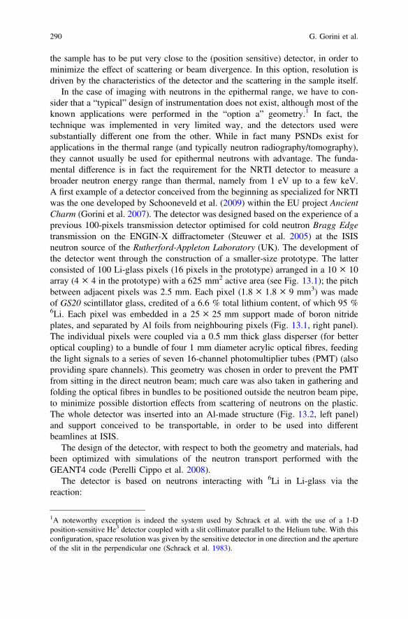
the sample has to be put very close to the (position sensitive) detector, in order tominimize the effect of scattering or beam divergence. In this option, resolution isdriven by the characteristics of the detector and the scattering in the sample itself.
In the case of imaging with neutrons in the epithermal range, we have to con-sider that a “typical” design of instrumentation does not exist, although most of theknown applications were performed in the “option a” geometry.1 In fact, thetechnique was implemented in very limited way, and the detectors used weresubstantially different one from the other. While in fact many PSNDs exist forapplications in the thermal range (and typically neutron radiography/tomography),they cannot usually be used for epithermal neutrons with advantage. The funda-mental difference is in fact the requirement for the NRTI detector to measure abroader neutron energy range than thermal, namely from 1 eV up to a few keV.A first example of a detector conceived from the beginning as specialized for NRTIwas the one developed by Schooneveld et al. (2009) within the EU project AncientCharm (Gorini et al. 2007). The detector was designed based on the experience of aprevious 100-pixels transmission detector optimised for cold neutron Bragg Edgetransmission on the ENGIN-X diffractometer (Steuwer et al. 2005) at the ISISneutron source of the Rutherford-Appleton Laboratory (UK). The development ofthe detector went through the construction of a smaller-size prototype. The latterconsisted of 100 Li-glass pixels (16 pixels in the prototype) arranged in a 10 × 10array (4 × 4 in the prototype) with a 625 mm2 active area (see Fig. 13.1); the pitchbetween adjacent pixels was 2.5 mm. Each pixel (1.8 × 1.8 × 9 mm3) was madeof GS20 scintillator glass, credited of a 6.6 % total lithium content, of which 95 %6Li. Each pixel was embedded in a 25 × 25 mm support made of boron nitrideplates, and separated by Al foils from neighbouring pixels (Fig. 13.1, right panel).The individual pixels were coupled via a 0.5 mm thick glass disperser (for betteroptical coupling) to a bundle of four 1 mm diameter acrylic optical fibres, feedingthe light signals to a series of seven 16-channel photomultiplier tubes (PMT) (alsoproviding spare channels). This geometry was chosen in order to prevent the PMTfrom sitting in the direct neutron beam; much care was also taken in gathering andfolding the optical fibres in bundles to be positioned outside the neutron beam pipe,to minimize possible distortion effects from scattering of neutrons on the plastic.The whole detector was inserted into an Al-made structure (Fig. 13.2, left panel)and support conceived to be transportable, in order to be used into differentbeamlines at ISIS.
The design of the detector, with respect to both the geometry and materials, hadbeen optimized with simulations of the neutron transport performed with theGEANT4 code (Perelli Cippo et al. 2008).
The detector is based on neutrons interacting with 6Li in Li-glass via thereaction:
1A noteworthy exception is indeed the system used by Schrack et al. with the use of a 1-Dposition-sensitive He3 detector coupled with a slit collimator parallel to the Helium tube. With thisconfiguration, space resolution was given by the sensitive detector in one direction and the apertureof the slit in the perpendicular one (Schrack et al. 1983).
290 G. Gorini et al.

63Liþ 1
0n ! 42Heþ 3
1HQ� value4:78 MeV
The charged particles deposit their energy in the glass, thus causing scintillationand consequent production of a light signal to be collected by the PMT. Thedetector contribution to the time resolution is small compared to the pulse width atspallation sources such as ISIS and J-PARC. Simulations conducted with theGEANT4 simulation package have shown that the time resolution due to theneutron transport in the PSND pixels is about 40 ns for 1000 eV neutrons and250 ns for 10 eV neutrons. Thus only for neutron energies below 10 eV the timeresolution of the PSD is comparable with e.g. the 300 ns pulse width at ISIS andsignificantly contributes to the overall time resolution.
The PSND was used at the INES diffractometer beamline at ISIS. It was con-nected to the standard ISIS Data Acquisition Electronics (DAE) for the registrationof TOF spectra. The efficiency of the single pixels (with a lower level discrimi-nation energy of 4 meV) was about 25 % for 10 eV and 4 % for 1000 eV neutrons,respectively. As the INES beamline has a typical neutron flux of 106 n s−1 cm−2,this resulted in an average count rate in the order of 40 kHz per channel on thewhole ISIS accelerator duty cycle. However, due to concentration of epithermalneutrons in the very first moments of the neutron pulse, maximum instantaneouscount rates of approximately 200–500 kHz per channel were recorded. The deadtime resulted to be in the order of 5 %.
Typical TOF spectra were recorded with a variable time binning (accordion),with maximum time resolution allowed by the DAE (i.e. 62.5 ns = 1/16 µs) in theregion 0–1 ms, where the most important resonances were expected to lie. A typicalspectrum recorded by the PSND is shown in Fig. 13.3.
Fig. 13.2 Left image of the PSND realized at the ISIS neutron source. Right schematic layout ofthe PSND structure (see text for details)
13 Neutron Resonance Imaging 291

A different perspective, though starting from the same physical issue, was usedin several works by Tremsin et al. (2012, 2014). They adapted the MCP technology,which was successfully developed for imaging X-ray astronomy and many otherphoton- or particle-counting applications. MCP detectors (Vallerga et al. 2009) arebased on insulator (usually glass) plates with closely packed channels of typicaldiameter in the order of 10 mm, depending on the forming procedure (drawing,etching, or firing in hydrogen). The plate surfaces are layered by a coat of aconductive material (usually nickel-based alloy) to act as input and output elec-trodes. When a suitable voltage (usually in the range of hundreds of volts) isapplied, every channel acts like a continuous dynode electron multiplier, as itmultiplies electrons through secondary emission from the channel walls. MCPs canbe made neutron-sensitive for instance through the addition of 10B to the glassmatrix (Tremsin et al. 2005); the neutrons interact according to the reaction:
10Bþ n ! aþ 7Li ðQ� value 2:79 MeVÞ
The alpha particle or 7Li, moving 180° apart to conserve momentum, has a highprobability of emerging from the channel wall surfaces into an open channel, thustriggering a secondary electrons cascade, and thus a detectable output pulse.Another approach to make the MCPs neutron-sensitive is by the addition of Gd(Fraser and Pearson 1990).
In order to preserve the spatial resolution allowed by the MCPs (basically thepitch between adjacent channels being 15–20 mm), a reading anode with similarresolution should be used. In the present case, Tremsin et al. made use of a Timepixreadout device (Llopart et al. 2007). Timepix is an application specific integratedcircuit (ASIC) based on the CMOS technology, composed of 256 × 256 pixels,each behaving as an amplifier, discriminator and counter.
MCPs based neutron detectors have been used in many applications; limiting tothe case of epithermal neutrons, Tremsin et al. (2012) used two different devices:the first one was 14 × 14 mm, with a nominal spatial resolution of 55 µm and timeresolution in the sub-nanosecond range. This device was used at the ROTAX
Fig. 13.3 A typicalTOF-spectrum recorded atINES by the PSND. Theinformation resides in the dipscaused by the resonances ofelements; the two strongestare related to copper. Most ofthe counts form a base-line,i.e. the recorded events fromundisturbed flux oftransmitted neutrons
292 G. Gorini et al.

beamline at ISIS to image Au, Gd, In and Ag sample foils, these elements havingresonance energies below 100 eV, and returning simple transmission images,though at high spatial resolution (about 150 µm). The TOF technique was exploitedat the pulsed neutron source of ISIS. Transmission images were recorded over alimited TOF (and thus energy) range, corresponding to selected resonances. In thisway, images were obtained where contrast (i.e. black/white levels) were due to thepresence of a selected element (see Figs. 13.4 and 13.5), not just to the amount of
Fig. 13.4 Neutron transmission radiography of a belt mount replica. a Full spectrum of the beamcontaining epithermal, thermal and cold neutrons. b Only neutrons in the energy range of 1–100 eV are registered in this image (Tremsin et al. 2012)
Fig. 13.5 Transmission images of the belt mount taken at the resonance energy of Ag and awayfrom it, same area as in Fig. 13.4. a Transmission image obtained with neutrons around 1.63 eVenergies. No resonances are present around that energy range. b Image obtained at the 5.3 eVsilver resonance. Both images are normalized by the open beam and represent the spatial variationof transmission coefficient at the corresponding neutron energy (Tremsin et al. 2012)
13 Neutron Resonance Imaging 293

matter crossed by the neutron beam (as is usually the case with thermal neutronradiography).
The second device (28 mm diameter) was also used at the NOBORU beamlineof J-PARC with samples made of elements also presenting resonances at higherenergies (like Cd, Co, Cu and Ta). The estimated efficiency of the detector wasestimated in the order of 70 and 50 % for cold and thermal neutrons, respectively,although the authors admit they don’t have a precise estimation of the efficiency inthe epithermal range (Tremsin et al. 2014). TOF spectra recorded by the detectorwere compared to calculated spectra in order to assess a quantitative analysis forfuture studies. In this respect, we have to consider that the dominant effect in timeresolution is due not to the detector itself but to the time structure of the neutronpulse, that is about 300 ns for ISIS and about 600 ns for J-PARC.
13.1.4 Facilities
A neutron facility optimized to exploit resonance imaging should have the fol-lowing proprieties:
(1) It should provide pulsed neutrons with the shortest possible pulse(2) It should provide a reasonable flux of epithermal neutrons at sample position(3) The gamma-ray background (typically from the spallation target and modera-
tor) should be as low as possible(4) For the sake of imaging, it should have a large beam transversal section(5) It should present a very reduced beam divergence
It is evident that requirements 2 and 3 are antithetical. In fact, both the neutronemission from the source and the amount of gamma background varies as theinverse of the square of the source-sample distance. Some thermalneutrons-optimized beamlines (typically diffractometers) with low-angle detectorsreduce the gamma background by the use of choppers, whose pulsation is timedwith the neutron pulse. Such choppers cut away most of the (instantaneous) gammaflash from the spallation target while transmitting the (slower) thermal neutrons.However, this practice is difficult when epithermal (faster) neutrons are necessary;in fact, in most practical situations, epithermal neutrons are fast enough to arrive atthe shutter position along with the gamma flash that is supposed to be cut.
Requirements 4 and 5 are also somehow antithetical. Some neutron beamlinesoptimized for NR in the thermal range present transversal beam sections as wide as200 × 200 mm with limited divergence. However, detectors for NR are also usu-ally of large dimensions (at least the scintillator converters); to all practical pur-poses, in the case of NRTI, it is of no use to have a beam wider than the dimensionof the transmission detector itself. As an example, in the case of the setup developedat ISIS, the dimensions of the detector were 25 × 25 mm, and the boron carbidejaws used in the INES beamline for the definition of the beam spot were usually set
294 G. Gorini et al.

to match such dimensions (the fully open beam at INES is 40 × 40 mm). In thecase of samples larger than these dimensions, a scanning procedure wasunavoidable.
The PSND developed at ISIS was used on the INES (Imberti et al. 2008)diffractometer beamline, while the mentioned smaller prototype was also tested atthe VESUVIO (Mayers and Reiter 2012) beamline of the same facility and at theGELINA (Mondelaers and Schillebeeckx 2006; Ene et al. 2010) facility of the JointResearch Centre at Geel (B).
INES (an acronym standing for Italian Neutron Experimental Station) is a TOFdiffractometer optimised for high resolution at low d-spacings. It makes use ofthermal neutrons, and thus, as for most beamlines at ISIS, it is subdued to a suitablemoderator, in this case made of water at 316 K. The resulting neutron spectrumpresents a typical shape made of (1) a Maxwellian peak at about 25 meV (2) a tailof higher-energy neutrons with typical 1/E1/2 dependence. The resulting flux ofneutrons, at the sample position (about 23 m from the neutron source) is in theorder of 106 n s−1 cm−2 in the epithermal range. The beam transverse section atsample position is 40 × 40 mm. INES is positioned on the same line-of-sight ofanother neutron instrument (and namely the spectrometer TOSCA) and it isequipped with a chopper used to cut away the gamma background (and fast neu-trons) from the two instruments; thus, when used for NRTI, the chopper has to beset at fully open position to make use of the epithermal neutrons.
VESUVIO is an inverted-geometry neutron TOF spectrometer optimized forepithermal neutrons. Being devoted to the exploitation of neutrons in the eV tohundreds of eV region, it is undermoderated, i.e. it is subdued to a room temper-ature moderator whose thickness (30 mm) is not enough to provide a completeneutron beam thermal equilibrium. This results in a spectrum, which is distinctlynot a Maxwell-Boltzmann distribution for energies above 100 meV (Φ ≈ 1/E), andan order of magnitude higher flux of epithermal neutrons than well-moderatedsources (details on the VESUVIO flux and spectrum can be found in Bedogni et al.2009). VESUVIO is not equipped with a neutron chopper. The sample position is
Fig. 13.6 The VESUVIObeamline neutron flux. Blackdots as from MCNPXsimulations. Red squaresexperimental data fromVESUVIO monitor detector
13 Neutron Resonance Imaging 295

located 11.055 m away from the source (about one half of the INES flight path),thus resulting in a higher flux (see Fig. 13.6) but also in a lower TOF resolution.
Of the three mentioned facilities, GELINA was especially designed for highresolution neutron-cross-section measurements in the resonance region. The facilityis based on a pulsed electron linac with a 800 Hz duty cycle and 70 µA averagecurrent. Typical pulse length is 10 ns; however, a pulse compression system allowsfor pulse width of about 1 ns at FWHM. The electrons are directed to a U/Mo 90/10alloy target, where, through Bremsstrahlung and consequent photonuclear reac-tions, produce neutrons with an average neutron flux of 3.4 × 10¹³ 1/s. Theobtained neutron spectrum is distributed from thermal to about 20 MeV energies; asfor VESUVIO and INES, the neutron beams are (under-) moderated in order toobtain a reasonable amount of neutrons in the energy range below, say, 100 keV.The emitted neutrons feed 10 beamlines with a series of experimental stations thatare located at different distances from the source (up to about 400 m).
The MCP-based detector was used both at ISIS and at the NOBORU beamline(Maekawa et al. 2009) of the Japan Proton Accelerator Complex (J-PARC). Theacronym NOBORU stands for NeutrOn Beamline for Observation & Research Use;it is a beamline dedicated to testing of neutron devices and detectors. The beamlineis credited with a neutron flux in excess of 107 n s−1 cm−2 in the energy region upto 1 MeV, and the beam transverse area is a generous 100 × 100 mm.
13.1.5 Examples
Several studies in the literature showed two-dimensional elemental mappings fromNRT data. Many different materials were tested (not always in the epithermalenergy range): from luggage inspection and contraband materials, like drug andexplosive simulants (Chen and Lanza 2002; Sowerby and Tickner 2007; Brandiset al. 2012; Mor et al. 2013), to cultural heritage materials (Tremsin et al. 2012;Perelli Cippo et al. 2011).
Actually, only one NRTI application producing 3D contrast figures of someelements was recently published (Festa et al. 2015).
This study was conducted at ISIS, using a dedicated set-up on the INESbeamline (see before), and it demonstrates the viability of NRTI technique using anearly mediaeval disc fibula, from the Hungarian National Museum in Budapest. Themethodology and analysis procedures described in the previous sections wereapplied. The artefact, is an ancient fibula, see Fig. 13.7, dated to the end of the 6thcentury AD, and coming from the cemetery site of Kölked-Feketekapu, one of themost important in the Carpathian basin, where ancient Germanic population lived.This kind of object was commonly used along the River Rheine (by the Franks) andin southern Germany (by the Alemanni).
296 G. Gorini et al.

A set of 16 NRTI radiographs was collected at different angles, using the PSNDdescribed before. Since the total lateral dimension of the sample exceeds the activearea of the detector, four exposures were recorded for each rotation. The 64exposures were matched together, and each radiograph contained 256 NRTI spectra(in a 16 × 16 matrix). Single spectra were analysed by the aid of routines in theOPEN GENIE software, in order to: (i) normalise the spectra and (ii) fitting therelevant dips. As reported before, instead of using REFIT, the areas of the dips werederived in the approximation of a linear background in a limited TOF interval, and aGaussian function reconstruction. The values of the areas so obtained in this way,were gathered in a two-dimensional 16 × 16 matrix, the so-calledpseudo-radiograph. By choosing a selected number of elements (i.e. Ag, Au, Cu,Fe), a series of pseudo-radiographs was obtained (see Fig. 13.8 for examples).
To derive 3D contrast figures of some elements present in the fibula, an FBPalgorithm was applied, returning 3D matrices, then transformed into 8-bit data, areadable format for commercial visualization programs. Each matrix was elementselective, since it represents an attenuation pseudo-coefficient due to the presence ofa specific resonance. The 3D-visualization is depicted in Fig. 13.9.
Fig. 13.7 Frontal and lateralpictures of the analysed discfibula fromKölked-Feketekapu(Hungary), dated to the end of6th century AD. The diameterof the fibula is about 3 cm(Festa et al. 2015)
13 Neutron Resonance Imaging 297

13.1.6 Areas of Application
Among other non-destructive neutron-based imaging techniques, NRTI is apotential technique to study the bulk elemental composition within a sample. As formost neutron-based techniques, no specimen preparation is needed and an entireobject (without sampling) can be investigated returning the bulk element concen-trations. These advantages make NRTI especially useful whenever non-destructiveinspections are needed, like for cultural heritage objects or advanced materials(prototypes and unique samples).
Concerning spatial resolution, other neutron-based imaging techniques have ahigher resolution. As a general rule, the overall spatial resolution is strictly relatedto the detector resolution. However, an intrinsic limit is given by the mean free pathof an epithermal neutron in an absorbing material, which can be in the order of afew mm for the upper end of the energy range considered (in the order of 1 keV). Inpractice, NRTI, from the literature data, was developed at high (150 µm; Tremsinet al. 2012) and low resolution (2.5 mm; Festa et al. 2015, but also Tomita et al.2012). The study based on the higher resolution detector has the drawback of thelimited element quantification (only 2D and not 3D output was shown).
Fig. 13.8 Slice of copper (a), gold (b), silver (c), iron (d) and data sets obtained from thereconstruction process (Festa et al. 2015)
298 G. Gorini et al.

On the other side, neutron tomography can reach for example 15 µm resolution,but has no elemental sensitivity.
Prompt Gamma Activation Imaging (PGAI) and NRTI have been applied to thesame specimen namely a disk-fibula from Kölked-Feketekapu (Hungary), making itpossible to compare features of both methods (Perelli Cippo et al. 2011; Schulzeet al. 2013).
Comparing the two techniques, we could observe that:
– Currently (Schulze et al. 2013) PGAI has a spatial resolution of about 2.5 mm.For NRTI, as we already described, the spatial resolution can be improved byimproving the resolution of the detector, whereas, for PGAI, the spatial reso-lution can only be improved by reducing the size of the neutron beam (hardly toobtain).
– NRTI requires lower acquisition times with respect to PGAI. Indeed, PGAImeasurements performed on the ancient fibula (Schulze et al. 2013), required a10 days period of neutron irradiation for the analysis of a quadrant of theartefact, while one day of measurements was sufficient for NRTI of the wholeobject (Festa et al. 2015). Almost an order of magnitude in time requirementscould be very important for a twofold reason: (a) costs of neutron measurementsrequire to reduce beam time as much as possible, and (b) cultural heritage
Fig. 13.9 Top part Neutron tomography (previous result, Schulze et al. 2013). Bottom part 3Dvisualization of the elements in the fibula (isosurfacescolor map: Cu = green, Fe = red,Au = yellow, Ag = blue; Festa et al. 2015)
13 Neutron Resonance Imaging 299

objects could be forbidden for too long irradiation times at least in the case whenfor museum objects lending time and insurance costs are considered.
– NRTI can map a lower number of elements than PGAI,
A limitation is that elements must have resonances in the epithermal region. Thisis true for many elements, but not for the lightest elements and for some heavynuclei with magic proton and neutron numbers.
Currently only fairly small objects can be studied mainly because of the detectoractive area, but also due to the sample holder and beamline instrumentation.Samples larger than the active detector area may still be measured, just mergingseveral radiographs, though requiring longer irradiation times. Beam sizes are fixed,though at the moment future beamlines are being designed for hosting very largesamples (as for instance the future IMAT beamline at ISIS).
References
Bedogni R et al (2009) Characterization of the neutron field at the ISIS-VESUVIO facility bymeans of a bonner sphere spectrometer. Nucl Instr Meth A 612:143
Brandis M et al (2012) Neutron measurements with Time-Resolved Event-Counting OpticalRadiation (TRECOR) detector. J Instrum 7:C04003
Chen G, Lanza RC (2002) Fast neutron resonance radiography for elemental imaging: theory andapplications. IEEE Trans Nucl Sci 49:1919
Ene D et al (2010) Global characterisation of the GELINA facility for high-resolution neutrontime-of-flight measurements by Monte Carlo simulations. Nucl Instr Meth A 618:54
Festa G et al (2015) Nuclear resonance transmission imaging for 3D elemental mapping at the ISISspallation neutron source. J Anal At Spectrom 30:745
Fraser GW Pearson JF (1990) The direct detection of thermal-neutrons by imagingmicrochannel-plate detectors. Nucl Instr Meth A 293:569
Furrer A, Mesot J, Straessle T (2009) Neutron scattering in condensed matter physics. WorldScientific, London
Gorini G et al (2007) Ancient charm: a research project for neutron-based investigation ofcultural-heritage objects. Il Nuovo Cimento C 47(30). See also http://ancient-charm.neutron-eu.net
Imberti S, Kockelmann W, Celli M et al (2008) Neutron diffractometer INES for quantitativephase analysis of archaeological objects. Meas Sci Technol 19:034003
Kak AC, Slaney M (1988) Principles of computerized tomographic imaging. IEEE Press,Piscataway, USA
Kopecky S et al (2009) The total cross section and resonance parameters for the 0.178 eVresonance of Cd-113. Nucl Instrum Meth B 267:2345
Llopart X, Ballabriga R, Campbell M, Tlustos L, Wong W (2007) Timepix, a 65k programmablepixel readout chip for arrival time, energy and/or photon counting measurements. Nucl InstrumMeth A 581:485 details of the Timepix device can be found in webpage: http://medipix.web.cern.ch/medipix/pages/medipix2/timepix.php
Lovesey SW (1987) Theory of neutron scattering from condensed matter. Clarendon Press, OxfordMaekawa F et al (2009) NOBORU: J-PARC BL10 for facility diagnostics and its possible
extension to innovative instruments. Nucl Instr Meth A 600:335Martz HE et al (2009) X-ray Imaging. CRC Press Inc, Bosa RocaMayers J, Reiter G (2012) The VESUVIO electron volt neutron spectrometer. Meas Sci Technol
23:045902
300 G. Gorini et al.

Mondelaers W, Schillebeeckx P (2006) GELINA, a neutron time-of-flight facility forhigh-resolution neutron data measurements, Notiziario Neutroni e Luce di Sincrotrone 11:19
Mor I et al (2013) Parameters affecting temporal resolution of Time Resolved Integrative OpticalNeutron Detector (TRION). J Instrum 8:P11012
Moxon M (1989) REFIT2: a least squares fitting program for resonance analysis in neutrontransmission and capture data, NEA—0914/02
Mughabghab S (2006) Atlas of neutron resonances. Elsevier, NetherlandsPerelli Cippo E et al (2008) Simulations and design of detectors for imaging with epithermal
neutrons, Meas Sci Technol 19:034027Perelli Cippo E et al (2011) Imaging of cultural heritage objects using neutron resonances. J Anal
At Spectrom 26:992Priesmeyer HG, Harz U (1975) Isotopic content determination in irradiated fuel by neutron
transmission analysis. Atomkernenergie 25:109Reich CW, Moore MS (1958) Multilevel formula for the fission process. Phys Rev 111:929Schillebeeckx P et al (2012) Determination of Resonance Parameters and their Covariances from
Neutron Induced Reaction Cross Section Data. Nucl Data Sheets 113:3054Schillebeeckx P et al (2014) Neutron resonance Spectroscopy for the characterisation of materials
and objects. JRC Science and Policy Reports. European Commission, Joint Research CentreInstitute for Reference Materials and Methods, Report EUR 26848-EN
Schooneveld EM et al (2009) A new position-sensitive transmission detector for epithermalneutron imaging. J Phys D Appl Phys 42:152003
Schrack RH et al (1983) Neutron radiography In Burton JP, van der Hardt P (ed) Springer,Netherlands, pp 495–502
Schulze R et al (2013) The ANCIENT CHARM project at FRM II: three dimensional elementalmapping by prompt gamma activation imaging and neutron tomography. J Anal At Spectrom28:1508
Shannon C (1998) Proceedings of the IRE 37:10–21 (1949). Reprinted in Proceedings of the IEEE86:447
Sowerby BD, Tickner JR (2007) Recent advances in fast neutron radiography for cargo inspection.Nucl Instr Meth A 580:799
Steuwer A et al (2005) Using pulsed neutron transmission for crystalline phase imaging andanalysis. J Appl Phys 97:074903–074911
Syme DB (1982) The black and white filter method for background determination in neutrontime-of-flight spectrometry. Nucl Instrum Meth 198:357
Tomita H et al (2012) Development of epithermal neutron camera based onresonance-energy-filtered imaging with GEM. J Instrum 7:C05010
Tremsin AS, Feller WB, Downing RG (2005) Efficiency optimization of microchannel plate(MCP) neutron imaging detectors. 1. Square channels with B-10 doping. Nucl Instrum Meth A539:278
Tremsin AS et al (2012) High resolution neutron resonance absorption imaging at a pulsed neutronbeamline. IEEE Trans Nucl Sci 59:3272
Tremsin AS et al (2014) Neutron resonance transmission spectroscopy with high spatial andenergy resolution at the J-PARC pulsed neutron source. Nucl Instr Meth A 746:47
Vallerga J et al (2009) The current and future capabilities of MCP based UV detectors. AstrophysSpace Sci 320:247
13 Neutron Resonance Imaging 301

Chapter 14Prompt Gamma Activation Imaging(PGAI)
Z. Kis, L. Szentmiklósi, R. Schulze and E. Abraham
Abstract The neutron is an ideal probe for elemental composition and structuralanalysis of samples due to its deep penetration into materials. This feature makes itespecially suitable for the non-invasive investigation of bulky samples from geol-ogy, material science, crystallography, and archaeometry. PGAI (Prompt GammaActivation Imaging)—a novel non-destructive, neutron based, two-dimensional,3-dimensional (2D/3D) elemental imaging method—was invented as an extensionof the well-established PGAA (Prompt Gamma Activation Analysis) bulk elementalanalysis method, in combination with NR/NT (Neutron Radiography/Tomography).The spatial resolution obtained so far for the elemental imaging part is on the orderof 5 mm. Selected experiments will be discussed to highlight the capabilities of thistechnique, including the analysis of cultural heritage objects. The results obtainedcan answer questions of historical interest, like the state of craftsmanship during anera, or the authenticity, and/or provenance of the investigated objects, as well asaspects of restoration and conservation procedures.
14.1 The Motivation
Most methods employed to characterize a variety of chemical, physical and (micro)structural properties of objects are invasive (e.g. Inductively Coupled Plasma MassSpectrometry, Atomic Absorption Spectroscopy) or have limited penetration depthin solid matter (e.g. methods using X-rays and charged particles). However neu-trons, as particles without charge, can penetrate deeply into objects andnon-destructively provide information about the structure and composition of the
Z. Kis (&) � L. SzentmiklósiMTA Centre for Energy Research, Budapest, Hungarye-mail: [email protected]
R. SchulzeUniversity of Cologne, Cologne, Germany
E. AbrahamUniversity of Bordeaux, Bordeaux, France
© Springer International Publishing Switzerland 2017N. Kardjilov and G. Festa (eds.), Neutron Methods for Archaeologyand Cultural Heritage, Neutron Scattering Applications and Techniques,DOI 10.1007/978-3-319-33163-8_14
303

whole interior. While the potential of neutron-based element and structure analysistechniques is large, their development has begun only recently. Few attempts havebeen made till now to use neutrons for qualitative or quantitative position-sensitiveelemental analysis, e.g. towards developing the PGAI technique. The motivation todevelop such a technique is to benefit from its unique features, i.e. it isnon-destructive, can be sensitive to chemical elements, even isotopes and structure,can have a spatial resolution in the order of a few mm, and it is possible toinvestigate bulky objects that are too thick for e.g. X-rays. In this chapter wepresent the way the PGAI technique evolved, briefly mentioning otherneutron-based position-sensitive elemental analysis methods. After giving someexamples, the limitations and peculiarities are mentioned as well.
14.2 The Basic Principles of Neutron-BasedPosition-Sensitive Elemental Analysis
Two- or three-dimensional element imaging data can be obtained in two basicways. The neutron-based position-sensitive elemental analysis techniques use eitherthe principles of tomography or the direct method. The first approach appliesmathematical algorithms to determine the spatial distribution from the measuredintegral quantities, while the other, the direct method, uses collimated irradiationand detection to define the source of the measured data. The detected particles couldbe the neutrons themselves, or the gamma-rays emerging from the radiative neutroncapture. The prompt and/or delayed gamma-rays originate from a distributed irra-diated region in the sample, since they are produced wherever neutrons interact withthe material along the beam path. The energies of the measured gamma-raysdetermine the elemental composition; while their intensities are a measure of theconcentrations inside the irradiated part of the sample.
Adopting the principles of transmission or emission tomography means the useof a mathematical algorithm, such as the filtered back projection, and successiverotations and translations of the object in front of a “camera” to create numerousimage projections in the plane of its sensitive screen (Spyrou 1987). In its originalimplementation (i.e. transmission tomography) the “camera” detects only theattenuation of the beam, i.e. the loss of intensity (Spyrou 1994). The disadvantageof the method is that the attenuation coefficients of the different materials could bychance be very similar making the identification of an element or compoundunreliable. In recently established methods (Anderson et al. 2009), such as NeutronResonance Capture Imaging (NRCI), Neutron Resonance Transmission (NRT) andenergy-selective neutron imaging using Bragg-cutoffs, the “camera” could be ele-ment- and position-sensitive as is discussed in other chapters of this book.
Another way to have position-sensitive elemental data is to apply the directmethod, where a narrow collimation of the neutron beam and of thegamma-detection can reduce the probed volume, so that the origin of the detected
304 Z. Kis et al.

gamma rays is well defined. This provides the basis to obtain the element distri-bution of the sample by scanning, i.e. measuring a set of gamma spectra at differentpositions in the sample (Baechler et al. 2001; Belgya et al. 2008b). This techniquewas named Prompt Gamma Activation Imaging (PGAI).
14.3 The Collection of 2D/3D Data
14.3.1 The Tomographic Reconstruction
According to the theory of computed tomography (i.e. Fourier slice theorem), a 3Delemental map of the sample can be constructed non-destructively slice by slice(Kak and Slaney 2001). The slices, which are treated independently, give the spatialvariation of the measured quantity (e.g. linear attenuation coefficient, energy andintensity of gamma rays) in a horizontal plane through the object. A slice refers to apixel row in an image; and is composed of the information recovered from the samerow in the successive projections. To do this, the collection of spectra of thecharacteristic prompt (Spyrou Kusminarto and Nicolaou 1987) or delayed (Spyrouet al. 1987) gamma-rays are required at a number of angles distributed over the360° rotation of the irradiated sample (this method is called emission tomography).It is theoretically equivalent whether the sample or the detector is rotated. Theefficiency of the system is reduced because either the neutron beam or thegamma-ray detector must be collimated in order to provide position information fortomography. That is, for delayed gamma-rays the narrow collimation of thegamma-ray detector, while for prompt gamma-rays the narrow collimation of theneutron beam makes it possible to detect gamma-rays emitted in a given plane ofthe sample, respectively (Spyrou 1987). Both versions enable a non-destructiveanalysis for the determination of elemental composition of the irradiated part of thesamples for major as well as minor components.
The method has been published as neutron-induced gamma-ray emissiontomography (NIGET) (Spyrou et al. 1997; Spyrou 1999), or neutron-inducedprompt γ-ray analysis with computed tomography (PGA-CT) (Segawa et al. 2009).In this latter case the measurements were carried out mainly using a single, wellcollimated high-resolution Ge detector and a narrowly collimated neutron beam ona Cd test sample, a three-sided wireframe pyramid of 1 cm side lengths.
The acquisition of gamma-ray spectra in tomographic mode is time consumingbecause of the low detection efficiency. Using state-of-the-art reconstructionmethods such as the maximum likelihood expectation maximization (ML-EM),measurements with even poor statistics can be evaluated (Segawa et al. 2009).There are some restrictions in the case of delayed gamma-ray measurements,because the half-lives of the radionuclides less than some hours (Spyrou 1987) limitthe set of elements to be studied effectively during a given scanning time. In promptgamma-ray measurements this time constraint is avoided.
14 Prompt Gamma Activation Imaging (PGAI) 305

The reconstruction algorithm of this method makes it mandatory that the integralinformation recorded with a detector along the beam path must cover the wholesample thickness in a slice. This poses further limitations on the size and neutronattenuation of the sample, and on the activity and spatial distribution of theradionuclides of interest.
14.3.2 The Direct Method
This is the most natural transition from a bulk analytical technique to a 3D-capablemethod, and it is best used in the case of prompt gamma-ray measurements(Kasztovszky and Belgya 2006). It is preferred if the detector used does not provideintrinsic position resolution and if the beam of slow neutrons, can be sharplycollimated.
The conventional PGAA method provides the average elemental composition ofan illuminated volume (Molnár 2004). With a highly collimated neutron beam andgamma-detection, the probed volume (a volume at the geometrical intersection ofthe neutron beam path and the gamma collimator’s solid angle) is reduced. Such acollimated neutron beam is often called a “pencil beam”, and in case of thermalneutrons, its dimension can be reduced down to 2–3 mm. The gamma-ray colli-mator is usually of similar or slightly larger size. Thus the spatial information of theelemental distribution in the sample can be obtained by scanning, i.e. measuring aset of gamma spectra at different positions in the sample. This technique is namedPrompt Gamma Activation Imaging (PGAI). PGAI utilizes low-energy, i.e. thermalor cold neutrons, as the cross-section for neutron capture reactions is increasing forlower neutron energies according to the so-called 1/v law. In present-day labora-tories, a typical PGAI setup (Fig. 14.1) consists of a sample holder at the end of aneutron beam guide and a shielded Compton-suppressed gamma spectrometerplaced perpendicular to the beam (Belgya et al. 2008a; Kudejova et al. 2008; Kiset al. 2015).
Basically two measurement configurations can be applied (Fig. 14.2). In thechord geometry only the neutron beam is collimated, so the resolution along thebeam direction is lost (Fig. 14.2a). Such data are suitable whenever 2D data areenough for meaningful results, and the gamma collimation can be omitted in favorof a higher event rate (Segawa et al. 2008). One of the first experiments of this kindwas performed on a piece of the 2-billion-year-old Oklo natural reactor (Baechleret al. 2001). To obtain spatially resolved data the cold neutron beam was focused,and it was reduced to a 1 mm2 area at the focal point. Because the object was a thinsample and was placed perpendicular to the beam, the 2D elemental map wasrepresentative of the elemental distribution of the whole sample.
If both the neutron beam and the gamma detector are collimated, the intersectionof the neutron beam and the solid angle of the collimated gamma-detector define aprobing volume, the so-called isovolume (Fig. 14.2b). The concept of this isovol-ume, called earlier “invisible container geometry”, was used with success in the past
306 Z. Kis et al.

to suppress background from metallic canisters of pressurized gases and leadcontainers (Révay 2008), and to determine micrograms of hydrogen inside a cat-alytic reactor assembly (Révay et al. 2008). Ideally it is a small fixed volume inspace which is the source of the analytical information. Its middle point is calledisocentre. Due to count rate considerations the smallest feasible volume was a fewtens of mm3 so far. This approach to delivering 3D information gives a direct image
Fig. 14.1 Illustration of a combined PGAI/NT setup. For PGAI measurements the neutroncollimator is put into the beam, while for NT an open neutron beam is needed (Schulze et al. 2011)
Fig. 14.2 Illustration of the active measurement volume for the scanning based approach. a 2Dsetup without gamma collimator (chord geometry). b 3D setup with neutron and gamma collimator(double collimated geometry). The blue line represents the path of the neutron beam. The yellowline shows the collimated view of the gamma detector. The intersection of the two lines gives thecurrently measured sample volume for b while for a the whole volume irradiated by the neutronbeam is measured
14 Prompt Gamma Activation Imaging (PGAI) 307

and does not involve the filtered back-projection principle. The data required to fillup the 3D grid is measured isovolume by isovolume, applying a systematic scan-ning of the whole sample, which is placed on a motorized sample stage. This scancan either be over the full sample volume or only of a smaller region of interest(Belgya et al. 2008b). A consequence of the better spatial resolution in comparisonto PGAA is the reduced count rate, which makes the systematic PGAI scans verytime consuming.
The data reduction in this case is straightforward: The measured raw data areplotted against the coordinates of the sample stage, i.e. the positions in the 3Dspace. However, this raw image is affected by biases from self-shielding of theneutrons and self-absorption of the gammas, and the distortion effects of thegamma-ray collimator’s transmission function, which have to be point-wise cor-rected for. A correction method is under development using random numbers(Monte Carlo method) to yield quantitative results (Kis et al. 2011).
With the isovolume measurements—unlike the tomographic reconstructiontechniques—it is not mandatory to measure and reconstruct the whole sample, butone can focus on selected parts of the object which may speed up the measurement.For real samples it is usually safe to assume that they are made of a few homo-geneous parts, and useful results can be made even if the full scanning with a givenresolution is not feasible. To do this a suitable option is to couple the positionsensitive PGAI with faster neutron imaging methods. Radiography, or even a fulltomography of a complex sample, can be completed in minutes/hours, and oftenprovides enough information to define regions of interest. If the spatial data fromradiography or tomography is linked to the positions of a motorized xyzω samplestage, one can move the selected parts of the sample into the probed volume. Ifnecessary, the accuracy of the positioning could be confirmed by repeated neutronimages, or even with a real-time video loop. The detailed elemental analysis byPGAI is then carried out only at these spots, saving a substantial amount of beamtime. This makes the technique, called neutron radiography, neutron tomography(NR/NT) driven PGAI, much more feasible and productive than PGAI of the wholesample.
In the framework of the EU FP6 ANCIENT CHARM (Analysis by Neutronresonant Capture Imaging and other Emerging Neutron Techniques: new CulturalHeritage and Archaeological Research Methods) project (2006–2009) novel3D-capable structure, phase and element analysis techniques were worked out asthe combination and extension of the conventional Neutron Tomography (NT),Prompt Gamma Activation Analysis (PGAA), Time-of-Flight Neutron Diffraction(TOF-ND), Neutron Resonance Capture Analysis (NRCA) and Neutron ResonanceTransmission (NRT). One of the major innovations was PGAI-NT, realized first inBudapest (Belgya et al. 2008a) and later at the FRM II PGAA station, Garching,Germany (Kudejova et al. 2008). It was demonstrated that a complete two orthree-dimensional element mapping with adequate resolution is possible, but ispresently feasible only for small objects due to constraints of experimental time andneutron flux. Nowadays the only permanent facility for NR/NT-driven PGAI inoperation, NIPS-NORMA, can be found at the Budapest Neutron Centre (BNC) as
308 Z. Kis et al.

an advanced version of the one built during the ANCIENT CHARM project. Thedetailed technical specifications of NIPS-NORMA are available in Szentmiklósiet al. (2010, 2013) and Kis et al. (2015).
14.4 Examples of PGAI-NT Studies
14.4.1 PGAI of a Disc Fibula from the 6th Century
First PGAI-NT pilot studies were accomplished on a fibula found at theKölked-Feketekapu site, Hungary, dated to the end of 6th century AD, and kept atthe Hungarian National Museum. It has a diameter of 31 mm, a thicknessof *10 mm, and weighs 20.08 g. It was thought that the fibula contains an outerring, presumably made of iron, and a main round part consisting of gold cells withgarnet (almandine) inlays. A pearl of unknown material is placed in the center of thefibula front. It had earlier been assumed that the back-plate was made out of bronze.
In the course of the PGAI method development, procedures had to be developedfor calibration, sample handling and software development. This was carried out atthe Institute of Isotopes (presently the Centre for Energy Research, HAS) inBudapest, Hungary, using replica samples of selected archaeological objects. Thefinal measurements were then performed at the Forschungs-Neutronenquelle HeinzMaier-Leibnitz (FRM II) in Garching, Germany which has a hundred times higherneutron flux. This high neutron flux made the measurement of the 3D elementalmapping of real archaeological samples feasible.
For the preparation of the elemental imaging measurements, a short PGAAmeasurement of the bulk sample was made at the Budapest PGAA setup, whichidentified the major elements Fe (64.5), S (15.3), Au (7.9), Cu (7.2), H (2.2), Al(1.2), Ag (0.9 %), Mn (0.7 %), and Cl (0.1 %) with relative fractions in weightpercent in brackets. From these results the measurement acquisition time for eachspot of the following PGAI measurement could be estimated, so as to be longenough to provide enough counts for a reliable elemental identification.Additionally the bulk measurement allowed the estimation of a potentially longlasting sample activation, which could delay the release of the sample due toradiation protection reasons. To reduce this risk the measurement time should bekept as short as possible, when isotopes with a long decay time are produced inlarger amounts.
As a PGAI scan of the full sample would be unfeasibly long (in the order ofweeks!), the knowledge of the morphological structure can be used to limit themeasurement scan to a few small regions typical of given parts of the object. Forthis fibula the NT confirmed the already expected rotational symmetry. Thus itseemed to be justified to measure only one quadrant of the sample and to extend themeasured elemental distribution over all four fibula quadrants by mirroring. Tofurther decrease the measurement time, the scanning grid was limited to three layers
14 Prompt Gamma Activation Imaging (PGAI) 309

in the fibula, which were assumed to provide representative results for the full fibula(see Fig. 14.3). The first layer was positioned to provide information about thealmandine inlays, the second layer was placed to analyze the filling material, andthe third layer was selected to measure the composition of the fibula back-plate. Ineach layer the measurement’s grid was further reduced to measure only everysecond position in the 2 × 2 mm step–size grid according to a checkerboard pattern(Fig. 14.3). Even with all these limitations the acquisition time for the 77 measuredspectra was around 10 full days (Schulze et al. 2013).
The spatial alignment of the datasets (from NT and PGAI) was carried out afterthe analysis of raw data, and some qualitative results for the significant elements areshown in Fig. 14.4.
Fig. 14.3 The disc fibula and the defined measurement grid for the PGAI experiment (reproducedfrom Schulze et al. 2013 with permission of The Royal Society of Chemistry)
Fig. 14.4 Spatial maps ofselected elements asregistered data-sets from thePGAI and NT imagingmodalities. The voxels aresingle data-points from PGAImeasurements. Thehighlighted voxels representregions where the givenelement was detected,whereas other voxels weremade transparent.Reproduced from Schulzeet al. (2013) with permissionof The Royal Society ofChemistry
310 Z. Kis et al.

The PGAI measurement revealed iron in nearly all measured positions, with thehighest intensities in the back-plate and outer ring. Sulphur was detected in theinner part of the fibula, so it is likely a component of the filling material. Gold wasmeasured in the front and back layer. The distribution in the front layer confirmedthe presence of a golden lining of the almandine inlays. The copper presence in theback layer was a hint to confirm that the back-plate is made of copper-alloy,probably bronze. Unfortunately, tin was not detected because its quantity is likelybelow detection limit in the copper matrix. The uniform distribution of hydrogen inthe front and middle layer indicates that it is another component of the fillingmaterial. The measured silver distribution follows the lining of the almandine inlay,so it could be a soldering component. At some discrete points on the back-platechlorine was measured. The discrete distribution leads to the assumption that it wasnot an original component of the fibula material, but might be a contamination fromeither chlorination while buried or restoration or conservation procedures.
These results confirmed some assumptions of the archaeologists, e.g. it hadearlier been assumed, that the fibula was repaired with an iron band which shouldkeep the inlays and the back-plate in place. The internal distribution of iron mayoriginate from some washing of iron oxide into the filling material. It was alsoconfirmed that the lining of the front inlays were made out of pure gold.
14.4.2 NT–Driven PGAI of an Eighteenth Dynasty EgyptianSealed Pottery
An Eighteenth Dynasty Egyptian sealed pottery from the Museum of Aquitaine(Bordeaux, France) has been investigated using computed tomography (CT) ofvarious modalities (terahertz electromagnetic radiation (Jackson et al. 2011), X-raysand neutrons) and NT-driven PGAI in order to analyze the bottle itself and itscontents (Abraham et al. 2014). X-ray and neutron imaging are routinely used, butterahertz (THz) imaging is only recently used to analyze museum artefactsnon-destructively. This multi-modal study emphasizes the complementarity andspecificity of the three imaging methods, together with the position-sensitive ele-mental mapping technique, all of which are shown to be of a prime importance forhistorians and museum curators dealing with cultural heritage.
The CT images of the pottery using THz radiation are presented in Fig. 14.5.The internal volume of the bottle has been estimated to be 100 cm3 with about25 cm3
filled by a movable content. At the bottom of the pottery, where THzradiation is strongly absorbed, it was concluded that either the bottle is filled by afixed content in this part or that the pottery walls are thicker here so that THzradiation is not transmitted.
With X-ray CT, front and axial views clearly confirmed the presence of themovable and deformable content (Fig. 14.6), previously revealed by THz CT.Higher spatial resolution makes it possible to see that the content is inhomogeneous
14 Prompt Gamma Activation Imaging (PGAI) 311

with small and larger fragments. It is not composed of mineral materials since itsdensity is much lower than the pottery walls made of clay and its X-ray absorptionis weak. The front views also reveal that the cork consists of two parts with anexternal sealing of clay (saturated white color) and an inside one made of anunknown low contrast material (grey color).
Neutron imaging gave information about the way the object has been closed by adouble stopper (clay and probably a ball of linen or some other string-like organicmaterial) and provided a more accurate representation of the mobile and hetero-geneous content, probably consisting of germinated herbal seeds (Fig. 14.7).
The elemental composition of three different parts of the jar was determined withNT-driven PGAI (Fig. 14.7a). The investigated parts were the following: (1) ‘Full’:irradiation of the inner content and surrounding wall; (2) ‘Void’: irradiation of avoid part of the bottle without the filling material (e.g., practically only the wallmaterial); and (3) ‘Plug’: irradiation of the cork region and surrounding walls. Dueto the uncertainty in the self-absorption corrections only a semi-quantitative
Fig. 14.5 THz CT. a Front view, horizontal position. b Front view, upside-down verticalposition. c Axial views at the positions indicated in b. (Abraham et al. 2014)
Fig. 14.6 X-ray CT (140 kV–200 mA). a Front view 1, b Front view 2, c Axial view (Abrahamet al. 2014)
312 Z. Kis et al.

elemental composition for the inner content could be given instead of absoluteconcentrations of the identified components. The amounts of the characteristicelements for ceramics (Na, Mg, Al, Si, K, Ca, Ti, Mn, and Fe) were roughly thesame in both ‘Full’ and ‘Void’ measurements. On the other hand, some elementscharacteristic of organic material (H, C, N, S, and Cl) show an excess in case of the‘Full’ measurement, compared with that of the ‘Void’. Furthermore, the compo-sition of the plug also shows an excess of H, C, N, S, and Cl, which confirms theorganic nature of the fabric.
As a result, the content could consist of germinated seeds (or any other driedorganic material) such as barley that was a staple cereal of ancient Egypt. It isconcluded that the internal cork could be made of a ball of linen.
14.5 Method Limitations and Peculiarities
14.5.1 Sample Positioning and Alignment
In addition to the development of various imaging methods, the tasks of spatialregistration of the data and object transportation have to be addressed if the study ona sample involves more than one setup. The joint use of different datasets hasadvantages over their separate evaluations. A marker-based approach was chosen incombination with the development of universal sample holders which aim to solvethe problems of safe transportation, reproducible positioning and unique dataregistration.
Fig. 14.7 Neutron CT. a Global front view. b 3D representation of the cork. Axial views of thecork at the position 1 and 2 indicated in b (Abraham et al. 2014)
14 Prompt Gamma Activation Imaging (PGAI) 313

14.5.1.1 Requirements
A crucial task is the correct placement of the samples in the desired measurementpositions. It is essential that the accuracy of the sample positioning be better thanthe resolution of the measurement method itself. This means that the alignment hasto be accurate to about 1 mm or better.
To define measurement positions which lie on the surface of the sample, a laserbeam can be used which is coincident with the path of the neutrons. The sample caneasily be positioned by eye in such a way that the laser hits the desired part of thesample. This method fails when it is desirable to investigate internal parts of asample, e.g. the glue or resin used during the manufacturing process of an object.For this case another method has to be used.
14.5.1.2 Sample Holders and Reference Markers
The construction of universal sample holders for the objects, which protect thevaluable objects from any possible damage during transportation from one facilityto another, and which ensure the unique and well-defined positioning on the dif-ferent instruments (Kudejova 2008) is sometimes necessary. Reference markersshould be attached to these sample holders at precisely determined positions relativeto the sample (see Fig. 14.8a).
These reference markers have to be detectable by all measurement methods andshould be small enough to allow accurate determination of their positions. For theunique alignment of these markers in 3D space at least four markers have to beused. For the tomography based methods it is essential that the markers, which havehigh neutron absorption, never appear in front or behind the samples during therotation, because then the filtered back-projection algorithm would fail.
For the cold neutron based methods, i.e. PGAI and NT, pin-heads, which werepainted with gadolinium-loaded white nail polish, were used to mark the referencepositions. Due to the high cross-section of gadolinium for cold neutrons they wereeasily detectable with these methods. Because of the nearly spherical shape thedetermination of their position could be performed very accurately by using thecentre of the spheres as reference.
14.5.1.3 Positioning with the Help of Reference Markers
By performing a neutron tomography of the sample in the frame with attachedreferences markers one gets a 3D “map” of the inner and outer parts of the object.The reference markers provide known points in space which can be used to convertfrom 3D voxels inside this map to millimetre coordinates in the laboratory coor-dinate frame.
The determination of the reference marker positions in the laboratory coordinatesystem, which is usually given by motor steps of the xyzω-tables used for sample
314 Z. Kis et al.

(a) (b)
(c) (d)
Fig. 14.8 Use of reference markers for sample positioning. a Fibula sample in holder withreference markers. b NT of fibula. The references markers are clearly visible in the reconstruction.c and d Slices of the NT reconstruction. The slice number gives the z-coordinate. c A slice acrossthe middle of the two upper reference markers gives the x-direction calibration. The knowndistance in mm of the reference markers and the distance in pixels in the reconstruction slice givethe conversion factor for the transfer of positional information from reconstruction to laboratorysystem. For the y-axis the lower front reference marker can be used. d: Slice in the middle of thefibula (Schulze et al. 2011)
14 Prompt Gamma Activation Imaging (PGAI) 315

positioning, can be achieved by different means, e.g. by measuring the distancefrom fixed known positions in the laboratory system with a ruler or caliper, utilizinga laser to place the markers to a known position or by doing an in-beam scan. Themotor positions obtained from these scans give a correspondence between samplestage and detector, and therefore the detected data.
With the known positions of the reference markers in the laboratory coordinatesystem, sample positioning is now a task of
• selecting a desired measurement point in the NT data-set,• determining the offset of this point in NT coordinates, i.e. pixel numbers and
slices in the reconstruction, from the positions of the reference markers in thereconstruction (Fig. 14.8c,d),
• and transferring these offsets to the laboratory coordinate system by applyingtranslation vectors, scaling factors and a rotation matrix.
The transferred coordinate offsets are finally added to the known position of oneof the reference markers when in the measurement position, which gives the finalcoordinates for the point and hence the sample stage setting.
14.5.1.4 Combination and Registration
It is important to have the ability to combine the results gained from the differentmeasurement methods. In the end a full 3D representation of the object, containingthe morphological structure, the measurement of elemental distributions and thecrystallographic properties is desirable. For this task 3D visualisation softwarecould be used, which allows the import and combination of different 3D data-setsand the navigation inside the combined data-sets for easy interpretation of theresults.
For the alignment of the different data-sets the reference markers used for thepositioning of the samples can be used. The collected data is inserted in a 3D voxelspace, where the voxel size is chosen according to the resolution of the measure-ment method. The position of the single data-points in this “voxel space” isdetermined relative to the reference markers, which are also included into these 3Ddata-sets. The final registration is then done by aligning the positions of the ref-erence markers.
14.5.2 Temporary Neutron Activation of the Objects
An a priori calculation of the potential activation due to the neutron irradiation ofthe museum objects could be of high importance when judging the feasibility of anexperiment. Based on the results, an upper limit of irradiation time can be definedwhich keeps the activity level of the objects below the exemption levels declared by
316 Z. Kis et al.

the law. The exemption levels are different for the different isotopes and, moreover,they might differ from country to country. An example is presented below. Theactivity values shown can be scaled according to the various irradiation situations.
The activity of an isotope (Ai) during a continuous neutron irradiation follows asaturation curve. If the number of activated atoms is zero at t = 0, then:
Ai ¼ ni � ri � U � 1� e�ki�t� �
where ni is the number of atoms of the ith isotope (ni = Θi × nelem, where Θi is theisotopic abundance of the ith isotope of the element, nelem is the number of theatoms of the chemical element in the path of the neutron beam), σi is the neutronabsorption cross section of the ith isotope for thermal neutrons (v = 2200 m/s), Φ isthe time independent thermal equivalent neutron flux of the cold or thermal neu-trons assumed to be constant over the volume of the object, λi is the decay constantof the ith isotope (λi = ln(2)/T1/2, where T1/2 is the half-life of the isotope). If theirradiation circumstances are steady and the saturation activity is reached, it will beconstant until the end of the irradiation due to the dynamical equilibrium betweengenerated and decaying nuclei. After the end of irradiation the activity of theisotope will follow an exponential decay curve.
A silver sphere weighting 0.298 grams was irradiated in a thermal equivalentneutron flux of 1.2 × 108 cm–2s–1 for 1 h at the PGAA station of the BudapestResearch Reactor, Hungary, representing a worst-case scenario, since silver has ahigh neutron capture cross-section and also a long half-life. A measurement after1 day cooling time yielded *10 Bq radioactivity for silver (Ag-110m) in thewhole sample, which is a very low value compared to its exemption level (106 Bq)for activity. This means that a rather large quantity of silver (*some grams) inmuseum objects could be irradiated for longer time in a similar neutron beamwithout any radiation protection consequences. For other typical components of anartefact with significant activation, such as Cu, Zn, Au, Na, the situation is evensafer.
For a more general calculation for these elements, let us consider 10 mmol(6 × 10²¹ atoms) of the i–th isotope, ni. Hence, for an isotope of mass number A theweight of the isotope is A/100 g: e.g. for Ag–109 mA = 1.09 g. This latter impliesthat the weight of the elemental silver in the sample is 1.09 g/0.48 = 2.27 g, where0.48 is the isotopic abundance of Ag-109. Let the thermal equivalent neutron fluxbe 1 × 108 cm−2s−1 in the whole volume of the sample (i.e. as a worst caseapproach we do not consider the self-shielding effect of the sample material). InFig. 14.9 the activities of the isotopes after 1 h irradiation are presented for differentσi values. It can be seen that the activities are going to be saturated if the value ofλi × tirr is at least 5 or larger. From Fig. 14.9 one can see that e.g. Ag–110m (themetastable product after capture of a neutron by Ag–109) and Zn–65 are far fromthe saturation, which is due to their rather long half-lives. It can also be seen thatAl–28 is already saturated after 1 h irradiation, because its half-life is just 2.24 min.
An irradiated object should no longer be considered as radioactive if its activityor activity concentration is below the exemption levels. If the activity after the
14 Prompt Gamma Activation Imaging (PGAI) 317

irradiation would exceed the limit for an isotope then the object should be con-sidered as radioactive material, and should be kept in a locker until its activity hasdecreased below the exemption level. This could be a problem for materials con-taining isotopes of rather long half-life (e.g. T1/2(Ag–110m) = 249.95 days). Forexample, the exemption level for the activity of Ag–110m is 106 Bq in Hungary,therefore the irradiations of an object at different facilities should be optimized in away not to exceed this level. For isotopes of shorter half-life (e.g. T1/2(Au–198) = 2.69 days) exceeding the exemption level is not such a serious problem.One should leave sufficient cooling time between measurements or after the lastmeasurement before the sample is released again. This must be considered alreadyat the planning stage of an experiment, i.e. the owners of the artefacts need exactdates of the loan period well in advance.
14.6 Conclusions
The results of elemental mapping obtained by position-sensitive neutron-basedanalytical techniques (PGAI, NR/NT-driven PGAI) alone could already answermany relevant questions in the cultural heritage science. The combination of these
0.1
0.51
25
10
50100
Ag-110m
Au-198
Zn-65
Cu-64
Na-24
Al-28
1.0E+00
1.0E+01
1.0E+02
1.0E+03
1.0E+04
1.0E+05
1.0E+06
1.0E+07
1.0E+08
0.0001 0.001 0.01 0.1 1 10 100
Activ
ity (B
q)
λi × t irr
Activity values for different σi's (ni = 6×10²¹ atoms, t irr = 3600 sec, Φtheq = 108 cm-2s-1)
Ag-110m Au-198
Zn-65 Cu-64
Na-24 Al-28
Fig. 14.9 Activity values after 1 h irradiation. The number of atoms of the irradiated isotopes is10 mmol (6 × 10²¹ atoms) in a thermal equivalent neutron flux of 108 cm−2s−1. The curves referto typical cross section values between 0.1 and 100 barns. For better clarity the activity values forsome interesting isotopes are presented as well. (The activity values do not contain the activityproduced during measurements due to irradiation with epithermal or higher energy neutrons.)
318 Z. Kis et al.

results with resonance neutron-based and scattering methods, or even withnon-nuclear (e.g. X-ray, THz) imaging, opens the possibility of a comprehensiveapproach to answer cultural-heritage-specific questions.
References
Abraham E, Bessou M, Ziéglé A, Hervé M-C, Szentmiklósi L, Kasztovszky Zs, Kis Z, Menu M(2014) Terahertz, X-ray and neutron computed tomography of an eighteenth dynasty Egyptiansealed pottery. Appl Phys A 117:963–972
Anderson IS, McGreevy RL, Bilheux HZ (eds) (2009) Neutron imaging and applications.Springer, New York
Baechler S, Materna T, Jolie J, Cauwels P, Crittin M, Honkimaki V, Johner H, Masschaele B,Mondelaers W, Kern J, Piboule M (2001) Non-destructive analysis of a bulky sample from anatural fossil reactor. J Radioanal Nucl Chem 250:39–45
Belgya T, Kis Z, Szentmiklósi L, Kasztovszky Zs, Festa G, Andreanelli L, De Pascale MP,Pietropaolo A, Kudejova P, Schulze R, Materna T (2008a) A new PGAI-NT setup at the NIPSfacility of the budapest research reactor. J Radioanal Nucl Chem 278:713–718
Belgya T, Kis Z, Szentmiklósi L, Kasztovszky Zs, Kudejova P, Schulze R, Materna T, Festa G,Caroppi PA (2008b) First elemental imaging experiments on a combined PGAI and NT setupat the budapest research reactor. J Radioanal Nucl Chem 278:751–754
Jackson JB, Bowen J, Walker G, Labaune J, Mourou G, Menu M, Fukunaga K (2011) A survey ofterahertz applications in cultural heritage conservation science. IEEE Terahertz Sci TechnolTrans 1:220–231
Kak AC, Slaney M (2001) Principles of Computerized Tomographic Imaging. Soc Ind Appl MathKasztovszky Zs, Belgya T (2006) From PGAA to PGAI: from bulk analysis to elemental mapping.
3:16–21Kis Z, Belgya T, Szentmiklósi L (2011) Monte Carlo simulations towards semi-quantitative
prompt gamma activation imaging. Nucl Instrum Methods Phys Res A 638:143–146Kis Z, Szentmiklósi L, Belgya T (2015) NIPS-NORMA station—a combined facility for
neutron-based nondestructive element analysis and imaging at the Budapest Neutron Centre.Nucl Instrum Methods Phys Res Sect Accel Spectrometers Detect Assoc Equip 779:116–123
Kudejova P (2008) Supports for accurate positioning and alignment of archaeological objects.FRM2, Garching, Germany
Kudejova P, Meierhofer G, Zeitelhack K, Jolie J, Schulze R, Türler A, Materna T (2008) The newPGAA and PGAI facility at the research reactor FRM II in Garching near Munich. J RadioanalNucl Chem 278:691–695
Molnár G (2004) Handbook of prompt gamma activation analysis with neutron beams. KluwerAcademic Publishers, Dordrecht
Révay Z (2008) Prompt gamma activation analysis of samples in thick containers. J RadioanalNucl Chem 276:825–830
Révay Z, Belgya T, Szentmiklósi L, Kis Z, Wootsch A, Teschner D, Swoboda M, Schlögl R,Borsodi J, Zepernick R (2008) In situ determination of hydrogen inside a catalytic reactor usingprompt gamma activation analysis. Anal Chem 80:6066–6071
Schulze R, Szentmiklósi L, Kis Z, Collaboration Ancient Charm (2011) The ancient charm project:new neutron based imaging methods for cultural heritage studies. Archeol E Calcolatori21:281–299
Schulze R, Szentmiklosi L, Kudejova P, Canella L, Kis Z, Belgya T, Jolie J, Ebert M, Materna T,Biro KT, Hajnal Z (2013) The ancient charm project at FRM II: three-dimensional elementalmapping by prompt gamma activation imaging and neutron tomography. J Anal At Spectrom28:1508–1512
14 Prompt Gamma Activation Imaging (PGAI) 319

Segawa M, Matsue H, Kureta M (2009) Development of three-dimensional prompt γ-ray analysissystem. Nucl Instrum Methods Phys Res Sect Accel Spectrometers Detect Assoc Equip605:54–56
Segawa M, Matsue H, Sekiya Y, Yamada S, Shinohara T, Oku T, Sasao H, Suzuki J, Shimizu HM(2008) 2D elemental analysis approach in focused neutron beam induced prompt gamma-rayanalysis at JAEA. J Radioanal Nucl Chem 278:647–651
Spyrou Kusminarto NM, Nicolaou GE (1987) 2-D reconstruction of elemental distribution withina sample using neutron capture prompt gamma-rays. J Radioanal Nucl Chem 112:57–64
Spyrou NM (1987) Prompt and delayed radiation measurements in the elemental analysis ofbiological materials: the case for neutron induced gamma-ray emission tomography.J Radioanal Nucl Chem 110:641–653
Spyrou NM (1994) Tomography and elemental analysis using neutrons in transmission.J Radioanal Nucl Chem 179:285–294
Spyrou NM (1999) Neutron activation analysis challenges: problems and applications inbiomedical and other areas. J Radioanal Nucl Chem 239:59–70
Spyrou NM, Balogun FA, Davies G (1987) Investigation of elemental distributions within abiological sample using neutron activation tomography. J Radioanal Nucl Chem 113:417–421
Spyrou NM, Sharaf JM, Rajeswaran S, Mesbahi E (1997) Determination of the elementaldistribution in a sample using neutron induced gamma-ray emission tomography. J RadioanalNucl Chem 217:237–241
Szentmiklósi L, Belgya T, Révay Z, Kis Z (2010) Upgrade of the prompt gamma activationanalysis and the neutron-induced prompt gamma spectroscopy facilities at the budapestresearch reactor. J Radioanal Nucl Chem 286:501–505
Szentmiklósi L, Kis Z, Belgya T, Berlizov A (2013) On the design and installation of a compton–suppressed HPGe spectrometer at the budapest neutron-induced prompt gamma spectroscopy(NIPS) facility. J Radioanal Nucl Chem 298:1605–1611
320 Z. Kis et al.

Chapter 15Neutron Activation Autoradiography
A. Denker, N. Kardjilov and B. Schröder-Smeibidl
Abstract Autoradiography uses a photographic film or imaging plate which areplaced in direct contact with a painting after irradiation by slow neutrons. Thepigments become radioactive after the interaction with the neutron beam and theemitted radiation (gammas, X-rays and electrons, so called beta-rays) is registeredin the film or plate. The blackening of the film is mainly due to the beta-raysbecause the gamma rays are high energetic and hardly interact with the film. In thisway the obtained picture can be called beta-radiography, but since the radioactiveelements in the painting itself are the source of beta rays, the technique is called“autoradiography.” In addition gamma spectrometry can be applied for detectingthe emitted radiation from activated elements and by analysis of the position of theenergy peaks and their intensity information about the chemical composition andthe amount of the pigments can be obtained. In this way position sensitive ele-mental analysis is possible.
15.1 History
The neutron activation autoradiography was first developed by Heather N.Lechtman and Edward V. Sayre and used for investigation of nineteenth centuryAmerican paintings and, later, of various paintings at the Hecksher Museum,Huntington, New York. In addition a group of seventeenth century Dutch andFlemish paintings from the Metropolian Museum of Art was analyzed and theresults have been published in (Ainsworth 1982).
In 1980 Prof. Dr. Bock from the Gemäldegalerie Berlin and Prof. Dr. J. Riedererfrom the Rathgen research laboratory contacted Prof. Dr. H. Dachs andW. Leuther atthe former Hahn-Meitner-Institute Berlin and proposed an instrument for neutron
A. Denker (&) � N. Kardjilov � B. Schröder-SmeibidlHelmholtz-Zentrum-Berlin, Hahn-Meitner-Platz 1, 14109 Berlin, Germanye-mail: [email protected]
N. Kardjilove-mail: [email protected]
© Springer International Publishing Switzerland 2017N. Kardjilov and G. Festa (eds.), Neutron Methods for Archaeologyand Cultural Heritage, Neutron Scattering Applications and Techniques,DOI 10.1007/978-3-319-33163-8_15
321

activation autoradiography at the BER-II research reactor. The effect of this initiativewas the installation of irradiation position at the thermal column of the reactor in 1984.In 1992 a dedicated instrument called B8 was installed at the cold neutron source. Forthe time of operation until nowadays more than 70 paintings are investigated.
15.2 Theory
The neutron activated autoradiography (NAAR) is based on the following principle:The painting is irradiated by intense beam of slow neutrons provided by a nuclearinstallation (e.g. research reactor). The neutrons interact with nuclei of the atoms ofthe pigments in the picture and some of the neutrons are captured. At this nuclearreaction the pigments become slightly radioactive. Immediately after the irradiationof several hours the painting is transferred from the irradiation position to a sep-arated post-processing room. Here the residual radioactivity emitted from theinteracted pigment atoms (isotopes) is depicted on a film placed on the top of thepainting as shown in Fig. 15.1.
The isotopes of certain element possess the same number of protons in theatomic nucleus but the number of neutrons is different. If the isotope is not in astable state then it emits energy in form of radioactive radiation (X-rays, gammas,electrons, beta-particles etc.) in order to reach its stable configuration. The differentisotopes of one element are designated by their atomic mass number which cor-responds to the sum of the number of protons and number of neutrons. Manganeseatoms, for example, have 25 protons in the atomic nucleus and there is one stablenon-radioactive isotope with 30 neutrons, resulting in an atomic mass number of55. When a neutron is captured, the neutron number and the atomic numberincreases by one. The atomic number is designated with an index above and to theleft of the element symbol:
55Mn and 56Mn ðas shown in Fig: 15:1Þ:
Fig. 15.1 Neutron capture inan atomic nucleus
322 A. Denker et al.

The signal detected in the X-ray film is mainly caused by β-radiation (beta) con-sisting of electrons. The radioactive isotopes emit also γ-radiation (gamma) which ischaracteristic for each element and thus opens the possibility of identifying the pig-ments by using of position sensitive gamma spectrometry as shown in Fig. 15.1.
Radioactive materials decay with time and the time needed for half of thematerial to decay is called half-life. The neutron autoradiography uses the fact thatthe rate of the decay is different for each isotope. Some atoms such as the copperisotope 66Cu decay very fast (minutes) and others such as the radioactive isotopesof mercury decay considerably slower (many days), see Table 15.1. Thus severalfilm layers can be laid onto the painting consecutively and removed afterwell-defined waiting times. In this way the radiation of only few of the elements canbe recorded separately on each of the film layers.
The Table 15.1 lists the typical elements presented in the pigments used by theold painters and the corresponding radioactive isotopes and their half-lives.
15.3 Instrumentation
The irradiation facility for NAAR uses usually a collimated neutron beam whichtransmits the painting through a small tilt angle, see Fig. 15.2. In this way a hor-izontal stripe with a length of about one meter on the painting is irradiated wherethe neutrons undergo nuclear interaction with the pigment layers. By scanning thepainting in vertical direction the painting is activated homogenously. After theneutron irradiation which takes typically several hours the painting is transferred toanother post-processing laboratory which is located usually outside the reactor hall.There layers of X-ray films or X-ray imaging plates are lain on the top of thepainting. The 2D maps of the activated pigments are saved in digital format bydirect read out of the imaging plates or scanning of the X-ray films. The differentdecay times of the various activated elements permits to visualize a certain pigment
Table 15.1 NAAR-Table of elements
Element Isotope Half-life Pigments
Manganes 56Mn 2.6 h Umbra, dark ochres
Potassium 42K 12.4 h Canvas
Copper 66Cu 5.1 min Azurit, malachite, verdigris
Copper 64Cu 13 h Azurit, malachite, verdigris
Sodium 24Na 15 h Canvas, glue, ultramarine
Arsenic 76As 26.5 h Realgar, auripigment, smalt
Antimony 122Sb 2.7 days Naples yellow
Phosphorus 32P 14 days Bone black
Mercury 203Hg 47 days Vermilion
Cobalt 60Co 5.3 years Smalt
15 Neutron Activation Autoradiography 323

by removing of the film and the imaging plate layers at defined time periods, seeTable 15.1.
The first film is exposed immediately after the painting irradiation. In this waymainly the radiation of atoms of the manganese isotope 56Mn (half-life = 2.6 h) isrecorded as the other elements decay much slower and their radiation is too weak toregister on the film during this short period of time. Manganese is contained inbrown pigments such as umbra or dark ochre. The image on the first film will showthe distribution of these pigments in the painting.
The next film can be exposed for the following 20 min and will record radiationfrom Sodium and Copper atoms which decay a little slower than the Manganeseatoms. The procedure is continued with still more films exposed for longer periodsof time so the radiation of the slower decaying atoms can be recorded as well. Thewhole procedure yields some 5–10 film layers and takes up to 50 days to complete.
15.4 Example
An example of such a post-processing procedure is shown in Fig. 15.3.A painting from the Gemäldegalerie Berlin similar to one painted by the French
Court Painter Georges de la Tour (1593–1652) owned by the Louvre was inves-tigated by NAAR in order to gain more information about its authorship—is it acopy painted by George de la Tour himself or by his son Etienne de la Tour?
Fig. 15.2 Painting irradiation instrument for autoradiography investigations at the BER-IIresearch reactor in Berlin (top view). The painting is fixed on a support in front of a neutron guideend with an open area of 3.5 × 12.5 cm2. The surface of the painting is adjusted under a smallangle (<3°) with respect to the axis of the guide. Thus a 12.5 cm wide strip of the painting isilluminated by the neutrons. The main free path of the neutrons within the paint layer is muchlonger than in the case of perpendicular transmission. The support is moved up and down with avelocity of a few cm/s in order to achieve a uniform activation of the total area of the panel. Thefacility is installed in a secure closed container. The basic area of the container is 250 × 450 cm2.On a special table in a shielded room in the basement the film exposure and the gammaspectroscopy can be performed for the suitable times (up to more than 4 weeks) depending on thehalf-lives of the isotopes
324 A. Denker et al.

Fig. 15.3 a Photo of the painting St. Sebastian ca. 1649, exposed in the Gemäldegalerie Berlin.b X-ray radiography. The white pigment is well visible because it contains lead which is strongabsorber for X-rays. The other pigments based on less absorbing elements like P or Cu are notvisible. c Autoradiography image after 1 day: 2CuCO3�Cu(OH)2 (azurite) is mainly visible inmourners veil. d Autoradiography image after 5 days: the long-lived activity of 203Hg (vermilionHgS) is clearly recognizable in the red dress and the lighter flesh colors. Also the body contourshows 32P (Phosphorous in bone black)
15 Neutron Activation Autoradiography 325

The painting was irradiated by a neutron flux of 109 n/cm2 s at theAutoradiography instrument B8 at the BER-II research reactor in Berlin. After theneutron irradiation the induced activity was detected with imaging plates as shownin Fig. 15.2.
Furthermore, the γ activity is recorded in different time steps at different loca-tions on the painting: e.g. after 5 days in order to distinguish between Mercury203Hg (T1/2 = 46.6 d) and Phosphorous 32P (T1/2 = 14.2 d)
The autoradiography image (Fig. 15.3 d) shows the advantage of the autora-diography method for visualizing the distribution of pigments containing very lightelements like Phosphorus. The visualisation of this element in deeper paint layers isimpossible using X-ray based techniques, as the absorption of above lying layerswill prohibit its detection.
The analysis gives evidence that painting is original copy by Georges de la Tourhimself because the paint stroke is similar to the one used in other paintings. Inaddition there is clear outline and lack of overlap between painted areas whichindicates the use of cartoons by the painter which is also typical for Georges de laTour.
15.5 Areas of Application
The NAAR method is used for investigation of artistic, technical or geologicalitems (foils, stones etc.) and other materials by qualitative depicting the elementaldistribution in the sample using imaging plates or by quantitative analysis based onposition sensitive gamma-spectroscopy. The NAAR instruments should be opti-mized for investigation of large format paintings. The cooperation with nationalmuseums and galleries is of vital importance. In case of the B8 instrument at theBER-II research reactor in Berlin two important external cooperation partners forjoint research projects are the Painting Gallery of the Berlin State Museum(Staatliche Museen Preussischer Kulturbesitz, Gemäldegalerie zu Berlin) and thePrussian Palaces and Gardens Foundation Berlin-Brandenburg (StiftungPreussischer Schlösser und Gärten Berlin-Brandenburg) in Potsdam.
15.6 Facilities
At the moment, the instrument B8 at the Berlin research reactor is the only dedi-cated facility for the neutron autoradiography of paintings.
326 A. Denker et al.

15.7 Particularities
The autoradiography can be considered as a non-destructive method because 4 from1012 atoms become radioactive on average. In extended studies (Ainsworth 1982) ithas been shown, that dose of orders of magnitudes higher than applied today wouldcreate changes in the material.
As shown in Table 15.1 there are some elements which produce isotopes withvery long half-life times after irradiation with neutrons, e.g. 60Co (T1/2 = 5.3 years)and if such elements are activated they will need very long time to decay. In orderto make sure that no hidden layers with these elements are present, a short testirradiation is performed every time when a new painting is prepared for autora-diography investigation. In this way by using of gamma spectrometry the amount ofcritical elements is estimated and a very conservative prediction about the expecteddecay time until the dose rate is below the radiation protection limit is made.Finally, the painting returns to the museum after going through a standard controlprocedure regulated by law and without any critical activity left, so that the paintingdoes not represent any risk for public health or the health of the conservators.
Reference
Ainsworth MW (1982) Art and autoradiography, metropolitan museum of art. New York
15 Neutron Activation Autoradiography 327

Chapter 16Neutron Imaging
N. Kardjilov, E. Lehmann, M. Strobl, R. Woracek and I. Manke
Abstract Neutron imaging is a non-destructive experimental method, whichallows for revealing of the inner structure of the investigated objects. Thehigh-penetration depth of the neutron beam in metal and rock materials in com-bination with the high-sensitivity to light-elements like hydrogen, lithium and borondetermines the complimentary of the method to the wide spread X-ray and syn-chrotron imaging. In modern archaeology and paleontology neutron radiographyand tomography are mainly applied for investigations of large scale samples,detection of organic materials and inspection of the level of degradation. Besideabsorption contrast, other contrast mechanisms can be utilized in neutron imaging.Within the last decade, major technique developments included energy selective(monochromatic) imaging, phase-contrast imaging, dark-field (USANS) imaging,polarized neutron imaging, neutron resonance absorption imaging and diffractioncontrast imaging. The latter, often also referred to as Bragg edge imaging, is basedon energy selection by a monochromator or by time of flight and can be regarded asa powerful tool for applications in cultural heritage and archaeology.
16.1 Absorption Contrast Based Neutron Imaging
16.1.1 History
The application of the neutron to produce radiographs quickly followed its dis-covery by Chadwick in 1932. Kallman and Kuhn in Germany in 1935 used neu-trons produced by an accelerator to make radiographs but the quality was poor due
N. Kardjilov (&) � I. MankeHelmholtz-Zentrum-Berlin, 14109 Berlin, Germanye-mail: [email protected]
E. LehmannPaul-Scherrer- Institute, Villigen, Switzerland
M. Strobl � R. WoracekESS Lund, Lund, Sweden
© Springer International Publishing Switzerland 2017N. Kardjilov and G. Festa (eds.), Neutron Methods for Archaeologyand Cultural Heritage, Neutron Scattering Applications and Techniques,DOI 10.1007/978-3-319-33163-8_16
329

to the weak and ill-defined beam (Kallmann and Kuhn 1940). This coupled with thecomplexity of the apparatus and the fact that hours of exposure were required didnot lead to early exploitation as had happened with X-rays. Nevertheless, themethods and potential of the technique were clearly demonstrated followed bysome basic experiments performed by Peter (1946).
The development of nuclear reactors during and after the war increased theintensity of neutron fluxes available for experimental purposes by many orders ofmagnitude, but further work on neutron radiography was not reported until 1956.The first use of a beam of neutrons from a reactor to produce a radiograph was byThewlis and Derbyshire (Thewlis 1956). They used a beam from the 6 MW gra-phite reactor BEPO at Harwell to produce good quality images.
The technique developed slowly for several years until problems associated withthe inspection of radioactive materials encouraged its more active revival. Severalresearchers reported their work in the early 1960s. But it was principally the workof Berger et al. (1964) of Argonne Laboratories in USA, followed by Barton (1965)at Birmingham University that led to its revival.
The history of neutron radiography stretches back 80 years; although, it is onlyin the last 30 years that it has come to the forefront as an accepted method ofnondestructive testing.
16.1.2 Theory
Absorption contrast imaging is based on recording the intensity attenuation for asample transmitted by a neutron beam. The attenuation properties of materials aredependent on the specific interaction processes with the used radiation like absorptionand scattering. In conventional radiography the attenuation of the incident beam by asample can be described by an exponential function of two parameters—the trans-mitted thickness d and the linear attenuation coefficient Σ of the sample, Eq. (16.1).
I ¼ I0expð�RdÞ ð16:1Þ
I0 and I are the intensities of the incident and transmitted beam through thesample, Fig. 16.1.
For high resolution radiography purposes of bulk samples mainly two kinds ofradiation are used: X-rays and neutrons. The charge-free neutron interacts with thenucleus of the atom, while in contrast X-rays interact with the charge distribution ofthe electron shell. Therefore the X-ray attenuation coefficients increase with theatomic number of the elements, i.e. with the number of electrons. The interactionprobability of neutrons with the nucleus depends on the total cross section σt. Theneutron cross section can be considered as the likelihood of interaction between anincident neutron and a target nucleus. As a consequence, the total cross section canbe represented as sum of the scattering and the absorption cross sectionsσt = σs + σa. The standard unit for measuring the cross section is the barn, which is
330 N. Kardjilov et al.

equal to 10−24 cm2. The relation between neutron cross section and attenuationcoefficient is given by Eq. (16.2).
R ¼ Naqat:wt:
rt ð16:2Þ
where Na is the Avogadro number, ρ is the density and at.wt. is the atomic weightof the correspondent element. For some simplification in case of comparisonbetween different aggregate states the ratio Σ/ρ, called mass attenuation coefficient,can be used.
The neutron cross section does not show a systematic dependence on the atomicnumber of the element. As a consequence, the attenuation properties of the elementsfor neutrons show a non-systematic dependence on the atomic number as shown inFig. 16.2.
Fig. 16.2 Interaction mechanisms of X-rays and neutrons with matter
Fig. 16.1 A schematicrepresentation of beamattenuation by a material withthickness d
16 Neutron Imaging 331

The neutron attenuation is sensitive to the isotope composition of the sample.The comparison of the attenuation coefficients for hydrogen 1H and its isotopedeuterium 2H in Fig. 16.2 shows much higher attenuation properties of hydrogen.For radiography purposes the energy of the neutrons is typically in the order ofmeV (thermal or cold neutrons). X-ray energies are normally in the order of ten toseveral hundred keV. Comparing the mass attenuation coefficients for differentelements for the case of X-rays and thermal neutrons (see Fig. 16.2) the followingmain conclusions can be drawn:
• The neutrons are very sensitive to some light elements like H, Li, B, whereX-rays do not provide a good contrast (low and similar atomic numbers);
• The distribution of attenuation coefficients for neutrons is independent of the atomicnumber which helps to achieve contrast even for neighbouring elements, while forX-rays one finds an approximately exponential increase with the atomic number;
• The neutrons easily penetrate thick layers of metals like Pb, Fe and Cu wherestandard X-ray imaging facilities with energies of several hundred keV fail;
• The neutrons can distinguish between isotopes (for instance 1H and 2H) which isnot the case for X-rays.
The attenuation coefficients of some metals, which are of high relevance forarchaeological investigations, are listed in Table 16.1.
More about the interaction mechanism of neutrons with matter is provided inBanhart (2008).
In case of tomography investigation the sample is rotated around a defined axiswhere 2-dimensional projections are recorded under different rotation angles. Themathematical reconstruction of the matrix of the attenuation coefficients in thesample volume can be done using the collected set of projections as shown inFig. 16.3.
Table 16.1 Attenuation coefficients of some metals for thermal neutrons
Material Au Ag Cu Sn Bronze Pb Zn Fe
Σ (cm−1) 6.28 3.99 0.99 0.20 0.87 0.37 0.34 1.20
Fig. 16.3 A schematic view of a standard tomographic arrangement
332 N. Kardjilov et al.

Examples of application of neutron radiography and tomography in materialsscience are presented in Kardjilov et al. (2011a, b) and Strobl et al. (2009).
16.1.3 Instrumentation
A main parameter in neutron imaging experiments is the achieved spatial resolution.For this purpose a well-defined neutron beam from a neutron source is used to illu-minate objects and to obtain “shadow images” on a two-dimensional detector screen.A schematic view of a typical tomographic arrangement is shown in Fig. 16.3.
Installations for neutron imaging are located at large-scale facilities where therequirements for high intensity and good beam definition can be fulfilled and arestationary setups surrounded by a corresponding infrastructure. An example of this
Fig. 16.4 Layout of the neutron imaging instrument CONRAD-2 at Helmholtz-Zentrum-Berlin(Kardjilov et al. 2016)
16 Neutron Imaging 333

is shown in Fig. 16.4 where the facility CONRAD-2 at HZB (Kardjilov et al. 2016)is presented.
The large dimensions of the facility are given mainly by the massive shieldingrequired for radiation protection and the space left for the experimentalinfrastructure.
The single components of neutron imaging instrument are presented in thefollowing sections.
16.1.3.1 Source
Free neutrons can be produced in different ways: in nuclear reactors by fissionreactions, in spallation sources by particle (proton) bombardment and the inducedspallation process, in neutron generators by fusion reactions or in radioactivesources by photo-neutron emission.
The neutron energy of the primarily obtained neutrons is relatively high (be-tween some tens of keV and hundreds of MeV), depending on the particularreaction. To obtain neutrons with lower energies, a moderation process has to beused, where the velocity of the fast neutrons is reduced by elastic collisions with thenuclei of the moderator material. The most common moderated neutrons suitablefor imaging are either thermal (around 25 meV) or cold (around 3 meV) ones. Itdepends on the individual installation and in particular where the source point of theimaging beam line is located, which part of the spectrum can be used for imaging.A cold neutron spectrum is shown in Fig. 16.4 (top-left).
16.1.3.2 Geometry (Beam Line Design)
The beam of a tomography facility needs a pinhole collimation, expressed by theL/D ratio (L = distance from pinhole to sample, D = pinhole diameter), highenough to satisfy the condition for geometrical blurring (Schillinger 2001), seeFig. 16.5:
L=D[ld
ð16:3Þ
Here, the distance between the sample and the detector l and the required res-olution d are of importance. Because the object is rotated during the inspection,l must be considered conservatively (as the maximum distance of an object pointfrom the detector) because the distances will change.
As a real example, a 10 cm distance between the sample and the detector planeand a resolution better than 0.1 mm would require an L/D ration in the order of1000, see (16.3). With smaller L/D values, lower spatial resolution in the tomog-raphy data will be obtained. Only in recent developments for a micro-setup with
334 N. Kardjilov et al.

Field-of-View (FOV) of 10 mm resolutions better than 20 µm were realized(Williams et al. 2012).
For general applications, including those relevant to archaeology and culturalheritage, the best possible experimental conditions that neutron tomography facil-ities can offer today are based on a well collimated, nearly parallel and extended (upto 30 cm beam size) thermal or cold beam.
16.1.3.3 Detectors
Neutrons are uncharged particles and hence unable to cause direct ionisation. Thedetection process for neutrons happens via nuclear reactions, based on absorption,scattering or fission. Only the secondary charged reaction products are able toinitiate a detection reaction.
The primary detectors in neutron imaging are based on layers of neutron sen-sitive materials (6Li, Gd, 10B) embedded inside an excitation material. They areplaced perpendicular to the neutron beam. A summary of reactions within materialssuitable for the neutron detection processes is given in Table 16.2. The secondary
Fig. 16.5 A layout of the geometrical bluring in neutron imaging experiment which is defined bythe L/D ratio and the distance to the detector l. (Schillinger 2001)
Table 16.2 Capturereactions for thermal and coldneutrons
3He + 1n ⇒ 3He + 1p + 0.77 MeV6Li + 1n ⇒ 3H + 4He + 4.79 MeV10B + 1n ⇒ 7Li + 4He + 2.78 MeV (7 %)⇒ 7Li* + 4He + 2.30 MeV (93 %)155Gd + 1n ⇒ 156Gd + γ’s + CE’s (7.9 MeV)157Gd + 1n ⇒ 158Gd + γ’s + CE’s (8.5 MeV)235U, 239Pu 1n ⇒ fission products + 80 MeV
16 Neutron Imaging 335

process, which is the actual detection process, can either be scintillation (lightemission), charge transfer or stimulated luminescence.
For neutron scintillators, developments over years have shown that ZnS layersdoped with colour centres to shift the emission wavelength are most useful inrespect to light efficiency. However, they are limited in the spatial resolution due tothe dissipation length of the reaction products from the neutron capture (e.g. 4Heand 3H from 6Li neutron capture) and due to the diffuse light output, when singlegrains of the scintillators get excited.
The requirements in neutron imaging for best possible performance are:
• the images must be in a digital format whereas the signal per pixel should be inlinear dependence to the applied radiation dose;
• the detector position must be fixed in relation to beam and sample desk;• the area of interest should be larger than the object size in any projection;• the dynamic range of the imaging systems should be as large as possible (e.g.
16 bit);• the sensitivity of the detection system with respect to perturbing beam com-
ponents (gamma radiation, neutrons with higher energies) must be as low aspossible;
• the noise level must be low and constant during all inspection work.
Specialized CCD-camera detectors are commonly in use for neutron tomographyas simplified shown in Fig. 16.6 (Kardjilov et al. 2011a, b).
Due to the extremely high light sensitivity of the CCD cameras a light-tightcover is needed around all component of the detector system (scintillator screen,mirror, camera, shielding). The camera is placed outside the beam to preventradiation damage to the CCD chip. It is optically coupled via a 45° mirror and a lensto the scintillator.
Fig. 16.6 Schematic layoutof CCD-camera baseddetector system. (Kardjilovet al. 2011a, b)
336 N. Kardjilov et al.

Depending on the neutron intensity, the CCD performance, the camera settingsand the readout properties, the exposure time per frame is in the order of fewseconds to some minutes. Such relative long exposure is only possible with cooledCCDs using mainly Peltier elements. Typical temperature levels on the chip are inthe order of −50 °C. Due to the required number of projections a tomography runtypically takes times of the order of one hour or even longer. This is a reasonabletiming compared to X-ray machines and sufficient for stationary investigations,where the object or process stays stable over the whole investigation time.
Most of the neutron imaging instruments have CCD cameras in use. Using aback-illuminated chip technology, the light collection efficiency has its maximumfor the spectral range of the visible light produced by the ZnS scintillator.
16.1.3.4 Sample Environment
The precise positioning of the sample in tomography configuration is a majorcondition for a successful experiment. For this purpose the beam lines are equippedwith a set of translation and tilt stages which allow for movement of the sample inthe through-plane in respect to the beam. A rotation table is used for collection ofangular projections from the sample and a translation stage helps for movement ofthe sample out of the beam area for collecting a set of open beam images. Typicalsample environment configuration is shown in Fig. 16.7.
Fig. 16.7 Typical sampleenvironment includingdetector and samplemanipulator (rotary, tilt nadtranslation tables)
16 Neutron Imaging 337

16.1.3.5 Shielding
As mentioned above, a strong neutron source is an important prerequisite for highquality neutron imaging. For every radiation source, there are legal requirementsregarding the safe operation and radiation protection of the personnel. A neutronimaging facility is therefore located within a measuring room, constructed of thickconcrete shielding walls, and accessible only through a labyrinth secured by asafety door.
16.1.4 Examples
The use of Neutron Tomography (NT) for archaeometric investigations is quiterecent. The first neutron tomography results for a non-destructive investigation onarchaeological samples were reported in 1996 (Schillinger et al. 1996). In thefollowing years a growing number of tomography measurements with neutronshave been performed on such kind of samples. One of the key reasons of thissuccess is the fast development in digital image recording and processing, whichenables the computation of tomographic reconstructions from high-resolutionimages at a reasonable timescale. The development of new detectors with bettersignal-to-noise characteristics and faster read-out electronics has allowed over-coming some of the spatial and time resolution limitations of conventional neutronradiography and tomography. On the other hand, the property of neutrons to easilytransmit trough large, dense samples is of great importance in modern archaeology.In fact, the three dimensional visualization of the inner structure of samples ofarchaeological interest helps to understand the technological process of manufac-turing or provides information about the source of materials used in ancient mas-terpieces, especially noble metals. Therefore, it is not surprising that there is agrowing interest of the scientific community towards the use of NT for archaeo-metric investigations. The neutron probe shows its advantages, as well as com-plementarities, with respect to classical X-rays investigation techniques, especiallywhen materials containing hydrogen are investigated. Indeed the high sensibility ofneutrons for some light elements (for example H, Li, B) solves most of the inter-pretation problems arising from samples characterized by the presence of polymericor aqueous components. For this reason another application of NT in modernarchaeology is the non-destructive inspection of the quality of specimens forconservation purposes. In such case, due to the high sensitivity of neutrons tohydrogenous materials, neutron tomography allows visualization of the distributionof impregnating solutions, for example, in treated woods and/or in partially cor-roded metal matrices.
For instance, the Neutron Tomography might be of extreme importance forobtaining the digital 3D reconstruction of recovered underwater items beforestarting the restoration work. First of all, the restoration and conservation workmight be supported by the high resolution of the digital images, avoiding therefore
338 N. Kardjilov et al.

wrong removal procedures of the calcareous concretion matrix of objects. Inaddition other precious information might be obtained for evaluating the degree ofembedding of the concretion matrix inside and outside the object and the damagescaused to the metallic parts, deciding whether or not the restoration work can takeplace (the metallic parts might collapse after years under water). Figure 16.8 showsthe tomographic reconstruction of a portion of a late Roman sword from shipwrecks in an area not far from Sicily southern coast characterized by a dangerouscliff Scoglio della Bottazza (Kardjilov et al. 2015).
Another example of application of NT in this context is shown in Fig. 16.9,where the tomographic volume of the hidden object (a nail) inside a calcareousconcretion shell has been extracted. Still there are many other objects that need tobe recovered from the sea and the NT technique might help in building a databasefor identifying the correct historical frame period and also the correct conservationapproach.
Fig. 16.8 Investigation of the handle of a late roman sword (left) by NT technique.A two-dimensional transmission image by neutrons is shown in the middle. A single slice fromthe 3D-tomographic volume is shown on the right. The color scale corresponds to the presentedattenuation coefficients for neutrons from blue (hollow space) to red (iron). The green partrepresents the distribution of dissolved iron (Iron oxide) (Kardjilov et al. 2015)
16 Neutron Imaging 339

16.1.5 Areas of Application
Besides archaeology and cultural heritage, there is a broad spectrum of applicationsusing the absorption contrast imaging techniques including materials research, lifesciences, and paleontology. Industrial applications including fuel cell research havealso been improved through these new developments (Kardjilov et al. 2011a, b;Strobl et al. 2009).
16.1.6 Facilities
Establishing neutron imaging as a standard tool for non-destructive testing andmaterial research required dedicated access to suitable beam lines at strong neutronsources. In the past years it was possible to establish stations for neutron tomog-raphy at leading neutron sources in Europe (as well as outside Europe).
Some more facilities are under preparation and installation. All these facilitiesdiffer to some extend concerning some key criteria like flux and spectra. The rightchoice of beam line for a certain task might be important for the success of aspecific investigation. The access to the beam lines and to user support is organisedvia proposal procedures of the different facilities. European funding supports thescientific use of this research infrastructure. A map of the facilities can be seen inFig. 16.10.
Fig. 16.9 Neutron tomographic investigation of object inside a calcareous concretion shell. Thephoto of the sample is shown on the left. The tomographic volume of the extracted nail is shown inthe three images following the tomographic reconstruction of the object (Kardjilov et al. 2011a, b)
340 N. Kardjilov et al.

Well established neutron imaging facilities having user operation (dating to theyear 2016) can be found in the following countries related to different geographicregions: http://isnr.de/index.php/facilities/user-facilities
16.2 Diffraction Contrast Based Neutron Imaging
16.2.1 History
Early experiments to study the nuclear cross-sections of elements, using trans-mission measurements, have already been reported by Fermi et al. in 1947 (Fermiet al. 1947) and Winsberg et al. in 1949 (Winsberg et al. 1949). The transmissiontechnique was even applied to study the effect of cold rolling on brass, includingdiscussion of grain size effects, by Weiss et al. back in 1952 (Weiss et al. 1952). In
Fig. 16.10 Map of the neutron imaging facilities worldwide (red: user operation; green: inhouseresearch; yellow: under construction). Interactive version of the map can be found under: http://isnr.de/index.php/facilities
16 Neutron Imaging 341

1950, Cassels provided a summary on total neutron scattering cross sections,including Bragg edges. (Cassels 1950) In the mid-1990’, a group of the NuclearPhysics Institute (Czech Republic) implemented the Bragg edge transmissionmethod at a neutron diffractometer instrument at a reactor source, aiming to mea-sure (residual) strain (Mikula et al. 1995; Wagner et al. 1997). Those measurementswere performed at reactor sources using monochromator crystals, which was timeconsuming and no spatially resolving detectors were available.
With the advent of neutron spallation sources in the 1970s (Carpenter 1977), thetime of flight technique now provided the possibility to record the transmissionspectrum much more efficiently. In 1982, Johnson and Bowman used the NBS (nowNational Institute of Standardization) 100 MeV Electron Linac to record and dis-tinguish Bragg edges for iron (Johnson and Bowman 1982). The next generation ofspallation sources installed at Los Alamos National Laboratory (USA; LANSCE) andRutherford Appleton Laboratory (UK; ISIS), provided unprecedented opportunities.Novel detector technology (Bowman et al. 1990) was used at LANSCE by Meggersand Priesmeyer et al. to study the phase transformation of austenite to bainite in grayiron in real time (Meggers et al. 1994a, b). At ISIS, D. Wang showed in his disser-tation in situ (tensile and compressive) loading of steel samples measured by neutrontransmission vs. surface strain gauges. (Wang 1996) The Bragg edge transmissiontechnique was further developed at LANSCE, with a focus to investigate kinetics ofstructural phase transitions, and at ISIS, with a focus on the measurement ofd-spacings and strain. Some notable publications as part of these developments atLANSCE and ISIS include the work by Priesmeyer et al. (1999) and Santisteban et al.(2002a, b), as well as the dissertation projects by Vogel at LANSCE (Vogel 2000, 3)and Steuwer at ISIS (Steuwer et al. 2001, 2003). A comparison of Bragg-Edgeneutron-transmission spectroscopy at both facilities is given by both groups inSantisteban et al. (2002a, b). The recent implementation of monochromator devices atexisting imaging beamlines at reactor sources (Treimer et al. 2006; Lehmann et al.2009) has opened the possibilities to exploit the same contrast mechanisms whilereadily providing good spatial resolution and a large field of view. It was shown thatin principal even strain radiography is feasible at an imaging beamline (Woracek et al.2011) and more relevant applications include the quantification of metallic phases bydiffraction contrast tomography (Woracek et al. 2014).
16.2.2 Theory
Information related to the crystal structure of crystalline materials (strain, phase,texture) is traditionally obtained using (X-ray or neutron) diffractometers. In adiffractometer where a fixedwavelength is used, the diffraction angle is determined. Ifa wavelength spectrum is available (typically at neutron spallation sources), awavelength-dependent intensity spectrum is recorded under some fixed angles to thedirection of the incident neutron beam. The detected intensity maxima (so-calledBragg peaks) are accordingly plotted as a function of diffraction angle or wavelength.
342 N. Kardjilov et al.

Due to the same (Bragg scattering) effect, the same information can (in principle)be obtained by recording the transmitted neutron beam through the sample: Someneutrons travel without interaction through the sample, some are absorbed, whilethose that are scattered out of the direction of the incident beam (which would bedetected in a diffractometer), leave a characteristic pattern of missing neutrons inthe transmitted intensity spectrum, so-called Bragg edges. Hence, additional spatialinformation in two dimensions can be obtained if an imaging detector is used intransmission geometry.
Performing Bragg edge transmission imaging with a detector positioned behindthe sample, requires the possibility to record the transmitted neutron intensity as afunction of wavelength. For a particular hkl family in a powder-likemulti-crystalline sample, the scattering angle increases as the wavelength isincreased until the Bragg scattering condition cannot be fulfilled any longer, whichoccurs for wavelengths larger than λ = 2dhkl sin 90° = 2dhkl. At this particularwavelength, the transmitted intensity increases drastically (the so called Braggedge: see Fig. 16.11). Obviously, any change in dhkl would shift the Bragg edgecorrespondingly, and consequently, strains along the beam direction (θBC = 90°)can be resolved, hence the method is sometimes termed “strain radiography”.Analogous to a diffraction pattern, phase and texture differences will also lead todifferences in the Bragg edge spectrum.
The Bragg edge transmission technique has recently gained attention again, dueto the new generation of spallation sources (SNS, J-PARC, ISIS 2nd target station,
Fig. 16.11 The Bragg scattering process in polycrystalline material is given schematically on theleft. An example of the energy dependent attenuation spectrum for iron is given on the right with abold line. The positions of the wavelengths fulfilling the Bragg law on the left are marked witharrows
16 Neutron Imaging 343

ESS) and the fact that many existing neutron imaging facilities now provide thepossibility of (tunable) wavelength selection.
16.2.3 Instrumentation
At several neutron imaging beamlines at steady neutron sources, monochromatordevices are available or are currently being installed, which allow choosing acertain neutron energy (wavelength). The most common monochromator devices atcontinuous sources are velocity selectors and double crystal monochromators,which provide an unchanged beam direction and usually can be tuned to differentenergies. Velocity selectors (also called turbine selectors) typically provide energyresolutions of Δλ/λ of ≈10–15 %, while a double crystal monochromator (Treimeret al. 2006) provides about 3 % (can be varied between <1–10 % depending on thetype of crystal being used). For pulsed sources (e.g. a spallation source), timeresolved data analysis provides the option to record neutrons of particular wave-lengths. The same can also be performed at a continuous source if choppers arebeing used. (Strobl et al. 2010) In all cases, if a better Δλ/λ is desired, a loss ofneutron intensity linearly with the resolution improvement is to be expected.Neutron imaging at time-of-flight (spallation based) sources has only recentlystarted and cannot yet be considered an established method. However, it has theadvantage that the wavelength spectrum is readily available, but sophisticated timeresolving imaging detectors are necessary and only recently have become available(Tremsin et al. 2005, 2008, 2009, 2010a, b; Siegmund et al. 2007), but it isexpected that significant advancements will happen within the next few years.A comprehensive overview of energy selective options for neutron imaging is givenby Lehmann et al. (2009). The double crystal monochromator at the CONRAD-2instrument is shown in Fig. 16.12.
Fig. 16.12 Double crystal monochormator for CONRAD at HZB
344 N. Kardjilov et al.

New detectors are being developed for time of flight imaging applications.Kiyanagi et al. (2014) report about the developments at J-PARC, that thosedetectors typically have a high counting rate with a medium to low spatial reso-lution (about 2–3 mm pixel size) or a medium counting rate with smaller pixel sizes(approx. 1 mm), while the active area is reasonably large (4–100 cm2). The detectortechnology that was developed by Tremsin and co-workers, is based on (doped withneutron absorbing atoms) microchannel plates (MCPs) and a Medipix/Timepixreadout sensor (Tremsin et al. 2005; Siegmund et al. 2007). Tremsin describes thedetection principle: “The process of neutron detection by the MCP consists of threestages: absorption of incoming neutron within the MCP glass; escape of the reactionproducts into adjacent pore; release of charged particles from the pore walls whichinitiate the electron avalanche in the pore producing the signal detected by thedetector readout” (Tremsin et al. 2008).
The latest version of this detector possesses a pixel size of 55 µm, a 512 × 512pixel field of view, and a temporal resolutions below 1 μs can be achieved.The MCP detector has been used for proof-of-concept studies at ISIS (Tremsin et al.2009) and SNS (Tremsin et al. 2010a, b), as well as for texture imaging of zirco-nium at ISIS (Santisteban et al. 2011). The same detector can be used for strainmapping under in situ loading. It was also used for phase mapping in samples thathave undergone transformation induced plasticity effect.
On the other hand, several dedicated neutron radiography/tomography instru-ments at steady state sources can readily provide spatial resolutions on the order ofor smaller than 50 μm (Kardjilov et al. 2009) and therefore implementation ofenergy selective Bragg-edge imaging techniques could open many new applica-tions. In principle there are two possibilities to do such energy dependent mea-surements at a reactor source (Lehmann et al. 2009): (a) using the time-of-flightinformation in distance from the source using a specifically designed choppersystem or (b) selection (or suppression) of neutrons from specific spectral parts. Inthe latter case the wavelengths can be selected by a velocity selector or a wave-length tunable device, e.g. a double crystal monochromator. Using different settingsor crystals allow selection of a very narrow spectral part, but one should keep inmind that the flux decreases as a narrower wavelength band is selected.
16.2.4 Examples
Proof of principle measurements have been reported by neutron imaging facilities,for the case of microstructural differences in welds (Lehmann et al. 2009; Schulzet al. 2009, 2010, 2011; Kardjilov et al. 2012), for differentiating materials andstrain variations in a bend steel plate (Treimer et al. 2006), for texture effects in aprocessed aluminium foam sandwich (AFS) (Kardjilov et al. 2009), formicrostructural differences in ancient swords (Salvemini et al. 2012) and historicalcopper (Peetermans et al. 2012). In 2008, the group at HZB (N. Kardjolv, I. Manke,
16 Neutron Imaging 345

T. Kandemir) demonstrated tomographic reconstructions of metallic samples(Fig. 16.13), which consisted of varying amount of martensite and bainite.
The majority of the published results, which have been obtained at existingneutron imaging facilities using the Bragg edge method, were largely of qualitative—rather than quantitative—nature. Nonetheless, images recorded in this mode canreveal inhomogeneities and features that would remain undetected otherwise. Theexample radiographs for a steel weld, obtained at wavelengths before and after theBragg cut off, shown in Fig. 16.14 present such an example. A comparison oftransmission measurements of different welds with electron backscatter diffraction(EBSD) have been performed by the group at PSI (Lehmann et al. 2014).A prominent example for quantification of phase fractions in a metastable stainlesssteel is given by Woracek and co-workers (Woracek et al. 2014) where austeniteand marteniste was visualized and quantified in radiography and tomogragphy. Itshould be noted that in this emerging field, ongoing method development isexpected to lead to even further improvements in the experimental capabilities.
Fig. 16.13 Demonstration of a monochromatic neutron tomography for discremination of twodiffernet crystalline phases. The measurement was taken at 4.06 Å
Fig. 16.14 Energy selective neutron images of weld joint between two austenitic steel plates.a Photographic image. b Radiographic images at two wavelengths around the Bragg edge for ironcorresponding to (110) lattice space. Bragg scattering from individual crystallites causes contrastin the radiographs due to preferred crystallographic orientations inside the weld, while no morescattering takes place after the Bragg-cut-off (Kardjilov et al. 2012)
346 N. Kardjilov et al.

16.2.5 Facilities
The energy-selective neutron imaging can be established at every imaging instru-ment using appropriate technique for beam monochromatization. Therefore allfacilities mentioned in Table 16.3 and Fig. 16.10 can be used for energy-selectiveinvestigations where the spallation sources like J-PARC (Japan) and ISIS (UnitedKingdom) are preferable for this kind of measurements. In this case thetime-of-flight method provides the best conditions for achieving high wavelengthresolution. New imaging installations are planned at SNS (USA) and at the futureESS (Sweden) which will extend the capabilities for energy-selective imaging.
References
Banhart J (2008) Advanced tomographic methods in materials research and engineering. OxfordUniversity Press, New York
Barton JP (1965) Radiographic examination using cold neutrons. Br J Appl Phys 16:1051Berger H, Tylka J, Talboy J (1964) Determination of cadmium burnup in reactor control rods by
neutron radiography. Nucl Sci Eng 18:236Bowman JD, Szymanski JJ, Yuan VW, Bowman CD, Silverman A, Zhu X (1990) Current-mode
detector for neutron time-of-flight studies. Nucl Instrum Methods Phys Res Sect A 297:183–189 (published online Epub11/15/)
Carpenter JM (1977) Pulsed spallation neutron sources for slow neutron scattering. Nucl InstrumMethods 145:91–113 (published online Epub8/15/)
Cassels J (1950) The scattering of neutrons by crystals. Prog Nucl Phys (editor OR)Fermi E, Sturm WJ, Sachs RG (1947) The transmission of slow neutrons through microcrystalline
materials. Phys Rev 71:589–594 (published online Epub05/01/)Johnson R, Bowman C (1982) High resolution powder diffraction by white source transmission
measurements. AIP Conf Proc 89:53–56 (published online Epub191)Josic L, Steuwer A, Lehmann E (2010) Energy selective neutron radiography in material research.
Appl Phys A 99:515–522 (published online Epub2010/06/01)Josic L, Lehmann E, Kaestner A (2011) Energy selective neutron imaging in solid state materials
science. Nucl Instrum Methods Phys Res Sect A 651:166–170 (published online Epub9/21/)Kallmann H, Kuhn E (1940) Vol US Patent No 2186 757Kardjilov N, Hilger A, Manke I, Strobl M, Dawson M, Banhart J (2009) New trends in neutron
imaging. Nucl Instrum Methods Phys Res Sect A 605:13–15Kardjilov N, Manke I, Hilger A, Strobl M, Banhart J (2011a) Neutron imaging in materials
science. Mater Today 14:248Kardjilov N, Dawson M, Hilger A, Manke I, Strobl M, Penumadu D, Kim FH, Garcia-Moreno F,
Banhart J (2011b) A highly adaptive detector system for high resolution neutron imaging. NuclInstrum Methods Phys Res A 651:95–99
Table 16.3 List of thecountries possessing neutronimaging facilities providinguser service (in year 2016)
Europe Germany, Switzerland, Hungary
Asia and Oceania South Korea, Japan, Australia
Nord America USA
South America Brazil
Africa South Africa
16 Neutron Imaging 347

Kardjilov N, Manke I, Hilger A, Williams S, Strobl M, Woracek R, Boin M, Lehmann E,Penumadu D, Banhart J (2012) Neutron Bragg-edge mapping of weld seams. Int J Mater Res151–154
Kardjilov N, Hilger A, Manke I, Benfante V, Lo Celso F, Triolo R, Ruffo I, Tusa S (2015) Neutrontomography in archaeology. Mater Prufung 57
Kardjilov N, Hilger A, Manke I, Woracek R, Banhart J (2016) CONRAD-2: the new neutronimaging instrument at the Helmholtz-Zentrum Berlin. J Appl Crystalography 49:195–202
Kiyanagi Y, Kamiyama T, Kino K, Sato H, Sato S, Uno S (2014) Pulsed neutron imaging using2-dimensional position sensitive detectors. J Instrum 9:C07012
Lehmann EH, Frei G, Vontobel P, Josic L, Kardjilov N, Hilger A, Kockelmann W, Steuwer A(2009) The energy-selective option in neutron imaging. Nucl Instrum Methods Phys ResSect A 603:429–438
Lehmann E, Peetermans S, Josic L, Leber H, van Swygenhoven H (2014) Energy-selectiveneutron imaging with high spatial resolution and its impact on the study ofcrystalline-structured materials. Nucl Instrum Methods Phys Res Sect A 735:102–109
Meggers K, Priesmeyer HG, Trela WJ, Bowman CD, Dahms M (1994a) Real time neutrontransmission investigation of the austenite-bainite transformation in grey iron. Nucl InstrumMethods Phys Res Sect B 88:423–429 (published online Epub6/2/)
Meggers K, Priesmeyer HG, Trela WJ, Dahms M (1994b) Investigation of the austenite-bainitetransformation in gray iron using real time neutron transmission. Mater Sci Eng A 188:301–304 (published online Epub11/30/)
Mikula P, Vrána M, Lukáš P, Šaroun J, Strunz P, Wagner V, Alefeld B (1995) Bragg optics forstrain/stress measurement techniques. Physica B Condensed Matter 213–214:845–847(published online Epub8/1/)
Peetermans S, van Langh R, Lehmann E, Pappot A (2012) Quantification of the materialcomposition of historical copper alloys by means of neutron transmission measurements.J Anal At Spectrom 27:1674–1679
Peter O (1946) Neutronen-Durchleuchtung. Zeitschrift Naturforschung Teil A 1:557Priesmeyer HG, Stalder M, Vogel S, Meggers K, Bless R, Trela W (1999) Bragg-Edge
Transmission as an Additional Tool for Strain Measurements. Textures Microstruct 33:173–185
Salvemini F, Grazzi F, Peetermans S, Civita F, Franci R, Hartmann S, Lehmann E, Zoppi M(2012) Quantitative characterization of Japanese ancient swords through energy-resolvedneutron imaging. J Anal At Spectrom 27:1494–1501
Santisteban JR, Edwards L, Fizpatrick ME, Steuwer A, Withers PJ (2002a) Engineeringapplications of Bragg-edge neutron transmission. Appl Phys A Mater Sci Process 74:s1433–s1436
Santisteban JR, Edwards L, Priesmeyer HG, Vogel S (2002b) Comparison of Bragg-Edgeneutron-transmission spectroscopy at ISIS and LANSCE. Appl Phys A Mater Sci Process 74:s1616–s1618
Santisteban JR, Vicente-Alvarez MA, Vizcaino P, Banchik AD, Vogel SC, Tremsin AS,Vallerga JV, McPhate JB, Lehmann E, Kockelmann W (2011) Texture imaging of zirconiumbased components by total neutron cross-section experiments. J Nucl Mater
Schillinger B (2001) Improved radiography and 3D tomography due to better beam geometry.Nondestr Test Eval 16:277–285
Schillinger B, Gebhard R, Haas B, Ludwig W, Rausch C, Wagner U (1996) 3D computertomography in material testing and archaeology. In: Presented at the 5th World Conference onNeutron Radiography. Berlin, Germany, June 17–20
Schulz M, Böni P, Calzada E, Mühlbauer M, Schillinger B (2009) Energy-dependent neutronimaging with a double crystal monochromator at the ANTARES facility at FRM II. NuclInstrum Methods Phys Res Sect A 605:33–35 (published online Epub6/21/)
Siegmund OH, Vallerga JV, Tremsin AS, McPhate J, Feller B (2007) High spatial resolutionneutron sensing microchannel plate detectors. Nucl Instrum Methods Phys Res Sect A576:178–182
348 N. Kardjilov et al.

Steuwer A, Withers PJ, Santisteban JR, Edwards L, Bruno G, Fitzpatrick ME, Daymond MR,Johnson MW, Wang D (2001) Bragg Edge Determination for Accurate Lattice Parameter andElastic Strain Measurement. physica status solidi (a) 185:221–230
Steuwer A, Santisteban JR, Withers PJ, Edwards L, Fitzpatrick ME (2003) In situ determination ofstresses from time-of-flight neutron transmission spectra. J Appl Crystallogr 36:1159–1168
Strobl M, Manke I, Kardjilov N, Hilger A, Dawson M, Banhart J (2009) Advances in neutronradiography and tomography. J Phys D Appl Phys 42:243001
Strobl M, Steitz R, Kreuzer M, Nawara A, Mezei F, Rose M, Amitesh P, Grunze M, Dahint R(2010) BioRef—a time-of-flight neutron reflectometer combined with in-situ infraredspectroscopy at the Helmholtz Centre Berlin. J Phys Conf Ser 251:012059
Thewlis J (1956) Neutron radiography. Br J Appl Phys 7:345Treimer W, Strobl M, Kardjilov N, Hilger A, Manke I (2006) Wavelength tunable device for
neutron radiography and tomography. Appl Phys Lett 89:203504Tremsin AS, Bruce Feller W, Gregory Downing R (2005) Efficiency optimization of microchannel
plate (MCP) neutron imaging detectors. I. Square channels with 10B doping. Nucl InstrumMethods Phys Res Sect A 539:278–311
Tremsin AS, Vallerga JV, McPhate JB, Siegmund OHW, Feller WB, Crow L, Cooper RG (2008)On the possibility to image thermal and cold neutron with sub-15 μm spatial resolution. NuclInstrum Methods Phys Res Sect A 592:374–384
Tremsin AS, McPhate JB, Kockelmann WA, Vallerga JV, Siegmund OHW, Feller WB (2009)Energy-Resolving Neutron Transmission Radiography at the ISIS Pulsed Spallation SourceWith a High-Resolution Neutron Counting Detector. Nucl Sci IEEE Trans 56:2931–2937
Tremsin AS, McPhate JB, Vallerga JV, Siegmund OHW, Feller WB, Bilheux HZ, Molaison JJ,Tulk CA, Crow L, Cooper RG, Penumadu D (2010a) Transmission Bragg edge spectroscopymeasurements at ORNL Spallation Neutron Source. J Phys Conf Ser 251:012069
Tremsin AS, Muhlbauer MJ, Schillinger B, McPhate JB, Vallerga JV, Siegmund OHW, Feller WB(2010b) High resolution stroboscopic neutron radiography at the FRM-II ANTARES facility.Nucl Sci IEEE Trans 57:2955–2962
Vogel S (2000) A Rietveld-Approach for the Analysis of Neutron Time-of-Flight TransmissionData. Ph.D., Thesis at University of Kiel, Germany (http://macau.uni-kiel.de/receive/dissertation_diss_00000330)
Wagner V, Kouril Z, Lukas P, Mikula P, Saroun J, Strunz P, Vrana M (1997) Residual strain/stressanalysis by means of energy-dispersive neutron transmission diffraction (EDNTD). Proc. SPIE2867, International Conference Neutrons in Research and Industry, pp 168–171, doi:10.1117/12.267893
Wang DQ (1996) Strain measurement using neutron diffraction. The Open UniversityWeiss RJ, Clark JR, Corliss L, Hastings J (1952) Neutron diffraction studies of cold-worked brass.
J Appl Phys 23:1379–1382Williams SH, Hilger A, Kardjilov N, Manke I, Strobl M, Douissard PA, Martin T, Riesemeier H,
Banhart J (2012) Detection system for microimaging with neutrons. J Instrum 7:P02014Winsberg L, Meneghetti D, Sidhu SS (1949) Total neutron cross sections of compounds with
different crystalline structures. Phys Rev 75:975–979 (published online Epub03/15/)Woracek R, Penumadu D, Kardjilov N, Hilger A, Strobl M, Wimpory R C, ... & Banhart J (2011)
Neutron Bragg-edge-imaging for strain mapping under in situ tensile loading. J Appl Phys 109(9):093506
Woracek R, Penumadu D, Kardjilov N, Hilger A, Boin M, Banhart J, Manke I (2014) 3D Mappingof Crystallographic Phase Distribution using Energy—Selective Neutron Tomography. AdvMater, 26(24):4069–4073
16 Neutron Imaging 349
Copyright © 2022 FDOKUMEN