Neutron Diffraction Measurement of Stress Redistribution in Parallel Seven-Wire Strands after Local...
11
Neutron Diffraction Measurement of Stress Redistribution in Parallel Seven-Wire Strands after Local Fracture F. Mei & I.C. Noyan & A. Brügger & R. Betti & B. Clausen & D. Brown & T. Sisneros Received: 16 December 2011 / Accepted: 17 April 2012 / Published online: 24 May 2012 # Society for Experimental Mechanics (outside the USA) 2012 Abstract We report results from neutron diffraction experi- ments where partitioning of applied tensile load between the inner and outer wires of seven-wire parallel and quasi-parallel wire strands were measured while 1-all wires were undergoing elastic deformation, 2-where one wire within the bundle was undergoing plastic flow and, 3-when one or more wires frac- tured under load. The results indicate that mechanical inter- ference and friction mechanisms have similar contributions to the load transferred to fractured wires, and both mechanisms should be included in analytical or numerical formulations of strain partitioning in quasi-parallel wire cables. Keywords Stress partitioning . Parallel wire strands . Suspension bridge cables . Fracture . Parallel wire cable . Neutron diffraction Introduction Main cables of suspension-bridges are ordered fiber compo- sites constructed from thousands of parallel, high-strength, galvanized steel wires, each nominally 5 mm in diameter. These wires are bundled together in close-packed hexagonal strands which, in turn, are packed together to form a circular cross-section; the cross-sections of the strands adjoining the periphery are adjusted so as to give the entire cable core a circular cross-section after compaction. The cable is then wrapped by a continuous steel wire under high tension. After the wrapping operation the cable is radially clamped at multiple locations along its length with cylindrical cable clamps. These clamps exert significant radial pressure on the cable and stabilize the cable geometry. They are also used as attachment points for suspender assemblies which transfer the weight of the bridge deck to the main cable. The tensile stresses induced in the main cable by the weight of the roadway (~ 400 MPa for major bridges) are transferred through the cable to the bridge towers and anchorages. Determination of the stress partitioning between the con- stituent bundles of the cable, and within the wires of a given bundle, is a non-trivial task with theoretical and experimental challenges[1, 2]. For in-situ testing on cables in service, the load carried by exposed bundles can be determined using vibrational techniques[3]. For measurements on an actual bridge cable, the (measured) standard deviation of the applied load in 18 peripheral strands of a 37 strand cable was about 12 kN, with the load range spanning 261–310 kN. Measure- ment of loads within interior bundles or within the wires of a given bundle in the field is not currently possible. For model development and verification purposes standard seven-wire strands are generally used[4, 5]. In a previous study[6] we used neutron diffraction to measure the partitioning of elastic strain in individual wires within a standard seven-wire test bundle as a function of applied load. The following points were noted: 1- For these short, ~40 cm in length, strands, where the wires were captured in conical grips and held together F. Mei : I.C. Noyan (*) Department of Applied Physics and Applied Mathematics, Fu Foundation School of Eng. & Appl. Sci. Columbia University, 500 W120th Street, New York, NY 10027, USA e-mail: [email protected] A. Brügger : R. Betti Department of Civil Engineering and Engineering Mechanics, Fu Foundation School of Eng. & Appl. Sci. Columbia University, 500 W120th Street, New York, NY 10027, USA B. Clausen : D. Brown : T. Sisneros Lujan Center, Los Alamos National Laboratory, P.O. Box 1663, Los Alamos, NM 87545, USA Experimental Mechanics (2013) 53:183–193 DOI 10.1007/s11340-012-9621-5
Transcript of Neutron Diffraction Measurement of Stress Redistribution in Parallel Seven-Wire Strands after Local...

Neutron Diffraction Measurement of Stress Redistributionin Parallel Seven-Wire Strands after Local Fracture
F. Mei & I.C. Noyan & A. Brügger & R. Betti & B. Clausen &
D. Brown & T. Sisneros
Received: 16 December 2011 /Accepted: 17 April 2012 /Published online: 24 May 2012# Society for Experimental Mechanics (outside the USA) 2012
Abstract We report results from neutron diffraction experi-ments where partitioning of applied tensile load between theinner and outer wires of seven-wire parallel and quasi-parallelwire strands weremeasuredwhile 1-all wires were undergoingelastic deformation, 2-where one wire within the bundle wasundergoing plastic flow and, 3-when one or more wires frac-tured under load. The results indicate that mechanical inter-ference and friction mechanisms have similar contributions tothe load transferred to fractured wires, and both mechanismsshould be included in analytical or numerical formulations ofstrain partitioning in quasi-parallel wire cables.
Keywords Stress partitioning . Parallel wire strands .
Suspension bridge cables . Fracture . Parallel wire cable .
Neutron diffraction
Introduction
Main cables of suspension-bridges are ordered fiber compo-sites constructed from thousands of parallel, high-strength,
galvanized steel wires, each nominally 5 mm in diameter.These wires are bundled together in close-packed hexagonalstrands which, in turn, are packed together to form a circularcross-section; the cross-sections of the strands adjoining theperiphery are adjusted so as to give the entire cable core acircular cross-section after compaction. The cable is thenwrapped by a continuous steel wire under high tension.After the wrapping operation the cable is radially clampedat multiple locations along its length with cylindrical cableclamps. These clamps exert significant radial pressure on thecable and stabilize the cable geometry. They are also used asattachment points for suspender assemblies which transferthe weight of the bridge deck to the main cable. The tensilestresses induced in the main cable by the weight of theroadway (~ 400 MPa for major bridges) are transferredthrough the cable to the bridge towers and anchorages.
Determination of the stress partitioning between the con-stituent bundles of the cable, and within the wires of a givenbundle, is a non-trivial task with theoretical and experimentalchallenges[1, 2]. For in-situ testing on cables in service, theload carried by exposed bundles can be determined usingvibrational techniques[3]. For measurements on an actualbridge cable, the (measured) standard deviation of the appliedload in 18 peripheral strands of a 37 strand cable was about12 kN, with the load range spanning 261–310 kN. Measure-ment of loads within interior bundles or within the wires of agiven bundle in the field is not currently possible. For modeldevelopment and verification purposes standard seven-wirestrands are generally used[4, 5]. In a previous study[6] we usedneutron diffraction to measure the partitioning of elastic strainin individual wires within a standard seven-wire test bundle as afunction of applied load. The following points were noted:
1- For these short, ~40 cm in length, strands, where thewires were captured in conical grips and held together
F. Mei : I.C. Noyan (*)Department of Applied Physics and Applied Mathematics,Fu Foundation School of Eng. & Appl. Sci. Columbia University,500 W120th Street,New York, NY 10027, USAe-mail: [email protected]
A. Brügger : R. BettiDepartment of Civil Engineering and Engineering Mechanics,Fu Foundation School of Eng. & Appl. Sci. Columbia University,500 W120th Street,New York, NY 10027, USA
B. Clausen :D. Brown : T. SisnerosLujan Center, Los Alamos National Laboratory,P.O. Box 1663, Los Alamos, NM 87545, USA
Experimental Mechanics (2013) 53:183–193DOI 10.1007/s11340-012-9621-5

with socket-epoxy, the strain carried by individual wirescould be different by 2.5×. In this case the strain partitioningbetween individual wires depended primarily on the howwell the wires were constrained by the conical cable grips.We concluded that the standard approach, brooming-out thewire ends within a conical cavity followed by potting insocket epoxy, did not yield adequate grip uniformity.
2- Friction at the contact surfaces with the neighboringwires transferred significant applied load (~30 %) intoa central wire whose ends did not extend into theconical grips, even when there was only a single clamp,finger-tight, holding the wires together at the center.This indicated a very short, ~ 30 cm, effective stresstransfer length.1 After a careful examination of theexperimental geometry, we observed that, even thoughthe wires in our strands were nominally parallel, thecurvature in the individual wires caused by the spoolingoperation during wire manufacture caused a smallamount of twist in the bundle, less than a few degreesfrom one end of the bundle to the other. Consequently,in addition to the frictional strain transfer across thecontact surfaces (Fig. 1(a)), this limited “twist” of thecable bundle could enhance such strain transfer throughmechanical interference at multiple points between thewires (Fig. 1(b)2). Our initial experiments were insuffi-cient for the deconvolution of the stress transfer contri-butions from friction and mechanical interference.
3- Another issue of interest was the redistribution of loadafter the in-situ fracture of a central wire inside a bundlesubjected to an applied far-field load. A wire that failedin-situ during loading would be more representative ofthe wire/strand response during actual service condi-tions than a pre-fractured wire segment included in thestrand. In addition, strain data within fractured periph-eral wires were needed.
In the current study these issues are addressed. In the“specimens” section, approaches for manufacturing conicalgrip assemblies which exerted more uniform loads on the steelwires in a strand are discussed. These approaches yieldedmore uniform load partitioning between the wires in a strand,especially at lower loads. However as the applied load in-creased, initial tensile failure always occurred in the grips dueto the high strength and stiffness of the wires. To ensurefracture failure of a given wire within the bundle below the
failure load of the grips, we developed a notching-weldingprocedure. This procedure and the improved grip fabricationtechniques were used to manufacture several seven-wirespecimens. These were then utilized in the neutron diffractioncharacterization of load partitioning in strands loaded past thein-situ wire fracture load for two geometries: 1-where all thewires in the strands were kept parallel by using wire guidesand, 2- for load partitioning in strands where there was a slightamount of twist along the strand axis. The results show thatlocal fracture within the strand can cause a shock loadingevent which can cause fracture in other (weak) constituentwires. In addition, it is seen that mechanical interference andfriction effects are comparable in magnitude for stress transferacross interfaces for the central wire within the strand.
Experimental Details
Specimens
Three samples based on the standard seven-wire test strandgeometry[5, 7] were used. These test strands were constructedusing 5 mm (0.196”) diameter, galvanized, A-coat, ASTMA586 steel wire (Table 1). The outer (six) wires of the strandswere centered at the vertices of a regular hexagon (Fig. 2). Theseventh wire was located at the center. To avoid large scaletwisting and pinching along the bundle length, pre-straightenedwires were used in strand construction. The wires had fibertexture, with the <110> direction along the fiber axis. In spec-imen S3-I cylindrical aluminum sleeves were used to ensurethat the wires remained exactly parallel over the strand lengthduring testing (Fig. 3). In this specimen a pre-notched wire (thenotching procedure is described in Wire Notching section) wasused in the central location. In specimens S3-II and S3-III thealuminum sleeves were not used since mild twist in the strandswas desired. The strands were radially clamped using stainlesssteel hose clamps; these served mainly to keep the wirestogether and the sample cross-section stable during assemblyand testing. While these clamps kept the wires nominally
1 We define the “effective stress transfer length” as the longitudinaldistance, measured from the fracture location, a broken wire recoversits full share of the applied load when multiple strain transfer mecha-nisms are operating.2 Figure 1(b) depicts a load-bearing wire with a full twist around ashort wire-segment. In our experiments the outer wires were twistedvery slightly around the central axis. However, since the wires wereclamped together, compatibility of deformation within the strandwould hinder unraveling of individual wires and create pinch points.
Fig. 1 (a) Schematic of strain transfer in clamped parallel wires. Thestrain is transferred to the short wire across shear tractions set-up at theinterface. For twisted (mechanically interfering wires), there may beadditional pinch points at which the wires are locked together (b)
184 Exp Mech (2013) 53:183–193
parallel, the outside wires exhibited very mild twist over thelength of the sample. In these samples one peripheral wire andthe central wire were pre-notched. For all samples, the gagelength between the grips was approximately 35 cm.
Grip Assemblies
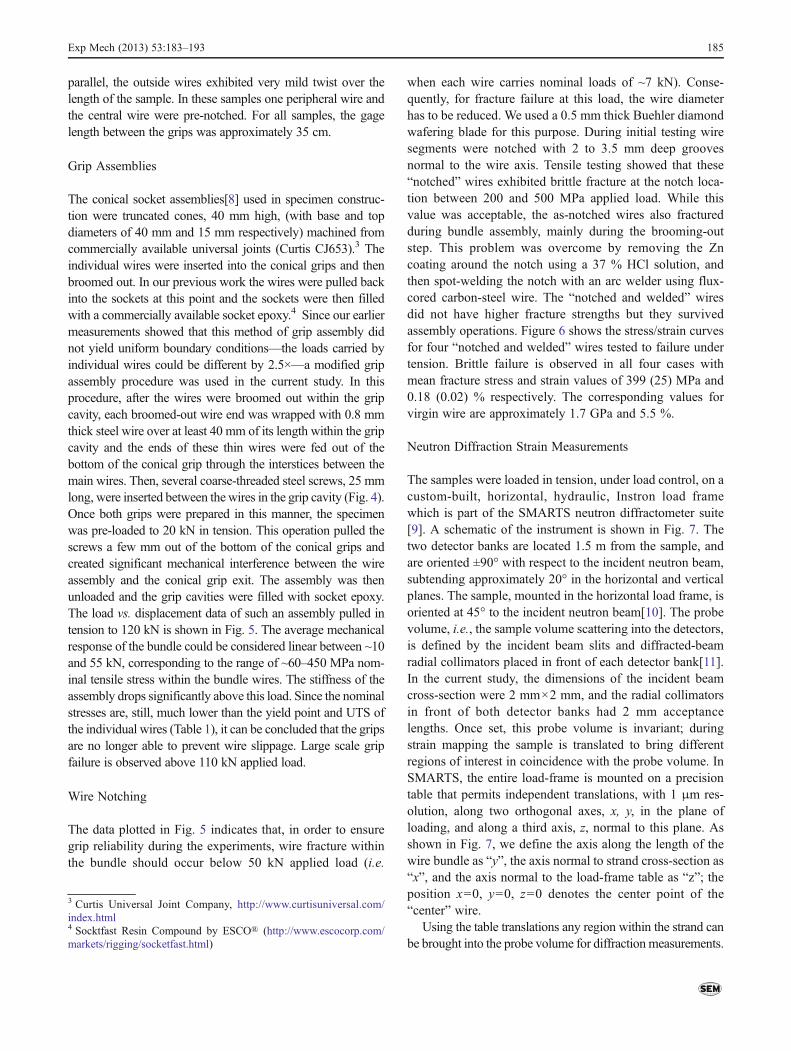
The conical socket assemblies[8] used in specimen construc-tion were truncated cones, 40 mm high, (with base and topdiameters of 40 mm and 15 mm respectively) machined fromcommercially available universal joints (Curtis CJ653).3 Theindividual wires were inserted into the conical grips and thenbroomed out. In our previous work the wires were pulled backinto the sockets at this point and the sockets were then filledwith a commercially available socket epoxy.4 Since our earliermeasurements showed that this method of grip assembly didnot yield uniform boundary conditions—the loads carried byindividual wires could be different by 2.5×—a modified gripassembly procedure was used in the current study. In thisprocedure, after the wires were broomed out within the gripcavity, each broomed-out wire end was wrapped with 0.8 mmthick steel wire over at least 40 mm of its length within the gripcavity and the ends of these thin wires were fed out of thebottom of the conical grip through the interstices between themain wires. Then, several coarse-threaded steel screws, 25 mmlong, were inserted between the wires in the grip cavity (Fig. 4).Once both grips were prepared in this manner, the specimenwas pre-loaded to 20 kN in tension. This operation pulled thescrews a few mm out of the bottom of the conical grips andcreated significant mechanical interference between the wireassembly and the conical grip exit. The assembly was thenunloaded and the grip cavities were filled with socket epoxy.The load vs. displacement data of such an assembly pulled intension to 120 kN is shown in Fig. 5. The average mechanicalresponse of the bundle could be considered linear between ~10and 55 kN, corresponding to the range of ~60–450 MPa nom-inal tensile stress within the bundle wires. The stiffness of theassembly drops significantly above this load. Since the nominalstresses are, still, much lower than the yield point and UTS ofthe individual wires (Table 1), it can be concluded that the gripsare no longer able to prevent wire slippage. Large scale gripfailure is observed above 110 kN applied load.
Wire Notching
The data plotted in Fig. 5 indicates that, in order to ensuregrip reliability during the experiments, wire fracture withinthe bundle should occur below 50 kN applied load (i.e.
when each wire carries nominal loads of ~7 kN). Conse-quently, for fracture failure at this load, the wire diameterhas to be reduced. We used a 0.5 mm thick Buehler diamondwafering blade for this purpose. During initial testing wiresegments were notched with 2 to 3.5 mm deep groovesnormal to the wire axis. Tensile testing showed that these“notched” wires exhibited brittle fracture at the notch loca-tion between 200 and 500 MPa applied load. While thisvalue was acceptable, the as-notched wires also fracturedduring bundle assembly, mainly during the brooming-outstep. This problem was overcome by removing the Zncoating around the notch using a 37 % HCl solution, andthen spot-welding the notch with an arc welder using flux-cored carbon-steel wire. The “notched and welded” wiresdid not have higher fracture strengths but they survivedassembly operations. Figure 6 shows the stress/strain curvesfor four “notched and welded” wires tested to failure undertension. Brittle failure is observed in all four cases withmean fracture stress and strain values of 399 (25) MPa and0.18 (0.02) % respectively. The corresponding values forvirgin wire are approximately 1.7 GPa and 5.5 %.
Neutron Diffraction Strain Measurements
The samples were loaded in tension, under load control, on acustom-built, horizontal, hydraulic, Instron load framewhich is part of the SMARTS neutron diffractometer suite[9]. A schematic of the instrument is shown in Fig. 7. Thetwo detector banks are located 1.5 m from the sample, andare oriented ±90° with respect to the incident neutron beam,subtending approximately 20° in the horizontal and verticalplanes. The sample, mounted in the horizontal load frame, isoriented at 45° to the incident neutron beam[10]. The probevolume, i.e., the sample volume scattering into the detectors,is defined by the incident beam slits and diffracted-beamradial collimators placed in front of each detector bank[11].In the current study, the dimensions of the incident beamcross-section were 2 mm×2 mm, and the radial collimatorsin front of both detector banks had 2 mm acceptancelengths. Once set, this probe volume is invariant; duringstrain mapping the sample is translated to bring differentregions of interest in coincidence with the probe volume. InSMARTS, the entire load-frame is mounted on a precisiontable that permits independent translations, with 1 μm res-olution, along two orthogonal axes, x, y, in the plane ofloading, and along a third axis, z, normal to this plane. Asshown in Fig. 7, we define the axis along the length of thewire bundle as “y”, the axis normal to strand cross-section as“x”, and the axis normal to the load-frame table as “z”; theposition x00, y00, z00 denotes the center point of the“center” wire.
Using the table translations any region within the strand canbe brought into the probe volume for diffractionmeasurements.
3 Curtis Universal Joint Company, http://www.curtisuniversal.com/index.html4 Socktfast Resin Compound by ESCO® (http://www.escocorp.com/markets/rigging/socketfast.html)
Exp Mech (2013) 53:183–193 185

The probe volume placement can be verified by doing intensityscans as a function of “x” position. After each loading step weperformed intensity scans, with a 1 mm step size, to ensure thatno shifting of the wire positions with load occurred. In thisprocedure the diffracted signal was monitored as a function ofx-position for the top, middle and (if used) bottom rows; thediffracted intensity was a maximum when the beam was com-pletely contained within a given wire, minimum at the inter-stices between the wires and zero outside the bundle. Thecenter position for each wire was obtained by fitting Gaussianfunctions to this profile. This procedure yielded the peak centerwithin ±0.25 mm. Further details, along with typical data werepublished in Reference [6]. The vertical position of the bundlecenter was also monitored by an electronic dial gage (Fig. 3) atall times. Any variations in this “z” position during loading,such as straightening of the sample under tension, were
eliminated by moving the sample table up or down, using thetable z translation, to compensate for the displacement shownby the dial gage. Our data showed that the wire center positionsin x did not change with loading and unloading, indicating thatthere was no untwisting in the strand with applied load.
Once the positions of the wire centers were verified at agiven load, the spallation-neutron scattering patterns in bothdetector banks were recorded from the center of each wire.Rietveld refinement[12, 13] with the Los Alamos GSASprogram[14] was used to fit the correct crystallographicmodel to the measured data (Fig. 8) from which the latticeparameters of the BCC ferrite phase of the ASTM A586wire in the axial (loading) direction, ay were obtained. Theelastic strains along the axial direction, εyy, were then com-puted from: εyy 0 (ay−a0)/a0, where a0 is the unstressedlattice parameter. We used the lattice parameter at zero loadas a0. As a result of this approximation, the strains calculat-ed from the lattice parameters are the elastic strains inducedby the applied load only; no information about the residualelastic strain state in the wires is obtained. We only used the
Table 1 Mechanical properties for as-supplied 5 mm (0.196”) diam-eter, galvanized, A-coat, ASTM A586 steel wire. The vendor data arethe mean values from seven sets of test results supplied by
WIREROPE WORKS Inc. We tested six wire segments in our labora-tory and the mean values of the relevant parameters are tabulated. Thevalues in parentheses represent one standard deviation
σf fracture stress (MPa) σ0.007 0.7 % yield stress (MPa) εf fracture strain (%) E Young’s modulus (GPa)
Vendor data 1764 (9) 1231 (35) 6.16 (0.89) 200
This work 1713 (25) 1336 (93) 5.48 (0.34) 199 (7)
Fig. 2 Schematic of the cross-section of a standard seven wire strandused in this study and the coordinate system for loading experiments.During testing tensile loads are applied along the y axis which iscoincident with the strand axis. Each wire is identified by a two lettermnemonic, where the first letter denotes the row (top, center or bottom)within the strand and the second the position within that row. Thehighlighted rectangle within the CF wire is the region from whichneutron diffraction data is obtained (to scale)
Fig. 3 Sample S3-I installed in the tensile tester of the SMARTSinstrument. The five cylindrical sleeves ensured that peripheral wiresremained parallel during loading. The notch in the central wire waslocated under the black stripe. The electronic dial indicator was used tomonitor the height of the sample during loading. Macroscopic strainwas monitored by an LVDT-based strain gage attached to the specimenwith rubber bands
186 Exp Mech (2013) 53:183–193

longitudinal strain values at the wire centers to study therelative load partitioning. In our previous study the trans-verse strains were also determined and, as expected, weregiven by the product of Poisson’s ratio and the axial strains[6]. The error bars for the longitudinal strains, obtained fromthe GSAS program, were between 20 and 100 microstrainfor all wires.
For a given wire, the variation of the elastic strain in theferrite phase along the wire axis, εyy as a function of theapplied load, ∂εyy/∂σA, was used to determine the fractionof applied load carried by the wire.5 ASTM A586 is apearlitic steel with ferrite and iron carbide phases (Fig. 9).Because of the difference in the mechanical parameters ofthe phases, the fraction of the load carried by the differentphases will be different. However, assuming the microstruc-ture to be invariant during the experiment—this is a strongassumption for the elastically loaded wires—the fraction ofload carried by any one phase should be independent ofapplied load, and variations in ∂εyy/∂σA can be ascribed tochanges in the configuration of the grips or to fracturewithin the system. The experiment has a built-in check foranisotropy/inhomogeneity effects: if enough neutron reflec-tions are used in the Rietveld averaging, and there are noconfigurational or extrinsic variations in the system underload, ∂εyy/∂σA should be equal to the macroscopic Young’smodulus for the material.
Experimental Results
Single Wire Fracture: Sample S3-I
In this experiment sample S3-I, which had only one notchedwire in the center (C) position, was used. This sample hadfive aluminum guide rings encircling the strand (Fig. 3). Thenotch of the center wire was equidistant from both grips.Neutron data were obtained from all seven wires as a func-tion of applied load past the point of fracture of the central(notched) wire. The sample was then unloaded and re-
5 We are using ∂εyy/∂σA only as a relative measure of the load uptakebetween identical wires loaded simultaneously, in parallel, from acommon set of grips in the elastic regime. If all other parameters areequal, ∂εyy/∂σA should be identical in all wires[16–19]. Further detailsabout Rietveld fitting and associated reliability factors can be found inReference [20].
Fig. 6 Stress vs. strain response of four independently tested “notchedand welded” wire segments. All four segments exhibited brittle fracturebelow 450 MPa tensile stress
Fig. 5 Load vs. displacement data of a standard seven-wire strand withimproved grips loaded in tension to grip failure. The continuous curvedepicts the measured data; the dashed line is a linear fit of the centralregion. The mechanical response can be considered linear between 10and 55 kN applied load which correspond to approximately 60–450 MPa nominal tensile stress in each wire. After 55 kN applied load,grip failure occurs
Fig. 4 (a). Placement of the interference screws with respect to thebroomed-out wires within the grip cavity (b). Our data show that aminimum of three screws are needed. During preloading the screws aredrawn into the exit of the grip cavity along with the wires and causemechanical interference. In addition the sharp (steel) screw edges biteinto the surface of the surrounding wires and lock them together (b).Softer, brass, screws did not yield good results. For clarity the thin steelwire windings and the universal joint linkage are not depicted
Exp Mech (2013) 53:183–193 187

loaded in a stepwise fashion; for these steps neutron datawas acquired from two wires only. At all load steps theincident neutron spot was centered within each wire; thelocus of the measurement positions was the cross-sectionalplane displaced 25 mm away from the notch towards the leftsample grip (Fig. 3). This displacement was necessary toavoid the heat-affected zone created by spot-welding.
The elastic-strain vs. applied stress data from all wires ofsample S3-I over the loading range are shown in Fig. 10(a).6
These data can be separated into three ranges: For loadsbetween zero load and 120 MPa, Range I, all wiresexhibited nominally the same linear elastic stress–strainbehavior, indicating that each wire carried approximately1/7th of the applied load. Consequently, in this load range,the re-engineered grip assemblies (Grip Assemblies section)impose uniform constraint on all seven wires. Between120 MPa and 350 MPa, Range II, the strain vs. load re-sponse of the perimeter wires are identical to the trendsobserved in Range I. The neutron-strain vs. load responseof the pre-notched center wire, however, becomes quasi-parabolic and the elastic strain in the central wire is lowerthan the strains of the peripheral wires at all loads. Theseobservations indicate plastic flow in the heat affected zonenear the notch of the center wire; if this were a grip problem,the wire would not be pulled to fracture. After the samplewas loaded to 400 MPa, we were able to measure the elasticstrain in the Center and the TF wires. However, as we were
translating the sample to measure the next position, theCenter wire fractured. Thus, the strain data at 400 MPahas two subsets: the strain values for the Center and TFwires correspond to the nominal stress, 400 MPa, acting onthe overall strand cross-section. The remaining five wireswere measured after the center wire fractured. Therefore,since the strand cross-section had decreased to 6/7th of theoriginal cross section, they carried a higher nominal stress.This is reflected in the steeper slopes of the line segmentsconnecting the respective neutron strain values at 350 and400 MPa nominal strand loads. After the measurements at400 MPa were completed the sample was loaded in threemore steps to a final (nominal) stress of 530 MPa (Theactual stress on the unbroken strands, assuming equal loadsharing, is approximately 620 MPa if the actual load-bearing cross-section is used). After fracture the measuredelastic strain in the central wire is low compression (approx-imately −450 με) and this value does not change withfurther loading, indicating that, in this post-fracture range(Range III), there was no strain transfer to the center wireduring further loading.
The slopes of regression lines fitted to the strain-load datashown in Fig. 10(a) are listed in Table 2. The stiffnessmodulus obtained from the average slope of the “appliedstress- neutron strain data” of the six outer wires in Range Iis 195 (16) GPa. This value agrees, within experimentalerror, with the values of the Young’s modulus shown inTable 1, confirming uniform load distribution at the grips.7
6 To check the precision of the data, strain measurements were repeatedin each wire of Sample S3-I at 225 MPa applied load. We observe thatthe scatter in the data for all wires are quite close to the error calculatedby the GSAS program.
7 This also shows that the strain calculated through the Rietveld pro-cedure is equivalent to the average macroscopic elastic strain.
Fig. 7 Schematic of the experi-mental geometry in SMARTS.For clarity only the central plane(z00) which contains the inci-dent beam and the x-y axes ofthe sample is shown. Neutronscattering data is collected fromthe sample volume defined bythe intersection of the incidentbeam and the apexes of the ac-ceptance apertures of the radialcollimators (inset)
188 Exp Mech (2013) 53:183–193

After fracture the average stiffness modulus for the outerwires calculated from the data in Fig. 10(a) drops to 172(30) GPa. However, if we correct the post-fracture slope ofthe perimeter wires for the loss of the center wire, this valueincreases to 201 (30) GPa, indicating that the load redistri-bution is properly captured in the data.
During unloading and re-loading, in order to save exper-imental time, we recorded neutron data from TN and Cwires only. The elastic strains calculated from these data
are plotted in Fig. 10(b). The unloading trace for the (intact)TN wire shows the expected decrease in tensile strain withdecreasing load. The slope of a least squares line fitted tothese points is 4.6 (0.1). The strain within the (fractured)central wire becomes more compressive with decreasingtensile load on the strand. This indicates frictional constraintof the central wire by the surrounding wires; as the sur-rounding (peripheral) wires become shorter during unload-ing, they also cause shortening in the central wire through
Fig. 10 (a) Uniaxial strain–stress data for all wires of sample S3-Iduring initial loading. In Range I the stress/strain response of all wiresare equivalent. In Range II the pre-notched center (C) wire responseindicates yielding. After the elastic strain in the C and TF weremeasured at 400 MPa, C fractured. Consequently Range III for thesewires are above 400 MPa. The two data points in the traces for all wiresat 225 MPa nominal stress are repeated measurements. (b) Uniaxialstrain–stress data for wires TN and C of sample S3-I during unloadingand re-loading. Strain transfer to the (fractured) center wire is due tofrictional constraint. The stress values plotted are calculated using theactual load-bearing cross-sectional area of the strand. A typical error-bar is shown on the lower right quadrant of the figure
Fig. 9 Microstructure of ASTM A586 wire used in the experiments. Atypical pearlitic microstructure with ferrite and carbide phases is ob-served. (SEM Micrograph, 8,000×; scale bar is 2 μm. Picture courtesyof Messrs. Tzu-Cheng Hsu and Yu-Min Peng)
Fig. 8 Typical neutron diffraction data obtained from the ferrite phaseof the pearlitic steel wires (only half of the measured and analyzedpoints are included for clarity), the refined profile, and the differencebetween the measured and the refined profiles; the difference valueshave been offset by −80 counts to aid visualization. Only the indexedpeaks were used to calculate the average lattice parameter
Exp Mech (2013) 53:183–193 189
frictional tractions formed at the contact surfaces.8 Thefraction of this strain transfer, obtained from the ratio ofthe slopes of the neutron-strain vs. applied stress profilesduring unloading is approximately ~20 % . We obtainedsimilar results when we removed the guide-rings and re-loaded the sample back to 620 MPa.9 The strain transferratio was again approximately 20 %.
Double Wire Fracture
Sample S3-II
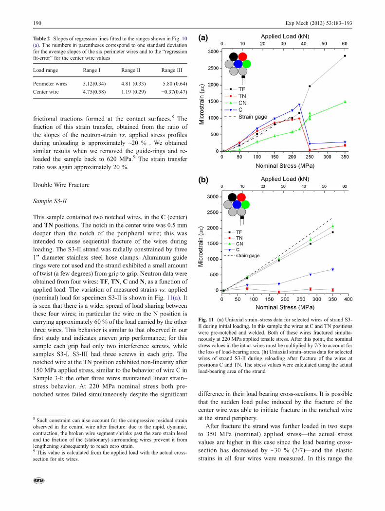
This sample contained two notched wires, in the C (center)and TN positions. The notch in the center wire was 0.5 mmdeeper than the notch of the peripheral wire; this wasintended to cause sequential fracture of the wires duringloading. The S3-II strand was radially constrained by three1” diameter stainless steel hose clamps. Aluminum guiderings were not used and the strand exhibited a small amountof twist (a few degrees) from grip to grip. Neutron data wereobtained from four wires: TF, TN, C and N, as a function ofapplied load. The variation of measured strains vs. applied(nominal) load for specimen S3-II is shown in Fig. 11(a). Itis seen that there is a wider spread of load sharing betweenthese four wires; in particular the wire in the N position iscarrying approximately 60 % of the load carried by the otherthree wires. This behavior is similar to that observed in ourfirst study and indicates uneven grip performance; for thissample each grip had only two interference screws, whilesamples S3-I, S3-III had three screws in each grip. Thenotched wire at the TN position exhibited non-linearity after150 MPa applied stress, similar to the behavior of wire C inSample 3-I; the other three wires maintained linear strain–stress behavior. At 220 MPa nominal stress both pre-notched wires failed simultaneously despite the significant difference in their load bearing cross-sections. It is possible
that the sudden load pulse induced by the fracture of thecenter wire was able to initiate fracture in the notched wireat the strand periphery.
After fracture the strand was further loaded in two stepsto 350 MPa (nominal) applied stress—the actual stressvalues are higher in this case since the load bearing cross-section has decreased by ~30 % (2/7)—and the elasticstrains in all four wires were measured. In this range the
8 Such constraint can also account for the compressive residual strainobserved in the central wire after fracture: due to the rapid, dynamic,contraction, the broken wire segment shrinks past the zero strain leveland the friction of the (stationary) surrounding wires prevent it fromlengthening subsequently to reach zero strain.9 This value is calculated from the applied load with the actual cross-section for six wires.
Fig. 11 (a) Uniaxial strain–stress data for selected wires of strand S3-II during initial loading. In this sample the wires at C and TN positionswere pre-notched and welded. Both of these wires fractured simulta-neously at 220 MPa applied tensile stress. After this point, the nominalstress values in the intact wires must be multiplied by 7/5 to account forthe loss of load-bearing area. (b) Uniaxial strain–stress data for selectedwires of strand S3-II during reloading after fracture of the wires atpositions C and TN. The stress values were calculated using the actualload-bearing area of the strand
Table 2 Slopes of regression lines fitted to the ranges shown in Fig. 10(a). The numbers in parentheses correspond to one standard deviationfor the average slopes of the six perimeter wires and to the “regressionfit-error” for the center wire values
Load range Range I Range II Range III
Perimeter wires 5.12(0.34) 4.81 (0.33) 5.80 (0.64)
Center wire 4.75(0.58) 1.19 (0.29) −0.37(0.47)
190 Exp Mech (2013) 53:183–193

unbroken wires, TF and N, exhibited elastic loading. Thefractured wires, on the other hand, did not show elasticloading within experimental error. To check for any loadtransfer to the broken wires over a larger load range, wire-bundle II was unloaded and, then, re-loaded back to350 MPa in four steps while the neutron strains in the samefour wires were monitored. These data are shown in Fig. 11(b). The slopes of the best-fit lines to the data from theunbroken wires, TF and N, are 5.96 (0.2) and 5.45 (0.1)respectively. The corresponding slopes from the fracturedwires C and TN are 1.87 (0.1) and 0.007 (0.1). Thus, thecenter wire, C, carries approximately 30 % of the elasticload carried by the unbroken wires. It is seen that, eventhough one of the exterior wires (TN) is also broken, theremaining five wires have enough interference with thecenter wire for efficient load transfer. On the other hand,the exterior fractured wire, TN, carries no load. This isexpected since there is negligible radial constraint couplingit to the rest of the strand.
Sample S3-III
This sample contained notched-and-welded wires in the centerand BN positions; it is similar to Sample S3-II in other aspects.During the experiment elastic strain vs. load data from threeun-notched wires: TF, TN, N and the central (notched andwelded) wire were measured (Fig. 12(a)). During loading allmeasured wires carried almost identical loads, indicating uni-form grips. At approximately 375 MPa both wires fracturedsimultaneously even though the wire at the BN location had50 % more load-bearing area than the center wire. Again, thedynamic load increase due to the fracture of one wire seems tohave induced fracture in the other defective wire. After frac-ture, the strain in the center wire did not drop to zero, butstabilized at 860με; the brokenwire was kept under tension bythe surrounding wires. During unloading this strain droppedmonotonically with applied load to approximately zero strain.(Fig. 12(b)). The sample was then reloaded in five steps to50 kN. The re-loading data is displaced slightly higher from theunloading data. However, the unloading and re-loading slopesare quite close; 2 (0.1) and 2.4 (0.1), respectively. The stresstransfer ratio, calculated from the slopes of least-square linesfitted to the stress–strain data from the broken and unbrokenwires is 0.33(0.05).
Discussion and Conclusions
Strand Construction
The elastic response regions of Figs. 10 and 12 show that ournew procedure for manufacturing grips yields a more uniformelastic strain distribution within a standard seven-wire strand
than simply brooming-out and potting the wires in socketepoxy. For samples S3-I and S3-III (Figs. 10(a) and 12(a))the fraction of total load carried by any wire was within 30 %of the expected, ideal, load fraction based on wire cross-sectional area. There are still issues, however. For all of ourspecimens load partitioning became more non-uniform withincreasing load. Such non-uniformity can be due to plastic
Fig. 12 (a) Uniaxial strain–stress data for selected wires of strand S3-III during initial loading. In this sample the wires at C and BNpositions were pre-notched and welded. Both of these wires fracturedsimultaneously at 375 MPa applied tensile stress. After this point, thenominal stress values in the intact wires must be multiplied by 7/5 toaccount for the loss of load-bearing area. (b) Uniaxial strain–stress datafor selected wires of strand S3-II during unloading and reloading afterfracture of the wires at positions C and BN. The arrows on the tracesindicate the direction of loading. The stress values were calculatedusing the gross load-bearing area of the strand to facilitate comparisonwith Fig. 12-a
Exp Mech (2013) 53:183–193 191
flow within the wires, or damage within the grips or grossgeometrical rearrangement within the strand such as untwist-ing. This last point is not relevant in our measurements sinceour alignment scans after each loading step indicated that thewire center positions were unchanged during loading andunloading. The shape of the neutron-strain vs. load tracescan be used to differentiate grip failure from plastic flow: ifplastic flow starts to occur in a weak spot, such as in the HAZnext to a notched-welded defect, the linear strain vs. load plotchanges to concave-down parabolic and saturates, followedby fracture (Wires S3-I-C; S3-II-TN). If a given wire is notheld firmly in the grips, it carries lower elastic load comparedto firmly-gripped wires from the beginning of the experiment.Its neutron-strain vs. applied stress trace, however, is generallylinear (after initial load take-up) and, if another wire within thestrand breaks, part of the load shed by the fractured wire ispicked up by the weakly-held wire (Wire S3-II-CN; also seethe plots in Reference [6] for badly gripped wires vs. firmlyclamped wires). Grip non-uniformity at higher loads is man-ifested through the divergence of the elastic strain carried bythe individual wires (Wires TF and CN for S3-II, Fig. 11(b);all peripheral wires for S3-I, Fig. 10(a)). We have no informa-tion on the effect of wire unlaying (untwisting) during tensileloading; If the strand is allowed to twist in a direction oppositeto its lay (unlay), the wires would elongate and all would shedload depending on their particular configuration. Unlaying ofa single wire within a nominally-parallel strand will be geo-metrically hindered by the neighboring wires if the entirestrand is clamped in multiple places.
Our results show that mechanical interference within thegrip cavity is an acceptable means of making better grips,especially for lower applied stresses. However, enough inter-ference elements (screws in our case) must be used so that allwires are locked together (Fig. 4). If the grips are not uniform,separating the effects of various mechanisms that can causeload shedding in individual wires becomes complicated.
The notching-and-welding procedure used in this work tocreate reproducible defects (which initiate brittle-fracture),requires improvement. Even though individual wire-segments tested during the development stage and wires S3-II-C, S3-III-C tested in SMARTS failed with brittle fracture,wires S3-I-C and S3II-TN exhibited plastic flow prior tofailure; as indicated by the saturation of elastic strains in thesewires, followed by fracture. Better control the welding processand the attendant microstructural changes in the notched-welded wires is now under investigation.
Load Partitioning within the Wires of a Parallel Seven-WireStrand following In-Situ Fracture
Our data indicate that the post-failure elastic strain state of afractured wire depends on its local boundary conditions.After fracture, the axial strains, εyy, of the (pre-notched)
Center wires for specimen S3-III, II and I were 860, 290and −258 με respectively. The variation of εyy with loadafter fracture depended on the mode of loading: further re-loading immediately after fracture produced little additionalload uptake (Figs. 10(a) and 11(a)), while during unloadingand then re-loading, εyy in the fractured wires in the center(C) positions of all three specimens showed a clear loaddependence (Figs. 10(b), 11(b) and 12(b)). The decrease inthe stress-transfer ratio at the higher tensile loads can beascribed to the Poisson contraction of the wires duringtensile loading. Using 0.33 for the Poisson’s ratio, the radialstrain in a given wire at 400 MPa nominal tensile stresswould be −0.00066. For a 10 mm length (two wire diame-ters, Fig. 2), this would yield a net contraction of 6.6 μm.Thus, for perfectly parallel wires, the frictional stress trans-fer would tend to zero at a critical tensile load. Any twistingin the wires, constrained by radial clamping, would force thewires together at some points and minimize such effects.The importance of even minimal twisting can be seen bycomparing the stress transfer ratios (SR) of strands S3-I,which used Al guide rings to keep the wires parallel, andthose of strands S3-II,III where the wires were radiallyconstrained by simple hose clamps. The SR for S3-II andIII were both larger than 0.3 (similar to the results from ourinitial study) while the corresponding value for S3-I wasapproximately 0.2. We conclude that local mechanical in-terference for nominally parallel wires has the same order-of-magnitude influence on load transfer from intact to bro-ken wires as friction. If lubricants are used to hinder corro-sion, they can also influence the load partitioning within acable by modifying the stiction/friction coefficients. Conse-quently, these effects should also be included in finite ele-ment models that take friction into account[15]. In standardseven wire strands boundary wires have no frictional ormechanical interference constrains and do not carry any loadafter fracture (Fig. 11(b)).
In summary, our analysis shows that local boundary con-ditions dominate the mechanism of stress transfer from intactto broken wires in parallel wire suspension bridge cables.Consequently strands with uniform mechanical response toapplied loads are required to separate possible load-sheddingand stress-transfer effects. Seven-wire parallel strands containonly one internal wire at the center (C) position and may notreally be adequate for supplying all of the experimental inputrequired for building comprehensive numerical models. Werecommend the use of larger wire bundles coupled with neu-tron diffraction measurements of the internal stress/strain dis-tributions for model testing and verification.
Acknowledgments This work is part of the work for the Master ofScience degree for Mr. Fang Mei. We thank Mr. Eric J. Larson of LujanCenter, Los Alamos National Laboratory, for Figs. 1 and 4; Mr. TravisSimmons, Senior Lab Technician, Carleton Laboratory, for machiningthe necessary specimen fixtures; Dr. Liming Li for help with sample
192 Exp Mech (2013) 53:183–193

manufacture and testing; Prof. Chris Marianetti for the welding processand helpful discussions and Mr. Tzu–Cheng Hsu and Mr. Yu-Min Pengfor metallographic analysis. The samples were developed and manu-factured in the facilities of the Carleton Laboratory of Civil Engineer-ing and Engineering Mechanics Department, Fu School of Engineeringand Applied Science at Columbia University. This work has benefitedfrom the use of the Lujan Neutron Scattering Center at LANSCE,funded by the Department of Energy’s Office of Basic Energy Scien-ces. Los Alamos National Laboratory is operated by Los AlamosNational Security LLC under DOE Contract DE-AC52-06NA25396.
References
1. Costello GA (1997) Theory of wire rope, 2nd edn. Springer Verlag,New York
2. Feyrer K (2007) Wire ropes: tension, endurance, reliability.Springer Verlag, Berlin
3. Talbot M, Laflamme JF, Glisic B (2007) Stress measurements inthe main cable of a suspension bridge under dead and traffic loads.Proceedings EVACES Porto, Portugal, Paper 138
4. Utting WS, Jones N (1985) Tensile testing of a wire rope strand. JStrain Anal Eng Des 20:151–164
5. Cappa P (1988) Experimental study of wire strains in an undam-aged and damaged steel strand subjected to tensile load. Exp Mech28:346–349
6. Noyan IC, Brugger A, Betti R, Clausen B (2010) Measurement ofstrain/load transfer in parallel seven-wire strands with neutrondiffraction. Exp Mech 50:265–272
7. Utting WS, Jones N (1987) Response of wire rope strands to axialtensile loads - Part I. Experimental results and theoretical predic-tions. Int J Mech Sci 29:605–619
8. Wilson C, MacFarlane J (2000) Failure of wire rope sockets underimpact loading. J Phys IV 10:553–558
9. Bourke MAM, Dunand DC, Ustundag E (2002) SMARTS—aspectrometer for strain measurement in engineering materials.Appl Phys A 72:S1707–S1709
10. Brown EN, Rae PJ, Dattelbaum DM, Clausen B, Brown DW(2008) In-situ measurement of crystalline lattice strains in polyte-trafluoroethylene. Exp Mech 48:119–131
11. Bourke MAM, Roberts JA, Davis D (1997) Macrostrain measure-ment using radial collimators at LANSCE. Proc SPIE Crete Greece2867:136–139
12. Rietveld HM (1967) Line profiles of neutron powder-diffractionpeaks for structure refinement. Acta Crystallogr 22:151–152
13. Rietveld HM (1969) A profile refinement method for nuclear andmagnetic structures. J Appl Crystallogr 2:65–71
14. Von Dreele RB, Jorgensen JD, Windsor CG (1982) Rietveld re-finement with spallation neutron powder diffraction data. J ApplCrystallogr 15:581–589
15. Waisman H, Montoya A, Betti R, Noyan IC (2011) Load transferand recovery length in parallel wires of suspension bridge cables. JEng Mech ASCE 137:227–237
16. Daymond MR, Bourke MAM, Von Dreele RB, Clausen B, Lor-entzen T (1997) Use of Rietveld refinement for elastic macrostraindetermination and for evaluation of plastic strain history fromdiffraction spectra. J Appl Phys 82:1554–1562
17. Clausen B, Lorentzen T, Bourke MAM, Daymond MR (1999)Lattice strain evolution during uniaxial tensile loading of stainlesssteel. Mater Sci Eng A 259:17–24
18. Daymond MR, Bourke MAM, Von Dreele RB (1999) Use ofRietveld refinement to fit a hexagonal crystal structure in thepresence of elastic and plastic anisotropy. J Appl Phys85:739–747
19. Daymond MR, Priesmeyer HG (2002) Elastoplastic deformationof ferritic steel and cementite studied by neutron diffraction andself-consistent modeling. Acta Mater 50:1613–1626
20. Toby BH (2006) R factors in Rietveld analysis: how good is goodenough? Powder Diffract 21:67–70
Exp Mech (2013) 53:183–193 193