Infoblox Installation Guide - Network Automation 2200 Appliance
Upload
khangminh22Category
view
0download
0
NEXCOM International Co., Ltd.
NEXCOM International Co., Ltd.Published April 2014
www.nexcom.com
Network and Communication SolutionsNetwork Security Appliance NSA 5120User Manual

Copyright © 2010 NEXCOM International Co., Ltd. All Rights Reserved. ii NSA 5120 User Manual
Contents
Contents
PrefaceCopyright ............................................................................................. ivDisclaimer ............................................................................................. ivAcknowledgements .............................................................................. ivRegulatory Compliance Statements ....................................................... ivDeclaration of Conformity ...................................................................... ivRoHS Compliance ................................................................................... vWarranty and RMA ................................................................................ viSafety Information ................................................................................viiInstallation Recommendations ................................................................viiSafety Precautions .................................................................................viiiTechnical Support and Assistance ........................................................... ixConventions Used in this Manual ........................................................... ixGlobal Service Contact Information ......................................................... xPackage Contents ..................................................................................xiiOrdering Information ............................................................................xiii
Chapter 1: Product IntroductionOverview ................................................................................................1
Key Features .........................................................................................1Hardware Specifications ..........................................................................2
NSA 5120 System .................................................................................2Main Board (NSB 5120) ........................................................................4
Getting to Know NSA 5120 ....................................................................7Front Panel ...........................................................................................7Rear Panel ............................................................................................8
Chapter 2: Jumpers And ConnectorsBefore You Begin ....................................................................................9Precautions .............................................................................................9Jumper Settings ....................................................................................10Locations of the Jumpers and Connectors .............................................11
NSB 5120 ...........................................................................................11Jumpers ................................................................................................12Connectors Pin Definitions ....................................................................15
External I/O Interface ........................................................................15Status Indicators .............................................................................15USB Ports .......................................................................................15RJ45 Type Console Port ..................................................................16F5 Bit0 Software Button .................................................................16Giga LAN Ports ...............................................................................17VGA Connector .............................................................................17
Internal Connectors ..........................................................................18PS/2 Keyboard/Mouse Connector ...................................................18USB Connector ..............................................................................18Reset Button ..................................................................................19
Copyright © 2010 NEXCOM International Co., Ltd. All Rights Reserved. iii
Contents
NSA 5120 User Manual
Power Button .................................................................................19SATAII Ports ....................................................................................20SATA DOM Power Connector .........................................................20GPIO Connector .............................................................................21Bypass D LED .................................................................................21Bypass C LED .................................................................................22Bypass B LED ..................................................................................22Bypass A LED .................................................................................23System Fan Connectors ..................................................................23CompactFlash Card Socket .............................................................24COM Connector ............................................................................25LCM Module Connector .................................................................25LCM Keypad Connector .................................................................26
Block Diagram of the Main Board .........................................................27
Chapter 3: System SetupRemoving the Chassis Cover ................................................................28Installing a DIMM ..................................................................................29Installing the CPU .................................................................................31Installing a CompactFlash Card .............................................................37Installing a 3.5” SATA Hard Drive ..........................................................39Installing Two 2.5” SATA Hard Drives ....................................................43
Chapter 4: BIOS SetupAbout BIOS Setup .................................................................................46When to Configure the BIOS .................................................................46Default Configuration ...........................................................................47Entering Setup ......................................................................................47Legends ................................................................................................47
BIOS Setup Utility ..................................................................................48Main ..................................................................................................48Advanced ...........................................................................................49Boot ...................................................................................................61Security ..............................................................................................64Chipset ...............................................................................................69Exit .....................................................................................................72
Appendix A: Watchdog TimerWatchdog Timer Setting .......................................................................75CRFC6 (Default 0x00) ...........................................................................75
Appendix B: GPI/O Programming GuideGPIO (J9) ...............................................................................................77
Appendix C: Bypass SpecificationsBTCR - Bypass Timer Configuration Register = 0XF2 ..............................80Bypass Control Function ........................................................................80
Appendix D: Power ConsumptionPower Consumption .............................................................................82
Copyright © 2010 NEXCOM International Co., Ltd. All Rights Reserved. iv NSA 5120 User Manual
Preface
PrefaCe
Regulatory Compliance Statements This section provides the FCC compliance statement for Class A devices and describes how to keep the system CE compliant.
Declaration of Conformity
FCC
This equipment has been tested and verified to comply with the limits for a Class A digital device, pursuant to Part 15 of FCC Rules. These limits are designed to provide reasonable protection against harmful interference when the equipment is operated in a commercial environment. This equip-ment generates, uses, and can radiate radio frequency energy and, if not installed and used in accordance with the instructions, may cause harmful interference to radio communications. Operation of this equipment in a residential area (domestic environment) is likely to cause harmful interfer-ence, in which case the user will be required to correct the interference (take adequate measures) at their own expense.
CE
The product(s) described in this manual complies with all applicable Euro-pean Union (CE) directives if it has a CE marking. For computer systems to remain CE compliant, only CE-compliant parts may be used. Maintaining CE compliance also requires proper cable and cabling techniques.
Copyright This publication, including all photographs, illustrations and software, is protected under international copyright laws, with all rights reserved. No part of this manual may be reproduced, copied, translated or transmitted in any form or by any means without the prior written consent from NEXCOM International Co., Ltd.
Disclaimer The information in this document is subject to change without prior notice and does not represent commitment from NEXCOM International Co., Ltd. However, users may update their knowledge of any product in use by con-stantly checking its manual posted on our website: http://www.nexcom.com. NEXCOM shall not be liable for direct, indirect, special, incidental, or consequential damages arising out of the use of any product, nor for any infringements upon the rights of third parties, which may result from such use. Any implied warranties of merchantability or fitness for any particular purpose is also disclaimed.
Acknowledgements NSA 5120 is a trademark of NEXCOM International Co., Ltd. All other product names mentioned herein are registered trademarks of their respec-tive owners.

Copyright © 2010 NEXCOM International Co., Ltd. All Rights Reserved. v NSA 5120 User Manual
Preface
RoHS Compliance
NEXCOM RoHS Environmental Policy and Status Update
NEXCOM is a global citizen for building the digital infra-structure. We are committed to providing green products and services, which are compliant with European Union
RoHS (Restriction on Use of Hazardous Substance in Electronic Equipment) directive 2002/95/EU, to be your trusted green partner and to protect our environment.
RoHS restricts the use of Lead (Pb) < 0.1% or 1,000ppm, Mercury (Hg) < 0.1% or 1,000ppm, Cadmium (Cd) < 0.01% or 100ppm, Hexavalent Chromium (Cr6+) < 0.1% or 1,000ppm, Polybrominated biphenyls (PBB) < 0.1% or 1,000ppm, and Polybrominated diphenyl Ethers (PBDE) < 0.1% or 1,000ppm.
In order to meet the RoHS compliant directives, NEXCOM has established an engineering and manufacturing task force in to implement the introduction of green products. The task force will ensure that we follow the standard NEXCOM development procedure and that all the new RoHS components and new manufacturing processes maintain the highest industry quality levels for which NEXCOM are renowned.
The model selection criteria will be based on market demand. Vendors and suppliers will ensure that all designed components will be RoHS compliant.
How to recognize NEXCOM RoHS Products?
For existing products where there are non-RoHS and RoHS versions, the suf-fix “(LF)” will be added to the compliant product name.
All new product models launched after January 2006 will be RoHS compli-ant. They will use the usual NEXCOM naming convention.

Copyright © 2010 NEXCOM International Co., Ltd. All Rights Reserved. vi NSA 5120 User Manual
Preface
Warranty and RMA
NEXCOM Warranty Period
NEXCOM manufactures products that are new or equivalent to new in accordance with industry standard. NEXCOM warrants that products will be free from defect in material and workmanship for 2 years, beginning on the date of invoice by NEXCOM. HCP series products (Blade Server) which are manufactured by NEXCOM are covered by a three year warranty period.
NEXCOM Return Merchandise Authorization (RMA)
? Customers shall enclose the “NEXCOM RMA Service Form” with the returned packages.
? Customers must collect all the information about the problems encoun-tered and note anything abnormal or, print out any on-screen messages, and describe the problems on the “NEXCOM RMA Service Form” for the RMA number apply process.
? Customers can send back the faulty products with or without acces-sories (manuals, cable, etc.) and any components from the card, such as CPU and RAM. If the components were suspected as part of the prob-lems, please note clearly which components are included. Otherwise, NEXCOM is not responsible for the devices/parts.
? Customers are responsible for the safe packaging of defective products, making sure it is durable enough to be resistant against further damage and deterioration during transportation. In case of damages occurred during transportation, the repair is treated as “Out of Warranty.”
? Any products returned by NEXCOM to other locations besides the cus-tomers’ site will bear an extra charge and will be billed to the customer.
Repair Service Charges for Out-of-Warranty Products
NEXCOM will charge for out-of-warranty products in two categories, one is basic diagnostic fee and another is component (product) fee.
System Level
? Component fee: NEXCOM will only charge for main components such as SMD chip, BGA chip, etc. Passive components will be repaired for free, ex: resistor, capacitor.
? Items will be replaced with NEXCOM products if the original one cannot be repaired. Ex: motherboard, power supply, etc.
? Replace with 3rd party products if needed.
? If RMA goods can not be repaired, NEXCOM will return it to the cus-tomer without any charge.
Board Level
? Component fee: NEXCOM will only charge for main components, such as SMD chip, BGA chip, etc. Passive components will be repaired for free, ex: resistors, capacitors.
? If RMA goods can not be repaired, NEXCOM will return it to the cus-tomer without any charge.
Copyright © 2010 NEXCOM International Co., Ltd. All Rights Reserved. vii NSA 5120 User Manual
Preface
Warnings
Read and adhere to all warnings, cautions, and notices in this guide and the documentation supplied with the chassis, power supply, and accessory modules. If the instructions for the chassis and power supply are incon-sistent with these instructions or the instructions for accessory modules, contact the supplier to find out how you can ensure that your computer meets safety and regulatory requirements.
CautionsElectrostatic discharge (ESD) can damage system components. Do the de-scribed procedures only at an ESD workstation. If no such station is avail-able, you can provide some ESD protection by wearing an antistatic wrist strap and attaching it to a metal part of the computer chassis.
Safety Information Before installing and using the device, note the following precautions:
▪ Read all instructions carefully.
▪ Do not place the unit on an unstable surface, cart, or stand.
▪ Follow all warnings and cautions in this manual.
▪ When replacing parts, ensure that your service technician uses parts specified by the manufacturer.
▪ Avoid using the system near water, in direct sunlight, or near a heating device.
▪ The load of the system unit does not solely rely for support from the rackmounts located on the sides. Firm support from the bottom is highly necessary in order to provide balance stability.
▪ The computer is provided with a battery-powered real-time clock circuit. There is a danger of explosion if battery is incorrectly replaced. Replace only with the same or equivalent type recommended by the manufactur-er. Discard used batteries according to the manufacturer’s instructions.
Installation Recommendations
Ensure you have a stable, clean working environment. Dust and dirt can get into components and cause a malfunction. Use containers to keep small components separated.
Adequate lighting and proper tools can prevent you from accidentally damaging the internal components. Most of the procedures that follow require only a few simple tools, including the following:
• A Philips screwdriver• A flat-tipped screwdriver• A grounding strap• An anti-static pad
Using your fingers can disconnect most of the connections. It is recom-mended that you do not use needlenose pliers to disconnect connections as these can damage the soft metal or plastic parts of the connectors.

Copyright © 2010 NEXCOM International Co., Ltd. All Rights Reserved. viii NSA 5120 User Manual
Preface
Safety Precautions
1. Read these safety instructions carefully.
2. Keep this User Manual for later reference.
3. Disconnect this equipment from any AC outlet before cleaning. Use a damp cloth. Do not use liquid or spray detergents for cleaning.
4. For plug-in equipment, the power outlet socket must be located near the equipment and must be easily accessible.
5. Keep this equipment away from humidity.
6. Put this equipment on a stable surface during installation. Dropping it or letting it fall may cause damage.
7. Do not leave this equipment in either an unconditioned environment or in a above 40oC storage temperature as this may damage the equipment.
8. The openings on the enclosure are for air convection to protect the equipment from overheating. DO NOT COVER THE OPENINGS.
9. Make sure the voltage of the power source is correct before connect-ing the equipment to the power outlet.
10. Place the power cord in a way so that people will not step on it. Do not place anything on top of the power cord. Use a power cord that has been approved for use with the product and that it matches the voltage and current marked on the product’s electrical range label. The voltage and current rating of the cord must be greater than the voltage and current rating marked on the product.
11. All cautions and warnings on the equipment should be noted.
12. If the equipment is not used for a long time, disconnect it from the power source to avoid damage by transient overvoltage.
13. Never pour any liquid into an opening. This may cause fire or electri-cal shock.
14. Never open the equipment. For safety reasons, the equipment should be opened only by qualified service personnel.
15. If one of the following situations arises, get the equipment checked by service personnel:
a. The power cord or plug is damaged.
b. Liquid has penetrated into the equipment.
c. The equipment has been exposed to moisture.
d. The equipment does not work well, or you cannot get it to work according to the user’s manual.
e. The equipment has been dropped and damaged.
f. The equipment has obvious signs of breakage.
16. Do not place heavy objects on the equipment.
17. The unit uses a three-wire ground cable which is equipped with a third pin to ground the unit and prevent electric shock. Do not defeat the purpose of this pin. If your outlet does not support this kind of plug, contact your electrician to replace your obsolete outlet.
18. CAUTION: DANGER OF EXPLOSION IF BATTERY IS INCORRECTLY REPLACED. REPLACE ONLY WITH THE SAME OR EQUIVALENT TYPE RECOMMENDED BY THE MANUFACTURER. DISCARD USED BATTER-IES ACCORDING TO THE MANUFACTURER’S INSTRUCTIONS.
19. The computer is provided with CD drives that comply with the ap-propriate safety standards including IEC 60825.
Copyright © 2010 NEXCOM International Co., Ltd. All Rights Reserved. ix NSA 5120 User Manual
Preface
Conventions Used in this Manual
Warning: Information about certain situations, which if not observed, can cause personal injury. This will prevent injury to yourself when performing a task.
Caution: Information to avoid damaging components or losing data.
Note: Provides additional information to complete a task easily.
Technical Support and Assistance
1. For the most updated information of NEXCOM products, visit NEX-COM’s website at www.nexcom.com.
2. For technical issues that require contacting our technical support team or sales representative, please have the following information ready before calling:
– Product name and serial number– Detailed information of the peripheral devices– Detailed information of the installed software (operating system,
version, application software, etc.)– A complete description of the problem– The exact wordings of the error messages
Warning!
1. Handling the unit: carry the unit with both hands and handle it with care.
2. Maintenance: to keep the unit clean, use only approved cleaning prod-ucts or clean with a dry cloth.
3. CompactFlash: Turn off the unit’s power before inserting or removing a CompactFlash storage card.
Copyright © 2010 NEXCOM International Co., Ltd. All Rights Reserved. x
Preface
NSA 5120 User Manual
Global Service Contact InformationHeadquartersNEXCOM International Co., Ltd.15F, No. 920, Chung-Cheng Rd., ZhongHe District, New Taipei City, 23586, Taiwan, R.O.C.Tel: +886-2-8226-7786 Fax: +886-2-8226-7782 www.nexcom.com
AmericaUSANEXCOM USA2883 Bayview Drive, Fremont CA 94538, USA Tel: +1-510-656-2248 Fax: +1-510-656-2158Email: [email protected]
AsiaTaiwanCentral Taiwan Office16F, No.250, Sec. 2, Chongde Rd., Beitun Dist., Taichung City 406, R.O.C. Tel: +886-4-2249-1179Fax: +886-4-2249-1172Email: [email protected]
JapanNEXCOM Japan9F, Tamachi Hara Bldg., 4-11-5, Shiba Minato-ku, Tokyo, 108-0014, Japan Tel: +81-3-5419-7830Fax: +81-3-5419-7832Email: [email protected]
ChinaNEXCOM China1F & 2F, Block A, No. 16 Yonyou Software Park, No. 68 Beiqing Road, Haidian District,Beijing, 100094, ChinaTel: +86-010-5704-2680Fax: +86-010-5704-2681Email: [email protected] www.nexcom.cn
Shanghai OfficeRoom 603/604, Huiyinmingzun Plaza Bldg., 1, No.609, Yunlin East Rd., Shanghai, 200062, ChinaTel: +86-21-5278-5868Fax: +86-21-3251-6358Email: [email protected] www.nexcom.cn
Copyright © 2010 NEXCOM International Co., Ltd. All Rights Reserved. xi
Preface
NSA 5120 User Manual
EuropeItalyNEXCOM ITALIA S.r.lVia Gaudenzio Ferrari 29, 21047 Saronno (VA), ItaliaTel: +39 02 9628 0333Fax: +39 02 9286 9215Email: [email protected]
United KingdomNEXCOM EUROPE10 Vincent Avenue, Crownhill Business Centre,Milton Keynes, Buckinghamshire MK8 0AB, United Kingdom Tel: +44-1908-267121Fax: +44-1908-262042Email: [email protected]
Shenzhen OfficeRoom1707, North Block, Pines Bldg., No.7 Tairan Rd., Futian Area, Shenzhen, 518040, ChinaTel: +86-755-8332-7203Fax: +86-755-8332-7213Email: [email protected] www.nexcom.cn
Wuhan Office 1-C1804/ 1805, Mingze Liwan, No. 519 South Luoshi Rd., Hongshan District, Wuhan, 430070, ChinaTel: +86-27-8722-7400Fax: +86-27-8722-7400Email: [email protected] www.nexcom.cn
Chengdu Office 9F, Shuxiangxie, Xuefu Garden, No.12 Section 1, South Yihuan Rd., Chengdu, 610061, ChinaTel: +86-28-8523-0186Fax: +86-28-8523-0186Email: [email protected] www.nexcom.cn
Copyright © 2010 NEXCOM International Co., Ltd. All Rights Reserved. xii
Preface
NSA 5120 User Manual
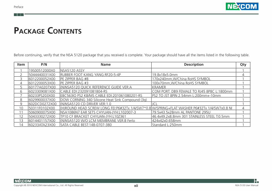
PaCkage Contents
Before continuing, verify that the NSA 5120 package that you received is complete. Your package should have all the items listed in the following table.
Item P/N Name Description Qty
1 19S00512000X0 NSA5120 ASSY 1 2 5044440031X00 RUBBER FOOT KANG YANG:RF20-5-4P 19.8x18x5.0mm 4 3 6012200052X00 PE ZIPPER BAG #8 170x240mm,W/China RoHS SYMBOL 1 4 6012200053X00 PE ZIPPER BAG #3 100x70mm,W/China RoHS SYMBOL 1 5 60177A0207X00 (N)NSA5120 QUICK REFERENCE GUIDE VER:A KRAMER 1 6 6023309081X00 CABLE EDI:232091081804-RS COM PORT. DB9 FEMALE TO RJ45 8P8C L:1800mm 1 7 60233PS203X00 EBC563IO PS2 KB/MS CABLE EDI:201061080201-RS PS2 TO JST 8PIN 2.54mm L:200mm+-10mm 1 8 6029900037X00 DOW CORNING 340 Silicone Heat Sink Compound (3g) 1 9 602DCD0272X00 (N)NSA5120 CD DRIVER VER:1.0 JCL 1 10 50311F0102X00 (H)ROUND HEAD SCREW LONG FEI:P6#32Tx 1/4/SW7*0.8 W/SPRING+FLAT WASHER P6#32Tx 1/4/SW7x0.8 NI 4 11 5060900075X00 NSA1086N7 EAR SETS CHYUAN-JYH:L102007-3 79.5x43.5x28mm AL PANTONE 295U 1 12 5043330272X00 TP10 CF BRACKET CHYUAN-JYH:L10Z361 46.4x49.2x8.8mm 301 STAINLESS STEEL T:0.5mm 1 13 6014401157X00 (N)NSA5120 W/O LCM MEMBRANE VER:B Ferlo 424x42x0.658mm 1 14 60233ATA23X00 SATA CABLE BEST:148-0707-380 Standard L:250mm 1

Copyright © 2010 NEXCOM International Co., Ltd. All Rights Reserved. xiii
Preface
NSA 5120 User Manual
ordering information
The following provides ordering information for NSA 5120.
• Barebone NSA 5120 (P/N: 10S00512000X0) - Supports Intel® Xeon™ 3400/i7/i5/i3 series, 4 DDR3 memory slots, 8
PCIe GbE LAN ports, CompactFlash socket, USB ports, VGA port, One PCIe x8 expansion slot.
• Options NSA 5120 LCM and Membrane (P/N: 88S00512000X0)
Copyright © 2010 NEXCOM International Co., Ltd. All Rights Reserved. 1 NSA 5120 User Manual
Chapter 1: Product Introduction
ChaPter 1: ProduCt introduCtion
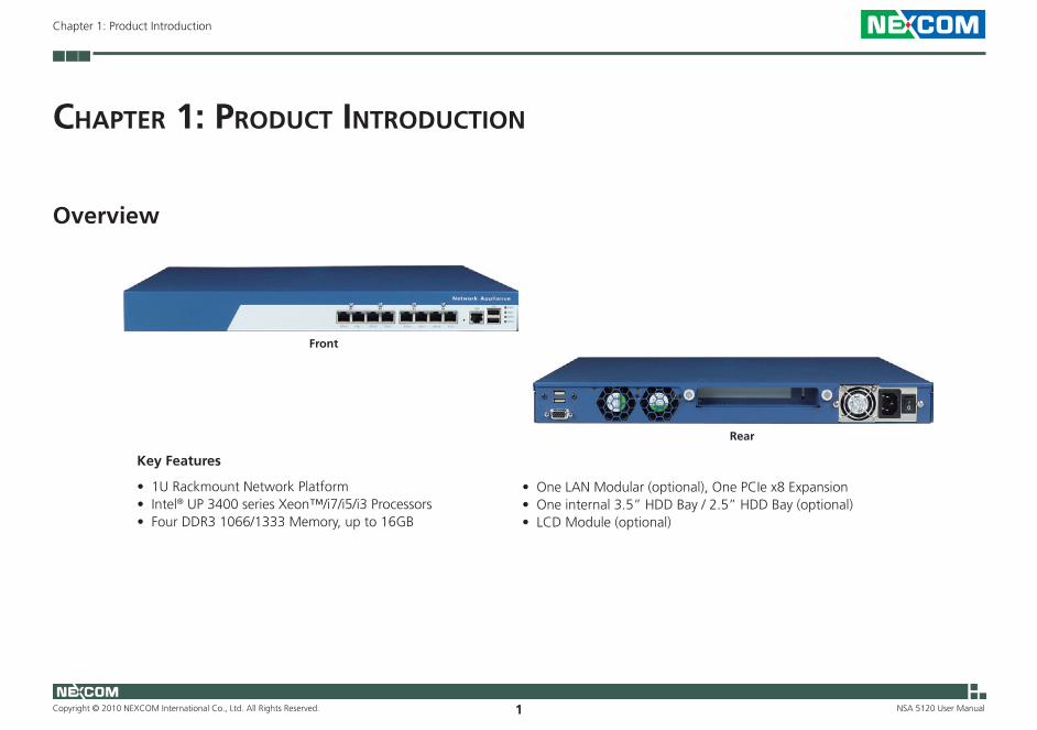
Overview
Key Features
• 1U Rackmount Network Platform• Intel® UP 3400 series Xeon™/i7/i5/i3 Processors• Four DDR3 1066/1333 Memory, up to 16GB
Rear
• One LAN Modular (optional), One PCIe x8 Expansion• One internal 3.5” HDD Bay / 2.5” HDD Bay (optional)• LCD Module (optional)
Front
Copyright © 2010 NEXCOM International Co., Ltd. All Rights Reserved. 2 NSA 5120 User Manual
Chapter 1: Product Introduction
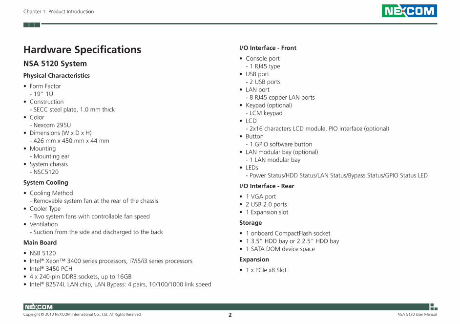
Hardware SpecificationsNSA 5120 SystemPhysical Characteristics
• Form Factor - 19” 1U• Construction - SECC steel plate, 1.0 mm thick• Color - Nexcom 295U• Dimensions (W x D x H) - 426 mm x 450 mm x 44 mm • Mounting - Mounting ear• System chassis - NSC5120
System Cooling
• Cooling Method - Removable system fan at the rear of the chassis• Cooler Type - Two system fans with controllable fan speed• Ventilation - Suction from the side and discharged to the back
Main Board
• NSB 5120• Intel® Xeon™ 3400 series processors, i7/i5/i3 series processors • Intel® 3450 PCH• 4 x 240-pin DDR3 sockets, up to 16GB• Intel® 82574L LAN chip, LAN Bypass: 4 pairs, 10/100/1000 link speed
I/O Interface - Front
• Console port - 1 RJ45 type • USB port - 2 USB ports • LAN port - 8 RJ45 copper LAN ports • Keypad (optional) - LCM keypad• LCD - 2x16 characters LCD module, PIO interface (optional)• Button - 1 GPIO software button • LAN modular bay (optional) - 1 LAN modular bay• LEDs - Power Status/HDD Status/LAN Status/Bypass Status/GPIO Status LED
I/O Interface - Rear
• 1 VGA port• 2 USB 2.0 ports• 1 Expansion slot
Storage
• 1 onboard CompactFlash socket• 1 3.5” HDD bay or 2 2.5” HDD bay• 1 SATA DOM device space
Expansion
• 1 x PCIe x8 Slot
Copyright © 2010 NEXCOM International Co., Ltd. All Rights Reserved. 3 NSA 5120 User Manual
Chapter 1: Product Introduction
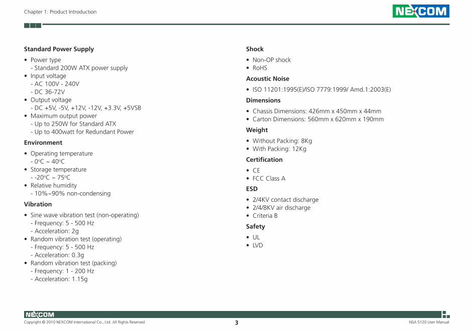
Standard Power Supply
• Power type - Standard 200W ATX power supply • Input voltage - AC 100V - 240V - DC 36-72V• Output voltage - DC +5V, -5V, +12V, -12V, +3.3V, +5VSB• Maximum output power - Up to 250W for Standard ATX - Up to 400watt for Redundant Power
Environment
• Operating temperature - 0oC ~ 40oC• Storage temperature - -20oC ~ 75oC• Relative humidity - 10%~90% non-condensing
Vibration
• Sine wave vibration test (non-operating) - Frequency: 5 - 500 Hz - Acceleration: 2g• Random vibration test (operating) - Frequency: 5 - 500 Hz - Acceleration: 0.3g• Random vibration test (packing) - Frequency: 1 - 200 Hz - Acceleration: 1.15g
Shock
• Non-OP shock• RoHS
Acoustic Noise
• ISO 11201:1995(E)/ISO 7779:1999/ Amd.1:2003(E)
Dimensions
• Chassis Dimensions: 426mm x 450mm x 44mm• Carton Dimensions: 560mm x 620mm x 190mm
Weight
• Without Packing: 8Kg• With Packing: 12Kg
Certification
• CE• FCC Class A
ESD
• 2/4KV contact discharge• 2/4/8KV air discharge• Criteria B
Safety
• UL• LVD
Copyright © 2010 NEXCOM International Co., Ltd. All Rights Reserved. 4 NSA 5120 User Manual
Chapter 1: Product Introduction
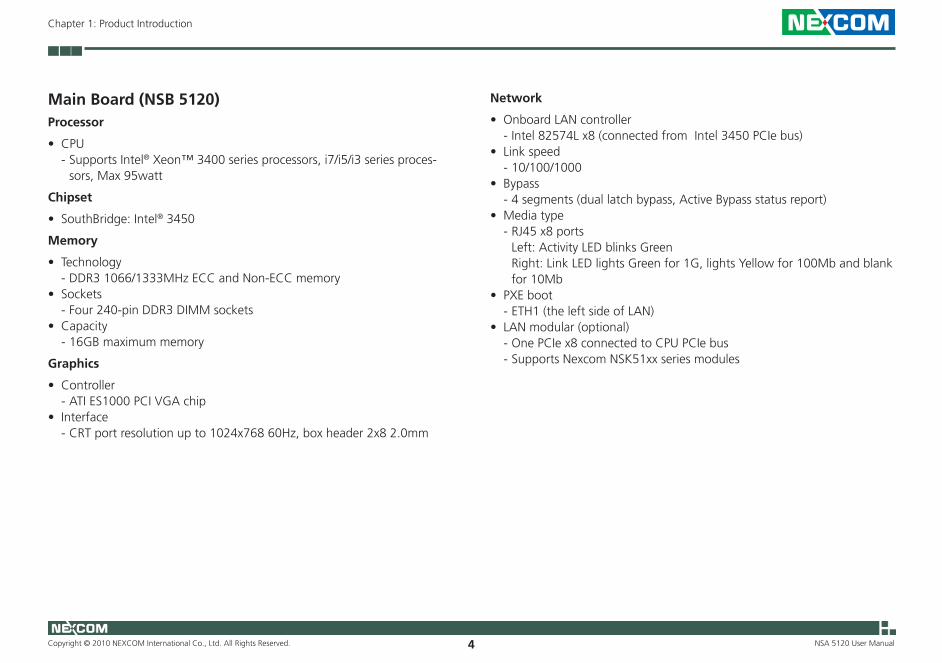
Main Board (NSB 5120)Processor
• CPU - Supports Intel® Xeon™ 3400 series processors, i7/i5/i3 series proces-
sors, Max 95watt
Chipset
• SouthBridge: Intel® 3450
Memory
• Technology - DDR3 1066/1333MHz ECC and Non-ECC memory• Sockets - Four 240-pin DDR3 DIMM sockets • Capacity - 16GB maximum memory
Graphics
• Controller - ATI ES1000 PCI VGA chip • Interface - CRT port resolution up to 1024x768 60Hz, box header 2x8 2.0mm
Network
• Onboard LAN controller - Intel 82574L x8 (connected from Intel 3450 PCIe bus)• Link speed - 10/100/1000• Bypass - 4 segments (dual latch bypass, Active Bypass status report)• Media type - RJ45 x8 ports Left: Activity LED blinks Green Right: Link LED lights Green for 1G, lights Yellow for 100Mb and blank
for 10Mb• PXE boot - ETH1 (the left side of LAN)• LAN modular (optional) - One PCIe x8 connected to CPU PCIe bus - Supports Nexcom NSK51xx series modules
Copyright © 2010 NEXCOM International Co., Ltd. All Rights Reserved. 5 NSA 5120 User Manual
Chapter 1: Product Introduction
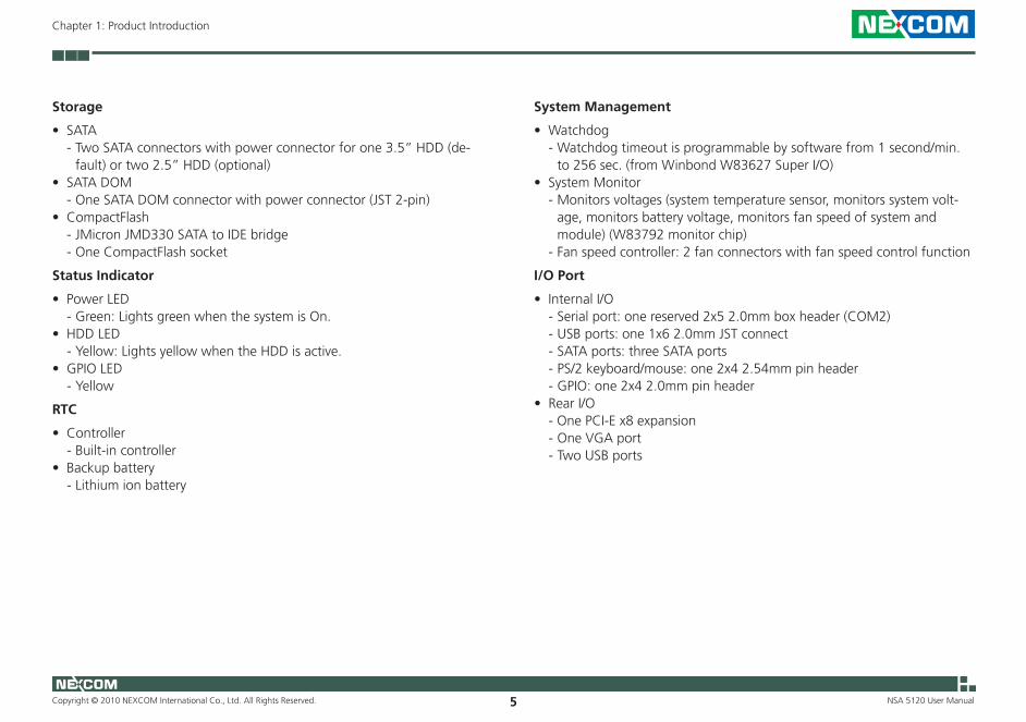
Storage
• SATA - Two SATA connectors with power connector for one 3.5” HDD (de-
fault) or two 2.5” HDD (optional)• SATA DOM - One SATA DOM connector with power connector (JST 2-pin)• CompactFlash - JMicron JMD330 SATA to IDE bridge - One CompactFlash socket
Status Indicator
• Power LED - Green: Lights green when the system is On.• HDD LED - Yellow: Lights yellow when the HDD is active.• GPIO LED - Yellow
RTC
• Controller - Built-in controller• Backup battery - Lithium ion battery
System Management
• Watchdog - Watchdog timeout is programmable by software from 1 second/min.
to 256 sec. (from Winbond W83627 Super I/O)• System Monitor - Monitors voltages (system temperature sensor, monitors system volt-
age, monitors battery voltage, monitors fan speed of system and module) (W83792 monitor chip)
- Fan speed controller: 2 fan connectors with fan speed control function
I/O Port
• Internal I/O - Serial port: one reserved 2x5 2.0mm box header (COM2) - USB ports: one 1x6 2.0mm JST connect - SATA ports: three SATA ports - PS/2 keyboard/mouse: one 2x4 2.54mm pin header - GPIO: one 2x4 2.0mm pin header• Rear I/O - One PCI-E x8 expansion - One VGA port - Two USB ports
Copyright © 2010 NEXCOM International Co., Ltd. All Rights Reserved. 6 NSA 5120 User Manual
Chapter 1: Product Introduction
• Front I/O - Two USB ports - One RJ45 type console port - Eight RJ45 copper LAN ports - One LCM keypad (optional) - One GPIO software button - One LAN module bay (optional)
Expansion
• PCI Express - One PCIe x8 slot
Power
• Connector type - ATX power connector• Power mode - AT mode (default), ATX mode Use the jumper to change the setting. The BIOS can auto detect the
power mode status.
BIOS
• Flash ROM - 64MB (SPI)• Type - AMI BIOS
Software
• Standard OS - Windows 2003, Linux Kernel 2.6 (Fedora Core, SUSE)• Drivers - VGA, LAN, WDT, GPIO, Hardware Monitor, Bypass• Sample code - LCM sample string display, LCM testing program, GPIO, WTD, Bypass,
Hardware Monitor
Environment
• Operating Temperature - 0oC - 40oC• Storage Temperature - -20oC - 75oC• Relative Humidity - 10%-90% non-condensing• EMI/EMC - CE/FCC Class A• ESD - 2/4KV contact discharge, 2/4/8KV air discharge, Criteria B
Copyright © 2010 NEXCOM International Co., Ltd. All Rights Reserved. 7 NSA 5120 User Manual
Chapter 1: Product Introduction
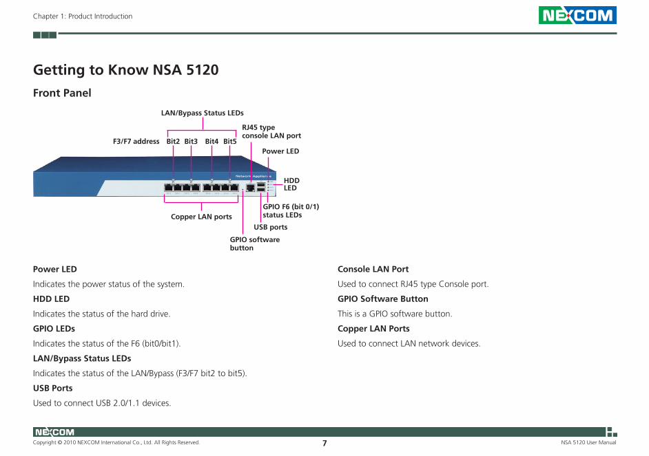
Getting to Know NSA 5120
RJ45 type console LAN port
HDD LED
Power LED
USB ports
GPIO F6 (bit 0/1) status LEDs
Power LED
Indicates the power status of the system.
HDD LED
Indicates the status of the hard drive.
GPIO LEDs
Indicates the status of the F6 (bit0/bit1).
LAN/Bypass Status LEDs
Indicates the status of the LAN/Bypass (F3/F7 bit2 to bit5).
USB Ports
Used to connect USB 2.0/1.1 devices.
Console LAN Port
Used to connect RJ45 type Console port.
GPIO Software Button
This is a GPIO software button.
Copper LAN Ports
Used to connect LAN network devices.
Front Panel
Copper LAN ports
GPIO software button
Bit2 Bit3 Bit4 Bit5F3/F7 address
LAN/Bypass Status LEDs

Copyright © 2010 NEXCOM International Co., Ltd. All Rights Reserved. 8 NSA 5120 User Manual
Chapter 1: Product Introduction
Expansion slot VGA port
USB ports
Power switch
Power On/Off Switch
Press to power-on or power-off the system.
Expansion Slot
Used to install a PCI Express x8 slot.
USB Ports
Used to connect USB 2.0/1.1 devices.
VGA Port
Used to connect an analog VGA monitor.
Rear Panel

Copyright © 2010 NEXCOM International Co., Ltd. All Rights Reserved. 9
Chapter 2: Jumpers and Connectors
NSA 5120 User Manual
This chapter describes how to set the jumpers on the motherboard. Note that the following procedures are generic for NSA 5120.
Before You Begin • Ensure you have a stable, clean working environment. Dust and dirt can
get into components and cause a malfunction. Use containers to keep small components separated.
• Adequate lighting and proper tools can prevent you from accidentally damaging the internal components. Most of the procedures that follow require only a few simple tools, including the following:
• A Philips screwdriver • A flat-tipped screwdriver • A set of jewelers Screwdrivers • A grounding strap • An anti-static pad
• Using your fingers can disconnect most of the connections. It is recom-mended that you do not use needle-nosed pliers to disconnect connec-tions as these can damage the soft metal or plastic parts of the connec-tors.
• Before working on internal components, make sure that the power is off. Ground yourself before touching any internal components, by touching a metal object. Static electricity can damage many of the elec-
tronic components. Humid environment tend to have less static electric-ity than dry environments. A grounding strap is warranted whenever danger of static electricity exists.
Precautions Computer components and electronic circuit boards can be damaged by discharges of static electricity. Working on the computers that are still con-nected to a power supply can be extremely dangerous.
Follow the guidelines below to avoid damage to your computer or your-self:
• Always disconnect the unit from the power outlet whenever you are working inside the case.
• If possible, wear a grounded wrist strap when you are working inside the computer case. Alternatively, discharge any static electricity by touching the bare metal chassis of the unit case, or the bare metal body of any other grounded appliance.
• Hold electronic circuit boards by the edges only. Do not touch the com-ponents on the board unless it is necessary to do so. Don’t flex or stress the circuit board.
• Leave all components inside the static-proof packaging that they shipped with until they are ready for installation.
• Use correct screws and do not over tighten screws.
ChaPter 2: JumPers and ConneCtors
Copyright © 2010 NEXCOM International Co., Ltd. All Rights Reserved. 10
Chapter 2: Jumpers and Connectors
NSA 5120 User Manual
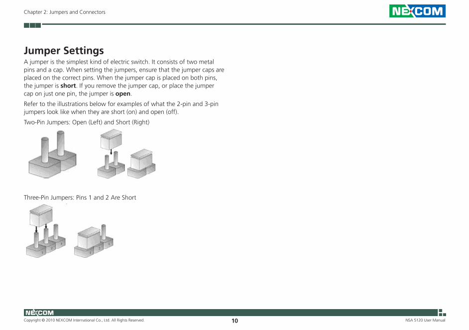
Jumper SettingsA jumper is the simplest kind of electric switch. It consists of two metal pins and a cap. When setting the jumpers, ensure that the jumper caps are placed on the correct pins. When the jumper cap is placed on both pins, the jumper is short. If you remove the jumper cap, or place the jumper cap on just one pin, the jumper is open.
Refer to the illustrations below for examples of what the 2-pin and 3-pin jumpers look like when they are short (on) and open (off).
Two-Pin Jumpers: Open (Left) and Short (Right)
Three-Pin Jumpers: Pins 1 and 2 Are Short
Copyright © 2010 NEXCOM International Co., Ltd. All Rights Reserved. 11
Chapter 2: Jumpers and Connectors
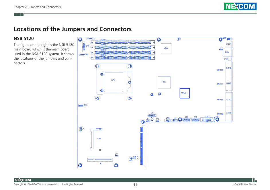
NSA 5120 User Manual
Locations of the Jumpers and ConnectorsNSB 5120The figure on the right is the NSB 5120 main board which is the main board used in the NSA 5120 system. It shows the locations of the jumpers and con-nectors.
Copyright © 2010 NEXCOM International Co., Ltd. All Rights Reserved. 12
Chapter 2: Jumpers and Connectors
NSA 5120 User Manual
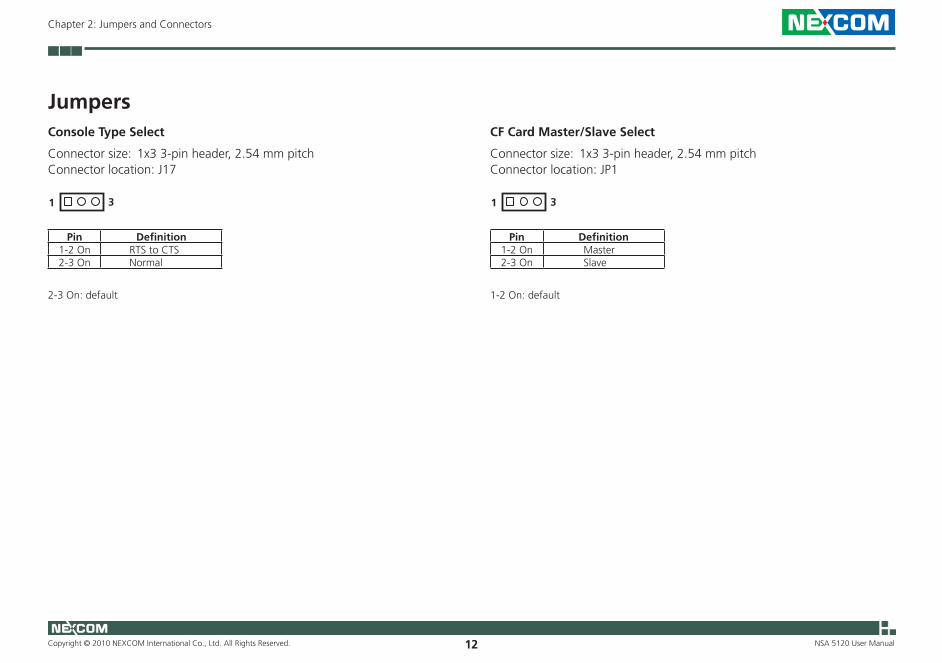
JumpersConsole Type Select
Connector size: 1x3 3-pin header, 2.54 mm pitchConnector location: J17
1 3
Pin Definition1-2 On RTS to CTS2-3 On Normal
2-3 On: default
CF Card Master/Slave Select
Connector size: 1x3 3-pin header, 2.54 mm pitchConnector location: JP1
1 3
Pin Definition1-2 On Master2-3 On Slave
1-2 On: default
Copyright © 2010 NEXCOM International Co., Ltd. All Rights Reserved. 13
Chapter 2: Jumpers and Connectors
NSA 5120 User Manual
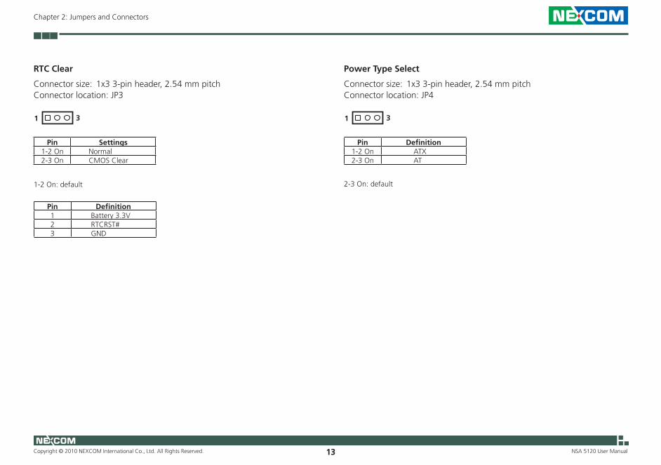
RTC Clear
Connector size: 1x3 3-pin header, 2.54 mm pitchConnector location: JP3
1 3
Pin Settings1-2 On Normal2-3 On CMOS Clear
1-2 On: default
Pin Definition1 Battery 3.3V2 RTCRST#3 GND
Power Type Select
Connector size: 1x3 3-pin header, 2.54 mm pitchConnector location: JP4
1 3
Pin Definition1-2 On ATX2-3 On AT
2-3 On: default

Copyright © 2010 NEXCOM International Co., Ltd. All Rights Reserved. 14
Chapter 2: Jumpers and Connectors
NSA 5120 User Manual
LAN EEPROM Write Protect
Connector size: 1x3 3-pin header, 2.54 mm pitchConnector location: JP5
1 3
Pin Definition1-2 On Write to EEPROM2-3 On Write Protected
2-3 On: default
Copyright © 2010 NEXCOM International Co., Ltd. All Rights Reserved. 15
Chapter 2: Jumpers and Connectors
NSA 5120 User Manual
External I/O Interface
Connector Pin Definitions
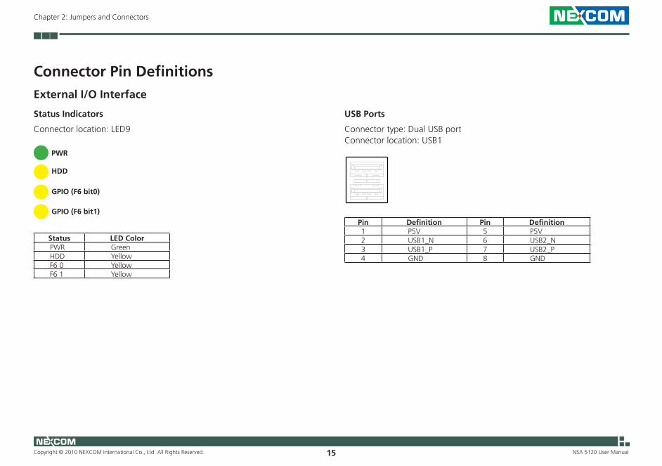
Status Indicators
Connector location: LED9
Status LED Color PWR Green HDD Yellow F6 0 Yellow F6 1 Yellow
GPIO (F6 bit1)
GPIO (F6 bit0)
PWR
HDD
USB Ports
Connector type: Dual USB portConnector location: USB1
Pin Definition Pin Definition1 P5V 5 P5V2 USB1_N 6 USB2_N3 USB1_P 7 USB2_P4 GND 8 GND

Copyright © 2010 NEXCOM International Co., Ltd. All Rights Reserved. 16
Chapter 2: Jumpers and Connectors
NSA 5120 User Manual
RJ45 Type Console LAN Port
Connector type: RJ45 portConnector location: LAN1
Pin Definition Pin Definition1 RTS /CTS 2 DTR3 TXD 4 GND5 DCD 6 RXD7 DSR 8 CTS
F5 Bit0 Software Button
Connector type: 2-pin jackConnector location: SW1
Pin Definition1 GND2 F5 Bit0
Copyright © 2010 NEXCOM International Co., Ltd. All Rights Reserved. 17
Chapter 2: Jumpers and Connectors
NSA 5120 User Manual
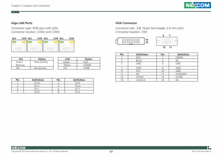
Giga LAN Ports
Connector type: RJ45 port with LEDsConnector location: CON2 and CON3
Act Link
Act Status Green Blinking
Data Activity
Off No Acitivity
Link Status Green 1GB Yellow 100MB Off 10MB
Pin Definition Pin Definition1 TX+0 2 TX-03 TX+1 4 TX+25 TX-2 6 TX-17 TX+3 8 TX-3
Act Link Act Link Act Link15
1115
VGA Connector
Connector size: 2x8 16-pin box header, 2.0 mm pitchConnector location: CN3
12
1516
Pin Definition Pin Definition1 RED 2 GREEN3 BLUE 4 NC5 GND 6 GND
7 GND 8 GND9 P5V 10 GND11 NC 12 VGADATA13 HSYNC 14 VSYNC15 VGACLK 16 NC

Copyright © 2010 NEXCOM International Co., Ltd. All Rights Reserved. 18
Chapter 2: Jumpers and Connectors
NSA 5120 User Manual
Internal Connectors
PS/2 Keyboard/Mouse Connector
Connector type: 2x4 8-pin header, 2.54 mmConnector location: J1
12
78
Pin Definition Pin Definition1 P5V 2 P5V3 KDAT 4 MDAT5 KCLK 6 MCLK
7 GND 8 GND
USB Connector
Connector type: 1x6 6-pin, 2.0 mm JSTConnector location: J2
1 6
Pin Definition1 P5V2 USB2-3 USB2+4 USB3-5 USB3+6 GND
Copyright © 2010 NEXCOM International Co., Ltd. All Rights Reserved. 19
Chapter 2: Jumpers and Connectors
NSA 5120 User Manual
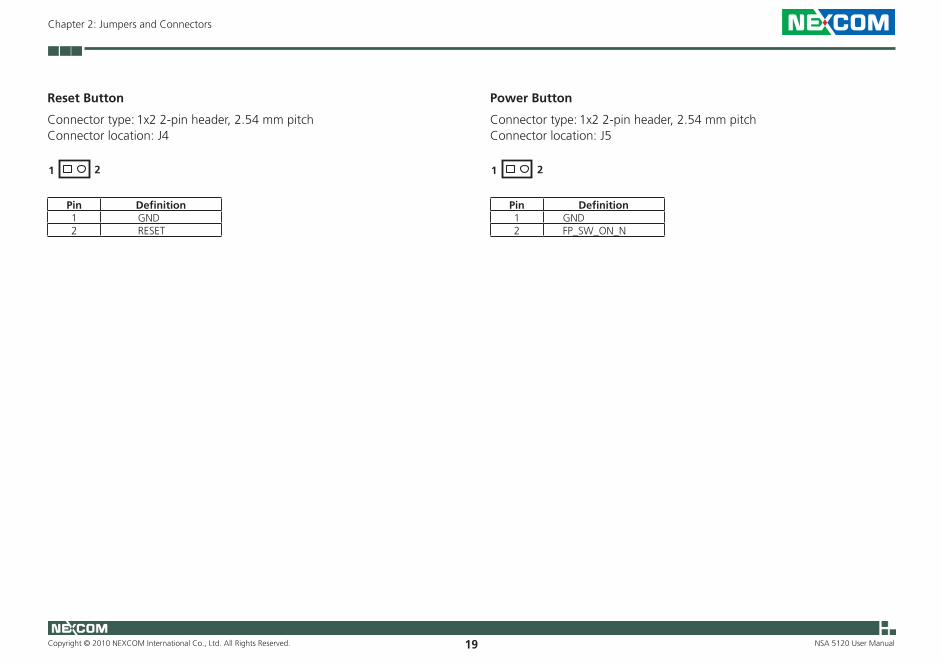
Reset Button
Connector type: 1x2 2-pin header, 2.54 mm pitchConnector location: J4
1 2
Pin Definition1 GND2 RESET
Power Button
Connector type: 1x2 2-pin header, 2.54 mm pitchConnector location: J5
1 2
Pin Definition1 GND2 FP_SW_ON_N
Copyright © 2010 NEXCOM International Co., Ltd. All Rights Reserved. 20
Chapter 2: Jumpers and Connectors
NSA 5120 User Manual
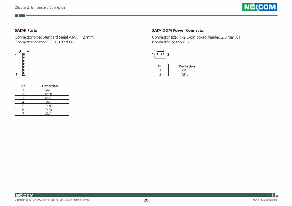
SATAII Ports
Connector type: Standard Serial ATAII, 1.27mmConnector location: J6, J11 and J12
Pin Definition1 GND2 TXP03 TXN04 GND5 RXN06 RXP07 GND
1
7
SATA DOM Power Connector
Connector size: 1x2 2-pin boxed header, 2.5 mm JSTConnector location: J7
1 2
Pin Definition1 P5V2 GND

Copyright © 2010 NEXCOM International Co., Ltd. All Rights Reserved. 21
Chapter 2: Jumpers and Connectors
NSA 5120 User Manual
GPIO Connector
Connector type: 2x5 10-pin header, 2.0 mmConnector location: J9
109
21
Pin Definition Pin Definition1 P5V 2 GND3 GPI10 4 GPO145 GPI11 6 GPO15
7 GPI12 8 GPO169 GPI13 10 GPO17
Bypass D LED
Connector type: 1x2 2-pin header, 2.54 mm pitchConnector location: J13
1 2
Pin Definition1 GND2 Bypass D LED+

Copyright © 2010 NEXCOM International Co., Ltd. All Rights Reserved. 22
Chapter 2: Jumpers and Connectors
NSA 5120 User Manual
Bypass C LED
Connector type: 1x2 2-pin header, 2.54 mm pitchConnector location: J14
1 2
Pin Definition1 GND2 Bypass C LED+
Bypass B LED
Connector type: 1x2 2-pin header, 2.54 mm pitchConnector location: J15
1 2
Pin Definition1 GND2 Bypass B LED+

Copyright © 2010 NEXCOM International Co., Ltd. All Rights Reserved. 23
Chapter 2: Jumpers and Connectors
NSA 5120 User Manual
Bypass A LED
Connector type: 1x2 2-pin header, 2.54 mm pitchConnector location: J16
1 2
Pin Definition1 GND2 Bypass A LED+
System Fan Connectors
Connector size: 4-pin Wafer, 2.54 mm pitchConnector location: CN1 and CN2
1
4
Pin Definition1 GND2 +12V3 FAN_TAC4 PWM

Copyright © 2010 NEXCOM International Co., Ltd. All Rights Reserved. 24
Chapter 2: Jumpers and Connectors
NSA 5120 User Manual
CompactFlash Card Socket
Connector type: CompactFlash Type 2Connector location: CN4
Pin Description Pin Description1 GND 2 SDD3A3 SDD4A 4 SDD5A5 SDD6A 6 SDD7A7 SDCS#1 8 GND9 GND 10 GND11 GND 12 GND13 P5V 14 GND15 GND 16 GND17 GND 18 SDA2A19 SDA1A 20 SDA0A21 SDD0A 22 SDD1A23 SDD2A 24 NC25 CF_CD2# 26 CF_CD1#27 SDD11A 28 SDD12A
Pin Description Pin Description29 SDD13A 30 SDD14A31 SDD15A 32 SDCS#333 NC 34 SDIOR#35 SDIOW# 36 P5V37 HDIRQ14 38 P5V39 CF_SEL# 40 NC41 IDERST# 42 SIORDY43 SDREQ 44 SDDACK#45 IDEACTP# 46 DIAG#47 SDD8A 48 SDD9A49 SDD10A 50 GND
Copyright © 2010 NEXCOM International Co., Ltd. All Rights Reserved. 25
Chapter 2: Jumpers and Connectors
NSA 5120 User Manual
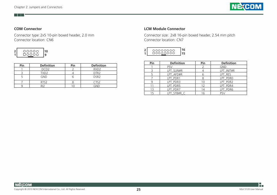
COM Connector
Connector type: 2x5 10-pin boxed header, 2.0 mmConnector location: CN6
12
910
Pin Definition Pin Definition1 DCD2 2 RXD23 TXD2 4 DTR25 GND 6 DSR2
7 RTS2 8 CTS29 RI2 10 GND
LCM Module Connector
Connector size: 2x8 16-pin boxed header, 2.54 mm pitchConnector location: CN7
12
1516
Pin Definition Pin Definition1 P5V 2 GND 3 LPT_SLIN#R 4 LPT_INIT#R5 LPT_AFD#R 6 LPT_RES7 LPT_PDR1 8 LPT_PDR09 LPT_PDR3 10 LPT_PDR211 LPT_PDR5 12 LPT_PDR413 LPT_PDR7 14 LPT_PDR615 LPT_STB#R_C 16 P5V
Copyright © 2010 NEXCOM International Co., Ltd. All Rights Reserved. 26
Chapter 2: Jumpers and Connectors
NSA 5120 User Manual
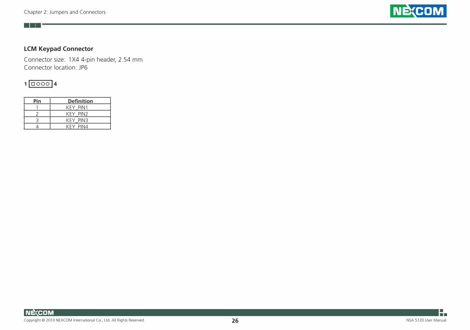
LCM Keypad Connector
Connector size: 1X4 4-pin header, 2.54 mmConnector location: JP6
1 4
Pin Definition1 KEY_PIN12 KEY_PIN23 KEY_PIN34 KEY_PIN4
Copyright © 2010 NEXCOM International Co., Ltd. All Rights Reserved. 27
Chapter 2: Jumpers and Connectors
NSA 5120 User Manual
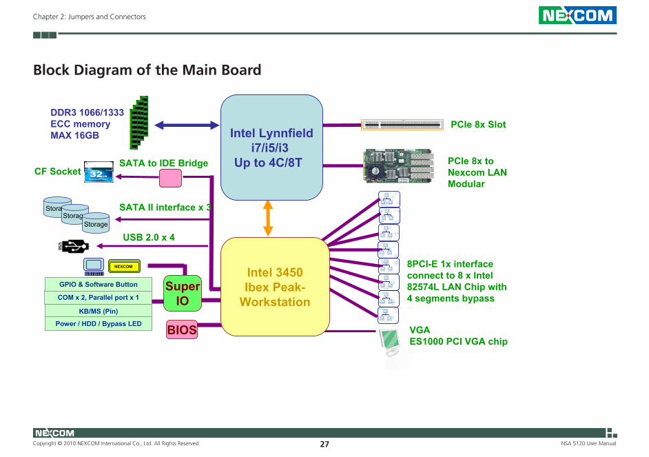
Block Diagram of the Main Board
1
NSA5120 Block Diagram
DDR3 1066/1333ECC memoryMAX 16GB
StorageStorage
COM x 2, Parallel port x 1
KB/MS (Pin)
GPIO & Software Button
Power / HDD / Bypass LED
SATA II interface x 3
USB 2.0 x 4
SuperIO
PCIe 8x Slot
NEXCOM
BIOS
Storage
Intel Lynnfieldi7/i5/i3
Up to 4C/8T
8PCI-E 1x interface connect to 8 x Intel 82574L LAN Chip with 4 segments bypass
PCIe 8x to Nexcom LAN Modular
VGAES1000 PCI VGA chip
SATA to IDE Bridge CF Socket
Intel 3450Ibex Peak-
Workstation
Copyright © 2010 NEXCOM International Co., Ltd. All Rights Reserved. 28
Chapter 3: System Setup
NSA 5120 User Manual
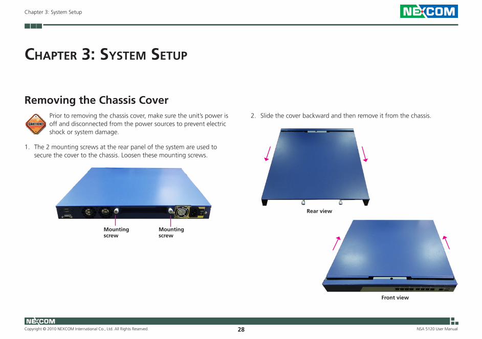
ChaPter 3: system setuP
Removing the Chassis Cover2. Slide the cover backward and then remove it from the chassis.Prior to removing the chassis cover, make sure the unit’s power is
off and disconnected from the power sources to prevent electric shock or system damage.
1. The 2 mounting screws at the rear panel of the system are used to secure the cover to the chassis. Loosen these mounting screws.
Mounting screw
Mounting screw
Rear view
Front view

Copyright © 2010 NEXCOM International Co., Ltd. All Rights Reserved. 29
Chapter 3: System Setup
NSA 5120 User Manual
Installing a DIMM
DIMM2DIMM1
1. The 4 DDR3 sockets are divided into 2 channels.
• DIMM 1 and DIMM 2 = Channel B DIMM 3 and DIMM 4 = Channel A• Always populate DIMM1 first. The system will not boot when
the first module is installed in DIMM2, DIMM3 or DIMM4.• When installing 2 modules for single channel configuration,
populate DIMM1 and DIMM2 first.• When installing 2 modules for dual channel configuration,
populate DIMM1 and DIMM3 first.
2. Push the ejector tabs which are at the ends of the socket outward. This indicates that the socket is unlocked.
Ejector tab
DIMM3DIMM4
Copyright © 2010 NEXCOM International Co., Ltd. All Rights Reserved. 30
Chapter 3: System Setup
NSA 5120 User Manual
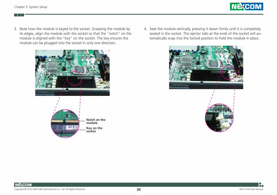
3. Note how the module is keyed to the socket. Grasping the module by its edges, align the module with the socket so that the “notch” on the module is aligned with the “key” on the socket. The key ensures the module can be plugged into the socket in only one direction.
Notch on the module
Key on the socket
4. Seat the module vertically, pressing it down firmly until it is completely seated in the socket. The ejector tabs at the ends of the socket will au-tomatically snap into the locked position to hold the module in place.

Copyright © 2010 NEXCOM International Co., Ltd. All Rights Reserved. 31
Chapter 3: System Setup
NSA 5120 User Manual
Installing the CPU
• Before you proceed, make sure (1) the CPU socket comes with a protective cap, (2) the cap is not damaged and (3) the socket’s contact pins are not bent.
• Make sure all power cables are unplugged before you install the CPU.
• The CPU socket must not come in contact with anything other than the CPU. Avoid unnecessary exposure. Remove the protec-tive cap only when you are about to install the CPU.
Heat sink
Mounting screw
2. Remove the heat sink to access the CPU socket.
CPU socket
1. If the system came with the heat sink already installed, loosen the mounting screws that secure the heat sink to the board.
Mounting screw
Mounting screw
Mounting screw
Copyright © 2010 NEXCOM International Co., Ltd. All Rights Reserved. 32
Chapter 3: System Setup
NSA 5120 User Manual
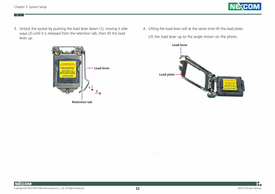
3. Unlock the socket by pushing the load lever down (1), moving it side-ways (2) until it is released from the retention tab; then lift the load lever up.
Load plate
Load lever
4. Lifting the load lever will at the same time lift the load plate.
Lift the load lever up to the angle shown on the photo.
Retention tab
Load lever
12
Copyright © 2010 NEXCOM International Co., Ltd. All Rights Reserved. 33
Chapter 3: System Setup
NSA 5120 User Manual
5. Remove the protective cap from the CPU socket. The cap is used to protect the CPU socket against dust and harmful particles. Remove the protective cap only when you are about to install the CPU.
Protective cap
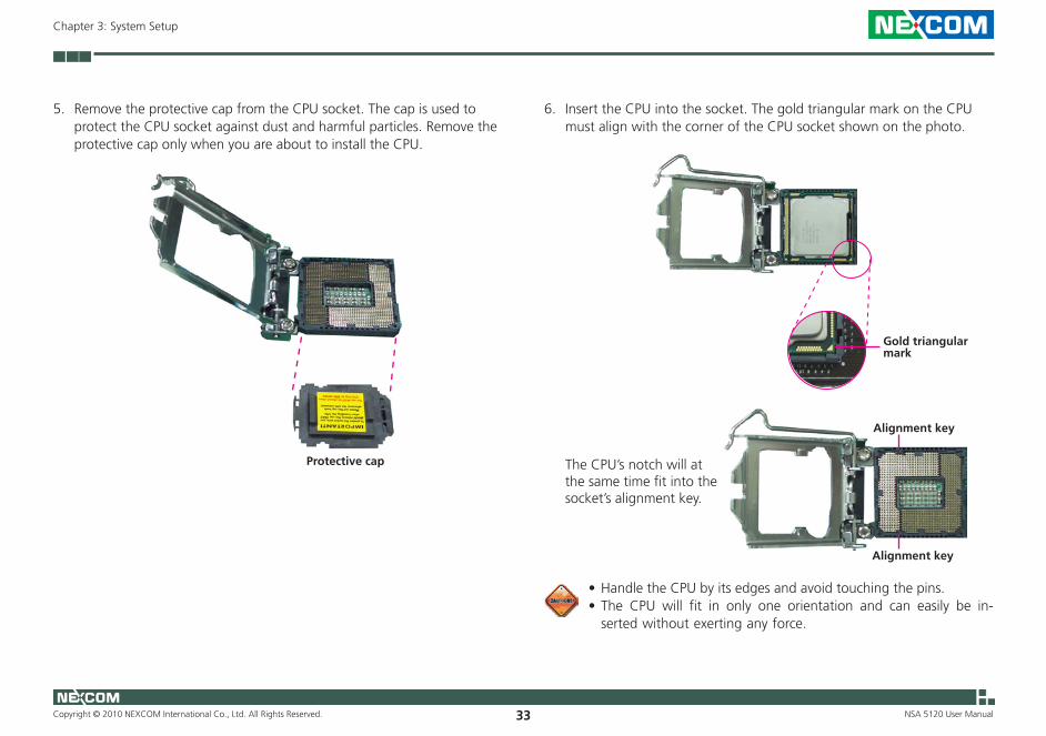
6. Insert the CPU into the socket. The gold triangular mark on the CPU must align with the corner of the CPU socket shown on the photo.
•Handle the CPU by its edges and avoid touching the pins.•The CPU will fit in only one orientation and can easily be in-
serted without exerting any force.
Gold triangular mark
The CPU’s notch will at the same time fit into the socket’s alignment key.
Alignment key
Alignment key

Copyright © 2010 NEXCOM International Co., Ltd. All Rights Reserved. 34
Chapter 3: System Setup
NSA 5120 User Manual
8. Hook the load lever under the retention tab.
Do not force the CPU into the socket. Forcing the CPU into the socket may bend the pins and damage the CPU.
7. Close the load plate and then push the load lever down.
While closing the load plate, make sure the front edge of the load plate slides under the retention knob.
Retention knob
Retention tab
Load lever

Copyright © 2010 NEXCOM International Co., Ltd. All Rights Reserved. 35
Chapter 3: System Setup
NSA 5120 User Manual
9. Apply thermal compound on top of the CPU. Do not spread the com-pound all over the surface. When you later place the heat sink on top of the CPU, the compound will disperse evenly.
Thermal compound on the CPU
10. Align the mounting screws of the heat sink with the mounting holes on the board.
Mounting hole
Copyright © 2010 NEXCOM International Co., Ltd. All Rights Reserved. 36
Chapter 3: System Setup
NSA 5120 User Manual
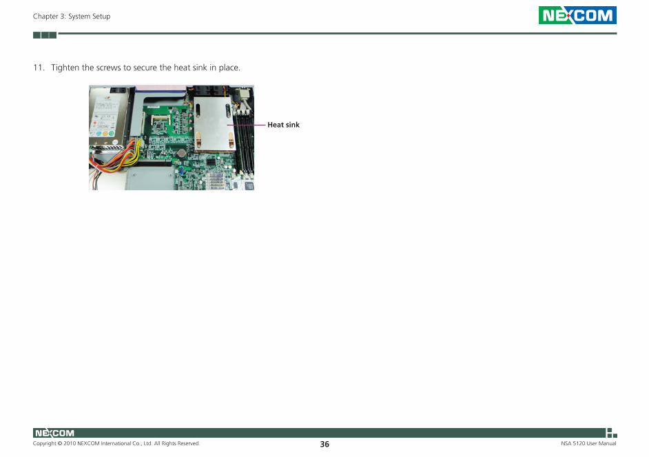
11. Tighten the screws to secure the heat sink in place.
Heat sink
Copyright © 2010 NEXCOM International Co., Ltd. All Rights Reserved. 37
Chapter 3: System Setup
NSA 5120 User Manual
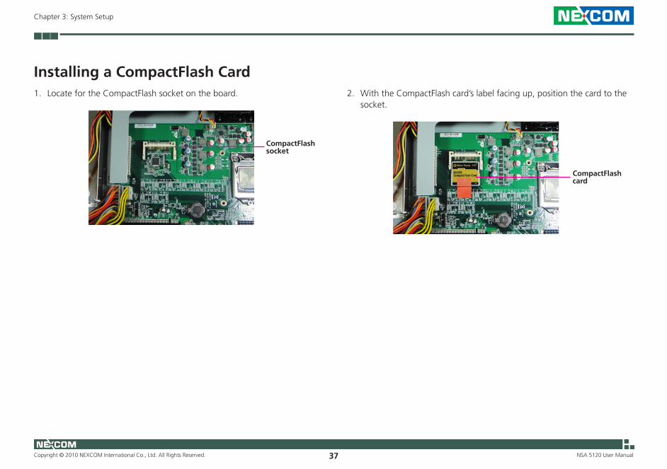
Installing a CompactFlash Card2. With the CompactFlash card’s label facing up, position the card to the
socket.
CompactFlash socket
CompactFlash card
1. Locate for the CompactFlash socket on the board.
Copyright © 2010 NEXCOM International Co., Ltd. All Rights Reserved. 38
Chapter 3: System Setup
NSA 5120 User Manual
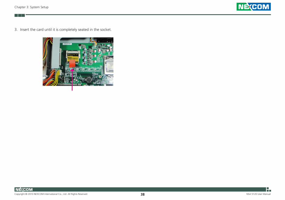
3. Insert the card until it is completely seated in the socket.
Copyright © 2010 NEXCOM International Co., Ltd. All Rights Reserved. 39
Chapter 3: System Setup
NSA 5120 User Manual
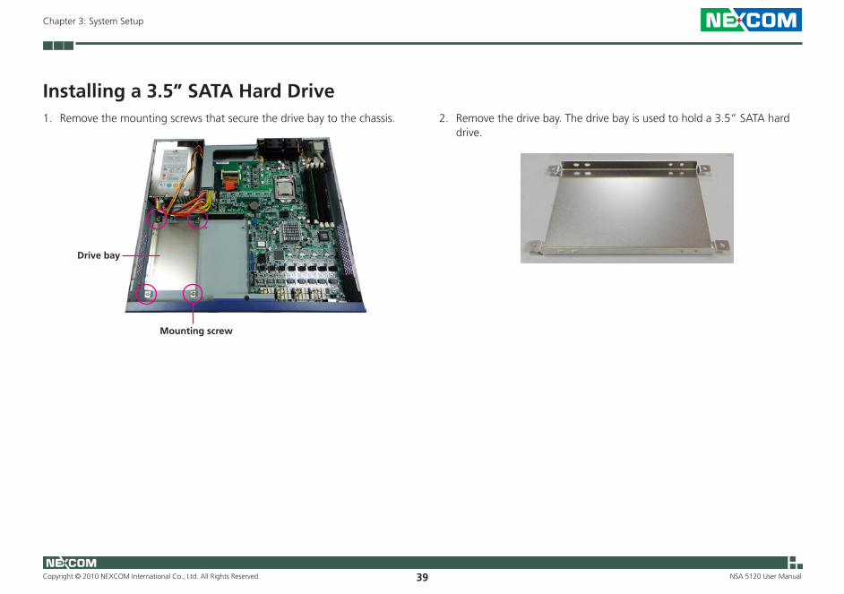
Installing a 3.5” SATA Hard Drive
Drive bay
Mounting screw
1. Remove the mounting screws that secure the drive bay to the chassis. 2. Remove the drive bay. The drive bay is used to hold a 3.5” SATA hard drive.
Copyright © 2010 NEXCOM International Co., Ltd. All Rights Reserved. 40
Chapter 3: System Setup
NSA 5120 User Manual
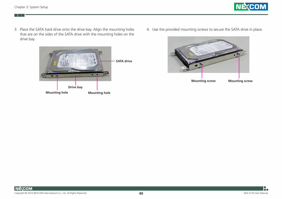
Drive bay
3. Place the SATA hard drive onto the drive bay. Align the mounting holes that are on the sides of the SATA drive with the mounting holes on the drive bay.
SATA drive
Mounting holeMounting hole
4. Use the provided mounting screws to secure the SATA drive in place.
Mounting screw Mounting screw
Copyright © 2010 NEXCOM International Co., Ltd. All Rights Reserved. 41
Chapter 3: System Setup
NSA 5120 User Manual
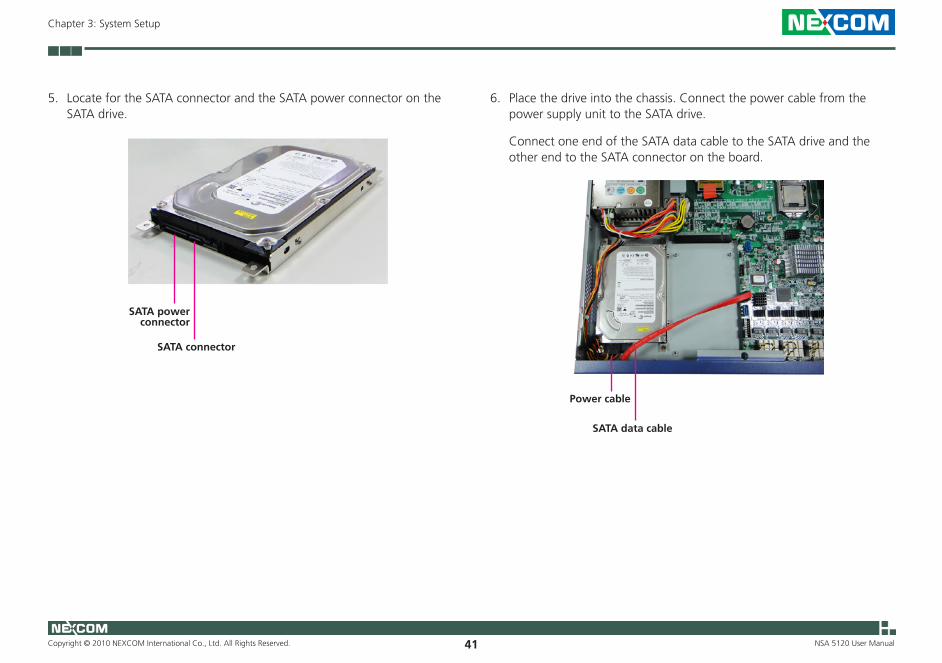
5. Locate for the SATA connector and the SATA power connector on the SATA drive.
SATA connector
SATA power connector
6. Place the drive into the chassis. Connect the power cable from the power supply unit to the SATA drive.
Connect one end of the SATA data cable to the SATA drive and the other end to the SATA connector on the board.
SATA data cable
Power cable
Copyright © 2010 NEXCOM International Co., Ltd. All Rights Reserved. 42
Chapter 3: System Setup
NSA 5120 User Manual
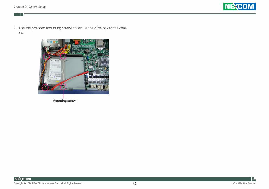
7. Use the provided mounting screws to secure the drive bay to the chas-sis.
Mounting screw
Copyright © 2010 NEXCOM International Co., Ltd. All Rights Reserved. 43
Chapter 3: System Setup
NSA 5120 User Manual
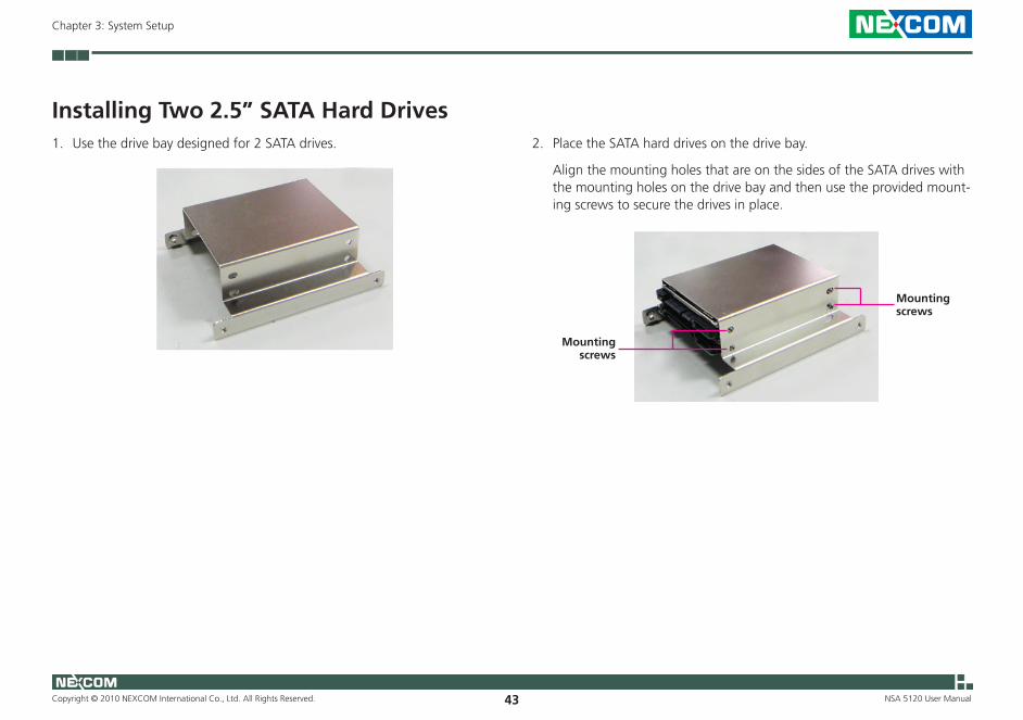
Installing Two 2.5” SATA Hard Drives
Mounting screws
1. Use the drive bay designed for 2 SATA drives. 2. Place the SATA hard drives on the drive bay.
Align the mounting holes that are on the sides of the SATA drives with the mounting holes on the drive bay and then use the provided mount-ing screws to secure the drives in place.
Mounting screws
Copyright © 2010 NEXCOM International Co., Ltd. All Rights Reserved. 44
Chapter 3: System Setup
NSA 5120 User Manual
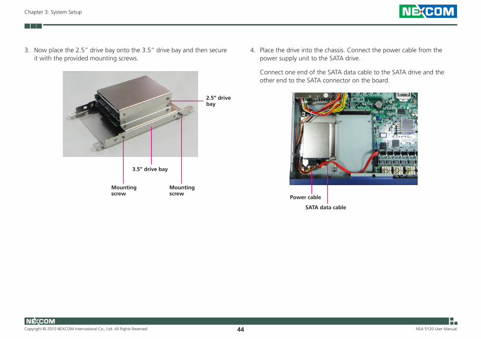
3. Now place the 2.5” drive bay onto the 3.5” drive bay and then secure it with the provided mounting screws.
Mounting screw
3.5” drive bay
2.5” drive bay
Mounting screw
4. Place the drive into the chassis. Connect the power cable from the power supply unit to the SATA drive.
Connect one end of the SATA data cable to the SATA drive and the other end to the SATA connector on the board.
SATA data cable
Power cable
Copyright © 2010 NEXCOM International Co., Ltd. All Rights Reserved. 45
Chapter 3: System Setup
NSA 5120 User Manual
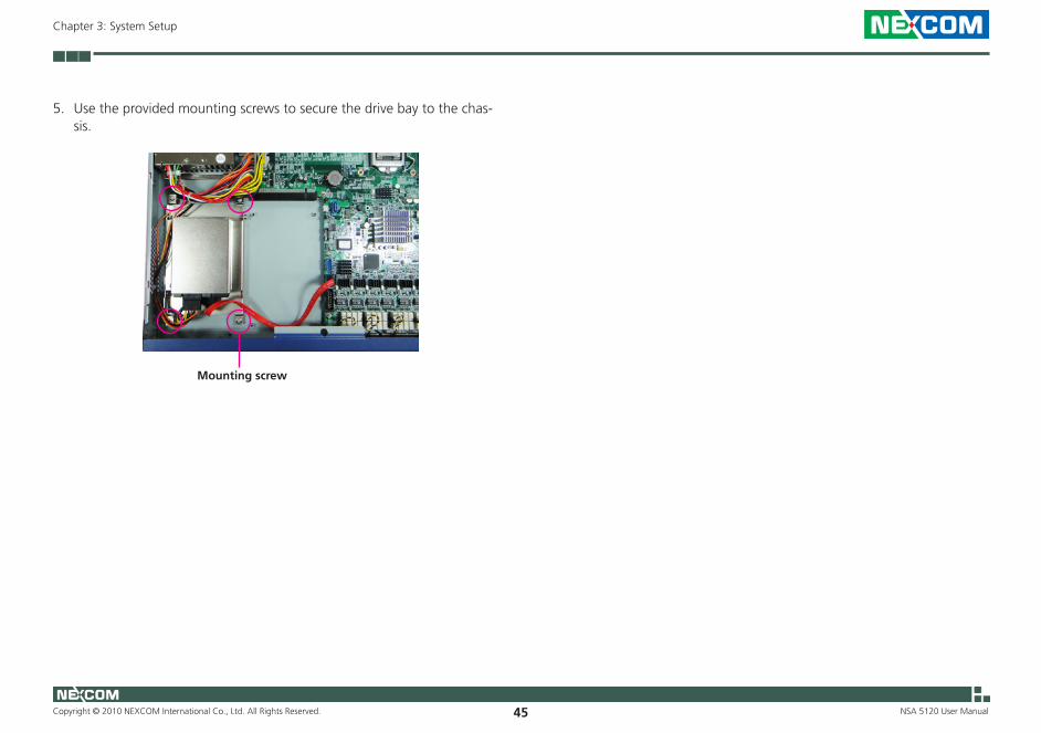
5. Use the provided mounting screws to secure the drive bay to the chas-sis.
Mounting screw

Copyright © 2010 NEXCOM International Co., Ltd. All Rights Reserved. 46
Chapter 4: BIOS Setup
NSA 5120 User Manual
This chapter describes how to use the BIOS setup program for the NSA 5120. The BIOS screens provided in this chapter are for reference only and may change if the BIOS is updated in the future.
To check for the latest updates and revisions, visit the NEXCOM Web site at www.nexcom.com.tw.
About BIOS Setup The BIOS (Basic Input and Output System) Setup program is a menu driven utility that enables you to make changes to the system configuration and tailor your system to suit your individual work needs. It is a ROM-based configuration utility that displays the system’s configuration status and provides you with a tool to set system parameters.
These parameters are stored in non-volatile battery-backed-up CMOS RAM that saves this information even when the power is turned off. When the system is turned back on, the system is configured with the values found in CMOS.
With easy-to-use pull down menus, you can configure such items as: ▪ Hard drives, diskette drives, and peripherals
▪ Video display type and display options
▪ Password protection from unauthorized use
▪ Power management features
The settings made in the setup program affect how the computer per-forms. It is important, therefore, first to try to understand all the Setup options, and second, to make settings appropriate for the way you use the computer.
When to Configure the BIOS This program should be executed under the following conditions: ▪ When changing the system configuration
▪ When a configuration error is detected by the system and you are prompted to make changes to the Setup program
▪ When resetting the system clock
▪ When redefining the communication ports to prevent any conflicts
▪ When making changes to the Power Management configuration
▪ When changing the password or making other changes to the security setup
Normally, CMOS setup is needed when the system hardware is not con-sistent with the information contained in the CMOS RAM, whenever the CMOS RAM has lost power, or the system features need to be changed.
ChaPter 4: Bios setuP
Copyright © 2010 NEXCOM International Co., Ltd. All Rights Reserved. 47
Chapter 4: BIOS Setup
NSA 5120 User Manual
Default ConfigurationMost of the configuration settings are either predefined according to the Load Optimal Defaults settings which are stored in the BIOS or are automatically detected and configured without requiring any actions. There are a few settings that you may need to change depending on your system configuration.
Entering Setup When the system is powered on, the BIOS will enter the Power-On Self Test (POST) routines. These routines perform various diagnostic checks; if an error is encountered, the error will be reported in one of two different ways: ▪ If the error occurs before the display device is initialized, a series of
beeps will be transmitted.
▪ If the error occurs after the display device is initialized, the screen will display the error message.
Powering on the computer and immediately pressing <Del> allows you to enter Setup. Another way to enter Setup is to power on the computer and wait for the following message during the POST:
TO ENTER SETUP BEFORE BOOT PRESS <CTRL-ALT-ESC> Press the <Del> key to enter Setup:
Legends
Key FunctionRight and Left arrows Moves the highlight left or right to select a
menu.Up and Down arrows Moves the highlight up or down between sub-
menus or fields.<Esc> Exits to the BIOS Setup Utility.+ (plus key) Scrolls forward through the values or options of
the highlighted field.- (minus key) Scrolls backward through the values or options
of the highlighted field.Tab Selects a field.<F1> Displays General Help.<F10> Saves and exits the Setup program.<Enter> Press <Enter> to enter the highlighted submenu.
Scroll Bar
When a scroll bar appears to the right of the setup screen, it indicates that there are more available fields not shown on the screen. Use the up and down arrow keys to scroll through all the available fields.
Submenu
When “u“ appears on the left of a particular field, it indicates that a submenu which contains additional options are available for that field. To display the submenu, move the highlight to that field and press <Enter>.
Copyright © 2010 NEXCOM International Co., Ltd. All Rights Reserved. 48
Chapter 4: BIOS Setup
NSA 5120 User Manual
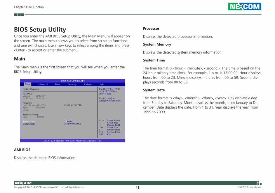
BIOS Setup Utility Once you enter the AMI BIOS Setup Utility, the Main Menu will appear on the screen. The main menu allows you to select from six setup functions and one exit choices. Use arrow keys to select among the items and press <Enter> to accept or enter the submenu.
Main
The Main menu is the first screen that you will see when you enter the BIOS Setup Utility.
AMI BIOS
Displays the detected BIOS information.
Processor
Displays the detected processor information.
System Memory
Displays the detected system memory information.
System Time
The time format is <hour>, <minute>, <second>. The time is based on the 24-hour military-time clock. For example, 1 p.m. is 13:00:00. Hour displays hours from 00 to 23. Minute displays minutes from 00 to 59. Second dis-plays seconds from 00 to 59.
System Date
The date format is <day>, <month>, <date>, <year>. Day displays a day, from Sunday to Saturday. Month displays the month, from January to De-cember. Date displays the date, from 1 to 31. Year displays the year, from 1999 to 2099.
Use [ENTER], [TAB] or [SHIFT-TAB] to select a field.
Use [+] or [-] to configure system Time.
BIOS SETUP UTILITYExitChipset
v02.67 (C)Copyright 1985-2009, American Megatrends, Inc.
← → Select Screen↑↓ Select Item+- Change FieldTab Select FieldF1 General HelpF10 Save and ExitESC Exit
System Overview
AMIBIOSVersion : G512-007Build Date : 08/03/10
ProcessorIntel (R) Xeon (R) CPU Speed :2666MHzCount :1
System MemorySize :1016MB
System TimeSystem Date
X3450 @ 2.67GHz
[14:06:01][Mon 09/06/2010]
Advanced Boot SecurityMain
Copyright © 2010 NEXCOM International Co., Ltd. All Rights Reserved. 49
Chapter 4: BIOS Setup
NSA 5120 User Manual
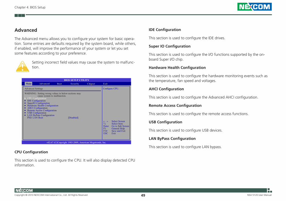
Advanced
The Advanced menu allows you to configure your system for basic opera-tion. Some entries are defaults required by the system board, while others, if enabled, will improve the performance of your system or let you set some features according to your preference.
Setting incorrect field values may cause the system to malfunc-tion.
CPU Configuration
This section is used to configure the CPU. It will also display detected CPU information.
IDE Configuration
This section is used to configure the IDE drives.
Super IO Configuration
This section is used to configure the I/O functions supported by the on-board Super I/O chip.
Hardware Health Configuration
This section is used to configure the hardware monitoring events such as the temperature, fan speed and voltages.
AHCI Configuration
This section is used to configure the Advanced AHCI configuration.
Remote Access Configuration
This section is used to configure the remote access functions.
USB Configuration
This section is used to configure USB devices.
LAN ByPass Configuration
This section is used to configure LAN bypass.
Configure CPU.
BIOS SETUP UTILITY
v02.67 (C)Copyright 1985-2009, American Megatrends, Inc.
← → Select Screen↑↓ Select ItemEnter Go to Sub ScreenF1 General HelpF10 Save and ExitESC Exit
Advanced Settings
WARNING: Setting wrong values in below sections may cause system to malfunction.
uCPU ConfigurationuIDE ConfigurationuSuperIO ConfigurationuHardware Health ConfigurationuAHCI ConfigurationuRemote Access ConfigurationuUSB ConfigurationuLAN ByPass Configuration PXE LAN Boot [Disabled]
ExitChipsetAdvanced Boot SecurityMain

Copyright © 2010 NEXCOM International Co., Ltd. All Rights Reserved. 50
Chapter 4: BIOS Setup
NSA 5120 User Manual
PXE LAN Boot
Enable this field if you wish to use the boot ROM (instead of a disk drive) to boot-up the system and access the local area network directly. If you wish to change the boot ROM’s settings, type the <Shift> and <F10> keys simultaneously when prompted during boot-up. Take note: you will be able to access the boot ROM’s program (by typing <Shift> + <F10>) only when this field is enabled.
Copyright © 2010 NEXCOM International Co., Ltd. All Rights Reserved. 51
Chapter 4: BIOS Setup
NSA 5120 User Manual
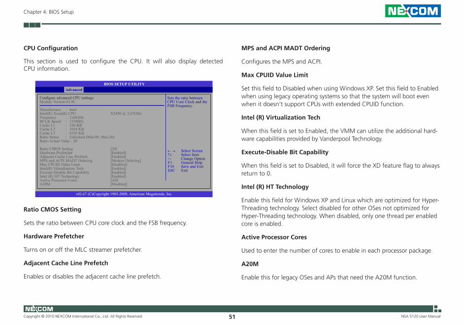
CPU Configuration
This section is used to configure the CPU. It will also display detected CPU information.
BIOS SETUP UTILITY
v02.67 (C)Copyright 1985-2009, American Megatrends, Inc.
← → Select Screen↑↓ Select Item+- Change OptionF1 General HelpF10 Save and ExitESC Exit
Configure advanced CPU settingsModule Version:01.0C
Manufacturer : IntelIntel(R) Xeon(R) CPU X3450 @ 2.67GHzFrequency : 2.66GHzBCLK Speed : 133MHzCache L1 : 256 KBCache L2 : 1024 KBCache L3 : 8192 KBRatio Status : Unlocked (Min:09, Max:20)Ratio Actual Value : 20
Ratio CMOS Setting [20]Hardware Prefetcher [Enabled]Adjacent Cache Line Prefetch [Enabled]MPS and ACPI MADT Ordering [Modern Ordering]Max CPUID Value Limit [Disabled]Intel(R) Virtualization Tech [Enabled]Execute-Disable Bit Capability [Enabled]Intel (R) HT Technology [Enabled]Active Processor Cores [All]A20M [Disabled]
Advanced
Sets the ratio between CPU Core Clock and the FSB Frequency.
Ratio CMOS Setting
Sets the ratio between CPU core clock and the FSB frequency.
Hardware Prefetcher
Turns on or off the MLC streamer prefetcher.
Adjacent Cache Line Prefetch
Enables or disables the adjacent cache line prefetch.
MPS and ACPI MADT Ordering
Configures the MPS and ACPI.
Max CPUID Value Limit
Set this field to Disabled when using Windows XP. Set this field to Enabled when using legacy operating systems so that the system will boot even when it doesn’t support CPUs with extended CPUID function.
Intel (R) Virtualization Tech
When this field is set to Enabled, the VMM can utilize the additional hard-ware capabilities provided by Vanderpool Technology.
Execute-Disable Bit Capability
When this field is set to Disabled, it will force the XD feature flag to always return to 0.
Intel (R) HT Technology
Enable this field for Windows XP and Linux which are optimized for Hyper-Threading technology. Select disabled for other OSes not optimized for Hyper-Threading technology. When disabled, only one thread per enabled core is enabled.
Active Processor Cores
Used to enter the number of cores to enable in each processor package.
A20M
Enable this for legacy OSes and APs that need the A20M function.
Copyright © 2010 NEXCOM International Co., Ltd. All Rights Reserved. 52
Chapter 4: BIOS Setup
NSA 5120 User Manual
IDERAIDAHCI Disabled
BIOS SETUP UTILITY
← → Select Screen↑↓ Select Item+- Change OptionF1 General HelpF10 Save and ExitESC Exit
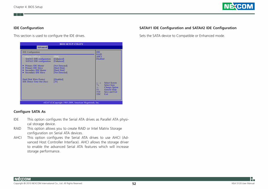
IDE Configuration
Configure SATA as [IDE] SATA#1 IDE configuration [Enhanced] SATA#2 IDE configuration [Enhanced]
uPrimary IDE Master [Not Detected]uPrimary IDE Slave [Hard Disk]uSecondary IDE Master [Hard Disk]uSecondary IDE Slave [Not Detected]
Hard Disk Wirte Protect [Disabled]IDE Detect Time Out (Sec) [35]
Advanced
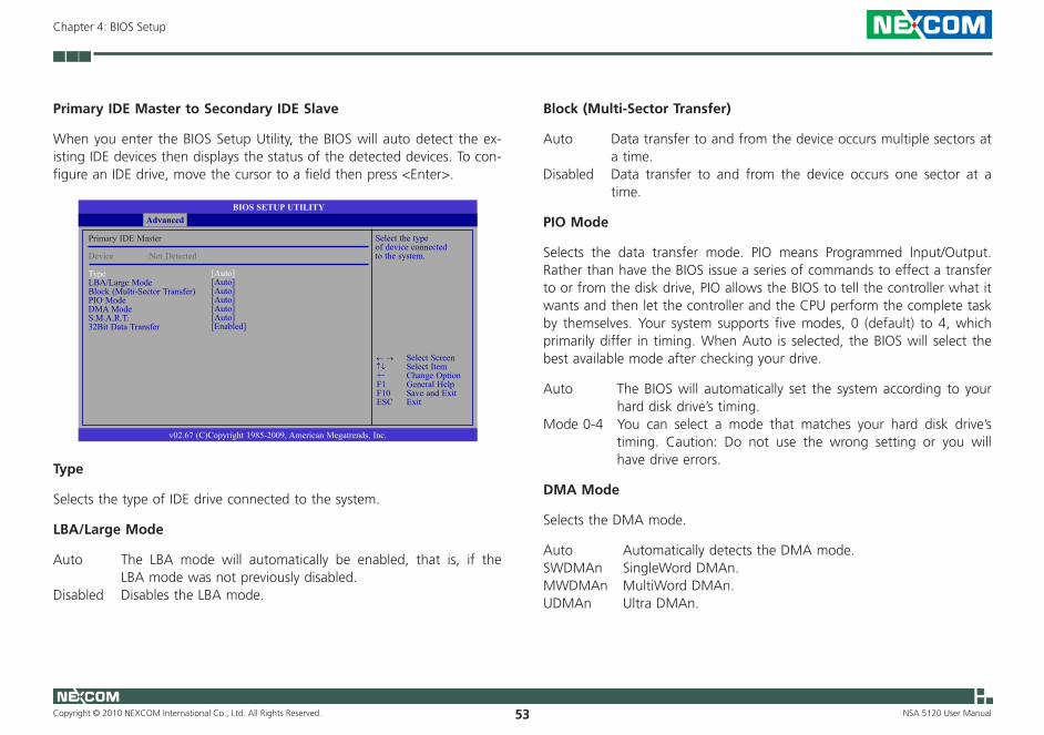
IDE Configuration
This section is used to configure the IDE drives.
Configure SATA As
IDE This option configures the Serial ATA drives as Parallel ATA physi-cal storage device.
RAID This option allows you to create RAID or Intel Matrix Storage configuration on Serial ATA devices.
AHCI This option configures the Serial ATA drives to use AHCI (Ad-vanced Host Controller Interface). AHCI allows the storage driver to enable the advanced Serial ATA features which will increase storage performance.
v02.67 (C)Copyright 1985-2009, American Megatrends, Inc.
SATA#1 IDE Configuration and SATA#2 IDE Configuration
Sets the SATA device to Compatible or Enhanced mode.
Copyright © 2010 NEXCOM International Co., Ltd. All Rights Reserved. 53
Chapter 4: BIOS Setup
NSA 5120 User Manual
Select the type of device connected to the system.
BIOS SETUP UTILITY
v02.67 (C)Copyright 1985-2009, American Megatrends, Inc.
← → Select Screen↑↓ Select Item+- Change OptionF1 General HelpF10 Save and ExitESC Exit
Primary IDE Master
Device :Not Detected
Type LBA/Large ModeBlock (Multi-Sector Transfer)PIO ModeDMA ModeS.M.A.R.T.32Bit Data Transfer
Advanced
[Auto][Auto][Auto] [Auto][Auto][Auto][Enabled]
Primary IDE Master to Secondary IDE Slave
When you enter the BIOS Setup Utility, the BIOS will auto detect the ex-isting IDE devices then displays the status of the detected devices. To con-figure an IDE drive, move the cursor to a field then press <Enter>.
Type
Selects the type of IDE drive connected to the system.
LBA/Large Mode
Auto The LBA mode will automatically be enabled, that is, if the LBA mode was not previously disabled.
Disabled Disables the LBA mode.
Block (Multi-Sector Transfer)
Auto Data transfer to and from the device occurs multiple sectors at a time.
Disabled Data transfer to and from the device occurs one sector at a time.
PIO Mode
Selects the data transfer mode. PIO means Programmed Input/Output. Rather than have the BIOS issue a series of commands to effect a transfer to or from the disk drive, PIO allows the BIOS to tell the controller what it wants and then let the controller and the CPU perform the complete task by themselves. Your system supports five modes, 0 (default) to 4, which primarily differ in timing. When Auto is selected, the BIOS will select the best available mode after checking your drive.
Auto The BIOS will automatically set the system according to your hard disk drive’s timing.
Mode 0-4 You can select a mode that matches your hard disk drive’s timing. Caution: Do not use the wrong setting or you will have drive errors.
DMA Mode
Selects the DMA mode.
Auto Automatically detects the DMA mode.SWDMAn SingleWord DMAn.MWDMAn MultiWord DMAn.UDMAn Ultra DMAn.
Copyright © 2010 NEXCOM International Co., Ltd. All Rights Reserved. 54
Chapter 4: BIOS Setup
NSA 5120 User Manual
S.M.A.R.T.
The system board supports SMART (Self-Monitoring, Analysis and Report-ing Technology) hard drives. SMART is a reliability prediction technology for ATA/IDE and SCSI drives. The drive will provide sufficient notice to the system or user to backup data prior to the drive’s failure. SMART is supported in ATA/33 or later hard drives. The options are Auto (default), Enabled and Disabled.
32Bit Data Transfer
Enables or disables 32-bit data transfer.
Hard Disk Write Protect
Enables or disables write protection of the device. This is applicable only when the device is accessible through the BIOS.
IDE Detect Time Out (Sec)
Selects the time out value for detecting ATA/ATAPI devices.
Copyright © 2010 NEXCOM International Co., Ltd. All Rights Reserved. 55
Chapter 4: BIOS Setup
NSA 5120 User Manual
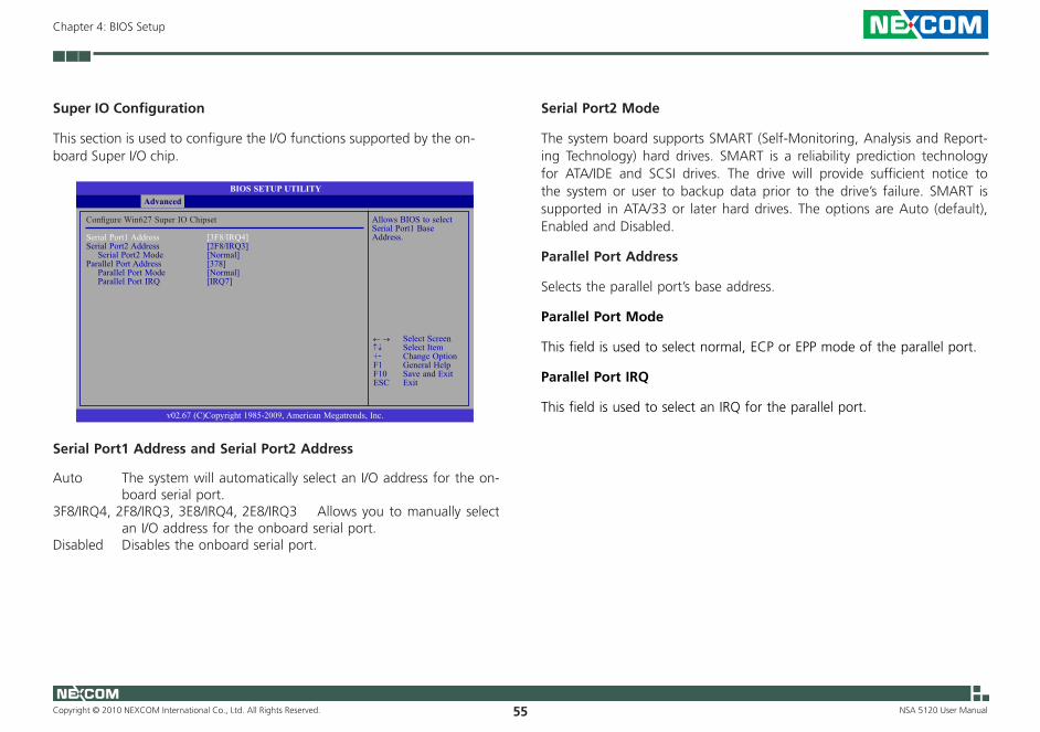
Super IO Configuration
This section is used to configure the I/O functions supported by the on-board Super I/O chip.
Allows BIOS to selectSerial Port1 Base Address.
BIOS SETUP UTILITY
← → Select Screen↑↓ Select Item+- Change OptionF1 General HelpF10 Save and ExitESC Exit
Configure Win627 Super IO Chipset
Serial Port1 Address [3F8/IRQ4]Serial Port2 Address [2F8/IRQ3] Serial Port2 Mode [Normal]Parallel Port Address [378] Parallel Port Mode [Normal] Parallel Port IRQ [IRQ7]
Advanced
v02.67 (C)Copyright 1985-2009, American Megatrends, Inc.
Serial Port1 Address and Serial Port2 Address
Auto The system will automatically select an I/O address for the on-board serial port.
3F8/IRQ4, 2F8/IRQ3, 3E8/IRQ4, 2E8/IRQ3 Allows you to manually select an I/O address for the onboard serial port.
Disabled Disables the onboard serial port.
Serial Port2 Mode
The system board supports SMART (Self-Monitoring, Analysis and Report-ing Technology) hard drives. SMART is a reliability prediction technology for ATA/IDE and SCSI drives. The drive will provide sufficient notice to the system or user to backup data prior to the drive’s failure. SMART is supported in ATA/33 or later hard drives. The options are Auto (default), Enabled and Disabled.
Parallel Port Address
Selects the parallel port’s base address.
Parallel Port Mode
This field is used to select normal, ECP or EPP mode of the parallel port.
Parallel Port IRQ
This field is used to select an IRQ for the parallel port.
Copyright © 2010 NEXCOM International Co., Ltd. All Rights Reserved. 56
Chapter 4: BIOS Setup
NSA 5120 User Manual
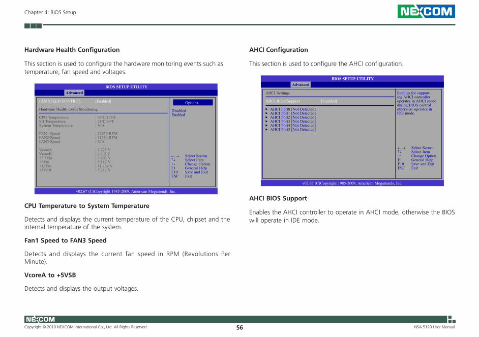
BIOS SETUP UTILITY
v02.67 (C)Copyright 1985-2009, American Megatrends, Inc.
← → Select Screen↑↓ Select Item+- Change OptionF1 General HelpF10 Save and ExitESC Exit
FAN SPEED CONTROL [Enabled]
Hardware Health Event Monitoring
CPU Temperature : 58oC/136oFSB Temperature : 21oC/69oFSystem Temperature : N/A
FAN1 Speed : 12053 RPMFAN2 Speed : 11250 RPMFAN3 Speed : N/A
VcoreA : 1.225 VVcoreB : 1.112 V+3.3Vin : 3.403 V+5Vin : 5.187 V+12Vin : 11.734 V+5VSB : 5.213 V
Advanced
Hardware Health Configuration
This section is used to configure the hardware monitoring events such as temperature, fan speed and voltages.
CPU Temperature to System Temperature
Detects and displays the current temperature of the CPU, chipset and the internal temperature of the system.
Fan1 Speed to FAN3 Speed
Detects and displays the current fan speed in RPM (Revolutions Per Minute).
VcoreA to +5VSB
Detects and displays the output voltages.
Options
DisabledEnabled
AHCI Configuration
This section is used to configure the AHCI configuration.
Enables for support-ing AHCI controller operates in AHCI mode during BIOS control otherwise operates in IDE mode.
BIOS SETUP UTILITY
v02.67 (C)Copyright 1985-2009, American Megatrends, Inc.
← → Select Screen↑↓ Select Item+- Change OptionF1 General HelpF10 Save and ExitESC Exit
AHCI Settings
AHCI BIOS Support [Enabled]
uAHCI Port0 [Not Detected]uAHCI Port1 [Not Detected]uAHCI Port2 [Not Detected]uAHCI Port3 [Not Detected]uAHCI Port4 [Not Detected]uAHCI Port5 [Not Detected]
Advanced
AHCI BIOS Support
Enables the AHCI controller to operate in AHCI mode, otherwise the BIOS will operate in IDE mode.
Copyright © 2010 NEXCOM International Co., Ltd. All Rights Reserved. 57
Chapter 4: BIOS Setup
NSA 5120 User Manual
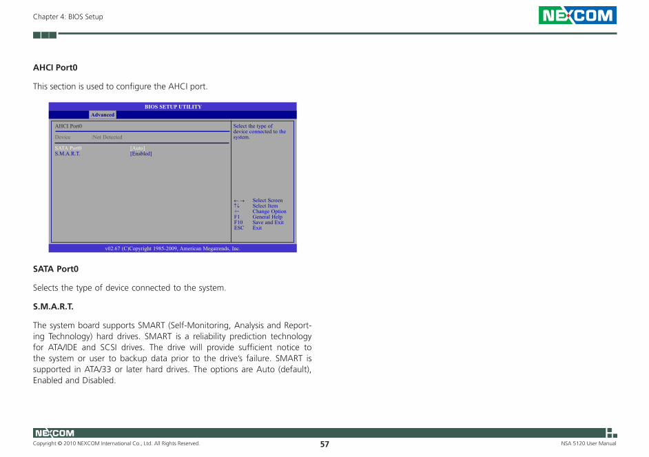
AHCI Port0
This section is used to configure the AHCI port.
Select the type of device connected to the system.
BIOS SETUP UTILITY
v02.67 (C)Copyright 1985-2009, American Megatrends, Inc.
← → Select Screen↑↓ Select Item+- Change OptionF1 General HelpF10 Save and ExitESC Exit
AHCI Port0
Device :Not Detected
SATA Port0 [Auto]S.M.A.R.T. [Enabled]
Advanced
SATA Port0
Selects the type of device connected to the system.
S.M.A.R.T.
The system board supports SMART (Self-Monitoring, Analysis and Report-ing Technology) hard drives. SMART is a reliability prediction technology for ATA/IDE and SCSI drives. The drive will provide sufficient notice to the system or user to backup data prior to the drive’s failure. SMART is supported in ATA/33 or later hard drives. The options are Auto (default), Enabled and Disabled.

Copyright © 2010 NEXCOM International Co., Ltd. All Rights Reserved. 58
Chapter 4: BIOS Setup
NSA 5120 User Manual
Remote Access Configuration
This field when enabled will redirect console via com port. and when dis-abled, will redirect console when keyboard is not available.
Select remote access type.
BIOS SETUP UTILITY
v02.67 (C)Copyright 1985-2009, American Megatrends, Inc.
← → Select Screen↑↓ Select Item+- Change OptionF1 General HelpF10 Save and ExitESC Exit
Configure Remote Access Type and Parameters
Remote Access [Enabled]
Serial Port Number [COM1] Base Address, IRQ [3F8h, 4]Serial Port Mode [09600 8,n,1]Flow Control [None]Redirection After BIOS POST [Boot Loader]Terminal Type [ANSI]VT-UTF8 Combo Key Support [Enabled]Sredir Memory Display Delay [Delay 2 Sec]
Advanced
Remote Access
Selects the remote access type.
Serial Port Number
Selects the serial port.
Base Address, IRQ
Selects an IRQ for the serial port.
Serial Port Mode
Selects a mode for the serial port.
Flow Control
Selects the flow control for console redirection.
Redirection After BIOS POST
Boot Loader Redirection is active during POST and during Boot Loader.Always Redirection is always active. Some OSes may not work
when this field is set to Always.Disabled Turns off the redirection after POST.
Terminal Type
Selects the target terminal type.
VT-UTF8 Combo Key Support
Enables or disables VT-UTF8 combination key support for ANSI/VT100 terminals.
Sredir Memory Display Delay
Selects the delay in seconds to display memory information.

Copyright © 2010 NEXCOM International Co., Ltd. All Rights Reserved. 59
Chapter 4: BIOS Setup
NSA 5120 User Manual
USB Configuration
This section is used to configure USB devices.
Enables support for legacy USB. AUTO option disables legacy support if no USB devices are connected.
BIOS SETUP UTILITY
v02.67 (C)Copyright 1985-2009, American Megatrends, Inc.
← → Select Screen↑↓ Select Item+- Change OptionF1 General HelpF10 Save and ExitESC Exit
USB Configuration
Module Version - 2.24.5-14.4
USB Devices Enabled: 1 Keyboard, 2 Hubs
Legacy USB Support [Enabled]Port 64/60 Emulation [Disabled]USB 2.0 Controller Mode [HiSpeed]BIOS EHCI Hand-Off [Disabled]USB Beep Message [Enabled]
Advanced
Legacy USB Support
Due to the limited space of the BIOS ROM, the support for legacy USB keyboard (in DOS mode) is by default set to Disabled. With more BIOS ROM space available, it will be able to support more advanced features as well as provide compatibility to a wide variety of peripheral devices.
If a PS/2 keyboard is not available and you need to use a USB keyboard to install Windows (installation is performed in DOS mode) or run any program under DOS, set this field to Enabled.
Port 64/60 Emulation
Enables the I/O port 60h/64h emulation. This should be enabled for com-plete USB keyboard legacy support for non-USB OSes..
USB 2.0 Controller Mode
Sets the USB 2.0 controller mode to HiSpeed (480 Mbps) or FullSpeed (12 Mbps).
BIOS EHCI Hand-Off
Enable this field when using operating systems without the EHCI hand-off support.
USB Beep Message
Enables the beep during USB device enumeration.
Copyright © 2010 NEXCOM International Co., Ltd. All Rights Reserved. 60
Chapter 4: BIOS Setup
NSA 5120 User Manual
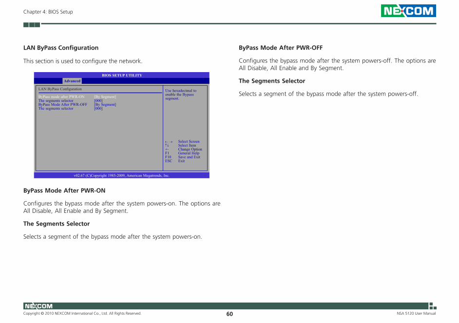
LAN ByPass Configuration
This section is used to configure the network.
BIOS SETUP UTILITY
v02.67 (C)Copyright 1985-2009, American Megatrends, Inc.
← → Select Screen↑↓ Select Item+- Change OptionF1 General HelpF10 Save and ExitESC Exit
LAN ByPass Configuration
ByPass mode after PWR-ON [By Segment]The segments selector [000]ByPass Mode After PWR-OFF [By Segment]The segments selector [000]
Advanced
Use hexadecimal to enable the Bypass segment.
ByPass Mode After PWR-ON
Configures the bypass mode after the system powers-on. The options are All Disable, All Enable and By Segment.
The Segments Selector
Selects a segment of the bypass mode after the system powers-on.
ByPass Mode After PWR-OFF
Configures the bypass mode after the system powers-off. The options are All Disable, All Enable and By Segment.
The Segments Selector
Selects a segment of the bypass mode after the system powers-off.

Copyright © 2010 NEXCOM International Co., Ltd. All Rights Reserved. 61
Chapter 4: BIOS Setup
NSA 5120 User Manual
Boot
Boot Settings Configuration
This section is used to configure settings during system boot.
Boot Device Priority
This section is used to select the boot priority sequence of the devices.
Hard Disk Drives
This section is used to select the boot priority sequence of the hard disk drives.
Configure settings during system boot.
BIOS SETUP UTILITY
v02.67 (C)Copyright 1985-2009, American Megatrends, Inc.
← → Select Screen↑↓ Select ItemEnter Go to Sub ScreenF1 General HelpF10 Save and ExitESC Exit
Boot Settings
uBoot Settings Configuration
uBoot Device PriorityuHard Disk Drives
Boot Settings Configuration
This section is used to configure settings during system boot.
Allows BIOS to skip certain tests while booting. This will decrease the time needed to boot the system.
BIOS SETUP UTILITY
v02.67 (C)Copyright 1985-2009, American Megatrends, Inc.
← → Select Screen↑↓ Select Item+- Change OptionF1 General HelpF10 Save and ExitESC Exit
Boot Settings Configuration
Quick Boot [Enabled]AddOn ROM Display Mode [Force BIOS]Bootup Num-Lock [On]PS/2 Mouse Support [Auto]Wait For ‘F1’ If Error [Disabled]Hit ‘DEL’ Message Display [Enabled]Interrupt 19 Capture [Disabled]
Boot
Quick Boot
When Enabled, the BIOS will shorten or skip some check items during POST. This will decrease the time needed to boot the system.
ExitChipsetAdvanced Boot SecurityMain
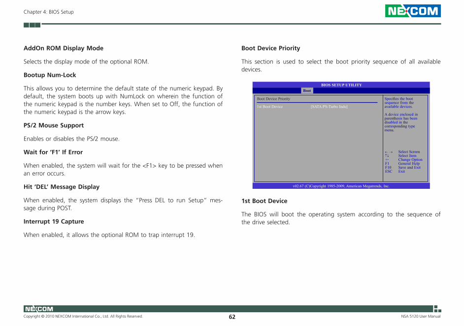
Copyright © 2010 NEXCOM International Co., Ltd. All Rights Reserved. 62
Chapter 4: BIOS Setup
NSA 5120 User Manual
AddOn ROM Display Mode
Selects the display mode of the optional ROM.
Bootup Num-Lock
This allows you to determine the default state of the numeric keypad. By default, the system boots up with NumLock on wherein the function of the numeric keypad is the number keys. When set to Off, the function of the numeric keypad is the arrow keys.
PS/2 Mouse Support
Enables or disables the PS/2 mouse.
Wait for ‘F1’ If Error
When enabled, the system will wait for the <F1> key to be pressed when an error occurs.
Hit ‘DEL’ Message Display
When enabled, the system displays the “Press DEL to run Setup” mes-sage during POST.
Interrupt 19 Capture
When enabled, it allows the optional ROM to trap interrupt 19.
Specifies the boot sequence from the available devices.
A device enclosed in parenthesis has been disabled in the corresponding type menu.
BIOS SETUP UTILITY
v02.67 (C)Copyright 1985-2009, American Megatrends, Inc.
← → Select Screen↑↓ Select Item+- Change OptionF1 General HelpF10 Save and ExitESC Exit
Boot Device Priority
1st Boot Device [SATA:PS-Turbo Indu]
Boot
Boot Device Priority
This section is used to select the boot priority sequence of all available devices.
1st Boot Device
The BIOS will boot the operating system according to the sequence of the drive selected.
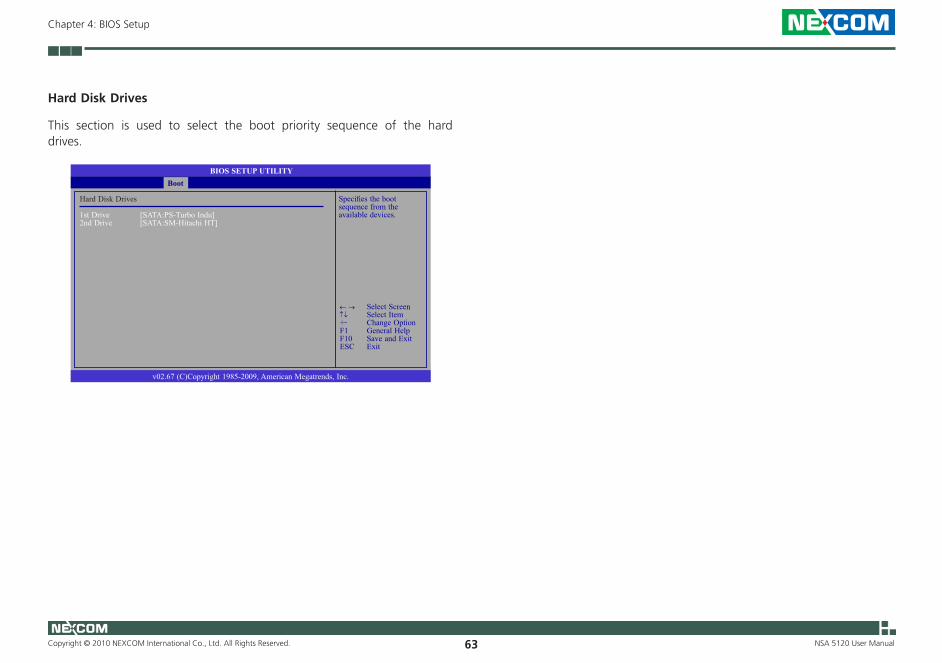
Copyright © 2010 NEXCOM International Co., Ltd. All Rights Reserved. 63
Chapter 4: BIOS Setup
NSA 5120 User Manual
Specifies the boot sequence from the available devices.
BIOS SETUP UTILITY
v02.67 (C)Copyright 1985-2009, American Megatrends, Inc.
← → Select Screen↑↓ Select Item+- Change OptionF1 General HelpF10 Save and ExitESC Exit
Hard Disk Drives
1st Drive [SATA:PS-Turbo Indu]2nd Drive [SATA:SM-Hitachi HT]
Boot
Hard Disk Drives
This section is used to select the boot priority sequence of the hard drives.
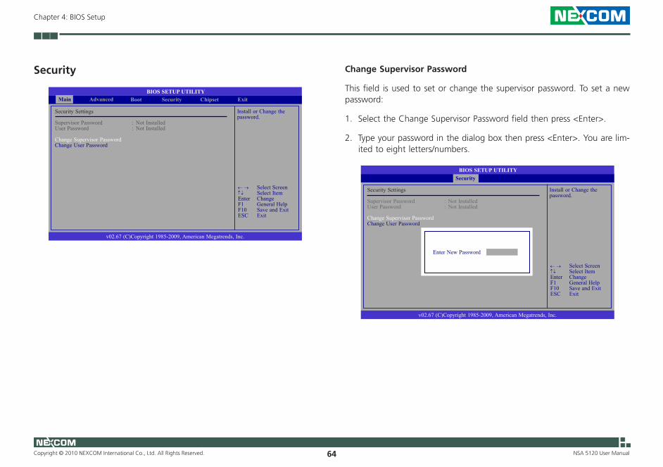
Copyright © 2010 NEXCOM International Co., Ltd. All Rights Reserved. 64
Chapter 4: BIOS Setup
NSA 5120 User Manual
Security
Install or Change the password.
BIOS SETUP UTILITY
v02.67 (C)Copyright 1985-2009, American Megatrends, Inc.
← → Select Screen↑↓ Select ItemEnter ChangeF1 General HelpF10 Save and ExitESC Exit
Security Settings
Supervisor Password : Not InstalledUser Password : Not Installed
Change Supervisor PasswordChange User Password
ExitChipsetAdvanced Boot SecurityMain
Change Supervisor Password
This field is used to set or change the supervisor password. To set a new password:
1. Select the Change Supervisor Password field then press <Enter>.
2. Type your password in the dialog box then press <Enter>. You are lim-ited to eight letters/numbers.
Install or Change the password.
BIOS SETUP UTILITY
v02.67 (C)Copyright 1985-2009, American Megatrends, Inc.
← → Select Screen↑↓ Select ItemEnter ChangeF1 General HelpF10 Save and ExitESC Exit
Security Settings
Supervisor Password : Not InstalledUser Password : Not Installed
Change Supervisor PasswordChange User Password
Security
Enter New Password
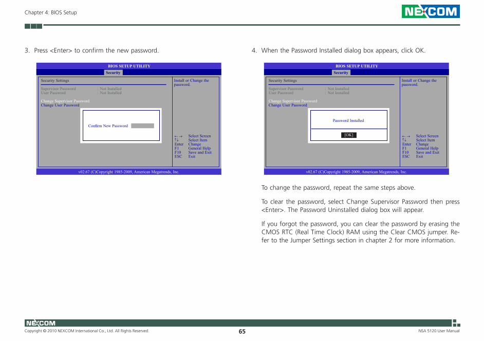
Copyright © 2010 NEXCOM International Co., Ltd. All Rights Reserved. 65
Chapter 4: BIOS Setup
NSA 5120 User Manual
3. Press <Enter> to confirm the new password.
Install or Change the password.
BIOS SETUP UTILITY
v02.67 (C)Copyright 1985-2009, American Megatrends, Inc.
← → Select Screen↑↓ Select ItemEnter ChangeF1 General HelpF10 Save and ExitESC Exit
Security Settings
Supervisor Password : Not InstalledUser Password : Not Installed
Change Supervisor PasswordChange User Password
Security
Confirm New Password
4. When the Password Installed dialog box appears, click OK.
Install or Change the password.
BIOS SETUP UTILITY
v02.67 (C)Copyright 1985-2009, American Megatrends, Inc.
← → Select Screen↑↓ Select ItemEnter ChangeF1 General HelpF10 Save and ExitESC Exit
Security Settings
Supervisor Password : Not InstalledUser Password : Not Installed
Change Supervisor PasswordChange User Password
Security
Password Installed
[OK]
To change the password, repeat the same steps above.
To clear the password, select Change Supervisor Password then press <Enter>. The Password Uninstalled dialog box will appear.
If you forgot the password, you can clear the password by erasing the CMOS RTC (Real Time Clock) RAM using the Clear CMOS jumper. Re-fer to the Jumper Settings section in chapter 2 for more information.

Copyright © 2010 NEXCOM International Co., Ltd. All Rights Reserved. 66
Chapter 4: BIOS Setup
NSA 5120 User Manual
After you have set the supervisor password, the User Access Level field will appear.
Limited: allows only limited fields to be changed such as Date and Time.No Access: prevents User access to the Setup Utility.View Only: allows ac-cess to the Setup Utility but the fields can not be changed.
BIOS SETUP UTILITY
v02.67 (C)Copyright 1985-2009, American Megatrends, Inc.
← → Select Screen↑↓ Select Item+- Change OptionF1 General HelpF10 Save and ExitESC Exit
Security Settings
Supervisor Password : InstalledUser Password : Not Installed
Change Supervisor PasswordUser Access Level [Full Access]Change User PasswordPassword Check [Setup]
Security
User Access Level
Selects the access level to the fields in the Setup utility.
LimitedAllows limited change to some fields such as Date and Time.
No AccessPrevents user access to the Setup utility.
View OnlyAllows you to view the settings but does not allow you to change the settings.
Full AccessAllows you to change settings to all the fields in the utility.

Copyright © 2010 NEXCOM International Co., Ltd. All Rights Reserved. 67
Chapter 4: BIOS Setup
NSA 5120 User Manual
Change User Password
This field is used to set or change the user password.
To set a new password:
1. Select the Change User Password field then press <Enter>.
2. Type your password in the dialog box then press <Enter>. You are lim-ited to eight letters/numbers.
Install or Change the password.
BIOS SETUP UTILITY
v02.67 (C)Copyright 1985-2009, American Megatrends, Inc.
← → Select Screen↑↓ Select ItemEnter ChangeF1 General HelpF10 Save and ExitESC Exit
Security
Enter New Password
Security Settings
Supervisor Password : InstalledUser Password : Not Installed
Change Supervisor PasswordChange User Password
3. Press <Enter> to confirm the new password.
Install or Change the password.
BIOS SETUP UTILITY
v02.67 (C)Copyright 1985-2009, American Megatrends, Inc.
← → Select Screen↑↓ Select ItemEnter ChangeF1 General HelpF10 Save and ExitESC Exit
Security
Security Settings
Supervisor Password : InstalledUser Password : Not Installed
Change Supervisor PasswordChange User Password
Confirm New Password
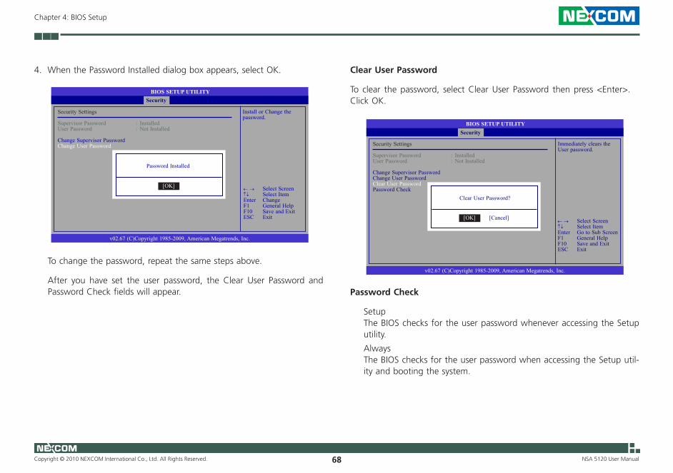
Copyright © 2010 NEXCOM International Co., Ltd. All Rights Reserved. 68
Chapter 4: BIOS Setup
NSA 5120 User Manual
4. When the Password Installed dialog box appears, select OK.
To change the password, repeat the same steps above.
After you have set the user password, the Clear User Password and Password Check fields will appear.
Install or Change the password.
BIOS SETUP UTILITY
v02.67 (C)Copyright 1985-2009, American Megatrends, Inc.
← → Select Screen↑↓ Select ItemEnter ChangeF1 General HelpF10 Save and ExitESC Exit
Security
Security Settings
Supervisor Password : InstalledUser Password : Not Installed
Change Supervisor PasswordChange User Password
Password Installed
[OK]
Clear User Password
To clear the password, select Clear User Password then press <Enter>. Click OK.
BIOS SETUP UTILITY
v02.67 (C)Copyright 1985-2009, American Megatrends, Inc.
Security
Security Settings
Supervisor Password : InstalledUser Password : Not Installed
Change Supervisor PasswordChange User PasswordClear User PasswordPassword Check
Clear User Password?
[OK] [Cancel]
Immediately clears the User password.
← → Select Screen↑↓ Select ItemEnter Go to Sub ScreenF1 General HelpF10 Save and ExitESC Exit
Password Check
Setup The BIOS checks for the user password whenever accessing the Setup utility.
Always The BIOS checks for the user password when accessing the Setup util-ity and booting the system.
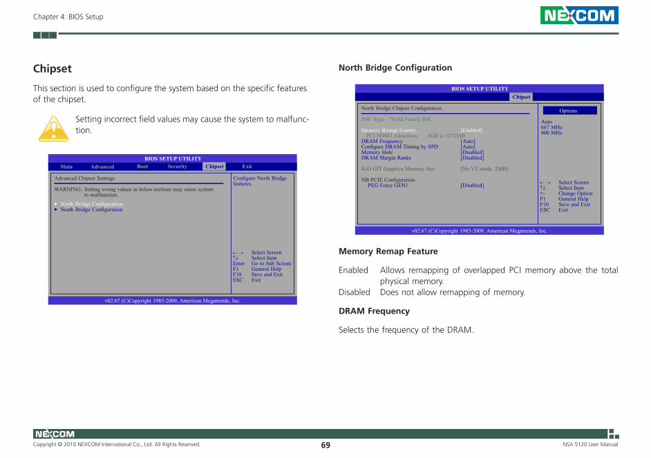
Copyright © 2010 NEXCOM International Co., Ltd. All Rights Reserved. 69
Chapter 4: BIOS Setup
NSA 5120 User Manual
Chipset
This section is used to configure the system based on the specific features of the chipset.
Setting incorrect field values may cause the system to malfunc-tion.
BIOS SETUP UTILITYExit
v02.67 (C)Copyright 1985-2009, American Megatrends, Inc.
← → Select Screen↑↓ Select ItemEnter Go to Sub ScreenF1 General HelpF10 Save and ExitESC Exit
Boot SecurityMain Advanced Chipset
Configure North Bridge features.
Advanced Chipset Settings
WARNING: Setting wrong values in below sections may cause system to malfunction.
uNorth Bridge Configuration uSouth Bridge Configuration
BIOS SETUP UTILITY
v02.67 (C)Copyright 1985-2009, American Megatrends, Inc.
← → Select Screen↑↓ Select Item+- Change OptionF1 General HelpF10 Save and ExitESC Exit
North Bridge Chipset Configuration
IMC Type : *Field Family IMC
Memory Remap Feature [Enabled] PCI MMIO Allocation: 4GB to 3072MBDRAM Frequency [Auto]Configure DRAM Timing by SPD [Auto]Memory Hole [Disabled]DRAM Margin Ranks [Disabled]
IGD GIT Graphics Memory Size [No VT mode, 2MB]
NB PCIE Configuration PEG Force GEN1 [Disabled]
Chipset
North Bridge Configuration
Options
Auto667 MHz800 MHz
Memory Remap Feature
Enabled Allows remapping of overlapped PCI memory above the total physical memory.
Disabled Does not allow remapping of memory.
DRAM Frequency
Selects the frequency of the DRAM.
Copyright © 2010 NEXCOM International Co., Ltd. All Rights Reserved. 70
Chapter 4: BIOS Setup
NSA 5120 User Manual
Configure DRAM Timing by SPD
Enabled The EEPROM on a DIMM has SPD (Serial Presence Detect) data structure that stores information about the module such as the memory type, memory size, memory speed, etc. When this op-tion is selected, the system will run according to the settings in the EEPROM. This option is the default setting because it provides the most stable condition for the system.
Disabled Select this option if you want to manually select the DRAM timings.
Memory Hole
This field is used to select the memory area that must not be addressed to the ISA bus.
DRAM Margin Ranks
The options are Enabled and Disabled.
PEG Force GEN1
Some PCIE graphics devices does not comply to the PCIE specification and may incorrectly report their Gen capability or link width. Select Enabled to force the graphics device in Gen 1 mode.
Copyright © 2010 NEXCOM International Co., Ltd. All Rights Reserved. 71
Chapter 4: BIOS Setup
NSA 5120 User Manual
South Bridge Configuration
Enable/Disable USB controller in system.
BIOS SETUP UTILITY
v02.67 (C)Copyright 1985-2009, American Megatrends, Inc.
← → Select Screen↑↓ Select Item+- Change OptionF1 General HelpF10 Save and ExitESC Exit
South Bridge Chipset Configuration
USB Function [Enabled] EHCI Controller#1 [Enabled] EHCI Controller#2 [Enabled]SMBUS Controller [Enabled]
SLP_S4# Min. Assertion Width [4 to 5 seconds]
Power-Supply Type [AT]
Chipset
USB Function
Enables or disables the USB ports.
EHCI Controller#1 and EHCI Controller#2
These fields are used to enable or disable the Enhanced Host Controller Interface controller.
SMBUS Controller
Enables or disables the SMBUS controller.
SLP_S4# Assertion Width
The options are 1 to 2 seconds, 2 to 3 seconds, 3 to 4 seconds and 4 to 5 seconds.
Power-Supply Type
Selects the type of power supply.
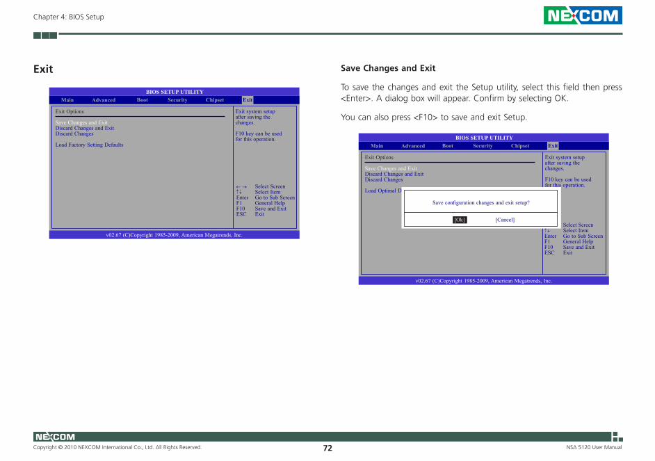
Copyright © 2010 NEXCOM International Co., Ltd. All Rights Reserved. 72
Chapter 4: BIOS Setup
NSA 5120 User Manual
Save Changes and Exit
To save the changes and exit the Setup utility, select this field then press <Enter>. A dialog box will appear. Confirm by selecting OK.
You can also press <F10> to save and exit Setup.
Exit system setup after saving the changes.
F10 key can be used for this operation.
BIOS SETUP UTILITYChipset
v02.67 (C)Copyright 1985-2009, American Megatrends, Inc.
← → Select Screen↑↓ Select ItemEnter Go to Sub ScreenF1 General HelpF10 Save and ExitESC Exit
Boot SecurityMain Advanced
Exit Options
Save Changes and Exit Discard Changes and ExitDiscard Changes
Load Optimal Defaults
Exit
Save configuration changes and exit setup?
[Cancel][Ok]
Exit
Exit system setupafter saving the changes.
F10 key can be used for this operation.
BIOS SETUP UTILITYChipset
v02.67 (C)Copyright 1985-2009, American Megatrends, Inc.
← → Select Screen↑↓ Select ItemEnter Go to Sub ScreenF1 General HelpF10 Save and ExitESC Exit
Boot SecurityMain Advanced
Exit Options
Save Changes and Exit Discard Changes and ExitDiscard Changes
Load Factory Setting Defaults
Exit

Copyright © 2010 NEXCOM International Co., Ltd. All Rights Reserved. 73
Chapter 4: BIOS Setup
NSA 5120 User Manual
Discard Changes and Exit
To exit the Setup utility without saving the changes, select this field then press <Enter>. A dialog box will appear. Confirm by selecting OK.
You can also press <ESC> to exit without saving the changes.
Exit system setup without saving any changes.
ESC key can be used for this operation.
BIOS SETUP UTILITYChipset
v02.67 (C)Copyright 1985-2009, American Megatrends, Inc.
← → Select Screen↑↓ Select ItemEnter Go to Sub ScreenF1 General HelpF10 Save and ExitESC Exit
Boot SecurityMain Advanced
Exit Options
Save Changes and Exit Discard Changes and ExitDiscard Changes
Load Optimal Defaults
Exit
Discard changes and exit setup?
[Cancel][Ok]
Discard Changes
To discard the changes, select this field then press <Enter>. A dialog box will appear. Confirm by selecting OK to discard all changes made and restore the previously saved settings.
You can also press <F7> to discard the changes.
Discards changes done so far to any of the setup questions.
F7 key can be used for this operation.
BIOS SETUP UTILITYChipset
v02.67 (C)Copyright 1985-2009, American Megatrends, Inc.
← → Select Screen↑↓ Select ItemEnter Go to Sub ScreenF1 General HelpF10 Save and ExitESC Exit
Boot SecurityMain Advanced
Exit Options
Save Changes and Exit Discard Changes and ExitDiscard Changes
Load Optimal Defaults
Exit
Discard Changes?
[Cancel][Ok]
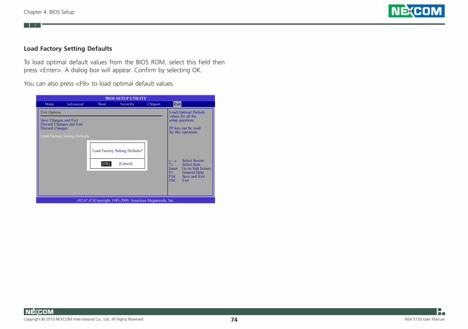
Copyright © 2010 NEXCOM International Co., Ltd. All Rights Reserved. 74
Chapter 4: BIOS Setup
NSA 5120 User Manual
Load Factory Setting Defaults
To load optimal default values from the BIOS ROM, select this field then press <Enter>. A dialog box will appear. Confirm by selecting OK.
You can also press <F9> to load optimal default values.
Load Optimal Default values for all the setup questions.
F9 key can be used for this operation.
BIOS SETUP UTILITYChipset
v02.67 (C)Copyright 1985-2009, American Megatrends, Inc.
← → Select Screen↑↓ Select ItemEnter Go to Sub ScreenF1 General HelpF10 Save and ExitESC Exit
Boot SecurityMain Advanced
Exit Options
Save Changes and Exit Discard Changes and ExitDiscard Changes
Load Factory Setting Defaults
Exit
Load Factory Setting Defaults?
[Cancel][Ok]
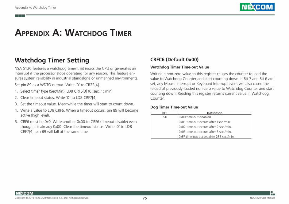
Copyright © 2010 NEXCOM International Co., Ltd. All Rights Reserved. 75 NSA 5120 User Manual
Appendix A: Watchdog Timer
aPPendix a: WatChdog timer
Watchdog Timer Setting NSA 5120 features a watchdog timer that resets the CPU or generates an interrupt if the processor stops operating for any reason. This feature en-sures system reliability in industrial standalone or unmanned environments.
Set pin 89 as a WDTO output. Write ‘0’ to CR2B[4].
1. Select timer type (Sec/Min). LD8 CRF5[3] (0: sec, 1: min)
2. Clear timeout status. Write ‘0’ to LD8 CRF7[4].
3. Set the timeout value. Meanwhile the timer will start to count down.
4. Write a value to LD8 CRF6. When a timeout occurs, pin 89 will become active (high level).
5. CRF6 must be 0x0. Write another 0x00 to CRF6 (timeout disable) even though it is already 0x00. Clear the timeout status. Write ‘0’ to LD8 CRF7[4]. pin 89 will fall at the same time.
CRFC6 (Default 0x00) Watchdog Timer Time-out Value
Writing a non-zero value to this register causes the counter to load the value to Watchdog Counter and start counting down. If Bit 7 and Bit 6 are set, any Mouse Interrupt or Keyboard Interrupt event will also cause the reload of previously-loaded non-zero value to Watchdog Counter and start counting down. Reading this register returns current value in Watchdog Counter.
Dog Timer Time-out ValueBIT Definition7-0 0x00 time-out disabled
0x01 time-out occurs after 1sec./min.
0x02 time-out occurs after 2 sec./min.
0x03 time-out occurs after 3 sec./min.
0xFF time-out occurs after 255 sec./min.
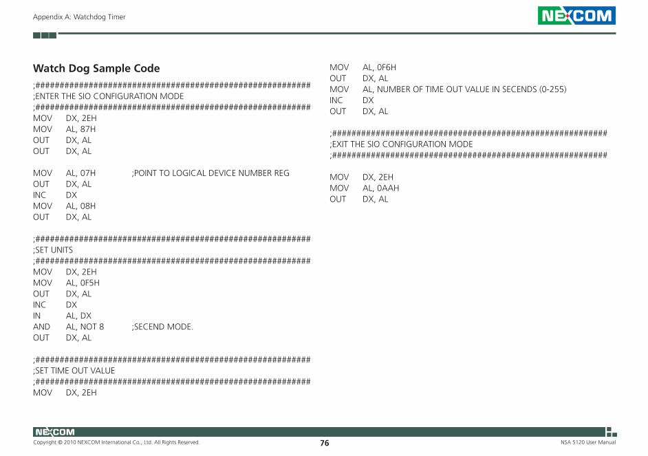
Copyright © 2010 NEXCOM International Co., Ltd. All Rights Reserved. 76 NSA 5120 User Manual
Appendix A: Watchdog Timer
Watch Dog Sample Code;#########################################################;ENTER THE SIO CONFIGURATION MODE ;#########################################################MOV DX, 2EHMOV AL, 87HOUT DX, ALOUT DX, AL
MOV AL, 07H ;POINT TO LOGICAL DEVICE NUMBER REGOUT DX, ALINC DXMOV AL, 08H OUT DX, AL
;#########################################################;SET UNITS;#########################################################MOV DX, 2EHMOV AL, 0F5H OUT DX, ALINC DXIN AL, DXAND AL, NOT 8 ;SECEND MODE. OUT DX, AL
;#########################################################;SET TIME OUT VALUE;#########################################################MOV DX, 2EH
MOV AL, 0F6H OUT DX, AL MOV AL, NUMBER OF TIME OUT VALUE IN SECENDS (0-255)INC DXOUT DX, AL ;#########################################################;EXIT THE SIO CONFIGURATION MODE;#########################################################
MOV DX, 2EHMOV AL, 0AAHOUT DX, AL
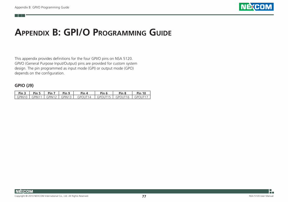
Copyright © 2010 NEXCOM International Co., Ltd. All Rights Reserved. 77
Appendix B: GPI/O Programming Guide
NSA 5120 User Manual
aPPendix B: gPi/o Programming guide
This appendix provides definitions for the four GPI/O pins on NSA 5120. GPI/O (General Purpose Input/Output) pins are provided for custom system design. The pin programmed as input mode (GPI) or output mode (GPO) depends on the configuration.
GPIO (J9)
Pin 3 Pin 5 Pin 7 Pin 9 Pin 4 Pin 6 Pin 8 Pin 10GPIN10 GPIN11 GPIN12 GPIN13 GPOUT14 GPOUT15 GPOUT16 GPOUT17
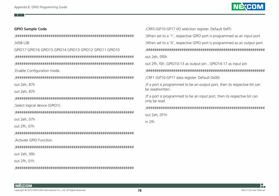
Copyright © 2010 NEXCOM International Co., Ltd. All Rights Reserved. 78
Appendix B: GPI/O Programming Guide
NSA 5120 User Manual
GPIO Sample Code
;#########################################################
;MSB LSB
GPIO17 GPIO16 GPIO15 GPIO14 GPIO13 GPIO12 GPIO11 GPIO10
;#########################################################
;#########################################################
;Enable Configuration mode.
;#########################################################
out 2eh, 87h
out 2eh, 87h
;#########################################################
;Select logical device (GPIO1).
;#########################################################
out 2eh, 07h
out 2fh, 07h
;#########################################################
;Activate GPIO Function.
;#########################################################
out 2eh, 30h
out 2fh, 01h
;#########################################################
;CRF0 (GP10-GP17 I/O selection register. Default 0xFF)
;When set to a ‘1’, respective GPIO port is programmed as an input port.
;When set to a ‘0’, respective GPIO port is programmed as an output port.
;#########################################################
out 2eh, 0f0h
out 2fh, f0h ;GPIO10-13 as output pin , GPIO14-17 as input pin
;#########################################################
;CRF1 (GP10-GP17 data register. Default 0x00)
;If a port is programmed to be an output port, then its respective bit can be read/written.
;If a port is programmed to be an input port, then its respective bit can only be read.
;#########################################################
out 2eh, 0f1h
in 2fh

Copyright © 2010 NEXCOM International Co., Ltd. All Rights Reserved. 79
Appendix B: GPI/O Programming Guide
NSA 5120 User Manual
SW1
Read GPI57 Sample Code
mov dx,4BBh
in al,dx
and al,1 ;now al (bit4) is GPIO56 value.
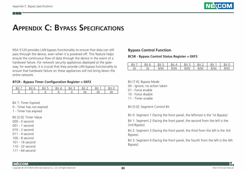
Copyright © 2010 NEXCOM International Co., Ltd. All Rights Reserved. 80
Appendix C: Bypass Specifications
NSA 5120 User Manual
NSA 5120 provides LAN bypass functionality to ensure that data can still pass through the device, even when it is powered off. This feature helps ensure the continuous flow of data through the device in the event of a hardware failure. For network security appliances deployed at the gate-way, for example, it is crucial that they provide LAN bypass functionality to ensure that hardware failure on these appliances will not bring down the entire network.
aPPendix C: ByPass sPeCifiCations
BTCR - Bypass Timer Configuration Register = 0XF2
Bit 7 Bit 6 Bit 5 Bit 4 Bit 3 Bit 2 Bit 1 Bit 0R X X X X W W W
Bit 7: Timer Expired0 - Timer has not expired1 - Timer has expired
Bit [2:0]: Timer Value000 - 0 second001 - 1 second010 - 2 second011 - 4 second100 - 8 second101 - 16 second110 - 32 second111 - 64 second
Bypass Control Function
BCSR - Bypass Control Status Register = 0XF3
Bit 7 Bit 6 Bit 5 Bit 4 Bit 3 Bit 2 Bit 1 Bit 0W W R/W R/W R/W R/W R/W R/W
Bit [7:6]: Bypass Mode00 - Ignore, no action taken01 - Force enable10 - Force disable11 - Timer enable
Bit [5:0]: Segment Control Bit
Bit 0: Segment 1 (facing the front panel, the leftmost is the 1st Bypass)
Bit 1: Segment 2 (facing the front panel, the second from the left is the 2nd Bypass)
Bit 2: Segment 3 (facing the front panel, the third from the left is the 3rd Bypass)
Bit 3: Segment 4 (facing the front panel, the fourth from the left is the 4th Bypass)
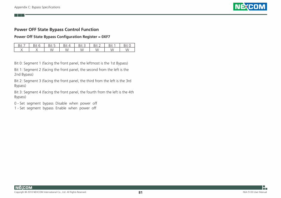
Copyright © 2010 NEXCOM International Co., Ltd. All Rights Reserved. 81
Appendix C: Bypass Specifications
NSA 5120 User Manual
Power OFF State Bypass Control Function
Power Off State Bypass Configuration Register = 0XF7
Bit 7 Bit 6 Bit 5 Bit 4 Bit 3 Bit 2 Bit 1 Bit 0X X W W W W W W
Bit 0: Segment 1 (facing the front panel, the leftmost is the 1st Bypass)
Bit 1: Segment 2 (facing the front panel, the second from the left is the 2nd Bypass)
Bit 2: Segment 3 (facing the front panel, the third from the left is the 3rd Bypass)
Bit 3: Segment 4 (facing the front panel, the fourth from the left is the 4th Bypass)
0 - Set segment bypass Disable when power off1 - Set segment bypass Enable when power off

Copyright © 2010 NEXCOM International Co., Ltd. All Rights Reserved. 82 NSA 5120 User Manual
Appendix D: Power Consumption
aPPendix d: PoWer ConsumPtion
Power Consumption
Voltage 12V 5VSB 3VSB 5V 3.3V VCORE0.5V-1.4V
1.1V 1.5V 0.75V 1.05V 1.8V
Net Name P12V P5VSB P3V3SB P5V P3V3 PV_VCCP P1V1_VTT P1V5_SM P0V75_SM_VTT VCC_PCH P1V8CPU 110
35 5PCH 1.5 0.512 7.8DDR3 18.5 1CK505 0.55Clock Buffer 0.582574L x 8 2.16Relay x 32 3.2PS2 KB/MS 0.5FAN x 2 1USB x 4 2Nexcom Module 0.5 0.1 1 8PCIE x4 or x8 slot 2.1 0.375 3Total Current 3.6 0 1.975 6.7 14.7 110 35 18.5 1 7.8 5

Copyright © 2010 NEXCOM International Co., Ltd. All Rights Reserved. 83 NSA 5120 User Manual
Appendix D: Power Consumption
Total Power Requirements
Power Type +12V +5V +3.3V TotalConsumed watts (Item W) 154W 96W 12.30W 262.3WConsumed currents (Item A ) 12.83A 19.2A 3.722AActually required currents (Item A / 0.8) 16.05A 24A 4.66AMaximum BTU (Power Supply Watt * 3.412) 82401 BTU/hr
Copyright © 2022 FDOKUMEN