Need of Governor: Function and Working Principle
22
Prepared by: Dr. Avinash Kumar Gautam, CAE, JNKVV, Jabalpur TRACTOR AND AUTOMOTIVE ENGINES B.Tech II Year, II Semester College of Agricultural Engineering, JNKVV, Jabalpur Prepared by: Dr. Avinash Kumar Gautam Need of Governor: Function and Working Principle Working principle The basic principle of working of governor is that the governor spring and flyweights are so selected that at any designed engine speed centrifugal force and spring force are in equilibrium. If the speed increases, the increasing centrifugal force of the flyweights acts through the system of levers to reduce the delivery of fuel and when the speed decrease, the control rod moves to step up the fuel delivery rate to increase the speed to desired level. The governor maintains all speeds automatically including idling and minimum speed. Governors are often included in the design of the fuel injection pump. The diesel engine governors should have following certain qualities or characteristics.
-
Upload
khangminh22 -
Category
Documents
-
view
0 -
download
0
Transcript of Need of Governor: Function and Working Principle

Prepared by: Dr. Avinash Kumar Gautam, CAE, JNKVV, Jabalpur
TRACTOR AND AUTOMOTIVE ENGINES
B.Tech II Year, II Semester
College of Agricultural Engineering, JNKVV, Jabalpur
Prepared by: Dr. Avinash Kumar Gautam
Need of Governor: Function and Working Principle
Working principle
The basic principle of
working of governor is that
the governor spring and
flyweights are so selected
that at any designed engine
speed centrifugal force and
spring force are in
equilibrium. If the speed
increases, the increasing
centrifugal force of the
flyweights acts through the
system of levers to reduce
the delivery of fuel and
when the speed decrease, the
control rod moves to step up the fuel delivery rate to increase the
speed to desired level. The governor maintains all speeds
automatically including idling and minimum speed. Governors
are often included in the design of the fuel injection pump. The
diesel engine governors should have following certain qualities or
characteristics.

Prepared by: Dr. Avinash Kumar Gautam, CAE, JNKVV, Jabalpur
Isochrones: It should maintain engine speed at constant value
regardless of the load.
Stability: Governor should maintain the desired speed without
variation. If the governor is not stable, the speed will swing back
and forth around the desired value which is known as hunting. A
governor with a high degree of precision or stability is known as
a “dead deal” governor.
The speed variation from no load to full load is known as
“steady state regulation” or speed drop or RPM (revolution per
minute) drop.
Speed drop = (S1 – S2)/S2 * 100
Where, S1 = No load speed
S2 = Rated full load speed
Similarly, to determine the sensitivity of governor, the
degree of unbalance is evaluated at maximum speed.
Percent of unbalance: (S1 – S2)/S3 * 100
Where, S3 = (S1+S2)/2

Prepared by: Dr. Avinash Kumar Gautam, CAE, JNKVV, Jabalpur
Types of Governor
Governor is the device used to control the speed in engines.
It is observed that when load is applied on the engine, the speed
tends to decrease which is known as rpm drop also, to compensate
the speed, governor is used in all stationary or mobile engines
which run on either single speed or variable speeds. In general,
following are the two operating systems being used in engines
governors.
i) Hit and Miss System
ii) Throttle system
In hit and miss system, the frequency of cycles for fuel supply is
controlled in the fuel system. Whereas, in throttle system, the
frequency remains the same but the quantity of fuel is being
controlled as per the engine requirements. Throttle system is the
most commonly governing system being used in modern engines
these days. The extent of throttle opening controls the fuel supply
and hence the engine speed.
Although, the governor is used to maintain the constant engine
speed, but still some variation in engine speed can be observed at
no load and maximum load. This variation can be expressed in
terms of Governor Regulation (%).
Governor Regulation = (S0 + S1) / 2(S0 – S1) x 100
Where, S0 = No Load speed
S1 = Maximum Load speed

Prepared by: Dr. Avinash Kumar Gautam, CAE, JNKVV, Jabalpur
The governors may be further classified as:
i. Centrifugal/Mechanical governor
ii. Pneumatic governor
iii. Hydraulic governor
Mechanical governor
The centrifugal/mechanical governor is most commonly
used governor in tractors. Two spring-loaded centrifugal weights
are mounted on the governor shaft having sliding collar which
further actuates the throttle and the fuel supply. As the engine
speed increases, the weights fly apart with the centrifugal force
against the spring tension to actuate fuel injection pump to reduce
the amount of fuel delivered and hence decreases the engine
speed. Similarly, the fuel supply is increased by the governor
when the engine speed tends to decrease.
Pneumatic governor
A pneumatic governor consists of venturi unit and
diaphragm unit which are connected by a vacuum pump. The
venturi unit leads to the engine inlet manifold and the diaphragm
unit is connected with the fuel injection pump. The position of the
butterfly valve in the venturi unit is controlled by the accelerator
pedal to control the amount of vacuum from the inlet manifold, to
actuate the fuel pump through diaphragm unit and hence the
amount of fuel injected.

Prepared by: Dr. Avinash Kumar Gautam, CAE, JNKVV, Jabalpur
Hydraulic governor
A hydraulic governor works on the principle of pressure
change and receives the oil from the engine lubricating system
which further act as controlling force to control the fuel supply
and hence the engine speed. The loss of oil pressure cuts the
supply of oil to the governor and cause the governor to shut down
the engine.
Prepared by: Dr. Avinash Kumar Gautam, CAE, JNKVV, Jabalpur
ENGINE COOLING SYSTEM
Engine is the device which converts heat energy generated
from the combustion of fuel into useful mechanical work. Around
25% of whole heat energy generated from the fuel is utilized for
generating the desired output. The rest of heat is either released
in the form of exhaust gases or is absorbed by the engine itself.
This absorbed heat by the engine is required to be dissipated
through engine cooling system otherwise engine will become
overheated and result in burning of lubricant which further causes
the engine seizure and damage to the engine components.
Following is the distribution of heat loss in engine operation.
Loss of heat through the cylinder walls/liners: 30%
- Loss of heat through exhaust gases: 35%
- Loss of heat in friction: 10%
Keeping in view the essential requirement of maintaining
optimum operating temperature of the engine a suitable cooling
system is required. However, the cooling beyond the desired
limit, results into decrease in the engine efficiency because of the
following reasons.
(i) Decrease in the thermal efficiency due to loss of heat
(ii) Decrease in the combustion efficiency due to less vaporization
of the fuel
(iii) Decrease in mechanical efficiency due to increase in piston
friction as the viscosity of lubricant increases with low
temperature
Prepared by: Dr. Avinash Kumar Gautam, CAE, JNKVV, Jabalpur
The overheating of an engine is considered to be as serious and
undesirable as over cooling. So, it is desired that the temperature
of cooling system is to be maintained in the optimum operating
temperature range (710 to 820C for petrol engines and 880 to
900C in diesel engines) to do the following ;
1. Maintain optimum lubrication between the moving
components of an engine
2. Minimize the loss of power due to detonation
3. Avoids burning of oil with fuel
Generally there are two types of cooling systems used in an
engine;
1. Air cooling system
2. Water cooling system

Prepared by: Dr. Avinash Kumar Gautam, CAE, JNKVV, Jabalpur
METHODS OF COOLING SYSTEM & COMPONENTS
Air cooling system
An air blower or fan is used in
the tractors having air cooled engines
to circulate the air for dissipating the
heat from the engine surface, cylinder
in particular. Special baffles/fins are
used to direct the air to reach the
desired heated component and to
avoid any hot spot. Size and spacing
of the fins depend upon the amount to
be removed, temperature of air, speed
of air, material of fins and spacing
between the fins and cylinder size. Generally, large number of
short fins are considered to be better that small number of large
fins. For an effective cooling the surface area of the metal in
contact with the air is to be increased. Higher pressure of air is
required when the spacing between the fins is reduced. Copper
and steel alloys have also been used to improve the rate of heat
transfer due to their better heat conductivity. Air cooled engines
are comparatively lighter, easier to warm up than the water cooled
engines. Air cooled engines can be used in extreme weather
conditions where water may get freeze.
Water cooling system
In water cooling system, water jackets are provided around
the engine cylinder or liners. The circulating water in these
jackets absorb the heat from the cylinder surface and then heated
water is cooled by the air passing in the radiator. The water

Prepared by: Dr. Avinash Kumar Gautam, CAE, JNKVV, Jabalpur
cooling system consists of water jackets, water pump, radiator,
thermostat valve, fan, belt and pulley etc. Although, water is the
most commonly used cooling agent whereas, special coolants
having better and desired properties like corrosion free, higher
boiling point etc. are also available in the market and
recommended also for obtaining and marinating higher engine
efficiency.
The water is made to circulate in the water jackets
continuously with desired pressure and speed with the help of
water pump driven by belt. Generally, water pumps are of
centrifugal type and consist of water inlet and outlet with impeller
which makes the water to come out from the pump outlet by a
centrifugal force. The pump inlet is connected with radiator at
bottom to draw the coolant/water from the radiator. When the
engine is cooled, the thermostat valve remains open and same

Prepared by: Dr. Avinash Kumar Gautam, CAE, JNKVV, Jabalpur
water/coolant is being circulated through the water jackets. By the
time, water/coolant gets heated, the thermostat valve is opened to
make water pass through the radiator to dissipate heat by coming
intact with the air passing through the radiator. The radiator is
located in the front of tractor/vehicle and it consists of
water/coolant tank, tubes and pressure cap on the tube. This
pressure cap is used to prevent water evaporation and increase the
pressure within the cooling system. The temperature difference
between the air outside and water inside the radiator is high, and
the heat is dissipated more quickly from water to the air. The air
is generated with help of fan and also by the forward movement
of the tractor.
Generally, engine operates efficiently in the temperature
range of 800C to 900C and it always desired that the engine
temperature should reach to this temperature as early as possible
in cool weather conditions and remain in this temperature range
only under excessive hot weather conditions. The thermostat is
designed to maintain this temperature range by regulating the
temperature of water/coolant circulating in the water jackets.
Proper maintenance schedules are to be followed to make
these engine cooling system run properly to ensure desired engine
efficiency and fuel economy. Running the engine at low
temperature results into loss of fuel as unburnt fuel, dilution of
lubricating oil and running the engine at high temperature causes
wearing of engine parts and complete seizure.
Prepared by: Dr. Avinash Kumar Gautam, CAE, JNKVV, Jabalpur
LUBRICATION SYSTEM
Engine lubrication is required in an engine to do the
following for running the engine at its maximum efficiency.
i) To reduce the friction between the moving parts
ii) To reduce the power required by moving parts to overcome the
friction
iii) To reduce the wear of engine components
iv) To reduce the heat generation due to friction between moving
parts
v) To absorb the heat generated and helps in engine cooling
vi) To act as seal between piston rings and cylinder walls/liners
vii) To clean the engine components by removing the dust or any
other foreign material entering in the engine cylinder
Engine lubrication can be classified into following two major
categories:
i) Splash lubrication system
ii) Force feed lubrication system
Splash lubrication system
In splash lubrication system the lubrication oil is picked
from the oil sump or a pan by a dipper provided at the bottom of
the connecting rod for piston in each cylinder. The connecting rod
picks the oil from the bottom and moves upward to the engine
components. Some oils is also reached to different components
like bearings, connecting rod through splash as mechanical
turbulence is generated in the crankcase by the moving
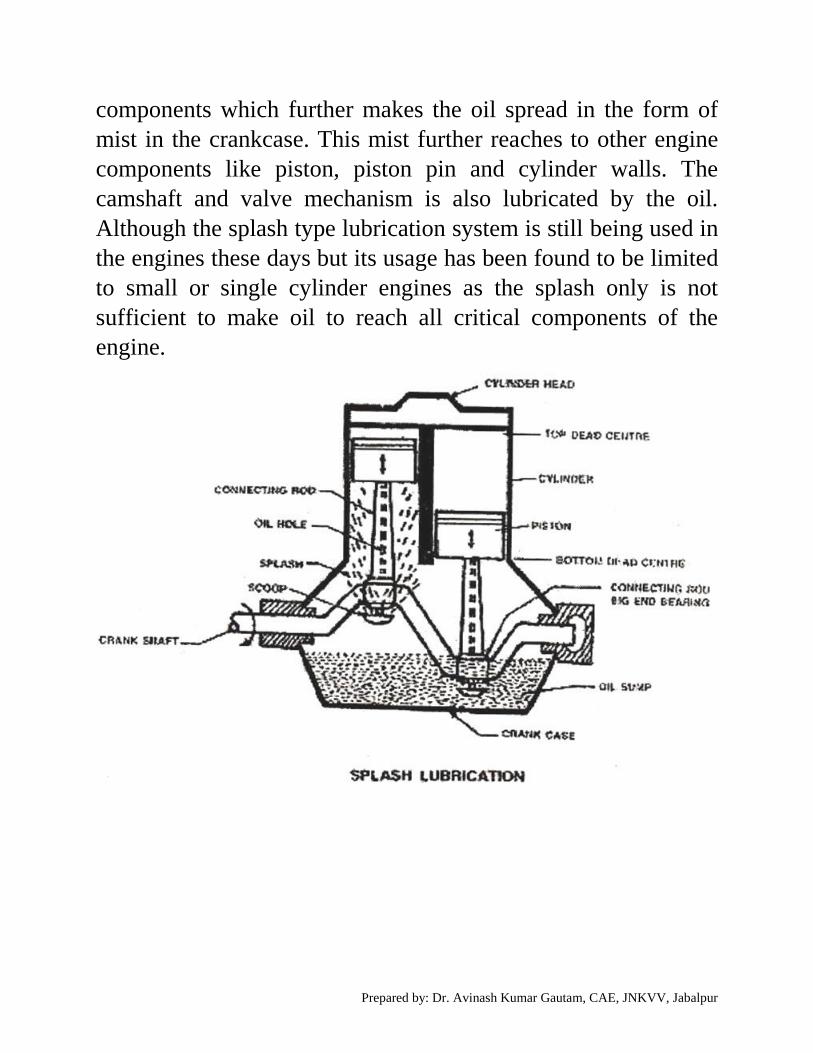
Prepared by: Dr. Avinash Kumar Gautam, CAE, JNKVV, Jabalpur
components which further makes the oil spread in the form of
mist in the crankcase. This mist further reaches to other engine
components like piston, piston pin and cylinder walls. The
camshaft and valve mechanism is also lubricated by the oil.
Although the splash type lubrication system is still being used in
the engines these days but its usage has been found to be limited
to small or single cylinder engines as the splash only is not
sufficient to make oil to reach all critical components of the
engine.

Prepared by: Dr. Avinash Kumar Gautam, CAE, JNKVV, Jabalpur
Force feed lubrication system
As splash system has limitations to lubricate all the critical
components in an engine, force feed system is used to generate
additional pressure to ensure oil reaching to all essential and
desired components for lubrication purposes. Generally, a gear
type pump driven by the camshaft generates the pressure in oil to
move from the crankcase to crankshaft, connecting rod, bearings
pistons and valves. So the lubricating oil is supplied to the engine
components under pressure, hence the reach of oil is enhanced to
lubricate the remote and farthest points. This helps in efficient
lubrication of engine components and hence in achieving better
engine performance.

Prepared by: Dr. Avinash Kumar Gautam, CAE, JNKVV, Jabalpur
PROPERTIES OF LUBRICANTS
For smooth functioning of engine components, the efficient
function of engine lubrication is must and for
efficient functioning of lubrication system, the lubricants should
also have the following properties.
- Viscosity
- Clean and stable
- Pour point
- Flashpoint
- Corrosion resistant
Viscosity
Viscosity is the property of the oil which refers to the resistance
it has to flow due which two surfaces are kept apart from each
other. The viscosity of the lubricants oil should be sufficient to
ensure hydrodynamic lubrication. Higher viscosity is also not
desirable as it increases the friction and power loss. The oil
viscosity decreases at higher temperature and loses its efficacy,
so the lubricants should have resistance against the temperature.
High viscosity lubricating oils also hampers the initial starting of
the engine. Viscosity Index (VI) is a measure of the change of
viscosity of oil with temperature. A high viscosity index means
less change of oil viscosity with temperature rise. Petroleum
lubricating oils general have viscosity index from 100 to 110,
which may be increased to 120 to 130 by means of additives.

Prepared by: Dr. Avinash Kumar Gautam, CAE, JNKVV, Jabalpur
Clean and stable
The lubricating oils should be sufficiently clean and stable for the
smooth and prolonged trouble free operation of the engine.
Lubricating oils should be stable at lowest and highest
temperature as the oil particles should not get separated at low
temperature and get vaporized at high temperature. Generally, it
is observed that at high temperature oils get oxidized which
become sticky and damages the engine components, sometimes
form carbon, which damages the piston rings causing
compression loss. So the lubricating oils should be chemically
stable also which do not change their properties at high
temperature.
Pour Point
It is the minimum temperature at which the fluid/oil pour and the
liquid/oil below this temperature will not be able to flow. Hence
the lubricants below this temperature cannot used and function
for its desired purpose. Thus, the lubricating oil with pour point
less than the lowest temperature encountered in the engine is
selected.
Flash Point
The flash point of the fluid/oil refers to the temperature at which
it gets sparked and it should be sufficiently high so as to avoid
flashing of oil vapors.
Corrosion Resistance
The lubricating oil used in the automobile engines should have
sufficient resistance to corrosion of the engine components like

Prepared by: Dr. Avinash Kumar Gautam, CAE, JNKVV, Jabalpur
pipe lines, crank case etc. which are in regular contact with each
other.

Prepared by: Dr. Avinash Kumar Gautam, CAE, JNKVV, Jabalpur
SPARK IGNITION – COMPONENTS & FUNCTION
Engine is the device to convert heat energy of fuel into useful
mechanical work. To use full potential of fuel to generate heat,
full combustion of fuel is required which further needs proper
ignition of the fuel. Poorly ignited fuel leads to loss of un-burnt
fuel. So, engine ignition system is of high significance for getting
maximum engine performance and efficiency. Engine ignition
system has either of the following types.
i) Spark ignition system
ii) Compression ignition system
Spark ignition system
In petrol engines where air fuel mixture is compressed in the
cylinder and an external/additional element i.e spark plug is used
to ignite the fuel and generate power stroke. When the air fuel
mixture (charge) is compressed, a high voltage spark jumps
across the gap in spark plug to ignite the charge. This jumping of
spark should happen at a particular and predetermined time. If the
spark occurs early while starting the engine i.e when piston is yet
to reach TDC, it would tend to result into a reverse kick. However,
when engine is running at full load, the spark is advanced to make
fuel to have sufficient time to burn and produce maximum heat
energy which would further be transferred by the piston to
generate maximum mechanical power. Following are the
components of electric system being used in spark ignition
system.
Battery: It is required to produce electric current to the ignition
circuit which comprises of distributor, ignition switch, ignition

Prepared by: Dr. Avinash Kumar Gautam, CAE, JNKVV, Jabalpur
coil, condenser, breaker point, spark plug and a generator. The
composition of battery is same as used in tractors for compression
ignition and discussed in the previous lecture no. 29.
Distributor: It is a rotating device used to open and close the
electric circuit between the battery and ignition coil which further
supply current to the primary winding of the coil. Magnetic field
is produced with this surging of current in the primary coil and
then the distributor opens the circuit to collapse the magnetic field
and generate the high voltage current in the secondary winding of
the coil. The distributor rotor then guides this high voltage to the
spark plug.
Ignition Coil: It is used as voltage transfer device which transfers
the low voltage (6 – 12 volts) current drawn from the battery to
high voltage (around 20,000 volts) current which is necessary to
jump the gap between spark plug. The ignition coil is made up of
laminated core which has several hundred turn of heavy wire as
primary winding and the secondary winding consists of thousands
of turns of fine wire. Primary and secondary windings are
insulated from each other and are also sealed fully.
Condenser: To have sudden collapse of magnetic field (which is
mandatory to generate high voltage current in the secondary coil,
a condenser is provided which is further connected with the
breaker point. This condenser also helps in avoiding spark being
produced at the breaker points which may damage these points.
As these contact points are being used continuously, the gaps (0.3
to 0.5 mm) between these contact breaker points are to be checked
regularly and dressed up.

Prepared by: Dr. Avinash Kumar Gautam, CAE, JNKVV, Jabalpur
Generator: The battery need to be charged regularly for which
generator is provided in the electric system of an engine.
Generator is provided with cutout which makes the generator to
get disconnected from the battery when the engine is running at
very low speed. Generator is driven by a belt which is to be
maintained at proper tension and bearing used should also be well
lubricated.
Spark plug: This is used to generate the high voltage spark which
is transferred from the tip of the spark plug to the engine
combustion chamber. It consists of outer shell having threads and
an electrode. It is available indifferent sizes as per the requirement
of engine. As the point of spark plug is always exposed to the
intense heat in the cylinder/combustion chamber, it may get
damaged and carbon deposits are seen many times. These
deposits are to be cleaned regularly and the gap should be kept
between 0.5 to 0.85 mm. The spark plugs are to be tightened
properly.
Magneto Ignition
In magneto ignition system there no battery being used but a
magento is there to generate its own small current which is further
steps up to high voltage enough to jump over the spark plug. The
spark should be produced at a right and predetermined time. In
magneto, a magnet is rotated so rapidly in a coil having turns of
wire which generates the current just like it is produced in the
battery ignition system. Similarly, a high voltage is also produced
in the secondary winding of the magneto coil. A distributor is
being used to carry this current to the spark plug. Magneto points
are to maintained properly as per the service schedule prescribed
by the manufacturer.

Prepared by: Dr. Avinash Kumar Gautam, CAE, JNKVV, Jabalpur
COMPRESSION IGNITION – COMPONENTS & FUNCTION
Diesel engines are compression ignition engines in which no
external component is required for igniting the fuel. The air
sucked by the engine during the downward motion of the piston
in the suction is compressed by the piston when it moves upward
during the compression stroke. With compression, the
temperature of air rises to such a high level that when atomized
fuel (diesel) is injected into the combustion chamber through the
nozzles (injectors) the fuel is ignited.
To initiate the ignition in first power stroke, electrical system is
required in diesel engines also which comprises of a battery and
starting motor. An electric current of 500 amperes at 12 to 24 volts
from the battery is provided to the starting motor which further
actuates the cranking of piston and generates the first power
stroke. If the engine does not start in the first attempt, subsequent
attempts are made to make the connections between battery and
starting motors but continuous and frequent attempts are to
avoided damage to the battery and motor. Once the engine is
started, the battery gets disconnected from the motor and power
strokes come in continuation as per the firing orders in multiple
cylinders. However, in single cylinder engine, the flywheel
restores sufficient energy to complete the engine cycle.
Sometimes glow plugs are also provided in the diesel engines to
heat the air entering into the cylinder through inlet manifolds,
particularly in winters or in the excessive cold areas. These glow
plugs are connected with the battery. Following are the different
types of compression ignition diesel engines.
i) Using electric motor driven by battery

Prepared by: Dr. Avinash Kumar Gautam, CAE, JNKVV, Jabalpur
ii) Starting by hand cranking using rotating lever
Electric motor with battery is most commonly used method in
small, medium and large sized tractors. Whereas, hand cranking
is used for small and stationary, single cylinder engines.
Battery Ignition System
Tractors these days are provided with a battery and starting motor
to initiate the engine ignition process. Electric current from the
battery is generated and it is used to run the starting motor which
further helps in initial cranking and hence ignites the fuel in
engine. Once, the fuel is ignited in the engine, the starting motor
gets disconnected from the engine.
Battery: Battery used in tractors is usually of three to six cells
which develop around 2.2 volts each. Each cell is having positive
and negative plates which are separated by the separators.
Positive plates are made of lead and antimony and negative plates
are generally made of spongy lead. Wooden or rubber material is
being used to make separators. A mixture of sulphuric acid and
distilled water is used as electrolyte with specific gravity of 1.280
when it is fully charged and it comes down to 1.150 or below
when the battery gets fully discharged. The battery should be
charged regularly and maintained properly by keeping the desired
level (above the plate) of electrolyte in the battery case/body. The
terminals of battery should be kept clean always.
Starting motor: 12 or 24 volts motors are used in tractors (diesel
engines) which have a drive to actuate automatic engagement of
pinion with the engine flywheel ring. This engagement of pinion
with the ring gear initiates the engine cranking. Once the engine
is started, the pinion is disengaged from the ring gear. The motors

Prepared by: Dr. Avinash Kumar Gautam, CAE, JNKVV, Jabalpur
should generate sufficient power to crank the engine by moving
the piston against heavy loads. Positive meshing of pinion and
ring gear is must to crank the engine otherwise multiple attempts
made continuously or in a short interval of time leads to discharge
of battery.
References:
1. E-Course online iasri.res.in
2. Sharma D.N. Agricultural Tractor and Machinery