Natural convection due to differential heating of inclined walls and heat source placed on bottom...
10
Energy and Buildings 89 (2015) 153–162 Contents lists available at ScienceDirect Energy and Buildings j ourna l ho me page: www.elsevier.com/locate/enbuild Natural convection due to differential heating of inclined walls and heat source placed on bottom wall of an attic shaped space Atta Sojoudi a , Suvash C. Saha b,∗ , Y.T. Gu b a Department of Mechanical Engineering, College of Engineering, University of Tehran, P.O. Box: 11155-4563, Tehran, Iran b School of Chemistry, Physics & Mechanical Engineering, Queensland University of Technology, 2 George Street, GPO Box 2434, Brisbane, QLD 4001, Australia a r t i c l e i n f o Article history: Received 29 October 2014 Received in revised form 9 December 2014 Accepted 23 December 2014 Available online 3 January 2015 Keywords: Free convection Attic shape space Differentially heating a b s t r a c t Numerical investigation of free convection heat transfer in an attic shaped enclosure with differentially heated two inclined walls and filled with air is performed in this study. The left inclined surface is uni- formly heated whereas the right inclined surface is uniformly cooled. There is a heat source placed on the right side of the bottom surface. Rest of the bottom surface is kept as adiabatic. Finite volume based commercial software ANSYS 15 (Fluent) is used to solve the governing equations. Dependency of various flow parameters of fluid flow and heat transfer is analyzed including Rayleigh number, Ra ranging from 10 3 to 10 6 , heater size from 0.2 to 0.6, heater position from 0.3 to 0.7 and aspect ratio from 0.2 to 1.0 with a fixed Prandtl number of 0.72. Outcomes have been reported in terms of temperature and stream function contours and local Nusselt number for various Ra, heater size, heater position, and aspect ratio. Grid sensitivity analysis is performed and numerically obtained results have been compared with those results available in the literature and found good agreement. © 2014 Elsevier B.V. All rights reserved. 1. Introduction One of the most important forms of fluid flow and heat transfer in an enclosure is due to natural convection where the fluid motion is simply induced by density gradients as a result of temperature difference. Two main classes of natural convection have been stud- ied [1]: (1) basic temperature gradient is aligned to the direction of gravity. (2) Basic temperature gradient is orthogonal to the direc- tion of gravity. The first one is also known as the heating from below class and the second one is referred to as the heating from the side class. Natural convection in triangular enclosure has received exten- sive attention since it has many industrial applications in energy transfer in rooms and buildings, convective motion in solar stills, nuclear reactor cooling, and electronic equipment cooling. Roll-configured cells consisting of two rolls that twist in con- tradictory directions are generated in an enclosure heated from below indicating a classic Rayleigh–Benard convection. For small values of Ra in a triangular cross sectional enclosure, the base flow primarily consists of one large pair of rolls, rising up to near the inclined walls and descending adjacent to the symmetry plane ∗ Corresponding author. Tel.: +61 731381413; fax: +61 731381469. E-mail address: s c [email protected] (S.C. Saha). of the enclosure. Increment of Ra to a critical value causes cell bifurcation. At the hot base, instabilities are activated and the generated vortices became larger until they approach the cold inclined wall and then split into opposed-rotating cells, namely secondary cells [2]. AR, aspect ratio, determines the value of the critical Ra at which these instabilities arise. The larger the AR, the higher the critical Ra. Increasing AR to a critical value while keeping Ra constant, cell disengagement takes place. Del Campo et al. [3] employed the Galerkin weighted residual finite element method with triangular elements to a stream function-vorticity-energy formulation to obtain steady-state solutions for two sets of bottom heater and side wall heater configurations. Heated inclined walls create more distinctive flow pattern completely dependent on the triangular configuration. They understood that flow potency and heat transfer rate were much higher in the bottom-heated enclosures than in the top-heated enclosures. Considering heat transfer phenomena, the bottom heated enclosures are gen- erally more effective in terms of the amount of heat transfer than those which are top-heated. Increasing Gr and AR causes a growth for the mean Nu while reaching critical AR, after which it reduces. First experimental investigation on natural convection in tri- angular cross sectional enclosure was accompanied by Probert and Thirst [4,5]. Using interferometer, they found the optimal pitch angle leading to the minimum rate of heat transfer in the http://dx.doi.org/10.1016/j.enbuild.2014.12.042 0378-7788/© 2014 Elsevier B.V. All rights reserved.
Transcript of Natural convection due to differential heating of inclined walls and heat source placed on bottom...
Nh
Aa
b
Q
a
ARRAA
KFAD
1
iidigtcc
stn
tbvpi
h0
Energy and Buildings 89 (2015) 153–162
Contents lists available at ScienceDirect
Energy and Buildings
j ourna l ho me page: www.elsev ier .com/ locate /enbui ld
atural convection due to differential heating of inclined walls andeat source placed on bottom wall of an attic shaped space
tta Sojoudia, Suvash C. Sahab,∗, Y.T. Gub
Department of Mechanical Engineering, College of Engineering, University of Tehran, P.O. Box: 11155-4563, Tehran, IranSchool of Chemistry, Physics & Mechanical Engineering, Queensland University of Technology, 2 George Street, GPO Box 2434, Brisbane,LD 4001, Australia
r t i c l e i n f o
rticle history:eceived 29 October 2014eceived in revised form 9 December 2014ccepted 23 December 2014vailable online 3 January 2015
eywords:
a b s t r a c t
Numerical investigation of free convection heat transfer in an attic shaped enclosure with differentiallyheated two inclined walls and filled with air is performed in this study. The left inclined surface is uni-formly heated whereas the right inclined surface is uniformly cooled. There is a heat source placed onthe right side of the bottom surface. Rest of the bottom surface is kept as adiabatic. Finite volume basedcommercial software ANSYS 15 (Fluent) is used to solve the governing equations. Dependency of variousflow parameters of fluid flow and heat transfer is analyzed including Rayleigh number, Ra ranging from
3 6
ree convectionttic shape spaceifferentially heating10 to 10 , heater size from 0.2 to 0.6, heater position from 0.3 to 0.7 and aspect ratio from 0.2 to 1.0with a fixed Prandtl number of 0.72. Outcomes have been reported in terms of temperature and streamfunction contours and local Nusselt number for various Ra, heater size, heater position, and aspect ratio.Grid sensitivity analysis is performed and numerically obtained results have been compared with thoseresults available in the literature and found good agreement.
© 2014 Elsevier B.V. All rights reserved.
. Introduction
One of the most important forms of fluid flow and heat transfern an enclosure is due to natural convection where the fluid motions simply induced by density gradients as a result of temperatureifference. Two main classes of natural convection have been stud-
ed [1]: (1) basic temperature gradient is aligned to the direction ofravity. (2) Basic temperature gradient is orthogonal to the direc-ion of gravity. The first one is also known as the heating from belowlass and the second one is referred to as the heating from the sidelass.
Natural convection in triangular enclosure has received exten-ive attention since it has many industrial applications in energyransfer in rooms and buildings, convective motion in solar stills,uclear reactor cooling, and electronic equipment cooling.
Roll-configured cells consisting of two rolls that twist in con-radictory directions are generated in an enclosure heated fromelow indicating a classic Rayleigh–Benard convection. For small
alues of Ra in a triangular cross sectional enclosure, the base flowrimarily consists of one large pair of rolls, rising up to near thenclined walls and descending adjacent to the symmetry plane
∗ Corresponding author. Tel.: +61 731381413; fax: +61 731381469.E-mail address: s c [email protected] (S.C. Saha).
ttp://dx.doi.org/10.1016/j.enbuild.2014.12.042378-7788/© 2014 Elsevier B.V. All rights reserved.
of the enclosure. Increment of Ra to a critical value causes cellbifurcation. At the hot base, instabilities are activated and thegenerated vortices became larger until they approach the coldinclined wall and then split into opposed-rotating cells, namelysecondary cells [2]. AR, aspect ratio, determines the value of thecritical Ra at which these instabilities arise. The larger the AR, thehigher the critical Ra. Increasing AR to a critical value while keepingRa constant, cell disengagement takes place. Del Campo et al. [3]employed the Galerkin weighted residual finite element methodwith triangular elements to a stream function-vorticity-energyformulation to obtain steady-state solutions for two sets of bottomheater and side wall heater configurations. Heated inclined wallscreate more distinctive flow pattern completely dependent onthe triangular configuration. They understood that flow potencyand heat transfer rate were much higher in the bottom-heatedenclosures than in the top-heated enclosures. Considering heattransfer phenomena, the bottom heated enclosures are gen-erally more effective in terms of the amount of heat transferthan those which are top-heated. Increasing Gr and AR causes agrowth for the mean Nu while reaching critical AR, after which itreduces.
First experimental investigation on natural convection in tri-angular cross sectional enclosure was accompanied by Probertand Thirst [4,5]. Using interferometer, they found the optimalpitch angle leading to the minimum rate of heat transfer in the
154 A. Sojoudi et al. / Energy and Bui
AR aspect ratiog gravitational acceleration [m/s2]Gr Grashof numberH enclosure height [m]L heater size [m]Nu local Nusselt numberNu mean Nusselt numberp pressure [N/m2]P dimensionless pressurePr Prandtl numberRa Rayleigh numberS distance between the heater center line and enclo-
sure midline [m]t time [s]T temperature [K]T0 reference temperature [K]TC cold wall temperature [K]TH hot wall temperature [K]u horizontal velocity component [m/s]U dimensionless horizontal velocity componentv vertical velocity component [m/s]V dimensionless horizontal velocity componentW enclosure half base [m]x horizontal coordinate character [m]X dimensionless horizontal coordinate charactery vertical coordinate character [m]Y dimensionless vertical coordinate character
Greek thermal diffusivity [m2/s]
thermal expansion coefficient [1/K]� kinematic viscosity [m2/s]� dimensionless temperature� density [kg/m3]� dimensionless time
aTic
thwtRw
tsvhae
setici[
ing analysis.
ttic of a modeled pitched roof with specified boundary condition.hey showed that the contribution by convection heat transfer isncreased rather than conduction with the increase of AR up to aritical value of aspect ratio.
Flack et al. [6] used laser velocity meter and an interferometero measure convection velocities and heat transfer rate of a bottomeated and cooled inclined walls of a triangular enclosure filledith air. Single roll circulation in each half of triangular cross sec-
ion was reported and transition to turbulence occurred for largera. Gradual dependency of mean Nu on Gr, regardless of geometry,as observed for the mentioned case.
Natural convection within right triangular enclosure with bot-om heater and cold side walls for air and distilled water wastudied by Poulikakos and Bejan [7,8] where Rayleigh–Benard con-ection problem occurred. Strong dependence of mean Nu for theeater was reported and single cell flow pattern was observed. Theylso suggested a new relationship for mean Nu when air filled thenclosure.
Holtzman et al. [9] performed series of experiments usingmoke filled triangular of bottom heated and cooled side wallsnclosure. Symmetry assumption was reported for lower Gr, withhe increase of Gr asymmetry and multicellular flow progressednside the enclosure denoting the appearance of pitchfork bifur-
ation. Number of counter rotating cells and asymmetricity werencreased for the above value of a critical Gr. Ghassemi and Roux10] reported the reduction of mean Nu when the pitch angleldings 89 (2015) 153–162
is increased due to the increment of distance between cold andhot wall.
The above mentioned boundary condition was also investigatedby several other researchers [11,7]. Effect of various parameterssuch as pitch angle, Ra and AR of the enclosure on mean Nuof the heated walls and fluid behavior can be seen in [12–23].They reported the configuration of the cells formed within theenclosure.
Triangular enclosure differentially heated from the inclinedwalls was firstly studied by Flack et al. [24–26]. They used exper-imental techniques to provide flow and heat transfer data fortriangular enclosure heated from both inclined walls and kept coldfrom the bottom as well as the triangular enclosure with cold andhot side walls and kept insulated from the bottom. A single pair ofcounter twisting cells on each half was reported for both heatedinclined walls and cold bottom while the flow stands laminar.Heated and cooled side walls with the insulated or cold bottomexhibited different behavior; a single vortex occupying the entireenclosure. The core of the enclosure is motionless while the fluidflow beside the inclined walls is approximately boundary layertype. The average distance of the heated bottom and upper cooledinclined walls reduced with the AR leading to enhancement of therate of heat transfer.
Akinsete and Coleman [27–29] performed important numer-ical evaluations for the alongside heated enclosures employingFinite-Difference technique of the steady-state stream function-vorticity-energy formulation. Their results revealed that one-thirdof the base wall length near the corner accounted for more thanhalf rate of the heat transferred across the wall for the two casesof isothermal and isoflux inclined walls. Also, the mean Nusseltnumber decreased as the aspect ratio was increased. Hasani andChung [30,31] reported a critical Ra for both heated inclined wallsand cold bottom enclosure which the Rayleigh numbers abovethat cause the flow to tighten the single cell between the inclinedwalls forming a large motionless zone. Further increasing the Ra,cell ramification happens through the vertical side of the enclo-sure.
Asan and Namli [32] numerically repeated the studies of [27–29]using finer grid and improved numerical strategy. They illus-trated multiple cell flow scheme containing two counter-twistingcells at the core for lower Ra and secondary vortices progressednear to the upright mid height for higher Ra, below the criti-cal Rayleigh number. Further increase of Ra, beyond the criticalvalue, caused larger secondary vortices while the main circula-tion is being reduced in size. With the decrease of AR, higherRa is required to change the flow pattern into multicellular flow.Basak et al. [33] investigated free convection heat transfer withina right triangular enclosure with insulated base wall. The influ-ence of alternating thermal boundary conditions on the verticaland inclined walls reported for Ra and Pr varying from 103 to105 and 0.07 to1000, respectively. Pseudodiffusive flow patternaltered to convection-dominated structure for increment of Ra.Also, they showed that Nu for upright wall enhanced up to approx-imately
√2 times that of the inclined wall, for all Ra and Pr
values.Saha et al. [34–38] have reported a complete discussion of
the fluid dynamics in attic space imposing isothermal, periodic,sudden and ramp heating boundary conditions. Total amount ofheat transferred thorough the heated walls was studied. Stratifica-tion or instability of the flow was represented for various thermalcondition and Ra. Also theoretical understanding of the transientbehavior of the flow in the enclosure was performed through scal-
The above literature indicates that the two heated boundaryconditions consisting of a heated inclined wall and a heated sourcewith limited length on bottom wall combined in a triangular
A. Sojoudi et al. / Energy and Buildings 89 (2015) 153–162 155
H
xy L
S
W
0, == vuTH
0,0 ===∂∂ vunT
0, == vuTC
hysica
eqmolh
2
cltHctat
3
sut
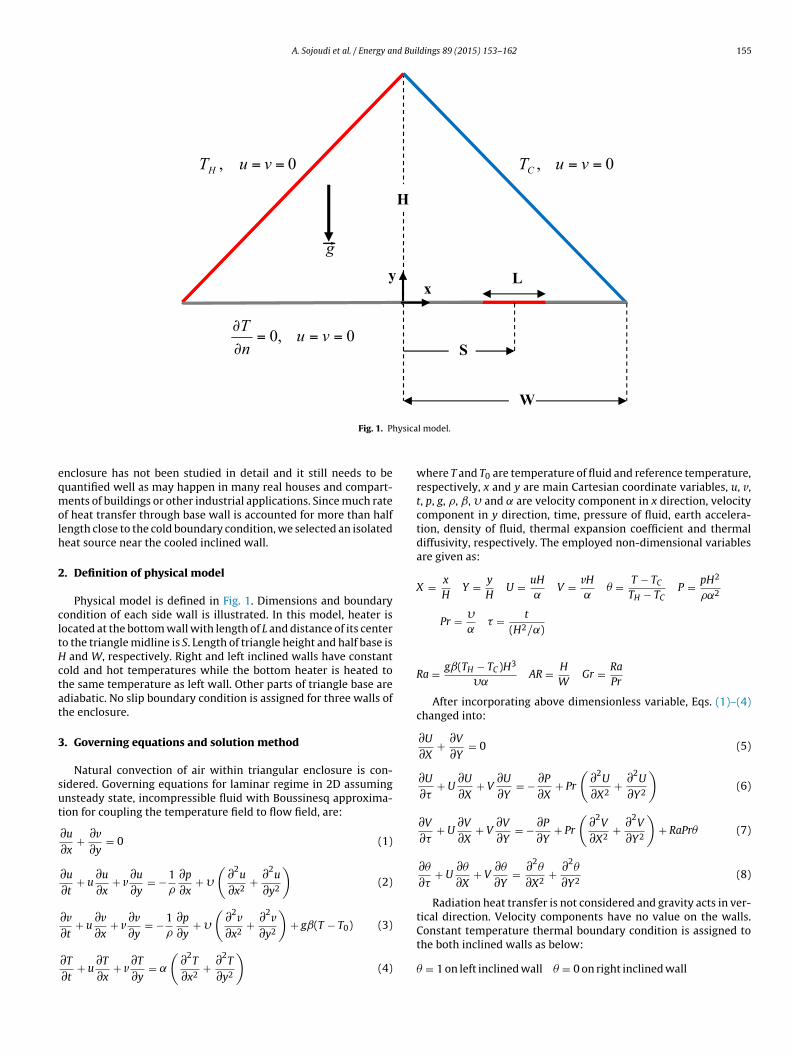
Fig. 1. P
nclosure has not been studied in detail and it still needs to beuantified well as may happen in many real houses and compart-ents of buildings or other industrial applications. Since much rate
f heat transfer through base wall is accounted for more than halfength close to the cold boundary condition, we selected an isolatedeat source near the cooled inclined wall.
. Definition of physical model
Physical model is defined in Fig. 1. Dimensions and boundaryondition of each side wall is illustrated. In this model, heater isocated at the bottom wall with length of L and distance of its centero the triangle midline is S. Length of triangle height and half base is
and W, respectively. Right and left inclined walls have constantold and hot temperatures while the bottom heater is heated tohe same temperature as left wall. Other parts of triangle base arediabatic. No slip boundary condition is assigned for three walls ofhe enclosure.
. Governing equations and solution method
Natural convection of air within triangular enclosure is con-idered. Governing equations for laminar regime in 2D assumingnsteady state, incompressible fluid with Boussinesq approxima-ion for coupling the temperature field to flow field, are:
∂u
∂x+ ∂v
∂y= 0 (1)
∂u
∂t+ u
∂u
∂x+ v
∂u
∂y= − 1
�
∂p
∂x+ �
(∂2
u
∂x2+ ∂2
u
∂y2
)(2)
∂v + u∂v + v
∂v = − 1 ∂p + �
(∂2v + ∂2v
)+ gˇ(T − T0) (3)
∂t ∂x ∂y � ∂y ∂x2 ∂y2
∂T
∂t+ u
∂T
∂x+ v
∂T
∂y= ˛
(∂2
T
∂x2+ ∂2
T
∂y2
)(4)
l model.
where T and T0 are temperature of fluid and reference temperature,respectively, x and y are main Cartesian coordinate variables, u, v,t, p, g, �, ˇ, � and are velocity component in x direction, velocitycomponent in y direction, time, pressure of fluid, earth accelera-tion, density of fluid, thermal expansion coefficient and thermaldiffusivity, respectively. The employed non-dimensional variablesare given as:
X = x
HY = y
HU = uH
˛V = vH
˛� = T − TC
TH − TCP = pH2
�˛2
Pr = �˛
� = t
(H2/˛)
Ra = gˇ(TH − TC )H3
�˛AR = H
WGr = Ra
Pr
After incorporating above dimensionless variable, Eqs. (1)–(4)changed into:
∂U
∂X+ ∂V
∂Y= 0 (5)
∂U
∂�+ U
∂U
∂X+ V
∂U
∂Y= − ∂P
∂X+ Pr
(∂2
U
∂X2+ ∂2
U
∂Y2
)(6)
∂V
∂�+ U
∂V
∂X+ V
∂V
∂Y= − ∂P
∂Y+ Pr
(∂2
V
∂X2+ ∂2
V
∂Y2
)+ RaPr� (7)
∂�
∂�+ U
∂�
∂X+ V
∂�
∂Y= ∂2
�
∂X2+ ∂2
�
∂Y2(8)
Radiation heat transfer is not considered and gravity acts in ver-tical direction. Velocity components have no value on the walls.
Constant temperature thermal boundary condition is assigned tothe both inclined walls as below:� = 1 on left inclined wall � = 0 on right inclined wall

156 A. Sojoudi et al. / Energy and Buildings 89 (2015) 153–162
x
Nu
0.2 0.4 0.6 0.8
10
20
30
40 Experiment (Ref. [27])Present numerical
Fw
L
�
r
id
N
N
τ
θ
0 0.01 0.02 0.03 0.04 0.05 0.060.8
0.85
0.9
0.95
1
Ra = 1.0 × 10³Ra = 1.0 × 10⁴Ra = 1.0 × 10⁵Ra = 1.0 × 10⁶
ig. 2. Distribution of the local Nu along cold wall boundary condition: comparisonith experiment.
To define a heat source on the bottom wall, a limited length of from bottom wall is maintained at constant temperature of TH:
= 1 for S − L
2< x < S + L
2
est of bottom is adiabatic:
∂�
∂Y= 0 for 0 < x < S − L
2and S + L
2< x < W
Two important parameters of local Nu and mean Nu are widelynvestigated as mentioned in the literature review, so they areefined as follows, respectively:
u = ∂�∣∣∣∣ (9)
∂Y on wall
u =∫
Through wall(∂�/∂Y) dl
wall length, l is parallel to the wall (10)
Fig. 4. Temperature contours for different dimensionless t
Fig. 3. Dimensionless temperature time series at point just above the bottom heater,(1, 0.01), for various Ra at AR = 0.5, S/W = 0.5 and L/W = 0.5.
Eqs. (5)–(8) are solved along with the initial and boundaryconditions using the SIMPLE scheme. The Finite Volume schemehas been chosen to discretize the governing equations, with theQUICK scheme approximating the advection term. The diffusionterms are discretized using central-differencing with second orderaccuracy.
4. Results and discussion
4.1. Grid sensitivity and validation of results
Numerical tests employing different grid sizes ranging from12,000 up to 16,000 triangular elements, it is concluded that
the optimal computational mesh that contributed grid indepen-dent solutions consists of 15,700 triangular elements. Symmetricalmeshes with respect to the midplane of the triangular enclo-sure were considered. Element density was enhanced in sensitiveime when Ra = 105, AR = 0.5, L/W = 0.5 and S/W = 0.4.
A. Sojoudi et al. / Energy and Buildings 89 (2015) 153–162 157
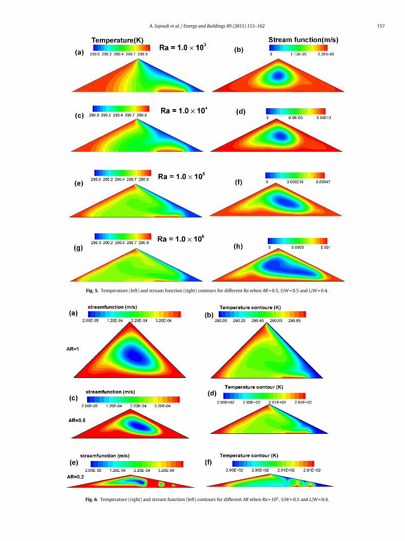
Fig. 5. Temperature (left) and stream function (right) contours for different Ra when AR = 0.5, S/W = 0.5 and L/W = 0.4.
Fig. 6. Temperature (right) and stream function (left) contours for different AR when Ra = 105, S/W = 0.5 and L/W = 0.4.
158 A. Sojoudi et al. / Energy and Buildings 89 (2015) 153–162
urs fo
atR
a
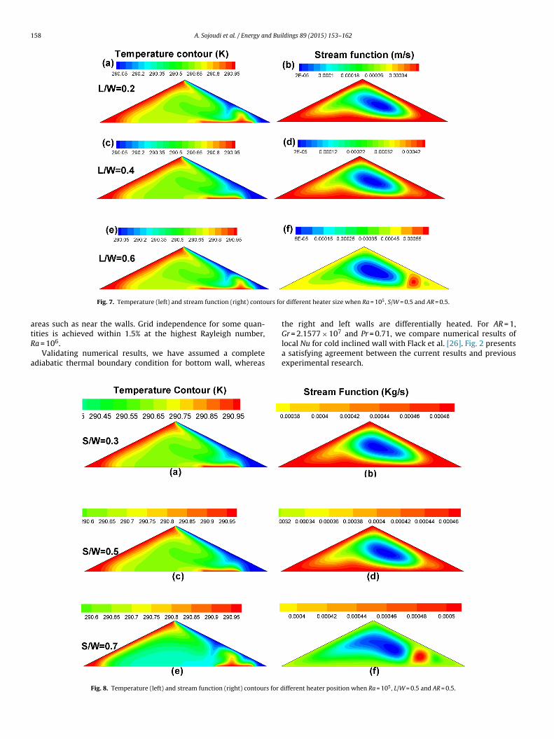
Fig. 7. Temperature (left) and stream function (right) conto
reas such as near the walls. Grid independence for some quan-
ities is achieved within 1.5% at the highest Rayleigh number,a = 106.Validating numerical results, we have assumed a completediabatic thermal boundary condition for bottom wall, whereas
Fig. 8. Temperature (left) and stream function (right) contours for d
r different heater size when Ra = 105, S/W = 0.5 and AR = 0.5.
the right and left walls are differentially heated. For AR = 1,7
Gr = 2.1577 × 10 and Pr = 0.71, we compare numerical results oflocal Nu for cold inclined wall with Flack et al. [26]. Fig. 2 presentsa satisfying agreement between the current results and previousexperimental research.
ifferent heater position when Ra = 105, L/W = 0.5 and AR = 0.5.
A. Sojoudi et al. / Energy and Bui
τ
MeanNu
0 0.00 5 0.01 0.01 5 0.020
2
4
6
8
10
12Ra = 1.0 × 10⁶Ra = 1.0 × 10⁵Ra = 1.0 × 10⁴Ra = 1.0 × 10³
FL
4
phidtdsasiphaicdi
FA
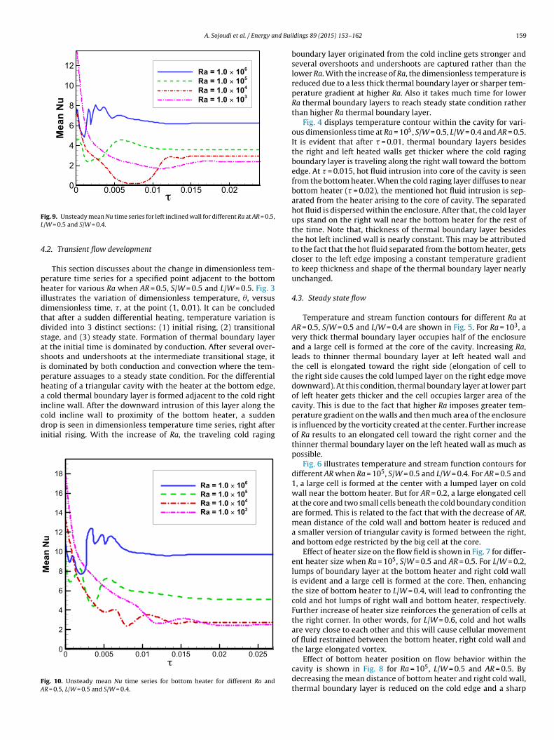
ig. 9. Unsteady mean Nu time series for left inclined wall for different Ra at AR = 0.5,/W = 0.5 and S/W = 0.4.
.2. Transient flow development
This section discusses about the change in dimensionless tem-erature time series for a specified point adjacent to the bottomeater for various Ra when AR = 0.5, S/W = 0.5 and L/W = 0.5. Fig. 3
llustrates the variation of dimensionless temperature, �, versusimensionless time, �, at the point (1, 0.01). It can be concludedhat after a sudden differential heating, temperature variation isivided into 3 distinct sections: (1) initial rising, (2) transitionaltage, and (3) steady state. Formation of thermal boundary layert the initial time is dominated by conduction. After several over-hoots and undershoots at the intermediate transitional stage, its dominated by both conduction and convection where the tem-erature assuages to a steady state condition. For the differentialeating of a triangular cavity with the heater at the bottom edge,
cold thermal boundary layer is formed adjacent to the cold rightncline wall. After the downward intrusion of this layer along the
old incline wall to proximity of the bottom heater, a suddenrop is seen in dimensionless temperature time series, right afternitial rising. With the increase of Ra, the traveling cold raging
τ
MeanNu
0 0.005 0.01 0.01 5 0.02 0.0250
2
4
6
8
10
12
14
16
18Ra = 1.0 × 10⁶Ra = 1.0 × 10⁵Ra = 1.0 × 10⁴Ra = 1.0 × 10³
ig. 10. Unsteady mean Nu time series for bottom heater for different Ra andR = 0.5, L/W = 0.5 and S/W = 0.4.
ldings 89 (2015) 153–162 159
boundary layer originated from the cold incline gets stronger andseveral overshoots and undershoots are captured rather than thelower Ra. With the increase of Ra, the dimensionless temperature isreduced due to a less thick thermal boundary layer or sharper tem-perature gradient at higher Ra. Also it takes much time for lowerRa thermal boundary layers to reach steady state condition ratherthan higher Ra thermal boundary layer.
Fig. 4 displays temperature contour within the cavity for vari-ous dimensionless time at Ra = 105, S/W = 0.5, L/W = 0.4 and AR = 0.5.It is evident that after � = 0.01, thermal boundary layers besidesthe right and left heated walls get thicker where the cold ragingboundary layer is traveling along the right wall toward the bottomedge. At � = 0.015, hot fluid intrusion into core of the cavity is seenfrom the bottom heater. When the cold raging layer diffuses to nearbottom heater (� = 0.02), the mentioned hot fluid intrusion is sep-arated from the heater arising to the core of cavity. The separatedhot fluid is dispersed within the enclosure. After that, the cold layerups stand on the right wall near the bottom heater for the rest ofthe time. Note that, thickness of thermal boundary layer besidesthe hot left inclined wall is nearly constant. This may be attributedto the fact that the hot fluid separated from the bottom heater, getscloser to the left edge imposing a constant temperature gradientto keep thickness and shape of the thermal boundary layer nearlyunchanged.
4.3. Steady state flow
Temperature and stream function contours for different Ra atAR = 0.5, S/W = 0.5 and L/W = 0.4 are shown in Fig. 5. For Ra = 103, avery thick thermal boundary layer occupies half of the enclosureand a large cell is formed at the core of the cavity. Increasing Ra,leads to thinner thermal boundary layer at left heated wall andthe cell is elongated toward the right side (elongation of cell tothe right side causes the cold lumped layer on the right edge movedownward). At this condition, thermal boundary layer at lower partof left heater gets thicker and the cell occupies larger area of thecavity. This is due to the fact that higher Ra imposes greater tem-perature gradient on the walls and then much area of the enclosureis influenced by the vorticity created at the center. Further increaseof Ra results to an elongated cell toward the right corner and thethinner thermal boundary layer on the left heated wall as much aspossible.
Fig. 6 illustrates temperature and stream function contours fordifferent AR when Ra = 105, S/W = 0.5 and L/W = 0.4. For AR = 0.5 and1, a large cell is formed at the center with a lumped layer on coldwall near the bottom heater. But for AR = 0.2, a large elongated cellat the core and two small cells beneath the cold boundary conditionare formed. This is related to the fact that with the decrease of AR,mean distance of the cold wall and bottom heater is reduced anda smaller version of triangular cavity is formed between the right,and bottom edge restricted by the big cell at the core.
Effect of heater size on the flow field is shown in Fig. 7 for differ-ent heater size when Ra = 105, S/W = 0.5 and AR = 0.5. For L/W = 0.2,lumps of boundary layer at the bottom heater and right cold wallis evident and a large cell is formed at the core. Then, enhancingthe size of bottom heater to L/W = 0.4, will lead to confronting thecold and hot lumps of right wall and bottom heater, respectively.Further increase of heater size reinforces the generation of cells atthe right corner. In other words, for L/W = 0.6, cold and hot wallsare very close to each other and this will cause cellular movementof fluid restrained between the bottom heater, right cold wall andthe large elongated vortex.
Effect of bottom heater position on flow behavior within thecavity is shown in Fig. 8 for Ra = 105, L/W = 0.5 and AR = 0.5. Bydecreasing the mean distance of bottom heater and right cold wall,thermal boundary layer is reduced on the cold edge and a sharp
160 A. Sojoudi et al. / Energy and Buildings 89 (2015) 153–162
AR
MeanNu
0.2 0.4 0.6 0.8 14
6
8
10
12 (a)
Ra
MeanNu
103 104 105 106
3
4
5
6
7
8
9 (c)
S/W
MeanNu
0.3 0.4 0.5 0.6 0.7
5.2
5.3
5.4
5.5 (d)L/W
MeanNu
0.2 0.3 0.4 0.5 0.6
4
5
6
7
(b)
F 5, S/W 5
R 0.4.
oa
4
wtspmttRdwsc
t
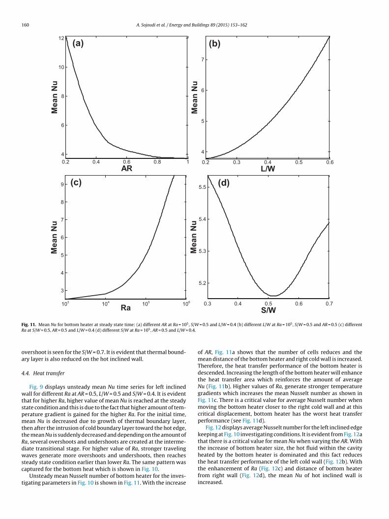
ig. 11. Mean Nu for bottom heater at steady state time: (a) different AR at Ra = 10a at S/W = 0.5, AR = 0.5 and L/W = 0.4 (d) different S/W at Ra = 105, AR = 0.5 and L/W =
vershoot is seen for the S/W = 0.7. It is evident that thermal bound-ry layer is also reduced on the hot inclined wall.
.4. Heat transfer
Fig. 9 displays unsteady mean Nu time series for left inclinedall for different Ra at AR = 0.5, L/W = 0.5 and S/W = 0.4. It is evident
hat for higher Ra, higher value of mean Nu is reached at the steadytate condition and this is due to the fact that higher amount of tem-erature gradient is gained for the higher Ra. For the initial time,ean Nu is decreased due to growth of thermal boundary layer,
hen after the intrusion of cold boundary layer toward the hot edge,he mean Nu is suddenly decreased and depending on the amount ofa, several overshoots and undershoots are created at the interme-iate transitional stage. For higher value of Ra, stronger travelingaves generate more overshoots and undershoots, then reaches
teady state condition earlier than lower Ra. The same pattern wasaptured for the bottom heat which is shown in Fig. 10.
Unsteady mean Nusselt number of bottom heater for the inves-igating parameters in Fig. 10 is shown in Fig. 11. With the increase
= 0.5 and L/W = 0.4 (b) different L/W at Ra = 10 , S/W = 0.5 and AR = 0.5 (c) different
of AR, Fig. 11a shows that the number of cells reduces and themean distance of the bottom heater and right cold wall is increased.Therefore, the heat transfer performance of the bottom heater isdescended. Increasing the length of the bottom heater will enhancethe heat transfer area which reinforces the amount of averageNu (Fig. 11b). Higher values of Ra, generate stronger temperaturegradients which increases the mean Nusselt number as shown inFig. 11c. There is a critical value for average Nusselt number whenmoving the bottom heater closer to the right cold wall and at thiscritical displacement, bottom heater has the worst heat transferperformance (see Fig. 11d).
Fig. 12 displays average Nusselt number for the left inclined edgekeeping at Fig. 10 investigating conditions. It is evident from Fig. 12athat there is a critical value for mean Nu when varying the AR. Withthe increase of bottom heater size, the hot fluid within the cavityheated by the bottom heater is dominated and this fact reduces
the heat transfer performance of the left cold wall (Fig. 12b). Withthe enhancement of Ra (Fig. 12c) and distance of bottom heaterfrom right wall (Fig. 12d), the mean Nu of hot inclined wall isincreased.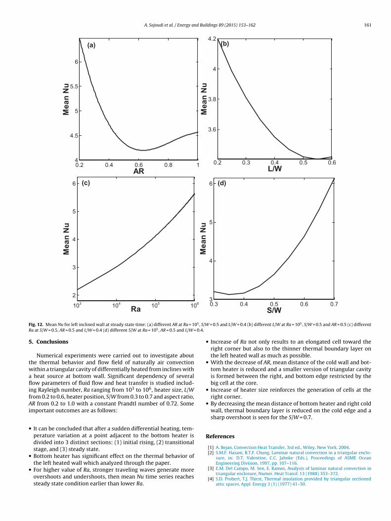
A. Sojoudi et al. / Energy and Buildings 89 (2015) 153–162 161
Ra
MeanNu
103 104 105 1062
3
4
5
6 (c)AR
MeanNu
0.2 0.4 0.6 0.8 14
4.5
5
5.5
6
(a)
L/W
MeanNu
0.2 0.3 0.4 0.5 0.6
3.6
3.8
4
4.2(b)
S/W
MeanNu
0.3 0.4 0.5 0.6 0.73
4
5
6 (d)
F 05, S/WR 0.4.
5
twaflifAi
•
•
•
ig. 12. Mean Nu for left inclined wall at steady state time: (a) different AR at Ra = 1a at S/W = 0.5, AR = 0.5 and L/W = 0.4 (d) different S/W at Ra = 105, AR = 0.5 and L/W =
. Conclusions
Numerical experiments were carried out to investigate abouthe thermal behavior and flow field of naturally air convectionithin a triangular cavity of differentially heated from inclines with
heat source at bottom wall. Significant dependency of severalow parameters of fluid flow and heat transfer is studied includ-
ng Rayleigh number, Ra ranging from 103 to 106, heater size, L/Wrom 0.2 to 0.6, heater position, S/W from 0.3 to 0.7 and aspect ratio,R from 0.2 to 1.0 with a constant Prandtl number of 0.72. Some
mportant outcomes are as follows:
It can be concluded that after a sudden differential heating, tem-perature variation at a point adjacent to the bottom heater isdivided into 3 distinct sections: (1) initial rising, (2) transitionalstage, and (3) steady state.Bottom heater has significant effect on the thermal behavior of
the left heated wall which analyzed through the paper.For higher value of Ra, stronger traveling waves generate moreovershoots and undershoots, then mean Nu time series reachessteady state condition earlier than lower Ra.= 0.5 and L/W = 0.4 (b) different L/W at Ra = 105, S/W = 0.5 and AR = 0.5 (c) different
• Increase of Ra not only results to an elongated cell toward theright corner but also to the thinner thermal boundary layer onthe left heated wall as much as possible.
• With the decrease of AR, mean distance of the cold wall and bot-tom heater is reduced and a smaller version of triangular cavityis formed between the right, and bottom edge restricted by thebig cell at the core.
• Increase of heater size reinforces the generation of cells at theright corner.
• By decreasing the mean distance of bottom heater and right coldwall, thermal boundary layer is reduced on the cold edge and asharp overshoot is seen for the S/W = 0.7.
References
[1] A. Bejan, Convection Heat Transfer, 3rd ed., Wiley, New York, 2004.[2] S.M.F. Hasani, B.T.F. Chung, Laminar natural convection in a triangular enclo-
sure, in: D.T. Valentine, C.C. Jahnke (Eds.), Proceedings of ASME Ocean
Engineering Division, 1997, pp. 107–116.[3] E.M. Del Campo, M. Sen, E. Ramos, Analysis of laminar natural convection intriangular enclosure, Numer. Heat Transf. 13 (1988) 353–372.
[4] S.D. Probert, T.J. Thirst, Thermal insulation provided by triangular sectionedattic spaces, Appl. Energy 3 (1) (1977) 41–50.
1 nd Bui
[
[
[
[
[
[
[
[
[
[
[
[
[
[
[
[
[
[
[
[
[
[
[
[
[
[
[
62 A. Sojoudi et al. / Energy a
[5] T.J. Thirst, S.D. Probert, Heat Transfer Versus Pitch Angle for NonventilatedTriangular-Sectioned, Apex-Upward Air-Filled Spaces, 660, ASTM Special Tech-nical Publication, 1978, pp. 203–210.
[6] R.D. Flack, The experimental measurement of natural convection heat transferin triangular enclosures heated or cooled from below, J. Heat Transf. 102 (1980)770–772.
[7] D. Poulikakos, A. Bejan, Natural convection experiments in a triangular space,J. Heat Transf. 105 (1983) 652–655.
[8] D. Poulikakos, A. Bejan, The fluid dynamics of an attic space, J. Fluid Mech. 131(1983) 251–269.
[9] G.A. Holtzman, R.W. Hill, K.S. Ball, Laminar natural convection in isosceles tri-angular enclosures heated from below and symmetrically cooled from above,J. Heat Transf. 122 (3) (2000) 485–491.
10] M. Ghassemi, J.A. Roux, in: R.K. Shah (Ed.), Numerical Investigation of NaturalConvection Within a Triangular Shaped Enclosure, Heat Transfer in ConvectiveFlows, ASME, New York, 1989, pp. 169–175.
11] A. Bejan, D. Poulikakos, Natural convection in an attic-shaped filled with porousmaterial, J. Heat Transf. 104 (1982) 241–247.
12] H. Salmun, Convection patterns in a triangular domain, Int. J. Heat Mass Transf.38 (2) (1995) 351–362.
13] H. Salmun, The stability of a single-cell steady-state solution in a triangularenclosure, Int. J. Heat Mass Transf. 38 (2) (1995) 363–369.
14] S.M.F. Hasani, B.T.F. Chung, Combined natural convection and radiation in atriangular enclosure, in: Proc. 7th AIAA/ASME Joint Thermo Physics & HeatTransfer Conference, vol. 357(1), 1998, pp. 63–72.
15] S.M.F. Hasani, B.T.F. Chung, Laminar natural convection in a triangular enclo-sure, in: D.T. Valentine, C.C. Jahnke (Eds.), Proc. ASME Ocean EngineeringDivision, ASME, New York, 1997, pp. 107–116.
16] S.W. Lam, R. Gani, J.G. Symons, Experimental and numerical studies ofnatural convection in trapezoidal cavities, J. Heat Transf. 111 (1989)372–377.
17] P.H. Gaskell, H.M. Thompson, M.D. Savage, A finite element analysis of steadyviscous flow in triangular cavities, Proc. Inst. Mech. Eng. C: J. Mech. Eng. Sci.213 (3) (1999) 263–276.
18] C. Lei, J.C. Patterson, Unsteady natural convection in a triangular enclo-sure induced by the absorption of radiation, J. Fluid Mech. 460 (2002)181–209.
19] S. Volker, T. Burton, S.P. Vanka, Finite-volume multigrid calculation of naturalconvection flows on unstructured grids, Numer. Heat Transf. B 30 (1) (1996)1–22.
20] T. Tynjala, A. Hajiloo, W. Polashenski Jr., P. Zamankhan, Magnetodissipation inferrofluids, J. Magn. Magn. Mater. 252 (2002) 123–125.
21] A. Omri, M. Najjari, S.B. Nasrallah, Numerical analysis of natural buoyancy-induced regimes in isosceles triangular cavities, Numer. Heat Transf. A 52 (7)(2007) 661–678.
[
[
ldings 89 (2015) 153–162
22] E.F. Kent, Numerical analysis of laminar natural convection in isosceles tri-angular enclosures, Proc. Inst. Mech. Eng. C: J. Mech. Eng. Sci. 223 (5) (2009)1157–1169.
23] G. Saha, T. Islam, S. Saha, Q. Islam, Natural convection in a tilted isosceles trian-gular enclosure with discrete bottom heating, Thammasat Int. J. Sci. Technol.12 (4) (2007) 24–35.
24] R.D. Flack, C.L. Witt, Laser velocimeter measurements in natural convectionflows in triangular enclosures, in: Proceeding of 3rd International Workshopon Laser Velocimetry (LV–III), 1979, pp. 445–454.
25] R.D. Flack, C.L. Witt, Velocity measurements in two natural convection air flowsusing a laser velocimeter, J. Heat Transf. 101 (1979) 256–260.
26] R.D. Flack, T.T. Konopnicki, J.H. Rooke, The measurement of natural convectionheat transfer in triangular enclosures, J. Heat Transf. 101 (1979) 648–654.
27] V.A. Akinsete, T.A. Coleman, Heat transfer by steady laminar free convection intriangular enclosures, Int. J. Heat Mass Transf. 25 (7) (1982) 991–998.
28] V.A. Akinsete, T.A. Coleman, Heat Transfer by Steady Laminar Free Convec-tion Within Triangular Enclosures, Numerical Methods in Thermal Problems,Pineridge Press, Ltd., Swansea, Wales, 1979, pp. 259–268.
29] V.A. Akinsete, T.A. Coleman, Heat transfer by steady laminar free convectionin triangular enclosures, in: Proceeding of International Congress Brasileiro DeEngenharia Mecanica, Brazil, 1979.
30] S.M.F. Hasani, B.T.F. Chung, Combined natural convection and radiation in atriangular enclosure, in: Proceeding of 7th AIAA/ASME Joint Thermo Physics &Heat Transfer Conference, vol. 357(1), 1998, pp. 63–72.
31] S.M.F. Hasani, B.T.F. Chung, Laminar natural convection in a triangularenclosure, in: D.T. Valentine, C.C. Jahnke (Eds.), Proceeding of ASME OceanEngineering Division, ASME, New York, 1997, pp. 107–116.
32] H. Asan, L. Namli, Laminar natural convection in a pitched roof of triangu-lar cross-section: summer day boundary conditions, Energy Build. 33 (2000)69–73.
33] T. Basak, S. Roy, C. Thirumalesha, Finite element analysis of steady natural con-vection in triangular enclosure: effects of various thermal boundary conditions,Chem. Eng. Sci. 62 (9) (2007) 2623–2640.
34] S.C. Saha, J.C. Patterson, C. Lei, Natural convection and heat transfer inattics subject to periodic thermal forcing, Int. J. Therm. Sci. 49 (10) (2010)1899–1910.
35] S.C. Saha, M.M.K. Khan, A review of natural convection and heat transfer inattic-shaped space, Energy Build. 43 (10) (2011) 2564–2571.
36] S.C. Saha, Unsteady natural convection in a triangular enclosure under isother-mal heating, Energy Build. 43 (2) (2011) 695–703.
37] S.C. Saha, J.C. Patterson, C. Lei, Natural convection in attic-shaped spaces subjectto sudden and ramp heating boundary conditions, Heat Mass Transf. 46 (6)(2010) 621–638.
38] S.C. Saha, J.C. Patterson, C. Lei, Scaling of natural convection of an inclined flatplate: sudden cooling condition, J. Heat Transf. – Trans. ASME 13 (2011) 041503.