Nanomechanics of Organic Layers and Biomenbranes
51
Nanomechanics of Organic Layers and Biomenbranes Gerard Oncins Marco ADVERTIMENT. La consulta d’aquesta tesi queda condicionada a l’acceptació de les següents condicions d'ús: La difusió d’aquesta tesi per mitjà del servei TDX (www.tesisenxarxa.net ) ha estat autoritzada pels titulars dels drets de propietat intel·lectual únicament per a usos privats emmarcats en activitats d’investigació i docència. No s’autoritza la seva reproducció amb finalitats de lucre ni la seva difusió i posada a disposició des d’un lloc aliè al servei TDX. No s’autoritza la presentació del seu contingut en una finestra o marc aliè a TDX (framing). Aquesta reserva de drets afecta tant al resum de presentació de la tesi com als seus continguts. En la utilització o cita de parts de la tesi és obligat indicar el nom de la persona autora. ADVERTENCIA. La consulta de esta tesis queda condicionada a la aceptación de las siguientes condiciones de uso: La difusión de esta tesis por medio del servicio TDR (www.tesisenred.net ) ha sido autorizada por los titulares de los derechos de propiedad intelectual únicamente para usos privados enmarcados en actividades de investigación y docencia. No se autoriza su reproducción con finalidades de lucro ni su difusión y puesta a disposición desde un sitio ajeno al servicio TDR. No se autoriza la presentación de su contenido en una ventana o marco ajeno a TDR (framing). Esta reserva de derechos afecta tanto al resumen de presentación de la tesis como a sus contenidos. En la utilización o cita de partes de la tesis es obligado indicar el nombre de la persona autora. WARNING. On having consulted this thesis you’re accepting the following use conditions: Spreading this thesis by the TDX (www.tesisenxarxa.net ) service has been authorized by the titular of the intellectual property rights only for private uses placed in investigation and teaching activities. Reproduction with lucrative aims is not authorized neither its spreading and availability from a site foreign to the TDX service. Introducing its content in a window or frame foreign to the TDX service is not authorized (framing). This rights affect to the presentation summary of the thesis as well as to its contents. In the using or citation of parts of the thesis it’s obliged to indicate the name of the author.
-
Upload
khangminh22 -
Category
Documents
-
view
6 -
download
0
Transcript of Nanomechanics of Organic Layers and Biomenbranes

Nanomechanics of Organic Layers and Biomenbranes
Gerard Oncins Marco
ADVERTIMENT. La consulta d’aquesta tesi queda condicionada a l’acceptació de les següents condicions d'ús: La difusió d’aquesta tesi per mitjà del servei TDX (www.tesisenxarxa.net) ha estat autoritzada pels titulars dels drets de propietat intel·lectual únicament per a usos privats emmarcats en activitats d’investigació i docència. No s’autoritza la seva reproducció amb finalitats de lucre ni la seva difusió i posada a disposició des d’un lloc aliè al servei TDX. No s’autoritza la presentació del seu contingut en una finestra o marc aliè a TDX (framing). Aquesta reserva de drets afecta tant al resum de presentació de la tesi com als seus continguts. En la utilització o cita de parts de la tesi és obligat indicar el nom de la persona autora. ADVERTENCIA. La consulta de esta tesis queda condicionada a la aceptación de las siguientes condiciones de uso: La difusión de esta tesis por medio del servicio TDR (www.tesisenred.net) ha sido autorizada por los titulares de los derechos de propiedad intelectual únicamente para usos privados enmarcados en actividades de investigación y docencia. No se autoriza su reproducción con finalidades de lucro ni su difusión y puesta a disposición desde un sitio ajeno al servicio TDR. No se autoriza la presentación de su contenido en una ventana o marco ajeno a TDR (framing). Esta reserva de derechos afecta tanto al resumen de presentación de la tesis como a sus contenidos. En la utilización o cita de partes de la tesis es obligado indicar el nombre de la persona autora. WARNING. On having consulted this thesis you’re accepting the following use conditions: Spreading this thesis by the TDX (www.tesisenxarxa.net) service has been authorized by the titular of the intellectual property rights only for private uses placed in investigation and teaching activities. Reproduction with lucrative aims is not authorized neither its spreading and availability from a site foreign to the TDX service. Introducing its content in a window or frame foreign to the TDX service is not authorized (framing). This rights affect to the presentation summary of the thesis as well as to its contents. In the using or citation of parts of the thesis it’s obliged to indicate the name of the author.

-.».« -4 UNIVERSITAT DE BARCELONA
Universitat de Barcelona
Facultat de Química
Departament de Química Física
NANOMECHANICS OF ORGANIC LAYERS
AND BIOMEMBRANES
f ^'-]í-, t.»-1'
Gerard Oncins Marco
TESI DOCTORAL

Nanotribologicalproperties of AlkanePhosphonic Acid SAMs
39X8 Langmuir 2006, 22. 398X-3WX
Nanotribological Properties of Alkanephosphonic Acid Self-AssembledMonolayers on Aluminum Oxide: Effects of Fluorination and
Substrate Crystallinity
Matthew J. Brukman,t·+ Gerard Oncins Marco.5 Timothy D. Dunbar,"Larry D. Boardman," and Robert W. Carpick**
Department of Engineering Physic*, í 'nirersin of I f ¡vconvin. Madison, ii'iscon-iin 53706. Department ofI'hysical CfiL'nii.\liy, University of ííarcelona. Barcelona Spain, and 3 M Corporate Research Materials
Luhuralur), St Paul. Minnesota 55144
Received October 22. 2005 In Final Form January 12. 2006
I wo phosphonic acid (HA) sell-assembled monola>ers (SAMs) are studied on three a luminum oxide surfaces, theC and R crystallographic planes of single cnstal a-alumina (sapphire) and a» amorphous sapor-deposited aluminathin film. SAMs are either lulh hvdrogenatedY]l·,(CM2)nIK>Ol·orsemifluonnatedCr;(Cr: :HCIl·)iiPO1lb. Atomicforce microscope (AFM) topographic imaging reveals that the deposited films are homogeneous, atomicallv smooth,and stable tor months in the laboratory environment. Static and advancing contact angle measurements agree wi thprevious vvotk on identical or similar dims, but receding mensineincnts suggest reduced cuvciage hoc. To enablereproducible nanotnbologv measurements \ \ i th the ATM. u scanning protocol is developed that leads to a stableconfiguration of the silicon tip. Adhesion lor the semifluorinuted films is either comparable to or lower than that forthe hvdrogenaied films, vvilh a dependence on contact history observed, l-'riclion between each film and the lips dependsstrongly upon the t v p e of molecule, w i th the fluorinated species exhibiting substantially higher friction. Subtle butreproducible differences in fiiction are obseived for a given SAM depending on the substrate, tevealing differencesin pack ing density for the S A Ms on t he di Itèrent substrates, friction is scon to increase lincarlv. wi th load, a consequenceof the tip's penetration into the monolascr.
Introduction
Self-assembled monolaycrs (SA Ms) have aroused great interestas a means of tailoring surfaces for micro- and nanoscaleapplications including biosensing,1 stielten reduction,- micro-andnanolithography,' and corrosion resistance.4 I he most widelyresearched SAM precursor is the alkanethiol,5 which is effectivein reducing adhesion and friction on noble metals, particularlygold, but substrates for high-quality alkanethiol self-assemblyare largely limited to these noble metals. Even on gold, the sulfurheadgroup atom that binds it to the substrate wil l oxidize withtime, leading to degradation of the corresponding tribologicalproperties6 in the absence of replenishing vapor- or liquid-phasemolecules. Because strategies for nanolechnology typicallyinclude silicon lithography processes and new techniques thatuse other novel materials, it is critical to develop stable SAMssuitable for a wide range of native metal and semiconductoroxides. Two such materials are phosphonic acid (PA) and silaneSAMs. The latter presents certain challenges in its depositionand surface attachment.'8 PA SAMs, however, form robust
* Corresponding author E-mail carpick íï'engr \\ isc edu Fax +1 (>U8-26J-745I
Unnersit) of Barcelona3M Coiporatc Kcseaii.li Matcnals Labonitor)Utmersitv of WisconsinCurrcnlK at North Carolina Stale Inners i lv . Department of PhvsicsI ) Chali N K Vija\ amonaran K fm\em Hinein n on 2002 17 1-122)AshurM W li Vau, t Carraro, C , I ce C Muth G J Houc. R l
Maboiidian R Sí;>< Icniatan 4 2001 VI). 2W-24.X( j lFnehe l S , Ai/enheri!. J Ahad S, , Wi l l /ms H Appl f/ns Leu 2000
'7 2406-2408í 4 ) \ \ h e l a n , C M . Kmsella M . Carbonell. L l l o . l l M . \fae\, K \liuo-
eleilion Ing 2003. 70. 5SI-557PlNu/zo, R G . Al la ia . D L J Aní Chan Sac 1983, IOS. 4481 -44S3(6iKielv J D. Houston. J C Laiigmiai 1999, IS 4 Í H - I S I 91711 cgraiiüe.J D . M a i k h a m J L ,kurk | ian,C K / emgmuir l'W3 9,174^-
17ÎÎ
attachments to mosi meta! oxides and arc thus excellent candidatesfor a wide array of substrates.1*
The alkanephosphonic acid molecule CH-,(CH2),,PO-,H2 is alinear hydrocarbon chain with a phosphonic acid headgroup (Ptetrahedrall) bonded to C. 0. and two OH groups) at the terminus.The headgroup is expected to bind to an oxide surface via twoor three condénsate bonds to surface ox> gen atoms. Two speciesof alkanephosphonic acid are used in this investigation—onewith a true alkane chain, CH-,(CH2)i7PO-,H2 (denoted H1SPA),and one fluorinated at the tail end, CF,(CF:)7(CH2)iiPO-JI(PsIlnPA). In a recent study, the identical semifluorinatedmolecule and fully alkane versions with either 16- or 22-carbonatoms were shown to form well-ordered monolayers on the nativeoxide of AI.10
Previous experimental and molecular dynamics studies haveshown that other SAMs w ith terminal fluorine groups have surfaceproperties distinct from those of ful ly hydrogenatcd SAMs." '-Fluorinated SAMs are more Hydrophobie and are superiorelectrical barriers compared to hydrogenated monolayers.1
However, the nanoscale frictional forces measured against thesesurfaces are also significantly higher.IJ '- The fluorinated portionof a SAM molecule like F sHnPA is also structurally differentfrom that of an alkane chain. In the latter, the carbon backbonedefines a single plane in the trans configuration. In (CFi),, chains,however, the carbon atoms form a helix. Replacing H with F also
(8)Sle\ens M i lungiumr 1999 15 277Î-277S(•»van Alston, .I I I fnngmmr 1999 15 7605-7614( K l ) P c l l e n t e M J Dimbar I D Boardiran I I) \ \ood.l .1 ./ finí
Clwm il 2003 /fr. Il72e>-11736(M I Gao J t> Luedlke. XV D Gmmlon D Rulh-. M . Israeljthvili, ! N
Landman, U J rlm, Cliem B 2004, IOS 3410 3425(I2inriscoe, r i . l \ a n s D l'ioc K Sut lamían. Sei 11982, JSOl, 389-407(l3)Cl iKKe\ C F D.Loiacono D N Lunnman 1990 6. 682-691(14) Kim. II I . K o i m . T Lee.T R.Peirv.s 's Luntmim 1997, IS 7 ls>2
7196( l5)Ocl>3lma, V l l l lman N langimin I9S9 S. 868
IÜ.IÜ2l/laU52»47k CCC: S33.50 C 2ÜÜ6 American Chemical SociehPublished on Web 03/23/2006
153

Chapter 4. Engineering Coatings. Experimental Results
\artcjtrtbology of Phosphonic Acid .SMA/s
increases the si/e of the individual molecules. Huorinatcd chainsegment«, have a van der Waals radius of 0.567 nm,16 whereasthe corresponding value for alkyl segments is 0.424 nm.17
Structural differences between ("Hi and CF? chains make Ihelatter stiffer, increasing the elastic modulus.18 '-3 Themechanism!s) by which fluorinatcd SAMs exhibit greater shearstrength (or friction) is not yet understood; candidate phenomenainclude packing2' and changes in characteristic activationvolumes.12 \ \hile adhesion effects have been ruled out.24
The commercial availability of synthetic single crystala-alumina (sapphire) with flat, oriented crystal faces, and theease of depositing smooth films of amorphous alumina allow fora straightforward investigation of the dependence of monolayerquality on substrate surface crystallinity. The question of surfacecrystallinity occurs on two levels: First, either the surface isamorphous or crystalline. Then, if it is crystalline, the differencesbetween cristallographie planes can be examined. The ( 1000)and (IÏ02Ï planes, also known respectively as the C and Rplanes,2-''*2" are used here in addition to an amorphous aluminumoxide thin film. The C-plane surface consists of hexagonallyspaced oxygen atoms, packed three per unit mesh, which is arhombus of areaO. 196 nm2. The R-plane unit mesh is rectangularand occupies 0.244 nm:. In this mesh, two oxygen atoms lie onthe surface with two more lying slightly lower but still exposed.These are shown in Figure 1 (adapted from Quo et al.25). Thevapor-deposited alumina is expected to be amorphous withoutany long-range ordering of oxygen atoms.
Experimental Section
Substrates to be coated ui th SAMs were prepared as follows.Single crystal C- and R-plane sapphire crystals (MarkeTeehInternational, Port Tovvnsend. WA) were cleaned with piranhasolution (4:1 H:S()4:H:O: 30% in H;()| then annealed at 1300 °Cfor 48 h. then rinsed wi th ethanuL Piranha tends to leave oxidesurfaces clean of hydrocarbons and well h\ droxy lated. It is veryreactive wi th organic materials and should be used with great care.Alumina-coated (150 nm) Si (100) wafers (Silicon Valley Micro-electronics. San Jose. CA) were rinsed with heptane, acetone, and2-propanol. blown dry with N2, and exposed to ultra\iolet light(ozone cleaning) for I Ornin. The amorphous and crystalline substrates«ere then immersed in I mM PjH||PA or H|SPA ethanol solutionsfor 24 h and rinsed with elhanol. Uncoiled (blank) C- and R-planesapphire dies were also piranha cleaned and elhanol rinsed and Ihenannealed al 1300 °C short!) before initial AI'M imaging. All sampleswere rinsed with ethanol again immediate!) before their ini t ia limaging in the AFM.
Contact angles measurements with water and hexadecane wereperformed wi th an AST Producís (Billerica. MA) VCA-2500XP,
( l6)Brandnip ,> , Immcrgiil. t- II fohmerHandhooi.2nlaí.V/t\m NewYod, 1975
(17) Tarada, k . Nagasaki, J . Nakamshi, I" . Abe. K I lara, M knoll. W .IshiJa, T. rukushima.Il Mivashila S Usui.T . Koini.T Lee T R ThinSulidFilms 1998. 3:9. 150-155
imCallahci, K L . Yokozeki, A . Bauer. S U . / />Ai's Clicm 19?.). 7Í2í8s>-T39s;
( 1 9 ) \ V o l t S G , Deutsch, M , Landau. T M , 1 aim, M . Leiseruwitz, L .kjaer, k , Msnielsen, J Science I'm. 2-1:, 1286-1290
(iOINasclh C Snalcn J I). Raholt. J l· J C/iem Wn< 1989. 911. 3855-3X61)
( 2 h h a t « n , I) I Smart, H l· J tm (hem .Soc 1990, 112 2821-2823(22)liaru>n S W , GouJol, A Bouloussa O . Róndele/, t . I m B H.
No\ak T , Acero. \ . Rice. S A J Citem /'/ns 1992. 96. 1343 - 1351(23 ) Chern«, R M , Vte er. C . frommer, J . Brodbccl, D. Luihi, R , I low aid.
t . Gunlheiodl, I I - J . Pujiliara M, lakano, 11 . Gotoli Y \alme 1992 JJ9(6391). 133
(24)Chaudhur \ , M k Oven M J Langmmi 1993,9,29-31<2<)(¡uo. J. Hhi. f> I am. f) Ph\i Kcr H 1992 -li. 13647-11656(26) Hongo, H. Yudasaka M . ktiihashi. I Nihcv. l· l i j i m a S Chemical
vapor deposition of singlcMVall carbon nanotuhes on iron-film-eoated sapphiresubstrates Chan I'lns Lett 2002. 361 349-354
(27)Guo, J Flhs, D C Lam, D J finí, Rei 61992 45. 3204-3214
Langnmir, Vol 22. \o 9. 2006 3989
°.o o o . o o
.o o0o.o oO-O.O O -O
Figure I. C plañe (a) and R plane (b) surfaces, adapted from Ref.25. Repeating mesh units are indicated by solid lines, oxygen byopen circles, and aluminum by solid circles. Increased size indicatesproximity to the surface.
video contact angle measurement apparatus. Drop volumes were 5til, for static and 3—7 n\* for the dy namic angle measurements inwhich fluid was added (advancing) or remov cd (receding) from thedroplet. Reported here are a\erage contact angles for at least twodifferent samples of the same ty pe. I Icvadecanc static measurementsw ere indislinguishably close to advancing v allies and are not reported.Uncertainties in the contact angles are estimated to be £2° for staticand advancing angle measurements and ±5° for receding anglemeasurements. After contact angle measurements, all samples \v erewashed with heptane and 2-propanol and blown dry wi th NS.
Atomic force microscopy was performed with a Digital InstrumentsMultimode APM with a Nanoscope IV controller. The instrumentwas placed on a vibration isolation platform and under a foam sound-absorbing hood in the ambient atmosphere w i t h the temperatureconsistently 20—22 °C. The relative humidity varied from day today. but preliminary work has show n that v ar\ ing the humidity ftom5 to 60"o does not have a noticeable effect on friction or adhesionforthese l'A SAMs. I he surfaces of both monolav ers are h> drophobic.so water should not be strongly adsorbed to the surface at low tomoderate ambient humid i ty .
Cantilevers w ere rectangular Si w ith its native oxide (Mikromasch,nominal dimensions 35 «m x 300 «m. nominal spring constant 0.2N'm). [".ach lever's normal force constant was calibrated experi-mentally b\ Sader's unloaded resonance method,28 wi th the planview dimensions measured w ith the e\ epiece of a Rcuhler Micrometmieroindenter (Lake Bluff. II ). 1 he lateral force calibration for
(28) Sader. J . Chon J . Mulvanev. I« Reí: .S<; Imlnim 1999. '0, 3W-
54

Nanotribologicalproperties of AlkanePhosphonic Acid SAMs
3990 Langinuir loi 22 \o 9 2006
caehcanlilevcr measureJ vlathewedge method2y '"was performedusmg a calibration grating (Mikromasch TGG01) piovidmg twolacets oriented at a known dihedral angle Open-source Matlabscripts ' \\eic used to extract and average the optical sensitiv itv(photodctcctor signal \olts nm ot cantilever motion) Irom batchesol loi ce—distance cunes and togeneiate the data plots lequired forthe calibration calculations 1 he sei ipts were also used to generateindividual lorce-cahbralcd friction-load data sets from the rawNanoscope output files
for triction versus load (PL) studies, a slow Iv descending sawtoothwaveform from an external Junction generator was added to thesetpomt signal (at IhcQuadrex board ol the Nanoscope IV controller),al lowing the feedback control to continuous!) decrease the normalforce over the course of an image The FL images vveic 25 nm scons(perpendicular 10 the long axis ot the cantilever) acquired at 6 1 11/.\\ilh 512 lines and 512 pixels per line corresponding to a scanvelocitv o f l 52 5 nm s Although the slow scan axis was turned ofttheie was still consideiable tip motion longitudinal!) (along thesurface parallel to the long axis ol the cantilever) due to the mit msiegeometric coupling between the vertical and longitudinal displace-ment ol the lip illative to the sampk mated b> the ti l l angle ol thecanti lever '""J Depending on the load range lor a given FI measure-ment this total longitudinal tip displacement was never more than200 nm As discussed below, the samples were suffiuentiv homo-geneous that this had no eftect on the measurement* Imaging theselected region betöre and alter the measurements ensured that stepedges and an) other defects were av oidcd dm ing FL measurements
Initial!} the Irictional lorce between the lip and sample changedas nieasui cments w ei c repealed under oihcrvv ise identical conditionsTins could be explained onlv bv the trainier ot molecules troni theS'V.M to the t ip a phenomenon that has been observed previous!)for silane films 4 This necessitated a run-in proceduie to stabiliseIhe lip A steadv-slate lip surlace was attained bv scanning the tipagainst the SAM at appreciable loads (50 to 100 nN) on the samplebelore perlormmg h L measurements New regions oí the samplew ere alw av -, used tor measurements after the tip lieatmenl piocedurewas carried out I his is sunilai to a p icv tous lv repoited method olt ip treatment * bv scanning the t ip against a mica sample, except thathere the sample used tor treatment and measuiement is the same\ comprehensive discussion ot the tip tieatment pioccss including
a demonstration of the tip contamination that it remedies, is presentedm the Results section
! riction (orces were determined m the stand ird manner bv takingthe hal l -width ol the trace—retrace f r ic t ion loops tor each last-scanline of the image averaged over the center 2% pixels ot each 512-pixel line lo avoid the sticking portion ol the loop I he normal loadsignal was similarh averaged Because the setpomt was variedcontinuous!) the corresponding uncertatntv associated wi th thenormal force for each point in a given Fl experiment is l/1700thot the total range of the peak-to-peak lorce for that trace 1 en to 20Iriclion-load images wire taken per sample 5 to 10 at one locationand an equal number at another location a tew bundled nanometersawav Averages ol the Inclion-load measurements w ere determinedbv combining data sels trom a giv^n location sorting bv the normaltorce and aveiaping the normal and (fictional forces in groups ofconsistent ranges oí normal force Ihe 95% confidence intervalswithin the groups of 10 weie general!) less than 0 I nN in normallorce and <10°n of the average lateral force lor each group
! xeepl at loads jus! greater than Ihe pull-ofi load individualInclion-load measurements were cssentiallv linear I his is in contrastto the numerous observ allons ot nonlinear Inclion-load bch ivior tor
|2«) Viandera M [Mon ! llalpcrm (j Reí Sti Imiriim 2003 7-l í<6^-3567
ijOlOnlelree D Carpitk R Salmerón M RÍI Sel linnum 1996 67j2'»-330<i
O l ) UK scripts are ivailablc for noncommcrcnl u^e alhtip mandm engr vust. edu íacuílv pa°es carpick toolbox liîm
132) Carinara "R l Brukman M I Carpick R VV Kti Si/ Imlium 200S"6 33706 1 6
(31) Watson O S Dink B P Bl ich Watson J A Mvhra S Ippl SuifSe/ 2(1(14 :ii lî.—U
I Ml Oían L M Xiao X D Wen S Z Langmiiir 2000 16 W2-670
Bi ukman cl al
solid—solid mteitaccs 5 j t> Tins has been attributed to a due-eldependence of írieíion upon the contad area w hieh v àries w ilh loadin a nonlinear fashion because oí elastic deformation Without iurtherinformation about the contact area we aie unable to connect themtertacial shear strength (Irictional force per unit area) duectlv tothe liiclional lorce although the I mear dependence is suggestive oteither a linear pressure dependence ol the shear strength1 ' r 01 thefact that the frictional lorce is not pnrnarilv related lo Ihe interfacialcontact aica I Ins w i l l be levisitcd m the Discussion section Auseful metric for comparing the f r i c t iona l properties ot the surfacesis the ilopc ol the FL traces, which we denote as a, having thephvsical mteipictationot the aveiagedifteiential friction loi a given[ L measurement or 'single-asperit) friction coefficient "
Another metric ol mierest is the pull-oft lorce between the tip andsample I his was determined both (rom force—dislaiice(H)) curves,in which the sample is raised into contact wi th the tip and thenwithdrawn and from the Fl measurementspreviotislv described Inboth tvpes of measurement the pull-off force was taken to be thedifference m normal force between the unloaded out-ot-contactposition and the last data point acquned before the tip pulls out olcontact with the sample FD and FL measurement procedures aredifleient m that I Ds are much shorter m duration (total time permeasurement 0 5 versus 85 s) and involve less sliding because thetip is not being scanned lalerallv during the measurement
Several cantilevers vveie used m these experiments to establishreproducibilttv The lip of each lever was imaged bv shadowtransmission electron microscopv before use in the AFM to ensurethat the tip shape was well defined and smooth!} curved and hada small radius ol curvature In i t ia l lv having radii ol curvature ol 20nm 01 less thev were worn lo radii ol up to 47 nm ^ over the courseof the hours ot sliding contact invo lved in a given experiment I hisettcct was anticipated and was accounted forbv c)cl ingthiough alloí the s imples twice in a given expeiiment 1 hus. the first nicasuie-menls could be compared to ihosc laken on the same sample houislaler VXheieas pull-oft forces tended to increase with tip use thefriction measurements, particularl} the slopes of the FL plots wereverv consistent lor a given sample and aie used as the figures olmerit in quan t i tv ing frict ion Although the meaning of the slope w i l lbe explained in the Discussion seclion il is worth emphasi/ing herethat the slopes a were not affected bv these changes m tip radius
Fach sample was imaged topographical!} before triction mea-surements vveie performed lioth SAM-coated C-plane and blankC-plane sapphire substrates liad w ide terraces approximate!) 1 4 nmin height corresponding we l l to the I 3 nm separation ol the basalplanes of the lattice (1 iguie 2) lopogiaphs of the monolaver onthe R plane (1 igure i) also showed a distribution ot sup heightsin the I —2 nm range ( 1 2 nm steps are expected) Fxcess PA SAMmolecules or other looselv bound contaminants vveie easilv sweptawa\ bv taking a topographic image at low loads (~20—30 nN)The coated amorphous alumina sui faces vveie much moreuniform with reduced topographic variation and no indication ofexcess l'A molecules (I igure 4) lhai there was no excess malcría!ev idem in the C -plane and amorphous alumina lopographs suggest1
that PA S \M deposition was more uniform on those surfaces th inon the R plane For all samples the ims toughness was less than0 s nm lor an image si?c ol í //n'T (multiple terraces in the image]or smaller and less than 0 I nm tor ( 100 nrnf. corresponding to asingle tenace
Results
A. Contact Angle. Contact angle measurements were per-formed to determine the wettabtlitv of the SA\is with polar(water) and nonpolnr (hexadecane) liquids Small contact angles
(3s) f-nacheseu M van den Oetelaar R Carpick R Ogicírec D FhpseC Silmeron M Iribol Leu 1919 ^ 7Î-78
¡361Carpick R ügíeíree D Salmerón M J ColtoxiInícifaic Sa 1999:il 393-400
(37) The afler rajli were Lsdmakd via Int. laler,i! Ljlihrattnn sainpktopounphs of IhL cresb of trK uetlse grating provided in uprxr bound to theshirpness ot the up Ridii were calculated bv iitting pirinolas to the topugraphs±4^ nm on eilliei side of the ue^l
155

Chapter 4. Engineering Coatings. Experimental Results
\anotrihology o? /'h'H,¡>!:t>uh Ami SA Ms l.atymuir. Ini. .V. .\<> 9. 2<>i*>
10nm
1.5Position /
figure 2. \t\1 ¡"po?;[,ipbic image .¡rui eross--.e;:non;it profile (fromA l<> A') •.!(' 1 1 : »l'A on í -['Une sapphire \d)at.cm Iérrate-. dill« i»height bj 1.2 um.
indicate ihc sprsadins o! the fluid on the SAM whereas largeangles indicate that contact between the f lu í a and SAM isunfavorable. As expected, and without regard to ¡he ¡iiiderlyiiij!AljOi surface, the r jH^PA SAMs always exhibited greatercontact angles with water and hexadecunc titan did the Hi J 'V$AMs(.Tftbfet í ana? i [nterestingly.therevwBalsotessvattatJOBlor a given contact angle measurement among the three typoof illumina for H »PA thai) for / \l f ¡PA. t he variation betweensubstrates within ibur of the f i v e measurements for «achhvdrogenirtedPA wKl^thanthevarifflkmmlbeseiniflkfOfbtMKif'-\. with the exception biirisr the «(Kaitcins: hexaciecanc!-.iCíi>ií rement.
B. 1 ip (. ORlíiminüïinn. Our in í l i a l n:e<t»uremeitt<> showed ¡iconsiderable amount of iranien! behavior wtlhin a set of Fi.mea»urenients. especiafis when switching beUvee» H¡sPA andi\Hs PA KiïHpîcs. lip coTttitniination K the SAM nK'tcaitcjwas believed to be the cau^e. and this was conf trnteJ more direcïlvht vc-mnirtg an uik-oated alumina suntpSu alter sounning a SAM-coated sample and observing even more pronounced transienteffects figure 5 deinoustraSes the variat ion in friction jsniitterialis added to a¡KÍ the» removed iron! ihc tip. liependins; on jhesample being »canned, í he first I' t. measurement shown i líihelíxl"')") was ohtüined with a liesh lip mi kire aiomifia. Subsequetill;. .a series of R. measuremciiis were performed on .1» H ¡«PAmonolayer mot show«: sec further below lor a comparison olfrictioiiai forces between coawd and nnco;ited Simplex i l l . ¡Jawwere immediately taken again on the same alumina surface(chmniilcgically labeled i -8t.
50 nm
0 nm
5
c
Z °01
* -5
~1Q
i t " t i r .
^ ~
^r
*»*JrwJ I 1 ! ! 1
1 15
Position / («nFigure 3. AI'M topographic image and eroy-»ccti<>n8l profile f fromA to A'I of H ¡,l' A <>n R-plane .sapphire alter excess coauoa i \ isiblu:ï.s ïlie w f i ï t c hands al î-he left ÍIEK! ínp} ha.v hccrt v\vepf ;i\ide.
Table 1 \\atcrtind ilc\ad«««c ( «ntaet Vngl* Mcasarements<m the H,,P.V SAM
ít f> pe
C-R-plé«i
AÏ.'O/ }\ 4:
1 si h U- 2. \> .lier and Hexttdceam- (on t at: L \ngk> MeaMirvrntwistm ih* MioPA SAM
alumina l>pc
('-plane s<ip|>hireÏÍ -plane sapphirejmorphíHís MO
v
aMs
1 >1 > - |I22°flU(> 1
«Mr
laie-ree
ii a?.(»'• 8H21 :|(W
hesiuíeeítne
xl\ .rec
80V77wny81 í»')
Friction is seen fo he gre.stlv reduced al first but thenincreases with ti^iie. Uns tnüisieni behavior can be explainedonly b> material transfer from f he H¡SPA surface to the tip(between runs ü and I ) and subsequent removal from the tipbv scanning She high-tf ici ion hare surface iddriiij; sums 1 -81.The general implication» of this behavior are s-ery important ifaccurate and reproducible friction measurements wild AI-M aredesired: the lip cheiv;¡s,ir> nu\ change upon scanning a newsample, and the tip roust be brought to steady state be!oreme<Hiircmcrns can be considered trustworthy í he extent to whichtransient frictions! hehavi.n <vents mav also tx- a general,ijiulitattve indication of the bonding of SAM molecules to .1suhsiratc.
156

Nanotribologicalproperties of AlkanePhosphonic Acid SAMs
l.anffmnir. \'nl. 22. ,Vo. 9. ~>
10nm
O nm
I ** l M l l* l
Posean.' t*»
figure 4. AI M topographie image and cross section (front A toA') oí' the l ' íllj KA SANI on uniorphous alumina.
i he purpose oí the tun-in procedure discussed in ¡heh- xpe! ¡mental Section is noi necessarily to remove material fromthe lip but to replace material on she tip tmiil it reaches a stead)stale for lhai particular surface, f he configuration of the materialon the tip is simply not known and is extreme!} difficult tocharacter!/«, í There are no established methods for this.) A simpleschematic is shown in Figure 6. The pnmarv consequence of f his&)uiMbratk>n procedure is that friction and adhesion measurementspresented here are not iip-on-SAM but Ht»PA-on-ideiective)-H :i?A i.it FsM : (PA-oiM defective i-l-'sl í ¡ : P A 1« oilier »ords. weare studying friction, adhesion, at«! contact evolution processesthat are relevant when an uncoated asperity makes contact witha SAM-coated surface. Also, previous friction measurementsperformed on other SAM« without any confirmation of stable,teproíínciblc behftvtO! rna> wairaní reinietpretation «í liirht ofthese results on phospbome acid SAMs.
( '. Afllii-siott. Adhesió« measurements vvete obtained in anumber of different sessions of data acquisition. There werelarge vat ¡atkms in pui l-oft'force measurements, and ¡his occurredon tour levels of descending magnitude: (level 1 1 from experimentto experiment imulving different tips, (level 2\ from position toposition on the same sample during a single experiment usingthe same Sip, t level 3 ) from one S> pe of measurement to the otherí I-Dot fi.}. and (level 4) from one type ofmonolaye! < f ..Hi l'Avs HisPAi to the other.
The variation wi th in level 1 is illustrated i''; the bar graph plotof Fissure 7. which shows the variation in pull-off force measuredon different days and with different A I M camilevers tips.
Figure 5. I I , mc^sureincnts o» hare <inu>fphi>us ítSíiniinu. U (soliüline t is the response oí an unused up on ihc bare aHnwna xíntpíc.Hicn. ¡IK tip was scanned un an H!SPA sample (iioqnired data noislKsvui). Subsequent scans (I S. i» order of ¡tcqnisitinn) show literesponse of this used up on the bare alumina sample »?ain. TheIrictionai lorces at each normal force increase '.sith successiveme.i.surcme»!.s, e\ cntualh reaching sle:KÍ) sîaic. siiiiil;ir tothe orfgtE-ainieasurernenl 0, as the SAM molecules arc tcfi'uncd ium¡ the tip.I he íarücr adhesion ioice >een in 8 its comrnired \vilh Uuti in n tanbe explained hj an increase in the up ratlins. Data se! 7 overlappedsets ft and K and is not shouri tor clariiv.
Higiire 6. Simple schematic iHusfrating molceiilcs transicrred toihe tip. Adsorhed SAM tnoleciiles inav lie >>n the surface or ma>.ili.icti to ¡he tip via end groups.
expressed in terms uf the- work of adhesion, calculated accordini;Io DMT contact niechimies. :" The pvi!>t-sc!uining < blamed i lipradii were used for the calculations, * ihese valúas representlower bounds to the work ot "adhesion. This is aniégale dala toial) (> pes ofaauniina substrates because there was unie variationiti adhesion am¡>n$¡ the three t>pes <>f stihsirates with the sametype of SAM on a given day. Approximately equal numbers ofmeasurement's were taken for each P -V substrate combination.and ihe measurements are shown in chronological order.
With tips 0 and 3. K«íl¡:P-\ and HisPA aie úxtistínguishflbl«.From (he «xostd and shird dató seis, each taken with up 2 butseparated b> 12 h. the H^PA shows distinctly higher adhesion,with ¡he adhesion bemeen I:«H¡|PA and the tip approximately55"o tlsat of i \ ¡«PA. The laboratory 's relative humidity readingsduring (he measurements were as follows- up ! = 20"-o; lip '.session 1 = 42%; tip 2. session 2 — *Í5*V tip 3 = not knownbiiî relieved to he 40- SO*/« on the basis of the consistent knownbehavior of the laboratory.
Y P. '«S-itJ Iwrfixr St i.
157

Chapter 4. Engineering Coatings. Experimental Results
ti/ I'ltosf'in'HK , tcul .V-J \b l.Mi¡t»itiir. Vol. 22. \v. 9. 2Hlff, 3993
TlpO I if! Ti?2 «<>3
Figure ?. Adhesion measurements of PA SAM turns on alumina,measured with u silicon ATM tip. Only one tip was uscj per pairof dala columns. I m>r bars arc 95% confidence intervals, for dielour sets of measurements. \ = 250.105.10?. an.) 2-10. respective!}.
2 0 3 Ü 40 S o 8 0 7 0Order of measurement
Figure 8. Pull-off force as measured by ixuh force—distance curvesand from I'l measurements Adhesion »a» usually greater duringfriction measurements and tended to increase with time within ;igiven series of measurements, suggesting thai adhesion lt> siercsisis play ing a role.
Levels 2 and 3 of variation (local spatial variation anddifferences between K(.) and K l , measurement«) are evident inthe «caster plot of Figure í with FD and PL daw obtained at twodistinct locations from each other, each for Hjsl'A and FsHnl'A-FL measurements c!eari> and consistently yield greater pull-offforces than ID tests. (Data in this Figure are presented in terms(if the raw null-off fi>rceralher than the work of -'adhesion, í Becausetransfer of material from the SAM to the tip is observed, it issuspected thai increased deformation of the tip and »ample chainmolecules. '' "; which is facilitated by the increased contact timesand «impressive nature or die H. measurement, is flic cause ofthis difference IxMween FD and Ft., measurements.
ThisifiifeteiKx- between FDiUid FL ¡lull-off'forces is consistentwith tase "adhesion hysteresis" idea of lsraelachviii/! l: whoshowed thai increased contact time and load for chainlikemolecules lead K> greater pull-off forces. Indeed, the tip andSAM are in contact for much longer limes and sliding disiauecsduring H.s í S5 s. 16 «mi than Airing FDs ;0.i s. <200nm). Thedifference does not result from the different loading rates usedbecause 0.1 !!/ FD measurements show cd no dtf fere-nee w tth í Dnwasurewents take» at 2 Hz. Also, hi one particular instance,moving from one position t..:> ¡mother «t lin: H¡«PA results in theFD puli-off íòrce being reduced, whereas the Ft., data remain inrelative agreement w:ith those from the previous spot, demon-strating the position-to-positiou variation in pull-off force. It ispossible dial the variations could reflect local differences in the
Wa, i .Í.ÍWAÍÍ. k . Ksjram¡Aí**<i. ï / iWt«^íKK-í liíítttí-i. À-~22l».
. K !'.iïm.v.m A laafmai 2WÍ 19 :'.•'>:• ifrlO!.iíi> Stnowh
°-75 ^0 ~^~ 0 25 SO" 75Normal force I nN
Figure 9. f'riciion > eisus load for throe bare ahtmin;) suriaees andan if:sf'A film, fach data set represents an average of 10measurements. Friction for the bare amorphous surface is lowerthan for the hare crystalline surfaces. fikeK because of increasedambient eoraannniition because- this surface « ¡is not furnace annealed.Alt SAM-eoated surfaces, including the one shown here, evhibitfriction that is dramatically lower than that for all unconted surfaces.
1S 2
-40 30 40
l M.-. Va! ?'.'(! ¡:p «M -)
-10 o ic ;Normal for ce >«N
figure 10. Averages of i series of I !. measurements: each is anaverage of six indiv ¡dual measurements. Onh míe o! even five dataixiims is shown for clarín. Standard errors in frictions.! foree (notshown) extend <;4"c. in each direction.
SAM packing tiensit>. bot ii'so. it is surprising that the S-'l. <Í!ílawere not aftecfsd: vve therefore suggest that Shis is unlikely, ifevariations in pull-oiT force that we observe require further studythat involves the extremely challenging task of identifying tiwspecific chemical nature of the tip as «el! as its shape and si/e:they may also reflect local surface or tip coiitamirmticn.
1). friction. Most dramatically, the application of u PAmonolayer to all three types of bare alumina greatly reducedfriction: see figure s> for a» example of H:*PA compared withthe three fsirc substrütes. These mcasurcmenis were taken I monthafter ¡tie C- and R-plane sapphire surfaces had beers ¡innentedand stored in laboratory air. whereas the amorphous aluminawas never annealed, t lie sapphire substrates are expecta) lishave a more polar and hydrophil« hydfoxytítted surface than ihebare aniorplMus alumina, hut the exact state is not known.Correspondingly, the hare amorphous substrate exhibits sig-nificantly less friction ¡md adhesion than She two bare sapphiresubstrates. Nevertheless, the PA SAM-coated surface exhibitseven more dramatically reduced friction. This decrease wasobserved for all SAMs. tor which absolute frictional forcesdecreased by up to a factor of 20 and the differential frictiondecreased by factors ranging from > to I t . compared with thebare substrates.
friction also varied systematically with SAM typ«. Figure 10shows Fi. data on a!i six SAM'substrate combinations, acquiredwith the same tip. Results from complete sets of 11., measurements
158
Nanotribologicalproperties of AlkanePhosphonic Acid SAMs
Latismuir. In/. 22 .Vo. 9. 2< i til.
iahte í. \ »fue» »I the Single-Asperity í'ríeiiiin ( »cff¡í.-f.itiic t« l l isPA »n t N« i Plane «f Sapphire
AC.«Mta
Tip? Tip 2 rip 3
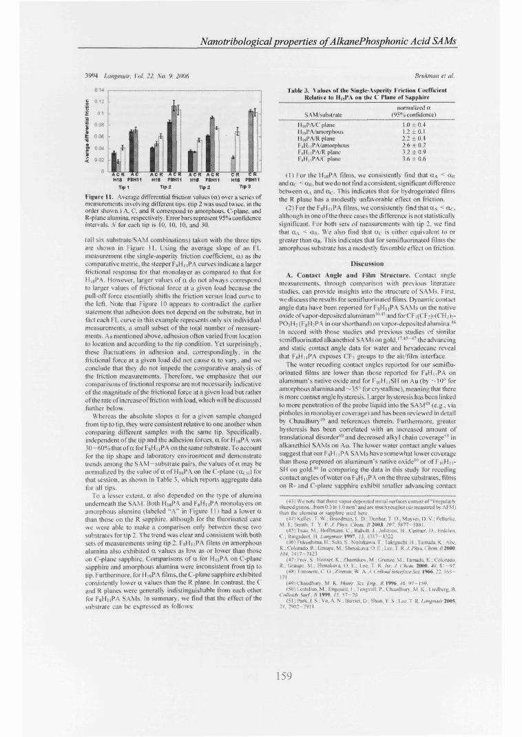
Figure 11. Average difiVrcntiai friction values to 1 over a sortes «fmeasurement', invoking different tips, ( l ip 2 «as usai twice, in theorder shown.) A. (.'. ami R correspond to amorphous, (.'-plane, ¡indR-planealumina, respectively. r'rrorbars represent 95"«confidenceintervals. A tor eaefi ¡i[> t.* í (i. l (i. ¡(i. and 30.
U!¡ sis Substrate SAM combination«) taken with the three lipsare shewn in : k';««.- I I. I sing f he average slope of an Fl-measuremeni ( the singie-aiperity friction coefficient, tu as shecomparative metric, the steeper t'sH ( ¡ P A eurv es indicate a Sargerfric-tional response fix that m..n)oiaycr as compared io that fatH :•<?A. Hoxvever, larger values oí o. do not itKvays correspondto larger values of friction.»! force at .1 ¿ivc-n load because thepull-off force essentially shifts the friction versus load curve tothe left Note that Figure I D appears to contradict (he mrlictMaternent thai adhesion does not depend on the substrate, run ¡ntact each I !.. curve in 'his example represents oni> si<( individualmeasurements, a small subset of the total number ¡>f measure-ments. As mentioned above, ud^sion often varied from locationto location and according to the tip condition. Yet surprisingly.these fluctuations in adhesion and. correspondingly, in thefrictionai f'vítve at a i^iven h>ad did noi c-íitse o. to vary . and wev\mclnde thaï thés do not impede the comparative ;an;i!v; oíthe t'notion measurements. Hiervfbrc. we eniphatst/e that ourcomparison» of frictjonal response are not necess.« il\ indicativeof the -rW-gmtude of the t'rictionat force ¡¡î ;î given load but raihetof the rate ofincrcase ot'friction with load, which «ill be discussed,further hei»\v.
\\ hcteas the absolute slopes ft for ¡> ylvcri sample changedfrom lip to tip- they were consistent relative io one another whencomparing different samples wi th the same tip. Specifically.Independent of l he tip and the adhesion torces. a for 11 ¡«PA was•u-60*9 that of« forfsHüPA onthesanieíiubsirsic. ' to accountlor the !ip shape and iartxsriitotv environment and demonstratetrends amorig itik." SA\! suhuratc pair«,, the values of a tnav heiKwiKiiiied by the value of d of H)»PA on tht t'-plane (ts,: •,•) forthai session, as shown in Table >. which reports aggregate djt.ttix aJI tips
Io ;j lesser extern, a ;tko depended on the type or 'aluminauiidernecifh the SAM ííotb l t ¡ s f* - \ and r s í í uPA monolayersonamorphous «ilumina t labeled "A" in Figure I i ï had a lower ttthan tSiose on the R sapphire, although for the tluorinated casewe were a!)lc to make ,t comparison only between these t.vosubstraies lor tip 2. The trend »vas clear and consiste»! with bothsets c>f measurement.« using tip 2.1 < H ; ; P A Hlrns on amorphousalumina also exhibited tt values -t.s low as or lower than thoseon C-pfane sapphire. < omparisons of a for HisPA on ( -planes;ipp!iiie and ¡)ini»rphí)Us alamina werv Inconsistent from tip totip. i-urthonnure. k«tl:SI'A films, the (_ -plane sapphire exhibitedconsistently lower « values than the R plane. In contrast, the Cand R planes were i;ensralf> indistinguishable from euch otherfor l- 'uHijPA SA\is. in Mitmnan.. we find that the eOsx-i of ¡hesubstrate .an ix- i:\presscd as Iblk-'As-
SAM.-siibstrau-
' plane
F,HitPA/R plaBKFtHuPA/T ptane
mirouili/«!«(95".,eonfnJenec)
! 0 ; 0 4l > ; (¡.l
2Â Ï112." 2 ± 0 '):!.6 -i- « ft
i t ) > or ¡he H:»PA films, we consistently lii-.d (iiai cu "' ft«and a < «i, . hut wedo m.>t find ¿consistent, significant differencebetween <is and «, . This indicates that for hydrogcnatcd filntsthe R plane has a modestly unfavorable eîlect on friction.
O For the fs>i I ¡ •. PA fiims. we eonsistemjy find th;st u \ •'- n, .ahht>u^h ¡none ¡>tftheihree eases the différence is not statisticallysiïniíicant. for both set» oi' measurements with tip 2, we findthai On < O... \\i- also find that a, is eifhet equivalent lo or»rester than a». This indicates that for swmiíluofinated iiíms theaniorphi'us substrate has a m¡xicsíly favorable effect m) friction.
A. i'onwtt Angle and Film Structure. Contact iinylenicasiitvmenfs. ¡tirou^h eomparisiu) wi th previous titeratittesiudiis. can provide m»¡ahts into Ihc structure of SA \ Is. f irst.we discuss ihe results fot semifíuOfinated films Dynamic cu!)î:icîanglsrdata have beer, reponed Sor I at t) ¡f -V SAMs on the nativeoxide or'v¿ptir-dí;p>.>si!ed aluminum"' ' and tort. I .it. I -í-íí.'(l.:i.--î*<)-: H ^ { }•?,] I ;P -\ imnjr shorthand) on v;ipot-dcpos;a£:íiíitfiï"tiina t:î
In accord with those studies and previous studies of similars.-mifînoriri.ited alkam-ihiol S \ SSs on g-.>kl. ' " *s '"' the advancingand static contact angle data for \\Mta and hexadecane reveaithat i 's i luf 'A exposes i.T? uiroaps to the «if 'film interface
The wuter receding contact angles reported for our seimflti-orinaied films are lower than those reponed for I ' uHcPA onaJumtnum's «alive oxide and f o r f ' ; ( H i : S H o n Au(by --10" i«ramorphous alumina and - "<s. forcrystaflinei. mcaniftgthatthertis mote contact ¿ingle f)\ stcresis. Larger hysieresis has been linkedto more penetration of the- probe liquid iniotheSAM'Me.g . viapinhoitts in numolavcr cover, ige l and iiasbs-en revk-werf in deuilby ( 'hmuihurj ••'•'' and refersiicis therein. Furtherniore. greíilsrhysteresis has bien correlated svti t i an Inc-ieased ¡uttount oftneislational disorder*1 ;ind decreased aiky I chain coverage1' ina&anethiol SAMt. on An. The lower water contact anule values.suggest lhat mn í -J í ¡P-\ S A Ms have somewhat lywei coveragethan those prepared on aluminum's native ovide"1 or oï f ' i. i i i •.-SH on goi(!.f's Sn computing ihs ¡iala in this studs lor recedingcontact angles of watsr on f-xH i ¡ S'A ois the three subsfraws, filmson IÎ- and C-phme sapphire exhibit wrtaHci ad\.¡ncing contact
: l.-'l if-: .:.it::riívd oi(U <,))# '• W .
V i 3l Itt ) \ !'
í.: fsl:ïl ¡(f ;>„: ;;K (ÍHK :l (<>XIÍiSl¿^3 SWr¿
itlS:! í !> -k:v!ial í fí
iiuKSl] : í
,T.I< > Ptt» ' ¡I-.-IK tUW»K .'>',>«*> ü í : , . . .i -n -;•', •! • - . ; ;••
íí?^fi.. s H»i$ttt. K.: /hamifaos, M •;;fi¡fi/)¿- Vî . í amiub K ("^li.racoi; <i:3c¡K- V I . SüB.,fco-s. 0.1 ¡« ; k ttr.J • km JIMIO. #'• S- *"
i^^ í-n^suv-:-, ^ o /:MF;SÍ: ^ A ' ( •l'.'.·W^VJ^v.-'.V-í l*K>íi .\'' ;^;-.171
1> i. )MI,<Í:Ï.IH \! k í ta'l .'>..; f »g K I fX: if' "7 ¡50.
(S(:; i,!üa-, M fn;«:«!-:: í iaivi-(il P . C teaníhioi M \ . f u - i l t i î i - :î! ofe;,.ft SwC s I W M. 57 -; t
(M l'MV ! S Vi- \ \ -M'HI.", il •-••'.III 'í S i : . - i X .',)>«.•!«.•• ÏIÜÍS."f. ï«" ;ví t
159

Chapter 4. Engineering Coatings. Experimental Results
\(inolnbolog\' of Phosphonic Add SAM\
angles and more hysteresis than those on amorphous alumina,meaning that there is higher coverage on the latter, suggestinga higher pack ing density and perhaps more translational orderingof the I 'gHiiPA SAM on the amorphous alumina.
The pure hydrocarbon SAMs reported here yield advancingand static contact angles consistent wi th the expression of the-CH5 group at the air/film interlace.10 44 52 " The advancing andstatic angles reported here tor water are close to those for 11 PAon aluminum's native oxide1" and Hi6PA applied to amorphousalumina through a spin-coat and heat procedure.44 Once again,the receding water contact angle values in our study are lowerthan those in previous studies (by ~10"). suggesting a somewhatlower coverage of HisPA in this study. In general, the reducedcontact angles in this study as compared to those in previouswork on films formed on the native oxide of aluminum mayresult from low er S AM coverage on the amorphous and crystal linealumina surfaces driven by the lower reactivity of these surfacesrelative to the native oxide of aluminum.
We note here a subtle difference in contact angles betweenHigPA on these substrates and what is typically observed forSAMs of long-chain alkanethiols on gold. Whereas the advancingwater contact angles reported here are essentially identical towhat has been reported for thiols on gold (110—115°), advancinghcxadecanc contact angles are significantly lower (50—52' forthiols.5051 38—41° for our work). Data from the literature haveshown that water has an advancing angle of ~113° for a methylsurface, whereas on a méthylène surface it is reduced to only~ 1030.54-1- Hcxadecanc, however, has an advancing contact angleof ~51 ° on a rncthy 1 surface, whereas it wets a méthylène surface.Consequently, hexadecane is a more sensitive probe of themethy lene content of a surface than is water. Whereas ouradvancing angles indicate a mostly meth) l-terminated surface,which is nearly the same as that of long-chain alkanelhiols ongold, the hexadecane advancing contact angles indicate that thereis some degree of additional méthylène content at the surface inour HigPA on sapphire and amorphous alumina than there is foralkane thiols on gold, consistent with the notion that the coverageis somewhat lower. Lower contact angles may also indicate ahigher tilt angle from the surface normal. Advancing hexadecanecontact angles with our FgH i iPA ( 80 - 81 °) very nearly reproducemeasurements of partially tluorinated thiols from the literature(e.g., 79° for F8H2SH'' and 83° for FsH8SH5f').
The PA SAMs are favorable to thiols in terms of longevityand stability. Whereas thiols on gold and silver oxidize anddegrade with time in a matter of weeks,^7 the PA SAMs examinedhere were stable for Ihe six months that elapsed between depositionand final ATM imaging; during that time, they were stored inan ambient laboratory atmosphere. The substrates were eventuallyreused for infrared spectroscopy measurements on the SAMs. sothe maximum lifetime of Ihese alumina/PA SAM pairs has notyet been determined.
B. Nanotribology of Bare versus Coaled Samples. Asexpected, coating alumina surfaces with PA SAMs reduces friction(both in absolute force and differential friction a) at the single-asperity level, and the reduction is dramatic. This clearlydemonstrates the effectiveness of PA SAMs in reliably reducing
(521 Bain, C D Tioiighton E B Tau. 's T . Ciail. J . Whilesides C MNu/™ R n ./ Im Chcm Suí 1989 / / / 321-335
(53)1 lakos, I l Newman R C McAIpmc. F- Alexander M R !air/liatrfare Anal 2004 î(> Î47-154
(54) Mrc S V , Licdberg. B . Aliarà, D 1. Langminr 1995 /Í.3S82 3803(55) Aliara Ü I Aire. S V [ l l iger C A .Smder R G ./ .1m C/iem Soi
1991 113 ISS2-1854(56(Weinste in , R I ) . Monarn, .1 . Ciishmc, !• .Coloració R . J r , I ce I R
l'ntel M . Alcsi W R , Jenmnss d K J fluí í hem H 2003. 1117. 11626( S T I l C K g e t t G .1 (//,// C/m» .l<í«2W» 4*9 17-18
L·ingtmnr, l'oi 22, ^t>. 9, 2006 3995
friction at the single-asperity level compared with uncoatedsubstrates. In general, the reduction in friction may be due toboth the reduced wcttability of the sample and the reducedattractive normal and tangential interactions with the tip that thechemically inert methyl or trifluoromethyl groups express at thesurface.
Interestingly, the reduction in pull-off force in going frombare amorphous alumina to PA SAM-coalcd alumina is verymodest compared to the reduction in friction. We thereforeattribute the friction reduction exclusively to a lower barrier tosliding and eliminate any decrease in contact area or attractionbetween the tip and sample as a possible cause for the reducedfriction.
The low friction behavior persisted over the ft months that thesamples were studied, indicating far better tribological stabilitythan for thiols on gold or silver.6-57 The range of values of thework of adhesion. 0.040—0.12 J'nr, is comparable to othermeasurements for silicon tips on SAMs58 and includes the valuemeasured for self-mated CH3-on-CH3 inlet faces.59 0.060 Jim2.
The reduced friction of bare amorphous alumina as comparedto that of bare annealed sapphire seen in Figure 9 suggests thatthere is an increased amount of passivating adventitious carbonadsorbed from ambient exposure on the former. Nevertheless,the addition of the PA SAM sti l l reduces differential friction bya factor of at least 5 beyond the lubrication provided by suchcontamination.
C. Kffect of Fluorination on Manotribology. In comparingdifferent PA SAM films with each other, the most noticeablecontrast is the pronounced increase in differential friction a ingoing from HigPA to FgHuPA monolayers. T) pically, there wasalso greater absolute friction at positive loads for the FjUn PA,with variations in adhesion resulting in outlying high absolutefriction measurements for HigPA, as seen, for example, in FigureJO. This is in agreement with previous results from otherexperimental and molecular dynamics studies of alkanethiols ongold.'460"'''' although in these studies only the terminal groupwas fluorinated whereas the rest of the chain was strictly alkane.Here, the slope of the friction vs load data differed by a factorof ~ 1.5—3.6, depending on the substrate, whereas previous workon alkanethiols reported factors of 3 to 4. We note that our workis the first where friction and load forces are experimentallycalibrated in situ.
The difference in friction between pure alkanes and — CF-,-terminaled alkanes has been attributed previously to the greatersize of the terminal CF; groups compared to that of OH; groups.Because only the terminal group was fluorinated in the previousstudies, the packing densities of the two types of chains wereidentical, and equal numbers of large CF-, groups were packedinto the same area as CHi groups, imposing a significant barrierto CFj group motion (i.e., deformation and rotation). In the MDsimulations of self-mated SAM interfaces by Park et al.,60 thisleads to higher ordering of the CFi groups in the film, and thisis correlated wi th higher frictiona! forces. However, in our case,the top 8 out of 19 caibons are fluorinated, precluding such adirect comparison of the data. A different possible origin of thiscontrast is discussed further below.
(58) Burns A K . Houston, 1 I- .Carpnk, K W MichaKkc. 1 A finí KetI cu 1999. S3, 1181
(591 Thomas R C. Houston J l . CrooU. R M . Kim. T . Miclulske. TA .7 Im Chan Stic 1995 l T, 3830-3834
(60) Park. H . l oren?, C D. Chandros-; VI . Stincns. M J . Oa-st. Cl S .liorodm, O A Longman 2004,20, 1(1(1(17-1(1(114
(61 ) Kim. 11 I . Oraupc. M . Oloba, O . Komi, T . Imaduddm, S . Lee, T R .l'em, S S langmuu 1999 15 3179-3185
(62) Graupe, M Komi f . kirn. 11 I .flarg. M Miura, Y r .TakenaiM, M ,IVrrv, S S . I ce, l R Collmdi luif, A 1999, /S-l. 239-244
( M l K i n i H 1 Koira. I . I ce, l R , Perry, S S InM Leu 1998 4, 117-40

Nanotribologicalproperties of AlkanePhosphonic Acid SAMs
22 \o 9
Marraai fore«ligure 12. I «f f i friUion dau at two neart>\ lotanons ''S"«confide«« mtvnais, S 5.
D. Linéarité ot í net ít»i \mits Load. Sever il prev ¡ous> studieshave reported that smgte-aspertis friction i! fi.nct-, are oftenproportional to tl,e Irat srea of *.w>tau •""* "" vvhiJi Tor asingleparahohcAspentv txrt\uenhomo^n<xms.tsotropic, linear,cl ¡»tie natsrwK as ftttll as. in mato »!h«t eases varws» Hi anoitime<<r fashion vnth the load in .1 t,har,ictemtic, u ill-definedm !«>)t.r " ' I his t) pe ofloati dependence *va> ran is seen m ..r ¡tecourse oí these experiments, as th; mdiv tdual K l f>lstw ívpicaliv\\crc almost always IngliS} 1 »car, as >e*n m i igure» 10 ¿iitl 12
furthermore uHWsleni wth the adhesion measiii emerasdescribid above, lite Î L puMMirenient» evhibi! a !>x.al variationm the pull-olf toree iFiaír« I2i \ft<a f L measuiemeius werepcttornKd at ont position, the ,aniiieitr «as moved to anotherspot, and anotlici -«ems was pet formed Uhcteas the pull-offtorce mcreased b\ 5U"o irum one position to anther, the averagedifteittuial friction a víiiedbs. less íhan ^V validating the »se«f a as ¡he figure of mt re f«r uimp,srmc inuion measurement^\V v' believe thai the consistency in this f iRure, despite ¡he v ai istionsin absolute friuional forn. and adhesió« foret, is a rallarremarkable demonstration ot independent contributions to thetotal IrKlioiwt behavior of an i
ít-IK if-ficl. •< *<V t j íkíEvt í> t Sal tKr<>ii H f < »'ifíllí»?!//^ V*t?«« j;íí ï"' <í ü
l »~)Suv t r 3 í h'îkx*. îî M ' v»Ji«r« í'tí,l<« »í xt-í »i \**n.ri ttUí.a·t''.'«K í.,-« í/í-í." i Mt»e t ;wlrxi ¡t VilvrhíiS I!<V3
í t < > j S f i ¿ t l f Soïu E ^ÏÍK ítv í *t K .-Ni,* ! l ' ) «íAÍ'f ' f'l .Jí"/ »níwrcV H > I « , Í ,<K «frf <í\íw< >^< r r« o« i '«nu." f I 'i |IK> H \! ! i!xHiwd 'Xiiii-a* ¡!n V ¡«¡lin!, ¡,0- n\ "( ,> •<
<í "u i í juk í A S i N * > K ï t í *} I ' 'iSf! ív>» V1 l>»*çmí<!<)<M í' > > f c ! '«i,
\.,>i sj p < t ïv» a> i Sií«.n»n M J !,».)»»'>.<
l í ' M í t f ! « [ *K (.; ï > » ;u ff V î*n> AÎ t ^ Í J^Í Î .^ ii ï ( iff lli! í", ».f* i « i i n t k t \ ) i i l>.j!>¿7 i l « ü»,i I J í A W > » V J f« '»i >,» i'M« f i U*1 U<(
«"""x ii|! t " V- S !nv o-i M t 'ï« f« W* '" , ->3 !1'HO* 1 1* ü' "*• s <!"-'•<.! s í A t i l » < ! V ' jo!ii«>» k ' 'n< "í
í, ' r >.! a-, !% ítí- |W í" i11' ' rxií"-)La-ïï/ M X ^ï ' - ïx^ S S \Vvij->!3 V ï Mi« Ai' /i Kí-fÀ-íss
"», ,i9->- > ^j-, ¡jj-,;l?")Jl . ,P k ! /'!« í, S,' Í .Wí Vi- I l«ï » « » IMi M i l R K i K v i M irdví!"l ^r iï i .IÍPKÍ i <\>!aï,. "> . ííf i
i Sjhutiiï M /'»ï A? í 'j IWi S' SV" ÍS-.!» ' ' ^ f ï . a ï j s k H ?v í r^ lk^u M ¡í' f-i S'ï Siíi* í m Ni Mai- vt
ïíftau«» n-í^-ïu rn^oi Sí ifítíií H3 ¿< 1)1 w í ÍHÍtt>ttín< «<<ilnitt '* *tlíl 'i't kfllí! í» í 'fi f% ' fv f ( í /J>t t > .J>í(/ í 1,1 '<ff<íl l i t i / t K U ( ^ SS nj-cr 'í í f s^ Mtí - > '>^ ifï.íï Sí^ívi-s vV irr ' f l te "• E1»1** pf"ï I í
!"0) 'A / U n>ü i MJI l !ii;,i»» JWII ,'• ,^<-,i<~!< '~ltS 'K llitSI I.Í llVUl! SI '<!'? ff 2WI ' "*! R'-ÍWI"-;)!*! TI M (1 Vunoi s! t<.,# ,>»;<, i . ij~/> ;nni >; < f -W) >ltl ÍÍ l <4 K : í" Atií,' W ^««s t. Ifîf ;1<~ '!i,t.fV \ ÎX
< » liid<v K I9i» p , '
ftmkmati es al
l he ¡meant} in the inction vs load <i¿ua and the !,iek oídependence of a on the pull-oft force v,tn he expla-ned bv oneof two hj tvthex-s 1 1 í tin; ihcar sncn^h is PRSÍUÍI- <K pendentor (2) 'rtction is- domin tf^l h) molecular ploxvms The firsth^potbiMs is nsolsxi't.'d by the observai ion itsu vingle-aspeii!}cont,ii.t> ue!iion>tKite trutional force* / proportional to themieiiai,tai \hcai \!ren!?th r ññd tV írue cnHâci afta l ( i e» !— r íi/ v*'1) Lsprssvin? tl»e sht.ir »trenaih dependence o» Utemean norrni! contact pressure to first order1- s ¡elds r = r<. *•tt/ í and iherelore l T . X Í I Í I í it/ * hen the sei on«! termdominate« ! ! plots are nearl> linear fhns. tt «.presents the«•hear strength •• depeiideni« on ttean lonutt pressure <»ul i^ thefisure o! merit !or friction Because the \1 M measures the(espouse of the norm il and she.» cm«*.! siicssts avinagul oveitheentre up sampie ¡unction and txxa«--e the toniatt iireadropioutof the toi ce equations above, this anaïjsísnl ft i* independentof ihe length kVi'leiif fiic t.onta<.( 11 e tSie Kidiiu of th« Up) 1 1 isniav not be the >..!«£ m gênerai especialtj !or laruc rjn¿e> ot tipïaJíiis and normal lo id
I hi*, hncjrdepeiidet.ee has been su-Rjeste-J to tx-a manifestai ionof the Î jriiig a.ttvatfon m(xt,l,f <>l * \vhcrebv the cficct oii!una.,ed noraiis! contact prtsiare is to modify the conlornu'ionot the niaíuiak at the interficc and tu c~.>tresj>ondmgl> createa larger «sergj barrier t<» sluing. lh«> mvreasmg ihe frtvtionalfore« per area (mtertau.i! sheai '•írciü.'th ¡ Î his is ¿xpeaed to he,i sumfkdtit tft«.<-( for softer 'nöcrwK sinh »s pol>mi,rs ,«idSANis, where prepare rcsdtl;, ¡naïves chan«e-. in ihe molecularcoti1sri:iatio» ai tlse interMk.i. Hmvevcr, for solids, ufícix no«ut h <.onioimâuonal ehaïuc with applied pressure ociuci themtei aa»,¡ai shear sirtngih remains constant as UK pi ensure >smvrCiised <iskwg as the materials «ire oniv e1(t»t'i<itl> delormedHenee ihe observation uf liiKarFl behavioi nm he indicativeof the tact that coafonnutimtal vhimges. tit-h as s/stuche dcíetís,art K-ingicKhjctdkiari in^ítasiíigdegTecastín. i<><id SSI ÍK EC vised.and thii> mercases the shear streng'h Hws i> precise!) what isob<<cr\cd !» a is«.«« molcvulai djoamics Simulation of fuciiottsliding lor viKatta-based S \M-ioated siirtacts ">•>
the «evotid hyportiiis is ft >i significant!) difieren! ph) sica!origin Unlike two atiff syîiifc sliding against taji other, suchas bare Si()> and \i () , the S\M !»\srs are compliant andanivrtroptc on ihe <>toniw scale \Vcak \¿n der \Vaais toteesbetween ;id¡acent clw.n" mean that displacement« normal to thesut face an !ocjh/e«.1 í i c , decoupled f torn then nciHibuis) llxis.one vv HilJ not expect the S SM so he Jetormed. & Mgnifiv.wtKouîside of !hs cuntact rc3ii>ii as K«I isotrupic elasfio solid wouldHowever the monolaver tsdcns>;l> p¡ ike<i m-plaii.' so iaieral(sheari deformation wi l l ».otjf le to molecules bcvond the contact/one Ifthecompressivi n¡'nn.¡í(v«!licalidefi>mialiyn¡-.k'C,ih/cdonh to the molecule« immediate:} undcnicjth the up then the¿U of slidmgmv ¡ilvcs molecular-scale plowing Rixitiscihtfiplits beîo\v the top «urtuie c>{ neighboring l*A moletule» {! ¡'¿lire1"«), the tip mast either usmptxss or laterally defoim arfi-iccntmokcu'cs m the Sorvv ard direi lion ¡o ill je As. the load »icR'4i>e>,the tip penetrate« the nwio'a>cr h\ an mcreasmsr anMtnt andciKi>iinkrsag!t,iter phjvical barncr t¡> iiioSi in b»i.aif-v n mustJeiorm more material at high loads than km loads í- romgÄxnet!}» »hin í pataboíoídal tip pínitrates a fiai surface. UKpf(>5ictcd contdtt area í > oí the tip aSona vin in-pljne direction^tlijt is, fht aiea 1 1 A 2-D pasabola of curvature ! , up to heii'hl
- tí. It^lti. *i A -lit% n u>v :"i-i ^nv f i / i
¡8Î V IV. n.« M s ( I K Í I I 'i n *«>!• f ) ïï !u:,/tim• M-> O
(W I a 11 S ft Mi"i •• , Ui imoi j s ,'jii>ii(<-20»<> ¡"í "
16J

Chapter 4. Engineering Coatings. Experimental Results
nh', !<•;</ ,S.-f Ms Umymar. l'ai. 22. \<>. 9 Wri 3W
Figurí 13. van der Waais interaction between tit«; chains is wealalio»mg mdh (dual molecule» to deform independent!) along theirxertical axes í tu- Ai-'M tip f tiercfose cornprei-s.» molecules locally,pcnclrati«}! the <m>'.in<i! MII face p!,u¡e of the film bj a depth It Somedegree of plowing is required for lateral motion, requiringcompressing or laterally deforming molecules in the iorvvard»cijîtilX'rms» tltrcclioii over ihe, pcnciralion deplh. I he. wort, requitedto slide lateral!) is proportion») to the wort, required to compre**or Kilcralh défera the forward neighboring molecules. Tip penetra-lion K »renter ;ii high loads (h21 (han hm load-. Oi I ). arid Ihe ^fiearslretiEth of Ihe ¡n!erf.i<,„' i'ltrease^ »tin load
h) K proportional to \'Rfi\ lor a contact thai is Hertzian or»vcaklv adhesive ¡such ai a DMT contact), the normal Kind /
/**" "Associated with the penetration depft ft ¡s /, — " V-* v'Äft'. where/.'* is th« reduced modulus of UK- contact.7^ Thcicftv«. theprojected area f). is proportional to '•'< - ¿ltd independent of A.Fuithcimttri, ¿n increase in aaheMt-n simph a<Ufc t« ¡he totaltoad, ma the iioidr dependence helwccn lit« iotai loaj andprojecivii conîiiet area remains die same. I I v,v fXistuLitc ttwtplowing dominates over intenacial sliding (i.e.. thai friction isproportional not iht to in-plane tip-surface contact area but tothe contact area projected onw the \ertita! plane), then i "~ tf. it-and frkfion v%ii! he lireariy proportioitai to the load. The ph>sica!baiis for iiiis postulate is. thai fricliona! energi dbsipalbn i>>r¡i>sdue !M the sliding of moiectfle> past one anoiher at the contactinterface hut it1 ihc mechanical deformation of tho lor\sarjneighboring molecule». This i? es»ntiall> a molecuiar-scaluiiwnifcstatio» itf \ t^'ix'lAiiciiv ; aportin» of the energy expendedto deform the molecule» rnechjnicdlU (in this case, to allow thetip to itiyve fi.swaid) is not reco\cr«f bul íi instead dissipased,
it bnotpossihlv, uitlwuf fuiihcrconipleinctilaiy expertnietikand ix'rhaps detailed sirnubiíoní, to dctcnnine which, if either,of ihc tuo h>p<>tliese> dewnivd aKwc applies litre Ilouevcr.it is clear that the simple model oi itucrlacial frivUon for sintk'asperities, where friciion is proponionai to Ihe contact aiea anda constant interfacial shear .ttrvnglh. docs not apply her« and thatthe «lope of Ihe H, curve h í key indicator of the inctÎKwismof Irictusncil energy dissipation.
T, f.ffwt of the Substrate (»n »he Nanotríhologicat Kcsjwnse.Epitaxial cfteeti aie believed îo be the cause of the more subtlehut nonetheless reproducible dependence of friction upon thesubstrate for both l'A S-VMs. I^»n¿ the \a» der VVaals r?diivalues of Tainada.'7 iower hounds of the surface area*per Of. and (>'_> chain are 0.156 and 0.278 nir-,fiiis nivnns tluf the 11 .yf'A chain is sniatlur in ci oss section thanIhe repealing >ui Tsice atea of the tnociv stalling ¡ilumtiM suKirate»10,1 ">o and f'.244 ran; for C" and R. reipedi v el j ), »o the avai Jahi I ¡tvof packing »iies for i i SÍ'A chain? should be the limning factorfor packing densits and the ("-plane should suppoit a densercoatiiî4 Additionally, ¡he O- () distances in ihe s:ipphiie basal
Figure 14. l,nd-on \ iew of an entile isoltited PA molecule, short ini!the tetragonal arrangement oí the O and P atoms in the headgroup.I he he.KÍgíoup i-» on the ícA, ífí the
figure 15. Pacliug «f MuPA on t" and R planes of sapphire.asssmiifig 1 1 » ! i eptta\) . I he chains rnaiiüai» tlie equilibrium iader \V,uïs spacinj! (denoted 1 1) for both surùee meshes h> chathe lilt wjgfc accfsrding ¡o (he surface rx>»(!int> sits dcnsitv.
plane (0.2? nm) are s'crj c'o<c to the .spacina of theKiiided temiinjl ( >'.s of the phosphonic acid jiroup îO,28 uni i a<;calculated b> C ¡tern .M ) 1 1 anibrtdgeSnll C'orp., C aríihriclgc, MA)(f igiire 1 4, which siiows the entire molecule. v\ ûh the headgroupin ihn fine^wunU). Thus,» U / b epslaxial rebtionshiphetwee»the I I isl* \ Iwadgroups and the C- ami K -plano «nit ceils i» likchand would lead to A near!) idiXiHv packed snonolajer on theformer arid a less <!ense monofaver on the latter (Figure 15). I'hflower dersakv would lead to a larger tilt anule of the molecules.The icduced friction that >ve observe tot the C piano comparedwith thai f->r (he R plane of ihe 1 1 j.f As is therefore cvn>i»i«rtv\ îth près îotis reports oi increased pacUn« density oí ;tlk.:tne(híolSAMs corrîKitim* win a reduction in f rictaon.''5 ** \ urthct more.a comparison of the friction caw between the 12 -plane andamorphous alumiiu suggest-» that, on avciage, sut face bondingsito are closer together in the aperiodic distribution of the latterthan in the R-plane ol sapphire and are c<iinparabic to that <>f tSseC-plane.
However, a single Fs>Hj|PA chain reijuirev moie atea (O.I7Srun-} than eithei repeating sin face mesh loi the C ¡md K planes.picventtog ¡in fidered { í >' \ epitaxial iirn-.ngcm.'nt of (he l'Amolecule»; the SANÍ molecules are siniplv ton large for efficient( I x l ; packing o» the crystalline surface«;. The nest iarge.fiffpeatin? surSsce nnítí, !v' / vTi fur R a»d ( v"> x v''3> for<\ are Urge enough for a <"( -, chain but A & ie»s-!hdíi-ídeal
iv . Also, each ! SH ¡ li'A molecule has w«diaiu«(tTSnt u> Jetennin; the packing order, with the ionger
hv/drogc iiitted •iection scektna a much closer packing svith itsneighbors \ia van del Waal* inlnaetion'» than ¡he bulkierfitiotiitatcd section can accommodate, f igiues 56 and 17demonstrate how the i J 1 ¡ . PA rnonola) ers max ortsam/o OH the< ' and R planes n hen either the t 'II/ or ('¥ > segmcnH domínalethe packing, respeciivelj.

Nanotribologicalproperties of AlkanePhosphonic Acid SAMs
/ '¡npniiiH S i \o 9 yw f}r«Kmar f í al
f »Delusions
Figure 16. Packina of f g U i » "s\Ms on the { and R phne» ot¡w ihv CIM. « IK a the 11 î «cgmenudatmiuic «wm uiwiig
i turn spaeiEy I hu>nn i*ui pottionvoí thi ihimiitivdislotltd
Figure I? Ptckim» nl l»Mn S\Ms on Ihv ( and R pi mes oísapphire tor th.ecaw.whue the C J 'segmcnt<vdi>min<tte.(naint'unin¿equilibrium-paung H)dro.:eMtcd pontons oHhech<«n are dMortedí.í <sm! Kreprvsutt lîic repeat di slam v stör ( í p ¡ekingand «'inmeshes of t R plane sapphire
i rev ct a! r have smdtcd this topic UWHÍ similar molcuiSes) <H;,I «H ¡ aid! f.lli-tjlkíiHvíhm's.mrg Nu and \g substrates(o dictife súrtate penodtv-ttv There the surface mesh was alsoí trger (han the í H- segments and s nailer iba» lite 11 - « gmeirts1 he absolute tilí an¿le of the (. S - chains i relative to the surfacenormal r<tl!t<r litan llie C l i > sigiitentj w<is »of ¿sffuKd by th<substrate but did «icicN&e with ibe number oí (. H< segments¡ ongeimouN.xiksIudmcíi.Ul· C H - v a r d u W uUmteraUiunv.and behaved more like unfluiirm ited titu Is Oit the bast^ ol theicsuhsoftiufpap« webelievetbaîtheFïHiif^^^M'sp^vkinii^trutture is i!<tver to that ,t! ¡he end ol the spevtru n where (. I f'set ments dominate ÍF it'ttre i f t t Xïíhouüt the* iiuesfi w «if howthe (, 11» and C 1 < wgmevttts ¿e<,o«itiiwi<tt8 each other dependingon substrate erjstalhmts is ¿n tmcrestinü one this discussionshould in>t detr tel from im; t >IKludion lhat the small -,>/& of theHtriiice rneshe> relative t« the ü¿e ol the t ï t jroup- imposesa suriQpiimal packina airangcmcm The a« >rphotts aluminalti'V\e\cr vt'iev im( ikvcwiriSj m pose poor rc¿Nr\ buvucrtlh«.hondmíf Mtes and the P \ s)o!ev,u!es
( oinpai mg «he trtetioil d.il<i fur S d i s PA on dntorpliou-xkhimmawith f «í í u PA on crvstalf t ie alumina, we therefore conclude thatihe packing daisitv isstmtenluifrtattt oniht Utmur, resultingin fhc observed rv.dui.lijn IB irictton The difkren.es in contactAntic mewtiruneHK hetMtxn a'n siphons «ti)d crsstaMiie sub-Urates tor the ÍUiorin ?ted films indicate jrejter ptkkinQ densuvon the an'Ofpbou« Sitriiccs, buKterm^ this conclusion
I here is «mother t vpiaiution lor 1 sl i nP \ hav itt^ lovset Inetionon the amorphous subslrate S1 jlec ji.tr dv nimihave linked higher interfti'ai nrdenng and <v^ith hiäher Ifictioit liti^ implies that these mon jlajers rctamIhcotderoithestibsirttes.de" iiîeîhe itvimmctismabilitv utihiS KM and crvitól it this is the ea,e then it would come at (hecost ot reduced picking denyh
<JTn ! « i > v M \S>tl· f S Si »^ !v V t i, > v o S (jíiKÍAlm S
Síslic and advancing toniact sui^ia. measurements perîormedviitíi Mater and he\artcean¿ íiií vonsisunt «ith previous ivjxirist>f f N SA\ls on ilumt! um oxide ^uhst!<ilcí> *howin¿ tli<¡i fio'hHfjt*\ and Iv l l ) )P \ S\Ms render hintin,t surfues hschijh; droph<-bie Howes«,' rccediii!»mi<s<;urements here are euvrttlsSower sviíh íhcsi, samplet «iiígacstinj: that som<-whai lower
íitgí¿ ÍÍMA <iiso iug¿>,vts that ï sH¡¡f"V h» a winewííírt higherpacking duteií} <mc! or ordennc on the amorphous sabstri'tecompared K> that of the ct> stillmv, substrates ] he topographic,ami ti ilxiio. tea! piopetlies i^f thv S \Ms «et e stable ii! a l<ilx)r<«orvenvuonmcnt fot it least 6 monitis, tiid ea!it5g iheif hiuh deviceofambieiitertviTOimieirtaHuibiitlv w steh i>,fir ;ttatírlba¡iíh<illor ilkanuhijK
\l-\î toposr-tphs síiosv that P \ SA\H on annealed sapphireand \apor-ifcpOMifti alumina are simiotii .md umiorm ', oiKcljbound Lnntiiniinant» or iK<nbc>ndrd 1' ^ nn'fn.uK·s tiul v\trt IK tretïiiived b\ ,ttí eihanúl riiiie ¡ire yh»tr\eü icr films, ya R-planesapphire, .intl thc'e jre teadih swept astee dursftj ccntavt mode\l M scanmnc to reveal the atònit«, steps of She imiterK trysmylecrssta! sapphiiesuhstiaic ( ontamuwtionutrhetiphy themonoUwr is observed for ¿il tllra-» leading to ir mssem (.fleetsin n.motnbclogv ratAsuremenu uníess the up <snd samp'e a'ebrous1« ío a stead) state M,T a rim-n process list we beheveuiaistlietipw!thä<kfs,Uive!3Vs,rof P Vmokxnles Oui interfai-escan thertfyrc be constderwi !>•> )•>£ tuaih scH-mated i>,¡£expirititv'ttí vsith tip^ deliberate^ coakd »tth S\Ms in adeposition process wi l l be required to venh 'hi- hspotlK"-i>>
\dbeMon bitv^een í1 \ S \\K and prsx.tss.ed si'icon Vl· \! tipsts influenced h> partial ilswiinatiiin a»d titcttíín ts ¡nf]ui,n>,edtxttit h\ fiuotinafiiitt and the surtaxe «*riangen)i.i)t of the iluininasubítMle Sp£i,ifieall> adhesion betxsesn proisssed tip< andI sil i f l \ ranged from SO to !00"<> ot that for H f»P \ anct wasrievti ls>rwer Ihv fotre disunt,c fevh»».|u£ of atlhtvion nti")-surcntunuvistsltml» K !d«dn.dwx<) values of ihcputl-ott forcecompared with ¡hose trvm the Sriction versus load techniqueï he compression ot chains on the tip and sampL> lesulíins: ¡r«iiwoie va'oriiti- contacts bctwecr (he i\s.> in ¡he latter nteihudm,i> be !iie cause or this effee! along the Im» öS pte\ t<>tis importsoi adhesión h> »teres!,
Boíl1 h pe·tí·f S V\Is demorblraied a ijrce roduvf ion in f rtetio icompared nnh the ¡nuton of ail bare alumina substrates1 urt iit in >a single aipertty Iticiion c»>ertcit,nts In fuHvhjdro^tnatcd ^ \Mswtti eoïis·stentlv kss b> -40 70% tfwttthe vorrespondmg \a!ues kir senMlIuotinííSed SANis \K0 ihilinear nature ol the friction versus load Mcj«ure'nient» indicatest'ui eiiherthe itttcriaen! shear 'trenjh ¡s pressure-depend witus that ftitfisi» ss go\trntd i>\ She plo««t¿ >>f the- ïip throughgreater depth» of lite $ \\1 vi tit mere t>mg load
\sht.reas «ipplsma S\Ms greatly txduved the Indien for allsiibstrjtcs some trends within a s.>i\en *--V\i tspe tiiditvate ascci)i)clt>i(lerelTecf ansingfiomthet,h >iceofiiluminj<;tibstra*eS rtvlioít i, g.íieíallj I «\er for amorphous suhyr¿ites ih ncrvíitítlítnc onc"> wlt«,rc<is diflereniwtion between the (. and Rplíiites «utíge»lv that vjeri^ and epiUvul esTeds plaj a siiiiili hjtohscrv »Me role m the packing .*d suhsequent fn.itotul resp%>nseof! I« S%Ms
Vcknt>»ie<tgmf«t, This wmk was supported b\ the V-utotuIScie-tice rixtmlaiion (C \RFfR \ w a t d N y
SS S'ira.! St ¡t '(,; m i t to i l , is V O ru ; Ä ,n-i v«
163

Chapter 4. Engineering Coatings. Experimental Results
4.6.6 Lateral Force Microscopy Study of Langmuir-Blodgett
Films of a Macrocyclic Compound
G. Oncins", J. Torrent-Burgués1', F. Sanza
"Department of Physical Chemistry, Universitat de Barcelona and Center of
Nanobioengineering of Catalonia (CREBEC), Martí i Franques I, 08028 Barcelona, Spain
bDepartment of Chemical Engineering, Universitat Politècnica de Catalunya, Colom 1, 08222,
Terrassa (Barcelona), Spain
Tribology Letters 21(3) (2006), 175-184.
4.6.6.1 Summary
As we have seen, organic monolayers can be used in MEMS and NEMS as
extremely sensitive sensors. In the case of this work, we studied Langmuir-Blodgett
monolayers of one macrocyclic compound that proved to be a copper sensor.
Nevertheless, our main goal in this work was to see if LFM was able to discern
between monolayers extracted at different surface pressures. As you may know,
there is a certain controversy about the surface pressure of Langmuir films once
they have been transferred to a substrate. Do they maintain the molecular area they
have on liquid subphase or perhaps they relax to reach an equilibrium pressure?
The obtained conclusions can be summarized as follows:
• AFM topographic study of the tiomacrocycle monolayers demonstrate that
the structure of the film once it has been transferred to mica depends on the
extraction pressure. The presence of islands is observed and a model to explain
its formation is proposed.

Frictional Study of a Cu (II) Sensor Compound
* F f vs. Fv curves present a discontinuity that corresponds with the monolayer
rupture. The threshold Fv value to disrupt the sample depends on the extraction
pressure. The higher the surface pressure, the higher the Fv value, so we
conclude that, although we do not know if the molecular area of the Langmuir
film is the same as in the Langmuir-Blodgett film, we proved that the samples do
not relax to reach an equilibrium surface pressure.
• LFM proves to be a suitable technique to study the nanotribology of organic
monolayers, being sensitive to their molecular structure. Besides, the islands
observed at high surface pressures present friction asymmetry, fact that provides
information about their structure.
165

Chapter 4. Engineering Coatings. Experimental Results
Tnbolo<t\ Lettin I « / 21 ,\o 3 \Ianh 2006 (& 2006)DO1 10 1007 si 1249 005-9009 ü
175
Lateral force microscopy study of Langmuir-Blodgett filmsof a macrocyclic compound
G Oncinsllh, J Torrent-Burgues1 and F San/'1 '*"Dci'tulintiit vf Ph\su.al Chtmtstr\ Litntisilcit f/t Bancloiui OÒ02M Biitçíluittt SfHun
l·dnlLi i>f \íinohiiicn%itucnnç ofCaKihniii (CREBECl 0&02& Btimtona Sjnun' DiiHirtnuitt of Ciitttiiail Etiçineetmç í nncrsitut Politctiiutí tic tattitiimci (.ohm 1 <)\222 Timrssa Bfiiulonct bptim
Retened 4 October 2005, dttcpled 19 December 2005, published online 25 April 2006
Langmuir Blodgctt filmsof 4-phen>l 4 sulfidc 11 (1 o\odcc>l) 1 7-dithu l l -azi-4 phosphicvclotctradecane a thiomacrocychccompound used as a Cu( l i ) ions sensor \\crc extracted o\cr mica at sever t í surface pressure values from two subphascs pure waterand a 00! M Cu(lî) aqueous solution Atomic Force Microscopy and Force Spectroscopy (Lateral Force Microscopy) were usedto sluds both Ihe morphology and the nanomechamcal response of Langmuir-Blodgetl films A correlation between extractionpressure and monoiayer mechanical properties was obtened so an increase in the extraction pressure of the monolayerscorresponds with an mciease m the \ertical force at which the monolayer breaks while doing lateral force experimentsExpelnnental data proves that Langmuir-Blodgett extraction technique t ru ly obtains monolayers w i t h different nanotribologicalproperties as a function of the extraction surface picssuic flic form mon of isl mcls on top of the monolavers was studied and amodel mechanism of formation is proposed A higher friction value was measured on the islands than on the monolayer andfriction asymmetry was observed in the latest stage of island formation
KE\ \\ORDS Nanotribology Inction test methods AFM Langmuir-Blodgett films
1. Introduction
Langmuir Blodgett films (LBs) have been a mattet ofextensive research during the last decades because ofthcirsuitability as models to study molecular organization[1 11] and a \vide range of monolayers and multilayers ofdifferent molecules have been studied wi th this techniquem the past [12 15] The capability to control either thechemistry of the subphasc, the area per molecule and theextraction surface pressure of the layers is an alternativeover other preparation techniques of suppoited mono-layers such as Self-Assembled Monolayer deposition(SAMs) [16] The control of the him tiansfer to the sub-strate and the possible relaxation of the extraction sur-face pressure of the suppoited film over time arc s t i l lsubject to controversy Scanning Piobe Microscopieshd\c proved to be suitable to study monolayers at amolecular level [17.18] LBs have been studied usingAtomic Force Microscopy (AFM) [8,9,12 13,19] toresolve its morphology and properties Alternatively,Surface Force Apparatus (SFA) has been used to resolvethe mechanical properties of these layers at a nanomctnclevel in different media and conditions [20,21]
Lateral Force Micioscopy (LFM) has become anincreasingly popular technique to study the frictional
*To whom correspondence should he addressedC mail fsan/ítí üb edu
and nanotnbologital properties of surfaces [22-25] Thedevelopment of suitable techniques to calibrate thevertical [26 30] and lateral [31,32] spring constants ofthe probes used m LFM measurements have allowed toobtain quantitative faction lesults m the NanoNewtonrange [23 25] LFM has been used to study the frictionalproperties of Langmuir-Blodgett layers [33-35], cngi-neenng coatings [36], surfaces of Micro-Electro-Mcchamcal Systems (MEMS) [37,38] and to studyorganic layers such as thiols on gold [39,40], alkylsilaneson mica [41] or silicon oxide substrates and alka-nephosphonates on different crystallographic planes ofaluminum [42] The versatility of this technique allowsstudying the samples under liquid to test phosphohpidbilaycrs on its physiological media [43]
4-Phenyl-4-sulfide-l l-(l-oxodecyl)-l,7-dithia-l I-aza-4-phosphacyclotctradecanc (compound A), figure 1, hasa thiomacrocycle that permits to bind coppei ions, soacting as a coppei lonophoie [44,45] A comparison ofthe mechanical properties of LB films of compound Aextiacted eithei from the water subphase or nom theCu(ll) aqueous solution subphasc offers the opportunityto study the influence of Cu(II) ions in the iheologicalproperties of LBs of compound A
In summary, the aim of the present work is to studythe morphology and mechanical properties of LBsfoimed by compound A using AFM and LFM LBs
166

Frictional Study of a Cu (II) Sensor Compound
i 76 6' Orttmï t'í fiï Líiïeídl ,f<»ïVï* ;m<rríSí-íí/Ji' m¡«> of
15Â
11.4 À
f í¿ure K Molccuíaa sîTutuuc or-í-phcií>l-4-Míjr)dt'-3MI-ouidfcv})-l.?-dítht(i-n-í*/.í-VphosphatvcIo:eíiíKÍcv,itsío (eomjxtoístí A),
were extracted ¡u diH'erent surface pressures and fromthe tHo mentioned subphases, so ihe change in thenanoliibologieal properties was studied. The cot relationbetween the surface pressure-area isotherms of com-pound A and the measured latera! force values obtainedby LFM on the monolayeis give a new insight in thefield of nanoirihology of LBs..
2, Experimental .section
2,1. Langttiuir Blo<lgeit film* preptiiatiua
l-angmuir films were obtained in a N1MA 1232D1D2Langmiiir Blodgctl trough (area1* 1200 cm"). Pure wa-ter (Millipore MiiliQ grade), and a 0.01 M solution ofCu(NOOj (analytical giadcl Here used as subphases. Asolution of compound A [46] in ehtorofoim, at a con-centration of i mg-rnl, was spread over the corre-sponding subphase, and ISniin were lag beforemeasurements if) ordei to permit evaporation of thesolvent. The compression speed was 50 cnr nun.
The coi responding LB films were transferred atconstant pressure onto a freshly cleaved atonneally flatmica surface. Ihe transfer was done using a M M AI252D1 dipper, at several surface pressures and at jconstant temporal ni c of 22 <C, The substrate,s weresheets of I cmxl cm cul from reed mica. LB liltns wereobtained íoilowing a Z deposition, that is, the sheet ofmica is first introduced in the subphase and once the
Langmutr film ¡s formed, the mica sheet is pulled upwith an extraction speed of 10 mm, mm The measuredtransfer ratios weie clo.se to 100%.
.2. Al'^f and Ll-M Mcaw
All measurements were performed vuth a Dimension3100 microscope attached to a Nauoseope IV controller(Digital Instruments, Santa Barbara, CA) m contactmode using V-.stwped SisN^ tips (OMCI. TR^OOPSA,O!\inpus. Japan) with a nominal spiing constant of0,08 N m. Force curves weie perfotraed always beforeacquiring topographic images in order to apply theminimum force on the surface and to avoid any mono-layer damage. The instrument was placed on a vibrationisolation table and in an isolation box (TMC, Pea body.MA). Temperature was maintained between 19 and21 °C and humidity was fkcd to 40 50% with the aid ofa nitrogen flux inside the isolation box.
Vertical spring constant force calibration was per-formed wuh a Force t'robel-O MFP (Asylum Research,Santa Baibara, CA>. Individual spring constants werecalibrated usina the thermal noise method [301 afterhaving measured ihe pie/o sensitnity (V nm) afterscieial minutes of performing foice piots. to avoidhystciesis.
Lateral force calibration [31] was performed to obtainquantitative friction values, using a wedge silicon oxide
16?

Chapter 4. Engineering Coatings. Experimental Results
OiHinSítítl Latí nil foi c i inuiosc(ip\ stutí} of LciH%iiuin-ßkHl%i It 177
calibration grating (Mikro-Masch TGG01) providingt\vo facets joined at a known dihedral angle Raw datatreatment was performed with Matlab scripts piovidedby R Carpick gioup [47] Buelly, the scripts weie usedto generate friction versus load data sets from Nano-scope files For fuction versus load measurements anascending saw tooth waveform fiom an exteinal func-tion generator (Agilent Palo Alto CA) was subtractedfiom the vertical photodetector signal obtained thioughthe Signal Access Module (Digital Instruments, SantaBarbara, CA) using a home-made card The icsultingvoltage was inserted to the veitical photodetector signalthrough the Signal Access Module allowing the feed-back control to maintain a steadily incieasmg normalforce over the course of a friction veisus load experi-ment The lateral motion of the tip was set to 25 nm at6 1 Hz with 512 lines and 512 pixels per line As a le-sult, a whole friction versus load cuive ranging from lowloads to high loads was obtained every 84 s We chooseto ramp the foice fiom low loads to high loads becausewe wanted to study the breakage of deposited layers asan mcieasing foice was applied
3. Results and discussion
31 Mor/ytio/og\ of the inoiwlcner1,
Figuie 2 shows the surface pressure-area peí mole-cule isotherms of compound A on pure water subphase(cune a) and on a 001 M Cu(II) aqueous solutionsubphasc (curve b) The change in shape of the iso-therms denotes the influence of coppei ions piesent mthe subphase Curve a) m ligure 2 nearly reaches a pla-teau at ~ 1 2 3 m N m , while curve b) only shows aninflexion point at ~ I5 5 mN m Aiiows m ftguie 2indicate the values of the surface pressure at which theLBs were extracted for its chaiacteiization
Figure ï shows the AFM images of compound A LBsextracted from a pure water subphasc at surface pres-sures of 4 (a), 8 (b) 12 (c) and 13 mN m (d) The
25
f 20E.ï 153
O)
O- 10
20 40 120 14060 80 100Area (A'/molecule)
figure 2 Surface pressure art-a isotherms of compound A wilhdifferent aqueous subph ises ( l) \\ Her {b) 001 M Cu(Il) aqueousbolution The ano\\i sho\v the extnction pressures studied in the
present work
piescnce of a complete monolayer covering the entiremica suiface was vended sciatching the suilace with theAFM tip at 50 60 nN (images not shown) and mea-suring the height of the monolayei m the nm of thescratch, being (« 1 nm at the minim um vertical force Infigure 3, we show the islands of compound A found ontop of the monolayer for all the extraction piessuresFor surface pressuics lowei than 12 3 mN'm (pressuresbelow the plateau threshold) the height of the islandsleached a maximum height of 1 nm and their size in-creased with increasing extraction prcssuic For pres-sures highei than 12 3 mN'm (plateau region in theisotherm), aggregates ~I5-17 nm high (figure 3(d))weie foimed We were unable to detect any kind ofmultilayered oigamzation in these aggi égales
Figure 4 shows the AFM images of the monolayersextiacted fiom the Cu(IF) aqueous solution subphase at8 (a), 12 (b) and 16 mN'm (c), respectively Islands donot appeal below 15 5 mN m, the inflexion point in theisotheim for Cu(II) aqueous solution subphase (figiiie 2,cune b) For surface pressures highei than this value theaggiegates observed on top of the monolaver were ~13-17 nm high (figure 4(c)), very similar to those observedfor LBs on water subphase at 13 mN m (figure 3(d))Correlating the isotherms with AFM images the for-mation of aggregates seen on water subphase at13 mN m and on Cu(II) aqueous solution subphase at16 mN m corresponds with a local collapse of themonolayer, which is due to the asymmetric nature of thecompound A molecules and to the lack of a stronghvdrophilic group Then, the particular shape of theisotherm is a consequence of the moleculai structuie ofthe compound A (figure 1) and its interaction with thesubphasc High compressions of the monolayer on watersubphase lead to the slip out of molecules lather than tochanges in the conformation or orientation of the mol-ecules (phase changes) and consequently high surfacepressures cannot be reached The effect of Cu(II) ions inthe subphasc is to bind the compound A molecules andto stabilize the monolayer in some degree As a conse-quence, the plateau in the isotherms is removed and thecorresponding AFM images demonstrate that it islinked to the absence of islands on top of the monolayerfor extraction surface pressures below the inflexionpoint
Compressibility coefficient values (around25x10 ' m mN) calculated for the raising part of thecurves a and b of figure 2, indicate the piesence of aliquid expanded (LE) phase It has also been corrobo-rated by AFM but wi th the charactenstic that someislands form on top of the monolajer
3 2 Monola\er trillion b\ Lt\f
Friction versus load curves were performed on themonolayer on areas free of islands and debris ranging

Fractional Study of a Cu (II) Sensor Compound
40<W!
Own
Own
•Xl 'VJ im.(iïc<>ot LanjimuírSxíhpii;ií.i-: water. I Í
äihm evíf-ícu-üaí diiï:tre;i 5 ¿mí . ïhc sccítoïí
c prevusfcs íaí <l m N ni. (h) îi iîi\ m. ic) l j mN ni. ut) H m N mN s^ith tîïi; wíiiíi.1 ïtnos <••» its».- t-.^p'.>criiph\ i;n¡fi>e.
l'rom no*contiiipi to high vertical loads and avoiding thecitJhcsive region (figure S'l. Experiments were performedthis way to test the response of the Langmuir Blodgcttmonotayerof compound A ag;im>t an increasing verticalload. Preliminarv experiments were performed to checkiriclion hsslcresis when ihc load salues ranged from ioxvto high values and rift n-rxa {(igure 5). No hvsteresiswas detecteu in the contact region, although ¡here weredifference-« around 0 nN load. In friction versus loadcurves aci·iiured from low to high load values a nourK0 nN initial friction regime suis observed between tipand monolayer. Having in mind that measurementsvseie peí forníeu from no-contact to high vertical loads,this initial regime eoiTcsfHindx with the tip coming intocontact with the water layer present on the monolayei(all measurements were performed at 40 50% RH) Thislow friction initial regime is believed to be due to the
slow reaction of the feedback loop as the tip contacts thewater layer on the monolayer of compound A Whenperforming experiments from high loads to no-conuict(ligure .'>. white dots), there is no such a behavior around0 nN vertical load because the feedback keeps onworking unt i l the snap-oil e\enl. At 1 2 nN load ¡ange,friction increased .steeply due to tip and monolayercoming into contact
We attempted to fit our experimental friction versusload curves on compound A monotayers svtth severalcontact mechanics models, namely Johnson KendallRoberts (.ÍK.R) [4S] and Derjajuiin Muller TopormtDMT) [49]. We also attempted to fit our data with thetransition equation proposed by Carpick t'í et!. [50], Thismodel permits to adjust a transition parameter (x) thattakes values from 0 to I . When -í O. the equationcorresponds to the DMT model and when x-1. i(
169

Chapter 4. Engineering Coatings. Experimental Results
f, <•/ al 7,í'ííVm/ A' sr¡<<7.r ff i..<ifixmii!i- Bi«iií'.c>t fiíftíí- 179
4. ATM un.iges »i J,;«¡¡>niuir BlCutli! iitjueout í
Q yfii 1 pro
f\trac«xi ,(! ilil&rt-rrt üirfínx- prvssurc* (ai S mN'iit, (bl Í2 ir.N-m. fe t !í> rnN m.ages ¡trat í ¡ira'' inscl in (ni »hou« the pursíaci: oi ibe «¡onoäiiya,
10-
5-
0-
-10 o 5010 20 30 4Vertical Force {nN)
figure S, Friction vecwts l»a>! t".irn-> (vrl'onned on I.,B> of ooiKpoünttA cMf.ioH\f M Í - ¡nN n *nh u,n?r «aria« Whisc curve »hnw» resillaiukcïi írotïí hiyît toads. i<> !o^ io;tds ;t«ti hïiick curve sho\v i^uïts iakcnî'roi« low U'uUs to high U.nuis bjch curve i> Ux" avcr.igc of 20 curve-;
perí'íírmíííi En riv? <jjfíüïiL·iïií ptüt-tí. i>r- t!^c- -,t;ít;ic<í ni the niimofayor.
corresponds with the JKR model, None of these modelsw;ts suitable for oar iruMsurumviUit. We bulies-c (hat (hemain reason is that ihc.se contact mechanics models aitonh laud for hiiniugcncous, ¡sotropic. linear und elasticmaterials [4XJ. This is not the cuse of Langmui r Blodgctt1'ilms on mica Moreover those models consider thatshear sirength r is constant Friction force (/•*) for ;>single aspcnlv i» given by J5J ) :
being A the intetfaeiul contact area. In fact. T is notnecessarily a constant and sho\v> a pressure-depcnüentterm:
t •" tl) 4. v />
where r« is the constant interfacial shear strength term, pis the pressure and s i* a diinensionless coefficient.Studies concerning friction measurements at thenanoscalc have shown thai the shea r strength can varydeiK'ndirig on the nature of the sample ¡52). Fo¡ all thiswe believe that these moikls are not really suitable toexplain the contact between an AFM tip and aLangrmiir BlodgeU monolayor.
Figure 6 shows friction versus load curves obtainedon compound A LBs extracted at severa! surfacepleasures. Although the general trend of (he curves isroughly the same in all «tves. there are some differencesthat can be related with the extraction pressure andmechanical properties of the monolayers. After theinitial contact between tip and monolayer, ¡i region inwhich the tip frictions the monolayer is reached. Thisregion ends with the appearance of a discontinuity inthe friction \erMi-. load curve that iv marked with anasterisk in figure fi. The loud at which this discontinuityappears increases as the monolayer extraction pressuredws (S.5.V 2.3 nN at S mN m. 20.1 i 2.8 nN at 12 inN.m and 2*).5 ' S.2 nN at !() mN mi. Previously, we haveshown that phospholipid Mayers break under the
70

Frictional Study of a Cu (II) Sensor Compound
180 G OHÍ;«Ï et al L·ilet al force micwaop) V/ÏK/Ï oi Lançnnin Blodçell filmf
10-
5-
O-1
(a)
5
12-,
10-
8-
6-
4-
0-
-2
10 20 30 40 50
Vertical Force (nN)
10 20 30 40
Vertica Force (nN)
50
10 20 30 40
Vertical Force (nN)
50
Figure 6 Friction versus lo \A cunes obtained on LBs ol compound Aextracted at difieren! pressures The expeiiments were performedincreasing the vertical load from no-contact to 50 nN SuhphascCu(ll) aqueous solution (a) 8 mN m (b) 12 mN m (c) 16 mN m Adiscontinuity rclitcd \vith the breakage of the monolayer is marked
wi th a * in the graphs
exeition of a certain vertical load and that this loadincreases as the mechanical strength of the bilayerincreases [43,51] This behavior had also been studiedwith lateral force microscopy and a discontinuity infriction versus load curves had been detected andrelated with the break of the phosphohpid bilayer[43] So. the discontinuities in the friction versus loadcurves obtained on compound A monolayers coi re-spond well with their breakage As a consequence,the presence of this discontinuity is a way to measurethe vertical force that the monolayer withstands be-foie bieaking while fnction expeiiments aie per-formed This fact is really important to confirm thesuitability of the Langmuir-Blodgett extractiontechnique to get layers wi th different nanotnbologicalproperties as a function of the extraction surfacepressure To ensure the reproducibihty of the ob-tained results, friction versus load experiments wereperformed with two different calibrated tips and inseveral experiments The results are shown m fig-ure 7(a) The magnitude depicted is the vertical forceat which the LB broke as friction versus loadexperiments were performed Random discontinuitieswere detected in friction versus load curves besidesthe ones that correspond with the ruptuie of themonolayer We believe that they correspond tomechanical or electrical noise and they appear at¡andom vertical loads The discontinuities presentedin figures 6 and 7 are not random at all and theyappear at ceitam veitical loads (enor bais are shownin figure 7) in 20 out of 30 friction versus load loopsperformed in five different positions for every sampleand every tip Previous scratching experiments intopographic mode performed on the monolayers ofcompound A showed that the bilayer can be lemovedfrom the surface of the mica applying loads m therange of veitical forces shown in figure 7
The friction coefficient on the monolayer (the slope ofthe linear region of contact between tip and monolayerin the friction versus load curve) at an extraction pres-sure of 16 mN m was calculated to be 0 124 ±0002 Foivertical load values highei than that coi responding withthe discontinuity shown in the friction versus loadcurves, there is a linear region with a friction coefficientthat was calculated to be 0 140±0002 This frictioncoefficient is quite similar to the friction coefficient ob-tained on mica under the same parametric conditions(0 142±0 001), so this legion corresponds to the contactbetween the tip and the monolayer suppôt ting substrate(mica) This fact has also been reported m a previouswork [53]
To compare the mechanical properties of layers ex-tracted fiom the two subphases, experiments have alsobeen performed on monolayeis extracted in pure watersubphase Results are shown in figure 7(b) The columns
17]

Chapter 4. Engineering Coatings. Experimental Results
(i, Ofli Í'JÇ t'í (ï/
40 T
c 3Q'
ïoa. ,n
!Sï
10-£en
12 16Surface Pressure (mN/rn)
40-
30
u.x:es3
10
I8 12
Surface Pressure (rrsN/m)16
f igítre 7 Axcr.íg'e'v *>í ¡he seníca! brc.ikïfmíUiïh fofcc^ obíamaï m íhe fr)cï!OB ver n-í íoíui expermi¿íííi i,¡) \\hiie jad gfey co;umf!-* staîïctpeiuKvnt» perform«! en LfK c-stv<K-iai with C'ti(il) io. in lb« »ub{>h<i'>s m 1*0 Jiîïcreiît d*>> witii two ihlïgíení c<i!ibr;ft«ä tips, í j ¡or bar^fi)r surulatd t!e\wiw:i. l.serv column iv ih<* me.ui va!«<! nt 20 t'rtctiitn servits ío,¡<! e\perimcnfi «htamcd in five different l>)caiion<. on xhc- sH(b) (""nmjxufsim ÏX-Í'ACCB hínfítíhitns^h KBCÍ.-S líbfaitïí'd frotî fik!u>« vcfMss IÍVHÏ ïla!,i (îïi LBs eMCdCtixi AiíÍMÍíñertíES! vabphavs White ct'ï
ïd so*
show the vertical force at which the break appears in thefriction versus load curvo, being the feature moredirectly related with the mechanical resistance of com-pound A monotasers. The discontinuity (breakage ofthe monolaycr} also shifted tu highei load as theextraction procure increased. White colutnn< show theciNults obtained on monolnyers; extracted with watersubphase and black columns correspond wi th mono-layers extracted \vith Cu(ll) aqueous volution subphase.IntereaingK, when monolayerN with \vaier and Cusubphase were extracted at (he same pressure (8 and12 mN;m), ihe break appeared at higher loads in watersubphase. As can be s.cen in figure 2, the area,moleculeto get a certain surface pressure is higher in C»(H)aqueous solution subphase than in water stibphase. Thismeans that, to reach a certain surface pressure, mole-cules are more packed with a water suhpbasc that \vith aCu stibphase. in condition, the discontinuity observedin the friction versus load curves is more sensitive to the
area-molecule that to surface pressure. As a conse-quence, as the area/molecule dccreascv, the load atwhich the monolayer breaks in friction versus loadcurves increases.
,í..í. f-'ot maltón <>/ i'j/í/m/v and friction asymmetry
Friction asymmetry is an eflect that has been detectedin a number of previous works concerning thiolipidl.angmuir Bkxigett monolaycrs [54], polydiacetytenemonolaycrs {55] and monogiycerol monolayers [35] andthat consists in a different friction response dependingon the scanning direction. As a consequence, trace andretrace friction signals show different value. TliNasymmetry was reported to be due to the orientation ofthe molecules on the surface (49.ÍO). In these vvoiks,friction changes as a function of the molecule hulro-caibon backbone orientation and tilting. Compound A
72

Frictional Study of a Cu (II) Sensor Compound
IÜ2
molecule has also a carbonated backbone, although themolecule is highly asymmetric. We have opened a 1520% of friction asymmetry only on islands onto com-pound A monolayer (figure 8}. As it has been shown infigure .X islands up io 1 urn high appear on top ofraonolayers at pressures up to 12 mN-ra. In fact, theseislands show heights around Q.I nm or í nm. this lustvalue corresponding w¡th the height of the monolayeron mica. This two height regimes arc shown in the AF.M¡mage in ligure S(c). 'The inland in the upper-right cornerof (he image is 1 nm high while the island in the lower-left corner is 0.3 nm high. The latest ¡s ditlkult to detecttopographic-ail} but it is nicely shown in the friction¡mage (ligure 8<di). Interestingly, friction asymmetryonly appears on the islands that are I run high and notin the islands that arc OJ nm high. We have attributedthe existence of (he two kinds of islands to two tiilfcrcmconsecutive formation steps thai have been depicted infigure 9. We suggest the possibility of local surfacepressure fluctuations and the asymmclric nature ofcompound A being responsible for the formation ofthese islands on monolayers extracted with water sub-phase. The laek of strong hvdrophilic centers in thethiomacrocvcle leads (o a weak interaction be! ween
compound A anil the water subphase. As a conse-quence, it seems possible to think thai compound Amolecules can he locally pushed up (figure Wa» fnnvtmgan aggregate on the surface (figure 9{b|). These aggre-gates can be seen in the center of the islands shown inligure 3(a) (two islands in the upper part of the image)and in figure 8(c) (island in the upper-right corner of the¡muge) Lately, these aggregates spread forming a cir-cular island that is O.A nm high (figure X(ci, lower partof the image and ligurc '(all. Sometimes, the accumu-lation of molecule A and the disordered islands coexist(as the aggregate disappears, the disordered islandgrows). Finally, the disordered islands increase theirpacking density and reach ¡t height of I nm (island infigure 3<eVi. which is the height of the monoluyer onmica. On the other hand, when there are Ciitll) ions in(he subphase there are no islands on top of the mono-layer until a pressure of 155 mNrm is reached. So it ¡sclear that Cu(l l ) ions play an important role in themorphology of the monolayer. We think that lo\v heightislands correspond with the first stage of island forma-tion (ligure 9(c). first step after molecules of compoundA have been expelled from (he monohiyei ). wheremolecules are disordered, tinder further compression.
¡(I)
Asymmetry
ÎDistance üjm; 2
Symmetry
Distance (ymî 1 5
100mV
OmV
í lijare S. t i:i-!ií»i íix'ps obl:t:ned on isküds. on M)itip>)a!i<l A monohtvcr extracted <m water subphtne at S ¡«N ;n. (ai Hiciïon siana! oi ¡m lilamiforinvui. -.ho»«))! an asymewirlc tm-sion (hi bi-iiui !fi rt>rtn.i!x>n (trocís-, shn»i!tji sjmmct-ic (Vu-lion. M ropoitraphit ¡m.ist- of the
roon<'l.isi-r f u ) l t iciïon lm;i,\- <•>( ;ht monoí:tyv-r (triiez retrae« íncttoii sijjiiíiü.
173

Chapter 4. Engineering Coatings. Experimental Results
G. Ortí'fïS t ' *J/ /.íí
<^£sJ K¿£^> < 1>< U·-··j* "- -J -" J te- - ..c^—-J
fouuation was proposed. Cu(II) ions effect on thecompound A monolayer is c\ident in the isotherms andin AFM images, and these ions mocase the stability ofthe monolayer. LFM has proved to be useful to .studythe nanotiibolog) of compound A-like films. Thebieakage of the LB nionolayeis vvas detected as a dis-continuity in the friction %emis load cm vc». In botheases, for puie water and for dull) aqueous solutionsuhphases, there ¡s a shift of the monolayer breakageload towards higher values as the extraction pressuieincreases. Besides, an asymmetry in friction was ob-served tor compound A islands m the latest stage offormation and this effect was related with its anangc-nient in the LB films-,
i iglú? 9 l>.íícrení stares tn ïht'fowiaítonol'arí ivíandon ,* fon'pomd'\ IJi film u> 1 \puKiur, i>f iwlcuskx fn.tn ¡he noBolajer. ¡S>¡f íureiíttion of ,<n jgjjregilí on the in<.i¡io!.H¡;i {<.) !>¡WY,iOm2 «f the,î£'jïre£.Jiiï to lor™ a títsuríkred isbnd oít tHe Mfnjce of ihe moüoí.iu"'
nsigof she M.iííJ ajíthí monoUvLM iirtJer fu;Ü3erí.\Mnpre$sioií
these molecules rearrange and oí der on the monolaveíto fosm islands (ha! show- the height of ¡i compactmonotoner (figure 9(d)X
IsiaiuK (hat arc in ius first stage of formation (03 umhigh) do not show friction <ii>>mmetry hec.tii\e there i>not a regular molécula! onk-r, so the friction signal isnot influenced b> the scanning diieciion. When theislands are eompktelv lotmcd (1 nm hich islands),ussnunetiy appeals, lesponding to the molecular orderestablished on (he island. It is miercs.ting to note that thefriction of the monolaycr and the friction of the com-pletéis formed island» arc different and that (he moiuv-byer does noi shcm fnelion ;is>mmetr>. Pium this factwe can conclude that the way compound A moleculesare ordered in the monolayer and m the islands isdiiFerent and that the structure of the islands b aniso-tropie. One possible explanation for this fact is that themonolayer is supported on mica, while the elands aresupported on the >urface of the monol<i\er so thesubsuale topography and chemistry i,s very diffeient forboth structures. Thus dtficicm oisrankation betweenislands, and monolayer has been depicted in ligure <),although the specilic orientation of the molecules in themonolayer and ¡n the islands is a hypothesis.
4. Conclusions.
AFM was used to study the topography of com-pound A Langmuir Hlodgeu films extracted at differentsurface pressures from two diifcrent aqueous subphnscsThe formation of islands on (he monolayer fiom thepure water subphase vui.s analysed and a nwdel foi its
Acknowledgments
The authors thank Dr. A. Errachid and group ofProf. J. Casabó for kindly providing the compound A.d.O. thanks Matt Brukman and Robot Caipick (Urn-•vetMty oí Wisconsin, Wï> foi pioviding the Matlubscripts to anal\¿e friction data and Samuel Lcsko(Digital Instiuments) and Mai c Castellai nau (Univer-sity of Barcelona) for helping in the development of theexpérimentai setup. This work has be«n supported b>Gcncjahtal de Catalunya liough project 2002PIRA00167, and bv MCYT through projects CTQ2004-OSW6-C02-OI and CT02004-(!8046-t()2-02.
References
inü O Bd>ir!.in j Mul Si|l| K H«.fi,!wno*s>,i. T74! (:nO<j20l
i:j K Wohnuîh .CJL C«nswr.«.io. P *. A munís. P M Jos San-io», \ A ait'V.J. R r Ar.xa ,in-¡ O N Olivctu Jr., J Ph>sClwm B J iW s2)«)5) -!1>Í9
|*>¡ X Hiun;. S Jiaip .m.l VI liu. J Ph>< O.«« B ttW(200?) 114[t] R, M,i!'c¡fn>,,ti< „mi A Ulwl!\isha-v>>i. J CoBoiJ Irtof Sei. :7f
tJOfH) 27')(sj S (\ut(mff). C . Rouhcnttî. h VuoEimd.i, A.. Limio^. H Lcnnn
d-vim-ti jmi M Kjuuincn. Chfm ï'hw Utt 37? (20»3) Jüd¡6| R R . Haiiwiîle k. N,ig N !> i»tvir«. t . P«<ssii»>«x .itht N O
Pficrvfn. Uin^nuir W (2MOT» }i.9s(7) I Kioitiholin. N His^enLmi and Rci'/c!. ) Mjlcr < tu-ra 9
(!«»«( l<)75|S¡ S ! qx>ralt!. í Bnngc«i, Q li!>-vc>i!!iki ¡ir<(! II M(-h«.itd,
L.m«muir 11 <!«•»> 7SO?[9] S U()f>u!ti, (i Bfc/CM»<i<ki and II WohwJJci.CoiíoulMüf A I6¡
<i)«0» 159(10! M K S<in\íii M K. Makhop<u!ít)jiv, \I Miikhctjco. A l).iitii,
j K a«sua«iiJ Peníntd. Phy> R,-i B 6î(3u:w:> "?'*)>> !j i l ) » V , T.ikam,>t,> f ^i,h!, J A Atu«l/in>!Li. A r lt.in.na, l> K
SJw.m?, I Ydng ji>u I' !> frem«. btiv-ntc -9l COOI) 12^(121 A (fim.m. ííí titirvdiH in>n itt LlitMl.u' Oi^tut« l·iími (Acdttermc
fie» Boulon. I
. «t Mbnd<¿e I tiivcísitv tVesj. ( .inribüdi-'c. 1996) «.ti '
(I4| k.l Sí , iw,im!BG Mn,>w. in \<I»-S(K/.Í.,' f/Rosof¡'(\J.iiiv¡ D-ctk.-i tue . N« Vork, :CXC)
Î I 5 ) f H RichartKou, ïii I nmfKW'ii Of<¡(tn\ athl FulitíH'rit Witiciuikcd. 'l II Rich,triKoit (John Wile) .m<i Sons, L i d . <1tit.bcstsi,2002) cn <

Frictional Study of a Cu (II) Sensor Compound
184 G Om im et tit Lattral fotte mit
[16j S H Gyepi-Garbrah and R Sileiovj Pins Chem 4(14) (2002)1416
[17] X Xiao, G Liu, O H Charjch and M Salmerón, Langmuir 1 1(1995) 1600
[1 8] J T Woodward and DK Schwartz. J Am Chem Soc 118(33)(1996) 7861
[19] \ h D u f i c n c a n d G U Lee, BBA Biomcmbranes 1509 (2000) 14[20] J Schneider P Bcrndt, K H ivcrstick S Kumar. S Chiruvoiu
and M Tirrell Langmuir 18(10) (2002) 1921[21] K Kunhara Hyomen Kagaku 18(19) (1997) 618[22] G J Leggelt, Anal Chun Acta 479 (2003) 1 7[23] R W Ca ip ickandM Salmeion Chem Rev 97(1997) 1163[24] B Bhushan. J N hraclachvili and U Landman, Nature 374
(1995) 607[25] J Krim Surf Su 500 (2002) 741[26] C P Green H Lioe, J P Cleveland. R Proksch, P Mulvaney
and J E Sader Re\ Sei Instr 75(6) (2004) 1988[27] J L Sader Rcv Sei Inslrum 66(9) (1995) 4 583[28] J P Cleveland and S Manne Rev Sei Instrum 64(2) (1991) 401[29] J L Huiler and J Bechhoefer, Rev Su Inslrum 64(7) (1993)
1868[30] C L Florin M Rief, II Lehmann M Ludwig C Dornmair,
VT Mov and H E Gaub. Biosens Bioelection 10(1995)895[31] D h Ogletrcc, R W tarpick and M Salmerón Rev Sei In-
strum 67(9) (l 996) 1298[12] R G Cam, M G Reitsma S Higgs and N W Page, Rev Su
Inslrum 72(8) (2001) 1104[33] R W Carpuk D Y Sasaki ami A R Burns Tlibol Leu 7(1999)
79[14] U Gchlcrt, J hang and C M Knobler J Phvs them B 102
(1998)2614[35] K llisaüa and C M knobler. Langmuir 16 (2000) 9190[36] C Corbella. M Vives G Onuns. C Canal J L Andújar and E
Bertran Diam Relat Mater 13 (2004) 1494[37] H Liu and B Bhushan Ultrarmcroscopy 97 (2001) 121[18] W R Ashuist C Yau C Cairaro C Lee ü J Kluth R F
Howe and R Maboudian, Sensor AUual A 91 (2001) 239
stíj/ii \iuth of Líinç/uutr Bloílyeit films
[39] N J Brewer B D Beake and G J Leggett. Langmuir, 17(2001)1970
[40] L Li, S Chcn and S Jiang Langmuir 19 (2001) 666[41] E Barrena S Kopla. D F Oglelree D U Charvch and M
Salmerón, Phvs Rev Lett 82(14) (1999) 2880[42] M J Biukman, G Oncms T D Dunbar, L D Boardman and
R W Carpick, Langmuir (m press)|41] G Oncms S Garcia-Manyes and t- San?, Langmuir 21(16)
(2005) 7173[44] I A Marques de Oliveira, M Pla-Roca L Estriche, J Casabo,
N Zme, J Bausells, F Bessueille, J Samitier and A Errachid21X14 IEEE Sumin 2004 The 3itl IEEE Cimfeieme on Sensors.Vienna Austria (2004)
[45] I A Marques de Olivcira M Pla-Roca L bscrichc J CasaboN Zme, J Bausells, J Samiuer and A Lrraehid Mat Su EngC (in press)
[46] J Torrent-Burgues, M Pla LI Escriche J Casabo. A Errachidand h Sanz, Colloid Sui face A (submitted)
[47] The scripts arc available for non commercial use at hup inan-dm engr wise edu faculty_pages_Larpick toolbox him
[48] K L Johnson K Kendall and A D Roberts Proc Roy SocLond A 124(1971) 101
[49] B V Deijagum V M Muller and Y P Topoiov, J ColloidInterface Sei 5l (1975) 114
[50] R W Carpick, D h Oglctree and M Salmerón, J ColloidInterface Su 211 (1999) 195
[51] J X - D Hu Xiao, D F OgletreeandM Salmerón Surf Su 127(1995)358
[52] O Piètrement and M Troyon, Langmuir 17 (2001) 6540[51] S García Manyes, G Oncms and 1- Sanz, Biophys J 89(3)
(2005) 1812[S4] M Liley D Gourdon D Slamou. U Meseth T M Fischer C
Lautz. Il Slahlbeig H Vogel N A Buinham and C DuschlScience 280 (1998) 271
[55] R W Carpick D Y Sasaki and A R Burns, Tribol Lett 7(1999)79
115

Chapter 5. Biological Coatings: the Nanobio Revolution
Chapter 5
S.Biological coatings. The nanobio
revolution.
5.1 INTRODUCTION
As we have seen, there are several ways to reduce friction in MEMS and
NEMS: we can coat them with hard films as is the case of DLC or we can also
functionalize their surface with alkanethiols, fatty acids, phosphonic acids or even
alkanesilanes in an attempt to reduce the coating thickness and to take advantage of
the possibility of chemical functionalization so as to meet specific mechanical
requirements. Nevertheless, we can also be interested in fimctionalizing our devices
with complex biological structures as proteins in order, for example, to use them
inside our body148'260. The union between the electronics industry and the biological
sciences has been for a long time an issue only dealt with in science-fiction movies
but nowadays great efforts are being done to integrate both worlds261"265. It is
remarkable the report released by Castellana et al.266, where phospholipid
membranes integrated in sensor devices by means of photolithographic, micro-
contact printing and related techniques are reviewed. In this regard, an interesting
sensor device was developed by Gu et al.267, who were able to detect the
conductivity change induced in a membrane by a certain analyte when it binds to a
transmembrane protein embedded in the phospholipid bilayer. A schematic of the
device is depicted in Fig. 30.

Probing PhospholipidB ¡layers with an AFM
a transmembranephospholipid biíayer protein
Hw aanalyte
<DEh-
Intensity
Fig. 30. Example of BioMEMS. Transmembrane proteins embedded in phospholipidbilayers can be used as organic sensors. The presence of the analyte in the channel createdby the protein changes the membrane conductivity, which can be recorded and related withthe analyte concentration. The detection limits are extremely small, as intensity variationsare in the pA range. A similar device was implemented by Gu et al267.
5.2 WHY PHOSPHOLIPIDS?
In this new and exciting scenario, phospholipid bilayers seem to be the
building blocks of the bio-devices coating, as they are used as a support to insert
more complex (and potentially interesting) molecules as trans membrane and
peripheral proteins or/and receptors. Phospholipid are the main constituent off\ j-O
cellular membranes , which are amazing structures in terms of nanotribology and
nanomechanics269, as their rigidity and elasticity can be modulated depending on
the physicochemical properties of the medium or on the presence of other
intercalated lipids as ergosterol270 or cholesterol271. Then, studying the
nanomechanics of phospholipid monolayers and bilayers is mandatory in order to
leap towards the integration of biology with MEMS and NEMS. Besides, the
complexity of these biological membranes makes of them ideal models to study and
isolate the effect of the different interactions that keep molecules together, that is,
177

Chapter 5. Biological Coatings: the Nanobio Revolution
van der Waals, hydration and electrostatic forces and that are of relevance in 2-
dimensional structures.
Our goal is to study phospholipid membranes from a fundamental point of
view, testing their mechanical resistance to be punctured or frictioned by an AFM
tip in liquid environment as a function of the ionic strength of the solution (I), the
temperature and the pH. Of course, this is an ambitious project and although our
contribution may be small, it sheds some light that will hopefully help to unveil the
mysteries of the nanoworld.
5.2.1 Phospholipid bilayers structure and formation
The membranes of mammalian cells272 have been designed to provide a
semi-permeable barrier able to maintain different aqueous media in each one of
their sides (different concentration of ions or biomolecules) and also an electrical
potential difference273. Besides, the membrane also works as a scaffolding to hold
the whole cellular structure so it must retain certain mechanical rigidity274, although
it must be fluid enough to permit the bidimensional diffusion of membrane proteins
along its structure275. As usual, Evolution has done a superb selection job.
Phospholipids are amphiphilic molecules, that is, they have got two
differentiated regions with opposed affinity for water as it can be seen in Fig. 31.
To begin with, they present a polar region or headgroup (phosphatidylcholine,
phosphatidylethanolamine, phosphatidylserine, etc) that can be charged or
zwitterionic, that is, overall neutral but with charge separation. This is the case of
phosphatidylcholines (PCs), a phospholipid family named after their polar
headgroup that will be discussed more extensively in this thesis, as the vast
majority of studies have been performed with them. Besides to the existence of
electrical charges, the polar region is hydrophilic, so it dissolves well in water. The
apolar region is constituted by two hydrocarbon chains attached to the polar
headgroup and that can show a variable unsaturation degree. As you may expect
because of its composition, this region is highly hydrophobic, so phospholipid

Probing Phospholipid Bilayers with an AFM
molecules can partially dissolve depending on the group they show to the liquid
medium. When they are in aqueous solution, they tend to form monolayers on the
liquid surface with the polar heads towards the liquid and the chains towards the air
as depicted in Fig. 32a. When the surface of the liquid is saturated, the next option
is to dissolve and they do it forming bilayers with the polar heads in the outer part
while the hydrophobic chains remain in the core of the bilayer, far from the water
medium and responding to the named hydrophobic effect. Instantaneously, the
bilayer folds forming spherical units called liposomes (Fig. 32a), which are fully
stable in solution. These liposomes can regain the planar bilayer structure if they
interact with a surface, forming the so-called Supported Planar Bilayers (SPBs),
which are depicted in Fig. 32d. Obviously, for this process to take place the
interaction between the polar heads and the substrate must be more favorable than
the interaction between polar heads and water, so electrostatic charges tend to take
the Lion's share (Fig. 326 and c}. In the case of PCs, the outer part of the bilayer is
positively charged (choline), so PC liposomes easily spread on negative hydrophilic
surfaces such as mica but it does not spread on hydrophobic neutral surfaces such
as highly ordered pyrolytic graphite (HOPG)276. Nevertheless, as we will see in
forthcoming sections, the solution pH and the presence of ions can alter the
distribution of charges both in the phospholipids and the surfaces, modifying their
interactions and, therefore, the quality of the SPBs.
hydrocarbon chains polar headgroup,,_ {hydrophobic) (hydrophilic)g _•*
179

Chapter 5. Biological Coatings: the Nanobio Revolution
Fig. 31. Several phospholipids with different polar heads and different charges, a) 1,2-Dimyristoyl -sn-Glycero-3- Phosphocholine (DMPC). b) 1,2-Dimyristoyl- sn-Glycero-3-Phosphoethanolamine (DMPE). c) 1,2-Dimyristoyl -sn-Glycero-3- [Phospho-rac-(l-glycerol)] (Sodium Salt) (DMPG) d) 1,2-Dipalmitoyl -sn-Glycero-3- [Phospho-L-Serine](Sodium Salt) (DPPS). More information in www.avantilipids.com
aphospholipid monolayer
aqyeous subphase A^jîîf^
liposomes
bspreadingmechanism
d supported planar biiayer
waier layers
mica / SiO,
Fig. 32. Supported planar bilayers formation mechanism, a) In solution, phospholipidmolecules tend to form a monolayer on the aqueous surface with the polar heads in contactwith the liquid. The rest of the molecules form liposomes, hiding the hydrocarbon chains inthe hydrophobic core, b) and c) The liposomes can spread on hydrophilic surfaces, formingsupported planar bilayers (SPBs). d) Between the substrate and the SPB, there is a certainquantity of water, as both the substrate and the polar heads are hydrophilic.
5.2.1.1 Van der Waals interactions
Van der Waals interactions arise from the proximity between the
hydrocarbon chains of adjacent phospholipids molecules and can be calculated as
follows,277
3a*hv 12 12 (29)
180

Probing Phospholipid Bilayers with an AFM
being a0 the polarizability, €0 the vacuum permittivity, a the distance
between 2 equivalent -CH2 groups in adjacent molecules, / the distance between
consecutive -CH2 groups in the same hydrocarbon chain and N A Avogadro's
number. For tightly packed hydrocarbon chains, which corresponds to an a = 0.4
nm (diameter of a hydrocarbon chain), EVtIW ~7kJ/mol per -CH2 group (the total
Evdw is obtained multiplying 7 kJ/mol per the number of -CH2 groups in the
molecule). In the case of phospholipids, each molecule is composed of two chains
and considering a hexagonal molecular packing278'279 and a certain a value, the EV(¡W
for the entire phospholipid bilayer can be calculated as in section 5.4.6. In that case,
as the monolayer was a LB film, the surface pressure was controlled and an
experimentally controlled a value was used, obtaining a total Evdw = 19.4 kJ/mol.
Considering that the DPPC hydrocarbon chains have 16 carbon atoms, we can see
that the packing is not as efficient as in the case of single chain molecules, which
have a higher ordering degree. Why nature has chosen two chain molecules when
one chain molecules could pack tighter? Perhaps it was thinking about increasing
membrane fluidity...
5.2.1.2 Hydration forces
Water plays a key role in the structure of biological membranes, as it
mediates the interaction between membranes and contributes to the transport of
biomolecules and other substances across phospholipid bilayers. Because of that,
the water that surrounds biomembranes has been thoroughly studied, both
experimentally and by means of computer simulations. Between the experimental
techniques, X-ray and neutron scattering are useful to study the membrane
structural changes and the relative position of water280, while NMR spectroscopy
can shed light on the dynamics of these processes and quantify water residence
times281'282. The hydrogen bonds can be assessed by means of infrared spectroscopy
and fluorescence spectroscopy is helpful to study the hydration shells around the
phospholipid bilayers and also the dynamics of water283. A first point of contact
with these experimental techniques can be the review written by Milhaud et al.284,
while simulation studies are reviewed by Berkowitz et al.285
181

Chapter 5. Biological Coatings: the Nanobio Revolution
Concerning the water-phospholipid interactions, the first question is to
answer how water structures around the phospholipid polar headgroups. This issue
was studied by Aman et al.286, who compared his simulations with experimental
NMR results and concluded that each DPPC headgroup perturbs ca. 17 water
molecules. Besides, they classified the water molecules in two groups depending on
the orientation of their dipoles, which can be parallel or perpendicular to the bilayer
plane. The results of those authors suggested that water can penetrate the polar
headgroup up to a certain extent and that the probability to find a water molecule
increased in a sigmoidal way from the inner part of the polar headgroup to the
interface liquid-bilayer surface. Nevertheless, these results suggested that the water
was not ordered around the polar headgroups, phenomenon that had been
previously confirmed experimentally. This contradiction was solved by Pandit et
al.287, who considered the roughness of the bilayer as a key parameter in the
calculations and predicted that the headgroups could perturb up to 20 water"Jnf\
molecules, obtaining similar results to those reported by Aman . Posterior
simulations increased the number of perturbed water molecules up to 25, more in
line with experimental calorimetric results288 and the inner structure of these waters
as a function of the distance from the center of the bilayer was resolved. Then, four
water layers were identified corresponding with the water inside the monolayer
(able to penetrate up to the ester groups), the first and second hydration shell and
the bulk water. The first hydration layer has the width of a water molecule, while
the secondary layer is thicker, confirming that the higher the distance from the
polar headgroup, the less ordered the water molecules are. It is interesting to note
that the inner molecules of water have a higher density than those in the bulk,
phenomenon that can be explained in terms of the water reorganization around the
headgroup electric charges.
Pasenkiewitz-Gierula et al.289'290 performed the first simulations concerning
the formation of hydrogen bonds between water molecules and phospholipid
headgroups choosing the specific case of cholines, but it was Lopez et al.291 who,
refining these measurements, reached important conclusions: the carbonyl oxygen
182

Probing Phospholipid Bilayers with an AFM
atoms have a better chance of forming hydrogen bonds with water than the ester
ones, while the oxygen atoms in the phosphate group are the ones with a better
chance as they are closer to the bilayer-liquid medium interface and, consequently,
more exposed to water molecules. Moreover, the simulation was able to
discriminate between the different oxygen atoms bonded to phosphorus atoms,
attributing a hydrogen bond creation probability of 74% for oxygen atoms double
bonded to phosphorus atoms (the probability was ca. 20% for single bonded
oxygen atoms). The distribution of water molecules around the choline group
results in two solvation shells, while the phosphate group is predominantly solvated
by water molecules close to the single bonded oxygen atoms. Interestingly, the
presence of water molecules bridging other water molecules that solvate the
phosphate groups was detected and considered to be, besides electrostatic and
hydrogen bonding forces, key interactions to understand the structure and
mechanical behavior of the membranes.
Concerning the diffusion of the water molecules that form hydrogen bonds
with the phospholipids, it was reported that it is higher for water molecules that are
linked to double bonded oxygen atoms, reaching values ca. 2.0 x 10~7 cm2/s, two
orders of magnitude below the diffusion rate of bulk water.
5.2.1.3 Electrostatic forces.
Biomembranes are in contact with electrolytic solutions and are highly
influenced by them292'293, mainly due to the presence of charged groups in the
phospholipid polar regions. This charge can interact with water molecules and
orient them into different solvation layers as seen in the previous section but it can
also interact with ions forming electrostatically bounded phospholipid networks
that can be tested, among other techniques, by zeta-potential measurements294"296
(phospholipids in solution) or by AFM and Force Spectroscopy297 (for supported
conFig.tions, as SPBs or LB films).
A convenient experimental approach to prove the importance of ions in the
structure of biomembranes was presented by Egawa et al.298 These authors studied
183

Chapter 5. Biological Coatings: the Nanobio Revolution
the spreading of PC and phosphatidylethanolamine (PE) liposomes onto the mica
surface by means of topographic AFM and they found that PCs form bilayers more
easily in the presence of MgCla, while PE phospholipids tend to form double
bilayers. They proposed that the PC headgroups, despite being neutral, have a
certain negative charge due to some acidic impurities299. Also PC bilayers do not
spread easily onto the negatively charged mica surface due to electrostatic
repulsion. Nevertheless, the ions in solution are able to shield the electrostatic
charge both on the mica and on the liposomes surface, promoting the bilayer
deposition. Additionaly, they measured the surface potential of the liposomes in
solution as a function of the NaCl concentration, reporting a potential increase for
PC and PE molecules and also for the mica surface, confirming that ions bind to the
phospholipid polar headgroups changing their surface charge. Garcia-Manyes et al.
established a relationship between the quality of the monolayers and the zeta-
potential of DMPC bilayers, confirming that the adherence of the phospholipids to
a surface is extremely dependent on the surface charge of both the bilayer and the
substrate276.
One of the first experimental proves of the structural changes induced in
phospholipid structures by ions was observed by Yamaguchi et al.300 They reported
that a 10 mM KC1 solution resulted in a reduction of PC phospholipids area per
molecule (up to the 90% of the initial area) while the same concentration of CaC^
produced an enhanced effect (80% of the initial area). They attributed this reduction
in area to a closer molecular packing between phospholipids, which is promoted by
the electrical shielding of the headgroup charges. In this direction, Makino et al.301
observed that the tilting of the polar headgroups was dependent on the medium /
value: at low /values, the phosphatidyl groups of DPPC molecules are in the outer
part of the bilayer, which mean that the polar headgroups are bended towards the
bilayer core as shown in Fig. 33a. Nevertheless, as the quantity of ions in solution
increases, the heads unfold and the phospholipids pack more efficiently (Fig. 336
and c). Besides, this orientation change contributes to the zeta-potential variation
!S4

Probing Phospholipid Bilayers with an AFM
observed as a function of / value. Interestingly, this work points out that the•3 AT
unfolding process is dependent on the / value, but also on the kind of ions .
Pandit et al.303 went a step further, trying to respond some key questions: 1)
where in the headgroup do ions bind?; and 2) how many lipids are involved in the
lipid-ion complex? By means of simulations of hydrated DPPC bilayers in pure
water and in NaCl solution, they concluded that NaCl presence improves the
headgroup interaction but also the hydrocarbon chains packing, promoting a bilayer
thickness increment of ca. 0.22 nm, which is consistent with the headgroup
unfolding model proposed by Makino301 and depicted in Fig. 33. Nevertheless,
Pandit did not observe any change in the headgroup tilting as NaCl is added to the
solution. Interestingly, they reported that Na+ penetrates the polar moiety up to the
phosphate group and that each Na+ ion can coordinate with two of them, while Cl"
accumulates near the choline groups. During these rearrangement processes, the
Na+ ions lose 3-4 water molecules from their first coordination cell, while Cl", with
its lowest coordination degree, only loses 1 water molecule. Böckmann et al.304
confirmed the results reported by Pandit, pointing out to the fact that Na+ can
coordinate up to 3 PC carbonyl oxygen atoms (Fig. 34) and extended their studies
also to divalent cations. It must be emphasized that experimental measurements
concerning the effect of divalent cations on phospholipid bilayers support the
existence of orientation changes in the polar moieties as a function of cationic
concentration, as demonstrated by NMR experiments concerning DPPC bilayers
and CaCb305'306. As you may expect from the results summarized here, there was a
certain controversy about / conditions, followed by certain urgency so as to
understand the different effect of mono- and divalent cations in the structure of the
phospholipid bilayers. Again, it was Böckmann et al. who shed some light on this
question, reporting that, while Na+ is able to coordinate up to 3 carbonyl oxygen
atoms in PC phospholipids, Ca2+ can coordinate 4 of them and that this
coordination increment requires a further phospholipid reorientation and an
improved molecular ordering, which results in a noticeable lipid diffusion reduction
respect to the Na+-coordinated bilayer. Sachs et al.307, in a comprehensive work
185

Chapter 5. Biological Coatings: the Nanobio Revolution
dealing with the orientation changes induced in the PC headgroups as a function of
different monovalent cations, reported that chaotropic ions308, that is, those which
are more prone to break water structure (e.g. C1O4" and F), can penetrate more
deeply in the polar headgroup and bind more strongly to it. They reported that the
ionic population is maximum between the phosphate and the carbonyl groups and
that the headgroup tilting is changed independently of the monovalent ion in the
medium. The mechanism of this reorientation process is based on electrostatic
interactions: the cations push the phosphate group towards the bilayer core, while
the anions attract the choline group to the bilayer surface, similarly to the Makino
et at. model301 depicted in Fig. 33.
— Ionic strength 4-
Fig. 33. Phosnholipid headgroup tilting induced by ionic strength (model proposed byMakino et al. '). a) At low / values, the PC headgroups are tilted to maximize electrostaticinteractions between phosphate and choline groups. Nevertheless, the distance betweenadjacent hydrocarbon chains (a) is far from the optimum van der Waals interaction, b) andc) As / increases, the ions place between the headgroup charges and establish robustelectrostatic nets, resulting in a membrane thickness increase and, consequently, in asmaller a. The smaller interchain distance also promotes stronger van der Waalsinteractions, which contribute to the overall increment of bilayer mechanical resistance
186

Probing Phospholipid Bilayers with an AFM
Fig. 34. Insertion of Na+ cations in the structure of PC membranes proposed by Böckmannet al.304 a) Phospholipid SPB, where the hexagonal molecular arrangement can be seen, b)Zoom of the upper monolayer where the PC polar moiety is represented by a - (phosphategroup) and a + (choline group). At high concentrations of NaCl, each Na+ cationcoordinates with three phospholipid molecules (the coordination number can be 4 fordivalent cations as Ca2i) and penetrates the polar moiety up to the phosphate group, c)Upper vision of the same structure.
5.3 PROBING PHOSPHOLIPID BILAYERS WITH AN AFM
5.3.1 Electrostatic double layer forces. Are they enough to
explain interactions between tip and sample?
AFM has proved to be a really suitable technique to investigate the
properties of a wide range of supported organic structures. Nevertheless, testing the
purely mechanical properties of these substances without having any interference in
the results becomes a real pain. In the case of Force Spectroscopy in liquid
environment, isolating and quantifying electrostatic double layers is one of the most
challenging goals that the AFM spectroscopist has to face. Fortunately, there is
quite a lot of good quality information about this topic, which will be summarizedin this chapter.
To begin with, we should remember that, when deposited on a polar
substrate, phospholipid bilayers arranges directing their their polar moieties
towards the liquid medium (and to the substrate, of course). No matter whether if
187

Chapter 5. Biological Coatings: the Nanobio Revolution
the polar headgroups have net charge or are zwitterionic, they structure the ions in
solution forming an electrical double layer309 that will try to counteract the surface
charge. Similarly, AFM tips, both if they are made of Si3N4 or SiOa, have a certain
surface charge and, consequently, will also structure ions around them forming an
electrical double layer310. According to this, a simple model is depicted in Fig. 35,
where the charged interface represents the phospholipid bilayer or the AFM tip. As
you may expect, when the AFM probe approaches the membrane surface, the
electrical double layers interact before undergoing electronic overlapping contact
(also called Born repulsion) between the solid surfaces. All these interactions are
experimentally detected as a cantilever deflection; the problem is that we can
misinterpret the deflection and think that the tip and the sample are in contact,
while they are still some nanometers apart, as it is shown in the cartoon depicted in
Fig. 36; if the tip and the sample have opposite charge, the tip bends downwards
and jumps into contact with the sample due to electrostatic attraction (Fig. 36a)
and, although the contact point is easily defined, the zero of Fv values becomes
somewhat ambiguous in the approaching Ax vs. Az curve. The opposite case
corresponds to a repulsive interaction (Fig. 366) where, despite having a clear Fv
reference value (Fv = 0 nN corresponds with the cantilever deflection when the tip
is far from the surface), now the contact point is not well defined. Of course, as our
goal is to obtain qualitative mechanical information from membranes, it is
necessary to understand these electrostatic interactions and separate them from the
real sample compression.
A pioneer work by Ishino et al.311'312 dealt with the effect of electrical
charges in Force Spectroscopy experiments, that is, the way the AFM probe
deflects as it approaches the sample before touching. Although Ishinos group did
not work with phospholipids, the experiments are somewhat revealing and worth
mentioning. He demonstrated that similar monolayers only differing in the terminal
functional group (stearyl amine or -CH3) interact differently with a SÍ3N4 tip while
performing Force Spectroscopy experiments. The zeta-potential measurements for
Si3N4 surfaces show a point of zero charge around pH 3.0, which means that the tip
i 88

Probing Phospholipid Bilayers with an AFM
is positively charged below this pH and negatively charged above it. Similarly,
stearyl amine monolayers have a pKa = 8.5, so they are positively charged below
pH 8.5. Then, it is clear that between pH 3.0 and 8.5, tip and monolayer have
contrary charges, fact that results in a strong attraction between both bodies that
materializes as a strong jump-to-contact event. Similar experiments performed on
stearic acid monolayers (pH 8.5313), showed a similar jump-to-contact phenomenon
for pH values below 8.5 but a strong repulsion above this value, as it would
correspond to two surfaces negatively charged. It is interesting to grasp this
repulsion concept in a nanometric way; in the absence of electrostatic interactions,
we know that the AFM tip is touching the sample surface because the cantilever
bends upwards, although we can not assure a true contact if there is electrostatic
repulsion. This effect was used by Senden et al.252 to develop a new AFM operation
mode (Electrical Double Layer mode). The authors claimed that any repulsive
interaction is, in principle, eager to be used as a feedback signal to obtain
topographic AFM images. Besides, the long range nature of electrostatic forces
makes of them a suitable feedback signal for nondestructive imaging strategies.
They imaged a SiaN4 sample with an AFM tip made of the same material,
observing that when both surfaces are clearly negative and the Ax vs. Az curves
show repulsion between them, it is possible to obtain an AFM image in the non-
contact region.
Interestingly, the tip-sample distance in this Electrical Double Layer mode
can be modulated changing the electrolyte concentration in the medium as
established by Debye:
'D~pNAe2I
Where AD is the Debye length and er is the dielectric constant. KD value is
considered as the thickness of the electrical double layer, a really important
parameter to modulate the tip-sample distance and kind of interaction. In this
direction Müller et al.314 proposed that finely tuned / and pH conditions are
189

Chapter 5. Biological Coatings: the Nanobio Revolution
necessary to obtain high resolution AFM images of soft biomolecules, which are
delicate and easily altered by the pressure exerted by the AFM tip while scanning.
Adjusting these parameters, the optimum repulsive interaction regime, which
consists on a strong electrostatic repulsion with a short AD, can be obtained.
bulk solution
diffuse layer
OHP
IHP *fj " ?
"f) i 4"
charged interface
Fig. 35. Charged interface in contact with an electrolyte and formation of the electricaldouble layer. The surface charge structures the ions in the form of an Internal Helmholtzplane (IHP), outer Helmholtz plane (UHP) and diffuse layer. For higher distances from thecharged interface, the ions do not feel the presence of the sample charge.
a
L,
imagingdeflection,
electrostaticattraction
/
jump-to-conlacS
piezo displacement
bimagingdeflection
Î electrostaticrepulsion
piezo displacement
medium ¡«¡uni medium
electrostaticattraction
^j electrostaticrepulsion
4- 4. 4. ^ 4. 4. _ _ _ _ _ _
Fig. 36. Electrostatic interactions between sample and tip. a) Attractive interaction, whichis seen as a strong jump-to-contact event in the approaching Ax vs. Az curve. In this case,topographic image has to be acquired in a Born contact basis (repulsion due to electronoverlapping), b) Repulsive interaction, which is detected by a cantilever deflection beforeBorn contact. Imaging can be done in a non-contact regime (Electrical Double Layer modeproposed by Senden et al.310). The double-layer has been omitted in the representations forthe sake of simplicity. The dotted line represents the deflection at which images areacquired or setpoint cantilever deflection.
90

Probing Phospholipid Bilayers with an AFM
5.3.1.1 DLVO theory: unifying electrostatic and van der Waals
interactions in the nano- range.
In order to understand the interactions between tip and sample we must be
aware of the dimensions of the surfaces in contact. As a starting point, gravitational
forces are not dominant at this range but forces acting in a radius of action below
100 nm must be considered315. These interactions, mainly electrostatic and van der
Waals forces, are electromagnetic in nature and were unified in the so-named
DLVO theory proposed by Derjaguin and Landau316 and refined by Verwey and
Overbeek317, providing a comprehensive basis for studying surface interactions.
The basis of van der Waals forces is the dipolar correlation between the
contacting surfaces. These interactions are time dependent, as they can be due to
orientation changes in permanent dipoles or to dipoles that modify their charge with
time, being this second possibility, known as dispersion interaction, the one that
usually dominates van der Waals forces. These interactions, despite being present
in all surfaces as all atoms are polarizable in some extent, are extremely short
ranged (they are proportional to D'1, being D the separation between the tip and the
sample) and mostly weakly attractive.
As a first approximation, the van der Waals forces between a plane and a
sphere of radius R are given by
where H stands for the Hamaker constant59'277'318'319, which depends on the
dielectric constant of the contacting surfaces and the medium they are immersed in.
The electrostatic interaction between a charged sphere and a charged plane
can be written as315'320'321
i,xe (32)
*r*o
191

Chapter 5. Biological Coatings: the Nanobio Revolution
Where o¡ and o¡ are the surface charge densities of the tip and the sample.
Finally,
(33)
5.3.1.2 What happens when a phospholipid bilayer is compressed?
Classical mechanics meets DLVO theory.
I guess this is a good point to gather all the interactions that have been
reviewed until this point. We have seen that phospholipid bilayers structure highly
depends on the ions that are present in the solution and on the pH. These two
parameters are crucial because they change the interactions between polar heads,
creating ionic networks between phospholipid molecules and electrolytes that
increase the molecular packing, changing the orientation of the polar heads due to
electrostatic repulsions and also modifying the van der Waals interactions between
the hydrocarbon chains, highly dependent on the intermolecular distance. The pH
conditions can result in a protonation or deprotonation of the phospholipid polar
moieties, dramatically changing the electrostatic equilibrium between individual
phospholipid molecules and also between the bilayer and the substrate. Besides, we
have seen that electrolyte double layers are formed on top of the bilayer as a
consequence of the polar headgroups charge separation (in the case of neutral polar
groups) or due to the presence of net charge (in charged headgroups). Of course, as
the AFM tip is also charged, the double layers of the two surfaces overlap and extra
forces arise. Fortunately, DLVO theory provides a comprehensive way to quantify
the van der Waals and electrostatic interactions between the tip and the membrane
but, as the tip compresses the bilayer, both the DLVO forces and the bilayer
mechanical resistance are probed at the same time. Can both contributions be
separated? Can the mechanical process of membrane compression be understood?
Can meaningful and quantitative mechanical parameters be extracted?
Firstly, we should revise the work by Schneider et al.322, where they
prepared LB phospholipid bilayers and explored the effect of the polar heads and
192

Probing Phospholipid Bilayers with anAFM
the hydrocarbon chain unsaturations in the mechanical properties of the bilayers.
They performed the measurements in pure water to avoid the formation of
electrolyte double layers, which is a good starting point despite not being really
meaningful in a strict physiological sense, and coated the tip with a -OH terminated
thiol so as to control the tip charge and its chemistry323 (Fig. 37). They observed
that, when the bilayer is compressed, a sudden jump in the Fv vs. Pj curves appears
when a threshold Fv value is reached. This jump was identified as a sudden bilayer
puncturing, phenomenon that had been previously observed in SFA experiments on
similar samples324'325 and on fatty acid layers326. Schneider et al. found that if the Fv
value at which the breakthrough event takes place (Fy) is divided by the tip R, then
Fy value becomes reproducible and has a different value for each of the three tested
phospholipids, pointing out that structural differences can be sensed by means of
breakthrough events detection and quantification. It is interesting to highlight that
dividing by the tip R, the authors attempted to normalize all the measurements,
which were practically performed with different tips. Apparently, the higher the R,
the higher the A value and the higher the Fv that must be applied on the monolayer
to break it, as the pressure applied on the monolayer is the real figure of merit.
Nevertheless, this would work if the entire tip apex was in contact with the sample;
in fact this is the never-ending real A - apparent A controversy, where frictional
measurements that prove why real and apparent A are not always proportional are
discussed.
Franz et al.70 studied the breakthrough event in more detail, concluding that
Fy value increases with tip penetration velocity. It was also revealed that the
penetration magnitude (the total height change during the breakthrough event)
decreases in magnitude when tip velocity increases, fact that was attributed to the
elastic-plastic properties of the bilayer; as the tip compresses the bilayer more
rapidly, the membrane is deformed up to a higher extent before being punctured,
which results in a thinner bilayer prior to the rupture process. This fact is consistent
with the Fy value increment with tip velocity, as higher Fy values would result in
higher bilayer deformation. A Fv vs. Pj curve is depicted in Fig. 38, where the
103

Chapter 5. Biological Coatings: the Nanobio Revolution
different regions concerning the elastic sample deformation prior to the bilayer
rupture and the sudden penetration event are depicted. Franz also detected the
presence of double jumps corresponding to the puncturing of two bilayers only
when using high R tips. They proposed that expulsed phospholipid molecules are
more prone to form a bilayer on high R tips (>90 nm), as in these conditions the tip
apex is like a flat surface if compared with the dimensions of a phospholipid
bilayer. Then, phospholipid molecules expulsed after puncturing would form a
bilayer on the tip, so the two detected breakthrough events in posterior
nanoindentation experiments would correspond to the disruption of the tip bilayer
and the sample bilayer. This hypothesis was supported by posterior experiments
with functionalized tips, where the spontaneous formation of bilayers on the tip
surface was not detected for small tip R values327. They also found that is possible
to observe breakthrough events both in liquid and solid phases, which had been a
matter of debate during the last years322'328.
Phospholipid bilayer
Fig. 37. Model of phospholipid bilayer breakthrough proposed by Schneider et al.322 Inorder to control the chemistry of the tip, it is coated with alkanethiols. The Ax vs. Az curvesrender reproducible Fy values.
Force Spectroscopy experiments also helped to understand in more detail the
membrane fusion process. As we have seen, a threshold Fy value is necessary to
penetrate a bilayer but in membrane fusion processes it is not likely that this energy
is available. Then, how does the membrane fusion works? Schneider et al.329 shed
194

Probing Phospholipid Bilayers with an AFM
some light on this issue, performing Ax vs. Az curves on a variety of phospholipid
bilayers with tips functionalized with -OH terminated and -CH3 terminated alkyl
chains. They observed variations in Fy value for several phospholipid bilayers when
using —OH terminated tips but, strikingly, Fy was near 0 when -CH.^ terminated tips
were used. In all these experiments electrostatic forces were minimized (no
electrolyte, no double-layer interactions), so the Fy values obtained for hydrophilic
tips (-OH terminated) were attributed to the intrinsic mechanical bilayer resistance
and to hydration forces, both detected as a steep repulsion in the contact between
tip and sample. Using a hydrophobic tip minimized the hydration forces, fact that
was experimentally verified as a lack of repulsion in the contact region, and a Fy
value reduction was expected. Nevertheless, there was a certain attraction between
the two surfaces, which was attributed to an interdigitation between the tip
hydrocarbon chains and the bilayer core. This hypothesis leans on previous results
presented by Schneider et al.322, who claimed that as the tip compresses the bilayer
and reaches its elastic limit, some defects are generated on the phospholipid
structure, acting as bilayer rupture nucleation points.
b* AFM probe
tip doubae layer
sample double layer
bilayer
deflection /
repulsivefnteracfcûn '"" ""'7™7^7.
bilayer
daub» layerrepulsion +Sâuîpte elasticdéformation
suddenpenetrationmagnitude
c+d
range of possible Otip-sample contact dpoints
+ deflection
mi """""
Fig. 38. a) Fv vs. Pj curve performed on a phospholipid bilayer in liquid environment, b)The tip is far from the surface and the double layers of tip and sample do not interact, so Ax~ 0. c) Assuming that the tip and the sample are both charged negatively, the interactionbetween the double layers results in an electrostatic repulsion, which is experimentallydetected as a Ax. d) The tip contacts the bilayer and deforms its structure. Note that b) andc) cannot be discerned hi the Fv vs. Pj curve shown in a), as both the electrostatic repulsion
195

Chapter 5. Biological Coatings: the Nanobio Revolution
and the bilayer mechanical resistance are detected as a Ax increment, e) Bilayer rupture atFv = Fy.
A further step was taken by Pera et al.327 who studied the interaction
between different phospholipid bilayers by means of Force Spectroscopy. To do
that, they functionalized the AFM tips with hydroxy-terminated alkanethiols, which
were proved to be a suitable substrate for the deposition of phospholipid liposomes
obtaining, for the first time, stable phospholipid bilayers on an AFM tip apex. This
work presents really interesting results: when a Ax vs. Az curve is performed on a
clean mica surface with a hydroxy- terminated tip, a breakthrough event in the Fv
vs. P j curve is detected, demonstrating the quality of the deposited bilayer and the
nature of the rupture event in Spectroscopy experiments. We must remember that
until then there was not a really clear prove that the sudden jump in the Ax vs. Az
curve corresponded with the film breakthrough although after remarkable works by
Dûfrene330, Schneider322'329, Butt68, Tiberg331, Richter332 and Künneke71 it seemed
quite an obvious explanation. Two possible mechanisms were proposed for the
double penetration events detected in Ax vs. Az curves when using tips coated with
phospholipid bilayers, as it is depicted in Fig. 39; the first one corresponds with the
simultaneous rupture of the monolayers in contact with the liquid medium forming
a single bilayer followed by the consequent rupture of this bilayer, while the second
one corresponds with the consecutive rupture of the individual bilayers present in
the interface. Interestingly, and according to the different interaction energy
between phospholipid molecules and mica or hidroxy- terminated alkanethiols, the
Fy value for tip-adsorbed bilayers is noticeably lower than that for bilayers
adsorbed on the mica surface68. Finally, and according to previously published
experiments, a breakthrough event was detected when performing Ax vs. Az curves
on a mica supported bilayer with an uncoated tip. As it is common knowledge,
high-quality, meaningful experiments always pose new questions and reopen old
debates and Pera's work was not an exception: When testing a certain sample with
a certain tip, they confirmed that Fy values dispersion was really small but when
changing the tip or the sample for an "identical" one, great variations were
recorded. These differences were attributed to several factors; To begin with, the tip

Probing Phospholipid Bilayers with anAFM
shape can influence the results (do you remember all the discussions about the
apparent and the real A value and the different contact mechanics models
proposed?), although a clear relationship between Fy value and the tip R was not
obtained, fact that was in clear contradiction with the works by Schneider et
aj 322,329 jt was ajso prOpOse(| mat me molecules that functionalize the tip can be
removed while performing Ax vs. Az curves, which in fact is a plausible hypothesis
because the pressures applied on the tip apex can reach the GPa regime .
Interestingly, Pera et al. detected that Ax vs. Az curves between two bilayers
always yielded a repulsive interaction in the contact region; as DLVO forces
comprise van der Waals (attractive) and electrostatic interactions (repulsive when
the composition of the bilayers is the same), the authors concluded that electrostatic
forces are dominant in the contact region. In fact, the van der Waals interaction for
a tip with a R = 100 nm is 50pN for a D = 1 nm334. They further investigated the
nature of the contact region changing 7 magnitude. As expressed in equation 30, if 7
value is decreased, AD increases and the electrostatic repulsive interaction between
double layers extend over a longer distance, being detected as a Ax variation up to
30 nm far from the sample surface. Besides, the double jump when Ax vs. Az curves
between functionalized tips and mica supported bilayers are not observed (just the
breakthrough event corresponding with the mica supported bilayer is detected),
demonstrating that tip-supported bilayers are weakly adsorbed and that are highly
dependent on the electrolyte concentration.
197

Chapter 5. Biological Coatings: the Nanobio Revolution
Fig. 39. Ax vs. Az curves performed on a mica supported phospholipid bilayer with anequally functionalized tip (the tip is coated with gold and a hidroxy- terminated alkanethiolmonolayer to improve the adherence of the phospholipid bilayer). Two individualbreakthrough events are detected and Pera et al.327 proposed two different mechanisms, a)Rupture of the outer monolayers both in tip and sample to form a bilayer or b) rupture ofthe tip bilayer, which proves to be less mechanically robust. The second jump leads to therupture of the phospholipid structures and to the consequent hard-contact between the tipand the mica surface.
5.3.2 Effect of pH. Chemical Force Microscopy - A novel
method to probe surface interactions
In this section, I would like to introduce the Chemical Force
Microscopy196'248'335'336 as a powerful technique to detect and quantify molecular
interactions at the nanometric level. In fact, it is based on the FA experimental
measurement between an AFM probe (that can be functionalized to meet specific
requirements) and the sample of study. FA value, which is calculated as the lowest
point in the retraction Ax vs. Az curve minus the baseline (Fig. 18), responds to the
different attractive and repulsive interactions that arise between the tip and the
sample as they come into contact. This technique has been widely used to test
different functional groups in different pH conditions, so I will begin with a brief

Probing Phospholipid Bilayers with anAFM
review of experimental soultions proposed in the past. After that, I will comment
on the only Chemical Force Microscopy work performed on phospholipid bilayers
that has been able to sense the changes that bilayers undergo at different pH values.
Besides, it is worth mentioning that this work was performed in our lab and,
although several techniques have been used in the past to assess the effect of pH on
phospholipid bilayers, this is, to the best of our knowledge, the only contribution to
the topic were nanometric measurements are involved.
I find quite didactic to comment on the work released by Vezenov et al.
concerning Chemical Force Microscopy, as it is exhaustive and comprehensive.
After functionalizing both Si3N4 tips and gold coated substrates with NH2/NH3+
terminated SAMs, they performed Ax vs. Az curves, finding that FA value is
practically 0 below pH 4 while it increases in a sigmoidal way to reach a plateau
around pH 6 (Fig. 40a). It is important to note that FA changes can be due both to
the mechanical properties of the interacting monolayers and to the different van der
Waals, steric, hydration and electrostatic forces altered by the change in pH.
Nevertheless, in these experiments the mechanical contribution was eliminated
because the only changes were introduced in the ionization state of the terminal
groups. With this in mind and considering that FA changes were only due to the
different electrostatic interactions between terminal groups and AFM tip, the
authors considered that the pKa of the amine groups in the monolayers was around
4. Consequently, below pH 4, both the tip and the sample surface are positively
charged and the electrostatic repulsion is responsible for the extremely low FA
value. At pH values higher than 4, the amine groups deprotonate and the
electrostatic repulsion disappears, while van der Waals interactions become
dominant. Interestingly, the pKa of amines in solution is 10-11, so a remarkable
pKa shift is seen between amines in solution and monolayers337. This is an
interesting point, where it is quite clear that our classical chemical knowledge must
be revisited when the reactions are considered from a nanometric point of view.
This effect has been detected in previous works338"340 and attributed to the surface
molecules number of freedom degrees reduction, changes in the dielectric constant
199

Chapter 5. Biological Coatings: the Nanobio Revolution
of the solution341 and different terminal groups solvation degree. The same kind of
measurements were performed with -COOH functionalized surfaces obtaining an
FA change around pH 5.5 (fig. 400). Nevertheless, this time FA was high at low pH
values while it decreased to a steady plateau around OnN for high pH values.
Obviously, the high FA values are due to the formation of hydrogen bonds between
the protonated carboxylic acid groups while the low FA values were attributed to
electrostatic repulsion between -COO" groups.
Friction measurements can also be used to assess the interaction forces
between surfaces. For -COOH terminated tips and samples, Ff vs. Fv curves
demonstrated that Ff is always higher than for -COO" terminated interfaces. In fact,
friction measurements complement Force Spectroscopy experiments, as it is
another way to quantify interactions between surfaces. Then, when groups that are
negatively charges are rubbed together, electrostatic repulsion prevents the two
surfaces from interacting, which results in low Ff values. On the other hand, the
protonated carboxylic groups form hydrogen bonds while they are in contact and
this effect leads to a Ff value increment. Similarly, // is also sensitive to the pH
value and the obtained experimental // vs. pH curves are very similar to the A¿ vs.
pH ones. To conclude, and just in case someone had any doubt about the
protonation/deprotonation process being responsible for the observed experimental
changes, they functionalized the interfaces with -OH terminated SAMs and, as you
would expect, both friction coefficient and adhesion forces proved to be
independent from the pH as the -OH groups cannot be deprotonated between pH 2
and 12. How elegant, don't you think?
Now that we have some notions about the Chemical Force Microscopy
capabilities, it is time to apply it to PC bilayers. The electrostatic interactions
present in these membranes are due to the polar headgroups which, despite being
neutral, show charge separation. Besides, there is one ionizable group in the
phosphate moiety, so the head has a certain pKa. Phospholipid pKa can be
experimentally measured by several techniques as surface potential
measurements342 or classical titrations343, although these techniques only work for
200

Probing Phospholipid Bilayers with an AFM
liposomes in solution and not for supported layers and we have seen before that
pKa values can change a lot depending on the structural disposition of the
molecules338"341'344, according to this, Garcia-Manyes et al.345 performed Ax vs. Az
curves on DMPC and l,2-Dilauroyl-s«-Glycero-3-Phosphocholine (DLPC) bilayers
with -COOH terminated AFM tips and studied the approaching curves instead of
the retraction ones with the object of avoiding any extra interactions because of
bilayer damage.
This is the point to gather some of our knowledge about phospholipid
bilayers and the electrostatic interactions that affect them, as the experiments
reported by Garcia-Manyes et al. combine some of these concepts in a very fruitful
way. PC bilayers have a residual negative charge in pure water that can be*70R
modulated (and sign reversed) increasing / value. Zeta-potential experiments
show that the 0 charge point for DMPC is obtained at 100 mM NaCl at neutral pH
20]