Multiport-Amplifier-Based Architecture Versus Classical Architecture for Space Telecommunication...
9
IEEE TRANSACTIONS ON MICROWAVE THEORY AND TECHNIQUES, VOL. 54, NO. 12, DECEMBER 2006 4353 Multiport-Amplifier-Based Architecture Versus Classical Architecture for Space Telecommunication Payloads Alain Mallet, Aitziber Anakabe, Jacques Sombrin, Member, IEEE, and Raquel Rodriguez Abstract—This paper discusses the suitability of using a multi- port amplifier (MPA) for a power section of space telecommuni- cation payloads with power flexibility requirements. The perfor- mances of an MPA-based architecture are compared to those of a classical amplification architecture having one power amplifier per beam. This study is based on a 4 4 -band MPA com- posed of four paralleled traveling-wave tube amplifiers (TWTAs). First, a static model of the MPA has been extracted from conven- tional characterizations. Second, the MPA has been characterized in a realistic environment for telecommunication operation. The good agreement between measured and simulated data serves to validate the MPA model. Once the model has been validated, ex- haustive simulations are performed to compare the performances of the MPA-based and classical architectures in terms of power consumption and the TWTA’s saturation power. As a result, the MPA approach proves to be an interesting solution because of its greater flexibility, lower power consumption, and lower saturation power required by the TWTAs. Index Terms—Communication systems, multiport circuits, power amplifiers (PAs), satellite communication, traveling-wave amplifiers, traveling-wave tubes (TWTs). I. INTRODUCTION I N ORDER to efficiently meet the evolution of the market over the large lifetime of satellites and minimize business- plan risks, the increase of flexibility is demanded by operators for multimedia telecommunication payloads [1]. This flexibility can be expressed in terms of antenna coverage, power allocation on the coverage, or global satellite flexibility to manage in orbit a fleet of satellites. Phased-array antenna-based payload is the most flexible so- lution since it offers a high level of in-orbit reconfigurability [2]–[4]. In spite of its great flexibility, this approach is not gen- erally implemented in current space telecommunication mis- sions, which are not yet so demanding. Today, although techno- logically possible, 1 2 phased-array antenna-based payload is not Manuscript received April 7, 2006; revised July 10, 2006. The work of A. Anakabe was supported by the Spanish Commission of Science and Technology under Grant TIC2003-004453. A. Mallet, J. Sombrin, and R. Rodriguez are with the Centre National d’Etudes Spatiales, 31401 Toulouse, France (e-mail: [email protected]; [email protected]; [email protected]). A. Anakabe is with the Electricity and Electronics Department, University of the Basque Country, 48080 Bilbao, Spain (e-mail: [email protected]). Color versions of Figs. 1, 2, and 4–20 and Tables III and V are available online at http://ieeexplore.ieee.org. Digital Object Identifier 10.1109/TMTT.2006.885904 1 Spaceway mission at Boeing home page. [Online]. Available: http://www. boeing.com/defense-space/space/bss/factsheets/702/spaceway/spaceway.html 2 Winds mission at Nasda home page. [Online.] Available: http://www. nasda.go.jp/projects/sat/winds/index_e.html often economically viable, especially in the - and -band. Nevertheless, it will probably play a leading role in the evolu- tion of future telecommunication space missions that involve a large number of beams with great flexibility requirements. Alternatively, using multiport amplifiers (MPAs) can be an at- tractive solution to respond to flexibility requirements in terms of power allocation switching since an MPA can intrinsically handle unbalanced traffic among beams and traffic variation over the time [5], [6]. In order to optimize the limited dc power available in the spacecraft, a very precise analysis is necessary. Furthermore, the saturation power required for the traveling-wave tube am- plifiers (TWTAs) can be very close to the technological limits. Therefore, the adequate sizing of the payload must be accurately calculated in order to ensure the required transmission quality. That is to say, the saturation power of power amplifiers (PAs) and their associated operating point in terms of output backoff (OBO) must be carefully chosen in order to minimize either the dc power consumption or the saturation power for a given trans- mission quality. Other factors that have already been discussed in the literature must also be considered, e.g., the port-signal as- signments [7], [8] and reliability [9], [10]. The aim of this paper is to demonstrate, through simulation and measurement results, the advantage of an MPA solution with respect to classical amplification architectures (with one PA per beam) provided that the operating point is carefully chosen in both cases. For that, the operation principle of MPAs and the main performances of the particular MPA characterized in this study are presented in Section II. The methodology proposed to select the optimum operating point, both from simulation and measurement results, is described step by step in Section III. This methodology is applied in Section IV to the analysis of a single TWTA under multicarrier excitation. Section V details the MPA model extraction and validation in the context of a representative multicarrier application. Finally, in Section VI, the performances of the MPA-based architecture and the classical architecture are compared for a TV direct video broadcasting application involving one single modulated carrier per channel. II. -BAND MPA A. MPA Operation Principle An MPA is composed of an array of PAs in parallel and a pair of complementary Butler matrix networks that consist of 90 hybrid networks [11]. A 4 4 MPA is shown in Fig. 1. The signal at each input in the MPA is divided into signals 0018-9480/$20.00 © 2006 IEEE
-
Upload
independent -
Category
Documents
-
view
2 -
download
0
Transcript of Multiport-Amplifier-Based Architecture Versus Classical Architecture for Space Telecommunication...

IEEE TRANSACTIONS ON MICROWAVE THEORY AND TECHNIQUES, VOL. 54, NO. 12, DECEMBER 2006 4353
Multiport-Amplifier-Based Architecture VersusClassical Architecture for Space
Telecommunication PayloadsAlain Mallet, Aitziber Anakabe, Jacques Sombrin, Member, IEEE, and Raquel Rodriguez
Abstract—This paper discusses the suitability of using a multi-port amplifier (MPA) for a power section of space telecommuni-cation payloads with power flexibility requirements. The perfor-mances of an MPA-based architecture are compared to those ofa classical amplification architecture having one power amplifierper beam. This study is based on a 4 4 -band MPA com-posed of four paralleled traveling-wave tube amplifiers (TWTAs).First, a static model of the MPA has been extracted from conven-tional characterizations. Second, the MPA has been characterizedin a realistic environment for telecommunication operation. Thegood agreement between measured and simulated data serves tovalidate the MPA model. Once the model has been validated, ex-haustive simulations are performed to compare the performancesof the MPA-based and classical architectures in terms of powerconsumption and the TWTA’s saturation power. As a result, theMPA approach proves to be an interesting solution because of itsgreater flexibility, lower power consumption, and lower saturationpower required by the TWTAs.
Index Terms—Communication systems, multiport circuits,power amplifiers (PAs), satellite communication, traveling-waveamplifiers, traveling-wave tubes (TWTs).
I. INTRODUCTION
I N ORDER to efficiently meet the evolution of the marketover the large lifetime of satellites and minimize business-
plan risks, the increase of flexibility is demanded by operatorsfor multimedia telecommunication payloads [1]. This flexibilitycan be expressed in terms of antenna coverage, power allocationon the coverage, or global satellite flexibility to manage in orbita fleet of satellites.
Phased-array antenna-based payload is the most flexible so-lution since it offers a high level of in-orbit reconfigurability[2]–[4]. In spite of its great flexibility, this approach is not gen-erally implemented in current space telecommunication mis-sions, which are not yet so demanding. Today, although techno-logically possible,1 2 phased-array antenna-based payload is not
Manuscript received April 7, 2006; revised July 10, 2006. The work of A.Anakabe was supported by the Spanish Commission of Science and Technologyunder Grant TIC2003-004453.
A. Mallet, J. Sombrin, and R. Rodriguez are with the Centre Nationald’Etudes Spatiales, 31401 Toulouse, France (e-mail: [email protected];[email protected]; [email protected]).
A. Anakabe is with the Electricity and Electronics Department, University ofthe Basque Country, 48080 Bilbao, Spain (e-mail: [email protected]).
Color versions of Figs. 1, 2, and 4–20 and Tables III and V are available onlineat http://ieeexplore.ieee.org.
Digital Object Identifier 10.1109/TMTT.2006.885904
1Spaceway mission at Boeing home page. [Online]. Available: http://www.boeing.com/defense-space/space/bss/factsheets/702/spaceway/spaceway.html
2Winds mission at Nasda home page. [Online.] Available: http://www.nasda.go.jp/projects/sat/winds/index_e.html
often economically viable, especially in the - and -band.Nevertheless, it will probably play a leading role in the evolu-tion of future telecommunication space missions that involve alarge number of beams with great flexibility requirements.
Alternatively, using multiport amplifiers (MPAs) can be an at-tractive solution to respond to flexibility requirements in termsof power allocation switching since an MPA can intrinsicallyhandle unbalanced traffic among beams and traffic variationover the time [5], [6].
In order to optimize the limited dc power available in thespacecraft, a very precise analysis is necessary. Furthermore,the saturation power required for the traveling-wave tube am-plifiers (TWTAs) can be very close to the technological limits.Therefore, the adequate sizing of the payload must be accuratelycalculated in order to ensure the required transmission quality.That is to say, the saturation power of power amplifiers (PAs)and their associated operating point in terms of output backoff(OBO) must be carefully chosen in order to minimize either thedc power consumption or the saturation power for a given trans-mission quality. Other factors that have already been discussedin the literature must also be considered, e.g., the port-signal as-signments [7], [8] and reliability [9], [10].
The aim of this paper is to demonstrate, through simulationand measurement results, the advantage of an MPA solutionwith respect to classical amplification architectures (with onePA per beam) provided that the operating point is carefullychosen in both cases. For that, the operation principle of MPAsand the main performances of the particular MPA characterizedin this study are presented in Section II. The methodologyproposed to select the optimum operating point, both fromsimulation and measurement results, is described step by stepin Section III. This methodology is applied in Section IV tothe analysis of a single TWTA under multicarrier excitation.Section V details the MPA model extraction and validation inthe context of a representative multicarrier application. Finally,in Section VI, the performances of the MPA-based architectureand the classical architecture are compared for a TV directvideo broadcasting application involving one single modulatedcarrier per channel.
II. -BAND MPA
A. MPA Operation Principle
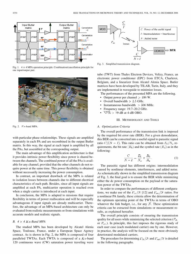
An MPA is composed of an array of PAs in parallel and apair of complementary Butler matrix networks that consistof 90 hybrid networks [11]. A 4 4 MPA is shown in Fig. 1.The signal at each input in the MPA is divided into signals
0018-9480/$20.00 © 2006 IEEE
4354 IEEE TRANSACTIONS ON MICROWAVE THEORY AND TECHNIQUES, VOL. 54, NO. 12, DECEMBER 2006
Fig. 1. 4� 4 MPA operation principle. Combination/cancellation principle forone input/output pair.
Fig. 2. Ka-band MPA.
with particular phase relationships. These signals are amplifiedseparately in each PA and are recombined in the output Butlermatrix. In this way, the signal at each input is amplified by allthe PAs, but assembled at the corresponding output.
The main advantage of this amplification architecture is thatit provides intrinsic power flexibility since power is shared be-tween the channels. The combined power of all the PAs is avail-able for any channel, provided that the other channels do not re-quire power at the same time. This power flexibility is obtainedwithout necessarily increasing the power consumption.
In contrast, an important drawback of the MPA is relatedto isolation losses between channels due to different electricalcharacteristics of each path. Besides, since all input signals areamplified at each PA, multicarrier operation is reached evenwhen a single carrier is introduced at each input.
In conclusion, the MPA is adapted to missions that requireflexibility in terms of power reallocation and will be especiallyadvantageous if input signals are already multicarrier. There-fore, the advantage of an MPA-based architecture can only beevaluated from realistic measurements or from simulations withaccurate models and realistic signals.
B. 4 4 -Band MPA
The studied MPA has been developed by Alcatel AleniaSpace, Toulouse, France, under a European Space Agencycontract. As is shown in Fig. 2, the MPA is composed of fourparalleled TWTAs. Each TWTA is composed of a -band120 continuous wave (CW) saturation power traveling wave
Fig. 3. Simplified transmission diagram.
tube (TWT) from Thales Electron Devices, Velizy, France, anelectronic power conditioner (EPC) from ETCA, Charleroi,Belgium, and a linearizer from Alcatel Alenia Space. Butlermatrices have been developed by TILAB, Turin, Italy, and theyare implemented in waveguide to minimize losses.
The performances of the presented MPA are the following.• Output power per channel W.• Overall bandwidth GHz.• Instantaneous bandwidth MHz.• Frequency range: 19.7–20.2 GHz.• dB at 4-dB OBO.
III. METHODOLOGY AND TOOLS
A. Optimization Criteria
The overall performance of the transmission link is imposedby the required bit error rate (BER). For a given demodulator,this BER can be converted into a useful signal to parasitic signalratio . This ratio can be obtained from re-quirements, the bit rate and the symbol rate as in thefollowing:
(1)
The parasitic signal has different origins: intermodulationcaused by nonlinear elements, interferences, and added noise.As schematically shown in the simplified transmission diagramof Fig. 3, the final goal is to ensure the BER while minimizingeither the dc power consumption on the payload or the satura-tion power of the TWTAs.
In order to compare the performances of different configura-tions, we make use of the [12] and ratios. Fora nonlinear PA family, these criteria allow the determination ofthe optimum operating point of the TWTAs in terms of OBOwhatever the link budget, i.e., for any . These optimizationcriteria can be extracted from simulations or measurement re-sults, as explained hereafter.
The overall principle consists of ensuring the transmissionquality for all users while minimizing the selected criterion (or ). In principle, this fact imposes the rigorous study ofeach user case (each modulated carrier) one by one. However,in practice, the analysis will be focused on the most obviouslydeteriorated modulated carriers.
The procedure for determining and is detailedin the following paragraphs.

MALLET et al.: MPA-BASED ARCHITECTURE VERSUS CLASSICAL ARCHITECTURE FOR SPACE TELECOMMUNICATION PAYLOADS 4355
Fig. 4. Illustration of the determination of optimum OBO from P =N andP =N curves.
Initially, the following parameters have to be obtained ei-ther from simulation or measurement results, as described inSections III-B and C, respectively.
• Input backoff (IBO): always referring to CW input satura-tion power (the sweep parameter).
• OBO: referring to CW output saturation power.• : total dc power consumption.• : useful signal power for the reference modulated carrier.• : signal-to-interference ratio for the reference modu-
lated carrier.From the specification (given by (1) and associ-
ated to the demodulator), we can deduce the ratio as
(2)
and can then be easily calculated, as in (3)and (4), respectively,
(3)
(4)
where
(5)
is the dc power corresponding to the reference modulated car-rier with denoting the bandwidth of this reference modulatedcarrier and denoting the total bandwidth.
Once these parameters are obtained, andcurves can be plotted versus OBO. An illustrative example isgiven in Fig. 4. It can be seen that the minima of those curvescorrespond, respectively, to the optimal operating point in termsof dc consumption or in terms of saturation power.
It is important to note that the minimum values of those twodifferent criteria cannot be directly compared. Eventually, thesaturation power and the operating point are chosen accordingto the absolute dimensioning parameter of the specific mission(dc power or TWTA’s saturation power).
In this paper, the dissipated power, which can also be a lim-iting parameter, is not taken into account. Nevertheless it couldbe easily analyzed in an analogous way by extractingas follows:
(6)
where denotes the transmitted intermodulation signal (thepart reflected by the filters is dissipated in the payload).
B. Simulation Methodology and Associated Software
All the simulations in this work have been carried out bymeans of Communication Library (COMLIB) software (aCNES internal simulation development), based on FORTRAN li-braries. For that end, it has been specifically adapted to simulatethe MPA’s behavior. COMLIB is based on a complex envelopsimulation and it is used to simulate transmission chains takinginto account linear and nonlinear distortions. Signal samplevectors are transformed alternately into time and frequencydomains according to the description of the different elements.
The MPA is modeled from the Butler matrices characteriza-tion and the measured AM/AM, AM/PM curves and char-acteristics of TWTAs [13].
The ratio is calculated from the equivalent gain method[14]. The equivalent gain value, given in (7) as follows, is de-fined as the ratio between the portion of the output signal corre-lated with the input signal and the input signal itself:
(7)
with denoting the signal sample element (voltage value).Thus, the noise of the signal not correlated with the input is
(8)
and the useful signal
(9)
can then be computed as
(10)
Finally, the parameters related with the two optimization cri-teria ( and ) can be calculated from these valuesfollowing the procedure detailed in Section III-A.
C. Measurement Methodology and Tools
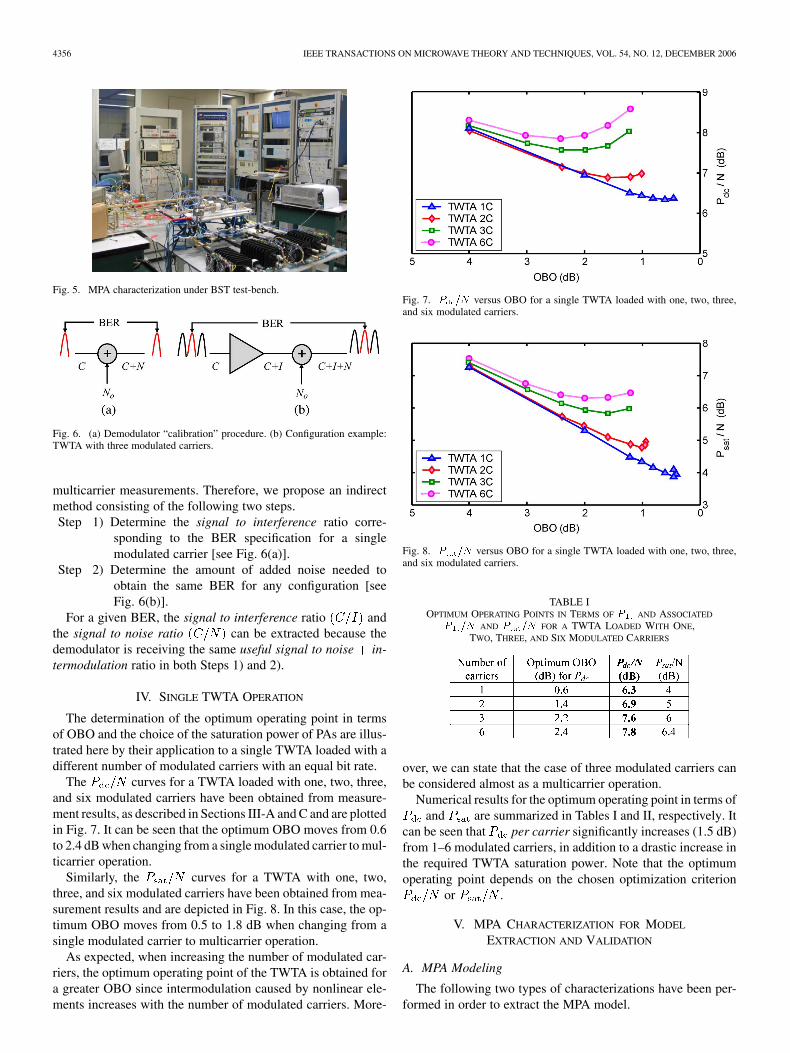
The measurements have been carried out in a transmissionsystem bench (BST) developed at CNES under an internaladvanced telecommunication program (ATF) program for testand analysis of -band multimedia satellite systems. Thiseasily reconfigurable facility has been used to test the MPA inrepresentative payload architectures with realistic signals. Aphotograph of the MPA characterization under the transmissionsystem bench is shown in Fig. 5.
Unlike simulation procedures, directly extracting the inter-modulation signal from the overall interferences (intermodula-tion and noise) is not straightforward in the case of modulated
4356 IEEE TRANSACTIONS ON MICROWAVE THEORY AND TECHNIQUES, VOL. 54, NO. 12, DECEMBER 2006
Fig. 5. MPA characterization under BST test-bench.
Fig. 6. (a) Demodulator “calibration” procedure. (b) Configuration example:TWTA with three modulated carriers.
multicarrier measurements. Therefore, we propose an indirectmethod consisting of the following two steps.Step 1) Determine the signal to interference ratio corre-
sponding to the BER specification for a singlemodulated carrier [see Fig. 6(a)].
Step 2) Determine the amount of added noise needed toobtain the same BER for any configuration [seeFig. 6(b)].
For a given BER, the signal to interference ratio andthe signal to noise ratio can be extracted because thedemodulator is receiving the same useful signal to noise in-termodulation ratio in both Steps 1) and 2).
IV. SINGLE TWTA OPERATION
The determination of the optimum operating point in termsof OBO and the choice of the saturation power of PAs are illus-trated here by their application to a single TWTA loaded with adifferent number of modulated carriers with an equal bit rate.
The curves for a TWTA loaded with one, two, three,and six modulated carriers have been obtained from measure-ment results, as described in Sections III-A and C and are plottedin Fig. 7. It can be seen that the optimum OBO moves from 0.6to 2.4 dB when changing from a single modulated carrier to mul-ticarrier operation.
Similarly, the curves for a TWTA with one, two,three, and six modulated carriers have been obtained from mea-surement results and are depicted in Fig. 8. In this case, the op-timum OBO moves from 0.5 to 1.8 dB when changing from asingle modulated carrier to multicarrier operation.
As expected, when increasing the number of modulated car-riers, the optimum operating point of the TWTA is obtained fora greater OBO since intermodulation caused by nonlinear ele-ments increases with the number of modulated carriers. More-
Fig. 7. P =N versus OBO for a single TWTA loaded with one, two, three,and six modulated carriers.
Fig. 8. P =N versus OBO for a single TWTA loaded with one, two, three,and six modulated carriers.
TABLE IOPTIMUM OPERATING POINTS IN TERMS OF P AND ASSOCIATED
P =N AND P =N FOR A TWTA LOADED WITH ONE,TWO, THREE, AND SIX MODULATED CARRIERS
over, we can state that the case of three modulated carriers canbe considered almost as a multicarrier operation.
Numerical results for the optimum operating point in terms ofand are summarized in Tables I and II, respectively. It
can be seen that per carrier significantly increases (1.5 dB)from 1–6 modulated carriers, in addition to a drastic increase inthe required TWTA saturation power. Note that the optimumoperating point depends on the chosen optimization criterion
or .
V. MPA CHARACTERIZATION FOR MODEL
EXTRACTION AND VALIDATION
A. MPA Modeling
The following two types of characterizations have been per-formed in order to extract the MPA model.
MALLET et al.: MPA-BASED ARCHITECTURE VERSUS CLASSICAL ARCHITECTURE FOR SPACE TELECOMMUNICATION PAYLOADS 4357
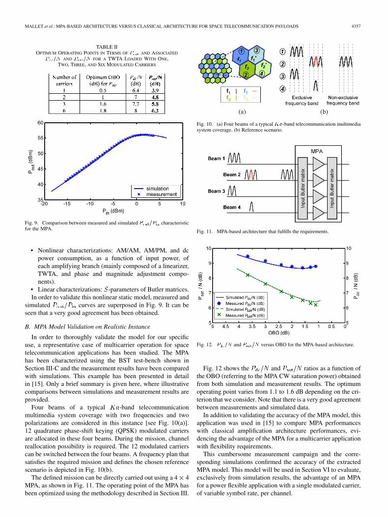
TABLE IIOPTIMUM OPERATING POINTS IN TERMS OF P AND ASSOCIATED
P =N AND P =N FOR A TWTA LOADED WITH ONE,TWO, THREE, AND SIX MODULATED CARRIERS
Fig. 9. Comparison between measured and simulated P =P characteristicfor the MPA.
• Nonlinear characterizations: AM/AM, AM/PM, and dcpower consumption, as a function of input power, ofeach amplifying branch (mainly composed of a linearizer,TWTA, and phase and magnitude adjustment compo-nents).
• Linear characterizations: -parameters of Butler matrices.In order to validate this nonlinear static model, measured and
simulated curves are superposed in Fig. 9. It can beseen that a very good agreement has been obtained.
B. MPA Model Validation on Realistic Instance
In order to thoroughly validate the model for our specificuse, a representative case of multicarrier operation for spacetelecommunication applications has been studied. The MPAhas been characterized using the BST test-bench shown inSection III-C and the measurement results have been comparedwith simulations. This example has been presented in detailin [15]. Only a brief summary is given here, where illustrativecomparisons between simulations and measurement results areprovided.
Four beams of a typical -band telecommunicationmultimedia system coverage with two frequencies and twopolarizations are considered in this instance [see Fig. 10(a)].12 quadrature phase-shift keying (QPSK) modulated carriersare allocated in these four beams. During the mission, channelreallocation possibility is required. The 12 modulated carrierscan be switched between the four beams. A frequency plan thatsatisfies the required mission and defines the chosen referencescenario is depicted in Fig. 10(b).
The defined mission can be directly carried out using a 4 4MPA, as shown in Fig. 11. The operating point of the MPA hasbeen optimized using the methodology described in Section III.
Fig. 10. (a) Four beams of a typical Ka-band telecommunication multimediasystem coverage. (b) Reference scenario.
Fig. 11. MPA-based architecture that fulfills the requirements.
Fig. 12. P =N and P =N versus OBO for the MPA-based architecture.
Fig. 12 shows the and ratios as a function ofthe OBO (referring to the MPA CW saturation power) obtainedfrom both simulation and measurement results. The optimumoperating point varies from 1.1 to 1.6 dB depending on the cri-terion that we consider. Note that there is a very good agreementbetween measurements and simulated data.
In addition to validating the accuracy of the MPA model, thisapplication was used in [15] to compare MPA performanceswith classical amplification architecture performances, evi-dencing the advantage of the MPA for a multicarrier applicationwith flexibility requirements.
This cumbersome measurement campaign and the corre-sponding simulations confirmed the accuracy of the extractedMPA model. This model will be used in Section VI to evaluate,exclusively from simulation results, the advantage of an MPAfor a power flexible application with a single modulated carrier,of variable symbol rate, per channel.

4358 IEEE TRANSACTIONS ON MICROWAVE THEORY AND TECHNIQUES, VOL. 54, NO. 12, DECEMBER 2006
Fig. 13. Flexible bandwidth allocation illustration.
TABLE IIIDESCRIPTION OF THE THREE CONFIGURATIONS
VI. COMPARISON BETWEEN CLASSICAL AND MPA-BASED
AMPLIFICATION ARCHITECTURES
A. Reference Scenario
This second example concerns an application where a band-width is allocated for the TV direct video broadcasting onfour beams with four antennas. Two polarizations are used: hor-izontal ( ) and vertical ( ). The bandwidth is considered tobe shared between two beams in any desired configuration. Asdepicted in Fig. 13, is shared by beams 1 and 2 on polar-ization and reutilized in polarization for beams 3 and 4.
Three representative configurations of this mission will beconsidered, which are: 1) balanced; 2) unbalanced; and 3) limit(see Table III). The “limit configuration” corresponds to the ex-treme case where only two beams among the four are used.
In order to perform realistic simulations, actual values fromthe demodulator of the measurement BST test-bench are con-sidered in all cases. Thus, is fixed to 3.25 dB, as itcorresponds to this demodulator with the given BER specifica-tion (10 without coding).
B. MPA-Based Architecture
The defined mission can be directly carried out using a 4 4MPA. The operating point of the MPA has been optimized usingthe methodology described in Section III in order to minimizedc power consumption for the given (fixed to3.25 dB). For that, in Fig. 14, curves are initially plottedversus OBO for the three different configurations. The twocurves traced in solid line correspond, respectively, to the two
Fig. 14. P =N curves for the determination of optimum OBO for the MPA-based architecture.
Fig. 15. P =N curves for the determination of optimum OBO for the MPA-based architecture. Level of carrier 1 from unbalanced configuration increased0.5 dB.
modulated carriers of different rate involved in the “unbalancedconfiguration.” The lower rate modulated carrier (triangles)is the most degraded and represents the dimensioning casebecause it corresponds to the higher value, around8.4 dB for 1.9-dB OBO.
A solution to reduce the dc consumption consists of in-creasing the relative power level of this carrier. A parametricstudy has been performed on this relative level and an optimumover level of 0.5 dB has been obtained. The modifiedcurves for the unbalanced scenario are updated in Fig. 15. Thisexample illustrates the capability for compensating, at leastpartially, the pumping effect of the smallest carriers in thenonlinearities by increasing their relative level at the input.
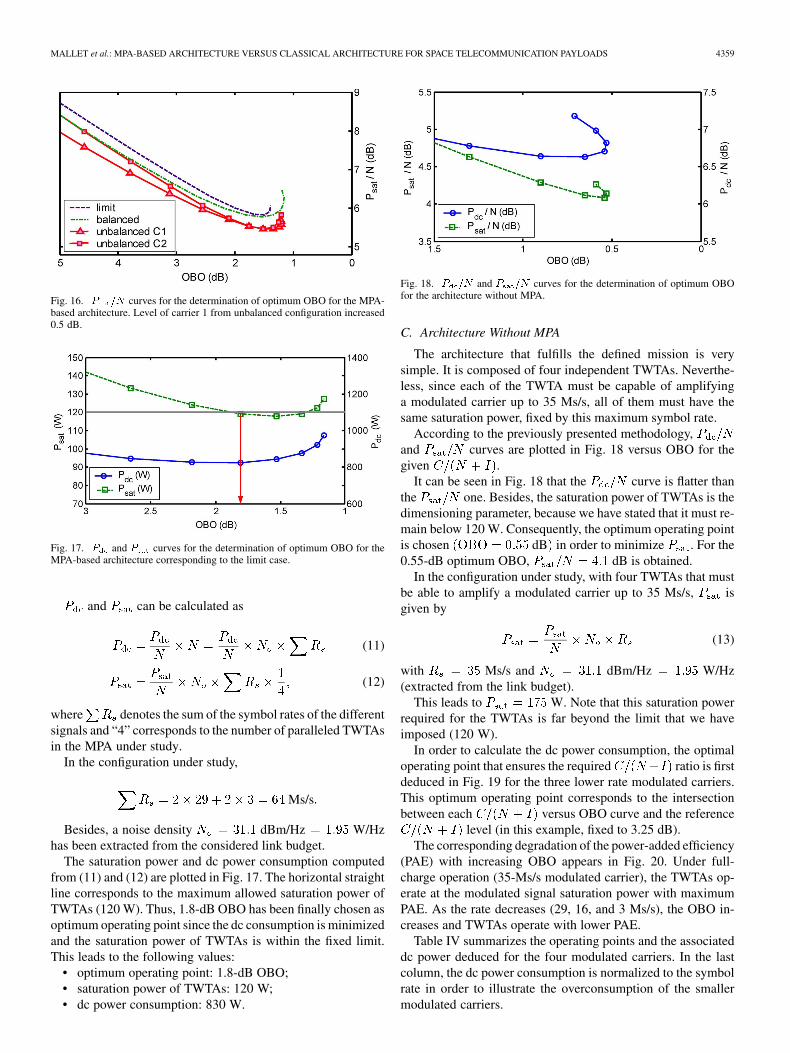
An optimum OBO of 1.8 dB is determined from Fig. 15for optimizing . Fig. 16 shows the versus OBOcurves for the four configurations. The optimum operatingpoint is approximately 1.5 dB for this parameter. It is importantto note that these optimum operating points are independent ofthe noise power density.
The dimensioning configuration is now the limit configura-tion since it corresponds to higher and . We willnow consider the noise power , extracted from the link budget,in order to determine the evolution, versus the OBO, of the re-quired saturation power of the TWTAs and the associated dcpower consumption of the MPA.
MALLET et al.: MPA-BASED ARCHITECTURE VERSUS CLASSICAL ARCHITECTURE FOR SPACE TELECOMMUNICATION PAYLOADS 4359
Fig. 16. P =N curves for the determination of optimum OBO for the MPA-based architecture. Level of carrier 1 from unbalanced configuration increased0.5 dB.
Fig. 17. P and P curves for the determination of optimum OBO for theMPA-based architecture corresponding to the limit case.
and can be calculated as
(11)
(12)
where denotes the sum of the symbol rates of the differentsignals and “4” corresponds to the number of paralleled TWTAsin the MPA under study.
In the configuration under study,
Ms/s
Besides, a noise density dBm/Hz W/Hzhas been extracted from the considered link budget.
The saturation power and dc power consumption computedfrom (11) and (12) are plotted in Fig. 17. The horizontal straightline corresponds to the maximum allowed saturation power ofTWTAs (120 W). Thus, 1.8-dB OBO has been finally chosen asoptimum operating point since the dc consumption is minimizedand the saturation power of TWTAs is within the fixed limit.This leads to the following values:
• optimum operating point: 1.8-dB OBO;• saturation power of TWTAs: 120 W;• dc power consumption: 830 W.
Fig. 18. P =N and P =N curves for the determination of optimum OBOfor the architecture without MPA.
C. Architecture Without MPA
The architecture that fulfills the defined mission is verysimple. It is composed of four independent TWTAs. Neverthe-less, since each of the TWTA must be capable of amplifyinga modulated carrier up to 35 Ms/s, all of them must have thesame saturation power, fixed by this maximum symbol rate.
According to the previously presented methodology,and curves are plotted in Fig. 18 versus OBO for thegiven .
It can be seen in Fig. 18 that the curve is flatter thanthe one. Besides, the saturation power of TWTAs is thedimensioning parameter, because we have stated that it must re-main below 120 W. Consequently, the optimum operating pointis chosen dB in order to minimize . For the0.55-dB optimum OBO, dB is obtained.
In the configuration under study, with four TWTAs that mustbe able to amplify a modulated carrier up to 35 Ms/s, isgiven by
(13)
with Ms/s and dBm/Hz W/Hz(extracted from the link budget).
This leads to W. Note that this saturation powerrequired for the TWTAs is far beyond the limit that we haveimposed (120 W).
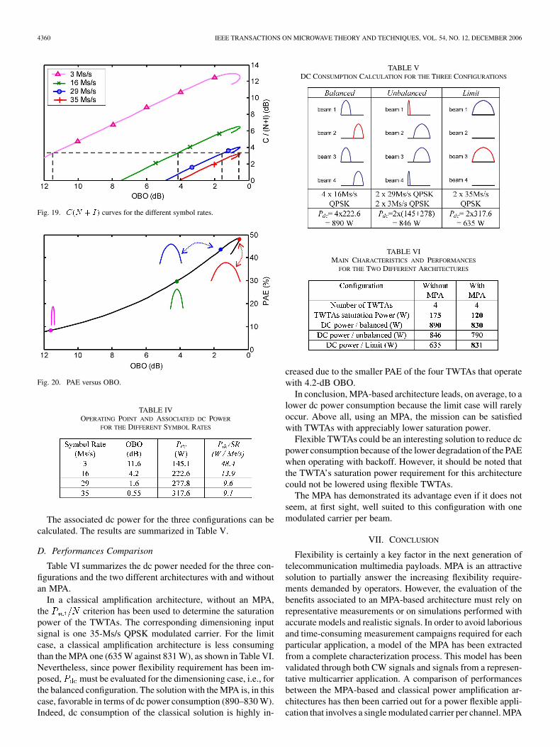
In order to calculate the dc power consumption, the optimaloperating point that ensures the required ratio is firstdeduced in Fig. 19 for the three lower rate modulated carriers.This optimum operating point corresponds to the intersectionbetween each versus OBO curve and the reference
level (in this example, fixed to 3.25 dB).The corresponding degradation of the power-added efficiency
(PAE) with increasing OBO appears in Fig. 20. Under full-charge operation (35-Ms/s modulated carrier), the TWTAs op-erate at the modulated signal saturation power with maximumPAE. As the rate decreases (29, 16, and 3 Ms/s), the OBO in-creases and TWTAs operate with lower PAE.
Table IV summarizes the operating points and the associateddc power deduced for the four modulated carriers. In the lastcolumn, the dc power consumption is normalized to the symbolrate in order to illustrate the overconsumption of the smallermodulated carriers.
4360 IEEE TRANSACTIONS ON MICROWAVE THEORY AND TECHNIQUES, VOL. 54, NO. 12, DECEMBER 2006
Fig. 19. C(N + I) curves for the different symbol rates.
Fig. 20. PAE versus OBO.
TABLE IVOPERATING POINT AND ASSOCIATED DC POWER
FOR THE DIFFERENT SYMBOL RATES
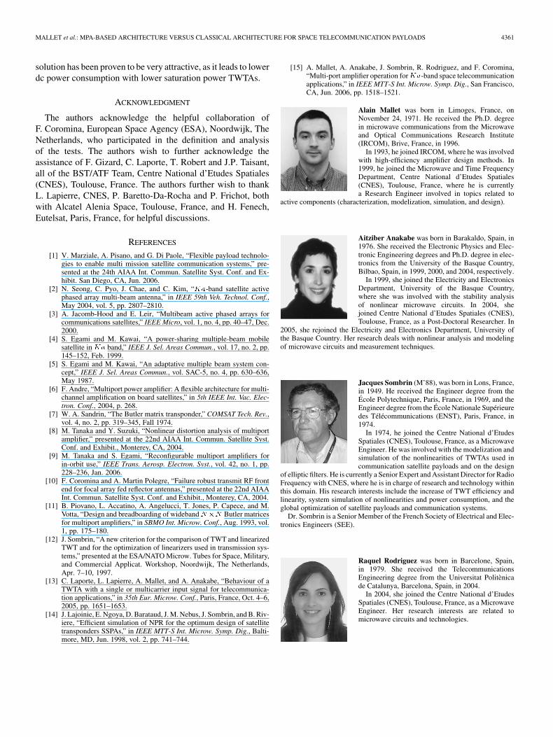
The associated dc power for the three configurations can becalculated. The results are summarized in Table V.
D. Performances Comparison
Table VI summarizes the dc power needed for the three con-figurations and the two different architectures with and withoutan MPA.
In a classical amplification architecture, without an MPA,the criterion has been used to determine the saturationpower of the TWTAs. The corresponding dimensioning inputsignal is one 35-Ms/s QPSK modulated carrier. For the limitcase, a classical amplification architecture is less consumingthan the MPA one (635 W against 831 W), as shown in Table VI.Nevertheless, since power flexibility requirement has been im-posed, must be evaluated for the dimensioning case, i.e., forthe balanced configuration. The solution with the MPA is, in thiscase, favorable in terms of dc power consumption (890–830 W).Indeed, dc consumption of the classical solution is highly in-
TABLE VDC CONSUMPTION CALCULATION FOR THE THREE CONFIGURATIONS
TABLE VIMAIN CHARACTERISTICS AND PERFORMANCES
FOR THE TWO DIFFERENT ARCHITECTURES
creased due to the smaller PAE of the four TWTAs that operatewith 4.2-dB OBO.
In conclusion, MPA-based architecture leads, on average, to alower dc power consumption because the limit case will rarelyoccur. Above all, using an MPA, the mission can be satisfiedwith TWTAs with appreciably lower saturation power.
Flexible TWTAs could be an interesting solution to reduce dcpower consumption because of the lower degradation of the PAEwhen operating with backoff. However, it should be noted thatthe TWTA’s saturation power requirement for this architecturecould not be lowered using flexible TWTAs.
The MPA has demonstrated its advantage even if it does notseem, at first sight, well suited to this configuration with onemodulated carrier per beam.
VII. CONCLUSION
Flexibility is certainly a key factor in the next generation oftelecommunication multimedia payloads. MPA is an attractivesolution to partially answer the increasing flexibility require-ments demanded by operators. However, the evaluation of thebenefits associated to an MPA-based architecture must rely onrepresentative measurements or on simulations performed withaccurate models and realistic signals. In order to avoid laboriousand time-consuming measurement campaigns required for eachparticular application, a model of the MPA has been extractedfrom a complete characterization process. This model has beenvalidated through both CW signals and signals from a represen-tative multicarrier application. A comparison of performancesbetween the MPA-based and classical power amplification ar-chitectures has then been carried out for a power flexible appli-cation that involves a single modulated carrier per channel. MPA
MALLET et al.: MPA-BASED ARCHITECTURE VERSUS CLASSICAL ARCHITECTURE FOR SPACE TELECOMMUNICATION PAYLOADS 4361
solution has been proven to be very attractive, as it leads to lowerdc power consumption with lower saturation power TWTAs.
ACKNOWLEDGMENT
The authors acknowledge the helpful collaboration ofF. Coromina, European Space Agency (ESA), Noordwijk, TheNetherlands, who participated in the definition and analysisof the tests. The authors wish to further acknowledge theassistance of F. Gizard, C. Laporte, T. Robert and J.P. Taisant,all of the BST/ATF Team, Centre National d’Etudes Spatiales(CNES), Toulouse, France. The authors further wish to thankL. Lapierre, CNES, P. Baretto-Da-Rocha and P. Frichot, bothwith Alcatel Alenia Space, Toulouse, France, and H. Fenech,Eutelsat, Paris, France, for helpful discussions.
REFERENCES
[1] V. Marziale, A. Pisano, and G. Di Paole, “Flexible payload technolo-gies to enable multi mission satellite communication systems,” pre-sented at the 24th AIAA Int. Commun. Satellite Syst. Conf. and Ex-hibit. San Diego, CA, Jun. 2006.
[2] N. Seong, C. Pyo, J. Chae, and C. Kim, “Ka-band satellite activephased array multi-beam antenna,” in IEEE 59th Veh. Technol. Conf.,May 2004, vol. 5, pp. 2807–2810.
[3] A. Jacomb-Hood and E. Leir, “Multibeam active phased arrays forcommunications satellites,” IEEE Micro, vol. 1, no. 4, pp. 40–47, Dec.2000.
[4] S. Egami and M. Kawai, “A power-sharing multiple-beam mobilesatellite inKa band,” IEEE J. Sel. Areas Commun., vol. 17, no. 2, pp.145–152, Feb. 1999.
[5] S. Egami and M. Kawai, “An adaptative multiple beam system con-cept,” IEEE J. Sel. Areas Commun., vol. SAC-5, no. 4, pp. 630–636,May 1987.
[6] F. Andre, “Multiport power amplifier: A flexible architecture for multi-channel amplification on board satellites,” in 5th IEEE Int. Vac. Elec-tron. Conf., 2004, p. 268.
[7] W. A. Sandrin, “The Butler matrix transponder,” COMSAT Tech. Rev.,vol. 4, no. 2, pp. 319–345, Fall 1974.
[8] M. Tanaka and Y. Suzuki, “Nonlinear distortion analysis of multiportamplifier,” presented at the 22nd AIAA Int. Commun. Satellite Syst.Conf. and Exhibit., Monterey, CA, 2004.
[9] M. Tanaka and S. Egami, “Reconfigurable multiport amplifiers forin-orbit use,” IEEE Trans. Aerosp. Electron. Syst., vol. 42, no. 1, pp.228–236, Jan. 2006.
[10] F. Coromina and A. Martin Polegre, “Failure robust transmit RF frontend for focal array fed reflector antennas,” presented at the 22nd AIAAInt. Commun. Satellite Syst. Conf. and Exhibit., Monterey, CA, 2004.
[11] B. Piovano, L. Accatino, A. Angelucci, T. Jones, P. Capece, and M.Votta, “Design and breadboarding of widebandN�N Butler matricesfor multiport amplifiers,” in SBMO Int. Microw. Conf., Aug. 1993, vol.1, pp. 175–180.
[12] J. Sombrin, “A new criterion for the comparison of TWT and linearizedTWT and for the optimization of linearizers used in transmission sys-tems,” presented at the ESA/NATO Microw. Tubes for Space, Military,and Commercial Applicat. Workshop, Noordwijk, The Netherlands,Apr. 7–10, 1997.
[13] C. Laporte, L. Lapierre, A. Mallet, and A. Anakabe, “Behaviour of aTWTA with a single or multicarrier input signal for telecommunica-tion applications,” in 35th Eur. Microw. Conf., Paris, France, Oct. 4–6,2005, pp. 1651–1653.
[14] J. Lajoinie, E. Ngoya, D. Barataud, J. M. Nebus, J. Sombrin, and B. Riv-iere, “Efficient simulation of NPR for the optimum design of satellitetransponders SSPAs,” in IEEE MTT-S Int. Microw. Symp. Dig., Balti-more, MD, Jun. 1998, vol. 2, pp. 741–744.
[15] A. Mallet, A. Anakabe, J. Sombrin, R. Rodriguez, and F. Coromina,“Multi-port amplifier operation forKa-band space telecommunicationapplications,” in IEEE MTT-S Int. Microw. Symp. Dig., San Francisco,CA, Jun. 2006, pp. 1518–1521.
Alain Mallet was born in Limoges, France, onNovember 24, 1971. He received the Ph.D. degreein microwave communications from the Microwaveand Optical Communications Research Institute(IRCOM), Brive, France, in 1996.
In 1993, he joined IRCOM, where he was involvedwith high-efficiency amplifier design methods. In1999, he joined the Microwave and Time FrequencyDepartment, Centre National d’Etudes Spatiales(CNES), Toulouse, France, where he is currentlya Research Engineer involved in topics related to
active components (characterization, modelization, simulation, and design).
Aitziber Anakabe was born in Barakaldo, Spain, in1976. She received the Electronic Physics and Elec-tronic Engineering degrees and Ph.D. degree in elec-tronics from the University of the Basque Country,Bilbao, Spain, in 1999, 2000, and 2004, respectively.
In 1999, she joined the Electricity and ElectronicsDepartment, University of the Basque Country,where she was involved with the stability analysisof nonlinear microwave circuits. In 2004, shejoined Centre National d’Etudes Spatiales (CNES),Toulouse, France, as a Post-Doctoral Researcher. In
2005, she rejoined the Electricity and Electronics Department, University ofthe Basque Country. Her research deals with nonlinear analysis and modelingof microwave circuits and measurement techniques.
Jacques Sombrin (M’88), was born in Lons, France,in 1949. He received the Engineer degree from theÉcole Polytechnique, Paris, France, in 1969, and theEngineer degree from the École Nationale Supérieuredes Télécommunications (ENST), Paris, France, in1974.
In 1974, he joined the Centre National d’EtudesSpatiales (CNES), Toulouse, France, as a MicrowaveEngineer. He was involved with the modelization andsimulation of the nonlinearities of TWTAs used incommunication satellite payloads and on the design
of elliptic filters. He is currently a Senior Expert and Assistant Director for RadioFrequency with CNES, where he is in charge of research and technology withinthis domain. His research interests include the increase of TWT efficiency andlinearity, system simulation of nonlinearities and power consumption, and theglobal optimization of satellite payloads and communication systems.
Dr. Sombrin is a Senior Member of the French Society of Electrical and Elec-tronics Engineers (SEE).
Raquel Rodriguez was born in Barcelone, Spain,in 1979. She received the TelecommunicationsEngineering degree from the Universitat Politènicade Catalunya, Barcelona, Spain, in 2004.
In 2004, she joined the Centre National d’EtudesSpatiales (CNES), Toulouse, France, as a MicrowaveEngineer. Her research interests are related tomicrowave circuits and technologies.