
MULTIPLE PROPERTY-BASED PARTITIONING FOR ...
170
Mälardalen University Press Licentiate Theses No. 176 MULTIPLE PROPERTY-BASED PARTITIONING FOR EMBEDDED APPLICATIONS Gaetana Sapienza 2014 School of Innovation, Design and Engineering
-
Upload
khangminh22 -
Category
Documents
-
view
1 -
download
0
Transcript of MULTIPLE PROPERTY-BASED PARTITIONING FOR ...

Mälardalen University Press Licentiate ThesesNo. 176
MULTIPLE PROPERTY-BASED PARTITIONINGFOR EMBEDDED APPLICATIONS
Gaetana Sapienza
2014
School of Innovation, Design and Engineering

Copyright © Gaetana Sapienza, 2014ISBN 978-91-7485-150-2ISSN 1651-9256Printed by Arkitektkopia, Västerås, Sweden

AbstractThe new development of different types of computation units, such as FPGAsand multicore CPUs, enables a tremendous improvement in performance ofapplications that utilize the dedicated types of computations. For complex ap-plications this however introduces a new challenge - what is the optimal de-ployment configuration of their components?
Today the application deployment is based on ad-hoc architectural deci-sions taken in an early design phase, when many design details are unknown,and as a consequence they often change in a later phase, increasing so the de-velopment costs. In addition, the decisions are taken based on a limited num-ber of requirements, mostly related to runtime properties such as performance,resource utilization and power consumption, but do not consider many otheraspects related to lifecycle properties, or to the project constraints. This ap-proach increases the risk that a decision has a negative impact on a runtime ora lifecycle system property and may lead to the mentioned changes.
This thesis addresses the problem of optimal hardware/software deploy-ment of an application. The main objective is to define a process in whichthe deployment decisions are taken in a systematic way in a later phase of thedesign process, and the partition decision process takes into account all arti-facts on which the decisions have direct impact. These artifacts include theapplication’s runtime properties, the properties related to the application life-cycle, the business goals, and the development project constraints. To achievethis objective we have a) defined a development process model that addressesthe deployment explicitly in the late design phase, b) designed a metamodelof component-based applications deployed as hardware or software executableunits, and c) analyzed the suitability of Multiple Criteria Decision Analysismethods for providing partitioning decisions based on a large number of cri-teria. In addition we have analysed which properties are affected by the par-titioning decisions in the Control and Automation domains. The feasibility ofthe proposed process is demonstrated throughout an industrial case study.
i


Sammanfattning
Partitionering av inbyggda system baserad pa multipla kriterier
Den nya utvecklingen av olika typer av berakningsenheter, som FPGA ochflerkarniga CPU mojliggor en vasentlig forbattring i prestanda for till ampningarsom utnyttjar dessa sarskilda typer av berakningar. Detta innbar emellertiden ny utmaning: vilken konfigurationar den optimala? Idagar programdel-ning i mjukvara och hardvara baserad pa ad-hoc beslut. Vanligtvis tas dessabeslut i tidigt designfasen, nar manga designdetaljerar okanda, och som enkonsekvens ofta forandras i ett senare skede somokar utvecklingskostnaderna.I till agg, ar de beslut som fattas utifran ett begransat antal krav, framst re-laterade till runtime egenskaper: till exempel prestanda, resursutnyttjande ochenergiforbrukning, men omfattar inte manga andra aspekter som ror livscykele-genskaper eller de olika begransningarna som man har i projektet. Detta beslutsatt okar risken for en negativ inverkan pa systemets egenskaper. Den haravhandlingen adresserar problemet om hur man placerar ut hardvaru- och mjuk-varufunktionalitet optimalt ur ett applikationsperspektiv. Huvudsyftetar attdefiniera en process dar besluten om applikationsfordelning (partition) tas paett systematiskt satt i ett senare skede av designprocessen, dar beslutspro-cessen tar hansyn till alla faktorer och artefakter pa vilka beslut har direkteffekt. Dessa artefakter inkluderar applikationens runtime egenskaper, egen-skaper som ror livscykeln, och begransningar inom uvecklingsprojektet. Foratt uppna detta mal har vi a) definierat en utvecklingsprocessmodell som tarupp partitioneringen i en sen designfas, b) utformat en metamodell for kompo-nentbaserade applikationer som bestar av bade hardvaru- och mjukvarukorbaraenheter, och c) analyserat mojligheter att anvanda en metod med multipla kri-terier (Multiple Criteria Decision Analysis) for att hantera partitionering. Slut-ligen har vi analyserat vilka egenskaper somar viktiga for partitionering inomStyr- och Automation domanen.
iii


Acknowledgements
I would like to express my greatest gratitude to my advisors Prof. Ivica Crnkovicand Prof. Tiberiu Seceleanu for having advised and guided me to grow as re-searcher.
I also would like to thank Peter Lofgren, Helena Malmqvist and JohanAkerberg to encourage me when I started considering to undertake this studyand to support this research work.
My thanks are extended to my colleagues and managers at ABB Corpo-rate Research, in Sweden and Norway and to my colleagues and professors atMalardalen University who have shared their knowledge and experience withme during this study. Looking forward to continue learning, cooperating withyou to further exchange know-how, competence and grow more from the pro-fessional and personal perspectives.
Lastly, special thanks to my family.
This research is supported by ABB Corporate Research, the KnowledgeFoundation through ITS-EASY, an Industrial Research School in EmbeddedSoftware and Systems, and by the Swedish Foundation for Strategic Researchthrough the RALF3 project.
Gaetana SapienzaVasteras, May 2014
v


List of Publications
Publications
Paper I - Partitioning decision process for embedded hardware and soft-ware deployment. G. Sapienza, I. Crnkovic, and T. Seceleanu. In Proceedingof the IEEE 37th Annual Computer Software and Applications ConferenceWorkshops (COMPSACW), 2013.
Paper II - Modelling for Hardware and Software Partitioning based onMultiple Properties. G. Sapienza, I. Crnkovic, and T. Seceleanu. In Proceed-ing of the 39th Euromicro Conference Series on Software Engineering andAdvanced Applications (SEAA), IEEE 2013.
Paper III - Architectural Decisions for HW/SW Partitioning Based onMultiple Extra-Functional Properties. G. Sapienza, I. Crnkovic, and P. Potena.In Proceeding the 11th Working IEEE/IFIP Conference on Software Architec-ture (WICSA), 2014.
Paper IV - Assessing Multiple Criteria Decision Analysis Suitability forHW/SW Deployment in Embedded Systems Design. G. Sapienza, G. Bresto-vac, R. Grgurina and T. Seceleanu. In the Journal of Systems Architecture:Embedded Software Design (JSA). Elsevier 2014 (under review).
Paper V - A Tool Integration Framework for Sustainable Embedded Sy-stems Development. T. Seceleanu and G. Sapienza. In IEEE Computer Society,(vol. 46 no. 11) Nov. 2013.
vii

viii
Related Publications
These publications are selected among the other not included publication,since they are more related to the thesis. They are referred in the first part ofthe thesis and have contributed to the thesis results.
Towards a methodology for hardware and software design separation inembedded systems. G. Sapienza, I. Crnkovic, and T. Seceleanu. In Proceedingof the 7th International Conference on Software Engineering Advances (IC-SEA), IARIA 2013. Best Paper Awarded.
Wind Turbine System: An Industrial Case Study in Formal Modeling andVerification. J. Suryadevara, G. Sapienza, C. Seceleanu, T. Seceleanu, S. Ellev-seth, and Paul Pettersson. In Proceeding of the 2nd International Workshop onFormal Techniques for Safety-Critical Systems (FTSCS). IEEE 2013.
Modelling for hardware and software deployment based on multiple pro-perties selection. G. Sapienza, I. Crnkovic, and T. Seceleanu. Technical ReportSchool of Innovation, Design and Engineering, Malardalen University. April2013. http://www.es.mdh.se/pdf publications/2764.pdf.
Architectural Decisions for HW/SW Partitioning based on multiple Extra-Functional Properties. G. Sapienza, I. Crnkovic and P. Potena. Technical Re-port School of Innovation, Design and Engineering, Malardalen University,October 2013. http://ww w.es.mdh.se/pdf publications/3132.pdf.

Contents
I Thesis 1
1 Introduction 31.1 Thesis Outline . . . . . . . . . . . . . . . . . . . . . . . . . . 5
2 Research Summary 72.1 Research Problem . . . . . . . . . . . . . . . . . . . . . . . . 7
2.2 Research Objective . . . . . . . . . . . . . . . . . . . . . . . 7
2.3 Research Questions . . . . . . . . . . . . . . . . . . . . . . . 8
2.4 Research Approach . . . . . . . . . . . . . . . . . . . . . . . 9
3 Contributions and the Included Publications 133.1 Research Contribution with respect to the Included Papers . . 13
3.2 Research Contribution Overview . . . . . . . . . . . . . . . . 19
4 Background and Related Work 214.1 Hardware/Software Partitioning . . . . . . . . . . . . . . . . 21
4.2 MCDA and Suitability for Partitioning . . . . . . . . . . . . . 23
4.3 Component Modelling and EFPs for Embedded Systems . . . 24
5 Conclusion and Future Work 275.1 Conclusion . . . . . . . . . . . . . . . . . . . . . . . . . . . 27
5.2 Future Work . . . . . . . . . . . . . . . . . . . . . . . . . . . 28
Bibliography 31
ix
x Contents
II Included Papers 39
6 Paper I:Partitioning Decision Process for Embedded Hardware and Soft-ware Deployment 416.1 Introduction . . . . . . . . . . . . . . . . . . . . . . . . . . . 436.2 Research Problem and Objective . . . . . . . . . . . . . . . . 446.3 The Partitioning Decision Process . . . . . . . . . . . . . . . 456.4 The Industrial Case Study . . . . . . . . . . . . . . . . . . . . 506.5 Related Work . . . . . . . . . . . . . . . . . . . . . . . . . . 546.6 Conclusions and Future Work . . . . . . . . . . . . . . . . . . 55References . . . . . . . . . . . . . . . . . . . . . . . . . . . . . . . 55
7 Paper II:Modelling for Hardware and Software Partitioning based on Mul-tiple Properties 597.1 Introduction . . . . . . . . . . . . . . . . . . . . . . . . . . . 617.2 The Metamodel for Partitioning . . . . . . . . . . . . . . . . 627.3 The MultiPar Process . . . . . . . . . . . . . . . . . . . . . . 647.4 Wind Turbine: Industrial Case Study . . . . . . . . . . . . . . 677.5 Related Work . . . . . . . . . . . . . . . . . . . . . . . . . . 717.6 Conclusions . . . . . . . . . . . . . . . . . . . . . . . . . . . 71References . . . . . . . . . . . . . . . . . . . . . . . . . . . . . . . 72
8 Paper III:Architectural Decisions for HW/SW Partitioning Based on Multi-ple Extra-Functional Properties 758.1 Introduction . . . . . . . . . . . . . . . . . . . . . . . . . . . 778.2 Modeling HW/SW component-based systems . . . . . . . . . 798.3 The partitioning quality framework . . . . . . . . . . . . . . . 82
8.3.1 Component property metamodel . . . . . . . . . . . . 828.3.2 The categorization of partitioning-related properties . 84
8.4 Survey of EFPs in the Automation and Control Domain . . . 868.4.1 Objective . . . . . . . . . . . . . . . . . . . . . . . . 888.4.2 Survey Design and Process . . . . . . . . . . . . . . . 888.4.3 Results . . . . . . . . . . . . . . . . . . . . . . . . . 908.4.4 Analysis . . . . . . . . . . . . . . . . . . . . . . . . 908.4.5 Validity . . . . . . . . . . . . . . . . . . . . . . . . . 92
8.5 Related Work . . . . . . . . . . . . . . . . . . . . . . . . . . 96

Contents xi
8.6 Conclusions and future work . . . . . . . . . . . . . . . . . . 98References . . . . . . . . . . . . . . . . . . . . . . . . . . . . . . . 99
9 Paper IV:Assessing Multiple Criteria Decision Analysis Suitability for HW/SWDeployment in Embedded Systems Design 1079.1 Introduction . . . . . . . . . . . . . . . . . . . . . . . . . . . 1099.2 Background . . . . . . . . . . . . . . . . . . . . . . . . . . . 110
9.2.1 Partitioning and MCDA Suitability Analysis RelatedWork . . . . . . . . . . . . . . . . . . . . . . . . . . 110
9.2.2 Multiple Criteria Decision Analysis Basic Concepts . . 1129.3 MULTI PAR: a New MCDA-based Partitioning Approach . . . 1169.4 MCDA Methods - Partitioning Suitability Criteria . . . . . . . 1179.5 Assessment of MCDA Suitability for Partitioning . . . . . . . 120
9.5.1 Methods Versus the 11-Suitability Criteria . . . . . . . 1239.5.2 Suitability Assessment . . . . . . . . . . . . . . . . . 1249.5.3 Tools . . . . . . . . . . . . . . . . . . . . . . . . . . 124
9.6 Composing the MCDA method in MULTI PAR . . . . . . . . . 1269.6.1 MCDA method integration into MULTI PAR . . . . . . 1299.6.2 MULTI PAR in Integration Scenarios . . . . . . . . . . 131
9.7 Industrial Case Study: A Wind Turbine Application . . . . . . 1339.7.1 The Case Study Description . . . . . . . . . . . . . . 1339.7.2 Application Modelling . . . . . . . . . . . . . . . . . 1349.7.3 Identification of EFPs . . . . . . . . . . . . . . . . . 1359.7.4 Application Partitioning Using the MCDA Methods . 135
9.8 Conclusions . . . . . . . . . . . . . . . . . . . . . . . . . . . 139References . . . . . . . . . . . . . . . . . . . . . . . . . . . . . . . 140
10 Paper V:A Tool Integration Framework for Sustainable Embedded SystemsDevelopment 14910.1 Introduction . . . . . . . . . . . . . . . . . . . . . . . . . . . 15110.2 Tool Integration Approaches . . . . . . . . . . . . . . . . . . 15110.3 The iFEST Solution . . . . . . . . . . . . . . . . . . . . . . . 153References . . . . . . . . . . . . . . . . . . . . . . . . . . . . . . . 155


I
Thesis
1


Chapter 1
Introduction
Industrial embedded applications are becoming more and more complex interms of features, constraints and utilization scenarios that they have to pro-vide and support. The advances in hardware technologies with respect to theheterogeneous platforms (i.e. platforms consisting of different computation re-sources, e.g. CPUs, FPGA, and GPU) enable improved capabilities and perfor-mance of such applications, by providing more effective executions of particu-lar type of computations. For example FPGA enables a high parallelism, whileCPU is more suitable for sequential processing. On another side, an inadequatedeployment may cause higher development costs or lower performance.
During the development - specifically at the design phase - it is of crucialimportance to decide upon the application deployment (also called partition-ing), i.e. which part of the application is designed and deployed as softwareexecutable units (e.g. compiled C/C++ code, etc.) and which part as hardware(e.g. synthesized from VHDL).
These architectural decisions (also referred here as partitioning decisions)have impact on (i) the application performance and quality, (ii) the overall de-velopment process and (iii) the application/system life-cycle management.
In traditional development processes [1], at an early stage of design phasea separation into two design flows occur: the hardware and software designflows. After an initial discussion (between hardware and software teams) whichleads to a number of partitioning decisions, the design is separated into thehardware and software design flows. Based on these decisions, the softwareengineers start designing and implementing the software part while the hard-ware engineers start with the hardware design and its prototyping. Usually the
3

4 Chapter 1. Introduction
software and hardware design and their implementation evolve separately. Theintegration of the application occurs before the testing phase.
In this context, the design phase is affected by several side effects such ashardware (HW) or/and software (SW) development flow interruptions due totheir mutual dependencies, which require redesign and unplanned iterations.They negatively impact the overall development process in terms of efficiency,quality and costs, the sustainability, and maintainability of the application du-ring its lifecycle.
Most of these issues are caused by the fact that the architectural decisionsare not supported by a systematic decision aiding the process and are performedat an early stage of the design phase, when not enough information is available[2].
Additionally, only a few factors are taken into account by the engineerswhen carrying out the partitioning decisions. They are mostly based on afew properties related to runtime characteristics (e.g. performance, resourceavailability, and power consumption), but do not consider many other aspects.Due to the increases in complexity of the applications in terms of requirementsand utilization scenarios, it is of crucial importance that the partitioning deci-sions are taken by considering a wider spectrum of properties. This spectrumspans from application/system lifecycle properties such as availability, safety,security, and standard compliances, to business goals and properties related toproject constraints such as available expertise, development lead time/costs,development of mass products/product line and so forth.
Overall, this makes the partitioning decision process a complex one.
In software engineering it is recognized that better quality, faster time tomarket, less risks and lower costs are achievable by enabling software reuse[3]. This concept well-suits hardware design as well, even though IP-reuse ofhardware is not comparable to the state of reuse in software engineering [4],and it is valid also for all of the partitioning decisions related to hardware orsoftware reusable units, which in today’s development processes is not handledin a systematic way.
Altogether these problems call for new research in partitioning approachestargeting solutions towards multi decision perspectives. A first step in this di-rection is a new approach presented here. We define thus theMultiple Criteria-based Partitioning MethodologyMULTI PAR, by combining Multiple CriteriaDecision Analysis methods, Component- and Model-based techniques, andwhich is able to address the mentioned issues and needs. Specifically:

1.1 Thesis Outline 5
• it enables a technology-independent design of embedded systems appli-cations in the early phase of the design, and a late deployment decisionactivity in the later design phase.
• it defines a method for a systematic deployment decision process that in-clude all possible non-functional aspects related to runtime and lifecycleproperties, the business goals, and development project constraints
The main contribution includes:a) the design of a process, based on a set of activities, integration scena-
rios and artifacts enabling the partitioning, and mechanisms to take into ac-count several non-functional properties (also referred in this thesis as Extra-Functional Properties (EFPs)) in the partitioning decisions;
b) the specification of a metamodel suitable for both capturing the hardwareand software aspects of the embedded applications and their related EFPs;
c) the categorization of component EFPs with respect to partitioning for theControl1and Automation domains;
d) the suitability assessment of MCDA methods for achieving partitioningsolutions.
In order to validate the proposed methodology applicability, we provide aproof-of-concept on an industrial case study.
1.1 Thesis Outline
The thesis is organized in two parts.
In Part I the research problems, the related research questions and the re-search approach are described. Also, it gives an overview of scientific contri-bution of this research work and presents the related work.
Part II includes the research papers: three of them published in conferenceproceedings, one in a computer magazine, and one published as a technicalreport. A shorter version of the report is submitted to a journal.
The remaining Part I is organized as follows:
1Examples of applications in this domains are: Soft Starters Applications to control accele-ration and deceleration of three-phase motors for waste management, pumps, compressors, etc.;Arc Guard Applications to protect electrical equipment and people from dangerous electrical andeliminate unnecessary production stops; etc.

6 Chapter 1. Introduction
Chapter 2: This chapter presents the research context. Specifically, it di-scusses the research problem and the related research questions with respectto the state of the art and practice. It introduces the research methodologyundertaken to perform this research work.
Chapter 3: This chapter presents the included papers in this licentiate thesisand the main contributions of each paper with respect to the research objectiveand research questions.
Chapter 4: In this chapter the related work is presented.
Chapter 5: The last chapter presents the conclusions of the licentiate thesisand future work towards the PhD degree.

Chapter 2
Research Summary
This chapter discusses the research problem, and presents the main researchobjective and the research questions that lead to the research work. It alsoprovides an overview of the undertaken approach to perform the research work.
2.1 Research Problem
Given the problem description in the Introduction, we stated the following re-search problem:
• How to define a systematic process to support the hardware/softwarepartitioning of an application?
• How to include all possible properties and concerns that are affected bythe partitioning in the decision process?
2.2 Research Objective
Based on the formulation of the research problem, the overall objective of thisresearch work is:
Designing a hardware/software partitioning decision method for component-based embedded applications based on multiple property requirements andconcerns, with a goal to achieve the optimal hardware/software deployment
7

8 Chapter 2. ResearchSummary
with respect to these properties and concerns.
The overall research objective is realized through:
• performing the partitioning at a late stage of the design phase;
• defining a systematic process to support engineers in carrying out thepartitioning decisions and enabling reuse of existing units;
• providing mechanisms to perform decisions based on many EFPs de-rived from the application/system requirements as well as the businessgoals and project constraints.
2.3 Research Questions
Driven by the overall objective, we formulate the main research questions, asfollows:
• RQ1. What would be a technology-independent process that enablesthe application partitioning in a late stage of the design?
• RQ2. How to enable a systematic decision process that supports theengineers in performing the application partitioning and enables reuse?
• RQ3. How to obtain an optimal and sustainable partitioning solu-tion(s) which take into account all possible decisions related to systemsrequirements, business goals and project constraints that are affected bythe partitioning of the application?
In RQ3, by the wordsustainablewe mean a partitioning solution able tosupport/facilitate the application sustainability over the entire lifecycle. Byop-timal we mean a solution able to trade-off the systems requirements and satisfythe performance constraints such as execution time, lower power consumption,etc.
The research questions are driving a long-term research project where thefinal outcomes are expected to be provided in the doctoral thesis. However,with respect to the main objective, in this licentiate thesis we provide a proof-of-concept of the proposed methodology and show its feasibility through anindustrial case study.

2.4 Research Approach 9
2.4 Research Approach
In order to answer to the main research questions and reach our objective, wetake an approach that is of an applied nature.
Depending on the different stages of the project, we have applied severalresearch activities:
a) Research Problem Identificationwhich leads to the
• definition of the key research objective and questions.
b) Analysisconsisting mainly of
• a hardware/software (HW/SW) partitioning methods survey of li-terature and the current state of practice in industry;
• an analysis of existing partitioning approaches (in literature and inindustry);
• an analysis of Multiple Criteria Decision Analysis (MCDA) me-thods and related tools.
• an interview: design, realization and analysis of interview to ana-lyze of HW/SW partitioning impact on EFPs in the Control andAutomation domains.
c) Construction of a new approachwhich includes
• definition and design of the partitioning process flow and relatedactivities;
• development of HW/SW component-based metamodel supportingpartitioning analysis decisions;
• identification of a MCDA tool chain supporting the partitioning.
d) Validation that includes
• case study: design and semi-automatic implementation of a windturbine application which is used to prove the feasibility of MUL-TIPAR. In particular, we have modelled the wind turbine applica-tion as a number of interconnected component models (using TheMathWorks Simulink tool)1. We have applied a number ofsuitable
1http://www.mathworks.se/products/simulink/

10 Chapter 2. ResearchSummary
Real World
Practical Problem Definition
Research Setting
Idealized ProblemDefinition
Research SettingIdealized Problem
Solution
Real World
Practical Problem Solution
Methods Processes Tools
Validation
Validation
Research Product DevelopmentLegend
Main Activity
Research Product Type
Flow
Figure 2.1: Research Approach Flow.
MCDA methods to perform the partitioning. Then we have auto-matically generated C-code and VHDL code (using the MathWorksEmbedded Coder , the Fixed-Point Designer, and HDL Coder tool-boxes2 ) in order to achieve the deployment of the application intoa Zynq3 device consisting of an FPGA and a multicore CPU.
In performing the research our strategy follows the guidelines proposed byShaw in [5], [6]. The research strategy is depicted by Figure 2.1 and describedas follows:
a) Analysis and Identification of the Practical Problem: we have ana-lyzed and discussed what the practical problem is and the related issueswhich are associated to a typical industrial embedded design process.We reached this through the analysis of the state of the art and practice.Based on this, we narrowed down the scope and we identified the mainresearch problem: today partitioning approaches are not designed to ei-ther enable a late and implementation-independent partitioning or to takeinto account EFPs which are derived from runtime and lifecycle require-ments, business goals and project constraints. Consequently our ultimategoal is to develop such a method to solve thisproblem.
2http://www.mathworks.se/fpga-design/hardware-software-codesign.html3http://www.xilinx.com/products/silicon-devices/soc/zynq-7000/index.htm

2.4 Research Approach 11
b) Definition of the Idealized Problem: We mapped the practical pro-blem into a research setting context. In this context, we formalized theproblem into a number of key research questions. In order to answer tothe research questions, we carried out further literature studies and in-vestigation analysis. They were mainly focused on existing partitioningapproaches and MCDA methods.
c) Development of Research Products:The main outcomes of our re-search were (i) the definition of a MCDA-based partitioning decisionprocess and the metamodels for enabling the partitioning accountingboth (more details are provided in Section 3.2); (ii) the definition andimplementation of an integration framework for supporting the designphase and the partitioning process; (iii) a set of guidelines to handleEFPs in the Control and Automation domains.
d) Definition and design of the Solution to the Idealized and PracticalProblem: We defined, designed and provided a solution, in form of anew partitioning methodology able of answering to research questions.We proposed it as solution to the idealized problem. In order to providea step forwards to the Solution to the practical problem, we carried outan interview-survey in the Control and Automation domain.
e) Research Validation: In order to validate the proposed idealized solu-tion, our strategy was based on questions related to the feasibility of theproposed methodology:
“Is our approach feasible?”
To answer to this question, we performed a case study which was tar-geting the deployment of an industrial prototype. Further validation, interms of efficiency of the approach is not addressed in this thesis, but isplanned as a part of the further research.


Chapter 3
Contributions and theIncluded Publications
This chapter summarizes the research contribution presented in the publica-tions included in the thesis. Firstly we present the contribution with respectto the included papers. We discuss here how the contribution of each paper isrelated to the research questions. Lately, we provide an overview of the overallcontribution.
3.1 Research Contribution with respect to the In-cluded Papers
We present our contribution through a set of publications. In this thesis fivepeer-to-peer paper are included. For each of them we present the title andauthors, the abstract, the contribution with respect to the research questionsand the individual contribution of the licentiate thesis author.
Paper I
G. Sapienza, I. Crnkovic, and T. Seceleanu.Partitioning decision pro-cess for embedded hardware and software deployment. In Proceeding of theIEEE 37th Annual Computer Software and Applications Conference Work-shops (COMPSACW), 2013.
13

14 Chapter 3. Contributions and the IncludedPublications
Abstract- Many types of embedded systems applications are implementedas a combination of software and hardware. For such systems the mapping ofthe application units into hardware and software, i.e. the partitioning process,is a key phase of the design. Although there exist techniques for partitioning,the entire process, in particular in relation to different application require-ments and project constraints, is not properly supported. This leads to severalunplanned iterations, redesigns and interruptions due to uncontrolled depen-dencies between hardware and software parts. In order to overcome theseproblems, we provide a design process that enables the partitioning based ona multiple criteria decision analysis in a late design phase. We illustrate theproposed approach and provide a proof-of-concept on an industrial case studyto validate the approach applicability.
Contribution with respect to the research questions- This work addressesthe first research question (RQ1) through the specification of a new methodo-logy able of systematically partitioning the application in a late stage of thedesign phase. Specifically, it enables application technology-independent de-sign in an early stage of the design phase and pushes the partitioning decisionsfor enabling platform-specific design to a late stage. This is mainly achievedby combining Component- and Model-based techniques in the partitioning ap-proach. Additionally, it provides a proof of concept on the applicability ofMCDA techniques on partitioning process.
Own Contribution - With respect to the definition of the new partition-ing methodology, I formed the method which was intensively discussed by allcoauthors. I was also responsible for the detailed definition of the partitioningdecision process, the establishment of the design tool chain and the demonstra-tion of the process’ viability through the realization of a case study.
Paper II
G. Sapienza, T. Seceleanu, and I. Crnkovic.Modelling for Hardware andSoftware Partitioning based on Multiple Properties.In 39th Euromicro Con-ference Series on Software Engineering and Advanced Applications (SEAA).IEEE, Sep 2013.
Abstract- In many embedded systems types the separation process for de-ploying the applications as software and hardware executable units, calledpartitioning is crucial. This is due to the fact that partitioning decisions im-

3.1 Research Contribution with respect to the Included Papers 15
pact the overall life cycle of the systems. In industry it is common practiceto take partitioning decisions in an early stage of the design, based on hard-ware and software designers expertise. We propose a new methodology as acombination of model-based and component-based approaches which enableslate partitioning decisions based on high level system requirements and projectconstrains. The final partitioning is decided based on a multi-property analysisapproach.
Contribution with respect to the research questions- Here, we focus onthe formalization of the overall process and in particular on the definition ofa comprehensive system metamodel. We design the process flow and the keyactivities to enable the partitioning and a theoretical metamodel of component-based systems (CBS). This latter allows to specify both hardware and softwarecomponents and to capture related EFPs. We extended and adapted some ex-isting software component models. The extension allows to specify both theHW and the SW components. CBS uses well-established Component-based-development technologies which enables effective reuse of components. Weadopted this approach and strengthened it by including a library of reusablecomponents which have to conform to the metamodel. We illustrated the pro-cess flow via an industrial case study. This work contributes to the followingresearch questions: RQ1 and RQ2 by the definition of the partitioning processflow and the specification of a comprehensive CBS metamodel. Specifically,with respect to the second research question (RQ2) it provides means to sup-port the designers before performing the partitioning and facilitate the reuse ofexisting hardware and software components.
Own Contribution - I was responsible for the detailed specification anddesign of the metamodel and the definition of process flow activities to ena-ble the partitioning. In addition, I showed the conformability of the proposedmetamodel and the viability of the proposed process flow on an industrial ap-plication.
Paper III
G. Sapienza, I. Crnkovic, and P. Potena.Architectural Decisions for HW/SWPartitioning Based on Multiple Extra-Functional Properties.In the 11th Work-ing IEEE/IFIP Conference on Software Architecture (WICSA 2014).

16 Chapter 3. Contributions and the IncludedPublications
Abstract - Growing advances in hardware technologies are enabling si-gnificant improvements in application performance by the deployment of com-ponents to dedicated executable units. This is particularly valid for CyberPhysical Systems in which the applications are partitioned in HW and SW ex-ecution units. The growing complexity of such systems, and increasing re-quirements, both project- and product-related, makes the partitioning decisionprocess complex. Although different approaches to this decision process havebeen proposed during recent decades, they lack the ability to provide relevantdecisions based on a larger number of requirements and project/business con-straints. A sound approach to this problem is taking into account all relevantrequirements and constraints and their relations to the properties of the com-ponents deployed either as HW or SW units. A typical approach for managinga large number of criteria is a multicriteria decision analysis. This, in its turn,requires uniform definitions of component properties and their realization inrespect to their HW/SW deployment. The aim of this paper is twofold: a)to provide an architectural metamodel of component based applications withspecifications of their properties with respect to their partitioning, and b) tocategorize component properties in relation to HW/SW deployment. The meta-model enables the transition of system requirements to system and componentproperties. The categorization provides support for architectural decisions. Itis demonstrated through a property guideline for the partitioning of the SystemAutomation and Control domain. The guideline is based on interviews withpractitioners and researchers, the experts in this domain.
Contribution with respect to the research questions- The work providesan analysis of EFPs with respect to component hardware and software deploy-ment. We analyzed several standards and existing quality models focused onEFPs. This results into a categorization of EFPs with respect to the partition-ing. Based on this categorization, we then carried out an interview-survey withresearchers and industrial senior designers in the area of Automation and Con-trol domains. The main goal of the interview-survey was to assess the impactof EFPs with respect to the partitioning decisions. With respect to the secondresearch question (RQ2) we provide a categorization of component propertiesin relation to HW/SW deployment which includes lifecycle properties, runtimeproperties and business goals and project constraints-related properties, and ametamodel for handling the component EFPs.
Own contribution - the modeling of the component-based system and ofthe component EFPs, the categorization of partitioning-related properties, the

3.1 Research Contribution with respect to the Included Papers 17
design and realization of the interview-survey as well as the analysis of the re-sults in order to provide the EFPs guideline to engineers working in the SystemAutomation and Control domains.
Paper IV
G. Sapienza, G. Brestovac, Grgurina and T. Seceleanu.Assessing MultipleCriteria Decision Analysis Suitability for HW/SW Deployment in EmbeddedSystems Design. In the Journal of Systems Architecture: Embedded SoftwareDesign (JSA). Elsevier 2014 (under review).
Abstract - The new advances in hardware technology in the form of het-erogeneous platforms consisting of different computation units enable deve-lopment of more sophisticated applications. Running on a heterogeneous plat-form, an application can better utilize the computation units dedicated to spe-cific types of algorithms. This, however, increases the complexity of the deploy-ment decision process. In our case, we analyze the application deployment interms of partitioning in hardware and software executable units. Today’s deve-lopment processes lack the support of systematic methodologies to aid systemarchitects and developers in carrying out partitioning decisions. To addressthe problem of a complex deployment decision process we have proposed anovel partitioning methodology calledMULTI PAR. MULTI PAR is able to pro-cess a large number of factors that have an impact on application characte-ristics based on the applications partitioning into hardware and software. Themethod is based on the Multi Criteria Decision Analysis (MCDA) approach.There exist many MCDA methods; however, not all of them are suitable for thepartitioning. The partitioning-related criteria to be used by MCDA can havedifferent types of values, precision of specifications, missing values, or even in-ability to be quantitatively expressed. For this reason it is important to choosea proper MCDA or a set of MCDA methods to achieve the optimal result. Inthis paper we present a survey of MCDA methods and analyze their suitabilityfor the deployment decisions. In addition, we present an approach on how tointegrate the most suitable MCDA methods into the development process thatincludes the deployment decision activity. We illustrate this approach by anindustrial case study.
Contribution with respect to the research questions- The work presentsan investigation on MCDA methods and an analysis of these methods with re-spect to the requirements on the partitioning. It also provides an assessment

18 Chapter 3. Contributions and the IncludedPublications
of MCDAs methods suitability and applicability in multiple EFP-based parti-tioning. In addition, it provides the design of a process flow for performing thepartitioning using the suitable MCDAs method (or collections of), tool integra-tion scenarios to combine the proposed process flow (using MCDA method)into a development process. The integration of the designed process flow isdemonstrated on an industrial prototype and it is based on the EFPs guidelinesobtained in the interview-survey (see paper III). In this work, the overall designmethodology is further developed; consequently it contributes to the answer ofthe first research question (RQ1). However, the main contribution of this re-search work is given with respect to the third research questions (RQ3) sincemechanisms based on MCDA techniques have been proposed which enable thepartitioning by taking into account many EFPs.
Own Contribution - I managed and guided the investigation of the MCDAmethods and related tools. I defined the partitioning requirements on MCDAmethods and tools to perform the analysis and assessment of their suitability forthe MULTI PAR methodology. I performed the analysis of the results. I guidedand partially design the process flow based on MCDA methods. I designed thetool chain and the integration scenarios, and worked on the realization of thedemonstrator (modeling, design, implementation and sensitivity analysis).
Paper V
T. Seceleanu, and G. Sapienza.A Tool Integration Framework for Sus-tainable Embedded Development.Computer, 29 Aug. 2013. IEEE computerSociety Digital Library. IEEE Computer Society.
Abstract- Tool integration in the context of embedded systems developmentand maintenance is challenging due to such systems lengthy life cycles andadaptability to process specifications. The iFEST project provides flexibility indevelopment processes and extends support for long product life cycles.
Contribution with respect to the research questions- This work focusedon providing an answer to the second research question (RQ2). Specifically,it defines a tool chain which is seamlessly integrated and orchestrated over anintegration platform. This latter allows to guarantee efficiency, systematicityto the engineers during the development in general and at the design phase. Itwas demonstrated through the design of an industrial application.

3.2 Research Contribution Overview 19
Own Contribution- I was responsible for (i) defining the orchestrator spe-cifications, (ii) the definition of the design, as well as (iii) the partitioning in-tegration scenarios over the platform, and (iv) the design and realization of theindustrial application to be deployed on a heterogeneous platform.
3.2 Research Contribution Overview
The main contribution of the thesis is here summarized as follows:
The development of a new systematic methodology achieving the deploy-ment of embedded applications on heterogeneous platforms and enabling par-titioning decisions which take into account multiple EFPs.
The proposed methodology is able to (i) systematically achieve the de-ployment of the application on heterogeneous platforms, allowing technology-independent design in a first stage of the design, and platform-dependent designin a late stage; (ii) find optimal deployment solutions which take into consi-deration all possible EFPs (affected by the partitioning) both from an applica-tion/systems requirements and business goals/project constraints perspectives;and (iii) facilitate/enable reuse.
Specifically in this thesis we provide the following “Research Products”(with respect to Section 2.4):
a) The design of the partitioning process flow, i.e. the set of activities andartifacts enabling the partitioning. (Paper I and Paper II)
b) The specification of a metamodel suitable for both describing HW andSW components as well as their related EFPs which is used for enablingthe partitioning. (Paper II, Paper III)
c) The categorization of HW and SW component EFPs in respect to thepartitioning and analysis of HW/SW partitioning impact on EFPs for theControl and Automation domains. (Paper III)
d) The suitability assessment of MCDA methods for achieving the parti-tioning solutions (or collection of). (Paper IV)
e) A seamless integration of a MCDA methods and tools able of supportingthe proposed partitioning process into the development process. (PaperIV and Paper V)

20 Chapter 3. Contributions and the IncludedPublications
We show the feasibility of MULTI PAR the realization of an industrial pro-totype within the context of iFEST.1
1iFEST - industrial Framework for Embedded Systems Tools (http://www.artemis-ifest.eu/).It is an Artemis JU research project which goal was to specify and develop a tool integrationframework for HW/SW co-design of heterogeneous and multi-core embedded systems.

Chapter 4
Background and RelatedWork
In this chapter the basic concepts related to our research and the related workare presented. It is divided into three main sections:
• Hardware/Software Partitioning
• MCDA and its suitability for partitioning
• Component Modelling and EFPs for Embedded Systems
4.1 Hardware/Software Partitioning
In literature, the deployment of an application on a heterogeneous platform assoftware or hardware executable units, also referred as partitioning, has beenextensively discussed in the context of the co-design discipline, e.g. [7], [8],[9], [10], [11], [12]. The partitioning problem is stated as “finding those partsof the model best implemented in hardware and those best implemented in soft-ware” [7] and “choosing the software and hardware implementation for eachcomponent of the system specification” [11]. In [13] the hardware/softwarepartitioning is defined as “the problem of dividing an application’s computa-tions into a part that executes as sequential instructions on a microprocessor(the “software”) and a part that runs as parallel circuits on some IC fabric like
21

22 Chapter 4. Background and Related Work
an ASIC or FPGA (the “hardware”), in order to reach design goals related tometrics such as performance, power, size, and cost.
Hardware/software partitioning is considered to be one of the main chal-lenges when designing embedded applications: “as it has a crucial impact bothon the cost and the overall performance of the resulted product” [14]. It is con-sidered an NP (non-deterministic polynomial)-hard problem [15]. A rigorousmathematic formulation and analysis of the partitioning problem is providedin [16], and a formal definition in form of task graphs, widely used in parti-tioning representation is presented in [15].
In literature there is a considerable body of knowledge related to the parti-tioning problem. It has been intensively studied and tackled in the 1990s andthe early years of the 2000s, when basically the co-design emerged as a newdiscipline [8]. Over the last two decades, a wide range of approaches have beenproposed in order to automate/support the partitioning using different strate-gies, for instance dynamic programming [17], heuristic algorithms based onthe tabu search, simulated annealing, genetic algorithm techniques [18], [19][20], [21] etc., integer programming [10], multiple objective optimization tech-niques [22], [23] and etc. An in-depth study of several partitioning approachesand related issues is provided in [21] and a walk through the highlights of par-titioning approaches over the last two decades can be found in [8].
However, all of these approaches are mainly oriented towards solutionssatisfying physical performance requirements. They achieve partitioning solu-tions based on platform-related indicators, as for instance potential speedups,area, communication overheads, locality and regularity of computations [24].Two cases are represented by Vulcan or COSYMA, two different frameworksfor co-design in which the partitioning is targeting optimization problems fo-cusing on design constraints such as timing, resource speed-up, etc. [25]. Thereexists few partitioning approaches which optimize combination of EFPs (e.g.design costs, energy consumptions, performance, etc.) [26], [27] but they arestill limited in the total number of EFPs that they can handle. Additionally,current partitioning approaches focused only on technical issues and do not ac-count properties related to the project development and business perspectives(like resource availability, testing costs, design lead time, legacy, productioncosts and so forth), neither the EPFs of interest for the development of em-bedded industrial application such as safety, reliability, security, sustainability,maintainability, and field-upgrading.
We have extended the existing approach by focusing on a large numberof criteria for providing partitioning solutions. We also focus on component-based systems in which the components can be reused.

4.2 MCDA and Suitability for Partitioning 23
4.2 MCDA and Suitability for Partitioning
Multiple Criteria Decision Analysis (MCDA) is sub-discipline of operationalresearch which objective is to “support the subjective evaluation of a finitenumber of decision alternatives under a finite number of performance criteria,by a single decision maker or by a group” [28]. In [29], MCDA is defined as“an umbrella term to describe a collection of formal approaches which seekto take explicit account of multiple criteria in helping individuals or groupsexplore decisions that matter”. MCDA is widely applied in several fields suchas medicine [30], forestry [31], economics [32], energy management [33], andtransportation [34] to solve a large and of different nature number of decisionproblems [35], [36].
A formal definition of a typical MCDA problem is provided in [37]. In [28]several MCDA methods which are discussed. In [36],Figueira et al. con-tributed to the state of the art by the most well-known and comprehensivesurvey on MCDA. A key aspect of MCDA methods is that it allows to “takethe multidimensionality of decision problems into account by using multiplecriteria, instead of one common denominator, such as a monetary number inCost-Benefit Analysis” [38].
In [36], [39], [40], [41] MCDA problems are roughly divided into two mainclasses. The first class includes methods dealing with problems considering afinite number of possible alternative solutions, referred also as Multiple At-tribute Decision Making (MADM) [29]. The second class considers problemsdealing with an infinite number of alternative solutions and it is commonlyreferred as Multiple Objective Decision Making (MODM) [42], [40]. Sinceour research problem deals with a finite number of alternative solutions we fo-cus on MADM approaches. A comparison highlighting the key differences inbetween these classes can be found in [40], [38].
Selecting an appropriate MCDA that best suits the requirements of a deci-sion-making specific problem is not a trivial task. Over the last decades a largenumber of MCDA methods has been proposed, they “differ in the way the ideaof multiple criteria is operationalised” [38], e.g. objective, criteria assessingand handling, weight computation and preference model, algorithms appliedand so forth. Consequently, depending on the decision-making user contextand problem type-to-solve some methods are more suitable than other me-thods. Several works have been proposed to assess the appropriateness of theMCDA methods for solving “decision-making problem at hand”, e.g. [38], [43]in which different methods are assessed with regards to sustainability issues orwhere the methods are assessed for their suitability in solving seismic structural

24 Chapter 4. Background and Related Work
retrofitting issues [44]; in [45] few methods are evaluated for their applicabili-ty in building design. These work in common have that they compare fewmethods based on a list of requirements. To reach our aim i.e. - assessing thesuitability of MCDA methods for partitioning - we use these works as startingpoint since they provide a set of general and common requirements that are ap-plicable for our suitability analysis. However, we extended the current state ofthe art by assessing several MCDA methods with respect to partitioning-relatedrequirements which work is not currently available in literature.
In literature, the optimal trade-off decision problem at design and imple-mentation levels has been tackled in research works such as [46], [47], [48],[49], [8] (which also include recent overviews on high-level design explorationon MCDA-related partitioning approaches) and in [48] (where an architecturalframework to enable the design of embedded control software is proposed).These works are especially focused on applying multi-objective optimization(MOO) techniques to achieve the optimization of multiple system objectivesor - hybrid approaches - in which the analytical optimization techniques arecombined with the evolutionary optimization techniques to achieve an optimaltrade-off of quality attributes in component based software systems [50]. Indifference to these previous research works, our approach is based on MCDAtechniques which are classified in literature as Multiple Attribute DecisionMaking (MADM) [29]. These techniques are more suitable to deal with thelack of information (uncertainty) as well as with information of different na-tures (e.g. qualitative, quantitative, distributions and so forth) and incompara-ble. They also provide means and supports to capture different project stake-holders’ perspectives and take into account them into the decision process. Weuse MCDA techniques by combining them, and our decision criteria are ap-plied on EFPs which include run-time and lifecycle properties, together withproject constraints and business goals.
4.3 Component Modelling and EFPs for Embed-ded Systems
There are different approaches in managing functional and EFP, for exam-ple those developed in the following projects: PROGRESS [51], ACTOR1,PREDATOR2, and CESAR3 projects.
1http://www.actors-project.eu/2http://www.predator-project.eu/index.html3http://www.cesarproject.eu/

4.3 Component Modelling and EFPs for Embedded Systems 25
The managing of EFPs in combination with the modelling of the hard-ware and software component with respect to the EFPs is of key significancein MULTI PAR. In this approach, hardware and software components specifyfunctions that are technology-independent and all EFPs are associated withcomponent variants, where a component variant is an implementation in a par-ticular technology (implemented either as a HW or a SW executable unit).
In the recent years, many research works have addressed the support andthe management of extra-functional requirements in embedded systems deve-lopment for hardware or software (e.g., [52], [53], [54], and [55]). In particular,different methods have been introduced in order to support the ad-hoc featuresof an embedded system such as the analysis of timing properties that are typi-cally computational and time consuming [56], or the management, the preser-vation and the analysis reuse of EFPs that are also critical tasks [57], [58],or to model the EFPs by taking into consideration their mutual impacts anddependencies [59].
Component models have been introduced for supporting embedded sys-tems development processes (e.g., [60], [61], and [62]), and approaches forembedded systems adaptation under EFPs constraints have been proposed aswell (see, e.g., [63], [64]).
In literature there exists several component models that are specified bymeans of metamodels, for example Palladio [65], Pecos [66], Save CCM [60]and ProCom [52] which in a similar way define interfaces and EFPs. Speci-fically, the definition of metamodels able to specify EFPs has been intenselystudied. For instance, in [67] fault tolerance issues have been tackled by usinga metamodel, while in [68] a service-oriented metamodel for distributed em-bedded real-time systems covers real-time properties of services, like responsetime, duration, deadline.
However, during the latest decades hardware and software designs metho-dologies have become more alike [7], and as highlighted in [69] designers shallhave an unified view of software and hardware, which converges into the con-current design of hardware/software [7] (for example, the HWSWCO project4
and the co-design framework [70]).With respect to the current research state of the art, we have extended it
by providing a set of metamodels able to describe embedded component-basedapplications from both hardware and software perspectives, as well as capturesystems (from both lifecycle and runtime perspectives) and project/businessrelated EFPsfeatures.
4http://hwswcodesign.gmv.com/

26 Chapter 4. Background and Related Work
Specifically, our approach allows the description of components indepen-dently from the underlying platform and the management of EFPs with re-spect to different component variants. Some component models allow differentimplementations of components, but these implementations applied the sametechnology and have the same EFP types for all variants, though the EFP mighthave different values.

Chapter 5
Conclusion and Future Work
This chapter concludes the thesis by discussing the significant aspects of theproposed approach. The chapter ends by introducing possible directions to-wards future continuation of the research work.
5.1 Conclusion
The main objective of this thesis is the design of a new systematic approach -MULTI PAR - to deploy embedded applications on heterogeneous platforms.
With respect to existing approaches, MULTI PAR applies a particular classof MCDA techniques (called Multiple Attribute Decision Making (MADM))which allows to take decisions based on a wide spectrum of EFPs and differentstakeholder point of views. In particular, it focuses on those EFPs which di-rectly are affected by the partitioning. In addition to this, it enables a systematicpartitioning process which is defined by a well-defined number of activities tosequential follow. In contrast to the state of practice, it is designed to performthe technology dependent-design in a late stage of the design phase in order tominimize redesign, unplanned process iteration and flow interruptions.
Besides applying MCDA techniques, a key concept on which MULTI PAR isbased is the adoption of Model- and Component-based techniques. By adopt-ing these techniques the designed approach facilitates the reuse of existing HWand SW units.
Motivated by the MULTI PAR approach but of general interest for any par-titioning process, we carried out an analysis which aim was to identification
27

28 Chapter 5. Conclusion and Future Work
of the EFPs which values impact on partitioning. Besides the impact of theruntime-related EFPs, this analysis also includes the importance of includingof take decisions based on those EFPs which are related to lifecycle aspects,business goals and project constraints. The analysis results were evaluatedthrough an interview-survey that we conducted with experts in the Control andAutomation fields.
In addition we have demonstrated the feasibility of MULTI PAR processthrough an industrial case.
As part of MULTI PAR but also applicable to any partitioning process, ourwork has led to the following research results. First, we provided the definitionof a systematic process flow and a set of well-defined activities to perform thepartitioning. Then, we specified a metamodel able to capturing HW and SWcomponent aspects and the related EFPs. We also provided a categorization ofthe EFPs of interest for the HW/SW deployment. This was achieved by takinginto account different quality models, standards, literature and the current stateof practice in partitioning. In addition to this, we provided an analysis on theimpact of the categorized EFPs on the partitioning decisions in the Control andAutomation domains. Lastly we assessed the suitability of MADM methodsfor being applied in partitioning processes based on set of criteria specific forthe partitioning. We also showed how any suitable MADM method could beintegrated in a development process through the MULTI PAR approach.
5.2 Future Work
MULTI PAR takes criteria for a set of EFPs, but does not consider mutual de-pendencies in between the EFPs and/or in between the HW and SW executableunits. An example of dependencies in between EFPs might be for instancerelated to lifecycle EFPs such as safety versus design cost. An example of de-pendency in between two components could be given by a requirements relatedto their deployment. For instance both components shall be deployed as SWexecutable units. In respect to this, further research efforts can be oriented onhow to capture, model and handle these kind of dependencies in MULTI PAR.
In addition, we plan to spend future research work on the specializationof the EFPs list and the impact of these EFPs with respect to the partitioning.Specifically, we aim to further complement the EFP list by including the EFPsderived by the analysis of several industry development processes and the EFPsderived by other standards that have impact on the system architecture as for

5.2 Future Work 29
instance the ISO/IEC/IEEE 420101. It is also of interesting to further extendthe conducted EFP analysis in the Control and Automation domains into otherdomains (e.g. automotive or telecommunication) in order to compare whichand how EFPs are affected by the partitioning in different domains.
Furthermore, in order to improve the integrability of MULTI PAR into thedevelopment process it can be included in an Integrated Development Envi-ronment (IDE). Specifically, we plan for the development of an IDE whichincludes a set of integrated tools and artifacts to
• handle the components and the library of existing components
• manage the specification of the EFPs
• model and manage the mutual dependencies in between EFPs as well asin between the components
• implement the MCDA and weighted assigned methods,
in order to facilitate the MULTI PAR process flow and more efficiently achievethe partitioning solution.
In addition to the above, for showing more evidences that the achievedresults satisfy our claims in terms of feasibility and effectiveness we aim tovalidate MULTI PAR in comparison to traditional approaches, according to thefollowing research questions:“Is the proposed approach more efficient thantraditional ones?, “If so, how we can measure the efficiency?”. Our aim is toprove these aspects on real industrial application developmentprocesses.
1http://www.iso-architecture.org/42010/


Bibliography
[1] David W. Franke and Martin K. Purvis. Hardware/software codesign: aperspective. InSoftware Engineering, 1991. Proceedings., 13th Interna-tional Conference on, pages 344–352, 1991.
[2] Sanjaya Kumar.The Codesign of Embedded Systems: A Unified Hard-ware/Software Representation: A Unified Hardware/Software Represen-tation. Springer, 1996.
[3] Ian Sommerville.Software Engineering. Addison-Wesley, Harlow, Eng-land, 9 edition, 2010.
[4] Patrick R. Schaumont.A Practical Introduction to Hardware/SoftwareCodesign. Springer Publishing Company, Incorporated, 1st edition, 2010.
[5] Mary Shaw. Writing Good Software Engineering Research Papers: Mini-tutorial. InProceedings of the 25th International Conference on SoftwareEngineering, ICSE, pages 726–736, Washington, DC, USA, 2003. IEEEComputer Society.
[6] Mary Shaw. What makes good research in software engineering?STTT,4(1):1–7, 2002.
[7] Giovanni De Micheli and Rajesh K Gupta. Hardware/Software Co-Design.IEEE MICRO, 85:349–365, 1997.
[8] Jurgen Teich. Hardware/Software Codesign: The Past, the Present,and Predicting the Future.Proceedings of the IEEE, 100(Centennial-Issue):1411–1430, 2012.
[9] Rolf Ernst. Codesign of Embedded Systems: Status and Trends.IEEEDes. Test, 15(2):45–54, April 1998.
31

32 Bibliography
[10] Ralf Niemann and Peter Marwedel. Hardware/Software Partitioning Us-ing Integer Programming. InProceedings of the 1996 European Con-ference on Design and Test, EDTC, Washington, DC, USA, 1996. IEEEComputer Society.
[11] Massimilano Chiodo, Paolo Giusto, Attila Jurecska, Harry C Hsieh,Alberto Sangiovanni-Vincentelli, and Luciano Lavagno. Hardware-Software Codesign of Embedded Systems.IEEE Micro, 14(4):26–36,August 1994.
[12] Wayne Wolf. A Decade of Hardware/Software Codesign.Computer,36(4):38–43, April 2003.
[13] Frank Vahid. What is Hardware/Software Partitioning?SIGDA Newsl.,39(6), 2009.
[14] Petru Eles, Zebo Peng, Krzysztof Kuchcinski, and Alexa Doboli. Sys-tem Level Hardware/Software Partitioning Based on Simulated Anneal-ing and Tabu Search.Design Automation for Embedded Systems, 2(1):5–32, 1997.
[15] Seyed-Abdoreza Tahaee and Amir Hossein Jahangir. A Polynomial Al-gorithm for Partitioning Problems.ACM Trans. Embed. Comput. Syst.,9(4):34:1–34:38, April 2010.
[16] Peter Arato, Sandor Juhasz, Zoltan Adam Mann, and Andras Orban.Hardware/software partitioning in embedded system design. InIn Proc.of the IEEE Int. Symposium on Intelligent Signal Processing, pages 197–202, 2003.
[17] Jigang Wu and Thambipillai Srikanthan. Low-complex dynamic pro-gramming algorithm for hardware/software partitioning.InformationProcessing Letters, 98(72):41–46, 2006.
[18] Madhura Purnaprajna, Marek Reformat, and Witold Pedrycz. Geneticalgorithms for hardware-software partitioning and optimal resource allo-cation.Journal of Systems Architecture, 53(7):339–354, 2007.
[19] K. Ben Chehida and M. Auguin. HW/SW Partitioning Approach for Re-configurable System Design. InProceedings of the 2002 InternationalConference on Compilers, Architecture, and Synthesis for Embedded Sys-tems, CASES, pages 247–251, New York, NY, USA, 2002. ACM.

Bibliography 33
[20] Jigang Wu, Thambipillai Srikanthan, and Ting Lei. Efficient heuristicalgorithms for path-based hardware/software partitioning.Mathematicaland Computer Modelling, 51(7-8):974–984, 2010.
[21] Marisa Lopez-Vallejo and Juan Carlos Lopez. On the Hardware-softwarePartitioning Problem: System Modeling and Partitioning Techniques.ACM Trans. Des. Autom. Electron. Syst., 8(3):269–297, 2003.
[22] Jorg Henkel and Rolf Ernst. An Approach to Automated Hard-ware/Software Partitioning Using a Flexible Granularity That is Drivenby High-level Estimation Techniques.IEEE Trans. Very Large Scale In-tegr. Syst., 9(2):273–290, April 2001.
[23] Xiaobo Hu, Garrison W. Greenwood, and Joseph G. D’Ambrosio. AnEvolutionary Approach to Hardware/ Software Partitioning. In Hans-Michael Voigt, Werner Ebeling, Ingo Rechenberger, and Hans-PaulSchwefel, editors,PPSN, volume 1141 ofLecture Notes in ComputerScience, pages 900–909. Springer, 1996.
[24] Matthias Gries. Methods for evaluating and covering the design spaceduring early design development.Integration, 38(2):131–183, 2004.
[25] Ralf Niemann.Hardware/Software CO-Design for Data Flow DominatedEmbedded Systems. Kluwer Academic Publishers, Norwell, MA, USA,1998.
[26] J. Teich, T. Blickle, and L. Thiele. An evolutionary approach to system-level synthesis. InProceedings of the 5th International Workshop onHardware/Software Co-Design, CODES, Washington, DC, USA, 1997.IEEE Computer Society.
[27] Robert P. Dick and Niraj K. Jha. MOCSYN: multiobjective core-basedsingle-chip system synthesis. InProceedings of the conference on Design,automation and test in Europe, DATE, New York, NY, USA, 1999. ACM.
[28] F. A. Lootsma.Multi-criteria decision analysis via ratio and differencejudgement. Kluwer Academic, Dordrecht, 1999.
[29] Valerie Belton and Theodor Stewart.Muliple Criteria Decision Analysis:An Integrated Approach. Kluwer Academic, Dordrecht, 2002.

34 Bibliography
[30] Rob Baltussen and Louis Niessen. Priority setting of health interventions:the need for multi-criteria decision analysis.Cost Effectiveness and Re-source Allocation, 4(1), 2006.
[31] G. A. Mendoza and H. Prabhu. Multiple criteria decision making ap-proaches to assessing forest sustainability using criteria and indicators: acase study.Forest Ecology and Management, 131:107–126, 2006.
[32] Edmundas Kazimieras Zavadskas and Zenonas Turskis. Multiple criteriadecision making (MCDM) methods in economics: an overview.Techno-logical and Economic Development of Economy, 17(2):397–427, 2011.
[33] S. D. Pohekar and M. Ramachandran. Application of multi-criteria de-cision making to sustainable energy planning. A review.Renewable andSustainable Energy Reviews, 8(4):365–381, 2004.
[34] Gwo-Hshiung Tzeng, Cheng-Wei Lin, and Serafim Opricovic. Multi-criteria analysis of alternative-fuel buses for public transportation.EnergyPolicy, 33(11):1373–1383, 2005.
[35] Constantin Zopounidis and Michael Doumpos. Multicriteria classifica-tion and sorting methods: A literature review.European Journal of Op-erational Research, 138(2):229–246, 2002.
[36] Jose R. Figueira, Salvatore Greco, and Matthias Ehrgott.Multiple criteriadecision analysis: state of the art surveys, volume 78. Springer Verlag,2005.
[37] Daniel Vanderpooten. The Interactive Approach in MCDA: A TechnicalFramework and Some Basic Conceptions.Mathematical and ComputerModelling, 12(10-11):1213–1220, 1989.
[38] Andrea De Montis, Pasquale De Toro, Bert Droste-Frake, Ines Omann,and Sigrid Stagl. Criteria for quality assessment of MCDA methods. InIn Proc. of 3rd Biennial Conf. of the European Society for EcologicalEconomics, Vienna, 2000.
[39] Ali Jahan and Kevin L. Edwards.Multi-criteria Decision Analysis forSupporting the Selection of Engineering Materials in Product Design.Butterworth-Heinemann, 2013.

Bibliography 35
[40] G. A. Mendoza and H. Martins. Multi-criteria decision analysis in naturalresource management: A critical review of methods and new modellingparadigms.Forest Ecology and Management, 230(1-3):1–22, 2006.
[41] E. Triantaphyllou, B. Shu, S. Nieto Sanchez, and T. Ray.Multi-CriteriaDecision Making: An Operations Research Approach, volume 15. NewYork, 1999.
[42] Ching-Lai Yoon, Paul K.and Hwang and Kwangsun Yoon.Multiple At-tribute Decision Making: An Introduction (Quantitative Applications inthe Social Sciences). Sage Pubn Inc., 1995.
[43] Andrea De Montis, Pasquale De Toro, Bert Droste-Frake, Ines Omann,and Sigrid Stagl. Assessing the quality of different MCDA methods.In Alternatives for Environmental Evaluation. Routledge Explorations inEnvironmental Economics. Taylor & Francis, 2002.
[44] N. Caterino, I. Iervolino, G. Manfredi, and E. Cosenza. Compara-tive Analysis of Multi-Criteria Decision-Making Methods for SeismicStructural Retrofitting.Comp.-Aided Civil and Infrastruct. Engineering,24(6):432–445, 2009.
[45] Kristo Mela, Teemu Tiainen, and Markku Heinisuo. Comparative studyof multiple criteria decision making methods for building design.Ad-vanced Engineering Informatics, 26(4):716–726, 2012.
[46] Joseph G. D’Ambrosio and Xiaobo (Sharon) Hu. Configuration-levelHardware/Software Partitioning for Real-time Embedded Systems. InProceedings of the 3rd International Workshop on Hardware/SoftwareCo-design, CODES, pages 34–41, Los Alamitos, CA, USA, 1994. IEEEComputer Society Press.
[47] Gang Quan, X. S. Hu, and G. Greenwood. Preference-driven hierarchicalhardware/software partitioning. InComputer Design. (ICCD) Interna-tional Conference on, pages 652–657, 1999.
[48] Arjan de Roo, Hasan Sozer, Lodewijk Bergmans, and Mehmet Aksit.MOO: An architectural framework for runtime optimization of multiplesystem objectives in embedded control software.Journal of Systems andSoftware, 86(10):2502–2519, 2013.

36 Bibliography
[49] Jacopo Panerati and Giovanni Beltrame. A Comparative Evaluation ofMulti-objective Exploration Algorithms for High-level Design.ACMTrans. Des. Autom. Electron. Syst., 19(2), 2014.
[50] Anne Koziolek, Danilo Ardagna, and Raffaela Mirandola. Hybrid multi-attribute QoS optimization in component based software systems.Jour-nal of Systems and Software, 86(10):2542–2558, 2013.
[51] J. Kraft, H. M. Kienle, T. Nolte, I. Crnkovic, and H. Hansson. SoftwareMaintenance Research in the PROGRESS Project for Predictable Em-bedded Software Systems. InSoftware Maintenance and Reengineering(CSMR), 2011 15th European Conference on, pages 335–338, 2011.
[52] Severine Sentilles, Petr Stepan, Jan Carlson, and Ivica Crnkovic. Integra-tion of Extra-Functional Properties in Component Models. In Iman Po-ernomo Christine Hofmeister Grace A. Lewis, editor,12th InternationalSymposium on Component Based Software Engineering (CBSE 2009),LNCS 5582. Springer Berlin, LNCS 5582, 2009.
[53] Paolo Costa, Geoff Coulson, Cecilia Mascolo, Luca Mottola, Gian PietroPicco, and Stefanos Zachariadis. Reconfigurable Component-based Mid-dleware for Networked Embedded Systems.IJWIN, 14(2):149–162,2007.
[54] D. Lohmann, W. Schroder-Preikschat, and O. Spinczyk. Functional andnon-functional properties in a family of embedded operating systems. InObject-Oriented Real-Time Dependable Systems, 2005. WORDS 2005.10th IEEE International Workshop on, pages 413–420, 2005.
[55] Umesh Balaji Kothandapani Ramesh, Severine Sentilles, and IvicaCrnkovic. Energy management in embedded systems: Towards a taxon-omy. In Rick Kazman, Patricia Lago, Niklaus Meyer, Maurizio Morisio,Hausi A Muller, Frances Paulisch, Giuseppe Scanniello, and Olaf Zim-mermann, editors,GREENS, pages 41–44. IEEE, 2012.
[56] Jan Carlson. Timing analysis of component-based embedded systems.In Proceedings of the 15th ACM SIGSOFT symposium on ComponentBased Software Engineering, CBSE, pages 151–156, New York, NY,USA, 2012. ACM.
[57] Mehrdad Saadatmand and Mikael Sjodin. Towards Accurate Monitoringof Extra-Functional Properties in Real-Time Embedded Systems. In Karl

Bibliography 37
R P H Leung and Pornsiri Muenchaisri, editors,APSEC, pages 338–341.IEEE, 2012.
[58] Antonio Cicchetti, Federico Ciccozzi, Thomas Leveque, and Sever-ine Sentilles. Evolution management of extra-functional properties incomponent-based embedded systems. InCBSE, pages 93–102, 2011.
[59] Mehrdad Saadatmand, Antonio Cicchetti, and Mikael Sjodin. Model-Based Trade-off Analysis of Non-Functional Requirements: An Auto-mated UML-Based Approach.International Journal of Advanced Com-puter Science, 3(11):575–588, November 2013.
[60] Hans Hansson, Mikael Akerholm, Ivica Crnkovic, and Martin Torngren.SaveCCM - a component model for safety-critical real-time systems. InEuromicro Conference, Special Session Component Models for Depend-able Systems. IEEE, sep 2004.
[61] Severine Sentilles, Aneta Vulgarakis, Tomas Bures, Jan Carlson, andIvica Crnkovic. A Component Model for Control-Intensive DistributedEmbedded Systems. InComponent-Based Software Engineering, volume5282 of Lecture Notes in Computer Science, pages 310–317. SpringerBerlin Heidelberg, 2008.
[62] Juan F. Navas, Jean-Philippe Babau, and Jacques Pulou. A component-based run-time evolution infrastructure for resource-constrained embed-ded systems. InProceedings of the ninth international conference onGenerative programming and component engineering, GPCE, pages 73–82, New York, NY, USA, 2010. ACM.
[63] Marc Zeller and Christian Prehofer. A Multi-Layered Control Approachfor Self-Adaptation in Automotive Embedded Systems.Adv. SoftwareEngineering, 2012, 2012.
[64] Marc Zeller and Christian Prehofer. Modeling and efficient solving ofextra-functional properties for adaptation in networked embedded real-time systems.Journal of Systems Architecture, 2012.
[65] F. Brosch, H. Koziolek, B. Buhnova, and R. Reussner. Architecture-Based Reliability Prediction with the Palladio Component Model.Soft-ware Engineering, IEEE Transactions on, 38(6):1319–1339, 2012.

[66] Oscar Nierstrasz, Gabriela Arevalo, Stephane Ducasse, Roel Wuyts, An-drew P. Black, Peter O. Muller, Christian Zeidler, Thomas Genssler, andReinier van den Born. A Component Model for Field Devices. In Judy MBishop, editor,Component Deployment, volume 2370 ofLecture Notesin Computer Science, pages 200–209. Springer, 2002.
[67] A. Ziani, B. Hamid, and J. Bruel. A Model-Driven Engineering Frame-work for Fault Tolerance in Dependable Embedded Systems Design. InSoftware Engineering and Advanced Applications (SEAA), 2012 38thEUROMICRO Conference on, pages 166–169, 2012.
[68] Muhammad Waqar Aziz, Radziah Mohamad, Dayang N.A. Jawawi, andRosbi Mamat. Service based meta-model for the development of dis-tributed embedded real-time systems.Real-Time Systems, 49(5):563–579, 2013.
[69] Frank Vahid and Tony Givargis.Embedded system design - a unifiedhardware/software introduction. Wiley-VCH, 2002.
[70] Antonio Cau, Roger Hale, J. Dimitrov, Hussein Zedan, Ben C.Moszkowski, M. Manjunathaiah, and M. Spivey. A CompositionalFramework for Hardware/Software Co-Design.Design Autom. for Emb.Sys., 6(4):367–399, 2002.

II
Included Papers
39


Chapter 6
Paper I:Partitioning Decision Processfor Embedded Hardware andSoftware Deployment
G. Sapienza, I. Crnkovic, and T. Seceleanu.
IEEE 37th Annual Computer Software and Applications Conference Work-shops (COMPSACW), 2013.
41

42 PaperI
Abstract
Many types of embedded systems applications are implemented as a combina-tion of software and hardware. For such systems the mapping of the applicationunits into hardware and software, i.e. the partitioning process, is a key phaseof the design. Although there exist techniques for partitioning, the entire pro-cess, in particular in relation to different application requirements and projectconstraints, is not properly supported. This leads to several unplanned itera-tions, redesigns and interruptions due to uncontrolled dependencies betweenhardware and software parts. In order to overcome these problems, we providea design process that enables the partitioning based on a multiple criteria deci-sion analysis in a late design phase. We illustrate the proposed approach andprovide a proof-of-concept on an industrial case study to validate the approachapplicability.

6.1 Introduction 43
6.1 Introduction
In many embedded systems applications are implemented in hardware and insoftware. In this type of applications, a proper mapping on hardware and soft-ware units is very important, due to reasons such as performance, reliability,and costs. A suitable mapping poses strong requirements on design methods,in terms of effectiveness and efficiency.
Today, it is a rather common practice that at early stages the design is splitinto separated flows: hardware and software. As a consequence, the partition-ing decision process - i.e. the process dealing with the decisions upon whichparts of the application have to be designed in hardware and which in software- is not supported by any well-structured methodology. This leads to a num-ber of issues (e.g. design flow interruptions, redesigns, undesired iterations,etc.) which negatively impacts the overall development process, the qualityand lifecycle of the final system. Detailed problem statements related to thepartitioning can be found in [1], [2].
Starting from the 1990s, an intensive research work was performed, fo-cusing on partitioning techniques which tackled solutions satisfying mainlylow-level performance and resource utilization requirements [3] , and severalpartitioning approaches were proposed [4] [5]. During the last years, the im-portance of a well-defined and effective partitioning decision process is ob-fuscated by tools and integrated co-design environments (e.g. MathWorksSimulink [6], Space Codesign Systems SpaceStudio [7]) which well-supportapproaches such as trial and error.
The increasing complexity of the applications is also leading to an in-creased architecture complexity and to a large number of components and com-munications between them. This has impact on the partition which process be-comes more intricate, and more difficult to manually obtain good results. In ad-dition to this, many project constraints, such as cost reduction, short lead time,have impact on the partition process since different efforts are for differentimplementation. Finally the non-functional requirements such as safety, relia-bility, and run-time resource constraints have impact on the partition decision.This all makes the partition process complex, dependent on many variables andthis lead to strong needs for an efficient and automated partition process thatprovides an acceptable solution in the given conditions.
In this paper we are proposing a new partitioning method that comprisesa complete development process from the requirements management, archi-tectural design, component modeling, to the decision for their implementationeither as software or hardware components. Our contribution in this paper can

44 PaperI
be summarized as follows. First we present a new systematic partitioning me-thodology (i) enabling technology-independent design in an early stage of thedesign and reusing existing solutions, i.e. functional units implemented eitheras software or hardware; (ii) performing the partitioning in a late stage of thedesign based on a multiple and even conflicting set of criteria derived by theoverall application requirements, system constraints (such as memory capacity,or process power), and the project constraints (such as efforts, costs, or time).Secondly, we establish a tool chain for supporting the methodology. Lastly, todemonstrate the viability of the approach, we provide a proof-of-concept on anindustrial case study.
The rest of the paper is organized as follows. Section 6.2 defines the mainproblem and states the main objective. Section 6.3 presents the new proposedmethodology. Section 6.4 illustrates the industrial case study. Section 6.5presents the related work, and finally Section 6.6 concludes the paper and dis-cusses future work.
6.2 Research Problem and Objective
For embedded systems built on heterogeneous platforms (e.g. a platform con-sisting of diverse computational units, for instance, an Field ProgrammableGate Array (FPGA), microprocessor and graphics processing unit GPU), aspecific activity of the design phase is to decide about the application deploy-ment. Assuming that an application is implemented by a set of interactingcomponents, the deployment decision is transformed to a setoff decisions foreach component, whether a component will be implemented as software (e.g.C/C++ code) or as hardware (e.g. VHDL, etc.).
It is common practice that deployment decisions are taken at an early stageof the design phase, and that it branches into two separated flows: hardwareand software design flows. Then, they evolve separately until the final integra-tion during the implementation phase. Figure 6.1 shows a simplified diagramof a traditional development process. It is not rare that the phases get inter-leaved and that iterations and/or optimizations are needed. In this scenario,the design phase is affected by issues such as hardware or software flow inter-ruptions (due their mutual dependencies), redesigns and unplanned iterationswhich negatively impact the overall development process in terms of efficiency,quality and costs, and the system lifecycle. Although hardware and softwarefor embedded applications are tightly connected: the (i) hardware design doesnot take into account the computational power required by software and the

6.3 The Partitioning Decision Process 45
capability that the software might offer for enabling hardware optimizationand (ii) software design does not impact the hardware design specifications,and does not fully exploit the available hardware resources. Beside this, theseparation into software and hardware often occurs without the support of anaccurate and well-structured partitioning decision process. Decisions are notthe results of an accurate tradeoff analysis taking into account the large andeven conflicting number of requirements and project constraints that nowadays- and even more in the future - are required to develop complex and sustainableapplications.
To overcome these problems, our main research objective is to provide amethodology for enabling technology-independent design and pushing parti-tioning decisions to a late stage, see Figure 6.2. Further, the partitioning deci-sions should be the results of many requirements and constraints, which in ourmethod is achieved through a Multiple Criteria Decision Analysis (MCDA).
To precisely specify the results we have defined the following researchquestions.
• How to properly enable technology-independent design in the earlierstage of the design phase and perform the partitioning decision processin a later stage?
• How to enable a systematic and effective process that supports the designengineers before partitioning?
• How to provide an effective and accurate partitioning decision processproviding optimal and sustainable results which taken into account re-quirements and project constraints?
6.3 The Partitioning Decision Process
In order to address to the aforementioned questions, we propose and design asystematic decision process for partitioning the application into hardware andsoftware. It allows common model-based design first and enables the separa-tion into hardware-specific design and software-specific design in late stage.
Foundations. Our approach is inspired by Model-Driven Architecturewith Platform-Independent Model (PIM) and Platform-Specific Model (PSM)stages [8] and supported by Model-based [9] and Component-based approaches[10]. The latter is a well-known approach in software development but it not

46 PaperI
II. RESEARCH PROBLEM AND OBJECTIVE
For embedded systems built on heterogeneous platforms (e.g. a platform consisting of diverse computational units, for instance, an Field Programmable Gate Array (FPGA), microprocessor and graphics processing unit GPU), a specific activity of the design phase is to decide about the application deployment. Assuming that an application is implemented by a set of interacting components, the deployment decision is transformed to a setoff decisions for each component, whether a component will be implemented as software (e.g. C/C++ code) or as hardware (e.g. VHDL, etc.).
It is common practice that deployment decisions are taken at an early stage of the design phase, and that it branches into two separated flows: hardware and software design flows. Then, they evolve separately until the final integration during the implementation phase. Figure 1 shows a simplified diagram of a traditional development process. It is not rare that the phases get interleaved and that iterations and/or optimizations are needed. In this scenario, the design phase is affected by issues such as hardware or software flow interruptions (due their mutual dependencies), redesigns and unplanned iterations which negatively impact the overall development process in terms of efficiency, quality and costs, and the system lifecycle. Although hardware and software for embedded applications are tightly connected: the (i) hardware design does not take into account the computational power required by software and the capability that the software might offer for enabling hardware optimization and (ii) software design does not impact the hardware design specifications, and does not fully exploit the available hardware resources. Beside this, the separation into software and hardware often occurs without the support of an accurate and well-structured partitioning decision process. Decisions are not the results of an accurate trade-off analysis taking into account the large and even conflicting number of requirements and project constraints that nowadays - and even more in the future - are required to develop complex and sustainable applications.
To overcome these problems, our main research objective is to provide a methodology for enabling technology-independent design and pushing partitioning decisions to a late stage. Further, the partitioning decisions should be the results of many requirements and constraints, which in our method is achieved through a Multiple Criteria Decision Analysis (MCDA).
To precisely specify the results we have defined the following research questions.
•
•
•
III. THE PARTITIONING DECISION PROCESS
In order to address to the aforementioned questions, we propose and design a systematic decision process for partitioning the application into hardware and software. It allows common model-based design first and enables the separation into hardware-specific design and software-specific design in late stage.
Our approach is inspired by Model-Driven Architecture with Platform-Independent Model (PIM) and Platform-Specific Model (PSM) stages [4] and supported by Model-based [21] and Component-based approaches [22]. The latter is a well-known approach in software development but it not used for development of both hardware and software, so specifically we extend the approach to hardware components as well. Consequently, we model the application as set of components. In the PIM stage, the representation of the components is technology-independent. After the partitioning, which corresponds to the PSM stage, they are hardware-specific and software-
Figure 1- Traditional Development Process ( Simplified Overview) Figure 2 - New Proposed Approach
675
Figure 6.1: Traditional Development Process (Simplified Overview).
used for development of both hardware and software, so specifically we ex-tend the approach to hardware components as well. Consequently, we modelthe application as set of components. In the PIM stage, the representation ofthe components is technology-independent. After the partitioning, which cor-responds to the PSM stage, they are hardware-specific and software-specificdesigned and implemented.
In order to formally provide a definition of application, hardware and soft-ware components, and their interconnections, we adapt and extend to hardware,the component definition given in [11]. Thus, the embedded systems can beseen as a component-based system (CBS) represented by a tern of elements:
CBS = 〈C,B, P 〉
whereC is the set of components representing the application, specificallythey can be hardware or software;B the set of bindings between the compo-nents;P the platform on which the components are deployed. This latter isalready given as result of project constraints.
TheCBS is derived by application requirements and project constraints.Figure 6.3 provides a diagram of theCBS.

6.3 The Partitioning Decision Process 47
II. RESEARCH PROBLEM AND OBJECTIVE
For embedded systems built on heterogeneous platforms (e.g. a platform consisting of diverse computational units, for instance, an Field Programmable Gate Array (FPGA), microprocessor and graphics processing unit GPU), a specific activity of the design phase is to decide about the application deployment. Assuming that an application is implemented by a set of interacting components, the deployment decision is transformed to a setoff decisions for each component, whether a component will be implemented as software (e.g. C/C++ code) or as hardware (e.g. VHDL, etc.).
It is common practice that deployment decisions are taken at an early stage of the design phase, and that it branches into two separated flows: hardware and software design flows. Then, they evolve separately until the final integration during the implementation phase. Figure 1 shows a simplified diagram of a traditional development process. It is not rare that the phases get interleaved and that iterations and/or optimizations are needed. In this scenario, the design phase is affected by issues such as hardware or software flow interruptions (due their mutual dependencies), redesigns and unplanned iterations which negatively impact the overall development process in terms of efficiency, quality and costs, and the system lifecycle. Although hardware and software for embedded applications are tightly connected: the (i) hardware design does not take into account the computational power required by software and the capability that the software might offer for enabling hardware optimization and (ii) software design does not impact the hardware design specifications, and does not fully exploit the available hardware resources. Beside this, the separation into software and hardware often occurs without the support of an accurate and well-structured partitioning decision process. Decisions are not the results of an accurate trade-off analysis taking into account the large and even conflicting number of requirements and project constraints that nowadays - and even more in the future - are required to develop complex and sustainable applications.
To overcome these problems, our main research objective is to provide a methodology for enabling technology-independent design and pushing partitioning decisions to a late stage. Further, the partitioning decisions should be the results of many requirements and constraints, which in our method is achieved through a Multiple Criteria Decision Analysis (MCDA).
To precisely specify the results we have defined the following research questions.
•
•
•
III. THE PARTITIONING DECISION PROCESS
In order to address to the aforementioned questions, we propose and design a systematic decision process for partitioning the application into hardware and software. It allows common model-based design first and enables the separation into hardware-specific design and software-specific design in late stage.
Our approach is inspired by Model-Driven Architecture with Platform-Independent Model (PIM) and Platform-Specific Model (PSM) stages [4] and supported by Model-based [21] and Component-based approaches [22]. The latter is a well-known approach in software development but it not used for development of both hardware and software, so specifically we extend the approach to hardware components as well. Consequently, we model the application as set of components. In the PIM stage, the representation of the components is technology-independent. After the partitioning, which corresponds to the PSM stage, they are hardware-specific and software-
Figure 1- Traditional Development Process ( Simplified Overview) Figure 2 - New Proposed Approach
675
Figure 6.2: New Proposed Approach.
By extending the definition provided in [11] to hardware components aswell, a componentC is defined by:
C = {I, P}
• an interface (I) which characterizes the component from a functionalperspective. The interface consists of two parts: required and provided
• a set of properties(P), which specify the a nonfunctional perspective.These properties also called extra-functional properties (EFP).
An example of component is given by a PI-controller. Its interface is repre-sented by the required signals (set-point and feedback) and the provided signal(regulated output). Execution time, accuracy, energy consumption, reliabilityare some instances of EFP for this component.
We expect that a component can have different implementations (hardwareor software), which we refer as variants. For each component, the interfaceremains the same, but the set of properties (P) or the properties values aredifferent for each variant. For example, the value of the worst-case executiontime is different between a hardware variant and a software one.

48 PaperI
specific designed and implemented. In order to formally provide a definition of application,
hardware and software components, and their interconnections, we adapt and extend to hardware, the component definition given in [5]. Thus, the embedded systems can be seen as a component-based system (CBS) represented by a tern of elements:
CBS = C,B,P!where (C) is the set of components representing the application, specifically they can be hardware or software; (B) the set of bindings between the components; (P) the platform on which the components are deployed. This latter is already given as result of project constraints. The CBS is derived by application requirements and project constraints. Figure 3 provides a diagram of the CBS.
Figure 3 - Component-based Systems D iagram. Component L ibrary
By extending the definition provided in [5] to hardware components as well, a component is defined by:
• an interface which characteriz es the component from a functional perspective. The interface consists of two parts: required and provided
• a set of properties which specify the a non-functional perspective. These properties also called extra-functional properties (E FP).
A n example of component is given by a PI-controller. Its interface is represented by the required signals (set-point and feedback ) and the provided signal (regulated output). E xecution time, accuracy, energy consumption, reliability are some instances of E FP for this component.
W e expect that a component can have different implementations (hardware or software), which we refer as variants. For each component, the interface remains the
same, but the set of properties or the properties values are different for each variant. For example, the value of the worst-case execution time is different between a hardware variant and a software one.
In addition to this, the approach enables high-level component reuse. In order to achieve this, a component library is built. It includes existing components and their variants.
E ach entry (i.e. a component) in the library consists of information about the interface and the E FP associated to each variant. The properties include characteristics of the component themselves, and specifications of the execution context, such as the type of platform in which the variant runs on. In Figure 4 , an example of entry is highlighted. It is a Power R egulator component (C2 ). Its interface consists of two required signals and two provided signals. It has hardware and software variants, and each variant has a number of E FP values associated, as shown in Figure 4 .
H ere, we briefly describe the main activities of
the designed methodology for enabling a systematic partitioning process. A long with the activities, a k ey artifact, called partitioning decision table is built. Components and their properties are the basic information included in this table. Based on it, partitioning decisions are evaluated and tak en. A s a consequence, it is of crucial importance to ensure that the table is properly built and that it contains all the relevant information needed to perform a successful partitioning. A n example of the table is provided in Figure 4 . The main activities are listed below.
The application is modeled as a number of interconnected components. The modeling is carried out based on the application requirements and the information available in the library. This latter provides, to the designers, a mean to tak e into account previous expertise, to give feedback to the requirements engineers in case of requirements incompleteness and to speed-up the modeling activities by component reuse. A t the end of this activity, the application architecture (i.e. components and bindings) is defined. E ach component has an entry in the partitioning decision table as shown Figure 4 . E ach component is identified, with respect to the library, as existing one (belonging to “ Set A ” ) and non-existing one (belonging to “ Set B” ). Set A and Set B are shown in Figure 4 . For existing components E FP information are retrieved from the library. For new ones, two possible variants are associated: hardware and software and the related E FP values are estimated.
. Based on overall application or project constraints a number of system decision criteria are identified. These criteria address the overall or part of the architecture. For instance, we can have criteria derived by a deployment constraint: two components have to be deployed as software.
676
Figure 6.3: Component-based Systems Diagram. Component Library.
High-level Reuse.In addition to this, the approach enables high-level com-ponent reuse. In order to achieve this, a component library is built. It includesexisting components and their variants.
Each entry (i.e. a component) in the library consists of information aboutthe interface and the EFP associated to each variant. The properties includecharacteristics of the component themselves, and specifications of the execu-tion context, such as the type of platform in which the variant runs on. InFigure 6.4, an example of entry is highlighted. It is a Power Regulator com-ponent (C2). Its interface consists of two required signals and two providedsignals. It has hardware and software variants, and each variant has a numberof EFP values associated, as shown in Figure 6.4.
Process Activities and Partitioning Decision Table Building. Here, webriefly describe the main activities of the designed methodology for enabling asystematic partitioning process. Along with the activities, a key artifact, calledpartitioning decision table is built. Components and their properties are thebasic information included in this table. Based on it, partitioning decisions areevaluated and taken. As a consequence, it is of crucial importance to ensure that

6.3 The Partitioning Decision Process 49
the table is properly built and that it contains all the relevant information neededto perform a successful partitioning. An example of the table is provided inFigure 6.4. The main activities are listed below.
a) Modeling of the application as a set of components.The applicationis modeled as a number of interconnected components. The modelingis carried out based on the application requirements and the informationavailable in the library. This latter provides, to the designers, a meanto take into account previous expertise, to give feedback to the require-ments engineers in case of requirements incompleteness and to speed-upthe modeling activities by component reuse. At the end of this activity,the application architecture (i.e. components and bindings) is defined.Each component has an entry in the partitioning decision table as shownFigure 6.4. Each component is identified, with respect to the library, asexisting one (belonging to Set A) and non-existing one (belonging to SetB). Set A and Set B are shown in Figure 6.4. For existing componentsEFP information are retrieved from the library. For new ones, two pos-sible variants are associated: hardware and software and the related EFPvalues are estimated.
b) Identification of overall application and project constraints to derivedecision criteria. Based on overall application or project constraints anumber of system decision criteria are identified. These criteria addressthe overall or part of the architecture. For instance, we can have cri-teria derived by a deployment constraint: two components have to bedeployed as software.
c) Identification of project- and application-related properties. Theidentification of component properties derived from (i) project constraintsand (ii) application constraints is carried out. The identified propertiesare respectively added into the partitioning decision table. Examples ofthese properties are provided in Figure 6.4. Section B contains the prop-erties related to project constraints. Section C includes the one related toapplication constraints. Subsequently, a value is assigned to each variant.
d) Filtering and Property prioritization. All variants which do not satisfyapplication and project constraints are filtered out. The next step is toassign a priority to the most relevant properties. It is carried out byassigning weights.

50 PaperI
C1.1 80% HW Altera 21 µs 2% 20h 0h 30h 2C1.2 5 0% 100 ( L O CS W S T M 36 µs 5 % 35 h 0h 4 5 h 2
C1.3 HW X i li n X 2C 2.1 9 2% S W F reesc ale 3% 4 5 h 0h 3
C 2.2 9 8% … . HW Altera 1% 5 6 h 0h 3
C 3.1 … . … . S W … . 10h 0h 24 h 0
C 3.2 … S W … … 2.1% 15 h 0h 15 h 0
… … … … .. … … .. … . … .. .. .. .. .. ..
C 89 .1 … HW Altera 21 µs … 0h 6 0h 0
C 89 .2 … . S W S T M 31 µs 0h 4 5 h 0
C 5 6 .1 HW Altera … 3% .. 0h 20h 80h 0
C 89 .2 … . S W S T M … 0h 36 h 80h 0
… . … … .. .. …
… . … . … … … . …
1 1
2 2
4 2
… .
9 0%
… .
80%
3%
5 %
… .
20 µs
6 0% …
13µs 2%
V o ltag e R eg u lato r
… …
9 0%30µs
3%
.. … .
Cu rren t F i lter
3 2
1 1
P I - Co n tro ller
P o w er R eg u lato r
Cu rren t Co m p en sato r
Figure 4 - Partitioning decision table building. Existing Components (Set A) retrieved from the library. New Components (Set B)
The identification of component properties derived from (i) project constraints and (ii) application constraints is carried out. The identified properties are respectively added into the partitioning decision table. Examples of these properties are provided in Figure 4. Section B contains the properties related to project constraints. Section C includes the one related to application constraints. Subsequently, a value is assigned to each variant.
All variants which do not satisfy application and project constraints are filtered out. The next step is to assign a priority to the most relevant properties. It is carried out by assigning weights.
Performing the partitioning of component variants based on (i) the criteria defined at point b, (ii) the properties values assigned at point c and (iii) the property weights decided at point e. The expected outcome is either a single partitioning solution or several ones. It is achieved by applying MCDA methods for selecting the component variants.
In case of multiple solutions, further decision criteria need to be defined by the design engineers. Based on these criteria, suitable MCDA methods for ranking the solutions will be applied.
In case the partitioning process does not converge to any feasible solution, the process is reviewed and new iterations are performed.
IV. THE INDUSTRIAL CASE STUDY
In order to validate the research work, we follow the guidelines proposed by Shaw in [7]. We base our validation strategy on a question related to the feasibility of the proposed overall process:
For this purpose, we applied the methodology on a real industrial application, developed for the Artemisia iFEST (industrial Framework for Embedded Systems Tools) project [7]. Here, a wind turbine control application is designed and deployed as a prototype. A wind turbine converts the rotational mechanical energy of the rotor blades into electrical energy, which will be distributed further via a power network. The core element of our application is the controller, which has to dynamically regulate the rotor blades’ pitch at different wind profiles while maximizing the generation of electrical energy. In the project, the application partitioning is carried out without the support of a systematic partitioning methodology. Partitioning decisions are performed in a relative early stage of the design phase. They are mostly based on the software and hardware designer expertise and they are also not pondered with respect to any project constraint. Our main idea is to show the viability of our partitioning decision process by using the same application. Initial steps on this direction were presented in [6]. Here, we complement the existing iFEST methodology and tool chain with MCDA techniques and tools. The list of the main used tools is given as follows. • HP – ALM (Hewlett-Packard Application Lifecycle
management) [1 8 ]: for specifying and analyzing the requirements.
677
Figure 6.4: Partitioning decision table building. Existing Components (Set A)retrieved from the library. New Components (Set B).
e) Component variants selection.Performing the partitioning of compo-nent variants based on (i) the criteria defined at point b, (ii) the propertiesvalues assigned at point c and (iii) the property weights decided at pointe. The expected outcome is either a single partitioning solution or sev-eral ones. It is achieved by applying MCDA methods for selecting thecomponent variants.
f) Solution ranking. In case of multiple solutions, further decision criterianeed to be defined by the design engineers. Based on these criteria,suitable MCDA methods for ranking the solutions will be applied.
In case the partitioning process does not converge to any feasible solution,the process is reviewed and new iterations are performed.
6.4 The Industrial Case Study
In order to validate the research work, we follow the guidelines proposed byShaw in [12]. We base our validation strategy on a question related to thefeasibility of the proposed overall process:Is this defined process feasible,viable?

6.4 The Industrial Case Study 51
For this purpose, we applied the methodology on a real industrial applica-tion, developed for the Artemisia iFEST (industrial Framework for EmbeddedSystems Tools) project [13]. Here, a wind turbine control application is de-signed and deployed as a prototype. A wind turbine converts the rotationalmechanical energy of the rotor blades into electrical energy, which will be dis-tributed further via a power network. The core element of our application isthe controller, which has to dynamically regulate the rotor blades pitch at dif-ferent wind profiles while maximizing the generation of electrical energy. Inthe project, the application partitioning is carried out without the support of asystematic partitioning methodology. Partitioning decisions are performed in arelative early stage of the design phase. They are mostly based on the softwareand hardware designer expertise and they are also not pondered with respect toany project constraint.
Our main idea is to show the viability of our partitioning decision processby using the same application. Initial steps on this direction were presentedin [14]. Here, we complement the existing iFEST methodology and tool chainwith MCDA techniques and tools. The list of the main used tools is given asfollows.
• HP ALM (Hewlett-Packard Application Lifecycle management) [15]:for specifying and analyzing the requirements.
• MathWorks Simulink [6]: mostly for the design and implementation (au-tomatic generation of C-code and VHDL) but also for the verificationand validation of the application.
• System for ANalysis of Alternatives (SANNA) [16]: a spreadsheet-basedtool for solving MCDA problems.
We start by specifying the requirements from a functional and extra-functionalperspective. They are subsequently provided as input for (i) the applicationmodeling and for the component selection; (ii) the extra-functional propertiesidentification of the components; (iii) the identification of project and applica-tion constraint properties.
We continue by modeling the application as a number of interconnectedcomponents. The final architecture is shown in Figure 6.5, through a Simulinkmodel. Each box represents a component. The core functionalities are modeledby: the main controller (Main Controller) which directs the overall control; thepitch regulator (Pitch Regulator) which calculates the pitch angle; and (iii) thepark and brake controller (Park and Brake Controller) which is responsible for

52 PaperI
Figure 5 - Wind Turbine Application and Plant Model – Component Model (Simulink).
• MathWorks Simulink [19]: mostly for the design and implementation (automatic generation of C-code and VHDL) but also for the verification and validation of the application.
• System for ANalysis of Alternatives (SANNA) [17]: a spreadsheet-based tool for solving MCDA problems.
We start by specifying the requirements from a functional and extra-functional perspective. They are subsequently provided as input for (i) the application modeling and for the component selection; (ii) the extra-functional properties identification of the components; (iii) the identification of project and application constraint properties.
We continue by modeling the application as a number of interconnected components. The final architecture is shown in Figure 5, through a Simulink model. Each box represents a component. The core functionalities are modeled by: the main controller ( ) which directs the overall control; the pitch regulator (
) which calculates the pitch angle; and (iii) the park and brake controller ( ) which is responsible for the park or brake of the turbine. In addition to this, it is required to transduce and filter the input signals to the main controller ( ), and to have a diagnostic system of the turbine (
). Besides taking into account the application requirements, the modeling activity is supported by taking into account the project constraints and the component library information. Example of project constraint is the platform on which to deploy the application, i.e. a combined technology solution of FPGA and CPU (belonging to the
Xilinx Zynq-7000 product family). This implies that each component has to be deployed either on the FPGA (hardware) or on the CPU (software). At the end of this activity, the component interface is identified in terms of the required and provided parts for each component, as it can be seen in each component model in Figure 5 and Figure 6. For instance, the
component consists of the and as a required part and of
and as provided one. In addition to this, all components are classified as existing (Set A) or new (Set B) ones with respect to the library, as shown in Figure 6. For instance, for the component there are two existing software variants in the library, while for the component two new virtual variants (hardware and software) are associated and inserted as entry in the partitioning decision table. As next step, the EFP of interest for the decision partitioning process, based on engineer expertise are identified and estimated. Few examples are: the execution time, the component size, the reliability, etc. In Figure 6, a simplified version of the partitioning decision table is shown. An example of project–related and application-related properties is shown as well. Subsequently, we perform filtering operations to remove the variants which do not satisfy the application or project constraints. In Figure 6, just the relevant variants are shown. After that, we assign weight values to the properties, in order to prioritize these latter. Initially it is assumed that all properties are equally important. Consequently, the same weight value is assigned to the two most important properties that we consider here: the execution time and development effort (Figure 6). The weight values are normalized.
678
Figure 6.5: Wind Turbine Application and Plant Model Component Model(Simulink).
the park or brake of the turbine. In addition to this, it is required to transduceand filter the input signals to the main controller (Input Signal Filter), and tohave a diagnostic system of the turbine (Diagnostic System).
Besides taking into account the application requirements, the modeling ac-tivity is supported by taking into account the project constraints and the com-ponent library information. Example of project constraint is the platform onwhich to deploy the application, i.e. a combined technology solution of FPGAand CPU (belonging to the Xilinx Zynq-7000 product family). This impliesthat each component has to be deployed either on the FPGA (hardware) or onthe CPU (software).
At the end of this activity, the component interface is identified in terms ofthe required and provided parts for each component, as it can be seen in eachcomponent model in Figure 6.5 and Figure 6.6. For instance, theMain Con-troller component consists of theFiltered TSandFiltered WSas a required partand ofPitch Brake, Parking BrakeandWind Turbine Stateas provided one. Inaddition to this, all components are classified as existing (Set A) or new (SetB) ones with respect to the library, as shown in Figure 6.6. For instance, fortheMain Controllercomponent there are two existing software variants in thelibrary, while for theDiagnostic Systemcomponent two new virtual variants(hardware and software) are associated and inserted as entry in the partitioningdecision table. As next step, the EFP of interest for the decision partitioningprocess, based on engineer expertise are identified and estimated. Few exam-

6.4 The Industrial Case Study 53
Figure 6 - Simplified Partitioning Decision Table (left). MCDA-based Partitioning Process. Final Partitioning Solution
Based on the information available in the table (i.e. component variants and properties values) and the properties priority, we have used the MCDA-based spreadsheet to select the components. Specifically, for performing the selection we use the Weighting Sum Approach or Model (WSA or WSM) method [17]. This method computes a global performance index related to each alternative (i.e. component variants) through the normalized weighted sum of each criterion. For C1, C2, and C3 a variant is selected, as shown by Figure 6, in the
column. The selection is performed based on the value of the
parameter (Figure 6), which is the performance index associated to each alternative computed through the WSA-method. This parameter has the same value for both C4 and C5 variants. Hence, several feasible partitioning solutions are available. In order to decide which solution to adopt, an additional decision criterion is defined which is derived by project constraints: the maximum acceptable development effort
for C4 and C5. Based on this, we assign new weight values to the properties and WSA-based calculations are iterated for C4 and C5. As a consequence, new ranking values for C4 and C5 are obtained, as shown in Figure 6.
The final partitioning solution is reached as follows: C2, C3, C4 and C5 are deployed as software (on the CPU) while C1 as hardware (on the FPGA), as shown in Figure 6, through the
column. With respect to the library, C1, C2 and C3 are reused, even though a virtual variant is taken into account for C3.
For each activity (see Section III), we performed analysis and verification.
In order to validate the design, we simulate the application using a model of a plant. This is calibrated against the turbine prototype.
V. RELATED WORK
Partitioning of application into hardware and software is considered to be a NP (non-deterministic polynomial)-Hard problem [9]. It is an extensively studied topic; classical approaches based on heuristic, iterative and clustering algorithms are presented and discussed in [10], [24],[25]. A sophisticated integer linear programming model for joint partitioning and scheduling is presented in [11]. Additional approaches like Genetic Algorithm and Artificial Neural Network are proposed in [12] and [13]. However, such approaches are mainly focused to address one specific criteria, e.g., component execution time, component power or memory consumption. The approach proposed in [14] describes a scheme for achieving partitioning results targeting low power consumption and short execution time.
On the other hand, partitioning decisions, today, must account for application and project requirements as well as constraints, which move the focus of partitioning problem into a multi criteria perspective. Examples of work in this direction are provided by [15] where a MCDA approach is used for ranking different partitioning solutions based on trade-off analysis. A partitioning process able of supporting application constraints imposed by the reuse of existing modules in the automotive industry is presented in [16]. However, approaches that generate partitioning
679
Figure 6.6: Simplified Partitioning Decision Table (left). MCDA-based Parti-tioning Process. Final Partitioning Solution.
ples are: the execution time, the component size, the reliability, etc. In Figure6.6, a simplified version of the partitioning decision table is shown. An ex-ample of project-related and application-related properties is shown as well.
Subsequently, we perform filtering operations to remove the variants whichdo not satisfy the application or project constraints. In Figure 6.6, just the rel-evant variants are shown. After that, we assign weight values to the properties,in order to prioritize these latter. Initially it is assumed that all properties areequally important. Consequently, the same weight value is assigned to the twomost important properties that we consider here: the execution time and devel-opment effort (Figure 6.6). The weight values are normalized.
Based on the information available in the table (i.e. component variants andproperties values) and the properties priority, we have used the MCDA-basedspreadsheet to select the components. Specifically, for performing the selectionwe use the Weighting Sum Approach or Model (WSA or WSM) method [16].This method computes a global performance index related to each alternative(i.e. component variants) through the normalized weighted sum of each cri-terion. For C1, C2, and C3 a variant is selected, as shown by Figure 6.4, inthe WSA-based SELECTION OF COMPONENTScolumn. The selection isperformed based on the value of theVARIANT RANKING (Normalized Value)parameter (Figure 6.6), which is the performance index associated to each al-

54 PaperI
ternative computed through the WSA-method. This parameter has the samevalue for both C4 and C5 variants. Hence, several feasible partitioning solu-tions are available. In order to decide which solution to adopt, an additionaldecision criterion is defined which is derived by project constraints: the maxi-mum acceptable development effort(MAX DEVELOPMENT EFFORT)for C4and C5. Based on this, we assign new weight values to the properties andWSA-based calculations are iterated for C4 and C5. As a consequence, newranking values for C4 and C5 are obtained, as shown in Figure 6.6 .
The final partitioning solution is reached as follows: C2, C3, C4 and C5are deployed as software (on the CPU) while C1 as hardware (on the FPGA),as shown in Figure 6.4, through theFINAL MCDA-based PARTITIONING SO-LUTION column. With respect to the library, C1, C2 and C3 are reused, eventhough a virtual variant is taken into account for C3.
For each activity (see Section 6.3), we performed analysis and verification.In order to validate the design, we simulate the application using a model of aplant. This is calibrated against the turbine prototype.
6.5 Related Work
Partitioning of application into hardware and software is considered to be aNP (non-deterministic polynomial) - Hard problem [17]. It is an extensivelystudied topic; classical approaches based on heuristic, iterative and clusteringalgorithms are presented and discussed in [21], [18], [19]. A sophisticatedinteger linear programming model for joint partitioning and scheduling is pre-sented in [20]. Additional approaches like Genetic Algorithm and ArtificialNeural Network are proposed in [21] and [22]. However, such approaches aremainly focused to address one specific criteria, e.g., component execution time,component power or memory consumption. The approach proposed in [23]describes a scheme for achieving partitioning results targeting low power con-sumption and short execution time.
On the other hand, partitioning decisions, today, must account for applica-tion and project requirements as well as constraints, which move the focus ofpartitioning problem into a multi criteria perspective. Examples of work in thisdirection are provided by [24] where a MCDA approach is used for rankingdifferent partitioning solutions based on trade-off analysis. A partitioning pro-cess able of supporting application constraints imposed by the reuse of existingmodules in the automotive industry is presented in [25]. However, approachesthat generate partitioning solutions based on MCDA which takes into account

6.6 Conclusions and Future Work 55
both project and application properties are inexistent.
6.6 Conclusions and Future Work
The main outcome of this research work is the design of an overall processsuitable for enabling (i) platform- independent design and reuse, and (ii) a sys-tematic decision process to partition applications in a late stage of the designphase. More in details the contribution includes:
• The definition of a component model that suites well both software andhardware components;
• The formalization of a systematic partitioning decision process, whichin comparison with traditional approaches enables decisions accountingproject and application constraints as well.
• The establishment of a tool chain for supporting the partitioning decisionprocess, based on a MCDA approach.
In addition, we have shown the feasibility of the process via the developmentof an industrial application prototype.
Future Work. From the overall methodology definition, we see the needfor the formalization of a meta-model for enabling an accurate modeling ofhardware and software components. In addition to this, it is also relevant toperform a systematic review of MCDA-techniques and tools in order to iden-tify more suitable and versatile ones.
ACKNOWLEDGMENT
This research is supported by the Knowledge Foundation through ITS-EASY,an Industrial Research School in Embedded Software and Systems, and bySwedish Foundation for Strategic Research through the RALF3 project, bothaffiliated with Malardalen University, Sweden, and the ARTEMIS iFEST project.

56 References
References
[1] Giovanni De Micheli and Rajesh K Gupta. Hardware/Software Co-Design.IEEE MICRO, 85:349–365, 1997.
[2] Stephen Edwards, Luciano Lavagno, Edward A. Lee, and AlbertoSangiovanni-Vincentelli. Readings in Hardware/Software Co-design.chapter Design of, pages 86–107. Kluwer Academic Publishers, Norwell,MA, USA, 2002.
[3] Wayne Wolf. A Decade of Hardware/Software Codesign.Computer,36(4):38–43, April 2003.
[4] Jurgen Teich. Hardware/Software Codesign: The Past, the Present,and Predicting the Future.Proceedings of the IEEE, 100(Centennial-Issue):1411–1430, 2012.
[5] Marisa Lopez-Vallejo and Juan Carlos Lopez. On the Hardware-softwarePartitioning Problem: System Modeling and Partitioning Techniques.ACM Trans. Des. Autom. Electron. Syst., 8(3):269–297, 2003.
[6] SIMULINK. Simulation and Model-Based Design Official Site.http://www.mathworks.se/products/simulink/index.html, 2013.
[7] Space Codesign Systems. Space Studio Official Site.http://www.spacecodesign.com, 2013.
[8] Anneke G. Kleppe, Jos Warmer, and Wim Bast.MDA Explained: TheModel Driven Architecture: Practice and Promise. Addison-WesleyLongman Publishing Co., Inc., Boston, MA, USA, 2003.
[9] Fabio Paterno.Model-Based Design and Evaluation of Interactive Appli-cations. Springer-Verlag, London, UK, UK, 1st edition, 1999.
[10] Ivica Crnkovic. Component-based software engineering for embeddedsystems. In Gruia-Catalin Roman, William G Griswold, and Bashar Nu-seibeh, editors,ICSE, pages 712–713. ACM, 2005.
[11] Ivica Crnkovic, Severine Sentilles, Aneta Vulgarakis, and Michel R. V.Chaudron. A Classification Framework for Software Component Models.IEEE Trans. Software Eng., 37(5):593–615, 2011.

References 57
[12] Mary Shaw. Writing Good Software Engineering Research Papers: Mini-tutorial. InProceedings of the 25th International Conference on SoftwareEngineering, ICSE, pages 726–736, Washington, DC, USA, 2003. IEEEComputer Society.
[13] iFEST - industrial Framework for Embedded Systems Tools. ARTEMISJU project #100203. http://www.artemis-ifest.eu, 2013.
[14] Gaetana Sapienza, Ivica Crnkovic, and Tiberiu Seceleanu. Towards a Me-thodology for Hardware and Software Design Separation in EmbeddedSystems. InIn Proceedings of the Seventh International Conference onSoftware Engineering Advances (ICSEA 2012), pages 557–562. IARIA,November 2012.
[15] Application Lifecycle Management. (ALM) — HP Official Site.http://www8.hp.com/us/en/softwaresolutions/ software.html, 2013.
[16] Josef Jablonsky. http://nb.vse.cz/˜jablon/sanna.htm.
[17] Peter Arato, Sandor Juhasz, Zoltan Adam Mann, and Andras Orban.Hardware/software partitioning in embedded system design. InIn Pro-ceedings of the IEEE International Symposium on Intelligent Signal Pro-cessing, pages 197–202, 2003.
[18] Waseem Ahmed and Douglas Myers. Concept-based Partitioning forLarge Multidomain Multifunctional Embedded Systems.ACM Trans.Des. Autom. Electron. Syst., 15(3):22:1–22:41, 2010.
[19] Jigang Wu, Qiqiang Sun, and Thambipillai Srikanthan. AlgorithmicAspects for Multiple-choice Hardware/Software Partitioning.Comput.Oper. Res., 39(12):3281–3292, December 2012.
[20] Ralf Niemann and Peter Marwedel. An Algorithm for Hardware/SoftwarePartitioning Using Mixed Integer Linear Programming. InProceedingsof the ED&TC, pages 165–193. Kluwer Academic Publishers, 1996.
[21] K. Ben Chehida and M. Auguin. HW/SW Partitioning Approach for Re-configurable System Design. InProceedings of the 2002 InternationalConference on Compilers, Architecture, and Synthesis for Embedded Sys-tems, CASES, pages 247–251, New York, NY, USA, 2002. ACM.

58 References
[22] M. A. Dias and W. S. Lacerda. Hardware/Software co-design using arti-ficial neural network and evolutionary computing. InProceedings of the5th Southern Conference on Programmable Logic, pages 153–157. IEEE,2009.
[23] Y. Fan and T. Lee. Grey Relational Hardware-Software Partitioning forEmbedded Multiprocessor FPGA Systems. InAdvances in InformationSciences and Service Sciences, volume 3, pages 32–39. AISS, 2011.
[24] P. Garg, Aseem Gupta, and Jerzy W. Rozenblit. Performance Analysis ofEmbedded Systems in the Virtual Component Co-Design Environment.In Proceedings of the 11th IEEE International Conference and Workshopon Engineering of Computer-Based Systems, ECBS, Washington, DC,USA, 2004. IEEE Computer Society.
[25] M. Meerwein, C. Baumgartner, and W. Glauert. Linking Codesign andReuse in Embedded Systems Design. InProceedings of the Eighth In-ternational Workshop on Hardware/Software Codesign, CODES, pages93–97, New York, NY, USA, 2000. ACM.

Chapter 7
Paper II:Modelling for Hardware andSoftware Partitioning basedon Multiple Properties
G. Sapienza, I. Crnkovic, and T. Seceleanu.
39th Euromicro Conference Series on Software Engineering and AdvancedApplications (SEAA), 2013.
59

60 PaperII
Abstract
Many types of embedded systems applications are implemented as a combina-tion of software and hardware. For such systems the mapping of the applicationunits into hardware and software, i.e. the partitioning process, is a key phaseof the design. Although there exist techniques for partitioning, the entire pro-cess, in particular in relation to different application requirements and projectconstraints, is not properly supported. This leads to several unplanned itera-tions, redesigns and interruptions due to uncontrolled dependencies betweenhardware and software parts. In order to overcome these problems, we providea design process that enables the partitioning based on a multiple criteria deci-sion analysis in a late design phase. We illustrate the proposed approach andprovide a proof-of-concept on an industrial case study to validate the approachapplicability.

7.1 Introduction 61
7.1 Introduction
Many modern embedded systems are implemented as software (SW) and hard-ware (HW) components, i.e. deployed as SW on CPU platforms and as HWprogrammed in Field-Programmable Gate Array (FPGA). The heterogeneousplatform dramatically increases the system performance. However, the increas-ing complexity of industrial embedded applications constantly challenge de-signers when making decisions upon the separation into HW and SW for theirdeployment. These design decisions are of crucial importance since they im-pact (i) the application performance and its quality, (ii) the entire developmentprocess, and (iii) system lifecycle management. They require to be taken uponseveral criteria which are derived from a number of requirements and projectconstraints, which differ, vary and have even conflicting priorities. Like inother architectural decisions, the partitioning (i.e. the SW/HW separation pro-cess) requires a trade-off analysis. Over the decades, several techniques andapproaches have been proposed for SW/HW partitioning, but they were mostlydriven by the technological advances in electronics performance [1], [2], [3]and often tackled the optimisation problem with focus on performance andcosts [4], [2]. In industry, mainly due to time pressure imposed by the time-to-market and cost optimization, it is a common practice to take partitioningdecisions in an early stage of the design phase and without the support of sys-tematic approach. They are most likely based just upon HW and SW teamexpertise, which often is not synergetically combined [1]. The decisions arelacking a support obtained by a comprehensive exploration of different optionswith respect to requirements and project constraints. Overdesigns, underde-signs, redesigns, flow interruptions in design and implementation, unplannediterations are some of the typical drawbacks generated by this practice [5].
This paper addresses these needs by introducing a new approachMultipleCriteria-based Partitioning Methodology, we called MULTI PAR.
This approach aims for (i) providing partitioning decision in a late stage ofsystem design, and (ii) base the partitioning decision on many and diverse cri-teria. The main contributions in this paper are a) formal definition of a compre-hensive metamodel able of describing both SW and HW units and b) descrip-tion of the MULTI PAR process flow which is based on the following strategy:(i) enabling application technology-independent design in the early stage ofthe design phase and pushing the partitioning decisions for enabling platform-specific design to a late stage, (ii) enabling the application deployment intoSW and HW based on multiple criteria decisions which account for the highlevel systems requirements and project constraints, and (iii) making also de-

62 PaperII
cisions based on a reusable set of alternatives, in order to enable design andimplementation reusability.
We illustrate a model conforms to the metamodel and the basic concepts ofMULTI PAR on an industrial case: a simple wind turbine control system. Therest of the paper is organized as follows: Section 7.2 presents the metamodel.Section 7.3 defines the MULTI PAR process, Section 7.4 illustrates a case study,Section 7.5 presents the related work and Section 7.6 concludes the paper andprovides the future directions of this research work.
7.2 The Metamodel for Partitioning
Component models and metamodels.There exists several component mod-els that are specified by means of metamodels, for example Pecos [6], and Pro-Com [7] which in a similar way define interfaces and Extra-Functional Prop-erties (EFPs). Our approach extends these specifications by allowing variablemanagement of EFPs with respect to different component variants. By allow-ing a variable set of EFPs for component variants we have made it possible toreason about very different implementations, like software and hardware, andwe have made it possible to easier compare the exhibited properties with thosethat are required.
In order to formally and unambiguously capture the essential domain con-cepts for components that have to be partitioned into SW or HW and the rel-evant relationships among them we have developed a metamodel. Figure 7.1shows a simplified overview of the diagram describing the proposed Component-based System (CBS) metamodel. It is also used along the following subsec-tions to explain the key concepts of the metamodel. Each CBS is supposed tobe identified, described and documented as shown in Figure 7.1 by theEntityIdentificationentity.Component-Based System.The central core is represented by theComponentBasedSystementity which compliantly to the definition provided in [8]. It iscomposed by a platform, a set of both components and connectors.Platform . ThePlatformentity is meant to abstract the model of an underlay-ing and already defined platform, on which an application is deployed in formof SW and HW components. It consists of PlatformComponent and Platform-Connector entities.
A PlatformComponententity models either a digital or analog HW com-ponent or a low-level SW component. ThePlatformComponentTypeentity isused to indicate if the PlatformComponent is an HW or SW. The application

7.2 The Metamodel for Partitioning 63
ComponentBasedSystem
Interface
- PortNumber
Component
EFP
Port
Variant
ConnectorPlatform
PlatformComponent PlatformConnector
Value
Category
Context
VariantType
VariantFormat
PortDataType
VariantPlatform
«abstract»Entity
Identification
- Description- Documentation- Name- Unique_ID
PlaftormComponentType
PlatformConnectorType
ConnectorType
PortTypeBinding
PortMode
Application
+RequiredInterface
1..*
1
1..*
1
+SubCategory_Type 1..*
1..
1
to be deployed on
1..*
1
1
1
+InPort
1..
11
+Instances 1..*
1
+Category_Type 1
1
+EFPs
1..*
1
1
1
1..*1
+Port_Mode
1.. 1
+ContextConditions
1..*
1
1..*
1
+PlatformConnector_Type11
+PortData_Type1
1
+PortType_Bindings
1..*
1
+ProvidedInterface
0..*
1
1
+Port
1
+Connector_Type
1
1
+OutPort1
1
+Source1 1
1+Source
1
1..*
1
1+Target1
+PlatformComponent_Type
1
1
+Instance_Platform 1..*
1
+Instance_Format 1
1
+Instance_Type 1
1
+Values1..*
1
+Target
1
1
Figure 7.1: Main view of the CBS Metamodel for enabling software and hard-ware partitioning.
components are deployed on platform components. This is defined by the se-mantic relationship between the PlatformComponent and the Component enti-ties named “to be deployed on”. Examples of hardware platform componentsare: CPUs (single and multi-core), FPGAs, RC-analog filters, etc. Examplesof SW platform components may be considered: RTOSs, Drivers, EthernetStacks, etc.
A PlatformConnectorentity serves to model the connections between plat-form components. It can be HW or SW, as modelled by thePlatformConnec-torTypeentity. Examples of platform connectors are: CAN bus or Ethernet.In order to be bound by a connector, platform components have to be able ofplaying two different roles: named Target and Source. If a platform componentplays both roles, it can be bound by the same connector. This is, for instance,an operational amplifier or flip-flop when connected in feedback.
Component. A Componententity is meant to abstract the model of an appli-cation component. In order to support MULTI PAR, a component consists of anInterface and one or more Variant entities.
TheInterfaceentity models the functional properties of the component, i.e.the component interface is divided into the required and provided interfaces.The component interface is defined through a number of ports. In Figure 7.1, aport is represented by thePort entity. It is modelled by assuming that it can playtwo roles, namedInPort andOutPort, which serves to respectively model the

64 PaperII
required and the provided interfaces. It is also assumed that each componentat least has an input port. A port is also characterized by the mode in whichinformation is exchanged, for instance synchronously or asynchronously.
TheVariantentity models a deployed component on a platform. Each com-ponent may have more variants associated with it. Each variant is character-ized by an implementation technology (i.e. SW or HW), a format (i.e. C-code,VHDL-code, binary, etc.), and a platform of deployment (i.e. the operatingsystem, the processor technology, etc.). A variant is specifically defined by therelationship with the data type associated to each port. Although the interfaceis the same, regardless of the component variants, each variant is characterizedby a specific platform-dependent implementation, resulting into a specific portimplementation. This is shown in Figure 7.1 by thePortTypeBindingandPort-DataTyperelationships. Examples of Port DataType are: Single Analog (e.g.ADC) Single Digital (e.g. I2C, RS232, etc.), Multiple Digital (e.g. 8/16/32-bitBUS, etc.), etc. Further, each variant has associated with it a number ofEFPentities, meant to model the component’s EFPs. An EFP entity is characterizedby: (i) a category e.g. component execution time, component size, componentreliability, etc.; (ii) a subcategory, which might be needed to distinguish EFPsspecific for HW or SW components (e.g. for the component size category, ex-amples are: the memory footprint for a SW component and the number of gatesfor a HW component); (iii) the context under which the property value is set;(iv) a collection of values for the given property.Connector. A Connectormodels the binding between the components. Thebindings are realized through the interfaces. Thus, the connector always bindstwo ports. These must be an input and an output port respectively, even ifbelonging to the same component (e.g. for implementing feedback signals).If the same component is connected through an input port and output port, itmust be able to play both roles, i.e. the Source and the Target - Figure 7.1. Anoutput port can be associated to more than one connectors.
7.3 The MultiPar Process
The MULTI PAR process includes a set of activities which lead to the HW/SWpartitioning of the application components. The process adopts a Component-based Development (CBD) process with emphasis on components’ reuse. TheMULTI PAR process is performed in several iterations of two phases: the firstone building the system architecture with focus on the functional requirementsand the second one considering extra-functional requirements.

7.3 The MultiPar Process 65
During the process several artifacts are used as input and some new arti-facts are being created. Alist of application requirementsand alist of projectconstraintsare used as input to the analysis, design and architecting activities.In addition, information about existing components is used, from acomponentlibrary. The components in the library are compliant to the metamodel definedin Figure 7.1.
The MULTI PAR process flow described by Figure 7.2, embodies the fol-lowing activities:
MultiPar Process FlowStart
Modelling Application and
Component Selection
Defining Exhibited Properties
Values
End
Component Required
Properties Identification and
Prioritization
Multiple Criteria-based Components Partitioning
Solutions Ranking Solutions?
«artifact»Application
Requirements
«artifact»Project
Constraints
«artifact»Component
Library
«artifact»Application Architecture
«artifact»Decision
Matrix
Project Decision
Project DecisionComponent Instances Filtering
1 solution
output
output
output
inputoutput
input
no solution
multiplesolutions
optimal solution
input
inputoutput
Figure 7.2: MultiPar Process Flow Diagram.
Application Modelling and Component Selection. The modelling activityis based on the information provided from the application requirements andproject constraints. By using this information as inputs, the application is mod-elled as a set of platform-independent components and connectors binding the

66 PaperII
components, compliantly with the metamodel defined in Figure 7.1. If foundin the component library, the defined components will be inserted into a matrixcalled Decision Matrix (DM). In this process all available implemented com-ponent variantsCi will be included. They will have different implementationsand different properties, but the same interface. The architectural design andcomponents’ identification is a complex process and may require several iter-ations. For each identified component which do not exist, a new componententry will be inserted into the DM. This component entry will include the in-terface specification and two virtual (i.e. yet non-existing) component variants(a SW one and HW one).Component Required Properties Identification and Prioritization. Afterthe architecture design and component identification, the component proper-ties that fulfill the extrafunctional requirements must be identified. From theextra-functional requirements and project constraints and by the architecturalanalysis two sets of properties of interest for the partitioning decisions - ap-plication propertiesPiA and project-related propertiesPiP will be identifiedand their related values will be defined. These are the required properties ofthe identified components. The required properties should be prioritized basedon a trade-off analysis. The priorities will be used as weight factors for theMCDA. The outcomes of this activity will be saved in the DM. The compo-nent variantsCi have some properties, i.e. they exhibit some properties. Wedefine them as exhibited propertiesPiE . The setsPiA andPiP may includesome properties that are not defined in the component variantsCi. The miss-ing values will be setup in a late stage.Component Variants Filtering. Many of the component variants do not sat-isfy the specifications of the required properties. For example, there can be arequired property that a particular component should be deployed on a particu-lar component platform or an EFP, for example memory usage, is far above thememory allowed to be used, as specified by the corresponding required prop-erty. Such variants are not relevant for the application and can be discarded asa candidate, i.e. they can be removed from the DM. The filtering activity isperformed whenever the values of the exhibited properties are changed.Defining Exhibited Properties Values. For the components variants whichthePiE do not have the specified values, the values have to be assigned. Theymight be measured, simulated or estimated. They will populate the DM (andpossibly the component library for future reuse).Multiple Criteria-based Component Partitioning. When the exhibited prop-erties and the required properties are defined as well as the cost function ex-pressed by the required properties priorities it is possible to search for a (local)

7.4 Wind Turbine: Industrial Case Study 67
optimal partitioning solution. Different MCDA techniques can be used in thesolution provision. This activity might converge to a single or several solutionsor no solution can be found. In a case it converges to a single solution the pro-cess flow is concluded. If several solutions are available, they will be ranked.If it will not converge new iterations need to be carried out.Solutions Ranking. This activity is the last one and is supposed to be per-formed in case several partitioning solutions are available. Based on projectconstraints and application requirements, further decision criteria will be de-fined for enabling MCDA-based ranking.
Figure 7.2 does not include the analysis and verification activities; they areiteratively performed along to each of the above described activities.
7.4 Wind Turbine: Industrial Case Study
Figure 7.3: Wind Turbine Application (WTA) Model.
To show the conformability of a model from the proposed metamodel andthe feasibility of MULTI PAR in an real industrial application we have developeda simple wind turbine application (WTA). The main objective of the WTA isto control the transformation of the rotational mechanical energy of the rotorblades, caused by the wind, into electrical energy, which will be redistributedvia a power network. The core element of the application is the controller,which dynamically regulates the rotor blades at different wind profiles whilemaximizing the generation of electrical energy and avoiding any damage to theplant. The application is deployed on an industrial wind turbine prototype.
In this case study we illustrate two simple different deployment scenar-ios of the same WTA. Both scenarios are driven by different sets of requiredproperties. They are named respectively:Performance-driven scenarioand

68 PaperII
Effort-driven scenario. The first scenario is originated by the need of sat-isfying application requirements on components execution time. The secondscenario needs to satisfy properties derived by project constraints such as thethe effort for the technology-dependent design of components, adaptation ofexisting components, the testing, etc.
The WTA is characterized by a set of platform project constraints, one ofthem specifying a combined technology implementation: CPU and FPGA. Asolution to this comes in the form of the Xilinx ZynQ chip.The Wind Turbine MultiPar Process Flow. We briefly describe in the fol-lowing the process flow behind the realization of the use case.1. WTA Modelling and Component Selection. Based on the WTA require-ments and project constraints lists, as well as on the information available fromthe existing components, the application architecture was defined. It is mod-elled as a number of interconnected components. The model is conformedto the proposed metamodel, and it is implemented by using The MathWorksSimulink. The simplified model is shown by Figure 7.3. The application is de-composed as follows: theSensorInterface(C1), interfacing the feedback signalcoming from the sensors to the controller, i.e. the turbine speed (TS) and windspeed (WS) signals; theFilter, filtering the feedback signals (C2), theMainController (C3) orchestrating the overall control of the application; thePitchEstimator (C4) estimating the desired pitch angle at the rotor blades;PitchRegulator(C5) regulating of the pitch angle based on the desired pitch and thecalculated pitch;Park and Brake Controller(C6) setting the pitch commandfor steering the rotor blade; andSupervision System(C7) supervisioning theexecution of the overall application. Each component defined by its interface:input and output port, and ports are bound via connectors. For instance, the C3interface is defined by theFiltered TS inportand thePitch Reference outport.Example of connector, is given by thePitch Brake Con, connecting C3 andC6. Each component has also an entry in the DM, as shown in Figure 7.4.
In order to validate the design of the application, the model has been sim-ulated, using the plant model (represented in Figure 7.3 by the grey boxes)which is calibrated against a real wind turbine prototype.
The component library includes a set of variants (i.e. reusable components)for the components C1, C2, C3 and C4 and they are directly populating the DM(see Figure 7.4), whereas for new components, in this case C5, C6 and C7 twovirtual variants:HW v andSW v are associated and the related EFPs valuesare estimated. In addition, for C4 anHW v (virtual variant) is associated, thisis due to a requirement on performance.2. Wind Turbine Component Required Properties Identification and Prioritiza-

7.4 Wind Turbine: Industrial Case Study 69
Figure 7.4: Wind Turbine Decision Matrix (DM) - simplified overview.
tion. Based on the WTA requirements and project constraints, thePiA andPiP
sets were defined. Examples of identified required properties belonging to thePiA sets are: (i) Max Execution Time, (ii) Required Accuracy. Whereas, ex-amples of identified required properties belonging to thePiP set are: Design,Implementation, Testing, Maintenance Effort, etc. Based on design/projectteams expertise, the related value are assigned. With respect to the prioriti-zation of the required properties, different weight values are assigned to therequired properties for each scenario.3. Filtering Component Variants. In the next activities the irrelevant vari-ants are not taken into account as follows: C1.1, C2.1, C3.2, C4.2 for thePerformance-driven scenario, since they do not satisfy the required proper-ties with respect to the max execution time, whereas C1.3, C4.4 for theEffort-driven scenario,since they do not satisfy the project constraints with respectto the development effort.4. Defining values of exhibited properties. The exhibited properties whichdo not have associated a values are estimated/calculated. The estimation ofthe is supported by the application’ simulations on the modelled plant and theestimations provided by The MathWorks Embedded Coder Toolbox used forautomatic C code generation (e.g. lines of code, execution time for SW vari-

70 PaperII
ants), HDL Coder Toolboxes for automatic VHDL code generation and by theXilinx ISE Simulator for execution time. The estimated values are used forboth scenarios. For existing components, some design effort is needed anywayto get them adapted.
Platform Architecture Effort-driven Scenario Wind Turbine : Application
Wind Turbine CBS : Component-Based
System
Wind Turbine :Platform
ZynQ 7000 - X Fabric :Platform
ComponentVxWorks-RTOS :
Platform Component
MainController :Component
PitchRegulator :Component
Park and Brake
Controller :Component
Supervision System :
Component
Sensor Interface :
Component
Wind Turbine CBS : Component-Based
System
Wind Turbine :Platform
ZynQ 7000 - X Processor :Platform
Component
VxWorks-RTOS :Platform
Component
ZynQ 7000 - X Fabric :Platform
Component
Filter :Component
Required Pitch
Estimator :Component
ZynQ 7000 - X Processor :Platform
Component
Platform Architecture Performance-driven Scenario
ApplicationArchitecture
deployed on
deployed ondeployed on
deployed on
deployed on
deployed on
Figure 7.5: Partitioning Deployment Scenarios: Effort-driven (left),Performance-driven (right). Wind Turbine Application Architecture (center).
5. Multiple Criteria-based Component Partitioning. Based on the informa-tion available on (i) the DM; (ii) the criteria derived by overall applicationrequirements and project constraints; (iii) design/project team expertise; andby carrying out a visual analysis of the DM the partitioning decisions are takenas follows: for thePerformance-driven scenario.the Filter, Sensor Interfaceand Park and Brake Controller components are deployed as hardware, whilethe remaining components as SW. The need of satisfying the execution timeis the main driver of these partitioning decisions. For theEffort-driven sce-nario, the Filter, Sensor Interface components are deployed as HW, while theremaining components as SW. The main driver in this case, is the optimiza-tion of overall design cost of the components. Figure 7.5 shows the selectedvariants for both scenarios. The key difference is given by the Park and BrakeController component deployment. It is deployed as an HW component inthe Performance-driven scenario and as a SW components in the Effort-drivenscenario.

7.5 Related Work 71
7.5 Related Work
Over the last decades several application architectural partitioning approachesand procedures mostly oriented towards solutions satisfying performance wereproposed, e.g. [9], [10]. Comparisons of the most well-known approaches arecited in [11]. Over the time the increase in complexity required new partition-ing approaches, which were focused only on few low-level extra-functional re-quirements: combination of design costs, energy consumptions, performanceas discussed in [12], but still no scalable for handling a large number of re-quirements. In difference to these approaches, we provide a wider-spectrummethod able of considering a larger number of requirements and constraintsderived by the application and, here new, by the project. In [13], a general ap-proach for performing quantitative analysis of architectural designs based on awell-defined criteria is proposed. The approach enables to quantitatively ratedesign architectural alternatives based on performance metrics. In particular,the so called Y-chart approach is presented and further discussed in [14], whichidentifies the three core main elements influencing the choices in finding fea-sible solutions. It is mainly focused on performance analysis for a given set ofapplications, i.e. video-signal processing applications, and further work is leftto different domains.
7.6 Conclusions
In this paper we have presented a method MULTI PAR for a systematic and sus-tainable decision process for partitioning embedded component-based systemsinto HW and SW. We have presented a metamodel suitable for enabling thepartitioning, the method foundation and its process flow.
The novel parts in the method are (i) specification of embedded systemswith components as HW and SW implementations, which required some adap-tions of the component-based principles, (ii) the model-based process, start-ing at platform independent level and a offering solution for technology selec-tion enabling high level component reuse, (iii) inclusion of application require-ments and project constraints in the partitioning decision process.
For the future work we plan to refine the process, related to the above men-tioned challenges, and then to improve the particular activities, in particularchoosing the most appropriate MCDA method. Finally our intention is to pro-vide an integrated tool support and evaluate that in a larger industrial context(e.g. in a development of wind turbine control systems in a product line), as-

72 References
suming reuse of the existing components during a larger period.
References
[1] Jurgen Teich. Hardware/Software Codesign: The Past, the Present,and Predicting the Future.Proceedings of the IEEE, 100(Centennial-Issue):1411–1430, 2012.
[2] Giovanni De Micheli and Rajesh K. Gupta. Hardware/Software Co-Design.IEEE MICRO, 85:349–365, 1997.
[3] Wayne Wolf. A Decade of Hardware/Software Codesign.Computer,36(4):38–43, April 2003.
[4] Marisa Lopez-Vallejo and Juan Carlos Lopez. On the Hardware-softwarePartitioning Problem: System Modeling and Partitioning Techniques.ACM Trans. Des. Autom. Electron. Syst., 8(3):269–297, 2003.
[5] Gaetana Sapienza, Ivica Crnkovic, and Tiberiu Seceleanu. Towards a Me-thodology for Hardware and Software Design Separation in EmbeddedSystems. InIn Proceedings of the Seventh International Conference onSoftware Engineering Advances (ICSEA 2012), pages 557–562. IARIA,November 2012.
[6] Oscar Nierstrasz, Gabriela Arevalo, Stephane Ducasse, Roel Wuyts, An-drew P. Black, Peter O. M.uller, Christian Zeidler, Thomas Genssler, andReinier van den Born. A Component Model for Field Devices. In Judy MBishop, editor,Component Deployment, volume 2370 ofLecture Notesin Computer Science, pages 200–209. Springer, 2002.
[7] Severine Sentilles, Petr Stepan, Jan Carlson, and Ivica Crnkovic. Integra-tion of Extra-Functional Properties in Component Models. In Iman Po-ernomo Christine Hofmeister Grace A. Lewis, editor,12th InternationalSymposium on Component Based Software Engineering (CBSE 2009),LNCS 5582. Springer Berlin, LNCS 5582, 2009.
[8] Gaetana Sapienza, Ivica Crnkovic, and Tiberiu Seceleanu. PartitioningDecision Process for Embedded Hardware and Software Deployment. InIn Proceeding of International Workshop on Industrial Experience in Em-bedded Systems Design, COMPSAC 2013. IEEE, July 2013.

References 73
[9] Rajesh K. Gupta and Giovanni De Micheli. Hardware-Software Cosyn-thesis for Digital Systems.IEEE Des. Test, 10(3):29–41, 1993.
[10] K. Ben Chehida and M. Auguin. HW/SW Partitioning Approach for Re-configurable System Design. InProceedings of the 2002 InternationalConference on Compilers, Architecture, and Synthesis for Embedded Sys-tems, CASES, pages 247–251, New York, NY, USA, 2002. ACM.
[11] Waseem Ahmed and Douglas Myers. Concept-based Partitioning forLarge Multidomain Multifunctional Embedded Systems.ACM Trans.Des. Autom. Electron. Syst., 15(3):22:1–22:41, 2010.
[12] Robert P. Dick and Niraj K. Jha. MOCSYN: multiobjective core-basedsingle-chip system synthesis. InProc. of Conf. on Design, automationand test in Europe, DATE. ACM, 1999.
[13] Bart Kienhuis, Ed Deprettere, Kees Vissers, and Pieter van der Wolf. AnApproach for Quantitative Analysis of Application-Specific Dataflow Ar-chitectures. InProc. of Int. Conf. on Application-Specific Systems, Archi-tectures and Processors, ASAP, Washington, DC, USA, 1997. IEEE.
[14] Bart Kienhuis, Ed F. Deprettere, Pieter van der Wolf, and Kees A Vissers.A Methodology to Design Programmable Embedded Systems - The Y-Chart Approach. InEmbedded Processor Design Challenges: Systems,Architectures, Modeling, and Simulation - SAMOS, pages 18–37, Lon-don, UK, UK, 2002. Springer-Verlag.


Chapter 8
Paper III:Architectural Decisions forHW/SW Partitioning Basedon MultipleExtra-Functional Properties
G. Sapienza, I. Crnkovic and P. Potena.
11th Working IEEE/IFIP Conference on Software Architecture (WICSA), 2014.
75

76 PaperIII
Abstract
Growing advances in hardware technologies are enabling significant improve-ments in application performance by the deployment of components to ded-icated executable units. This is particularly valid for Cyber Physical Sys-tems in which the applications are partitioned in HW and SW execution units.The growing complexity of such systems, and increasing requirements, bothproject- and product-related, makes the partitioning decision process complex.Although different approaches to this decision process have been proposed dur-ing recent decades, they lack the ability to provide relevant decisions based ona larger number of requirements and project/business constraints. A soundapproach to this problem is taking into account all relevant requirements andconstraints and their relations to the properties of the components deployedeither as HW or SW units. A typical approach for managing a large num-ber of criteria is a multi-criteria decision analysis. This, in its turn, requiresuniform definitions of component properties and their realization in respect totheir HW/SW deployment. The aim of this paper is twofold: a) to provide anarchitectural metamodel of component-based applications with specificationsof their properties with respect to their partitioning, and b) to categorize com-ponent properties in relation to HW/SW deployment. The metamodel enablesthe transition of system requirements to system and component properties. Thecategorization provides support for architectural decisions. It is demonstratedthrough a property guideline for the partitioning of the System Automation andControl domain. The guideline is based on interviews with practitioners andresearchers, the experts in this domain.

8.1 Introduction 77
8.1 Introduction
In recent years, diverse hardware technologies have enabled a significant im-provement in software performance. These hardware technologies offer het-erogeneous platforms consisting of different computational units on which aparticular application utilizes the specific properties of the platform. In addi-tion to the already-present multicore CPUs, other computational units such asGPUs (Graphical Process Unit) and FPGA (Field-Programmable Gate Array)are becoming available for general-purpose software applications. This capa-bility introduces software into new domains, and enables more sophisticatedapplications, but it also poses new challenges for software development. Al-though the computational units are characterized by particular features (such asfull parallelism, or fast process context switch) it is not always obvious whichparts of a software application should be deployed on which unit. This is espe-cially true for different types of embedded systems, or cyber-physical systems(CPSs), which have specific requirements of runtime properties such as perfor-mance, resource consumption, timing properties, dependability, and lifecycleproperties such as productions costs. In particular, the architectural decisionabout HW/SW partitioning, i.e. which application components will be imple-mented and deployed as software executable units (e.g. the compiled C/C++source code), and which as hardware executable units (e.g. synthesized fromVHDL), is becoming increasingly challenging. The partitioning decision is aknown problem and there is a considerable body of knowledge related to that(e.g., [1], [2], [3]). In these approaches, a few factors are typically taken intoconsideration for a trade-off partitioning decision: e.g. resource availability(power, CPU utilization) and performance. However, due to the increased com-plexity and demands on system and project performance efficiency, partitioningdecisions are related to many requirements, not only to run-time properties, butalso to project constraints (such as available expertise, or development costs),or to business goals (such as development of mass-products, or product-line,etc.). This makes the design process quite complex and inaccurate in takingad-hoc decisions, or manually processing all requirements. While many suchdecisions depend on the architects expertise and gut feeling, it is not guaranteedthat a good (not to say the best) decision can be taken. To be able to come to anaccurate decision, we must take a systematic and, when possible, an automaticapproach to provide the decision.
In our previous work [4] and [5] we proposed a partitioning decision pro-cess, MULTI PAR, for component-based CPSs based on a) transformation of therequirements and constraints to Extra-Functional Properties (EFPs) through

78 PaperIII
Software Architecture, and b) Multi-Criteria Decision Analysis (MCDA) ofcomponent EFPs that depends on the component implementation and deploy-ment (as HW or SW units). MULTI PAR enables the consideration of manycomponent EFPs identified in the architecting process, and the discovery of a(semi)optimal deployment architecture in respect to the HW/SW deployment.This approach is appealing since it takes into consideration many requirementsand many properties that reflect not only run-time aspects but also businessand development project-related aspects. It does, however, introduce a morecomplex decision process. To make such a process feasible, two importantquestions must be addressed:
1. How to specify different EFPs in a uniform way so that it is possible touse them in an deployment analysis?
2. Which EFPs depend, and to which extent they depend on the deploy-ment?
The goal of this paper is twofold: a) to provide a theoretical model ofcomponent-based systems with HW/SW components and their properties, andb) to categorize component properties in respect to HW/SW deployment. Thefirst part includes the extension of some existing component models. The ex-tension is necessary because of the dual nature of component implementations,namely as HW or SW units. The second part includes an analysis of EFPsdefined in several standards and quality models, in respect to HW/SW de-ployment, and then a discussion with researchers and industry experts in theAutomation and Control domain, which results in a comprehensive survey ofEPFs and the impact of the partitioning decisions on their values. The con-crete contribution of this paper is a) a component and EFP model for HW/SWcomponent-based systems, b) categorization of EFPs in respect to partitioning,and c) analysis of the impact of HW/SW partitioning on EFPs for the Controland Automation domain, provided by experts from industry and academia.
The paper is structured as follows. Section 8.2 describes a formal modelof component-based CPSs including EFP specifications. In Section 8.3 , thepaper gives the partitioning quality framework with system architecture meta-model, together with a categorization of EFPs. Section 8.4 provides an analysisof EFPs in the System Automation and Control domain, based on an empiri-cal survey. Related work is described in Section 8.5 and, finally, Section 9.8concludes the paper.

8.2 Modeling HW/SW component-based systems 79
8.2 Modeling HW/SW component-based systems
The main idea of MULTI PAR is to automate the HW/SW partitioning decisionbased on the properties of components, either implemented as SW or HW.The MULTI PAR approach uses the Model-Driven Architecture with (i) thePlatform-Independent Model (PIM) stage for initially achieving technology-independent design and (ii) the Platform-Specific Model (PSM) stage for sub-sequently enabling HW-specific and SW-specific designs. This implies first thedesign of the software architecture, with the identification of components andthe connection between them, and then the design of the deployment view. Thefocus of MULTI PAR is the partitioning decision process in the PSM architect-ing stage.
An equally important approach in MULTI PAR is the reuse of existing com-ponents, for which we not only have the available implementation, but alsospecifications of their EFPs within a particular context (e.g. execution plat-form, implementation, etc.). A critical part of this kind of approach is breakingthe system requirements down into component requirements, and then select-ing the most appropriate components, i.e. selecting the components whoseproperties provide the best solutions in respect to the requirements.
We extend the component-based development (CBD) technique a well-known approach in SW development but not used for development of bothHW and SW - to represent HW components as well. We adapt the component-based system formalism provided in [6] in order to define (i) the system as anumber of components able to represent both SW and HW components, (ii)the interconnections between the components, and (iii) the platform on whichthe components are deployed.
We define a systemS that consists of a platformP and a set of applicationsA that includesn applicationsAi, i.e.
S =< P,A > where A = {Ai}, i = 1..k (8.1)
Note that the platform can be distributed, i.e. it can consist of differentand multiple execution units. We consider applications built from new andexisting components, i.e. component-based applications. A component-basedapplicationCBA is formally described as a pair of the following elements:
CBA = < C,B > (8.2)
whereC represents the set of components in which the application is decom-

80 PaperIII
posed1; B represents the set of bindings interconnecting the components, re-ferred to as connectors.
A component is meant to be a modular, deployable, reusable and replace-able self-contained unit of one or more functionalities of the application. Itcan be implemented and deployed as HW or SW, i.e. it can either be synthe-sized into HW blocks or compiled into SW executable machine code. Someexamples of CPS application components are: a PI-regulator, a Robot-axiscontroller, a FIR filter, etc.
Each componentC (later deployed as either HW or SW) is characterizedby a number of properties: functional properties, specified by its interfaceIand extra-functional properties (EFPs):
C =< I, P > (8.3)
Functional properties are expressed as provided interface. In addition a com-ponent has a required interface that specifies the functions the component isusing. A simple example of the interface with respect to a PI-Controller com-ponent may be the error signal as required interface and the controlled outputas provided interface. Examples of EFPs are: execution time, memory size,reliability, etc. For each componentC, which is represented as a model (i.e. aspecification), there can exist more implementations, i.e. component variants.
C = {Ci} : i = 1..n (8.4)
Ci =< I, Pi > , Pi ⊆ P (8.5)
WhereCi is the i-th instance (also called a variant) associated to the componentC andn is the total number of variants for that component. Each variant imple-ments the same interface, but the EFPs, defined asPi may vary from variant tovariant.
Pi = {Pij} : j = 1..m (8.6)
wherem is a number of specified properties forCi.Note that this is significantly different to the specification in most compo-
nent models (see in [6]), in which components comply to the same rules, i.e.to the same interface and the same EFPs. The different implementations of acomponent not only provide different values of the same properties, butmay
1If not explicitly specified differently, by “components” we assume “application components”
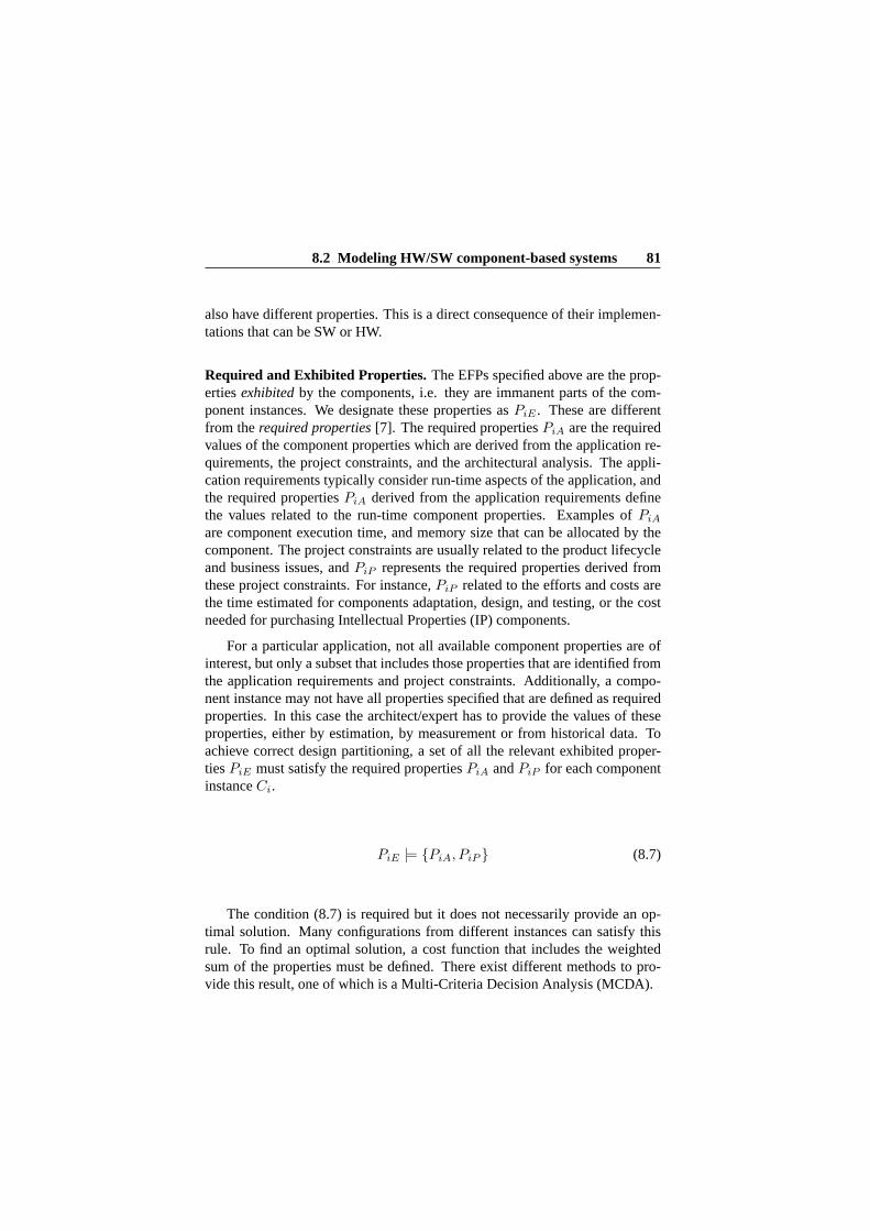
8.2 Modeling HW/SW component-based systems 81
also have different properties. This is a direct consequence of their implemen-tations that can be SW or HW.
Required and Exhibited Properties.The EFPs specified above are the prop-ertiesexhibitedby the components, i.e. they are immanent parts of the com-ponent instances. We designate these properties asPiE . These are differentfrom therequired properties[7]. The required propertiesPiA are the requiredvalues of the component properties which are derived from the application re-quirements, the project constraints, and the architectural analysis. The appli-cation requirements typically consider run-time aspects of the application, andthe required propertiesPiA derived from the application requirements definethe values related to the run-time component properties. Examples ofPiA
are component execution time, and memory size that can be allocated by thecomponent. The project constraints are usually related to the product lifecycleand business issues, andPiP represents the required properties derived fromthese project constraints. For instance,PiP related to the efforts and costs arethe time estimated for components adaptation, design, and testing, or the costneeded for purchasing Intellectual Properties (IP) components.
For a particular application, not all available component properties are ofinterest, but only a subset that includes those properties that are identified fromthe application requirements and project constraints. Additionally, a compo-nent instance may not have all properties specified that are defined as requiredproperties. In this case the architect/expert has to provide the values of theseproperties, either by estimation, by measurement or from historical data. Toachieve correct design partitioning, a set of all the relevant exhibited proper-tiesPiE must satisfy the required propertiesPiA andPiP for each componentinstanceCi.
PiE |= {PiA, PiP } (8.7)
The condition (8.7) is required but it does not necessarily provide an op-timal solution. Many configurations from different instances can satisfy thisrule. To find an optimal solution, a cost function that includes the weightedsum of the properties must be defined. There exist different methods to pro-vide this result, one of which is a Multi-Criteria Decision Analysis (MCDA).

82 PaperIII
8.3 The partitioning quality framework
The next steps in our formalization are i) specification of a property metamodelwhich is able to encompass the heterogeneity derived by the intrinsically dif-ferent nature of HW or SW components, and ii) categorization of EFPs withrespect to their sensitivity to the HW/SW partitioning decisions.
8.3.1 Component property metamodel
The property metamodel is a part of the entire component-based system meta-model, which is based on the definitions from the previous section. Figure8.1 shows a simplified overview of the component-based system; a completedmetamodel and detailed description can be found in [5]. Note that here, in con-trast to typical metamodels for software components, different variants of thesame component can have different EFPs. A component variant type is relatedto the component implementation: it can be SW, HW, or “virtual”; the “virtual”type is defined for not yet implemented components.
System
Interface
Component
Extra-FunctionalProperty
Variant
Connector
Platform VariantType
- Type :VariantTypes
VariantPlatform
- Name :PlatformsList
Component-based Application
«enumeration»VariantTypes
HW SW VIRTUAL
1..*
+ports
1
1
11
1
1..*
1
+Variants 1..*
1
+EFPs 1..*
1
1
1
1..*
1
Figure 8.1: Component-based System Metamodel (Simplified Overview).
Figure 8.2 shows an overview of the diagram describing the ComponentExtra-Functional Property. The key entities of this metamodel are: theCompo-nent Extra-Functional Property, theComponentVariantPropertyValueand theComponentPropertyCategory.

8.3 The partitioning quality framework 83
ComponentVariantPropertyValue
- PropertyValue- ValueAccuracy
Extra-FunctionalProperty
«enumeration»FormatTypes
Integer Float String Enumerative Interval Distribution
Metric
- MetricDescription- Format :FormatTypes- Unit :MetricsUnits
Context
- ObtainedAs :ObtainedAsTypes- DevelopmentEnvironment :DevelpomentEnvironmentLists- SpecificMeasurabilityConditions
ComponentProperty Category
- PropertyCategory :ComponentPropertyCategories
«abstract»Entity
Identification
- Description- Documentation- Name- Unique_ID
«enumeration»ComponentPropertySubcategories
COST SUBCATEGORY PERFORMANCE SUBCATEGORY SECURITY SUBCATEGORY
«enumeration»ComponentPropertyCategories
LIFECYCLE RUNTIME PROJECT-RELATED BUSINESS-RELATED
«enumeration»ObtainedAsType
ESTIMATED MEASURED SIMULATED
«enumeration»MetricsUnits
1..*
1
1
1
Component Property subcategory
1..
1..*+ values
1
1
1
Figure 8.2: Component Extra-Functional Property Metamodel.
Component Extra-Functional Property. The central core is represented bythe component EFP entity which abstracts a component property. It belongs toa specific category as modeled by the ComponentPropertyCategory and has anassociated set of values related to a specific component variant.ComponentPropertyCategory. There exist several different categories ofproperties. This categorization is used to group similar properties. The cate-gories are listed through theComponentPropertyCategoriesas shown in Figure8.2. Each category can also be divided into subcategories. This enables catego-rizations that follow different standards, or it can be used for grouping complexproperties that are related to a number of other (sub)properties - for example aperformance, or a categorization used in a particular domain to group stronglyrelated properties, for instance, the COST subcategory can include costs for

84 PaperIII
the design, implementation, verification and validation, and maintenance. Thedefinition of the subcategory refers to the value associated to a specific compo-nent variant.
ComponentVariantPropertyValue. TheComponentVariantPropertyValueab-stracts the value associated with the property. Each value has associated (i) ametric to quantitatively or qualitatively express the value (or set of), and de-fined through a description, a format (described by theFormatTypeentity), and(ii) a context which serves to capture the conditions under which the value isestimated, simulated or measured (as described by theObtainedAsType).
8.3.2 The categorization of partitioning-related properties
The main driving question in this research iswhich are the properties whosevalues strongly depend on the partitioning decisions, and which properties areindependent of the partitioning? To answer this question we provide (i) a listof possible EFPs and their categorization following the metamodel shown inFigure 8.2, and (ii) an analysis of the EFPs in respect to their dependencies onthe partitioning.
To provide a list of all possible EFPs we use three types of sources a) exist-ing quality models and standards; b) existing literature related to the partition-ing decisions; and c) experience from the practice provided by experts in thefield.
• Quality models and standards. Specifically, we exploited the followingstandards and quality models.
1. ISO/IEC International Standard Software product Quality Require-ments and Evaluation (SQuaRE) [8] defined for software qualities,i.e. an extension of the International Standard ISO/IEC 9126 [9],which was extensively exploited in the state of the art;
2. Several well-known quality classifications, in particular the Mc-Call’s quality model [10], the Boehm’s quality model [11], the La-prie’s dependability tree (attributes) [12];
3. The quality attribute utility tree modified for embedded hardwareplatforms (later referred to as HW-ATAM) [13] based on the well-known Architecture Tradeoff Analysis Method (ATAM-CYC [14]);

8.3 The partitioning quality framework 85
• State Of The Art (SOTA). There is a rich body of knowledge related toHW/SW partitioning. We have extracted the EFPs addressed in theseworks. The details of this work are given in Section 5 (Related Work).
• State Of The Practice (SOPA). We provided a survey carried out withinthe iFEST (industrial Framework for Embedded Systems Tools) ArtemisJU research project , with a consortium of more than 20 companies anduniversities2 in which discussion was held with the project membersabout important EFPs and their relation to the HW/SW partitioning. Tothis end, we conducted an empirical study that, in combination with thesurvey, included data collection through in-depth interviews with expertsand researchers from both companies involved in the iFEST project, andcompanies and universities in Sweden. The details of this study are pre-sented in Section 4.
We categorized the EFPs in three main categories: i) LifCycle EFPs; ii)RunTime EFPs; and iii) Project/Business-related EFPs. As presented in [7],the system lifecycle perspective encompasses those properties which are re-lated to the system development process and its maintenance, while the run-time perspective interests those properties whose behavior is visible, applica-ble, and measurable at run-time. In summary, all identified and of-interestproperties are divided into three categories, namely “LifeCycle”, “RunTime”and “Project/Business-related”.
The table shown in Figure 8.3 reports the details of our categorization.The table is structured by category i.e. it is divided into LifeCycle, RunTimeand Project/Business-related. Each category is then divided into subcategories,which group properties having similar descriptions. This is done in order toimprove understandability of the categorization. However, as in most of thecases in the table shown in Figure 8.3, this does not preclude a subcategoryfrom also being a property. In particular, in this table each category is orga-nized as follows: the first and second columns represent the subcategories andthe group of related properties, respectively. For instance, in the first row ofthe LifeCycle category, Usability is a subcategory grouping properties suchas Appropriateness, Recognizability, User error protection, User interface aes-thetics, Learnability and Training. In addition to the subcategory name, thesources from which the property is taken are reported. The categorization fol-lows the classification in the standards and quality models (SQuaRE, ISO9126,McCall, etc.) as much as possible. Using the example just mentioned above,
2iFEST - http://www.artemis-ifest.eu/

86 PaperIII
for the Usability subcategory we have to exploit both the SQuaRE and the Mc-Calls quality model in order to identify its related properties. For each property(i.e., related to a given subcategory), its source is also reported in parenthesis.
We can observe that LifeCycle properties are present in the largest quantity.Short descriptions (titles) of the properties can be found in [15]. Many of thoseproperties are difficult to measure. The RunTime properties are extensivelystudied in research and used in practice, and it is possible to express many ofthem quantitatively. The Project-related properties are time- and effort-relatedproperties, as properties of project-related activities. The Business-relatedproperties consider types of products (like mass products, product families, andsimilar). A relevant observation is that some properties have subcategories indifferent categories. For instance, Reliability is a RunTime property, but manyLifeCycle properties have direct impact on the reliability. Such properties aremarked in the table with an “*”.
8.4 Survey of EFPs in the Automation and Con-trol Domain
The table shown in Figure 8.3 presents a list of possible EFP candidates whichmay be important in the partitioning decision process. The influence of parti-tioning on specific EFP also depends on other factors, for example on particulararchitectural solutions, or the overall goals of the application, so it is not pos-sible to provide a general list valid for any type of application. However, inspecific domains in which there are similar architectural solutions, and similarnon-functional requirements, it is more feasible to provide such a list. We aimto identify which EFPs are of interest for partitioning in the Automation andControl domain, which covers a vast range of business domains, such as energygeneration and transportation, industrial plants (chemical, pulp and paper, foodindustry), medical instruments, etc.
In order to achieve this goal we conducted an interview-survey involv-ing several companies working in the Automation and Control domain. Wespecifically targeted companies whose products vary from low voltage systems(e.g. motor controllers, industrial robots) up to systems for controlling electricpower transmission lines. The interview-survey research followed a methodspecified in [16]. An overview of data collected is presented here. Completedocumentation of the results can be found in [15].

8.4 Survey of EFPs in the Automation and Control Domain 87
TABLEI.
LIFECYCLECATEGORY,RUNTIMECATEGORY,PROJECT/BUSINESS- RELATEDCATEGORIES.
LifeCycleCategory
Subcategory
Property
Usability(SQuaRE,McCall)
Appropriateness
recognizability(SQuaRE)
Usererrorprotection(SQuaRE)
Userinterfaceaesthetics(SQuaRE)
Learnability(SQuaRE)
Training(McCall)
Integrity*(McCall)
Accessaudit(McCall)
Reliability*(SQuaRE)
Maturity(SQuaRE)
Security*(SQuaRE)
Accountability(SQuaRE)
Compatibility(SQuaRE,McCall)
Compatibility(SQuaRE)
Interoperability(McCall)
CommunicationCommonality
(McCall)
DataCommonality(McCall)
Modifiability(SQuaRE,Boehm)
Modifiability(SQuaRE)
Expandibility(McCall)
Scalability(HW-ATAM,SOPA)
Upgradability(SOPA)
Augmentability(Boehm)
Structuredness(Boehm)
Maintainability(SQuaRE,McCall)
Maintainability
(SQuaRE,MaCall,Laprie)
Analysability(SQuaRE)
Reusability(SQuaRE)
Conciseness(McCall)
Modularity(SQuaRE)
Testability(McCall)
Testability(SQuaRE,HW-ATAM)
Instrumentation(McCall)
Simplicity(McCall)
Generality(McCall)
Debuggability(SOPA)
Understandability(Boehm)
Understandability(Boehm)
Legibility(Boehm)
Flexibility(McCall)
Flexibility(McCall)
Self-descriptiveness(Boehm)
HumanEngineering(Boehm)
HumanEngineering(Boehm)
Communicativeness(Boehm)
LifeCycleCategory
Subcategory
Property
Correctness(McCall)
Correctness(McCall)
Completeness(McCall)
Consistency(McCall)
Traceability(McCall)
Portability(SQuaRE)
Portability(SQuaRE)
Adaptability(SQuaRE)
Installability(SQuaRE)
Replaceability(SQuaRE)
PlatformIndependency(McCall)
Integrability(SOPA)
Project/BusinessrelatedCategory
Subcategory
Property
Maintainability*
Integrationwithlegacy
system
(SOPA)
Productsupport(SOPA)
Volatilerequirements(SOPA)
Productiontype
Massproduction(SOPA)
Single/Smallproduction(SOPA)
Productvariability(SOPA)
Productlifetime(SOPA)
Cost
DesignCost(SOPA)
ImplementationCost(SOPA)
IntegrationCost(SOPA)
TestingCost(SOPA)
ProductionCost(SOPA)
MaintenanceCost(SOPA)
DevelopmentEnvironmentCost(SOPA)
MaintenanceEnvironmentCost(SOPA)
LeadTime
DesignLeadTime(SOPA)
ImplementationLeadTime(SOPA)
IntegrationLeadTime(SOPA)
TestingLeadTime(SOPA)
ProductionLeadTime(SOPA)
MaintenanceLeadTime(SOPA)
Time-to-market(HW-ATAM,SOPA)
ProjectTeam
Distributedproject
environment(SOPA)
Availableexpertise(SOPA)
RunTimeCategory
Subcategory
Property
Usability(SQuaRE)
Operability(SQuaRE)
Accessibility(SQuaRE)
Integrity(McCall)
Accesscontrol(McCall)
Reliability(SQuaRE,McCall)
Reliability(SQuaRE)
Accuracy(McCall)
ErrorTolerance(McCall)
Availability(SQuaRE)
Faulttolerance(SQuaRE)
Recoverability(SQuaRE)
Self-containedness(Boehm)
Security(SQuaRE)
Security(SQuaRE)
Authenticity(SQuaRE)
Confidentiality(SQuaRE,Laprie)
Integrity(SQuaRE,Laprie)
Non-repudiation(SQuaRE)
Modifiability*(SOTA)
Configurability(HW-ATAM)
FunctionalSuitability(SQuaRE)
FunctionalSuitability(SQuaRE)
FunctionalAppropriateness(SQuaRE)
FunctionalCompletness(SQuaRE)
FunctionalCorrectness(SQuaRE)
Dependability(Laprie)
Dependability(Laprie)
Safety(Laprie)
Robusteness(HW-ATAM)
Schedulability(SOTA,SOPA)
Performance(SQuaRE)
PerformanceEfficiency(SQuaRE)
ResourceUtilization(SQuaRE)
TimeBehaviour(SQuaRE)
Capacity(SQuaRE)
PowerConsumption
(HW-ATAM,SOTA,SOPA)
Compatibility(SQuaRE)
Co-existence(SQuaRE)
Interoperability(SQuaRE)
requirements,therearemorepossibilitiestoprovidesucha
list.WeaimtoidentifywhichEFPsareofinterestforthe
partitioninginthedomainofAutomationandControl,which
coversavastrangeofbusinessdomains,suchasenergy
generationandtransportation,industrialplants(chemical,pulp
andpaper,foodindustry),medicalinstruments,etc.
Inordertoachievethisgoalwehave
conductedan
interview-surveyinwhichseveralcompaniesworkinginthe
AutomationandControlDomainwereinvolved.Specifically,
wetargetcompanieswhichproductsvaryfrom
lowvoltage
systems(e.g.motorcontrollers,industrialrobots)uptosys-
temsforcontrollingelectricpowertransmissionlines.The
interview-surveyresearchfollowsamethodspecifiedin[3].
Anoverview
ofdatacollectedandtheresultsarepresented
here.Acompletedocumentationoftheresultscanbefound
in[37].
A.Objective
Toidentifythekeypartitioningpropertiesfortheafore-
mentioneddomain,foreachEFPfrom
TableIwedefinethe
followingquestions:
RQ1
Doesthepartitioningchoice(HWorSW)haveadirect
impactontheproperty?
RQ1
Toensureorachievethispropertywouldyoupreferto
haveasolutioninHWorSW
oritdoesnotmatter?
Bythesetworesearch
questions,forthisdomainweaim
at(i)identifying
themostimpactingEFP
sforthepartitioning
decisions(related
toRQ1)
and(ii)providingaguidance
for
architects(related
toRQ1andRQ2)
byhighlightingforeach
property
adefaultpreference
ofits
realizationeither
asHW
orSW
.
B.SurveyDesignandProcess
Theinterview-surveywascarriedoutamong15experts.
Theparticipantshavebeenselectedbasedontheiraffiliation
andexpertise.Theparticipantswereselectedfrom
industry(in
totalfivecompaniesandanindustrialresearchcenter)andfrom
academia(twouniversities).Allparticipantshavemorethen5
yearsofexperienceassystem
architects(i.e.,experiencewith
bothHWandSW
design)and9ofthem
havebeenworking
formorethan15yearsinthefield.Inaddition,weselectedthe
participantsaccordingtotheirprevailingworkingexperience,
sotheparticipants’poolwasbalancedasfollows:i.e.5
specialistswhichhave/areprevalentworkingexperiencewith
HWdesign,5specialistswithSW
design,and5specialists
experiencedwithbothHWandSW.
TableIIsummarisesthedistributionoftheparticipantswith
respecttotheirworkingexperiences(i.e.workingspecializa-
tion,affiliationandyearsofexperienceinthefield).
Theinteractionwiththeparticipantswasorganisedintwo
phases:1)anintroductiontotheinterview-survey,whichwas
arrangedinform
ofindividualface-to-facemeetings.The
purposeofthemeetingswastogettheparticipantfamiliar
withtheoverallgoaloftheresearch,presentingtheEFPscat-
egorization,passingthroughEFP’slists,andfinallyexplaining
Figure 8.3: Tables of LifeCycle Category, RunTime Category,Project/Business-related Categories.

88 PaperIII
8.4.1 Objective
To identify the key partitioning properties for the aforementioned domain, foreach EFP from Figure 8.3 we pose the following questions:
RQ1 Does the partitioning choice (HW or SW) have a direct impact on theproperty?
RQ1 To ensure or achieve this property would you prefer to have a solution inHW or SW or it Does Not Matter?
With these two research questions, we aim to (i) identify the EFPs which havethe most impact on the partitioning decisions (related to RQ1), and (ii) provideguidance for architects (related to RQ1 and RQ2) by highlighting a defaultpreference (HW or SW) for the realization of each property.
8.4.2 Survey Design and Process
The interview-survey was carried out among 15 experts. The participants wereselected based on their affiliation and expertise. The participants were selectedfrom industry (in total five companies and an industrial research center) andfrom academia (two universities). All participants had more than five years ofexperience as system architects (i.e., experience with both HW and SW design)and nine of them had been working for more than 15 years in the field. In addi-tion, we selected the participants according to their prevailing work experience,with the participants pool balanced as follows: five specialists with prevalentwork experience in HW design, five specialists in SW design, and five spe-cialists in both HW and SW design. Table 8.1 summarizes the distribution ofthe participants with respect to their work experience (i.e. work specialization,affiliation and years of experience in the field).
The interaction with the participants was organized in two phases: 1) anintroduction to the interview-survey, which was arranged in the form of in-dividual face-to-face meetings. The purpose of the meetings was to get theparticipant familiar with the overall goal of the research, presenting the EFPcategorizations, running through the EFP lists, and finally explaining how tofill out the questionnaire; and 2) the completion of the questionnaire by theparticipants.
The questionnaire consists of three main parts, related to the three mainEFP categories. For each EFP specified in the table in Figure 8.3 the partici-pants answered RQ1 and RQ2, as shown in Table 8.2. The complete question-naire is presented in [15].

8.4 Survey of EFPs in the Automation and Control Domain 89
Table 8.1: Distribution among theparticipants
No Profession Affiliation Expert Experience
1 System Architect Industry HW 15 years2 System Architect Industry HW 15 years3 Senior Developer Industry HW 5 years4 Principal Industrial Scientist Industry/University HW 15 years5 Principal Industrial Scientist Industry/University HW 15years
6 Senior System Architect Industry SW 15 years7 Industrial Scientist Industry/University SW 15 years8 Researcher Industry/University SW 5 years9 Professor Industry/University SW 15 years
10 Researcher University SW 5years
11 Senior Product Manager Industry HW/SW 15 years12 Senior Developer Industry HW/SW 5 years13 Industrial Scientist Industry/University HW/SW 5 years14 Senior Researcher University HW/SW 5 years16 Professor University HW/SW 5years
Table 8.2: Example of questionnaire records for the LifeCycle Category
RQ1. Does the partition choice (SW or HW) have a direct impact on the property?RQ2. To ensure/achieve this property would you prefer to have a solution in HW orSW or it does notmatter?
Property Name Property Description RQ1 RQ2
Access Audit The ease with which the component itself anddata can be checked for compliance with stan-dards or other requirements (McCall).
YES HW
Accountability The degree to which the actions of an entity canbe traced uniquely to the entity (SQuaRE).
YES HW
Structuredness The degree to which a component possesses adefinite pattern of organization of its interde-pendent parts (Boehm)
YES HW

90 PaperIII
8.4.3 Results
The collected data is presented in Figures 8.4, 8.5, 8.6, which summarizethe results related to each category respectively, i.e. LifeCycle (Figure 8.4),RunTime (Figure 8.5) and Project/Business-related (Figure 8.6 EFPs). Eachfigure contains two stacked bar graphs, the one on left showing the RQ1 resultsand the one on the right reporting the RQ2 results. The properties in the graphsare sorted in descending order, according to the impact on a given property(provided by RQ1), as judged by the participants. For each graph the verticalaxis label reports the properties per category. There are 44 properties for theLifeCycle category, 31 properties for the RunTime category and 24 for theProject/Business-related category.
The graphs show percentage distributions of the answers (YES or NO) forthe Partitioning Impact graph, and HW, SW or DNM (Does Not Matter) forPreference (HW-SW) graph.
8.4.4 Analysis
To start analyzing the results, we introduce two indices:The Impact Partitioning Factor (IPF), which gives a statistical measure
of the impact that a given property has on the partitioning decisions for thespecific domain. This index is used to analyze the results with respect to RQ1.It is calculated by the ratio in percentage between the total number of positiveanswers and the number of participants. We interpret the IPF according to theFleiss Kappa agreement interpretation3, (60-100 % - a substantial or almostperfect agreement).
Table 8.3: IPFinterpretationImpact Partitioning Factor Interpr etation0-40% YES, (60-100% NO) No Impact on Partitioning40-60% YES, (30-70% NO) Unclear Impact60-100% YES, (0-40% NO) Clear Impact on Partitioning
ThePreferable Deployment Choice(PDC), which gives a statistical mea-sure of the deployment preference for each possibility, i.e. HW, SW or DNM(“Does Not Matter”) with respect to the given property for this specificdomain.
3Fleiss Kappa - http://en.wikipedia.org/wiki/Fleiss’ kappa

8.4 Survey of EFPs in the Automation and Control Domain 91
This index is used to analyze the results with respect to RQ2. In this case wealso use the Fleiss Kappa interpretation.LifeCycle Category. Adaptability, Flexibility, andMantainabilityresult in an“almost perfect IPF” as it can be observed in Figure 8.4, (above 80%), whichwe interpret as a clear impact of the partitioning on these properties. The prop-erties such asInstallability, Analyzability, Expandibility, Platform Indepen-dency, Portability, Access control, Augmentability, Integrability, Modifiabil-ity, andUpgradabilityhave a “substantial IPF” (above 61%), so a substantialagreement that these properties are clearly affected by the partitioning deci-sion. Conversely, the propertiesAccountability, Communication Commonality,Consistency, User Error Protection, Completeness, Data Commonality, Self-descriptiveness, Simplicity, Training, Understandability, Access Audit, Ma-turity, Learnability, Legibility, Structuredness, Traceability, Appropriateness,Appropriateness Recognizability, Usability, Correctness, Human Engineering,andCommunicativenessbelong to a set of EFPs that are not sensitive to thepartitioning decision. With regards to RQ2 (i.e. a preferable solution) we canpoint out that the preferable solutions for the EFPs with a clear partitioningimpact are software implementations.RunTime Category. In this category thePower Consumptionproperty is theonly one that shows a clear impact of the partitioning on these type of prop-erties. Nevertheless, properties likeCo-existence, Performance, Efficiency,Recoverability, Time Behavior, Reliability, and Securityshow a substantialagreement in the understanding of a clear impact of the partitioning on theseproperties. In contrast to the LifeCycle properties, here the hardware solu-tions prevail to achieve or ensure these properties in an advantageous way. ThepropertiesFunctional Correctness, Accessibility, Authenticity, FunctionalAppropriateness, Functional Completeness, Operability, Functional Suitabil-ity, andNon-repudiationare not directly affected by partitioning.Project/Business-related Category.By looking at the results in Figure 8.6we can conclude that the partitioning decisions in the vast majority have animpact on the Business- and Project-related EPFs (that are directly related tothe project constraints and business goals). In the majority, the software so-lutions prevail. There is large number of properties here which have either an“almost perfect IPF” (6 EPFs of 24 properties in total, compared to 3 of 44 inthe LifeCycle category and 1 of 31 the RunTime category) or a “substantialIPF” (10 EFPs of 24). With respect to the “almost perfect IPF”, it is interestingto note that theMaintenance-relatedproperties (i.e. cost and lead time) have aclear impact similar to theMaintainability property in the LifeCycle category,as well as a preference for a SW implementation solution.

92 PaperIII
General remarks. General remarks in relation to the current state of the art areas follows: (i) with respect to the RunTime EFPs, the results show a confirma-tion of the common properties used in literature, and some new properties (suchas Recoverability); and (ii) with respect to LifeCycle and Project/Business-related EFPs, it is observed that many new properties are considered importantfor the partitioning decision process. In particular, the outcomes confirm ourhypothesis that project and business constraints should be considered in parti-tioning decisions, which is in general missing in the state of the art and practicetoday.
8.4.5 Validity
In this section we address the validity of our empirical study. To this end, wediscuss the following main types of validity threats proposed in [17].
Construct Validity. As common practice, in order to assure a high constructvalidity (i.e., a high relation between the theory behind our study and its obser-vation), we used indirect measures (such as the reported working hours for thequestionnaire review taken as a measure of effort) to conduct all steps of ourwork. The steps span from questionnaire preparation through recruitment ofrespondents to evaluation of results. Measures have been used in order to, forexample: (1) avoid mono-operation bias by selecting participants with differentbackgrounds and work experience (see Section 8.4.2); and (2) assure rigorousplanning of the study with a solid protocol for data collection and analysis.Additional threats to construct validity are represented by, for example: (1)the questionnaire structure that facilitates the data collection; (2) the individ-ual face-to-face meetings, based on a presentation illustrating the key conceptsleading the research, to get the participant familiar with the overall goal of thestudy; and (3) the anonymity and confidentiality guaranteed in the processingof the results to avoid evaluation apprehension.Internal Validity. As done in [18], we addressed the confounding variablesrepresenting a major potential source of bias in empirical studies “by exclusionand randomization”. Exclusion concerns the fact that we did not select partici-pants who were not sufficiently experienced in HW or SW design. On the onehand, we carefully balanced our pool of participants (see Section 8.4.2) accord-ing to their prevailing work experience and affiliation. On the other hand, wehave used a random sample of the population in order to avoid the well-knownproblem of selection bias [19]. Moreover, we addressed the issue of ambigu-ously and poorly-worded questions [18] as described in the following points.

8.4 Survey of EFPs in the Automation and Control Domain 93
Figure 8.4: LifeCycle Property Graphs. Partitioning Impact (left). HW/SWDeployment Preference (right).

94 PaperIII
Figure 8.5: RunTime Property Graphs. Partitioning Impact (left). HW/SWDeployment Preference (right)

8.4 Survey of EFPs in the Automation and Control Domain 95
Figure 8.6: Project/Business-related Property Graphs. Partitioning Impact(left). HW/SW Deployment Preference (right)

96 PaperIII
(1) Before being released to the participants the questionnaire was iterativelyreviewed by university and industry experts.Moreover, our questionnaire was based on well-assessed standards and qualitymodels (see Section 8.3.2). (2) To let the participants understand the back-ground and objective of this work, we performed individual face-to-face meet-ings. In addition, we piloted the respondents’ work in different interactions.External Validity. This validity deals with the generalization of the resultsoutside the scope of the study. Based on discussions with the experts, ourassumption is that the results are applicable to the Automation and Controldomain, i.e. to a population having our adopted sampling profile. It was notthe intention of this paper to deal with different application domains, but weintend to work on this aspect by analyzing possible changes in the results whendomain features are adjusted.Conclusion Validity. This validity is focused on how sure we can be of draw-ing correct conclusions about the relation between the treatment and the actualoutcome we observed. We achieved reliable results by piloting the question-naire in multiple interactions, and by providing the participants with key con-cepts on the study. We also assured a reliable treatment implementation byusing the same treatment/procedure with all participants (e.g., we distributedthe same questionnaire). We found the right heterogeneity among the respon-dents (i.e., we carefully defined our pool of participants by not using a verydiverse group of respondents) by selecting the participants from a populationgeneral enough to not reduce the external validity.
8.5 Related Work
The work related to our research can be divided into three categories: (i)par-titioning and HW/SW co-design; (ii) analysis of EFPs for embedded systems;and (iii) design space exploration.Partitioning and HW/SW co-design.During the last few decades, several ap-proaches have been proposed to application architecture partitioning and pro-cedures oriented towards solutions which satisfy performance requirements,e.g. [20], [3]. A wide range of approaches have been proposed in order toautomate/support the hardware/software partitioning activity using differentstrategies such as dynamic programming [21], heuristic algorithm based onthe tabu search techniques [22], integer programming [23], and genetic algo-rithms [24]. A list that categorizes these approaches as well as other approachesfocused on implementation issues, can be found in [3] and [8]. However, all

8.5 Related Work 97
these approaches basically provide guidelines to deciding which parts of thespecification should be implemented in software and which in hardware. Theydo this by considering platform-related indicators, such as potential speedups,area, communication overheads, locality and regularity of computations [25].Usually, they deal with a few EFPs and are focused only on technical issues.However, some partitioning approaches do exist which optimize the combina-tion of extra-functional requirements (e.g. design costs, energy consumptions,performance, etc.) [26], [27], but are still limited in their total number of prop-erties. In order to provide an answer to (i) the increase in complexity of theCPSs and (ii) the advances in underlying hardware technologies when it comesto the architectural partitioning decision, in contrast to existing approaches toa component-based application we propose a general and systematic methodo-logy capable of accounting many properties and based on MCDA techniqueswhich are, to the best of our knowledge, non-existent today.Analysis of EFPs for embedded systems. In the last few years, several re-search efforts have been devoted to the definition of methods and tools ableto predict and evaluate the quality of embedded systems (e.g., [28], [29], and[30]). In particular, different techniques have been introduced to support thespecific features of an embedded system (e.g., the analysis of timing propertiesthat are typically computational and time consuming [31], or the management,preservation and analysis reuse of EFPs that are also critical tasks [32], [33]).Research efforts have been made to support the development and adaptationof embedded systems. For example, component models have been introducedto support the development of embedded systems (e.g., [34], [35], and [36]),and approaches to the adaptation of embedded systems under EFP constraintshave been proposed (see, e.g., [37], [38]). Several approaches have also beenintroduced to estimate EFPs for software and hardware implementations (see,for example [39], [40], [41] for power and energy estimation). The run timeof a hardware implementation on a FPGA, for example in [42] is estimatedby exploiting the simulation and a performance model of the FPGA. In con-trast, a statistical approach is proposed in [43] to estimate the execution timeof embedded software.
The topic of the definition of metamodels to specify EFPs has been alsostudied intensely. For example, in [44] fault tolerance aspects were covered byusing a metamodel, while in [45] a service-oriented metamodel for distributedembedded real-time systems covers real-time properties of services, like re-sponse time, duration, and deadline.
Other challenges related to quality analysis are seen in the strict designconstraints (typical, for example, of mission-critical systems [46]) that affect

98 PaperIII
the interaction between hardware and software components. Several papershave focused on these hardware/software co-verification4 issues (see for exam-ple [48] and [49]). In the recent decades, digital and software designs method-ologies have become more alike [2] and, as already foreseen in [50] they re-quire designers to have a unified view of software and hardware, which con-verge with the concurrent design of hardware/software [2] (see, for example,the HWSWCO project5 and the co-design framework in [47]).Design space exploration: As recalled in [51], design space exploration isan umbrella activity defined by a set of tasks addressing aspects of represen-tation, estimation, and exploration algorithms. An overview of design spaceexploration techniques, such as those used for System-on-a-Chip architecturescan be found in [24]. Several frameworks and tools have been built for theefficient multi-objective exploration (e.g., energy/delay tradeoff [52], occupa-tion of the FPGA, load of the processor, and performance of the applicationtradeoff [53]) of the candidate architectures in order to, for example: (i) enablerun-time resource management in the context of multiple applications [52], or;(ii) simulate the target system and dynamically profile the target applicationsby exploiting heuristic algorithms for the reduction of the Pareto set explorationtime [53].
8.6 Conclusions and future work
In this paper, we have (i) presented a theoretical component-based approach tosupport the deployment of CPSs (as HW or SW components) into heteroge-neous platforms based on many EFPs, and (ii) categorized EFPs in relation tothe HW or SW deployment, and analyzed the HW/SW component deploymentimpact on these EFPs in the Automation and Control domain.
Specifically, with respect to the state of the art, the novelty of our contribu-tions can be summarized in the following points. To the best of our knowledge,this is the first paper that (i) proposes a metamodel thatenables the manage-ment of both application requirements and project/business constraints for theCPS application deployment, and (ii) provides a categorization forHW/SW de-ploymentof EFPs, derived by different quality models, standards, literature andthe current state of practice.
The analysis of the categorization has led to some interesting findings: i)Although the values of EFPs depend on the application architecture andthe
4It is also called co-simulation in the hardware industry [47].5http://hwswcodesign.gmv.com/

References 99
runtime context, there are EFPs that are strongly influenced by the partition-ing decision. In general HW solutions provide better runtime EFPs related tosystem performance, while SW solutions provide better characteristics of life-cycle EFPs, such as modifiability, evolvability, and variability. ii) The projectconstraints play important roles in the partitioning decision process which ingeneral lacks support in existing partitioning approaches.
Our intention with the categorization and partitioning impact analysis is toprovide support to system and software architects in taking architectural de-ployment decisions. Additional work may be required in the specializationof the EFP list, and in the partitioning impact on the EFPs. Furthermore, thefindings will be integrated into our MULTI PAR framework in the form of semi-automatic support.
References
[1] Jurgen Teich. Hardware/Software Codesign: The Past, the Present,and Predicting the Future.Proceedings of the IEEE, 100(Centennial-Issue):1411–1430, 2012.
[2] Giovanni De Micheli and Rajesh K. Gupta. Hardware/Software Co-Design.IEEE MICRO, 85:349–365, 1997.
[3] Marisa Lopez-Vallejo and Juan Carlos Lopez. On the Hardware-softwarePartitioning Problem: System Modeling and Partitioning Techniques.ACM Trans. Des. Autom. Electron. Syst., 8(3):269–297, 2003.
[4] Gaetana Sapienza, Ivica Crnkovic, and Tiberiu Seceleanu. PartitioningDecision Process for Embedded Hardware and Software Deployment. InIn Proceeding of International Workshop on Industrial Experience in Em-bedded Systems Design, COMPSAC 2013. IEEE, July 2013.
[5] Gaetana Sapienza, Tiberiu Seceleanu, and Ivica Crnkovic. Modelling forHardware and Software Partitioning based on Multiple Properties. In39thEuromicro Conference Series on Software Engineering and Advanced Ap-plications. IEEE Computer Society, September 2013.
[6] Ivica Crnkovic, Severine Sentilles, Aneta Vulgarakis, and Michel R. V.Chaudron. A Classification Framework for Software Component Models.IEEE Trans. Software Eng., 37(5):593–615, 2011.
100 References
[7] Ivica Crnkovic, Magnus Larsson, and Otto Preiss. Concerning Pre-dictability in Dependable Component-Based Systems: Classification ofQuality Attributes.Architecting Dependable Systems III, pages 257–278,2005.
[8] ISO/IEC 25000. Software product Quality Requirements and Evaluation(SQuaRE), Guide to SQuaRE. InInternational Standard Organization.
[9] ISO/IEC 9126. Information Technology – Product Quality – Part1: Qual-ity Model. In International Standard ISO/IEC 9126, International Stan-dard Organization.
[10] J. A. McCall, P. K. Richards, and G. F. Walters.Factors in SoftwareQuality. Volume I: Concepts and Definitions of Software Quality. ADA049. General Electric, 1977.
[11] B. W. Boehm, J. R. Brown, and M. Lipow. Quantitative evaluation ofsoftware quality. InProceedings of the 2nd international conference onSoftware engineering, ICSE, pages 592–605, Los Alamitos, CA, USA,1976. IEEE Computer Society Press.
[12] Algirdas Avizienis, Jean-Claude Laprie, and Brian Randell. Dependabil-ity and its threats - A taxonomy. In Rene Jacquart, editor,IFIP CongressTopical Sessions, pages 91–120. Kluwer, 2004.
[13] F. Salewski and A. Taylor. Systematic considerations for the applicationof FPGAs in industrial applications. InIndustrial Electronics, 2008. ISIE2008. IEEE International Symposium on, pages 2009–2015, 2008.
[14] Rick Kazman, Mark H. Klein, Mario Barbacci, Thomas A. Longstaff,Howard F. Lipson, and S. Jeromy Carriere. The Architecture TradeoffAnalysis Method. InICECCS, pages 68–78. IEEE Computer Society,1998.
[15] G. Sapienza, I. Crnkovic, and P. Potena. Technical Report: Archi-tectural Decisions for HW/SW Partitioning based on multiple Extra-Functional Properties. Technical report, School of Innovation, Designand Engineering, Malardalen University, http://www.es.mdh.se/pdf pub-lications/3132.pdf.
[16] E. Babbie.Survey Research Method, 2nd edition. Wadsworth PublishingCompany, 1990.

References 101
[17] Claes Wohlin, Per Runeson, Martin Host, Magnus C Ohlsson, BjoornRegnell, and Anders Wesslen. Experimentation in software engineering:an introduction. Kluwer Academic Publishers, Norwell, MA, USA, 2000.
[18] Uwe van Heesch and Paris Avgeriou. Mature Architecting - A Surveyabout the Reasoning Process of Professional Architects. InWICSA, pages260–269. IEEE Computer Society, 2011.
[19] Hyrum K. Wright, Miryung Kim., and Dewayne E. Perry. Validity con-cerns in software engineering research. InProceedings of the FSE/SDPworkshop on Future of software engineering research, FoSER, pages411–414, New York, NY, USA, 2010. ACM.
[20] K. Ben Chehida and M. Auguin. HW/SW Partitioning Approach for Re-configurable System Design. InProceedings of the 2002 InternationalConference on Compilers, Architecture, and Synthesis for Embedded Sys-tems, CASES, pages 247–251, New York, NY, USA, 2002. ACM.
[21] Jigang Wu and Thambipillai Srikanthan. Low-complex dynamic pro-gramming algorithm for hardware/software partitioning.InformationProcessing Letters, 98(72):41–46, 2006.
[22] Jigang Wu, Thambipillai Srikanthan, and Ting Lei. Efficient heuristicalgorithms for path-based hardware/software partitioning.Mathematicaland Computer Modelling, 51(7-8):974–984, 2010.
[23] Ralf Niemann and Peter Marwedel. Hardware/Software Partitioning Us-ing Integer Programming. InProceedings of the 1996 European Con-ference on Design and Test, EDTC, Washington, DC, USA, 1996. IEEEComputer Society.
[24] Madhura Purnaprajna, Marek Reformat, and Witold Pedrycz. Geneticalgorithms for hardware-software partitioning and optimal resource allo-cation.Journal of Systems Architecture, 53(7):339–354, 2007.
[25] Matthias Gries. Methods for evaluating and covering the design spaceduring early design development.Integration, 38(2):131–183, 2004.
[26] J. Teich, T. Blickle, and L. Thiele. An evolutionary approach to system-level synthesis. InProceedings of the 5th International Workshop onHardware/Software Co-Design, CODES, Washington, DC, USA, 1997.IEEE Computer Society.

102 References
[27] Robert P. Dick and Niraj K. Jha. MOCSYN: multiobjective core-basedsingle-chip system synthesis. InProceedings of the conference on Design,automation and test in Europe, DATE, New York, NY, USA, 1999. ACM.
[28] Paolo Costa, Geoff Coulson, Cecilia Mascolo, Luca Mottola, Gian PietroPicco, and Stefanos Zachariadis. Reconfigurable Component-based Mid-dleware for Networked Embedded Systems.IJWIN, 14(2):149–162,2007.
[29] D. Lohmann, W. Schroder-Preikschat, and O. Spinczyk. Functional andnon-functional properties in a family of embedded operating systems. InObject-Oriented Real-Time Dependable Systems, 2005. WORDS 2005.10th IEEE International Workshop on, pages 413–420, 2005.
[30] Umesh Balaji Kothandapani Ramesh, Severine Sentilles, and IvicaCrnkovic. Energy management in embedded systems: Towards a taxon-omy. In Rick Kazman, Patricia Lago, Niklaus Meyer, Maurizio Morisio,Hausi A Muller, Frances Paulisch, Giuseppe Scanniello, and Olaf Zim-mermann, editors,GREENS, pages 41–44. IEEE, 2012.
[31] Jan Carlson. Timing analysis of component-based embedded systems.In Proceedings of the 15th ACM SIGSOFT symposium on ComponentBased Software Engineering, CBSE, pages 151–156, New York, NY,USA, 2012. ACM.
[32] Mehrdad Saadatmand and Mikael Sjodin. Towards Accurate Monitoringof Extra-Functional Properties in Real-Time Embedded Systems. In KarlR P H Leung and Pornsiri Muenchaisri, editors,APSEC, pages 338–341.IEEE, 2012.
[33] Antonio Cicchetti, Federico Ciccozzi, Thomas Leveque, and Sever-ine Sentilles. Evolution management of extra-functional properties incomponent-based embedded systems. InCBSE, pages 93–102, 2011.
[34] Hans Hansson, Mikael Akerholm, Ivica Crnkovic, and Martin Torngren.SaveCCM - a component model for safety-critical real-time systems. InEuromicro Conference, Special Session Component Models for Depend-able Systems. IEEE, September 2004.
[35] Severine Sentilles, Aneta Vulgarakis, Tomas Bures, Jan Carlson, andIvica Crnkovic. A Component Model for Control-Intensive DistributedEmbedded Systems. InComponent-Based Software Engineering, volume

References 103
5282 of Lecture Notes in Computer Science, pages 310–317. SpringerBerlin Heidelberg, 2008.
[36] Juan F. Navas, Jean-Philippe Babau, and Jacques Pulou. A component-based run-time evolution infrastructure for resource-constrained embed-ded systems. InProceedings of the ninth international conference onGenerative programming and component engineering, GPCE, pages 73–82, New York, NY, USA, 2010. ACM.
[37] Marc Zeller and Christian Prehofer. A Multi-Layered Control Approachfor Self-Adaptation in Automotive Embedded Systems.Adv. SoftwareEngineering, 2012, 2012.
[38] Marc Zeller and Christian Prehofer. Modeling and efficient solving ofextra-functional properties for adaptation in networked embedded real-time systems.Journal of Systems Architecture, 2012.
[39] J. Henkel and Yanbing Li. Avalanche: an environment for designspace exploration and optimization of low-power embedded systems.Very Large Scale Integration (VLSI) Systems, IEEE Transactions on,10(4):454–468, 2002.
[40] L. Senn, E. Senn, and C. Samoyeau. Modelling the Power and EnergyConsumption of NIOS II Softcores on FPGA. InCluster ComputingWorkshops (CLUSTER WORKSHOPS), 2012 IEEE International Con-ference on, pages 179–183, 2012.
[41] Carlo Brandolese, William Fornaciari, Fabio Salice, and Donatella Sci-uto. The Impact of Source Code Transformations on Software Powerand Energy Consumption.Journal of Circuits, Systems, and Computers,11(5):477–502, 2002.
[42] P. Bjureus, M. Millberg, and A. Jantsch. FPGA resource and timing es-timation from Matlab execution traces. InHardware/Software Codesign,2002. CODES 2002. Proceedings of the Tenth International Symposiumon, pages 31–36, 2002.
[43] P. Giusto, G. Martin, and E. Harcourt. Reliable estimation of executiontime of embedded software. InProceedings of the conference on Design,automation and test in Europe, DATE, pages 580–589, 2001.

104 References
[44] A. Ziani, B. Hamid, and J. Bruel. A Model-Driven Engineering Frame-work for Fault Tolerance in Dependable Embedded Systems Design. InSoftware Engineering and Advanced Applications (SEAA), 2012 38thEUROMICRO Conference on, pages 166–169, 2012.
[45] Muhammad Waqar Aziz, Radziah Mohamad, DayangN.A. Jawawi, andRosbi Mamat. Service based meta-model for the development of dis-tributed embedded real-time systems.Real-Time Systems, 49(5):563–579, 2013.
[46] Fei Xie and Huaiyu Liu. Unified Property Specification for Hard-ware/Software Co-Verification. InCOMPSAC (1), pages 483–490. IEEEComputer Society, 2007.
[47] Antonio Cau, Roger Hale, J Dimitrov, Hussein Zedan, Ben CMoszkowski, M Manjunathaiah, and M Spivey. A Compositional Frame-work for Hardware/Software Co-Design.Design Autom. for Emb. Sys.,6(4):367–399, 2002.
[48] Juha-Pekka Soininen, Tuomo Huttunen, Kari Tiensyrja, and HannuHeusala. Cosimulation of real-time control systems. InEURO-DAC,pages 170–175. IEEE Computer Society, 1995.
[49] M. El Shobaki. Verification of embedded real-time systems using hard-ware/software co-simulation. InEuromicro Conference, 1998. Proceed-ings. 24th, volume 1, pages 46–50 vol.1, 1998.
[50] Frank Vahid and Tony Givargis.Embedded system design - a unifiedhardware/software introduction. Wiley-VCH, 2002.
[51] Jeffry T. Russell and Margarida F. Jacome. Embedded architect: a tool forearly performance evaluation of embedded software. InProceedings ofthe 25th International Conference on Software Engineering, ICSE, pages824–825. IEEE Computer Society, 2003.
[52] G. Mariani, V. Sima, G. Palermo, V. Zaccaria, C. Silvano, and K. Bertels.Using multi-objective design space exploration to enable run-time re-source management for reconfigurable architectures. InDesign, Automa-tion Test in Europe Conference Exhibition (DATE), 2012, pages 1379–1384, 2012.

References 105
[53] Gianluca Palermo, Cristina Silvano, and Vittorio Zaccaria. Multi-objective design space exploration of embedded systems.J. EmbeddedComputing, 1(3):305–316, 2005.


Chapter 9
Paper IV:Assessing Multiple CriteriaDecision Analysis Suitabilityfor HW/SW Deployment inEmbedded Systems Design
G. Sapienza, G. Brestovac, R. Grgurina and T. Seceleanu.
In the Journal of Systems Architecture: Embedded Software Design (JSA).Elsevier 2014 (under review).
107

108 PaperIV
Abstract
The new advances in hardware technology in the form of heterogeneous plat-forms consisting of different computation units enable development of moresophisticated applications. Running on a heterogeneous platform, an appli-cation can better utilize the computation units dedicated to specific types ofalgorithms. This, however, increases the complexity of the deployment deci-sion process. In our case, we analyze the application deployment in terms ofpartitioning in hardware and software executable units. Today’s developmentprocesses lack the support of systematic methodologies to aid system architectsand developers in carrying out partitioning decisions. To address the problemof a complex deployment decision process we have proposed a novel parti-tioning methodology called MULTI PAR. MULTI PAR is able to process a largenumber of factors that have an impact on application characteristics based onthe applications partitioning into hardware and software. The method is basedon the Multi Criteria Decision Analysis (MCDA) approach. There exist manyMCDA methods; however, not all of them are suitable for the partitioning.The partitioning-related criteria to be used by MCDA can have different typesof values, precision of specifications, missing values, or even inability to bequantitatively expressed. For this reason it is important to choose a properMCDA or a set of MCDA methods to achieve the optimal result. In this paperwe present a survey of MCDA methods and analyze their suitability for thedeployment decisions. In addition, we present an approach on how to integratethe most suitable MCDA methods into the development process that includesthe deployment decision activity. We illustrate this approach by an industrialcase study.
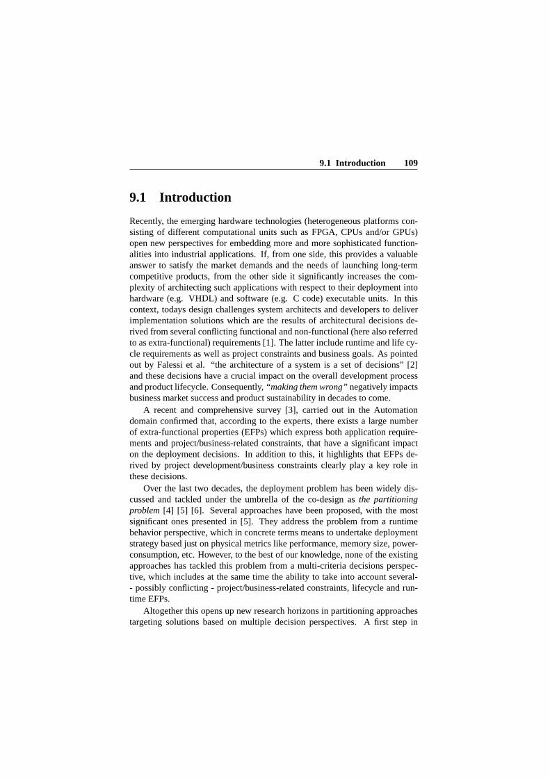
9.1 Introduction 109
9.1 Introduction
Recently, the emerging hardware technologies (heterogeneous platforms con-sisting of different computational units such as FPGA, CPUs and/or GPUs)open new perspectives for embedding more and more sophisticated function-alities into industrial applications. If, from one side, this provides a valuableanswer to satisfy the market demands and the needs of launching long-termcompetitive products, from the other side it significantly increases the com-plexity of architecting such applications with respect to their deployment intohardware (e.g. VHDL) and software (e.g. C code) executable units. In thiscontext, todays design challenges system architects and developers to deliverimplementation solutions which are the results of architectural decisions de-rived from several conflicting functional and non-functional (here also referredto as extra-functional) requirements [1]. The latter include runtime and life cy-cle requirements as well as project constraints and business goals. As pointedout by Falessi et al. “the architecture of a system is a set of decisions” [2]and these decisions have a crucial impact on the overall development processand product lifecycle. Consequently,“making them wrong”negatively impactsbusiness market success and product sustainability in decades to come.
A recent and comprehensive survey [3], carried out in the Automationdomain confirmed that, according to the experts, there exists a large numberof extra-functional properties (EFPs) which express both application require-ments and project/business-related constraints, that have a significant impacton the deployment decisions. In addition to this, it highlights that EFPs de-rived by project development/business constraints clearly play a key role inthese decisions.
Over the last two decades, the deployment problem has been widely dis-cussed and tackled under the umbrella of the co-design asthe partitioningproblem[4] [5] [6]. Several approaches have been proposed, with the mostsignificant ones presented in [5]. They address the problem from a runtimebehavior perspective, which in concrete terms means to undertake deploymentstrategy based just on physical metrics like performance, memory size, power-consumption, etc. However, to the best of our knowledge, none of the existingapproaches has tackled this problem from a multi-criteria decisions perspec-tive, which includes at the same time the ability to take into account several-- possibly conflicting - project/business-related constraints, lifecycle and run-time EFPs.
Altogether this opens up new research horizons in partitioning approachestargeting solutions based on multiple decision perspectives. A first step in

110 PaperIV
this direction is represented by the introduction of MULTI PAR [7]. M ULTI -PAR enables the partitioning of the application based on: (i) transformation ofthe application requirements and project/business-related constraints into EFPsthrough component-based software architecture; (ii) the reuse of existing com-ponents, and; (iii) applying a MCDA approach.
Existing partitioning approaches apply multi-objective optimization tech-niques [8] [9] [10] on a limited number of physical metrics. Conversely, MUL-TIPAR is based on those types of MCDA techniques which: a) consider multi-actor decision making scenarios where various stakeholders’ points of viewcan be, or need to be, taken into account; b) capture aspects of realism [11] anddo not require a strict mathematical abstraction of the problem; c) may operatewith missing, imprecise, uncertain data [11].
In our present study we are interested in finding answers to a couple ofquestions, as follows:
1. Which MCDA method (or collection) is suitable for achieving partition-ing solutions based on multiple non-functional properties?
2. How can MCDA methods be composed into the development process
To achieve this goal, we start by identifying MCDA methods that are avai-lable today. Then, we define the key requirements of interest for the parti-tioning. Based on these, we derive“11-suitability criteria” to assess MCDAmethods. We do this by applying the selected methods on an industrial demon-strator.
9.2 Background
We start here by giving the definition of partitioning and presenting the relevantwork, and then continue with the advantages that a MCDA-based partitioningapproach brings to the process. We also present some basic MCDA principles.
9.2.1 Partitioning and MCDA Suitability Analysis RelatedWork
We share here the definition of the partitioning problem stated as “finding thoseparts of the model best implemented in hardware and those best implementedin software” [4]. Hardware/software partitioning is considered to be one ofthe main challenges faced when designing embedded applications: “as it has a

9.2 Background 111
crucial impact both on the cost and on the overall performance of the resultedproduct” [12]. However, this is a Non-deterministic Polynomial (NP)-hardproblem [13]. A rigorous mathematic formulation and analysis of the parti-tioning problem is provided in [14].
There is a considerable body of knowledge related to partitioning and re-lated issues. It was intensively studied in the 1990s and the early years of the2000s, when the co-design basically emerged as a new discipline [5]. Overthe decades, a wide range of approaches have been proposed in order to au-tomate/support the hardware/software partitioning using different strategies,for instance dynamic programming [15], heuristic algorithms based on thetabu search, simulated annealing, genetic algorithm techniques [16] [17] [18][19] [20] etc., integer programming [21], multiple objective optimization tech-niques [8] [9], etc. An in-depth study of several partitioning approaches andrelated issues is provided in [19] and a walk through of the highlights of par-titioning approaches over the last two decades is found in [6] [5] [22]. All ofthese approaches are mainly oriented towards solutions satisfying physical per-formance requirements. They provide partitioning solutions whose results arebased on platform-related indicators, like potential speedups, area, communi-cation overheads, locality and regularity of computations [23]. For instance,this is the case with approaches such as Vulcan or COSYMA which target op-timization problems focusing on design constraints such as timing, resourcespeed-up and so forth [24].
Even though there exist few partitioning approaches which optimize com-bination of Extra-Functional Requirements (e.g. design costs, energy con-sumptions, performance, etc.) [25] [26], they are still limited in the total num-ber of EFPs they are dealing with. Additionally, current partitioning approachesonly focus on technical issues and do not take into account properties related tothe project development and business perspectives (e.g. legacy, resource avail-ability, design effort, testing costs, production costs, etc,) or the EFPs of keyimportance for embedded industrial application developments such as safety,reliability, security, maintainability, sustainability, scalability, field upgrade-ability and so forth.
Unlike with the previous work [27] [28] [29] [5], which includes recentoverviews on high-level design exploration of MCDA-related partitioning ap-proaches - especially focused on multi-objective optimization techniques - ourapproach is focused on MCDA techniques which deal with lack of information(uncertainty) as well as with information of different nature (e.g. qualitative,quantitative, distributions and so forth) and with incomparable information.Another advantage lies in the fact that it provides a means of making decisions

112 PaperIV
based on different project stakeholders perspectives. In addition to this, it isthe first approach which brings together project-related constraints and busi-ness goals (together with lifecycle as well as runtime non-functional require-ments) [3] into the set of decision criteria. Today, to the best of our knowl-edge, such partitioning methodology is non-existent. Selecting an appropriateMCDA that best suits the requirements of a decision-making specific problemis not a trivial task. Over the last few decades, a large number of MCDA me-thods has been proposed, they “differ in the way the idea of multiple criteriais operationalised” [30], e.g. objective, criteria assessing, weight computationand preference model, algorithms applied, and so forth. Consequently, depend-ing on the decision-making user context and the problem type to solve, somemethods are more suitable than others.
Several works have been proposed to assess the appropriateness of MCDAmethods for solving the “decision-making problem at hand”, e.g. [30] [31]in which different methods are assessed with regard to sustainability issues orwhere the methods are assessed for their suitability in solving seismic structuralretrofitting issues [32]; in [33] a few methods are evaluated for their applica-bility in building design. Nevertheless, they focus on highlighting strengthsand weaknesses with respect to a specific class of multi-decision problem anddomain. These works have in common that they compare a few methods basedon a list of requirements.
In order to reach our aim i.e.assessing the suitability of MCDA methods forpartitioning, we use these works as a starting point since they provide a set ofgeneral and common (to all methods) requirements that are applicable for oursuitability analysis. However, we extend the current state of the art by asses-sing several MCDA methods with respect to partitioning-related requirementswhose work is not currently available in literature.
9.2.2 Multiple Criteria Decision Analysis Basic Concepts
Multiple Criteria Decision Analysis (MCDA) (also referred to as Multiple Cri-teria Decision Making (MCDM), or Multiple Criteria Decision Aid) is a branchof Operational Research which “refers to making decisions in the presence ofmultiple, usually conflicting, criteria” [34]. MCDA is defined [35] as “an um-brella term to describe a collection of formal approaches which seek to takeexplicit account of multiple criteria in helping individuals or groups exploredecisions that matter”. It is widely applied in many fields like medicine [36],forestry [37], economics [38], energy management [39], transportation [40],etc. to solve a vast number of different problems [41] [11].

9.2 Background 113
In [11] [42] [43] [44] MCDA problems are roughly divided into two mainclasses. The first class includes methods dealing with problems consideringa finite number of possible alternative solutions, also referred to as MultipleAttribute Decision Making (MADM) [35]. The second class considers pro-blems dealing with an infinite number of alternative solutions and it is usuallyreferred as Multiple Objective Decision Making (MODM) [45] [43]. Sinceour research problem deals with a finite number of alternative solutions, wefocus on MADM approaches. A comparison highlighting the key differencebetween these classes can be found in [43] [30]. We present below the mainkeywords around the MCDA concept. As there are no global definitions ofthese terms [46], authors use them interchangeably.• Attributes can be defined as the characteristics, qualities or performanceparameters of alternatives [47].• An alternative represents the item to evaluate according to its attributes tofind the final decision solution (or set of solutions).• A Criterion [34], is a measure of effectiveness representing the basis forevaluation.• Objectives are defined [47] as “reflections of the desires of the decisionmaker and they indicate the direction in which the decision maker wants theorganization to work”.• Goals (or targets) can be understood as “apriori values or levels of aspira-tion” that can be “either achieved or surpassed or not exceeded” [34].
A formal definition of a typical MCDA problem is provided in [48]. Cri-teria and alternatives are collected in a table (also referred to here as Deci-sion Matrix (DMx)). A typical DMx is shown in Figure 9.1 where the setof alternatives is represented byA = {a1, ..., an}, and the set of criteria byF = {f1, ..., fk}.
Figure 9.1: A simplified example of MCDA table, commonly referred as De-cision Matrix.

114 PaperIV
The evaluation value of the alternativeai with respect to the j-th criterionis defined byfj (ai).
Let us analyze those characteristics by considering a simple example ofbuying a house. The alternatives areHouse 1,House 2,House 3, and the at-tributes are the price, overall impression for location, house size and comfort.The DMx for this example is shown in Figure 9.2.
Figure 9.2: House-Buying Example Decision Matrix.
The main goal of a Decision Maker (DM) is to find the (set of) alternative(s)which best optimizes/trades-off all the criteria. The solution of a MCDA prob-lem depends not only on the evaluation of alternative values, but is also mostlyaffected by the different criteria weights (i.e. the importance of a specific cri-teria with respect to other criteria) assigned by different DMs.
In our examples, for instance, the first step is the assignment of the weightsto each criteria (Figure 2) by using an appropriate weighting method. Theweights are normalized. Next, we perform the assignment of the preferenceto each criterion, with respect to the so called benefit and cost functions. The“benefit” and “cost” preferences denote the maximum and minimum valuesthat are preferred, respectively. For example, the DMs may prefer to buy ahouse with the lowest possible price but, at the same time, may prefer thelargest possible house.
The DM has to take into account multiple and conflicting criteria. The“price” of a house may conflict with the size of the house (“House size”). Ad-ditionally, the criteria ‘Price” and ‘House size” are measured with differentunits (dollars vs. square metres). This is what is usually referred to as solv-ing decision problems dealing with incommensurable units. Additionally, thecriteria “price” and “house size” are measured with different units terms (dol-lars vs. square meters). This is what is usually referred as solving decision

9.2 Background 115
problems dealing withincommensurable units[44] [34] [49]. Criteria mightbe ofqualitative or quantitative nature (the price of a house can be numeri-cally measured while the comfort rating can be subjectively described as high,medium, low) or they might bedeterministic or probabilistic [49] (the priceof a house can be described using deterministic values while the overall impres-sion of location could be a random value).Uncertainty also plays a key rolewhen making decisions. It can be caused by different nature, e.g. as derivedby subjective judgement or by unknown or incomplete (imprecise) infor-mation [49]. In such a scenario, which also includes the mixing of differentcriteria natures, the problems are intrinsically hard to solve.
We mentioned a well-known classification of the most frequent decision-making problems [11] [50]. It deals mainly with decisions related to the choice,ranking or classification/sorting of alternatives. As a consequence, MCDAmethods can be grouped as follows:• Choice methods.The objective of these methods is to aid DMs in selectinga subset of alternatives under constraints, as restricted as possible. For exam-ple, using these methods the DM might choose to buy two or more houses,depending on his budget and size limits. Lets assume that DM has a maxi-mum budget limit of $ 800,000 and a minimum size limit of 206 m2. Basedon these constraints, thePROMETHEE V1 method (a MCDA method for thechoice problem) has proposedHouse 1 andHouse 3 as the best possible alter-natives for DM.• Ranking methods.This class of methods is used to aid DMs in ranking allof the alternatives from best to worst. For example, using these methods theDM will get a ranking of all houses and might choose to buy the best-rankedhouse. The final output fromPROMETHEEII method (a MCDA method forranking problem) isHouse 2,House 1 andHouse 3.• Classification/Sorting methods.The goal of this class of methods is to aidDMs in assigning alternatives to a defined class. If the classes can also be or-dered, then the DMs deal with what are defined as ordered sorting problems.Using theSMAA-TRI method (a MCDA method for the classification prob-lem) the houses are placed in two classes suchgoodor bad, i.e. theHouse 1andHouse 2 could be classified as a good andHouse 3 could be classified asa bad option.
With respect to the above classification, this research focuses on methodsable to solve either ranking or classification decision problems since they couldboth be applied to reach (a) partitioning solution(s). The first type ofmethod
1PROMETHEE I, II and V are part of the PROMETHEE method family. The completeoverview of the family can be found in [11].

116 PaperIV
can be used to rank all of the hardware (HW) and software (SW) alternatives;methods of the second type can classify an alternative either as hardware orsoftware.
9.3 MULTI PAR: a New MCDA-based PartitioningApproach
Unlike from existing approaches, MULTI PAR enables the partitioning of com-ponent-based applications into hardware or software executable units based ondecisions which take into account several, sometimes conflicting, EFPs, andthe reuse of existing components. It applies MCDA techniques in the finalstages of the process to obtain partitioning solutions which are optimized undermultiple EFP-related objectives.
The design process including MULTI PAR adopts a Component-based De-velopment (CBD) approach as described in [51] where the design is performedin several iterations of two phases: the first one building the system architec-ture with a focus on the functional requirements and the second one consider-ing extra-functional requirements. MULTI PAR defines the following high-levelactivities, with a simplified overview in Figure 9.3.
Component Identification. Existing components are identified as potentialcandidates from a library of existing implementations (called component vari-ants). The components in the library are compliant with the metamodel definedin [7]. For non-existing components, two virtual instances (hardware and soft-ware) are defined.
EFP Prioritization . The EFPs derived from the application requirements andbusiness/project-related constraints are identified and prioritized.
Filtering . All candidate variants which exhibited properties which do not sat-isfy the required properties are filtered out. If, for a given component, no suit-able existing variant remains, two new virtual instances (hardware and soft-ware) will be defined and associated with it.
Value Assignment. The missing component property values are defined.
Partitioning . By means of MCDA methods, a solution or set of solutions forpartitioning is provided. In the case of multiple solutions, the most suitable oneis selected. If the MCDA methods will not converge to any solution, part of theprocess needs to be iterated, based on engineers’ judgements.

9.4 MCDA Methods - Partitioning Suitability Criteria 117
MultiPar Process FlowStart
Component Identification
Value Assignment
End
EFP Prioritization
Partitioning
Solutions Ranking Solutions?
Application Requirements
Project Constraints
Component Library
Application Architecture
Decision Matrix
Project Decision
Project Decision
Filtering
Activity
Artifact
output
optimal solution
1 solution
multiplesolutions
no solution
input
input
outputinput
output
output
output
input
Figure 9.3: MULTI PAR Process Flow Diagram.
9.4 MCDA Methods - Partitioning Suitability Cri-teria
We identify here the features of interest that the MCDA methods need to pro-vide. We start by eliciting key requirements for the partitioning process (the“Elicitation part”), and then derive the suitability criteria of interest to carryout the assessment (the “Extraction part”). In support of our work, we explorethe following topics:
• Hardware/Software Partitioning State of the Art. Even though most of therequirements are collected through the previous MULTI PAR research work [7][52], there exists a rich body of knowledge related to partitioning approacheswhich has been used to support the elicitation of the requirements (see Section9.2).
• Current State of Practice and Experiences on partitioning in indus-

118 PaperIV
try today. We used the results provided by a recent project survey2 whichgathered the industrial and academic experiences related to the developmentand maintenance of hardware/software co-design systems (heterogenous andmulti-core systems) and their relation with respect to the partitioning. We alsoanalyzed the results of the empirical study on the architectural decisions forhardware/software partitioning based on multiple EFPs conducted in [3]. Thisprovides data collected through survey with experts and researchers from bothcompanies and universities in Sweden.• MCDA State of the Art . The survey from Figueira at al. [11] and workssuch as [30] [31] had a key influence in deriving the criteria for our assessment.
Elicitation Part. In order to reduce the inconsistencies typical of any require-ments elicitation process, the requirements are iteratively reviewed by prac-titioners and researchers from industry and university. The requirements aredivided into several hierarchical categories as shown in Figure 9.4. The key el-ements of the model are the “requirements” and the “relationships”. The latterindicate the dependencies between different requirements.
The groups are further divided into two levels. The first level exploits thehigh level requirements, i.e. a collection of statements which identify the scopeboundaries of the partitioning process:(i) the general process features (e.g. reliability of the entire process, traceabilityof the process artifacts, etc.);(ii) the handling of the EFPs and the elements to be partitioned (also referred toin literature using different names such as unit, element, component, function,etc.);(iii) the decision handling (which includes the requirements related to the par-titioning decision of the stakeholders (e.g. the DMs, system architects, etc.)
The second level documents focus on the detailed requirements, i.e. a col-lection of declarative statements defining what partitioning process-related so-lutions have to be met.
In Figure 9.4, the group of requirements belonging to the second level thatare directly related to our assessment are highlighted using a gray rectangle.We briefly present below some examples of such requirements (additional de-tails can be found in [53]).•Requirements addressing the general process features:(i) the process shall besystematic, it has to consist of a well-defined process flow and related activities;(ii) it has to enable reuse of existing components; (iii) it has to be ableto
2iFEST - http://www.artemis-ifest.eu/

9.4 MCDA Methods - Partitioning Suitability Criteria 119
handle the classification and/or ranking of hardware and software units to bepartitioned; (iv) it shall provide metrics to assess the quality of the overallpartitioning solutions; etc.
Second Level Reqs GroupsFirst Level Reqs Groups
General Process Features
EFPs Handling
Elements to be partitioned Handling
Decisions Handling
Reusability
Scalability
Transparancy
....
Decision Criteria Derivation
EFPs Modelling
Prioritization
Filtering
Decisions Analysis
Criteria Preferences
Element Modelling
Reqs
Reqs Assessment-related R
Figure 9.4: Simplified overview of the requirements model for hard-ware/software partitioning processes.
• Requirements addressing the elements to be partitioned:(i) there exists afinite number of elements to allocate; (ii) elements have to be mapped eitheras software or hardware executable units; (iii) there might exist software orhardware elements that have to be reused, etc.; (iv) each element might haveseveral associated EFPs; etc.• Requirements addressing the handling of extra-functional properties:(i)there exist a finite number of EFPs; (ii) there is no limit to the number ofEFPs that might be associated with an element; (iii) there exist different typesof EFP-associated values, (e.g. qualitative, quantitative, probabilistic, ranges,and unknown or incomplete values); (iv) prioritization among EFPs or groupof EFPs shall be allowed; etc.

120 PaperIV
• Requirements addressing the decision handling:(i) there might exist severalDMs; (ii) prioritization mechanisms shall be provided in order to handle DMsand stakeholders’ preferences; etc.
Extraction Part. Based on the mentioned requirements and with the supportof experts from industry and university, we derived 11 MCDA-related criteria(also referred to within the text as11-suitability criteria) of fundamental im-portance for the partitioning. We then grouped them into tree classes accordingto their priority (see Table 9.1). The criteria and their respective priorities willbe used to conduct the method/tool suitability assessment (see Section 9.5).Additional details about the criteria are available in [53].
9.5 Assessment of MCDA Suitability for Partition-ing
We gathered information on the current MCDA methods according to the prob-lem classification presented in Section 9.2.2. We divide the methods intoranking and classification classes. During the investigation, we figured outthat some of the methods belonging to a method family (e.g.ELECTREorPROMETHEE) could be used for solving choice problems too. For complete-ness, we report those methods as well.
The results are summarized in Figure 9.5. It shows which MCDA methodswe identified for each class. For each method, we were also interested in de-termining the methods ability to handle uncertainty (U), dependency (D) andif there exist available tools (T) to implement the method.
The outcome of our search shows that there are 86 methods for solvingranking problems, and 20 methods for solving classification problems, 14 ofwhich can handle missing values. Several of the methods have at least one toolimplementing them. In multiple situations (e.g.IDS, SANNA, DEFINITE,etc.), some tools are implementing a limited number of method functionalities,or are providing additional functionalities that the method does not expose. Nomethod is able to handle/model dependencies for both criteria and alternatives.The ANPmethod comes closest by allowing the construction of criteria net-works. This latter allows the modeling of interdependencies between criteria.However, as discussed in [54], the limitations of such an approach make it un-suitable for being applied in the partitioning decision processes with a largenumber of criteria.
Of the 86 methods we identified above, we have selected 37 methods to

9.5 Assessment of MCDA Suitability for Partitioning 121
Table 9.1: The11-suitabilitycriteriaHigh Priority
Qualitative The method shall be able to estimate the solutions basedonAssessment qualitative information. For instance, a component might have
an EFP (e.g. expert level of confidence) whose valuesmightexpressed as: high, medium, low
Quantitative The method shall be able to estimate the solutions basedonAssessment quantitativeinformation.Unknown The method shall be able to estimate the decisions in the caseofInformation missing information. For instance, some legacycomponents
used in a previous product might not have all theassociatedinformation (i.e. EFP values) of interest and it wouldbehard and time consuming to retrievethem.
Scalability The methods shall not be restricted to the use of alimitednumber of criteria (derived by EFPs) and alternatives(i.e. components).
Subjective The methods shall provide means for the DMs to influencetheJudgment decisions,e.g. by selecting preference functions,setting
thresholds, and soforth.Dependency The methods shall be able to model and obtainsolutionsHandling which take into account the architectural dependenciesthat
might exist (i) between the components (alternatives) e.g.thebandwidth, and (ii) between the EFPs (criteria) (e.g. safety,reliability,and soforth).
Medium PriorityProbability-based the method shall be able to estimate the decisions onEFPsAssessment which value can be expressed by a probability distribution,
e.g. the time distribution of the service maintenance per year.Interval The method shall be able to estimate the decisions onEFPsInformation whose values are expressed by intervals/ranges, e.g.the
estimated line of code (LOC) might be expressed withaninterval such as 200-300LOC.
Preference The methods shall allow the elicitation of the preferencesfromElicitation the DMs (e.g. weights and theirprioritization).Low Priority
Inconsistency The methods shall provide the means to detect inconsistencyIndication between the EFP values. For instance, in the case of anEFP
whose value is greater than its maximum limit, the methodsshouldprovide a means to detect this inconsistency.
Decision The methods shall provide the means to trace thedecisionTraceability process in order to facilitate DMs’ sensitivity
analysis or partial re-iterations of the partitioningprocess.

122 PaperIV
Leg
end
UU
nce
rtai
nit
y
TT
oo
l D
Dep
end
ency
Figure 9.5: MCDA Methods.

9.5 Assessment of MCDA Suitability for Partitioning 123
take into account for our assessment, of which 31 are ranking methods and 6are classification methods.
In order to verify the fulfillment of the11-suitability criteria defined inSection 9.4, we studied each method and tested some of them on a down-sized version of our case study (Section 9.7) by using either spreadsheet-basedimplementations or available tools (whenever they implement all method fea-tures).
The methods belonging to a family (e.g.the ELECTRE family) havebeen evaluated per member. Thus, we have considered each method indepen-dently (e.g.ELECTRE III andELECTRE IV).
9.5.1 Methods Versus the 11-Suitability Criteria
Figure 9.6 shows the results of our investigation, that is, the selected methodsversus the11-suitability criteria. In brief:
• All methods are able to support quantitative data, but few of them canhandle both qualitative and quantitative data (4 ranking methods and 2classification methods).
• More than 80% of the ranking methods are capable of allowing DMspreference elicitation (they allow consideration of criteria weights); thisrate is lower (about 30%) for the classification methods.
• The estimation of the decisions based on probabilistic and intervals datais barely supported by 4 ranking methods, and just one classificationmethod address these.
• 50% of classification methods provide solutions under uncertainty con-ditions, while only around 30% of the ranking methods handle the lackof data.
• Almost all methods allow scalability in terms of criteria and alternatives.However,AHP[55] [56] [57] [58], (andANP, since based onAHP) havesome limitations when the number of criteria is increasing. For example,AHPneeds to perform n(n-1)/2 pairwise comparisons; as the numberof criteria increases, it becomes more difficult and time-consuming tosynthesize the weights.
• Indication of inconsistency (types, etc) is observed by a few (3) rankingmethods.

124 PaperIV
• For a large number of methods (27 ranking and 6 classification) it ispossible to trace back how the decisions have been carried out.
• The ability to consider the DMs’ judgment is offered by 18 ranking and2 classification methods.
• Modelling and handling dependencies between the criteria and betweenalternatives is not fulfilled by any of the investigated methods.
For the ranking methods, the largest number of criteria is fulfilled by theEvidential Reasoning [49] [59] method, at 8 out of 11 criteria. For theclassification methods, theSMAA-TRI [60] method covers the highest numberof criteria , at 6.
9.5.2 Suitability Assessment
In order to assess which methods are the most suitable to solve partitioningproblems we applied the Weighed Sum Method (WSM) [61] on the results ofSection 9.5.1 in combination with the SMART method [62] [63].
Applying the method requires assigning a weight to each of the11-suitabilitycriteria (see the rows “SMART weight” and “Normalized SMART weight ”inFigure 9.6), respectively. We assign the weights based on thepriority of thecriteria (the “PRIORITY” row in Figure 9.6), and on the feedback receivedfrom the experts in industry and academy.
The results of the WSM method are shown in the “Weighted SUM Score”column in Figure 9.6. TheEVIDENTIAL REASONINGmethod has the high-est score, above 0,7. However, there exist seven methods with a score greaterthan 0,6 (e.g.PROMETHEE I and II, REGIME, EVAMIX , etc.) Thereare no classification methods with a score above 0,6. TheTOMASOmethod isthe least suitable method for partitioning (lowest score 0,27).
9.5.3 Tools
We aim to integrate the selected method(s) into the MULTI PAR approach. Thus,the next step is to identify what are the available software tools associated withthe methods and which method features are implemented by the tool(s).
Our investigation results in the identification of 22 tools, where 17 imple-ment ranking methods, 4 implement classification methods and 1 implementsboth classes of methods.

9.5 Assessment of MCDA Suitability for Partitioning 125
Figure 9.6: MCDA methods versus the11-suitability criteria.

126 PaperIV
The mapping between the methods and the tools is provided in Figure 9.7.Some of the tools implement more than one method, for instance theSANNAtool (implementing 5 methods) orDECERNS MCDA tool (implementing 6methods).
We performed an analysis of the tools with respect to the11-suitabilitycriteria defined in Section 9.4 and three additional criteria related to tool fea-tures such as the ability to automatically generate a report (Report Genera-tion); the possibility of visualizing the results through graphs (Graph Visual-ization); and tools support via manual and/or help (Manual/Help). The resultsare shown in Figure 9.8.Visual Promethee Academic, Intelligent DecisionSystems(IDS) andDEFINITE fulfill the largest number of criteria (10/13) forsolving ranking problems, while for classification problems theJSMAA toolis the most suitable (7/13).
However, we decide d not to evaluate some methods (such asVikor ,EXPROM1, EXPROM2, PAIRS, QUALIFLEX, STOPROM2, PRAGMAandPRO-AFTN) with respect to the above-mentioned tool criteria due to the fact that theassociated tools were deprecated (i.e. supported only by, for example, DiskOperating System (DOS)). In addition to this, by a comparison between Figure9.6 and Figure 9.8, it can be seen that tools exist in which the fulfilled cri-teria correspond to the same fulfilled criteria of the methods they implement,for instance theIDS tool andEvidential Reasoning method. But thisis not trivial for most of the other tools, examples beingVisual PrometheeAcademic, or DEFINITE. DEFINITE, for instance, is not able to deal withmissing values either for theREGIMEmethod orEVAMIXmethod.
9.6 Composing the MCDA method inMULTI PAR
According to the results presented in Section 9.5, theEvidential Reaso-ning(ER) method is the most suitable candidate to support MCDA actionstowards hardware/software partitioning. It fulfills most of the requirements.Other methods might be applied as well, for instancePROMETHEE I andII , or REGIME.
Here, we describe how a MCDA method can be integrated into the MUL-TIPAR approach.

9.6 Composing the MCDA method inMULTI PAR 127
Figure 9.7: MCDA methods versus tools.

128 PaperIV
Figure 9.8: MCDA tool versus the criteria (they also include the11-suitabilitycriteria).

9.6 Composing the MCDA method inMULTI PAR 129
9.6.1 MCDA method integration into MULTI PAR
“Partitioning” is a key activity of MULTI PAR (Figure 9.3). We further developthis activity through the design of a number of sub-activities, as shown in Fig-ure 9.9. We briefly describe them, as follows.
Legend
Group ofSub-activities
Group ofSub-activities
2 Weight Assignment
1 DMx Analysis
5 Sensitivity analysis
3 Preference assignment 4 Solution Ranking based on MCDA Method
Start
2.1 Weight Assignment
Method Selection/Review
1.1 Decision
Matrix Analysis
2.2 Weight Assignment/Review
3.1 Assign criteria
preference
Application Requirements
Business/Project Constraints
Decision Matrix
4.1 Criteria Hierachical
Modelling and Specification
4.2 EFPs Subjectve
Judgement Assignment
4.3 Component Variants
Assessment
4.4 Component Variants Ranking
5.1 Sensitivity Analysis
Assessment
Sub-Activity
Process Flow Start
Process Flow End
Artifact
End
data
data
weights
preferences
data
Figure 9.9: Multiple Criteria-based Component Partitioning Activity (de-scribed through the sub-activities and the related process flow).
Decision Matrix Analysis. The process starts by analyzing the DMx in orderto check that, for a given EFP (corresponding to a criterion), the values of thealternatives are uniformly expressed (e.g. given properties of type integer, wecheck that all components’ variant values are expressed by integers), and liewithin the admissible range.Weight Assignment. We continue by selecting a method for the assignmentof weights to the EFPs. The resulting weights are further assigned and normal-ized. These sub-activities allow the consideration of the possibly of differentstakeholder points of view, and hence directly influencing the component rank-ing. In the case that there is no partitioning solution found, the process isreiterated, possibly requiring a change in the weight values. Some well-known

130 PaperIV
methods of assigning weights are described in [63] [62] [64] [65].Preference Assignment.Here, a preference is assigned to each EFP. For in-stance, if we consider EFPs such as “Implementation Cost” the DMs mightwant this to be as low as possible, but for “Modifiability” they might considerit a benefit to have this as high as possible.Solution Ranking based on MCDA Method.The objective of the next groupof sub-activities is to achieve partitioning through the ranking of the componentvariants, applying a MCDA method.
The flow starts by creating a hierarchical model of the EFPs. For instance,for ER, this consists of defining the goal and subsequently sorting and hierar-chically arranging all EFPs according to this goal. ForPROMETHEE II, , itis not necessary to define the goal, however the DM needs to sort and hierar-chically arrange all of the EFPs.
Next, the EFP’ subjective judgements have to be formalized for both thequalitative and quantitative EFPs. In the case of using theERmethod, at theend of this sub-activity, each EFP is expressed as a set of “evaluation grades”(e.g.WORST, POOR, AVERAGE, GOOD, BEST). In the case ofPROMETHEEII , a preference function has to be associated with each EFP in order to reflectthe perception of the criterion scale by the DM. Several types of preferencefunctions are proposed in the literature [11] and indications are given on theway to select appropriate functions for different types of EFPs. Since by usingPROMETHEE II, the preference functions are not able to handle qualitativevalues, a set of “evaluation grades” needs to be quantified (e.g.WORSTwillreceive the quantitative value 1,POORvalue 2,AVERAGEvalue 3,GOODvalue 4, andBESTwill receive quantitative value 5).
Subsequently, we perform the assessment of the component variants, forinstance by usingER. Each alternative value (qualitative or quantitative) has tobe mapped with respect to the set of main goal evaluation grades. In the caseof usingPROMETHEE II, the three preference flows (i.e. positive, negativeand net flow values) are computed in order to globally assess each componentvariant with respect to all other - see [53] for more details aboutPROMETHEEII .
Lastly, the ranking of the component variants is performed. Some of thesub-activities in Figure 9.9 may require iteration. For instance the sub-activities4.2, 4.3 and 4.4 are reiterated until all components are processed.Sensitivity analysis.As soon as the component variants are ranked, a sensiti-vity analysis is carried out in order to assess the impact of missing information,or to observe how changes in the weight model might affect the decisions, andso forth.

9.6 Composing the MCDA method inMULTI PAR 131
9.6.2 MULTI PAR in Integration Scenarios
As mentioned, one of our goals is to integrate our MCDA-based partitioningapproach into the typical embedded systems development process. We providehere the specifications for the integration into an iFEST-based developmentprocess, as it is meant (among others) to support the hardware/software co-design of heterogeneous and multi-core embedded systems. In particular, weextend the work in [66] by the definition of integration scenarios includingMULTI PAR.
The integration is mainly driven by interactions between the tools involvedin the partitioning. They are built upon a set of concepts based on service-oriented architecture (SoA)-like communication between stakeholders and toolsin different development phases. Here, the development is simplified overa number of phases, starting with the Requirement and Elicitation Analysis(R&A) phase, continuing into Design and Implementation (D&I) and endingwith Verification and Validation (V&V). The interactions between the tools andthe actors involved in the process are captured in Figures 9.10 and 9.11
The specifications are given through the description of ascenario. It con-sists of one or more user stories (US) which describe the principal actors andthe actions performed by them with the support of a tool. It also includes in-formation about the produced/consumed artifacts related to these actions.
Figure 9.10: Partitioning scenarios for integration into the development pro-cess.
We briefly describe three key scenarios, as follows:

132 PaperIV
1. Application Requirements and Project/Business Constraints into EFPs.This scenario describes the interactions between a requirement modelling tooland the engineers working with it and the designers/DMs working to achievethe application partitioning. Requirement engineers capture all of the extra-functional requirements and project business constraints with the support ofthe stakeholders, and represent them in an EFP requirement model.
2. Architectural Design into Component Variants. This scenario describesthe interaction between the designers using the tools to model the applicationarchitecture and the designers and DMs who work with the MCDA-based par-titioning tools in order to select the component variants and related EFP valuesthat will go through the partitioning process.
3. Partitioning Solution. This last scenario describes the interaction occurringat the D&I phase between the DMs, harwdare/software designers and develop-ers for providing the partitioning solution and moving towards its implementa-tion.
Scenario ID
Development Phase Tool A
Tool A PurposeDevelopment
Phase Tool B
Tool B User Story (US)
2 D & IArchitecture Modelling
Tool
Architectural Design into Component
Variants
D & IMCDA-based Partitioning
Tool
US 2.1 Component Variants Handling. Based on (i) the architectural model (i.e. a number of interconnected component models) and (ii) the reusable component variants (available through the component library), the component variants (i.e.alternatives) are identified by hw/sw designers and inserted into the DMx which is provided by Tool B.
3 D & IMCDA-based Partitioning
Tool
Partitioning Solution
D & IArchitecture Modelling
Tool
US 3.1 Partitioning Solution Output . As soon as the Decision Matrix is completed, i.e. it contains the criteria (see US1.1), the criteria preferences and weights (see US1.2) and the alternatives (see US 2.1), the partitioning solution (or set thereof) is calculated and output by Tool A.US 3.2 Partitioning Solution Analysis. The solution is assessed with respect to uncertainty, preferences, weights and so forth by DMs and designers. This is then fed back to Tool B in order to proceed toward its further design and implementation.
RE&A1
US 1.1 EFPs Insertion. Based on the requirement model and the project/business constraints provided by Tools A, the EFPs are identified by the stakeholders (including the DM) and inserted into the Decision Matrix (DMx) provided by Tool B. With support of the developers, the EFPs’ values must be inserted into the DMx as well.US 1.2 Assign Weight Preference and Weights. Based on the requirement model and the project/business constraints provided by Tools A, for each EFP the preference and weight must be assigned by the DMs with the support of the remaining stakeholders and they must be inserted into the DMx provided by Tool B.
MCDA-based Partitioning
ToolD & I
Application Requirement
s Project/Busin
ess Constraints into EFPs
Requirement Modelling
Tool
Figure 9.11: Partitioning scenario specifications.

9.7 Industrial Case Study: A Wind Turbine Application 133
9.7 Industrial Case Study: A Wind Turbine Ap-plication
Here, we will apply the results of previous sections to an industrial case study, asimplified wind turbine controller. Our aim is to show the feasibility of the pro-posed approach using the selected MCDA method. We start with an overviewof the case study and the application component-based architectural model.Subsequently, we describe the integration of the MULTI PAR approach into thedevelopment process.
9.7.1 The Case Study Description
The main purpose of a wind turbine is to control the transformation of the me-chanical energy of the rotor blades into electrical energy, to be distributed viaa power network. The core element of the application is the controller, whichin parallel has to dynamically regulate the rotor blades at different wind pro-files, maximize the generation of electrical energy, monitor the execution, andavoid any damage to the plant. Initially, the application was partitioned anddeployed on an industrial prototype without the support of a systematic par-titioning methodology and based on hardware and software expertise. In thisresearch work, we apply MULTI PAR to partition the application (as harwdareor software executable units). The application is then deployed on the Zynq3
heterogeneous platform (FPGA and dual-core CPUs ).The application partitioning was achieved by using the following tools:
• HP - ALM (Hewlett-Packard Application Lifecycle Management) andEnterprise Architect (EA) from Sparx Systems. They were used for the elic-itation and handling of the application requirements and process/business con-straints in order to capture the EFPs.
• The MathWorks Simulink and related toolboxes. Used to perform thetechnology-independent architectural design. They also support the imple-mentation (via automated code generation, as applicable) and deployment ofthe application.
• Intelligent Decision System (IDS) and Visual Promethee Academic.The
3http://www.xilinx.com/products/silicon-devices/soc/zynq-7000/

134 PaperIV
IDS4, is used for the implementation of theERmethod andVisual PrometheeAcademic5 implements thePROMETHEE IImethod.
These tools are also used during the overall development process for anal-ysis, verification and validation.
9.7.2 Application Modelling
The application is modelled as a number of interconnected components. Somewill be deployed as hardware on the FPGA and the remainder as software onthe CPUs. The descriptions below help us complete the activities required bythe US.2.1 (Figure 9.11).
Figure 9.12 depicts the high-level architectural model. It conforms to themetamodel defined in [7]. The main components are: theSensor Interfaceconnects to the sensors reading turbine and wind speed; theFilter filters thefeedback signals; theMain Controller oversees the overall control of the ap-plication; thePitch Estimatorestimates the pitch angle at the rotor blades; thePitch Regulatorregulates the pitch angle based on the desired pitch and thecalculated pitch; thePark and Brake Controllerssend the commands to steerthe rotor blade. The other components support the activities above.
Figure 9.13 shows a simplified overview of the DMx including the com-ponents and their variants. We consider here that a library already contains anumber of variants, for most of the components, but not for all of them.
Figure 9.12: Wind Turbine ArchitecturalModel.
4http://www.e-ids.co.uk/5http://www.promethee-gaia.net/

9.7 Industrial Case Study: A Wind Turbine Application 135
9.7.3 Identification of EFPs
To identify the EFPs of interest for the partitioning, we used the empiricalstudy conducted in [3]. It categorized about 100 EFPs (based on existing qua-lity models, state of the art and practice) and analyzed the hardware/softwarecomponent deployment impact of those EFPs in the Automation and Controldomains. Based on the application requirements, the stakeholder preferences(such as various costs, lead times, etc.) and the results of the aforementionedstudy, and with the support of the system architect (acting as DM), we tookinto account 27 EFPs.
Then, we complemented the DMx by inserting the selected EFPs and therespective values per each component variant. For the existing component vari-ants, most of the values were taken from the library, and the missing ones wereestimated. For new components, two virtual instances are inserted (each cor-responding to a possible harwdare or software implementation, respectively)with estimated values of the EFPs.
However, some of the values could not be estimated or retrieved, leavingus with a MCDA problem of uncertainty. Figure 9.13 shows the most signifi-cant criteria (i.e. EFPs) from the values type perspective, that is, enumeration,boolean, integer, float, intervals, and probabilistic distribution types, as wellas unknown values. For instance: the “Testing Lead Time” EFP type has aninterval data type and the metric expresses the estimated number of weeks;the ‘Maintainability” EFP’s data type is an enumeration type (NOT MAINTE-NABLE, VERY DIFFICULT, DIFFICULT, EASY, VERY EASY) which esti-mates the level of difficulty in maintainining the components for the givenapplication based on developers’ expertise; the “Reliability” EFPs is definedthrough a Gaussian distribution (expressed by mean value and variance) indi-cating the number of failures over 10 years.
The activities of identifying the EFPs of interest and handling the EFPs’values are part of the first integration scenario (see US 1.1 in Figure 9.11).
9.7.4 Application Partitioning Using the MCDA Methods
We detail here the completion of the first scenario and the realization of thethird one. We describe the partitioning and go through the process flow de-scribed in Section 9.6.1.
We start by analyzing the DMx for consistency with respect to the datatype of each criteria, and then we specify the preferences (task performed bythe DM). Subsequently, we assign weights to each EFP (Figure 9.13); they cor-

136 PaperIV
Property
Mai
nta
inab
ility
Po
rtab
ility
Sca
lab
ility
Po
wer
C
on
sum
pti
on
Rel
iab
ility
Imp
lem
enta
tio
nC
ost
Mai
nte
nan
ceC
ost
Tes
tin
g
Co
st
Tes
tin
g
Lea
d T
ime
Ava
ilab
leex
per
tise
Metric W $ $ $Man/
Week.
Data Type enum boolean enum float distribution float float integer interval enumPreference Max Max Max Min Min Min Min Min Min MaxgNormalized 0,04 0,04 0,03 0,05 0,03 0,04 0,04 0,04 0,04 0,03
ComponenentID
Variant ID
ComponentVariantType
C1.1 HW Easy 1 Yes N(2,2) 180 85 500 [1-2] High 1 1C1.2 HW Easy 1 0,24 250 100 350 [1-2] Medium 2 3C1.3 SW Easy 0 0,36 N(5,2) 450 150 700 [0-1] Medium 3 2C2.1 HW Easy 0 Yes N(2,1) 200 100 300 [2-3] Medium 1 1C2.2 HW Easy 0 Yes 0,43 N(3,2) 150 150 350 [1-2] Medium 4 3C2.3 SW 1 N(9,1) 300 120 300 [0-1] Medium 2 2C2.4 SW Easy 0 Yes 0,45 N(10,2) 300 80 320 [1-2] Medium 3 4C3.1 HW 1 No 0,78 N(4,3) 5000 250 1600 [5-7] High 2 1C3.2 HW Difficult 0 No 5500 200 1800 [5-8] High 4 4C3.3 SW Easy 1 Yes N(25,3) 4500 150 2400 [3-4] Medium 1 2C3.4 SW Easy 0 No 0,9 N(22,2) 5200 180 2800 [4-5] Medium 3 3C4.1 HW Difficult 0 Yes 2500 100 800 [2-3] Low 4 3C4.2 SW Easy 0,43 N(7,2) 2800 80 1000 [2-3] Low 3 4C4.3 SW 0 Yes N(7,2) 2200 50 600 [1-2] Medium 2 2C4.4 SW_v Easy 1 Yes 0,44 N(8,1) 2500 50 400 [1-3] Medium 1 1C5.1 HW Easy 1 0,39 N(5,2) 2000 150 400 [2-3] Medium 3 3C5.2 HW Easy 0 0,43 1750 120 350 [2-3] Medium 2 2C5.3 SW Easy 0 Yes 0,47 2000 150 360 [1-2] Medium 1 1C6.1 HW Easy 0 Yes 0,26 N(5,1) 500 200 300 [2-3] Medium 3 3C6.2 SW Easy 1 Yes 0,26 N(8,1) 550 150 350 [1-2] Medium 1 1C6.3 SW Easy 0 0,47 350 150 320 [1-2] Medium 2 2C7.1 HW_v Difficult No 0,35 N(10,1) 4000 250 2500 [4-5] Medium 1 2C7.2 SW_v Easy 0 Yes 0,41 N(22,3) 2800 150 1500 [3-4] High 2 1C8.1 HW_v Easy 1 Yes 0,41 N(7,1) 2200 150 600 [2-3] Medium 2 2C8.2 SW_v Easy 1 Yes 0,46 N(8,1) 2000 100 500 [2-3] Medium 1 1C9.1 HW_v Difficult Yes 0,39 N(7,1) 2500 150 600 [2-3] Medium 2 2C9.2 SW_v Easy 1 Yes 0,41 N(8,1) 2800 150 650 [1-2] Medium 1 1C10.1 HW_v Difficult 1 Yes 0,32 N(7,1) 2400 150 450 [3-4] Medium 2 2C10.2 SW_v Easy 1 Yes 0,46 N(10,2) 2000 100 500 [2-3] Medium 1 1C11.1 HW_v Easy 1 Yes 0,47 N(3,1) 600 50 350 [2-3] Medium 1 2C11.2 SW_v Easy 1 Yes 0,49 N(5,1) 800 50 400 [2-3] Medium 2 1C12.1 HW_v Difficult 1 No 1,38 N(10,2) 6000 300 2500 [4-5] Medium 2 1C12.2 SW_v Easy 1 No 1,84 N(10,2) 6000 300 2800 [2-3] Medium 1 2
Lifecycle Runtime
Diagnostic
BrakeController
ParkController
PitchRegulator
Scaling
Supervision
ER
Ran
k
Pro
met
hee
II
Ran
k
New
Co
mp
on
ents
Saturation
Sensor Interface
Filter
MainController
Exi
stin
g c
om
po
nen
ts
Pitch Estimator
PI-Controller
Project-Business-related
Figure 9.13: Simplified version of the DMx.
respond to the values of the partitioning impact indices obtained from the em-pirical study [3]. We apply theERmethod (theIDS tool) and thePROMETHEEII method (theVisual Promethee Academic tool).
Criteria Hierarchical Modelling and Specification . For theERmethod, froman hierarchical perspective, all of the criteria are equally important, hencethe hierarchy consists of two levels: the high level includes the top criterion(the “goal”) that we called “Partitioning” (to which the following top criterion

9.7 Industrial Case Study: A Wind Turbine Application 137
grades are defined :WORST, POOR, AVERAGE, GOOD, BEST) and the lowlevel includes all of the 27 EFPs. InPROMETHEE II, there is a single levelfor EFPs.
Subjective Judgement Assignment and Component Variants Assessmentof EFPs. Next, with the support of the DM we assess the subjective judgementsof the EFPs and of the component variants. For theERmethod we analyze theEFPs and the values of the corresponding alternatives with respect to the topcriterion grades. For instance:• We assess the qualitative criteria according to the elements already avail-able in the table (e.g.NOT MAINTENABLE, VERY DIFFICULT, DIFFICULT,EASY, VERY EASY) for the “Maintainability” criterion);• We assess the quantitative criteria with respect to a scale having as its limitsthe lowest and highest alternative values in the DMx for the given criterion;• We transform the probabilistic distribution criteria into quantitative valuescorresponding to their respective probability. For instance, considering a nor-mal probability distributionN [μ, σ2], with a standard deviation (σ) around themean value (μ), the values are computed as follows:
v(i) = (μ + i σ2) i = −floor(m
2)..f loor(
m
2),
wherev is the quantitative value andm is the number of values that we wantto have for the given criterion.
We perform a similar approach for thePROMETHEE IImethod. Sincethe method cannot handle them, we map all qualitative values into quantitativevalues. For example,{HIGH,MEDIUM,LOW → {3, 2, 1}}.
Component Variants Ranking. We then use both theIDS andVisual Prome-thee Academic tools for achieving the ranking of the component variants.This activity is iteratively performed for each component.
Figure 9.13 reports for each component the ranking values (see the “ERRank” and “PROMETHEE II Rank” columns). By comparing the results ofthe two MCDA methods, more than 50% of the components (7 out of 12) havedifferent component variants ranking.
In the case of existing components, theER method, suggests a softwareimplementation for theMain Controller, Pitch Estimator, PI-Controller, Sa-turation components, and a hardware implementation is preferred for theFil-ter andSensor Interfacecomponents. In contrast,PROMETHEE IIselects ahardware variant for theMain Controller.

138 PaperIV
For new components, theDiagnostic, and Pitch Regulatorshall be de-ployed as hardware as ofER, while PROMETHEE IIimplements theSuper-visioncomponent in hardware only.
Sensitivity analysis. Our aim here is to evaluate the volatility of the variantranking, by varying the weights of the EFPs, or their values, respectively.
We consider, for example, theFilter and theSensor Interfacecomponents,and the Testing Cost criterion for each variant, in theER approach. Figures9.14 and 9.15 show the results of our analysis, where the variations on rankingare highlighted.
Variant Ranking at the initial Testing Cost
Criterion values ( 73%) 0% 10% 20% 30% 40% 50% 60% 70% 80% 90% 100%
HW 1 HW 1 HW 1 HW 1 HW 1 HW 1 HW 1 HW 1 HW 1 HW 1 HW 1 HW 1
SW 1 SW 1 SW 1 SW 1 SW 1 SW 1 SW 1 SW 1 SW 1 SW 1 SW 1 SW 1
SW 2 HW 2 HW 2 HW 2 HW 2 HW 2 HW 2 HW 2 SW 2 SW 2 SW 2 SW 2
HW 2 SW 2 SW 2 SW 2 SW 2 SW 2 SW 2 SW 2 HW 2 HW 0 HW 1 HW 2
HW 1 HW 1 HW 1 HW 1 HW 1 HW 1 HW 1 HW 1 HW 1 HW 1 HW 1 HW 1
HW 2 HW 2 HW 2 HW 2 HW 2 HW 2 HW 2 HW 2 HW 2 HW 2 HW 2 HW 2
SW 1 SW 1 SW 2 SW 3 SW 4 SW 5 SW 6 SW 7 SW 8 SW 9 SW 10 SW 11
Weight Variation for the Testing Cost Criteria
Filt
erS
enso
rIn
terf
ace
Figure 9.14: Sensitivity analysis - weight variation forFilter andSensor Inter-face.
Observe that the Testing Cost forSensor Interfacewas not significant inrelation to the total cost (Figure 9.14), so it is expected that other criteria play amore important role. ForFilter, the Testing Cost is a larger part of the total cost,hence, at some point (here around 70%) the value of Testing Cost becomes sosignificant that the partitioning ranking changes.
In Figure 9.15, the variation of the EFPs value has a significant impacton the partitioning solutions already at a variation of±10%. This occurs forall the variants, leading to the conclusion that the partitioning solution is verysensitive to this EFP value. For most (75%) of theFilter variants, an increasein the testing cost leads to a software solution.

9.8 Conclusions 139
Variation Factor 0,1 0,2 0,5 0,9 1 (Initial value) 1,1 2 5 10Calculated Value 30 60 150 270 300 330 600 1500 3000
HW 1 HW 1 HW 1 HW 1 HW 1 HW 1 HW 1 HW 1 HW 1SW 1 SW 1 SW 1 SW 1 SW 1 SW 1 SW 1 SW 1 SW 1HW 2 HW 2 HW 2 SW 2 SW 2 SW 2 HW 2 HW 2 HW 2SW 2 SW 2 SW 2 HW 2 HW 2 HW 2 SW 2 SW 2 SW 2
Variation Factor 0,1 0,2 0,5 0,9 1 (Initial value) 1,1 2 5 10Calculated Value 35 70 175 315 350 385 700 1750 3500
HW 1 HW 1 HW 1 HW 1 HW 1 HW 1 HW 1 HW 1 HW 1SW 1 SW 1 SW 1 SW 1 SW 1 SW 1 SW 1 SW 1 SW 1HW 2 HW 2 HW 2 HW 2 SW 2 SW 2 SW 2 SW 2 SW 2SW 2 SW 2 SW 2 SW 2 HW 2 HW 2 HW 2 HW 2 HW 2
Variation Factor 0,1 0,2 0,5 0,9 1 (Initial value) 1,1 2 5 10Calculated Value 30 60 150 270 300 330 600 1500 3000
HW 1 HW 1 HW 1 HW 1 HW 1 HW 1 HW 1 HW 1 HW 1SW 1 SW 1 SW 1 SW 1 SW 1 SW 1 SW 1 SW 1 SW 1HW 2 HW 2 HW 2 SW 2 SW 2 SW 2 HW 2 HW 2 HW 2SW 2 SW 2 SW 2 HW 2 HW 2 HW 2 SW 2 SW 2 SW 2
Variation Factor 0,1 0,2 0,5 0,9 1 (Initial value) 1,1 2 5 10Calculated Value 32 64 160 288 320 352 640 1600 3200
HW 1 HW 1 HW 1 HW 1 HW 1 HW 1 HW 1 HW 1 HW 1SW 1 SW 1 SW 1 SW 1 SW 1 SW 1 SW 1 SW 1 SW 1SW 2 SW 2 SW 2 SW 2 SW 2 HW 2 HW 2 HW 2 HW 2HW 2 HW 2 HW 2 HW 2 HW 2 SW 2 SW 2 SW 2 SW 2R
anki
ng
Data Variation for the HW1 Filter Variant
Data Variation for the HW2 Filter Variant
Data Variation for the SW1 Filter Variant
Data Variation for the SW2 Filter Variant
Ran
kin
gR
anki
ng
Ran
kin
g
Figure 9.15: Sensitivity analysis - Testing Cost EFP value variation forFilter.
9.8 Conclusions
In this paper, we presented a suitability analysis on MCDA methods being ap-plied into MULTI PAR, a novel hardware/software partitioning methodology.We also showed how MULTI PAR can be integrated into the development pro-cess. In order to show the feasibility of the approach, we used an industrialdemonstrator.
To the best of our knowledge this is the first study that proposes a suitabi-lity analysis of MCDA methods to hardware/software partitioning. It providesa set of guidelines - the11-suitability criteria - which can be used to assessthe suitability of any MCDA in the partitioning decision process. We also de-scribe an approach to integrate MCDA methods into development processesfor embedded systems, enabling the decision makers to select appropriate im-plementation technologies.
The study is also one of the first to propose the introduction of an extendedset of parameters into the partitioning process. Thus, the technology selec-tion is based not only on the “usual” parameters (performance, area, memory,

140 References
power, etc), but also on project (product) specific parameters, such as develo-pment time, costs, etc.Future Work . Our results here show that at the moment there are no MCDAmethods able to fulfill all of the11-suitability criteria. As highlighted by ex-perts in the field, architectural dependencies between components and depen-dencies between difference EFPs are of key importance in achieving efficientpartitioning solutions which guarantee the sustainability of the system over itsentire lifecycle. As a consequence we see of key importance the orientation ofour future research towards the definition of an approach able to model thesedependencies and integrate it into the entire partitioning process. In addition tothis, based on the comparison between the component variant ranking usingERandPROMETHEE, where 50% of the components were differently ranked, wesee the need for further investigation. Specifically, we see of key importancean impact analysis clarifying the effect of the number of fulfilled11-suitabilitycriteria on the reliability of the partitioning solution.
Acknowledgment
This research is supported by the Knowledge Foundation through ITS-EASY,an Industrial Research School in Embedded Software and Systems, and by theSwedish Foundation for Strategic Research through the RALF3 project.
References
[1] Michael Eisenring, Lothar Thiele, and Eckart Zitzler. Conflicting Criteriain Embedded System Design.IEEE DESIGN & TEST OF COMPUTERS,17:51–59, 2000.
[2] Davide Falessi, Giovanni Cantone, Rick Kazman, and Philippe Kruchten.Decision-making techniques for software architecture design: A compar-ative survey.ACM Comput. Surv., 43(4):33:1–33:28, 2011.
[3] Gaetana Sapienza, Ivica Crnkovic, and Pasqualina Potena. ArchitecturalDecisions for HW/SW Partitioning Based on Multiple Extra-FunctionalProperties. InProc. of Int. the 11th Working IEEE/IFIP Conf. on SoftwareArchitecture. IEEE, Apr 2014.

References 141
[4] Giovanni De Micheli and Rajesh K. Gupta. Hardware/Software Co-Design.IEEE MICRO, 85:349–365, 1997.
[5] Jurgen Teich. Hardware/Software Codesign: The Past, the Present,and Predicting the Future.Proceedings of the IEEE, 100(Centennial-Issue):1411–1430, 2012.
[6] Wayne Wolf. A Decade of Hardware/Software Codesign.Computer,36(4):38–43, April 2003.
[7] Gaetana Sapienza, Tiberiu Seceleanu, and Ivica Crnkovic. Modelling forHardware and Software Partitioning based on Multiple Properties. In39thEuromicro Conference Series on Software Engineering and Advanced Ap-plications. IEEE Computer Society, September 2013.
[8] Jorg Henkel and Rolf Ernst. An Approach to Automated Hard-ware/Software Partitioning Using a Flexible Granularity That is Drivenby High-level Estimation Techniques.IEEE Trans. Very Large Scale In-tegr. Syst., 9(2):273–290, April 2001.
[9] Xiaobo Hu, Garrison W. Greenwood, and Joseph G. D’Ambrosio. AnEvolutionary Approach to Hardware/ Software Partitioning. In Hans-Michael Voigt, Werner Ebeling, Ingo Rechenberger, and Hans-PaulSchwefel, editors,PPSN, volume 1141 ofLecture Notes in ComputerScience, pages 900–909. Springer, 1996.
[10] Simon Kunzli, Lothar Thiele, and Eckart Zitzler. Multi-criteria decisionmaking in embedded system design. InIn B. AlHashimi (Ed.), System OnChip: Next Generation Electronics, IEE Press, pages 3–28, 2006.
[11] Jose R. Figueira, Salvatore Greco, and Matthias Ehrgott.Multiple criteriadecision analysis: state of the art surveys, volume 78. Springer Verlag,2005.
[12] Petru Eles, Zebo Peng, Krzysztof Kuchcinski, and Alexa Doboli. Sys-tem Level Hardware/Software Partitioning Based on Simulated Anneal-ing and Tabu Search.Design Automation for Embedded Systems, 2(1):5–32, 1997.
[13] Seyed-Abdoreza Tahaee and Amir Hossein Jahangir. A Polynomial Al-gorithm for Partitioning Problems.ACM Trans. Embed. Comput. Syst.,9(4):34:1–34:38, April 2010.

142 References
[14] Peter Arato, Sandor Juhasz, Zoltan Adam Mann, and Andras Orban.Hardware/software partitioning in embedded system design. InIn Proc.of the IEEE Int. Symposium on Intelligent Signal Processing, pages 197–202, 2003.
[15] Jigang Wu and Thambipillai Srikanthan. Low-complex dynamic pro-gramming algorithm for hardware/software partitioning.InformationProcessing Letters, 98(72):41–46, 2006.
[16] Madhura Purnaprajna, Marek Reformat, and Witold Pedrycz. Geneticalgorithms for hardware-software partitioning and optimal resource allo-cation.Journal of Systems Architecture, 53(7):339–354, 2007.
[17] K. Ben Chehida and M. Auguin. HW/SW Partitioning Approach for Re-configurable System Design. InProceedings of the 2002 InternationalConference on Compilers, Architecture, and Synthesis for Embedded Sys-tems, CASES, pages 247–251, New York, NY, USA, 2002. ACM.
[18] Jigang Wu, Thambipillai Srikanthan, and Ting Lei. Efficient heuristicalgorithms for path-based hardware/software partitioning.Mathematicaland Computer Modelling, 51(7-8):974–984, 2010.
[19] Marisa Lopez-Vallejo and Juan Carlos Lopez. On the Hardware-softwarePartitioning Problem: System Modeling and Partitioning Techniques.ACM Trans. Des. Autom. Electron. Syst., 8(3):269–297, 2003.
[20] Theerayod Wiangtong, Peter Y. K. Cheung, and Wayne Luk. Com-paring Three Heuristic Search Methods for Functional Partitioning inHardware-Software Codesign.Design Automation for Embedded Sys-tems, 6(4):425–449, 2002.
[21] Ralf Niemann and Peter Marwedel. Hardware/Software Partitioning Us-ing Integer Programming. InProceedings of the 1996 European Con-ference on Design and Test, EDTC, Washington, DC, USA, 1996. IEEEComputer Society.
[22] Giovanni De Micheli, Rolf Ernestand, and Wayne Wolf.Readings inhardware/software co-design. Morgan Kaufmann Publishers, San Fran-cisco, 2002.
[23] Matthias Gries. Methods for evaluating and covering the design spaceduring early design development.Integration, 38(2):131–183, 2004.

References 143
[24] Ralf Niemann.Hardware/Software CO-Design for Data Flow DominatedEmbedded Systems. Kluwer Academic Publishers, Norwell, MA, USA,1998.
[25] J. Teich, T. Blickle, and L. Thiele. An evolutionary approach to system-level synthesis. InProceedings of the 5th International Workshop onHardware/Software Co-Design, CODES, Washington, DC, USA, 1997.IEEE Computer Society.
[26] Robert P. Dick and Niraj K. Jha. MOCSYN: multiobjective core-basedsingle-chip system synthesis. InProceedings of the conference on Design,automation and test in Europe, DATE, New York, NY, USA, 1999. ACM.
[27] Joseph G. D’Ambrosio and Xiaobo (Sharon) Hu. Configuration-levelHardware/Software Partitioning for Real-time Embedded Systems. InProceedings of the 3rd International Workshop on Hardware/SoftwareCo-design, CODES, pages 34–41, Los Alamitos, CA, USA, 1994. IEEEComputer Society Press.
[28] Gang Quan, X. S. Hu, and G. Greenwood. Preference-driven hierarchicalhardware/software partitioning. InComputer Design. (ICCD) Interna-tional Conference on, pages 652–657, 1999.
[29] Jacopo Panerati and Giovanni Beltrame. A Comparative Evaluation ofMulti-objective Exploration Algorithms for High-level Design.ACMTrans. Des. Autom. Electron. Syst., 19(2), 2014.
[30] Andrea De Montis, Pasquale De Toro, Bert Droste-Frake, Ines Omann,and Sigrid Stagl. Criteria for quality assessment of MCDA methods. InIn Proc. of 3rd Biennial Conf. of the European Society for EcologicalEconomics, Vienna, 2000.
[31] Andrea De Montis, Pasquale De Toro, Bert Droste-Frake, Ines Omann,and Sigrid Stagl. Assessing the quality of different MCDA methods.In Alternatives for Environmental Evaluation. Routledge Explorations inEnvironmental Economics. Taylor & Francis, 2002.
[32] N. Caterino, I. Iervolino, G. Manfredi, and E. Cosenza. Compara-tive Analysis of Multi-Criteria Decision-Making Methods for SeismicStructural Retrofitting.Comp.-Aided Civil and Infrastruct. Engineering,24(6):432–445, 2009.

144 References
[33] Kristo Mela, Teemu Tiainen, and Markku Heinisuo. Comparative studyof multiple criteria decision making methods for building design.Ad-vanced Engineering Informatics, 26(4):716–726, 2012.
[34] Ching-Lai Hwang and Kwangsun Yoon.Multiple Attribute DecisionMaking: Methods and Applications; A State-of-the-Art Survey (LectureNotes in Economics and Mathematical Systems). Springer, 1981.
[35] Valerie Belton and Theodor J. Stewart.Multiple Criteria Decision Anal-ysis - An Integrated Approach. Springer, 2002.
[36] Rob Baltussen and Louis Niessen. Priority setting of health interventions:the need for multi-criteria decision analysis.Cost Effectiveness and Re-source Allocation, 4(1), 2006.
[37] Guillermo A. Mendoza and R. Prabhu. Multiple criteria decision makingapproaches to assessing forest sustainability using criteria and indicators:a case study.Forest Ecology and Management, 131:107–126, 2000.
[38] Edmundas Kazimieras Zavadskas and Zenonas Turskis. Multiple criteriadecision making (MCDM) methods in economics: an overview.Techno-logical and Economic Development of Economy, 17(2):397–427, 2011.
[39] S. D. Pohekar and M. Ramachandran. Application of multi-criteria de-cision making to sustainable energy planning. A review.Renewable andSustainable Energy Reviews, 8(4):365–381, 2004.
[40] Gwo-Hshiung Tzeng, Cheng-Wei Lin, and Serafim Opricovic. Multi-criteria analysis of alternative-fuel buses for public transportation.EnergyPolicy, 33(11):1373–1383, 2005.
[41] Constantin Zopounidis and Michael Doumpos. Multicriteria classifica-tion and sorting methods: A literature review.European Journal of Op-erational Research, 138(2):229–246, 2002.
[42] Ali Jahan and Kevin L Edwards.Multi-criteria Decision Analysis forSupporting the Selection of Engineering Materials in Product Design.Butterworth-Heinemann, 2013.
[43] G. A. Mendoza and H. Martins. Multi-criteria decision analysis in naturalresource management: A critical review of methods and new modellingparadigms.Forest Ecology and Management, 230(1-3):1–22, 2006.

References 145
[44] E. Triantaphyllou, B. Shu, S. Nieto Sanchez, and T. Ray.Multi-CriteriaDecision Making: An Operations Research Approach, volume 15. NewYork, 1999.
[45] Paul K. Yoon, Ching-Lai Hwang, and Kwangsun Yoon.Multiple At-tribute Decision Making: An Introduction (Quantitative Applications inthe Social Sciences). Sage Pubn Inc., 1995.
[46] Ralph L. Keeney and Howard Raiffa.Decisions with Multiple Objectives:Preferences and Value Tradeoffs. Cambridge University Press, 1993.
[47] C. L. Hwang and A. S. M. Masud.Multiple Objective Decision Making- Methods and Applications: A State-of-the-Art Survey (Lecture Notes inEconomics and Mathematical Systems). Springer, 1979.
[48] Daniel Vanderpooten. The Interactive Approach in MCDA: A TechnicalFramework and Some Basic Conceptions.Mathematical and ComputerModelling, 12(10-11):1213–1220, 1989.
[49] Ling Xu and Jian-Bo Yang. Introduction to Multi-Criteria Decision Mak-ing and the Evidential Reasoning Approach.Working Paper Series No.0106, Manchester School of Management, University of ManchesterIn-stitute and Technology.
[50] Salvatore Greco, Benedetto Matarazzo, and Roman Slowinski. Roughsets theory for multicriteria decision analysis.European Journal of Oper.Research, 129(1):1–47, 2001.
[51] Ivica Crnkovic and Magnus Larsson.Building Reliable Component-Based Software Systems. Artech House publisher, 2002.
[52] Gaetana Sapienza, Ivica Crnkovic, and Tiberiu Seceleanu. PartitioningDecision Process for Embedded Hardware and Software Deployment. InIn Proceeding of International Workshop on Industrial Experience in Em-bedded Systems Design, COMPSAC 2013. IEEE, July 2013.
[53] Goran Brestovac and Robi Grgurina. Applying Multi-Criteria Deci-sion Analysis Methods in Embedded Systems Design. Technical report,School of Innovation, Design and Engineering, Malardalen University,http://www.idt.mdh.se/utbildning/exjobb/files/TR1522.pdf.
[54] Zehra KamishOzturk. A Review of Multi Criteria Decision Making withDependecy between Criteria. In Proc. of MCDM, Chania, Greece, 2006.

146 References
[55] Thomas L. Saaty and Luis G. Vargas.Models, Methods, Concepts &Applications of the Analytic Hierarchy Process (Int. Series in OperationsResearch & Management Science). Springer, 2012.
[56] Thomas L. Saaty. What is the Analytic Hierarchy Process? In GautamMitra, Harvey J. Greenberg, Freerk A. Lootsma, Marcel J. Rijkaert, andHans J. Zimmermann, editors,Mathematical Models for Decision Sup-port, volume 48 ofNATO ASI Series, pages 109–121. Springer BerlinHeidelberg, 1988.
[57] Ram K. Shrestha, Janaki R. R. Alavalapati, and Robert S. Kalmbacher.Exploring the potential for silvopasture adoption in south-central Florida:an application of SWOT-AHP method.Agricultural Systems, 81(3):185–199, 2004.
[58] M. Skibniewski and L. Chao. Evaluation of Advanced Construction Tech-nology with AHP Method. Journal of Construction Engineering andManagement, 118(3):577–593, 1992.
[59] D. L. Xu and J. B. Yang. Intelligent decision system based on the eviden-tial reasoning approach and its applications.Journal of Telecommunica-tions and Information Technology, nr 3:73–80, 2005.
[60] T. Tervonen, R. Lahdelma, J. Almeida Dias, J. Figueira, and P. Salminen.SMAA-TRI. In Igor Linkov, GregoryA. Kiker, and RichardJ. Wenning,editors,Environmental Security in Harbors and Coastal Areas, NATOSecurity through Science Series, pages 217–231. Springer Netherlands,2007.
[61] R.Timothy Marler and Jasbir S. Arora. The weighted sum method formulti-objective optimization: new insights.Structural and Multidisci-plinary Optimization, 41(6):853–862, 2010.
[62] Jyri Mustajoki, Raimo P. Hamalainen, and Ahti Salo. Decision supportby interval SMART/SWING - methods to incorporate uncertainty intomultiattribute analysis. Inin the SMART and SWING methods, DecisionSciences 36, pages 317–339, 2001.
[63] Ward Edwards and F. Hutton Barron. SMARTS and SMARTER: Im-proved Simple Methods for Multiattribute Utility Measurement.Organi-zational Behavior and Human Decision Processes, 60(3):306–325, 1994.

References 147
[64] A. T. W. Chu, R. E. Kalaba, and K. Spingarn. A comparison of twomethods for determining the weights of belonging to fuzzy sets.Journalof Optimization Theory and Applications, 27(4):531–538, 1979.
[65] Alessio Ishizaka and Markus Lusti. How to derive priorities in AHP: acomparative study.Central European Journal of Operations Research,14(4):387–400, 2006.
[66] Tiberiu Seceleanu and Gaetana Sapienza. A Tool Integration Frame-work for Sustainable Embedded Systems Development. volume 46. IEEEComputer Society, November 2013.


Chapter 10
Paper V:A Tool IntegrationFramework for SustainableEmbedded SystemsDevelopment
T. Seceleanu and G. Sapienza.
IEEE Computer Society, (vol. 46 no. 11) Nov. 2013
149

150 PaperV
Abstract
Tool integration in the context of embedded systems development and mainte-nance is challenging due to such systems lengthy life cycles and adaptabilityto process specifications. The iFEST framework provides flexibility in deve-lopment processes and extends support for long product life cycles.

10.1 Introduction 151
10.1 Introduction
Designing today’s complex and pervasive computing systems is only possiblethrough the use of specialized tools that support design at a high level of ab-straction (allowing modeling, separation of concerns, and refinement), performcertain automated procedures (such as model translations, code generation,compilation, and synthesis), and prepare data for further downstream opera-tions (such as requirements collection and analysis, and test case generation).Even the simplest of devices have electronic or embedded systems supportingan avalanche of features, constraints, and utilization scenarios.
But how well does the system development process integrate appropriatetools? In practice, inserting a tool at a later stage of the process is difficultbecause it requires knowledge of handling, possible process changes, inter-action with other up- and downstream tools, and so on. A study connectedwith the industrial Framework for Embedded Systems Tools (iFEST; www.artemis-ifest.eu) project, which was formed to identify and propose solutionsfor the tool chain creation, revealed that 74 percent of participating compa-nies used natural-language- or text-based tools to capture and analyze systemrequirements. Some 11 percent of participants, however, used tools such asMicrosoft Word or Excel - despite the fact that these are certainly not specificrequirements-handling tools.
Moreover, what about problems that go beyond adapting to an existing pro-cess and learning curve? No single tool handles all the necessary steps in sys-tem development. A tool chain, that is, a set of tools used in sequence, in prin-ciple, does address subsequent system development steps, but tool border - thedistinction between output and input formats between tools used in a sequence- remain difficult to cross thus translation between the formats is required. Ourability to trace a requirement through the development process to whatever ar-tifact it is translated into or associated with - as required or recommended by agrowing number of standards (ISO 26262, IEC 61508) - is limited.
10.2 Tool Integration Approaches
When a product has been around a long time - 25 years in some domains - itis not always possible to address faults, updates, and changes in functionalitywith the same tools used when the product was first developed. In the iFESTstudy, most of the companies revealed using a point-to-point approach to toolintegration, meaning that they do address problems specific to a couple of given

152 PaperV
tools or specific to a given development process flow.Communication of data, or of information such as traces, across more than
one level or tool in the development chain is difficult and error prone. This inturn makes system life-cycle activities such as bug fixing, updates, upgrades,maintenance, and so on, difficult to execute, and could introduce additionalerrors.
The pursuit of simpler embedded systems development has been the fo-cus of recent research and tool product efforts. Major tool providers such asMathWorks (Matlab Simulink), IBM (Jazz platform), Sparx Systems (Enter-prise Architect), and others approach development simplification by extendingtheir respective service portfolios to handle more of the development processphases. Whenever this portfolio expansion is not possible, private tool-to-toollinks (where tool A provides itself a translation to cross the border to tool B)are established for subsequent tools in the flow of the development process,or a manual intervention (where the designer must look for a tool A/tool Btranslator, or provide one) is necessary.
Although there are multiple benefits to adopting portfolio expansion so-lutions, there are costs as well. End users particularly detest vendor lock-in,which is when, after reaching a critical number of developments based on asingle tool chain, they are forced to continue with the same tools in futureprojects, due to an existing body of legacy designs, required compatibility, costof tool replacement, and more.
Alternately, open-tool integration (OTI) solutions can ease system develop-ment by promoting a simpler linkage of tools into versatile and dynamic toolchains. OTI solutions are characterized by the separation of the tools from theactual integration mechanisms. Some early approaches in this area mostly fo-cused on softwaretargeted technologies, such as the jETI platform [1].jETI isa service-based solution to manage the software development tools increasingavailability, utility, and performance. However, because embedded systemsare built on both hardware and software components, hardware developmentshould also be addressed.
More recently, OTI solutions rely on model-based characteristics of theinvolved tools to approach integration [2]. An example of this is the Model-Bus solution considered in the Cesar (which stands for cost-efficient methodsand processes for safety relevant embedded systems; www. cesarproject.eu)project. Modern OTI solutions also introduce the concept of tool adaptors(TAs) and a serviceoriented architecture (SoA)-like communication betweensystem participants and tools. TAs, in short, transform various internal toolmodels into a common semantic that other tools in the process have access to

10.3 The iFEST Solution 153
and can use following subsequent adaptations.
10.3 The iFEST Solution
Recent progress toward a tool integration platform, as reports from iFEST sug-gest, extends the TA and SoA concepts to non-model-based tools. In this fash-ion, such a platform provides a larger base for tool selection and utilization.Then it also considers the latest developments in integration specification, suchas the Open Services for Lifecycle Collaboration. OSLC is a set of specifica-tions “to allow conforming independent software and product life-cycle toolsto integrate their data and workflows in support of end-to-end life-cycle pro-cesses (http:// open-services.net), and it has also contributed to developmentof the framework. iFEST combines the TA and SoA approaches and providessupport for complete (both software and hardware) system development andsustainability, based on the openness of OSLCfor a more pragmatic solution tothe problems associated with building open tool chains.
The iFEST integration framework provides concepts, technological specifi-cations, and guidelines that support systematic development and maintenanceof tool chains per organizational needs. Because OSLC does not address is-sues such as control/operational integration, model transformation, transac-tions, versioning, and licensing, iFEST specifications bridge this gap. Toolsdo not communicate directly with each other, so they might not be aware of thecomposition of the platform (as an instantiation of the framework)that is, of thepresence of other tools in the system. All communication is conducted via theorchestrator, which if the platform is so configured also oversees the access toa central repository.
Hence, one of the central services shown in Figure 10.1 is orchestration.The orchestrator, which is usually a toolset, controls the interoperability of theengineering or other type tool instances within a given platform. It providesservices such as
• tool registration(tool profiles, available tool services, and so on);
• tool subscription(catalogues of active tool services, lists of active sub-scribers, and the like); and
• notifications, including updates, status, error handling, registration, sub-scription, and versioning.

154 PaperV
The orchestrator could also offer support for project management, reposi-tory management, and licensing. Many services would benefit from an addi-tional automation service. In this way, the orchestrator would not only enableand monitor the activities within the platform but would also coordinate them,possibly according to a script like automation plan. The actions would be trig-gered by events issued by the entitled tools.
Figure 10.1: The iFEST generic platform. Private tool chains and individualtools coexist, on a virtually connected platform.Services are provided by toolsand their execution is supervised by the orchestrator, which also provides thebasic platform services.
Figure 10.2 shows an iFEST platform in action, as it was used to build asimple controller for a small wind turbine not a challenging design but exem-plary of the approach. The development process demonstrates tool replace-ment where initial requirements entered in IRQA (a requirements definitionand management tool from Visure) were transferred to HP ALM (an applica-tion life-cycle management tool from Hewlett-Packard)and full and automatedtrace extraction between HP ALM and Simulink, all via platform-provided ser-vices. In addition, private links ensure software artifact compilation, hardware

10.3 The iFEST Solution 155
block synthesis, and automatic test-case generation and execution. Overall, theplatforms simplicity reduced the number of errors, led to quick bug identifi-cation and fix, and created a smooth and traceable process flow from require-ments capture through testing, allowing the specialized designers to focus ontheir specific duties and eliminating any need for natural-language informationpassing.
Figure 10.2: An iFEST platform instance, as used in the realization of the smallwind turbine design.
Today’s tool integration solutions will likely be adopted by the large ma-jority of tool vendors. Configuration and adaptation to specific cases will comevia a single entry pointthe orchestrator, for which even simpler solutions mustbe forged. Automation is another area that will likewise see further develop-ments.

156 References
References
[1] Tiziana Margaria, Ralf Nagel, and Bernhard Steffen. jETI: A Tool forRemote Tool Integration. In Nicolas Halbwachs and Lenore D. Zuck, ed-itors, TACAS, volume 3440 ofLecture Notes in Computer Science, pages557–562. Springer, 2005.
[2] Gabor Karsai, Andras Lang, and Sandeep Neema. Design patterns for opentool integration.Software and System Modeling, 4(2):157–170, 2005.