
Umberger and Francesca Bavuso, 2010 Response: Reflections on Reflections, Art Bulletin XCII: 1-2
Multiple internal reflections in the cochlea and their effecton DPOAE fine structure
Sumitrajit Dhara)
Department of Speech and Hearing Sciences, Indiana University, Bloomington, Indiana 47405
Carrick L. TalmadgeNational Center for Physical Acoustics, University of Mississippi, University, Mississippi 38677
Glenis R. LongGraduate Center, City University of New York, New York, New York 10016
Arnold TubisInstitute for Nonlinear Science, University of California–San Diego, La Jolla, California 92093
~Received 5 May 2002; revised 11 August 2002; accepted 11 August 2002!
In recent years, evidence has accumulated in support of a two-source model of distortion productotoacoustic emissions~DPOAEs!. According to such models DPOAEs recorded in the ear canal areassociated with two separate sources of cochlear origin. It is the interference between thecontributions from the two sources that gives rise to the DPOAE fine structure~a pseudoperiodicchange in DPOAE level or group delay with frequency!. Multiple internal reflections between thebase of the cochlea~oval window! and the DP tonotopic place can add additional significantcomponents for certain stimulus conditions and thus modify the DPOAE fine structure. DPOAEs, atfrequency increments between 4 and 8 Hz, were recorded at fixedf 2 / f 1 ratios of 1.053, 1.065, 1.08,1.11, 1.14, 1.18, 1.22, 1.26, 1.30, 1.32, 1.34, and 1.36 from four subjects. The resulting patterns ofDPOAE amplitude and group delay~the negative of the slope of phase! revealed several previouslyunreported patterns in addition to the commonly reported log sine variation with frequency. Theseobserved ‘‘exotic’’ patterns are predicted in computational simulations when multiple internalreflections are included. An inverse FFT algorithm was used to convert DPOAE data from thefrequency to the ‘‘time’’ domain. Comparison of data in the time and frequency domains confirmedthe occurrence of these ‘‘exotic’’ patterns in conjunction with the presence of multiple internalreflections. Multiple internal reflections were observed more commonly for high primary ratios( f 2 / f 1>1.3). These results indicate that a full interpretation of the DPOAE level and phase~groupdelay! must include not only the two generation sources, but also multiple internal reflections.© 2002 Acoustical Society of America.@DOI: 10.1121/1.1516757#
PACS numbers: 43.64.Bt, 43.64.Ha, 43.64.Jb@BLM #
eo
ee-ldere
oheailallTm
ndve
na-
ri
sednc-
-torin-
ap-thene
thees acy
I. INTRODUCTION
Distortion product otoacoustic emissions~DPOAEs! aresignals generated in the cochlea in response to simultanstimulation by two pure tones~Kemp, 1978!. The two stimu-lus tones, at frequenciesf 1 and f 2 ( f 2. f 1), commonly re-ferred to as primaries, generate distortion products at sevfrequencies (f dp) that are mathematically related to the frquencies of the primaries. In the currently accepted modeapical DPOAEs (f dp, f 1), the initial DP energy is generateby the nonlinear interaction between the primaries at thoverlap region near the tonotopic location of the higher fquency primary~see Kummeret al., 1995, for review!. Thisenergy at the distortion product frequency then travels bapically and basally. The apically traveling energy reacthe region of the DP characteristic place and is reflected bdue to localized random inhomogeneities on the basmembrane, while the fraction of the energy traveling basafrom the generation region reaches the ear canal directly.theory of reflections on the basilar membrane from rando
a!Electronic mail: [email protected]
2882 J. Acoust. Soc. Am. 112 (6), December 2002 0001-4966/2002/1
us
ral
of
ir-
thsckr
yhely
distributed inhomogeneities was formalized by Zweig aShera ~1995! and later incorporated in a comprehensimodel of otoacoustic emissions by Talmadgeet al. ~1998!.The DPOAE signal recorded in the ear canal is a combition of the ‘‘overlap’’ or ‘‘generator’’ and ‘‘reflection’’ com-ponents~Talmadgeet al., 1998, 1999; Mauermannet al.,1999b; Knight and Kemp, 2000; Dreisbach, 1999; Kalluand Shera, 2001; Konrad-Martinet al., 2001!. The funda-mental distinction between the two components is expresprimarily as a difference in their phase behaviors as futions of the DPOAE frequency~Talmadgeet al., 1998, 1999;Shera and Guinan, 1999!. The approximate scaling symmetry of the cochlea implies that the phase of the generacomponent due to cochlear nonlinearities is very nearlydependent off dp for fixed primary ratios~Sheraet al., 2000!.However, the phase of the reflection component varies ridly with f dp because the inhomogeneities responsible forreflections are fixed in location on the basilar membra~Shera and Zweig, 1993; Zweig and Shera, 1995!. TheDPOAE level recorded in the ear canal is a result ofinterference between the two components that generatpseudoperiodic variation in level as a function of frequen
12(6)/2882/16/$19.00 © 2002 Acoustical Society of America
do
ttioasmthn
twlo
he
a
p
;
th
FFi
ls-
aerieinrio
onet.
eown of
rtasrce
ro-
c-Sto-’’anoff
eful
ndave
ipleearom
ero-
enalrely
per-spe-ns
alhisde-eco-
yDP
ao-de
heraansal
iples of
afrelo
thetioH
deo
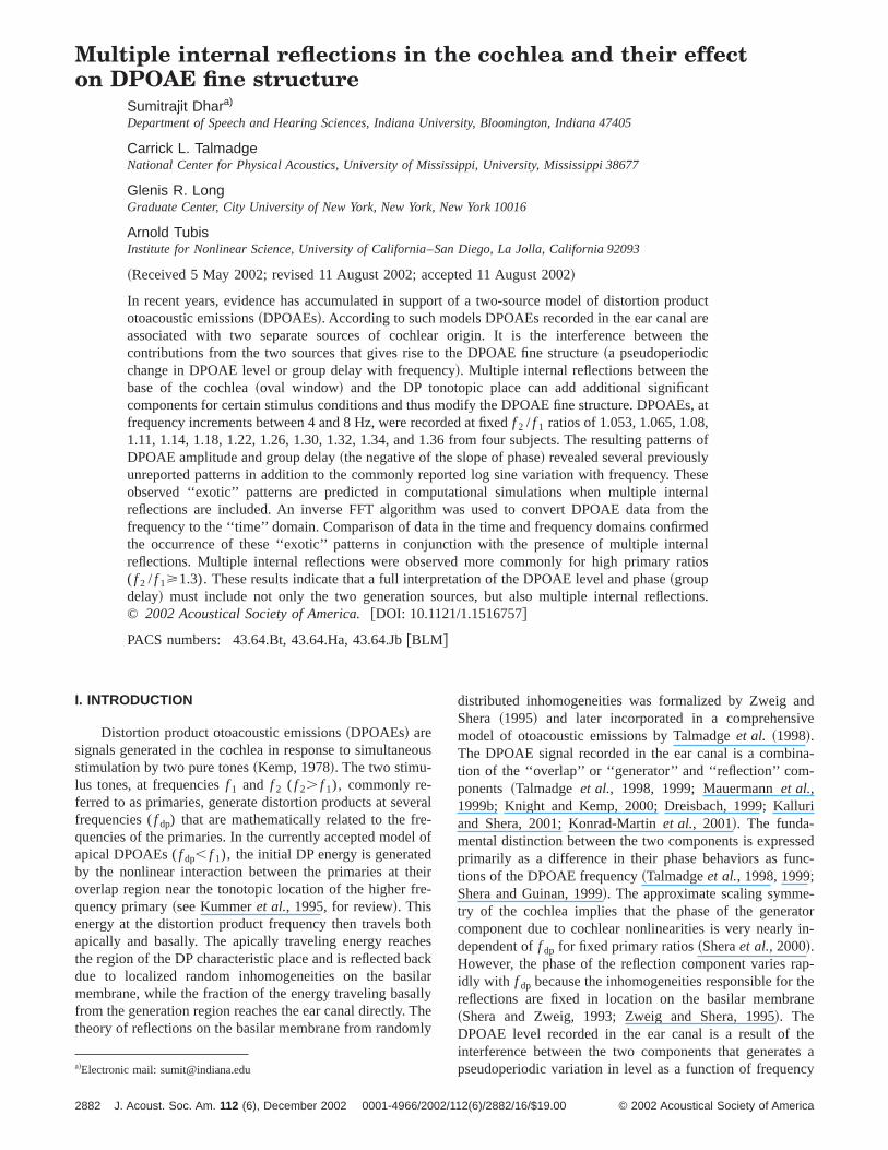
known as fine structure. Typical fine-structure data fromnormal-hearing ear is displayed in Fig. 1. Note the pseuperiodic variation~fine structure! observed for both level andgroup delay. Group delay is calculated as the 1/2p times thenegative of the slope of the phase. The steep slope ofphase curve below 2450 Hz reflects a dominant refleccomponent. On the other hand, the relatively slow phvariation above 2450 Hz is indicative that the generator coponent is dominant. Note that the relationship betweenlevel and group-delay fine structures is a direct consequeof the phase behavior at the fine structure minima. Thefine structures are negatively and positively correlated beand above 2450 Hz, respectively.
Computational models proposed by several researcgive theoretical support for the two-source model~Zweigand Shera, 1995; Talmadgeet al., 1998, 1999; Mauermannet al., 1999b! and convincing evidence for such models hbeen presented using several experimental paradigmsvarious research groups~e.g., Talmadgeet al., 1999; Mauer-mannet al., 1999a; Konrad-Martinet al., 2001; Kalluri andShera, 2001!. Specific experimental paradigms include supression of the ‘‘reflection’’ component~e.g., Heitmannet al., 1988; Talmadgeet al., 1999; Kalluri and Shera, 2001Konrad-Martinet al., 2001! or indirect isolation of the ‘‘gen-erator’’ component by computing a moving average ofoverall amplitude and phase~Brown et al., 1996!. The twocomponents have also been isolated using inverse-analysis~Stoveret al., 1996; Fahey and Allen, 1997; Kallurand Shera, 2001; Knight and Kemp, 2001!. Additionally, re-sults from novel experimental designs such as using puprimaries~Talmadgeet al., 1999! or placing the DP characteristic place in a region of hearing loss~Mauermannet al.,1999a! have also provided support for these models. Tmadgeet al. ~1999! exploited the temporal differences in thgeneration of the two components, when one of the primais pulsed on and off, to visualize them in the time domaThe generator component is present alone for a brief pe
FIG. 1. DP level, phase, and group-delay fine structure from a normhearing ear recorded with primary levels of 65 and 60 dB SPL and aquency ratio of 1.225. Group delay is calculated as the negative of the sof the phase divided by 2p. The DPOAE phase changes rapidly betweenfrequencies of 2300 and 2450 Hz, indicating dominance of the refleccomponent. The slow variation in phase with frequency above 2450indicates dominance of the generator component. The level and groupfine structures are negatively and positively correlated below and ab2450 Hz, respectively.
J. Acoust. Soc. Am., Vol. 112, No. 6, December 2002
a-
hene-eceow
rs
sby
-
e
T
ed
l-
s.d
after the onset of the pulsed primary, while the reflecticomponent is present alone for a brief period after its offsMauermannet al. ~1999a! used the pattern of DPOAE finstructure in individuals with notched hearing losses to shthat the presence of fine structure depended on a regionormal hearing at the DP frequencies.
Along with this convincing body of evidence in suppoof a two-source model of DPOAEs, preliminary evidence halso been presented to indicate that a simple two-soumodel might not encapusulate the full complexity of the pcess of DPOAE generation~Stover et al., 1996; Talmadgeet al., 1999; Konrad-Martinet al., 2001!. This evidencepoints towards the contribution of additional cochlear refletion components to the signal recorded in the ear canal.ver et al. ~1996! observed multiple peaks in ‘‘time domaindata derived from frequency-domain DPOAE data usinginverse FFT algorithm. In discussing the possible sourcethe multiple peaks, the authors considered the presence o~i!multiple sources in the cochlea,~ii ! ‘‘one ~or two! sourcesand multiple reflections between them,’’ and~iii ! a singlesource responsible for all the observed peaks. After carconsideration of all three possibilities, Stoveret al. ~1996!concluded that
... the most parsimonious explanation, at this time,may be that there are multiple sources for the acous-tic distortion that is measured in the ear canal... .
However, advances in the theory of DPOAE generation asupporting experimental evidence obtained since 1996 hled the same group to attribute the presence of multpeaks in IFFT data to multiple reflections in the cochl~Konrad-Martinet al., 2001!. The most direct evidence fomultiple internal reflections to date has perhaps come frdirect time domain measurements of Talmadgeet al. ~1999!in which additional ‘‘peaks’’ of energy were observed aftthe offset of the pulsed primary. While the reflection compnent forms the first ‘‘peak’’ after stimulus offset, multiplinternal reflections would be responsible for any additiopeaks. It should be noted that the above results were mecasual observations made during examination of the proties of the generator and reflection components and thecifics of the phenomenon of multiple internal reflectiohave not yet been reported in the literature.
Although experimental work regarding multiple internreflections has been limited, the theoretical foundation of tphenomenon has already been explored in considerabletail. The basis for multiple internal reflections is tied to thpresence of an impedance mismatch at the base of thechlea ~oval window!, resulting in a basal reflectance. Anbasal-moving wave from the generator region or thecharacteristic region will encounter this reflectance andportion of this wave will be reflected back towards the cchlear apex. This phenomenon of reflection of retrograwaves at the stapes has been formalized in detail by Sand Zweig~1991!. The presence of the two reflectances,apical reflectance at the DP tonotopic location and a bareflectance at the base of the cochlea, results in multreflections inside the cochlea. Some of the specific detail
l--
pe
nzlayve
2883Dhar et al.: Multiple reflections and DP fine structure
plcwaaroervdhea
neheti
ngohe
plp
ftu,
thillngsieti
re
r-
-bP
to-llyne.ithtolly
-
itialac-. Are-m-
-r-
to
P
thethepic
ter-he
l is
ted
ndec-and
atorichfor
dentry-h
in
is-
d inbe-deally
twgioP
multiple-internal-reflection models~e.g., Talmadgeet al.,1998, 1999! are discussed in a later section.
In this paper we examine the phenomenon of multiinternal reflections and their effects on DPOAE fine struture. We begin by discussing the relevant aspects of the tsource model. The emphasis here is in highlighting the ftors that influence the generation of multiple internreflections. It is shown that internal reflections have a pfound effect on level and group-delay fine structures. Sevterms are introduced to help describe and categorize theied fine structure shapes that are predicted by the moFinally, the programmatically determined predictions of tlevel and group-delay fine structure shapes are presentedshown to be supported by observations of different fistructure shapes in normal-hearing adult human ears. Tobservations were made from a data base of high-resoluDPOAE recordings from four subjects under a broad raof primary levels and frequency ratios. The implicationsthese findings and their impact on the currently establismodel of DPOAEs are discussed to conclude the paper.
II. MODEL SUMMARY
The analytic aspects critical to the presence of multiinternal reflections presented here are based on the comhensive model of DPOAEs proposed by Talmadgeet al.~1997, 1998, 1999!. This model falls in the general class otwo-source interference models and shares basic feawith other published analytic models~e.g., Zweig and Shera1995; Mauermannet al., 1999b!.
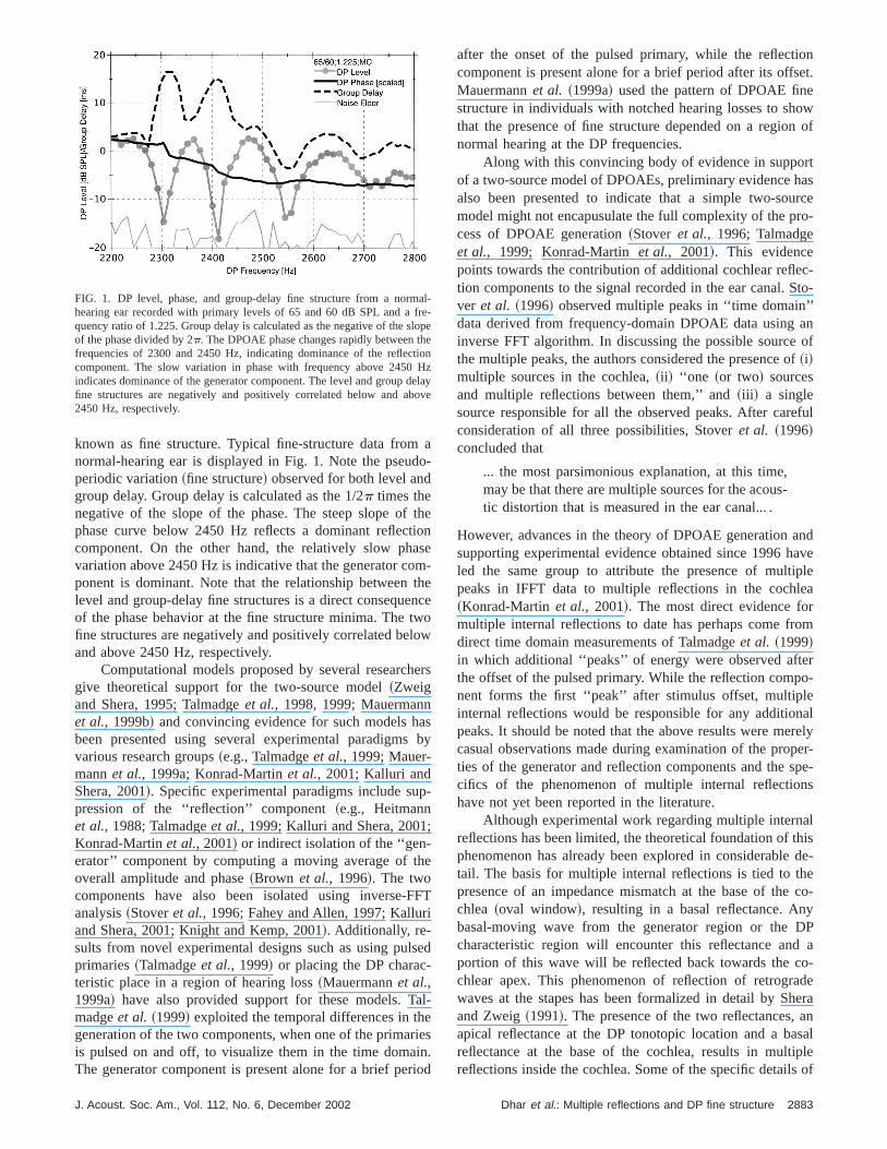
The process of DPOAE generation, incorporated inabove model, is comprised of three separate stages, astrated in Fig. 2. In the first stage the two primary traveliwaves propagate to their characteristic places on the bamembrane and reach peaks in their activity patterns. DPergy is generated in the region of overlap between the acity patterns of the two primaries~near thef 2 tonotopic place!due to cochlear nonlinearities. If the two primary stimuli aconsidered to be of angular frequenciesv1 and v2 (v2
.v1), DP energy at the frequenciesvdp5(n11)v12nv2
(n51,2,3...) are generated in the cochlea. Note that thislationship describes~apical! DPOAEs that are lower in frequency than the primaries~tonotopic site of DP apical tothose of the primaries,vdp,v1,v2). Although only theDPOAE at the frequency 2f 12 f 2 is considered in this paper, the theoretical implications of the findings shouldapplicable to all other apical DPOAEs. A fraction of the D
FIG. 2. Schematic representation of the mechanisms involved in thesource model. The two sources are associated with the ‘‘generator’’ reand the ‘‘reflection’’ region.Pl represents the initial basally traveling Dwave;Pr represents the initial apically traveling DP wave.Ra is the apicalreflectance due to reflection sources in the 2f 12 f 2 tonotopic region, whileRb is the basal reflectance at the stapes.
2884 J. Acoust. Soc. Am., Vol. 112, No. 6, December 2002
e-o-c-l-alar-el.
nd-se
onefd
ere-
res
eus-
larn-v-
e-
e
energy generated in this overlap region travels basallywards the middle ear, while another fraction travels apicatowards its characteristic place on the basilar membraBased on the typical picture of the basilar membrane wthe base to the left and the apex to the right, we will referthe energy traveling basally as associated with the initialeft moving component (Pl), and the energy traveling towards the 2f 12 f 2 region with the initially right movingcomponent (Pr).
In the second stage of the generation process, the inapically traveling DP wave reaches the region of its charteristic place and achieves a tall and broad activity patternfraction of this wave is reflected basally due to coherentflections from random inhomogeneities on the basilar mebrane.@The reader is directed to Shera and Zweig~1993! andZweig and Shera~1995! for technical details on the mechanism of coherent reflections.# This mechanism is characteized by the apical reflectance (Ra). At this stage there aretwo separate DP waves at the angular frequencyvdp travel-ing basally. Both of these waves are partially transmittedthe ear canal through the middle ear.
In the third and final stage, the basally traveling Dwaves encounter a basal reflectance (Rb) at the stapes due tothe impedance mismatch between the middle ear andcochlea. Both of these waves are reflected back towardscochlear apex. Thus two reflectances, at the DP tonotoplace (Ra) and the stapes (Rb), are set up and result in DPwaves that are reflected back and forth. These multiple innal reflections produce an ‘‘internal resonance’’ factor in texpression for the DP ear canal signal~Talmadgeet al.,1998!. In summary, the DPOAE recorded in the ear canaa result of all three of the following elements:
~i! initial basal- and apical-moving DP waves generaat the generator region on the basilar membrane,
~ii ! reflected DP wave from the DP tonotopic region, a~iii ! internal resonance components due to multiple refl
tions of cochlear DP waves between the stapesthe DP tonotopic region.
The main observable difference between the generand reflection components is in their phase behaviors, whare reflective of the putative mechanisms responsiblethem. When recorded using a fixed (f 2 / f 1) ratio paradigm,the phase of the generator component is almost indepenof frequency (f dp) due to the approximate scaling symmetin the cochlea~Sheraet al., 2000!. The phase of the reflection component~s!, on the other hand, varies rapidly witfrequency since the source of these reflections is fixedlocation on the basilar membrance~Talmadgeet al., 1999;Shera and Guinan, 1999!. This distinction is essentially thesame as that made between ‘‘wave’’ and ‘‘place-fixed’’ emsions~see Knight and Kemp, 2000, for review!. As was dis-cussed in the previous section, the fine structure observethe ear-canal signal is a consequence of the interactiontween the components of DPOAE. The complex amplituof the DPOAE recorded in the ear canal has been analyticderived by Talmadgeet al. ~1998!:
o-n
Dhar et al.: Multiple reflections and DP fine structure

ry
o
eo-nale
r r
co.sb-
an
hlaner
c-
p-
ellentdertoer,arm-the
of
netheea-AEken
ve.l’’
hebe
Pe~v2 ,r ,vdp!5F 1
12Ra~vdp!Rb~vdp!G@Pl~v2 ,r ,vdp!
1Ra~vdp!Pr~v2 ,r ,vdp!#, ~1!
wherev1 andv2 are the angular frequencies of the primastimuli andr 5v2 /v1 , andvdp is the angular DPOAE fre-quency.Ra is the apical reflectance due to random inhomgeneities around the DP tonotopic site,Rb is the basal reflec-tance at the junction between the cochlea and stapes~ovalwindow!, and Pl and Pr are measures respectively of thinitially basal-moving and apical-moving DP wave compnents. In the absence of basal reflectance, the compofrom the 2f 12 f 2 tonotopic region is determined by the totenergy generated in the generator region, the ratio betwthe apical and basal DP wave energy from the generatogion, and the reflectanceRa . Rb determines the proportionof basally traveling energy that is reflected towards thechlear apex at the junction of the cochlea with the stapesthe limit of Ra51 and negligible multiple internal reflection(RaRb!1), the DPOAE ear canal pressure signal wouldPl1Pr . Talmadgeet al. ~1998! parameterize the ratio between the initial apical and basal DP waves asRd(vdp)5Pr(vdp)/Pl(vdp).
If the dependence of various quantities onv1 andv2 aresuppressed, the full fine-structure equation@Eq. ~1!# can bere-written as follows:
Pe~vdp!5Pl~vdp!1Ra~vdp!Pr~vdp!
12Ra~vdp!Rb~vdp!. ~2!
Equation~2! can be simplified in appearance as:
Pe~vdp!5Pl~vdp!11Ra~vdp!@Pr~vdp!/Pl~vdp!#
12Ra~vdp!Rb~vdp!
[Pl~vdp!11Ra~vdp!Rd~vdp!
12Ra~vdp!Rb~vdp!
[Pl~vdp!11R1
12R2, ~3!
whereRd5Pr /Pl , R15RaRd , andR25RaRb .The fraction involving the termsR1 and R2 in Eq. ~3!
modulatesPl . R1 is the contribution of the reflection fromthe DP tonotopic region to the DPOAE in the absence ofreflections from the stapes. The 1/(12R2) term representsthe contributions of the resonance created inside the cocdue to multiple internal reflections between the stapesthe DP region on the basilar membrane. Since only the tRa(vdp) is expected to have rapid phase dependence onvdp,a new termFdp(vdp) is introduced to characterize fine struture:
Fdp~vdp!511R1
12R2. ~4!
The relevant characteristics of this function are
Ldp~vdp!5 loguFdp~v!u,
wdp~vdp!5arg@Fdp~v!#, ~5!
J. Acoust. Soc. Am., Vol. 112, No. 6, December 2002
-
ent
ene-
-In
e
y
ead
m
tdp~vdp!52wdp8 ~vdp!.
Ldp, wdp, andtdp represent the level, total phase, and groudelay fine structure functions, respectively. Note thatLdp isgiven by
Ldp~vdp!51
2logF11uR1u212uR1ucosw1
11uR2u222uR2ucosw2G , ~6!
wherew1,25arg@R1,2#. Thus, the terms on the left-hand sidof Eqs. ~4!–~6! represent the combined contribution of acomponents from the DP tonotopic region and their salicharacteristics, namely, level, phase, and group delay. Unmost stimulus conditions the only significant contributionthe ear canal signal comes from the first reflection. Howevadditional reflections can contribute significantly to the ecanal signal under specific stimulus conditions. The cobined levels and phases of all significant reflections fromDP tonotopic region determine the exact characteristicsthe final fine structure.
III. FINE-STRUCTURE SHAPE
A. Effect of resonance
The relationship between level and group-delay fistructures is determined by the relative dominance ofgenerator and reflection components of the DPOAE msured in the ear canal. The predicted pattern for DPOlevel fine structure, when just the two components are tainto account (R250), is limited to ‘‘normal log-sine’’ for allvalues ofR1 ~top-left panel in Fig. 3!. This pattern is classi-fied as ‘‘log-sine’’ as this would be the pattern if a sine waplus a constant (11b cosvt) were plotted on a log scaleThis fine-structure pattern is further classified as ‘‘norma
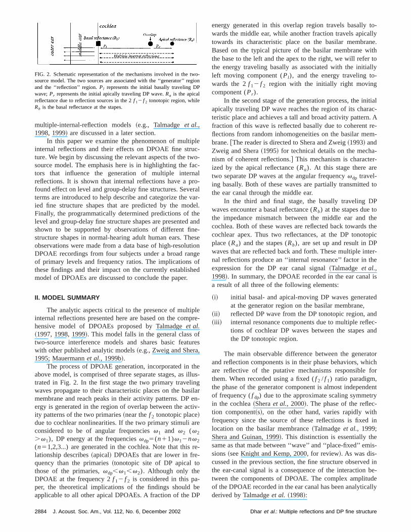
FIG. 3. Full model prediction of DPOAE fine-structure taxonomy. T‘‘doubled’’ shape is not expected in level fine structure; all shapes shouldobserved in group-delay fine structure.
2885Dhar et al.: Multiple reflections and DP fine structure
-te
of
iounrgfinge
devo
eon
c-be
exonnent-
Fi
aaer
orFice
ro-f atheceter
ni-thevetheere
jec-a
low.Eq.if-
ded
c-ly.velima
of
o-
c-uc-ttede-ngin-ima
i--
the
.a orby
nd
aircat
~maxima broader than minima! since this is the most commonly observed form. Group-delay fine structure is predicto be either normal log-sine~top-right panel of Fig. 3! or‘‘inverted’’ ~minima broader than maxima—top-left panelFig. 3! for uR1u,1 or uR1u.1, respectively. This limitedmodel, incorporating the generator and the initial reflectcomponents, also predicts that only group-delay fine strture can be inverted. While both level and group-delay fistructures are normal when the generator component is lain magnitude than the reflection component, group-delaystructure is inverted when the reflection component is larin magnitude than the generator component~Talmadgeet al.,1999!. This combination of normal level fine structure aninverted group-delay fine structure has been reported prously by Talmadgeet al. ~1999!, and the reader is directed tthat publication for further details.
When the full model with all terms including multiplinternal reflections is examined, a more complex familyfine-structure shapes is predicted. The predicted set of fistructure patterns is depicted in Fig. 3.
B. Determining fine structure shape
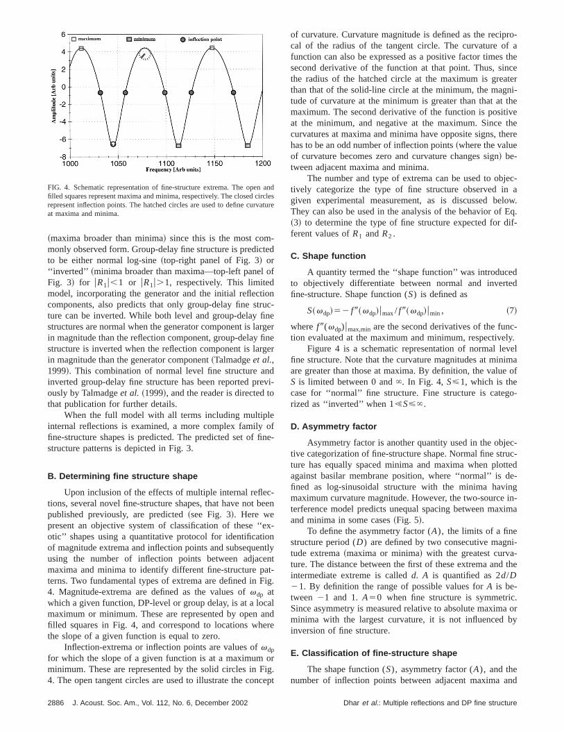
Upon inclusion of the effects of multiple internal refletions, several novel fine-structure shapes, that have notpublished previously, are predicted~see Fig. 3!. Here wepresent an objective system of classification of these ‘‘otic’’ shapes using a quantitative protocol for identificatiof magnitude extrema and inflection points and subsequeusing the number of inflection points between adjacmaxima and minima to identify different fine-structure paterns. Two fundamental types of extrema are defined in4. Magnitude-extrema are defined as the values ofvdp atwhich a given function, DP-level or group delay, is at a locmaximum or minimum. These are represented by openfilled squares in Fig. 4, and correspond to locations whthe slope of a given function is equal to zero.
Inflection-extrema or inflection points are values ofvdp
for which the slope of a given function is at a maximumminimum. These are represented by the solid circles in4. The open tangent circles are used to illustrate the con
FIG. 4. Schematic representation of fine-structure extrema. The openfilled squares represent maxima and minima, respectively. The closed crepresent inflection points. The hatched circles are used to define curvat maxima and minima.
2886 J. Acoust. Soc. Am., Vol. 112, No. 6, December 2002
d
nc-eerer
i-
fe-
en
-
tlyt
g.
lnde
g.pt
of curvature. Curvature magnitude is defined as the recipcal of the radius of the tangent circle. The curvature ofunction can also be expressed as a positive factor timessecond derivative of the function at that point. Thus, sinthe radius of the hatched circle at the maximum is greathan that of the solid-line circle at the minimum, the magtude of curvature at the minimum is greater than that atmaximum. The second derivative of the function is positiat the minimum, and negative at the maximum. Sincecurvatures at maxima and minima have opposite signs, thhas to be an odd number of inflection points~where the valueof curvature becomes zero and curvature changes sign! be-tween adjacent maxima and minima.
The number and type of extrema can be used to obtively categorize the type of fine structure observed ingiven experimental measurement, as is discussed beThey can also be used in the analysis of the behavior of~3! to determine the type of fine structure expected for dferent values ofR1 andR2 .
C. Shape function
A quantity termed the ‘‘shape function’’ was introduceto objectively differentiate between normal and invertfine-structure. Shape function (S) is defined as
S~vdp!52 f 9~vdp!umax/ f 9~vdp!umin , ~7!
where f 9(vdp)umax,min are the second derivatives of the funtion evaluated at the maximum and minimum, respective
Figure 4 is a schematic representation of normal lefine structure. Note that the curvature magnitudes at minare greater than those at maxima. By definition, the valueS is limited between 0 and̀ . In Fig. 4, S<1, which is thecase for ‘‘normal’’ fine structure. Fine structure is categrized as ‘‘inverted’’ when 1!S<`.
D. Asymmetry factor
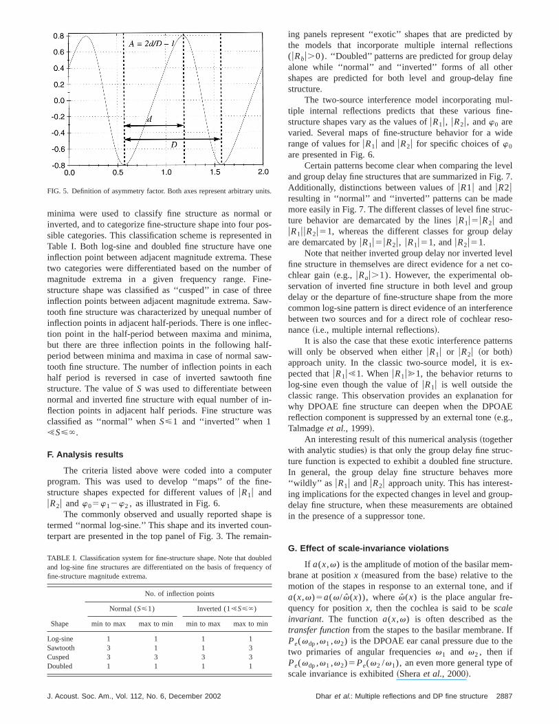
Asymmetry factor is another quantity used in the objetive categorization of fine-structure shape. Normal fine strture has equally spaced minima and maxima when ploagainst basilar membrane position, where ‘‘normal’’ is dfined as log-sinusoidal structure with the minima havimaximum curvature magnitude. However, the two-sourceterference model predicts unequal spacing between maxand minima in some cases~Fig. 5!.
To define the asymmetry factor (A), the limits of a finestructure period (D) are defined by two consecutive magntude extrema~maxima or minima! with the greatest curvature. The distance between the first of these extrema andintermediate extreme is calledd. A is quantified as 2d/D21. By definition the range of possible values forA is be-tween 21 and 1.A50 when fine structure is symmetricSince asymmetry is measured relative to absolute maximminima with the largest curvature, it is not influencedinversion of fine structure.
E. Classification of fine-structure shape
The shape function (S), asymmetry factor (A), and thenumber of inflection points between adjacent maxima a
ndlesure
Dhar et al.: Multiple reflections and DP fine structure
oodnernerear
ecalf-awcnnina
tee-
enai
bynsy
fine
ul-e-
ide
vel. 7.
euc-
lay
velco--uporenceso-
rns
x-
forAE
-re.oret-up-ined
-
d if-
e. Ifhe
f
its
ley
minima were used to classify fine structure as normalinverted, and to categorize fine-structure shape into four psible categories. This classification scheme is representeTable I. Both log-sine and doubled fine structure have oinflection point between adjacent magnitude extrema. Thtwo categories were differentiated based on the numbemagnitude extrema in a given frequency range. Fistructure shape was classified as ‘‘cusped’’ in case of thinflection points between adjacent magnitude extrema. Stooth fine structure was characterized by unequal numbeinflection points in adjacent half-periods. There is one infltion point in the half-period between maxima and minimbut there are three inflection points in the following haperiod between minima and maxima in case of normal stooth fine structure. The number of inflection points in eahalf period is reversed in case of inverted sawtooth fistructure. The value ofS was used to differentiate betweenormal and inverted fine structure with equal number offlection points in adjacent half periods. Fine structure wclassified as ‘‘normal’’ whenS<1 and ‘‘inverted’’ when 1!S<`.
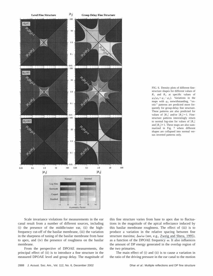
F. Analysis results
The criteria listed above were coded into a compuprogram. This was used to develop ‘‘maps’’ of the finstructure shapes expected for different values ofuR1u anduR2u andw05w12w2 , as illustrated in Fig. 6.
The commonly observed and usually reported shaptermed ‘‘normal log-sine.’’ This shape and its inverted couterpart are presented in the top panel of Fig. 3. The rem
FIG. 5. Definition of asymmetry factor. Both axes represent arbitrary un
TABLE I. Classification system for fine-structure shape. Note that douband log-sine fine structures are differentiated on the basis of frequencfine-structure magnitude extrema.
Shape
No. of inflection points
Normal (S<1) Inverted (1!S<`)
min to max max to min min to max max to min
Log-sine 1 1 1 1Sawtooth 3 1 1 3Cusped 3 3 3 3Doubled 1 1 1 1
J. Acoust. Soc. Am., Vol. 112, No. 6, December 2002
rs-ineseof-e
w-of-,
-he
-s
r
is-n-
ing panels represent ‘‘exotic’’ shapes that are predictedthe models that incorporate multiple internal reflectio(uRbu.0). ‘‘Doubled’’ patterns are predicted for group delaalone while ‘‘normal’’ and ‘‘inverted’’ forms of all othershapes are predicted for both level and group-delaystructure.
The two-source interference model incorporating mtiple internal reflections predicts that these various finstructure shapes vary as the values ofuR1u, uR2u, andw0 arevaried. Several maps of fine-structure behavior for a wrange of values foruR1u and uR2u for specific choices ofw0
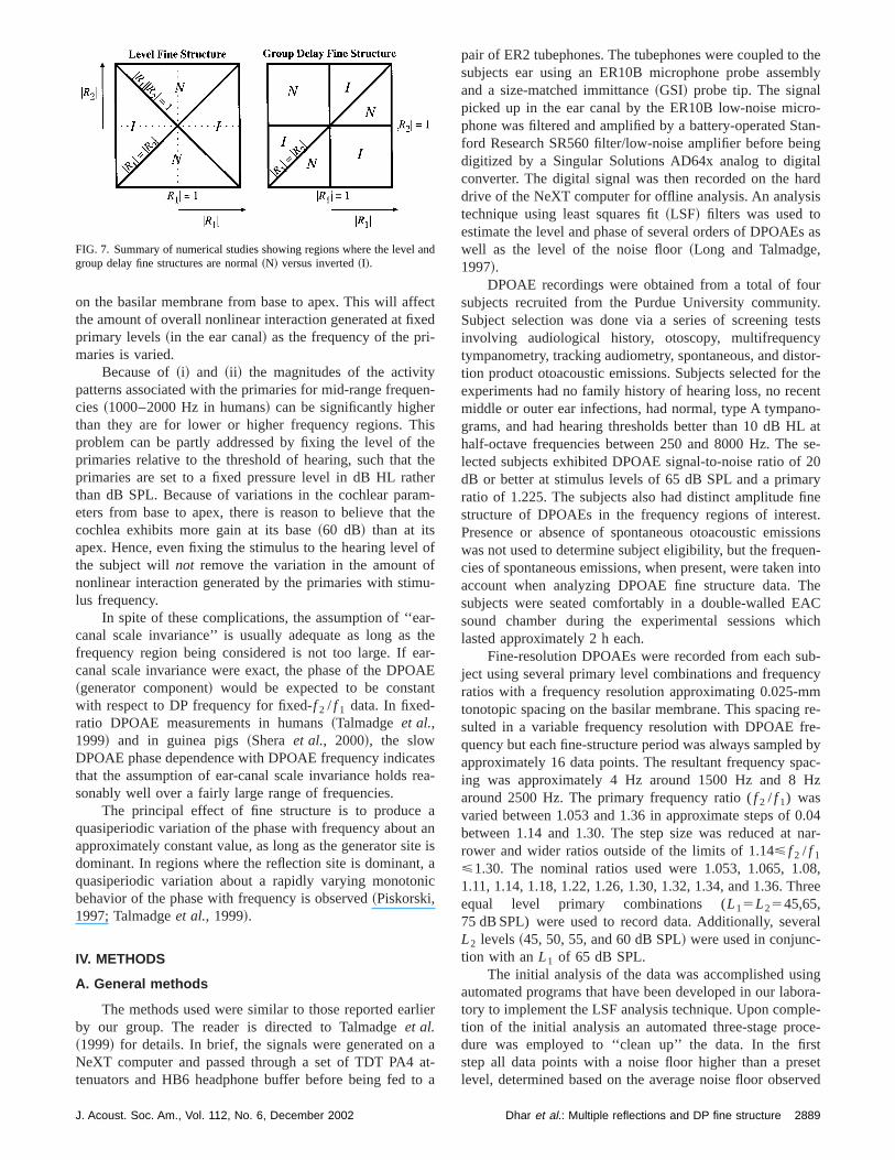
are presented in Fig. 6.Certain patterns become clear when comparing the le
and group delay fine structures that are summarized in FigAdditionally, distinctions between values ofuR1u and uR2uresulting in ‘‘normal’’ and ‘‘inverted’’ patterns can be madmore easily in Fig. 7. The different classes of level fine strture behavior are demarcated by the linesuR1u5uR2u anduR1uuR2u51, whereas the different classes for group deare demarcated byuR1u5uR2u, uR1u51, anduR2u51.
Note that neither inverted group delay nor inverted lefine structure in themselves are direct evidence for a netchlear gain~e.g., uRau.1). However, the experimental observation of inverted fine structure in both level and grodelay or the departure of fine-structure shape from the mcommon log-sine pattern is direct evidence of an interferebetween two sources and for a direct role of cochlear renance~i.e., multiple internal reflections!.
It is also the case that these exotic interference pattewill only be observed when eitheruR1u or uR2u ~or both!approach unity. In the classic two-source model, it is epected thatuR1u!1. WhenuR1u@1, the behavior returns tolog-sine even though the value ofuR1u is well outside theclassic range. This observation provides an explanationwhy DPOAE fine structure can deepen when the DPOreflection component is suppressed by an external tone~e.g.,Talmadgeet al., 1999!.
An interesting result of this numerical analysis~togetherwith analytic studies! is that only the group delay fine structure function is expected to exhibit a doubled fine structuIn general, the group delay fine structure behaves m‘‘wildly’’ as uR1u and uR2u approach unity. This has interesing implications for the expected changes in level and grodelay fine structure, when these measurements are obtain the presence of a suppressor tone.
G. Effect of scale-invariance violations
If a(x,v) is the amplitude of motion of the basilar membrane at positionx ~measured from the base! relative to themotion of the stapes in response to an external tone, ana(x,v)5a(v/v̂(x)), wherev̂(x) is the place angular frequency for positionx, then the cochlea is said to bescaleinvariant. The function a(x,v) is often described as thtransfer functionfrom the stapes to the basilar membranePe(vdp,v1 ,v2) is the DPOAE ear canal pressure due to ttwo primaries of angular frequenciesv1 and v2 , then ifPe(vdp,v1 ,v2)5Pe(v2 /v1), an even more general type oscale invariance is exhibited~Sheraet al., 2000!.
.
dof
2887Dhar et al.: Multiple reflections and DP fine structure
f
-.or
n
-
r-
FIG. 6. Density plots of different fine-structure shapes for different values oR1 and R2 at specific values ofw0(w05w12w2). Variations in themaps with w0 notwithstanding, ‘‘ex-otic’’ patterns are predicted more frequently for group-delay fine structureThese patterns are also predicted fvalues of uR1u and/or uR2u'1. Fine-structure patterns interestingly returto normal log-sine for values ofuR1uanduR2u@1. These maps are also summarized in Fig. 7 where differentshapes are collapsed into normal vesus inverted patterns only.
ein
aila
the
ua-by
ne
of
ion
Scale invariance violations for measurements in thecanal result from a number of different sources, includ~i! the presence of the middle/outer ear,~ii ! the high-frequency cut-off of the basilar membrane,~iii ! the variationin the sharpness of tuning of the basilar membrane from bto apex, and~iv! the presence of roughness on the basmembrane.
From the perspective of DPOAE measurements,principal effect of~ii ! is to introduce a fine structure in thmeasured DPOAE level and group delay. The magnitude
2888 J. Acoust. Soc. Am., Vol. 112, No. 6, December 2002
arg
ser
e
of
this fine structure varies from base to apex due to flucttions in the magnitude of the apical reflectance inducedthis basilar membrane roughness. The effect of~iii ! is toproduce a variation in the relative spacing between fistructure maxima;Dv/v ~see, e.g., Zweig and Shera, 1995!,as a function of the DPOAE frequencyv. It also influencesthe amount of DP energy generated in the overlap regionthe two primaries.
The main effect of~i! and ~ii ! is to cause a variation inthe ratio of the driving pressure in the ear canal to the mot
Dhar et al.: Multiple reflections and DP fine structure
ecxe-
erhiththheamt t
l ofu
artaA
nt
tere
at aitet,ic
rli
ato
thebly
ro-tan-ingalardis
s as
urity.estsytor-the
ento-
L atse-20rynest.sionsen-
intohe
ACich
ub-ncymre-
e-d byac-
Hz
.04nar-
08,ree
ral
ingora-le-ce-stsetrved
an
on the basilar membrane from base to apex. This will affthe amount of overall nonlinear interaction generated at fiprimary levels~in the ear canal! as the frequency of the primaries is varied.
Because of~i! and ~ii ! the magnitudes of the activitypatterns associated with the primaries for mid-range frequcies ~1000–2000 Hz in humans! can be significantly highethan they are for lower or higher frequency regions. Tproblem can be partly addressed by fixing the level ofprimaries relative to the threshold of hearing, such thatprimaries are set to a fixed pressure level in dB HL ratthan dB SPL. Because of variations in the cochlear pareters from base to apex, there is reason to believe thacochlea exhibits more gain at its base~60 dB! than at itsapex. Hence, even fixing the stimulus to the hearing levethe subject willnot remove the variation in the amount ononlinear interaction generated by the primaries with stimlus frequency.
In spite of these complications, the assumption of ‘‘ecanal scale invariance’’ is usually adequate as long asfrequency region being considered is not too large. If ecanal scale invariance were exact, the phase of the DPO~generator component! would be expected to be constawith respect to DP frequency for fixed-f 2 / f 1 data. In fixed-ratio DPOAE measurements in humans~Talmadgeet al.,1999! and in guinea pigs~Shera et al., 2000!, the slowDPOAE phase dependence with DPOAE frequency indicathat the assumption of ear-canal scale invariance holdssonably well over a fairly large range of frequencies.
The principal effect of fine structure is to producequasiperiodic variation of the phase with frequency abouapproximately constant value, as long as the generator sdominant. In regions where the reflection site is dominanquasiperiodic variation about a rapidly varying monotonbehavior of the phase with frequency is observed~Piskorski,1997; Talmadgeet al., 1999!.
IV. METHODS
A. General methods
The methods used were similar to those reported eaby our group. The reader is directed to Talmadgeet al.~1999! for details. In brief, the signals were generated onNeXT computer and passed through a set of TDT PA4tenuators and HB6 headphone buffer before being fed
FIG. 7. Summary of numerical studies showing regions where the levelgroup delay fine structures are normal~N! versus inverted~I!.
J. Acoust. Soc. Am., Vol. 112, No. 6, December 2002
td
n-
seer-
he
f
-
-her-E
sa-
nis
a
er
at-a
pair of ER2 tubephones. The tubephones were coupled tosubjects ear using an ER10B microphone probe assemand a size-matched immittance~GSI! probe tip. The signalpicked up in the ear canal by the ER10B low-noise micphone was filtered and amplified by a battery-operated Sford Research SR560 filter/low-noise amplifier before bedigitized by a Singular Solutions AD64x analog to digitconverter. The digital signal was then recorded on the hdrive of the NeXT computer for offline analysis. An analystechnique using least squares fit~LSF! filters was used toestimate the level and phase of several orders of DPOAEwell as the level of the noise floor~Long and Talmadge,1997!.
DPOAE recordings were obtained from a total of fosubjects recruited from the Purdue University communSubject selection was done via a series of screening tinvolving audiological history, otoscopy, multifrequenctympanometry, tracking audiometry, spontaneous, and distion product otoacoustic emissions. Subjects selected forexperiments had no family history of hearing loss, no recmiddle or outer ear infections, had normal, type A tympangrams, and had hearing thresholds better than 10 dB Hhalf-octave frequencies between 250 and 8000 Hz. Thelected subjects exhibited DPOAE signal-to-noise ratio ofdB or better at stimulus levels of 65 dB SPL and a primaratio of 1.225. The subjects also had distinct amplitude fistructure of DPOAEs in the frequency regions of interePresence or absence of spontaneous otoacoustic emiswas not used to determine subject eligibility, but the frequcies of spontaneous emissions, when present, were takenaccount when analyzing DPOAE fine structure data. Tsubjects were seated comfortably in a double-walled Esound chamber during the experimental sessions whlasted approximately 2 h each.
Fine-resolution DPOAEs were recorded from each sject using several primary level combinations and frequeratios with a frequency resolution approximating 0.025-mtonotopic spacing on the basilar membrane. This spacingsulted in a variable frequency resolution with DPOAE frquency but each fine-structure period was always sampleapproximately 16 data points. The resultant frequency sping was approximately 4 Hz around 1500 Hz and 8around 2500 Hz. The primary frequency ratio (f 2 / f 1) wasvaried between 1.053 and 1.36 in approximate steps of 0between 1.14 and 1.30. The step size was reduced atrower and wider ratios outside of the limits of 1.14< f 2 / f 1
<1.30. The nominal ratios used were 1.053, 1.065, 1.1.11, 1.14, 1.18, 1.22, 1.26, 1.30, 1.32, 1.34, and 1.36. Thequal level primary combinations (L15L2545,65,75 dB SPL) were used to record data. Additionally, seveL2 levels~45, 50, 55, and 60 dB SPL! were used in conjunc-tion with anL1 of 65 dB SPL.
The initial analysis of the data was accomplished usautomated programs that have been developed in our labtory to implement the LSF analysis technique. Upon comption of the initial analysis an automated three-stage produre was employed to ‘‘clean up’’ the data. In the firstep all data points with a noise floor higher than a prelevel, determined based on the average noise floor obse
d
2889Dhar et al.: Multiple reflections and DP fine structure
eooh
trewtha
ale
acather
or
thita
FTthvia
hedzeref tine
enndre
pulse
othlt
eddi
pimo
atalt.
on,o asthe
thethetheine
chudeointthede-eroero.ero
repe,atasedcu-ereero.arsbe
un-datami-al-datand
theand
ofs inilevari-l., aasels,or
ned
in our laboratory, were rejected. At the next stage, a thrpoint, overlapping, median filter based on the noise flestimate was applied to the data set. Data points witsignal-to-noise ratio less than a preset value, based ondata for the given subject and stimulus condition, werejected. The data set generated after the first two stepssaved in a subdirectory for the last stage of analysis. Instage the phase data were unwrapped using an automalgorithm, the results of which were cross checked manuin every case and additional unwrappings were performwhere necessary.
Once the phase was completely unwrapped and visuinspected to be smoothly varying, the data were used toculate group delay. Group delay was calculated by fittingunwrapped DP phase with a straight line in five-point intvals. The group delay is given by2mw/2p, wheremw is theslope of the straight line.
B. Inverse FFT
A customized algorithm was developed in the laboratto implement an inverse fast Fourier transform~IFFT! pro-cedure on DPOAE frequency-domain data. The goal ofIFFT procedure was to resolve DPOAE components wdifferent latencies. Simply stated, a FFT converts signfrom the time domain to the frequency domain; an IFworks in the reverse direction, converting signals fromfrequency to the time domain. IFFT protocols have preously been used to convert frequency-domain DPOAE dto the time domain~e.g., Stoveret al., 1996; Knight andKemp, 2001; Kalluri and Shera, 2001; Konrad-Martinet al.,2001!. In the present application of the IFFT protocol, treal and imaginary parts of the complex DPOAE amplituwere used as input for the IFFT algorithm (FFT filter si51024) following interpolation of data points to ensuequal spacing. The result was a reverse transformation odata into the time domain. A rectangular and a Welch wdow were used in the time and frequency domains, resptively. These windows were chosen after careful experimtation with several other window types in both time afrequency domains. The chosen window combinationsulted in the lowest maximum error~in dB! when frequency-domain fine structures reconstructed from the IFFT outwere compared with original data. This combination aproduced the least amount of peak-broadening withoutevating the noise floor in the absence of a signal.
The IFFT protocol was also used to reduce the noisethe data by time-domain filtering. Once the DPOAE compnents were identified and the time window containingmaximum energy for all components was established, a fito remove noise outside of the time window was appliThis removed noise-related fluctuations in the amplituspectra and allowed visualization of minute alterationsfine-structure shape. The efficacy of the objective shadetermination analysis described in the next sectionproved as a result of time-domain filtering. The effectsfiltering were most noticeable at high ratios (f 2 / f 1.1.30)with poor separation between the signal and noise.
2890 J. Acoust. Soc. Am., Vol. 112, No. 6, December 2002
e-rahe-asistedlyd
llyl-e-
y
ehls
e-ta
e
he-c--
-
tol-
in-eer.ene--f
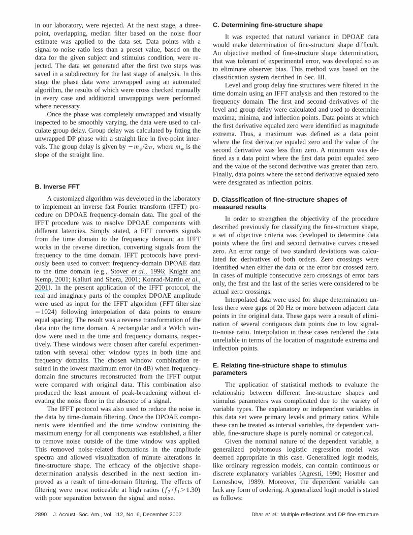
C. Determining fine-structure shape
It was expected that natural variance in DPOAE dwould make determination of fine-structure shape difficuAn objective method of fine-structure shape determinatithat was tolerant of experimental error, was developed sto eliminate observer bias. This method was based onclassification system decribed in Sec. III.
Level and group delay fine structures were filtered intime domain using an IFFT analysis and then restored tofrequency domain. The first and second derivatives oflevel and group delay were calculated and used to determmaxima, minima, and inflection points. Data points at whithe first derivative equaled zero were identified as magnitextrema. Thus, a maximum was defined as a data pwhere the first derivative equaled zero and the value ofsecond derivative was less than zero. A minimum wasfined as a data point where the first data point equaled zand the value of the second derivative was greater than zFinally, data points where the second derivative equaled zwere designated as inflection points.
D. Classification of fine-structure shapes ofmeasured results
In order to strengthen the objectivity of the procedudescribed previously for classifying the fine-structure shaa set of objective criteria was developed to determine dpoints where the first and second derivative curves croszero. An error range of two standard deviations was callated for derivatives of both orders. Zero crossings widentified when either the data or the error bar crossed zIn cases of multiple consecutive zero crossings of error bonly, the first and the last of the series were considered toactual zero crossings.
Interpolated data were used for shape determinationless there were gaps of 20 Hz or more between adjacentpoints in the original data. These gaps were a result of elination of several contiguous data points due to low signto-noise ratio. Interpolation in these cases rendered theunreliable in terms of the location of magnitude extrema ainflection points.
E. Relating fine-structure shape to stimulusparameters
The application of statistical methods to evaluaterelationship between different fine-structure shapesstimulus parameters was complicated due to the varietyvariable types. The explanatory or independent variablethis data set were primary levels and primary ratios. Whthese can be treated as interval variables, the dependentable, fine-structure shape is purely nominal or categorica
Given the nominal nature of the dependent variablegeneralized polytomous logistic regression model wdeemed appropriate in this case. Generalized logit modlike ordinary regression models, can contain continuousdiscrete explanatory variables~Agresti, 1990; Hosmer andLemeshow, 1989!. Moreover, the dependent variable calack any form of ordering. A generalized logit model is statas follows:
Dhar et al.: Multiple reflections and DP fine structure

ora,ndre-ns.dereate
FIG. 8. Examples of different fine-structure shapes fDPOAE level. DPOAE level is presented with maximminima, and inflection points marked by diamonds ainverted triangles, respectively. The dashed line repsents group delay under the same stimulus conditioSubject and stimulus condition information is includein each panel. Symbols are not used in panels whinterpolated data are presented. Abscissa and ordinranges are different for each panel.
(
e
se
,retar
ereuee
tw
tioc-
ouainb6
estin-
ionalin-he
ndine,andre,ob-
d 9ndi-vel-ep-ed
ureect.ataPLretthismal
p j~xi !5exp~b j8xi !
(h51J exp~bh8xi !
, ~8!
where p j (xi) denotes the probability of responsej51,...,J) at the i th setting of values ofk explanatory vari-ables,xi5(1,xi1 ,...,xik). The eight predicted fine-structurshapes~four patterns each for normal and inverted! are asso-ciated with values ofj 51,...,8.k equals 2 in this data set athere are two explanatory variables—primary ratio and levThe first explanatory variable~primary ratio! has 12 settingswhile primary level has 7 settings. The CATMOD proceduof the statistical software package, SAS, was used to obmaximum likelihood estimates for the occurrence of diffeent fine-structure shapes for different stimulus parametPrimary level, ratio, and an interaction term involving levand ratio were included in the CATMOD model. The outpof this procedure contained an ANOVA table which was usto establish statistical significance. Note that the dependvariable categories were designed to be divided intogroups with j <4 and j >5 signifying normal and invertedfine-structure shapes, respectively. This allowed estimaof maximum likelihood of normal versus inverted fine struture for different stimulus parameters.
The above model was used to analyze level and grdelay fine-structure shapes independently. In a parallel ansis, the dependent variable was altered to reflect a combtion of level and group delay fine-structure shapes. Comnation of level and group delay shapes resulted incategories.
J. Acoust. Soc. Am., Vol. 112, No. 6, December 2002
l.
in-s.ltdnto
n
ply-a-i-4
Fine-structure periods in the frequency range of interwere assigned nominal center-frequency values in 50-Hzcrements. Thus, frequency was treated as an observatvariable. In order to avoid the contaminating effects of wdowing, the three central fine-structure periods within ttest-frequency range for each subject were considered.
V. RESULTS
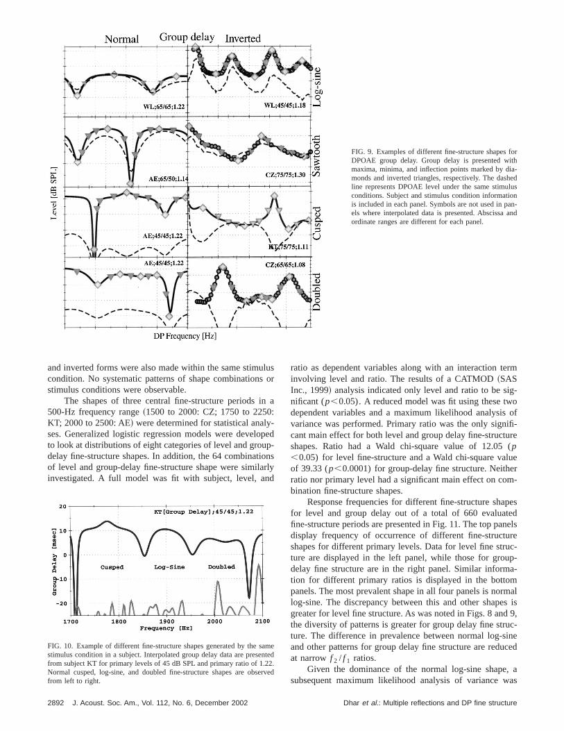
Different fine-structure shapes observed in level agroup-delay data are presented in Figs. 8 and 9. Log-ssawtooth, cusped, and doubled shapes in both normalinverted forms were observed for group-delay fine structuand all shapes except doubled and inverted-cusped wereserved in level fine structure. Each panel in Figs. 8 anrepresents data from different subjects and stimulus cotions. The line with circular symbols represents either le~Fig. 8! or group delay~Fig. 9!. The diamond symbols represent maxima and minima while the inverted triangles rresent inflection points. Lines without symbols are uswhen interpolated data are presented.
There were several instances of different fine-structshapes for the same stimulus condition for a given subjOne such example is displayed in Fig. 10. Group delay dare presented for subject KT for primary levels of 45 dB Sand primary ratio of 1.22. Three different fine-structushapes~cusped, log-sine, and doubled—from left to righ!are observed. All three shapes are of the normal form incase. However, observations of switching between nor
2891Dhar et al.: Multiple reflections and DP fine structure
oritha-ed
lusn
an-and
FIG. 9. Examples of different fine-structure shapes fDPOAE group delay. Group delay is presented wmaxima, minima, and inflection points marked by dimonds and inverted triangles, respectively. The dashline represents DPOAE level under the same stimuconditions. Subject and stimulus condition informatiois included in each panel. Symbols are not used in pels where interpolated data is presented. Abscissaordinate ranges are different for each panel.
lus
n:-pp
ionrld
rm
g-oof
ifi-ure
(lueerm-
pesednelsrec-p-a-mmals is9,
uc-ineced
, aas
ant2.er
and inverted forms were also made within the same stimucondition. No systematic patterns of shape combinationstimulus conditions were observable.
The shapes of three central fine-structure periods i500-Hz frequency range~1500 to 2000: CZ; 1750 to 2250KT; 2000 to 2500: AE! were determined for statistical analyses. Generalized logistic regression models were develoto look at distributions of eight categories of level and groudelay fine-structure shapes. In addition, the 64 combinatof level and group-delay fine-structure shape were similainvestigated. A full model was fit with subject, level, an
FIG. 10. Example of different fine-structure shapes generated by the sstimulus condition in a subject. Interpolated group delay data are presefrom subject KT for primary levels of 45 dB SPL and primary ratio of 1.2Normal cusped, log-sine, and doubled fine-structure shapes are obsfrom left to right.
2892 J. Acoust. Soc. Am., Vol. 112, No. 6, December 2002
sor
a
ed-s
y
ratio as dependent variables along with an interaction teinvolving level and ratio. The results of a CATMOD~SASInc., 1999! analysis indicated only level and ratio to be sinificant (p,0.05). A reduced model was fit using these twdependent variables and a maximum likelihood analysisvariance was performed. Primary ratio was the only signcant main effect for both level and group delay fine-structshapes. Ratio had a Wald chi-square value of 12.05p,0.05) for level fine-structure and a Wald chi-square vaof 39.33 (p,0.0001) for group-delay fine structure. Neithratio nor primary level had a significant main effect on cobination fine-structure shapes.
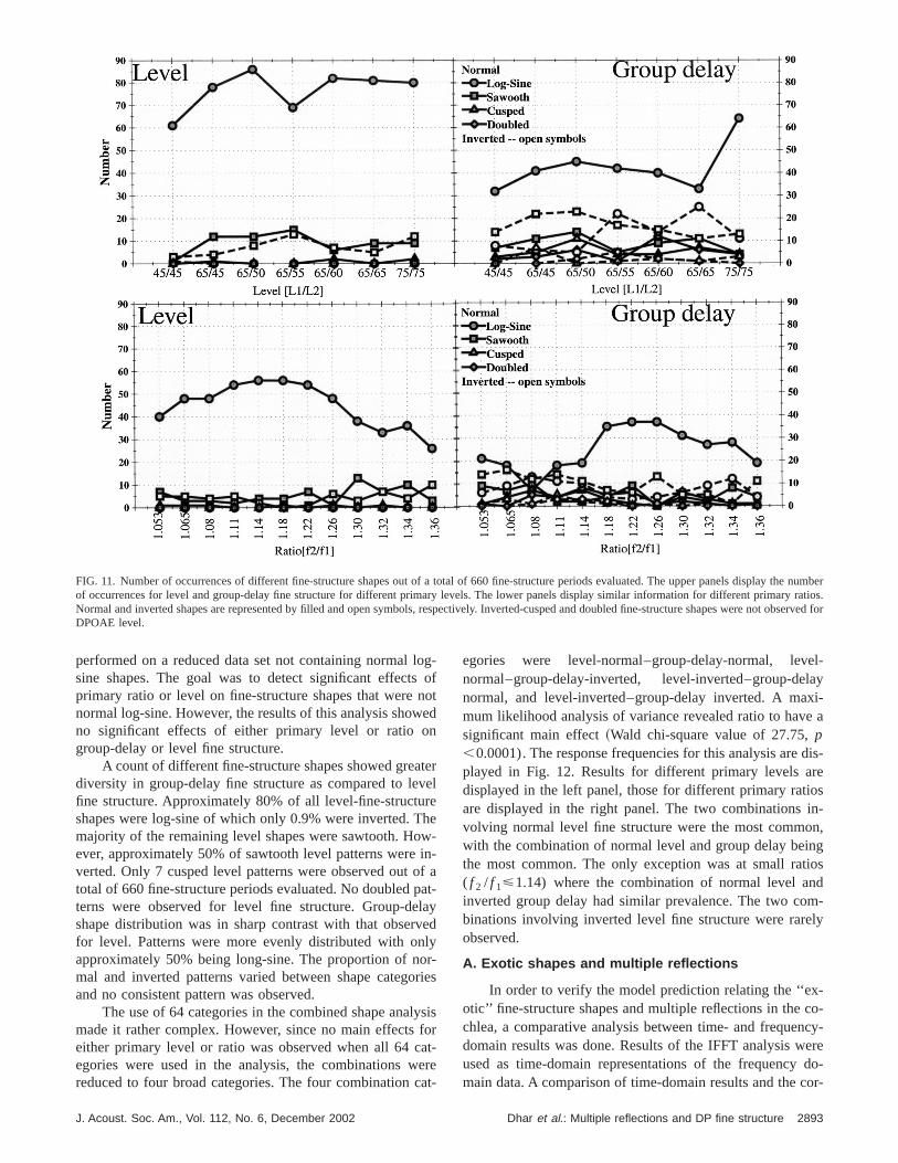
Response frequencies for different fine-structure shafor level and group delay out of a total of 660 evaluatfine-structure periods are presented in Fig. 11. The top padisplay frequency of occurrence of different fine-structushapes for different primary levels. Data for level fine struture are displayed in the left panel, while those for groudelay fine structure are in the right panel. Similar informtion for different primary ratios is displayed in the bottopanels. The most prevalent shape in all four panels is norlog-sine. The discrepancy between this and other shapegreater for level fine structure. As was noted in Figs. 8 andthe diversity of patterns is greater for group delay fine strture. The difference in prevalence between normal log-sand other patterns for group delay fine structure are reduat narrowf 2 / f 1 ratios.
Given the dominance of the normal log-sine shapesubsequent maximum likelihood analysis of variance w
meed
ved
Dhar et al.: Multiple reflections and DP fine structure
the n
obse
FIG. 11. Number of occurrences of different fine-structure shapes out of a total of 660 fine-structure periods evaluated. The upper panels displayumberof occurrences for level and group-delay fine structure for different primary levels. The lower panels display similar information for different primary ratios.Normal and inverted shapes are represented by filled and open symbols, respectively. Inverted-cusped and doubled fine-structure shapes were notrved forDPOAE level.
lo
noen
teverehwin
ofalavely
oror
lysfoate
ca
el-layxi-e a
dis-reosin-n,
ngiosdm-ly
-o-
ncy-eredo-or-
performed on a reduced data set not containing normalsine shapes. The goal was to detect significant effectsprimary ratio or level on fine-structure shapes that werenormal log-sine. However, the results of this analysis showno significant effects of either primary level or ratio ogroup-delay or level fine structure.
A count of different fine-structure shapes showed greadiversity in group-delay fine structure as compared to lefine structure. Approximately 80% of all level-fine-structushapes were log-sine of which only 0.9% were inverted. Tmajority of the remaining level shapes were sawtooth. Hoever, approximately 50% of sawtooth level patterns wereverted. Only 7 cusped level patterns were observed outtotal of 660 fine-structure periods evaluated. No doubled pterns were observed for level fine structure. Group-deshape distribution was in sharp contrast with that obserfor level. Patterns were more evenly distributed with onapproximately 50% being long-sine. The proportion of nmal and inverted patterns varied between shape categand no consistent pattern was observed.
The use of 64 categories in the combined shape anamade it rather complex. However, since no main effectseither primary level or ratio was observed when all 64 cegories were used in the analysis, the combinations wreduced to four broad categories. The four combination
J. Acoust. Soc. Am., Vol. 112, No. 6, December 2002
g-oftd
rl
e--at-yd
-ies
isr-ret-
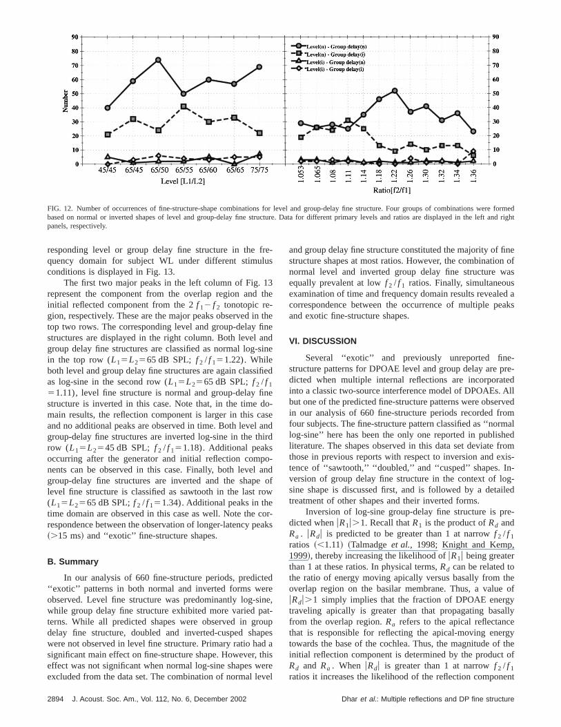
egories were level-normal–group-delay-normal, levnormal–group-delay-inverted, level-inverted–group-denormal, and level-inverted–group-delay inverted. A mamum likelihood analysis of variance revealed ratio to havsignificant main effect~Wald chi-square value of 27.75,p,0.0001). The response frequencies for this analysis areplayed in Fig. 12. Results for different primary levels adisplayed in the left panel, those for different primary ratiare displayed in the right panel. The two combinationsvolving normal level fine structure were the most commowith the combination of normal level and group delay beithe most common. The only exception was at small rat( f 2 / f 1<1.14) where the combination of normal level aninverted group delay had similar prevalence. The two cobinations involving inverted level fine structure were rareobserved.
A. Exotic shapes and multiple reflections
In order to verify the model prediction relating the ‘‘exotic’’ fine-structure shapes and multiple reflections in the cchlea, a comparative analysis between time- and frequedomain results was done. Results of the IFFT analysis wused as time-domain representations of the frequencymain data. A comparison of time-domain results and the c
2893Dhar et al.: Multiple reflections and DP fine structure
re formeand ri
FIG. 12. Number of occurrences of fine-structure-shape combinations for level and group-delay fine structure. Four groups of combinations wedbased on normal or inverted shapes of level and group-delay fine structure. Data for different primary levels and ratios are displayed in the leftghtpanels, respectively.
reus
3th
tnn
sin
ifi
ndoasanir
oaneo
coea
tereineatoupdtheve
nen ofas
d aaks
-re-edAllrvedom
aledromxis--g-iled
e-
heof
ylly
ergytheof
ent
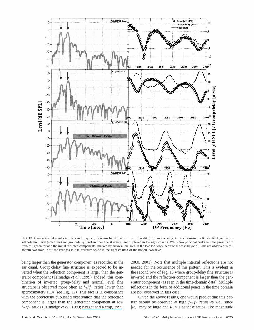
responding level or group delay fine structure in the fquency domain for subject WL under different stimulconditions is displayed in Fig. 13.
The first two major peaks in the left column of Fig. 1represent the component from the overlap region andinitial reflected component from the 2f 12 f 2 tonotopic re-gion, respectively. These are the major peaks observed intop two rows. The corresponding level and group-delay fistructures are displayed in the right column. Both level agroup delay fine structures are classified as normal log-in the top row (L15L2565 dB SPL; f 2 / f 151.22). Whileboth level and group delay fine structures are again classas log-sine in the second row (L15L2565 dB SPL; f 2 / f 1
51.11), level fine structure is normal and group-delay fistructure is inverted in this case. Note that, in the timemain results, the reflection component is larger in this cand no additional peaks are observed in time. Both levelgroup-delay fine structures are inverted log-sine in the throw (L15L2545 dB SPL; f 2 / f 151.18). Additional peaksoccurring after the generator and initial reflection compnents can be observed in this case. Finally, both levelgroup-delay fine structures are inverted and the shaplevel fine structure is classified as sawtooth in the last r(L15L2565 dB SPL;f 2 / f 151.34). Additional peaks in thetime domain are observed in this case as well. Note therespondence between the observation of longer-latency p~.15 ms! and ‘‘exotic’’ fine-structure shapes.
B. Summary
In our analysis of 660 fine-structure periods, predic‘‘exotic’’ patterns in both normal and inverted forms weobserved. Level fine structure was predominantly log-swhile group delay fine structure exhibited more varied pterns. While all predicted shapes were observed in grdelay fine structure, doubled and inverted-cusped shawere not observed in level fine structure. Primary ratio hasignificant main effect on fine-structure shape. However,effect was not significant when normal log-sine shapes wexcluded from the data set. The combination of normal le
2894 J. Acoust. Soc. Am., Vol. 112, No. 6, December 2002
-
e
heede
ed
e-edd
-dofw
r-ks
d
,-pesaisrel
and group delay fine structure constituted the majority of fistructure shapes at most ratios. However, the combinationormal level and inverted group delay fine structure wequally prevalent at lowf 2 / f 1 ratios. Finally, simultaneousexamination of time and frequency domain results revealecorrespondence between the occurrence of multiple peand exotic fine-structure shapes.
VI. DISCUSSION
Several ‘‘exotic’’ and previously unreported finestructure patterns for DPOAE level and group delay are pdicted when multiple internal reflections are incorporatinto a classic two-source interference model of DPOAEs.but one of the predicted fine-structure patterns were obsein our analysis of 660 fine-structure periods recorded frfour subjects. The fine-structure pattern classified as ‘‘normlog-sine’’ here has been the only one reported in publishliterature. The shapes observed in this data set deviate fthose in previous reports with respect to inversion and etence of ‘‘sawtooth,’’ ‘‘doubled,’’ and ‘‘cusped’’ shapes. Inversion of group delay fine structure in the context of losine shape is discussed first, and is followed by a detatreatment of other shapes and their inverted forms.
Inversion of log-sine group-delay fine structure is prdicted whenuR1u.1. Recall thatR1 is the product ofRd andRa . uRdu is predicted to be greater than 1 at narrowf 2 / f 1
ratios ~,1.11! ~Talmadgeet al., 1998; Knight and Kemp,1999!, thereby increasing the likelihood ofuR1u being greaterthan 1 at these ratios. In physical terms,Rd can be related tothe ratio of energy moving apically versus basally from toverlap region on the basilar membrane. Thus, a valueuRdu.1 simply implies that the fraction of DPOAE energtraveling apically is greater than that propagating basafrom the overlap region.Ra refers to the apical reflectancthat is responsible for reflecting the apical-moving enetowards the base of the cochlea. Thus, the magnitude ofinitial reflection component is determined by the productRd and Ra . When uRdu is greater than 1 at narrowf 2 / f 1
ratios it increases the likelihood of the reflection compon
Dhar et al.: Multiple reflections and DP fine structure
yed iably
in the
FIG. 13. Comparison of results in times and frequency domains for different stimulus conditions from one subject. Time domain results are displan theleft column. Level~solid line! and group-delay~broken line! fine structures are displayed in the right column. While two principal peaks in time, presumfrom the generator and the initial reflected components~marked by arrows!, are seen in the two top rows, additional peaks beyond 15 ms are observedbottom two rows. Note the changes in fine-structure shape in the right column of the bottom two rows.
ie
ne
iolo,
ott ine isen-
in
at-
e
being larger than the generator component as recorded inear canal. Group-delay fine structure is expected to beverted when the reflection component is larger than the gerator component~Talmadgeet al., 1999!. Indeed, this com-bination of inverted group-delay and normal level fistructure is observed more often atf 2 / f 1 ratios lower thanapproximately 1.14~see Fig. 12!. This fact is in consonancewith the previously published observation that the reflectcomponent is larger than the generator component atf 2 / f 1 ratios~Talmadgeet al., 1999; Knight and Kemp, 1999
J. Acoust. Soc. Am., Vol. 112, No. 6, December 2002
then-n-
nw
2000, 2001!. Note that multiple internal reflections are nneeded for the occurrence of this pattern. This is evidenthe second row of Fig. 13 where group-delay fine structurinverted and the reflection component is larger than the gerator component~as seen in the time-domain data!. Multiplereflections in the form of additional peaks in the time domaare not observed in this case.
Given the above results, one would predict that this ptern should be observed at highf 2 / f 1 ratios as well sinceuRau may be large andRd'1 at these ratios. The magnitud
2895Dhar et al.: Multiple reflections and DP fine structure
h
rnriet
e
to
sup
in
eceu
l-
tettethr
itAiffi
a
b
y
allecr
ia
mhe
lurn
ettl
e
-c-mis-cy
ain
in
herver
smsAf-
pro-co-
f aaks
ec-em-eireatoresi-
ancyeta-on-n-
t asu-p-o-lsorgylueon
tionec-to-on
llyinbysis
cre-heirtionin.
inandpe-
of the apical reflectanceuRau is expected to tend to be higfor high f 2 / f 1 ratios as the 2f 12 f 2 tonotopic place movesfurther away from the peak regions of the excitation patteof the primaries and the suppressive effects of the primaon Ra are reduced. However, asuRau becomes larger, so musuR2u since it is the product ofuRau anduRbu ~recall thatRb isthe basal reflectance!. High uR2u can be produced by largvalues of eitheruRau or uRbu, or both.uRbu, the magnitude ofthe basal reflectance at the junction of the cochlea andmiddle ear, is independent of the primary frequency ratiolevels, but depends onf dp . Simply stated,uRbu is at its low-est at DP frequencies most conducive to reverse transmisof energy from the cochlea through the middle ear. Our crent two-source interference model incorporates a simmodel of the middle ear where the tympanic membranetreated as a single piston with a fixed incudo-stapedial joGiven these simplifications, Talmadgeet al. ~1998! have de-rived the behavior ofRb with respect to frequency. Thmodel predictsuRbu to be minimum at middle ear resonanwhich turns out to be between 1000 and 1500 Hz. It shobe noted that the low-frequency slope ofuRbu is steeper andperhaps more importantly the value ofuRbu can be quite [email protected]<uRbu<1 over all frequencies for the mode of Tamadgeet al. ~1998!#. Such values ofuRbu would result in amajority of the basal energy in the cochlea being reflecback towards the apex and a small portion being transmito the ear canal. This is consistent with observations thatlevel of the 2f 12 f 2 DPOAE is approximately 30 dB highein the cochlea than in the ear canal~Zwicker and Harris,1990; Puria and Rosowski, 1996!.
The predictions foruRbu in the simplified middle earmodel used in our model of DPOAEs are consistent wreports of reverse middle ear transmission in humans.though reverse transmission of the middle ear is more dcult to study and consequently not as frequently studiedforward transmission, Puria and Rosowski~1996! found apeak around middle ear resonance~'1000 Hz! and a low-pass function between 1000 and 4000 Hz. Thus, it canargued that larger variations ofuR2u would have to be due tovariations ofuRau which is expected to vary with frequenc~Talmadgeet al., 1998; Talmadgeet al., 2000!.
SinceuRau tends to be high at widef 2 / f 1 ratios and lowprimary levels,uR2u is expected to be high also. In physicterms, high values ofuR2u imply high values of both apicaand basal reflectances resulting in multiple internal refltions. Such additional components are observed at laf 2 / f 1 ratios with latencies greater than that of the initreflection component~see two bottom panels of Fig. 13!.Although significant correlation between stimulus paraeters and these multiple reflections could not be establisthey were observed at highf 2 / f 1 ratios and low primarylevels. The lack of significant correlation between stimuparameters and occurrence of ‘‘exotic’’ fine-structure patte~and multiple reflections by deduction! could be due to therelative paucity of such observations in the data set. Sevconditions have to be met for these multiple reflectionsoccur and all these conditions were obviously not frequenpresent in the current data set.
The presence of such additional components has b
2896 J. Acoust. Soc. Am., Vol. 112, No. 6, December 2002
ss
her
ionr-leist.
ld
dde
hl--s
e
-gel
-d,
ss
raloy
en
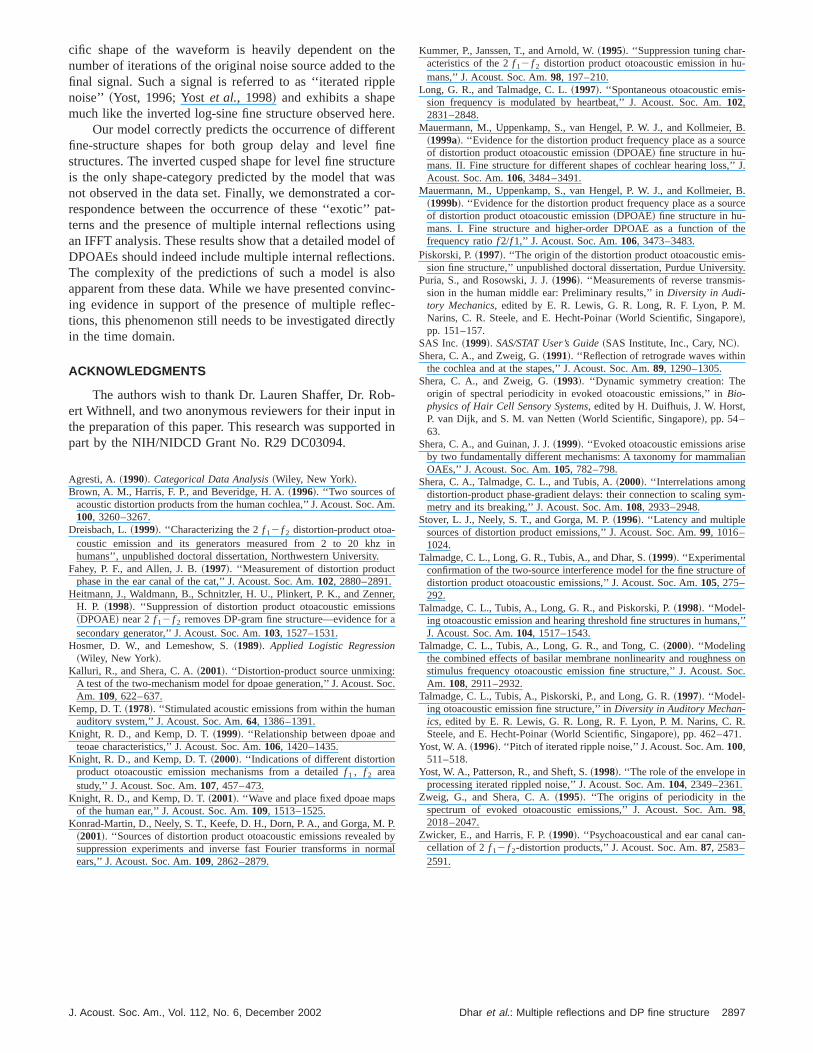
postulated in cochlear models~Zweig and Shera, 1995; Talmadgeet al., 1998!. These internal reflections are also neessary for the generation of spontaneous otoacoustic esions, fine structure in transient and stimulus frequenemissions, and threshold microstructure~Talmadgeet al.,1998!. Evidence for them has also been seen in time dommeasurements of DPOAEs~Talmadgeet al., 1999!. Stoveret al. ~1996! observed multiple peaks in the time domawhen they applied an inverse FFT to their fixed-f 2 data.Consistent with observations made in this data set, higlatency peaks emerged for lower stimulus levels. Stoet al. ~1996! proposed the presence of ‘‘one~or two! sourcesand multiple reflections between this~these! and the bound-aries of the cochlea’’ as one of three possible mechaniresponsible for the generation of these additional peaks.ter a detailed analysis of the three mechanisms, theyposed that the presence of multiple sources inside thechlea was the most likely causative agent. The lack oconstant temporal relationship between the additional pewas one of the reasons for rejecting multiple internal refltions as a probable mechanism. The lack of a constant tporal relationship between peaks could be a result of thuse of a fixed-f 2 paradigm. As one primary is fixed and thother varied in frequency, the distance between the generand the 2f 12 f 2 tonotopic regions, and that between th2 f 12 f 2 region and the base of the cochlea, are alteredmultaneously. This negates the approximate phase constof the generator component, thereby making the interprtion of IFFT data more ambiguous. These latency relatiships are easier to interpret in a fixed-ratio paradigm. Aother issue that confounded Stoveret al. ~1996! was ‘‘whyprogressively later occurring reflections become dominan~stimulus! level is decreased.’’ It can be argued that as stimlus level decreases,uRau becomes larger as there is less supression from the primaries. Additionally the gain of the cchlear amplifier around the DP tonotopic region could abe higher as the magnitude of the apical-moving enereaching the DP tonotopic region is reduced. A higher vaof uRau would result in increased magnitude of the reflecticomponent for a givenuRdu. Although we did not observeany instances where the amplitudes of secondary refleccomponents were larger than the generation or initial refltion component, such an observation would only pointwards the inherent complexity of the DPOAE generatiprocess. A detailed understanding of the dependence ofuRauon stimulus level needs to be developed in order to fuappreciate the complexity of multiple internal reflectionsthe cochlea. It should be noted that in a later publicationthe same group, the multiple peaks from an IFFT analywere attributed to multiple internal reflections~Konrad-Martin et al., 2001!.
The presence of non-log-sine fine structures lendsdence to the presence of multiple internal reflections as tobservation demonstrates the significance of the contribuof these reflections to the signal in the frequency domaAgain, this is not unique to DPOAEs. Alterationsfrequency-domain waveforms are seen when a broadbnoise is added to itself after a specific time delay. The s
Dhar et al.: Multiple reflections and DP fine structure
ththle
ern
fintuwacopain
elnslsoin
ecct
bind
Am
z
t
nens
r a
o
n
d
s
. Pb
rm
-
-
, B.rce
,’’ J.
, B.rce
the
-ity.-
.
eian
ym-
of
ns,’’
s onoc.
R.
n-
cific shape of the waveform is heavily dependent onnumber of iterations of the original noise source added tofinal signal. Such a signal is referred to as ‘‘iterated rippnoise’’ ~Yost, 1996; Yostet al., 1998! and exhibits a shapemuch like the inverted log-sine fine structure observed h
Our model correctly predicts the occurrence of differefine-structure shapes for both group delay and levelstructures. The inverted cusped shape for level fine strucis the only shape-category predicted by the model thatnot observed in the data set. Finally, we demonstrated arespondence between the occurrence of these ‘‘exotic’’terns and the presence of multiple internal reflections usan IFFT analysis. These results show that a detailed modDPOAEs should indeed include multiple internal reflectioThe complexity of the predictions of such a model is aapparent from these data. While we have presented conving evidence in support of the presence of multiple refltions, this phenomenon still needs to be investigated direin the time domain.
ACKNOWLEDGMENTS
The authors wish to thank Dr. Lauren Shaffer, Dr. Roert Withnell, and two anonymous reviewers for their inputthe preparation of this paper. This research was supportepart by the NIH/NIDCD Grant No. R29 DC03094.
Agresti, A. ~1990!. Categorical Data Analysis~Wiley, New York!.Brown, A. M., Harris, F. P., and Beveridge, H. A.~1996!. ‘‘Two sources of
acoustic distortion products from the human cochlea,’’ J. Acoust. Soc.100, 3260–3267.
Dreisbach, L.~1999!. ‘‘Characterizing the 2f 12 f 2 distortion-product otoa-coustic emission and its generators measured from 2 to 20 khhumans’’, unpublished doctoral dissertation, Northwestern University.
Fahey, P. F., and Allen, J. B.~1997!. ‘‘Measurement of distortion producphase in the ear canal of the cat,’’ J. Acoust. Soc. Am.102, 2880–2891.
Heitmann, J., Waldmann, B., Schnitzler, H. U., Plinkert, P. K., and ZenH. P. ~1998!. ‘‘Suppression of distortion product otoacoustic emissio~DPOAE! near 2f 12 f 2 removes DP-gram fine structure—evidence fosecondary generator,’’ J. Acoust. Soc. Am.103, 1527–1531.
Hosmer, D. W., and Lemeshow, S.~1989!. Applied Logistic Regression~Wiley, New York!.
Kalluri, R., and Shera, C. A.~2001!. ‘‘Distortion-product source unmixing:A test of the two-mechanism model for dpoae generation,’’ J. Acoust. SAm. 109, 622–637.
Kemp, D. T.~1978!. ‘‘Stimulated acoustic emissions from within the humaauditory system,’’ J. Acoust. Soc. Am.64, 1386–1391.
Knight, R. D., and Kemp, D. T.~1999!. ‘‘Relationship between dpoae anteoae characteristics,’’ J. Acoust. Soc. Am.106, 1420–1435.
Knight, R. D., and Kemp, D. T.~2000!. ‘‘Indications of different distortionproduct otoacoustic emission mechanisms from a detailedf 1 , f 2 areastudy,’’ J. Acoust. Soc. Am.107, 457–473.
Knight, R. D., and Kemp, D. T.~2001!. ‘‘Wave and place fixed dpoae mapof the human ear,’’ J. Acoust. Soc. Am.109, 1513–1525.
Konrad-Martin, D., Neely, S. T., Keefe, D. H., Dorn, P. A., and Gorga, M~2001!. ‘‘Sources of distortion product otoacoustic emissions revealedsuppression experiments and inverse fast Fourier transforms in noears,’’ J. Acoust. Soc. Am.109, 2862–2879.
J. Acoust. Soc. Am., Vol. 112, No. 6, December 2002
ee
e.teresr-t-gof.
c--ly
-
in
.
in
r,
c.
.yal
Kummer, P., Janssen, T., and Arnold, W.~1995!. ‘‘Suppression tuning char-acteristics of the 2f 12 f 2 distortion product otoacoustic emission in humans,’’ J. Acoust. Soc. Am.98, 197–210.
Long, G. R., and Talmadge, C. L.~1997!. ‘‘Spontaneous otoacoustic emission frequency is modulated by heartbeat,’’ J. Acoust. Soc. Am.102,2831–2848.
Mauermann, M., Uppenkamp, S., van Hengel, P. W. J., and Kollmeier~1999a!. ‘‘Evidence for the distortion product frequency place as a souof distortion product otoacoustic emission~DPOAE! fine structure in hu-mans. II. Fine structure for different shapes of cochlear hearing lossAcoust. Soc. Am.106, 3484–3491.
Mauermann, M., Uppenkamp, S., van Hengel, P. W. J., and Kollmeier~1999b!. ‘‘Evidence for the distortion product frequency place as a souof distortion product otoacoustic emission~DPOAE! fine structure in hu-mans. I. Fine structure and higher-order DPOAE as a function offrequency ratiof 2/f 1,’’ J. Acoust. Soc. Am.106, 3473–3483.
Piskorski, P.~1997!. ‘‘The origin of the distortion product otoacoustic emission fine structure,’’ unpublished doctoral dissertation, Purdue Univers
Puria, S., and Rosowski, J. J.~1996!. ‘‘Measurements of reverse transmission in the human middle ear: Preliminary results,’’ inDiversity in Audi-tory Mechanics, edited by E. R. Lewis, G. R. Long, R. F. Lyon, P. MNarins, C. R. Steele, and E. Hecht-Poinar~World Scientific, Singapore!,pp. 151–157.
SAS Inc.~1999!. SAS/STAT User’s Guide~SAS Institute, Inc., Cary, NC!.Shera, C. A., and Zweig, G.~1991!. ‘‘Reflection of retrograde waves within
the cochlea and at the stapes,’’ J. Acoust. Soc. Am.89, 1290–1305.Shera, C. A., and Zweig, G.~1993!. ‘‘Dynamic symmetry creation: The
origin of spectral periodicity in evoked otoacoustic emissions,’’ inBio-physics of Hair Cell Sensory Systems, edited by H. Duifhuis, J. W. Horst,P. van Dijk, and S. M. van Netten~World Scientific, Singapore!, pp. 54–63.
Shera, C. A., and Guinan, J. J.~1999!. ‘‘Evoked otoacoustic emissions arisby two fundamentally different mechanisms: A taxonomy for mammalOAEs,’’ J. Acoust. Soc. Am.105, 782–798.
Shera, C. A., Talmadge, C. L., and Tubis, A.~2000!. ‘‘Interrelations amongdistortion-product phase-gradient delays: their connection to scaling smetry and its breaking,’’ J. Acoust. Soc. Am.108, 2933–2948.
Stover, L. J., Neely, S. T., and Gorga, M. P.~1996!. ‘‘Latency and multiplesources of distortion product emissions,’’ J. Acoust. Soc. Am.99, 1016–1024.
Talmadge, C. L., Long, G. R., Tubis, A., and Dhar, S.~1999!. ‘‘Experimentalconfirmation of the two-source interference model for the fine structuredistortion product otoacoustic emissions,’’ J. Acoust. Soc. Am.105, 275–292.
Talmadge, C. L., Tubis, A., Long, G. R., and Piskorski, P.~1998!. ‘‘Model-ing otoacoustic emission and hearing threshold fine structures in humaJ. Acoust. Soc. Am.104, 1517–1543.
Talmadge, C. L., Tubis, A., Long, G. R., and Tong, C.~2000!. ‘‘Modelingthe combined effects of basilar membrane nonlinearity and roughnesstimulus frequency otoacoustic emission fine structure,’’ J. Acoust. SAm. 108, 2911–2932.
Talmadge, C. L., Tubis, A., Piskorski, P., and Long, G. R.~1997!. ‘‘Model-ing otoacoustic emission fine structure,’’ inDiversity in Auditory Mechan-ics, edited by E. R. Lewis, G. R. Long, R. F. Lyon, P. M. Narins, C.Steele, and E. Hecht-Poinar~World Scientific, Singapore!, pp. 462–471.
Yost, W. A. ~1996!. ‘‘Pitch of iterated ripple noise,’’ J. Acoust. Soc. Am.100,511–518.
Yost, W. A., Patterson, R., and Sheft, S.~1998!. ‘‘The role of the envelope inprocessing iterated rippled noise,’’ J. Acoust. Soc. Am.104, 2349–2361.
Zweig, G., and Shera, C. A.~1995!. ‘‘The origins of periodicity in thespectrum of evoked otoacoustic emissions,’’ J. Acoust. Soc. Am.98,2018–2047.
Zwicker, E., and Harris, F. P.~1990!. ‘‘Psychoacoustical and ear canal cacellation of 2f 12 f 2-distortion products,’’ J. Acoust. Soc. Am.87, 2583–2591.
2897Dhar et al.: Multiple reflections and DP fine structure
Copyright © 2022 FDOKUMEN