
The default mode network and EEG alpha oscillations: An independent component analysis

IEEE-International Conference on Signal processing, Communications and NetworkingMadras Institute of Technology, Anna University Chennai India, Jan 4-6, 2008. Pp384-391
Multiple 3-D Objects Detection and RecognitionUsing Independent Component Analysis
Ajay.S.Nathl, Sundaresh Ram2, Balaji.V1, K.Balachandarl'Sri Venkateswara College of Engineering, Sriperumbudur, Chennai, India.
2Velammal Engineering College, Ambattur, Chennai, India.E-mail: proton6O7gyahoo.com, sundaresh2ggmail.com
Abstract - In this paper we present a new approach to the low-dimensional space is the PCA also called thedetection and recognition of multiple 3-Dimensional ob- (discrete)jects in an image and describe a working, near-real-time Karhunen-Loeve transform (KLT) or the Hotellingmultiple 3-D objects detection and recognition system. transform. The use of KLT for feature extraction fromThe developed method processes in three steps. At the face images was first suggested by Sirovich and Kirbyfirst step the edges of the objects in an image are foundausing edge detection following which the boundaries are [13]. This method was further developed by Turk anddetected using a block processing algorithm (BPA), traced Pentland [12], [14], [15] to give a particularly success-and labelled. In the second step the 3-D object recognition ful application of face recognition. PCA has theof the detected objects is accomplished by utilising neural- distinction of being the optimal linear transformationnetwork architecture developed based on independent for keeping the subspace that has largest variance. Thecomponent analysis (ICA). In the last and the crucial low-dimensional space has been called the eigenspace,phase of the process, an algorithm is developed where any and the projections of the images onto this space haveunknown object (the object that is not available in the been called the eigenimages.database) is added to the existing database followed bydynamically training the ICA neural network, therebymaking the database ever growing. The system developed Later, ICA was used for recognizing faces developedis also capable of detecting and recognizing objects that by Bartlett et al. [2], [5]. ICA was originally developedare occluded .The database of images captured by a CCD
a'... r
camera is usedinthis paper. ~a few years ago in relation with blind source separationcamera is used in this paper. (BSS) problems, in which the goal is to extract inde-Key words - BPA, ICA, Occlusion, Dynamic Learning, pendent source signals from their linear mixtures usingBackground removal algorithm (BRGA). minimum of a priori information. The concept of ICA
was later extended to 3-dimensional object recogni-tion (3-DOR) based on appearance [7].
I. INTRODUCTIONThe paper is organized as follows. Section II de-
Theydtctinvand rogt system in Mace scribes the use of Block processing algorithm and edgeVisin tyicalyivoles sme srt f aninpt deice detection used for detecting the objects. Section III
usually a CCD camera to capture images of the object focueon hedBac Ground Removjaltalgorithmnbaseand to create a model database. The objects in an image onuwhich the Bjct are g enor aini tio IVare detected and then sent to the recognition algorithm, dicu the ontent areation ofthe datase Scdiscusses the content and creation of the database. Sec-which tries to find the model to which the object best tion V describes the basics of ICA. Section VI dis-matches. cusses the training of the ICA neural network using
In this paper, the images consisting of multiple ob- Infomax algorithm. Section VII discusses the applica-jects were first subjected to detection algorithm where tion of recognition algorithm to each of the extractedeach object was extracted from the image. Each of object from the image and their identification. Experi-these extracted objects was then recognized using a mental results are presented in Section VIII and werecognition algorithm. The recognition algorithm is conclude with a discussion in Section IX.based on the concept of ICA (Independent Component II. DETECTIONAnalysis). The system developed is capable of detect-ing and even recognizing objects with partial occlu- The image consisting of multiple objects was con-sion. verted to a gray scale from the RGB format. The Gray-A. Earlier Work scale image or the intensity image is then subjected to
canny edge detection algorithm [9]. The Canny methodThe basic idea in the appearance-based approach is finds edges by looking for local maxima of the gradient
to project the images into a low-dimensional space, of the intensity image. The gradient is calculated usingwhich captures the important characteristics of the ob- the derivative of a Gaussian filter. The method usesject to be recognized. One popular method to obtain a two thresholds, to detect strong and weak edges, and
978-1-4244-1923-4/08/$25.00 ©C2008 IEEE 384

Multiple 3-D Objects Detection and Recognition Using Independent Component Analysis
includes the weak edges in the output only if they are common background (white) for all the detected im-connected to strong edges. An example is shown is ages. This is achieved using the Background RemovalFig. 1. Algorithm (BGRA), which we developed.
A. Block Processing Algorithm As shown in Fig.2 the detected object has a non-
The image obtained after the canny edge detector does white background, which has to be removed before
not give a crisp and closed boundary for the objects to giving it for recognition. The BGRA scans the cannydetected image row-wise. A seeker starts from the left-be extracted. The Block Processing Algorithm (BPA) . tel1 otimage If. a blackspixelisefound
overcomes this difficulty. In the algorithm the edge the coresponding pie inate gra scal imageuisdetected image is split into sub blocks of 16x16 pixels. the firstswhitepixel in the row isThe algorithm scans row-wise, checking for white pix- fund the.see erskp andsmoveson to the next row.els in the sub-blocks. If a single white pixel is found T i k l lthe seeker reaches the last row.
the whole sub-block iS made white. The image after the Ti stkspaeutltesee ece h atrwthewholesub-blockprocessingalgorishma wit. Thim the FThe process is repeated from the right - top pixel of the
image. The image after the BGRA is shown below inthe Fig.3.
IV. DATABASE
The database, which we created, consists of 11 objectsand 36 poses of each object were taken. Making a total396 images. Fig.4 shows all the 11 objects of the cre-ated database.
Fig.3 The detected objects after the applying BGRA.
Fig.1 Top: Image on the right is the original image and the one on theleft shows the gray scale image. Bottom: The image shows the edgesof each object detected after applying the gray scale image to cannyedge detector.
Fig.4 The database of the eleven objects.
The images of the objects were taken using anOlympus CCD camera. The images were taken at every
I ~~~~~~~~100of pose angle, i.e. the object was rotated and animage was taken after every 100 of rotation from 0 to
Fig.2 Left: Objects detected with a background. Right: The image 360 degrees. This gave 36 images of each object, andwith crisp and closed boundaries after applying the BPA. 396 total numbers of images.
III. BACKGROUND REMOVALV. ICA
Aniae ositngo ojct asabakron Different definitions of linear ICA have appeared inwhose colour varies from one to another. When the
deteced obectsith vryin backround are iventhe literature [6], [8]. The definition that is used in thisfor recognition the recognition rate reduces. To im- paper iS given below.prove the accuracy of the system we decided to set a
385

IEEE-ICSCN Jan 4-6, 2008
1) Definition. ICA of a random vector consists of esti- extract the independent components. But it turns outmating the following generative model for the data: that by making certain assumptions the problem can
x = As (1) indeed be solved.
In the above definition noise is not considered ex-. ' . ~~~~~~A.Preprocessing ofthe Dataplicitly, therefore simplifying the problem of ICA, Ansince noise is considered as just another source. As Prior to applying the data to the algorithm to performmentioned earlier, this is motivated by the fact that ICA, it is sphered. Although sphering may not be ne-given the independent components are unknown, it cessary for every type of data or in various algorithms,cannot be determined a priori what is noise and what is it has been observed that sphering speeds up the con-useful information. vergence rate even when it is not strictly needed as a
The data model used here is similar to the one used preprocessing stage. The process of "sphering" the datain [16]. Consider m scalar random variables x*.xm involves removing the mean from the data and passingwhich are linear combinations of n unknown indepen- it through a zero-phase whitening filter. In other words,dent components of the source signal SI.Sn, assumed the row means are removed from the input data matrix.
mutually statistically independent and zero mean. Let the data be represented by Xraw. First we get X0 asmay be considered as the underlying "cause" of xi. Let the zero-mean data, and subsequently it is filtered withthe variables be represented by a zero-phase whitening filter, Wz, where
X = .,XmiT (2) Xo= Xraw-E{Xraw}, and W, = 2(E{XOX1T})-1/2 (7)
and the variables Si be represented by The resulting sphered data X is now given byx= [s, ,s] (3) X =W-XO (8)
then the linear combination is given by the relationship Sphering essentially removes the first- and second-order characteristics, which helps in speeding up of the
n convergence of the ICA algorithm [17]. Spheringmakes the covariance matrix of the input data equal to
x = L a, si = As and makes the transformation roughly orthogonal. Af-i=i ter sphering, the data is ready to be given to the ICA
algorithm.here A is an unknown fixed matrix m x n of full rank,called the mixing matrix, whose columns are denotedVby ai, i = 1,... ,n. These columns are called the ICA Every fifth image of the database of all objects werebasis vectors, or basis functions. The weighting of taken for training the ICA neural network, thusthese functions by s gives the image x. These are the amounting to eight images per object and making acounterparts of the principal eigenvectors in PCA. The total of 88 objects in the training database.fundamental problem of ICA is then to recover the un-derlying causes s from the mixtures x. Since only x is Each image in the training database was first con-observed, the problem changes to estimating B in verted into gray scale or intensity image. These images
were then subjected to BGRA and the non-white back-s = (ATAy' ATx = Bx (5) ground was removed. The sizes of these images were
It may also be worthwhile to mention that if the signal now changed to 32 x 32 due to memory constraints andx is a function of time, then the coefficients in are also for faster recognition. Each of the images was thena function of time, and (4) becomes converted into a matrix of size lxI024, thereby con-
verting the whole training database into an 88 x 1024n matrix.
x(t) = ai si (t) = As(t) (6) The algorithm used for training the ICA neural net-work is the Information Maximization or the InfoMaxalgorithm. The info-max algorithm utilizes the max-
From the definition given in (4), the object of per- imization of information criterion for ICA. It is imple-forming ICA on an observed data is to find a transfor- mented on a feed forward neural network as shown in
my Fig5. The M-dimensional signal x is the input to theineedn fro ecotraspsil. Sic n network. Recall that the input is considered to be madepriori information is available either of the source sig- up of independent components s, (see Section V). Eachnals or of the mixing matrix, it may seem impossible to input xi is weighted by the weights connected to the
neuron and summed to give the M outputs u1, i.e.
386

Multiple 3-D Objects Detection and Recognition Using Independent Component Analysis
M entropy is maximized with respect to the weight ma-trix.
Ui=L wiwxj; i=1,2.M. (9)
i11] The original rule given by Bell and Sejnowski forWit the change in weights is given by [3], [17]t0L~~~~~~~~ f(ti(.) Yl E _ ~~~~woo (W )- +0(p(V)/X/p(U)) x (4
The gradient update rule for the weight matrix W, is as.X2 T;22 follows:
AW= WT)- + E(Y'XT) (15)
where Yi' = f"(Ui)/ f'(Ui), the ratio between thesecond and first partial derivatives of the activationfunction, T stands for transpose, E for expected value,H(Y) is the entropy of the random vector Y, and Aw
/ /1l;em! 1H(Y) is the gradient of the entropy in matrix form, i.e.,the cell in row i, columnj of this matrix is the deriva-tive of H(Y) with respect to Wij. Computation of the
Fig.5 Neural network used for implementing the independent com- matrix inverse can be avoided by employing the naturalponent analysis. The weights are updated using the info-max algo- gradient [1], which amounts to multiplying the absoluterithm. For simplicity, the feedback loop from the outputs to the gradient by WT W, resulting in the following learningweights is not shown. rule [18]:
AW=(I+Y'UT)W (16)which may be expressed in the following compactform:
U = Wx (10) where I is the identity matrix. The logistic transferfunction
Each ui is then passed through a monotonic nonde-creasing non-linearity to obtain the outputs yi as
Yi = f(u), i= 1,2,....,M (11) f(u) = --------
1+e-u (17)which in the compact form may be written as
y = f(u) = f(Wx) (12) gives Y'i=(1-2Yi) (18)
When there are multiple inputs and outputs, maximiz-
The joint entropy of the outputs of the network is given ing the joint entropy of the output Y encourages theThebJo1ntentropyH oflY2,the M)outpts o th netork1S gvenindividual outputs to move toward statistical indepen-by H(yJ,y2l.'JY) = dence. When the form of the nonlinear transfer func-
H(y1) + H(y2)+. .+H(yAJ - I(y,,y2, yx) (13) tionf is the same as the cumulative density functions ofthe underlying ICs (up to scaling and translation) it can
where H(yi) are the marginal entropies and be shown that maximizing the joint entropy of the out-I(Y1,Y2,. ,YM) is the mutual information in the output. It puts in Y also minimizes the mutual information be-is obvious from the above expression that maximiza- tween the individual outputs in U [17], [11]. In prac-tion of the joint entropy can be achieved by maximiz- tice, the logistic transfer function has been found suffi-ing the marginal entropies and by minimizing the mu- cient to separate mixtures of natural signals with sparsetual information. In the ideal case, the mutual informa- distributions including sound sources [1]. The algo-tion would be zero and the marginal distribution of the rithm is speeded up by including a "sphering" stepoutputs is uniform, since the marginal entropy of am- prior to learning [17]. The row means of are subtracted,plitude bounded random variable is maximum when its and then X is passed through the whitening matrix Wz,marginal distribution is uniform. In other words, the which is twice the inverse square root1 of the cova-nonlinearity ft.) used in the network should have the riance matrixshape of the c.d.f. of the source s1. In the info-max al- W=2*CvX) (19)gorithm, the nonlinearity iS fixed, and the marginal=2*CvX(l)
387

IEEE-ICSCN Jan 4-6, 2008
This removes the first and the second-order statistics of b for the linear combination of the basis images in Uthe data; both the mean and covariances are set to zero that comprised of images in X were determined below.and the variances are equalized. When the inputs toICA are the "sphered" data, the full transform matrix The PC representation of the zero mean images in XICAarethe "sproduct"ofthe,sheringlmatrixans m matrix based on Pm is given as Rm = X Pm. A minimumWI is the product of the sphering matrix and the squared error approximation of X is obtained by X^ =learned by ICA Rm Pmi . The ICA algorithm produced a matrix WI in
WI= WWZ (20) (20) such that
MacKay [9] and Pearlmutter [12] showed that the ICA WI pmT = U - pmT = WI 1 U (22)algorithm converges to the maximum likelihood esti- Thus X^ = RmPm'T - X^W1IU (23)mate of
W-1 for the following generative model of the data: The rows of RmWI1 contained the coefficients for theX=W1S (21) linear combination of statistically independent sources
where S = (SI,.-,Sn)' is a vector of independent ran-U that comprised X^. The IC representation of the im-
domvariables,called the sources with cumul edages based on the set of m statistically independentcumulativfeature images, U was, therefore, given by the rows oftributions equal to fi, in other words, using logistic ac- the matrix
tivation functions corresponds to assuming logisticrandom sources and using the standard cumulative B = RmW1 (24)Gaussian distribution as activation functions corres-
pondsto asumigGassia randm sorces Thu,~-A representation for test images was obtained by usingponds to assuming Gaussian random sources. Thus, W-I, the inverse of the weight matrix in Bell and Sej- the PC representation based on the training images to
nowski's algorithm, can be interpreted as the source obtainmixing matrix and the U = Wx variables can be inter- Rtest = Xtest Pm, and then computingpreted as the maximum-likelihood (ML) estimates of B test = R test W-1 (25)the sources that generated the data.
The Euclidean distance method was used to measureVII. RECOGNITION the distance between the test image's signature and the
The test objects in the images which were detected trained image's signatures present in the training data-
using the BPA and whose background was removed base. The signature nearest to the testing signature isusing BGRA are then given for recognition by ICA. chosen as the recognized object.We organize a data matrix X such that the all the im- VIII. EXPERIMENTAL RESULTSages in the training database are in rows and their cor-
respndig pielsin clums ie., ha 88 owsandThe recognition accuracy was extremely good com-1024 columns and each image has a zero mean ICA pared to the earlier works done. Multiple objectsfinds aolumsatrix schthatgthe rows azerof meareICA (more than 8 objects) were placed in an image, whichfinds a matrix W such that the rows of U = WX are as weedtce n eonie ihgo cuaystatistically independent as possible. The source images were detected and recognized with good accuracy.statsticatedlby rowsdofpUnarenthenusas possibeso images These objects were place against different backgroundestimated by rows of U are then used as basis images colors including white, camouflaged (the backgroundor signatures of the objects based on which only recog- color is same as the color of the object) and other ran-nition takes place. dom colors. The Table I shows the Recognition rateThe number of IC's found by the ICA depends on the (%) using ICA for each of the objects separately withdimensionality of the input. We had 88 images in the different backgrounds. From the Table I it is concludedtraining database and thus ICA would find 88 separate that recognition rate for objects against white back-IC's. Since this number was large and since it would ground and any other colored background were as hightake more time for recognition we chose to perform as 96.46%. The objects which were placed againstPCA following which ICA was performed. Based on camouflaged backgrounds still managed a very goodthe earlier work by Marian Stewart Bartlett, Javier R. recognition rate of 81.82%. Fig.6 shows the image of 8Movellan, and Terrence J. Sejnowski [10] we chose the different poses of object "DUCK" which is camouf-first m PC eigenvectors of the image set. The use of laged with the background and a single detected objectPCA vectors did not throw away the higher-order rela- with the camouflaged background removed usingtionships, they existed in the data but were not sepa- BGRA.rated. Let Pm denote the first m PC axes in its column.We performed ICA on PinT, producing a matrix of mindependent images in the rows of U. The coefficients
388

Multiple 3-D Objects Detection and Recognition Using Independent Component Analysis
A. Occlusion
The image shown in Fig.6 shows eight different posesof the object "KING" with occlusion (up to 80%). Thisimage when given for detection using BPA. The de-tected boundaries of the objects are shown in Fig. 7. Asdepicted in the image above there are 9 objects insteadof the actual count of 8. This is because the secondobject was detected as two different objects on accountof occlusion. The detected objects after BGRA weresent to the ICA recognition algorithm, which recog-nized the objects with l100% accuracy. Due to the pres-ence of signature in each part of the object, in this case Fig.7 The image shows 8 different poses of the object KING withthe head and base of the chess coin, made the system occlusion. The second object in the first row as can be seen has beenrecognize the objects 100% accurate even when they split into 2 parts (more than 86% occlusion).were split.
B. Dynamic LearningOne of the added features of this system is dynamic
learning. Euclidean distance is the concept used toidentify the signature of the object to be recognizedwith the existing image's signature. The maximum ofthe shortest Euclidean distances obtained by comparingwith the existing images is taken as the threshold value.If during recognition the Euclidean distance is morethan this threshold it means that the object that has tobe recognized is not available in the database and thusis a new object. This object is then sent for training and Fig. 8 The image shown after BPA. Note that the second object hasa new set of updated weights is created and the new been detected as two separate objects on account of occlusion.threshold value is also revised.
Fig.9 The new object which is not present in the database initially,Fig.6 Left: Shows the 8 different poses of DUCK against a camouf- which later is added as a part of the ever-growing database.laged backround. Right: Shows the last object of the second row afterapplying BGRA.
389
IEEE-ICSCN Jan 4-6, 2008
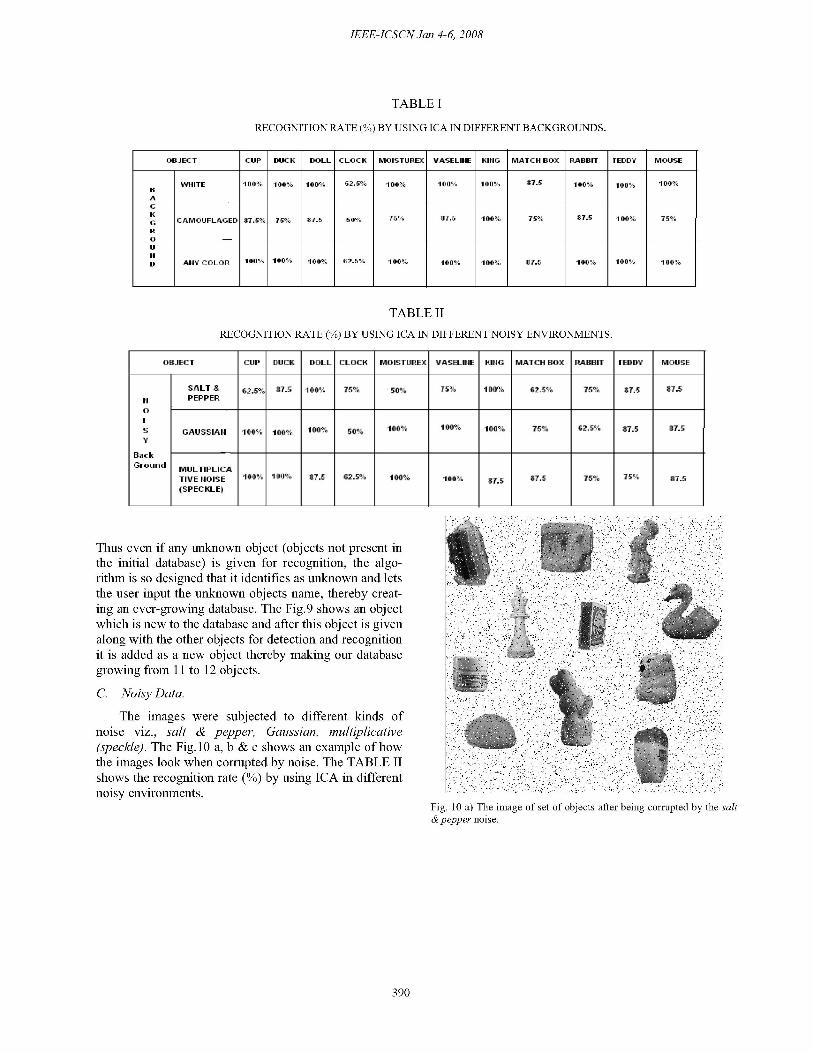
TABLE I
RECOGNITION RATE (%) BY USING ICA IN DIFFERENT BACKGROUNDS.
OBJECT CUP DUCK DOLL CLOCK MOISTUREX lfASELIIIE KIIiG MATCH BOX RABBIT TEDDY MOUSE
|WHITE 100% 100% 100% 62.5% 100% 100% 100% 87.5 100% 100% 100%BAcG CAMOUFLAGED 87.5% 75% 87.5 I 75; 875 5100% IF 37.0 1 T5oR0U
D AHlY COLOR 100% 100% 100% 62.5% 100% 100% 100% 87.5 100% 100% 100%
TABLE II
RECOGNITION RATE (%) BY USING ICA IN DIFFERENT NOISY ENVIRONMENTS.
O~BJECT CUIP DUJCK DOLL CLOCK MOISTUJREX VJASELkflE KLUG MATCH BOX PABrIT TEDDY MOUSE
SALT & |7.5 1 5% -50 ?% 10% 62.5% 15% |7.5 87.CPEPPER
0
5 GAUSSIAHI 1 ° - 1 % I%37.-
Back
MULTIPLICATIVE HOISE 1 100% 7 i2S 1 10% *7 * | .
(SPECKLE)
Thus even if any unknown object (objects not present inthe initial database) is given for recognition, the algo-rithm is so designed that it identifies as unknown and letsthe user input the unknown objects name, thereby creat-ing an ever-growing database. The Fig.9 shows an objectwhich is new to the database and after this object is givenalong with the other objects for detection and recognitionit is added as a new object thereby making our databasegrowing from 11I to 12 objects.C. Noisy Data.
The images were subjected to different kinds ofnoise viz., salt & pepper, Gaussian, multiplicative(speckle). The Fig. 10 a, b & c shows an example of howthe images look when corrupted by noise. The TABLE IIshows the recognition rate (0) by using ICA in differentnoisy environments.
Fig. 10 a) The image of set of objects after being corrupted by the salt& pepper noise.
390

Multiple 3-D Objects Detection and Recognition Using Independent Component Analysis
Conf Human Vision Electronic Imaging III, San Jose, CA,1998, pp. 628-639.
[3] A. J. Bell and T. J. Sejnowski, "An information-maximization approach to blind separation and blind deconvo-lution," Neural Comput., vol. 7,no. 6, pp. 1 129-1 169, 1996.
[4] Canny, J., "A Computational Approach To Edge Detec-tion," IEEE Trans. Pattern Analysis and Machine Intelligence,8:679-7 14, 1986..
[5] 5. Chol and 0. Lee, "Factorial code representation of facesfor recognition," in Lecture Notes in Computer Science, 1811,Biologically Motivated Computer Vision, S. W. Lee, H. H.Builthoff, and T. Poggio, Eds. New York: Springer-Verlag,2000, pp.42-61.[6] P. Comon, "Independent component analysis a new con-cept?," Signal Processing, vol. 36, no. 3, pp. 287-314, 1994.
Fig. 10 b) The image of set of objects after being corrupted by the [7] Harkirat S. Sahambi and K. Khorasani, "A Neural-NetworkGaussian noise. Appearance-Based 3-D Object Recognition Using Independent
Component Analysis," in IEEE Trans. on Neural Networks,vol. 14,No. 1,january 2003
[8] C. Jutten and J. Herault, "Blind separation of sources, part1: an adaptive algorithm based on neuromimetic architecture,"Signal Processing, vol. 24, no. 1, pp. 1-tO, 1991.
[9] D. J. C. MacKay, Maximum Likelihood and Covariant Al-gorithms for Independent Component Analysis:, 1996.
[10] Marian Stewart Bartlett, Javier R. Movellan, and TerrenceJ. Sejnowski, "Face recognition by Independent ComponentAnalysis," IEEE Trans. on Neural Networks, vol.13, No. 6,November 2002.
[11] J.-P. Nadal and N. Parga, "Non-linear neurons in the lownoise limit: A factorial code maximizes information transfer,"Network, vol. 6, pp. 666-681, 1994.][12] B. A. Pearlmutter and L. C. Parra, "A context-sensitivegeneralization of ICA," in Advances in Neural InformationProcessing Systems, Mozer, Jordan, and Petsche, Eds. Cam-
Fig. 10 c) The image of set of objects after being corrupted by the bridge, MA: MIT Press, 1996, vol. 9.Multiplicative (speckle) noise.
XLCONCLUSIO][13] A. Pentland, B. Moghaddam, and T. StaH.er, "View-basedXI.CONCLUSION ~~~~~andmodular eigenspaces," in Proc. IEEE Conf. Comput. Vision
The system has been put to test and has shown excellent Pattern Recognition, 1994, pp. 84-91.results on different backgrounds. The two added features [14] L. Sirovich and M. Kirby, "Low-dimensional procedureof the system designed are detection and recognition of for the characterization of human faces," J. Opt. Soc. Amer.,occluded objects and Dynamic learning of unknown ob- vol. 4, no. 3, pp. 619-624, Mar. 1987.jects. In future the system can be modified to recognize [15] M. Turk and A. Pentland, "Eigenfaces for recognition," Jobjects with different sizes (Scaling), thereby identifying Cognitive Neurosci., vol. 3, no. 1, pp. 71-86, 1991the distance of the object from the CCD sensor. We are
1]MA.TranA.PPetnd"Fcrcoiinusg
currentl workngonen achievetaiong the faboe proess.iio, [1]Mi.Trnn A .Pnln,"ac eonto sn
currontlyc working.on achieving the above process. eigenfaces," in Proc. IEEE Computer Society Conf ComputerREFERENCES Vision Pattern Recognition, Maui, HI, 1991, pp. 686-69 1.
[1] 5. Amari, A. Cichocki, and H. H. Yang, "A new learning [17]-, "The independent components of natural scenes arealgorithm for blind signal separation," in Advances in Neural edge filters," Vision Res., vol. 37, no. 23, pp. 3327-3338, 1997.Information Processing, Systems. Cambridgze, MA: MIT Press,
Copyright © 2022 FDOKUMEN