Projection and nested force-gradient methods for quantum ...
Upload
independentCategory
view
4download
0
NASA TP-1998-3703
Multimodal Perception and MulticriterionControl of Nested Systems:
II. Constraints on Crew Members During SpaceVehicle Abort, Entry, and LandingP. Vernon McDonald, Gary E. Riccio, Gregg E. Irvin, and Jacob J. Bloomberg
April 1998

The NASA STI Program Office . . . in Profile
Since its founding, NASA has been dedicated tothe advancement of aeronautics and spacescience. The NASA Scientific and TechnicalInformation (STI) Program Office plays a keypart in helping NASA maintain this importantrole.
The NASA STI Program Office is operated byLangley Research Center, the lead center forNASA’s scientific and technical information.The NASA STI Program Office provides accessto the NASA STI Database, the largestcollection of aeronautical and space science STIin the world. The Program Office is alsoNASA’s institutional mechanism fordisseminating the results of its research anddevelopment activities. These results arepublished by NASA in the NASA STI ReportSeries, which includes the following reporttypes:
• TECHNICAL PUBLICATION. Reports ofcompleted research or a major significantphase of research that present the results ofNASA programs and include extensive dataor theoretical analysis. Includescompilations of significant scientific andtechnical data and information deemed to beof continuing reference value. NASA’scounterpart of peer-reviewed formalprofessional papers but has less stringentlimitations on manuscript length and extentof graphic presentations.
• TECHNICAL MEMORANDUM. Scientificand technical findings that are preliminaryor of specialized interest, e.g., quick releasereports, working papers, and bibliographiesthat contain minimal annotation. Does notcontain extensive analysis.
• CONTRACTOR REPORT. Scientific andtechnical findings by NASA-sponsoredcontractors and grantees.
• CONFERENCE PUBLICATION. Collectedpapers from scientific and technical confer-ences, symposia, seminars, or other meetingssponsored or cosponsored by NASA.
• SPECIAL PUBLICATION. Scientific,technical, or historical information fromNASA programs, projects, and mission, oftenconcerned with subjects having substantialpublic interest.
• TECHNICAL TRANSLATION.English-language translations of foreignscientific and technical material pertinent toNASA’s mission.
Specialized services that complement the STIProgram Office’s diverse offerings includecreating custom thesauri, building customizeddatabases, organizing and publishing researchresults . . . even providing videos.
For more information about the NASA STIProgram Office, see the following:
• Access the NASA STI Program Home Pageat http://www.sti.nasa.gov
• E-mail your question via the Internet [email protected]
• Fax your question to the NASA Access HelpDesk at (301) 621-0134
• Telephone the NASA Access Help Desk at(301) 621-0390
• Write to:NASA Access Help DeskNASA Center for AeroSpace Information800 Elkridge Landing RoadLinthicum Heights, MD 21090-2934

NASA TP-1998-3703
Multimodal Perception and MulticriterionControl of Nested Systems:
II. Constraints on Crew Members During SpaceVehicle Abort, Entry, and LandingP. Vernon McDonaldWyle Laboratories, Inc.
Gary E. RiccioNascent Technologies
Gregg E. IrvinNascent Technologies
Jacob J. BloombergNASA JSC Life Sciences Research Laboratories
April 1998
Acknowledgments
The ideas presented in this report emerged from conversations with a number of individuals at NASAJohnson Space Center (JSC). We were extremely fortunate to benefit from the expertise of Dr. LizWalden, who is engaged in support of the Advanced Human-Automation Projects Office at JSC. Herknowledge of launch and reentry demands on crew, and the upgrade plans for Orbiter cockpit controlsand displays proved to be invaluable. Mr. James Dagen, of the Structures and Dynamics Branch,provided unique ascent and reentry vibration data from the Shuttle middeck. We also benefitted from thewilling cooperation of Mr. Ray Dell’Osso of the Mission Operation Directorate’s Space Flight TrainingDivision. Members of the JSC Life Sciences Research Laboratories provided continuing supportthroughout the evolution of this report. Finally, we would like to take this opportunity to thank all thepilots, commanders, and mission specialists who were willing to share their flight experiences with us.
Available from:
NASA Center for AeroSpace Information National Technical Information Service7121 Standard 5285 Port Royal RoadHanover, MD 21076-1320 Springfield, VA 22161Price Code: A17 Price Code: A10
Contents
Page
iii
Preface ................................................................................................................................................ 1
Abstract .............................................................................................................................................. 2
1. Identification and Significance of the Issues................................................................................. 2
2. Shuttle Flight Deck Operations & Conditions ............................................................................... 5
2.1 Visual and Manual Demands on the Flight Deck .................................................................. 5
2.2 Shuttle Launch/Reentry/Landing Conditions......................................................................... 8
2.3 Current & New Technologies for Space Vehicle Flight Decks ............................................. 12
2.3.1 Current Displays and Controls ................................................................................... 12
2.3.2 Future Displays and Controls...................................................................................... 13
3. Human Perception and Performance .............................................................................................. 14
3.1 Effects of Whole-Body Perturbations on Visual and Manual Performance .......................... 14
3.2 Human Performance Adaptations to Weightlessness ............................................................ 20
4. Multicriterion Control and Coordination in Nested Systems........................................................ 22
4.1 Theoretical Foundations ......................................................................................................... 22
4.2 Relevance to Flight Deck Performance.................................................................................. 24
4.2.1 Task Constraints.......................................................................................................... 24
4.2.2 Whole-Body Perturbations.......................................................................................... 25
4.2.3 Visual/Manual Performance ....................................................................................... 25
4.2.4 Coordination of Nested Systems................................................................................. 26
5. Cockpit Design Implications .......................................................................................................... 27
5.1 Robustness of Cockpit Displays and Controls ....................................................................... 27
5.2 Robust Cockpit Design........................................................................................................... 27
6. Literature Cited............................................................................................................................... 28
Contents(continued)
Page
iv
Figures
1 Schematic showing panel identification for current shuttle flight deck controlsand displays .................................................................................................................................... 5
2 Typical shuttle acceleration time history during ascent ................................................................. 10
3 STS-5 flight deck z-axis vibration power spectra vs time during ascent ....................................... 11
4 STS-5 flight deck z-axis vibration power spectra vs time during ascent ....................................... 11
5 G-load vs. time for 3-DOF simulated reentry profile..................................................................... 12
6 Transmissibility as a function of vibration frequency. Center curve is meanvibration amplitude; top and bottom curves are ±1 standard deviation.(From Boff & Lincoln, 1988)......................................................................................................... 15
7 Reading error for three display viewing conditions, 0.5-5 Hz.(From Boff & Lincoln, 1988)......................................................................................................... 16
8 Reading error: whole-body vibration, 2.8-63 Hz. (From Boff & Lincoln, 1988) .......................... 17
9 Effect of vertical, horizontal, and dual axis (circular) vibration on visual performance.(From Boff & Lincoln, 1988)......................................................................................................... 17
10 Increase in mean reading error with vibration magnitude for four character sizes.(From Boff & Lincoln, 1988)......................................................................................................... 18
11 Effect of whole-body vertical vibration on contrast threshold for sinusoidal gratingswith spatial frequencies of 7.5, 10, and 12.5 cycles/deg. (From Boff & Lincoln, 1988).............. 18
12 Effect of modulation contrast on reading errors with panel-mounted displays.(From Boff & Lincoln, 1988)......................................................................................................... 19
13 Increase in root mean square tracking error/vibration acceleration level observedduring z-axis whole-body vibration. Total static error = 7 mm rms for zero-order dynamics and 15 mm rms for first-order dynamics. (From Boff & Lincoln, 1988) ........................ 20
14 Postflight dynamic visual acuity performance presented as a percentage of preflight performanceafter long duration flight. Numbers under each box indicate the numberof subjects ....................................................................................................................................... 21
15 Ratio of axial head acceleration to the initial foot contact ground reaction force peakbefore and after long duration flight. Numbers under each box indicate the numberof subjects ....................................................................................................................................... 21
v
Acronyms
A/L approach/landing
ADI attitude director indicator
AMI alpha/Mach indicator
BFS backup flight system
CRT cathode ray tube
CSS control stick steering
DOF degrees of freedom
ET external tank
GN&C guidance, navigation, and control
HUD head-up display
ISS International Space Station
LCD liquid crystal display
MECO main engine cut off
MEDS multifunctional electronic display system
PASS primary avionics software system
PIO pilot-induced oscillation
SPI surface position indicator
SRB solid rocket booster
TAEM terminal area energy management
VOR vestibulo-ocular reflex

1
Preface
This series of three reports will describe the challenges to human perception and motor control that resultfrom whole-body perturbations during locomotion. Our approach to this set of problems is based on theassumption that individuals, in the context of their surroundings, are adaptive nonlinear control systemswith multiple levels of nesting, multiple inputs, and multiple outputs. We consider interactions betweenindividuals and their surroundings to be the fundamental unit of analysis for research in human perceptionand movement. Our approach to the analysis of nested biological control systems was developed over morethan a decade of research on human-machine interactions in aerospace operations. The early research wasconducted in collaboration with the Air Force Armstrong Laboratory at Wright-Patterson Air Force Base,Ohio (see e.g., Brown, Cardullo, McMillan, Riccio & Sinacori, 1991; Riccio, 1993; Zacharias, Warren &Riccio, 1986). Recent research also includes collaboration with the Neuroscience Laboratory at the NASAJohnson Space Center in Houston, Texas (see e.g., Riccio, McDonald, Peters, Layne & Bloomberg, 1997).
The first report in the series, “Multimodal Perception and Multicriterion Control of Nested Systems: I.Coordination of Postural Control and Vehicular Control,” describes the theoretical and operationalfoundations for our analysis of human-environment interactions. This report focuses on the coupledbiological control systems involved in piloting an air vehicle and in stabilizing perception and movementin the cockpit. It is emphasized that the analysis is not limited to vehicular control. The analysis ispresented in a way that is generalized to all forms of locomotion and to other activities that involvewhole-body perturbations. In addition, the report motivates and facilitates comparisons between condi-tions of real and simulated vehicular motion. This provides a framework for assessing human perceptionand performance in real-world conditions, in controlled conditions that allow for more refined measure-ment and evaluation, and in simulations that are intended to foster the development of skill.
The second report in the series, “Multimodal Perception and Multicriterion Control of Nested Systems:II. Constraints on Crew Members During Space Vehicle Abort, Entry, and Landing,” applies our theo-retical framework for nested human-environment interactions to the problems of flight crew perceptionand performance during planned and potential aerodynamic maneuvers of space vehicles. This reportpresents an approach to identification of task demands on perceptual and motor systems on the flightdeck, to the measurement of perturbations to and interactions among the various subsystems of thehuman body, to the assessment of the skills involved in coordinating the nested subsystems in thepresence of such disturbances, and to the development of flight deck displays and controls that promotesuch skill and that increase robustness of the human-machine system.
The third report in the series, “Multimodal Perception and Multicriterion Control of Nested Systems: III.Assessment of Visual Stability During Treadmill Locomotion,” applies our theoretical framework to theproblem of eye-head-trunk coordination during walking or running. This report presents a method forevaluating visual resolution and gaze stability during common activities involving whole-body motion.The functional visual assessment test that is described provides a measure of visual “acuity” that issensitive to coordination between the oculomotor subsystems and other biomechanical subsystems of thebody. This approach enhances diagnostic sensitivity to a variety of physiological impairments, and itenhances diagnostic relevance with respect to operational or everyday activities.

2
Abstract
This report reviews the operational demands made of a Shuttle pilot or commander within the context ofa proven empirical methodology for describing human sensorimotor performance and whole-bodycoordination in mechanically and perceptually complex environments. The conclusions of this reviewpertain to
a) methods for improving our understanding of the psychophysics and biomechanics of visual/manualcontrol and whole-body coordination in space vehicle cockpits.
b) the application of scientific knowledge about human perception and performance in dynamic inertialconditions to the development of technology, procedures, and training for personnel in space vehiclecockpits.
c) recommendations for mitigation of safety and reliability concerns about human performance in spacevehicle cockpits.
d) in-flight evaluation of flight crew performance during nominal and off-nominal launch and reentryscenarios.
1. Identification and Significance of the IssuesIn this report we review the factors that affect the stability and adaptability of flight crew visual and manualperformance during space vehicle launch, reentry, and landing maneuvers. The operational relevance ofthese effects are specified in terms of the implications for current and advanced cockpit design.
A large proportion of the information the crew monitors in the current Orbiter cockpit is visual. At thesame time, the crew accomplishes the majority of its control inputs manually. As in other vehicles,maintenance of visual stability and manual stability is a fundamental component of piloting skill. Visualand manual stability are complicated by postural perturbations that result from controlled maneuvers anduncontrolled disturbances of the space vehicle during ascent and descent. Consequently, three relatedbehavioral goals are to stabilize gaze for visual acuity, stabilize the hand for manual control, and controlthe nested eye-head-torso-arm-hand system in the presence of mechanical disturbances. Moreover, at thetime of atmosphere reentry, the crew may be adapted to weightlessness while they must function reliablyin a rapidly changing inertial environment. Whole-body coordination must be sufficiently adaptable toensure stability of the visual and manual subsystems given such challenging conditions. The Shuttlepilot and commander must be prepared for the following specific challenges:
• Both the sensory and musculoskeletal systems are affected by weightlessness. The severity of theaftereffects that can be detected immediately postflight depend on the amount of time spent inweightlessness.
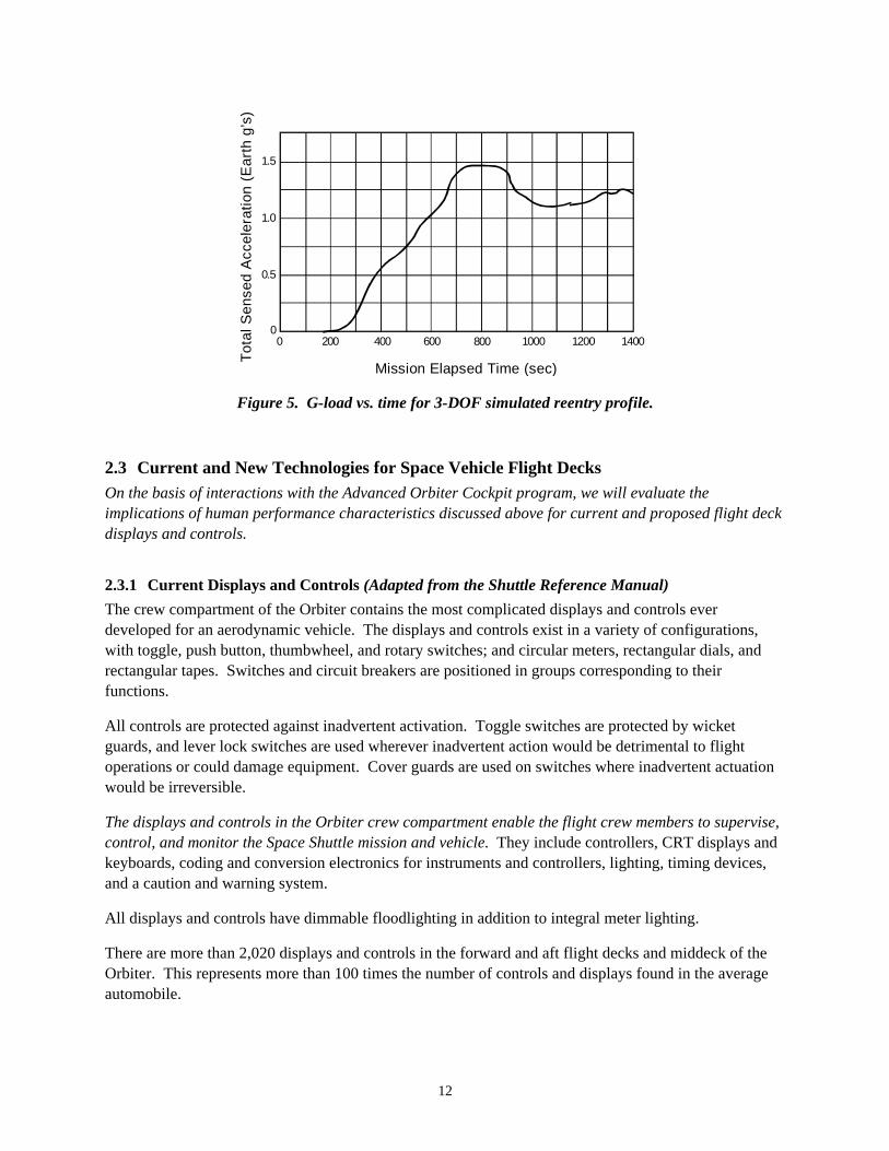
• The reentry phase of a mission is characterized by a rapidly changing inertial environment. NominalShuttle reentry entails varying g-loads up to 1.5g (nominally through the z-axis) occurring immedi-ately following the transition from weightlessness.
• Launch abort scenarios (e.g., East Coast Abort) will entail rapidly changing g-loads deviating fromthe +3g acceleration of a nominal Shuttle launch.
3
• Buffeting as a result of variations in the air mass causes vibration of the airframe and the operatorsduring entry and landing.
• Transient disturbances (e.g. wind gusts) can occur unexpectedly during the entry and landing.
• The opportunities for breaking off a particular flight procedure are either nonexistent or rapidlydiminishing irrespective of the challenges that are encountered during abort, entry, or landing.There is not a second chance.
We believe that crew effectiveness in these scenarios must be addressed for a number of reasons, includingthe following:
• NASA-sponsored research has shown that control of the eyes, head, and trunk is compromised bythe aftereffects of weightlessness. The task-relevant consequences of such aftereffects include, forexample, significant changes in visual performance immediately postflight.
• NASA-sponsored research is providing increasing evidence of changes in human perception andperformance following short- and long-duration space flight. Depending on the length of the flightthese effects can be severe.
• Research conducted outside of NASA indicates that whole-body coordination is compromised bylevels of variation in the inertial environment that are within nominal parameters for Shuttle entryand landing.
• Research conducted outside of NASA indicates whole body coordination is compromised by levelsof vehicular vibration that are within nominal parameters for Shuttle entry and landing. There isclear evidence that human perception and performance in aircraft cockpits is affected by vibrationand other environmental stressors to the extent that whole-body coordination is compromised.
• There is a notable lack of information about the capabilities and limitations of whole-bodycoordination on the flight decks of space vehicles, especially in off-nominal reentry and landingconditions.
• There is a notable lack of information about the operational robustness of human perception andperformance on the flight decks of space vehicles during off-nominal scenarios.
Visual and manual stability during space vehicle launch/reentry/landing is important for the detection ofdeviations from nominal flight conditions and for the timely and reliable execution of actions that areappropriate for any off-nominal conditions. Decisions will be made with less confidence and will bedelayed when circumstances degrade visual performance. Similarly, control responses may be inaccu-rate and delayed when circumstances degrade manual performance. In this report we evaluate the natureand extent of changes in visual and manual performance due to the aftereffects of weightlessness, theeffects of aero disturbances, and the effects of a variable-g environment. Our intent is to evaluate theseeffects in the specific context of flight deck operations so as to determine the implications for design offlight deck technology.
Our review will focus on visual/manual control and on the timeliness and confidence of the attendantdecisions. It also will relate indirectly to the adaptability and stability of the pilots’ more-or-less continuousflight control actions. We have shown that results from conventional psychophysical studies of sensorysystems can help explain characteristics of manual control and sensorimotor integration observed in simu-lated aircraft (Flach, Riccio, McMillan, & Warren, 1986; Riccio & Cress, 1986; Zacharias, Warren & Riccio,1986). Such research is important because, in the atmosphere, the Shuttle operates like a conventional
4
aircraft in a low lift/drag approach (Berry, Powers, Szalai, & Wilson, 1982). The rotational hand controllercontrols the elevons for pitch and roll, and pedals control the rudder for yaw.
Control of a vehicle and control of the pilot-vehicle system depends on the characteristics of the humansensory systems as well as the characteristics of the human motor systems. Visual stability and resolu-tion, for example, are important during the various phases of landing (e.g. heading alignment, flare, andtouchdown) insofar as it influences pilot workload and handling qualities (Berry et al., 1982; Smith &Bailey, 1982; Weingarten, 1978, 1979). As with damage to the Shuttle’s structure or flight-controlsystems, impairment of the pilot’s sensory or motor systems can lead to degraded flying qualities, pilot-induced oscillations (PIOs) and catastrophic failure. It is important to note that degradation in handlingqualities and flight-control performance is highly nonlinear or “explosive” over smooth changes inparameters of the pilot-vehicle system (Smith & Bailey, 1982). This quantitative finding is reinforced bypilot comments: “an unsatisfactory or worse flight control system can look benign until taxed near thelimit” (Berry et al., 1982, p. 323). These qualitative and quantitative characteristics have been notedsince the initial test and evaluation of Shuttle Orbiter landing (e.g., Weingarten, 1978, 1979). It followsthat problems with off-nominal conditions may not be predicted from behavior observed under nominalconditions unless one more closely examines the human subsystems involved in control of the pilot-vehicle system (Riccio, 1995; Riccio et al., 1998).
There have been occasions where Shuttle flight crew have made direct reference to visual problemsduring reentry and landing. Such comments have been made to the authors of this report, to a member ofthe NASA Johnson Space Center (JSC) Advanced Orbiter Cockpit team, and to engineers in the JSCStructures and Mechanics Division. To date these comments have been informal observations, but theJSC Advanced Orbiter Cockpit team is currently surveying all the active flight crew for their opinionspertaining to the human interface of current Shuttle flight deck displays and controls especially withreference to launch, ascent, reentry, and landing. Finally, at least one Shuttle commander is firmlyconvinced that there is no way he could land the Shuttle after a long-duration flight (>1 month) given theadaptive effects of long-duration flight.
Understanding crew effectiveness has direct implications for space vehicle design. The future Shuttleflight deck will incorporate new display and control technology that improves crew effectiveness to theextent that constraints on human perception and performance are addressed during design. Orbiterupgrade efforts that increase flight crew autonomy and situational awareness could correspondinglyincrease the reliance on human perception and performance. Any effort to increase flight crew situ-ational awareness will rely on accurate perception of system status through flight deck displays andcontrols. In the near future, we will have crews flying on the International Space Station (ISS). ISSemergency evacuation will require that crew members pilot a crew return vehicle after having spent up toseveral months in weightlessness. The ISS crew return vehicle currently is being designed. Finally,successful landing of a manned spacecraft during future missions to Mars will depend on the capabilitiesof a human operator who has spent 6 months or more in weightlessness.
5
2. Shuttle Flight Deck Operations and Conditions
2.1 Visual and Manual Demands on the Flight DeckThis section presents material for the purpose of evaluating task demands on visual and manual controlin the flight deck of extant and planned space vehicles. Knowing the exact nature of the flight crewresponsibilities is critical to display and control design and accurate evaluation of the relevance ofphysiological and environmental factors.
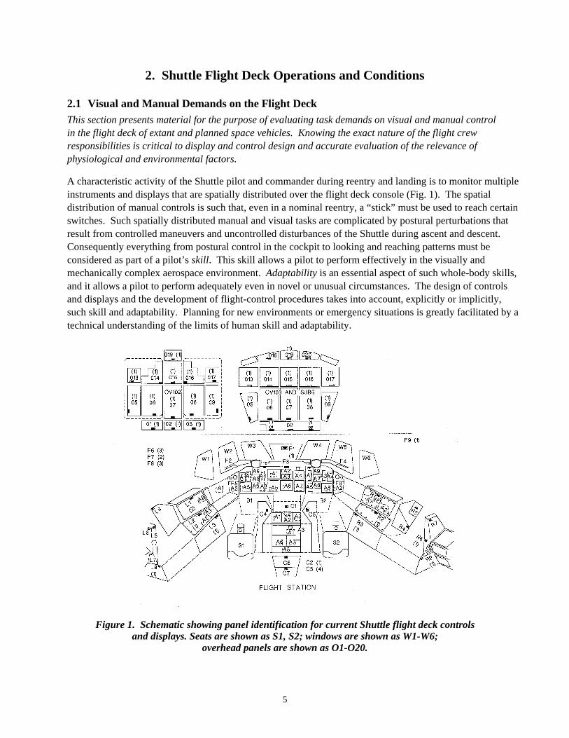
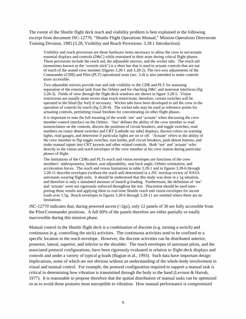
A characteristic activity of the Shuttle pilot and commander during reentry and landing is to monitor multipleinstruments and displays that are spatially distributed over the flight deck console (Fig. 1). The spatialdistribution of manual controls is such that, even in a nominal reentry, a “stick” must be used to reach certainswitches. Such spatially distributed manual and visual tasks are complicated by postural perturbations thatresult from controlled maneuvers and uncontrolled disturbances of the Shuttle during ascent and descent.Consequently everything from postural control in the cockpit to looking and reaching patterns must beconsidered as part of a pilot’s skill. This skill allows a pilot to perform effectively in the visually andmechanically complex aerospace environment. Adaptability is an essential aspect of such whole-body skills,and it allows a pilot to perform adequately even in novel or unusual circumstances. The design of controlsand displays and the development of flight-control procedures takes into account, explicitly or implicitly,such skill and adaptability. Planning for new environments or emergency situations is greatly facilitated by atechnical understanding of the limits of human skill and adaptability.
Figure 1. Schematic showing panel identification for current Shuttle flight deck controlsand displays. Seats are shown as S1, S2; windows are shown as W1-W6;
overhead panels are shown as O1-O20.
6
The extent of the Shuttle flight deck reach and visibility problem is best explained in the followingexcerpt from document JSC-12770, “Shuttle Flight Operations Manual,” Mission Operations DirectorateTraining Division, 1985 (3.28, Visibility and Reach Provisions: 3.28.1 Introduction):
Visibility and reach provisions are those hardware items necessary to allow the crew to see/actuateessential displays and controls (D&C) while restrained in their seats during critical flight phases.These provisions include the reach aid, the adjustable mirrors, and the wicket tabs. The reach aid(sometimes known as the ‘swizzle stick’) is a short bar that is used to actuate controls that are outof reach of the seated crew member (figures 3.28-1 and 3.28-2). The two-axis adjustments of theCommander (CDR) and Pilot (PLT) operational seats (sec. 3.4) is also intended to make controlsmore accessible.
Two adjustable mirrors provide rear and side visibility to the CDR and PLT for assessingseparation of the external tank from the Orbiter and for checking D&C and man/seat interfaces (fig3.28-3). Fields of view through the flight deck windows are shown in figure 3.28-5. Visionrestrictions are usually more severe than reach restrictions; therefore, certain switches will beoperated in the blind (by feel) if necessary. Wicket tabs have been developed to aid the crew in theoperation of controls by touch (fig 3.28-4). The wicket tabs may be used as reference points foractuating controls, permitting visual freedom for concentrating on other flight phases.
It is important to note the full meaning of the words ‘see’ and ‘actuate’ when discussing the crewmember-control interface on the Orbiter. ‘See’ defines the ability of the crew member to readnomenclature on the controls, discern the positions of circuit breakers, and toggle switches, readnumbers on rotary detent switches and CRT [cathode ray tube] displays, discern colors on warninglights, read gauges, and determine if particular lights are on or off. ‘Actuate’ refers to the ability ofthe crew member to flip toggle switches, turn knobs, pull circuit breakers, push detent buttons, andmake manual inputs into CRT keysets and other related controls. Both ‘see’ and ‘actuate’ referdirectly to the vision and reach envelopes of the crew member at his crew station during particularphases of flight.
The limitations of the CDRs and PLTs reach and vision envelopes are functions of the crewmembers’ anthropometry, helmet, seat adjustability, seat back angle, Orbiter orientation, andacceleration forces. The reach and vision limitations in table 3.28-1 and in figures 3.28-6 through3.28-11 describe envelopes (without the reach aid) determined in a JSC mockup review of NASAastronauts wearing flight suits. It should be understood that this study was done in a 1g situation,and therefore is only a simulated measure of launch g-loading. Furthermore, the definition of ‘see’and ‘actuate’ were not rigorously enforced throughout the test. Discretion should be used inter-preting these results and applying them to real-time Shuttle reach and vision envelopes for ascentloads over 1.5g. Reach envelopes in figures 3.28-6 through 3.28-11 are omitted where there are nolimitations.
JSC-12770 indicates that, during powered ascent (>2gx), only 12 panels of 30 are fully accessible fromthe Pilot/Commander positions. A full 60% of the panels therefore are either partially or totallyinaccessible during this mission phase.
Manual control in the Shuttle flight deck is a combination of discrete (e.g. turning a switch) andcontinuous (e.g. controlling the stick) activities. The continuous activities tend to be confined to aspecific location in the reach envelope. However, the discrete activities can be distributed anterior,posterior, lateral, superior, and inferior to the shoulder. The reach envelopes of astronaut pilots, and theassociated postural configurations, have been rigorously evaluated in relation to flight-deck displays andcontrols and under a variety of typical g-loads (Bagian et al., 1993). Such data have important designimplications, some of which are not obvious without an understanding of the whole-body involvement invisual and manual control. For example, the postural configuration required to support a manual task iscritical in determining how vibration is transmitted through the body to the hand (Levison & Harrah,1977). It is reasonable to propose therefore that the spatial distribution of manual tasks can be optimizedso as to avoid those postures most susceptible to vibration. How manual performance is compromised
7
by vibration will also depend on the resistance to motion offered by the controlled device, as well as thecontrol dimension of the device (displacement, force, velocity, etc.).
No guidance, navigation, and control (GN&C)-related crew actions are planned for first stage of ascentunless a failure occurs. To ensure that the auto flight control system is maintaining the expected ascentprofile, the flight crew can verify that the vehicle is at the correct pitch attitude (via the attitude directorindicator) and altitude rate (via the altitude/vertical velocity indicator) at each of five designated timesduring first-stage ascent. The flight crew can monitor that the main engines correctly throttle down andup. They can also ensure that the Pc-50 message (chamber pressure greater than 50 psi) correctly ap-pears on the major mode 102 (first-stage) ascent trajectory CRT display before solid rocket booster(SRB) separation and that SRB separation occurs on time. Manual intervention by the crew is required ifthese events are not automatically accomplished. The crew is also responsible for monitoring mainengine performance. During first-stage ascent, only limited information is available to the crew on theprimary avionics software system (PASS) and backup flight system major mode 102 displays.
During second-stage ascent, the flight crew monitors the onboard systems to ensure that the majorGN&C events occur correctly and on time. These events include closed-loop guidance convergence, 3-gthrottling, main engine cut off (MECO), external tank (ET) separation and the negative Z translationfollowing ET separation. To monitor these events, the flight crew uses the dedicated displays: the mainengine status lights on panel F7 and the PASS ascent trajectory and the bakcup flight system (BFS)ascent trajectory 2 displays.
The crew can monitor guidance convergence by noting if the guidance-computed time of MECO isstabilized on the ascent trajectory display. If not, the crew takes manual control of the vehicle. They canalso ensure that acceleration does not exceed 3 g’s via the BFS ascent trajectory 2 display as well as theaccel tape on the alpha/Mach indicator (AMI). The crew can monitor MECO velocity on the BFS ascenttrajectory 2 display as well as on the M/vel tape on the AMI. MECO is detected by the illumination ofthree red main engine status lights and by the main propulsion system chamber pressure meters on panelF7 going to zero.
Depending on mission requirements, the crew may be required to translate in the plus X direction, usingthe translational hand controller for 11 seconds, to allow the ET camera to photograph the tank.
At specified points during second-stage ascent, the Mission Control Center will make voice calls to thecrew indicating their status with respect to aborts. For example, the “negative return” call indicates thatit is too late to select a return-to-launch-site abort.
During landing, in the automatic mode, the Orbiter is essentially a missile, and the flight crew monitorsthe instruments to verify that the vehicle is following the correct trajectory. The onboard computersexecute the flight control laws (equations). If the vehicle diverges from the trajectory, the crew can takeover at any time by switching to control stick steering (CSS). The Orbiter can fly to a landing in theautomatic mode (only landing gear extension and braking action on the runway are required by the flightcrew). The autoland mode capability of the Orbiter is used by the crew usually to a predetermined pointin flying around the heading alignment cylinder. In flights to date, the crew has switched to CSS whenthe Orbiter is subsonic.
About five minutes before entry interface, the crew adjusts the software to major mode 304. During thismode, which lasts until terminal area energy management (TAEM) interface, five CRTs become
8
available sequentially and are used to monitor auto guidance and the Orbiter trajectory compared to theplanned entry profile. The five displays are identical except for the central plot, which shows theOrbiter’s velocity versus range or energy/weight versus range with a changing scale as the Orbiterapproaches the landing site. This plot also includes static background lines that allow the crew tomonitor the Orbiter’s progression compared to planned entry profiles.
Once TAEM interface is reached, the software automatically makes a transition to major mode 305.The CRT vertical situation 1 display then becomes available. It includes a central plot of Orbiter altitudewith respect to range. This plot has three background lines that represent the nominal altitude versusrange profile, a dynamic pressure limit in guidance profile and a maximum lift-over-drag profile. At30,000 feet, the scale and title on the display change to vertical situation 2, and the display is usedthrough landing. When the approach and landing interface conditions are met, a flashing “A/L” appearson the display.
Another prime CRT display used during entry is the horizontal situation. In addition to providing insightinto and control over navigation parameters, this display gives the crew Orbiter position and headinginformation once the Orbiter is below 200,000 feet.
The flight crew then uses the entry trajectory, vertical situation, and horizontal situation CRT displays tomonitor the GN&C software. They crew can also use them to determine whether a manual takeover isrequired.
In summary, it is clear that human operations are integral to Shuttle flight control. While complexmonitoring encompasses the majority of nominal launch and landing activities, there is the expectationthat the crew can manually control the Shuttle, should it be necessary. Such off-nominal activities aremore complex given the need for discrete and continuous manual control inputs in addition to complexvisual monitoring.
2.2 Shuttle Launch/Reentry/Landing Conditions
This section presents material for the purpose of evaluating disturbances that are common during Shuttlelaunch & reentry. These include vibrations, transient disturbances, and changes in the g-loads.
Excerpts from NASA-STD-3000/Vol.1/Rev.B describe NASA’s position on the launch and reentryenvironment, and vibration phenomena from a human performance perspective.
Vibration seldom occurs in the operational situation as a single isolated variable. Other environ-mental variables such as weightlessness, linear acceleration, etc., can be expected to interact withvibration either to reduce or to increase the debilitating effects. Equipment variables include sizeof graduations or illumination of instruments, inflated pressure suits, etc.; procedural variablesinclude task load, variations in time of performance, etc.; and finally, personal variables, such asfatigue and deconditioning. The effects of some of these can be predicted at this time; others mustawait further research....Studies of human response to vibration have been conducted in fieldenvironments and in complex laboratory simulations. However, most of the available informationresults from laboratory experiments. The most useful information shows the effects of changingthe characteristics of vibration (magnitude, frequency, etc.), the influence of modifying the trans-mission of vibration to the body (by seating and postural alterations), the sources and extent ofindividual variability, and the effects of alterations to the operator’s task. [Section 5.5.2 VibrationDesign Consideration]

9
Significant levels of vibration occur routinely in space module operations during the maximumaerodynamic pressure portion of boost. The vibration is coupled with a significant linear accelera-tion bias...The Mercury astronauts complained that vibration during boost interfered with theirvision. The Titan II rocket produced intense vibration at 11Hz. [Section 5.5.2.1.1 Launch PhaseVibrations]
Significant vibration levels occur during reentry but these levels are not as intense as experiencedduring the launch phase. The vibration is coupled with a significant linear deceleration bias...During entry, low-frequency oscillation may occur if entry angle is too steep. If the angle is morethan one or two degrees, high peak oscillation, depending on the shape of the vehicle, may beproduced. The frequency of such oscillations reach a peak coincident with the entry decelerationpeak. The amplitude of the oscillation progressively decreases during deceleration. For an entryangle of ten degrees, a 2 Hz oscillation with a peak of 0.12-g and an arc of one degree has beenpredicted. Skip-glide entry of a lift-drag vehicle may produce oscillations. [Section 5.5.2.1.3Entry Phase Vibrations]
Vibration may affect crew member performance, and may produce physiological and biodynamiceffects, as well as subjective or annoyance effects. Whole-body vibration may act additively withnoise to cause stress and fatigue and degrade vigilance and performance. There has been limitedresearch combining vibration with other environmental stressors such as acceleration, noise, andaltitude. [Section 5.5.2.3 Human Responses to Vibration-Design Considerations]
The physical responses of the body are primarily the result of the body acting as a complex systemof masses, elasticities, dampings, and couplings in the low frequency range, i.e., up to 50 Hz. Theimpedance of the body and its parts and organs damp vibration over certain frequency ranges andmay amplify vibration over other frequency ranges within various portions or all of the body.[Section 5.5.2.3.1 Physiological Effects of Vibration]
Vibration affects performance either by modifying perception or by influencing controlmovements. [Section 5.5.2.3.2 Performance Effects of Vibration]
Notable in this material is the lack of detail in descriptions of the vibration environment, including theresulting postural perturbations, on the Shuttle flight deck during reentry. Data were collected on earlyShuttle flights, but were directed more to evaluating structural integrity of the flight deck and instru-mentation. Little or no attention appears to have been given to the human performance implications ofthese vibrations. However, some acknowledgment of these implications can be found in the “ShuttleCrew Operations Manual” (last update: August 1996). This document is provided as a reference forSpace Shuttle crew members and contains information on each shuttle system and every phase of ageneric Space Shuttle mission. Following are some specific items pertaining to sensations associatedwith Ascent and Entry:
Prelaunch, SSME [Space Shuttle main engine] gimbal checks can be felt throughout the shuttlestructure... First stage is characterized by a rapid g buildup to slightly over 2g, accompanied by agreat deal of noise and vibration. Instruments and CRT displays can be monitored, but precisetasks are difficult. [7.1 Ascent: Sensory Cues]
The digital auto pilot (DAP) includes bending filters in all axes that protect the DAP from couplingwith the Orbiter structure in a resonant oscillation. If the bending filter constants were wrong, itcould be possible to cause an oscillation...Symptoms are a high frequency oscillation (4 Hz),accompanied by airframe vibration caused by oscillation of the aero surfaces. The crew mayobserve these oscillations on the SPI [surface position indicator] or the ADI [attitude directorindicator] rate needles. A yaw jet limit cycle may also occur. [7.3 Entry]
Returning from orbit, some crew members have reported increased sensitivity to g as it buildsduring entry. One crew member observed that “when you hit a quarter g on entry, it seems liketwo g’s in the T-38...Crew members should be aware that their ability to perform entry tasks maybe degraded from that experienced in the SMS during training. Keep in mind that g’s stay around1.3 until Mach 2.5. [7.3 Entry: Sensory Cues]

10
On the recent STS-78 launch, NASA positioned a video camera on the flight deck to record the ascent.A review of this tape and the associated comments made by the pilot during the subsequent downlinkindicate the nature of the disturbances from the powered ascent:
Pilot: “Now we are in, obviously, first stage. Pretty bumpy ride, and you can feel the throttle down.”
CapCom: “…it sure does show the rough ride of the solids.”
Pilot: “Yeah, as you well know, it is a pretty impressive ride on those boosters.”
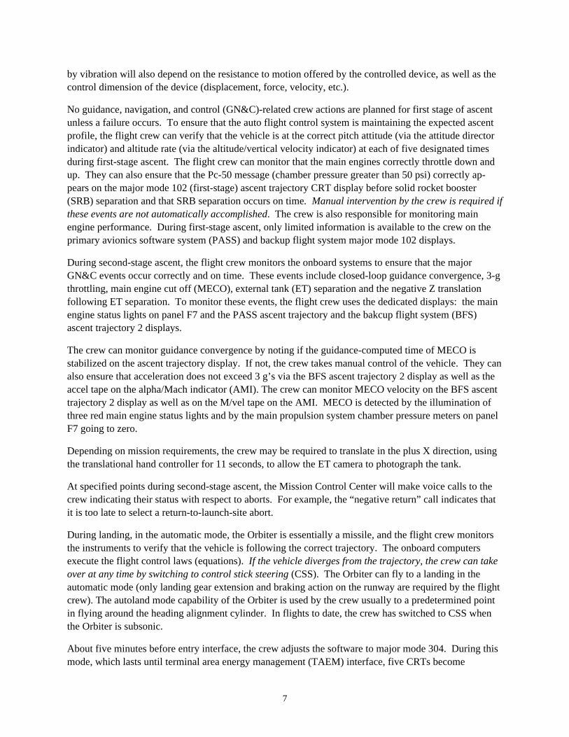
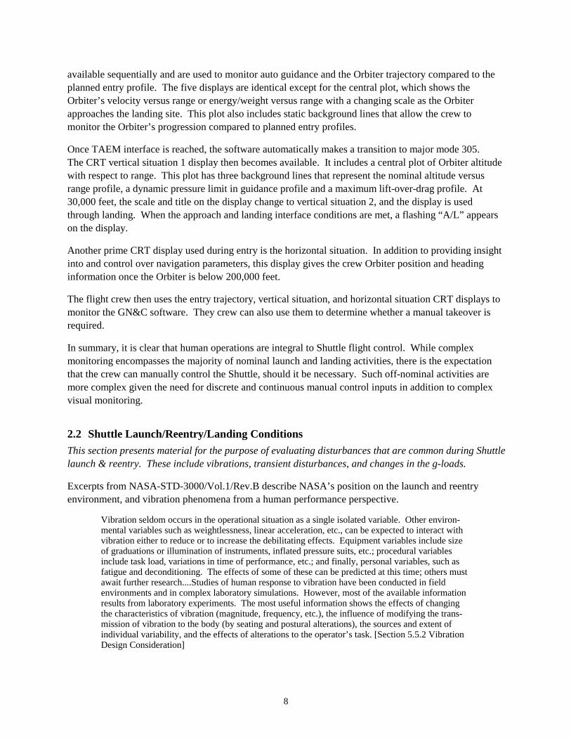
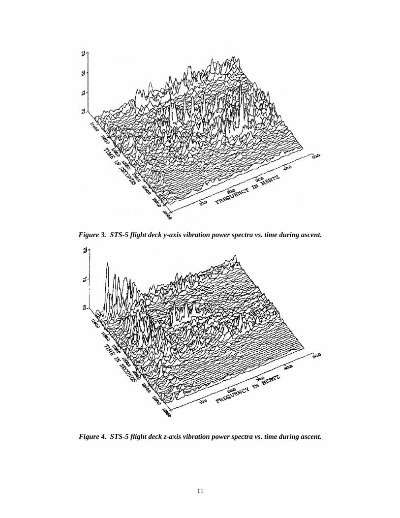
Quantification of these phenomena can be seen in Figures 2, 3, and 4, which present data of actual ascentg-loads and vibrations. The y-axis of the Shuttle runs from wing tip to wing tip, the z-axis runs from thetopside to the underside of the wings. The vibration data in Figures 3 and 4 were gathered from acceler-ometers located in the nose of the Shuttle. Unfortunately, we were unable to obtain similar detailedvibration data for reentry. Figure 5 depicts a simulated reentry g-load profile. Reentry flight deck vibra-tions were described by structural engineers at NASA as "relatively benign" compared to the launchvibrations. However, those same engineers did report that postflight conversations with Shuttle crewmembers revealed a heightened sensitivity to any vibration and acceleration.
Figure 2. Typical Shuttle acceleration time history during ascent.
11
Figure 3. STS-5 flight deck y-axis vibration power spectra vs. time during ascent.
Figure 4. STS-5 flight deck z-axis vibration power spectra vs. time during ascent.
12
200 400 600 800 1000 1200 140000
0.5
1.0
1.5
Mission Elapsed Time (sec)
Tot
al S
ense
d A
ccel
erat
ion
(E
arth
g’s
)
Figure 5. G-load vs. time for 3-DOF simulated reentry profile.
2.3 Current and New Technologies for Space Vehicle Flight DecksOn the basis of interactions with the Advanced Orbiter Cockpit program, we will evaluate theimplications of human performance characteristics discussed above for current and proposed flight deckdisplays and controls.
2.3.1 Current Displays and Controls (Adapted from the Shuttle Reference Manual)
The crew compartment of the Orbiter contains the most complicated displays and controls everdeveloped for an aerodynamic vehicle. The displays and controls exist in a variety of configurations,with toggle, push button, thumbwheel, and rotary switches; and circular meters, rectangular dials, andrectangular tapes. Switches and circuit breakers are positioned in groups corresponding to theirfunctions.
All controls are protected against inadvertent activation. Toggle switches are protected by wicketguards, and lever lock switches are used wherever inadvertent action would be detrimental to flightoperations or could damage equipment. Cover guards are used on switches where inadvertent actuationwould be irreversible.
The displays and controls in the Orbiter crew compartment enable the flight crew members to supervise,control, and monitor the Space Shuttle mission and vehicle. They include controllers, CRT displays andkeyboards, coding and conversion electronics for instruments and controllers, lighting, timing devices,and a caution and warning system.
All displays and controls have dimmable floodlighting in addition to integral meter lighting.
There are more than 2,020 displays and controls in the forward and aft flight decks and middeck of theOrbiter. This represents more than 100 times the number of controls and displays found in the averageautomobile.
13
Orbiter displays and controls consist of panel displays, mechanical controls, and electrically operatedcontrols. Generally, the displays and controls are grouped by function and arranged in operationalsequence from left to right or top to bottom with the most critical and most frequently used deviceslocated to maximize the crew’s performance and efficiency.
The forward flight control area panels are labeled L for the left, or commander’s position; R for the right,or pilot’s position; F for the front section; O for the overhead position, and C for the lower center section(Fig. 1).
The head-up display (HUD) was introduced to the Shuttle to ease the demands on the fight crew, afterHUD technology had proven so useful in military aircraft. The HUD is an optical miniprocessor thatcues the commander and/or pilot during the final phase of entry and particularly in the final approach tothe runway. With minimal movement of their eyes from the forward windows (head up) to the dedicateddisplay instruments (head down), the commander and pilot can read data from HUDs located in front ofthem on their respective glareshields. The HUD displays the same data presented on several otherinstruments, including the ADI, SPI, AMI, and altitude/vertical velocity indicator.
The HUD allows out-of-the-window viewing by superimposing flight commands and information on atransparent combiner in the window’s field of view. The baseline Orbiter, like most commercial aircraft,presents conventional electromechanical display on a panel beneath the glareshield, which necessitatesthat the flight crew look down for information and then up to see out the window. During critical flightphases, particularly approach and landing, this is not an easy task. In the Orbiter, with its unique vehicledynamics and approach trajectories, this situation is even more difficult.
The current caution and warning system is worthy of note also. The system consists of software andelectronics that provide the crew with visual and aural cues when a system exceeds predefined operatinglimits. Visual cues consist of four red MASTER ALARM lights, a 40-light array on panel F7, a 120-lightarray on panel R13U, and CRT messages. The aural cue is sent to the communications system fordistribution to flight crew headsets or speaker boxes. Fault messages for some parameters are issuedevery time the software completes the required number of data counts with the parameter out of limits.This can result in a steady stream of fault messages and MASTER ALARMs that may obscure otherimportant fault messages. If this situation is encountered, the crew or Mission Control can inhibit theaffected parameter to prevent nuisance messages in alarms in OPS 2 or OPS 4. In OPS 1, OPS 6, orOPS 3 the crew generally has to tolerate the extra alarms/fault messages and pay extra close attention tothe fault summary display.
2.3.2 Future Displays and Controls
One upgrade item already scheduled for integration into the Orbiter flight deck is the multifunctionalelectronic display system (MEDS). This upgrade will replace the current Orbiter cockpit displays, whichare early 1970s technology. The current displays which provide command and control of the SpaceShuttle are “single string” electromechanical devices that are experiencing life-related failures and aremaintenance-intensive. The MEDS upgrade uses a state-of-the-art, multiple-redundant liquid crystaldisplay (LCD) system to replace these devices. However, the MEDS system is intended to simplyreplicate the symbology and layout of the current displays. In essence, the MEDS LCDs will “draw” thedisplays so that they look identical to those currently used in the Shuttle.
14
Other efforts within NASA are addressing a complete overhaul of the Orbiter flight deck. The end resultmay have very little resemblance to today’s Shuttle flight deck. In particular, efforts are under way todevelop a state-of-the-art glass fight deck leveraged on the best “glass cockpit” implementations in themilitary and commercial sectors. Such a development would result in a reconfigurable flight deck inwhich only context relevant (e.g. ascent, orbit, reentry) displays and controls would be presented to theoperator. One current working example of state-of-the-art flight deck technology, symbology, andarchitecture is seen in the Boeing 777. Reference for these upgrades include MIL-STD-1787B, “AircraftDisplay Symbology,” and AFGS-87213B, “Displays, Airborne, Electronically/Optically Generated.”
Candidate technologies that have been considered to date include head down and head up displays,information display and symbology, information control technologies (e.g. hands-on throttle and stick),automation technologies, health monitoring, detection, and diagnosis implementations, and caution,advisory and warning implementations.
Find up-to-date information concerning advanced Orbiter cockpit concepts at the website of JSC’s RapidPrototyping and Interface Development Lab (http://dp4.jsc.nasa.gov:8001/PROJECTS/AOC/).
3. Human Perception and PerformanceThis section describes the effects of vehicular disturbances and the effects of adaptation to weightless-ness on visual and manual performance in conditions that are relevant or comparable to Shuttle launchand reentry.
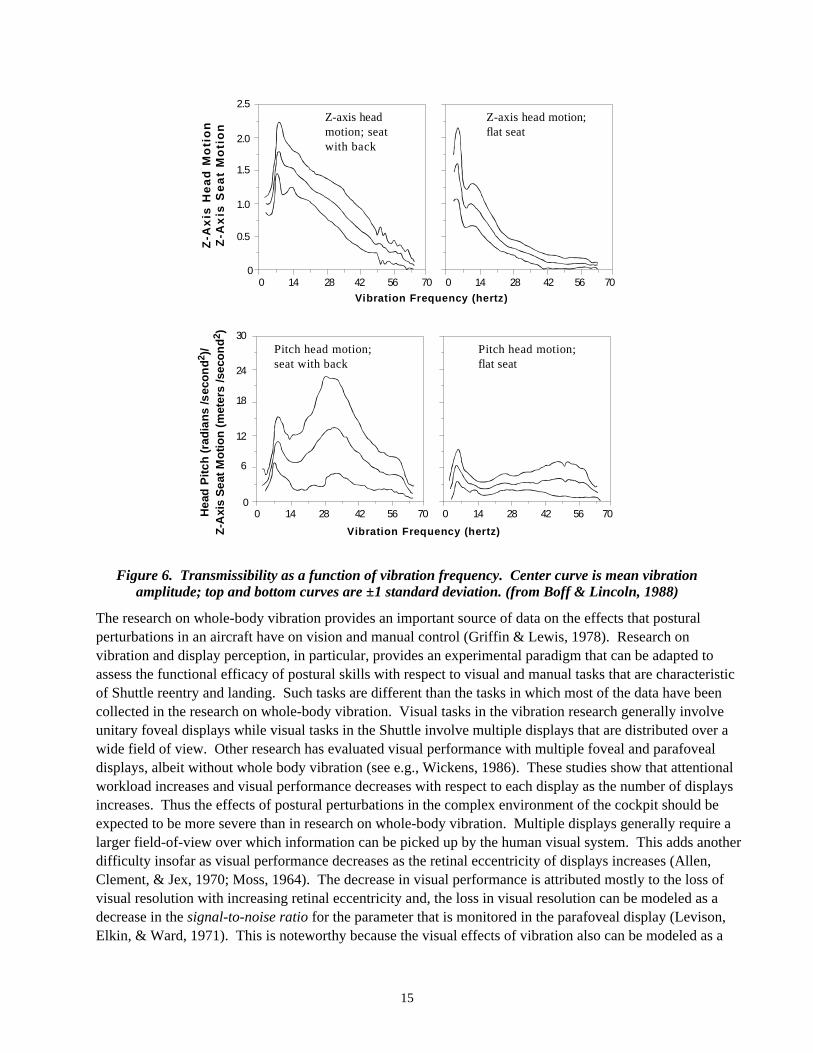
3.1 Effects of Whole-Body Perturbations on Visual and Manual PerformanceVibration and transients have consequences for nonrigid organisms in general (Riccio & Stoffregen,1988) and, in particular, for occupants of vehicles who are neither rigid nor rigidly attached to the vehi-cle (Boff & Lincoln, 1988, pp. 2076-2081; Griffin, 1975; Riccio, 1995; Riccio et al., 1998). Because ofthe nonrigidity of the body and nonuniformities in the mass and moment of inertia of various body seg-ments, relative motion of body segments is generated by the vibration and transients encountered duringwhole-body movement. Such disturbances can degrade vehicular control by interfering with perceptionand action in the cockpit. For example, movements of the head relative to the cockpit can degrade thepickup of information from instruments and displays (Boff & Lincoln, 1988, pp. 2082-2101; Griffin &Lewis, 1978; Lewis & Griffin, 1978; Moseley & Griffin, 1986). Uncontrolled body movements can alsodegrade manual control performance (Boff & Lincoln, 1988, pp. 2106-2117; Lewis & Griffin, 1978). Arich source of data on transmissibility of forces to the head and torso is the research on whole-body“vibration” of seated individuals (summarized in Boff and Lincoln 1988). There is a peak intransmissibility for both vertical and pitch motion of the head at vertical perturbation frequencies of 3-8Hz (Fig. 6). At low frequencies, significant amounts of head motion can occur at the first harmonic ofthe vertical perturbation force. Transmission of vertical perturbations to the head has been shown to beaffected by posture, muscle tension, body size, sustained acceleration, and attachment of extra masses(Griffin 1975), and by adaptation to space flight (McDonald et al., 1996).
15
Z-A
xis
He
ad
Mo
tio
nZ
-Ax
is S
ea
t M
oti
on
0 14 28 42 56 700 14 28 42 56 70
2.5
2.0
1.5
1.0
0.5
0
Vibration Frequency (hertz)
Pitch head motion;seat with back
Pitch head motion;flat seat
Hea
d P
itch
(ra
dia
ns
/sec
on
d2 )
/Z
-Axi
s S
eat
Mo
tio
n (
met
ers
/sec
on
d2 )
0 14 28 42 56 700 14 28 42 56 70
30
24
18
12
6
0
Vibration Frequency (hertz)
Z-axis headmotion; seatwith back
Z-axis head motion;flat seat
Figure 6. Transmissibility as a function of vibration frequency. Center curve is mean vibrationamplitude; top and bottom curves are ±1 standard deviation. (from Boff & Lincoln, 1988)
The research on whole-body vibration provides an important source of data on the effects that posturalperturbations in an aircraft have on vision and manual control (Griffin & Lewis, 1978). Research onvibration and display perception, in particular, provides an experimental paradigm that can be adapted toassess the functional efficacy of postural skills with respect to visual and manual tasks that are characteristicof Shuttle reentry and landing. Such tasks are different than the tasks in which most of the data have beencollected in the research on whole-body vibration. Visual tasks in the vibration research generally involveunitary foveal displays while visual tasks in the Shuttle involve multiple displays that are distributed over awide field of view. Other research has evaluated visual performance with multiple foveal and parafovealdisplays, albeit without whole body vibration (see e.g., Wickens, 1986). These studies show that attentionalworkload increases and visual performance decreases with respect to each display as the number of displaysincreases. Thus the effects of postural perturbations in the complex environment of the cockpit should beexpected to be more severe than in research on whole-body vibration. Multiple displays generally require alarger field-of-view over which information can be picked up by the human visual system. This adds anotherdifficulty insofar as visual performance decreases as the retinal eccentricity of displays increases (Allen,Clement, & Jex, 1970; Moss, 1964). The decrease in visual performance is attributed mostly to the loss ofvisual resolution with increasing retinal eccentricity and, the loss in visual resolution can be modeled as adecrease in the signal-to-noise ratio for the parameter that is monitored in the parafoveal display (Levison,Elkin, & Ward, 1971). This is noteworthy because the visual effects of vibration also can be modeled as a
16
reduction in the signal-to-noise ratio for task-dependent parameters that are visually displayed (Zacharias &Levison, 1979). Thus, the effects of retinal eccentricity and vibration are commensurable. The research onwhole-body vibration can be adapted, by including tasks that are typical of the Shuttle cockpit, to develop amature paradigm for evaluating human performance during Shuttle reentry and landing.
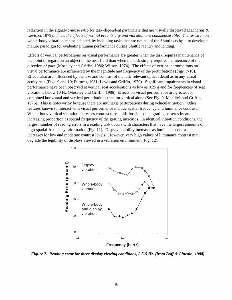
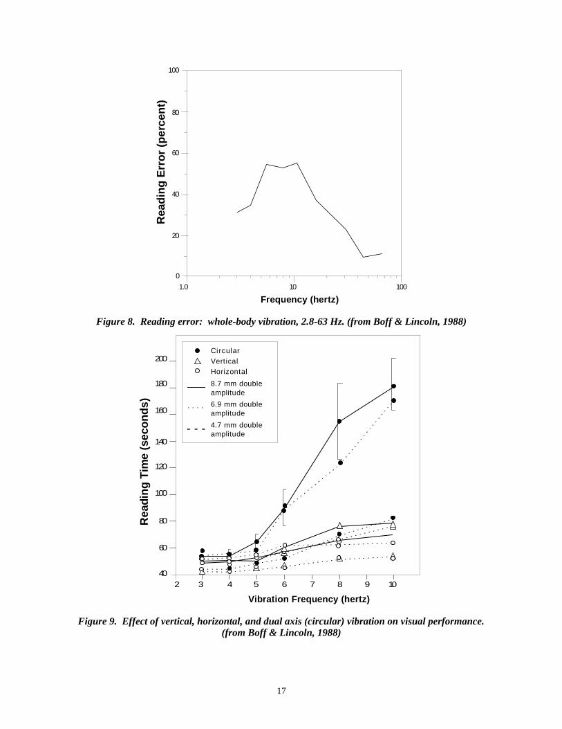
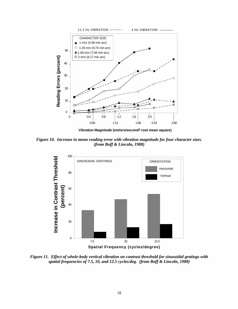
Effects of vertical perturbations on visual performance are greater when the task requires maintenance ofthe point of regard on an object in the near field than when the task simply requires maintenance of thedirection of gaze (Moseley and Griffin, 1986; Wilson, 1974). The effects of vertical perturbations onvisual performance are influenced by the magnitude and frequency of the perturbations (Figs. 7-10).Effects also are influenced by the size and contrast of the task-relevant optical detail as in any visualacuity task (Figs. 9 and 10; Furness, 1981; Lewis and Griffin, 1979). Significant impairments in visualperformance have been observed at vertical seat accelerations as low as 0.25 g and for frequencies of seatvibrations below 10 Hz (Moseley and Griffin, 1986). Effects on visual performance are greater forcombined horizontal and vertical perturbations than for vertical alone (See Fig. 9; Meddick and Griffin,1976). This is noteworthy because there are multiaxis perturbations during vehicular motion. Otherfeatures known to interact with visual performance include spatial frequency and luminance contrast.Whole-body vertical vibration increases contrast thresholds for sinusoidal grating patterns by anincreasing proportion as spatial frequency of the grating increases. In identical vibration conditions, thelargest number of reading errors in a reading task occurs with characters that have the largest amounts ofhigh-spatial-frequency information (Fig. 11). Display legibility increases as luminance contrastincreases for low and moderate contrast levels. However, very high values of luminance contrast maydegrade the legibility of displays viewed in a vibration environment (Fig. 12).
0
20
40
60
80
100
0.1 1.0 10
Frequency (hertz)
Display vibration
Whole-body vibration
Whole-body and display vibration
Rea
din
g E
rro
r (p
erce
nt )
Figure 7. Reading error for three display viewing conditions, 0.5-5 Hz. (from Boff & Lincoln, 1988)
17
0
20
40
60
80
100
1.0 10 100
Frequency (hertz)
Rea
din
g E
rro
r (p
erce
nt )
Figure 8. Reading error: whole-body vibration, 2.8-63 Hz. (from Boff & Lincoln, 1988)
Vibration Frequency (hertz)
Rea
din
g T
ime
(sec
on
ds)
CircularVerticalHorizontal
8.7 mm doubleamplitude
6.9 mm doubleamplitude
4.7 mm doubleamplitude
200
180
160
140
120
100
80
60
402 3 4 5 6 7 8 9 10
Figure 9. Effect of vertical, horizontal, and dual axis (circular) vibration on visual performance.(from Boff & Lincoln, 1988)
18
CHARACTER SIZE
1 mm (4.58 min arc)
1.25 mm (5.73 min arc)
1.65 mm (7.56 min arc)2 mm (9.17 min arc)
Rea
din
g E
rror
s (p
erce
nt)
0
10
20
30
40
50
0 0.4 0.8 1.2 1.6 2.0
0.56 1.12 1.68 2.24 2.80
Vibration Magnitude (meters/second2 root mean square)
4 Hz VIBRATION11.2 Hz VIBRATION
Figure 10. Increase in mean reading error with vibration magnitude for four character sizes.(from Boff & Lincoln, 1988)
100
80
60
40
20
0
SINUSOIDAL GRATINGS
7.5 10 12.5
Spatial Frequency (cycles/degree)
ORIENTATION
Horizontal
Vertical
In
crea
se in
Con
tras
t Th
resh
old
(pe r
cen
t)
Figure 11. Effect of whole-body vertical vibration on contrast threshold for sinusoidal gratings withspatial frequencies of 7.5, 10, and 12.5 cycles/deg. (from Boff & Lincoln, 1988)

19
0
10
12
0.20 0.33 0.60 0.78 0.88 0.94 0.97 0.99
Modulation Contrast
ACCELERATION LEVEL
(m/sec2)
B 1.25 C 1.60 D 2.00 E 2.50 F 2.80
A 0.00
Rea
din
g E
rro
r (%
)
A
B
C
D
E
F8
6
4
2
Figure 12. Effect of modulation contrast on reading errors with panel-mounted displays.(from Boff & Lincoln, 1988)
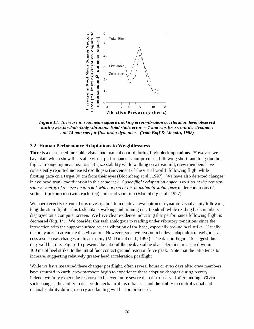
As stated above, manual control is also susceptible to vibration interference. Manual tracking is mostsensitive to disruption by whole-body vibration in the region of 3-8 Hz (Fig. 13). Sensitivity of a task todisruption depends upon both system dynamics and vibration frequency content. Dynamics with asimple gain (zero-order dynamics) transmit all frequencies equally. Direct transmission of vibrationthrough the body and into the control system (breakthrough) therefore contributes a large proportion oferror in zero-order systems. Dynamics with pure integration (first-order dynamics) attenuate in inverseproportion to frequency. First-order tasks are therefore less sensitive to direct breakthrough. However,first-order tasks are more sensitive to other forms of vibration-induced disruption. It should be noted thattranslational body motion can induce considerable rotary motion at the controlling limb; rotary knobscan therefore show as much breakthrough as joysticks (see Boff & Lincoln, 1988, for details).
Measurement of visual and manual performance in the Shuttle flight deck would provide a uniqueopportunity to obtain a quantitative and meaningful evaluation of the functional consequences ofvehicular vibration and adaptive coordination in the eye-head-torso-hand system.
20
Inc
rea
se
in
Ro
ot
Me
an
Sq
ua
re V
ec
tor/
Err
or
(mil
lim
et e
rs)/
Vib
rati
on
Ma
gn
itu
de
me
ters
/se
co
nd
2 ro
ot
me
an
sq
ua
re)
6
0
1
2
3
4
5
0 2 3 5 10 20
Vibrat ion Fr equency (her tz)
Total Error
First order
Zero order
Figure 13. Increase in root mean square tracking error/vibration acceleration level observedduring z-axis whole-body vibration. Total static error = 7 mm rms for zero-order dynamics
and 15 mm rms for first-order dynamics. (from Boff & Lincoln, 1988)
3.2 Human Performance Adaptations to WeightlessnessThere is a clear need for stable visual and manual control during flight deck operations. However, wehave data which show that stable visual performance is compromised following short- and long-durationflight. In ongoing investigations of gaze stability while walking on a treadmill, crew members haveconsistently reported increased oscillopsia (movement of the visual world) following flight whilefixating gaze on a target 30 cm from their eyes (Bloomberg et al., 1997). We have also detected changesin eye-head-trunk coordination in this same task. Space flight adaptation appears to disrupt the compen-satory synergy of the eye-head-trunk which together act to maintain stable gaze under conditions ofvertical trunk motion (with each step) and head vibration (Bloomberg et al., 1997).
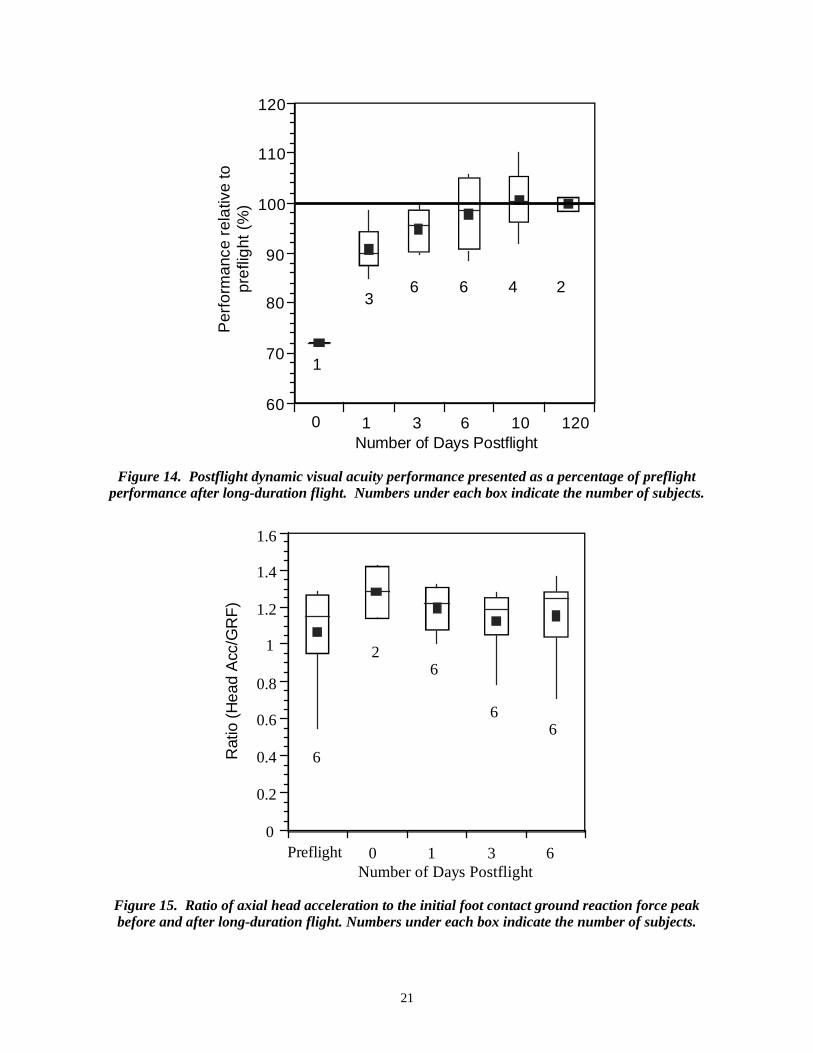
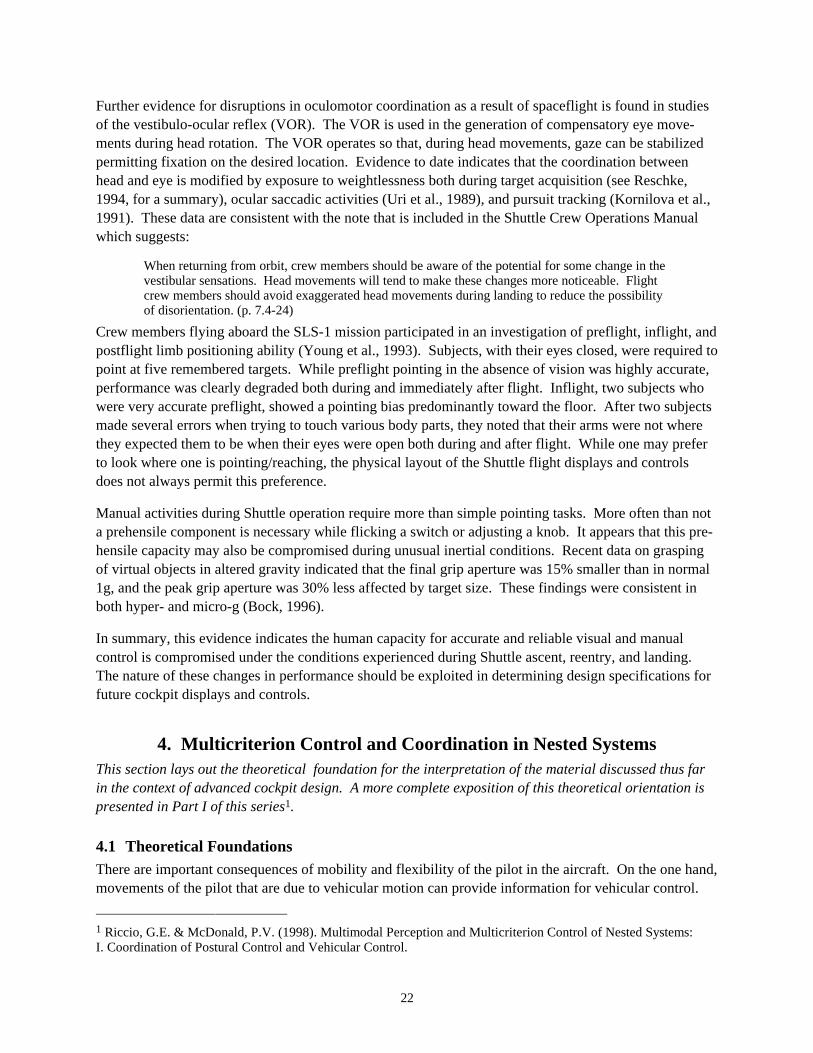
We have recently extended this investigation to include an evaluation of dynamic visual acuity followinglong-duration flight. This task entails walking and running on a treadmill while reading back numbersdisplayed on a computer screen. We have clear evidence indicating that performance following flight isdecreased (Fig. 14). We consider this task analogous to reading under vibratory conditions since theinteraction with the support surface causes vibration of the head, especially around heel strike. Usuallythe body acts to attenuate this vibration. However, we have reason to believe adaptation to weightless-ness also causes changes in this capacity (McDonald et al., 1997). The data in Figure 15 suggest thismay well be true. Figure 15 presents the ratio of the peak axial head acceleration, measured within100 ms of heel strike, to the initial foot contact ground reaction force peak. Note that the ratio tends toincrease, suggesting relatively greater head acceleration postflight.
While we have measured these changes postflight, often several hours or even days after crew membershave returned to earth, crew members begin to experience these adaptive changes during reentry.Indeed, we fully expect the response to be even more severe than that observed after landing. Givensuch changes, the ability to deal with mechanical disturbances, and the ability to control visual andmanual stability during reentry and landing will be compromised.
21
0 1 3 6 10 12060
70
80
90
100
110
120
1
36 6 4 2
Number of Days Postflight
Per
for m
ance
rel
ativ
e t o
pre
flig
ht (
%)
Figure 14. Postflight dynamic visual acuity performance presented as a percentage of preflightperformance after long-duration flight. Numbers under each box indicate the number of subjects.
Number of Days PostflightPreflight 0 1 3 6
0
0.2
0.4
0.6
0.8
1
1.2
1.4
1.6
2
6
6
66
Rat
io (
Hea
d A
cc/G
RF
)
Figure 15. Ratio of axial head acceleration to the initial foot contact ground reaction force peakbefore and after long-duration flight. Numbers under each box indicate the number of subjects.
22
Further evidence for disruptions in oculomotor coordination as a result of spaceflight is found in studiesof the vestibulo-ocular reflex (VOR). The VOR is used in the generation of compensatory eye move-ments during head rotation. The VOR operates so that, during head movements, gaze can be stabilizedpermitting fixation on the desired location. Evidence to date indicates that the coordination betweenhead and eye is modified by exposure to weightlessness both during target acquisition (see Reschke,1994, for a summary), ocular saccadic activities (Uri et al., 1989), and pursuit tracking (Kornilova et al.,1991). These data are consistent with the note that is included in the Shuttle Crew Operations Manualwhich suggests:
When returning from orbit, crew members should be aware of the potential for some change in thevestibular sensations. Head movements will tend to make these changes more noticeable. Flightcrew members should avoid exaggerated head movements during landing to reduce the possibilityof disorientation. (p. 7.4-24)
Crew members flying aboard the SLS-1 mission participated in an investigation of preflight, inflight, andpostflight limb positioning ability (Young et al., 1993). Subjects, with their eyes closed, were required topoint at five remembered targets. While preflight pointing in the absence of vision was highly accurate,performance was clearly degraded both during and immediately after flight. Inflight, two subjects whowere very accurate preflight, showed a pointing bias predominantly toward the floor. After two subjectsmade several errors when trying to touch various body parts, they noted that their arms were not wherethey expected them to be when their eyes were open both during and after flight. While one may preferto look where one is pointing/reaching, the physical layout of the Shuttle flight displays and controlsdoes not always permit this preference.
Manual activities during Shuttle operation require more than simple pointing tasks. More often than nota prehensile component is necessary while flicking a switch or adjusting a knob. It appears that this pre-hensile capacity may also be compromised during unusual inertial conditions. Recent data on graspingof virtual objects in altered gravity indicated that the final grip aperture was 15% smaller than in normal1g, and the peak grip aperture was 30% less affected by target size. These findings were consistent inboth hyper- and micro-g (Bock, 1996).
In summary, this evidence indicates the human capacity for accurate and reliable visual and manualcontrol is compromised under the conditions experienced during Shuttle ascent, reentry, and landing.The nature of these changes in performance should be exploited in determining design specifications forfuture cockpit displays and controls.
4. Multicriterion Control and Coordination in Nested SystemsThis section lays out the theoretical foundation for the interpretation of the material discussed thus farin the context of advanced cockpit design. A more complete exposition of this theoretical orientation ispresented in Part I of this series1.
4.1 Theoretical FoundationsThere are important consequences of mobility and flexibility of the pilot in the aircraft. On the one hand,movements of the pilot that are due to vehicular motion can provide information for vehicular control.
1 Riccio, G.E. & McDonald, P.V. (1998). Multimodal Perception and Multicriterion Control of Nested Systems:I. Coordination of Postural Control and Vehicular Control.
23
On the other hand, uncontrolled movements of the body can interfere with perception and action in thecockpit. If uncontrolled movements interfere with vehicular control, reduction of uncontrolled move-ments should improve vehicular control. One method of reducing uncontrolled movements is to reducemobility and flexibility of the pilot by adding passive restraints in the cockpit. For example, addingshoulder restraint pads to the conventional lap belt and shoulder harness in the cockpit of a high-performance vehicle improves tracking performance when the pilot is subjected to sustained orfluctuating lateral forces that are due to vehicular motion (Van Patten, Repperger, Hudsen, & Frazier,1983). Reduction of uncontrolled movements through such a system of passive restraints improves boththe precision and accuracy of control; fewer control errors are made and there is less cross-couplingamong the various degrees of freedom (DOF) in the multi-input multi-output control that is typical offlight.
The pilot, and other occupants of a vehicle, also reduce uncontrolled movements through adaptive pos-tural control activity. The various segments of the body must be actively stabilized whenever one is notpassively stabilized (Riccio & Stoffregen, 1990; Stoffregen & Riccio, 1988). Even when it is reasonableto maximize passive restraints on the torso (e.g., in a vehicle), it is important to allow some mobility ofthe head and limbs to facilitate looking at, around, and through; and to facilitate reaching and manualcontrol (Riccio et al., 1998; Riccio & Stoffregen, 1988). Mobility can be increased through reduction ofpassive restraint, but this also increases the demands on active stabilization, that is, on postural control.Postural control with various body segments is limited by passive restraints such as seat belts andshoulder harnesses. Pushing on support surfaces with the legs and arms can be used to compensate fortorques due to tilt or imbalance (cf., Riccio & Stoffregen, 1988; Zacharkow, 1988), but such posturalcontrol strategies can lead to inappropriate actions on the control stick and rudder pedals (Van Patten etal., 1983). In an aircraft cockpit, the major body segments that can be coordinated in this way are thehead and the upper torso (Riccio, 1995; Riccio et al., 1998).
The dynamics of balance in the cockpit vary because of variation in the gravitoinertial vector within andacross typical flight maneuvers (see e.g., Brown et al., 1991; Riccio, 1995; Riccio et al., 1998). Linearand centripetal acceleration of the aircraft change both the direction and magnitude of the gravitoinertialvector. Changes in the direction of this vector shift the location of the potential gradient for balance inthe postural configuration space. Changes in the magnitude of this vector change the steepness of thegradient and change the size of the region within which postural perturbations can be reversed. Thus,postural control in vehicles must be robust, or it must adapt, to variations in both the direction of balanceand the consequences of imbalance. Postural aftereffects of exposure to altered gravitoinertial environ-ments have been demonstrated in several investigations using human centrifuges (Bles & de Graaf, 1992;Hamilton, Kantor, & Magee, 1989; Martin & Riccio, 1993). These studies reveal that limits on adapt-ability vary among individuals and that, beyond these limits, individuals experience postural instabilityand motion sickness. In some cases, stability limits are avoided by adopting robust postural controlstrategies characterized by stiff, “robot-like,” or other movement patterns with reduced DOF.
Adaptability is also important because the evaluation functions, and associated potential gradients, forpostural control are influenced by situation-specific factors other than torques on the body segments(Riccio, 1993; Riccio & Stoffregen, 1988; 1991). Such factors include different constraints which areimposed on postural control by different tasks. We have shown that postural perturbations are differentfor tasks involving reading, low-force tapping, or simply maintaining balance when the mechanicalconditions are otherwise identical (Riccio, Lee, & Martin, 1993). These results also suggest that taskconstraints can have effects that are similar to the effects of mechanical constraints, and these constraints
24
can be modeled in the similar ways. In particular, movement of the head due to whole-body perturbationwas reduced for the reading task while movement of other body segments was unaffected. Thus, adapta-tion of multisegment (i.e., nonrigid) postural control to task constraints was both specific and functional.In many cases, such coordination requires exquisite observability and controllability of the interactionbetween translation and rotation of the head. Given that prolonged weightlessness alters vestibularperception of translation and rotation, we suspect that space flight adaptation may result in head-trunkcoordination that is less specific and less functional given the task demands of reentry.
The meaning of the sensory information, its implications for action, is influenced by the context. Forexample, perceived rotational motion or change in orientation may or may not require a compensatorypostural action. Disturbances on the aircraft can result in changes in orientation (e.g., pitch and roll) ofthe aircraft that may not be visible if outside-the-cockpit optical structure is impoverished. In addition,the visible surroundings inside the cockpits of many aircraft are often more extensive and richer inoptical structure than the visible surroundings outside the cockpit, and the visible surroundings inside thecockpit are more relevant to perception and action in the cockpit (e.g., viewing instruments and handlingcontrols). Furthermore, the support surfaces move with the visible surroundings inside the cockpit. Thispresents a problem for postural control that may be difficult to overcome: Posture may be controlledwith respect to the support surfaces and visible surroundings inside the cockpit to facilitate interactionwith the cockpit environment, but posture must also be controlled with respect to the inertial environ-ment to avoid or limit imbalance (note that this is a problem even when the surroundings outside thecockpit are visible). This situation is analogous to “sway referencing” of the support surface and visiblesurroundings during the experimental or diagnostic evaluation of stance (see Nashner & McCollum,1985). It is well known that vestibular sensitivity to imbalance mitigates the destabilizing effects ofthese unusual environments. We suspect that space flight adaptation may result in difficulties withperception and action in the cockpit over changes in the g-vector and over the complex relationshipsamong sensory reference frames during reentry.
4.2 Relevance to Flight Deck Performance
4.2.1 Task Constraints
The adaptability and sensitivity of postural control must be considered with specific reference to(nonmechanical) task constraints imposed in particular phases of the mission. Only under thesecircumstances could this information indicate whether visual and manual stability is governed by tacitknowledge of the effects that head and trunk motion has on visual and manual performance (Riccio,1993, 1995; Riccio et al., 1998; Riccio & Stoffregen, 1988, 1991). Individual differences due to experi-ence in postural stabilization and in performance under challenging cockpit conditions also shed light onthese aspects of piloting skill. As noted above, everything from postural control in the cockpit to lookingand reaching patterns must be considered as part of a pilot's skill. This skill allows a pilot to performeffectively in the visually and mechanically complex aerospace environment. Adaptability is an essen-tial aspect of such whole-body skills, and it allows a pilot to perform adequately even in novel or unusualcircumstances. The design of controls and displays and the development of flight-control procedurestakes into account, explicitly or implicitly, such skill and adaptability. Planning for new environments oremergency situations is greatly facilitated by a technical understanding of the limits of human skill andadaptability.
25
4.2.2 Whole-Body Perturbations
There is a conspicuous lack of detail in descriptions of the vibration environment, including the resultingpostural perturbations, on the Shuttle flight deck during reentry. Data were collected on early Shuttleflights, but were directed more to evaluating structural integrity of the flight deck and instrumentation.Little or no attention appears to have been given to the human performance implications of thesevibrations. From the material we have reviewed it is clear that the relation between motion of the crewmembers’ head, trunk, and seat is critical for preserving robust visual and manual control. Moreover,each phase of a mission presents different challenges to preserving this control. Specifically, attentionmust be given to the context specific performance:
• during predictable and unpredictable disturbances
• during ascent/abort performance
• during reentry/landing performance
• for different types and axes of disturbances
• for different body configurations (e.g. head up vs. head down)
Evaluations of performance in these contexts will provide detailed information about postural perturba-tions during vehicular disturbances that are typical of abort, entry and landing. Such data will be usefulin future applications of human performance models to advanced cockpit design.
4.2.3 Visual/Manual Performance
Measurement of visual and manual performance provides a unique opportunity to obtain a quantitativeand meaningful evaluation of the functional consequences of vehicular vibration and adaptive coordina-tion in the eye-head-torso-hand system. On the basis of the material reviewed here, one would expectthat there will be significant impairments in visual and manual performance under conditions of whole-body perturbations that are common during Shuttle ascent and reentry. Visual performance shoulddecrease with increases in the RMS magnitude of disturbances in all translational and rotational axes.Uncorrelated disturbances in multiple axes will have a significantly greater effect on visual performance.Visual performance should increase with increases in modal frequency of disturbance power between1 and 10 Hz. Below 5 Hz, the effect of the disturbance spectrum on visual performance should beinfluenced by the known dynamics of the vestibulo-ocular reflex. As indicated in Section 3.1, manualcontrol is also susceptible to vibration interference. We expect that the greatest disruption in manualtracking will occur for whole-body vibration in the region of 3-8 Hz. The frequency dependence ofeffects on visual performance and manual control should be different for different types and axes ofdisturbance because of the dynamics and adaptability of shock absorption for the corresponding bodyaxes. Predictability of disturbances should reduce the effects of disturbances, and this interaction shouldbe frequency dependent.
The specification of the disturbance profile and associated human response capabilities will determinethe robustness of human performance in the cockpit. The consequences of such relate directly tohandling qualities and flight control (see e.g., Riccio, 1995; Riccio et al., 1998). Indicators of potentialproblems include time delays, spatial errors such as overshoot, PIOs, damped oscillations of thesimulated vehicle that suggest imminent PIOs, and degraded visual performance that can lead to suchproblems with spatiotemporal accuracy and precision. It is necessary to identify, by direct observation or
26
extrapolation, the magnitudes of perturbation that lead to delayed or inaccurate responses. Such bounda-ries can be specified for particular axes and for particular combinations of axes. Soft or fuzzy boundariescan be represented, for example, in gradients implicit in nested iso-performance contours in jointparameter spaces (Riccio, 1993, 1995; Riccio et al., 1998; Stoffregen and Riccio, 1988, 1991). The keyis to identify regions where degradation in handling qualities and flight-control performance is highlynonlinear or "explosive" over smooth changes in parameters of the pilot-vehicle system. The resultingrelationships describe the domain of perturbations within which visual perception and manual control aresufficiently robust to allow for stable flight control and acceptable handling qualities.
4.2.4 Coordination of Nested Systems
We are convinced that it is crucial to gather quantitative information about the effects of stability andadaptability of whole-body coordination on display perception within the flight deck context. In thiscontext, we would expect to see a monotonic yet nonlinear relationship between reading accuracy andthe departure from unity-gain negative-feedback compensation for the head-neck system. Relatedly, wewould expect to observe a two-dimensional "tolerance region" (Riccio and Stoffregen, 1988, 1991) withrespect to unity gain and 180° phase relations for the head-neck system, within which there will be noeffect of imperfect compensation on performance. Such tolerance should be provided by oculomotorcompensation and by attentional mechanisms that facilitate visual perception during expected changes inretinal projection of the display. Outside of this tolerance region, we would expect to observe sharpdecrements in performance due to excessive blurring of the retinal image (Boff and Lincoln, 1988).Retinal blur and decrements in display perception have been observed with whole-body accelerationsbelow 1 g (see Section 3.1). Retinal blur and the effects on visual perception would be exacerbated byany aftereffects of weightlessness on oculomotor compensation (see Section 3.2). Postural perturbationsdue to vehicular vibration and aftereffects of weightlessness each pose challenges to oculomotorcompensation. A better understanding of these challenges can lead to the design of more robust displaysand to training methods or other prophylactic measures that enhance visual perception and performancein the cockpit.
Measurement of perceptual performance in these operationally relevant conditions provides a uniqueopportunity to obtain a quantitative and meaningful evaluation of departures from unity gain and 180°phase relations in the head-neck system. More generally, it provides a meaningful evaluation of the taskconstraints that is commensurate with the evaluation of mechanical constraints. As indicated in Section4.0, posture may be controlled with respect to the support surfaces and visible surroundings inside thecockpit to facilitate interaction with the cockpit environment, but posture must also be controlled withrespect to the inertial environment to avoid or limit imbalance. In dynamical models of purposefulmovement systems, evaluative functions that include such effects of movement and performance are asimportant as the classical functions associated with energy management (Riccio 1993, 1995; Riccio etal., 1993; Riccio et al., 1998). Such understanding of postural dynamics and the skills involved inhuman-systems interaction provides a firm foundation for recommendations about interface design andabout training that fosters the development of the associated whole-body skills. It increases the range ofscientific knowledge that is recognized as operationally relevant and, thus, that can be applied toadvanced cockpit design.
27
5. Cockpit Design Implications
5.1 Robustness of Cockpit Displays and ControlsImpaired visual performance may arise from the vibration of the eye induced by whole-body vibration orby vibration of the object or displays being viewed. The effects of vibration on vision depends on manyfactors including viewing distance, the translation and rotation components of ocular disturbances, andluminance adaptation (Casagrande, et al., 1986; Irvin, Norton & Casagrande, 1986; Irvin & Verrillo,1979; Verrillo & Irvin, 1979). The state of luminance adaptation of the visual system determines thetemporal integration constant of the visual system and, hence, the spatio-temporal frequency effects ofvibration on retinal blur (Kuyk, et al., 1983; Irvin, et al., 1983). Consequently quantification of thespatial characteristics of cockpit displays is critical for any accurate determination of human perform-ance limits. These spatial characteristics include spatial frequency analysis and characterization ofinformation-relevant aspects of display elements such as length of bar indicators, orientation of pointers,visual subtense and spacing of alphanumeric, luminance contrast, and line width. It is our position thatrelevant display elements should be spatially characterized according to their critical features for visibil-ity and in a manner which facilitates the quantification of vibration effects on visibility. As a result theeffects of vibration on the display characteristics can be represented as perturbations in spatio-temporalfrequency and variations in contrast.
The spatio-temporal contrast sensitivity characteristics of the human visual system and, hence, vibration-induced degradation of visibility depend critically on the state of visual adaptation due to meanillumination. Mean illumination of the cockpit displays under operational conditions provides theappropriate spatio-temporal characterization of visual display features over specified perturbations of thehead. The quantification of the relevant spatial characteristics of cockpit displays and the effects ofvibration on the appropriate space, time, and intensity properties of the critical display features willenable appropriate metrics of display visibility to be applied under representative vibration and illumina-tion conditions in the cockpit. Our approach provides a relevant and common representation for displayfeatures and vibration effects. This in turn facilitates a quantitative assessment of the visibility of extantdisplay elements and display systems with respect to representative vibration conditions (Doyal, Irvin,Donohue, & Dowler, 1992; Doyal, Irvin & Ramer, 1995; Irvin, Gaska, & Jacobson, 1995; Stengle et al,1994).
5.2 Robust Cockpit DesignAs indicated in Section 3.1, loss in visual resolution can be modeled as a decrease in the signal-to-noiseratio for particular features in a visual display, and the visual effects of vibration also can be modeled asa reduction in the signal-to-noise ratio for task dependent parameters that are visually displayed(Levison, Elkin, & Ward, 1971; Zacharias & Levison, 1979). Section 3.1 also indicated that whole-bodyperturbations can be described as an illumination-dependent reduction in modulation contrast due to thesuperposition of a "noise" distribution on the retinal projection of a display. Knowledge about visualacuity and display characteristics can be applied to identify the domain of gaze instabilities over whichthere is sufficient acuity for timely and accurate decisions and responses in the cockpit. Challenges togaze stability and visual acuity, then, can be derived from this information together with data on thewhole-body perturbations that would be experienced during abort, entry and landing maneuvers of spacevehicles. One should then be able to indicate the extent to which oculomotor compensation is required
28
for adequate performance in the cockpit. This would subsequently allow one to make inferences aboutthe likelihood of vibration-related acuity problems in the cockpit based upon the scientific literature onoculomotor control (see Section 3.2). Analysis of this form will reveal the relative robustness of variousextant and planned display elements and display systems with respect to gaze stabilization underchallenging conditions in the space vehicles.
6. Literature Cited
Allen, RW, Clement, WF, & Jex, HR (1970). Research on display scanning, sampling, and reconstruc-tion using separate main and secondary tracking tasks, NASA CR-1569. Washington, DC: NASA.
Bagian, JP, Greenisen, MC, Schafer, LE, Probe, JD, & Krutz, RW (1993). Reach performance whilewearing the Space Shuttle launch and entry suit during exposure to launch accelerations. Crew InterfaceAnalysis: Selected Articles on Space Human Factors Research, 1987-1991, pp 122-125.
Berry, DT, Powers, BG, Szalai, KJ, & Wilson, RJ (1982). In-flight investigation of control system puretime delays. Journal of Aircraft, 19, pp 318-323.
Bles, W, & de Graaf, B (1992). Postural consequences of long duration centrifugation with 3Gz.Postural and Gait Control Mechanisms, pp 276-279.
Bloomberg, JJ, Peters, BT, Smith, SL, Huebner, WP, & Reschke, MF (1997). Locomotor head-trunkcoordination strategies following space flight. Journal of Vestibular Research, 7, pp 161-177.
Bock, O (1996). Grasping of virtual objects in changed gravity. Aviation, Space, and EnvironmentalMedicine, 67, pp 1185-9.
Boff, KR, & Lincoln, JE (1988). Engineering Data Compendium: Human Perception and Performance.Wright-Patterson AFB, OH: Harry G. Armstrong Aerospace Medical Research Laboratory.
Brown, YJ, Cardullo, FM, McMillan, GR, Riccio, GE, & Sinacori, JB (1991). New approaches tomotion cuing in flight simulators, AL-TR-1991-0139. Wright-Patterson AFB, OH: Harry G. ArmstrongAerospace Medical Research Laboratory.
Casagrande, VA, Irvin, GE, Norton, TT, Sesma, MA, & Petry, HM (1986). Difference of GaussianModel of Contrast Sensitivity Functions from W-, X- and Y-like Cells in Primate LGN. InvestigativeOphthalmology and Visual Science, 27.
Doyal, JA, Irvin, GE, Donohue, TR, & Dowler, MG (1992). Flight Simulation of Infrared SmokeObscuration Using Equivalent Contrast Reduction. Proceedings of the Smoke/Obscurants SymposiumXVI: Smoke: The Margin of Victory. U.S. Army Chemical and Biological Defense Agency, ChemicalResearch, Development and Engineering Center, Research and Technology Directorate, Vol. 1, pp229-240.
Doyal, JA, Irvin, GE, & Ramer, DP (1995). Operator Cursor Positioning Performance on NavigationalUpdate and Target Positioning Tasks: Evaluation of Gain Functions for the B-2 Radar-Embedded CursorSystem(U), AL/CFHI-TR-1995-0106. Harry G. Armstrong Aerospace Medical Research Laboratory:Crew Systems Directorate, Human Engineering Division, Crew Systems Integration Branch.
29
Flach, J, Riccio, G, McMillan, G, & Warren, R (1986). Psychophysical methods for equating perform-ance between alternative motion simulators. Ergonomics, 29, pp 1423-1438.
Furness, TA (1981). The effects of whole-body vibration on the perception of the helmet-mounteddisplay. Unpublished doctoral dissertation, University of Southampton, England.
Griffin, MJ (1975). Vertical vibration of seated subjects: Effects of posture, vibration level andfrequency. Aviation Space and Environmental Medicine, 46, pp 269-276.
Griffin, MJ, & Lewis, CH (1978). A review of the effects of vibration on visual acuity and continuousmanual control, Part I: Visual acuity. Journal of Sound and Vibration, 56(3), pp 383-413.
Hamilton, KM, Kantor, L, & Magee, LE (1989). Limitations of postural equilibrium tests for examiningsimulator sickness. Aviation, Space, & Environmental Medicine, 60, pp 246-251.
Irvin, GE, Norton, TT, & Casagrande, VA (1986). Receptive-field Properties Derived from SpatialContrast Sensitivity Measurements of Primate LGN Cells. Investigative Ophthalmology and VisualScience, 27.
Irvin, GE & Verrillo, RT (1979). Absolute Magnitude Estimation of Line Length as a Function ofContrast, Line Orientation, and Viewing Distance. Sensory Processes, 3, pp 275-285.
Verrillo, RT & Irvin, GE (1979). Absolute Magnitude Estimation of Line Length as a Function ofOrientation and Contrast Polarity. Sensory Processes, 3, pp 261-274.
Irvin, GE, Sesma, MA, Kuyk, TK, Norton, TT, & Casagrande, VA (1983). Visual Response Latenciesand Contrast Sensitivity Functions in Primate Lateral Geniculate Nucleus after Monocular Deprivation.Society for Neuroscience, 9, p 25.
Irvin, GE, Gaska, JP, & Jacobson, LD (1995). Human Performance Model (HPM): A General Modelof Human Visual Discrimination Developed to Predict Human-System Performance for use in TacticalDecision Aids and Mission Performance Aids, PL-TR-95-2092. Phillips Laboratory, Directorate ofGeophysics, Air Force Material Command, Hanscom AFB, MA.
Kornilova, LN, Goncharenko, AM, Bodo, G, Elkan, K, Grigorova, V, Manev, A (1991). Pathogensis ofsensory disorders in microgravity. Physiologist, 34S, pp 36-39.
Kuyk, TK, Irvin, GE, Petry, HM, Casagrande, VA, & Norton, TT (1983). Latencies to Visual Stimula-tion and Spatial Tuning in Primate X-Like and Y-Like LGN Cells. Investigative Ophthalmology andVisual Science, 3, p 264.
Levison, WH, Elkind, JI, & Ward, JL (1971). Studies of multi-variable manual control systems: amodel for task interference, NASA CR-1746. Washington, DC: NASA.
Levison, WH, & Harrah, CB (1977). Biomechanical and performance response of man in six differentdirectional axis vibration environments, AMRL-TR-75-94. Wright-Patterson AFB, OH.
Lewis, CH, & Griffin, MJ (1978). A review of the effects of vibration on visual acuity and continuousmanual control, Part II: continuous manual control. Journal of Sound and Vibration, 56(3), pp 415-457.
30
Lewis CH, & Griffin MJ (1979). The effect of character size on the legibility of a numeric displayduring vertical whole-body vibration. Journal of Sound and Vibration, 67, pp 562-565.
Martin, E, & Riccio, G (1993). Postural instability and motion sickness after prolonged exposure to a2G environment. In: Valenti, SS (Ed.), VIIth International Conference on Event Perception and Action.Vancouver, Canada: Erlbaum.
McDonald, PV, Bloomberg, JJ, & Layne, CS (1997). A review of adaptative change in musculoskeletalimpedance during space flight and associated implications for postflight head movement control. Journalof Vestibular Research, 7, pp 239-250.
McDonald, PV, Lafortune, MA, Layne, CS, & Bloomberg, JJ (1996). Challenges to head stability afterspace flight. Society for Neuroscience Abstracts, 22. Washington, D.C.
Meddick, RD, & Griffin, MJ (1976). The effect of two-axis vibration on the legibility of readingmaterial. Ergonomics, 19, pp 22-23.
Moseley, MJ, & Griffin, MJ (1986). Effects of display vibration and whole body vibration on visualperformance. Ergonomics, 29, pp 977-983.
Moss, SM (1964). Tracking with a differential brightness display: II. peripheral tracking. Journal ofApplied Psychology, 48, pp 249-254.
MSIS Program (1995). Man Systems Integration Standards: Volume 1 (Rev. B), NASA-STD-3000.NASA-JSC: MSIS Program
Nashner, LM, & McCollum, G (1985). The organization of human postural movements: A formal basisand experimental synthesis. The Behavioral and Brain Sciences, pp 135-1724.
Reschke, MF, Bloomberg, JJ, Paloski, WH, Harm, DL, & Parker, DE (1994). Neurophysiologic aspects:Sensory and sensory-motor function. In: Nicogossian, AE, Huntoon, CL, & Pool, SL (Eds.) SpacePhysiology and Medicine, 3rd ed., pp 261-285. Philadelphia, PA: Lea & Febiger.
Riccio, GE (1993). Information in movement variability about the qualitative dynamics of posture andorientation. In: Newell, K (Ed.) Variability and Motor Control, pp 317-357. Champaign, IL: HumanKinetics.
Riccio, GE (1995). Coordination of postural control and vehicular control: Implications for multimodalperception and simulation. In Hancock, P, Flach, J, Caird, J, & Vicente, K (Eds.) Local applications ofthe ecological approach to human-machine systems, pp 122-181. Hillsdale, NJ: Lawrence Erlbaum.
Riccio, GE, Lee, D, & Martin, E (1993). Task constraints on postural control. In Valenti, SS (Ed.)VIIth International Conference on Event Perception and Action, pp 306-310. Vancouver, Canada:Erlbaum.
Riccio, GE, & Cress, J (1986). Frequency response of the visual system to simulated changes inaltitude: comparison of active and passive psychophysics. Proceedings of the 22nd Annual Conferenceon Manual Control. Wright-Patterson AFB, OH: Aeronautical Systems Division.
31
Riccio, GE, & McDonald, PV (1998). Multimodal Perception and Multicriterion Control of NestedSystems: I. Coordination of Postural Control and Vehicular Control, NASA Technical Paper 3703.Johnson Space Center, Houston, TX.
Riccio, GE, & Stoffregen, TA (1988). Affordances as constraints on the control of stance. HumanMovement Science, 7, pp 265-300.
Riccio, GE, & Stoffregen, TA (1990). Gravitoinertial force versus the direction of balance in theperception and control of orientation. Psychological Review, 97, pp 135-137.
Riccio, GE, & Stoffregen, TA (1991). An ecological theory of motion sickness and postural instability.Ecological Psychology, 3, pp 195-240.
Shuttle Flight Operations Manual Volume 12: Crew Systems; Basic, Revision A (1985), JSC-12770.NASA Johnson Space Center, Missions Operation Directorate: Training Division.
Shuttle Crew Operations Manual (1996). NASA Johnson Space Center, Missions OperationDirectorate: Training Division.
Smith, RE, & Bailey, RE (1982). Evaluating the flying qualities of today’s fighter aircraft. In: Fuller &Pitts (Eds.) Design Criteria for the future of flight controls, AFWAL-TR-82-3064, pp 471-480. Wright-Patterson AFB, OH: Flight Dynamics Lab.
Stengle, JD, Heaton, HH, Finch, S, Hopper, J, Irvin, GE, Irvin, JG, et al., (1994). Systems EngineeringDesign and Technical Analysis for Strategic Avionics Crew Station Design Evaluation Facility(SACDEF), AL/CFHI-TR-1994-0074. Harry G. Armstrong Aerospace Medical Research Laboratory:Crew Systems Directorate, Human Engineering Division, Crew Systems Integration Branch.
Stoffregen, TA, & Riccio, GE (1988). An ecological theory of orientation and the vestibular system.Psychological Review, 95, pp 3-14.
Uri, JJ, Linder, BJ, Moore, TP, Pool, SL, & Thornton, WE (1989). Saccadic eye movements duringspaceflight, NASA Technical Memorandum, 100(475):9.
Van Patten, RE, Repperger, DW, Hudsen, KE, & Frazier, JW (1983). Investigation of the effects of Gyand Gz on AFTI/F-16 control inputs, restraints, and tracking performance, AFAMRL-TR-83-080.Wright-Patterson AFB, OH: Air Force Aerospace Medical Research Laboratory.
Weingarten, NC (1978). In-flight simulation of the Space Shuttle Orbiter during landing approach andtouchdown in the Total In-Flight Simulator, CALSPAN Report No. 6339-F-1. Buffalo, NY: CALSPAN.
Weingarten, NC (1979). In-flight simulation of the Space Shuttle (STS-1) during landing approach withpilot-induced oscillation suppressor, CALSPAN Report No. 6339-F-2. Buffalo, NY: CALSPAN.
Wickens, CD (1986). The effects of control dynamics on performance. In: Boff, RR, Kaufman, L, &Thomas, JP (Eds.), Handbook of perception and human performance, Vol. 2, pp 39-1 - 39-60. NewYork: Wiley.
Wilson, RV (1974). Display collimation under whole-body vibration. Human Factors, 16, pp 186-195.

32
Young, LR, Oman, CM, Merfeld, D, Watt, DGD, Roy, S, Deluca, C, Balkwill, D, Christie, J, Groleau, N,Jackson, DK, Law, G, Modestino, S, & Mayer, W (1993). Spatial Orientation and Posture During andFollowing Weightlessness: Human Experiments on Spacelab–Life–Sciences–1, Journal of VestibularResearch, Vol. 3, pp 231–240.
Zacharias, G, & Levison, WH (1979). A performance analyzer for identifying changes in humanoperator tracking strategies, AFAMRL-TR-79-17. Wright-Patterson AFB, OH: Aerospace MedicalResearch Laboratory.
Zacharias, G, Warren, R, & Riccio, G (1986). Modeling the pilot’s use of flight simulator visual cues ina terrain following task. Proceedings of the 22nd Annual Conference on Manual Control. Wright-Patterson AFB, OH: Aeronautical Systems Division.
Zacharkow, D (1988). Posture: Sitting, standing, chair design and exercise. Springfield, IL: Charles C.Thomas.

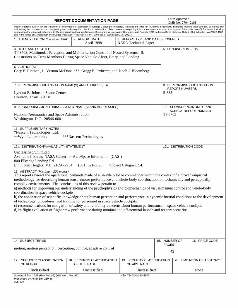
REPORT DOCUMENTATION PAGE Form ApprovedOMB No. 0704-0188
Public reporting burden for this collection of information is estimated to average 1 hour per response, including the time for reviewing instructions, searching existing data sources, gathering andmaintaining the data needed, and completing and reviewing the collection of information. Send comments regarding this burden estimate or any other aspect of this collection of information, includingsuggestions for reducing this burden, to Wwashington Headquarters Services, Directorate for information Operations and Reports, 1215 Jefferson Davis Highway, Sutie1 1204, Arlington, VA 22202-4302,and to the Office of Management and Budget, Paperwork Reduction Project (0704-0188), Washington, DC 20503.
1. AGENCY USE ONLY (Leave Blank) 2. REPORT DATE 3. REPORT TYPE AND DATES COVERED April 1998 NASA Technical Paper
4. TITLE AND SUBTITLE 5. FUNDING NUMBERSTP 3703, Multimodal Perception and Multicriterion Control of Nested Systems: II.Constraints on Crew Members During Space Vehicle Abort, Entry, and Landing
6. AUTHOR(S) Gary E. Riccio* , P. Vernon McDonald**, Gregg E. Irvin***, and Jacob J. Bloomberg
7. PERFORMING ORGANIZATION NAME(S) AND ADDRESS(ES) 8. PERFORMING ORGANIZATIONREPORT NUMBERS
Lyndon B. Johnson Space CenterHouston, Texas 77058
S-835
9. SPONSORING/MONITORING AGENCY NAME(S) AND ADDRESS(ES) 10. SPONSORING/MONITORINGAGENCY REPORT NUMBER
National Aeronautics and Space AdministrationWashington, D.C. 20546-0001
TP 3703
11. SUPPLEMENTARY NOTES*Nascent Technologies, Ltd.**Wyle Laboratories ***Nascent Technologies
12a. DISTRIBUTION/AVAILABILITY STATEMENT 12b. DISTRIBUTION CODE
Unclassified/unlimitedAvailable from the NASA Center for AeroSpace Information (CASI)800 Elkridge Landing RdLinthicum Heights, MD 21090-2934 (301) 621-0390 Subject Category: 54
13. ABSTRACT (Maximum 200 words)This report reviews the operational demands made of a Shuttle pilot or commander within the context of a proven empiricalmethodology for describing human sensorimotor performance and whole-body coordination in mechanically and perceptuallycomplex environments. The conclusions of this review pertain toa) methods for improving our understanding of the psychophysics and biomechanics of visual/manual control and whole-bodycoordination in space vehicle cockpits.b) the application of scientific knowledge about human perception and performance in dynamic inertial conditions to the developmentof technology, procedures, and training for personnel in space vehicle cockpits.c) recommendations for mitigation of safety and reliability concerns about human performance in space vehicle cockpits.d) in-flight evaluation of flight crew performance during nominal and off-nominal launch and reentry scenarios.
14. SUBJECT TERMS 15. NUMBER OF PAGES
16. PRICE CODE
motion, motion perception, perception, control, adaptive control42
17. SECURITY CLASSIFICATIONOF REPORT
18. SECURITY CLASSIFICATION OF THIS PAGE
19. SECURITY CLASSIFICATION OF ABSTRACT
20. LIMITATION OF ABSTRACT
Unclassified Unclassified Unclassified NoneStandrard Form 298 (Rev Feb 89) (MS Word Mar 97)Prescribed by ANSI Std. 239-18298-102
NSN 7540-01-280-5500


Copyright © 2022 FDOKUMEN