Multicavity linear transformer driver facility for Z-pinch and ...
13
Multicavity linear transformer driver facility for Z-pinch and high-power microwave research B. J. Sporer , 1 A. P. Shah , 1 G. V. Dowhan , 1 R. V. Shapovalov , 1 D. A. Packard, 1 M. Wisher, 2,* J. J. Leckbee, 2 K. J. Hendricks , 3 B. W. Hoff , 3 Y. Y. Lau, 1 R. M. Gilgenbach, 1 N. M. Jordan, 1 and R. D. McBride 1 1 Nuclear Engineering and Radiological Sciences, University of Michigan, Ann Arbor, Michigan 48109, USA 2 Sandia National Laboratories, Albuquerque, New Mexico 87185, USA 3 Air Force Research Laboratory, Albuquerque, New Mexico 87117-5776, USA (Received 27 July 2021; accepted 21 September 2021; published 21 October 2021) BLUE is a four-cavity linear transformer driver system in the Plasma, Pulsed Power, and Microwave Laboratory at the University of Michigan. Each BLUE cavity can store up to 2 kJ of electrical energy and provide an open-circuit voltage of 200 kV when using the maximum bipolar charge voltage of 100 kV. The impedance of each cavity is approximately 0.5 Ω, and the rise time of the current pulse into a reasonably matched load is ∼100 ns. The system will be used to study high-energy-density Z-pinch plasmas and high-power radiation sources. The facility has been equipped to handle intense bursts of x rays, nuclear fusion neutrons, and high-power microwaves (HPM). This paper reports on the construction and performance of the first (prototype) BLUE cavity and its auxiliary systems, as well as preliminary experiments using the cavity to drive resistive loads and a magnetically insulated line oscillator (MILO) HPM device. In these initial single cavity, BLUE-driven MILO experiments, 1.19 GHz microwave oscillations were successfully generated. DOI: 10.1103/PhysRevAccelBeams.24.100402 I. INTRODUCTION Linear transformer drivers (LTDs) [1–4] are an innovative and compact pulsed power technology under extensive investigation around the world [5–22]. At the University of Michigan, a single-cavity LTD facility called MAIZE has been operational for over a decade [7,18,19]. MAIZE is a very low-impedance driver (∼0.1 Ω) and is capable of generating a current pulse that rises from 0 to 1 MA in as little as 100 ns into a matched load. To complement the single-cavity MAIZE facility, a four-cavity LTD facility called BLUE is under construction. The 1.25-m diameter cavities used for BLUE were originally fabricated at the Institute of High Current Electronics (IHCE) in Tomsk, Russia, before becoming the basis for the 21-cavity Ursa Minor facility [12,13] at Sandia National Laboratories (SNL). Ursa Minor has since been dismantled and repurposed. The original four IHCE cavities are now part of the BLUE facility at the University of Michigan. Figure 1 shows the BLUE experimental bay in the Plasma, Pulsed Power, and Microwave Lab (PPML) at the University of Michigan. A concrete brick wall was arranged around the cavities to contain radiation produced by the facility, including neutrons from deuterium pinches. The white steel rack suspends the cavities on their sides and allows the cavities to be stacked in series. The rack has rails that allow the cavities to glide into position. A motorized overhead crane can remove individual cavities and place them on a purpose-built wooden stand for servicing. Either 1, 2, 3, or 4 cavities can be stacked in series so that the driver impedance and driver voltage can be varied, and the effects of this variation on load performance can be investigated. The coupling of many stacked LTD cavities is important for future conceptual accelerators like Z-300 and Z-800 [15], which will require thousands of LTD cavities combined in both series and parallel configurations. The donation from SNL included the empty metal cavities themselves as well as some of the fundamental internal elements, such as the spark-gap switches, the capacitors, the insulators, the anode transmission line framework, and the Metglas cores. Auxiliary equipment had to be built from scratch, including the high-voltage charging circuitry, the control systems, the trigger pulse generator, and the core reset or pre-magnetization pulse generator. * Present address: SARA, Inc., Colorado Springs, Colorado 80920, USA. Published by the American Physical Society under the terms of the Creative Commons Attribution 4.0 International license. Further distribution of this work must maintain attribution to the author(s) and the published article’s title, journal citation, and DOI. PHYSICAL REVIEW ACCELERATORS AND BEAMS 24, 100402 (2021) 2469-9888=21=24(10)=100402(13) 100402-1 Published by the American Physical Society
-
Upload
khangminh22 -
Category
Documents
-
view
3 -
download
0
Transcript of Multicavity linear transformer driver facility for Z-pinch and ...
Multicavity linear transformer driver facility for Z-pinchand high-power microwave research
B. J. Sporer ,1 A. P. Shah ,1 G. V. Dowhan ,1 R. V. Shapovalov ,1 D. A. Packard,1
M. Wisher,2,* J. J. Leckbee,2 K. J. Hendricks ,3 B.W. Hoff ,3 Y. Y. Lau,1
R. M. Gilgenbach,1 N. M. Jordan,1 and R. D. McBride 1
1Nuclear Engineering and Radiological Sciences, University of Michigan,Ann Arbor, Michigan 48109, USA
2Sandia National Laboratories, Albuquerque, New Mexico 87185, USA3Air Force Research Laboratory, Albuquerque, New Mexico 87117-5776, USA
(Received 27 July 2021; accepted 21 September 2021; published 21 October 2021)
BLUE is a four-cavity linear transformer driver system in the Plasma, Pulsed Power, and MicrowaveLaboratory at the University of Michigan. Each BLUE cavity can store up to 2 kJ of electrical energyand provide an open-circuit voltage of 200 kV when using the maximum bipolar charge voltage of�100 kV. The impedance of each cavity is approximately 0.5 Ω, and the rise time of the currentpulse into a reasonably matched load is ∼100 ns. The system will be used to study high-energy-densityZ-pinch plasmas and high-power radiation sources. The facility has been equipped to handle intensebursts of x rays, nuclear fusion neutrons, and high-power microwaves (HPM). This paper reports on theconstruction and performance of the first (prototype) BLUE cavity and its auxiliary systems, as well aspreliminary experiments using the cavity to drive resistive loads and a magnetically insulated lineoscillator (MILO) HPM device. In these initial single cavity, BLUE-driven MILO experiments,1.19 GHz microwave oscillations were successfully generated.
DOI: 10.1103/PhysRevAccelBeams.24.100402
I. INTRODUCTION
Linear transformer drivers (LTDs) [1–4] are aninnovative and compact pulsed power technology underextensive investigation around the world [5–22]. At theUniversity of Michigan, a single-cavity LTD facilitycalled MAIZE has been operational for over a decade[7,18,19]. MAIZE is a very low-impedance driver(∼0.1 Ω) and is capable of generating a current pulsethat rises from 0 to 1 MA in as little as 100 ns into amatched load. To complement the single-cavity MAIZEfacility, a four-cavity LTD facility called BLUE is underconstruction. The 1.25-m diameter cavities used forBLUE were originally fabricated at the Institute ofHigh Current Electronics (IHCE) in Tomsk, Russia,before becoming the basis for the 21-cavity UrsaMinor facility [12,13] at Sandia National Laboratories(SNL). Ursa Minor has since been dismantled and
repurposed. The original four IHCE cavities are nowpart of the BLUE facility at the University of Michigan.Figure 1 shows the BLUE experimental bay in the
Plasma, Pulsed Power, and Microwave Lab (PPML) atthe University of Michigan. A concrete brick wall wasarranged around the cavities to contain radiation producedby the facility, including neutrons from deuterium pinches.The white steel rack suspends the cavities on their sides andallows the cavities to be stacked in series. The rack has railsthat allow the cavities to glide into position. A motorizedoverhead crane can remove individual cavities and placethemon a purpose-built wooden stand for servicing. Either 1,2, 3, or 4 cavities can be stacked in series so that the driverimpedance and driver voltage can bevaried, and the effects ofthis variation on load performance can be investigated. Thecoupling of many stacked LTD cavities is important forfuture conceptual accelerators like Z-300 and Z-800 [15],which will require thousands of LTD cavities combined inboth series and parallel configurations.The donation from SNL included the emptymetal cavities
themselves as well as some of the fundamental internalelements, such as the spark-gap switches, the capacitors, theinsulators, the anode transmission line framework, and theMetglas cores. Auxiliary equipment had to be built fromscratch, including the high-voltage charging circuitry, thecontrol systems, the trigger pulse generator, and the core resetor pre-magnetization pulse generator.
*Present address: SARA, Inc., Colorado Springs, Colorado80920, USA.
Published by the American Physical Society under the terms ofthe Creative Commons Attribution 4.0 International license.Further distribution of this work must maintain attribution tothe author(s) and the published article’s title, journal citation,and DOI.
PHYSICAL REVIEW ACCELERATORS AND BEAMS 24, 100402 (2021)
2469-9888=21=24(10)=100402(13) 100402-1 Published by the American Physical Society

The remainder of this paper is organized as follows. InSec. II, the assembly of the first (prototype) BLUE LTDcavity is described. In Sec. III, the auxiliary systems aredescribed. In Sec. IV, results are presented from experimentswhere the cavity was fired in two architectures: (1) as asingle-stage bipolar Marx generator without ferromagneticcores [Fig. 1(a)] and (2) as a true LTD with ferromagneticcores and a pre-magnetization pulse generator to reset ormagnetize those cores [Fig. 1(b)]. Both architectures weretested with a dummy resistive load. In Sec. V, results arepresented from experimentswhereBLUEwas used to drive ahigh-power microwave (HPM) device known as a magneti-cally insulated line oscillator (MILO). In these BLUE-drivenMILO experiments, 1.19-GHz microwave oscillations weresuccessfully generated.
II. THE PROTOTYPE BLUE CAVITY
Images of the first completed BLUE cavity are presentedin Figs. 1 and 2. In Figs. 1(a) and 2, a clear polycarbonatelid was in use, which enables the interior components to beobserved during operation. The plastic lid also eliminatesthe parasitic current path around the LTD case [19], andthus all of the current is driven through the load at the centerof the machine. Because the parasitic current path iseliminated, ferromagnetic cores were not required norinstalled in Figs. 1(a) and 2 (i.e., the cavity was in abipolar Marx generator configuration). As our testingevolved, the clear plastic lid was eventually replaced witha metal lid, and thus pre-magnetized ferromagnetic coresbecame a requirement (see Sec. III E for a discussion on theLTD cores).Referring to Fig. 2, each BLUE cavity is comprised of
ten “bricks,” where each brick consists of two 100-kV,20-nF capacitors (general atomics part #35467) and a single200-kV (�100-kV) spark-gap switch (L3Harris Model#40264–200kV). A photograph of an L3Harris spark-gapswitch is presented in Fig. 3. Each switch was refurbished
FIG. 3. An L3Harris spark-gap switch with brass electrodes,capable of operation at 200 kV (�100 kV) and up to 200 psi gasfill. These switches are used in the MAIZE & BLUE LTDsystems at the University of Michigan. In this image, the switch isshown with a shorting wire between the UV-pin and midplane. Inthe BLUE cavity, the shorting wires are replaced with 3-MΩresistor chains for proper operation of the UV-pin.
FIG. 2. The first assembledBLUEcavity, shownherewith a clearpolycarbonate lid and no ferromagnetic cores (i.e., the cavity is in asingle-stage bipolar Marx generator configuration). The cavity isfilledwith transformer oil. The small vacuumchamber on top of thecavity houses the resistive load. The brass structure on top of thechamber is the current viewing resistor (CVR). Plug-in feed-throughs with 3D-printed parts allow high-voltage cables to beeasily disconnected from the cavity without removing the lid ordraining the transformer oil.
(a) (b)
FIG. 1. The BLUE experimental bay in the Plasma, PulsedPower, and Microwave Lab (PPML) at the University ofMichigan, with the prototype BLUE cavity configured as:(a) a bipolar Marx generator with a clear plastic lid; and(b) as a linear transformer driver with a steel lid.
B. J. SPORER et al. PHYS. REV. ACCEL. BEAMS 24, 100402 (2021)
100402-2

and tested with ten nominal discharges in the PPML “brick-tester” before installation in the BLUE cavity. Switch pre-fires were rarely observed in either the brick tester or inBLUE—only one definite pre-fire event was confirmed inthe ∼100 shots performed thus far on the first cavity.Each BLUE cavity also consists of a transmission line
framework for mounting the bricks in the cavities, largeplastic insulator disks for separating the anode and cathodesides of the cavity, charging and triggering circuitry (suchas HV resistors, inductors, and cable feedthroughs), switchgas lines, and diagnostics.The trigger inductors (each ∼2 μH) were installed
between the main trigger bus line and the UV-pins/mid-planes of the L3Harris switches. Due to the finite capaci-tance of a switch midplane (∼7 pF), the trigger inductorsserve to amplify the trigger pulse and reduce the jitter of theswitch [20]. They also provide some isolation betweenswitches during the breakdown process. The bronze-col-ored trigger inductors can be seen attached to the switchesin Fig. 2.Bipolar LTD cavities such as MAIZE and BLUE require
both a positive and negative high-voltage charging supply.The open-circuit output voltage of the cavity is equal to thedifference between the positive and negative values. Sincethese values usually have the same magnitude, the open-circuit output voltage is usually twice the “charge voltage.”For example, a�100-kV charge voltage results in a 200-kVopen-circuit output voltage. The spark-gap switches arebipolar as well, holding off both charge polarities fromeach other, until a trigger pulse on the grounded midplaneelectrode breaks down the switch. Each L3Harris switchalso includes a “UV-pin.” Upon triggering, the pin creates asmall spark at the switch midplane. The spark floods theswitch gas with photoionizing UV light, thus reducing thebreakdown jitter [23,24]. In a typical bipolar LTD cavity,the switch electrodes (and charging side of the capacitors)are chained together around the cavity through chargingresistors or charging inductors (see Fig. 2).A high “rep-rate” (rate of repetitively charging and
firing) is desired for various experimental platforms onBLUE (e.g., HPM experiments and dense plasma focusneutron source experiments). Thus, dual Spellman 12-kWpower supplies were acquired. They allow a theoretical rep-rate >1 Hz, as long as the charging impedance is kept low.However, having a small charging impedance between eachbrick may lead to degradation of the L3Harris spark-gapsduring pre-fire events, due to excessive current draw fromneighboring bricks. Resistor chains were assembled toserve as the charging impedance between each brick.Ultimately, a 37.5-kΩ total resistance for each chain waschosen as a compromise between brick isolation and fastcharging time. These resistor chains limit undesired pre-firecurrents through adjacent bricks to <2.7 A. Consideringthe 20-nF capacitors used in BLUE, the RC time constantof this charging impedance is 750 μs.
Five high-voltage cables are fed into each BLUE cavity:one for each charge polarity, one for a trigger pulse, andone for each pre-magnetization pulse polarity. Since theBLUE cavities must be moved back and forth between theservicing test stand and the side-mounting stacking rack, itwas desired for the high-voltage (HV) cables to be ableto be unplugged from the cavity without the need to openthe cavity or drain the transformer oil. To this end, anovel plug-in connection was developed utilizing SLA3D-printed parts. This HV feedthrough connection isdepicted in Fig. 2. The cavity dimensions limited thelength of the feedthroughs, making the dc charge cablesespecially prone to arcing. Luckily, it was found that thearcing could be eliminated by partially filling the feed-throughs with a dielectric grease.
III. AUXILIARY SYSTEMS
A. Control panel
To streamline the firing sequence of the BLUE system, aconsolidated and intuitive control interface was desired. Thefiring sequence includes monitoring safety interlocks, oper-ating the Spellman high-voltage power supplies, operatinghigh-voltage Ross relays for isolation or grounding, andgenerating the fire command logic pulse. Semiautonomouscontrol of the firing sequence and other system functionsminimizes manual input and allows for faster rep-rating ofthe facility.Figure 4 shows the control panel assembled for BLUE.
The panel is semiautonomous, using the programmableArduino Uno board (which is based on the ATmega328P8-bit microcontroller). The best electrical resilience wasobtained with the Ruggeduino-SE, a ruggedized version ofthe Uno manufactured by Rugged Circuits.The panel is capable of rep-rating BLUE by automati-
cally controlling the charging sequence as fast as possible.The only user input required is pressing the button to firethe machine. The panel has many other features as well,including monitoring for pre-fire events, automatic purging
FIG. 4. Arduino Uno (ATmega328P-based) control panel forsemiautonomous control of the BLUE charging and firingsequence, as well as other system functions.
MULTICAVITY LINEAR TRANSFORMER … PHYS. REV. ACCEL. BEAMS 24, 100402 (2021)
100402-3

of the switch gas, and control of the pre-magnetizationpulse generator.
B. HV Ross relay barrel
Three high-voltage relays (producedbyRossEngineeringCorporation) are used to connect or disconnect the cavitycapacitors from the charging supplies. They also providepassive grounding in the event of an emergency abort orunexpected power loss. Operation of the three relays ishandled by the Arduino-based control panel. The relaysmust be submerged in transformer oil to prevent arcing, so a20-gallon steel drum was used to house the three relays, asshown in Fig. 5. The drum also contains two 50-kΩ ceramicdump resistors, which absorb the energy stored in thecavity(s) upon abort. High-voltage feedthroughs similar tothose developed for the prototype BLUE cavity allowup to five positive and five negative cables to plug intothe barrel.
C. 200-kV trigger pulse generator
The L3Harris spark-gap switches require a high-voltagepulse as a trigger. The pulse is applied to the midplane,distorting the field in the switch enough to breakdown thepressurized gas (dry “zero” air) in the switch. Avery fast dVdton the rising edge of the pulse is desired to minimize thejitter of a single switch and the jitter between multipleswitches receiving the same trigger pulse. The pulse should
also have a macroscopic amount of energy (≫1 J) to ensurerobust triggering of many switches in parallel (up to 40switches with all four BLUE cavities in operation).To achieve a large dV
dt , a single bipolar brick, charged inparallel with the LTD cavities, is used to trigger the cavities.This gives a trigger voltage equal to twice the chargevoltage (also equal to a single-cavity’s open-circuit outputvoltage). The trigger brick is housed in a ten-gallon steeldrum with high-voltage plug-in feedthroughs similar tothose used on the prototype BLUE cavity and Ross relaybarrel. Positive or negative trigger output may be chosen bygrounding the opposite polarity. The trigger pulse generatorbarrel is shown in Fig. 6.The brick used in the trigger generator is identical to
those used in the BLUE cavities, consisting of two 20-nFcapacitors and a L3Harris spark-gap switch. The singlespark-gap switch in the trigger generator is itself triggeredby a PT55 pulse generator, which is mounted to the top ofthe barrel, as shown in Fig. 6. See Sec. III D for furtherdiscussion of the PT55.
D. 300-V pulse generator (PT003 replacement)
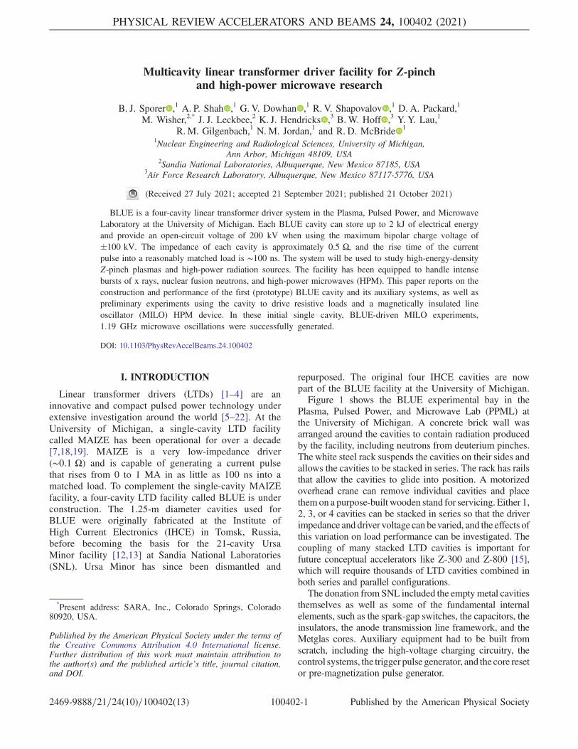
The Pacific Atlantic Electronics (PAE) PT55 module(see Fig. 7), which is no longer in production, uses a rarekrytron switch to produce a þ50 kV output pulse with arisetime of less than 2 ns. The module requires a low-powerþ7 kVDC charge voltage and a positive 250–300 V triggerpulse. PT55s are compact, low-jitter, and very useful in a
FIG. 5. A 20-gallon oil drum contains the three Ross HV relaysused in the charging circuit. The relays are operated by the controlpanel (see Sec. III A and Fig. 4) during the charging sequence.The large copper-sulfate dump resistors in this photograph wereultimately replaced with 50-kΩ ceramic resistors.
FIG. 6. The 10-gallon oil drum containing the trigger pulsegenerating brick, which is charged in parallel with the BLUELTD cavities and triggered by the PT55 pulse generator mountedto the top of the drum.
B. J. SPORER et al. PHYS. REV. ACCEL. BEAMS 24, 100402 (2021)
100402-4
pulsed-power laboratory, namely for triggering spark-gapswitches. The single L3Harris spark-gap switch used in theBLUE trigger pulse generator (and also used in the MAIZE& BLUE LTD cavities) can be reliably triggered by a PT55pulse, even when the switch is being operated at fullvoltage (200 kV). Several PT55s of varying condition arestockpiled in the PPML.The PT55 draws <1 mA from its þ7 kVDC power
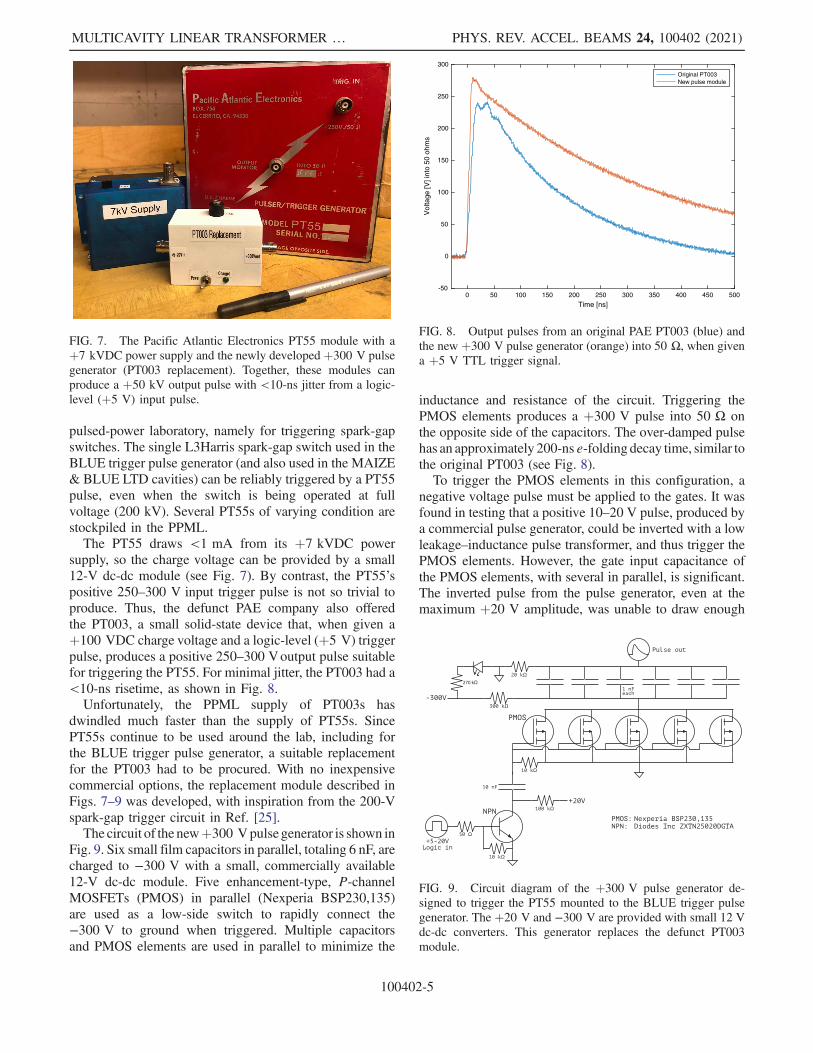
supply, so the charge voltage can be provided by a small12-V dc-dc module (see Fig. 7). By contrast, the PT55’spositive 250–300 V input trigger pulse is not so trivial toproduce. Thus, the defunct PAE company also offeredthe PT003, a small solid-state device that, when given aþ100 VDC charge voltage and a logic-level (þ5 V) triggerpulse, produces a positive 250–300 Voutput pulse suitablefor triggering the PT55. For minimal jitter, the PT003 had a<10-ns risetime, as shown in Fig. 8.Unfortunately, the PPML supply of PT003s has
dwindled much faster than the supply of PT55s. SincePT55s continue to be used around the lab, including forthe BLUE trigger pulse generator, a suitable replacementfor the PT003 had to be procured. With no inexpensivecommercial options, the replacement module described inFigs. 7–9 was developed, with inspiration from the 200-Vspark-gap trigger circuit in Ref. [25].The circuit of the newþ300 Vpulse generator is shown in
Fig. 9. Six small film capacitors in parallel, totaling 6 nF, arecharged to −300 V with a small, commercially available12-V dc-dc module. Five enhancement-type, P-channelMOSFETs (PMOS) in parallel (Nexperia BSP230,135)are used as a low-side switch to rapidly connect the−300 V to ground when triggered. Multiple capacitorsand PMOS elements are used in parallel to minimize the
inductance and resistance of the circuit. Triggering thePMOS elements produces a þ300 V pulse into 50 Ω onthe opposite side of the capacitors. The over-damped pulsehas an approximately 200-nse-folding decay time, similar tothe original PT003 (see Fig. 8).To trigger the PMOS elements in this configuration, a
negative voltage pulse must be applied to the gates. It wasfound in testing that a positive 10–20 V pulse, produced bya commercial pulse generator, could be inverted with a lowleakage–inductance pulse transformer, and thus trigger thePMOS elements. However, the gate input capacitance ofthe PMOS elements, with several in parallel, is significant.The inverted pulse from the pulse generator, even at themaximum þ20 V amplitude, was unable to draw enough
0 50 100 150 200 250 300 350 400 450 500
Time [ns]
-50
0
50
100
150
200
250
300
Vol
tage
[V] i
nto
50 o
hms
Original PT003New pulse module
FIG. 8. Output pulses from an original PAE PT003 (blue) andthe new þ300 V pulse generator (orange) into 50 Ω, when givena þ5 V TTL trigger signal.
FIG. 7. The Pacific Atlantic Electronics PT55 module with aþ7 kVDC power supply and the newly developed þ300 V pulsegenerator (PT003 replacement). Together, these modules canproduce a þ50 kV output pulse with <10-ns jitter from a logic-level (þ5 V) input pulse.
FIG. 9. Circuit diagram of the þ300 V pulse generator de-signed to trigger the PT55 mounted to the BLUE trigger pulsegenerator. The þ20 V and −300 V are provided with small 12 Vdc-dc converters. This generator replaces the defunct PT003module.
MULTICAVITY LINEAR TRANSFORMER … PHYS. REV. ACCEL. BEAMS 24, 100402 (2021)
100402-5
instantaneous current from the gates to achieve the desiredrisetime and amplitude.To trigger the PMOS elements more strongly with only a
logic-level (þ5 V) pulse, an NPN transistor (Diodes Inc.ZXTN25020DGTA) was added to the circuit. A 10-nFcapacitor is charged to þ20 V from an additional dc-dcconverter. This capacitor is discharged to ground via thetransistor upon receipt of a positive logic-level pulse.Closure of the transistor switch produces a −20 V pulseon the output of the capacitor, which is fed to the PMOSgates. The addition of the NPN transistor to the circuitproduced the desired amplitude and risetime to reliablytrigger the PT55 with jitter <10 ns (see Fig. 8).
E. Pre-magnetization pulse generator for resettingBLUE’s ferromagnetic cores
In an LTD cavity, there is a parasitic path that thedischarge current can take along the inner surface of theLTD’s metallic case [19]. This parasitic path is in parallelwith the load. To limit the current that takes this parasiticpath (and thus force the current through the load asdesired), LTD cavities usually include two ferromagneticcores (an upper core and a lower core) within the loopformed by the parasitic current path.The ferromagnetic cores typically consist of thin iron or
Metglas tape, which is laminated with a dielectric film,wound into large rings, and potted in epoxy resin. Since theparasitic current path encloses the cores, generation of aparasitic current drives magnetization of the cores. Sincethe cores are made of thin strips of semiresistive materialwith high-magnetic permeability μ ≫ μ0, there is a highinductance associated with the parasitic path, which min-imizes the fraction of current taking this path. In addition,there is a resistive effect due to eddy currents generatedduring magnetization of the cores, which appears at highfrequency [11]. Energy losses in the cores during an LTDdischarge are often modeled with a static (and many timesempirically determined) resistance in parallel with the load.To model lower-frequency pulses around the cores, such asthe core resetting or pre-magnetization discharge, an initialresistance that reduces rapidly after several microseconds isappropriate.Due to magnetic hysteresis in the cores, the parasitic
current from repeated cavity discharges eventually saturatesthe magnetic domains in the cores in a direction thatreduces the effective permeability of the cores and thusreduces the impedance of the parasitic current path. Torecover the maximum effective impedance for the parasiticcurrent path, the alignment of the magnetic domains mustbe reset (reversed) back into their ideal direction for an LTDdischarge. This can be done by applying a pre-magnetiza-tion pulse to the cavity. This “pre-mag” pulse drives acurrent in the LTD’s metallic case that runs in a directionopposite to that of the parasitic current generated during anLTD discharge. The pre-mag pulse can be applied using a
much lower voltage and generating a much lower peakcurrent than that of an LTD discharge, but the pre-magpulse must then be applied over a proportionally longertimescale. The pre-mag pulse can be applied anytimebetween LTD discharges, but it is typically done beforeinstallation of the experimental load, since the pre-magpulse can ruin sensitive loads by driving modest currentsthrough the load over long timescales.The “volt-second product” of the cores is the parameter
that defines the magnetic saturation properties of the cores.It can be roughly calculated from the material propertiesand geometry of the cores. From previous literature on thecavities (during the development of Ursa Minor) [26], thevolt-second product of the cores used in the BLUE cavitiesis estimated to be around 20 mVs. This figure makesintuitive sense: one can think about the volt-second productas if each core must “hold-off” the 100-kV pulse from halfof the cavity for at least 200 ns (the typical experimentaltime). It also gives an estimate of the required pre-magpulse duration for saturation. For example, if the pre-magpulse voltage is 600 V, then saturation can be expected aftera pulse duration of 33 μs. Reference [26] also recommendsa pre-magnetizing current of at least 1.5 kA to reachsaturation in the Ursa Minor (or BLUE) cores.After exploratory modeling in LTspice, a relatively
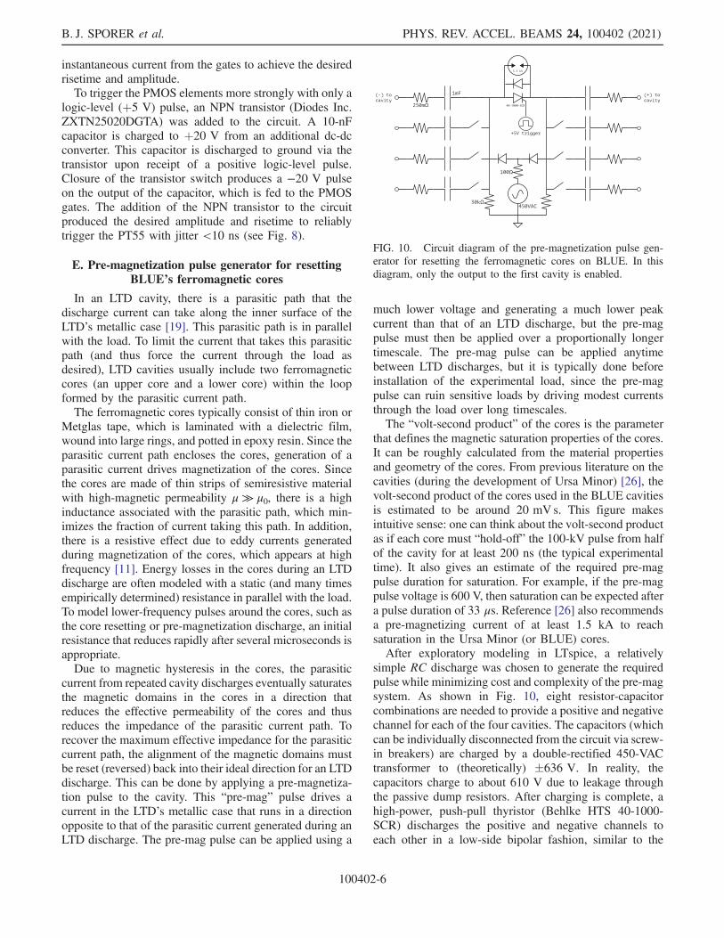
simple RC discharge was chosen to generate the requiredpulse while minimizing cost and complexity of the pre-magsystem. As shown in Fig. 10, eight resistor-capacitorcombinations are needed to provide a positive and negativechannel for each of the four cavities. The capacitors (whichcan be individually disconnected from the circuit via screw-in breakers) are charged by a double-rectified 450-VACtransformer to (theoretically) �636 V. In reality, thecapacitors charge to about 610 V due to leakage throughthe passive dump resistors. After charging is complete, ahigh-power, push-pull thyristor (Behlke HTS 40-1000-SCR) discharges the positive and negative channels toeach other in a low-side bipolar fashion, similar to the
FIG. 10. Circuit diagram of the pre-magnetization pulse gen-erator for resetting the ferromagnetic cores on BLUE. In thisdiagram, only the output to the first cavity is enabled.
B. J. SPORER et al. PHYS. REV. ACCEL. BEAMS 24, 100402 (2021)
100402-6

operation of a bipolar LTD brick. In each channel, theresulting output pulse of the 1-mF capacitor is sent througha short length of nichrome wire acting as a high-power250-mΩ resistor, over-damping the pulse, before it issent to the cavity. An internal photograph of the pre-magnetization pulse generator constructed for BLUE isshown in Fig. 11.Output current pulses from a single channel of the pre-
magnetization pulse generator were measured with aPearson coil (see Fig. 12). When the cores have alreadybeen saturated in the desired direction (i.e., the pre-maggenerator has already been successfully fired in preparationfor an LTD discharge), the pre-mag current pulse into thecavity is nearly identical to the pulse into a short-circuitload, indicating that the cavity has a very low impedancefor the direction of the pre-mag current pulse (and thus ahigh impedance for the direction of the parasitic currentpulse during an LTD discharge). When the cores aresaturated in the undesired direction (i.e., the cores are inneed of a resetting pre-mag pulse), a notch in the waveformof the pre-mag current is observed (see Fig. 12). This notchis the result of the initially high impedance of the cavity (forthe direction of the pre-mag current) dropping rapidly in thefirst ∼25 μs of the pulse. Note that 25 μs is consistent withthe rough estimate of 33 μs from the volt-second product ofthe cores. This notch was predicted via LTspice modelingprior to the first experimental tests of the system. TheLTspice pre-mag model was then fine-tuned to nearlyreplicate the experimental results, as shown in Fig. 12.The dynamic impedance seen by the pre-mag generator is
both inductive and resistive, with the resistive componentbeing due to the eddy current effect mentioned previously.However, only the resistive component was tuned (modu-lated in time) to nearly replicate the experimental resultswith LTspice. Note that a tuned inductance (modulated intime) could also have been used to obtain results that agreewell with experiments, so this tuning method does notnecessarily provide the exact temporal behavior of thecores’ effective inductance or resistance values.The effects of successful pre-magnetization on the main
LTD cavity discharge can be seen in load current mea-surements taken when the cavity is fired into a resistiveload. This is discussed in Sec. IV B. In general, pre-magnetization of the cavity increases the amplitude ofthe LTD’s main discharge current by 10–20% and extendsthe duration of positive current into the load.There is a large issue to be aware of in designing a pre-
magnetization pulse generator for LTDs. Since (ideally) thepre-mag cables remain attached to the cavity during an LTDdischarge, the high-voltage, high-frequency pulse from themain discharge can travel back to the pre-mag generator,potentially damaging medium-voltage electronics such asthe charging diodes or, more importantly, the thyristor. Twothyristors on BLUE’s pre-mag system were damaged duringLTD discharges, despite attempts to protect themwithmetal-oxide varistors and an over-voltage spark-gap placed directlyacross the thyristor terminals (see Fig. 10). Transient-voltage-suppression diodes and/or better spark-gaps mayprovidemore effective protection from the fast transients, butthis has yet to be demonstrated experimentally. For now,triggered spark-gaps are recommended as a more robustalternative to thyristors for a pre-mag system switch.
FIG. 11. Photograph of the internal components of the pre-magnetization pulse generator constructed for resetting theferromagnetic cores on BLUE. This photograph shows thegenerator’s four positive and four negative output channels.The dark blue 3D-printed plastic structures on top of thecapacitors are the screw-in breakers for connecting individualchannels. In this photograph, only the cables to the first cavity areattached.
0 20 40 60 80 100 120
Time [microseconds]
0
200
400
600
800
1000
1200
1400
1600
1800
2000
Pre
-Mag
Cur
rent
[A]
Into short-circuitInto previously-magnetized BLUE cavityInto BLUE cavity in need of pre-magnetizationLTspice fit
FIG. 12. Output current waveforms from a single channel of thepre-magnetization pulse generator into three load scenarios:(1) into a short-circuit load (blue); (2) into the cavity for thecase where the cores have already been reset or pre-magnetized(green); and (3) into the cavity for the case where the cores needto be reset or pre-magnetized (red). Also shown is a waveformproduced by an LTspice model fine-tuned to closely match theexperimental results.
MULTICAVITY LINEAR TRANSFORMER … PHYS. REV. ACCEL. BEAMS 24, 100402 (2021)
100402-7
IV. RESISTIVE LOAD TESTING OF THEPROTOTYPE BLUE CAVITY
A. Bipolar Marx generator configuration
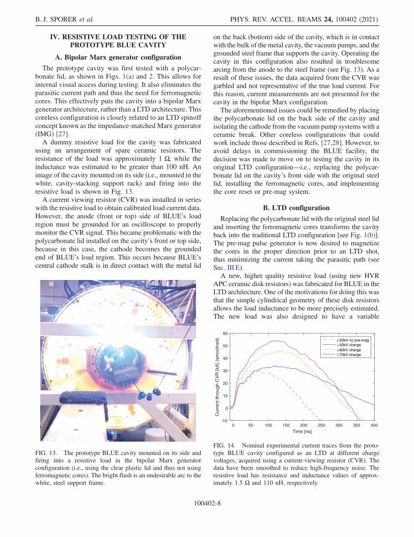
The prototype cavity was first tested with a polycar-bonate lid, as shown in Figs. 1(a) and 2. This allows forinternal visual access during testing. It also eliminates theparasitic current path and thus the need for ferromagneticcores. This effectively puts the cavity into a bipolar Marxgenerator architecture, rather than a LTD architecture. Thiscoreless configuration is closely related to an LTD spinoffconcept known as the impedance-matched Marx generator(IMG) [27].A dummy resistive load for the cavity was fabricated
using an arrangement of spare ceramic resistors. Theresistance of the load was approximately 1 Ω, while theinductance was estimated to be greater than 100 nH. Animage of the cavity mounted on its side (i.e., mounted in thewhite, cavity-stacking support rack) and firing into theresistive load is shown in Fig. 13.A current viewing resistor (CVR) was installed in series
with the resistive load to obtain calibrated load current data.However, the anode (front or top) side of BLUE’s loadregion must be grounded for an oscilloscope to properlymonitor the CVR signal. This became problematic with thepolycarbonate lid installed on the cavity’s front or top side,because in this case, the cathode becomes the groundedend of BLUE’s load region. This occurs because BLUE’scentral cathode stalk is in direct contact with the metal lid
on the back (bottom) side of the cavity, which is in contactwith the bulk of the metal cavity, the vacuum pumps, and thegrounded steel frame that supports the cavity. Operating thecavity in this configuration also resulted in troublesomearcing from the anode to the steel frame (see Fig. 13). As aresult of these issues, the data acquired from the CVR wasgarbled and not representative of the true load current. Forthis reason, current measurements are not presented for thecavity in the bipolar Marx configuration.The aforementioned issues could be remedied by placing
the polycarbonate lid on the back side of the cavity andisolating the cathode from the vacuum pump systems with aceramic break. Other coreless configurations that couldwork include those described in Refs. [27,28]. However, toavoid delays in commissioning the BLUE facility, thedecision was made to move on to testing the cavity in itsoriginal LTD configuration—i.e., replacing the polycar-bonate lid on the cavity’s front side with the original steellid, installing the ferromagnetic cores, and implementingthe core reset or pre-mag system.
B. LTD configuration
Replacing the polycarbonate lid with the original steel lidand inserting the ferromagnetic cores transforms the cavityback into the traditional LTD configuration [see Fig. 1(b)].The pre-mag pulse generator is now desired to magnetizethe cores in the proper direction prior to an LTD shot,thus minimizing the current taking the parasitic path (seeSec. III E).A new, higher quality resistive load (using new HVR
APC ceramic disk resistors) was fabricated for BLUE in theLTD architecture. One of the motivations for doing this wasthat the simple cylindrical geometry of these disk resistorsallows the load inductance to be more precisely estimated.The new load was also designed to have a variable
FIG. 13. The prototype BLUE cavity mounted on its side andfiring into a resistive load in the bipolar Marx generatorconfiguration (i.e., using the clear plastic lid and thus not usingferromagnetic cores). The bright flash is an undesirable arc to thewhite, steel support frame.
0 50 100 150 200 250 300 350 400
Time [ns]
-10
0
10
20
30
40
50
60
Cur
rent
thro
ugh
CV
R [k
A] (
smoo
thed
) 50kV no pre-mag50kV charge60kV charge70kV charge
FIG. 14. Nominal experimental current traces from the proto-type BLUE cavity configured as an LTD at different chargevoltages, acquired using a current-viewing resistor (CVR). Thedata have been smoothed to reduce high-frequency noise. Theresistive load has resistance and inductance values of approx-imately 1.5 Ω and 110 nH, respectively.
B. J. SPORER et al. PHYS. REV. ACCEL. BEAMS 24, 100402 (2021)
100402-8
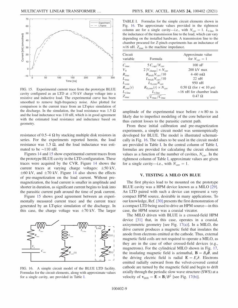
resistance of 0.5–4 Ω by stacking multiple disk resistors inseries. For the experiments reported herein, the loadresistance was 1.5 Ω, and the load inductance was esti-mated to be ∼110 nH.Figures 14 and 15 show experimental current traces from
the prototype BLUE cavity in the LTD configuration. Thesetraces were acquired by the CVR. Figure 14 shows thecurrent traces at varying charge voltages: �50 kV,�60 kV, and �70 kV. Figure 14 also shows the effectsof pre-magnetization on the load current. Without pre-magnetization, the load current is smaller in amplitude andshorter in duration, as significant current begins to leak intothe parasitic current path around the time of peak current.Figure 15 shows good agreement between an experi-
mentally measured current trace and the current tracegenerated by an LTspice simulation of the discharge. Inthis case, the charge voltage was �70 kV. The larger
amplitude of the experimental trace before t ≈ 80 ns islikely due to imperfect modeling of the core behavior andthus current losses to the parasitic current path.From these initial calibration and pre-magnetization
experiments, a simple circuit model was semiempiricallydeveloped for BLUE. The model is illustrated schemati-cally in Fig. 16. The values to be used in the circuit modelare provided in Table I. In the central column of Table I,formulas are provided for calculating the circuit elementvalues as a function of the number of cavities, Ncav. In therightmost column of Table I, approximate values are givenfor a single cavity—i.e., with Ncav ¼ 1.
V. TESTING A MILO ON BLUE
The first physics load to be mounted on the prototypeBLUE cavity was a HPM device known as a MILO [29].An LTD paired with such a device can represent a verycompact HPM source, desirable in many applications. Toour knowledge, Ref. [30] presents the first demonstration ofa compact LTD being used to drive an HPM source—in thiscase, the HPM source was a coaxial vircator.The MILO driven with BLUE is a crossed-field HPM
device [31] that, in this case, operates in a coaxial,axisymmetric geometry [see Fig. 17(a)]. In a MILO, thedrive current produces a magnetic field that insulates theanode from electrons emitted at the cathode. Thus, externalmagnetic field coils are not required to operate a MILO, asthey are in the case of other crossed-field devices (e.g.,magnetrons). For the cylindrical MILO shown in Fig. 17,the insulating magnetic field is azimuthal, B ¼ Bθθ̂, andthe driving electric field is radial E ¼ Err̂. Electronsemitted radially outward from the velvet-covered centralcathode are turned by the magnetic field and begin to driftaxially through the periodic slow wave structure (SWS) at avelocity of vdrift ¼ E × B=B2 [see Fig. 17(b)].
FIG. 16. A simple circuit model of the BLUE LTD facility.Formulas for the circuit elements, along with approximate valuesfor a single cavity, are provided in Table I.
TABLE I. Formulas for the simple circuit elements shown inFig. 16. The approximate values provided in the rightmostcolumn are for a single cavity—i.e., with Ncav ¼ 1. Lt-line isthe inductance of the transmission line to the load, which can varydepending on the installed hardware. A transmission line to thechamber procured for Z-pinch experiments has an inductance of≈16 nH. Zmac is the machine impedance.
Circuit Approximate valuevariable Formula for Ncav ¼ 1
Cmac 5Ccap=Ncav 100 nFV0 2 jVchargej × Ncav 200 kV maxRmac RbrickNcav=10 4–60 mΩLmac LbrickNcav=10 22 nHLcore L0;coreNcav 950 nHRcoreðtÞ R0;coreðtÞ × Ncav 0.50 Ω (for t ≪ 10 μs)Lt-line Lt-line ∼16 nH for chamber loadsZmac
ffiffiffiffiffiffiffiffiffiffiffiffiffiffiffiffiffiffiffiffiffi
Lmac=Cmac
p
0.47 Ω
0 50 100 150 200 250 300
Time [ns]
-10
0
10
20
30
40
50
60
70C
urre
nt [k
A] (
smoo
thed
)ExperimentLTspice
FIG. 15. Experimental current trace from the prototype BLUEcavity configured as an LTD at �70 kV charge voltage into aresistive and inductive load. The experimental curve has beensmoothed to remove high-frequency noise. Also plotted forcomparison is the current trace from an LTspice simulation ofthe discharge. In the simulation, the load resistance was 1.5 Ωand the load inductance was 110 nH, which is in good agreementwith the estimated load resistance and inductance based ongeometry.
MULTICAVITY LINEAR TRANSFORMER … PHYS. REV. ACCEL. BEAMS 24, 100402 (2021)
100402-9
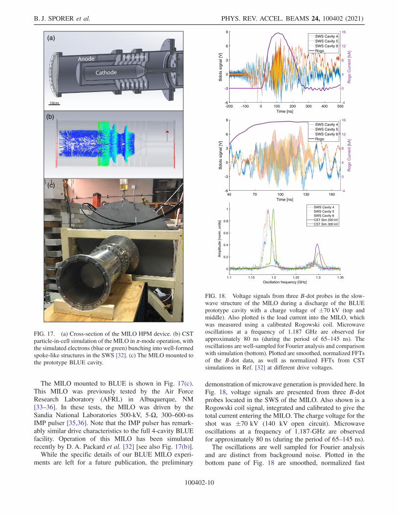
The MILO mounted to BLUE is shown in Fig. 17(c).This MILO was previously tested by the Air ForceResearch Laboratory (AFRL) in Albuquerque, NM[33–36]. In these tests, the MILO was driven by theSandia National Laboratories 500-kV, 5-Ω, 300–600-nsIMP pulser [35,36]. Note that the IMP pulser has remark-ably similar drive characteristics to the full 4-cavity BLUEfacility. Operation of this MILO has been simulatedrecently by D. A. Packard et al. [32] [see also Fig. 17(b)].While the specific details of our BLUE MILO experi-
ments are left for a future publication, the preliminary
demonstration of microwave generation is provided here. InFig. 18, voltage signals are presented from three B-dotprobes located in the SWS of the MILO. Also shown is aRogowski coil signal, integrated and calibrated to give thetotal current entering the MILO. The charge voltage for theshot was �70 kV (140 kV open circuit). Microwaveoscillations at a frequency of 1.187-GHz are observedfor approximately 80 ns (during the period of 65–145 ns).The oscillations are well sampled for Fourier analysis
and are distinct from background noise. Plotted in thebottom pane of Fig. 18 are smoothed, normalized fast
(b)
(c)
(a)
FIG. 17. (a) Cross-section of the MILO HPM device. (b) CSTparticle-in-cell simulation of the MILO in π-mode operation, withthe simulated electrons (blue or green) bunching into well-formedspoke-like structures in the SWS [32]. (c) The MILO mounted tothe prototype BLUE cavity.
1.1 1.15 1.2 1.25 1.3 1.35
Oscillation frequency [GHz]
0
0.2
0.4
0.6
0.8
1
Am
plitu
de [n
orm
. uni
ts]
SWS Cavity 4SWS Cavity 5SWS Cavity 6CST Sim 200 kVCST Sim 300 kV
40 70 100 130 160Time [ns]
-6
-3
0
3
6
9
Bdo
ts s
igna
l [V
]
-4
0
4
8
12
16
Rog
o C
urre
nt [k
A]
SWS Cavity 4SWS Cavity 5SWS Cavity 6Rogo
-200 -100 0 100 200 300 400 500Time [ns]
-6
-3
0
3
6
9
Bdo
ts s
igna
l [V
]
-4
0
4
8
12
16
Rog
o C
urre
nt [k
A]
SWS Cavity 4SWS Cavity 5SWS Cavity 6Rogo
FIG. 18. Voltage signals from three B-dot probes in the slow-wave structure of the MILO during a discharge of the BLUEprototype cavity with a charge voltage of �70 kV (top andmiddle). Also plotted is the load current into the MILO, whichwas measured using a calibrated Rogowski coil. Microwaveoscillations at a frequency of 1.187 GHz are observed forapproximately 80 ns (during the period of 65–145 ns). Theoscillations are well-sampled for Fourier analysis and comparisonwith simulation (bottom). Plotted are smoothed, normalized FFTsof the B-dot data, as well as normalized FFTs from CSTsimulations in Ref. [32] at different drive voltages.
B. J. SPORER et al. PHYS. REV. ACCEL. BEAMS 24, 100402 (2021)
100402-10
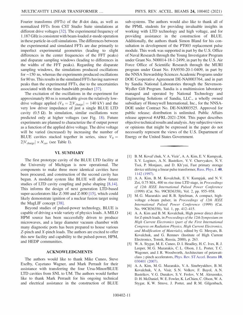
Fourier transforms (FFTs) of the B-dot data, as well asnormalized FFTs from CST Studio Suite simulations atdifferent drive voltages [32]. The experimental frequency of1.187GHz is consistentwith beam-loaded π-mode operationin these particle-in-cell simulations. The differences betweenthe experimental and simulated FFTs are due primarily toimperfect experimental geometries (leading to slightdifferences in the center frequencies of the FFT peaks)and disparate sampling windows (leading to differences inthe widths of the FFT peaks). Regarding the disparatesampling windows, the simulations produced oscillationsfor ∼150 ns, whereas the experiments produced oscillationsfor 80 ns. This results in the simulated FFTs having narrowerpeaks than the experimental FFTs, due to the uncertaintiesassociated with the time-bandwidth product [37].The excitation of the oscillations in the experiment for
approximately 80 ns is remarkable given the relatively low-drive voltage applied (V0 ¼ 2jVchargej ¼ 140 kV) and thevery low driver impedance of just a single BLUE LTDcavity (0.5 Ω). In simulation, similar oscillations werepredicted only at higher voltages (see Fig. 18). Futureexperiments are planned to characterize the rf output poweras a function of the applied drive voltage. The drive voltagewill be varied (increased) by increasing the number ofBLUE cavities stacked together in series, since V0 ¼2jVchargej × Ncav (see Table I).
VI. SUMMARY
The first prototype cavity of the BLUE LTD facility atthe University of Michigan is now operational. Thecomponents to make three more identical cavities havebeen procured, and construction of the second cavity hasbegun. A modular system like BLUE will allow futurestudies of LTD cavity coupling and pulse shaping [8,14].This informs the design of next generation LTD-basedsuper-accelerators like Z-300 and Z-800 [15], which couldlikely demonstrate ignition of a nuclear fusion target usingthe MagLIF concept [38].Beyond studies of pulsed-power technology, BLUE is
capable of driving a wide variety of physics loads. A MILOHPM source has been successfully driven to producemicrowaves, and a large diameter vacuum chamber withmany diagnostic ports has been prepared to house variousZ-pinch and X-pinch loads. The authors are excited to offerthis new facility and capability to the pulsed-power, HPM,and HEDP communities.
ACKNOWLEDGMENTS
The authors would like to thank Mike Cuneo, SteveExelby, Cayetano Wagner, and Mark Perrault for theirassistance with transferring the four Ursa-Minor/BLUELTD cavities from SNL to UM. The authors would furtherlike to thank Mark Perrault for his ongoing technicaland electrical assistance in the construction of BLUE
sub-systems. The authors would also like to thank all ofthe PPML students for providing invaluable insights inworking with LTD technology and high voltage, and forproviding assistance in the construction of BLUE.Additionally, the authors thank Simon Bland for his con-sultation in development of the PT003 replacement pulsemodule. This work was supported in part by the U.S. Officeof Naval Research through the Young Investigator Programunder Grant No. N00014-18-1-2499, in part by the U.S. AirForce Office of Scientific Research through the MURIprogram under Grant No. FA9550-20-1-0409, in part bythe NNSA Stewardship Sciences Academic Programs underDOE Cooperative Agreement DE-NA0003764, and in partby Sandia National Laboratories through the Stevenson-Wydler Gift Program. Sandia is a multimission laboratorymanaged and operated by National Technology andEngineering Solutions of Sandia, LLC., a wholly ownedsubsidiary of Honeywell International, Inc., for the NNSA-DOE under Contract No. DE-NA0003525. Approved forpublic release; distribution is unlimited. Public Affairsrelease approval #AFRL-2021-2304. This paper describesobjective technical results and analysis.Any subjectiveviewsor opinions that might be expressed in the paper do notnecessarily represent the views of the U.S. Department ofEnergy or the United States Government.
[1] B.M. Koval’chuk, V. A. Vizir’, A. A. Kim, E. V. Kumpyak,S. V. Loginov, A. N. Bastrikov, V. V. Chervyakov, N. V.Tsoi, P. Monjaux, and D. Kh’yui, Fast primary storagedevice utilizing a linear pulse transformer, Russ. Phys. J. 40,1142 (1997).
[2] A. A. Kim, B. M. Kovalchuk, E. V. Kumpjak, and N. V.Zoi, 0.75 MA, 400 ns rise time LTD stage, in Proceedingsof 12th IEEE International Pulsed Power Conference(1999) (Cat. No. 99CH36358), Vol. 2, pp. 955–958.
[3] M. G. Mazarakis and R. B. Spielman, A compact, high-voltage e-beam pulser, in Proceedings of 12th IEEEInternational Pulsed Power Conference (1999) (Cat.No. 99CH36358), Vol. 1, pp. 412–415.
[4] A. A. Kim and B.M. Kovalchuk, High power direct driverfor Z-pinch loads, in Proceedings of the 12th Symposium onHigh Current Electronics (part of the First InternationalCongress on Radiation Physics, High Current Electronics,and Modification of Materials), edited by G. Mesyats, B.Kovalchuk, and G. Remnev (Institute of High CurrentElectronics, Tomsk, Russia, 2000), p. 263.
[5] W. A. Stygar, M. E. Cuneo, D. I. Headley, H. C. Ives, R. J.Leeper, M. G. Mazarakis, C. L. Olson, J. L. Porter, T. C.Wagoner, and J. R. Woodworth, Architecture of petawatt-class z-pinch accelerators, Phys. Rev. STAccel. Beams 10,030401 (2007).
[6] A. A. Kim, M. G. Mazarakis, V. A. Sinebryukhov, B.M.Kovalchuk, V. A. Visir, S. N. Volkov, F. Bayol, A. N.Bastrikov, V. G. Durakov, S. V. Frolov, V. M. Alexeenko,D. H.McDaniel, W. E. Fowler, K. LeChien, C. Olson,W. A.Stygar, K.W. Struve, J. Porter, and R.M. Gilgenbach,
MULTICAVITY LINEAR TRANSFORMER … PHYS. REV. ACCEL. BEAMS 24, 100402 (2021)
100402-11

Development and tests of fast 1-MA linear transformer driverstages, Phys. Rev. ST Accel. Beams 12, 050402 (2009).
[7] R. M. Gilgenbach, M. R. Gomez, J. C. Zier, W.W. Tang,D. M. French, Y. Y. Lau, M. G. Mazarakis, M. E. Cuneo,M. D. Johnston, B. V. Oliver, T. A. Mehlhorn, A. A. Kim,and V. A. Sinebryukhov, MAIZE: A 1 MA LTD-DrivenZ-Pinch at The University of Michigan, AIP Conf. Proc.1088, 259 (2009).
[8] W. A. Stygar, W. E. Fowler, K. R. LeChien, F. W. Long,M. G. Mazarakis, G. R. McKee, J. L. McKenney, J. L.Porter, M. E. Savage, B. S. Stoltzfus, D. M. Van De Valde,and J. R. Woodworth, Shaping the output pulse of a linear-transformer-driver module, Phys. Rev. ST Accel. Beams12, 030402 (2009).
[9] M. G. Mazarakis, W. E. Fowler, A. A. Kim, V. A.Sinebryukhov, S. T. Rogowski, R. A. Sharpe, D. H.McDaniel, C. L. Olson, J. L. Porter, K. W. Struve, W. A.Stygar, and J. R. Woodworth, High current, 0.5-MA, fast,100-ns, linear transformer driver experiments, Phys. Rev.ST Accel. Beams 12, 050401 (2009).
[10] M. G. Mazarakis et al., High-current linear transformerdriver development at Sandia National Laboratories, IEEETrans. Plasma Sci. 38, 704 (2010).
[11] A. A. Kim, M. G. Mazarakis, V. I. Manylov, V. A. Vizir,and W. A. Stygar, Energy loss due to eddy current in lineartransformer driver cores, Phys. Rev. ST Accel. Beams 13,070401 (2010).
[12] J. Leckbee, S. Cordova, B. Oliver, T. Webb, M. Toury, M.Caron, R. Rosol, B. Bui, T. Romero, and D. Ziska, Lineartransformer driver (LTD) research for radiographic appli-cations, in Proceedings of 2011 IEEE Pulsed PowerConference (IEEE, Chicago, 2011), pp. 614–618.
[13] J. J. Leckbee, T. D. Pointon, S. R. Cordova, B. V.Oliver, T. J.Webb, M. Toury, M. Caron, and D.W. Droemer, Commis-sioning and power flow studies of the 2.5-MeV Ursa MinorLTD, in Proceedings of 2012 IEEE International PowerModulator andHighVoltageConference (IPMHVC) (IEEE,San Diego, 2012), pp. 169–173.
[14] A. A. Kim, M. G. Mazarakis, V. A. Sinebryukhov, S. N.Volkov, S. S. Kondratiev, V. M. Alexeenko, F. Bayol, G.Demol, and W. A. Stygar, Square pulse linear transformerdriver, Phys. Rev. ST Accel. Beams 15, 040401 (2012).
[15] W. A. Stygar et al., Conceptual designs of two petawatt-class pulsed-power accelerators for high-energy-density-physics experiments, Phys. Rev. ST Accel. Beams 18,110401 (2015).
[16] L. Zhou, Z. Li, Z. Wang, C. Liang, M. Li, J. Qi, and Y. Chu,Design of a 5-MA 100-ns linear-transformer-driver accel-erator for wire array Z-pinch experiments, Phys. Rev.Accel. Beams 19, 030401 (2016).
[17] A. Kim, B. Kovalchuk, V. Kokshenev, A. Shishlov, N.Ratakhin, V. Oreshkin, V. Rostov, V. Koshelev, and V.Losev, Review of high-power pulsed systems at theInstitute of High Current Electronics, Matter Radiat.Extremes 1, 201 (2016).
[18] P. C. Campbell, J. M. Woolstrum, F. Antoulinakis, T. M.Jones, D. A. Yager-Elorriaga, S. M. Miller, N. M. Jordan,Y. Y. Lau, R. M. Gilgenbach, and R. D. McBride, Diag-nostic and power feed upgrades to the MAIZE facility,IEEE Trans. Plasma Sci. 46, 3973 (2018).
[19] R. D. McBride et al., A primer on pulsed power and lineartransformer drivers for high energy density physics appli-cations, IEEE Trans. Plasma Sci. 46, 3928 (2018).
[20] J. D. Douglass et al., 100 GW linear transformer drivercavity: Design, simulations, and performance, Phys. Rev.Accel. Beams 21, 120401 (2018).
[21] A. A. Kim and M. G. Mazarakis, The Story of the LTDDevelopment, IEEE Trans. Plasma Sci. 48, 749 (2020).
[22] F. Conti, J. C. Valenzuela, V. Fadeev, N. Aybar, D. B.Reisman, A. Williams, G. Collins, J. Narkis, M. P. Ross,F. N. Beg, and R. B. Spielman, MA-class linear trans-former driver for Z-pinch research, Phys. Rev. Accel.Beams 23, 090401 (2020).
[23] J. Woodworth, J. Alexander, F. Gruner, W. Stygar, M.Harden, J. Blickem, G. Dension, F. White, L. Lucero, H.Anderson et al., Low-inductance gas switches for lineartransformer drivers, Phys. Rev. ST Accel. Beams 12,060401 (2009).
[24] J. R. Woodworth, W. A. Stygar, L. F. Bennett, M. G.Mazarakis, H. Anderson, M. Harden, J. Blickem, F.Gruner, and R. White, New low inductance gas switchesfor linear transformer drivers, Phys. Rev. STAccel. Beams13, 080401 (2010).
[25] J. Yan, S. Parker, T. Gheorghiu, N. Schwartz, S.Theocharous, and S. N. Bland, Miniature solid-stateswitched spiral generator for the cost effective, program-mable triggering of large scale pulsed power accelerators,Phys. Rev. Accel. Beams 24, 030401 (2021).
[26] A. A. Kim, A. N. Bastrikov, S. N. Volkov, V. G. Durakov,B. M. Kovalchuk, and V. A. Sinebryukhov, Developmentof the ultra-fast LTD stage, in Proceedings of 2002 14thInternational Conference on High-Power Particle Beams(BEAMS) (IEEE, Albuquerque, 2002), Vol. 1, pp. 81–84.
[27] W. Stygar, K. LeChien, M. Mazarakis, M. Savage, B.Stoltzfus, K. Austin, E. Breden, M. Cuneo, B. Hutsel, S.Lewis et al., Impedance-matched Marx generators, Phys.Rev. Accel. Beams 20, 040402 (2017).
[28] P.-A. Gourdain, M. Evans, P. Efthimion, R. Ellis, W. Fox,H. R. Hasson, H. Ji, R. V. Shapovalov, J. R. Young, and I.West-Abdallah, Coreless fast pulsed-power drivers, IEEETrans. Plasma Sci. 49, 2161 (2021).
[29] R. W. Lemke and M. C. Clark, Theory and simulation ofhigh-power microwave generation in a magnetically in-sulated transmission line oscillator, J. Appl. Phys. 62, 3436(1987).
[30] B. M. Kovalchuk, S. D. Polevin, R. V. Tsygankov, andA. A. Zherlitsyn, S-band coaxial vircator with electronbeam premodulation based on compact linear transformerdriver, IEEE Trans. Plasma Sci. 38, 2819 (2010).
[31] J. Benford, J. A. Swegle, and E. Schamiloglu, High PowerMicrowaves, 2nd ed. (Taylor & Francis Group, London,2007).
[32] D. A. Packard, A. Cooleybeck, N. M. Jordan, B. J. Sporer,A. E. Mazarakis, Y. Lau, R. M. Gilgenbach, and R. D.McBride, HFSS and CST Simulations of a GW-ClassMILO, IEEE Trans. Plasma Sci. 48, 1894 (2020).
[33] S. E. Calico, M. C. Clark, R. W. Lemke, and M. C. Scott,Experimental and theoretical investigations of a magneti-cally insulated line oscillator (MILO), in Proceedings ofIntense Microwave Pulses III, edited by H. E. Brandt,
B. J. SPORER et al. PHYS. REV. ACCEL. BEAMS 24, 100402 (2021)
100402-12

International Society for Optics and Photonics (SPIE, SanDiego, 1995), Vol. 2557, pp. 50–59.
[34] R.W. Lemke, S. E. Calico, andM. C. Clark, Investigation ofa load-limited, magnetically insulated transmission lineoscillator (MILO), IEEE Trans. Plasma Sci. 25, 364 (1997).
[35] M. Haworth, G. Baca, J. Benford, T. Englert, K. Hackett,K. Hendricks, D. Henley, M. LaCour, R. Lemke, D. Priceet al., Significant pulse-lengthening in a multigigawattmagnetically insulated transmission line oscillator, IEEETrans. Plasma Sci. 26, 312 (1998).
[36] M. Haworth, J. Luginsland, and R. Lemke, Evidence of anew pulse-shortening mechanism in a load-limited MILO,IEEE Trans. Plasma Sci. 28, 511 (2000).
[37] D. Gabor, Theory of communication. part 1: The analysisof information, J. Inst. Electr. Eng. 93, 429 (1946).
[38] S. Slutz, W. Stygar, M. Gomez, K. Peterson, A. Sefkow,D. Sinars, R. Vesey, E. Campbell, and R. Betti,Scaling magnetized liner inertial fusion on Z and futurepulsed-power accelerators, Phys. Plasmas 23, 022702(2016).
MULTICAVITY LINEAR TRANSFORMER … PHYS. REV. ACCEL. BEAMS 24, 100402 (2021)
100402-13