Multi-stage air compressor: - Marian Engineering College
26
Module 5 contd… COMPRESSORS Multi-stage air compressor: Dr. K. Pratheesh Associate Professor Mechanical Engineering Department Marian Engineering College Trivandrum
-
Upload
khangminh22 -
Category
Documents
-
view
2 -
download
0
Transcript of Multi-stage air compressor: - Marian Engineering College

Module 5 contd…COMPRESSORS
Multi-stage air compressor:
Dr. K. Pratheesh
Associate Professor
Mechanical Engineering DepartmentMarian Engineering College
Trivandrum

Free Air Delivery (FAD)
• The free air delivered is the actual volume delivered at the stated pressure with reduced
intake pressure and temperature and expressed in m3 /min . It is denoted as Vo
Vo =

Multi-stage air compressor:
• In a multi stage air compressor, compression of air takes place in more than one cylinder.
• Multi stage air compressor is used in places where high pressure air is required.
• Fig. shows the general arrangement of a two-stage air compressor.
• It consists of a low pressure (L.P) cylinder, an intercooler and a high pressure (H.P) cylinder.Both the pistons (in L.P and H.P cylinders) are driven by a single prime mover through acommon shaft.
• Atmospheric air at pressure P1 taken into the low pressure cylinder is compressed to a
high pressure (P2). This pressure is intermediate between intake pressure (P1) and delivery
pressure P3). Hence this is known as intermediate pressure.
• The air from low pressure cylinder is then passed into an intercooler.
• In the intercooler, the air is cooled at constant pressure by circulating cold water.
• The cooled air from the intercooler is then taken into the high pressure cylinder.
• In the high pressure cylinder, air is further compressed to the final delivery pressure (p3) andsupplied to the air receiver tank.


Advantages:
1. Saving in work input: The air is cooled in an intercooler before entering the high pressure cylinder.
Hence less power is required to drive a multistage compressor as compared to a single stage
compressor for delivering same quantity of air at the same delivery pressure.
2. Better balancing: When the air is sucked in one cylinder, there is compression in the other cylinder.
This provides more uniform torque. Hence size of the flywheel is reduced.
3. No leakage and better lubrication: The pressure and temperature ranges are kept within desirable
limits. This results in a) Minimum air leakage through the piston of the cylinder and b) effective
lubrication due to lower temperature.
4. More volumetric efficiency: For small pressure range, effect of expansion of the remnant air (high
pressure air in the clearance space) is less. Thus by increasing number of stages, volumetric efficiency
is improved.

5. High delivery pressure: The delivery pressure of air is high with reasonable
volumetric efficiency.
6. Simple construction of LP cylinder: The maximum pressure in the low pressure
cylinder is less. Hence, low pressure cylinder can be made lighter in construction.
7. Cheaper materials: Lower operating temperature permits the use of cheaper
materials for construction.

Disadvantages:
1. More than one cylinder is required.
2 An intercooler is required. This increases initial cost. Also space required is
more.
3. Continuous flow of cooling water is required.
4. Complicated in construction.

Intercoolers:
• An intercooler is a simple heat exchanger.
• It exchanges the heat of compressed air from the LP compressor to the circulating
water before the air enters the HP compressor.
• It consists of a number of special metal tubes connected to corrosion resistant plates
at both ends.
• The entire nest of tubes is covered by an outer shell.

Working:
• Cold water enters the bottom of the intercooler through water inlet (1) and flows into the bottom
tubes.
• Then they pass through the top tubes and leaves through the water outlet (2) at the top.
• Air from LP compressor enters through the air inlet (3) of the intercooler and passes over the tubes.
• While passing over the tubes, the air is cooled (by the cold water circulated through the tubes).
• This cold air leaves the intercooler through the air outlet (4).
• Baffle plates are provided in the intercooler to change the direction of air.
• This provides a better heat transfer from air to the circulating water.


Work input required in multistage compressor:
• The following assumptions are made for calculating the work input in multistage
compression.
1. Pressure during suction and delivery remains constant in each stage.
2. Intercooling takes place at constant pressure in each stage.
3. The compression process is same for each stage.
4. The mass of air handled by LP cylinder and HP cylinder is same.
5. There is no clearance volume in each cylinder.
6 There is no pressure drop between the two stages.

• Derivation of Work input required in multistage compressor:
• Derivation of Condition for Maximum efficiency or
Condition for minimum work input
will be uploaded as videos

Rotary compressors:
• Rotary compressors have a rotor to develop pressure. They are classified as
• (1) Positive displacement compressors and (2) Non positive displacement (Dynamic)
compressors
• In positive displacement compressors, the air is trapped in between two sets of engaging
surfaces. The pressure rise is obtained by the back flow of air (as in the case of Roots
blower) or both by squeezing action and back flow of air (as in the case of vane blower).
Example: (1) Roots blower, (2) Vane blower, (3) Screw compressor.
• In dynamic compressors, there is a continuous steady flow of air. The air is not positively
contained within certain boundaries. Energy is transferred from the rotor of the
compressor to the air. The pressure rise is primarily due to dynamic effects.
• Example: (1) Centrifugal compressor, (2) Axial flow compressor.
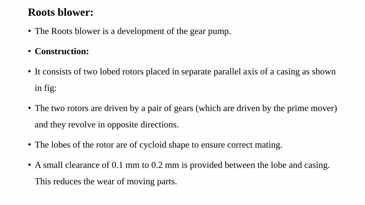
Roots blower:
• The Roots blower is a development of the gear pump.
• Construction:
• It consists of two lobed rotors placed in separate parallel axis of a casing as shown
in fig:
• The two rotors are driven by a pair of gears (which are driven by the prime mover)
and they revolve in opposite directions.
• The lobes of the rotor are of cycloid shape to ensure correct mating.
• A small clearance of 0.1 mm to 0.2 mm is provided between the lobe and casing.
This reduces the wear of moving parts.
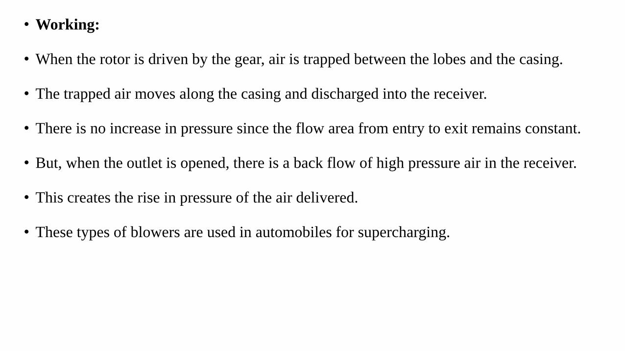
• Working:
• When the rotor is driven by the gear, air is trapped between the lobes and the casing.
• The trapped air moves along the casing and discharged into the receiver.
• There is no increase in pressure since the flow area from entry to exit remains constant.
• But, when the outlet is opened, there is a back flow of high pressure air in the receiver.
• This creates the rise in pressure of the air delivered.
• These types of blowers are used in automobiles for supercharging.


Vane blower
• Construction: A vane blower consists of
(1) a rotor,
(2) vanes mounted on the rotor,
(3) inlet and outlet ports and
(4) casing.
• The rotor is placed eccentrically in the outer casing. Concentric vanes (usually 6
to 8 nos.) are mounted on the rotor. The vanes are made of fibre or carbon. Inlet
suction area is greater than outlet delivery area.

• Working: When the rotor is rotated by the prime mover, air is entrapped
between two consecutive vanes. This air is gradually compressed due to
decreasing volume between the rotor and the outer casing. This air is
delivered to the receiver. This partly compressed air is further increased in
pressure due to the back flow of high pressure air from the receiver.
• Advantages: 1. Very simple and compact, 2. High efficiency 3. Higher
speeds are possible


Centrifugal compressor• Construction:
• It consists of an impeller, a casing and a diffuser.
• The impeller consists of a number of blades or vanes, is mounted on
the compressor shaft inside the casing.
• The impeller is surrounded by the casing.

• Working:
• In this compressor air enters axially and leaves radially.
• When the impeller rotates, air enters axially through the eye of the impeller with a low
velocity.
• This air moves over the impeller vanes. Then, it flows radially outwards from the impeller.
The velocity and pressure increases in the impeller.
• The air then enters the diverging passage known as diffuser. In the diffuser, kinetic energy
is converted into pressure energy and the pressure of the air further increases. It is shown in
fig.
• Finally, high pressure air is delivered to the receiver. Generally half of the total pressure
rise takes place in the impeller and the other half in the diffuser.
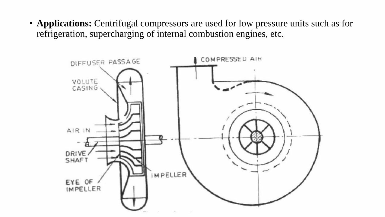
• Applications: Centrifugal compressors are used for low pressure units such as for refrigeration, supercharging of internal combustion engines, etc.

Axial flow compressor
• In this air compressor, air enters and leaves axially.
• Construction: It consists of two sets of blades: Rotor blades and stator blades. The
blades are so arranged that the unit consists of adjacent rows of rotor blades and
stator blades as shown in fig.
• The stator blades are fixed to the casing. The rotor blades are fixed on the rotating
drum. The drum is rotated by a prime mover through a driving shaft.
• Single stage compressor consists of a row of rotor blades followed by a row of stator
blades. Compression of air takes place in each pair of blades (one rotor blade and one
stator blade). Hence there are many stages of compression in this type of compressor.

• Working: When the switch is switched on, the prime mover rotates the drum. Air
enters through the compressor inlet and passes through the rotor and stator blades
• Applications:
• 1. They are widely used in high pressure units such as industrial and marine gas
turbine plants,
• 2. They are most suitable for aircraft work (Jet propulsion) since they require less
frontal area.


END OF MODULE 5
THANK YOU