Multi-scale analysis of cone penetration test (CPT) in a virtual calibration chamber
26
1 Multiscale analysis of CPT in a virtual calibration chamber Joanna Butlanska, Marcos Arroyo, Antonio Gens, and Catherine O’Sullivan Abstract: A virtual calibration chamber was developed using a 3D DEM to perform CPT tests on a discrete analogue of Ticino sand. The macro-scale response of the DEM model was previously shown to be in good quantitative agreement with that of analogous physical models. In the current study the performance of the model at meso- and micro-scale levels of resolution is examined. The micro-scale response is examined using particle displacements and contact force distributions. The meso-scale behaviour is examined using stress and strain fields obtained through appropriate averaging and interpolating procedures. Four CPT tests are examined at the steady state penetration stage. The effects of radial boundary conditions, initial stress state, initial average density and particle rotational inertia are examined. The ability of the micro- and meso-scale data to identify and explain the relevant mechanisms underlying the significant differences in the macro-scale response of the models is discussed. Comparisons with similar phenomena observed in physical tests are also highlighted. Key words: cone penetration, calibration chamber, numerical modelling, discrete element method. 1. Introduction Cone penetration tests are a basic geotechnical soil characterization tool. They are particularly valuable for granular soils, where intact sample retrieval is very difficult. Their use in offshore work is widespread Lunne (2012) because of the relative ease of deployment. Interpretation of CPT test results in sands still relies largely on empirical correlations Mayne (2006); Schnaid (2009). These correlations are often developed in calibration chambers (CC), where the soil state and properties can be carefully controlled Huang and Hsu (2004). Calibration chambers are relatively large pieces of equipment, and calibration chamber testing is expensive and time-consuming. The idea of complementing the physical tests with virtual equivalents (i.e. numerical models) is attractive and has been considered for some time Houlsby and Hitchman (1989a). These numerical models allow internal parameters that are difficult to measure in-situ to be monitored and the additional insight that they provide into CPT-soil interaction can improve interpretation techniques. There have been several partially successful attempts to model CPT tests in sands using finite elements Susila and Hryciw (2003); Huang and Hsu (2004); Ahmadi et al. (2005). However boundary Received . Revision received . Accepted . Revision accepted . Joanna Butlanska, Marcos Arroyo, and Antonio Gens. Departament d’Enginyeria del Terreny, Cartogr` afica i Geof´ ısica, Universitat Polit` ecnica de Catalunya, Jordi Girona 1-3, Barcelona, 08034. Catherine O’Sullivan. 1 Department of Civil Engineering, Imperial College of Science and Technology, SW7 2AZ London, UK. 1 Corresponding author (e-mail: [email protected]). Canadian Geotechnical Journal : 1–26 () DOI: 10.1139/ Published by NRC Research Press Page 1 of 26 Can. Geotech. J. Downloaded from www.nrcresearchpress.com by UNIVERSITAT POLITECNICA DE CATALUNYA on 10/29/13 For personal use only. This Just-IN manuscript is the accepted manuscript prior to copy editing and page composition. It may differ from the final official version of record.
Transcript of Multi-scale analysis of cone penetration test (CPT) in a virtual calibration chamber

1
Multiscale analysis of CPT in a virtualcalibration chamber
Joanna Butlanska, Marcos Arroyo, Antonio Gens, and CatherineO’Sullivan
Abstract: A virtual calibration chamber was developed using a 3D DEM to perform CPTtests on a discrete analogue of Ticino sand. The macro-scale response of the DEM modelwas previously shown to be in good quantitative agreement with that of analogous physicalmodels. In the current study the performance of the model at meso- and micro-scale levelsof resolution is examined. The micro-scale response is examined using particle displacementsand contact force distributions. The meso-scale behaviour is examined using stress and strainfields obtained through appropriate averaging and interpolating procedures. Four CPT testsare examined at the steady state penetration stage. The effects of radial boundary conditions,initial stress state, initial average density and particle rotational inertia are examined. Theability of the micro- and meso-scale data to identify and explain the relevant mechanismsunderlying the significant differences in the macro-scale response of the models is discussed.Comparisons with similar phenomena observed in physical tests are also highlighted.
Key words: cone penetration, calibration chamber, numerical modelling, discrete elementmethod.
1. Introduction
Cone penetration tests are a basic geotechnical soil characterization tool. They are particularlyvaluable for granular soils, where intact sample retrieval is very difficult. Their use in offshore work iswidespread Lunne (2012) because of the relative ease of deployment. Interpretation of CPT test resultsin sands still relies largely on empirical correlations Mayne (2006); Schnaid (2009). These correlationsare often developed in calibration chambers (CC), where the soil state and properties can be carefullycontrolled Huang and Hsu (2004). Calibration chambers are relatively large pieces of equipment,and calibration chamber testing is expensive and time-consuming. The idea of complementing thephysical tests with virtual equivalents (i.e. numerical models) is attractive and has been considered forsome time Houlsby and Hitchman (1989a). These numerical models allow internal parameters that aredifficult to measure in-situ to be monitored and the additional insight that they provide into CPT-soilinteraction can improve interpretation techniques.
There have been several partially successful attempts to model CPT tests in sands using finiteelements Susila and Hryciw (2003); Huang and Hsu (2004); Ahmadi et al. (2005). However boundary
Received . Revision received . Accepted . Revision accepted .
Joanna Butlanska, Marcos Arroyo, and Antonio Gens. Departament d’Enginyeria del Terreny, Cartograficai Geofısica, Universitat Politecnica de Catalunya, Jordi Girona 1-3, Barcelona, 08034.Catherine O’Sullivan.1 Department of Civil Engineering, Imperial College of Science and Technology, SW72AZ London, UK.1 Corresponding author (e-mail: [email protected]).
Canadian Geotechnical Journal : 1–26 () DOI: 10.1139/ Published by NRC Research Press
Page 1 of 26C
an. G
eote
ch. J
. Dow
nloa
ded
from
ww
w.n
rcre
sear
chpr
ess.
com
by
UN
IVE
RSI
TA
T P
OL
ITE
CN
ICA
DE
CA
TA
LU
NY
A o
n 10
/29/
13Fo
r pe
rson
al u
se o
nly.
Thi
s Ju
st-I
N m
anus
crip
t is
the
acce
pted
man
uscr
ipt p
rior
to c
opy
editi
ng a
nd p
age
com
posi
tion.
It m
ay d
iffe
r fr
om th
e fi
nal o
ffic
ial v
ersi
on o
f re
cord
.

2 Canadian Geotechnical Journal Vol. ,
value problems involving large strain contact problems in dilatant materials remain difficult to modelwith continuum-based approaches Bienen et al. (2011). One of these difficulties is the need for arelatively advanced soil constitutive model which typically requires a relatively complex calibrationprocess. It is therefore worth exploring the potential of alternative approaches such as the discreteelement method.
The discrete element method (DEM) is rapidly gaining acceptance as a major tool for investigatingthe behaviour of soils and key aspects of soil material response have been demonstrated to ’emerge’from DEM models O’Sullivan (2011). While the major contribution of DEM in geomechanics to datehas been to advance understanding of the fundamental nature of soil behaviour (e.g. Wang and Leung(2008)); it is also recognized that DEM-based models can be applied directly to solve larger-scaleengineering problems Cundall (2001); Maynar and Rodrıguez (2005); Bertrand et al. (2008).
The first attempts to apply DEM to model cone penetration tests were performed using 2D ele-ments, or disks Huang and Ma (1994); Calvetti and Nova (2005); Jiang et al. (2006b). This dimen-sional restriction was imposed on the modellers because of the high computational cost of 3D DEMmodelling. Many interesting results were obtained, however, for the most part, the comparison withtests on real soils remained qualitative rather than quantitative. Only recently Butlanska et al. (2010b)more realistic 3D simulations of the CPT problem have been achieved. Arroyo et al. (2011) showedthat a CPT performed in a virtual calibration chamber (VCC) filled with a discrete analogue of Ticinosand resulted on steady state penetration values that were in close quantitative agreement with predic-tions based on correlations previously established in physical chambers. Such correlations between tipresistance, initial mean stress and density Jamiolkowski et al. (2003) are still the cornerstone of muchpractical field work interpretation and the agreement noted was therefore encouraging. Similar work,but with a somewhat different emphasis, was recently presented by Mcdowell et al. (2012); Lin andWu (2012).
While the advantages of DEM-based VCC testing are clear, a number of areas require further ex-ploration. These include specimen formation procedures and their influence on chamber homogeneityButlanska et al. (2009); the exploitation of model symmetries; the implementation of different bound-ary conditions; the different scale effects derived from basic geometrical ratios of the model dimensionsButlanska et al. (2010a), etc. Many of these issues are also relevant in physical chambers, althoughDEM introduces some constraints of its own; for instance the particle size of the discrete analogueto Ticino sand is scaled up by a factor of 50 in our models. The computational advantages that fol-lows from that particle scaling has the side effect of artificially increasing the fluctuation of observedresponses (Arroyo et al. (2011); Pasha et al. (2013)). Despite this limitation, DEM models have thesignificant advantage that the results and conditions of each experiment can be examined in much moredetail than is the case for physical experiments.
Indeed, one essential feature of DEM-based models is that they can be examined at various levelsof resolution, i.e. the micro-scale, the meso-scale and the macro-scale. The ability to switch from onelevel of resolution to another makes use of DEM-based models very attractive. In this paper, followinga concise description of the modelling approach, we illustrate this possibility by examining results ofCPT simulations at these three levels of resolution.
2. Modelling approach
2.1. Numerical methodThe DEM code PFC3D Itasca Consulting Group (2008) was used. The discrete elements are spher-
ical in shape. DEM simulations with spherical particles tend to give macro-scale friction (φ ) valuesthat are lower than one would expect for a real sand (i.e. Thornton (2000) had a maximum φ valueof 27◦) and Harkness et al. (2005) clearly show, using DEM, that samples of non-spherical particlesare stronger than those with spherical particles. Particle rotation was inhibited here in an attempt to
Published by NRC Research Press
Page 2 of 26C
an. G
eote
ch. J
. Dow
nloa
ded
from
ww
w.n
rcre
sear
chpr
ess.
com
by
UN
IVE
RSI
TA
T P
OL
ITE
CN
ICA
DE
CA
TA
LU
NY
A o
n 10
/29/
13Fo
r pe
rson
al u
se o
nly.
Thi
s Ju
st-I
N m
anus
crip
t is
the
acce
pted
man
uscr
ipt p
rior
to c
opy
editi
ng a
nd p
age
com
posi
tion.
It m
ay d
iffe
r fr
om th
e fi
nal o
ffic
ial v
ersi
on o
f re
cord
.

Butlanska, Arroyo, Gens, and O’Sullivan 3
Table 1. Parameters of contact law
Parameter Value
Kcoeff (MN/m) 300
Stiffness ratio α (-) 0.25
Friction coefficient tan(φµ) (deg) 0.35
damping (-) 0.05
capture the rotational resistance that exists when the particle shapes are not spherical. This approachwas already advocated by Ting et al. (1989) and has been also successfully applied byCalvetti (2008).
The contact law employed is elasto-plastic. The elastic part is linear and the normal and tangentialstiffness at any contact, kN and kS , are described by the following scaling rule,
kN = 2KcoeffD1D2
D1 +D2[1]
kS = αkN
Where D1 and D2 are the diameters of the two contacting particles and Kcoeff is a normal contactmodulus. This choice has proven useful in other geotechnical problems Calvetti (2008). A constantratio, α, between normal and shear stiffness was selected. The plastic components of the contact laware the frictional slider acting in the tangential direction and the no tension constraint acting in thenormal direction. In the frictional slider the initiation of sliding is determined by a friction coefficient(φµ). No cohesion is included in the contact model.
The contact model parameters were calibrated by simulation of a triaxial compression test on Ticinosand Butlanska et al. (2010b) and are given in Table 1. The simulations employed a local non-viscousdamping coefficient of 0.05 Cundall (1987). The time step employed in the simulations was in therange of 1.3–1.5e−5 s.
2.2. Model constructionThe cone shaft was modelled using four rigid cylindrical walls, one frictionless wall and three
frictional walls as illustrated in Figure 1. The tip had an angle of 60 degrees and was also frictionalwith a tip-particle friction coefficient set equal to the interparticle friction (tan(φµ) = 0.35). Thecalibration chamber walls were frictionless. In all the tests described here the cone diameter, dc was71.2 mm and the calibration chamber diameter Dc was 1200 mm. The ratio of these two quantities,Rd, is 16.8; this is a value for which radial boundary effects are known to influence the results inphysical chambers Parkin and Lunne (1982). Procedures to correct scale effects on cone resistance forcomparison with ideal field conditions are discussed in Butlanska et al. (2010a). Here all the resultsare presented without any correction for scale effects, since the objective is to compare different testswith the same cone and chamber size.
Both the cone and the CC have cylindrical symmetry. In principle, frictionless radial walls prevent-ing circumferential motion of particles can be used to enforce this symmetry and reduce the computa-tional cost. Butlanska et al. (2009) show that changes in the macro response of the model between full,half and quarter chambers are second order for medium-dense specimens. However they did also showthat radial walls induced local heterogeneities at the micro and meso-scale at specimen formation. Toavoid those effects, the tests examined here were always performed on a full chamber.
For computational efficiency the number of particles (59986) was determined by matching a grainsize distribution equal to that of Ticino sand but scaled by a factor of 50 (Table 2). A typical simulationtook around 1 day on a PC (Intel Core 2 Quad, Q6600 @ 2.40GHz, 3.25 GB of RAM). The specimens
Published by NRC Research Press
Page 3 of 26C
an. G
eote
ch. J
. Dow
nloa
ded
from
ww
w.n
rcre
sear
chpr
ess.
com
by
UN
IVE
RSI
TA
T P
OL
ITE
CN
ICA
DE
CA
TA
LU
NY
A o
n 10
/29/
13Fo
r pe
rson
al u
se o
nly.
Thi
s Ju
st-I
N m
anus
crip
t is
the
acce
pted
man
uscr
ipt p
rior
to c
opy
editi
ng a
nd p
age
com
posi
tion.
It m
ay d
iffe
r fr
om th
e fi
nal o
ffic
ial v
ersi
on o
f re
cord
.

4 Canadian Geotechnical Journal Vol. ,
Fig. 1. View of the DEM model components with indication of the main relevant dimensions (a) calibrationchamber (b) cone.
(a) (b)
Table 2. Ticino sand properties and grain sizecharacteristics of the analogue discrete mate-rial
Properties Ticino Sand DEM VCC
D50 (mm) 0.53 26.5
Cu (-) 1.61 1.31
Dmin (mm) 0.09 4.5
emin (-) 0.578 -
emax (-) 0.924 -
were created to a relative density slightly above the target value using the radius expansion method.Then, the particle velocities were reset to zero and the material was subject to an isotropic compressionto 10 kPa and in an iterative process the interparticle friction was varied to obtain a close fit (within5%) to the relative density target. The interparticle friction was then reset to the calibrated value andthe isotropic stress was monotonically increased to the target value (Table 2). Once the system was inequilibrium the cone penetration was simulated at a rate of 10 cm/s. Penetration was stopped 10-20 cmabove the chamber bottom.
2.3. Test seriesThe conditions of the tests examined here are summarized in Table 3. Five tests were selected for
detailed examination. In three of them (T16, T20 and T16Rot) the CPT was performed under isotropicstress conditions that were maintained constant at the radial and top boundaries (BC1). The differencebetween T16 and T20 lies in the initial relative density of the discrete material, which is 75% forT16 and 90% for T20. The difference between T16 and T16Rot is that in T16rot particle rotationwas freely allowed (i.e. each particle rotates according to the angular acceleration that results fromits own angular moment balance) whereas in the T16 the setting of impeded rotation was applied byfixing the the rotational degree of freedom of the spherical particles in xyz directions. Two other tests(T163, T164) were performed in a chamber subjected to anisotropic stress conditions: the differencebetween them was the radial boundary condition; T163 (BC1) was stress controlled to have a constant
Published by NRC Research Press
Page 4 of 26C
an. G
eote
ch. J
. Dow
nloa
ded
from
ww
w.n
rcre
sear
chpr
ess.
com
by
UN
IVE
RSI
TA
T P
OL
ITE
CN
ICA
DE
CA
TA
LU
NY
A o
n 10
/29/
13Fo
r pe
rson
al u
se o
nly.
Thi
s Ju
st-I
N m
anus
crip
t is
the
acce
pted
man
uscr
ipt p
rior
to c
opy
editi
ng a
nd p
age
com
posi
tion.
It m
ay d
iffe
r fr
om th
e fi
nal o
ffic
ial v
ersi
on o
f re
cord
.

Butlanska, Arroyo, Gens, and O’Sullivan 5
horizontal stress whereas no lateral displacement was allowed in T164 (BC3). Therefore three pairs oftests can be identified in which the effect of a single variable (T16 and T20 for initial density, T16 andT16rot for particle rotation and T163 and T164 for radial boundary condition) is examined in isolation.In addition, the comparison of T20 and T163 gives a good indication of the effect of varying verticalstress in the chamber, although they also differ slightly in initial density and radial stress.
Table 3. Characteristics and main results of the VCC CPT tests
Test ID T16 T20 T163 T164 T16RotBC BC1 BC1 BC1 BC3 BC1DR0 (%) 75.2 90 96.8 96.8 75.2σz0 (kPa) 100 100 313 313 100σh0 (kPa) 100 100 109 109 100a (MPa) 10.36 12.92 13.04 40.8 1.18b (1/m) 20 20 25 8 13.5Nickname MedIsoBC1 DenseIsoBC1 DenseKoBC1 DenseKoBC3 MedIsoRotBC1Key Feature Medium
dense,isotropic,constant radialstress
Dense,isotropic,constant radialstress
Dense,anisotropic,constant radialstress
Dense,anisotropic,fixed radialwall
Mediumdense,isotropic,constant ra-dial stress,free particlerotation
3. Macro-Scale results
The macro-scale is the scale of most interest from an engineering viewpoint, because it deals withsystem responses such as cone tip resistance. An example of cone penetration tip resistance data froma test on a VCC is shown in Figure 2. The data are very noisy, with large oscillations. Numericalexperiments Butlanska et al. (2010a) using variably sized cones in the same chamber show that suchoscillations are an artefact of the scaled discrete material and can be filtered out. To do that, a steadystate cone resistance was extracted from the raw penetration curves by fitting them to the followingexpression:
qc(h) = a [1− exp (−bh)][2]
where qc is cone tip resistance; h is penetration depth and a & b are fitting parameters. These fittingparameters convey some useful information. Parameter a gives the asymptotic value of cone resistance;whereas parameter b is inversely related to the limit of shallow penetration. For instance, if that limitis at h95, the depth where 95% of the asymptotic limit value is reached, then
h95 ≈3
b[3]
The application of this procedure is also illustrated in Figure 2; the fitting parameters (a, b) for all thetests reported here are given in Table 3.
The macro-scale responses for the five tests examined here are presented as filtered penetrationcurves in Figure 3. The test results are paired so as to highlight the effect of each of the variables notedabove. It is clear from Figure 3 that: (a) an increase in initial density increases the cone resistance;(b) a change in the radial boundary condition from stress control (BC1) to strain control (BC3) resultsin a large increase in cone resistance; (c) an increase in the initial vertical stress has negligible effect
Published by NRC Research Press
Page 5 of 26C
an. G
eote
ch. J
. Dow
nloa
ded
from
ww
w.n
rcre
sear
chpr
ess.
com
by
UN
IVE
RSI
TA
T P
OL
ITE
CN
ICA
DE
CA
TA
LU
NY
A o
n 10
/29/
13Fo
r pe
rson
al u
se o
nly.
Thi
s Ju
st-I
N m
anus
crip
t is
the
acce
pted
man
uscr
ipt p
rior
to c
opy
editi
ng a
nd p
age
com
posi
tion.
It m
ay d
iffe
r fr
om th
e fi
nal o
ffic
ial v
ersi
on o
f re
cord
.

6 Canadian Geotechnical Journal Vol. ,
Fig. 2. Typical raw result and filtered penetration curve.
0 5 10 15 200
0.1
0.2
0.3
0.4
0.5
0.6
0.7
Pen
etra
tion
Dep
th [
m]
Cone Resistance qc [MPa]
T163:DenseKoBC1Trend Funcion: Eqn. 2
on the limiting cone resistance; and (d) allowing particle rotation results in a large reduction in coneresistance.
All these macro-scale results can be related to similar observations of response in physical cham-bers. The positive effect of initial soil density on cone tip resistance is one of the basic results of CCtesting (e.g. Jamiolkowski et al. (2003)). A large increase in cone resistance when the radial boundarycondition changes from fixed radial stress (BC1) to zero radial displacement (BC3) has been observedin chambers with relatively small cone to chamber diameter ratio (e.g. Parkin and Lunne (1982)).Houlsby and Hitchman (1989b) showed that the initial vertical stress had very little bearing on thecone resistance measured in CC tests performed under BC1 conditions.
The important effect of particle rotation on cone resistance can be related to the work of Lehaneand Liu (2012) who showed that an increase in sand sphericity resulted in a marked decrease (up to afactor of 5) in cone resistance. As explained above, increasing sphericity facilitates particle rotation. Inour numerical experiment only the two extremes of the range (maximum ability to rotate and impededrotation) are explored, hence the factor of 10 that appears in the ratio of cone resistances seems to agreewith the observations of Lehane and Liu (2012).
4. Micro-scale results
The results of DEM simulations can be described using either discrete or continuum variables. Thediscrete variables are those directly derived from the basic modelling units of the method, i.e. particlesand contacts. Examples of discrete variables are contact orientations, contact forces, particle displace-ments, etc. The continuum variables are those that can be also employed in continuum mechanics:stress and strain tensors are the most common, but a fabric tensor might be another relevant example.
The micro-scale level of resolution describes variables at the highest possible resolution, that is, atthe particle or contact level: the variables described at this level are usually discrete, but they might bealso continuum inspired (e.g. particle stress, O’Sullivan (2011)). A key problem is to select parametersthat give a meaningful insight into the mechanics, this is particularly difficult when dealing with large3D models, where visualization is challenging. Detailed results were recovered for analysis when thecone tip was located at a normalised depth of 5.4 cone diameters, which corresponds to 0.39 m and iswell into the steady-state zone for all tests. Results were also collected for a shallow penetration stageof 0.1 m but, with one exception explained below, they are not examined here.
Published by NRC Research Press
Page 6 of 26C
an. G
eote
ch. J
. Dow
nloa
ded
from
ww
w.n
rcre
sear
chpr
ess.
com
by
UN
IVE
RSI
TA
T P
OL
ITE
CN
ICA
DE
CA
TA
LU
NY
A o
n 10
/29/
13Fo
r pe
rson
al u
se o
nly.
Thi
s Ju
st-I
N m
anus
crip
t is
the
acce
pted
man
uscr
ipt p
rior
to c
opy
editi
ng a
nd p
age
com
posi
tion.
It m
ay d
iffe
r fr
om th
e fi
nal o
ffic
ial v
ersi
on o
f re
cord
.

Butlanska, Arroyo, Gens, and O’Sullivan 7
Fig. 3. Filtered macro response of the VCC CPT tests (a) effect of initial density (b) effect of radial boundarycondition (c) effect of vertical stress (d) effect of particle rotation.
0 5 10 15 200
0.1
0.2
0.3
0.4
0.5
0.6
0.7
Pen
etra
tion
Dep
th [
m]
Cone Resistance qc [MPa]
T16:MedIsoBc1T20:DenseIsoBc1
(a)
0 20 40 600
0.1
0.2
0.3
0.4
0.5
0.6
0.7
Pen
etra
tion
Dep
th [
m]
Cone Resistance qc [MPa]
T163:DenseKoBC1T164:DenseKoBC3
(b)
0 5 10 15 200
0.1
0.2
0.3
0.4
0.5
0.6
0.7
Pen
etra
tion
Dep
th [
m]
Cone Resistance qc [MPa]
T20:DenseIsoBc1T163:DenseKoBc1
(c)
0 5 10 15 200
0.1
0.2
0.3
0.4
0.5
0.6
0.7
Pen
etra
tion
Dep
th [
m]
Cone Resistance qc [MPa]
T16:MedIsoBC1T16Rot:MedIsoRorBC1
(d)
4.1. Displacements
For rotation-inhibited particles the only kinematic variable associated with each element is the dis-placement vector. Here, the 3D displacement vector field was visualized by projecting the vectors ontoa vertical plane. In Figure 4, the displacement vector for particles whose center is located within onemean diameter of a vertical plane that bisects the chamber and passes through the chamber axis arerepresented as arrows projected onto this vertical plane. The arrow length equals the displacementmagnitude scaled by a factor of 30 for clarity. In all cases the largest displacements appear to occurclose to the cone, with particles moving downwards and sideways. The radial boundary conditionaffects the displacement field away from the cone and the displacement field becomes almost hori-zontal close to the radial wall (this is particularly clear for test T163). It is also noteworthy that the
Published by NRC Research Press
Page 7 of 26C
an. G
eote
ch. J
. Dow
nloa
ded
from
ww
w.n
rcre
sear
chpr
ess.
com
by
UN
IVE
RSI
TA
T P
OL
ITE
CN
ICA
DE
CA
TA
LU
NY
A o
n 10
/29/
13Fo
r pe
rson
al u
se o
nly.
Thi
s Ju
st-I
N m
anus
crip
t is
the
acce
pted
man
uscr
ipt p
rior
to c
opy
editi
ng a
nd p
age
com
posi
tion.
It m
ay d
iffe
r fr
om th
e fi
nal o
ffic
ial v
ersi
on o
f re
cord
.

8 Canadian Geotechnical Journal Vol. ,
displacement magnitude far from the cone is larger in T163 than for the similarly constrained T16; thisdifference is attributed to the larger vertical stress applied to T163 which enhances vertical downwardsdisplacements close to the top boundary.
Fig. 4. Particle displacement vectors projected in a vertical section of the chamber (cone starts from the surface).Particle displacement vectors larger than mean are illustrated in black and lower than mean are shown in gray.
−8 −6 −4 −2 0 2 4 6 8−10
−8
−6
−4
−2
0
2
x*/dc
∆h/d
c
(a) T20:DenseIsoBC1
−8 −6 −4 −2 0 2 4 6 8−10
−8
−6
−4
−2
0
2
x*/dc
∆h/d
c
(b) T16:MedIsoBC1
−8 −6 −4 −2 0 2 4 6 8−10
−8
−6
−4
−2
0
2
x*/dc
∆h/d
c
(c) T16Rot:MedIsoRotBC1
−8 −6 −4 −2 0 2 4 6 8−10
−8
−6
−4
−2
0
2
x*/dc
∆h/d
c
(d) T163:DenseK0BC1
−8 −6 −4 −2 0 2 4 6 8−10
−8
−6
−4
−2
0
2
x*/dc
∆h/d
c
(e) T164:DenseK0BC3
A full appreciation of the displacement field is not possible using this vector representation. InFigure 5 a binary criteria is employed; and the particles are shaded according to the direction of theirvertical displacement (w). This representation allows detection of features of the displacement field
Published by NRC Research Press
Page 8 of 26C
an. G
eote
ch. J
. Dow
nloa
ded
from
ww
w.n
rcre
sear
chpr
ess.
com
by
UN
IVE
RSI
TA
T P
OL
ITE
CN
ICA
DE
CA
TA
LU
NY
A o
n 10
/29/
13Fo
r pe
rson
al u
se o
nly.
Thi
s Ju
st-I
N m
anus
crip
t is
the
acce
pted
man
uscr
ipt p
rior
to c
opy
editi
ng a
nd p
age
com
posi
tion.
It m
ay d
iffe
r fr
om th
e fi
nal o
ffic
ial v
ersi
on o
f re
cord
.

Butlanska, Arroyo, Gens, and O’Sullivan 9
away from the cone. Most notably a definite boundary appears in the test with fixed radial walls (T164)between an inner core of particles, all of whom are displaced downwards and an external peripheryof particles that all move upwards. Amongst the tests with a mobile radial wall only the case withfree rotation (T16Rot) shows also an intermediate zone of upward motion. This zone has a different,lobulated shape, and a less clear boundary than that appearing in T164.
Fig. 5. Binary representation of vertical displacement for particles contained in a vertical section (black particlesupwards vertical displacement, w > 0 and white particles downwards vertical displacement, w < 0).
−5 0 5−10
−8
−6
−4
−2
0
X/dc
∆h/d
c
(a) T20:DenseIsoBC1
−5 0 5−10
−8
−6
−4
−2
0
X/dc
∆h/d
c
(b) T16:MedIsoBC1
−5 0 5−10
−8
−6
−4
−2
0
X/dc
∆h/d
c
(c) T16Rot:MedIsoRotBC1
−5 0 5−10
−8
−6
−4
−2
0
X/dc
∆h/d
c
(d) T163:DenseK0BC1
−5 0 5−10
−8
−6
−4
−2
0
X/dc
∆h/d
c
(e) T164:DenseK0BC3
To identify features close to the cone it is useful to look at the particle displacement magnitudesnormalized by the cone diameter, as presented in Figure 6. A small number of particles close to thecone shaft are entrapped in the cone motion and have very large displacements. This entrapped materialeffectively forms a coating layer with a thickness that rarely exceeds two particles, and this layer is notcontinuous; it has numerous gaps. This feature appeared in all 5 tests and seems relatively insensitive
Published by NRC Research Press
Page 9 of 26C
an. G
eote
ch. J
. Dow
nloa
ded
from
ww
w.n
rcre
sear
chpr
ess.
com
by
UN
IVE
RSI
TA
T P
OL
ITE
CN
ICA
DE
CA
TA
LU
NY
A o
n 10
/29/
13Fo
r pe
rson
al u
se o
nly.
Thi
s Ju
st-I
N m
anus
crip
t is
the
acce
pted
man
uscr
ipt p
rior
to c
opy
editi
ng a
nd p
age
com
posi
tion.
It m
ay d
iffe
r fr
om th
e fi
nal o
ffic
ial v
ersi
on o
f re
cord
.

10 Canadian Geotechnical Journal Vol. ,
to the different variables explored here. Similar entrapment mechanisms have been observed in 2DDEM simulations Jiang et al. (2006a) and in laboratory models of pile penetration (e.g. van den Berg(1994)).
Fig. 6. Normalized displacement magnitude (utot/dc) for particles contained in a vertical chamber section.
−5 0 5−10
−8
−6
−4
−2
0
x/dc
∆h/d
c
0 0.5 1 1.5 2
(a) T20:DenseIsoBC1
−5 0 5−10
−8
−6
−4
−2
0
x/dc
∆h/d
c
0 0.5 1 1.5 2
(b) T16:MedIsoBC1
−5 0 5−10
−8
−6
−4
−2
0
x/dc
∆h/d
c
0 0.5 1 1.5 2
(c) T16Rot:MedIsoRotBC1
−5 0 5−10
−8
−6
−4
−2
0
x/dc
∆h/d
c
0 0.5 1 1.5 2
(d) T163:DenseK0BC1
−5 0 5−10
−8
−6
−4
−2
0
x/dc
∆h/d
c
0 0.5 1 1.5 2
(e) T164:DenseK0BC3
The normalised displacement plots given in Figure 6 are also interesting in areas distant from the
Published by NRC Research Press
Page 10 of 26C
an. G
eote
ch. J
. Dow
nloa
ded
from
ww
w.n
rcre
sear
chpr
ess.
com
by
UN
IVE
RSI
TA
T P
OL
ITE
CN
ICA
DE
CA
TA
LU
NY
A o
n 10
/29/
13Fo
r pe
rson
al u
se o
nly.
Thi
s Ju
st-I
N m
anus
crip
t is
the
acce
pted
man
uscr
ipt p
rior
to c
opy
editi
ng a
nd p
age
com
posi
tion.
It m
ay d
iffe
r fr
om th
e fi
nal o
ffic
ial v
ersi
on o
f re
cord
.

Butlanska, Arroyo, Gens, and O’Sullivan 11
cone, where they show the shape of zones containing particles with small displacements. These zonesare clearly sensitive to the specified radial boundary condition, for instance, fixed walls (T164) imposea clear cylindrical pattern and concentrate the motion around the cone. It is however surprising to notethat a similar cylindrical pattern, albeit more imperfect, appears also on the case with free rotation(T16Rot). These two tests have steady state penetration resistance values that differ by a factor of 40;it seems then that similar micro-scale displacement patterns can give rise to very different macro-scaleresponse. To explain the observed differences in cone resistance it seems necessary to go beyond purekinematics.
4.2. Contact forcesSystem-wide contact force plots are useful to explore force transmission across the system. In Fig-
ure 7 3D contact force vectors are represented in planar projection along a vertical section containingthe chamber axis (Figure 7). The heterogeneity of the magnitude of contact forces in discrete mediaforce networks is well known, relatively distinct strong force chains that carry a large proportion of thestress form in the material (e.g. Radjai et al. (1996)). The magnitude of the contact forces also variessignificantly between the different VCC tests, as shown by the cumulative force magnitude distribu-tions in Figure 8. To deal with that variability the data have been filtered so that only forces above theaverage value in each graph are represented and the line thickness is made proportional to the forcevalue normalised by that average force.
The magnitude of contact forces does increase with observed cone tip resistance, with the largervalues corresponding to the T164 case and the smaller to the T16Rot case. In that test, T16Rot, whereparticles have no rolling resistance, the force network magnitude is distributed much more uniformly.The kinematic restraint seems to create a wider distribution of contact force magnitudes.
The spatial distribution of contact forces is also interesting. The plots reveal two significant com-mon features in the tests performed under isotropic (BC1) conditions using particles with inhibitedrotation (T16, T20 and T163): (a) the strong force network clearly focuses on the penetrometer tip (b)the force network is sparser above the tip with relatively small forces appearing in the vicinity of theshaft. These features are in strong contrast to what was observed in T164 and T16Rot. In test T164,performed under a no-displacement radial boundary condition, the strong force network emanates fromboth the cone tip and the cone shaft. In tests T16Rot, the spatial distribution of force magnitude withinthe chamber is more homogeneous for the free rotating particles. This difference arises from the knownfact that rotational resistance stabilizes force chains (e.g. Tordesillas and Muthuswamy (2009)) and sowhere rotation is inhibited a smaller number of strong force chains are sufficient to transmit the forcefrom the penetrating cone. Moreover, the length of these strong force chains also varies and dependson the initial conditions, particle shapes, the rotational resistance at particle contact point and the endconstraints to the grain column Guo (2012). Hence, the largest force chains, l ≈ 11D50, was observedfor test T164 with no-displacement radial boundary condition (Figure 8e). It is also expected thatincrease Rd ratio (i.e. increase in DV CC/D50 ratio) will not result in larger force chains.
A different perspective of the same phenomenon is conveyed by the polar histograms of the forcevector azimuth (α) represented in Figure 10. The contact forces analysed are those within a cylindricalmeasurement volume coaxial with the chamber, located at the top surface and having a diameter andheight of 0.1 m as shown in Figure 10a. Three different stages are represented for every test: the initialstate, the state after shallow penetration (i.e. when the cone tip has just entered the virtual sand box)and deep penetration, when the cone tip is located at 5.4 dc below the surface. The histogram bin widthis 10 deg. and the number of vectors lying within each increment is shown as a point in the middle ofthe increment to allow for comparison of the three stages. The data show that the distribution of theazimuth of contact forces in the measurement volume is approximately isotropic before the test andremains so after the cone has passed through. On the other hand the number of contacts (represented bythe radial distance in the polar histogram) is greatly reduced by the passing of the cone in all the tests
Published by NRC Research Press
Page 11 of 26C
an. G
eote
ch. J
. Dow
nloa
ded
from
ww
w.n
rcre
sear
chpr
ess.
com
by
UN
IVE
RSI
TA
T P
OL
ITE
CN
ICA
DE
CA
TA
LU
NY
A o
n 10
/29/
13Fo
r pe
rson
al u
se o
nly.
Thi
s Ju
st-I
N m
anus
crip
t is
the
acce
pted
man
uscr
ipt p
rior
to c
opy
editi
ng a
nd p
age
com
posi
tion.
It m
ay d
iffe
r fr
om th
e fi
nal o
ffic
ial v
ersi
on o
f re
cord
.

12 Canadian Geotechnical Journal Vol. ,
Fig. 7. Contact normal forces for particles lying within a vertical section of the chamber. Only forces exceedingaverage normal force are plotted. The lines join the centroids of contacting spheres. The line thickness is pro-portional to the magnitude of the normal force. Forces exceeding the average value +5 standard deviations areillustrated in black; large (above average but not extreme) are shown in dark gray; small (below average) markedin light gray.
−8 −6 −4 −2 0 2 4 6 8
−9
−8
−7
−6
−5
−4
−3
−2
−1
0
1
2
x*/dc
∆h/d
c
(a) T20:DenseIsoBC1
−8 −6 −4 −2 0 2 4 6 8
−9
−8
−7
−6
−5
−4
−3
−2
−1
0
1
2
x*/dc
∆h/d
c
(b) T16:MedIsoBC1
−8 −6 −4 −2 0 2 4 6 8
−9
−8
−7
−6
−5
−4
−3
−2
−1
0
1
2
x*/dc
∆h/d
c
(c) T16Rot:MedIsoRotBC1
−8 −6 −4 −2 0 2 4 6 8
−9
−8
−7
−6
−5
−4
−3
−2
−1
0
1
2
x*/dc
∆h/d
c
(d) T163:DenseK0BC1
−8 −6 −4 −2 0 2 4 6 8
−9
−8
−7
−6
−5
−4
−3
−2
−1
0
1
2
x*/dc
∆h/d
c
(e) T164:DenseK0BC3
performed under BC1 conditions (T16, T20 and T163). The reduction is far less marked for the BC3case (T164) and almost non-existent for the test with rotating particles (T16Rot). Thus it would seemthat the ability of the cone to disrupt the granular fabric is reduced by two different, almost opposing,
Published by NRC Research Press
Page 12 of 26C
an. G
eote
ch. J
. Dow
nloa
ded
from
ww
w.n
rcre
sear
chpr
ess.
com
by
UN
IVE
RSI
TA
T P
OL
ITE
CN
ICA
DE
CA
TA
LU
NY
A o
n 10
/29/
13Fo
r pe
rson
al u
se o
nly.
Thi
s Ju
st-I
N m
anus
crip
t is
the
acce
pted
man
uscr
ipt p
rior
to c
opy
editi
ng a
nd p
age
com
posi
tion.
It m
ay d
iffe
r fr
om th
e fi
nal o
ffic
ial v
ersi
on o
f re
cord
.

Butlanska, Arroyo, Gens, and O’Sullivan 13
Fig. 8. Cumulative force magnitude distribution.
10−2
100
102
0
10
20
30
40
50
60
70
80
90
100
Force [kN]
Per
cent
age
of fo
rces
that
are
sm
alle
r [%
]
T20T16T16RotT163T164
mechanisms. In the first case by the greater constraint offered by the immobile radial boundary. In thesecond case by the reduced stability of force chains that is associated with rotational freedom.
Fig. 9. Key to (a) calculating number of contacts vs. azimuth orientation used in Figure 10 and (b) averagingzones for displacement and stresses.
(a) (b)
5. Meso-scale results
The meso-scale data are obtained using operations that can broadly be labelled as averaging or ho-mogenizing, (but they may include grid projection and interpolation as ancillary techniques) to obtainrepresentative values of the relevant variables within a volume that contains several, possibly many, el-
Published by NRC Research Press
Page 13 of 26C
an. G
eote
ch. J
. Dow
nloa
ded
from
ww
w.n
rcre
sear
chpr
ess.
com
by
UN
IVE
RSI
TA
T P
OL
ITE
CN
ICA
DE
CA
TA
LU
NY
A o
n 10
/29/
13Fo
r pe
rson
al u
se o
nly.
Thi
s Ju
st-I
N m
anus
crip
t is
the
acce
pted
man
uscr
ipt p
rior
to c
opy
editi
ng a
nd p
age
com
posi
tion.
It m
ay d
iffe
r fr
om th
e fi
nal o
ffic
ial v
ersi
on o
f re
cord
.

14 Canadian Geotechnical Journal Vol. ,
Fig. 10. Number of contacts vs azimuth orientation in a shallow axial zone before penetration, at shallow pene-tration and at deep penetration.
50
100
150
30
210
60
240
90
270
120
300
150
330
180 0
(a) T20:DenseIsoBC1
50
100
150
30
210
60
240
90
270
120
300
150
330
180 0
(b) T16:MedIsoBC1
50
100
150
30
210
60
240
90
270
120
300
150
330
180 0
(c) T16Rot:MedIsoRotBC1
50
100
150
30
210
60
240
90
270
120
300
150
330
180 0
(d) T163DenseK0BC1
50
100
150
30
210
60
240
90
270
120
300
150
330
180 0
InitialStageShallowPenetrationDeepPenetration
(e) T164DenseK0BC3
ements. Both discrete and continuum-inspired variables can be represented at this level. The definitionof the averaging volume (i.e. the size and geometry and the applied averaging procedure) will have asignificant influence on the data outcome. These choices have to be decided upon bearing in mind thepurpose of the exercise.
If the meso-scale data are used to develop a continuum constitutive law (e.g. Jiang et al. (2006a)),then the averaging volume should correspond to the ’representative volume element’ that underlies thecontinuum model. On the other hand, if the purpose of the meso-scale analysis is mainly that of gainingunderstanding on an engineering system, the averaging volume choice may be more pragmatic. Forinstance the layered cylindrical shell illustrated in Figure 9a is employed below for averaging purposes.Other frequently employed averaging volumes include spheres or horizontal bands.
5.1. Displacement
Micro-scale representations of displacements show a strong variability that is reduced by volume-averaging. This averaging should be cautiously applied, because significant information can be lost inthe process. A clear justification is given by analysing the problem symmetry: any variability that doesnot respect the main problem symmetries can be safely assumed as random. In the VCC CPT problemboth the chamber and the CPT maintain cylindrical symmetry. The only source of asymmetry in the
Published by NRC Research Press
Page 14 of 26C
an. G
eote
ch. J
. Dow
nloa
ded
from
ww
w.n
rcre
sear
chpr
ess.
com
by
UN
IVE
RSI
TA
T P
OL
ITE
CN
ICA
DE
CA
TA
LU
NY
A o
n 10
/29/
13Fo
r pe
rson
al u
se o
nly.
Thi
s Ju
st-I
N m
anus
crip
t is
the
acce
pted
man
uscr
ipt p
rior
to c
opy
editi
ng a
nd p
age
com
posi
tion.
It m
ay d
iffe
r fr
om th
e fi
nal o
ffic
ial v
ersi
on o
f re
cord
.

Butlanska, Arroyo, Gens, and O’Sullivan 15
problem is that due to the specimen formation procedure. Butlanska et al. (2009) show, however, thatsuch asymmetry is relatively small. It seems therefore safe to average using volumes that maintaincylindrical symmetry.
The averaged vertical displacement (wz) field at three radial distances from the axis is illustratedin Figure 11. Displacements are normalised by the cone diameter. Averaged displacements (wz)within Zone 1 (Figure 12a) are always negative, i.e directed downwards. For all simulations the depthdependency is similar, with a marked peak 1-2 diameters above the tip. However, their magnitudesdiffer, with the free-rotating case (T16Rot) generally showing the smallest value, although it is similarto T16 and T163 close to the surface. The second smallest magnitude corresponds to the case with fixedradial walls (T164). For the BC1 cases with inhibited rotation the largest downwards displacementsare observed when the applied load at the stress-controlled top boundary increases (T163). At largerdistances from the cone the vertical displacement magnitudes are much smaller and the effect of thevertical stress is more marked.
Fig. 11. Averaged vertical particle displacements in annular subsections of the chamber.
−0.5 −0.4 −0.3 −0.2 −0.1 0 0.1−10
−9
−8
−7
−6
−5
−4
−3
−2
−1
0
wz/d
c
∆h/d
c
(a) zone 1
−0.1 −0.05 0 0.05 0.1 0.15 0.2−10
−9
−8
−7
−6
−5
−4
−3
−2
−1
0
wz/d
c
∆h/d
c
(b) zone 2
−0.1 −0.05 0 0.05 0.1 0.15 0.2−10
−9
−8
−7
−6
−5
−4
−3
−2
−1
0
wz/d
c
∆h/d
c
T16:MedIsoBC1T20:DenseIsoBC1T163:DenseKoBC1T164:DenseKoBC3T16Rot:MedIsoRotBC1
(c) zone 3
5.2. Stress fieldsCalculation of stresses in DEM was here based on a well-established procedure Potyondy and
Cundall (2004) in which representative or notional average grain stresses, σpij , are first computed andthen these are averaged in the reference volume to obtain the representative volume stress, as follows
σpij = − 1
V p
∑Nc,p
c=1|xci − x
pi |n
c,pi F cj
σij =1
V
∑Np
p=1
(σpij + σpji
)2
V p[4]
Where the superscripts indicate particle (p) or contact (c), hence N c,p is the number of contacts perparticle and Np is the number of particles of volume V p within the averaging volume, V. For eachcontact, n is the normal vector at the contact and F is the contact force vector; x denotes a positionvector of either a contact point or a particle centre. In the second equation above, it is made explicitthat only the symmetric part of the particle stresses is averaged. As a consequence of inhibiting rotationthe particle stress tensors are not in rotational equilibrium and σpij 6= σpji for i6=j.
Figure 12 illustrates the variation in the radial stress with normalized depth, for all the tests hereexamined in three stacks of cylindrical shells located at three different distances from the chamber axis(Figure 10b). In the Figures stress values are normalised by the initial radial stress value, i.e. 100 kPa,for T16rot, T20 and T16, and 109 kPa for tests T163 and T164).
Published by NRC Research Press
Page 15 of 26C
an. G
eote
ch. J
. Dow
nloa
ded
from
ww
w.n
rcre
sear
chpr
ess.
com
by
UN
IVE
RSI
TA
T P
OL
ITE
CN
ICA
DE
CA
TA
LU
NY
A o
n 10
/29/
13Fo
r pe
rson
al u
se o
nly.
Thi
s Ju
st-I
N m
anus
crip
t is
the
acce
pted
man
uscr
ipt p
rior
to c
opy
editi
ng a
nd p
age
com
posi
tion.
It m
ay d
iffe
r fr
om th
e fi
nal o
ffic
ial v
ersi
on o
f re
cord
.

16 Canadian Geotechnical Journal Vol. ,
Fig. 12. Averaged normalised radial stresses in circular/ring-type subsections of the chamber.
0 20 40 60 80−8
−6
−4
−2
0
2
4
6
8
10
σr/σ
0
norm
aliz
ed d
epth
T16:MedIsoBC1T20:DenseIsoBC1T16Rot:MedIsoRotBC1T163:DenseKoBC1T164:DenseKoBC3
(a) zone 1
0 2 4 6 8 10−8
−6
−4
−2
0
2
4
6
8
10
σr/σ
0
norm
aliz
ed d
epth
(b) zone 2
0 2 4 6 8 10−8
−6
−4
−2
0
2
4
6
8
10
σr/σ
0
norm
aliz
ed d
epth
(c) zone 3
Several interesting features are discernible. The radial stress vertical profile in the vicinity of thechamber axis (Figure 13a) appears dominated by a large peak close to the cone tip. Along the shaft theradial stress decays rapidly above and below that peak, attaining much smaller values. The only casein which the decay is less pronounced is the test performed under BC3 conditions (T164). This caseshows also a slower reduction of the radial stress with distance from the cone (Figure 13b, Figure 13c).It is worth noting that the stress increases that are predicted by the model would likely result in somegrain crushing in physical tests. That effect was not modeled here. The effect of the fixed radialboundary is less marked in the vertical stress profiles shown in Figure 13. The vertical stress close tothe shaft for test T164 is not always above that observed in the BC1 cases. The vertical stress profilesshow also some effect of the mixed vertical boundary condition that is applied in the VCC (constantstress at the top boundary; fixed displacement at the bottom).
Fig. 13. Averaged normalised vertical stresses in circular/ring-type subsections of the chamber.
0 10 20 30 40−8
−6
−4
−2
0
2
4
6
8
10
σz/σ
0
norm
aliz
ed d
epth
T16:MedIsoBC1T20:DenseIsoBC1T16Rot:MedIsoRotBC1T163:DenseKoBC1T164:DenseKoBC3
(a)
0 2 4 6 8 10−8
−6
−4
−2
0
2
4
6
8
10
σz/σ
0
norm
aliz
ed d
epth
(b)
0 2 4 6 8 10−8
−6
−4
−2
0
2
4
6
8
10
σz/σ
0
norm
aliz
ed d
epth
(c)
A qualitatively similar radial stress reduction pattern along the shaft is now well established fordriven piles and accepted as a basis for design Jardine and Chow (2007). The similitarity of the stresspattern with observations in physical models is even more pronounced using the steady state conepenetration value as the normalising stress. In Figure 14 the radial stresses are normalised in this wayand compared with analogous results from Yang et al. (2012) obtained on a physical CC filled withFontaineblau sand. The radial boundary condition on the physical chamber was of the BC3 type, hencemore similar to the numerical test T164; however, the physical chamber had a larger chamber to cone
Published by NRC Research Press
Page 16 of 26C
an. G
eote
ch. J
. Dow
nloa
ded
from
ww
w.n
rcre
sear
chpr
ess.
com
by
UN
IVE
RSI
TA
T P
OL
ITE
CN
ICA
DE
CA
TA
LU
NY
A o
n 10
/29/
13Fo
r pe
rson
al u
se o
nly.
Thi
s Ju
st-I
N m
anus
crip
t is
the
acce
pted
man
uscr
ipt p
rior
to c
opy
editi
ng a
nd p
age
com
posi
tion.
It m
ay d
iffe
r fr
om th
e fi
nal o
ffic
ial v
ersi
on o
f re
cord
.

Butlanska, Arroyo, Gens, and O’Sullivan 17
diameter ratio, Rd, of 33.3, and therefore the influence of that boundary should be smaller and theresults closer to that of the fixed radial stress condition. Results from the VCC CPT are shorter thanthe physical tests, extending only 8 cone radius above and below the cone tip. The results from theVCC CPT are shorter than those from the physical tests. Nevertheless, a good agreement is apparentbetween the numerical and physical tests in the location and magnitude (Figure 15d) of the normalisedradial stress peaks.
Fig. 14. Profiles of radial stress normalised by cone penetration value (a) VCC CPT on Ticino sand DenseK0BC3(b) VCC CPT on Ticino sand DenseK0BC1 (c) measurements during CPT on a CC on Fontainebleau sand Yanget al. (2012) and (d) peak values of normalised radial stress vs radial distance normalised by cone radius.
0 5 10 15 20 25 30−8
−6
−4
−2
0
2
4
6
8
10
σr/a [%]
norm
aliz
ed d
epth
r/Rc=0
r/Rc=11.2
r/Rc=14.0
(a)
0 5 10 15 20 25 30−8
−6
−4
−2
0
2
4
6
8
10
σr/a [%]
norm
aliz
ed d
epth
r/Rc=0
r/Rc=11.2
r/Rc=14.0
(b)
(c)
0 5 10 150
2
4
6
8
10
12
14
16
18
20
\r/Rc
σ r/a [%
]
T163:DenseKoBC1T164:DenseKoBC3mini ICP2 push
(d)
Published by NRC Research Press
Page 17 of 26C
an. G
eote
ch. J
. Dow
nloa
ded
from
ww
w.n
rcre
sear
chpr
ess.
com
by
UN
IVE
RSI
TA
T P
OL
ITE
CN
ICA
DE
CA
TA
LU
NY
A o
n 10
/29/
13Fo
r pe
rson
al u
se o
nly.
Thi
s Ju
st-I
N m
anus
crip
t is
the
acce
pted
man
uscr
ipt p
rior
to c
opy
editi
ng a
nd p
age
com
posi
tion.
It m
ay d
iffe
r fr
om th
e fi
nal o
ffic
ial v
ersi
on o
f re
cord
.

18 Canadian Geotechnical Journal Vol. ,
5.3. Strain fieldsThe raw outcomes of DEM simulations are displacements (and sometimes rotations) of particles.
Strain is then calculated by post-processing the displacement data. The definition of continuum strainis based upon calculation of the partial derivatives of a differentiable displacement field. A meansof obtaining a local, differentiable, function from the originally discontinuous displacement data isrequired. This is a challenging area where no unanimity has yet arisen about the best way to proceedBagi (2006); Kruyt et al. (2010); the challenge is increased when it is desired to preserve the patternof localization that might arise in the simulated experiment. With this problem in mind O’Sullivanet al. (2003) proposed a non-linear interpolation procedure for strain calculations that showed goodability to capture localization patterns in 2D DEM simulations. The approach is based upon that ofmeshless methods (e.g.Li and Liu (2000) This procedure was later adapted Butlanska et al. (2011) toobtain strain fields in the 3D case of the VCC CPT simulations.
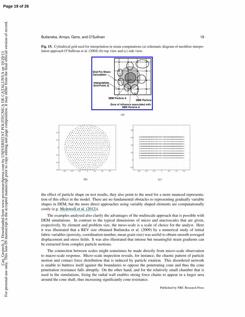
A schematic diagram of this approach can be seen in Figure 16a. A regular grid of interpola-tion points is overlaid upon the simulation domain and if an interpolation point Q is within the zoneof influence of a particle A, the displacement at Q in the x-direction, uQx, is the product of a func-tion IA(Q)uAy evaluated at point Q and the displacement of particle A in the x-direction (uAx), i.e.uQx = IA(Q)uAy . The function IA describes how the influence of particle A on the calculated dis-placements varies within its zone of influence. If, as illustrated in Figure 16a, the point Q is withinthe zone of influence of m particles, the displacement, uQx, can be expressed in terms of the particledisplacements,
∑mp=1Ipupx∆Vp, ∆Vp is the weight associated with that particle, depending on the
local particle packing. Once this expression is determined for all three components of velocity, thedisplacement gradients in the x-,y-, and z-directions can be determined and the strain tensor can beevaluated at each grid point. Full details of the method are given in O’Sullivan et al. (2003).
In the current study the radial grid interval was set as 3.7 cm, the vertical grid interval as 6.3 cmand the influence zone of each particle extended to 5 times its radius. The numerical grid is shownin Figure 16b and Figure 16c. Examples of the strain distributions obtained are illustrated in Figure16 and Figure 17, where the strain field is evaluated on a vertical section containing the chamber axis.These figures represent two invariant measures of strain. Figure 17 shows the second invariant ofstrain, the deviatoric shear strain εq , and Figure 17 gives the volumetric strain, εvol. All the strainsrepresented are computed using particle displacements from the (reference) initial state and so theyuse the displacement data that has been previously examined. The interpolation procedure succeedsin identifying an intensely localized field around the intruding cone. It is however quite noticeablehow the strain pattern appears very similar in all cases examined and shows little dependency on theparameters explored. The dominating effect of that strain localization obscures some differences thatwere visible in the displacement pattern shown before. This result, however, agrees with the long heldview Baligh (1985) that deep penetration problems are kinematically constrained to a degree in whichthe strain field around the cone should be largely independent of many factors controlling soil response.
6. Concluding remarks
The numerical simulations of CPT tests analysed here have shown qualitative agreement with anumber of previous macro-scale observations on physical tests in sands: the observed macro-scaleeffects of soil initial density, of the vertical stress applied, of the radial boundary condition and of par-ticle shape on cone penetration are well captured in the models. Because of the associated experimentaldifficulties there is less evidence from physical chambers concerning the behaviour at the meso- andmicro-scale.
The five tests analysed here clearly illustrate that the extrapolation of calibration chamber results tofield conditions faces some important challenges. The influence of radial boundary conditions, if notproperly accounted for, can hide the effect of more fundamental variables, like density or stress. Al-though the results shown here concerning the effect of rotational freedom on cone penetration confirm
Published by NRC Research Press
Page 18 of 26C
an. G
eote
ch. J
. Dow
nloa
ded
from
ww
w.n
rcre
sear
chpr
ess.
com
by
UN
IVE
RSI
TA
T P
OL
ITE
CN
ICA
DE
CA
TA
LU
NY
A o
n 10
/29/
13Fo
r pe
rson
al u
se o
nly.
Thi
s Ju
st-I
N m
anus
crip
t is
the
acce
pted
man
uscr
ipt p
rior
to c
opy
editi
ng a
nd p
age
com
posi
tion.
It m
ay d
iffe
r fr
om th
e fi
nal o
ffic
ial v
ersi
on o
f re
cord
.
Butlanska, Arroyo, Gens, and O’Sullivan 19
Fig. 15. Cylindrical grid used for interpolation in strain computations (a) schematic diagram of meshfree interpo-lation approach O’Sullivan et al. (2004) (b) top view and (c) side view.
(a)
−0.6 −0.4 −0.2 0 0.2 0.4 0.6−0.6
−0.4
−0.2
0
0.2
0.4
(b)
−0.6 −0.4 −0.2 0 0.2 0.4 0.6
−0.2
0
0.2
0.4
0.6
0.8
(c)
the effect of particle shape on test results, they also point to the need for a more nuanced representa-tion of this effect in the model. There are no fundamental obstacles to representing gradually variableshapes in DEM, but the more direct approaches using variably shaped elements are computationallycostly (e.g. Mcdowell et al. (2012)).
The examples analysed also clarify the advantages of the multiscale approach that is possible withDEM simulations. In contrast to the typical dimensions of micro and macroscales that are given,respectively, by element and problem size, the meso-scale is a scale of choice for the analyst. Hereit was illustrated that a REV size obtained Butlanska et al. (2009) by a numerical study of initialfabric variables (porosity, coordination number, mean grain size) was useful to obtain smooth averageddisplacement and stress fields. It was also illustrated that intense but meaningful strain gradients canbe extracted from complex particle motions.
The connection between scales might sometimes be made directly from micro-scale observationto macro-scale response. Micro-scale inspection reveals, for instance, the chaotic pattern of particlemotion and contact force distribution that is induced by particle rotation. This disordered networkis unable to buttress itself against the boundaries to oppose the penetrating cone and thus the conepenetration resistance falls abruptly. On the other hand, and for the relatively small chamber that isused in the simulations, fixing the radial wall enables strong force chains to appear in a larger areaaround the cone shaft, thus increasing significantly cone resistance.
Published by NRC Research Press
Page 19 of 26C
an. G
eote
ch. J
. Dow
nloa
ded
from
ww
w.n
rcre
sear
chpr
ess.
com
by
UN
IVE
RSI
TA
T P
OL
ITE
CN
ICA
DE
CA
TA
LU
NY
A o
n 10
/29/
13Fo
r pe
rson
al u
se o
nly.
Thi
s Ju
st-I
N m
anus
crip
t is
the
acce
pted
man
uscr
ipt p
rior
to c
opy
editi
ng a
nd p
age
com
posi
tion.
It m
ay d
iffe
r fr
om th
e fi
nal o
ffic
ial v
ersi
on o
f re
cord
.

20 Canadian Geotechnical Journal Vol. ,
Fig. 16. Second invariant shear strain.
−8 −6 −4 −2 0 2 4 6 8
−8
−6
−4
−2
0
5
5
5
11
1116
1616
21
21
27
27
32
32
X/dc
∆h/d
c
0 5 10 15 20 25 30
(a) T20:DenseIsoBC1
−8 −6 −4 −2 0 2 4 6 8
−8
−6
−4
−2
0
6 6
6
11
11
17
17
17
22
22
28
2833
33
X/dc
∆h/d
c
0 5 10 15 20 25 30
(b) T16:MedIsoBC1
−8 −6 −4 −2 0 2 4 6 8
−8
−6
−4
−2
0
7
7
7
14
1414
21
21
29
29
36
36
43
X/dc
∆h/d
c
0 5 10 15 20 25 30
(c) T16Rot:MedIsoRotBC1
−8 −6 −4 −2 0 2 4 6 8
−8
−6
−4
−2
0
7
7
7
12
12
17
17
23
23
23
28
28
33
33
X/dc
∆h/d
c
0 5 10 15 20 25 30
(d) T163:DenseK0BC1
−8 −6 −4 −2 0 2 4 6 8
−8
−6
−4
−2
0
6
6
6
12
12 18
1824
24
30
30 36
X/dc
∆h/d
c
0 5 10 15 20 25 30
(e) T164:DenseK0BC3
It should be pointed out that several meso- and micro-scale aspects highlighted here such as the ra-dial stress decrease with tip distance and soil entrapment alongside the shaft are also well documentedin physical calibration chamber tests. In particular, the quantitative agreement of the normalised be-haviour of radial stress with radial distance with the observations of Yang et al. (2012) in physicalchambers increases the confidence on this modelling approach.
Published by NRC Research Press
Page 20 of 26C
an. G
eote
ch. J
. Dow
nloa
ded
from
ww
w.n
rcre
sear
chpr
ess.
com
by
UN
IVE
RSI
TA
T P
OL
ITE
CN
ICA
DE
CA
TA
LU
NY
A o
n 10
/29/
13Fo
r pe
rson
al u
se o
nly.
Thi
s Ju
st-I
N m
anus
crip
t is
the
acce
pted
man
uscr
ipt p
rior
to c
opy
editi
ng a
nd p
age
com
posi
tion.
It m
ay d
iffe
r fr
om th
e fi
nal o
ffic
ial v
ersi
on o
f re
cord
.

Butlanska, Arroyo, Gens, and O’Sullivan 21
Fig. 17. Volumetric strains.
−8 −6 −4 −2 0 2 4 6 8
−8
−6
−4
−2
0
6
6
6
14
14
21
21
28
28
35
3543
X/dc
∆h/d
c
0 5 10 15 20 25 30
(a) T20:DenseIsoBC1
−8 −6 −4 −2 0 2 4 6 8
−8
−6
−4
−2
0
5
5
12
12
19
19 26
26
3333
40
40
−2
X/dc
∆h/d
c
0 5 10 15 20 25 30
(b) T16:MedIsoBC1
−8 −6 −4 −2 0 2 4 6 8
−8
−6
−4
−2
0
−3
3
3
3
9
916
16
22
22
2828−3
−3−3
−3
X/dc
∆h/d
c
−5 0 5 10 15 20 25 30
(c) T16Rot:MedIsoRotBC1
−8 −6 −4 −2 0 2 4 6 8
−8
−6
−4
−2
0
6
6
13
13
19
19
26
26 3333
3939
X/dc
∆h/d
c
0 5 10 15 20 25 30
(d) T163:DenseK0BC1
−8 −6 −4 −2 0 2 4 6 8
−8
−6
−4
−2
0
6
6
13
13
19
19 2626
33
3340
X/dc
∆h/d
c
0 5 10 15 20 25 30
(e) T164:DenseK0BC3
Acknowledgment
The support of the Ministry of Science and Innovation of Spain through research grants BIA2008-06537 and BIA2011-27217 is gratefully acknowledged.
Published by NRC Research Press
Page 21 of 26C
an. G
eote
ch. J
. Dow
nloa
ded
from
ww
w.n
rcre
sear
chpr
ess.
com
by
UN
IVE
RSI
TA
T P
OL
ITE
CN
ICA
DE
CA
TA
LU
NY
A o
n 10
/29/
13Fo
r pe
rson
al u
se o
nly.
Thi
s Ju
st-I
N m
anus
crip
t is
the
acce
pted
man
uscr
ipt p
rior
to c
opy
editi
ng a
nd p
age
com
posi
tion.
It m
ay d
iffe
r fr
om th
e fi
nal o
ffic
ial v
ersi
on o
f re
cord
.

22 Canadian Geotechnical Journal Vol. ,
References
M.M. Ahmadi, P.M. Byrne, and R.G. Campanella. Cone tip resistance insand: modeling, verification, and applications. Canadian Geotechnical Jour-nal, 42(4):977–993, 2005. ISSN 1208-6010. doi: 10.1139/t05-030. URLhttp://article.pubs.nrc-cnrc.gc.ca/ppv/RPViewDoc?issn=1208-6010&volume=42&issue=4&startPage=977&ab=y.
Marcos Arroyo, Joanna Butlanska, Antonio Gens, Francesco Calvetti, and Michele Jami-olkowski. Cone penetration tests in a virtual calibration chamber. Geotechnique,61(6):525–531, June 2011. ISSN 0016-8505. doi: 10.1680/geot.9.P.067. URLhttp://www.icevirtuallibrary.com/content/article/10.1680/geot.9.p.067.
Katalin Bagi. Analysis of microstructural strain tensors for granular assemblies. International Journalof Solids and Structures, 43(10):3166–3184, May 2006. doi: 10.1016/j.ijsolstr.2005.07.016. URLhttp://www.sciencedirect.com/science/article/pii/S0020768305004397.
M.M. Baligh. Strain Path Method. Journal of Geotechnical Engineering, 111(9):1108–1136, 1985. ISSN 07339410. doi: 10.1061/(ASCE)0733-9410(1985)111:9(1108). URLhttp://link.aip.org/link/JGENDZ/v111/i9/p1108/s1&Agg=doi.
David Bertrand, Francois Nicot, Philippe Gotteland, and Stephane Lambert. Discrete elementmethod (DEM) numerical modeling of double-twisted hexagonal mesh. Canadian Geotechni-cal Journal, 45(8):1104–1117, August 2008. ISSN 0008-3674. doi: 10.1139/T08-036. URLhttp://www.nrcresearchpress.com/doi/abs/10.1139/T08-036.
B. Bienen, S. Henke, and T. Pucker. Numerical study of the bearing behaviour of circular footings pen-etrating into sand. In 13th International Conference of the International Association for ComputerMethods and Advances in Geomechanics (IACMAG), pages 939–944, 2011.
Joanna Butlanska, Marcos Arroyo, and Antonio Gens. Homogeneity and Symmetry in DEMModels of Cone Penetration. In Masami Nakagawa and Stefan Luding, editors, AIPConference Proceedings, pages 425–428. AIP, 2009. doi: 10.1063/1.3179952. URLhttp://link.aip.org/link/APCPCS/v1145/i1/p425/s1&Agg=doi.
Joanna Butlanska, Marcos Arroyo, and Antonio Gens. Size effects on a virtual calibration chamber. InT. Benz and S. Nordal, editors, Numerical Methods in Geotechnical Engineering, pages 225–230.CRC PRESS / BALKEMA, 2010a.
Joanna Butlanska, Marcos Arroyo, and Antonio Gens. Virtual Calibration Chamber CPT tests onTicino sand. In 2nd International Symposium on Cone Penetration Testing, CPT’10, pages 217–224, 2010b.
Joanna Butlanska, Catherine OSullivan, Marcos Arroyo, and Antonio Gens. Mapping Deformationduring CPT in a Virtual Calibration Chamber. In International Symposium on Geomechanics andGeotechnics: From Micro to Macro, pages 559–564. Taylor & Francis Group, 2011.
F. Calvetti and R. Nova. Micro-macro relationships from DEM simulated element and in-situ tests. InPowders & grains, pages 245–250, 2005.
Francesco Calvetti. Discrete modelling of granular materials and geotechnical prob-lems. European Journal of Environmental and Civil Engineering, 12(7-8):951–965,August 2008. ISSN 1964-8189. doi: 10.1080/19648189.2008.9693055. URLhttp://www.tandfonline.com/doi/abs/10.1080/19648189.2008.9693055.
Published by NRC Research Press
Page 22 of 26C
an. G
eote
ch. J
. Dow
nloa
ded
from
ww
w.n
rcre
sear
chpr
ess.
com
by
UN
IVE
RSI
TA
T P
OL
ITE
CN
ICA
DE
CA
TA
LU
NY
A o
n 10
/29/
13Fo
r pe
rson
al u
se o
nly.
Thi
s Ju
st-I
N m
anus
crip
t is
the
acce
pted
man
uscr
ipt p
rior
to c
opy
editi
ng a
nd p
age
com
posi
tion.
It m
ay d
iffe
r fr
om th
e fi
nal o
ffic
ial v
ersi
on o
f re
cord
.

Butlanska, Arroyo, Gens, and O’Sullivan 23
P.A. Cundall. Distinct Element Models of Rock and Soil Structure. In Analytical and ComputationalMethods in Engineering Rock Mechanics, chapter 4, pages 129–163. Allen & Unwin, e.t. brownedition, 1987.
P.A. Cundall. A discontinuous future for numerical modelling in geomechan-ics? Proceedings of the ICE - Geotechnical Engineering, 149(1):41–47, Jan-uary 2001. ISSN 1353-2618. doi: 10.1680/geng.2001.149.1.41. URLhttp://www.icevirtuallibrary.com/content/article/10.1680/geng.2001.149.1.41.
Peijun Guo. Critical length of force chains and shear band thickness in dense granular materials. ActaGeotechnica, 7(1):41–55, January 2012. ISSN 1861-1125. doi: 10.1007/s11440-011-0154-3. URLhttp://www.springerlink.com/index/10.1007/s11440-011-0154-3.
R.M. Harkness, W. Powrie, X. Zhang, and Q. Ni. Numerical modelling of planestrain tests on sands using a particulate approach. Geotechnique, 55(4):297–306, January 2005. ISSN 0016-8505. doi: 10.1680/geot.2005.55.4.297. URLhttp://www.icevirtuallibrary.com/content/article/10.1680/geot.2005.55.4.297.
G.T. Houlsby and R. Hitchman. Discussion: Calibration chamber testsof a cone penetrometer in sand. Geotechnique, 39(4):727–731, Jan-uary 1989a. ISSN 0016-8505. doi: 10.1680/geot.1989.39.4.727. URLhttp://www.icevirtuallibrary.com/content/article/10.1680/geot.1989.39.4.727.
G.T. Houlsby and R. Hitchman. Discussion: Calibration chamber testsof a cone penetrometer in sand. Geotechnique, 39(4):727–731, Jan-uary 1989b. ISSN 0016-8505. doi: 10.1680/geot.1989.39.4.727. URLhttp://www.icevirtuallibrary.com/content/article/10.1680/geot.1989.39.4.727.
A.B. Huang and H.H. Hsu. Advanced Calibration Chambers for Cone Penetration Testing in Cohe-sionless Soils. In 2nd International Conference on Site Characterization- ISC-2, pages 147–166,2004.
An-Bin Huang and Max Y. Ma. An analytical study of cone penetration tests in granular material.Canadian Geotechnical Journal, 31(1):91–103, February 1994. ISSN 0008-3674. doi: 10.1139/t94-010. URL http://www.nrcresearchpress.com/doi/abs/10.1139/t94-010.
Inc Itasca Consulting Group. Guide Book: Theory and background PFC3D. Technical report, ItascaInc., 2008.
M. Jamiolkowski, D.C.F. Lo Presti, and M. Manassero. Evaluation of Relative Den-sity and Shear Strength of Sands from CPT and DMT. In Soil Behavior andSoft Ground Construction, pages 201–238, Reston, VA, January 2003. American Soci-ety of Civil Engineers. ISBN 978-0-7844-0659-5. doi: 10.1061/40659(2003)7. URLhttp://ascelibrary.org/doi/abs/10.1061/40659%282003%297.
R.J. Jardine and F. Chow. Some recent developments in offshore pile design. In 6th InternationalOffshore Site Investigation and Geotechnics, London, UK, 2007.
M.J. Jiang, D. Harris, and H.H. Zhu. Future continuum models for granular materials in penetrationanalyses. Granular Matter, 9(1-2):97–108, October 2006a. ISSN 1434-5021. doi: 10.1007/s10035-006-0026-y. URL http://www.springerlink.com/index/10.1007/s10035-006-0026-y.
Published by NRC Research Press
Page 23 of 26C
an. G
eote
ch. J
. Dow
nloa
ded
from
ww
w.n
rcre
sear
chpr
ess.
com
by
UN
IVE
RSI
TA
T P
OL
ITE
CN
ICA
DE
CA
TA
LU
NY
A o
n 10
/29/
13Fo
r pe
rson
al u
se o
nly.
Thi
s Ju
st-I
N m
anus
crip
t is
the
acce
pted
man
uscr
ipt p
rior
to c
opy
editi
ng a
nd p
age
com
posi
tion.
It m
ay d
iffe
r fr
om th
e fi
nal o
ffic
ial v
ersi
on o
f re
cord
.

24 Canadian Geotechnical Journal Vol. ,
M.J. Jiang, H.S. Yu, and D. Harris. Discrete element modelling of deep penetration ingranular soils. International Journal for Numerical and Analytical Methods in Geome-chanics, 30(4):335–361, April 2006b. ISSN 0363-9061. doi: 10.1002/nag.473. URLhttp://doi.wiley.com/10.1002/nag.473.
N.P. Kruyt, I. Agnolin, S. Luding, and L. Rothenburg. Micromechanical study of elastic mod-uli of loose granular materials. Journal of the Mechanics and Physics of Solids, 58(9):1286–1301, September 2010. ISSN 00225096. doi: 10.1016/j.jmps.2010.06.003. URLhttp://linkinghub.elsevier.com/retrieve/pii/S0022509610001195.
B.M. Lehane and Q.B. Liu. The influence of particle shape on the (centrifuge) cone pen-etration test (CPT) end resistance in uniformly graded granular soils. Geotechnique, 62(11):973–984, November 2012. ISSN 0016-8505. doi: 10.1680/geot.10.P.077. URLhttp://www.icevirtuallibrary.com/content/article/10.1680/geot.10.P.077.
Shaofan Li and Wing Kam Liu. Numerical simulations of strain localization ininelastic solids using mesh-free methods. International Journal for Numeri-cal Methods in Engineering, 48(9):1285–1309, 2000. ISSN 1097-0207. URLhttp://dx.doi.org/10.1002/1097-0207(20000730)48:9<1285::AID-NME825>3.0.CO
2-H.
Jia Lin and Wei Wu. Numerical study of miniature penetrometer in granular ma-terial by discrete element method. Philosophical Magazine, 92(28-30):3474–3482,October 2012. ISSN 1478-6435. doi: 10.1080/14786435.2012.706373. URLhttp://www.tandfonline.com/doi/abs/10.1080/14786435.2012.706373.
Tom Lunne. The Fourth James K. Mitchell Lecture: The CPT in offshoresoil investigations - a historic perspective. Geomechanics and Geoengineer-ing, 7(2):75–101, March 2012. doi: 10.1080/17486025.2011.640712. URLhttp://dx.doi.org/10.1080/17486025.2011.640712.
Manuel J. Maynar and Luis E. Rodrıguez. Discrete Numerical Model for Anal-ysis of Earth Pressure Balance Tunnel Excavation. Journal of Geotech-nical and Geoenvironmental Engineering, 131(10):1234–1242, October 2005.ISSN 1090-0241. doi: 10.1061/(ASCE)1090-0241(2005)131:10(1234). URLhttp://ascelibrary.org/doi/abs/10.1061/(ASCE)1090-0241(2005)131:10(1234).
P. Mayne. In-situ test calibrations for evaluating soil parameters. In Characterisation and EngineeringProperties of Natural Soils. Taylor & Francis, November 2006. ISBN 978-0-415-42691-6. doi:10.1201/NOE0415426916.ch2. URL http://dx.doi.org/10.1201/NOE0415426916.ch2.
G.R. Mcdowell, O. Falagush, and H.-S. Yu. A particle refinement method for simulat-ing DEM of cone penetration testing in granular materials. Geotechnique Letters, 2(July-September):141–147, September 2012. ISSN 2045-2543. doi: 10.1680/geolett.12.00036. URLhttp://www.icevirtuallibrary.com/content/article/10.1680/geolett.12.00036.
C. O’Sullivan, Cui, L., and J.D. Bray. Three-Dimensional Discrete Element Simulations of DirectShear Tests. In 2nd International PFC Symposium, 2004.
Catherine O’Sullivan. Particle-Based Discrete Element Modeling: Geomechan-ics Perspective. International Journal of Geomechanics, 11(6):449–464, Decem-ber 2011. ISSN 1532-3641. doi: 10.1061/(ASCE)GM.1943-5622.0000024. URLhttp://ascelibrary.org/doi/abs/10.1061/(ASCE)GM.1943-5622.0000024.
Published by NRC Research Press
Page 24 of 26C
an. G
eote
ch. J
. Dow
nloa
ded
from
ww
w.n
rcre
sear
chpr
ess.
com
by
UN
IVE
RSI
TA
T P
OL
ITE
CN
ICA
DE
CA
TA
LU
NY
A o
n 10
/29/
13Fo
r pe
rson
al u
se o
nly.
Thi
s Ju
st-I
N m
anus
crip
t is
the
acce
pted
man
uscr
ipt p
rior
to c
opy
editi
ng a
nd p
age
com
posi
tion.
It m
ay d
iffe
r fr
om th
e fi
nal o
ffic
ial v
ersi
on o
f re
cord
.

Butlanska, Arroyo, Gens, and O’Sullivan 25
Catherine O’Sullivan, Jonathan D. Bray, and Shaofan Li. A new approach for calculating strainfor particulate media. International Journal for Numerical and Analytical Methods in Ge-omechanics, 27(10):859–877, August 2003. ISSN 0363-9061. doi: 10.1002/nag.304. URLhttp://doi.wiley.com/10.1002/nag.304.
A.K. Parkin and T. Lunne. Boundary effect in the laboratory calibration of a cone penetrometer in sand.In Proceedings of 2nd European Symposium on Penetration Testing, pages 761–768, Amsterdam,1982.
M. Pasha, C. Hare, A. Hassanpour, and M. Ghadiri. Analysis of ball indentation oncohesive powder beds using distinct element modelling. Powder Technology, 233:80–90, January 2013. ISSN 00325910. doi: 10.1016/j.powtec.2012.08.017. URLhttp://linkinghub.elsevier.com/retrieve/pii/S0032591012005724.
D.O. Potyondy and P.A. Cundall. A bonded-particle model for rock. Interna-tional Journal of Rock Mechanics and Mining Sciences, 41(8):1329–1364, De-cember 2004. ISSN 13651609. doi: 10.1016/j.ijrmms.2004.09.011. URLhttp://linkinghub.elsevier.com/retrieve/pii/S1365160904002874.
Farhang Radjai, Michel Jean, Jean-Jacques Moreau, and Stephane Roux. Force Distri-butions in Dense Two-Dimensional Granular Systems. Physical Review Letters, 77(2):274–277, July 1996. ISSN 0031-9007. doi: 10.1103/PhysRevLett.77.274. URLhttp://link.aps.org/doi/10.1103/PhysRevLett.77.274.
F. Schnaid. In situ testing in geomechanics. CRC Press, 2009.
E. Susila and R.D. Hryciw. Large displacement FEM modelling of the cone penetration test (CPT)in normally consolidated sand. International Journal for Numerical and Analytical Methods inGeomechanics, 27(7):585–602, June 2003. ISSN 0363-9061. doi: 10.1002/nag.287. URLhttp://doi.wiley.com/10.1002/nag.287.
C. Thornton. Numerical simulations of deviatoric shear deformation of granular media. Geotechnique,50(1):43–53, January 2000. ISSN 0016-8505. doi: 10.1680/geot.2000.50.1.43. URLhttp://www.icevirtuallibrary.com/content/article/10.1680/geot.2000.50.1.43.
John M. Ting, Brent T. Corkum, Claudia R. Kauffman, and Carlo Greco. Discrete Nu-merical Model for Soil Mechanics. Journal of Geotechnical Engineering, 115(3):379–398,March 1989. ISSN 0733-9410. doi: 10.1061/(ASCE)0733-9410(1989)115:3(379). URLhttp://ascelibrary.org/doi/abs/10.1061/(ASCE)0733-9410(1989)115:3(379).
Antoinette Tordesillas and Maya Muthuswamy. On the modeling of confined buck-ling of force chains. Journal of the Mechanics and Physics of Solids, 57(4):706–727, April 2009. ISSN 00225096. doi: 10.1016/j.jmps.2009.01.005. URLhttp://linkinghub.elsevier.com/retrieve/pii/S0022509609000027.
P. van den Berg. Analysis of soil penetration. PhD thesis, Delft University of Technology, 1994.
Y.-H. Wang and S.-C. Leung. A particulate-scale investigation of cemented sand behavior. CanadianGeotechnical Journal, 45(1):29–44, January 2008. ISSN 0008-3674. doi: 10.1139/T07-070. URLhttp://www.nrcresearchpress.com/doi/abs/10.1139/T07-070.
Z.X. Yang, B.T. Zhu, P. Foray, and R.J. Jardine. Measurement of stressesaround closed-ended displacement piles in sand. Geotechnique, pages 1–17, September 2012. ISSN 0016-8505. doi: 10.1680/geot.9.P.137. URLhttp://www.icevirtuallibrary.com/content/article/10.1680/geot.9.P.137.
Published by NRC Research Press
Page 25 of 26C
an. G
eote
ch. J
. Dow
nloa
ded
from
ww
w.n
rcre
sear
chpr
ess.
com
by
UN
IVE
RSI
TA
T P
OL
ITE
CN
ICA
DE
CA
TA
LU
NY
A o
n 10
/29/
13Fo
r pe
rson
al u
se o
nly.
Thi
s Ju
st-I
N m
anus
crip
t is
the
acce
pted
man
uscr
ipt p
rior
to c
opy
editi
ng a
nd p
age
com
posi
tion.
It m
ay d
iffe
r fr
om th
e fi
nal o
ffic
ial v
ersi
on o
f re
cord
.
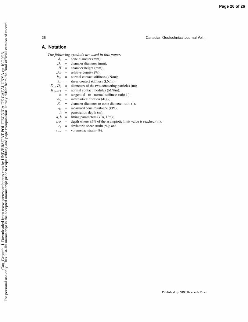
26 Canadian Geotechnical Journal Vol. ,
A. Notation
The following symbols are used in this paper:dc = cone diameter (mm);Dc = chamber diameter (mm);H = chamber height (mm);DR = relative density (%);kN = normal contact stiffness (kN/m);kS = shear contact stiffness (kN/m);
D1, D2 = diameters of the two contacting particles (m);Kcoeff = normal contact modulus (MN/m);
α = tangential - to - normal stiffness ratio (-);φµ = interpartical friction (deg);Rd = chamber diameter-to-cone diameter ratio (-);qc = measured cone resistance (kPa);h = penetration depth (m);
a, b = fitting parameters (kPa, 1/m);h95 = depth where 95% of the asymptotic limit value is reached (m);εq = deviatoric shear strain (%); and
εvol = volumetric strain (%).
Published by NRC Research Press
Page 26 of 26C
an. G
eote
ch. J
. Dow
nloa
ded
from
ww
w.n
rcre
sear
chpr
ess.
com
by
UN
IVE
RSI
TA
T P
OL
ITE
CN
ICA
DE
CA
TA
LU
NY
A o
n 10
/29/
13Fo
r pe
rson
al u
se o
nly.
Thi
s Ju
st-I
N m
anus
crip
t is
the
acce
pted
man
uscr
ipt p
rior
to c
opy
editi
ng a
nd p
age
com
posi
tion.
It m
ay d
iffe
r fr
om th
e fi
nal o
ffic
ial v
ersi
on o
f re
cord
.