
MT-CNC / MTC200 TOOL MANAGEMENT 16VRS - Bosch ...
231
MT-CNC / MTC200 TOOL MANAGEMENT 16VRS DOK-MTC200-TOOL*MA*V16-ANW1-EN-P · Users Manual mannesmann Rexroth engineering Indramat 277508
-
Upload
khangminh22 -
Category
Documents
-
view
2 -
download
0
Transcript of MT-CNC / MTC200 TOOL MANAGEMENT 16VRS - Bosch ...
MT-CNC / MTC200TOOL MANAGEMENT
16VRS
DOK-MTC200-TOOL*MA*V16-ANW1-EN-P ·
Users Manual
mannesmannRexroth
engineering
Indramat277508

About this document Tool Management
DOK-MTC200-TOOL*MA*V16-ANW1-EN-P ·
Tool Management
Users Manual
DOK-MTC200-TOOL*MA*V16-ANW1-EN-P ·
• Mappe 1/ Section 6
• Drawing no.109-1041-4105-00_EN/01.98
This document explains the structure and use of the extensive toolmanagement that is available for each MTC process. Tool data and toolstorage definitions are described and all NC and SPS commands areexplained with examples.
Document identification ofprevious and present output
ReleaseDate
Remarks
109-1041-4105-00 01/98 new edition
INDRAMAT GmbH, 1997
Copying this document, and giving it to others and the use orcommunication of the contents thereof without express authority, areforbidden. Offenders are liable for the payment of damages. All rights arereserved in the event of the grant of a patent or the registration of utilitymodel or design (DIN 34-1).
All rights are reserved with respect to the content of this documentationand the availability of the product.
INDRAMAT GmbH • Bgm.-Dr.-Nebel-Str. 2 • D-97816 Lohr a. Main
Telephone +49 (0)9352/40-0 • Tx 689421 • Fax +49 (0)9352/40-4885
Dept. ENC (RK)
Title
Documentation type
Document code
Internal file reference
Purpose of this document
Course of modifications
Copyrights
Validity
Published by

Tool Management Contents I
DOK-MTC200-TOOL*MA*V16-ANW1-EN-P ·
Contents
1 Introduction 1-11.1 Terminology ......................................................................................................................................... 1-1
2 Tool Setup List 2-12.1 Purpose of the Setup List..................................................................................................................... 2-1
Setup List Data.............................................................................................................................. 2-1
2.2 Tool Lists and Setup Lists.................................................................................................................... 2-2
Basic Tool Data of Setup List........................................................................................................ 2-3
Setup Lists within the MTC.......................................................................................................... 2-12
3 Tool List 3-13.1 Purpose of Tool List ............................................................................................................................. 3-1
3.2 Tool List data........................................................................................................................................ 3-1
Basic Tool Data of Tool List .......................................................................................................... 3-3
Tool Edge data.............................................................................................................................. 3-9
3.3 Tool List within the control system ..................................................................................................... 3-15
4 Active Tool List 4-14.1 General information to the Active Tool List .......................................................................................... 4-1
4.2 Data of the Active Tool List .................................................................................................................. 4-1
4.3 Tool status bits..................................................................................................................................... 4-9
Tool Setup List specific status bits .............................................................................................. 4-10
Location specific tool status bits.................................................................................................. 4-12
Tool specific tool status bits ........................................................................................................ 4-15
4.4 Tool Edge status bits ......................................................................................................................... 4-20
Setup List specific Edge status bits............................................................................................. 4-20
Tool specific Edge status bits...................................................................................................... 4-21
5 Working with Tool Management 5-15.1 Automatic tool check............................................................................................................................ 5-1
Conditions for automatic tool check .............................................................................................. 5-1
Error reaction of automatic tool check .......................................................................................... 5-1
Checks performed during the tool check ...................................................................................... 5-2
5.2 Production ............................................................................................................................................ 5-3
Before and during production........................................................................................................ 5-3
Tool storage (magazine/turret) modifications................................................................................ 5-4
6 NC Tool Management Control Functions 6-1

II Contents Tool Management
DOK-MTC200-TOOL*MA*V16-ANW1-EN-P ·
6.1 Requirements....................................................................................................................................... 6-1
Tool and tool data preparation. ..................................................................................................... 6-1
6.2 NC preparatory functions (G-codes) .................................................................................................... 6-6
Tool length correction, cancel (G47) ........................................................................................... 6-10
6.3 Tool storage movement and tool change NC-commands ................................................................. 6-13
Tool storage movement NC-commands ..................................................................................... 6-13
Tool change NC-commands ....................................................................................................... 6-20
Tool Data read/write (TLD).......................................................................................................... 6-23
7 SPS Tool Management Control FUNCTIONs 7-17.1 Standard FUNCTIONs for SPS controlled tool storages and changers .............................................. 7-1
Overview SPS controlled tool storages and changers .................................................................. 7-1
7.2 Standard FUNCTIONs for SPS controlled tool changers .................................................................... 7-3
Reference Tool Storage ................................................................................................................ 7-3
Position Tool Storage.................................................................................................................... 7-6
7.3 Standard Tool Change FUNCTIONs ................................................................................................... 7-9
Complete tool change ................................................................................................................... 7-9
Tool change between Magazine and Spindle ............................................................................. 7-11
7.4 Tool Transfer FUNCTIONs ................................................................................................................ 7-18
Sequence of a Tool Transfer ...................................................................................................... 7-18
7.5 Combined Spindle / Turret axis.......................................................................................................... 7-25
Read and acknowledge turret mode ........................................................................................... 7-25
Read and acknowledge spindle mode ........................................................................................ 7-26
7.6 Controlling the tool storage movement .............................................................................................. 7-27
Enable tool storage, PxxC.MGENA ............................................................................................ 7-28
Tool Storage Status Signals........................................................................................................ 7-33
7.7 Tool Data read/write, FUNCTION_BLOCK TLD_RD/TLD_WR......................................................... 7-42
7.8 Error handling, tool data FUNCTION_BLOCKs. ................................................................................ 7-45
8 Applications 8-18.1 NC servo disk tool magazine with direct tool change .......................................................................... 8-1
Functional description ................................................................................................................... 8-1
MTC parameter sets ..................................................................................................................... 8-2
NC-programs................................................................................................................................. 8-3
SPS Program ................................................................................................................................ 8-5
8.2 SPS controlled chain magazine with double gripper tool changer ....................................................... 8-8
Functional description ................................................................................................................... 8-9
MTC parameter sets ..................................................................................................................... 8-9
NC-programs............................................................................................................................... 8-10
SPS Program .............................................................................................................................. 8-12
8.3 'Combined Spindle (live tool) / Turret' NC servo axis......................................................................... 8-18
8.4 Functional description ........................................................................................................................ 8-19
MTC parameter sets ................................................................................................................... 8-19
NC-programs............................................................................................................................... 8-21
SPS Program .............................................................................................................................. 8-21
8.5 NC servo controlled tool turret ........................................................................................................... 8-24
Functional description ................................................................................................................. 8-24

Tool Management Contents III
DOK-MTC200-TOOL*MA*V16-ANW1-EN-P ·
MTC parameter sets ................................................................................................................... 8-24
NC-programs............................................................................................................................... 8-26
SPS Program .............................................................................................................................. 8-26
8.6 Stationary tool magazine (rack) ......................................................................................................... 8-27
Functional description ................................................................................................................. 8-28
MTC parameter sets ................................................................................................................... 8-29
NC-programs............................................................................................................................... 8-30
SPS Program .............................................................................................................................. 8-32
8.7 Single tool station............................................................................................................................... 8-36
Functional description ................................................................................................................. 8-37
MTC parameter sets ................................................................................................................... 8-37
NC-programs............................................................................................................................... 8-38
SPS Program .............................................................................................................................. 8-38
8.8 Single tool spindle, multiple tools ....................................................................................................... 8-39
Functional description ................................................................................................................. 8-39
MTC parameter sets ................................................................................................................... 8-40
NC-programs............................................................................................................................... 8-41
SPS Program .............................................................................................................................. 8-41
8.9 Multiple spindles with single tool ........................................................................................................ 8-41
Functional description ................................................................................................................. 8-42
MTC parameter sets ................................................................................................................... 8-43
NC-programs............................................................................................................................... 8-44
SPS Program .............................................................................................................................. 8-44
8.10 One Tool List and multiple tool storages.......................................................................................... 8-44
Functional description ................................................................................................................. 8-45
MTC parameter sets ................................................................................................................... 8-46
NC-programs............................................................................................................................... 8-47
SPS Program .............................................................................................................................. 8-47
9 Tool Management Parameters 9-19.1 System parameters for tool management............................................................................................ 9-1
9.2 Process parameters for tool management........................................................................................... 9-7
9.3 Combined spindle/turret axis parameters .......................................................................................... 9-12
10 Appendix 10-110.1 Tool Management NC-command Overview..................................................................................... 10-1
10.2 Tool Management SPS FUNCTION Overview ................................................................................ 10-2
10.3 Tool Management CNC⇔SPS Gateway Signal Overview .............................................................. 10-3
10.4 Tool Management Signal and Command Overview ........................................................................ 10-4
10.5 Tool Correction Type Overview........................................................................................................ 10-5
10.6 Tool Edge Orientation Overview ...................................................................................................... 10-6
10.7 Tool List Data Overview................................................................................................................... 10-7
10.8 Tool Status Bits ................................................................................................................................ 10-9
10.9 Tool Edge Status Bits..................................................................................................................... 10-10
10.10 Setup List print out ....................................................................................................................... 10-11
10.11 Tool List print out.......................................................................................................................... 10-11

IV Contents Tool Management
DOK-MTC200-TOOL*MA*V16-ANW1-EN-P ·
11 Index 11-1
12 List of Figures 12-1

Tool Management Introduction 1-1
DOK-MTC200-TOOL*MA*V16-ANW1-EN-P ·
1 IntroductionThe tool management of the MTC provides powerful functions to operatedifferent types of tool magazines and tool turrets.
The tool management automatically compares the tool Setup List,containing the tool reference values with the Tool List, containing theactual tool values. The actual tool data of individual tools is compared withthe setup data in the tool Setup List, using the common tool names as areference. The Tool Name (ID) may consist of any 28 Case SensitiveLetters or Numerals. This method allows of 'automatic tool check' nearlyexcludes any tool collisions and prevents damage to man, machine andmaterial and reduces cycle downtime based on incorrect tool setup.
The tool management provides beside the compensation for tool length,tool nose radius and mill radius path, a monitoring of the tool life, itswarning limits and automatic tool wear compensation. Replacement toolsof tool families (if available) are selected automatically at the time of toolchange to replace worn out tools with the same tool name.
The tool management of the MTC handles numerical (servo) as well asprogrammable controller (SPS) controlled magazines and turrets.
Each process (0..6) is capable of controlling one magazine or turret andthe tool changes between the available tool spindles (1..4), grippers (1..4)and tool storage (magazine/turret). System and process parameter setupdefines these capabilities. Tool storage movements are performedasynchronous to the axis movements of a process.
The tool management controls all movements in the case of numerical(servo) controlled tool storage. Extensive functions, e.g., search for emptypocket, are provided also for programmable controller controlled toolstorage
Configurable data sets allow optimum adaptation to the used technology(Drilling, Milling, Turning, Grinding, etc.), machine specifics andprocessing.
Simultaneous application of different manufacturing technologies, e.g.,milling and turning, allow complete precision machining on one machine.
1.1 Terminology
The following is a summary contains the basic context between NC-program and Tool Data Organization.
• The MTC contains 7 independent processes (0..6)
• Each process can execute NC-programs, independent of otherprocesses
• Each process has an independent tool management. The toolmanagement can easily be adapted to a large variety of toolmagazines, turrets and tool changers via Parameter Setup.
• The MTC provides two NC-memories (A and B). Each memory cancontain a NC-program package.
• NC-program packages are stored on a BTV or compatible PC runningthe MTC User Interface (MUI/GUI) and can be loaded into the MTC.
• Each NC-program package can contain up to 99 NC-programs perprocess.
• Tool Setup Lists can be station (process) or NC-program specific. AllNC-programs of a process share the same Setup List if station specificis defined in the Process Parameters.
• The Tool Setup list contains the tool requirements of all tools that areused in the NC-programs.

1-2 Introduction Tool Management
DOK-MTC200-TOOL*MA*V16-ANW1-EN-P ·
• Tool Magazines and Turrets are referred to in general as ToolStorage. Tool Lists contain the actual tool data and reside in the MUI,by means on the PC. An Active Tool List contains the latest actual tooldata of the tool storage and resides in the MTC for each process.
• Tool Lists can be generated and prepared via the MUI (MTC UserInterface) during machining. They can be downloaded to and uploadfrom the MTC via the MUI. Active Tool Lists in the MTC can bemodified via the SOT (Station Operator Terminal) and MUI.
Tool Setup List Tool List
Task Tool requirements for all
needed tools.
Actual tool data of all tools that arecontained in the tool storage. Can beprepared and archived.
Contents Basic Tool Data:
* Tool Name
* Units
* User Data (option)
Tool Edge Data:
* Toll Edge ID
* Tool life data (option)
* Geometric data (option)
* Wear factors (option)
Basic Tool Data:
* Tool Name
* Tool Index (tool family)
* Location data
* Units
* User Data (option)
Tool Edge Data:
* Toll Edge ID
* Tool life data (option)
* Geometric data (option)
* User data (option)
Identification Tools are identified via T-number andTool Name (ID).
Tools are identified via location (pocket)number and Tool Name (ID).
Ext. Modification
(MUI, SOT, SPS or NC)
Setup Lists in the MTC cannot bemodified.
Active Tool Lists (Tool Lists in MTC) canbe modified during NC-programexecution.
Int. Modification
(MTC)
No modification by MTC. MTC updates the tool life and tool wearwhen necessary.
General Organization Setup Lists are part of a NC-programpackage.
Tool Lists are independent of other ToolLists and data.
MUI Organization Station specific Setup List:
One Tool Setup List can exist perprocess.
Program specific Setup List:
One Tool Setup List can exist for eachNC-program within a NC-programpackage.
One Active Tool List is
allowed per process.
In the MUI, up to 99 Tool Lists can beavailable per process.
Loading MTC Available Tool Setup Lists are
loaded together with the NC-programpackage.
Tool Lists are loaded independent ofother Tool Lists or data.
Activation Tool Setup Lists are loaded
into NC-memory A or B and selectedaccordingly.
One Tool List must be loaded for eachprocess.
List Archiving Tool Setup Lists are saved together withthe NC-program package.
Tool Lists and Active Tool Lists must besaved individually.
Fig. 1-1: Tool and Setup List comparison
Tool Management Tool Setup List 2-1
DOK-MTC200-TOOL*MA*V16-ANW1-EN-P ·
2 Tool Setup List
2.1 Purpose of the Setup List
The presence and usability of all tools that are required for a desiredmachining is checked via the Setup List. Station (process) or NC-programspecific Setup Lists are available (see Chapter 2.2 Tool Lists and SetupLists).
A Setup List must exist for each process that uses some type of toolstorage (magazine/turret) and its tools to perform machining. Refer to theMTC User Interface Manual for explanations on how to generate SetupLists.
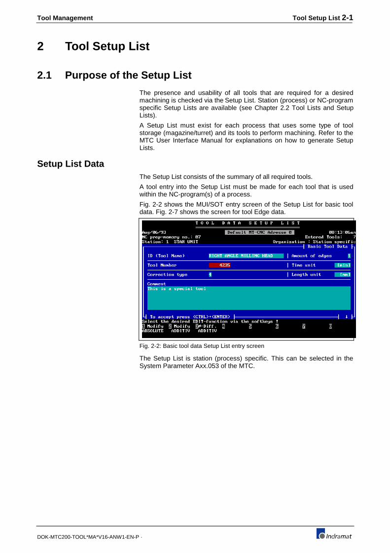
Setup List DataThe Setup List consists of the summary of all required tools.
A tool entry into the Setup List must be made for each tool that is usedwithin the NC-program(s) of a process.
Fig. 2-2 shows the MUI/SOT entry screen of the Setup List for basic tooldata. Fig. 2-7 shows the screen for tool Edge data.
Fig. 2-2: Basic tool data Setup List entry screen
The Setup List is station (process) specific. This can be selected in theSystem Parameter Axx.053 of the MTC.

2-2 Tool Setup List Tool Management
DOK-MTC200-TOOL*MA*V16-ANW1-EN-P ·
NC-program package 1
Process NC-Programs Setup List
0123456
01 02 04 06 08 11 15 27 58 67 yes03 07 09 13 17 2244 47 57 66 74 87 94 9801 02 03 04 05
no
31 32 35 39 43 51 55 5702 06 07 09 20 25 27 63 7114 17 22 28 38 59 65
nonononono
.
.
.
.
.
..
..
.
..
.
NC-program package 12
List
NC-program entry Tool List preparation
1 2 3 . . . .
Tool Lists process 0
.
..
.
..
..
.Tool Lists process 6
99
99
NC-program package 1
Process NC-Programs Setup List
0123456
01 02 04 06 08 11 15 27 58 67 yes03 07 09 13 17 2244 47 57 66 74 87 94 9801 02 03 04 05
no
31 32 35 39 43 51 55 5702 06 07 09 20 25 27 63 7114 17 22 28 38 59 65
nonononono
.
.
.
.
..
MT-CNC
Tool memory process 0
.
..
.
..
.Tool memory process 6
MUI (PC)
Actual tool data
NC memory A
NC memory B
List
Fig. 2-3: NC-Program and tool data management
The tool data requirements that have been specified during the NC-program generation are loaded together with the NC-program packageinto the MTC.
The actual tool data can be prepared and loaded via the MUI/SOT. Tooldata can also be entered, erased and modified online in the MTC, usingfunctions of the MUI/SOT and SOT.
Tool Lists in the MUI/SOT allow to generate Magazine and Turret toolconfigurations outside the MTC. The Tool Lists are then ready to beloaded at the next Magazine or Turret configuration change.
2.2 Tool Lists and Setup Lists
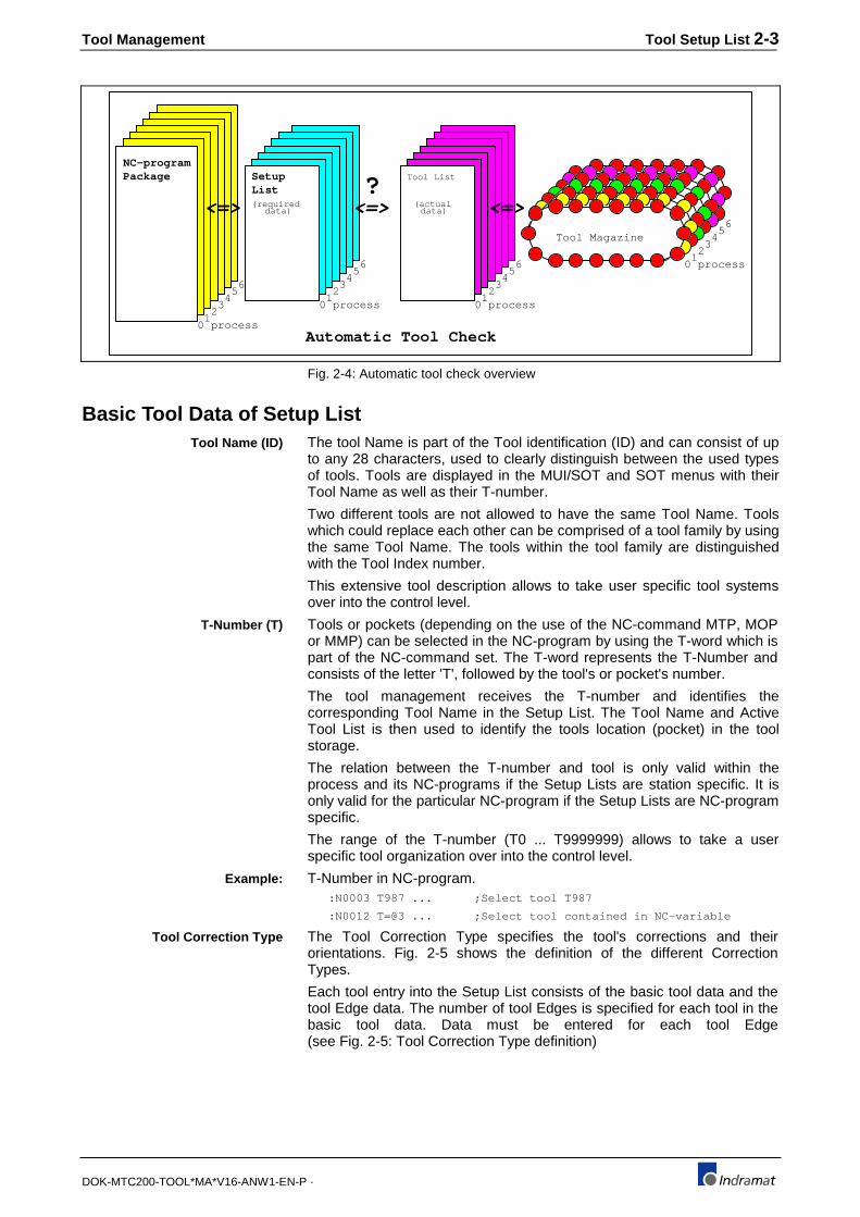
The tool management performs automatic tool checks during which itcompares the tool data in the Active Tool List with the data in the activeSetup List. Tools contained in the Setup List must be present in the ActiveTool List and fulfill the Setup List requirements. (Refer to Chapter 5 formore information.)
The Setup List is station (process) specific. This can be selected in theSystem Parameter Axx.053 of the MTC.
Tool Management Tool Setup List 2-3
DOK-MTC200-TOOL*MA*V16-ANW1-EN-P ·
NC-programPackage Setup Tool List
(required
List
data)(actual
data)
Automatic Tool Check
Tool Magazine
0 process1
23
45
6
0 process1
23
45
6
0 process1
23
45
6 0 process1
23
45
6<=> <=><=>
?
Fig. 2-4: Automatic tool check overview
Basic Tool Data of Setup ListThe tool Name is part of the Tool identification (ID) and can consist of upto any 28 characters, used to clearly distinguish between the used typesof tools. Tools are displayed in the MUI/SOT and SOT menus with theirTool Name as well as their T-number.
Two different tools are not allowed to have the same Tool Name. Toolswhich could replace each other can be comprised of a tool family by usingthe same Tool Name. The tools within the tool family are distinguishedwith the Tool Index number.
This extensive tool description allows to take user specific tool systemsover into the control level.
Tools or pockets (depending on the use of the NC-command MTP, MOPor MMP) can be selected in the NC-program by using the T-word which ispart of the NC-command set. The T-word represents the T-Number andconsists of the letter 'T', followed by the tool's or pocket's number.
The tool management receives the T-number and identifies thecorresponding Tool Name in the Setup List. The Tool Name and ActiveTool List is then used to identify the tools location (pocket) in the toolstorage.
The relation between the T-number and tool is only valid within theprocess and its NC-programs if the Setup Lists are station specific. It isonly valid for the particular NC-program if the Setup Lists are NC-programspecific.
The range of the T-number (T0 ... T9999999) allows to take a userspecific tool organization over into the control level.
T-Number in NC-program. :N0003 T987 ... ;Select tool T987
:N0012 T=@3 ... ;Select tool contained in NC-variable
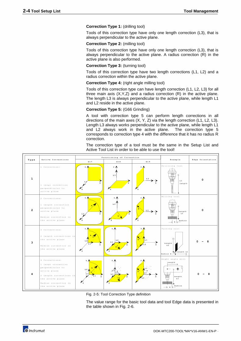
The Tool Correction Type specifies the tool's corrections and theirorientations. Fig. 2-5 shows the definition of the different CorrectionTypes.
Each tool entry into the Setup List consists of the basic tool data and thetool Edge data. The number of tool Edges is specified for each tool in thebasic tool data. Data must be entered for each tool Edge(see Fig. 2-5: Tool Correction Type definition)
Tool Name (ID)
T-Number (T)
Example:
Tool Correction Type
2-4 Tool Setup List Tool Management
DOK-MTC200-TOOL*MA*V16-ANW1-EN-P ·
Correction Type 1: (drilling tool)
Tools of this correction type have only one length correction (L3), that isalways perpendicular to the active plane.
Correction Type 2: (milling tool)
Tools of this correction type have only one length correction (L3), that isalways perpendicular to the active plane. A radius correction (R) in theactive plane is also performed.
Correction Type 3: (turning tool)
Tools of this correction type have two length corrections (L1, L2) and aradius correction within the active plane.
Correction Type 4: (right angle milling tool)
Tools of this correction type can have length correction (L1, L2, L3) for allthree main axis (X,Y,Z) and a radius correction (R) in the active plane.The length L3 is always perpendicular to the active plane, while length L1and L2 reside in the active plane.
Correction Type 5: (G66 Grinding)
A tool with correction type 5 can perform length corrections in alldirections of the main axes (X, Y, Z) via the length correction (L1, L2, L3).Length L3 always works perpendicular to the active plane, while length L1and L2 always work in the active plane. The correction type 5corresponds to correction type 4 with the difference that it has no radius Rcorrection.
The correction type of a tool must be the same in the Setup List andActive Tool List in order to be able to use the tool!
T y p e A c t i v e C o r r e c t i o n s
1 C o r r e c t i o n :
1
1 l e n g t c o r r e c t i o n
p e r p e n d i c u l a r t o
a c t i v e p l a n e
G 1 7 G 1 8 G 1 9
D r i l l l i n g t o o l
F u n c t i o n i n g o f C o r r e c t i o n
0
E x a m p l e E d g e O r i e n t a t i o n
M i l l i n g t o o l
0
T u r n i n g t o o l
0 - 8
4 C o r r e c t i o n s :R i g h t a n g l e m i l l
0 - 8
3
3 C o r r e c t i o n s :
2 l e n g t h c o r r e c t i o n s i n
t h e a c t i v e p l a n e
R a d i u s c o r r e c t i o n i n
t h e a c t i v e p l a n e
2
2 C o r r e c t i o n s :
1 l e n g t h c o r r e c t i o n
p e r p e n d i c u l a r t o
a c t i v e p l a n e
R a d i u s c o r r e c t i o n i n
t h e a c t i v e p l a n e
4
1 l e n g t c o r r e c t i o n
p e r p e n d i c u l a r t o
a c t i v e p l a n e
2 L e n g t h c o r r e c t i o n s i n
t h e a c t i v e p l a n e
R a d i u s c o r r e c t i o n i n
t h e a c t i v e p l a n e
Y
Z
X
L 3
Y
Z
X
L 3
Y
L 3
Z
X
Y
L 3
Z
X
R
Y
Z
X
L 3
R
Z
Y
X
L 3R
Y
Z
X
R
L 1
L 2
Y
Z
X
R
L 1
L 2
L 3
Y
Z
XR
L 1L 2
Y
Z
XR
L 1L 2
L 3
Y
X
R L 1
L 2
Y
X
R
L 1
L 2
L 3
L 3
L e n g t h
R a d i u sR
L 3
L e n g t h
L 3
L e n g t h
R a d i u sR
L e n g t h/
L e n g t h L 1
R a d i u s R
L e n g t h
L 2
Fig. 2-5: Tool Correction Type definition
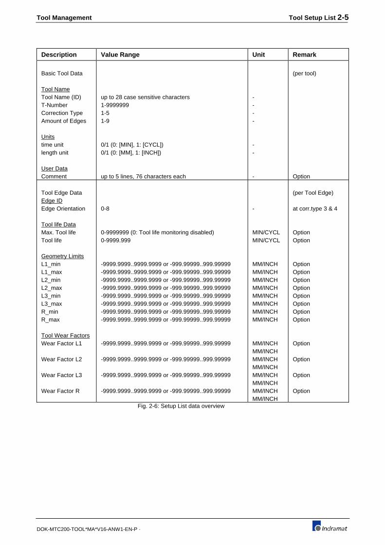
The value range for the basic tool data and tool Edge data is presented inthe table shown in Fig. 2-6.
Tool Management Tool Setup List 2-5
DOK-MTC200-TOOL*MA*V16-ANW1-EN-P ·
Description Value Range Unit Remark
Basic Tool Data
Tool NameTool Name (ID)T-NumberCorrection TypeAmount of Edges
Unitstime unitlength unit
User DataComment
up to 28 case sensitive characters1-99999991-51-9
0/1 (0: [MIN], 1: [CYCL])0/1 (0: [MM], 1: [INCH])
up to 5 lines, 76 characters each
----
--
-
(per tool)
Option
Tool Edge DataEdge IDEdge Orientation
Tool life DataMax. Tool lifeTool life
Geometry LimitsL1_minL1_maxL2_minL2_maxL3_minL3_maxR_minR_max
Tool Wear FactorsWear Factor L1
Wear Factor L2
Wear Factor L3
Wear Factor R
0-8
0-9999999 (0: Tool life monitoring disabled)0-9999.999
-9999.9999..9999.9999 or -999.99999..999.99999-9999.9999..9999.9999 or -999.99999..999.99999-9999.9999..9999.9999 or -999.99999..999.99999-9999.9999..9999.9999 or -999.99999..999.99999-9999.9999..9999.9999 or -999.99999..999.99999-9999.9999..9999.9999 or -999.99999..999.99999-9999.9999..9999.9999 or -999.99999..999.99999-9999.9999..9999.9999 or -999.99999..999.99999
-9999.9999..9999.9999 or -999.99999..999.99999
-9999.9999..9999.9999 or -999.99999..999.99999
-9999.9999..9999.9999 or -999.99999..999.99999
-9999.9999..9999.9999 or -999.99999..999.99999
-
MIN/CYCLMIN/CYCL
MM/INCHMM/INCHMM/INCHMM/INCHMM/INCHMM/INCHMM/INCHMM/INCH
MM/INCHMM/INCHMM/INCHMM/INCHMM/INCHMM/INCHMM/INCHMM/INCH
(per Tool Edge)
at corr.type 3 & 4
OptionOption
OptionOptionOptionOptionOptionOptionOptionOption
Option
Option
Option
Option
Fig. 2-6: Setup List data overview
2-6 Tool Setup List Tool Management
DOK-MTC200-TOOL*MA*V16-ANW1-EN-P ·
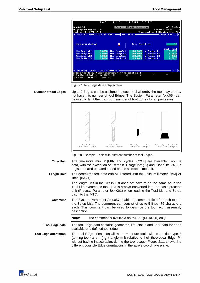
Fig. 2-7: Tool Edge data entry screen
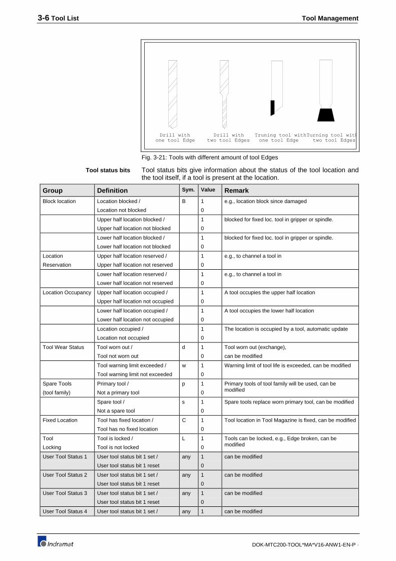
Up to 9 Edges can be assigned to each tool whereby the tool may or maynot have this number of tool Edges. The System Parameter Axx.054 canbe used to limit the maximum number of tool Edges for all processes.
Drill withone tool Edge
Drill withtwo tool Edges one tool Edge
Truning tool with Turning tool withtwo tool Edges
Fig. 2-8: Example: Tools with different number of tool Edges.
The time units 'minute' [MIN] and 'cycles' [CYCL] are available. Tool lifedata, with the exception of 'Remain. Usage life' (%) and 'Used life' (%), isregistered and updated based on the selected time unit.
The geometric tool data can be entered with the units 'millimeter' [MM] or'Inch' [INCH].
The length unit in the Setup List does not have to be the same as in theTool List. Geometric tool data is always converted into the basic processunit (Process Parameter Bxx.001) when loading the Tool List and SetupList into the MTC.
The System Parameter Axx.057 enables a comment field for each tool inthe Setup List. The comment can consist of up to 5 lines, 76 characterseach. This comment can be used to describe the tool, e.g., assemblydescription.
Note : The comment is available on the PC (MUI/GUI) only!
The tool Edge data contains geometric, life, status and user data for eachavailable and defined tool edge.
The tool Edge orientation allows to measure tools with correction type 3(turning tool) and 4 (right angle mill) relative to their theoretical Edge 'P',without having inaccuracies during the tool usage. Figure 2.11 shows thedifferent possible Edge orientations in the active coordinate plane.
Number of tool Edges
Time Unit
Length Unit
Comment
Tool Edge data
Tool Edge orientation
Tool Management Tool Setup List 2-7
DOK-MTC200-TOOL*MA*V16-ANW1-EN-P ·
P B
S
P B
S
P B
S
P B
S
B
S
P B
R
X
ZEdge orientation 3
: path of theortical Edge peak 'P' (programmed contour)
: resulting contour
: path of Edge center
P : theoretical Edge peak
S : Edge centerB : actual touch point
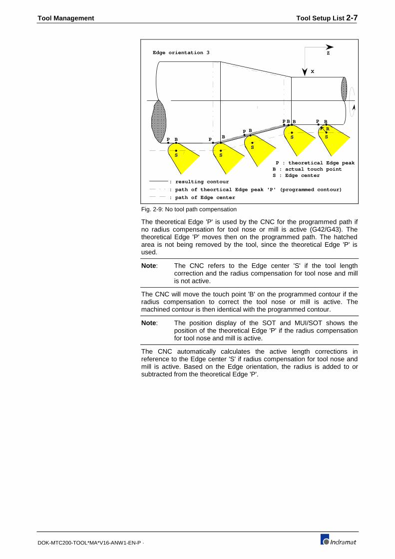
Fig. 2-9: No tool path compensation
The theoretical Edge 'P' is used by the CNC for the programmed path ifno radius compensation for tool nose or mill is active (G42/G43). Thetheoretical Edge 'P' moves then on the programmed path. The hatchedarea is not being removed by the tool, since the theoretical Edge 'P' isused.
Note : The CNC refers to the Edge center 'S' if the tool lengthcorrection and the radius compensation for tool nose and millis not active.
The CNC will move the touch point 'B' on the programmed contour if theradius compensation to correct the tool nose or mill is active. Themachined contour is then identical with the programmed contour.
Note : The position display of the SOT and MUI/SOT shows theposition of the theoretical Edge 'P' if the radius compensationfor tool nose and mill is active.
The CNC automatically calculates the active length corrections inreference to the Edge center 'S' if radius compensation for tool nose andmill is active. Based on the Edge orientation, the radius is added to orsubtracted from the theoretical Edge 'P'.

2-8 Tool Setup List Tool Management
DOK-MTC200-TOOL*MA*V16-ANW1-EN-P ·
P B
S
P B
S
P B
S
P B
S
B
S
P B
R
X
ZEdge orientation 3
: path of theortical Edge peak 'P' (programmed contour)
: resulting contour
: path of Edge center
P : theoretical Edge peak
S : Edge center
B : actual touch point
Fig. 2-10: With tool path compensation
E d g e O r i e n t a t i o n
P
1
S
P
4
S
P
3
S
P
2
S
P
8
S
P5 S 7SP
P = S
P
6
S
0
L 2
Y ( G 1 7 )
X ( G 1 8 )
Z ( G 1 9 )
L 1
P
1
S
P
4
S
P
3
S
P
2
S
P
8
S
P5 S 7SPP = S
P
6
S
0
L 2
L 1
Y ( G 1 7 )
X ( G 1 8 )
Z ( G 1 9 )
Y ( G 1 7 )
X ( G 1 8 )
Z ( G 1 9 )
X ( G 1 7 )
Z ( G 1 8 )
Y ( G 1 9 )
X ( G 1 7 )
Z ( G 1 8 )
Y ( G 1 9 )
Fig. 2-11: Tool Edge Orientation Overview
The Maximum Tool Life is the tool's maximum machining time, minutes orNC-program (cutting) cycles. The machining time is usually the time inwhich the resharpened tool cuts under steady conditions until it is wornout. While machining, the tool is used normally for the same tool/materialcombination only.
Maximum Tool Life

Tool Management Tool Setup List 2-9
DOK-MTC200-TOOL*MA*V16-ANW1-EN-P ·
Note : The tool life monitoring is switched off if a value of 0 isentered. The updating of the Maximum Tool Life is thensuppressed.
The tool life is defined as the time during which the tool is cutting the part.
Tool life can be used in conjunction with user data to perform checks inthe CNC and SPS. An example would be, to determine whether theamount of tools of a tool family in the Active Tool List is sufficient for aproduction cycle.
Geometric length limitation values are used to perform tool length checks.The length of all tools within a tool family that are in the Active Tool Listmust be within the length limits specified for the same tool in the SetupList. Only tools that fulfill this requirement will be used by the toolmanagement for machining.
To prevent and reduce downtime during production, automatic toolchecks are performed at the start of NC-programs. Collisions can beprevented already during the programming stage, if reasonable andaccurate length limitations are entered.
Note : Setup List tool length limits are not considered for toolcorrections.
Depending on the correction type, the
• maximum lengths 'Max.LengthL1', 'Max.LengthL2' and 'Max.LengthL3'and
• minimum lengths 'Min.LengthL1', 'Min.LengthL2' and 'Min.LengthL3'
define the coordinate length limits of the tool . The tool can be used if itsactual lengths fall within its specified limits.
Groove milling.
Task: Cut of a 30mm deep groove.
Tool Name (ID) : GROOVE MILL D12
Correction type : 2
Max.Length L3 : 60 mm
Min.Length L3 : 30 mm
The MTC checks during the automatic tool check that a tool with thename GROOVE MILL D12 is contained in the Active Tool List. If the toolexists, its length must be within 30 and 60 mm.
Radius limitation values are used to perform tool radius checks. Theradius of all tools within a tool family that are in the Active Tool List mustbe within the radius limits specified for the same tool in the Setup List.Only tools that fulfill this requirement will be used by the tool managementfor machining.
To prevent and reduce downtime during production, automatic toolchecks are performed at the start of NC-programs. Collisions can beprevented already during the programming stage, if reasonable andaccurate length limitation is entered.
Note : Setup List radius limits are considered for tool corrections.
Depending on the correction type, the
• maximum radius 'Max.Radius R' and
• minimum radius 'Min.Radius R'
Tool Life
Maximum and minimum toollength
Example:
Maximum and minimum toolradius

2-10 Tool Setup List Tool Management
DOK-MTC200-TOOL*MA*V16-ANW1-EN-P ·
specify the limits of the tool radius. The tool can be used if its actualradius remains within these limits.
Groove milling.
Task: A groove with a width of 20mm (+0.02mm / -0.04mm) must be cut.
Tool Name (ID) : GROOVE MILL D20
Correction type : 2
Max. radius R_max : 20.02/2=10.01
Min. radius R_min : 19.96/2=9.98
The MTC checks during the automatic tool check that a tool with thename GROOVE MILL D20 is contained in the Active Tool List. If the toolexists, its radius must be within 9.98 mm and 10.01 mm.
The length wear factors can be used to compensate tool length wear.Tool length wear can be activated via G48 and G49.
The length compensation value is calculated by multiplying the tool'susage time with its length wear factor. The usage time is determined whileG1, G2, G3, G63, G64, G65, and G33 is active if the length wear factorhas the unit 'MM/MIN' or 'INCH/MIN'.
The Tool life is one cycle and the compensation is the amount specifiedas length wear factor, if the unit of the length wear factor is 'MM/CYCL' or'INCH/CYCL'.
The tool management updates the usage time and compensates thelength wear automatically if
• a different tool Edge is selected (NC-command E)
• the same tool Edge is selected (NC-command E)
• if the tool is put back into the tool magazine
• if the tool is taken out of the machining position in the case of a toolturret
• if T0 (no tool) is selected in the case of a tool turret or no tool storage(magazine/turret) at all.
The radius wear factor can be used to compensate tool radius wear. Toolradius wear can be activated via G41 and G42.
The radius compensation value is calculated by multiplying the tool'susage time with its radius wear factor.
The usage time is determined while G1, G2, G3, G63, G64, G65 and G33is active if the radius wear factor has the unit 'MM/MIN' or 'INCH/MIN'.
The usage time is one cycle and the compensation is the amountspecified as radius wear factor, if the unit of the radius wear factor is'MM/CYCL' or 'INCH/CYCL'.
The tool management updates the usage time and compensates theradius wear automatically if
• a different tool Edge is selected (NC-command E)
• the same tool Edge is selected (NC-command E)
• if the tool is put back into the tool magazine
• if the tool is taken out of the machining position in the case of a toolturret
• if T0 (no tool) is selected in the case of a tool turret or no tool storage(magazine/turret) at all.
Example:
Length tool wear factor
(L1, L2, L3)
Radius tool wear factor (R)

Tool Management Tool Setup List 2-11
DOK-MTC200-TOOL*MA*V16-ANW1-EN-P ·
Setup Lists can be organized either as station (process) or NC-programspecific. The System Parameter Axx.053 allows to make this globalselection for the MTC.
Station (process) specific Setup List selection allows to create only oneSetup List per process in the NC-program package. Up to 99 NC-programs per process share in this case the same Setup List.
NC-program 1
NC-program 2
NC-program 3
:
NC-program 99
Setup List
Process 0
NC-program 1
NC-program 2
NC-program 3
:
NC-program 99
Setup List
Process 1
....
NC-program 1
NC-program 2
NC-program 3
:
NC-program 99
Setup List
Process 99
NC-program package 7
Fig. 2-12: Station specific Setup List.
This type of organization is recommended if part families that differ onlylittle are produced and if all required tools are contained in thecorresponding Tool List and tool storage.
NC-program specific Setup List selection allows to create one Setup Listfor each NC-program of a NC-program package.
This type of organization is recommended if parts differ more and if not allrequired tools are contained in the corresponding Tool Lists and toolstorage. Different Setup Lists and Tool Lists are required for the individualNC-programs.
NC-program 1
NC-program 2
NC-program 3
:
Setup List 1
Process 0
NC-program 1
NC-program 2
NC-program 3
:
NC-program 99
Setup List 1
Process 1
....
NC-program 1
NC-program 2
NC-program 3
:
NC-program 99
Setup List 1
Process 6
NC-program package 7
Setup List 2
Setup List 3
Setup List 99
: :
NC-program 99
Setup List 2
Setup List 3
Setup List 99
: :
Setup List 2
Setup List 3
Setup List 99
: :
Fig. 2-13: NC-program specific Setup List.
Setup List Organization

2-12 Tool Setup List Tool Management
DOK-MTC200-TOOL*MA*V16-ANW1-EN-P ·
Setup Lists within the MTCTool Setup Lists (SL) can be generated or modified by using the UserInterface (MUI/SOT), independently of the active NC-program.
The MUI/SOT main menu "2 = NC-program administration" contains theNC-program index that allows NC-program modifications. The key <F5>allows access to the Setup List for the process or NC-program. For moreinformation refer to the MTC User Interface (MUI/SOT) Manual.
Note : The Setup List should be updated while writing or modifyingthe NC-program to prevent machine downtime when startingthe NC-program. This downtime may be caused by wrong ormissing setup data.
The Setup Lists are always transferred together with the NC-programpackage into the MTC memory A or B via the MUI/SOT.
The Setup List data is not modified while the Setup List is active in theMTC memory.
The Setup Lists will be stored together with the NC-program since theyare part of the NC-program package. NC-program packages can bearchived to and retrieved from HD, FD or Server via MUI/SOT main menuitem 1. Refer to the User Interface (MUI/SOT) Manual for moreinformation about archiving of NC-program packages.
Up to 1000 NC-program packages can be stored per disk drive.
Fig. 2-14 contains shows an overview on how the NC-program packagesand Setup Lists can be transferred within the control system.

Tool Management Tool Setup List 2-13
DOK-MTC200-TOOL*MA*V16-ANW1-EN-P ·
NC-Program package
Process NC-programs
0 01 02 15 32 58 66 67 73 95 991 01 02 03 04 05 06
no
: : :5 02 07 12 17 25 28
yes
yes6 03 07 14 19 22 27 29 35 no
1 NC-program2
34
56
78
910
1112
.
Archiving NC-program packags & Setup Lists NC-Archive
Setup List. .
1000
NC-Program package 1
Process NC-programs
0 02 17 23 38 43 51 74 811 04 07 10 21 37 40 no: : :5 01 04 08 11 18 23 26 41 75 82
yes
yes6 02 03 04 09 13 15 17 22 no
12
34
56
78
910
1112
Setup List
package
Editing NC-program packags & Setup Lists MUI
1 NC-programpackage
Machining of part, using MT-CNCNC-program packags & Setup Lists
NC-Program package 2
Process NC-programs
0 03 17 23 36 74 81
1 04 07 10 21 37 40 yes
: : :
5 01 23 26 41 75
yes
yes
6 02 03 04 22 no
Setup List
NC-memory A
NC-Program package 6
Process NC-programs
0 17 36 51 74 81
1 07 10 37 40 yes
: : :
5 01 04 23 26 41 75 82
no
no
6 02 03 15 17 22 no
Setup List
NC-memory B
Fig. 2-14: NC-program packages and Setup Lists in MTC

Tool Management Tool List 3-1
DOK-MTC200-TOOL*MA*V16-ANW1-EN-P ·
3 Tool List
3.1 Purpose of Tool List
Tool Lists are used to prepare and store tool data sets.
They can be generated, modified and saved via the MUI/SOT duringmachining. Tool storage (magazine/turret) configurations for consecutivemachining can be prepared up front without machine downtime.
The changeover time for the tool storage (magazine/turret) therefore isreduced to a minimum. The user only needs to load the prepared ToolList into the MTC and equip the tool storage with the tools according tothe Tool List.
With downloading, the Tool List in the MTC becomes the Active Tool List.This Active Tool List reflect the actual tool status once the process ormachining is started. The Tool List in the MUI/SOT looses its meaning,since it contains the original tool data.
Besides the basic tool data, the Tool List also contains the tool Edge data(such as Edge ID, geometry, tool life and wear, and user data) of alldefined tools.
CAUTION
Changes, such as inserting, deleting or moving tools, inthe Active Tool List must reflect the real facts in the toolstorage (magazine/turret) and vise versa to preventdamage to man and machine!
3.2 Tool List data
The Tool List consists of the summary of all tool entries in the tool storage(magazine/turret). The tool data in the Tool List consists of the basic tooldata and the data of the different tool Edges.
Fig. 3-15 and Fig. 3-16 show the MUI/SOT screens for basic tool data andtool Edge data.
User Tool Data
Fig. 3-15: Tool List, Basic Tool Data MUI/SOT screen

3-2 Tool List Tool Management
DOK-MTC200-TOOL*MA*V16-ANW1-EN-P ·
User Edge Data
Fig. 3-16: Tool List, Tool Edge Data MUI/SOT screen
The value range for the basic tool data and tool Edge data is presented inthe table shown in Figure 0.2C.
Description Value Range Unit Remark
Basic Tool Data
Tool Name
Tool Name (ID)
Tool Storage
Tool location
Index Number
Correction Type
Amount of Edges
Tool Status
Pocket Data
half pocket overlap
old pocket
Units
length unit
User Tool Data
User tool data 1
.
User tool data 9
up to 28 case sensitive characters
0-2 (0: Mag./Turret, 1: Spindle, 2: Gripper)
0-999
1-999
1-5
1-9
0/1
0-4
1-999
0/1 (0: [MM], 1: [INCH])
+/- 1.2*10-38 ... +/-3.4*10+38 and 0
(nom. entry via MUI/SOT: as with geometric data)
+/- 1.2*10-38 ... +/-3.4*10+38 and 0
(nom. entry via MUI/SOT: as with geometric data)
-
-
-
-
-
-
-
-
-
-
any
.
any
per tool
run index
run index
24 stat. bits
symmetrical
option
option

Tool Management Tool List 3-3
DOK-MTC200-TOOL*MA*V16-ANW1-EN-P ·
Tool Edge Data
Edge ID
Edge Orientation
Edge Status
Tool life Data
Remain. Tool life
Warning Limit
Geometric Data
Length L1
Length L2
Length L3
Radius R
Wear L1
Wear L2
Wear L3
Wear R
Offset L1
Offset L2
Offset L3
Offset R
User Edge Data
User Edge Data 1
.
.
User Edge Data 5
0-8
0/1(16 status bits)
0.00-100.00
0.00-100.00
-9999.9999..9999.9999 or -999.99999..999.99999
-9999.9999..9999.9999 or -999.99999..999.99999
-9999.9999..9999.9999 or -999.99999..999.99999
-9999.9999..9999.9999 or -999.99999..999.99999
-9999.9999..9999.9999 or -999.99999..999.99999
-9999.9999..9999.9999 or -999.99999..999.99999
-9999.9999..9999.9999 or -999.99999..999.99999
-9999.9999..9999.9999 or -999.99999..999.99999
-9999.9999..9999.9999 or -999.99999..999.99999
-9999.9999..9999.9999 or -999.99999..999.99999
-9999.9999..9999.9999 or -999.99999..999.99999
-9999.9999..9999.9999 or -999.99999..999.99999
+/- 1.2*10-38 ... +/-3.4*10+38 and 0
(nom. entry via MUI/SOT: as geometric data)
.
+/- 1.2*10-38 ... +/-3.4*10+38 and 0
(nom. entry via MUI/SOT: as geometric data)
-
-
%
%
MM/INCH
MM/INCH
MM/INCH
MM/INCH
MM/INCH
MM/INCH
MM/INCH
MM/INCH
MM/INCH
MM/INCH
MM/INCH
MM/INCH
any
.
.
any
per Tool Edge
corr.type 3/4
8 stat. bits
option
option
option
option
option
option
option
option
option
option
option
option
Fig. 3-17: Tool List data overview
Basic Tool Data of Tool ListThe tool Name is part of the Tool identification (ID).
The Tool Name can consist of up to any 28 characters. It is used for cleardistinction between the used types of tools.
Tools are displayed in the MUI/SOT and SOT menus with their ToolName as well as their T-number. Two different tools are not allowed tohave the same Tool Name.
Tools which could replace each other can be comprised of a tool family byusing the same Tool Name. The tools within the tool family aredistinguished with the Tool Index (see chapter 3.2).
This expanded tool description system allows to take user specific toolsystems over into the control level.
The 'tool storage' data of the Tool List is not completely available sinceonly the tool storage (tool storage = 0) and the spindles (tool storage =1)are registered.
In the Tool List, spindles are identified with the leading character 'S'.
Tool Name
Tool storage

3-4 Tool List Tool Management
DOK-MTC200-TOOL*MA*V16-ANW1-EN-P ·
The 'tool location' data identifies within the tool storage the tool pocket orspindle number that contains the tool.
Using the Tool List, all tool locations in the tool storage as well as allavailable spindles can be prepared with tool data.
CAUTION
⇒ After loading the Tool List into the MTC it becomes toan Active Tool List. Changes, such as inserting,deleting or moving tools, in the Active Tool List mustreflect the real facts in the tool storage(magazine/turret) and vise versa to prevent damage toman and machine!
The tool index is used to
• identify spare tools within a tool family, since tools of a tool family havethe same tool name (ID).
• determine the sequence of their usage.
Tools of a tool family are used according to their tool index number. Toolsthat are not worn out and have a lower index number are used first beforetools with a higher index number.
All tools of a tool family are called with the same T-number that isspecified with the tool name.
Spare tools are used whenever the T-number is programmed and theprevious tool has been locked or is worn out.
Tool index and tool family.
The tool family `MILL 50MM' (correction type 4) contains 4 tools. The ToolList may contain the following data for the tools within this family:
Tool
Number
Tool Name Index Length
L3
Offset
L3
Radius
R
Offset
R
number
T25
T25
T25
T25
MILL 50MM
MILL 50MM
MILL 50MM
MILL 50MM
1
2
3
4
120.00
121.00
120.00
122.00
+0.00
-0.023
-1.820
+0.02
25.00
25.00
25.00
25.00
+0.03
-0.14
-0.02
-0.21
13
2
5
11Fig. 3-18: Tool family data
The Setup List would have to contain the following tool data to match theMagazine List:
T-number Tool Name L3_max. L3_min. R_max. R_min. Wear L3 Wear R
T25 MILL 50MM 125.00 115.00 25.05 24.95 0.001 0.002Fig. 3-19: Tool data to match the magazine list
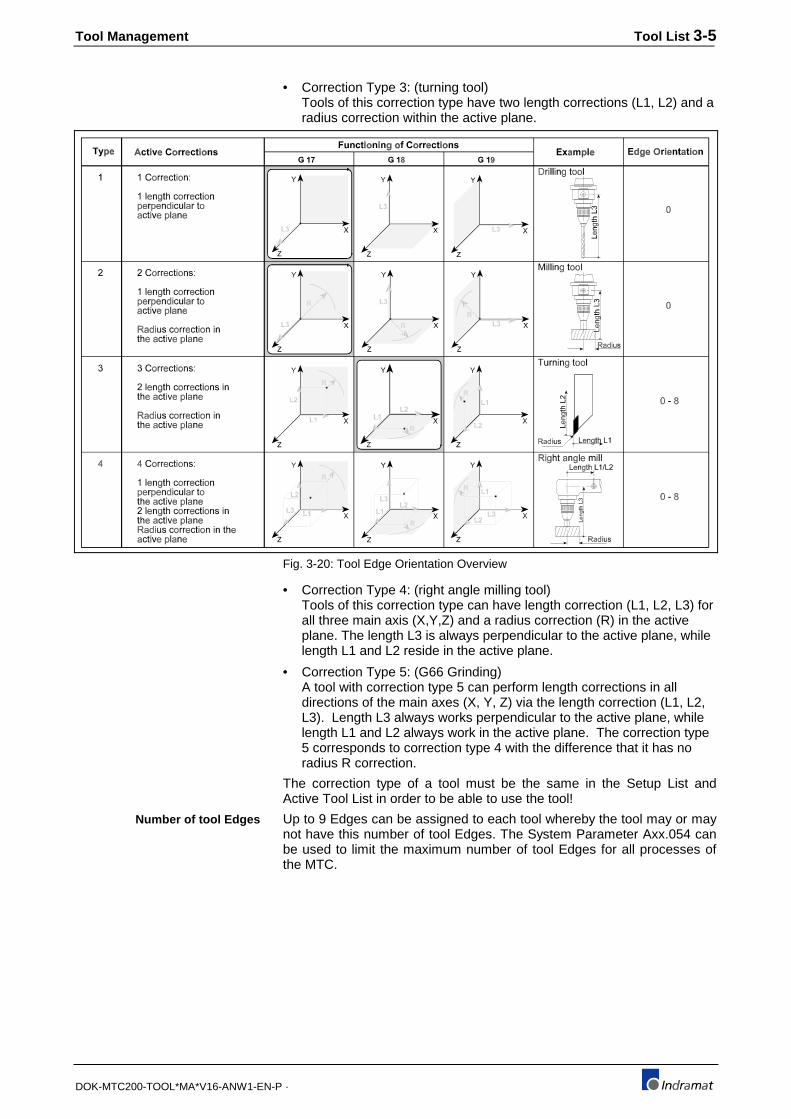
The Tool Correction Type specifies the amount of the tool's correctionsand their orientations. Fig. 3-20 shows the definition of the differentCorrection Types.
Each tool entry into the Tool List consists of the basic tool data and thetool Edge data. The number of tool Edges is specified for each tool in thebasic tool data. Data must be entered for each tool Edge (see Fig. 3-17).
• Correction Type 1: (drilling tool)Tools of this correction type have only one length correction (L3), thatis always perpendicular to the active plane.
• Correction Type 2: (milling tool)Tools of this correction type have only one length correction (L3), thatis always perpendicular to the active plane. A radius correction (R) inthe active plane is also performed.
Tool location
Tool Index
Example:
Correction type
Tool Management Tool List 3-5
DOK-MTC200-TOOL*MA*V16-ANW1-EN-P ·
• Correction Type 3: (turning tool)Tools of this correction type have two length corrections (L1, L2) and aradius correction within the active plane.
Fig. 3-20: Tool Edge Orientation Overview
• Correction Type 4: (right angle milling tool)Tools of this correction type can have length correction (L1, L2, L3) forall three main axis (X,Y,Z) and a radius correction (R) in the activeplane. The length L3 is always perpendicular to the active plane, whilelength L1 and L2 reside in the active plane.
• Correction Type 5: (G66 Grinding)A tool with correction type 5 can perform length corrections in alldirections of the main axes (X, Y, Z) via the length correction (L1, L2,L3). Length L3 always works perpendicular to the active plane, whilelength L1 and L2 always work in the active plane. The correction type5 corresponds to correction type 4 with the difference that it has noradius R correction.
The correction type of a tool must be the same in the Setup List andActive Tool List in order to be able to use the tool!
Up to 9 Edges can be assigned to each tool whereby the tool may or maynot have this number of tool Edges. The System Parameter Axx.054 canbe used to limit the maximum number of tool Edges for all processes ofthe MTC.
Number of tool Edges
3-6 Tool List Tool Management
DOK-MTC200-TOOL*MA*V16-ANW1-EN-P ·
Drill withone tool Edge
Drill withtwo tool Edges one tool Edge
Truning tool withTurning tool wit htwo tool Edges
Fig. 3-21: Tools with different amount of tool Edges
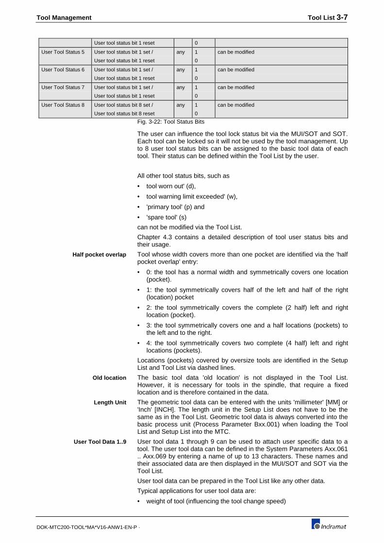
Tool status bits give information about the status of the tool location andthe tool itself, if a tool is present at the location.
Group Definition Sym. Value Remark
Block location Location blocked /
Location not blocked
B 1
0
e.g., location block since damaged
Upper half location blocked /
Upper half location not blocked
1
0
blocked for fixed loc. tool in gripper or spindle.
Lower half location blocked /
Lower half location not blocked
1
0
blocked for fixed loc. tool in gripper or spindle.
Location
Reservation
Upper half location reserved /
Upper half location not reserved
1
0
e.g., to channel a tool in
Lower half location reserved /
Lower half location not reserved
1
0
e.g., to channel a tool in
Location Occupancy Upper half location occupied /
Upper half location not occupied
1
0
A tool occupies the upper half location
Lower half location occupied /
Lower half location not occupied
1
0
A tool occupies the lower half location
Location occupied /
Location not occupied
1
0
The location is occupied by a tool, automatic update
Tool Wear Status Tool worn out /
Tool not worn out
d 1
0
Tool worn out (exchange),
can be modified
Tool warning limit exceeded /
Tool warning limit not exceeded
w 1
0
Warning limit of tool life is exceeded, can be modified
Spare Tools
(tool family)
Primary tool /
Not a primary tool
p 1
0
Primary tools of tool family will be used, can bemodified
Spare tool /
Not a spare tool
s 1
0
Spare tools replace worn primary tool, can be modified
Fixed Location Tool has fixed location /
Tool has no fixed location
C 1
0
Tool location in Tool Magazine is fixed, can be modified
Tool
Locking
Tool is locked /
Tool is not locked
L 1
0
Tools can be locked, e.g., Edge broken, can bemodified
User Tool Status 1 User tool status bit 1 set /
User tool status bit 1 reset
any 1
0
can be modified
User Tool Status 2 User tool status bit 1 set /
User tool status bit 1 reset
any 1
0
can be modified
User Tool Status 3 User tool status bit 1 set /
User tool status bit 1 reset
any 1
0
can be modified
User Tool Status 4 User tool status bit 1 set / any 1 can be modified
Tool status bits
Tool Management Tool List 3-7
DOK-MTC200-TOOL*MA*V16-ANW1-EN-P ·
User tool status bit 1 reset 0
User Tool Status 5 User tool status bit 1 set /
User tool status bit 1 reset
any 1
0
can be modified
User Tool Status 6 User tool status bit 1 set /
User tool status bit 1 reset
any 1
0
can be modified
User Tool Status 7 User tool status bit 1 set /
User tool status bit 1 reset
any 1
0
can be modified
User Tool Status 8 User tool status bit 8 set /
User tool status bit 8 reset
any 1
0
can be modified
Fig. 3-22: Tool Status Bits
The user can influence the tool lock status bit via the MUI/SOT and SOT.Each tool can be locked so it will not be used by the tool management. Upto 8 user tool status bits can be assigned to the basic tool data of eachtool. Their status can be defined within the Tool List by the user.
All other tool status bits, such as
• tool worn out' (d),
• tool warning limit exceeded' (w),
• 'primary tool' (p) and
• 'spare tool' (s)
can not be modified via the Tool List.
Chapter 4.3 contains a detailed description of tool user status bits andtheir usage.
Tool whose width covers more than one pocket are identified via the 'halfpocket overlap' entry:
• 0: the tool has a normal width and symmetrically covers one location(pocket).
• 1: the tool symmetrically covers half of the left and half of the right(location) pocket
• 2: the tool symmetrically covers the complete (2 half) left and rightlocation (pocket).
• 3: the tool symmetrically covers one and a half locations (pockets) tothe left and to the right.
• 4: the tool symmetrically covers two complete (4 half) left and rightlocations (pockets).
Locations (pockets) covered by oversize tools are identified in the SetupList and Tool List via dashed lines.
The basic tool data 'old location' is not displayed in the Tool List.However, it is necessary for tools in the spindle, that require a fixedlocation and is therefore contained in the data.
The geometric tool data can be entered with the units 'millimeter' [MM] or'Inch' [INCH]. The length unit in the Setup List does not have to be thesame as in the Tool List. Geometric tool data is always converted into thebasic process unit (Process Parameter Bxx.001) when loading the ToolList and Setup List into the MTC.
User tool data 1 through 9 can be used to attach user specific data to atool. The user tool data can be defined in the System Parameters Axx.061.. Axx.069 by entering a name of up to 13 characters. These names andtheir associated data are then displayed in the MUI/SOT and SOT via theTool List.
User tool data can be prepared in the Tool List like any other data.
Typical applications for user tool data are:
• weight of tool (influencing the tool change speed)
Half pocket overlap
Old location
Length Unit
User Tool Data 1..9

3-8 Tool List Tool Management
DOK-MTC200-TOOL*MA*V16-ANW1-EN-P ·
• maximum speed of the tool
• maximum dimension of the tool (collision check)
• sensitivity for tool monitoring system
• maximum spindle power (tool protection)
Fig. 3-23: Example: User tool data on MUI/SOT screen
The following user tool data has been defined in the system parametersfor this example:
• PATH ACC %
• Weight LB
• SPDL LOAD %
This allows to enter for each tool a specific value that can be accessedvia the NC-command TLD in the NC-program. In addition the user toolstatus bit '3' is set for tool number T6 that resides in pocket number 5.
Fig. 3-24: Correction type '2', one tool Edge
This tool is of the correction type '2' and has only one tool Edge.
The user tool Edge data
• PATH VEL. %, and user Edge status bit
• A
were defined in the system parameters for all tools.
E. g., this allows the user to specify the max. feedrate override value forthis tool.

Tool Management Tool List 3-9
DOK-MTC200-TOOL*MA*V16-ANW1-EN-P ·
In any case, the user must implement the necessary NC and progr.controller program to achieve the desired functionality.
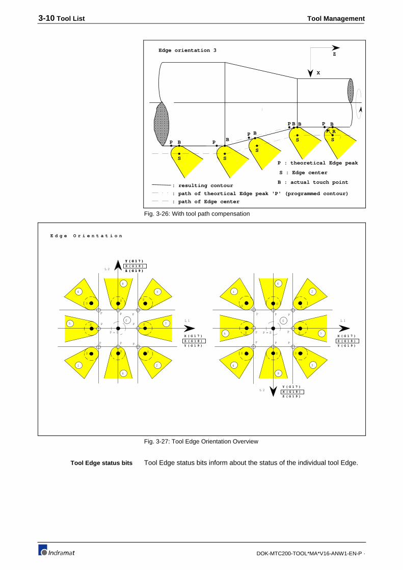
Tool Edge dataThe tool Edge orientation allows to measure tools with correction type 3(turning tool) and 4 (right angle mill) relative to their theoretical Edge 'P',without having inaccuracies during the tool usage. Figure 3-27 shows thedifferent possible Edge orientations in the active coordinate plane.
The theoretical Edge 'P' is used by the CNC for the programmed path ifno radius compensation for tool nose or mill is active (G42/G43). Thetheoretical Edge 'P' moves then on the programmed path. The hatchedarea is not being removed by the tool, since the theoretical Edge 'P' isused.
Note : The CNC refers to the Edge center 'S' if the tool lengthcorrection and the radius compensation for tool nose and millis not active.
The CNC will move the touch point 'B' on the programmed contour if theradius compensation to correct the tool nose or mill is active. Themachined contour is then identical with the programmed contour.
Note : The position display of the SOT and MUI/SOT shows theposition of the theoretical Edge 'P' if the radius compensationfor tool nose and mill is active.
The CNC automatically calculates the active length corrections inreference to the Edge center 'S' if radius compensation for tool nose andmill (G41/G42) is active. Based on the Edge orientation, the radius isadded to or subtracted from the theoretical Edge 'P'.
P B
S
P B
S
P B
S
P B
S
B
S
P B
R
X
ZEdge orientation 3
: path of theortical Edge peak 'P' (programmed contour)
: resulting contour
: path of Edge center
P : theoretical Edge peak
S : Edge centerB : actual touch point
Fig. 3-25: No tool path compensation
Tool Edge orientation
3-10 Tool List Tool Management
DOK-MTC200-TOOL*MA*V16-ANW1-EN-P ·
P B
S
P B
S
P B
S
P B
S
B
S
P B
R
X
ZEdge orientation 3
: path of theortical Edge peak 'P' (programmed contour)
: resulting contour
: path of Edge center
P : theoretical Edge peak
S : Edge center
B : actual touch point
Fig. 3-26: With tool path compensation
E d g e O r i e n t a t i o n
P
1
S
P
4
S
P
3
S
P
2
S
P
8
S
P5 S 7SP
P = S
P
6
S
0
L 2
Y ( G 1 7 )
X ( G 1 8 )
Z ( G 1 9 )
L 1
P
1
S
P
4
S
P
3
S
P
2
S
P
8
S
P5 S 7SPP = S
P
6
S
0
L 2
L 1
Y ( G 1 7 )
X ( G 1 8 )
Z ( G 1 9 )
Y ( G 1 7 )
X ( G 1 8 )
Z ( G 1 9 )
X ( G 1 7 )
Z ( G 1 8 )
Y ( G 1 9 )
X ( G 1 7 )
Z ( G 1 8 )
Y ( G 1 9 )
Fig. 3-27: Tool Edge Orientation Overview
Tool Edge status bits inform about the status of the individual tool Edge.Tool Edge status bits

Tool Management Tool List 3-11
DOK-MTC200-TOOL*MA*V16-ANW1-EN-P ·
Group Definition Sym. Value RemarkEdge Wear Status Edge worn out /
Edge not worn out
d 1
0
can not be modified
Edge warning limit exceeded /
Edge warning limit not exceeded
w 1
0
can not be modified
User Edge Status 1 User edge status bit 1 set /
User edge status bit 1 reset
any 1
0
can be modified
User Edge Status 2 User edge status bit 2 set /
User edge status bit 2 reset
any 1
0
can be modified
User Edge Status 3 User edge status bit 3 set /
User edge status bit 3 reset
any 1
0
can be modified
User Edge Status 4 User edge status bit 4 set /
User edge status bit 4 reset
any 1
0
can be modified
User Edge Status 5 User edge status bit 5 set /
User edge status bit 5 reset
any 1
0
can be modified
Fig. 3-28: Tool Edge status bits.
Up to four user Edge status bits can be assigned to each tool Edge. Theirstatus can be influenced via the MUI/SOT or SOT. The two Edge statusbits
• 'Edge worn out' and
• 'Edge warning limit exceeded'
cannot be modified via SOT or MUI/SOT.
Chapter 4.4 contains a complete description of Edge status bits.
The Remaining Tool Life defines the tool's wear status in %, independentof the tool/workpiece material combination.
Remain. Tool Life [%] = previous remain. ToolLife - Tool Life[MIN] or [CYCL]
Max. Tool Life [MIN] or [CYCL]100[%]*
Note : The tool management uses '1 cycle' for Tool Life if the unit[CYCL] for Tool Life was selected for the tool in the Setup List.
Each time the tool management updates tool data it checks the remainingTool Life of all tools. The status of Gateway signal PxxSMGTWO is set to'1' if the remaining Tool Life of all tools within a tool family is zero.
The tool management monitors the remaining Tool Life (%) and uses theGateway process status signal PxxSMGWRN to indicate that theremaining Tool Life time (%) is below the specified limit.
The status of PxxSMGWRN is set to `1` at the time of tool check if thelast tool within the tool family exceeded its warning limit.
The warning limit is a percentage value of the Max. Tool Life which is100%.
The tool dimensions are being automatically compensated by using thegeometric data if the compensation is activated.
Remaining Tool Life
Warning limit
Geometry data

3-12 Tool List Tool Management
DOK-MTC200-TOOL*MA*V16-ANW1-EN-P ·
The geometry data consists of the following groups:
Geometry Wear Offset
Length L1Length L2Length L3Radius R
Tool Wear L1Tool Wear L2Tool Wear L3Tool Wear R
Offset L1Offset L2Offset L3Offset R
Fig. 3-29: Geometry data groups
The wear and offset registers can be selected as an option via theSystem Parameter Axx.055 and Axx.056.
• The geometry registers are used as program independent storage,used to compensate the tool dimensions.
• Wear registers are used by the tool management to compensation thetool wear that occurs over time or cycles. For that purpose, the toolmanagement calculates the corresponding wear (see chapter 2.2) andadds it to the already existing value in the wear register. The tool wearregisters are being influenced by the 'Reset' function of the MUI/SOTand SOT. This 'Reset' function resets the tool's wear registers to 0 andthe remaining Tool Life to 100%.
• Offset registers are not being influenced by the tool management. Likethe wear registers, they can be used to compensate dimensionaldeviations. The deviations are either determined by the user or anautomatic gauging system. They also can be used as additionalmemory for offsets, e.g., to compensate for adapter dimensions.
Note : Wear and offset registers are internally set to 0 if they are notselected via the System Parameters Axx.055 and Axx.056.
The length 'L1', 'L2' and 'L3' of a tool Edge is calculated as follows:
Length correction L1 = Length L1 + Wear L1 + Offset L1
Length correction L2 = Length L2 + Wear L2 + Offset L2
Length correction L3 = Length L3 + Wear L3 + Offset L3
Length L3: 210.000+ Wear L3: -0.030+ Offset L3: 0.015
= Length corr.L3: 209.985L3_min=2000mm
Length correct ion L3=209.985mm
L3_max=230mm
Fig. 3-30: Correction type 1 length correction
Tool length correction

Tool Management Tool List 3-13
DOK-MTC200-TOOL*MA*V16-ANW1-EN-P ·
The radius 'R' correction of a tool Edge is calculated as follows:
Radius correction R = Radius R + Wear R + Offset R
Radius R: 15.000+ Wear R: -0.002+ Offset R: -0.150
= Radius corr. R: 14.848
R_min=14.800mm
Radius correction=14.848mm
R_max=14.900mm
Fig. 3-31: Correction type 2 radius correction
Tool radius correction
3-14 Tool List Tool Management
DOK-MTC200-TOOL*MA*V16-ANW1-EN-P ·
Determined correction values:
1) Not considering of radius
Correction type
Edge orientation
Lenth L3
Wear L3
1
0
162.13
Offset L3
0
0
1) Considering the radius
Correction type
Edge orientation
Lenth L3
Wear L3
2
0
162.13
Offset L3
0
0
Radius R
Wear R
8
Offset R
0
0R
Length L3
Z
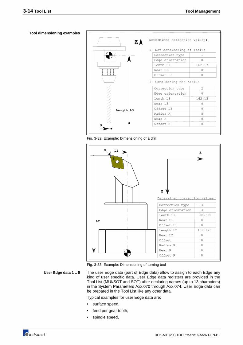
Fig. 3-32: Example: Dimensioning of a drill
Determined correction values:
Correction type
Edge orientation
Lenth L1
Wear L1
3
3
38.322
Offset L1
0
0
Length L2
Wear L2
Offset
197.827
0
0
Radius R
Wear R
8
Offset R
0
0
X
ZL1
S
R
L2
Fig. 3-33: Example: Dimensioning of turning tool
The user Edge data (part of Edge data) allow to assign to each Edge anykind of user specific data. User Edge data registers are provided in theTool List (MUI/SOT and SOT) after declaring names (up to 13 characters)in the System Parameters Axx.070 through Axx.074. User Edge data canbe prepared in the Tool List like any other data.
Typical examples for user Edge data are:
• surface speed,
• feed per gear tooth,
• spindle speed,
Tool dimensioning examples
User Edge data 1 .. 5

Tool Management Tool List 3-15
DOK-MTC200-TOOL*MA*V16-ANW1-EN-P ·
• feedrate
• temporary storage of corrected dimensions,
• average value
• practical value
3.3 Tool List within the control system
MUI/SOT menu item 6 'Tool Management' and its sub menu 'Tool Lists'allow to generate up to 99 Tool Lists for each process. The Tool Lists canbe created, erased, copied, saved and modified independently from theactive NC-program.
Tool storage process 6
...
Tool Lists for process 6
Archiving of Tool Lists Tool List Archive
12
34
..
.1000
1
1000
Creat and modify Tool Lists MUI
1 2 99...
Tool Lists for process 0
Machining, using Active Tool Lists MT-CNC
12
..
.6
0 Process
12
..
.6
0 Process
Tool storage process 0
Active Tool List
Fig. 3-34: Tool Lists within the control system
The MUI/SOT allows in addition to download the Tool List and to uploadthe Active Tool List. A Tool List can be loaded into the MTC only if no NC-program is active.
MUI/SOT main menu item 1 'Archives Administration' and its sub menuitem 2 'Tool List Archive' provide function to archive Tool Lists to andretrieve from HD, FD and file servers (Host).
Changes in the tool storage (magazine/turret) requires
• that the same changes are performed in the Active Tool List
• or that a newly generated Tool List for the new tool storageconfiguration is loaded into the MTC.

3-16 Tool List Tool Management
DOK-MTC200-TOOL*MA*V16-ANW1-EN-P ·

Tool Management Active Tool List 4-1
DOK-MTC200-TOOL*MA*V16-ANW1-EN-P ·
4 Active Tool List
4.1 General information to the Active Tool List
The data that is contained in the tool storage of the MTC is referred to asactual tool data or Active Tool List.
The Active Tool List of a process can be viewed in ONLINE mode in theMUI/GUI as well as the SOT. In addition to the actual tool data, thecorresponding Setup List data is displayed also in the Active Tool List.This provides all information to assure quick problem recognition andrecovery in the case of a tool data mismatch or error.
The location and status of all tools used in the process is contained in theTool List. Based on the Process Parameter definitions, the user can viewall available tool storage locations (pockets), tool spindles and grippersvia the Tool List.
The displayed tool data sets are based on the System Parameterconfiguration also. System Parameters allow to select specific data forSetup and Tool Lists such as tool life data, tool wear registers, tool offsetregisters, tool geometry limits and tool wear factors.
Additional user data and user status bits can be defined in the basic tooldata and tool Edge data. The tool management updates the actual tooldata such as tool location (pocket), tool life and tool wear data, duringNC-program execution. Tool Setup List specific data, however, remainsunchanged.
Functions to insert a tool, remove a tool, view tool data, modify tool data,reset worn tools (tool life and tool wear registers) and a move a tool, areprovided by the tool management for the operator in the Active Tool Listdisplay of the MUI/GUI and SOT. Using these functions, all changes inthe actual tool configuration can be entered into the Active Tool List (referto MTC User Interface and SOT Manual).
Note : Tool Lists can be generated while machining occurs. Whenchanging the actual tool storage (magazine/turret)configuration, the Tool List can the be loaded into the MTCand becomes the Active Tool List.
4.2 Data of the Active Tool List
The Active Tool List consists of the summary of all tools that are presentin the tool storage (magazine/turret), tool spindles and grippers. Thefollowing Figures show MUI/GUI screens of the Active Tool List. For moreinformation refer to the MTC User Interface and SOT Manual.
Fig. 4-35: MUI/GUI Operator Display of Active Tool List (GEO).

4-2 Active Tool List Tool Management
DOK-MTC200-TOOL*MA*V16-ANW1-EN-P ·
• The ‘Active Tool List (GEO)’ screen is shown as the first display whenentering the Tool Management menu if a MTC is connected and toolmanagement is active for the selected station (process). The screenprovides immediate access to the tool’s current diagnostics and edgedata.
• The Active Tool List is sorted by Location (column Locat.). The cursorkeys <⇑>, <⇓>, <PgUp> and <PgDn> can be used to scroll through theentire location list. Tool Spindle locations are displayed at the top ofthe list, followed by Tool Gripper and Magazine Pocket or TurretPosition locations.
• The column Name shows the tool’s name, T-number and tool familyindex number. The last line displays the currently active Tool StatusBits. Press <F9>/<Help> at any time to display detailed contextsensitive help for the tool status bits or refer to the descriptions inFigure 4-36 and the sections in this chapter.
• Absolute (<F1>), additive (<F2>) and diameter (<F3>) values can beentered for geometric (column GEO) data, wear (column T. Wear) andoffset (column Offset).
• The softkey <F4> allows to scroll through the three planes whereby thecorresponding coordinate axis is displayed left of the tool length (L1,L2, L3) and radius (R) name that is available for the tool. The currentlyin the process active plane is displayed highlighted.
• The displayed geometry unit can be switched between ‘Inch’ and ‘MM’using <F5>. The currently in the process active unit is displayedhighlighted.
• Softkey <F6> and <F7> allow to scroll through the available tooledges.
Fig. 4-36: MUI/GUI Help for Active Tool List menu.
Fig. 4-37: MUI/GUI additional functions in Active Tool List (GEO).
Press <Ctrl>+<F7> to open the full Tool List editor and <Ctlr>+<F4> to goto the condensed ‘Active Tool List (Location)’ display as shown in thFigure below.
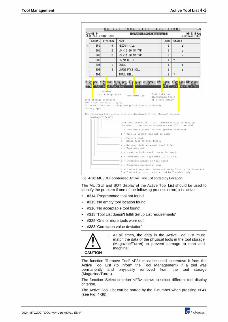
Tool Management Active Tool List 4-3
DOK-MTC200-TOOL*MA*V16-ANW1-EN-P ·
T-numberin the NC-program
SP1 = tool spindle 1 (S,S1)001 = tool location 1 (magazine pocket/turret position)GP1 = gripper 1
Tool storage location:
Tool Name (ID)Tool Index todistinguish toolsof a tool family
The following tool status bits are displayed in the 'Status' column:
!tefBwpLC12345678
User tool status bit 1..8. Characters are defined bythe user in the System Parameters Axx.075 .. Axx.082.
C = Tool has a fixed location (pocket/position)
L = Tool is locked (can not be used)
p = Primary tools = Spare tool of tool family
w = Warning limit exceeded (tool life)d = Tool worn out
B = Location is blocked (cannot be used)
e = Incorrect number of tool edges
t = Incorrect correction type
! = Tool not present (when sorted by T-number only)? = Tool not required? (when sorted by location or T-number)
f = Incorrect tool Edge data (L1,L2,L3,R)
Fig. 4-38: MUI/GUI condensed Active Tool List sorted by Location.
The MUI/GUI and SOT display of the Active Tool List should be used toidentify the problem if one of the following process error(s) is active:
• #314 'Programmed tool not found'
• #315 'No empty tool location found'
• #316 'No acceptable tool found'
• #318 'Tool List doesn't fulfill Setup List requirements'
• #325 'One or more tools worn out'
• #383 'Correction value deviation'
CAUTION
⇒ At all times, the data in the Active Tool List mustmatch the data of the physical tools in the tool storage(Magazine/Turret) to prevent damage to man andmachine!
The function 'Remove Tool' <F2> must be used to remove it from theActive Tool List (to inform the Tool Management) if a tool waspermanently and physically removed from the tool storage(Magazine/Turret).
The function 'Select criterion' <F3> allows to select different tool displaycriterion.
The Active Tool List can be sorted by the T-number when pressing <F4>(see Fig. 4-36).
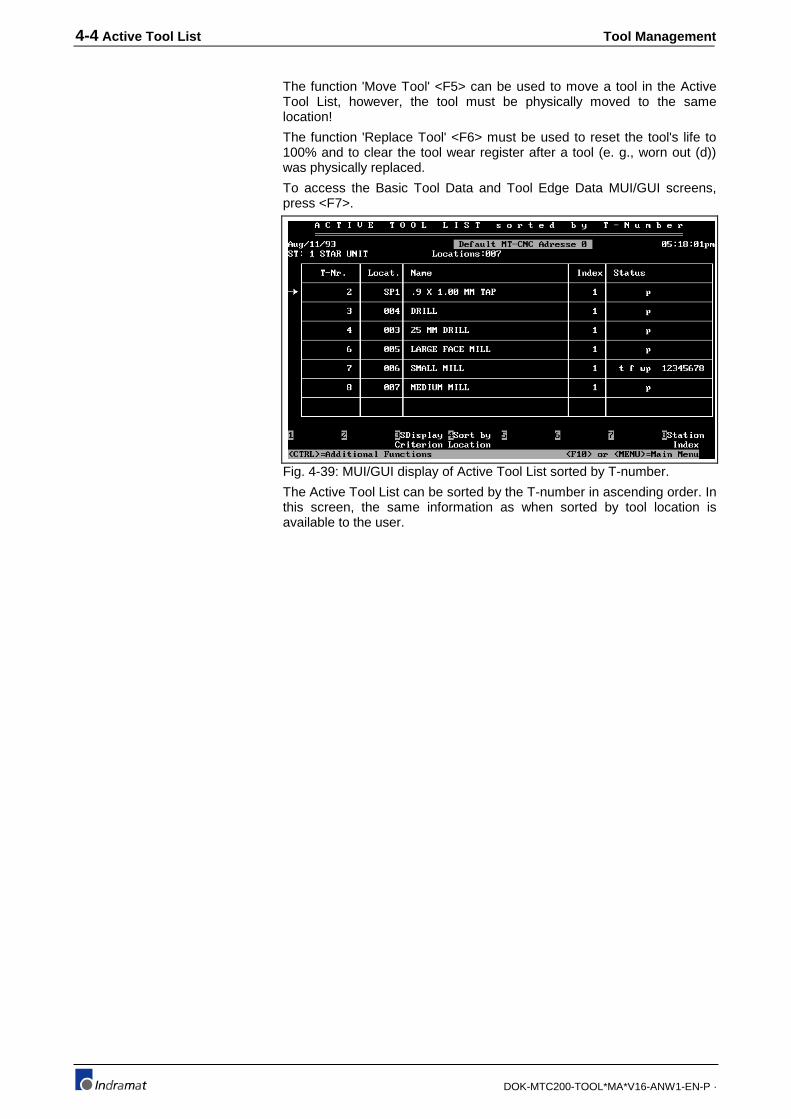
4-4 Active Tool List Tool Management
DOK-MTC200-TOOL*MA*V16-ANW1-EN-P ·
The function 'Move Tool' <F5> can be used to move a tool in the ActiveTool List, however, the tool must be physically moved to the samelocation!
The function 'Replace Tool' <F6> must be used to reset the tool's life to100% and to clear the tool wear register after a tool (e. g., worn out (d))was physically replaced.
To access the Basic Tool Data and Tool Edge Data MUI/GUI screens,press <F7>.
Fig. 4-39: MUI/GUI display of Active Tool List sorted by T-number.
The Active Tool List can be sorted by the T-number in ascending order. Inthis screen, the same information as when sorted by tool location isavailable to the user.

Tool Management Active Tool List 4-5
DOK-MTC200-TOOL*MA*V16-ANW1-EN-P ·
?tefBwpLC12345678
User tool status bit 1..8. Characters are defined by the user in the System Parameters Axx.075 .. Axx.082.
C = Tool has a fixed location (pocket/position)
L = Tool is locked (can not be used)
p = Primary tool s = Spare tool of tool family
w = Warning limit exceeded (tool life)d = Tool worn out
B = Location is blocked (cannot be used)
e = Incorrect number of tool edges
t = Incorrect correction type
? = Tool not required?
f = Incorrect tool Edge data (L1,L2,L3,R)
User tool data 1..9. Names are defined by the user in the SystemParameters Axx.061 .. Axx.069.
The following tool status bits are displayed in the 'Status' line:
Status of current tool location:P = Pocket/PositionS = Tool spindleG = Gripper
Fig. 4-40: Basic tool data in MUI/GUI display of Active Tool List
Use <Tab> to move cursor forward and <Shift>+<Tab> to move cursorbackward. Press <PgDn> to access the Tool Edge Data of the tool's Edgenumber 1.
To enter an absolute value, use the <F1> key. <F2> allows to add a valueto the existing value. <F3> allows to enter diameter values and will dividethe entry by 2 to automatically generate the radius value.
CAUTION
⇒ At all times, the data in the Active Tool List mustmatch the data of the physical tool to prevent damageto man and machine!

4-6 Active Tool List Tool Management
DOK-MTC200-TOOL*MA*V16-ANW1-EN-P ·
e123rwABCD
User tool Edge status bit 1..4. Characters are defined by the user in the System Parameters Axx.083 .. Axx.086.
w = Warning limit exceeded (tool life)d = Tool Edge worn out
3 = Invalid (min./max. exceeded) tool length L3
2 = Invalid (min./max. exceeded) tool length L2
1 = Invalid (min./max. exceeded) tool length L1
e = Invalid tool Edge orientation
r = Invalid (min./max. exceeded) tool radius R
The following tool status bits are displayed in the 'Status' line:
Status of current tool location:P = Pocket/PositionS = Tool spindleG = Gripper
Fig. 4-41: Tool Edge data in MUI/GUI display of Active Tool List
Use <Tab> to move cursor forward and <Shift>+<Tab> to move cursorbackward. Press <PgDn> to access the Tool Edge Data of the next toolEdge and <PgUp> to access the previous tool Edge or the basic tool data.
To enter an absolute value, use the <F1> key. <F2> allows to add a valueto the existing value. <F3> allows to enter diameter values and will dividethe entry by 2 to automatically generate the radius value.
CAUTION
⇒ At all times, the data in the Active Tool List mustmatch the data of the physical tool to prevent damageto man and machine!
Depending on the tool's correction type, more or less Edge data isavailable. The MUI/GUI and SOT display scrolls when selecting the fieldswith the <Tab> key.
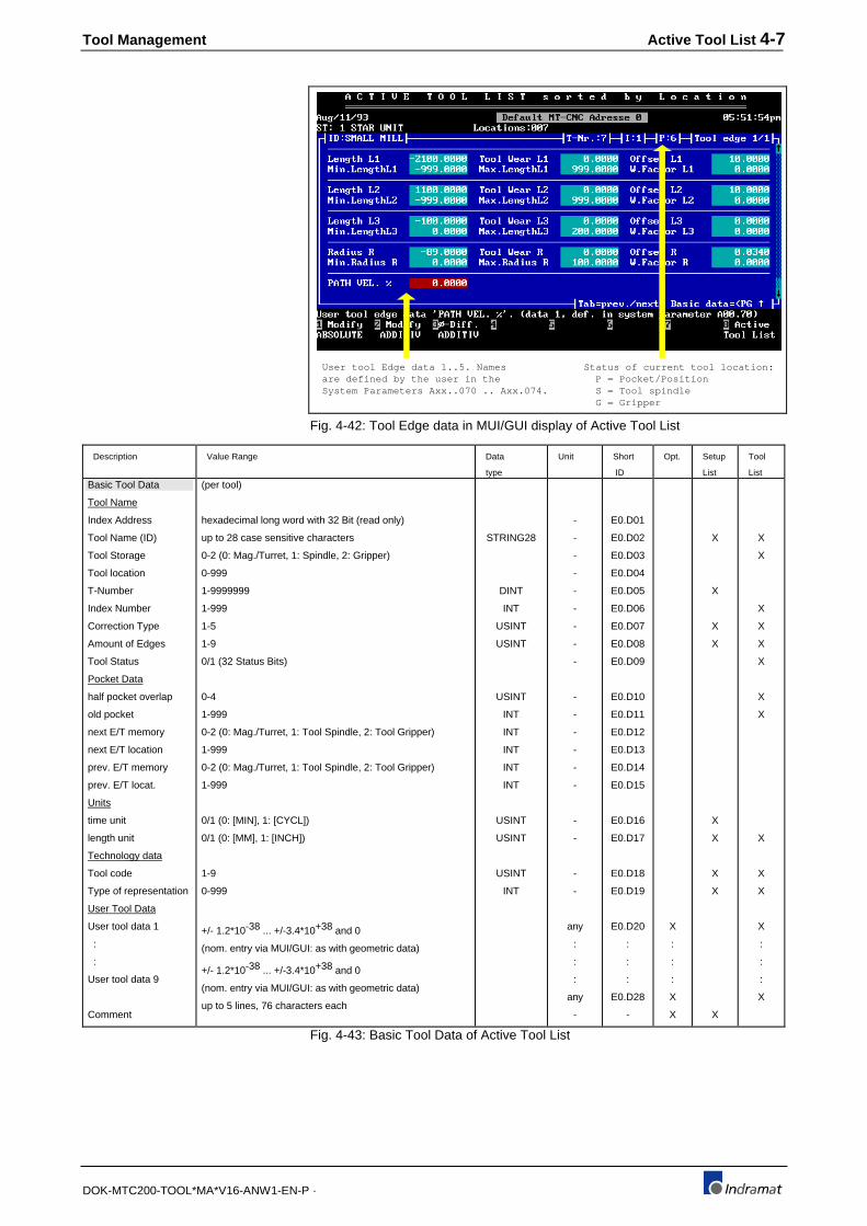
Tool Management Active Tool List 4-7
DOK-MTC200-TOOL*MA*V16-ANW1-EN-P ·
Status of current tool location:P = Pocket/PositionS = Tool spindleG = Gripper
User tool Edge data 1..5. Names are defined by the user in theSystem Parameters Axx..070 .. Axx.074.
Fig. 4-42: Tool Edge data in MUI/GUI display of Active Tool List
Description Value Range Data
type
Unit Short
ID
Opt. Setup
List
Tool
ListBasic Tool Data
Tool Name
Index Address
Tool Name (ID)
Tool Storage
Tool location
T-Number
Index Number
Correction Type
Amount of Edges
Tool Status
Pocket Data
half pocket overlap
old pocket
next E/T memory
next E/T location
prev. E/T memory
prev. E/T locat.
Units
time unit
length unit
Technology data
Tool code
Type of representation
User Tool Data
User tool data 1
:
:
User tool data 9
Comment
(per tool)
hexadecimal long word with 32 Bit (read only)
up to 28 case sensitive characters
0-2 (0: Mag./Turret, 1: Spindle, 2: Gripper)
0-999
1-9999999
1-999
1-5
1-9
0/1 (32 Status Bits)
0-4
1-999
0-2 (0: Mag./Turret, 1: Tool Spindle, 2: Tool Gripper)
1-999
0-2 (0: Mag./Turret, 1: Tool Spindle, 2: Tool Gripper)
1-999
0/1 (0: [MIN], 1: [CYCL])
0/1 (0: [MM], 1: [INCH])
1-9
0-999
+/- 1.2*10-38 ... +/-3.4*10+38 and 0
(nom. entry via MUI/GUI: as with geometric data)
+/- 1.2*10-38 ... +/-3.4*10+38 and 0
(nom. entry via MUI/GUI: as with geometric data)
up to 5 lines, 76 characters each
STRING28
DINT
INT
USINT
USINT
USINT
INT
INT
INT
INT
INT
USINT
USINT
USINT
INT
-
-
-
-
-
-
-
-
-
-
-
-
-
-
-
-
-
-
-
any
:
:
:
any
-
E0.D01
E0.D02
E0.D03
E0.D04
E0.D05
E0.D06
E0.D07
E0.D08
E0.D09
E0.D10
E0.D11
E0.D12
E0.D13
E0.D14
E0.D15
E0.D16
E0.D17
E0.D18
E0.D19
E0.D20
:
:
:
E0.D28
-
X
:
:
:
X
X
X
X
X
X
X
X
X
X
X
X
X
X
X
X
X
X
X
X
X
X
X
:
:
:
X
Fig. 4-43: Basic Tool Data of Active Tool List
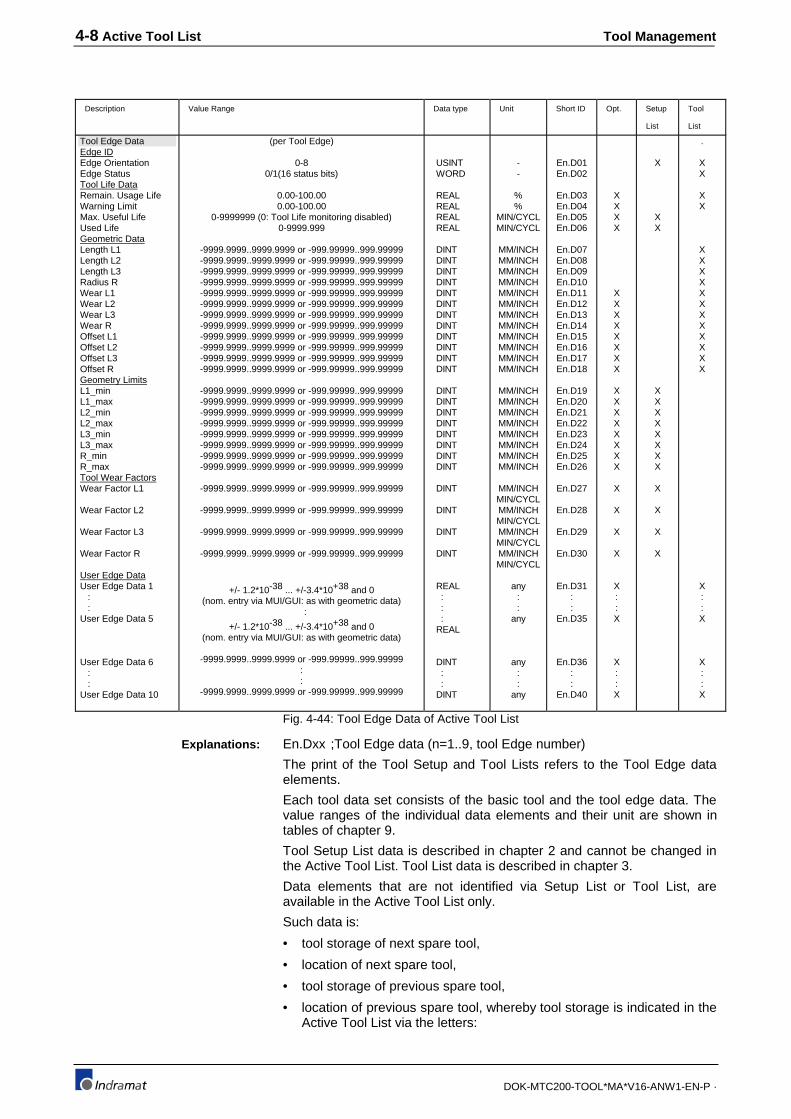
4-8 Active Tool List Tool Management
DOK-MTC200-TOOL*MA*V16-ANW1-EN-P ·
Description Value Range Data type Unit Short ID Opt. Setup
List
Tool
List
Tool Edge DataEdge IDEdge OrientationEdge StatusTool Life DataRemain. Usage LifeWarning LimitMax. Useful LifeUsed LifeGeometric DataLength L1Length L2Length L3Radius RWear L1Wear L2Wear L3Wear ROffset L1Offset L2Offset L3Offset RGeometry LimitsL1_minL1_maxL2_minL2_maxL3_minL3_maxR_minR_maxTool Wear FactorsWear Factor L1
Wear Factor L2
Wear Factor L3
Wear Factor R
User Edge DataUser Edge Data 1 : :User Edge Data 5
User Edge Data 6 : :User Edge Data 10
(per Tool Edge)
0-80/1(16 status bits)
0.00-100.000.00-100.00
0-9999999 (0: Tool Life monitoring disabled)0-9999.999
-9999.9999..9999.9999 or -999.99999..999.99999-9999.9999..9999.9999 or -999.99999..999.99999-9999.9999..9999.9999 or -999.99999..999.99999-9999.9999..9999.9999 or -999.99999..999.99999-9999.9999..9999.9999 or -999.99999..999.99999-9999.9999..9999.9999 or -999.99999..999.99999-9999.9999..9999.9999 or -999.99999..999.99999-9999.9999..9999.9999 or -999.99999..999.99999-9999.9999..9999.9999 or -999.99999..999.99999-9999.9999..9999.9999 or -999.99999..999.99999-9999.9999..9999.9999 or -999.99999..999.99999-9999.9999..9999.9999 or -999.99999..999.99999
-9999.9999..9999.9999 or -999.99999..999.99999-9999.9999..9999.9999 or -999.99999..999.99999-9999.9999..9999.9999 or -999.99999..999.99999-9999.9999..9999.9999 or -999.99999..999.99999-9999.9999..9999.9999 or -999.99999..999.99999-9999.9999..9999.9999 or -999.99999..999.99999-9999.9999..9999.9999 or -999.99999..999.99999-9999.9999..9999.9999 or -999.99999..999.99999
-9999.9999..9999.9999 or -999.99999..999.99999
-9999.9999..9999.9999 or -999.99999..999.99999
-9999.9999..9999.9999 or -999.99999..999.99999
-9999.9999..9999.9999 or -999.99999..999.99999
+/- 1.2*10-38 ... +/-3.4*10+38 and 0(nom. entry via MUI/GUI: as with geometric data)
:
+/- 1.2*10-38 ... +/-3.4*10+38 and 0(nom. entry via MUI/GUI: as with geometric data)
-9999.9999..9999.9999 or -999.99999..999.99999::
-9999.9999..9999.9999 or -999.99999..999.99999
USINT WORD
REAL REAL REAL REAL
DINT DINT DINT DINT DINT DINT DINT DINT DINT DINT DINT DINT
DINT DINT DINT DINT DINT DINT DINT DINT
DINT
DINT
DINT
DINT
REAL : : : REAL
DINT : : DINT
--
%%
MIN/CYCLMIN/CYCL
MM/INCHMM/INCHMM/INCHMM/INCHMM/INCHMM/INCHMM/INCHMM/INCHMM/INCHMM/INCHMM/INCHMM/INCH
MM/INCHMM/INCHMM/INCHMM/INCHMM/INCHMM/INCHMM/INCHMM/INCH
MM/INCHMIN/CYCLMM/INCHMIN/CYCLMM/INCHMIN/CYCLMM/INCHMIN/CYCL
any::
any
any::
any
En.D01En.D02
En.D03En.D04En.D05En.D06
En.D07En.D08En.D09En.D10En.D11En.D12En.D13En.D14En.D15En.D16En.D17En.D18
En.D19En.D20En.D21En.D22En.D23En.D24En.D25En.D26
En.D27
En.D28
En.D29
En.D30
En.D31::
En.D35
En.D36::
En.D40
XXXX
XXXXXXXX
XXXXXXXX
X
X
X
X
X::X
X::X
X
XX
XXXXXXXX
X
X
X
X
.
XX
XX
XXXXXXXXXXXX
X::X
X::X
Fig. 4-44: Tool Edge Data of Active Tool List
En.Dxx ;Tool Edge data (n=1..9, tool Edge number)
The print of the Tool Setup and Tool Lists refers to the Tool Edge dataelements.
Each tool data set consists of the basic tool and the tool edge data. Thevalue ranges of the individual data elements and their unit are shown intables of chapter 9.
Tool Setup List data is described in chapter 2 and cannot be changed inthe Active Tool List. Tool List data is described in chapter 3.
Data elements that are not identified via Setup List or Tool List, areavailable in the Active Tool List only.
Such data is:
• tool storage of next spare tool,
• location of next spare tool,
• tool storage of previous spare tool,
• location of previous spare tool, whereby tool storage is indicated in theActive Tool List via the letters:
Explanations:

Tool Management Active Tool List 4-9
DOK-MTC200-TOOL*MA*V16-ANW1-EN-P ·
• '' for magazine (pocket) and turret (position),
• 'S' for tool spindle and
• 'G' for tool gripper.
In addition, the Remaining Tool Life in [MIN] or [CYCL] is displayed in theActive Tool List.
4.3 Tool status bits
The tool status bits provide status information about the tool and toollocations (magazine pockets, turret positions).
It can be distinguished between Setup List, location and tool specificstatus bits:
• Setup List specific status bits describe the tool status in regards tothe requirements of the Setup List.
• Location specific status bits reflect the status of a location.
• Tool specific status bits reflect the tool's status.
All tool status bits that can be defined by the user are referred to as userstatus bits.
Note : - The group definitions are for display purpose only (useful reduction of data for user).- The groups are not recognized as such in the MTC.- Status bits that are identified with upper case letters can be influenced by the user.- Status bits that are identified via lower case letters can not be influenced by user
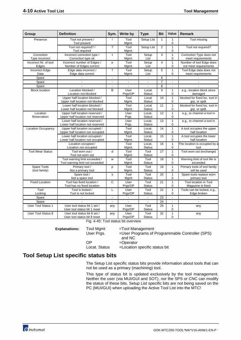
4-10 Active Tool List Tool Management
DOK-MTC200-TOOL*MA*V16-ANW1-EN-P ·
Group Definition Sym. Write by Type Bit Value Remark
Presence Tool not present /Tool present
! ToolMgmt.
Setup List 1 10
Tool missing
Tool not required? /Tool required
? ToolMgmt.
Setup List 2 10
Tool not required?
CorrectionType Incorrect
Incorrect correction type /Correction type ok
t ToolMgmt.
SetupList
3 10
Correction Type does notmeet requirements
Incorrect Nr. of toolEdges
Incorrect number of Edges /Number of Edges correct
e ToolMgmt.
SetupList
4 10
Number of tool Edge doesnot meet requirements
Incorrect EdgeData
Edge data incorrect /Edge data correct
f ToolMgmt.
SetupList
5 10
Tool Edge data does notmeet requirements
Spare - - - - 6 - -Spare - - - - 7 - -Spare - - - - 8 - -
Block location Location blocked /Location not blocked
B UserPrgs/OP
LocatStatus
9 10
e.g., location block sincedamaged
Upper half location blocked /Upper half location not blocked
ToolMgmt.
LocatStatus
10 10
blocked for fixed loc. tool ingrp. or spdl.
Lower half location blocked /Lower half location not blocked
ToolMgmt.
LocatStatus
11 10
blocked for fixed loc. tool ingrp. or spdl.
LocationReservation
Upper half location reserved /Upper half location not reserved
UserPrgs.
Locat.Status
12 10
e.g., to channel a tool in
Lower half location reserved /Lower half location not reserved
UserPrgs.
Locat.Status
13 10
e.g., to channel a tool in
Location Occupancy Upper half location occupied /Upper half location not occupied
ToolMgmt.
Locat.Status
14 10
A tool occupies the upperhalf location
Lower half location occupied /Lower half location not occupied
ToolMgmt.
Locat.Status
15 10
A tool occupies the lowerhalf location
Location occupied /Location not occupied
ToolMgmt.
Locat.Status
16 10
The location is occupied by atool
Tool Wear Status Tool worn out /Tool not worn out
d ToolMgmt.
ToolStatus
17 10
Tool worn out (exchange)
Tool warning limit exceeded /Tool warning limit not exceeded
w ToolMgmt.
ToolStatus
18 10
Warning limit of tool life isexceeded
Spare Tools(tool family)
Primary tool /Not a primary tool
p ToolMgmt.
ToolStatus
19 10
Primary tools of tool familywill be used
Spare tool /Not a spare tool
s ToolMgmt
ToolStatus
20 10
Spare tools replace wornprimary tool
Fixed Location Tool has fixed location /Tool has no fixed location
C UserPrgs/OP
ToolStatus
21 10
Tool location in ToolMagazine is fixed
ToolLocking
Tool is locked /Tool is not locked
L UserPrgs/OP
ToolStatus
22 10
Tools can be locked, e.g.,Edge broken
Spare - - - - 23 - -Spare - - - - 24 - -
User Tool Status 1 User tool status bit 1 set /User tool status bit 1 reset
any UserPrgs/OP
ToolStatus
25 10
any
User Tool Status 8 User tool status bit 8 set /User tool status bit 8 reset
any UserPrgs/OP
ToolStatus
32 10
any
Fig. 4-45: Tool status bit overview
Tool Mgmt =Tool ManagementUser Prgs. =User Programs of Programmable Controller (SPS)
and NCOP =OperatorLocat. Status =Location specific status bit
Tool Setup List specific status bitsThe Setup List specific status bits provide information about tools that cannot be used as a primary (machining) tool.
This type of status bit is updated exclusively by the tool management.Neither the user (via MUI/GUI and SOT), nor the SPS or CNC can modifythe status of these bits. Setup List specific bits are not being saved on thePC (MUI/GUI) when uploading the Active Tool List into the MTC!
Explanations:

Tool Management Active Tool List 4-11
DOK-MTC200-TOOL*MA*V16-ANW1-EN-P ·
Explanation: This identification means that there is nosuch tool in the tool storage(magazine/turret).
Symbol: ! (Request to operator)
Bit number: 1
Display (MUI/GUI/SOT): in Tool List sorted by T-number
Affiliation: Setup List specific
Access right: Tool management
Update time: during automatic tool check
Effects: Limitations to the operator:All MUI/GUI/SOT functions are allowed
Limitation for user programs (SPS/CNC):All data manipulations are allowed
Limitation for tool management:No process advance (start) or reverse
Explanation: This identification means that this type oftool is either not necessary for the currentoperation or a tool check (advance/reverse)needs to be performed. This is the case ifthe Tool List was just loaded into the MTCand '?' is displayed for all tools contained inthe then Active Tool List.
Symbol: ? (Question to operator)
Bit number: 2
Display (MUI/GUI/SOT): in Tool List
Affiliation: Setup List specific
Access right: Tool management
Update time: during automatic tool check
Effects: Limitations to the operator:All MUI/GUI/SOT functions are allowed
Limitation for user programs (SPS/CNC):All data manipulations are allowed
Limitation for tool management:None
Explanation: This identification means that the tool'scorrection type does not match the requiredone in of the Setup List.
Symbol: t (Correction type)t
Bit number: 3
Display (MUI/GUI/SOT): in Tool List
Affiliation: Setup List specific
Access right: Tool management
Update time: during automatic tool check
Effects: Limitations to the operator:All MUI/GUI/SOT functions are allowed
Limitation for user programs (SPS/CNC):All data manipulations are allowed
Limitation for tool management:No process advance (start) or reverse
Tool not present (!)
Tool not necessary (?)
Invalid correction type (t)
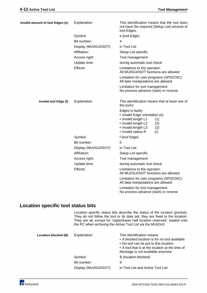
4-12 Active Tool List Tool Management
DOK-MTC200-TOOL*MA*V16-ANW1-EN-P ·
Explanation: This identification means that the tool doesnot have the required (Setup List) amount oftool Edges.
Symbol: e (tool Edge)
Bit number: 4
Display (MUI/GUI/SOT): in Tool List
Affiliation: Setup List specific
Access right: Tool management
Update time: during automatic tool check
Effects: Limitations to the operator:All MUI/GUI/SOT functions are allowed
Limitation for user programs (SPS/CNC):All data manipulations are allowed
Limitation for tool managementNo process advance (start) or reverse
Explanation: This identification means that at least one ofthe tool's
Edges is faulty:• Invalid Edge orientation (e)• Invalid length L1 (1)• Invalid length L2 (2)• Invalid length L3 (3)• Invalid radius R (r)
Symbol: f (tool Edge)
Bit number: 5
Display (MUI/GUI/SOT): in Tool List
Affiliation: Setup List specific
Access right: Tool management
Update time: during automatic tool check
Effects: Limitations to the operator:All MUI/GUI/SOT functions are allowed
Limitation for user programs (SPS/CNC):All data manipulations are allowed
Limitation for tool managementNo process advance (start) or reverse
Location specific tool status bitsLocation specific status bits describe the status of the location (pocket).They do not follow the tool or its data set, they are fixed to the location.They are all, except for 'Upper/lower half location reserved', loaded ontothe PC when archiving the Active Tool List via the MUI/GUI.
Explanation: This identification means:• A blocked location is for no tool available• No tool can be put to this location• A tool that is at the location at the time ofblockage is not available anymore
Symbol: B (location blocked)
Bit number: 9
Display (MUI/GUI/SOT): in Tool List and Active Tool List
Invalid amount of tool Edges (e)
Invalid tool Edge (f)
Location blocked (B)

Tool Management Active Tool List 4-13
DOK-MTC200-TOOL*MA*V16-ANW1-EN-P ·
Affiliation: Location List specific
Access right: User (MUI/GUI/SOT) and user programs(SPS/CNC)
Update time: at any time
General limitations: Reserved locations and half locations thatare specified for fixed location tools can notbe blocked by user or user programs.
Effects: Limitations to the operator:All MUI/GUI/SOT functions are allowed
Limitation for user programs (SPS/CNC):All data manipulations are allowed
Limitation for tool management:• All transfer request in regarding a blockedlocation are not allowed. Attempts result inan error message with stop of NC-programexecution.• A blocked location can not be moved intotool change position via NC-commandMFP, since the location is not available.• A tool that resides on a blocked locationcan not be moved into tool change positionvia NC-command MTP, since the locationand the tool are not available.• The NC-command MOP or MMP must beused to move a blocked location into toolchange position.• Besides locations (pockets) in magazinesor turrets, tool spindles and tool gripperscan be blocked also.
Explanation: This identification means:The upper/lower half location is blocked fora tool (currently in tool gripper or toolspindle) with fixed location.
Symbol: -
Bit number: 10/11
Display (MUI/GUI/SOT): in Tool List and Active Tool List
Affiliation: Location List specific
Access right: Tool management
Update time: at any time
General limitations: A blocked location cannot be blocked for atool with a fixed location.
Effects: Limitations to the operator:All MUI/GUI/SOT functions are blocked(MDI allows influencing in case ofemergency)
Limitation for user programs (SPS/CNC):All data manipulations are allowed
Limitation for tool management:• All transfer requests are allowed for sucha location.• The NC-command MOP or MFP must beused to bring the corresponding tool with afixed location to such a location.• The NC-command MMP must be used tobring a location, that is blocked for a tool
Upper/lower half locationblocked

4-14 Active Tool List Tool Management
DOK-MTC200-TOOL*MA*V16-ANW1-EN-P ·
with fixed location, into tool change position.
Explanation: This identification means:Such a location is reserved for userprograms, that import/export and resort toolstorages beside preparing tools for thecurrent operation.
Symbol: -
Bit number: 12/13
Display (MUI/GUI/SOT): in Tool List
Affiliation: Location List specific
Access right: User (MUI/GUI/SOT) and user programs(SPS/CNC)
Update time: at any time
General limitations: A blocked location or a location for a toolwith a fixed location cannot be reserved.
Effects: Limitations to the operator:All MUI/GUI/SOT functions are blocked
Limitation for user programs (SPS/CNC):All data manipulations are allowed
Limitation for tool management:• All transfer requests are allowed for sucha location.• The NC-command MFP cannot be usedto move a reserved location into toolchange position (counts as an occupiedlocation).• The NC-command MTP cannot be usedto move a location that is reserved andcontains a tool into tool change position(location, including tool are reserved).• A reserved location can be moved to thetool change position by using the NC-command MMP or MOP.
Explanation: This identification means:The location is occupied by an oversize tool.
Symbol: -
Bit number: 14/15
Display (MUI/GUI/SOT): in Tool List and Active Tool List
Affiliation: Location List specific
Access right: Tool management
Update time: • In the Active Tool List when entering andmodifying.• In the Tool List when using the MUI/GUIfunctions Insert, Erase, Modify and Move• At every tool transfer.
Effects: Limitations to the operator:All MUI/GUI/SOT functions are blocked
Limitation for user programs (SPS/CNC):All data manipulations are allowed
Limitation for tool management:A tool transfer to such a location is notallowed.
Upper/lower half locationreserved
Upper/lower half locationoccupied

Tool Management Active Tool List 4-15
DOK-MTC200-TOOL*MA*V16-ANW1-EN-P ·
Explanation: This identification means:The location is occupied by a tool.
Symbol: -
Bit number: 16
Display (MUI/GUI/SOT): Obvious via the tool entry in the Tool Listand Active Tool List.
Affiliation: Location List specific
Access right: Tool management
Update time: • In the Active Tool List when entering• In the Tool List when using the MUI/GUIfunctions Insert, Erase and Move.• At every tool transfer.
Effects: Limitations to the operator:All MUI/GUI/SOT functions are allowed
Limitation for user programs (SPS/CNC):All data manipulations are allowed
Limitation for tool managementA tool transfer to such a location is notallowed.
Tool specific tool status bitsTool specific status bits describe the tool's status in more detail. They arepart of the tool's data set and follow the tool.
They are transferred to the MUI/GUI when loading the Active Tool Listfrom the MTC to the MUI/GUI.
Up to 8 user tool status bits can be assigned to each tool via SystemParameter definition (refer to System Parameter Manual).
Explanation: This identification means:The remaining Tool Life of at least one ofthe tool's edges is zero, the tool is worn out
Symbol: d (done)
Bit number: 17
Display (MUI/GUI/SOT): In the Tool List and Active Tool List.
Affiliation: Tool specific
Access right: Tool management
Update time: The tool management updates the 'Toolworn out' bit together with the tool Edgestatus bits of available Edges. Updatesoccur:• During the automatic tool check.• When selecting a different tool edge (NC-command E)• When the tool is put back into the toolstorage (tool storage = Magazine).• When the tool is swiveled out of themachining position (tool storage = turret).• When selecting no tool via NC-commandT0 (tool storage = turret, or no tool storageavailable)
Effects: Limitations to the operator:All MUI/GUI and SOT functions are allowed
The MUI/GUI and SOT function 'Reset' canbe used to reset the tool's remaining Tool
Location occupied
Tool worn out (d)

4-16 Active Tool List Tool Management
DOK-MTC200-TOOL*MA*V16-ANW1-EN-P ·
Life to 100%. The corresponding tool in thetool storage must have been exchangedwith a new tool at the time of 'Reset'.
Limitation for user programs (SPS/CNC):All data manipulations are allowed
Limitation for tool management:The tool is not available for further usage iffurther spare tools are available in the toolfamily.The tool can be used if it is the primary tooland no further spare tools are available inthe tool family.
Note: • The tool may wear out during its usage if the machining withthe tool lasts longer than the remaining Tool Life. In such acase the machining is not stopped until the tool data isupdated.• A worn out tool can be selected via the NC-command Tduring a NC-program cycle if it is the primary tool and no sparetools are available for the tool family.
Note: • The status of the process Gateway signals PxxSMGERR andPxxSMGWRN is set to `1` in the SPS if the tool managementdetects a worn out tool with no spare tools.• The status of the process error status Gateway signalPxxSERROR is set to `1` at the end of the NC-program cycle.This prevents a restart of the process until the tool is replacedand 'Reset' or until the process error is cleared. The toolreplacement can be delayed to any extend by clearing theprocess error and starting the NC-program for another cycle.
Explanation: This identification means:• At least one Edge of the tool hasexceeded its warning limit.• Tool that have exceeded their warninglimit should be exchanged at the nextchance with worn out tools to minimizedowntime.
Symbol: w (warning limit)
Bit number: 18
Display (MUI/GUI/SOT): In the Tool List and Active Tool List.
Affiliation: Tool specific
Access right: Tool management
Update time: The tool management updates the 'Toolwarning limit exceeded' bit together with thetool Edge status bits of available Edges.Updates occur:• During the automatic tool check.• When selecting a different tool edge (NC-command E).• When the tool is put back into the toolstorage (tool storage = Magazine).• When the tool is swiveled out of themachining position (tool storage = turret).• When selecting no tool via NC-command
Tool warning limit exceeded (w)

Tool Management Active Tool List 4-17
DOK-MTC200-TOOL*MA*V16-ANW1-EN-P ·
T0 (tool storage = turret, or no tool storageavailable).
Effects: Limitations to the operator:• All MUI/GUI and SOT functions areallowed
The MUI/GUI and SOT function 'Reset' canbe used to reset the tool's remaining ToolLife to 100%. The corresponding tool in thetool storage must have been exchangedwith a new tool at the time of 'Reset'.
Limitation for user programs (SPS/CNC):All data manipulations are allowed
Limitation for tool management:A tool with exceeded warning limit remainsprimary tool until it is 'Locked' or worn out.
Note: The status of the process Gateways status signalPxxSMGWRN is set to `1` if the primary tool exceeded itswarning limit and if no spare tool is available.
Explanation: This identification means:• This tool of the tool family will be used thenext time when the T-number of the toolfamily is executed in the NC-program.• The correction and tool life data of this arebeing used once it is in the tool spindle.
Symbol: p (primary)
Bit number: 19
Display (MUI/GUI/SOT): In the Tool List and Active Tool List.
Affiliation: Tool specific
Access right: Tool management
Update time: The tool management updates the 'Primarytool' bit:• During the automatic tool check.• When the tool is put back into the toolstorage (tool storage = Magazine).• When the tool is swiveled out of themachining position (tool storage = turret).• When selecting no tool via NC-commandT0 (tool storage = turret, or no tool storageavailable).
Effects: Limitations to the operator:All MUI/GUI and SOT functions are allowed
Limitation for user programs (SPS/CNC):All data manipulations are allowed
Limitation for tool management:The primary tool is always used with theNC-command MTP.
Explanation: This identification means:• This tool of the tool family is a spare tool,which means it fulfills the Setup Listrequirements, is not worn out and not theprimary tool.• The sequence of using spare tools is
Primary tool (p)
Spare tool (s)

4-18 Active Tool List Tool Management
DOK-MTC200-TOOL*MA*V16-ANW1-EN-P ·
defined by their Index number. Tools withlower index numbers are used first.
Symbol: s (spare)
Bit number: 20
Display (MUI/GUI/SOT): In the Tool List and Active Tool List.
Affiliation: Tool specific
Access right: Tool management
Update time: The tool management updates the 'Sparetool' bit:• During the automatic tool check.• When the tool is put back into the toolstorage (tool storage = Magazine).• When the tool is swiveled out of themachining position (tool storage = turret).• When selecting no tool via NC-commandT0 (tool storage = turret, or no tool storageavailable).
Effects: Limitations to the operator:All MUI/GUI and SOT functions are allowed
Limitation for user programs (SPS/CNC):All data manipulations are allowed
Limitation for tool management:The primary tool is used first if the NC-command MTP is programmed
Explanation: This identification means:• The tool management puts this tool afterits usage always back into the samelocation, from where it was taken (e.g.,magazine pocket).
Symbol: C (fixed location)
Bit number: 21
Display (MUI/GUI/SOT): In the Tool List and Active Tool List.
Affiliation: Tool specific
Access right: User via SPS and NC-program
Update time: At any time with the following limitations:• A tool must reside in the location to markit as 'fixed location tool'. It is then assignedto that location• The fixed location bit can be removed ifthe tool is in the tool storage location, a toolgripper or a tool spindle. The tool storagelocation (e.g., magazine pocket) is freelyavailable to the tool management thereafter.
Effects: Limitations to the operator:All MUI/GUI and SOT functions are allowed
Limitation for user programs (SPS/CNC):All data manipulations are allowed
Limitation for tool management:• The primary tool is used first if the NC-command MTP is programmed.• When transferring the tool from the toolstorage location into the tool spindle/gripper,
Fixed location tool (C)

Tool Management Active Tool List 4-19
DOK-MTC200-TOOL*MA*V16-ANW1-EN-P ·
the upper and lower half location of thefixed location tool are being blocked.Additional half locations will be blocked asspecified if the fixed location tool's width isgreater.
Explanation: This identification means:The locked tool is not available to themanagement for further usage.
Symbol: L (locked tool)
Bit number: 22
Display (MUI/GUI/SOT): In the Tool List and Active Tool List.
Affiliation: Tool specific
Access right: User via SPS and NC-program
Update time: At any time.
Effects: Limitations to the operator:All MUI/GUI and SOT functions are allowed
Limitation for user programs (SPS/CNC):All data manipulations are allowed
Limitation for tool management:• A locked tool is not being considered bythe NC-command MTP.• It cannot be used even if there are nofurther spare tools available.
Locked tool (L)

4-20 Active Tool List Tool Management
DOK-MTC200-TOOL*MA*V16-ANW1-EN-P ·
4.4 Tool Edge status bits
The tool Edge status bits provide a more detailed information about theEdge's status. Tool Edge status bits can be divided into:
• Setup List specific Edge status bits describe the Edge statusregarding the requirements of the Setup List.
• Tool specific Edge status bits describe the status of thecorresponding Edge.
Group Definition Sym. Writeby
Type Bit Value Remark
Invalid EdgeOrientation
Edge orientation invalid /Edge orientation valid
e ToolMgmt.
SetupList
1 10
-
Invalid ToolLength L1
Tool length L1 invalid /Tool length L1 valid
1 ToolMgmt.
SetupList
2 10
-
Invalid ToolLength L2
Tool length L2 invalid /Tool length L2 valid
2 ToolMgmt.
SetupList
3 10
-
Invalid ToolLength L3
Tool length L3 invalid /Tool length L3 valid
3 ToolMgmt.
SetupList
4 10
-
Invalid ToolRadius R
Tool radius R invalid /Tool radius R valid
r ToolMgmt.
SetupList
5 10
-
Spare - - - - 6 - -Spare - - - - 7 - -Spare - - - - 8 - -
Edge WearStatus
Edge worn out /Edge not worn out
d ToolMgmt.
SetupList
9 10
-
Edge warning limit exceeded /Edge warning limit not exceeded
w ToolMgmt.
SetupList
10 10
-
Spare - - - - 11 - -Spare - - - - 12 - -
User Edge Status1
User edge status bit 1 set /User edge status bit 1 reset
any UserPrgs/OP
ToolStatus
13 10
-
: : : : : : : :User Edge Status
4User edge status bit 4 set /User edge status bit 4 reset
any UserPrgs/OP
ToolStatus
16 10
-
Fig. 4-46: Tool Edge status bit overview
Tool Mgmt =Tool ManagementUser Prgs. =User Programs of Programmable Controller (SPS)
and NCOP =OperatorLocat. Status =Location specific status bit
Setup List specific Edge status bitsTool Edge status bits provide detailed information about the Edge's statusif the Edge cannot be used for further machining.
Setup List specific Edge status bits are updated by the toolmanagement only. The user cannot influence these bits via MUI/GUI,SOT, CNC or SPS.
Tool specific status bits are not being archived on the PC (MUI/GUI) whenloading and storing the Active Tool List to the PC (MUI/GUI).
Explanation: This identification means:
• The tool's tool Edge orientation differsfrom the one specified for the tool in theSetup List.
Symbol: e (edge orientation)
Bit number: 1
Display (MUI/GUI/SOT): In the Tool List and Active Tool List.
Affiliation: Setup List specific
Access right: Tool management
Update time: During the automatic tool check.
Explanations:
Invalid tool Edge orientation (e)

Tool Management Active Tool List 4-21
DOK-MTC200-TOOL*MA*V16-ANW1-EN-P ·
Effects: Limitations to the operator:All MUI/GUI and SOT functions are allowed
Limitation for user programs (SPS/CNC):All data manipulations are allowed
Limitation for tool management:Process (NC-program) start not possible
Explanation: This identification means:
• The tool's geometry L1/L2/L3/R differ fromthe necessary dimensions (calculationbased geometry, wear and offset values).
Symbol: 1 (length 1 invalid)
2 (length 2 invalid)
3 (length 3 invalid)
r (radius R invalid)
Bit number: 2/3/4/5
Display (MUI/GUI/SOT): In the Tool List and Active Tool List.
Affiliation: Setup List specific
Access right: Tool management
Update time: During the automatic tool check.
Effects: Limitations to the operator:All MUI/GUI and SOT functions are allowed
Limitation for user programs (SPS/CNC):All data manipulations are allowed
Limitation for tool management:Process (NC-program) start not possible
Tool specific Edge status bitsTool specific status bits describe the status of a tool in more detail. Theyare part of the tool's data set and move with the tool.
They are being archived on the PC (MUI/GUI) when loading and storingthe Active Tool List to the PC (MUI/GUI).
In addition, up to 4 user tool Edge status bits can be defined via theSystem Parameters Axx.083 .. Axx.086. Each of the user tool Edge statusbits is then available at each tool of each process.
Explanation: This identification means:
• The remaining Tool Life of the tool Edge iszero (%).
Symbol: d (edge done)
Bit number: 9
Display (MUI/GUI/SOT): In the Tool List and Active Tool List.
Affiliation: Tool specific
Access right: Tool management
Update time: • During the automatic tool check.
• When selecting another tool edge via NC-command E.
• When selecting the same tool edge viaNC-command E.
• When the tool is put back into the toolstorage (tool storage = Magazine).
• When the tool is swiveled out of the
Invalid geometry L1/L2/L3/R(1/2/3/r)
Edge worn out (d)
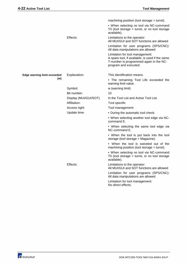
4-22 Active Tool List Tool Management
DOK-MTC200-TOOL*MA*V16-ANW1-EN-P ·
machining position (tool storage = turret).
• When selecting no tool via NC-commandT0 (tool storage = turret, or no tool storageavailable).
Effects: Limitations to the operator:All MUI/GUI and SOT functions are allowed
Limitation for user programs (SPS/CNC):All data manipulations are allowed
Limitation for tool management:A spare tool, if available, is used if the sameT-number is programmed again in the NC-program and executed.
Explanation: This identification means:
• The remaining Tool Life exceeded thewarning limit value.
Symbol: w (warning limit)
Bit number: 10
Display (MUI/GUI/SOT): In the Tool List and Active Tool List.
Affiliation: Tool specific
Access right: Tool management
Update time: • During the automatic tool check.
• When selecting another tool edge via NC-command E.
• When selecting the same tool edge viaNC-command E.
• When the tool is put back into the toolstorage (tool storage = Magazine).
• When the tool is swiveled out of themachining position (tool storage = turret).
• When selecting no tool via NC-commandT0 (tool storage = turret, or no tool storageavailable).
Effects: Limitations to the operator:All MUI/GUI and SOT functions are allowed
Limitation for user programs (SPS/CNC):All data manipulations are allowed
Limitation for tool management:No direct effects.
Edge warning limit exceeded(w)
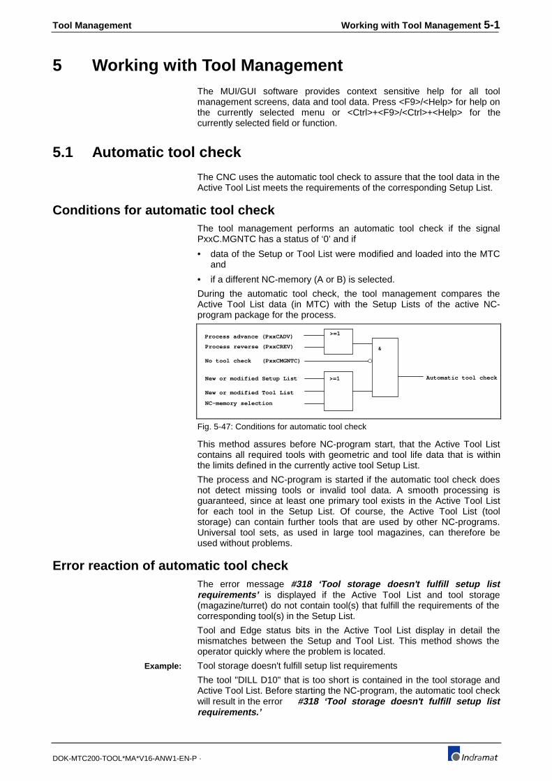
Tool Management Working with Tool Management 5-1
DOK-MTC200-TOOL*MA*V16-ANW1-EN-P ·
5 Working with Tool ManagementThe MUI/GUI software provides context sensitive help for all toolmanagement screens, data and tool data. Press <F9>/<Help> for help onthe currently selected menu or <Ctrl>+<F9>/<Ctrl>+<Help> for thecurrently selected field or function.
5.1 Automatic tool check
The CNC uses the automatic tool check to assure that the tool data in theActive Tool List meets the requirements of the corresponding Setup List.
Conditions for automatic tool checkThe tool management performs an automatic tool check if the signalPxxC.MGNTC has a status of ‘0’ and if
• data of the Setup or Tool List were modified and loaded into the MTCand
• if a different NC-memory (A or B) is selected.
During the automatic tool check, the tool management compares theActive Tool List data (in MTC) with the Setup Lists of the active NC-program package for the process.
Process advance (PxxCADV)
Process reverse (PxxCREV)
New or modified Setup List
New or modified Tool List
NC-memory selection
>=1
>=1
&
Automatic tool check
No tool check (PxxCMGNTC)
Fig. 5-47: Conditions for automatic tool check
This method assures before NC-program start, that the Active Tool Listcontains all required tools with geometric and tool life data that is withinthe limits defined in the currently active tool Setup List.
The process and NC-program is started if the automatic tool check doesnot detect missing tools or invalid tool data. A smooth processing isguaranteed, since at least one primary tool exists in the Active Tool Listfor each tool in the Setup List. Of course, the Active Tool List (toolstorage) can contain further tools that are used by other NC-programs.Universal tool sets, as used in large tool magazines, can therefore beused without problems.
Error reaction of automatic tool checkThe error message #318 ‘Tool storage doesn't fulfill setup listrequirements’ is displayed if the Active Tool List and tool storage(magazine/turret) do not contain tool(s) that fulfill the requirements of thecorresponding tool(s) in the Setup List.
Tool and Edge status bits in the Active Tool List display in detail themismatches between the Setup and Tool List. This method shows theoperator quickly where the problem is located.
Tool storage doesn't fulfill setup list requirements
The tool "DILL D10" that is too short is contained in the tool storage andActive Tool List. Before starting the NC-program, the automatic tool checkwill result in the error #318 ‘Tool storage doesn't fulfill setup listrequirements.’
Example:

5-2 Working with Tool Management Tool Management
DOK-MTC200-TOOL*MA*V16-ANW1-EN-P ·
Station 1 AUTOMATIC
T O O L S
Ps-P1--T-Nr.---Name--------------------
:119 1 DRILL D10
_:_____________I:0002__f____P__________
3:120 1234567 DRILL D8
: I:0002 p
:121 9 TAP M6
_:_____________I:0002_______p__________
1:122 78 TAP M5
_:_____________I:0001_______p__________
2:123 79 TAP M10
_:_____________I:0002_______p__________
:124 80 DRILL D15
_:_____________I:0001_______p__________
INS DEL RESET MOVE DATA EXIT
Fig. 5-48: Active Tool List on SOT
The Edge status bit 'Invalid tool Edge' (f) is set for the tool with the name'DRILL D10'. The next menu level (DATA) displays the tool data whichalso contains the Edge information. The Edge status bit (3) for 'Length L3'is displayed and indicates that the length L3 is invalid.
Station 1 AUTOMATIC
-----------T O O L D A T A------------
ID: DRILL D10
P: 119 T.: 25 D: 1
-------------Edge 1 of 1---------------
Edge status 3
Time Rem.Usage time 98.00 [ % ]
Warning limit 5.00 [ % ]
Rem.Usage time 1235 [CYCL]
Max. usage time 1260 [CYCL]
GEO Geometry 70.0000 [ mm ]
Next spare tool -
Previous spare tool -
Selection: Edge PgUp Data PgUp PgDn
EDIT EXIT
Fig. 5-49: Tool and Edge data on SOT
The length L3 can be edited if it was entered incorrectly. However, thetool and its data (specially length L3 and an the Remain. Tool Life) mustbe replaced with the correct one in all other cases.
Refer to Chapter 4 for MUI/GUI Tool Management screen samples thatare provided for working with the Active Tool List that contains the data ofthe tools in the tool storage.
Checks performed during the tool checkEach tool that is entered into the Setup List initiates the followingsequence during the automatic tool check:
• The tool management searches the Tool List for tools with the sametool name (ID).

Tool Management Working with Tool Management 5-3
DOK-MTC200-TOOL*MA*V16-ANW1-EN-P ·
• The Setup List data is assigned to all found tools. Previously assignedSetup List data is being overwritten.
• The tool status bit 'Tool not present' (!) is being set for all the tools thatcannot be found in the Tool List.
• The tool status bit 'Tool not necessary' (?) is being set for all the toolsthat are available in the Tool List but are not entered into andrequested by the Setup List.
• The basic tool data and tool Edge data is being checked afterassigning the Setup List specific data.
• The tool Edge status bits are used to indicated the examination resultsof Edge data, such as orientation, geometry and wear.
The tool status bit 'Invalid tool Edge' (f) is set if on of the tool's Edgesdoes not fulfill the orientation or geometry requirements.
Tool wear status is indicated via the tool status bits 'Tool worn out' (d) and'Tool warning limit exceeded' (w) if one of the tool's Edges is worn out orhas its warning limit exceeded.
Based on the basic tool data of the Setup List, the tool managementchecks the correction type and amount of tool Edges. The result isindicated via the tool status bit 'Invalid correction type' (t) and 'Invalidnumber of Edges' (e).
Depending on the tool, status bits for blocking a location, reserving alocation and occupying a location are being set or reset accordingly.
Tools with the same name are being identified and marked as 'Primarytool' (p) and 'Spare tool' (s).
5.2 Production
Before and during productionNC-programs that are required for production can be programmed via theMTC User Interface (MUI/GUI) in 'Off-line' (e.., work preparation) or in'ONLINE' mode at the machine.
The corresponding Setup Lists must be generated during NC-programgeneration.
Tools, required for the production, must be provided according to theirspecification in the Setup Lists. It is recommended to enter the tool dataon another PC (MUI/GUI) into Tool Lists (that reflect the tool storage(magazine/turret) configuration), so that the machine operation is notdisturbed. The Tool Lists can then be generated while the tools are beingselected, assembled and adjusted according to the Setup Lists.
Spare tools (of tool family) should be used to prevent downtime if the toollife is very short.
In the case of a new part, tools must be used according to the Tool Listand the corresponding Tool List must be loaded into the MTC.

5-4 Working with Tool Management Tool Management
DOK-MTC200-TOOL*MA*V16-ANW1-EN-P ·
CAUTION
• At all times, the tool storage (magazine/turret) mustcontain tools whose data matches with the data of theActive Tool List in the MTC. Locations that are specifiedas empty are not allowed to contain a tool.
• The operator must check this especially beforestarting a new part and after tool modifications.
The operator can contribute to a smooth production also duringmachining. The current status of all tools can be observed to perform thenecessary tasks on time to minimize downtime due to worn out tools.
Wo r k P r e p a r a t i o n
M U I ( P C )
M U I ( P C )
T o o l s h o p
T o o l w a r e h o u s e
T o o l
M a g a z i n e /
M U I ( P C ) M T - C N C
T u r r e t
T o o l
M a g a z i n e /
T u r r e t
T o o l
M a g a z i n e /
T u r r e t
T o o l
M a g a z i n e /
T u r r e t
T o o l
M a g a z i n e /
T u r r e t
T o o l
M a g a z i n e /
T u r r e t
T o o l
M a g a z i n e /
M U I ( P C ) M T - C N C
T u r r e t
T o o l
M a g a z i n e /
T u r r e t
T o o l
M a g a z i n e /
T u r r e t
T o o l
M a g a z i n e /
M U I ( P C ) M T - C N C
T u r r e t
T o o l
M a g a z i n e /
T u r r e t
T o o l
M a g a z i n e /
T u r r e t
T o o l
M a g a z i n e /
T u r r e t
T o o l
M a g a z i n e /
T u r r e t
. .
. . . . ..
T o o l s
T o o l L i s t s
N C - p r o g r a m s w i t h S e t u p L i s t s
M a c h i n i n g c e n t e r 3
M a c h i n i n g c e n t e r 2
M a c h i n i n g c e n t e r 1
P r o d u c t i o n
.
. . . .
..
..
.
.
.
.
Fig. 5-50: MTC Tool Management in production environment
Tool storage (magazine/turret) modificationsAny modification made to the tool storage configuration and its tools mustbe made in the Active Tool List (in MTC) accordingly. Morecomprehensive modifications to a tool storage (magazine/ turret) can beperformed in the MTC via a new Tool List, just as when creating a totallynew configuration.
First, all actual tool data should be loaded in form of a Tool List into theMUI (PC) or generated in the MUI. The tool data can then be modifiedduring the physical modification by using the functions to INSERT,REMOVE, MOVE, MODIFY and RESET tools.
The modified and matching Tool List must be loaded into the MTC afterthe physical changes have been made.
CAUTION
Grippers do not count to the tool storage(magazine/turret) and are not part of the Tool List!
They are not allowed to contain any tools beforechanging the tool storage configuration (new Tool List) toprevent tool collision, damage to man and machine!
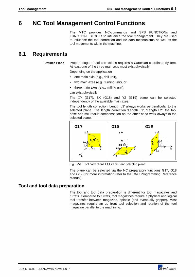
Tool Management NC Tool Management Control Functions 6-1
DOK-MTC200-TOOL*MA*V16-ANW1-EN-P ·
6 NC Tool Management Control FunctionsThe MTC provides NC-commands and SPS FUNCTIONs andFUNCTION_ BLOCKs to influence the tool management. They are usedto influence the tool correction and life data mechanisms as well as thetool movements within the machine.
6.1 Requirements
Proper usage of tool corrections requires a Cartesian coordinate system.At least one of the three main axis must exist physically.
Depending on the application
• one main axis (e.g., drill unit),
• two main axes (e.g., turning unit), or
• three main axes (e.g., milling unit),
can exist physically.
The XY (G17), ZX (G18) and YZ (G19) plane can be selectedindependently of the available main axes.
The tool length correction 'Length L3' always works perpendicular to theselected plane. The length correction 'Length L1', 'Length L2', the toolnose and mill radius compensation on the other hand work always in theselected plane.
G17 G18 G19Y
Z
X
R
L1
L2
L3 L3
Y
Z
XRL1
L2L3
Y
X
RL1
L2
L3
Fig. 6-51: Tool corrections L1,L2,L3,R and selected plane
The plane can be selected via the NC preparatory functions G17, G18and G19 (for more information refer to the CNC Programming ReferenceManual).
Tool and tool data preparation.The tool and tool data preparation is different for tool magazines andturrets. Compared to turrets, tool magazines require a physical and logicaltool transfer between magazine, spindle (and eventually gripper). Mostmagazines require an up front tool selection and rotation of the toolmagazine parallel to the machining.
Defined Plane

6-2 NC Tool Management Control Functions Tool Management
DOK-MTC200-TOOL*MA*V16-ANW1-EN-P ·
U s e r l e v e l
N C -
T x x x x x x x M T P
o r
T x x x M M P
T M S
o r
T C H
T o o l
T o o l
P r e p a r a t i o n
L o g i c
P o c k e t
T o o l
T o o l D a t a
P r e p a r a t i o n
L o g i c
T o o l - >
T o o l
T o o l < - >
T o o l
T o o l
D a t a
D a t a o fa c t i v a t e d
t o o l
T o o l M a n a g e m e n t
L o g i c t o m o v e
p o c k e t i n t o
t o o l c h a n g e
T o o l
T r a n s f e r
L o g i cA c k n l g .
C h a n g eT o o l
A c t u a l
C o m m a n d e d
p o s i t i o n
S P S p r o g r a m
M T - C N C f i r m w a r e F i r m w a r e( N C c o n t r o l l e d m a g a z i n e a x i s )
O E M( S P S c o n t r o l l e d m a g a z i n e d r i v e )
o r
( N C c t r l . m a g . a x i s )
S P S p r o g r a m
( S P S c t r l . m a g . d r i v e )
N u m b e r
N u m b e r
T r a n s f e r
S p i n d l e
T r a n s f e r
S p i n d l e
p r o g r a m s
P o s i t i o n
P o s i t i o n
C o m m a n d
S p i n d l e
G r i p p e r
T o o lT r a n s f e r
H a r d w a r e
S e l e c t e d
T o o l
M a g a z i n e m o v e m e n t
M a g a z i n e
M a n a g e m e n t
Fig. 6-52: Tool and tool data preparation for tool magazine
Differentiation must be made between the selected and the active tool inthe spindle in the case of tool magazines.
A tool that is selected via the NC-program will be moved into tool changeposition. Tool data is not considered up to the point of tool transfer whichis also initiated by NC-program. The tool management provides thecorresponding tool data for production upon the tool transfer command.The selected tool becomes then the active tool and 'Edge 1' becomes bydefault the active tool Edge.
The correction and life data of the active Edge are used during machiningfor length correction and tool nose and mill radius compensation.

Tool Management NC Tool Management Control Functions 6-3
DOK-MTC200-TOOL*MA*V16-ANW1-EN-P ·
U s e r l e v e l
N C -
T x x x x x x x M T P
o r
T x x x M M P
M a n a g e m e n t
T o o l D a t a
P r e p a r a t i o n
L o g i c
T o o l
P o s i t i o n
T o o l
D a t a
D a t a o fa c t i v a t e d
t o o l
L o g i c t o m o v e
t o o l i n t o
ma c h i n i n g
S P S p r o g r a m
M T - C N C f i r m w a r e F i r m w a r e( N C c o n t r o l l e d t u r r e ta x i s )
O E M( S P S c o n t r o l l e d t u r r e td i )
o r
N u m b e r
p r o g r a m s
H a r d w a r e
N u m b e r P o s i t i o nC o m m a n d e d
P o s i t i o n
A c t u a l
p o s i t i o n T u r r e t
T u r r e t
M o v e m e n t
A c t i v e t o o l
T o o l s p i n d l e
T o o l
Fig. 6-53: Tool and tool data preparation for tool turret.
The tool is brought into machining position and becomes the active toolwhen calling the tool in the NC-program. The tool managementsimultaneously provides the corresponding tool data for the machiningthat follows. 'Edge 1' becomes the default active Edge.
The correction and life data of the active Edge are used during machiningfor length correction and tool nose and mill radius compensation.
T<constant> ;constant=0..9999999, except 0..999 withMMP
T<mathematical expression>
The T-word is used to select the next tool or tool location (pocket ofmagazine, position of turret). The NC-command SPT must be used toselect the desired tool spindle if more than one tool spindle is operated bythe process.
The letter 'T', followed by a integer number defines the tool's number(0..9999999) or location (pocket/position)(0..999). The tool or locationnumber can also be the result (automatically integer format) of amathematical expression in the NC-program.
The data of the selected tool becomes active during the next tool changeif the tool storage is a tool magazine. The T-word and tool magazinemovement can be programmed up front without influencing the toolcorrections.
The positioning of the tool storage (turret/magazine) and the tool transferitself are initiated via special NC-commands.
The tool corrections are deactivated after programming 'T0' (no tool) andperforming the tool transfer. The T-word contains '0' after MTC power onwhich means 'T0' is selected.
Each tool used in the NC-program must be defined in the tool Setup Listfor the process or NC-program. A process error occurs (No acceptabletool found) if the tool is not defined but programmed. The tool number isassigned to the corresponding tool in the Active Tool List at NC-programstart.
Tool selection (T)
Syntax:

6-4 NC Tool Management Control Functions Tool Management
DOK-MTC200-TOOL*MA*V16-ANW1-EN-P ·
A selected tool number (T) stays active until a different tool number isprogrammed. This allows to call tools in the NC-program and use toolchange subroutines.
The tool management of each process can monitor the tool wear and life.Tool families can be defined to automatically use a replacement tool if theactive tool is worn out.
The T-word function depends on the type of tool storage device:
• Tool storage is of the type tool magazine:Used in conjunction with a NC-command MTP and MMP, the T-wordresults in the positioning of the selected tool in the defined tool changeposition. Corresponding tool data is provided with the next tool changeNC-command TSM, TMS and TCH.An empty magazine pocket is moved into tool change position if 'T0' isprogrammed and the NC-command MTP is executed. The tool data ofthe currently active tool becomes inactive after executing the next toolchange NC-command.
• Tool storage is of the type tool turret:The corresponding tool is moved into machining position if a T-word isprogrammed and the NC-command MTP and MMP is executed. Thetool's data becomes active at the same time .The NC-command MTP and 'T0' deactivate the tool data of the toolthat is currently in machining position. No turret movement occurs.
• Tool storage is of the type tool spindle only:The T-word and NC-command E activate the data of the tool thatresides in the selected tool spindle if no tool magazine or turret existsand the tool management is active. 'T0' can be used to deactivate thetool's data. No other tool change NC-commands are required.
E<constant> ;constant=1..9, (def. in sys.param.Axx.054)
The NC-command E selects the defined tool Edge of the currently activetool if a tool magazine or turret exists. It automatically activates the data ofthe tool in the currently selected tool spindle if only a tool spindle exists.
The letter E is followed by a single digit number that can range from 1..9and represents the Edge number. The maximum number of tool Edgescan be globally specified for the MTC via system parameter Axx.054.
The Edge activation internally provides the corresponding Edge correctionand life data that is used by the tool management while the Edge isactive.
The tool Edge number 1 is selected and its data is provided
• at each tool transfer into the spindle (magazine),
• when rotating the tool into machining position (turret), and
• if the T-word is used to activate the tool in the selected tool spindle ifno tool magazine or turret exists.
The Edge number 1 default simplifies the use of most tools, since no toolEdge must be selected via the NC-program.
The life and wear data of the active tool is updated whenever there is aNC-command E executed in the NC-program. This allows to monitor toollife and wear data during long machining cycles with the same tool.
A tool change is always initiated via a NC-command.
Tool change sequences often require axis movements and the use ofother NC-commands, such as preparatory functions (G-codes). Theyshould therefore be contained in a NC-subroutine or NC-cycle. This
Tool Edge selection (E)
Syntax:
Tool change

Tool Management NC Tool Management Control Functions 6-5
DOK-MTC200-TOOL*MA*V16-ANW1-EN-P ·
reduces the programming of the tool change in the NC-program to the T-number and branch to the tool change NC-subroutine.
Call of tool change subroutine in NC-program.:
T17 BSR .TOOLCH ;Tool change
G54 ;Activate workpiece zero point
G0 X450 Z20 ;Rapid approach
G1 X585.5 F750 ;Machining
:
SPT
SPT<constant> constant ∈ {1,2,3,4} ;tool spindle
The NC-command SPT must be used to select the tool spindle for thenext tool selection (programmed T-word) if more than one spindle isoperated in the process.
Tool spindle '1' is automatically selected as default at the start of eachNC-program, after MTC power on, 'Control Reset' and execution of theNC-command BST and RET.
Tool spindles are independent of main spindle axes that are controlled bythe process via CNC and SPS. Main spindle axes with the designation‘S’/‘S1’, ‘S2’ or S3 are not automatically associated with the tool spindle 1,2, 3, or 4.
The association between physical tool spindles (main spindle axes) andlogical tool spindles depends on the NC-program. For example, if M103for spindle ‘S1’ is used to cut a part and the NC-command SPT3 wasexecuted, the tool management will use the data of the tool in the logicaltool spindle number 3 for correction during the cut. Of course, the data ofthe tool in the tool spindle must match the data of the physical tool drivenvia main spindle ‘S1’.
This fact allows to freely associate any logical tool spindle to any physicalspindle, independent whether a servo spindle drive, three phase motor orno spindle motor at all (e.g. laser cutting, etc.) is used.
The NC-command selects the active tool spindle if the process operatesmore than one spindle as a tool spindle. E. g., if the parameter Bxx.018contains the value 2, two tool spindles are available in the process andthe NC-command SPT1 and SPT2 must be used to select them. If thenumber of spindles with tool is 3 or 4, SPT3 and SPT4 can be used toselect them.
Simultaneously with the tool spindle selection, the tool life and correctiondata for the tool's Edge number 1 are provided to the tool management.
The NC-command SPT de-couples the activation of a tool from the tooltransfer. This allows to transfer tools during machining from non-activetool spindles to the tool storage (magazine/turret), without automaticallybecoming the active tool.
Upon a NC-command SPT, the tool's life and wear data in the currentlyselected tool spindle is being updated before switching to the tool in thenewly selected tool spindle.
The NC-command SPT must NOT be programmed in the NC-program ifthe process operates only tool spindle 1.
The life of the active tool that resides in the active tool spindle ismonitored during all movements except movements with the preparatoryfunction G0 and is therefore independent of the main spindle selection orrotation!
Example:
Spindle selection for Toolmanagement (SPT)
Syntax:
Selection of a new tool:
Monitoring tool life:
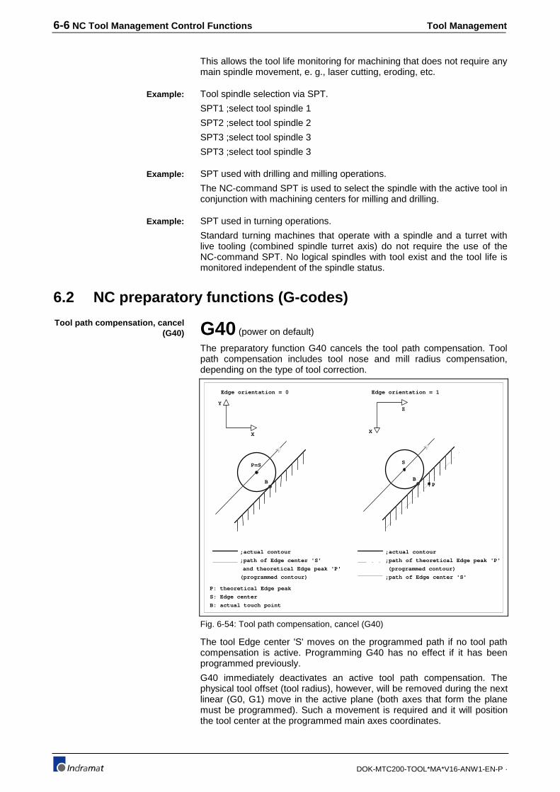
6-6 NC Tool Management Control Functions Tool Management
DOK-MTC200-TOOL*MA*V16-ANW1-EN-P ·
This allows the tool life monitoring for machining that does not require anymain spindle movement, e. g., laser cutting, eroding, etc.
Tool spindle selection via SPT.
SPT1 ;select tool spindle 1
SPT2 ;select tool spindle 2
SPT3 ;select tool spindle 3
SPT3 ;select tool spindle 3
SPT used with drilling and milling operations.
The NC-command SPT is used to select the spindle with the active tool inconjunction with machining centers for milling and drilling.
SPT used in turning operations.
Standard turning machines that operate with a spindle and a turret withlive tooling (combined spindle turret axis) do not require the use of theNC-command SPT. No logical spindles with tool exist and the tool life ismonitored independent of the spindle status.
6.2 NC preparatory functions (G-codes)
G40 (power on default)
The preparatory function G40 cancels the tool path compensation. Toolpath compensation includes tool nose and mill radius compensation,depending on the type of tool correction.
Edge orientation = 0
Y
X
P=S
B
S
B
Edge orientation = 1
X
Z
P
;actual contour
;path of Edge center 'S'
and theoretical Edge peak 'P'
(programmed contour)
P: theoretical Edge peak
S: Edge center
B: actual touch point
;actual contour
;path of theoretical Edge peak 'P'
;path of Edge center 'S'
(programmed contour)
Fig. 6-54: Tool path compensation, cancel (G40)
The tool Edge center 'S' moves on the programmed path if no tool pathcompensation is active. Programming G40 has no effect if it has beenprogrammed previously.
G40 immediately deactivates an active tool path compensation. Thephysical tool offset (tool radius), however, will be removed during the nextlinear (G0, G1) move in the active plane (both axes that form the planemust be programmed). Such a movement is required and it will positionthe tool center at the programmed main axes coordinates.
Example:
Example:
Example:
Tool path compensation, cancel(G40)

Tool Management NC Tool Management Control Functions 6-7
DOK-MTC200-TOOL*MA*V16-ANW1-EN-P ·
G41The preparatory function G41 activates the tool nose and mill radiuscompensation to the left of the workpiece contour.
The tool Edge center is shifted to the left of the workpiece contour whenlooking in direction of tool movement. The tool Edge center follows theprogrammed path running parallel to and at a distance from the contourequal to the radius (equidistant).
The radius correction 'R' of a tool Edge is calculated as follows:
Radius correction = Radius R + Wear R + Offset RA programmed G41 has no effect if G41 is still active from previous NC-blocks.
Edge orientation = 0
Y
X
P=S
B
S
B
Edge orientation = 1
X
Z
P
;actual contour
;path of Edge center 'S'
and theoretical Edge peak 'P'
(programmed contour)
P: theoretical Edge peak
S: Edge center
B: actual touch point
;actual contour
;path of theoretical Edge peak 'P'
;path of Edge center 'S'
(programmed contour)
Fig. 6-55: Tool path compensation left (G41)
G41 immediately activates the tool path compensation to the left if G42 orG40 is active. The physical tool offset (tool radius), however, will beimplemented by the CNC during the next linear move (G0, G1) in theactive plane (both axes that form the plane must be programmed). Such amovement is required and it will position the tool's cutting Edge at theprogrammed main axes coordinates.
Refer to the CNC Programming Reference Manual for more information.
Tool path compensation left (G41).
See example Fig. 6-57
G42The preparatory function G42 activates the tool nose and mill radiuscompensation to the right of the workpiece contour.
Tool path compensation to leftof workpiece contour (G41)
Example:
Tool path compensation to theright of workpiece contour
(G42)

6-8 NC Tool Management Control Functions Tool Management
DOK-MTC200-TOOL*MA*V16-ANW1-EN-P ·
Edge orientation = 0
Y
X
P=S
B
Edge orientation = 1
X
Z
S
BP
;actual contour
;path of Edge center 'S'
and theoretical Edge peak 'P'
(programmed contour)
P: theoretical Edge peak
S: Edge center
B: actual touch point
;actual contour
;path of theoretical Edge peak 'P'
;path of Edge center 'S'
(programmed contour)
Fig. 6-56: Tool path compensation right (G42)
The tool Edge center is shifted to the right of the workpiece contour whenlooking in direction of tool movement. The tool center follows theprogrammed path running parallel to and at a distance from the contourequal to the radius (equidistant).
The radius correction 'R' of a tool Edge is calculated as follows:
Radius correction = Radius R + Wear R + Offset RA programmed G42 has no effect if G42 is still active from previous NC-blocks.
G42 immediately activates the tool path compensation to the right if G41or G40 is active. The physical tool offset (tool radius), however, will beimplemented by the CNC during the next linear move (G0, G1) in theactive plane (both axes that form the plane must be programmed). Such amovement is required and it will position the tool's cutting Edge at theprogrammed main axes coordinates.
Refer to the CNC Programming Reference Manual for more information.

Tool Management NC Tool Management Control Functions 6-9
DOK-MTC200-TOOL*MA*V16-ANW1-EN-P ·
X
Y
Z
G3
G2G42
Edge orientation 3
G3
G2 Edge orientation 2
G41
X
Y
G2
G3G41
Edge orientation 4
G2
G3 Edge orientation 1
G42
Z
X
Y
Z
G3
G2G42
Edge orientation 3
G3
G2 Edge orientation 2
G41
X
Y
G2
G3G41
Edge orientation 4
G2
G3 Edge orientation 1
G42
Z
Behind turning center
Before turning center
Fig. 6-57: Example: Tool path compensation when turning (G40, G41, G42).
G43 (power on default)
An arc is inserted as contour transition element in outside corners if G43is activated and tool path compensation G41 or G42) is active.
Insertedarc for
transition
= 90°
Fig. 6-58: Contour transition 'arc' (G43)
Contour transition 'arc' (G43)

6-10 NC Tool Management Control Functions Tool Management
DOK-MTC200-TOOL*MA*V16-ANW1-EN-P ·
G44An chamfer is inserted as contour transition element in outside cornerswith a transition angle greater than 90°, if G44 is activated and tool pathcompensation G41 or G42 is active.
inserted transitionchamfer
(transition angle > 90 )= 90°
Fig. 6-59: Contour transition 'chamfer' ( G44)
The intersection of the contour parallels is used to determine the contourtransition point if G44 is used with outside corners if their transition angleis less than or equal to 90°.
S
S'(Transition angle less
than or equal to 90°)= 90°
Fig. 6-60: Contour transition 'chamfer';<= 90° (G44)
S = Programmed block transition point
S' = Compensated block transition point
Tool length correction, cancel (G47)
G47 (power on default)
No tool length correction is performed if G47 is active. This means theprogrammed positions for the tool main axis refer to the spindle flange (orother defined reference).
Movements which are not used to cut material are normally programmedwithout tool length correction, e.g., tool change sequences.
G47 immediately cancels an active tool length correction if G48 or G49 isactive. The physical tool offset (tool length L3), however, will be removed
Contour transition 'chamfer'(G44)

Tool Management NC Tool Management Control Functions 6-11
DOK-MTC200-TOOL*MA*V16-ANW1-EN-P ·
by the CNC during the next linear move in direction of the tool main axesthat is perpendicular to the active plane. This move will position thespindle flange (or its reference) at the programmed main axescoordinates.
G48Once the tool length correction is activated via G48, the CNCcompensates the tool lengths L1, L2 (depending on the tool correctiontype) in the positive direction of the main axes that form the active plane,and length L3 in the positive direction of the tool axis that is perpendicularto the active plane. The physical correction becomes active with the nextmain axes movement.
The tool Edge lengths that need to be compensated when G48 is active,are calculated as follows:
Length correction L1 = Length L1 + Wear L1 + Offset L1
Length correction L2 = Length L2 + Wear L2 + Offset L2
Length correction L3 = Length L3 + Wear L3 + Offset L3
G49Once the tool length correction is activated via G48, the CNCcompensates the tool lengths L1, L2 (depending on the tool correctiontype) in the negative direction of the main axes that form the active plane,and length L3 in the negative direction of the tool axis that isperpendicular to the active plane. The physical correction becomes activewith the next main axes movement.
The tool Edge lengths that need to be compensated when G49 is active,are calculated as follows:
Length correction L1 = Length L1 + Wear L1 + Offset L1
Length correction L2 = Length L2 + Wear L2 + Offset L2
Length correction L3 = Length L3 + Wear L3 + (Offset L3 * (-1))
The following examples show tool length correction for a milling tool(correction type 2) and a right angle milling head (correction type 4),depending on the active plane and tool length correction.
Tool length correction, positive(G48)
Tool length correction, negative(G49)
Examples to tool lengthcorrection
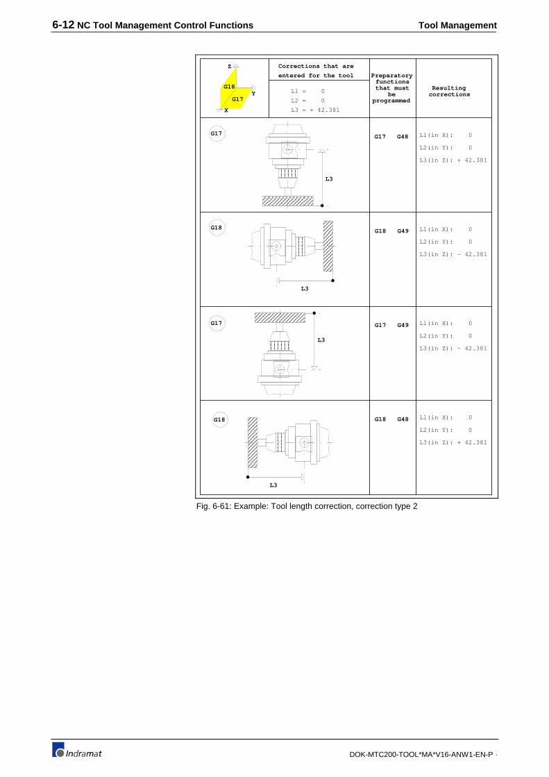
6-12 NC Tool Management Control Functions Tool Management
DOK-MTC200-TOOL*MA*V16-ANW1-EN-P ·
G17
Z
Y
X
G17
G18
G18
G17
G18
G17 G48 L1(in X): 0
L2(in Y): 0
L3(in Z): + 42.381
G18 G49 L1(in X): 0
L2(in Y): 0
L3(in Z): - 42.381
G17 G49 L1(in X): 0
L2(in Y): 0
L3(in Z): - 42.381
G18 G48 L1(in X): 0
L2(in Y): 0
L3(in Z): + 42.381
Corrections that are
entered for the tool
L1 = 0
L2 = 0
L3 = + 42.381
Preparatoryfunctionsthat must
beprogrammed
Resultingcorrections
L3
L3
L3
L3
Fig. 6-61: Example: Tool length correction, correction type 2

Tool Management NC Tool Management Control Functions 6-13
DOK-MTC200-TOOL*MA*V16-ANW1-EN-P ·
G17
L1
L3
Z
Y
X
G17
G18
G18
L3
L1
G17
L1
L3
G18
L3
L1
G17 G48 L1(in X): -169.371
L2(in Y): 0
L3(in Z): + 78.212
G18 G49 L1(in X): -169.371
L2(in Y): 0
L3(in Z): - 78.212
G17 G49 L1(in X): -169.371
L2(in Y): 0
L3(in Z): - 78.212
G18 G48 L1(in X): -169.371
L2(in Y): 0
L3(in Z): + 78.212
Corrections that are
entered for the tool
L1 = -169.371
L2 = 0
L3 = + 78.211
Preparatoryfunctionsthat must
beprogrammed
Resultingcorrections
Fig. 6-62: Tool length correction, correction type 4
6.3 Tool storage movement and tool change NC-commands
Special NC-commands are available in the MTC to control tool storagemovement and tool changes.
Tool storage movement NC-commandsAll tool storage (magazine/turret) movements occur asynchronous to themovements of all other process NC axes. The tool storage NC-commands are used only to start its movement. The CNC continues NC-program execution and does not wait for the tool storage movement to becompleted.
The NC-command MRY must be used to stop the NC-program execution,if it is required that the previously started tool storage movement isfinished. This synchronizes the NC-program execution with the toolstorage movement.
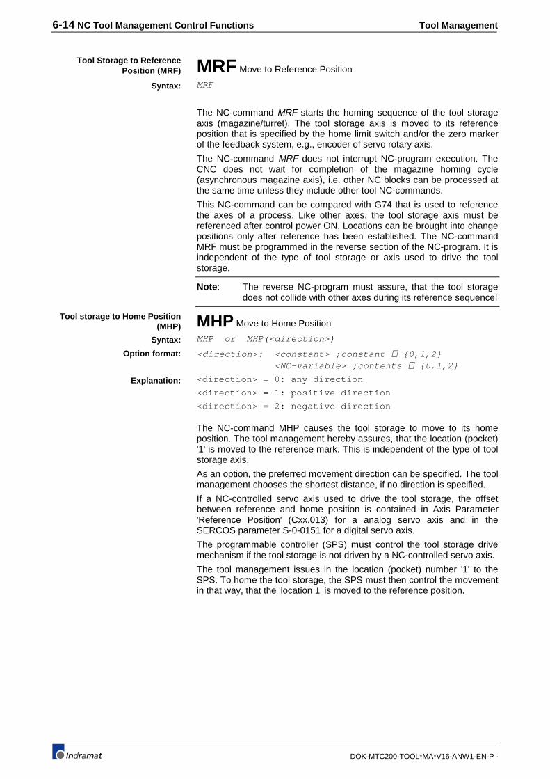
6-14 NC Tool Management Control Functions Tool Management
DOK-MTC200-TOOL*MA*V16-ANW1-EN-P ·
MRF Move to Reference Position
MRF
The NC-command MRF starts the homing sequence of the tool storageaxis (magazine/turret). The tool storage axis is moved to its referenceposition that is specified by the home limit switch and/or the zero markerof the feedback system, e.g., encoder of servo rotary axis.
The NC-command MRF does not interrupt NC-program execution. TheCNC does not wait for completion of the magazine homing cycle(asynchronous magazine axis), i.e. other NC blocks can be processed atthe same time unless they include other tool NC-commands.
This NC-command can be compared with G74 that is used to referencethe axes of a process. Like other axes, the tool storage axis must bereferenced after control power ON. Locations can be brought into changepositions only after reference has been established. The NC-commandMRF must be programmed in the reverse section of the NC-program. It isindependent of the type of tool storage or axis used to drive the toolstorage.
Note : The reverse NC-program must assure, that the tool storagedoes not collide with other axes during its reference sequence!
MHP Move to Home Position
MHP or MHP(<direction>)
<direction>: <constant> ;constant ∈ {0,1,2} <NC-variable> ;contents ∈ {0,1,2}
<direction> = 0: any direction
<direction> = 1: positive direction
<direction> = 2: negative direction
The NC-command MHP causes the tool storage to move to its homeposition. The tool management hereby assures, that the location (pocket)'1' is moved to the reference mark. This is independent of the type of toolstorage axis.
As an option, the preferred movement direction can be specified. The toolmanagement chooses the shortest distance, if no direction is specified.
If a NC-controlled servo axis used to drive the tool storage, the offsetbetween reference and home position is contained in Axis Parameter'Reference Position' (Cxx.013) for a analog servo axis and in theSERCOS parameter S-0-0151 for a digital servo axis.
The programmable controller (SPS) must control the tool storage drivemechanism if the tool storage is not driven by a NC-controlled servo axis.
The tool management issues in the location (pocket) number '1' to theSPS. To home the tool storage, the SPS must then control the movementin that way, that the 'location 1' is moved to the reference position.
Tool Storage to ReferencePosition (MRF)
Syntax:
Tool storage to Home Position(MHP)
Syntax:
Option format:
Explanation:

Tool Management NC Tool Management Control Functions 6-15
DOK-MTC200-TOOL*MA*V16-ANW1-EN-P ·
1
23456
78
910
1112 13
141516
Referencemark
Magazine at reference position
12
3456
7
8
910
1112 13141516
Referencemark
Magazine at base position
Fig. 6-63: Example: Home and reference position of disk tool storage
The CNC continues NC-program execution while the tool storage movesto its home position, unless the NC encounters the NC-command MRYor another tool NC-command. The CNC then stops NC-programexecution until the tool storage movement is completed.
MTP Move Tool into Position
MTP or MTP(<position>) orMTP(<position>,<direction>)
<position>: <constant>, <NC-variable> ;constant ∈{1,2,3,4}
<direction>: <constant>, <NC-variable> ;constant ∈{0,1,2,3}
<position> = 1: move location sel. tool into changeposition 1
<position> = 2: move location sel. tool into changeposition 2
<position> = 3: move location sel. tool into changeposition 3
<position> = 4: move location sel. tool into changeposition 4
<direction> = 0: any direction (shortest distance)
<direction> = 1: positive direction
<direction> = 2: negative direction
<direction> = 3: 360 degree turn
The NC-command MTP will cause the tool storage (turret/magazine) tomove the location (pocket/position) that contains the selected tool (T-word) to the specified tool change position.
The command parameter <direction> and <position> can be usedoptional, e. g., MTP(1), MTP() and MTP(1,2). Position 1 and any directionis used by the CNC if the respective parameter is not programmed.
The tool management will move the primary tool to the tool changeposition if the specified tool represents a tool family with more than onetool.
Usually, MTP is programmed together with the tool selection (T-word)right after changing the currently active tool. The next tool is then movedinto the specified change position while machining with the current tool.This is very effective when using a tool changer mechanism with twogrippers that allows to simultaneously exchange the tool in the spindlewith the tool in the change position.
Move Tool into Position (MTP)
Syntax:
Option format:
Explanation:

6-16 NC Tool Management Control Functions Tool Management
DOK-MTC200-TOOL*MA*V16-ANW1-EN-P ·
The next empty location is then moved into tool change position if the tool'T0' was programmed and MTP is executed. This empty location can thenreceive the tool that is currently in the spindle.
Program execution does not stop to wait for completion of the tool storage(asynchronous) movement, NC-block execution continues until anothertool NC-command is encountered.
POS1POS2
POS3
Referenceposition
+
12
3
4
56
7
8
T238
T831
T125
T239
T91
T254
T121
POS1POS2
POS3
Referenceposition
T91 MTP(3,1)
+
1
2
34
5
6
78
T238
T831T125
T239
T91
T254
T121
Fig. 6-64: Example: Move Tool into Position (MTP)
The turning tool T91 in location 3 must be moved in positive (CW)direction to change position 3. This can be accomplished by programming'T91 MTP(3,1)' in the NC-program or via MDI (Manual Data Input).
MMP Move Location into Position
MMP or MMP(<position>) orMMP(<position>,<direction>)
<position>: <constant>, <NC-variable> ;constant ∈{1,2,3,4}
<direction>: <constant>, <NC-variable> ;constant ∈{0,1,2}
<position> = 1: move selected location into changeposition 1
<position> = 2: move selected location into changeposition 2
<position> = 3: move selected location into changeposition 3
<position> = 4: move selected location into changeposition 4
<direction> = 0: any direction (shortest distance)
<direction> = 1: positive direction
<direction> = 2: negative direction
The NC-command MMP will cause the tool storage (turret/magazine) tomove the location (magazine pocket / turret position, not tool number)that is programmed via the T-word to the specified tool change position.
Program execution does not stop to wait for completion of the tool storage(asynchronous) movement, NC-block execution continues until anothertool NC-command is encountered.
The command parameter <direction> and <position> can be usedoptional, e. g., MMP(1), MMP() and MMP(1,2). Position 1 and anydirection is used by the CNC if the respective parameter is notprogrammed.
The NC-command MMP is usually used to reorganize, insert or removetools from the tool storage.
Move Location into Position(MMP)
Syntax:
Option format:
Explanation:

Tool Management NC Tool Management Control Functions 6-17
DOK-MTC200-TOOL*MA*V16-ANW1-EN-P ·
Note : The contents of the T-word (T-number) is used as the locationand not the tool (T) number if the NC-command MMP isexecuted. Tools of tool families are used by MMP only if theirlocation number has been programmed previously in the T-word (value range is 0..999).
POS1POS2
POS3
Referenceposition
+
12
3
4
56
7
8
T238
T831
T125
T239
T91
T254
T121
POS1POS2
POS3
Referenceposition
T91 MTP(3,1)
+
1
2
34
5
6
78
T238
T831T125
T239
T91
T254
T121
Fig. 6-65: Move Location into Position (MMP)
The turning tool T91 in location 3 must be replaced via change position 3.This can be accomplished by jogging the turret or by executing the NC-block 'T3 MMP(3,0)' via MDI (Manual Data Input). The turret will herebymove location 3 on the shortest distance (negative (CCW) direction) tothe change position 3.
MFP Move Free Pocket into Position
MFP or MFP(<position>) orMFP(<position>,<direction>)
<position>: <constant>, <NC-variable> ;constant ∈{1,2,3,4}
<direction>: <constant>, <NC-variable> ;constant ∈{0,1,2}
<position> = 1: move next free location into changeposition 1
<position> = 2: move next free location into changeposition 2
<position> = 3: move next free location into changeposition 3
<position> = 4: move next free location into changeposition 4
<direction> = 0: any direction (shortest distance)
<direction> = 1: positive direction
<direction> = 2: negative direction
The NC-command MFP causes a tool storage (magazine) movement thatwill bring the closest and empty location (pocket) into the specified toolchange position.
The command parameter <direction> and <position> can be usedoptional, e. g., MFP(1), MFP() and MFP(1,2). Position 1 and any directionis used by the CNC if the respective parameter is not programmed.
The NC-command MFP is used to put the tool that is currently in thegripper or spindle back into the next empty magazine pocket. This isespecially required when using tool changers without grippers or a singlegripper and using a random (tools go into the next available pocket)magazine. The tool must then be returned to the magazine (not oldlocation, otherwise MOP) before the newly selected tool can be picked bythe spindle or the gripper.
Move Free Pocket into Position(MFP)
Syntax:
Option format:
Explanation:

6-18 NC Tool Management Control Functions Tool Management
DOK-MTC200-TOOL*MA*V16-ANW1-EN-P ·
Program execution does not stop to wait for completion of the tool storagemovement (asynchronous), NC-block execution continues until anothertool NC-command is encountered.
1234
5
67 8 9 10 11
12
13
141516
Referencemark
+
POS 1POS 2
Gripper 1
Spindle 1
Gripper 2
Spindle 2
Empty
Tool
Gripper 1
Spindle 1
Gripper 2
Spindle 2
MFP(2,2) 13 1415
16
123456
7
8
9 10 11 12
Referencemark
+
POS 1POS 2
-
Fig. 6-66: Move (CCW) free magazine pocket into tool change position '2'.
MOP Move Old Pocket into Position
MOP or MOP(<position>) orMOP(<position>,<direction>) orMOP(<position>,<direction>,<tool spindle>)
<position>: <constant>, <NC-variable> ;constant ∈ {1,2,3,4}
<direction>: <constant>, <NC-variable> ;constant ∈ {0,1,2}
<tool spindle>: <constant>, <NC-variable> ;constant ∈ {1,2,3,4}
<position> = 1: move old location into changeposition 1
<position> = 2: move old location into changeposition 2
<position> = 3: move old location into changeposition 3
<position> = 4: move old location into changeposition 4
<direction> = 0: any direction (shortest distance)
<direction> = 1: positive direction
<direction> = 2: negative direction
<tool spindle> = 1: old location for tool in toolspindle 1
<tool spindle> = 2: old location for tool in toolspindle 2
<tool spindle> = 3: old location for tool in toolspindle 3
<tool spindle> = 4: old location for tool in toolspindle 4
The NC-command MOP will cause the tool storage (magazine) to movethe corresponding location (pocket) into the specified tool change positionfrom which the active tool (currently in the specified spindle) wasremoved.
This NC-command makes it possible to maintain the tool order in toolmagazines, e.g., for single arm tool changers or if tools that occupy morethan one pocket are used.
Move Old Pocket into Position(MOP)
Syntax:
Option format:
Explanation:
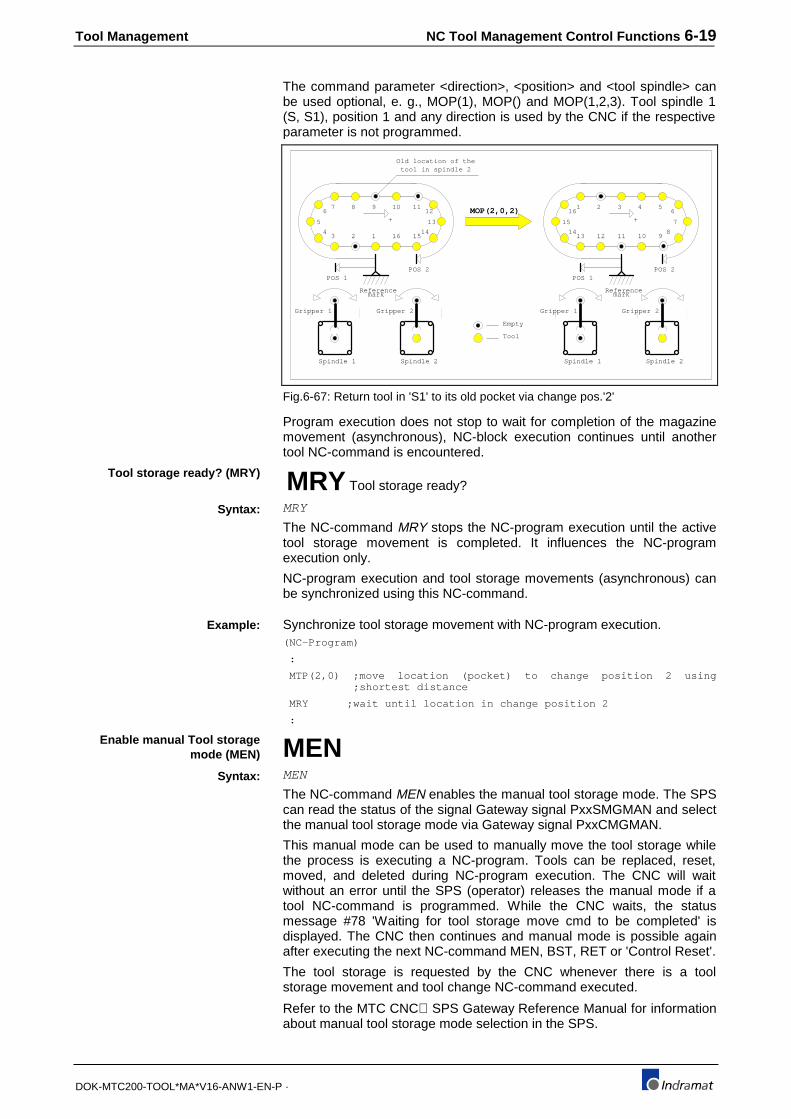
Tool Management NC Tool Management Control Functions 6-19
DOK-MTC200-TOOL*MA*V16-ANW1-EN-P ·
The command parameter <direction>, <position> and <tool spindle> canbe used optional, e. g., MOP(1), MOP() and MOP(1,2,3). Tool spindle 1(S, S1), position 1 and any direction is used by the CNC if the respectiveparameter is not programmed.
1234
5
67 8 9 10 11
12
13
141516
Referencemark
+
POS 1POS 2
Gripper 1
Spindle 1
Gripper 2
Spindle 2
Empty
Tool
Gripper 1
Spindle 1
Gripper 2
Spindle 2
MOP(2,0,2)
11121314
15
161 2 3 4 5
6
7
8910
Referencemark
+
POS 1POS 2
Old location of thetool in spindle 2
Fig.6-67: Return tool in 'S1' to its old pocket via change pos.'2'
Program execution does not stop to wait for completion of the magazinemovement (asynchronous), NC-block execution continues until anothertool NC-command is encountered.
MRY Tool storage ready?
MRY
The NC-command MRY stops the NC-program execution until the activetool storage movement is completed. It influences the NC-programexecution only.
NC-program execution and tool storage movements (asynchronous) canbe synchronized using this NC-command.
Synchronize tool storage movement with NC-program execution.(NC-Program)
:
MTP(2,0) ;move location (pocket) to change position 2 using ;shortest distance
MRY ;wait until location in change position 2
:
MENMEN
The NC-command MEN enables the manual tool storage mode. The SPScan read the status of the signal Gateway signal PxxSMGMAN and selectthe manual tool storage mode via Gateway signal PxxCMGMAN.
This manual mode can be used to manually move the tool storage whilethe process is executing a NC-program. Tools can be replaced, reset,moved, and deleted during NC-program execution. The CNC will waitwithout an error until the SPS (operator) releases the manual mode if atool NC-command is programmed. While the CNC waits, the statusmessage #78 'Waiting for tool storage move cmd to be completed' isdisplayed. The CNC then continues and manual mode is possible againafter executing the next NC-command MEN, BST, RET or 'Control Reset'.
The tool storage is requested by the CNC whenever there is a toolstorage movement and tool change NC-command executed.
Refer to the MTC CNC⇔SPS Gateway Reference Manual for informationabout manual tool storage mode selection in the SPS.
Tool storage ready? (MRY)
Syntax:
Example:
Enable manual Tool storagemode (MEN)
Syntax:

6-20 NC Tool Management Control Functions Tool Management
DOK-MTC200-TOOL*MA*V16-ANW1-EN-P ·
Tool change NC-commandsTool change NC-commands are only required, if the tool storage device isa magazine and the tools must be exchanged with a tool spindle and viseversa. The transfer may be accomplished directly between tool storageand tool spindle or via grippers (see SPS tool transfer FUNCTIONs in theProgrammable Controller Reference Manual).
Tool change NC-commands are not required if the tool storage is definedin the process parameter as a turret.
TCH Perform a complete tool change
TCH or TCH(<position>) or TCH(<position>,<toolspindle>)
<position>: <constant>, <NC-variable> ;constant ∈ {1,2,3,4}
<tool spindle>: <constant>, <NC-variable> ;constant ∈ {1,2,3,4}
<position> = 1: exchange tool in change position 1
<position> = 2: exchange tool in change position 2
<position> = 3: exchange tool in change position 3
<position> = 4: exchange tool in change position 4
<tool spindle> = 1: or tool in tool spindle 1
<tool spindle> = 2: or tool in tool spindle 2
<tool spindle> = 3: or tool in tool spindle 3
<tool spindle> = 4: or tool in tool spindle 4
The NC-command TCH initiates the exchange of the tool that is located inthe selected tool spindle with the tool that is in the selected tool changeposition.
This requires that the pocket containing the selected tool must be movedinto the selected tool change position prior to the NC-command TCH. Thetool transfer itself is controlled by the programmable controller program(SPS).
The NC-program execution of the process waits until the tool change iscompleted.
The command parameter <position> and <tool spindle> are optional. Toolchange position '1' is used by the tool management if no <position> isdefined with the NC-command TCH. Tool spindle 1 is used if the <toolspindle> option is not programmed.
The NC-command TCH is mostly used in the conjunction with toolchanger mechanisms that have two or more grippers. A process error andmessage is generated if a tool change is not allowed by the toolmanagement, e. g., if a tool transfer to a gripper that already contains atool is requested by the SPS program.
TMS Tool from magazine into spindle
TMS or TMS(<position>) or TMS(<position>,<toolspindle>)
<position>: <constant>, <NC-variable> ;constant ∈ {1,2,3,4}
<tool spindle>: <constant>, <NC-variable> ;constant ∈ {1,2,3,4}
<position> = 1: change tool in change position 1
<position> = 2: change tool in change position 2
Tool change (TCH)
Syntax:
Option format:
Explanation:
Tool from magazine to spindle(TMS)
Syntax:
Option format:
Explanation:

Tool Management NC Tool Management Control Functions 6-21
DOK-MTC200-TOOL*MA*V16-ANW1-EN-P ·
<position> = 3: change tool in change position 3
<position> = 4: change tool in change position 4
<tool spindle> = 1: to tool spindle 1
<tool spindle> = 2: to tool spindle 2
<tool spindle> = 3: to tool spindle 3
<tool spindle> = 4: to tool spindle 4
The NC command TMS initiates the transfer of the tool that is in theselected change position into the selected tool spindle. This requires thatthe pocket containing the selected tool must be moved into the selectedtool change position prior to the NC command TMS, and that the selectedtool spindle does not contain a tool.
NC-program execution is interrupted until the tool change is completed.
The NC-command parameter <position> and <tool spindle> are optional.Tool change position '1' is used by the tool management if not <position>is defined with the NC-command TMS. Tool spindle 1 is used if the <toolspindle> option is not programmed.
A process error and message is generated if a tool change from themagazine to the spindle is not allowed by the tool management, e. g., ifthe spindle already contains a tool.
TSM Tool from spindle to magazine
TSM or TSM(<position>) or TSM(<position>,<toolspindle>)
<position>: <constant>, <NC-variable> ;constant ∈ {1,2,3,4}
<tool spindle>: <constant>, <NC-variable> ;constant ∈ {1,2,3,4}
<position> = 1: tool from tool spindle to changeposition 1
<position> = 2: tool from tool spindle to changeposition 2
<position> = 3: tool from tool spindle to changeposition 3
<position> = 4: tool from tool spindle to changeposition 4
<tool spindle> = 1:
<tool spindle> = 2:
<tool spindle> = 3:
<tool spindle> = 4:
The NC-command TSM initiates the transfer of the tool that is located inthe specified tool spindle to the empty magazine pocket in the selectedtool change position. The old (empty and that contained the tool in thespindle) or next available empty pocket must be moved into the selectedtool change position prior to the NC-command TSM and the selected toolspindle must contain a tool. The tool transfer itself is controlled by theSPS.
NC-program execution is interrupted until the tool change is completed.
The command parameter <position> and <tool spindle> are optional. Toolchange position '1' is used by the tool management if not <position> isdefined with the NC-command TSM. Tool spindle 1 is used if the <toolspindle> option is not programmed.
Tool from spindle to magazine(TSM)
Syntax:
Option format:
Explanation:

6-22 NC Tool Management Control Functions Tool Management
DOK-MTC200-TOOL*MA*V16-ANW1-EN-P ·
A process error and message is generated if a tool change from thespindle to the magazine is not allowed by the tool management, e. g., ifthe magazine pocket in the tool change position already contains a tool.
BSE Branch if spindle empty
BSE <label> ;<label> = .###### (# ∈ {0...9,A...Z,_,a...z})
A branch to the NC-block, starting with the defined label, is performed ifthe tool spindle 1 is empty (contains no tool) and the NC-command BSE(Branch if Spindle Empty) is executed.
The branch NC-command BSE can be used to determine whether thetool spindle 1 contains a tool or is empty.
BTE Branch if tool T0 selected
BTE <label> ;<label> = .###### (# ∈ {0...9,A...Z,_,a...z})
A branch to the NC-block starting with the defined label is performed if thetool T0 (no tool) has been programmed and the NC-command BTE isexecuted.
T0 indicates that the tool that is in the currently selected spindle should beremoved and put back into a tool storage location.
Branch if Spindle Empty (BSE)
Syntax:
Branch if Tool T0 is selected(BTE)
Syntax:

Tool Management NC Tool Management Control Functions 6-23
DOK-MTC200-TOOL*MA*V16-ANW1-EN-P ·
Tool Data read/write (TLD)
TLDTLD([<process>],[<address>],<s/t>,<l/[i]>,<[edge]>,[<element>],[<status>]
The NC-command TLD can be used to read tool and tool Edge data fromand write (limited) it to the Active Tool List of the process.
NC-variables can be used instead of constants, however, nomathematical expressions can be used for the parameters (<..>) of NC-command TLD.
Optional NC-command parameters are identified by square brackets ('['and ']') and must not be programmed. This however, requires theprogramming of the separator ',' at all times even though the parameter isnot programmed.
• The process in which the NC-command TLD is being executed will beused if no value is specified for the parameter <process>.
• The value '0' for 'tool storage' and 'location' addressing is used if novalue is specified for the parameter <address>.
• The parameter <l/i> that identifies the tool index number is optional ifthe parameter <address>=2, and defines 'T-number' with 'Tool index'addressing. In this case and if no value is defined for parameter <l/i>,the index number of the primary tool of the tool family (selected via T-number) is used.
• The value '0' to access basic tool data elements is used if no value isspecified for the parameter <edge>.
• The parameter <status> must be specified only if the number in theparameter <element> addresses status bit information (value 9 forstatus basic tool data status bits, and value 2 for tool Edge status bits).for tool data elements.
Syntax:
Optional NC-command TLDparameter:

6-24 NC Tool Management Control Functions Tool Management
DOK-MTC200-TOOL*MA*V16-ANW1-EN-P ·
<process> ∈∈ {none,0..6} none: Process in which TLD is used 0..6:Process 0 to 6
<address> ∈∈ {none,0,1} none: The next two parameters areinterpreted as 'tool storage' and'location'.
0: The next two parameters areinterpreted as 'tool storage' and'location'
1: The next two parameters areinterpreted as 'T-number' and 'toolindex number'
<s/t> ∈∈ {0,1,2} if <address>=0 or 1 0: Tool storage (magazine/turret)
1: Spindle
2: Gripper
∈∈ {1..9999999} if <address>=2 1..9999999: Tool number (T-number)
<l/i> ∈∈ {1..999} if <address>=0 or 1 and <s/t>=0
1..999: Magazine pocket, turret posit.
∈∈ {1,2,3,4} if <address>=0 or 1 and <s/t>=1
1: Tool spindle 1
2: Tool spindle 2
3: Tool spindle 3
4: Tool spindle 4
∈∈ {1..4} if <address>=0 or 1 and <s/t/=2
1..4: Gripper number
∈∈ {none, 1..999} if <address>=2 none: Uses index number of the toolfamily's (selected via T-number)primary tool
1..999: Tool of tool family with this toolindex number
<edge> ∈∈ {none,0..9} none: Basic tool data
0: Basic tool data
1..9: Data of tool Edge number 1..9
<element> ∈∈ {3..26} if <edge>=0 3..28: Basic tool data element 3..28
∈∈ {1..35} if <edge>=1..9 1..40: Tool Edge data element 1..40
<status> ∈∈ {1..32} if <edge>=0 1..32: Basic tool status bit 1..32
∈∈ {1..16} if <edge>=1..9 1..16: Tool Edge status bit 1..16
Reading tool data via NC-command TLD.:
N0246 @23=TLD(,0,1,2,0,5,) ;read T-number of the tool that is in spindle 'S2'
: || | | | +----- Tool data element 5, tool number (T-number)
|| | | +------- 0: basic tool data
|| | +--------- 2: tool spindle 'S2'
|| +----------- 1: tool storage is spindle
|+------------- 0: 'tool storage' and 'location' addressing
+-------------- none: process in which TLD is executed
Checks performed by the MTC when using the NC-command TLD:
• All NC-command TLD parameters must be within their allowed range.
• The specified process must be defined in the currently activeparameter set.
NC-command TLD parameterdescription:
Example:
General checks:

Tool Management NC Tool Management Control Functions 6-25
DOK-MTC200-TOOL*MA*V16-ANW1-EN-P ·
• The tool management must be defined and available for the specifiedprocess.
• The tool storage device (magazine/turret) must provide at least onelocation (pocket for magazine, position for turret) if 'tool storage' and'location' addressing is used in the NC-command TLD (<address>=0or 1).
• At least one tool with the specified T-number and index must beavailable in the Active Tool List of the process if the 'T-number' and'tool index number' addressing is used in the NC-command TLD(<address>=2).
• The value specified for the tool Edge is not allowed to exceed themaximum number of tool edges, defined in the system parameterAxx.005 of the currently active parameter set.
Note: If one or more of the above requirements are violated, aprocess error with stop will be activated before TLD executionand the message #286 "Invalid parameter @ in NC-command programmed" will be displayed. The numberdisplayed for '@' identifies the incorrect NC-commandparameter (starting to count with 1, from the left).
• Data elements that are part of the Tool Setup List cannot be modifiedvia the NC-command TLD.
• All data elements and status bits that are assigned by the toolmanagement only cannot be modified via the NC-command TLD.
• The data elements 'Tool Storage' (3), 'Tool location' (4) and 'T-number'(5) cannot be modified.
• Tool List specific data can be accessed only after an automatic toolcheck has been performed if the 'T-number' and 'tool index number'addressing is specified for the NC-command TLD.
• Setup List specific data can be accessed only after an automatic toolcheck has been performed if the 'tool storage' and 'location'addressing is specified for the NC-command TLD.
CAUTION
⇒ If one or more of the above requirements are violated,a process error with stop will be activated before TLDexecution and the message #286 "Data is writeprotected" will be displayed. Values that will bewritten to tool data must be evaluated (for the allowedvalid range) in the NC-program prior to the executionof the NC-command TLD. A partial check isperformed during the next automatic tool check
• Tool List specific tool data that is modified via the NC-command TLD,will cause an automatic tool check (compared with correspondingSetup List data). The automatic tool check will be performed at thenext NC-program start if the tool that contains the data is used. A toolis used if it is specified in Setup List of the active NC-program orprocess.
• Modification of Tool List specific data will not cause an automatic toolcheck if the tool is not specified in the Setup List of the NC-program orprocess. Meaning that the tool is not used.
Checks before TLD write cycle:
Automatic tool check:

Tool Management SPS Tool Management Control FUNCTIONs 7-1
DOK-MTC200-TOOL*MA*V16-ANW1-EN-P ·
7 SPS Tool Management Control FUNCTIONs
7.1 Standard FUNCTIONs for SPS controlled tool storagesand changers
The movement of a tool storage is programmable controller (SPS)controlled, if no NC-controlled servo axis is used.
Overview SPS controlled tool storages and changers
Tool Management
01
23
45
6
01
23
45
6
Tool storage movement
12
34
56
0
Tool changerAxis movement
12
34
56
0
MUI(PC) / SOT Operator Panel
NC-program
t
Tool List
NC-program
Setup List
01
23
45
6
01
23
45
6
Tool List
CNC SPS
Programmable
controller (SPS)
program
..
..
.
..
..
..
..
.
..
..
..
. ..
..
.
t
Fig. 7-68: MTC tool management data flow
The programmable controller (SPS) program can be used to adaptdifferent types of tool storages (magazines) and tool changers to the toolmanagement of the MTC. The SPS of the MTC therefore provides apowerful set of standard FUNCTIONs.
The NC-command set provides NC-commands to initiate tool change andtool storage (magazine) movement commands.
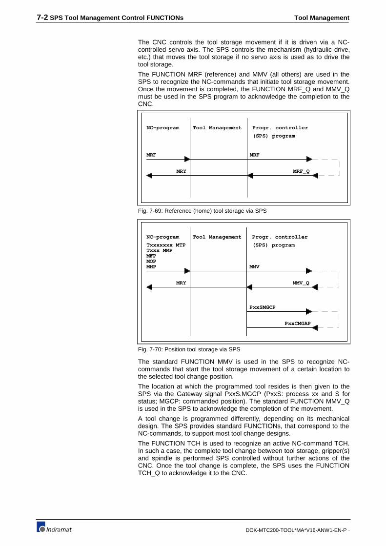
7-2 SPS Tool Management Control FUNCTIONs Tool Management
DOK-MTC200-TOOL*MA*V16-ANW1-EN-P ·
The CNC controls the tool storage movement if it is driven via a NC-controlled servo axis. The SPS controls the mechanism (hydraulic drive,etc.) that moves the tool storage if no servo axis is used as to drive thetool storage.
The FUNCTION MRF (reference) and MMV (all others) are used in theSPS to recognize the NC-commands that initiate tool storage movement.Once the movement is completed, the FUNCTION MRF_Q and MMV_Qmust be used in the SPS program to acknowledge the completion to theCNC.
NC-program
MRF
Tool Management
MRY
Progr. controller
(SPS) program
MRF
MRF_Q
Fig. 7-69: Reference (home) tool storage via SPS
NC-program
MOP
Tool Management
MRY
Progr. controller
(SPS) program
MMV
MMV_Q
Txxxxxxx MTPTxxx MMPMFP
MHP
PxxSMGCP
PxxCMGAP
Fig. 7-70: Position tool storage via SPS
The standard FUNCTION MMV is used in the SPS to recognize NC-commands that start the tool storage movement of a certain location tothe selected tool change position.
The location at which the programmed tool resides is then given to theSPS via the Gateway signal PxxS.MGCP (PxxS: process xx and S forstatus; MGCP: commanded position). The standard FUNCTION MMV_Qis used in the SPS to acknowledge the completion of the movement.
A tool change is programmed differently, depending on its mechanicaldesign. The SPS provides standard FUNCTIONs, that correspond to theNC-commands, to support most tool change designs.
The FUNCTION TCH is used to recognize an active NC-command TCH.In such a case, the complete tool change between tool storage, gripper(s)and spindle is performed SPS controlled without further actions of theCNC. Once the tool change is complete, the SPS uses the FUNCTIONTCH_Q to acknowledge it to the CNC.
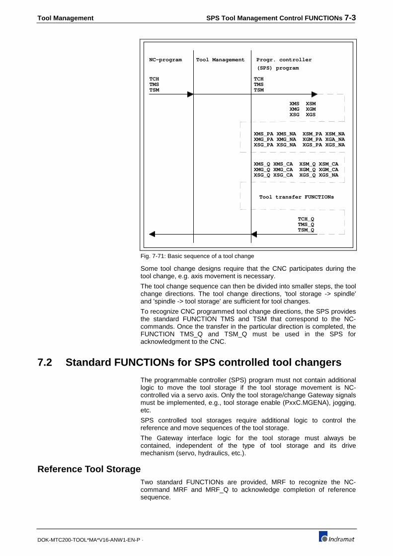
Tool Management SPS Tool Management Control FUNCTIONs 7-3
DOK-MTC200-TOOL*MA*V16-ANW1-EN-P ·
NC-program
TMS
Tool Management Progr. controller
(SPS) program
TSM
TCH
TSMTMSTCH
TSM_QTMS_QTCH_Q
Tool transfer FUNCTIONs
XMS XSMXMG XGMXSG XGS
XMS_PA XMS_NA XSM_PA XSM_NAXMG_PA XMG_NA XGM_PA XGA_NAXSG_PA XSG_NA XGS_PA XGS_NA
XMS_Q XMS_CA XSM_Q XSM_CAXMG_Q XMG_CA XGM_Q XGM_CAXSG_Q XSG_CA XGS_Q XGS_NA
Fig. 7-71: Basic sequence of a tool change
Some tool change designs require that the CNC participates during thetool change, e.g. axis movement is necessary.
The tool change sequence can then be divided into smaller steps, the toolchange directions. The tool change directions, 'tool storage -> spindle'and 'spindle -> tool storage' are sufficient for tool changes.
To recognize CNC programmed tool change directions, the SPS providesthe standard FUNCTION TMS and TSM that correspond to the NC-commands. Once the transfer in the particular direction is completed, theFUNCTION TMS_Q and TSM_Q must be used in the SPS foracknowledgment to the CNC.
7.2 Standard FUNCTIONs for SPS controlled tool changers
The programmable controller (SPS) program must not contain additionallogic to move the tool storage if the tool storage movement is NC-controlled via a servo axis. Only the tool storage/change Gateway signalsmust be implemented, e.g., tool storage enable (PxxC.MGENA), jogging,etc.
SPS controlled tool storages require additional logic to control thereference and move sequences of the tool storage.
The Gateway interface logic for the tool storage must always becontained, independent of the type of tool storage and its drivemechanism (servo, hydraulics, etc.).
Reference Tool StorageTwo standard FUNCTIONs are provided, MRF to recognize the NC-command MRF and MRF_Q to acknowledge completion of referencesequence.

7-4 SPS Tool Management Control FUNCTIONs Tool Management
DOK-MTC200-TOOL*MA*V16-ANW1-EN-P ·
The FUNCTION MRF is used in the programmable controller (SPS)program to recognize the NC-command MRF that starts the referencesequence of the tool storage.
MRF
ACTIVE
PROC
BOOL
INT BOOL
Fig. 7-72: Read tool storage NC-command MRF via FUNCTION MRF
ACTIVE: 0 - FUNCTION MRF not active
1 - FUNCTION MRF active
PROC: 0..6 process number
MRF result: 0 - NC-command MRF not active or ACTIVE=0
1 - NC-command MRF active.
The FUNCTION MRF_Q must be used to acknowledge the completion ofthe reference sequence.
The FUNCTION MRF_Q is used in the programmable controller (SPS)program to acknowledge the completion of the tool storage referencesequence.
The CNC stops NC-program execution until the associated NC servo axisis successfully homed and the CNC receives the acknowledgment via theFUNCTION MRF_Q.
MRF_Q
QUIT
PROC
BOOL
INT BOOL
Fig. 7-73: Acknowledge tool storage NC-command MRF via FUNCTION MRF_Q
QUIT: 0 - FUNCTION MRF_Q not active
1 - Acknowledge completion of reference sequence
PROC: 0..6 Process number
MRF_Q result: Reflects the status of QUIT.
Reference Tool Storage,FUNCTION MRF
Acknowledge Tool Storage atReference, FUNCTION MRF_Q

Tool Management SPS Tool Management Control FUNCTIONs 7-5
DOK-MTC200-TOOL*MA*V16-ANW1-EN-P ·
NC-ProgramProcess 1
N0010 MRF ;(1)
MRF
ACTIVE
PROC
SPS ProgramProcess 1
1
MRF_Q
QUIT
PROC
QMAGPOS
(* (2) (3) *)
X
1
IREF
N0011 ..
N0023 MRY ;(5)
(* (4) *)
:
Fig. 7-74: Reference Tool Storage sequence
(1) The NC-command MRF is executed in the CNC and transferred tothe SPS.
(2) The NC-command MRF is recognized in the SPS via the FUNCTIONMRF. The Gateway signal P01S.MGCP contains the commanded toolstorage location.
(3) The output QMAGPOS is set in the SPS to start the referencesequence of the tool storage.
(4) The input IREF indicates that the tool storage is at its referenceposition. The SPS must write the actual location into the Gatewaysignal P01C.MGCP.
(5) The NC-command MRY is used in the NC-program to stop NC-program execution until the reference sequence is acknowledged ascompleted via MRF_Q.
NC-commandMRF
(1)
SPS FUNCTIONMRF
(2)
SPS FUNCTIONMRF_Q
(5)
OutputQMAGPOS
(3)
InputIREF
(4)
CommandedlocationP01S.MGCP XXXXXXXXXXXX11111111111111111111111111111111111
ActuallocationP01C.MGAP XXXXXXXXXXXXXXXXXXXXXXXXXXXXXXXXX11111111111111
SPS controlled endless tool magazine
Declaration in a FUNCTION_BLOCK:VAR_INPUTPROC INT (*Process number*)IREF BOOL (*Magazine reference switch*):
Sequence between SPS andCNC, 'Reference Tool Storage'
Example:

7-6 SPS Tool Management Control FUNCTIONs Tool Management
DOK-MTC200-TOOL*MA*V16-ANW1-EN-P ·
VAR_OUTPUTPXXCMGAP INT (*Actual mag. pos., pocket nr. in tool change position*)QMAGPOS BOOL (*Move magazine in positive direction*)QMAGNEG BOOL (*Move magazine in negative direction*):
Ladder Diagram implementation in a FUNCTION_BLOCK:: :|(*NC-command MRF to reference magazine*) || +-------+ || |MRF | |+--------+ACTIVE +-------------------------------------------O>nomrf || PROC -+PROC | || +-------+ ||(*Positive magazine direction for reference sequence*) || QMAGPOS |+--------------------------------------------------------+----(S)----+| | QMAGNEG || +----(R)----+|(*Stop magazine movement*) || IREF QMAGPOS |+-----| |------------------------------------------------+----(R)----+| | QMAGNEG || +----(R)----+| +----O>nomr ||(*NC-command MRF to reference magazine*) || +-------+ |
Position Tool StorageThe tool storage must move the pocket with the selected tool and emptypockets into the tool change position in order to use different tools duringa NC-program cycle.
The FUNCTION MMV is used in the programmable controller (SPS)program to recognize tool storage move NC-commands (MHP, MMP,MTP, MFP, MOP) that starts the reference sequence of the tool storage.
MMV
ACTIVE
PROC
BOOL
INT BOOL
Fig. 7-75: Read tool storage NC-command MMV via FUNCTION MMV
ACTIVE: 0 - FUNCTION MMV not active
1 - FUNCTION MMV active
PROC: 0..6 Process number
MRF result: 0 - NC-cmd. MMV not active or ACTIVE=0
1 - NC-command MMV active.
The FUNCTION MMV_Q must be used to acknowledge the completion ofthe tool storage movement.
The FUNCTION MMV_Q is used in the programmable controller (SPS)program to acknowledge the completion of the initiated (NC-commandsMHP, MMP, MTP, MFP, MOP) tool storage move.
The CNC stops NC-program execution until it receives thisacknowledgment if the NC-command MHP, MMP, MTP, MFP or MOP isactive.
Move Tool Storage, FUNCTIONMMV
Acknowledge Tool StorageMove, FUNCTION MMV_Q

Tool Management SPS Tool Management Control FUNCTIONs 7-7
DOK-MTC200-TOOL*MA*V16-ANW1-EN-P ·
MMV_Q
QUIT
PROC
BOOL
INT BOOL
Fig. 7-76: Ackng. tool storage NC-command MMV via FUNCTION MMV_Q
QUIT: 0 - FUNCTION MMV_Q not active
1 - Acknowledge compl. of reference sequence
PROC: 0..6 Process number
MMV_Q result: Reflects the status of QUIT
NC-ProgramProcess 1
N0010 T4 MTP ;(1)
MMV
ACTIVE
PROC
SPS ProgramProcess 1
1
MMV_Q
QUIT
PROC
QMAGPOS
(* (2) (3) *)
1
N0011 ..
N0023 MRY ;(7)
(*Magazine location counter *)
:
COUNTCOUNT PULSEEVALUATION
=ACTUAL
COMMAND
(*Pocket count detection (4) *)
(5)
(6)
(*Detect tool storage NC-command *)
Fig. 7-77: Move Tool Storage sequence
(1) The NC-command 'T4 MTP' is executed in the CNC and transferredto the SPS. The tool T4 resides in pocket #3 of the endless 8 pocketmagazine. Pocket #8 is currently in the tool change position.
NC-commandT4 MTP
(1)
SPS FUNCTIONMMV
(2)
SPS FUNCTIONMMV_Q
(7)
OutputQMAGPOS
(3)
InputCOUNT
(5)
CommandedlocationP01S.MGCP XXXXXXXXXXXX333333333333333333333333333333333333333
ActuallocationP01C.MGAP 888888888888888888881111111122222222333333333333333
(T4 is contained in pocket #3)
(Endless magazine with 8 pockets)
(6)
(4)
(2) The NC-command MTP is recognized in the SPS via the FUNCTIONMMV. The Gateway signal P01S.MGCP contains the commandedtool storage location, in this case the number 3.

7-8 SPS Tool Management Control FUNCTIONs Tool Management
DOK-MTC200-TOOL*MA*V16-ANW1-EN-P ·
(3) The output QMAGPOS is set in the SPS to start the tool storagemovement in positive direction.
(4) User logic in the programmable controller program evaluates thecount switch and increments a counter to generate the actualmagazine position P1C.MGAP
(5) The commanded pocket is in the tool change position, if the actualmagazine position (P1C.MGAP) equals the commanded position(P1S.MGCP).
(6) The SPS stops the tool magazine movement and acknowledges themovement as completed.
(7) The NC-command MRY is used in the NC-program to stop NC-program execution until the tool storage movement is acknowledgedto be complete via MMV_Q.
SPS controlled endless tool magazine
Declaration in a FUNCTION_BLOCK:VAR_INPUTPROC INT (*Process number*)COUNT BOOL (*Magazine pocket count switch*)PXXSMGCP INT (*Commanded magazine position of selected T-number (tool)*)MAXPOCK INT (*Maximum number of magazine tool pockets*):VAR_END
VAR_OUTPUTPXXCMGAP INT (*Actual mag. pos., pocket nr. in tool change position*)QMAGPOS BOOL (*Move magazine in positive direction*)QMAGNEG BOOL (*Move magazine in negative direction*):VAR_END
VARMCNT (*MAGAZINE POCKET COUNT ONS*)RCNT R_TRIG (*MAGAZINE POCKET COUNT ONS FB*)::VAR_END
Ladder Diagram implementation in a FUNCTION_BLOCK:: :|(*ONS for magazine pocket counter*) || RCNT || +-------+ || COUNT |R_TRIG | MCNT |+---| |--+CLK Q_+--------------------------------------------(S)----+| +-------+ ||(*Magazine move NC-command active*) || +-------+ || |MMV | |+--------+ACTIVE +-------------------------------------------O>nommv || PROC -+PROC | || +-------+ ||(*Comparison: Actual pocket in tool change position = commanded*) || +-------+ || PXXSMGCP -+= | || PXXCNGAO -+ +---------------------------------------->>mgend || +-------+ ||(*Move magazine in positive direction*) || QMAGPOS |+--------------------------------------------------------+----(S)----+| | QMAGNEG || +----(R)----+|(*Evaluate magazine pocket count signal*) || MCNT |+-----| |----------------------------------------------------O>mgend +
Example:

Tool Management SPS Tool Management Control FUNCTIONs 7-9
DOK-MTC200-TOOL*MA*V16-ANW1-EN-P ·
|(*Magazine pocket counter to build actual magazine position*) || +-------+ || PXXCMGAP -+ + | || 1 -+ +-PXXCMGAP || +-------+ ||(*Check for maximum number of pockets overflow*) || +-------+ || PXXCMGAP -+ > | || MAXPOCK -+ +----------------------------------------0>mgend || +-------+ ||(*Reset magazine pocket counter to 1 if overflow*) || +-------+ || 1 -+ +-PXXCMGAP || +-------+ ||(*Stop magazine movement and acknowledge NC-command*) ||mgend: || +-------+ +-------+ || PXXCMGAP -+ = | |MMV_Q | QMAGPOS || PXXSMGCP -+ +---+QUIT +------------------------+----(R)----+| +-------+ | | | QMAGNEG || PROC -+PROC | +----(R)----+| +-------+ ||nommv: |: :
7.3 Standard Tool Change FUNCTIONs
Tool change FUNCTIONs are required only if the tool storage is of thetype magazine and if tools must be exchanged between spindle,magazine and eventually grippers. Tool change FUNCTIONs are notpermitted with tool turrets and systems that use only tool spindle(s) andno tool storage device.
Due to the variety of mechanical tool change designs, the tool transfersequence must be implemented in the programmable controller (SPS)program. SPS provides special standard FUNCTIONs (part of the CNC⇔SPS Gateway) to simplify the programming of such sequences.
All tool change sequences are initiated via tool change NC-commandsand NC-block execution is halted. The tool change is then recognized andperformed by the SPS. Completed tool change sequences areacknowledged to the CNC which allows the CNC to continue NC-blockexecution.
A complete tool change can be initiated with the NC-command TCH, thatcan be recognized in the SPS program via the FUNCTION TCH.Individual tool change sequences between spindle(s), magazine andgripper(s) can be performed in the SPS using the correspondingFUNCTIONs.
It may be necessary to divide NC tool change sequences into smallersteps if additional NC actions such as axis movements are requiredduring the tool change. The NC-commands TMS and TSM can initiatesuch small tool change sequences. They can be recognized in the SPSvia the corresponding FUNCTIONs TMS and TSM.
Complete tool changeThe NC-command TCH can be used in the NC-program to initiate acomplete tool change if no further NC operations are required during thetool change. The NC-program execution stops until the tool change isacknowledged as completed by the SPS.
In the SPS program, the tool change is split into individual sequences.Tool transfer FUNCTIONs must be used in the SPS program to informthe tool management about the tool location. The NC-program executioncontinues after the SPS acknowledges the completion of the tool change(NC-command TCH).
The status of the NC-command TCH must be read in the SPS programvia the FUNCTION TCH. The NC-command TCH initiates in the SPS
Complete tool change,FUNCTION TCH

7-10 SPS Tool Management Control FUNCTIONs Tool Management
DOK-MTC200-TOOL*MA*V16-ANW1-EN-P ·
program the user tool change sequencer. The NC-program executionstops until the NC-command TCH is acknowledged in the SPS programvia FUNCTION TCH_Q after completion of the tool transfer sequence.
BOOL BOOL INT INT INT
TCH ACTIVE PROC POS SPINDLE
Fig. 7-78: Read tool change NC-command TCH via FUNCTION TCH
ACTIVE: 0 FUNCTION TCH not active.
ACTIVE: 1 Enable FUNCTION TCH.
TCH: 0 No NC cmd. TCH active or ACTIVE = `0`.
TCH: 1 NC command TCH cmd. and ACTIVE=`1`.
PROC: 0..6 Process number
The FUNCTION TCH_Q must be used in the SPS to acknowledge thecompletion of the tool change that was initiated via the NC-commandTCH.
BOOL BOOL INT INT INT
TCH_Q QUIT PROC POS SPINDLE
Fig. 7-79: Ackn. tool change cmd. TCH via FUNCTION TCH_Q
QUIT: 0 - FUNCTION TCH_Q not active.
QUIT: 1 - Acknowledge the NC-command TCH.
TCH_Q: Reflects the status of QUIT.
PROC: 0..6 - Process number
(1) The NC-command TCH is used in the NC-program to initiate acomplete tool change. NC-program execution stops until the SPSacknowledges the tool change as completed via the FUNCTIONTCH_Q.
(2) The NC-command TCH is recognized in the SPS via the FUNCTIONTCH.
(3) The tool change is initiated in the programmable controller (SPS)program.
(4) The sequence of a complete tool change usually consists of multipleoperations (e. g., open/close gripper, clamp/unclamp spindle) and tooltransfer FUNCTIONs.
(5) The complete tool change was performed SPS program controlled.The user must implement the logic accordingly.
(6) FUNCTION TCH_Q is used in the SPS program to acknowledge thetool change NC-command TCH.
(7) NC-program execution continues.
Complete tool change,FUNCTION TCH_Q
Sequence between SPS andCNC, 'Complete Tool Change'

Tool Management SPS Tool Management Control FUNCTIONs 7-11
DOK-MTC200-TOOL*MA*V16-ANW1-EN-P ·
NC-ProgramProcess 1
N0010 TCH ;(1)
SPS ProgramProcess 1
N0011 ..
N0023 ... ;(7)
:
(5)
(6)
(*Detect NC-command TCH*)
Initiates completetool change (3)
(2)
Physical and logicaltool change (4)
Complete tool changeperformed
TCH
ACTIVE
SPINDLE1
PROC
POS1
1
TCH_Q
QUIT
SPINDLE1
PROC
POS1
1
Fig. 7-80: Complete Tool Change sequence
NC-commandTCH
(1)
SPS FUNCTIONTCH
(2)
SPS FUNCTIONTCH_Q
(7)
OutputQMAGPOS
(3)
Tool changecomplete
(5)
(6)
(4)
Tool change between Magazine and SpindleBeside the general tool change NC-command TCH, more specific toolchange NC-commands such as TMS and TSM for changes betweenmagazine and spindle are available. By using them, the tool changesequence can be split up into smaller sections that allow NC operationsnecessary for the tool change.
The NC-program can contain smaller tool change steps, e. g.,'clamp/unclamp' via auxiliary M-functions, motion NC-blocks to themagazine and spindle orientation to unlock or lock the tool in themagazine pocket. Standard tool change and transfer FUNCTIONs mustbe used in the programmable controller (SPS) program to inform the toolmanagement about the physical tool location and to acknowledge thecompletion of the tool change NC-command.

7-12 SPS Tool Management Control FUNCTIONs Tool Management
DOK-MTC200-TOOL*MA*V16-ANW1-EN-P ·
The status of the NC-command TMS must be read in the SPS programvia the FUNCTION TMS.
TMS
ACTIVE
PROC
BOOL
INT
POS
SPINDLEINT BOOL
INT
Fig. 7-81: Read tool change NC-command TMS via FUNCTION TMS
ACTIVE = `0` FUNCTION TMS not active.
ACTIVE = `1` Enable FUNCTION TMS.
TMS = `0` No NC-command TCH active orACTIVE = `0`.
TMS = `1` NC-command TMS commanded andACTIVE = `1`.
PROC = 0..6 Process number.
POS = 1..4 Tool change position
SPINDLE= 1..3 1 = Tool spindle 1
2 = Tool spindle 2
3 = Tool Spindle 3
The NC-command TMS initiates in the SPS program the tool changesequence for a tool transfer from the specified tool change position to thespecified tool spindle. NC-program execution stops until the NC-command TMS is acknowledged in the SPS program via FUNCTIONTMS_Q after completion of the tool transfer sequence.
TMS_Q
QUIT
PROC
BOOL
INT
POS
SPINDLEINT BOOL
INT
Fig. 7-82: Acknowledge tool change NC-command TMS via FUNCTION TMS_Q
QUIT = `0` : FUNCTION TMS_Q not active.
QUIT = `1` : Acknowledge the NC-command TMS.
TMS_Q : Reflects the status of QUIT.
PROC = 0..6 : Process number.
POS = 1..4 : Tool change position
SPINDLE= 1..3 : 1 = Tool spindle 1 (S,S1)2 = Tool spindle 2 (S2)3 = Tool Spindle 3 (S3)
The FUNCTION TMS_Q must be used in the SPS to acknowledge thetool change from the magazine to the spindle, that was initiated via theNC-command TMS.
Tool from Magazine to Spindle,FUNCTION TMS
Acknowledge Tool fromMagazine to Spindle, FUNCTION
TMS_Q

Tool Management SPS Tool Management Control FUNCTIONs 7-13
DOK-MTC200-TOOL*MA*V16-ANW1-EN-P ·
NC-ProgramProcess 1
N0010 TMS ;(1)TMSACTIVEPROC
SPS ProgramProcess 1
1
TMS_QQUITPROC
N0011 ..
N0023 ... ;(7)
:
(5)
(6)
(*Detect NC-command TMS*)
Initiate Magazine-> Spindle tool change
(3)
(2)
Physical and logical
tool change
1
(4)
Complete Magazine -> Spindletool change performed
POSSPINDLE
11
SPINDLE11 POS
Fig. 7-83: Magazine -> Spindle Tool Change sequence
NC-commandTMS
(1)
SPS FUNCTIONTMS
(2)
SPS FUNCTIONTMS_Q
(7)
Tool chagneactive
(3)
Tool changecomplete
(5)
(6)
(4)
(1) The NC-command TMS is used in the NC-program to initiate the toolchange from the magazine to the spindle. NC-program executionstops until the SPS acknowledges the tool change as completed viathe FUNCTION TMS_Q.
(2) The NC-command TMS is recognized in the SPS via the FUNCTIONTMS.
(3) The tool change is initiated in the programmable controller (SPS)program.
(4) The sequence of the tool change usually consists of one or moreoperations (e. g., open/close gripper, clamp spindle) and tool transferFUNCTION(s).
(5) The tool change was performed, controlled via SPS program. Theuser must implement the logic accordingly.
(6) FUNCTION TMS_Q is used in the SPS program to acknowledge thetool change NC-command TMS.
(7) NC-program execution continues.
Tool change from magazine to spindle.
Declaration in a FUNCTION_BLOCK:
FUNCTION_BLOCK TMS_TSMVAR_INPUTENA BOOL 2#1 (*ENABLE*)CLAMPED BOOL 2#0 (*SPINDLE CLAMPED*)UNCLAMPED BOOL 2#0 (*SPINDLE UNCLAMPED*)PROCESS INT (*PROCESS NUMBER*)
Sequence between SPS andCNC, 'Magazine->Spindle Tool
Change'
Example:

7-14 SPS Tool Management Control FUNCTIONs Tool Management
DOK-MTC200-TOOL*MA*V16-ANW1-EN-P ·
POSITION INT 1 (*DIRECTION PARAMETER*)SPINDLE INT 1 (*SPINDLE NUMBER*):VAR_OUTPUTMMV_A BOOL (*POCKET SELECTION ACTIVE*)MRF_A BOOL (*HOMING ACTIVE*)TMS_A BOOL (*TOOL CHANGE MAG.->SPDL.ACTIVE*)TSM_A BOOL (*TOOL CHANGE SDPL.->MAG.ACTIVE*)END_VAR
VARTMS_AA BOOL (*TMS ACTIVE*)TSM_AA BOOL (*TSM ACTIVE*)XMS_A BOOL (*TOOL XFER MAG.->SPINDLE*)XSM_A BOOL (*TOOL XFER SPINDLE->MAG.*)XMSPA BOOL (*XFER MAG.->SP. POSITIVE ACKN.*)XMSNA BOOL (*XFER MAG.->SP. NEGATIVE ACKN.*)XSMPA BOOL (*XFER SP.->MAG. POSITIVE ACKN*)XSMNA BOOL (*XFER SP.->MAG. NEGATIVE ACKN.*):
Implementation Instruction List in a FUNCTION_BLOCK:: :|(*TOOL CHANGE FROM MAGAZINE TO SPINDLE: STEP 1*) ||(*READ TMS COMMAND*) || +--------+ ||ENA |TMS | TMS_AA |+| |--------+ACTIVE +----------------------------------------------------------( )------+| PROCESS-+PROC | || POSITION-+POS | || SPINDLE-+SPINDLE | || +--------+ ||(*PERFORM TRANSFER WHEN UNCLAMPED*) ||TMS_AA CLAMPED |+| |--------| |-----------------------------------------------------------------O>NOTMS ||(*INITIATE TOOL TRANSFER FROM MAGAZINE TO SPINDLE: STEP 2*) || +--------+ ||XMS_A |XMS | XMS_A |+|/|--------+INIT +----------------------------------------------------------(S)------+| PROCESS-+PROC | || POSITION-+POS | || SPINDLE-+SPINDLE | || +--------+ ||(*READ POSITIVE XMS ACKNOWLEDGE*) || +--------+ || |XMS_PA | XMSPA |+-----------+ACTIVE +----------------------------------------------------------( )------+| PROCESS-+PROC | || POSITION-+POS | || SPINDLE-+SPINDLE | || +--------+ ||(*READ NEGATIVE XMS ACKNOWLEDGE*) || +--------+ || |XMS_NA | XMSNA |+-----------+ACTIVE +----------------------------------------------------------( )------+| PROCESS-+PROC | || POSITION-+POS | || SPINDLE-+SPINDLE | || +--------+ ||(*TOOL ACKNOWLEDGE TOOL TRANSFER FROM MAGAZINE TO SPINDLE: STEP 3*) || +--------+ +--------+ ||XMSPA |XMS_Q | |TMS_Q | XMS_A |+| |-------++QUIT +-+QUIT +-----------------------------------------------(R)------+|XMSNA || | | | |+| |-------+| | | | || PROCESS-|PROC | | | || POSITION-|POS | | | || SPINDLE-|SPINDLE | | | || +--------+ | | || PROCESS-+PROC | || POSITION-+POS | || SPINDLE-+SPINDLE | || +--------+ ||(*OUTPUT TMS_A*) ||NOTMS: ||TMS_AA TMS_A |+| |-------+--------------------------------------------------------------------( )------+|XMS_A | |+| |-------+ |

Tool Management SPS Tool Management Control FUNCTIONs 7-15
DOK-MTC200-TOOL*MA*V16-ANW1-EN-P ·
|(*TOOL CHANGE FROM SPINDLE TO MAGAZINE: STEP 1*) ||(*READ TSM COMMAND*) || +--------+ ||ENA |TSM | TSM_AA |+| |--------+ACTIVE |----------------------------------------------------------( )------+| PROCESS-+PROC | || SPINDLE-+SPINDLE | || POSITION-+POS | || +--------+ ||(*PERFORM TRANSFER WHEN UNCLAMPED*) ||TSM_AA UNCLAMPED |+| |--------| |-----------------------------------------------------------------O>NOTSM ||(*TOOL TRANSFER FROM SPINDLE TO MAGAZINE: STEP 2*) || +--------+ ||XSM_A |XSM | XSM_A |+|/|--------+INIT |----------------------------------------------------------(S)------+| PROCESS-+PROC | || SPINDLE-+SPINDLE | || POSITION-+POS | || +--------+ || +--------+ || |XSM_PA | XSMPA |+-----------+ACTIVE +----------------------------------------------------------( )------+| PROCESS-+PROC | || SPINDLE-+SPINDLE | || POSITION-+POS | || +--------+ ||(*READ NEGATIVE XSM ACKNOWLEDGE*) || +--------+ || |XSM_NA | XSMNA |+-----------+ACTIVE +----------------------------------------------------------( )------+| PROCESS-+PROC | || SPINDLE-+SPINDLE | || POSITION-+POS | || +--------+ ||(*ACKNOWLEDGE TOOL TRANSFER FROM SPINDLE TO MAGAZINE: STEP 3*) || +--------+ +--------+ ||XSMPA |XSM_Q | |TSM_Q | XSM_A |+| |-------++QUIT +-+QUIT |-----------------------------------------------(R)------+|XSMNA || | | | |+| |-------+| | | | || PROCESS-|PROC | | | || SPINDLE-|SPINDLE | | | || POSITION-|POS | | | || +--------+ | | || PROCESS-+PROC | || SPINDLE-+SPINDLE | || POSITION-+POS | || +--------+ ||(*OUTPUT TSM_A*) ||NOTSM: ||XSM_A TSM_A |+| |-------+--------------------------------------------------------------------( )------+|TSM_AA | |+| |-------+ ||(*RESET USED VARIABLES*) ||ENA XMS_A |+|/|---------------------------------------------------------------------------+(R)------+| | || |XSM_A || +(R)------+

7-16 SPS Tool Management Control FUNCTIONs Tool Management
DOK-MTC200-TOOL*MA*V16-ANW1-EN-P ·
The status of the NC-command TSM must be read in the SPS programvia the FUNCTION TSM.
TSM
ACTIVE
PROC
BOOL
INT
POS
SPINDLE
INT BOOL
INT
Fig. 7-84: Read tool change NC-command TSM via FUNCTION TSM
ACTIVE = `0` : FUNCTION TSM not active.
ACTIVE = `1` : Enable FUNCTION TSM.
TMS = `0` : No NC-command TCH active orACTIVE = `0`.
TMS = `1` : NC-command TSM commanded andACTIVE = `1`.
PROC = 0..6 : process number.
SPINDLE= 1..3 : 1 = Tool spindle 12 = Tool spindle 23 = Tool Spindle 3
POS = 1..4 : Tool change position
The NC-command TSM initiates in the SPS program the tool changesequence for a tool transfer from the specified tool spindle to the specifiedtool change position. NC-program execution stops until the NC-commandTSM is acknowledged in the SPS program via FUNCTION TSM_Q aftercompletion of the tool transfer sequence.
The FUNCTION TSM_Q must be used in the SPS to acknowledge thetool change from the spindle to the magazine, that was initiated via theNC-command TSM.
TSM_Q
QUIT
PROC
BOOL
INT
POS
SPINDLE
INT BOOL
INT
Fig. 7-85: Acknowledge tool change NC-command TSM via FUNCTION TSM_Q
QUIT = `0` : FUNCTION TSM_Q not active.
QUIT = `1` : Acknowledge NC-command TSM.
TMS_Q : Reflects the status of QUIT.
PROC = 0..6 : Process number.
SPINDLE= 1..3 : 1 = Tool spindle 12 = Tool spindle 23 = Tool Spindle 3
POS = 1..4 : Tool change position
Tool from Spindle to Magazine,FUNCTION TSM
Acknowledge Tool from Spindleto Magazine, FUNCTION TSM_Q

Tool Management SPS Tool Management Control FUNCTIONs 7-17
DOK-MTC200-TOOL*MA*V16-ANW1-EN-P ·
NC-ProgramProcess 1
N0010 TSM ;(1)TSMACTIVEPROC
SPS ProgramProcess 1
1
TSM_QQUITPROC
N0011 ..
N0023 ... ;(7)
:
(5)
(6)
(*Detect NC-command TSM*)
Initiate Spindle-> Magazine tool change
(3)
(2)
Physical and logical
tool change
1
(4)
Complete Spindel -> Magazinetool change performed
SPINDLE11
POS
SPINDLE1
1
POS
Fig. 7-86: Spindle -> Magazine Tool Change sequence
(1) The NC-command TSM is used in the NC-program to initiate the toolchange from the spindle to the magazine. NC-program executionstops until the SPS acknowledges the tool change as completed viathe FUNCTION TSM_Q.
(2) The NC-command TSM is recognized in the SPS via the FUNCTIONTSM.
(3) The tool change is initiated in the programmable controller (SPS)program.
(4) The sequence of the tool change usually consists of one or moreoperations (e. g., open/close gripper, unclamp spindle) and tooltransfer FUNCTION(s).
(5) The tool change was performed, controlled via SPS program. Theuser must implement the logic accordingly.
(6) FUNCTION TSM_Q is used in the SPS program to acknowledge thetool change NC-command TSM.
(7) NC-program execution continues.
NC-commandTSM
(1)
SPS FUNCTIONTSM
(2)
SPS FUNCTIONTSM_Q
(7)
Tool chagneactive
(3)
Tool changecomplete
(5)
(6)
(4)
Sequence between SPS andCNC, 'Spindle -> Magazine Tool
Change'
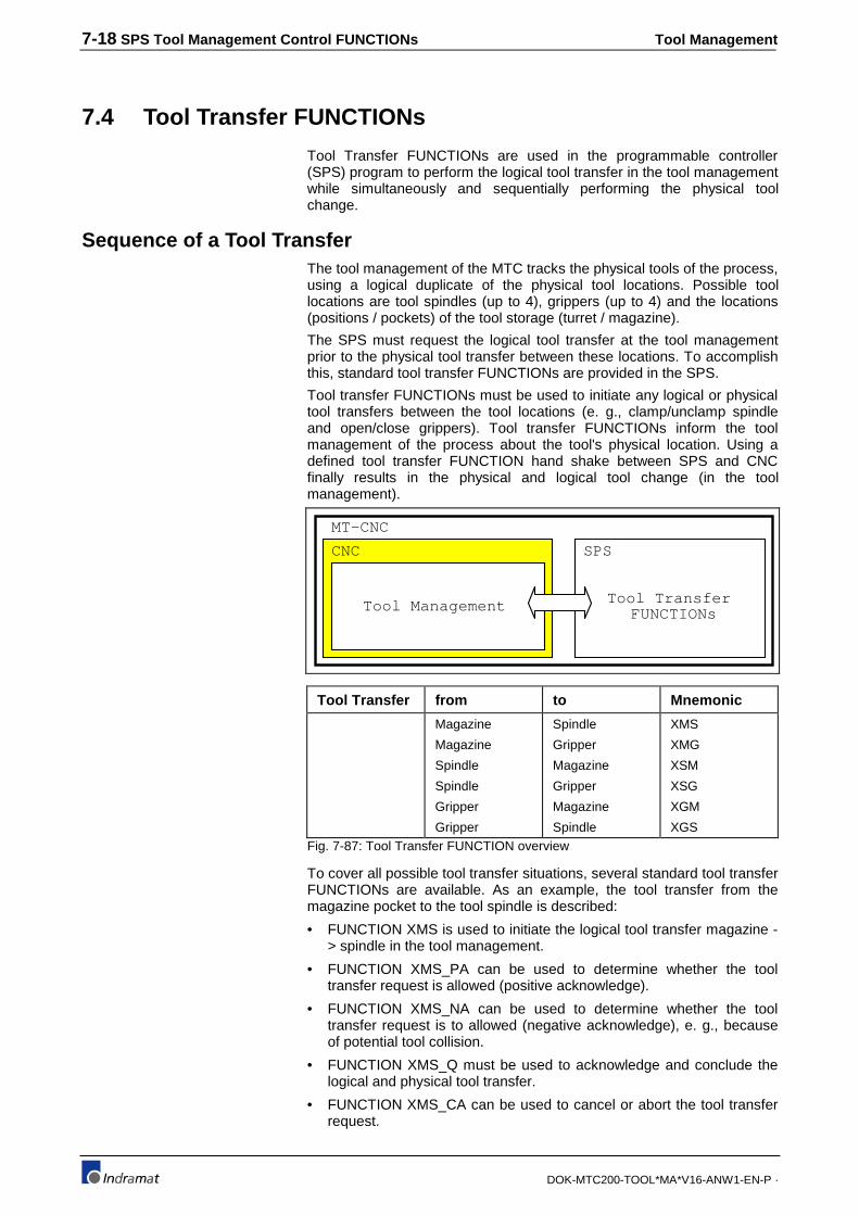
7-18 SPS Tool Management Control FUNCTIONs Tool Management
DOK-MTC200-TOOL*MA*V16-ANW1-EN-P ·
7.4 Tool Transfer FUNCTIONs
Tool Transfer FUNCTIONs are used in the programmable controller(SPS) program to perform the logical tool transfer in the tool managementwhile simultaneously and sequentially performing the physical toolchange.
Sequence of a Tool TransferThe tool management of the MTC tracks the physical tools of the process,using a logical duplicate of the physical tool locations. Possible toollocations are tool spindles (up to 4), grippers (up to 4) and the locations(positions / pockets) of the tool storage (turret / magazine).
The SPS must request the logical tool transfer at the tool managementprior to the physical tool transfer between these locations. To accomplishthis, standard tool transfer FUNCTIONs are provided in the SPS.
Tool transfer FUNCTIONs must be used to initiate any logical or physicaltool transfers between the tool locations (e. g., clamp/unclamp spindleand open/close grippers). Tool transfer FUNCTIONs inform the toolmanagement of the process about the tool's physical location. Using adefined tool transfer FUNCTION hand shake between SPS and CNCfinally results in the physical and logical tool change (in the toolmanagement).
Tool TransferFUNCTIONsTool Management
CNC SPS
MT-CNC
Tool Transfer from to Mnemonic
Magazine
Magazine
Spindle
Spindle
Gripper
Gripper
Spindle
Gripper
Magazine
Gripper
Magazine
Spindle
XMS
XMG
XSM
XSG
XGM
XGSFig. 7-87: Tool Transfer FUNCTION overview
To cover all possible tool transfer situations, several standard tool transferFUNCTIONs are available. As an example, the tool transfer from themagazine pocket to the tool spindle is described:
• FUNCTION XMS is used to initiate the logical tool transfer magazine -> spindle in the tool management.
• FUNCTION XMS_PA can be used to determine whether the tooltransfer request is allowed (positive acknowledge).
• FUNCTION XMS_NA can be used to determine whether the tooltransfer request is to allowed (negative acknowledge), e. g., becauseof potential tool collision.
• FUNCTION XMS_Q must be used to acknowledge and conclude thelogical and physical tool transfer.
• FUNCTION XMS_CA can be used to cancel or abort the tool transferrequest.

Tool Management SPS Tool Management Control FUNCTIONs 7-19
DOK-MTC200-TOOL*MA*V16-ANW1-EN-P ·
The SPS provides the FUNCTION XMS to request a logical tool transferfrom the magazine pocket in the specified tool change position to thespecified tool spindle. The tool management acknowledges the transferrequest either positive or negative.
A positive acknowledge is recognized via a status of `1` at theFUNCTION XMS_PA. If in such a case a status of `1` is applied to theFUNCTION XMS_Q, a logical tool transfer in the tool management, fromthe pocket in the tool change position to the spindle, is performed.
A negative acknowledge indicates that the transfer to the spindle is notpossible, e.g., the spindle already contains a tool. The FUNCTIONXMS_NA must be used to recognize a negative acknowledge. The statusof PxxS.MGERR is set to `1` also if the requested tool transfer is notallowed.
XMS
INIT
PROC
BOOL
INT
POS
SPINDLEINT BOOL
INT
Fig. 7-88: Magazine - > Spindle tool transfer request, FUNCTION XMS
INIT = `0` : No transfer request active
INIT = `0`->`1`: Tool transfer request magazine->spindle
XMS : Reflects status of INIT
PROC = 0..6 : Process number
POS = 1..4 : Tool change position
SPINDLE= 1..3 : 1 = Tool spindle 12 = Tool spindle 23 = Tool Spindle 3
A positive acknowledge of a tool transfer request XMS is recognized via astatus of `1` at the FUNCTION XMS_PA. The tool management logicallytransfers the tool in this case from the pocket in the tool change positionto the spindle.
XMS_PA
ACTIVE
PROC
BOOL
INT
POS
SPINDLEINT BOOL
INT
Fig. 7-89: Magazine - > Spindle tool xfer positive ackng., FUNCTION XMS_PA
ACTIVE = `0` : Not reading acknowledge status.
ACTIVE = `1` : Read positive acknowledgestatus.
XMS_PA = `0` : No positive ackn. or ACTIVE =`0`.
XMS_PA = `0`->`1`: Transfer positive acknowledged(allowed).
PROC = 0..6 : Process number
Magazine->Spindle tool transferrequest, FUNCTION XMS
Magazine->Spindle tool transferpositive acknowledge,
FUNCTION XMS_PA
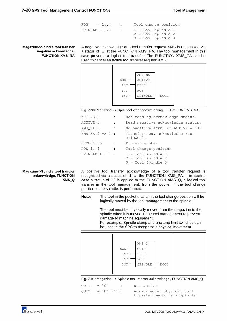
7-20 SPS Tool Management Control FUNCTIONs Tool Management
DOK-MTC200-TOOL*MA*V16-ANW1-EN-P ·
POS = 1..4 : Tool change position
SPINDLE= 1..3 : 1 = Tool spindle 12 = Tool spindle 23 = Tool Spindle 3
A negative acknowledge of a tool transfer request XMS is recognized viaa status of `1` at the FUNCTION XMS_NA. The tool management in thiscase prevents a logical tool transfer. The FUNCTION XMS_CA can beused to cancel an active tool transfer request XMS.
XMS_NA
ACTIVE
PROC
BOOL
INT
POS
SPINDLEINT BOOL
INT
Fig. 7-90: Magazine - > Spdl. tool xfer negative ackng., FUNCTION XMS_NA
ACTIVE 0 : Not reading acknowledge status.
ACTIVE 1 : Read negative acknowledge status.
XMS_NA 0 : No negative ackn. or ACTIVE = `0`.
XMS_NA 0 -> 1 : Transfer neg. acknowledge (notallowed).
PROC 0..6 : Process number
POS 1..4 : Tool change position
SPINDLE 1..3 : 1 = Tool spindle 12 = Tool spindle 23 = Tool Spindle 3
A positive tool transfer acknowledge of a tool transfer request isrecognized via a status of `1` at the FUNCTION XMS_PA. If in such acase a status of `1` is applied to the FUNCTION XMS_Q, a logical tooltransfer in the tool management, from the pocket in the tool changeposition to the spindle, is performed.
Note: The tool in the pocket that is in the tool change position will belogically moved by the tool management to the spindle!
The tool must be physically moved from the magazine to thespindle when it is moved in the tool management to preventdamage to machine equipment!For example, Spindle clamp and unclamp limit switches canbe used in the SPS to recognize a physical movement.
XMS_Q
QUIT
PROC
BOOL
INT
POS
SPINDLEINT BOOL
INT
Fig. 7-91: Magazine - > Spindle tool transfer acknowledge., FUNCTION XMS_Q
QUIT = `0` : Not active.
QUIT = `0`->`1`: Acknowledge, physical tooltransfer magazine-> spindle
Magazine->Spindle tool transfernegative acknowledge,
FUNCTION XMS_NA
Magazine->Spindle tool transferacknowledge, FUNCTION
XMS_Q
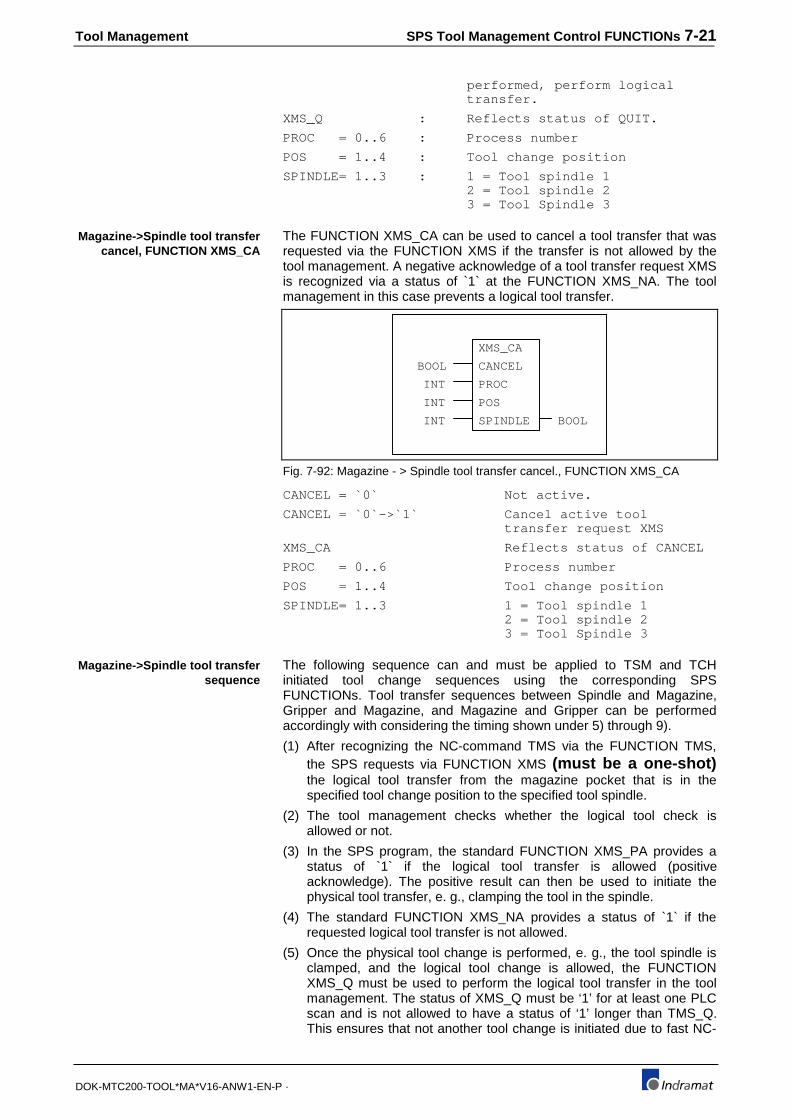
Tool Management SPS Tool Management Control FUNCTIONs 7-21
DOK-MTC200-TOOL*MA*V16-ANW1-EN-P ·
performed, perform logicaltransfer.
XMS_Q : Reflects status of QUIT.
PROC = 0..6 : Process number
POS = 1..4 : Tool change position
SPINDLE= 1..3 : 1 = Tool spindle 12 = Tool spindle 23 = Tool Spindle 3
The FUNCTION XMS_CA can be used to cancel a tool transfer that wasrequested via the FUNCTION XMS if the transfer is not allowed by thetool management. A negative acknowledge of a tool transfer request XMSis recognized via a status of `1` at the FUNCTION XMS_NA. The toolmanagement in this case prevents a logical tool transfer.
XMS_CA
CANCEL
PROC
BOOL
INT
POS
SPINDLEINT BOOL
INT
Fig. 7-92: Magazine - > Spindle tool transfer cancel., FUNCTION XMS_CA
CANCEL = `0` Not active.
CANCEL = `0`->`1` Cancel active tooltransfer request XMS
XMS_CA Reflects status of CANCEL
PROC = 0..6 Process number
POS = 1..4 Tool change position
SPINDLE= 1..3 1 = Tool spindle 12 = Tool spindle 23 = Tool Spindle 3
The following sequence can and must be applied to TSM and TCHinitiated tool change sequences using the corresponding SPSFUNCTIONs. Tool transfer sequences between Spindle and Magazine,Gripper and Magazine, and Magazine and Gripper can be performedaccordingly with considering the timing shown under 5) through 9).
(1) After recognizing the NC-command TMS via the FUNCTION TMS,the SPS requests via FUNCTION XMS (must be a one-shot)the logical tool transfer from the magazine pocket that is in thespecified tool change position to the specified tool spindle.
(2) The tool management checks whether the logical tool check isallowed or not.
(3) In the SPS program, the standard FUNCTION XMS_PA provides astatus of `1` if the logical tool transfer is allowed (positiveacknowledge). The positive result can then be used to initiate thephysical tool transfer, e. g., clamping the tool in the spindle.
(4) The standard FUNCTION XMS_NA provides a status of `1` if therequested logical tool transfer is not allowed.
(5) Once the physical tool change is performed, e. g., the tool spindle isclamped, and the logical tool change is allowed, the FUNCTIONXMS_Q must be used to perform the logical tool transfer in the toolmanagement. The status of XMS_Q must be ‘1’ for at least one PLCscan and is not allowed to have a status of ‘1’ longer than TMS_Q.This ensures that not another tool change is initiated due to fast NC-
Magazine->Spindle tool transfercancel, FUNCTION XMS_CA
Magazine->Spindle tool transfersequence

7-22 SPS Tool Management Control FUNCTIONs Tool Management
DOK-MTC200-TOOL*MA*V16-ANW1-EN-P ·
block execution after TMS acknowledgment while the logical tooltransfer acknowledgment XMS_Q has still a state of ‘1’.
(6) The standard FUNCTION XMS_CA can be used to cancel an activetool transfer XMS request if not allowed by the tool management.
(7) The tool management then cancels the logical tool transfer requestand does not transfer the tool.
(8) After the logical and physical tool transfer, the FUNCTION TMS_Qmust be used to acknowledge completion of the NC-command TMS.NC-program execution continues.
Tool ManagementProcess 1
TMSACTIVEPROC
SPS ProgramProcess 1
1
(5)
(*Detect NC-command TMS*)
(3)
(4)
NC-ProgramProcess 1
N0010 TSM
N0011 ..
N0023 ...
:
POSSPINDLE
11
TMS
XMSINITPROC1
(*Tool transfer request*)
POSSPINDLE
11
XMS
TMS
Tool Managementchecks wetherrequested tooltransfer isallowed or not
XMS_PAACITVEPROC1
(*Tool transfer positive ackn.*)
POSSPINDLE
11
XMS_PA
XMS
XMS_NAACITVEPROC1
(*Tool transfer negative ackn.*)
POSSPINDLE
11
XMS_NA
XMS
XMS_QQUITPROC1
(*Tool transfer acknowledge*)
POSSPINDLE
11
XMS_Q
XMS_PA CLAMPED
(1)
(2)
(7)XMS_CAQUITPROC1
(*Tool transfer cancel*)
POSSPINDLE
11
XMS
XMS_NA P1C.CLEAR
Tool Managementperforms logicaltool transferas requested
(6)
Tool Managementcancels logicaltool transferrequested
(8)
Stop of
NC-program
execution
CLAMP
(9)TMS_QQUITPROC1
(*Tool change acknowledge*)
POSSPINDLE
11
XMS
XMS_Q
XMS
R
R
S
Fig. 7-93: Magazine->Spindle tool transfer sequence
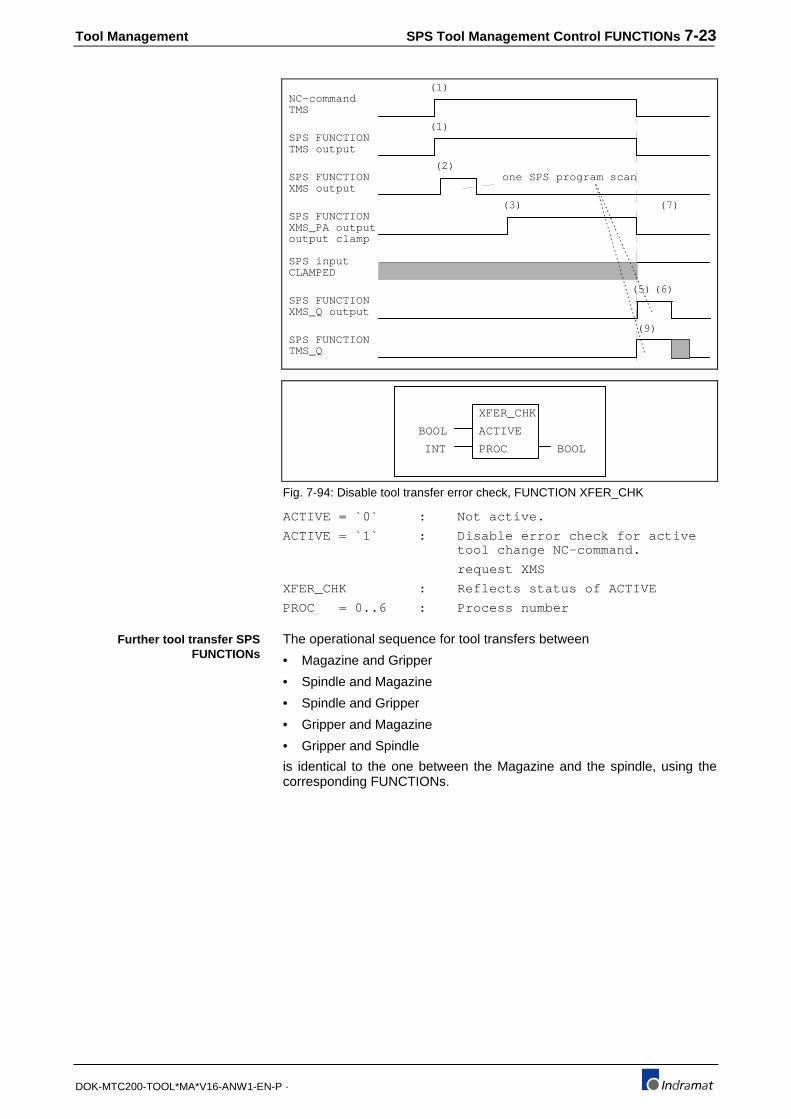
Tool Management SPS Tool Management Control FUNCTIONs 7-23
DOK-MTC200-TOOL*MA*V16-ANW1-EN-P ·
SPS FUNCTIONTMS output
(1)
SPS FUNCTIONXMS output
(2)
SPS FUNCTIONXMS_PA output
(7)
SPS inputCLAMPED
SPS FUNCTIONXMS_Q output
(5)
(3)
NC-commandTMS
(1)
SPS FUNCTIONTMS_Q
(6)
one SPS program scan
output clamp
(9)
XFER_CHK
ACTIVE
PROC
BOOL
INT BOOL
Fig. 7-94: Disable tool transfer error check, FUNCTION XFER_CHK
ACTIVE = `0` : Not active.
ACTIVE = `1` : Disable error check for activetool change NC-command.
request XMS
XFER_CHK : Reflects status of ACTIVE
PROC = 0..6 : Process number
The operational sequence for tool transfers between
• Magazine and Gripper
• Spindle and Magazine
• Spindle and Gripper
• Gripper and Magazine
• Gripper and Spindle
is identical to the one between the Magazine and the spindle, using thecorresponding FUNCTIONs.
Further tool transfer SPSFUNCTIONs

7-24 SPS Tool Management Control FUNCTIONs Tool Management
DOK-MTC200-TOOL*MA*V16-ANW1-EN-P ·
XMSPA| |-------+XMSNA || |-------+
XMSINITPROCPOSSPINDLE
BOOLINTINTINT BOOL
XMS_PAACTIVEPROCPOSSPINDLE
BOOLINTINTINT BOOL
XMS_NAACTIVEPROCPOSSPINDLE
BOOLINTINTINT BOOL
XMS_QQUITPROCPOSSPINDLE
BOOLINTINTINT BOOL
Magazine -> Spindle
Request
Positive Acknowledge
Negative Acknowledge
Acknowledge
XMS_CACANCELPROCPOSSPINDLE
BOOLINTINTINT BOOL
Cancel
XSMINITPROCSPINDLEPOS
BOOLINTINTINT BOOL
XSM_PAACTIVEPROCSPINDLEPOS
BOOLINTINTINT BOOL
XSM_NAACTIVEPROCSPINDLEPOS
BOOLINTINTINT BOOL
XSM_QQUITPROCSPINDLEPOS
BOOLINTINTINT BOOL
Spindle -> Magazine
Request
Positive Acknowledge
Negative Acknowledge
Acknowledge
XSM_CACANCELPROCSPINDLEPOS
BOOLINTINTINT BOOL
Cancel
XMGINITPROCPOSGRIP
BOOLINTINTINT BOOL
XMG_PAACTIVEPROCPOSGRIP
BOOLINTINTINT BOOL
XMG_NAACTIVEPROCPOSGRIP
BOOLINTINTINT BOOL
XMG_QQUITPROCPOSGRIP
BOOLINTINTINT BOOL
Magazine -> Gripper
Request
Positive Acknowledge
Negative Acknowledge
Acknowledge
XMG_CACANCELPROCPOSGRIP
BOOLINTINTINT BOOL
Cancel
XGMINITPROCPOSGRIP
BOOLINTINTINT BOOL
XGM_PAACTIVEPROCGRIPPOS
BOOLINTINTINT BOOL
XGM_NAACTIVEPROCGRIPPOS
BOOLINTINTINT BOOL
XGM_QQUITPROCGRIPPOS
BOOLINTINTINT BOOL
Gripper -> Magazine
Request
Positive Acknowledge
Negative Acknowledge
Acknowledge
XGM_CACANCELPROCGRIPPOS
BOOLINTINTINT BOOL
Cancel
XSGINITPROC
BOOLINTINTINT BOOL
XSG_PAACTIVEPROC
GRIP
BOOLINTINTINT BOOL
XSG_NAACTIVEPROC
GRIP
BOOLINTINTINT BOOL
XSG_QQUITPROC
GRIP
BOOLINTINTINT BOOL
Spindle -> Gripper
Request
Positive Acknowledge
Negative Acknowledge
Acknowledge
XSG_CACANCELPROC
GRIP
BOOLINTINTINT BOOL
Cancel
SPINDLEGRIP
SPINDLE
SPINDLE
SPINDLE
SPINDLE
XGSINITPROC
BOOLINTINTINT BOOL
XGS_PAACTIVEPROC
SPINDLE
BOOLINTINTINT BOOL
XGS_NAACTIVEPROC
SPINDLE
BOOLINTINTINT BOOL
XGS_QQUITPROC
SPINDLE
BOOLINTINTINT BOOL
Gripper -> Spindle
Request
Positive Acknowledge
Negative Acknowledge
Acknowledge
XGS_CACANCELPROC
SPINDLE
BOOLINTINTINT BOOL
Cancel
GRIPSPINDLE
GRIP
GRIP
GRIP
GRIP
PROC :Process 0..6POS :Tool change positionGRIP :Gripper 1..4SPINDLE :tool spindle 1..4
Fig. 7-95: Tool Transfer FUNCTION overview

Tool Management SPS Tool Management Control FUNCTIONs 7-25
DOK-MTC200-TOOL*MA*V16-ANW1-EN-P ·
7.5 Combined Spindle / Turret axis
The MTC system parameters allow to specify a combined spindle turretaxis. Such an axis type allows to use one drive to move the tool turret andspindle for live tooling. The CNC automatically switches between turretand spindle mode, depending on the executed NC-command.
The turret mode is selected if a NC-command that initiates a turretmovement is executed. After completion of the turret movement, the CNCautomatically switches back to spindle mode.
Standard FUNCTIONs are available in the SPS to read and acknowledgethe spindle and turret mode:
• Read & acknowledge turret mode : FUNCTION MAG_ACT &FUNCTION MAG_Q
• Read & acknowledge spindle mode: FUNCTION SPDL_ACT &FUNCTION SPDL_Q
These FUNCTIONs must be used to control the mechanical switchingbetween turret mechanism and the tool that is currently in machiningposition.
Read and acknowledge turret modeThe CNC selects the turret mode if a tool storage movement NC-command is programmed and a combined spindle/turret axis is definedfor the process. The process then automatically has a turret tool storagedriven by a servo or spindle drive (depending on their capabilities) thatcan also be used as a spindle for live tooling.
The standard FUNCTION MAG_ACT must be used in the SPS programto recognize the turret mode.
MAG_ACT
ACTIVE
PROC
BOOL
INT BOOL
Fig. 7-96: Read turret mode, FUNCTION MAG_ACT
ACTIVE = `0` : Not active.
ACTIVE = `1` : Read turret mode status
MAG_ACT= '0' : Turret mode not active or ACTIVE= '0'.
MAG_ACT= '1 : Turret mode active
PROC = 0..6 : Process number
Once the combined spindle/turret axis is mechanically coupled to movethe turret, the standard FUNCTION MAG_Q must be used toacknowledge this status to the CNC.
The acknowledgment must remain active while the turret mode is active,otherwise a process error
#321 'Comb. Spindle/Turret axis acknowledgment missing'
is activated.
MAG_Q
QUIT
PROC
BOOL
INT BOOL
Read turret mode
Acknowledge the turret mode

7-26 SPS Tool Management Control FUNCTIONs Tool Management
DOK-MTC200-TOOL*MA*V16-ANW1-EN-P ·
Fig. 7-97: Acknowledge turret mode, FUNCTION MAG_Q
QUIT = `0` : Not active.
QUIT = `1` : Acknowledges turret mode
MAG_Q = '0' : Reflects status of QUIT
PROC = 0..6 : Process number
Declaration in a PROGRAM:
PROGRAM EXAMPLEVAR_INPUTI0_MAGMOD %I1.1.0 (*LS Turret engaged*)I0_SPMOD %I1.1.1 (*LS Spindle engaged*):VAR_OUTPUTQ0_MAGMOD %Q1.0.0 (*SOL Engage turret*)Q0_SPMOD %Q1.0.1 (*SOL Engage spindle*):VARRQRD_COIL BOOL (*Required coil*):VAR RETAIN
END_VARImplementation Instruction List in a PROGRAM:
: :|(*READ TURRET MODE STATUS AND ENGAGE TURRET*) || +--------+ || |MAG_ACT | Q0_MAGMOD |+-----------+ACTIVE +-------------------------------------------------------+--(S)------+| 0-+PROC | |Q0_SPMOD || +--------+ +--(R)------+|(*ACKNOWLEDGE THAT TURRET ENGAGED*) || +--------+ ||I0_MAGMOD I0_SPMOD |MAG_Q | X |+| |--------|/|---------+QUIT +----------------------------------------------( )------+| 0-+PROC | || +--------+ |
Read and acknowledge spindle modeThe CNC selects the spindle mode if NO tool storage movement NC-command is programmed and a combined spindle/turret axis is definedfor the process. The process then automatically has a turret tool storagedriven by a servo or spindle drive (depending on their capabilities) thatcan also be used as a spindle for live tooling.
The standard FUNCTION SPDL_ACT must be used in the SPS programto recognize the spindle mode.
SPDL_ACT
ACTIVE
PROC
BOOL
INT BOOL
Fig. 7-98: Read spindle mode, FUNCTION SPDL_ACT
ACTIVE = `0` : Not active.
ACTIVE = `1` : Read spindle mode status
SPDL_ACT= '0' : Spindle mode not active orACTIVE = '0'.
SPDL_ACT= '1 : Spindle mode active
PROC = 0..6 : Process number
Example to turret mode ofcombined spindle/turret axis
Read spindle mode
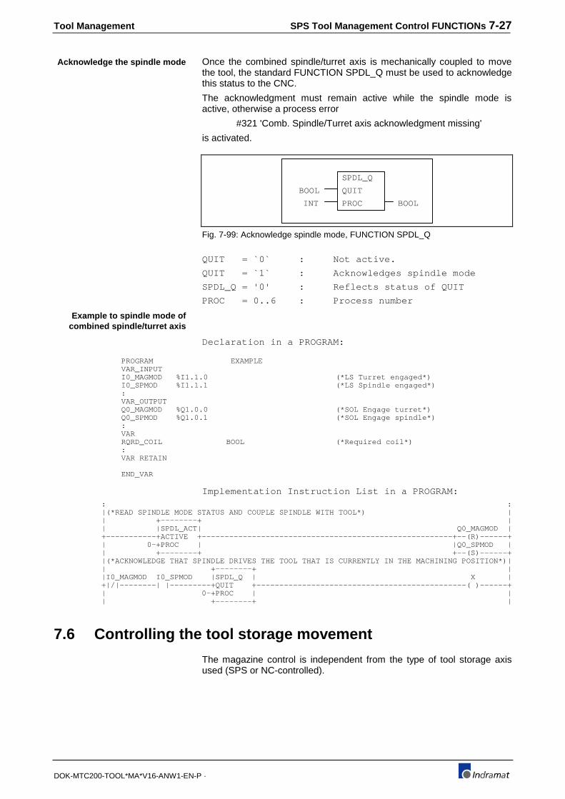
Tool Management SPS Tool Management Control FUNCTIONs 7-27
DOK-MTC200-TOOL*MA*V16-ANW1-EN-P ·
Once the combined spindle/turret axis is mechanically coupled to movethe tool, the standard FUNCTION SPDL_Q must be used to acknowledgethis status to the CNC.
The acknowledgment must remain active while the spindle mode isactive, otherwise a process error
#321 'Comb. Spindle/Turret axis acknowledgment missing'
is activated.
SPDL_Q
QUIT
PROC
BOOL
INT BOOL
Fig. 7-99: Acknowledge spindle mode, FUNCTION SPDL_Q
QUIT = `0` : Not active.
QUIT = `1` : Acknowledges spindle mode
SPDL_Q = '0' : Reflects status of QUIT
PROC = 0..6 : Process number
Declaration in a PROGRAM:
PROGRAM EXAMPLEVAR_INPUTI0_MAGMOD %I1.1.0 (*LS Turret engaged*)I0_SPMOD %I1.1.1 (*LS Spindle engaged*):VAR_OUTPUTQ0_MAGMOD %Q1.0.0 (*SOL Engage turret*)Q0_SPMOD %Q1.0.1 (*SOL Engage spindle*):VARRQRD_COIL BOOL (*Required coil*):VAR RETAIN
END_VAR
Implementation Instruction List in a PROGRAM:: :|(*READ SPINDLE MODE STATUS AND COUPLE SPINDLE WITH TOOL*) || +--------+ || |SPDL_ACT| Q0_MAGMOD |+-----------+ACTIVE +-------------------------------------------------------+--(R)------+| 0-+PROC | |Q0_SPMOD || +--------+ +--(S)------+|(*ACKNOWLEDGE THAT SPINDLE DRIVES THE TOOL THAT IS CURRENTLY IN THE MACHINING POSITION*)|| +--------+ ||I0_MAGMOD I0_SPMOD |SPDL_Q | X |+|/|--------| |---------+QUIT +----------------------------------------------( )------+| 0-+PROC | || +--------+ |
7.6 Controlling the tool storage movement
The magazine control is independent from the type of tool storage axisused (SPS or NC-controlled).
Acknowledge the spindle mode
Example to spindle mode ofcombined spindle/turret axis

7-28 SPS Tool Management Control FUNCTIONs Tool Management
DOK-MTC200-TOOL*MA*V16-ANW1-EN-P ·
Tool Management
Tool storagemovement
NC-commands
MTPMMPMFPMOPMRFMHP
Tool managementcontrol logic
CNC
location
Axis ProcessorAPR
Servo & NC
tool storagecontrolled
Tool storagecontrol and status
Gateway signals
PxxCMGHOMPxxCMGBPPxxMGMOV:
User logic and
SPS programFUNCTIONs in the
(position/pocket)location MRF
MMV
SPS
SPS
tool storagecontrolled
MT-CNC
Process
Fig. 7-100: Principal operation of the tool storage
Tool storage movements can be initiated via NC-program, MDI mode,and the SPS program. The MTC provides a Gateway control and statussignal set for each process to control manual tool storage movements.Refer to section 1 of the MTC CNC⇔SPS Gateway Reference Manual forsignal definitions used in the following sections.
Enable tool storage, PxxC.MGENAControl signal SPS ⇒CNC
The control signal is valid in all operating modes.
PxxC.MGENA = `0` :Tool storage not enabled by SPS
PxxC.MGENA = `1` :Tool storage enabled.
The signal PxxC.MGENA must have a status of `1` to enable any toolstorage movements. The tool storage must be enabled for its manualmode via SPS and CNC mode.
The status `0` of PxxC.MGENA immediately stops NC controlled toolstorage movement and must stop SPS controlled movements. Toolstorage movements continue if the status of PxxC.MGENA switches backto `1`.

Tool Management SPS Tool Management Control FUNCTIONs 7-29
DOK-MTC200-TOOL*MA*V16-ANW1-EN-P ·
This feature can be used interlock the tool storage with safety devices, e.g., guarding. The servo axis of a CNC controlled tool storage is disabled ifPxxC.ENABL switches to `0`, e. g., magazine access door is beingopened. The tool management resets the signal PxxS.MGENA to `0` ifthe magazine is SPS controlled and PxxC.ENABL switches to `0`.
A process stop (e. g, change of operating mode), a process error anddisabling the process has the same result as a status of `0` atPxxC.ENABL.
Note : If the tool storage movement is SPS controlled (PxxS.MGPLC= `1`), the SPS logic that causes tool storage movement mustbe combined with the signal PxxS.MGENA. To preventdamage and injury, the interlock must prevent any movementif the status of PxxS.MGENA is `0`!
CNC controlledtool storage
Axis Processor
APR
Tool
Management
movementinterruption Axis enable
Imediate stop
SPSSPS controlledtool storage
movementinterruption PxxSMGENA
SPS controlledtool storage
movementinterruption
Safety devices
movementinterruption
(e.g.,guarding)
PxxCMGENA
Error
Process enable
Fig. 7-101: Tool storage enable signal, PxxC.MGENA
Control signal SPS ⇒CNC
The control signal is valid in all operating modes.
PxxC.MGMAN = `0` :Tool storage is controlled by CNCprogram.
PxxC.MGMAN = `1` :Manual (SPS) tool storage mode(request).
The tool storage can be moved manually independent of the activeprocess operating mode, e. g., while the NC-program of the process isexecuted. The SPS must request the manual tool storage mode with thestatus `1` of the signal PxxC.MGMAN at the tool management.
The tool management allows manual mode only if manual mode isenabled. The NC-command 'MEN' (Magazine Enable) enables themanual magazine mode. The manual mode is also enabled if the NC-program execution is not active.
The status signal PxxS.MGMAN = `1` indicates the SPS that the toolmanagement has switched the tool storage into manual mode. It will stayin manual mode until the signal PxxC.MGMAN switches back to `0`.
The CNC continues executing the process program until the next toolstorage NC-command is to be executed if manual tool storage mode(PxxS.MGMAN=`1`) is active. The MUI then displays the status message'Waiting for tool magazine command to be completed'.
The CNC continues with the NC-program and the message disappearsexecution after the SPS resets the request for manual tool storage mode(PxxC.MGMAN =`0`).
Manual Tool Storage Mode,PxxC.MGMAN

7-30 SPS Tool Management Control FUNCTIONs Tool Management
DOK-MTC200-TOOL*MA*V16-ANW1-EN-P ·
The tool management indicates with the status signal PxxS.MGREQ =`1`that the tool storage is required by the CNC. The CNC requests the toolstorage if a tool storage movement NC-command (MTP, MMP, MFP,MOP, MHP and MRF) is to be executed.
The NC-command MEN, RET, BST and a 'Control Reset' reset the NCrequest for the tool storage. The SPS request for manual tool storagemode is suppressed by the tool management until one of theseoperations is performed.
A Tool storage, NC servo or SPS controlled, can be manually operated asasynchronous axis while the process operating mode automatic or semi-automatic is active.
NC-program
Tool storage movementNC-command
MTP,MMP,MFP,MOP,MHP,MRF
Tool management
>=1BST,RET
MEN
'Control Reset'
S
R
SPS
&
Q PxxSMGENQ
PxxCMGMAN
PxxSMGMAN
Manual tool storagemode request
Tool storagein manual mode
NC tool storage request
Fig. 7-102: Tool storage operating mode
Control signal SPS ⇒CNC
The control signal is valid in all operating modes.
PxxC.MGHOM = `0` :Homing not commanded.
PxxC.MGHOM = `0`->`1` :Start of tool storage homing sequence
A signal change from `0` to `1` at PxxC.MGHOM causes the tool storageto move to its home position. The tool management transfers the homingcommand to the controlling Axis Processor (APR) if the tool storage axisis servo controlled.
The NC-command MRF can be read in the SPS via FUNCTION MRF.The result of FUNCTION MRF must then be assigned to PxxC.MGHOM ifthe tool storage is SPS controlled. The signal PxxC.MGHOM can be usedalso to home the tool storage axis independent of NC-command MRFexecution. The magazine axis must be homed after each power OFF/ONif incremental position feedback is used. It is wise to home the toolstorage together with other process axes in the reverse program.
Note : The tool storage home position is specified by its mechanicalreference switch and cam, if the tool storage is SPScontrolled. The zero marker of the encoder, the reference camand switch specify the home position of a servo controlled toolstorage axis. The magazine home position must not beidentical with the magazine base position! The axis parameterCxx.037 (xx = analog axis 1..20) or digital drive parameter S-0-0052, S0-0054 specifies the difference between referenceand base position.
Home Tool Storage,PxxC.MGHOM
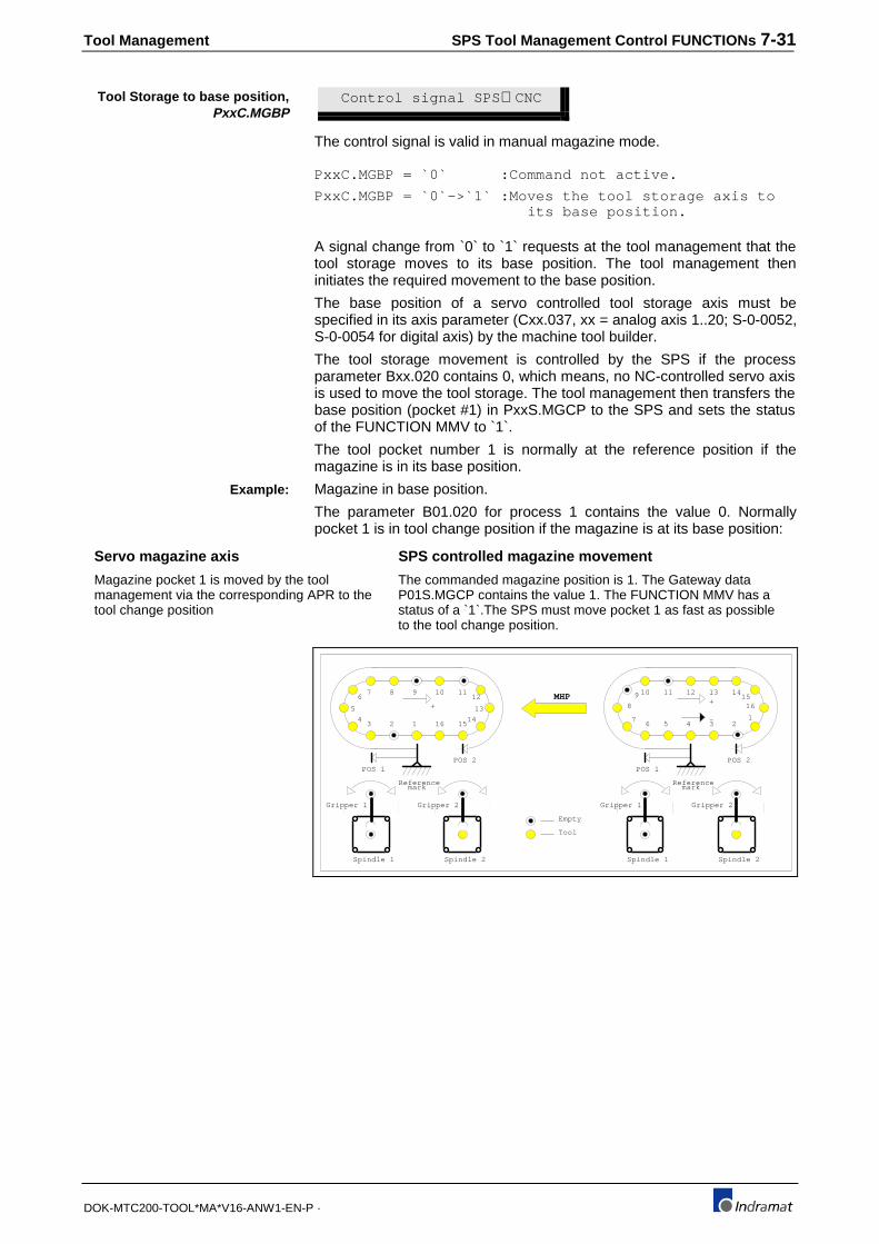
Tool Management SPS Tool Management Control FUNCTIONs 7-31
DOK-MTC200-TOOL*MA*V16-ANW1-EN-P ·
Control signal SPS ⇒CNC
The control signal is valid in manual magazine mode.
PxxC.MGBP = `0` :Command not active.
PxxC.MGBP = `0`->`1` :Moves the tool storage axis to its base position.
A signal change from `0` to `1` requests at the tool management that thetool storage moves to its base position. The tool management theninitiates the required movement to the base position.
The base position of a servo controlled tool storage axis must bespecified in its axis parameter (Cxx.037, xx = analog axis 1..20; S-0-0052,S-0-0054 for digital axis) by the machine tool builder.
The tool storage movement is controlled by the SPS if the processparameter Bxx.020 contains 0, which means, no NC-controlled servo axisis used to move the tool storage. The tool management then transfers thebase position (pocket #1) in PxxS.MGCP to the SPS and sets the statusof the FUNCTION MMV to `1`.
The tool pocket number 1 is normally at the reference position if themagazine is in its base position.
Magazine in base position.
The parameter B01.020 for process 1 contains the value 0. Normallypocket 1 is in tool change position if the magazine is at its base position:
Servo magazine axis SPS controlled magazine movement
Magazine pocket 1 is moved by the toolmanagement via the corresponding APR to thetool change position
The commanded magazine position is 1. The Gateway dataP01S.MGCP contains the value 1. The FUNCTION MMV has astatus of a `1`.The SPS must move pocket 1 as fast as possibleto the tool change position.
1234
5
67 8 9 10 11
12
13
141516
Referencemark
+
POS 1POS 2
Gripper 1
Spindle 1
Gripper 2
Spindle 2
Empty
Tool
Gripper 1
Spindle 1
Gripper 2
Spindle 2
MHP 13 1415
16
123456
7
8
9 10 11 12
Referencemark
+
POS 1POS 2
-
Tool Storage to base position,PxxC.MGBP
Example:
7-32 SPS Tool Management Control FUNCTIONs Tool Management
DOK-MTC200-TOOL*MA*V16-ANW1-EN-P ·
Control signal SPS ⇒CNC
The control signal is valid in manual tool storage mode.
PxxC.MGPOS = `0` :Do not move.
PxxC.MGPOS = `0`->`1` :Move tool storage 1 location in pos. direction.
A signal change from `0` to `1` causes the tool management to commandthe tool storage location with the next higher location number into thereference position. Location number 1 follows the highest location numberif the tool storage is defined as an endless or none endless tool storage(Magazine/Turret).
The tool management transfers the new position to the Axes Processorthat controls the servo tool storage axis.
The data word PxxS.MGCP contains the commanded location numberthat must be moved to the reference position if the tool storage is SPScontrolled. The value 0 in process parameter Bxx.020 specifies themagazine as SPS controlled. The FUNCTION MMV must be used in theSPS to recognize tool storage movement NC-commands.
Control signal SPS ⇒CNC
The control signal is valid in manual tool storage mode.
PxxC.MGNEG = `0` :Do not move.
PxxC.MGNEG = `0`->`1` :Move tool storage 1 location inneg. direction.
A signal change from `0` to `1` causes the tool management to commandthe tool storage location with the next lower location number into thereference position. The highest location number follows location number 1if the tool storage is defined as an endless or non-endless tool storage(Magazine/Turret).
The tool management transfers the new position to the Axes Processorthat controls the servo tool storage axis.
The data word PxxS.MGCP contains the commanded location numberthat must be moved to the reference position if the tool storage is SPScontrolled. The value 0 in process parameter Bxx.020 specifies themagazine as SPS controlled. The FUNCTION MMV must be used in theSPS to recognize tool storage movement NC-commands.
Control signal SPS ⇒CNC
The control data word is valid in all operating modes.
PxxC.MGAP ;Actual tool storage location number (0..999) that is in the reference position.
The contents of this Integer data is necessary only for a SPS controlledtool storage. The SPS must write the number of the location that iscurrently in the reference position into this data word to keep the toolmanagement informed.
The positioning of a SPS controlled tool storage must be done via theSPS program. The tool management always provides the commandedlocation (position/pocket) number via PxxS.MGCP to the SPS. The SPSFUNCTION MMV must be used to recognize active tool storage
Move Tool Storage Positive,PxxC.MGPOS
Move Tool Storage Negative,PxxC.MGNEG
Actual Tool Storage Position,PxxC.MGAP

Tool Management SPS Tool Management Control FUNCTIONs 7-33
DOK-MTC200-TOOL*MA*V16-ANW1-EN-P ·
movement NC-commands and to initiate a movement, that will bring thecommanded location on the shortest distance to the reference position.
The actual tool storage position must updated during the magazinemovement. The position is then transferred via PxxC.MGAP to the toolmanagement.
The SPS must acknowledge the completion of the movement with theFUNCTION MMV_Q. The status of MMV_Q must be set to a `1` if thecommanded and actual location number are equal, PxxC.MGAP =PxxS.MGCP.
Note : The tool management does NOT check that the correctlocation is at the reference position if the SPS confirms themovement completion via FUNCTION MMV_Q. The toolmanagement does not compare PxxS.MGCP andPxxC.MGAP! However, the location number specified inPxxC.MGAP is used in consecutive tool transfer FUNCTIONs!
Control signal SPS⇒CNC
The control signal is valid in all operating modes.
PxxC.MGNTC = `0` :Perform Automatic Tool Check.
PxxC.MGNTC = `1` :Do NOT perform Automatic Tool Check.
The tool management performs an Automatic Tool Check (comparesdata of Active Tool List then matches the requirements of the active ToolSetup List) if PxxC.MGNTC is `0` and the process is advanced(PxxC.ADV) or reversed (PxxC.REV).]
No Automatic Tool Check is performed if the status of PxxC.MGNTC is`1` at the time of process advance or reverse. The data of the active ToolSetup List is then not considered by the tool management, only generaladministration tasks are performed.
Refer to the Tool Management Reference Manual for more information.
Tool Storage Status SignalsThe tool management provides information about the tool storage andtool status, the tool storage status Gateway signals. The status isindependent of the type of tool storage drive (servo or SPS controlled).
Status signal CNC ⇒SPS
The status signal is valid in all operating modes.
PxxS.MGENA = `0` :Tool storage movements disabled.
PxxS.MGENA = `1` :Tool storage movements enabled.
The tool management uses the signal PxxS.MGENA to enable or disablethe tool storage movement if it is SPS and not NC servo controlled.
Reasons for disabling the tool storage can be safety devices. Their signalstatus must be interlocked with signal PxxC.MGENA. A Pxx.MGENAsignal status `0` will cause a `0` at the signal PxxS.MGENA.
The signal PxxS.MGENA also switches to `0` if a process or system erroroccurs, if the process is disabled or if an internal process stop is applied.For example, changing the process operating mode during NC-programexecution causes a process stop.
No Automatic Tool Check,PxxC.MGNTC
Tool Storage Enabled,PxxS.MGENA
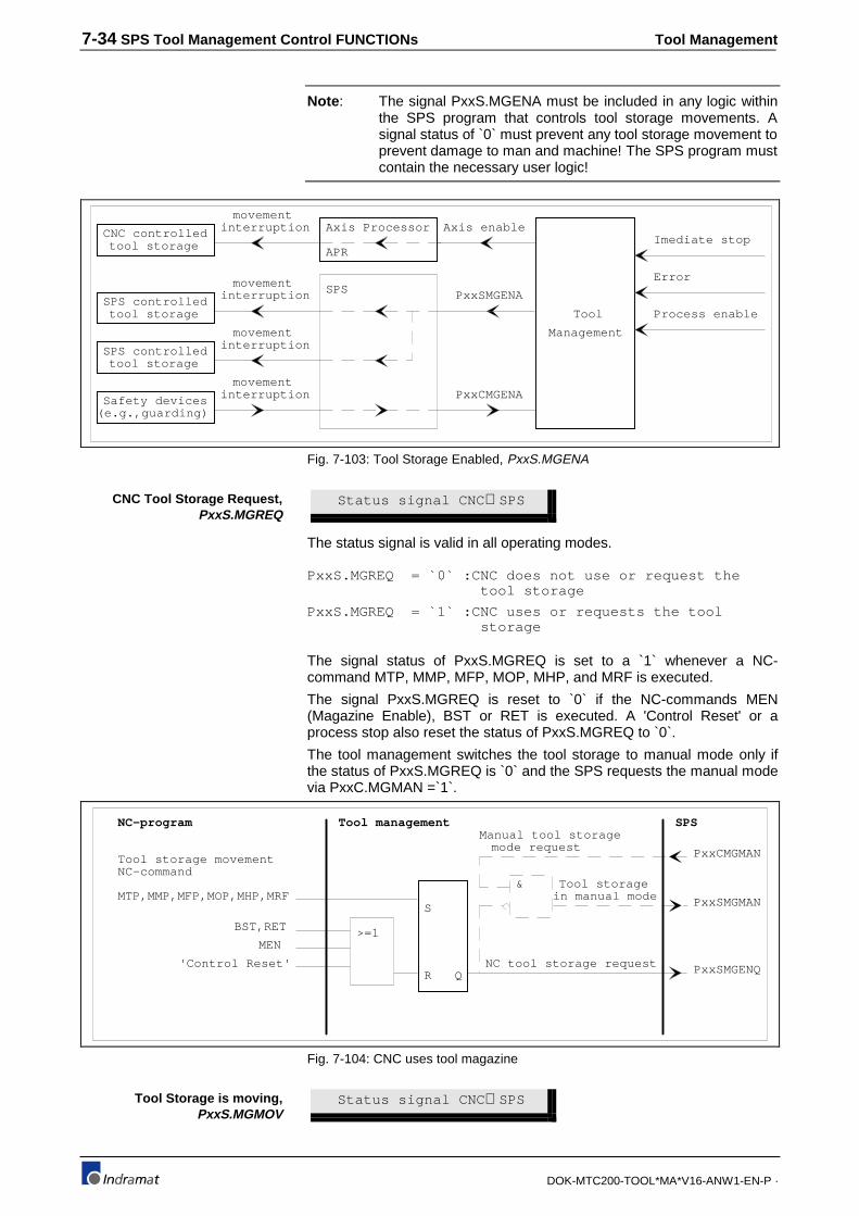
7-34 SPS Tool Management Control FUNCTIONs Tool Management
DOK-MTC200-TOOL*MA*V16-ANW1-EN-P ·
Note : The signal PxxS.MGENA must be included in any logic withinthe SPS program that controls tool storage movements. Asignal status of `0` must prevent any tool storage movement toprevent damage to man and machine! The SPS program mustcontain the necessary user logic!
CNC controlledtool storage
Axis Processor
APR
Tool
Management
movementinterruption Axis enable
Imediate stop
SPSSPS controlledtool storage
movementinterruption PxxSMGENA
SPS controlledtool storage
movementinterruption
Safety devices
movementinterruption
(e.g.,guarding)
PxxCMGENA
Error
Process enable
Fig. 7-103: Tool Storage Enabled, PxxS.MGENA
Status signal CNC ⇒SPS
The status signal is valid in all operating modes.
PxxS.MGREQ = `0` :CNC does not use or request the tool storage
PxxS.MGREQ = `1` :CNC uses or requests the tool storage
The signal status of PxxS.MGREQ is set to a `1` whenever a NC-command MTP, MMP, MFP, MOP, MHP, and MRF is executed.
The signal PxxS.MGREQ is reset to `0` if the NC-commands MEN(Magazine Enable), BST or RET is executed. A 'Control Reset' or aprocess stop also reset the status of PxxS.MGREQ to `0`.
The tool management switches the tool storage to manual mode only ifthe status of PxxS.MGREQ is `0` and the SPS requests the manual modevia PxxC.MGMAN =`1`.
NC-program
Tool storage movementNC-command
MTP,MMP,MFP,MOP,MHP,MRF
Tool management
>=1BST,RET
MEN
'Control Reset'
S
R
SPS
&
Q PxxSMGENQ
PxxCMGMAN
PxxSMGMAN
Manual tool storagemode request
Tool storagein manual mode
NC tool storage request
Fig. 7-104: CNC uses tool magazine
Status signal CNC ⇒SPS
CNC Tool Storage Request,PxxS.MGREQ
Tool Storage is moving,PxxS.MGMOV

Tool Management SPS Tool Management Control FUNCTIONs 7-35
DOK-MTC200-TOOL*MA*V16-ANW1-EN-P ·
The status signal is valid in all operating modes.
PxxS.MGMOV = `0` :NO tool storage movement (standstill)
PxxS.MGMOV = `1` :Tool storage is moving
The status of the signal PxxS.MGMOV is `1` whenever the tool storagemoves. The signal is valid for SPS and servo controlled tool storages. Themovement can be commanded by either the CNC or the SPS.
SPS tool storage movement commands are suppressed by the toolmanagement while the tool storage moves (PxxS.MGMOV = `1`).
Status signal CNC ⇒SPS
The status signal valid in all operating modes.
PxxS.MGMAN = `0` :Tool storage not in manual mode
PxxS.MGMAN = `1` :Tool storage is in manual mode
A status `1` indicates that the tool management switched the tool storageinto manual mode. The SPS must have requested the manual mode(PxxC.MGMAN = `1`) and has in manual mode control over themagazine.
The tool management sets the signal status of PxxS.MGMAN to `1` only ifthe SPS requests manual tool storage mode (PxxC.MGMAN = `1`) andthe CNC does not request or use the tool storage. The NC-commandMEN can be used to allow SPS manual mode access.
Status signal CNC ⇒SPS
The status signal is valid in all operating modes.
PxxS.MGBP = `0` :Tool storage in base position
PxxS.MGBP = `1` :Tool storage is in base position
The signal PxxS.MGBP is only necessary for SPS controlled toolstorages. Its status is set to `1` if the tool storage is at its base position,which means, location number 1 is at the tool storage reference position.
This signal may be used in the SPS program to enable NC-programexecution only if the tool storage is at its base position. SPS programinterlocks should be made if collisions with the tool storage could occur.
Status signal CNC ⇒SPS
The status signal is valid in all operating modes.
PxxS.MGCP : The data contains the location number( ±0..999) that must be moved to the tool storagereference position.
The PxxS.MGCP contents is only required when using a SPS controlledtool storage device (Magazine/Turret).
The tool management sends in PxxS.MGCP that tool location numberthat must be moved to the reference position in order to locate theprogrammed tool in the selected (in tool storage movement NC-command) tool change position.
Manual Tool Storage ModeStatus, PxxS.MGMAN
Tool Storage in Base Position,PxxS.MGBP
Commanded Tool StoragePosition, PxxS.MGCP

7-36 SPS Tool Management Control FUNCTIONs Tool Management
DOK-MTC200-TOOL*MA*V16-ANW1-EN-P ·
Also, the user SPS program must control the direction of the tool storagemovement.
NC-program
Tool storage movementNC-command
MTP,MMP,MFP,MOP,MHP,MRF
Tool management
>=1BST,RET
MEN
'Control Reset'
S
R
SPS
&
Q PxxSMGENQ
PxxCMGMAN
PxxSMGMAN
Manual tool storagemode request
Tool storagein manual mode
NC tool storage request
Fig. 7-105: Commanded and actual location of SPS controlled tool storage
Depending on the active tool storage NC-command and its 'Position'option, PxxS.MGCP contains the following information:
The process parameters
• Bxx.021 Position 1 (Offset to the Reference)
• Bxx.022 Position 2 (Offset to the Reference)
• Bxx.023 Position 3 (Offset to the Reference)
• Bxx.024 Position 4 (Offset to the Reference)
allow to specify a location offset in positive movement direction, startingat the reference position. This allows to define up to 4 tool changepositions that can be selected as an option in the tool storage movementNC-commands.
The tool management automatically considers the selected positionand its offset. PxxS.MGCP contains the respective location numberif a offset greater than 0 locations is selected.
The respective location number is the result of the tool's orprogrammed location number minus the selected location offset(see examples) for endless magazines and turrets.
In the case of endless magazines or turrets, the contents of PxxS.MGCPis always positive, since 1 follows the highest location number and viceversa (modulo calculation).
No position offsets should be used in conjunction with SPS controllednone endless tool storages that are of the type rack and cannot bemoved. PxxS.MGCP will then contain always positive values.
Non-endless tool rack type tool changers that move can have differentoffset positions. PxxS.MGCP contains then positive location numbers forlocations that are located within the physical location number range of therack and eventually negative numbers when tools must be moved intopositions that reside outside the physical location number range (seeexample).
• Upon recognizing a tool storage movement NC-command viaFUNCTION MMV ('1') in the SPS, the SPS must control the toolstorage in such a way that the location number in PxxS.MGCP ismoved to the reference position.
• PxxS.MGCP contains the respective location number of the lastselected tool (T-number) if the NC-command MTP is executed.PxxS.MGCP contains the respective location number of the via NC-command MMP programmed location.

Tool Management SPS Tool Management Control FUNCTIONs 7-37
DOK-MTC200-TOOL*MA*V16-ANW1-EN-P ·
• PxxS.MGCP contains the respective location number of the closestavailable free (empty) location if the NC-command MFP is executed.
• The respective location (pocket/position) number of the tool that iscurrently in, or was last in the selected (NC-command) tool spindle, iscontained in PxxS.MGCP if the NC-command MOP is executed.
• The NC-command MHP provides the location number 1 inPxxS.MGCP which defines the base position.
• The pocket number 0 (reference) is contained in PxxS.MGCP if theNC-command MRF is active and its completion is acknowledged viathe FUNCTION MRF_Q (`0`->`1`).
The actual tool storage position must be transferred via PxxC.MGAP fromthe SPS to the tool management during the movement.
The SPS must stop the tool storage movement when commandedlocation is in at the tool storage reference position and actual equalscommanded position. The status of the SPS FUNCTION MMV_Q mustthen be set to `1` (1 program scan) to confirm the movement completionto the tool management.
Commanded magazine pocket via PxxS.MGCP.
The SPS controlled endless tool turret has 8 tool locations, eachcontaining a tool.
POS1POS2
POS3
Referenceposition
+
12
3
4
56
7
8
T238
T831
T125
T239
T91
T254
T121
POS1POS2
POS3
Referenceposition
T91 MTP(2)
+
1
2
34
5
6
78
T238
T831T125
T239
T91
T254
T121
T3 MMP(2)
Fig. 7-106: Example: Commanded magazine pocket via PxxS.MGCP
The following offset entries must be specified in the process parameters:
• Bxx.021 Position 1 (Offset to the Reference) = 1
• Bxx.022 Position 2 (Offset to the Reference) = 4
• Bxx.023 Position 3 (Offset to the Reference) = 5
• Bxx.024 Position 4 (Offset to the Reference) = 0
The NC-program contains the statement 'T91 MTP(2)' or 'T3 MMP(2)' tomove the tool T91 in location number 3 to the machining position number2. After searching for the T91 in the Active Magazine List, the toolmanagement determines the respective location number that must bemoved to the reference position.
Position 2 is offset by 5 tool locations. T91 is contained in location number3 that is currently in the reference position. Location number 3 minus 5will result in the respective location number 6.
The tool management provides location number 6 in PxxS.MGCP andsets the status of the FUNCTION MMV to `1`. The SPS must now control
Example:

7-38 SPS Tool Management Control FUNCTIONs Tool Management
DOK-MTC200-TOOL*MA*V16-ANW1-EN-P ·
the turret movement in such a way, that location 6 is moved to thereference position. T91 is then in the programmed position 2 (MTP(2)).
FUNCTION MMV_Q must be set to `1` to acknowledge the completion ofthe turret positioning
T5 MTP
- +
1 2 3 4 5 6
P0S1
7 8 9
P0S2
T13 T234 T45 T1234 T5
- +
1 2 3 4 5 6
P0S1
T13 T234 T45 T1234 T5
T5 MTP(2)
- +
1 2 3 4 5 6
P0S1
7 8 9
P0S2
T13 T234 T45 T1234 T5
P0S1
-1 0
P0S2
- +
1 2 3 4 5 6
T13 T234 T45 T1234 T5
-2
A
B
Fig. 7-107: SPS controlled none endless rack type tool magazine has 6 toollocations, each containing a tool
The following offset entries must be specified in the process parameters:
• Bxx.021 Position 1 (Offset to the Reference) = 0
• Bxx.022 Position 2 (Offset to the Reference) = 8
• Bxx.023 Position 3 (Offset to the Reference) = 0
• Bxx.024 Position 4 (Offset to the Reference) = 0
In order to bring T5 into tool change position POS1 (see A), PxxS.MGCPwill contain the location number '6'. The tool rack must the physicallymove negative to bring T5 into POS1. POS1 has no offset entry, its offsetis 0.
PxxS.MGCP will contain the location number '-2' if tool T5 must be movedto tool change position POS2. The offset of POS2 is 8 locations. Therespective location '-2' equals the max. amount of locations in the rack (6)minus the offset value (8). The rack must move three locations in positivedirection, so that the location '-2' is at the reference position and T5 inPOS2.
SPS program for SPS controlled tool storage.
Declaration List PROGRAM ..... VAR_INPUT P00S %IW0.172 iPROC (*PROCESS 0 STATUS*) SPCLPD %I4.0.0 (*LS SPINDLE CLAMPED*) :
END_VAR VAR_OUTPUT P00C %QW0.160 qPROC (*PROCESS 0 CONTROL*) SDCLP %Q4.13.5 (*SOL CLAMP SPINDLE*)
:VAR(*AUTOMATIC MARKER ALLOCATION*)
MMV_A BOOL (*NC-COMMAND MTP, MFP, MOP OR MHP ACTIVE*) MMV_QA BOOL (*ACKN. OF MTP, MFP, MOP OR MHP*) MRF_A BOOL (*NC-COMMAND MRF ACTIVE*) MRF_QA BOOL (*ACKNOWLEDGE OF NC-COMMAND MRF*) MG_EQ BOOL (*MAGAZINE COMMANDED=ACTUAL POSITION*) TMS_A BOOL (*NC-COMMAND TMS ACTIVE*)
Example:

Tool Management SPS Tool Management Control FUNCTIONs 7-39
DOK-MTC200-TOOL*MA*V16-ANW1-EN-P ·
XMS_A BOOL (*TOOL TRANSFER COMMAND XMS ACTIVE*) XMS_PAA BOOL (*XMS POSITIVE ACKNOWLEDGE*) XMS_QA BOOL (*ACKN. TOOL TRANSFER COMMAND XMS*) TMS_QA BOOL (*ACKN. NC-COMMAND TMS*)
:
Time diagram of MRF, MMV, TMS and PxxS.MGCP
Definitions: T1 in pocket 1, T2 in pocket 2, ..., no position offset.
'1' (one character) = duration of one SPS program scan
NC-command -MRF..----MRY..--MTP..---MRY-..--TMS.-------..-MOP--MRY..T-number ----..-------..T3---..-------..----..--T1---..---------..T in spindle 0000..0000000..00000..0000000..0000..0000033..333333333..MRF_A _111..111____.._____.._______..____.._______.._________..MRF_QA ____..__1____.._____.._______..____.._______.._________..MMV_A ____.._______..__111..1111___..____.._______.._11______..MMV_QA _____________.._____..___1___..____.._______..__1______..PxxS.MGCP XXXX..XX00000..00333..3333333..3333..3333333..333333333..PxxC.MGAP XXXX..XX11111..11111..1333333..3333..3333333..333333333..MG_EQ XXXX..XX_____.._____.._111111..1111..1111111..111111111..TMS_A ____.._______.._____.._______..__11..111111_.._________..XMS_A ____.._______.._____.._______..__1_.._______.._________..XMS_PAA ____.._______.._____.._______..____.._1_____.._________..SPCLP ____.._______.._____.._______..____.._111111..111111111..SPCLPD ____.._______.._____.._______..____.._____11..111111111..XMS_QA ____.._______.._____.._______..____.._____1_.._________..TMS_QA ____.._______.._____.._______..____.._____1_.._________..
Implementation of MRF and MMV in Instruction List : (*HOMING ACTIVE*) LD 2#1 (*PERMANENT STATUS `1`*) MRF( PROC:= 1 (*PROCESS 1*) ) ST MRF_A (*NC-COMMAND MRF ACTIVE*) JMPCN NOMRF (*JUMP TO NOMRF IF NO MRF*) (*ACKNOWLEDGE HOME COMMAND*) LD 1 (*HOME: POCKET 1*) ST P01C.MGAP (*ACTUAL MAGAZINE POCKET*) LDN MRF_QA (*ACKN. NC-COMMAND MRF*) MRF_Q( PROC:= 1 (*PROCESS 1*) ) SETC MRF_QA (*ACKN. NC-COMMAND MRF*) (*CLEAR HOME ACKNOWLEDGED*)NOMRF: LDN MRF_A (*NC-COMMAND MRF ACTIVE*) RESC MRFQ (*ACKN. NC-COMMAND MRF*) (*MAGAZINE MOVE COMMANDED*) LD 2#1 (*PERMANENT STATUS `1`*) MMV( PROC:= 1 (*PROCESS 1*) ) ST MMV_A (*NC-COMMAND MTP, MFP, MOP OR MHP ACTIVE*) JMPCN NOMMV (*JUMP TO NOMMV IF NO MOVE COMMANDED*) (*COMMANDED POCKET > ACTUAL POCKET*) LD MGCP (*COMMANDED POCKET NUMBER*) ST MGAP (*ACTUAL POCKET NUMBER*) (*ACKNOWLEDGE MOVE COMMAND*) LDN MMV_QA (*ACKN. OF MTP, MFP, MOP OR MHP*) AND MG_EQ (*MAGAZINE COMMANDED=ACTIVE POCKET*) MMV_Q( PROC:= 1 (*PROCESS 1*) ) SETC MMV_QA (*ACKN. OF MTP, MFP, MOP OR MHP*) (*CLEAR MOVE ACKNOWLEDGED*)NOMMV: LDN MMV_A (*NC-COMMAND MTP, MFP, MOP OR MHP ACTIVE*) RESC MMV_QA (*ACKN. OF MTP, MFP, MOP OR MHP*) :
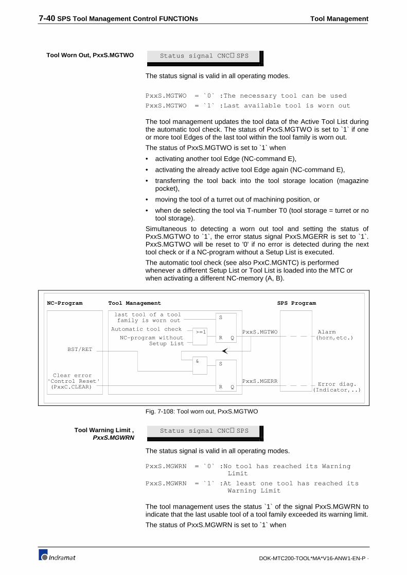
7-40 SPS Tool Management Control FUNCTIONs Tool Management
DOK-MTC200-TOOL*MA*V16-ANW1-EN-P ·
Status signal CNC ⇒SPS
The status signal is valid in all operating modes.
PxxS.MGTWO = `0` :The necessary tool can be used
PxxS.MGTWO = `1` :Last available tool is worn out
The tool management updates the tool data of the Active Tool List duringthe automatic tool check. The status of PxxS.MGTWO is set to `1` if oneor more tool Edges of the last tool within the tool family is worn out.
The status of PxxS.MGTWO is set to `1` when
• activating another tool Edge (NC-command E),
• activating the already active tool Edge again (NC-command E),
• transferring the tool back into the tool storage location (magazinepocket),
• moving the tool of a turret out of machining position, or
• when de selecting the tool via T-number T0 (tool storage = turret or notool storage).
Simultaneous to detecting a worn out tool and setting the status ofPxxS.MGTWO to `1`, the error status signal PxxS.MGERR is set to `1`.PxxS.MGTWO will be reset to '0' if no error is detected during the nexttool check or if a NC-program without a Setup List is executed.
The automatic tool check (see also PxxC.MGNTC) is performedwhenever a different Setup List or Tool List is loaded into the MTC orwhen activating a different NC-memory (A, B).
NC-Program Tool Management
last tool of a toolfamily is worn out
Automatic tool check
NC-program without Setup List
>=1
S
R
& S
R
SPS Program
PxxS.MGTWOQ
QPxxS.MGERR
BST/RET
Clear error'Control Reset'(PxxC.CLEAR) Error diag.
(Indicator,..)
Alarm(horn,etc.)
Fig. 7-108: Tool worn out, PxxS.MGTWO
Status signal CNC ⇒SPS
The status signal is valid in all operating modes.
PxxS.MGWRN = `0` :No tool has reached its Warning Limit
PxxS.MGWRN = `1` :At least one tool has reached its Warning Limit
The tool management uses the status `1` of the signal PxxS.MGWRN toindicate that the last usable tool of a tool family exceeded its warning limit.
The status of PxxS.MGWRN is set to `1` when
Tool Worn Out, PxxS.MGTWO
Tool Warning Limit ,PxxS.MGWRN

Tool Management SPS Tool Management Control FUNCTIONs 7-41
DOK-MTC200-TOOL*MA*V16-ANW1-EN-P ·
• activating another tool Edge (NC-command E),
• activating the already active tool Edge again (NC-command E),
• transferring the tool back into the tool storage location (magazinepocket),
• moving the tool of a turret out of machining position, or
• when de selecting the tool via T-number T0 (tool storage = turret or notool storage).
Tool ManagementSPS Program
PxxS.MGWRN(Indicator,..)Diagnostics
Last usable tool of at leastone tool family has reached its warning limit
Automatic tool check
NC-program without Setup List
>=1
S
R Q
Fig. 7-109: Tool warning limit reached, PxxS.MGWRN
PxxS.MGWRN will be reset to '0' if no error is detected during the nexttool check or if a NC-program without a Setup List is executed.
The automatic tool check (see also PxxC.MGNTC) is performedwhenever a different Setup List or Tool List is loaded into the MTC orwhen activating a different NC-memory (A, B).
Status signal CNC ⇒SPS
The status signal is valid in all operating modes.
PxxS.MGERR = `0` :All required tools are O.K., no error
PxxS.MGERR = `1` :Tool Storage or tool error active
The tool management sets the status of PxxS.MGERR to a `1` if a toolstorage or tool error occurs (i.e. tool worn out). The SPS program can usethis signal for further error processing.
The signal is set to a status of `1` if
• the last usable tool or at least one tool family is worn out,
• the Active Tool List does not fulfill the Setup List requirements,
• a tool that was programmed via the T-word (T) cannot be found,
• the signal PxxS.MGTWO has a status of `1` at the end of NC-programexecution (BST, RET), and
• the tool management recognizes potential tool collisions
A status `1` of the signal PxxS.MGERR causes a process stop and aprocess error at the latest after the next NC-command BST or RET isexecuted. These NC commands end the NC-program execution for theprocess.
Tool Storage/Tool Error,PxxS.MGERR

7-42 SPS Tool Management Control FUNCTIONs Tool Management
DOK-MTC200-TOOL*MA*V16-ANW1-EN-P ·
Tool ManagementSPS Program
PxxS.MGWRN(Indicator,..)Diagnostics
All errors recognizedby the tool mangement
Automatic tool check
NC-program without Setup List
>=1
S
R Q
Fig. 7-110: Tool storage and tool error, PxxS.MGERR
PxxS.MGERR will be reset to '0' if no error is detected during the next toolcheck or if a NC-program without a Setup List is executed.
The automatic tool check (see also PxxC.MGNTC) is performedwhenever a different Setup List or Tool List is loaded into the MTC orwhen activating a different NC-memory (A, B).
7.7 Tool Data read/write, FUNCTION_BLOCKTLD_RD/TLD_WR
The MTC provides the standard FUNCTION_BLOCKs TLD_RD andTLD_WR that allow to read and write tool data, and are the equivalent tothe NC-command TLD. Tool data is stored in the CPU of the MTC whichcauses a delay of at least one SPS program scan when reading data.
Consideration to automatic tool check:
• Tool List specific tool data that is modified via the TLD_WR will causean automatic tool check (compared with corresponding Setup Listdata). The automatic tool check will be performed at the next NC-program advance or reverse if the tool that contains the data is used.A tool is used if it is specified in Setup List of the active NC-program orprocess.
• Modification of Tool List specific data will not cause an automatic toolcheck if the tool is not specified in the Setup List of the NC-program orprocess, which means if the tool is not used.
The tables listed at the end of this chapter provide the basic and tool edgedata as well as the tool and edge status bit information that is available inthe tool management of the MTC.

Tool Management SPS Tool Management Control FUNCTIONs 7-43
DOK-MTC200-TOOL*MA*V16-ANW1-EN-P ·
• Read tool data • Write tool data: +---------------------+ +---------------------+ ¦TLD_RD ¦ ¦TLD_WR ¦ BOOL-¦READ BOOL_+-BOOL BOOL-¦WRITE READY+-BOOL INT-¦TYP INT_+-INT INT-¦TYP ¦ INT-¦PROC REAL_+-REAL INT-¦PROC ¦ INT-¦ADDRESS READY+-BOOL INT-¦ADDRESS ¦ DINT-¦STOR_TNR ¦ DINT-¦STOR_TNR ¦ INT-¦LOC_TIND ¦ INT-¦LOC_TIND ¦ INT-¦EDGE ¦ INT-¦EDGE ¦ INT-¦ELEMENT ¦ INT-¦ELEMENT ¦ INT-¦STATUS ¦ INT-¦STATUS ¦ +---------------------+ BOOL-¦BOOL_ ¦
INT-¦INT_ ¦ REAL-¦REAL_ ¦ +---------------------+
YP = `0` ;BOOL, (Boolean type of data that is written or read)`1` ;BYTE`2` ;WORD`3` ;DWORD, (Double WORD)`4` ;USINT, (Unsigned Short INTeger)`5` ;SINT, (Short INTeger)`6` ;UINT, (Unsigned INTeger)`7` ;INT, (INTeger)`8` ;UDINT, (Unsigned Double INTeger)`9` ;DINT, (Double INTeger)`10` ;REAL, (single REAL floating point)`11` ;TIME12` ;STRING, (character sequence)
* check your SPS software release for availabilityPROC = `0...6` ;Process numberADDRESS = `0` ;Next 2 inputs are interpreted as tool STORage and LOCation information
`1` ;Next two inputs are interpreted as T-NumbeR and Tool INDex numberSTOR_TNR = `0` ;Magazine / Turret , if ADDRESS = `0`
`1` ;Tool spindle , if ADDRESS = `0``2` ;Tool gripper , if ADDRESS = `0`
`1...9999999` ;Tool number (T-number) , if ADDRESS = `1`LOC_ TIND = `0...999` ;Magazine pocket / Turret position , if ADDRESS = `0`, STOR_IND = `0`
`0..3` ;Tool spindle , if ADDRESS = `0`, STOR_IND = `0` `0..4` ;Tool gripper , if ADDRESS = `0`, STOR_IND = `0` `0..999` ;Tool index number , if ADDRESS = `1`
EDGE = `0` ;Basic tool data (Figure 0.13.2A) `1...9` ;Tool edge (`0...9) data (Figure 0.13.2B)
ELEMENT = `3....26` ;Basic tool data element 3...26 ,if EDGE = `0` (Figure 0.13.2A) `1...35` ;Tool edge data element 1...15 ,if EDGE = `1` (Figure 0.13.2B)
STATUS = `0...31` ;Basic tool data, tool status bit 0...3` ,if EDGE = `0` (Figure 0.13.2C) `0...15` ;Tool edge data, tool edge status bit 1..15 ,if EDGE = `1` (Figure 0.13.2D)
BOOL_ = `0`,`1` ;Boolean data to be written or Boolean result of readINT_ = `-32768..32767` ;INTeger data to be written or INTeger result of readREAL_ = -3.402823E38..-1.175495E-38 or 1.175495E-38...3.402823E38
;REAL data to be written or REAL result of read
Reading tool data, TLD_RDREAD = `0` ;FB not active.
`1` ;Initiate tool data readREADY = `0` ;Data invalid or READ = `0` when using TLD_RD
`1` ;Data valid when using TLD_RD
Writing tool data, TLD_WRWRITE = `0` ;FB not active.
`1` ;Initiate tool data writeREADY = `0` ;Data write active or WRITE =`0` when using TLD_WR
`1` ;Data write finished when using TLD_WR
Fig. 7-111: Tool Data read/write, FUNCTION_BLOCK TLD_RD/TLD_WR
c def g g
¸¶¶¶¶¶¶¶¶¶¶¶¹ ¸¶¶¶¶¶¶¶¶¶¶¶¶¶¶¶¶¶¶¶¶¶¶¶¶¶¶¶¶5($' ¶¶¶¶» º¶¶¶¶»
¸¶¶¶¶¶¶¶¶¶¶¶¹ ¸¶¶¶¶¶¶¶¶¶¶¶¶¶¶¶¶¶¶¶¶¶¶¶¶¶¶¶¶7RRO GDWD ¶¶¶¶» º¶¶¶¶»
¸¶¹ ¸¶¹ ¸¶¹5($'< ¶¶¶¶¶¶¶¶¶¶¶¶¶¶¶» º¶¶¶¶¶¶¶¶¶¶¶¶¶¶¶» º¶¶¶¶¶¶¶¶¶» º¶¶
Fig. 7-112: Timing diagram, tool data read via TLD_RD

7-44 SPS Tool Management Control FUNCTIONs Tool Management
DOK-MTC200-TOOL*MA*V16-ANW1-EN-P ·
(1) A status of `1` at the READ input initiates the read cycle of thespecified tool data. Tool data can be specified via the inputs PROC,ADDRESS, STOR_TNR, LOC_TIND, EDGE, ELEMENT andSTATUS. The type of the tool data must be defined via the number atthe input TYP. The tool data is automatically converted to the formatdefined via TYP if it is not available in the CNC in such a format.
(2) The status of READY switches to `1` if READ is `1` and the tool datais received and available in the output that corresponds to the typedefined via TYP.
(3) READ can be set to `0` if only one read cycle should be performed.
(4) READY is reset to `0` if READ switches to `0`.
(5) The tool data is continuously read while READ has a status of `1`. Anew read cycle is automatically initiated after completion (READY=`1`) of the previous read cycle.
Read tool data via TLD_RD
Declaration:VAR_INPUTP01S A#P01S iPROC (*PROCESS 1 STATUS*):VAR_OUTPUTP01C A#P01C qPROC (*Process 01 control signals*):VARISPDL1 R BOOL (*P1 tool spindle 1 read*)TSPDL1_T BOOL (*P1 tool in tool spindle 1*)TSPDL1_R TLD_RD (*P1 read tool in tool spindle 1?*):
Implementation in Ladder Diagram:: :| (*Check for tool in tool spindle 1 by reading the tool *) || (*status bit 16 ‘location occupied’. *) || TSPDL1_R || +-----------------+ || ISPDL1 R ¦TLD_RD ¦ VAR5_1OK |+---| |----¦READ BOOL_+--------------------------( )----+| 0-¦TYP INT_+ || 2-¦PROC REAL_+ TSPDL1_T || 0-¦ADDRESS READY+--------------------------( )----+| 1-¦STOR_TNR ¦ || 1-¦LOC_TIND ¦ || 0-¦EDGE ¦ || 9-¦ELEMENT ¦ || 16-¦STATUS ¦ || +-----------------+ |: :
c def g g
¸¶¶¶¶¶¶¶¶¶¶¶¹ ¸¶¶¶¶¶¶¶¶¶¶¶¶¶¶¶¶¶¶¶¶¶¶¶¶¶¶¶¶:5,7( ¶¶¶¶» º¶¶¶¶»
¸¶¶¶¶¶¶¶¶¶¶¶¹ ¸¶¶¶¶¶¶¶¶¶¶¶¶¶¶¶¶¶¶¶¶¶¶¶¶¶¶¶¶'$7$ ¶¶¶¶» º¶¶¶¶»
¸¶¹ ¸¶¹ ¸¶¹5($'< ¶¶¶¶¶¶¶¶¶¶¶¶¶¶¶» º¶¶¶¶¶¶¶¶¶¶¶¶¶¶¶» º¶¶¶¶¶¶¶¶¶» º¶¶
Fig. 7-113: Timing diagram, tool data write via TLD_WR
(1) A status of `1` at the WRITE input initiates the write cycle of thespecified tool data. Tool data can be specified via the inputs PROC,ADDRESS, STOR_TNR, LOC_TIND, EDGE, ELEMENT andSTATUS. The type of the tool data must be defined via the number atthe input TYP. The tool data format defined via TYP is automaticallyconverted to the to the required format in the CNC if the specifiedTYP is incorrect.
(2) The status of READY switches to `1` if READ is `1` and the definedtool data is written into the define tool data element in the CNC.
(3) WRITE can be set to `0` if only one write cycle should be performed.
(4) READY is reset to `0` if WRITE switches to `0`.
(5) The tool data is continuously writes while WRITE has a status of `1`.A new write cycle is automatically initiated after completion (READY=`1`) of the previous write cycle.
Example:

Tool Management SPS Tool Management Control FUNCTIONs 7-45
DOK-MTC200-TOOL*MA*V16-ANW1-EN-P ·
Writing tool data via TLD_WR.
Declaration:VAR_INPUTP01S A#P01S iPROC (*PROCESS 1 STATUS*):VAR_OUTPUTP01C A#P01C qPROC (*Process 01 control signals*):VARTSPDL1_B BOOL (*P1 tool in tool spindle 1 broken*)TSPDL1_BD BOOL (*P1 locked broken tool in tool spindle 1*)TSPDL1_BW TLD_WR (*P1 lock broken tool in tool spindle 1*):
Implementation in Ladder Diagram:: :| (*Set tool status bit 22 ‘lock tool’ if the tool in tool *) || (*spindle was detected as broken. The tool can be removed*) || (*from the tool spindle, however, it will not be used by *) || (*the tool management again until the ‘L’ bit is reset ! *) || (*Existing spare tool will be used until then. *) || TSPDL1_BW || +-----------------+ || ISPDL1 R ¦TLD_WR ¦ TSPDL1_BD |+---| |----¦WRITE READY+--------------------------( )----+| 0-¦TYP ¦ || 1-¦PROC ¦ || 0-¦ADDRESS ¦ || 1-¦STOR_TNR ¦ || 1-¦LOC_TIND ¦ || 0-¦EDGE ¦ || 9-¦ELEMENT ¦ || 22-¦STATUS ¦ |+----------¦BOOL_ ¦ || -¦INT_ ¦ || -¦REAL_ ¦ || +-----------------+ |: :
7.8 Error handling, tool data FUNCTION_BLOCKs.
Programming errors can cause improper execution of theFUNCTION_BLOCKs TLD_RD and TLD_WR RLVAR_RD. The errorhandling allows to detect such errors and react upon their occurrence.
The Identifier Errortyp (INT) provides a number that identifies theFUNCTION_BLOCK that has an error. The following is valid for NC-variable FUNCTION_BLOCKs:
FUNCTION_BLOCK ErrorTypTLD_WR -169
TLD_RD -170
The number in ErrorNum provides the cause of the error:
1 ;Invalid input parameter values, such as negative value at inputTYP, PROC, ADDRESS, STOR_TNR, LOC_TIND, EDGE, ELEMENT,STATUS
- number greater than the defined input value range
Refer to section 8... for information how to use the error information.
Example:

Tool Management Applications 8-1
DOK-MTC200-TOOL*MA*V16-ANW1-EN-P ·
8 ApplicationsMTC tool management applications for different types of tool magazinesand tool change mechanisms are contained in this chapter.
Required parameter settings, NC-programs and programmable controller(SPS) program settings describe their logical functionality. The basicstructure of NC-subroutines and the shown user FUNCTION_BLOCKscover the majority of applications. Additional application specific safetyfeatures and modifications may be required.
8.1 NC servo disk tool magazine with direct tool change
A NC servo controlled disk type tool magazine is used for a 3-axishorizontal milling machine. The tool transfer is directly performed betweenthe spindle and magazine.
+
-
12
3
4
56
7
10
89
1112
POS1
X-axis
Z-axis
Y-axis
X
y
Z
Y-axis motor
Main spindle
tool
tool changeposition
X-axis motor
None-endlesstool magazine
Fig. 8-114: Milling station with NC servo disk magazine
The milling station is controlled via MTC process 0. The tool magazine isbased on a half disk which makes it 'non-endless' and provides 7 toolpockets.
A full disk would provide in this case 12 pockets and be 'endless'. Boththe NC- and SPS program are capable of handling endless and none-endless magazines with up to 999 pockets.
The tool change position POS1 is located in the machining area. Tochange the tool, the corresponding pocket will be rotated into POS1.POS1 is defined by the virtual pocket '10' which results in an offset of 9pockets (1+9=10) when counting in positive direction.
The distance between the pockets is defined in the axis parameterCxx.022 (degrees) if a NC-controlled servo axis is used to move themagazine. The CNC automatically considers gear ratio and max. numberof pockets when moving pockets into the programmed positions, even ifmultiple motor turns are required. This allows to move chain type toolmagazines with up to 999 pockets.
Functional descriptionThe milling station moves to a safe position, so that no collision with thetool magazine occurs. The pocket that contains the selected tool (T-number) is then rotated into POS1. To position the spindle behind thetool, a linear move is performed and the spindle is oriented into thecorrect position. The Z-axis advances the spindle so that the drawbar can
Tool from Magazine -> Spindle:

8-2 Applications Tool Management
DOK-MTC200-TOOL*MA*V16-ANW1-EN-P ·
grab and clamp the tool (physical transfer). Once the spindle is clamped,the logical tool transfer 'Magazine -> Spindle' is performed. The spindleorients 90° to unlock the pocket after the successful transfer. Then a X-axis move is used to remove the tool from the pocket.
The tool magazine rotates back to its base position and the milling stationcan perform the programmed machining with the selected tool.
The milling station moves to a safe position, so that no collision with thetool magazine occurs. The pocket that contained the tool in the spindle isthen rotated into POS1. A linear move is performed to position the toolbeside the pocket in POS1 and the spindle is oriented into the correctposition. The X-axis moves towards the pocket and pushes the tool intothe (still unlocked) pocket. The spindle rotates 90° to lock the pocket. Thephysical transfer is performed when unclamping the tool. Once thespindle is unclamped, the logical tool transfer 'Magazine -> Spindle' isperformed. , The Z-axis moves away from the magazine towards the backto a safe position after the successful transfer. The tool magazine thenrotates back to its base position if T0 is selected or brings the newlyselected tool (T-number ≠T0) into POS1.
MTC parameter sets
- System parameters:
Par. Description Value Unit
A00.000 Name of the Management Process 3-axis mill station
:
:
A00.032 Axis 1 (APR Module 1 - 1st Axis) Type Digital Linear Axis
A00.033 Axis 2 (APR Module 1 - 2nd Axis) Type Digital Linear Axis
A00.034 Axis 3 (APR Module 1 - 3rd Axis) Type Digital Linear Axis
A00.035 Axis 4 (APR Module 1 - 4th Axis) Type Digital Rotary Axis
A00.036 Axis 5 (APR Module 2 - 1st Axis) Type Digital Main Spindle
:
:
A00.052 Tool Management yes
A00.053 Organization of the setup list station sp.
A00.054 maximum amount of edges 1
A00.055 Wear factor register yes
A00.056 Offset register yes
A00.057 Comment (Assembly instruction) no
A00.058 Wear factors yes
A00.059 Tool life data yes
A00.060 Tool geometry limits yes
:
- Process parameters:
Par. Description Value Unit
:
:
B00.014 Tool Management yes
B00.015 Type of Tool Storage Magazine
B00.016 Endless Rotating Tool Storage no
B00.017 Number of Tool Locations in Tool Storage 7
B00.018 Number of Spindles with Tool 1
B00.019 Number of Grippers 0
B00.020 Axis Number of Tool Storage Axis 4
B00.021 Position 1 (Offset to the Reference) 9
B00.022 Position 2 (Offset to the Reference) 0
Tool from Spindle -> Magazine:

Tool Management Applications 8-3
DOK-MTC200-TOOL*MA*V16-ANW1-EN-P ·
B00.023 Position 3 (Offset to the Reference) 0
B00.024 Position 4 (Offset to the Reference) 0
B00.025 Max. Entry for Length Wear 0.1000 mm
B00.026 Max. Entry for Radius Wear 0.1000 mm
B00.027 Max. Entry for Length Offset 0.1000 mm
B00.028 Max. Entry for Radius Offset 0.1000 mm
:
- Tool Magazine servo MTC Axis (#4) parameter:
The axis parameter C04.053 defines the distance between the tool pockets. The distance is usually defined in degrees,depending on the definition in parameter C04.006.
Par. Description Value Unit
C04.000 Associated Process(es) M
C04.001 Axis Designation W
C04.053 Axis defined in RIGHT HAND COORD. System as W
C04.006 Programming Units / Table Revolution 360.0000 units
:
:
C04.022 Parametric Jogging Distance 30.0000 units
:
:
NC-programs - Tool Change NC-subroutine '.M6D':
;----------------------------------------------------------------------
;
; TOOL CHANGE SUBROUTINE "M6D" FOR SERVO
; AND NC-CONTROLLED DISK TOOL MAGAZINE
; (ENDLESS AND NON ENDLESS)
;
;----------------------------------------------------------------------
N0001 .M6D
G53 G90 M5 BSE .EM_SPI
rev .r_1.0 ;machine coordinate system, absolute
programming, spindle stop, spindle empty?
N0002 G40 G47 ;cancel tool path compensation and
length correction
;
;Move tool in spindle into empty magazine pocket where it resided
;
N0003 G0 X250 Y24.85 Z406.13
rev .r_1.1 ;safety distance
N0004 MOP rev .r_1.2 ;move old magazine pocket into position
N0005 S0 M19 ;orient spindle to position 1 (unlock)
N0006 MRY ;wait until magazine is positioned
N0007 TPE ;pocket in position empty?
N0008 X440.7 rev .r_1.3 ;move tool into pocket
N0009 S90 M19 rev .r_1.4 ;orient spindle to position 2 (lock)
N0010 TSM rev .r_2.4 ;logical and physical tool transfer
spindle->magazine
N0011 G4 F.3 rev .r_2.3 ;0.3 second dwell
N0012 G0 Z530 rev .r_2.2 ;retract Z-axis
N0013 BTE .NOTOL1 ;was 'T0' programmed?
N0014 BRA .NEWTOL ;branch to get new tool
;
;no tool in the spindle
;

8-4 Applications Tool Management
DOK-MTC200-TOOL*MA*V16-ANW1-EN-P ·
N0015 .EM_SPI
BTE .NOTOL2 rev .r_3.0 ;was 'T0' programmed?
N0016 G0 X250 Y24.85 Z530 ;to machine base position
N0017 X440.7 rev .r_3.1 ;move behind tool change position
;
;Move tool of magazine pocket in tool change position to spindle
;
N0018 .NEWTOL
MTP rev .r_3.2 ;move pocket of programmed tool into
tool change position
N0019 S90 M19 ;orient spindle to position 2 (lock)
N0020 M11 rev .r_3.3 ;unclamp tool bar in spindle
N0021 MRY rev .r_3.4 ;wait until magazine is positioned
N0022 G0 Z406.13 rev .r_4.4 ;advance Z-axis to grab tool
N0023 TMS rev .r_4.3 ;logical and physical tool transfer
magazine->spindle
N0024 G4 F0.8 rev .r_4.2 ;0.8 second dwell
N0025 S0 M19 rev .r_4.1 ;orient spindle to position 1 (unlock)
N0026 G0 X250 rev .r_4.0 ;remove tool from magazine pocket
N0027 MHP rev .r_4.0 ;tool magazine to base position
N0028 MEN RTS ;enable magazine for manual mode
;
;'T0' (no tool) is programmed and the tool in the spindle was put
;back into its original magazine pocket
;
N0029 .NOTOL1
MHP rev .r_2.1 ;tool magazine to base position
N0030 G0 X250 rev .r_2.0 ;move in X-direction out of magazine
N0031 MEN RTS ;enable magazine for manual mode
;
;'T0' (no tool) is programmed and the spindle does not contain a tool
;
N0032 .NOTOL2
MEN RTS ;enable magazine for manual mode
;
;----------------------------------------------------------------------
;
; REVERSE PROGRAM
;
;----------------------------------------------------------------------
;
N0033 .1_1.4 BSE .r_2.4
N0034 M10 ;clamp
N0035 .r_1.3 S0 M19 ;orient spindle to position 1 (unlock)
N0036 .r_1.2 G0 X250 ;move in X-direction out of magazine
N0037 .r_1.1 MHP ;tool magazine to base position
N0038 .r_1.0 G0 X250 Y24.85 Z530
N0039 MEN RTS ;enable magazine for manual mode
;
N0040 .r_2.4 G4 F0.3 ;0.3 second dwell
N0041 .r_2.3 G0 Z530 ;retract Z-axis
N0042 .r_2.2 MHP ;tool magazine to base position
N0043 .r_2.1 G0 X250 ;move in X-direction out of magazine
N0044 .r_2.0 MEN RTS ;enable magazine for manual mode
;
N0045 .r_3.4 BRA .r_4.4
N0046 .r_3.3 G0 Z530 ;retract Z-axis
N0047 .r_3.2 S0 M19 ;orient spindle to position 1 (unlock)

Tool Management Applications 8-5
DOK-MTC200-TOOL*MA*V16-ANW1-EN-P ·
N0048 .r_3.1 MHP Z530 ;tool magazine to base position, retract
Z-axis
N0049 .r_3.0 G0 X250 Y24.85 Z530 ;to machine base position
N0050 MEN RTS ;enable magazine for manual mode
;
N0051 .r_4.4 G4 F0.8 ;0.8 second dwell
N0052 .r_4.3 S0 M19 ;orient spindle to position 1 (unlock)
N0053 .r_4.2 G0 X250 ;move in X-direction out of magazine
N0054 .r_4.1 MHP ;tool magazine to base position
N0055 .r_4.0 MEN RTS ;enable magazine for manual mode
;
SPS ProgramTool change FUNCTION_BLOCK TMS_TSM:
Declaration FUNCTION_BLOCK TMS_TSM
(*This FUNCTION_BLOCK can be used with servo and NC-controlled tool *)
(*magazines that use the tool change NC-commands TMS and TSM to transfer*)
(*the tool between the tool spindle and magazine.*)
(*The output XF_ERR is '1' if the tool transfer is not allowed and will*)
(*cause a logical tool collision. This error can be cleared and the tool*)
(*transfer can be canceled by using a '1' at XF_CANCEL.*)
VAR_INPUT
ENA BOOL 2#1 (*ENABLE*)
XF_CANCEL BOOL (*CANCEL XFER ERROR*)
CLAMPED BOOL 2#0 (*SPINDLE CLAMPED*)
UNCLAMPED BOOL 2#0 (*SPINDLE UNCLAMPED*)
PROCESS INT (*PROCESS NUMBER*)
POSITION INT 1 (*DIRECTION PARAMETER*)
SPINDLE INT 1 (*SPINDLE NUMBER*)
END_VAR
VAR_OUTPUT
XF_ERR BOOL (*TOOL TRANSFER ERROR*)
MMV_A BOOL (*POCKET SELECTION ACTIVE*)
MRF_A BOOL (*HOMING ACTIVE*)
TMS_A BOOL (*TOOL CHANGE MAG.->SPDL.ACTIVE*)
TSM_A BOOL (*TOOL CHANGE SDPL.->MAG.ACTIVE*)
END_VAR
VAR
RQDCOIL BOOL (*REQUIRED COIL*)
MRF_1 BOOL (*1 PLC SCAN DELAY MRF*)
TMS_AA BOOL (*TMS ACTIVE*)
TSM_AA BOOL (*TSM ACTIVE*)
XMS_A BOOL (*TOOL XFER MAG.->SPINDLE*)
XSM_A BOOL (*TOOL XFER SPINDLE->MAG.*)
XMSPA BOOL (*XFER MAG.->SP. POSITIVE ACKN.*)
XSMPA BOOL (*XFER SP.->MAG. POSITIVE ACKN*)
XSMNA BOOL (*XFER SP.->MAG. NEGATIVE ACKN.*)
MRFQ BOOL (*HOME ACKNOWLEDGED*)
MMVQ BOOL (*MOVE ACKNOWLEDGED*)
END_VAR
VAR RETAIN
END_VAR

8-6 Applications Tool Management
DOK-MTC200-TOOL*MA*V16-ANW1-EN-P ·
Implementation of FUNCTION_BLOCK TMS_TSM:
1 ! ! !(*Read NC-command MRF 'Reference Magazine'*) ! 2 ! +--------+ ! !ENA !MRF ! MRF_A ! !! !--------!ACTIVE !-----------------------------------------------------------------------------+( )------! ! PROCESS-!PROC ! +O>NOMRF ! ! +--------+ ! 3 ! ! !(*Acknowledge NC-command MRF*) ! 4 ! +--------+ ! !MRF_1 MRFQ !MRF_Q ! MRFQ ! !! !--------!/!--------!QUIT !-------------------------------------------------------------------(S)------! ! PROCESS-!PROC ! ! ! +--------+ ! 5 ! ! !(*Clear NC-command MRF acknowledged*) ! 6 !NOMRF: ! !MRF_A MRFQ ! !!/!------------------------------------------------------------------------------------------------(R)------! 7 ! ! !(*Generate one SPS program scan delay for NC-command MRF acknowledgment*) ! 8 ! ! !MRF_A MRF_1 ! !! !------------------------------------------------------------------------------------------------( )------! 9 ! ! !(*Read active tool storage move NC-command*) ! 10 ! +--------+ ! !ENA !MMV ! MMV_A ! !! !--------!ACTIVE !-----------------------------------------------------------------------------+( )------! ! PROCESS-!PROC ! +O>NOMMV ! ! +--------+ ! 11 ! ! !(*Acknowledge tool storage move NC-command*) ! 12 ! +--------+ ! !MMV_A !MMV_Q ! MMVQ ! !! !--------!QUIT !------------------------------------------------------------------------------(S)------! ! PROCESS-!PROC ! ! ! +--------+ ! 13 ! ! !(*Clear tool storage move NC-command acknowledgment*) ! 14 !NOMMV: ! !MMV_A MMVQ ! !!/!------------------------------------------------------------------------------------------------(R)------! 15 ! ! !(*Read tool change NC-command TMS 'Magazine -> Spindle'*) ! 16 ! +--------+ ! !ENA !TMS ! TMS_AA ! !! !--------!ACTIVE !------------------------------------------------------------------------------( )------! ! PROCESS-!PROC ! ! ! POSITION-!POS ! ! ! SPINDLE-!SPINDLE ! ! ! +--------+ ! 17 ! ! !(*Perform logical tool transfer if tool is clamped in tool spindle*) ! 18 ! ! !TMS_AA CLAMPED ! !! !--------! !-------------------------------------------------------------------------------------O>NOTMS ! 19 ! ! !(*Initiate logical tool transfer from magazine to tool spindle*) ! 20 ! +--------+ ! !XMS_A !XMS ! XMS_A ! !!/!--------!INIT !------------------------------------------------------------------------------(S)------! ! PROCESS-!PROC ! ! ! POSITION-!POS ! ! ! SPINDLE-!SPINDLE ! ! ! +--------+ ! 21 ! ! !(*Read positive acknowledge of tool transfer 'Magazine -> Spindle'*) ! 22 ! +--------+ ! ! !XMS_PA ! XMSPA ! !-----------!ACTIVE !------------------------------------------------------------------------------( )------! ! PROCESS-!PROC ! ! ! POSITION-!POS ! ! ! SPINDLE-!SPINDLE ! ! ! +--------+ ! 23 ! ! !(*Read negative acknowledge of tool transfer 'Magazine -> Spindle'*) ! 24 ! +--------+ ! ! !XMS_NA ! XF_ERR ! !-----------!ACTIVE !------------------------------------------------------------------------------(S)------! ! PROCESS-!PROC ! ! ! POSITION-!POS ! ! ! SPINDLE-!SPINDLE ! ! ! +--------+ ! 25 ! ! ! (*Acknowledge logical and physical tool transfer from magazine to spindle *) ! 26 ! +--------+ +--------+ ! !XMSPA !XMS_Q ! !TMS_Q ! XMS_A ! !! !--------!QUIT !-!QUIT !-------------------------------------------------------------------(R)------! ! PROCESS-!PROC ! ! ! ! ! POSITION-!POS ! ! ! ! ! SPINDLE-!SPINDLE ! ! ! ! ! +--------+ ! ! ! ! PROCESS-!PROC ! ! ! POSITION-!POS ! ! ! SPINDLE-!SPINDLE ! ! ! +--------+ ! 27 ! ! !(*Cancel tool transfer if negative acknowledge*) ! 28 !NOTMS: +--------+ ! !XF_ERR XF_CANCEL !XMS_CA ! XF_ERR ! !! !--------! !--------!CANCEL !------------------------------------------------------------------+(R)------! ! + + !XMS_A ! ! PROCESS-!PROC ! +(R)------! ! POSITION-!POS ! ! ! SPINDLE-!SPINDLE ! ! ! +--------+ ! 29 ! !

Tool Management Applications 8-7
DOK-MTC200-TOOL*MA*V16-ANW1-EN-P ·
!(*Output TMS_A*) ! 30 ! ! !TMS_AA TMS_A ! !! !-------+----------------------------------------------------------------------------------------( )------! !XMS_A ! ! !! !-------+ ! 31 ! ! !(*Read tool change NC-command TSM 'Spindle -> Magazine'*) ! 32 ! +--------+ ! !ENA !TSM ! TSM_AA ! !! !--------!ACTIVE !------------------------------------------------------------------------------( )------! ! PROCESS-!PROC ! ! ! SPINDLE-!SPINDLE ! ! ! POSITION-!POS ! ! ! +--------+ ! 33 ! ! !(*Perform logical tool transfer if tool is unclamped *) ! 34 ! ! !TSM_AA UNCLAMPED ! !! !--------! !-------------------------------------------------------------------------------------O>NOTSM ! 35 ! ! ! ! !(*Initiate logical tool transfer from tool spindle to magazine*) ! 36 ! +--------+ ! !XSM_A !XSM ! XSM_A ! !!/!--------!INIT !------------------------------------------------------------------------------(S)------! ! PROCESS-!PROC ! ! ! SPINDLE-!SPINDLE ! ! ! POSITION-!POS ! ! ! +--------+ ! 37 ! ! !(*Read positive acknowledge of tool transfer 'Spindle -> Magazine'*) ! 38 ! +--------+ ! ! !XSM_PA ! XSMPA ! !-----------!ACTIVE !------------------------------------------------------------------------------( )------! ! PROCESS-!PROC ! ! ! SPINDLE-!SPINDLE ! ! ! POSITION-!POS ! ! ! +--------+ ! 39 ! ! !(*Read negative acknowledge of tool transfer 'Spindle -> Magazine'*) ! 40 ! +--------+ ! ! !XSM_NA ! XF_ERR ! !-----------!ACTIVE !------------------------------------------------------------------------------(S)------! ! PROCESS-!PROC ! ! ! SPINDLE-!SPINDLE ! ! ! POSITION-!POS ! ! ! +--------+ ! 41 ! ! ! (*Acknowledge logical and physical tool transfer from spindle to magazine*) ! 42 ! +--------+ +--------+ ! !XSMPA !XSM_Q ! !TSM_Q ! XSM_A ! !! !--------!QUIT !-!QUIT !-------------------------------------------------------------------(R)------! ! PROCESS-!PROC ! ! ! ! ! SPINDLE-!SPINDLE ! ! ! ! ! POSITION-!POS ! ! ! ! ! +--------+ ! ! ! ! PROCESS-!PROC ! ! ! SPINDLE-!SPINDLE ! ! ! POSITION-!POS ! ! ! +--------+ ! 43 ! ! !(*Cancel tool transfer if negative 'spindle -> magazine' acknowledge*) ! 44 !NOTSM: +--------+ ! !XF_ERR XF_CANCEL !XSM_CA ! XF_ERR ! !! !--------! !--------!CANCEL !------------------------------------------------------------------+(R)------! ! + + !XSM_A ! ! POSITION-!PROC ! +(R)------! ! SPINDLE-!SPINDLE ! ! ! POSITION-!POS ! ! ! +--------+ ! 45 ! ! !(*Output TSM_A*) ! 46 ! ! !XSM_A TSM_A ! !! !-------+----------------------------------------------------------------------------------------( )------! !TSM_AA ! ! !! !-------+ ! 47 ! ! !(*Reset used SPS variables*) ! 48 ! ! !ENA XMS_A ! !!/!-----------------------------------------------------------------------------------------------+(R)------! ! !XSM_A ! ! +(R)------!
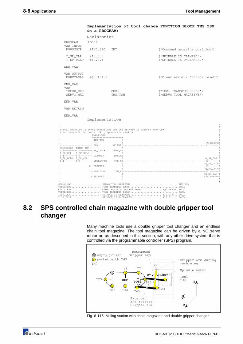
8-8 Applications Tool Management
DOK-MTC200-TOOL*MA*V16-ANW1-EN-P ·
Implementation of tool change FUNCTION_BLOCK TMS_TSMin a PROGRAM:
Declaration PROGRAM TOOLS VAR_INPUT P00SMGCP %IW0.180 INT (*Command magazine position*) : I_SP_CLP %I0.0.0 (*SPINDLE IS CLAMPED*) I_SP_UCLP %I0.0.1 (*SPINDLE IS UNCLAMPED*) : END_VAR
VAR_OUTPUT P00CCLEAR %Q0.164.0 (*Clear error / Control reset*) : END_VAR VAR TXFER_ERR BOOL (*TOOL TRANSFER ERROR*) SERVO_MAG TMS_TSM (*SERVO TOOL MAGAZINE*) : END_VAR
VAR RETAIN : END_VAR
Implementation : : ! ! !(*Tool magazine is servo controlled and the spindle is used to pick-up*) ! !(*and drop-off the tools. No grippers are used.*) ! ! SERVO_MAG ! ! +-------------------+ ! ! !TMS_TSM ! ! ! ! ! TXFER_ERR! !----------------------!ENA XF_ERR!--------------------------------------------------------( )------! !P00CCLEAR TXFER_ERR ! ! ! !! !--------! !--------!XF_CANCEL MMV_A! ! !I_SP_CLP I_SP_UCLP ! ! ! !! !--------!/!--------!CLAMPED MRF_A! ! !I_SP_UCLP I_SP_CLP ! ! Q_SP_CLP ! !! !--------!/!--------!UNCLAMPED TMS_A!-------------------------------------------------------+(S)------! ! ! ! !Q_SP_UCLP! ! 0-!PROCESS ! +(R)------! ! ! ! Q_SP_UCLP! ! 1-!POSITION TSM_A!-------------------------------------------------------+(S)------! ! ! ! !Q_SP_CLP ! ! 1-!SPINDLE ! +(R)------! ! +-------------------+ ! : :
SERVO_MAG.................... SERVO TOOL MAGAZINE..................... .......... TMS_TSM TXFER_ERR.................... TOOL TRANSFER ERROR..................... .......... BOOL P00CCLEAR.................... Clear error / Control reset............. %Q0.164.0. BOOL TXFER_ERR.................... TOOL TRANSFER ERROR..................... .......... BOOL I_SP_CLP..................... SPINDLE IS CLAMPED...................... %I0.0.0... BOOL I_SP_UCLP.................... SPINDLE IS UNCLAMPED.................... %I0.0.1... BOOL
8.2 SPS controlled chain magazine with double gripper toolchanger
Many machine tools use a double gripper tool changer and an endlesschain tool magazine. The tool magazine can be driven by a NC servomotor or, as described in this section, with any other drive system that iscontrolled via the programmable controller (SPS) program.
T45
Extended
Retracted
POS1
Spindle motor
Tool
Gripper arm during machining
Gripper arm
Gripper arm
+
X
Z
Y
90°
0° 180°
REF
1 2
3
456
7
8
T45T23
T23
empty pocket8
6 pocket with T47T47
T25
T6 T2
T47 T34
and rotated
Fig. 8-115: Milling station with chain magazine and double gripper changer

Tool Management Applications 8-9
DOK-MTC200-TOOL*MA*V16-ANW1-EN-P ·
The SPS program must control the magazine movements and the logicaland physical tool transfers between the magazine pocket, grippers andtool spindle. The complete tool change sequence is initiated in the NC-program via the auxiliary M-function M6.
Tool storage move NC-commands are used to generate the commandedpocket number in the SPS that must be brought into tool change position.The tool change position POS1 has an offset of 2 pockets from thereference position (1+2=3) in positive direction.
The gripper arm can move together with the Y-axis slide or be stationary.If stationary, the spindle must be moved to a tool change position via alinear move of the main axes.
Some tool magazines are mounted stationary. Others move with thespindle and gripper arm, as described in the following example.
Functional descriptionThe next tool is selected during machining and its pocket is moved intotool change position POS1. This asynchronous magazine axis movementallows to prepare the next tool to reduce tool change time.
To change the tool, the spindle is stopped to the correct position and thestation moves to a safe position where the tool change can be performedwithout collision.
The gripper arm rotates from 90° to 0° and clamps the tool in the spindlevia gripper 2, unclamps the spindle and clamps the tool in the pocket(POS1) via gripper 1 (physical transfers).
Once the grippers are clamped and the spindle is unclamped, the SPSprogram performs the logical tool transfer 'magazine pocket->gripper 1'and 'spindle -> gripper 2'. After the successful transfer, the gripper arm isextended, rotated to 180° and retracted.
The new tool in gripper 1 is physically transferred to the spindle byclamping the spindle and unclamping gripper 1. Unclamping the gripper 2physically transfers the old tool into the magazine pocket.
Once the grippers are unclamped and the spindle is clamped, the SPSprogram performs the logical tool transfer 'gripper 1->spindle' and 'gripper2 -> magazine pocket'. After the successful transfer, the gripper armrotates back to 90° and machining can continue with the new tool .
At this time the next tool can already be selected in the NC-program andorder to move it into tool change position during machining.
MTC parameter setsSystem parameters:
Par. Description Value Unit
A00.000 Name of the Management Process 3-axis mill station
:
:
A00.032 Axis 1 (APR Module 1 - 1st Axis) Type Digital Linear Axis
A00.033 Axis 2 (APR Module 1 - 2nd Axis) Type Digital Linear Axis
A00.034 Axis 3 (APR Module 1 - 3rd Axis) Type Digital Linear Axis
A00.036 Axis 4 (APR Module 2 - 1st Axis) Type Digital Main Spindle
:
:
A00.052 Tool Management yes
A00.053 Organization of the setup list station sp.
A00.054 maximum amount of edges 1
A00.055 Wear factor register yes
Tool from 'magazine pocket ->gripper 1' and 'spindle ->
gripper 2':
Tool from 'gripper 1 -> spindle'and 'gripper 2 -> magazine
pocket':

8-10 Applications Tool Management
DOK-MTC200-TOOL*MA*V16-ANW1-EN-P ·
A00.056 Offset register yes
A00.057 Comment (Assembly instruction) no
A00.058 Wear factors yes
A00.059 Tool life data yes
A00.060 Tool geometry limits yes
:
:
Process parameters: Par. Description Value Unit
:
:
B00.014 Tool Management yes
B00.015 Type of Tool Storage Magazine
B00.016 Endless Rotating Tool Storage yes
B00.017 Number of Tool Locations in Tool Storage 8
B00.018 Number of Spindles with Tool 1
B00.019 Number of Grippers 2
B00.020 Axis Number of Tool Storage Axis 0
B00.021 Position 1 (Offset to the Reference) 2
B00.022 Position 2 (Offset to the Reference) 0
B00.023 Position 3 (Offset to the Reference) 0
B00.024 Position 4 (Offset to the Reference) 0
B00.025 Max. Entry for Length Wear 0.1000 mm
B00.026 Max. Entry for Radius Wear 0.1000 mm
B00.027 Max. Entry for Length Offset 0.1000 mm
B00.028 Max. Entry for Radius Offset 0.1000 mm
:
NC-programsCall of tool change in NC-program:
;----------------------------------------------------------------------
;
; Machining: Flange
;
;----------------------------------------------------------------------
N0056 .START
T45 BSR .M6G ;bring tool T45 in spindle
:
; Cut circle
N0157 G54 X12.52 Y-31.967 Z109.31 G0 M3 S850 T23 MTP
;bring tool T23 to POS1
N0158 Z6 ;set workpiece zero point, approach
X, Y and Z
N0059 G3 I131.55 J131.55 F640 ;cut circle
N0160 G0 Z20 BSR .M6G ;retract Z, exchange T23 with T45
:
N0189 T0 BSR .M6G ;remove tool from spindle into next
available free magazine pocket
N0190 BST .START

Tool Management Applications 8-11
DOK-MTC200-TOOL*MA*V16-ANW1-EN-P ·
Tool Change NC-subroutine '.M6G':
;----------------------------------------------------------------------
;
; TOOL CHANGE SUBROUTINE "M6G" FOR PROGRAMMABLE
; CONTROLLER (SPS) CONTROLLED CHAIN TOOL MAGAZINE
; (ENDLESS) WITH DOUBLE GRIPPER
;
;----------------------------------------------------------------------
N0056 .M6G
BTE .M6G_T0 ;'T0' (no tool) programmed
N0057 MTP ;move pocket of programmed tool into
tool change position
;
N0058 .M6G_TX
G53 G90 M5 ;machine coordinate system, absolute
programming, spindle stop
N0059 G40 G47 ;cancel tool path compensation and
length correction
N0060 G0 Z295 ;retract Z-axis to tool change position
N0061 S0 M19 MRY ;orient spindle, wait until magazine is
positioned
N0062 Q1 rev .M6_R1 ;rotate gripper to 0°
N0063 Q2 rev .M6_R2 ;close grippers (physical xfer)
N0064 M11 rev .M6_R3 ;unclamp the spindle (physical xfer)
N0065 TMS rev .M6_R4 ;logical tool transfer
magazine -> gripper 1 and
spindle -> gripper 2
N0066 Q4 rev .M6_R5 ;extend gripper arm
N0067 Q7 rev .M6_R9 ;rotate gripper to 180°
N0068 Q8 rev .M6_R10 ;retract gripper arm
N0069 M10 rev .M6_R6 ;clamp the spindle (physical xfer)
N0070 Q6 rev .M6_R7 ;open grippers (physical xfer)
N0071 TSM rev .M6_R8 ;logical tool transfer
gripper 2 -> magazine and
gripper 1 -> spindle
N0072 Q9 ;gripper arm to 90°
N0073 MEN RTS ;enable manual magazine mode
;
; 'T0' (no tool) programmed
;
N0074 .M6G_T0
MFP BRA .M6G_TX ;move next available and empty magazine
pocket into tool change position
;
;----------------------------------------------------------------------
;
; REVERSE PROGRAM
;
;----------------------------------------------------------------------
;
;abort physical transfer to grippers, move tools back into spindle and
magazine pocket.
N0075 .M6_R2
Q8 rev .M6_R2 ;retract gripper arm
N0076 M11 rev .M6_R1 ;clamp spindle
N0077 .M6_R1 Q2 ;unclamp the grippers
Q9 ;gripper arm to 90°
N0078 MEN RTS ;enable magazine for manual mode

8-12 Applications Tool Management
DOK-MTC200-TOOL*MA*V16-ANW1-EN-P ·
;
;complete tool transfer, since tools are in grippers
N0079 .M6_R3
N0080 .M6_R4 Q4 rev .M6_R5 ;extend gripper arm
N0081 .M6_R5 Q7 rev .M6_R9 ;rotate gripper to 180°
N0082 .M6_R9 Q8 rev .M6_R10 ;retract gripper arm
N0083 .M6_R9 M10 rev .M6_R6 ;clamp the spindle (physical xfer)
N0084 .M6_R6 Q6 ;open grippers (physical xfer)
TSM rev .M6_R8 ;logical tool transfer
gripper 2 -> magazine and
gripper 1 -> spindle
N0085 .M6_R8 Q9 ;gripper arm to 90°
N0086 MEN RTS ;enable manual magazine mode
;
SPS ProgramTwo FUNCTION_BLOCKs have been designed, CHAINMAG to controlthe magazine movement, and TCH_2GR to control the double gripper toolchange mechanism. This modular design allows to use both with differenttype of tool magazines or tool change mechanisms.
SPS tool magazine control FUNCTION_BLOCK CHAINMAG:
Declaration FUNCTION_BLOCK CHAINMAG (*HOMING OF A CHAIN TOOL MAGAZINE VIA SEQUENCER*) (*I_COUNT :1 ;COUNT SWITCH ON*) (* :0 ;COUNT SWITCH OFF*) (*I_REF :1 ;REFERENCE SWITCH ON*) (* :0 ;REFERENCE SWITCH OFF*) (*Q_MAGPOS :1 ;ROTATE MAGAZINE IN POSITIVE DIRECTION*) (* :0 ;NO CONTROL*) (*Q_MAGNEG :1 ;ROTATE MAGAZINE IN NEGATIVE DIRECTION*) (* :0 ;NO CONTROL*) VAR_INPUT I_REF BOOL (*REFERENCE SWITCH*) I_COUNT BOOL (*COUNT SWITCH*) MAXPOCKET INT (*NUMBER OF MAGAZINE POCKETS*) PXXSMGCP INT (*COMMANDED MAGAZINE POCKET*) PROCESS INT (*PROCESS NUMBER*) END_VAR
VAR_OUTPUT Q_MAGPOS BOOL (*POSITIVE MAGAZINE DIRECTION*) Q_MAGNEG BOOL (*NEGATIVE MAGAZINE DIRECTION*) PXXCMGAP INT (*ACTUAL MAGAZINE POCKET*) END_VAR
VAR RQDCOIL BOOL (*REQUIRED COIL*) R_COUNT R_TRIG (*POSITIVE EDGE OF COUNT*) ONS_COUNT BOOL (*ONS OF COUNT*) MXXSMGCP INT (*MODULO COMMANDED POCKET*) END_VAR
VAR RETAIN
END_VAR
Implementation 1 ! ! !(*Read NC-command MRF that initiates sequence to reference magazine*) ! 2 ! +--------+ ! ! !MRF ! ! !-----------!ACTIVE !------------------------------------------------------------------------------O>NOMRF ! ! PROCESS-!PROC ! ! ! +--------+ ! 3 ! ! !(*Initiate magazine movement in positive direction*) ! 4 ! ! ! Q_MAGPOS ! !--------------------------------------------------------------------------------------------------+(S)------! ! !Q_MAGNEG ! ! +(R)------! 5 ! ! !(*Stop magazine movement once the reference switch is detected*) ! 6 ! !

Tool Management Applications 8-13
DOK-MTC200-TOOL*MA*V16-ANW1-EN-P ·
!I_REF Q_MAGPOS ! !! !-----------------------------------------------------------------------------------------------+(R)------! ! +O>NOMRF ! 7 ! ! !(*Pocket number 1 at reference position*) ! 8 ! +--------+ ! ! !:= ! ! ! 1-! !-PXXCMGAP ! ! +--------+ ! 9 ! ! !(*Acknowledge the active NC-command MRF*) ! 10 ! +--------+ ! ! !MRF_Q ! RQDCOIL ! !-----------!QUIT !------------------------------------------------------------------------------( )------! ! PROCESS-!PROC ! ! ! +--------+ ! 11 ! ! !(*Move commanded pocket into tool change position*) ! 12 !NOMRF: ! 13 ! ! !(*Evaluate count switch*) ! 14 ! R_COUNT ! ! +-------------------+ ! ! !R_TRIG ! ! !I_COUNT ! ! ONS_COUNT! !! !--------!CLK Q_!-------------------------------------------------------------------( )------! ! +-------------------+ ! 15 ! ! !(*Read active tool magazine movement NC-commands*) ! 16 ! +--------+ ! ! !MMV ! ! !-----------!ACTIVE !------------------------------------------------------------------------------O>NOMMV ! ! PROCESS-!PROC ! ! ! +--------+ ! 17 ! ! !(*Commanded pocket modulo maximum number of pockets*) ! 18 ! +--------+ ! ! !MOD ! ! ! PXXSMGCP-! !-MXXSMGCP ! ! MAXPOCKET-! ! ! ! +--------+ ! 19 ! ! !(*Set maximum pocket number if modulo result is zero*) ! 20 ! +--------+ ! ! != ! ! ! MXXSMGCP-! !------------------------------------------------------------------------------O>MOD0 ! ! 0-! ! ! ! +--------+ ! 21 ! +--------+ ! ! !:= ! ! ! MAXPOCKET-! !-MXXSMGCP ! ! +--------+ ! 22 ! ! !(*Commanded pocket = Actual pocket*) ! 23 !MOD0: +--------+ ! ! != ! ! ! MXXSMGCP-! !------------------------------------------------------------------------------>>MGEND ! ! PXXCMGAP-! ! ! ! +--------+ ! 24 ! !
!(*Initiate magazine movement in positive direction*) ! 25 ! ! ! Q_MAGPOS ! !--------------------------------------------------------------------------------------------------+(S)------! ! !Q_MAGNEG ! ! +(R)------! 26 ! ! !(*Count pulse*) ! 27 ! ! !ONS_COUNT ! !! !------------------------------------------------------------------------------------------------>>MGEND ! 28 ! ! !(*Increment actual pocket count*) ! 29 ! +--------+ ! ! !+ ! ! ! PXXCMGAP-! !-PXXCMGAP ! ! 1-! ! ! ! +--------+ ! 30 ! ! !(*Check for overflow, actual pocket count*) ! 31 ! +--------+ ! ! !> ! ! ! PXXCMGAP-! !------------------------------------------------------------------------------>>MGEND ! ! MAXPOCKET-! ! ! ! +--------+ ! 32 ! ! !(*Set actual pocket count to 1*) ! 33 ! +--------+ ! ! !:= ! ! ! 1-! !-PXXCMGAP ! ! +--------+ ! 34 !MGEND: ! 35 ! ! !(*Stop magazine movement and acknowledge tool storage move NC-command*) !
36 ! +--------+ +--------+ ! ! != ! !MMV_Q ! Q_MAGPOS ! ! MXXSMGCP-! !-!QUIT !------------------------------------------------------------------+(R)------! ! ! ! ! ! !Q_MAGNEG ! ! PXXCMGAP-! ! ! ! +(R)------! ! +--------+ ! ! ! ! PROCESS-!PROC ! ! ! +--------+ ! 37 !NOMMV: ! ! !

8-14 Applications Tool Management
DOK-MTC200-TOOL*MA*V16-ANW1-EN-P ·
Double gripper tool changer FUNCTION_BLOCK TCH_2GR:
Declaration FUNCTION_BLOCK TCH_2GR (*Tool change mechanism with double gripper*) VAR_INPUT I_GR_OPEN BOOL (*LS GRIPPERS OPEN*) I_GR_CLOS BOOL (*LS GRIPPERS CLOSED*) I_SP_OPEN BOOL (*LS SPINLDE UNCLAMPED*) I_SP_CLOS BOOL (*LS SPINDLE CLAMPED*) I_ARM_0 BOOL (*LS GRIPPER ARM AT 0°*) I_ARM_90 BOOL (*LS GRIPPER ARM AT 90°*) I_ARM_180 BOOL (*LS GRIPPER ARM AT 180°*) I_ARM_EXT BOOL (*LS GRIPPER ARM EXTEND*) I_ARM_RET BOOL (*LS GRIPPER ARM RETRACT*) PROCESS INT (*PROCESS NUMBER*) END_VAR
VAR_OUTPUT Q_GR_OPEN BOOL (*SOL OPEN GRIPPERS*) Q_GR_CLOS BOOL (*SOL CLOSE GRIPPERS*) Q_SP_OPEN BOOL (*SOL UNCLAMP SPINDLE*) Q_SP_CLOS BOOL (*SOL CLAMP SPINDLE*) Q_ARM_0 BOOL (*SOL GRIPPER ARM TO 0°*) Q_ARM_90 BOOL (*SOL GRIPPER ARM TO 90°*) Q_ARM_180 BOOL (*SOL GRIPPER ARM TO 180°*) Q_ARM_EXT BOOL (*SOL EXTEND GRIPPER ARM*) Q_ARM_RET BOOL (*SOL RETRACT GRIPPER ARM*) END_VAR
VAR RQDCOIL BOOL (*REQUIRED COIL*) M_XMG_INI BOOL (*INIT TOOL XFER MAG->GR *) M_XMG_OK BOOL (*TOOL XFER MAG->GR IS OK*) M_XSG_INI BOOL (*INIT TOOL XFER SPDL->GR *) M_XSG_OK BOOL (*TOOL XFER SPDL->GR IS OK*) M_XGS_INI BOOL (*INIT TOOL XFER GR->SPDL*) M_XGS_OK BOOL (*TOOL XFER GR->SPDL IS OK*) M_XGM_INI BOOL (*INIT TOOL XFER GR->MAG*) M_XGM_OK BOOL (*TOOL XFER GR->MAG IS OK*) END_VAR
VAR RETAIN
END_VAR
Implementation 1 ! ! !(*Auxiliary Q-function Q1: Rotate gripper arm to 0° position*) ! 2 ! +--------+ ! ! !Q_FKT ! Q_ARM_0 ! !-----------!ACTIVE !-----------------------------------------------------------------------------+(S)------! ! ! ! !Q_ARM_90 ! ! PROCESS-!PROC ! +(R)------! ! 1-!NR ! ! ! +--------+ ! 3 ! ! !(*Acknowledge auxiliary Q-function Q1: Gripper arm at 0° position*) ! 4 ! +--------+ ! !I_ARM_0 I_ARM_90 !Q_FKT_Q ! RQDCOIL ! !! !--------!/!--------!QUIT !-------------------------------------------------------------------( )------! ! PROCESS-!PROC ! ! ! 1-!NR ! ! ! +--------+ ! 5 ! ! !(*Auxiliary Q-function Q2: Close grippers*) ! 6 ! +--------+ ! ! !Q_FKT ! Q_GR_CLOS! !-----------!ACTIVE !-----------------------------------------------------------------------------+(S)------! ! ! ! !Q_GR_OPEN! ! PROCESS-!PROC ! +(R)------! ! 2-!NR ! ! ! +--------+ ! 7 ! ! !(*Acknowledge auxiliary Q-function Q2: Grippers closed*) ! 8 ! +--------+ ! !I_GR_CLOS I_GR_OPEN !Q_FKT_Q ! RQDCOIL ! !! !--------!/!--------!QUIT !-------------------------------------------------------------------( )------! ! PROCESS-!PROC ! ! ! 2-!NR ! ! ! +--------+ ! 9 ! ! !(*Auxiliary Q-function Q3: Unclamp spindle*) ! 10 ! +--------+ ! ! !Q_FKT ! Q_SP_OPEN! !-----------!ACTIVE !-----------------------------------------------------------------------------+(S)------! ! ! ! !Q_SP_CLOS! ! PROCESS-!PROC ! +(R)------! ! 3-!NR ! ! ! +--------+ ! 11 ! !
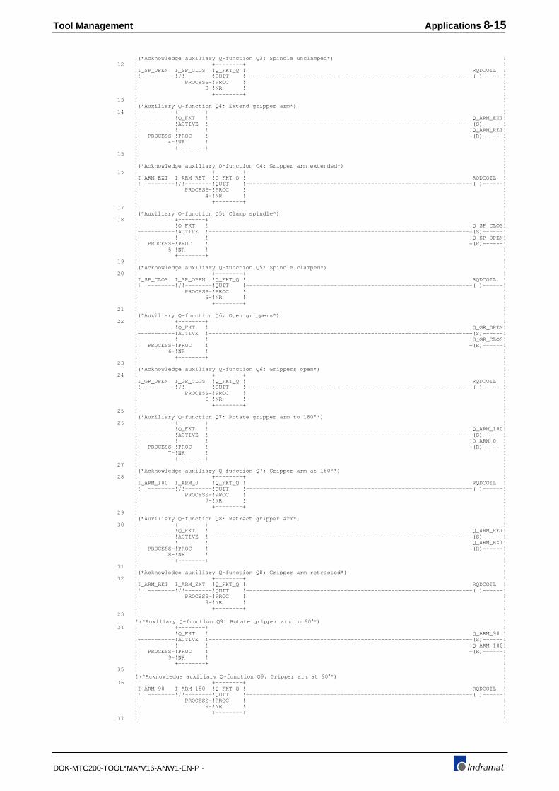
Tool Management Applications 8-15
DOK-MTC200-TOOL*MA*V16-ANW1-EN-P ·
!(*Acknowledge auxiliary Q-function Q3: Spindle unclamped*) ! 12 ! +--------+ ! !I_SP_OPEN I_SP_CLOS !Q_FKT_Q ! RQDCOIL ! !! !--------!/!--------!QUIT !-------------------------------------------------------------------( )------! ! PROCESS-!PROC ! ! ! 3-!NR ! ! ! +--------+ ! 13 ! ! !(*Auxiliary Q-function Q4: Extend gripper arm*) ! 14 ! +--------+ ! ! !Q_FKT ! Q_ARM_EXT! !-----------!ACTIVE !-----------------------------------------------------------------------------+(S)------! ! ! ! !Q_ARM_RET! ! PROCESS-!PROC ! +(R)------! ! 4-!NR ! ! ! +--------+ ! 15 ! ! ! ! !(*Acknowledge auxiliary Q-function Q4: Gripper arm extended*) ! 16 ! +--------+ ! !I_ARM_EXT I_ARM_RET !Q_FKT_Q ! RQDCOIL ! !! !--------!/!--------!QUIT !-------------------------------------------------------------------( )------! ! PROCESS-!PROC ! ! ! 4-!NR ! ! ! +--------+ ! 17 ! ! !(*Auxiliary Q-function Q5: Clamp spindle*) ! 18 ! +--------+ ! ! !Q_FKT ! Q_SP_CLOS! !-----------!ACTIVE !-----------------------------------------------------------------------------+(S)------! ! ! ! !Q_SP_OPEN! ! PROCESS-!PROC ! +(R)------! ! 5-!NR ! ! ! +--------+ ! 19 ! ! !(*Acknowledge auxiliary Q-function Q5: Spindle clamped*) ! 20 ! +--------+ ! !I_SP_CLOS I_SP_OPEN !Q_FKT_Q ! RQDCOIL ! !! !--------!/!--------!QUIT !-------------------------------------------------------------------( )------! ! PROCESS-!PROC ! ! ! 5-!NR ! ! ! +--------+ ! 21 ! ! !(*Auxiliary Q-function Q6: Open grippers*) ! 22 ! +--------+ ! ! !Q_FKT ! Q_GR_OPEN! !-----------!ACTIVE !-----------------------------------------------------------------------------+(S)------! ! ! ! !Q_GR_CLOS! ! PROCESS-!PROC ! +(R)------! ! 6-!NR ! ! ! +--------+ ! 23 ! ! !(*Acknowledge auxiliary Q-function Q6: Grippers open*) ! 24 ! +--------+ ! !I_GR_OPEN I_GR_CLOS !Q_FKT_Q ! RQDCOIL ! !! !--------!/!--------!QUIT !-------------------------------------------------------------------( )------! ! PROCESS-!PROC ! ! ! 6-!NR ! ! ! +--------+ ! 25 ! ! !(*Auxiliary Q-function Q7: Rotate gripper arm to 180°*) ! 26 ! +--------+ ! ! !Q_FKT ! Q_ARM_180! !-----------!ACTIVE !-----------------------------------------------------------------------------+(S)------! ! ! ! !Q_ARM_0 ! ! PROCESS-!PROC ! +(R)------! ! 7-!NR ! ! ! +--------+ ! 27 ! ! !(*Acknowledge auxiliary Q-function Q7: Gripper arm at 180°*) ! 28 ! +--------+ ! !I_ARM_180 I_ARM_0 !Q_FKT_Q ! RQDCOIL ! !! !--------!/!--------!QUIT !-------------------------------------------------------------------( )------! ! PROCESS-!PROC ! ! ! 7-!NR ! ! ! +--------+ ! 29 ! ! !(*Auxiliary Q-function Q8: Retract gripper arm*) ! 30 ! +--------+ ! ! !Q_FKT ! Q_ARM_RET! !-----------!ACTIVE !-----------------------------------------------------------------------------+(S)------! ! ! ! !Q_ARM_EXT! ! PROCESS-!PROC ! +(R)------! ! 8-!NR ! ! ! +--------+ ! 31 ! ! !(*Acknowledge auxiliary Q-function Q8: Gripper arm retracted*) ! 32 ! +--------+ ! !I_ARM_RET I_ARM_EXT !Q_FKT_Q ! RQDCOIL ! !! !--------!/!--------!QUIT !-------------------------------------------------------------------( )------! ! PROCESS-!PROC ! ! ! 8-!NR ! ! ! +--------+ ! 23 ! ! !(*Auxiliary Q-function Q9: Rotate gripper arm to 90 °*) ! 34 ! +--------+ ! ! !Q_FKT ! Q_ARM_90 ! !-----------!ACTIVE !-----------------------------------------------------------------------------+(S)------! ! ! ! !Q_ARM_180! ! PROCESS-!PROC ! +(R)------! ! 9-!NR ! ! ! +--------+ ! 35 ! ! !(*Acknowledge auxiliary Q-function Q9: Gripper arm at 90 °*) ! 36 ! +--------+ ! !I_ARM_90 I_ARM_180 !Q_FKT_Q ! RQDCOIL ! !! !--------!/!--------!QUIT !-------------------------------------------------------------------( )------! ! PROCESS-!PROC ! ! ! 9-!NR ! ! ! +--------+ ! 37 ! !

8-16 Applications Tool Management
DOK-MTC200-TOOL*MA*V16-ANW1-EN-P ·
!(*Read tool change NC-command TMS; 'tool from magazine to spindle'*) ! !(*Initiate tool transfer sequences*) ! !(* tool from magazine pocket -> gripper 1*) ! !(* tool from spindle -> gripper 2*) ! 38 ! +--------+ ! ! !TMS ! ! !-----------!ACTIVE !------------------------------------------------------------------------------O>NOTMS ! ! PROCESS-!PROC ! ! ! 1-!POS ! ! ! 1-!SPINDLE ! ! ! +--------+ ! 39 ! ! !(*Initiate tool transfer from magazine to gripper 1 of the gripper arm*) ! 40 ! +--------+ ! !M_XMG_INI M_XSG_INI !XMG ! M_XMG_INI! !!/!--------!/!--------!INIT !-------------------------------------------------------------------(S)------! ! PROCESS-!PROC ! ! ! 1-!POS ! ! ! 1-!GRIP ! ! ! +--------+ ! 41 ! ! ! (*Acknowledge logical tool transfer(via ONS) from magazine to gripper 1 of the gripper arm*) ! 42 ! +--------+ +--------+ ! !M_XMG_INI M_XMG_OK !XMG_PA ! !XMG_Q ! M_XMG_OK ! !! !--------!/!--------!ACTIVE !-!QUIT !--------------------------------------------------------(S)------! ! PROCESS-!PROC ! ! ! ! ! 1-!POS ! ! ! ! ! 1-!GRIP ! ! ! ! ! +--------+ ! ! ! ! PROCESS-!PROC ! ! ! 1-!POS ! ! ! 1-!GRIP ! ! ! +--------+ ! 43 ! ! !(*Initiate tool transfer from spindle to gripper 2 of the gripper arm*) ! 44 ! +--------+ ! !M_XMG_OK M_XSG_INI !XSG ! M_XSG_INI! !! !--------!/!--------!INIT !-------------------------------------------------------------------(S)------! ! PROCESS-!PROC ! ! ! 1-!SPINDLE ! ! ! 2-!GRIP ! ! ! +--------+ ! 45 ! ! ! (*Acknowledge tool transfer(via ONS) from spindle to gripper 2 of the gripper arm*) ! 46 ! +--------+ +--------+ ! !M_XSG_INI M_XSG_OK !XSG_PA ! !XSG_Q ! M_XSG_OK ! !! !--------!/!--------!ACTIVE !-!QUIT !--------------------------------------------------------(S)------! ! PROCESS-!PROC ! ! ! ! ! 1-!SPINDLE ! ! ! ! ! 2-!GRIP ! ! ! ! ! +--------+ ! ! ! ! PROCESS-!PROC ! ! ! 1-!SPINDLE ! ! ! 2-!GRIP ! ! ! +--------+ ! 47 ! ! !(*Acknowledge tool change NC-command TMS*) ! 48 ! +--------+ ! !M_XMG_INI M_XMG_OK M_XSG_INI M_XSG_OK !TMS_Q ! M_XMG_INI! !! !--------! !--------! !--------! !--------!QUIT !--------------------------------------------+(R)------! ! ! ! !M_XMG_OK ! ! PROCESS-!PROC ! !(R)------! ! ! ! !M_XSG_INI! ! 1-!POS ! !(R)------! ! ! ! !M_XSG_OK ! ! 1-!SPINDLE ! +(R)------! ! +--------+ ! 49 !NOTMS: ! 50 ! ! !(*Read tool change NC-command TSM; 'tool from spindle to magazine'*) ! !(*Initiate tool transfer sequences*) ! !(* tool from gripper 1 -> spindle*) ! !(* tool from gripper 2 -> magazine pocket*) ! 51 ! +--------+ ! ! !TSM ! ! !-----------!ACTIVE !------------------------------------------------------------------------------O>NOTSM ! ! PROCESS-!PROC ! ! ! 1-!SPINDLE ! ! ! 1-!POS ! ! ! +--------+ ! 52 ! ! !(*Initiate tool transfer from gripper 1 to spindle*) ! 53 ! +--------+ ! !M_XGS_INI M_XGM_INI !XGS ! M_XGS_INI! !!/!--------!/!--------!INIT !-------------------------------------------------------------------(S)------! ! PROCESS-!PROC ! ! ! 1-!GRIP ! ! ! 1-!SPINDLE ! ! ! +--------+ ! 54 ! ! ! (*Acknowledge tool transfer(via ONS) from gripper 1 to the spindle*) ! 55 ! +--------+ +--------+ ! !M_XGS_INI M_XGS_OK !XGS_PA ! !XGS_Q ! M_XGS_OK ! !! !--------!/!--------!ACTIVE !-!QUIT !--------------------------------------------------------(S)------! ! PROCESS-!PROC ! ! ! ! ! 1-!GRIP ! ! ! ! ! 1-!SPINDLE ! ! ! ! ! +--------+ ! ! ! ! PROCESS-!PROC ! ! ! 1-!GRIP ! ! ! 1-!SPINDLE ! ! ! +--------+ ! 56 ! ! !(*Initiate tool transfer from gripper 2 to the magazine*) ! 57 ! +--------+ ! !M_XGS_OK M_XGM_INI !XGM ! M_XGM_INI! !! !--------!/!--------!INIT !-------------------------------------------------------------------(S)------! ! PROCESS-!PROC ! ! ! 2-!GRIP ! ! ! 1-!POS ! ! ! +--------+ ! 58 ! !
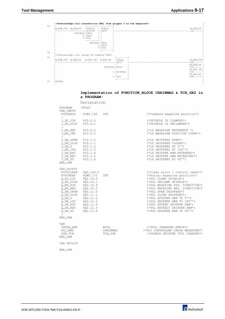
Tool Management Applications 8-17
DOK-MTC200-TOOL*MA*V16-ANW1-EN-P ·
! (*Acknowledge tool transfer(via ONS) from gripper 2 to the magazine*) ! 59 ! +--------+ +--------+ ! !M_XGM_INI M_XGM_OK !XGM_PA ! !XGM_Q ! M_XGM_OK ! !! !--------!/!--------!ACTIVE !-!QUIT !--------------------------------------------------------(S)------! ! PROCESS-!PROC ! ! ! ! ! 2-!GRIP ! ! ! ! ! 1-!POS ! ! ! ! ! +--------+ ! ! ! ! PROCESS-!PROC ! ! ! 2-!GRIP ! ! ! 1-!POS ! ! ! +--------+ ! 60 ! ! !(*Acknowledge tool change NC-command TSM*) ! 61 ! +--------+ ! !M_XGM_INI M_XGM_OK M_XGS_INI M_XGS_OK !TSM_Q ! M_XGM_INI! !! !--------! !--------! !--------! !--------!QUIT !--------------------------------------------+(R)------! ! ! ! !M_XGM_OK ! ! PROCESS-!PROC ! !(R)------! ! ! ! !M_XGS_INI! ! 1-!SPINDLE ! !(R)------! ! ! ! !M_XGS_OK ! ! 1-!POS ! +(R)------! ! +--------+ ! 62 !NOTSM: ! ! !
Implementation of FUNCTION_BLOCK CHAINMAG & TCH_GR2 ina PROGRAM:
Declaration PROGRAM TOOLS VAR_INPUT P00SMGCP %IW0.180 INT (*Command magazine position*) : I_SP_CLP %I0.0.0 (*SPINDLE IS CLAMPED*) I_SP_UCLP %I0.0.1 (*SPINDLE IS UNCLAMPED*) : I_MG_REF %I0.0.2 (*LS MAGAZINE REFERENCE *) I_MG_CNT %I0.0.3 (*LS MAGAZINE POSITION COUNT*) : I_GR_OPEN %I0.1.0 (*LS GRIPPERS OPEN*) I_GR_CLOS %I0.1.1 (*LS GRIPPERS CLOSED*) I_GR_0 %I0.1.2 (*LS GRIPPERS AT 0°*) I_GR_180 %I0.1.3 (*LS GRIPPERS AT 180°*) I_GR_EXT %I0.1.4 (*LS GRIPPER ARM EXTENDED*) I_GR_RET %I0.1.5 (*LS GRIPPER ARM RETRACTED*) I_GR_90 %I0.1.6 (*LS GRIPPERS AT 90°*) END_VAR
VAR_OUTPUT P00CCLEAR %Q0.164.0 (*Clear error / Control reset*) P00CMGAP %QW0.170 INT (*Actual magazine position*) Q_SP_CLP %Q0.10.0 (*SOL CLAMP SPINDLE*) Q_SP_UCLP %Q0.10.1 (*SOL UNCLAMP SPINDLE*) Q_MG_POS %Q0.10.4 (*SOL MAGAZINE POS. DIRECTION*) Q_MG_NEG %Q0.10.5 (*SOL MAGAZINE NEG. DIRECTION*) Q_GR_OPEN %Q0.11.0 (*SOL OPEN GRIPPERS*) Q_GR_CLOS %Q0.11.1 (*SOL CLOSE GRIPPERS*) Q_GR_0 %Q0.11.2 (*SOL GRIPPER ARM TO 0°*) Q_GR_180 %Q0.11.3 (*SOL GRIPPER ARM TO 180°*) Q_GR_EXT %Q0.11.4 (*SOL EXTEND GRIPPER ARM*) Q_GR_RET %Q0.11.5 (*SOL RETRACT GRIPPER ARM*) Q_GR_90 %Q0.11.6 (*SOL GRIPPER ARM TO 90°*) : END_VAR
VAR TXFER_ERR BOOL (*TOOL TRANSFER ERROR*) PLC_MAG CHAINMAG (*PLC CONTROLLED CHAIN MAGAZINE*) DGR_TCH TCH_2GR (*DOUBLE GRIPPER TOOL CHANGER*) END_VAR
VAR RETAIN
END_VAR

8-18 Applications Tool Management
DOK-MTC200-TOOL*MA*V16-ANW1-EN-P ·
Implementation : : !(*Tool changer with double gripper*) ! ! DGR_TCH ! ! +-------------------+ ! ! !TCH_2GR ! ! !I_GR_OPEN I_GR_CLOS ! ! Q_GR_OPEN! !! !--------!/!--------!I_GR_OPEN Q_GR_OPEN!--------------------------------------------------------( )------! ! ! ! ! !I_GR_CLOS I_GR_OPEN ! ! Q_GR_CLOS! !! !--------!/!--------!I_GR_CLOS Q_GR_CLOS!--------------------------------------------------------( )------! ! ! ! ! !I_SP_UCLP I_SP_CLP ! ! Q_SP_UCLP! !! !--------!/!--------!I_SP_OPEN Q_SP_OPEN!--------------------------------------------------------( )------! ! ! ! ! !I_SP_CLP I_SP_UCLP ! ! Q_SP_CLP ! !! !--------!/!--------!I_SP_CLOS Q_SP_CLOS!--------------------------------------------------------( )------! ! ! ! ! !I_GR_0 I_GR_90 ! ! Q_GR_0 ! !! !--------!/!--------!I_ARM_0 Q_ARM_0!--------------------------------------------------------( )------! ! ! ! ! !I_GR_90 I_GR_180 ! ! Q_GR_90 ! !! !--------!/!--------!I_ARM_90 Q_ARM_90 !--------------------------------------------------------( )------! ! ! ! ! !I_GR_180 I_GR_0 ! ! Q_GR_180 ! !! !--------!/!--------!I_ARM_180 Q_ARM_180!--------------------------------------------------------( )------! ! ! ! ! !I_GR_EXT I_GR_RET ! ! Q_GR_EXT ! !! !--------!/!--------!I_ARM_EXT Q_ARM_EXT!--------------------------------------------------------( )------! ! ! ! ! !I_GR_RET I_GR_EXT ! ! Q_GR_RET ! !! !--------!/!--------!I_ARM_RET Q_ARM_RET!--------------------------------------------------------( )------! ! ! ! ! ! 0-!PROCESS ! ! ! ! ! ! ! +-------------------+ !
DGR_TCH...................... DOUBLE GRIPPER TOOL CHANGER............. .......... TCH_2GR I_GR_OPEN.................... LS GRIPPERS OPEN........................ %I0.1.0... BOOL I_GR_CLOS.................... LS GRIPPERS CLOSED...................... %I0.1.1... BOOL Q_GR_OPEN.................... SOL OPEN GRIPPERS....................... %Q0.11.0.. BOOL I_GR_CLOS.................... LS GRIPPERS CLOSED...................... %I0.1.1... BOOL I_GR_OPEN.................... LS GRIPPERS OPEN........................ %I0.1.0... BOOL Q_GR_CLOS.................... SOL CLOSE GRIPPERS...................... %Q0.11.1.. BOOL I_SP_UCLP.................... SPINDLE IS UNCLAMPED.................... %I0.0.1... BOOL I_SP_CLP..................... SPINDLE IS CLAMPED...................... %I0.0.0... BOOL Q_SP_UCLP.................... SOL UNCLAMP SPINDLE..................... %Q0.10.1.. BOOL I_SP_CLP..................... SPINDLE IS CLAMPED...................... %I0.0.0... BOOL I_SP_UCLP.................... SPINDLE IS UNCLAMPED.................... %I0.0.1... BOOL Q_SP_CLP..................... SOL CLAMP SPINDLE....................... %Q0.10.0.. BOOL I_GR_0....................... LS GRIPPERS AT 0°....................... %I0.1.2... BOOL I_GR_90...................... LS GRIPPERS AT 90°...................... %I0.1.6... BOOL Q_GR_0....................... SOL GRIPPER ARM TO 0°................... %Q0.11.2.. BOOL I_GR_90...................... LS GRIPPERS AT 90°...................... %I0.1.6... BOOL I_GR_180..................... LS GRIPPERS AT 180°..................... %I0.1.3... BOOL Q_GR_90...................... SOL GRIPPER ARM TO 90°.................. %Q0.11.6.. BOOL I_GR_180..................... LS GRIPPERS AT 180°..................... %I0.1.3... BOOL I_GR_0....................... LS GRIPPERS AT 0°....................... %I0.1.2... BOOL Q_GR_180..................... SOL GRIPPER ARM TO 180°................. %Q0.11.3.. BOOL I_GR_EXT..................... LS GRIPPER ARM EXTENDED................. %I0.1.4... BOOL I_GR_RET..................... LS GRIPPER ARM RETRACTED................ %I0.1.5... BOOL Q_GR_EXT..................... SOL EXTEND GRIPPER ARM.................. %Q0.11.4.. BOOL I_GR_RET..................... LS GRIPPER ARM RETRACTED................ %I0.1.5... BOOL I_GR_EXT..................... LS GRIPPER ARM EXTENDED................. %I0.1.4... BOOL Q_GR_RET..................... SOL RETRACT GRIPPER ARM................. %Q0.11.5.. BOOL 0............................ ........................................ .......... ANY_INT
! ! ! ! !(*PLC controlled magazine movement (no NC-servo)*) ! ! PLC_MAG ! ! !CHAINMAG ! ! !I_MG_REF ! ! Q_MG_POS ! !! !--------!I_REF Q_MAGPOS!-------------------------------------------------------------------( )------! !I_MG_CNT ! ! Q_MG_NEG ! !! !--------!I_COUNT Q_MAGNEG!-------------------------------------------------------------------( )------! ! 35-!MAXPOCKET PXXCMGAP!-P00CMGAP ! ! P00SMGCP-!PXXSMGCP ! ! ! 0-!PROCESS ! ! ! +-------------------+ !
PLC_MAG...................... PLC CONTROLLED CHAIN MAGAZINE........... .......... CHAINMAG I_MG_REF..................... LS MAGAZINE REFERENCE .................. %I0.0.2... BOOL Q_MG_POS..................... SOL MAGAZINE POS. DIRECTION............. %Q0.10.4.. BOOL I_MG_CNT..................... LS MAGAZINE POSITION COUNT.............. %I0.0.3... BOOL Q_MG_NEG..................... SOL MAGAZINE NEG. DIRECTION............. %Q0.10.5.. BOOL 35........................... ........................................ .......... ANY_INT P00CMGAP..................... Actual magazine position................ %QW0.170.. INT P00SMGCP..................... Command magazine position............... %IW0.180.. INT 0............................ ........................................ .......... ANY_INT
8.3 'Combined Spindle (live tool) / Turret' NC servo axis
Turrets with live tooling are used especially in turning machines. Usually,one AC servo motor is used to drive the live tool and position the turret.The AC servo motor is mechanically switched between the tool and turretto accomplish this.

Tool Management Applications 8-19
DOK-MTC200-TOOL*MA*V16-ANW1-EN-P ·
POS1Reference
position
+
1
2
34
5
6
78
T238
T831T125
T239
T91
T254
T121
Turret mode
Spindle mode
1
1
20
1
Z
X
S1/C
Fig. 8-116: 'Combined Spindle (live tool) / Turret' NC servo axis
The MTC provides in its parameter setup a 'combined spindle/turret' axistype to define a turret and spindle, driven by the same AC servo drive. A'rotary' type axis is used for the turret if both, the turret and spindle isdriven by its own motor.
This example shows the use of a 'combined spindle/turret' axis andtherefore contains in the SPS program special FUNCTIONs to recognizethe mode and acknowledge its mechanical selection.
Indramat's digital AC servo drives must be used for 'Combinedspindle/turret axes'. They provide the functionality needed by the CNC todirectly switch between spindle and rotary axis. This simplifiesimplementation, troubleshooting and operation of such a live tool turret.
8.4 Functional description
It is assumed, that the motor of the combined 'spindle/turret axis' is first ofall mechanically coupled to the tool and functions as the spindle.
First of all, the spindle is oriented in the tool change NC-subroutine 'M6T'.The NC-command MTP (or MMP) is used to orient the last selected tool(pocket) into machining position and activate its tool data. The CNCautomatically selects turret mode that can be recognized in the SPSprogram via the FUNCTION MAG_ACT. The FUNCTION MAG_Q mustbe used in the SPS program to acknowledge the mechanical connectionof the motor to the turret. The CNC then rotates the selected tool intomachining position.
Spindle mode is automatically selected by the CNC whenever NC-commands are executed that do NOT cause a turret movement. NC-program execution continues after MTP and MMP until the NC-commandMRY is to be executed. NC-program execution then stops until the turretmovement is finished and the motor is mechanically coupled to the toolagain (spindle).
The FUNCTION SPDL_ACT must be used in the SPS program torecognize the spindle mode that is automatically selected by the CNC.The FUNCTION SPDL_Q must be used in the SPS program toacknowledge the mechanically connecting of the motor to the tool. Themotor then functions as a spindle again.
MTC parameter setsSystem parameters:
Par. Description Value Unit
A00.000 Name of the Management Process Turning satin
:
Tool into machining position:
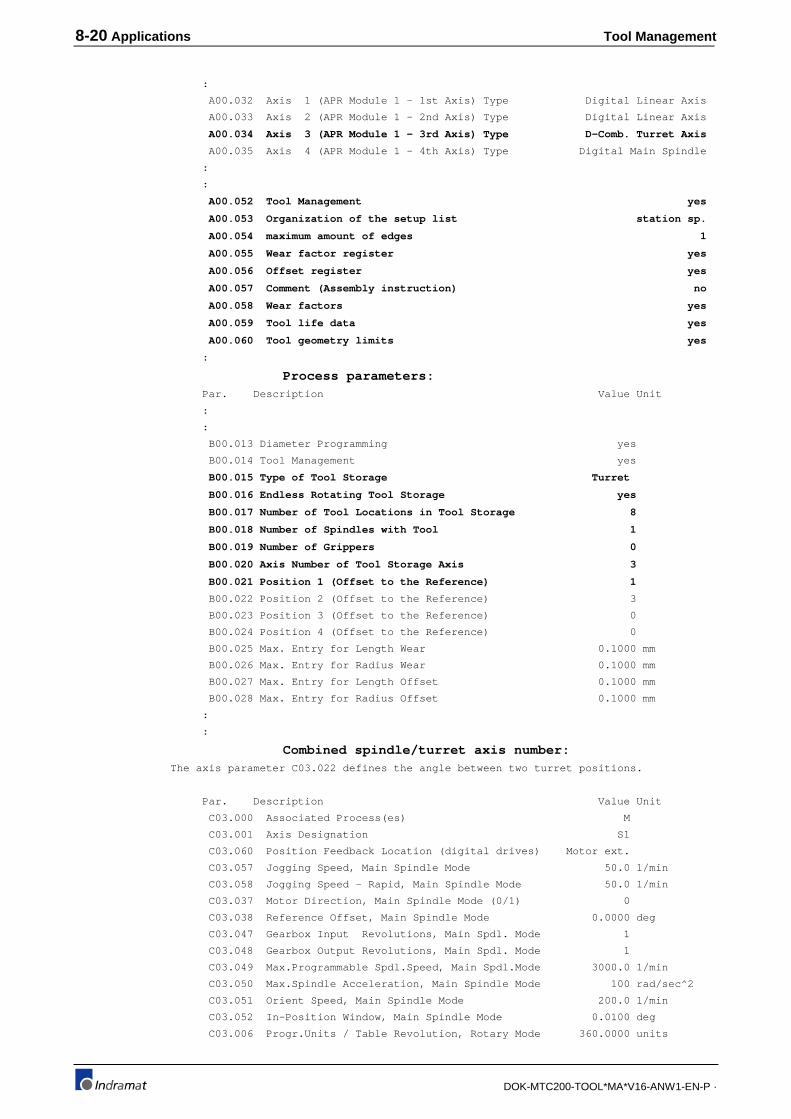
8-20 Applications Tool Management
DOK-MTC200-TOOL*MA*V16-ANW1-EN-P ·
:
A00.032 Axis 1 (APR Module 1 - 1st Axis) Type Digital Linear Axis
A00.033 Axis 2 (APR Module 1 - 2nd Axis) Type Digital Linear Axis
A00.034 Axis 3 (APR Module 1 - 3rd Axis) Type D-Comb. Turret Axis
A00.035 Axis 4 (APR Module 1 - 4th Axis) Type Digital Main Spindle
:
:
A00.052 Tool Management yes
A00.053 Organization of the setup list station sp.
A00.054 maximum amount of edges 1
A00.055 Wear factor register yes
A00.056 Offset register yes
A00.057 Comment (Assembly instruction) no
A00.058 Wear factors yes
A00.059 Tool life data yes
A00.060 Tool geometry limits yes
:
Process parameters: Par. Description Value Unit
:
:
B00.013 Diameter Programming yes
B00.014 Tool Management yes
B00.015 Type of Tool Storage Turret
B00.016 Endless Rotating Tool Storage yes
B00.017 Number of Tool Locations in Tool Storage 8
B00.018 Number of Spindles with Tool 1
B00.019 Number of Grippers 0
B00.020 Axis Number of Tool Storage Axis 3
B00.021 Position 1 (Offset to the Reference) 1
B00.022 Position 2 (Offset to the Reference) 3
B00.023 Position 3 (Offset to the Reference) 0
B00.024 Position 4 (Offset to the Reference) 0
B00.025 Max. Entry for Length Wear 0.1000 mm
B00.026 Max. Entry for Radius Wear 0.1000 mm
B00.027 Max. Entry for Length Offset 0.1000 mm
B00.028 Max. Entry for Radius Offset 0.1000 mm
:
:
Combined spindle/turret axis number: The axis parameter C03.022 defines the angle between two turret positions.
Par. Description Value Unit
C03.000 Associated Process(es) M
C03.001 Axis Designation S1
C03.060 Position Feedback Location (digital drives) Motor ext.
C03.057 Jogging Speed, Main Spindle Mode 50.0 1/min
C03.058 Jogging Speed - Rapid, Main Spindle Mode 50.0 1/min
C03.037 Motor Direction, Main Spindle Mode (0/1) 0
C03.038 Reference Offset, Main Spindle Mode 0.0000 deg
C03.047 Gearbox Input Revolutions, Main Spdl. Mode 1
C03.048 Gearbox Output Revolutions, Main Spdl. Mode 1
C03.049 Max.Programmable Spdl.Speed, Main Spdl.Mode 3000.0 1/min
C03.050 Max.Spindle Acceleration, Main Spindle Mode 100 rad/sec^2
C03.051 Orient Speed, Main Spindle Mode 200.0 1/min
C03.052 In-Position Window, Main Spindle Mode 0.0100 deg
C03.006 Progr.Units / Table Revolution, Rotary Mode 360.0000 units

Tool Management Applications 8-21
DOK-MTC200-TOOL*MA*V16-ANW1-EN-P ·
C03.007 Gearbox Input Revolutions, Rotary Mode 20
C03.008 Gearbox Output Revolutions, Rotary Mode 1
C03.013 Reference Position, Rotary Mode 0.0000 units
C03.014 Position Polarity (0/1), Rotary Mode 0
C03.016 Maximum Feedrate, Rotary Mode 50000.0 units/min
C03.017 Max. Feedrate Change w/o Ramp, Rotary Mode 200.0 units/min
C03.018 Maximum Acceleration Rate, Rotary Mode 100 units/sec^2
C03.019 Homing Speed, Rotary Mode 10000.0 units/min
C03.022 Parametric Jogging Distance, Rotary Mode 45.000 units
C03.023 In-Position Window, Rotary Mode 0.0100 units
C03.033 Home Limit Switch Input, Rotary Mode 00.00.0
In addition digital drive parameters are required.
NC-programsCall of tool change in NC-program:
;----------------------------------------------------------------------
;
; NC SERVO CONTROLLED TURRET (ENDLESS AND NON ENDLESS)
; WITH LIVE TOOLING
; THE SPINDLE DRIVES THE TOOL AND THE TURRET
; (SAUTER TOOL CHANGER)
;
;----------------------------------------------------------------------
N0087 .M6S
M19 S0 ;position tool spindle
N0088 BTE .M6S_T0 ;branch if tool 'T0' active
N0089 MTP ;move programmed tool into machining
position
N0090 G48 ;activate tool length correction
N0091 MRY RTS ;wait for turret positioning complete
;
N0092 .M6S_T0 G47 RTS ;cancel tool length correction
SPS ProgramThe FUNCTION_BLOCK S_TURRET controls the mechanical switchingof the motor and the FUNCTION_BLOCK TURRET acknowledges thetool storage move NC-commands. Its implementation into a PROGRAMshows the additional logic required.
FUNCTION_BLOCK S_TURRET:
Declaration FUNCTION_BLOCK S_TURRET VAR_INPUT I_TURRET BOOL (*TURRET MODE SELECTION*) I_SPINDLE BOOL (*SPINDLE MODE SELECTION*) I_T_LOCK BOOL (*TURRET LOCKED*) I_T_ULOCK BOOL (*TURRET UNLOCKED*) I_T_DENG BOOL (*TURRET DISENGAGED*) I_T_ENG BOOL (*TURRET ENGAGED*) I_SP_ENG BOOL (*SPINDLE ENGAGED*) I_SP_DENG BOOL (*SPINDLE DISENGAGED*) I_CLUTCH BOOL (*CLUTCH*) ENA_SOL BOOL (*ENABLE SOLENOID*) PROCESS INT (*Process number*) END_VAR
VAR_OUTPUT SOLTURRET BOOL (*SELECT TURRET MODE*) SOLSPINDL BOOL (*SELECT SPINDLE MODE*) Q_TURRET BOOL (*TURRET MODE ACTIVE*)

8-22 Applications Tool Management
DOK-MTC200-TOOL*MA*V16-ANW1-EN-P ·
Q_SPINDLE BOOL (*SPINDLE MODE ACTIVE*) ERR BOOL (*UNDEFINED CLUTCH POSITION*) MRF_A BOOL (*NC-command MRF active*) MMV_A BOOL (*Turret move NC-command active*) END_VAR
VAR M_SPINDLE BOOL (*SPINDLE MODE*) M_TURRET BOOL (*TURRET MODE *) MRFQ BOOL (*NC-command MRF acknowledge*) MMVQ BOOL (*Turret move NC-command acknowledge*) ERR_TON TON (*ERROR WATCHDOG*) TURRET_TP TP (*PULSE, TURRET MODE SELECTION*) SPINDL_TP TP (*PULSE, SPINDLE MODE SELECTION*) END_VAR
VAR RETAIN
END_VAR
Implementation 1 ! ! !I_T_LOCK I_T_DENG I_SP_ENG I_T_ULOCK I_T_ENG I_SP_DENG M_SPINDLE! !! !--------! !--------! !--------!/!--------!/!--------!/!-----------------------------------------( )------! 2 ! ! !(*CONDITIONS FOR TURRET MODE*) ! 3 ! ! !I_T_LOCK I_T_DENG I_SP_ENG I_T_ULOCK I_T_ENG I_SP_DENG M_TURRET ! !!/!--------!/!--------!/!--------! !--------! !--------! !-----------------------------------------( )------! 4 ! ! !(*SPINDLE MODE SELECTION*) ! 5 ! SPINDL_TP ! ! +-------------------+ ! ! !TP ! ! !M_TURRET I_SPINDLE ENA_SOL ! ! SOLSPINDL! !! !--------! !--------! !--------!IN_ Q_!--------------------------------------------+(S)------! ! ! ! !SOLTURRET! ! T#1s-!PT_ ! +(R)------! ! ! ET_! ! ! +-------------------+ ! 6 ! ! !(*TURRET MODE SELECTION*) ! 7 ! TURRET_TP ! ! +-------------------+ ! ! !TP ! ! !M_SPINDLE I_TURRET ENA_SOL ! ! SOLTURRET! !! !--------! !--------! !--------!IN_ Q_!--------------------------------------------+(S)------! ! ! ! !SOLSPINDL! ! T#1s-!PT_ ! +(R)------! ! ! ET_! ! ! +-------------------+ ! 8 ! ! !(*SPINDLE MODE ACTIVE*) ! 9 ! ! !M_SPINDLE ERR Q_SPINDLE! !! !--------!/!-------------------------------------------------------------------------------------( )------! 10 ! ! !(*TURRET MODE ACTIVE*) ! 11 ! ! !M_TURRET ERR Q_TURRET ! !! !--------!/!-------------------------------------------------------------------------------------( )------! 12 ! ! !(*TURRET/SPINDLE IN UNDEFINED CONDITION*) ! 13 ! ERR_TON ! ! +-------------------+ ! ! !TON ! ! !M_SPINDLE M_TURRET ! ! ERR ! !!/!--------!/!--------!IN_ Q_!--------------------------------------------------------( )------! ! T#3s-!PT_ ET_! ! ! +-------------------+ ! 14 ! ! !(*Read NC-command MRF 'Reference Magazine'*) ! 15 ! +--------+ ! !ENA_SOL !MRF ! MRF_A ! !! !--------!ACTIVE !-----------------------------------------------------------------------------+( )------! ! PROCESS-!PROC ! +O>NOMRF ! ! +--------+ ! 16 ! ! !(*Acknowledge NC-command MRF*) ! 17 ! +--------+ ! !MRFQ !MRF_Q ! MRFQ ! !! !--------!QUIT !------------------------------------------------------------------------------(S)------! ! ROCESS-!PROC ! ! ! +--------+ ! 18 ! ! !(*Clear NC-command MRF acknowledged*) ! 19 !NOMRF: ! !MRF_A MRFQ ! !!/!------------------------------------------------------------------------------------------------(R)------! 20 ! ! !(*Read active tool storage move NC-command*) ! 21 ! +--------+ ! !ENA_SOL !MMV ! MMV_A ! !! !--------!ACTIVE !-----------------------------------------------------------------------------+( )------! ! PROCESS-!PROC ! +O>NOMMV ! ! +--------+ ! 22 ! ! !(*Acknowledge tool storage move NC-command*) ! 23 ! +--------+ ! !MMV_A !MMV_Q ! MMVQ ! !! !--------!QUIT !------------------------------------------------------------------------------(S)------! ! PROCESS-!PROC ! ! ! +--------+ ! 24 ! ! !(*Clear tool storage move NC-command acknowledgment*) !

Tool Management Applications 8-23
DOK-MTC200-TOOL*MA*V16-ANW1-EN-P ·
25 !NOMMV: ! !MMV_A MMVQ ! !!/!------------------------------------------------------------------------------------------------(R)------!
Implementation of FUNCTION_BLOCK S_TURRET in PROGRAM:
Declaration PROGRAM TOOLS VAR_INPUT P00SMGCP %IW0.180 INT (*Command magazine position*) : I_T_LOCK %I0.2.0 (*LS TURRET LOCKED*) I_T_ULOCK %I0.2.1 (*LS TURRET UNLOCKED*) I_T_DENG %I0.2.2 (*LS TURRET DISENGAGE*) I_T_ENG %I0.2.3 (*LS TURRET ENGAGE*) I_SP_DENG %I0.2.4 (*LS SPINDLE DISENGAGE*) I_SP_ENG %I0.2.5 (*LS SPINDLE ENGAGE*) I_CLUTCH %I0.2.6 (*LS CLUTCH*) END_VAR
VAR_OUTPUT P00CCLEAR %Q0.164.0 (*Clear error / Control reset*) : Q_SPINDLE %Q0.10.6 (*SOL SPINDLE MODE SELECTION*) Q_TURRET %Q0.10.7 (*SOL TURRET MODE SELECTION*) Q_LT_TURR %Q0.11.6 (*LT TURRET MODE ACTIVE*) Q_LT_SPDL %Q0.11.7 (*LT SPINDLE MODE ACTIVE*) END_VAR
VAR TXFER_ERR BOOL (*TOOL TRANSFER ERROR*) SP_TURRET S_TURRET (*TURRET/LIVE TOOL*) END_VAR
VAR RETAIN
END_VAR
Implementation 9 ! ! !(*Mechanical switching between turret and spindle mode*) ! 10 ! SP_TURRET ! ! +-------------------+ ! ! !S_TURRET ! ! ! +--------+ ! ! ! ! !MAG_ACT ! ! ! Q_TURRET ! !-----------!ACTIVE !-!I_TURRET SOLTURRET!--------------------------------------------------------( )------! ! ! ! ! ! Q_SPINDLE! ! 0-!PROC ! ! SOLSPINDL!--------------------------------------------------------( )------! ! ! ! ! ! +--------+ ! ! ! ! ! ! !MAG_Q ! Q_LT_TURR! ! +--------+ ! Q_TURRET!------------!QUIT !----------------------------------( )------! ! +--------+ ! ! 0-!PROC ! ! ! !SPDL_ACT! ! ! ---------- ! !-----------!ACTIVE !-!I_SPINDLE ! ! ! 0-!PROC ! ! ! +--------+ ! ! ! ! ! ! !SPDL_Q ! Q_LT_SPDL! ! +--------+ ! Q_SPINDLE!------------!QUIT !----------------------------------( )------! !I_T_LOCK I_T_ULOCK ! ! ! ! ! !! !--------!/!--------!I_T_LOCK ! 0-!PROC ! ! ! ! ! ---------- ! !I_T_ULOCK I_T_LOCK ! ! ! !! !--------!/!--------!I_T_ULOCK ! ! !I_T_DENG I_T_ENG ! ! Q_SPT_ERR! !! !--------!/!--------!I_T_DENG ERR!--------------------------------------------------------( )------! !I_T_ENG I_T_DENG ! ! ! !! !--------!/!--------!I_T_ENG ! ! !I_SP_ENG I_SP_DENG ! ! ! !! !--------!/!--------!I_SP_ENG MRF_A!- ! !I_SP_DENG I_SP_ENG ! ! ! !! !--------!/!--------!I_SP_DENG ! ! !I_CLUTCH ! ! ! !! !-------------------!I_CLUTCH MMV_A!- ! !----------------------!ENA_SOL ! ! ! 1-!PROCESS ! ! ! +-------------------+ !
SP_TURRET.................... TURRET/LIVE TOOL........................ .......... S_TURRET MAG_ACT...................... ........................................ .......... MAG_ACT Q_TURRET..................... SOL TURRET MODE SELECTION............... %Q0.10.7.. BOOL 0............................ ........................................ .......... ANY_INT Q_SPINDLE.................... SOL SPINDLE MODE SELECTION.............. %Q0.10.6.. BOOL MAG_Q........................ ........................................ .......... MAG_Q Q_LT_TURR.................... LT TURRET MODE ACTIVE................... %Q0.11.6.. BOOL SPDL_ACT..................... ........................................ .......... SPDL_ACT 0............................ ........................................ .......... ANY_INT 0............................ ........................................ .......... ANY_INT SPDL_Q....................... ........................................ .......... SPDL_Q Q_LT_SPDL.................... LT SPINDLE MODE ACTIVE.................. %Q0.11.7.. BOOL I_T_LOCK..................... LS TURRET LOCKED........................ %I0.2.0... BOOL I_T_ULOCK.................... LS TURRET UNLOCKED...................... %I0.2.1... BOOL 0............................ ........................................ .......... ANY_INT I_T_ULOCK.................... LS TURRET UNLOCKED...................... %I0.2.1... BOOL I_T_LOCK..................... LS TURRET LOCKED........................ %I0.2.0... BOOL I_T_DENG..................... LS TURRET DISENGAGE..................... %I0.2.2... BOOL I_T_ENG...................... LS TURRET ENGAGE........................ %I0.2.3... BOOL Q_SPT_ERR.................... LT TURRET/SPINDLE SWITCH ERROR.......... %Q0.10.3.. BOOL I_T_ENG...................... LS TURRET ENGAGE........................ %I0.2.3... BOOL

8-24 Applications Tool Management
DOK-MTC200-TOOL*MA*V16-ANW1-EN-P ·
I_T_DENG..................... LS TURRET DISENGAGE..................... %I0.2.2... BOOL I_SP_ENG..................... LS SPINDLE ENGAGE....................... %I0.2.5... BOOL I_SP_DENG.................... LS SPINDLE DISENGAGE.................... %I0.2.4... BOOL I_SP_DENG.................... LS SPINDLE DISENGAGE.................... %I0.2.4... BOOL I_SP_ENG..................... LS SPINDLE ENGAGE....................... %I0.2.5... BOOL I_CLUTCH..................... LS CLUTCH............................... %I0.2.6... BOOL 1............................ ........................................ .......... ANY_INT
8.5 NC servo controlled tool turret
POS1Reference
position
+
1
2
34
5
6
78
T831
T91
20
1
T91
T831
T91
T91
X
Z
S
Fig. 8-117: NC servo controlled tool turret
NC servo controlled turrets require the least amount of programming inthe MTC, since the tool transfer is performed by the CNC and noprogramming in the SPS is required.
Functional descriptionThe NC-command MTP (or MMP) is used to orient the last selected tool(pocket) into machining position and activate its tool data. NC-programexecution continues after MTP and MMP until the NC-command MRY isto be executed. NC-program execution then stops until the turretmovement is finished.
MTC parameter setsSystem parameters:
Par. Description Value Unit
A00.000 Name of the Management Process Turning station
: :
A00.032 Axis 1 (APR Module 1 - 1st Axis) Type Digital Linear Axis
A00.033 Axis 2 (APR Module 1 - 2nd Axis) Type Digital Linear Axis
A00.034 Axis 3 (APR Module 1 - 3rd Axis) Type Digital Rotary Axis
A00.035 Axis 4 (APR Module 1 - 4th Axis) Type Digital Main Spindle
: :
A00.052 Tool Management yes
A00.053 Organization of the setup list station sp.
A00.054 maximum amount of edges 1
A00.055 Wear factor register yes
A00.056 Offset register yes
A00.057 Comment (Assembly instruction) no
A00.058 Wear factors yes
A00.059 Tool life data yes
A00.060 Tool geometry limits yes
:
:
Tool into machining position:

Tool Management Applications 8-25
DOK-MTC200-TOOL*MA*V16-ANW1-EN-P ·
Process parameters:
Par. Description Value Unit
:
:
B00.013 Diameter Programming yes
B00.014 Tool Management yes
B00.015 Type of Tool Storage Turret
B00.016 Endless Rotating Tool Storage yes
B00.017 Number of Tool Locations in Tool Storage 8
B00.018 Number of Spindles with Tool 0
B00.019 Number of Grippers 0
B00.020 Axis Number of Tool Storage Axis 3
B00.021 Position 1 (Offset to the Reference) 1
B00.022 Position 2 (Offset to the Reference) 3
B00.023 Position 3 (Offset to the Reference) 0
B00.024 Position 4 (Offset to the Reference) 0
B00.025 Max. Entry for Length Wear 0.1000 mm
B00.026 Max. Entry for Radius Wear 0.1000 mm
B00.027 Max. Entry for Length Offset 0.1000 mm
B00.028 Max. Entry for Radius Offset 0.1000 mm
:
:
Rotary axis parameters (in MTC) for turret:
The axis parameter C03.022 defines the angle between two turretpositions.
Par. Description Value Unit
C03.000 Associated Process(es) M
C03.001 Axis Designation W
C03.053 Axis defined in RIGHT HAND COORD. System as W
C03.006 Programming Units / Table Revolution 360.0000 units
C03.011 Positive Software Travel Limit 0.0000 units
C03.012 Negative Software Travel Limit 0.0000 units
C03.016 Maximum Feedrate 50000.0 units/min
C03.017 Maximum Feedrate Change w/o Ramp 200.0 units/min
C03.018 Maximum Acceleration Rate 100 units/sec^2
C03.020 Jogging Speed 50.0 units/min
C03.021 Jogging Speed - Rapid 50.0 units/min
C03.022 Parametric Jogging Distance 36.0000 units
C03.023 In-Position Window 0.0100 units
:
:
Digital drive parameters (in MTC) for turret axis:
:
:
S-0-0032 Primary Mode of Operation 0000000000000011
S-0-0033 Secondary Operation Mode 1 0000000000001011
S-0-0034 Secondary Operation Mode 2 0000000000000010
S-0-0035 Secondary Operation Mode 3 0000000000000000
S-0-0076 Position Data Scaling Method 0000000011000010
S-0-0077 Linear Position Data Scaling Factor 1
S-0-0078 Linear Position Data Scaling Exponent -4
S-0-0079 Rotational Position Resolution 3600000
S-0-0103 Modulo Value 0.0000 Grad
S-0-0055 Position Polarity Parameter 0000000000001111
S-0-0044 Scaling of Velocity Data 0000000001000010
S-0-0045 Scaling Factor for Velocity Data 1

8-26 Applications Tool Management
DOK-MTC200-TOOL*MA*V16-ANW1-EN-P ·
S-0-0046 Scaling Exponent for Velocity Data -4
S-0-0043 Velocity Polarity Parameter 0000000000000111
S-0-0160 Scaling Method for Acceleration Data 0000000001000001
S-0-0161 Scaling Factor for Acceleration Data 1
S-0-0162 Scaling Exponent for Acceleration Data -3
S-0-0086 Scaling Method for Torque-Force Data 0000000000000000
S-0-0093 Scaling Factor for Torque-Force Data 1
S-0-0094 Scaling Exponent for Torque-Force Data -1
S-0-0085 Torque Polarity Parameter 0000000000000111
:
:
S-0-0121 Input Revolutions of Load Gear 20
S-0-0122 Output Revolutions of Load Gear 1
S-0-0123 Feed Constant 45.0000 Grad
:
:
S-0-0041 Homing Velocity 20.0000 U/min
S-0-0057 Position Window 0.0050 Grad
S-0-0091 Bipolar Velocity Limit Value 150.0000 U/min
:
:
S-0-0092 Bipolar Torque Limit Value 400.0 %
:
:
NC-programsCall of tool change in NC-program:
;----------------------------------------------------------------------
;
; NC SERVO CONTROLLED TURRET (ENDLESS AND NON ENDLESS)
;
;----------------------------------------------------------------------
N0087 .M6
M19 S0 ;position tool spindle
N0088 BTE .M6_T0 ;branch if tool 'T0' active
N0089 MTP ;move programmed tool into machining
position
N0090 G48 ;activate tool length correction
N0091 MRY RTS ;wait for turret positioning complete
;
N0092 .M6_T0 G47 RTS ;cancel tool length correction
;
;
SPS ProgramOnly a small SPS FUNCTION_BLOCK TURRET is required toacknowledge the tool storage move NC-commands if the tool turret isdriven by a CNC servo axis (axis #3 in this example).
FUNCTION_BLOCK TURRET:
Declaration FUNCTION_BLOCK TURRET VAR_INPUT ENA BOOL (*ENABLE*) PROCESS INT (*Process number*) END_VAR
VAR_OUTPUT MRF_A BOOL (*NC-command MRF active*)

Tool Management Applications 8-27
DOK-MTC200-TOOL*MA*V16-ANW1-EN-P ·
MMV_A BOOL (*Turret move NC-command active*) END_VAR
VAR MRFQ BOOL (*NC-command MRF acknowledge*) MMVQ BOOL (*Turret move NC-command acknowledge*) END_VAR
Implementation 1 ! ! !(*Read NC-command MRF 'Reference Magazine'*) ! 2 ! +--------+ ! !ENA !MRF ! MRF_A ! !! !--------!ACTIVE !-----------------------------------------------------------------------------+( )------! ! PROCESS-!PROC ! +O>NOMRF ! ! +--------+ ! 3 ! ! !(*Acknowledge NC-command MRF*) ! 4 ! +--------+ ! !MRFQ !MRF_Q ! MRFQ ! !! !--------!QUIT !------------------------------------------------------------------------------(S)------! ! ROCESS-!PROC ! ! ! +--------+ ! 5 ! ! !(*Clear NC-command MRF acknowledged*) ! 6 !NOMRF: ! !MRF_A MRFQ ! !!/!------------------------------------------------------------------------------------------------(R)------! 7 ! ! !(*Read active tool storage move NC-command*) ! 8 ! +--------+ ! !ENA !MMV ! MMV_A ! !! !--------!ACTIVE !-----------------------------------------------------------------------------+( )------! ! PROCESS-!PROC ! +O>NOMMV ! ! +--------+ ! 9 ! ! !(*Acknowledge tool storage move NC-command*) ! 10 ! +--------+ ! !MMV_A !MMV_Q ! MMVQ ! !! !--------!QUIT !------------------------------------------------------------------------------(S)------! ! PROCESS-!PROC ! ! ! +--------+ ! 11 ! ! !(*Clear tool storage move NC-command acknowledgment*) ! 12 !NOMMV: ! !MMV_A MMVQ ! !!/!------------------------------------------------------------------------------------------------(R)------!
Implementation of FUNCTION_BLOCK S_TURRET in PROGRAM:
Declaration PROGRAM TOOLS VAR_INPUT : END_VAR
VAR_OUTPUT : END_VAR
VAR RQDCOIL BOOL (*Required coil*) A_TURRET TURRET (*Tool TURRET*) END_VAR
VAR RETAIN
END_VAR
Implementation 9 ! ! !(*Mechanical switching between turret and spindle mode*) ! 10 ! A_TURRET ! ! +-------------------+ ! ! !TURRET ! ! ! ! ! RQDCOIL ! !-----------!ENA MRF_A!--------------------------------------------------------( )------! ! 0-!PROCESS MMV_A!- ! ! +-------------------+ !
8.6 Stationary tool magazine (rack)
Stations with a small number of tools are especially required in transferlines. Stationary rack type tool magazines offer here very cost effectivesolutions.
Most applications require only a small number of different tools with oneor more spare tools because of limited tool life time. More sophisticated

8-28 Applications Tool Management
DOK-MTC200-TOOL*MA*V16-ANW1-EN-P ·
tool magazines and tool change mechanisms are required to reduce toolchange time. In this example, the main axes of the station are used topick up and drop off the tool.
The use of tool families allows to extend machine up time, since the sparetools are automatically taken by the tool management if the primary tool isworn out.
X-axis
Z-axis
Y-axis
X
y
Z
Y-axis motor
Main spindle
X-axis motor
1
2
3
4
5
6
T13
T13
T6
T234
T6
T76
Tool Rack
Pocket number
T234
Fig. 8-118: Stationary tool magazine (rack)
Tool storage move NC-commands (MTP, MOP, MFP, MMP) are used inthe NC-program to generate the pocket number for the last selected tool.The CNC does not know that the tool magazine is not moving it onlyknows that its "movements" are SPS program controlled.
The pocket number is then transferred in the SPS program into a NC-variable which can be accessed by the CNC. This allows to use thepocket number in the tool change NC-subroutine to move the Y-axis tothe correct pocket location.
Functional descriptionThe tool storage NC-command MTP is executed in the CNC and thepocket number of the last selected tool (T) is stored in a NC-variable. Thespindle must be empty, unclamped and correctly positioned beforemoving the spindle behind the tool via a linear move. The pocket numberis considered for the Y-axis position in this movement.
The Z-axis then advances the spindle so that the drawbar can grab thetool and clamps the spindle (physical transfer). Once the spindle isclamped, the logical tool transfer 'Magazine -> Spindle' is performed.Depending on the type of pocket used, the spindle may orient to unlockthe pocket or do nothing.
Then a X-axis move is used to remove the tool from the pocket andmachining with the selected tool can begin.
The tool storage NC-command MOP is executed in the CNC and thepocket number of the tool that is currently in the spindle is stored in a NC-variable. The spindle must orient to the correct position and a linear moveis performed to position the tool with its pocket.
Tool from Magazine -> Spindle:
Tool from Spindle -> Magazine:
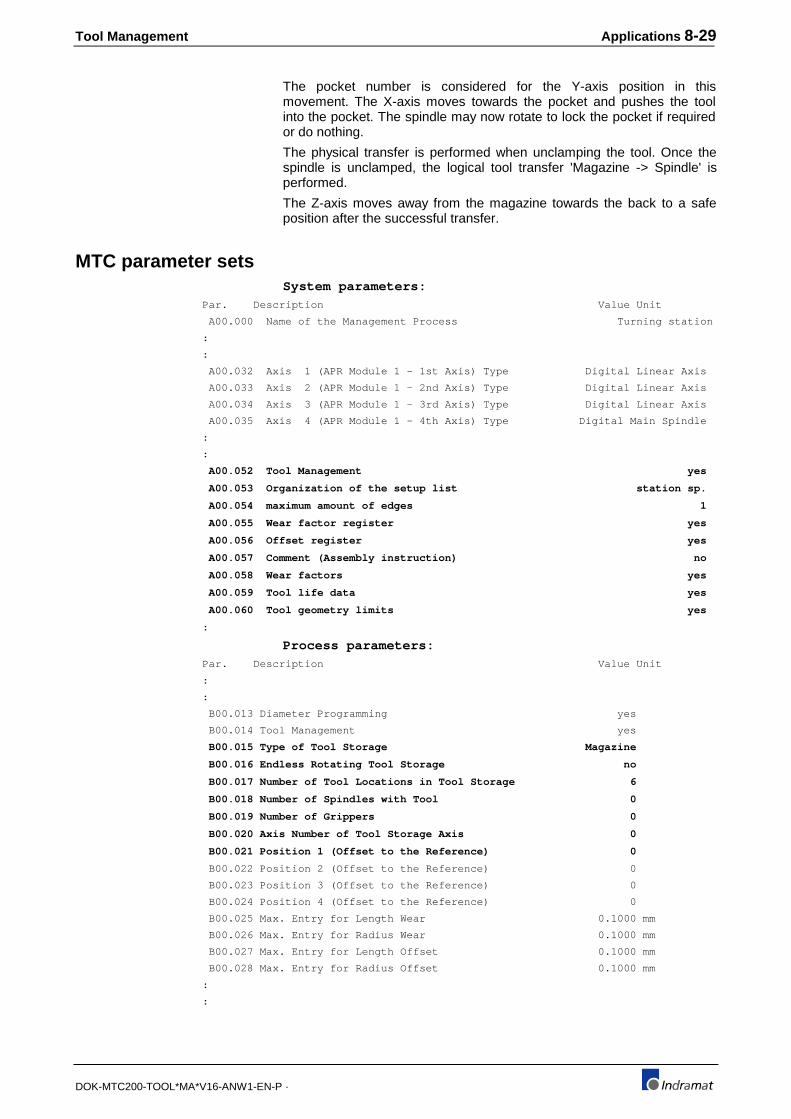
Tool Management Applications 8-29
DOK-MTC200-TOOL*MA*V16-ANW1-EN-P ·
The pocket number is considered for the Y-axis position in thismovement. The X-axis moves towards the pocket and pushes the toolinto the pocket. The spindle may now rotate to lock the pocket if requiredor do nothing.
The physical transfer is performed when unclamping the tool. Once thespindle is unclamped, the logical tool transfer 'Magazine -> Spindle' isperformed.
The Z-axis moves away from the magazine towards the back to a safeposition after the successful transfer.
MTC parameter setsSystem parameters:
Par. Description Value Unit
A00.000 Name of the Management Process Turning station
:
:
A00.032 Axis 1 (APR Module 1 - 1st Axis) Type Digital Linear Axis
A00.033 Axis 2 (APR Module 1 - 2nd Axis) Type Digital Linear Axis
A00.034 Axis 3 (APR Module 1 - 3rd Axis) Type Digital Linear Axis
A00.035 Axis 4 (APR Module 1 - 4th Axis) Type Digital Main Spindle
:
:
A00.052 Tool Management yes
A00.053 Organization of the setup list station sp.
A00.054 maximum amount of edges 1
A00.055 Wear factor register yes
A00.056 Offset register yes
A00.057 Comment (Assembly instruction) no
A00.058 Wear factors yes
A00.059 Tool life data yes
A00.060 Tool geometry limits yes
:
Process parameters:
Par. Description Value Unit
:
:
B00.013 Diameter Programming yes
B00.014 Tool Management yes
B00.015 Type of Tool Storage Magazine
B00.016 Endless Rotating Tool Storage no
B00.017 Number of Tool Locations in Tool Storage 6
B00.018 Number of Spindles with Tool 0
B00.019 Number of Grippers 0
B00.020 Axis Number of Tool Storage Axis 0
B00.021 Position 1 (Offset to the Reference) 0
B00.022 Position 2 (Offset to the Reference) 0
B00.023 Position 3 (Offset to the Reference) 0
B00.024 Position 4 (Offset to the Reference) 0
B00.025 Max. Entry for Length Wear 0.1000 mm
B00.026 Max. Entry for Radius Wear 0.1000 mm
B00.027 Max. Entry for Length Offset 0.1000 mm
B00.028 Max. Entry for Radius Offset 0.1000 mm
:
:

8-30 Applications Tool Management
DOK-MTC200-TOOL*MA*V16-ANW1-EN-P ·
NC-programsCall of tool change in NC-program:
;----------------------------------------------------------------------
;
; TOOL CHANGE SUBROUTINE "M6R" FOR RACK TYPE NON ENDLESS
; TOOL MAGAZINE. THE CNC MAIN AXES ARE USED TO PICK
; UP AND DROP OFF THE TOOLS.
; The pocket number is transferred to the CNC via a NC-variable
; which influences the position of the respective main Y-axis.
;----------------------------------------------------------------------
N0093 .M6_R9 M10 rev .M6_R6 ;clamp the spindle (physical xfer)
;
; Request and check pocket number of the tool currently in the spindle
;
N0094 .M6R
BSE .M6R_S0 ;branch if spindle empty
N0095 MOP ;request old pocket number of tool
that resides in the spindle
N0096 MRY ;wait until pocket number in
NC-variable @99
N0097 @0=@99 ;check for invalid pocket number 0
N0098 BEQ .M6RER1
;
; Request and check pocket number of the currently selected tool (T)
;
N0099 .M6R_S0
BTE .M6R_T0 ;branch if 'T0' (no tool) is programmed
N0100 MTP ;request pocket number of last selected
tool
N0101 MRY ;wait until pocket number in
NC-variable @99
N0102 @0=@99 ;check for invalid pocket number 0
N0103 BEQ .M6RER2
;
; Move tool currently in spindle into its old pocket
;
N0104 .M6R_T0
N0105 G40 G47 G53 G71 G90 ;cancel tool radius compensation
and length correction, machine
coordinate system, mm, absolute
programming
N0106 BSE .M6R_SE ;branch if spindle is empty
N0107 MOP ;request old pocket number of tool
that resides in the spindle
N0108 MRY ;wait until pocket number in
NC-variable @99
N0109 TPE ;safety check tool pocket empty?
N0110 G0 X200 Y=(300-(@99*100)) Z450 M19 S0 rev .M6R_1
;approach pocket for tool that is in
the spindle, orient spindle
N0111 G0 X250 rev .M6R_2 ;move tool into magazine pocket
N0112 TSM rev .M6R_3 ;unclamp spindle (physical xfer)
logical transfer spindle -> magazine
N0113 G0 Z550 rev .M6R_4 ;retract Z-axis
N0114 TSE ;check spindle empty
N0115 BRA .M6R_N

Tool Management Applications 8-31
DOK-MTC200-TOOL*MA*V16-ANW1-EN-P ·
N0116 .M6R_SE ;no tool in spindle
N0117 G0 X250 Y=(300-(@99*100)) Z550 M19 S0 rev .M6R_1
;approach tool and pocket from behind
N0118 .M6R_N
;
; Move currently selected tool into spindle
;
N0119 BTE .M6R_TE ;branch if 'T0' (no tool) is programmed
N0120 MTP ;request pocket number of last selected
tool
N0121 MRY ;wait until pocket number in
NC-variable @99
N0122 G0 Z550 M19 S0 rev .M6R_11 ;retract Z-axis, spindle orient
N0123 G0 X250 Y=(300-(@99*100)) M11 rev .M6R_22
;approach tool pocket from behind,
N0124 G0 Z450 rev .M6R_33 ;advance Z-axis to grab tool
N0125 TMS rev .M6R_44 ;clamp spindle (physical xfer)
logical transfer magazine -> spindle
N0126 G0 X200 rev .M6R_55 ;pull tool from magazine pocket
N0127 MEN RTS ;enable manual magazine mode
;
; No tool selected, no tool in spindle
;
N0128 .M6R_TE
M10 ;clamp spindle drawbar
N0129 G0 X200 MEN RTS ;X-axis to safe position, enable
magazine for manual mode
;
; Error if pocket 0 is obtained via MOP and spindle is NOT empty
;
N0130 .M6RER1
M0 [Pocket 0, spindle not empty] @98=151
;pocket # 0 error, program stop
;
; Error if pocket 0 is obtained via MTP and no 'T0' is selected
;
N0131 .M6RER2
M0 [Pocket 0, pocket in change position not empty] @98=152
;pocket # 0 error, program stop
;
; Reverse program: Tool from Spindle -> Magazine
;
N0132 .M6R_2
BSE .M6R_NT ;Branch if spindle empty
N0133 MOP ;request old pocket number of tool
that resides in the spindle
N0134 MRY ;wait until pocket number in
NC-variable @99
N0135 TPE ;safety check tool pocket empty?
N0136 G0 X200 Y=(300-(@99*100)) Z450 M19 S0 rev .M6R_1
;approach pocket for tool that is in
the spindle, orient spindle
N0137 G0 X250 rev .M6R_2 ;move tool into magazine pocket
N0138 TSM rev .M6R_3 ;unclamp spindle (physical xfer)
logical transfer spindle -> magazine
N0139 .M6R_NT
M11 ;safety spindle unclamp
N0140 .M6R_4

8-32 Applications Tool Management
DOK-MTC200-TOOL*MA*V16-ANW1-EN-P ·
N0141 .M6R_3
G0 Z550 ;retract Z-axis
N0142 .M6R_1
X200 ;move away from magazine
N0143 MEN RTS ;enable magazine for manual mode
;
; Reverse program: Tool from Magazine -> Spindle
;
N0144 .M6R_22
BTE .M6R_NP ;branch if 'T0' (no tool) is programmed
N0145 MTP ;request pocket number of last selected
tool
N0146 MRY ;wait until pocket number in
NC-variable @99
N0147 G0 Z550 M19 S0 ;retract Z-axis, spindle orient
N0148 G0 X250 Y=(300-(@99*100)) M11 ;approach tool pocket from behind,
unclamp
N0149 .M6R_22
G0 Z450 ;advance Z-axis to grab tool
N0150 .M6R_33
BSE .M6R_SN ;branch if spindle empty
N0151 M10 BRA .M6R_NS ;clamp spindle
N0152 .M6R_SN
TMS ;clamp spindle (physical xfer)
logical transfer magazine -> spindle
N0153 .M6R_44
N0154 .M6R_NS
G0 X200 ;pull tool from magazine pocket
N0155 .M6R_55
MEN RTS ;enable manual magazine mode
;
SPS ProgramThe FUNCTION_BLOCK LINTIM is used to recognize tool storage moveNC-commands (no physical movement exists) and provide the issuedpocket number via a NC-variable to the CNC.
The tool transfer NC-commands TMS and TSM are recognized and usedto initiate and perform the tool transfer between the magazine and the toolspindle.FUNCTION_BLOCK LINTIM:
Declaration FUNCTION_BLOCK LINTM (*This FUNCTION_BLOCK LINTM can be used with rack type tool magazines, *) (*whereby CNC controlled motion is used to pick-up and drop off the tool.*) (*Standard tool storage move NC-commands (MTP, MFP, MHP, MOP, MMP) in the *) (*NC-program will generate a pocket number that is contained in the *) (*defined NC-variable. The NC-command MRF must be used to reference the *) (*rack type magazine even though the rack may not move.*) (*The NC-program can use the contents of the NC-variable and move the *) (*tool magazine rack or tool spindle accordingly.*) (*It is essential that the defined NC-variable is not used otherwise.*) (*Additional safety measures may be required and applied by the user.*) VAR_INPUT ENA BOOL 2#1 (*ENABLE*) CLAMPED BOOL 2#0 (*SPINDLE CLAMPED*) UNCLAMPED BOOL 2#0 (*SPINDLE UNCLAMPED*) PROCESS INT (*PROCESS NUMBER*) SPINDLE INT (*SPINDLE NUMBER*) POSITION INT (*POSITION NUMBER*) VARIABLE INT (*VARIABLE NUMBER*) MGCP INT (*COMMANDED MAGAZINE POCKET*) END_VAR

Tool Management Applications 8-33
DOK-MTC200-TOOL*MA*V16-ANW1-EN-P ·
VAR_OUTPUT MMV_A BOOL (*POCKET SELECTION ACTIVE*) MRF_A BOOL (*HOMING ACTIVE*) TMS_A BOOL (*TOOL CHANGE MAG.->SPDL.ACTIVE*) TSM_A BOOL (*TOOL CHANGE SDPL.->MAG.ACTIVE*) POCKET INT (*VARIABLE VALUE (POCKET NUMBER)*) POCK_OK BOOL (*POCKET NUMBER OK*) MGAP INT (*ACTUAL MAGAZINE POCKET*) END_VAR
VAR RQDCOIL BOOL (*REQUIRED COIL*) MMV_1 BOOL (*1 PLC SCAN DELAY MMV*) MMV_2 BOOL (*2 PLC SCAN DELAY MMV*) MRF_1 BOOL (*1 PLC SCAN DELAY MRF*) ONSMMV_A BOOL (*ONS MMV_A*) HONSMMV_A BOOL (*HELP ONS MMV_A*) TMS_AA BOOL (*TMS ACTIVE*) TSM_AA BOOL (*TSM ACTIVE*) XMS_A BOOL (*TOOL XFER MAG.->SPINDLE*) XSM_A BOOL (*TOOL XFER SPINDLE->MAG.*) XMSPA BOOL (*XFER MAG.->SP. POSITIVE ACKN.*) XMSNA BOOL (*XFER MAG.->SP. NEGATIVE ACKN.*) XSMPA BOOL (*XFER SP.->MAG. POSITIVE ACKN*) XSMNA BOOL (*XFER SP.->MAG. NEGATIVE ACKN.*) VARHS BOOL (*VARIABLE READ/WRITE HANDSHAKE*) RD_VAR VAR_RD (*READ VARIABLE*) WR_VAR VAR_WR (*WRITE VARIABLE*) MRFQ BOOL (*HOME ACKNOWLEDGED*) MMVQ BOOL (*MOVE ACKNOWLEDGED*) END_VAR
VAR RETAIN
END_VAR
Implementation 1 ! ! !(*HOMING ACTIVE*) ! 2 ! +--------+ ! !ENA !MRF ! MRF_A ! !! !--------!ACTIVE !-----------------------------------------------------------------------------+( )------! ! PROCESS-!PROC ! +O>NOMRF ! ! +--------+ ! 3 ! ! !(*ACKNOWLEDGE HOME COMMAND*) ! 4 ! +--------+ ! ! !:= ! ! ! 1-! !-MGAP ! ! +--------+ ! 5 ! +--------+ ! !MRF_1 MRFQ !MRF_Q ! MRFQ ! !! !--------!/!--------!QUIT !-------------------------------------------------------------------(S)------! ! PROCESS-!PROC ! ! ! +--------+ ! 6 ! ! !(*CLEAR HOME ACKNOWLEDGED*) ! 7 !NOMRF: ! !MRF_A MRFQ ! !!/!------------------------------------------------------------------------------------------------(R)------! 8 ! ! !MRF_A MRF_1 ! !! !------------------------------------------------------------------------------------------------( )------! 9 ! ! !(*MAGAZINE MOVE COMMANDED*) ! 10 ! +--------+ ! !ENA !MMV ! MMV_A ! !! !--------!ACTIVE !-----------------------------------------------------------------------------+( )------! ! PROCESS-!PROC ! +O>NOMMV ! ! +--------+ ! 11 ! ! !(*COMMANDED POCKET > ACTUAL POCKET*) !
12 ! +--------+ ! ! !:= ! ! ! MGCP-! !-MGAP ! ! +--------+ ! 13 ! !

8-34 Applications Tool Management
DOK-MTC200-TOOL*MA*V16-ANW1-EN-P ·
!(*ACKNOWLEDGE MOVE COMMAND*) ! 14 ! +--------+ ! !MMV_2 POCK_OK !MMV_Q ! MMVQ ! !! !--------! !--------!QUIT !-------------------------------------------------------------------(S)------! ! PROCESS-!PROC ! ! ! +--------+ ! 15 ! ! !(*CLEAR MOVE ACKNOWLEDGED*) ! 16 !NOMMV: ! !MMV_A MMVQ ! !!/!------------------------------------------------------------------------------------------------(R)------! 17 ! ! !(*TOOL CHANGE FROM MAGAZINE TO SPINDLE: STEP 1*) ! !(*READ TMS COMMAND*) ! 18 ! +--------+ ! !ENA !TMS ! CLAMPED TMS_AA ! !! !--------!ACTIVE !-! !-------------------------------------------------------------------------+( )------! ! PROCESS-!PROC ! +O>NOTMS ! ! POSITION-!POS ! ! ! SPINDLE-!SPINDLE ! ! ! +--------+ ! 19 ! ! !(*INITIATE TOOL TRANSFER FROM MAGAZINE TO SPINDLE: STEP 2*) ! 20 ! +--------+ ! !XMS_A !XMS ! XMS_A ! !!/!--------!INIT !------------------------------------------------------------------------------(S)------! ! PROCESS-!PROC ! ! ! POSITION-!POS ! ! ! SPINDLE-!SPINDLE ! ! ! +--------+ ! 21 ! ! !(*READ POSITIVE XMS ACKNOWLEDGE*) ! 22 ! +--------+ ! ! !XMS_PA ! XMSPA ! !-----------!ACTIVE !------------------------------------------------------------------------------( )------! ! PROCESS-!PROC ! ! ! POSITION-!POS ! ! ! SPINDLE-!SPINDLE ! ! ! +--------+ ! 23 ! ! !(*READ NEGATIVE XMS ACKNOWLEDGE*) ! 24 ! +--------+ ! ! !XMS_NA ! XMSNA ! !-----------!ACTIVE !------------------------------------------------------------------------------( )------! ! PROCESS-!PROC ! ! ! POSITION-!POS ! ! ! SPINDLE-!SPINDLE ! ! ! +--------+ ! 25 ! ! !(*ACKNOWLEDGE LOGICAL (VIA ONS OR TOGETHER WITH TMS_Q) AND PHYSICAL TOOL XFER, MAGAZINE->SPINDLE: STEP 3*) ! 26 ! +--------+ +--------+ ! !XMSPA !XMS_Q ! !TMS_Q ! XMS_A ! !! !-------+!QUIT !-!QUIT !-------------------------------------------------------------------(R)------! !XMSNA !! ! ! ! ! !! !-------+! ! ! ! ! ! PROCESS-!PROC ! ! ! ! ! POSITION-!POS ! ! ! ! ! SPINDLE-!SPINDLE ! ! ! ! ! +--------+ ! ! ! ! PROCESS-!PROC ! ! ! POSITION-!POS ! ! ! SPINDLE-!SPINDLE ! ! ! +--------+ ! 27 ! ! !(*OUTPUT TMS_A*) ! 28 !NOTMS: ! !TMS_AA TMS_A ! !! !-------+----------------------------------------------------------------------------------------( )------! !XMS_A ! ! !! !-------+ ! 29 ! ! !(*TOOL CHANGE FROM SPINDLE TO MAGAZINE: STEP 1*) ! !(*READ TSM COMMAND*) ! 30 ! +--------+ ! !ENA !TSM ! UNCLAMPED TSM_AA ! !! !--------!ACTIVE !-! !-------------------------------------------------------------------------+( )------! ! PROCESS-!PROC ! +O>NOTSM ! ! POSITION-!SPINDLE ! ! ! SPINDLE-!POS ! ! ! +--------+ ! 31 ! ! !(*TOOL TRANSFER FROM SPINDLE TO MAGAZINE: STEP 2*) ! 32 ! +--------+ ! !XMS_A !XSM ! XSM_A ! !!/!--------!INIT !------------------------------------------------------------------------------(S)------! ! PROCESS-!PROC ! ! ! SPINDLE-!SPINDLE ! ! ! POSITION-!POS ! ! ! +--------+ ! 33 ! ! !(*READ POSITIVE XSM ACKNOWLEDGE*) ! 34 ! +--------+ ! ! !XSM_PA ! XSMPA ! !-----------!ACTIVE !------------------------------------------------------------------------------( )------! ! PROCESS-!PROC ! ! ! SPINDLE-!SPINDLE ! ! ! POSITION-!POS ! ! ! +--------+ ! 35 ! ! !(*READ NEGATIVE XSM ACKNOWLEDGE*) ! 36 ! +--------+ ! ! !XSM_NA ! XSMNA ! !-----------!ACTIVE !------------------------------------------------------------------------------( )------! ! PROCESS-!PROC ! ! ! SPINDLE-!SPINDLE ! ! ! POSITION-!POS ! ! ! +--------+ ! 37 ! !

Tool Management Applications 8-35
DOK-MTC200-TOOL*MA*V16-ANW1-EN-P ·
!(*ACKNOWLEDGE LOGICAL (VIA ONS OR TOGETHER WITH TSM_Q) AND PHYSICAL TOOL XFER, SPINDLE->MAGAZINE: STEP 3*) ! 38 ! +--------+ +--------+ ! !XSMPA !XSM_Q ! !TSM_Q ! XSM_A ! !! !-------+!QUIT !-!QUIT !-------------------------------------------------------------------(R)------! !XSMNA !! ! ! ! ! !! !-------+! ! ! ! ! ! PROCESS-!PROC ! ! ! ! ! SPINDLE-!SPINDLE ! ! ! ! ! POSITION-!POS ! ! ! ! ! +--------+ ! ! ! ! PROCESS-!PROC ! ! ! SPINDLE-!SPINDLE ! ! ! POSITION-!POS ! ! ! +--------+ ! 39 ! ! !(*OUTPUT TSM_A*) ! 40 !NOTSM: ! !XSM_A TSM_A ! !! !-------+----------------------------------------------------------------------------------------( )------! !TSM_AA ! ! !! !-------+ ! 41 ! ! !(*RESET USED VARIABLES*) ! 42 ! ! !ENA XMS_A ! !!/!-----------------------------------------------------------------------------------------------+(R)------! ! !XSM_A ! ! +(R)------! 43 ! ! !(*SAVE COMMANDED POCKET IN VARIABLE*) ! 44 ! WR_VAR ! ! +-------------------+ ! ! !VAR_WR ! ! !VARHS ! ! VARHS ! !!/!--------!WRITE READY!-------------------------------------------------------------------(S)------! ! MGCP-!DATA ! ! ! PROCESS-!PROC ! ! ! VARIABLE-!NR ! ! ! +-------------------+ ! 45 ! ! !(*READ POCKET NUMBER FROM VARIABLE*) ! 46 ! RD_VAR ! ! +-------------------+ ! ! !VAR_RD ! ! !VARHS ! ! VARHS ! !! !--------!READ READY!-------------------------------------------------------------------(R)------! ! PROCESS-!PROC DATA!-POCKET ! ! VARIABLE-!NR ! ! ! +-------------------+ ! 47 ! ! !(*COMPARE COMMANDED POCKET NR. WITH NUMBER IN VARIABLE*) ! 48 ! +--------+ ! ! != ! POCK_OK ! ! MGCP-! !------------------------------------------------------------------------------( )------! ! POCKET-! ! ! ! +--------+ ! 49 ! ! !(*DELAY MMV FOR ONE PLC SCAN FOR NEW COMMANDED POCKET NUMBER*) ! 50 ! ! !MMV_1 MMV_2 ! !! !------------------------------------------------------------------------------------------------(S)------! 51 ! ! !(*DELAY MMV FOR ONE PLC SCAN FOR NEW COMMANDED POCKET NUMBER*) ! 52 ! ! !ONSMMV_A MMV_1 ! !! !------------------------------------------------------------------------------------------------(S)------! 53 ! ! !(*ONS MMV_A*) ! 54 ! ! !MMV_A HONSMMV_A ONSMMV_A ! !! !--------!/!-------------------------------------------------------------------------------------( )------! 55 ! ! !MMV_A HONSMMV_A! !! !------------------------------------------------------------------------------------------------( )------! 56 ! ! !(*RESET PLC SCAN DEALY MMV*) ! 57 ! ! !MMVQ MMV_1 ! !! !-----------------------------------------------------------------------------------------------+(R)------! ! !MMV_2 ! ! +(R)------!
Implementation of FUNCTION_BLOCK LINTIM in a PROGRAM:
Declaration PROGRAM TOOLS VAR_INPUT P00SMGCP %IW0.180 INT (*Command magazine position*) I_SP_CLP %I0.0.0 (*SPINDLE IS CLAMPED*) I_SP_UCLP %I0.0.1 (*SPINDLE IS UNCLAMPED*) : END_VAR
VAR_OUTPUT P00CCLEAR %Q0.164.0 (*Clear error / Control reset*) P00CMGAP %QW0.170 INT (*Actual magazine position*) Q_SP_CLP %Q0.10.0 (*SOL CLAMP SPINDLE*) Q_SP_UCLP %Q0.10.1 (*SOL UNCLAMP SPINDLE*) : END_VAR
VAR TOOL_RACK LINTM (*TOOL RACK*)

8-36 Applications Tool Management
DOK-MTC200-TOOL*MA*V16-ANW1-EN-P ·
: END_VAR
VAR RETAIN
END_VARImplementation
! ! !(*Stationary tool rack, spindle move to pick-up and drop off the tool, *) ! !(*using the pocket number stored in NC-variable @99*) ! ! TOOL_RACK ! ! +-------------------+ ! ! !LINTM ! ! !----------------------!ENA MMV_A! ! !I_SP_CLP I_SP_UCLP ! ! ! !! !--------!/!--------!CLAMPED MRF_A! ! !I_SP_UCLP I_SP_CLP ! ! Q_SP_CLP ! !! !--------!/!--------!UNCLAMPED TMS_A!-------------------------------------------------------+(S)------! ! ! ! !Q_SP_UCLP! ! 0-!PROCESS ! +(R)------! ! ! ! Q_SP_UCLP! ! 1-!SPINDLE TSM_A!-------------------------------------------------------+(R)------! ! ! ! !Q_SP_CLP ! ! 1-!POSITION ! +(R)------! ! 99-!VARIABLE POCKET! ! ! P00SMGCP-!MGCP POCK_OK! ! ! ! MGAP!-P00CMGAP ! ! +-------------------+ !
TOOL_RACK.................... TOOL RACK............................... .......... LINTM I_SP_CLP..................... SPINDLE IS CLAMPED...................... %I0.0.0... BOOL I_SP_UCLP.................... SPINDLE IS UNCLAMPED.................... %I0.0.1... BOOL I_SP_UCLP.................... SPINDLE IS UNCLAMPED.................... %I0.0.1... BOOL I_SP_CLP..................... SPINDLE IS CLAMPED...................... %I0.0.0... BOOL Q_SP_CLP..................... SOL CLAMP SPINDLE....................... %Q0.10.0.. BOOL 0............................ ........................................ .......... ANY_INT Q_SP_UCLP.................... SOL UNCLAMP SPINDLE..................... %Q0.10.1.. BOOL
1............................ ........................................ .......... ANY_INT Q_SP_UCLP.................... SOL UNCLAMP SPINDLE..................... %Q0.10.1.. BOOL 1............................ ........................................ .......... ANY_INT Q_SP_CLP..................... SOL CLAMP SPINDLE....................... %Q0.10.0.. BOOL 99........................... ........................................ .......... ANY_INT P00SMGCP..................... Command magazine position............... %IW0.180.. INT P00CMGAP..................... Actual magazine position................ %QW0.170.. INT
8.7 Single tool station
Z-axis
Z-axis motor
Spindle motor S
Tool
L3
Fig. 8-119: Single tool station
Stations (one or multiple axes) with a single tool are commonly used intransfer lines and require tool management mostly to monitor tool life. Thetool management of the MTC can be used in single tool applications aswell.
No tool magazine (Bxx.017=0, zero locations) and only one (Bxx.018=1)tool spindle 1 must be specified in the process parameters. The Tool Listthen contains only one tool for the spindle. All MUI and SOT functions,such as 'Reset', can be applied to the tool.
By using the tool management, the spindle face can be used as machinereference and make the NC-program independent of the tool's geometricdimensions.
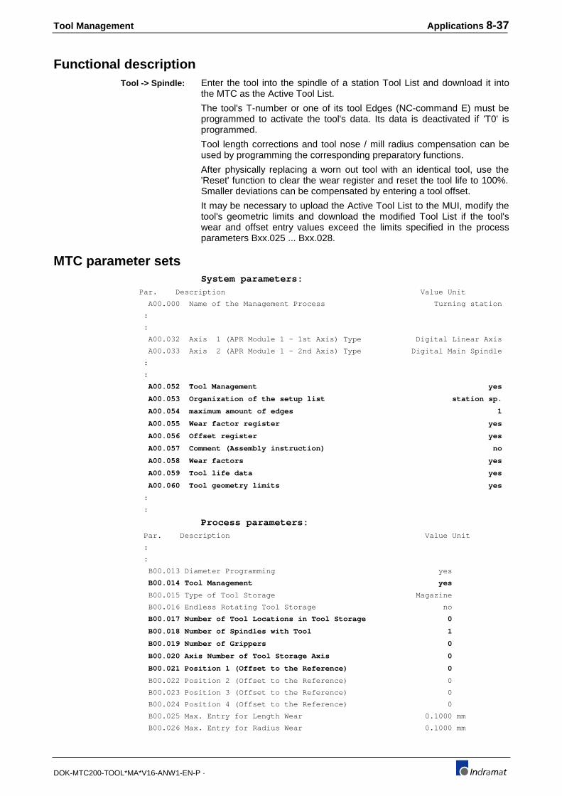
Tool Management Applications 8-37
DOK-MTC200-TOOL*MA*V16-ANW1-EN-P ·
Functional descriptionEnter the tool into the spindle of a station Tool List and download it intothe MTC as the Active Tool List.
The tool's T-number or one of its tool Edges (NC-command E) must beprogrammed to activate the tool's data. Its data is deactivated if 'T0' isprogrammed.
Tool length corrections and tool nose / mill radius compensation can beused by programming the corresponding preparatory functions.
After physically replacing a worn out tool with an identical tool, use the'Reset' function to clear the wear register and reset the tool life to 100%.Smaller deviations can be compensated by entering a tool offset.
It may be necessary to upload the Active Tool List to the MUI, modify thetool's geometric limits and download the modified Tool List if the tool'swear and offset entry values exceed the limits specified in the processparameters Bxx.025 ... Bxx.028.
MTC parameter setsSystem parameters:
Par. Description Value Unit
A00.000 Name of the Management Process Turning station
:
:
A00.032 Axis 1 (APR Module 1 - 1st Axis) Type Digital Linear Axis
A00.033 Axis 2 (APR Module 1 - 2nd Axis) Type Digital Main Spindle
:
:
A00.052 Tool Management yes
A00.053 Organization of the setup list station sp.
A00.054 maximum amount of edges 1
A00.055 Wear factor register yes
A00.056 Offset register yes
A00.057 Comment (Assembly instruction) no
A00.058 Wear factors yes
A00.059 Tool life data yes
A00.060 Tool geometry limits yes
:
:
Process parameters:
Par. Description Value Unit
:
:
B00.013 Diameter Programming yes
B00.014 Tool Management yes
B00.015 Type of Tool Storage Magazine
B00.016 Endless Rotating Tool Storage no
B00.017 Number of Tool Locations in Tool Storage 0
B00.018 Number of Spindles with Tool 1
B00.019 Number of Grippers 0
B00.020 Axis Number of Tool Storage Axis 0
B00.021 Position 1 (Offset to the Reference) 0
B00.022 Position 2 (Offset to the Reference) 0
B00.023 Position 3 (Offset to the Reference) 0
B00.024 Position 4 (Offset to the Reference) 0
B00.025 Max. Entry for Length Wear 0.1000 mm
B00.026 Max. Entry for Radius Wear 0.1000 mm
Tool -> Spindle:

8-38 Applications Tool Management
DOK-MTC200-TOOL*MA*V16-ANW1-EN-P ·
B00.027 Max. Entry for Length Offset 0.1000 mm
B00.028 Max. Entry for Radius Offset 0.1000 mm
:
:
NC-programsCall of tool in NC-program:
;----------------------------------------------------------------------
;
; Drill hole 2
;
;----------------------------------------------------------------------
N0000 .START
G70 G48 G17 T1 ;tool length correction, Tool T1
N0001 S580 M3 ;spindle on
N0002 G0 Z0.1 ;rapid advance
N0003 G1 Z-2 F280 ;drill to middle
N0004 G4 F.5 ;dwell time
N0005 G1 Z-3.345 F280 E1 ;drill to full depth, tool Edge E1
to update tool data
N0006 G4 F.5 ;dwell time
N0007 G0 Z5 ;Retract Z-axis
N0008 BST .START
SPS ProgramNo logic for tool storage movement and tool transfer is required in theSPS program if only one tool is used in one tool spindle.

Tool Management Applications 8-39
DOK-MTC200-TOOL*MA*V16-ANW1-EN-P ·
8.8 Single tool spindle, multiple tools
Stations (one or multiple axes) with a single spindle and one or morephysical tools that do not reside in a tool storage (magazine/turret) aresometimes used in transfer machines, e. g., drill and reamer through thehollow spindle.
The tool management can be used to monitor tool life and compensatefor the tool limits.
Two solutions are available for such a station:
1. Define a endless tool magazine with two locations (one for drill, onefor reamer) and one tool spindle. Set the status of SPS FUNCTIONXFER_CHK to `1` which disables the need of tool change NC-commands to perform the tool transfer in the SPS program. Useauxiliary M-functions to initiate the tool transfer into the spindle.
2. Define one (Bxx.018=1) tool in tool spindle 1 and no tool magazine(Bxx.017=0, zero locations) in the process parameters. The Tool Listthen contains only one tool with multiple tool Edges for the spindle. AllMUI and SOT functions, such as 'Reset', can be applied on the tool.
By using the tool management, the spindle face can be used as machinezero and make the NC-program independent of the tool's geometricdimensions.
Z-axis
Z-axis motor
Spindle motor S
Tool Edge E1 to cut seat
L3
Reamer
L3
Tool Edge E2, reamer
Hydraulic cyclinder
Fig. 8-120: Single tool spindle, multiple tools
Functional descriptionThe use of one tool with multiple tool Edges is described in the following.
Specify in the System Parameters a minimum of two tool Edges per tool(Axx.054=2). Enter the tool into the spindle of a station Tool List anddownload it into the MTC as the Active Tool List.
The tool's T-number must be programmed to activate the tool's data. Itsdata is deactivated if 'T0' is programmed. Tool Edge E1 is active asdefault and will activate the tool life monitoring (if set >0 in the Setup List)and allow to correct the length L3 of the seat tool if G48 (tool lengthcorrection) is active.
After extending the reamer, tool Edge E2 must be activated to monitorreamer life and eventually compensate the reamer length L3 (normally inthis case length L3=0) if such a length correction is required.
After physically replacing a worn out tool with an identical tool, use the'MODIFY' function to clear the Edge wear register and reset the tool Edge
Tool -> Spindle:
Select Tool Edge E1 and E2:

8-40 Applications Tool Management
DOK-MTC200-TOOL*MA*V16-ANW1-EN-P ·
life to 100% if only one of the tools is physically replaced. Use 'RESET' ifboth tools are physically replaced. Smaller deviations can becompensated by entering a tool offset.
It may be necessary to upload the Active Tool List to the MUI, modify thetool's geometric limits and download the modified Tool List if the tool'swear and offset entry values exceed the limits specified in the processparameters Bxx.025 ... Bxx.028.
MTC parameter setsSystem parameters:
Par. Description Value Unit
A00.000 Name of the Management Process Turning station
:
:
A00.032 Axis 1 (APR Module 1 - 1st Axis) Type Digital Linear Axis
A00.033 Axis 2 (APR Module 1 - 2nd Axis) Type Digital Main Spindle
:
:
A00.052 Tool Management yes
A00.053 Organization of the setup list station sp.
A00.054 maximum amount of edges 2
A00.055 Wear factor register yes
A00.056 Offset register yes
A00.057 Comment (Assembly instruction) no
A00.058 Wear factors yes
A00.059 Tool life data yes
A00.060 Tool geometry limits yes
:
:
Process parameters:
Par. Description Value Unit
:
:
B00.013 Diameter Programming yes
B00.014 Tool Management yes
B00.015 Type of Tool Storage Magazine
B00.016 Endless Rotating Tool Storage no
B00.017 Number of Tool Locations in Tool Storage 0
B00.018 Number of Spindles with Tool 1
B00.019 Number of Grippers 0
B00.020 Axis Number of Tool Storage Axis 0
B00.021 Position 1 (Offset to the Reference) 0
B00.022 Position 2 (Offset to the Reference) 0
B00.023 Position 3 (Offset to the Reference) 0
B00.024 Position 4 (Offset to the Reference) 0
B00.025 Max. Entry for Length Wear 0.1000 mm
B00.026 Max. Entry for Radius Wear 0.1000 mm
B00.027 Max. Entry for Length Offset 0.1000 mm
B00.028 Max. Entry for Radius Offset 0.1000 mm
: :

Tool Management Applications 8-41
DOK-MTC200-TOOL*MA*V16-ANW1-EN-P ·
NC-programsCall of tool in NC-program:
;----------------------------------------------------------------------
;
; Machine valve seat and ream valve shaft hole
;
;----------------------------------------------------------------------
N0000 .START
G70 G48 G17 T1 ;tool length correction, Tool T1 and
Edge E1 activated by default
N0001 G0 Z0.1 ;rapid advance
N0002 G1 Z-.234 F280 ;machine valve seat
N0003 G0 Z-.2 ;retract Z-axis
N0004 M35 E2 ;Advance reamer, tool Edge E2 to
monitor reamer life only (L3=0)
N0005 G4 F.5 ;dwell time
N0006 M34 ;Retract reamer
N0007 G0 Z5 ;Retract Z-axis
N0008 BST .START
SPS ProgramNo logic for tool storage movement and tool transfer is required in theSPS program if only one tool is used in one tool spindle.
8.9 Multiple spindles with single tool
Some applications require stations (one or multiple axes) with multiplespindles, each containing one tool. The tool management supports up to4 tool spindles whereby only the data one spindle can be active at a time.The NC-command SPT must be used to select one of the available toolspindles.

8-42 Applications Tool Management
DOK-MTC200-TOOL*MA*V16-ANW1-EN-P ·
Z-axis
Z-axis motor
Spindle motor
Drill in tool spindle 1 (T1)
X-Axis
L3
L3
R
Tool in tool spindle 1 (T2)
Y
Z
X
Fig. 8-121: Two tool spindle with single tools
The process may or may not operate NC-controlled main spindle axes.The tool spindle 1, 2, may correspond to the main spindle axisdesignation S1, S2 if main spindle axes are operated by the process.
This example shows the use of two tool spindles without NC-controlledmain spindle drives driving tool T1 and T2. Both tool spindles are drivenvia SPS controlled AC motors and mounted on the same base, movetogether.
Tool spindle 1 contains a drill. A mill is contained in tool spindle 2.
Functional descriptionThe use of one or more tool spindles (max. 4) is described in thefollowing. Tool spindle 1 should be defined with axis designation 'S1' andtool spindle 2 with 'S2' if both are operated as NC-controlled spindledrives by the process.
Spindle control M-functions and the S-word can be used in the NC-program to program different spindle speeds and directions. The NC-command 'T0' will deactivate the tool data of the currently active toolspindle. Use the MUI or SOT 'RESET' function if the tool is physicallyreplaced. Smaller geometric deviations can be compensated by enteringa tool offset.
It may be necessary to upload the Active Tool List to the MUI, modify thetool's geometric limits and download the modified Tool List if the tool'swear and offset entry values exceed the limits specified in the processparameters Bxx.025 ... Bxx.028.
Specify in the Process Parameters a minimum of two tool spindles(Bxx.018=2).
Enter one tool into per tool spindle into a Tool List and download it into theMTC as the Active Tool List. It is assumed for now that the tool T1 'DRILL'(correction type 1) has been entered for tool spindle 1 and T2 for toolspindle 2 'MILL' (correction type 2).
Tool -> Spindle:

Tool Management Applications 8-43
DOK-MTC200-TOOL*MA*V16-ANW1-EN-P ·
• The tool T2 works in the ZX-plane which requires that G18 is activatedto use the tool corrections during the machining. The NC-command'SPT2 T2' must be contained in a NC-block prior to tool lengthcorrection G48/G49 and mill radius compensation G41/G42 to activatethe tool spindle 2 and tool data of T2. The NC-command 'E1' or 'T2'can be used thereafter to update the tool data if required.
• The Z-axis represents the axis perpendicular to the active XY-plane,which requires G17 to be active in order to use tool length correction.Tool spindle 1 is active by default and must be selected only if anothertool spindle is currently active. The NC-command 'SPT1 T1' must becontained in a NC-block prior to tool length correction G48/G49 toactivate the tool spindle 1 and tool data of T1. The NC-command 'E1'or 'T1' can be used thereafter to update the tool data if required.
MTC parameter setsSystem parameters:
Par. Description Value Unit
A00.000 Name of the Management Process STATION 2
:
A00.032 Axis 1 (APR Module 1 - 1st Axis) Type Digital Linear Axis
A00.033 Axis 2 (APR Module 1 - 2nd Axis) Type Digital Main Spindle
A00.034 Axis 3 (APR Module 1 - 3rd Axis) Type Digital Main Spindle
:
A00.052 Tool Management yes
A00.053 Organization of the setup list station sp.
A00.054 maximum amount of edges 2
A00.055 Wear factor register yes
A00.056 Offset register yes
A00.057 Comment (Assembly instruction) no
A00.058 Wear factors yes
A00.059 Tool life data yes
A00.060 Tool geometry limits yes
:
Process parameters:
Par. Description Value Unit
:
B00.013 Diameter Programming yes
B00.014 Tool Management yes
B00.015 Type of Tool Storage Magazine
B00.016 Endless Rotating Tool Storage no
B00.017 Number of Tool Locations in Tool Storage 0
B00.018 Number of Spindles with Tool 2
B00.019 Number of Grippers 0
B00.020 Axis Number of Tool Storage Axis 0
B00.021 Position 1 (Offset to the Reference) 0
B00.022 Position 2 (Offset to the Reference) 0
B00.023 Position 3 (Offset to the Reference) 0
B00.024 Position 4 (Offset to the Reference) 0
B00.025 Max. Entry for Length Wear 0.1000 mm
B00.026 Max. Entry for Radius Wear 0.1000 mm
B00.027 Max. Entry for Length Offset 0.1000 mm
B00.028 Max. Entry for Radius Offset 0.1000 mm
:
Axis parameters tool spindle 1 (S1):
Par. Description Value Unit
C04.000 Associated Process(es) M
C04.001 Axis Designation S1
Select tool T1 in spindle 1 andtool T2 in spindle 2:

8-44 Applications Tool Management
DOK-MTC200-TOOL*MA*V16-ANW1-EN-P ·
C04.020 Jogging Speed 50.0 1/min
C04.021 Jogging Speed - Rapid 500.0 1/min
C04.022 Parametric Spindle Jogging Distance 5.0000 deg
C04.049 Maximum Programmable Spindle Speed 3000.0 1/min
C04.050 Maximum Spindle Acceleration Rate 100 rad/sec^2
Axis parameters tool spindle 2 (S2):
Par. Description Value Unit
C05.000 Associated Process(es) M
C05.001 Axis Designation S2
C05.020 Jogging Speed 50.0 1/min
C05.021 Jogging Speed - Rapid 500.0 1/min
C05.022 Parametric Spindle Jogging Distance 5.0000 deg
C05.049 Maximum Programmable Spindle Speed 6000.0 1/min
C05.050 Maximum Spindle Acceleration Rate 100 rad/sec^2
NC-programsCall of tool in NC-program:
;----------------------------------------------------------------------
; Drill holes and face mill
;----------------------------------------------------------------------
N0000 .START
G70 ... ;Move to safety position
N0001 G18 ... ;ZX-plane ...
N0002 SPT2 T2 ;Select tool spindle S2 and T2 data
N.... G48 G42 M203 S2 800 ;corrections, S2 CW at 800 rpm
N.... ... ;machine with tool T2
N.... ... ;...
N.... G17 M205 ... ;XY-plane, S2 stop, ....
N.... SPT1 T1 ;Select tool spindle S1 and T1 data
N.... G48 M103 S1 1500 ... ;length corr., S1 CW at 1500 rpm
N.... ... ;machine with tool T1
N.... ... ;...
N.... BST .START
SPS ProgramNo logic for tool storage movement and tool transfer is required in theSPS program if only one tool is used per tool spindle.
8.10 One Tool List and multiple tool storages
Multiple physical tool storages with one Tool List in the MTC can be usedto minimize tool change time by using low cost tool change mechanisms.
The duplication of a main axis and main tool spindle will replace the toolchange mechanism, since the tools are picked up and dropped off by viathe tool spindles. One spindle machines while the other spindle gets thenext tool. The tool change time is then reduced to the main axes rapidtraverse movements (approach with new tool while retracting with the oldtool) and axis switching time.
The axis switching feature (NC-command FAX and GAX) of the MTCprovides the feature to switch axis between their primary process andsecondary processes. One main axis, used to move the spindle to andfrom the tool storage, and one tool spindle are assigned to a process. Upto three such processes can exist, since up to three tool spindles can beoperated.

Tool Management Applications 8-45
DOK-MTC200-TOOL*MA*V16-ANW1-EN-P ·
The tool management and Active Tool List is operated in another processtogether with the remaining main axes, executing the main machiningNC-program after switching the tool spindle (with the last selected tool)and remaining main axis over. In the meantime, the previous tool is putback and the next tool is picked up by the second tool spindle.
Z-axis
Z-axis motor
Spindle motor
Drill in tool spindle 1 (T1)
X-Axis
L3
L3
R
Tool in tool spindle 1 (T2)
Y
Z
X
Fig. 8-122: Two tool storages and one Active Tool List
The process may or may not operate NC-controlled main spindle axes.The tool spindle 1 and 2 may correspond to the main spindle axisdesignation S1 and S2 if main spindle axes are operated by the process.
This example shows the use of two tool spindles without NC-controlledmain spindle drives driving tool T1 and T2. Both tool spindles are drivenvia SPS controlled AC motors and mounted on the same base, movetogether.
Tool spindle 1 contains a drill. A mill is contained in tool spindle 2.
Functional descriptionThe use of one or more tool spindles (max. 3) is described in thefollowing. Tool spindle 1 should be defined with axis designation 'S1' andtool spindle 2 with 'S2' if both are operated as NC-controlled spindledrives by the process.
Spindle control M-functions and the S-word can be used in the NC-program to program different spindle speeds and directions. The NC-command 'T0' will deactivate the tool data of the currently active toolspindle. Use the MUI or SOT 'RESET' function if the tool is physicallyreplaced. Smaller geometric deviations can be compensated by enteringa tool offset.
It may be necessary to upload the Active Tool List to the MUI, modify thetool's geometric limits and download the modified Tool List if the tool'swear and offset entry values exceed the limits specified in the processparameters Bxx.025 ... Bxx.028.
Specify in the Process Parameters a minimum of two tool spindles(Bxx.018=2).
Enter one tool into per tool spindle into a Tool List and download it into theMTC as the Active Tool List. It is assumed for now that the tool T1 'DRILL'
Tool -> Spindle:

8-46 Applications Tool Management
DOK-MTC200-TOOL*MA*V16-ANW1-EN-P ·
(correction type 1) has been entered for tool spindle 1 and T2 for toolspindle 2 'MILL' (correction type 2).
• The tool T2 works in the ZX-plane which requires that G18 is activatedto use the tool corrections during the machining. The NC-command'SPT2 T2' must be contained in a NC-block prior to tool lengthcorrection G48/G49 and mill radius compensation G41/G42 to activatethe tool spindle 2 and tool data of T2. The NC-command 'E1' or 'T2'can be used thereafter to update the tool data if required.
• The Z-axis represents the axis perpendicular to the active XY-plane,which requires G17 to be active in order to use tool length correction.Tool spindle 1 is active by default and must be selected only if anothertool spindle is currently active. The NC-command 'SPT1 T1' must becontained in a NC-block prior to tool length correction G48/G49 toactivate the tool spindle 1 and tool data of T1. The NC-command 'E1'or 'T1' can be used thereafter to update the tool data if required.
MTC parameter setsSystem parameters:
Par. Description Value Unit
A00.000 Name of the Management Process STATION 2
:
A00.032 Axis 1 (APR Module 1 - 1st Axis) Type Digital Linear Axis
A00.033 Axis 2 (APR Module 1 - 2nd Axis) Type Digital Main Spindle
A00.034 Axis 3 (APR Module 1 - 3rd Axis) Type Digital Main Spindle
:
A00.052 Tool Management yes
A00.053 Organization of the setup list station sp.
A00.054 maximum amount of edges 2
A00.055 Wear factor register yes
A00.056 Offset register yes
A00.057 Comment (Assembly instruction) no
A00.058 Wear factors yes
A00.059 Tool life data yes
A00.060 Tool geometry limits yes
:
Process parameters:
Par. Description Value Unit
:
B00.013 Diameter Programming yes
B00.014 Tool Management yes
B00.015 Type of Tool Storage Magazine
B00.016 Endless Rotating Tool Storage no
B00.017 Number of Tool Locations in Tool Storage 0
B00.018 Number of Spindles with Tool 2
B00.019 Number of Grippers 0
B00.020 Axis Number of Tool Storage Axis 0
B00.021 Position 1 (Offset to the Reference) 0
B00.022 Position 2 (Offset to the Reference) 0
B00.023 Position 3 (Offset to the Reference) 0
B00.024 Position 4 (Offset to the Reference) 0
B00.025 Max. Entry for Length Wear 0.1000 mm
B00.026 Max. Entry for Radius Wear 0.1000 mm
B00.027 Max. Entry for Length Offset 0.1000 mm
B00.028 Max. Entry for Radius Offset 0.1000 mm
:
Axis parameters tool spindle 1 (S1):
Select tool T1 in spindle 1 andtool T2 in spindle 2:

Tool Management Applications 8-47
DOK-MTC200-TOOL*MA*V16-ANW1-EN-P ·
Par. Description Value Unit
C04.000 Associated Process(es) M
C04.001 Axis Designation S1
C04.020 Jogging Speed 50.0 1/min
C04.021 Jogging Speed - Rapid 500.0 1/min
C04.022 Parametric Spindle Jogging Distance 5.0000 deg
C04.049 Maximum Programmable Spindle Speed 3000.0 1/min
C04.050 Maximum Spindle Acceleration Rate 100 rad/sec^2
Axis parameters tool spindle 2 (S2):
Par. Description Value Unit
C05.000 Associated Process(es) M
C05.001 Axis Designation S2
C05.020 Jogging Speed 50.0 1/min
C05.021 Jogging Speed - Rapid 500.0 1/min
C05.022 Parametric Spindle Jogging Distance 5.0000 deg
C05.049 Maximum Programmable Spindle Speed 6000.0 1/min
C05.050 Maximum Spindle Acceleration Rate 100 rad/sec^2
NC-programsCall of tool in NC-program:
;----------------------------------------------------------------------
; Drill holes and face mill
;----------------------------------------------------------------------
N0000 .START
G70 ... ;Move to safety position
N0001 G18 ... ;ZX-plane ...
N0002 SPT2 T2 ;Select tool spindle S2 and T2 data
N.... G48 G42 M203 S2 800 ;corrections, S2 CW at 800 rpm
N.... ... ;machine with tool T2
N.... ... ;...
N.... G17 M205 ... ;XY-plane, S2 stop, ....
N.... SPT1 T1 ;Select tool spindle S1 and T1 data
N.... G48 M103 S1 1500 ... ;length corr., S1 CW at 1500 rpm
N.... ... ;machine with tool T1
N.... ... ;...
N.... BST .START
SPS ProgramNo logic for tool storage movement and tool transfer is required in theSPS program if only one tool is used per tool spindle.

Tool Management Tool Management Parameters 9-1
DOK-MTC200-TOOL*MA*V16-ANW1-EN-P ·
9 Tool Management ParametersThis section pertains to the Tool Management parameters for the MTC.The system and process parameters in this section, when enabled, areused to set all the variables for each tool management system required.The Axis parameters listed are for a special Turret axis. Theseparameters are a combination of the digital servo and spindle parametersand described in section 0.3.
9.1 System parameters for tool management
Fig. 9-123: MUI/GUI System Parameter screen
Number: A00.052
Name: Tool Management
Default Value: No
Value range: No/Yes
This parameter selects the tool management functions for this parameterset. This parameter should be set to 'yes' if any process will be using toolmanagement. Tool Management is needed if the designer needs theability to use multiple tools, monitor and/or correct for tool wear, ormonitor number of cycles.
As soon as Tool Management is enabled with' yes', further systemparameters A00.053 - A00.086 and A00.092 - A00.096 appear whichconfigure the tool data sets within the system. The tool data sets are thenoptimized using these parameters. Also, Setup lists can be generated (viaMUI/GUI menu item #2) for the NC-program or process (depending onAxx.053) and the Tool management MUI/GUI menu item #6 and SOTmenu item #3 is activated.
Number: A00.053
Name: Organization of the setup list
Default Value: Station sp.
Value range: Station spec./ Program spec.
When 'Station Specific' is selected in this parameter, the Setup List (partof the NC-program package, MUI/GUI Menu item #2) is common for all99 NC-programs per process. This form of organization is best for partfamily production, or when all necessary tools can be housed in the sametool storage unit (i.e. magazine or turret).

9-2 Tool Management Parameters Tool Management
DOK-MTC200-TOOL*MA*V16-ANW1-EN-P ·
Fig. 9-124: Station specific Setup List organization
When 'Program Specific' is selected in this parameter, the setup is uniquefor each of the 99 NC-programs per process. This type of organization isuseful if the Tool List varies substantially from NC-program to NC-program, or when a magazine or turret is exchanged for each part run.
Fig. 9-125: Program specific Setup List organization
Number: A00.054
Name: Maximum number of edges
Default Value: 1
Value range: 1-9
This parameter specifies the maximum number of cutting edges per toolto be managed. Each tool can have up to nine cutting edges whether ornot the actual tool has this number of edges. Since additional storage isallowed for with each additional edge, the designer should allow for themaximum for any tool on the installation. If a tool uses less edges, thiscan be adjusted for in the tool screens. Tools with fewer edges can stillexist.

Tool Management Tool Management Parameters 9-3
DOK-MTC200-TOOL*MA*V16-ANW1-EN-P ·
Drill withone tool Edge
Drill withtwo tool Edges one tool Edge
Turning tool withTurning tool wit htwo tool Edges
Fig. 9-126: Tools With Different Number Of Edges
Number: A00.055
Name: Wear factor register
Default Value: No
Value range: No/Yes
Number: A00.056
Name: Offset register
Default Value: No
Value range: No/Yes
The 'Wear factor register' parameter allows for tool wear data to beincluded in the tool data set, and the 'Offset register' parameter allows foroffset data to be included in the tool data set. If 'yes' is selected, theseregisters appear in the tool management menu of the MUI/GUI and theSOT, and they include entry fields for lengths 'L1', 'L2', 'L3', and radius 'R'.
If Wear factors are enabled (see system parameters A00.058), the MTCuses the wear records (W.Factor L1, W.Factor L2, W.Factor L3 andW.Factor R) to automatically compensate for the wear of the tools. If theWear factors are not chosen, the wear records are used as a resetabletool compensation used by the tool setter to manually adjust for wear.
The wear records are also influenced by the MUI/GUI 'Reset' function.Besides resetting the status time to 100%, the Reset - function resets allwear records belonging to the tool to zero. The offset register, however, isnot reset by the MUI/GUI 'Reset' function .
If Wear factors (system parameters A00.058) need to be available in theMUI/GUI and/or the SOT, this parameter must be selected.
Number: A00.057
Name: Comment (Assembly instruction)
Default Value: No
Value range: No/Yes
This parameter opens up a field of up to 5 lines x 75 characters in theSetup List. Using the Comments, information can be entered in the SetupList to give the operator or tool setter instructions for exchanging dull orbroken tools, or for any other information the designer would like to haveavailable.
The Comments are only available in the MUI/GUI Setup List. They are notavailable on the SOT.
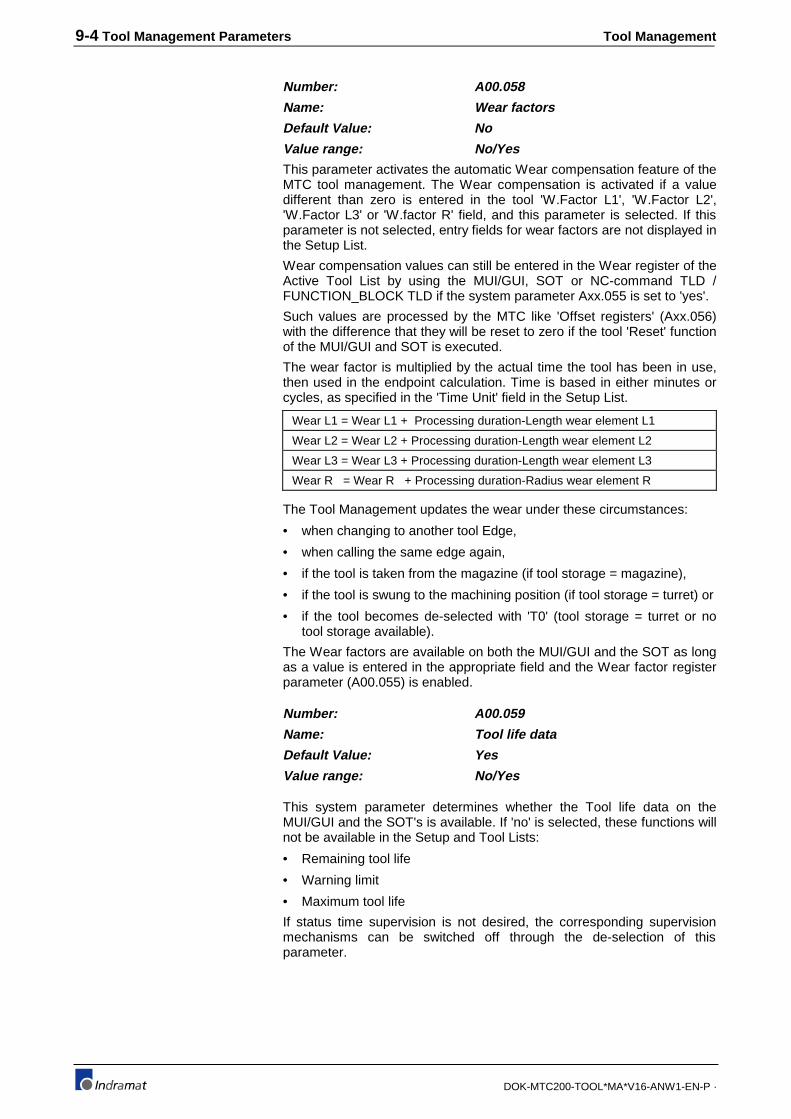
9-4 Tool Management Parameters Tool Management
DOK-MTC200-TOOL*MA*V16-ANW1-EN-P ·
Number: A00.058
Name: Wear factors
Default Value: No
Value range: No/Yes
This parameter activates the automatic Wear compensation feature of theMTC tool management. The Wear compensation is activated if a valuedifferent than zero is entered in the tool 'W.Factor L1', 'W.Factor L2','W.Factor L3' or 'W.factor R' field, and this parameter is selected. If thisparameter is not selected, entry fields for wear factors are not displayed inthe Setup List.
Wear compensation values can still be entered in the Wear register of theActive Tool List by using the MUI/GUI, SOT or NC-command TLD /FUNCTION_BLOCK TLD if the system parameter Axx.055 is set to 'yes'.
Such values are processed by the MTC like 'Offset registers' (Axx.056)with the difference that they will be reset to zero if the tool 'Reset' functionof the MUI/GUI and SOT is executed.
The wear factor is multiplied by the actual time the tool has been in use,then used in the endpoint calculation. Time is based in either minutes orcycles, as specified in the 'Time Unit' field in the Setup List.
Wear L1 = Wear L1 + Processing duration-Length wear element L1
Wear L2 = Wear L2 + Processing duration-Length wear element L2
Wear L3 = Wear L3 + Processing duration-Length wear element L3
Wear R = Wear R + Processing duration-Radius wear element R
The Tool Management updates the wear under these circumstances:
• when changing to another tool Edge,
• when calling the same edge again,
• if the tool is taken from the magazine (if tool storage = magazine),
• if the tool is swung to the machining position (if tool storage = turret) or
• if the tool becomes de-selected with 'T0' (tool storage = turret or notool storage available).
The Wear factors are available on both the MUI/GUI and the SOT as longas a value is entered in the appropriate field and the Wear factor registerparameter (A00.055) is enabled.
Number: A00.059
Name: Tool life data
Default Value: Yes
Value range: No/Yes
This system parameter determines whether the Tool life data on theMUI/GUI and the SOT's is available. If 'no' is selected, these functions willnot be available in the Setup and Tool Lists:
• Remaining tool life
• Warning limit
• Maximum tool life
If status time supervision is not desired, the corresponding supervisionmechanisms can be switched off through the de-selection of thisparameter.

Tool Management Tool Management Parameters 9-5
DOK-MTC200-TOOL*MA*V16-ANW1-EN-P ·
Number: A00.060
Name: Tool geometry limits
Default Value: No
Value range: No/Yes
This system parameter allows geometry limiting values to be entered inthe Tool List on the MUI/GUI and the SOT(s). The Tool geometry limitsmake it possible to check a tool in the tool storage with regard to theirsuitability for immediate use.
The check of the tool geometry at each new start prevents collisions andsubsequent damages to the tool, work piece and machine. The tool lengthand radius check happens during the automatic tool check:
L1 _ min < L1 < L1 _ max.
L2 _ min < L2 < L2 _ max.
L3 _ min < L3 < L3 _ max.
R _ min < R < R _ max.
If the geometry check is not desired, select 'no' to have the correspondingcheck switched off.
Number: A00.061-A00.069
Name: Description of user tool data 1-9
Default Value: <blank>
Value range: 13 Characters; Any ASCII text except/, ! or #
The user data 1 to 9 allow arbitrary user specific data to be given to eachtool in the tool set. The desired user data is entered in each tool data set,on the MUI/GUI, SOT(s) or NC-command TLD / FUNCTION_BLOCK TLD(read & write like any other data).
Tool - user data.
• Tool life
• Speed of tool change
• maximum RPM of the tool
• maximum dimensions of the tool
Number: A00.070-A00.074
A00.092-A00.096
Name: Description of user tool edge data 1-10
Default Value: <blank>
Value range: 13 Characters; Any ASCII text except /,! or #
Depending on the setting of system parameter A00.091, “ToolTechnology” the following A00.096 system parameters have differentfunctionality:
A00.091 set to ‘Grinding’
A00.070 Defined as min. spindle speed [S-min]
A00.071 Defined as max. spindle speed [S-max]
A00.072 Defined as max. grind Disk Circumference Speed [DCS-max]
A00.073 Defined as slant angle [Slant Angle]
A00.074 Defined as associated follower edge [ass.foll-E.]
Example:

9-6 Tool Management Parameters Tool Management
DOK-MTC200-TOOL*MA*V16-ANW1-EN-P ·
A00.091 set to “Turn./Mill”
(default setting)
The user data (1...10) allow arbitrary user specific edge data (13characters; any ASCII text except /, !, or #) to be given to each tool in thetool set. The desired user edge data is entered in each tool data set, onthe MUI, SOT, or NC-command TLD
Tool Edge user data.
• Cutting speed,
• Number of spindle revolutions,
• Processing support,
• Median value storage
• Correction value-buffer
Number: A00.075-A00.082
Name: Symbol for user tool status bit 1-8
Default Value: <blank>
Value range: 1 Character; Any ASCII text except /, !or #
These parameters allow arbitrary user specific status information for eachtool to be given via user - tool status bits 1 to 8. The desired user symbolis entered in each tool data set, on the MUI/GUI, SOT(s) or NC-commandTLD / FUNCTION_BLOCK TLD (read & write like any other data).
User tool status bits.
• Tool that never leaves tool storage)
• Tool not yet measured
• Tool is required for later processing
• Tool with reduced speed
All User status bits and data are denoted in upper case letters, while theinternal status bits and data are lower case.
Number: A00.083-A00.086
Name: Symbol for user tool edge status bit 1-4
Default Value: <blank>
Value range: 1 Character; Any ASCII text except /, !or #
These parameters allow arbitrary user specific status information for eachtool edge to be given via user - tool edge status bits 1 to 4. The desireduser symbol is entered in each tool data set, on the MUI/GUI and theSOT's indicated and includes a value entry for the corresponding bit.
Typical examples for user - tool edge status bits are:
• Edge measure
• Edge exchange
All User status bits and data are denoted in Upper Case Letters, while theinternal status bits and data are lower case.
Number: A00.091
Name: Tool Technology
Default Value: Turn./Mill.
Example:
Example:

Tool Management Tool Management Parameters 9-7
DOK-MTC200-TOOL*MA*V16-ANW1-EN-P ·
Value range: Turn./Mill. Or Grinding
This parameter can be used to specify special functions for the ‘User ToolEdge Data 1…5’ (A00.070…A00.074), used for grinding. If set to‘Turn./Mill’, the user can freely specify (A00.070…A00.074).
9.2 Process parameters for tool management
Number: Bxx.014
Name: Tool Management
Default Value: No
Value range: No/Yes
This parameter should be set to 'yes' if this process will be using toolmanagement. Tool Management is needed if the designer needs theability to use multiple tools, monitor and/or correct for tool wear, ormonitor number of cycles.
As soon as Tool Management is enabled with' yes', further processparameters (Bxx.015...Bxx.028, Bxx.043) appear which configure the tooldata sets within the process. The tool data sets are then optimized usingthese parameters. Also, menu items to generate and administrate toolSetup List are available in MUI/GUI menu item #2.
Number: Bxx.015
Name: Type of Tool Storage
Default Value: Magazine
Value range: Magazine/Turret
Either magazines or turrets can be used as tool storage. Magazinesnecessitate both a physical as well as a logical tool transfer between theavailable spindles and the magazine, using grippers if applicable. On thecontrary, a turret keeps the tools in the same relative position. They arebrought in for use solely through rotation of the turret to the properposition.
If neither a magazine or turret is used, but Tool management is desiredwith the tool in the spindle, this is how the process parameters would beset:
'Number of tool locations in tool storage (Bxx.017)' =0
'Number of Spindles with Tool (Bxx.018)' =1, 2 or 3
Number: Bxx.016
Name: Endless Rotating Tool Storage
Default Value: No
Value range: No/Yes
This parameter allows for magazines and turrets to rotate in the samedirection endlessly. Before setting this parameter, it's important to insurethat the distance between the last and first tool storage places is equal toall others and that the first place follows the last place when rotating thetool storage unit.
If these criteria are not met, set this parameter to 'no'. typically thesewould be linear ('wine rack') magazines, and half disc magazines.

9-8 Tool Management Parameters Tool Management
DOK-MTC200-TOOL*MA*V16-ANW1-EN-P ·
Fig. 9-127: Types Of Tool Storage
Number: Bxx.017
Name: Number of Tool Locations in Tool Storage
Default Value: 0
Value range: 0-999
This parameter specifies the number of tool locations (pockets ofmagazine, positions of turret) in the tool storage. It is only used if toolstorage is needed.
Number: Bxx.018
Name: Number of Tool Spindles
Default Value: 0
Value range: 0-4
This parameter specifies the number of Tool spindles used with thisprocess. Tool spindles are defined as spindles that turn tools whose datais managed by the tool management of the MTC. These spindles areused as tool locations, i.e. tools are exchanged and held there. Duringprocessing only one tool and tool spindle can be active per process. TheTool Management uses the tool’s data and updates its tool corrections aswell as the status bits, tool life and wear data.
The NC-command SPT must be used to select the active tool spindle(tool spindle 1 = default). Also, the Number of Spindles with Tool is notnecessarily the number of the physically available spindles. Individual livetools in a turret do not count as tool spindles, but as turret positions.
Up to 4 tool spindle tool locations can be used per process, whereby noNC-controlled spindles must be available.
Number: Bxx.019
Name: Number of Grippers
Default Value: 0
Value range: 0-4
This parameter is used when the tool changer in the process usesgrippers to exchange the tool between the spindle and the magazine.When this parameter is used the Tool Management sets aside internaldata storage, provides an interface to the SPS, and provides fields for thenumber of grippers entered in the Setup List(s), Active Tool List(s) andTool List(s).

Tool Management Tool Management Parameters 9-9
DOK-MTC200-TOOL*MA*V16-ANW1-EN-P ·
Number: Bxx.020
Name: Axis Number for Magazine Axis
Default Value: 0
Value range: 0-20
This parameters specifies the MTC axis number to be used to move thetool storage axis. This number correlates with the system parameterA00.032-A00.051. This parameter is only used if the MTC controls aservo tool storage axis for this process. If the process has no tool storageor uses an SPS controlled tool storage, then 0 must be entered in thisparameter.
Note : The axis defined in this parameter can NOT be switched tosecondary processes - Cxx.000 Associated Processes)! Itmust remain in its primary process, since the tool storage(management) can NOT be switched either!
Number: Bxx.021-Bxx.024
Name: Position 1-4 (Offset to theReference)
Default Value: 0
Value range: 0-999
This parameter allows the definition of up to four arbitrary positions for thetool storage unit which can be used for tool change, exchange, orprocessing.
These positions are in relation to the tool change reference position. Thereference is defined as tool pocket or position "1" and is the position themagazine or turret goes to when executing the NC-command MHP. Theoffsets relative to the reference are counted in the direction of ascendingposition numbers, in positive direction.
The position offset number can NOT be greater than the number oflocations in tool storage (Parameter number Bxx.017) if the tool storage isendless (Bxx.016=yes). The offset number can be greater if the toolstorage is none-endless (Bxx.016=no). Refer also to section 7.6.2.6 formore information about none-endless tool storages.
The Active Tool List indicates the tool and position to which the tool will bemoved via the letter 'L1' for position POS1, 'L2' for position POS2, L3 forposition POS3 and 'L4' for position POS4.
Offsets in different types of tool storages.
1) 'endless' chain magazine :
Bxx.015 Type of Tool Storage Magazine
Bxx.016 Endless Rotating Tool Storage yes
Bxx.017 Number of Tool Locations in Tool Storage 22
:
Bxx.021 Position 1 (Offset to the Reference) 3
Bxx.022 Position 2 (Offset to the Reference) 8
Bxx.023 Position 3 (Offset to the Reference) 19
Bxx.024 Position 4 (Offset to the Reference) 0
:
Example:

9-10 Tool Management Parameters Tool Management
DOK-MTC200-TOOL*MA*V16-ANW1-EN-P ·
22 2 3 5 6
19
20
18 17 16 15 13 1211
7
8
9
10
4
14
1
21
Reference mark
POS1
POS2POS3
Cxx.013=30° if NC-controlled servo magazine axis
Fig. 9-128: Endless chain magazine
2) 'None endless' linear magazine :
Bxx.015 Type of Tool Storage Magazine
Bxx.016 Endless Rotating Tool Storage no
Bxx.017 Number of Tool Locations in Tool Storage 7
:
Bxx.021 Position 1 (Offset to the Reference) 9
Bxx.022 Position 2 (Offset to the Reference) 0
Bxx.023 Position 3 (Offset to the Reference) 0
Bxx.024 Position 4 (Offset to the Reference) 0
:
+
-
12
3
4
56
7
10
89
1112
POS1
tool changeposition
Non-endlesstool disk magazine 1
2
3
4
5
6
T13
T13
T6
T6
T76
Tool Rack
Pocket number
T234
7T73
8
9
10 POS1
Non-endless
Fig. 9-129: Non-endless disk/rack magazine
Number: Bxx.025
Name: Max. Entry for Length Wear
Default Value: 0.1000mm,0.0039 inch
Value range: 0-99999.9999mm, 0-3937.0079 inch

Tool Management Tool Management Parameters 9-11
DOK-MTC200-TOOL*MA*V16-ANW1-EN-P ·
Number: Bxx.026
Name: Max. Entry for Radius Wear
Default Value: 0.1000mm,0.0039 inch
Value range: 0-99999.9999mm, 0-3937.0079 inch
Number: Bxx.027
Name: Max. Entry for Length Offset
Default Value: 0.1000mm,0.0039 inch
Value range: 0-99999.9999mm, 0-3937.0079 inch
Number: Bxx.028
Name: Max. Entry for Radius Offset
Default Value: 0.1000mm,0.0039 inch
Value range: 0-99999.9999mm, 0-3937.0079 inch
These parameters limit the wear - and offset - entry into the Active ToolList, both for the tool length and the tool radius. They are used toguarantee against excessive values being placed in these fields.
The amount of the pertinent entry may not exceed the value depositedhere:
The values in these fields are used for the absolute and the incrementalentries through the MUI/GUI and SOT. Values entered via the NC-command TLD / FUNCTION_BLOCK TLD will be checked during the nextautomatic tool check only!
Number: Bxx.043
Name: Activate Tool Correction
Default Value: imm. after Stop
Value range: imm. after Stop
next activation
next pos. NC block
Immediately After Stop
A tool data modification is only possible when a process stop is active(PxxS.STOP=1) or after deselecting a toll edge (deactivating a tool). thecorrection value will be processed with a new process advance, reverseor after another tool edge selection (tool activation).
Next Activation
A tool data modification is possible any time. The modified correctionvalues is considered at the next activation of the tool. The old correctionvalues remain active until the tool is deactivated.
Next Possible NC-block
A tool data modification is possible any time. The modified correctionvalues are considered in the NC-block that is being loaded into the NC-block preparation memory next.
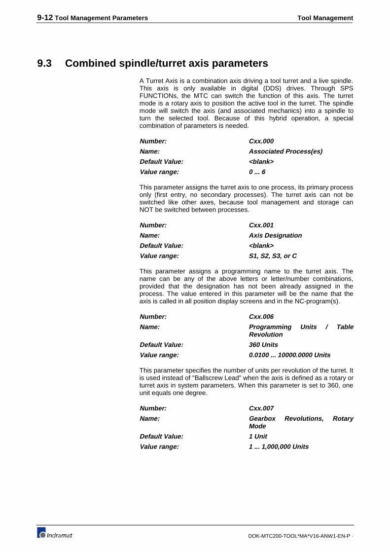
9-12 Tool Management Parameters Tool Management
DOK-MTC200-TOOL*MA*V16-ANW1-EN-P ·
9.3 Combined spindle/turret axis parameters
A Turret Axis is a combination axis driving a tool turret and a live spindle.This axis is only available in digital (DDS) drives. Through SPSFUNCTIONs, the MTC can switch the function of this axis. The turretmode is a rotary axis to position the active tool in the turret. The spindlemode will switch the axis (and associated mechanics) into a spindle toturn the selected tool. Because of this hybrid operation, a specialcombination of parameters is needed.
Number: Cxx.000
Name: Associated Process(es)
Default Value: <blank>
Value range: 0 ... 6
This parameter assigns the turret axis to one process, its primary processonly (first entry, no secondary processes). The turret axis can not beswitched like other axes, because tool management and storage canNOT be switched between processes.
Number: Cxx.001
Name: Axis Designation
Default Value: <blank>
Value range: S1, S2, S3, or C
This parameter assigns a programming name to the turret axis. Thename can be any of the above letters or letter/number combinations,provided that the designation has not been already assigned in theprocess. The value entered in this parameter will be the name that theaxis is called in all position display screens and in the NC-program(s).
Number: Cxx.006
Name: Programming Units / TableRevolution
Default Value: 360 Units
Value range: 0.0100 ... 10000.0000 Units
This parameter specifies the number of units per revolution of the turret. Itis used instead of "Ballscrew Lead" when the axis is defined as a rotary orturret axis in system parameters. When this parameter is set to 360, oneunit equals one degree.
Number: Cxx.007
Name: Gearbox Revolutions, RotaryMode
Default Value: 1 Unit
Value range: 1 ... 1,000,000 Units

Tool Management Tool Management Parameters 9-13
DOK-MTC200-TOOL*MA*V16-ANW1-EN-P ·
Number: Cxx.008
Name: Gearbox Revolutions, Rotary Mode
Default Value: 1 Unit
Value range: 1 ... 1,000,000 Units
In these parameters, enter the ratio for the gear train connected betweenthe motor and the rotary turret table. This must be a whole number ratio,so the programmer must multiply by a common value if the ratio is notbetween whole numbers.
Gear ratio.
Gear ratio: 1.71875:1 ⇒ Gear box input : 55
Gear box output: 32
Number: Cxx.013
Name: Reference Position, Rotary Mode
Default Value: 0.000 Units
Value range: -100,000.0000 ... 100,000.0000 Units
This parameter specifies the value used by the CNC to compensate forthe difference between encoder zero marker and the home position 1 ofthe tool storage (magazine/turret).
The offset value contained in Cxx.013 is displayed in the MUI/GUI andSOT position display after successfully referencing (reference marker atthe reference position) the axis (single axis home or NC-command MRF).
The value of Cxx.022 is displayed after brining the axis to its homeposition (location 1 at the reference position) via the NC-command MHP.
1
23456
78
910
1112 13
141516
Referencemark
Magazine at reference position
12
3456
7
8
910
1112 1314
1516
Referencemark
Magazine at base position
Offset in degrees
after NC-command MRF after NC-command MHP
Fig. 9-130: Example: Home and reference position of disk tool storage
Number: Cxx.014
Name: Position Polarity (0,1) , Rotary Mode
Default Value: 0
Value range: 0/1
This parameter allows the user to change the direction of rotation for theturret axis. A "0" in this parameter signifies normal direction, i.e. the motorturns clockwise for a programmed positive move, while a 1 signifiesreversed direction. This is the turret position polarity only, the motordirection for spindle operation is selected with Cxx.037.
Example:

9-14 Tool Management Parameters Tool Management
DOK-MTC200-TOOL*MA*V16-ANW1-EN-P ·
Number: Cxx.016
Name: Maximum Feedrate, Rotary Mode
Default Value: 200.0 Units
Value range: 10.0 - 500,000.0 Units
The value entered in this parameter is the velocity that the axis is limitedto. This is the velocity that the axis will try to achieve when a move toanother turret position is programmed, depending on the angle of rotationand the acceleration ramp. This parameter is only active when the turretis positioning the tool, not when the spindle is turning the tool. Themaximum programmable spindle speed is programmed with Cxx.049.
Number: Cxx.017
Name: Maximum Feedrate Change W/ORamp, Rotary Mode
Default Value: 200.0 Units
Value range: 0.1-100,000.00 Units
The value entered into this parameter defines the velocity at which theacceleration switches from the Kv factor to a linear ramp at the ratedefined in Cxx.018. For a turret axis, this parameter should be set nearzero so that the Maximum Acceleration Rate (Cxx.016) will adjust thesmoothness of the turret's rotation.
TIME (SECONDS)
VELOCITY (Units/Min)
1000
3000
4000
7000
1 3 5
5 SECONDS
4000 IPM
2000
2 4
Max. Feedrate Change W/ORamp (Bxx.017)
Max. Feedrate (Cxx.016)
4000 Un i ts /Min*60=240KUni ts /Sec,240K Uni ts /Sec/5 S = 48KUni ts /Sec 2
Max. Acceleration Rate(Bxx.018)
6
R a m p
Kvfactor
Fig. 9-131: Example: Axis Velocity Profile
Number: Cxx.018
Name: Maximum Acceleration Rate,Rotary Mode
Default Value: 100 Units/sec 2
Value range: 1-100,000 Units/sec 2
This parameter Acceleration rate ramp above the feedrate defined inCxx.017 (Max. Feedrate Change W/O Ramp). This is a linear feed ramp,
defined in units/S2 .To see the effect of this parameter, see Cxx.017. Thisparameter is only active when the turret is positioning the tool, not whenthe spindle is turning the tool. The maximum spindle acceleration rate isprogrammed with Cxx.050.

Tool Management Tool Management Parameters 9-15
DOK-MTC200-TOOL*MA*V16-ANW1-EN-P ·
Number: Cxx.019
Name: Homing Speed, Rotary Mode
Default Value: 200 Units/min
Value range: 10.0 - 100,000.0 Units/min
This parameter specifies the speed at which the turret will home. Thismeans that when a G74 is programmed, or the axis is manually senthome (using AxxC.HOME) the axis will approach at the specified speed.Using the NC-command G74, the homing speed may be overridden usingan F word in the NC Program however, the homing velocity will be limitedto the max. homing velocity specified in this parameter. This parameter isonly active when the turret is homing, not when the spindle is orienting.The spindle orient speed is programmed with Cxx.051.
Number: Cxx.057
Name: Jogging speed, Main SpindleMode
Default Value: 50 1/min (RPM)
Value range: 10.0 ... 100,000.0 1/min (RPM)
This parameter specifies the speed at which the spindle will jog whenusing the AxxC.JGPOS or AxxC.JGNEG SPS Gateway signals. Thisparameter is only used in spindle mode, because the turret can only bejogged from pocket to pocket using the parametric jog mode.
Number: Cxx.058
Name: Jogging Speed - Rapid, MainSpindle Mode
Default Value: 50 1/min (RPM)
Value range: 10 ... 100,000.0 1/min (RPM)
Active in digital set? Yes
This parameter specifies the speed at which the spindle will jog whenusing the AxxC.JGPOS or AxxC.JGNEG SPS Gateway signals, alongwith the RAPID Gateway signal. This parameter is only used in spindlemode, because the turret can only be jogged from pocket to pocket usingthe parametric jog mode.
Number: Cxx.022
Name: Parametric Jogging Distance of the Turret,Rotary Mode
Default Value: 5.0000 Units
Value range: 0.0001 ... 10,000 Units
This parameter defines the incremental jogging distance for the turretwhen using the Parametric jogging mode. The value in this parametershould be the same as the unit distance between turret positions. For aturret like the one in the example of Cxx.013, this parameter would be setto 30.0000 units. Refer to CNC⇔SPS Gateway Reference Manual andsection 2.3 of the System Parameter Reference Manual for further detailson the parametric jog function.

9-16 Tool Management Parameters Tool Management
DOK-MTC200-TOOL*MA*V16-ANW1-EN-P ·
Number: Cxx.023
Name: In-Position Window, Rotary Mode
Default Value: 0.0100 Units
Value range: 0.0001-10.0000 Units
This parameter sets the maximum position loop deviation allowed. If theaxis
is not within the position window at NC-block end, the NC-block will notcomplete, and no error will be present. If this condition occurs, check theposition display for the axis, viewing the "Distance to go" (DTG) and LAGcolumn. Usually a mechanical blockage is preventing the turret fromfinishing the move.
Number: Cxx.037
Name: Motor Direction, Main SpindleMode (0/1)
Default Value: 0
Value range: 0/1
This parameter defines the motor direction when the jog commands (+/-)or the auxiliary spindle M-Functions (M3,M103,M203,M303,M4,M104,etc.)are used. A "0" in this parameter denotes a clockwise rotation of the shaftwhen looking from the back towards the front of the spindle motor. TheNC-command M03 should cause a tool rotation that causes a right handtap to move towards the part.
This value is only active when this axis is in the spindle mode, i.e. that theSPS FUNCTION SPDL_ACT is on. See 7.5 and the SPS ReferenceManual for details. When the axis is in turret mode (FUNCTIONMAG_ACT), the turret direction is defined by Cxx.014, Position Polarity.
Number: Cxx.038
Name: Reference Offset, Main SpindleMode
Default Value: 0.0000 degree
Value range: -100,000 ... 100,000 degree
1) Orient ing the spindleto S=0 leaves the head inthis posit ion, 30° awayfrom the needed posi t ion.
2) Entering -30° inCxx.038, then or ient ing toS=0 again wi l l posi t ion thespindle correct ly.
Fig. 9-132: Example: Spindle Zero Position Shift of -30 degrees
This parameter defines the spindle reference position shift. The referenceposition may be shifted to another physical position. This parameter could

Tool Management Tool Management Parameters 9-17
DOK-MTC200-TOOL*MA*V16-ANW1-EN-P ·
be used in the case that the relationship between spindle encoder andspindle key way has been changed. Rather than changing the relationshipphysically, simply enter the shift value desired to achieve the desired zeroposition.
Number: Cxx.047
Name: Gearbox Input Revolutions, Main SpindleMode
Default Value: 1 Unit
Value range: 1- 1,000,000 Units
Number: Cxx.048
Name: Gearbox Output Revolutions, Main SpindleMode
Default Value: 1 Unit
Value range: 1-1,000,000 Units
In these parameters, enter the ratio for a gearbox connected between thespindle motor and tool. This must be a whole number ratio, so theprogrammer must multiply by a common value if the ratio is not betweenwhole numbers.
Note : When these parameters are used with a turret/spindle axis it ishighly recommended that the ratio is set to 1:1. A homereference switch for the spindle and other complications will beavoided by setting these parameters to 1:1.
Number: Cxx.049
Name: Max Programmable Spdl Speed, MainSpindle Mode
Default Value: 200.0 1/min (RPM)
Value range: 10.0-50,000.0 1/min (RPM)
This parameter specifies the maximum spindle speed allowed to beprogrammed. If a speed out of the range defined is programmed, no errordiagnostic is generated by the MTC however, the spindle will not exceedthis specified limit. This value is only active when this axis is in the spindlemode, i.e. that the SPS FUNCTION SPDL_ACT is on. See 7.5 and theSPS Reference Manual for details. When the axis is in turret mode(FUNCTION MAG_ACT) the maximum speed is defined by Cxx.016,Max. Feedrate.
Number: Cxx.050
Name: Max Spindle Acceleration Rate, MainSpindle Mode
Default Value: 100 rad/sec 2
Value range: 1-100,000 rad/sec 2
This parameter defines the spindle acceleration rate for this axis. Thevalue is motor and drive size, and machine mechanics dependent. Thevalue should be such that the spindle can be accelerated from standstill tomax. velocity and back to standstill in the time required and withoutoverloading the spindle drive. This value is only active when this axis is inthe spindle mode, i.e. that the SPS FUNCTION SPDL_ACT is on. See 7.5and the SPS Reference Manual for details. When the axis is in turretmode (FUNCTION MAG_ACT) the maximum acceleration is defined byCxx.018, Maximum Acceleration Rate.

9-18 Tool Management Parameters Tool Management
DOK-MTC200-TOOL*MA*V16-ANW1-EN-P ·
Number: Cxx.051
Name: Orient Speed, Main Spindle Mode
Default Value: 200 1/min (RPM)
Value range: 10-12,000 1/min (RPM)
This parameter specifies the speed at which the spindle will orient from astandstill. This means that when an M19 is programmed the axis willorient at the specified speed if it is stopped. If the spindle was movingwhen an M19 is commanded, it will orient using the last programmed Sword. Likewise, this orient speed may be overridden using an S wordcombined with M19 in the NC Program however, this limit will not beexceeded. This value is only active when this axis is in the spindle mode,i.e. that the SPS FUNCTION SPDL_ACT is on. See 7.5 and the SPSReference Manual for details. When the axis is in turret mode(FUNCTION MAG_ACT), the homing speed is defined by Cxx.019,Homing Speed.
Number: Cxx.052
Name: In-Position Window, Main Spindle Mode
Default Value: 0.0100 degree
Value range: 0.0001-360 Degrees
This parameter specifies the angle in degrees (refer to the drive's manualfor positioning accuracy) that a spindle will be considered "in position" bythe CNC interpolator. If the spindle is not within this position window atblock end, the block will not complete, and no error will be present. If thiscondition occurs, the operator should check the position display for theaxis, viewing the "Distance to go" (DTG) column. Usually this condition iscaused by an improper spindle Kv factor (too low), or some mechanicalblockage.
Number: Cxx.059
Name: Parametric Spindle Jogging distance
Default Value: 5.0000 degree
Value range: 0.0001-10000.0000 Degrees
Defines the incremental jogging distance when using the Parametricjogging mode via the PxxC.JOGMn Gateway signals.
Number: Cxx.060
Name: Position Feedback Location (digital drives)
Default Value: Motor
Value range: Motor / External Feedback
Defines whether the motor or external feedback device is used forposition control. The scaling feedback parameters must be entered in thedigital SERCOS drive.

Tool Management Appendix 10-1
DOK-MTC200-TOOL*MA*V16-ANW1-EN-P ·
10 Appendix
10.1 Tool Management NC-command Overview
NC-command Description
BSE .label
BTE .label
G40
G41
G42
G43
G44
G47
G48
G49
MEN
MFP
MHP
MMP
MOP
MRF
MRY
MTP
TCH
TPE
TMS
TSE
TSM
SPT
TLD
Branch if currently selected Spindle (SPT) empty
Branch if tool T0 selected
Edge and mill radius path compensation, cancel (default)
Edge and mill radius path comp. left of contour
Edge and mill radius path comp. right of contour
Contour transition 'arc'
Contour transition 'chamfer'
Tool length correction, cancel (default)
Tool length correction positive
Tool length correction negative
Release tool storage for manual mode
Move to next free location (pocket)
Move to home position
Move programmed location into position
Move to old location (pocket)
Move to reference position
Wait until (tool storage) in position
Move programmed tool into position
Perform complete tool change
Check, Tool Pocket (storage location) empty?
Tool from Magazine to Spindle
Check, Spindle empty?
Tool from Spindle to Magazine
Spindle selection for Tool Management
Tool Data read/writeFig. 10-133: Tool Management NC-command Overview

10-2 Appendix Tool Management
DOK-MTC200-TOOL*MA*V16-ANW1-EN-P ·
10.2 Tool Management SPS FUNCTION Overview
SPS FUNCTION Description
MAG_ACT
MAG_Q
MMV
MMV_Q
MRF
MRF_Q
SPDL_ACT
SPDL_Q
TCH
TCH_Q
TMS
TMS_Q
TSM
TSM_Q
XGM
XGM_PA
XGM_NA
XGM_Q
XGM_CA
XGS
XGS_PA
XGS_NA
XGS_Q
XGS_CA
XMG
XMG_PA
XMG_NA
XMG_Q
XMG_CA
XMS
XMS_PA
XMS_NA
XMS_Q
XMS_CA
XSG
XSG_PA
XSG_NA
XSG_Q
XSG_CA
XSM
XSM_PA
XSM_NA
XSM_Q
XSM_CA
XFER_CHK
Turret mode active
Turret mode acknowledge
Magazine movement
Magazine movement acknowledge
Magazine reference
Magazine reference acknowledge
Spindle mode active
Spindle mode acknowledge
Tool change
Tool change acknowledge
Tool from magazine to spindle
Tool from magazine to spindle acknowledge
Tool from spindle to magazine
Tool from spindle to magazine acknowledge
Tool transfer gripper to magazine, request
Tool transfer gripper to magazine, positive acknowledge
Tool transfer gripper to magazine, negative acknowledge
Tool transfer gripper to magazine, request acknowledge
Tool transfer gripper to magazine, request cancel
Tool transfer gripper to spindle, request
Tool transfer gripper to spindle, positive acknowledge
Tool transfer gripper to spindle negative acknowledge
Tool transfer gripper to spindle, request acknowledge
Tool transfer gripper to spindle, request cancel
Tool transfer magazine to gripper, request
Tool transfer magazine to gripper, positive acknowledge
Tool transfer magazine to gripper, negative acknowledge
Tool transfer magazine to gripper, request acknowledge
Tool transfer magazine to gripper, request cancel
Tool transfer magazine to spindle, request
Tool transfer magazine to spindle, positive acknowledge
Tool transfer magazine to spindle, negative acknowledge
Tool transfer magazine to spindle, request acknowledge
Tool transfer magazine to spindle, request cancel
Tool transfer spindle to gripper, request
Tool transfer spindle to gripper, positive acknowledge
Tool transfer spindle to gripper, negative acknowledge
Tool transfer spindle to gripper, request acknowledge
Tool transfer spindle to gripper, request cancel
Tool transfer spindle to magazine, request
Tool transfer spindle to magazine, positive acknowledge
Tool transfer spindle to magazine, negative acknowledge
Tool transfer spindle to magazine, request acknowledge
Tool transfer spindle to magazine, request cancel
Disable tool transfer error checkFig. 10-134: Tool Management SPS FUNCTION Overview

Tool Management Appendix 10-3
DOK-MTC200-TOOL*MA*V16-ANW1-EN-P ·
10.3 Tool Management CNC ⇔SPS Gateway Signal Overview
Signal Description
PxxSMGBP
PxxSMGENA
PxxSMGREQ
PxxSMGERR
PxxSMGMAN
PxxSMGMOV
PxxSMGTWO
PxxSMGWRN
PxxCMGBP
PxxCMGHOM
PxxCMGNEG
PxxCMGPOS
PxxCMGNTC
PxxCMGMAN
PxxCMGENA
PxxCMGAP
PxxSMGCP
Tool storage at home position
Tool storage and tool transfer enabled
CNC tool storage request
Tool storage or tool error
Manual tool storage mode
Tool storage moves
Tool worn out
Tool warning limit
Tool storage to base position
Home tool storage
Move tool storage negative
Move tool storage positive
No automatic tool check
Manual tool storage mode
Enable tool storage movement and tool transfer
Actual tool storage position relative to reference
Commanded tool storage position relative to reference
Fig. 10-135: Tool Management CNC⇔SPS Gateway Signal Overview

10-4 Appendix Tool Management
DOK-MTC200-TOOL*MA*V16-ANW1-EN-P ·
10.4 Tool Management Signal and Command Overview
MT-CNC
NC
0
6
PROCESS 0
PROCESS 6
Tool
movement
commands
SPS
storage
MFPMOPMTPMHPMRFMMP MRY
Tool Management
PROCESS 0
PROCESS 6
movements
storage
for tool
FUNCTIONs
MMV
MRF
MMV_Q
MRF_Q
0
6
TMS
TSM
TCH
XMS
XMG
XSM
XSG
XGM
XGS
XMS_PA
XMG_PA
XSM_PA
XSG_PA
XGM_PA
XGS_PA
XMS_NA
XMG_NA
XSM_NA
XSG_NA
XGM_NA
XGS_NA
XMS_CA
XMG_CA
XSM_CA
XSG_CA
XGM_CA
XGS_CA
XMS_Q
XMG_Q
XSM_Q
XSG_Q
XGM_Q
XGS_Q
Tool
check
BSE
BTE
TPE
TSE
comm.
P0CMGENA P0SMGENAP0SMGTWO P0SMGREQ
P0CMGMAN
P0CMGHOM
P0CMGBP
P0CMGPOS
P0CMGNEG
P0CMGAP
P0SMGMAN
P0SMGMOV
P0SMGBP
P0SMGCP
P0SMGWRN
P0SMGERR
Reset
RET
BST .Label
MEN
TCH
TSM
TMS
Tool Transfer Commands
Tool Transfer FUNCTIONs Tool Management Gateway Signals
Command Status
12...
.
..
12
P0CMGENA
P0CMGNTC
Fig. 10-136: Tool Management Signal and Command Overview
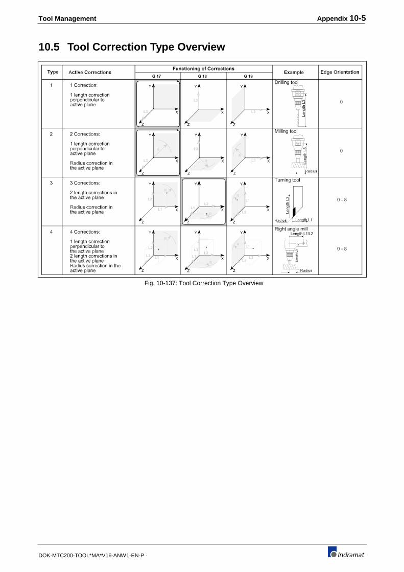
Tool Management Appendix 10-5
DOK-MTC200-TOOL*MA*V16-ANW1-EN-P ·
10.5 Tool Correction Type Overview
Fig. 10-137: Tool Correction Type Overview

10-6 Appendix Tool Management
DOK-MTC200-TOOL*MA*V16-ANW1-EN-P ·
10.6 Tool Edge Orientation Overview
E d g e O r i e n t a t i o n
P
1
S
P
4
S
P
3
S
P
2
S
P
8
S
P5 S 7SP
P = S
P
6
S
0
L 2
L 1
P
1
S
P
4
S
P
3
S
P
2
S
P
8
S
P5 S 7SPP = S
P
6
S
0
L 2
L 1
Y ( G 1 7 )
X ( G 1 8 )
Z ( G 1 9 )
Y ( G 1 7 )
X ( G 1 8 )
Z ( G 1 9 )
Y ( G 1 7 )
X ( G 1 8 )
Z ( G 1 9 )
X ( G 1 7 )
Z ( G 1 8 )
Y ( G 1 9 )
X ( G 1 7 )
Z ( G 1 8 )
Y ( G 1 9 )
Fig. 10-138: Tool Edge Orientation Overview
E d g e O r i e n t a t i o n
S
P
P = SS
P
S
P P
S
L 2
L 1P
S
P
S
P
S
P
S
S
P
P = SS
P
S
P P
S
L 2
L 1
P
S
P
S
P
S
P
S
1 20 3 84 5 6 7
2
1 20 3 84 5 6 7
Y ( G 1 7 )
X ( G 1 8 )
Z ( G 1 9 )
Y ( G 1 7 )
X ( G 1 8 )
Z ( G 1 9 )
Y ( G 1 7 )
X ( G 1 8 )
Z ( G 1 9 )
X ( G 1 7 )
Z ( G 1 8 )
Y ( G 1 9 )
Y ( G 1 7 )
X ( G 1 8 )
Z ( G 1 9 )
X ( G 1 7 )
Z ( G 1 8 )
Y ( G 1 9 )
Y ( G 1 7 )
X ( G 1 8 )
Z ( G 1 9 )
Y ( G 1 7 )
X ( G 1 8 )
Z ( G 1 9 )
Fig. 10-139: Tool Edge Orientation Overview

Tool Management Appendix 10-7
DOK-MTC200-TOOL*MA*V16-ANW1-EN-P ·
10.7 Tool List Data OverviewDescription Value Range Unit Short
IDOpt. Setup
ListToolList
Basic Tool Data
Tool Name
Index Address
Tool Name (ID)
Tool Storage
Tool location
T-Number
Index Number
Correction Type
Amount of Edges
Tool Status
Pocket Data
half pocket overlap
old pocket
next E/T memory
next E/T location
prev. E/T memory
prev. E/T locat.
Units
time unit
length unit
Technology data
Tool code
Type of representation
User Tool Data
User tool data 1
:
:
User tool data 9
Comment
(per tool)
hexadecimal long word with 32 Bit (read only)
up to 28 case sensitive characters
0-2 (0: Mag./Turret, 1: Spindle, 2: Gripper)
0-999
1-9999999
1-999
1-4
1-9
0/1 (32 Status Bits)
0-4
1-999
0-2 (0: Mag./Turret, 1: Tool Spindle, 2: Tool Gripper)
1-999
0-2 (0: Mag./Turret, 1: Tool Spindle, 2: Tool Gripper)
1-999
0/1 (0: [MIN], 1: [CYCL])
0/1 (0: [MM], 1: [INCH])
1-9
0-999
+/- 1.2*10-38 ... +/-3.4*10+38 and 0
(nom. entry via MUI/GUI: as with geometric data)
+/- 1.2*10-38 ... +/-3.4*10+38 and 0
(nom. entry via MUI/GUI: as with geometric data)
up to 5 lines, 76 characters each
STRING28
DINT
INT
USINT
USINT
USINT
INT
INT
INT
INT
INT
USINT
USINT
USINT
INT
-
-
-
-
-
-
-
-
-
-
-
-
-
-
-
-
-
-
-
any
:
:
:
any
-
E0.D01
E0.D02
E0.D03
E0.D04
E0.D05
E0.D06
E0.D07
E0.D08
E0.D09
E0.D10
E0.D11
E0.D12
E0.D13
E0.D14
E0.D15
E0.D16
E0.D17
E0.D18
E0.D19
E0.D20
:
:
:
E0.D28
-
X
:
:
:
X
X
X
X
X
X
X
X
X
X
X
X
X
X
X
X
X
X
X
X
X
X
X
:
:
:
X
Fig. 10-140: Basic Tool Data Overview
E0.Dxx ;Basic tool data element
The print of the Tool Setup and Tool Lists refers to the Tool Edge dataelements.
Refer to Fig. 10-139 for Tool Edge data.
Explanations:

10-8 Appendix Tool Management
DOK-MTC200-TOOL*MA*V16-ANW1-EN-P ·
Description Value Range Unit Short ID
Opt. SetupList
ToolList
Tool Edge DataEdge IDEdge OrientationEdge StatusTool life DataRemain. Usage lifeWarning LimitMax. Useful lifeUsed lifeGeometric DataLength L1Length L2Length L3Radius RWear L1Wear L2Wear L3Wear ROffset L1Offset L2Offset L3Offset RGeometry LimitsL1_minL1_maxL2_minL2_maxL3_minL3_maxR_minR_maxTool Wear FactorsWear Factor L1
Wear Factor L2
Wear Factor L3
Wear Factor R
User Edge DataUser Edge Data 1 : :User Edge Data 5
User Edge Data 6 : :User Edge Data 10
(per Tool Edge)
0-80/1(16 status bits)
0.00-100.000.00-100.00
0-9999999 (0: Tool life monitoring disabled)0-9999.999
-9999.9999..9999.9999 or -999.99999..999.99999-9999.9999..9999.9999 or -999.99999..999.99999-9999.9999..9999.9999 or -999.99999..999.99999-9999.9999..9999.9999 or -999.99999..999.99999-9999.9999..9999.9999 or -999.99999..999.99999-9999.9999..9999.9999 or -999.99999..999.99999-9999.9999..9999.9999 or -999.99999..999.99999-9999.9999..9999.9999 or -999.99999..999.99999-9999.9999..9999.9999 or -999.99999..999.99999-9999.9999..9999.9999 or -999.99999..999.99999-9999.9999..9999.9999 or -999.99999..999.99999-9999.9999..9999.9999 or -999.99999..999.99999
-9999.9999..9999.9999 or -999.99999..999.99999-9999.9999..9999.9999 or -999.99999..999.99999-9999.9999..9999.9999 or -999.99999..999.99999-9999.9999..9999.9999 or -999.99999..999.99999-9999.9999..9999.9999 or -999.99999..999.99999-9999.9999..9999.9999 or -999.99999..999.99999-9999.9999..9999.9999 or -999.99999..999.99999-9999.9999..9999.9999 or -999.99999..999.99999
-9999.9999..9999.9999 or -999.99999..999.99999
-9999.9999..9999.9999 or -999.99999..999.99999
-9999.9999..9999.9999 or -999.99999..999.99999
-9999.9999..9999.9999 or -999.99999..999.99999
+/- 1.2*10-38 ... +/-3.4*10+38 and 0(nom. entry via MUI/GUI: as with geometric data)
:
+/- 1.2*10-38 ... +/-3.4*10+38 and 0(nom. entry via MUI/GUI: as with geometric data)
-9999.9999..9999.9999 or -999.99999..999.99999::
-9999.9999..9999.9999 or -999.99999..999.99999
USINT WORD
REAL REAL REAL REAL
DINT DINT DINT DINT DINT DINT DINT DINT DINT DINT DINT DINT
DINT DINT DINT DINT DINT DINT DINT DINT
DINT
DINT
DINT
DINT
REAL : : : REAL
DINT : : DINT
--
%%
MIN/CYCLMIN/CYCL
MM/INCHMM/INCHMM/INCHMM/INCHMM/INCHMM/INCHMM/INCHMM/INCHMM/INCHMM/INCHMM/INCHMM/INCH
MM/INCHMM/INCHMM/INCHMM/INCHMM/INCHMM/INCHMM/INCHMM/INCH
MM/INCHMIN/CYCLMM/INCHMIN/CYCLMM/INCHMIN/CYCLMM/INCHMIN/CYCL
any::
any
any::
any
En.D01En.D02
En.D03En.D04En.D05En.D06
En.D07En.D08En.D09En.D10En.D11En.D12En.D13En.D14En.D15En.D16En.D17En.D18
En.D19En.D20En.D21En.D22En.D23En.D24En.D25En.D26
En.D27
En.D28
En.D29
En.D30
En.D31::
En.D35
En.D36::
En.D40
XXXX
XXXXXXXX
XXXXXXXX
X
X
X
X
X::X
X::X
X
XX
XXXXXXXX
X
X
X
X
.
XX
XX
XXXXXXXXXXXX
X::X
X::X
Fig. 10-141: Tool Edge Data Overview
En.Dxx ;Tool edge data element, 'n' stands for Edge number (1..9). Theprint of the Tool Setup and Tool Lists refers to the Tool Edge dataelements.
Explanations:
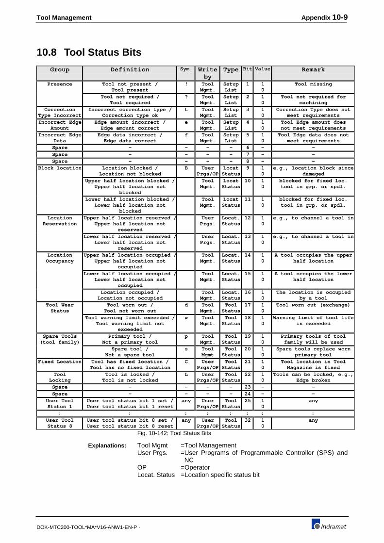
Tool Management Appendix 10-9
DOK-MTC200-TOOL*MA*V16-ANW1-EN-P ·
10.8 Tool Status Bits
Group Definition Sym. Writeby
Type Bit Value Remark
Presence Tool not present /Tool present
! ToolMgmt.
SetupList
1 10
Tool missing
Tool not required /Tool required
? ToolMgmt.
SetupList
2 10
Tool not required formachining
CorrectionType Incorrect
Incorrect correction type /Correction type ok
t ToolMgmt.
SetupList
3 10
Correction Type does notmeet requirements
Incorrect EdgeAmount
Edge amount incorrect /Edge amount correct
e ToolMgmt.
SetupList
4 10
Tool Edge amount doesnot meet requirements
Incorrect EdgeData
Edge data incorrect /Edge data correct
f ToolMgmt.
SetupList
5 10
Tool Edge data does notmeet requirements
Spare - - - - 6 - -Spare - - - - 7 - -Spare - - - - 8 - -
Block location Location blocked /Location not blocked
B UserPrgs/OP
LocatStatus
9 10
e.g., location block sincedamaged
Upper half location blocked /Upper half location not
blocked
ToolMgmt.
LocatStatus
10 10
blocked for fixed loc.tool in grp. or spdl.
Lower half location blocked /Lower half location not
blocked
ToolMgmt.
LocatStatus
11 10
blocked for fixed loc.tool in grp. or spdl.
LocationReservation
Upper half location reserved /Upper half location not
reserved
UserPrgs.
Locat.Status
12 10
e.g., to channel a tool in
Lower half location reserved /Lower half location not
reserved
UserPrgs.
Locat.Status
13 10
e.g., to channel a tool in
LocationOccupancy
Upper half location occupied /Upper half location not
occupied
ToolMgmt.
Locat.Status
14 10
A tool occupies the upperhalf location
Lower half location occupied /Lower half location not
occupied
ToolMgmt.
Locat.Status
15 10
A tool occupies the lowerhalf location
Location occupied /Location not occupied
ToolMgmt.
Locat.Status
16 10
The location is occupiedby a tool
Tool WearStatus
Tool worn out /Tool not worn out
d ToolMgmt.
ToolStatus
17 10
Tool worn out (exchange)
Tool warning limit exceeded /Tool warning limit not
exceeded
w ToolMgmt.
ToolStatus
18 10
Warning limit of tool lifeis exceeded
Spare Tools(tool family)
Primary tool /Not a primary tool
p ToolMgmt.
ToolStatus
19 10
Primary tools of toolfamily will be used
Spare tool /Not a spare tool
s ToolMgmt
ToolStatus
20 10
Spare tools replace wornprimary tool
Fixed Location Tool has fixed location /Tool has no fixed location
C UserPrgs/OP
ToolStatus
21 10
Tool location in ToolMagazine is fixed
ToolLocking
Tool is locked /Tool is not locked
L UserPrgs/OP
ToolStatus
22 10
Tools can be locked, e.g.,Edge broken
Spare - - - - 23 - -Spare - - - - 24 - -
User ToolStatus 1
User tool status bit 1 set /User tool status bit 1 reset
any UserPrgs/OP
ToolStatus
25 10
any
: : : : : : : :User ToolStatus 8
User tool status bit 8 set /User tool status bit 8 reset
any UserPrgs/OP
ToolStatus
32 10
any
Fig. 10-142: Tool Status Bits
Tool Mgmt =Tool ManagementUser Prgs. =User Programs of Programmable Controller (SPS) and
NCOP =OperatorLocat. Status =Location specific status bit
Explanations:

10-10 Appendix Tool Management
DOK-MTC200-TOOL*MA*V16-ANW1-EN-P ·
10.9 Tool Edge Status Bits
Group Definition Sym. Writeby
Type Bit Value Remark
Invalid EdgeOrientation
Edge orientation invalid /Edge orientation valid
e ToolMgmt.
SetupList
1 10
-
Invalid ToolLength L1
Tool length L1 invalid /Tool length L1 valid
1 ToolMgmt.
SetupList
2 10
-
Invalid ToolLength L2
Tool length L2 invalid /Tool length L2 valid
2 ToolMgmt.
SetupList
3 10
-
Invalid ToolLength L3
Tool length L3 invalid /Tool length L3 valid
3 ToolMgmt.
SetupList
4 10
-
Invalid ToolRadius R
Tool radius R invalid /Tool radius R valid
r ToolMgmt.
SetupList
5 10
-
Spare - - - - 6 - -Spare - - - - 7 - -Spare - - - - 8 - -
Edge WearStatus
Edge worn out /Edge not worn out
d ToolMgmt.
SetupList
9 10
-
Edge warning limit exceeded /Edge warning limit not exceeded
w ToolMgmt.
SetupList
10 10
-
Spare - - - - 11 - -Spare - - - - 12 - -
User EdgeStatus 1
User edge status bit 1 set /User edge status bit 1 reset
any UserPrgs/OP
ToolStatus
13 10
-
: : : : : : : :User EdgeStatus 4
User edge status bit 4 set /User edge status bit 4 reset
any UserPrgs/OP
ToolStatus
16 10
-
Fig. 10-143: Tool Edge Status Bits
Tool Mgmt =Tool ManagementUser Prgs. =User Programs of Programmable Controller (SPS) and
NCOP =OperatorLocat. Status =Location specific status bit
Explanations:
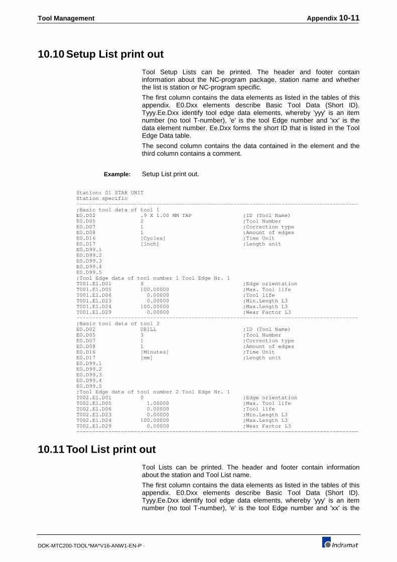
Tool Management Appendix 10-11
DOK-MTC200-TOOL*MA*V16-ANW1-EN-P ·
10.10 Setup List print out
Tool Setup Lists can be printed. The header and footer containinformation about the NC-program package, station name and whetherthe list is station or NC-program specific.
The first column contains the data elements as listed in the tables of thisappendix. E0.Dxx elements describe Basic Tool Data (Short ID).Tyyy.Ee.Dxx identify tool edge data elements, whereby 'yyy' is an itemnumber (no tool T-number), 'e' is the tool Edge number and 'xx' is thedata element number. Ee.Dxx forms the short ID that is listed in the ToolEdge Data table.
The second column contains the data contained in the element and thethird column contains a comment.
Setup List print out.
Station: 01 STAR UNIT Station specific ---------------------------------------------------------------------------------------- ;Basic tool data of tool 1 E0.D02 .9 X 1.00 MM TAP ;ID (Tool Name) E0.D05 2 ;Tool Number E0.D07 1 ;Correction type E0.D08 1 ;Amount of edges E0.D16 [Cycles] ;Time Unit E0.D17 [Inch] ;Length unit E0.D99.1 E0.D99.2 E0.D99.3 E0.D99.4 E0.D99.5 ;Tool Edge data of tool number 1 Tool Edge Nr. 1 T001.E1.D01 0 ;Edge orientation T001.E1.D05 100.00000 ;Max. Tool life T001.E1.D06 0.00000 ;Tool life T001.E1.D23 0.00000 ;Min.Length L3 T001.E1.D24 100.00000 ;Max.Length L3 T001.E1.D29 0.00000 ;Wear Factor L3 ---------------------------------------------------------------------------------------- ;Basic tool data of tool 2 E0.D02 DRILL ;ID (Tool Name) E0.D05 3 ;Tool Number E0.D07 1 ;Correction type E0.D08 1 ;Amount of edges E0.D16 [Minutes] ;Time Unit E0.D17 [mm] ;Length unit E0.D99.1 E0.D99.2 E0.D99.3 E0.D99.4 E0.D99.5 ;Tool Edge data of tool number 2 Tool Edge Nr. 1 T002.E1.D01 0 ;Edge orientation T002.E1.D05 1.00000 ;Max. Tool life T002.E1.D06 0.00000 ;Tool life T002.E1.D23 0.00000 ;Min.Length L3 T002.E1.D24 100.00000 ;Max.Length L3 T002.E1.D29 0.00000 ;Wear Factor L3 ----------------------------------------------------------------------------------------
10.11 Tool List print out
Tool Lists can be printed. The header and footer contain informationabout the station and Tool List name.
The first column contains the data elements as listed in the tables of thisappendix. E0.Dxx elements describe Basic Tool Data (Short ID).Tyyy.Ee.Dxx identify tool edge data elements, whereby 'yyy' is an itemnumber (no tool T-number), 'e' is the tool Edge number and 'xx' is the
Example:

10-12 Appendix Tool Management
DOK-MTC200-TOOL*MA*V16-ANW1-EN-P ·
data element number. Ee.Dxx form the short ID that is listed in the ToolEdge Data table.
The second column contains the data contained in the element and thethird column contains a comment.
Setup List print out.
Station : 01 Tool List:11 TEST ---------------------------------------------------------------------------------------- ;Basic tool data of tool 1 E0.D02 .9 X 1.00 MM TAP ;ID (Tool Name) E0.D06 1 ;Index Number E0.D07 1 ;Correction type E0.D08 1 ;Amount of edges E0.D09 --------------- --p-------------;Status E0.D10 0 ;Free Locations E0.D17 [mm] ;Length unit E0.D18 0.00000 ;PATH ACC. % E0.D19 0.00000 ;WEIGHT LB E0.D20 0.00000 ;SPDL. LOAD % ;Tool Edge data of tool number 1 Tool Edge Nr. 1 T001.E1.D01 0 ;Edge orientation T001.E1.D02 ---------------- ;T-Edge Status T001.E1.D03 100.00000 ;Rem. Tool life T001.E1.D04 20.00000 ;Warning Limit T001.E1.D09 240.00000 ;Length L3 T001.E1.D13 0.00000 ;Tool Wear L3 T001.E1.D17 -1.00000 ;Offset L3 T001.E1.D31 0.00000 ;PATH VEL. % ---------------------------------------------------------------------------------------- ;Basic tool data of tool 2 E0.D02 .9 X 1.00 MM TAP ;ID (Tool Name) E0.D06 2 ;Index Number E0.D07 1 ;Correction type E0.D08 1 ;Amount of edges E0.D09 --------------- ---s------------;Status E0.D10 0 ;Free Locations E0.D17 [mm] ;Length unit E0.D18 0.00000 ;PATH ACC. % E0.D19 0.00000 ;WEIGHT LB E0.D20 0.00000 ;SPDL. LOAD % ;Tool Edge data of tool number 2 Tool Edge Nr. 1 T002.E1.D01 0 ;Edge orientation T002.E1.D02 ---------------- ;T-Edge Status T002.E1.D03 100.00000 ;Rem. Tool life T002.E1.D04 10.00000 ;Warning Limit T002.E1.D09 89.00000 ;Length L3 T002.E1.D13 0.00000 ;Tool Wear L3 T002.E1.D17 0.00000 ;Offset L3 T002.E1.D31 0.00000 ;PATH VEL. % ---------------------------------------------------------------------------------------- ;Basic tool data of tool 3 E0.D02 25 MM DRILL ;ID (Tool Name) E0.D06 1 ;Index Number E0.D07 1 ;Correction type E0.D08 1 ;Amount of edges E0.D09 --------------- --p-------------;Status E0.D10 0 ;Free Locations E0.D17 [mm] ;Length unit E0.D18 0.00000 ;PATH ACC. % E0.D19 0.00000 ;WEIGHT LB E0.D20 0.00000 ;SPDL. LOAD % ;Tool Edge data of tool number 3 Tool Edge Nr. 1 ---------------------------------------------------------------------------------------- T003.E1.D01 0 ;Edge orientation T003.E1.D02 ---------------- ;T-Edge Status T003.E1.D03 98.00000 ;Rem. Tool life T003.E1.D04 10.00000 ;Warning Limit T003.E1.D09 123.00000 ;Length L3 T003.E1.D13 0.00000 ;Tool Wear L3 T003.E1.D17 0.23000 ;Offset L3 T003.E1.D31 0.00000 ;PATH VEL. % ---------------------------------------------------------------------------------------- ;Basic tool data of tool 4 E0.D02 DRILL ;ID (Tool Name) E0.D06 1 ;Index Number E0.D07 1 ;Correction type E0.D08 1 ;Amount of edges E0.D09 --------------- --p-------------;Status E0.D10 0 ;Free Locations E0.D17 [mm] ;Length unit
Example:

Tool Management Appendix 10-13
DOK-MTC200-TOOL*MA*V16-ANW1-EN-P ·
E0.D18 0.00000 ;PATH ACC. % E0.D19 0.00000 ;WEIGHT LB E0.D20 0.00000 ;SPDL. LOAD % ;Tool Edge data of tool number 4 Tool Edge Nr. 1 T004.E1.D01 0 ;Edge orientation T004.E1.D02 ---------------- ;T-Edge Status T004.E1.D03 100.00000 ;Rem. Tool life T004.E1.D04 5.00000 ;Warning Limit T004.E1.D09 50.00000 ;Length L3 T004.E1.D13 0.00000 ;Tool Wear L3 T004.E1.D17 1.43200 ;Offset L3 T004.E1.D31 0.00000 ;PATH VEL. % ---------------------------------------------------------------------------------------- ;Basic tool data of tool 5 E0.D02 LARGE FACE MILL ;ID (Tool Name) E0.D06 1 ;Index Number E0.D07 2 ;Correction type E0.D08 1 ;Amount of edges E0.D09 --------------- --p-------------;Status E0.D10 0 ;Free Locations E0.D17 [mm] ;Length unit E0.D18 75.00000 ;PATH ACC. % E0.D19 37.00000 ;WEIGHT LB E0.D20 85.00000 ;SPDL. LOAD % ;Tool Edge data of tool number 5 Tool Edge Nr. 1 T005.E1.D01 0 ;Edge orientation T005.E1.D02 ------------A--- ;T-Edge Status T005.E1.D03 100.00000 ;Rem. Tool life T005.E1.D04 10.00000 ;Warning Limit T005.E1.D09 100.00000 ;Length L3 T005.E1.D10 8.00000 ;Radius R T005.E1.D13 0.00000 ;Tool Wear L3 T005.E1.D14 0.00000 ;Tool Wear R T005.E1.D17 -0.02340 ;Offset L3 T005.E1.D18 0.00000 ;Offset R T005.E1.D31 89.00000 ;PATH VEL. %----------------------------------------------------------------------------------------

10-14 Appendix Tool Management
DOK-MTC200-TOOL*MA*V16-ANW1-EN-P ·
Tool Management Index 11-1
DOK-MTC200-TOOL*MA*V16-ANW1-EN-P ·
11 Index
A
Active Tool List 1-2, 2-9, 3-1, 4-6, 5-4, 6-23
actual tool data 4-1
Appendix 10-1
Applications 8-1
asynchronous magazine axis 6-14
Automatc tool check 2-3
automatic tool check 5-1, 5-3, 7-35
Axis parameter C00.022 8-3
Axis parameter Cxx.000 9-11, 9-12
Axis parameter Cxx.001 9-12
Axis parameter Cxx.006 8-3, 9-12
Axis parameter Cxx.007 9-12
Axis parameter Cxx.008 9-13
Axis parameter Cxx.013 6-14, 9-13
Axis parameter Cxx.014 9-13
Axis parameter Cxx.016 9-14
Axis parameter Cxx.017 9-14
Axis parameter Cxx.018 9-14
Axis parameter Cxx.019 9-15
Axis parameter Cxx.020 9-15
Axis parameter Cxx.021 9-15
Axis parameter Cxx.022 8-29, 8-34, 9-15
Axis parameter Cxx.023 9-16
Axis parameter Cxx.037 7-33, 9-16
Axis parameter Cxx.038 9-16
Axis parameter Cxx.047 9-17
Axis parameter Cxx.048 9-17
Axis parameter Cxx.049 9-17
Axis parameter Cxx.050 9-17
Axis parameter Cxx.051 9-18
Axis parameter Cxx.052 9-18
axis parameter Cxx.053 8-3
B
Basic Tool Data 4-7, 10-11, 10-12
Branch if Spindle Empty 6-22
C
combined spindle turret 6-6
command MEN 6-19
command TCH 6-20
command TSM 6-22
comment 2-6
compensation to left of contour 6-7
compensation to right of contour 6-8
compensation to the left 6-7
Complete Tool Change 7-10
Contour transition 'arc' 6-9

11-2 Index Tool Management
DOK-MTC200-TOOL*MA*V16-ANW1-EN-P ·
Contour transition 'chamfer' 6-10
Control Reset 6-5, 6-20, 7-32, 7-36
Correction Type 3-4, 6-11
Correction Type 1 2-4
Correction Type 2 2-4, 3-5, 6-11, 6-12
Correction Type 3 2-4, 2-6, 3-5, 3-9
Correction Type 4 2-4, 2-6, 3-5, 3-9, 6-11, 6-13
Cxx.006 8-3
Cxx.053 8-3
D
disk type tool magazine 8-1
E
Edge data registers 3-14
Edge Orientation 3-5
Edge warning limit exceeded (w) 4-22
Edge worn out (d) 4-21
Enable manual Tool storagre mode 6-19
Endless 9-7
endless magazine 7-39
endless tool storage 9-9
endless turret 7-39
endless, none 7-40
Error handling, TLD_RD 7-48
Error handling, TLD_WR 7-48
Error handling, tool data 7-48
F
Fixed location tool (C) 4-18
FUNCTION MAG_ACT 7-27, 7-28, 8-27, 9-16, 9-17, 9-18
FUNCTION MAG_Q 7-27, 7-28, 8-27
FUNCTION MMV 7-33
FUNCTION MMV 7-2, 7-6, 7-8, 7-33, 7-34, 7-35, 7-39, 8-7,
8-17, 8-31, 8-36, 8-43
FUNCTION MMV_Q 7-2, 7-6, 7-8, 7-9, 7-35, 7-39, 8-7, 8-17,
8-31, 8-36, 8-44
FUNCTION MRF 7-2, 7-4, 7-5, 7-6, 7-32, 8-7, 8-16, 8-31,
8-35, 8-42
FUNCTION MRF_Q 7-2, 7-4, 7-5, 7-39, 8-7, 8-17, 8-31, 8-36,
8-42
FUNCTION Q_FKT 8-19
FUNCTION Q_FKT_Q 8-19
FUNCTION R_TRIG 7-8
FUNCTION SPDL_ACT 7-27, 7-28, 7-29, 8-27, 9-16, 9-17, 9-18
FUNCTION SPDL_Q 7-27, 7-29, 8-27
FUNCTION TCH 7-2, 7-9, 7-10
FUNCTION TCH_Q 7-2, 7-10
FUNCTION TMS 7-3, 7-12, 7-13, 7-14, 7-23, 8-7, 8-23,
8-44
FUNCTION TMS_Q 7-3, 7-12, 7-13, 7-14, 7-23, 8-7, 8-44
FUNCTION TSM 7-3, 7-9, 7-16, 7-17, 7-18, 8-9, 8-23,
8-44

Tool Management Index 11-3
DOK-MTC200-TOOL*MA*V16-ANW1-EN-P ·
FUNCTION TSM_Q 7-3, 7-16, 7-17, 7-18, 8-9, 8-25, 8-46
FUNCTION XFER_CHK 7-25, 8-50
FUNCTION XGM 8-24
FUNCTION XGM_PA 8-25
FUNCTION XGM_Q 8-25
FUNCTION XGS 8-23
FUNCTION XGS_PA 8-23
FUNCTION XGS_Q 8-23
FUNCTION XMG 8-23
FUNCTION XMG_PA 8-23
FUNCTION XMG_Q 8-23
FUNCTION XMS 7-14, 7-20, 7-21, 7-22, 7-23, 8-7, 8-44
FUNCTION XMS_CA 7-21, 7-22, 7-23, 8-8
FUNCTION XMS_NA 7-14, 7-20, 7-21, 7-22, 7-23, 8-7, 8-44
FUNCTION XMS_PA 7-14, 7-20, 7-21, 7-23, 8-7, 8-44
FUNCTION XMS_Q 7-14, 7-20, 7-21, 7-22, 7-23, 8-7, 8-44
FUNCTION XSG 8-23
FUNCTION XSG_PA 8-23
FUNCTION XSG_Q 8-23
FUNCTION XSM 7-16, 8-9, 8-44
FUNCTION XSM_CA 8-9
FUNCTION XSM_NA 8-9, 8-45
FUNCTION XSM_PA 7-16, 8-9, 8-44
FUNCTION XSM_Q 7-16, 8-9, 8-46
FUNCTION, TCH 7-26
FUNCTION, TCH_Q 7-26
FUNCTION, TMS 7-26
FUNCTION, TMS_Q 7-26
FUNCTION, TSM 7-26
FUNCTION, TSM_Q 7-26
FUNCTION, XGM 7-26
FUNCTION, XGM_CA 7-26
FUNCTION, XGM_NA 7-26
FUNCTION, XGM_PA 7-26
FUNCTION, XGM_Q 7-26
FUNCTION, XGS 7-26
FUNCTION, XGS_CA 7-26
FUNCTION, XGS_NA 7-26
FUNCTION, XGS_PA 7-26
FUNCTION, XGS_Q 7-26
FUNCTION, XMG 7-26
FUNCTION, XMG_CA 7-26
FUNCTION, XMG_NA 7-26
FUNCTION, XMG_PA 7-26
FUNCTION, XMG_Q 7-26
FUNCTION, XMS 7-26
FUNCTION, XMS_CA 7-26
FUNCTION, XMS_NA 7-26
FUNCTION, XMS_PA 7-26
FUNCTION, XMS_Q 7-26
FUNCTION, XSG 7-28
FUNCTION, XSG_CA 7-28
FUNCTION, XSG_NA 7-28
FUNCTION, XSG_PA 7-28
FUNCTION, XSG_Q 7-28
11-4 Index Tool Management
DOK-MTC200-TOOL*MA*V16-ANW1-EN-P ·
FUNCTION, XSM 7-26
FUNCTION, XSM_CA 7-26
FUNCTION, XSM_NA 7-26
FUNCTION, XSM_PA 7-26
FUNCTION, XSM_Q 7-26
FUNCTION_BLOCK CHAINMAG 8-15, 8-19
FUNCTION_BLOCK LINTIM 8-41, 8-46
FUNCTION_BLOCK R_TRIG 8-17
FUNCTION_BLOCK S_TURRET 8-30, 8-35, 8-41
FUNCTION_BLOCK TMS_TSM 8-5, 8-7, 8-10
FUNCTION_BLOCK TON 8-31
FUNCTION_BLOCK TP 8-30
FUNCTION_BLOCK TURRET 8-29
FUNCTION_BLOCK VAR_RD 8-46
FUNCTION_BLOCK VAR_WR 8-46
FUNCTIONs 7-1
FUNCTIONs TMS 7-9
G
Gateway Signal 10-3
Gateway signal PxxCMGTWO 3-11
Geometric length limit 2-9
gripper 8-10
H
half pocket overlap 3-7
homing sequence of tool storage 6-14
I
INCH/CYCL 2-10
INCH/MIN 2-10
Introduction 1-1
Invalid amount of tool Edges (e) 4-12
Invalid correction type (t) 4-11, 5-3
Invalid geometry L 1 4-21
Invalid geometry L2 4-21
Invalid geometry L3 4-21
Invalid geometry r 4-21
Invalid number of Edges (e) 5-3
Invalid tool Edge (f) 4-12, 5-3
Invalid tool Edge orientation (e) 4-20
L
Length L1 6-1
Length L2 6-1
Length L3 6-1
Length tool wear factor 2-10
length unit in the Setup List 2-6
Length Unit INCH 3-7
Length Unit MM 3-7
location 6-16, 6-24
Location blocked (B) 4-12

Tool Management Index 11-5
DOK-MTC200-TOOL*MA*V16-ANW1-EN-P ·
Location occupied 4-15
Locked tool (L) 4-19
M
Magazine -> Spindle sequence 7-13
manual tool storage mode 6-19
Max.LengthL1 2-9
Max.LengthL2 2-9
Max.LengthL3 2-9
Max.Radius R 2-9
maximum tool length 2-9
Maximum Tool Life 2-8, 2-9
maximum tool radius 2-9
Min.LengthL1 2-9
Min.LengthL2 2-9
Min.LengthL3 2-9
Min.Radius R 2-10
minimum tool length 2-9
minimum tool radius 2-9
MM/CYCL 2-10
MM/MIN 2-10
Move Free Pocket into Position 6-17
Move Location into Position 6-16
Move to Home Position 6-14
Move to Reference Position 6-14
Move Tool into Position 6-15
Move Tool Storage sequence 7-7
MTC User Interface 1-1
MUI 1-1, 1-2
N
NC servo disk tool magazine 8-1
NC-command BSE 6-22, 8-3, 8-39
NC-command BST 6-5, 6-20, 7-32, 7-36, 7-44
NC-command BTE 8-4, 8-39
NC-command E 2-10, 4-22, 6-4, 7-42, 7-43, 8-48
NC-command MEN 6-20, 7-32, 7-37, 8-4, 8-14
NC-command MFP 6-17, 7-6, 7-32, 7-36, 7-39
NC-command MHP 6-14, 7-6, 7-32, 7-36, 7-39, 8-4, 9-9, 9-
13
NC-command MMP 6-16, 7-6, 7-32, 7-39, 8-27, 8-33
NC-command MOP 6-18, 6-19, 7-6, 7-32, 7-36, 7-39, 8-37,
8-39
NC-command MRF 6-14, 7-4, 7-5, 7-6, 7-32, 7-36, 7-39,
9-13
NC-command MRY 6-13, 6-15, 6-19, 7-5, 7-8, 8-3, 8-14,
8-27, 8-29, 8-33, 8-39
NC-command MTP 4-18, 4-19, 6-15, 7-6, 7-8, 7-32, 7-36,
7-39, 8-4, 8-13, 8-14, 8-27, 8-29, 8-33,
8-37, 8-39
NC-command RET 6-5, 6-20, 7-32, 7-36, 7-44
NC-command SPT 6-3, 6-5, 8-53, 8-56, 9-8
NC-command T 6-3

11-6 Index Tool Management
DOK-MTC200-TOOL*MA*V16-ANW1-EN-P ·
NC-command T0 4-18, 4-18, 4-22
NC-command TCH 7-2, 7-9, 7-10, 7-11
NC-command TLD 3-8, 6-23, 9-4, 9-5, 9-6
NC-command TMS 7-11, 7-12, 7-13, 7-23, 8-4, 8-14, 8-41
NC-command TPE 8-3, 8-39
NC-command TSE 8-40
NC-command TSM 7-11, 7-17, 7-18, 8-4, 8-14, 8-41
NC-command, TCH 7-22
NC-command, TMS 7-22, 7-26
NC-command, TSM 7-22, 7-26
NC-commands MEN 7-36
NC-memory 7-43, 7-44
NC-memory A/B 1-1, 7-45
NC-program package 2-12
NC-program specific Setup List 2-11
none endless magazine 7-39
none endless turret 7-39
number of tool Edges 2-6, 3-5
O
Offset to the Reference 7-38, 7-40, 7-41
old location 3-7
OPERATION MOD 8-17
Organization of the setup lis 9-1
Overview Correction Types 10-5
Overview Edge Orientation 2-8, 3-5, 3-10, 10-6
Overview NC-command 10-1
Overview Signal and Command 10-4
Overview SPS FUNCTION 10-3
P
Parameter parameter B00.014 9-7
Parameter parameter B00.015 9-7
Parameter parameter B00.016 9-7
Parameter parameter B00.017 9-8
Parameter parameter B00.018 9-8
Parameter parameter B00.019 9-8
Parameter parameter B00.020 9-9
Parameter parameter B00.021 9-9
Parameter parameter B00.022 9-9
Parameter parameter B00.023 9-9
Parameter parameter B00.024 9-9
Position 1 7-38, 7-40, 7-41
Position 2 7-38, 7-40, 7-41
Position 3 7-38, 7-40, 7-41
Position 4 7-38, 7-40, 7-41
Preparatory function G1 2-10
Preparatory function G17 2-8, 3-10, 6-1
Preparatory function G18 2-8, 3-10, 6-1
Preparatory function G19 2-8, 3-10, 6-1
Preparatory function G2 2-10
Preparatory function G3 2-10
Preparatory function G33 2-10

Tool Management Index 11-7
DOK-MTC200-TOOL*MA*V16-ANW1-EN-P ·
Preparatory function G40 6-6, 6-7, 6-8, 8-3
Preparatory function G41 6-7, 6-8, 6-9, 6-10
Preparatory function G42 2-7, 3-9, 6-7, 6-8, 6-9, 6-10
Preparatory function G43 2-7, 3-9
preparatory function G44 6-10
Preparatory function G47 6-10, 8-3
Preparatory function G48 6-10, 6-11
Preparatory function G49 6-10
Preparatory function G63 2-10
Preparatory function G64 2-10
Preparatory function G65 2-10
Preparatory function G74 6-14, 9-15
primary tool (p) 3-7, 4-17, 5-3
Process parameter B00.016 8-2
Process parameter B00.017 8-2
Process parameter B00.018 8-3
Process parameter B00.020 8-3
Process parameter B00.021 8-3
Process parameter Bxx.001 2-6, 3-7
Process parameter Bxx.011 8-28
Process parameter Bxx.015 8-12, 8-28, 8-38, 8-49, 8-51, 8-54, 8-57,
9-9, 9-10
Process parameter Bxx.016 8-12, 8-28, 8-33, 8-38, 8-49, 8-51, 8-54,
8-57, 9-9, 9-10
Process parameter Bxx.017 8-12, 8-28, 8-33, 8-38, 8-49, 8-50, 8-51,
8-54, 8-57, 9-9, 9-10
Process parameter Bxx.018 8-12, 8-28, 8-33, 8-38, 8-48, 8-49, 8-50,
8-51, 8-54, 8-57
Process parameter Bxx.019 8-12, 8-28, 8-33, 8-38, 8-49, 8-51, 8-54,
8-58
Process parameter Bxx.020 7-34, 8-12, 8-28, 8-33, 8-38, 8-49, 8-51,
8-54, 8-58
Process parameter Bxx.021 7-38, 8-12, 8-33, 8-38, 8-49, 8-51, 8-54,
8-58, 9-9, 9-10
Process parameter Bxx.022 7-38
Process parameter Bxx.023 7-38
Process parameter Bxx.024 7-38
Process parameter Bxx.026 9-11
Process parameter Bxx.027 9-11
Process parameter Bxx.028 9-11
Program Specific Setup List 9-2
programmable controller 1-1
Pxx.MGAP 7-8
PxxC.ADV 7-35
PxxC.MGAP 7-34, 7-39
PxxC.MGBP 7-33
PxxC.MGCP 7-5
PxxC.MGENA 7-3, 7-30, 7-35
PxxC.MGHOM 7-32
PxxC.MGMAN 7-31, 7-37
PxxC.MGNEG 7-34
PxxC.MGNTC 5-1, 7-35
PxxC.MGPOS 7-34
PxxC.REV 7-35
PxxCMGMAN 6-19

11-8 Index Tool Management
DOK-MTC200-TOOL*MA*V16-ANW1-EN-P ·
PxxS.MGBP 7-37
PxxS.MGCP 7-2, 7-5, 7-8, 7-33, 7-34, 7-35, 7-38
PxxS.MGENA 7-31, 7-35
PxxS.MGERR 7-20, 7-43, 7-44
PxxS.MGMAN 7-37
PxxS.MGMOV 7-37
PxxS.MGREQ 7-36
PxxS.MGTWO 7-42, 7-44
PxxS.MGWRN 7-43
PxxSMGWRN 3-11
R
Radius tool wear factor 2-10
Reference Tool Storage sequence 7-5
Remaining Tool Life 4-9
respective location 7-38
reverse NC-program 6-14
S
sequence of a tool change 7-3
sequences, tool change 7-22
sequences, tool transfer logical 7-22
SERCOS parameter S-0-0151 6-14
Setup List 2-11
Setup List specific 4-20, 4-21
Setup List specific status bit 1 4-21
Setup List specific status bit 2 4-21
Setup List specific status bit 3 4-21
Setup List specific status bit e 4-20
Setup List specific status bit r 4-21
Setup List specific status bits 4-10
Setup List specific tool Edge status bits 4-20
Single tool spindle, multiple tools 8-50, 8-52, 8-55
Single tool station 8-47
SOT 1-2
spare tool (s) 3-7, 4-18, 5-3
Spindle -> Magazine sequence 7-18
spindle mode 8-27
Spindle selection for tool management 6-5
SPS 1-1
SPS Tool Mngt. Contr. Functions 7-1
Station specific Setup List 2-11, 9-1
System parameter A00.052 8-2, 9-1
System parameter A00.053 8-2, 9-1
System parameter A00.054 8-2
System parameter A00.055 8-2
System parameter A00.056 8-2, 9-3
System parameter A00.057 9-3
System parameter A00.058 9-4
System parameter A00.059 9-4
System parameter A00.060 9-5
System parameter A00.061 9-5
System parameter A00.062 9-5
Tool Management Index 11-9
DOK-MTC200-TOOL*MA*V16-ANW1-EN-P ·
System parameter A00.063 9-5
System parameter A00.064 9-5
System parameter A00.065 9-5
System parameter A00.066 9-5
System parameter A00.067 9-5
System parameter A00.068 9-5
System parameter A00.069 9-5
System parameter A00.070 9-5
System parameter A00.071 9-5
System parameter A00.072 9-5
System parameter A00.074 9-5
System parameter A00.075 9-6
System parameter A00.076 9-6
System parameter A00.077 9-6
System parameter A00.078 9-6
System parameter A00.079 9-6
System parameter A00.080 9-6
System parameter A00.081 9-6
System parameter A00.082 9-6
System parameter A00.083 9-6, 9-7
System parameter A00.084 9-6, 9-7
System parameter A00.085 9-6, 9-7
System parameter A00.086 9-6, 9-7
System parameter Axx.053 2-1, 2-2, 8-28, 8-38, 8-51, 8-54, 8-57
System parameter Axx.054 2-6, 3-5, 6-4, 8-12, 8-28, 8-33, 8-38,
8-48, 8-50, 8-51, 8-53, 8-54, 8-57
System parameter Axx.055 3-12, 8-28, 8-33, 8-38, 8-51, 8-54, 8-57
System parameter Axx.056 3-12, 8-48
System parameter Axx.059 8-48
System parameters Axx.061 3-7
System parameters Axx.062 3-7
System parameters Axx.063 3-7
System parameters Axx.064 3-7
System parameters Axx.065 3-7
System parameters Axx.066 3-7
System parameters Axx.067 3-7
System parameters Axx.068 3-7
System parameters Axx.069 3-7
System parameters Axx.070 3-14
System parameters Axx.071 3-14
System parameters Axx.072 3-14
System parameters Axx.073 3-14
System parameters Axx.074 3-14
System paramter A00.055 9-3
T
T 6-3
T0 2-10, 6-3, 7-43, 8-29, 8-48, 8-50
T-number 2-3, 6-24, 7-43, 8-48, 8-50
Tool and Setup List comparison 1-2
Tool change 6-20
Tool change FUNCTIONs 7-9
tool change subroutine 6-4
tool data preparation 6-2

11-10 Index Tool Management
DOK-MTC200-TOOL*MA*V16-ANW1-EN-P ·
tool data preparation 6-3
Tool Data read/write 6-23, 7-45, 7-46
Tool data, read 7-47
tool data, write 7-48
Tool Edge Data 4-8, 10-11, 10-12
tool Edge orientation 2-6, 3-9
Tool Edge selection 6-4
Tool Edge status bit 3-11
tool Edge status bits 4-20, 10-10
tool Edges 3-4, 7-42, 9-2
tool family 2-3, 3-4, 7-42
Tool Index 2-3, 3-4, 6-24
Tool length correction 3-12
Tool length correction, cancel 6-10
Tool length correction, negative 6-11
Tool length correction, positive 6-11
Tool Life 1-1, 1-2, 2-5, 2-6, 2-8, 2-9, 3-1, 3-3, 3-6,
3-11, 3-12, 4-1, 4-8, 4-10, 4-15, 4-16,
4-17, 4-21, 4-22, 5-1, 5-2, 5-3, 6-4, 6-6,
8-12, 8-28, 8-33, 8-38, 8-48, 8-50, 8-51,
8-54, 8-57, 9-4, 9-5, 10-8, 10-9
Tool List 1-2, 3-1
Tool List data overview 3-3
Tool List sorted by Location 4-1, 4-2, 4-3
Tool List sorted by T-number 4-4
Tool Lists 3-15
tool location 2-3, 3-4, 6-25
tool location selection 6-3
tool magazine 6-4
Tool Management 5-4
Tool Management Parameters 9-1
Tool Name 2-3, 3-4, 5-3
Tool not necessary (?) 4-11, 5-3
Tool not present (!) 4-11, 5-3
tool number 6-4
tool number selection 6-3
tool path compensation 2-7, 2-8, 3-9, 3-10, 6-6
Tool radius correction 3-13
Tool specific 4-17, 4-18, 4-19, 4-21, 4-22
Tool specific Edge status bit d 4-21
Tool specific Edge status bit w 4-22
tool specific status bit C 4-18
tool specific status bit d 4-15
tool specific status bit L 4-19
tool specific status bit p 4-17
tool specific status bit s 4-18
tool specific status bit w 4-16
Tool specific status bits 4-15
tool spindle 6-4, 6-24
Tool Status 3-7
Tool status bit overview 4-10
Tool Status Bits 10-9
Tool Storage 1-2, 3-3, 5-4, 6-24, 6-25
Tool storage and tool error 7-45
tool storage movement complete? 6-19

Tool Management Index 11-11
DOK-MTC200-TOOL*MA*V16-ANW1-EN-P ·
Tool transfer sequences 7-22
tool transfer, logical 6-1
tool transfer, physical 6-1
tool turret 6-4
tool warning limit exceeded (w) 3-7, 4-16, 5-3
Tool warning limit reached 7-44
Tool worn out 7-43
tool worn out (d) 3-7, 4-15, 5-3
turret mode 7-27, 7-28, 8-27
T-word 6-3, 6-15
U
Upper/lower half location blocked 4-13
Upper/lower half location occupied 4-14
Upper/lower half location reserved 4-12, 4-14
user Edge data 3-14
User tool data 3-7
user tool Edge status bits 4-21
Y
YZ plane 6-1
Z
ZX plane 6-1

Tool Management List of Figures 12-1
DOK-MTC200-TOOL*MA*V16-ANW1-EN-P ·
12 List of FiguresFig. 1-1: Tool and Setup List comparison 1-2Fig. 2-2: Basic tool data Setup List entry screen 2-1Fig. 2-3: NC-Program and tool data management 2-2Fig. 2-4: Automatic tool check overview 2-3Fig. 2-5: Tool Correction Type definition 2-4Fig. 2-6: Setup List data overview 2-5Fig. 2-7: Tool Edge data entry screen 2-6Fig. 2-8: Example: Tools with different number of tool Edges. 2-6Fig. 2-9: No tool path compensation 2-7Fig. 2-10: With tool path compensation 2-8Fig. 2-11: Tool Edge Orientation Overview 2-8Fig. 2-12: Station specific Setup List. 2-11Fig. 2-13: NC-program specific Setup List. 2-11Fig. 2-14: NC-program packages and Setup Lists in MTC 2-13Fig. 3-15: Tool List, Basic Tool Data MUI/SOT screen 3-1Fig. 3-16: Tool List, Tool Edge Data MUI/SOT screen 3-2Fig. 3-17: Tool List data overview 3-3Fig. 3-18: Tool family data .......... 3-4Fig. 3-19: Tool data to match the magazine list 3-4Fig. 3-20: Tool Edge Orientation Overview 3-5Fig. 3-21: Tools with different amount of tool Edges 3-6Fig. 3-22: Tool Status Bits .......... 3-7Fig. 3-23: Example: User tool data on MUI/SOT screen 3-8Fig. 3-24: Correction type '2', one tool Edge 3-8Fig. 3-25: No tool path compensation 3-9Fig. 3-26: With tool path compensation 3-10Fig. 3-27: Tool Edge Orientation Overview 3-10Fig. 3-28: Tool Edge status bits. . 3-11Fig. 3-29: Geometry data groups 3-12Fig. 3-30: Correction type 1 length correction 3-12Fig. 3-31: Correction type 2 radius correction 3-13Fig. 3-32: Example: Dimensioning of a drill 3-14Fig. 3-33: Example: Dimensioning of turning tool 3-14Fig. 3-34: Tool Lists within the control system 3-15Fig. 4-35: MUI/GUI Operator Display of Active Tool List (GEO). 4-1Fig. 4-36: MUI/GUI Help for Active Tool List menu. 4-2Fig. 4-37: MUI/GUI additional functions in Active Tool List (GEO). 4-2Fig. 4-38: MUI/GUI condensed Active Tool List sorted by Location.
............................................. 4-3Fig. 4-39: MUI/GUI display of Active Tool List sorted by T-number.
............................................. 4-4Fig. 4-40: Basic tool data in MUI/GUI display of Active Tool List 4-5Fig. 4-41: Tool Edge data in MUI/GUI display of Active Tool List 4-6Fig. 4-42: Tool Edge data in MUI/GUI display of Active Tool List 4-7Fig. 4-43: Basic Tool Data of Active Tool List 4-7Fig. 4-44: Tool Edge Data of Active Tool List 4-8Fig. 4-45: Tool status bit overview 4-10Fig. 4-46: Tool Edge status bit overview 4-20Fig. 5-47: Conditions for automatic tool check 5-1Fig. 5-48: Active Tool List on SOT 5-2Fig. 5-49: Tool and Edge data on SOT 5-2Fig. 5-50: MTC Tool Management in production environment 5-4Fig. 6-51: Tool corrections L1,L2,L3,R and selected plane 6-1Fig. 6-52: Tool and tool data preparation for tool magazine 6-2Fig. 6-53: Tool and tool data preparation for tool turret. 6-3Fig. 6-54: Tool path compensation, cancel (G40) 6-6Fig. 6-55: Tool path compensation left (G41) 6-7Fig. 6-56: Tool path compensation right (G42) 6-8Fig. 6-57: Example: Tool path compensation when turning
(G40, G41, G42).................. 6-9
12-2 List of Figures Tool Management
DOK-MTC200-TOOL*MA*V16-ANW1-EN-P ·
Fig. 6-58: Contour transition 'arc' (G43) 6-9Fig. 6-59: Contour transition 'chamfer' ( G44) 6-10Fig. 6-60: Contour transition 'chamfer';<= 90° (G44) 6-10Fig. 6-61: Example: Tool length correction, correction type 2 6-12Fig. 6-62: Tool length correction, correction type 4 6-13Fig. 6-63: Example: Home and reference position of disk
tool storage.......................... 6-15Fig. 6-64: Example: Move Tool into Position (MTP) 6-16Fig. 6-65: Move Location into Position (MMP) 6-17Fig. 6-66: Move (CCW) free magazine pocket into
tool change position '2'. ....... 6-18Fig.6-67: Return tool in 'S1' to its old pocket via change pos.'2' 6-19Fig. 7-68: MTC tool management data flow 7-1Fig. 7-69: Reference (home) tool storage via SPS 7-2Fig. 7-70: Position tool storage via SPS 7-2Fig. 7-71: Basic sequence of a tool change 7-3Fig. 7-72: Read tool storage NC-command MRF
via FUNCTION MRF ........... 7-4Fig. 7-73: Acknowledge tool storage NC-command MRF
via FUNCTION MRF_Q....... 7-4Fig. 7-74: Reference Tool Storage sequence 7-5Fig. 7-75: Read tool storage NC-command MMV via FUNCTION MMV
............................................. 7-6Fig. 7-76: Ackng. tool storage NC-command MMV
via FUNCTION MMV_Q ...... 7-7Fig. 7-77: Move Tool Storage sequence 7-7Fig. 7-78: Read tool change NC-command TCH
via FUNCTION TCH............ 7-10Fig. 7-79: Ackn. tool change cmd. TCH via FUNCTION TCH_Q 7-10Fig. 7-80: Complete Tool Change sequence 7-11Fig. 7-81: Read tool change NC-command TMS
via FUNCTION TMS............ 7-12Fig. 7-82: Acknowledge tool change NC-command TMS
via FUNCTION TMS_Q....... 7-12Fig. 7-83: Magazine -> Spindle Tool Change sequence 7-13Fig. 7-84: Read tool change NC-command TSM
via FUNCTION TSM............ 7-16Fig. 7-85: Acknowledge tool change NC-command TSM
via FUNCTION TSM_Q....... 7-16Fig. 7-86: Spindle -> Magazine Tool Change sequence 7-17Fig. 7-87: Tool Transfer FUNCTION overview 7-18Fig. 7-88: Magazine - > Spindle tool transfer request,
FUNCTION XMS................. 7-19Fig. 7-89: Magazine - > Spindle tool xfer positive ackng.,
FUNCTION XMS_PA .......... 7-19Fig. 7-90: Magazine - > Spdl. tool xfer negative ackng.,
FUNCTION XMS_NA.......... 7-20Fig. 7-91: Magazine - > Spindle tool transfer acknowledge.,
FUNCTION XMS_Q ............ 7-20Fig. 7-92: Magazine - > Spindle tool transfer cancel.,
FUNCTION XMS_CA.......... 7-21Fig. 7-93: Magazine->Spindle tool transfer sequence 7-22Fig. 7-94: Disable tool transfer error check,
FUNCTION XFER_CHK...... 7-23Fig. 7-95: Tool Transfer FUNCTION overview 7-24Fig. 7-96: Read turret mode, FUNCTION MAG_ACT 7-25Fig. 7-97: Acknowledge turret mode, FUNCTION MAG_Q 7-26Fig. 7-98: Read spindle mode, FUNCTION SPDL_ACT 7-26Fig. 7-99: Acknowledge spindle mode, FUNCTION SPDL_Q 7-27Fig. 7-100: Principal operation of the tool storage 7-28Fig. 7-101: Tool storage enable signal, PxxC.MGENA 7-29Fig. 7-102: Tool storage operating mode 7-30Fig. 7-103: Tool Storage Enabled, PxxS.MGENA 7-34

Tool Management List of Figures 12-3
DOK-MTC200-TOOL*MA*V16-ANW1-EN-P ·
Fig. 7-104: CNC uses tool magazine 7-34Fig. 7-105: Commanded and actual location of SPS controlled tool
storage................................. 7-36Fig. 7-106: Example: Commanded magazine pocket via PxxS.MGCP
............................................. 7-37Fig. 7-107: SPS controlled none endless rack type
tool magazine has 6 tool locations, each containing a tool 7-38Fig. 7-108: Tool worn out, PxxS.MGTWO 7-40Fig. 7-109: Tool warning limit reached, PxxS.MGWRN 7-41Fig. 7-110: Tool storage and tool error, PxxS.MGERR 7-42Fig. 7-111: Tool Data read/write,
FUNCTION_BLOCK TLD_RD/TLD_WR 7-43Fig. 7-112: Timing diagram, tool data read via TLD_RD 7-43Fig. 7-113: Timing diagram, tool data write via TLD_WR 7-44Fig. 8-114: Milling station with NC servo disk magazine 8-1Fig. 8-115: Milling station with chain magazine and double
gripper changer ................... 8-8Fig. 8-116: 'Combined Spindle (live tool) / Turret' NC servo axis 8-19Fig. 8-117: NC servo controlled tool turret 8-24Fig. 8-118: Stationary tool magazine (rack) 8-28Fig. 8-119: Single tool station ..... 8-36Fig. 8-120: Single tool spindle, multiple tools 8-39Fig. 8-121: Two tool spindle with single tools 8-42Fig. 8-122: Two tool storages and one Active Tool List 8-45Fig. 9-123: MUI/GUI System Parameter screen 9-1Fig. 9-124: Station specific Setup List organization 9-2Fig. 9-125: Program specific Setup List organization 9-2Fig. 9-126: Tools With Different Number Of Edges 9-3Fig. 9-127: Types Of Tool Storage 9-8Fig. 9-128: Endless chain magazine 9-10Fig. 9-129: Non-endless disk/rack magazine 9-10Fig. 9-130: Example: Home and reference position of
disk tool storage .................. 9-13Fig. 9-131: Example: Axis Velocity Profile 9-14Fig. 9-132: Example: Spindle Zero Position Shift of -30 degrees 9-16Fig. 10-133: Tool Management NC-command Overview 10-1Fig. 10-134: Tool Management SPS FUNCTION Overview 10-2Fig. 10-135: Tool Management CNC⇔SPS
....Gateway Signal Overview 10-3Fig. 10-136: Tool Management Signal and Command Overview 10-4Fig. 10-137: Tool Correction Type Overview 10-5Fig. 10-138: Tool Edge Orientation Overview 10-6Fig. 10-139: Tool Edge Orientation Overview 10-6Fig. 10-140: Basic Tool Data Overview 10-7Fig. 10-141: Tool Edge Data Overview 10-8Fig. 10-142: Tool Status Bits ...... 10-9Fig. 10-144: Tool Edge Status Bits 10-10

12-4 List of Figures Tool Management
DOK-MTC200-TOOL*MA*V16-ANW1-EN-P ·
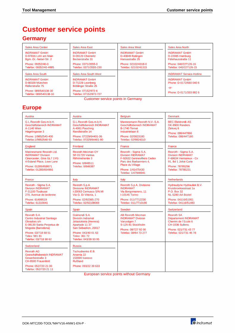
Tool Management Customer service points
DOK-MTC200-TOOL*MA*V16-ANW1-EN-P ·
Customer service pointsGermany
Sales Area Center
INDRAMAT GmbHD-97816 Lohr am MainBgm.-Dr.-Nebel-Str. 2
Phone: 09352/40-0Telefax: 09352/40-4885
Sales Area East
INDRAMAT GmbHD-09120 ChemnitzBeckerstraße 31
Phone: 0371/3555-0Telefax: 0371/3555-230
Sales Area West
INDRAMAT GmbHD-40849 RatingenHansastraße 25
Phone: 02102/4318-0Telefax: 02102/41315
Sales Area North
INDRAMAT GmbHD-22085 HamburgFährhausstraße 11
Phone: 040/227126-16Telefax: 040/227126-15
Sales Area South
INDRAMAT GmbHD-80339 MünchenRidlerstraße 75
Phone: 089/540138-30Telefax: 089/540138-10
Sales Area South West
INDRAMAT GmbHD-71229 LeonbergBöblinger Straße 25
Phone: 07152/972-6Telefax: 07152/972-727
INDRAMAT Service-Hotline
INDRAMAT GmbHPhone: D-0172/660 040 6
-or-
Phone: D-0171/333 882 6
Customer service points in Germany
EuropeAustria
G.L.Rexroth Ges.m.b.H.Geschäftsbereich INDRAMATA-1140 WienHägelingasse 3
Phone: 1/9852540-400Telefax:1/9852540-93
Austria
G.L.Rexroth Ges.m.b.H.Geschäftsbereich INDRAMATA-4061 PaschingRandlstraße 14
Phone: 07229/64401-36Telefax: 07229/64401-80
Belgium
Mannesmann Rexroth N.V.-S.A.Geschäftsbereich INDRAMATB-1740 TernatIndustrielaan 8
Phone: 02/5823180Telefax: 02/5824310
Denmark
BEC Elektronik ASDK-8900 RandersZinkvej 6
Phone: 086/447866Telefax: 086/447160
England
Mannesmann Rexroth Ltd.INDRAMAT DivisionCirencester, Glos GL7 1YG4 Esland Place, Love Lane
Phone: 01285/658671Telefax: 01285/654991
Finnland
Rexroth Mecman OYSF-01720 VantaaRiihimiehentie 3
Phone: 0/848511Telefax: 0/846387
France
Rexroth - Sigma S.A.Division INDRAMATF-92632 Gennevilliers CedexParc des Barbanniers 4,Place du Village
Phone: 1/41475430Telefax: 1/47946941
France
Rexroth - Sigma S.A.Division INDRAMATF-69634 Venissieux - Cx91, Bd 1 Joliot Curie
Phone: 78785256Telefax: 78785231
France
Rexroth - Sigma S.A.Division INDRAMATF-31100 Toulouse270, Avenue de lardenne
Phone: 61499519Telefax: 61310041
Italy
Rexroth S.p.A.Divisione INDRAMATI-20063 Cernusco S/N.MIVia G. Di Vittoria, 1
Phone: 02/92365-270Telefax: 02/92108069
Italy
Rexroth S.p.A. DivisioneINDRAMATVia Borgomanero, 11I-10145 Torino
Phone: 011/7712230Telefax: 011/7710190
Netherlands
Hydraudyne Hydrauliek B.V.Kruisbroeksestraat 1aP.O. Box 32NL-5280 AA Boxtel
Phone: 04116/51951Telefax: 04116/51483
Spain
Rexroth S.A.Centro Industrial SantiagoObradors s/nE-08130 Santa Perpetua deMogoda (Barcelona)
Phone: 03/718 68 51Telex: 591 81Telefax: 03/718 98 62
Spain
Goimendi S.A.División IndramatJolastokieta (Herrera)Apartado 11 37San Sebastion, 20017
Phone: 043/40 01 63Telex: 361 72Telefax: 043/39 93 95
Sweden
AB Rexroth MecmanINDRAMAT DivisionVaruvägen 7S-125 81 Stockholm
Phone: 08/727 92 00Telefax: 08/64 73 277
Switzerland
Rexroth SADépartement INDRAMATChemin de l`Ecole 6CH-1036 Sullens
Phone: 021/731 43 77Telefax: 021/731 46 78
Switzerland
Rexroth AGGeeschäftsbereich INDRAMATGewerbestraße 3CH-8500 Frauenfeld
Phone: 052/720 21 00Telefax: 052/720 21 11
Russia
Tschudnenko E.B.Arsenia 22153000 IvanovoRußland
Phone: 093/22 39 633
European service points without Germany
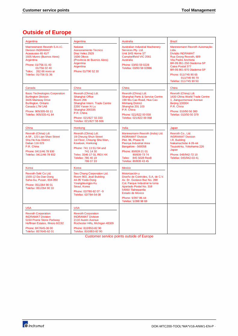
Customer service points Tool Management
DOK-MTC200-TOOL*MA*V16-ANW1-EN-P ·
Outside of EuropeArgentina
Mannesmann Rexroth S.A.I.C.Division INDRAMATAcassusso 48 41/71605 Munro (Buenos Aires)Argentina
Phone: 01/756 01 40 01/756 02 40Telex: 262 66 rexro arTelefax: 01/756 01 36
Argentina
NakaseAsesoramiento TecnicoDiaz Velez 29291636 Olivos(Provincia de Buenos Aires)ArgentinaArgentina
Phone 01/790 52 30
Australia
Australian Industrial MacheneryServices Pty. Ltd.Unit 3/45 Horne STCampbellfield VIC 2061Australia
Phone: 03/93 59 0228Telefax: 03/93 59 02886
Brazil
Mannesmann Rexroth AutomaçãoLtda.Divisão INDRAMATRua Georg Rexroth, 609Vila Padre AnchietaBR-09.951-250 Diadema-SPCaixa Postal 377BR-09.901-970 Diadema-SP
Phone: 011/745 90 65 011/745 90 70Telefax: 011/745 90 50
Canada
Basic Technologies CorporationBurlington Division3426 Mainway DriveBurlington, OntarioCanada L7M 1A8
Phone: 905/335-55 11Telefax: 905/335-41 84
China
Rexroth (China) Ldt.Shanghai OfficeRoom 206Shanghai Intern. Trade Centre2200 Yanan Xi LuShanghai 200335P.R. China
Phone: 021/627 55 333Telefax: 021/627 55 666
China
Rexroth (China) Ldt.Shanghai Parts & Service Centre199 Wu Cao Road, Hua CaoMinhang DistrictShanghai 201 103P.R. China
Phone: 021/622 00 058Telefax: 021/622 00 068
China
Rexroth (China) Ldt.1430 China World Trade Centre1, Jianguomenwai AvenueBeijing 100004P.R. China
Phone: 010/50 50 380Telefax: 010/50 50 379
China
Rexroth (China) Ldt.A-5F., 123 Lian Shan StreetSha He Kou DistrictDalian 116 023P.R. China
Phone: 0411/46 78 930Telefax: 0411/46 78 932
Honkong
Rexroth (China) Ldt.19 Cheung Shun Street1st Floor, Cheung Sha Wan,Kowloon, Honkong
Phone: 741 13 51/-54 und 741 14 30Telex: 3346 17 GL REX HXTelefax: 786 40 19 786 07 33
India
Mannesmann Rexroth (India) Ltd.INDRAMAT DivisionPlot. 96, Phase IIIPeenya Industrial AreaBangalore - 560058
Phone: 80/839 21 01 80/839 73 74Telex: 845 5028 RexBTelefax: 80/839 43 45
Japan
Rexroth Co., Ltd.INDRAMAT DivisionI.R. BuildingNakamachidai 4-26-44Tsuzuki-ku, Yokohama 226Japan
Phone: 045/942-72 10Telefax: 045/942-03 41
Korea
Rexroth-Seki Co Ltd.1500-12 Da-Dae-DongSaha-Gu, Pusan, 604-050
Phone: 051/264 90 01Telefax: 051/264 90 10
Korea
Seo Chang Corporation Ltd.Room 903, Jeail Building44-35 Yoido-DongYoungdeungpo-KuSeoul, Korea
Phone: 02/780-82 07 ~9Telefax: 02/784-54 08
Mexico
Motorización yDiseño de Controles, S.A. de C.V.Av. Dr. Gustavo Baz No. 288Col. Parque Industrial la IomaApartado Postal No. 31854060 TlalnepantlaEstado de Mexico
Phone: 5/397 86 44Telefax: 5/398 98 88
USA
Rexroth CorporationINDRAMAT Division5150 Prairie Stone ParkwayHoffman Estates, Illinois 60192
Phone: 847/645-36 00Telefax: 857/645-62 01
USA
Rexroth CorporationINDRAMAT Division2110 Austin AvenueRochester Hills, Michigan 48309
Phone: 810/853-82 90Telefax: 810/853-82 90
Customer service points outside of Europe

Tool Management Customer service points
DOK-MTC200-TOOL*MA*V16-ANW1-EN-P ·
Notes