MSO/DPO5000, DPO7000, DPO70000/B/C, DSA70000/B/C ...
921
xx MSO/DPO5000, DPO7000, DPO70000/B/C, DSA70000/B/C, and MSO70000 Series Digital Oscilloscopes ZZZ Programmer Manual *P077001010* 077-0010-10
-
Upload
khangminh22 -
Category
Documents
-
view
0 -
download
0
Transcript of MSO/DPO5000, DPO7000, DPO70000/B/C, DSA70000/B/C ...

xx
MSO/DPO5000, DPO7000, DPO70000/B/C, DSA70000/B/C,and MSO70000 SeriesDigital Oscilloscopes
ZZZ
Programmer Manual
*P077001010*
077-0010-10


MSO/DPO5000, DPO7000, DPO70000/B/C, DSA70000/B/C, andMSO70000 SeriesDigital Oscilloscopes
ZZZ
Programmer Manual
xx
www.tektronix.com077-0010-10

Copyright © Tektronix. All rights reserved. Licensed software products are owned by Tektronix or its subsidiariesor suppliers, and are protected by national copyright laws and international treaty provisions.
Tektronix products are covered by U.S. and foreign patents, issued and pending. Information in this publicationsupersedes that in all previously published material. Specifications and price change privileges reserved.
TEKTRONIX and TEK are registered trademarks of Tektronix, Inc.
FastFrame, OpenChoice, iView, Pinpoint, RT-Eye, MyScope, TekLink, TekVPI, MultiView Zoom, and DPXare trademarks of Tektronix, Inc.
MSO/DPO5000, DPO7000, DPO70000/B/C, DSA70000/B/C, and MSO70000 Series Programmer Online Help,076-0021-10
Contacting Tektronix
Tektronix, Inc.14150 SW Karl Braun DriveP.O. Box 500Beaverton, OR 97077USA
For product information, sales, service, and technical support:In North America, call 1-800-833-9200.Worldwide, visit www.tektronix.com to find contacts in your area.

Table of Contents
Preface . . . . . . . . . . . . . . . . . . . . . . . . . . . . . . . . . . . . . . . . . . . . . . . . . . . . . . . . . . . . . . . . . . . . . . . . . . . . . . . . . . . . . . . . . . . . . . . . . . . . . . . . . . . . . . iiiGetting Started . . . . . . . . . . . . . . . . . . . . . . . . . . . . . . . . . . . . . . . . . . . . . . . . . . . . . . . . . . . . . . . . . . . . . . . . . . . . . . . . . . . . . . . . . . . . . . . . . . . . 1-1
Setting Up Remote Communications. . . . . . . . . . . . . . . . . . . . . . . . . . . . . . . . . . . . . . . . . . . . . . . . . . . . . . . . . . . . . . . . . . . . . . 1-1Command Syntax. . . . . . . . . . . . . . . . . . . . . . . . . . . . . . . . . . . . . . . . . . . . . . . . . . . . . . . . . . . . . . . . . . . . . . . . . . . . . . . . . . . . . . . . . . . . . . . . . 2-1
Backus-Naur Form Notation . . . . . . . . . . . . . . . . . . . . . . . . . . . . . . . . . . . . . . . . . . . . . . . . . . . . . . . . . . . . . . . . . . . . . . . . . . . . . . . 2-1Command and Query Structure . . . . . . . . . . . . . . . . . . . . . . . . . . . . . . . . . . . . . . . . . . . . . . . . . . . . . . . . . . . . . . . . . . . . . . . . . . . . 2-1Clearing the Instrument . . . . . . . . . . . . . . . . . . . . . . . . . . . . . . . . . . . . . . . . . . . . . . . . . . . . . . . . . . . . . . . . . . . . . . . . . . . . . . . . . . . . . 2-3Command Entry. . . . . . . . . . . . . . . . . . . . . . . . . . . . . . . . . . . . . . . . . . . . . . . . . . . . . . . . . . . . . . . . . . . . . . . . . . . . . . . . . . . . . . . . . . . . . . 2-3Constructed Mnemonics . . . . . . . . . . . . . . . . . . . . . . . . . . . . . . . . . . . . . . . . . . . . . . . . . . . . . . . . . . . . . . . . . . . . . . . . . . . . . . . . . . . . 2-6Argument Types. . . . . . . . . . . . . . . . . . . . . . . . . . . . . . . . . . . . . . . . . . . . . . . . . . . . . . . . . . . . . . . . . . . . . . . . . . . . . . . . . . . . . . . . . . . . . . 2-7
Command Groups . . . . . . . . . . . . . . . . . . . . . . . . . . . . . . . . . . . . . . . . . . . . . . . . . . . . . . . . . . . . . . . . . . . . . . . . . . . . . . . . . . . . . . . . . . . . . . 2-11Acquisition Command Group .. . . . . . . . . . . . . . . . . . . . . . . . . . . . . . . . . . . . . . . . . . . . . . . . . . . . . . . . . . . . . . . . . . . . . . . . . . . 2-11Alias Command Group.. . . . . . . . . . . . . . . . . . . . . . . . . . . . . . . . . . . . . . . . . . . . . . . . . . . . . . . . . . . . . . . . . . . . . . . . . . . . . . . . . . . 2-12Bus Command Group .. . . . . . . . . . . . . . . . . . . . . . . . . . . . . . . . . . . . . . . . . . . . . . . . . . . . . . . . . . . . . . . . . . . . . . . . . . . . . . . . . . . . 2-13Calibration Command Group.. . . . . . . . . . . . . . . . . . . . . . . . . . . . . . . . . . . . . . . . . . . . . . . . . . . . . . . . . . . . . . . . . . . . . . . . . . . . 2-15Cursor Command Group .. . . . . . . . . . . . . . . . . . . . . . . . . . . . . . . . . . . . . . . . . . . . . . . . . . . . . . . . . . . . . . . . . . . . . . . . . . . . . . . . . 2-16Diagnostics Command Group .. . . . . . . . . . . . . . . . . . . . . . . . . . . . . . . . . . . . . . . . . . . . . . . . . . . . . . . . . . . . . . . . . . . . . . . . . . . 2-19Digital Command Group.. . . . . . . . . . . . . . . . . . . . . . . . . . . . . . . . . . . . . . . . . . . . . . . . . . . . . . . . . . . . . . . . . . . . . . . . . . . . . . . . . 2-20Display Control Command Group . . . . . . . . . . . . . . . . . . . . . . . . . . . . . . . . . . . . . . . . . . . . . . . . . . . . . . . . . . . . . . . . . . . . . . . 2-21E-mail Command Group .. . . . . . . . . . . . . . . . . . . . . . . . . . . . . . . . . . . . . . . . . . . . . . . . . . . . . . . . . . . . . . . . . . . . . . . . . . . . . . . . . 2-24Error Detector Command Group .. . . . . . . . . . . . . . . . . . . . . . . . . . . . . . . . . . . . . . . . . . . . . . . . . . . . . . . . . . . . . . . . . . . . . . . . 2-26File System Command Group .. . . . . . . . . . . . . . . . . . . . . . . . . . . . . . . . . . . . . . . . . . . . . . . . . . . . . . . . . . . . . . . . . . . . . . . . . . . 2-35Hard Copy Command Group .. . . . . . . . . . . . . . . . . . . . . . . . . . . . . . . . . . . . . . . . . . . . . . . . . . . . . . . . . . . . . . . . . . . . . . . . . . . . 2-36Histogram Command Group .. . . . . . . . . . . . . . . . . . . . . . . . . . . . . . . . . . . . . . . . . . . . . . . . . . . . . . . . . . . . . . . . . . . . . . . . . . . . 2-37Horizontal Command Group .. . . . . . . . . . . . . . . . . . . . . . . . . . . . . . . . . . . . . . . . . . . . . . . . . . . . . . . . . . . . . . . . . . . . . . . . . . . . 2-38Limit Test Command Group.. . . . . . . . . . . . . . . . . . . . . . . . . . . . . . . . . . . . . . . . . . . . . . . . . . . . . . . . . . . . . . . . . . . . . . . . . . . . . 2-42Low Speed Serial Trigger Command Group.. . . . . . . . . . . . . . . . . . . . . . . . . . . . . . . . . . . . . . . . . . . . . . . . . . . . . . . . . . . 2-43Mask Command Group . . . . . . . . . . . . . . . . . . . . . . . . . . . . . . . . . . . . . . . . . . . . . . . . . . . . . . . . . . . . . . . . . . . . . . . . . . . . . . . . . . . 2-49Math Command Group.. . . . . . . . . . . . . . . . . . . . . . . . . . . . . . . . . . . . . . . . . . . . . . . . . . . . . . . . . . . . . . . . . . . . . . . . . . . . . . . . . . . 2-54Measurement Command Group .. . . . . . . . . . . . . . . . . . . . . . . . . . . . . . . . . . . . . . . . . . . . . . . . . . . . . . . . . . . . . . . . . . . . . . . . . 2-56Miscellaneous Command Group .. . . . . . . . . . . . . . . . . . . . . . . . . . . . . . . . . . . . . . . . . . . . . . . . . . . . . . . . . . . . . . . . . . . . . . . . 2-60Save and Recall Command Group . . . . . . . . . . . . . . . . . . . . . . . . . . . . . . . . . . . . . . . . . . . . . . . . . . . . . . . . . . . . . . . . . . . . . . . 2-62Search and Mark Command Group .. . . . . . . . . . . . . . . . . . . . . . . . . . . . . . . . . . . . . . . . . . . . . . . . . . . . . . . . . . . . . . . . . . . . . 2-63Status and Error Command Group. . . . . . . . . . . . . . . . . . . . . . . . . . . . . . . . . . . . . . . . . . . . . . . . . . . . . . . . . . . . . . . . . . . . . . . 2-72TekLink Command Group .. . . . . . . . . . . . . . . . . . . . . . . . . . . . . . . . . . . . . . . . . . . . . . . . . . . . . . . . . . . . . . . . . . . . . . . . . . . . . . . 2-73Trigger Command Group .. . . . . . . . . . . . . . . . . . . . . . . . . . . . . . . . . . . . . . . . . . . . . . . . . . . . . . . . . . . . . . . . . . . . . . . . . . . . . . . . 2-75Vertical Command Group.. . . . . . . . . . . . . . . . . . . . . . . . . . . . . . . . . . . . . . . . . . . . . . . . . . . . . . . . . . . . . . . . . . . . . . . . . . . . . . . . 2-93Waveform Transfer Command Group . . . . . . . . . . . . . . . . . . . . . . . . . . . . . . . . . . . . . . . . . . . . . . . . . . . . . . . . . . . . . . . . . . . 2-98Zoom Command Group . . . . . . . . . . . . . . . . . . . . . . . . . . . . . . . . . . . . . . . . . . . . . . . . . . . . . . . . . . . . . . . . . . . . . . . . . . . . . . . . . . 2-104
MSO/DPO5000, DPO7000, DPO70000/B/C, DSA70000/B/C, and MSO70000 Series i

Table of Contents
Commands Listed in Alphabetical Order . . . . . . . . . . . . . . . . . . . . . . . . . . . . . . . . . . . . . . . . . . . . . . . . . . . . . . . . . . . . . . . . . . . 2-107Status and Events . . . . . . . . . . . . . . . . . . . . . . . . . . . . . . . . . . . . . . . . . . . . . . . . . . . . . . . . . . . . . . . . . . . . . . . . . . . . . . . . . . . . . . . . . . . . . . . . . 3-1
Registers . . . . . . . . . . . . . . . . . . . . . . . . . . . . . . . . . . . . . . . . . . . . . . . . . . . . . . . . . . . . . . . . . . . . . . . . . . . . . . . . . . . . . . . . . . . . . . . . . . . . . . 3-1*PSC Command .. . . . . . . . . . . . . . . . . . . . . . . . . . . . . . . . . . . . . . . . . . . . . . . . . . . . . . . . . . . . . . . . . . . . . . . . . . . . . . . . . . . . . . . . . . . . 3-4Queues . . . . . . . . . . . . . . . . . . . . . . . . . . . . . . . . . . . . . . . . . . . . . . . . . . . . . . . . . . . . . . . . . . . . . . . . . . . . . . . . . . . . . . . . . . . . . . . . . . . . . . . . 3-4Event Handling Sequence. . . . . . . . . . . . . . . . . . . . . . . . . . . . . . . . . . . . . . . . . . . . . . . . . . . . . . . . . . . . . . . . . . . . . . . . . . . . . . . . . . . 3-5Synchronization Methods . . . . . . . . . . . . . . . . . . . . . . . . . . . . . . . . . . . . . . . . . . . . . . . . . . . . . . . . . . . . . . . . . . . . . . . . . . . . . . . . . . . 3-6
Appendix A: Character Set . . . . . . . . . . . . . . . . . . . . . . . . . . . . . . . . . . . . . . . . . . . . . . . . . . . . . . . . . . . . . . . . . . . . . . . . . . . . . . . . . . . . . A-1Appendix B: Reserved Words . . . . . . . . . . . . . . . . . . . . . . . . . . . . . . . . . . . . . . . . . . . . . . . . . . . . . . . . . . . . . . . . . . . . . . . . . . . . . . . . . . B-1Appendix C: Factory Default Setup Values. . . . . . . . . . . . . . . . . . . . . . . . . . . . . . . . . . . . . . . . . . . . . . . . . . . . . . . . . . . . . . . . . . . C-1
Default Setup .. . . . . . . . . . . . . . . . . . . . . . . . . . . . . . . . . . . . . . . . . . . . . . . . . . . . . . . . . . . . . . . . . . . . . . . . . . . . . . . . . . . . . . . . . . . . . . . C-1Appendix D: GPIB Interface Specifications . . . . . . . . . . . . . . . . . . . . . . . . . . . . . . . . . . . . . . . . . . . . . . . . . . . . . . . . . . . . . . . . . . D-1
Interface Messages . . . . . . . . . . . . . . . . . . . . . . . . . . . . . . . . . . . . . . . . . . . . . . . . . . . . . . . . . . . . . . . . . . . . . . . . . . . . . . . . . . . . . . . . . D-1GPIB Functions . . . . . . . . . . . . . . . . . . . . . . . . . . . . . . . . . . . . . . . . . . . . . . . . . . . . . . . . . . . . . . . . . . . . . . . . . . . . . . . . . . . . . . . . . . . . . D-1
GlossaryIndex
ii MSO/DPO5000, DPO7000, DPO70000/B/C, DSA70000/B/C, and MSO70000 Series

PrefaceThis programmer manual provides you with the information required to useProgrammable Interface commands for remotely controlling your instrument.
Documentation Quick Start User Manual. The user manual has information aboutinstalling and operating the instrument. It also provides concepts andtheories about using the instrument that are not covered in the online help.Online Help. This is an online help system that is integrated with the UserInterface application that ships with this product. The online help providesin-depth operation and user interface help.Getting Started with OpenChoice ™ Solutions Manual. A book thatexplores some options for getting data from your instrument into any oneof several available analysis tools.Specifications and Performance Verification. Instrument specificationsand a performance verification procedure.TekVISA Programmer Manual. The manual describes TekVISA, theTektronix implementation of the VISA Application Programming Interface(API). TekVISA is industry-compliant software for writing interoperableinstrument drivers in a variety of Application Development Environments(ADEs).Other Included Documentation. Installation booklets are included in theProduct Software and Operating System Restore Software packages.Service Manual. The service manual includes procedures to service theinstrument to the module level.
MSO/DPO5000, DPO7000, DPO70000/B/C, DSA70000/B/C, and MSO70000 Series iii

Preface
The programmer guide is divided into the following major topics:
Getting Started. This topic introduces you to the programming informationand provides basic information about setting up your instrument for remotecontrol.
Command Groups. This topic contains all the commands listed in functionalgroups. Each group consists of an overview of the commands in that group anda table that lists all the commands and queries for that group. You can click acommand in the listing to display a detailed description of the command.
Command Syntax. This topic provides an overview of the command syntaxthat you use to communicate with the instrument and other general informationabout commands, such as how commands and queries are constructed, how toenter commands, constructed mnemonics, and argument types.
Status and Events. This topic discusses the status and event reporting systemfor the GPIB interfaces. This system informs you of certain significant eventsthat occur within the instrument. Topics that are discussed include registers,queues, event handling sequences, synchronization methods, and messagesthat the instrument may return, including error messages.
Miscellaneous. This topic contains miscellaneous information, such as alist of reserved words, a table of the factory initialization (default) settings,and interface specifications that may be helpful when using commands toremotely control the instrument.
iv MSO/DPO5000, DPO7000, DPO70000/B/C, DSA70000/B/C, and MSO70000 Series

Getting StartedThis programmer guide provides you with the information required to useProgrammable Interface commands for remotely controlling your instrument.With this information, you can write computer programs that will performfunctions such as setting the front panel controls, taking measurements,performing statistical calculations, and exporting data for use in other programs,such as spreadsheets.
In addition to the traditional GPIB electronic interface (referred to as the physicalGPIB interface), your instrument is provided with a TekVISA GPIB-compatibleinterface (referred to as the virtual GPIB interface). This is a software ApplicationProgramming Interface (API) which enables you to communicate with theinstrument in a variety of ways, including via the Internet. With the following twoexceptions, these interfaces are completely independent:
HEADER. Command headers enabled or disabled on one interface arecorrespondingly enabled or disabled on the other interface. Refer to thecommand descriptions for more detailed information.
VERBOSE. Verbosity enabled or disabled on one interface is correspondinglyenabled or disabled on the other interface. Refer to the command descriptionfor more detailed information.
Most examples in this document require that both HEADER and VERBOSE are ON.
Refer to Documentation for information on related manuals and documents.
Setting Up Remote CommunicationsOn MSO/DPO5000 Series instruments only: The instruments require aTEK-USB-488 adapter. You can remotely communicate between youroscilloscope and PC via Ethernet, USB, and GPIB.
MSO/DPO5000, DPO7000, DPO70000/B/C, DSA70000/B/C, and MSO70000 Series 1-1

Getting Started
To use Ethernet, start by connecting an appropriate Ethernet cable to theEthernet port (RJ-45 connector) on the rear panel of your oscilloscope. Thisconnects the oscilloscope to a 10/100/1000 Base-T local area network.
To use USB, start by connecting an appropriate USB cable to the USBdevice port on the rear panel of your oscilloscope. With USB, the systemautomatically configures itself.
To use GPIB, start by connecting an appropriate USB cable to the USBdevice port on the rear panel of your oscilloscope. Connect the other end tothe TEK-USB-488 adapter host port. Then connect a GPIB cable from theTEK-USB-488 adapter to your PC or other GPIB-enabled instrument. You canapply power to the TEK-USB-488 adapter in one of the following two ways.
With an appropriate power supply connected to wall power and the adapter.
By connecting a USB cable to a Host port on the oscilloscope and thedevice (B type) connector on the adapter. Without a power connection theadapter will not function properly.
Before setting up the instrument for remote communications using the electronic(physical) GPIB interface, you should familiarize yourself with the followingGPIB requirements:
A unique device address must be assigned to each device on the bus. No twodevices can share the same device address.
No more than 15 devices can be connected to any one line.
One device should be connected for every 6 feet (2 meters) of cable used.
No more than 65 feet (20 meters) of cable should be used to connect devicesto a bus.
At least two-thirds of the devices on the network should be powered on whileusing the network.
Connect the devices on the network in a star or linear configuration. Do notuse loop or parallel configurations.
Connecting to theInstrument
Your instrument has a 24-pin GPIB connector. (this connector is available on allinstruments except MSO/DPO5000 Series instruments) on its rear (side) panel.This connector has a D-type shell and conforms to IEEE Std 488.1¾1987. Attachan IEEE Std 488.1¾1987 GPIB cable to this connector and to your controller asshown in the following figure:
1-2 MSO/DPO5000, DPO7000, DPO70000/B/C, DSA70000/B/C, and MSO70000 Series

Getting Started
If necessary, the GPIB connectors can be stacked as shown in the following figure:
Setting the GPIB Address To function correctly, your instrument must have a unique device address. Thedefault settings for the GPIB configuration are:
GPIB Address 1.
GPIB Mode Talk/Listen
To change either of the GPIB settings, do the following:
1. Select GPIB Configuration from the Utilities menu.
MSO/DPO5000, DPO7000, DPO70000/B/C, DSA70000/B/C, and MSO70000 Series 1-3

Getting Started
2. Click the Configuration Talk/Listen button.
The following screen appears on MSO/DPO5000 Series instruments:
3. Change the GPIB Address to a unique address.
4. Click the Close button.
The instrument is now set up for bidirectional communication with your controller.
1-4 MSO/DPO5000, DPO7000, DPO70000/B/C, DSA70000/B/C, and MSO70000 Series

Command SyntaxYou can control the operations and functions of the instrument using variousmeans of communication depending on the instrument through the use ofcommands and queries. The following related topics listed describe the syntax ofthese commands and queries. The topics also describe the conventions that theinstrument uses to process them. See the Command Groups topic in the tableof contents for a listing of the commands by command group, or use the indexto locate a specific command.
Backus-Naur Form NotationThis documentation describes the commands and queries using Backus-NaurForm (BNF) notation. Refer to the following table for the symbols that are used.
Table 2-1: Symbols for Backus-Naur Form
Symbol Meaning< > Defined element::= Is defined as| Exclusive OR Group; one element is required[ ] Optional; can be omitted. . . Previous element(s) may be repeated( ) Comment
Command and Query StructureCommands consist of set commands and query commands (usually calledcommands and queries). Commands modify instrument settings or tell theinstrument to perform a specific action. Queries cause the instrument to returndata and status information.
Most commands have both a set form and a query form. The query form of thecommand differs from the set form by its question mark on the end. For example,the set command ACQuire:MODe has a query form ACQuire:MODe?. Not allcommands have both a set and a query form. Some commands have set only andsome have query only.
Messages A command message is a command or query name followed by any informationthe instrument must execute the command or query. Command messages maycontain five element types, defined in the following table.
MSO/DPO5000, DPO7000, DPO70000/B/C, DSA70000/B/C, and MSO70000 Series 2-1

Command Syntax
Table 2-2: Command Message Elements
Symbol Meaning<Header> This is the basic command name. If the header ends with a question
mark, the command is a query. The header may begin with a colon(:) character. If the command is concatenated with other commands,the beginning colon is required. Never use the beginning colon withcommand headers beginning with a asterisk (*).
<Mnemonic> This is a header subfunction. Some command headers have only onemnemonic. If a command header has multiple mnemonics, a colon (:)character always separates them from each other.
<Argument> This is a quantity, quality, restriction, or limit associated with the header.Some commands have no arguments while others have multiplearguments. A <space> separates arguments from the header. A<comma> separates arguments from each other.
<Comma> A single comma is used between arguments of multiple-argumentcommands. Optionally, there may be white space characters beforeand after the comma.
<Space> A white space character is used between a command header and therelated argument. Optionally, a white space may consist of multiplewhite space characters.
Commands Commands cause the instrument to perform a specific function or change one ofthe settings. Commands have the structure:
[:]<Header>[<Space><Argument>[<Comma> <Argument>]...]
A command header consists of one or more mnemonics arranged in a hierarchicalor tree structure. The first mnemonic is the base or root of the tree and eachsubsequent mnemonic is a level or branch off the previous one. Commands at ahigher level in the tree may affect those at a lower level. The leading colon (:)always returns you to the base of the command tree.
Queries Queries cause the instrument to return status or setting information. Querieshave the structure:
[:]<Header>?
[:]<Header>?[<Space><Argument> [<Comma><Argument>]...]
You can specify a query command at any level within the command tree unlessotherwise noted. These branch queries return information about all the mnemonicsbelow the specified branch or level. For example, HIStogram:STATistics:STDdev?returns the standard deviation of the histogram, while HIStogram:STATistics?returns all the histogram statistics, and HIStogram? returns all the histogramparameters.
2-2 MSO/DPO5000, DPO7000, DPO70000/B/C, DSA70000/B/C, and MSO70000 Series

Command Syntax
Headers You can control whether the instrument returns headers as part of the queryresponse. Use the HEADer command to control this feature. If header is on,the query response returns command headers, then formats itself as a valid setcommand. When header is off, the response includes only the values. This maymake it easier to parse and extract the information from the response. Thefollowing table shows the difference in responses.
Table 2-3: Comparison of Header Off and Header On Responses
Query Header Off Header OnTIME? ”14:30:00” :TIME”14:30:00”ACQuire:NUMAVg? 100 :ACQUIRE:NUMAVG 100
Clearing the InstrumentYou can clear the Output Queue and reset the instrument to accept a newcommand or query by using the selected Device Clear (DCL) GPIB function.Refer to your GPIB library documentation for further details about the selectedDevice Clear operation.
Command EntryThe following rules apply when entering commands:
You can enter commands in upper or lower case.
You can precede any command with white space characters. White spacecharacters include any combination of the ASCII control characters 00 through09 and 0B through 20 hexadecimal (0 through 9 and 11 through 32 decimal).
The instrument ignores commands consisting of any combination of whitespace characters and line feeds.
Abbreviating You can abbreviate many instrument commands. Each command in thisdocumentation shows the abbreviations in capitals. For example, you can enterthe command ACQuire:NUMAvg simply as ACQ:NUMA or acq:numa.
Abbreviation rules may change over time as new instrument models areintroduced. Thus, for the most robust code, use the full spelling.
MSO/DPO5000, DPO7000, DPO70000/B/C, DSA70000/B/C, and MSO70000 Series 2-3

Command Syntax
If you use the HEADer command to have command headers included as partof query responses, you can further control whether the returned headers areabbreviated or are full-length with the VERBose command.
Concatenating You can concatenate any combination of set commands and queries using asemicolon (;). The instrument executes concatenated commands in the orderreceived.
2-4 MSO/DPO5000, DPO7000, DPO70000/B/C, DSA70000/B/C, and MSO70000 Series

Command Syntax
When concatenating commands and queries, you must follow these rules:
1. Separate completely different headers by a semicolon and by the beginningcolon on all commands except the first one. For example, the commandsTRIGger:MODe NORMal and ACQuire:NUMAVg 10, can be concatenatedinto the following single command:
TRIGger:MODe NORMal;:ACQuire:NUMAVg 10
2. If concatenated commands have headers that differ by only the last mnemonic,you can abbreviate the second command and eliminate the beginning colon.For example, you can concatenate the commands ACQuire:MODe ENVelope
and ACQuire:NUMAVg 10 into a single command:
ACQuire:MODe ENVelope; NUMAVg 10
The longer version works equally well:
ACQuire:MODe ENVelope;:ACQuire:NUMAVg 10
3. Never precede a star (*) command with a colon:
ACQuire:MODe ENVelope;*OPC
Any commands that follow will be processed as if the star command was notthere so the commands, ACQuire:MODe ENVelope;*OPC;NUMAVg 10 willset the acquisition mode to envelope and set the number of acquisitions foraveraging to 10.
4. When you concatenate queries, the responses to all the queries areconcatenated into a single response message. For example, if the displayimageview color is temperature and the display recordview color is spectral,the concatenated query DISplay:COLOr:PALETTE:IMAGEVIEW?;RECORDVIEW? will return the following.
If the header is on:
:DISPLAY:COLOR:PALETTE:IMAGEVIEW TEMPERATURE;
:DISPLAY:COLOR:PALETTE:RECORDVIEW SPECTRAL
If the header is off:
TEMPERATURE;SPECTRAL
5. Set commands and queries may be concatenated in the same message. Forexample,
ACQuire:MODe SAMple;NUMAVg?;STATE?
is a valid message that sets the acquisition mode to sample. The message thenqueries the number of acquisitions for averaging and the acquisition state.Concatenated commands and queries are executed in the order received.
Here are some invalid concatenations:
MSO/DPO5000, DPO7000, DPO70000/B/C, DSA70000/B/C, and MSO70000 Series 2-5

Command Syntax
DISplay:PERSistance:RESET;ACQuire:NUMAVg 10 (no colon beforeACQuire)
DISplay:GRAticule FULl;:FILTer SINX (extra colon before FILTer; useDISplay:GRAticule FULl;FILTer SINX instead)
DISplay:PERSistance:RESET;:*OPC (colon before a star (*) command)
DISplay:COLOr:MATHCOLOr DEFAULT;COLOr:REFCOLOr INHERIT (levelsof the mnemonics are different; either remove the second use of COLor or place:DISPlay: in front of COLOr:REFCOLOr INHERIT)
Terminating This documentation uses <EOM> (End of message) to represent a messageterminator.
Table 2-4: End of Message Terminator
Symbol Meaning<EOM> Message terminator
The end-of-message terminator must be the END message (EOI assertedconcurrently with the last data byte). The last data byte may be an ASCII linefeed(LF) character.
This instrument does not support ASCII LF only message termination. Theinstrument always terminates outgoing messages with LF and EOI.
Constructed MnemonicsSome header mnemonics specify one of a range of mnemonics. For example, achannel mnemonic can be CH1, CH2, CH3, or CH4. You use these mnemonicsin the command just as you do any other mnemonic. For example, there is aCH1:POSition command, and there is also a CH2:POSition command. In thecommand descriptions, this list of choices is abbreviated as CH<x>.
Cursor PositionMnemonics
When cursors are displayed, commands may specify which cursor of the pair touse.
Table 2-5: Cursor Mnemonics
Symbol MeaningCURSOR<x> A cursor selector; <x> is either 1 or 2.POSITION<x> A cursor selector; <x> is either 1 or 2.HPOS<x> A cursor selector; <x> is either 1 or 2.
2-6 MSO/DPO5000, DPO7000, DPO70000/B/C, DSA70000/B/C, and MSO70000 Series

Command Syntax
Math Specifier Mnemonics Commands can specify the mathematical waveform to use as a mnemonic inthe header.
Table 2-6: Math Specifier Mnemonics
Symbol MeaningMath<x> A math waveform specifier; <x> is 1 through 4.
Measurement SpecifierMnemonics
Commands can specify which measurement to set or query as a mnemonic in theheader. Up to eight automated measurements may be displayed.
Table 2-7: Measurement Specifier Mnemonics
Symbol MeaningMEAS<x> A measurement specifier; <x> is 1 through 8.
Channel Mnemonics Commands specify the channel to use as a mnemonic in the header.
Table 2-8: Channel Mnemonics
Symbol MeaningCH<x> A channel specifier; <x> is 1 through 4.
Reference WaveformMnemonics
Commands can specify the reference waveform to use as a mnemonic in theheader.
Table 2-9: Reference Waveform Mnemonics
Symbol MeaningREF<x> A reference waveform specifier; <x> is 1 thru 4.
Argument TypesNumeric Many instrument commands require numeric arguments. The syntax shows the
format that the instrument returns in response to a query. This is also the preferredformat when sending the command to the instrument though any of the formatswill be accepted. This documentation represents these arguments as follows:
Table 2-10: Numeric Arguments
Symbol Meaning<NR1> Signed integer value<NR2> Floating point value without an exponent<NR3> Floating point value with an exponent
MSO/DPO5000, DPO7000, DPO70000/B/C, DSA70000/B/C, and MSO70000 Series 2-7

Command Syntax
Most numeric arguments will be automatically forced to a valid setting, either byrounding or truncating, when an invalid number is input unless otherwise notedin the command description.
Quoted String Some commands accept or return data in the form of a quoted string, which issimply a group of ASCII characters enclosed by a single quote (’) or double quote("). The following is an example of a quoted string: "This is a quoted
string". This documentation represents these arguments as follows:
Table 2-11: Quoted String Argument
Symbol Meaning<QString> Quoted string of ASCII text
A quoted string can include any character defined in the 7-bit ASCII characterset. Follow these rules when you use quoted strings:
1. Use the same type of quote character to open and close the string. Forexample: "this is a valid string".
2. You can mix quotation marks within a string if you follow the previous rule.For example, "this is an ’acceptable’ string".
3. You can include a quote character within a string by repeating the quote. Forexample: "here is a "" mark".
4. Strings can have upper or lower case characters.
5. If you use a GPIB network, you cannot terminate a quoted string with theEND message before the closing delimiter.
6. A carriage return or line feed embedded in a quoted string does not terminatethe string, but is treated as just another character in the string.
7. The maximum length of a quoted string returned from a query is 255characters.
Here are some invalid strings:
"Invalid string argument’ (quotes are not of the same type)
"test<EOI>" (termination character is embedded in the string)
Block Several instrument commands use a block argument form (see the following table).
Table 2-12: Block Argument
Symbol Meaning<NZDig> A nonzero digit character in the range of 1–9<Dig> A digit character, in the range of 0–9
2-8 MSO/DPO5000, DPO7000, DPO70000/B/C, DSA70000/B/C, and MSO70000 Series

Command Syntax
Table 2-12: Block Argument (cont.)
Symbol Meaning<DChar> A character with the hexadecimal equivalent of 00 through FF (0
through 255 decimal)<Block> A block of data bytes defined as: <Block> ::=
#<NZDig><Dig>[<Dig>...][<DChar>...]|#0[<DChar>...]<terminator>
<NZDig> specifies the number of <Dig> elements that follow. Taken together,the <NZDig> and <Dig> elements form a decimal integer that specifies howmany <DChar> elements follow.
NOTE. The digit <NZDig> is in hexadecimal format. This deviates slightly fromthe IEEE 488.2 specification that it be in decimal format, as extra allowancesmust be made for data lengths that are greater than 999,999,999 <DChar>elements (for example 500M record lengths at 2 bytes per point).
MSO/DPO5000, DPO7000, DPO70000/B/C, DSA70000/B/C, and MSO70000 Series 2-9

Command Syntax
2-10 MSO/DPO5000, DPO7000, DPO70000/B/C, DSA70000/B/C, and MSO70000 Series

Command GroupsThe programmable interface conforms to Tektronix standard codes and formatsexcept where noted. The GPIB interface also conforms to IEEE Std 488.2-1987except where noted.
Acquisition Command GroupUse the commands in the Acquisition Command Group to set up the modes andfunctions that control how the instrument acquires the signals you input to thechannels and processes them into waveforms.
Using these commands for acquiring waveforms, you can do the following:
Start and stop acquisitions.
Control whether each waveform is simply acquired, averaged, or envelopedover successive acquisitions of that waveform.
Set the controls or conditions that start and stop acquisitions.
Determine the action the system takes upon completing an acquisition, suchas saving all waveforms and taking a measurement when the acquisition isstopped.
Control acquisition of acquired channel waveforms.
Set acquisition parameters.
Table 2-13: Acquisition commands
Command DescriptionACQuire:INTERPEightbit Sets or queries the interpolation acquisition
modeACQuire:MAGnivu Sets or queries the MagniVu feature
NOTE. This programmer manualsupports many oscilloscope modelsfrom Tektronix. This feature is onlyavailable on some models.
ACQuire:MODe Sets or queries acquisition modeACQuire:NUMFRAMESACQuired? Returns the number of acquisitions that have
occurredACQuire:NUMACq? Returns the number of waveform acquisitions
that have occurred since starting acquisitionwith the ACQuire:STATE RUN command
ACQuire:NUMAVg Sets or queries number of acquisitions for anaveraged waveform
MSO/DPO5000, DPO7000, DPO70000/B/C, DSA70000/B/C, and MSO70000 Series 2-11

Command Groups
Table 2-13: Acquisition commands (cont.)
Command DescriptionACQuire:NUMEnv Sets or queries number of acquisitions for
envelope waveformACQuire:NUMSAMples Sets or queries the number of samples that
make up a WfmDB for single sequencemode and Mask Pass/Fail Completion Test
ACQuire:SAMPlingmode Sets or queries the sampling modeACQuire:STATE Starts, stops, or returns acquisition stateACQuire:STOPAfter Sets or queries whether the acquisition is
continuous or single sequenceFASTAcq? Enables, disables, or returns state of Fast
Acquisition modeFASTAcq:HIACQRATE Sets or queries the state of FastAcq
optimization for capturing the details with ahigher sample rate
FASTAcq:STATE Returns the Fast Acquisition state
Alias Command GroupAlias commands allow you to define new commands as a sequence of standardcommands. You may find this useful when repeatedly using the same commandsto perform certain tasks like setting up measurements.
Aliases are similar to macros but do not include the capability to substituteparameters into alias bodies. The alias mechanism obeys the following rules:
The alias name must consist of a valid IEEE 488.2 message unit, which maynot appear in a message preceded by a colon, comma, or a command or queryprogram header.
The alias name may not appear in a message followed by program date, acolon, comma, or question mark.
An alias name must be distinct from any keyword or keyword short form.
An alias name cannot be redefined without first being deleted using one ofthe alias deletion functions.
Alias names do not appear in response messages.
The Alias commands are defined in Tektronix Standard Codes and Formats.Deviations between that standard and what is specified here will be considerederrors unless specifically noted in the command description in this document.
2-12 MSO/DPO5000, DPO7000, DPO70000/B/C, DSA70000/B/C, and MSO70000 Series

Command Groups
Table 2-14: Alias commands
Command DescriptionALIas Sets or queries the alias stateALIas:CATalog? Returns a list of the currently defined alias
labelsALIas:DEFine Assigns a sequence of program messages
to an alias labelALIas:DELEte Removes a specified aliasALIas:DELEte:ALL Deletes all existing aliasesALIas:DELEte:NAMe Removes a specified aliasALIas:STATE Sets or queries the alias state
Bus Command Group
NOTE. This programmer manual supports many oscilloscope models fromTektronix. This feature is only available on some models.
Use the commands in the Bus Command Group to configure a bus. Thesecommands let you:
Specify the bus type
Specify the digital signals to be used in the bus
Specify its display style
Bus Mnemonics Commands specify the bus to use as a mnemonic in the header.
Table 2-15: Bus mnemonics
Symbol MeaningB<x> A bus specifier; <x> is 1 through 16.
Table 2-16: Bus commands
Command DescriptionBUS:B<x>:DISplay:DECOde:FILe Sets or queries the symbol table file for the
specified busBUS:B<x>:DISplay:DECOde:STAte Sets or queries if the specified bus is enabled
to display symbolic decode of its busformvalues or not
MSO/DPO5000, DPO7000, DPO70000/B/C, DSA70000/B/C, and MSO70000 Series 2-13

Command Groups
Table 2-16: Bus commands (cont.)
Command DescriptionBUS:B<x>:DISplay:FORMat Sets or queries the format for displaying
numeric values in the ’bus’ waveform of thespecified bus
BUS:B<x>:DISplay:TYPe Sets or queries the display style for thespecified bus
BUS:B<x>:I2C:CLOCk:SOUrce Sets or queries the I2C clock (SCLK) sourcefor the specified bus
BUS:B<x>:I2C:DATa:SOUrce Sets or queries the I2C data (SDA) sourcefor the specified bus
BUS:B<x>:I2C:RWINADDR Determines whether decoded I2C slaveaddresses are pure seven-bit values, or havethe R/W* combined with them
BUS:B<x>:LABel Sets or queries the waveform label for thespecified bus
BUS:B<x>:PARallel:CLOCk:EDGE Determines which edges of its clock signalcause a clocked parallel bus to sample newstates
BUS:B<x>:PARallel:CLOCk:SOUrce Sets or queries the Parallel clock source forthe specified bus
BUS:B<x>:PARallel:ISCLOCKED Determines whether the bus operates in aclocked or asynchronous fashion
BUS:B<x>:PARallel:SOURCES Sets or queries the member signals for theParallel mode of the bus to or reports themas an MSB-to-LSB ordered list
BUS:B<x>:POSition Sets or queries the position waveform for thespecified bus
BUS:B<x>:RS232c:BITRate Sets or queries the RS-232 bit rate for thespecified bus
BUS:B<x>:RS232c:DATABits Sets or queries the number of RS-232 databits for the specified bus
BUS:B<x>:RS232c:DELIMiter Sets or queries the RS-232 delimiting valuefor a packet on the specified bus
BUS:B<x>:RS232c:DISplaymode Sets or queries the display mode for thespecified bus
BUS:B<x>:RS232c:PARity Sets or queries the RS-232 parity for thespecified bus
BUS:B<x>:RS232c:POLarity Sets or queries the RS-232 polarity for thespecified bus
BUS:B<x>:RS232c:SOUrce Sets or queries the RS-232 polarity for thespecified bus
BUS:B<x>:SPI:BITOrder Sets or queries the shift direction used tode-serialize data for the SPI mode of the bus
2-14 MSO/DPO5000, DPO7000, DPO70000/B/C, DSA70000/B/C, and MSO70000 Series
Command Groups
Table 2-16: Bus commands (cont.)
Command DescriptionBUS:B<x>:SPI:CLOCk:POLarity Sets or queries the SPI clock (SCLK) polarity
for the specified busBUS:B<x>:SPI:CLOCk:SOUrce Sets or queries the SPI clock (SCLK) source
for the specified busBUS:B<x>:SPI:DATa:POLarity Sets or queries the SPI data (DATA) polarity
for the specified busBUS:B<x>:SPI:DATa:SIZE Sets or queries the number of bits per word
for the specified busBUS:B<x>:SPI:DATa:SOUrce Sets or queries the SPI data (DATA) source
for the specified busBUS:B<x>:SPI:SELect:POLarity Sets or queries the SPI Slave Select (SS)
polarity for the specified busBUS:B<x>:SPI:SELect:SOUrce Sets or queries the SPI Slave Select (SS)
source for the specified busBUS:B<x>:TYPe Sets or queries the bus type specifiedBUS:B<x>:USB:BITRate Sets or queries the USB bit rate for the
specified busBUS:B<x>:USB:PRObe Sets or queries the type of probe connected
to the USB signal for the specified busBUS:B<x>:USB:SOUrce Sets or queries the USB Data Source for the
specified busBUS:B<x>:USB:SOUrce:DMINus Sets or queries the USB Data Source for D-
input for the specified busBUS:B<x>:USB:SOUrce:DPLUs Sets or queries the USB Data Source for D+
input for the specified busSELect:B<x> Sets or queries the display state for the
specified bus
Calibration Command GroupThe Calibration commands provide information about the current state ofinstrument calibration and allow you to initiate internal signal path calibration(SPC). You can also order a printed copy (see Recommended Accessories in theonline help for the instrument).
Table 2-17: Calibration commands
Command DescriptionCALibrate? Returns the internal and factory calibration
status
MSO/DPO5000, DPO7000, DPO70000/B/C, DSA70000/B/C, and MSO70000 Series 2-15

Command Groups
Table 2-17: Calibration commands (cont.)
Command Description*CAL? Instructs the instrument to perform
self-calibration and returns the calibrationstatus when complete
CALibrate:CALProbe:CH<x>? Performs a probe calibration for the selectedchannel and returns the calibration status
CALibrate:INTERNal Starts the internal signal path calibrationCALibrate:INTERNal:STARt Starts the internal signal path calibrationCALibrate:INTERNal:STATus? Returns the current status of the internal
signal path calibrationCALibrate:PRObestate:CH<x>? Returns the probe calibration status for the
probe of the selected channelCALibrate:RESults? Returns the status of all calibration
subsystems without performing an SPCoperation
CALibrate:RESults:SPC? Returns the results of the last SPC operation
Cursor Command GroupUse the commands in the Cursor Command Group to control the cursor displayand readout. You can use these commands to control the setups for cursor 1 andcursor 2, such as waveform source, cursor position, and cursor color.
2-16 MSO/DPO5000, DPO7000, DPO70000/B/C, DSA70000/B/C, and MSO70000 Series

Command Groups
You can also use the commands to select one of the following cursor functions:
Off. Shuts off the display of all cursors.
Vertical Bars. Displays vertical bar cursors, which provide traditionalhorizontal unit readouts for Cursor 1 (bar1), Cursor 2 (bar2), the delta betweenthem, and 1/delta (results in frequency when the horizontal unit is time).
Horizontal Bars. Displays horizontal bar cursors, which provide traditionalvertical unit readouts for Cursor 1 (bar1), Cursor 2 (bar2), and the deltabetween them.
Waveform Cursors. Consists of two cursors you can independently assign toa waveform. These cursors provide the same readouts that the vertical andhorizontal bar cursors provide. Waveform cursors enable you to convenientlymeasure waveform amplitude and time. In XY or XYZ format, waveformcursors indicate the amplitude position of an XY pair (Ch1 vs Ch2 voltage,where Ch1 is the X axis and Ch2 is the Y axis) relative to the trigger.
Screen Cursors. Consists of two pairs of independent horizontal and verticalcursors. You can use these cursors to indicate an arbitrary position withinthe waveform display area. Screen cursors, depending on the style selected,consist of the intersection of a vertical and horizontal line, an X, or a verticalline with an X. These cursors have no association with any waveform, otherthan they inherit the color of the waveform they are assigned too.
Table 2-18: Cursor commands
Command DescriptionCURSor? Returns all cursor settingsCURSor:FUNCtion Sets or queries the cursor typeCURSor:HBArs? Returns hbar cursor settingsCURSor:HBArs:DELTa? Returns hbars cursors vertical differenceCURSor:HBArs:POSITION<x> Sets or queries the hbar cursor<x> vertical
positionCURSor:HBArs:UNIts? Returns hbar cursor unitsCURSor:LINESTyle Sets or queries the cursor line styleCURSor:MODe Sets or queries whether cursors move in
unison or separatelyCURSor:SCREEN:STYle Sets or queries the cursor type for screen
modeCURSor:SCREEN:XPOSITION<x> Sets or queries the x position of the specified
screen cursorCURSor:SCREEN:YPOSITION<x> Sets or queries the y position of the specified
screen cursorCURSor:SOUrce<x> Sets or queries the source for cursor <x>CURSor:STATE Turns cursors on or off or returns their state
MSO/DPO5000, DPO7000, DPO70000/B/C, DSA70000/B/C, and MSO70000 Series 2-17
Command Groups
Table 2-18: Cursor commands (cont.)
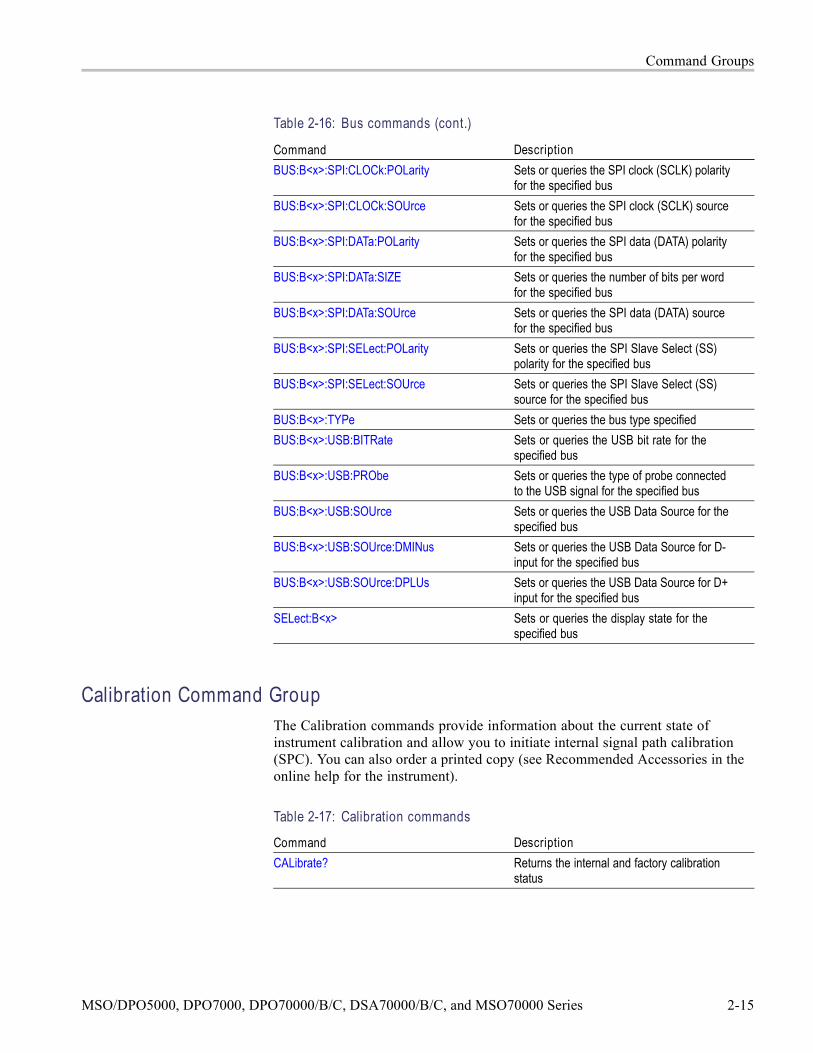
Command DescriptionCURSor:VBArs Sets or queries the position of vertical bar
cursorsCURSor:VBArs:DELTa? Returns the difference between vbar cursorsCURSor:VBArs:POSITION<x> Sets or queries the vbar cursor<x> horizontal
positionCURSor:VBArs:POS<x> Sets or queries the horizontal position for
vertical bar cursorsCURSor:VBArs:UNIts Sets or queries the units for vbar cursorsCURSor:WAVEform Sets or queries the current settings for
waveform cursorsCURSor:WAVEform:HDELTA? Returns the horizontal difference between
waveform cursorsCURSor:WAVEform:HPOS<x>? Returns the position of waveform cursor <x>CURSor:WAVEform:POSition<x> Sets or queries the position of waveform
cursor <x>CURSor:WAVEform:STYle Sets or queries the cursor type for waveform
modeCURSor:WAVEform:UNIts Sets or queries the units for waveform
cursorsCURSor:WAVEform:VDELTA? Returns the vertical difference between
waveform cursorsCURSor:XY? Returns the current settings for XY cursorsCURSor:XY:PRODDELta? Returns the product of the difference
between the cursors X positions and Ypositions
CURSor:XY:PRODUCT<x>? Returns the product of the X and Y positionsfor the specified cursor
CURSor:XY:RADIUS<x>? Returns the radius of the specified cursorCURSor:XY:RATDELta? Returns ratio of the difference between the
cursors X position and Y positionCURSor:XY:RATIO<x>? Returns ratio of the X (horizontal) and Y
(vertical) position for the specified cursorCURSor:XY:RDELta? Returns the Dr valueCURSor:XY:READOUT Sets or queries the XY cursor readout modeCURSor:XY:RECTX<x> Sets or queries the X cursor position in
rectangular coordinatesCURSor:XY:RECTY<x> Sets or queries the Y cursor position in
rectangular coordinatesCURSor:XY:THDELta? Returns the XY cursor angle delta in polar
coordinates
2-18 MSO/DPO5000, DPO7000, DPO70000/B/C, DSA70000/B/C, and MSO70000 Series

Command Groups
Table 2-18: Cursor commands (cont.)
Command DescriptionCURSor:XY:THETA<x>? Returns the XY cursor angle in polar
coordinatesCURSor:XY:XDELta? Returns the XY cursor ΔX value in
rectangular coordinatesCURSor:XY:YDELta? Returns the XY cursor ΔY value in
rectangular coordinates
Diagnostics Command GroupThe Diagnostic commands control the selection and execution of diagnostic tests.
Table 2-19: Diagnostics commands
Command DescriptionDIAg:CONTROL:HALT Enables or disables halting on first diagnostic
failureDIAg:CONTROL:LOOP Enables or disables looping of diagnosticsDIAg:FAILURES:CLEAR Sets and queries the clearing of pass/fail
information from data structures, not theEvent Log, at the start of diagnostic tests
DIAg:EXECUTE Executes currently selected set of diagnosticsDIAg:ITEM? Returns all data associated with a selected
menu itemDIAg:ITEM:FAILURES? Returns the total number of failures that
occurredDIAg:ITEM:NAMe? Returns the name of the selected menu itemDIAg:ITEM:RESULT? Returns the results of the last test executed
on this itemDIAg:ITEM:SUBITEMS? Returns the number of subitems associated
with this itemDIAg:LEVEL Sets the current level of diagnostic test
hierarchyDIAg:LOOPS? Returns the number of times the diagnostics
were completed during the last executionDIAg:NAMe? Returns the subsystem name, area, and test
name of the current diagnostic testDIAg:NAMe:AREA? Returns the selected area of the current
diagnostic testDIAg:NAMe:SUBSYS? Returns the subsystem of the current
diagnostic test
MSO/DPO5000, DPO7000, DPO70000/B/C, DSA70000/B/C, and MSO70000 Series 2-19

Command Groups
Table 2-19: Diagnostics commands (cont.)
Command DescriptionDIAg:NAMe:TEST? Returns the name of the current diagnostic
testDIAg:NUMITEMS? Returns the number of items on the currently
selected level of test hierarchyDIAg:RESults? Returns a brief pass or fail status of the last
test executionDIAg:RESults:VERBose? Returns a more explanatory message about
the results of the last diagnostic executionDIAg:SELect:ALL Selects all available diagnosticsDIAg:SELect:AREA Selects one of the available diagnostic areasDIAg:SELect:LAST Sets the last item of a group of items from
the same level of test hierarchyDIAg:SELect:SUBSYS Selects one of the available diagnostic
subsystemsDIAg:SELect:TEST Selects one of the available diagnostic testsDIAg:STATE Sets the instrument operating stateDIAg:STOP Terminates the execution of diagnosticsTEST Selects and executes an item at any level
of the test hierarchyTEST:RESults? Returns a brief pass or fail status of the last
test executionTEST:RESults:VERBose? Returns a more explanatory message about
the results of the last test executionTEST:STOP Terminates the execution of the test
Digital Command Group
NOTE. This programmer manual supports many oscilloscope models fromTektronix. This feature is only available on some models.
Use the commands in the Digital Command Group to acquire 24 digital signalsand analyze them. The digital signals includes:
Signals from each of the 16 data channels of its digital probes
Signals derived from each of the four analog acquisition channels
Signals derived from each of the four math expressions
2-20 MSO/DPO5000, DPO7000, DPO70000/B/C, DSA70000/B/C, and MSO70000 Series

Command Groups
Table 2-20: Digital commands
Command DescriptionCQ<x>:THRESHold Sets or queries the threshold for converting
the specified clock/qualifier signal to digitalform
DISplay:DIGital:HEIght Sets or queries the height of the digital inputwaveform and the label associated with thechannel
D<x>:LABEL Sets or queries the label that appears for thespecified digital input on the display
D<x>:POSition Sets or queries the position for the specifieddigital input
D<x>:PROBE:ID:SERnumber? Queries the serial number of the digital probethat provides the specified digital signal
D<x>:PROBE:ID:TYPe? Queries the type of digital probe that providesthe specified digital signal
D<x>:THRESHold Sets or queries the threshold level for thedigital signal specified
REF<x>:THRESHold sets or queries the comparable threshold forconverting the reference signal to digital form
SELect:DALL Sets the display state of all the digital inputsSELect:DIGTraces:COMbination Turns on the digital channels that have
binary digits as 1SELect:DIGTraces:LISt Turns on the specified digital channels or
returns the list of digital channels that are onSELect:D<x> Sets or queries the display state for the
digital input specified
Display Control Command GroupUse the commands in the Display Control Command Group to change thegraticule style, the displayed intensities, and to set the characteristics of thewaveform display.
You can set the display of date and time; cursor, histogram, mask, andmeasurement readouts; measurement annotations, and the mode in whichwaveforms are displayed.
MSO/DPO5000, DPO7000, DPO70000/B/C, DSA70000/B/C, and MSO70000 Series 2-21

Command Groups
There are six color palettes from which you can select:
Normal. Displays hues and lightness levels for best overall viewing.
Temp. Displays areas of the waveform with the highest sample density inwarmer colors (red shades) while the areas of lowest sample density appear incooler colors (blue shades).
Spectral. Displays areas of the waveform with the highest sample density inblue shades while the areas of lowest sample density appear in red shades.
Green. Displays waveforms in shades of green. Areas of the waveform withthe highest sample density appear in lighter green shades while the areas oflowest sample density appear in darker green shades.
Gray. Displays waveforms in shades of gray. Areas of the waveform withthe highest sample density appear in lighter gray shades while the areas oflowest sample density appear in darker gray shades.
User. Allows you to create a customized color palette.
Use the commands to set the style that best displays your waveforms and graticuledisplay properties.
NOTE. The mode you choose globally affects all displayed waveforms.
Table 2-21: Display commands
Command DescriptionDISplay? Returns current display settingsDISplay:CLOCk Sets or queries the display of the date/time
stampDISplay:COLOr? Returns color group settingsDISplay:COLOr:MATHCOLOr Sets or queries the color to be used for math
tracesDISplay:COLOr:PALEtte:IMAGEView Sets or queries the color palette for
imageview waveformsDISplay:COLOr:PALEtte:RECORDView Sets or queries the color palette for
recordview waveformsDISplay:COLOr:PALEtte:USEr Returns the user palette group settingsDISplay:COLOr:PALEtte:USEr:CARet Sets or queries the user caret colorDISplay:COLOr:PALEtte:USEr:CH<x> Sets or queries the user palette channel
colorsDISplay:COLOr:PALEtte:USEr:GRAticule Sets or queries the user palette graticuleDISplay:COLOr:PALEtte:USEr:HIStogram Sets or queries the user palette histogram
colorDISplay:COLOr:PALEtte:USEr:MASK Sets or queries the user palette mask color
2-22 MSO/DPO5000, DPO7000, DPO70000/B/C, DSA70000/B/C, and MSO70000 Series

Command Groups
Table 2-21: Display commands (cont.)
Command DescriptionDISplay:COLOr:PALEtte:USEr:MASKHighlight
Sets or queries the user palette mask hitscolor
DISplay:COLOr:PALEtte:USEr:MATH<x> Sets or queries the user palette math colorsDISplay:COLOr:PALEtte:USEr:REF<x> Sets or queries the user palette reference
colorsDISplay:COLOr:PALEtte:USEr:WAVEform Sets or queries the user palette waveform
colorsDISplay:COLOr:REFCOLOr Sets or queries the color to be used for
reference tracesDISplay:FILTer Sets or queries the type of interpolation to
use for the displayDISplay:FORMat Sets or queries the display formatDISplay:GRAticule Sets or queries the type of graticule that is
displayedDISplay:INTENSITy? Returns the waveform and graticule
saturation levelsDISplay:INTENSITy:BACKLight Sets or queries the waveform backlight
intensity settingsDISplay:INTENSITy:WAVEform:IMAGEView Sets or queries the waveform saturation level
for imageview waveformsDISplay:INTENSITy:WAVEform:RECORDView
Sets or queries the waveform saturation levelfor recordview waveforms
DISplay:PERSistence Sets or queries display persistence settingDISplay:PERSistence:RESET Clears the persistence dataDISplay:SCREENTExt? Returns all screen text settingsDISplay:SCREENTExt:LABel<x>? Sets or queries the screen text setting for a
given labelDISplay:SCREENTExt:LABel<x>:FONTCOlor
Sets or queries the screen text label font color
DISplay:SCREENTExt:LABel<x>:FONTNAme
Sets or queries the screen text label fontname for a given label
DISplay:SCREENTExt:LABel<x>:FONTSIze Sets or queries the screen text label font sizefor a given label
DISplay:SCREENTExt:LABel<x>:FONTSTyle
Sets or queries the screen text label fontstyle for a given label
DISplay:SCREENTExt:LABel<x>:NAMe Sets the text to be displayed for a given labelDISplay:SCREENTExt:LABel<x>:STATE Sets or queries the screen text label state for
a given labelDISplay:SCREENTExt:LABel<x>:XPOS Sets or queries the horizontal position of a
given label
MSO/DPO5000, DPO7000, DPO70000/B/C, DSA70000/B/C, and MSO70000 Series 2-23

Command Groups
Table 2-21: Display commands (cont.)
Command DescriptionDISplay:SCREENTExt:LABel<x>:YPOS Sets or queries the vertical position of a given
labelDISplay:SCREENTExt:STATE Sets or queries the state of the display of
screen textDISplay:SHOWREmote Sets or queries the state of the remote
display feature and is equivalent to selectingDisplay Remote from the Display menu
DISplay:STYle Sets or queries data display styleDISplay:TRIGBar Sets or queries the display setting of the
trigger level indicator bar(s)DISplay:TRIGT Sets or queries the display of the trigger point
indicatorDISplay:VARpersist Sets or queries the persistence decay timeDISplay:WAVEform Sets or queries the display of waveform
traces
E-mail Command GroupCommands in the E-mail group allow you to send e-mail to one or moredesignated recipients whenever a selected event, such as a trigger, mask testfailure (Option MTM only), or a limit test failure occurs in the instrument.
Using this feature, you do not have to continually monitor the instrument forthe event.
When an event occurs, the instrument will send an SMTP mail message to one ormore designated recipients through the specified mail server. The message caninclude any of the following:
Screen image
Waveform data
Measurement data at the time of the event
NOTE. Your instrument must be connected to the Local Area Network (LAN)using Transfer C Protocol/Internet Protocol (TCP/IP). The recipient must alsohave an SMTP mail server. To send e-mail for a mask test failure, you must haveMask Testing (Option MTM) installed.
2-24 MSO/DPO5000, DPO7000, DPO70000/B/C, DSA70000/B/C, and MSO70000 Series
Command Groups
Table 2-22: E-mail commands
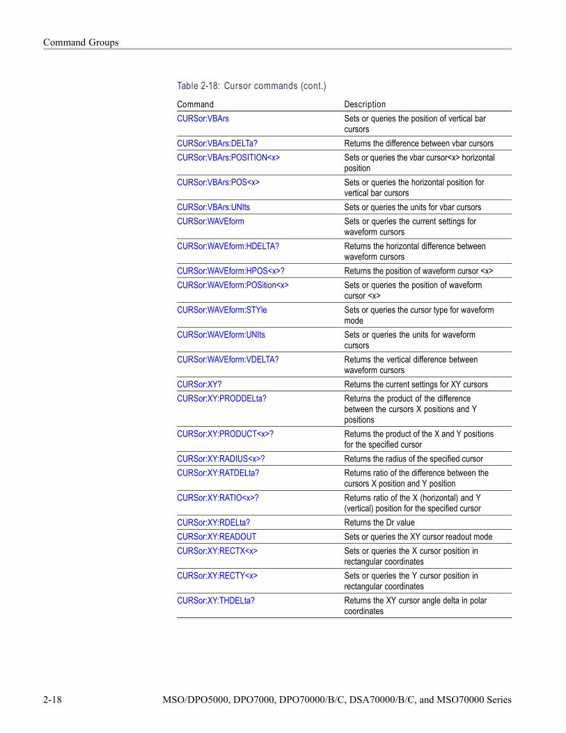
Command DescriptionEMail Sends a test e-mail message or sets the
current e-mail sent count to zeroEMail:ATTempts Sets or queries the number of times that an
attempt will be made to send e-mail to theSMTP e-mail server
EMail:AUTHLogin Sets or queries the login name that will beused if the SMTP e-mail server requires onefor authentication
EMail:AUTHPassword Sets the password that will be used ifthe SMTP e-mail server requires one forauthentication
EMail:COUNt? Returns the number of e-mails that havebeen sent since Email on Event was armed
EMail:FROm Sets or queries the From line in the e-mailEMail:HOSTwanted Sets or queries the hostname that will be
used when e-mail is sent to the SMTP e-mailserver
EMail:IMAGe Sets or queries whether image data isincluded in the e-mail
EMail:MASK Sets or queries whether e-mail is sent whena mask test failure occurs
EMail:MAXSize Sets or queries the maximum size (inmegabytes) of e-mail that can be sent to theSMTP server
EMail:MEASUrement Sets or queries whether measurement datais included in the e-mail
EMail:NUMEMails Sets or queries the number e-mails that canbe sent when Email onEvent is armed
EMail:SMTPPort Sets or queries the SMTP port number thatthe e-mail server uses
EMail:SMTPServer Sets or queries the address of the SMTPmail server
EMail:STATUS? Queries the status of e-mailEMail:TIMEOut Sets or queries the global timeout in secondsEMail:TO Sets or queries the address of the
recipient(s) of an e-mail. Multiple addressesare separated with a semicolon (;)
EMail:TRIGger Sets or queries whether e-mail is sent whena trigger occurs
EMail:WAVEform Sets or queries whether waveform data isincluded in the e-mail
MSO/DPO5000, DPO7000, DPO70000/B/C, DSA70000/B/C, and MSO70000 Series 2-25

Command Groups
Error Detector Command Group
NOTE. This programmer manual supports many oscilloscope models fromTektronix. This feature is only available on some models.
The error detector provides error detection on many serial standards. This sectionprovides error detector theory and a list of commands in the error detectorcommand group.
Error Detector Theory ofOperation
The Tektronix error detector option provides the following:
Automated receiver testing using AWG7000 Series
SATA Bit Error Detection: 1.5 Gb/s, 3.0 Gb/s, and 6.0 Gb/s Standards
SATA Frame Error Detection: 1.5 Gb/s, 3.0 Gb/s, and 6.0 Gb/s Standards
USB 3.0 Symbol Error Detection: 5 Gb/s Standard
PCIe Gen1 and Gen2 Bit Error Detection: 5 Gb/s Standard
Illegal Character and Disparity Error Detection: 1.25 Gb/s to 6.25 Gb/s
Tracking for Spread Spectrum Clocks with up to 5000 ppm (downspread)
The following table lists the various types of error detection:
Table 2-23: Types of error detection
Error Type (Units) ErrorRate
(Units)Resolution
Effectiveness Limitations
Character Number ofcharactererrors pernumber ofcharacterstested
Character 90% to 95% Can misserrors if acharacter ischanged to alegal character
Frame Number offrame errorsper number offrames tested
Frame 100%(finds allerrors)
Many bit errorscan equal oneframe error
Symbol Number ofsymbol errorsper number ofsymbols tested
Symbol 100%(finds allerrors)
Several biterrors canequal onesymbol error
Bit Number ofbit errors pernumber of bitstested
Bit 100%(finds allerrors)
Pattern lengthlimited bymemory depth
2-26 MSO/DPO5000, DPO7000, DPO70000/B/C, DSA70000/B/C, and MSO70000 Series

Command Groups
For non-USB bit error testing, you must provide the signal test pattern length andsync pattern. Align characters must be provided for all test types. All of theseparameter values depend on the actual signal test pattern. The signal test patternlength is generally known from the signal generator setup. The align character is a10-bit character with both RD+ and RD– disparity values and must actually bepresent in the signal test pattern to keep the receiver aligned to the 10-bit characterboundaries. The sync pattern is a unique 10-, 20-, 30-, or 40-bit sequence (oneto four 10-bit characters) that must actually be present in the signal test patternto align the signal so that bit-by-bit comparisons can be made. The sync patterndoes not have to be “at the beginning” of the signal test pattern but it can beanywhere in the signal test pattern, as the fixed-length signal test pattern is sentrepetitively by the signal generator.
To better understand the bit error detector, examine and use the setup files thatcontain the parameter settings in GPIB command format. Signal test patterns aresupported with the following setup files:
Any8B10BCJTPatBitErrorSetup.txt
Any8B10BCJTPcharacterErrorSetup.txt
PCIeCJTPatBit ErrorSetup.txt
SataCJTPatBitErrorSetup.txt
SataCJTPatCharactErrorSetup.txt
SataFrameComplianceFrameErrorSetup.txt
SataHFTPbitErrorSetjup.txt
SataLBPbitErrorSetup.txt
SataLFTPbitErrorSetup.txt
SataMFTPbitErrorSetup.txt
UsbCP0_SKPbitErrorSetup.txt
UsbCP0_SKPcharacterErrorSetup.txt
UsbCP0_SKPsymbolErrorSetup.txt
The oscilloscope error detector has the ability to learn the pattern from thesignal test pattern. This capability can be used when you suspect that your DUTmay have unintentional design/logic errors that modify the signal test patternbefore it reaches the oscilloscope. In this case, the oscilloscope can learn themodified signal test pattern, so that testing can continue even in the presence ofthe design/logic error.
The USB bit error and USB symbol error detection follow the same concept asSATA frame error detection. In frame error detection, the received serial datais kept aligned to 10-bit boundaries, converted from 10-bit characters to 8-bitcharacters, monitored for Start of Frame (SOF) and End of Frame (EOF) symbols,scrambled per the specification, to both compute the Cyclic Redundancy Check
MSO/DPO5000, DPO7000, DPO70000/B/C, DSA70000/B/C, and MSO70000 Series 2-27

Command Groups
(CRC) and extract the transmitted CRC from the data. The align primitives can bedetected and rejected if desired.
Example of ProgrammaticInterface (PI) Commands
Used for SATA Frame Error
A 6 Gb/s Lone Bit Pattern (LBP) compliance pattern is injected into oscilloscopeCh1.
Setup serial trigger with 8b10b coding at 6.0 Gb/s for SATA at 6 Gb/s using thefollowing PI commands:
*RST //Default Setup puts you into Edge Trigger on Ch1.
TRIG:A:TYPE SERIAL //Select Serial Trigger
TRIG:A:SERIAL:SOURCE Ch1 //Select serial Source Ch1.
TRIG:A:SERIAL:CODE S8B10B //Select 8b10b Coding.
TRIG:A:SERIAL:STANDARD SATA6_0 //Select Standard (SATA1_5, SATA3_0,SATA6_0).
Alternatively, setup serial trigger with 8b10b coding at 6 Gb/s using the userinterface.
1. Push Default Setup button.
2. Select Serial Trigger from the Trigger drop-down list.
a. Select Serial Source Ch1
b. Select Coding = S8b10b
c. Select SATA6_0 Standard (or set bitrate = 6 Gb/s).
The following error detector PI commands enable SATA frame error testing onthe LBP signal test pattern:
TRIG:A:SERIAL:ERROR:ENABLE ON
TRIG:A:SERIAL:ERROR:FILE:RECALL
“SataFrameComplianceFrameErrorSetup.txt”
TRIG:A SETLEVEL
TRIG:A:SERIAL:ERROR:FRAME:TEST START
Send the following error detector PI command to terminate frame error testingand return to serial trigger:
TRIG:A:SERIAL:ERROR:ENABLE OFF
When frame error detector is used, a count of illegal characters and disparityerrors is also provided. The elapsed time in seconds and DD:HH:MM:SS units isavailable through the PI.
2-28 MSO/DPO5000, DPO7000, DPO70000/B/C, DSA70000/B/C, and MSO70000 Series

Command Groups
Table 2-24: Error Detector commands
Command DescriptionGeneral Purpose GroupTRIGger:A:SERIAL:ERRORdetector:DURATION:COUNT
Sets or queries the test duration countas number of bits, frames, symbols, orcharacters to be tested for error testing
TRIGger:A:SERIAL:ERRORdetector:DURATION:SECONDS
Sets or queries the test duration in secondsfor error testing
TRIGger:A:SERIAL:ERRORdetector:DURATION:TIME
Sets or queries the test duration time indays, hours, minutes, and seconds forerror detector
TRIGger:A:SERIAL:ERRORdetector:DURATION:TIME:DAYS
Sets or queries the test duration time dayscomponent for error testing
TRIGger:A:SERIAL:ERRORdetector:DURATION:TIME:HOURS
Sets or queries the test duration time hourscomponent for error testing
TRIGger:A:SERIAL:ERRORdetector:DURATION:TIME:MINUTES
Sets or queries the test duration timeminutes component for error testing
TRIGger:A:SERIAL:ERRORdetector:DURATION:TIME:SECONDS
Sets or queries the test duration timeseconds component for error testing
TRIGger:A:SERIAL:ERRORdetector:ENAble Sets or queries the status of the erroroption. ENAble must be ON to activate theerror detector
TRIGger:A:SERIAL:ERRORdetector:ERRORLIMIT
Sets or queries the error limit value to usewhen STOPWHEN is ERROR
TRIGger:A:SERIAL:ERRORdetector:PATTERNNAME
Sets or queries the pattern name stored inthe setup file
TRIGger:A:SERIAL:ERRORdetector:STOPWHEN
Sets or queries the stopping condition
TRIGger:A:SERIAL:ERRORdetector:SCRAMBLED
Sets or queries the status of the datascrambling option
TRIGger:A:SERIAL:ERRORdetector:STANDARD
Sets or queries the standard selection forerror testing
TRIGger:A:SERIAL:ERRORdetector:TYPE Sets or queries the error detector typeBit Error Detection GroupTRIGger:A:SERIAL:ERRORdetector:BIT:LENGTH
Sets or queries the signal test patternlength in bits for non-USB bit error testing
TRIGger:A:SERIAL:ERRORdetector:BIT:SYNCPATtern
Sets or queries the bit sync pattern fornon-USB bit error testing
TRIGger:A:SERIAL:ERRORdetector:BIT:TEST
Arguments START and STOP initiateand terminate bit error testing. ArgumentCLEAR zeroes bit error test results.Argument LEARN copies the test patternfrom the signal
MSO/DPO5000, DPO7000, DPO70000/B/C, DSA70000/B/C, and MSO70000 Series 2-29

Command Groups
Table 2-24: Error Detector commands (cont.)
Command DescriptionTRIGger:A:SERIAL:ERRORdetector:BIT:TEST:COUNT?
Queries the bit error count for bit errortesting
TRIGger:A:SERIAL:ERRORdetector:BIT:TEST:DURATION?
Queries the elapsed duration of symbolstested for bit error testing
TRIGger:A:SERIAL:ERRORdetector:BIT:TEST:MAXALIGNS?
Queries the maximum consecutive SATAalign primitives or USB skip order sets forbit error testing
TRIGger:A:SERIAL:ERRORdetector:BIT:TEST:RATE?
Queries the calculated symbol error ratefor bit error testing
TRIGger:A:SERIAL:ERRORdetector:BIT:TEST:RESULTS?
Queries all the results for bit error testing
TRIGger:A:SERIAL:ERRORdetector:BIT:TEST:SECONDS?
Queries the elapsed time in seconds for biterror testing
TRIGger:A:SERIAL:ERRORdetector:BIT:TEST:STATUS?
Queries all of the bit error test status bits
TRIGger:A:SERIAL:ERRORdetector:BIT:TEST:STATUS:MAX_AP?
Queries the MAX_AP status for bit errortesting
TRIGger:A:SERIAL:ERRORdetector:BIT:TEST:STATUS:LOCK?
Queries the LOCK status for bit errortesting
TRIGger:A:SERIAL:ERRORdetector:BIT:TEST:STATUS:SIGNAL?
Queries the SIGNAL status for bit errortesting
TRIGger:A:SERIAL:ERRORdetector:BIT:TEST:STATUS:START?
Queries the START status for bit errortesting
TRIGger:A:SERIAL:ERRORdetector:BIT:TEST:STATUS:SYNC?
Queries the SYNC status for bit errortesting
TRIGger:A:SERIAL:ERRORdetector:BIT:TEST:TIME?
Queries the elapsed time (in days, hours,minutes, and seconds) for bit error testing
TRIGger:A:SERIAL:ERRORdetector:BIT:TEST:TIME:DAYS?
Queries the elapsed time days componentfor bit error testing
TRIGger:A:SERIAL:ERRORdetector:BIT:TEST:TIME:HOURS?
Queries the elapsed time hours componentfor bit error testing
TRIGger:A:SERIAL:ERRORdetector:BIT:TEST:TIME:MINUTES?
Queries the elapsed time minutescomponent for bit error testing
TRIGger:A:SERIAL:ERRORdetector:BIT:TEST:TIME:SECONDS?
Queries the elapsed time secondscomponent for bit error testing
TRIGger:A:SERIAL:ERRORdetector:SSC Sets or queries the status of the spreadspectrum clock tracking option
Frame Error Detection GroupTRIGger:A:SERIAL:ERRORdetector:FRAME? Queries all frame error settings, status, and
resultsTRIGger:A:SERIAL:ERRORdetector:FRAME:EOF
Sets or queries the End of Frame for frameerror testing
2-30 MSO/DPO5000, DPO7000, DPO70000/B/C, DSA70000/B/C, and MSO70000 Series

Command Groups
Table 2-24: Error Detector commands (cont.)
Command DescriptionTRIGger:A:SERIAL:ERRORdetector:FRAME:INITIALCRCVALue
Sets or queries the initial CRC value forframe error testing
TRIGger:A:SERIAL:ERRORdetector:FRAME:SOF
Sets or queries the Start of Frame for frameerror testing
TRIGger:A:SERIAL:ERRORdetector:FRAME:TEST
Arguments START and STOP initiate andterminate frame error testing. ArgumentCLEAR zeroes the frame error results
TRIGger:A:SERIAL:ERRORdetector:FRAME:TEST:BADCHARS?
Queries the illegal character count forframe error testing
TRIGger:A:SERIAL:ERRORdetector:FRAME:TEST:COUNT?
Queries the test error count for frame errortesting
TRIGger:A:SERIAL:ERRORdetector:FRAME:TEST:DISPARITY?
Queries the disparity error count for frameerror testing
TRIGger:A:SERIAL:ERRORdetector:FRAME:TEST:DURATION?
Queries the elapsed duration (in number offrames) tested by the frame
TRIGger:A:SERIAL:ERRORdetector:FRAME:TEST:MAXALIGNS?
Queries the maximum consecutive alignsencountered for frame error testing
TRIGger:A:SERIAL:ERRORdetector:FRAME:TEST:RATE?
Queries the calculated frame error rate forframe error testing
TRIGger:A:SERIAL:ERRORdetector:FRAME:TEST:RESULTS?
Queries all the results for frame errortesting
TRIGger:A:SERIAL:ERRORdetector:FRAME:TEST:SECONDS?
Queries the elapsed duration in secondsfor frame error testing
TRIGger:A:SERIAL:ERRORdetector:FRAME:TEST:STATUS?
Queries all of the frame error status at once
TRIGger:A:SERIAL:ERRORdetector:FRAME:TEST:STATUS:MAX_AP?
Queries the MAX_AP status for the frameerror test
TRIGger:A:SERIAL:ERRORdetector:FRAME:TEST:STATUS:LOCK?
Queries the LOCK status for the frameerror test
TRIGger:A:SERIAL:ERRORdetector:FRAME:TEST:STATUS:SIGNAL?
Queries the SIGNAL status for the frameerror test
TRIGger:A:SERIAL:ERRORdetector:FRAME:TEST:STATUS:START?
Queries the START status for frame errortests
TRIGger:A:SERIAL:ERRORdetector:FRAME:TEST:TIME?
Queries the elapsed time (in days, hours,minutes, and seconds) for frame errortesting
TRIGger:A:SERIAL:ERRORdetector:FRAME:TEST:TIME:DAYS?
Queries the elapsed time days componentfor frame error testing
TRIGger:A:SERIAL:ERRORdetector:FRAME:TEST:TIME:HOURS?
Queries the elapsed time hours componentfor frame error testing
TRIGger:A:SERIAL:ERRORdetector:FRAME:TEST:TIME:MINUTES?
Queries the elapsed time minutescomponent for frame error testing
MSO/DPO5000, DPO7000, DPO70000/B/C, DSA70000/B/C, and MSO70000 Series 2-31

Command Groups
Table 2-24: Error Detector commands (cont.)
Command DescriptionTRIGger:A:SERIAL:ERRORdetector:FRAME:TEST:TIME:SECONDS?
Queries the elapsed time secondscomponent for frame error testing
Symbol Error Detection GroupTRIGger:A:SERIAL:ERRORdetector:SYMBOL?
Queries all symbol error settings, status,and results
TRIGger:A:SERIAL:ERRORdetector:SYMBOL:TEST
Arguments START and STOP initiate andterminate symbol error testing. ArgumentCLEAR zeroes the symbol error results
TRIGger:A:SERIAL:ERRORdetector:SYMBOL:TEST:BADCHARS?
Queries the illegal character count forsymbol error testing
TRIGger:A:SERIAL:ERRORdetector:SYMBOL:TEST:BITCOUNT?
Queries the bit error count (number of badbits) for symbol error testing
TRIGger:A:SERIAL:ERRORdetector:SYMBOL:TEST:BITDURATION?
Queries the elapsed duration (in units ofbits) tested for symbol error testing
TRIGger:A:SERIAL:ERRORdetector:SYMBOL:TEST:BITRATE?
Queries the calculated bit error rate forsymbol error testing
TRIGger:A:SERIAL:ERRORdetector:SYMBOL:TEST:COUNT?
Queries the symbol error count for symbolerror testing
TRIGger:A:SERIAL:ERRORdetector:SYMBOL:TEST:DISPARITY?
Queries the disparity error count for symbolerror testing
TRIGger:A:SERIAL:ERRORdetector:SYMBOL:TEST:DURATION?
Queries the elapsed duration for symbolerror testing
TRIGger:A:SERIAL:ERRORdetector:SYMBOL:TEST:MAXALIGNS?
Queries the maximum consecutive skiporder sets encountered for symbol errortesting
TRIGger:A:SERIAL:ERRORdetector:SYMBOL:TEST:RATE?
Queries the calculated symbol error ratefor symbol error testing
TRIGger:A:SERIAL:ERRORdetector:SYMBOL:TEST:RESULTS?
Queries all of the results for symbol errortesting
TRIGger:A:SERIAL:ERRORdetector:SYMBOL:TEST:SECONDS?
Queries the elapsed duration time inseconds for symbol error testing
TRIGger:A:SERIAL:ERRORdetector:SYMBOL:TEST:STATUS?
Queries all of the status for the symbolerror tests
TRIGger:A:SERIAL:ERRORdetector:SYMBOL:TEST:STATUS:MAX_AP?
Queries the MAX_AP status for the symbolerror test
TRIGger:A:SERIAL:ERRORdetector:SYMBOL:TEST:STATUS:LOCK?
Queries the LOCK status for the symbolerror test
TRIGger:A:SERIAL:ERRORdetector:SYMBOL:TEST:STATUS:SIGNAL?
Queries the SIGNAL status for the symbolerror test
TRIGger:A:SERIAL:ERRORdetector:SYMBOL:TEST:STATUS:START?
Queries the START status for symbol errortesting
2-32 MSO/DPO5000, DPO7000, DPO70000/B/C, DSA70000/B/C, and MSO70000 Series

Command Groups
Table 2-24: Error Detector commands (cont.)
Command DescriptionTRIGger:A:SERIAL:ERRORdetector:SYMBOL:TEST:TIME?
Queries the elapsed time (in days, hours,minutes, and seconds) for symbol errortesting
TRIGger:A:SERIAL:ERRORdetector:SYMBOL:TEST:TIME:DAYS?
Queries the elapsed time days componentfor symbol error testing
TRIGger:A:SERIAL:ERRORdetector:SYMBOL:TEST:TIME:HOURS?
Queries the elapsed time hours componentfor symbol error testing
TRIGger:A:SERIAL:ERRORdetector:SYMBOL:TEST:TIME:MINUTES?
Queries the elapsed time minutescomponent for symbol error testing
TRIGger:A:SERIAL:ERRORdetector:SYMBOL:TEST:TIME:SECONDS?
Queries the elapsed time secondscomponent for symbol error testing
Character Error Detection GroupTRIGger:A:SERIAL:ERRORdetector:CHARACTER?
Queries all character error settings, status,and results
TRIGger:A:SERIAL:ERRORdetector:CHARACTER:TEST
Argument START and STOP initiate andterminate character error testing. ArgumentCLEAR zeroes the character error results
TRIGger:A:SERIAL:ERRORdetector:CHARACTER:TEST:COUNT?
Queries the number of illegal characters inthe signal for error testing
TRIGger:A:SERIAL:ERRORdetector:CHARACTER:TEST:DISPCOUNT?
Queries the number of disparity errors inthe signal for character error testing
TRIGger:A:SERIAL:ERRORdetector:CHARACTER:TEST:DISPRATE?
Queries the calculated disparity error ratefor character error testing
TRIGger:A:SERIAL:ERRORdetector:CHARACTER:TEST:DURATION?
Queries the elapsed duration in units ofcharacters tested
TRIGger:A:SERIAL:ERRORdetector:CHARACTER:TEST:MAXALIGNS?
Queries the maximum consecutive alignsencountered for character error testing
TRIGger:A:SERIAL:ERRORdetector:CHARACTER:TEST:RATE?
Queries the calculated illegal charactererror rate for error testing
TRIGger:A:SERIAL:ERRORdetector:CHARACTER:TEST:RESULTS?
Queries all of the character error testresults
TRIGger:A:SERIAL:ERRORdetector:CHARACTER:TEST:SECONDS?
Queries the elapsed duration time secondscomponent for character error testing
TRIGger:A:SERIAL:ERRORdetector:CHARACTER:TEST:STATUS?
Queries all of the status for character errortests
TRIGger:A:SERIAL:ERRORdetector:CHARACTER:TEST:STATUS:MAX_AP?
Queries the MAX_AP status for thecharacter error test
TRIGger:A:SERIAL:ERRORdetector:CHARACTER:TEST:STATUS:LOCK?
Queries the LOCK status for the charactererror test
TRIGger:A:SERIAL:ERRORdetector:CHARACTER:TEST:STATUS:SIGNAL?
Queries the SIGNAL status for thecharacter error test
MSO/DPO5000, DPO7000, DPO70000/B/C, DSA70000/B/C, and MSO70000 Series 2-33

Command Groups
Table 2-24: Error Detector commands (cont.)
Command DescriptionTRIGger:A:SERIAL:ERRORdetector:CHARACTER:TEST:STATUS:START?
Queries the START status for the charactererror testing
TRIGger:A:SERIAL:ERRORdetector:CHARACTER:TEST:TIME?
Queries the elapsed time (in days, hours,minutes, and seconds) for character errortesting
TRIGger:A:SERIAL:ERRORdetector:CHARACTER:TEST:TIME:DAYS?
Queries the elapsed time days componentfor character error testing
TRIGger:A:SERIAL:ERRORdetector:CHARACTER:TEST:TIME:HOURS?
Queries the elapsed time hours componentfor character error testing
TRIGger:A:SERIAL:ERRORdetector:CHARACTER:TEST:TIME:MINUTES?
Queries the elapsed time minutescomponent for character error testing
TRIGger:A:SERIAL:ERRORdetector:CHARACTER:TEST:TIME:SECONDS?
Queries the elapsed time secondscomponent for character error testing
File GroupTRIGger:A:SERIAL:ERRORdetector:FILE:RECALL
Initiates a file recall of error detectorparameters from a text file
TRIGger:A:SERIAL:ERRORdetector:FILE:SAVE
Initiates a file save of error detectorparameters to a text file
Align Pattern GroupTRIGger:A:SERIAL:ERRORdetector:ALIGNCHARacter?
Queries both of the align character values
TRIGger:A:SERIAL:ERRORdetector:ALIGNCHARacter:RDMINUS
Sets or queries the RD- align charactervalue
TRIGger:A:SERIAL:ERRORdetector:ALIGNCHARacter:RDPLUS
Sets or queries the RD+ align charactervalue
TRIGger:A:SERIAL:ERRORdetector:ALIGNPRIMitive?
Queries all of the align primitive values
TRIGger:A:SERIAL:ERRORdetector:ALIGNPRIMitive:RDMINUS?
Queries the RD- align primitive enable andstring values
TRIGger:A:SERIAL:ERRORdetector:ALIGNPRIMitive:RDMINUS:ENABLE
Sets or queries the status of the RD- alignprimitive option
TRIGger:A:SERIAL:ERRORdetector:ALIGNPRIMitive:RDMINUS:PATtern
Sets or queries the RD- align primitivepattern
TRIGger:A:SERIAL:ERRORdetector:ALIGNPRIMitive:RDPLUS?
Queries the RD+ align primitive enable andstring values
TRIGger:A:SERIAL:ERRORdetector:ALIGNPRIMitive:RDPLUS:ENABLE
Sets or queries the status of the RD+ alignprimitive option
TRIGger:A:SERIAL:ERRORdetector:ALIGNPRIMitive:RDPLUS:PATtern
Sets or queries the RD+ align primitivepattern
TRIGger:A:SERIAL:ERRORdetector:ALIGNPRIMitive:S8BPATtern
Sets or queries the 32-bit version for alignprimitive pattern
2-34 MSO/DPO5000, DPO7000, DPO70000/B/C, DSA70000/B/C, and MSO70000 Series

Command Groups
Table 2-24: Error Detector commands (cont.)
Command DescriptionTRIGger:A:SERIAL:ERRORdetector:MAXALIGNS
Sets or queries the maximum consecutivealign primitives before an error
Skip Order Set GroupTRIGger:A:SERIAL:ERRORdetector:SKIPSETPRIMitive:RDMINUS?
Queries the RD- skip order set enable andstring values
TRIGger:A:SERIAL:ERRORdetector:SKIPSETPRIMitive:RDMINUS:ENABLE
Sets or queries the status of the RD- skiporder set option
TRIGger:A:SERIAL:ERRORdetector:SKIPSETPRIMitive:RDMINUS:PATtern
Sets or queries the RD- skip order setpattern
TRIGger:A:SERIAL:ERRORdetector:SKIPSETPRIMitive:RDPLUS?
Queries the RD+ skip order set enable andstring values
TRIGger:A:SERIAL:ERRORdetector:SKIPSETPRIMitive:RDPLUS:ENABLE
Sets or queries the status of the RD+ skiporder set option
TRIGger:A:SERIAL:ERRORdetector:SKIPSETPRIMitive:RDPLUS:PATtern
Sets or queries the RD+ skip order setpattern
TRIGger:A:SERIAL:ERRORdetector:SKIPSETPRIMitive:S8BPATtern
Sets or queries the 32-bit skip order setpattern
File System Command GroupUse the commands in the File System Command Group to help you use thebuilt-in hard disk drive. You can use the commands to do the following:
List the contents of the default directory
Create and delete directories
Create, copy, read, rename, or delete a file
When using these commands, keep the following points in mind:
File arguments are always enclosed within double quotes:“C:\MYDIR\TEK00001.SET”
File names follow the MS-DOS format: [DRIVE:][\PATH\]filename
Path separators may be either forward slashes (/) or back slashes (\)
MSO/DPO5000, DPO7000, DPO70000/B/C, DSA70000/B/C, and MSO70000 Series 2-35

Command Groups
NOTE. Using back slash as a path separator may produce some unexpectedresults, depending on how your controller application treats escaped characters.Many applications recognize the sequence of back slash followed by an alphabeticcharacter as an escaped character, and, as such, interpret that alphabeticcharacter as a control character. For example, the sequence “\n” may beinterpreted as a newline character; “\t” may be interpreted as a tab character. Toensure that this interpretation does not occur, you can use double back slashes.For example, “C:\\testfile.txt”.
Some FILESystem commands may fail because a file has read-only attributes.You will not be able to delete or replace such files until this attribute isremoved. Refer to the operating system help on file properties for furtherinformation.
Table 2-25: File System commands
Command DescriptionFILESystem? Returns the file system stateFILESystem:COPy Copies one or more files to a new fileFILESystem:CWD Sets or queries the current working directory
for FILESystem GPIB commandsFILESystem:DELEte Deletes a named file or directoryFILESystem:DIR? Returns a list of directory contentsFILESystem:MKDir Makes a new directoryFILESystem:PRInt Prints a named file to the named portFILESystem:READFile Copies the named file to the GPIB portFILESystem:REName Assigns a new name to an existing fileFILESystem:RMDir Deletes the named directoryFILESystem:WRITEFile Copies the GPIB port block data to a named
file
Hard Copy Command GroupHard Copy commands enable you to make hard copies of data files or send thedata to a specified file. In addition, these commands provide you with informationabout (and the ability to set) file path settings.
Table 2-26: Hard Copy commands
Command DescriptionEXPort Copies a waveform to a specified file or
returns formatting and file informationEXPort:FILEName Sets or queries the export file path
2-36 MSO/DPO5000, DPO7000, DPO70000/B/C, DSA70000/B/C, and MSO70000 Series

Command Groups
Table 2-26: Hard Copy commands (cont.)
Command DescriptionEXPort:FORMat Sets or queries the export image formatEXPort:PALEtte Sets or queries the export color paletteEXPort:READOuts Sets or queries the position of the readouts
for exportEXPort:VIEW Sets or queries the export screen capture
areaHARDCopy Sends a screen copy to the selected port or
returns the selected port and file pathHARDCopy:FILEName Sets or queries the hard copy file pathHARDCopy:LAYout Sets or queries the page orientation for hard
copyHARDCopy:PALEtte Sets or queries the hard copy color paletteHARDCopy:PORT Sets or queries whether the hard copy data
will be sent to a file or printed on the nexthard copy command
HARDCopy:READOuts Sets or queries the position of the readoutsfor hardcopy
HARDCopy:VIEW Sets or queries the area of the screen to behardcopied
Histogram Command GroupHistogram commands let you select the type of histogram, what part of thewaveform should go into the histogram, and histogram statistics. Use commandsfrom this group to do the following:
Create a histogram of vertical or horizontal values for a channel, math, orreference waveform
Adjust the limits of the waveform area from which the histogram data isobtained
Clear histogram count and restart
Retrieve the histogram data
Table 2-27: Histogram commands
Command DescriptionHIStogram? Returns all histogram parametersHIStogram:BOX Sets or queries the left, top, right, and bottom
positions of the histogram box, in sourcewaveform coordinates
MSO/DPO5000, DPO7000, DPO70000/B/C, DSA70000/B/C, and MSO70000 Series 2-37

Command Groups
Table 2-27: Histogram commands (cont.)
Command DescriptionHIStogram:BOXPcnt Sets or queries same as HIStogram:BOX,
but in percentage coordinates, with 0,0 upperleft and 100,100 lower right
HIStogram:COUNt Clears histogram count source data andrestarts counting
HIStogram:DATa? Returns a comma-separated list of histogramdata numbers
HIStogram:DISplay Sets or queries whether histogram data isdisplayed and the current display type setting
HIStogram:FUNCtion Sets the type of histogram to createOr queries the current histogram type
HIStogram:MODe Sets type of histogram to create or turnshistograms offOr queries the current histogram type or thathistogram display is disabled
HIStogram:SIZe Sets or queries the width (or height) of thehistogram on the screen in divisions
HIStogram:SOUrce Sets or queries which source waveform willbe compared against the histogram boxwhen the histogram testing is enabled
HIStogram:STATE Sets or queries whether histogramcalculations are enabled
Horizontal Command GroupHorizontal commands control the time bases of the instrument. You can set thetime per division (or time per point) of the main time base. You can use theHorizontal commands to do the following:
Set the scale, horizontal position and reference, and units of the time base
Get the screen resolution, time of first point and time of last point, or get allthe horizontal settings
Enable or disable the display of the time base
You may substitute SECdiv for SCAle in the horizontal commands. This providesprogram compatibility with earlier models of Tektronix instruments.
Table 2-28: Horizontal commands
Command DescriptionHORizontal? Returns all learnable settings for the
horizontal commands
2-38 MSO/DPO5000, DPO7000, DPO70000/B/C, DSA70000/B/C, and MSO70000 Series

Command Groups
Table 2-28: Horizontal commands (cont.)
Command DescriptionHORizontal:ACQDURATION? Returns the time base durationHORizontal:ACQLENGTH? Returns the record lengthHORizontal:DIGital:MAGnivu:POSition? Queries the horizontal position of the
MagniVu digital acquisition
NOTE. This programmer manualsupports many oscilloscope modelsfrom Tektronix. This feature is onlyavailable on some models.
HORizontal:DIGital:RECOrdlength? Queries the record length of the digitalacquisition
HORizontal:DIGital:RECOrdlength:MAGnivu?
Queries the record length of the MagniVudigital acquisition
NOTE. This programmer manualsupports many oscilloscope modelsfrom Tektronix. This feature is onlyavailable on some models.
HORizontal:DIGital:RECOrdlength:MAIn? Queries the record length of the main digitalacquisition
HORizontal:DIGital:SAMPLERate? Queries the sample rate of the digitalacquisition
HORizontal:DIGital:SAMPLERate:MAGnivu?
Queries the sample rate of the MagniVudigital acquisition
NOTE. This programmer manualsupports many oscilloscope modelsfrom Tektronix. This feature is onlyavailable on some models.
HORizontal:DIGital:SAMPLERate:MAIn? Queries the sample rate of the main digitalacquisition
HORizontal:DIVisions? Returns the number of graticule divisionsover which the waveform is displayed
HORizontal:FASTframe? Returns all settings for the horizontalFastFrame commands
HORizontal:FASTframe:COUNt Sets or queries the FastFrame frame countHORizontal:FASTframe:MAXFRames? Returns the maximum number of FastFrame
frames which can be acquired at the currentframe length
HORizontal:FASTframe:MULtipleframes:FRAMESTart:<wfm>
Sets or queries the start frame numberon the specified waveform for FastFramemultiple frames
HORizontal:FASTframe:MULtipleframes:MODe
Sets or queries the mode for FastFramemultiple frames
MSO/DPO5000, DPO7000, DPO70000/B/C, DSA70000/B/C, and MSO70000 Series 2-39

Command Groups
Table 2-28: Horizontal commands (cont.)
Command DescriptionHORizontal:FASTframe:MULtipleframes:NUMFRames:<wfm>
Sets or queries the number of frames on thespecified waveform for FastFrame multipleframes
HORizontal:FASTframe:REF:FRAme Sets or queries the FastFrame referenceframe number
HORizontal:FASTframe:REF:SOUrce Sets or queries the FastFrame Referencewaveform source
HORizontal:FASTframe:SELECTED:CH<x> Sets or queries the FastFrame selectedframe number on the specified waveform
HORizontal:FASTframe:SELECTED:MATH<x>
Sets or queries the FastFrame selectedframe number on the specified waveform
HORizontal:FASTframe:SELECTED:REF<x>
Sets or queries the FastFrame selectedframe number on the specified waveform
HORizontal:FASTframe:SELECTED:SOUrce
Sets or queries the FastFrame sourcewaveform
HORizontal:FASTframe:SEQuence Sets or queries the FastFrame sourcewaveform
HORizontal:FASTframe:STATE Sets or queries the state of FastFrameacquisition
HORizontal:FASTframe:SUMFrame Sets or queries the summary frame modeHORizontal:FASTframe:TIMEStamp:ALL:<wfm>?
Returns the frame number and time stampfor each frame between requested frames,inclusive, within the specified waveform
HORizontal:FASTframe:TIMEStamp:BETWeen:<wfm>?
Returns the relative trigger for the delta timebetween the specified frames, within thespecified waveform
HORizontal:FASTframe:TIMEStamp:DELTa:<wfm>?
Returns the relative time between thetriggers of the FastFrame Selected and theFastFrame Reference, within the specifiedwaveform
HORizontal:FASTframe:TIMEStamp:FRAMe:<wfm>?
Returns the absolute trigger date and timefor the specified frame and waveform
HORizontal:FASTframe:TIMEStamp:REF? Returns the absolute trigger date and time forthe FastFrame specified reference waveform
HORizontal:FASTframe:TIMEStamp:SELECTED:<wfm>?
Returns the absolute trigger date and time forthe FastFrame Selected, within the specifiedwaveform
HORizontal:FASTframe:TRACk Sets up or returns the state of FastFrametracking
HORizontal:FASTframe:XZEro:ALL:CH<x>? Returns the time from the trigger to the startof the specified frames on the specifiedchannel
2-40 MSO/DPO5000, DPO7000, DPO70000/B/C, DSA70000/B/C, and MSO70000 Series

Command Groups
Table 2-28: Horizontal commands (cont.)
Command DescriptionHORizontal:FASTframe:XZEro:ALL:REF<x>?
Returns the time from the trigger to the startof the specified frames on the specifiedreference
HORizontal:FASTframe:XZEro:FRAme:CH<x>?
Returns the time from the trigger to thestart of the specified frame on the specifiedchannel
HORizontal:FASTframe:XZEro:FRAme:REF<x>?
Returns the time from the trigger to thestart of the specified frame on the specifiedreference
HORizontal:FASTframe:XZEro:REF? Sets or queries the time from the trigger tothe trigger sample on the reference waveform
HORizontal:FASTframe:XZEro:SELECTED:CH<x>?
Sets or queries the time from the trigger tothe trigger sample on the selected channel
HORizontal:FASTframe:XZEro:SELECTED:REF<x>?
Sets or queries the time from the trigger tothe trigger sample on the selected referencewaveform
HORizontal:MAIn? Returns the time per division of the maintime base
HORizontal[:MAIn]:DELay:MODe Sets or queries the main time base triggerdelay mode
HORizontal[:MAIn]:DELay:POSition Sets or queries the main time base positionwhen Horizontal Delay Mode is turned off
HORizontal[:MAIn]:DELay:TIMe Sets or queries the main time base triggerdelay time
HORizontal:MAIn:INTERPRatio? Returns the main horizontal time baseinterpolation ratio
HORizontal[:MAIn]:POSition Sets or queries the waveform horizontalposition on the display
HORizontal:MAIn:UNIts Sets or queries the units for the horizontaltime base
HORizontal:MAIn:UNIts:STRing Sets or queries the units string for thehorizontal main time base trigger delay
HORizontal:MODE Sets or queries the horizontal mode. Automode is the factory default
HORizontal:MODE:AUTO:LIMITrecordlen Sets or queries the record length limit usedby the auto horizontal mode
HORizontal:MODE:RECOrdlength Sets or queries the record lengthHORizontal:MODE:SAMPLERate Sets or queries the sample rateHORizontal:MODE:SCAle Sets or queries the horizontal scaleHORizontal:POSition Either positions the waveform horizontally on
the display or returns its horizontal positionon the display
MSO/DPO5000, DPO7000, DPO70000/B/C, DSA70000/B/C, and MSO70000 Series 2-41

Command Groups
Table 2-28: Horizontal commands (cont.)
Command DescriptionHORizontal:ROLL Sets or queries the horizontal roll mode
statusHORizontal:TIMEStamp:CH<x>? Returns the absolute trigger date and time
for the specified frame and waveformHORizontal:TIMEStamp:REF<x>? Returns the absolute trigger date and time
for FastFrame reference
Limit Test Command GroupUse the commands in the Limit Test Command Group to perform limit testingby selecting channel, math, or reference waveforms and comparing them againsta template waveform.
Table 2-29: Limit Test commands
Command DescriptionLIMit? Returns all settings for the Limit commandsLIMit:BEEP Causes the instrument to beep when the
waveform data exceeds the limits set in thelimit test
LIMit:COMpare Resets the limit test comparison templateLIMit:COMpare:CH<x> Sets or queries the template against which
to compare the waveform acquired from thechannel specified by x
LIMit:COMpare:MATH<x> Sets or queries the template against which tocompare the math waveform specified by x
LIMit:COMpare:REF<x> Sets or queries the template against which tocompare the reference waveform specifiedby x
LIMit:EMail Sets or queries whether an E-mail isgenerated when the source waveform dataexceeds the limits specified for the limit test
LIMit:HARDCopy Sets or queries whether a hard copyoperation is executed on the waveform whenany waveform data exceeds the limit set inthe limit test. LIMit:STATE must be set to ONfor the hard copy operation to execute
LIMit:HIGHLIGHTHits Sets or queries whether violation highlightingoccurs when limit testing is active, and,if the RESET argument is set, clears thehighlighting
LIMit:HIGHLIGHTHits:RESet Resets the hits highlighting for limit testing
2-42 MSO/DPO5000, DPO7000, DPO70000/B/C, DSA70000/B/C, and MSO70000 Series

Command Groups
Table 2-29: Limit Test commands (cont.)
Command DescriptionLIMit:LOCk Sets or queries whether vertical scaling and
positioning affect both source and templatefor template comparison pairs
LIMit:LOG Sets or queries whether a log file is savedwhen the source waveform data exceeds thetest limits
LIMit:SAVEWFM Sets or queries whether the source waveformis saved when the source waveform dataexceeds the test limits
LIMit:SAVEWFM:FILEName Sets or queries the path where waveformsor log files will be saved when the waveformdata exceeds the limits set by the limit test
LIMit:SRQ Sets or queries whether a Service RequestInterrupt (SRQ) is generated when thewaveform data falls outside of the test limits
LIMit:STATE Sets limit testing on or off or queries whetherlimit testing is in effect
LIMit:STATus? Queries the state of limit testingLIMit:STOPOnviolation Sets or queries whether acquisitions are
stopped when the waveform data exceedsthe test limits
LIMit:TEMPlate:STORe Saves the specified source waveform to thespecified reference or file name
LIMit:TEMPlate:TOLerance:HORizontal Sets or queries the amount in units ofhorizontal divisions, by which the sourcewaveform is varied horizontally whencreating the destination waveform
LIMit:TEMPlate:TOLerance:VERTical Sets or queries the amount in units ofvertical divisions, by which the sourcewaveform is varied vertically when creatingthe destination waveform
LIMit:TEMPlate:DESTination Sets or queries destination referencewaveform that the limit template
LIMit:TEMPlate:SOUrce Sets or queries the channel, mathwaveform, or reference waveform that theLIMit:TEMPlate:STORe command will use
Low Speed Serial Trigger Command GroupUse the commands in the Low Speed Serial Trigger Command Group to controlserial triggering for the instrument.
MSO/DPO5000, DPO7000, DPO70000/B/C, DSA70000/B/C, and MSO70000 Series 2-43
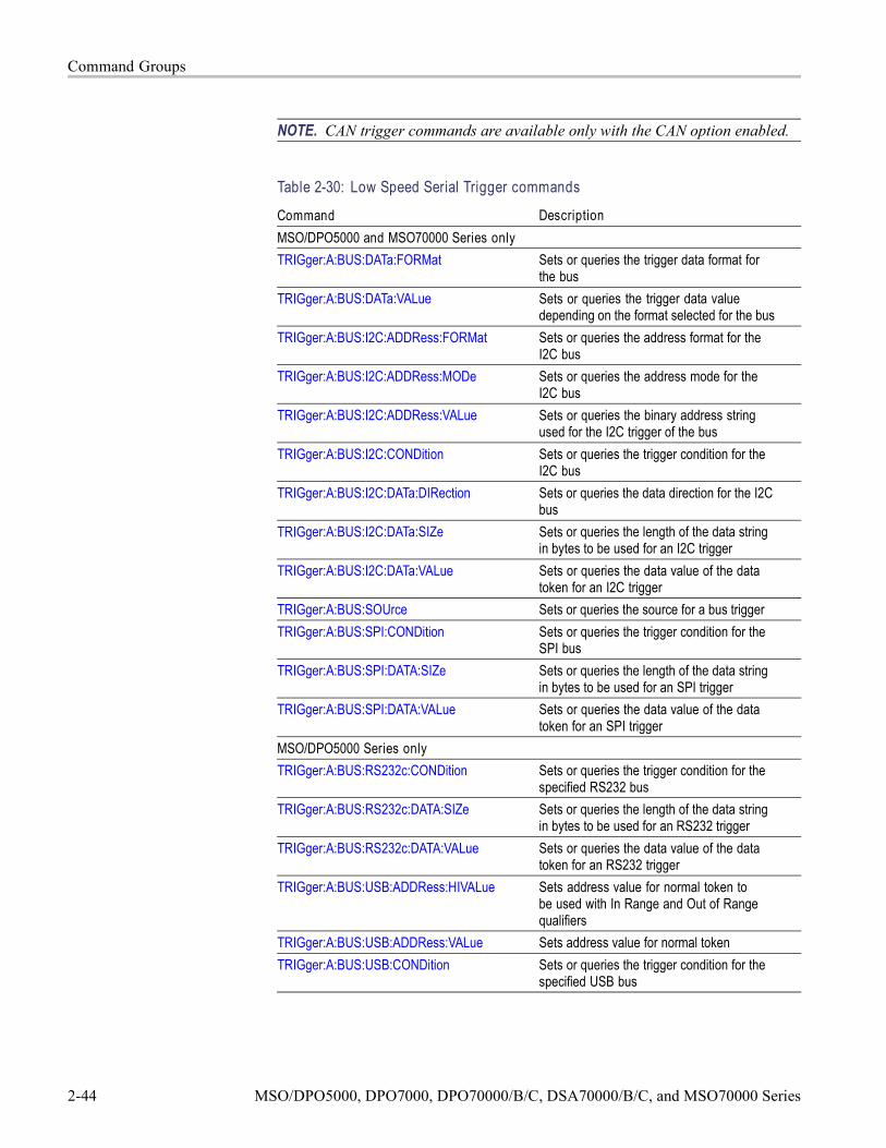
Command Groups
NOTE. CAN trigger commands are available only with the CAN option enabled.
Table 2-30: Low Speed Serial Trigger commands
Command DescriptionMSO/DPO5000 and MSO70000 Series onlyTRIGger:A:BUS:DATa:FORMat Sets or queries the trigger data format for
the busTRIGger:A:BUS:DATa:VALue Sets or queries the trigger data value
depending on the format selected for the busTRIGger:A:BUS:I2C:ADDRess:FORMat Sets or queries the address format for the
I2C busTRIGger:A:BUS:I2C:ADDRess:MODe Sets or queries the address mode for the
I2C busTRIGger:A:BUS:I2C:ADDRess:VALue Sets or queries the binary address string
used for the I2C trigger of the busTRIGger:A:BUS:I2C:CONDition Sets or queries the trigger condition for the
I2C busTRIGger:A:BUS:I2C:DATa:DIRection Sets or queries the data direction for the I2C
busTRIGger:A:BUS:I2C:DATa:SIZe Sets or queries the length of the data string
in bytes to be used for an I2C triggerTRIGger:A:BUS:I2C:DATa:VALue Sets or queries the data value of the data
token for an I2C triggerTRIGger:A:BUS:SOUrce Sets or queries the source for a bus triggerTRIGger:A:BUS:SPI:CONDition Sets or queries the trigger condition for the
SPI busTRIGger:A:BUS:SPI:DATA:SIZe Sets or queries the length of the data string
in bytes to be used for an SPI triggerTRIGger:A:BUS:SPI:DATA:VALue Sets or queries the data value of the data
token for an SPI triggerMSO/DPO5000 Series onlyTRIGger:A:BUS:RS232c:CONDition Sets or queries the trigger condition for the
specified RS232 busTRIGger:A:BUS:RS232c:DATA:SIZe Sets or queries the length of the data string
in bytes to be used for an RS232 triggerTRIGger:A:BUS:RS232c:DATA:VALue Sets or queries the data value of the data
token for an RS232 triggerTRIGger:A:BUS:USB:ADDRess:HIVALue Sets address value for normal token to
be used with In Range and Out of Rangequalifiers
TRIGger:A:BUS:USB:ADDRess:VALue Sets address value for normal tokenTRIGger:A:BUS:USB:CONDition Sets or queries the trigger condition for the
specified USB bus
2-44 MSO/DPO5000, DPO7000, DPO70000/B/C, DSA70000/B/C, and MSO70000 Series

Command Groups
Table 2-30: Low Speed Serial Trigger commands (cont.)
Command DescriptionMSO/DPO5000 and MSO70000 Series onlyTRIGger:A:BUS:USB:DATa:HIVALue Sets or queries the trigger data value for data
token of the specified USB busTRIGger:A:BUS:USB:DATa:OFFSet Sets or queries the data offset for the USB
bus triggerTRIGger:A:BUS:USB:DATa:SIZe Sets or queries the number of contiguous
data bytes for the USB bus triggerTRIGger:A:BUS:USB:DATa:TYPe Sets or queries the data packet type when
USB bus trigger condition is Data PacketTRIGger:A:BUS:USB:DATa:VALue Sets or queries the USB bus trigger data
value for data tokenTRIGger:A:BUS:USB:ENDPoint:HIVALue Sets or queries the endpoint value for data
token to be used with in range and out ofrange qualifiers
TRIGger:A:BUS:USB:ENDPoint:VALue Sets or queries the endpoint value for normaltoken of the specified USB bus
TRIGger:A:BUS:USB:ERRTYPE Sets or queries the error type when USB bustrigger on condition is set to Error
TRIGger:A:BUS:USB:HANDShaketype Sets or queries the handshake type whenUSB bus trigger on condition is set toHandshake Packet
TRIGger:A:BUS:USB:QUALIFIER Sets or queries the USB bus trigger qualifierfor address, endpoint, and data
TRIGger:A:BUS:USB:SPECIALType Sets or queries the PID value for SpecialPacket USB bus trigger on condition
TRIGger:A:BUS:USB:SPLIT:ET:VALUE Sets or queries the Endpoint Type value ofthe specified USB bus trigger
TRIGger:A:BUS:USB:SPLIT:HUB:VALUE Sets or queries the hub address for SPLITtoken of the USB bus trigger
TRIGger:A:BUS:USB:SPLIT:PORT:VALUE Sets or queries the port address for SPLITtoken of the USB bus trigger
TRIGger:A:BUS:USB:SPLIT:SC:VALUE Sets or queries the Start/Complete value forthe USB bus trigger on split token field
TRIGger:A:BUS:USB:SPLIT:SE:VALUE Sets or queries the Start/End value for theUSB bus trigger
TRIGger:A:BUS:USB:TOKENType Sets or queries the Token Type when USBTrigger condition is set to Token (Address)Packet
DPO7000 Series only
MSO/DPO5000, DPO7000, DPO70000/B/C, DSA70000/B/C, and MSO70000 Series 2-45

Command Groups
Table 2-30: Low Speed Serial Trigger commands (cont.)
Command DescriptionMSO/DPO5000 and MSO70000 Series onlyTRIGger:A:CAN:CONDition Sets or queries the CAN condition
NOTE. This trigger is available onlywith Option LSA installed.
TRIGger:A:CAN:DATa:DIRection Sets or queries the CAN trigger condition tobe valid on a READ, WRITE, or either
NOTE. This trigger is available onlywith Option LSA installed.
TRIGger:A:CAN:FORMat Sets or queries the CAN data format
NOTE. This trigger is available onlywith Option LSA installed.
TRIGger:A:CAN:DATa:LEVel Sets or queries the CAN Trigger thresholdfor the CAN data source
NOTE. This trigger is available onlywith Option LSA installed.
TRIGger:A:CAN:DATa:SOUrce Sets or queries the CAN data source
NOTE. This trigger is available onlywith Option LSA installed.
TRIGger:A:CAN:DATa:VALue Sets or queries the binary data string usedfor CAN Trigger if the trigger condition is IDor IDANDDATA
NOTE. This trigger is available onlywith Option LSA installed.
TRIGger:A:CAN:FRAMEtype Sets or queries the CAN trigger frame type
NOTE. This trigger is available onlywith Option LSA installed.
TRIGger:A:CAN:IDENTifier:MODe Sets or queries the CAN trigger identifiermode
NOTE. This trigger is available onlywith Option LSA installed.
TRIGger:A:CAN:IDENTifier:VALue Sets or queries the binary address stringused for the CAN trigger if the triggercondition is ID or IDANDDATA
NOTE. This trigger is available onlywith Option LSA installed.
2-46 MSO/DPO5000, DPO7000, DPO70000/B/C, DSA70000/B/C, and MSO70000 Series

Command Groups
Table 2-30: Low Speed Serial Trigger commands (cont.)
Command DescriptionMSO/DPO5000 and MSO70000 Series onlyTRIGger:A:CAN:PROBE Sets or queries the probing method used to
probe the CAN signal
NOTE. This trigger is available onlywith Option LSA installed.
TRIGger:A:CAN:SPEed Sets or queries the bit rate of the CANsystem
NOTE. This trigger is available onlywith Option LSA installed.
TRIGger:A:I2C:ADDRess:MODe Sets or queries the I2C address mode to 7or 10 bit
TRIGger:A:I2C:ADDRess:RWINClude Sets or queries the I2C address mode toinclude the read/write bit as an additional 8thbit of the 7-bit address
TRIGger:A:I2C:ADDRess:TYPe Sets or queries the I2C address typeTRIGger:A:I2C:ADDRess:VALue Sets or queries the binary address string
used for the I2C trigger if the trigger conditionis ADDR or ADDRANDDATA
TRIGger:A:I2C:CLOCk:LEVel Sets or queries the clock source for the I2CSerial Trigger
TRIGger:A:I2C:CLOCk:SOUrce Sets or queries the clock source for the I2CSerial Trigger
TRIGger:A:I2C:CONDition Sets or queries the trigger condition for theI2C trigger
TRIGger:A:I2C:DATa:DIRection Sets or queries the I2C trigger condition validon a READ, WRITE, or either
TRIGger:A:I2C:DATa:LEVel Sets or queries the threshold level for theI2C data source
TRIGger:A:I2C:DATa:SOUrce Sets or queries the data source for the I2Cserial trigger
TRIGger:A:I2C:DATa:STARt Sets or queries the data start byteTRIGger:A:I2C:DATa:VALue Sets or queries the binary data string used
for I2C triggering if the trigger condition isDATA or ADDRANDDATA
TRIGger:A:I2C:FORMat Sets or queries the display format for the I2Cdata value
TRIGger:A:RS232:BAUd Sets or queries the baud rate for RS232triggering
TRIGger:A:RS232:DATa:LEVel Sets or queries the threshold for the RS232data source
TRIGger:A:RS232:DATa:SOUrce Sets or queries the RS232 data source
MSO/DPO5000, DPO7000, DPO70000/B/C, DSA70000/B/C, and MSO70000 Series 2-47

Command Groups
Table 2-30: Low Speed Serial Trigger commands (cont.)
Command DescriptionMSO/DPO5000 and MSO70000 Series onlyTRIGger:A:RS232:DATa:VALue Sets or queries the binary data string used
for RS232 triggeringTRIGger:A:RS232:FORMat Sets or queries the display format for the
RS232 data valueTRIGger:A:RS232:PARity Sets or queries the state of the RS232 parity
bitTRIGger:A:SPI:CONDition Sets or queries the trigger condition for SPI
triggeringTRIGger:A:SPI:DATa:MISO:ACTIVE Sets or queries the SPI MISO polarityTRIGger:A:SPI:DATa:MISO:LEVel Sets or queries the threshold for the SPI
MISO data sourceTRIGger:A:SPI:DATa:MISO:SOUrce Sets or queries the MISO data source for the
SPI triggerTRIGger:A:SPI:DATa:MISO:VALue Sets or queries the binary data string used
for the SPI trigger if the trigger condition isset to MISO or MISOMOSI
TRIGger:A:SPI:DATa:MOSI:ACTIVE Sets or queries the SPI MOSI polarityTRIGger:A:SPI:DATa:MOSI:LEVel Sets or queries the threshold for the SPI
MOSI data sourceTRIGger:A:SPI:DATa:MOSI:SOUrce Sets or queries the MOSI data source for the
SPI triggerTRIGger:A:SPI:DATa:MOSI:VALue Sets or queries the binary data string used
for the SPI trigger if the trigger condition isset to MOSI or MISOMOSI
TRIGger:A:SPI:DATa:STARt Sets or queries the nth data byte on the datasource after the signal on the enable slavesource switches to the polarity specified bythe Slave Select Polarity
TRIGger:A:SPI:FORMat Sets or queries the SPI trigger data formatTRIGger:A:SPI:SCLK:ACTIVE Sets or queries the SPI SCLK polarityTRIGger:A:SPI:SCLK:LEVel Sets or queries the threshold for the SPI
trigger SCLKTRIGger:A:SPI:SCLK:SOUrce Sets or queries the SPI SCLK sourceTRIGger:A:SPI:SS:ACTIVE Sets or queries the SPI trigger Slave Select
(SS) polarityTRIGger:A:SPI:SS:LEVel Sets or queries the threshold for the SPI
trigger Slave Select (SS) signalTRIGger:A:SPI:SS:SOUrce Sets or queries the SPI trigger Slave Select
(SS) source
2-48 MSO/DPO5000, DPO7000, DPO70000/B/C, DSA70000/B/C, and MSO70000 Series

Command Groups
Mask Command GroupUse the commands in the Mask Command Group to compare incoming waveformsagainst standard or user-defined telecommunications masks. Standard masks areavailable only when option MTM is installed. Without option MTM, you needto define your masks. When the instrument detects waveforms that fall inside oroutside of the mask limits, it can perform tasks such as generating hard copy,saving the waveform, emitting a beep or an SRQ, stopping and waiting for yourinput, sending an E-mail message with specified data, logging the time/date of theacquired waveform, or some combination of these actions.
A mask is a set of polygonal regions on the screen. Every vertical line of thescreen intersects the polygon in zero, one, or two places, but never in more thantwo places. (A vertical line that intersects a vertical mask border is counted.) Youhave to break up more complicated polygons into two separate segments. Unlikelimit testing, the inside of a mask is the region where waveform data wouldnot normally fall. A telecommunications standard requires up to eight of thesesegments. Pulse standards always have two segments. Standards with eye patternsusually have three masks, but some have four.
You use the commands in the Mask Command Group to do the following:
Specify the waveform source to test and the mask to use.
Specify whether to use, and the size of, mask margins, which allow you toshrink or expand an existing set of polygons by a specified percentage.
Specify whether to display a readout of hits and the mask on screen. Optionsalso exist for auto fitting the incoming waveforms to match the mask youchoose.
Select industry-standard masks that support a variety of electrical and opticalcommunication standards (available only with option MTM).
Define and edit your own custom mask; create an entirely new mask, or usea standard mask (option MTM only) as a starting reference, and edit it tomeet your needs.
Enable, disable, or reset the mask counts. Once you turn on mask counting, itremains on until you explicitly turn it off.
Option MTM also provides communication trigger commands that you can usewith the mask commands, such as TRIGger:A:TYPe Communication. Refer tothe Trigger Command Group.
Table 2-31: Mask commands
Command DescriptionMASK? Returns the states of all settable mask
parametersMASK:AUTOAdjust Optimizes signal position within the mask to
minimize hits
MSO/DPO5000, DPO7000, DPO70000/B/C, DSA70000/B/C, and MSO70000 Series 2-49

Command Groups
Table 2-31: Mask commands (cont.)
Command DescriptionMASK:AUTOAdjust:HDELTA Sets or queries how far autofit searches
horizontallyMASK:AUTOAdjust:VDELTA Sets or queries how far autofit searches
verticallyMASK:AUTOSet:AUTOAdjust Controls what happens at the end of a mask
autoset. If ON, the horz/vert auto adjustmentis run ONCE to potentially improve the resultof mask autoset
MASK:AUTOSet:HPOS Controls whether the algorithm will attempt tochange the horizontal position of the signalwhile attempting to autoset
MASK:AUTOSet:HSCAle Controls whether the algorithm will attempt tochange the horizontal scale while attemptingto autoset
MASK:AUTOSet:MODe Controls whether an autoset will beautomatically done after a standard mask isselected
MASK:AUTOSet:OFFSETAdj Sets autoset not to enforce the rule that,for pulse standards, requires 0 V to be in acertain place in the mask. Instead, autosetwill attempt to measure the DC offset inthe signal and use scope offset or positioncontrols to compensate for the DC offset inthe signal
MASK:AUTOSet:STANdard Selects the standard mask in autosetMASK:AUTOSet:TRIGger Controls if a MASK:AUTOSet affects the
trigger levelMASK:AUTOSet:USER:ONE Sets or queries the level 1 used by autoset
for user masksMASK:AUTOSet:USER:TYPe Sets or queries how autoset scales a maskMASK:AUTOSet:USER:ZERo Sets or queries the level 0 used by autoset
for user masksMASK:AUTOSet:VPOS Controls whether the autoset algorithm will
affect the vertical position (or offset) of thesignal while attempting to autoset
MASK:AUTOSet:VSCAle Controls whether the autoset algorithm willattempt to change the vertical scale whileattempting to autoset
MASK:COPy:USER Copies the currently displayed mask to theUser mask
MASK:COUNt Resets to zero the number of hits for all masksegments on the specified source
2-50 MSO/DPO5000, DPO7000, DPO70000/B/C, DSA70000/B/C, and MSO70000 Series
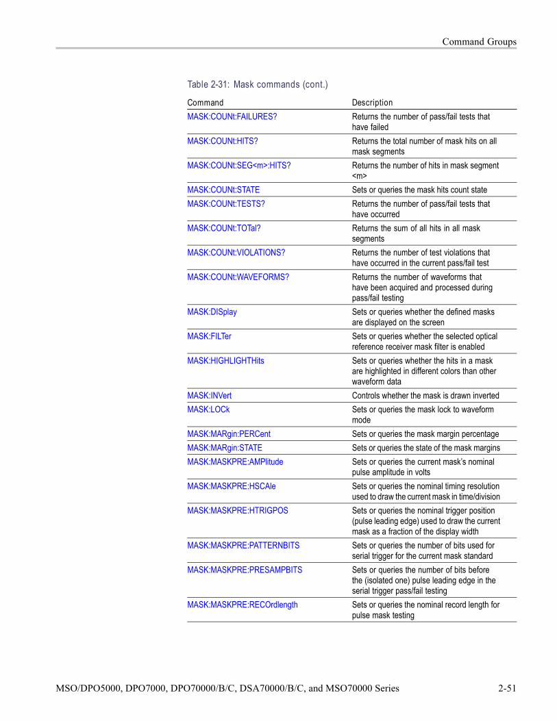
Command Groups
Table 2-31: Mask commands (cont.)
Command DescriptionMASK:COUNt:FAILURES? Returns the number of pass/fail tests that
have failedMASK:COUNt:HITS? Returns the total number of mask hits on all
mask segmentsMASK:COUNt:SEG<m>:HITS? Returns the number of hits in mask segment
<m>MASK:COUNt:STATE Sets or queries the mask hits count stateMASK:COUNt:TESTS? Returns the number of pass/fail tests that
have occurredMASK:COUNt:TOTal? Returns the sum of all hits in all mask
segmentsMASK:COUNt:VIOLATIONS? Returns the number of test violations that
have occurred in the current pass/fail testMASK:COUNt:WAVEFORMS? Returns the number of waveforms that
have been acquired and processed duringpass/fail testing
MASK:DISplay Sets or queries whether the defined masksare displayed on the screen
MASK:FILTer Sets or queries whether the selected opticalreference receiver mask filter is enabled
MASK:HIGHLIGHTHits Sets or queries whether the hits in a maskare highlighted in different colors than otherwaveform data
MASK:INVert Controls whether the mask is drawn invertedMASK:LOCk Sets or queries the mask lock to waveform
modeMASK:MARgin:PERCent Sets or queries the mask margin percentageMASK:MARgin:STATE Sets or queries the state of the mask marginsMASK:MASKPRE:AMPlitude Sets or queries the current mask’s nominal
pulse amplitude in voltsMASK:MASKPRE:HSCAle Sets or queries the nominal timing resolution
used to draw the current mask in time/divisionMASK:MASKPRE:HTRIGPOS Sets or queries the nominal trigger position
(pulse leading edge) used to draw the currentmask as a fraction of the display width
MASK:MASKPRE:PATTERNBITS Sets or queries the number of bits used forserial trigger for the current mask standard
MASK:MASKPRE:PRESAMPBITS Sets or queries the number of bits beforethe (isolated one) pulse leading edge in theserial trigger pass/fail testing
MASK:MASKPRE:RECOrdlength Sets or queries the nominal record length forpulse mask testing
MSO/DPO5000, DPO7000, DPO70000/B/C, DSA70000/B/C, and MSO70000 Series 2-51
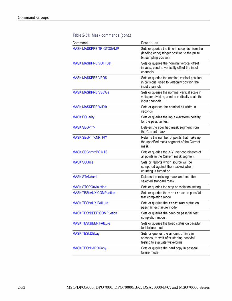
Command Groups
Table 2-31: Mask commands (cont.)
Command DescriptionMASK:MASKPRE:TRIGTOSAMP Sets or queries the time in seconds, from the
(leading edge) trigger position to the pulsebit sampling position
MASK:MASKPRE:VOFFSet Sets or queries the nominal vertical offsetin volts, used to vertically offset the inputchannels
MASK:MASKPRE:VPOS Sets or queries the nominal vertical positionin divisions, used to vertically position theinput channels
MASK:MASKPRE:VSCAle Sets or queries the nominal vertical scale involts per division, used to vertically scale theinput channels
MASK:MASKPRE:WIDth Sets or queries the nominal bit width inseconds
MASK:POLarity Sets or queries the input waveform polarityfor the pass/fail test
MASK:SEG<m> Deletes the specified mask segment fromthe Current mask
MASK:SEG<m>:NR_Pt? Returns the number of points that make upthe specified mask segment of the Currentmask
MASK:SEG<m>:POINTS Sets or queries the X-Y user coordinates ofall points in the Current mask segment
MASK:SOUrce Sets or reports which source will becompared against the mask(s) whencounting is turned on
MASK:STANdard Deletes the existing mask and sets theselected standard mask
MASK:STOPOnviolation Sets or queries the stop on violation settingMASK:TESt:AUX:COMPLetion Sets or queries the test:aux on pass/fail
test completion modeMASK:TESt:AUX:FAILure Sets or queries the test:aux status on
pass/fail test failure modeMASK:TESt:BEEP:COMPLetion Sets or queries the beep on pass/fail test
completion modeMASK:TESt:BEEP:FAILure Sets or queries the beep status on pass/fail
test failure modeMASK:TESt:DELay Sets or queries the amount of time in
seconds, to wait after starting pass/failtesting to evaluate waveforms
MASK:TESt:HARDCopy Sets or queries the hard copy in pass/failfailure mode
2-52 MSO/DPO5000, DPO7000, DPO70000/B/C, DSA70000/B/C, and MSO70000 Series

Command Groups
Table 2-31: Mask commands (cont.)
Command DescriptionMASK:TESt:LOG:FAILure Sets or queries the log status on pass/fail
test failure modeMASK:TESt:REPeat Sets or queries the repeat pass/fail test on
completion modeMASK:TESt:SAMple Sets or queries the minimum number of
waveform database (WfmDB) points theinstrument can acquire before it stops asingle sequence acquisition or stops runninga mask test
MASK:TESt:SAMple:THReshold Sets or queries the minimum number ofhits in mask regions needed to cause thepass/fail status to change from PASSING toFAILING
MASK:TESt:SAVEWFM Sets or queries the save waveform to file onfailure setting
MASK:TESt:SAVEWFM:FILEName Sets or queries the name of the directory andfile to use with the MASK:TESt:SAVEWFMcommand
MASK:TESt:SRQ:COMPLetion Sets or queries an SRQ on pass/fail testcompletion mode
MASK:TESt:SRQ:FAILure Sets or queries the SRQ status on pass/failtest failure mode
MASK:TESt:STATE Sets or queries the state of mask pass/failtesting
MASK:TESt:STATUS? Returns the pass/fail test statusMASK:TESt:STOP:FAILure Sets or queries the stop status on pass/fail
test failure modeMASK:TESt:THReshold Sets or queries the number of failed tested
waveforms needed in each pass/fail test tocause the pass/fail status to change fromPASSING to FAILING
MASK:TESt:WAVEform Sets or queries the number of waveforms totest during pass/fail testing
MASK:USER:AMPlitude Sets or queries the current mask’s nominalpulse amplitude in volts
MASK:USER:BITRate Sets or queries the user mask’s bit rateMASK:USER:HSCAle Sets or queries the nominal timing resolution
used to draw the mask in time/divisionMASK:USER:HTRIGPOS Sets or queries the nominal trigger position
(pulse leading edge) used to draw the maskas a fraction of the display width
MASK:USER:LABel Sets or queries the label assigned to a usermask
MSO/DPO5000, DPO7000, DPO70000/B/C, DSA70000/B/C, and MSO70000 Series 2-53

Command Groups
Table 2-31: Mask commands (cont.)
Command DescriptionMASK:USER:PATTERNBITS Sets or queries the number of bits used for
serial trigger for the User mask standardMASK:USER:PRESAMPBITS Sets or queries the number of bits before
the (isolated one) pulse leading edge in theserial trigger pass/fail testing
MASK:USER:RECOrdlength Sets or queries the nominal record length forpulse mask testing
MASK:USER:SEG<m> Deletes the specified mask segment fromthe User mask
MASK:USER:SEG<m>:NR_Pt? Returns the number of points that make upthe specified User mask segment
MASK:USER:SEG<m>:POINTS Sets or queries the X-Y user coordinates ofall points in the specified User mask segment
MASK:USER:TRIGTOSAMP Sets or queries the time in seconds, from the(leading edge) trigger position to the pulsebit sampling position
MASK:USER:VOFFSet Sets or queries the nominal vertical offsetin volts, used to vertically offset the inputchannels
MASK:USER:VPOS Sets or queries the nominal vertical positionin divisions, used to vertically position theinput channels
MASK:USER:VSCAle Sets or queries the nominal vertical scale involts per division, used to vertically scale theinput channels
MASK:USER:WIDth Sets or queries the nominal bit width inseconds
RECAll:MASK Recalls a stored mask as the User maskSAVe:MASK Saves the User mask to a mass storage file
Math Command GroupUse the commands in the Math Command Group to create and define mathwaveforms. You can define and display up to four math waveforms simultaneouslyon four channel models and up to two on two channel models. Use the availablemath functions to define your math waveform.
The math waveform you create depends on sources listed in the math expression.If you change these sources, the math waveforms you previously defined will beaffected.
Math expressions can be simple, containing no mathematical computation, suchas CH1, which specifies that a waveform shows the signal source of channel 1.
2-54 MSO/DPO5000, DPO7000, DPO70000/B/C, DSA70000/B/C, and MSO70000 Series

Command Groups
Math expressions can also be complex, consisting of 100 plus characters andcomprising many sources, functions, and operands.
The acquisition of a live waveform can stop for several reasons: You can turn offthe channel, stop the waveform (via Run/Stop from the Horiz/Acq menu), or stopthe trigger (via Run/Stop from the Trig menu). When you turn off the channel,math continues and data is acquired but is not displayed. When you stop either thewaveform or the trigger, the math calculation stops, and the last math calculationperformed is displayed.
When a live waveform update or reference waveform is altered, math waveformscontaining those waveforms as sources are also updated to reflect the changes.Also, sources must exist but do not need to be displayed to be used in and toupdate math waveforms.
Table 2-32: Math commands
Command DescriptionMATH<x>? Returns the specified math waveform
settingsMATH<x>:DEFine Sets or queries the math<x> waveform
definition for the specified waveformMATH<x>:FILTer:MODe Sets or queries the filter rise time parameter
(centered or shifted)MATH<x>:FILTer:RISetime Sets or queries the filter rise time parameterMATH<x>:LABel:NAMe Sets or queries the label string used for
annotating the displayed math waveformMATH<x>:LABel:XPOS Sets or queries the X screen offset where the
math waveform label is displayedMATH<x>:LABel:YPOS Sets or queries the Y screen offset where the
math waveform label is displayedMATH<x>:NUMAVg Sets or queries the acquisition number at
which the averaging algorithm will beginexponential averaging
MATH<x>:SPECTral? Returns the specified math waveformspectral setups
MATH<x>:SPECTral:CENTER Sets or queries the center frequency of thespectral analyzer output data span
MATH<x>:SPECTral:GATEPOS Sets or queries the position of the center ofthe gate
MATH<x>:SPECTral:GATEWIDTH Sets or queries the gate width input to thespectral analyzer
MATH<x>:SPECTral:LOCk Sets or queries the state of the spectrallocking for the specified math waveform
MATH<x>:SPECTral:MAG Sets or queries the units of the SpectralMagfunction in the specified math string
MSO/DPO5000, DPO7000, DPO70000/B/C, DSA70000/B/C, and MSO70000 Series 2-55

Command Groups
Table 2-32: Math commands (cont.)
Command DescriptionMATH<x>:SPECTral:PHASE Sets or queries the units of the SpectralPhase
function in the specified math stringMATH<x>:SPECTral:REFLevel Sets or queries the vertical position of the
output data from the spectral analyzerMATH<x>:SPECTral:REFLEVELOffset Sets or queries the spectral reference level
offset used for calculating the dB valueMATH<x>:SPECTral:RESBw Sets or queries the resolution bandwidth of
the spectral analyzerMATH<x>:SPECTral:SPAN Sets the top of the frequency span to a value
that is closest to the specified valueOr queries the specified math waveform’scurrent frequency span value
MATH<x>:SPECTral:SUPPress Sets or queries the phase suppressionthreshold
MATH<x>:SPECTral:UNWRap Enables or disables or returns the state ofthe phase unwrap of the spectral analyzeroutput data
MATH<x>:SPECTral:WINdow Sets or queries the window function usedto multiply the input data to the spectralanalyzer
MATH<x>:UNITString Sets or queries the units used for the mathwaveform; command overrides the defaultunit string
MATH<x>:VERTical:POSition Sets or queries the specified math waveformvertical position
MATH<x>:VERTical:SCAle Sets or queries the specified math waveformvertical scale (per div)
MATHArbflt<x>:FILepath Sets the file path for a file of filter coefficientsand reads the file
MATHArbflt<x>:READFile Forces a reread of the filter file for thespecified arbitrary filter
MATHVAR? Sets or queries all 8 numerical values youcan use within math expressions
MATHVAR:VAR<x> Sets or queries a numerical value you canuse within math expressions
MATH<x>:THRESHold Sets or queries the comparable threshold forconverting the math signal to digital form
Measurement Command GroupUse the commands in the Measurement Command Group to control the automatedmeasurement system.
2-56 MSO/DPO5000, DPO7000, DPO70000/B/C, DSA70000/B/C, and MSO70000 Series

Command Groups
Up to eight automated measurements can be displayed on the screen. In thecommands, these measurement readouts are named MEAS<x>, where <x> can be1 through 8.
In addition to the eight displayed measurements, the measurement commands letyou specify an additional measurement, IMMed. The immediate measurementhas no front panel equivalent. Immediate measurements are never displayed.Because they are computed only when needed, immediate measurements slow thewaveform update rate less than displayed measurements.
Whether you use displayed or immediate measurements, use the VALue query toobtain measurement results.
Measurement commands can set and query measurement parameters. You canassign parameters, such as waveform sources and reference levels, differentlyfor each measurement.
Table 2-33: Measurement commands
Command DescriptionMEASUrement? Returns all measurement parametersMEASUrement:ANNOTation:IMMEDSTAte Sets or queries the state of immediate
measurement annotationMEASUrement:ANNOTation:NUMX? Returns the number of horizontal
measurement annotations being displayedMEASUrement:ANNOTation:NUMY? Returns the number of vertical measurement
annotations being displayedMEASUrement:ANNOTation:STATE Sets or queries the state of visible
measurement annotationsMEASUrement:ANNOTation:TYPe Sets or queries the type of annotations being
usedMEASUrement:ANNOTation:X<x>? Returns the value of the specified annotationMEASUrement:ANNOTation:Y<x>? Returns the value of the specified annotationMEASUrement:GATing Sets or queries the measurement gatingMEASUrement:IMMed? Returns all immediate measurement setup
parametersMEASUrement:IMMed:DELay? Returns information about the immediate
delay measurementMEASUrement:IMMed:DELay:DIREction Sets or queries the search direction to use
for immediate delay measurementsMEASUrement:IMMed:DELay:EDGE[1] Sets or queries the slope of the edge
used for immediate delay “from” waveformmeasurements
MEASUrement:IMMed:DELay:EDGE2 Sets or queries the slope of the edgeused for immediate delay “to” waveformmeasurements
MSO/DPO5000, DPO7000, DPO70000/B/C, DSA70000/B/C, and MSO70000 Series 2-57

Command Groups
Table 2-33: Measurement commands (cont.)
Command DescriptionMEASUrement:IMMed:METHod Specifies or queries the method used to
calculate the 0% and 100% reference levelfor immediate measurements
MEASUrement:IMMed:NOISe Sets or queries the location of the noisemeasurement on the eye waveform
MEASUrement:IMMed:REFLevel? Returns the reference levelsMEASUrement:IMMed:REFLevel:ABSolute:HIGH
Sets or queries the high reference level
MEASUrement:IMMed:REFLevel:ABSolute:LOW
Sets or queries the low reference level
MEASUrement:IMMed:REFLevel:ABSolute:MID<x>
Sets or queries the middle reference levels
MEASUrement:IMMed:REFLevel:METHod Sets or queries the method used to calculatemeasurements
MEASUrement:IMMed:REFLevel:PERCent:HIGH
Sets or queries the top level for rise time(90% level)
MEASUrement:IMMed:REFLevel:PERCent:LOW
Sets or queries the low level for rise time(10% level)
MEASUrement:IMMed:REFLevel:PERCent:MID<x>
Sets or queries the mid levels formeasurements
MEASUrement:IMMed:SOUrce<x> Sets or queries the source to measure “to”or “from” for phase or delay immediatemeasurements
MEASUrement:IMMed:SOUrce<x>:SIGType Sets or queries the type of input signal usedfor the specified measurement source
MEASUrement:IMMed:TYPe Sets or queries the type of the immediatemeasurement
MEASUrement:IMMed:UNIts? Returns the units of the immediatemeasurement
MEASUrement:IMMed:VALue? Returns the value of the immediatemeasurement
MEASUrement:MEAS<x>? Returns all measurement parameters for thedisplayed measurement
MEASUrement:MEAS<x>:COUNt? Returns the number of values accumulatedsince the last statistical reset
MEASUrement:MEAS<x>:DELay? Returns the delay measurement parametersfor specified measurement
MEASUrement:MEAS<x>:DELay:DIREction Sets or queries the search direction to usefor delay measurements
MEASUrement:MEAS<x>:DELay:EDGE<x> Sets or queries the slope of the edgeto use for delay “from” or “to” waveformmeasurements
2-58 MSO/DPO5000, DPO7000, DPO70000/B/C, DSA70000/B/C, and MSO70000 Series

Command Groups
Table 2-33: Measurement commands (cont.)
Command DescriptionMEASUrement:MEAS<x>:MAXimum? Returns the maximum value found since the
last statistical resetMEASUrement:MEAS<x>:MEAN? Returns the mean value accumulated since
the last statistical resetMEASUrement:MEAS<x>:METHod Sets or queries the method used to calculate
the 0% and 100% reference levelMEASUrement:MEAS<x>:MINImum? Returns the minimum value found since the
last statistical resetMEASUrement:MEAS<x>:NOISe Sets or queries the location of the noise
measurement on the eye waveform forMEAS<x>
MEASUrement:MEAS<x>:REFLevel? Returns the reference levelsMEASUrement:MEAS<x>:REFLevel:ABSolute:HIGH
Sets or queries the top level for rise time(90% level)
MEASUrement:MEAS<x>:REFLevel:ABSolute:LOW
Sets or queries the low level for rise time(10%)
MEASUrement:MEAS<x>:REFLevel:ABSolute:MID<x>
Sets or queries the mid1 or mid2 level formeasurements
MEASUrement:MEAS<x>:REFLevel:METHod
Sets or queries the reference level unitsused for measurement calculations
MEASUrement:MEAS<x>:REFLevel:PERCent:HIGH
Sets or queries the top level for rise time(90% level)
MEASUrement:MEAS<x>:REFLevel:PERCent:LOW
Sets or queries the low level for rise time(10% level)
MEASUrement:MEAS<x>:REFLevel:PERCent:MID<x>
Sets or queries the mid1 or mid2 level fordelay measurements
MEASUrement:MEAS<x>:SOUrce<x> Sets or queries the source to measure “from”or “to” for phase or delay measurements
MEASUrement:MEAS<x>:SOUrce<x>:SIGType
Sets or queries the type of input signal usedfor the specified measurement source for thespecified measurement slot
MEASUrement:MEAS<x>:STATE Sets or queries whether the specifiedmeasurement slot is computed anddisplayed
MEASUrement:MEAS<x>:STDdev? Returns the standard deviation of valuesaccumulated since the last statistical reset
MEASUrement:MEAS<x>:TYPe Sets or queries the measurement<x> typeMEASUrement:MEAS<x>:UNIts? Returns measurement<x> unitsMEASUrement:MEAS<x>:VALue? Returns the value of measurement<x>MEASUrement:METHod Sets or queries the method used for
calculating reference levels
MSO/DPO5000, DPO7000, DPO70000/B/C, DSA70000/B/C, and MSO70000 Series 2-59

Command Groups
Table 2-33: Measurement commands (cont.)
Command DescriptionMEASUrement:NOISe Sets or queries the location of the noise
measurement on the eye waveformMEASUrement:REFLevel:ABSolute:HIGH Sets or queries the top reference level for
rise timeMEASUrement:REFLevel:ABSolute:LOW Sets or queries the low reference level for
rise timeMEASUrement:REFLevel:ABSolute:MID<x> Sets or queries the mid1 or mid2 reference
level for measurementsMEASUrement:REFLevel:METHod Sets or queries the method for assigning
high and low reference levelsMEASUrement:REFLevel:PERCent:HIGH Sets or queries the top reference percent
level for rise timeMEASUrement:REFLevel:PERCent:LOW Sets or queries the low reference percent
level for rise timeMEASUrement:REFLevel:PERCent:MID<x> Sets or queries the mid1 or mid 2 reference
percent level for waveform measurementsMEASUrement:SOUrce<x>:SIGType Sets or queries the type of input signal used
for the specified measurement sourceMEASUrement:STATIstics:COUNt Clears existing measurement statistics from
memoryMEASUrement:STATIstics:MODe Turns measurement statistics on or off
and sets or queries which pair of statisticalaccumulations is displayed
MEASUrement:STATIstics:WEIghting Sets or queries the ’time constant’ formean and standard deviation statisticalaccumulations
Miscellaneous Command GroupMiscellaneous commands do not fit into other categories.
Several commands and queries are common to all 488.2-1987 devices on theGPIB bus. The 488.2-1987 standard defines these commands. The commoncommands begin with an asterisk (*) character.
Table 2-34: Miscellaneous commands
Command DescriptionAUXout? Returns the auxiliary out setupAUXout:EDGE Sets or queries the direction in which the
trigger output signal will transition when atrigger occurs
2-60 MSO/DPO5000, DPO7000, DPO70000/B/C, DSA70000/B/C, and MSO70000 Series

Command Groups
Table 2-34: Miscellaneous commands (cont.)
Command DescriptionAUXout:SOUrce Sets or queries the trigger source at the BNC
connectionAUTOSet Sets the vertical, horizontal, and trigger
controls of the instrument to automaticallyacquire and display the selected waveform
BELl In previous models, this command soundedthe audio indicator. Provided for backwardcompatibility
CMDBatch Turns command batching on or offOr returns the state of command batching
DATE Sets or queries the date that the instrumentcan display
*DDT Sets or queries the commands that will beexecuted by the group execute trigger
FPANel:PRESS Turns off the displayed menuHEADer Sets or queries the Response Header
Enable StateHDR Sets or queries the Response Header
Enable StateID? Returns identifying information about the
instrument and its firmware*IDN? Returns the instrument identification codeLOCk Sets or queries the front panel lock state*LRN? Returns a listing of instrument settingsNEWpass Changes the password for user protected
dataPASSWord Provides access for changing user protected
dataREM Specifies a comment which is ignored by the
instrumentROSc:OUT:FREQuency Sets or queries the selected frequency for
the timebase reference output signalROSc:SOUrce Sets or queries the selected source for the
time base reference oscillatorROSc:STATE? Returns whether the time base reference
oscillator is lockedROSc:TRACking Sets or queries the selected source for the
time base reference oscillator. The referenceoscillator locks to this source
SET? Returns a listing of instrument settings
MSO/DPO5000, DPO7000, DPO70000/B/C, DSA70000/B/C, and MSO70000 Series 2-61

Command Groups
Table 2-34: Miscellaneous commands (cont.)
Command DescriptionTEKSecure Initializes both waveform and setup
memoriesTIME Sets or queries the time displayed by the
instrument*TRG Performs the group execute trigger (GET)*TST? Tests the GPIB interface and returns statusUNLock Unlocks front panelUSBTMC:PRODUCTID:DECimal? Queries the USBTMC product ID in decimalUSBTMC:PRODUCTID:HEXadecimal? Qeries the USBTMC product ID in
hexadecimalUSBTMC:SERIALnumber? Qeries the instrument serial numberUSBTMC:VENDORID:DECimal? Queries the USBTMC product ID in decimalUSBTMC:VENDORID:HEXadecimal? Queries the USBTMC product ID in
hexadecimalVERBose Sets or queries the verbose state
Save and Recall Command GroupUse the commands in the Save and Recall Command Group to store and retrieveinternal waveforms and settings. When you save a setup, you save all the settingsof the instrument. When you recall a setup, the instrument restores itself to thestate that it was in when you originally saved that setting.
Table 2-35: Save and Recall commands
Command Description*RCL Restores the state of the instrument from a
copy of the setting stored in memory*SAV Stores the current instrument state to a
specified memory location*SDS Changes the specified setup to reference the
factory setup instead of the user setupDELEte:SETUp Removes stored setups from memory and
initializes the location with the factory defaultsetups
DELEte:WAVEform Deletes (one or all of) the stored referencewaveforms from memory
FACtory Resets the instrument to factory defaultsettings
RECAll:SETUp Recalls saved instrument settings
2-62 MSO/DPO5000, DPO7000, DPO70000/B/C, DSA70000/B/C, and MSO70000 Series

Command Groups
Table 2-35: Save and Recall commands (cont.)
Command DescriptionRECAll:SETUp:DESKew Sets or queries the deskew values that are
affected by a default setup or a recalled setupRECAll:WAVEform Recalls a stored waveform to a reference
locationSAVe:SETUp Saves the current front panel setup to a
specified memory location or fileSAVe:WAVEform Saves a waveform to one of four reference
memory locations or a mass storage fileSAVe:WAVEform:FILEFormat Sets or queries the format for saved
waveformsSETUp:NAMe Sets or queries the user-defined setup label
Search and Mark Command GroupUse Search and Mark commands to seek out and identify information in waveformrecords that warrant further investigation.
Table 2-36: Search and Mark commands
Command DescriptionMARK Moves to the next or previous reference
mark, or queries the current mark setupMARK:CREATE Creates a mark on a specified waveform or
all waveforms in a columnMARK:DELEte Deletes a mark on a particular waveform, all
waveforms in a column, the selected mark,or all marks
MARK:FREE? Returns how many marks are available foruse
MARK:SELECTED:END? Returns the end of the selected mark, 0 to100% of the waveform
MARK:SELECTED:FOCUS? Returns the focus of the selected mark, 0 to100% of the waveform
MARK:SELECTED:LABel Set or queries the label for the selected markMARK:SELECTED:MARKSINCOLumn? Returns the number of marks in the current
zoom pixel columnMARK:SELECTED:OWNer? Returns the owner of the selected markMARK:SELECTED:SOUrce? Sets or queries the source waveform for the
selected markMARK:SELECTED:STARt? Returns the starting point of the selected
mark, 0 to 100% of the waveform
MSO/DPO5000, DPO7000, DPO70000/B/C, DSA70000/B/C, and MSO70000 Series 2-63

Command Groups
Table 2-36: Search and Mark commands (cont.)
Command DescriptionMARK:SELECTED:STATE Returns the on or off state of the selected
mark. The selected mark is at or near thecenter of the display
MARK:SELECTED:ZOOm:POSition? Returns the position of the selected mark, 0to 100% of the zoom overview window
MARK:SELECTED:ZOOm:SCAle? Returns the scale of the selected mark, 0 to100% of the zoom overview window
MARK:TOTal? Returns how many marks are currently inuse
SEARCH:SEARCH<x> Converts the specified search marks to theuser marks. <x> can be 1 to 8
SEARCH:SEARCH<x>:COPy Copies the search criteria to the trigger, thetrigger criteria to a search, or copy search tosearch. <x> is the search number
SEARCH:SEARCH<x>:STATE Selects which search is selectedSEARCH:SEARCH<x>:TOTAL? Returns the total number of matches for the
search. The total number of matches maybe more than the number of marks placed
SEARCH:SEARCH<x>:TRIGger:A:DDRMemory:AUTOBitrate
Sets or queries the auto bit rate setting
SEARCH:SEARCH<x>:TRIGger:A:DDRMemory:AUTOReflevel
Sets or queries the auto reference levelssetting
SEARCH:SEARCH<x>:TRIGger:A:DDRMemory:BITRate
Sets or queries the DDR memory bit rate
SEARCH:SEARCH<x>:TRIGger:A:DDRMemory:CSActive
Sets or queries whether the expectedchip-select will be an active HIGH or LOW
SEARCH:SEARCH<x>:TRIGger:A:DDRMemory:CSLevel
Sets or queries the DDR memory searchchip-select level
SEARCH:SEARCH<x>:TRIGger:A:DDRMemory:CSMode
Sets or queries the chip-select mode
SEARCH:SEARCH<x>:TRIGger:A:DDRMemory:CSSource
Sets or queries the chip select source
SEARCH:SEARCH<x>:TRIGger:A:DDRMemory:DATASource
Sets or queries the DDR memory datasource
SEARCH:SEARCH<x>:TRIGger:A:DDRMemory:HYSterisis
Sets or queries the hysterisis percent forDDR memory searches
SEARCH:SEARCH<x>:TRIGger:A:DDRMemory:REFLevel:DATa:HIGH
Sets or queries the value of the data HIGHreference level
SEARCH:SEARCH<x>:TRIGger:A:DDRMemory:REFLevel:DATa:LOW
Sets or queries the value of the data LOWreference level
SEARCH:SEARCH<x>:TRIGger:A:DDRMemory:REFLevel:DATa:MID
Sets or queries the value of the data MIDreference level
2-64 MSO/DPO5000, DPO7000, DPO70000/B/C, DSA70000/B/C, and MSO70000 Series

Command Groups
Table 2-36: Search and Mark commands (cont.)
Command DescriptionSEARCH:SEARCH<x>:TRIGger:A:DDRMemory:REFLevel:STROBE:HIGH
Sets or queries the value of the strobe HIGHreference level
SEARCH:SEARCH<x>:TRIGger:A:DDRMemory:REFLevel:STROBE:LOW
Sets or queries the value of the strobe LOWreference level
SEARCH:SEARCH<x>:TRIGger:A:DDRMemory:REFLevel:STROBE:MID
Sets or queries the value of the strobe MIDreference level
SEARCH:SEARCH<x>:TRIGger:A:DDRMemory:STANdard
Sets or queries the DDR standard type for aDDR Memory analysis search
SEARCH:SEARCH<x>:TRIGger:A:DDRMemory:STROBEsource
Sets or queries the strobe source for a DDRMemory analysis search
SEARCH:SEARCH<x>:TRIGger:A:EDGE:SLOpe:CH<x>
Sets or queries the slope for an edge triggersearch to determine where to place a mark.<x> is the search number or the channelnumber
SEARCH:SEARCH<x>:TRIGger:A:EDGE:SLOpe:MATH<x>
Sets or queries the slope for an edge triggersearch to determine where to place a mark.<x> is the search number or the mathwaveform number
SEARCH:SEARCH<x>:TRIGger:A:EDGE:SLOpe:REF<x>
Sets or queries the slope for an edge triggersearch to determine where to place a mark.<x> is the search number or the referencewaveform number
SEARCH:SEARCH<x>:TRIGger:A:EDGE:SOUrce
Sets or queries the source waveform for anedge trigger search to determine where toplace a mark. <x> is the search number
SEARCH:SEARCH<x>:TRIGger:A:GLItch:POLarity:CH<x>
Sets or queries the polarity for a glitch triggersearch to determine where to place a mark.<x> is the search number or channel number
SEARCH:SEARCH<x>:TRIGger:A:GLItch:POLarity:MATH<x>
Sets or queries the polarity for a glitch triggersearch to determine where to place a mark.<x> is the search number or math waveformnumber
SEARCH:SEARCH<x>:TRIGger:A:GLItch:POLarity:REF<x>
Sets or queries the polarity for a glitch triggersearch to determine where to place a mark.<x> is the search number or referencewaveform number
SEARCH:SEARCH<x>:TRIGger:A:GLItch:TRIGIF
Sets or queries the accept or reject state fora glitch trigger search to determine where toplace a mark. <x> is the search number
SEARCH:SEARCH<x>:TRIGger:A:GLItch:WIDth
Sets or queries the glitch width for a glitchtrigger search to determine where to place amark. <x> is the search number
MSO/DPO5000, DPO7000, DPO70000/B/C, DSA70000/B/C, and MSO70000 Series 2-65

Command Groups
Table 2-36: Search and Mark commands (cont.)
Command DescriptionSEARCH:SEARCH<x>:TRIGger:A:LEVel:CH<x>
Sets or queries the level for an edge triggersearch to determine where to place amark. <x> is the search number or thechannel number. Each channel can have anindependent level
SEARCH:SEARCH<x>:TRIGger:A:LEVel:MATH<x>
Sets or queries the math waveform level foran edge trigger search to determine whereto place a mark. <x> is the search numberor math waveform number
SEARCH:SEARCH<x>:TRIGger:A:LEVel:REF<x>
Sets or queries the specified referencewaveform level for a trigger searchto determine where to place a mark.SEARCH<x> is the search number andREF<x> is the reference channel number
SEARCH:SEARCH<x>:TRIGger:A:LOGIc:FUNCtion
Sets or queries the logic operator for apattern or state trigger search to determinewhere to place a mark. <x> is the searchnumber
SEARCH:SEARCH<x>:TRIGger:A:LOGIc:INPut:CH<x>
Sets or queries the Boolean logic criteria fora pattern or state trigger search to determinewhere to place a mark. <x> is the searchnumber or the channel number
SEARCH:SEARCH<x>:TRIGger:A:LOGIc:INPut:MATH<x>
Sets or queries the Boolean logic criteria fora pattern or state trigger search to determinewhere to place a mark. <x> is the searchnumber or the math waveform number
SEARCH:SEARCH<x>:TRIGger:A:LOGIc:INPut:REF<x>
Sets or queries the Boolean logic criteria fora pattern or state trigger search to determinewhere to place a mark. <x> is the searchnumber or the reference channel number
SEARCH:SEARCH<x>:TRIGger:A:LOGIc:THReshold:CH<x>
Sets or queries the channel thresholdlevel for a pattern or state trigger searchto determine where to place a mark.SEARCH<x> is the search number andCH<x> is the channel number
SEARCH:SEARCH<x>:TRIGger:A:LOGIc:THReshold:MATH<x>
Sets or queries the math waveform thresholdlevel for a pattern or state trigger search todetermine where to place a mark. <x> isthe search number or the Math waveformnumber
SEARCH:SEARCH<x>:TRIGger:A:LOGIc:THReshold:REF<x>
Sets or queries the reference waveformthreshold level for a pattern or state triggersearch to determine where to place a mark.<x> is the search number or the referencewaveform number
2-66 MSO/DPO5000, DPO7000, DPO70000/B/C, DSA70000/B/C, and MSO70000 Series

Command Groups
Table 2-36: Search and Mark commands (cont.)
Command DescriptionSEARCH:SEARCH<x>:TRIGger:A:PATtern:WHEn
Sets or queries the pattern trigger patterntest that determines where to place a mark.<x> is the search number
SEARCH:SEARCH<x>:TRIGger:A:PATtern:WHEn:LESSLimit
Sets or queries the time the pattern triggerless limit test uses to determines where toplace a mark. <x> is the search number
SEARCH:SEARCH<x>:TRIGger:A:PATtern:WHEn:MORELimit
Sets or queries the time the pattern triggermore limit test uses to determines where toplace a mark. <x> is the search number
SEARCH:SEARCH<x>:TRIGger:A:PULse:SOUrce
Sets or queries the source waveform for apulse trigger search to determine where toplace a mark. <x> is the search number.This is the source for Glitch, Width, Runt,Timeout or Window searches
SEARCH:SEARCH<x>:TRIGger:A:RUNT:POLarity:CH<x>
Sets or queries the polarity setting for a runttrigger search to determine where to place amark. <x> is the search number or channelnumber
SEARCH:SEARCH<x>:TRIGger:A:RUNT:POLarity:MATH<x>
Sets or queries the polarity setting for a runttrigger search to determine where to placea mark. <x> is the search number or mathwaveform number
SEARCH:SEARCH<x>:TRIGger:A:RUNT:POLarity:REF<x>
Sets or queries the polarity setting for a runttrigger search to determine where to place amark. <x> is the search number or referencewaveform number
SEARCH:SEARCH<x>:TRIGger:A:RUNT:THReshold:HIGH:CH<x>
Sets or queries the channel threshold HIGHlevel for a runt trigger search to determinewhere to place a mark. <x> is the searchnumber or the channel number
SEARCH:SEARCH<x>:TRIGger:A:RUNT:THReshold:HIGH:MATH<x>
Sets or queries the math waveform thresholdHIGH level for a runt trigger search todetermine where to place a mark. <x> isthe search number or the math waveformnumber
SEARCH:SEARCH<x>:TRIGger:A:RUNT:THReshold:HIGH:REF<x>
Sets or queries the reference waveformthreshold HIGH level for a runt triggersearch to determine where to place a mark.<x> is the search number or the referencewaveform number
SEARCH:SEARCH<x>:TRIGger:A:RUNT:THReshold:LOW:CH<x>
Sets or queries the channel threshold LOWlevel for a runt trigger search to determinewhere to place a mark. <x> is the searchnumber or the channel number
MSO/DPO5000, DPO7000, DPO70000/B/C, DSA70000/B/C, and MSO70000 Series 2-67

Command Groups
Table 2-36: Search and Mark commands (cont.)
Command DescriptionSEARCH:SEARCH<x>:TRIGger:A:RUNT:THReshold:LOW:MATH<x>
Sets or queries the math waveform thresholdLOW level for a runt trigger search todetermine where to place a mark. <x> isthe search number or the math waveformnumber
SEARCH:SEARCH<x>:TRIGger:A:RUNT:THReshold:LOW:REF<x>
Sets or queries the reference waveformthreshold LOW level for a runt trigger searchto determine where to place a mark. <x>is the search number or the referencewaveform number
SEARCH:SEARCH<x>:TRIGger:A:RUNT:WHEn
Sets or queries the condition setting for arunt trigger search to determine where toplace a mark. <x> is the search number
SEARCH:SEARCH<x>:TRIGger:A:RUNT:WIDth
Sets or queries the width setting for a runttrigger search to determine where to place amark. <x> is the search number
SEARCH:SEARCH<x>:TRIGger:A:SETHold:CLOCk:EDGE
Sets or queries the clock slope setting for asetup/hold trigger search to determine whereto place a mark. <x> is the search number
SEARCH:SEARCH<x>:TRIGger:A:SETHold:CLOCk:SOUrce
Sets or queries the clock source setting for asetup/hold trigger search to determine whereto place a mark. <x> is the search number
SEARCH:SEARCH<x>:TRIGger:A:SETHold:CLOCk:THReshold:CH<x>
Sets or queries the clock threshold settingfor a setup/hold trigger search to determinewhere to place a mark. <x> is the searchnumber or channel number
SEARCH:SEARCH<x>:TRIGger:A:SETHold:CLOCk:THReshold:MATH<x>
Sets or queries the clock threshold settingfor a setup/hold trigger search to determinewhere to place a mark. <x> is the searchnumber or math waveform number
SEARCH:SEARCH<x>:TRIGger:A:SETHold:CLOCk:THReshold:REF<x>
Sets or queries the clock threshold settingfor a setup/hold trigger search to determinewhere to place a mark. <x> is the searchnumber or reference waveform number
SEARCH:SEARCH<x>:TRIGger:A:SETHold:DATa:SOUrce
Sets or queries the data source setting for asetup/hold trigger search to determine whereto place a mark. <x> is the search number
SEARCH:SEARCH<x>:TRIGger:A:SETHold:DATa:THReshold:CH<x>
Sets or queries the data threshold settingfor a setup/hold trigger search to determinewhere to place a mark. <x> is the searchnumber or channel number
SEARCH:SEARCH<x>:TRIGger:A:SETHold:DATa:THReshold:MATH<x>
Sets or queries the data threshold settingfor a setup/hold trigger search to determinewhere to place a mark. <x> is the searchnumber or math waveform number
2-68 MSO/DPO5000, DPO7000, DPO70000/B/C, DSA70000/B/C, and MSO70000 Series

Command Groups
Table 2-36: Search and Mark commands (cont.)
Command DescriptionSEARCH:SEARCH<x>:TRIGger:A:SETHold:DATa:THReshold:REF<x>
Sets or queries the threshold high voltagelevel setting for a transition trigger searchto determine where to place a mark. <x> isthe search number or reference waveformnumber
SEARCH:SEARCH<x>:TRIGger:A:SETHold:HOLDTime
Sets or queries the hold time setting for asetup/hold trigger search to determine whereto place a mark. <x> is the search number
SEARCH:SEARCH<x>:TRIGger:A:SETHold:SETTime
Sets or queries the setup time setting for asetup/hold trigger search to determine whereto place a mark. <x> is the search number
SEARCH:SEARCH<x>:TRIGger:A:STATE:CLOCk:EDGE
Sets or queries the clock slope setting for astate trigger search to determine where toplace a mark. <x> is the search number
SEARCH:SEARCH<x>:TRIGger:A:STATE:CLOCk:SOUrce
Sets or queries the clock source of thetwelve waveforms for a state trigger searchto determine where to place a mark. <x> isthe search number. The hardware trigger isalways on the channel CH4
SEARCH:SEARCH<x>:TRIGger:A:STATE:WHEn
Sets or queries the state trigger search todetermine where to place a mark. <x> isthe search number
SEARCH:SEARCH<x>:TRIGger:A:TIMEOut:POLarity:CH<x>
Sets or queries the polarity for a timeouttrigger search to determine where to place amark. <x> is the search number or channelnumber
SEARCH:SEARCH<x>:TRIGger:A:TIMEOut:POLarity:MATH<x>
Sets or queries the polarity for a timeouttrigger search to determine where to placea mark. <x> is the search number or mathwaveform number
SEARCH:SEARCH<x>:TRIGger:A:TIMEOut:POLarity:REF<x>
Sets or queries the polarity for a timeouttrigger search to determine where to place amark. <x> is the search number or referencewaveform number
SEARCH:SEARCH<x>:TRIGger:A:TIMEOut:TIMe
Sets or queries the time setting for a timeouttrigger search to determine where to place amark. <x> is the search number
SEARCH:SEARCH<x>:TRIGger:A:TRANsition:DELTATime
Sets or queries the transition time settingfor a transition trigger search to determinewhere to place a mark.<x> is the searchnumber
SEARCH:SEARCH<x>:TRIGger:A:TRANsition:POLarity:CH<x>
Sets or queries the polarity setting for atransition trigger search to determine whereto place a mark. <x> is the search numberor channel number
MSO/DPO5000, DPO7000, DPO70000/B/C, DSA70000/B/C, and MSO70000 Series 2-69

Command Groups
Table 2-36: Search and Mark commands (cont.)
Command DescriptionSEARCH:SEARCH<x>:TRIGger:A:TRANsition:POLarity:MATH<x>
Sets or queries the polarity setting for atransition trigger search to determine whereto place a mark. <x> is the search numberor math waveform number
SEARCH:SEARCH<x>:TRIGger:A:TRANsition:POLarity:REF<x>
Sets or queries the polarity setting for atransition trigger search to determine whereto place a mark. <x> is the search numberor reference waveform number
SEARCH:SEARCH<x>:TRIGger:A:TRANsition:THReshold:HIGH:CH<x>
Sets or queries the threshold high voltagelevel setting for a transition trigger search todetermine where to place a mark. <x> is thesearch number or channel number
SEARCH:SEARCH<x>:TRIGger:A:TRANsition:THReshold:HIGH:MATH<x>
Sets or queries the threshold high voltagelevel setting for a transition trigger search todetermine where to place a mark. <x> is thesearch number or math waveform number
SEARCH:SEARCH<x>:TRIGger:A:TRANsition:THReshold:HIGH:REF<x>
Sets or queries the threshold high voltagelevel setting for a transition trigger searchto determine where to place a mark. <x> isthe search number or reference waveformnumber
SEARCH:SEARCH<x>:TRIGger:A:TRANsition:THReshold:LOW:CH<x>
Sets or queries the threshold low voltagelevel setting for a transition trigger search todetermine where to place a mark. <x> is thesearch number or channel number
SEARCH:SEARCH<x>:TRIGger:A:TRANsition:THReshold:LOW:MATH<x>
Sets or queries the threshold low voltagelevel setting for a transition trigger search todetermine where to place a mark. <x> is thesearch number or math waveform number
SEARCH:SEARCH<x>:TRIGger:A:TRANsition:THReshold:LOW:REF<x>
Sets or queries the threshold low voltagelevel setting for a transition trigger searchto determine where to place a mark. <x> isthe search number or reference waveformnumber
SEARCH:SEARCH<x>:TRIGger:A:TRANsition:WHEn
Sets or queries the condition setting for atransition trigger search to determine whereto place a mark. <x> is the search number
SEARCH:SEARCH<x>:TRIGger:A:TYPe Sets or queries the trigger type setting for asearch to determine where to place a mark.<x> is the search number
NOTE. Except EDGE all otheroptions must be purchased.
2-70 MSO/DPO5000, DPO7000, DPO70000/B/C, DSA70000/B/C, and MSO70000 Series

Command Groups
Table 2-36: Search and Mark commands (cont.)
Command DescriptionSEARCH:SEARCH<x>:TRIGger:A:WIDth:HIGHLimit
Sets or queries the upper time limit settingfor a width search to determine where toplace a mark. <x> is the search number
SEARCH:SEARCH<x>:TRIGger:A:WIDth:LOWLimit
Sets or queries the lower time limit settingfor a width search to determine where toplace a mark. <x> is the search number
SEARCH:SEARCH<x>:TRIGger:A:WIDth:POLarity:CH<x>
Sets or queries the polarity for a width searchto determine where to place a mark. <x> isthe search number or channel number
SEARCH:SEARCH<x>:TRIGger:A:WIDth:POLarity:MATH<x>
Sets or queries the polarity for a widthsearch to determine where to place a mark.<x> is the search number or math waveformnumber
SEARCH:SEARCH<x>:TRIGger:A:WIDth:POLarity:REF<x>
Sets or queries the polarity for a width searchto determine where to place a mark. <x> isthe search number or reference waveformnumber
SEARCH:SEARCH<x>:TRIGger:A:WIDth:WHEn
Sets or queries the width search to determinewhere to place a mark. <x> is the searchnumber
SEARCH:SEARCH<x>:TRIGger:A:WINdow:EVENT
Sets or queries the window search todetermine where to place a mark. <x> isthe search number
SEARCH:SEARCH<x>:TRIGger:A:WINdow:THReshold:HIGH:CH<x>
Sets or queries the channel waveformthreshold HIGH level for a window search todetermine where to place a mark. <x> is thesearch number or channel number
SEARCH:SEARCH<x>:TRIGger:A:WINdow:THReshold:HIGH:MATH<x>
Sets or queries the channel waveformthreshold HIGH level for a window search todetermine where to place a mark. <x> is thesearch number or math waveform number
SEARCH:SEARCH<x>:TRIGger:A:WINdow:THReshold:HIGH:REF<x>
Sets or queries the channel waveformthreshold HIGH level for a window search todetermine where to place a mark. <x> is thesearch number or reference number
SEARCH:SEARCH<x>:TRIGger:A:WINdow:THReshold:LOW:CH<x>
Sets or queries the channel waveformthreshold LOW level for a window search todetermine where to place a mark. <x> is thesearch number or channel number
SEARCH:SEARCH<x>:TRIGger:A:WINdow:THReshold:LOW:MATH<x>
Sets or queries the channel waveformthreshold LOW level for a window search todetermine where to place a mark. <x> is thesearch number or math waveform number
MSO/DPO5000, DPO7000, DPO70000/B/C, DSA70000/B/C, and MSO70000 Series 2-71

Command Groups
Table 2-36: Search and Mark commands (cont.)
Command DescriptionSEARCH:SEARCH<x>:TRIGger:A:WINdow:THReshold:LOW:REF<x>
Sets or queries the channel waveformthreshold LOW level for a window searchto determine where to place a mark. <x> isthe search number or reference waveformnumber
SEARCH:SEARCH<x>:TRIGger:A:WINdow:WIDth
Sets or queries the width setting for awindow search to determine where to placea mark. <x> is the search number
SEARCH:STOP Sets or queries the stop of acquisitions whena search finds an event
SEARCH:SEARCH<x>:TRIGger:A:DDRMemory:MARgin
Sets or queries the termination logic marginfor back-to-back writes
SEARCH:SEARCH<x>:TRIGger:A:DDRMemory:MAXCas
Sets or queries the maximum distance inclock periods, to the left of the start of themark where the instrument looks for thechip-select pulse
SEARCH:SEARCH<x>:TRIGger:A:DDRMemory:MINCas
Sets or queries the minimum distance inclock periods, to the left of the start of themark where the instrument looks for thechip-select pulse
Status and Error Command GroupUse the commands in the Status and Error command Group to determine thestatus of the instrument and control events.
Several commands and queries used with the instrument are common to alldevices on the GPIB bus. The IEEE Std 488.2-1987 defines these commands andqueries. The common commands begin with an asterisk (*) character.
Table 2-37: Status and Error commands
Command Description*CLS Clears status*ESE Sets or queries the bits in the Event Status
Enable Register*ESR? Returns the contents of the Standard Event
Status Register*OPC Generates the operation complete message
in the standard event status register when allpending operations are finishedOr returns “1” when all current operationsare finished
2-72 MSO/DPO5000, DPO7000, DPO70000/B/C, DSA70000/B/C, and MSO70000 Series

Command Groups
Table 2-37: Status and Error commands (cont.)
Command Description*OPT? Returns a list of options installed in the
instrument*PSC Sets or queries the power on status flag*PUD Sets or queries a string of protected user
data*RST Resets the instrument to factory default
settings*SRE Sets or queries the bits in the Service
Request Enable Register*STB? Returns the contents of the Status Byte
Register*WAI Prevents the instrument from executing
further commands until all pendingoperations finish
ALLEv? Returns all events and their messagesBUSY? Returns instrument statusDESE Sets or queries the bits in the Device Event
Status Enable RegisterEVENT? Returns event code from the event queueEVMsg? Returns event code, message from the event
queueEVQty? Returns the number of events in the event
queue
TekLink Command Group
NOTE. This programmer manual supports many oscilloscope models fromTektronix. This feature is only available on some models.
Use the commands in the TekLink command Group to set up TekLink andMultiScope triggering.
MSO/DPO5000, DPO7000, DPO70000/B/C, DSA70000/B/C, and MSO70000 Series 2-73

Command Groups
Table 2-38: TekLink commands
Command DescriptionTEKLink:CONNection? Returns the current TekLink network
connection
NOTE. This programmer manualsupports many oscilloscope modelsfrom Tektronix. This feature is onlyavailable on some models.
TEKLink:REFClk Sets or queries the current state of theinstrument’s TekLink Reference Output
NOTE. This programmer manualsupports many oscilloscope modelsfrom Tektronix. This feature is onlyavailable on some models.
TRIGger:MULTiscope Sets or queries the state of MultiScopetriggering, either ENABle or DISable
TRIGger:MULTiscope:ALIGN:COMPleted? Returns whether the oscilloscope hassuccessfully completed the MultiScopetrigger align procedure
TRIGger:MULTiscope:ALIGN:DESKEW? Sets or queries the deskew time innanoseconds, for horizontal positioning ofthe waveform
TRIGger:MULTiscope:ALIGN:MRTTime Sends or returns the maximum round triptime to each instrument in a calibration cycle
TRIGger:MULTiscope:ALIGN:SETSTATE Measures the round trip time betweensending a trigger out the TekLink port andreceiving it back from the port
TRIGger:MULTiscope:ALIGN:VALue? Queries the delay time in nanoseconds, fortrigger out of the TekLink trigger out line
TRIGger:MULTiscope:ALIGN Starts the TekLink trigger alignmentprocedure on all oscilloscopes which areparticipating with the oscilloscope that is inMultiScope triggering
TRIGger:MULTiscope:DELay? Returns the delay time for trigger out of theTekLink trigger out line
TRIGger:MULTiscope:LOGic Sets or queries the role of the instrument inthe MultiScope trigger networkSets or queries the trigger type for theTekLink trigger
TRIGger:MULTiscope:ROLe Sets or queries the role of the instrumentin the MultiScope trigger network, eitherPRODUCER or CONSUMER
2-74 MSO/DPO5000, DPO7000, DPO70000/B/C, DSA70000/B/C, and MSO70000 Series

Command Groups
Trigger Command GroupUse the commands in the Trigger Command Group to control all aspects oftriggering for the instrument.
There are two triggers: A and B. Where appropriate, the command set has parallelconstructions for each trigger.
You can set the A or B triggers to edge mode. Edge triggering lets you displaya waveform at or near the point where the signal passes through a voltage levelof your choosing.
You can also set A or B triggers to pulse or logic modes. With pulse triggering,the instrument triggers whenever it detects a pulse of a certain width or height.Logic triggering lets you logically combine the signals on one or more channels.The instrument then triggers when it detects a certain combination of signal levels.Video triggering enables you to trigger on the most common Standard Definition,High Definition, and custom video standards. You can trigger on all fields, alllines, or individual video lines.
NOTE. This programmer manual supports many oscilloscope models fromTektronix. This feature is only available on some models.
If you have Option MTM (Mask Testing) installed, you also have access to acommunication mode. When this mode is selected, several communication triggercommands are available that work with the mask commands. Refer to MaskCommand Group.
Table 2-39: Trigger commands
Command DescriptionTRIGger Forces a trigger event to occur or returns
current trigger parameters for the instrumentTRIGger:A Sets A trigger level to 50% or returns current
A trigger parametersTRIGger:A|B:EDGE:COUPling Sets or queries the type of coupling for the
edge triggerTRIGger:A|B:EDGE:SLOpe Sets or queries the slope for the edge triggerTRIGger:A|B:EDGE:SLOpe:AUX Sets or queries the slope for the edge trigger
for the AUX In inputTRIGger:A|B:EDGE:SLOpe:CH<x> Sets or queries the slope for the edge trigger
for the channelTRIGger:A|B:EDGE:SOUrce Sets or queries the source for the edge triggerTRIGger:A|B:LEVel Sets or queries the level for the triggerTRIGger:A|B:LEVel:CH<x> Sets or queries the level for the trigger for the
channel
MSO/DPO5000, DPO7000, DPO70000/B/C, DSA70000/B/C, and MSO70000 Series 2-75

Command Groups
Table 2-39: Trigger commands (cont.)
Command DescriptionTRIGger:A|B:EDGE? Returns the source, coupling and source for
the edge triggerTRIGger:A|B:EDGE:COUPling:CH<x> Sets or queries the type of coupling for the A
or B trigger for the specified channelTRIGger:A|B:LOGIc? Returns all of the A or B trigger logic
parameters
NOTE. This programmer manualsupports many oscilloscope modelsfrom Tektronix. This feature is onlyavailable on some models.
TRIGger:A|B:LOGIc:CLAss Sets or queries the type of trigger logic
NOTE. This programmer manualsupports many oscilloscope modelsfrom Tektronix. This feature is onlyavailable on some models.
TRIGger:A|B:LOGIc:FUNCtion Sets or queries the logical combination of theinput channels for the logic trigger
NOTE. This programmer manualsupports many oscilloscope modelsfrom Tektronix. This feature is onlyavailable on some models.
TRIGger:A|B:LOGIc:INPut? Returns the logic trigger input expected forchannel 1, 2, and 3
NOTE. This programmer manualsupports many oscilloscope modelsfrom Tektronix. This feature is onlyavailable on some models.
TRIGger:A|B:LOGIc:INPut:ALL Sets or queries the A or B logic trigger inputcondition for all the channels
NOTE. This programmer manualsupports many oscilloscope modelsfrom Tektronix. This feature is onlyavailable on some models.
TRIGger:A|B:LOGIc:INPut:CH<x> Sets or queries the A or B logical trigger inputfor the specified channel
NOTE. This programmer manualsupports many oscilloscope modelsfrom Tektronix. This feature is onlyavailable on some models.
2-76 MSO/DPO5000, DPO7000, DPO70000/B/C, DSA70000/B/C, and MSO70000 Series

Command Groups
Table 2-39: Trigger commands (cont.)
Command DescriptionTRIGger:A|B:LOGIc:INPut:FORMat Sets or queries the A or B logic trigger pattern
format
NOTE. This programmer manualsupports many oscilloscope modelsfrom Tektronix. This feature is onlyavailable on some models.
TRIGger:A|B:LOGIc:PATtern:INPut:CH<x>
Sets or queries the logic pattern trigger inputfor the indicated channel
NOTE. This programmer manualsupports many oscilloscope modelsfrom Tektronix. This feature is onlyavailable on some models.
TRIGger:A|B:LOGIc:PATtern:WHEn Sets or queries the condition for generatingthe logic pattern trigger
NOTE. This programmer manualsupports many oscilloscope modelsfrom Tektronix. This feature is onlyavailable on some models.
TRIGger:A|B:LOGIc:PATtern:WHEn:LESSLimit
Sets or queries the maximum time that theselected pattern may be true and still generatea logic pattern trigger
NOTE. This programmer manualsupports many oscilloscope modelsfrom Tektronix. This feature is onlyavailable on some models.
TRIGger:A|B:LOGIc:PATtern:WHEn:MORELimit
Sets or queries the minimum time that theselected pattern may be true and still generatea logic pattern trigger
NOTE. This programmer manualsupports many oscilloscope modelsfrom Tektronix. This feature is onlyavailable on some models.
TRIGger:A|B:LOGIc:PATtern? Returns the conditions for generating a logicpattern trigger
NOTE. This programmer manualsupports many oscilloscope modelsfrom Tektronix. This feature is onlyavailable on some models.
MSO/DPO5000, DPO7000, DPO70000/B/C, DSA70000/B/C, and MSO70000 Series 2-77

Command Groups
Table 2-39: Trigger commands (cont.)
Command DescriptionTRIGger:A|B:LOGIc:SETHold:CLOCk:EDGE
Sets or queries the clock edge polarity forsetup and hold triggering
NOTE. This programmer manualsupports many oscilloscope modelsfrom Tektronix. This feature is onlyavailable on some models.
TRIGger:A|B:LOGIc:SETHold:CLOCk:SOUrce
Sets or queries the clock source for the logictrigger setup and hold input
NOTE. This programmer manualsupports many oscilloscope modelsfrom Tektronix. This feature is onlyavailable on some models.
TRIGger:A|B:LOGIc:SETHold:CLOCk:THReshold
Sets or queries the clock voltage threshold forsetup and hold trigger
NOTE. This programmer manualsupports many oscilloscope modelsfrom Tektronix. This feature is onlyavailable on some models.
TRIGger:A|B:LOGIc:SETHold:CLOCk:THReshold:CH<x>
Sets or queries the clock voltage threshold forsetup and hold trigger for the channel
NOTE. This programmer manualsupports many oscilloscope modelsfrom Tektronix. This feature is onlyavailable on some models.
TRIGger:A|B:LOGIc:SETHold:CLOCk? Returns clock edge polarity, voltage thresholdand source input for setup/hold triggering
NOTE. This programmer manualsupports many oscilloscope modelsfrom Tektronix. This feature is onlyavailable on some models.
TRIGger:A|B:LOGIc:SETHold:DATa:SOUrce
Sets or queries the data source for the setupand hold trigger
NOTE. This programmer manualsupports many oscilloscope modelsfrom Tektronix. This feature is onlyavailable on some models.
2-78 MSO/DPO5000, DPO7000, DPO70000/B/C, DSA70000/B/C, and MSO70000 Series

Command Groups
Table 2-39: Trigger commands (cont.)
Command DescriptionTRIGger:A|B:LOGIc:SETHold:DATa:THReshold
Sets or queries the data voltage threshold forsetup and hold trigger
NOTE. This programmer manualsupports many oscilloscope modelsfrom Tektronix. This feature is onlyavailable on some models.
TRIGger:A|B:LOGIc:SETHold:DATa:THReshold:CH<x>
Sets or queries the data voltage threshold forsetup and hold trigger for the channel
NOTE. This programmer manualsupports many oscilloscope modelsfrom Tektronix. This feature is onlyavailable on some models.
TRIGger:A|B:LOGIc:SETHold:DATa? Returns the voltage threshold and data sourcefor the setup/hold trigger
NOTE. This programmer manualsupports many oscilloscope modelsfrom Tektronix. This feature is onlyavailable on some models.
TRIGger:A|B:LOGIc:SETHold:HOLDTime Sets or queries the hold time for the setup andhold violation triggering
NOTE. This programmer manualsupports many oscilloscope modelsfrom Tektronix. This feature is onlyavailable on some models.
TRIGger:A|B:LOGIc:SETHold:QUAlify Sets or queries the setup and hold violationtrigger qualifications
NOTE. This programmer manualsupports many oscilloscope modelsfrom Tektronix. This feature is onlyavailable on some models.
TRIGger:A|B:LOGIc:SETHold:SETTime Sets or queries the setup time for setup andhold violation triggering
NOTE. This programmer manualsupports many oscilloscope modelsfrom Tektronix. This feature is onlyavailable on some models.
MSO/DPO5000, DPO7000, DPO70000/B/C, DSA70000/B/C, and MSO70000 Series 2-79

Command Groups
Table 2-39: Trigger commands (cont.)
Command DescriptionTRIGger:A|B:LOGIc:SETHold? Returns clock edge polarity, voltage threshold
and source; data voltage threshold andsource; and setup/hold times for setup andhold violation triggering
NOTE. This programmer manualsupports many oscilloscope modelsfrom Tektronix. This feature is onlyavailable on some models.
TRIGger:A|B:LOGIc:STATE:CLOck:SOUrce
Sets or queries the A or B logic trigger state ofclock source
NOTE. This programmer manualsupports many oscilloscope modelsfrom Tektronix. This feature is onlyavailable on some models.
TRIGger:A|B:LOGIc:STATE:INPut:CH<x> Sets or queries the slope for indicated channelof the logic state trigger
NOTE. This programmer manualsupports many oscilloscope modelsfrom Tektronix. This feature is onlyavailable on some models.
TRIGger:A|B:LOGIc:STATE:WHEn Sets or queries the condition for generating alogic state trigger
NOTE. This programmer manualsupports many oscilloscope modelsfrom Tektronix. This feature is onlyavailable on some models.
TRIGger:A|B:LOGIc:STATE? Returns the data input and trigger criteria forthe logic state trigger
NOTE. This programmer manualsupports many oscilloscope modelsfrom Tektronix. This feature is onlyavailable on some models.
TRIGger:A|B:LOGIc:THReshold:CH<x> Sets or queries the logic state trigger thresholdvoltage for the specified channel
NOTE. This programmer manualsupports many oscilloscope modelsfrom Tektronix. This feature is onlyavailable on some models.
2-80 MSO/DPO5000, DPO7000, DPO70000/B/C, DSA70000/B/C, and MSO70000 Series

Command Groups
Table 2-39: Trigger commands (cont.)
Command DescriptionTRIGger:A|B:LOWerthreshold:CH<x> Sets or queries CH<x> lower trigger level for
TRIGger: LVLSrcpreference
NOTE. This programmer manualsupports many oscilloscope modelsfrom Tektronix. This feature is onlyavailable on some models.
TRIGger:A|B:LOGIc:THReshold? Returns the threshold voltage for all channelsin logic trigger
NOTE. This programmer manualsupports many oscilloscope modelsfrom Tektronix. This feature is onlyavailable on some models.
TRIGger:A|B:PULse? Returns the pulse trigger parameters
NOTE. This programmer manualsupports many oscilloscope modelsfrom Tektronix. This feature is onlyavailable on some models.
TRIGger:A|B:PULse:CLAss Sets or queries the type of pulse on which totrigger
NOTE. This programmer manualsupports many oscilloscope modelsfrom Tektronix. This feature is onlyavailable on some models.
TRIGger:A|B:PULse:GLItch:POLarity Sets or queries the polarity for the pulse glitchtrigger
NOTE. This programmer manualsupports many oscilloscope modelsfrom Tektronix. This feature is onlyavailable on some models.
TRIGger:A|B:PULse:GLItch:POLarity:CH<x>
Sets or queries the polarity for the A or B pulseglitch trigger for the channel
NOTE. This programmer manualsupports many oscilloscope modelsfrom Tektronix. This feature is onlyavailable on some models.
TRIGger:A|B:PULse:GLItch:QUAlify Sets or queries the glitch trigger qualifications
NOTE. This programmer manualsupports many oscilloscope modelsfrom Tektronix. This feature is onlyavailable on some models.
MSO/DPO5000, DPO7000, DPO70000/B/C, DSA70000/B/C, and MSO70000 Series 2-81

Command Groups
Table 2-39: Trigger commands (cont.)
Command DescriptionTRIGger:A|B:PULse:GLItch:TRIGIF Sets or queries the acceptance or rejection of
pulse glitch trigger, based on width
NOTE. This programmer manualsupports many oscilloscope modelsfrom Tektronix. This feature is onlyavailable on some models.
TRIGger:A|B:PULse:GLItch:WIDth Sets or queries the width of the A pulse glitchtrigger
NOTE. This programmer manualsupports many oscilloscope modelsfrom Tektronix. This feature is onlyavailable on some models.
TRIGger:A|B:PULse:GLItch? Returns the current A glitch pulse triggerparameters
NOTE. This programmer manualsupports many oscilloscope modelsfrom Tektronix. This feature is onlyavailable on some models.
TRIGger:A|B:PULse:RUNT:POLarity Sets or queries the polarity for the pulse runttrigger
NOTE. This programmer manualsupports many oscilloscope modelsfrom Tektronix. This feature is onlyavailable on some models.
TRIGger:A|B:PULse:RUNT:POLarity:CH<x>
Sets or queries the polarity for the A or B pulserunt trigger for the channel
NOTE. This programmer manualsupports many oscilloscope modelsfrom Tektronix. This feature is onlyavailable on some models.
TRIGger:A|B:PULse:RUNT:QUAlify Sets or queries the polarity for the A or Bpulse runt trigger
NOTE. This programmer manualsupports many oscilloscope modelsfrom Tektronix. This feature is onlyavailable on some models.
2-82 MSO/DPO5000, DPO7000, DPO70000/B/C, DSA70000/B/C, and MSO70000 Series

Command Groups
Table 2-39: Trigger commands (cont.)
Command DescriptionTRIGger:A|B:PULse:RUNT:THReshold:BOTh
Sets the upper and lower switching thresholdsfor the A pulse runt trigger
NOTE. This programmer manualsupports many oscilloscope modelsfrom Tektronix. This feature is onlyavailable on some models.
TRIGger:A|B:PULse:RUNT:THReshold:HIGH
Sets or queries the upper limit for the A pulserunt trigger
NOTE. This programmer manualsupports many oscilloscope modelsfrom Tektronix. This feature is onlyavailable on some models.
TRIGger:A|B:PULse:RUNT:THReshold:LOW
Sets or queries the lower limit for the A pulserunt trigger
NOTE. This programmer manualsupports many oscilloscope modelsfrom Tektronix. This feature is onlyavailable on some models.
TRIGger:A|B:PULse:RUNT:THReshold? Returns the upper and lower thresholds forthe A pulse runt trigger
NOTE. This programmer manualsupports many oscilloscope modelsfrom Tektronix. This feature is onlyavailable on some models.
TRIGger:A|B:PULse:RUNT:WHEn Sets or queries the type of pulse width thetrigger checks for when it uncovers a runt
NOTE. This programmer manualsupports many oscilloscope modelsfrom Tektronix. This feature is onlyavailable on some models.
TRIGger:A|B:PULse:RUNT:WIDth Sets or queries the minimum width for A pulserunt trigger
NOTE. This programmer manualsupports many oscilloscope modelsfrom Tektronix. This feature is onlyavailable on some models.
MSO/DPO5000, DPO7000, DPO70000/B/C, DSA70000/B/C, and MSO70000 Series 2-83
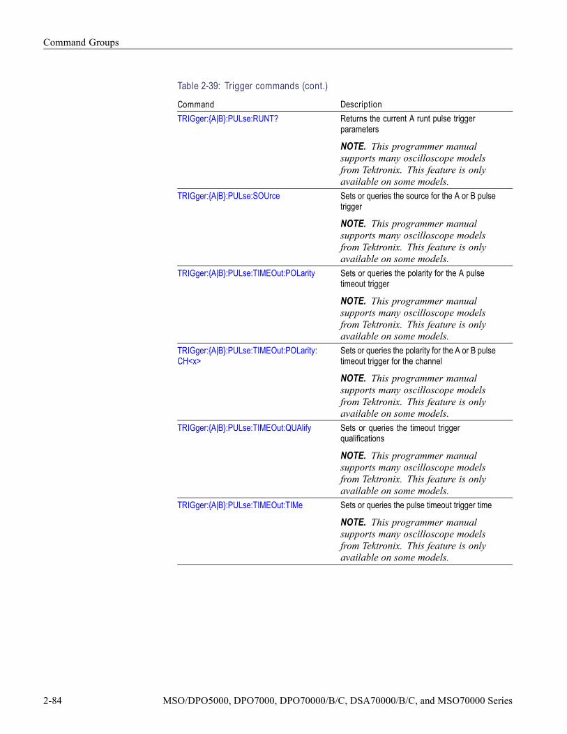
Command Groups
Table 2-39: Trigger commands (cont.)
Command DescriptionTRIGger:A|B:PULse:RUNT? Returns the current A runt pulse trigger
parameters
NOTE. This programmer manualsupports many oscilloscope modelsfrom Tektronix. This feature is onlyavailable on some models.
TRIGger:A|B:PULse:SOUrce Sets or queries the source for the A or B pulsetrigger
NOTE. This programmer manualsupports many oscilloscope modelsfrom Tektronix. This feature is onlyavailable on some models.
TRIGger:A|B:PULse:TIMEOut:POLarity Sets or queries the polarity for the A pulsetimeout trigger
NOTE. This programmer manualsupports many oscilloscope modelsfrom Tektronix. This feature is onlyavailable on some models.
TRIGger:A|B:PULse:TIMEOut:POLarity:CH<x>
Sets or queries the polarity for the A or B pulsetimeout trigger for the channel
NOTE. This programmer manualsupports many oscilloscope modelsfrom Tektronix. This feature is onlyavailable on some models.
TRIGger:A|B:PULse:TIMEOut:QUAlify Sets or queries the timeout triggerqualifications
NOTE. This programmer manualsupports many oscilloscope modelsfrom Tektronix. This feature is onlyavailable on some models.
TRIGger:A|B:PULse:TIMEOut:TIMe Sets or queries the pulse timeout trigger time
NOTE. This programmer manualsupports many oscilloscope modelsfrom Tektronix. This feature is onlyavailable on some models.
2-84 MSO/DPO5000, DPO7000, DPO70000/B/C, DSA70000/B/C, and MSO70000 Series

Command Groups
Table 2-39: Trigger commands (cont.)
Command DescriptionTRIGger:A|B:PULse:TIMEOut? Returns the parameters for the A pulse
timeout trigger
NOTE. This programmer manualsupports many oscilloscope modelsfrom Tektronix. This feature is onlyavailable on some models.
TRIGger:A|B:PULse:TRANsition:DELTATime
Sets or queries the delta time used incalculating the transition value
NOTE. This programmer manualsupports many oscilloscope modelsfrom Tektronix. This feature is onlyavailable on some models.
TRIGger:A|B:PULse:TRANsition:POLarity Sets or queries the polarity for the A pulsetransition trigger
NOTE. This programmer manualsupports many oscilloscope modelsfrom Tektronix. This feature is onlyavailable on some models.
TRIGger:A|B:PULse:TRANsition:POLarity:CH<x>
Sets or queries the polarity for the A or B pulsetransition trigger for the channel
NOTE. This programmer manualsupports many oscilloscope modelsfrom Tektronix. This feature is onlyavailable on some models.
TRIGger:A|B:PULse:TRANsition:QUAlify Sets or queries the transition triggerqualifications
NOTE. This programmer manualsupports many oscilloscope modelsfrom Tektronix. This feature is onlyavailable on some models.
TRIGger:A|B:PULse:TRANsition:THReshold:BOTh
Sets the upper and lower thresholds for thetransition trigger
NOTE. This programmer manualsupports many oscilloscope modelsfrom Tektronix. This feature is onlyavailable on some models.
MSO/DPO5000, DPO7000, DPO70000/B/C, DSA70000/B/C, and MSO70000 Series 2-85

Command Groups
Table 2-39: Trigger commands (cont.)
Command DescriptionTRIGger:A|B:PULse:TRANsition:THReshold:HIGH
Sets or queries the upper transition triggerthreshold
NOTE. This programmer manualsupports many oscilloscope modelsfrom Tektronix. This feature is onlyavailable on some models.
TRIGger:A|B:PULse:TRANsition:THReshold:LOW
Sets or queries the lower transition triggerthreshold
NOTE. This programmer manualsupports many oscilloscope modelsfrom Tektronix. This feature is onlyavailable on some models.
TRIGger:A|B:PULse:TRANsition:THReshold?
Returns the upper and lower threshold limitsfor the transition time trigger
NOTE. This programmer manualsupports many oscilloscope modelsfrom Tektronix. This feature is onlyavailable on some models.
TRIGger:A|B:PULse:TRANsition:WHEn Sets or queries whether to check for atransitioning signal that is faster or slower thanthe specified delta time for the transition timetrigger
NOTE. This programmer manualsupports many oscilloscope modelsfrom Tektronix. This feature is onlyavailable on some models.
TRIGger:A|B:PULse:TRANsition? Returns the delta time, polarity, and bothupper and lower threshold limits for thetransition time trigger
NOTE. This programmer manualsupports many oscilloscope modelsfrom Tektronix. This feature is onlyavailable on some models.
7TRIGger:A|B:PULse:WIDth:HIGHLimit Sets or queries the upper limit for the A pulsewidth trigger
NOTE. This programmer manualsupports many oscilloscope modelsfrom Tektronix. This feature is onlyavailable on some models.
2-86 MSO/DPO5000, DPO7000, DPO70000/B/C, DSA70000/B/C, and MSO70000 Series

Command Groups
Table 2-39: Trigger commands (cont.)
Command DescriptionTRIGger:A|B:PULse:WIDth:LOWLimit Sets or queries the lower limit for the pulse
width trigger
NOTE. This programmer manualsupports many oscilloscope modelsfrom Tektronix. This feature is onlyavailable on some models.
TRIGger:A|B:PULse:WIDth:POLarity Sets or queries the polarity for the pulse widthtrigger
NOTE. This programmer manualsupports many oscilloscope modelsfrom Tektronix. This feature is onlyavailable on some models.
TRIGger:A|B:PULse:WIDth:POLarity:CH<x>
Sets or queries the polarity for the A or B pulsewidth trigger for the channel
NOTE. This programmer manualsupports many oscilloscope modelsfrom Tektronix. This feature is onlyavailable on some models.
TRIGger:A|B:PULse:WIDth:QUAlify Sets or queries the pulse width triggerqualifications
NOTE. This programmer manualsupports many oscilloscope modelsfrom Tektronix. This feature is onlyavailable on some models.
TRIGger:A|B:PULse:WIDth:WHEn Sets or queries the criteria for widthspecification of pulse width trigger events
NOTE. This programmer manualsupports many oscilloscope modelsfrom Tektronix. This feature is onlyavailable on some models.
TRIGger:A|B:PULse:WIDth? Returns the trigger pulse width parameters
NOTE. This programmer manualsupports many oscilloscope modelsfrom Tektronix. This feature is onlyavailable on some models.
MSO/DPO5000, DPO7000, DPO70000/B/C, DSA70000/B/C, and MSO70000 Series 2-87

Command Groups
Table 2-39: Trigger commands (cont.)
Command DescriptionTRIGger:A|B:PULse:WINdow? Returns the current window pulse trigger
parameters
NOTE. This programmer manualsupports many oscilloscope modelsfrom Tektronix. This feature is onlyavailable on some models.
TRIGger:A|B:PULse:WINdow:EVENT Sets or queries the window trigger event
NOTE. This programmer manualsupports many oscilloscope modelsfrom Tektronix. This feature is onlyavailable on some models.
TRIGger:A|B:PULse:WINdow:POLarity Sets or queries the pulse trigger windowpolarity of the selected trigger Source
NOTE. This programmer manualsupports many oscilloscope modelsfrom Tektronix. This feature is onlyavailable on some models.
TRIGger:A|B:PULse:WINdow:POLarity:CH<x>
Sets or queries the pulse trigger windowpolarity of the specified channel
NOTE. This programmer manualsupports many oscilloscope modelsfrom Tektronix. This feature is onlyavailable on some models.
TRIGger:A|B:PULse:WINdow:QUAlify Sets or queries the window triggerqualifications
NOTE. This programmer manualsupports many oscilloscope modelsfrom Tektronix. This feature is onlyavailable on some models.
TRIGger:A|B:PULse:WINdow:THReshold:BOTh
Sets both window thresholds
NOTE. This programmer manualsupports many oscilloscope modelsfrom Tektronix. This feature is onlyavailable on some models.
TRIGger:A|B:PULse:WINdow:THReshold:HIGH
Sets or queries high window threshold
NOTE. This programmer manualsupports many oscilloscope modelsfrom Tektronix. This feature is onlyavailable on some models.
2-88 MSO/DPO5000, DPO7000, DPO70000/B/C, DSA70000/B/C, and MSO70000 Series

Command Groups
Table 2-39: Trigger commands (cont.)
Command DescriptionTRIGger:A|B:PULse:WINdow:THReshold:LOW
Sets or queries low window threshold
NOTE. This programmer manualsupports many oscilloscope modelsfrom Tektronix. This feature is onlyavailable on some models.
TRIGger:A|B:PULse:WINdow:THReshold?
Returns the upper and lower thresholds forthe pulse window trigger
NOTE. This programmer manualsupports many oscilloscope modelsfrom Tektronix. This feature is onlyavailable on some models.
TRIGger:A|B:PULse:WINdow:WIDTH Sets or queries minimum width of violation
NOTE. This programmer manualsupports many oscilloscope modelsfrom Tektronix. This feature is onlyavailable on some models.
TRIGger:A|B:READY? Queries the trigger ready state
NOTE. This programmer manualsupports many oscilloscope modelsfrom Tektronix. This feature is onlyavailable on some models.
TRIGger:A|B:TYPe Sets or queries the type of A or B triggerTRIGger:A|B:UPPerthreshold:CH<x> Sets or queries the CH<x> upper trigger level
for TRIGger:LVLSrcpreferenceTRIGger:A:BUS:DATa:FORMat Sets or queries the trigger data format for the
busTRIGger:A:BUS:DATa:VALue Sets or queries the trigger data value
depending on the format selected for the busTRIGger:A:BUS:I2C:ADDRess:FORMat Sets or queries the address format for the I2C
busTRIGger:A:BUS:I2C:ADDRess:MODe Sets or queries the address mode for the I2C
busTRIGger:A:BUS:I2C:ADDRess:VALue Sets or queries the binary address string used
for the I2C trigger of the busTRIGger:A:BUS:I2C:CONDition Sets or queries the trigger condition for the
I2C busTRIGger:A:BUS:I2C:DATa:DIRection Sets or queries the data direction for the I2C
busTRIGger:A:BUS:RS232c:CONDition Sets or queries the trigger condition for the
specified RS232C bus
MSO/DPO5000, DPO7000, DPO70000/B/C, DSA70000/B/C, and MSO70000 Series 2-89

Command Groups
Table 2-39: Trigger commands (cont.)
Command DescriptionTRIGger:A:BUS:SOUrce Sets or queries the source for a bus triggerTRIGger:A:BUS:SPI:CONDition Sets or queries the trigger condition for the
SPI busTRIGger:A:BUS:USB:CONDition Sets or queries the trigger condition for the
specified USB busTRIGger:A:BUS:USB:DATa:HIVALue Sets or queries the trigger data value for data
token of the specified USB busTRIGger:A:BUS:USB:DATa:OFFSet Sets or queries the data offset for the USB
bus triggerTRIGger:A:BUS:USB:DATa:SIZe Sets or queries the number of contiguous data
bytes to USB bus triggerTRIGger:A:BUS:USB:DATa:TYPe Sets or queries the data packet type when
USB bus trigger condition is Data PacketTRIGger:A:BUS:USB:DATa:VALue Sets or queries the USB bus trigger data value
for data tokenTRIGger:A:BUS:USB:ENDPoint:HIVALue Sets or queries the endpoint value for data
token of the specified USB busTRIGger:A:BUS:USB:ENDPoint:VALue Sets or queries the endpoint value for normal
token of the specified USB busTRIGger:A:BUS:USB:ERRTYPE Set or queries the error type when USB bus
trigger on condition is set to ErrorTRIGger:A:BUS:USB:HANDShaketype Set or queries the handshake type when USB
bus trigger on condition is set to HandshakePacket
TRIGger:A:BUS:USB:QUALIFIER Set or queries the USB bus trigger qualifier foraddress, endpoint, and data
TRIGger:A:BUS:USB:SPECIALType Set or queries the PID value for SpecialPacket USB bus trigger on condition
TRIGger:A:BUS:USB:SPLIT:ET:VALUE Set or queries the End Point Type value of thespecified USB bus trigger
TRIGger:A:BUS:USB:SPLIT:HUB:VALUE Set or queries the port address for SPLITtoken of the USB bus trigger
TRIGger:A:BUS:USB:SPLIT:PORT:VALUE Set or queries the port address for SPLITtoken of the USB bus trigger
TRIGger:A:BUS:USB:SPLIT:SC:VALUE Set or queries the Start/Complete value forthe USB bus trigger on split token field
TRIGger:A:BUS:USB:SPLIT:SE:VALUE Set or queries the Start/End value for the USBbus trigger for the specified USB bus
TRIGger:A:BUS:USB:TOKENType Set or queries the Token Type when Triggercondition is set to TOKEN for the specifiedUSB bus
2-90 MSO/DPO5000, DPO7000, DPO70000/B/C, DSA70000/B/C, and MSO70000 Series

Command Groups
Table 2-39: Trigger commands (cont.)
Command DescriptionTRIGger:A:COMMunication:AMI|HDB3|B3ZS|B6ZS|B8ZS:PULSEForm
Sets or queries the selected communicationpulse form for the specified USB bus
TRIGger:A:COMMunication:AMI|HDB3|B3ZS|B6ZS|B8ZS:THReshold:HIGH
Sets the communication threshold high level
TRIGger:A:COMMunication:AMI|HDB3|B3ZS|B6ZS|B8ZS:THReshold:LOW
Sets the communication threshold low level
TRIGger:A:COMMunication:BITRate Sets or queries the communication bit rateTRIGger:A:COMMunication:CLOCk:POLarity
Sets or queries the polarity of the clock signal
TRIGger:A:COMMunication:CMI:PULSEForm
Selects the CMI pulse form
TRIGger:A:COMMunication:CODe Sets the communication signal codeTRIGger:A:COMMunication:SOUrce Sets the communication source channelTRIGger:A:COMMunication:SOUrce:TYPe Sets the type of communication source
channelTRIGger:A:COMMunication:STANdard Selects the communication standard that
identifies the code and bit rateTRIGger:A:HOLDoff:ACTUal? Returns the holdoff time actually used by the
A triggerTRIGger:A:HOLDoff:BY Sets or queries the type of holdoff for the A
triggerTRIGger:A:HOLDoff:TIMe Sets or queries the A trigger holdoff timeTRIGger:A:HOLDoff? Returns the A trigger holdoff parametersTRIGger:A:MODe Sets or queries the A trigger modeTRIGger:A:SERIAL:BITRate Sets or queries the clock/data bit rateTRIGger:A:SERIAL:CLOCk:LEVel Sets or queries the serial trigger clock levelTRIGger:A:SERIAL:CLOCk:POLarity Sets or queries the serial clock polarityTRIGger:A:SERIAL:CLOCk:SOUrce Sets or queries the serial data source channelTRIGger:A:SERIAL:CODe Sets or queries the signal codeTRIGger:A:SERIAL:DATa:FORMat Sets or queries how the Pattern string is
formattedTRIGger:A:SERIAL:DATa:PATtern Sets or queries the data pattern to allow up to
64 bit serial patternsTRIGger:A:SERIAL:DATa:PATtern:NRZ Sets or queries the data pattern to allow up to
64 bit serial patternsTRIGger:A:SERIAL:DATa:PATtern:S8B10B Sets or queries the data pattern to allow up to
64 bit serial patterns
MSO/DPO5000, DPO7000, DPO70000/B/C, DSA70000/B/C, and MSO70000 Series 2-91

Command Groups
Table 2-39: Trigger commands (cont.)
Command DescriptionTRIGger:A:SERIAL:LOCKLen Sets or queries the length in bits of the
repeating bit pattern for pattern lock triggerTRIGger:A:SERIAL:LOCKOffset Sets or queries the length in bits of the
repeating bit pattern for pattern lock triggerTRIGger:A:SERIAL:SOUrce Sets or queries the length in bits of the
repeating bit pattern for pattern lock triggerTRIGger:A:SERIAL:STANdard Sets or queries the length in bits of the
repeating bit pattern for pattern lock triggerTRIGger:A:SERIAL:TRIGgeron Sets or queries the length in bits of the
repeating bit pattern for pattern lock triggerTRIGger:A:VIDeo? Returns the video parameters for the A triggerTRIGger:A:VIDeo:CUSTom? Returns the custom video parameters for the
A triggerTRIGger:A:VIDeo:CUSTom:FORMat Sets or queries the video scan format when
the video standard is set to CustomTRIGger:A:VIDeo:CUSTom:LINEPeriod Sets or queries the custom video line periodTRIGger:A:VIDeo:CUSTom:SYNCInterval Sets or queries the custom video sync intervalTRIGger:A:VIDeo:FIELD Sets or queries the video field triggerTRIGger:A:VIDeo:HOLdoff:FIELD Sets or queries the trigger holdoff in video
field unitsTRIGger:A:VIDeo:LINE Sets or queries the trigger delay as several
video linesTRIGger:A:VIDeo:POLarity Sets or queries the polarity of the video triggerTRIGger:A:VIDeo:SCAN Sets or queries the video scan rateTRIGger:A:VIDeo:SOUrce Sets or queries the video trigger sourceTRIGger:A:VIDeo:STANdard Sets or queries the video standardTRIGger:AUXLevel Sets or queries the level for the auxiliary
triggerTRIGger:B Sets the B trigger level to 50% or queries the
B trigger parametersTRIGger:B:BY Sets or queries B trigger time or event
qualifiersTRIGger:B:EVENTS:COUNt Sets or queries the number of events that
must occur before the B trigger occursTRIGger:B:EVENTS? Returns the current B trigger events parameterTRIGger:B:RESET:SOUrce Sets or queries the source for the trigger resetTRIGger:B:RESET:STATE Sets or queries the state of the B triggerTRIGger:B:RESET:THReshold Sets or queries the threshold for the trigger
reset
2-92 MSO/DPO5000, DPO7000, DPO70000/B/C, DSA70000/B/C, and MSO70000 Series

Command Groups
Table 2-39: Trigger commands (cont.)
Command DescriptionTRIGger:B:RESET:TIMEOut Sets or queries the reset time for the timeout
trigger resetTRIGger:B:RESET:TRANsition Sets or queries the type of transition required
for a transition trigger resetTRIGger:B:RESET:TYPe Sets or queries the type of A→B sequential
trigger resetTRIGger:B:SCAN:ADVANCEafter Sets or queries the B-Event Scan advance
after valueTRIGger:B:SCAN:ENAble Sets or queries if the B-Event Scan is on or offTRIGger:B:SCAN:ENDevent Sets or queries the end event value of B-Event
ScanTRIGger:B:SCAN:MODE Sets or queries the sequence advance mode
of B-Event ScanTRIGger:B:SCAN:STARTevent Sets or queries the start event value of
B-Event ScanTRIGger:B:STATE Returns the current state of the triggering
systemTRIGger:B:TIMe Sets or queries the B trigger delay time.TRIGger:ENHanced Sets or queries the state of trigger position
enhancement.TRIGger:LVLSrcpreference Sets or queries how the trigger source and
levels interact.TRIGger:QUALification:BUS:FORMat Sets or queries the format of the bit pattern for
the bus qualification.TRIGger:QUALification:BUS:SOUrce Sets or queries the source for the bus
qualification.TRIGger:QUALification:BUS:VALue Sets or queries the bit pattern for the bus
qualificationTRIGger:SENSITivity Set or queries the state of trigger sensitivity.
When on, the instrument calculates a rollingaverage for trigger position enhancement
TRIGger:STATE? Returns the current state of the triggeringsystem
Vertical Command GroupUse the commands in the Vertical Command Group to control the vertical setup ofall live (channel) waveforms for acquisition and to control the display of channel,reference, and math waveforms.
You may replace VOLts with SCAle in the vertical commands. This providesprogram compatibility with earlier models of Tektronix instruments.
MSO/DPO5000, DPO7000, DPO70000/B/C, DSA70000/B/C, and MSO70000 Series 2-93

Command Groups
Table 2-40: Vertical commands
Command DescriptionAUXIn:BANdwidth Sets or queries the selectable low-pass
bandwidth limit filter of the AUX In inputAUXIn:COUPling Sets or queries the input attenuator coupling
setting for the AUX In inputAUXIn:OFFSet Sets or queries the vertical offset for the AUX
In inputAUXIn:PRObe:AUTOZero Sets the probe attached to the AUX In input
to autozeroAUXIn:PRObe:DEGAUSS Starts a degauss cycle of the probe attached
to the AUX In inputAUXIn:PRObe:DEGAUSS:STATE? Returns whether the probe attached to the
AUX In input is degaussedAUXIn:PRObe:FORCEDRange Sets the probe attached to the AUX In input
to the default range of the probe, or thecommand queries the default range of theprobe
AUXIn:PRObe:GAIN? Returns the gain factor of the probe that isattached to the AUX In input
AUXIn:PRObe:ID:SERnumber? Returns the probe serial numberAUXIn:PRObe:ID:TYPe? Returns the probe typeAUXIn:PRObe:INPUTMode Sets or queries one of the probe’s four input
modesAUXIn:PRObe:INPUTMode:AOFFSet Sets or queries the requested A mode offset
control of the probe that is attached to theAUX In input
AUXIn:PRObe:INPUTMode:BOFFSet Sets or queries the requested B mode offsetcontrol of the probe that is attached to theAUX In input
AUXIn:PRObe:INPUTMode:CMOFFSet Sets or queries the requested common modeoffset control of the probe that is attached tothe AUX In input
AUXIn:PRObe:INPUTMode:DMOFFSet Sets or queries the requested differentialmode offset control of the probe that isattached to the AUX In input
AUXIn:PRObe:RANge Sets or queries the set attenuation range ofthe probe on the AUX In input
AUXIn:PRObe:RESistance? Returns the resistance factor of the probethat is attached to the AUX In input
AUXIn:PRObe:SET Sets or queries aspects of probe accessoryuser interfaces, for example probeattenuation factors
AUXIn:PRObe:SIGnal Sets or queries aspects of probe accessoryuser interfaces
2-94 MSO/DPO5000, DPO7000, DPO70000/B/C, DSA70000/B/C, and MSO70000 Series

Command Groups
Table 2-40: Vertical commands (cont.)
Command DescriptionAUXIn:PRObe:TIPtype Sets or queries the type of probe tip being
usedAUXIn:PRObe:UNIts? Returns a string describing the units of
measure for the probe attached to the AUXIn input
AUXIn:PROBEFunc:EXTAtten Sets or queries the input-output ratio, ofexternal attenuation or gain, between thesignal and the AUX In input
AUXIn:PROBEFunc:EXTDBatten Sets or queries the input-output ratio(expressed in decibel units) of externalattenuation or gain between the signal andthe instrument AUX In input
AUXIn:PROBEFunc:EXTUnits Sets or queries the unit of measurement forthe external attenuator of the AUX In input
CH<x>? Returns vertical parameters for the specifiedchannel
CH<x>:BANdwidth Sets or queries the bandwidth of the specifiedchannel
CH<x>:BANdwidth:ENHanced Sets or queries either the “BandwidthEnhancement (DSP) Enabled” or “AnalogOnly” option.
CH<x>:BANdwidth:ENHanced:APPLYtoall Sets or queries whether the enhancedbandwidth filter applies to all active channels
CH<x>:BANdwidth:ENHanced:FORCe Sets or queries the Force constant samplerate of the Digital Filters (DSP)
CH<x>:BANdwidth:ENHanced:STATE? Returns the state of the bandwidthenhancement filter
CH<x>:COUPling Sets or queries the coupling setting for thespecified channel
CH<x>:DESKew Sets or queries the deskew time for thespecified channel
CH<x>:ICAPture:SOUrce Selects which digital probe signal will acquirefor the specified channel when put in iCapturemode
NOTE. This is available only onMSO70000 Series instruments.
CH<x>:ICAPture:STATE Selects the state of the digital probe signalwill acquire for the specified channel whenput in iCapture mode
NOTE. This is available only onMSO70000 Series instruments.
MSO/DPO5000, DPO7000, DPO70000/B/C, DSA70000/B/C, and MSO70000 Series 2-95

Command Groups
Table 2-40: Vertical commands (cont.)
Command DescriptionCH<x>:LABel:NAMe Defines or queries the label for the channel
waveformCH<x>:LABel:XPOS Sets or queries the X display coordinate for
the channel waveform labelCH<x>:LABel:YPOS Sets or queries the Y display coordinate for
the channel waveform labelCH<x>:OFFSet Sets or queries the channel offsetCH<x>:POSition Sets or queries the channel vertical positionCH<x>:PRObe? Returns the gain, resistance, units, and ID
of the probe that is attached to the specifiedchannel
CH<x>:PRObe:AUTOZero Autozeros the probe attached to the specifiedchannel
CH<x>:PRObe:DEGAUSS Starts a degauss cycle of the probe attachedto the specified channel
CH<x>:PRObe:DEGAUSS:STATE? Returns whether the probe attached to thespecified channel is degaussed
CH<x>:PRObe:FORCEDRange Sets the attached probe to its default range,or it queries the default range of the probe
CH<x>:PRObe:GAIN? Returns the gain of the probe that is attachedto the specified channel
CH<x>:PRObe:ID? Returns the type and serial number ofthe probe that is attached to the specifiedchannel
CH<x>:PRObe:ID:SERnumber? Returns the serial number of the probe thatis attached to the specified channel
CH<x>:PRObe:ID:TYPe? Returns the type of probe that is attached tothe specified channel
CH<x>:PRObe:INPUTMode Sets or queries the input mode of the probethat is attached to the specified channel
CH<x>:PRObe:INPUTMode:AOFFSet Sets or queries the requested A mode offsetcontrol of the probe that is attached to thespecified channel
CH<x>:PRObe:INPUTMode:BOFFSet Sets or queries the requested B mode offsetcontrol of the probe that is attached to thespecified channel
CH<x>:PRObe:INPUTMode:CMOFFSet Sets or queries the requested common modeoffset control of the probe that is attached tothe specified channel
CH<x>:PRObe:INPUTMode:DMOFFSet Sets or queries the requested differentialmode offset control of the probe that isattached to the specified channel
2-96 MSO/DPO5000, DPO7000, DPO70000/B/C, DSA70000/B/C, and MSO70000 Series

Command Groups
Table 2-40: Vertical commands (cont.)
Command DescriptionCH<x>:PRObe:RANge Sets or queries the attenuation range of the
probe on the designated channelCH<x>:PRObe:RESistance? Returns the resistance of the probe that is
attached to the specified channelCH<x>:PRObe:SET Sets or queries aspects of probe accessory
user interfaces, for example probeattenuation factors
CH<x>:PRObe:SIGnal Sets or queries aspects of probe accessoryuser interfaces
CH<x>:PRObe:TIPtype Sets or queries the type of probe tip beingused on the specified channel
CH<x>:PRObe:UNIts? Returns the units of the probe that is attachedto the specified channel
CH<x>:PROBECal? Returns the probe calibration statusCH<x>:PROBECOntrol Sets or queries the probe rangeCH<x>:PROBEFunc:EXTAtten Sets the attenuation value for the specified
channel to the specified scale factorOr queries the user-specified attenuation
CH<x>:PROBEFunc:EXTDBatten Sets the attenuation value for the specifiedchannel to the specified value in decibelsOr queries the user-specified attenuation indecibels
CH<x>:PROBEFunc:EXTUnits Sets the unit of measurement for the externalattenuator of the specified channelOr queries the user-specified unit ofmeasurement for the external attenuator
CH<x>:SCAle Sets or queries the vertical scale of thespecified channel
CH<x>:TERmination Sets channel input terminationCH<x>:THRESHold Sets or queries the comparison level for
converting the specified channel to digitalform
REF<x>:HORizontal:POSition Sets or queries the horizontal position of thespecified reference waveform in percent ofthe waveform that is displayed to the right ofthe center vertical graticule
REF<x>:LABel? Returns a branch query containing thewaveform label name and the coordinates atwhich the label is displayed
REF<x>:LABel:NAMe Sets or queries the label of the designatedwaveform
MSO/DPO5000, DPO7000, DPO70000/B/C, DSA70000/B/C, and MSO70000 Series 2-97

Command Groups
Table 2-40: Vertical commands (cont.)
Command DescriptionREF<x>:LABel:XPOS Sets or queries the position of the reference
waveform label on the X axisREF<x>:LABel:YPOS Sets or queries the position of the reference
waveform label on the Y axisREF<x>:VERTical:POSition Sets or queries the vertical position of the
specified reference waveformREF<x>:VERTical:SCAle Sets or queries the reference waveform
vertical scale in vertical units/divSELect? Returns information on which waveforms are
on or off and which waveform is selectedSELect:<wfm> Turns on the specified waveform
Or queries whether the specified channel ison or off
SELect:CH<x> Sets or queries the displayed state of thespecified channel waveform
SELect:CONTROl Sets or queries the waveform controlled bythe front panel
Waveform Transfer Command GroupUse the commands in the Waveform Transfer Command Group to transferwaveform data points to and from the instrument. Waveform data points are acollection of values that define a waveform. One data value usually representsone data point in the waveform record. When working with envelope waveforms,each data value is either the minimum or maximum of a min/max pair.
Before you transfer waveform data, you must specify the data format, recordlength, and waveform source.
Data Formats. Acquired waveform data uses eight or more bits to represent eachdata point. The number of bits used depends on the acquisition mode specifiedwhen you acquired the data. Data acquired in SAMple or ENVelope mode useseight bits per waveform data point. Data acquired in AVERage mode uses up to14 bits per point.
The instrument can transfer waveform data in either ASCII or binary format.You specify the format with the DATa:ENCdg command. The instrument usessigned, 4 byte integers and floating point values; it does not support unsignedfloating point values.
ASCII data is represented by signed integer or floating point values. An exampleASCII waveform data string may look like this:
2-98 MSO/DPO5000, DPO7000, DPO70000/B/C, DSA70000/B/C, and MSO70000 Series
Command Groups
CURVE<space>-110,-109,-110,-110,-109,-107,-109,-107,-106,-105,-103,-100,-97,-90,-84,-80
Use ASCII to obtain more readable and easier to format output than binary.However, ASCII may require more bytes to send the same values than it does withbinary. This may reduce transmission speeds.
Binary data can be represented by signed integer or floating point values. Therange of the values depends on the byte width specified. When the byte width isone, signed integer data ranges from -128 to 127, and positive integer valuesrange from 0 to 255. When the byte width is two, the values range from -32768 to32767. When a MATH (or REF that came from a MATH) is used, 32-bit floatingpoint values are used that are four bytes in width.
The defined binary formats specify the order in which the bytes are transferred.The following are the four binary formats:
RIBinary specifies signed integer data-point representation with the mostsignificant byte transferred first.
SRIBinary is the same as RIBinary except that the byte order is swapped,meaning that the least significant byte is transferred first. This format is usefulwhen transferring data to PCs.
RFBinary specifies floating point data-point representation with the mostsignificant byte transferred first.
SRFBinary is the same as RFBinary except that the byte order is swapped,meaning that the least significant byte is transferred first. This format is usefulwhen transferring data to PCs.
Waveform Data and Record Lengths. You can transfer multiple points for eachwaveform record. You can transfer a portion of the waveform or you can transferthe entire record. You can use the DATa:STARt and DATa:STOP commands tospecify the first and last data points of the waveform record.
When transferring data into the instrument, you must first specify the record lengthof the destination waveform record. You do this with the WFMInpre:NR_Ptcommand. Next, specify the first data point within the waveform record. Forexample, when you set DATa:STARt to 1, data points will be stored startingwith the first point in the record. The instrument will ignore the value set byDATa:STOP when reading in data. It will stop reading data when there is no moredata to read or when it has reached the specified record length.
When transferring data from the instrument, you must specify the first and lastdata points in the waveform record. Setting DATa:STARt to 1 and DATa:STOP tothe record length will always return the entire waveform.
For CURVe queries of FastFrame acquisitions, the data for each frame isconcatenated together into one long stream. For example, if you acquire 5 framesof 1000 points each, a curve query (with DATA:START 1 and DATA:STOP 1000)
MSO/DPO5000, DPO7000, DPO70000/B/C, DSA70000/B/C, and MSO70000 Series 2-99

Command Groups
will return 5 * 1000 or 5000 data points. There is no separator between eachframe in the data.
If you set DATA:START and DATA:STOP to a subset of the record length thenyou get that section of data from each frame. For example, with 5 frames of1000 points each and DATA:START 101 and DATA:STOP 150, you will getpoints 101-150 for the first frame followed by points 101-150 of the secondframe, and similar things. In this case the total number of points returned will be5 * 50 or 250 points.
Waveform Data Locations and Memory Allocation. The DATa:SOUrce commandspecifies the waveform source when transferring a waveform from the instrument.Waveforms sent to the instrument are always stored in one of the four referencememory locations. Use the DATa:DESTination command to specify a referencememory location.
Waveform Preamble. Each waveform that you transfer has an associatedwaveform preamble that contains information such as the horizontal scale, thevertical scale, and other settings in effect when the waveform was created. Referto the individual WFMInpre? and WFMOutpre? commands for more information.
Scaling Waveform Data. Once you transfer the waveform data to the controller,you can convert the data points into voltage values for analysis using informationfrom the waveform preamble.
Transferring Waveform Data from the Instrument.
You can transfer waveforms from the instrument to an external controller usingthe following sequence:
1. Select the waveform source(s) using DATa:SOUrce.
2. Specify the waveform data format using DATa:ENCdg.
3. Specify the number of bytes per data point using WFMOutpre:BYT_Nr.
NOTE. MATH waveforms (and REF waveforms that came from a MATH) arealways set to four bytes.
4. Specify the portion of the waveform that you want to transfer usingDATa:STARt and DATa:STOP.
5. Transfer waveform preamble information using WFMOutpre.
6. Transfer waveform data from the instrument using CURVe.
2-100 MSO/DPO5000, DPO7000, DPO70000/B/C, DSA70000/B/C, and MSO70000 Series

Command Groups
Transferring Waveform Data to the Instrument.
1. Specify waveform reference memory using DATa:DESTination.
2. Set WFMInpre:NR_Pt to equal the number of data points to be sent.
3. Specify the waveform data format using WFMInpre:ENCdg.
4. Specify the number of bytes per data point using WFMInpre:BYT_Nr.
5. Specify first data point in the waveform record using DATa:STARt.
6. Transfer waveform preamble information using WFMInpre.
7. Transfer the waveform data using CURVe.
NOTE. FastAcq waveforms cannot be returned to the instrument via the CURVecommand.
Table 2-41: Waveform Transfer commands
Command DescriptionALLOcate:WAVEform:REF<x>? Returns the record length for the specified
reference waveform, if active, or zero (0) ifnot active
CURVe The command format transferswaveform data to the instrument(reference memory location specifiedby DATa:DESTination)The query format transfers waveformdata from instrument specified by theDATa:SOUrce command
CURVENext? Returns unique waveform data from a newacquisition
CURVEStream Transfers continuously the waveform datafrom the instrument as it is acquired
DATa Sets the format and location of the waveformdata that is transferred with the CURVe
CommandOr queries the format and location of thewaveform data that is transferred with theCURVe? command
DATa:DESTination Sets or queries the reference memorylocation for storing waveform data sent tothe instrument
DATa:ENCdg Sets or queries the format of outgoingwaveform data
DATa:FRAMESTARt Sets or queries the starting data frame forwaveform transfer
MSO/DPO5000, DPO7000, DPO70000/B/C, DSA70000/B/C, and MSO70000 Series 2-101

Command Groups
Table 2-41: Waveform Transfer commands (cont.)
Command DescriptionDATa:FRAMESTOP Sets or queries the ending data frame for
waveform transferDATa:SOUrce Sets or queries the location of waveform
data transferred from the instrumentDATa:STARt Sets or queries the starting point in waveform
transferDATa:STOP Sets or queries the ending data point in
waveform transferWAVFrm? Returns WFMOutpre? and CURVe?
data for the waveform as specified by theDATA:SOUrce command
WAVFRMStream? Returns WFMOUTPRE? andCURVESTREAM? data for the waveformsspecified by the DATASOURCE command
WFMInpre? Returns the waveform formattingspecification to be applied to the nextincoming CURVE command data
WFMInpre:BIT_Nr Sets or queries the number of bits per binarywaveform point
WFMInpre:BN_Fmt Sets or queries the format of binary data forthe incoming waveform
WFMInpre:BYT_Nr Sets or queries the binary field data width forthe first ordered waveform
WFMInpre:BYT_Or Sets or queries the byte order of waveformpoints
WFMInpre:ENCdg Sets or queries the type of encoding forincoming waveform data
WFMInpre:NR_Pt Sets or queries the number of points in thetransmitted waveform record
WFMInpre:PT_Fmt Sets or queries the point format of incomingwaveform data
WFMInpre:PT_Off Sets or queries the trigger point within theincoming waveform data
WFMInpre:WFId Allows a waveform extracted from theinstrument to be more easily sent back
WFMInpre:XINcr Sets or queries the horizontal samplinginterval between incoming waveform points
WFMInpre:XUNit Sets or queries the horizontal units of theincoming waveform
WFMInpre:XZEro Sets or queries the (sub-sample) timebetween the trigger sample and theoccurrence of the actual incoming waveformtrigger
2-102 MSO/DPO5000, DPO7000, DPO70000/B/C, DSA70000/B/C, and MSO70000 Series

Command Groups
Table 2-41: Waveform Transfer commands (cont.)
Command DescriptionWFMInpre:YMUlt Sets or queries the vertical scale factor, per
digitizing level, of the incoming waveformpoints
WFMInpre:YOFf Sets or queries the vertical position of theincoming waveform in digitizing levels
WFMInpre:YUNit Sets or queries the vertical units of theincoming waveform
WFMInpre:YZEro Sets or queries the offset of the incomingwaveform
WFMOutpre? Returns the waveform formatting data for thewaveform specified by the DATA:SOURCEcommand
WFMOutpre:BIT_Nr Sets or queries the number of bits perwaveform point that outgoing waveformscontain
WFMOutpre:BN_Fmt Sets or queries the format of binary data forthe waveform
WFMOutpre:BYT_Nr Sets or queries the data width for thewaveform
WFMOutpre:BYT_Or Sets or queries the byte order of waveformpoints
WFMOutpre:ENCdg Sets or queries the type of encoding foroutgoing waveforms
WFMOutpre:NR_Pt? Returns the number of points for thewaveform transmitted in response to aCURVe? query
WFMOutpre:PT_Fmt? Returns the point format for the waveformWFMOutpre:PT_Off? Returns the trigger point relative to
DATA:START for the waveformWFMOutpre:PT_ORder? Returns whether the source waveform is
DPOWFMOutpre:WFId? Returns a string describing the acquisition
parameters for the waveformWFMOutpre:XINcr? Returns the horizontal sampling intervalWFMOutpre:XUNit? Returns the horizontal units for the waveformWFMOutpre:XZEro? Returns the (sub-sample) time between the
trigger sample and the occurrence of theactual waveform trigger
WFMOutpre:YMUlt? Returns the vertical scale factor per digitizinglevel for the waveform
WFMOutpre:YOFf? Returns the vertical offset in digitizing levelsfor the waveform
MSO/DPO5000, DPO7000, DPO70000/B/C, DSA70000/B/C, and MSO70000 Series 2-103

Command Groups
Table 2-41: Waveform Transfer commands (cont.)
Command DescriptionWFMOutpre:YUNit? Returns the vertical units for the waveformWFMOutpre:YZEro? Returns the vertical offset for the waveformWFMInpre:NR_FR Sets or queries one frame, indicating
the number of frames in the transmittedwaveform record
WFMOutpre:NR_FR? Query-only command returns the numberof frames for the DATa:SOUrce waveformtransmitted in response to a CURVe? query
Zoom Command GroupZoom commands let you expand and position the waveform display horizontallyand vertically, without changing the time base or vertical settings.
You can specify up to four zoom areas. You can also specify a zoomed waveformas a zoom source, which enables you to zoom in on a zoomed waveform.
Table 2-42: Zoom commands
Command DescriptionZOOm Resets the zoom transforms to default values
for all traces or live traces. The ZOOm queryreturns the current vertical and horizontalpositioning and scaling of the display
ZOOm:GRAticule:SIZE Sets or queries the size of the zoom graticuleZOOm:HORizontal:POSition Sets or queries the horizontal position around
which the zoom waveform is displayed.It is freely movable within the confines ofthe acquired waveform (0% to 100%) andmeasured from left to right of the acquiredwaveform
ZOOm:HORizontal:SCAle Sets or queries the zoom horizontal scalefactor around which the zoom waveform isdisplayed
ZOOm:MATH<x>:HORizontal:POSition Sets or queries the horizontal position of thespecified math waveform
ZOOm:MATH<x>:HORizontal:SCAle Sets or queries the zoom horizontal scalefactor of the specified math waveform
ZOOm:MATH<x>:VERTical:POSition Sets or queries the vertical position of thespecified math waveform
ZOOm:MATH<x>:VERTical:SCAle Sets or queries the vertical scale of thespecified math waveform
ZOOm:MODe Sets or queries the zoom mode
2-104 MSO/DPO5000, DPO7000, DPO70000/B/C, DSA70000/B/C, and MSO70000 Series

Command Groups
Table 2-42: Zoom commands (cont.)
Command DescriptionZOOm:REF<x>:HORizontal:POSition Sets or queries the horizontal position of the
specified reference waveformZOOm:REF<x>:HORizontal:SCAle Sets or queries the zoom horizontal scale
factor of the specified reference waveformZOOm:REF<x>:VERTical:POSition Sets or queries the vertical position of the
specified reference waveformZOOm:REF<x>:VERTical:SCAle Sets or queries the zoom vertical scale of the
specified reference waveformZOOm:SCROLL:DIREction Sets or queries the direction of AutoScroll
for zoomed waveformsZOOm:SCROLL:LOCk Sets or queries the state of Scroll Lock, on
or offZOOm:SCROLL:SPEED Sets or queries the speed of AutoScroll for
zoomed waveformsZOOm:STATE Specifies or returns a trace as zoomed on
or offZOOm:VERTical:POSition Sets or queries the vertical position around
which the zoom waveform is displayed.It is freely movable within the confines ofthe acquired waveform (0% to 100%) andmeasured from left to right of the acquiredwaveform
ZOOm:VERTical:SCAle Sets or queries the zoom vertical scalefactor around which the zoom waveform isdisplayed
ZOOm:ZOOM<x> Sets or queries zoom factors for the specifiedzoom
ZOOm:ZOOM<x>:DCHAN:DISplay Sets or queries the display of the digitalwaveforms for the specified zoom
ZOOm:ZOOM<x>:SCROLLLock Sets or queries Scroll Lock for the specifiedzoom
ZOOm:ZOOM<x>:STATE Sets or queries the specified zoom on or off,where x is an integer from 1 to 4 representingthe desired zoom window
ZOOm:ZOOM<x>:<wfm>:DISplay Sets or queries the display of the specifiedwaveform for the specified zoom
ZOOm:ZOOM<x>:<wfm>:HORizontal:SCAle Sets or queries the horizontal zoom scale ofthe specified waveform in the specified zoom
ZOOm:ZOOM<x>:<wfm>:VERTical:POSition
Sets or queries the vertical zoom position forthe specified waveform in the specified zoom
ZOOm:ZOOM<x>:<wfm>:VERTical:SCAle Sets or queries the vertical zoom scale forthe specified waveform in the specified zoom
MSO/DPO5000, DPO7000, DPO70000/B/C, DSA70000/B/C, and MSO70000 Series 2-105

Command Groups
2-106 MSO/DPO5000, DPO7000, DPO70000/B/C, DSA70000/B/C, and MSO70000 Series

Commands Listed in Alphabetical Order
ACQuire:INTERPEightbitThis command sets or queries the interpolation acquisition mode of the instrument.
Group Acquisition
Syntax ACQuire:INTERPEightbit AUTO|ON|OFFACQuire:INTERPEightbit?
Arguments AUTO lets the instrument automatically select the interpolation acquisition mode.
ON turns on the eight bit interpolation mode.
OFF turns off the eight bit interpolation mode.
Examples ACQUIRE:INTERPEIGHTBIT ON sets the interpolation sampling mode ON.
ACQUIRE:INTERPEIGHTBIT? might return :ACQUIRE:INTERPEIGHTBITAUTO indicating the interpolation sampling mode is set to AUTO.
ACQuire:MAGnivu
NOTE. This programmer manual supports many oscilloscope models fromTektronix. This feature is only available on some models.
This command sets or queries the MagniVu feature.
This feature provides up to 32 times signal detail for fast viewing of short eventsand is not recommended for slow data formats such as RS-232.
Group Acquisition
Syntax ACQuire:MAGnivu <NR1>|OFF|ONACQuire:MAGnivu?
Arguments <NR1> = 0 disables the MagniVu feature; any other value turns this feature on.
OFF disables the MagniVu feature.
ON enables the MagniVu feature.
MSO/DPO5000, DPO7000, DPO70000/B/C, DSA70000/B/C, and MSO70000 Series 2-107

Commands Listed in Alphabetical Order
Examples ACQUIRE:MAGNIVU ON sets the MagniVu mode to on.
ACQUIRE:MAGNIVU? might return :ACQUIRE:MAGNIVU ON, indicating that theMagniVu mode is on.
ACQuire:MODeThis command sets or queries the acquisition mode of the instrument.This affects all live waveforms. This command is equivalent to selectingHorizontal/Acquisition from the Horiz/Acq menu, and then choosing the desiredmode from the Acquisition Mode group box.
Waveforms are the displayed data point values taken from acquisition intervals.Each acquisition interval represents a time duration set by the horizontal scale(time per division). The instrument sampling system always samples at themaximum rate and so an acquisition interval may include more than one sample.
The acquisition mode (which you set using this ACQuire:MODe command)determines how the final value of the acquisition interval is generated from themany data samples.
Group Acquisition
Syntax ACQuire:MODeSAMple|PEAKdetect|HIRes|AVErage|WFMDB|ENVelopeACQuire:MODe?
Related Commands ACQuire:NUMAVg, CURVe
Arguments SAMple specifies that the displayed data point value is the first sampled valuethat is taken during the acquisition interval. In sample mode, all waveform datahas 8 bits of precision. You can request 16 bit data with a CURVe query but thelower-order 8 bits of data will be zero. SAMple is the default mode.
PEAKdetect specifies the display of high-low range of the samples taken from asingle waveform acquisition. The high-low range is displayed as a vertical columnthat extends from the highest to the lowest value sampled during the acquisitioninterval. PEAKdetect mode can reveal the presence of aliasing or narrow spikes.
HIRes specifies Hi Res mode where the displayed data point value is theaverage of all the samples taken during the acquisition interval. This is a formof averaging, where the average comes from a single waveform acquisition. Thenumber of samples taken during the acquisition interval determines the number ofdata values that compose the average.
2-108 MSO/DPO5000, DPO7000, DPO70000/B/C, DSA70000/B/C, and MSO70000 Series

Commands Listed in Alphabetical Order
AVErage specifies averaging mode, in which the resulting waveform shows anaverage of SAMple data points from several separate waveform acquisitions. Theinstrument processes the number of waveforms you specify into the acquiredwaveform, creating a running exponential average of the input signal. The numberof waveform acquisitions that go into making up the average waveform is set orqueried using the ACQuire:NUMEnv command.
WFMDB (Waveform Database) mode acquires and displays a waveform pixmap. Apixmap is the accumulation of one or more acquisitions.
ENVelope specifies envelope mode, where the resulting waveform shows thePEAKdetect range of data points from several separate waveform acquisitions.The number of waveform acquisitions that go into making up the envelopewaveform is set or queried using the ACQuire:NUMEnv command.
The instrument acquires data after each trigger event using Sample mode; it thendetermines the pix map location of each sample point and accumulates it withstored data from previous acquisitions.
A Pix map is a two dimensional array. The value at each point in the array isa counter that reflects the hit intensity. Infinite and noninfinite persist displaymodes affect how pix maps are accumulated. Zoom, Math, FastAcq, FastFrame,XY, Roll, and Interpolated Time (IT) Sampling Mode are conflicting features toWFMDB acqMode. Turning on one of them generally turns the other one off.Selection of some standard masks (for example, eye masks, which require optionMTM) changes the acquisition mode to WFMDB.
Examples ACQUIRE:MODE ENVELOPE sets the acquisition mode to display a waveform thatis an envelope of many individual waveform acquisitions.
ACQUIRE:MODE? might return :ACQuire:MODe AVERAGE, indicating thatthe displayed waveform is the average of the specified number of waveformacquisitions.
ACQuire:NUMACq? (Query Only)This query-only command returns the number of waveform acquisitions that haveoccurred since starting acquisition with the ACQuire:STATE RUN command.This value is reset to zero when any acquisition, horizontal, or vertical argumentsthat affect the waveform are changed. The maximum number of acquisitions thatcan be counted is 230–1. The instrument stops counting when this number isreached. This is the same value that displays in the lower right of the screen.
Group Acquisition
Syntax ACQuire:NUMACq?
MSO/DPO5000, DPO7000, DPO70000/B/C, DSA70000/B/C, and MSO70000 Series 2-109

Commands Listed in Alphabetical Order
Related Commands ACQuire:STATE
Examples ACQUIRE:NUMACQ? might return :ACQUIRE:NUMACQ 350, indicating that 350acquisitions have occurred since executing an ACQuire:STATE RUN command.
ACQuire:NUMAVgThis command sets or queries the number of waveform acquisitions that make upan averaged waveform. Use the ACQuire:MODe command to enable the Averagemode. Sending this command is equivalent to selecting Horizontal/AcquisitionSetup from the Horiz/Acq menu, selecting the Acquisition tab, and choosingAverage from the Acquisition Mode group box. Then enter the desired numberof waveforms that will be used to make up an averaged waveform in the # ofWfms box.
Group Acquisition
Syntax ACQuire:NUMAVg <NR1>ACQuire:NUMAVg?
Related Commands ACQuire:MODe
Arguments <NR1> is the number of waveform acquisitions to average.
Examples ACQUIRE:NUMAVG 10 specifies that 10 waveform averages will be performedbefore exponential averaging starts.
ACQUIRE:NUMAVG? might return :ACQUIRE:NUMAVG 75, indicating that thereare 75 acquisitions specified for averaging.
ACQuire:NUMEnvThis command sets or queries the number of waveform acquisitions that makeup an envelope waveform. Sending this command is equivalent to setting the #of Wfms in the Acquisition Setup menu when Envelope Acquisition mode isselected.
NOTE. Sending INFInite as an argument sets 2e9 envelopes. The query responsewill be 2e9 not INFInite.
2-110 MSO/DPO5000, DPO7000, DPO70000/B/C, DSA70000/B/C, and MSO70000 Series

Commands Listed in Alphabetical Order
Group Acquisition
Syntax ACQuire:NUMEnv <NR1>|INFIniteACQuire:NUMEnv?
Arguments <NR1> is the number of waveform acquisitions to be enveloped.
INFInite specifies the number of waveform acquisitions to be enveloped.Setting the argument to infinite sets the envelopes to 2e9.
Examples ACQUIRE:NUMENV 10 specifies that an enveloped waveform will show the resultof combining 10 separately acquired waveforms.
ACQUIRE:NUMENV? might return :ACQUIRE:NUMENV 75, indicating that 75acquisitions are acquired for enveloped waveforms.
ACQuire:NUMFRAMESACQuired? (Query Only)This query-only command returns the number of frames acquired when inFastFrame Single Sequence and acquisitions are running. When the FastFramesingle sequence stop condition is set to Stop Manually, this number counts pastthe number of frames which were requested as new frames are acquired, untilSTOP is pushed. When not in FastFrame Single Sequence, this value is the samenumber reported by ACQ:NUMACQ.
Group Acquisition
Syntax ACQuire:NUMFRAMESACQuired?
Related Commands ACQuire:NUMACq?
Examples ACQUIRE:NUMFRAMESACQUIRED? might return:ACQUIRE:NUMFRAMESACQUIRED 350, indicating that 350 frames have beenacquired.
ACQuire:NUMSAMplesThis command sets or queries the minimum number of acquired samples thatmake up a waveform database (WfmDB) waveform for single sequence mode andMask Pass/Fail Completion Test. This is equivalent to setting the WaveformDatabase Samples in the Acquisition Mode side menu.
MSO/DPO5000, DPO7000, DPO70000/B/C, DSA70000/B/C, and MSO70000 Series 2-111

Commands Listed in Alphabetical Order
Group Acquisition
Syntax ACQuire:NUMSAMples <NR1>ACQuire:NUMSAMples?
Arguments <NR1> is the minimum number of acquired samples that make up a waveformdatabase (WfmDB) waveform for single sequence mode and Mask Pass/FailCompletion Test. The default value is 16,000 samples. The range is 5,000 to2,147,400,000 samples.
In real time mode, if the entire trace is displayed, one triggered acquisition shouldacquire 5000 samples for a record length of 5000. If you want 5001 samples, theinstrument will need to make two acquisitions (10,000 samples). If you requestfewer samples than the record length, the number of samples will be the same asthe record length.
Examples ACQUIRE:NUMSAMPLES 5000 specifies that 5000 samples will be acquired inWfmDB mode for single sequence mode and Mask Pass/Fail Completion Test.
ACQUIRE:NUMSAMPLES? might return :ACQUIRE:NUMSAMples 10000,indicating that there are 10,000 samples to be acquired in WfmDB mode forsingle sequence and Mask Pass/Fail Completion Test.
ACQuire:SAMPlingmodeThis command sets or queries the sampling mode.
Group Acquisition
Syntax ACQuire:SAMPlingmode RT|IT|ETACQuire:SAMPlingmode?
Arguments RT sets the sampling mode to real time only.
IT sets the sampling mode to interpolation allowed (OFF in REPET).
ET sets the sampling mode to equivalent time allowed (ON in REPET).
The number of channels selected and the sampling speed affects the mode thatthe instrument uses to acquire data. At slow sampling speeds the instrument usesreal time sampling. At fast sampling speeds, the instrument uses equivalent timesampling or interpolation. For speeds between these extremes, some instrumentscreate waveform records differently, depending on the number of input channelsselected.
2-112 MSO/DPO5000, DPO7000, DPO70000/B/C, DSA70000/B/C, and MSO70000 Series

Commands Listed in Alphabetical Order
Examples ACQUIRE:SAMPLINGMODE IT specifies that interpolation is allowed.
ACQUIRE:SAMPLINGMODE? might return :ACQUIRE:SAMPLINGMODE RT,indicating that sampling mode is real time only.
ACQuire:STATEThis command starts or stops acquisitions. When state is set to ON or RUN, anew acquisition will be started. If the last acquisition was a single acquisitionsequence, a new single sequence acquisition will be started. If the last acquisitionwas continuous, a new continuous acquisition will be started.
If RUN is issued in the middle of completing a single sequence acquisition (forexample, averaging or enveloping), the acquisition sequence is restarted, andany accumulated data is discarded. Also, the instrument resets the number ofacquisitions. If the RUN argument is issued while in continuous mode, a resetoccurs and acquired data continues to acquire.
If acquire:stopafter is SEQUENCE, pressing the front panel RUN/STOP button isequivalent to sending these commands: ACQUIRE:STOPAFTER RUNSTOP andeither ACQUIRE:STATE ON or ACQUIRE:STATE RUN.
Group Acquisition
Syntax ACQuire:STATE OFF|ON|RUN|STOP|<NR1>ACQuire:STATE?
Related Commands ACQuire:STOPAfter
Arguments OFF stops acquisitions.
ON starts acquisitions.
RUN starts acquisitions.
STOP stops acquisitions.
<NR1> = 0 stops acquisitions; any other value starts acquisitions.
Examples ACQUIRE:STATE RUN starts the acquisition of waveform data and resets the countof the number of acquisitions.
ACQUIRE:STATE? might return :ACQUIRE:STATE 0, indicating that theacquisition is stopped.
MSO/DPO5000, DPO7000, DPO70000/B/C, DSA70000/B/C, and MSO70000 Series 2-113

Commands Listed in Alphabetical Order
ACQuire:STOPAfterThis command sets or queries whether the instrument continually acquiresacquisitions or acquires a single sequence. Pressing SINGLE on the frontpanel button is equivalent to sending these commands: ACQUIRE:STOPAFTERSEQUENCE and ACQUIRE:STATE 1.
Group Acquisition
Syntax ACQuire:STOPAfter RUNSTop|SEQuenceACQuire:STOPAfter?
Related Commands ACQuire:STATE
Arguments RUNSTop specifies that the instrument will continually acquire data, ifACQuire:STATE is turned on.
SEQuence specifies that the next acquisition will be a single-sequence acquisition.
Examples ACQUIRE:STOPAFTER RUNSTOP sets the instrument to continually acquire data.
ACQUIRE:STOPAFTER? might return :ACQUIRE:STOPAFTER SEQUENCE,indicating that the next acquisition the instrument makes will be of thesingle-sequence type.
ALIasThis command sets or queries the state of alias functionality.
Group Alias
Syntax ALIas OFF|ON|<NR1>ALIas?
Related Commands ALIas:STATE
Arguments OFF turns Alias expansion off. If a defined alias is sent when ALIas:STATE isoff, a command error (102) will be generated.
ON turns Alias expansion on. When a defined alias is received, the specifiedcommand sequence is substituted for the alias and executed.
2-114 MSO/DPO5000, DPO7000, DPO70000/B/C, DSA70000/B/C, and MSO70000 Series

Commands Listed in Alphabetical Order
<NR1> = 0 disables Alias mode; any other value enables Alias mode.
Examples ALIAS ON turns the alias feature on. When a defined alias is received, the specifiedcommand sequence is substituted for the alias and executed.
ALIAS? might return :ALIAS:STATE 1, indicating that the alias feature is on.
ALIas:CATalog? (Query Only)This query-only command returns a list of the currently defined alias labels,separated by commas. If no aliases are defined, the query returns the string “”.
Group Alias
Syntax ALIas:CATalog?
Examples ALIAS:CATALOG? might return the string :ALIAS:CATALOG
"SETUP1","TESTMENU1","DEFAULT" showing that there are three aliasesnamed SETUP1, TESTMENU1, and DEFAULT.
ALIas:DEFineThis command assigns a sequence of program messages to an alias label. Thesemessages are then substituted for the alias whenever it is received as a commandor query, provided that ALIas:STATE is turned on. The query form of thiscommand returns the definitions of a selected alias.
NOTE. Attempting to give two aliases the same name causes an error. To give anew alias the name of an existing alias, the existing alias must first be deleted.
Group Alias
Syntax ALIas:DEFine <QString><,><QString>|<Block>ALIas:DEFine?
Related Commands ALIas:STATE
MSO/DPO5000, DPO7000, DPO70000/B/C, DSA70000/B/C, and MSO70000 Series 2-115

Commands Listed in Alphabetical Order
Arguments The first <QString> is the alias label.
This label cannot be a command name. Labels must start with a letter and cancontain only letters, numbers, and underscores; other characters are not allowed.The label must be less than or equal to 12 characters.
The second <QString> or <Block> is a complete sequence of program messages.
The messages can contain only valid commands that must be separated bysemicolons and must follow all rules for concatenating commands. The sequencemust be less than or equal to 256 characters.
Examples ALIAS:DEFINE "ST1",":RECALL:SETUP 5;:AUTOSET
EXECUTE;:SELECT:CH1 ON" defines an alias named “ST1” that setsup the instrument.
ALIAS:DEFINE? "ST1" returns :ALIAS:DEFINE "ST1",#246
:RECALL:SETUP 5;:AUTOSET EXECUTE;:SELECT:CH1 ON.
ALIas:DELEte (No Query Form)This command removes a specified alias and is identical to ALIas:DELEte:NAMe.An error message is generated if the named alias does not exist.
Group Alias
Syntax ALIas:DELEte <QString>
Related Commands *ESR?, ALIas:DELEte:ALL
Arguments <QString> is the name of the alias to be removed. Using ALIas:DELEtewithout specifying an alias causes an execution error. <QString> must be apreviously defined value.
Examples ALIAS:DELETE "SETUP1" deletes the alias named SETUP1.
ALIas:DELEte:ALL (No Query Form)This command deletes all existing aliases.
Group Alias
2-116 MSO/DPO5000, DPO7000, DPO70000/B/C, DSA70000/B/C, and MSO70000 Series

Commands Listed in Alphabetical Order
Syntax ALIas:DELEte:ALL
Related Commands ALIas:DELEte, ALIas:DELEte:NAMe
Examples ALIAS:DELETE:ALL deletes all existing aliases.
ALIas:DELEte:NAMe (No Query Form)This command removes a specified alias. An error message is generated if thenamed alias does not exist. This command is identical to ALIas:DELEte.
Group Alias
Syntax ALIas:DELEte:NAMe <QString>
Arguments <QString> is the name of the alias to remove. Using ALIas:DELEte:NAMewithout specifying an alias causes an exception error.<QString> must be apreviously defined alias.
Examples ALIAS:DELETE:NAME "STARTUP" deletes the alias named STARTUP.
ALIas:STATEThis command turns aliases on or off and is identical to the ALIas command. Thequery form of this command returns the state of the aliases.
Group Alias
Syntax ALIas:STATE OFF|ON|<NR1>ALIas:STATE?
Arguments OFF turns alias expansion off. If a defined alias is sent when ALIas:STATE isOFF, the instrument generates a command error (102).
ON turns alias expansion on. When a defined alias is received, the specifiedcommand sequence is substituted for the alias and executed.
<NR1> = 0 turns off aliases; any other value turns on aliases.
MSO/DPO5000, DPO7000, DPO70000/B/C, DSA70000/B/C, and MSO70000 Series 2-117

Commands Listed in Alphabetical Order
Examples ALIAS:STATE OFF turns off the alias feature.
ALIAS:STATE? might return :ALIAS:STATE ON, indicating that alias expansionis currently turned on.
ALLEv? (Query Only)This query-only command prompts the instrument to return all events and theirmessages (delimited by commas), and removes the returned events from the EventQueue. Use the *ESR? query to enable the events to be returned. This commandis similar to repeatedly sending *EVMsg? queries to the instrument.
Group Status and Error
Syntax ALLEv?
Related Commands *ESR?, EVMsg?
Examples ALLEV? might return :ALLEV 2225,"Measurement error, No waveform
to measure; "420,"Query UNTERMINATED;".
ALLOcate:WAVEform:REF<x>? (Query Only)This query-only command returns the record length for the specified referencewaveform, if active, or zero (0) if not active (that is, no slot exists for the referencewaveform).
Group Waveform Transfer
Syntax ALLOcate:WAVEform:REF<x>?
Examples ALLOCATE:WAVEFORM:REF3? might return 5000 if a 5000 point waveform wasactive in the reference 3 slot.
AUTOSet (No Query Form)This command (no query format) sets the vertical, horizontal, and trigger controlsof the instrument to automatically acquire and display the selected waveform.(To autoset a video waveform, the video trigger must be set to video standard,
2-118 MSO/DPO5000, DPO7000, DPO70000/B/C, DSA70000/B/C, and MSO70000 Series

Commands Listed in Alphabetical Order
not custom. Video arguments require video hardware.) This is equivalent topressing the front panel AUTOSET button. For a detailed description of autosetfunctionality, see Autoset in the index of the online help for your instrument.
Group Miscellaneous
Syntax AUTOSet EXECute|UNDo|VIDeo|VLines|VFields
Related Commands DISplay:GRAticule
Arguments EXECute autosets the displayed waveform; this is equivalent to pressing the frontpanel AUTOSET button. If the display is set to a PAL, MV, or IRE graticule, thisargument forces the graticule display to full mode (frame, grid, and cross hair).
UNDo returns the instrument to the setting prior to executing an autoset.
VIDeo autosets the displayed waveform.
VLines autosets the displayed waveform.
VFields autosets the displayed waveform.
Examples AUTOSET VFields sets the instrument to trigger on all video fields.
AUXIn:BANdwidthThis command sets or queries the selectable low-pass bandwidth limit filter of theAUX In input. The bandwidth will change with an appropriate probe attached.This is equivalent to selecting Bandwidth from the Vertical menu.
The query form of this command always returns the maximum bandwidth ofthe AUX In input.
Group Vertical
Syntax AUXIn:BANdwidth <NR3>AUXIn:BANdwidth?
Arguments <NR3> is one of the supported bandwidths on the attached probe.
Examples AUXIN:BANDWIDTH 10.0000E+9 sets the bandwidth of AUX In input to10 GHz.
MSO/DPO5000, DPO7000, DPO70000/B/C, DSA70000/B/C, and MSO70000 Series 2-119

Commands Listed in Alphabetical Order
AUXIN:BANDWIDTH?, for DPO7054 instruments, might return:AUXIN:BANDWIDTH 500.0000E+06, indicating that there is no bandwidthlimiting on the AUX In input.
AUXIn:COUPlingThis command sets or queries the input attenuator coupling setting for the AUXIn input. The coupling will change with an appropriate probe attached. Thiscommand is equivalent to selecting Coupling from the Vertical menu.
Group Vertical
Syntax AUXIn:COUPling <NR3>AUXIn:COUPling?
Arguments <NR3> is one of the supported input attenuator couplings on the attached probe.
Examples AUXIN:COUPLING GND sets the AUX In input to ground.
AUXIN:COUPling? might return :AUXIN:COUPling GND, indicating that AUXIn input is set to GND coupling.
AUXIn:OFFSetThis command sets or queries the vertical offset for the AUX In input. Thiscommand is equivalent to selecting Offset from the Vertical menu.
This command offsets the vertical acquisition window (moves the level at thevertical center of the acquisition window) for the input. Visualize offset asscrolling the acquisition window towards the top of a large signal for increasedoffset values, and scrolling towards the bottom for decreased offset values. Theresolution of the vertical window sets the offset increment for this control.
Offset adjusts only the vertical center of the acquisition window to help determinewhat data is acquired. The instrument always displays the input signal minus theoffset value. The channel reference marker will move to the vertical graticuleposition given by the negative of the offset value divided by the scale factor,unless that position is off-screen. If the computed coordinate for the referencemark is off-screen, the mark moves to the nearest screen limit and changes froma right-pointing arrow (→) to an arrow pointing in the appropriate off-screendirection.
Group Vertical
2-120 MSO/DPO5000, DPO7000, DPO70000/B/C, DSA70000/B/C, and MSO70000 Series

Commands Listed in Alphabetical Order
Syntax AUXIn:OFFSet <NR3>AUXIn:OFFSet?
Arguments <NR3> is the offset value for the specified channel.
Examples AUXIN:OFFSet 2.0E-3 sets the offset for AUX In input to 2 mV.
AUXIN:OFFSet? might return :AUXIN:OFFSET 1.0000E-03, indicating thatthe offset for AUX In input is set to 1 mV.
AUXIn:PRObe:AUTOZero (No Query Form)The command sets the probe attached to the AUX In input to autozero.
Group Vertical
Syntax AUXIn:PRObe:AUTOZero EXECute
Arguments EXECute sets the probe to autozero.
Examples AUXIN:PROBE:AUTOZERO EXECUTE sets the probe to autozero.
AUXIn:PRObe:DEGAUSS (No Query Form)This command starts a degauss cycle of the probe attached to the AUX In input.The degauss cycle will change with an appropriate probe attached.
Group Vertical
Syntax AUXIn:PRObe:DEGAUSS EXECute
Arguments EXECute starts a probe degauss cycle.
Examples AUXIN:PROBE:DEGAUSS EXECUTE, degausses the probe attached to the AUXIn input.
MSO/DPO5000, DPO7000, DPO70000/B/C, DSA70000/B/C, and MSO70000 Series 2-121

Commands Listed in Alphabetical Order
AUXIn:PRObe:DEGAUSS:STATE? (Query Only)This command queries whether the probe attached to the AUX In input isdegaussed.
Group Vertical
Syntax AUXIn:PRObe:DEGAUSS:STATE?
Examples AUXIN:PROBE:DEGAUSS:STATE? might returnAUXIN:PROBE:DEGAUSS:STATE PASSED, indicating that the probe isdegaussed.
AUXIn:PRObe:FORCEDRangeThis command sets the probe attached to the AUX In input to the specified range,or the command queries the probe range.
Group Vertical
Syntax AUXIn:PRObe:FORCEDRange <NR3>AUXIn:PRObe:FORCEDRange?
Arguments <NR3> specifies the probe range.
Examples If a TCP0030 current probe is attached the AUX IN input, AUXIN:PROBE:FORCEDRANGE 5.0 sets the probe to its 5 Ampere range.
AUXIN:PROBE:FORCEDRANGE might return :AUXIN:PROBE:FORCEDRANGE10.0000E+36, indicating that the probe range is set to 10.0000E+36 dB.
AUXIn:PRObe:GAIN? (Query Only)This query-only command returns the gain factor of the probe that is attached tothe AUX In input. The “gain” of a probe is the output divided by the input transferratio. For example, a common 10x probe has a gain of 0.1.
Group Vertical
2-122 MSO/DPO5000, DPO7000, DPO70000/B/C, DSA70000/B/C, and MSO70000 Series

Commands Listed in Alphabetical Order
Syntax AUXIn:PRObe:GAIN?
Examples AUXIN:PROBE:GAIN? might return :AUXIN:PROBE:GAIN 0.1000E+00,indicating that the attached 10x probe delivers 0.1 V to the AUX In BNC forevery 1.0 V applied to the probe input.
AUXIn:PRObe:ID:SERnumber? (Query Only)This query-only command returns the probe serial number.
Group Vertical
Syntax AUXIn:PRObe:ID:SERnumber?
Examples AUXIN:PROBE:ID:SERNUMBER? might return :AUXIN:PROBE:ID:SERNUMBER“B999999”, indicating that the probe serial number is set to B999999.
AUXIn:PRObe:ID:TYPe? (Query Only)This query-only command returns the probe type.
Group Vertical
Syntax AUXIn:PRObe:ID:TYPe?
Examples AUXIN:PROBE:ID:TYPE? might return :AUXIN:PROBE:ID:TYPE “TAP1500”,indicating that the probe type is set to TAP1500.
AUXIn:PRObe:INPUTModeThis command sets or queries one of the probe’s four input modes on the AUXIn input.
Group Vertical
Syntax AUXIn:PRObe:INPUTMode DEFault|DIFFerential|COMmonmode|A|BAUXIn:PRObe:INPUTMode?
MSO/DPO5000, DPO7000, DPO70000/B/C, DSA70000/B/C, and MSO70000 Series 2-123
Commands Listed in Alphabetical Order
Arguments DEFault sets the probe to the default mode.
DIFFerential sets the probe to route differential signals to the host.
COMmonmode sets the probe to route common-mode signals to the host.
A sets the probe to route single-ended A signals to the host.
B sets the probe to route single-ended B signals to the host.
Examples AUXIN:PROBE:INPUTMODE A sets the probe to route single-ended A signals tothe host.
AUXIN:PROBE:INPUTMODE? might return :AUXIN:PROBE:INPUTMODEDEFAULT, indicating that the probe input mode on the AUXIN input is set toDEFAULT.
AUXIn:PRObe:INPUTMode:AOFFSetThis command sets or queries the requested A mode offset control of the probethat is attached to the AUX In input.
Group Vertical
Syntax AUXIn:PRObe:INPUTMode:AOFFSet <NR3>AUXIn:PRObe:INPUTMode:AOFFSet?
Arguments <NR3> specifies the A mode offset control.
Examples AUXIN:PROBE:INPUTMODE:AOFFSET 0.2 sets the A mode offset control to0.2 V.
AUXIN:PROBE:INPUTMODE:AOFFSET? might return :AUXIN:PROBE:INPUTMODE:AOFFSET 0.0000, indicating that the A mode offset control isset to 0 V.
AUXIn:PRObe:INPUTMode:BOFFSetThis command sets or queries the requested B mode offset control of the probethat is attached to the AUX In input.
Group Vertical
2-124 MSO/DPO5000, DPO7000, DPO70000/B/C, DSA70000/B/C, and MSO70000 Series

Commands Listed in Alphabetical Order
Syntax AUXIn:PRObe:INPUTMode:BOFFSet <NR3>AUXIn:PRObe:INPUTMode:BOFFSet?
Arguments <NR3> specifies the B mode offset control.
Examples AUXIN:PROBE:INPUTMODE:BOFFSET 0.2 sets the B mode offset control to0.2 V.
AUXIN:PROBE:INPUTMODE:BOFFSET? might return :AUXIN:PROBE:INPUTMODE:BOFFSET? “0.0000”, indicating that the B mode offset controlis set to 0 V.
AUXIn:PRObe:INPUTMode:CMOFFSetThis command sets or queries the requested common mode offset control of theprobe that is attached to the AUX In input.
Group Vertical
Syntax AUXIn:PRObe:INPUTMode:CMOFFSet <NR3>AUXIn:PRObe:INPUTMode:CMOFFSet?
Arguments <NR3> specifies the common mode offset control
Examples AUXIN:PROBE:INPUTMODE:CMOFFSET 0.2 sets the common mode offsetcontrol to 0.2 V.
AUXIN:PROBE:INPUTMODE:CMOFFSET? might return :AUXIN:PROBE:INPUTMODE:CMOFFSET? “0.0000”, indicating that the common mode offsetcontrol is set to 0 V.
AUXIn:PRObe:INPUTMode:DMOFFSetThis command sets or queries the requested differential mode offset control of theprobe that is attached to the AUX In input.
Group Vertical
Syntax AUXIn:PRObe:INPUTMode:DMOFFSet <NR3>AUXIn:PRObe:INPUTMode:DMOFFSet?
MSO/DPO5000, DPO7000, DPO70000/B/C, DSA70000/B/C, and MSO70000 Series 2-125

Commands Listed in Alphabetical Order
Arguments <NR3> specifies the differential mode offset control.
Examples AUXIN:PROBE:INPUTMODE:DMOFFSET 0.2 sets the differential mode offsetcontrol to 0.2 V.
AUXIN:PROBE:INPUTMODE:DMOFFSET? might return :AUXIN:PROBE:INPUTMODE:DMOFFSET? “0.0000”, indicating that the differential mode offsetcontrol is set to 0 V.
AUXIn:PRObe:RANgeThis command controls or queries the set attenuation range of the probe on theAUX In input.
Group Vertical
Syntax AUXIn:PRObe:RANgeATTEN1X|ATTEN1_25X|ATTEN1_5X|ATTEN1_75X|ATTEN2X|ATTEN2_5X|ATTEN3X|ATTEN3_5X|ATTEN4X|ATTEN4_5X|ATTEN5X|ATTEN5_5X|ATTEN6X|ATTEN6_5X|ATTEN7X|ATTEN7_5X|ATTEN8X|ATTEN8_5X|ATTEN9X|ATTEN9_5X|ATTEN10X|ATTEN12_5X|ATTEN15X|ATTEN17_5X|ATTEN20X|ATTEN25X|ATTEN30X|ATTEN35X|ATTEN40X|ATTEN45X|ATTEN50X|ATTEN55X|ATTEN60X|ATTEN65X|ATTEN70X|ATTEN75X|ATTEN80X|ATTEN85X|ATTEN90X|ATTEN95X|ATTEN100X|ATTEN125X|ATTEN150X|ATTEN175X|ATTEN200X|ATTEN250X|ATTEN300X|ATTEN350X|ATTEN400X|ATTEN450X|ATTEN500X|ATTEN550X|ATTEN600X|ATTEN650X|ATTEN700X|ATTEN750X|ATTEN800X|ATTEN850X|ATTEN900X|ATTEN950X|ATTEN1000XAUXIn:PRObe:RANge?
Examples AUXIN:PROBE:RANGE ATTEN10X sets the probe attenuation to 10X.
AUXIN:PROBE:RANGE? might return :AUXIN:PROBE:RANGE ATTEN1_25X,indicating that the probe attenuation is set to 25X.
AUXIn:PRObe:RESistance? (Query Only)This query-only command returns the resistance factor of the probe that isattached to the AUX In input.
Group Vertical
Syntax AUXIn:PRObe:RESistance?
2-126 MSO/DPO5000, DPO7000, DPO70000/B/C, DSA70000/B/C, and MSO70000 Series

Commands Listed in Alphabetical Order
Examples AUXIN:PROBE:RESISTANCE? might return :AUXIN:PROBE:RESISTANCE10.0000E+06, indicating that the input resistance of the probe attached to theAUXIN input is set to 10 MΩ.
AUXIn:PRObe:SETThis command sets or queries aspects of probe accessory user interfaces, forexample probe attenuation factors. The available arguments for this commandwill vary depending on the accessory you attach to the instrument auxiliarytrigger input.
For the P7260 probe, you can select between two attenuation factors using eitherthis GPIB command or the push switch on the probe. The probe enables therelevant path and adjusts the settings based on the characteristics of the path inuse. The probe signal path selection is not kept in persistent storage. The probewill lose the selection if you reboot the instrument or remove the probe. Also, theinstrument does not store the selection in the save/recall setup operation.
Group Vertical
Syntax AUXIn:PRObe:SET <QString>AUXIn:PRObe:SET?
Arguments <QString> is a quoted string representing a settable aspect of the attachedaccessory.
Example strings for some probes are shown as follows:
ATTENUATION 5X sets the P7260 probe to ±0.75 V dynamic range with 6 GHzbandwidth and 5X attenuation.
ATTENUATION 25X sets the P7260 probe to ±3 V dynamic range with 6 GHzbandwidth and 25X attenuation.
VTERMsource AUTO sets the P7380SMA probe voltage termination source toauto.
VTERMsource INTernal sets the P7380SMA probe voltage termination sourceto internal.
VTERMsource EXTernal sets the P7380SMA probe voltage termination sourceto external.
Examples AUXIN:PROBE:SET "ATTEN 25X" sets the P7260 probe to the selection for ±3 Vdynamic range with 3 GHz bandwidth and 25X attenuation.
MSO/DPO5000, DPO7000, DPO70000/B/C, DSA70000/B/C, and MSO70000 Series 2-127
Commands Listed in Alphabetical Order
AUXIN:PROBE:SET? might return :CH2:PROBE:SET "ATTENUATION 5X"
indicating that the P7260 probe is set to the selection for ±0.75 V dynamic rangewith 6 GHz bandwidth and 5X attenuation.
AUXIN:PROBE:SET? "ATTEN" might return :CH2:PROBE:SET"ATTENUATION 25X", indicating that the P7260 probe is set to the selection for±3 V dynamic range with 3 GHz bandwidth and 25X attenuation.
AUXIn:PRObe:SIGnalThis command sets or queries aspects of probe accessory user interfaces. Theavailable arguments for this command will vary depending on the accessory youattach to the instrument.
Group Vertical
Syntax AUXIn:PRObe:SIGnal PASS|BYPassAUXIn:PRObe:SIGnal?
Arguments PASS opens a relay passing your signal to the instrument.
BYPass closes a relay preventing your signal from reaching the instrument.During probe degauss, the signal should be bypassed.
Examples AUXIN:PROBE:SIGNAL PASS opens a relay passing your signal to the instrument.
AUXIN:PROBE:SIGNAL? might return :AUXIN:PROBE:SIGNAL BYPASS,indicating that the relay is closed preventing your signal from reaching theinstrument.
AUXIn:PRObe:TIPtypeThis command sets or queries the type of probe tip being used.
Group Vertical
Syntax AUXIn:PRObe:TIPtype HBWStraightflex|OTHerAUXIn:PRObe:TIPtype?
Arguments HBWStraightflex lets the instrument know you are using a high bandwidthstraight-flex probe tip.
2-128 MSO/DPO5000, DPO7000, DPO70000/B/C, DSA70000/B/C, and MSO70000 Series

Commands Listed in Alphabetical Order
OTHer lets the instrument know you are not using a high bandwidth straight-flexprobe tip.
Examples AUXIN:PROBE:TIPTYPE HBWStraightflex sets the auxiliary input probe tiptype to HBWStraightflex.
AUXIN:PROBE:TIPTYPE? might return :AUXIN:PROBE:TIPTYPE OTHER,indicating the probe tip is not a HBWStraightflex type.
AUXIn:PRObe:UNIts? (Query Only)This query-only command returns a string describing the units of measure for theprobe attached to the AUX In input.
Group Vertical
Syntax AUXIn:PRObe:UNIts?
Examples AUXIN:PROBE:UNITS? might return :AUXIN:PROBE:UNITS "V", indicatingthat the units of measure for the attached probe are volts.
AUXIn:PROBEFunc:EXTAttenThis command sets the input-output ratio, of external attenuation or gain, betweenthe signal and the AUX In input.
The query form of this command returns the user-specified attenuation. Notethat this command deals with an attenuation factor, not a gain factor, unlikeCH<x>:PRObe? (This command returns a value independent of the externalattenuation). For example, if you specify a 20X attenuation factor, the commandsreturn the following values (assuming that a 1x probe is presently attached, sincethe external attenuation is used in combination with the probe attenuation):
AUXIN:PROBE:EXTA? 20.00E+0
AUXIN:PROBE? 1.0E+0
This command is equivalent to selecting Attenuation from the Vertical menu, andthen either viewing or setting Ext Atten.
Group Vertical
MSO/DPO5000, DPO7000, DPO70000/B/C, DSA70000/B/C, and MSO70000 Series 2-129

Commands Listed in Alphabetical Order
Syntax AUXIn:PROBEFunc:EXTAtten <NR3>AUXIn:PROBEFunc:EXTAtten?
Related Commands AUXIn:PROBEFunc:EXTDBatten
Arguments <NR3> is the attenuation value, which is specified as a multiplier in the rangefrom 1.00E-10 to 1.00E+10.
Examples AUXIN:PROBEFUNC:EXTATTEN 167.00E-3 sets specifies an externalattenuation, which is connected between the user’s input signal and the input ofthe probe attached to the AUX In input.
AUXIN:PROBEFUNC:EXTATTEN? might return :AUXIN:PROBEFUNC:EXTATTEN1.0000E+00, indicating that the attached probe is connected directly to theuser’s signal.
AUXIn:PROBEFunc:EXTDBattenThis command sets the input-output ratio (expressed in decibel units) of externalattenuation or gain between the signal and the instrument AUX In input.
The query form of this command returns the user-specified attenuation in decibels:1X = 0 dB, 10X = 20 dB, 100X = 40 dB, and similar things.
This command is equivalent to selecting Attenuation from the Vertical menu, andthen either viewing or setting Ext Att(dB).
Group Vertical
Syntax AUXIn:PROBEFunc:EXTDBatten <NR3>AUXIn:PROBEFunc:EXTDBatten?
Related Commands AUXIn:PROBEFunc:EXTDBatten
Arguments <NR3> is the attenuation value, which is specified in the range from -200.00 dBto 200.00 dB.
Examples AUXIN:PROBEFUNC:EXTDBATTEN 2.5 sets the attenuation value on the AUXIN input to 2.5 dB.
2-130 MSO/DPO5000, DPO7000, DPO70000/B/C, DSA70000/B/C, and MSO70000 Series

Commands Listed in Alphabetical Order
AUXIN:PROBEFUNC:EXTDBATTEN? might return:AUXIN:PROBEFUNC:EXTDBATTEEN 2.5000E+00, indicating that theattenuation value on the AUX IN input is set to 2.5 dB.
AUXIn:PROBEFunc:EXTUnitsThis command sets the unit of measurement for the external attenuator of theAUX In input. There is also a corresponding query that returns the user-specifiedunit of measurement for the external attenuator. Unless these units are set tothe factory default string value of “None”, they become the attenuated units ofmeasurement for the input. It is assumed that the probe connected to the input is ofthe correct type to receive the output of the user’s external transducer or network.
Group Vertical
Syntax AUXIn:PROBEFunc:EXTUnits <QString>AUXIn:PROBEFunc:EXTUnits?
Related Commands AUXIn:PRObe:UNIts?
Arguments <QString> can contain a string of up to eight characters to indicate theattenuation unit of measurement for the AUX In input. However, most instrumentattenuators only display the first two characters.
Examples AUXIN:PROBEFUNC:EXTUNITS "Pa" sets the unit of measurement for theAUX IN external attenuator.
AUXIN:PROBEFUNC:EXTUNITS? might return :AUXIN:PROBEFUNC:EXTUNITS"Pa", indicating that the AUX IN external attenuator units of measurement arePascals.
AUXout? (Query Only)This query-only command returns the auxiliary output setup and is equivalent toselecting External Signals. From the Utilities menu, and then viewing the currentsettings for the AUX OUT Configuration.
Group Miscellaneous
Syntax AUXout?
MSO/DPO5000, DPO7000, DPO70000/B/C, DSA70000/B/C, and MSO70000 Series 2-131

Commands Listed in Alphabetical Order
Related Commands AUXout:SOUrce
Examples AUXOUT? might return :AUXOUT:SOURCE ATRIGGER;EDGE RISING, indicatingthat the source at the BNC connector is set to the A trigger and the polarity is setto the rising edge of the trigger output signal.
AUXout:EDGEThis command sets or queries the direction in which the trigger output signalwill transition when a trigger occurs.
Group Miscellaneous
Syntax AUXout:EDGE RISing|FALlingAUXout:EDGE?
Arguments RISing sets the polarity to the rising edge.
FALling sets the polarity to the falling edge.
Examples AUXOUT:EDGE RISING sets the polarity to rising edge.
AUXOUT:EDGE? might return :AUXOUT:EDGE FALLING, indicating that thepolarity is set to falling edge.
AUXout:SOUrceThis command sets or queries the trigger source at the BNC connection. Thiscommand is equivalent to selecting AUX OUT Configuration from the Utilitiesmenu and then selecting the desired Configuration setting.
Group Miscellaneous
Syntax AUXout:SOUrce ATRIGger|BTRIGger|MAIn|DELayed|EVENT|REFOutAUXout:SOUrce?
Related Commands AUXout?
2-132 MSO/DPO5000, DPO7000, DPO70000/B/C, DSA70000/B/C, and MSO70000 Series

Commands Listed in Alphabetical Order
Arguments ATRIGger sets the source at the BNC connector to the main trigger.
BTRIGger sets the source at the BNC connector to the delayed trigger.
MAIn sets the source at the BNC connector to the main trigger.
DELayed sets the source at the BNC connector to the delayed trigger.
EVENT sets the source at the BNC connector to a specified event.
REFOut sets the source at the BNC connector to the reference output.
Examples AUXOUT:SOURCE? might return :AUXOUT:SOURCE ATRIGGER, indicating thatthe source at the BNC connector is set to the A trigger.
BELl (No Query Form)This command was previously used to beep an audio indicator and is provided forbackward compatibility.
Group Miscellaneous
Syntax BELl
Examples BELL is accepted but does nothing.
BUS:B<x>:DISplay:DECOde:FILe
NOTE. This programmer manual supports many oscilloscope models fromTektronix. This feature is only available on some models.
This command sets or queries the name of a TSF-formatted text file to constructa symbolic decode table from for the specified bus.
The decode table associates symbolic names with the numeric values theyrepresent. When a Bus is set to perform symbolic decode, numeric values in its"busform" trace are replaced by the first matching symbol (if any) from the table.Each Bus may use its own specific lookup table. For example, an I2C-type Busmight use a table that associates the symbol "ROM" with the number 0b10100111,even though another Busses’ table associates the symbol "MAX" with that samenumber. The lookup table format is the same for all the bus types.
The decode files for all the buses are available in the default locationC:\TekScope\busDecodeTables\.
MSO/DPO5000, DPO7000, DPO70000/B/C, DSA70000/B/C, and MSO70000 Series 2-133

Commands Listed in Alphabetical Order
Group Bus
Syntax BUS:B<x>:DISplay:DECOde:FILe decodeFileNameBUS:B<x>:DISplay:DECOde:FILe?
Arguments decodeFileName specifies the name of a TSF-formatted text file.
Examples BUS:B1:DISPLAY:DECODE:FILE
“C:\TekScope\busDecodeTables\BusDecode.tsf” uses theTSF-formatted text file BusDecode.tsf.
BUS:B1:DISPLAY:DECODE:FILE? mightreturn :BUS:B1:DISPLAY:DECODE:FILE
“C:\TekScope\busDecodeTables\BusDecode.tsf”, indicating that theTSF-formatted text file used is BusDecode.tsf.
BUS:B<x>:DISplay:DECOde:STAte
NOTE. This programmer manual supports many oscilloscope models fromTektronix. This feature is only available on some models.
This command sets or queries if the specified bus is enabled to display symbolicdecode of its busform values or not.
Group Bus
Syntax BUS:B<x>:DISplay:DECOde:STAte OFF|ON|RELoadBUS:B<x>:DISplay:DECOde:STAte?
Related Commands BUS:B<x>:DISplay:TYPe
Arguments OFF disables the specified bus to not display symbolic decode of its busformvalues.
ON enables the specified bus to display symbolic decode of its busform values.
RELoad reparses to whatever symbolic decode file name it is currently assigned.For example, this can be useful if the contents of that file are changed after havingassigned it to a Bus.
2-134 MSO/DPO5000, DPO7000, DPO70000/B/C, DSA70000/B/C, and MSO70000 Series
Commands Listed in Alphabetical Order
Examples BUS:B1:DISPLAY:DECODE:STATE ON enables the bus B1 to display symbolicdecode of its busform values.
BUS:B1:DISPLAY:DECODE:STATE? might return:BUS:B1:DISPLAY:DECODE:STATE OFF, indicating that the bus B1 does notdisplay symbolic decode of its busform values.
BUS:B<x>:DISplay:FORMat
NOTE. This programmer manual supports many oscilloscope models fromTektronix. This feature is only available on some models.
This command sets or queries the format for displaying numeric values in the’bus’ waveform of the specified bus.
Group Bus
Syntax BUS:B<x>:DISplay:FORMat BINary|DECimal|HEXadecimalBUS:B<x>:DISplay:FORMat?
Arguments BINary sets the display format to binary.
DECimal sets the display format to decimal.
HEXadecimal sets the display format to hexadecimal.
Examples BUS:B1:DISPLAY:FORMAT DEC sets the display format for the numericalinformation in the bus waveform to decimal.
BUS:B1:DISPLAY:FORMAT? might return BUS:B1:DISPLAY:FORMAT BINARY,indicating that the display format for the numerical information in the buswaveform is set to binary.
BUS:B<x>:DISplay:TYPe
NOTE. This programmer manual supports many oscilloscope models fromTektronix. This feature is only available on some models.
This command sets or queries the decoding display style for the specified bus.You can display in either logic waveform, busform, or both.
MSO/DPO5000, DPO7000, DPO70000/B/C, DSA70000/B/C, and MSO70000 Series 2-135
Commands Listed in Alphabetical Order
Group Bus
Syntax BUS:B<x>:DISplay:TYPe WAVEFORMS|BUS|BOThBUS:B<x>:DISplay:TYPe?
Related Commands BUS:B<x>:DISplay:DECOde:STAte
Arguments WAVEFORMS, displays the decoding in logic waveforms only.
BUS, displays the decoding in busform only.
BOTh, displays the decoding in both logic waveform and busform.
Examples BUS:B1:DISPLAY:TYPE BUS sets the decoding display in busform.
BUS:B1:DISPLAY:TYPE? might return :BUS:B1:DISPLAY:TYPE WAVEFORMS,indicating that the decoding display is set to waveform.
BUS:B<x>:I2C:CLOCk:SOUrce
NOTE. This programmer manual supports many oscilloscope models fromTektronix. This feature is only available on some models.
This command sets or queries the I2C clock (SCLK) source for the specified bus.
Group Bus
Syntax BUS:B<x>:I2C:CLOCk:SOUrceCH1|CH2|CH3|CH4|MATH1|MATH2|MATH3|MATH4|D0|D1|D2|D3D4|D5|D6|D7|D8|D9|D10|D11|D12|D13|D14|D15 [,CH1|CH2|CH3|CH4|MATH1|MATH2|MATH3|MATH4|D0|D1|D2|D3|D4|D5|D6|D7|D8|D9|D10|D11|D12|D13|D14|D15] ...BUS:B<x>:I2C:CLOCk:SOUrce?
Related Commands BUS:B<x>:I2C:DATa:SOUrce, BUS:B<x>:I2C:RWINADDR
Arguments CH1–CH4 specifies an analog channel to use as the I2C SCLK source.
MATH1–MATH4 specifies a math channel to use as the I2C SCLK source.
D0–D15 specifies a digital channel to use as the I2C SCLK source.
2-136 MSO/DPO5000, DPO7000, DPO70000/B/C, DSA70000/B/C, and MSO70000 Series

Commands Listed in Alphabetical Order
Examples BUS:B1:I2C:CLOCK:SOURCE CH1 sets the I2C SCLK source to CH1.
BUS:B1:I2C:CLOCK:SOURCE? might return :BUS:B1:I2C:CLOCK:SOURCED4, indicating that the I2C SCLK source is set to D4.
BUS:B<x>:I2C:DATa:SOUrce
NOTE. This programmer manual supports many oscilloscope models fromTektronix. This feature is only available on some models.
This command sets or queries the I2C data (SDA) source for the specified bus.
Group Bus
Syntax BUS:B<x>:I2C:DATa:SOUrceCH1|CH2|CH3|CH4|MATH1|MATH2|MATH3|MATH4|D0|D1|D2|D3D4|D5|D6|D7|D8|D9|D10|D11|D12|D13|D14|D15 [,CH1|CH2|CH3|CH4|MATH1|MATH2|MATH3|MATH4|D0|D1|D2|D3|D4|D5|D6|D7|D8|D9|D10|D11|D12|D13|D14|D15] ...BUS:B<x>:I2C:DATa:SOUrce?
Related Commands BUS:B<x>:I2C:CLOCk:SOUrce, BUS:B<x>:I2C:RWINADDR
Arguments CH1–CH4 specifies an analog channel to use as the I2C SDATA source.
MATH1–MATH4 specifies a math channel to use as the I2C SDATA source.
D0–D15 specifies a digital channel to use as the I2C SDATA source.
Examples BUS:B1:I2C:DATA:SOURCE D5 sets the I2C SDATA source to D5.
BUS:B1:I2C:DATA:SOURCE? might return :BUS:B1:I2C:DATA:SOURCEMATH1, indicating that the I2C SDATA source is set to MATH1.
BUS:B<x>:I2C:RWINADDR
NOTE. This programmer manual supports many oscilloscope models fromTektronix. This feature is only available on some models.
MSO/DPO5000, DPO7000, DPO70000/B/C, DSA70000/B/C, and MSO70000 Series 2-137

Commands Listed in Alphabetical Order
This command sets or queries the manner in which seven-bit I2C slave addressesare represented in the "busform" display of the specified bus.
Group Bus
Syntax BUS:B<x>:I2C:RWINADDR No|YesBUS:B<x>:I2C:RWINADDR?
Related Commands BUS:B<x>:I2C:CLOCk:SOUrce, BUS:B<x>:I2C:DATa:SOUrce
Arguments No displays seven-bit slave addresses as integers in the range of 0 to 127, with thestate of the R/W* bit from the LSB of the slave address byte. For example, theslave address byte of 0b10100101 is displayed as the value 0x52 R.
Yes displayed the entire slave address byte as a number, with the R/W* signal asits LSB (bit 0) and the slave address in bits 7..0. For example, the slave addressbyte of 0b10100101 is displayed as the value 0xA5 R.
Examples BUS:B1:I2C:RWINADDR NO displays seven-bit slave addresses as integers inthe range of 0 to 127.
BUS:B1:I2C:RWINADDR? might return :BUS:B1:I2C:RWINADDR YES,indicating that the entire slave address byte is displayed as a number, with theR/W* signal as its LSB (bit 0) and the slave address in bits 7..0.
BUS:B<x>:LABel
NOTE. This programmer manual supports many oscilloscope models fromTektronix. This feature is only available on some models.
This command sets or queries the waveform label for the specified bus. Thebus name string accepts only eight characters and truncates when more thaneight characters.
Group Bus
Syntax BUS:B<x>:LABel <busName>BUS:B<x>:LABel?
Related Commands BUS:B<x>:POSition, BUS:B<x>:TYPe
2-138 MSO/DPO5000, DPO7000, DPO70000/B/C, DSA70000/B/C, and MSO70000 Series

Commands Listed in Alphabetical Order
Arguments <busName> is an alphanumeric string of text, enclosed in quotes. The text stringis limited to 30 characters. It contains the text label information for bus.
Examples BUS:B1:LABEL “TEST” sets the waveform label for the bus B1 to TEST.
BUS:B1:LABEL? might return :BUS:B1:LABEL “BUS 1”, indicating that thewaveform label for the bus B1 is set to “BUS 1”.
BUS:B<x>:PARallel:CLOCk:EDGE
NOTE. This programmer manual supports many oscilloscope models fromTektronix. This feature is only available on some models.
This command sets or queries which edge of a clocked parallel busses’ signalestablishes the times at which new bus values are sampled.
Group Bus
Syntax BUS:B<x>:PARallel:CLOCk:EDGE RISe|FALL|EITHerBUS:B<x>:PARallel:CLOCk:EDGE?
Related Commands BUS:B<x>:PARallel:CLOCk:SOUrce, BUS:B<x>:PARallel:ISCLOCKED,BUS:B<x>:PARallel:SOURCES
Arguments RISe decodes on the rising edge of the clocked parallel buss signal.
FALL decodes on the falling edge of the clocked parallel buss signal.
EITHer decodes on the rising or falling edge of the clocked parallel buss signal.
Examples BUS:B1:PARALLEL:CLOCK:EDGE FALL sets the decoding to happen on thefalling edge of its clocked parallel bus B1.
BUS:B1:PARALLEL:CLOCK:EDGE? might return:BUS:B1:PARALLEL:CLOCK:EDGE RISE, indicating that when bus B1 operatesin Clocked Parallel mode, it samples new data values on the rising edge of itsclock source signal.
BUS:B<x>:PARallel:CLOCk:SOUrceThis command sets or queries the Parallel clock source for the specified bus.
MSO/DPO5000, DPO7000, DPO70000/B/C, DSA70000/B/C, and MSO70000 Series 2-139

Commands Listed in Alphabetical Order
NOTE. This programmer manual supports many oscilloscope models fromTektronix. This feature is only available on some models.
Group Bus
Syntax BUS:B<x>:PARallel:CLOCk:SOUrceCH1|CH2|CH3|CH4|MAT1|MATH2|MATH3|MATH4|D0|D1|D3|D4|D5|D6|D7|D8|D9|D10|D11|D12|D13|D14|D15 [,CH1|CH2|CH3|CH4|MATH1|MATH2|MATH3|MATH4|D0|D1|D2|D3|D4|D5|D6|D7|D8|D9|D10|D11|D12|D13|D14|D15] ...BUS:B<x>:PARallel:CLOCk:SOUrce?
Related Commands BUS:B<x>:PARallel:CLOCk:EDGE, BUS:B<x>:PARallel:ISCLOCKED,BUS:B<x>:PARallel:SOURCES
Arguments CH1–CH4 specifies an analog channel to use as the Parallel clock source.
MATH1–MATH4 specifies the math channel to use as the Parallel clock source.
D0–D15 specifies a digital channel to use as the Parallel clock source.
Examples BUS:B1:PARALLEL:CLOCK:SOURCE D6 sets the Parallel clock source for thebus B1 to D6.
BUS:B1:PARALLEL:CLOCK:SOURCE? might return:BUS:B1:PARALLEL:CLOCK:SOURCE D11, indicating that the Parallel clocksource for the bus B1 is set to D11.
BUS:B<x>:PARallel:ISCLOCKEDThis command sets or queries the Parallel bus behavior to either Clocked or notClocked for the specified bus.
NOTE. This programmer manual supports many oscilloscope models fromTektronix. This feature is only available on some models.
Group Bus
Syntax BUS:B<x>:PARallel:ISCLOCKED YES|NOBUS:B<x>:PARallel:ISCLOCKED?
2-140 MSO/DPO5000, DPO7000, DPO70000/B/C, DSA70000/B/C, and MSO70000 Series

Commands Listed in Alphabetical Order
Related Commands BUS:B<x>:PARallel:CLOCk:EDGE, BUS:B<x>:PARallel:CLOCk:SOUrce,BUS:B<x>:PARallel:SOURCES
Arguments YES specifies the Parallel mode of the specified bus to be clocked.
NO specifies the Parallel mode of the specified bus to be unclocked (asynchronous).
Examples BUS:B1:PARALLEL:ISCLOCKED YES sets B1 bus to have Clocked behaviorwhen operating in Parallel mode.
BUS:B1:PARALLEL:ISCLOCKED? might return:BUS:B1:PARALLEL:ISCLOCKED YES, indicating that the bus B1 is setto Clocked Parallel mode.
BUS:B<x>:PARallel:SOURCES
NOTE. This programmer manual supports many oscilloscope models fromTektronix. This feature is only available on some models.
This command sets or queries the members of the Parallel mode of specified busaccording to a supplied list of signals.
The first item on the list becomes the MSB signal of the Bus. The second becomesthe next-most-significant, and so on, with the last item becoming the LSB of thebus. If no signals are listed, the Bus is emptied of members.
No signal may appear more than once in the list of bus members.
Group Bus
Syntax BUS:B<x>:PARallel:SOURCESCH1|CH2|CH3|CH4|MATH1|MATH2|MATH3|MATH4|D0|D1|D2|D3D4|D5|D6|D7|D8|D9|D10|D11|D12|D13|D14|D15 [,CH1|CH2|CH3|CH4|MATH1|MATH2|MATH3|MATH4|D0|D1|D2|D3|D4|D5|D6|D7|D8|D9|D10|D11|D12|D13|D14|D15] ...BUS:B<x>:PARallel:SOURCES?
Related Commands BUS:B<x>:PARallel:CLOCk:EDGE, BUS:B<x>:PARallel:CLOCk:SOUrce,BUS:B<x>:PARallel:ISCLOCKED
Arguments CH1–CH4 specifies an analog channel to use as the Parallel source.
MATH1–MATH4 specifies the math channel to use as the Parallel source.
MSO/DPO5000, DPO7000, DPO70000/B/C, DSA70000/B/C, and MSO70000 Series 2-141

Commands Listed in Alphabetical Order
D0–D15 specifies a digital channel to use as the Parallel source.
Examples BUS:B1:PARALLEL:SOURCES D3, D1, D4, D2 sets the digital signals D3,D1, D4, and D2 as members of the Parallel bus B1.
BUS:B1:PARALLEL:SOURCES? might return :BUS:B1:PARALLEL:SOURCESD3, D5, indicating that the digital signals D3 and D5 are part of the Parallelbus B1.
BUS:B<x>:POSition
NOTE. This programmer manual supports many oscilloscope models fromTektronix. This feature is only available on some models.
This command sets or queries the position for the waveform specified bus.
Group Bus
Syntax BUS:B<x>:POSition <NR3>BUS:B<x>:POSition?
Related Commands BUS:B<x>:LABel, BUS:B<x>:TYPe
Arguments <NR3> specifies the position.
Examples BUS:B1:POSITION 3 sets the position of the busform of the bus B1 to3 Divisions. (above the zero level).
BUS:B1:POSITION? might return :BUS:B1:POSITION 5.0000, indicatingthat the position of the busform of the bus B1 is set to 5 Divisions. (above thezero level).
BUS:B<x>:RS232c:BITRate
NOTE. This programmer manual supports many oscilloscope models fromTektronix. This feature is only available on some models.
2-142 MSO/DPO5000, DPO7000, DPO70000/B/C, DSA70000/B/C, and MSO70000 Series

Commands Listed in Alphabetical Order
This command sets or queries the RS-232 bit rate for bus<x>, where x is thebus number.
Group Bus
Syntax BUS:B<x>:RS232c:BITRate <NR1>BUS:B<x>:RS232c:BITRate?
Arguments <NR1> is the bit rate in bits-per-second. You can enter any positive integer, andthe instrument will coerce the value to the closest supported bit rate.
Examples BUS:B1:RS232C:BITRATE 9500 sets the bit rate for the RS-232 bus B1 to9500 bits-per-second.
BUS:B1:RS232C:BITRATE? might return :BUS:B1:RS232C:BITRATE9.5000E+3, indicating that the bit rate for the RS-232 bus B1 is set to9500 bits-per-second.
BUS:B<x>:RS232c:DATABits
NOTE. This programmer manual supports many oscilloscope models fromTektronix. This feature is only available on some models.
This command sets or queries the number of RS-232 data bits for bus<x>, wherex is the bus number.
Group Bus
Syntax BUS:B<x>:RS232c:DATABits 7|8|9BUS:B<x>:RS232c:DATABits?
Arguments 7 specifies seven bits in the RS-232 data frame.
8 specifies eight bits in the RS-232 data frame.
9 specifies nine bits in the RS-232 data frame.
MSO/DPO5000, DPO7000, DPO70000/B/C, DSA70000/B/C, and MSO70000 Series 2-143

Commands Listed in Alphabetical Order
Examples BUS:B1:RS232C:DATABITS 8 sets the data bits to 8 for the RS-232 bus B1.
BUS:B1:RS232C:DATABITS? might return :BUS:B1:RS232C:DATABITS 8,indicating that the data bits is set to 8 for the RS-232 bus B1.
BUS:B<x>:RS232c:DELIMiter
NOTE. This programmer manual supports many oscilloscope models fromTektronix. This feature is only available on some models.
This command sets or queries the RS-232 delimiting value for a packet on bus<x>, where x is the bus number.
Group Bus
Syntax BUS:B<x>:RS232c:DELIMiter NULL|LF|CR|SPace|XFFBUS:B<x>:RS232c:DELIMiter?
Arguments NULl specifies NULl (0x00 ) delimiting value for a packet.
LF specifies LF (0x0A) delimiting value for a packet.
CR specifies CR (0x0D) delimiting value for a packet.
XFF specifies XFF (0xFF) delimiting value for a packet.
SPace specifies SPace delimiting value for a packet.
Examples BUS:B1:RS232C:DELIMITER LF sets the delimiter to 0x0A for the RS-232bus B1.
BUS:B1:RS232C:DELIMITER? might return :BUS:B1:RS232C:DELIMITERNULL, indicating that the delimiter to 0x00 for the RS-232 bus B1.
BUS:B<x>:RS232c:DISplaymode
NOTE. This programmer manual supports many oscilloscope models fromTektronix. This feature is only available on some models.
This command sets or queries the RS-232 display mode for the bus <x> displayand event table, where x is the bus number.
2-144 MSO/DPO5000, DPO7000, DPO70000/B/C, DSA70000/B/C, and MSO70000 Series

Commands Listed in Alphabetical Order
Group Bus
Syntax BUS:B<x>:RS232c:DISplaymode FRAme|PACKETBUS:B<x>:RS232c:DISplaymode?
Arguments FRAme displays each frame as a single entity.
PACKET displays a group of frames terminated with a single frame defined by theBUS:B<x>:RS232C:DELImiter command or the front panel.
Examples BUS:B1:RS232C:DISPLAYMODE FRAME sets the display mode for the RS-232bus B1 to Frame.
BUS:B1:RS232C:DISPLAYMODE? might return:BUS:B1:RS232C:DISPLAYMODE PACKET, indicating that the display mode forthe RS-232 bus B1 is set to Packet.
BUS:B<x>:RS232c:PARity
NOTE. This programmer manual supports many oscilloscope models fromTektronix. This feature is only available on some models.
This command sets or queries the RS-232 parity for bus <x>, where x is the busnumber.
Group Bus
Syntax BUS:B<x>:RS232c:PARity NONe|EVEN|ODDBUS:B<x>:RS232c:PARity?
Arguments NONe specifies no parity.
EVEN specifies even parity.
ODD specifies odd parity.
Examples BUS:B1:RS232C:PARITY ODD sets the parity for the RS-232 bus B1 to odd.
BUS:B1:RS232C:PARITY? might return :BUS:B1:RS232C:PARITY NONE,indicating that the display mode for the RS-232 bus B1 is set to none.
MSO/DPO5000, DPO7000, DPO70000/B/C, DSA70000/B/C, and MSO70000 Series 2-145

Commands Listed in Alphabetical Order
BUS:B<x>:RS232c:POLarity
NOTE. This programmer manual supports many oscilloscope models fromTektronix. This feature is only available on some models.
This command sets or queries the RS-232 polarity for bus <x>, where x is thebus number.
Group Bus
Syntax BUS:B<x>:RS232c:POLarity NORMal|INVERTedBUS:B<x>:RS232c:POLarity?
Arguments NORMal sets the RS-232 bus polarity to positive.
INVERTed sets the RS-232 bus polarity to negative.
Examples BUS:B1:RS232C:POLARITY inverted sets the polarity for the RS-232 busB1 to Inverted.
BUS:B1:RS232C:POLARITY? might return :BUS:B1:RS232C:POLARITYNORMAL, indicating that the polarity for the RS-232 bus B1 is set to Normal.
BUS:B<x>:RS232c:SOUrce
NOTE. This programmer manual supports many oscilloscope models fromTektronix. This feature is only available on some models.
This command sets or queries the RS-232 polarity for bus <x>, where x is thebus number.
Group Bus
Syntax BUS:B<x>:RS232c:SOUrceCH1|CH2|CH3|CH4|D0|D1|D2|D3|D4|D5|D6|D7|D8|D9|D10|D11|D12|D13|D14|D15|OffBUS:B<x>:RS232c:SOUrce?
2-146 MSO/DPO5000, DPO7000, DPO70000/B/C, DSA70000/B/C, and MSO70000 Series

Commands Listed in Alphabetical Order
Arguments CH1–CH4 or D0–D15 specifies the channel to use for the RS-232 RX source.
Off sets the specified bus input to off.
Examples BUS:B1:RS232C:SOURCE D0 sets the source for the RS-232 bus B1 to D0.
BUS:B1:RS232C:SOURCE? might return :BUS:B1:RS232C:SOURCE CH1,indicating that the source for the RS-232 bus B1 is CH1.
BUS:B<x>:SPI:BITOrder
NOTE. This programmer manual supports many oscilloscope models fromTektronix. This feature is only available on some models.
This command sets or queries the shift direction used by the SPI buss decodingoperation to deserialize the data bit sequence into recovered word values.
Group Bus
Syntax BUS:B<x>:SPI:BITOrder LSB|MSBBUS:B<x>:SPI:BITOrder?
Related Commands BUS:B<x>:SPI:DATa:SIZE
Arguments LSB specifies that each bit becomes the recovered value’s new LSB, after shiftingpreviously recovered bits one place to the left. The decoding happens right to left.
MSB specifies that each successive bit from the bus’s data line becomes the newMSB of the recovered value, shifting any previously recovered bits one place tothe right. The decoding happens left to right.
Examples BUS:B1:SPI:BITORDER LSB sets each bit order for the SPI bus B1 to LSB.
BUS:B1:SPI:BITORDER? might return :BUS:B1:SPI:BITORDER MSB,indicating that the bit order for the SPI bus B1 is set to MSB.
BUS:B<x>:SPI:CLOCk:POLarity
NOTE. This programmer manual supports many oscilloscope models fromTektronix. This feature is only available on some models.
MSO/DPO5000, DPO7000, DPO70000/B/C, DSA70000/B/C, and MSO70000 Series 2-147

Commands Listed in Alphabetical Order
This command sets or queries the SPI clock (SCK) polarity for the specified bus.
Group Bus
Syntax BUS:B<x>:SPI:CLOCk:POLarity RISE|FALLBUS:B<x>:SPI:CLOCk:POLarity?
Related Commands BUS:B<x>:SPI:CLOCk:SOUrce
Arguments RISE sets the clock to the rising edge of the signal.
FALL sets the clock to the falling edge of the signal.
Examples BUS:B1:SPI:CLOCK:POLARITY FALL sets the SPI clock polarity to the fallingedge for the bus B1.
BUS:B1:SPI:CLOCK:POLARITY? might return:BUS:B1:SPI:CLOCK:POLARITY RISE, indicating that the SPI clock polarityfor the bus B1 is set to the rising edge.
BUS:B<x>:SPI:CLOCk:SOUrce
NOTE. This programmer manual supports many oscilloscope models fromTektronix. This feature is only available on some models.
This command sets or queries the SPI clock (SCK) source for the specified bus.
Group Bus
Syntax BUS:B<x>:SPI:CLOCk:SOUrceCH1|CH2|CH3|CH4|MATH1|MATH2|MATH3|MATH4|D0|D1|D2|D3D4|D5|D6|D7|D8|D9|D10|D11|D12|D13|D14|D15 [,CH1|CH2|CH3|CH4|MATH1|MATH2|MATH3|MATH4|D0|D1|D2|D3|D4|D5|D6|D7|D8|D9|D10|D11|D12|D13|D14|D15] ...BUS:B<x>:SPI:CLOCk:SOUrce?
Related Commands BUS:B<x>:SPI:CLOCk:POLarity
2-148 MSO/DPO5000, DPO7000, DPO70000/B/C, DSA70000/B/C, and MSO70000 Series

Commands Listed in Alphabetical Order
Arguments CH1–CH4 designates an analog channel as the buss SPI clock source.
MATH1–MATH4 designates a math waveform as the clock source.
D0–D15 designates a digital input signal as the clock source.
Examples BUS:B1:SPI:CLOCK:SOURCE D8 sets the SPI clock source for the bus B1 to D8.
BUS:B1:SPI:CLOCK:SOURCE? might return :BUS:B1:SPI:CLOCK:SOURCED11, indicating that the SPI clock source for the bus B1 is set to D11.
BUS:B<x>:SPI:DATa:POLarity
NOTE. This programmer manual supports many oscilloscope models fromTektronix. This feature is only available on some models.
This command sets or queries the SPI data (DATA) polarity for the bus specifiedby x. The value of x can range from 1 through 16. The SPI decode operationtreats high inputs as ones in normal polarity and zeros in inverted polarity.
Group Bus
Syntax BUS:B<x>:SPI:DATa:POLarity high|lowBUS:B<x>:SPI:DATa:POLarity?
Related Commands
Arguments high sets the SPI data polarity to active high.
low sets the SPI data polarity to active low.
Examples BUS:B1:SPI:DATA:POLARITY high sets the SPI data polarity for the bus B1to active high.
BUS:B1:SPI:DATA:POLARITY? might return :BUS:B1:SPI:DATA:POLARITYLOW, indicating that the SPI data polarity for the bus B1 is set to active low.
BUS:B<x>:SPI:DATa:SIZE
NOTE. This programmer manual supports many oscilloscope models fromTektronix. This feature is only available on some models.
MSO/DPO5000, DPO7000, DPO70000/B/C, DSA70000/B/C, and MSO70000 Series 2-149

Commands Listed in Alphabetical Order
This command sets or queries the number of bits per word for the specified bus.
Group Bus
Syntax BUS:B<x>:SPI:DATa:SIZE <NR1>BUS:B<x>:SPI:DATa:SIZE?
Related Commands
Arguments <NR1> is the data size for the specified bus. The minimum value is 2 andmaximum is 64.
Examples BUS:B1:SPI:DATA:SIZE 7 sets the data size for the bus B1 to seven bits perword.
BUS:B1:SPI:DATA:SIZE? might return BUS:B1:SPI:DATA:SIZE 8,indicating that the data size for the bus B1 is set to eight bits per word.
BUS:B<x>:SPI:DATa:SOUrce
NOTE. This programmer manual supports many oscilloscope models fromTektronix. This feature is only available on some models.
This command sets or queries the SPI data (DATA) source for the bus specifiedby x. The value of x can range from 1 through 16.
Group Bus
Syntax BUS:B<x>:SPI:DATa:SOUrceCH1|CH2|CH3|CH4|MATH1|MATH2|MATH3|MATH4|D0|D1|D2|D3D4|D5|D6|D7|D8|D9|D10|D11|D12|D13|D14|D15 [,CH1|CH2|CH3|CH4|MATH1|MATH2|MATH3|MATH4|D0|D1|D2|D3|D4|D5|D6|D7|D8|D9|D10|D11|D12|D13|D14|D15] ...BUS:B<x>:SPI:DATa:SOUrce?
Arguments CH1–CH4 designates an analog channel as the busses’ SPI data source.
MATH1–MATH4 designates a math waveform as the data source.
D0–D15 designates a digital input signal as the data source.
2-150 MSO/DPO5000, DPO7000, DPO70000/B/C, DSA70000/B/C, and MSO70000 Series

Commands Listed in Alphabetical Order
Examples BUS:B1:SPI:DATA:SOURCE D2 sets the SPI data source for the bus B1 to D2.
BUS:B1:SPI:DATA:SOURCE? might return :BUS:B1:SPI:DATA:SOURCE D3,indicating that the SPI data source for the bus B1 is set to D3.
BUS:B<x>:SPI:SELect:POLarity
NOTE. This programmer manual supports many oscilloscope models fromTektronix. This feature is only available on some models.
This command sets or queries the SPI Slave Select (SS) polarity for the specifiedbus.
Group Bus
Syntax BUS:B<x>:SPI:SELect:POLarity LOW|HIGHBUS:B<x>:SPI:SELect:POLarity?
Related Commands BUS:B<x>:SPI:SELect:SOUrce
Arguments LOW sets an active low polarity.
HIGH sets an active high polarity.
Examples BUS:B1:SPI:SELECT:POLARITY HIGH sets the SPI Slave Select polarity forthe bus B1 to active high.
BUS:B1:SPI:SELECT:POLARITY? might return:BUS:B1:SPI:SELECT:POLARITY HIGH, indicating that the SPI Slave Selectpolarity for the bus B1 is set to active high.
BUS:B<x>:SPI:SELect:SOUrce
NOTE. This programmer manual supports many oscilloscope models fromTektronix. This feature is only available on some models.
This command sets or queries the SPI Slave Select (SS) source for the specifiedbus.
MSO/DPO5000, DPO7000, DPO70000/B/C, DSA70000/B/C, and MSO70000 Series 2-151
Commands Listed in Alphabetical Order
Group Bus
Syntax BUS:B<x>:SPI:SELect:SOUrceCH1|CH2|CH3|CH4|MATH1|MATH2|MATH3|MATH4|D0|D1|D2|D3D4|D5|D6|D7|D8|D9|D10|D11|D12|D13|D14|D15 [,CH1|CH2|CH3|CH4|MATH1|MATH2|MATH3|MATH4|D0|D1|D2|D3|D4|D5|D6|D7|D8|D9|D10|D11|D12|D13|D14|D15] ...BUS:B<x>:SPI:SELect:SOUrce?
Related Commands BUS:B<x>:SPI:SELect:POLarity
Arguments CH1–CH4 designates an analog channel as the busses’ SPI Slave Select source.
MATH1–MAThH4 designates a math waveform as the Slave Select source.
D0–D15 designates a digital input signal as the Slave Select source.
Examples BUS:B1:SPI:SELECT:SOURCE MATH5 sets the SPI Slave Select source forthe bus B1 to MATH5.
BUS:B1:SPI:SELECT:SOURCE? might return :BUS:B1:SPI:SELECT:SOURCED3, indicating that the SPI Slave Select source for the bus B1 is set to D3.
BUS:B<x>:TYPe
NOTE. This programmer manual supports many oscilloscope models fromTektronix. This feature is only available on some models.
This command sets or queries the type for the specified bus.
Group Bus
Syntax BUS:B<x>:TYPe PARallel|I2C|SPI|RS232|USBBUS:B<x>:TYPe?
Arguments PARallel specifies the Parallel bus.
I2C specifies the Inter-IC bus.
SPI specifies the Serial Peripheral Interface bus.
RS232 specifies the RS232 Serial bus.
2-152 MSO/DPO5000, DPO7000, DPO70000/B/C, DSA70000/B/C, and MSO70000 Series

Commands Listed in Alphabetical Order
USB specifies the Universal Serial Bus.
Examples BUS:B1:TYPE I2C sets the bus B1 type to I2C.
BUS:B1:TYPE? might return :BUS:B1:TYPE SPI, indicating that thebus B1 type is set to SPI and that the bus behavior is governed by the:BUS:B1:SPI:xxxx commands.
BUS:B<x>:USB:BITRate
NOTE. This programmer manual supports many oscilloscope models fromTektronix. This feature is only available on some models.
This command sets or queries the USB bit rate for bus <x>, where x is the busnumber.
Group Bus
Syntax BUS:B<x>:USB:BITRate LOW|FULL|HIGHBUS:B<x>:USB:BITRate?
Arguments LOW indicates the bit rate is 1.5 Mbps.
FULL indicates the bit rate is 12 Mbps.
HIGH indicates the bit rate is 480 Mbps.
Examples BUS:B1:USB:BITRATE FULL sets the bit rate to 12 Mbps.
BUS:B1:USB:BITRATE? might return :BUS:B1:USB:BITRATE LOW, whichindicates that the bit rate is 1.5 Mbps.
BUS:B<x>:USB:PRObe
NOTE. This programmer manual supports many oscilloscope models fromTektronix. This feature is only available on some models.
This command sets or queries the type of probe connected to the USB signal forbus <x>, where x is the bus number.
MSO/DPO5000, DPO7000, DPO70000/B/C, DSA70000/B/C, and MSO70000 Series 2-153
Commands Listed in Alphabetical Order
Group Bus
Syntax BUS:B<x>:USB:PRObe DIFFerential|SINGleendedBUS:B<x>:USB:PRObe?
Arguments DIFFerential indicates that the bus probe is a differential probe.
SINGleended indicates that the bus probe is a single-ended probe.
Examples BUS:B1:USB:PROBE DIFFERENTIAL sets the bus probe to be a differentialprobe.
BUS:B1:USB:PROBE? might return :BUS:B1:USB:PROBE SINGLEENDED,indicating that a single-ended probe is used.
BUS:B<x>:USB:SOUrce
NOTE. This programmer manual supports many oscilloscope models fromTektronix. This feature is only available on some models.
This command sets or queries the USB Data Source for bus <x>, where x is thebus number.
Group Bus
Syntax BUS:B<x>:USB:SOUrceCH1|CH2|CH3|CH4|D0|D1|D2|D3|D4|D5|D6|D7|D8|D9|D10|D11|D12|D13|D14|D15|MATH1|MATH2|MATH3|MATH4BUS:B<x>:USB:SOUrce?
Arguments CH1–Ch4, D0–D15, or MATH1–MATH4 specifies the USB Data Source for thespecified bus.
Examples BUS:B1:USB:SOURCE D2 sets the USB Data Source to D2.
BUS:B1:USB:SOURCE? might return :BUS:B1:USB:SOURCE D3, indicatingthat the USB Data Source used is D3.
2-154 MSO/DPO5000, DPO7000, DPO70000/B/C, DSA70000/B/C, and MSO70000 Series
Commands Listed in Alphabetical Order
BUS:B<x>:USB:SOUrce:DMINus
NOTE. This programmer manual supports many oscilloscope models fromTektronix. This feature is only available on some models.
This command sets or queries the USB Data Source for D- input for bus <x>,where x is the bus number.
If you are using single-ended probes, you need to set the sources for both theD+ and D- inputs.
Group Bus
Syntax BUS:B<x>:USB:SOUrce:DMINusCH1|CH2|CH3|CH4|D0|D1|D2|D3|D4|D5|D6|D7|D8|D9|D10|D11|D12|D13|D14|D1BUS:B<x>:USB:SOUrce:DMINus?
Arguments CH1–Ch4, D0–D15, or MATH1–MATH4 specifies the USB Data Source for D- input.
Examples BUS:B1:USB:SOURCE:DMINUS CH2 sets the USB Data Source for D- inputto CH2.
BUS:B1:USB:SOURCE:DMINUS? might return :BUS:B1:USB:SOURCE:DMINUSCH4, indicating that CH4 is set to be the D- input for USB data.
BUS:B<x>:USB:SOUrce:DPLUs
NOTE. This programmer manual supports many oscilloscope models fromTektronix. This feature is only available on some models.
This command sets or queries the USB Data Source for D+ input. If you are usingsingle-ended probes, you need to set the sources for both the D+ and D- inputs.
Group Bus
Syntax BUS:B<x>:USB:SOUrce:DPLUsCH1|CH2|CH3|CH4|D0|D1|D2|D3|D4|D5|D6|D7|D8|D9|D10|D11|D12|D13|D14|D15|MATH1|MATH2|MATH3|MATH4BUS:B<x>:USB:SOUrce:DPLUs?
MSO/DPO5000, DPO7000, DPO70000/B/C, DSA70000/B/C, and MSO70000 Series 2-155

Commands Listed in Alphabetical Order
Arguments CH1–Ch4, D0–D15, or MATH1–MATH4 specifies the USB Data Source for D+ input.
Examples BUS:B1:USB:SOURCE:DPLUS D2 sets the USB Data Source for D+ input to D2.
BUS:B1:USB:SOURCE:DPLUS? might return :BUS:B1:USB:SOURCE:DPLUSD3, indicating that D3 is set to be the D+ input for USB data.
BUSY? (Query Only)This query-only command returns the status of the instrument. This commandallows you to synchronize the operation of the instrument with your applicationprogram.
Group Status and Error
Syntax BUSY?
Related Commands *OPC, *WAI
Returns <NR1> = 0 means that the instrument is not busy processing a command whoseexecution time is extensive.
<NR1> = 1 means that the instrument is busy processing a command Commandsthat Generate an OPC Message (See Table 2-46.).
Examples BUSY? might return :BUSY 1, indicating that the instrument is currently busy.
*CAL? (Query Only)This query-only command starts signal path compensation and returns the statusupon completion.
Group Calibration
Syntax *CAL?
Related Commands CALibrate:RESults:SPC?
2-156 MSO/DPO5000, DPO7000, DPO70000/B/C, DSA70000/B/C, and MSO70000 Series

Commands Listed in Alphabetical Order
Returns 0 indicates SPC passed.
-1 indicates SPC failed.
3 indicates the instrument is still in the warm up phase and SPC was not run.
Examples *CAL? starts the internal signal path calibration and returns the status uponcompletion.
CALibrate? (Query Only)This query returns the status of instrument calibration, including internal signalpath calibration, factory calibration, and probe calibration.
Group Calibration
Syntax CALibrate?
Examples CALIBRATE? might return :CALIBRATE:INTERNAL:STATUS
PASS;CALIBRATE:FACTORY:STATUS PASS0;:CALIBRATE:RESULTS:SPC
PASS;:CALIBRATE:PROBESTATE:CH1 1;CH2 1;CH3 1;CH4 1, indicatingthe calibration status.
CALibrate:CALProbe:CH<x>? (Query Only)This query-only command instructs the instrument to perform a probe calibrationfor the selected channel and returns the calibration status. The Channel <x>range is 1 through 4. This command is equivalent to selecting Probe Cal fromthe Vertical menu. You must warm up the instrument for at least 20 minutesbefore running this command.
NOTE. A probe query takes approximately 30 seconds to complete. No othercommands will be executed until calibration is complete.
Group Calibration
Syntax CALibrate:CALProbe:CH<x>?
Related Commands CALibrate:PRObestate:CH<x>?, CH<x>:PROBECal?
MSO/DPO5000, DPO7000, DPO70000/B/C, DSA70000/B/C, and MSO70000 Series 2-157

Commands Listed in Alphabetical Order
Returns H -1 indicating the probe calibration failed for the selected channel.
H 0 indicating the probe calibration passed for the selected channel.
H 1 indicating the probe calibration is initialized for the selected channel.
Examples CALIBRATE:CALPROBE:CH2? might return :CALIBRATE:CALPROBE:CH2 0,indicating the probe calibration passed for Channel 2.
CALibrate:INTERNal (No Query Form)This command (no query form) starts the internal signal path calibration (SPC) ofthe instrument. You can use the CALibrate:INTERNal:STATus? query to returnthe current status of the internal signal path calibration of the instrument.
Group Calibration
Syntax CALibrate:INTERNal
Related Commands CALibrate:RESults:SPC?
Examples CALIBRATE:INTERNAL starts the internal signal path calibration of theinstrument.
CALibrate:INTERNal:STARt (No Query Form)This command (no query form) starts the internal signal path calibration (SPC)of the instrument. This command is the same as the CALibrate:INTERNalcommand. You can use the CALibrate:INTERNal:STATus? query to return thecurrent status of the internal signal path calibration of the instrument.
Group Calibration
Syntax CALibrate:INTERNal:STARt
Related Commands CALibrate:RESults:SPC?
Examples CALIBRATE:INTERNAL:START starts the internal signal path calibration of theinstrument.
2-158 MSO/DPO5000, DPO7000, DPO70000/B/C, DSA70000/B/C, and MSO70000 Series

Commands Listed in Alphabetical Order
CALibrate:INTERNal:STATus? (Query Only)This query-only command returns the current status of the internal signal pathcalibration.
Group Calibration
Syntax CALibrate:INTERNal:STATus?
Related Commands *CAL?
Returns This query will return one of the following:
INIT indicates the instrument has not had internal signal path calibration run.
WARMUP indicates the instrument has not warmed up for the required timeto perform signal path calibration.
PASS indicates that the signal path calibration completed successfully.
FAIL indicates that the signal path calibration did not complete successfully.
TEMPDRIFT indicates that the instrument has not reached a state of stabletemperature adequate for performing signal path calibration.
RUNNING indicates that the signal path calibration is currently running.
Examples CALIBRATE:INTERNAL:STATUS? might return:CALIBRATE:INTERNAL:STATUS INIT, indicating that the current status of theinternal signal path calibration is that it has not been run.
CALibrate:PRObestate:CH<x>? (Query Only)This query-only command returns the probe calibration status for the probe of theselected channel, 1 through 4.
Group Calibration
Syntax CALibrate:PRObestate:CH<x>?
Related Commands CH<x>:PROBECal?
MSO/DPO5000, DPO7000, DPO70000/B/C, DSA70000/B/C, and MSO70000 Series 2-159

Commands Listed in Alphabetical Order
Returns This query will return one of the following:
–1 Indicating the probe calibration failed for the selected channel.
0 Indicating the probe calibration passed for the selected channel.
1 Indicating the probe calibration is initialized for the selected channel.
2 Indicating that the probe calibration for the selected channel is running.
Examples CALIBRATE:PROBESTATE:CH1? might return :CALIBRATE:PROBESTATE:CH10, indicating that the probe calibration for Channel 1 passed.
CALibrate:RESults? (Query Only)This query-only command returns the status of internal and factory calibrations,without performing any calibration operations. The results returned do not includethe calibration status of attached probes. The CALibrate:RESults? query isintended to support GO/NoGO testing of the instrument calibration readiness: allreturned results should indicate PASS status if the instrument is “fit for duty”. Itis quite common, however, to use uncalibrated probes (particularly when theinstrument inputs are connected into a test system with coaxial cables).
This command is equivalent to selecting Instrument Calibration from the Utilitiesmenu and then viewing the contents of the Status field.
Group Calibration
Syntax CALibrate:RESults?
Related Commands *CAL?
Examples CALIBRATE:RESULTS? returns the status of all the calibration subsystems.The query might return :CALIBRATE:RESULTS:SPC PASS;FACTORY PASS,indicating that the status of internal and factory calibrations, without performingany calibration operations is set to PASS.
CALibrate:RESults:SPC? (Query Only)This query-only command returns the results of the last SPC operation. However,this query does not cause an SPC to be run. This command is equivalent toselecting Instrument Calibration from the Utilities menu.
2-160 MSO/DPO5000, DPO7000, DPO70000/B/C, DSA70000/B/C, and MSO70000 Series

Commands Listed in Alphabetical Order
Group Calibration
Syntax CALibrate:RESults:SPC?
Related Commands *CAL?
Examples CALIBRATE:RESULTS:SPC? returns the results of the last SPC operation: eitherPASS, FAIL, WARMUP, TEMPDRIFT, INIT, or RUNNING.
CH<x>? (Query Only)This query-only command returns the vertical parameters for the specifiedchannel. The channel is specified by x. The value of x can range from 1 through4. This command is similar to selecting Vertical Setup from the Vertical menu.
Group Vertical
Syntax CH<x>?
Examples CH1? might return the following vertical parameters forchannel 1: :CH1:BANDWIDTH 1.0000E+09;COUPLING
DC;DESKEW0.0000E+00;OFFSET 0.0000E+00;POSITION
0.0000E+00;SCALE 5.0000E-01;PROBCAL INIT;PROBE:GAIN
1.0000E+00;RESISTANCE 1.0000E+06;UNITS "V";ID:TYPE
"1X";SERNUMBER "N/A";:CH1:PROBEFUNC:EXTATTEN
1.0000E+00;EXTUNITS "None";:CH1:LABEL:NAME "";XPOS
5;YPOS 5.
CH<x>:BANdwidthThis command sets or queries the selectable low-pass bandwidth limit filter of thespecified channel. The channel is specified by x. The value of x can range from 1through 4. This is equivalent to selecting Bandwidth from the Vertical menu.
The query form of this command always returns the approximate realizedbandwidth of the channel.
Available arguments depend upon the instrument and the attached accessories.
Group Vertical
MSO/DPO5000, DPO7000, DPO70000/B/C, DSA70000/B/C, and MSO70000 Series 2-161

Commands Listed in Alphabetical Order
Syntax CH<x>:BANdwidth TWEnty|ONEfifty|TWOfifty|FIVe|FULl|<NR3>CH<x>:BANdwidth?
Arguments TWEnty sets the upper bandwidth limit to 20 MHz.
ONEfifty sets the upper bandwidth limit to 150 MHz.
TWOfifty sets the upper bandwidth limit to 250 MHz.
FIVe sets the upper bandwidth limit to 500 MHz.
FULl disables any optional bandwidth limiting. The specified channel operates atits maximum bandwidth.
<NR3> argument is a double-precision ASCII string. The instrument rounds thisvalue to an available bandwidth using geometric rounding and then uses thisvalue set the upper bandwidth.
Examples CH1:BANDWIDTH TWENTY sets the bandwidth of Channel 1 to 20 MHz.
CH2:BANDWIDTH?, for DPO7054 instruments, might return :CH2:BANDWIDTH500.0000E+06, indicating that there is no bandwidth limiting on Channel 2.
For DPO7104 instruments, this query might return :CH2:BANDWIDTH1.0000E+09 indicating that there is no bandwidth limiting on Channel 2.
CH<x>:BANdwidth:ENHancedThis command sets or queries the “Bandwidth Enhancement (DSP) Enabled” or“Analog Only” option.
NOTE. When possible, use the CH<x>:BANdwidth command to choose theenhanced bandwidth DSP filter.
Group Vertical
Syntax CH<x>:BANdwidth:ENHanced AUTO|OFFCH<x>:BANdwidth:ENHanced?
Arguments AUTO allows “Bandwidth Enhanced (DSP) Enabled”, filtering as possible.
OFF allows “Analog Only”, preventing DSP filtering.
Examples CH1:BANDWIDTH:ENHANCED AUTO allows bandwidth enhancement filtering aspossible.
2-162 MSO/DPO5000, DPO7000, DPO70000/B/C, DSA70000/B/C, and MSO70000 Series

Commands Listed in Alphabetical Order
CH1:BANDWIDTH:ENHANCED? might return :CH1:BANDWIDTH:ENHANCEDAUTO, indicating that the bandwidth will be enhanced if possible.
CH<x>:BANdwidth:ENHanced:APPLYtoallThis command sets or queries specified channel’s bandwidth and bandwidthenhanced selection, “DSP” or “Analog Only” to set the other channels the same.Bandwidth achieved on each channel may further be limited while conditions,such as a lower bandwidth probe, that limited the bandwidth exist. A query willalmost certainly return 0, as once the request is processed, ApplyToAll willreturn to its default state of OFF allowing the channels to continue operatingindependently.
Group Vertical
Syntax CH<x>:BANdwidth:ENHanced:APPLYtoall ON|OFF|1|0CH<x>:BANdwidth:ENHanced:APPLYtoall?
Arguments ON sets other channels to bandwidth and bandwidth enhancement filters or analogonly of the specified channel.
OFF is the default setting, each channel operates independently regardingbandwidth and bandwidth enhanced (DSP).
1 sets other channels to bandwidth and bandwidth enhancement filters or analogonly of the specified channel.
0 is the default and each channel operates independently regarding bandwidth andbandwidth enhanced (DSP).
Examples CH1:BANDWIDTH:ENHANCED:APPLYTOALL ON sets the CH1 Bandwidthselection and Digital Filters (DSP) Enabled or Analog Only selection to the other3 channels. The bandwidth set is influenced by the BW limitations of the channel.If CH1 is not physically limited and has requested 15.0 GHz (DSP) bandwidth,while CH2 has a P7313 probe attached which is limited to 12.5 GHz (HW). Arequest via CH1 ApplyToAll might result in 13 GHz (DSP) on CH2. If no otherBandwidth selections were made on CH2, subsequent removal of the probe onCH2 would result in 15 GHz (DSP) on CH2.
CH:BANDWIDTH:ENHANCED:APPLYTOALL? might return:CH:BANDWIDTH:ENHANCED:APPLYTOALL 0, indicating that eachchannel operates independently regarding bandwidth and bandwidth enhanced(DSP).
MSO/DPO5000, DPO7000, DPO70000/B/C, DSA70000/B/C, and MSO70000 Series 2-163

Commands Listed in Alphabetical Order
CH<x>:BANdwidth:ENHanced:FORCeThis command sets or queries the Force constant sample rate of the Digital Filters(DSP). The bandwidth Enhanced Filter provides you the ability to “Force”constant sample rate, keeping the system in the sample rate base. This is alsoknown as Bandwidth Enhanced AUTO.
NOTE. The bandwidth set is influenced by the requested bandwidth and itschannel limitations.
NOTE. If Force is ON, a request to lower the sample rate below the DSPsupported rate is rejected.
Group Vertical
Syntax CH<x>:BANdwidth:ENHanced:FORCe OFF|ONCH<x>:BANdwidth:ENHanced:FORCe?
Arguments OFF is the default setting; DSP filtering occurs when sample rate is supported.
ON forces the conditions appropriate for Digital Filtering (DSP) to occur. With thisoption system changes are made to achieve sample rate that Bandwidth EnhancedDigital Filters (DSP) operate in, a Horizontal Mode of Constant Sample Rate,appropriate DSP BW, and Bandwidth Enhanced Auto on the specified channelwould all be selected. Incompatible features would be turned off for example,FastAcq would be inhibited.
Examples CH1:BANDWIDTH:ENHANCED:FORCE? might return:CH1:BANDWIDTH:ENHANCED:FORCE ON, request to lower the sample ratebelow the DSP supported rate would be rejected.
CH<x>:BANdwidth:ENHanced:STATE? (Query Only)This query-only command returns the state of the bandwidth enhancement filter(DSP).
Group Vertical
Syntax CH<x>:BANdwidth:ENHanced:STATE?
2-164 MSO/DPO5000, DPO7000, DPO70000/B/C, DSA70000/B/C, and MSO70000 Series

Commands Listed in Alphabetical Order
Examples CH1:BANDWIDTH:ENHANCED:STATE? might return:CH1:BANDWIDTH:ENHANCED:STATE 1, indicating the bandwidth enhancementfilter is on.
CH<x>:COUPlingThis command sets or queries the input attenuator coupling setting for the specifiedchannel. The channel is specified by x. The value of x can range from 1 through4. This command is equivalent to selecting Coupling from the Vertical menu.
NOTE. The available arguments depend on the instrument and the attachedaccessories.
Group Vertical
Syntax CH<x>:COUPling AC|DC|GND|DCREJectCH<x>:COUPling?
Arguments AC sets the specified channel to AC coupling.
DC sets the specified channel to DC coupling.
GND sets the specified channel to ground. Only a flat, ground-level waveformwill be displayed.
DCREJect sets DC Reject coupling when probes are attached that have thatfeature.
Examples CH2:COUPLING GND sets Channel 2 to ground.
CH3:COUPLING? might return :CH3:COUPLING DC, indicating that Channel 3is set to DC coupling.
CH<x>:DESKewThis command sets or queries the deskew time for the specified channel. Thechannel is specified by x. The value of x can range from 1 through 4. Thiscommand is equivalent to selecting Deskew from the Vertical Setup menu.
You can adjust the deskew time to add an independent, channel-based delay timeto the delay (set by the horizontal position control and common to all channels)from the common trigger point to first sample taken for each channel. This letsyou compensate individual channels for different delays introduced by theirindividual input hook ups.
MSO/DPO5000, DPO7000, DPO70000/B/C, DSA70000/B/C, and MSO70000 Series 2-165
Commands Listed in Alphabetical Order
Group Vertical
Syntax CH<x>:DESKew <NR3>CH<x>:DESKew?
Arguments <NR3> is the deskew time for this channel, ranging from -25 ns to +25 ns with aresolution of 1 ps. Out-of-range values are clipped.
Examples CH4:DESKEW 5.0E-9 sets the deskew time for Channel 4 to 5 ns.
CH2:DESKEW? might return :CH2:DESKEW 2.0000E-09, indicating that thedeskew time for Channel 2 is set to 2 ns.
CH<x>:ICAPture:SOUrce
NOTE. This is available only on MSO70000 Series instruments.
This command sets or queries the digital source to acquire iCapture signals.
NOTE. To use this command, iCapture should be turned on.
Group Vertical
Syntax CH<x>:ICAPture:SOUrce D0|D1|D2|D3|D4|D5|D6|D7|D8|D9|D10|D11|D12|D13|D14|D15|CQ0CH<x>:ICAPture:SOUrce?
Related Commands CH<x>:ICAPture:STATE
Arguments D0–D15 or CQ0 specifies the digital channel.
Examples CH1:ICAPTURE:SOURCE D8 selects the signal from digital probe input D8 as thesignal CH1 acquires in iCapture mode (:CH1:ICAPture:STATE is ON).
CH1:ICAPTURE:SOURCE? might return :CH1:ICAPTURE:SOURCE D9,indicating that the signal from digital probe input is set to D9.
2-166 MSO/DPO5000, DPO7000, DPO70000/B/C, DSA70000/B/C, and MSO70000 Series

Commands Listed in Alphabetical Order
CH<x>:ICAPture:STATE
NOTE. This is available only on MSO70000 Series instruments.
This command sets or queries the state of the iCapture feature for the channelspecified by x. The value of x can range from 1 through 4.
Group Vertical
Syntax CH<x>:ICAPture:STATE <NR1>|OFF|ONCH<x>:ICAPture:STATE?
Related Commands CH<x>:ICAPture:SOUrce
Arguments <NR1> = 0 turns off the iCapture feature; any other value turns on the iCapturefeature.
OFF turns off the iCapture feature.
ON turns on the iCapture feature.
Examples CH1:ICAPTURE:STATE ON turns on the iCapture feature.
CH1:ICAPTURE:STATE? might return :CH1:ICAPTURE:STATE 0, indicatingthat the iCapture feature is turned off.
CH<x>:LABel:NAMeThis command sets or queries the label attached to the displayed waveform for thespecified channel. The channel is specified by x. The value of x can range from 1through 4. This command is equivalent to selecting Label from the Vertical menu.
Group Vertical
Syntax CH<x>:LABel:NAMe <QString>CH<x>:LABel:NAMe?
Arguments <QString> is an alphanumeric character string, ranging from 1 through 32characters in length.
MSO/DPO5000, DPO7000, DPO70000/B/C, DSA70000/B/C, and MSO70000 Series 2-167

Commands Listed in Alphabetical Order
Examples CH2:LABEL:NAME "Pressure" changes the waveform label for the Channel 2waveform to “Pressure”.
CH3:LABEL:NAME? might return :CH3:LABEL:NAME "Force", indicating thatthe waveform label for the Channel 3 waveform is “Force”.
CH<x>:LABel:XPOSThis command sets or queries the X screen offset at which the label (attached tothe displayed waveform of the specified channel) is displayed, relative to the leftedge of the screen. The channel is specified by x. The value of x can range from 1through 4. This command is equivalent to selecting Label from the Vertical menuand either viewing or setting X Pos.
Group Vertical
Syntax CH<x>:LABel:XPOS <NR1>CH<x>:LABel:XPOS?
Arguments <NR1> is the location (control in divisions) where the waveform label for theselected channel is displayed, relative to the left edge of the screen. Argumentsshould be integers ranging from 0 through 10.
Examples CH3:LABEL:XPOS 5 moves the waveform label for the Channel 3 that it begins5 divisions to the right of the left edge of the screen.
CH2:LABEL:XPOS? might return :CH2:LABEL:XPOS 5, indicating that thewaveform label for the Channel 2 currently 5 divisions to the right of the leftedge of the screen.
CH<x>:LABel:YPOSThis command sets or queries the Y screen offset at which the label (attached tothe displayed waveform of the specified channel) is displayed, relative to thewaveform handle. The channel is specified by x. The value of x can range from 1through 4. This command is equivalent to selecting Label from the Vertical menuand either viewing or setting Y Pos.
Group Vertical
Syntax CH<x>:LABel:YPOS <NR1>CH<x>:LABel:YPOS?
2-168 MSO/DPO5000, DPO7000, DPO70000/B/C, DSA70000/B/C, and MSO70000 Series

Commands Listed in Alphabetical Order
Arguments <NR1> is the location (in divisions) where the waveform label for the selectedchannel is displayed, relative to the waveform handle. Arguments should beintegers ranging from 10 to -10.
Examples CH3:LABEl:YPOS -2.5 moves the waveform label for the Channel 32.5 divisions below the waveform handle.
CH2:LABEl:YPOS? might return :CH2:LABEL:YPOS 0, indicating that thewaveform label for the Channel 2 is currently located at the waveform handle.
CH<x>:OFFSetThis command sets or queries the vertical offset for the specified channel. Thechannel is specified by x. The value of x can range from 1 through 4. Thiscommand is equivalent to selecting Offset from the Vertical menu.
This command offsets the vertical acquisition window (moves the level at thevertical center of the acquisition window) for the selected channel. Visualize offsetas scrolling the acquisition window towards the top of a large signal for increasedoffset values, and scrolling towards the bottom for decreased offset values. Theresolution of the vertical window sets the offset increment for this control.
Offset adjusts only the vertical center of the acquisition window for channelwaveforms to help determine what data is acquired. The instrument alwaysdisplays the input signal minus the offset value. The channel reference marker willmove to the vertical graticule position given by the negative of the offset valuedivided by the scale factor, unless that position is off-screen. If the computedcoordinate for the reference mark is off-screen, the mark moves to the nearestscreen limit and changes from a right-pointing arrow (→) to an arrow pointing inthe appropriate off-screen direction.
Group Vertical
Syntax CH<x>:OFFSet <NR3>CH<x>:OFFSet?
Related Commands CH<x>:POSition
Arguments <NR3> is the offset value for the specified channel.
Examples CH3:OFFSET 2.0E-3 sets the offset for Channel 3 to 2 mV.
CH4:OFFSET? might return :CH4:OFFSET 1.0000E-03, indicating that theoffset for Channel 4 is set to 1 mV.
MSO/DPO5000, DPO7000, DPO70000/B/C, DSA70000/B/C, and MSO70000 Series 2-169

Commands Listed in Alphabetical Order
CH<x>:POSitionThis command sets or queries the vertical position of the specified channel. Thechannel is specified by x. The value of x can range from 1 through 4. The positionvalue is applied to the signal before it is digitized. This command is equivalentto selecting Position/Scale from the Vertical menu and either viewing or settingPosition.
Increasing the position value of a waveform causes the waveform to move up,and decreasing the position value causes the waveform to move down. Positionadjusts only the display position of a waveform, whether it is a channel, math,or reference waveform. The position value determines the vertical graticulecoordinate at which input signal values, minus the present offset setting for thatchannel, are displayed. For example, if the position for Channel 3 is set to 2.0and the offset is set to 3.0, then input signals equal to 3.0 units are displayed2.0 divisions above the center of the screen.
Group Vertical
Syntax CH<x>:POSition <NR3>CH<x>:POSition?
Related Commands CH<x>:OFFSet, D<x>:POSition,MATH<x>:VERTical:POSition,REF<x>:VERTical:POSition,
Arguments <NR3> is the position value, in divisions from the center graticule, ranging from8 to -8 divisions.
Examples CH2:POSITION 1.3E+00 positions the Channel 2 input signal 1.3 divisionsabove the center graticule.
CH1:POSITION? might return :CH1:POSITION -1.3000E+00, indicating thatthe current position of Channel 1 is 1.3 divisions below the center graticule.
CH<x>:PRObe? (Query Only)This query-only command returns all information concerning the probe that isattached to the specified channel. The channel is specified by x. The value of xcan range from 1 through 4.
Group Vertical
2-170 MSO/DPO5000, DPO7000, DPO70000/B/C, DSA70000/B/C, and MSO70000 Series

Commands Listed in Alphabetical Order
Syntax CH<x>:PRObe?
Related Commands CH<x>:PROBECal?
Examples CH2:PROBE? might return :CH2:PROBE:GAIN 1.0000E-01; RESISTANCE
1.0000E+07;UNITS "V";ID:TYPE "10X"’SERNUMBER "N/A" for a 10Xprobe, indicating that (among other parameters) the attenuation factor for the probeattached to Channel 2 is 100.0 mV (assuming that probe units are set to volts).
CH<x>:PRObe:AUTOZero (No Query Form)This command sets the probe attached to the input to autozero. The channel isspecified by x. The value of x can range from 1 through 4.
Group Vertical
Syntax CH<x>:PRObe:AUTOZero EXECute
Arguments EXECute sets the probe attached to the specified channel to autozero.
Examples CH1:PROBE:AUTOZERO EXECUTE sets the probe attached to the Channel 1 toautozero.
CH<x>:PRObe:DEGAUSS (No Query Form)This command starts a degauss cycle of the probe attached to the specifiedchannel. The channel is specified by x. The value of x can range from 1 through 4.
Group Vertical
Syntax CH<x>:PRObe:DEGAUSS EXECute
Arguments EXECute starts the degauss cycle.
Examples CH1:PROBE:DEGAUSS EXECUTE causes the probe attached to Channel 1 todegauss.
MSO/DPO5000, DPO7000, DPO70000/B/C, DSA70000/B/C, and MSO70000 Series 2-171

Commands Listed in Alphabetical Order
CH<x>:PRObe:DEGAUSS:STATE? (Query Only)This command queries whether the probe attached to the specified channel isdegaussed.
Group Vertical
Syntax CH<x>:PRObe:DEGAUSS:STATE?
Examples CH2:PROBE:DEGAUSS:STATE? might return :CH2:PROBE:DEGAUSS:STATEPASSED, indicating that the probe attached to the Channel 2 is degaussed.
CH<x>:PRObe:FORCEDRangeThis command sets the attached probe to the specified range, or it queries therange of the probe attached to the specified channel. The channel is specified by x.The value of x can range from 1 through 4.
A partial list of probes supported by this command includes the following probes:TCP0001, TCP0030, TCP0150, TDP0500, TDP1000, and TDP1500.
CH<x>:PRObe:FORCEDRange response will not appear in CH<x>:PRObe?or *LRN? query responses for channels that do not have probes thatimplement the appropriate features.
This command can be sent to any channel whose ’range-selection’ policy isManual without regard to the kind of probe installed in that channel (an errorresults if the policy is Auto). This permits accepting previous SET? or *LRN?query responses even if the attached probe is different from the one when thequery was sent.
The CH<x>:PRObe:FORCEDRange? query can be sent explicitly to anychannel even though these commands do not appear in a “SET?” response,but the oscilloscope will reply with the string "N/A" if the probe does notimplement those control mechanisms.
Group Vertical
Syntax CH<x>:PRObe:FORCEDRange <dynamicRangeNR3>CH<x>:PRObe:FORCEDRange?
Arguments <dynamicRangeNR3> specifies the probe range.
2-172 MSO/DPO5000, DPO7000, DPO70000/B/C, DSA70000/B/C, and MSO70000 Series

Commands Listed in Alphabetical Order
Examples If a TCP0030 current probe is attached to the Channel 1 input,CH1:PROBE:FORCEDRANGE 5.0 sets the attached probe to its 5 Ampere range.
CH1:PROBE:FORCEDRANGE? might return :CH1:PROBE:FORCEDRANGE2.5000, indicating that the range of the probe attached to the Channel 1 is set to2.5 Ampere.
CH<x>:PRObe:GAIN? (Query Only)This query-only command returns the gain factor of the probe that is attached tothe specified channel. The channel is specified by x. The value of x can rangefrom 1 through 4. The “gain” of a probe is the output divided by the input transferratio. For example, a common 10x probe has a gain of 0.1.
Group Vertical
Syntax CH<x>:PRObe:GAIN?
Related Commands CH<x>:SCAle
Examples CH2:PROBE:GAIN? might return :CH2:PROBE:GAIN 0.1000E+00, indicatingthat the attached 10X probe delivers 0.1 V to the Channel 2 BNC for every 1.0 Vapplied to the probe input.
CH<x>:PRObe:ID? (Query Only)This query-only command returns the type and serial of the probe that is attachedto the specified channel. The channel is specified by x. The value of x can rangefrom 1 through 4.
Group Vertical
Syntax CH<x>:PRObe:ID?
Examples CH2:PROBE:ID? might return :CH2:PROBE:ID:TYPE "10X";SERNUMBER
"N/A", indicating that a passive 10X probe of unknown serial number is attachedto Channel 2.
MSO/DPO5000, DPO7000, DPO70000/B/C, DSA70000/B/C, and MSO70000 Series 2-173
Commands Listed in Alphabetical Order
CH<x>:PRObe:ID:SERnumber? (Query Only)This query-only command returns the serial number of the probe that is attachedto the specified channel. The channel is specified by x. The value of x can rangefrom 1 through 4.
NOTE. For Level 0 and 1 probes, the serial number will be “N/A”.
Group Vertical
Syntax CH<x>:PRObe:ID:SERnumber?
Examples CH1:PROBE:ID:SERNUMBER? might return :CH1:PROBE:ID:SERNUMBER"B010289", indicating that the serial number of the probe attached to Channel 1is B010289.
CH<x>:PRObe:ID:TYPe? (Query Only)This query-only command returns the type of probe that is attached to thespecified channel. The channel is specified by x. The value of x can range from 1through 4. Level 2 (or higher) probes supply their exact product nomenclature; forLevel 0 or 1 probes, a generic ’type string’ of “nnX” is returned.
Group Vertical
Syntax CH<x>:PRObe:ID:TYPe?
Examples CH1:PROBE:ID:TYPE? might return :CH1:PROBE:ID:TYPE "P6203",indicating that P6203-type probe is attached to Channel 1.
CH<x>:PRObe:INPUTModeThis command sets or queries the input mode of the probe that is attached tothe specified channel.
Group Vertical
Syntax CH<x>:PRObe:INPUTMode DEFault|DIFFerential|COMmonmode|A|BCH<x>:PRObe:INPUTMode?
2-174 MSO/DPO5000, DPO7000, DPO70000/B/C, DSA70000/B/C, and MSO70000 Series

Commands Listed in Alphabetical Order
Arguments DEFault sets to the default.
DIFFerential sets the probe to route differential signals to the host.
COMmonmode sets the probe to route common-mode signals to the host.
A sets the probe to route single-ended A signals to the host.
B sets the probe to route single-ended B signals to the host.
Examples CH1:PROBE:INPUTMODE 5.0 sets the attached probe to Channel 1 to its5 Ampere range.
CH1:PROBE:INPUTMODE? might return :CH1:PROBE:INPUTMODE A, indicatingthat the input mode of the probe that is attached to the Channel 1 is set toDEFAULT
CH<x>:PRObe:INPUTMode:AOFFSetThis command sets or queries the requested A mode offset control of the probethat is attached to the specified channel.
Group Vertical
Syntax CH<x>:PRObe:INPUTMode:AOFFSet <NR3>CH<x>:PRObe:INPUTMode:AOFFSet?
Arguments <NR3> specifies the A mode offset control.
Examples CH1:PROBE:INPUTMODE:AOFFSET 5.0 sets the requested A mode offsetcontrol of the probe that is attached to the Channel 1 to its 5 Ampere range.
CH1:PROBE:INPUTMODE:AOFFSET? might return:CH1:PROBE:INPUTMODE:AOFFSET? 0.0000, indicating that the requested Amode offset control of the probe that is attached to the Channel 1 is set to 0.0.
CH<x>:PRObe:INPUTMode:BOFFSetThis command sets or queries the requested B mode offset control of the probethat is attached to the specified channel.
Group Vertical
MSO/DPO5000, DPO7000, DPO70000/B/C, DSA70000/B/C, and MSO70000 Series 2-175

Commands Listed in Alphabetical Order
Syntax CH<x>:PRObe:INPUTMode:BOFFSet <NR3>CH<x>:PRObe:INPUTMode:BOFFSet?
Arguments <NR3> specifies the B mode offset control.
Examples CH1:PROBE:INPUTMODE:BOFFSET 5.0 sets the requested B mode offsetcontrol of the probe that is attached to the Channel 1 to its 5 Ampere range.
CH1:PROBE:INPUTMODE:BOFFSET? might return:CH1:PROBE:INPUTMODE:BOFFSET 0.0000, indicating that the requested Amode offset control of the probe that is attached to the Channel 1 is set to 0.0.
CH<x>:PRObe:INPUTMode:CMOFFSetThis command sets or queries the requested common mode offset control of theprobe that is attached to the specified channel.
Group Vertical
Syntax CH<x>:PRObe:INPUTMode:CMOFFSet <NR3>CH<x>:PRObe:INPUTMode:CMOFFSet?
Arguments <NR3> specifies the common mode offset control.
Examples CH1:PROBE:INPUTMODE:CMOFFSET 5.0 sets the requested common modeoffset control of the probe that is attached to the Channel 1 to its 5 Ampere range.
CH1:PROBE:INPUTMODE:CMOFFSET? might return:CH1:PROBE:INPUTMODE:CMOFFSET 0.0000, indicating that the requestedcommon mode offset control of the probe that is attached to the Channel 1 isset to 0.0.
CH<x>:PRObe:INPUTMode:DMOFFSetThis command sets or queries the requested common mode differential modeoffset control of the probe that is attached to the specified channel.
Group Vertical
2-176 MSO/DPO5000, DPO7000, DPO70000/B/C, DSA70000/B/C, and MSO70000 Series
Commands Listed in Alphabetical Order
Syntax CH<x>:PRObe:INPUTMode:DMOFFSet <NR3>CH<x>:PRObe:INPUTMode:DMOFFSet?
Arguments <NR3> specifies the differential mode offset control.
Examples CH1:PROBE:INPUTMODE:DMOFFSET 5.0 sets the requested differential modeoffset control of the probe that is attached to the Channel 1 to its 5 Ampere range.
CH1:PROBE:INPUTMODE:DMOFFSET? might return:CH1:PROBE:INPUTMODE:DMOFFSET 0.0000, indicating that the requesteddifferential mode offset control of the probe that is attached to the Channel1 is set to 0.0.
CH<x>:PRObe:RANgeThis command controls or queries the attenuation range of the probe on thedesignated channel.
A partial list of probes supported by this command includes the followingprobes: P7260, P7313, P7313SMA, P7340A, P7360, P7360A, P7380, P7380A,P7380SMA, and P7520.
CH<x>:PRObe:RANge response will not appear in CH<x>:PRObe? or*LRN? query responses for channels that do not have probes that implementthe appropriate features.
This command can be sent to any channel whose ’range-selection’ policy isManual without regard to the kind of probe installed in that channel (an errorresults if the policy is Auto). This permits accepting previous SET? or *LRN?query responses even if the attached probe is different from the one when thequery was sent.
The CH<x>:PRObe:RANge? query can be sent explicitly to any channeleven though these commands do not appear in a SET? response, but theoscilloscope will reply with the string "N/A" if the probe does not implementthose control mechanisms.
Group Vertical
Syntax CH<x>:PRObe:RANge <rangeName>CH<x>:PRObe:RANgeATTEN1X|ATTEN1_25X|ATTEN1_5X|ATTEN1_75X|ATTEN2X|ATTEN2_5X|ATTEN3X|ATTEN3_5X|ATTEN4X|ATTEN4_5X|ATTEN5X|ATTEN5_5X|ATTEN6X|ATTEN6_5X|ATTEN7X|ATTEN7_5X|ATTEN8X|ATTEN8_5X|ATTEN9X|ATTEN9_5X|ATTEN10X|ATTEN12_5X|ATTEN15X|ATTEN17_5X|ATTEN20X|
MSO/DPO5000, DPO7000, DPO70000/B/C, DSA70000/B/C, and MSO70000 Series 2-177
Commands Listed in Alphabetical Order
ATTEN25X|ATTEN30X|ATTEN35X|ATTEN40X|ATTEN45X|ATTEN50X|ATTEN55X|ATTEN60X|ATTEN65X|ATTEN70X|ATTEN75X|ATTEN80X|ATTEN85X|ATTEN90X|ATTEN95X|ATTEN100X|ATTEN125X|ATTEN150X|ATTEN175X|ATTEN200X|ATTEN250X|ATTEN300X|ATTEN350X|ATTEN400X|ATTEN450X|ATTEN500X|ATTEN550X|ATTEN600X|ATTEN650X|ATTEN700X|ATTEN750X|ATTEN800X|ATTEN850X|ATTEN900X|ATTEN950X|ATTEN1000XCH<x>:PRObe:RANge?
Examples CH1:PROBE:RANGE ATTEN10X sets the attenuation range of the probe attachedto Channel 1 to 10X.
CH1:PROBE:RANGE? might return :CH1:PROBE:RANGE ATTEN1_25X,indicating that the attenuation range of the probe on the designated Channel 1is set to 25X.
CH<x>:PRObe:RESistance? (Query Only)This query-only command returns the resistance factor of the probe that isattached to the specified channel. The channel is specified by x. The value of xcan range from 1 through 4.
Group Vertical
Syntax CH<x>:PRObe:RESistance?
Examples CH2:PROBE:RESISTANCE? might return :CH2:PROBE:RESISTANCE1.0000E+06, indicating that the input resistance of the probe attached toChannel 2 is 1 MΩ.
CH<x>:PRObe:SETThis command sets or queries aspects of probe accessory user interfaces, forexample probe attenuation factors. The available arguments for this commandwill vary depending on the accessory you attach to the instrument.
For the P7260 probe, you can select between two attenuation factors usingeither this GPIB command or the push switch on the probe. The probe enablesthe relevant path and adjusts the set of available vertical settings based on thecharacteristics of the path in use. The probe signal path selection is not kept inpersistent storage. The probe will lose the selection if you reboot the instrumentor remove the probe. Also, the instrument does not store the selection in thesave/recall setup operation.
2-178 MSO/DPO5000, DPO7000, DPO70000/B/C, DSA70000/B/C, and MSO70000 Series

Commands Listed in Alphabetical Order
Group Vertical
Syntax CH<x>:PRObe:SET <QString>CH<x>:PRObe:SET?
Arguments <QString> is a quoted string representing a settable aspect of the attachedaccessory. Example strings for some probes are shown as follows:
ATTENuation 5X sets the P7260 probe to ±0.75 V dynamic range with 6 GHzbandwidth and 5X attenuation.
ATTENuation 25X sets the P7260 probe to ±3 V dynamic range with 6 GHzbandwidth and 25X attenuation.
VTERMsource AUTO sets the P7380SMA probe voltage termination source toauto.
VTERMsource INTernal sets the P7380SMA probe voltage termination sourceto internal.
VTERMsource EXTernal sets the P7380SMA probe voltage termination sourceto external.
Examples CH2:PROBE:SET "ATTEN 25X" sets the P7260 probe to the selection for ±3 Vdynamic range with 3 GHz bandwidth and 25X attenuation.
CH2:PROBE:SET? might retur. :CH2:PROBE:SET "ATTENUATION 5X"
indicating that the P7260 probe is set to the selection for ±0.75 V dynamic rangewith 6 GHz bandwidth and 5X attenuation.
CH2:PROBE:SET? "ATTEN" might retur. :CH2:PROBE:SET "ATTENUATION
25X", indicating that the P7260 probe is set to the selection for ±3 V dynamicrange with 3 GHz bandwidth and 25X attenuation.
CH<x>:PRObe:SIGnalThis command sets or queries aspects of probe accessory user interfaces. Theavailable arguments for this command will vary depending on the accessory youattach to the instrument.
Group Vertical
Syntax CH<x>:PRObe:SIGnal PASS|BYPassCH<x>:PRObe:SIGnal?
MSO/DPO5000, DPO7000, DPO70000/B/C, DSA70000/B/C, and MSO70000 Series 2-179

Commands Listed in Alphabetical Order
Arguments PASS opens a relay passing your signal to the instrument.
BYPass closes a relay preventing your signal from reaching the instrument.During probe degauss, the signal should be bypassed.
Examples CH2:PROBE:SIGNAL PASS opens a relay passing your signal on Channel 2 tothe instrument.
CH1:PROBE:SIGNAL? might return :CH1:PROBE:SIGNAL BYPASS, indicatingthat the relay is closed preventing your Channel 1 signal from reaching theinstrument.
CH<x>:PRObe:TIPtypeThis command sets or queries the type of probe tip being used on the specifiedchannel.
Group Vertical
Syntax CH<x>:PRObe:TIPtype HBWStraightflex|OTHerCH<x>:PRObe:TIPtype?
Arguments HBWStraightflex lets the instrument know you are using a high bandwidthstraight-flex probe tip.
OTHer lets the instrument know you are not using a high bandwidth straight-flexprobe tip.
Examples CH1:PROBE:TIPTYPE HBWSTRAIGHTFLEX sets the channel 1 probe tip type toHBWStraightflex.
CH1:PROBE:TIPTYPE? might return :CH1:PROBE:TIPTYPE OTHER, indicatingthe probe tip is not an HBWStraightflex type.
CH<x>:PRObe:UNIts? (Query Only)This query-only command returns a string describing the units of measure forthe probe attached to the specified channel. The channel is specified by x. Thevalue of x can range from 1 through 4.
Group Vertical
2-180 MSO/DPO5000, DPO7000, DPO70000/B/C, DSA70000/B/C, and MSO70000 Series

Commands Listed in Alphabetical Order
Syntax CH<x>:PRObe:UNIts?
Related Commands CH<x>:PROBEFunc:EXTUnits
Examples CH4:PROBE:UNITS? might return :CH4:PROBE:UNITS "V", indicating that theunits of measure for the probe attached to Channel 4 are volts.
CH<x>:PROBECal? (Query Only)This query-only command returns the probe calibration state for the selectedchannel. The channel is specified by x. The value of x can range from 1 through4. This command is equivalent to selecting Probe Cal from the Vertical menu.
Group Vertical
Syntax CH<x>:PROBECal?
Returns This query will return one of the following:
FAIl signifies that the probe calibration has failed for the selected channel.
INIT signifies that the probe calibration has not yet been run for the selectedchannel.
PASS signifies the probe calibration has passed for the selected channel.
Examples CH2:PROBECAL? might return :CH2:PROBECAL PASS indicating that the probecalibration has passed for Channel 2.
CH<x>:PROBECOntrolThis command allows you to set or query the probe range.
Group Vertical
Syntax CH<x>:PROBECOntrol AUTO|MANualCH<x>:PROBECOntrol?
MSO/DPO5000, DPO7000, DPO70000/B/C, DSA70000/B/C, and MSO70000 Series 2-181

Commands Listed in Alphabetical Order
Arguments AUTO sets the values. The probe range is automatically calculated.
MANual allows you to select various valid values for the probe connected to aparticular channel.
Examples CH2:PROBECONTROL AUTO sets the values and the probe range is automaticallycalculated.
CH2:PROBECONTROL? might return :CH2:PROBECONTROL MANUAL indicatingthat you can select various valid values for the probe connected to a particularchannel.
CH<x>:PROBEFunc:EXTAttenThis command is used to specify the input-output ratio, of external attenuation orgain, between the signal and the instrument input channels.
The channel is specified by x. The value of x can range from 1 through 4.
The query form of this command returns the user-specified attenuation. Notethat this command deals with an attenuation factor, not a gain factor, unlikeCH<x>:PRObe? (This command returns a value independent of the externalattenuation). For example, if you specify a 20x attenuation factor for channel 1,the commands return the following values (assuming that a 1x probe is presentlyattached, since the external attenuation is used in combination with the probeattenuation):
CH1:PRObe:EXTA? 20.00E+0
CH1:PRObe? 1.0E+0
This command is equivalent to selecting Attenuation from the Vertical menu, andthen either viewing or setting Ext Atten.
Group Vertical
Syntax CH<x>:PROBEFunc:EXTAtten <NR3>CH<x>:PROBEFunc:EXTAtten?
Related Commands CH<x>:PROBEFunc:EXTDBatten
Arguments <NR3> is the attenuation value, which is specified as a multiplier in the rangefrom 1.00E-10 to 1.00E+10.
2-182 MSO/DPO5000, DPO7000, DPO70000/B/C, DSA70000/B/C, and MSO70000 Series

Commands Listed in Alphabetical Order
Examples CH1:PROBEFUNC:EXTATTEN 167.00E-3 specifies an external attenuation,which is connected between the user’s input signal and the input of the probeattached to Channel 1.
CH2:PROBEFUNC:EXTATTEN? might return :CH2:PROBEFUNC:EXTATTEN1.0000E+00, indicating that the probe attached to Channel 2 is connecteddirectly to the user’s signal.
CH<x>:PROBEFunc:EXTDBattenUse this command to specify the input-output ratio (expressed in decibel units) ofexternal attenuation or gain between the signal and the instrument input channels.
The channel is specified by x. The value of x can range from 1 through 4.
The query form of this command returns the user-specified attenuation in decibels:1X = 0 dB, 10X = 20 dB, 100X = 40 dB, and similar things.
This command is equivalent to selecting Attenuation from the Vertical menu, andthen either viewing or setting Ext Att (dB).
Group Vertical
Syntax CH<x>:PROBEFunc:EXTDBatten <NR3>CH<x>:PROBEFunc:EXTDBatten?
Related Commands CH<x>:PROBEFunc:EXTAtten
Arguments <NR3> is the attenuation value, which is specified in the range from -200.00 dBto 200.00 dB.
Examples CH3:PROBEFUNC:EXTDBATTEN 2.5 specifies an external 2.5 dB attenuatoron Channel 3.
CH1:PROBEFUNC:EXTDBATTEN? might return:CH1:PROBEFUNC:EXTDBATTEEN 2.5000E+00, indicating that the attenuationfor Channel 1 is 2.5 dB.
CH<x>:PROBEFunc:EXTUnitsThis command sets the unit of measurement for the external attenuator of thespecified channel. The channel is specified by x. The value of x can range from1 through 4. There is also a corresponding query that returns the user-specifiedunit of measurement for the external attenuator. Unless these units are set to
MSO/DPO5000, DPO7000, DPO70000/B/C, DSA70000/B/C, and MSO70000 Series 2-183

Commands Listed in Alphabetical Order
the factory default string value of “None”, they become the attenuated units ofmeasurement for that channel. It is assumed that the probe connected to thespecified channel is of the correct type to receive the output of the user’s externaltransducer or network.
Group Vertical
Syntax CH<x>:PROBEFunc:EXTUnits <QString>CH<x>:PROBEFunc:EXTUnits?
Related Commands CH<x>:PRObe:UNIts?
Arguments <QString> can contain a string of up to eight characters to indicate theattenuation unit of measurement for the specified channel. However, mostinstrument attenuators only display the first two characters.
Examples CH4:PROBEFUNC:EXTUNITS "Pa" sets the unit of measurement for the Channel4 external attenuator.
CH2:PROBEFUNC:EXTUNITS? might return :CH2:PROBEFUNC:EXTUNITS"Pa", indicating that the Channel 2 external attenuator units of measurement arePascals.
CH<x>:SCAleThis command sets or queries the vertical scale of the specified channel. Thechannel is specified by x. The value of x can range from 1 through 4. Sendingthis command is equivalent to selecting Vertical Setup from the Vertical menuand then viewing or setting the Scale.
Each waveform has a vertical scale parameter. For a signal with constantamplitude, increasing the Scale causes the waveform to be displayed smaller.Decreasing the scale causes the waveform to be displayed larger.
Scale affects all waveforms, but affects channel waveforms differently fromother waveforms:
For channel waveforms, this setting controls the vertical size of the acquisitionwindow and the display scale. The range and resolution of scale valuesdepends on the probe attached and any other external factors you havespecified.
For reference and math waveforms, this setting controls the display only,graphically scaling these waveforms and having no affect on the acquisitionhardware.
2-184 MSO/DPO5000, DPO7000, DPO70000/B/C, DSA70000/B/C, and MSO70000 Series

Commands Listed in Alphabetical Order
Group Vertical
Syntax CH<x>:SCAle <NR3>CH<x>:SCAle?
Related Commands CH<x>:OFFSet, CH<x>:POSition, REF<x>:VERTical:SCAle,MATH<x>:VERTical:SCAle, CH<x>:THRESHold
Arguments <NR3> is the vertical channel scale in units per division.
Examples CH4:SCALE 100E-03 sets the Channel 4 scale to 100 mV per division.
CH2:SCALE? might return :CH2:SCALE 1.0000E+00, indicating that thecurrent scale setting of Channel 2 is 1 V per division.
CH<x>:TERminationThis command sets the connected/disconnected status of a 50 Ω resistor, whichmay be connected between the specified channel’s coupled input and instrumentground. The channel is specified by x. The value of x can range from 1 through4. There is also a corresponding query that requests the termination parameterand translates this enumeration into one of the two float values. This command isequivalent to selecting Termination from the Vertical menu or toggling betweentermination values from the VERTICAL area of the front panel.
NOTE. The available arguments depend on the instrument and the attachedaccessories.
Group Vertical
Syntax CH<x>:TERmination <NR3>CH<x>:TERmination?
Arguments <NR3> specifies the channel input resistance, which can be specified as 50 Ω or1,000,000 Ω.
Examples CH4:TERMINATION 50.0E+0 establishes 50 Ω impedance on Channel 1.
CH2:TERMINATION? might return :CH2:TERMINATION 50.0E+0, indicatingthat Channel 2 is set to 50 Ω impedance.
MSO/DPO5000, DPO7000, DPO70000/B/C, DSA70000/B/C, and MSO70000 Series 2-185

Commands Listed in Alphabetical Order
CH<x>:THRESHoldThis command sets or queries the comparable threshold for converting the analogsignal to digital form for the channel specified by x. The value of x can rangefrom 1 through 4.
Group Vertical
Syntax CH<x>:THRESHold <NR3>CH<x>:THRESHold?
Related Commands CH<x>:POSition, CH<x>:SCAle
D<x>:THRESHold, MATH<x>:THRESHold
Arguments <NR3> specifies the analog threshold in volts.
Examples CH1:THRESHOLD 1 sets the threshold value of the channel CH1 to 1 volt.
CH1:THRESHOLD? might return CH1:THRESHOLD 500.0000E-3, indicating thatthe threshold value set for the channel CH1 is 0.5 volts.
*CLS (No Query Form)This command (no query form) clears the following:
Event Queue
Standard Event Status Register
Status Byte Register (except the MAV bit)
If the *CLS command immediately follows an <EOI>, the Output Queue andMAV bit (Status Byte Register bit 4) are also cleared. MAV indicates thatinformation is in the output queue. The device clear (DCL) GPIB control messagewill clear the output queue and thus MAV. *CLS does not clear the output queueor MAV.
*CLS can suppress a Service Request that is to be generated by an *OPC. Thiswill happen if a single sequence acquisition operation is still being processedwhen the *CLS command is executed.
Group Status and Error
2-186 MSO/DPO5000, DPO7000, DPO70000/B/C, DSA70000/B/C, and MSO70000 Series

Commands Listed in Alphabetical Order
Syntax *CLS
Related Commands DESE, *ESE, *ESR?, EVENT?, EVMsg?, *SRE, *STB?
Examples *CLS clears the instrument status data structures.
CMDBatchThis command sets or queries the state of command batching. By batchingcommands, database transactions can be optimized, increasing commandthroughput. Also, batching allows for ALL commands in an individual batch tobe order independent and accomplish the same result as if the commands werecoupled.
The Batch state is persistent and will be saved across power cycles, but will notbe saved and recalled as part of a setup. In a setup scenario, the factory initialvalue is enabled.
Group Miscellaneous
Syntax CMDBatch OFF|ON|<NR1>CMDBatch?
Arguments OFF turns command batching off.
ON turns command batching on.
<NR1> = 0 turns command batching off; any other value turns command batchingon.
Examples CMDBATCHOFF disables command batching.
CMDBATCH? might return :CMDBATCH 1, indicating that command batching isturned on.
CQ<x>:THRESHold
NOTE. The command is available only on MSO70000 Series instruments.
This command sets or queries the comparable threshold for converting theclock/qualifier signal to its digital form, where x is zero.
MSO/DPO5000, DPO7000, DPO70000/B/C, DSA70000/B/C, and MSO70000 Series 2-187

Commands Listed in Alphabetical Order
Group Digital
Syntax CQ<x>:THRESHold <NR3>CQ<x>:THRESHold?
Arguments <NR3> specifies the channel/qualifier threshold in volts.
Examples CQ0:THRESHOLD 0.5 sets the threshold value of the channel/qualifier CQ0 to0.5 volt.
CQ0:THRESHOLD? might return CQ0:THRESHOLD 1.4000, indicating that thethreshold value set for the channel/qualifier CQ0 is 1.4 volts.
CURSor?This query-only command returns all of the current cursor settings.
Group Cursor
Syntax CURSor?
Examples CURSOR? might return the following as the current cursor settings::CURSOR:STATE 1;FUNCTION VBARS;LINESTYLE SOLID;MODE
INDEPENDENT;SOURCE1 CH1; SOURCE2 CH1;SCREEN:STYLE
LINES; :CURSOR:VBARS:UNITS SECONDS;POSITION1
-1.6000E-6;POSITION2 1.6000E-6; :CURSOR:HBARS:POSITION1
300.0000E-3; POSITION2 -300.0000E-3;UNITS BASE;
:CURSOR:WAVEFORM:POSITION1 -1.6000E-6;POSITION2 1.6000E-6;
SOURCE2 CH1;UNITS BASE;STYLE LINE_X;:CURSOR:XY :PRODDELTA
99.1000E+36;PRODUCT1 99.1000E+36;PRODUCT2 99.1000E+36;
READOUT RECTANGULAR;RADIUS1 99.1000E+36;RADIUS2 99.1000E+36;
RATDELTA 99.1000E+36;RATIO1 99.1000E+36;RATIO2 99.1000E+36;
RDELTA 99.1000E+36;RECTX1 0.0000;RECTX2 0.0000;RECTY1
0.0000; RECTY2 0.0000;THDELTA 99.1000E+36;THETA1
99.1000E+36; THETA2 99.1000E+36;XDELTA 0.0000;YDELTA 0.0000.
CURSor:FUNCtionThis command sets or queries the cursor type. Sending this command isequivalent to selecting Cursor Type from the Cursors menu, and then choosingfrom the drop-down list.
2-188 MSO/DPO5000, DPO7000, DPO70000/B/C, DSA70000/B/C, and MSO70000 Series

Commands Listed in Alphabetical Order
Group Cursor
Syntax CURSor:FUNCtion OFF|HBArs|VBArs|SCREEN|WAVEformCURSor:FUNCtion?
Related Commands CURSor:STATE
Arguments OFF removes the cursors from the display but does not change the cursor type.
HBArs specifies horizontal bar cursors, which measure in vertical units.
VBArs specifies vertical bar cursors, which measure in horizontal units.
SCREEN specifies both horizontal and vertical bar cursors, which measure inhorizontal and vertical units specified by the Cursor 1 and Cursor 2 Sources. Usethese cursors to measure anywhere in the waveform display area.
WAVEform specifies paired or split cursors in YT display format for measuringwaveform amplitude and time. In XY and XYZ format, these cursors indicate theamplitude positions of an XY pair (Ch1 vs Ch2 voltage, where Ch1 is the X axisand Ch2 is the Y axis) relative to the trigger.
Examples CURSOR:FUNCTIONVBArs selects the vertical bar cursors type.
CURSOR:FUNCTION? might return :CURSor:FUNCtion HBArs, indicating thatthe horizontal bar cursors are currently selected.
CURSor:HBArs? (Query Only)This query-only command returns the current settings for the horizontal barcursors.
Group Cursor
Syntax CURSor:HBArs?
Examples CURSOR:HBARS? might return the horizontalbar setting as :CURSOR:HBARS:POSITION1320.0000E-03;POSITION2-320.0000E-03;UNITS BASE.
MSO/DPO5000, DPO7000, DPO70000/B/C, DSA70000/B/C, and MSO70000 Series 2-189

Commands Listed in Alphabetical Order
CURSor:HBArs:DELTa? (Query Only)This query-only command returns the vertical difference between the twohorizontal bar cursors.
Group Cursor
Syntax CURSor:HBArs:DELTa?
Related Commands CURSor:HBArs:UNIts?
Returns A floating point value with an exponent.
Examples CURSOR:HBARS:DELTA? might return :CURSOR:HBARS:DELTA 5.0800E+00,indicating that the voltage difference between the two cursors is 5.08 V.
CURSor:HBArs:POSITION<x>This command sets or queries the horizontal bar cursor position relative to ground,which is expressed in vertical units (usually volts). The cursor is specified by x,which can be 1 or 2. This command is the equivalent to selecting Cursor Positionfrom the Cursors menu, selecting the H Bars Cursor Type, and then viewingor editing the desired cursor position.
Group Cursor
Syntax CURSor:HBArs:POSITION<x> <NR3>CURSor:HBArs:POSITION<x>?
Related Commands CURSor:FUNCtion
Arguments <NR3> specifies the cursor position relative to ground.
Examples CURSOR:HBARS:POSITION1 25.0E-3 positions Cursor 1 of the horizontalcursors at 25 mV.
CURSOR:HBARS:POSITION2? might return :CURSOR:HBARS:POSITION2-64.0000E-03, indicating that Cursor 2 of the horizontal bar cursors is at -64 mV.
2-190 MSO/DPO5000, DPO7000, DPO70000/B/C, DSA70000/B/C, and MSO70000 Series

Commands Listed in Alphabetical Order
CURSor:HBArs:UNIts? (Query Only)This query-only command returns the units for the horizontal bar cursors.
This query always returns BASE, indicating that the units for the horizontal barcursors are those of the base waveform to which they were assigned.
Group Cursor
Syntax CURSor:HBArs:UNIts?
Examples CURSOR:HBARS:UNITS? always returns :CURSOR:HBARS:UNITS BASE
indicating that the units for the horizontal bar cursors are base.
CURSor:LINESTyleThis command sets or queries the cursors line style used when cursors aredisplayed.
Group Cursor
Syntax CURSor:LINESTyle SOLID|DASHed|SDASHedCURSor:LINESTyle?
Arguments SOLID displays the cursors as solid lines.
DASHed displays the cursors as dashed lines.
SDASHed displays the cursors as solid-dashed lines.
Examples CURSOR:LINESTYLESOLID displays the cursors as solid lines.
CURSOR:LINESTYLE? might return :CURSOR:LINESTYLE DASHED, indicatingthat the cursors are displayed as dashed lines.
CURSor:MODeThis command sets or queries whether the two cursors move together in unison orseparately. This command is the equivalent of selecting Cursor Mode from theCursors menu, and then choosing from the drop-down list.
MSO/DPO5000, DPO7000, DPO70000/B/C, DSA70000/B/C, and MSO70000 Series 2-191

Commands Listed in Alphabetical Order
Group Cursor
Syntax CURSor:MODe TRACk|INDependentCURSor:MODe?
Arguments TRACk ties the navigational functionality of the two cursors together. For cursor 1adjustments, this ties the movement of the two cursors together; however, cursor 2continues to move independently of cursor 1.
INDependent allows independent adjustment of the two cursors.
Examples CURSOR:MODE TRACK specifies that the cursor positions move in unison.
CURSOR:MODE? might return :CURSOR:MODE TRACK, indicating that the twocursors move in unison.
CURSor:SCREEN:STYleThis command sets or queries the cursor type for Screen mode.
Group Cursor
Syntax CURSor:SCREEN:STYle LINE_X|LINES|XCURSor:SCREEN:STYle?
Arguments LINE_X specifies the cursor style to be a line with superimposed X.
LINES specifies the cursor style to be a line.
X specifies the cursor style to be an X.
Examples CURSOR:SCREEN:STYLE LINES sets the cursor style to lines.
CURSOR:SCREEN:STYLE? might return :CURSOR:SCREEN:STYLE X, indicatingthat the style for screen cursors is X.
CURSor:SCREEN:XPOSITION<x>This command sets or queries the x position of the specified screen cursor. Thecursor is specified by x, which can be 1 or 2. If the cursor is not specified, itdefaults to cursor 1.
2-192 MSO/DPO5000, DPO7000, DPO70000/B/C, DSA70000/B/C, and MSO70000 Series

Commands Listed in Alphabetical Order
Group Cursor
Syntax CURSor:SCREEN:XPOSITION<x> <NR3>CURSor:SCREEN:XPOSITION<x>?
Related Commands CURSor:SCREEN:YPOSITION<x>
Arguments <NR3> specifies the x position of the specified screen cursor.
Examples CURSOR:SCREEN:XPOSITION1 15.0E-3 sets the x position of the screenCursor 1 to 15 mV.
CURSOR:SCREEN:XPOSITION2? might return :CURSOR:SCREEN:XPOSITION2-64.0000E-03 indicating that x position of the screen Cursor 2 is set to -64 mV.
CURSor:SCREEN:YPOSITION<x>This command sets or queries the y position of the specified screen cursor. Thecursor is specified by x, which can be 1 or 2. If the cursor is not specified, itdefaults to cursor 1.
Group Cursor
Syntax CURSor:SCREEN:YPOSITION<x> <NR3>CURSor:SCREEN:YPOSITION<x>?
Related Commands CURSor:SCREEN:XPOSITION<x>
Arguments <NR3> specifies the y position of the specified screen cursor.
Examples CURSOR:SCREEN:YPOSITION1 25.0E-3 sets the y position of the screenCursor 1 to 25 mV.
CURSOR:SCREEN:YPOSITION2? might return :CURSOR:SCREEN:YPOSITION2-53.0000E-03 indicating that y position of the screen Cursor 2 is set to -53 mV.
MSO/DPO5000, DPO7000, DPO70000/B/C, DSA70000/B/C, and MSO70000 Series 2-193

Commands Listed in Alphabetical Order
CURSor:SOUrce<x>This command sets or queries the source(s) for the currently selected cursor type.The cursor is specified by x, which can be 1 or 2. If the cursor is not specified,it defaults to cursor 1.
This command is equivalent to selecting Cursor Setup from the Cursors menu,and then choosing the desired cursor source.
Group Cursor
Syntax CURSor:SOUrce<x>CH1|CH2|CH3|CH4|MATH1|MATH2|MATH3|MATH4|REF1|REF1|REF3|REF4CURSor:SOUrce<x>?
Arguments CH1–CH4 sets an input channel waveform as the cursor source. The valid channelwaveform range is from 1 through 4.
MATH1–MATH4 sets a math waveform as the cursor source. The valid mathwaveform range is from 1 through 4.
REF1–REF4 sets a reference waveform as the cursor source. The valid referencewaveform range is from 1 through 4.
Returns Any valid waveform.
Examples CURSOR:SOURCE 1 CH2 sets the Cursor1 source to Channel 2.
CURSOR:SOURCE2? might return :CURSOR:SOURCE2 CH2 indicating that theCursor2 source is Channel 2.
CURSOR:SOURCE? might return :CURSOR:SOURCE1 CH2, indicating that theCursor1 source is Channel 2. If you do not specify the cursor, the cursor 1 sourceis returned.
CURSor:STATEThis command sets or queries the state of cursors. Note that setting the cursorstate does not modify the cursor type.
This command is equivalent to pressing the CURSOR button on the front panel.
Group Cursor
2-194 MSO/DPO5000, DPO7000, DPO70000/B/C, DSA70000/B/C, and MSO70000 Series

Commands Listed in Alphabetical Order
Syntax CURSor:STATE ON|OFF|<NR1>CURSor:STATE?
Related Commands CURSor:FUNCtion
Arguments ON displays the cursors.
OFF removes cursors from the display.
<NR1> = 0 disables the display cursors; any other value enables the displaycursors.
Examples CURSOR:STATE ON displays the cursors.
CURSOR:STATE? might return :CURSOR:STATE 1, indicating that the cursorsare active on the display.
CURSor:VBArsThis command sets or queries the current settings for the vertical bar cursors orforces them to snap to positions specified by the DATa:STARt and DATa:STOPcommands.
Group Cursor
Syntax CURSor:VBArs SNApCURSor:VBArs?
Related Commands DATa:STARt, DATa:STOP
Arguments SNAp forces the position of vertical bar cursor 1 and 2 to snap to the waveformrecord points specified by the DATa:STARt and DATa:STOP commands,respectively.
Examples CURSOR:VBARS SNAp forces vertical bar cursor1 to the DATA:START positionand vertical bar cursor 2 to the DATA:STOP position.
CURSOR:VBARS? might return the following vertical bar settings:CURSOR:VBARS:UNITS SECONDS;POSITION1 1.0000E-06;POSITION2
9.0000E-06.
MSO/DPO5000, DPO7000, DPO70000/B/C, DSA70000/B/C, and MSO70000 Series 2-195

Commands Listed in Alphabetical Order
CURSor:VBArs:DELTa? (Query Only)This query-only command returns the horizontal difference between the twovertical bar cursors. The units are specified by the CURSor:VBArs:UNItscommand. The position can appear in units of Base or 1/Base.
Group Cursor
Syntax CURSor:VBArs:DELTa?
Related Commands CURSor:VBArs:UNIts
Returns A floating point value with an exponent.
Examples CURSOR:VBARS:DELTA? might return :CURSOR:VBARS:DELTA 1.0640E+00,indicating that the time between the vertical bar cursors is 1.064 s.
CURSor:VBArs:POSITION<x>This command sets or queries the horizontal position for vertical bar cursors. Thecursor is specified by x, which can be 1 or 2. Values are with respect to triggerposition or the zero reference point for the designated waveform (if horizontalunits are not set to time). Use the CURSor:VBArs:UNIts command to specifyunits. The position can appear in units of base or 1/base.
This command is the equivalent of selecting Cursor Setup from the Cursors menu,selecting V Bars Cursor Type, and then viewing or editing the desired cursorposition.
Group Cursor
Syntax CURSor:VBArs:POSITION<x> <NR3>CURSor:VBArs:POSITION<x>?
Related Commands CURSor:VBArs:UNIts
Arguments <NR3> specifies the cursor position.
Returns A floating point value with an exponent.
2-196 MSO/DPO5000, DPO7000, DPO70000/B/C, DSA70000/B/C, and MSO70000 Series

Commands Listed in Alphabetical Order
Examples CURSOR:VBARS:POSITION2 9.00E-6 positions the cursor2 vertical bar cursorat 9 ms.
CURSOR:VBARS:POSITION1? this command might return:CURSOR:VBARS:POSITION1 1.0000E-06, indicating that thecursor1 vertical bar is positioned at 1 ms.
CURSor:VBArs:POS<x>This command sets or queries the horizontal position for vertical bar cursors. Thecursor is specified by x, which can be 1 or 2. Values are with respect to triggerposition or the zero reference point for the designated waveform (if horizontalunits are not set to time). Use the CURSor:VBArs:UNIts command to specifyunits. The position can appear in units of base or 1/base.
This command is the equivalent of selecting Cursor Setup from the Cursors menu,selecting V Bars Cursor Type, and then viewing or editing the desired cursorposition.
Group Cursor
Syntax CURSor:VBArs:POS<x> <NR3>CURSor:VBArs:POS<x>?
Related Commands CURSor:VBArs:UNIts
Arguments <NR3> specifies the cursor position.
Returns A floating point value with an exponent.
Examples CURSOR:VBARS:POS2 9.00E-6 positions the cursor2 vertical bar cursor at 9 ms.
CURSOR:VBARS:POS? this command might return :CURSOR:VBARS:POS11.0000E-06, indicating that the cursor1 vertical bar is positioned at 1 ms.
CURSor:VBArs:UNItsThis command sets or queries the units for the vertical bar cursors.
Group Cursor
MSO/DPO5000, DPO7000, DPO70000/B/C, DSA70000/B/C, and MSO70000 Series 2-197

Commands Listed in Alphabetical Order
Syntax CURSor:VBArs:UNIts SECOnds|HERtzCURSor:VBArs:UNIts?
Arguments SECOnds sets the units of the vertical bar cursors for the time domain (seconds).
HERtz sets the units of the vertical bar cursors for the frequency domain (Hertz).
Returns A string for SECOnds or HERtz, depending on the current vertical bar cursor units.
Examples CURSOR:VBARS:UNITS HERTZ sets the units of the vertical bar cursors to1/seconds.
CURSOR:VBARS:UNITS? might return :CURSOR:VBARS:UNITS SECONDS,indicating that the units for the vertical bar cursor are currently set to seconds.
CURSor:WAVEformThis command sets or queries the current settings for the waveform cursors orforces them to snap to positions specified by the DATa:STARt and DATa:STOPcommands.
Group Cursor
Syntax CURSor:WAVEform SNApCURSor:WAVEform?
Related Commands DATa:STARt, DATa:STOP
Arguments SNAp forces the position of waveform cursor 1 and 2 to snap to the waveformrecord points specified by the DATa:STARt and DATa:STOP commands,respectively.
Examples CURSOR:WAVEFORM SNAP forces waveform cursor1 to the DATA:START positionand waveform cursor 2 to the DATA:STOP position.
CURSOR:WAVEFORM? might return the following waveform cursorsettings :CURSOR:WAVEFORM:UNITS SECONDS;POSITION1
1.0000E-06;POSITION2 9.0000E-06.
2-198 MSO/DPO5000, DPO7000, DPO70000/B/C, DSA70000/B/C, and MSO70000 Series

Commands Listed in Alphabetical Order
CURSor:WAVEform:HDELTA? (Query Only)This query-only command returns the horizontal difference between the waveformcursors. This is the absolute value of the horizontal position of the first cursorminus the horizontal position of the second cursor. This is equivalent to thewaveform delta-time readout value.
Group Cursor
Syntax CURSor:WAVEform:HDELTA?
Examples CURSOR:WAVEFORM:HDELTA? might return :CURSOR:WAVEFORM:HDELTA1.03E-9, indicating that the time between the waveform cursors is 1.03 ns.
CURSor:WAVEform:HPOS<x>? (Query Only)This query-only command returns the position of the specified waveform cursor.The cursor is specified by x, which can be 1 or 2. This corresponds to the v1 or v2(cursor 1 or cursor 2) cursor readout.
Group Cursor
Syntax CURSor:WAVEform:HPOS<x>?
Examples CURSOR:WAVEFORM:HPOS1? might return :CURSOR:WAVEFORM:HPOS20.247344970703, indicating that cursor 2 is at 247.3 mV with respect to groundon the source waveform.
CURSor:WAVEform:POSition<x>This command sets or queries the position of a waveform cursor, which isconstrained to be visible in the selected time base. (Use the CURSor:FUNCtioncommand to set the cursor function to Waveform.) The cursor is specified by x,which can be 1 or 2. This is equivalent to setting a value in the Position control inthe Cursor1 or Cursor2 sections of the Cursor Setup dialog box (when Waveformis selected in the Function section).
Group Cursor
MSO/DPO5000, DPO7000, DPO70000/B/C, DSA70000/B/C, and MSO70000 Series 2-199

Commands Listed in Alphabetical Order
Syntax CURSor:WAVEform:POSition<x> <NR3>CURSor:WAVEform:POSition<x>?
Related Commands CURSor:FUNCtion
Arguments <NR3> specifies the cursor position measured relative to the time of the triggerpoint of the source waveform.
Examples CURSOR:WAVEFORM:POSITION2 9.00E-6 sets the waveform cursor 2 positionto 9 μs.
CURSOR:WAVEFORM:POSITION2? might return:CURSOR:WAVEFORM:POSITION2 51.0701402806E-009, indicatingwaveform cursor 2 is at 51.1 ns.
CURSor:WAVEform:STYleThis command sets or queries the cursor type for Waveform mode.
Group Cursor
Syntax CURSor:WAVEform:STYle LINE_X|LINES|XCURSor:WAVEform:STYle?
Arguments LINE_X specifies the cursor style to be a line with superimposed X.
LINES specifies the cursor style to be a line.
X specifies the cursor style to be an X.
Examples CURSOR:WAVEFORM:STYLE LINES sets the cursor style to lines.
CURSOR:WAVEFORM:STYLE? might return :CURSOR:WAVEFORM:STYLE X,indicating that the style for waveform cursors is X.
CURSor:WAVEform:UNItsThis command sets or queries the units for waveform cursors.
Group Cursor
2-200 MSO/DPO5000, DPO7000, DPO70000/B/C, DSA70000/B/C, and MSO70000 Series

Commands Listed in Alphabetical Order
Syntax CURSor:WAVEform:UNIts BASeCURSor:WAVEform:UNIts?
Arguments BASe sets cursor units to base.
Examples CURSOR:WAVEFORM:UNITS BASe sets the waveform cursor units to base.
CURSOR:WAVEFORM:UNITS? might return :CURSOR:WAVEFORM:UNITS BASE,indicating that the units for waveform cursors are base.
CURSor:WAVEform:VDELTA? (Query Only)This query-only command returns the vertical difference between the waveformcursors. This is the absolute value of the vertical position of the first cursor minusthe vertical position of the second cursor. This is equivalent to the waveformdelta-voltage readout value.
Group Cursor
Syntax CURSor:WAVEform:VDELTA?
Examples CURSOR:WAVEFORM:VDELTA? might return :CURSOR:WAVEFORM:VDELTA1.06E-3, indicating that the voltage between the waveform cursors is 1.06 mV.
CURSor:XY? (Query Only)This query-only command returns all of the XY cursor parameters.
NOTE. The values returned for all XY cursor readouts, that do not pertain to thecurrent CURSor:XY:READOUT setting, are returned as the IEEE representation ofNAN (Not a Number): 99.1000E+36.
Group Cursor
Syntax CURSor:XY?
Examples CURSOR:XY? might return :CURSOR:XY:PRODDELTA
99.1000E+36;PRODUCT1 99.1000E+36;PRODUCT2 99.1000E+36;READOUTRECTANGULAR;RADIUS1 99.1000E+36;RADIUS2 99.1000E+36;RATDELTA
MSO/DPO5000, DPO7000, DPO70000/B/C, DSA70000/B/C, and MSO70000 Series 2-201
Commands Listed in Alphabetical Order
99.1000E+36; RATIO 199.1000E+36;RATIO2 99.1000E+36;RDELTA99.1000E+36;RECTX1 1.0000;RECTX2 1.0200;RECTY1360.0001E-6;RECTY2360.0001E-6; THDELTA 99.1000E+36;THETA199.1000E+36;THETA2 99.1000E+36;XDELTA 20.0000E-3;YDELTA 0.0000.
CURSor:XY:PRODDELta? (Query Only)This query-only command returns the product of the difference between thecursors X positions and Y positions when the CURSor:XY:READOUT is set toPRODuct. The ΔX × ΔY value is calculated as (Cursor 2 X - Cursor 1 X) ×(Cursor 2 Y - Cursor 1 Y).
NOTE. This query is only valid when the CURSor:XY:READOUT is set toPRODuct. If the readout is set other than product, the IEEE representation ofNAN (Not a Number) is returned: 99.1000E+36.
Group Cursor
Syntax CURSor:XY:PRODDELta?
Examples CURSOR:XY:PRODDELTA? might return :CURSOR:XY:PRODDELTA -24.9856,indicating that the ΔX × ΔY value is -24.9856 VV.
CURSor:XY:PRODUCT<x>? (Query Only)This query-only command returns the product of the X and Y positions for thespecified cursor when the CURSor:XY:READOUT is set to PRODuct. The cursoris specified by x, which can be 1 or 2.
NOTE. This query is only valid when the CURSor:XY:READOUT is set toPRODuct. If the readout is set other than product, the IEEE representation ofNAN (Not a Number) is returned: 99.1000E+36.
Group Cursor
Syntax CURSor:XY:PRODUCT<x>?
2-202 MSO/DPO5000, DPO7000, DPO70000/B/C, DSA70000/B/C, and MSO70000 Series

Commands Listed in Alphabetical Order
Examples CURSOR:XY:PRODUCT1? might return :CURSOR:XY:PRODUCT1 806.4004E-3,indicating that the product of the X position times the Y position for Cursor 1is 806.4004 mVV.
CURSor:XY:RADIUS<x>? (Query Only)This query-only command returns the radius of the specified cursor when theCURSor:XY:READOUT is set to POLARCoord. The cursor is specified by x,which can be 1 or 2.
NOTE. This query is only valid when the CURSor:XY:READOUT is set toPOLARCoord. If the readout is set other than polar coordinates, the IEEErepresentation of NAN (Not a Number) is returned: 99.1000E+36.
Group Cursor
Syntax CURSor:XY:RADIUS<x>?
Examples CURSOR:XY:RADIUS2? might return :CURSOR:XY:RADIUS2 4.9600,indicating that the Cursor 2 radius is 4.9600 V.
CURSor:XY:RATDELta? (Query Only)This query-only command returns ratio of the difference between the cursorsX position and Y position (ΔY ¸ ΔX) when the CURSor:XY:READOUT is setto RATio. The ratio is calculated as (Cursor 2 Y - Cursor 1 Y) ÷ (Cursor 2 X -Cursor 1 X).
NOTE. This query is only valid when the CURSor:XY:READOUT is set to RATio.If the readout is set other than ratio, the IEEE representation of NAN (Not aNumber) is returned: 99.1000E+36.
Group Cursor
Syntax CURSor:XY:RATDELta?
Examples CURSOR:XY:RATDELTA? might return :CURSOR:XY:RATDELTA -1.0167,indicating that the ΔY/ΔX ratio is -1.0167.
MSO/DPO5000, DPO7000, DPO70000/B/C, DSA70000/B/C, and MSO70000 Series 2-203

Commands Listed in Alphabetical Order
CURSor:XY:RATIO<x>? (Query Only)This query-only command returns ratio the of the X (horizontal) and Y (vertical)position for the specified cursor when the CURSor:XY:READOUT is set to RATio.The cursor is specified by x, which can be 1 or 2. The ratio is calculated as Y ÷ X.
NOTE. This query is only valid when the CURSor:XY:READOUT is set to RATio.If the readout is set other than ratio, the IEEE representation of NAN (Not aNumber) is returned: 99.1000E+36.
Group Cursor
Syntax CURSor:XY:RATIO<x>?
Examples CURSOR:XY:RATIO1? might return :CURSOR:XY:RATIO1 15.8730E-3
indicating that the ratio of the X and Y positions for Cursor 1 is 15.8730E-3.
CURSor:XY:RDELta? (Query Only)This query-only command returns the delta radius (Δr) value when theCURSOR:XY:READOUT is set to POLARCoord.
NOTE. This query is only valid when the CURSOR:XY:READOUT is set toPOLARCoord. If the readout is set other than polar coordinates, the IEEErepresentation of NAN (Not a Number) is returned: 99.1000E+36.
Group Cursor
Syntax CURSor:XY:RDELta?
Examples CURSOR:XY:RDELTA? might return :CURSOR:XY:RDELTA 6.9600, indicatingthat the difference between the cursors radius is 6.9600 V.
CURSor:XY:READOUTThis command sets or queries the XY cursor readout (available whenDISplay:FORMat is set to XY).
Group Cursor
2-204 MSO/DPO5000, DPO7000, DPO70000/B/C, DSA70000/B/C, and MSO70000 Series

Commands Listed in Alphabetical Order
Syntax CURSor:XY:READOUT RECTangular|POLARCoord|PRODuct|RATioCURSor:XY:READOUT?
Related Commands DISplay:FORMat
Arguments RECTangular displays the following values: X1, X2, ΔX, Y1, Y2, ΔY, t1, t2, Δt.
POLARCoord displays the following values: r1, r2, Δr, q1, q2, Δq, t1, t2, Δt.
PRODuct displays the following values: X1 x Y1, X2 xY2, ΔX x ΔY, t1, t2, ΔDt.
RATio displays the following values: Y1 ¸ X1, Y2 ¸ X2, ΔY ¸ x ΔX, t1, t2, Δt.
Examples CURSOR:XY:READOUT RECTangular sets the XY cursor readout to rectangular.
CURSOR:XY:READOUT? might return :CURSOR:XY:READOUT RECTANGULAR,indicating that the XY cursor readout is set to rectangular mode.
CURSor:XY:RECTX<x>This command sets or queries the X cursor position in rectangular coordinates.The cursor is specified by x, which can be 1 or 2.
NOTE. This query is only valid when the CURSor:XY:READOUT is set toRECTangular. If the readout is set other than rectangular coordinates, the IEEErepresentation of NAN (Not a Number) is returned: 99.1000E+36.
Group Cursor
Syntax CURSor:XY:RECTX<x> <NR3>CURSor:XY:RECTX<x>?
Arguments <NR3> is the X position of the specified cursor in rectangular coordinates.
Examples CURSOR:XY:RECTX2 5.04 sets the X position of Cursor 2 to 5.04 V inrectangular coordinates.
CURSOR:XY:RECTX1? might return :CURSOR:XY:RECTX1 5.1200, indicatingthat the X position of Cursor 1 is set to 5.1200 in rectangular coordinates.
MSO/DPO5000, DPO7000, DPO70000/B/C, DSA70000/B/C, and MSO70000 Series 2-205

Commands Listed in Alphabetical Order
CURSor:XY:RECTY<x>This command sets or queries the Y cursor position in rectangular coordinates.The cursor is specified by x, which can be 1 or 2.
NOTE. This query is only valid when the CURSor:XY:READOUT is set toRECTangular. If the readout is set to other than rectangular coordinates, theIEEE representation of NAN (Not a Number) is returned: 99.1000E+36.
Group Cursor
Syntax CURSor:XY:RECTY<x> <NR3>CURSor:XY:RECTY<x>?
Arguments <NR3> is the Y position of the specified cursor in rectangular coordinates.
Examples CURSOR:XY:RECTY1 2.5 sets the Y position of Cursor 1 to 2.5 V.
CURSOR:XY:RECTY2? might return :CURSOR:XY:RECTY2 4.8800, indicatingthat the position of Cursor 2 in rectangular coordinates is 4.88 V.
CURSor:XY:THDELta? (Query Only)This query-only command returns the XY cursor angle delta in polar coordinates.
NOTE. This query is only valid when the CURSor:XY:READOUT is set toPOLARCoord. If the readout is set other than polar coordinates, the IEEErepresentation of NAN (Not a Number) is returned: 99.1000E+36.
Group Cursor
Syntax CURSor:XY:THDELta?
Examples CURSOR:XY:THDELTA? might return :CURSOR:XY:THDELTA 136.3748,indicating that the Dq XY cursor angle is 136.3748 degrees.
2-206 MSO/DPO5000, DPO7000, DPO70000/B/C, DSA70000/B/C, and MSO70000 Series

Commands Listed in Alphabetical Order
CURSor:XY:THETA<x>? (Query Only)This query-only command returns the XY cursor angle in polar coordinates. Thecursor is specified by x, which can be 1 or 2.
NOTE. This query is only valid when the CURSor:XY:READOUT is set toPOLARCoord. If the readout is set other than polar coordinates, the IEEErepresentation of NAN (Not a Number) is returned: 99.1000E+36.
Group Cursor
Syntax CURSor:XY:THETA<x>?
Examples CURSOR:XY:THETA2? might return :CURSOR:XY:THETA2 -89.0906,indicating that the Channel 2 XY cursor angle in polar coordinates is -89.0906degrees.
CURSor:XY:XDELta? (Query Only)This query-only command returns the XY cursor X delta value in rectangularcoordinates.
NOTE. This query is only valid when the CURSor:XY:READOUT is set toRECTangular. If the readout is set to other than rectangular coordinates, theIEEE representation of NAN (Not a Number) is returned: 99.1000E+36.
Group Cursor
Syntax CURSor:XY:XDELta?
Examples CURSOR:XY:XDELTA? might return :CURSOR:XY:XDELTA 40.0000E-3,indicating that the DX value is 40 mV.
CURSor:XY:YDELta? (Query Only)This query-only command returns the XY cursor Y delta value in rectangularcoordinates.
MSO/DPO5000, DPO7000, DPO70000/B/C, DSA70000/B/C, and MSO70000 Series 2-207

Commands Listed in Alphabetical Order
NOTE. This query is only valid when the CURSor:XY:READOUT is set toRECTangular. If the readout is set to other than rectangular coordinates, theIEEE representation of NAN (Not a Number) is returned: 99.1000E+36.
Group Cursor
Syntax CURSor:XY:YDELta?
Examples CURSOR:XY:YDELTA? might return :CURSOR:XY:YDELTA 40.0000E-6,indicating that the DY value is 40 μV.
CURVeThis command transfers waveform data to and from the instrument. Eachwaveform that is transferred has an associated waveform preamble that containsinformation such as data format and scale.
The CURVe? query transfers data from the instrument. The data source is specifiedby the DATa:SOUrce command. The first and last data points are specified by theDATa:STARt and DATa:STOP commands.
The CURVe command transfers waveform data to the instrument. The data is storedin the reference memory location specified by DATa:DESTination, starting withthe data point specified by DATa:STARt. Only one waveform can be transferredat a time. The waveform will only be displayed if the reference is displayed.
Group Waveform Transfer
Syntax CURVeCURVe <Block>|<asc curve>CURVe?
Related Commands DATa:DESTination, DATa:SOUrce, DATa:STARt, DATa:STOP,SAVe:WAVEform, SAVe:WAVEform:FILEFormat, WFMInpre?,WFMInpre:BYT_Nr, WFMOutpre?, WFMInpre:NR_FR, WFMOutpre:NR_FR?
Arguments <Block> is the waveform data in binary format. The waveform is formatted as:#<x><yyy><data><newline>, where:
<x> is the number of y bytes. For example, if <yyy>=500, then <x>=3)
2-208 MSO/DPO5000, DPO7000, DPO70000/B/C, DSA70000/B/C, and MSO70000 Series

Commands Listed in Alphabetical Order
NOTE. <x> is hexadecimal format. The letters A-F denote several y bytesbetween 10 and 15 digits.
<yyy> is the number of bytes to transfer. If width is 1, then all bytes onthe bus are single data points. If width is 2, then all bytes on the bus are2-byte pairs. If width is 4, then all bytes on the bus are 4-byte pairs. Use theWFMInpre:BYT_Nr command to set the width.
<data> is the curve data.
<newline> is a single byte new line character at the end of the data.
<asc curve> is the waveform data in ASCII format. The format for ASCII datais <NR1>[,<NR1>...], where each <NR1> represents a data point.
Examples CURVE <Block> sets the format of the waveform data, transferred to and from theinstrument, to binary format.
CURVE? with ASCII encoding, start and stop of 1 and 10 respectively, and a widthset to 1 might return :CURVE 61,62,61,60,60,-59,-59,-58,-58,-59
NOTE. Curve data is transferred from the instrument asynchronously and,depending upon the length of the curve record, such transfers can require severalseconds to complete. During this time, the instrument will not respond to usercontrols. You can interrupt these asynchronous data transfers by sending adevice clear message to the instrument or by interrupting the query with anothercommand or query. Verify that curve data is completely transferred.
It is recommended that you follow such queries with an *ESR? query and verifythat the error bit returned and, if set, check the event queue to ascertain thereason for the error. If the error was caused by an interrupted query, then theasynchronous data transfer had not completed when the *ESR? query was sent.In this case, you may need increase your program’s time-out value to ensurethat all data is transferred and read.
CURVENext? (Query Only)This query-only command returns unique waveform data from the instrument.This query performs just like CURVe?, except multiple uses guarantee that thewaveform returned is always a new acquisition since the previous CURVENext?.Note that if the instrument is acquiring waveform records at a slow rate (highresolution mode), you must configure the controller for long timeout thresholds.Data will not be transferred until a new waveform is acquired since the previous:CURVENext? response.
NOTE. This command does not work with Single Sequence.
MSO/DPO5000, DPO7000, DPO70000/B/C, DSA70000/B/C, and MSO70000 Series 2-209
Commands Listed in Alphabetical Order
Group Waveform Transfer
Syntax CURVENext?
Related Commands CURVe?, DATa:DESTination, DATa:SOUrce, DATa:STARt, DATa:STOP,WFMOutpre?
Examples CURVENEXT? This query with ASCII encoding, start and stop of 1and 10 respectively, and a width set to 1 might retur. :CURVENEXT61,62,61,60,60,-59,-59,-58,-58,-59.
CURVEStreamThis query continuously transfers waveform data from the instrument as it isacquired. This command puts the instrument into a talk-only mode, allowingthe controller to receive waveform records as fast as (and as soon as) they areacquired. Use the DATa:SOUrce command to specify the waveform sources. Thecommand does the same thing as the CURVe command.
Control of the instrument through the user interface or other external client isnot possible while in streaming mode.
The GPIB controller must take the instrument out of this continuous talkingmode to terminate the query and allow other input sources to resumecommunication with the instrument. The following options are available totransition out of streaming curve mode: send a device clear over the bus orsend another query to the instrument (a MEPE Query Interrupted error willoccur, but the instrument will be placed back into its normal talk/listen mode).
Turning the waveform screen display mode off (:DISplay:WAVEform OFF)will increase waveform throughput during streaming mode.
While in streaming mode, two extreme conditions can occur. If the waveformrecords are being acquired slowly (high resolution), configure the controllerfor long time-out thresholds, as the data is not sent out until each completerecord is acquired. If the waveform records are being acquired rapidly (lowresolution), and the controller is not reading the data off the bus fast enough,the trigger rate is slowed to allow each waveform to be sent sequentially.
NOTE. This command does not work with Single Sequence.
Group Waveform Transfer
2-210 MSO/DPO5000, DPO7000, DPO70000/B/C, DSA70000/B/C, and MSO70000 Series

Commands Listed in Alphabetical Order
Syntax CURVEStream <Block>|<asc curve>CURVEStream?
Related Commands CURVe, DATa:DESTination, DATa:SOUrce, DATa:STARt, DATa:STOP,SAVe:WAVEform, SAVe:WAVEform:FILEFormat, WFMInpre?,WFMInpre:BYT_Nr, WFMOutpre?, WFMInpre:NR_FR, WFMOutpre:NR_FR?
Arguments See the CURVe command.
Returns Waveform data in its native binary format. To save processing time, DATa:ENCdgFASTEST is set and waveform data is shipped in its raw native format.
DATaThis command sets or queries the format and location of the waveform data that istransferred with the CURVe command.
Group Waveform Transfer
Syntax DATa INIT|SNApDATa?
Related Commands CURVe, DATa:STARt, DATa:STOP, DATa:ENCdg, SAVe:WAVEform:FILEFormat, WFMInpre:NR_FR, WFMInpre:NR_Pt, WFMOutpre:NR_FR?,WFMOutpre:NR_Pt?
Arguments INIT initializes the waveform data parameters to their factory defaults.
SNAp sets DATa:STARt and DATa:STOP to match the current VBar/Screen/Waveform cursor positions.
Examples DATA INIT initializes the waveform data parameters to their factory defaults.
DATA? might return :DATA:DESTINATION REF1;ENCDG RIBINARY;SOURCE
CH1;START 1;STOP 1000;FRAMESTART 1;FRAMESTOP 1000.
DATa:DESTinationThis command sets or queries the reference memory location for storing waveformdata that is transferred into the instrument by the CURVe command.
MSO/DPO5000, DPO7000, DPO70000/B/C, DSA70000/B/C, and MSO70000 Series 2-211

Commands Listed in Alphabetical Order
Group Waveform Transfer
Syntax DATa:DESTination REF<x>DATa:DESTination?
Related Commands CURVe
Arguments REF<x> is the reference where the waveform will be stored. The referencenumber is specified by x, which ranges from 1 through 4.
Examples DATA:DESTINATION? might return :DATA:DESTINATION REF3, indicating thatreference 3 is the currently selected reference memory location for waveformdata. DATA:DESTINATION REF1 indicates that incoming waveform data bestored in reference 1.
DATa:ENCdgThis command sets or queries the format of outgoing waveform data. Thiscommand is equivalent to setting WFMOutpre:ENCdg, WFMOutpre:BN_Fmt,and WFMOutpre:BYT_Or. Setting the DATa:ENGdg value causes thecorresponding WFMOutpre values to be updated and visa versa.
NOTE. Values are constrained (for outbound data) to the format of the dataspecified by DATa:SOUrce.
Group Waveform Transfer
Syntax DATa:ENCdgASCIi|FAStest|RIBinary|RPBinary|FPBinary|SRIbinary|SRPbinary|SFPbinaryDATa:ENCdg?
Related Commands WFMOutpre:ENCdg, WFMOutpre:BN_Fmt, WFMOutpre:BYT_Or
2-212 MSO/DPO5000, DPO7000, DPO70000/B/C, DSA70000/B/C, and MSO70000 Series
Commands Listed in Alphabetical Order
Arguments ASCIi specifies the ASCII representation of signed INT, FLOAT. If ASCII isthe value, then :BN_Fmt and :BYT_Or are ignored.
FAStest specifies that the data be sent in the fastest possible mannerconsistent with maintaining accuracy and is interpreted with respect to thefirst waveform specified in the DATA:SOUrce list.
:ENCdg will always be BIN, :BYT_Or will always be LSB, but :BN_Fmt and:BYT_Nr will depend on the first DATa:SOUrce waveform. :BN_Fmt willbe RI unless the waveform is internally stored as a floating point number, inwhich case the FP format will be used.
RIBinary specifies signed integer data point representation with the mostsignificant byte transferred first.
When :BYT_Nr is 1, the range is from -128 through 127. When :BYT_Nris 2, the range is from -32,768 through 32,767. When :BYT_Nr is 8, thenthe waveform being queried is set to Fast Acquisition mode. Center screenis 0 (zero). The upper limit is one division above the top of the screen andthe lower limit is one division below the bottom of the screen. This is thedefault argument.
RPBinary specifies the positive integer data-point representation, with themost significant byte transferred first.
When :BYT_Nr is 1, the range from 0 through 255. When :BYT_Nr is 2, therange is from 0 to 65,535. When :BYT_Nr is 8, then the waveform beingqueried is set to Fast Acquisition mode. The center of the screen is 127. Theupper limit is one division above the top of the screen and the lower limit isone division below the bottom of the screen.
FPBinary specifies the floating point (width = 4) data.
The range is from –3.4 × 1038 to 3.4 × 1038. The center of the screen is 0. Theupper limit is one division above the top of the screen and the lower limit isone division below the bottom of the screen.
The FPBinary argument is only applicable to math waveforms or refwaveforms saved from math waveforms.
SRIbinary is the same as RIBinary except that the byte order is swapped,meaning that the least significant byte is transferred first. This format is usefulwhen transferring data to IBM compatible PCs.
SRPbinary is the same as RPBinary except that the byte order is swapped,meaning that the least significant byte is transferred first. This format is usefulwhen transferring data to PCs.
SFPbinary specifies floating point data in IBM PC format. The SFPbinaryargument only works on math waveforms or ref waveforms saved from mathwaveforms.
MSO/DPO5000, DPO7000, DPO70000/B/C, DSA70000/B/C, and MSO70000 Series 2-213

Commands Listed in Alphabetical Order
Table 2-43: DATa and WFMOutpre Parameter Settings
WFMOutpre SettingsDATa:ENCdgSetting :ENCdg :BN_Fmt :BYT_Or :BYT_NRASCii ASC N/A N/A 1,2,4,8FAStest BIN RI/FP MSB 1,2,4RIBinary BIN RI MSB 1,2,8RPBinary BIN RP MSB 1,2,8FPBinary BIN FP MSB 4SRIbinary BIN RI LSB 1,2,8SRPbinary BIN RP LSB 1,2,8SFPbinary BIN FP LSB 4
Examples DATA:ENCDG RPBinary sets the data encoding format to be a positive integerwhere the most significant byte is transferred first.
DATA:ENCDG? might return :DATa:ENCDG SRPBINARY for the format of theoutgoing waveform data.
DATa:FRAMESTARtThis command sets or queries the starting data frame for waveform transfer. Thiscommand allows for transferring partial frames of the waveform to and fromthe instrument.
Group Waveform Transfer
Syntax DATa:FRAMESTARt <NR1>DATa:FRAMESTARt?
Arguments <NR1> is the first data frame that is transferred, which ranges from 1 to the numberof acquired frames. Data is transferred from <NR1> to DATa:FRAMESTOP orthe number a acquired frames, whichever is less. If <NR1> is greater than thenumber of acquired frames, then you will receive the last acquired frame. If noframes were acquired, then you receive the first frame which contains all nulls.
Returns The starting data frame for waveform transfer.
Examples DATa:FRAMESTARt 10 specifies that the waveform transfer will begin withframe 10.
2-214 MSO/DPO5000, DPO7000, DPO70000/B/C, DSA70000/B/C, and MSO70000 Series

Commands Listed in Alphabetical Order
DATa:FRAMESTARt? might return :DATA:FRAMESTART 214 indicating thefirst waveform frame that will be transferred.
DATa:FRAMESTOPThis command sets or queries the ending data frame for waveform transfer. Thiscommand allows for transferring partial frames of the waveform to and fromthe instrument.
Group Waveform Transfer
Syntax DATa:FRAMESTOP <NR1>DATa:FRAMESTOP?
Arguments <NR1> is the last data frame that is transferred, which ranges from 1 to thenumber of acquired frames. If <NR1> is greater than the number of acquiredframes, then you will receive up to the number of acquired frames. If bothDATA:FRAMESTART and DATA:FRAMESTOP are greater than the number ofacquired frames, then you will receive the last acquired frame. If no frames wereacquired, then you receive the first frame which contains all nulls.
DATA:FRAMESTART and DATA:FRAMESTOP are order independent. The smallernumber is used as in CURVe and SAVe:WAVEform queries.
To always transfer complete waveforms, set DATA:FRAMESTART to 1 andDATA:FRAMESTOP to the maximum number of acquired frames, or larger.
Returns The last data frame that will be transferred.
Examples DATa:FRAMESTOP 1500 specifies that the waveform transfer will stop withframe 1500.
DATa:FRAMESTOP? might return :DATA:FRAMESTOP 14900 indicating thelast waveform frame that will be transferred.
DATa:SOUrceThis command sets or queries the location of waveform data that is transferredfrom the instrument by the CURVe? Query.
Group Waveform Transfer
MSO/DPO5000, DPO7000, DPO70000/B/C, DSA70000/B/C, and MSO70000 Series 2-215

Commands Listed in Alphabetical Order
Syntax DATa:SOUrce <wfm>[<,><wfm>]DATa:SOUrce?
Related Commands CURVe
Arguments <wfm> is the location of the waveform data that will be transferred from theinstrument to the controller.
Examples DATA:SOURCE CH1 specifies that the CH1 waveforms will be transferred in thenext CURVe? query.
DATA:SOURCE? might return :DATA:SOURCE REF3, indicating that the sourcefor the waveform data which is transferred using a CURVe? query is reference 3.
DATa:STARtThis command sets or queries the starting data point for waveform transfer. Thiscommand allows for the transfer of partial waveforms to and from the instrument.
Group Waveform Transfer
Syntax DATa:STARt <NR1>DATa:STARt?
Related Commands CURVe, DATa, DATa:STOP, SAVe:WAVEform, SAVe:WAVEform:FILEFormat,WFMInpre:NR_Pt, WFMOutpre:NR_Pt?, WFMInpre:NR_FR,WFMOutpre:NR_FR?
Arguments <NR1> is the first data point that will be transferred, which ranges from 1 to therecord length. Data will be transferred from <NR1> to DATa:STOP or the recordlength, whichever is less. If <NR1> is greater than the record length, the lastdata point in the record is transferred.
DATa:STARt and DATa:STOP are order independent. When DATa:STOP isgreater than DATa:STARt, the values will be swapped internally for the CURVE?query.
Examples DATA:START 10 specifies that the waveform transfer will begin with data point 10.
DATA:START? might return :DATA:START 214, indicating that data point 214 isthe first waveform data point that will be transferred.
2-216 MSO/DPO5000, DPO7000, DPO70000/B/C, DSA70000/B/C, and MSO70000 Series
Commands Listed in Alphabetical Order
DATa:STOPThis command sets or queries the last data point that will be transferred whenusing the CURVe? query. This command allows for the transfer of partialwaveforms to the controller.
Changes to the record length value are not automatically reflected in the data:stopvalue. As record length is varied, the DATa:STOP value must be explicitly changedto ensure the entire record is transmitted. In other words, curve results will notautomatically and correctly reflect increases in record length if the distance fromDATa:STARt to DATa:STOP stays smaller than the increased record length.
NOTE. When using the CURVe command, DATa:STOP is ignored andWFMInpre:NR_Pt is used.
Group Waveform Transfer
Syntax DATa:STOP <NR1>DATa:STOP?
Related Commands CURVe, DATa, DATa:STARt, SAVe:WAVEform, SAVe:WAVEform:FILEFormat,WFMInpre:NR_Pt, WFMOutpre:NR_Pt?, WFMInpre:NR_FR,WFMOutpre:NR_FR?
Arguments <NR1> is the last data point that will be transferred, which ranges from 1 tothe record length. If <NR1> is greater than the record length, then data will betransferred up to the record length. If both DATa:STARt and DATa:STOP aregreater than the record length, the last data point in the record is returned.
DATa:STARt and DATa:STOP are order independent. When DATa:STOP is lessthan DATa:STARt, the values will be swapped internally for the CURVE? query.
If you always want to transfer complete waveforms, set DATa:STARt to 1 andDATa:STOP to the maximum record length, or larger.
Examples DATA:STOP 15000 specifies that the waveform transfer will stop at data point15000.
DATA:STOP? might return :DATA:STOP 14900, indicating that 14900 is the lastwaveform data point that will be transferred.
MSO/DPO5000, DPO7000, DPO70000/B/C, DSA70000/B/C, and MSO70000 Series 2-217

Commands Listed in Alphabetical Order
DATEThis command sets or queries the date that the instrument can display. Thiscommand is equivalent to selecting Set Date & Time from the Utilities menu andthen setting the fields in the Date group box.
Group Miscellaneous
Syntax DATE <QString>DATE?
Related Commands TIME
Arguments <QString> is a date in the form “yyyy-mm-dd” where yyyy refers to a four-digityear number, mm refers to a two-digit month number from 01 to 12, and dd refersto a two-digit day number in the month.
Examples DATE"2000-01-24" specifies that the date is set to January 24, 2000.
DATE? might return :DATE 2000-01-24, indicating the current date is set toJanuary 24, 2000.
*DDTThis command allows you to specify a command or a list of commands that areexecuted when the instrument receives a *TRG command or the GET GPIBinterface message. Define Device Trigger (*DDT) is a special alias that the *TRGcommand uses.
Group Miscellaneous
Syntax *DDT <Block>|<QString>*DDT?
Related Commands ALIas, *TRG
Arguments <Block> is a complete sequence of program messages. The messages can containonly valid commands that must be separated by semicolons and must follow allrules for concatenating commands. The sequence must be less than or equal to 80characters. The format of this argument is always returned as a query.
2-218 MSO/DPO5000, DPO7000, DPO70000/B/C, DSA70000/B/C, and MSO70000 Series
Commands Listed in Alphabetical Order
<QString> is a complete sequence of program messages. The messages cancontain only valid commands that must be separated by semicolons and mustfollow all rules for concatenating commands. The sequence must be less than orequal to 80 characters.
Examples *DDT #OACQUIRE:STATE RUN specifies that the acquisition system will bestarted each time a *TRG command is sent.
DELEte:SETUp (No Query Form)This command (no query form) changes the setup to reference the factory setupinstead of the specific user setup slot. The content of the setup slot is unchanged,but the data will no longer be accessible to you.
This command is equivalent to selecting Delete from the File menu, and thenclicking the specific setup you want to delete (user setups are shown as Setup-Userand are ordered in the list from 1 through 10, if defined) or All Setups.
NOTE. The setup information cannot be recovered once it is deleted.
Group Save and Recall
Syntax DELEte:SETUp ALL|<NR1>
Related Commands *RCL, RECAll:SETUp, *RST, *SAV, SAVe:SETUp, *SDS
Arguments ALL deletes all the stored setups.
<NR1> specifies a setup storage location to delete. Setup storage location valuesrange from 1 through 10; using an out-of-range value causes an error.
Examples DELETE:SETUP ALL deletes all stored setups. All ten storage locations areinitialized to the factory default setup.
DELEte:WAVEform (No Query Form)This command (no query form) deletes one or all stored reference waveformsfrom memory.
MSO/DPO5000, DPO7000, DPO70000/B/C, DSA70000/B/C, and MSO70000 Series 2-219

Commands Listed in Alphabetical Order
This command is equivalent to selecting Delete from the File menu, and thenchoosing the reference waveform you want to delete; choosing All Refs deletes allof the reference waveforms.
Group Save and Recall
Syntax DELEte:WAVEform ALL|REF<x>
Related Commands RECAll:WAVEform, SAVe:WAVEform
Arguments ALL specifies to delete all the stored reference waveforms.
REF<x> specifies to delete one of the reference memory locations. Referencememory location values range from 1 through 4.
Examples DELETE:WAVEFORM ALL removes all waveforms stored in reference memory.
DELETE:WAVEFORM REF2 removes the waveform stored at REF2.
DESEThis command sets and queries the bits in the Device Event Status Enable Register(DESER). The DESER is the mask that determines whether events are reported tothe Standard Event Status Register (SESR), and entered into the Event Queue.For a more detailed discussion of the use of these registers, see Registers.
Group Status and Error
Syntax DESE <NR1>DESE?
Related Commands *CLS, *ESE, *ESR?, EVENT?, EVMsg?, *SRE, *STB?
Arguments <NR1> The binary bits of the DESER are set according to this value, which rangesfrom 1 through 255. For example, DESE 209 sets the DESER to the binary value11010001 (that is, the most significant bit in the register is set to 1, the next mostsignificant bit to 1, the next bit to 0, etc.).
The power-on default for DESER is all bits set if *PSC is 1. If *PSC is 0, theDESER maintains the previous power cycle value through the current power cycle.
2-220 MSO/DPO5000, DPO7000, DPO70000/B/C, DSA70000/B/C, and MSO70000 Series
Commands Listed in Alphabetical Order
NOTE. Setting the DESER and ESER to the same value allows only those codesto be entered into the Event Queue and summarized on the ESB bit (bit 5) of theStatus Byte Register. Use the *ESE command to set the ESER.
Examples DESE 209 sets the DESER to binary 11010001, which enables the PON, URQ,EXE and OPC bits.
DESE? might return :DESE 186, showing that the DESER contains the binaryvalue 10111010.
DIAg:CONTROL:HALTThis command determines or queries whether the next execution of diagnosticslooping will stop on the first diagnostic failure that occurs or will continue toloop on the selected set of diagnostic functions. This command is equivalent toselecting Instrument Diagnostics from the Utilities menu and then enabling Halton Fail.
Group Diagnostics
Syntax DIAg:CONTROL:HALT ON|OFF|<NR1>DIAg:CONTROL:HALT?
Related Commands DIAg:CONTROL:LOOP
Arguments ON enables the halt function, causing the execution of diagnostics looping to haltat the first diagnostic failure that occurs.
OFF disables the halt looping function, allowing the instrument to continue to loopon the entire set of diagnostics, even if diagnostic failure occurs.
<NR1> = 0 enables the halt function; any other value disables the halt function.
Examples DIAG:CONTROL:HALT ON enables the halt function, causing the execution ofdiagnostics looping to halt at the first diagnostic failure that occurs.
DIAG:CONTROL:HALT? might return :DIAG:CONTROL:HALT 0, indicating thatthe halt function is enabled.
DIAg:CONTROL:LOOPThis command determines or queries whether the next execution of diagnosticsexecutes once or continuously loops on the selected set of diagnostics (assuming
MSO/DPO5000, DPO7000, DPO70000/B/C, DSA70000/B/C, and MSO70000 Series 2-221

Commands Listed in Alphabetical Order
the halt control is set to off using the DIAg:CONTROL:HALT command or thatthe halt control is set to ON but no failures occur). This command is equivalentto selecting Instrument Diagnostics from the Utilities menu and then enablingLoop Control.
Group Diagnostics
Syntax DIAg:CONTROL:LOOP ON|OFF|<NR1>DIAg:CONTROL:LOOP?
Related Commands DIAg:CONTROL:HALT, DIAg:STOP
Arguments ON enables the loop function, causing the execution of diagnostics to continuouslyloop.
OFF disables the loop function, causing the instrument to execute the entire set ofdiagnostics once and then halt.
<NR1> = 0 enables the loop function; any other value disables the loop function.
Examples DIAG:CONTROL:LOOP ON enables the loop function.
DIAG:CONTROL:LOOP? might return :DIAG:CONTROL:LOOP 0, indicating thatlooping on diagnostics is enabled.
DIAg:EXECUTE (No Query Form)This command (no query form) starts the execution of the currently selected setof diagnostics. This command is equivalent to selecting Instrument Diagnosticsfrom the Utilities menu and then pressing Run.
Group Diagnostics
Syntax DIAg:EXECUTE
Related Commands DIAg:STATE
Examples DIAG:EXECUTE starts the execution of the entire set of diagnostics.
2-222 MSO/DPO5000, DPO7000, DPO70000/B/C, DSA70000/B/C, and MSO70000 Series

Commands Listed in Alphabetical Order
DIAg:FAILURES:CLEARThis command sets and queries the clearing of pass/fail information from datastructures, not the Event Log, at the start of diagnostic tests.
Group Diagnostics
Syntax DIAg:FAILURES:CLEAR <NR1>|OFF|ONDIAg:FAILURES:CLEAR?
Arguments <NR1> = 0 turns off the clearing the pass/fail information at the start of tests; anyother value turns on the clearing of pass/fail information.
OFF does not clear pass/fail information at the start of tests.
ON clears pass/fail information from data structures, not the Event Log, at thestart of tests.
Examples DIAG:FAILURES:CLEAR ON clears pass/fail information on the start of tests.
DIAG:FAILURES:CLEAR? might return DIAG:FAILURES:CLEAR1 indicatingthat pass/fail information will be cleared at the start of tests.
DIAg:ITEM? (Query Only)This query-only command returns the diagnostics settings. This command isequivalent to selecting Instrument Diagnostics from the Utilities menu, and thenreviewing the diagnostics settings.
This query-only command can be issued while diagnostics are still in progress.
Group Diagnostics
Syntax DIAg:ITEM? <NR1>
Related Commands DIAg:ITEM:FAILURES?, DIAg:ITEM:NAMe?, DIAg:ITEM:RESULT?,DIAg:ITEM:SUBITEMS?
Arguments <NR1> sets the index item about which data will be returned, which ranges from0 through 15.
MSO/DPO5000, DPO7000, DPO70000/B/C, DSA70000/B/C, and MSO70000 Series 2-223

Commands Listed in Alphabetical Order
Examples DIAG:ITEM? 2 might return :DIAG:ITEM 2,"Acquisition","Pass",0,8,indicating that the acquisition test passed and that there were 0 failures of the8 subitems for that test.
DIAg:ITEM:FAILURES? (Query Only)This query-only command returns the total number of failures. This commandis equivalent to selecting Instrument Diagnostics from the Utilities menu andthen reviewing the Diagnostic Status.
This query-only command can be issued while diagnostics are still in progress.
Group Diagnostics
Syntax DIAg:ITEM:FAILURES? <NR1>
Related Commands DIAg:ITEM?, DIAg:ITEM:NAMe?, DIAg:ITEM:RESULT?,DIAg:ITEM:SUBITEMS?
Arguments <NR1> sets the index item about which data will be returned, which ranges from0 through 15.
Examples DIAG:ITEM:FAILURES? 2 might return :DIAG:ITEM:FAILURES 2,0,indicating that there were 0 failures for item 2.
DIAg:ITEM:NAMe? (Query Only)This query-only command returns the name of the selected menu item. Thiscommand is equivalent to selecting Instrument Diagnostics from the Utilitiesmenu and then reviewing the Subsystem, Area and Test settings.
This query-only command can be issued while diagnostics are still in progress.
Group Diagnostics
Syntax DIAg:ITEM:NAMe? <NR1>
Related Commands DIAg:ITEM?, DIAg:ITEM:FAILURES?, DIAg:ITEM:RESULT?,DIAg:ITEM:SUBITEMS?
2-224 MSO/DPO5000, DPO7000, DPO70000/B/C, DSA70000/B/C, and MSO70000 Series

Commands Listed in Alphabetical Order
Arguments <NR1> sets the index item about which data will be returned, which ranges from0 through 15.
Examples DIAG:ITEM:NAME? 2 might return :DIAG:ITEM:NAME 2,"Acquisition"
indicating that the selected menu item (2) is Acquisition.
DIAg:ITEM:RESULT? (Query Only)This query-only command returns the result from the last execution of the item.This command is equivalent to selecting Instrument Diagnostics from the Utilitiesmenu and then reviewing the Diagnostic Status.
This query-only command can be issued while diagnostics are still in progress.
Group Diagnostics
Syntax DIAg:ITEM:RESULT? <NR1>
Related Commands DIAg:ITEM?, DIAg:ITEM:NAMe?, DIAg:ITEM:FAILURES?,DIAg:ITEM:SUBITEMS?
Arguments <NR1> sets the index item about which data will be returned, which ranges from0 through 15.
Examples DIAG:ITEM:RESULT? 2 might return :DIAG:ITEM:RESULT 2,"Pass",indicating that the item passed during the last execution.
DIAG:ITEM:RESULT? 2 might return :DIAG:ITEM:RESULT 2,"Fail",indicating that the item failed during the last execution.
DIAG:ITEM:RESULT? 2 might return :DIAG:ITEM:RESULT 2," ", indicatingthat the item was not run.
DIAg:ITEM:SUBITEMS? (Query Only)This query-only command returns the number of subitems associated with theitem. This command is equivalent to selecting Instrument Diagnostics from theUtilities menu, choosing the Subsystem, Area or Test setting and then reviewingthe resulting subitems.
This query-only command can be issued while diagnostics are still in progress.
MSO/DPO5000, DPO7000, DPO70000/B/C, DSA70000/B/C, and MSO70000 Series 2-225
Commands Listed in Alphabetical Order
Group Diagnostics
Syntax DIAg:ITEM:SUBITEMS? <NR1>
Related Commands DIAg:ITEM?, DIAg:ITEM:NAMe?, DIAg:ITEM:FAILURES?,DIAg:ITEM:RESULT?
Arguments <NR1> sets the index item about which data will be returned, which ranges from0 through 15.
Examples DIAG:ITEM:SUBITEMS? 2 might return :DIAG:ITEM:SUBITEMS 2,8,indicating that there are 8 subitems associated with the selected item.
DIAg:LEVELThis command sets or queries the selected level of diagnostic test hierarchy. Thiscommand is equivalent to selecting Instrument Diagnostics from the Utilitiesmenu and then reviewing the Diagnostic Status.
Group Diagnostics
Syntax DIAg:LEVEL SUBSYS|AREA|TESTDIAg:LEVEL?
Arguments SUBSYS sets diagnostic testing to the subsystem level.
AREA sets diagnostic testing to the area level.
TEST sets diagnostic testing to the test level.
Examples DIAG:LEVEL AREA sets the level of diagnostic test hierarchy to Area.
DIAG:LEVEL? might return :DIAG:LEVEL SUBSYSI, indicating that the currentlevel of diagnostic test hierarchy is Subsys.
DIAg:LOOPS? (Query Only)This query-only command returns the number of times that the selecteddiagnostics set was completed during the last diagnostic execution. This commandis equivalent to selecting Instrument Diagnostics from the Utilities menu and thenreviewing the Elapsed Loops.
2-226 MSO/DPO5000, DPO7000, DPO70000/B/C, DSA70000/B/C, and MSO70000 Series

Commands Listed in Alphabetical Order
This query-only command can be issued while diagnostics are still in progress.
Group Diagnostics
Syntax DIAg:LOOPS?
Examples DIAG:LOOPS? might return :DIAG:LOOPS 5 indicating that the selected set ofdiagnostics was completed five times during the last diagnostic execution.
DIAg:NAMe? (Query Only)This query-only command returns the names of the subsystem, area, and test ofthe current diagnostic test. This command can be issued while diagnostics arestill in progress.
Group Diagnostics
Syntax DIAg:NAMe?
Related Commands DIAg:NAMe:AREA?, DIAg:NAMe:SUBSYS?, DIAg:NAMe:TEST?
Examples DIAG:NAME? might return :DIAG:NAME:SUBSYS "Processor";AREA
"Memory";TEST"DRAMWalk1", indicating the subsystem name, area name, andtest name of the currently selected diagnostic test.
DIAg:NAMe:AREA? (Query Only)This query-only command returns the selected area of the current diagnostic test.There are three levels of diagnostic test hierarchy: subsystem, area and test. Thiscommand is equivalent to selecting Instrument Diagnostics from the Utilitiesmenu and then reviewing the Diagnostic Status.
This query-only command can be issued while diagnostics are still in progress.
Group Diagnostics
Syntax DIAg:NAMe:AREA?
MSO/DPO5000, DPO7000, DPO70000/B/C, DSA70000/B/C, and MSO70000 Series 2-227

Commands Listed in Alphabetical Order
Related Commands DIAg:NAMe?, DIAg:NAMe:SUBSYS?, DIAg:NAMe:TEST?
Examples DIAG:NAME:AREA? might return :DIAG:NAME:AREA "Memory" indicating theselected area name of the current diagnostic test.
DIAg:NAMe:SUBSYS? (Query Only)This query-only command returns the subsystem of the current diagnostic test.This command is equivalent to selecting Instrument Diagnostics from the Utilitiesmenu and then reviewing the Diagnostic Status.
This query-only command can be issued while diagnostics are still in progress.
Group Diagnostics
Syntax DIAg:NAMe:SUBSYS?
Related Commands DIAg:NAMe?, DIAg:NAMe:AREA?, DIAg:NAMe:TEST?
Examples DIAG:NAME:SUBSYS? might return :DIAG:NAME:SUBSYS "Acquisition",indicating the subsystem name of the current diagnostic test.
DIAg:NAMe:TEST? (Query Only)This query-only command returns the name of the current diagnostic test. Thiscommand is equivalent to selecting Instrument Diagnostics from the Utilitiesmenu and then reviewing the Diagnostic Status.
This query-only command can be issued while diagnostics are still in progress.
Group Diagnostics
Syntax DIAg:NAMe:TEST?
Related Commands DIAg:NAMe?, DIAg:NAMe:AREA?, DIAg:NAMe:SUBSYS?
Examples DIAG:NAME:TEST? might return :DIAG:NAME:TEST
"diagDataFormatConf", indicating the test name of the current diagnostic test.
2-228 MSO/DPO5000, DPO7000, DPO70000/B/C, DSA70000/B/C, and MSO70000 Series
Commands Listed in Alphabetical Order
DIAg:NUMITEMS? (Query Only)This query-only command returns the number of items on the currently selectedlevel of test hierarchy, which ranges from 1 through 15. This command isequivalent to selecting Instrument Diagnostics from the Utilities menu and thenreviewing the Diagnostic Status.
This query-only command can be issued while diagnostics are still in progress.
Group Diagnostics
Syntax DIAg:NUMITEMS?
Examples DIAG:NUMITEMS? might return :DIAG:NUMITEMS 7, indicating the number ofitems on the currently selected level of test hierarchy.
DIAg:RESults? (Query Only)This query-only command returns an abbreviated status about the results of thelast diagnostic (or test) execution. For a more explanatory status message, usethe DIAg:RESults:VERBose? query. This command is equivalent to selectingInstrument Diagnostics from the Utilities menu and then reviewing the DiagnosticStatus.
This query-only command can be issued while diagnostics are still in progress.
Group Diagnostics
Syntax DIAg:RESults?
Related Commands DIAg:RESults:VERBose?
Examples DIAG:RESULTS? might return :DIAG:RESULTS "135", indicating the specificfailure code of the first test failure that occurred.
DIAG:RESULTS? might return :DIAG:RESULTS "Pass", indicating that the lastdiagnostic test passed.
DIAG:RESULTS? might return :DIAG:RESULTS "*****", indicating that thediagnostic test was not run.
MSO/DPO5000, DPO7000, DPO70000/B/C, DSA70000/B/C, and MSO70000 Series 2-229

Commands Listed in Alphabetical Order
DIAg:RESults:VERBose? (Query Only)This query-only command returns a more explanatory message about the resultsof the last diagnostic (or test) execution than the DIAg:RESults? query. Thiscommand is equivalent to selecting Instrument Diagnostics from the Utilitiesmenu and then reviewing the Diagnostic Status.
This query-only command can be issued while diagnostics are still in progress.
Group Diagnostics
Syntax DIAg:RESults:VERBose?
Related Commands DIAg:RESults?
Examples DIAG:RESULTS:VERBOSE? might return
:DIAG:RESULTS:VERBOSE "DIAG ABORTED, ERROR 15 in A2D-Dmux
1 interconnects".
DIAg:SELect:ALL (No Query Form)This command (no query form) selects all available diagnostics. This command isequivalent to selecting Instrument Diagnostics from the Utilities menu and thenchoosing ALL from the Subsystem, Area and Test pull-down lists.
Group Diagnostics
Syntax DIAg:SELect:ALL ALL
Related Commands DIAg:NAMe:AREA?, DIAg:NAMe:SUBSYS?, DIAg:NAMe:TEST?,DIAg:EXECUTE
Arguments ALL selects all available diagnostics.
Examples DIAG:SELECT:ALL ALL selects all available diagnostics.
2-230 MSO/DPO5000, DPO7000, DPO70000/B/C, DSA70000/B/C, and MSO70000 Series

Commands Listed in Alphabetical Order
DIAg:SELect:AREAThis command selects or queries an available diagnostic area. This command isequivalent to selecting Instrument Diagnostics from the Utilities menu and thenselecting an Area from the pull-down list.
NOTE. This command should be executed only if DIAg:LEVEL is currently setto AREA.
Group Diagnostics
Syntax DIAg:SELect:AREA <NR1>DIAg:SELect:AREA?
Related Commands DIAg:SELect:SUBSYS, DIAg:SELect:TEST, DIAg:SELect:LAST
Arguments <NR1> selects a diagnostic area by number, which can range from 0 (zero selectsall) through 15 (as specified by DIAg:NUMITEMS?).
Examples DIAG:SELECT:AREA 1 selects Area 1 as the area to be diagnosed.
DIAG:SELECT:AREA? might return :DIAG:SELECT:AREA 0, indicating thatall areas are selected.
DIAg:SELect:LASTThis command selects one or more diagnostic menu items to be executed via theDIAg:EXECUTE command. If you specify DIAg:LEVEL SUBSYS, then menuitems come from this diagnostic level and are limited to the value returned by theDIAg:NUMITEMS? query. For example, if the return from the DIAg:NUMITEMS?query is :DIAG:NUMITEMS 5, specifying DIAg:SELECT:SUBSYS 2 indicatesthat diagnostics will start from subsystem 2 and that you can specify a range from2 through 5 for DIAg:SELect:LAST.
If you enter :DIAg:SELect:LAST 2, only subsystem 2 will be executed.DIAg:SELect:LAST 4, subsystems 2 through 4 will be executed.
Group Diagnostics
Syntax DIAg:SELect:LAST <NR1>DIAg:SELect:LAST?
MSO/DPO5000, DPO7000, DPO70000/B/C, DSA70000/B/C, and MSO70000 Series 2-231

Commands Listed in Alphabetical Order
Related Commands DIAg:EXECUTE, DIAg:LEVEL, DIAg:NAMe:AREA?,DIAg:NAMe:SUBSYS?, DIAg:NAMe:TEST?, DIAg:NUMITEMS?,DIAg:SELect:SUBSYS
Arguments <NR1> selects an integer that identifies the number of the last item that will beexecuted when the DIAg:EXECUTE command is run.
Examples DIAG:SELECT:LAST 2 specifies that (based on the example in the descriptionabove) only subsystem 2 will be executed.
DIAG:SELECT:LAST? might return :DIAG:SELECT:LAST 5, indicating that 5 isthe last item of a group of items from the current level of test hierarchy.
DIAg:SELect:SUBSYSThis command selects or queries the available subsystem. This command isequivalent to selecting Instrument Diagnostics from the Utilities menu and thenchoosing a Subsystem from the drop-down list.
NOTE. This command should be executed only if DIAg:LEVEL is currently set toSUBSYS.
Group Diagnostics
Syntax DIAg:SELect:SUBSYS <NR1>DIAg:SELect:SUBSYS?
Related Commands DIAg:SELect:AREA, DIAg:SELect:LAST
Arguments <NR1> selects a subsystem by number, which can range from 0 (zero selects ALL)through 15 (as limited by the return from DIAg:NUMITEMS?).
Examples DIAG:SELECT:SUBSYS 1 selects Subsystem 1 as the subsystem to be diagnosed.
DIAG:SELECT:SUBSYS? might return :DIAG:SELECT:SUBSYS 0, indicatingthat all subsystems are selected.
2-232 MSO/DPO5000, DPO7000, DPO70000/B/C, DSA70000/B/C, and MSO70000 Series

Commands Listed in Alphabetical Order
DIAg:SELect:TESTThis command selects or queries one of the available tests. This command isequivalent to selecting Instrument Diagnostics from the Utilities menu and thenchoosing a Test from the drop-down list.
NOTE. This command should be executed only if DIAg:LEVEL is currently setto TEST.
Group Diagnostics
Syntax DIAg:SELect:TEST <NR1>DIAg:SELect:TEST?
Related Commands DIAg:SELect:AREA, DIAg:SELect:LAST, DIAg:SELect:SUBSYS
Arguments <NR1> selects a test by number, which can range from 0 (zero selects ALL)through 15 (as limited by the return from DIAg:NUMITEMS?).
Examples DIAG:SELECT:TEST 1 selects Test 1 as the test to be executed.
DIAG:SELECT:TEST? might return :DIAG:SELECT:TEST 0, indicating alltests have been selected.
DIAg:STATEThis command changes the instrument operating state. Depending on theargument, diagnostics capabilities are either turned on or off. This command isequivalent to opening the DIAg:STATE dialog (ON) or closing it (OFF).
Group Diagnostics
Syntax DIAg:STATE EXECUTE|ON|OFF|<NR1>DIAg:STATE?
Related Commands TEST:STOP
MSO/DPO5000, DPO7000, DPO70000/B/C, DSA70000/B/C, and MSO70000 Series 2-233

Commands Listed in Alphabetical Order
Arguments EXECUTE starts execution of the diagnostics.
ON puts the instrument into the state in which diagnostics can be run. Thisargument is thrown automatically if the DIAg:EXECUTE command is executed.
OFF disables diagnostics capabilities and returns the instrument to a normaloperating state.
<NR1> = 0 disables diagnostics capabilities and returns the instrument to a normaloperating state; any other value enables diagnostics.
Examples DIAG:STATE OFF turns off diagnostics capabilities and returns the instrument to anormal operating state.
DIAG:STATE? might return :DIAG:STATE 0, indicating that diagnostics aredisabled.
DIAg:STOP (No Query Form)This command (no query form) causes diagnostics (or test) execution to terminateat the end of the next low-level test. This command is equivalent to selectingInstrument Diagnostics from the Utilities menu and then clicking Abort.
Group Diagnostics
Syntax DIAg:STOP
Related Commands TEST:STOP
Examples DIAG:STOP terminates diagnostics (or test) execution at the end of the nextlow-level test.
DISplay? (Query Only)This query-only command returns the current Display settings. This command isequivalent to selecting Display Setup from the Display menu and then viewingthe contents of each tab.
Group Display Control
Syntax DISplay?
2-234 MSO/DPO5000, DPO7000, DPO70000/B/C, DSA70000/B/C, and MSO70000 Series

Commands Listed in Alphabetical Order
Examples DISPLAY? might return :DISPLAY:CLOCK 1;COLOR:PALETTE:IMAGEVIEW
MONOGREEN; RECORDVIEW TEMPERATURE;USER:GRATICULE
165,50,15;CH1 180,50,100; CH2 300,50,100;CH3
60,50,100;CH4 240,50,100;REF1 0,90,0; REF2
0,90,100;REF3 60,90,100;REF4 240,90,100;MATH1
160,50,100; MATH2 40,60,100;MATH3 120,60,100;MATH4
195,50,100; HISTOGRAM 320,50,100;CARET 150,50,100;MASK
0,25,75;MASKHIGHLIGHT 140,50,100;:DISPLAY:COLOR:MATHCOLOR
DEFAULT;REFCOLOR DEFAULT; :DISPLAY:FILTER SINX;FORMAT
YT;GRATICULE IRE;INTENSITY :WAVEFORM:IMAGEVIEW
81.0000;RECORDVIEW 81.0000;:DISPLAY :INTENSITY:AUTOBRIGHT
0; :DISPLAY:PERSISTENCE OFF;STYLE DOTS;TRIGBAR OFF;TRIGT
1; CURSORTICK LONG;VARPERSIST 2.6000;SCREENTEXT:STATE
1; LABEL1:NAME "";XPOS 100;YPOS 5;:DISPLAY:SCREENTEXT
:LABEL2:NAME "THIS IS SCREEN TEXT";XPOS 100;YPOS 20;
:DISPLAY:SCREENTEXT:LABEL3:NAME "";XPOS 100;YPOS 35;
:DISPLAY:SCREENTEXT:LABEL4:NAME "";XPOS 100;YPOS 50;
:DISPLAY:SCREENTEXT:LABEL5:NAME "";XPOS 100;YPOS 343;
:DISPLAY:SCREENTEXT:LABEL6:NAME "";XPOS 100;YPOS 80;
:DISPLAY:SCREENTEXT:LABEL7:NAME "";XPOS 100;YPOS 95;
:DISPLAY:SCREENTEXT:LABEL8:NAME "";XPOS 100;YPOS 110;
:DISPLAY:WAVEFORM 1.
DISplay:CLOCkThis command sets or queries the display of the date and time. This is equivalentto selecting Display Date & Time from the Display menu. The query form of thiscommand returns an ON (1) or an OFF (0).
Group Display Control
Syntax DISplay:CLOCk ON|OFF|<NR1>DISplay:CLOCk?
Related Commands DATE, TIME
Arguments ON enables display of date and time.
OFF disables display of date and time.
<NR1> = 0 disables display of date and time; any other value enables displayof date and time.
MSO/DPO5000, DPO7000, DPO70000/B/C, DSA70000/B/C, and MSO70000 Series 2-235

Commands Listed in Alphabetical Order
Examples DISPLAY:CLOCK ON enables display of date and time.
DISPLAY:CLOCK? might return :DISPLAY:CLOCK 1 indicating that the displayof date and time is currently enabled.
DISplay:COLOr? (Query Only)This query-only command returns the settings from the PALETTE, MATHCOLORand REFCOLOR commands. This is equivalent to selecting Colors from theDisplay menu.
Group Display Control
Syntax DISplay:COLOr?
Arguments None
Examples DISPLAY:COLOR? might return :DISPLAY:COLOR:PALETTE:IMAGEVIEWTEMPERATURE;RECORDVIEW NORMAL;USER:GRATICULE 165,50,15;CH1180,50,100;CH2 300,50,100;CH3 60,50,100;CH4 240,50,100;REF1 0,90,0;REF20,90,100;REF3 60,90,100;REF4 240,90,100;MATH1 160,50,100;MATH240,60,100;MATH3 120,60,100;MATH4 195,50,100;HISTOGRAM320,50,100;CARET 150,50,100;MASK 0,25,75;MASKHIGHLIGHT140,50,100;:DISPLAY:COLOR:MATHCOLOR DEFAULT;REFCOLORDEFAULT indicating that the primary source waveform color is used for eachmath trace.
DISplay:COLOr:MATHCOLOrThis command sets or queries the color to be used for math traces, either in thestandard palette’s nominal Math color, or according to the color of the sourcewaveform. This command is equivalent to selecting Display Setup from theDisplay menu and then choosing the Colors tab.
Group Display Control
Syntax DISplay:COLOr:MATHCOLOr DEFAULT|INHERITDISplay:COLOr:MATHCOLOr?
Related Commands DISplay:COLOr:PALEtte:IMAGEView, DISplay:COLOr:PALEtte:RECORDView
2-236 MSO/DPO5000, DPO7000, DPO70000/B/C, DSA70000/B/C, and MSO70000 Series

Commands Listed in Alphabetical Order
Arguments DEFAULT sets color math traces in nominal palette math color, which is red.
INHERIT sets color math traces in the source waveform color. Math waveformsare drawn in the same color as their primary source waveform.
Examples DISPLAY:COLOR:MATHCOLORDEFAULT sets the color math traces in the nominalpalette math color.
DISPLAY:COLOR:MATHCOLOR? might return :DISPLAY:COLOR:MATHCOLORINHERIT, indicating that the primary source waveform color is used for eachmath trace.
DISplay:COLOr:PALEtte:IMAGEViewThis command sets or queries the color palette for all image view (DPO andWfmDB) traces.
Group Display Control
Syntax DISplay:COLOr:PALEtte:IMAGEViewNORMal|MONOGREEN|MONOGRAY|TEMPErature|SPECTral|USErDISplay:COLOr:PALEtte:IMAGEView?
Arguments NORMal colors traces according to their channel. This is the default color palette.
MONOGREEN colors traces green, emulating a traditional instrument color palette.
MONOGRAY colors traces gray, emulating a monochrome instrument.
TEMPErature
All traces share a multicolored palette, where “intensity” is represented by hue;blue for least frequently hit, red for most frequently hit.
SPECTral.
All traces share a multicolored palette, where “intensity” is represented by hue;red for least frequently hit, blue for most frequently hit.
USEr.
All traces share a user-defined palette.
Examples DISPLAY:COLOR:PALETTE:IMAGEVIEWMONOGRAY sets the palette for alldisplay types.
DISPLAY:COLOR:PALETTE:IMAGEVIEW? might return:DISPLAY:COLOR:PALETTE:IMAGEVIEW NORMAL, indicating that
MSO/DPO5000, DPO7000, DPO70000/B/C, DSA70000/B/C, and MSO70000 Series 2-237

Commands Listed in Alphabetical Order
the Normal color palette is currently selected, which colors traces according totheir channel.
DISplay:COLOr:PALEtte:RECORDViewThis command sets or queries the color palette for all record view (non imageview) waveforms.
Group Display Control
Syntax DISplay:COLOr:PALEtte:RECORDViewNORMal|MONOGREEN|MONOGRAY|TEMPErature|SPECTral|USErDISplay:COLOr:PALEtte:RECORDView?
Arguments NORMal colors traces according to their channel. This is the default color palette.
MONOGREEN colors traces green, emulating a traditional instrument color palette.
MONOGRAY colors traces gray, emulating a monochrome instrument.
TEMPErature colors all traces using a multicolored palette, where “intensity”is represented by hue; blue for least frequently hit, red for most frequently hit.All traces share this palette.
SPECTral colors all traces using a multicolored palette, where “intensity” isrepresented by hue; red for least frequently hit, blue for most frequently hit. Alltraces share this palette.
USEr colors all traces using a user-defined palette. All traces share this palette.
Examples DISPLAY:COLOR:PALETTE:RECORDVIEW MONOGRAY sets the palette for alldisplay types.
DISPLAY:COLOR:PALETTE:RECORDVIEW? might return:DISPLAY:COLOR:PALETTE:RECORDVIEW NORMAL, indicating thatthe Normal color palette is currently selected, which colors traces according totheir channel.
DISplay:COLOr:PALEtte:USErThis command queries the color palette for group settings. It outputs settingsfrom the DISPlay CARET, CH<x>, GRATICULE, HISTOGRAM, MASK,
MASKHIGHLIGHT, MATH<x>, and REF<x> commands.
Group Display Control
2-238 MSO/DPO5000, DPO7000, DPO70000/B/C, DSA70000/B/C, and MSO70000 Series

Commands Listed in Alphabetical Order
Syntax DISplay:COLOr:PALEtte:USEr RESETDISplay:COLOr:PALEtte:USEr?
Arguments RESET sets all user palettes to their default values.
Examples DISPLAY:COLOR:PALETTE:USER? might return:DISPLAY:COLOR:PALETTE:USER:GRATICULE 165,50,15;CH1
180,50,100;CH2 300 50,100;CH3 60,50,100;CH4 240,50,100;REF1
0,90,0;REF2 0,90,100;REF3 60,90,100;REF4 240,90,100;MATH1
160,50,100;MATH2 40,60,100;MATH3 120,60,100;MATH4
195,50,100;HISTOGRAM 320,50,100;CARET 150,50,100;MASK
0,25,75;MASKHIGHLIGHT 140,50,100.
DISplay:COLOr:PALEtte:USEr:CARetThis command sets or queries the caret color for the user palette. It assigns theHUE, light, Saturation (HLS) triplet used for the caret color. The caret is the solid,inverted delta positioned on the top graticule line, which indicates the triggerposition within the waveform record.
Group Display Control
Syntax DISplay:COLOr:PALEtte:USEr:CARet <NR1>,<NR1>,<NR1>DISplay:COLOr:PALEtte:USEr:CARet?
Arguments <NR1> Hue. Range of 0 to 360.
<NR1> Lightness. Range of 0 to 100.
<NR1> Saturation. Range of 0 to 100.
Examples DISPLAY:COLOR:PALETTE:USER:CARET 330,75,100 sets the caret color hueto 330, the lightness to 75, and the saturation to 100.
DISPLAY:COLOR:PALETTE:USER:CARET? might return:DISPLAY:COLOR:PALETTE:USER:CARET 250, 85, 90, indicating that thecolor hue is set at 250, the lightness is set to 85, and the saturation is set to 90.
MSO/DPO5000, DPO7000, DPO70000/B/C, DSA70000/B/C, and MSO70000 Series 2-239

Commands Listed in Alphabetical Order
DISplay:COLOr:PALEtte:USEr:CH<x>This command sets or queries the hue-lightness-saturation (HLS) triplet to be usedfor the specified channel color for the user palette. The channel is specified by x.The value of x can range from 1 through 4.
Group Display Control
Syntax DISplay:COLOr:PALEtte:USEr:CH<x> <NR1>,<NR1>,<NR1>DISplay:COLOr:PALEtte:USEr:CH<x>?
Arguments <NR1> Hue. Range of 0 to 360.
<NR1> Lightness. Range of 0 to 100.
<NR1> Saturation. Range of 0 to 100.
Examples DISPLAY:COLOR:PALETTE:USER:CH1 330,75,100 sets a user palette of hue= 330, lightness = 75, and saturation = 100 for Channel 1.
DISPLAY:COLOR:PALETTE:USER:CH2? might return:DISPLAY:COLOR:PALETTE:USER:CH2 325,65,100 indicatingthat Channel 2 color for the user palette is set at 325 for hue, 65 for lightness,and 100 for saturation.
DISplay:COLOr:PALEtte:USEr:GRAticuleThis command sets or queries the user palette graticule color. It assigns thehue-lightness-saturation triplet to be used for the graticule color for the userpalette.
Group Display Control
Syntax DISplay:COLOr:PALEtte:USEr:GRAticule <NR1>,<NR1>,<NR1>DISplay:COLOr:PALEtte:USEr:GRAticule?
Arguments <NR1> Hue. Range of 0 to 360.
<NR1> Lightness. Range of 0 to 100.
<NR1> Saturation. Range of 0 to 100.
2-240 MSO/DPO5000, DPO7000, DPO70000/B/C, DSA70000/B/C, and MSO70000 Series

Commands Listed in Alphabetical Order
Examples DISPLAY:COLOR:PALETTE:USER:GRATICULE 330,75,100 sets the graticulecolor for the user palette.
DISPLAY:COLOR:PALETTE:USER:GRATICULE? might return:DISPLAY:COLOR:PALETTE:USER:GRATICULE 300,60,85, indicating thatthe user palette graticule color is assigned a hue of 300, a lightness of 60, and asaturation of 85.
DISplay:COLOr:PALEtte:USEr:HIStogramThis command sets or queries the user palette histogram color. It assigns thehue-saturation-lightness (HLS) triplet to be used for the histogram color for theuser palette.
Group Display Control
Syntax DISplay:COLOr:PALEtte:USEr:HIStogram <NR1>,<NR1>,<NR1>DISplay:COLOr:PALEtte:USEr:HIStogram?
Arguments <NR1> Hue. Range of 0 to 360.
<NR1> Lightness. Range of 0 to 100.
<NR1> Saturation. Range of 0 to 100.
Examples DISPLAY:COLOR:PALETTE:USER:HISTOGRAM 330,75,100 sets the histogramcolor for the user palette.
DISPLAY:COLOR:PALETTE:USER:HISTOGRAM? might return:DISPLAY:COLOR:PALETTE:USER:HISTOGRAM 330,50,90, indicating thatthe user palette histogram color is assigned a hue of 330, a lightness of 50, and asaturation of 90.
DISplay:COLOr:PALEtte:USEr:MASKThis command sets or queries the user palette mask color. It assigns thehue-lightness-saturation (HLS) color for the mask color for the user palette.
Group Display Control
Syntax DISplay:COLOr:PALEtte:USEr:MASK <NR1>,<NR1>,<NR1>DISplay:COLOr:PALEtte:USEr:MASK?
MSO/DPO5000, DPO7000, DPO70000/B/C, DSA70000/B/C, and MSO70000 Series 2-241
Commands Listed in Alphabetical Order
Arguments <NR1> Hue. Range of 0 to 360.
<NR1> Lightness. Range of 0 to 100.
<NR1> Saturation. Range of 0 to 100.
Examples DISPLAY:COLOR:PALETTE:USER:MASK 330,75,100 sets the mask color forthe user palette.
DISPLAY:COLOR:PALETTE:USER:MASK? might return:DISPLAY:COLOR:PALETTE:USER:MASK 330,50,90, indicatingthat the user palette mask color is assigned a hue of 330, a lightness of 50, and asaturation of 90.
DISplay:COLOr:PALEtte:USEr:MASKHighlightThis command sets or queries the user palette mask hits color. It assigns thehue-lightness-saturation (HLS) triplet to be used for the mask highlight (maskhits) color for the user palette.
Group Display Control
Syntax DISplay:COLOr:PALEtte:USEr:MASKHighlight <NR1>,<NR1>,<NR1>DISplay:COLOr:PALEtte:USEr:MASKHighlight?
Arguments <NR1> Hue. Range of 0 to 360.
<NR1> Lightness. Range of 0 to 100.
<NR1> Saturation. Range of 0 to 100.
Examples DISPLAY:COLOR:PALETTE:USER:MASKHIGHLIGHT 330,75,100 sets themask highlight (mask hits) color for the user palette.
DISPLAY:COLOR:PALETTE:USER:MASKHIGHLIGHT? might return:DISPLAY:COLOR:PALETTE:USER:MASK:HIGHLIGHT 325,65,100,indicating that the user palette mask highlight color is assigned a hue of 325, alightness of 65, and a saturation of 100.
DISplay:COLOr:PALEtte:USEr:MATH<x>This command sets or queries the user palette math colors. It assigns thehue-lightness-saturation (HLS) triplet to be used for the specified math waveformfor the user palette. The math waveform is specified by x. The value of x canrange from 1 through 4.
2-242 MSO/DPO5000, DPO7000, DPO70000/B/C, DSA70000/B/C, and MSO70000 Series

Commands Listed in Alphabetical Order
Group Display Control
Syntax DISplay:COLOr:PALEtte:USEr:MATH<x> <NR1>,<NR1>,<NR1>DISplay:COLOr:PALEtte:USEr:MATH<x>?
Arguments <NR1> Hue. Range of 0 to 360.
<NR1> Lightness. Range of 0 to 100.
<NR1> Saturation. Range of 0 to 100.
Examples DISPLAY:COLOR:PALETTE:USER:MATH2 330,75,100 sets the color of thespecified Math 2 waveform for the user palette.
DISPLAY:COLOR:PALETTE:USER:MATH2? might return:DISPLAY:COLOR:PALETTE:USER:MATH2 345,75,98, indicatingthat the user palette color of the Math 2 waveform is set to a hue of 345, alightness of 75, and a saturation of 98.
DISplay:COLOr:PALEtte:USEr:REF<x>This command sets or queries the user palette reference colors assigned to thereference waveforms. It assigns the hue-lightness-saturation (HLS) triplet to beused for the specified reference waveform color for the user palette. The referencewaveform is specified by x. The value of x can range from 1 through 4.
Group Display Control
Syntax DISplay:COLOr:PALEtte:USEr:REF<x> <NR1>,<NR1>,<NR1>DISplay:COLOr:PALEtte:USEr:REF<x>?
Arguments <NR1> Hue. Range of 0 to 360.
<NR1> Lightness. Range of 0 to 100.
<NR1> Saturation. Range of 0 to 100.
Examples DISPLAY:COLOR:PALETTE:USER:REF1 330,75,100 sets the Reference 1waveform color for the user palette.
DISPLAY:COLOR:PALETTE:USER:REF2? might return:DISPLAY:COLOR:PALETTE:USER:REF2 300,90,100, indicatingthat the user palette color for Reference 2 waveform is assigned a hue of 300, andlightness of 90, and a saturation of 100.
MSO/DPO5000, DPO7000, DPO70000/B/C, DSA70000/B/C, and MSO70000 Series 2-243

Commands Listed in Alphabetical Order
DISplay:COLOr:PALEtte:USEr:WAVEformThis command sets or queries the user palette waveform colors. It assigns thehue-lightness-saturation (HLS) triplet to be used for the specified waveform forthe user palette.
Group Display Control
Syntax DISplay:COLOr:PALEtte:USEr:WAVEformHLS|TEMPErature|SPECTralDISplay:COLOr:PALEtte:USEr:WAVEform?
Arguments HLS sets the color of user waveforms to the hue, lightness, and saturation specifiedby the DISplay:COLOr:PALEtte:USEr:WAVEform commands.
TEMPErature sets the color of user waveforms to temperature.
SPECTral sets the color of user waveforms to spectral.
Examples DISPLAY:COLOR:PALETTE:USER:WAVEFORM SPECTRAL sets the userwaveforms color palette to spectral.
DISPLAY:COLOR:PALETTE:USER:WAVEFORM? might return:DISPLAY:COLOR:PALETTE:USER:WAVEFORM TEMPERATURE, indicating thatthe color of user waveforms is set to temperature.
DISplay:COLOr:REFCOLOrThis command sets or queries the color to be used for reference traces, either inthe standard palette’s nominal REF color or according to the color of the sourcewaveform. This command is equivalent to selecting Display Setup from theDisplay menu and then choosing the Colors tab.
Group Display Control
Syntax DISplay:COLOr:REFCOLOr DEFAULT|INHERITDISplay:COLOr:REFCOLOr?
Related Commands DISplay:INTENSITy:WAVEform:IMAGEView, DISplay:INTENSITy:WAVEform:RECORDView
2-244 MSO/DPO5000, DPO7000, DPO70000/B/C, DSA70000/B/C, and MSO70000 Series

Commands Listed in Alphabetical Order
Arguments DEFAULT assigns color reference traces to the nominal palette reference color,which is off-white.
INHERIT assigns color reference traces to the source waveform color.
Examples DISPLAY:COLOR:REFCOLOR DEFAULT assigns color reference traces to thenominal palette reference color, which is off-white.
DISPLAY:COLOR:REFCOLOR? might return :DISPLAY:COLOR:REFCOLORINHERIT, indicating that source waveform color is used for reference traces.
DISplay:DIGital:HEIght
NOTE. This programmer manual supports many oscilloscope models fromTektronix. This feature is only available on some models.
This command sets or queries the height of the digital input waveform and thelabel associated with the channel.
Group Digital
Syntax DISplay:DIGital:HEIght SMAll|LARge|MEDium|XSMAllDISplay:DIGital:HEIght?
Arguments SMAll specifies the height of the digital input waveform and the label associatedwith the channel to small.
LARge specifies the height of the digital input waveform and the label associatedwith the channel to large.
MEDium specifies the height of the digital input waveform and the label associatedwith the channel to medium.
XSMAll specifies the height of the digital input waveform and the label associatedwith the channel to extra small.
Examples DISPLAY:DIGITAL:HEIGHT MEDIUM sets the height of the digital inputwaveform and the label associated with the channel to MEDIUM.
DISPLAY:DIGITAL:HEIGHT? might return :DISPLAY:DIGITAL:HEIGHTSMALL, indicating that the height of the digital input waveform and the labelassociated with the channel is set to SMALL.
MSO/DPO5000, DPO7000, DPO70000/B/C, DSA70000/B/C, and MSO70000 Series 2-245

Commands Listed in Alphabetical Order
DISplay:FILTerThis command sets or queries the type of interpolation to use for the display.Filtering only applies to normal-mode acquisition. The DISplay:FILTercommand also provides selection for acquisition interpolation type. This commandis equivalent to selecting Waveform Interpolation from the Display menu.
Group Display Control
Syntax DISplay:FILTer LINEAr|SINXDISplay:FILTer?
Arguments LINEAr specifies linear interpolation, where acquired points are connected withstraight lines.
SINX specifies sin(x)/x interpolation, where acquired points are fit to a curve.
Examples DISPLAY:FILTER SINX specifies sine-curve interpolation, when magnifyingwaveforms.
DISPLAY:FILTER? might return :DISPLAY:FILTER LINEAR, indicating thatstraight-line interpolation is specified for magnifying waveforms.
DISplay:FORMatThis command sets or queries the display format. This command is equivalent toselecting Format from the Display menu.
Group Display Control
Syntax DISplay:FORMat YT|XY|XYZDISplay:FORMat?
Arguments YT sets the display to a voltage versus time format and is the default mode.
XY argument displays one waveform against another. The source pairs that makeup an XY trace are predefined and are listed in the following table. Selecting onesource causes its corresponding source to be implicitly selected, producing asingle trace from the two input waveforms.
XYZ argument is available only for four-channel instruments. The argumentcombines channel 1 and channel 2 for X and Y coordinates and uses channel 3 to
2-246 MSO/DPO5000, DPO7000, DPO70000/B/C, DSA70000/B/C, and MSO70000 Series

Commands Listed in Alphabetical Order
provide the intensity value for the sample. XYZ groups channels 1, 2 and 3 toform a single trace. Other channel, math, and reference waveforms are turned off.
Table 2-44: XY Format Pairs
X-Axis Source Y-Axis SourceCH 1 CH 2CH 3 CH 4Ref 1 Ref 2Ref 3 Ref 4
Examples DISPLAY:FORMAT YT selects a voltage versus time format for the display.
DISPLAY:FORMAT? might return :DISPLAY:FORMAT XY is for the displayformat, indicating that the display is in the XY mode.
DISplay:GRAticuleThis command selects or queries the type of graticule that is displayed. Thiscommand is equivalent to selecting Graticule Style from the Display menu.
Group Display Control
Syntax DISplay:GRAticuleCROSSHair|FRAme|FULl|GRId|IRE|NTSC|MV|PALDISplay:GRAticule?
Arguments CROSSHair specifies a frame and cross hairs.
FRAme specifies a frame only.
FULl specifies a frame, a grid and cross hairs.
GRId specifies a frame and grid only.
IRE specifies an IRE video graticule, and sets the vertical scale to 143 mV perdivision.
NTSC specifies an NTSC video graticule (same as the IRE graticule), and sets thevertical scale to 133 mV per division.
MV specifies an mV video graticule and sets the vertical scale to 133 mV perdivision. This graticule is used to measure PAL standard video signals.
PAL specifies a PAL video graticule (same as the mV graticule) and sets thevertical scale to 133 mV per division. This graticule is used to measure PALstandard video signals.
MSO/DPO5000, DPO7000, DPO70000/B/C, DSA70000/B/C, and MSO70000 Series 2-247

Commands Listed in Alphabetical Order
Examples DISPLAY:GRATICULE FRAME sets the graticule type to display the frame only.
DISPLAY:GRATICULE? might return :DISPLAY:GRATICULE FULL, indicatingthat all graticule elements are selected.
DISplay:INTENSITy? (Query Only)This query-only command returns the waveform saturation level and screen saversettings. This command is equivalent to selecting Display Setup from the Displaymenu and choosing the Appearance tab.
Group Display Control
Syntax DISplay:INTENSITy?
Related Commands ,DISplay:INTENSITy:WAVEform:IMAGEView, DISplay:INTENSITy:WAVEform:RECORDView
Arguments None
Examples DISPLAY:INTENSITY? might return:DISPLAY:INTENSITY:WAVEFORM:IMAGEVIEW 75.0000;RECORDVIEW
10.0000;:DISPLAY:INTENSITY:AUTOBRIGHT 1.
DISplay:INTENSITy:BACKLight
NOTE. This programmer manual supports many oscilloscope models fromTektronix. This feature is only available on some models.
This command sets or queries the waveform backlight intensity settings.
Group Display
Syntax DISplay:INTENSITy:BACKLight LOW|MEDium|HIGHDISplay:INTENSITy:BACKLight?
2-248 MSO/DPO5000, DPO7000, DPO70000/B/C, DSA70000/B/C, and MSO70000 Series

Commands Listed in Alphabetical Order
Arguments LOW selects a low brightness level.
MEDium selects a moderate brightness level.
HIGH selects a full brightness level.
Examples DISPLAY:INTENSITY:BACKLIGHT LOW sets the waveform backlight to lowbrightness level.
DISPLAY:INTENSITY:BACKLIGHT? might return:DISPLAY:INTENSITY:BACKLIGHT HIGH, indicating that the waveformbacklight is set to full brightness level.
DISplay:INTENSITy:WAVEform:IMAGEViewThis command sets or queries the saturation level for image view waveforms.
Group Display Control
Syntax DISplay:INTENSITy:WAVEform:IMAGEView <NR2>DISplay:INTENSITy:WAVEform:IMAGEView?
Related Commands DISplay:INTENSITy:WAVEform:RECORDView
Arguments <NR2> is the waveform saturation and ranges from 10 to 100 percent.
Examples DISPLAY:INTENSITY:WAVEFORM:IMAGEVIEW 100 sets the image viewwaveform saturation to 100 percent.
DISPLAY:INTENSITY:WAVEFORM:IMAGEVIEW? might return:DISPLAY:INTENSITY:WAVEFORM:IMAGEVIEW 60.0000, indicating that thesaturation level of the image view waveforms is currently set to 60 percent.
DISplay:INTENSITy:WAVEform:RECORDViewThis command sets or queries the saturation level for record view waveforms.
Group Display Control
Syntax DISplay:INTENSITy:WAVEform:RECORDView <NR2>DISplay:INTENSITy:WAVEform:RECORDView?
MSO/DPO5000, DPO7000, DPO70000/B/C, DSA70000/B/C, and MSO70000 Series 2-249
Commands Listed in Alphabetical Order
Related Commands DISplay:INTENSITy:WAVEform:IMAGEView
Arguments <NR2> is the waveform saturation and ranges from 10 to 100 percent.
Examples DISPLAY:INTENSITY:WAVEFORM:RECORDVIEW 100 sets the record viewwaveform saturation to 100 percent.
DISPLAY:INTENSITY:WAVEFORM:RECORDVIEW? might return:DISPLAY:INTENSITY:WAVEFORM:RECORDVIEW 60.0000, indicating that thesaturation of the record view waveforms is currently set to 60 percent.
DISplay:PERSistenceThis command sets or queries the persistence aspect of the display. This affectsthe display only and is equivalent to selecting Display Persistence from theDisplay menu.
Group Display Control
Syntax DISplay:PERSistence OFF|INFPersist|VARpersistDISplay:PERSistence?
Related Commands DISplay:VARpersist
Arguments OFF disables the persistence aspect of the display.
INFPersist sets a display mode where any pixels, once touched by samples,remain set until cleared by a mode change.
VARPersist sets a display mode where set pixels are gradually dimmed.
Examples DISPLAY:PERSISTENCE VARPERSIST sets the persistence aspect of the displayto fade set pixels according to the time set in the DISplay:VARpersist command.
DISPLAY:PERSISTENCE? might return :DISPLAY:PERSISTENCE OFF,indicating that the persistence aspect of the display is disabled.
DISplay:PERSistence:RESET (No Query Form)This query-only command controls the clearing of persistence data. Persistencedata includes all acquired waveform data.
This is equivalent to pressing the front panel ’Clear’ button.
2-250 MSO/DPO5000, DPO7000, DPO70000/B/C, DSA70000/B/C, and MSO70000 Series
Commands Listed in Alphabetical Order
Group Display Control
Syntax DISplay:PERSistence:RESET
Related Commands DISplay:PERSistence, DISplay:VARpersist
Examples DISPLAY:PERSISTENCE:RESET clears the display of persistence data.
DISplay:SCREENTExt? (Query Only)This query-only command returns all screen text settings.
Group Display Control
Syntax DISplay:SCREENTExt?
Related Commands DISplay:SCREENTExt:STATE, DISplay:SCREENTExt:LABel<x>?, DISplay:SCREENTExt:LABel<x>:NAMe, DISplay:SCREENTExt:LABel<x>:XPOS,DISplay:SCREENTExt:LABel<x>:YPOS
Examples DISPLAY:SCREENTEXT? might reply: :DISPLAY:SCREENTEXT:STATE0;LABEL1:NAME "";XPOS 100;YPOS
5;:DISPLAY:SCREENTEXT:LABEL2:NAME "";XPOS 100;YPOS
20;:DISPLAY:SCREENTEXT:LABEL3:NAME "";;XPOS 100;YPOS
35;:DISPLAY:SCREENTEXT:LABEL4:NAME "";XPOS 100;YPOS
50;:DISPLAY:SCREENTEXT:LABEL5:NAME "";XPOS 100;YPOS
65;:DISPLAY:SCREENTEXT:LABEL6:NAME "";XPOS 100;YPOS
80;:DISPLAY:SCREENTEXT:LABEL7:NAME "";XPOS 100;YPOS
95;:DISPLAY:SCREENTEXT:LABEL8:NAME "";XPOS 100;YPOS 110.
DISplay:SCREENTExt:LABel<x>? (Query Only)This query-only command returns the screen text setting for a given label.Specifically, it provides the name, horizontal position (XPOS), and verticalposition (YPOS).
Group Display Control
MSO/DPO5000, DPO7000, DPO70000/B/C, DSA70000/B/C, and MSO70000 Series 2-251

Commands Listed in Alphabetical Order
Syntax DISplay:SCREENTExt:LABel<x>?
Related Commands DISplay:SCREENTExt?, DISplay:SCREENTExt:STATE, DISplay:SCREENTExt:LABel<x>:NAMe, DISplay:SCREENTExt:LABel<x>:XPOS,DISplay:SCREENTExt:LABel<x>:YPOS
Examples DISPLAY:SCREENTEXT:LABEL3? might return:DISPLAY:SCREENTEXT:LABEL3:NAME "THIS IS SCREEN TEXT"; :XPOS
100; :YPOS 35, indicating that the name of Label 3 is THIS IS SCREENTEXT, and the label is position at 100 horizontally and at 35 vertically.
DISplay:SCREENTExt:LABel<x>:FONTCOlorThis command sets or queries the screen text label font color. <x> is the labelnumber, 1 through 8.
Group Display Control
Syntax DISplay:SCREENTExt:LABel<x>:FONTCOlor <QString>DISplay:SCREENTExt:LABel<x>:FONTCOlor?
Arguments <QString> argument is the font color to be displayed for a given label.
Examples DISPLAY:SCREENTEXT:LABEL1:FONTCOLOR 0240120 sets the Label 1 fontcolor to 0240120 with Hue of 0, Lightness of 240, and Saturation of 120.
DISPLAY:SCREENTEXT:LABEL3:FONTCOlOR? might return:DISPLAY:SCREENTEXT:LABEL3:FONTCOlOR 16711680, indicating that thefont color of the Label 1 is set to 16711680 with Hue of 167, Lightness of 116,and Saturation of 80.
DISplay:SCREENTExt:LABel<x>:FONTNAmeThis command sets or queries the screen text label font name. <x> is the labelnumber which ranges from 1 through 8.
Group Display Control
Syntax DISplay:SCREENTExt:LABel<x>:FONTNAme <QString>DISplay:SCREENTExt:LABel<x>:FONTNAme?
2-252 MSO/DPO5000, DPO7000, DPO70000/B/C, DSA70000/B/C, and MSO70000 Series

Commands Listed in Alphabetical Order
Arguments <QString> argument is the font name to be displayed for a given label.
Examples DISPLAY:SCREENTEXT:LABEL1:FONTNAME ARIAL sets the Label 1 font nameto Arial.
DISPLAY:SCREENTEXT:LABEL1:FONTNAME? might returnDISPLAY:SCREENTEXT:LABEL1:FONTNAME "Arial Narrow",indicating that the Label 1 font name is set to Arial Narrow.
DISplay:SCREENTExt:LABel<x>:FONTSIzeThis command sets or queries the screen text label font size. <x> is the labelnumber which ranges from 1 through 8.
Group Display Control
Syntax DISplay:SCREENTExt:LABel<x>:FONTSIze <NR1>DISplay:SCREENTExt:LABel<x>:FONTSIze?
Arguments <NR1> is the font size to be displayed for a given label.
Examples DISPLAY:SCREENTEXT:LABEL1:FONTSIZE 11 sets the Label 1 font size to 11.
DISPLAY:SCREENTEXT:LABEL1:FONTSIZE? might returnDISPLAY:SCREENTEXT:LABEL1:FONTSIZE 9, indicating that theLabel 1 font size is set to 9.
DISplay:SCREENTExt:LABel<x>:FONTSTyleThis command sets or queries the screen text label font style. <x> is the labelnumber, 1 through 8.
Group Display Control
Syntax DISplay:SCREENTExt:LABel<x>:FONTSTyle <QString>DISplay:SCREENTExt:LABel<x>:FONTSTyle?
Arguments <QString> argument is the font style to be displayed for a given label.
MSO/DPO5000, DPO7000, DPO70000/B/C, DSA70000/B/C, and MSO70000 Series 2-253

Commands Listed in Alphabetical Order
Examples DISPLAY:SCREENTEXT:LABEL1:FONTSTYLE BOLD sets the Label 1 font styleto BOLD.
DISPLAY:SCREENTEXT:LABEL1:FONTSTYLE? might returnDISPLAY:SCREENTEXT:LABEL1:FONTSTYLE "Regular", indicating that theLabel 1 font style is Regular.
DISplay:SCREENTExt:LABel<x>:NAMeThis command sets the text to be displayed for a given label. The label is specifiedby <x>. The value of <x> can range from 1 through 8.
Group Display Control
Syntax DISplay:SCREENTExt:LABel<x>:NAMe <QString>DISplay:SCREENTExt:LABel<x>:NAMe?
Related Commands , DISplay:SCREENTExt:STATE, DISplay:SCREENTExt:LABel<x>:XPOS,DISplay:SCREENTExt:LABel<x>:YPOS
Arguments <QString> argument is the text to be displayed for a given label.
Examples DISPLAY:SCREENTEXT:LABEL2:NAME "THIS IS SCREEN TEXT" sets thescreen text for Label 2 to THIS IS SCREEN TEXT.
DISPLAY:SCREENTEXT:LABEL2:NAME? might return:DISPLAY:SCREENTEXT:LABEL2:NAME "MyWaveform", indicating that theLabel 2 screen text is set to MyWaveform.
DISplay:SCREENTExt:LABel<x>:STATEThis command sets the state to be displayed for a given label. <x> is the labelnumber, 1 through 8.
Group Display Control
Syntax DISplay:SCREENTExt:LABel<x>:STATE <NR1>|OFF|ONDISplay:SCREENTExt:LABel<x>:STATE?
2-254 MSO/DPO5000, DPO7000, DPO70000/B/C, DSA70000/B/C, and MSO70000 Series

Commands Listed in Alphabetical Order
Arguments OFF sets the screen text to not display.
ON sets the screen text to display.
Examples DISPLAY:SCREENTEXT:LABEL2:STATE ON sets the Label 2 screen text todisplay.
DISPLAY:SCREENTEXT:LABEL2:STATE? might return:DISPLAY:SCREENTEXT:LABEL2:STATE 1, indicating that theLabel 2 screen text display is ON.
DISplay:SCREENTExt:LABel<x>:XPOSThis command sets the horizontal position of a given screen text label. The labelis specified by x. The value of x can range from 1 through 8.
Group Display Control
Syntax DISplay:SCREENTExt:LABel<x>:XPOS <NR1>
Related Commands DISplay:SCREENTExt:STATE, DISplay:SCREENTExt:LABel<x>:NAMe,DISplay:SCREENTExt:LABel<x>:YPOS
Arguments <NR1> sets the horizontal position of the screen text label. The value can rangefrom 0 to 500.
Examples DISPLAY:SCREENTEXT:LABEL3:XPOS 100 sets the horizontal position ofLabel 3 to 100.
DISPLAY:SCREENTEXT:LABEL3:XPOS? might return:DISPLAY:SCREENTEXT:LABEL3:XPOS 250, indicating that the screen Label3 is horizontally positioned to 250.
DISplay:SCREENTExt:LABel<x>:YPOSThis command sets the vertical position of a given label. The label is specified byx. The value of x can range from 1 through 8.
Group Display Control
Syntax DISplay:SCREENTExt:LABel<x>:YPOS <NR1>
MSO/DPO5000, DPO7000, DPO70000/B/C, DSA70000/B/C, and MSO70000 Series 2-255

Commands Listed in Alphabetical Order
Related Commands DISplay:SCREENTExt:STATE, DISplay:SCREENTExt:LABel<x>:NAMe,DISplay:SCREENTExt:LABel<x>:XPOS
Arguments <NR1> sets the vertical position of the screen text label. The value can rangefrom 0 to 385.
Examples DISPLAY:SCREENTEXT:LABEL3:YPOS 100 sets the vertical position of Label3 to 100.
DISPLAY:SCREENTEXT:LABEL3:YPOS? might return:DISPLAY:SCREENTEXT:LABEL3:YPOS 192, indicating that screen Label 3 isvertically positioned to 192.
DISplay:SCREENTExt:STATEThis command controls the display of screen text.
Group Display Control
Syntax DISplay:SCREENTExt:STATE ON|OFF|<NR1>
Related Commands DISplay:SCREENTExt?, DISplay:SCREENTExt:LABel<x>?, DISplay:SCREENTExt:LABel<x>:NAMe, DISplay:SCREENTExt:LABel<x>:XPOS,DISplay:SCREENTExt:LABel<x>:YPOS
Arguments ON turns on the display of screen text.
OFF turns off the display of screen text.
<NR1> = 0 disables screen text; any other value enables screen text.
Examples DISPLAY:SCREENTEXT:STATE ON turns the screen text display on.
DISPLAY:SCREENTEXT:STATE? might return :DISPLAY:SCREENTEXT:STATE1, indicating that the screen text is displayed.
DISplay:SHOWREmote
NOTE. This programmer manual supports many oscilloscope models fromTektronix. This feature is only available on some models.
2-256 MSO/DPO5000, DPO7000, DPO70000/B/C, DSA70000/B/C, and MSO70000 Series

Commands Listed in Alphabetical Order
This command sets or queries the state of the remote display feature and isequivalent to selecting Display Remote from the Display menu. The query formof this command returns ON (1) or OFF (0).
This feature allows you to view waveforms and other graticule data on a remotedisplay using remote control software like VNC (Virtual Network Computing) orSymantec pcAnywhere.
Group Display Control
Syntax DISplay:SHOWREmote ON|OFF|NR1DISplay:SHOWREmote?
Arguments ON enables the remote display of waveform and other graticule data.
OFF disables the remote display of waveform and other graticule data.
NR1 = 0 disables remote display of waveform and other graticule data; any othervalue enables remote display of waveform and other graticule data.
Examples DISPLAY:SHOWREMOTE ON enables remote display of waveform and othergraticule data.
DISPLAY:SHOWREMOTE? might return :DISPLAY:SHOWREMOTE 1, indicatingthat the remote display of waveform and other graticule data is currently enabled.
DISplay:STYleThis command sets or queries how the data is displayed for normal and FastAcqmodes. This command is equivalent to selecting Display Style from the Displaymenu and choosing a style.
Group Display Control
Syntax DISplay:STYle VECtors|DOTs|INTENSIFiedDISplay:STYle?
Arguments VECtors connects adjacent data points. New points immediately replace old ones.
DOTs displays individual data points. New points immediately replace old ones.
INTENSIFied causes the display to show interpolated samples with dark spaces(Only the “real” samples are displayed).
MSO/DPO5000, DPO7000, DPO70000/B/C, DSA70000/B/C, and MSO70000 Series 2-257
Commands Listed in Alphabetical Order
When FastAcq mode is enabled, intensified samples display as dots. However,turning off FastAcq mode causes the display style to snap back to its previoussetting.
Examples DISPLAY:STYLE VECTORS sets the display to connect adjacent data points.
DISPLAY:STYLE? might return :DISPLAY:STYLE INTENSIFIED, indicatingthat interpolated samples are not displayed.
DISplay:TRIGBarThis command controls or queries the display of the trigger-level indicator bars.Indicator bars show where the trigger voltage level is set.
The instrument will only display the bar if the associated trigger source is alsodisplayed. If both a main and a delayed trigger are displayed, then two bars willappear. One will accompany each source. If a logic trigger is selected, thenmultiple bars may appear. One will show the upper threshold and one will showthe lower threshold. This command is equivalent to selecting Display Setup fromthe Display menu and then choosing the Objects tab.
Group Display Control
Syntax DISplay:TRIGBar OFF|SHORt|LONGDISplay:TRIGBar?
Arguments OFF removes the trigger indicator bar from the display.
SHORt displays, as the indicator, a short arrow at the right side of the graticule foreach displayed trigger signal.
LONG displays, as the indicator, a horizontal line across the width of the graticulefor each displayed trigger signal.
Examples DISPLAY:TRIGBAR LONG sets the display to show a long trigger indicator bar(or bars).
DISPLAY:TRIGBAR? might return :DISPLAY:TRIGBAR OFF, indicating that theindicator bar is removed from the display.
DISplay:TRIGTThis command controls or queries the display of the trigger T. The trigger T showswhere the trigger occurred on the waveform.
2-258 MSO/DPO5000, DPO7000, DPO70000/B/C, DSA70000/B/C, and MSO70000 Series

Commands Listed in Alphabetical Order
Group Display Control
Syntax DISplay:TRIGT <NR1>|OFF|ONDISplay:TRIGT?
Arguments <NR1> = 0 disables the trigger T; any other value displays the trigger T.
OFF removes the trigger indicator T from the display.
ON displays a T at the trigger point.
Examples DISPLAY:TRIGT OFF disables the trigger T.
DISPLAY:TRIGT? might return :DISPLAY:TRIGT 1 indicating that the triggerT is displayed.
DISplay:VARpersistThis command sets or queries persistence decay time, which is the approximatedecay time for a freshly struck persistence sample. This command is equivalent toselecting Display Setup from the Display menu, selecting the Appearance tab, andthen entering the desired Persist Time.
Group Display Control
Syntax DISplay:VARpersist <NR3>DISplay:VARpersist?
Related Commands DISplay:PERSistence
Arguments <NR3> indicates the persistence decay time and ranges from 0.5 to 100.
Examples DISPLAY:VARPERSIST 5 sets the persistence decay time to 5.
DISPLAY:VARPERSIST? might return :DISPLAY:VARPERSIST 3.0000E-01,indicating that persistence decay time is currently set to 0.300.
DISplay:WAVEformThis command controls or queries the display of acquisition and referencewaveforms.
MSO/DPO5000, DPO7000, DPO70000/B/C, DSA70000/B/C, and MSO70000 Series 2-259

Commands Listed in Alphabetical Order
Group Display Control
Syntax DISplay:WAVEform <NR1>|OFF|ONDISplay:WAVEform?
Arguments <NR1> = 0 removes waveforms from the display; any other value displays thewaveforms.
OFF removes the waveforms from the display.
ON displays waveforms on the display.
Examples DISPLAY:WAVEFORM OFF removes waveforms from the display.
DISPLAY:WAVEFORM? might return :DISPLAY:WAVEFORM 1, indicating thatwaveforms are displayed.
D<x>:LABEL
NOTE. This programmer manual supports many oscilloscope models fromTektronix. This feature is only available on some models.
This command sets or queries the label that appears for the specified digital inputon the display.
Group Digital
Syntax D<x>:LABEL <QString>D<x>:LABEL?
Related Commands D<x>:POSition, D<x>:THRESHold
Arguments <QString> is an alphanumeric string of characters, enclosed in quotes, thatdefines the label text.
Examples D1:LABEL “INPUT” sets the label for the digital input D1 to INPUT.
D1:LABEL? might return :D1:LABEL “CLOCK”, indicating that the label forthe digital input D1 is set to CLOCK.
2-260 MSO/DPO5000, DPO7000, DPO70000/B/C, DSA70000/B/C, and MSO70000 Series

Commands Listed in Alphabetical Order
D<x>:POSition
NOTE. This programmer manual supports many oscilloscope models fromTektronix. This feature is only available on some models.
This command sets or queries the position for the specified digital input.
Group Digital
Syntax D<x>:POSition <NR3>D<x>:POSition?
Related Commands D<x>:LABEL, D<x>:THRESHold
CH<x>:POSition, D<x>:POSition, MATH<x>:VERTical:POSition
Arguments <NR3> specifies the position.
Examples D1:POSITION 2 sets the position for the digital input D1 to 2.3400 divisions.
D1:POSITION? might return :D1:POSITION 3.3400, indicating that theposition for the digital input D1 is set to 3.34 divisions.
D<x>:PROBE:ID:SERnumber? (Query Only)
NOTE. This programmer manual supports many oscilloscope models fromTektronix. This feature is only available on some models.
This command queries the serial number of the digital probe that provides thespecified digital signal.
Group Digital
Syntax D<x>:PROBE:ID:SERnumber?
Related Commands D<x>:PROBE:ID:TYPe?
MSO/DPO5000, DPO7000, DPO70000/B/C, DSA70000/B/C, and MSO70000 Series 2-261

Commands Listed in Alphabetical Order
Examples D1:PROBE:ID:SERNUMBER? might return :D1:PROBE:ID:SERNUMBER“PQ009”, indicating that the serial number of the digital probe that provides thespecified digital signal D1 is set to PQ009.
D<x>:PROBE:ID:TYPe? (Query Only)
NOTE. This programmer manual supports many oscilloscope models fromTektronix. This feature is only available on some models.
This command queries the type of digital probe that provides the specified digitalsignal.
Group Digital
Syntax D<x>:PROBE:ID:TYPe?
Related Commands D<x>:PROBE:ID:SERnumber?
Examples D1:PROBE:ID:TYPE? might return :D1:PROBE:ID:TYPE “P6717”, indicatingthat the type of digital probe which provides the specified digital signal D1 isP6717.
D<x>:THRESHold
NOTE. This programmer manual supports many oscilloscope models fromTektronix. This feature is only available on some models.
This command sets or queries the threshold level for the specified digital signal.
Group Digital
Syntax D<x>:THRESHold <NR3>D<x>:THRESHold?
Related Commands D<x>:LABEL, D<x>:POSition
CH<x>:THRESHold, MATH<x>:THRESHold
2-262 MSO/DPO5000, DPO7000, DPO70000/B/C, DSA70000/B/C, and MSO70000 Series
Commands Listed in Alphabetical Order
Arguments <NR3> specifies the threshold level in volts.
Examples D5:THRESHOLD 1.5 sets the threshold for digital channel D5 to 1.5 volts.
D14:THRESHOLD? might return :D14:THRESHOLD 1.2500 indicating that thethreshold level for the digital channel D14 is set to 1.25 volts.
EMail (No Query Form)This command (no query form) sends a test e-mail message or sets the currente-mail sent count to zero.
Group E-mail
Syntax EMail TESt|RESET
Arguments TESt argument sends a test e-mail message.
RESET argument sets the e-mail sent count to zero.
Examples EMAILTEST
This command sends a test e-mail.
EMAILRESET resets the sent mail count to zero.
EMail:ATTemptsThis command sets or queries the number of times that an attempt will be made tosend e-mail to the SMTP e-mail server. The default is 1.
Group E-mail
Syntax EMail:ATTempts <NR1>EMail:ATTempts?
Arguments <NR1> can be 1 through 20. This number is the specified number of attempts thatwill be made to send e-mail to the SMTP server.
MSO/DPO5000, DPO7000, DPO70000/B/C, DSA70000/B/C, and MSO70000 Series 2-263

Commands Listed in Alphabetical Order
Examples EMAIL:ATTEMPTS 15 specifies that 15 attempts will be made to send the e-mailto the SMTP e-mail server.
EMAIL:ATTEMPTS? might return :EMAIL:ATTEMPTS 10, indicating that 10attempts will be made to send the e-mail to the SMTP e-mail server.
EMail:AUTHLoginThis command sets or queries the login name that will be used if the SMTP e-mailserver requires one for authentication.
Group E-mail
Syntax EMail:AUTHLogin <QString>EMail:AUTHLogin?
Arguments <QString> argument is a string that specifies the login name to be used withthe SMTP e-mail server.
Examples EMAIL:AUTHLOGIN kentb specifies that kentb will be used as the login namewith the SMTP e-mail server.
EMAIL:AUTHLOGIN? might return :EMAIL:AUTHLOGIN "bobk", indicating thatbobk will be used as the login name used with the SMTP e-mail server.
EMail:AUTHPassword (No Query Form)This command (no query form) sets the password that will be used if the SMTPe-mail server requires one for authentication.
Group E-mail
Syntax EMail:AUTHPassword <QString>
Arguments <QString> argument is a string that specifies the password to be used with theSMTP e-mail server.
Examples EMAIL:AUTHPASSWORD "123xyz" specifies that 123xyz will be used as thepassword with the SMTP e-mail server.
2-264 MSO/DPO5000, DPO7000, DPO70000/B/C, DSA70000/B/C, and MSO70000 Series

Commands Listed in Alphabetical Order
EMail:COUNt? (Query Only)This query only command returns the number of e-mails that have been sent sinceEmail on Event was armed. The range of values returned can be from 0 to 50.
Group E-mail
Syntax EMail:COUNt?
Examples EMAIL:COUNT? might return :EMAIL:COUNT 15, indicating that 15 e-mails havebeen sent since e-mail on event was armed.
EMail:FROmThis command sets or queries the From line in the e-mail. The default for theFrom line is the instrument model and serial number.
Group E-mail
Syntax EMail:FROm <QString>EMail:FROm?
Arguments <QString> argument is a string that is placed in the From line of the e-mail.An example is “johnz”.
Examples EMAIL:FROM "kentb" specifies that kentb will be placed in the From line ofthe e-mail.
EMAIL:FROM? might return :EMAIL:FROM "BOBK", indicating that bobk willappear in the From line of the e-mail.
EMail:HOSTwantedThis command sets or queries the host name that will be used when e-mail is sentto the SMTP e-mail server if the DPO host name will not work.
Group E-mail
MSO/DPO5000, DPO7000, DPO70000/B/C, DSA70000/B/C, and MSO70000 Series 2-265

Commands Listed in Alphabetical Order
Syntax EMail:HOSTwanted <QString>EMail:HOSTwanted?
Arguments <QString> argument is a string that specifies the host name to be used with theSMTP e-mail server if the default DPO host name will not work.
Examples EMAIL:HOSTWANTED "LazyEight" specifies that LazyEight will be used as thehost name when sending e-mail to the SMTP e-mail server.
EMAIL:HOSTWANTED? might return :EMAIL:HOSTWANTED "LazyEight",indicating that LazyEight is the host name used with the SMTP e-mail server.
EMail:IMAGeThis command sets or queries whether a screen image is included in e-mail. Ifthis command is set to ON, the format and content of the screen image included isspecified using the EXPort commands within the Hard Copy Command group.
Group E-mail
Syntax EMail:IMAGe ON|OFF|NR1EMail:IMAGe?
Related Commands EXPort
Arguments ON argument enables the inclusion of a screen image in e-mail.
OFF argument disables the inclusion of a screen image in e-mail.
<NR1> = 0 disables the inclusion of a screen image in e-mail; any other valueenables the inclusion of a screen image in e-mail.
Examples EMAIL:IMAGE 1 enables the inclusion of a screen image in e-mail.
EMAIL:IMAGE? might return :EMAIL:IMAGE 0 indicating that a screen imageis not included in the e-mail.
EMail:MASKThis command sets or queries whether e-mail is sent when a mask test failureoccurs.
2-266 MSO/DPO5000, DPO7000, DPO70000/B/C, DSA70000/B/C, and MSO70000 Series

Commands Listed in Alphabetical Order
Group E-mail
Syntax EMail:MASK ON|OFF|<NR1>EMail:MASK?
Arguments ON argument enables sending e-mail when a mask test failure occurs.
OFF disables sending e-mail when a mask test failure occurs.
<NR1> = 0 disables sending e-mail when a mask test failure occurs; any othervalue enables sending e-mail when a mask test failure occurs.
Examples EMAIL:MASK 1 enables sending e-mail when a mask test failure occurs.
EMAIL:MASK? might return :EMAIL:MASK 0, indicating that e-mail will not besent when a mask test failure occurs.
EMail:MAXSizeThis command sets or queries the maximum size (in megabytes) of e-mail that canbe sent to the SMTP server.
Group E-mail
Syntax EMail:MAXSize <NR1>EMail:MAXSize?
Arguments <NR1> can be 0 through 2000 (megabytes). This is the maximum size of eache-mail that can be sent to the SMTP server.
Examples EMAIL:MAXSIZE 5 sets the maximum size of each e-mail enclosure to5 megabytes of data.
EMAIL:MAXSIZE? might return :EMAIL:MAXSIZE 10, indicating that eache-mail sent to the SMTP server can contain up to 10 megabytes of data.
EMail:MEASUrementThis command sets or queries whether measurement data is included as anattachment to e-mail. You must specify the saved measurement selection and themeasurement format using the Email on Event setup menu. There are no remotecommands for this purpose.
MSO/DPO5000, DPO7000, DPO70000/B/C, DSA70000/B/C, and MSO70000 Series 2-267

Commands Listed in Alphabetical Order
Group E-mail
Syntax EMail:MEASUrement ON|OFF|<NR1>EMail:MEASUrement?
Arguments ON enables the inclusion of measurement data in e-mail.
OFF disables the inclusion of measurement data in e-mail.
<NR1> = 0 disables the inclusion of measurement data in the e-mail; any othervalue enables including measurement data in the e-mail.
Examples EMAIL:MEASUREMENT 1 enables the inclusion of measurement data in e-mail.
EMAIL:MEASUREMENT? might return :EMAIL:MEASUREMENT 0, indicating thatmeasurement data is not included in the e-mail.
EMail:NUMEMailsThis command sets or queries the number of e-mails you can send when Email onEvent is armed, from 1 to 50. This limit is to restrict e-mail floods.
Group E-mail
Syntax EMail:NUMEMails <NR1>EMail:NUMEMails?
Related Commands EMail
Arguments <NR1> can be 1 through 50. This is the number of e-mails you can send before thenumber of sent e-mails must be reset with the EMail RESet command.
Examples EMAIL:NUMEMAILS 10 sets the number of e-mails that can be sent to 10.
EMAIL:NUMEMAILS? might return :EMAIL:NUMEMAILS 5, indicating that fivee-mails can be sent.
EMail:SMTPPortThis command sets or queries the SMTP port number that the e-mail server uses ifother than the default of 25.
2-268 MSO/DPO5000, DPO7000, DPO70000/B/C, DSA70000/B/C, and MSO70000 Series

Commands Listed in Alphabetical Order
Group E-mail
Syntax EMail:SMTPPort <NR1>EMail:SMTPPort?
Arguments <NR1> can be 1 through 65535. This number specifies the TCPIP port number.
Examples EMAIL:SMTPPORT 55 specifies that the SMTP e-mail server will communicateon TCPIP port 55.
EMAIL:SMTPPORT? might return :EMAIL:SMTPPORT 10, indicating that TCPIPport 10 will be used to communicate with the SMTP e-mail server.
EMail:SMTPServerThis command sets or queries the address of the SMTP mail server.
Group E-mail
Syntax EMail:SMTPServer <QString>EMail:SMTPServer?
Arguments <QString> argument is the address of the SMTP mail server that will handle themail service request. For example, “smtp.tek.com”.
Examples EMAIL:SMTPSERVER "smtp.tek.com" sets the SMTP mail server tosmtp.tek.com. This will be the mail server used for mail service requests.
EMAIL:SMTPSERVER? might return :EMAIL:SMTPSERVER "SMTP.TEK.COM",indicating that the SMTP mail sever is set to SMTP.tek.com.
EMail:STATUS? (Query Only)This query only command returns the status of the last e-mail you attemptedto send.
Group E-mail
Syntax EMail:STATUS?
MSO/DPO5000, DPO7000, DPO70000/B/C, DSA70000/B/C, and MSO70000 Series 2-269

Commands Listed in Alphabetical Order
Returns The status might be one of the following strings:
PASS - indicates that the last e-mail message sent was successful or that noemail message was attempted.
FAIL - indicates that the last e-mail message attempted was not sent.
SEND - indicates that an e-mail message is currently being sent.
HOST_FAIL - indicates that the instrument failed to connect to the SMTPserver.
CONNECTION_FAIL - indicates that the SMTP server refused theconnection.
Examples EMAIL:STATUS? might return :EMAIL:STATUS FAIL, indicating that the e-mailfailed to be sent.
EMail:TIMEOutThis command sets or queries the global timeout in seconds. The default is30 seconds. You use this timeout for socket connections and may need to changeit from the default on some networks.
Group E-mail
Syntax EMail:TIMEOut <NR1>EMail:TIMEOut?
Arguments <NR1> argument is the global timeout in seconds. The value for NR1 can be 0through 500.
Examples EMAIL:TIMEOUT 60 that 60 seconds will be used for network connectiontimeouts.
EMAIL:TIMEOUT? might return :EMAIL:TIMEOUT 30, indicating that the defaultof 30 seconds is set for network connection timeouts.
EMail:TOThis command sets or queries the address of the recipient(s) of an e-mail.
Group E-mail
2-270 MSO/DPO5000, DPO7000, DPO70000/B/C, DSA70000/B/C, and MSO70000 Series

Commands Listed in Alphabetical Order
Syntax EMail:TO <QString>EMail:TO?
Arguments <QString> argument is the e-mail address of the recipient (or recipients).Multiple addresses are separated with semicolons (;). For example,“[email protected];[email protected]” specifies that both johndoe and billsmithat tek.com will receive e-mail when the event occurs. The length of this stringis limited to 252 characters.
Examples EMAIL:TO "[email protected]" will send e-mail to [email protected] whenthe event occurs.
EMAIL:TO? might return :EMAIL:TO "[email protected]", indicating thatthe [email protected] will receive e-mail when the event occurs.
EMail:TRIGgerThis command sets or queries whether e-mail is sent when a trigger occurs. Thee-mail is sent after the acquisition is complete.
Group E-mail
Syntax EMail:TRIGger ON|OFF|<NR1>EMail:TRIGger?
Arguments ON argument enables sending e-mail when a trigger occurs.
OFF disables sending e-mail when a trigger occurs.
<NR1> = 0 disables sending e-mail when a trigger occurs; any other value enablessending e-mail when a trigger occurs.
Examples EMAIL:TRIGGER 1 enables sending e-mail when a trigger occurs.
EMAIL:TRIGGER? might return :EMAIL:TRIGGER 0, indicating that e-mailwill not be sent when a trigger occurs.
EMail:WAVEformThis command sets or queries whether waveform data is included in e-mail. Thewaveforms to be included, the start and stop points (and, or, frames for FastFrame mode), and the data formats are specified by the DATa and WFMOutpre?commands within the Waveform Transfer Command group.
MSO/DPO5000, DPO7000, DPO70000/B/C, DSA70000/B/C, and MSO70000 Series 2-271
Commands Listed in Alphabetical Order
Group E-mail
Syntax EMail:WAVEform ON|OFF|<NR1>EMail:WAVEform?
Arguments ON enables the inclusion of waveform data in e-mail.
OFF disables the inclusion of waveform data in e-mail.
<NR1> = 0 disables the inclusion of waveform data in the e-mail; any other valueenables including waveform data in the e-mail.
Examples EMAIL:WAVEFORM 1 enables the inclusion of waveform data in e-mail.
EMAIL:WAVEFORM? might return :EMAIL:WAVEFORM 0, indicating thatwaveform data is not included in the e-mail.
*ESEThis command sets and queries the bits in the Event Status Enable Register(ESER). The ESER prevents events from being reported to the Status ByteRegister (STB). For a more detailed discussion of the use of these registers, seeRegisters.
Group Status and Error
Syntax *ESE <NR1>*ESE?
Related Commands *CLS, DESE, *ESR?, EVENT?, EVMsg?, *SRE, *STB?
Arguments <NR1> specifies the binary bits of the ESER according to this value, which rangesfrom 0 through 255.
The power-on default for the ESER is 0 if *PSC is 1. If *PSC is 0, the ESERmaintains the previous power cycle value through the current power cycle.
NOTE. Setting the DESER and the ESER to the same values allows only thosecodes to be entered into the Event Queue and summarized on the ESB bit (bit 5) ofthe Status Byte Register. Use the DESE command to set the DESER.
2-272 MSO/DPO5000, DPO7000, DPO70000/B/C, DSA70000/B/C, and MSO70000 Series

Commands Listed in Alphabetical Order
Examples *ESE 209 sets the ESER to binary 11010001, which enables the PON, URQ,EXE, and OPC bits.
*ESE? might return 186, showing that the ESER contains DESE the binaryvalue 10111010.
*ESR? (Query Only)This query-only command returns the contents of the Standard Event StatusRegister (SESR). *ESR? also clears the SESR (since reading the SESR clears it).For a more detailed discussion of the use of these registers, see Registers.
Group Status and Error
Syntax *ESR?
Related Commands ALLEv?, *CLS, DESE, *ESE, EVENT?, EVMsg?, *SRE, *STB?
Examples *ESR? might return *ESR 213, showing that the SESR contains the binaryvalue 11010101.
EVENT? (Query Only)This query-only command returns an event code from the Event Queue thatprovides information about the results of the last *ESR? read. EVENT? alsoremoves the returned value from the Event Queue.
Group Status and Error
Syntax EVENT?
Related Commands ALLEv?, *CLS, DESE, *ESE, *ESR?, EVMsg?, *SRE, *STB?
Examples EVENT? might return :EVENT 110, showing that there was an error in a commandheader.
MSO/DPO5000, DPO7000, DPO70000/B/C, DSA70000/B/C, and MSO70000 Series 2-273

Commands Listed in Alphabetical Order
EVMsg? (Query Only)This query-only command removes a single event code from the Event Queue thatis associated with the results of the last *ESR? read and returns the event codewith an explanatory message. For more information, see Event Handling.
Group Status and Error
Syntax EVMsg?
Related Commands ALLEv?
*CLS, DESE, *ESE, *ESR?, EVENT?, *SRE, *STB?
Returns The event code and message in the following format:
<Event Code><Comma><QString>[<EventCode><Comma><QString>...]<QString>::= <Message>;[<Command>]
where <Command> is the command that caused the error and may be returnedwhen a command error is detected by the instrument. As much of the commandwill be returned as possible without exceeding the 60 character limit of the<Message> and <Command> string combined. The command string isright-justified.
Examples EVMSG? might return :EVMSG 110,"Command header error".
EVQty? (Query Only)This query-only command returns the number of event codes that are in the EventQueue. This is useful when using the ALLEv? query, since it lets you knowexactly how may events will be returned.
Group Status and Error
Syntax EVQty?
Related Commands ALLEv?, EVENT?, EVMsg?
Examples EVQTY? might return :EVQTY 3, indicating the number of event codes in theEvent Queue.
2-274 MSO/DPO5000, DPO7000, DPO70000/B/C, DSA70000/B/C, and MSO70000 Series

Commands Listed in Alphabetical Order
EXPortThis command sends a copy of the waveform to the file path specified byEXPort:FILEName. The EXPort query returns image format and file information.
Group Hard Copy
Syntax EXPort STARtEXPort?
Arguments STARt initiates the export.
Examples EXPORT START initiates export to the file specified file by EXPort:FILEName.
EXPORT? returns the export formatting and file path. The query mightreturn :EXPORT:FILENAME "untitled"; FORMAT BMP;IMAGE
NORMAL; PALETTE COLOR;VIEW FULLSCREEN "C\TekScope\Screen
Captures\hcFILE.BMP".
EXPort:FILENameThis command sets or queries the file/path that will be sent export data on thenext EXPort command.
Group Hard Copy
Syntax EXPort:FILEName <file path>EXPort:FILEName?
Related Commands HARDCopy
Arguments <file path> specifies that the hard copy is sent to the named file. <filepath> is a quoted string that defines the file name and path. Input the filepath using the form <drive>:<dir>/<filename>.<drive> and one or more<dir>s are optional. The file path cannot exceed 128 characters. If you do notspecify the path with <drive>: and one or more <dir>s, the default location is“C:\TekScope\Screen Captures”. While filename extensions are not required,they are highly recommended.
Examples EXPORT:FILENAME "TEK.BMP" sets TEK.BMP as the selected file name. Thenext export will be sent to this file in the default hard copy directory.
MSO/DPO5000, DPO7000, DPO70000/B/C, DSA70000/B/C, and MSO70000 Series 2-275

Commands Listed in Alphabetical Order
EXPORT:FILENAME? might return :EXPORT:FILENAME
"C:\TekScope\Screen Captures\TEK.BMP" as the selectedfile.
EXPort:FORMatThis command sets or queries the image format for exporting waveforms to a file.
Group Hard Copy
Syntax EXPort:FORMat BMP|JPEG|PNG|PCX|TIFFEXPort:FORMat?
Arguments BMP specifies BMP image format.
JPEG specifies JPEG image format.
PNG specifies PNG image format.
PCX specifies PCX image format.
TIFF specifies TIFF image format.
Examples EXPORT:FORMAT BMP sets the export format to BMP.
EXPORT:FORMAT? might return :EXPORT:FORMAT JPEG, indicating thatwaveforms will be exported in the JPEG format.
EXPort:PALEtteThis command sets or queries the export color palette.
Group Hard Copy
Syntax EXPort:PALEtte COLOr|INKSaver|BLACKANDWhiteEXPort:PALEtte?
Arguments COLOr Hardcopy output is color.
INKSaver Hardcopy output saves ink.
BLACKANDwhite Hardcopy output is black and white.
2-276 MSO/DPO5000, DPO7000, DPO70000/B/C, DSA70000/B/C, and MSO70000 Series
Commands Listed in Alphabetical Order
Examples EXPORT:PALETTE color sets the export color palette to Color.
EXPORT:PALETTE? might return :EXPORT PALETTE COLOR, indicating thehard copy output will be in color.
EXPort:READOutsThis command sets or queries the area on the screen where the readout appear forexport. This command is equivalent to selecting Export Setup from the File menuand setting the Readouts Below Graticule in the control window.
Group Hard Copy
Syntax EXPort:READOuts OFFGRAticule|ONGRAticuleEXPort:READOuts?
Arguments OFFGRATICULE places the readouts off the graticule area.
ONGRATICULE places the readouts on the graticule area for export.
Examples EXPORT:READOUTS OFFGRATICULE places the readouts off the graticule area.
EXPORT:READOUTS? might return :EXPORT READOUTS ONGRATICULE,indicating the readout on the graticule area for export.
EXPort:VIEWThis command sets or queries the area of the screen to be exported.
Group Hard Copy
Syntax EXPort:VIEW FULLSCREEN|GRAticule|FULLNOmenuEXPort:VIEW?
Arguments FULLSCREEN displays both the graticule and menu areas of the screen.
GRAticule displays only the graticule area of the screen.
FULLNOmenu displays the full screen but hides any menus or toolbars.
MSO/DPO5000, DPO7000, DPO70000/B/C, DSA70000/B/C, and MSO70000 Series 2-277

Commands Listed in Alphabetical Order
Examples EXPORT:VIEW FULLSCREEN sets the exported view area to Full Screen.
EXPORT:VIEW? might return :EXPORT:VIEW GRATICULE, indicating that onlythe graticule area of the screen will be exported.
FACtory (No Query Form)This command (no query form) resets the instrument to its factory default settings.
This command is equivalent to pressing the DEFAULT SETUP button located onthe instrument front panel or selecting Recall Default Setup from the File menu.
This command resets the instrument settings to factory defaults:
Clears the Event Status Enable Register.
Clears the Service Request Enable Register.
Sets the Device Event Status Enable Register to 255.
Sets the Power On Status Clear Flag to TRUE.
Purges all defined aliases.
Sets the macro defined by *DDT to a “zero-length field”.
Clears the pending operation flag and associated operations.
This command does not reset the following:
The state of the GPIB (IEEE Std 488.1-1987) interface.
The selected GPIB address.
Calibration data that affects device specifications.
Protected user data.
Stored settings.
The current password (if you set one).
Group Save and Recall
Syntax FACtory
Related Commands *PSC, *RCL, RECAll:SETUp, *RST, *SAV, SAVe:SETUp
Arguments None
2-278 MSO/DPO5000, DPO7000, DPO70000/B/C, DSA70000/B/C, and MSO70000 Series

Commands Listed in Alphabetical Order
Examples FACTORY resets the instrument to its factory default settings.
FASTAcq? (Query Only)This query-only command returns the state of Fast Acquisitions. This command isequivalent to pressing the FASTACQ button on the front panel.
Group Acquisition
Syntax FASTAcq?
Examples FASTACQ?might return the following string for the current acquisition parameters::FASTACQ:STATE 0.
FASTAcq:HIACQRATEThis command sets or queries the state of FastAcq optimization for capturingsignal details with a higher sample rate.
Group Acquisition
Syntax FASTAcq:HIACQRATE <NR1>|OFF|ONFASTAcq:HIACQRATE?
Arguments <NR1> = 0 sets FastAcq optimization for capturing signal details with a highersample rate; any other value sets FastAcq optimization for capturing rare eventswith more acquisitions.
OFF sets FastAcq optimization for capturing signal details with a higher samplerate.
ON sets FastAcq optimization for capturing rare events with more acquisitions.
Examples FASTACQ:HIACQRATE ON sets optimizes FastAcq for capturing rare events withmore acquisitions.
FASTACQ:HIACQRATE? might return :FASTACQ:HIACQRATE 0, indicating thatthe FastAcq is optimized for capturing signal details with a higher sample rate.
MSO/DPO5000, DPO7000, DPO70000/B/C, DSA70000/B/C, and MSO70000 Series 2-279

Commands Listed in Alphabetical Order
FASTAcq:STATEThis command sets or queries the state of Fast Acquisitions. This command isequivalent to the FASTACQ button on the front panel.
Group Acquisition
Syntax FASTAcq:STATE ON|OFF|<NR1>FASTAcq:STATE?
Arguments ON enables Fast Acquisitions mode.
OFF disables Fast Acquisitions mode.
<NR1> = 0 disables Fast Acquisitions mode; any other value enables FastAcquisitions mode.
Examples FASTACQ:STATE ON enables the Fast Acquisitions mode.
FASTACQ:STATE? might return :FASTACQ:STATE 1, indicating that FastAcquisitions mode is currently active.
FILESystem? (Query Only)This query-only command returns the directory listing of the current workingdirectory. This query is the same as the FILESystem:DIR? query.
Group File System
Syntax FILESystem?
Related Commands FILESystem:COPy, FILESystem:CWD, FILESystem:DELEte,FILESystem:DIR?, FILESystem:PRInt, FILESystem:READFile,FILESystem:REName, FILESystem:WRITEFile
Arguments None.
Examples FILESYSTEM? might return :FILESYSTEM:DIR,
".","..","myFile.txt","myWaveform.wfm".
2-280 MSO/DPO5000, DPO7000, DPO70000/B/C, DSA70000/B/C, and MSO70000 Series

Commands Listed in Alphabetical Order
FILESystem:COPy (No Query Form)This command (no query form) copies a named file to a new file. The new filemay be in a totally separate directory than the old file. You can only copy one fileat a time using this command. Wild card characters are not allowed.
Group File System
Syntax FILESystem:COPy <source file path>,<destination file path>
Related Commands FILESystem:CWD, FILESystem:DELEte
Arguments <source file path> is a quoted string that defines the file name and path.If the file path is within the current working directory, you need only specifythe file name.
<destination file path> is a quoted string that defines the file name andpath. If the file path is within the current working directory, you need only specifythe file name.
Examples FILESYSTEM:COPY "C:\MYDIR\TEK00001.SET",
"C:\ANOTHERDIR\COPYOFTEK001.SET" copies the file namedTEK00001.SET, located in the MYDIR directory on the C drive to a file namedCOPYOFTEK001.SET in the ANOTHERDIR directory on the C drive.
FILESystem:CWDThis command sets or queries the current working directory for FILESystemGPIB commands. The default working directory is “C:\TekScope”. Anytime thatyou use this command to change the directory, the directory that you specify isretained as the current working directory until you either change the directory oryou delete the directory. If you delete the current working directory, the instrumentresets current working directory to the default directory (C:\TekScope) the nexttime the instrument is powered on or the next time you execute a file systemcommand. The current working directory is retained between power cycles.
This command supports the permutations of file and directory names that aresupported by Microsoft Windows:
Relative path names; for example, “.\Temp”
Absolute path names; for example, “C:\Windows\System”
Implied relative path names; for example “newfile.text” becomes“C:\TekScope\newfile.txt” if the current working directory is “C:\TekScope”
MSO/DPO5000, DPO7000, DPO70000/B/C, DSA70000/B/C, and MSO70000 Series 2-281

Commands Listed in Alphabetical Order
Group File System
Syntax FILESystem:CWD <new working directory path>
Arguments <new working directory path> is a quoted string that defines the currentworking; a directory name can be up to 128 characters.
Examples FILESYSTEM:CWD "C:\TekScope\Screen Captures" sets the currentworking directory to Screen Captures.
FILESYSTEM:CWD? might return :FILESYSTEM:CWD
"C:\TekScope\Waveforms", indicating that the current working directoryis set to Waveforms.
FILESystem:DELEte (No Query Form)This command (no query form) deletes a named file. It does not delete directories.Use the FILESystem:RMDir command to delete a directory.
Group File System
Syntax FILESystem:DELEte <file path>
Related Commands FILESystem:COPy, FILESystem:CWD, FILESystem:RMDir
Arguments <file path> is a quoted string that defines the file name and path. If the filepath is within the current working directory, you need only specify the file name.
Examples FILESYSTEM:DELETE "NOT_MINE.SET" deletes the file namedNOT_MINE.SET from the current working directory.
FILESystem:DIR? (Query Only)This query-only command returns a comma separated list of quoted strings. Eachstring contains the name of a file or directory in the current working directory.
Group File System
2-282 MSO/DPO5000, DPO7000, DPO70000/B/C, DSA70000/B/C, and MSO70000 Series

Commands Listed in Alphabetical Order
Syntax FILESystem:DIR?
Related Commands FILESystem:CWD, FILESystem:MKDir
Arguments None
Examples FILESYSTEM:DIR? returns a list of files and directories in the current workingdirectory.
FILESystem:MKDir (No Query Form)This command (no query form) creates a new directory.
Group File System
Syntax FILESystem:MKDir <directory path>
Related Commands FILESystem:CWD, FILESystem:DIR?
Arguments <directory path> is a quoted string that specifies the directory to create.
Examples FILESYSTEM:MKDIR "C:\NewDirectory" creates the directory namedNewDirectory at the root of the C drive.
These two commands create the directory MyNewSubDirectory within theexisting directory MyDirectory at the root of the C drive:
FILESYSTEM:CWD "C:\MyDirectory"; FILESYSTEM:MKDIR
"MyNewSubDirectory"
This, of course, assumes that C:\MyDirectory already existed and was not aread-only directory.
FILESystem:PRInt (No Query Form)This command (no query form) prints a named file to a named port. Thiscommand is the same as the FILESystem:READFile command.
MSO/DPO5000, DPO7000, DPO70000/B/C, DSA70000/B/C, and MSO70000 Series 2-283

Commands Listed in Alphabetical Order
This command is not IEEE 488.2 compliant for the following reasons:
The command produces output on the 488.2 bus. Queries, not commands, arethe only message units that should produce output on the 488.2 bus. Errorsmay not be recognized if they occur while data is being output in response tothis command. This will be evident if a command is sent to the instrumentbefore all of the data generated by this command is read. In such cases, youshould send a device clear message to the instrument.
The command does not use a standard 488.2 output format. The closestdefined format is the indefinite format of ARBITRARY BLOCK PROGRAMDATA encoding. However, this command output omits the initial ’#0’characters needed for that format.
Newlines, ASCII value 10, can be included in the output data. Output onthe bus can be terminated by newlines. The output of this command is onlyterminated by <EOI>.
Group File System
Syntax FILESystem:PRInt <filepath>, GPIb
Related Commands FILESystem:CWD, FILESystem:READFile
Arguments <file path> is a quoted string that defines the file name and path. If the filepath is within the current working directory, you need only specify the file name.
GPIb specifies that the hard copy is sent out of the GPIB port. GPIb is the onlyport allowed for this command.
Examples FILESYSTEM:PRINT "C:\TEK00000.IBM",GPIB sends the file namedTEK00000.IBM out of the GPIB port.
FILESystem:READFile (No Query Form)This command (no query form) prints a named file to a named port. It is identicalto the FILESystem:PRInt command.
2-284 MSO/DPO5000, DPO7000, DPO70000/B/C, DSA70000/B/C, and MSO70000 Series

Commands Listed in Alphabetical Order
This command is not IEEE 488.2 compliant for the following reasons:
The command produces output on the 488.2 bus. Queries, not commands, arethe only message units that should produce output on the 488.2 bus. Errorsmay not be recognized if they occur while data is being output in response tothis command. This will be evident if a command is sent to the instrumentbefore all of the data generated by this command is read. In such cases, youshould send a device clear message to the instrument.
The command does not use a standard 488.2 output format. The closestdefined format is the indefinite format of ARBITRARY BLOCK PROGRAMDATA encoding. However, this command output omits the initial ’#0’characters needed for that format.
Newlines, ASCII value 10, can be included in the output data. Output onthe bus can be terminated by newlines. The output of this command is onlyterminated by <EOI>.
Group File System
Syntax FILESystem:READFile <filepath>
Related Commands FILESystem:CWD, FILESystem:PRInt
Arguments <file path> is a quoted string that defines the file name and path. If the filepath is within the current working directory, you need only specify the file name.
Examples FILESYSTEM:READFILE "C:\TEK00000.IBM" sends the file namedTEK00000.IBM out of the GPIB port.
FILESystem:REName (No Query Form)This command (no query form) assigns a new name to an existing file.
Group File System
Syntax FILESystem:REName <old file path>,<new file path>
Related Commands FILESystem:CWD
MSO/DPO5000, DPO7000, DPO70000/B/C, DSA70000/B/C, and MSO70000 Series 2-285

Commands Listed in Alphabetical Order
Arguments <old file path> is a quoted string that defines the file name and path. If the filepath is within the current working directory, you need only specify the file name.
<new file path> is a quoted string that defines the file name and path. If the filepath is within the current working directory, you need only specify the file name.
Examples FILESYSTEM:RENAME "C:\TEK00000.SET","C:\MYSETTING.SET" gives thefile named TEK00000.SET the new name of MYSETTING.SET. The file remainsin the root directory on the C drive.
FILESystem:RMDir (No Query Form)This command (no query form) deletes a named directory. The directory cannotcontain any files. If there are files in the directory, they must first be deleted. Thedirectory must not be a read-only directory.
Group File System
Syntax FILESystem:RMDir <directory path>
Related Commands FILESystem:CWD
Arguments <directory path> is a quoted string that defines the file name and path. If thefile path is within the current working directory, you need only specify the filename.
Examples FILESYSTEM:RMDIR "C:\OldDirectory" removes the directory namedOldDirectory from the root of the C drive.
FILESystem:WRITEFile (No Query Form)This command (no query form) copies the block data from the GPIB port toa named file.
Group File System
Syntax FILESystem:WRITEFile <file path>,<data>
Related Commands FILESystem:CWD
2-286 MSO/DPO5000, DPO7000, DPO70000/B/C, DSA70000/B/C, and MSO70000 Series

Commands Listed in Alphabetical Order
Arguments <file path> is a quoted string that defines the file name and path. If the filepath is within the current working directory, you need only specify the file name.
<data> can be either DEFINITE LENGTH or INDEFINITE LENGTHARBITRARY BLOCK PROGRAM DATA encoding as described in IEEE 488.2.
Examples FILESYSTEM:WRITEFILE "C:\SomeNewFile.txt",#221 1.23 2.54 8.22
-1.22<EOI> creates a file named “SomeNewFile.txt” on the root of the C drive,containing the string of 21 characters “ 1.23 2.54 8.22 -1.22”. This is an exampleof using the definite length arbitrary block.
FILESYSTEM:WRITEFILE "C:\SomeNewFile.txt",#0 This is a
test<NL+EOI> creates a file named “SomeNewFile.txt” on the root of the Cdrive, containing the string “This is a test.” This is an example of using theindefinite length arbitrary block. The newline character (0x0a) is required.
FILESYSTEM:WRITEFILE "C:\SomeNewFile.txt",#221 1.23 2.54 8.22
-1.22<NL+EOI> creates a file named “SomeNewFile.txt” on the root of the Cdrive, containing the string of 21 characters “ 1.23 2.54 8.22 -1.22”. Because thedata argument is indefinite format arbitrary block program data, it may containany 8-bit values, including newline characters (hexadecimal 0a). The fact thatnewline characters are allowed makes this command deviate from the strictestinterpretation of the IEEE488.2 specification.
FPANel:PRESS (No Query Form)This command turns off the displayed menu. It turns off everything exceptwarning messages.
Group Miscellaneous
Syntax FPANel:PRESS <menuoff>
Arguments menuoff turns off the menu.
Examples FPANEL:PRESS menuoff turns of the displayed menu.
HARDCopyThis command sends a copy of the screen display to the port specified byHARDCopy:PORT. This command is equivalent to pressing the PRINT button onthe front panel. When printing to a file, the file format is Windows Bitmap Image(BMP).
MSO/DPO5000, DPO7000, DPO70000/B/C, DSA70000/B/C, and MSO70000 Series 2-287

Commands Listed in Alphabetical Order
The HARDCopy query returns the port and file path.
Group Hardcopy
Syntax HARDCopy STARtHARDCopy?
Related Commands *WAI, *CLS
Arguments STARt initiates a screen copy to a file or the default system printer, as specifiedby the :HARDCopy:PORT selection. The default system printer is set within theWindows operating system. If you need information about how to set the defaultsystem printer, refer to Microsoft Windows online help.
NOTE. Use the *WAI command between HARDCopy STARt commands to ensurethat the first hard copy is complete before starting another.
Examples HARDCOPY START initiates a screen copy to a file or the default system printer,as specified by the :HARDCopy:PORT selection.
HARDCOPY? returns the hard copy file path and the selected port. Thequery might return :HARDCOPY:FILENAME “C:\TekScope\ScreenCaptures\hcFILE.BMP”;PORT FILE.
HARDCopy:FILENameThis command sets or queries the file that will be sent hardcopy data on the nextHARDCopy command (if the HARDCopy:PORT is set to FILE).
Group Hardcopy
Syntax HARDCopy:FILEName <file path>HARDCopy:FILEName?
Related Commands HARDCopy
Arguments <file path> specifies that the hard copy is sent to the named file. <filepath> is a quoted string that defines the file name and path. Input the filepath using the form <drive>:<dir>/<filename>.<drive> and one or more<dir>s are optional. The file path cannot exceed 128 characters. If you do not
2-288 MSO/DPO5000, DPO7000, DPO70000/B/C, DSA70000/B/C, and MSO70000 Series

Commands Listed in Alphabetical Order
specify the path with <drive>: and one or more <dir>s, the default location is“C:\TekScope\Screen Captures”. While filename extensions are not required,they are highly recommended.
Examples HARDCOPY:FILENAME "TEK.BMP" sets TEK.BMP as the selected file name. Thenext hard copy will be sent to this file in the default hard copy directory, if the:HARDCopy:PORT selection is FILE.
HARDCOPY:FILENAME? might return :HARDCOPY:FILENAME
"C:\TekScope\Screen Captures\TEK.BMP" as the selected file.
HARDCopy:LAYoutThis command sets or queries the page orientation for hard copy.
Group Hardcopy
Syntax HARDCopy:LAYout PORTRait|LANdscapeHARDCopy:LAYout?
Arguments PORTRait orients the screen image vertically on the printed page.
LANDscape orients the screen image horizontally on the printed page.
Examples HARDCOPY:LAYOUT LANDSCAPE sets the hard copy page orientation to Landscape.
HARDCOPY:LAYOUT? might return :HARDCOPY:LAYOUT PORTRAIT, indicatingthat the hard copy page orientation is set to portrait.
HARDCopy:PALEtteThis command sets or queries the hard copy color palette.
Group Hardcopy
Syntax HARDCopy:PALEtte COLOr|INKSaver|BLACKANDWhiteHARDCopy:PALEtte?
Arguments COLOr argument sets the hard copy output to color.
INKSaver argument sets the hard copy output to save ink.
MSO/DPO5000, DPO7000, DPO70000/B/C, DSA70000/B/C, and MSO70000 Series 2-289

Commands Listed in Alphabetical Order
BLACKANDwhite argument sets the hard copy output to black and white.
Examples HARDCOPY:PALETTE COLOR sets the hard copy output to Color.
HARDCOPY:PALETTE? might return :HARDCOPY:PALETTE GRAYSCALE,indicating that the output for hard copy will be in gray scale.
HARDCopy:PORTThis command selects or returns whether the hard copy data will be sent to a fileor printed on the next hard copy command (for example, the HARDCopy STARt
command). This is equivalent to selecting Print in the File menu and then eitherchoosing Print to file or specifying the default printer. If FILE is selected then theEXPORT setup commands are used to create the file. If PRINTER is selected thenthe HARDCOPY commands are used to send the data to the printer.
Group Hardcopy
Syntax HARDCopy:PORT FILE|PRINTERHARDCopy:PORT?
Related Commands HARDCopy, HARDCopy:FILEName
Arguments FILE argument specifies that the hard copy is stored in the file specified in theHARDCopy:FILEName command.
PRINTER argument specifies that the hard copy is sent to the printer specifiedin the Print dialog box.
Examples HARDCOPY:PORT FILE specifies that the hard copy is stored in the file specifiedin the HARDCopy:FILEName command.
HARDCOPY:PORT? might return :HARDCOPY:PORT FILE indicating that hardcopies are sent to the specified file.
The following commands sequence lets you to specify an inksaver data hardcopy is stored in a file:
*RST
HARDCOPY:PORT FILE
HARDCOPY:PALETTE INKSAVER
HARDCOPY:FILENAME “FILE_INKSAVER”
HARDCOPY START
2-290 MSO/DPO5000, DPO7000, DPO70000/B/C, DSA70000/B/C, and MSO70000 Series

Commands Listed in Alphabetical Order
The following commands sequence lets you to specify a color data hard copyis stored in a file:
HARDCOPY:PALETTE COLOR
HARDCOPY:FILENAME :FILE COLOR”
HARDCOPY START
Both files will be the same since they are directed to a file. If they were directed toa printer then the printouts would be different.
HARDCopy:READOutsThis command sets or queries the area on a hardcopy where the readout appear.This command is equivalent to selecting Page Setup from the File menu andsetting the Readouts Below Graticule in the control window.
Group Hardcopy
Syntax HARDCopy:READOuts OFFGRAticule|ONGRAticuleHARDCopy:READOuts?
Arguments OFFGRATICULE places the readouts off the graticule area.
ONGRATICULE places the readouts on the graticule area on hardcopies.
HARDCopy:VIEWThis command sets or queries the area of the screen to be hard copied.
Group Hardcopy
Syntax HARDCopy:VIEW FULLSCREEN|GRAticule|FULLNOmenuHARDCopy:VIEW?
Arguments FULLSCREEN sets the area to be hard copied to both the graticule and menu areasof the screen.
GRAticule sets the area to be hard copied to only the graticule area of the screen.
FULLNOmenu sets the area to be hard copied to full screen but hides any menus ortoolbars.
MSO/DPO5000, DPO7000, DPO70000/B/C, DSA70000/B/C, and MSO70000 Series 2-291
Commands Listed in Alphabetical Order
Examples HARDCOPY:VIEW FULLSCREEN sets the hard copy area to Full Screen.
HARDCOPY:VIEW? might return :HARDCOPY:VIEW GRATICULE, indicating thatonly the graticule area of the screen will be hard copied.
HDRThis command is identical to the HEADer query and is included for backwardcompatibility purposes.
Group Miscellaneous
Syntax HDR OFF|ON|<NR1>HDR?
Related Commands HEADer, VERBose
Arguments OFF sets the Response Header Enable State to false. This causes the instrument toomit headers on query responses, so that only the argument is returned.
ON sets the Response Header Enable State to true. This causes the instrumentto include headers on applicable query responses. You can then use the queryresponse as a command.
<NR1> = 0 sets the Response Header Enable State to false; any other value setsthis state to true, which causes the instrument to send headers on query responses.
Examples HDR OFF specifies that the instrument omits headers on query responses, so thatonly the argument is returned.
HDR? might return :HEADER 1, indicating that the instrument is including headerson applicable query responses.
HEADerThis command sets or queries the Response Header Enable State that causes theinstrument to either include or omit headers on query responses.
NOTE. This command does not affect IEEE Std 488.2-1987 Common Commands(those starting with an asterisk); these commands never return headers. Thiscommand does make a corresponding change in the Response Header EnableState of the opposite interface (physical or virtual GPIB interface). Refer toIntroduction for more information.
2-292 MSO/DPO5000, DPO7000, DPO70000/B/C, DSA70000/B/C, and MSO70000 Series

Commands Listed in Alphabetical Order
Group Miscellaneous
Syntax HEADer OFF|ON|<NR1>HEADer?
Related Commands HDR, VERBose
Arguments OFF sets the Response Header Enable State to false. This causes the instrument toomit headers on query responses, so that only the argument is returned.
ON sets the Response Header Enable State to true. This causes the instrumentto include headers on applicable query responses. You can then use the queryresponse as a command.
<NR1> = 0 sets the Response Header Enable State to false; any other value setsthis state to true.
Examples HEADER OFF specifies that the instrument omits headers on query responses,so that only the argument is returned.
HEADER? might return :HEADER 1, indicating that the instrument is includingheaders on applicable query responses.
HIStogram? (Query Only)This query-only command returns all histogram parameters; it queries the stateof all histogram parameters that the user can set. This command is equivalent toselecting Waveform Histograms from the Measure menu.
Group Histogram
Syntax HIStogram?
Related Commands MEASUrement:METHod
Examples HISTOGRAM? might return the histogram parameters as :HISTOGRAM:BOXPCNT30.0000,25.1000,70.0000,75.2000;DISPLAY LINEAR;STATE
1;FUNCTION VERTICAL;SIZE 2.0000;SOURCE CH1.
MSO/DPO5000, DPO7000, DPO70000/B/C, DSA70000/B/C, and MSO70000 Series 2-293

Commands Listed in Alphabetical Order
HIStogram:BOXThis command defines or returns the left, top, right, and bottom boundaries of thehistogram box, in source waveform coordinates. This command is equivalentto selecting Waveform Histograms from the Measure menu and then settingLimits for Left, Right, Top, and Bottom in the appropriate boxes. The commandis similar to the HIStogram:BOXPcnt command except that command usespercentage coordinates to define the boundaries of the histogram box.
NOTE. This command implicitly clears the histogram count and statistics for thehistogram and histogram source data when HIStogram:STATE is turned on.
Group Histogram
Syntax HIStogram:BOX <NR3>,<NR3>,<NR3>,<NR3>HIStogram:BOX?
Related Commands HIStogram:BOXPcnt
Arguments <NR3> specifies the left position of the histogram box in source waveformcoordinates.
<NR3> specifies the top position of the histogram box in source waveformcoordinates.
<NR3> specifies the right position of the histogram box in source waveformcoordinates.
<NR3> specifies the bottom position of the histogram box in source waveformcoordinates.
Examples HISTOGRAM:BOX 1E-9, 0.250, 2E-9, 0.500 defines the coordinates of thehistogram box in source waveform coordinates.
HISTOGRAM:BOX? might return :HISTOGRAM:BOX 1.0000E-09, 0.2500,
2.0000E-09, 0.5000, which identifies the coordinates of the histogram box insource waveform coordinates.
HIStogram:BOXPcntThis command defines or queries the left, top, right, and bottom positions ofthe histogram box in percentage coordinates. The upper left has the value 0,0and the lower right has the value 100, 100. Any value outside the range of 0to 100 is clipped. This command is similar to the HIStogram:BOX command
2-294 MSO/DPO5000, DPO7000, DPO70000/B/C, DSA70000/B/C, and MSO70000 Series

Commands Listed in Alphabetical Order
except that this command uses percentage coordinates to define the boundariesof the histogram box.
NOTE. This command implicitly clears the histogram count and statistics for thehistogram and histogram source data when HIStogram:STATE is turned on.
Group Histogram
Syntax HIStogram:BOXPcnt <NR2>, <NR2>, <NR2>, <NR2>HIStogram:BOXPcnt?
Related Commands HIStogram:BOX
Arguments <NR2> specifies the left position of the histogram box in percentage coordinates.The default value is 30.0.
<NR2> specifies the top position of the histogram box in percentage coordinates.The default value is 25.1.
<NR2> specifies the right position of the histogram box in percentage coordinates.The default value is 70.0.
<NR2> specifies the bottom position of the histogram box in percentagecoordinates. The default value is 75.2.
Examples HISTOGRAM:BOXPCNT 30.0,25.0,70.0,75.0 sets the left boundary of thehistogram box to 30% of the graticule (3 divisions from the left edge); the topboundary to 25% of the graticule (0.25 × 8 = 2.0 divisions from the top edge);the right boundary to 70% of the graticule (7 divisions from the left edge); andthe bottom boundary to 75% of the graticule (0.75 × 8 = 6.0 divisions from thetop edge).
HISTOGRAM:BOXPCNT? might return :HISTOGRAM:BOXPCNT
30.0000,25.1000,70.0000,75.2000.
HIStogram:COUNt (No Query Form)This command (no query form) clears the count and statistics for the histogramand the histogram source data. If the histogram is on, then counting restarts.This command is equivalent selecting Waveform Histograms from the Measuremenu and then clicking the Reset button.
Group Histogram
MSO/DPO5000, DPO7000, DPO70000/B/C, DSA70000/B/C, and MSO70000 Series 2-295

Commands Listed in Alphabetical Order
Syntax HIStogram:COUNt RESET
Related Commands HIStogram:BOX, HIStogram:BOXPcnt
Examples HISTOGRAM:COUNT RESET clears the count and statistics for the histogram andthe histogram source data.
HIStogram:DATa? (Query Only)This query-only command returns an ASCII comma-separated list of histogramdata numbers. This command returns 252 values for vertical histograms and 1000values for horizontal histograms. The first and last value are not displayed, andare used for over range and under range tracking.
NOTE. You must set the histogram state to ON before sending this query or thesystem will generate an error indicating: “Source waveform is not active”.
The Histogram:DATa? query corresponds to the Histogram Data (CSV) controlsincluded in the instrument user interface. To find these controls, select either Edit> Copy > Setup > Measurements tab or the File > Save As > Histogram button.
This command returns only histogram data values separated by commas on asingle line. The CSV file created by the user interface actions indicated above,writes out a line for each histogram data point, and contains the time relative tothe trigger, a comma, and the histogram value.
Group Histogram
Syntax HIStogram:DATa?
Related Commands HIStogram:BOX, HIStogram:BOXPcnt, HIStogram:COUNt,HIStogram:DISplay, HIStogram:FUNCtion, HIStogram:MODe, HIStogram:SIZe,HIStogram:SOUrce, HIStogram:STATE
Examples HISTOGRAM:DATA? might return :HISTOGRAM:DATA
0,0,0,0,0,0,0,0,0,0,0,0,0,0,0,0,0,0,0,0,0,0,
0,0,0,0,0,0,0,0,0,0,0,0,0,0,0,0,0,0,0,0,0,0,
0,0,0,0,0,0,1245,933,903,1003,838,782,764,697,
687,620,582,566,530,595,557,552,518,524,606,
503,526,470,498,554,534,487,546,548,504,554,
513,566,639,508,643,704,662,769,785,806,922,
2-296 MSO/DPO5000, DPO7000, DPO70000/B/C, DSA70000/B/C, and MSO70000 Series

Commands Listed in Alphabetical Order
960,1153,1336,1478,1960,4515,17598,52184,
67040,50417,12885,4104,2382,1866,1699,1428,
1288,1271,1140,975,1024,894,841,841,678,841,
804,685,713,746,729,644,640,787,768,668,671,
661,745,755,692,882,772,802,862,770,854,799,
969,1102,1080,1040,1272,1329,1394,1760,1428,
2418,3313,4475,0,0,0,0,0,0,0,0,0,0,0,0,0,0,0,
0,0,0,0,0,0,0,0,0,0,0,0,0,0,0,0,0,0,0,0,0,0,0,
0,0,0,0,0,0,0,0,0,0,0.
HIStogram:DISplayThis command sets the scaling of the histogram data display to be the count ofeach histogram bin or the log of that count. The default scaling is Linear.
The query form of this command returns either the histogram display scaling orthe display status “off.”
This command is equivalent to selecting Waveform Histogram from the Measuremenu, and then selecting Linear or Log in the Histogram Scaling group.
Group Histogram
Syntax HIStogram:DISplay OFF|LOG|LINEArHIStogram:DISplay?
Related Commands HIStogram:MODe, HIStogram:STATE
Arguments <OFF> disables the histogram display but allows histogram data to accumulate.This argument provides for backward compatibility with older DPO Seriesinstruments; it does not affect a change in the display scaling of the histogram.When queried, HIStogram:DISplay? will return OFF if the histogram state ormode is disabled using the HIStogram:MODe or HIStogram:STATE commands.
<LOG> sets the histogram display to logarithmic scaling.
<LINEAr> sets the histogram display to linear scaling. This is the default setting.
Examples HISTOGRAM:DISPLAY LOG sets the histogram scaling to be the log count of eachhistogram bin.
HISTOGRAM:DISPLAY? might return :HISTOGRAM:DISPLAY LOG, indicatingthat the current histogram display scaling is the log count of each histogram bin.
MSO/DPO5000, DPO7000, DPO70000/B/C, DSA70000/B/C, and MSO70000 Series 2-297
Commands Listed in Alphabetical Order
HIStogram:FUNCtionThis command either selects the type of histogram to create or returns the currenthistogram type. This command is equivalent to selecting Waveform Histogramfrom the Measure menu and then choosing either Horizontal or Vertical from theHistogram Mode group box.
Group Histogram
Syntax HIStogram:FUNCtion HORizontal|VERTicalHIStogram:FUNCtion?
Related Commands HIStogram:MODe, HIStogram:STATE
Arguments HORizontal displays a horizontally positioned histogram that shows timedistribution.
VERTical displays a vertically positioned histogram that shows a voltagedistribution (or another distribution such as amperes).
Examples HISTOGRAM:FUNCTION HORIZONTAL sets the histogram mode to the horizontaldisplay mode.
HISTOGRAM:FUNCTION? might return :HISTOGRAM:FUNCTION VERTICAL,indicating that the vertical display mode is selected for the histogram.
HIStogram:MODeThis command selects the type of histogram to create or disables the histogramdisplay. The query form either returns the current histogram type or that histogramdisplay is disabled. This command is equivalent to selecting Waveform Histogramfrom the Measure menu and then choosing from the Histogram Mode group box.
HIStogram:MODe is functionally equivalent to the HIStogram:FUNCtion andHIStogram:STATE commands and is included for backward compatibilitypurposes.
Group Histogram
Syntax HIStogram:MODe HORizontal|VERTical|OFFHIStogram:MODe?
2-298 MSO/DPO5000, DPO7000, DPO70000/B/C, DSA70000/B/C, and MSO70000 Series

Commands Listed in Alphabetical Order
Related Commands HIStogram:FUNCtion, HIStogram:STATE, HIStogram:DISplay
Arguments HORizontal enables a horizontally positioned histogram that shows timedistribution.
VERTical enables a vertically positioned histogram that shows a voltagedistribution (or another distribution such as amperes).
OFF disables collection of the histogram measurement.
Examples HISTOGRAM:MODE HORIZONTAL sets the type of histogram created to horizontal,which displays a horizontally positioned histogram that shows time distribution.
HISTOGRAM:MODE? might return :HISTOGRAM:MODE OFF, indicating thathistogram display is disabled.
HIStogram:SIZeThis command sets or queries the width or height of the histogram on the screen.This is equivalent to selecting Waveform Histograms from the Measure menu andthen entering a value in the Histogram Size box.
Group Histogram
Syntax HIStogram:SIZe <NR3>HIStogram:SIZe?
Related Commands HIStogram:DISplay
Arguments <NR3> specifies the histogram size. The value can vary from 0.1 to 8.0 divisions inHORizontal mode and from 0.1 to 10.0 divisions in VERTical mode. Resolutionis to the nearest pixel.
Examples HISTOGRAM:SIZE 2.0 sets the size of the histogram to 2.0 divisions.
HISTOGRAM:SIZE? might return :HISTOGRAM:SIZE 2.0000E+01, indicatesthe histogram size is set to 2.0 divisions.
HIStogram:SOUrceThis command sets or queries which source will be compared against thehistogram box when the histogram testing is enabled. This is equivalent to
MSO/DPO5000, DPO7000, DPO70000/B/C, DSA70000/B/C, and MSO70000 Series 2-299

Commands Listed in Alphabetical Order
selecting Waveform Histograms from the Measure menu and then choosing thedesired waveform source. The waveform need not be displayed for histograms torun. You might want the channel displays disabled so you can see a full-screenhistogram and not have waveform data confuse the display.
Group Histogram
Syntax HIStogram:SOUrce CH<x>|MATH<x>|REF<x>HIStogram:SOUrce?
Related Commands HIStogram:DISplay
Arguments CH<x> selects a channel waveform as the source for the histogram. The x variablecan be expressed as an integer ranging from 1 through 4.
MATH<x> selects a math waveform as the source for the histogram. The x variablecan be expressed as an integer ranging from 1 through 4.
REF<x> selects a reference waveform as the source for the histogram. The xvariable can be expressed as an integer ranging from 1 through 4.
Examples HISTOGRAM:SOURCE CH1 enables the Channel 1 waveform to be comparedagainst the histogram box. The default time base, Main, is used for the histogramdisplay.
HISTOGRAM:SOURCE? might return :HISTOGRAM:SOURCE CH1, indicating thatthe waveform for Channel 1 is the source for the histogram.
HIStogram:STATEThis command sets or queries whether the histogram calculations are enabled.This is equivalent to selecting Waveform Histograms from the Measure menu.
Group Histogram
Syntax HIStogram:STATE ON|OFF|<NR1>HIStogram:STATE?
Related Commands HIStogram:MODe, MEASUrement:METHod
2-300 MSO/DPO5000, DPO7000, DPO70000/B/C, DSA70000/B/C, and MSO70000 Series
Commands Listed in Alphabetical Order
Arguments <ON> enables histogram calculations.
<OFF> disables the histogram calculations.
<NR1> = 0 disables histogram calculations; any other value enables histogramcalculations.
Examples HISTOGRAM:STATE ON enables histogram calculations.
HISTOGRAM:STATE? might return :HISTOGRAM:STATE 0, indicating thathistogram calculations are currently disabled.
HORizontal? (Query Only)This query-only command returns all settings for the horizontal commands.
Group Horizontal
Syntax HORizontal?
Examples HORIZONTAL? might return the following horizontal settings:HORIZONTAL:DELAY:MODE 0;POSITION 50.0000;TIME
0.00000000000;:HORIZONTAL:MAIN:INTERPRATIO
1.0000;POSITION 50.0000;UNITS:STRING "s";:HORIZONTAL:ROLL
AUTO;MODE AUTO;MODE:AUTO:LIMITRECORDLEN
200000;:HORIZONTAL:MODE:RECORDLENGTH 1000;SAMPLERATE
40.0000E+9;SCAL.
HORizontal:ACQDURATION? (Query Only)This query returns the timebase duration.
Group Horizontal
Syntax HORizontal:ACQDURATION?
Returns <NR3> returns the duration of the acquisition.
Examples HORIZONTAL:ACQDURATION? might return :HORIZONTAL:ACQDURATION5.0E-9, indicating the acquisition duration is 5.0 us.
MSO/DPO5000, DPO7000, DPO70000/B/C, DSA70000/B/C, and MSO70000 Series 2-301

Commands Listed in Alphabetical Order
HORizontal:ACQLENGTH? (Query Only)This query returns the record length.
Group Horizontal
Syntax HORizontal:ACQLENGTH?
Returns <NR1> returns the record length.
Examples HORIZONTAL:ACQLENGTH? might return :HORIZONTAL:ACQLENGTH 50000,indicating the acquisition record length is 50000 points.
HORizontal:DIGital:RECOrdlength? (Query Only)
NOTE. This programmer manual supports many oscilloscope models fromTektronix. This feature is only available on some models.
NOTE. The HORizontal:DIGital:SAMPLERate? returns the sample rate ofthe currently selected digital acquisition (either the Main values or the MagniVuvalues), depending on the ACQuire:MAGnivu setting.
This command queries the record length of the digital acquisition.
Group Horizontal
Syntax HORizontal:DIGital:RECOrdlength?
Related Commands HORizontal:DIGital:SAMPLERate?
Examples HORIZONTAL:DIGITAL:RECORDLENGTH? might return:HORIZONTAL:DIGITAL:RECORDLENGTH 125000, indicating thatthe record length of the horizontal digital acquisition is set to 125000.
2-302 MSO/DPO5000, DPO7000, DPO70000/B/C, DSA70000/B/C, and MSO70000 Series

Commands Listed in Alphabetical Order
HORizontal:DIGital:RECOrdlength:MAIn? (Query Only)This command queries the record length of the main digital acquisition. This isthe non-MagniVu, long record length acquisition.
Group Horizontal
Syntax HORizontal:DIGital:RECOrdlength:MAIn?
Returns <nr1> returns the record length.
Examples HORIZONTAL:DIGITAL:RECORDLENGTH:MAIN? might return:HORIZONTAL:DIGITAL:RECORDLENGTH:MAIN 2500, indicating that therecord length of the main digital acquisition is 2500.
HORizontal:DIGital:RECOrdlength:MAGnivu? (Query Only)
NOTE. This programmer manual supports many oscilloscope models fromTektronix. This feature is only available on some models.
This command queries the record length of the MagniVu digital acquisition.
Group Horizontal
Syntax HORizontal:DIGital:RECOrdlength:MAGnivu?
Returns <nr1> returns the record length.
Examples HORIZONTAL:DIGITAL:RECORDLENGTH:MAGNIVU? might return:HORIZONTAL:DIGITAL:RECORDLENGTH:MAGNIVU 10880, indicating that therecord length of the MagniVu digital acquisition is 10880.
HORizontal:DIGital:SAMPLERate:MAIn? (Query Only)
NOTE. This programmer manual supports many oscilloscope models fromTektronix. This feature is only available on some models.
MSO/DPO5000, DPO7000, DPO70000/B/C, DSA70000/B/C, and MSO70000 Series 2-303
Commands Listed in Alphabetical Order
This command queries the sample rate of the MagniVu digital acquisition.
Group Horizontal
Syntax HORizontal:DIGital:SAMPLERate:MAIn?
Returns <nr3> returns the sample rate.
Examples HORIZONTAL:DIGITAL:SAMPLERATE:MAIN? might return:HORIZONTAL:DIGITAL:SAMPLERATE:MAIN 500e6, indicating thatthe sample rate of the MagniVu digital acquisition is 500e6.
HORizontal:DIGital:SAMPLERate:MAGnivu? (Query Only)
NOTE. This programmer manual supports many oscilloscope models fromTektronix. This feature is only available on some models.
This command queries the sample rate of the MagniVu digital acquisition.
Group Horizontal
Syntax HORizontal:DIGital:SAMPLERate:MAGnivu?
Returns <nr3> specifies the sample rate.
Examples HORIZONTAL:DIGITAL:SAMPLERATE:MAGNIVU? might return:HORIZONTAL:DIGITAL:SAMPLERATE:MAGNIVU 16.5e9, indicating that thesample rate of the MagniVu digital acquisition is 16.5e9.
HORizontal:DIGital:MAGnivu:POSition? (Query Only)
NOTE. This programmer manual supports many oscilloscope models fromTektronix. This feature is only available on some models.
This command queries the horizontal position of the trigger in percent, within theMagniVu digital acquisition.
2-304 MSO/DPO5000, DPO7000, DPO70000/B/C, DSA70000/B/C, and MSO70000 Series
Commands Listed in Alphabetical Order
The MagniVu digital acquisition always includes the trigger. When the triggerposition is adjusted near the edges of the display, the horizontal position of theMagniVu acquisition is adjusted to keep as much of the MagniVu acquisition inthe display region as possible.
Group Horizontal
Syntax HORizontal:DIGital:MAGnivu:POSition?
Returns <nr3> specifies the horizontal position.
Examples HORIZONTAL:DIGITAL:MAGNIVU:POSITION? might return:HORIZONTAL:DIGITAL:MAGNIVU:POSITION 50.0, indicating that thehorizontal position of the MagniVu digital acquisition is 50.0.
HORizontal:DIGital:SAMPLERate? (Query Only)
NOTE. This programmer manual supports many oscilloscope models fromTektronix. This feature is only available on some models.
This command queries the sample rate of the digital acquisition.
NOTE. In the MSO/DPO5000 Series instruments, theHORizontal:DIGital:SAMPLERate? returns the sample rate of the currentlyselected digital acquisition (either the Main values or the MagniVu values,depending on the ACQuire:MAGnivu setting.
Group Horizontal
Syntax HORizontal:DIGital:SAMPLERate?
Related Commands HORizontal:DIGital:RECOrdlength?
Examples HORIZONTAL:DIGITAL:SAMPLERATE? might return:HORIZONTAL:DIGITAL:SAMPLERATE 62.5000E+6, indicating that thesample rate of the horizontal digital acquisition is set to 62.5000E+6.
MSO/DPO5000, DPO7000, DPO70000/B/C, DSA70000/B/C, and MSO70000 Series 2-305
Commands Listed in Alphabetical Order
HORizontal:DIVisions? (Query Only)This query-only command returns the number of graticule divisions over whichthe waveform is displayed.
Group Horizontal
Syntax HORizontal:DIVisions?
Examples HORIZONTAL:DIVISIONS? might return :HORIZONTAL:DIVISIONS 10.0000,indicating that the waveform is displayed across ten division.
HORizontal:FASTframe? (Query Only)This query-only command returns all of the settings for the horizontal FastFramecommands.
Group Horizontal
Syntax HORizontal:FASTframe?
Examples HORIZONTAL:FASTFRAME? might return :HORIZONTAL:FASTFRAME:STATE1;READOUTS 0;SUMFRAME NONE;MULTIPLEFRAMES:MODE
OVERLAY;FRAMESTART:CH1 1;CH2 1;CH3 1;CH4 1;MATH1
1;MATH2 1;MATH3 1;MATH4 1;REF1 1;REF2 1;REF3 1;REF4
1;:HORIZONTAL:FASTFRAME:MULTIPLEFRAMES:NUMFRAMES:CH1
2;CH2 2;CH3 2;CH4 2;MATH1 2;MATH2 2;MATH3 2;MATH4 2;REF1
2;REF2 2;REF3 2;REF4 2;:HORIZONTAL:FASTFRAME:LENGTH
500;COUNT 2;SELECTED:CH1 2;CH2 2;CH3 2;CH4 2;MATH1
2;MATH2 2;MATH3 2;MATH4 2;REF1 2;REF2 2;REF3
2;REF4 2;:HORIZONTAL:FASTFRAME:REF:SOURCE CH4;FRAME
1;:HORIZONTAL:FASTFRAME:TRACK ALL.
HORizontal:FASTframe:COUNtThis command sets or queries FastFrame frame count. This command isequivalent to selecting Fast Frame Setup from the Horiz/Acq menu and enteringa value in the Frame Count box. FastFrame captures a series of triggeredacquisitions with minimal intervening time.
2-306 MSO/DPO5000, DPO7000, DPO70000/B/C, DSA70000/B/C, and MSO70000 Series
Commands Listed in Alphabetical Order
Group Horizontal
Syntax HORizontal:FASTframe:COUNt <NR1>HORizontal:FASTframe:COUNt?
Related Commands HORizontal:MODE:RECOrdlength
Arguments <NR1> indicates the number of frames to acquire.
Examples HORIZONTAL:FASTFRAME:COUNT 2 sets up FastFrame mode to acquire twoframes (segments) of data.
HORIZONTAL:FASTFRAME:COUNT? might return:HORIZONTAL:FASTFRAME:COUNT 4, indicating that FastFrame mode iscurrently set to acquire 4 frames of data.
HORizontal:FASTframe:MAXFRames? (Query Only)This query only command returns the maximum number of FastFrame frameswhich can be acquired at the current frame length.
Group Horizontal
Syntax HORizontal:FASTframe:MAXFRames?
Examples HORIZONTAL:FASTFRAME:MAXFRAMES? might return :HORIZONTAL:FASTFRAME:MAXFRAMES 3, indicating that the maximum number of FastFrameframes which can be acquired at the current frame length is 3.
HORizontal:FASTframe:MULtipleframes:FRAMESTart:<wfm>This command sets or queries the start frame number on the specified waveformfor the FastFrame multiple frames feature. Valid waveforms include CH<x>,MATH<x>, and REF<x>. The value of x can be an integer ranging from 1through 4. The multiple frames feature supports displaying multiple frames in anoverlaid manner.
Group Horizontal
MSO/DPO5000, DPO7000, DPO70000/B/C, DSA70000/B/C, and MSO70000 Series 2-307
Commands Listed in Alphabetical Order
Syntax HORizontal:FASTframe:MULtipleframes:FRAMESTart:<wfm> <NR1>HORizontal:FASTframe:MULtipleframes:FRAMESTart:<wfm>?
Related Commands HORizontal:FASTframe:MULtipleframes:NUMFRames:<wfm>, HORizontal:FASTframe:MULtipleframes:MODe, HORizontal:FASTframe:COUNt
Arguments <NR1> specifies the start frame number on the specified waveform.
Examples HORIZONTAL:FASTFRAME:MULTIPLEFRAMES:FRAMESTART:CH1 3 sets thestart frame number to frame 3 on Channel 1.
HORIZONTAL:FASTFRAME:MULTIPLEFRAMES:FRAMESTART:CH1? mightreturn :HORIZONTAL:FASTFRAME:MULTIFRAMES:FRAMESTART:CH1 3,indicating that the start frame number is frame 3 for Channel 1.
HORizontal:FASTframe:MULtipleframes:MODeThis command sets or queries the mode for the FastFrame multiple frames feature.This feature displays multiple frames in an overlaid manner.
Group Horizontal
Syntax HORizontal:FASTframe:MULtipleframes:MODeOFF|OVERlay|ONLYOVERlayHORizontal:FASTframe:MULtipleframes:MODe?
Related Commands HORizontal:FASTframe:MULtipleframes:FRAMESTart:<wfm>,HORizontal:FASTframe:MULtipleframes:NUMFRames:<wfm>,HORizontal:FASTframe:COUNt
Arguments OFF turns off the multiple frames mode.
OVERlay sets the multiple frames mode to overlay.
Examples HORIZONTAL:FASTFRAME:MULTIPLEFRAMES:MODE OFF turns off the multipleframes mode.
HORIZONTAL:FASTFRAME:MULTIPLEFRAMES:MODE? might return:HORIZONTAL:FASTFRAME:MULTIPLEFRAMES:MODE OFF, indicating that themultiple frames mode is off.
2-308 MSO/DPO5000, DPO7000, DPO70000/B/C, DSA70000/B/C, and MSO70000 Series

Commands Listed in Alphabetical Order
HORizontal:FASTframe:MULtipleframes:NUMFRames:<wfm>This command sets or queries the number of frames on the specified waveformfor the FastFrame multiple frames feature. The multiple frames feature supportsdisplaying multiple frames in an overlaid manner.
Valid waveforms include CH<x>, MATH<x> and REF<x>. The x variable canbe expressed as an integer ranging from 1 through 4.
Group Horizontal
Syntax HORizontal:FASTframe:MULtipleframes:NUMFRames:<wfm> <NR1>HORizontal:FASTframe:MULtipleframes:NUMFRames:<wfm>?
Related Commands HORizontal:FASTframe:MULtipleframes:FRAMESTart:<wfm>, HORizontal:FASTframe:MULtipleframes:MODe, HORizontal:FASTframe:COUNt
Arguments <NR1> represents the number of frames on the specified waveform.
Examples HORIZONTAL:FASTFRAME:MULTIPLEFRAMES:NUMFRAMES:CH1 3 sets thenumber of frames to 3 on Channel 1.
HORIZONTAL:FASTFRAME:MULTIPLEFRAMES:NUMFRAMES:CH1? might return:HORIZONTAL:FASTFRAME:MULTIPLEFRAMES:NUMFRAMES:CH1 1, indicatingthat the number of frames on Channel 1 is 3.
HORizontal:FASTframe:REF:FRAmeThis command sets or queries the FastFrame reference frame number. TheReference Frame number is used to calculate time differences for each frameand displays those differences in the graticule. This command is equivalent toselecting FastFrame Setup in the Horiz/Acq menu and entering a value in theTime Stamps/Frame box.
Group Horizontal
Syntax HORizontal:FASTframe:REF:FRAme <NR1>HORizontal:FASTframe:REF:FRAme?
Related Commands HORizontal:FASTframe:REF:SOUrce, HORizontal:FASTframe:TIMEStamp:DELTa:<wfm>?, HORizontal:FASTframe:TIMEStamp:REF?,HORizontal:FASTframe:TRACk
MSO/DPO5000, DPO7000, DPO70000/B/C, DSA70000/B/C, and MSO70000 Series 2-309

Commands Listed in Alphabetical Order
Arguments <NR1> specifies the FastFrame reference frame.
Examples HORIZONTAL:FASTFRAME:REF:FRAME 2 sets the FastFrame reference frameto 2.
HORIZONTAL:FASTFRAME:REF:FRAME? might return:HORIZONTAL:FASTFRAME:REF:FRAME 3, indicating that the FastFramereference frame is currently set to 3.
HORizontal:FASTframe:REF:SOUrceThis command sets or queries FastFrame Reference waveform source. This isequivalent to selecting FastFrame Setup from the Horiz/Acq menu and choosingthe reference source.
Group Horizontal
Syntax HORizontal:FASTframe:REF:SOUrce <wfm>HORizontal:FASTframe:REF:SOUrce?
Related Commands HORizontal:FASTframe:REF:FRAme, HORizontal:FASTframe:TIMEStamp:DELTa:<wfm>?, HORizontal:FASTframe:TIMEStamp:REF?,HORizontal:FASTframe:TRACk
Arguments <wfm> specifies the FastFrame Reference waveform source. Valid waveformsinclude CH<x> and MATH<x> The x variable can be expressed as an integerranging from 1 through 4.
Examples HORIZONTAL:FASTFRAME:REF:SOURCE CH2 sets the horizontal FastFramewaveform reference source to Channel 2.
HORIZONTAL:FASTFRAME:REF:SOURCE? might return:HORIZONTAL:FASTFRAME:REF:SOURCE CH2, indicating that theFastFrame waveform source is currently set to Channel 2.
HORizontal:FASTframe:SELECTED:CH<x>This command sets or queries the FastFrame selected frame number on thespecified waveform.
Group Horizontal
2-310 MSO/DPO5000, DPO7000, DPO70000/B/C, DSA70000/B/C, and MSO70000 Series

Commands Listed in Alphabetical Order
Syntax HORizontal:FASTframe:SELECTED:CH<x> <NRF>HORizontal:FASTframe:SELECTED:CH<x>?
Arguments <NRF> is the selected frame number.
Examples HORIZONTAL:FASTFRAME:SELECTED:CH1 5 selects frame 5 on Channel 1.
HORIZONTAL:FASTFRAME:SELECTED:CH1? might return:HORIZONTAL:FASTFRAME:SELECTED:CH1 5, indicating frame 5on Channel 1 is selected.
HORizontal:FASTframe:SELECTED:MATH<x>This command sets or queries the FastFrame selected frame number on thespecified waveform.
Group Horizontal
Syntax HORizontal:FASTframe:SELECTED:MATH<x> <NRF>HORizontal:FASTframe:SELECTED:MATH<x>?
Arguments <NRF> is the selected frame number.
Examples HORIZONTAL:FASTFRAME:SELECTED:MATH2 4 selects frame 4 on Math 2waveform.
HORIZONTAL:FASTFRAME:SELECTED:MATH1? might return:HORIZONTAL:FASTFRAME:SELECTED:MATH1 5, indicating that frame 5 onMath 1 waveform is selected.
HORizontal:FASTframe:SELECTED:REF<x>This command sets or queries the FastFrame selected frame number on thespecified waveform.
Group Horizontal
Syntax HORizontal:FASTframe:SELECTED:REF<x> <NRF>HORizontal:FASTframe:SELECTED:REF<x>?
MSO/DPO5000, DPO7000, DPO70000/B/C, DSA70000/B/C, and MSO70000 Series 2-311

Commands Listed in Alphabetical Order
Arguments <NRF> is the selected frame number.
Examples HORIZONTAL:FASTFRAME:SELECTED:REF1 1 selects frame 1 on Reference1 waveform.
HORIZONTAL:FASTFRAME:SELECTED:REF1? might return:HORIZONTAL:FASTFRAME:SELECTED:REF1 25, indicating frame 25 onReference 1 waveform is the selected frame.
HORizontal:FASTframe:SELECTED:SOUrceThis command sets or queries the FastFrame source waveform. This is equivalentto selecting FastFrame Setup from the Horiz/Acq menu, and then choosing thewaveform source. Valid waveforms include CH<x> and MATH<x>. The xvariable can be expressed as an integer ranging from 1 through 4.
Group Horizontal
Syntax HORizontal:FASTframe:SELECTED:SOUrce <NR1>HORizontal:FASTframe:SELECTED:SOUrce?
Related Commands HORizontal:FASTframe:TRACk, HORizontal:FASTframe:TIMEStamp:DELTa:<wfm>?, HORizontal:FASTframe:TIMEStamp:REF?
Arguments <NR1> specifies the selected frame number on the specified waveform.
Examples HORIZONTAL:FASTFRAME:SELECTED:SOURCE CH2 sets the FastFrame sourceto Channel 2.
HORIZONTAL:FASTFRAME:SELECTED:SOURCE? might return:HORIZONTAL:FASTFRAME:SELECTED:SOURCE CH1, indicating that theselected source is Channel 1.
HORizontal:FASTframe:SEQuenceThis command sets or queries the FastFrame single-sequence mode stop condition.
Group Horizontal
2-312 MSO/DPO5000, DPO7000, DPO70000/B/C, DSA70000/B/C, and MSO70000 Series
Commands Listed in Alphabetical Order
Syntax HORizontal:FASTframe:SEQuence FIRst|LASTHORizontal:FASTframe:SEQuence?
Arguments FIRst sets single sequence to stop after n frames.
LAST sets single sequence to stop manually.
Examples HORIZONTAL:FASTFRAME:SEQUENCE First sets single-sequence mode to stopafter n frames.
HORIZONTAL:FASTFRAME:SEQUENCE? might return:HORIZONTAL:FASTFRAME:SEQUENCE LAST, indicating the FastFramesingle-sequence mode is stop manually.
HORizontal:FASTframe:STATEThis command sets or queries the state of FastFrame acquisition. This isequivalent to setting FastFrame to On in the FastFrame Setup menu. FastFramelets users capture a series of triggered acquisitions with minimal time betweenthem.
The digitizing instrument in FastFrame mode is ready to accept a continuous burstof triggers 400 ms after the controller sends the ACQuire:STATE RUN command.
Group Horizontal
Syntax HORizontal:FASTframe:STATE ON|OFF|<NR1>HORizontal:FASTframe:STATE?
Related Commands ACQuire:STATE
Arguments <ON> turns on horizontal FastFrame.
<OFF> turns off horizontal FastFrame.
<NR1> = 0 turns off horizontal FastFrame; any other value turns on horizontalFastFrame.
Examples HORIZONTAL:FASTFRAME:STATE ON turns on horizontal FastFrame.
HORIZONTAL:FASTFRAME:STATE? might return:HORIZONTAL:FASTFRAME:STATE 0, indicating that the current state ofFastFrame is off.
MSO/DPO5000, DPO7000, DPO70000/B/C, DSA70000/B/C, and MSO70000 Series 2-313

Commands Listed in Alphabetical Order
HORizontal:FASTframe:SUMFrameThis command sets or queries the summary frame mode. When ENVelope isselected, the last frame in a FastFrame acquisition is an envelope of all the priorframes in the acquisition. When AVErage is selected, the last frame is replacedwith a frame that is the computed average of all the prior frames in the acquisition.For the summary frame control to be active, the number of frames must be twoor greater.
Group Horizontal
Syntax HORizontal:FASTframe:SUMFrame NONe|ENVelope|AVErageHORizontal:FASTframe:SUMFrame?
Arguments NONE turns off the summary mode for FastFrame. This is the default setting.
ENVelope argument displays the last frame in a FastFrame acquisition as anenvelope of all the prior frames in the acquisition.
AVErage argument displays the last frame in a FastFrame acquisition as a framethat is the computed average of all the prior frames in the acquisition.
Examples HORIZONTAL:FASTFRAME:SUMFRAME NONE turns off the summary frame feature.
HORIZONTAL:FASTFRAME:SUMFRAME? might return:HORIZONTAL:FASTFRAME:SUMFRAME AVERAGE, indicating that the summarymode for FastFRame is set to AVERAGE and will display the last frame in theacquisition as the average of all the prior frames in the acquisition.
HORizontal:FASTframe:TIMEStamp:ALL:<wfm>? (Query Only)This query-only command returns the frame number and time stamp for eachframe between requested frames, inclusive, within the specified waveform.Argument order is unimportant. Valid waveforms include CH<x>, MATH<x> andREF<x>. The x variable can be expressed as an integer ranging from 1 through 4.
The format of the output is as follows:
DD MON YYYY HH:MM:SS.xxx xxx xxx xxx
DD MON YYYY is day, month, and year
HH:MM:SS is hours, minutes, and seconds
.xxx xxx xxx xxx is fractions of a second to picoseconds
2-314 MSO/DPO5000, DPO7000, DPO70000/B/C, DSA70000/B/C, and MSO70000 Series

Commands Listed in Alphabetical Order
Group Horizontal
Syntax HORizontal:FASTframe:TIMEStamp:ALL:<wfm>? <NR1>, <NR1>
Arguments <NR1> specifies the selected “from” frame number within the specified waveform.
<NR1> specifies the selected “to” frame number within the specified waveform.
Examples HORIZONTAL:FASTFRAME:TIMESTAMP:ALL:CH2? 4,1 might return:HORIZONTAL:FASTFRAME:TIMESTAMP:ALL:CH1 4,1,“02 Mar 200020:10:54.542 037 272 620” This is the list of time stamps from frame 1 throughframe 4 on Channel 1.
HORizontal:FASTframe:TIMEStamp:BETWeen:<wfm>? (Query Only)This query-only command returns the relative trigger for the delta time betweenthe specified frames, within the specified waveform. Valid waveforms includeCH<x>, MATH<x> and REF<x>. The x variable can be expressed as an integerranging from 1 through 4.
The format of the delta time output is as follows:
HH:MM:SS.xxx xxx xxx xxx
HH:MM:SS is hours, minutes, and seconds
.xxx xxx xxx xxx is fractions of a second to picoseconds
Group Horizontal
Syntax HORizontal:FASTframe:TIMEStamp:BETWeen:<wfm>? <NR1>, <NR1>
Arguments <NR1> specifies the selected “from” frame number within the specified waveform.
<NR1> specifies the selected “to” frame number within the specified waveform.
Examples HORIZONTAL:FASTFRAME:TIMESTAMP:BETWEEN:CH1? 5,2 mightreturn :HORIZONTAL:FASTFRAME:TIMESTAMP:BETWEEN:CH15,2,"00:00:00.010 000 540 624". This is the delta of Channel 1’s TimeStamp frame 5 - Time Stamp frame 2 (TS[5]-TS[2]).
MSO/DPO5000, DPO7000, DPO70000/B/C, DSA70000/B/C, and MSO70000 Series 2-315
Commands Listed in Alphabetical Order
HORizontal:FASTframe:TIMEStamp:DELTa:<wfm>? (Query Only)This query-only command returns the relative time between the triggers of theFastFrame Selected and the FastFrame Reference, within the specified waveform.Valid waveforms include CH<x>, MATH<x>, and REF<x>. The x variable canbe expressed as an integer ranging from 1 through 4.
The format of the output is as follows:
HH:MM:SS.xxx xxx xxx xxx
HH:MM:SS is hours, minutes, and seconds
.xxx xxx xxx xxx is fractions of a second to picoseconds
Group Horizontal
Syntax HORizontal:FASTframe:TIMEStamp:DELTa:<wfm>?
Examples HORIZONTAL:FASTRAME:TIMESTAMP:DELTA:CH1? might return:HORIZONTAL:FASTFRAME:TIMESTAMP:DELTA:CH1 "00:00:00.006 000
306 556" This is the delta time stamp of FastFrame Selected Frame on Channel 1- FastFrame Reference Frame (TS[C1 Selected]-TS[Reference]).
HORizontal:FASTframe:TIMEStamp:FRAMe:<wfm>? (Query Only)This query-only command returns the absolute trigger date and time for thespecified frame and waveform. Valid waveforms include CH<x>, MATH<x> andREF<x>. The x variable can be expressed as an integer ranging from 1 through 4.
The format of the output is as follows:
DD MON YYYY HH:MM:SS.xxx xxx xxx xxx
DD MON YYYY is day, month, and year
HH:MM:SS is hours, minutes, and seconds
.xxx xxx xxx xxx is fractions of a second to picoseconds
Group Horizontal
Syntax HORizontal:FASTframe:TIMEStamp:FRAMe:<wfm>? <NR1>
Arguments <NR1> is the frame number for which the timestamp will be returned on thespecified waveform.
2-316 MSO/DPO5000, DPO7000, DPO70000/B/C, DSA70000/B/C, and MSO70000 Series

Commands Listed in Alphabetical Order
Examples HORIZONTAL:FASTFRAME:TIMESTAMP:FRAME:CH1? 10 might return:HORIZONTAL:FASTFRAME:TIMESTAMP:FRAME:CH1 10,"02 Mar 2000
20:10:54.536 036 928 432" which is the time stamp of Channel 1, frame 10.
HORizontal:FASTframe:TIMEStamp:REF? (Query Only)This query-only command returns the absolute trigger date and time for FastFramereference.
The format of the output is as follows:
DD MON YYYY HH:MM:SS.xxx xxx xxx xxx
DD MON YYYY is day, month, and year
HH:MM:SS is hours, minutes, and seconds
.xxx xxx xxx xxx is fractions of a second to picoseconds
Group Horizontal
Syntax HORizontal:FASTframe:TIMEStamp:REF?
Related Commands HORizontal:FASTframe:REF:FRAme, HORizontal:FASTframe:REF:SOUrce
Examples HORIZONTAL:FASTFRAME:TIMESTAMP:REF? might return:HORIZONTAL:FASTFRAME:TIMESTAMP:REF "02 Mar 2000
20:10:54.533 036 838 784". This is the time stamp of FastFrame Reference.
HORizontal:FASTframe:TIMEStamp:SELECTED:<wfm>? (Query Only)This query-only command returns the absolute trigger date and time for theFastFrame Selected, within the specified waveform. Valid waveforms includeCH<x>, MATH<x> and REF<x>. The x variable can be expressed as an integerranging from 1 through 4.
The format of the output is as follows:
DD MON YYYY HH:MM:SS.xxx xxx xxx xxx
DD MON YYYY is day, month, and year
HH:MM:SS is hours, minutes, and seconds
.xxx xxx xxx xxx is fractions of a second to picoseconds
MSO/DPO5000, DPO7000, DPO70000/B/C, DSA70000/B/C, and MSO70000 Series 2-317

Commands Listed in Alphabetical Order
Group Horizontal
Syntax HORizontal:FASTframe:TIMEStamp:SELECTED:<wfm>?
Related Commands HORizontal:FASTframe:SELECTED:SOUrce
Examples HORIZONTAL:FASTFRAME:TIMESTAMP:SELECTED:REF1? might return:HORIZONTAL:FASTFRAME:TIMESTAMP:SELECTED:REF1 "02 MAR 2000
20:10:54:539 037 145 340". This is the time stamp of FastFrame Selectedon Reference 1 waveform.
HORizontal:FASTframe:TRACkThis command sets up or queries the state of FastFrame tracking feature. Thiscommand is equivalent to selecting FastFrame Setup from the Horiz/Acq menuand then clicking the desired Frame Tracking state.
When FastFrame Track is set to “live”, the channel and math waveforms arelocked together. Adjusting a channel waveform also adjusts a related mathwaveform. All reference waveforms are also locked together but they are separatefrom channel and math waveforms.
For example, when you set the Selected Frame Source Ch1 to Frame 3, thenSelected Frame Ch2, Ch3, Ch4, Math1, Math2, Math3 and Math4 are also set toFrame 3.
When you set the Selected Frame Source Ref1 to Frame 2, then Selected FrameRef2, Ref3 and Ref4 are also set to Frame 2. If the Frame Tracking is set to Live,changing Selected Frame Ch1 will not affect the Selected Frame Ref1 frame ofthe Reference Frame setting.
When FastFrame Track is set to “all”, the channel, math and reference waveformsare locked together. Adjusting a channel waveform also adjusts the related mathand reference waveforms.
For example, when you set the Selected Frame Source Ch1 to Frame 3, thenSelected Frame Ch2, Ch3, Ch4, Math1, Math2, Math3, Math4, Ref1, Ref2, Ref3and Ref4 are also set to Frame 3.
Group Horizontal
Syntax HORizontal:FASTframe:TRACk LIVE|ALLHORizontal:FASTframe:TRACk?
2-318 MSO/DPO5000, DPO7000, DPO70000/B/C, DSA70000/B/C, and MSO70000 Series
Commands Listed in Alphabetical Order
Related Commands HORizontal:FASTframe:REF:FRAme, HORizontal:FASTframe:REF:SOUrce,HORizontal:FASTframe:SELECTED:SOUrce
Arguments LIVE sets FastFrame Track to Live.
ALL sets FastFrame Track to All.
Examples HORIZONTAL:FASTFRAME:TRACK LIVE sets FastFrame Track to live.
HORIZONTAL:FASTFRAME:TRACK? might return:HORIZONTAL:FASTFRAME:TRACK ALL, indicating that all FastFrame SelectedFrames and the FastFrame Reference will be locked together.
HORizontal:FASTframe:XZEro:ALL:CH<x>? (Query Only)This command queries the time from the trigger to the trigger sample of thespecified frames on the specified channel.
Group Horizontal
Syntax HORizontal:FASTframe:XZEro:ALL:CH<x>? <NR1>,<NR1>
Arguments <NR1> specifies the first and last frame of a range of frames.
Examples HORIZONTAL:FASTFRAME:XZERO:ALL:CH1? 1,4 mightreturn :HORIZONTAL:FASTFRAME:XZERO:ALL:CH1 1,4,"1:
2.5265E-009","2: 3.9010E-010","3: 3.8285E-009","4:
1.3237E-009", giving the first 4 XZERO times for Channel 1.
HORizontal:FASTframe:XZEro:ALL:REF<x>? (Query Only)This command queries the time from the trigger to the trigger sample of thespecified frames on the specified reference.
Group Horizontal
Syntax HORizontal:FASTframe:XZEro:ALL:REF<x>? <NR1>,<NR1>
Arguments <NR1> specifies the first and last frame of a range of frames.
MSO/DPO5000, DPO7000, DPO70000/B/C, DSA70000/B/C, and MSO70000 Series 2-319

Commands Listed in Alphabetical Order
Examples HORIZONTAL:FASTFRAME:XZERO:ALL:REF1? 1,3 mightreturn :HORIZONTAL:FASTFRAME:XZERO:ALL:REF1 1,3,"1:
2.5265E-009","2: 3.9010E-010","3: 3.8285E-009", giving the first3XZERO times for Reference 1.
HORizontal:FASTframe:XZEro:FRAme:CH<x>? (Query Only)This command queries the time from the trigger to the trigger sample of thespecified frame on the specified channel.
Group Horizontal
Syntax HORizontal:FASTframe:XZEro:FRAme:CH<x>? <NR1>
Arguments <NR1> specifies a frame on the specified channel.
Examples HORIZONTAL:FASTFRAME:XZERO:FRAME:CH1? 3 might return:HORIZONTAL:FASTFRAME:XZERO:FRAME:CH1 3,3.8285E-9, indicating thetime from the trigger to the start of frame 3 on Channel 1 is 3.83 ns.
HORizontal:FASTframe:XZEro:FRAme:REF<x>? (Query Only)This command queries the time from the trigger to the trigger sample of thespecified frame on the specified reference.
Group Horizontal
Syntax HORizontal:FASTframe:XZEro:FRAme:REF<x>? <NR1>
Arguments <NR1> specifies a frame on the specified reference.
Examples HORIZONTAL:FASTFRAME:XZERO:FRAME:REF1? 3 might return:HORIZONTAL:FASTFRAME:XZERO:FRAME:REF1 3,3.8285E-9, indicatingthe time from the trigger to the start of frame 3 on Reference 1 is 3.83 ns.
2-320 MSO/DPO5000, DPO7000, DPO70000/B/C, DSA70000/B/C, and MSO70000 Series

Commands Listed in Alphabetical Order
HORizontal:FASTframe:XZEro:REF? (Query Only)This command sets or queries the time from the trigger to the trigger sample onthe reference waveform.
Group Horizontal
Syntax HORizontal:FASTframe:XZEro:REF?
Examples HORIZONTAL:FASTFRAME:XZERO:REF1? might return:HORIZONTAL:FASTFRAME:XZERO:REF 35.1000E-12, indicatingthat the Reference 1 waveform trigger sample occurred 35.1 ps after the trigger.
HORizontal:FASTframe:XZEro:SELECTED:CH<x>? (Query Only)This command sets or queries the time from the trigger to the trigger sample onthe selected channel. CH<x> can be CH1, CH2, CH3, or CH4.
Group Horizontal
Syntax HORizontal:FASTframe:XZEro:SELECTED:CH<x>?
Examples HORIZONTAL:FASTFRAME:XZERO:SELECTED:CH1? might return:HORIZONTAL:FASTFRAME:XZERO:SELECTED:CH1 35.1000E-12, indicatingthat the selected Channel 1 trigger sample occurred 35.1 ps after the trigger.
HORizontal:FASTframe:XZEro:SELECTED:REF<x>? (Query Only)This command sets or queries the time from the trigger to the trigger sample onthe selected reference waveform. REF<x> can be REF1, REF2, REF3, or REF4.
Group Horizontal
Syntax HORizontal:FASTframe:XZEro:SELECTED:REF<x>?
Examples HORIZONTAL:FASTFRAME:XZERO:SELECTED:REF1? might return:HORIZONTAL:FASTFRAME:XZERO:SELECTED:REF1 35.1000E-12,indicating that the selected Reference 1 waveform trigger sample occurred 35.1 psafter the trigger.
MSO/DPO5000, DPO7000, DPO70000/B/C, DSA70000/B/C, and MSO70000 Series 2-321

Commands Listed in Alphabetical Order
HORizontal:MAIn? (Query Only)This query-only command returns the time per division of the time base. Thiscommand is equivalent to selecting Position/Scale from the Horiz/Acq menu.
Group Horizontal
Syntax HORizontal:MAIn?
Related Commands HORizontal:MODE:SCAle
Examples HORIZONTAL:MAIN? might return :HORIZONTAL:MAIN:INTERPRATIO1.0000;SCALE 40.0000E-9;POSITION 50.0000;SAMPLERATE
1.2500E+9;UNITS:STRING "s".
HORizontal[:MAIn]:DELay:MODeThis command sets or queries the time base trigger delay mode. This command isequivalent to choosing Delay Mode On from the Horiz/Acq menu.
Group Horizontal
Syntax HORizontal[:MAIn]:DELay:MODe ON|OFF|<NR1>HORizontal[:MAIn]:DELay:MODe?
Related Commands HORizontal[:MAIn]:DELay:TIMe
Arguments ON enables the time base trigger delay mode.
OFF disables the time base trigger delay mode.
<NR1> = 0 disables the time base trigger delay mode, any other value enables thetime base trigger delay mode.
Examples HORIZONTAL:DELAY:MODE ON enables the time base trigger delay mode.
HORIZONTAL:DELAY:MODE? might return :HORIZONTAL:DELAY:MODE 1,indicating that the time base trigger delay mode is currently enabled.
2-322 MSO/DPO5000, DPO7000, DPO70000/B/C, DSA70000/B/C, and MSO70000 Series

Commands Listed in Alphabetical Order
HORizontal[:MAIn]:DELay:POSitionThis command sets or queries the time base position when Horizontal Delay Modeis turned on. This command is equivalent to selecting Horizontal/AcquisitionSetup from the Horiz/Acq menu and then entering a Ref Point value.
Group Horizontal
Syntax HORizontal[:MAIn]:DELay:POSition <NR3>HORizontal[:MAIn]:DELay:POSition?
Related Commands HORizontal[:MAIn]:DELay:TIMe
Arguments <NR3> is from 0 to ≈100 and is the percentage of the waveform that is displayedleft of the center graticule.
NOTE. The upper limit of the waveform position is slightly limited by a value thatis determined from the record length (upper limit = 100 - 1/record length).
Examples HORIZONTAL:DELAY:POSITION 5E+1 sets the time base trigger delay positionto 50 percent.
HORIZONTAL:DELAY:POSITION? might return:HORIZONTAL:DELAY:POSITION 5.0000E+01, indicating that the time basetrigger delay position is currently set to 50 percent.
HORizontal[:MAIn]:DELay:TIMeThis command sets or queries the time base trigger delay time. This command isequivalent to selecting Position/Scale from the Horiz/Acq menu and choosing avalue for Horiz Delay.
Group Horizontal
Syntax HORizontal[:MAIn]:DELay:TIMe <NR3>HORizontal[:MAIn]:DELay:TIMe?
Related Commands HORizontal[:MAIn]:DELay:MODe, HORizontal[:MAIn]:DELay:POSition
MSO/DPO5000, DPO7000, DPO70000/B/C, DSA70000/B/C, and MSO70000 Series 2-323

Commands Listed in Alphabetical Order
Arguments <NR3> specifies the time base trigger delay time setting, typically represented inseconds.
Examples HORIZONTAL:DELAY:TIME 5.0E-3 sets the time base trigger delay time to 5 ms.
HORIZONTAL:DELAY:TIME? might return :HORIZONTAL:DELAY:TIME5.0000E-05, indicating that the time delay setting is 5 µs.
HORizontal:MAIn:INTERPRatio? (Query Only)This query-only command returns the Horizontal Main time base interpolationratio. The ratio is useful for calculating the maximum sampling rate when usersrequest sampling rates that are faster than the maximum rate specified by theacquisition hardware.
The default maximum sampling rate as specified by the acquisition hardware is 1.
An interpolation ratio other than 1 means that displayed and retrieved waveformscontain additional points that are derived through interpolation. At such times,the retrieved waveform data is actually 16-bit data. You should set the data widthaccordingly.
Group Horizontal
Syntax HORizontal:MAIn:INTERPRatio?
Examples HORIZONTAL:MAIN:INTERPRATIO? might return:HORIZONTAL:MAIN:INTERPRATIO 10.0.
HORizontal[:MAIn]:POSitionGroup Horizontal
Syntax HORizontal[:MAIn]:POSition <NR3>HORizontal[:MAIn]:POSition?
Related Commands HORizontal[:MAIn]:DELay:MODe
Arguments <NR3> argument can range from 0 to ≈100 and is the percentage of the waveformthat is displayed left of the center graticule.
2-324 MSO/DPO5000, DPO7000, DPO70000/B/C, DSA70000/B/C, and MSO70000 Series

Commands Listed in Alphabetical Order
NOTE. The upper limit of the waveform position is slightly limited by a value thatis determined from the record length (upper limit = 100 - 1/record length).
Examples HORIZONTAL:MAIN:POSITION 5.000E+01 sets the horizontal position of thewaveform such that 10 percent of the waveform is to the left of center of thescreen.
HORIZONTAL:MAIN:POSITION? might return :HORIZONTAL:MAIN:POSITION5.0000E+01, indicating that the horizontal position of the waveform on thescreen is currently set to 50 percent.
HORizontal:MAIn:UNItsThis command sets or queries the units for the horizontal time base. It isequivalent to setting the HORizontal:MAIn:UNIts:STRing.
Group Horizontal
Syntax HORizontal:MAIn:UNIts <QString>HORizontal:MAIn:UNIts?
Related Commands HORizontal:MAIn:UNIts:STRing
Arguments <QString> is the time base units string.
Examples HORIZONTAL:MAIN:UNITS "LUM" sets the time base multiplier to 5.5, the unitsto lumens and the time base units offset to 2.9.
HORIZONTAL:MAIN:UNITS? might return:HORIZONTAL:MAIN:UNITS:STRING “lum”.
HORizontal:MAIn:UNIts:STRingThis command sets or queries the units string for the horizontal time base.
Group Horizontal
Syntax HORizontal:MAIn:UNIts:STRing <QString>HORizontal:MAIn:UNIts:STRing?
MSO/DPO5000, DPO7000, DPO70000/B/C, DSA70000/B/C, and MSO70000 Series 2-325

Commands Listed in Alphabetical Order
Related Commands HORizontal:MAIn:UNIts
Arguments <QString> is the time base units string.
Examples HORIZONTAL:MAIN:UNITS:STRING “LUM” sets the units string for the timebase trigger delay to lumens.
HORIZONTAL:MAIN:UNITS:STRING? might return:HORIZONTAL:MAIN:UNITS:STRING "lum", indicating that the units string forthe time base trigger delay is set to lumens.
HORizontal:MODEThis command set or queries the horizontal mode. Auto mode is the factorydefault.
Group Horizontal
Syntax HORizontal:MODE AUTO|CONStant|MANualHORizontal:MODE?
Related Commands HORizontal:MODE:AUTO:LIMITrecordlen, HORizontal:MODE:RECOrdlength, HORizontal:MODE:SAMPLERate, HORizontal:MODE:SCAle
Arguments AUTO selects the automatic horizontal model. Auto mode attempts to keep recordlength constant as you change the time per division setting. Record length isread only.
CONSTANT selects the constant horizontal model. Constant mode attempts to keepsample rate constant as you change the time per division setting. Record lengthis read only.
MANUAL selects the manual horizontal model. Manual mode lets you changesample mode and record length. Time per division or Horizontal scale is read only.
Examples HORIZONTAL:MODE AUTO sets the horizontal mode to auto.
HORIZONTAL:MODE? might return :HORIZONTAL:MODE MANUAL, indicating thatthe horizontal mode is manual.
2-326 MSO/DPO5000, DPO7000, DPO70000/B/C, DSA70000/B/C, and MSO70000 Series

Commands Listed in Alphabetical Order
HORizontal:MODE:AUTO:LIMITrecordlenThis command sets or queries the record length limit used by the auto horizontalmode.
Group Horizontal
Syntax HORizontal:MODE:AUTO:LIMITrecordlen <NR1>HORizontal:MODE:AUTO:LIMITrecordlen?
Arguments <NR1> is the record length limit in samples.
Examples HORIZONTAL:MODE:AUTO:LIMITRECORDLEN 1000 sets the record length limitto 1000 samples.
HORIZONTAL:MODE:AUTO:LIMITRECORDLEN? might return:HORIZONTAL:MODE:AUTO:LIMITRECORDLEN 1000000, indicating that therecord length limit is set to 1,000,000 samples.
HORizontal:MODE:RECOrdlengthThis command sets or queries the record length.
Group Horizontal
Syntax HORizontal:MODE:RECOrdlength <NR1>HORizontal:MODE:RECOrdlength?
Arguments <NR1> is the record length in samples. Manual mode lets you change the recordlength, while the record length is read only for Auto and Constant mode.
Examples HORIZONTAL:MODE:RECORDLENGTH 1000 sets the record length to1000 samples.
HORIZONTAL:MODE:RECORDLENGTH? might return:HORIZONTAL:MODE:RECORDLENGTH 1000000, indicating that the recordlength is set to 1,000,000 samples
MSO/DPO5000, DPO7000, DPO70000/B/C, DSA70000/B/C, and MSO70000 Series 2-327

Commands Listed in Alphabetical Order
HORizontal:MODE:SAMPLERateThis command sets or queries the sample rate.
Group Horizontal
Syntax HORizontal:MODE:SAMPLERate <NR1>HORizontal:MODE:SAMPLERate?
Arguments <NR1> is the sample rate in samples per second.
Examples HORIZONTAL:MODE:SAMPLERATE 1e6 sets the sample rate to 1 million samplesper second.
HORIZONTAL:MODE:SAMPLERATE? might return:HORIZONTAL:MODE:SAMPLERATE 5.0000E+6, indicating that the sample rateis set to 5 million samples per second.
HORizontal:MODE:SCAleThis command sets or queries the horizontal scale.
Group Horizontal
Syntax HORizontal:MODE:SCAle <NR1>HORizontal:MODE:SCAle?
Arguments <NR1> is the horizontal scale in seconds per division. The horizontal scale isread only for Manual mode.
Examples HORIZONTAL:MODE:SCALE 2e-9 sets the horizontal scale to 2 ns per division.
HORIZONTAL:MODE:SCALE? might return :HORIZONTAL:MODE:SCALE20.0000E-6, indicating that the horizontal scale is set to 10 μs per division.
HORizontal:POSitionThis command either positions the waveform horizontally on the display orreturns its horizontal position on the display. When Horizontal Delay Modeis turned off, this command is equivalent to adjusting the HORIZONTALPOSITION knob on the front panel.
2-328 MSO/DPO5000, DPO7000, DPO70000/B/C, DSA70000/B/C, and MSO70000 Series

Commands Listed in Alphabetical Order
Group Horizontal
Syntax HORizontal:POSition <NR3>HORizontal:POSition?
Related Commands HORizontal[:MAIn]:DELay:MODe
Arguments <NR3> is from 0 to ≈100 and is the percentage of the waveform that is displayedleft of the center graticule.
NOTE. The upper limit of the waveform position is slightly limited by a value thatis determined from the record length (upper limit = 100 - 1/record length).
Examples HORIZONTAL:POSITION 10 sets the horizontal position of the waveform suchthat 10% of the waveform is to the left of screen center.
HORIZONTAL:POSITION? might return :HORIZONTAL:POSITION5.0000E+01 indicates the horizontal position of the waveform on the screen.
HORizontal:ROLLThis command sets or queries the Roll Mode status. Use Roll Mode when youwant to view data at very slow sweep speeds. It is useful for observing datasamples on the screen as they occur. This command is equivalent to selectingHorizontal/Acquisition Setup from the Horiz/Acq menu, selecting the Acquisitiontab, and setting the Roll Mode to Auto or Off.
Group Horizontal
Syntax HORizontal:ROLL AUTO|OFF|ONHORizontal:ROLL?
Arguments AUTO enables Roll Mode, if the time/division is set appropriately.
OFF disables Roll Mode.ON enables Roll Mode, if the time/division is set appropriately.
Examples HORIZONTAL:ROLL ON enables Roll Mode.
HORIZONTAL:ROLL? might return :HORIZONTAL:ROLL OFF, indicating that theRoll Mode is disabled.
MSO/DPO5000, DPO7000, DPO70000/B/C, DSA70000/B/C, and MSO70000 Series 2-329

Commands Listed in Alphabetical Order
HORizontal:TIMEStamp:CH<x>? (Query Only)This query returns the horizontal timebase for the channel. The channel isspecified by x. The value of x can range from 1 through 4.
Group Horizontal
Syntax HORizontal:TIMEStamp:CH<x>?
Examples HORIZONTAL:TIMESTAMP:CH1? might return :HORIZONTAL:TIMESTAMP:CH1"timestamp not available", indicating that the timebase for the Channel1 is not available.
HORizontal:TIMEStamp:REF<x>? (Query Only)This query returns the horizontal timebase for the reference waveform. Thereference is specified by x. The value of x can range from 1 through 4.
Group Horizontal
Syntax HORizontal:TIMEStamp:REF<x>?
Examples HORIZONTAL:TIMESTAMP:REF1? might return:HORIZONTAL:TIMESTAMP:REF1 "timestamp not available", indicatingthat the timebase for the Reference 1 waveform is not available.
ID? (Query Only)This query-only command returns identifying information about the instrumentand related firmware.
Group Miscellaneous
Syntax ID?
Related Commands *IDN?
2-330 MSO/DPO5000, DPO7000, DPO70000/B/C, DSA70000/B/C, and MSO70000 Series

Commands Listed in Alphabetical Order
Examples ID? might return :ID TEK/DPO7104,CF:91.1CT,FV:4.0.0, indicating thatthe instrument model number is set to TEK/DPO7104, configured format is set toCF:91.1CT, and firmware version number is set to FV:4.0.0.
*IDN? (Query Only)This query-only command returns the instrument identification code.
Group Miscellaneous
Syntax *IDN?
Related Commands ID?
Examples *IDN? might return :*IDN TEKTRONIX,DPO7104,10000001,CF:91.1CT
FV:01.00.912,, indicating the instrument model number, serial number,configured number, and firmware version number.
LIMit? (Query Only)This query-only command returns all settings for the Limit commands.
NOTE. The command works only if the LT Limit Test option is enabled.
Group Limit Test
Syntax LIMit?
Examples LIMIT? might return :LIMIT:BEEP 0;COMPARE:CH1 NONE;CH2
NONE;CH3 NONE;CH4 NONE;REF1 NONE;REF2 NONE;REF3
NONE;REF4 NONE;MATH1 NONE;MATH2 NONE;MATH3 NONE;MATH4
NONE;:LIMIT:HARDCOPY 0;STATE 0;TEMPLATE:DESTINATION
REF1;SOURCE CH2;TOLERANCE:HORIZONTAL 40.0000E-3;VERTICAL
40.0000E-3;:LIMIT:SRQ 0;STOPONVIOLATION 0;SAVEWFM
0;SAVEWFM:FILENAME "C:/TekScope/waveforms/";:LIMIT:LOG
0;EMAIL 0;HIGHLIGHTHITS 1;LOCK 1.
MSO/DPO5000, DPO7000, DPO70000/B/C, DSA70000/B/C, and MSO70000 Series 2-331

Commands Listed in Alphabetical Order
LIMit:BEEPThis command causes the instrument to beep when the waveform data exceeds thelimits set in the limit test (LIMit:STATE must be on).
NOTE. The command works only if the LT Limit Test option is enabled.
Group Limit Test
Syntax LIMit:BEEP OFF|ON|<NR1>LIMit:BEEP?
Related Commands LIMit:STATE
Arguments OFF disables the beep.
ON enables the beep.
<NR1> = 0 disables the beep; any other value enables the beep.
Examples LIMIT:BEEPON causes a beep when any waveform data exceeds the limitsspecified in the limit test.
LIMIT:BEEP? might return :LIMIT:BEEP 0, indicating that the instrument willnot beep when waveform data exceeds the limits specified in the limit test.
LIMit:COMpare (No Query Form)This command resets the Limit Test comparison template.
NOTE. The command works only if the LT Limit Test option is enabled.
Group Limit Test
Syntax LIMit:COMpare RESet
Arguments RESet resets the Limit template to “None.”
Examples LIMIT:COMPARE RESET sets the Limit template to None.
2-332 MSO/DPO5000, DPO7000, DPO70000/B/C, DSA70000/B/C, and MSO70000 Series

Commands Listed in Alphabetical Order
LIMit:COMpare:CH<x>This command sets or queries the template against which to compare thewaveform acquired from the channel specified by x. The template can be awaveform saved in any of the reference locations (REF1 through REF4) or none.
NOTE. The command works only if the LT Limit Test option is enabled.
Group Limit Test
Syntax LIMit:COMpare:CH<x> NONe|REF<x>LIMit:COMpare:CH<x>?
Arguments NONe turns off template testing for the channel specified by CH<x>.
REF<x> selects which channel waveform to use as the template against which tocompare the waveforms acquired by the specified channel (CH<x>).
Examples LIMIT:COMPARE:CH1 REF1 specifies REF1 as the template waveform againstwhich to compare waveforms acquired using Channel 1.
LIMIT:COMPARE:CH2? might return :LIMIT:COMPARE:CH2 REF4, indicatingthat the waveform acquired by Channel 2 is compared to the template waveformstored in REF4.
LIMit:COMpare:MATH<x>This command sets or queries the template against which to compare the mathwaveform specified by x, which can be 1 through 4. The template can be awaveform saved in any of the reference locations (REF1 through REF4) or none.
NOTE. The command works only if the LT Limit Test option is enabled.
Group Limit Test
Syntax LIMit:COMpare:MATH<x> NONe|REF<x>LIMit:COMpare:MATH<x>?
Arguments NONe argument turns off template testing for the math waveform specified byMATH<x>.
MSO/DPO5000, DPO7000, DPO70000/B/C, DSA70000/B/C, and MSO70000 Series 2-333

Commands Listed in Alphabetical Order
REF<x> argument selects which reference waveform to use as the template againstwhich to compare the math waveform specified by MATH<x>.
Examples LIMIT:COMPARE:MATH1 REF1 specifies REF1 as the template waveform againstwhich to compare Math 1 waveform.
LIMIT:COMPARE:MATH2? might return :LIMIT:COMPARE:MATH2 REF4,indicating that the Math 2 waveform is compared to the template waveform storedin REF4.
LIMit:COMpare:REF<x>This command sets or queries the template against which to compare the referencewaveform specified by x, which can be 1 through 4. The template can be awaveform saved in any of the reference locations (REF1 through REF4) or none.
NOTE. The command works only if the LT Limit Test option is enabled.
Group Limit Test
Syntax LIMit:COMpare:REF<x> NONe|REF<x>LIMit:COMpare:REF<x>?
Arguments NONe argument turns off template testing for the reference waveform specifiedby REF<x>.
REF<x> argument selects which reference waveform to use as the template againstwhich to compare the reference waveform specified by REF<x>.
Examples LIMIT:COMPARE:REF2 REF1 specifies REF2 as the template waveform againstwhich to compare Reference 1.
LIMIT:COMPARE:REF2? might return :LIMIT:COMPARE:REF2 REF4,indicating that the Reference 4 waveform is compared to the template waveformstored in REF2.
LIMit:EMailThis command sets or queries whether an e-mail is generated when the sourcewaveform data exceeds the limits specified for the limit test.
NOTE. The command works only if the LT Limit Test option is enabled.
2-334 MSO/DPO5000, DPO7000, DPO70000/B/C, DSA70000/B/C, and MSO70000 Series

Commands Listed in Alphabetical Order
Group Limit Test
Syntax LIMit:EMail OFF|ON|<NR1>LIMit:EMail?
Arguments OFF disables generating an e-mail when the source waveform exceeds the testlimits.
ON enables generating an e-mail when the source waveform exceeds the test limits.
<NR1> = 0 disables the e-mail feature so that when the source waveform dataexceeds the limits set by the limit test, an e-mail is not generated; any other valueenables the e-mail feature so that when the source waveform data exceeds thelimits set by the limit test, an e-mail is generated. For queries, a 0 is returned ifthe e-mail feature is off; a 1 is returned if the e-mail feature is on.
Examples LIMIT:EMAIL1 enables the e-mail feature so that when the source waveform dataexceeds the limits set by the limit test, an e-mail is generated.
LIMIT:EMAIL? might return :LIMIT:EMAIL 0, indicating that the e-mailfeature is disabled and that an e-mail will not be generated when the sourcewaveform exceeds the limits of the limit test.
LIMit:HARDCopyThis command sets or queries whether a hard copy operation is executed onthe waveform when any waveform data exceeds the limit set in the limit test.LIMit:STATE must be set to ON for the hard copy operation to execute. The hardcopy operation uses the port and prints in the format and layout specified bythe HARDCopy commands.
NOTE. The command works only if the LT Limit Test option is enabled.
Group Limit Test
Syntax LIMit:HARDCopy OFF|ON|<NR1>LIMit:HARDCopy?
Related Commands HARDCopy:FILEName, HARDCopy:PORT, LIMit:STATE
MSO/DPO5000, DPO7000, DPO70000/B/C, DSA70000/B/C, and MSO70000 Series 2-335

Commands Listed in Alphabetical Order
Arguments OFF disables the hard copy operation.
ON turns on the hard copy operation for the waveform when any waveform dataexceeds the limits set by the limit test.
<NR1> = 0 disables the hard copy operation; any other value turns on the hardcopy operation for the waveform when any waveform data exceeds the limits setby the limit test. For queries, a 0 is returned if the hard copy operation is off; a 1 isreturned if the hard copy operation is on.
Examples LIMIT:HARDCOPY ON specifies that the hard copy operation will occur for thewaveform when any waveform data exceeds the limits specified in the limit test.
LIMIT:HARDCOPY? might return :LIMIT:HARDCOPY 0, indicating that thehardcopy operation is disabled.
LIMit:HIGHLIGHTHitsThis command sets or queries whether violation highlighting occurs when limittesting is active, and, if the RESET argument is set, clears the highlighting.
NOTE. The command works only if the LT Limit Test option is enabled.
Group Limit Test
Syntax LIMit:HIGHLIGHTHits OFF|ON|<NR1>LIMit:HIGHLIGHTHits?
Arguments OFF disables violation highlighting when limit testing is active.
ON enables violation highlighting when limit testing is active.
<NR1> = 0 disables the violation highlighting when limit testing is active; anyother value enables the violation highlighting feature when limit testing is active.For queries, a 0 is returned if the violation highlighting feature is off; a 1 isreturned if the violation highlighting feature is on.
Examples LIMIT:HIGHLIGHTHITS 1 enables the violation highlighting when the limittesting is active.
LIMIT:HIGHLIGHTHITS? might return :LIMIT:HIGHLIGHTHITS 0, indicatingthat the violation highlighting feature is disabled.
2-336 MSO/DPO5000, DPO7000, DPO70000/B/C, DSA70000/B/C, and MSO70000 Series

Commands Listed in Alphabetical Order
LIMit:HIGHLIGHTHits:RESet (No Query Form)This command resets the hits highlighting for limit testing.
NOTE. The command works only if the LT Limit Test option is enabled.
Group Limit Test
Syntax LIMit:HIGHLIGHTHits:RESet
Examples LIMIT:HIGHLIGHTHITS:RESET resets the violation highlighting displayedwhile limit testing.
LIMit:LOCkThis command sets or queries whether vertical scaling and positioning affect bothsource and template for template comparison pairs.
NOTE. The command works only if the LT Limit Test option is enabled.
Group Limit Test
Syntax LIMit:LOCk OFF|ON|<NR1>LIMit:LOCk?
Arguments OFF disables the lock feature.
ON enables the lock feature.
<NR1> = 0 disables the lock feature; any other value enables the lock feature.For queries, a 0 is returned if the lock feature is off; a 1 is returned if the lockfeature is on.
Examples LIMIT:LOCK ON enables the lock feature so that vertical scaling and positioningaffect both the source and the template for template comparison pairs.
LIMIT:LOCK? might return :LIMIT:LOCK 0, indicating that the lock feature isdisabled.
MSO/DPO5000, DPO7000, DPO70000/B/C, DSA70000/B/C, and MSO70000 Series 2-337

Commands Listed in Alphabetical Order
LIMit:LOGThis command sets or queries whether a log file is saved when the sourcewaveform data exceeds the test limits.
NOTE. The command works only if the LT Limit Test option is enabled.
Group Limit Test
Syntax LIMit:LOG OFF|ON|<NR1>LIMit:LOG?
Arguments OFF disables saving a log file when the source waveform exceeds the test limits.
ON enables saving a log file when the source waveform exceeds the test limits.
<NR1> = 0 disables the save log file feature so that when the source waveformdata exceeds the limits set by the limit test, a log file is not saved; any other valueenables the save log file feature so that when the source waveform data exceedsthe limits set by the limit test, a log file is saved. For queries, a 0 is returned if thesave log file feature is off; a 1 is returned if the save log file feature is on.
Examples LIMIT:LOG 1 enables the save log file feature so that when the source waveformdata exceeds the limits set by the limit test, a log file is saved.
LIMIT:LOG? might return :LIMIT:LOG 0, indicating that the save log filefeature is disabled and that a log file will not be saved when the source waveformexceeds the limits of the limit test.
LIMit:SAVEWFMThis command sets or queries whether the source waveform is saved when thesource waveform data exceeds the test limits.
NOTE. The command works only if the LT Limit Test option is enabled.
Group Limit Test
Syntax LIMit:SAVEWFM OFF|ON|<NR1>LIMit:SAVEWFM?
2-338 MSO/DPO5000, DPO7000, DPO70000/B/C, DSA70000/B/C, and MSO70000 Series

Commands Listed in Alphabetical Order
Arguments OFF disables saving the source waveform when it exceeds the test limits.
ON enables saving the source waveform when it exceeds the test limits.
<NR1> = 0 disables the save waveform feature so that when the source waveformdata exceeds the limits set by the limit test, the source waveform is not saved; anyother value enables the save waveform feature so that when the source waveformdata exceeds the limits set by the limit test, the source waveform is saved. Forqueries, a 0 is returned if the save waveform feature is off; a 1 is returned if thesave waveform feature is on.
Examples LIMIT:SAVEWFM 1 enables the save waveform feature so that when the sourcewaveform data exceeds the limits set by the limit test, the source waveformis saved.
LIMIT:SAVEWFM? might return :LIMIT:SAVEWFM 0, indicating that the savewaveform feature is disabled and that the source waveform will not be savedwhen it exceeds the limits of the limit test.
LIMit:SAVEWFM:FILENameThis command sets or queries the path where waveforms or log files will be savedwhen the waveform data exceeds the limits set by the limit test.
NOTE. The command works only if the LT Limit Test option is enabled.
Group Limit Test
Syntax LIMit:SAVEWFM:FILEName <QString>LIMit:SAVEWFM:FILEName?
Arguments <QString> argument is a string containing the path of where the waveformwill be saved.
Examples LIMIT:SAVEWFM:FILENAME “C:/TekScope/waveforms” sets the path wherea waveform will be saved when it exceeds the limits of the limit test.
LIMIT:SAVEWFM:FILENAME? might return :LIMIT:SAVEWFM:FILENAME“C:/TekScope/waveforms”, indicating the path were the waveform will besaved when it exceeds the limits of the limit test.
MSO/DPO5000, DPO7000, DPO70000/B/C, DSA70000/B/C, and MSO70000 Series 2-339

Commands Listed in Alphabetical Order
LIMit:SRQThis command sets or queries whether a Service Request Interrupt (SRQ) isgenerated when the waveform data falls outside of the test limits.
NOTE. The command works only if the LT Limit Test option is enabled.
Group Limit Test
Syntax LIMit:SRQ OFF|ON|<NR1>LIMit:SRQ?
Arguments OFF disables generation of an SRQ when the waveform data falls outside of thelimits set by the limit test.
ON enables generation of an SRQ when the waveform data falls outside of thelimits set by the limit test. If an SRQ is generated, the instrument sends the statusevent “Limit testing failed.”
<NR1> = 0 disables sending an SRQ when the waveform data falls outside of thelimits set by the limit test; any other value enables generation of an SRQ when thewaveform data falls outside of the limits set by the limit test. For queries, a 0 isreturned if SRQ is off; a 1 is returned if the SRQ is on.
Examples LIMIT:SRQ 1 specifies that an SRQ will be generated when the waveform datafalls outside of the limits set by the limit test. If an SRQ is generated, an statusevent of “Limit testing failed” is output.
LIMIT:SRQ? might return :LIMIT:SRQ 0, indicating that an SRQ will not begenerated when the waveform data falls outside of the limits set by the limit test.
LIMit:STATEThis command sets limit testing on or off or queries whether limit testing is ineffect.
NOTE. The command works only if the LT Limit Test option is enabled.
Group Limit Test
Syntax LIMit:STATE OFF|ON|<NR1>LIMit:STATE?
2-340 MSO/DPO5000, DPO7000, DPO70000/B/C, DSA70000/B/C, and MSO70000 Series
Commands Listed in Alphabetical Order
Arguments OFF disables limit testing.
ON turns on limit testing of waveforms.
<NR1> = 0 disables the limit testing operation; any other value turns on limittesting of waveforms. For queries, a 0 is returned if limit testing is off; a 1 isreturned if the limit testing is on.
Examples LIMIT:STATE ON specifies that limit testing of waveforms is on.
LIMIT:STATE? might return :LIMIT:STATE 0, indicating that the limit testingof waveforms is off.
LIMit:STATus? (Query Only)This command queries the state of limit testing.
NOTE. The command works only if the LT Limit Test option is enabled.
Group Limit Test
Syntax LIMit:STATus?
Examples LIMIT:STATUS? might return :LIMIT:STATUS PASS, indicating that the limittest is passing.
LIMit:STOPOnviolationThis command sets or queries whether acquisitions are stopped when thewaveform data exceeds the test limits.
NOTE. The command works only if the LT Limit Test option is enabled.
Group Limit Test
Syntax LIMit:STOPOnviolation OFF|ON|<NR1>LIMit:STOPOnviolation?
MSO/DPO5000, DPO7000, DPO70000/B/C, DSA70000/B/C, and MSO70000 Series 2-341

Commands Listed in Alphabetical Order
Arguments OFF disables the stop on violation feature.
ON enables the stop on violation feature so that when the waveform data exceedsthe limits set by the limit test, acquisitions are stopped.
<NR1> = 0 disables the stop on violation feature; any other value enables the stopon violation feature so that when the waveform data exceeds the limits set by thelimit test, acquisitions are stopped. For queries, a 0 is returned if the stop onviolation feature is off; a 1 is returned if the stop on violation feature is on.
Examples LIMIT:STOPONVIOLATION 1 enables the stop on violation feature so that whenthe waveform data exceeds the limits set by the limit test, acquisitions are stopped.
LIMIT:STOPONVIOLATION? might return :LIMIT:STOPONVIOLATION 0,indicating that the stop on violation feature is disabled.
LIMit:TEMPlate:DESTinationThis command sets or queries the destination reference waveform that theLIMit:TEMPlate:STORe command will use.
NOTE. The command works only if the LT Limit Test option is enabled.
Group Limit Test
Syntax LIMit:TEMPlate:DESTination REF1|REF2|REF3|REF4LIMit:TEMPlate:DESTination?
Arguments REF<x> specifies the reference waveform destination in which the templatewaveform is to be stored.
Examples LIMIT:TEMPLATE:DESTINATION REF2 specifies that the template waveformreferred to with the LIMit:TEMPlate:STORe command is stored as the REF2waveform.
LIMIT:TEMPLATE:DESTINATION? might return :LIMIT:TEMPLATE:DESTINATION REF3, indicating the REF3 waveform is used to store the templatewaveform referred to with the LIMit:TEMPlate:STORe command.
LIMit:TEMPlate:SOUrceThis command sets or queries the channel, math waveform, or reference waveformthat the LIMit:TEMPlate:STORe command will use.
2-342 MSO/DPO5000, DPO7000, DPO70000/B/C, DSA70000/B/C, and MSO70000 Series
Commands Listed in Alphabetical Order
NOTE. The command works only if the LT Limit Test option is enabled.
Group Limit Test
Syntax LIMit:TEMPlate:SOUrceCH1|CH2|CH3|CH4|MATH1|MATH2|MATH3|MATH4|REF1|REF2|REF3|REF4LIMit:TEMPlate:SOUrce?
Arguments CH1–CH4 specifies the channel used by the LIMit:TEMPlate:STORe command.
MATH1–MATH4 specifies the math waveform used by the LIMit:TEMPlate:STORecommand.
REF1–REF4 specifies the reference waveform used by the LIMit:TEMPlate:STORecommand.
Examples LIMIT:TEMPLATE:SOURCE CH2 specifies that the template waveform for limittests is the waveform currently acquired using Channel 2.
LIMIT:TEMPLATE:SOURCE? might return :LIMIT:TEMPLATE:SOURCE MATH3,indicating that the template waveform for limit tests is the waveform currentlystored as the Math 3 waveform.
LIMit:TEMPlate:STORe (No Query Form)This command (no query form) saves the specified source waveform to thespecified reference or file name.
NOTE. The command works only if the LT Limit Test option is enabled.
Group Limit Test
Syntax LIMit:TEMPlate:STORe <wfm>,REF<x>|<file path>
Arguments <wfm> specifies the waveform that will be saved as the template. The source of thewaveform can be CH<x> (where x is 1 through 4 for four channel instruments),MATH<x>, or Ref<x> (where x is 1 through 4).
REF<x> specifies a reference location in which the template waveform will bestored. The reference waveform specified by x, which can be 1 through 4.
MSO/DPO5000, DPO7000, DPO70000/B/C, DSA70000/B/C, and MSO70000 Series 2-343

Commands Listed in Alphabetical Order
<file path> specifies a file path where the template waveform will be stored.This argument is a quoted string.
Examples LIMIT:TEMPLATE:STORE CH3,REF1 creates a template reference waveform,REF1, using Channel 3 as its source.
LIMIT:TEMPLATE:STORE CH1,"TEMPLATE.WFM" creates a template referencewaveform, template.wfm, using Channel 1 as the source.
LIMit:TEMPlate:TOLerance:HORizontalThis command sets or queries the amount in units of horizontal divisions, bywhich the source waveform is varied horizontally when creating the destinationwaveform.
NOTE. The command works only if the LT Limit Test option is enabled.
Group Limit Test
Syntax LIMit:TEMPlate:TOLerance:HORizontal <NR3>LIMit:TEMPlate:TOLerance:HORizontal?
Arguments <NR3> is the amount in horizontal divisions, by which the current sourcewaveform is allowed to deviate from the template waveform without exceedingthe limits set in the limit test. The range is 0 to 5 divisions.
Examples LIMIT:TEMPLATE:TOLERANCE:HORIZONTAL 1.0 specifies that the currentwaveform is close enough to the template waveform if it is within ±1.0 horizontaldivision.
LIMIT:TEMPLATE:TOLERANCE:HORIZONTAL? might return:LIMIT:TEMPLATE:TOLERANCE:HORIZONTAL 2.0, indicating that the currentwaveform is close enough to the template waveform if it is within ±2.0 horizontaldivisions.
LIMit:TEMPlate:TOLerance:VERTicalThis command sets or queries the amount in units of vertical divisions, by whichthe source waveform is varied vertically when creating the destination waveform.
NOTE. The command works only if the LT Limit Test option is enabled.
2-344 MSO/DPO5000, DPO7000, DPO70000/B/C, DSA70000/B/C, and MSO70000 Series

Commands Listed in Alphabetical Order
Group Limit Test
Syntax LIMit:TEMPlate:TOLerance:VERTical <NR3>LIMit:TEMPlate:TOLerance:VERTical?
Arguments <NR3> is the amount in vertical divisions, by which the current source waveformis allowed to deviate from the template waveform without exceeding the limits setin the limit test. The range is 0 to 5 divisions.
Examples LIMIT:TEMPLATE:TOLERANCE:VERTICAL 1.0 specifies that the currentwaveform is close enough to the template waveform if it is within ±1.0 verticaldivision.
LIMIT:TEMPLATE:TOLERANCE:VERTICAL? might return:LIMIT:TEMPLATE:TOLERANCE:VERTICAL 2.0, indicating that thecurrent waveform is close enough to the template waveform if it is within±2.0 vertical divisions.
LOCkThis command enables or disables all front panel buttons and knobs, includingthe touch screen. There is no front panel equivalent.
Group Miscellaneous
Syntax LOCk ALL|NONeLOCk?
Related Commands UNLock
Arguments ALL disables all front panel controls.
NONe enables all front panel controls. This is equivalent to the UNLock ALLcommand.
If the instrument is in the Remote With Lockout State (RWLS), the LOCkNONe command has no effect. For more information, see the ANSI/IEEE Std488.1-1987 Standard Digital Interface for Programmable Instrumentation, section2.8.3 on RL State Descriptions.
MSO/DPO5000, DPO7000, DPO70000/B/C, DSA70000/B/C, and MSO70000 Series 2-345

Commands Listed in Alphabetical Order
Examples LOCK ALL locks the front panel controls.
LOCK? might return :LOCK NONE, indicating that the front panel controls areenabled by this command.
*LRN? (Query Only)This query-only command returns the commands that list the instrument settings(except for configuration information for the calibration values), allowing you torecord or “learn” the current instrument settings. You can use these commandsto return the instrument to the state it was in when you made the *LRN? query.This command is identical to the SET? Command.
Group Miscellaneous
Syntax *LRN?
Related Commands SET?
Examples *LRN? might return the following response: :ACQUIRE:STOPAFTERRUNSTOP;STATE 1;MODE SAMPLE;NUMENV 10;NUMAVG
16;NUMSAMPLES 16000;SAMPLINGMODE IT;:FASTACQ:STATE
0;:APPLICATION:GPKNOB1:ACTIVE 0;:APPLICATION:GPKNOB2:ACTIVE
0;:APPLICATION:WINDOW:HEIGHT 236;WIDTH
640;:APPLICATION:SCOPEAPP:STATE RUNNING;WINDOW
FULLSCREEN;:APPLICATION:EXTAPP:STATE
NOTRUNNING;:VARIABLE:EVENT:REPORT BOTH;:AUXOUT:SOURCE
ATRIGGER;EDGE FALLING;:CMDBATCH 1;:HEADER 1;:LOCK
NONE;:ROSC:SOURCE INTERNAL;:VERBOSE 1;:ALIAS:STATE
0;:DISPLAY:CLOCK 1;COLOR:PALETTE:IMAGEVIEW
TEMPERATURE;RECORDVIEW NORMAL;USER:GRATICULE 165,50,15;CH1
180,50,100;CH2 300,50,100;CH3 60,50,100;CH4 240,50,100;REF1
0,90,0;REF2 0,90,100;REF3 60,90,100;REF4 240,90,100;MATH1
160,50,100;MATH2 40,60,100;MATH3 120,60,100;MATH4
195,50,100;HISTOGRAM 320,50,100;CARET 150,50,100;MASK
0,25,75;MASKHIGHLIGHT 140,50,100;:DISPLAY:COLOR:MATHCOLOR
DEFAULT.
MARKThis commands moves to the next or previous reference mark, or it queries thecurrent mark setup.
2-346 MSO/DPO5000, DPO7000, DPO70000/B/C, DSA70000/B/C, and MSO70000 Series

Commands Listed in Alphabetical Order
Group Search and Mark
Syntax MARK NEXT|PREViousMARK?
Arguments NEXT moves to the next reference mark on the right.
PREVious moves to the next reference mark on the left.
Examples MARK NEXT moves to the next reference mark on the right.
MARK? might return :MARK:SELECTED:STATE 1;START
64.4000;FOCUS 64.4000;ZOOM:POSITION 64.4000;SCALE
-3.1416;:MARK:SELECTED:END 64.4000;SOURCE
CH1;OWNER SEARCH1;MARKSINCOLUMN 1;LABEL "+Edge:
level=420.32mV";:MARK:FREE 1011;TOTAL 13, which is the currentmark setup.
MARK:CREATE (No Query Form)This command creates a mark on a specified waveform or all waveforms in acolumn.
Group Search and Mark
Syntax MARK:CREATE CH<x>|MATH<x>|REF<x>|COLUMN
Arguments CH<x> creates the mark on a channel waveform, where <x> is the channel numberand can be 1, 2, 3, or 4.
MATH<x> creates the mark on the math waveform, where <x> is the channelnumber and can be 1, 2, 3, or 4.
REF<x> creates the mark on a reference waveform, where <x> is the referencewaveform number can be 1, 2, 3, or 4.
COLUMN creates marks on all waveforms in the current zoom pixel column.
Examples MARK:CREATE CH1 creates a mark on Channel 1.
MSO/DPO5000, DPO7000, DPO70000/B/C, DSA70000/B/C, and MSO70000 Series 2-347

Commands Listed in Alphabetical Order
MARK:DELEte (No Query Form)This command deletes a mark on a particular waveform, all waveforms in acolumn, the selected mark, or all marks.
Group Search and Mark
Syntax MARK:DELEte CH<x>|MATH<x>|SELECTED|REF<x>|ALL|COLUMN
Arguments CH<x> deletes the mark on a channel waveform, where <x> is the channel numberand can be 1, 2, 3, or 4.
MATH<x> deletes the mark on the math waveform, where <x> is the channelnumber and can be 1, 2, 3, or 4.
SELECTED deletes the mark on the selected waveform.
REF<x> deletes the mark on a reference waveform, where <x> is the referencewaveform number and can be 1, 2, 3, or 4.
ALL deletes all marks on all waveforms.
COLUMN deletes marks on all waveforms in the current zoom pixel column.
Examples MARK:DELETE CH1 deletes the mark on the Channel 1 waveform.
MARK:FREE? (Query Only)This query-only command returns how many marks are available for use.
Group Search and Mark
Syntax MARK:FREE?
Examples MARK:FREE? might return :MARK:FREE 1011, indicating there are 1,011 marksavailable for use.
MARK:SELECTED:END? (Query Only)This query-only command returns the end of the selected mark, 0 to 100% ofthe waveform.
2-348 MSO/DPO5000, DPO7000, DPO70000/B/C, DSA70000/B/C, and MSO70000 Series
Commands Listed in Alphabetical Order
Group Search and Mark
Syntax MARK:SELECTED:END?
Examples MARK:SELECTED:END? might return :MARK:SELECTED:END 93.0000,indicating that the selected mark is at 93% of the waveform.
MARK:SELECTED:FOCUS? (Query Only)This query-only command returns the focus of the selected mark, 0 to 100%of the waveform.
Group Search and Mark
Syntax MARK:SELECTED:FOCUS?
Examples MARK:SELECTED:FOCUS? might return :MARK:SELECTED:FOCUS 50.0000,indicating that the selected mark is at 50% of the waveform.
MARK:SELECTED:LABelThis command sets or queries the label for the selected mark.
Group Search and Mark
Syntax MARK:SELECTED:LABel <QString>MARK:SELECTED:LABel?
Arguments <QString> is the quoted string label for the mark.
Examples MARK:SELECTED:LABEL “Test 42.3” sets the selected mark to a User markand changes the mark description to Test 42.3.
MARK:SELECTED:LABEL? might return :MARK:SELECTED:LABEL "+Edge:
level=420.32mV", indicating that the label description for the selected markis +Edge: level=420.32 mV.
MSO/DPO5000, DPO7000, DPO70000/B/C, DSA70000/B/C, and MSO70000 Series 2-349

Commands Listed in Alphabetical Order
MARK:SELECTED:MARKSINCOLumn? (Query Only)This query-only command returns the number of marks in the current zoom pixelcolumn.
Group Search and Mark
Syntax MARK:SELECTED:MARKSINCOLumn?
Arguments MARK:SELECTED:MARKSINCOLUMN? might return:MARK:SELECTED:MARKSINCOLUMN 1, indicating there is 1 mark in thepixel column.
MARK:SELECTED:OWNer? (Query Only)This query-only command returns the owner of the selected mark.
Group Search and Mark
Syntax MARK:SELECTED:OWNer?
Examples MARK:SELECTED:OWNER? might return: :MARK:SELECTED:OWNER SEARCH1,indicating that the selected mark is a Search1 mark.
MARK:SELECTED:SOUrce? (Query Only)This query-only command returns the source waveform for the selected mark.
Group Search and Mark
Syntax MARK:SELECTED:SOUrce?
Examples MARK:SELECTED:SOURCE? might return :MARK:SELECTED:SOURCE CH2,indicating that Channel 2 is the selected mark source.
2-350 MSO/DPO5000, DPO7000, DPO70000/B/C, DSA70000/B/C, and MSO70000 Series

Commands Listed in Alphabetical Order
MARK:SELECTED:STARt? (Query Only)This query-only command returns the starting point of the selected mark, 0 to100% of the waveform.
Group Search and Mark
Syntax MARK:SELECTED:STARt?
Examples MARK:SELECTED:START? might return :MARK:SELECTED:START 5.8000,indicating that the selected mark start location is 5.8% of the waveform.
MARK:SELECTED:STATEThis command sets or queries the on or off state of the selected mark. The selectedmark is at or near the center of the display. If you push the Set/Clear button,this mark will disappear.
Group Search and Mark
Syntax MARK:SELECTED:STATE <NR1>|OFF|ONMARK:SELECTED:STATE?
Arguments OFF argument disables selected mark.
ON argument enables the selected mark.
<NR1> = 0 disables the selected mark; any other value enables the selected mark.For queries, a 0 is returned if the selected mark state is off; a 1 is returned ifthe selected mark state is on.
Examples MARK:SELECTED:STATE ON turns the selected mark state on.
MARK:SELECTED:STATE? might return :MARK:SELECTED:STATE 0, indicatingthe selected mark stare is off.
MARK:SELECTED:ZOOm:POSition? (Query Only)This query-only command returns the position of the selected mark, of the zoomoverview window. If the return value is less than zero then the zoom scale will notbe changed when Next or Prev makes this the selected mark.
MSO/DPO5000, DPO7000, DPO70000/B/C, DSA70000/B/C, and MSO70000 Series 2-351

Commands Listed in Alphabetical Order
Group Search and Mark
Syntax MARK:SELECTED:ZOOm:POSition?
Examples MARK:SELECTED:ZOOM:POSITION? might return:MARK:SELECTED:ZOOM:POSITION 27.7000, indicating that the positionis 27.7%.
MARK:SELECTED:ZOOm:SCAle? (Query Only)This query-only command returns the scale of the selected mark of the zoomoverview window. The returned value might be < 0 (for example from Search),which means that the zoom scale will not be changed when Next or Prev makesthis the selected mark.
Group Search and Mark
Syntax MARK:SELECTED:ZOOm:SCAle?
Examples MARK:SELECTED:ZOOM:SCALE? might return :MARK:SELECTED:ZOOM:SCAlE5.0, indicating that the zoom scale value 5.0 will be used when a mark is theselected mark.
MARK:TOTal? (Query Only)This query-only command returns how many marks are currently in use.
Group Search and Mark
Syntax MARK:TOTal?
Examples MARK:TOTAL? might return :MARK:TOTAL 210, indicating that 210 marks are inuse.
MASK? (Query Only)This query-only command returns the states of all settable mask parameters.
2-352 MSO/DPO5000, DPO7000, DPO70000/B/C, DSA70000/B/C, and MSO70000 Series
Commands Listed in Alphabetical Order
Group Mask
Syntax MASK?
Examples MASK? might return the following response. :MASK:FILTER 0;AUTOADJUST
0;AUTOADJUST:HDELTA 10;VDELTA 10;:MASK:AUTOSET:AUTOADJUST
1;HPOS 1;HSCALE 1;MODE MANUAL;OFFSETADJ 1;TRIGGER 1;VPOS
1;VSCALE 1;STANDARD NONE;USER:ONE 0.0000;ZERO 0.0000;TYPE
NORMALIZED;:MASK:SOURCE CH1;COUNT:FAILURES 0;HITS 0;SEG1:.
MASK:AUTOAdjustThis command optimizes or queries the signal position within the mask tominimize hits. It sets a mode so that the MASK:SOURCE waveform is comparedagainst the mask and is shifted up, down, left, or right to minimize the hits.
Group Mask
Syntax MASK:AUTOAdjust ON|OFF|<NR1>MASK:AUTOAdjust?
Arguments ON enables the autoadjust function.
OFF disables the autoadjust function.
<NR1> = 0 disables the autoadjust function; any other value enables it.
Examples MASK:AUTOADJUST ON enables the autoadjust function.
MASK:AUTOADJUST? might return :MASK:AUTOADJUST 1, indicating that theautoadjust function is enabled.
MASK:AUTOAdjust:HDELTAThis command sets or returns how far autofit searches horizontally.
Autofit moves the waveform vertically and/or horizontally to reduce the numberof hits within a given mask. If infinite or variable persistence is enabled, thesemovements will clear any persistant data. If Autofit makes frequent adjustments,there might be very little or even no persistant data displayed.
Group Mask
MSO/DPO5000, DPO7000, DPO70000/B/C, DSA70000/B/C, and MSO70000 Series 2-353

Commands Listed in Alphabetical Order
Syntax MASK:AUTOAdjust:HDELTA <NR3>MASK:AUTOAdjust:HDELTA?
Arguments <NR3> is a floating point number that represents a percent of a division.
Examples MASK:AUTOADJUST:HDELTA 0.6 sets the horizontal autofit search to 0.6 division.
MASK:AUTOADJUST:HDELTA? might return :MASK:AUTOADJUST:HDELTA 2,indicating that the horizontal autofit search is set to 2 divisions.
MASK:AUTOAdjust:VDELTAThis command sets or returns how far autofit searches vertically.
Autofit moves the waveform vertically and/or horizontally to reduce the numberof hits within a given mask. If infinite or variable persistence is enabled, thesemovements will clear any persistant data. If Autofit makes frequent adjustments,there might be very little or even no persistant data displayed.
Group Mask
Syntax MASK:AUTOAdjust:VDELTA <NR3>MASK:AUTOAdjust:VDELTA?
Arguments <NR3> is a floating point number that represents a percent of a division.
Examples MASK:AUTOADJUST:VDELTA 0.6 sets the vertical autofit search to 0.6 of adivision.
MASK:AUTOADJUST:VDELTA? might return :MASK:AUTOADJUST:VDELTA 2,indicating that the vertical autofit search is set to 2 divisions.
MASK:AUTOSet:AUTOAdjust
NOTE. The command works only if the Option MTM is enabled.
This command sets or returns whether the instrument settings are automaticallymatched to signal characteristics and specific mask requirements. It controls whathappens at the end of a mask autoset. If ON, the horz/vert auto adjustment is runONCE to potentially improve the result of mask autoset.
2-354 MSO/DPO5000, DPO7000, DPO70000/B/C, DSA70000/B/C, and MSO70000 Series

Commands Listed in Alphabetical Order
This command, like all the MASK:AUTOSET commands, affects only an autoset ona standard mask, not the general instrument autoset function.
Group Mask
Syntax MASK:AUTOSet:AUTOAdjust ON|OFF|<NR1>MASK:AUTOSet:AUTOAdjust?
Arguments ON enables the autoset:autoadjust function.
OFF disables the autoset:autoadjust function.
<NR1> = 0 disables the autoset:autoadjust function; any other value enables it.
Examples MASK:AUTOSET:AUTOADJUST ON enables the autoset autoadjust function.
MASK:AUTOSET:AUTOADJUST? might return :MASK:AUTOSET:AUTOADJUST 1,indicating that the autoset:autoadjust function is enabled.
MASK:AUTOSet:HPOSThis command controls whether the autoset algorithm will attempt to changethe horizontal position of the signal while attempting to do a mask autoset. Thedefault is ON.
This command, like all the MASK:AUTOSET commands, affects only an autoset ona standard mask, not the general instrument autoset function.
Group Mask
Syntax MASK:AUTOSet:HPOS ON|OFF|<NR1>MASK:AUTOSet:HPOS?
Arguments ON enables the autoset:hpos function.
OFF disables the autoset:hpos function.
<NR1> = 0 disables the autoset:hpos function; any other value disables enables it.
Examples MASK:AUTOSET:HPOS ON enables the autoset:hpos function.
MASK:AUTOSET:HPOS? might return :MASK:AUTOSET:HPOS 1, indicating thatthe autoset:hpos function is enabled.
MSO/DPO5000, DPO7000, DPO70000/B/C, DSA70000/B/C, and MSO70000 Series 2-355
Commands Listed in Alphabetical Order
MASK:AUTOSet:HSCAleThis command controls whether the autoset algorithm will attempt to change thehorizontal scale while attempting a mask autoset.
This command, like all the MASK:AUTOSET commands, affects only an autoset ona standard mask, not the general instrument autoset function.
Group Mask
Syntax MASK:AUTOSet:HSCAle ON|OFF|<NR1>MASK:AUTOSet:HSCAle?
Arguments ON enables the autoset:hscale function.
OFF disables the autoset:hscale function.
<NR1> = 0 disables the autoset:hscale function; any other value enables it.
Examples MASK:AUTOSET:HSCALE ON enables the autoset:hscale function.
MASK:AUTOSET:HSCALE? might return :MASK:AUTOSET:HSCALE 1, indicatingthat the autoset:hscale function is enabled.
MASK:AUTOSet:MODeThis command controls whether a mask autoset will be automatically done aftera standard mask is selected. The autoset will never happen if the standard maskis selected from GPIB, since a “SET?” sent back to the oscilloscope should notperform a mask autoset.
The default value is: manual.
This command, like all the MASK:AUTOSET commands, affects only an autoset ona standard mask, not the general instrument autoset function.
Group Mask
Syntax MASK:AUTOSet:MODe MANual|AUTOMASK:AUTOSet:MODe?
Arguments MANual mask autoset is set manually.
AUTO mask autoset is set automatically.
2-356 MSO/DPO5000, DPO7000, DPO70000/B/C, DSA70000/B/C, and MSO70000 Series
Commands Listed in Alphabetical Order
Examples MASK:AUTOSET:MODE AUTO sets the mask autoset manually.
MASK:AUTOSET:MODE? might return :MASK:AUTOSET:MODE MANUAL,indicating that the mask autoset is set manually.
MASK:AUTOSet:OFFSETAdjThis command sets mask autoset not to enforce the rule that, for pulse standards,require 0 V to be in a certain place in the mask. Instead, mask autoset will attemptto measure the DC offset in the signal and use oscilloscope offset or positioncontrols to compensate for the DC offset in the signal.
This command, like all the MASK:AUTOSET commands, affects only an autoset ona standard mask, not the general instrument autoset function.
Group Mask
Syntax MASK:AUTOSet:OFFSETAdj ON|OFF|<NR1>MASK:AUTOSet:OFFSETAdj?
Arguments ON enables the autoset:offsetadj function.
OFF disables the autoset:offsetadj function.
<NR1> = 0 disables the autoset:offsetadj function; any other value enables it.
Examples MASK:AUTOSET:OFFSETADJ ON enables the autoset:offsetadj function.
MASK:AUTOSET:OFFSETADJ? might return :MASK:AUTOSET:OFFSETADJ 1,indicating that the autoset:offsetadj function is enabled.
MASK:AUTOSet:STANdard
NOTE. The command works only if the Option MTM is enabled.
This command selects the standard mask in a mask autoset.
This command, like all the MASK:AUTOSET commands, affects only an autoset ona standard mask, not the general instrument autoset function.
Group Mask
MSO/DPO5000, DPO7000, DPO70000/B/C, DSA70000/B/C, and MSO70000 Series 2-357

Commands Listed in Alphabetical Order
Syntax MASK:AUTOSet:STANdardATATXG1|ATATXG2|ATATXG3|ATARXG1|ATARXG2|ATARXG3|CLOCKCoax|CLOCKSymmetrical|D1|D2|DS0Contra|DS0Double|DS0Single|DS0Timing|DS1|DS1A|DS1C|DS2RATESymmetrical|DS2RATECoax|DS2|DS3|DS4NA|DS4NA_Max|E1Symmetrical|E1Coax|E2|E3|E4_0|E4_1|ENET100FX|ENET100STP |ENET100UTP |ENET1250|ENET1000BCX_NTP2|ENET1000BCX_ATP2|ENET1000BCX_ATP3|ENETXAUI_Near|ENETXAUI_Far|FC133|FC266|FC531|FC1063|FC1063Draft|FC2125|FC133E|FC266E|FC531E|FC1063E|FC1063E_NBT|FC1063E_NDT|FC1063E_NGT|FC1063E_ABT|FC1063E_ADT|FC1063E_AGT|FC1063E_ABR|FC1063E_ADR|FC1063E_AGR|FC2125E_NBT|FC2125E_NDT|FC2125E_NGT|FC2125E_ABT|FC2125E_ADT|FC2125E_AGT|FC2125E_ABR|FC2125E_ADR|FC2125E_AGR|FC4250E_ABR|FC4250E_ABT|FC4250E_ADR|FC4250E_ADT|FC4250E_AGR|FC4250E_AGT|FC4250E_NBT|FC4250E_NDT|FC4250E_NGT|FST1|FST2|FST3|FST4|FST5|FST6|FW1394BS400BT1|FW1394BS400BT2|FW1394BS800BT1|FW1394BS800BT2|FW1394BS1600BT1|FW1394BS1600BT2|FW1394BS400B|FW1394BS800B|FW1394BS1600B|G703DS1|G703DS3|HST1|HST2|HST3|HST4|HST5|HST6|INF2_5G|INF2_5GE|NONe|OC1|OC3|OC12|OC48|OC48_FEC|RATE32Mbit|RATE97Mbit|RIO_DRV500M|RIO_DRV750M|RIO_DRV1G|RIO_DRV1_5G|RIO_DRV2G|RIO_EDRV500M|RIO_EDRV750M |RIO_EDRV1G|RIO_EDRV1_5G|RIO_EDRV2G|RIO_RCV500M|RIO_RCV750M|RIO_RCV1G|RIO_RCV1_5G|RIO_RCV2G|RIO_SERIAL_1G|RIO_SERIAL_2G|RIO_SERIAL_3G|SFI5_XMITADATA2|SFI5_XMITCDATA2|SFI5_XMITACLK2|SFI5_XMITCCLK2|SFI5_RCVBDATA2|SFI5_RCVDDATA2|SFI5_RCVBCLK2|SFI5_RCVDCLK2|SFI5_XMITADATA3|SFI5_XMITCDATA3|SFI5_XMITACLK3|SFI5_XMITCCLK3|SFI5_RCVBDATA3|SFI5_RCVDDATA3|SFI5_RCVBCLK3|SFI5_RCVDCLK3|PCIEXPRESS_Xmit|PCIEXPRESS_Rcv|SAS1_5_IR|SAS1_5_CR|SAS1_5_XR|SAS1_5_IR_AASJ|SAS1_5_CR_AASJ|SAS1_5_XR_AASJ|SAS1_5_SATA|SAS3_0_IR|SAS3_0_CR|SAS3_0_XR|SAS3_0_IR_AASJ|SAS3_0_CR_AASJ|SAS3_0_XR_AASJ|SAS3_0_SATA|STM0_1|STM0_0|STM0_HDBX|STM1E_0|STM1E_1|STS1Pulse|STS1Eye|STS3|STS3_Max|TFI5_2|TFI5_3|USERMask|VIDEO270|VIDEO292M|VIDEO360|VSROC192MASK:AUTOSet:STANdard?
Arguments ATATXG1 (Serial ATA, G1 Tx, 1.5 Gb/s)
ATATXG2 (Serial ATA, G2 Tx, 3.0 Gb/s)
ATATXG3 (Serial ATA, G3 Tx).
ATARXG1 (Serial ATA, G1 Rx 1.5 Gb/s)
ATARXG2 (Serial ATA, G2, Rx, 3.0 Gb/s)
2-358 MSO/DPO5000, DPO7000, DPO70000/B/C, DSA70000/B/C, and MSO70000 Series
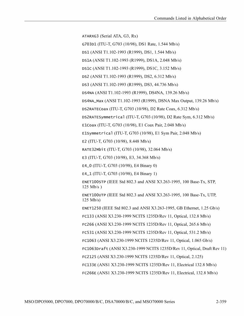
Commands Listed in Alphabetical Order
ATARXG3 (Serial ATA, G3, Rx)
G703D1 (ITU-T, G703 (10/98), DS1 Rate, 1.544 Mb/s)
DS1 (ANSI T1.102-1993 (R1999), DS1, 1.544 Mb/s)
DS1A (ANSI T1.102-1993 (R1999), DS1A, 2.048 Mb/s)
DS1C (ANSI T1.102-1993 (R1999), DS1C, 3.152 Mb/s)
DS2 (ANSI T1.102-1993 (R1999), DS2, 6.312 Mb/s)
DS3 (ANSI T1.102-1993 (R1999), DS3, 44.736 Mb/s)
DS4NA (ANSI T1.102-1993 (R1999), DS4NA, 139.26 Mb/s)
DS4NA_Max (ANSI T1.102-1993 (R1999), DSNA Max Output, 139.26 Mb/s)
DS2RATECoax (ITU-T, G703 (10/98), D2 Rate Coax, 6.312 Mb/s)
DS2RATESymmetrical (ITU-T, G703 (10/98), D2 Rate Sym, 6.312 Mb/s)
E1Coax (ITU-T, G703 (10/98), E1 Coax Pair, 2.048 Mb/s)
E1Symmetrical (ITU-T, G703 (10/98), E1 Sym Pair, 2.048 Mb/s)
E2 (ITU-T, G703 (10/98), 8.448 Mb/s)
RATE32Mbit (ITU-T, G703 (10/98), 32.064 Mb/s)
E3 (ITU-T, G703 (10/98), E3, 34.368 Mb/s)
E4_0 (ITU-T, G703 (10/98), E4 Binary 0)
E4_1 (ITU-T, G703 (10/98), E4 Binary 1)
ENET100STP (IEEE Std 802.3 and ANSI X3.263-1995, 100 Base-Tx, STP,125 Mb/s )
ENET100UTP (IEEE Std 802.3 and ANSI X3.263-1995, 100 Base-Tx, UTP,125 Mb/s)
ENET1250 (IEEE Std 802.3 and ANSI X3.263-1995, GB Ethernet, 1.25 Gb/s)
FC133 (ANSI X3.230-1999 NCITS 1235D/Rev 11, Optical, 132.8 Mb/s)
FC266 (ANSI X3.230-1999 NCITS 1235D/Rev 11, Optical, 265.6 Mb/s)
FC531 (ANSI X3.230-1999 NCITS 1235D/Rev 11, Optical, 531.2 Mb/s)
FC1063 (ANSI X3.230-1999 NCITS 1235D/Rev 11, Optical, 1.065 Gb/s)
FC1063Draft (ANSI X3.230-1999 NCITS 1235D/Rev 11, Optical, Draft Rev 11)
FC2125 (ANSI X3.230-1999 NCITS 1235D/Rev 11, Optical, 2.125)
FC133E (ANS1 X3.230-1999 NCITS 1235D/Rev 11, Electrical 132.8 Mb/s)
FC266E (ANS1 X3.230-1999 NCITS 1235D/Rev 11, Electrical, 132.8 Mb/s)
MSO/DPO5000, DPO7000, DPO70000/B/C, DSA70000/B/C, and MSO70000 Series 2-359

Commands Listed in Alphabetical Order
FC531E (ANS1 X3.230-1999 NCITS 1235D/Rev 11, Electrical, 531.2 Mb/s)
FC1063E (ANS1 X3.230-1999 NCITS 1235D/Rev 11, Electrical, 1.0625 Gb/s)
FC1063E_NBT (ANS1 X3.230-1999 NCITS 1235D/Rev 11, Norm, Beta, Transm)
FC1063E_NDT (ANS1 X3.230-1999 NCITS 1235D/Rev 11, Norm, Delta, Transm)
FC1063E_NGT (ANS1 X3.230-1999 NCITS 1235D/Rev 11, Norm, Gamma,Transm)
FC1063E_ABT (ANS1 X3.230-1999 NCITS 1235D/Rev 11, Abs, Beta, Transm)
FC1063E_ADT (ANS1 X3.230-1999 NCITS 1235D/Rev 11, Abs, Beta, Transm)
FC1063E_AGT (ANS1 X3.230-1999 NCITS 1235D/Rev 11, Abs, Gamma,Transm)
FC1063E_ABR (ANS1 X3.230-1999 NCITS 1235D/Rev 11, Abs, Beta, Recv)
FC1063E_ADR (ANS1 X3.230-1999 NCITS 1235D/Rev 11, Abs, Delta, Recv)
FC1063E_AGR (ANS1 X3.230-1999 NCITS 1235D/Rev 11, Abs, Gamma, Recv)
FC2125E_NBT (ANS1 X3.230-1999 NCITS 1235D/Rev 11, Norm, Beta, Transm)
FC2125E_NDT (ANS1 X3.230-1999 NCITS 1235D/Rev 11, Norm, Delta, Transm)
FC2125E_NGT (ANS1 X3.230-1999 NCITS 1235D/Rev 11, Norm, Gamma,Transm)
FC2125E_ABT (ANS1 X3.230-1999 NCITS 1235D/Rev 11, Abs, Beta, Transm)
FC2125E_ADT (ANS1 X3.230-1999 NCITS 1235D/Rev 11, Abs, Delta, Transm)
FC2125E_AGT (ANS1 X3.230-1999 NCITS 1235D/Rev 11, Abs, Gamma,Transm)
FC2125E_ABR (ANS1 X3.230-1999 NCITS 1235D/Rev 11, Abs, Beta, Recv)
FC2125E_ADR (ANS1 X3.230-1999 NCITS 1235D/Rev 11, Abs, Delta, Recv)
FC2125E_AGR (ANS1 X3.230-1999 NCITS 1235D/Rev 11, Abs, Gamma, Recv)
ENET1000BCX_NTP2 (1000B-CX Norm, TP2, 1.25 Gb/s)
ENET1000BCX_ATP2 (1000B-CX Abs, TP2, 1.25 Gb/s)
ENET1000BCX_ATP3 (1000B-CX Abs, TP3, 1.25 Gb/s)
ENETXAUI_Near (10 Gigabit Attachment Unit Interface (XAUI), Near,3,125 Gb/s)
ENETXAUI_Far (10 Gigabit Attachment Unit Interface (XAUI), Far, 3.125 Gb/s)
FST1 (USB, FS:T1, 12 Mb/s)
FST2 (USB, FS:T2, 12 Mb/s)
2-360 MSO/DPO5000, DPO7000, DPO70000/B/C, DSA70000/B/C, and MSO70000 Series

Commands Listed in Alphabetical Order
FST3 (USB, FS:T3, 12 Mb/s)
FST4 (USB, FS:T4: 12 Mb/s)
FST5 (USB, FS:T5, 12 Mb/s)
FST6 (USB, FS:T6, 12 Mb/s)
FW1394BS400BT1 (IEEE 1394b, S400b T1, 491.5 Mb/s)
FW1394BS400BT2 (IEEE 1394b, S400b T2, 491.5 Mb/s)
FW1394BS800BT1 (IEEE 1394b, S800b T1, 983.0 Mb/s)
FW1394BS800BT2 (IEEE 1394b, S800b T2, 983.0 Mb/s)
FW1394BS1600BT1 (IEEE 1394b, S1600b T1, 1.966 Gb/s)
FW1394BS1600BT2 (IEEE 1394b, S1600b T2, 1.966 Gb/s)
FW1394BS400B (IEEE 1394b, S400 Optical, 491.5 Mb/s)
FW1394BS800B (IEEE 1394b, S800 Optical, 988.0 Mb/s)
FW1394BS1600B (IEEE 1394b, S1600 Optical, 1.966 Gb/s)
G703DS3 (ITU-T, G703 (10/98))
HST1 (USB, HS:T1, 480 Mb/s)
HST2 (USB, HS:T2, 480 Mb/s)
HST3 (USB, HS:T3, 480 Mb/s)
HST4 (USB, HS:T4, 480 Mb/s)
HST5 (USB, HS:T5, 480 Mb/s)
HST6 (USB, HS:T6, 480 Mb/s)
INF2_5G (InfiniBand, IBTA Spec 1.0a, 2.5 Optical, 2.5 Gb/s)
INF2_5GE (InfiniBand, IBTA Spec 1.0a, 2.5 Electrical, 2.5 Gb/s)
OC1 (GR 253-CORE Issue 3 9/21/2000 OC1/STM0, 51.84 Mb/s)
OC3 (GR 253-CORE Issue 3 9/21/2000 OC1/STM1, 155.52, Mb/s)
OC12 (GR 253-CORE Issue 3 9/21/2000 OC1/STM4, 622.08 Mb/s)
OC48 (GR 253-CORE Issue 3 9/21/2000 OC1/STM16, 2.4883 Gb/s
OC48_FEC (Forward Error Correction - CSA8000 mask, 2.666 Gb/s)
PCIEXPRESS_Xmit (PCI Express Transmitter, 2.5 Gb/s)
PCIEXPRESS_Rcv (PCI Express Receiver, 2.5 Gb/s)
RATE97Mbit (ITU-T, G703 (10/98), 97 Mbit, 97.728 Mb/s)
RIO_DRV500M (Rapid IO Driver, 500 Mb/s)
MSO/DPO5000, DPO7000, DPO70000/B/C, DSA70000/B/C, and MSO70000 Series 2-361

Commands Listed in Alphabetical Order
RIO_DRV750M (Rapid IO Driver, 750 Mb/s)
RIO_DRV1G (Rapid IO Driver, 1 Gb/s)
RIO_DRV1_5G (Rapid IO Driver, 5 Gb/s)
RIO_DRV2G (Rapid IO Driver, 2 Gb/s)
RIO_EDRV500M (Rapid IO Extended Driver, 500 Mb/s)
RIO_EDRV750M (Rapid IO Extended Driver, 750 Mb/s)
RIO_EDRV1G (Rapid IO Extended Driver, 1 Gb/s)
RIO_EDRV1_5G (Rapid IO Extended Driver, 1.5 Gb/s)
RIO_EDRV2G (Rapid IO Extended Driver, 2 Gb/s)
RIO_RCV500M (Rapid IO Receiver, 500 Mb/s)
RIO_RCV750M (Rapid IO Receiver, 750 Mb/s)
RIO_RCV1G (Rapid IO Receiver, 1 Gb/s)
RIO_RCV1_5G (Rapid IO Receiver, 1.5 Gb/s)
RIO_RCV2G (Rapid IO Receiver, 2 Gb/s)
RIO_SERIAL_1G (Rapid IO Serial, 1.25 Gb/s)
RIO_SERIAL_2G (Rapid IO Serial, 2.5 Gb/s)
RIO_SERIAL_3G (Rapid IO Serial, 3.25 Gb/s)
SFI5_XMITADATA2 (SFI15 Transmit: Test Point A Data Signal 2, 2.488 Gb/s)
SFI5_XMITCDATA2 (SFI15 Transmit: Test Point C Data Signal 2, 2.488 Gb/s)
SFI5_XMITACLK2 (SFI15 Transmit: Test Point A Clock Signal 2, 2.488 Gb/s)
SFI5_XMITCCLK2 (SFI15 Transmit: Test Point C Clock Signal 2, 2.488 Gb/s)
SFI5_RCVBDATA2 (SFI15 Receive: Test Point B Data Signal 2, 2.488 Gb/s)
SFI5_RCVDDATA2 (SFI15 Receive: Test Point D Data Signal 2, 2.488 Gb/s)
SFI5_RCVBCLK2 (SFI15 Receive: Test Point B Clock Signal 2, 2.488 Gb/s)
SFI5_RCVDCLK2 (SFI15 Receive: Test Point D Clock Signal 2, 2.488 Gb/s)
SFI5_XMITADATA3 (SFI15 Transmit: Test Point A Data Signal 3, 3.125 Gb/s)
SFI5_XMITCDATA3 (SFI15 Transmit: Test Point C Data Signal 3, 3.125 Gb/s)
SFI5_XMITACLK3 (SFI15 Transmit: Test Point A Clock Signal 3, 3.125 Gb/s)
SFI5_XMITCCLK3 (SFI15 Transmit: Test Point C Clock Signal 3, 3.125 Gb/s)
SFI5_RCVBDATA3 (SFI15 Receive: Test Point B Data Signal 3, 3.125 Gb/s)
SFI5_RCVDDATA3 (SFI15 Receive: Test Point D Data Signal 3, 3.125 Gb/s)
2-362 MSO/DPO5000, DPO7000, DPO70000/B/C, DSA70000/B/C, and MSO70000 Series

Commands Listed in Alphabetical Order
SFI5_RCVBCLK3 (SFI15 Receive: Test Point B Clock Signal 3, 3.125 Gb/s)
SFI5_RCVDCLK3 (SFI15 Receive: Test Point D Clock Signal 3, 3.125 Gb/s
STM1E_0 (ITU-T, G703 (10/98), STM1E Binary 0)
STM1E_1 (ITU-T, G703 (10/98), STM1E Binary 1)
STS1Pulse (ANSI T1.102-1993 (R1999), STS-1 Pulse, 51.84 Mb/s)
STS1Eye (ANSI T1.102-1993 (R1999), STS-1 Eye, 51.84 Mb/s)
STS3 (ANSI T1.102-1993 (R1999), STS-3, 155.52 Mb/s)
STS3_Max (ANSI T1.102-1993 (R1999), STS-3 Max Output, 155.52 Mb/s)
TFI15_2 (TFI-5, 2.488 Gb/s)
TFI5_3 (TFI-5, 3.1104 Gb/s)
USERMask
VIDEO292M (SMPTE, 1.485 Gb/s)
VSROC192 (VSR OC192/STM64, 1.24416 Gb/s)
Examples MASK:AUTOSET:STANDARD E1COAX selects the E1 Coax standard mask.
MASK:AUTOSET:STANDARD? might return :MASK:AUTOSET:STANDARDE1COAX, indicating that the E1 Coax mask is selected as the current mask standard.
MASK:AUTOSet:TRIGgerThis command specifies whether a mask AUTOSet affects the trigger level. Othertrigger settings such as type of trigger are not changed by autoset. The default isON.
This command, like all the mask autoset commands, affects only an autoset on astandard mask, not the general instrument autoset function.
Group Mask
Syntax MASK:AUTOSet:TRIGger ON|OFF|<NR1>MASK:AUTOSet:TRIGger?
Arguments ON enables the autoset:trigger function.
OFF disables the autoset:trigger function.
<NR1> = 0 disables the autoset:trigger function; any other value enables it.
MSO/DPO5000, DPO7000, DPO70000/B/C, DSA70000/B/C, and MSO70000 Series 2-363

Commands Listed in Alphabetical Order
Examples MASK:AUTOSET:TRIGGER ON enables the autoset:trigger function.
MASK:AUTOSET:TRIGGER? might return :MASK:AUTOSET:TRIGGER 1,indicating that the autoset:trigger function is enabled.
MASK:AUTOSet:USER:ONEThis command sets or queries the level 1 value used by autoset for user masks.
Group Mask
Syntax MASK:AUTOSet:USER:ONE <NR3>MASK:AUTOSet:USER:ONE?
Related Commands MASK:AUTOSet:USER:TYPe, MASK:AUTOSet:USER:ZERo
Arguments <NR3> sets the level 1 value used by autoset for user masks.
Examples MASK:AUTOSET:USER:ONE 1 sets the autoset for 1 in user masks is 1.0 volts.
MASK:AUTOSET:USER:ONE? might return :MASK:AUTOSET:USER:ON 0.0000,indicating that the autoset is using 0.0 volts for 1 in user masks.
MASK:AUTOSet:USER:TYPeThis command sets or queries how autoset scales a mask.
Group Mask
Syntax MASK:AUTOSet:USER:TYPe ABSolute|NORMALIZedMASK:AUTOSet:USER:TYPe?
Related Commands MASK:AUTOSet:USER:ONE, MASK:AUTOSet:USER:ZERo
Arguments ABSOLUTE tells autoset to use the values supplied by MASK:AUTOSet:USER:ONE and MASK:AUTOSet:USER:ZERo for the one and zero of the mask.
NORMALIZED tells autoset to determine the mask one and zero by looking at themask.
2-364 MSO/DPO5000, DPO7000, DPO70000/B/C, DSA70000/B/C, and MSO70000 Series

Commands Listed in Alphabetical Order
Examples MASK:AUTOSET:USER:TYPE NORMALIZED sets the autoset scales in a maskto normalize.
MASK:AUTOSET:USER:TYPE? might return :MASK:AUTOSET:USER:TYPENORMALIZED, indicating that the autoset is set to normalize scales in a mask.
MASK:AUTOSet:USER:ZERo
NOTE. The command works only if the Option MTM is enabled.
This command sets or queries the level 0 used by autoset for user masks.
Group Mask
Syntax MASK:AUTOSet:USER:ZERo <NR3>MASK:AUTOSet:USER:ZERo?
Related Commands MASK:AUTOSet:USER:TYPe, MASK:AUTOSet:USER:ONE
Arguments <NR3> sets the zero level that autoset uses for user masks.
Examples MASK:AUTOSET:USER:ZERO 1.000 sets the autoset for zero in user masks toscales in a mask to normalize.
MASK:AUTOSET:USER:ZERO? might return :MASK:AUTOSET:USER:ZERO0.0000, indicating that the autoset is using 0.0 volts for zero in user masks.
MASK:AUTOSet:VPOSThis command controls whether the mask autoset algorithm will affect the verticalposition (or offset) of the signal while attempting to autoset. The default is ON.
This command, like all the mask autoset commands, affects only an autoset on astandard mask, not the general instrument autoset function.
Group Mask
Syntax MASK:AUTOSet:VPOS ON|OFF|<NR1>MASK:AUTOSet:VPOS?
MSO/DPO5000, DPO7000, DPO70000/B/C, DSA70000/B/C, and MSO70000 Series 2-365

Commands Listed in Alphabetical Order
Arguments ON enables the autoset:vpos function.
OFF disables the autoset:vpos function.
<NR1> = 0 disables the autoset:vpos function; any other value enables it.
Examples MASK:AUTOSET:VPOS ON enables the autoset:vpos function.
MASK:AUTOSET:VPOS? might return :MASK:AUTOSET:VPOS 0.0000,indicating that the autoset:vpos function is disabled.
MASK:AUTOSet:VSCAle
NOTE. The command works only if the Option MTM is enabled.
This command controls whether the mask autoset algorithm will affect the verticalscale while attempting to autoset.
This command, like all the mask autoset commands, affects only an autoset on astandard mask, not the general instrument autoset function.
Group Mask
Syntax MASK:AUTOSet:VSCAle ON|OFF|<NR1>MASK:AUTOSet:VSCAle?
Arguments ON enables the autoset:vscale function.
OFF disables the autoset:vscale function.
<NR1> = 0 disables the autoset:vscale function; any other value enables it.
Examples MASK:AUTOSET:VSCALE ON enables the autoset:vscale function.
MASK:AUTOSET:VSCALE? might return :MASK:AUTOSET:VSCALE 0.0000,indicating that the autoset:vcale function is disabled.
MASK:COPy:USER (No Query Form)This command copies the currently displayed mask to the user mask.
Group Mask
2-366 MSO/DPO5000, DPO7000, DPO70000/B/C, DSA70000/B/C, and MSO70000 Series

Commands Listed in Alphabetical Order
Syntax MASK:COPy:USER
Examples MASK:COPY:USER copies the current mask to the user mask.
MASK:COUNt (No Query Form)
NOTE. The command works only if the Option MTM is enabled.
This command resets to zero the number of hits for all mask segments on thespecified source.
This is equivalent to pressing the front panel ’Clear’ button.
Group Mask
Syntax MASK:COUNt RESET
Arguments RESET sets to zero the number of hits for all mask segments on the specifiedsource.
Examples MASK:COUNT resets to zero the number of hits for all mask segments on thespecified source.
MASK:COUNt:FAILURES? (Query Only)This query-only command returns the number of pass/fail tests that have failed.The default is 0. Pass/fail testing must be enabled.
Group Mask
Syntax MASK:COUNt:FAILURES?
Returns <NR1>
Examples MASK:COUNT:FAILURES? might return :MASK:COUNT:FAILURES 0, showingthat no tests have failed.
MSO/DPO5000, DPO7000, DPO70000/B/C, DSA70000/B/C, and MSO70000 Series 2-367

Commands Listed in Alphabetical Order
MASK:COUNt:HITS? (Query Only)
NOTE. The command works only if the Option MTM is enabled.
This query-only command returns the number of hits on all mask segments. Hitcounting must be turned on.
Group Mask
Syntax MASK:COUNt:HITS?
Returns <NR1>
Examples MASK:COUNT:HITS? might return :MASK:COUNT:HITS 0, showing there wereno hits from any source on any mask segments.
MASK:COUNt:SEG<m>:HITS? (Query Only)This query-only command returns the number of hits in mask segment <m>. Hitcounting must be turned on.
m is the mask segment number.
Group Mask
Syntax MASK:COUNt:SEG<m>:HITS?
Returns <NR1> returns the number of hits in the mask segment.
Examples MASK:COUNT:SEG1:HITS? might return :MASK:COUNT:SEG1:HITS 0,showing that there have been no hits.
MASK:COUNt:STATEThis command sets or queries the mask hits count state; it controls whethermask counting is being done. MASK:DISplay must be ON to enableMASK:COUNt:STATE to count mask violations.
2-368 MSO/DPO5000, DPO7000, DPO70000/B/C, DSA70000/B/C, and MSO70000 Series

Commands Listed in Alphabetical Order
Group Mask
Syntax MASK:COUNt:STATE OFF|ON|<NR1>MASK:COUNt:STATE?
Arguments S123hi456va
ON turns on mask counting.
OFF turns off mask counting. This is the default state.
<NR1> = 0 turns off mask hit counting, and other values turn on mask hit counting.
Examples MASK:COUNT:STATE ON turns on mask hit counting.
MASK:COUNT:STATE? might return :MASK:COUNT:STATE 1, indicating thatthe mask counting is on.
MASK:COUNt:TESTS? (Query Only)This query-only command returns the number of pass/fail tests that have occurred.
Group Mask
Syntax MASK:COUNt:TESTS?
Returns <NR1>
Examples MASK:COUNT:TESTS? might return :MASK:COUNT:TESTS 50, showing 50tests have occurred.
MASK:COUNt:TOTal? (Query Only)This query-only command returns the sum of all hits in all mask segments. Thiscommand is the same as MASK:COUNT:HITS? and is kept for compatibilitywith other Tektronix instruments.
Group Mask
Syntax MASK:COUNt:TOTal?
MSO/DPO5000, DPO7000, DPO70000/B/C, DSA70000/B/C, and MSO70000 Series 2-369
Commands Listed in Alphabetical Order
Returns <NR1>
Examples MASK:COUNT:TOTAL? might return :MASK:COUNT:TOTAL 50, showing 50hits have occurred.
MASK:COUNt:VIOLATIONS? (Query Only)This query-only command returns the number of test violations that have occurredin the current pass/fail test. A test violation occurs when any part of a waveformfalls within any mask segment. The default is 0.
Group Mask
Syntax MASK:COUNt:VIOLATIONS?
Related Commands MASK:COUNt:TESTS?, MASK:COUNt:TOTal?, MASK:COUNt:WAVEFORMS?, MASK:TESt:REPeat
Returns <NR1>
Examples MASK:COUNT:VIOLATIONS? might return :MASK:COUNT:VIOLATIONS 50,showing that 50 test violations have occurred.
MASK:COUNt:WAVEFORMS? (Query Only)This query-only command returns the number of waveforms that have beenacquired and processed during pass/fail testing.
Group Mask
Syntax MASK:COUNt:WAVEFORMS?
Related Commands MASK:COUNt:TESTS?, MASK:COUNt:TOTal?, MASK:COUNt:VIOLATIONS?
Returns <NR1>
2-370 MSO/DPO5000, DPO7000, DPO70000/B/C, DSA70000/B/C, and MSO70000 Series

Commands Listed in Alphabetical Order
Examples MASK:COUNT:WAVEFORMS? might return :MASK:COUNT:WAVEFORMS 1000,showing that 1,000 waveforms have been acquired and processed.
MASK:DISplayThis command sets or queries whether or not defined masks are displayed on thescreen. This is useful for temporarily turning off user-defined masks withoutdeleting them. It is also useful for removing a standard mask from the screen, butleaving it as the selected standard. Mask counting, mask testing, and mask autosetare unavailable if the mask display is Off. The default is On.
Group Mask
Syntax MASK:DISplay OFF|ON|<NR1>MASK:DISplay?
Arguments ON shows the masks on the display. This is the default value.
OFF removes the masks from the display.
<NR1> = 0 removes the masks from the display; any other value shows the maskson the display.
Examples MASK:DISPLAY ON sets the display to show the defined masks.
MASK:DISPLAY? might return :MASK:DISPLAY 1, indicating that the definedmasks on the screen are displayed.
MASK:FILTerThis command sets or returns whether the selected digital filter will be run onthe waveform data. The filter simulates optical hardware. That is, it simulatesdifferent hardware for each of several different optical standards.
The digital filter runs on OC1, OC3, OC12, OC48, FC133, FC266, FC531,FC1063, FC2125Draft, Gigabit Ethernet, Infiniband 2.5 Gb, 1394 b, 393 Mb,786.43 Mb, 1.572 Gb
Group Mask
Syntax MASK:FILTer OFF|ON|<NR1>MASK:FILTer?
MSO/DPO5000, DPO7000, DPO70000/B/C, DSA70000/B/C, and MSO70000 Series 2-371

Commands Listed in Alphabetical Order
Related Commands ACQuire:MODe
Arguments OFF disables the digital filter.
ON enables the digital filter.
<NR1> = 0 disables the digital filter; any other value enables it.
Examples MASK:FILTERON enables the digital filter.
MASK:FILTER? might return :MASK:FILTER 1, indicating that the selecteddigital filter will be run on the waveform data.
MASK:HIGHLIGHTHitsThis command sets or returns whether or not hits in a mask are highlighted indifferent colors than other waveform data. The default is On.
Group Mask
Syntax MASK:HIGHLIGHTHits OFF|ON|<NR1>MASK:HIGHLIGHTHits?
Arguments OFF disables the mask:highlighthits function.
ON enables the mask:highlighthits function.
<NR1> = 0 disables the mask:highlighthits function; any other value enables it.
Examples MASK:HIGHLIGHTHITS ON enables the mask highlighthits function.
MASK:HIGHLIGHTHITS? might return :MASK:HIGHLIGHTHITS 1, indicatingthat the mask:highlighthits function is enabled.
MASK:INVertThis command controls whether the mask is drawn inverted. It has no effect if thismask cannot be inverted. The default is Off (Positive).
Group Mask
Syntax MASK:INVert OFF|ON|<NR1>
2-372 MSO/DPO5000, DPO7000, DPO70000/B/C, DSA70000/B/C, and MSO70000 Series
Commands Listed in Alphabetical Order
Arguments OFF Positive
ON Negative
<NR1> = 0 disables the mask:invert function; any other value enables it.
Examples MASK:INVERTON enables the mask invert function.
MASK:INVERT? might return :MASK:INVERT 1, indicating that the mask isdrawn inverted.
MASK:LOCkThis command sets or returns the mask lock to waveform mode. It locks the maskto the waveform such that changes to the horizontal and/or vertical scale settingsredraws the mask segments in proportion. This feature allows for expandinghorizontal and/or vertical settings to zoom in on waveforms and masks to visuallyexamine violation areas in more detail.
Group Mask
Syntax MASK:LOCk OFF|ON|<NR1>MASK:LOCk?
Arguments OFF turns off mask lock to waveform.
ON turns on mask lock to waveform.
<NR1> = 0 turns off mask lock to waveform and any other value turns on masklock to waveform.
Examples MASK:LOCK ON turns on mask lock to waveform.
MASK:LOCK? might return :MASK:LOCK 1, indicating that the mask lock towaveform mode is enabled.
MASK:MARgin:PERCentThis command sets or queries the mask margin percentage. If you set a positivemask margin percentage, the polygon expands and the mask test will be moredifficult to pass due to the expanded test area. If you set a negative mask marginpercentage, the polygon shrinks and the mask test will be easier to pass due tothe smaller area.
MSO/DPO5000, DPO7000, DPO70000/B/C, DSA70000/B/C, and MSO70000 Series 2-373

Commands Listed in Alphabetical Order
Group Mask
Syntax MASK:MARgin:PERCent <NR3>MASK:MARgin:PERCent?
Arguments <NR3> values range from -50.0 to +50.0. The default is 5.
Examples MASK:MARGIN:PERCENT 25 sets the mask margin percentage to 25.
MASK:MARGIN:PERCENT? might return :MASK:MARGIN:PERCENT1.00000000000E+001, indicating that the mask margin is set to 10%.
MASK:MARgin:STATEThis command sets or returns the state of the mask margins.
Group Mask
Syntax MASK:MARgin:STATE OFF|ON|<NR1>MASK:MARgin:STATE?
Arguments OFF turns off mask margins. The currently displayed margined mask is erased andthe original mask is displayed.
ON turns on mask margins.
<NR1> = 0 turns off mask margins; any other integer turns on the selected maskmargins.
Examples MASK:MARGIN:STATE ON turns on mask margins.
MASK:MARGIN:STATE? might return :MASK:MARGIN:STATE 1, indicating thatthe mask margins are on.
MASK:MASKPRE:AMPlitudeThis command sets or returns the current mask’s nominal pulse amplitude involts. The query form of this command returns the nominal pulse amplitudeof the displayed mask. The set form of this command only affects the current(displayed) mask.
2-374 MSO/DPO5000, DPO7000, DPO70000/B/C, DSA70000/B/C, and MSO70000 Series

Commands Listed in Alphabetical Order
Group Mask
Syntax MASK:MASKPRE:AMPlitude <NR3>MASK:MASKPRE:AMPlitude?
Related Commands MASK:MASKPRE:VSCAle
Arguments <NR3> is a floating number that sets the nominal pulse amplitude in volts.
Examples MASK:MASKPRE:AMPLITUDE 2.4 sets the current mask nominal pulse amplitudeto 2.4 volts.
MASK:MASKPRE:AMPLITUDE? might return :MASK:MASKPRE:AMPLITUDE 1,indicating that the current mask’s nominal pulse amplitude is set to 1.0 V.
MASK:MASKPRE:HSCAleThis command sets or returns the nominal timing resolution used to draw themask in time/division. The query form of this command returns the nominaltiming resolution of the displayed mask. The set form of this command onlyaffects the current (displayed) mask.
Group Mask
Syntax MASK:MASKPRE:HSCAle <NR3>MASK:MASKPRE:HSCAle?
Related Commands MASK:MASKPRE:HTRIGPOS
Arguments <NR3> is a floating point number that sets the mask drawing timing resolution.
Examples MASK:MASKPRE:HSCALE 40E-9 sets the nominal timing resolution used to drawthe mask pulse shape to 40 nanoseconds per division.
MASK:MASKPRE:HSCALE? might return :MASK:MASKPRE:HSCALE 1, indicatingthat the current mask’s nominal timing resolution is to 1 nanosecond per divisions.
MSO/DPO5000, DPO7000, DPO70000/B/C, DSA70000/B/C, and MSO70000 Series 2-375

Commands Listed in Alphabetical Order
MASK:MASKPRE:HTRIGPOSThis command sets or returns the nominal trigger position (pulse leading edge)used to draw the mask as a fraction of the display width. The query form of thiscommand returns the nominal trigger position of the displayed mask. The set formof this command only affects the current (displayed) mask.
Group Mask
Syntax MASK:MASKPRE:HTRIGPOS <NR3>MASK:MASKPRE:HTRIGPOS?
Related Commands MASK:MASKPRE:HSCAle
Arguments <NR3> is a floating point number in the range of 0.0 to 1.0 that sets the triggerpoints as a fraction of the display width, referenced from the left edge of thegraticule. The number 0.0 represents the left edge.
Examples MASK:MASKPRE:HTRIGPOS 0.6 sets the current mask nominal pulse leadingedge position to the sixth horizontal graticule division.
MASK:MASKPRE:HTRIGPOS? might return :MASK:MASKPRE:HTRIGPOS 0.8,indicating that the trigger position is set to eight horizontal graticule divisions.
MASK:MASKPRE:PATTERNBITSThis command sets or returns the number of bits used for serial trigger for theUser mask standard. For example, DS1 requires six bits: four leading zeros,a one, and a trailing zero. The query form of this command returns the serialbit value of the displayed mask. The set form of this command only affects thecurrent (displayed) mask.
Group Mask
Syntax MASK:MASKPRE:PATTERNBITS <NR1>MASK:MASKPRE:PATTERNBITS?
Related Commands MASK:MASKPRE:PRESAMPBITS
Arguments <NR1> is an integer that sets the number of bits.
2-376 MSO/DPO5000, DPO7000, DPO70000/B/C, DSA70000/B/C, and MSO70000 Series

Commands Listed in Alphabetical Order
Examples MASK:MASKPRE:PATTERNBITS 6 sets the current mask number of serial patternbits to 6.
MASK:MASKPRE:PATTERNBITS? might return :MASK:MASKPRE:PATTERNBITS8, indicating that the number of bits for serial trigger of the user mask standard isset to 8.
MASK:MASKPRE:PRESAMPBITSThis command sets or returns the number of bits before the (isolated one) pulseleading edge in the serial trigger pass/fail testing. For example, DS1 has fourleading zeros. The query form of this command returns the presample bit valueof the displayed mask. The set form of this command only affects the current(displayed) mask.
Group Mask
Syntax MASK:MASKPRE:PRESAMPBITS <NR1>MASK:MASKPRE:PRESAMPBITS?
Related Commands MASK:MASKPRE:PATTERNBITS
Arguments <NR1> is an integer that sets the number of bits before the trigger pulse.
Examples MASK:MASKPRE:PRESAMPBITS 4 sets the current mask number of bits beforethe trigger pulse to 4.
MASK:MASKPRE:PRESAMPBITS? might return :MASK:MASKPRE:PRESAMPBITS8, indicating that the presample bit value of the displayed mask is set to 8.
MASK:MASKPRE:RECOrdlengthThis command sets or returns the nominal record length for pulse mask testing.The query form of this command returns the record length value of the displayedmask. The set form of this command only affects the current (displayed) mask.
Group Mask
Syntax MASK:MASKPRE:RECOrdlength <NR1>MASK:MASKPRE:RECOrdlength?
MSO/DPO5000, DPO7000, DPO70000/B/C, DSA70000/B/C, and MSO70000 Series 2-377

Commands Listed in Alphabetical Order
Arguments <NR1> is an integer number that sets the record length.
Examples MASK:MASKPRE:RECORDLENGTH 500 sets the current mask record length to500 points.
MASK:MASKPRE:RECORDLENGTH? might return:MASK:MASKPRE:RECORDLENGTH 400, indicating that the nominal recordlength for pulse mask testing is set to 400.
MASK:MASKPRE:TRIGTOSAMPThis command sets or returns the time in seconds, from the (leading edge) triggerposition to the pulse bit sampling position. The query form of this commandreturns the time value of the displayed mask. The set form of this command onlyaffects the current (displayed) mask.
Group Mask
Syntax MASK:MASKPRE:TRIGTOSAMP <NR3>MASK:MASKPRE:TRIGTOSAMP?
Related Commands MASK:MASKPRE:WIDth
Arguments <NR3> is the floating point number that sets the time to the pulse bit samplingposition.
Examples MASK:MASKPRE:TRIGTOSAMP 162E-9 sets the current mask time fromthe (leading edge) trigger position to the pulse bit sampling position to162 nanoseconds.
MASK:MASKPRE:TRIGTOSAMP? might return :MASK:MASKPRE:TRIGTOSAMP100, indicating that the time value of the displayed mask is set to 100 nanoseconds.
MASK:MASKPRE:VOFFSetThis command sets or returns the nominal vertical offset in volts, used tovertically offset the input channels. The query form of this command returns theoffset value of the displayed mask. The set form of this command only affectsthe current (displayed) mask.
Group Mask
2-378 MSO/DPO5000, DPO7000, DPO70000/B/C, DSA70000/B/C, and MSO70000 Series

Commands Listed in Alphabetical Order
Syntax MASK:MASKPRE:VOFFSet <NR3>MASK:MASKPRE:VOFFSet?
Related Commands MASK:MASKPRE:VPOS, MASK:MASKPRE:VSCAle
Arguments <NR3> is a floating point number that sets the nominal vertical offset in volts.
Examples MASK:MASKPRE:VOFFSET 0.0 sets the current mask nominal vertical offsetto 0.0 volts.
MASK:MASKPRE:VOFFSET? might return :MASK:MASKPREVOFFSET 1.0000,indicating that the offset value of the displayed mask is set to 1.0 volts.
MASK:MASKPRE:VPOSThis command sets or returns the nominal vertical position, control in divisions,used to vertically position the input channels. The query form of this commandreturns the vertical position value of the displayed mask. The set form of thiscommand only affects the current (displayed) mask.
Group Mask
Syntax MASK:MASKPRE:VPOS <NR3>MASK:MASKPRE:VPOS?
Related Commands MASK:MASKPRE:VOFFSet, MASK:MASKPRE:VSCAle
Arguments <NR3> is a floating point number that sets the nominal vertical position controlin divisions.
Examples MASK:MASKPRE:VPOS -0.8 sets the current mask nominal vertical position to-0.8 divisions.
MASK:MASKPRE:VPOS? might return :MASK:MASKPRE:VPOS 1.0000,indicating that the vertical position value of the displayed mask is set to1.0 divisions.
MASK:MASKPRE:VSCAleThis command sets or returns the nominal vertical scale in volts per division, usedto vertically scale the input channels. The query form of this command returns the
MSO/DPO5000, DPO7000, DPO70000/B/C, DSA70000/B/C, and MSO70000 Series 2-379

Commands Listed in Alphabetical Order
vertical scale value of the displayed mask. The set form of this command onlyaffects the current (displayed) mask.
Group Mask
Syntax MASK:MASKPRE:VSCAle <NR3>MASK:MASKPRE:VSCAle?
Related Commands MASK:MASKPRE:VOFFSet, MASK:MASKPRE:VPOS
Arguments <NR3> is a floating point number that sets the nominal bit width in seconds.
Examples MASK:MASKPRE:VSCALE 200E-3 sets the current mask nominal vertical scaleto 200 millivolts per division.
MASK:MASKPRE:VSCALE? might return :MASK:MASKPRE:VSCALE400.0000E-3, indicating that the vertical position value of the displayed mask isset to 400 millivolts per division.
MASK:MASKPRE:WIDthThis command sets or returns the nominal bit width in seconds. The query formof this command returns the bit width value of the displayed mask. The set formof this command only affects the current (displayed) mask.
Group Mask
Syntax MASK:MASKPRE:WIDth <NR3>MASK:MASKPRE:WIDth?
Related Commands MASK:MASKPRE:TRIGTOSAMP
Arguments <NR3> is a floating point number that sets the nominal bit width in seconds. Thisnumber is the time of one bit of data where bit width = 1 / ( data rate of the signal ).
Examples MASK:MASKPRE:WIDTH 648E-9 sets the current mask nominal bit width to648 nanoseconds (1.544 Mbits/second).
MASK:MASKPRE:WIDTH? might return :MASK:MASKPRE:WIDTH 500.0000E–9,indicating that the bit width value of the displayed mask is set to 500 nanoseconds.
2-380 MSO/DPO5000, DPO7000, DPO70000/B/C, DSA70000/B/C, and MSO70000 Series

Commands Listed in Alphabetical Order
MASK:POLarityThis command sets or returns the input waveform polarity for the pass/fail test.It controls whether to test positive pulse, negative pulse, or both during pass/failtesting. This command only applies when MASK:TESt:STATE is on.
Group Mask
Syntax MASK:POLarity BOTh|NEGAtive|POSITIVeMASK:POLarity?
Related Commands MASK:TESt:STATE
Arguments BOTh enables testing for both positive and negative pulses. The instrument testspositive pulses on the mask:source waveform until ½ of the waveform is tested.Then the instrument inverts the mask and performs the remaining tests.
NEGAtive enables testing on negative pulses.
POSITIVe enables testing on positive pulses. This is the default.
Examples MASK:POLARITY BOTH sets pass/fail to test both positive (normal) and negative(inverted) waveforms.
MASK:POLARITY? might return :MASK:POLARITY POSITIVE, indicating thatthe input waveform polarity for the pass/fail test is set to positive.
MASK:SEG<m> (No Query Form)This command deletes the specified mask segment from the current mask.
m is an integer that specifies the mask segment number to delete from the currentmask.
Group Mask
Syntax MASK:SEG<m> DELEte
Arguments DELETE removes the specified mask segment from the mask.
Examples MASK:SEG3 DELETE deletes mask segment three from the current mask.
MSO/DPO5000, DPO7000, DPO70000/B/C, DSA70000/B/C, and MSO70000 Series 2-381

Commands Listed in Alphabetical Order
MASK:SEG<m>:NR_Pt? (Query Only)This query-only command returns the number of points that make up the specifiedmask segment of the current mask. Each mask point consists of an X-Y pair ofcoordinates.
m is an integer number that specifies a mask segment number of the current mask.
Group Mask
Syntax MASK:SEG<m>:NR_Pt?
Returns <NR1> is 0 to 50.
Examples MASK:SEG2:NR_PT? might return :MASK:SEG2:NR_PT 5.
MASK:SEG<m>:POINTSThis command sets or returns the X-Y user coordinates of all points in the currentmask segment. The set form defines new points in the current mask, replacing anyexisting points in the current mask segment; it sets or returns the vertices for aparticular segment in the current mask.
m is an integer that specifies the current mask segment number.
Group Mask
Syntax MASK:SEG<m>:POINTS <NR3>,<NR3>[,<NR3>,<NR3>]MASK:SEG<m>:POINTS?
Arguments <NR3> refers to the coordinates of one of the vertices in the Current mask. Eachpair of numbers represents the horizontal and vertical coordinates of a masksegment vertex. The pairs must be listed in a counterclockwise order. If thevertical or horizontal scale or position is changed after this command and then thequery form of this command is issued, the value returned from the instrument willnot be the same. If just one pair is input, it is ignored and the current mask segmentis marked as undefined. The default is no points in the current mask segment.
Examples MASK:SEG2:POINTS -2.3E-9, 44E-3, -2.5E-9, 47E-3, 1.2E-9,
44E-3 defines the points in current mask segment 2.
2-382 MSO/DPO5000, DPO7000, DPO70000/B/C, DSA70000/B/C, and MSO70000 Series

Commands Listed in Alphabetical Order
MASK:SEG2:POINTS? might return :MASK:SEG2:POINTS 0.0000, 0.0000,indicating that the X-Y user coordinates of all points in the Current mask segmentare set to 0,0.
MASK:SOUrceThis command sets or reports which source will be compared against the mask(s)when counting is turned on; it controls which trace to use in mask counting. Italso affects mask autoset and how triggering is set up when you select the mask.
Group Mask
Syntax MASK:SOUrce CH[1-4]|MATH[1-4]|REF[1-4]MASK:SOUrce?
Arguments CH<1-4> selects a channel waveform to be compared against the specified mask.The range for is 1 through 4.
MATH<1-4> selects a math waveform to be compared against the specified mask.The range for is 1 through 4.
REF<1-4> selects a reference waveform to be compared against the specifiedmask. The range is 1 through 4.
Examples MASK:SOURCE CH1 enables CH1 to be compared against the mask. Since atimebase is not specified, the default, Main, is used.
MASK:SOURCE? might return :MASK:SOURCE CH1,MAIN, indicating that theChannel 1 waveform will be compared against the mask using the Main timebase.
MASK:STANdardThis command deletes the existing mask (if any) and sets the selected standardmask. If MASK:COUNt:STATE is ON, mask counting starts immediately. Thequery form of this command returns the current mask standard.
NOTE. There are several available mask standards that require a higherbandwidth than permitted for some instruments. In such cases, a warning isposted to the standard event system upon selection of any of these standards. Toensure that the mask you select is fully supported by the instrument, always checkthe event status register after selecting a mask standard.
MSO/DPO5000, DPO7000, DPO70000/B/C, DSA70000/B/C, and MSO70000 Series 2-383

Commands Listed in Alphabetical Order
The following warning event is posted if the mask exceeds the instrumentbandwidth: 2318,“Consider system bandwidth when testing at this bit rate.”
Conditions This command is only valid for instruments with Option MTM installed.
Group Mask
Syntax MASK:STANdard ATARXG1|ATARXG2|ATARXG3|ATATXG1|ATATXG2|ATATXG3|CLOCKCoax|CLOCKSymmetrical|D1|D2|DS0Contra|DS0Double|DS0Single|DS0Timing|DS1|DS1A|DS1C|DS2|DS2RATECoax|DS2RATESymmetrical|DS3|DS4NA|DS4NA_Max|E1Coax|E1Symmetrical|E2|E3|E4_1|E4_0|ENET1000BCX_ATP2|ENET1000BCX_ATP3|ENET1000BCX_NTP2|ENET100FX|ENET100STP|ENET100UTP |ENET1250|ENETXAUI_Far|ENETXAUI_Near|FC1063|FC1063Draft|FC1063E|FC1063E_ABR|FC1063E_ABT|FC1063E_ADR|FC1063E_ADT|FC1063E_AGR|FC1063E_AGT|FC1063E_NBT|FC1063E_NDT|FC1063E_NGT|FC133|FC133E|FC2125|FC2125E_ABR|FC2125E_ABT|FC2125E_ADR|FC2125E_ADT|FC2125E_AGR|FC2125E_AGT|FC2125E_NBT|FC2125E_NDT|FC2125E_NGT|FC266|FC266E|FC4250E_ABR|FC4250E_ABT|FC4250E_ADR|FC4250E_ADT|FC4250E_AGR|FC4250E_AGT|FC4250E_NBT|FC4250E_NDT|FC4250E_NGT|FC531|FC531E|FST1|FST2|FST3|FST4|FST5|FST6|FW1394BS1600B|FW1394BS1600BT1|FW1394BS1600BT2|FW1394BS400B|FW1394BS400BT1|FW1394BS400BT2|FW1394BS800B|FW1394BS800BT1|FW1394BS800BT2|G703DS1|G703DS3|HST1|HST2|HST3|HST4|HST5|HST6|INF2_5G|INF2_5GE|NONe|OC1|OC12|OC3|OC48|OC48_FEC|PCIEXPRESS_Rcv|PCIEXPRESS_Xmit|RATE32Mbit|RATE97Mbit|RIO_DRV1G|RIO_DRV1_5G|RIO_DRV2G|RIO_DRV500M|RIO_DRV500M|RIO_DRV750M|RIO_EDRV1G|RIO_EDRV1_5G|RIO_EDRV2G|RIO_EDRV500M|RIO_EDRV500M|RIO_EDRV750M|RIO_RCV1G|RIO_RCV1_5G|RIO_RCV2G|RIO_RCV500M| RIO_RCV500M|RIO_RCV750M|RIO_SERIAL_1G|RIO_SERIAL_2G|RIO_SERIAL_3G|SFI5_RCVBCLK2|SFI5_RCVBCLK3|SFI5_RCVBDATA2 |SFI5_RCVBDATA3|SFI5_RCVDCLK2|SFI5_RCVDCLK3|SFI5_RCVDDATA2|SFI5_RCVDDATA3|SFI5_XMITACLK2|SFI5_XMITACLK3|SFI5_XMITADATA2|SFI5_XMITADATA3|SFI5_XMITCCLK2|SFI5_XMITCCLK3|SFI5_XMITCDATA2|SFI5_XMITCDATA3|STM0_0|STM0_1|STM0_HDBX|STM1E_1|STM1E_0|STS1Eye|STS1Pulse| STS3|STS3_Max|TFI5_2|TFI5_3|USERMask|VIDEO270|VIDEO292M|VIDEO360|VSROC192|SAS1_5_IR|SAS1_5_CR|SAS1_5_XR|SAS1_5_IR_AASJ|SAS1_5_CR_AASJ|SAS1_5_XR_AASJ|SAS1_5_SATA|SAS3_0_IR|SAS3_0_CR|SAS3_0_XR|SAS3_0_IR_AASJ|SAS3_0_CR_AASJ|SAS3_0_XR_AASJ |SAS3_0_SATA
2-384 MSO/DPO5000, DPO7000, DPO70000/B/C, DSA70000/B/C, and MSO70000 Series

Commands Listed in Alphabetical Order
MASK:STANdard?
Related Commands ACQuire:MODe
Arguments ATARXG1 (Serial ATA, G1 Rx 1.5 Gb/s)
ATARXG2 (Serial ATA, G2, Rx, 3.0 Gb/s)
ATARXG3 (Serial ATA, G3, Rx)
ATATXG1 (Serial ATA, G1 Tx, 1.5 Gb/s)
ATATXG2 (Serial ATA, G2 Tx, 3.0 Gb/s)
H ATATXG3 (Serial ATA, G3 Tx)
CLOCKCoax
CLOCKSymmetrical
D1
D2
DS0Contra (ITU-T, G703 (10/98), 64 kb/s)
DS0Double (ITU-T, G703 (10/98), 64 kb/s)
DS0Single (ITU-T, G703 (10/98), 64 kb/s)
DS0Timing (ITU-T, G703 (10/98), 64 kb/s)
DS1 (ANSI T1.102-1993 (R1999), DS1, 1.544 Mb/s)
DS1A (ANSI T1.102-1993 (R1999), DS1A, 2.048 Mb/s)
DS1C (ANSI T1.102-1993 (R1999), DS1C, 3.152 Mb/s)
DS2 (ANSI T1.102-1993 (R1999), DS2, 6.312 Mb/s)
DS2RATECoax (ITU-T, G703 (10/98), D2 Rate Coax, 6.312 Mb/s)
DS2RATESymmetrical (ITU-T, G703 (10/98), D2 Rate Sym, 6.312 Mb/s)
DS3 (ANSI T1.102-1993 (R1999), DS3, 44.736 Mb/s)
DS4NA (ANSI T1.102-1993 (R1999), DS4NA, 139.26 Mb/s)
DS4NA_Max (ANSI T1.102-1993 (R1999), DSNA Max Output, 139.26 Mb
E1Coax (ITU-T, G703 (10/98), E1 Coax Pair, 2.048 Mb/s)
E1Symmetrical (ITU-T, G703 (10/98), E1 Sym Pair, 2.048 Mb/s)
E2 (ITU-T, G703 (10/98), E2, 8.448 Mb/s)
E3 (ITU-T, G703 (10/98), E3, 34.368 Mb/s)
MSO/DPO5000, DPO7000, DPO70000/B/C, DSA70000/B/C, and MSO70000 Series 2-385
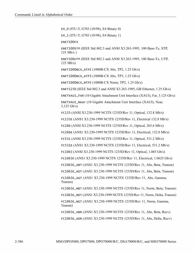
Commands Listed in Alphabetical Order
E4_0 (ITU-T, G703 (10/98), E4 Binary 0)
E4_1 (ITU-T, G703 (10/98), E4 Binary 1)
ENET100FX
ENET100STP (IEEE Std 802.3 and ANSI X3.263-1995, 100 Base-Tx, STP,125 Mb/s )
ENET100UTP (IEEE Std 802.3 and ANSI X3.263-1995, 100 Base-Tx, UTP,125 Mb/s)
ENET1000BCX_ATP2 (1000B-CX Abs, TP2, 1.25 Gb/s)
ENET1000BCX_ATP3 (1000B-CX Abs, TP3, 1.25 Gb/s)
ENET1000BCX_NTP2 (1000B-CX Norm, TP2, 1.25 Gb/s)
ENET1250 (IEEE Std 802.3 and ANSI X3.263-1995, GB Ethernet, 1.25 Gb/s)
ENETXAUI_FAR (10 Gigabit Attachment Unit Interface (XAUI), Far, 3.125 Gb/s)
ENETXAUI_Near (10 Gigabit Attachment Unit Interface (XAUI), Near,3,125 Gb/s)
FC133 (ANSI X3.230-1999 NCITS 1235D/Rev 11, Optical, 132.8 Mb/s)
FC133E (ANS1 X3.230-1999 NCITS 1235D/Rev 11, Electrical 132.8 Mb/s)
FC266 (ANSI X3.230-1999 NCITS 1235D/Rev 11, Optical, 265.6 Mb/s)
FC266E (ANS1 X3.230-1999 NCITS 1235D/Rev 11, Electrical, 132.8 Mb/s)
FC531 (ANSI X3.230-1999 NCITS 1235D/Rev 11, Optical, 531.2 Mb/s)
FC531E (ANS1 X3.230-1999 NCITS 1235D/Rev 11, Electrical, 531.2 Mb/s)
FC1063 (ANSI X3.230-1999 NCITS 1235D/Rev 11, Optical, 1.065 Gb/s)
FC1063E (ANS1 X3.230-1999 NCITS 1235D/Rev 11, Electrical, 1.0625 Gb/s)
FC1063E_ABT (ANS1 X3.230-1999 NCITS 1235D/Rev 11, Abs, Beta, Transm)
FC1063E_ADT (ANS1 X3.230-1999 NCITS 1235D/Rev 11, Abs, Beta, Transm)
FC1063E_AGT (ANS1 X3.230-1999 NCITS 1235D/Rev 11, Abs, Gamma,Transm)
FC1063E_NBT (ANS1 X3.230-1999 NCITS 1235D/Rev 11, Norm, Beta, Transm)
FC1063E_NDT (ANS1 X3.230-1999 NCITS 1235D/Rev 11, Norm, Delta, Transm)
FC1063E_NGT (ANS1 X3.230-1999 NCITS 1235D/Rev 11, Norm, Gamma,Transm)
FC1063E_ABR (ANS1 X3.230-1999 NCITS 1235D/Rev 11, Abs, Beta, Recv)
FC1063E_ADR (ANS1 X3.230-1999 NCITS 1235D/Rev 11, Abs, Delta, Recv)
2-386 MSO/DPO5000, DPO7000, DPO70000/B/C, DSA70000/B/C, and MSO70000 Series

Commands Listed in Alphabetical Order
FC1063E_AGR (ANS1 X3.230-1999 NCITS 1235D/Rev 11, Abs, Gamma, Recv)
FC1063Draft (ANSI X3.230-1999 NCITS 1235D/Rev 11, Optical, Draft Rev 11)
FC2125 (ANSI X3.230-1999 NCITS 1235D/Rev 11, Optical, 2.125)
FC2125E_ABT (ANS1 X3.230-1999 NCITS 1235D/Rev 11, Abs, Beta, Transm)
FC2125E_ADT (ANS1 X3.230-1999 NCITS 1235D/Rev 11, Abs, Delta, Transm)
FC2125E_AGT (ANS1 X3.230-1999 NCITS 1235D/Rev 11, Abs, Gamma,Transm)
FC2125E_NBT (ANS1 X3.230-1999 NCITS 1235D/Rev 11, Norm, Beta, Transm)
FC2125E_NDT (ANS1 X3.230-1999 NCITS 1235D/Rev 11, Norm, Delta, Transm)
FC2125E_NGT (ANS1 X3.230-1999 NCITS 1235D/Rev 11, Norm, Gamma,Transm)
FC2125E_ABR (ANS1 X3.230-1999 NCITS 1235D/Rev 11, Abs, Beta, Recv)
FC2125E_ADR (ANS1 X3.230-1999 NCITS 1235D/Rev 11, Abs, Delta, Recv)
FC2125E_AGR (ANS1 X3.230-1999 NCITS 1235D/Rev 11, Abs, Gamma, Recv)
FC4250E_ABT (ANS1 X3.230-1999 NCITS 1235D/Rev 4.0, Abs, Beta, Transm)
FC4250E_ADT (ANS1 X3.230-1999 NCITS 1235D/Rev 4.0, Abs, Delta, Transm)
FC4250E_AGT (ANS1 X3.230-1999 NCITS 1235D/Rev 4.0, Abs, Gamma,Transm)
FC4250E_NBT (ANS1 X3.230-1999 NCITS 1235D/Rev 4.0, Norm, Beta, Transm)
FC4250E_NDT (ANS1 X3.230-1999 NCITS 1235D/Rev 4.0, Norm, Delta,Transm)
FC4250E_NGT (ANS1 X3.230-1999 NCITS 1235D/Rev 4.0, Norm, Gamma,Transm)
FC4250E_ABR (ANS1 X3.230-1999 NCITS 1235D/Rev 4.0, Abs, Beta, Recv)
FC4250E_ADR (ANS1 X3.230-1999 NCITS 1235D/Rev 4.0, Abs, Delta, Recv)
FC4250E_AGR (ANS1 X3.230-1999 NCITS 1235D/Rev 4.0, Abs, Gamma, Recv)
FST1 (USB, FS:T1, 12 Mb/s)
FST2 (USB, FS:T2, 12 Mb/s)
FST3 (USB, FS:T3, 12 Mb/s)
FST4 (USB, FS:T4: 12 Mb/s)
FST5 (USB, FS:T5, 12 Mb/s)
FST6 (USB, FS:T6, 12 Mb/s)
MSO/DPO5000, DPO7000, DPO70000/B/C, DSA70000/B/C, and MSO70000 Series 2-387

Commands Listed in Alphabetical Order
FW1394BS400B (IEEE 1394b, S400 Optical, 491.5 Mb/s)
FW1394BS400BT1 (IEEE 1394b, S400b T1, 491.5 Mb/s)
FW1394BS400BT2 (IEEE 1394b, S400b T2, 491.5 Mb/s)
FW1394BS800B (IEEE 1394b, S800 Optical, 988.0 Mb/s)
FW1394BS800BT1 (IEEE 1394b, S800b T1, 983.0 Mb/s)
FW1394BS800BT2 (IEEE 1394b, S800b T2, 983.0 Mb/s)
FW1394BS1600B (IEEE 1394b, S1600 Optical, 1.966 Gb/s)
FW1394BS1600BT1 (IEEE 1394b, S1600b T1, 1.966 Gb/s)
FW1394BS1600BT2 (IEEE 1394b, S1600b T2, 1.966 Gb/s)
G703D1 (ITU-T, G703 (10/98), DS1 Rate, 1.544 Mb/s)
G703DS3 (ITU-T, G703 (10/98)
HST1 (USB, HS:T1, 480 Mb/s) G703DS3 (ITU-T, G703 (10/98)
HST2 (USB, HS:T2, 480 Mb/s) G703DS3 (ITU-T, G703 (10/98)
HST3 (USB, HS:T3, 480 Mb/s)
HST4 (USB, HS:T4, 480 Mb/s)
HST5 (USB, HS:T5, 480 Mb/s)
HST6 (USB, HS:T6, 480 Mb/s)
INF2_5G (InfiniBand, IBTA Spec 1.0a, 2.5 Optical, 2.5 Gb/s)
INF2_5GE (InfiniBand, IBTA Spec 1.0a, 2.5 Electrical, 2.5 Gb/s)
NONe
OC1 (GR 253-CORE Issue 3 9/21/2000 OC1/STM0, 51.84 Mb/s)
OC3 (GR 253-CORE Issue 3 9/21/2000 OC1/STM1, 155.52, Mb/s)
OC12 (GR 253-CORE Issue 3 9/21/2000 OC1/STM4, 622.08 Mb/s)
OC48 (GR 253-CORE Issue 3 9/21/2000 OC1/STM16, 2.4883 Gb/s
OC48_FEC (Forward Error Correction - CSA8000 mask, 2.666 Gb/s)
PCIEXPRESS_Xmit (PCI Express Transmitter, 2.5 Gb/s)
PCIEXPRESS_Rcv (PCI Express Receiver, 2.5 Gb/s)
RATE32Mbit (ITU-T, G703 (10/98), 32.064 Mb/s)
RATE97Mbit (ITU-T, G703 (10/98), 97 Mbit, 97.728 Mb/s)
RIO_DRV1G (Rapid IO Driver, 1 Gb/s)
RIO_DRV1_5G (Rapid IO Driver, 5 Gb/s)
2-388 MSO/DPO5000, DPO7000, DPO70000/B/C, DSA70000/B/C, and MSO70000 Series
Commands Listed in Alphabetical Order
RIO_DRV2G (Rapid IO Driver, 2 Gb/s)
RIO_DRV500M (Rapid IO Driver, 500 Mb/s)
RIO_DRV750M (Rapid IO Driver, 750 Mb/s)
RIO_EDRV1G (Rapid IO Extended Driver, 1 Gb/s)
RIO_EDRV1_5G (Rapid IO Extended Driver, 1.5 Gb/s)
RIO_EDRV2G (Rapid IO Extended Driver, 2 Gb/s)
RIO_EDRV500M (Rapid IO Extended Driver, 500 Mb/s)
RIO_EDRV750M (Rapid IO Extended Driver, 750 Mb/s)
RIO_RCV500M (Rapid IO Receiver, 500 Mb/s)
RIO_RCV750M (Rapid IO Receiver, 750 Mb/s)
RIO_RCV1G (Rapid IO Receiver, 1 Gb/s)
RIO_RCV1_5G (Rapid IO Receiver, 1.5 Gb/s)
RIO_RCV2G (Rapid IO Receiver, 2 Gb/s)
RIO_SERIAL_1G (Rapid IO Serial, 1.25 Gb/s)
RIO_SERIAL_2G (Rapid IO Serial, 2.5 Gb/s)
RIO_SERIAL_3G (Rapid IO Serial, 3.25 Gb/s)
SFI5_XMITADATA2 (SFI15 Transmit: Test Point A Data Signal 2, 2.488 Gb/s)
SFI5_XMITCDATA2 (SFI15 Transmit: Test Point C Data Signal 2, 2.488 Gb/s)
SFI5_XMITACLK2 (SFI15 Transmit: Test Point A Clock Signal 2, 2.488 Gb/s)
SFI5_XMITCCLK2 (SFI15 Transmit: Test Point C Clock Signal 2, 2.488 Gb/s)
SFI5_RCVBDATA2 (SFI15 Receive: Test Point B Data Signal 2, 2.488 Gb/s)
SFI5_RCVDDATA2 (SFI15 Receive: Test Point D Data Signal 2, 2.488 Gb/s)
SFI5_RCVBCLK2 (SFI15 Receive: Test Point B Clock Signal 2, 2.488 Gb/s)
SFI5_RCVDCLK2 (SFI15 Receive: Test Point D Clock Signal 2, 2.488 Gb/s)
SFI5_XMITADATA3 (SFI15 Transmit: Test Point A Data Signal 3, 3.125 Gb/s)
SFI5_XMITCDATA3 (SFI15 Transmit: Test Point C Data Signal 3, 3.125 Gb/s)
SFI5_XMITACLK3 (SFI15 Transmit: Test Point A Clock Signal 3, 3.125 Gb/s)
SFI5_XMITCCLK3 (SFI15 Transmit: Test Point C Clock Signal 3, 3.125 Gb/s)
SFI5_RCVBDATA3 (SFI15 Receive: Test Point B Data Signal 3, 3.125 Gb/s)
SFI5_RCVDDATA3 (SFI15 Receive: Test Point D Data Signal 3, 3.125 Gb/s)
SFI5_RCVBCLK3 (SFI15 Receive: Test Point B Clock Signal 3, 3.125 Gb/s)
MSO/DPO5000, DPO7000, DPO70000/B/C, DSA70000/B/C, and MSO70000 Series 2-389

Commands Listed in Alphabetical Order
SFI5_RCVDCLK3 (SFI15 Receive: Test Point D Clock Signal 3, 3.125 Gb/s
STM0_0 (ITU-T, G703 (10/98), STM1E Binary 0)
STM0_1 (ITU-T, G703 (10/98), STM1E Binary 1)
STM0_HDBX
STS1Eye (ANSI T1.102-1993 (R1999), STS-1 Eye, 51.84 Mb/s)
STS1Pulse (ANSI T1.102-1993 (R1999), STS-1 Pulse, 51.84 Mb/s)
STS3 (ANSI T1.102-1993 (R1999), STS-3, 155.52 Mb/s)
STS3_Max (ANSI T1.102-1993 (R1999), STS-3 Max Output, 155.52 Mb/s)
TFI15_2 (TFI-5, 2.488 Gb/s)
TFI5_3 (TFI-5, 3.1104 Gb/s)
USERMask
VIDEO270
VIDEO292M
VIDEO360
VSROC192 (VSR OC192/STM64, 1.24416 Gb/s)
Examples MASK:STANDARD E1COAX selects the E1 Coax standard mask.
MASK:STANDARD? might return :MASK:STANDARD E1COAX, indicating that theE1 Coax mask is selected as the current mask standard.
MASK:STOPOnviolationThis command sets or returns the stop on violation setting. When enabled, thiscommand stops waveform acquisitions on the first occurrence of a waveformviolation. MASK:DISplay must be ON for the instrument to detect violations.
Group Mask
Syntax MASK:STOPOnviolation OFF|ON|<NR1>MASK:STOPOnviolation?
Arguments OFF turns off mask test stop on violation.
ON stops waveform acquisition on the first occurrence of a mask violation.
<NR1> = 0 turns off stop on violation; any other value turns on stop on violation.
2-390 MSO/DPO5000, DPO7000, DPO70000/B/C, DSA70000/B/C, and MSO70000 Series

Commands Listed in Alphabetical Order
Examples MASK:STOPONVIOLATION ON sets the instrument to stop waveform acquisitionon the first occurrence of a waveform violation.
MASK:STOPONVIOLATION? might return :MASK:STOPONVIOLATION ON,indicating that the stops waveform acquisitions on the first occurrence of awaveform violation is enabled.
MASK:TESt:AUX:COMPLetionThis command sets or returns the test:aux on pass/fail test completion mode.When enabled, this command causes the instrument to provide a TTL signal at theAux:Out port when the mask pass/fail status changes to ‘Failing’.
Group Mask
Syntax MASK:TESt:AUX:COMPLetion OFF|ON|<NR1>MASK:TESt:AUX:COMPLetion?
Arguments OFF turns off the pass/fail mask:test:aux on completion.
ON turns on the pass/fail mask:test:aux on completion.
<NR1> = 0 disables the mask:test:aux:completion function; any other valueenables it.
Examples MASK:TEST:AUX:COMPLETION ON turns on the pass/fail test on completion.
MASK:TEST:AUX:COMPLETION? might return :MASK:TEST:AUX:COMPLETIONON, indicating that the test:aux on pass/fail test completion mode is turned on.
MASK:TESt:AUX:FAILureThis command sets or returns the test:aux status on pass/fail test failure mode.When enabled, this command causes the instrument to provide a TTL signal at theAuxOut port when the pass/fail status changes to ‘Failing’.
Group Mask
Syntax MASK:TESt:AUX:FAILure OFF|ON|<NR1>MASK:TESt:AUX:FAILure?
MSO/DPO5000, DPO7000, DPO70000/B/C, DSA70000/B/C, and MSO70000 Series 2-391

Commands Listed in Alphabetical Order
Arguments OFF turns off the pass/fail mask:test:aux on failure. This is the default.
ON turns on the pass/fail mask:test:aux on failure.
<NR1> = 0 disables the mask:test:aux:failure function; any other value enables it.
Examples MASK:TEST:AUX:FAILURE ON turns on the pass/fail test on failure.
MASK:TEST:AUX:FAILURE? might return :MASK:TEST:AUX:FAILURE ON,indicating that the pass/fail mask:test:aux on failure is turned on.
MASK:TESt:BEEP:COMPLetionThis command sets or returns the beep on pass/fail test completion mode. Whenenabled, this command causes the instrument to emit a tone when the maskpass/fail test completes.
Group Mask
Syntax MASK:TESt:BEEP:COMPLetion OFF|ON|<NR1>MASK:TESt:BEEP:COMPLetion?
Arguments OFF turns off the pass/fail beep on completion.
ON turns on the pass/fail beep on completion.
<NR1> = 0 turns off the pass/fail beep on completion, any other integer turnson the pass/fail beep on completion.
Examples MASK:TEST:BEEP:COMPLETION ON turns on pas/fail beep on completion.
MASK:TEST:BEEP:COMPLETION? might return:MASK:TEST:BEEP:COMPLETION ON, indicating that the pass/fail beep oncompletion is turned on.
MASK:TESt:BEEP:FAILureThis command sets or returns the beep status on pass/fail test failure mode. Whenenabled, this command causes the instrument to emit a tone when the pass/failstatus changes to ‘Failing’.
Group Mask
2-392 MSO/DPO5000, DPO7000, DPO70000/B/C, DSA70000/B/C, and MSO70000 Series

Commands Listed in Alphabetical Order
Syntax MASK:TESt:BEEP:FAILure OFF|ON|<NR1>MASK:TESt:BEEP:FAILure?
Arguments OFF turns off the pass/fail beep on failure. This is the default.
ON turns on the pass/fail beep on failure.
<NR1> = 0 turns off the pass/fail beep on failure, and any other integer turns onthe pass/fail beep on failure.
Examples MASK:TEST:BEEP:FAILURE OFF turns off the pass/fail beep on failure.
MASK:TEST:BEEP:FAILURE? might return :MASK:TEST:BEEP:FAILURE ON,indicating that the pass/fail beep on failure is turned on.
MASK:TESt:DELayThis command sets or returns the amount of time in seconds, to wait after startingpass/fail testing to evaluate waveforms. This is useful if the test system requires‘settling’ time before evaluating waveforms.
Group Mask
Syntax MASK:TESt:DELay <NR3>MASK:TESt:DELay?
Arguments <NR3> is a floating point number that specifies the amount of time in seconds,to delay the start of the pass/fail test.
Examples MASK:TEST:DELAY 2.5 delays waveform evaluation by 2.5 seconds after thestart of pass/fail testing.
MASK:TEST:DELAY? might return :MASK:TEST:DELAY 5, indicating that theamount of time to wait after starting pass/fail testing to evaluate waveforms isset to 5 seconds.
MASK:TESt:HARDCopyThis command sets or returns the hard copy in pass/fail failure mode. Whenenabled, this command causes the instrument to generate a screen hard copy, tothe default printer using the current instrument hard copy settings, as soon as thepass/fail status changes to ‘Failing’.
MSO/DPO5000, DPO7000, DPO70000/B/C, DSA70000/B/C, and MSO70000 Series 2-393

Commands Listed in Alphabetical Order
Group Mask
Syntax MASK:TESt:HARDCopy OFF|ON|<NR1>MASK:TESt:HARDCopy?
Arguments OFF turns off generate hard copy on failure.
ON turns on generate hard copy on failure.
<NR1> = 0 turns off generate hard copy on failure, and any other value turns ongenerate hard copy on failure.
Examples MASK:TEST:HARDCOPY ON turns on generate hard copy on failure.
MASK:TEST:HARDCOPY? might return :MASK:TEST:HARDCOPY ON, indicatingthat the generate hard copy on failure is turned on.
MASK:TESt:LOG:FAILureThis command sets or returns the log status on pass/fail test failure mode. Whenenabled, this command causes the instrument to log the current date and time to afile when the pass/fail status changes to ‘Failing’. The file name is determinedfrom the current date and time. The user cannot change this name.
Group Mask
Syntax MASK:TESt:LOG:FAILure OFF|ON|<NR1>MASK:TESt:LOG:FAILure?
Related Commands MASK:TESt:SAVEWFM:FILEName
Arguments OFF turns off the pass/fail log on failure. This is the default.
ON turns on the pass/fail log on failure.
<NR1> = 0 turns off the pass/fail log on failure, and any other integer turns on thepass/fail log on failure.
Examples MASK:TEST:LOG:FAILURE OFF turns off the pass/fail log on failure.
MASK:TEST:LOG:FAILURE? might return :MASK:TEST:LOG:FAILURE ON,indicating that the pass/fail log on failure is turned on.
2-394 MSO/DPO5000, DPO7000, DPO70000/B/C, DSA70000/B/C, and MSO70000 Series

Commands Listed in Alphabetical Order
MASK:TESt:REPeatThis command sets or returns the repeat pass/fail test on completion mode. Whenenabled, this command repeats the pass/fail test cycle at the completion of theprevious test cycle.
Group Mask
Syntax MASK:TESt:REPeat OFF|ON|<NR1>MASK:TESt:REPeat?
Related Commands MASK:COUNt:VIOLATIONS?
Arguments OFF turns off repeat on completion.
ON turns on repeat on completion.
<NR1> = 0 turns off repeat on completion, and any other integer turns on repeat oncompletion.
Examples MASK:TEST:REPEAT ON causes the instrument to continuously repeat the pass/failtest.
MASK:TEST:REPEAT? might return :MASK:TEST:REPEAT ON, indicating thatthe repeat pass/fail test on completion is turned on.
MASK:TESt:SAMpleThis command sets or returns the minimum number of waveform database(WfmDB) points the instrument can acquire before it stops a single sequenceacquisition or stops running a mask test.
Hint: a bigger sample size may allow a greater throughput (more waveforms toget acquired at a time). However, a very large sample size may slow down thedisplay update. So to speed up the display rate, consider reducing the sample size.
This command works the same as the ACQuire:NUMSAMples command.
Group Mask
Syntax MASK:TESt:SAMple <NR1>MASK:TESt:SAMple?
MSO/DPO5000, DPO7000, DPO70000/B/C, DSA70000/B/C, and MSO70000 Series 2-395

Commands Listed in Alphabetical Order
Arguments <NR1> the number of points to sample.
Examples MASK:TEST:SAMPLE 100000 sets the instrument to acquire 100,000 WfmDBpoints.
MASK:TEST:SAMPLE? might return :MASK:TEST:SAMPLE 100000, indicatingthat the repeat pass/fail test on completion is set to 100,000 WfmDB points.
MASK:TESt:SAMple:THResholdThis command sets or returns the minimum number of hits in mask regionsneeded to cause the pass/fail status to change from PASSING to FAILING. Thisaffects the mask test when the instrument is acquiring in waveform database(WfmDB) mode.
Group Mask
Syntax MASK:TESt:SAMple:THReshold <NR1>MASK:TESt:SAMple:THReshold?
Arguments <NR1> is the number of hits that can happen when the test fails.
Examples MASK:TEST:SAMPLE:THRESHOLD 100 sets the test to fail when 100 or morehits happen.
MASK:TEST:SAMPLE:THRESHOLD? might return :MASK:TEST:THRESHOLD1000, indicating that the repeat pass/fail test on completion is set to 1000 WfmDBpoints.
MASK:TESt:SAVEWFMThis command sets or returns the save waveform to file on failure setting. Whenenabled, this command copies waveform data from active channels to files whenthe pass/fail test status changes to ‘Failing’.
NOTE. This instrument saves files only on the first violation that causes thepass/fail test to fail. To generate a waveform file for every violation occurrence,set MASK:TESt:REPeat to ON and MASK:TESt:WAVEform to 1. Use thistechnique only when the expected number of violations is small and the violationoccurs intermittently.
2-396 MSO/DPO5000, DPO7000, DPO70000/B/C, DSA70000/B/C, and MSO70000 Series

Commands Listed in Alphabetical Order
Group Mask
Syntax MASK:TESt:SAVEWFM OFF|ON|<NR1>MASK:TESt:SAVEWFM?
Arguments OFF turns off copying all active channel waveforms to files.
ON turns on copying all active channel waveforms to files.
<NR1> = 0 turns off copying all active channel waveforms to files, and any otherinteger turns on copying all active channel waveforms to files.
Examples MASK:TEST:SAVEWFM ON sets the instrument to save the failing waveform datato files.
MASK:TEST:SAVEWFM? might return :MASK:TEST:SAVEWFM 1000, indicatingthat the repeat pass/fail test on completion is set to 1000 WfmDB points.
MASK:TESt:SAVEWFM:FILENameThis command sets or returns the name of the directory and file to use with theMASK:TESt:SAVEWFM command. It defines the directory the files will be putin (name comes from date and time).
Group Mask
Syntax MASK:TESt:SAVEWFM:FILEName <QString>MASK:TESt:SAVEWFM:FILEName?
Related Commands MASK:TESt:SAVEWFM, MASK:TESt:LOG:FAILure
Arguments <QString> is a string representing the name of the file to save waveform data to.
Examples MASK:TEST:SAVEWFM:FILENAME "TEST" sets the file “TEST” as the file to savewaveform data to on failure.
MASK:TEST:SAVEWFM:FILENAME? might return:MASK:TEST:SAVEWFM:FILENAME “C:/TekScope/Waveforms”, indicatingthat the directory “C:/TekScope/Waveforms” the files will be put in.
MSO/DPO5000, DPO7000, DPO70000/B/C, DSA70000/B/C, and MSO70000 Series 2-397

Commands Listed in Alphabetical Order
MASK:TESt:SRQ:COMPLetionThis command sets or returns an SRQ on pass/fail test completion mode. Whenenabled, this command causes the instrument to send a GPIB SRQ commandwhen the mask pass/fail test completes.
Group Mask
Syntax MASK:TESt:SRQ:COMPLetion OFF|ON|<NR1>MASK:TESt:SRQ:COMPLetion?
Arguments OFF turns off the pass/fail SRQ on completion.
ON turns on the pass/fail SRQ on completion.
<NR1> = 0 turns off the pass/fail SR on completion, any other integer turns on thepass/fail SRQ on completion.
Examples MASK:TEST:SRQ:COMPLETION ON turns on pass/fail SRQ on completion.
MASK:TEST:SRQ:COMPLETION? might return :MASK:TEST:SRQ:COMPLETION1, indicating that the pass/fail SRQ on completion is turned on.
MASK:TESt:SRQ:FAILureThis command sets or returns the SRQ status on pass/fail test failure mode. Whenenabled, this command causes the instrument to send a GPIB SRQ commandwhen the pass/fail status changes to ‘Failing’. In other words, it sends an SRQwhen a failure occurs during the mask pass/fail test.
Group Mask
Syntax MASK:TESt:SRQ:FAILure OFF|ON|<NR1>MASK:TESt:SRQ:FAILure?
Arguments OFF turns off the pass/fail SRQ on failure. This is the default.
ON turns on the pass/fail SRQ on failure.
<NR1> = 0 turns off the pass/fail SRQ on failure, and any other integer turns onthe pass/fail SRQ on failure.
2-398 MSO/DPO5000, DPO7000, DPO70000/B/C, DSA70000/B/C, and MSO70000 Series

Commands Listed in Alphabetical Order
Examples MASK:TEST:SRQ:FAILURE OFF turns off the pass/fail SRQ on failure.
MASK:TEST:SRQ:FAILURE? might return :MASK:TEST:SRQ:FAILURE 1,indicating that the pass/fail SRQ on failure is turned on.
MASK:TESt:STATEThis command sets or returns the state of mask pass/fail testing. When enabled,this command resets the pass/fail status information and starts pass/fail masktesting. This command also generates an ‘Operation Complete’ message whenpass/fail testing completes. Refer to BUSY? and *OPC commands for informationon synchronizing a controller with pass/fail testing.
Group Mask
Syntax MASK:TESt:STATE OFF|ON|<NR1>MASK:TESt:STATE?
Arguments OFF turns off mask pass/fail testing.
ON turns on mask pass/fail testing.
<NR1> = 0 turns off mask pass/fail testing; any other integer turns on maskpass/fail testing.
Examples MASK:TEST:STATE ON turns on mask pass/fail testing.
MASK:TEST:STATE? might return :MASK:TEST:STATE 0, indicating that themask pass/fail testing is turned off.
MASK:TESt:STATUS? (Query Only)This query-only command returns the pass/fail test status. This commandreturns one of: OFF, DELAY, PASSING, FAILING, PASSED, FAILED, andVIOLATION. In other words, it indicates the result of the pass/fail test. Whenthe violation count exceeds the violation threshold, the status changes fromPassing to Failed.
Group Mask
Syntax MASK:TESt:STATUS?
MSO/DPO5000, DPO7000, DPO70000/B/C, DSA70000/B/C, and MSO70000 Series 2-399

Commands Listed in Alphabetical Order
Examples MASK:TEST:STATUS? might return :MASK:TEST:STATUS PASSING indicatespass test status.
MASK:TESt:STOP:FAILureThis command sets or returns the stop status on pass/fail test failure mode. Whenenabled, this command causes the instrument to stop acquiring data when thepass/fail status changes to ‘Failing’. Repeat-on-completion mode has no effect.
Group Mask
Syntax MASK:TESt:STOP:FAILure OFF|ON|<NR1>MASK:TESt:STOP:FAILure?
Arguments OFF turns off the pass/fail stop on failure. This is the default.
ON turns on the pass/fail stop on failure.
<NR1> = 0 turns off the pass/fail stop on failure, and any other integer turns onthe pass/fail SRQ on failure.
Examples MASK:TEST:STOP:FAILURE OFF turns off the pass/fail stop on failure.
MASK:TEST:STOP:FAILURE? might return :MASK:TEST:STOP:FAILURE 0,indicating that the mask pass/fail testing is turned off.
MASK:TESt:THResholdThis command sets or returns the number of failed tested waveforms neededin each pass/fail test to cause the pass/fail status to change from ’Passing’ to’Failing’.
Group Mask
Syntax MASK:TESt:THReshold <NR1>MASK:TESt:THReshold?
Arguments <NR1> is an integer that represents the number of tested waveform violationsoccurring in each pass/fail test needed to change the pass/fail status to ’Failing’.This means that if the threshold is set to the default of 1 then 1 failure would causea test failure. If the threshold is set to 2 then 2 failures would cause a test failure.
2-400 MSO/DPO5000, DPO7000, DPO70000/B/C, DSA70000/B/C, and MSO70000 Series

Commands Listed in Alphabetical Order
Examples MASK:TEST:THRESHOLD 20 sets the number of failed tested waveforms to 20that is needed in each pass/fail test to cause the pass/fail status to change from’Passing’ to ’Failing’.
MASK:TEST:THRESHOLD? might return :MASK:TEST:THRESHOLD 32,indicating that the 32 failures would cause a test failure.
MASK:TESt:WAVEformThis command sets or returns the number of waveforms to test during pass/failtesting. If Averaging is on, this is the number of averaged waveforms to testduring pass/fail testing. It specifies the number of waveforms to be acquired incounting the mask hits in the pass/fail test. The default is 20.
Group Mask
Syntax MASK:TESt:WAVEform <NR1>MASK:TESt:WAVEform?
Arguments <NR1> is an integer that sets the number of tested (sampled or averaged)waveforms to test for each pass/fail test.
Examples MASK:TEST:WAVEFORM 20 sets the number of failures that would cause a testfailure to 20.
MASK:TEST:WAVEFORM? might return
:MASK:TEST:WAVEFORM 50, indicating that the 50 failures would cause a testfailure.
MASK:USER:AMPlitudeThis command sets or returns the current mask’s nominal pulse amplitude involts. The query form of this command returns the nominal pulse amplitude ofthe displayed mask. The set form of this command only affects the user mask,regardless of the current (displayed) mask.
Group Mask
Syntax MASK:USER:AMPlitude <NR3>MASK:USER:AMPlitude?
MSO/DPO5000, DPO7000, DPO70000/B/C, DSA70000/B/C, and MSO70000 Series 2-401

Commands Listed in Alphabetical Order
Related Commands MASK:USER:VSCAle
Arguments <NR3> is a floating number that sets the nominal pulse amplitude in volts.
Examples MASK:USER:AMPLITUDE 2.4 sets the user mask nominal pulse amplitude to2.4 volts.
MASK:USER:AMPLITUDE? might return
:MASK:USER:AMPLITUDE 100.0000E–3, indicating that the user mask nominalpulse amplitude to set to 0.1 volts.
MASK:USER:BITRateThis command sets or returns the bit rate for the user mask.
Group Mask
Syntax MASK:USER:BITRate <NR1>MASK:USER:BITRate?
Arguments <NR1> is a number that sets the bit rate of the user mask in bits per second.
Examples MASK:USER:BITRATE 156E6 sets the bit rate.
MASK:USER:BITRATE? might return :MASK:USER:BITRATE 1560000,indicating that the bit rate of the user mask is set to 1560000 bits per second.
MASK:USER:HSCAleThis command sets or returns the nominal timing resolution used to draw themask in time/division. The query form of this command returns the nominaltiming resolution of the displayed mask. The set form of this command onlyaffects the user mask, regardless of the current (displayed) mask.
Group Mask
Syntax MASK:USER:HSCAle <NR3>MASK:USER:HSCAle?
2-402 MSO/DPO5000, DPO7000, DPO70000/B/C, DSA70000/B/C, and MSO70000 Series

Commands Listed in Alphabetical Order
Related Commands MASK:USER:HTRIGPOS
Arguments <NR3> is a floating point number that sets the mask drawing timing resolution.
Examples MASK:USER:HSCALE 200E–9 sets the nominal timing resolution used to draw themask to 200 nanoseconds per division.
MASK:USER:HSCALE? might return :MASK:USER:HSCALE 40.0000E–9,indicating that the nominal timing resolution used to draw the mask pulse shapeis set to 40 nanoseconds per division.
MASK:USER:HTRIGPOSThis command sets or returns the nominal trigger position (pulse leading edge)used to draw the mask as a fraction of the display width. The query form ofthis command returns the nominal trigger position of the displayed mask. Theset form of this command only affects the user mask, regardless of the current(displayed) mask.
Group Mask
Syntax MASK:USER:HTRIGPOS <NR3>MASK:USER:HTRIGPOS?
Related Commands MASK:USER:HSCAle
Arguments <NR3> is a floating point number in the range of 0.0 to 1.0 that sets the triggerpoints as a fraction of the display width, referenced from the left edge of thegraticule.
0.0 represents the left edge.
Examples MASK:USER:HTRIGPOS 0.6 sets the nominal trigger position of the displayedmask to 0.6.
MASK:USER:HTRIGPOS? might return :MASK:USER:HTRIGPOS 500.0000E–3,indicating that the nominal trigger position of the displayed mask is set to 0.5.
MSO/DPO5000, DPO7000, DPO70000/B/C, DSA70000/B/C, and MSO70000 Series 2-403

Commands Listed in Alphabetical Order
MASK:USER:LABelThis command sets or queries the label assigned to a user mask. This label isdisplayed in the upper left-hand corner of the graticule when a user mask isselected.
Group Mask
Syntax MASK:USER:LABel <QString>MASK:USER:LABel?
Arguments <QString> is an alphanumeric character string used to annotate a user mask label.
Examples MASK:USER:LABEL "mikesdata" assigns “mikesdata” as the user mask label.
MASK:USER:LABEL? might return :MASK:USER:LABel "mikesdata",indicating that the label assigned to a user mask is set to “mikesdata”.
MASK:USER:PATTERNBITSThis command sets or returns the number of bits used for serial trigger for theUser mask standard. For example, DS1 requires six bits, four leading zeros, a one,and a trailing zero. The query form of this command returns the serial bit value ofthe displayed mask. The set form of this command only affects the User mask,regardless of the current (displayed) mask.
Group Mask
Syntax MASK:USER:PATTERNBITS <NR1>MASK:USER:PATTERNBITS?
Related Commands MASK:USER:PRESAMPBITS
Arguments <NR1> is an integer that sets the number of bits.
Examples MASK:USER:PATTERNBITS 6 sets the serial bit value of the displayed mask to 6.
MASK:USER:PATTERNBITS? might return :MASK:USER:PATTERNBITS 1,indicating that the serial bit value of the displayed mask is set to 1.
2-404 MSO/DPO5000, DPO7000, DPO70000/B/C, DSA70000/B/C, and MSO70000 Series

Commands Listed in Alphabetical Order
MASK:USER:PRESAMPBITSThis command sets or returns the number of bits before the (isolated one) pulseleading edge in the serial trigger pass/fail testing. For example, DS1 has fourleading zeros. The query form of this command returns the presample bit value ofthe displayed mask. The set form of this command only affects the user mask,regardless of the current (displayed) mask.
Group Mask
Syntax MASK:USER:PRESAMPBITS <NR1>MASK:USER:PRESAMPBITS?
Related Commands MASK:USER:PATTERNBITS
Arguments <NR1> is an integer that sets the number of bits before the trigger pulse.
Examples MASK:USER:PRESAMPBITS 4 sets the presample bit value of the displayed maskto 4.
MASK:USER:PRESAMPBITS? might return :MASK:USER:PRESAMPBITS 0,indicating that the presample bit value of the displayed mask is set to 0.
MASK:USER:RECOrdlengthThis command sets or returns the nominal record length for pulse mask testing.The query form of this command returns the record length value of the displayedmask. The set form of this command only affects the user mask, regardless ofthe current (displayed) mask.
Group Mask
Syntax MASK:USER:RECOrdlength <NR1>MASK:USER:RECOrdlength?
Arguments <NR1> is an integer number that sets the record length.
Examples MASK:USER:RECORDLENGTH 500 sets the record length value of the displayedmask to 500 points.
MSO/DPO5000, DPO7000, DPO70000/B/C, DSA70000/B/C, and MSO70000 Series 2-405

Commands Listed in Alphabetical Order
MASK:USER:RECORDLENGTH? might return :MASK:USER:RECORDLENGTH 0,indicating that the record length value of the displayed mask is set to 0.
MASK:USER:SEG<m> (No Query Form)This command deletes the specified mask segment from the user mask, whether ornot the user mask is the current mask.
m is an integer that specifies the user mask segment number to delete from theuser mask.
Group Mask
Syntax MASK:USER:SEG<m> DELEte
Arguments DELEte removes the specified segment from the mask.
Examples MASK:USER:SEG3 DELETE deletes mask segment three from the user mask.
MASK:USER:SEG<m>:NR_Pt? (Query Only)This query-only command returns the number of points that make up the specifieduser mask segment. Each mask point consists of a pair of X-Y coordinates.
m is an integer that specifies a user mask segment number.
Group Mask
Syntax MASK:USER:SEG<m>:NR_Pt?
Returns <NR1> is 0 to 50.
Examples MASK:USER:SEG2:NR_PT? might return :MASK:USER:SEG2:NR_PT 5.
MASK:USER:SEG<m>:POINTSThis command sets or returns the X-Y user coordinates of all points in thespecified user mask segment. The set form defines new points in the user mask,
2-406 MSO/DPO5000, DPO7000, DPO70000/B/C, DSA70000/B/C, and MSO70000 Series
Commands Listed in Alphabetical Order
replacing any existing points in the specified user mask segment. It sets or returnsthe vertices for a particular segment in the selected mask.
m is an integer that specifies the user mask segment number.
Group Mask
Syntax MASK:USER:SEG<m>:POINTS <NR3>, <NR3> [, <NR3>, <NR3>]MASK:USER:SEG<m>:POINTS?
Arguments <NR3> refers to the coordinates of one of the vertices in the user mask. Each pairof numbers represents the horizontal and vertical coordinates of a mask segmentvertex. The pairs must be listed in a counterclockwise order. If the vertical orhorizontal scale or position is changed after this command and then the queryform of this command is issued, the value returned from the instrument will notbe the same. If just one pair is input, it is ignored and the user mask segment ismarked as undefined. The default is not points in the user mask segment.
Examples MASK:USER:SEG2:POINTS -2.3E-9, 44E-3, -2.5E-9, 47E-3,
1.2E-9, 44E-3 defines the points in user mask segment 2.
MASK:USER:SEG2:POINTS? might return :MASK:USER:SEG2:POINTS0.0000 0.0000, indicating that the X-Y user coordinates for user mask segment2 in the selected mask is set to 0, 0.
MASK:USER:TRIGTOSAMPThis command sets or returns the time in seconds, from the (leading edge) triggerposition to the pulse bit sampling position. The query form of this commandreturns the time value of the displayed mask. The set form of this command onlyaffects the user mask, regardless of the current (displayed) mask.
Group Mask
Syntax MASK:USER:TRIGTOSAMP <NR3>MASK:USER:TRIGTOSAMP?
Related Commands MASK:USER:WIDth
Arguments <NR3> is the floating point number that sets the time to the pulse bit samplingposition.
MSO/DPO5000, DPO7000, DPO70000/B/C, DSA70000/B/C, and MSO70000 Series 2-407

Commands Listed in Alphabetical Order
Examples MASK:USER:TRIGTOSAMP 162E-9 sets the user mask time from the (leadingedge) trigger position to the pulse bit sampling position to 162 nanoseconds.
MASK:USER:TRIGTOSAMP? might return :MASK:USER:TRIGTOSAMP 0.0000,indicating that the time value of the displayed mask is set to 0 nanosecond.
MASK:USER:VOFFSetThis command sets or returns the nominal vertical offset in volts, used tovertically offset the input channels. The query form of this command returns theoffset value of the displayed mask. The set form of this command only affects theuser mask, regardless of the current (displayed) mask.
Group Mask
Syntax MASK:USER:VOFFSet <NR3>MASK:USER:VOFFSet?
Related Commands MASK:USER:VPOS, MASK:USER:VSCAle
Arguments <NR3> is a floating point number that sets the nominal vertical offset in volts.
Examples MASK:USER:VOFFSET 0.0 sets the user mask nominal vertical offset to 0.0 volts.
MASK:USER:VOFFSET? might return :MASK:USER:VOFFSET 0.0000,indicating that the nominal vertical offset value of the displayed mask is set to0 volts.
MASK:USER:VPOSThis command sets or returns the nominal vertical position, control in divisions,used to vertically position the input channels. The query form of this commandreturns the vertical position value of the displayed mask. The set form of thiscommand only affects the user mask, regardless of the current (displayed) mask.
Group Mask
Syntax MASK:USER:VPOS <NR3>MASK:USER:VPOS?
Related Commands MASK:USER:VOFFSet, MASK:USER:VSCAle
2-408 MSO/DPO5000, DPO7000, DPO70000/B/C, DSA70000/B/C, and MSO70000 Series

Commands Listed in Alphabetical Order
Arguments <NR3> is a floating point number that sets the nominal vertical position controlin divisions.
Examples MASK:USER:VPOS -0.8 sets the user mask nominal vertical position to-0.8 divisions.
MASK:USER:VPOS? might return :MASK:USER:VPOS 0.0000, indicating thatthe nominal vertical value of the displayed mask is set to 0 divisions.
MASK:USER:VSCAleThis command sets or returns the nominal vertical scale in volts per division, usedto vertically scale the input channels. The query form of this command returns thevertical scale value of the displayed mask. The set form of this command onlyaffects the user mask, regardless of the current (displayed) mask.
Group Mask
Syntax MASK:USER:VSCAle <NR3>MASK:USER:VSCAle?
Related Commands MASK:USER:VOFFSet, MASK:USER:VPOS
Arguments <NR3> is a floating point number that sets the nominal bit width in seconds.
Examples MASK:USER:VSCALE200E-3 sets the user mask nominal vertical scale to200 millivolts per division.
MASK:USER:VSCALE? might return :MASK:USER:VSCALE 1.0000E-3,indicating that the nominal vertical scale of the displayed mask is set to 1 millivoltper division.
MASK:USER:WIDthThis command sets or returns the nominal bit width in seconds. The query formof this command returns the bit width value of the displayed mask. The set formof this command only affects the user mask, regardless of the current (displayed)mask.
Group Mask
MSO/DPO5000, DPO7000, DPO70000/B/C, DSA70000/B/C, and MSO70000 Series 2-409

Commands Listed in Alphabetical Order
Syntax MASK:USER:WIDth <NR3>MASK:USER:WIDth?
Related Commands MASK:USER:TRIGTOSAMP
Arguments <NR3> is a floating point number that sets the nominal bit width in seconds. Thisis the time of one bit of data where bit width = 1 / (data rate of the signal).
Examples MASK:USER:WIDTH 648E-9 sets the user mask nominal bit width to 648nanoseconds (1.544 Mbits/second).
MASK:USER:WIDTH? might return :MASK:USER:WIDTH 1.0000E-3,indicating that the nominal vertical scale of the displayed mask is set to 1 millivoltper division.
MATHArbfl t<x>:FILepathThis command or query sets the file path for a file of filter coefficients. Setting apath will read that file and load the filter for ARBFLT<x>, where x can be 1 to 4.
Group Math
Syntax MATHArbflt<x>:FILepath <QString>MATHArbflt<x>:FILepath?
Arguments <QString> specifies the path to the file of filter coefficients.
Examples MATHARBFLT1:FILEPATH “c:/myfilters/20mhz.flt” reads filtercoefficients from the file and loads the filter for ARBFLT1.
MATHARBFLT1:FILEPATH? might return:MATHARBFLT1:FILEPATH “C:\TekScope\Math Arbitrary
Filters\LowPass-Norm\lowpass_0.bw.flt”, indicating that thepath to the file of filter coefficients is set to “C:\TekScope\Math ArbitraryFilters\LowPass-Norm\lowpass_0.bw.flt”.
MATHArbfl t<x>:READFile (No Query Form)This command forces a reread of the filter file for each arbitrary filter in use. The<x> specifies the filter and can be 1 to 4.
2-410 MSO/DPO5000, DPO7000, DPO70000/B/C, DSA70000/B/C, and MSO70000 Series

Commands Listed in Alphabetical Order
Group Math
Syntax MATHArbflt<x>:READFile FORCe
Arguments FORCe forces a reread of the filter file.
Examples MATHARBFLT1:READFILE FORCE forces a reread of the filter file atMATHARBFLT1:FILEPATH location for each arbitrary filter in use.
MATHVAR? (Query Only)This command queries all 8 numerical values you can use within math expressions.
Group Math
Syntax MATHVAR?
Related Commands MATHVAR:VAR<x>, MATH<x>:DEFine
Returns <NR3> are the stored numerical values.
Examples MATHVAR? returns the values of all variables stored in locations 1 through 8.
MATHVAR:VAR<x>This command sets or queries one of 8 different numerical values you can usewithin math expressions. These values can range from -9.9e37 to 9.9e37; thedefault values are 0.0. <x> specifies the location, 1 through 8, in which you canstore values. Stored math variables can be referenced within math expressions asVAR1, VAR2,...VAR8.
For example, the following command defines MATH1 as the product of Channel 1and math variable 1: MATH1:DEFINE "CH1 * VAR1".
Group Math
Syntax MATHVAR:VAR<x> <NR3>MATHVAR:VAR<x>?
MSO/DPO5000, DPO7000, DPO70000/B/C, DSA70000/B/C, and MSO70000 Series 2-411

Commands Listed in Alphabetical Order
Related Commands MATHVAR?, MATH<x>:DEFine
Arguments <NR3> specifies the numerical value to be stored in location x <1 through 8>.
Examples MATHVAR:VAR3 -2.43E-5 stores the value -2.43e-5 in the third math variablelocation.
MATHVAR:VAR3? might return :MATHVAR:VAR3 24.3000E-6 for the expressionstored in location 3.
MATH<x>? (Query Only)This query-only command returns the definition for the math waveform specifiedby <x>, which ranges from 1 through 4.
Group Math
Syntax MATH<x>?
Related Commands SELect:<wfm>
Examples MATH1? might return the following definition of a mathwaveform: :MATH1:DEFINE "Ch1-Ch2";UNITSTRING "V";
NUMAVG 2;VERTICAL:SCALE 112.0000E-3; POSITION
1.6400;:MATH1:LABEL:NAME "";XPOS 1.0000;YPOS
600.0000E-3;:MATH1:SPECTRAL:MAG DB;PHASE DEGREES;GATEPOS
0.0000;GATEWIDTH 4.0000E-6;REFLEVEL 20.0000;REFLEVELOFFSET
223.6000E-3;SPAN 625.0000E+6;CENTER 312.5000E+6;RESBW
500.0000E+3;WINDOW GAUSSIAN;SUPPRESS -200.0000;UNWRAP 0;LOCK
0.
MATH<x>:DEFineThis command allows you to define new waveforms using mathematicalexpressions. Sending this command is equivalent to selecting Math Setup fromthe Math menu, selecting a math waveform (Math 1 through Math 4), and thenentering a math expression in the Math<x> box. The query form of this commandreturns the math definition for the specified math waveform.
You can specify a math expression from waveforms, measurements and scalarsources, functions, operands, and numerical constants. You can define and displayup to four math waveforms simultaneously.
2-412 MSO/DPO5000, DPO7000, DPO70000/B/C, DSA70000/B/C, and MSO70000 Series

Commands Listed in Alphabetical Order
Math expressions can be simple, such as Ch1, which specifies that a waveformshould show the signal source of Channel 1 with no mathematical computation.Math expressions can also be complex, consisting of 100 plus characters andcomprising many sources (including other math waveforms), functions, andoperands. As an example, you can enter the expression Log(Ch1+Ch2), whichspecifies that the signals from channels 1 and 2 are to be algebraically added, andthe base 10 log of the sum is to be shown as the final math waveform.
For more information about constructing mathematical expressions, see Creatingand Using Math Waveforms in the user online help for this instrument.
Group Math
Syntax MATH<x>:DEFine <QString>MATH<x>:DEFine?
Related Commands MATHVAR:VAR<x>
Arguments <QString> quoted string argument is the mathematical expression that definesthe waveform.
Examples MATH2:DEFINE "CH1+CH2" adds the Channel 1 and Channel 2, storing theresults in Math 2 waveform.
MATH1:DEFINE? might return
:MATH1:DEFINE "CH2*REF2" as the expression that defines Math 1 waveform.
MATH<x>:FILTer:MODeThis command or query sets or returns the filter rise time parameter.
Group Math
Syntax MATH<x>:FILTer:MODe CENTered|SHIFtedMATH<x>:FILTer:MODe?
Arguments CENTERED sets the value at any point to the average of that point in the sourcewaveform and N points on either side of that point.
SHIFTED sets the value at any point to the average of that point in the sourcewaveform and 2N points before that in the source waveform. This shifts a rising
MSO/DPO5000, DPO7000, DPO70000/B/C, DSA70000/B/C, and MSO70000 Series 2-413
Commands Listed in Alphabetical Order
edge to the right side of the screen. Shifted mode is sometimes called a causalfilter since the value at any point is not caused by points after it in time.
Examples MATH1:FILTER:MODE SHIFTED sets the filter mode to shifted.
MATH1:FILTER:MODE? might return :MATH1:FILTER:MODE CENTERED,indicating that the filter rise time parameter is set to CENTERED mode for Math1 waveform.
MATH<x>:FILTer:RISetimeThis command or query sets or returns the filter rise time parameter.
Group Math
Syntax MATH<x>:FILTer:RISetime <NR3>MATH<x>:FILTer:RISetime?
Arguments <NR3> sets how the filter affects a signal. The bandwidth of the filter isapproximately 0.35 / (filter rise time). For a square wave input, the measurementsystem rise time of Math(x) = filter (chx) is very close to the filter rise time ofMath(x).
Examples MATH1:FILTER:RISETIME 1.7e-3 sets the filter rise time to 1.7 milliseconds.
MATH1:FILTER:RISETIME? might return
:MATH1:FILTER:RISETIME 1.0000E-9, indicating that the filter rise timeparameter is set to 1 nanoseconds for Math 1 waveform.
MATH<x>:LABel:NAMeThis command sets or returns the label string, which is used for annotating themath waveform on the screen. The math waveform to which the label is attachedis specified by x, which ranges in value from 1 through 4. This command isequivalent to selecting Math Setup from the Math menu and entering a labelin the Label box.
Group Math
Syntax MATH<x>:LABel:NAMe <QString>MATH<x>:LABel:NAMe?
2-414 MSO/DPO5000, DPO7000, DPO70000/B/C, DSA70000/B/C, and MSO70000 Series
Commands Listed in Alphabetical Order
Arguments <QString> specifies the label to annotate the math waveform.
Examples MATH2:LABEL:NAME "PROBE POINT7" assigns “Probe point7” Math 2waveform.
MATH2:LABEL:NAME? might return :MATH2:LABEL:NAME "Probe point7",indicating that Probe point 7 is the label for Math 2 waveform.
MATH<x>:LABel:XPOSThis command sets or queries the X screen offset at which the label attached to amath waveform is displayed, relative to the left edge of the screen. Channels arespecified by x, which ranges from 1 through 4. This command is equivalent toselecting Math Label from the Math menu and entering a value in the X Positionbox.
Group Math
Syntax MATH<x>:LABel:XPOS <NR1>MATH<x>:LABel:XPOS?
Related Commands MATH<x>:LABel:YPOS
Arguments <NR1> is the location (in divisions) where the label for the selected mathwaveform is displayed, relative to the left edge of the screen. Arguments shouldbe integers ranging from 0 to 10.
Examples MATH2:LABEL:XPOS 5 moves the waveform label for the Math 2 waveform(on a four-channel instrument) so that it begins 5 divisions to the right of theleft edge of the screen.
MATH2:LABEL:XPOS? might return :MATH2:LABEL:XPOS 2.5, indicating thatthe waveform label for the Math 2 waveform is currently 2.5 divisions to the rightof the left edge of the screen.
MATH<x>:LABel:YPOSThis command sets or queries the Y screen offset at which the label attachedto a math waveform is displayed, relative to the waveform handle. The Mathwaveform is specified by x, which ranges from 1 through 4. This command isequivalent to selecting Math Label from the Math menu and entering a valuein the Y Position box.
MSO/DPO5000, DPO7000, DPO70000/B/C, DSA70000/B/C, and MSO70000 Series 2-415

Commands Listed in Alphabetical Order
Group Math
Syntax MATH<x>:LABel:YPOS <NR1>MATH<x>:LABel:YPOS?
Related Commands MATH<x>:LABel:XPOS
Arguments <NR1> is the location (in divisions) where the label for the selected mathwaveform is displayed, relative to the waveform handle. Arguments should rangfrom 10 to –10.
Examples MATH2:LABEL:YPOS -2.5 moves the waveform label for the Math 2 waveformto 2.5 divisions below the waveform handle.
MATH2:LABEL:YPOS? might return :MATH2:LABEL:YPOS 0, indicating that thewaveform label for the Math 2 waveform is currently located at the waveformhandle.
MATH<x>:NUMAVgThis command sets or returns the acquisition number at which the averagingalgorithm will begin exponential averaging. Prior to that acquisition number, thealgorithm uses stable averaging. This has no effect unless the AVG() function isused in the specified math expression. If so, it affects all AVG() functions in thismath expression. The Math waveform is specified by x, which ranges from 1through 4. This command is equivalent to selecting Set Math Averages from theMath menu and then entering an averaging value for the math waveform.
Group Math
Syntax MATH<x>:NUMAVg <NR1>MATH<x>:NUMAVg?
Related Commands ACQuire:NUMAVg
Arguments <NR1> specifies the number of acquisitions over which exponential averagingis performed.
2-416 MSO/DPO5000, DPO7000, DPO70000/B/C, DSA70000/B/C, and MSO70000 Series

Commands Listed in Alphabetical Order
Examples MATH2:NUMAVG 10 averages the Math 2 waveform ten times.
MATH2:NUMAVG? might return :MATH2:NUMAVG 10, indicating that ten Math 2waveforms are averaged before a single acquisition occurs.
MATH<x>:SPECTral? (Query Only)This query-only command returns the current spectral setups for the specifiedmath waveform. The Math waveform is specified by x, which ranges from 1through 4. This command is equivalent to selecting Spectral Setup from theMath menu and viewing the current spectral setup values.
Group Math
Syntax MATH<x>:SPECTral?
Examples MATH1:SPECTRAL? might return the spectral setup values for MATH1as follows: :MATH1:SPECTRAL:MAG DB; PHASE DEGREES; GATEPOS
0.0000E+00; GATEWIDTH 1.9996E-06; REFLEVEL 4.4587+01;
REFLEVELOFFSET2.2360E-01; SPAN 1.2500E+09; CENTER
6.2500E+08; RESBW 1.0002E=06; WINDOW GAUSSIAN; SUPPRESS
-3.5000E+01; UNWRAP 0;LOCK 0.
MATH<x>:SPECTral:CENTERThis command specifies or returns the center frequency of the spectral analyzeroutput data span for the specified math waveform. The Math waveform is specifiedby x, which ranges from 1 through 4. This command is equivalent to selectingSpectral Setup from the Math menu and then entering a Center Freq value.
Group Math
Syntax MATH<x>:SPECTral:CENTER <NR3>MATH<x>:SPECTral:CENTER?
Related Commands MATH<x>:SPECTral:SPAN, HORizontal:MODE:SAMPLERate
Arguments <NR3> is the desired frequency of the spectral analyzer output data span in hertz.
MSO/DPO5000, DPO7000, DPO70000/B/C, DSA70000/B/C, and MSO70000 Series 2-417
Commands Listed in Alphabetical Order
Examples MATH3:SPECTRAL:CENTER 10.09E6 sets the center frequency to the closestvalue it can attain to 10.09 MHz.
MATH2:SPECTRAL:CENTER? might return :MATH2:SPECTral:CENTER10.0900E+06, indicating that the center frequency is currently set at 10.09 MHz.
MATH<x>:SPECTral:GATEPOSThis command sets or returns the position of the center of the gate, which is usedas the data input to the spectral analyzer for the specified math waveform. Themath waveform is specified by x, which ranges from 1 through 4. This commandis equivalent to selecting Spectral Setup from the Math menu and then enteringa Gate Pos value.
Group Math
Syntax MATH<x>:SPECTral:GATEPOS <NR3>MATH<x>:SPECTral:GATEPOS?
Related Commands MATH<x>:SPECTral:GATEWIDTH
Arguments <NR3> is the gate position. Units are represented in seconds, with respect totrigger position.
Examples MATH1:SPECTRAL:GATEPOS –2e8 specifies the position of the edge of the gateused as the data input to the spectral analyzer. The –2e–8 specifies that the centerof the gate is 2e–8 seconds before (to the left of) the trigger.
MATH2:SPECTRAL:GATEPOS? might return :MATH2:SPECTRAL:GATEPOS0.0000E+00, indicating that the gate position is set to zero (the trigger position).
MATH<x>:SPECTral:GATEWIDTHThis command sets or returns the gate width input in seconds, to the spectralanalyzer for the specified math waveform. The math waveform is specified by x,which ranges from 1 through 4. This command is equivalent to selecting SpectralSetup from the Math menu and entering a duration value in the Gate Dur box.
Group Math
2-418 MSO/DPO5000, DPO7000, DPO70000/B/C, DSA70000/B/C, and MSO70000 Series

Commands Listed in Alphabetical Order
Syntax MATH<x>:SPECTral:GATEWIDTH <NR3>MATH<x>:SPECTral:GATEWIDTH?
Related Commands MATH<x>:SPECTral:GATEPOS
Arguments <NR3> is the time across the 10-division screen in seconds.
Examples MATH1:SPECTRAL:GATEWIDTH 1.0E-3 sets the gate width input to the spectralanalyzer at 1 ms.
MATH3:SPECTRAL:GATEWIDTH? might return :MATH3:SPECTRAL:GATEWIDTH1.0000E-03, indicating that the gate width to the spectral analyzer is set to 1 ms.
MATH<x>:SPECTral:LOCkThis command locks menus for two or more math waveforms together as a group.The query form of this command returns an ON (1) or OFF (0), indicating whetherspectral locking is turned on. This command is equal to selecting Spectral Setupfrom the Math menu, choosing the Control tab and then clicking the Time/TrackFrequency Domain Controls button associated with the math waveforms thatyou want to lock.
Table 2-45: Math<x> Lock Combinations
Math1 Math2 Math3 Locked Math WaveformsOff Off Off NoneOff Off On Math3 and Math4 lockedOff On Off Math2 and Math3 lockedOff On On Math2, Math3, and Math4 lockedOn Off Off Math1 and Math2 lockedOn Off On Math1 and Math2 locked, Math3
and Math4 lockedOn On Off Math1, Math2, and Math3 lockedOn On On Math1, Math2, Math3, and Math4
locked
NOTE. Executing MATH4:SPECTral:LOCk via the GPIB interface has no effectsince there is no Math5 to which it can be locked.
Group Math
MSO/DPO5000, DPO7000, DPO70000/B/C, DSA70000/B/C, and MSO70000 Series 2-419

Commands Listed in Alphabetical Order
Syntax MATH<x>:SPECTral:LOCk ON|OFF|<NR1>MATH<x>:SPECTral:LOCk?
Arguments ON turns on the parameter lock for the specified math waveform.
OFF turns off the parameter lock for the specified math waveform.
<NR1> = 0 disables the parameter lock for the specified math waveform; anyother value enables the parameter lock.
Examples MATH1:SPECTRAL:LOCK ON turns on the parameter lock for Math 1, whichcauses the parameters for Math 1 and Math 2 waveforms to be locked together.
MATH1:SPECTRAL:LOCK? might return :MATH1:SPECTRAL:LOCK 0, indicatingthat the parameter lock for Math 1 waveform is turned off.
MATH<x>:SPECTral:MAGThis command sets or returns the units of the SpectralMag function in thespecified math definition string. The Math waveform is specified by x, whichranges from 1 through 4. This command is equivalent to selecting Spectral Magfrom the Math menu and then entering the units that you want in the Scale box, orselecting Basic from the Math menu and then clicking the desired Scale button.
Group Math
Syntax MATH<x>:SPECTral:MAG LINEAr|DB|DBMMATH<x>:SPECTral:MAG?
Arguments LINEAR sets the SpectralMag units to linear.
DB sets the SpectralMag units to decibels.
DBM sets the SpectralMag units to decibels. It also sets the Ref Level Offset to avalue that is the equivalent of 1 mW into 50 Ω.
Examples MATH2:SPECTRAL:MAG DB sets the SpectralMag units for Math 2 waveform todecibels.
MATH2:SPECTRAL:MAG? might return :MATH2:SPECTRAL:MAG DB, indicatingthat the SpectralMag units for Math 2 waveform are set to decibels.
2-420 MSO/DPO5000, DPO7000, DPO70000/B/C, DSA70000/B/C, and MSO70000 Series

Commands Listed in Alphabetical Order
MATH<x>:SPECTral:PHASEThis command sets or returns the units of a SpectralPhase function in the specifiedmath definition string. The Math waveform is specified by x, which ranges from1 through 4. This command is equal to selecting Spectral Phase from the Mathmenu, selecting the Advanced button, selecting the Vert Axis tab, and thenclicking the desired Scale button.
Group Math
Syntax MATH<x>:SPECTral:PHASE DEGrees|RADians|GROUPDelayMATH<x>:SPECTral:PHASE?
Arguments DEGREES sets the SpectralPhase units to degrees.
RADIANS sets the SpectralPhase units to radians.
GROUPDELAY sets the SpectralPhase units to groupdelay, which computes thederivative of unwrapped phase spectrum. Units are expressed in seconds.
Examples MATH2:SPECTRAL:PHASE DEGREES sets the SpectralPhase units for Math 2waveform to degrees.
MATH2:SPECTRAL:PHASE? might return :MATH2:SPECTRAL:PHASE RADIANS,indicating that the SpectralPhase units for Math 2 waveform are set to radians.
MATH<x>:SPECTral:REFLevelThis command specifies the vertical position of the specified spectral mathwaveform on the display screen. The numerical value represents the position atthe top of the display graticule. The Math waveform is specified by x, whichranges from 1 through 4. This command is equal to selecting Spectral Setupfrom the Math menu, choosing the Mag tab and then entering a value in theReference Level box.
Group Math
Syntax MATH<x>:SPECTral:REFLevel <NR3>MATH<x>:SPECTral:REFLevel?
Related Commands MATH<x>:SPECTral:REFLEVELOffset
MSO/DPO5000, DPO7000, DPO70000/B/C, DSA70000/B/C, and MSO70000 Series 2-421

Commands Listed in Alphabetical Order
Arguments <NR3> is the value that represents the top of the display screen graticule. Therange depends on the units and both the MATH<x>:VERTical:SCAle andMATH<x>:VERTical:POSition settings.
Examples MATH1:SPECTRAL:REFLEVEL -10 sets the top of the display screen to be areference level of -10 dB. If the vertical scale is LINEAR, then the vertical unitswill be the same as the input waveform.
MATH1:SPECTRAL:REFLEVEL? might return :MATH1:SPECTRAL:REFLEVEL2.0000E+01, indicating that the top of the display screen is set to a referencelevel of 20 dB.
MATH<x>:SPECTral:REFLEVELOffsetThis command sets or returns the spectral level offset used for calculating the dBvalue for the specified math waveform. The Math waveform is specified by x,which ranges from 1 through 4. Changing the reference level offset causes thespectral waveform to move vertically, with respect to zero dB. This command isequal to selecting Spectral Setup from the Math menu, choosing the Mag tab andthen entering a value in the Reference Level Offset box.
Group Math
Syntax MATH<x>:SPECTral:REFLEVELOffset DBM|<NR3>MATH<x>:SPECTral:REFLEVELOffset?
Related Commands MATH<x>:SPECTral:REFLevel
Arguments DBM specifies the reference level used for calculation to be equivalent to 1 mWinto 50 Ω (Zero dB will occur at this level).
<NR3> specifies the reference level used for calculation of the decibel value whenthe output units are Log.
Examples MATH1:SPECTRAL:REFLEVELOFFSET 0.5 sets the reference level for the Logcalculation for decibel to be 0.5. dB = A × Log(y/<NR3>) where A is 10 if theinput units are watts and A is 20 if the input units are not watts.
MATH1:SPECTRAL:REFLEVELOFFSET DBM sets the decibel reference to beequivalent to 1 mW into 50 Ω. The reference level numerical value will depend onthe input units. If the units are volts, the value is set to 0.2236 V; if the units areamperes, the value is set to 40 µA; if the units are watts, the value is set to 0.001 W.
2-422 MSO/DPO5000, DPO7000, DPO70000/B/C, DSA70000/B/C, and MSO70000 Series

Commands Listed in Alphabetical Order
MATH1:SPECTRAL:REFLEVELOFFSET? might return:MATH1:SPECTRAL:REFLEVELOFFSET 2.23360E-01, indicating that thespectral reference level offset is 223.6 mV.
MATH<x>:SPECTral:RESBwThis command sets or returns the resolution bandwidth of the spectral analyzer forthe specified math waveform. The Math waveform is specified by x, which rangesfrom 1 through 4. This command is equivalent to selecting Spectral Setup fromthe Math menu and then entering a value in the Res BW box.
Group Math
Syntax MATH<x>:SPECTral:RESBw <NR3>MATH<x>:SPECTral:RESBw?
Related Commands MATH<x>:SPECTral:GATEWIDTH, MATH<x>:SPECTral:CENTER,MATH<x>:SPECTral:SPAN, MATH<x>:SPECTral:WINdow
Arguments <NR3> is the desired resolution bandwidth value. Units are represented in Hertz.
Examples MATH1:SPECTRAL:RESBW 250E3 sets the resolution bandwidth to the attainablevalue that is close to 250 kHz.
MATH1:SPECTRAL:RESBW? might return :MATH1:SPECTRAL:RESBW1.0002E+06, indicating the actual resolution bandwidth value obtained fromthe spectral analyzer.
MATH<x>:SPECTral:SPANThis command sets the ceiling of the frequency span to a value that is closest tothe specified value. The query form of this command returns the current spanvalue for specified math waveform. The Math waveform is specified by x, whichranges from 1 through 4. This command is equal to selecting Spectral Setup fromthe Math menu and then entering a value in the Freq Span box.
Group Math
Syntax MATH<x>:SPECTral:SPAN <NR3>|FULlMATH<x>:SPECTral:SPAN?
MSO/DPO5000, DPO7000, DPO70000/B/C, DSA70000/B/C, and MSO70000 Series 2-423
Commands Listed in Alphabetical Order
Related Commands MATH<x>:SPECTral:CENTER
Arguments <NR3> specifies the frequency span of the output data vector from the spectralanalyzer.
FULL sets the top of the span to 1/2 the sample rate and sets the center frequencyto 1/2 the span.
Examples MATH1:SPECTRAL:SPAN FULL sets the top of the span to 1/2 the sample rate andsets the center frequency to 1/2 the span.
MATH1:SPECTRAL:SPAN 2.56E6 sets the top of the span to a value that isclosest to 2.56 MHz.
MATH1:SPECTRAL:SPAN? might return :MATH1:SPECTRAL:SPAN1.2500E+09, indicating the actual span value obtained by the spectral analyzer.
MATH<x>:SPECTral:SUPPressThis command sets or returns the phase suppression threshold for the specifiedmath waveform. The Math waveform is specified by x, which ranges from 1through 4. This command is equal to selecting Spectral Setup from the Mathmenu, choosing the Phase tab and then entering a value in the SuppressionThreshold box. This command affects only Spectral Phase waveforms.
Group Math
Syntax MATH<x>:SPECTral:SUPPress <NR3>MATH<x>:SPECTral:SUPPress?
Related Commands MATH<x>:SPECTral:UNWRap
Arguments <NR3> is the magnitude level that data with magnitude values below this valueare displayed as zero phase.
Examples MATH1:SPECTRAL:SUPPRESS -62 specifies that any data with magnitude valuesless than -62 dB will have their phase output set to zero.
MATH1:SPECTRAL:SUPPRESS? might return :MATH1:SPECTRAL:SUPPRESS-3.5000E+01, indicating that the phase suppression threshold is currently set to-35 dB.
2-424 MSO/DPO5000, DPO7000, DPO70000/B/C, DSA70000/B/C, and MSO70000 Series

Commands Listed in Alphabetical Order
MATH<x>:SPECTral:UNWRapThis command sets or returns whether phase unwrap of the spectral analyzeroutput data is enabled for the specified math waveform. The Math waveform isspecified by x, which ranges from 1 through 4. This command is equal to selectingSpectral Setup from the Math menu, choosing the Phase tab and then clicking theUnwrap button. This command affects only Spectral Phase waveforms.
Group Math
Syntax MATH<x>:SPECTral:UNWRap ON|OFF|<NR1>MATH<x>:SPECTral:UNWRap?
Related Commands MATH<x>:SPECTral:SUPPress
Arguments ON enables phase unwrap.
OFF disables phase wrap.
<NR1> = 0 disables phase wrap; any other value enables phase wrap.
Examples MATH1:SPECTRAL:UNWRAP ON enables phase wrap of the spectral analyzeroutput data.
MATH1:SPECTRAL:UNWRAP? might return :MATH1:SPECTRAL:UNWRAP 0,indicating that the phase unwrap of the spectral analyzer output data is disabled.
MATH<x>:SPECTral:WINdowThis command sets or returns the window function used to multiply the spectralanalyzer input data for the specified math waveform. The Math waveform isspecified by x, which ranges from 1 through 4. A spectral window determineswhat the filter shape of the spectral analyzer will be in the frequency domain. Itcan be described by a mathematical function that is multiplied point-by-point timesthe input data to the spectral analyzer. This command is equal to selecting SpectralSetup from the Math menu, and choosing from the Window Type drop-down list.
Following is a list of arguments that specify the window function used to multiplythe spectral analyzer input data. The windows are listed in the order of theirability to resolve frequencies (resolution bandwidth). For additional informationabout spectral windows, see Selecting a Spectral Window in the online help forthis instrument.
Group Math
MSO/DPO5000, DPO7000, DPO70000/B/C, DSA70000/B/C, and MSO70000 Series 2-425

Commands Listed in Alphabetical Order
Syntax MATH<x>:SPECTral:WINdowRECTANGular|HAMMing|HANNing|KAISERBessel|BLACKMANHarris|FLATTOP2|GAUSSMATH<x>:SPECTral:WINdow?
Related Commands MATH<x>:SPECTral:RESBw
Arguments RECTANGular window function is equivalent to multiplying all gate data by one.
HAMMing window function is based on a cosine series.
HANNing window function is based on a cosine series.
KAISERBessel window function is based on a cosine series.
BLACKMANHarris window function is based on a cosine series.
FLATTOP2 window function is a cosine series window with a flattened frequencyresponse lobe.
GAUSSian window function has the best localization characteristics in the jointtime/frequency plane.
TEKEXPonential window has an exponential nonsymmetrical shape in the timedomain and a triangular shape in the frequency domain.
Examples MATH2:SPECTRAL:WINDOW HANNING applies a Hanning window to the spectralanalyzer input data.
MATH2:SPECTRAL:WINDOW? might return :MATH2:SPECTRAL:WINDOWTEKEXPONENTIAL, indicating that the window function used to multiply thespectral analyzer input data is the Tek exponential function.
MATH<x>:THRESHoldThis command sets or queries the threshold for the math waveform specified byx, which can be 1 through 4.
Group Math
Syntax MATH<x>:THRESHold <NR3>MATH<x>:THRESHold?
Related Commands CH<x>:THRESHold, D<x>:THRESHold
Arguments <NR3> specifies the math threshold in volts.
2-426 MSO/DPO5000, DPO7000, DPO70000/B/C, DSA70000/B/C, and MSO70000 Series

Commands Listed in Alphabetical Order
Examples MATH1:THRESHOLD 1 sets the threshold value of the MATH1 to 1 volt.
MATH1:THRESHOLD? might return MATH1:THRESHOLD 500.0000E-3,indicating that the threshold value set for the MATH1 is 0.5 volts.
MATH<x>:UNITStringThis command sets or queries the string to use for units for the math waveformspecified by x, which can be 1 through 4. This command will override the defaultunit string with the one that you specify.
Group Math
Syntax MATH<x>:UNITString <QString>MATH<x>:UNITString?
Arguments <QString> quoted string argument is the units to be used for the specified mathwaveform.
Examples MATH2:UNITString "deg" specifies that the unit of the Math 2 waveformoperation will be called deg.
MATH1:UNITSTRING? might return :MATH1:UNITSTRING "deg" as the unitfor the Math 1 waveform operation.
MATH<x>:VERTical:POSitionThis command sets or queries the vertical position of the specified Mathwaveform. The Math waveform is specified by x, which ranges from 1 through4. The position value is usually applied to the signal before it is digitized. Thehighest three units/div scale ranges of a given math are implemented by changingthe way the acquired data is displayed. When the instrument is operating inany of these highest three scale ranges, the position control operates only onthe signal after it is digitized. Note that if a signal that exceeds the range of thedigitizer in one of these three scale ranges is repositioned, the displayed waveformwill contain clipped values on-screen. This command is equivalent to selectingPosition/Scale from the Math menu and then entering a Vert Pos value or adjustingthe front panel Vertical POSITION knob.
Increasing the position value of a waveform causes the waveform to move up, anddecreasing the position value causes the waveform to move down. Position adjustsonly the display position of a waveform, whether a channel, math, or referencewaveform. The position value determines the vertical graticule coordinate atwhich input signal values, equal to the present offset setting for that reference, are
MSO/DPO5000, DPO7000, DPO70000/B/C, DSA70000/B/C, and MSO70000 Series 2-427

Commands Listed in Alphabetical Order
displayed. For example, if the position for Math 3 is set to 2.0 and the offset isset to 3.0, then the input signals equal to 3.0 are displayed 2.0 divisions abovethe center of the screen.
Be aware that autoscaling occurs when a math waveform is first defined andenabled, or when a math string changes. After the math waveform is computedfor the first time, the instrument determines the min + max of that waveformdata. Then, the instrument sets the math position so that (min + max)/2 is inthe center of the screen. In addition, the instrument sets the math scale so thatthe range of the min and max cover 6 divisions. This autoscaling process cantake up to 1/2 second to complete and will override any vertical scale or positioncommands for that math waveform received during this time. You should insert anappropriate pause in your program after defining and enabling a math waveformbefore changing its position or scale.
Group Math
Syntax MATH<x>:VERTical:POSition <NR3>MATH<x>:VERTical:POSition?
Related Commands CH<x>:POSition, REF<x>:VERTical:POSition
Arguments <NR3> is the desired position control in divisions from the center graticule.
Examples MATH2:VERTICAL:POSITION 1.3E+00 positions the Math 2 waveform inputsignal 1.3 divisions higher than a position of 0.
MATH1:VERTICAL:POSITION? might return :MATH1:VERTICAL:POSITION-1.3000E+00 indicating that the current position of Math 1 waveform is1.3 divisions below the center graticule.
MATH<x>:VERTical:SCAleThis command sets or queries the vertical scale of the specified math waveform.The Math waveform is specified by x, which ranges from 1 through 4. Thiscommand is equivalent to selecting Position/Scale from the Math menu and thenentering a Vert Scale value or adjusting the front panel Vertical SCALE knob.
Each waveform has its own vertical scale parameter. For a signal with constantamplitude, increasing the scale causes the waveform to be displayed smaller.Decreasing the scale causes the waveform to be displayed larger.
Scale affects all waveforms. For reference and math waveforms, the scale settingcontrols the display only, graphically scaling these waveforms and having noaffect on the acquisition hardware.
2-428 MSO/DPO5000, DPO7000, DPO70000/B/C, DSA70000/B/C, and MSO70000 Series

Commands Listed in Alphabetical Order
Be aware that autoscaling occurs when a math waveform is first defined andenabled, or when a math string changes. After the math waveform is computedfor the first time, the instrument determines the min + max of that waveformdata. Then, the instrument sets the math position so that (min + max)/2 is inthe center of the screen. In addition, the instrument sets the math scale so thatthe range of the min and max covers 6 divisions. This autoscaling process cantake up to 1/2 second to complete and will override any vertical scale or positioncommands for that math waveform received during this time. You should insert anappropriate pause in your program after defining and enabling a math waveformbefore changing its position or scale.
Group Math
Syntax MATH<x>:VERTical:SCAle <NR3>MATH<x>:VERTical:SCAle?
Related Commands CH<x>:SCAle, REF<x>:VERTical:SCAle
Arguments <NR3> is the scale in volts, amps or watts per division. The range is from100.0E-36 through 100.0E+36.
Examples MATH4:VERTICAL:SCALE 100E-03 sets the Math 4 waveform scale to 100 mVper division.
MATH2:VERTICAL:SCALE? might return :MATH2:VERTICAL:SCALE1.0000E+00, indicating that the current scale setting of Math 2 waveform is1 V per division.
MEASUrement? (Query Only)This query-only command returns all measurement parameters in the followingorder: MEAS1, MEAS2, MEAS3, MEAS4, MEAS5, MEAS6, MEAS7, MEAS8,and IMMED.
Group Measurement
Syntax MEASUrement?
Examples MEASUREMENT? might return :MEASUREMENT:GATING
OFF;IMMED:TYPE UNDEFINED;UNITS "V";SOURCE1 CH1;SOURCE2
CH1;SOURCE1:SIGTYPE PULSE;:MEASUREMENT:IMMED:SOURCE2:SIGTYPE
MSO/DPO5000, DPO7000, DPO70000/B/C, DSA70000/B/C, and MSO70000 Series 2-429

Commands Listed in Alphabetical Order
PULSE;:MEASUREMENT:IMMED:DELAY:EDGE1 RISE;EDGE2
RISE;DIRECTION FORWARDS;:MEASUREMENT:IMMED:REFLEVEL:METHOD
PERCENT;ABSOLUTE:HIGH 0.0000;LOW 0.0000;MID1 0.0000;MID2
0.0000;:MEASUREMENT:IMMED:REFLEVEL:PERCENT:HIGH 90.0000;LOW
10.0000;MID1 50.0000;MID2 50.0000;:MEASUREMENT:IMMED:METHOD
HISTOGRAM;NOISE HIGH;:MEASUREMENT:MEAS1:STATE
0;TYPE UNDEFINED;UNITS "V";SOURCE1 CH1;SOURCE2
CH1;SOURCE1:SIGTYPE PULSE;:MEASUREMENT:MEAS1:SOURCE2:SIGTYPE
PULSE;:MEASUREMENT:MEAS1:DELAY:EDGE1 RISE;EDGE2
RISE;DIRECTION FORWARDS;:MEASUREMENT:MEAS1:REFLEVEL:METHOD
PERCENT;ABSOLUTE:HIGH 0.0000;LOW 0.0000;MID1 0.0000;MID2
0.0000;:MEASUREMENT:MEAS1:REFLEVEL:PERCENT:HIGH 90.0000;LOW
10.0000;MID1 50.0000;MID2 50.0000;:MEASUREMENT:MEAS1:METHOD
HISTOGRAM;NOISE HIGH;:MEASUREMENT:MEAS2:STATE
0;TYPE UNDEFINED;UNITS "V";SOURCE1 CH1;SOURCE2
CH1;SOURCE1:SIGTYPE PULSE;:MEASUREMENT:MEAS2:SOURCE2:SIGTYPE
PULSE;:MEASUREMENT:MEAS2:DELAY:EDGE1 RISE;EDGE2
RISE;DIRECTION.
MEASUrement:ANNOTation:IMMEDSTAteThis command sets or queries the state of immediate measurement annotation.
Group Measurement
Syntax MEASUrement:ANNOTation:IMMEDSTAte <NR1>|OFF|ONMEASUrement:ANNOTation:IMMEDSTAte?
Arguments NR1 = 0 disables immediate state measurement annotation, any other valueenables immediate state measurements.
OFF disables annotation on immediate state measurements.
ON enables annotation on immediate state measurements.
Examples MEASUREMENT:ANNOTATION:IMMEDSTATE ON enables annotation of immediatemeasurements.
MEASUREMENT:ANNOTATION:IMMEDSTATE? might return:MEASUREMENT:ANNOTATION:IMMEDSTATE 0, indicating thatannotation of immediate measurements is off.
2-430 MSO/DPO5000, DPO7000, DPO70000/B/C, DSA70000/B/C, and MSO70000 Series

Commands Listed in Alphabetical Order
MEASUrement:ANNOTation:NUMX? (Query Only)This query-only command returns the number of horizontal measurementannotations currently being displayed.
Group Measurement
Syntax MEASUrement:ANNOTation:NUMX?
Examples MEASUREMENT:ANNOTATION:NUMX? might returnMEASUREMENT:ANNOTATION:NUMX 2, indicating that there are currently 2horizontal lines drawn on the graticule showing where the measurement specifiedby MEASUREMENT:ANNOTATION:STATE is being performed.
MEASUrement:ANNOTation:NUMY? (Query Only)This query-only command returns the number of vertical measurement annotationscurrently being displayed.
Group Measurement
Syntax MEASUrement:ANNOTation:NUMY?
Examples MEASUREMENT:ANNOTATION:NUMY? might returnMEASUREMENT:ANNOTATION:NUMY 2, indicating that there are currently 2vertical lines drawn on the graticule showing where the measurement specified byMEASUREMENT:ANNOTATION:STATE is being performed.
MEASUrement:ANNOTation:STATEThis command sets or returns the state of visible measurement annotations.
Group Measurement
Syntax MEASUrement:ANNOTation:STATEOFF|MEAS1|MEAS2|MEAS3|MEAS4|MEAS5|MEAS6|MEAS7|MEAS8MEASUrement:ANNOTation:STATE?
MSO/DPO5000, DPO7000, DPO70000/B/C, DSA70000/B/C, and MSO70000 Series 2-431

Commands Listed in Alphabetical Order
Arguments OFF turns off visible measurement annotations.
MEAS<x> turns on the display of visible measurement annotations for measurement<x>, where <x> can be 1, 2, 3, 4, 5, 6, 7, or 8. There must be an activemeasurement before you can activate an annotation for a specified measurement.
Examples MEASUREMENT:ANNOTATION:STATE MEAS2 turns on the display of visiblemeasurement annotations for measurement 2.
MEASUREMENT:ANNOTATION:STATE? might return:MEASUREMENT:ANNOTATION:STATE OFF, indicating that no measurementannotations are active.
MEASUrement:ANNOTation:TYPeThis command sets or queries the type of annotations being used. This commandis similar to setting the annotation type in the Measure > Annotation menu.
Group Measurement
Syntax MEASUrement:ANNOTation:TYPe STANdard|DETAiledMEASUrement:ANNOTation:TYPe?
Arguments STANdard sets the annotation type to STANDARD.
DETAiled sets the annotation type to DETAiled, so that more detailed annotationsare displayed.
Examples MEASUREMENT:ANNOTATION:TYPE DETAILED sets the measurement annotationtype to detailed.
MEASUREMENT:ANNOTATION:TYPE? might return:MEASUREMENT:ANNOTATION:TYPE STANDARD, indicating that standardannotations will be displayed.
MEASUrement:ANNOTation:X<x>? (Query Only)This query-only command returns the value of the specified X annotation. Xannotations are numbered, in general, from top to bottom on the display. Thevalue of <x> can vary from 1 to 6.
Group Measurement
2-432 MSO/DPO5000, DPO7000, DPO70000/B/C, DSA70000/B/C, and MSO70000 Series

Commands Listed in Alphabetical Order
Syntax MEASUrement:ANNOTation:X<x>?
Examples MEASUREMENT:ANNOTATION:X1? might return:MEASUREMENT:ANNOTATION:X1 277.2250E-12, indicating that annotationX1 is 277 ps to the right of the trigger.
MEASUrement:ANNOTation:Y<x>? (Query Only)This query-only command returns the value of the specified Y annotation. Yannotations are numbered, in general, from left to right on the display. The valueof <x> can vary from 1 to 6.
Group Measurement
Syntax MEASUrement:ANNOTation:Y<x>?
Examples MEASUREMENT:ANNOTATION:Y1? might return:MEASUREMENT:ANNOTATION:X1 305.6406E-3,, indicating that annotationY1 is 305 mV above the channel reference.
MEASUrement:GATingThis command specifies or returns the measurement gating setting. This commandis equivalent to selecting Gating from the Measure menu and then clicking thedesired Measurement Gating setting.
Group Measurement
Syntax MEASUrement:GATing ON|OFF|<NR1>|ZOOM<x>|CURSorMEASUrement:GATing?
Arguments ON turns on measurement gating.
OFF turns off measurement gating.
<NR1> = 0 turns off measurement gating; any other value turns on measurementgating.
ZOOM<x> turns on gating, using the left and right edges of the zoom box. <x>specifies the zoom window, which ranges from 1 through 4.
MSO/DPO5000, DPO7000, DPO70000/B/C, DSA70000/B/C, and MSO70000 Series 2-433

Commands Listed in Alphabetical Order
CURSOR limits measurements to the portion of the waveform between the verticalbar cursors, even if they are off screen.
Examples MEASUREMENT:GATING ON turns on measurement gating.
MEASUREMENT:GATING? might return :MEASUREMENT:GATING CURSOR,indicating that measurements are limited to the portion of the waveform betweenthe vertical bar cursors.
MEASUrement:IMMed? (Query Only)This query-only command returns all immediate measurement setup parameters.
Group Measurement
Syntax MEASUrement:IMMed?
Examples MEASUREMENT:IMMED? might return :MEASUREMENT:IMMED:TYPEAMPLITUDE; UNITS "V";SOURCE1 CH1;SOURCE2 CH1;
SOURCE1:SIGTYPE PULSE; :MEASUREMENT:IMMED:SOURCE2:SIGTYPE
PULSE; :MEASUREMENT:IMMED:DELAY:EDGE1 RISE; EDGE2
RISE;DIRECTION FORWARDS; :MEASUREMENT:IMMED:REFLEVEL:METHOD
PERCENT; ABSOLUTE:HIGH 0.0000;LOW 0.0000;MID1 0.0000;MID2
0.0000;:MEASUREMENT:IMMED:REFLEVEL:PERCENT:HIGH 90.0000;LOW
10.0000;MID1 50.0000;MID2 50.0000;:MEASUREMENT:IMMED:METHOD
HISTOGRAM;NOISE HIGH.
MEASUrement:IMMed:DELay? (Query Only)This query-only command returns information about the immediate delaymeasurement. This command is equivalent to selecting Measurement Setup fromthe Measure menu, choosing the Time tab and then clicking the Delay button.
Group Measurement
Syntax MEASUrement:IMMed:DELay?
Examples MEASUREMENT:IMMED:DELAY? might return:MEASUREMENT:IMMED:DELAY:EDGE1 RISE;EDGE2 RISE; DIRECTION
FORWARDS.
2-434 MSO/DPO5000, DPO7000, DPO70000/B/C, DSA70000/B/C, and MSO70000 Series

Commands Listed in Alphabetical Order
MEASUrement:IMMed:DELay:DIREctionThis command sets or returns the starting point and direction that determinesthe delay “to” edge when taking an immediate delay measurement. Use theMEASUrement:IMMed:SOUrce<x> command to specify the delay “to”waveform. This command is equivalent to selecting Measurement Setup from theMeasure menu, choosing the Time tab, clicking the Delay button to display thedelay settings and then clicking the desired Search Direction setting.
Group Measurement
Syntax MEASUrement:IMMed:DELay:DIREction BACKWards|FORWardsMEASUrement:IMMed:DELay:DIREction?
Related Commands MEASUrement:IMMed:SOUrce<x>
Arguments BACKWards starts the search at the end of the waveform and looks for the lastrising or falling edge in the waveform.
FORWards starts the search at the beginning of the waveform and looks for thefirst rising or falling edge in the waveform.
Examples MEASUREMENT:IMMED:DELAY:DIRECTION FORWARDS starts searching from thebeginning of the waveform record and looks for the first rising or falling edge.
MEASUREMENT:IMMED:DELAY:DIRECTION? might return:MEASUREMENT:IMMED:DELAY:DIRECTION BACKWARDS, indicatingthat searching begins at the end of the waveform record and looks for the lastrising or falling edge.
MEASUrement:IMMed:DELay:EDGE[1]This command sets or queries the slope of the edge that is used for the delay“from” waveform when taking an immediate delay measurement. Use theMEASUrement:IMMed:SOUrce<x> command to specify the waveform. Thiscommand is equivalent to selecting Measurement Setup from the Measure menu,choosing the Time tab, clicking the Delay button to display the delay settings andthen clicking the desired Delay Edge1 setting.
NOTE. If you do not specify a numerical suffix, the source is assumed to beSOURCE 1.
MSO/DPO5000, DPO7000, DPO70000/B/C, DSA70000/B/C, and MSO70000 Series 2-435

Commands Listed in Alphabetical Order
Group Measurement
Syntax MEASUrement:IMMed:DELay:EDGE[1] FALL|RISeMEASUrement:IMMed:DELay:EDGE[1]?
Related Commands MEASUrement:IMMed:SOUrce<x>
Arguments FALL specifies the falling edge.
RISe specifies the rising edge.
Examples MEASUREMENT:IMMED:DELAY:EDGE[1] 1 RISE specifies that the rising edgebe used for the immediate delay measurement.
MEASUREMENT:IMMED:DELAY:EDGE[1]? might return:MEASUREMENT:IMMED:DELAY:EDGE1 FALL, indicating that thefalling edge or negative edge of the waveform is used for the immediate delaymeasurement.
MEASUrement:IMMed:DELay:EDGE2This command sets or queries the slope of the edge that is used for the delay“to” waveform when taking an immediate delay measurement. Use theMEASUrement:IMMed:SOUrce<x> command to specify the waveform. Thiscommand is equivalent to selecting Measurement Setup from the Measure menu,choosing the Time tab, clicking the Delay button to display the delay settings andthen clicking the desired Delay Edge2 setting.
Group Measurement
Syntax MEASUrement:IMMed:DELay:EDGE2 FALL|RISeMEASUrement:IMMed:DELay:EDGE2?
Related Commands MEASUrement:IMMed:SOUrce<x>
Arguments FALL specifies the falling edge.
RISe specifies the rising edge.
Examples MEASUREMENT:IMMED:DELAY:EDGE2 RISE specifies that the rising edge be usedfor the immediate delay measurement.
2-436 MSO/DPO5000, DPO7000, DPO70000/B/C, DSA70000/B/C, and MSO70000 Series
Commands Listed in Alphabetical Order
MEASUREMENT:IMMED:DELAY:EDGE2? might return:MEASUREMENT:IMMED:DELAY:EDGE2 FALL, indicating that the falling edge ornegative edge of the waveform is used for the immediate delay measurement.
MEASUrement:IMMed:METHodThis command specifies or queries the method used to calculate the 0% and 100%reference level for immediate measurements.
Group Measurement
Syntax MEASUrement:IMMed:METHod HIStogram|MINMax|MEANMEASUrement:IMMed:METHod?
Arguments HIStogram sets the high and low waveform levels statistically using a histogramalgorithm.
MINMax sets the high and low waveform levels to MAX and MIN, respectively.
MEAN sets the high and low waveform levels to their mean.
Examples MEASUREMENT:IMMED:METHOD HISTOGRAM specifies that the high and lowreference levels are set statistically.
MEASUREMENT:IMMED:METHOD? might return :MEASUREMENT:IMMED:METHODMINMAX, indicating that the reference levels are set to MIN and MAX forimmediate measurements.
MEASUrement:IMMed:NOISeThis command sets or queries whether the noise measurement is made on the highor low level of the waveform. Sending this command is equivalent to selectingRef Levs > Eye > Top Level or Base Level in the Comm tab of the MeasurementSetup dialog box. The Eye section is displayed only if you have an eye-pattern oroptical measurement defined.
Conditions This command is only valid if the instrument has Option MTM is installed.
Group Measurement
Syntax MEASUrement:IMMed:NOISe HIGH|LOWMEASUrement:IMMed:NOISe?
MSO/DPO5000, DPO7000, DPO70000/B/C, DSA70000/B/C, and MSO70000 Series 2-437

Commands Listed in Alphabetical Order
Arguments HIGH argument causes the measurement for noise to be taken at the high levelof the waveform.
LOW argument causes the measurement for noise to be taken at the low level ofthe waveform.
Examples MEASUREMENT:IMMED:NOISE HIGH causes the noise measurement to be made atthe high level of the waveform.
MEASUREMENT:IMMED:NOISE? might return :MEASUREMENT:IMMED:NOISELOW, indicating that the noise measurement will be made at the low level of thewaveform.
MEASUrement:IMMed:REFLevel? (Query Only)This query-only command returns the reference level settings for the immediatemeasurement. It returns them in the following order: ABSOLUTE and thenPERCENT for individual user measurements.
Group Measurement
Syntax MEASUrement:IMMed:REFLevel?
Examples MEASUREMENT:IMMED:REFLEVEL? might return:MEASUREMENT:IMMED:REFLEVEL:PERCENT:HIGH 90 indicating that thereference level is set to 90% of HIGH.
MEASUrement:IMMed:REFLevel:ABSolute:HIGHThis command sets or queries the high reference level, and is the upper referencelevel when MEASUrement:IMMed:REFLevel:METHod is set to Absolute. Notethat this command affects the results of rise and fall measurements.
NOTE. This command affects the results of period, frequency, delay, and allcyclic measurements.
Group Measurement
Syntax MEASUrement:IMMed:REFLevel:ABSolute:HIGH <NR3>MEASUrement:IMMed:REFLevel:ABSolute:HIGH?
2-438 MSO/DPO5000, DPO7000, DPO70000/B/C, DSA70000/B/C, and MSO70000 Series

Commands Listed in Alphabetical Order
Related Commands MEASUrement:IMMed:REFLevel:METHod
Arguments <NR3> is the high reference level in volts. The default is 0.0 V.
Examples MEASUREMENT:IMMED:REFLEVEL:ABSOLUTE:HIGH 1.71 sets the highreference level to 1.71 V.
MEASUREMENT:IMMED:REFLEVEL:ABSOLUTE:HIGH? might return:MEASUREMENT:IMMED:REFLEVEL:ABSOLUTE:HIGH 1.7100E+00, indicatingthat the absolute high reference level is set to 1.71 V.
MEASUrement:IMMed:REFLevel:ABSolute:LOWThis command sets or queries the low reference level, and is the zero percent levelwhen MEASUrement:IMMed:REFLevel:METHod is set to Absolute. Note thatthis command affects the results of rise and fall measurements.
NOTE. This command affects the results of period, frequency, delay, and allcyclic measurements.
Group Measurement
Syntax MEASUrement:IMMed:REFLevel:ABSolute:LOW <NR3>MEASUrement:IMMed:REFLevel:ABSolute:LOW?
Related Commands MEASUrement:IMMed:REFLevel:METHod
Arguments <NR3> is the low reference level in volts. The default is 0.0 V.
Examples MEASUREMENT:IMMED:REFLEVEL:ABSOLUTE:LOW 0.0 sets the low referencelevel to 0.0 V.
MEASUREMENT:IMMED:REFLEVEL:ABSOLUTE:LOW? might return:MEASUREMENT:MEAS1:REFLEVEL:ABSOLUTE:LOW 0.0000E+00, indicatingthat the absolute low reference level is set to 0.0 V.
MEASUrement:IMMed:REFLevel:ABSolute:MID<x>This command sets or queries the mid reference level, and is the 50% referencelevel when MEASUrement:IMMed:REFLevel:METHod is set to Absolute. Note
MSO/DPO5000, DPO7000, DPO70000/B/C, DSA70000/B/C, and MSO70000 Series 2-439

Commands Listed in Alphabetical Order
that this command affects the results of period, frequency, delay, and all cyclicmeasurements. Note that this command affects the results of delay measurements.
NOTE. This command affects the results of period, frequency, delay, and allcyclic measurements.
Group Measurement
Syntax MEASUrement:IMMed:REFLevel:ABSolute:MID<x> <NR3>MEASUrement:IMMed:REFLevel:ABSolute:MID<x>?
Related Commands MEASUrement:IMMed:REFLevel:METHod
Arguments <NR3> is the mid1 (the “from” waveform when taking a delay measurement)or mid2 (the “to” waveform when taking a delay measurement) reference levelin volts. The default is 0.0 V.
Examples MEASUREMENT:IMMED:REFLEVEL:ABSOLUTE:MID2 0.5 sets the mid referencelevel for the delay waveform to 0.5 V.
MEASUREMENT:IMMED:REFLEVEL:ABSOLUTE:MID2? might return:MEASUREMENT:IMMED:REFLEVEL:ABSOLUTE:MID2 0.5000E+00, indicatingthat the absolute mid2 reference level is set to 0.5 V.
MEASUrement:IMMed:REFLevel:METHodThis command specifies or queries the reference level units used for measurementcalculations. This command is equivalent to selecting Reference Levels fromthe Measure menu and then choosing the desired reference level from the Unitsgroup box.
Group Measurement
Syntax MEASUrement:IMMed:REFLevel:METHod ABSolute|PERCentMEASUrement:IMMed:REFLevel:METHod?
Arguments ABSolute specifies that the reference levels are set explicitly using theMEASUrement:IMMed:REFLevel:ABSolute commands. This method is usefulwhen precise values are required. For instance, when designing to publishedinterface specifications, such as RS-232-C.
2-440 MSO/DPO5000, DPO7000, DPO70000/B/C, DSA70000/B/C, and MSO70000 Series

Commands Listed in Alphabetical Order
PERCent specifies that the reference levels are calculated as a percentrelative to HIGH and LOW. The percentages are defined using theMEASUrement:IMMed:REFLevel:PERCent commands.
Examples MEASUREMENT:IMMED:REFLEVEL:METHOD ABSOLUTE specifies that explicituser-defined values are used for the reference levels.
MEASUREMENT:IMMED:REFLEVEL:METHOD? might return:MEASUREMENT:IMMED:REFLEVEL:METHOD PERCENT, indicatingthat the reference level units used are calculated as a percent relative to HIGHand LOW.
MEASUrement:IMMed:REFLevel:PERCent:HIGHThis command sets or queries the percentage (where 100% is equal to HIGH) usedto calculate the high reference level when MEASUrement:IMMed:REFLevel:METHod is set to Percent. Note that this command affects the results of riseand fall measurements.
NOTE. This command affects the results of period, frequency, delay, and allcyclic measurements.
Group Measurement
Syntax MEASUrement:IMMed:REFLevel:PERCent:HIGH <NR1>MEASUrement:IMMed:REFLevel:PERCent:HIGH?
Related Commands MEASUrement:IMMed:REFLevel:METHod
Arguments <NR1> is the high reference level, ranging from 0 to 100%. The default highreference level is 90%.
Examples MEASUREMENT:IMMED:REFLEVEL:PERCENT:HIGH 95 sets the high referencelevel to 95% of HIGH.
MEASUREMENT:IMMED:REFLEVEL:PERCENT:HIGH? might return:MEASUREMENT:IMMED:REFLEVEL:PERCENT:HIGH 90, indicating that thepercentage high reference level is set to 90% of HIGH.
MSO/DPO5000, DPO7000, DPO70000/B/C, DSA70000/B/C, and MSO70000 Series 2-441

Commands Listed in Alphabetical Order
MEASUrement:IMMed:REFLevel:PERCent:LOWThis command sets or queries the percentage (where 100% is equal to HIGH)used to calculate the low reference level when MEASUrement:IMMed:REFLevel:METHod is set to Percent. Note that this command affects the results of rise andfall measurements. This command is equivalent to selecting Reference Levelsfrom the Measure menu and then entering the Percentage Low Ref value.
NOTE. This command affects the results of period, frequency, delay, and allcyclic measurements.
Group Measurement
Syntax MEASUrement:IMMed:REFLevel:PERCent:LOW <NR1>MEASUrement:IMMed:REFLevel:PERCent:LOW?
Related Commands MEASUrement:IMMed:REFLevel:METHod
Arguments <NR1> is the low reference level, ranging from 0 to 100%. The default lowreference level is 10%.
Examples MEASUREMENT:IMMED:REFLEVEL:PERCENT:LOW 15 sets the low referencelevel to 15% of HIGH.
MEASUREMENT:IMMED:REFLEVEL:PERCENT:LOW? might return:MEASUREMENT:IMMED:REFLEVEL:PERCENT:LOW 10, indicating that thepercentage low reference level is set to 10% of HIGH.
MEASUrement:IMMed:REFLevel:PERCent:MID<x>This command sets or queries the percentage (where 100% is equal to HIGH) usedto calculate the mid reference level when MEASUrement:IMMed:REFLevel:METHod is set to Percent. Mid1 is for the first waveform specified, and Mid2 isfor the second waveform specified. Note that this command affects the resultsof delay measurements.
NOTE. This command affects the results of period, frequency, delay, and allcyclic measurements.
Group Measurement
2-442 MSO/DPO5000, DPO7000, DPO70000/B/C, DSA70000/B/C, and MSO70000 Series

Commands Listed in Alphabetical Order
Syntax MEASUrement:IMMed:REFLevel:PERCent:MID<x> <NR1>MEASUrement:IMMed:REFLevel:PERCent:MID<x>?
Related Commands MEASUrement:IMMed:REFLevel:METHod
Arguments <NR1> is the mid reference level, ranging from 0 to 100%. The default midreference level is 50%.
Examples MEASUREMENT:IMMED:REFLEVEL:PERCENT:MID2 40 sets the mid2 referencelevel to 40% of HIGH.
MEASUREMENT:IMMED:REFLEVEL:PERCENT:MID2? might return:MEASUREMENT:IMMED:REFLEVEL:PERCENT:MID2 45, indicating that thepercentage mid2 reference level is set to 45% of HIGH.
MEASUrement:IMMed:SOUrce<x>This command sets or queries the source for phase or delay immediatemeasurements. This command is equivalent to selecting Measurement Setupfrom the Measure menu, choosing the Time tab, clicking the Delay button todisplay the delay settings and then clicking the desired Source1 (From) setting orSource2 (To) setting.
Tip: Source2 measurements only apply to phase and delay measurement types,which require both a target (Source1) and reference (Source2) source.
Group Measurement
Syntax MEASUrement:IMMed:SOUrce<x> CH<x>|MATH<y>|REF<x>|HIStogramMEASUrement:IMMed:SOUrce<x>?
Arguments CH<x> is an input channel waveform. The x variable can be expressed as aninteger ranging from 1 through 4.
MATH<y> is a math waveform. The y variable can be expressed as an integerranging from 1 through 4.
REF<X> is a reference waveform. The x variable can be expressed as an integerranging from 1 through 4.
HIStogram indicates histogram as the object to be measured. HIStogram notallowed on SOUrce2.
MSO/DPO5000, DPO7000, DPO70000/B/C, DSA70000/B/C, and MSO70000 Series 2-443

Commands Listed in Alphabetical Order
Examples MEASUREMENT:IMMED:SOURCE2 REF3 sets the waveform in reference memorylocation 3 as the delay “to” source when making delay measurements.
MEASUREMENT:IMMED:SOURCE2? might return:MEASUREMENT:IMMED:SOURCE2 MATH1, indicating that Math1 is theimmediate measurement source.
MEASUrement:IMMed:SOUrce<x>:SIGTypeThis command sets or queries the type of input signal used for measurementSOURCE<x>, 1 or 2.
To ensure accurate measurements, use this command to specify the input-signaltype for the measurement source.
Conditions This command is only valid if the instrument has Option MTM is installed.
Group Measurement
Syntax MEASUrement:IMMed:SOUrce<x>:SIGType PULse|EYEMEASUrement:IMMed:SOUrce<x>:SIGType?
Arguments PULSE is for generic signals that are not associated with synchronouscommunications standards.
EYE is for synchronous-communication signals with NRZ-like characteristics(nonreturn to zero).
Examples MEASUREMENT:IMMED:SOURCE1:SIGTYPE PULSE selects Pulse as the signaltype for source 1.
MEASUREMENT:IMMED:SOURCE1:SIGTYPE? might return:MEASUREMENT:IMMED:SOURCE1:SIGTYPE EYE, indicating that thesignal type for source 1 is EYE.
MEASUrement:IMMed:TYPeThis command sets or queries the immediate measurement type.
Group Measurement
2-444 MSO/DPO5000, DPO7000, DPO70000/B/C, DSA70000/B/C, and MSO70000 Series

Commands Listed in Alphabetical Order
Syntax MEASUrement:IMMed:TYPe AMPlitude|AREa|BURst|CARea|CMEan|CRMs|DELay|DISTDUty|EXTINCTDB|EXTINCTPCT|EXTINCTRATIO|EYEHeight|EYEWIdth|FALL|FREQuency|HIGH|HITs|LOW|MAXimum|MEAN|MEDian|MINImum|NCROss|NDUty|NOVershoot|NWIdth|PBASe|PCROss|PCTCROss|PDUty|PEAKHits|PERIod|PHAse|PK2Pk|PKPKJitter|PKPKNoise|POVershoot|PTOP|PWIdth|QFACtor|RISe|RMS|RMSJitter|RMSNoise|SIGMA1|SIGMA2|SIGMA3|SIXSigmajit|SNRatio|STDdev| UNDEFINED|WAVEFORMSMEASUrement:IMMed:TYPe?
Arguments AMPlitude measures the amplitude of the selected waveform. In other words, itmeasures the high value less the low value measured over the entire waveform orgated region.
Amplitude = High - Low
AREa measures the voltage over time. The area is over the entire waveform orgated region and is measured in volt-seconds. The area measured above theground is positive, while the area below ground is negative.
BURst measures the duration of a burst. The measurement is made over the entirewaveform or gated region.
CARea (cycle area) measures the voltage over time. In other words, it measures involt-seconds, the area over the first cycle in the waveform or the first cycle in thegated region. The area measured above the common reference point is positive,while the area below the common reference point is negative.
CMEan (cycle mean) measures the arithmetic mean over the first cycle in thewaveform or the first cycle in the gated region.
CRMs (cycle rms) measures the true Root Mean Square voltage over the first cyclein the waveform or the first cycle in the gated region.
DELay measures the time between the middle reference (default = 50%) amplitudepoint of the source waveform and the destination waveform.
DISTDUty (duty cycle distortion) measures the time between the falling edge andthe rising edge of the eye pattern at the mid reference level. It is the peak-to-peaktime variation of the first eye crossing measured at the mid-reference as a percentof the eye period.
EXTINCTDB measures the extinction ratio of an optical waveform (eye diagram).Extinction Ratio (dB) measures the ratio of the average power levels for the logicHigh to the logic Low of an optical waveform and expresses the result in dB. Thismeasurement only works for fast acquisition signals or a reference waveformsaved in fast acquisition mode.
Extinction dB = 10 × (log 10 (High / Low)
MSO/DPO5000, DPO7000, DPO70000/B/C, DSA70000/B/C, and MSO70000 Series 2-445
Commands Listed in Alphabetical Order
EXTINCTPCT measures the extinction ratio of the selected optical waveform.Extinction Ratio (%) measures the ratio of the average power levels for the logicLow (off) to the logic (High) (on) of an optical waveform and expresses theresult in percent. This measurement only works for fast acquisition signals or areference waveform saved in fast acquisition mode.
Extinction % = 100.0 × (Low / High)
EXTINCTRATIO measures the extinction ratio of the selected optical waveform.Extinction Ratio measures the ratio of the average power levels for the logic Highto the logic Low of an optical waveform and expresses the result without units.This measurement only works for fast acquisition signals or a reference waveformsaved in fast acquisition mode. Extinction ratios greater than 100 or less than 1generate errors; low must be greater than or equal to 1 μW.
Extinction Ratio = (High / Low)
EYEHeight measures the vertical opening of an eye diagram in volts.
EYEWidth measures the width of an eye diagram in seconds.
FALL measures the time taken for the falling edge of the first pulse in thewaveform or gated region to fall from a high reference value (default is 90%) to alow reference value (default is 10%).
FREQuency measures the first cycle in the waveform or gated region. Frequencyis the reciprocal of the period and is measured in hertz (Hz), where 1 Hz = 1 cycleper second.
HIGH measures the High reference (100% level, sometimes called Topline) ofa waveform.
You can also limit the High measurement (normally taken over the entirewaveform record) to a gated region on the waveform.
HITs (histogram hits) measures the number of points in or on the histogram box.
LOW measures the Low reference (0% level, sometimes called Baseline) ofa waveform.
MAXimum finds the maximum amplitude. This value is the most positive peakvoltage found. It is measured over the entire waveform or gated region. Whenhistogram is selected with the MEASUrement:METHod command, the maximummeasurement measures the voltage of the highest nonzero bin in verticalhistograms or the time of the right-most bin in horizontal histograms.
MEAN amplitude measurement finds the arithmetic mean over the entire waveformor gated region. When histogram is selected with the MEASUrement:METHodcommand, the mean measurement measures the average of all acquired pointswithin or on the histogram.
MEDian (histogram measurement) measures the middle point of the histogrambox. Half of all acquired points within or on the histogram box are less than thisvalue and half are greater than this value.
2-446 MSO/DPO5000, DPO7000, DPO70000/B/C, DSA70000/B/C, and MSO70000 Series

Commands Listed in Alphabetical Order
MINImum finds the minimum amplitude. This value is typically the most negativepeak voltage. It is measured over the entire waveform or gated region. Whenhistogram is selected with the MEASUrement:METHod command, the minimummeasurement measures the lowest nonzero bin in vertical histograms or the timeof the left-most nonzero bin in the horizontal histograms.
NCROss (timing measurement) measures the time from the trigger point to the firstfalling edge of the waveform or gated region. The distance (time) is measured atthe middle reference amplitude point of the signal.
NDUty (negative duty cycle) is the ratio of the negative pulse width to the signalperiod, expressed as a percentage. The duty cycle is measured on the first cycle inthe waveform or gated region.
Negative Duty Cycle = (Negative Width) / Period × 100%
NOVershoot (negative overshoot) finds the negative overshoot value over theentire waveform or gated region.
Negative Overshoot = (Low - Minimum) / Amplitude × 100%)
NWIdth (negative width) measurement is the distance (time) between the middlereference (default = 50%) amplitude points of a negative pulse. The measurementis made on the first pulse in the waveform or gated region.
PBASe measures the base value used in extinction ratio measurements.
PCROss (timing measurement) measures the time from the trigger point to the firstpositive edge of the waveform or gated region. The distance (time) is measured atthe middle reference amplitude point of the signal.
PCTCROss measures the location of the eye crossing point expressed as apercentage of EYEHeight.
Crossing percent = 100 ×[(eye-crossing-point - PBASe)/(PTOP - PBASe)]
PDUty (positive duty cycle) is the ratio of the positive pulse width to the signalperiod, expressed as a percentage. It is measured on the first cycle in thewaveform or gated region.
Positive Duty Cycle = (Positive Width)/Period × 100%
PEAKHits measures the number of points in the largest bin of the histogram.
PERIod is the time required to complete the first cycle in a waveform or gatedregion. Period is the reciprocal of frequency and is measured in seconds.
PHAse measures the phase difference (amount of time a waveform leads or lagsthe reference waveform) between two waveforms. The measurement is madebetween the middle reference points of the two waveforms and is expressed indegrees, where 360° represents one waveform cycle.
PK2Pk (peak-to-peak) finds the absolute difference between the maximum andminimum amplitude in the entire waveform or gated region. When histogram is
MSO/DPO5000, DPO7000, DPO70000/B/C, DSA70000/B/C, and MSO70000 Series 2-447

Commands Listed in Alphabetical Order
selected with the MEASUrement:METHod command, the PK2Pk measurementmeasures the histogram peak to peak difference.
PKPKJitter measures the variance (minimum and maximum values) in thetime locations of the cross point.
PKPKNoise measures the peak-to-peak noise on a waveform at the mid referencelevel.
POVershoot
The positive overshoot amplitude measurement finds the positive overshoot valueover the entire waveform or gated region.
Positive Overshoot = (Maximum - High) / Amplitude ×100%
PTOT measures the top value used in extinction ratio measurements.
PWIdth (positive width) is the distance (time) between the middle reference(default = 50%) amplitude points of a positive pulse. The measurement is madeon the first pulse in the waveform or gated region.
QFACtor measures the quality factor. The Q factor is a figure of merit for an eyediagram, which indicates the vertical eye opening relative to the noise at the lowand high logic levels. It is the ratio of the eye size to noise.
RISe timing measurement finds the rise time of the waveform. The rise time isthe time it takes for the leading edge of the first pulse encountered to rise from alow reference value (default is 10%) to a high reference value (default is 90%).
RMS amplitude measurement finds the true Root Mean Square voltage in the entirewaveform or gated region.
RMSJitter measures the variance in the time locations of the cross point. TheRMS jitter is defined as one standard deviation at the cross point.
RMSNoise measures the Root Mean Square noise amplitude on a waveform atthe mid reference level.
SIGMA1 (histogram measurement) measures the percentage of points in thehistogram that are within one standard deviation of the histogram mean.
SIGMA2 (histogram measurement) measures the percentage of points in thehistogram that are within two standard deviations of the histogram mean.
SIGMA3 (histogram measurement) measures the percentage of points in thehistogram that are within three standard deviations of the histogram mean.
SIXSigmajit (histogram measurement) is six × RMSJitter.
SNRatio measures the signal-to-noise ratio. The signal-to-noise ratio is theamplitude of a noise rejection band centered on the mid level.
STDdev measures the standard deviation (Root Mean Square (RMS) deviation) ofall acquired points within or on the histogram box.
2-448 MSO/DPO5000, DPO7000, DPO70000/B/C, DSA70000/B/C, and MSO70000 Series
Commands Listed in Alphabetical Order
UNDEFINED is the default measurement type, which indicates that no measurementtype is specified. Once a measurement type is chosen, it can be cleared usingthis argument.
WAVEFORMS (waveform count) measures the number of waveforms used tocalculate the histogram.
Examples MEASUREMENT:IMMED:TYPE FREQUENCY defines the immediate measurement tobe a frequency measurement.
MEASUREMENT:IMMED:TYPE? might return :MEASUREMENT:IMMED:TYPE RMS,indicating that the immediate measurement is the true Root Mean Square voltage.
MEASUrement:IMMed:UNIts? (Query Only)This query-only command returns the units of the immediate measurement.
Group Measurement
Syntax MEASUrement:IMMed:UNIts?
Examples MEASUREMENT:IMMED:UNITS? might return :MEASUREMENT:IMMED:UNIts"s", indicating that units for the immediate measurement are in seconds.
MEASUrement:IMMed:VALue? (Query Only)This query-only command returns the value of the measurement specified by theMEASUrement:IMMed:TYPe command. The measurement is immediately takenon the source(s) specified by a MEASUrement:IMMed:SOUrce<x> command.
NOTE. A change to CH<x>:SCALe will not necessarily have taken affect itfollowed by this command.
Group Measurement
Syntax MEASUrement:IMMed:VALue?
Related Commands MEASUrement:IMMed:TYPe, MEASUrement:IMMed:SOUrce<x>, *ESR?,ALLEv?
MSO/DPO5000, DPO7000, DPO70000/B/C, DSA70000/B/C, and MSO70000 Series 2-449

Commands Listed in Alphabetical Order
Examples MEASUREMENT:IMMED:VALUE? might return :MEASUREMENT:IMMED:VALUE9.9000E+37. If the measurement has an error or warning associated with it,then an item is added to the error queue. The error can be checked for with the*ESR? and ALLEv? commands.
MEASUrement:MEAS<x>? (Query Only)This query-only command returns all measurement parameters for the displayedmeasurement specified by x, which can range from 1 through 8. This querycommand is equivalent to selecting Measurement Setup from the Measure menuand viewing the Measurements table; then choosing the Time tab, clicking theDelay button and viewing the Delay Edge and Search Direction settings.
Group Measurement
Syntax MEASUrement:MEAS<x>?
Examples MEASUREMENT:MEAS1? might return :MEASUREMENT:MEAS1:STATE0;TYPE UNDEFINED;UNITS "V";SOURCE1 CH1;SOURCE2
CH1;SOURCE1:SIGTYPE PULSE;:MEASUREMENT:MEAS1:SOURCE2:SIGTYPE
PULSE;:MEASUREMENT:MEAS1:DELAY:EDGE1 RISE;EDGE2 RISE;
DIRECTION FORWARDS;:MEASUREMENT:MEAS1:REFLEVEL:METHOD
PERCENT;ABSOLUTE:HIGH 0.0000;LOW 0.0000;MID1 0.0000;MID2
0.0000;:MEASUREMENT:MEAS1:REFLEVEL:PERCENT:HIGH 90.0000;LOW
10.0000;MID1 50.0000;MID2 50.0000;:MEASUREMENT:MEAS1:METHOD
HISTOGRAM;NOISE HIGH.
MEASUrement:MEAS<x>:COUNt? (Query Only)This query-only command returns the number of values accumulated for thismeasurement since the last statistical reset. Some values may have been ignoredbecause they generated an error. Measurements are specified by x, which rangesfrom 1 through 8.
Group Measurement
Syntax MEASUrement:MEAS<x>:COUNt?
Examples MEASUREMENT:MEAS3:COUNT? might return :MEASUREMENT:MEAS3:COUNT3.247000000E+03.
2-450 MSO/DPO5000, DPO7000, DPO70000/B/C, DSA70000/B/C, and MSO70000 Series

Commands Listed in Alphabetical Order
MEASUrement:MEAS<x>:DELay? (Query Only)This query-only command returns the delay measurement parameters for themeasurement specified by <x>, which ranges from 1 through 8. Measurementparameters are presented in the following order: Edge1, Edge2, and Direction.This query command is equivalent to selecting Time from the Measure menu,choosing Delay and viewing the Delay Edge and Search Direction settings.
Group Measurement
Syntax MEASUrement:MEAS<x>:DELay?
Examples MEASUREMENT:MEAS3:DELAY? might return:MEASUREMENT:MEAS3:DELAY:EDGE1 RISE;EDGE2 RISE;DIRECTION
FORWARDS.
MEASUrement:MEAS<x>:DELay:DIREctionThis command sets or queries the starting point and direction thatdetermines the delay “to” edge when taking a delay measurement. Use theMEASUrement:MEAS<x>:SOUrce<x> command to specify the waveform. Thiscommand is equivalent to selecting Time from the Measure menu, choosing Delayfrom the drop-down list and then clicking the desired Search Direction setting.Measurements are specified by x, which ranges from 1 through 8.
Group Measurement
Syntax MEASUrement:MEAS<x>:DELay:DIREction BACKWards|FORWardsMEASUrement:MEAS<x>:DELay:DIREction?
Related Commands MEASUrement:MEAS<x>:SOUrce<x>
Arguments BACKWards means that the search starts at the end of the waveformand looks for the last rising or falling edge in the waveform. Use theMEASUrement:MEAS<x>:DELay:EDGE<x> command to specify the slopeof the edge.
FORWards means that the search starts at the beginning of the waveformand looks for the first rising or falling edge in the waveform. Use theMEASUrement:MEAS<x>:DELay:EDGE<x> command to specify the slopeof the edge.
MSO/DPO5000, DPO7000, DPO70000/B/C, DSA70000/B/C, and MSO70000 Series 2-451

Commands Listed in Alphabetical Order
Examples MEASUREMENT:MEAS1:DELAY:DIRECTION BACKWARDS starts searching fromthe end of the waveform record.
MEASUREMENT:MEAS3:DELAY:DIRECTION? might return:MEASUREMENT:MEAS3:DELAY:DIRECTION BACKWARDS, indicatingthat the current search direction is backward.
MEASUrement:MEAS<x>:DELay:EDGE<x>This command sets or queries the slope of the edge that is used for the delay“from” waveform (edge1) and the delay “to” waveform (edge2) when taking adelay measurement. Use the MEASUrement:MEAS<x>:SOURCE2 command tospecify the waveform. This command is equivalent to selecting Time from theMeasure menu, choosing Delay from the drop-down list and then clicking thedesired Delay Edge setting. Measurements are specified by x, which ranges from1 through 8.
Group Measurement
Syntax MEASUrement:MEAS<x>:DELay:EDGE<x> FALL|RISeMEASUrement:MEAS<x>:DELay:EDGE<x>?
Related Commands MEASUrement:MEAS<x>:SOUrce<x>
Arguments FALL specifies the falling edge of the waveform.
RISE specifies the rising edge of the waveform.
Examples MEASUREMENT:MEAS3:DELAY:EDGE2 RISE specifies that the rising edge of thewaveform be used for measurement 3.
MEASUREMENT:MEAS1:DELAY:EDGE2? might return:MEASUREMENT:MEAS1:DELAY:EDGE2 FALL, indicating that the falling edgeof the waveform is being used for measurement 1.
MEASUrement:MEAS<x>:MAXimum? (Query Only)This query-only command returns the maximum value found for this measurementsince the last statistical reset. Measurements are specified by x, which rangesfrom 1 through 8.
Group Measurement
2-452 MSO/DPO5000, DPO7000, DPO70000/B/C, DSA70000/B/C, and MSO70000 Series

Commands Listed in Alphabetical Order
Syntax MEASUrement:MEAS<x>:MAXimum?
Examples MEASUREMENT:MEAS3:MAXIMUM? might return:MEASUREMENT:MEAS3:MAXIMUM 4.18E-9.
MEASUrement:MEAS<x>:MEAN? (Query Only)This query-only command returns the mean value accumulated for thismeasurement since the last statistical reset. Measurements are specified by x,which ranges from 1 through 8.
Group Measurement
Syntax MEASUrement:MEAS<x>:MEAN?
Examples MEASUREMENT:MEAS1:MEAN? might return :MEASUREMENT:MEAS1:MEAN514.71E-09.
MEASUrement:MEAS<x>:METHodThis command specifies or queries the method used to calculate the 0% and100% reference level.
Group Measurement
Syntax MEASUrement:MEAS<x>:METHod HIStogram|MINMax|MEANMEASUrement:MEAS<x>:METHod?
Arguments HIStogram sets the high and low waveform levels statistically using a histogramalgorithm.
MINMax sets the high and low waveform levels to MAX and MIN, respectively.
MEAN sets the high and low waveform levels to their mean.
Examples MEASUREMENT:MEAS1:METHOD HISTOGRAM specifies that the high and lowreference levels are set statistically.
MEASUREMENT:MEAS1:METHOD? might return :MEASUREMENT:MEAS1:METHODMINMAX, indicating that the reference levels are set to MIN and MAX.
MSO/DPO5000, DPO7000, DPO70000/B/C, DSA70000/B/C, and MSO70000 Series 2-453

Commands Listed in Alphabetical Order
MEASUrement:MEAS<x>:MINImum? (Query Only)This query-only command returns the minimum value found for this measurementsince the last statistical reset. Measurements are specified by x, which rangesfrom 1 through 8.
Group Measurement
Syntax MEASUrement:MEAS<x>:MINImum?
Examples MEASUREMENT:MEAS1:MINIMUM? might return:MEASUREMENT:MEAS1:MINIMUM 1.75E-09.
MEASUrement:MEAS<x>:NOISeThis command sets or queries whether the noise measurement is made on the highor low level of the waveform. Sending this command is equivalent to selectingRef Levs > Eye > Top Level or Base Level in the Comm tab of the MeasurementSetup dialog box. The Eye section is displayed only if you have an eye-patternor optical measurement defined. Measurements are specified by x, which rangesfrom 1 through 8.
Conditions This command is only valid if the instrument has Option MTM is installed.
Group Measurement
Syntax MEASUrement:MEAS<x>:NOISe HIGH|LOWMEASUrement:MEAS<x>:NOISe?
Arguments HIGH argument causes the measurement for noise to be taken at the high levelof the waveform.
LOW argument causes the measurement for noise to be taken at the low level ofthe waveform.
Examples MEASUREMENT:MEAS1:NOISE HIGH causes the noise measurement to be madeat the high level of the waveform for Measurement 1.
MEASUREMENT:MEAS2:NOISE? might return :MEASUREMENT:MEAS2:NOISELOW, indicating that Measurement 2 will measure noise at the low level of thewaveform.
2-454 MSO/DPO5000, DPO7000, DPO70000/B/C, DSA70000/B/C, and MSO70000 Series

Commands Listed in Alphabetical Order
MEASUrement:MEAS<x>:REFLevel? (Query Only)This query-only command returns the current reference level parameters. It returnsthem in the following order: ABSOLUTE and then PERCENT for individual usermeasurements. Measurements are specified by x, which ranges from 1 through 8.
Group Measurement
Syntax MEASUrement:MEAS<x>:REFLevel?
Examples MEASUREMENT:MEAS1:REFLEVEL? might return:MEASUREMENT:MEAS1:REFLEVEL:ABSOLUTE:HIGH 1.7100E+00, indicatingthat the reference level is set to 1.71 V.
MEASUrement:MEAS<x>:REFLevel:ABSolute:HIGHThis command sets or queries the high reference level, and is the upper referencelevel when MEASUrement:MEAS<x>:REFLevel:METHod is set to Absolute.Measurements are specified by x, which ranges from 1 through 8.
NOTE. This command affects the results of rise and fall measurements
Group Measurement
Syntax MEASUrement:MEAS<x>:REFLevel:ABSolute:HIGH <NR3>MEASUrement:MEAS<x>:REFLevel:ABSolute:HIGH?
Related Commands MEASUrement:MEAS<x>:REFLevel:METHod
Arguments <NR3> is the high reference level in volts. The default is 0.0 V.
Examples MEASUREMENT:MEAS1:REFLEVEL:ABSOLUTE:HIGH 1.71 sets the highreference level to 1.71 V.
MEASUREMENT:MEAS1:REFLEVEL:ABSOLUTE:HIGH? might return:MEASUREMENT:MEAS1:REFLEVEL:ABSOLUTE:HIGH 1.7100E+00, indicatingthat the absolute high reference level is set to 1.71 V.
MSO/DPO5000, DPO7000, DPO70000/B/C, DSA70000/B/C, and MSO70000 Series 2-455

Commands Listed in Alphabetical Order
MEASUrement:MEAS<x>:REFLevel:ABSolute:LOWThis command sets or queries the low reference level, and is the lower referencelevel when MEASUrement:MEAS<x>:REFLevel:METHod is set to Absolute.Measurements are specified by x, which ranges from 1 through 8.
NOTE. This command affects the results of rise and fall measurements.
Group Measurement
Syntax MEASUrement:MEAS<x>:REFLevel:ABSolute:LOW <NR3>MEASUrement:MEAS<x>:REFLevel:ABSolute:LOW?
Related Commands MEASUrement:MEAS<x>:REFLevel:METHod
Arguments <NR3> is the low reference level in volts. The default is 0.0 V.
Examples MEASUREMENT:MEAS1:REFLEVEL:ABSOLUTE:LOW 0.0 V sets the lowreference level to 0.0 V.
MEASUREMENT:MEAS1:REFLEVEL:ABSOLUTE:LOW? might return:MEASUREMENT:MEAS1:REFLEVEL:ABSOLUTE:LOW 0.0000E+00, indicatingthat the absolute low reference level is set to 0.0 V.
MEASUrement:MEAS<x>:REFLevel:ABSolute:MID<x>This command sets or queries the mid reference level for the “to” waveformwhen taking a delay measurement, and is the 50% reference level whenMEASUrement:MEAS<x>:REFLevel:METHod is set to Absolute. Mid1 setsthe “from” waveform and Mid2 sets the “to” waveform when taking a delaymeasurement. Measurements are specified by x, which ranges from 1 through 8.
NOTE. This command affects the results of period, frequency, delay, and allcyclic measurements.
Group Measurement
Syntax MEASUrement:MEAS<x>:REFLevel:ABSolute:MID<x> <NR3>MEASUrement:MEAS<x>:REFLevel:ABSolute:MID<x>?
2-456 MSO/DPO5000, DPO7000, DPO70000/B/C, DSA70000/B/C, and MSO70000 Series

Commands Listed in Alphabetical Order
Related Commands MEASUrement:MEAS<x>:REFLevel:METHod
Arguments <NR3> is the mid reference level in volts. The default is 0.0 V.
Examples MEASUREMENT:MEAS1:REFLEVEL:ABSOLUTE:MID2 0.5 sets the mid referencelevel for the delay waveform to 0.5 V.
MEASUREMENT:MEAS1:REFLEVEL:ABSOLUTE:MID2? might return:MEASUREMENT:MEAS1:REFLEVEL:ABSOLUTE:MID2 0.5000E+00, indicatingthat the absolute mid2 reference level is set to 0.5 V.
MEASUrement:MEAS<x>:REFLevel:METHodThis command specifies or queries the reference level units used for measurementcalculations. This command is equivalent to selecting Reference Levels from theMeasure menu and then choosing the desired reference level from the Units groupbox. Measurements are specified by x, which ranges from 1 through 8.
Group Measurement
Syntax MEASUrement:MEAS<x>:REFLevel:METHod ABSolute|PERCentMEASUrement:MEAS<x>:REFLevel:METHod?
Arguments ABSolute specifies that the reference levels are set explicitly using theMEASUrement:MEAS<x>:REFLevel:ABSolute commands. This method isuseful when precise values are required (for example, when designing to publishedinterface specifications, such as RS-232-C.
PERCent specifies that the reference levels are calculated as a percentrelative to HIGH and LOW. The percentages are defined using theMEASUrement:MEAS<x>:REFLevel:PERCent commands.
Examples MEASUREMENT:MEAS1:REFLEVEL:METHOD ABSOLUTE specifies that explicituser-defined values are used for the reference levels.
MEASUREMENT:MEAS1:REFLEVEL:METHOD? might return:MEASUREMENT:MEAS1:REFLEVEL:METHOD PERCENT, indicatingthat the reference level units used are calculated as a percent relative to HIGHand LOW.
MSO/DPO5000, DPO7000, DPO70000/B/C, DSA70000/B/C, and MSO70000 Series 2-457

Commands Listed in Alphabetical Order
MEASUrement:MEAS<x>:REFLevel:PERCent:HIGHThis command sets or queries the percentage (where 100% is equal to HIGH)used to calculate the high reference level when MEASUrement:MEAS<x>:REFLevel:METHod is set to Percent. Measurements are specified by x, whichranges from 1 through 8.
NOTE. This command affects the results of rise and fall measurements.
Group Measurement
Syntax MEASUrement:MEAS<x>:REFLevel:PERCent:HIGH <NR3>MEASUrement:MEAS<x>:REFLevel:PERCent:HIGH?
Related Commands MEASUrement:MEAS<x>:REFLevel:METHod
Arguments <NR3> is the high reference level, ranging from 0 to 100%. The default highreference level is 90%.
Examples MEASUREMENT:MEAS1:REFLEVEL:PERCENT:HIGH 95 sets the high referencelevel to 95% of HIGH.
MEASUREMENT:MEAS1:REFLEVEL:PERCENT:HIGH? might return:MEASUREMENT:MEAS1:REFLEVEL:PERCENT:HIGH 90, indicating that thepercentage high reference level is set to 90% of HIGH.
MEASUrement:MEAS<x>:REFLevel:PERCent:LOWThis command sets or queries the percentage (where 100% is equal to HIGH) usedto calculate the low reference level when MEASUrement:MEAS<x>:REFLevel:METHod is set to Percent. This command is equivalent to selecting ReferenceLevels from the Measure menu, and then entering the Percentage Low Ref value.Measurements are specified by x, which ranges from 1 through 8.
NOTE. This command affects the results of rise and fall measurements.
Group Measurement
Syntax MEASUrement:MEAS<x>:REFLevel:PERCent:LOW <NR3>MEASUrement:MEAS<x>:REFLevel:PERCent:LOW?
2-458 MSO/DPO5000, DPO7000, DPO70000/B/C, DSA70000/B/C, and MSO70000 Series

Commands Listed in Alphabetical Order
Related Commands MEASUrement:MEAS<x>:REFLevel:METHod
Arguments <NR3> is the low reference level, ranging from 0 to 100%. The default lowreference level is 10%.
Examples MEASUREMENT:MEAS1:REFLEVEL:PERCENT:LOW 15 sets the high referencelevel to 15% of HIGH.
MEASUREMENT:MEAS1:REFLEVEL:PERCENT:LOW? might return:MEASUREMENT:MEAS1:REFLEVEL:PERCENT:LOW 10, indicating that thepercentage high reference level is set to 10% of HIGH.
MEASUrement:MEAS<x>:REFLevel:PERCent:MID<x>This command sets or queries the percentage (where 100% is equal to HIGH)used to calculate the mid reference level for the second waveform specified whenMEASUrement:MEAS<x>:REFLevel:METHod is set to Percent. Mid1 specifiesthe “from” waveform and Mid2 specifies the “to” waveform for delaymeasurements. Measurements are specified by x, which ranges from 1 through 8.
NOTE. This command affects the results of delay measurements.
Group Measurement
Syntax MEASUrement:MEAS<x>:REFLevel:PERCent:MID<x> <NR3>MEASUrement:MEAS<x>:REFLevel:PERCent:MID<x>?
Related Commands MEASUrement:MEAS<x>:REFLevel:METHod
Arguments <NR3> is the mid reference level, ranging from 0 to 100%. The default midreference level is 50%.
Examples MEASUREMENT:MEAS1:REFLEVEL:PERCENT:MID2 40 sets the mid2 referencelevel to 40% of HIGH.
MEASUREMENT:MEAS1:REFLEVEL:PERCENT:MID2? might return:MEASUREMENT:MEAS1:REFLEVEL:PERCENT:MID2 45, indicating that thepercentage mid2 reference level is set to 45% of HIGH.
MSO/DPO5000, DPO7000, DPO70000/B/C, DSA70000/B/C, and MSO70000 Series 2-459

Commands Listed in Alphabetical Order
MEASUrement:MEAS<x>:SOUrce<x>This command sets or queries the source for all single channel measurements andspecifies the reference source to measure “to” when taking a delay measurementor phase measurement. Measurements are specified by x, which ranges from 1through 8. This command is equivalent to selecting Measurement Setup from theMeasure menu, selecting a measurement type of either Phase or Delay, and thenchoosing the desired measurement source.
Tip: Source2 measurements apply only to phase and delay measurement types,which require both a target (Source1) and reference (Source2) source.
Group Measurement
Syntax MEASUrement:MEAS<x>:SOUrce<x>CH<x>|MATH<y>|REF<x>|HIStogramMEASUrement:MEAS<x>:SOUrce<x>?
Related Commands MEASUrement:MEAS<x>:TYPe
Arguments CH<x> is an input channel waveform. The x variable can be expressed as aninteger ranging from 1 through 4.
MATH<y> is a math waveform. The y variable can be expressed as an integerranging from 1 through 4.
REF<x> is a reference waveform. The x variable can be expressed as an integerranging from 1 through 4.
HIStogram is a histogram. Histogram is valid only for source 1.
Examples MEASUREMENT:MEAS4:SOURCE2 CH1 specifies CH1 as the delay “to” sourcewhen making delay measurement.
MEASUREMENT:MEAS2:SOURCE2? might return:MEASUREMENT:MEAS2:SOURCE2 MATH1, indicating that Math 1 is themeasurement 2 source.
MEASUrement:MEAS<x>:SOUrce<x>:SIGTypeThis command sets or queries the type of input signal used for the specifiedmeasurement slot. MEAS<x> is 1 through 8 for the measurement slot usingSOURCE<x>, 1 or 2.
To ensure accurate measurements, use this command to specify the input-signaltype for the measurement source.
2-460 MSO/DPO5000, DPO7000, DPO70000/B/C, DSA70000/B/C, and MSO70000 Series

Commands Listed in Alphabetical Order
Conditions This command is only valid if the instrument has Option MTM is installed.
Group Measurement
Syntax MEASUrement:MEAS<x>:SOUrce<x>:SIGType PULse|EYEMEASUrement:MEAS<x>:SOUrce<x>:SIGType?
Arguments PULSE is for generic signals that are not associated with synchronouscommunications standards.
EYE is for synchronous-communication signals with NRZ-like characteristics(nonreturn to zero).
Examples MEASUREMENT:MEAS5:SOURCE1:SIGTYPE PULSE selects Pulse as the signaltype associated with source 1 for measurement slot 5.
MEASUREMENT:MEAS2:SOURCE1:SIGTYPE? might return:MEASUREMENT:MEAS2:SOURCE1:SIGTYPE EYE, indicating that thesignal type associated with source 1 of measurement slot 2 is EYE.
MEASUrement:MEAS<x>:STATEThis command sets or queries whether the specified measurement slot is computedand displayed. The measurement slot is specified by x, which ranges from 1through 8. This command is equivalent to selecting Measurement Setup from theMeasure menu and then clicking the Display button.
For a measurement to display, you must have selected a source waveformand defined the measurement you want to take and display. You select themeasurement using the MEASUrement:MEAS<x>:SOUrce<x> command.You define the measurement type using the MEASUrement:MEAS<x>:TYPecommand.
Group Measurement
Syntax MEASUrement:MEAS<x>:STATE OFF|ON|<NR1>MEASUrement:MEAS<x>:STATE?
Related Commands MEASUrement:MEAS<x>:SOUrce<x>, MEASUrement:MEAS<x>:TYPe
MSO/DPO5000, DPO7000, DPO70000/B/C, DSA70000/B/C, and MSO70000 Series 2-461
Commands Listed in Alphabetical Order
Arguments OFF disables calculation and display of the specified measurement slot.
ON enables calculation and display of the specified measurement slot.
<NR1> = 0 disables calculation and display of the specified measurement slot; anyother value enables calculation and display of the specified measurement slot.
Examples MEASUREMENT:MEAS2:STATE ON computes and displays the measurementdefined as measurement 2.
MEASUREMENT:MEAS1:STATE? might return :MEASUREMENT:MEAS1:STATE 0,indicating that measurement defined for measurement slot 1 is disabled.
MEASUrement:MEAS<x>:STDdev? (Query Only)This query-only command returns the standard deviation of values accumulatedfor this measurement since the last statistical reset. Measurements are specifiedby x, which ranges from 1 through 8.
Group Measurement
Syntax MEASUrement:MEAS<x>:STDdev?
Examples MEASUREMENT:MEAS1:STDDEV? might return :MEASUREMENT:MEAS1:STDDEV21.0E-12.
MEASUrement:MEAS<x>:TYPeThis command sets or queries the measurement type defined for the specifiedmeasurement slot. The measurement slot is specified by x, which ranges from 1through 8. This command is equivalent to selecting Measurement Setup from theMeasure menu and then choosing the desired measurement type.
Group Measurement
Syntax MEASUrement:MEAS<x>:TYPe AMPlitude|AREa|BURst|CARea|CMEan|CRMs|DELay|DISTDUty|EXTINCTDB|EXTINCTPCT|EXTINCTRATIO|EYEHeight|EYEWIdth|FALL|FREQuency|HIGH|HITs|LOW|MAXimum|MEAN|MEDian|MINImum|NCROss|NDUty|NOVershoot|NWIdth|PBASe|PCROss|PCTCROss|PDUty|PEAKHits|PERIod|PHAse|PK2Pk|PKPKJitter|PKPKNoise|POVershoot|PTOP|PWIdth|QFACtor|
2-462 MSO/DPO5000, DPO7000, DPO70000/B/C, DSA70000/B/C, and MSO70000 Series

Commands Listed in Alphabetical Order
RISe|RMS|RMSJitter|RMSNoise|SIGMA1|SIGMA2|SIGMA3|SIXSigmajit|SNRatio|STDdev|UNDEFINED| WAVEFORMSMEASUrement:MEAS<x>:TYPe?
Arguments AMPlitude measures the amplitude of the selected waveform. In other words, itmeasures the high value less the low value measured over the entire waveform orgated region.
Amplitude = High - Low
AREa measures the voltage over time. The area is over the entire waveform orgated region and is measured in volt-seconds. The area measured above theground is positive, while the area below ground is negative.
BURst measures the duration of a burst. The measurement is made over the entirewaveform or gated region.
CARea (cycle area) measures the voltage over time. In other words, it measures involt-seconds, the area over the first cycle in the waveform or the first cycle in thegated region. The area measured above the common reference point is positive,while the area below the common reference point is negative.
CMEan (cycle mean) measures the arithmetic mean over the first cycle in thewaveform or the first cycle in the gated region.
CRMs (cycle rms) measures the true Root Mean Square voltage over the first cyclein the waveform or the first cycle in the gated region.
DELay measures the time between the middle reference (default = 50%) amplitudepoint of the source waveform and the destination waveform.
DISTDUty (duty cycle distortion) measures the time between the falling edge andthe rising edge of the eye pattern at the mid reference level. It is the peak-to-peaktime variation of the first eye crossing measured at the mid-reference as a percentof the eye period.
EXTINCTDB measures the extinction ratio of an optical waveform (eye diagram).Extinction Ratio (dB) measures the ratio of the average power levels for the logicHigh to the logic Low of an optical waveform and expresses the result in dB. Thismeasurement only works for fast acquisition signals or a reference waveformsaved in fast acquisition mode.
Extinction dB = 10 × (log 10 (High / Low)
EXTINCTPCT measures the extinction ratio of the selected optical waveform.Extinction Ratio (%) measures the ratio of the average power levels for the logicLow (off) to the logic (High) (on) of an optical waveform and expresses theresult in percent. This measurement only works for fast acquisition signals or areference waveform saved in fast acquisition mode.
Extinction % = 100.0 × (Low / High)
MSO/DPO5000, DPO7000, DPO70000/B/C, DSA70000/B/C, and MSO70000 Series 2-463

Commands Listed in Alphabetical Order
EXTINCTRATIO measures the extinction ratio of the selected optical waveform.Extinction Ratio measures the ratio of the average power levels for the logic Highto the logic Low of an optical waveform and expresses the result without units.This measurement only works for fast acquisition signals or a reference waveformsaved in fast acquisition mode. Extinction ratios greater than 100 or less than 1generate errors; low must be greater than or equal to 1 μW.
Extinction Ratio = (High / Low)
EYEHeight measures the vertical opening of an eye diagram in volts.
EYEWidth measures the width of an eye diagram in seconds.
FALL measures the time taken for the falling edge of the first pulse in thewaveform or gated region to fall from a high reference value (default is 90%) to alow reference value (default is 10%).
FREQuency measures the first cycle in the waveform or gated region. Frequencyis the reciprocal of the period and is measured in hertz (Hz), where 1 Hz = 1 cycleper second.
HIGH measures the High reference (100% level, sometimes called Topline) ofa waveform.
You can also limit the High measurement (normally taken over the entirewaveform record) to a gated region on the waveform.
HITs (histogram hits) measures the number of points in or on the histogram box.
LOW measures the Low reference (0% level, sometimes called Baseline) ofa waveform.
MAXimum finds the maximum amplitude. This value is the most positive peakvoltage found. It is measured over the entire waveform or gated region. Whenhistogram is selected with the MEASUrement:METHod command, the maximummeasurement measures the voltage of the highest nonzero bin in verticalhistograms or the time of the right-most bin in horizontal histograms.
MEAN amplitude measurement finds the arithmetic mean over the entire waveformor gated region. When histogram is selected with the MEASUrement:METHodcommand, the mean measurement measures the average of all acquired pointswithin or on the histogram.
MEDian (histogram measurement) measures the middle point of the histogrambox. Half of all acquired points within or on the histogram box are less than thisvalue and half are greater than this value.
MINImum finds the minimum amplitude. This value is typically the most negativepeak voltage. It is measured over the entire waveform or gated region. Whenhistogram is selected with the MEASUrement:METHod command, the minimummeasurement measures the lowest nonzero bin in vertical histograms or the timeof the left-most nonzero bin in the horizontal histograms.
2-464 MSO/DPO5000, DPO7000, DPO70000/B/C, DSA70000/B/C, and MSO70000 Series

Commands Listed in Alphabetical Order
NCROss (timing measurement) measures the time from the trigger point to the firstfalling edge of the waveform or gated region. The distance (time) is measured atthe middle reference amplitude point of the signal.
NDUty (negative duty cycle) is the ratio of the negative pulse width to the signalperiod, expressed as a percentage. The duty cycle is measured on the first cycle inthe waveform or gated region.
Negative Duty Cycle = (Negative Width) / Period × 100%
NOVershoot (negative overshoot) finds the negative overshoot value over theentire waveform or gated region.
Negative Overshoot = (Low - Minimum) / Amplitude × 100%)
NWIdth (negative width) measurement is the distance (time) between the middlereference (default = 50%) amplitude points of a negative pulse. The measurementis made on the first pulse in the waveform or gated region.
PBASe measures the base value used in extinction ratio measurements.
PCROss (timing measurement) measures the time from the trigger point to the firstpositive edge of the waveform or gated region. The distance (time) is measured atthe middle reference amplitude point of the signal.
PCTCROss measures the location of the eye crossing point expressed as apercentage of EYEHeight.
Crossing percent = 100 ×[(eye-crossing-point - PBASe)/(PTOP - PBASe)]
PDUty (positive duty cycle) is the ratio of the positive pulse width to the signalperiod, expressed as a percentage. It is measured on the first cycle in thewaveform or gated region.
Positive Duty Cycle = (Positive Width)/Period × 100%
PEAKHits measures the number of points in the largest bin of the histogram.
PERIod is the time required to complete the first cycle in a waveform or gatedregion. Period is the reciprocal of frequency and is measured in seconds.
PHAse measures the phase difference (amount of time a waveform leads or lagsthe reference waveform) between two waveforms. The measurement is madebetween the middle reference points of the two waveforms and is expressed indegrees, where 360° represents one waveform cycle.
PK2Pk (peak-to-peak) finds the absolute difference between the maximum andminimum amplitude in the entire waveform or gated region. When histogram isselected with the MEASUrement:METHod command, the PK2Pk measurementmeasures the histogram peak to peak difference.
PKPKJitter measures the variance (minimum and maximum values) in thetime locations of the cross point.
MSO/DPO5000, DPO7000, DPO70000/B/C, DSA70000/B/C, and MSO70000 Series 2-465

Commands Listed in Alphabetical Order
PKPKNoise measures the peak-to-peak noise on a waveform at the mid referencelevel.
POVershoot
The positive overshoot amplitude measurement finds the positive overshoot valueover the entire waveform or gated region.
Positive Overshoot = (Maximum - High) / Amplitude ×100%
PTOT measures the top value used in extinction ratio measurements.
PWIdth (positive width) is the distance (time) between the middle reference(default = 50%) amplitude points of a positive pulse. The measurement is madeon the first pulse in the waveform or gated region.
QFACtor measures the quality factor. The Q factor is a figure of merit for an eyediagram, which indicates the vertical eye opening relative to the noise at the lowand high logic levels. It is the ratio of the eye size to noise.
RISe timing measurement finds the rise time of the waveform. The rise time isthe time it takes for the leading edge of the first pulse encountered to rise from alow reference value (default is 10%) to a high reference value (default is 90%).
RMS amplitude measurement finds the true Root Mean Square voltage in the entirewaveform or gated region.
RMSJitter measures the variance in the time locations of the cross point. TheRMS jitter is defined as one standard deviation at the cross point.
RMSNoise measures the Root Mean Square noise amplitude on a waveform atthe mid reference level.
SIGMA1 (histogram measurement) measures the percentage of points in thehistogram that are within one standard deviation of the histogram mean.
SIGMA2 (histogram measurement) measures the percentage of points in thehistogram that are within two standard deviations of the histogram mean.
SIGMA3 (histogram measurement) measures the percentage of points in thehistogram that are within three standard deviations of the histogram mean.
SIXSigmajit (histogram measurement) is six × RMSJitter.
SNRatio measures the signal-to-noise ratio. The signal-to-noise ratio is theamplitude of a noise rejection band centered on the mid level.
STDdev measures the standard deviation (Root Mean Square (RMS) deviation) ofall acquired points within or on the histogram box.
UNDEFINED is the default measurement type, which indicates that no measurementtype is specified. Once a measurement type is chosen, it can be cleared usingthis argument.
2-466 MSO/DPO5000, DPO7000, DPO70000/B/C, DSA70000/B/C, and MSO70000 Series

Commands Listed in Alphabetical Order
WAVEFORMS (waveform count) measures the number of waveforms used tocalculate the histogram.
Examples MEASUREMENT:MEAS2:TYPE FREQUENCY defines measurement 2 as ameasurement of the frequency of a waveform.
MEASUREMENT:MEAS1:TYPE? might return :MEASUREMENT:MEAS1:TYPE RMS,indicating that measurement 1 is defined to measure the RMS value of a waveform.
MEASUrement:MEAS<x>:UNIts? (Query Only)This query-only command returns the units associated with the specifiedmeasurement. Measurements are specified by x, which ranges from 1 through 8.
Group Measurement
Syntax MEASUrement:MEAS<x>:UNIts?
Related Commands MEASUrement:MEAS<x>:TYPe
Examples MEASUREMENT:MEAS1:UNITS? might return :MEASUREMENT:MEAS1:UNITS %,indicating units for measurement 1 are set to percent.
MEASUrement:MEAS<x>:VALue? (Query Only)This query-only command returns the value that is calculated for the measurementspecified by <x>, which ranges from 1 through 8. This command is equivalent toselecting Display Statistics from the Measure menu and then choosing Value fromthe drop-down list to display all measurement values on-screen.
NOTE. This is the displayed value in the on-screen display. If measurementstatistics are enabled, a new value is calculated with every waveform. In addition,this value is updated about every 1/3 second. If you are acquiring a longacquisition record, the instrument may take longer to update.
Group Measurement
Syntax MEASUrement:MEAS<x>:VALue?
MSO/DPO5000, DPO7000, DPO70000/B/C, DSA70000/B/C, and MSO70000 Series 2-467

Commands Listed in Alphabetical Order
Related Commands MEASUrement:MEAS<x>:UNIts?, *ESR?, ALLEv?
Examples MEASUREMENT:MEAS1:VALUE? might return :MEASUREMENT:MEAS1:VALUE2.8740E-06. If the measurement has an error or warning associated with it,then an item is added to the error queue. The error can be checked for with the*ESR? and ALLEv? commands.
MEASUrement:METHodThis command sets or queries the method used to calculate the 0% and 100%reference level. This command is equivalent to selecting Reference Levels fromthe Measure menu and then choosing the desired Determine Base, Top Fromsetting.
Group Measurement
Syntax MEASUrement:METHod HIStogram|MEAN|MINMaxMEASUrement:METHod?
Related Commands MEASUrement:REFLevel:PERCent:HIGH, MEASUrement:REFLevel:PERCent:LOW, MEASUrement:REFLevel:PERCent:MID<x>,
Arguments HIStogram sets the high and low reference levels to the most common valueseither above or below the mid point, depending on whether the high referencepoint or the low reference point is being defined. Because the statistical approachignores short-term aberrations, such as overshoot or ringing, the histogram methodis the best setting for examining pulses.
MEAN sets the high and low reference levels to the mean values using all valueseither above or below the midpoint, depending of whether it is defining the highor low reference level. The selection is best used for examining eye patterns.
MINMax uses the highest and lowest values of the waveform record. This selectionis best for examining waveforms with no large, flat portions of a common value,such as sine waves and triangle waves.
Examples MEASUREMENT:METHOD HISTOGRAM specifies that the high and low referencelevels are set statistically.
MEASUREMENT:METHOD? might return :MEASUREMENT:METHOD MINMAX,indicating that the reference levels are set to MIN and MAX.
2-468 MSO/DPO5000, DPO7000, DPO70000/B/C, DSA70000/B/C, and MSO70000 Series

Commands Listed in Alphabetical Order
MEASUrement:NOISeThis command sets or queries whether the noise measurement is made on the highor low level of the waveform. Sending this command is equivalent to selectingRef Levs > Eye > Top Level or Base Level in the Comm tab of the MeasurementSetup dialog box. The Eye section is displayed only if you have an eye-pattern oroptical measurement defined.
Conditions This command is only valid if the instrument has Option MTM is installed
Group Measurement
Syntax MEASUrement:NOISe HIGH|LOWMEASUrement:NOISe?
Arguments HIGH argument causes the measurement for noise to be taken at the high levelof the waveform.
LOW argument causes the measurement for noise to be taken at the low level ofthe waveform.
Examples MEASUREMENT:NOISEHIGH causes the noise measurement to be made at thehigh level of the waveform.
MEASUREMENT:NOISE? might return :MEASUREMENT:NOISE LOW, indicatingthat the noise measurement will be made at the low level of the waveform.
MEASUrement:REFLevel:ABSolute:HIGHThis command sets or queries the high reference level, and is the upper referencelevel when MEASUrement:REFLevel:METHod is set to Absolute. Thiscommand affects the results of rise and fall measurements and is equivalentto selecting Reference Levels from the Measure menu, and then entering theAbsolute High Ref value.
NOTE. this command affects the associated reference level parameterfor all MEASurements:IMMed and the eight periodic measurements.To change the parameter for individual measurements, use theMEASUrement:MEAS<x>:REFLevel commands.
Group Measurement
MSO/DPO5000, DPO7000, DPO70000/B/C, DSA70000/B/C, and MSO70000 Series 2-469

Commands Listed in Alphabetical Order
Syntax MEASUrement:REFLevel:ABSolute:HIGH <NR3>MEASUrement:REFLevel:ABSolute:HIGH?
Related Commands MEASUrement:REFLevel:METHod, MEASUrement:IMMed:TYPe,MEASUrement:MEAS<x>:TYPe
Arguments <NR3> is the high reference level in volts. The default is 0.0 V.
Examples MEASUREMENT:REFLEVEL:ABSOLUTE:HIGH 1.71 sets the high reference levelto 1.71 V.
MEASUREMENT:REFLEVEL:ABSOLUTE:HIGH? might return:MEASUREMENT:REFLEVEL:ABSOLUTE:HIGH 1.7100E+00,indicating that the absolute high reference level is set to 1.71 V.
MEASUrement:REFLevel:ABSolute:LOWThis command sets or queries the low reference level, and is the lower referencelevel when MEASUrement:REFLevel:METHod is set to Absolute. Thiscommand affects the results of rise and fall measurements and is equivalentto selecting Reference Levels from the Measure menu, and then entering theAbsolute Low Ref value.
NOTE. this command affects the associated reference level parameterfor all MEASurements:IMMed and the eight periodic measurements.To change the parameter for individual measurements, use theMEASUrement:MEAS<x>:REFLevel commands.
Group Measurement
Syntax MEASUrement:REFLevel:ABSolute:LOW <NR3>MEASUrement:REFLevel:ABSolute:LOW?
Related Commands MEASUrement:REFLevel:METHod, MEASUrement:IMMed:TYPe,MEASUrement:MEAS<x>:TYPe
Arguments <NR3> is the low reference level in volts. The default is 0.0 V.
Examples MEASUREMENT:REFLEVEL:ABSOLUTE:LOW 0.0 sets the low reference levelto 0.0 V.
2-470 MSO/DPO5000, DPO7000, DPO70000/B/C, DSA70000/B/C, and MSO70000 Series

Commands Listed in Alphabetical Order
MEASUREMENT:REFLEVEL:ABSOLUTE:LOW? might return:MEASUREMENT:REFLEVEL:ABSOLUTE:LOW 0.0000E+00, indicating that theabsolute low reference level is set to 0.0 V.
MEASUrement:REFLevel:ABSolute:MID<x>This command sets or queries the mid reference level for the “from” waveform(mid1) and the “to” waveform (mid2) when taking a delay measurement, andis the 50% reference level when MEASUrement:REFLevel:METHod is set toAbsolute. This command affects the results of period, frequency, delay, and allcyclic measurements and is equivalent to selecting Reference Levels from theMeasure menu, and then entering the Absolute Mid2 Ref value.
NOTE. This command affects the associated reference level parameterfor all MEASurements:IMMed and the eight periodic measurements.To change the parameter for individual measurements, use theMEASUrement:MEAS<x>:REFLevel commands.
Group Measurement
Syntax MEASUrement:REFLevel:ABSolute:MID<x> <NR3>MEASUrement:REFLevel:ABSolute:MID<x>?
Related Commands MEASUrement:REFLevel:METHod
Arguments <NR3> is the mid reference level in volts. The default is 0.0 V.
Examples MEASUREMENT:REFLEVEL:ABSOLUTE:MID2 0.5 sets the mid reference levelfor the delay waveform to 0.5 V.
MEASUREMENT:REFLEVEL:ABSOLUTE:MID2? might return:MEASUREMENT:REFLEVEL:ABSOLUTE:MID2 0.5000E+00, indicating that theabsolute mid2 reference level is set to 0.5 V.
MEASUrement:REFLevel:METHodThis command specifies or queries the reference level units used for measurementcalculations. This command is equivalent to selecting Reference Levels from theMeasure menu, and then choosing the desired reference level from the Unitsgroup box.
MSO/DPO5000, DPO7000, DPO70000/B/C, DSA70000/B/C, and MSO70000 Series 2-471

Commands Listed in Alphabetical Order
NOTE. This command affects the associated reference level parameterfor all MEASurements:IMMed and the eight periodic measurements.To change the parameter for individual measurements, use theMEASUrement:MEAS<x>:REFLevel commands.
Group Measurement
Syntax MEASUrement:REFLevel:METHod ABSolute|PERCentMEASUrement:REFLevel:METHod?
Arguments ABSolute specifies that the reference levels are set explicitly using theMEASUrement:REFLevel:ABSolute commands. This method is useful whenprecise values are required (for example, when designing to published interfacespecifications, such as RS-232-C).
PERCent specifies that the reference levels are calculated as a percentrelative to HIGH and LOW. The percentages are defined using theMEASUrement:REFLevel:PERCent commands.
Examples MEASUREMENT:REFLEVEL:METHOD ABSOLUTE specifies that explicituser-defined values are used for the reference levels.
MEASUREMENT:REFLEVEL:METHOD? might return:MEASUREMENT:REFLEVEL:METHOD PERCENT, indicating that the referencelevel units used are calculated as a percent relative to HIGH and LOW.
MEASUrement:REFLevel:PERCent:HIGHThis command sets or queries the percent (where 100% is equalto HIGH) that is used to calculate the high reference level whenMEASUrement:REFLevel:METHod is set to Percent. This command affects theresults of rise and fall measurements and is equivalent to selecting ReferenceLevels from the Measure menu, and then entering the Percentage High Ref value.
NOTE. This command affects the associated reference level parameterfor all MEASurements:IMMed and the eight periodic measurements.To change the parameter for individual measurements, use theMEASUrement:MEAS<x>:REFLevel commands.
Group Measurement
2-472 MSO/DPO5000, DPO7000, DPO70000/B/C, DSA70000/B/C, and MSO70000 Series

Commands Listed in Alphabetical Order
Syntax MEASUrement:REFLevel:PERCent:HIGH <NR3>MEASUrement:REFLevel:PERCent:HIGH?
Related Commands MEASUrement:REFLevel:METHod, MEASUrement:IMMed:TYPe,MEASUrement:MEAS<x>:TYPe
Arguments <NR3> is the high reference level, ranging from 0 to 100%. The default highreference level is 90%.
Examples MEASUREMENT:REFLEVEL:PERCENT:HIGH 95 sets the high reference levelto 95% of HIGH.
MEASUREMENT:REFLEVEL:PERCENT:HIGH? might return:MEASUREMENT:REFLEVEL:PERCENT:HIGH 90, indicating that thepercentage high reference level is set to 90% of HIGH.
MEASUrement:REFLevel:PERCent:LOWThis command sets or queries the percent (where 100% is equalto HIGH) that is used to calculate the low reference level whenMEASUrement:REFLevel:METHod is set to Percent. This command affects theresults of rise and fall measurements and is equivalent to selecting ReferenceLevels from the Measure menu, and then entering the Percentage Low Ref value.
NOTE. This command affects the associated reference level parameterfor all MEASurements:IMMed and the eight periodic measurements.To change the parameter for individual measurements, use theMEASUrement:MEAS<x>:REFLevel commands.
Group Measurement
Syntax MEASUrement:REFLevel:PERCent:LOW <NR3>MEASUrement:REFLevel:PERCent:LOW?
Related Commands MEASUrement:REFLevel:METHod, MEASUrement:IMMed:TYPe,MEASUrement:MEAS<x>:TYPe
Arguments <NR3> is the low reference level, ranging from 0 to 100%. The default lowreference level is 10%.
MSO/DPO5000, DPO7000, DPO70000/B/C, DSA70000/B/C, and MSO70000 Series 2-473

Commands Listed in Alphabetical Order
Examples MEASUREMENT:REFLEVEL:PERCENT:LOW 15 sets the high reference level to15% of HIGH.
MEASUREMENT:REFLEVEL:PERCENT:LOW? might return:MEASUREMENT:REFLEVEL:PERCENT:LOW 10, indicating that thepercentage high reference level is set to 10% of HIGH.
MEASUrement:REFLevel:PERCent:MID<x>This command sets or queries the percent (where 100% is equalto HIGH) that is used to calculate the mid reference level whenMEASUrement:REFLevel:METHod is set to Percent. Mid1 specifies the percentfor the first waveform and Mid2 specifies the percent for the second waveformspecified for delay measurements. This command affects the results of period,frequency, delay, and all cyclic measurements and is equivalent to selectingReference Levels from the Measure menu, and then entering the Percentage MidRef value.
NOTE. This command affects the associated reference level parameterfor all MEASurements:IMMed and the eight periodic measurements.To change the parameter for individual measurements, use theMEASUrement:MEAS<x>:REFLevel commands.
Group Measurement
Syntax MEASUrement:REFLevel:PERCent:MID<x> <NR3>MEASUrement:REFLevel:PERCent:MID<x>?
Related Commands MEASUrement:REFLevel:METHod
Arguments <NR3> is the mid reference level, ranging from 0 to 100%. The default midreference level is 50%.
Examples MEASUREMENT:REFLEVEL:PERCENT:MID2 40 sets the mid2 reference levelto 40% of HIGH.
MEASUREMENT:REFLEVEL:PERCENT:MID2? might return:MEASUREMENT:REFLEVEL:PERCENT:MID2 45, indicating that thepercentage mid2 reference level is set to 45% of HIGH.
2-474 MSO/DPO5000, DPO7000, DPO70000/B/C, DSA70000/B/C, and MSO70000 Series

Commands Listed in Alphabetical Order
MEASUrement:SOUrce<x>:SIGTypeThis command sets or queries the type of input signal used for measurementSOURCE<x>, 1 or 2.
To ensure accurate measurements, use this command to specify the input-signaltype for the measurement source.
Conditions This command is valid only if the instrument has Option MTM is installed
Group Measurement
Syntax MEASUrement:SOUrce<x>:SIGType PULse|EYEMEASUrement:SOUrce<x>:SIGType?
Arguments PULSE is for generic signals that are not associated with synchronouscommunications standards.
EYE is for synchronous-communication signals with NRZ-like characteristics(nonreturn to zero).
Examples MEASUREMENT:SOURCE1:SIGTYPE PULSE selects Pulse as the signal type forsource 1.
MEASUREMENT:SOURCE1:SIGTYPE? might return:MEASUREMENT:SOURCE1:SIGTYPE EYE, indicating that the signal type forsource 1 is EYE.
MEASUrement:STATIstics:COUNt (No Query Form)This command (no query form) clears existing measurement statistics frommemory. This command is equivalent to selecting Measurement Setup from theMeasure menu, selecting Statistics, and clicking the Reset button.
Group Measurement
Syntax MEASUrement:STATIstics:COUNt RESET
Related Commands MEASUrement:STATIstics:MODe
Arguments RESET clears existing measurement statistics from memory.
MSO/DPO5000, DPO7000, DPO70000/B/C, DSA70000/B/C, and MSO70000 Series 2-475

Commands Listed in Alphabetical Order
Examples MEASUREMENT:STATISTICS:COUNT RESET resets the count of the statisticsmeasurement to zero, clears the measurement statistics from memory, and restartsthe calculation.
MEASUrement:STATIstics:MODeThis command controls the operation and display of measurement statistics. Thiscommand is equivalent to selecting Measurement Setup from the Measure menu,clicking the Statistics button and then choosing the desired Measurement Format.
Group Measurement
Syntax MEASUrement:STATIstics:MODeOFF|ALL|VALUEMean|MINMax|MEANSTDdevMEASUrement:STATIstics:MODe?
Related Commands MEASUrement:STATIstics:WEIghting
Arguments OFF turns off all measurements. This is the default value.
ALL turns on statistics and displays all statistics for each measurement.
VALUEMean turns on statistics and displays the value and the mean (µ) of eachmeasurement.
MINMax turns on statistics and displays the min and max of each measurement.
MEANSTDdev turns on statistics and displays the mean and standard deviationof each measurement.
Examples MEASUREMENT:STATISTICS:MODE OFF turns off statistic measurements.
MEASUREMENT:STATISTICS:MODE? might return:MEASUREMENT:STATISTICS:MODE ALL, indicating that measurement statisticsare turned on and all statistics are being displayed for each measurement.
MEASUrement:STATIstics:WEIghtingThis command sets or queries the time constant for mean and standard deviationstatistical accumulations. This command is equivalent to selecting MeasurementSetup from the Measure menu, clicking the Statistics button and entering thedesired Weight n= value.
2-476 MSO/DPO5000, DPO7000, DPO70000/B/C, DSA70000/B/C, and MSO70000 Series

Commands Listed in Alphabetical Order
Group Measurement
Syntax MEASUrement:STATIstics:WEIghting <NR1>MEASUrement:STATIstics:WEIghting?
Related Commands MEASUrement:STATIstics:MODe
Arguments <NR1> is the time constant for the mean and standard deviation statisticalaccumulations.
Examples MEASUREMENT:STATISTICS:WEIGHTING 4 sets statistical weighting to 4.
MEASUREMENT:STATISTICS:WEIGHTING? might return:MEASUREMENT:STATISTICS:WEIGHTING 4, indicating thatmeasurement statistics weighting is currently set to 4.
NEWpass (No Query Form)This command (no query form) changes the password that enables access topassword protected data. The PASSWord command must be successfully executedbefore using this command or an execution error will be generated.
Group Miscellaneous
Syntax NEWpass <QString>
Related Commands PASSWord, *PUD
Arguments <QString> is the new password, which can contain up to 10 characters.
Examples NEWPASS"mypassword" creates a new password (mypassword) for accessingyour protected data.
*OPCThis command generates the operation complete message in the Standard EventStatus Register (SESR) when all pending commands that generate an OPCmessage are complete. The *OPC? query places the ASCII character “1” into theoutput queue when all such OPC commands are complete. The *OPC? response is
MSO/DPO5000, DPO7000, DPO70000/B/C, DSA70000/B/C, and MSO70000 Series 2-477

Commands Listed in Alphabetical Order
not available to read until all pending operations finish. For a complete discussionof the use of these registers and the output queue, see Registers and Queues.
The *OPC command allows you to synchronize the operation of the instrumentwith your application program. For more information, see SynchronizationMethods.
Table 2-46: Commands that Generate an OPC Message
Operation CommandSingle sequence acquisition ACQuire:STATE ON or
ACQuire:STATE RUN orACQuire:STATE 1 (when ACQuire:STOPAfter is set toSEQuence)
Starts diagnostics DIAg:EXECUTECalibration step Refer to the Service Manual.Test execution TEST
*RST, FACtory, TEKSecureRecall setup*RCL, RECAll:SETUp
Group Status and Error
Syntax *OPC*OPC?
Related Commands BUSY?, *WAI
Examples *OPC generates the operation complete message in the SESR at the completion ofall pending OPC operations.
*OPC? might return 1 to indicate that all pending OPC operations are finished.
*OPT? (Query Only)This query-only command returns a list of the options installed in your instrument.
Group Status and Error
Syntax *OPT?
Examples *OPT? might return :3M:16 Meg Max 4M/CH.
2-478 MSO/DPO5000, DPO7000, DPO70000/B/C, DSA70000/B/C, and MSO70000 Series

Commands Listed in Alphabetical Order
PASSWord (No Query Form)This command (no query form) enables the *PUD and NEWpass set commands.Sending PASSWord without any arguments disables these same commands. Oncethe password is successfully entered, the *PUD and NEWpass commands areenabled until the instrument is powered off, or until the FACtory command, thePASSWord command with no arguments, or the *RST command is issued.
To change the password, you must first enter the valid password with thePASSWord command and then change to your new password with the NEWpasscommand. Remember that the password is case sensitive.
Group Miscellaneous
Syntax PASSWord <QString>
Related Commands NEWpass, *PUD
Arguments <QString> is the password, which can contain up to 10 characters. The factorydefault password is “XYZZY” and is always valid.
Examples PASSWORD "XYZZY" enables the *PUD and NEWPass set commands.
PASSWORD disables the *PUD and NEWPass set commands. You can still use thequery version of *PUD.
*PSCThis command sets and queries the power-on status flag that controls theautomatic power-on handling of the DESER, SRER, and ESER registers. When*PSC is true, the DESER register is set to 255 and the SRER and ESER registersare set to 0 at power-on. When *PSC is false, the current values in the DESER,SRER, and ESER registers are preserved in nonvolatile memory when power isshut off and are restored at power-on.
Group Status and Error
Syntax *PSC OFF|ON|<NR1>*PSC?
Related Commands DESE, *ESE, FACtory, *RST, *SRE
MSO/DPO5000, DPO7000, DPO70000/B/C, DSA70000/B/C, and MSO70000 Series 2-479

Commands Listed in Alphabetical Order
Arguments OFF sets the power-on status clear flag to false, disables the power-on clear andallows the instrument to possibly assert SRQ after power-on.
ON sets the power-on status clear flag to true, enabling the power-on status clearand prevents any SRQ assertion after power on.
<NR1> = 0 sets the power-on status clear flag to false, disables the power-on clearand allows the instrument to possibly assert SRQ after power-on; any other valuesets the power-on status clear flag to true, enabling the power-on status clear andprevents any SRQ assertion after power on.
Examples *PSC0 sets the power-on status clear flag to false.
*PSC? might return 1 to indicate that the power-on status clear flag is set to true.
*PUDThis command sets or queries a string of Protected User Data. This data isprotected by the PASSWord command. You can modify it only by first enteringthe correct password. This password is not necessary to query the data.
Group Status and Error
Syntax *PUD <Block>|<QString>*PUD?
Related Commands PASSWord
Arguments <Block> is a block containing up to 100 characters.
<QString> is a string containing up to 100 characters.
Examples *PUD#229This instrument belongs to me stores the string “Thisinstrument belongs to me” in the user protected data area.
*PUD? might return #221PROPERTY OF COMPANY X.
*RCL (No Query Form)This command (no query form) restores the state of the instrument from a copy ofthe settings stored in memory (The settings are stored using the *SAV command).If ‘factory’ is referenced (by specifying ‘0’), the factory default values will berestored.
2-480 MSO/DPO5000, DPO7000, DPO70000/B/C, DSA70000/B/C, and MSO70000 Series

Commands Listed in Alphabetical Order
This command is equivalent to RECAll:SETup and performs the same function asselecting Recall from the File menu, and then pressing the Setup button.
Group Save and Recall
Syntax *RCL <NR1>
Related Commands DELEte:SETUp, FACtory, *LRN?, RECAll:SETUp, *RST, *SAV, SAVe:SETUp
Arguments <NR1> specifies a setup storage location value ranging from 0 through 10. Usingan out-of-range value causes an execution error.
Examples *RCL 3 restores the instrument from a copy of the settings stored in memorylocation 3.
RECAll:MASK (No Query Form)This command (no query form) recalls a stored mask as the User mask.
Group Mask
Syntax RECAll:MASK <QString>
Related Commands SAVe:MASK
Arguments <QString> is a quoted string that defines the file name and path from where themask will be recalled. Input the file path using the form <drive>/<dir>/<filename>.<drive> and one or more <dir>s are optional. If you do not specify them, theinstrument will read the mask from the default directory. <filename> stands for afile name of up to 128 characters (use of wildcard characters in filenames is notsupported). File name extensions are not required but are highly recommended.
The file is stored in ASCII format and is user-editable.
Examples RECALL:MASK "TEST" recalls the mask stored in the file named TEST as theUser mask.
MSO/DPO5000, DPO7000, DPO70000/B/C, DSA70000/B/C, and MSO70000 Series 2-481

Commands Listed in Alphabetical Order
RECAll:SETUp (No Query Form)This command (no query form) returns stored or factory settings to the instrumentfrom a copy of the settings stored in memory. If factory is referenced (byspecifying ‘0’), the factory default values will be restored. This command isequivalent to *RCL and performs the same function as selecting Recall from theFile menu, and then choosing the Setup button.
Group Save and Recall
Syntax RECAll:SETUp FACtory|<NR1>|<file path>
Related Commands FACtory, *RCL, *RST, *SAV, SAVe:SETUp
Arguments FACtory restores the factory setup.
<NR1> specifies a setup storage location to restore. Setup storage location valuesrange from 0 through 10; using an out of range value causes an error (222, “Dataout of range”).
<file path> specifies a location for an instrument setup file. <file path> is aquoted string that defines the file name and path. Input the file path using the form<drive>:<dir>/<filename>.<drive> and one or more <dir>s are optional. If youdo not specify them, the instrument will read the file from the default directory(C:\TekScope\setups). <filename> stands for a file name of up to 128 characters(use of wildcard characters in filenames is not supported). File name extensionsare not required, but highly recommended.
Examples RECALL:SETUP FACTORY recalls (and makes current) the instrument setup to itsfactory defaults.
RECALL:SETUP 2 recalls the instrument setup from setup storage location 2.
RECALL:SETUP "TEK00000.SET" recalls the setup from the file TEK00000.SETin the default directory for setups (C:\TekScope\setups).
RECAll:SETUp:DESKewThis command sets or queries the deskew values that are affected by a defaultsetup or a recalled setup.
NOTE. This setting is changed only by TekSecure (which resets it to the defaultsetting of UNLOCK) or through explicit user request (from the Recall Setup dialogbox in the TekScope User Interface).
2-482 MSO/DPO5000, DPO7000, DPO70000/B/C, DSA70000/B/C, and MSO70000 Series

Commands Listed in Alphabetical Order
Group SaveRecall
Syntax RECAll:SETUp:DESKew LOCK|UNLOCKRECAll:SETUp:DESKew?
Arguments LOCK a default or a recall setup will not change the deskew settings when thisoption is selected.
UNLOCK a default setup will reset the deskew settings to factory values and a recallsetup will apply the setup deskew values to the recalled oscilloscope state.
Examples RECALL:SETUP:DESKEW LOCK, a default or recall setup will not change thedeskew settings.
RECALL:SETUP:DESKEW? might return :RECALL:SETUP:DESKEW UNLOCK,indicating that a default setup will reset the deskew settings to factory values anda recall setup will apply the setup deskew values to the recalled oscilloscope state.
RECAll:WAVEform (No Query Form)This command (no query form) recalls a stored waveform to a reference location.This command is equivalent to selecting Recall from the File menu, and thenpressing the Waveform button.
Group Save and Recall
Syntax RECAll:WAVEform <file path>,REF<x>
Related Commands DELEte:WAVEform, SAVe:WAVEform
Arguments <file path> specifies a location for a stored waveform file. <file path> is aquoted string that defines the file name and path. Input the file path using theform <drive>:<dir>/<filename>.<drive> and one or more <dir>s are optional. Ifyou do not specify them, the instrument will read the waveform from the defaultdirectory (C:\TekScope|Waveforms). <filename> stands for a file name of up to128 characters (use of wildcard characters in filenames is not supported). Filename extensions are not required but are highly recommended.
REF<x> specifies a location in internal reference memory. Reference memorylocation values range from 1 through 4.
MSO/DPO5000, DPO7000, DPO70000/B/C, DSA70000/B/C, and MSO70000 Series 2-483

Commands Listed in Alphabetical Order
Examples RECALL:WAVEFORM "TEK00000.WFM",REF1 recalls the waveform storedin the file named TEK00000.WFM from the default directory for waveforms(C:\TekScope\Waveforms) to the reference location 1.
REF<x>:HORizontal:POSitionThis command sets or queries the horizontal display position of the referencewaveform. The reference waveform is specified by x. The value of x can rangefrom 1 through 4. This command is equivalent to selecting Reference Waveformsfrom the File menu, choosing Reference Setup¼ from the drop-down list,selecting a reference waveform, and then entering the horizontal position valueusing the multipurpose knob.
Group Vertical
Syntax REF<x>:HORizontal:POSition <NR3>REF<x>:HORizontal:POSition?
Arguments <NR3> argument specifies the horizontal position of the specified referencewaveform in percentage of the waveform that is displayed to the right of thecenter vertical graticule. The range of this argument is from 0 through 100.
Examples REF2:HORIZONTAL:POSITION 0.0 positions the start of the Reference 2waveform at the center graticule.
REF1:HORIZONTAL:POSITION? might return :REF1:HORIZONTAL:POSITION50, indicating that the Reference 1 waveform is centered on the horizontalgraticule.
REF<x>:LABel? (Query Only)This query-only command returns a branch query containing the waveform labelname and the coordinates at which the label (attached to the displayed waveformof the specified reference) is displayed. The reference waveform is specifiedby x. The value of x can range from 1 through 4. This command is equivalentto selecting Reference Waveforms from the File menu and then choosing Labelfrom the drop-down list.
Group Vertical
Syntax REF<x>:LABel?
2-484 MSO/DPO5000, DPO7000, DPO70000/B/C, DSA70000/B/C, and MSO70000 Series

Commands Listed in Alphabetical Order
Related Commands REF<x>:LABel:NAMe, REF<x>:LABel:XPOS, REF<x>:LABel:YPOS
Examples REF1:LABEL? might return :REF1:LABEl:NAME
"Myname";:XPOS-200;:YPOS 50.
REF<x>:LABel:NAMeThis command sets or queries the label of the designated waveform. The referencewaveform is specified by x. The value of x can range from 1 through 4. Thiscommand is equivalent to selecting Reference Waveforms from the File menu,choosing Label from the drop-down list, selecting the tab associated with thereference for which you want to create a label, and entering a label in the Labelbox.
Group Vertical
Syntax REF<x>:LABel:NAMe <QString>REF<x>:LABel:NAMe?
Related Commands REF<x>:LABel?
Arguments <QString> is the character string that will be used for the reference waveformlabel name.
Examples REF4:LABEL:NAME "My Reference" sets the label name of Reference 4waveform to “My Reference”.
REF3:LABEL:NAME? might return :REF3:LABEL:NAME "Signal2", indicatingthat the label name for Reference 3 waveform is currently set to “Signal2”.
REF<x>:LABel:XPOSThis command sets or queries the X screen offset at which the label (attached tothe displayed waveform of the specified reference) is displayed, relative to theleft edge of the screen The reference waveform is specified by x. The value of xcan range from 1 through 4. This command is equivalent to selecting ReferenceWaveforms from the File menu, choosing Label from the drop-down list, selectingthe tab associated with the reference for which you want to position a label, andentering a value in the X Position box.
Group Vertical
MSO/DPO5000, DPO7000, DPO70000/B/C, DSA70000/B/C, and MSO70000 Series 2-485

Commands Listed in Alphabetical Order
Syntax REF<x>:LABel:XPOS <NR1>REF<x>:LABel:XPOS?
Related Commands REF<x>:LABel?
Arguments <NR1> is the location (control in divisions) where the waveform label for theselected reference is displayed, relative to the left edge of the screen. Argumentsshould be integers ranging from 0 through 10.
Examples REF4:LABEL:XPOS 10moves the waveform label for the Reference 3 waveform,so that it begins 10 divisions to the right of the left edge of the screen.
REF2:LABEL:XPOS? might return :REF2:LABEL:XPOS 1.5, indicating that thex-axis for the Reference 2 waveform is currently 1.5 divisions to the right of theleft edge of the screen.
REF<x>:LABel:YPOSThis command sets or queries the Y screen offset at which the label (attached tothe displayed waveform of the specified reference) is displayed, relative to thecenter of the screen. The reference waveform is specified by x. The value of xcan range from 1 through 4. This command is equivalent to selecting ReferenceWaveforms from the File menu, choosing Label from the drop-down list, selectingthe tab associated with the reference for which you want to position a label, andentering a value in the Y Position box.
Group Vertical
Syntax REF<x>:LABel:YPOS <NR1>REF<x>:LABel:YPOS?
Related Commands REF<x>:LABel?
Arguments <NR1> is the location (in divisions) where the waveform label for the selectedreference is displayed, relative to the waveform handle. Arguments should beintegers ranging from 10 to -10.
Examples REF3:LABEL:YPOS -10 moves the waveform label for the Reference 3waveform 10 divisions below the waveform handle.
2-486 MSO/DPO5000, DPO7000, DPO70000/B/C, DSA70000/B/C, and MSO70000 Series

Commands Listed in Alphabetical Order
REF2:LABEL:YPOS? might return :REF2:LABEL:YPOS 0, indicating thatthe waveform label for the Reference 2 waveform is currently located at thewaveform handle.
REF<x>:THRESHoldThis command sets or queries the comparable threshold for converting thereference signal to digital form for the channel specified by x. The value of xcan range from 1 through 4.
Group Digital
Syntax REF<x>:THRESHold <NR3>REF<x>:THRESHold?
Arguments <NR3> specifies the reference threshold in volts.
Examples REF1:THRESHOLD 1 sets the threshold value of the reference REF1 to 1 volt.
REF1:THRESHOLD? might return :REF1:THRESHOLD 500.0000E-3, indicatingthat the threshold value set for the reference REF1 is 0.5 volts.
REF<x>:VERTical:POSitionThis command sets or queries the vertical position of a reference waveform Thereference waveform is specified by x. The value of x can range from 1 through 4.
This command is equivalent to selecting Reference Waveforms from the Filemenu, choosing Reference Setup from the drop-down list, selecting a referencewaveform, and then entering the Position value using the multipurpose knob.
Increasing the position value of a waveform causes the waveform to move up,and decreasing the position value causes the waveform to move down. Positionadjusts only the display position of a waveform. The position value determines thevertical graticule coordinate at which signal values are displayed. For example, ifthe position for Reference 3 is set to 2.0, the signal represented by that referencewill be displayed at 2.0 divisions above the center of the screen.
NOTE. References are static. All position and scale changes are applied in apost-processing mode.
Group Vertical
MSO/DPO5000, DPO7000, DPO70000/B/C, DSA70000/B/C, and MSO70000 Series 2-487
Commands Listed in Alphabetical Order
Syntax REF<x>:VERTical:POSition <NR3>REF<x>:VERTical:POSition?
Related Commands CH<x>:POSition, MATH<x>:VERTical:POSition, D<x>:POSition
Arguments <NR3> is the desired position, control in divisions from the center horizontalgraticule. The range is from -5 to 5 divisions.
Examples REF2:VERTICAL:POSITION 1.3E+00 positions the Reference 2 waveforminput signal 1.3 divisions above the center horizontal graticule.
REF1:VERTICAL:POSITION? might return :REF1:VERTICAL:POSITION-1.3000E+00, indicating that the current position of Reference 1 waveform is1.3 divisions below the center horizontal graticule.
REF<x>:VERTical:SCAleThis command sets or queries the vertical scale of a reference waveform. Thereference waveform is specified by x. The value of x can range from 1 through4. This command is equivalent to selecting Reference Waveforms from the Filemenu, choosing Reference Setup from the drop-down list, selecting a referencewaveform, and then entering the Scale value using the multipurpose knob.
Each waveform has a vertical scale parameter. For a signal with constantamplitude, increasing the Scale causes the waveform to be displayed smaller.Decreasing the scale causes the waveform to be displayed larger.
Scale affects all waveforms, but affects reference and math waveforms differentlyfrom channel waveforms:
For reference and math waveforms, this setting controls the display only,graphically scaling these waveforms and having no affect on the acquisitionhardware.
For channel waveforms, this setting controls the vertical size of the acquisitionwindow and the display scale. The range and resolution of scale valuesdepends on the probe attached and any other external factors you havespecified.
Group Vertical
Syntax REF<x>:VERTical:SCAle <NR3>REF<x>:VERTical:SCAle?
2-488 MSO/DPO5000, DPO7000, DPO70000/B/C, DSA70000/B/C, and MSO70000 Series

Commands Listed in Alphabetical Order
Related Commands CH<x>:SCAle, MATH<x>:VERTical:SCAle
Arguments <NR3> is the gain in user units per division.
Examples REF4:VERTICAL:SCALE 100E-03 sets the Reference 4 waveform scale to100 mV per division.
REF4:VERTICAL:SCALE? might return :REF2:VERTICAL:SCALE1.0000e+00, indicating that the current vertical scale setting for Reference 2waveform is 1 V per division.
REM (No Query Form)This command (no query form) embeds a comment within GPIB programs as ameans of internally documenting the programs. The instrument ignores theseembedded comment lines.
Group Miscellaneous
Syntax REM <QString>
Related Commands NEWpass, *PUD
Arguments <QString> is a string that can contain a maximum of 80 characters.
Examples REM "This is a comment" is a comment string that the instrument will ignore.
ROSc:OUT:FREQuency
NOTE. This programmer manual supports many oscilloscope models fromTektronix. This feature is only available on some models.
This command sets or returns the selected frequency for the timebase referenceoutput signal.
Group Miscellaneous
MSO/DPO5000, DPO7000, DPO70000/B/C, DSA70000/B/C, and MSO70000 Series 2-489

Commands Listed in Alphabetical Order
Syntax ROSc:OUT:FREQuency MHZ10|MHZ100ROSc:OUT:FREQuency?
Arguments MHZ10 outputs a 10 MHz reference signal to the REF OUT connector.
MHZ100 outputs a 100 MHz reference signal to the REF OUT connector.
Examples ROSC:OUT:FREQUENCYMHZ10 outputs a 10 MHz reference signal to the REFOUT connector.
ROSC:OUT:FREQUENCY? might return ROSC:OUT:FREQUENCY MHZ100
indicating that the 100 MHz reference signal is output to the REF OUT connector.
ROSc:SOUrce
NOTE. This programmer manual supports many oscilloscope models fromTektronix. This feature is only available on some models.
This command sets or queries the selected source for the time base referenceoscillator. The reference oscillator locks to this source. Depending on thecommand argument that you specify, you can use an external reference or use theinternal crystal oscillator as the time base reference.
This command is also useful for synchronizing multiple instruments.
Group Miscellaneous
Syntax ROSc:SOUrce INTERnal|EXTernalROSc:SOUrce INTERnal|EXTernal|TEKLinkROSc:SOUrce?
Related Commands ROSc:STATE?
Arguments INTERnal specifies the internal 10 MHz crystal oscillator as the time basereference.
EXTernal specifies the user-supplied external signal as the time base reference.
TEKLink specifies the TekLink signal as the time base reference.
Examples ROSC:SOURCE INTERNAL specifies the internal 10 MHz crystal oscillator asthe time base reference.
2-490 MSO/DPO5000, DPO7000, DPO70000/B/C, DSA70000/B/C, and MSO70000 Series

Commands Listed in Alphabetical Order
ROSC:SOURCE? might return :ROSC:SOURCE INTERNAL, indicating that the10 MHz crystal oscillator is being used as the time base reference.
ROSc:STATE? (Query Only)
NOTE. This programmer manual supports many oscilloscope models fromTektronix. This feature is only available on some models.
This query-only command returns whether the time base reference oscillator islocked. This command will return either LOCKED or UNLOCKED.
Group Miscellaneous
Syntax ROSc:STATE?
Related Commands ROSc:TRACking
Examples ROSC:STATE? might return :ROSC:STATE LOCKED, indicating that the timebase reference is locked.
ROSc:TRACking
NOTE. This programmer manual supports many oscilloscope models fromTektronix. This feature is only available on some models.
This command sets or queries the selected source for the time base referenceoscillator. The reference oscillator locks to this source. Depending on thecommand argument that you specify, you can use an external reference signal thatis fed through or bypasses the phase-locked loop.
This command is also useful for synchronizing multiple instruments.
Group Miscellaneous
Syntax ROSc:TRACking STABle|FASTROSc:TRACking?
MSO/DPO5000, DPO7000, DPO70000/B/C, DSA70000/B/C, and MSO70000 Series 2-491

Commands Listed in Alphabetical Order
Arguments STABle tracking mode specifies that the external reference signal is fed through aphase-locked loop that removes jitter from the external reference.
FAST tracking mode specifies that the external reference signal bypasses thephase-locked loop.
Examples ROSC:TRACKING STABLE feeds the external reference signal through theinstrument phase-locked loop.
ROSC:TRACKING? might return :ROSC:TRACKING FAST, indicating that theexternal reference signal bypasses the phase-locked loop.
*RST (No Query Form)This command (no query form) resets the instrument to the factory defaultsettings. The *RST command does not change the following:
The state of the IEEE Std 488.1-1987 interface
The selected IEEE Std 488.1-1987 address of the instrument
Calibration data that affect device specifications
The Output Queue
The Service Request Enable Register setting
The Power-on status clear flag setting
Alias definitions
Stored settings
The *PUD? Response
Any of the values associated with the DATA command.
*RST only resets the programmable interface settings, it does not change theuser interface settings.
Group Status and Error
Syntax *RST
Related Commands FACtory, RECAll:SETUp, SAVe:SETUp
Arguments None
2-492 MSO/DPO5000, DPO7000, DPO70000/B/C, DSA70000/B/C, and MSO70000 Series

Commands Listed in Alphabetical Order
Examples *RST resets the instrument settings to factory defaults.
*SAV (No Query Form)This command (no query form) stores the state of the instrument to a specifiedmemory location. You can later use the *RCL command to restore the instrumentto this saved state.
This command is equivalent to selecting Save As from the File menu, and thenpressing the Setup button.
Group Save and Recall
Syntax *SAV <NR1>
Related Commands *RCL, RECAll:SETUp, SAVe:SETUp
Arguments <NR1> specifies a location in which to save the state of the instrument. Locationvalues range from 1 through 10. Using an out-of-range location value causes anexecution error. Any settings that have been stored previously at this locationwill be overwritten.
Examples *SAV 2 saves the current instrument state in memory location 2.
SAVe:MASK (No Query Form)This command (no query form) saves the user mask to a mass storage file.
Group Mask
Syntax SAVe:MASK <QString>
Related Commands RECAll:MASK
Arguments <QString> is the location to where the mask is stored. <file path> is a quotedstring that defines the file name and path. Input the file path using the form<drive>/<dir>/<filename>. <drive> and one or more <dir>s are optional.
The file is stored in ASCII format and is user-editable.
MSO/DPO5000, DPO7000, DPO70000/B/C, DSA70000/B/C, and MSO70000 Series 2-493

Commands Listed in Alphabetical Order
Examples SAVE:MASK "TEST" saves the user mask to the file TEST in the default directoryand on the default drive.
SAVe:SETUp (No Query Form)This command (no query form) stores the state of the instrument to a specifiedmemory location. You can later use the *RCL command to restore the instrumentto this saved state. This is equivalent to selecting Save As from the File menu,and then pressing the Setup button.
Group Save and Recall
Syntax SAVe:SETUp <file path>|<NR1>
Related Commands *RCL, RECAll:SETUp, *SAV
Arguments <file path> is the target location for storing the setup file. <file path> is aquoted string that defines the file name and path. Input the file path using the form<drive>:<dir>/<filename>. <drive> and one or more <dir>s are optional. If youdo not specify them, the instrument will store the file in the default directory(C:\TekScope\setups). <filename> stands for a file name of up to 128 characters.(Use of wildcard characters in filenames is not supported.) File name extensionsare not required but are highly recommended. For setups, use the extension“.SET”.
<NR1> specifies a location for saving the current front panel setup. The frontpanel setup value ranges from 1 to 10. Using an out-of-range value causes anexecution error. Any settings that have been stored previously at this locationwill be overwritten.
Examples SAVE:SETUP 5 saves the current instrument setup in memory location 5.
SAVE:SETUP"TEK00000.SET" saves the current instrument setup in the fileTEK00000.SET in the default directory for setups (C:\TekScope\setups).
SAVe:WAVEform (No Query Form)This command (no query form) saves a waveform to one of four referencememory locations or a file. This command is equivalent to selecting ReferenceWaveforms from the File menu and choosing Save Wfm from the drop-down list.
Group Save and Recall
2-494 MSO/DPO5000, DPO7000, DPO70000/B/C, DSA70000/B/C, and MSO70000 Series
Commands Listed in Alphabetical Order
Syntax SAVe:WAVEform[<wfm>,REF<x>] |[<wfm>,<QString>]|[ALL,[QString]]|[DIGITALALL,<QString>]
Related Commands DELEte:WAVEform, RECAll:WAVEform
Arguments <wfm>,REF<x> saves the specified waveform to the specified reference memorylocation. <wfm> can be any of CH<x>, MATH<x>, and REF<x>.
<wfm>,<QString> saves the specified waveform to the file specified. The file isa quoted string that defines the file name and path. Input the file path using theform <drive>/<dir>/<filename>. <drive> and one or more <dir>s are optional. Ifyou do not specify them, the instrument will write the waveform to the defaultdirectory. <filename> stands for a file name of up to 125 characters, followed bya period (“.”) and the three-character extension. Internal format waveforms usethe .wfm extension, spreadsheet format files use the .csv extension and MathCadformat files use the .dat extension.
ALL,[QString>] saves all displayed waveforms, excluding digital waveforms,to individual files based on the SAVE:WAVEFORM:FILEFORMAT setting. If a filename argument is specified, it is used as a prefix for each file followed by thewaveform ID (such as CH1, MATH1, REF1). If no file name is specified, thedefault prefix "TDSWfm_" is used, and the file is saved to the default directory.
DIGITALALL,<QString> saves all digital waveforms to a single file specifiedby the quoted string argument and based on the SAVE:WAVEFORM:FILEFORMATsetting. Possible output formats include SPREADSHEET.CSV. SPREADSHEET.TXT,and INTERNAL. Any other formats default to SPREADSHEET.CSV output.
Examples SAVE:WAVEFORMMATH2,REF2 saves the Math2 waveform in reference memorylocation2.
SAVE:WAVEFORMMATH1,"TEK0000.WFM" saves the Math1 waveform to the fileTEK00000.WFM in the default directory and on the default drive.
SAVe:WAVEform:FILEFormatThis command specifies or returns the file format for saved waveforms. Waveformheader and timing information is included in the resulting file of non-internalformats. The instrument saves DPO waveforms as a 1000 x 502 matrix, with thefirst row corresponding to the most recently acquired data. The values specified byDATa:STARt and DATa:STOP determine the range of waveform data to output.In the event that DATa:STOP value is greater than the current record length, thecurrent record length determines the last output value.
This command is equivalent to selecting Save As from the File menu, clickingthe Waveform button, and choosing the desired waveform file format from theSave as type drop-down list.
MSO/DPO5000, DPO7000, DPO70000/B/C, DSA70000/B/C, and MSO70000 Series 2-495

Commands Listed in Alphabetical Order
Group Save and Recall
Syntax SAVe:WAVEform:FILEFormatINTERNal|MATHCad|MATLab|SPREADSHEETCsv|SPREADSHEETTxt|TIMEStampSAVe:WAVEform:FILEFormat?
Related Commands CURVe, DATa, DATa:STARt, DATa:STOP, SAVe:WAVEform,WFMInpre:NR_Pt, WFMOutpre:NR_Pt?
Arguments INTERNal specifies that waveforms are saved in an internal format, using a.wfm file name extension. These files can be recalled as reference waveforms.When this argument is specified, the settings specified via the DATa:STARt andDATa:STOP commands have no meaning as the entire waveform is saved.
MATHCad specifies that waveforms are saved in MathCad format, using a .dat filename extension. When saving in this format, waveform values are delimited withnew lines. MathCad format enables easy import of waveform data into MathCador MATLAB. For FastAcq waveforms, data is imported as a matrix. For theseformats, waveform header and timing information is saved in a separate headerfile. MathCad format header files use a _hdr.dat extension.
MATLab specifies that waveforms are saved in Matlab format, using a .dat filename extension. When saving in this format, waveform values are delimited withnew lines. MATLAB format enables easy import of waveform data into MathCador MATLAB. For FastAcq waveforms, data is imported as a matrix. For theseformats, waveform header and timing information is saved in a separate headerfile. MATLAB format header files use a _hdr.dat extension.
SPREADSHEETCsv specifies that waveform data is saved in a format that containscomma delimited values. These waveform data files are named using the .csv filename extension. Saving waveforms in CSV format enables spreadsheet programsto import the data.
SPREADSHEETTxt specifies that waveform data is saved in a format that containstab delimited values. These waveform data files are named using the .txt filename extension. Saving waveforms in this format enables spreadsheet programsto import the data.
TIMEStamp specifies that timestamp data is saved in a format that contains commadelimited values. These data files are named using the .txt file name extension.Saving waveforms in this format enables spreadsheet programs to import the data.
Examples SAVE:WAVEFORM:FILEFORMAT INTERNAL specifies that the internal file formatis the format used for saving waveforms.
2-496 MSO/DPO5000, DPO7000, DPO70000/B/C, DSA70000/B/C, and MSO70000 Series

Commands Listed in Alphabetical Order
SAVE:WAVEFORM:FILEFORMAT? might return :SAVE:WAVEFORM:FILEFORMATINTERNAL, indicating that waveforms are saved using the internal format.
*SDS (No Query Form)This command (no query form) changes the specified setup to reference thefactory setup instead of the specific user setup slot. The content of the setup slot isunchanged, but the data will no longer be accessible to you.
This command is equivalent to selecting Delete from the File menu, and thenchoosing the specified setup.
Group Save and Recall
Syntax *SDS <NR1>
Related Commands DELEte:SETUp
Arguments <NR1> specifies a user setup location to delete. Setup storage location valuesrange from 1 through 10; using an out-of-range value causes an error.
Examples *SDS2 changes setup slot 2 to reference the factory setup.
SEARCH:SEARCH<x>This command converts the specified search marks to the user marks. <x> canbe 1 to 8.
Group Search and Mark
Syntax SEARCH:SEARCH<x> <QString>SEARCH:SEARCH<x>?
Arguments <QString> specifies the user search marks.
Examples SEARCH:SEARCH1 TOUSER converts the Search 1 mark to the user marks.
SEARCH:SEARCH1? might return :SEARCH:SEARCH1 TOUSER, indicating thatall the search1 marks are converted to user marks.
MSO/DPO5000, DPO7000, DPO70000/B/C, DSA70000/B/C, and MSO70000 Series 2-497

Commands Listed in Alphabetical Order
SEARCH:SEARCH<x>:COPy (No Query Form)This command (no query form) copies the search criteria to the trigger, the triggercriteria to a search, or copy search to search. <x> is the search number.
Group Search and Mark
Syntax SEARCH:SEARCH<x>:COPySEARCHtotrigger|TRIGgertosearch|FROMSearch<x>
Arguments SEARCHtotrigger copies the search criteria to the trigger.
TRIGgertosearch copies the trigger criteria to the search.
FROMSearch<x> copies the search criteria to the search, where <x> is 1 to 8.
Examples SEARCH:SEARCH1:COPY TRIGGERTOSEARCH copies the trigger criteria to thesearch 1 criteria.
SEARCH:SEARCH<x>:STATEThis command sets the search state to on or off. <x> is the search number, whichcan be 1 to 8. The query form returns the search state.
Group Search and Mark
Syntax SEARCH:SEARCH<x>:STATE <NR1>|OFF|ONSEARCH:SEARCH<x>:STATE?
Arguments OFF or <NR1> = 0 sets the search state to off.
ON or <NR1> ≠ 0 sets the search state to on.
Examples SEARCH:SEARCH2:STATE ON sets the search state for search 2 on.
SEARCH:SEARCH1:STATE? might return :SEARCH:SEARCH1:STATE 0,indicating that the search 1 is off.
2-498 MSO/DPO5000, DPO7000, DPO70000/B/C, DSA70000/B/C, and MSO70000 Series

Commands Listed in Alphabetical Order
SEARCH:SEARCH<x>:TOTAL? (Query Only)This query-only command returns the total number of matches for the search. Thetotal number of matches may be more than the number of marks placed. <x>is the search number.
Group Search and Mark
Syntax SEARCH:SEARCH<x>:TOTAL?
Examples SEARCH:SEARCH1:TOTAL? might return :SEARCH:SEARCH1:TOTAL 7,indicating that there are 7 matches for search 1.
SEARCH:SEARCH<x>:TRIGger:A:DDRMemory:AUTOBitrateThis command sets or queries the auto bit rate value for a DDR Memory analysissearch to determine where to place a mark. <x> is the search number.
Group Search and Mark
Syntax SEARCH:SEARCH<x>:TRIGger:A:DDRMemory:AUTOBitrateAUTO|CUSTomSEARCH:SEARCH<x>:TRIGger:A:DDRMemory:AUTOBitrate?
Arguments AUTO sets the auto bit rate to auto. When auto is selected, the instrumentdetermines the bit rate from the applied signal.
CUSTom sets the auto bit rate to custom. When custom is selected, you set thebit rate value.
Examples SEARCH:SEARCH1:TRIGGER:A:DDRMEMORY:AUTOBITRATE CUSTOM sets theauto bit rate to custom and you can set the desired bit rate value.
SEARCH:SEARCH1:TRIGGER:A:DDRMEMORY:AUTOBITRATE? might return:SEARCH:SEARCH1:TRIGGER:A:DDRMEMORY:AUTOBITRATE AUTO, indicatingthat the auto bit rate is set to auto.
SEARCH:SEARCH<x>:TRIGger:A:DDRMemory:AUTOReflevelThis command sets or queries the reference levels for a DDR Memory analysissearch to determine where to place a mark. <x> is the search number.
MSO/DPO5000, DPO7000, DPO70000/B/C, DSA70000/B/C, and MSO70000 Series 2-499

Commands Listed in Alphabetical Order
Group Search and Mark
Syntax SEARCH:SEARCH<x>:TRIGger:A:DDRMemory:AUTOReflevelAUTO|CUSTomSEARCH:SEARCH<x>:TRIGger:A:DDRMemory:AUTOReflevel?
Arguments AUTO sets the reference levels to auto. When auto is selected, the instrumentdetermines the reference level from the applied signal.
CUSTom sets the reference levels to custom. When custom is selected, you setthe reference level
Examples SEARCH:SEARCH1:TRIGGER:A:DDRMEMORY:AUTOREFLEVEL CUSTOM sets theDDR reference levels to custom and you can set the desired reference level.
SEARCH:SEARCH1:TRIGGER:A:DDRMEMORY:AUTOREFLEVEL? might return:SEARCH:SEARCH1:TRIGGER:A:DDRMEMORY:AUTOREFLEVEL AUTO,indicating that the reference levels are set to auto.
SEARCH:SEARCH<x>:TRIGger:A:DDRMemory:BITRateThis command sets or queries the data rate value for a DDR Memory analysissearch to determine where to place a mark. You can set the bit rate only whenAUTOBITRATE is Custom. <x> is the search number.
Group Search and Mark
Syntax SEARCH:SEARCH<x>:TRIGger:A:DDRMemory:BITRate <NR3>SEARCH:SEARCH<x>:TRIGger:A:DDRMemory:BITRate?
Related Commands SEARCH:SEARCH<x>:TRIGger:A:DDRMemory:AUTOBitRate
Arguments <NR3> specifies the DDR data rate in bits per second.
Examples SEARCH:SEARCH1:TRIGGER:A:DDRMEMORY:BITRATE 8.0 +36 sets the DDRdata rate to 8.0E+30 Mb/s.
SEARCH:SEARCH1:TRIGGER:A:DDRMEMORY:BITRATE? might return:SEARCH:SEARCH1:TRIGGER:A:DDRMEMORY:BITRATE 9.9000E+36,indicating that the DDR data rate is set to 9.9 E+30 Mb/s.
2-500 MSO/DPO5000, DPO7000, DPO70000/B/C, DSA70000/B/C, and MSO70000 Series
Commands Listed in Alphabetical Order
SEARCH:SEARCH<x>:TRIGger:A:DDRMemory:CSActiveThis command sets or queries whether the expected chip-select will be an activeHIGH or LOW.
Group Search and Mark
Syntax SEARCH:SEARCH<x>:TRIGger:A:DDRMemory:CSActive HIGH|LOWSEARCH:SEARCH<x>:TRIGger:A:DDRMemory:CSActive?
Arguments HIGH sets the search to look for an active HIGH.
LOW sets the search to look for an active HIGH.
Examples SEARCH:SEARCH1:TRIGGER:A:DDRMEMORY:CSACTIVE HIGH sets the DDRmemory search chip select to an active HIGH.
SEARCH:SEARCH1:TRIGGER:A:DDRMEMORY:CSACTIVE? might return:SEARCH:SEARCH1:TRIGGER:A:DDRMEMORY:CSACTIVE LOW, indicating thechip select is set to an active LOW.
SEARCH:SEARCH<x>:TRIGger:A:DDRMemory:CSLevelThis command sets or queries the DDR memory search chip-select level.
Group Search and Mark
Syntax SEARCH:SEARCH<x>:TRIGger:A:DDRMemory:CSLevel <NR3>SEARCH:SEARCH<x>:TRIGger:A:DDRMemory:CSLevel?
Related Commands SEARCH:SEARCH<x>:TRIGger:A:DDRMemory:CSMode
Arguments <NR3> is the amount of chip-select level in volts.
Examples SEARCH:SEARCH1:TRIGGER:A:DDRMEMORY:CSLEVEL 1.1 sets the chip-selectlevel for DDR memory searches to 1.1 volts.
SEARCH:SEARCH1:TRIGGER:A:DDRMEMORY:CSLEVEL? might return:SEARCH:SEARCH1:TRIGGER:A:DDRMEMORY:CSLEVEL 0.0000, indicatingthe chip-select level for DDR memory searches is set to zero volts.
MSO/DPO5000, DPO7000, DPO70000/B/C, DSA70000/B/C, and MSO70000 Series 2-501

Commands Listed in Alphabetical Order
SEARCH:SEARCH<x>:TRIGger:A:DDRMemory:CSModeThis command sets or queries the chip-select mode for DDR memory searches.
Group Search and Mark
Syntax SEARCH:SEARCH<x>:TRIGger:A:DDRMemory:CSMode AUTO|MANualSEARCH:SEARCH<x>:TRIGger:A:DDRMemory:CSMode?
Related Commands SEARCH:SEARCH<x>:TRIGger:A:DDRMemory:CSLevel
Arguments AUTO mode calculates the chip-select level for you.
MANUAL lets you manually set the chip-select level.
Examples SEARCH:SEARCH1:TRIGGER:A:DDRMEMORY:CSMODE MANUAL sets thechip-select mode for DDR memory searches to MANUAL.
SEARCH:SEARCH1:TRIGGER:A:DDRMEMORY:CSMODE? might return:SEARCH:SEARCH1:TRIGGER:A:DDRMEMORY:CSMODE AUTO, indicating thechip-select mode for DDR memory searches is set to AUTO.
SEARCH:SEARCH<x>:TRIGger:A:DDRMemory:CSSourceThis command sets or queries the chip select source for DDR memory searches.
Group Search and Mark
Syntax SEARCH:SEARCH<x>:TRIGger:A:DDRMemory:CSSourceCH<x>|MATH<x>|REF<x>|NONeSEARCH:SEARCH<x>:TRIGger:A:DDRMemory:CSSource?
Arguments CH<x> specifies one input channel as the search source, where <x> is the channelnumber and can be 1, 2, 3, or 4.
MATH<x> specifies the math waveform as the search source, where <x> = 1, 2, 3or 4.
REF<x> specifies the reference waveform as the search source, where <x> =1, 2, 3 or 4.
NONe specifies no CSSource.
2-502 MSO/DPO5000, DPO7000, DPO70000/B/C, DSA70000/B/C, and MSO70000 Series

Commands Listed in Alphabetical Order
Examples SEARCH:SEARCH1:TRIGGER:A:DDRMEMORY:CSSOURCE REF1 sets the chipselect source for DDR memory searches to reference 1.
SEARCH:SEARCH1:TRIGGER:A:DDRMEMORY:CSSOURCE? might return:SEARCH:SEARCH1:TRIGGER:A:DDRMEMORY:CSSOURCE CH1, indicating thechip select source for DDR memory searches is channel 1.
SEARCH:SEARCH<x>:TRIGger:A:DDRMemory:DATASourceThis command sets or queries the data source for a DDR Memory analysis searchto determine where to place a mark. <x> is the search number.
Group Search and Mark
Syntax SEARCH:SEARCH<x>:TRIGger:A:DDRMemory:DATASourceCH<x>|MATH<x>|REF<x>SEARCH:SEARCH<x>:TRIGger:A:DDRMemory:DATASource?
Arguments CH<x> specifies one input channel as the search source, where <x> is the channelnumber.
MATH<x> specifies the math waveform as the search source, where <x> = 1, 2, 3or 4.
REF<x> specifies the reference waveform as the search source, where <x> =1, 2, 3 or 4.
Examples SEARCH:SEARCH1:TRIGGER:A:DDRMEMORY:DATASOURCE CH2 sets the DDRdata source to CH2.
SEARCH:SEARCH1:TRIGGER:A:DDRMEMORY:DATASOURCE? might return:SEARCH:SEARCH1:TRIGGER:A:DDRMEMORY:DATASOURCE CH1, indicatingthat the DDR data source is set to CH1.
SEARCH:SEARCH<x>:TRIGger:A:DDRMemory:HYSterisisThis command sets or queries the hysterisis percent for DDR memory searches.
Group Search and Mark
Syntax SEARCH:SEARCH<x>:TRIGger:A:DDRMemory:HYSterisis <NR3>SEARCH:SEARCH<x>:TRIGger:A:DDRMemory:HYSterisis?
MSO/DPO5000, DPO7000, DPO70000/B/C, DSA70000/B/C, and MSO70000 Series 2-503

Commands Listed in Alphabetical Order
Arguments <NR3> is the hysterisis amount in percent.
Examples SEARCH:SEARCH1:TRIGGER:A:DDRMEMORY:HYSTERISIS 0.10 sets thehysterisis for DDR memory searches to 0.10 percent.
SEARCH:SEARCH1:TRIGGER:A:DDRMEMORY:HYSTERISIS? might return:SEARCH:SEARCH1:TRIGGER:A:DDRMEMORY:HYSTERISIS 1.0000,indicating the hysterisis for DDR memory searches is set to 1.0 percent.
SEARCH:SEARCH<x>:TRIGger:A:DDRMemory:MARginThis command sets or queries the termination logic margin for back-to-backwrites.
Group Search and Mark
Syntax SEARCH:SEARCH<x>:TRIGger:A:DDRMemory:MARgin <NR3>SEARCH:SEARCH<x>:TRIGger:A:DDRMemory:MARgin?
Arguments <NR3> is the termination logic margin in percent.
Examples SEARCH:SEARCH1:TRIGGER:A:DDRMEMORY:MARGIN 1.0000 sets thetermination logic margin to 1.0 percent.
SEARCH:SEARCH1:TRIGGER:A:DDRMEMORY:MARGIN? might return:SEARCH:SEARCH1:TRIGGER:A:DDRMEMORY:MARGIN 0.0000, indicating thetermination logic margin is set to 0.0 percent.
SEARCH:SEARCH<x>:TRIGger:A:DDRMemory:MAXCasThis command sets or queries the maximum distance in clock periods, to the leftof the start of the mark where the instrument looks for the chip-select pulse.
Group Search and Mark
Syntax SEARCH:SEARCH<x>:TRIGger:A:DDRMemory:MAXCas <NR3>SEARCH:SEARCH<x>:TRIGger:A:DDRMemory:MAXCas?
Arguments <NR3> is the maximum distance in clock periods, to the left of the start of themark where the instrument looks for the chip-select pulse.
2-504 MSO/DPO5000, DPO7000, DPO70000/B/C, DSA70000/B/C, and MSO70000 Series

Commands Listed in Alphabetical Order
Examples SEARCH:SEARCH1:TRIGGER:A:DDRMEMORY:MAXCAS 2.0000 sets MAXCas to2.0 clock periods to the left of the start of the mark.
SEARCH:SEARCH1:TRIGGER:A:DDRMEMORY:MAXCAS? might return:SEARCH:SEARCH1:TRIGGER:A:DDRMEMORY:MAXCAS 3.0000, indicatingMAXCas is set to 3.0 clock periods to the left of the mark.
SEARCH:SEARCH<x>:TRIGger:A:DDRMemory:MINCasThis command sets or queries the minimum distance in clock periods, to the leftof the start of the mark where the instrument looks for the chip-select pulse.
Group Search and Mark
Syntax SEARCH:SEARCH<x>:TRIGger:A:DDRMemory:MINCas <NR3>SEARCH:SEARCH<x>:TRIGger:A:DDRMemory:MINCas?
Arguments <NR3> is the minimum distance in clock periods, to the left of the start of the markwhere the instrument looks for the chip-select pulse.
Examples SEARCH:SEARCH1:TRIGGER:A:DDRMEMORY:MINCAS 2.0000 sets MINCas to2.0 clock periods to the left of the start of the mark.
SEARCH:SEARCH1:TRIGGER:A:DDRMEMORY:MINCAS? might return:SEARCH:SEARCH1:TRIGGER:A:DDRMEMORY:MINCAS 2.0000, indicatingMINCas is set to 2.0 clock periods to the left of the mark.
SEARCH:SEARCH<x>:TRIGger:A:DDRMemory:REFLevel:DATa:HIGHThis command sets or queries the value of the data HIGH reference level for aDDR Memory analysis search to determine where to place a mark. You can setthe value only when AUTOREFLEVEL is Custom. <x> is the search number.
Group Search and Mark
Syntax SEARCH:SEARCH<x>:TRIGger:A:DDRMemory:REFLevel:DATa:HIGH<NRF>SEARCH:SEARCH<x>:TRIGger:A:DDRMemory:REFLevel:DATa:HIGH?
Related Commands SEARCH:SEARCH<x>:TRIGger:A:DDRMemory:AUTOReflevel
MSO/DPO5000, DPO7000, DPO70000/B/C, DSA70000/B/C, and MSO70000 Series 2-505

Commands Listed in Alphabetical Order
Arguments <NRF> specifies the value of the data HIGH reference level in volts.
Examples SEARCH:SEARCH1:TRIGGER:A:DDRMEMORY:REFLEVEL:DATA:HIGH 1 setsthe data HIGH reference level to 1.0 volt.
SEARCH:SEARCH1:TRIGGER:A:DDRMEMORY:REFLEVEL:DATA:HIGH? mightreturn :SEARCH:SEARCH1:TRIGGER:A:DDRMEMORY:REFLEVEL:DATA:HIGH0.0000, indicating that the data HIGH reference level is set to 0 volt.
SEARCH:SEARCH<x>:TRIGger:A:DDRMemory:REFLevel:DATa:LOWThis command sets or queries the value of the data LOW reference level for aDDR Memory analysis search to determine where to place a mark. You can setthe value only when AUTOREFLEVEL is Custom. <x> is the search number.
Group Search and Mark
Syntax SEARCH:SEARCH<x>:TRIGger:A:DDRMemory:REFLevel:DATa:LOW <NRF>SEARCH:SEARCH<x>:TRIGger:A:DDRMemory:REFLevel:DATa:LOW?
Related Commands SEARCH:SEARCH<x>:TRIGger:A:DDRMemory:AUTOReflevel
Arguments <NRF> specifies the value of the data LOW reference level in volts.
Examples SEARCH:SEARCH1:TRIGGER:A:DDRMEMORY:REFLEVEL:DATA:LOW 0.2 setsthe data LOW reference level to 0.2 volt.
SEARCH:SEARCH1:TRIGGER:A:DDRMEMORY:REFLEVEL:DATA:LOW? mightreturn :SEARCH:SEARCH1:TRIGGER:A:DDRMEMORY:REFLEVEL:DATA:LOW200.0000E-3, indicating that the data LOW reference level is set to 0.2 volt.
SEARCH:SEARCH<x>:TRIGger:A:DDRMemory:REFLevel:DATa:MIDThis command sets or queries the value of the data MID reference level for aDDR Memory analysis search to determine where to place a mark. You can setthe value only when AUTOREFLEVEL is Custom. <x> is the search number.
Group Search and Mark
2-506 MSO/DPO5000, DPO7000, DPO70000/B/C, DSA70000/B/C, and MSO70000 Series

Commands Listed in Alphabetical Order
Syntax SEARCH:SEARCH<x>:TRIGger:A:DDRMemory:REFLevel:DATa:MID <NRF>SEARCH:SEARCH<x>:TRIGger:A:DDRMemory:REFLevel:DATa:MID?
Related Commands SEARCH:SEARCH<x>:TRIGger:A:DDRMemory:AUTOReflevel
Arguments <NRF> specifies the value of the data MID reference level in volts.
Examples SEARCH:SEARCH1:TRIGGER:A:DDRMEMORY:REFLEVEL:DATA:MID 1.5 setsthe data MID reference level to 1.5 volts.
SEARCH:SEARCH1:TRIGGER:A:DDRMEMORY:REFLEVEL:DATA:MID? mightreturn :SEARCH:SEARCH1:TRIGGER:A:DDRMEMORY:REFLEVEL:DATA:MID1.0000, indicating that the data MID reference level is set to 1.0 volt.
SEARCH:SEARCH<x>:TRIGger:A:DDRMemory:REFLevel:STROBE:HIGHThis command sets or queries the value of the strobe HIGH reference level for aDDR Memory analysis search to determine where to place a mark. You can setthe value only when AUTOREFLEVEL is Custom. <x> is the search number.
Group Search and Mark
Syntax SEARCH:SEARCH<x>:TRIGger:A:DDRMemory:REFLevel:STROBE:HIGH<NRF>SEARCH:SEARCH<x>:TRIGger:A:DDRMemory:REFLevel:STROBE:HIGH?
Related Commands SEARCH:SEARCH<x>:TRIGger:A:DDRMemory:AUTOReflevel
Arguments <NRF> specifies the value of the strobe HIGH reference level in volts.
Examples SEARCH:SEARCH1:TRIGGER:A:DDRMEMORY:REFLEVEL:STROBE:HIGH 5.0
sets the strobe HIGH reference level to 5.0 volts.
SEARCH:SEARCH1:TRIGGER:A:DDRMEMORY:REFLEVEL:STROBE:HIGH?
might return:SEARCH:SEARCH1:TRIGGER:A:DDRMEMORY:REFLEVEL:STROBE:HIGH
0.000, indicating that the strobe HIGH reference level is set to 0 volt.
MSO/DPO5000, DPO7000, DPO70000/B/C, DSA70000/B/C, and MSO70000 Series 2-507

Commands Listed in Alphabetical Order
SEARCH:SEARCH<x>:TRIGger:A:DDRMemory:REFLevel:STROBE:LOWThis command sets or queries the value of the strobe LOW reference level for aDDR Memory analysis search to determine where to place a mark. You can setthe value only when AUTOREFLEVEL is Custom. <x> is the search number.
Group Search and Mark
Syntax SEARCH:SEARCH<x>:TRIGger:A:DDRMemory:REFLevel:STROBE:LOW<NRF>SEARCH:SEARCH<x>:TRIGger:A:DDRMemory:REFLevel:STROBE:LOW?
Related Commands SEARCH:SEARCH<x>:TRIGger:A:DDRMemory:AUTOReflevel
Arguments <NRF> specifies the value of the strobe LOW reference level in volts.
Examples SEARCH:SEARCH1:TRIGGER:A:DDRMEMORY:REFLEVEL:STROBE:LOW 1 setsthe strobe LOW reference level to 1.0 volt.
SEARCH:SEARCH1:TRIGGER:A:DDRMEMORY:REFLEVEL:STROBE:LOW? mightreturn :SEARCH:SEARCH1:TRIGGER:A:DDRMEMORY:REFLEVEL:STROBE:LOW0.0000, indicating that the strobe LOW reference level is set to 0 volt.
SEARCH:SEARCH<x>:TRIGger:A:DDRMemory:REFLevel:STROBE:MIDThis command sets or queries the value of the strobe MID reference level for aDDR Memory analysis search to determine where to place a mark. You can setthe value only when AUTOREFLEVEL is Custom. <x> is the search number.
Group Search and Mark
Syntax SEARCH:SEARCH<x>:TRIGger:A:DDRMemory:REFLevel:STROBE:MID<NRF>SEARCH:SEARCH<x>:TRIGger:A:DDRMemory:REFLevel:STROBE:MID?
Related Commands SEARCH:SEARCH<x>:TRIGger:A:DDRMemory:AUTOReflevel
Arguments <NRF> specifies the value of the strobe MID reference level in volts.
2-508 MSO/DPO5000, DPO7000, DPO70000/B/C, DSA70000/B/C, and MSO70000 Series
Commands Listed in Alphabetical Order
Examples SEARCH:SEARCH1:TRIGGER:A:DDRMEMORY:REFLEVEL:STROBE:MID 3 setsthe strobe MID reference level to 3.0 volts.
SEARCH:SEARCH1:TRIGGER:A:DDRMEMORY:REFLEVEL:STROBE:MID? mightreturn :SEARCH:SEARCH1:TRIGGER:A:DDRMEMORY:REFLEVEL:STROBE:MID0.0000, indicating that the strobe MID reference level is set to 0 volt.
SEARCH:SEARCH<x>:TRIGger:A:DDRMemory:STANdardThis command sets or queries the DDR standard for a DDR Memory analysissearch to determine where to place a mark. <x> is the search number.
Group Search and Mark
Syntax SEARCH:SEARCH<x>:TRIGger:A:DDRMemory:STANdardDDR|DDR2|DDR3|GDDR3|LPDDRSEARCH:SEARCH<x>:TRIGger:A:DDRMemory:STANdard?
Arguments <DDR> sets the DDR standard type to DDR.
<DDR2> sets the DDR standard type to DDR2.
<DDR3> sets the DDR standard type to DDR3.
<GDDR3> sets the DDR standard type to GDDR3.
<LPDDR> sets the DDR standard type to LPDDR.
Examples SEARCH:SEARCH1:TRIGGER:A:DDRMEMORY:STANDARD DDR2 sets the DDRstandard to DDR2.
SEARCH:SEARCH1:TRIGGER:A:DDRMEMORY:STANDARD? might return:SEARCH:SEARCH1:TRIGGER:A:DDRMEMORY:STANDARD DDR3, indicatingthat the DDR standard is set to DDR3.
SEARCH:SEARCH<x>:TRIGger:A:DDRMemory:STROBEsourceThis command sets or queries the strobe source for a DDR Memory analysissearch to determine where to place a mark. <x> is the search number.
Group Search and Mark
Syntax SEARCH:SEARCH<x>:TRIGger:A:DDRMemory:STROBEsourceCH<x>|MATH<x>|REF<x>
MSO/DPO5000, DPO7000, DPO70000/B/C, DSA70000/B/C, and MSO70000 Series 2-509

Commands Listed in Alphabetical Order
SEARCH:SEARCH<x>:TRIGger:A:DDRMemory:STROBEsource?
Arguments CH<x> specifies the input channel as the search source, where <x> is the channelnumber.
MATH<x> specifies the math waveform as the search source, where <x> = 1, 2, 3or 4.
REF<x> specifies the reference waveform as the search source, where <x> =1, 2, 3 or 4.
Examples SEARCH:SEARCH1:TRIGGER:A:DDRMEMORY:STROBESOURCE REF2 sets theDDR strobe source to REF2.
SEARCH:SEARCH1:TRIGGER:A:DDRMEMORY:STROBESOURCE? might return:SEARCH:SEARCH1:TRIGGER:A:DDRMEMORY:STROBESOURCE CH1, indicatingthat the DDR strobe source is set to CH1.
SEARCH:SEARCH<x>:TRIGger:A:EDGE:SLOpe:CH<x>This command sets or queries the slope for an edge trigger search to determinewhere to place a mark. <x> is the search number or the channel number.
Group Search and Mark
Syntax SEARCH:SEARCH<x>:TRIGger:A:EDGE:SLOpe:CH<x>RISe|FALL|EITherSEARCH:SEARCH<x>:TRIGger:A:EDGE:SLOpe:CH<x>?
Arguments RISe specifies a rising edge.
FALL specifies a falling edge.
EITher specifies either rising or falling edge.
Examples SEARCH:SEARCH1:TRIGGER:A:EDGE:SLOPE:CH2 RISE sets the Channel2 slope for search 1 to rise.
SEARCH:SEARCH1:TRIGGER:A:EDGE:SLOPE:CH1? might return:SEARCH:SEARCH1:TRIGGER:A:EDGE:SLOPE:CH1 RISE, indicating that theslope for the Channel 1 trigger for search 1 is rise.
2-510 MSO/DPO5000, DPO7000, DPO70000/B/C, DSA70000/B/C, and MSO70000 Series

Commands Listed in Alphabetical Order
SEARCH:SEARCH<x>:TRIGger:A:EDGE:SLOpe:MATH<x>This command sets or queries the slope for an edge trigger search to determinewhere to place a mark. <x> is the search number or the math waveform number.
Group Search and Mark
Syntax SEARCH:SEARCH<x>:TRIGger:A:EDGE:SLOpe:MATH<x>RISe|FALL|EITherSEARCH:SEARCH<x>:TRIGger:A:EDGE:SLOpe:MATH<x>?
Arguments RISe specifies a rising edge.
FALL specifies a falling edge.
EITHER specifies either rising or falling edge.
Examples SEARCH:SEARCH1:TRIGGER:A:EDGE:SLOPE:MATH2 RISE sets the Math 2waveform slope for search 1 to rise.
SEARCH:SEARCH1:TRIGGER:A:EDGE:SLOPE:MATH1? might return:SEARCH:SEARCH1:TRIGGER:A:EDGE:SLOPE:MATH1 RISE, indicating thatthe slope for the Math 1 waveform trigger for search 1 is rise.
SEARCH:SEARCH<x>:TRIGger:A:EDGE:SLOpe:REF<x>This command sets or queries the slope for an edge trigger search to determinewhere to place a mark. <x> is the search number or the reference waveformnumber.
Group Search and Mark
Syntax SEARCH:SEARCH<x>:TRIGger:A:EDGE:SLOpe:REF<x>RISe|FALL|EITherSEARCH:SEARCH<x>:TRIGger:A:EDGE:SLOpe:REF<x>?
Arguments RISe specifies a rising edge.
FALL specifies a falling edge.
EITHER specifies either rising or falling edge.
MSO/DPO5000, DPO7000, DPO70000/B/C, DSA70000/B/C, and MSO70000 Series 2-511
Commands Listed in Alphabetical Order
Examples SEARCH:SEARCH1:TRIGGER:A:EDGE:SLOPE:REF2 RISE sets the Reference 2waveform slope for search 1 to rise.
SEARCH:SEARCH1:TRIGGER:A:EDGE:SLOPE:REF1? might return:SEARCH:SEARCH1:TRIGGER:A:EDGE:SLOPE:REF1 FALL, indicating that theslope for the Reference 1 waveform trigger for search 1 is the falling edge.
SEARCH:SEARCH<x>:TRIGger:A:EDGE:SOUrceThis command sets or queries the source waveform for an edge trigger search todetermine where to place a mark. <x> is the search number.
Group Search and Mark
Syntax SEARCH:SEARCH<x>:TRIGger:A:EDGE:SOUrceCH<x>|MATH<x>|REF<x>SEARCH:SEARCH<x>:TRIGger:A:EDGE:SOUrce?
Arguments CH<x> specifies one input channel as the edge source, where <x> is the channelnumber.
MATH<x> specifies the math waveform as the search source, where <x> = 1, 2, 3or 4.
REF<x> specifies the reference waveform as the search source, where <x> =1, 2, 3 or 4.
Examples SEARCH:SEARCH1:TRIGGER:A:EDGE:SOURCE CH2 sets the source waveformfor the A trigger to Channel 2.
SEARCH:SEARCH1:TRIGGER:A:EDGE:SOURCE? might return:SEARCH:SEARCH1:TRIGGER:A:EDGE:SOURCE CH2, indicating that theChannel 2 edge trigger is the source for search 1.
SEARCH:SEARCH<x>:TRIGger:A:GLItch:POLarity:CH<x>This command sets or queries the polarity for a glitch trigger search to determinewhere to place a mark. <x> is the search number or channel number.
Group Search and Mark
Syntax SEARCH:SEARCH<x>:TRIGger:A:GLItch:POLarity:CH<x>EITher|NEGAtive|POSITIVe
2-512 MSO/DPO5000, DPO7000, DPO70000/B/C, DSA70000/B/C, and MSO70000 Series
Commands Listed in Alphabetical Order
SEARCH:SEARCH<x>:TRIGger:A:GLItch:POLarity:CH<x>?
Arguments EITher specifies positive or negative polarity.
NEGAtive specifies a negative polarity.
POSITIVe specifies a positive glitch polarity.
Examples SEARCH:SEARCH1:TRIGGER:A:GLITCH:POLARITY:CH2 NEGATIVE specifiesthat the Channel 2 glitch polarity must be negative for search 1.
SEARCH:SEARCH1:TRIGGER:A:GLITCH:POLARITY:CH1? might return:SEARCH:SEARCH1:TRIGGER:A:GLITCH:POLARITY:CH1 NEGATIVE,indicating that the Channel 1 glitch polarity for search 1 is negative.
SEARCH:SEARCH<x>:TRIGger:A:GLItch:POLarity:MATH<x>This command sets or queries the polarity for a glitch trigger search to determinewhere to place a mark. <x> is the search number or math waveform number.
Group Search and Mark
Syntax SEARCH:SEARCH<x>:TRIGger:A:GLItch:POLarity:MATH<x>EITher|NEGAtive|POSITIVeSEARCH:SEARCH<x>:TRIGger:A:GLItch:POLarity:MATH<x>?
Arguments EITher specifies positive or negative polarity.
NEGAtive specifies a negative polarity.
POSITIVe specifies a positive glitch polarity.
Examples SEARCH:SEARCH1:TRIGGER:A:GLITCH:POLARITY:MATH2 NEGATIVE
specifies that the Math 2 waveform glitch polarity must be negative for search 1.
SEARCH:SEARCH1:TRIGGER:A:GLITCH:POLARITY:MATH1? might return:SEARCH:SEARCH1:TRIGGER:A:GLITCH:POLARITY:MATH1 POSITIVE,indicating that the Math 1 waveform glitch polarity for search 1 is positive.
SEARCH:SEARCH<x>:TRIGger:A:GLItch:POLarity:REF<x>This command sets or queries the polarity for a glitch trigger search to determinewhere to place a mark. <x> is the search number or reference waveform number.
MSO/DPO5000, DPO7000, DPO70000/B/C, DSA70000/B/C, and MSO70000 Series 2-513

Commands Listed in Alphabetical Order
Group Search and Mark
Syntax SEARCH:SEARCH<x>:TRIGger:A:GLItch:POLarity:REF<x>EITher|NEGAtive|POSITIVeSEARCH:SEARCH<x>:TRIGger:A:GLItch:POLarity:REF<x>?
Arguments EITher specifies positive or negative polarity.
NEGAtive specifies a negative polarity.
POSITIVe specifies a positive glitch polarity.
Examples SEARCH:SEARCH1:TRIGGER:A:GLITCH:POLARITY:REF2 NEGATIVE
specifies that the Reference 2 waveform glitch polarity must be negative forsearch 1.
SEARCH:SEARCH1:TRIGGER:A:GLITCH:POLARITY:REF1? might return:SEARCH:SEARCH1:TRIGGER:A:GLITCH:POLARITY:REF1 POSITIVE,indicating that the Reference 1 waveform glitch polarity for search 1 is positive.
SEARCH:SEARCH<x>:TRIGger:A:GLItch:TRIGIFThis command sets or queries the accept or reject state for a glitch trigger searchto determine where to place a mark. <x> is the search number.
Group Search and Mark
Syntax SEARCH:SEARCH<x>:TRIGger:A:GLItch:TRIGIF ACCept|REJectSEARCH:SEARCH<x>:TRIGger:A:GLItch:TRIGIF?
Arguments ACCept specifies that a glitch occurs.
REJect specifies that a glitch does not occur.
Examples SEARCH:SEARCH1:TRIGGER:A:GLITCH:TRIGIF ACCEPT specifies to placea mark if the A trigger glitch occurs.
SEARCH:SEARCH1:TRIGGER:A:GLITCH:TRIGIF? might return:SEARCH:SEARCH1:TRIGGER:A:GLITCH:TRIGIF ACCEPT, indicating that amark will be placed if a glitch occurs.
2-514 MSO/DPO5000, DPO7000, DPO70000/B/C, DSA70000/B/C, and MSO70000 Series

Commands Listed in Alphabetical Order
SEARCH:SEARCH<x>:TRIGger:A:GLItch:WIDthThis command sets or queries the glitch width for a glitch trigger search todetermine where to place a mark. <x> is the search number.
Group Search and Mark
Syntax SEARCH:SEARCH<x>:TRIGger:A:GLItch:WIDth <NR3>SEARCH:SEARCH<x>:TRIGger:A:GLItch:WIDth?
Arguments <NR3> specifies the glitch width in seconds.
Examples SEARCH:SEARCH1:TRIGGER:A:GLITCH:WIDTH 0.000000002 sets thesearch1 glitch width to 2.0 ns.
SEARCH:SEARCH1:TRIGGER:A:GLITCH:WIDTH? might return:SEARCH:SEARCH1:TRIGGER:A:GLITCH:WIDTH 1.50E-6, indicating that thesearch 1 glitch width is set to 1.50 μs.
SEARCH:SEARCH<x>:TRIGger:A:LEVel:CH<x>This command sets or queries the level for an edge trigger search to determinewhere to place a mark. <x> is the search number or the channel number. Eachchannel can have an independent level.
Group Search and Mark
Syntax SEARCH:SEARCH<x>:TRIGger:A:LEVel:CH<x> <NR3>|ECL|TTLSEARCH:SEARCH<x>:TRIGger:A:LEVel:CH<x>?
Arguments <NR3> specifies the trigger level in volts.
ECL specifies a -1.3 V trigger level.
TTL specifies a 1.4 V trigger level.
Examples SEARCH:SEARCH1:TRIGGER:A:LEVEL:CH2 1.0 sets the Channel 1 A triggerlevel for search 1 to 1.0 Volts.
SEARCH:SEARCH1:TRIGGER:A:LEVEL:CH1? might return:SEARCH:SEARCH1:TRIGGER:A:LEVEL:CH1 200.0000E-3, indicating theChannel 1 trigger level for search 1 is 200 mV.
MSO/DPO5000, DPO7000, DPO70000/B/C, DSA70000/B/C, and MSO70000 Series 2-515

Commands Listed in Alphabetical Order
SEARCH:SEARCH<x>:TRIGger:A:LEVel:MATH<x>This command sets or queries the math waveform level for an edge trigger searchto determine where to place a mark. <x> is the search number or math waveformnumber.
Group Search and Mark
Syntax SEARCH:SEARCH<x>:TRIGger:A:LEVel:MATH<x> <NR3>|ECL|TTLSEARCH:SEARCH<x>:TRIGger:A:LEVel:MATH<x>?
Arguments <NR3> specifies the trigger level in volts.
ECL specifies a -1.3 V trigger level.
TTL specifies a 1.4 V trigger level.
Examples SEARCH:SEARCH1:TRIGGER:A:LEVEL:MATH2 0.20 sets the Math 2 waveformtrigger level for search 1 to 200 mV.
SEARCH:SEARCH1:TRIGGER:A:LEVEL:MATH1? might return:SEARCH:SEARCH1:TRIGGER:A:LEVEL:MATH1 100.0000E-3, indicating thatthe Math 2 waveform trigger level for search 1 is set to 100 mV.
SEARCH:SEARCH<x>:TRIGger:A:LEVel:REF<x>This command sets or queries the specified reference waveform level for a triggersearch to determine where to place a mark. SEARCH<x> is the search number andREF<x> is the reference channel number.
Group Search and Mark
Syntax SEARCH:SEARCH<x>:TRIGger:A:LEVel:REF<x> <NR3>|ECL|TTLSEARCH:SEARCH<x>:TRIGger:A:LEVel:REF<x>?
Arguments <NR3> specifies the trigger level in volts.
ECL specifies a -1.3 V trigger level.
TTL specifies a 1.4 V trigger level.
Examples SEARCH:SEARCH1:TRIGGER:A:LEVEL:REF2 0.20 sets the Reference 2waveform trigger level for search 1 to 200 mV.
2-516 MSO/DPO5000, DPO7000, DPO70000/B/C, DSA70000/B/C, and MSO70000 Series

Commands Listed in Alphabetical Order
SEARCH:SEARCH1:TRIGGER:A:LEVEL:REF1? might return:SEARCH:SEARCH1:TRIGGER:A:LEVEL:REF1 200.0000E-3, indicating thatthe Reference 1 waveform trigger level for search 1 is set to 200 mV.
SEARCH:SEARCH<x>:TRIGger:A:LOGIc:FUNCtionThis command sets or queries the logic operator for a pattern or state triggersearch to determine where to place a mark. <x> is the search number.
Group Search and Mark
Syntax SEARCH:SEARCH<x>:TRIGger:A:LOGIc:FUNCtion AND|NANd|NOR|ORSEARCH:SEARCH<x>:TRIGger:A:LOGIc:FUNCtion?
Arguments AND places a mark if all conditions are true.
NANd places a mark if any of the conditions are false.
NOR places a mark if all conditions are false.
OR places a mark if any of the conditions are true.
Examples SEARCH:SEARCH1:TRIGGER:A:LOGIC:FUNCTION AND sets the trigger a logicfunction for search 1 to AND.
SEARCH:SEARCH1:TRIGGER:A:LOGIC:FUNCTION? might return:SEARCH:SEARCH1:TRIGGER:A:LOGIC:FUNCTION NOR, indicating that thelogic function for search 1 is set to NOR.
SEARCH:SEARCH<x>:TRIGger:A:LOGIc:INPut:CH<x>This command sets or queries the Boolean logic criteria for a pattern or statetrigger search to determine where to place a mark. <x> is the search numberor the channel number.
Group Search and Mark
Syntax SEARCH:SEARCH<x>:TRIGger:A:LOGIc:INPut:CH<x> HIGH|LOW|XSEARCH:SEARCH<x>:TRIGger:A:LOGIc:INPut:CH<x>?
Arguments HIGH specifies the logic high.
LOW specifies the logic low.
MSO/DPO5000, DPO7000, DPO70000/B/C, DSA70000/B/C, and MSO70000 Series 2-517

Commands Listed in Alphabetical Order
X specifies a “don’t care” state.
Examples SEARCH:SEARCH1:TRIGGER:A:LOGIC:INPUT:CH2 HIGH sets the logic inputfor Channel 1 to HIGH.
SEARCH:SEARCH1:TRIGGER:A:LOGIC:INPUT:CH1? might return:SEARCH:SEARCH1:TRIGGER:A:LOGIC:INPUT:CH1 LOW, indicating the logicinput on Channel 1 for search 1 is set to LOW.
SEARCH:SEARCH<x>:TRIGger:A:LOGIc:INPut:MATH<x>This command sets or queries the Boolean logic criteria for a pattern or statetrigger search to determine where to place a mark. <x> is the search number orthe math waveform number.
Group Search and Mark
Syntax SEARCH:SEARCH<x>:TRIGger:A:LOGIc:INPut:MATH<x> HIGH|LOW|XSEARCH:SEARCH<x>:TRIGger:A:LOGIc:INPut:MATH<x>?
Arguments HIGH specifies a high logic level.
LOW specifies a low logic level.
X specifies a “don’t care” condition.
Examples SEARCH:SEARCH1:TRIGGER:A:LOGIC:INPUT:MATH2 HIGH sets the Math 2waveform logic input for search 1 to HIGH.
SEARCH:SEARCH1:TRIGGER:A:LOGIC:INPUT:MATH1? might return:SEARCH:SEARCH1:TRIGGER:A:LOGIC:INPUT:MATH1 LOW, indicating theMath 1 waveform logic input for search 1 is set to LOW.
SEARCH:SEARCH<x>:TRIGger:A:LOGIc:INPut:REF<x>This command sets or queries the Boolean logic criteria for a pattern or statetrigger search to determine where to place a mark. <x> is the search number orthe reference channel number.
Group Search and Mark
2-518 MSO/DPO5000, DPO7000, DPO70000/B/C, DSA70000/B/C, and MSO70000 Series

Commands Listed in Alphabetical Order
Syntax SEARCH:SEARCH<x>:TRIGger:A:LOGIc:INPut:REF<x> HIGH|LOW|XSEARCH:SEARCH<x>:TRIGger:A:LOGIc:INPut:REF<x>?
Arguments HIGH specifies a high logic level.
LOW specifies a low logic level.
X specifies a “don’t care” condition.
Examples SEARCH:SEARCH1:TRIGGER:A:LOGIC:INPUT:REF2 HIGH sets the Reference2 waveform logic input for search 1 to HIGH.
SEARCH:SEARCH1:TRIGGER:A:LOGIC:INPUT:REF1? might return:SEARCH:SEARCH1:TRIGGER:A:LOGIC:INPUT:REF1 LOW, indicating theReference 1 waveform login input for search 1 is set to LOW.
SEARCH:SEARCH<x>:TRIGger:A:LOGIc:THReshold:CH<x>This command sets or queries the channel threshold level for a pattern or statetrigger search to determine where to place a mark. SEARCH<x> is the searchnumber and CH<x> is the channel number.
Group Search and Mark
Syntax SEARCH:SEARCH<x>:TRIGger:A:LOGIc:THReshold:CH<x> <NR3>SEARCH:SEARCH<x>:TRIGger:A:LOGIc:THReshold:CH<x>?
Arguments <NR3> specifies the threshold level in volts.
Examples SEARCH:SEARCH1:TRIGGER:A:LOGIC:THRESHOLD:CH2 1.3 sets theChannel 2 logic threshold for search 1 to 1.3 Volts.
SEARCH:SEARCH1:TRIGGER:A:LOGIC:THRESHOLD:CH1? might return:SEARCH:SEARCH1:TRIGGER:A:LOGIC:THRESHOLD:CH1 2.0000, indicatingthe Channel 1 logic threshold for search 1 is set to 2.0 Volts.
SEARCH:SEARCH<x>:TRIGger:A:LOGIc:THReshold:MATH<x>This command sets or queries the math waveform threshold level for a patternor state trigger search to determine where to place a mark. <x> is the searchnumber or channel number.
MSO/DPO5000, DPO7000, DPO70000/B/C, DSA70000/B/C, and MSO70000 Series 2-519

Commands Listed in Alphabetical Order
Group Search and Mark
Syntax SEARCH:SEARCH<x>:TRIGger:A:LOGIc:THReshold:MATH<x> <NR3>SEARCH:SEARCH<x>:TRIGger:A:LOGIc:THReshold:MATH<x>?
Arguments <NR3> specifies the threshold level in volts.
Examples SEARCH:SEARCH1:TRIGGER:A:LOGIC:THRESHOLD:MATH2 2.0 sets theMath 2 waveform logic trigger threshold for search 1 to 2.0 Volts.
SEARCH:SEARCH1:TRIGGER:A:LOGIC:THRESHOLD:MATH1? might return:SEARCH:SEARCH1:TRIGGER:A:LOGIC:THRESHOLD:MATH1 1.4000,indicating the Math 1 waveform logic threshold for search 1 is set to 1.4 Volts.
SEARCH:SEARCH<x>:TRIGger:A:LOGIc:THReshold:REF<x>This command sets or queries the reference waveform threshold level for a patternor state trigger search to determine where to place a mark. <x> is the searchnumber or the reference waveform number.
Group Search and Mark
Syntax SEARCH:SEARCH<x>:TRIGger:A:LOGIc:THReshold:REF<x> <NR3>SEARCH:SEARCH<x>:TRIGger:A:LOGIc:THReshold:REF<x>?
Arguments <NR3> specifies the threshold level in volts.
Examples SEARCH:SEARCH1:TRIGGER:A:LOGIC:THRESHOLD:REF2 2.0 sets theReference 2 waveform logic trigger threshold for search 1 to 2.0 Volts.
SEARCH:SEARCH1:TRIGGER:A:LOGIC:THRESHOLD:REF1? might return:SEARCH:SEARCH1:TRIGGER:A:LOGIC:THRESHOLD:REF1 1.4000,indicating the Reference 1 waveform logic trigger threshold for search 1 is setto 1.4 Volts.
SEARCH:SEARCH<x>:TRIGger:A:PATtern:WHEnThis command sets or queries the pattern trigger pattern test that determines whereto place a mark. <x> is the search number.
2-520 MSO/DPO5000, DPO7000, DPO70000/B/C, DSA70000/B/C, and MSO70000 Series

Commands Listed in Alphabetical Order
Group Search and Mark
Syntax SEARCH:SEARCH<x>:TRIGger:A:PATtern:WHEnTRUe|FALSe|LESSThan|MOREThanSEARCH:SEARCH<x>:TRIGger:A:PATtern:WHEn?
Related Commands SEARCH:SEARCH<x>:TRIGger:A:PATtern:WHEn:LESSLimit,SEARCH:SEARCH<x>:TRIGger:A:PATtern:WHEn:MORELimit
Arguments TRUe specifies a TRUE logic level.
FALSe specifies a FALSE logic level.
LESSThan specifies the pattern must be TRUE less than the time limit.
MOREThan specifies the pattern must be TRUE more than the time limit.
Examples SEARCH:SEARCH1:TRIGGER:A:PATTERN:WHEN TRUE sets the pattern triggerto trigger when the pattern is TRUE.
SEARCH:SEARCH1:TRIGGER:A:PATTERN:WHEN? might return:SEARCH:SEARCH1:TRIGGER:A:PATTERN:WHEN TRUE, indicating search 1will place a mark when the pattern trigger pattern is TRUE.
SEARCH:SEARCH<x>:TRIGger:A:PATtern:WHEn:LESSLimitThis command sets or queries the time the pattern trigger lesslimit test uses todetermines where to place a mark. <x> is the search number.
Group Search and Mark
Syntax SEARCH:SEARCH<x>:TRIGger:A:PATtern:WHEn:LESSLimit <NR3>SEARCH:SEARCH<x>:TRIGger:A:PATtern:WHEn:LESSLimit?
Related Commands SEARCH:SEARCH<x>:TRIGger:A:PATtern:WHEn, SEARCH:SEARCH<x>:TRIGger:A:PATtern:WHEn:MORELimit
Arguments <NR3> is the time in seconds.
Examples SEARCH:SEARCH1:TRIGGER:A:PATTERN:WHEN:LESSLIMIT 1.0e-9 setsthe less than time limit to 1 ns.
MSO/DPO5000, DPO7000, DPO70000/B/C, DSA70000/B/C, and MSO70000 Series 2-521

Commands Listed in Alphabetical Order
SEARCH:SEARCH1:TRIGGER:A:PATTERN:WHEN:LESSLIMIT? might return:SEARCH:SEARCH1:TRIGGER:A:PATTERN:WHEN:LESSLIMIT 1.0000E-9,indicating the lesslimit time is set to 1 ns.
SEARCH:SEARCH<x>:TRIGger:A:PATtern:WHEn:MORELimitThis command sets or queries the time the pattern trigger morelimit test uses todetermines where to place a mark. <x> is the search number.
Group Search and Mark
Syntax SEARCH:SEARCH<x>:TRIGger:A:PATtern:WHEn:MORELimit <NR3>SEARCH:SEARCH<x>:TRIGger:A:PATtern:WHEn:MORELimit?
Related Commands SEARCH:SEARCH<x>:TRIGger:A:PATtern:WHEn, SEARCH:SEARCH<x>:TRIGger:A:PATtern:WHEn:LESSLimit
Arguments <NR3> is the time in seconds.
Examples SEARCH:SEARCH1:TRIGGER:A:PATTERN:WHEN:MORELIMIT 2.0e-9 sets themore limit time to 2 ns.
SEARCH:SEARCH1:TRIGGER:A:PATTERN:WHEN:MORELIMIT? mightreturn :SEARCH:SEARCH1:TRIGGER:A:PATTERN:WHEN:MORELIMIT500.0000E-12, indicating the more limit time is set to 500 ps.
SEARCH:SEARCH<x>:TRIGger:A:PULse:SOUrceThis command sets or queries the source waveform for a pulse trigger search todetermine where to place a mark. <x> is the search number.
NOTE. This is the source for Glitch, Width, Runt, Timeout or Window searches.
Group Search and Mark
Syntax SEARCH:SEARCH<x>:TRIGger:A:PULse:SOUrceCH<x>|MATH<x>|REF<x>SEARCH:SEARCH<x>:TRIGger:A:PULse:SOUrce?
2-522 MSO/DPO5000, DPO7000, DPO70000/B/C, DSA70000/B/C, and MSO70000 Series

Commands Listed in Alphabetical Order
Arguments CH<x> specifies one input channel as the edge source, where <x> = 1, 2, 3 or 4.
MATH<x> specifies the math waveform as the search source, where <x> = 1, 2, 3or 4.
REF<x> specifies the reference waveform as the search source, where <x> =1, 2, 3 or 4.
Examples SEARCH:SEARCH1:TRIGGER:A:PULSE:SOURCE REF1 sets the pulse triggersource for search1 to the Reference 1 waveform.
SEARCH:SEARCH1:TRIGGER:A:PULSE:SOURCE? might return:SEARCH:SEARCH1:TRIGGER:A:PULSE:SOURCE MATH1, indicating the pulsetrigger source for search 1 is set to the Math 1 waveform.
SEARCH:SEARCH<x>:TRIGger:A:RUNT:POLarity:CH<x>This command sets or queries the polarity setting for a runt trigger search todetermine where to place a mark. <x> is the search number or channel number.
Group Search and Mark
Syntax SEARCH:SEARCH<x>:TRIGger:A:RUNT:POLarity:CH<x>EITher|NEGAtive|POSITIVeSEARCH:SEARCH<x>:TRIGger:A:RUNT:POLarity:CH<x>?
Arguments EITher places a mark on a runt of either polarity.
NEGative places a mark when the falling edge crosses the high threshold andthe rising edge recrosses the high threshold without either edge ever crossingthe low threshold.
POSitive places a mark when the rising edge crosses the low threshold andthe falling edge recrosses the low threshold without either edge ever crossingthe high threshold.
Examples SEARCH:SEARCH1:TRIGGER:A:RUNT:POLARITY:CH2 NEGATIVE sets theChannel 2 runt polarity for search 1 to negative.
SEARCH:SEARCH1:TRIGGER:A:RUNT:POLARITY:CH1? might return:SEARCH:SEARCH1:TRIGGER:A:RUNT:POLARITY:CH1 POSITIVE, indicatingthe Channel 1 runt polarity for search 1 is set to positive.
MSO/DPO5000, DPO7000, DPO70000/B/C, DSA70000/B/C, and MSO70000 Series 2-523

Commands Listed in Alphabetical Order
SEARCH:SEARCH<x>:TRIGger:A:RUNT:POLarity:MATH<x>This command sets or queries the polarity setting for a runt trigger search todetermine where to place a mark. <x> is the search number or math waveformnumber.
Group Search and Mark
Syntax SEARCH:SEARCH<x>:TRIGger:A:RUNT:POLarity:MATH<x>EITher|NEGAtive|POSITIVeSEARCH:SEARCH<x>:TRIGger:A:RUNT:POLarity:MATH<x>?
Arguments EITher places a mark on a runt of either polarity.
NEGative places a mark when the falling edge crosses the high threshold andthe rising edge recrosses the high threshold without either edge ever crossingthe low threshold.
POSitive places a mark when the rising edge crosses the low threshold andthe falling edge recrosses the low threshold without either edge ever crossingthe high threshold.
Examples SEARCH:SEARCH1:TRIGGER:A:RUNT:POLARITY:MATH2 NEGATIVE sets theMath 2 waveform runt polarity for search 1 to negative.
SEARCH:SEARCH1:TRIGGER:A:RUNT:POLARITY:MATH1? might return:SEARCH:SEARCH1:TRIGGER:A:RUNT:POLARITY:MATH1 POSITIVE,indicating the Math 1 waveform runt polarity for search 1 is set to positive.
SEARCH:SEARCH<x>:TRIGger:A:RUNT:POLarity:REF<x>This command sets or queries the polarity setting for a runt trigger search todetermine where to place a mark. <x> is the search number or reference waveformnumber.
Group Search and Mark
Syntax SEARCH:SEARCH<x>:TRIGger:A:RUNT:POLarity:REF<x>EITher|NEGAtive|POSITIVeSEARCH:SEARCH<x>:TRIGger:A:RUNT:POLarity:REF<x>?
2-524 MSO/DPO5000, DPO7000, DPO70000/B/C, DSA70000/B/C, and MSO70000 Series

Commands Listed in Alphabetical Order
Arguments EITher places a mark on a runt of either polarity.
NEGative places a mark when the falling edge crosses the high threshold andthe rising edge recrosses the high threshold without either edge ever crossingthe low threshold.
POSitive places a mark when the rising edge crosses the low threshold andthe falling edge recrosses the low threshold without either edge ever crossingthe high threshold.
Examples SEARCH:SEARCH1:TRIGGER:A:RUNT:POLARITY:REF2 NEGATIVE sets theReference 1 waveform runt polarity for search 1 to negative.
SEARCH:SEARCH1:TRIGGER:A:RUNT:POLARITY:REF1? might return:SEARCH:SEARCH1:TRIGGER:A:RUNT:POLARITY:REF1 POSITIVE,indicating the Reference 1 waveform runt polarity for search 1 is set to positive.
SEARCH:SEARCH<x>:TRIGger:A:RUNT:THReshold:HIGH:CH<x>This command sets or queries the channel threshold HIGH level for a runt triggersearch to determine where to place a mark. <x> is the search number or thechannel number.
Group Search and Mark
Syntax SEARCH:SEARCH<x>:TRIGger:A:RUNT:THReshold:HIGH:CH<x> <NR3>SEARCH:SEARCH<x>:TRIGger:A:RUNT:THReshold:HIGH:CH<x>?
Arguments <NR3> specifies the HIGH threshold in volts.
Examples SEARCH:SEARCH1:TRIGGER:A:RUNT:THRESHOLD:HIGH:CH2 1.3 sets therunt threshold high level to 1.3 Volts.
SEARCH:SEARCH1:TRIGGER:A:RUNT:THRESHOLD:HIGH:CH1? might return:SEARCH:SEARCH1:TRIGGER:A:RUNT:THRESHOLD:HIGH:CH1 2.0000,indicating the Channel 1 runt trigger high threshold is set to 2.0 Volts.
SEARCH:SEARCH<x>:TRIGger:A:RUNT:THReshold:HIGH:MATH<x>This command sets or returns the math waveform threshold HIGH level for a runttrigger search to determine where to place a mark. <x> is the search number orthe math waveform number.
MSO/DPO5000, DPO7000, DPO70000/B/C, DSA70000/B/C, and MSO70000 Series 2-525

Commands Listed in Alphabetical Order
Group Search and Mark
Syntax SEARCH:SEARCH<x>:TRIGger:A:RUNT:THReshold:HIGH:MATH<x> <NR3>SEARCH:SEARCH<x>:TRIGger:A:RUNT:THReshold:HIGH:MATH<x>?
Arguments <NR3> specifies the HIGH threshold level.
Examples SEARCH:SEARCH1:TRIGGER:A:RUNT:THRESHOLD:HIGH:MATH2 1.3 sets therunt trigger HIGH threshold to 1.3 Volts.
SEARCH:SEARCH1:TRIGGER:A:RUNT:THRESHOLD:HIGH:MATH1? mightreturn :SEARCH:SEARCH1:TRIGGER:A:RUNT:THRESHOLD:HIGH:MATH12.0000, indicating that the Math 1 waveform runt trigger HIGH threshold is setto 2.0 Volts.
SEARCH:SEARCH<x>:TRIGger:A:RUNT:THReshold:HIGH:REF<x>This command sets or returns the reference waveform threshold HIGH level for arunt trigger search to determine where to place a mark. <x> is the search numberor the reference waveform number.
Group Search and Mark
Syntax SEARCH:SEARCH<x>:TRIGger:A:RUNT:THReshold:HIGH:REF<x> <NR3>SEARCH:SEARCH<x>:TRIGger:A:RUNT:THReshold:HIGH:REF<x>?
Arguments <NR3> specifies the HIGH threshold in volts.
Examples SEARCH:SEARCH1:TRIGGER:A:RUNT:THRESHOLD:HIGH:REF2 1.3 sets therunt trigger HIGH threshold to 1.3 Volts.
SEARCH:SEARCH1:TRIGGER:A:RUNT:THRESHOLD:HIGH:REF1? might return:SEARCH:SEARCH1:TRIGGER:A:RUNT:THRESHOLD:HIGH:REF1 2.0000,indicating that the Reference 1 waveform runt trigger HIGH threshold is set to2.0 Volts.
SEARCH:SEARCH<x>:TRIGger:A:RUNT:THReshold:LOW:CH<x>This command sets or queries the channel waveform threshold LOW level for arunt trigger search to determine where to place a mark. <x> is the search numberor the channel number.
2-526 MSO/DPO5000, DPO7000, DPO70000/B/C, DSA70000/B/C, and MSO70000 Series

Commands Listed in Alphabetical Order
Group Search and Mark
Syntax SEARCH:SEARCH<x>:TRIGger:A:RUNT:THReshold:LOW:CH<x> <NR3>SEARCH:SEARCH<x>:TRIGger:A:RUNT:THReshold:LOW:CH<x>?
Arguments <NR3> specifies the LOW threshold in volts.
Examples SEARCH:SEARCH1:TRIGGER:A:RUNT:THRESHOLD:LOW:CH2 0.10 sets theChannel 2 LOW runt trigger threshold for search 1 to 100 mV.
SEARCH:SEARCH1:TRIGGER:A:RUNT:THRESHOLD:LOW:CH1? might return:SEARCH:SEARCH1:TRIGGER:A:RUNT:THRESHOLD:LOW:CH1 800.0000E-3,indicating the Channel 1 runt trigger LOW threshold for search 1 is set to 800 mV.
SEARCH:SEARCH<x>:TRIGger:A:RUNT:THReshold:LOW:MATH<x>This command sets or queries the math waveform threshold LOW level for a runttrigger search to determine where to place a mark. <x> is the search number orthe math waveform number.
Group Search and Mark
Syntax SEARCH:SEARCH<x>:TRIGger:A:RUNT:THReshold:LOW:MATH<x> <NR3>SEARCH:SEARCH<x>:TRIGger:A:RUNT:THReshold:LOW:MATH<x>?
Arguments <NR3> specifies the LOW threshold level.
Examples SEARCH:SEARCH1:TRIGGER:A:RUNT:THRESHOLD:LOW:MATH2 0.10 sets theMath 2 waveform runt trigger LOW threshold for search 1 to 100 mV.
SEARCH:SEARCH1:TRIGGER:A:RUNT:THRESHOLD:LOW:MATH1? mightreturn :SEARCH:SEARCH1:TRIGGER:A:RUNT:THRESHOLD:LOW:MATH1800.0000E-3, indicating the Math 1 waveform runt trigger LOW thresholdfor search 1 is set to 800 mV.
SEARCH:SEARCH<x>:TRIGger:A:RUNT:THReshold:LOW:REF<x>This command sets or returns the reference waveform threshold LOW level for arunt trigger search to determine where to place a mark. <x> is the search numberor the reference waveform number.
MSO/DPO5000, DPO7000, DPO70000/B/C, DSA70000/B/C, and MSO70000 Series 2-527

Commands Listed in Alphabetical Order
Group Search and Mark
Syntax SEARCH:SEARCH<x>:TRIGger:A:RUNT:THReshold:LOW:REF<x> <NR3>SEARCH:SEARCH<x>:TRIGger:A:RUNT:THReshold:LOW:REF<x>?
Arguments <NR3> specifies the LOW threshold in volts.
Examples SEARCH:SEARCH1:TRIGGER:A:RUNT:THRESHOLD:LOW:REF2 0.10 sets theReference 2 waveform runt trigger LOW threshold for search 1 to 100 mV.
SEARCH:SEARCH1:TRIGGER:A:RUNT:THRESHOLD:LOW:REF1? mightreturn :SEARCH:SEARCH1:TRIGGER:A:RUNT:THRESHOLD:LOW:REF1800.0000E-3, indicating that the Reference 1 waveform runt trigger LOWthreshold for search 1 is 800 mV.
SEARCH:SEARCH<x>:TRIGger:A:RUNT:WHEnThis command sets or returns the condition setting for a runt trigger search todetermine where to place a mark. <x> is the search number.
Group Search and Mark
Syntax SEARCH:SEARCH<x>:TRIGger:A:RUNT:WHEn OCCurs|WIDERthanSEARCH:SEARCH<x>:TRIGger:A:RUNT:WHEn?
Arguments OCCurs argument specifies a trigger event if a runt of any detectable width occurs.
WIDERthan argument sets the oscilloscope to trigger if a runt pulse is detectedwith width wider than the time set by the SEARCH:SEARCH<x>:TRIGger:A:RUNT:WIDth command.
Examples SEARCH:SEARCH1:TRIGGER:A:RUNT:WHEN WIDERTHAN sets the oscilloscopeto trigger when a runt pulse is detected with width wider than the time set by theSEARCH:SEARCH<x>:TRIGger:A:RUNT:WIDth command.
SEARCH:SEARCH1:TRIGGER:A:RUNT:WHEN? might return:SEARCH:SEARCH1:TRIGGER:A:RUNT:WHEN OCCURS, indicatingthat a mark is placed if a runt trigger event occurs.
2-528 MSO/DPO5000, DPO7000, DPO70000/B/C, DSA70000/B/C, and MSO70000 Series

Commands Listed in Alphabetical Order
SEARCH:SEARCH<x>:TRIGger:A:RUNT:WIDthThis command sets or queries the width setting for a runt trigger search todetermine where to place a mark. <x> is the search number.
Group Search and Mark
Syntax SEARCH:SEARCH<x>:TRIGger:A:RUNT:WIDth <NR3>SEARCH:SEARCH<x>:TRIGger:A:RUNT:WIDth?
Arguments <NR3> specifies the minimum width in seconds.
Examples SEARCH:SEARCH1:TRIGGER:A:RUNT:WIDTH 400E–12 sets the runt triggerminimum width for search 1 to 0.4 nanoseconds.
SEARCH:SEARCH1:TRIGGER:A:RUNT:WIDTH? might return:SEARCH:SEARCH1:TRIGGER:A:RUNT:WIDTH 500.00O0E-12, indicating thatthe runt trigger minimum width for search 1 is set to 0.5 nanoseconds.
SEARCH:SEARCH<x>:TRIGger:A:SETHold:CLOCk:EDGEThis command sets or queries the clock slope setting for a setup/hold triggersearch to determine where to place a mark. <x> is the search number.
Group Search and Mark
Syntax SEARCH:SEARCH<x>:TRIGger:A:SETHold:CLOCk:EDGE FALL|RISeSEARCH:SEARCH<x>:TRIGger:A:SETHold:CLOCk:EDGE?
Arguments FALL specifies the polarity as the clock falling edge.
RISe specifies the polarity as the clock rising edge.
Examples SEARCH:SEARCH1:TRIGGER:A:SETHOLD:CLOCK:EDGE FALL sets thesetup/hold trigger clock slope polarity for search 1 to falling edge.
SEARCH:SEARCH1:TRIGGER:A:SETHOLD:CLOCK:EDGE? might return:SEARCH:SEARCH1:TRIGGER:A:SETHOLD:CLOCK:EDGE RISE, indicating thatthe setup/hold trigger clock slope polarity for search 1 is set to rising edge.
MSO/DPO5000, DPO7000, DPO70000/B/C, DSA70000/B/C, and MSO70000 Series 2-529

Commands Listed in Alphabetical Order
SEARCH:SEARCH<x>:TRIGger:A:SETHold:CLOCk:SOUrceThis command sets or queries the clock source setting for a setup/hold triggersearch to determine where to place a mark. <x> is the search number.
Group Search and Mark
Syntax SEARCH:SEARCH<x>:TRIGger:A:SETHold:CLOCk:SOUrceCH<x>|MATH<x>|REF<x>SEARCH:SEARCH<x>:TRIGger:A:SETHold:CLOCk:SOUrceSEARCH:SEARCH<x>:TRIGger:A:SETHold:CLOCk:SOUrce?
Arguments CH<x> specifies an input channel as the edge source, where <x> = 1, 2, 3 or 4.
MATH<x> specifies the math waveform as the search source, where <x> = 1, 2, 3or 4.
REF<x> specifies the reference waveform as the search source, where <x> =1, 2, 3 or 4.
Examples SEARCH:SEARCH1:TRIGGER:A:SETHOLD:CLOCK:SOURCE MATH1 sets thesetup/hold trigger clock source setting for search 1 to MATH1.
SEARCH:SEARCH1:TRIGGER:A:SETHOLD:CLOCK:SOURCE? might return:SEARCH:SEARCH1:TRIGGER:A:SETHOLD:CLOCK:SOURCE CH1, indicatingthat the setup/hold trigger clock source setting for search 1 is set to CH1.
SEARCH:SEARCH<x>:TRIGger:A:SETHold:CLOCk:THReshold:CH<x>This command sets or queries the clock threshold setting for a setup/hold triggersearch to determine where to place a mark. <x> is the search number or channelnumber.
Group Search and Mark
Syntax SEARCH:SEARCH<x>:TRIGger:A:SETHold:CLOCk:THReshold:CH<x>NR3|ECL|TTLSEARCH:SEARCH<x>:TRIGger:A:SETHold:CLOCk:THReshold:CH<x>?
Arguments <NR3> is the clock level in volts.
ECL specifies a preset ECL high level of -1.3 V.
TTL specifies a preset TTL high level of 1.4 V.
2-530 MSO/DPO5000, DPO7000, DPO70000/B/C, DSA70000/B/C, and MSO70000 Series

Commands Listed in Alphabetical Order
Examples SEARCH:SEARCH1:TRIGGER:A:SETHOLD:CLOCK:THRESHOLD:CH2 ECL setsthe Channel 2 setup/hold trigger clock threshold setting for search 1 to ECL.
SEARCH:SEARCH1:TRIGGER:A:SETHOLD:CLOCK:THRESHOLD:CH1? mightreturn :SEARCH:SEARCH1:TRIGGER:A:SETHOLD:CLOCK:THRESHOLD:CH1–1.3000, indicating that the Channel 1 setup/hold trigger clock threshold settingfor search 1 is set to -1.3 volts.
SEARCH:SEARCH<x>:TRIGger:A:SETHold:CLOCk:THReshold:MATH<x>This command sets or queries the clock threshold setting for a setup/hold triggersearch to determine where to place a mark. <x> is the search number or mathwaveform number.
Group Search and Mark
Syntax SEARCH:SEARCH<x>:TRIGger:A:SETHold:CLOCk:THReshold:MATH<x>NR3|ECL|TTLSEARCH:SEARCH<x>:TRIGger:A:SETHold:CLOCk:THReshold:MATH<x>?
Arguments <NR3> is the clock level in volts.
ECL specifies a preset ECL high level of -1.3 V.
TTL specifies a preset TTL high level of 1.4 V.
Examples SEARCH:SEARCH1:TRIGGER:A:SETHOLD:CLOCK:THRESHOLD:MATH2 ECL
sets the clock threshold setting of the Math 2 waveform for a setup/hold triggersearch to ECL.
SEARCH:SEARCH1:TRIGGER:A:SETHOLD:CLOCK:THRESHOLD:MATH1? mightreturn :SEARCH:SEARCH1:TRIGGER:A:SETHOLD:CLOCK:THRESHOLD:MATH11.4000, indicating that the clock threshold setting of the Math 1 waveform for asetup/hold trigger search is set to 1.4 volts.
SEARCH:SEARCH<x>:TRIGger:A:SETHold:CLOCk:THReshold:REF<x>This command sets or queries the clock threshold setting for a setup/hold triggersearch to determine where to place a mark. <x> is the search number or referencewaveform number.
Group Search and Mark
MSO/DPO5000, DPO7000, DPO70000/B/C, DSA70000/B/C, and MSO70000 Series 2-531

Commands Listed in Alphabetical Order
Syntax SEARCH:SEARCH<x>:TRIGger:A:SETHold:CLOCk:THReshold:REF<x>NR3|ECL|TTLSEARCH:SEARCH<x>:TRIGger:A:SETHold:CLOCk:THReshold:REF<x>?
Arguments <NR3> is the clock level in volts.
ECL specifies a preset ECL high level of -1.3 V.
TTL specifies a preset TTL high level of 1.4 V.
Examples SEARCH:SEARCH1:TRIGGER:A:SETHOLD:CLOCK:THRESHOLD:REF2 ECL
sets the clock threshold setting of the Reference 2 waveform for a setup/holdtrigger search to ECL.
SEARCH:SEARCH1:TRIGGER:A:SETHOLD:CLOCK:THRESHOLD:REF1? mightreturn :SEARCH:SEARCH1:TRIGGER:A:SETHOLD:CLOCK:THRESHOLD:REF11.0000, indicating that the clock threshold setting of the Reference 1 waveformfor a setup/hold trigger search is set to 1 volt.
SEARCH:SEARCH<x>:TRIGger:A:SETHold:DATa:SOUrceThis command sets or queries the data source setting for a setup/hold triggersearch to determine where to place a mark. <x> is the search number.
Group Search and Mark
Syntax SEARCH:SEARCH<x>:TRIGger:A:SETHold:DATa:SOUrceCH<x>|MATH<x>|REF<x>SEARCH:SEARCH<x>:TRIGger:A:SETHold:DATa:SOUrce?
Arguments CH<x> specifies an input channel as the search source, where <x> = 1, 2, 3 or 4.
MATH<x> specifies the math waveform as the search source, where <x> = 1, 2, 3or 4.
REF<x> specifies the reference waveform as the search source, where <x> =1, 2, 3 or 4.
Examples SEARCH:SEARCH1:TRIGGER:A:SETHOLD:DATA:SOURCE MATH1 sets thesetup/hold trigger data source setting for search 1 to the Math 1 waveform.
SEARCH:SEARCH1:TRIGGER:A:SETHOLD:DATA:SOURCE? might return:SEARCH:SEARCH1:TRIGGER:A:SETHOLD:DATA:SOURCE CH1, indicating thatthe setup/hold trigger data source setting for search 1 is set to the Channel 1.
2-532 MSO/DPO5000, DPO7000, DPO70000/B/C, DSA70000/B/C, and MSO70000 Series

Commands Listed in Alphabetical Order
SEARCH:SEARCH<x>:TRIGger:A:SETHold:DATa:THReshold:CH<x>This command sets or queries the data threshold setting for a setup/hold triggersearch to determine where to place a mark. <x> is the search number or channelnumber.
Group Search and Mark
Syntax SEARCH:SEARCH<x>:TRIGger:A:SETHold:DATa:THReshold:CH<x>NR3|ECL|TTLSEARCH:SEARCH<x>:TRIGger:A:SETHold:DATa:THReshold:CH<x>?
Arguments <NR3> is the clock level in volts.
ECL specifies a preset ECL high level of -1.3 V.
TTL specifies a preset TTL high level of 1.4 V.
Examples SEARCH:SEARCH1:TRIGGER:A:SETHOLD:DATA:THRESHOLD:CH2 ECL setsthe Channel 2 setup/hold trigger data threshold setting for search 1 to -1.3 volts.
SEARCH:SEARCH1:TRIGGER:A:SETHOLD:DATA:THRESHOLD:CH1? mightreturn :SEARCH:SEARCH1:TRIGGER:A:SETHOLD:DATA:THRESHOLD:CH11.4000, indicating that the Channel 1 setup/hold trigger data threshold setting forsearch 1 is set to 1.4 V.
SEARCH:SEARCH<x>:TRIGger:A:SETHold:DATa:THReshold:MATH<x>This command sets or queries the data threshold setting for a setup/hold triggersearch to determine where to place a mark. <x> is the search number or mathwaveform number.
Group Search and Mark
Syntax SEARCH:SEARCH<x>:TRIGger:A:SETHold:DATa:THReshold:MATH<x>NR3|ECL|TTLSEARCH:SEARCH<x>:TRIGger:A:SETHold:DATa:THReshold:MATH<x>?
Arguments <NR3> is the clock level in volts.
ECL specifies a preset ECL high level of -1.3 V.
TTL specifies a preset TTL high level of 1.4 V.
MSO/DPO5000, DPO7000, DPO70000/B/C, DSA70000/B/C, and MSO70000 Series 2-533

Commands Listed in Alphabetical Order
Examples SEARCH:SEARCH1:TRIGGER:A:SETHOLD:DATA:THRESHOLD:MATH1 ECL
sets the Math 2 waveform setup/hold trigger data threshold setting for search 1to -1.3 volts.
SEARCH:SEARCH1:TRIGGER:A:SETHOLD:DATA:THRESHOLD:MATH1? mightreturn :SEARCH:SEARCH1:TRIGGER:A:SETHOLD:DATA:THRESHOLD:MATH11.0000, indicating that the Math 1 waveform setup/hold trigger data thresholdsetting for search 1 is set to 1.0 volt.
SEARCH:SEARCH<x>:TRIGger:A:SETHold:DATa:THReshold:REF<x>This command sets or queries the data threshold setting for a setup/hold triggersearch to determine where to place a mark. <x> is the search number or referencewaveform number.
Group Search and Mark
Syntax SEARCH:SEARCH<x>:TRIGger:A:SETHold:DATa:THReshold:REF<x>NR3|ECL|TTLSEARCH:SEARCH<x>:TRIGger:A:SETHold:DATa:THReshold:REF<x>?
Arguments <NR3> is the clock level in volts.
ECL specifies a preset ECL high level of -1.3 V.
TTL specifies a preset TTL high level of 1.4 V.
Examples SEARCH:SEARCH1:TRIGGER:A:SETHOLD:DATA:THRESHOLD:REF2 ECL setsthe Reference 2 waveform setup/hold trigger data threshold setting for search 1to -1.3 volts.
SEARCH:SEARCH1:TRIGGER:A:SETHOLD:DATA:THRESHOLD:REF1? mightreturn :SEARCH:SEARCH1:TRIGGER:A:SETHOLD:DATA:THRESHOLD:REF11.4000, indicating that the Reference 1 waveform setup/hold trigger datathreshold setting for search 1 is set to 1.4 volts.
SEARCH:SEARCH<x>:TRIGger:A:SETHold:HOLDTimeThis command sets or queries the hold time setting for a setup/hold trigger searchto determine where to place a mark. <x> is the search number.
Group Search and Mark
2-534 MSO/DPO5000, DPO7000, DPO70000/B/C, DSA70000/B/C, and MSO70000 Series
Commands Listed in Alphabetical Order
Syntax SEARCH:SEARCH<x>:TRIGger:A:SETHold:HOLDTime <NR3>SEARCH:SEARCH<x>:TRIGger:A:SETHold:HOLDTime?
Arguments <NR3> specifies the hold time setting in seconds. Positive values for hold timeoccur after the clock edge. Negative values occur before the clock edge.
Examples SEARCH:SEARCH1:TRIGGER:A:SETHOLD:HOLDTIME 400E-12 sets thesetup/hold trigger hold time setting for search 1 to 400 ps.
SEARCH:SEARCH1:TRIGGER:A:SETHOLD:HOLDTIME? might return:SEARCH:SEARCH1:TRIGGER:A:SETHOLD:HOLDTIME 500.0000E–12,indicating that the setup/hold trigger hold time setting for search 1 is set to 0.5 ns.
SEARCH:SEARCH<x>:TRIGger:A:SETHold:SETTimeThis command sets or queries the setup time setting for a setup/hold trigger searchto determine where to place a mark. <x> is the search number.
Group Search and Mark
Syntax SEARCH:SEARCH<x>:TRIGger:A:SETHold:SETTime <NR3>SEARCH:SEARCH<x>:TRIGger:A:SETHold:SETTime?
Arguments <NR3> specifies the setup time for setup and hold violation triggering.
Examples SEARCH:SEARCH1:TRIGGER:A:SETHOLD:SETTIME 2E–9 sets the setup/holdtrigger setup time setting for search 1 to 2 ns.
SEARCH:SEARCH1:TRIGGER:A:SETHOLD:SETTIME? might return:SEARCH:SEARCH1:TRIGGER:A:SETHOLD:SETTIME 1.0000E–9, indicatingthat the setup/hold trigger setup time setting for search 1 is set to 1.0 ns.
SEARCH:SEARCH<x>:TRIGger:A:STATE:CLOCk:EDGEThis command sets or queries the clock slope setting for a state trigger search todetermine where to place a mark. <x> is the search number.
Group Search and Mark
Syntax SEARCH:SEARCH<x>:TRIGger:A:STATE:CLOCk:EDGE FALL|RISeSEARCH:SEARCH<x>:TRIGger:A:STATE:CLOCk:EDGE?
MSO/DPO5000, DPO7000, DPO70000/B/C, DSA70000/B/C, and MSO70000 Series 2-535

Commands Listed in Alphabetical Order
Arguments FALL specifies polarity as the clock falling edge.
RISe specifies polarity as the clock rising edge.
Examples SEARCH:SEARCH1:TRIGGER:A:STATE:CLOCK:EDGE RISE sets the statetrigger clock slope polarity setting for search 1 to RISE.
SEARCH:SEARCH1:TRIGGER:A:STATE:CLOCK:EDGE? might return:SEARCH:SEARCH1:TRIGGER:A:STATE:CLOCk:EDGE FALL, indicating thatthe state trigger clock slope polarity setting for search 1 is set to FALL.
SEARCH:SEARCH<x>:TRIGger:A:STATE:CLOCk:SOUrceThis command sets or queries the clock source of the twelve waveforms for a statetrigger search to determine where to place a mark. <x> is the search number. Thehardware trigger is always on the channel 4.
Group Search and Mark
Syntax SEARCH:SEARCH<x>:TRIGger:A:STATE:CLOCk:SOUrceCH<x>|MATH<x>|REF<x>SEARCH:SEARCH<x>:TRIGger:A:STATE:CLOCk:SOUrce?
Arguments CH<x> specifies an input channel as the search source, where <x> = 1, 2, 3 or 4.
MATH<x> specifies the math waveform as the search source, where <x> = 1, 2, 3or 4.REF<x> specifies the reference waveform as the search source, where <x> =1, 2, 3 or 4.
Examples SEARCH:SEARCH1:TRIGGER:A:STATE:CLOCK:SOURCE CH2 sets the statetrigger clock source for search 1 to Channel 2.
SEARCH:SEARCH1:TRIGGER:A:STATE:CLOCK:SOURCE? might return:SEARCH:SEARCH1:TRIGGER:A:STATE:CLOCK:SOURCE CH1, indicating thatthe state trigger clock source for search 1 is set to Channel 1.
SEARCH:SEARCH<x>:TRIGger:A:STATE:WHEnThis command sets or queries the state trigger search to determine where to placea mark. <x> is the search number.
Group Search and Mark
2-536 MSO/DPO5000, DPO7000, DPO70000/B/C, DSA70000/B/C, and MSO70000 Series

Commands Listed in Alphabetical Order
Syntax SEARCH:SEARCH<x>:TRIGger:A:STATE:WHEn TRUe|FALSeSEARCH:SEARCH<x>:TRIGger:A:STATE:WHEn?
Arguments TRUe specifies a TRUE logic level.
FALSe specifies a FALSE logic level.
Examples SEARCH:SEARCH1:TRIGGER:A:STATE:WHEN FALSE sets the state trigger logiclevel for search 1 to FALSE.
SEARCH:SEARCH1:TRIGGER:A:STATE:WHEN? might return:SEARCH:SEARCH1:TRIGGER:A:STATE:WHEN TRUE, indicating that the statetrigger logic level for search 1 is set to TRUE.
SEARCH:SEARCH<x>:TRIGger:A:TIMEOut:POLarity:CH<x>This command sets or queries the polarity for a timeout trigger search to determinewhere to place a mark. <x> is the search number or channel number.
Group Search and Mark
Syntax SEARCH:SEARCH<x>:TRIGger:A:TIMEOut:POLarity:CH<x>STAYSHigh|STAYSLow|EITherSEARCH:SEARCH<x>:TRIGger:A:TIMEOut:POLarity:CH<x>?
Arguments STAYSHigh specifies the polarity stays HIGH.
STAYSLow specifies the polarity stays LOW.
EITher specifies the polarity either stays HIGH or stays LOW.
Examples SEARCH:SEARCH1:TRIGGER:A:TIMEOUT:POLARITY:CH2 STAYSLOW sets theChannel 2 timeout trigger polarity for search 1 to STAYSLOW.
SEARCH:SEARCH1:TRIGGER:A:TIMEOUT:POLARITY:CH1? might return:SEARCH:SEARCH1:TRIGGER:A:TIMEOUT:POLARITY:CH1 STAYSHIGH,indicating that the Channel 2 timeout trigger polarity for search 1 is set toSTAYSHIGH.
SEARCH:SEARCH<x>:TRIGger:A:TIMEOut:POLarity:MATH<x>This command sets or queries the polarity for a timeout trigger search to determinewhere to place a mark. <x> is the search number or math waveform number.
MSO/DPO5000, DPO7000, DPO70000/B/C, DSA70000/B/C, and MSO70000 Series 2-537
Commands Listed in Alphabetical Order
Group Search and Mark
Syntax SEARCH:SEARCH<x>:TRIGger:A:TIMEOut:POLarity:MATH<x>STAYSHigh|STAYSLow|EITherSEARCH:SEARCH<x>:TRIGger:A:TIMEOut:POLarity:MATH<x>?
Arguments STAYSHigh specifies the polarity stays HIGH.
STAYSLow specifies the polarity stays LOW.
EITher specifies the polarity either stays HIGH or stays LOW.
Examples SEARCH:SEARCH1:TRIGGER:A:TIMEOUT:POLARITY:MATH2 STAYSLOW setsthe Math 2 waveform timeout trigger polarity for search 1 to STAYSLOW.
SEARCH:SEARCH1:TRIGGER:A:TIMEOUT:POLARITY:MATH1? might return:SEARCH:SEARCH1:TRIGGER:A:TIMEOUT:POLARITY:MATH1 STAYSHIGH,indicating that the Math 1 waveform timeout trigger polarity for search 1 is setto STAYSHIGH.
SEARCH:SEARCH<x>:TRIGger:A:TIMEOut:POLarity:REF<x>This command sets or queries the polarity for a timeout trigger search to determinewhere to place a mark. <x> is the search number or reference waveform number.
Group Search and Mark
Syntax SEARCH:SEARCH<x>:TRIGger:A:TIMEOut:POLarity:REF<x>STAYSHigh|STAYSLow|EITherSEARCH:SEARCH<x>:TRIGger:A:TIMEOut:POLarity:REF<x>?
Arguments STAYSHigh specifies the polarity stays HIGH.
STAYSLow specifies the polarity stays LOW.
EITher specifies the polarity either stays HIGH or stays LOW.
Examples SEARCH:SEARCH1:TRIGGER:A:TIMEOUT:POLARITY:REF2 STAYSLOW setsthe Reference 2 waveform timeout trigger polarity for search 1 to STAYSLOW.
SEARCH:SEARCH1:TRIGGER:A:TIMEOUT:POLARITY:REF1? might return:SEARCH:SEARCH1:TRIGGER:A:TIMEOUT:POLARITY:REF1 STAYSHIGH,indicating that the Reference 2 waveform timeout trigger polarity for search 1is set to STAYSHIGH.
2-538 MSO/DPO5000, DPO7000, DPO70000/B/C, DSA70000/B/C, and MSO70000 Series

Commands Listed in Alphabetical Order
SEARCH:SEARCH<x>:TRIGger:A:TIMEOut:TIMeThis command sets or queries the time setting for a timeout trigger search todetermine where to place a mark. <x> is the search number.
Group Search and Mark
Syntax SEARCH:SEARCH<x>:TRIGger:A:TIMEOut:TIMe <NR3>SEARCH:SEARCH<x>:TRIGger:A:TIMEOut:TIMe?
Arguments <NR3> is the time in seconds.
Examples SEARCH:SEARCH1:TRIGGER:A:TIMEOUT:TIME 400E-9 sets the timeouttrigger time setting for search 1 to 400 ns.
SEARCH:SEARCH1:TRIGGER:A:TIMEOUT:TIME? might return:SEARCH:SEARCH1:TRIGGER:A:TIMEOUT:TIME 500.0000E-12, indicatingthat the timeout trigger time setting for search 1 is set to 500 ns.
SEARCH:SEARCH<x>:TRIGger:A:TRANsition:DELTATimeThis command sets or queries the transition time setting for a transition triggersearch to determine where to place a mark.<x> is the search number.
Group Search and Mark
Syntax SEARCH:SEARCH<x>:TRIGger:A:TRANsition:DELTATime <NR3>SEARCH:SEARCH<x>:TRIGger:A:TRANsition:DELTATime?
Arguments <NR3> specifies the transition time in seconds.
Examples SEARCH:SEARCH1:TRIGGER:A:TIMEOUT:TIME 400E-9 sets the transitiontrigger time setting for search 1 to 400 ns.
SEARCH:SEARCH1:TRIGGER:A:TRANSITION:DELTATIME? might return:SEARCH:SEARCH1:TRIGGER:A:TRANSITION:DELTATIME 500.0000E-12,indicating that the transition trigger time setting for search 1 is set to 500 ps.
MSO/DPO5000, DPO7000, DPO70000/B/C, DSA70000/B/C, and MSO70000 Series 2-539

Commands Listed in Alphabetical Order
SEARCH:SEARCH<x>:TRIGger:A:TRANsition:POLarity:CH<x>This command sets or queries the polarity setting for a transition trigger search todetermine where to place a mark. <x> is the search number or channel number.
Group Search and Mark
Syntax SEARCH:SEARCH<x>:TRIGger:A:TRANsition:POLarity:CH<x>EITher|NEGAtive|POSITIVeSEARCH:SEARCH<x>:TRIGger:A:TRANsition:POLarity:CH<x>?
Arguments EITher specifies either positive or negative polarity.
NEGative specifies that a pulse edge must traverse from the upper (most positive)to lower (most negative) level for transition triggering to occur.
POSitive specifies that a pulse edge must traverse from the lower (mostnegative) to higher (most positive) level for transition triggering to occur.
Examples SEARCH:SEARCH1:TRIGGER:A:TRANSITION:POLARITY:CH12 NEGATIVE
sets the Channel 2 transition trigger polarity setting for search 1 to NEGATIVE.
SEARCH:SEARCH1:TRIGGER:A:TRANSITION:POLARITY:CH1? might return:SEARCH:SEARCH1:TRIGGER:A:TRANSITION:POLARITY:CH1 POSITIVE,indicating that the Channel 1 transition trigger polarity setting for search 1 isset to POSITIVE.
SEARCH:SEARCH<x>:TRIGger:A:TRANsition:POLarity:MATH<x>This command sets or queries the polarity setting for a transition trigger search todetermine where to place a mark. <x> is the search number or math waveformnumber.
Group Search and Mark
Syntax SEARCH:SEARCH<x>:TRIGger:A:TRANsition:POLarity:MATH<x>EITher|NEGAtive|POSITIVeSEARCH:SEARCH<x>:TRIGger:A:TRANsition:POLarity:MATH<x>?
Arguments EITher specifies either positive or negative polarity.
NEGative specifies that a pulse edge must traverse from the upper (most positive)to lower (most negative) level for transition triggering to occur.
2-540 MSO/DPO5000, DPO7000, DPO70000/B/C, DSA70000/B/C, and MSO70000 Series

Commands Listed in Alphabetical Order
POSitive specifies that a pulse edge must traverse from the lower (mostnegative) to higher (most positive) level for transition triggering to occur.
Examples SEARCH:SEARCH1:TRIGGER:A:TRANSITION:POLARITY:MATH2 NEGATIVE
sets the Math 2 waveform transition trigger polarity setting for search 1 toNEGATIVE.
SEARCH:SEARCH1:TRIGGER:A:TRANSITION:POLARITY:MATH1? mightreturn :SEARCH:SEARCH1:TRIGGER:A:TRANSITION:POLARITY:MATH1POSITIVE, indicating that the Math 1 waveform transition trigger polarity settingfor search 1 is set to POSITIVE.
SEARCH:SEARCH<x>:TRIGger:A:TRANsition:POLarity:REF<x>This command sets or queries the polarity setting for a transition trigger searchto determine where to place a mark. <x> is the search number or referencewaveform number.
Group Search and Mark
Syntax SEARCH:SEARCH<x>:TRIGger:A:TRANsition:POLarity:REF<x>EITher|NEGAtive|POSITIVeSEARCH:SEARCH<x>:TRIGger:A:TRANsition:POLarity:REF<x>?
Arguments EITher specifies either positive or negative polarity.
NEGative specifies that a pulse edge must traverse from the upper (most positive)to lower (most negative) level for transition triggering to occur.
POSitive specifies that a pulse edge must traverse from the lower (mostnegative) to higher (most positive) level for transition triggering to occur.
Examples SEARCH:SEARCH1:TRIGGER:A:TRANSITION:POLARITY:REF2 NEGATIVE
sets the Reference 2 waveform transition trigger polarity setting for search 1 toNEGATIVE.
SEARCH:SEARCH1:TRIGGER:A:TRANSITION:POLARITY:REF1? might return:SEARCH:SEARCH1:TRIGGER:A:TRANSITION:POLARITY:REF1 POSITIVE,indicating that the Reference 2 waveform transition trigger polarity setting forsearch 1 is set to POSITIVE.
MSO/DPO5000, DPO7000, DPO70000/B/C, DSA70000/B/C, and MSO70000 Series 2-541

Commands Listed in Alphabetical Order
SEARCH:SEARCH<x>:TRIGger:A:TRANsition:THReshold:HIGH:CH<x>This command sets or queries the threshold high voltage level setting for atransition trigger search to determine where to place a mark. <x> is the searchnumber or channel number.
Group Search and Mark
Syntax SEARCH:SEARCH<x>:TRIGger:A:TRANsition:THReshold:HIGH:CH<x><NR3>SEARCH:SEARCH<x>:TRIGger:A:TRANsition:THReshold:HIGH:CH<x>?
Arguments <NR3> specifies the HIGH threshold in volts.
Examples SEARCH:SEARCH1:TRIGGER:A:TRANSITION:THRESHOLD:HIGH:CH2 1.5
sets the Channel 2 transition trigger HIGH threshold setting for search 1 to1.5 volts.
SEARCH:SEARCH1:TRIGGER:A:TRANSITION:THRESHOLD:HIGH:CH1? mightreturn :SEARCH:SEARCH1:TRIGGER:A:TRANSITION:THRESHOLD:HIGH:CH12.0000, indicating that the Channel 1 transition trigger HIGH threshold settingfor search 1 is set to 2 volts.
SEARCH:SEARCH<x>:TRIGger:A:TRANsition:THReshold:HIGH:MATH<x>This command sets or queries the threshold high voltage level setting for atransition trigger search to determine where to place a mark. <x> is the searchnumber or math waveform number.
Group Search and Mark
Syntax SEARCH:SEARCH<x>:TRIGger:A:TRANsition:THReshold:HIGH:MATH<x><NR3>SEARCH:SEARCH<x>:TRIGger:A:TRANsition:THReshold:HIGH:MATH<x>?
Arguments <NR3> specifies the HIGH threshold in volts.
Examples SEARCH:SEARCH1:TRIGGER:A:TRANSITION:THRESHOLD:HIGH:MATH2 1.5
sets the Math 2 waveform transition trigger HIGH threshold setting for search 1to 1.5 volts.
2-542 MSO/DPO5000, DPO7000, DPO70000/B/C, DSA70000/B/C, and MSO70000 Series

Commands Listed in Alphabetical Order
SEARCH:SEARCH1:TRIGGER:A:TRANSITION:THRESHOLD:HIGH:MATH1?
might return:SEARCH:SEARCH1:TRIGGER:A:TRANSITION:THRESHOLD:HIGH:MATH1
2.0000, indicating that the Math 1 waveform transition trigger HIGH thresholdsetting for search 1 is set to 2 volts.
SEARCH:SEARCH<x>:TRIGger:A:TRANsition:THReshold:HIGH:REF<x>This command sets or queries the threshold high voltage level setting for atransition trigger search to determine where to place a mark. <x> is the searchnumber or reference waveform number.
Group Search and Mark
Syntax SEARCH:SEARCH<x>:TRIGger:A:TRANsition:THReshold:HIGH:REF<x><NR3>SEARCH:SEARCH<x>:TRIGger:A:TRANsition:THReshold:HIGH:REF<x>?
Arguments <NR3> specifies the HIGH threshold in volts.
Examples SEARCH:SEARCH1:TRIGGER:A:TRANSITION:THRESHOLD:HIGH:REF2 1.5
sets the Reference 2 waveform transition trigger HIGH threshold setting forsearch 1 to 1.5 volts.
SEARCH:SEARCH1:TRIGGER:A:TRANSITION:THRESHOLD:HIGH:REF1?
might return:SEARCH:SEARCH1:TRIGGER:A:TRANSITION:THRESHOLD:HIGH:REF1
2.0000, indicating that the Reference 1 waveform transition trigger HIGHthreshold setting for search 1 is set to 2 volts.
SEARCH:SEARCH<x>:TRIGger:A:TRANsition:THReshold:LOW:CH<x>This command sets or queries the threshold low voltage level setting for atransition trigger search to determine where to place a mark. <x> is the searchnumber or channel number.
Group Search and Mark
Syntax SEARCH:SEARCH<x>:TRIGger:A:TRANsition:THReshold:LOW:CH<x><NR3>SEARCH:SEARCH<x>:TRIGger:A:TRANsition:THReshold:LOW:CH<x>?
MSO/DPO5000, DPO7000, DPO70000/B/C, DSA70000/B/C, and MSO70000 Series 2-543

Commands Listed in Alphabetical Order
Arguments <NR3> specifies the LOW threshold in volts.
Examples SEARCH:SEARCH1:TRIGGER:A:TRANSITION:THRESHOLD:LOW:CH2 0.5 setsthe Channel 2 transition trigger LOW threshold setting for search 1 to 0.5 volts.
SEARCH:SEARCH1:TRIGGER:A:TRANSITION:THRESHOLD:LOW:CH1? mightreturn :SEARCH:SEARCH1:TRIGGER:A:TRANSITION:THRESHOLD:LOW:CH1800.0000E–3, indicating that the Channel 1 transition trigger LOW thresholdsetting for search 1 is set to 0.8 volts.
SEARCH:SEARCH<x>:TRIGger:A:TRANsition:THReshold:LOW:MATH<x>This command sets or queries the threshold low voltage level setting for atransition trigger search to determine where to place a mark. <x> is the searchnumber or math waveform number.
Group Search and Mark
Syntax SEARCH:SEARCH<x>:TRIGger:A:TRANsition:THReshold:LOW:MATH<x><NR3>SEARCH:SEARCH<x>:TRIGger:A:TRANsition:THReshold:LOW:MATH<x>?
Arguments <NR3> specifies the LOW threshold in volts.
Examples SEARCH:SEARCH1:TRIGGER:A:TRANSITION:THRESHOLD:LOW:MATH2 0.5
sets the Math 2 waveform transition trigger LOW threshold setting for search 1to 0.5 volts.
SEARCH:SEARCH1:TRIGGER:A:TRANSITION:THRESHOLD:LOW:MATH1?
might return:SEARCH:SEARCH1:TRIGGER:A:TRANSITION:THRESHOLD:LOW:MATH1
800.0000E–3, indicating that the Math 1 waveform transition trigger LOWthreshold setting for search 1 is set to 0.8 volts.
SEARCH:SEARCH<x>:TRIGger:A:TRANsition:THReshold:LOW:REF<x>This command sets or queries the threshold low voltage level setting for atransition trigger search to determine where to place a mark. <x> is the searchnumber or reference waveform number.
Group Search and Mark
2-544 MSO/DPO5000, DPO7000, DPO70000/B/C, DSA70000/B/C, and MSO70000 Series

Commands Listed in Alphabetical Order
Syntax SEARCH:SEARCH<x>:TRIGger:A:TRANsition:THReshold:LOW:REF<x><NR3>SEARCH:SEARCH<x>:TRIGger:A:TRANsition:THReshold:LOW:REF<x>?
Arguments <NR3> specifies the LOW threshold in volts.
Examples SEARCH:SEARCH1:TRIGGER:A:TRANSITION:THRESHOLD:LOW:REF2 0.5
sets the Reference 2 waveform transition trigger LOW threshold setting for search1 to 0.5 volts.
SEARCH:SEARCH1:TRIGGER:A:TRANSITION:THRESHOLD:LOW:REF1? mightreturn :SEARCH:SEARCH1:TRIGGER:A:TRANSITION:THRESHOLD:LOW:REF1800.0000E–3, indicating that the Reference 1 waveform transition trigger LOWthreshold setting for search 1 is set to 0.8 volts.
SEARCH:SEARCH<x>:TRIGger:A:TRANsition:WHEnThis command sets or queries the condition setting for a transition trigger searchto determine where to place a mark. <x> is the search number.
Group Search and Mark
Syntax SEARCH:SEARCH<x>:TRIGger:A:TRANsition:WHEnFASTERthan|SLOWERthanSEARCH:SEARCH<x>:TRIGger:A:TRANsition:WHEn?
Arguments FASTERthan sets the trigger to occur when the transitioning signal is faster thanthe set volts/second rate.
SLOWERthan sets the trigger to occur when the transitioning signal is slowerthan the set volts/second rate.
Examples SEARCH:SEARCH1:TRIGGER:A:TRANSITION:WHEN SLOWERTHAN sets thetransition trigger condition setting for search 1 to SLOWERTHAN.
SEARCH:SEARCH1:TRIGGER:A:TRANSITION:WHEN? might return:SEARCH:SEARCH1:TRIGGER:A:TRANSITION:WHEN FASTERTHAN, indicatingthat the transition trigger condition setting for search 1 is set to FASTERTHAN.
SEARCH:SEARCH<x>:TRIGger:A:TYPeThis command sets or queries the trigger type setting for a search to determinewhere to place a mark. <x> is the search number.
MSO/DPO5000, DPO7000, DPO70000/B/C, DSA70000/B/C, and MSO70000 Series 2-545

Commands Listed in Alphabetical Order
Group Search and Mark
Syntax SEARCH:SEARCH<x>:TRIGger:A:TYPeEDGE|RUNT|TRANsition|PATtern|GLItch|SETHold|UNDEFINED|WIDth|TIMEOut|WINdow|STATE|DDRRead|DDRWrite|DDRREADWriteSEARCH:SEARCH<x>:TRIGger:A:TYPe?
Arguments EDGE triggers when the source input signal amplitude crosses the specified levelin the direction given by the slope.
NOTE. EDGE is standard. All other arguments are optional.
RUNT triggers when a pulse crosses the first preset voltage threshold butdoes not cross the second preset threshold before recrossing the first. Thethresholds are set with the SEARCH:SEARCH<x>:TRIGger:A:RUNt:HIGH andSEARCH:SEARCH<x>:TRIGger:A:RUNt:LOW THRESHOLD commands.
TRANsition triggers when a pulse crosses both thresholds in the same directionas the specified polarity and the transition time between the two thresholdcrossings is greater or less than the specified time delta.
PATtern trigger on a functional pattern combination of one to four input signalsources.
GLItch triggers at the trailing edge of the glitch pulse where the signal crossesthe trigger level.
SETHold triggers on the data input signal transitions relative to the clock inputsignal transitions within the setup and hold time violation zone.
UNDEFINED is the default. To perform a search, select a different argument.
WIDth triggers on input signal source pulses that are inside or outside of thegiven time range.
TIMEOut triggers on an input signal source that stays above, stays below, or stayseither above or beow the trigger level for a given time.
WINdow triggers on an input signal source that enters or exits the horizontal banddefined by the two trigger levels.
STATE triggers on a functional pattern combination of one to three data sources atthe time of the clock transition.
DDRRead triggers at the start and end of the read bus.
DDRWrite triggers at the start and end of the write bus.
DDRREADWrite triggers at the start and end of both the read and write bus.
2-546 MSO/DPO5000, DPO7000, DPO70000/B/C, DSA70000/B/C, and MSO70000 Series

Commands Listed in Alphabetical Order
Examples SEARCH:SEARCH1:TRIGGER:A:TYPE RUNT sets the trigger type setting forsearch 1 to RUNT.
SEARCH:SEARCH1:TRIGGER:A:TYPE? might return:SEARCH:SEARCH1:TRIGGER:A:TYPE EDGE, indicating that the trigger typesetting for search 1 is set to EDGE.
SEARCH:SEARCH<x>:TRIGger:A:WIDth:HIGHLimitThis command sets or queries the upper time limit setting for a width triggersearch to determine where to place a mark. <x> is the search number.
Group Search and Mark
Syntax SEARCH:SEARCH<x>:TRIGger:A:WIDth:HIGHLimit <NR3>SEARCH:SEARCH<x>:TRIGger:A:WIDth:HIGHLimit?
Arguments <NR3> specifies the upper time limit in seconds.
Examples SEARCH:SEARCH1:TRIGGER:A:WIDTH:HIGHLIMIT 400E-12 sets the widthtrigger upper time limit setting for search 1 to 0.4 ns.
SEARCH:SEARCH1:TRIGGER:A:WIDTH:HIGHLIMIT? might return:SEARCH:SEARCH1:TRIGGER:A:WIDTH:HIGHLIMIT 500.0000E-12,indicating that the width trigger upper time limit setting for search 1 is set to 0.5 ns.
SEARCH:SEARCH<x>:TRIGger:A:WIDth:LOWLimitThis command sets or queries the lower time limit setting for a width triggersearch to determine where to place a mark. <x> is the search number.
Group Search and Mark
Syntax SEARCH:SEARCH<x>:TRIGger:A:WIDth:LOWLimit <NR3>SEARCH:SEARCH<x>:TRIGger:A:WIDth:LOWLimit?
Arguments <NR3> specifies the lower time limit in seconds.
Examples SEARCH:SEARCH1:TRIGGER:A:WIDTH:LOWLIMIT 400E-12 sets the widthtrigger lower time limit setting for search 1 to 0.4 ns.
MSO/DPO5000, DPO7000, DPO70000/B/C, DSA70000/B/C, and MSO70000 Series 2-547

Commands Listed in Alphabetical Order
SEARCH:SEARCH1:TRIGGER:A:WIDTH:LOWLIMIT? might return:SEARCH:SEARCH1:TRIGGER:A:WIDTH:LOWLIMIT 500.0000E-12,indicating that the width trigger lower time limit setting for search 1 is set to 0.5 ns.
SEARCH:SEARCH<x>:TRIGger:A:WIDth:POLarity:CH<x>This command sets or queries the polarity for a width trigger search to determinewhere to place a mark. <x> is the search number or channel number.
Group Search and Mark
Syntax SEARCH:SEARCH<x>:TRIGger:A:WIDth:POLarity:CH<x>NEGAtive|POSITIVeSEARCH:SEARCH<x>:TRIGger:A:WIDth:POLarity:CH<x>?
Arguments NEGAtive specifies a negative polarity.
POSITIVe specifies a positive polarity.
Examples SEARCH:SEARCH1:TRIGGER:A:WIDTH:POLARITY:CH2 NEGATIVE sets theChannel 2 width trigger polarity setting for search 1 to NEGATIVE.
SEARCH:SEARCH1:TRIGGER:A:WIDTH:POLARITY:CH1? might return:SEARCH:SEARCH1:TRIGGER:A:WIDTH:POLARITY:CH1 POSITIVE,indicating that the Channel 1 width trigger polarity setting for search 1 is setto POSITIVE.
SEARCH:SEARCH<x>:TRIGger:A:WIDth:POLarity:MATH<x>This command sets or queries the polarity for a width trigger search to determinewhere to place a mark. <x> is the search number or math waveform number.
Group Search and Mark
Syntax SEARCH:SEARCH<x>:TRIGger:A:WIDth:POLarity:MATH<x>NEGAtive|POSITIVeSEARCH:SEARCH<x>:TRIGger:A:WIDth:POLarity:MATH<x>?
Arguments NEGAtive specifies a negative polarity.
POSITIVe specifies a positive polarity.
2-548 MSO/DPO5000, DPO7000, DPO70000/B/C, DSA70000/B/C, and MSO70000 Series

Commands Listed in Alphabetical Order
Examples SEARCH:SEARCH1:TRIGGER:A:WIDTH:POLARITY:MATH2 NEGATIVE sets theMath 2 waveform width trigger polarity setting for search 1 to NEGATIVE.
SEARCH:SEARCH1:TRIGGER:A:WIDTH:POLARITY:MATH1? might return:SEARCH:SEARCH1:TRIGGER:A:WIDTH:POLARITY:MATH1 POSITIVE,indicating that the Math 1 waveform width trigger polarity setting for search1 is set to POSITIVE.
SEARCH:SEARCH<x>:TRIGger:A:WIDth:POLarity:REF<x>This command sets or queries the polarity for a width trigger search to determinewhere to place a mark. <x> is the search number or reference waveform number.
Group Search and Mark
Syntax SEARCH:SEARCH<x>:TRIGger:A:WIDth:POLarity:REF<x>NEGAtive|POSITIVeSEARCH:SEARCH<x>:TRIGger:A:WIDth:POLarity:REF<x>?
Arguments NEGAtive specifies a negative polarity.
POSITIVe specifies a positive polarity.
Examples SEARCH:SEARCH1:TRIGGER:A:WIDTH:POLARITY:REF2 NEGATIVE sets theReference 2 waveform width trigger polarity setting for search 1 to NEGATIVE.
SEARCH:SEARCH1:TRIGGER:A:WIDTH:POLARITY:REF1? might return:SEARCH:SEARCH1:TRIGGER:A:WIDTH:POLARITY:REF1 POSITIVE,indicating that the Reference 1 waveform width trigger polarity setting for search1 is set to POSITIVE.
SEARCH:SEARCH<x>:TRIGger:A:WIDth:WHEnThis command sets or queries the width trigger search to determine where toplace a mark. <x> is the search number.
Group Search and Mark
Syntax SEARCH:SEARCH<x>:TRIGger:A:WIDth:WHEn OUTside|WIThinSEARCH:SEARCH<x>:TRIGger:A:WIDth:WHEn?
MSO/DPO5000, DPO7000, DPO70000/B/C, DSA70000/B/C, and MSO70000 Series 2-549

Commands Listed in Alphabetical Order
Arguments OUTside specifies the outside limits.
WIThin specifies the inside limits.
Examples SEARCH:SEARCH1:TRIGGER:A:WIDTH:WHEN OUTSIDE sets the width triggerfor search 1 to outside limits.
SEARCH:SEARCH1:TRIGGER:A:WIDTH:WHEN? might return:SEARCH:SEARCH1:TRIGGER:A:WIDTH:WHEN WITHIN, indicating that thewidth trigger for search 1 is set to inside limits.
SEARCH:SEARCH<x>:TRIGger:A:WINdow:EVENTThis command sets or queries the window trigger search to determine where toplace a mark. <x> is the search number.
Group Search and Mark
Syntax SEARCH:SEARCH<x>:TRIGger:A:WINdow:EVENTOUTSIDEGreater|INSIDEGreater|ENTERSWindow|EXITSWindowSEARCH:SEARCH<x>:TRIGger:A:WINdow:EVENT?
Arguments OUTSIDEGreater specifies a trigger event when the signal leaves the windowdefined by the threshold levels for the time specified by Width.
INSIDEGreater specifies a trigger event when the signal enters the windowdefined by the threshold levels for the time specified by Width.
ENTERSWindow specifies a trigger event when the signal enters the windowdefined by the threshold levels.
EXITSWindow specifies a trigger event when the signal leaves the window definedby the threshold levels.
Examples SEARCH:SEARCH1:TRIGGER:A:WIDTH:EVENT OUTSIDEGREATER sets thewindow trigger for search 1 specifies a trigger when the signal leaves the windowdefined by the threshold levels for the time specified by width.
SEARCH:SEARCH1:TRIGGER:A:WIDTH:EVENT? might return:SEARCH:SEARCH1:TRIGGER:A:WIDTH:EVENT ENTERSWINDOW, indicatingthat the window trigger for search 1 specifies a trigger when the signal enters thewindow defined by the threshold levels.
2-550 MSO/DPO5000, DPO7000, DPO70000/B/C, DSA70000/B/C, and MSO70000 Series

Commands Listed in Alphabetical Order
SEARCH:SEARCH<x>:TRIGger:A:WINdow:THReshold:HIGH:CH<x>This command sets or queries the channel threshold HIGH level for a windowtrigger search to determine where to place a mark. <x> is the search number orchannel number.
Group Search and Mark
Syntax SEARCH:SEARCH<x>:TRIGger:A:WINdow:THReshold:HIGH:CH<x> <NR3>SEARCH:SEARCH<x>:TRIGger:A:WINdow:THReshold:HIGH:CH<x>?
Arguments <NR3> specifies the HIGH threshold level.
Examples SEARCH:SEARCH1:TRIGGER:A:WINDOW:THRESHOLD:HIGH:CH2 1.5000 setsthe Channel 2 window trigger high threshold level for search 1 to 1.5 volts.
SEARCH:SEARCH1:TRIGGER:A:WINDOW:THRESHOLD:HIGH:CH1? mightreturn :SEARCH:SEARCH1:TRIGGER:A:WINDOW:THRESHOLD:HIGH:CH12.0000, indicating that the Channel 2 window trigger high threshold level forsearch 1 is set to 2.0 V.
SEARCH:SEARCH<x>:TRIGger:A:WINdow:THReshold:HIGH:MATH<x>This command sets or queries the math waveform threshold HIGH level for awindow trigger search to determine where to place a mark. <x> is the searchnumber or math waveform number.
Group Search and Mark
Syntax SEARCH:SEARCH<x>:TRIGger:A:WINdow:THReshold:HIGH:MATH<x><NR3>SEARCH:SEARCH<x>:TRIGger:A:WINdow:THReshold:HIGH:MATH<x>?
Arguments <NR3> specifies the HIGH threshold level.
Examples SEARCH:SEARCH1:TRIGGER:A:WINDOW:THRESHOLD:HIGH:MATH2 1.5000
sets the Math 2 waveform window trigger high threshold level for search 1 to1.5 volts.
SEARCH:SEARCH1:TRIGGER:A:WINDOW:THRESHOLD:HIGH:MATH1? mightreturn :SEARCH:SEARCH1:TRIGGER:A:WINDOW:THRESHOLD:HIGH:MATH1
MSO/DPO5000, DPO7000, DPO70000/B/C, DSA70000/B/C, and MSO70000 Series 2-551

Commands Listed in Alphabetical Order
2.0000, indicating that the Math 1 waveform window trigger high threshold levelfor search 1 is set to 2.0 volts.
SEARCH:SEARCH<x>:TRIGger:A:WINdow:THReshold:HIGH:REF<x>This command sets or queries the reference waveform threshold HIGH level fora window trigger search to determine where to place a mark. <x> is the searchnumber or reference waveform number.
Group Search and Mark
Syntax SEARCH:SEARCH<x>:TRIGger:A:WINdow:THReshold:HIGH:REF<x><NR3>SEARCH:SEARCH<x>:TRIGger:A:WINdow:THReshold:HIGH:REF<x>?
Arguments <NR3> specifies the HIGH threshold level.
Examples SEARCH:SEARCH1:TRIGGER:A:WINDOW:THRESHOLD:HIGH:REF2 1.5000
sets the Reference 2 waveform window trigger high threshold level for search 1to 1.5 volts.
SEARCH:SEARCH1:TRIGGER:A:WINDOW:THRESHOLD:HIGH:REF1? mightreturn :SEARCH:SEARCH1:TRIGGER:A:WINDOW:THRESHOLD:HIGH:REF12.0000, indicating that the Reference 1 waveform window trigger high thresholdlevel for search 1 is set to 2.0 volts.
SEARCH:SEARCH<x>:TRIGger:A:WINdow:THReshold:LOW:CH<x>This command sets or queries the channel waveform threshold LOW level for awindow trigger search to determine where to place a mark. <x> is the searchnumber or channel waveform number.
Group Search and Mark
Syntax SEARCH:SEARCH<x>:TRIGger:A:WINdow:THReshold:LOW:CH<x> <NR3>SEARCH:SEARCH<x>:TRIGger:A:WINdow:THReshold:LOW:CH<x>?
Arguments <NR3> specifies the LOW threshold level.
2-552 MSO/DPO5000, DPO7000, DPO70000/B/C, DSA70000/B/C, and MSO70000 Series

Commands Listed in Alphabetical Order
Examples SEARCH:SEARCH1:TRIGGER:A:WINDOW:THRESHOLD:LOW:CH2 0.5 sets theChannel 2 window trigger low threshold level for search 1 to 0.5 volts.
SEARCH:SEARCH1:TRIGGER:A:WINDOW:THRESHOLD:LOW:CH1? mightreturn :SEARCH:SEARCH1:TRIGGER:A:WINDOW:THRESHOLD:LOW:CH1800.0000E-3, indicating that the Channel 1 window trigger high threshold levelfor search 1 is set to 0.8 volts.
SEARCH:SEARCH<x>:TRIGger:A:WINdow:THReshold:LOW:MATH<x>This command sets or queries the math waveform threshold LOW level for awindow trigger search to determine where to place a mark. <x> is the searchnumber or math waveform number.
Group Search and Mark
Syntax SEARCH:SEARCH<x>:TRIGger:A:WINdow:THReshold:LOW:MATH<x><NR3>SEARCH:SEARCH<x>:TRIGger:A:WINdow:THReshold:LOW:MATH<x>?
Arguments <NR3> specifies the LOW threshold level.
Examples SEARCH:SEARCH1:TRIGGER:A:WINDOW:THRESHOLD:LOW:MATH2 0.5 setsthe Math 2 waveform window trigger low threshold level for search 1 to 0.5 volts.
SEARCH:SEARCH1:TRIGGER:A:WINDOW:THRESHOLD:LOW:MATH1? mightreturn :SEARCH:SEARCH1:TRIGGER:A:WINDOW:THRESHOLD:LOW:MATH1800.0000E-3, indicating that the Math 1 waveform window trigger lowthreshold level for search 1 is set to 0.8 volts.
SEARCH:SEARCH<x>:TRIGger:A:WINdow:THReshold:LOW:REF<x>This command sets or queries the reference waveform threshold LOW level fora window trigger search to determine where to place a mark. <x> is the searchnumber or reference waveform number.
Group Search and Mark
Syntax SEARCH:SEARCH<x>:TRIGger:A:WINdow:THReshold:LOW:REF<x> <NR3>SEARCH:SEARCH<x>:TRIGger:A:WINdow:THReshold:LOW:REF<x>?
MSO/DPO5000, DPO7000, DPO70000/B/C, DSA70000/B/C, and MSO70000 Series 2-553

Commands Listed in Alphabetical Order
Arguments <NR3> specifies the LOW threshold level.
Examples SEARCH:SEARCH1:TRIGGER:A:WINDOW:THRESHOLD:LOW:REF2 0.5 sets theReference 2 waveform window trigger low threshold level for search 1 to 0.5 volts.
SEARCH:SEARCH1:TRIGGER:A:WINDOW:THRESHOLD:LOW:REF1? mightreturn :SEARCH:SEARCH1:TRIGGER:A:WINDOW:THRESHOLD:LOW:REF12.0000, indicating that the Reference 1 waveform window trigger low thresholdlevel for search 1 is set to 0.8 volts.
SEARCH:SEARCH<x>:TRIGger:A:WINdow:WIDthThis command sets or queries the width setting for a window trigger search todetermine where to place a mark. <x> is the search number.
Group Search and Mark
Syntax SEARCH:SEARCH<x>:TRIGger:A:WINdow:WIDth <NR3>SEARCH:SEARCH<x>:TRIGger:A:WINdow:WIDth?
Arguments <NR3> specifies the minimum width in seconds.
ECL specifies a preset high level of -1.3 V and TTL specifies a preset high levelof +1.4V.
Examples SEARCH:SEARCH1:TRIGGER:A:WINDOW:WIDTH 400E–12 sets the windowtrigger width setting for search 1 to 0.4 ns.
SEARCH:SEARCH1:TRIGGER:A:WINDOW:WIDTH? might return:SEARCH:SEARCH1:TRIGGER:A:WINDOW:WIDTH 500.0000E–12, indicatingthat the window trigger width setting for search 1 is set to 0.5 ns.
SEARCH:STOPThis command sets or queries the stop of acquisitions when a search finds an event.
Group Search and Mark
Syntax SEARCH:STOP <NR1>|OFF|ON|1|0SEARCH:STOP?
2-554 MSO/DPO5000, DPO7000, DPO70000/B/C, DSA70000/B/C, and MSO70000 Series
Commands Listed in Alphabetical Order
Arguments <NR1> any numerical nonzero, stops the acquisition.
OFF continues the acquisition.
ON stops the acquisition.
1 stops the acquisition.
0 continues the acquisition.
Examples SEARCH:STOP 1 stops the acquisition.
SEARCH:STOP? might return :SEARCH:STOP 1, indicating that a search foundan event and stops acquisition.
SELect? (Query Only)This query-only command returns the selected waveform that is affected by thefront panel controls and the display status (on or off) of all waveforms. This querycommand is equivalent to selecting Measurement Setup from the Measure menuand viewing the Source waveform setting.
Group Vertical
Syntax SELect?
Examples SELECT? might return the waveform and status information as :SELECT:CH11;CH2 0;CH3 0;CH4 0;MATH1 0; MATH2 0;MATH3 0;MATH4 0;REF1
0;REF2 0; REF3 0;REF4 0;CONTROL CH1.
SELect:B<x>This command sets or queries the display state for the bus specified by x. Thevalue of x can range from 1 through 16.
Group Bus
Syntax SELect:B<x> <NR1>|OFF|ONSELect:B<x>?
Related Commands SELect:CH<x>, SELect:D<x>, SELect:<wfm>
MSO/DPO5000, DPO7000, DPO70000/B/C, DSA70000/B/C, and MSO70000 Series 2-555

Commands Listed in Alphabetical Order
Arguments <NR1> = 0 turns off the display of the specified bus; any other value turns on thedisplay of the specified bus.
OFF turns off the display of the indicated bus.
ON turns on the display of the indicated bus.
Examples SELECT:B1 1 displays bus B1.
SELECT:B1? might return :SELECT:B1 ON, indicating bus B1 is displayed.
SELect:CH<x>This command sets or queries the displayed state of the specified channelwaveform. The x can be channel 1 through 4.
Group Vertical
Syntax SELect:CH<x> <NR1>|OFF|ONSELect:CH<x>?
Related Commands SELect:B<x>, SELect:D<x>, SELect:<wfm>
Arguments <NR1> = 0 turns off the display of the specified channel waveform; any othervalue turns on the display of the specified waveform.
OFF turns off the display of the indicated channel waveform.
ON displays the indicated channel waveform.
Examples SELECT:CH1 ON displays Channel 1.
SELECT:CH1? might return :SELECT:CH1 1, indicating Channel 1 is displayed.
SELect:CONTROl<wfm>This command sets or queries the waveform that is selected as the impliedrecipient of channel-related commands that support legacy-style programs. Thecommand form also performs the equivalent of a SELect:<wfm> ON command.This command is equivalent to selecting Measurement Setup from the Measuremenu and either viewing or setting the Source waveform.
Group Vertical
2-556 MSO/DPO5000, DPO7000, DPO70000/B/C, DSA70000/B/C, and MSO70000 Series

Commands Listed in Alphabetical Order
Syntax SELect:CONTROl CH<x>|MATH<x>|REF<x>SELect:CONTROl?
Arguments CH<x> selects the specified channel waveform as the waveform that is affected bythe front panel controls. The x variable can be expressed as an integer rangingfrom 1 through 4.
MATH<x> selects the specified math waveform as the waveform that is affected bythe front panel controls. The x variable can be expressed as an integer rangingfrom 1 through 4.
REF<x> selects the specified reference waveform as the waveform that is affectedby the front panel controls. The x variable can be expressed as an integer rangingfrom 1 through 4.
Examples SELECT:CONTROL CH2 resets acquisition displays on Channel 2, and causes theselected waveform to be the implied object of waveform commands.
SELECT:CONTROL? might return :SELECT:CONTROL MATH3, indicating thatMath 3 is the implied object of waveform commands.
SELect:DALL (No Query Form)This command sets the displayed state of all the digital inputs.
Group Digital
Syntax SELect:DALL <NR1>
Arguments <NR1> = 0 turns off the display of all the digital inputs; any other value turnson the display of all the digital inputs.
OFF turns off the display of all the digital inputs.
ON displays all the digital inputs.
Examples SELECT:DALL ON sets the displayed state of all the digital inputs to on.
SELect:DIGTraces:COMbination (No Query Form)This command turns on the digital channels that have binary digits as 1. Thebinary digits are obtained from the set decimal value.
MSO/DPO5000, DPO7000, DPO70000/B/C, DSA70000/B/C, and MSO70000 Series 2-557

Commands Listed in Alphabetical Order
Group Digital
Syntax SELect:DIGTraces:COMbination <nr1>
Arguments nr1 is a decimal integer.
Examples SELECT:DIGTRACES:COMBINATION 6 turns on the D1 and D2 digital channels.
SELect:DIGTraces:LIStThis command turns on the specified digital channels or returns the list of digitalchannels that are on.
Group Digital
Syntax SELect:DIGTraces:LISt <Dx>SELect:DIGTraces:LISt?
Arguments <Dx> are the specified digital channels, for example D3, D6, D8.
Examples SELECT:DIGTRACES:LIST D0 D1 turns on the digital channel D0 and D1.
SELECT:DIGTRACES:LIST? might return :SELECT:DIGTRACES:LIST D3,
D4, D5, indicating that digital channels D3, D4, and D5 are on. The other digitalchannels are off.
SELect:D<x>This command sets or queries the display state for the digital input specified by x.The value of x can range from 0 through 15.
Group Digital
Syntax SELect:D<x> <NR1>|OFF|ONSELect:D<x>?
Related Commands SELect:B<x>, SELect:CH<x>, SELect:<wfm>
2-558 MSO/DPO5000, DPO7000, DPO70000/B/C, DSA70000/B/C, and MSO70000 Series

Commands Listed in Alphabetical Order
Arguments <NR1> = 0 turns off the display of the specified digital input; any other valueturns on the display of the specified bus.
OFF turns off the display of the indicated bus.
ON turns on the display of the indicated bus.
Examples SELECT:D1 ON displays digital input D1.
SELECT:D1? might return :SELECT:D1 1, indicating digital input D1 isdisplayed.
SELect:<wfm>This command turns on the display of a specified waveform and also resets theacquisition. The query returns whether the channel is on or off but does notindicate whether it is the selected waveform. WFM can be a channel, math, orreference waveform.
Group Vertical
Syntax SELect:<wfm> ON|OFF|<NR1>SELect:<wfm>?
Related Commands SELect:B<x>, SELect:CH<x>, SELect:D<x>
Arguments ON turns on the display of the specified waveform. This waveform also becomesthe selected waveform.
OFF turns off the display of the specified waveform.
<NR1> = 0 turns off the display of the specified waveform; any other value turnson the display of the specified waveform.
Examples SELECT:CH2 ON turns the channel 2 waveform display on, and selects Channel 2.
SELECT:REF1? might return :SELECT:REF1 1, indicating that Reference 1waveform is being displayed.
SET? (Query Only)This query-only command returns the commands that list the instrument settings,except for configuration information for the calibration values. You can use thesecommands to return the instrument to the state it was in when you made the SET?
MSO/DPO5000, DPO7000, DPO70000/B/C, DSA70000/B/C, and MSO70000 Series 2-559

Commands Listed in Alphabetical Order
query. The SET? query always returns command headers, regardless of the settingof the HEADer command. This is because the returned commands are intendedto be sent back to the instrument as a command string. The VERBose commandcan still be used to specify whether the returned headers should be abbreviatedor full-length.
This command is identical to the *LRN? command.
Group Miscellaneous
Syntax SET?
Related Commands HEADer, *LRN?, VERBose
Examples SET? might return the following response: :ACQUIRE:STOPAFTERRUNSTOP;STATE 1;MODE SAMPLE;NUMENV 10;NUMAVG 16;REPET
1;:FASTACQ:STATE 0;:APPLICATION:GPKNOB1:ACTIVE
0;:APPLICATION:GPKNOB2:ACTIVE 0;:APPLICATION:WINDOW:HEIGHT
236;WIDTH 640;:APPLICATION:SCOPEAPP:STATE
RUNNING;WINDOW FULLSCREEN;:APPLICATION:EXTAPP:STATE
NOTRUNNING;:AUXOUT:SOURCE ATRIGGER;EDGE FALLING;:CMDBATCH
1;:HEADER 1;:LOCK NONE;:ROSC:SOURCE INTERNAL;:VERBOSE
1;:ALIAS:STATE 0;:DISPLAY:CLOCK 1;COLOR:PALETTE
NORMAL;MATHCOLOR DEFAULT;REFCOLOR DEFAULT;:DISPLAY:FILTER
SINX;FORMAT YT;GRATICULE FULL;INTENSITY:WAVEFORM
75.0000;AUTOBRIGHT 1;:DISPLAY:PERSISTENCE
OFF;STYLE VECTORS;TRIGBAR SHORT;TRIGT 1;VARPERSIST
500.0000E-3;:HARDCOPY:FILENAME "untitled";PORT
FILE;:DIAG:LEVEL SUBSYS;:SAVE:WAVEFORM:FILEFORMAT
INTERNAL;:TRIGGER:A:MODE AUTO;TYPE
EDGE;LEVEL 0.0000;HOLDOFF:BY DEFAULT;TIME
1.5000E-6;:TRIGGER:A:EDGE:SOURCE CH1;COUPLING DC;SLOPE RISE;.
SETUp:NAMeThis command allows you to create (or query) a name for your saved setups. Thedefault name for all user setups is “User.” The default name for factory setupsis “Factory.”
This command is equivalent to selecting Save As from the File menu, pressingthe Setup button, selecting the desired setup location, clicking the keyboard icon,and entering your setup name.
2-560 MSO/DPO5000, DPO7000, DPO70000/B/C, DSA70000/B/C, and MSO70000 Series

Commands Listed in Alphabetical Order
Group Save and Recall
Syntax SETUp:NAMe <NR1>,<QString>SETUp:NAMe? <NR1>
Related Commands SAVe:SETUp
Arguments <NR1> specifies a location in which the setup label is stored. Location valuesrange from 1 through 10.
<QString> is a string containing the setup label.
Examples SETUP:NAME1, "My Setup" changes the setup label for internal setup location1 to “My Setup”.
SETUP:NAME? 2 might return :SETUP:NAME 2,"My Setup", indicating that“My Setup” is the setup label that you defined for internal setup location 2.
*SREThe *SRE (Service Request Enable) command sets and queries the bits in theService Request Enable Register. For more information, refer to Registers.
Group Status and Error
Syntax *SRE <NR1>*SRE?
Related Commands *CLS, DESE, *ESE, *ESR?, EVENT?, EVMsg?, FACtory, *STB?
Arguments <NR1> is a value in the range from 0 through 255. The binary bits of the SRERare set according to this value. Using an out-of-range value causes an executionerror. The power-on default for SRER is 0 if *PSC is 1. If *PSC is 0, the SRERmaintains the previous power cycle value through the current power cycle.
Examples *SRE 48 sets the bits in the SRER to binary 00110000.
*SRE? might return 32, showing that the bits in the SRER have the binary valueof 00100000.
MSO/DPO5000, DPO7000, DPO70000/B/C, DSA70000/B/C, and MSO70000 Series 2-561
Commands Listed in Alphabetical Order
*STB? (Query Only)The *STB? (Read Status Byte) query returns the contents of the Status ByteRegister (SBR) using the Master Summary Status (MSS) bit. For moreinformation, refer to Registers.
Group Status and Error
Syntax *STB?
Related Commands *CLS, DESE, *ESE, *ESR?, EVENT?, EVMsg?, FACtory, *SRE
Returns <NR1>
Examples *STB?might return 96, showing that the SBR contains the binary value 01100000.
TEKLink:CONNection? (Query Only)
NOTE. This programmer manual supports many oscilloscope models fromTektronix. This feature is only available on some models.
This command returns the current TekLink network connection.
Group TekLink
Syntax TEKLink:CONNection?
Returns INSTRUMENT when two instruments are connected through a TekLink cable.
HUB when two or more instruments are connected to a hub through a TekLinkcable.
NONE when the instrument is not connected through a TekLink cable.
Examples TEKLINK:CONNECTION? might return :TEKLINK:CONNECTION:INSTRUMENT,indicating that the two instruments are connected through a TekLink cable.
2-562 MSO/DPO5000, DPO7000, DPO70000/B/C, DSA70000/B/C, and MSO70000 Series

Commands Listed in Alphabetical Order
TEKLink:REFClk
NOTE. This programmer manual supports many oscilloscope models fromTektronix. This feature is only available on some models.
This command sets or queries the current state of the intrument’s TekLinkReference Output.
Group TekLink
Syntax TEKLink:REFClk ON|OFF|PENDINGTEKLink:REFClk?
Arguments ON specifies the on state of the instrument’s TekLink Reference Output.
OFF specifies the off state of the instrument’s TekLink Reference Output.
PENDING specifies the pending state of the instrument’s TekLink ReferenceOutput.
Examples TEKLINK:REFCLK ON sets the on state of the instrument’s TekLink ReferenceOutput.
TEKLINK:REFCLK? might return :TEKLINK:REFCLK OFF, indicating that theoff state of the instrument’s TekLink Reference Output.
TEKSecure (No Query Form)This command initializes both waveform and setup memories, overwriting anypreviously stored data.
TEKSecure deletes all four waveform reference memory slots on the hard drive, ifthey exist, and puts all setups in the factory-initialized state. External setups thatare stored on the hard drive are not affected.
Group Miscellaneous
Syntax TEKSecure
Examples TEKSECURE initializes both waveform and setup memories.
MSO/DPO5000, DPO7000, DPO70000/B/C, DSA70000/B/C, and MSO70000 Series 2-563

Commands Listed in Alphabetical Order
TESTThis command provides the ability to select and execute an item at any level ofthe test hierarchy (Test, Area or Subsystem). The query returns the last commandsent. This command is equivalent to selecting Instrument Diagnostics from theUtilities menu, choosing a test and then pressing Run.
NOTE. We recommend turning off both DIAg:CONTROL:HALT andDIAg:CONTROL:LOOP before executing the TEST command.
Group Diagnostics
Syntax TEST <QString>TEST?
Related Commands TEST:RESults?, TEST:RESults:VERBose?, TEST:STOP
Arguments <QString> sets the test ID, which ranges from 0 through 3 characters. If no testID is specified, all available diagnostics are executed.
Examples TEST "1" executes all Acquisition tests (Subsystem:Acquisition).
TEST "11" executes all Acquisition Memory tests (Subsystem:Acquisition,Area:Memory).
TEST "113" executes a specific Acquisition Memory test (Subsystem:Acquisition,Area:Memory, Test:Address Lines).
TEST:RESults? (Query Only)This query-only command returns an abbreviated status about the results ofthe last TEST execution. This command is equivalent to selecting InstrumentDiagnostics from the Utilities menu and then reviewing the Diagnostic Status.
Group Diagnostics
Syntax TEST:RESults?
Related Commands TEST, TEST:RESults:VERBose?
2-564 MSO/DPO5000, DPO7000, DPO70000/B/C, DSA70000/B/C, and MSO70000 Series

Commands Listed in Alphabetical Order
Examples TEST:RESULTS? might return :TEST:RESULTS "135", indicating the specificfailure code of the first test failure.
TEST:RESULTS? might return :TEST:RESULTS "PASS", indicating that thepreviously executed test passed.
TEST:RESULTS? might return :TEST:RESULTS "*****", indicating that thetest was not run.
TEST:RESults:VERBose? (Query Only)This query-only command returns a more explanatory message about the resultsof the last TEST execution than the TEST:RESults? query. This command isequivalent to selecting Instrument Diagnostics from the Utilities menu and thenclicking the Error Log button.
Group Diagnostics
Syntax TEST:RESults:VERBose?
Related Commands TEST, TEST:RESults?
Examples TEST:RESULTS:VERBOSE? might return :TEST:RESULTS:VERBOSE DIAG
ABORTED, ERROR 15 in A2D-Dmux 1 interconnects".
TEST:STOP (No Query Form)This command (no query form) causes test (or diagnostics) execution to terminateat the end of the next low-level test. This command is equivalent to selectingInstrument Diagnostics from the Utilities menu and then clicking Abort.
Group Diagnostics
Syntax TEST:STOP
Related Commands DIAg:STOP
Examples TEST:STOP terminates test (or diagnostics) execution at the end of the nextlow-level test.
MSO/DPO5000, DPO7000, DPO70000/B/C, DSA70000/B/C, and MSO70000 Series 2-565

Commands Listed in Alphabetical Order
TIMEThis command sets or queries the time that the instrument displays. Thiscommand is equivalent to selecting Set Time & Date from the Utilities menu andthen setting the fields in the Time group box.
Group Miscellaneous
Syntax TIME <QString>TIME?
Related Commands DATE
Arguments <QString> is a time in the form “hh:mm:ss” where hh refers to a two-digit hournumber, mm refers to a two-digit minute number from 01 to 60, and ss refers to atwo-digit second number from 01 to 60.
Examples TIME “14:00:00” sets the time to exactly 2:00 p.m.
TIME? might return :TIME "14:05:17, indicating the current time is set to2:05 p.m. and 17 seconds.
*TRG (No Query Form)This command (no query form) performs the group execute trigger on commandsdefined by *DDT.
Group Miscellaneous
Syntax *TRG
Related Commands *DDT
Examples *TRG immediately executes all commands that have been defined by *DDT.
TRIGgerThis command forces a trigger event to occur. The query returns the currenttrigger parameters for the instrument.
2-566 MSO/DPO5000, DPO7000, DPO70000/B/C, DSA70000/B/C, and MSO70000 Series

Commands Listed in Alphabetical Order
Group Trigger
Syntax TRIGger FORCeTRIGger?
Arguments FORCe creates a trigger event. If TRIGger:STATE is set to READy, the acquisitionwill complete. Otherwise, this command will be ignored. This is equivalent toselecting A Event (Main) Trigger Setup from the Trig menu and then clickingForce Trigger.
Examples TRIGGER FORCE forces a trigger event to occur.
TRIGGER? might return these trigger parameters: :TRIGGER:A:MODEAUTO;TYPE EDGE;LEVEL 0.0000;HOLDOFF:BY DEFAULT;TIME
1.5000E-6;:TRIGGER:A:EDGE:SOURCE CH1;COUPLING
DC;SLOPE RISE;:TRIGGER:A:LOGIC:CLASS PATTERN;FUNCTION
AND;THRESHOLD:CH1 1.2000;CH2 1.2000;CH3 1.2000;CH4
1.2000;:TRIGGER:A:LOGIC:INPUT:CH1 HIGH;CH2
X;CH3 X;:TRIGGER:A:LOGIC:PATTERN:INPUT:CH4
X;:TRIGGER:A:LOGIC:PATTERN:WHEN
TRUE;WHEN:LESSLIMIT 5.0000E-9;MORELIMIT
5.0000E-9;:TRIGGER:A:LOGIC:SETHOLD:CLOCK:EDGE RISE;THRESHOLD
1.2000;SOURCE CH2;:TRIGGER:A:LOGIC:SETHOLD:DATA:THRESHOLD
1.2000;SOURCE CH1;:TRIGGER:A:LOGIC:SETHOLD:HOLDTIME
2.0000E-9;SETTIME 3.0000E-9;:TRIGGER:A:LOGIC:STATE:INPUT:CH4
RISE;:TRIGGER:A:LOGIC:STATE:WHEN
TRUE;:TRIGGER:A:PULSE:CLASS GLITCH;SOURCE
CH1;GLITCH:WIDTH 2.0000E-9;TRIGIF ACCEPT;POLARITY
POSITIVE;:TRIGGER:A:PULSE:WINDOW:TYPE INSIDE;WHEN
OCCURS;WIDTH 2.0000E-9;LOGIC:INPUT:CH1 HIGH;CH2 HIGH;CH3
HIGH;CH4 HIGH;:TRIGGER:A:PULSE:WINDOW:LOGIC:THRESHOLD:CH1
1.2000;CH2 1.2000;CH3 1.2000;CH4
1.2000;:TRIGGER:A:PULSE:WINDOW:THRESHOLD:HIGH 1.2000;LOW
800.0000E-3;:TRIGGER:A:PULSE:RUNT:LOGIC:THRESHOLD:CH1
1.2000;CH2 1.2000;CH3 1.2000;CH4
1.2000;:TRIGGER:A:PULSE:RUNT:POLARITY
POSITIVE;THRESHOLD:HIGH 1.2000;LOW
800.0000E-3;:TRIGGER:A:PULSE:RUNT:WHEN OCCURS;WIDTH
2.0000E-9;:TRIGGER:A:PULSE:TRANSITION:DELTATIME
2.0000E-9;POLARITY POSITIVE;THRESHOLD:HIGH 1.2000;LOW
800.0000E-3;:TRIGGER:A:PULSE:TRANSITION:WHEN
FASTERTHAN;:TRIGGER:A:PULSE:WIDTH:LOWLIMIT
2.0000E-9;HIGHLIMIT 2.0000E-9;WHEN WITHIN;POLARITY
POSITIVE;:TRIGGER:A:PULSE:TIMEOUT:POLARITY
STAYSHIGH;TIME 2.0000E-9;:TRIGGER:A:VIDEO:CUSTOM:FORMAT
INTERLACED;SCAN RATE1;:TRIGGER:A:VIDEO:FIELD
MSO/DPO5000, DPO7000, DPO70000/B/C, DSA70000/B/C, and MSO70000 Series 2-567

Commands Listed in Alphabetical Order
ALLFIELDS;HOLDOFF:FIELD 0.0000;:TRIGGER:A:VIDEO:LINE
1;POLARITY NORMAL;SCAN RATE1;SOURCE CH1;STANDARD
NTSC;:TRIGGER:A:COMMUNICATION:STANDARD CUSTOM;CODE
NRZ;BITRATE 1544000;AMI:PULSEFORM PLUSONE;THRESHOLD:HIGH
0.0000;LOW 0.0000;:TRIGGER:A:COMMUNICATION:CLOCK:POLARITY
RISE;:TRIGGER:A:COMMUNICATION:CMI:PULSEFORM
PLUSONE;:TRIGGER:A:COMMUNICATION:SOURCE CH1;SOURCE:TYPE
DATA;:TRIGGER:B:STATE 0;TYPE EDGE;LEVEL 0.0000;BY
EVENTS;EDGE:SOURCE CH1;SLOPE RISE;COUPLING
DC;:TRIGGER:B:TIME 16.0000E-9;EVENTS:COUNT 2.
TRIGger:A|B:EDGE? (Query Only)This query-only command returns the trigger source, coupling, and slope for thespecified edge trigger. This command is equivalent to selecting Edge Setup fromthe Trig menu and viewing the current setups, or selecting B Event (Delayed)Trigger Setup from the Trig menu and viewing the current Source, Slope, andCoupling settings.
Group Trigger
Syntax TRIGger:A|B:EDGE?
Related Commands TRIGger:A|B:PULse?, TRIGger:A|B:LOGIc?, TRIGger:A|B:EDGE:COUPling, TRIGger:A|B:EDGE:SLOpe, TRIGger:A|B:EDGE:SOUrce,TRIGger:B:STATE
Examples TRIGGER:A:EDGE? might return :TRIGGER:A:EDGE:SOURCE CH1;COUPLING
DC; SLOPE RISE, indicating the trigger source, coupling, and slope for the Aedge trigger.
TRIGger:A|B:EDGE:COUPlingThis command sets or queries the type of coupling for the edge trigger. Thiscommand is equivalent to selecting Event Trigger Setup from the Trig menu,selecting Edge Trigger, and choosing from the Coupling drop-down list.
Group Trigger
Syntax TRIGger:A|B:EDGE:COUPlingAC|DC|HFRej|LFRej|NOISErej|ATRIGger
2-568 MSO/DPO5000, DPO7000, DPO70000/B/C, DSA70000/B/C, and MSO70000 Series

Commands Listed in Alphabetical Order
TRIGger:A|B:EDGE:COUPling?
Related Commands TRIGger:A|B:EDGE:SOUrce, TRIGger:A|B:EDGE:SLOpe
Arguments AC selects AC trigger coupling, which passes the input signals above 60 Hz to thetrigger circuitry.
DC selects DC trigger coupling, which passes all input signals to the triggercircuitry.
HFRej coupling attenuates signals above 50 kHz before passing the signals to thetrigger circuitry.
LFRej coupling attenuates signals below 80 kHz before passing the signals to thetrigger circuitry.
NOISErej coupling provides stable triggering by increasing the trigger hysteresis.Increased hysteresis reduces the trigger sensitivity to noise but may require greatertrigger signal amplitude.
ATRIGger this B trigger command sets the B trigger coupling to match the settingon the A trigger.
Examples TRIGGER:A:EDGE:COUPLING DC sets the A edge trigger coupling to DC.
TRIGGER:A:EDGE:COUPLING? might return :TRIGGER:A:EDGE:COUPLINGDC, indicating that the A edge trigger coupling is set to DC.
TRIGger:A|B:EDGE:COUPling:CH<x>This command sets or queries the type of coupling for the A or B trigger for thespecified channel. This command is equivalent to selecting A or B Trigger Setupfrom the Trig menu and choosing the setting from the Coupling drop-down list.
Group Trigger
Syntax TRIGger:A|B:EDGE:COUPling:CH<x>AC|DC|HFRej|LFRej|NOISErejTRIGger:A|B:EDGE:COUPling:CH<x>?
Related Commands TRIGger:A|B:EDGE:COUPling
Arguments AC selects AC trigger coupling.
DC selects DC trigger coupling.
MSO/DPO5000, DPO7000, DPO70000/B/C, DSA70000/B/C, and MSO70000 Series 2-569

Commands Listed in Alphabetical Order
HFRej selects high frequency low sensitivity.
LFRej selects low frequency low sensitivity.
NOISErej selects DC low sensitivity.
Examples TRIGGER:B:EDGE:COUPLING:CH1 DC selects DC for the B trigger couplingof Channel 1.
TRIGGER:B:EDGE:COUPLING:CH1? might return:TRIGGER:B:EDGE:COUPLING:CH1 LFREJ for the B trigger coupling.
TRIGger:A|B:EDGE:SLOpeThis command sets or queries the slope for the edge trigger. This command isequivalent to selecting Event Trigger Setup from the Trig menu and then choosingthe desired Slope.
Group Trigger
Syntax TRIGger:A|B:EDGE:SLOpe RISe|FALL|EITherTRIGger:A|B:EDGE:SLOpe?
Related Commands TRIGger:A|B:EDGE:SOUrce, TRIGger:A|B:EDGE:COUPling,TRIGger:A|B:EDGE?, TRIGger:B:STATE
Arguments RISe specifies to trigger on the rising or positive edge of a signal.
FALL specifies to trigger on the falling or negative edge of a signal.
EITHER specified to trigger on either the rising or falling edge of a signal.
Examples TRIGGER:A:EDGE:SLOPE RISE sets the A edge trigger slope to positive, whichtriggers on the rising edge of the signal.
TRIGGER:A:EDGE:SLOPE? might return :TRIGGER:A:EDGE:SLOPE FALL,indicating that the A edge trigger slope is negative.
TRIGger:A|B:EDGE:SLOpe:AUXThis command sets or queries the slope for the edge trigger for the AUX In input.This command is equivalent to selecting A Event or B Event Trigger Setup fromthe Trig menu and then choosing the desired Slope.
2-570 MSO/DPO5000, DPO7000, DPO70000/B/C, DSA70000/B/C, and MSO70000 Series
Commands Listed in Alphabetical Order
Group Trigger
Syntax TRIGger:A|B:EDGE:SLOpe:AUX RISe|FALLTRIGger:A|B:EDGE:SLOpe:AUX?
Arguments RISE specifies to trigger on the rising or positive edge of a signal.
FALL specifies to trigger on the falling or negative edge of a signal.
Examples TRIGGER:A:EDGE:SLOPE:AUX RISE sets the A edge trigger slope to positive,which triggers on the rising edge of the signal.
TRIGGER:A:EDGE:SLOPE:AUX? might return :TRIGGER:A:EDGE:SLOPE:AUXFALL, indicating that the A edge trigger slope is negative.
TRIGger:A|B:EDGE:SLOpe:CH<x>This command sets or queries the slope for the edge trigger for the specifiedchannel. This command is equivalent to selecting A Event or B Event TriggerSetup from the Trig menu and then choosing the desired Slope.
Group Trigger
Syntax TRIGger:A|B:EDGE:SLOpe:CH<x> RISe|FALL|EITherTRIGger:A|B:EDGE:SLOpe:CH<x>?
Related Commands TRIGger:A|B:EDGE:SOUrce, TRIGger:A|B:EDGE:COUPling
Arguments RISe specifies to trigger on the rising or positive edge of a signal.
FALL specifies to trigger on the falling or negative edge of a signal.
EITher specifies to trigger on either the rising or falling edge of a signal.
Examples TRIGGER:A:EDGE:SLOPE:CH2 RISE sets the Channel 2 edge trigger slope torising or positive
TRIGGER:A:EDGE:SLOPE:CH1? might return :TRIGGER:A:EDGE:SLOPEFALL, indicating that the A edge trigger slope is negative.
MSO/DPO5000, DPO7000, DPO70000/B/C, DSA70000/B/C, and MSO70000 Series 2-571

Commands Listed in Alphabetical Order
TRIGger:A|B:EDGE:SOUrceThis command sets or queries the source for the edge trigger. This command isequivalent to selecting Event Trigger Setup from the Trig menu and then choosingfrom the Source drop-down list.
Group Trigger
Syntax TRIGger:A|B:EDGE:SOUrce AUXiliary|CH<x>|LINE|D<x>TRIGger:A|B:EDGE:SOUrce?
Related Commands TRIGger:A|B:EDGE:SLOpe, TRIGger:A|B:EDGE:COUPling,TRIGger:A|B:EDGE?, TRIGger:B:STATE
Arguments AUXiliary specifies an external trigger using the Auxiliary Trigger Input. xcan be 1, 2, 3, or 4.
CH<x> specifies one input channel as the edge trigger source.
LINE specifies AC line voltage, and is for A Trigger only.
D<x> specifies a digital input as the edge trigger source. x can be 0 through 15.
Examples TRIGGER:A:EDGE:SOURCE CH2 sets the A edge trigger source to inputchannel CH2.
TRIGGER:A:EDGE:SOURCE? might return :TRIGGER:A:EDGE:SOURCE CH1,indicating that the A edge trigger source is set to input channel CH1.
TRIGger:A|B:LEVelThis command sets or queries the level for the trigger. This command isequivalent to selecting Holdoff from the Trig menu and then viewing or setting thetrigger Level or selecting B Event (Delayed) Trigger Setup from the Trig menuand setting the B Trig Level voltage.
Group Trigger
Syntax TRIGger:A|B:LEVel ECL|TTL|<NR3>TRIGger:A|B:LEVel?
Related Commands TRIGger:A|B:LEVel, TRIGger:B, TRIGger:A|B:EDGE:SOUrceTRIGger:B:STATE
2-572 MSO/DPO5000, DPO7000, DPO70000/B/C, DSA70000/B/C, and MSO70000 Series

Commands Listed in Alphabetical Order
Arguments ECL specifies the ECL high level.
TTL specifies the TTL high level.
<NR3> specifies the trigger level in user units (usually volts).
Examples TRIGGER:A:LEVEL TTL sets the A edge trigger to TTL high level.
TRIGGER:A:LEVEL? might return :TRIGGER:A:LEVel 1.3000E+00,indicating that the A edge trigger is set to 1.3 V.
TRIGger:A|B:LEVel:CH<x>This command sets or queries the CH<x> trigger level forTRIGGER:LVLSRCPREFERENCE SRCDEPENDENT mode.
The CH<x> range is 1 to 4.
Group Trigger
Syntax TRIGger:A|B:LEVel:CH<x> ECL|TTL|<NR3>TRIGger:A|B:LEVel:CH<x>?
Arguments ECL specifies the ECL high level.
TTL specifies the TTL high level.
<NR3> specifies the trigger level in user units (usually volts).
Examples TRIGGER:A:LEVEL:CH1 TTL sets the A trigger level for Channel 1 to the TTLhigh level.
TRIGGER:A:LEVEL:CH2? might return :TRIGGER:A:LEVEL:CH21.3000E+00, indicating that the A trigger level for Channel 2 is set to 1.3 V.
TRIGger:A|B:LOGIc? (Query Only)This query-only command returns all of the logic trigger parameters.
NOTE. This programmer manual supports many oscilloscope models fromTektronix. This feature is only available on some models.
Group Trigger
MSO/DPO5000, DPO7000, DPO70000/B/C, DSA70000/B/C, and MSO70000 Series 2-573
Commands Listed in Alphabetical Order
Syntax TRIGger:A|B:LOGIc?
Related Commands TRIGger:A|B:LOGIc:CLAss
Examples TRIGGER:A:LOGIC? might return :TRIGGER:A:LOGIC:CLASSPATTERN; FUNCTION AND;WHEN TRUE; THRESHOLD:CH1 1.4000;CH2
1.4000;CH3 1.4000; CH4 1.4000;:TRIGGER:A:LOGIC:INPUT:CH1
HIGH; CH2 X;CH3 X; :TRIGGER:A:LOGIC:PATTERN:INPUT:CH4
X; :TRIGGER:A:LOGIC:PATTERN:WHEN TRUE;
WHEN:LESSLIMIT 5.0000E-9; MORELIMIT
5.0000E-9; :TRIGGER:A:LOGIC:SETHOLD:CLOCK:EDGE
RISE; THRESHOLD 1.4000;SOURCE CH2;
:TRIGGER:A:LOGIC:SETHOLD:DATA:THRESHOLD 1.4000;SOURCE
CH1; :TRIGGER:A:LOGIC:SETHOLD:HOLDTIME2.0000E-9; SETTIME
3.0000E-9; :TRIGGER:A:LOGIC:STATE:INPUT:CH4 RISE;
:TRIGGER:A:LOGIC:STATE:WHEN TRUE.
TRIGger:A|B:LOGIc:CLAss
NOTE. This programmer manual supports many oscilloscope models fromTektronix. This feature is only available on some models.
This command sets or queries the class of the Logic Trigger. Used with theTRIGger:A|B:TYPe command, this command is equivalent to selecting LogicPattern, Logic State, or Setup/Hold Setup from the Trig menu.
Group Trigger
Syntax TRIGger:A|B:LOGIc:CLAss PATtern|STATE|SETHoldTRIGger:A|B:LOGIc:CLAss?
Related Commands TRIGger:A|B:TYPe, TRIGger:A|B:PULse:CLAss
Arguments PATtern sets the instrument to trigger when the specified logical combinations ofChannels 1, 2, 3, and 4 are met.
STATE sets the instrument to trigger when the specified conditions of Channels 1,2, and 3 are met after the Channel 4 (clock) condition is met.
SETHold sets the instrument to trigger on setup and hold violations between adata source and a clock source. Use one channel input as the clock signal and a
2-574 MSO/DPO5000, DPO7000, DPO70000/B/C, DSA70000/B/C, and MSO70000 Series

Commands Listed in Alphabetical Order
second channel input as the data input. The clocking and data levels are used todetermine if a clock or data transition has occurred.
Examples TRIGGER:A:LOGIC:CLASS PATTERN sets the trigger A logic class to PATtern,which causes the instrument to trigger when the specified logical combinations ofChannels 1, 2, 3, and 4 are met.
TRIGGER:A:LOGIC:CLASS? might return :TRIGGER:A:LOGIC:CLASSPATTERN, indicating that the A trigger level for channel 2 is set to PATTERN,which causes the instrument to trigger when the specified logical combinations ofChannels 1, 2, 3, and 4 are met.
TRIGger:A|B:LOGIc:FUNCtion
NOTE. This programmer manual supports many oscilloscope models fromTektronix. This feature is only available on some models.
This command sets or queries the logical combination of the input channels forthe pattern and state logic triggers. This command is equivalent to selecting EventTrigger Setup from the Trig menu, selecting Pattern or State for the Trigger Type,and setting or viewing the Pattern Type.
Group Trigger
Syntax TRIGger:A|B:LOGIc:FUNCtion AND|NANd|NOR|ORTRIGger:A|B:LOGIc:FUNCtion?
Related Commands TRIGger:A|B:LOGIc:PATtern:WHEn, TRIGger:A|B:LOGIc:INPut:CH<x>,TRIGger:A|B:LOGIc:THReshold:CH<x>
Arguments AND specifies to trigger if all conditions are true.
NANd specifies to trigger if any of the conditions are false.
NOR specifies to trigger if all conditions are false.
OR specifies to trigger if any of the conditions are true.
Examples TRIGGER:A:LOGIC:FUNCTION AND sets the logical combination of channels tobe true when all conditions are true.
MSO/DPO5000, DPO7000, DPO70000/B/C, DSA70000/B/C, and MSO70000 Series 2-575
Commands Listed in Alphabetical Order
TRIGGER:A:LOGIC:FUNCTION? might return :TRIGGER:A:LOGIC:FUNCTIONNAND, indicating that the instrument will trigger if the AND logic conditionsare false.
TRIGger:A|B:LOGIc:INPut? (Query Only)
NOTE. This programmer manual supports many oscilloscope models fromTektronix. This feature is only available on some models.
This query-only command returns the logic trigger input expected forChannel 1, 2, and 3. Channel 4 is set or queried with the commandTRIGger:A|B:LOGIc:PATtern:INPut:CH<x>.
This command is equivalent to selecting Event Trigger Setup and viewing orsetting the Input Threshold for the channels.
Group Trigger
Syntax TRIGger:A|B:LOGIc:INPut?
Related Commands TRIGger:A|B:LOGIc:PATtern:INPut:CH<x>
Examples TRIGGER:A:LOGIC:INPUT? might return :TRIGGER:A:LOGIC:INPUT:CH1HIGH;CH2 X;CH3 X, indicating that a logic high is expected on Channel 1 whileChannel 2 and Channel 3 are “don’t care.”
TRIGger:A|B:LOGIc:INPut:ALL
NOTE. This programmer manual supports many oscilloscope models fromTektronix. This feature is only available on some models.
This command sets or queries the A or B logic trigger input condition for all thechannels. The command is available when the Trigger Type is set to Pattern/State.
Group Trigger
Syntax TRIGger:A|B:LOGIc:INPut:ALL <QString>TRIGger:A|B:LOGIc:INPut:ALL?
2-576 MSO/DPO5000, DPO7000, DPO70000/B/C, DSA70000/B/C, and MSO70000 Series
Commands Listed in Alphabetical Order
Related Commands TRIGger:A|B:LOGIc:INPut:FORMat
Arguments <QString> specifies the bit pattern for all the channels.
Examples TRIGGER:A:LOGIC:INPUT:ALL “0xxxx” sets logic high to channel D0 and“don’t care” condition for CH1 through CH4.
TRIGGER:A:LOGIC:INPUT:ALL? might return:TRIGGER:A:LOGIC:INPUT:ALL “1111xxxx”, indicating that a logic high isset on D3 through D0 and a “don’t care” condition is set on CH1 through CH4.
TRIGger:A|B:LOGIc:INPut:CH<x>
NOTE. This programmer manual supports many oscilloscope models fromTektronix. This feature is only available on some models.
This command sets or queries the A or B logical trigger input for the channelspecified by x. The value of x ranges from 1 through 3. Note that CH4 cannotbe set or queried with this command. For details about setting this channel, seeTRIGger:A|B:LOGIc:PATtern:INPut:CH<x>. This command is equivalent toselecting Event Trigger Setup from the Trig menu and then choosing the desiredlogical input from the Ch<x> drop-down list, which is located in the InputThreshold group box.
Group Trigger
Syntax TRIGger:A|B:LOGIc:INPut:CH<x> HIGH|LOW|XTRIGger:A|B:LOGIc:INPut:CH<x>?
Related Commands TRIGger:A|B:LOGIc:PATtern:INPut:CH<x>
Arguments HIGH specifies the logic high.
LOW specifies the logic low.
X specifies a “don’t care” state.
Examples TRIGGER:A:LOGIC:INPUT:CH2 HIGH sets the A logic trigger input to logicHIGH for Channel 2.
MSO/DPO5000, DPO7000, DPO70000/B/C, DSA70000/B/C, and MSO70000 Series 2-577

Commands Listed in Alphabetical Order
TRIGGER:A:LOGIC:INPUT:CH1? might return :TRIGGER:LOGIC:INPUT:CH1X, indicating that the setting for the A logic trigger input to Channel 1 does notmatter.
TRIGger:A|B:LOGIc:INPut:FORMat
NOTE. This programmer manual supports many oscilloscope models fromTektronix. This feature is only available on some models.
This command sets or queries the A or B logic trigger pattern format.
Group Trigger
Syntax TRIGger:A|B:LOGIc:INPut:FORMat HEXadecimal|BINaryTRIGger:A|B:LOGIc:INPut:FORMat?
Related Commands TRIGger:A|B:LOGIc:INPut:ALL
Arguments HEXadecimal specifies hexadecimal pattern format for A or B logic trigger.
BINary specifies binary pattern format for A or B logic trigger.
Examples TRIGGER:A:LOGIC:INPUT:FORMAT HEX sets the A logic trigger pattern formatto hexadecimal.
TRIGGER:A:LOGIC:INPUT:FORMAT? might return:TRIGGER:A:LOGIC:INPUT:FORMAT BINARY, indicating that the A logictrigger pattern format is set to binary.
TRIGger:A|B:LOGIc:PATtern? (Query Only)
NOTE. This programmer manual supports many oscilloscope models fromTektronix. This feature is only available on some models.
This query-only command returns the conditions used for generating an Alogic pattern trigger, with respect to the defined input pattern, and identifies themaximum and minimum time that the selected pattern may be true and stillgenerate the trigger. This command is equivalent to selecting Logic Pattern fromthe Trig menu and then viewing the current setups.
2-578 MSO/DPO5000, DPO7000, DPO70000/B/C, DSA70000/B/C, and MSO70000 Series

Commands Listed in Alphabetical Order
Group Trigger
Syntax TRIGger:A|B:LOGIc:PATtern?
Related Commands TRIGger:A|B:LOGIc:PATtern:INPut:CH<x>, TRIGger:A|B:LOGIc:PATtern:WHEn, TRIGger:A|B:LOGIc:PATtern:WHEn:LESSLimit,TRIGger:A|B:LOGIc:PATtern:WHEn:MORELimit
Examples TRIGGER:A:LOGIC:PATTERN? might return:TRIGGER:A:LOGIC:PATTERN:INPUT:CH4 X;
:TRIGGER:A:LOGIC:PATTERN:WHEN TRUE; WHEN:LESSLIMIT
5.0000E-9;MORELIMIT 5.0000E-9.
TRIGger:A|B:LOGIc:PATtern:INPut:CH<x>
NOTE. This programmer manual supports many oscilloscope models fromTektronix. This feature is only available on some models.
This command sets or queries the A or B logic trigger input for the specifiedchannel. This command specifies the logic value used when the pattern triggerdetects the threshold level.
This command is equivalent to selecting Logic Pattern from the Trig menu andthen choosing the desired logical input from the channel drop-down list, which islocated in the Input Threshold group box.
Group Trigger
Syntax TRIGger:A|B:LOGIc:PATtern:INPut:CH<x> HIGH|LOW|XTRIGger:A|B:LOGIc:PATtern:INPut:CH<x>?
Related Commands TRIGger:A|B:LOGIc:FUNCtion, TRIGger:A|B:LOGIc:INPut:CH<x>,TRIGger:A|B:LOGIc:THReshold:CH<x>
Arguments HIGH specifies the logic high.
LOW specifies the logic low.
X specifies a “don’t care” state.
MSO/DPO5000, DPO7000, DPO70000/B/C, DSA70000/B/C, and MSO70000 Series 2-579

Commands Listed in Alphabetical Order
Examples TRIGGER:A:LOGIC:PATTERN:INPUT:CH4 HIGH This command sets theA logic trigger input to logic high for Channel 4 when the logic class is setto PATtern. When the threshold level is detected, High places a 1 on theChannel 4 input to the selected function.
TRIGGER:A:LOGIC:PATTERN:INPUT:CH4? might return:TRIGGER:A:LOGIC:PATTERN:INPUT:CH4 HIGH, indicating thatthe logic input for Channel 4 is logic high.
TRIGger:A|B:LOGIc:PATtern:WHEn
NOTE. This programmer manual supports many oscilloscope models fromTektronix. This feature is only available on some models.
This command sets or queries the condition for generating an A or B logic patterntrigger with respect to the defined input pattern. This command is equivalent toselecting A or B Event (Main) Trigger Setup from the Trig menu, selecting Patternfor Trigger Type, and choosing a trigger condition from the Pattern drop-downlist, which is located in the Trigger When group box.
Group Trigger
Syntax TRIGger:A|B:LOGIc:PATtern:WHEnTRUe|FALSe|LESSThan|MOREThanTRIGger:A|B:LOGIc:PATtern:WHEn?
Related Commands TRIGger:A|B:LOGIc:FUNCtion, TRIGger:A|B:LOGIc:INPut?, TRIGger:A|B:LOGIc:THReshold?, TRIGger:A|B:LOGIc:PATtern:WHEn:LESSLimit,TRIGger:A|B:LOGIc:PATtern:WHEn:MORELimit
Arguments TRUe sets the instrument to trigger when the pattern becomes true.
FALSe sets the instrument to trigger when the pattern becomes false.
LESSThan sets the instrument to trigger if the specific pattern is true less than thetime set by the TRIGger:A|B:LOGIc:PATtern:WHEn:LESSLimit command.
MOREThan argument sets the instrument to trigger if the specific pattern is truelonger than the specified time set by the TRIGger:A|B:LOGIc:PATtern:WHEn:MORELimit command.
Examples TRIGGER:A:LOGIC:PATTERN:WHEN FALSE specifies to trigger the A logicpattern when the pattern becomes false.
2-580 MSO/DPO5000, DPO7000, DPO70000/B/C, DSA70000/B/C, and MSO70000 Series

Commands Listed in Alphabetical Order
TRIGGER:A:LOGIC:PATTERN:WHEN? might return:TRIGGER:A:LOGIC:PATTERN:WHEN TRUE, indicating that the A logic patternwill trigger when the pattern becomes true.
TRIGger:A|B:LOGIc:PATtern:WHEn:LESSLimit
NOTE. This programmer manual supports many oscilloscope models fromTektronix. This feature is only available on some models.
This command sets or queries the maximum time that the selected pattern may betrue and still generate an A or B logic pattern trigger. This command is equivalentto selecting the A or B Event (Main) Trigger Setup from the Trig menu, selectingPattern as the Trigger Type, selecting Less Than for the Pattern in the TriggerWhen settings, and entering a maximum value for Time.
Group Trigger
Syntax TRIGger:A|B:LOGIc:PATtern:WHEn:LESSLimit <NR3>TRIGger:A|B:LOGIc:PATtern:WHEn:LESSLimit?
Related Commands TRIGger:A|B:LOGIc:PATtern:WHEn:MORELimit
Arguments <NR3> specifies the amount of time to hold the pattern true.
Examples TRIGGER:A:LOGIC:PATTERN:WHEN:LESSLIMIT 10.0E+00 sets themaximum time that the selected pattern may hold true (and generate an A logicpattern trigger) to 10 s.
TRIGGER:A:LOGIC:PATTERN:WHEN:LESSLIMIT? might return:TRIGGER:A:LOGIC:PATTERN:WHEN:LESSLIMIT 5.0000E-09, indicatingthat the selected pattern may hold true for up to 5 ns and still generate an A logicpattern trigger.
TRIGger:A|B:LOGIc:PATtern:WHEn:MORELimit
NOTE. This programmer manual supports many oscilloscope models fromTektronix. This feature is only available on some models.
MSO/DPO5000, DPO7000, DPO70000/B/C, DSA70000/B/C, and MSO70000 Series 2-581

Commands Listed in Alphabetical Order
This command sets or queries the minimum time that the selected pattern may betrue and still generate an A or B logic pattern trigger. This command is equivalentto selecting A or B Event (Main) Trigger Setup from the Trig menu, selectingPattern as the Trigger Type, selecting More Than for the Pattern in the TriggerWhen settings, and entering a minimum value for Time.
Group Trigger
Syntax TRIGger:A|B:LOGIc:PATtern:WHEn:MORELimit <NR3>TRIGger:A|B:LOGIc:PATtern:WHEn:MORELimit?
Related Commands TRIGger:A|B:LOGIc:PATtern:WHEn:LESSLimit
Arguments <NR3> specifies the amount of time to hold the pattern true.
Examples TRIGGER:A:LOGIC:PATTERN:WHEN:MORELIMIT 10.0E+00 sets the minimumtime that the selected pattern may hold true (and generate an A logic patterntrigger) to 10 s.
TRIGGER:A:LOGIC:PATTERN:WHEN:MORELIMIT? might return:TRIGGER:A:LOGIC:PATTERN:WHEN:MORELIMIT 5.0000E-09, indicatingthat the selected pattern must hold true for at least 5 ns to generate an A logicpattern trigger.
TRIGger:A|B:LOGIc:SETHold? (Query Only)
NOTE. This programmer manual supports many oscilloscope models fromTektronix. This feature is only available on some models.
This query-only command returns the clock edge polarity, voltage threshold andsource input, data voltage threshold and source, and both setup and hold timesfor setup and hold violation triggering. This command is equivalent to selectingSetup/Hold Setup from the Trig menu and then viewing the current setups.
Group Trigger
Syntax TRIGger:A|B:LOGIc:SETHold?
Related Commands TRIGger:A|B:LOGIc:PATtern?, TRIGger:A|B:LOGIc:STATE?
2-582 MSO/DPO5000, DPO7000, DPO70000/B/C, DSA70000/B/C, and MSO70000 Series

Commands Listed in Alphabetical Order
Examples TRIGGER:A:LOGIC:SETHOLD? might return the settings:TRIGGER:A:LOGIC:SETHOLD:CLOCK:EDGE RISE; THRESHOLD
1.4000;THRESHOLD:CH1 1.4000;CH2 1.2000;CH3 1.2000;CH4
1.2000;:TRIGGER:A:LOGIC:SETHOLD:CLOCK:SOURCE
CH2;:TRIGGER:A:LOGIC:SETHOLD:DATA:THRESHOLD
1.4000;THRESHOLD: CH1 1.4000;CH2 1.2000;CH3 1.2000;CH4
1.2000;:TRIGGER:A:LOGIC:SETHOLD :HOLDTIME 2.0000E-9;SETTIME
3.0000E-9;QUALIFY OCCURS.
TRIGger:A|B:LOGIc:SETHold:CLOCk? (Query Only)
NOTE. This programmer manual supports many oscilloscope models fromTektronix. This feature is only available on some models.
This query-only command returns the clock edge polarity, voltage threshold andsource input for setup and hold triggering. This command is equivalent to selectingSetup/Hold Setup from the Trig menu and then viewing the current clock setups.
Group Trigger
Syntax TRIGger:A|B:LOGIc:SETHold:CLOCk?
Related Commands TRIGger:A|B:LOGIc:SETHold:DATa?, TRIGger:A|B:LOGIc:SETHold:CLOCk:EDGE, TRIGger:A|B:LOGIc:SETHold:CLOCk:THReshold,TRIGger:A|B:LOGIc:SETHold:CLOCk:SOUrce
Examples TRIGGER:A:LOGIC:SETHOLD:CLOCK? might return:TRIGGER:A:LOGIC:SETHOLD:CLOCK:EDGE RISE;THRESHOLD
1.2000;THRESHOLD:CH1 1.2000;CH2 1.2000; CH3 1.2000;CH4
1.2000;:TRIGGER:A:LOGIC:SETHOLD:CLOCK:SOURCE CH2, indicating thecurrent clock settings for setup and hold triggering.
TRIGger:A|B:LOGIc:SETHold:CLOCk:EDGE
NOTE. This programmer manual supports many oscilloscope models fromTektronix. This feature is only available on some models.
MSO/DPO5000, DPO7000, DPO70000/B/C, DSA70000/B/C, and MSO70000 Series 2-583

Commands Listed in Alphabetical Order
This command sets or queries the clock edge polarity for setup and holdtriggering. This is equivalent to selecting Setup/Hold Setup from the Trig menuand then choosing the desired Clock Edge.
Group Trigger
Syntax TRIGger:A|B:LOGIc:SETHold:CLOCk:EDGE FALL|RISeTRIGger:A|B:LOGIc:SETHold:CLOCk:EDGE?
Related Commands TRIGger:A|B:LOGIc:SETHold:CLOCk:SOUrce, TRIGger:A|B:LOGIc:SETHold:CLOCk:THReshold
Arguments FALL specifies polarity as the clock falling edge.
RISe specifies polarity as the clock rising edge.
Examples TRIGGER:A:LOGIC:SETHOLD:CLOCK:EDGE RISE specifies the polarity asthe clock rising edge.
TRIGGER:A:LOGIC:SETHOLD:CLOCK:EDGE? might return:TRIGGER:A:LOGIC:SETHOLD:CLOCK:EDGE RISE, indicating thatpolarity is specified as the clock rising edge.
TRIGger:A|B:LOGIc:SETHold:CLOCk:SOUrce
NOTE. This programmer manual supports many oscilloscope models fromTektronix. This feature is only available on some models.
This command sets or queries the clock source for the A or B logic trigger setupand hold input. This is equivalent to selecting Setup/Hold Setup from the Trigmenu and choosing the desired channel from the Clock Source drop-down list.
Group Trigger
Syntax TRIGger:A|B:LOGIc:SETHold:CLOCk:SOUrce CH<x>TRIGger:A|B:LOGIc:SETHold:CLOCk:SOUrce?
Related Commands TRIGger:A|B:LOGIc:SETHold:CLOCk:EDGE, TRIGger:A|B:LOGIc:SETHold:CLOCk:THReshold
2-584 MSO/DPO5000, DPO7000, DPO70000/B/C, DSA70000/B/C, and MSO70000 Series
Commands Listed in Alphabetical Order
Arguments CH<x> specifies the input channel, which ranges from 1 through 4 for four-channelinstruments or 1 through 2 for two channel instruments.
Examples TRIGGER:A:LOGIC:SETHOLD:CLOCK:SOURCE CH1 specifies channel 1 as theA logic setup and hold input.
TRIGGER:A:LOGIC:SETHOLD:CLOCK:SOURCE? might return:TRIGGER:A:LOGIC:SETHOLD:CLOCK:SOURCE CH4, indicating that channel 4is the clock source for the setup and hold input for the A logic trigger.
TRIGger:A|B:LOGIc:SETHold:CLOCk:THReshold
NOTE. This programmer manual supports many oscilloscope models fromTektronix. This feature is only available on some models.
This command sets or queries the clock voltage threshold for the setup and holdtrigger. This command is equivalent to selecting Setup/Hold Setup from the Trigmenu and setting the desired Clock Level.
Group Trigger
Syntax TRIGger:A|B:LOGIc:SETHold:CLOCk:THReshold ECL|TTL|<NR3>TRIGger:A|B:LOGIc:SETHold:CLOCk:THReshold?
Related Commands TRIGger:A|B:LOGIc:SETHold:CLOCk:EDGE, TRIGger:A|B:LOGIc:SETHold:CLOCk:SOUrce
Arguments ECL specifies a preset ECL high level.
TTL specifies a preset TTL high level.
<NR3> is the clock level in volts.
Examples TRIGGER:A:LOGIC:SETHOLD:CLOCK:THRESHOLD TTL specifies the presetTTL value as the clock threshold for the setup and hold trigger.
TRIGGER:A:LOGIC:SETHOLD:CLOCK:THRESHOLD? might return:TRIGGER:A:LOGIC:SETHOLD:CLOCK:THRESHOLD 1.2000E+00, indicatingthat the clock threshold for the setup and hold trigger is 1.2 V.
MSO/DPO5000, DPO7000, DPO70000/B/C, DSA70000/B/C, and MSO70000 Series 2-585

Commands Listed in Alphabetical Order
TRIGger:A|B:LOGIc:SETHold:CLOCk:THReshold:CH<x>
NOTE. This programmer manual supports many oscilloscope models fromTektronix. This feature is only available on some models.
This command sets or queries the clock voltage threshold for setup and holdtrigger. This command is equivalent to selecting Setup/Hold Setup from the Trigmenu and then setting the desired Clock Level. The value of x can range from1 through 4.
Group Trigger
Syntax TRIGger:A|B:LOGIc:SETHold:CLOCk:THReshold:CH<x>ECL|TTL|<NR3>TRIGger:A|B:LOGIc:SETHold:CLOCk:THReshold:CH<x>?
Related Commands TRIGger:A|B:LOGIc:SETHold:CLOCk:EDGE, TRIGger:A|B:LOGIc:SETHold:CLOCk:SOUrce
Arguments ECL specifies a preset ECL high level.
TTL specifies a preset TTL high level.
<NR3> is the clock level in volts.
Examples TRIGGER:A:LOGIC:SETHOLD:CLOCK:THRESHOLD:CH3 TTL specifies thepreset TTL value as the clock threshold for setup and hold trigger for Channel 3.
TRIGGER:A:LOGIC:SETHOLD:CLOCK:THRESHOLD:CH3? might return:TRIGGER:A:LOGIC:SETHOLD:CLOCK:THRESHOLD:CH3 1.2000E+00,indicating that the clock threshold for setup and hold trigger is 1.2 V for Channel 3.
TRIGger:A|B:LOGIc:SETHold:DATa? (Query Only)
NOTE. This programmer manual supports many oscilloscope models fromTektronix. This feature is only available on some models.
This query-only command returns the voltage threshold and data source for thesetup and hold trigger. This command is equivalent to selecting Setup/Hold Setupfrom the Trig menu and then viewing the current data setups.
2-586 MSO/DPO5000, DPO7000, DPO70000/B/C, DSA70000/B/C, and MSO70000 Series

Commands Listed in Alphabetical Order
Group Trigger
Syntax TRIGger:A|B:LOGIc:SETHold:DATa?
Related Commands TRIGger:A|B:LOGIc:SETHold:CLOCk?
Examples TRIGGER:A:LOGIC:SETHOLD:DATA? might return:TRIGGER:A:LOGIC:SETHOLD:CLOCK:EDGE RISE;THRESHOLD
1.2000;THRESHOLD:CH1 1.2000;CH2 1.2000; CH3 1.2000;CH4
1.2000;:TRIGGER:A:LOGIC:SETHOLD:CLOCK:SOURCE CH2, indicating thecurrent trigger data settings.
TRIGger:A|B:LOGIc:SETHold:DATa:SOUrce
NOTE. This programmer manual supports many oscilloscope models fromTektronix. This feature is only available on some models.
This command sets or queries the data source for the setup and hold trigger. Thiscommand is equivalent to selecting Setup/Hold Setup from the Trig menu andchoosing the desired channel from the Data Source drop-down list.
Group Trigger
Syntax TRIGger:A|B:LOGIc:SETHold:DATa:SOUrce CH<x>TRIGger:A|B:LOGIc:SETHold:DATa:SOUrce?
Related Commands TRIGger:A|B:LOGIc:SETHold:DATa:THReshold
Arguments CH<x> specifies the input channel, which ranges from 1 through 4.
Examples TRIGGER:A:LOGIC:SETHOLD:DATA:SOURCE CH1 sets channel 1 as the clocksource for the setup and hold trigger.
TRIGGER:A:LOGIC:SETHOLD:DATA:SOURCE? might return:TRIGGER:A:LOGIC:SETHOLD:DATA:SOURCE CH2, indicating that Channel 2is the current clock source for the setup and hold trigger.
MSO/DPO5000, DPO7000, DPO70000/B/C, DSA70000/B/C, and MSO70000 Series 2-587

Commands Listed in Alphabetical Order
TRIGger:A|B:LOGIc:SETHold:DATa:THReshold
NOTE. This programmer manual supports many oscilloscope models fromTektronix. This feature is only available on some models.
This command sets or queries the data voltage threshold for setup and hold trigger.This command is equivalent to selecting Setup/Hold Setup from the Trig menuand then setting the desired Data Level.
Group Trigger
Syntax TRIGger:A|B:LOGIc:SETHold:DATa:THReshold ECL|TTL|<NR3>TRIGger:A|B:LOGIc:SETHold:DATa:THReshold?
Related Commands TRIGger:A|B:LOGIc:SETHold:DATa:SOUrce
Arguments ECL specifies the preset ECL high level.
TTL specifies the preset TTL high level.
<NR3> is the setup and hold data level in V.
Examples TRIGGER:A:LOGIC:SETHOLD:DATA:THRESHOLD TTL specifies the preset TTLhigh level as the current data voltage level for the setup and hold trigger.
TRIGGER:A:LOGIC:SETHOLD:DATA:THRESHOLD? might return:TRIGGER:A:LOGIC:SETHOLD:DATA:THRESHOLD 1.2000E+00, indicatingthat 1.2 V is the current data voltage level for the setup and hold trigger.
TRIGger:A|B:LOGIc:SETHold:DATa:THReshold:CH<x>
NOTE. This programmer manual supports many oscilloscope models fromTektronix. This feature is only available on some models.
This command sets or queries the data voltage threshold for setup and hold trigger.
This command is equivalent to selecting A or B Event Trigger Setup from theTrig menu and then setting the desired Data Level. The value of x can rangefrom 1 through 4.
2-588 MSO/DPO5000, DPO7000, DPO70000/B/C, DSA70000/B/C, and MSO70000 Series

Commands Listed in Alphabetical Order
Group Trigger
Syntax TRIGger:A|B:LOGIc:SETHold:DATa:THReshold:CH<x>ECL|TTL|<NR3>TRIGger:A|B:LOGIc:SETHold:DATa:THReshold:CH<x>?
Related Commands TRIGger:A|B:LOGIc:SETHold:DATa:THReshold:CH<x>
Arguments ECL specifies the preset ECL high level.
TTL specifies the preset TTL high level.
<NR3> is the setup and hold data level in V.
Examples TRIGGER:A:LOGIC:SETHOLD:DATA:THRESHOLD:CH2 TTL specifies the presetTTL high level as the current data voltage level for setup and hold trigger forChannel 2.
TRIGGER:A:LOGIC:SETHOLD:DATA:THRESHOLD:CH2? might return:TRIGGER:A:LOGIC:SETHOLD:DATA:THRESHOLD:CH2 1.2000E+00,indicating that 1.2 V is the current data voltage level for setup and hold triggerfor Channel 2.
TRIGger:A|B:LOGIc:SETHold:HOLDTime
NOTE. This programmer manual supports many oscilloscope models fromTektronix. This feature is only available on some models.
This command sets or queries the hold time for setup and hold violation triggering.This command is equivalent to selecting Setup/Hold Setup from the Trig menuand then setting the desired Hold Time.
Group Trigger
Syntax TRIGger:A|B:LOGIc:SETHold:HOLDTime <NR3>TRIGger:A|B:LOGIc:SETHold:HOLDTime?
Related Commands TRIGger:A|B:LOGIc:SETHold:SETTime
MSO/DPO5000, DPO7000, DPO70000/B/C, DSA70000/B/C, and MSO70000 Series 2-589

Commands Listed in Alphabetical Order
Arguments <NR3> specifies the hold time setting in seconds. Positive values for hold timeoccur after the clock edge. Negative values occur before the clock edge.
Examples TRIGGER:A:LOGIC:SETHOLD:HOLDTIME 3.0E-3 sets the hold time for thesetup and hold trigger to 3 ms.
TRIGGER:A:LOGIC:SETHOLD:HOLDTIME? might return:TRIGGER:A:LOGIC:SETHOLD:HOLDTIME 2.0000E-09, indicatingthat the current hold time for the setup and hold trigger is 2 ns.
TRIGger:A|B:LOGIc:SETHold:QUAlify
NOTE. This programmer manual supports many oscilloscope models fromTektronix. This feature is only available on some models.
This command sets or queries the Setup/Hold Trigger qualification. This isequivalent to selecting Setup/Hold Setup from the Trig menu and selectingOccurs, Logic, or Bus in the Trigger If Setup/Hold drop-down list box.
NOTE. If you use the LOGIc argument, you must specify the channel logicconditions.
BUS is same as OccursAnd in the user interface.
NOTE. In Trigger B logic setup/hold, the OccursAnd option is not available in theTrigger If Setup/Hold drop-down list box.
Group Trigger
Syntax TRIGger:A|B:LOGIc:SETHold:QUAlify OCCurs|LOGIc|BUSTRIGger:A|B:LOGIc:SETHold:QUAlify?
Related Commands TRIGger:QUALification:BUS:FORMat, TRIGger:QUALification:BUS:SOUrce,TRIGger:QUALification:BUS:VALue
Arguments OCCurs specifies a trigger if any detectable event occurs.
LOGIc specifies a trigger if the individual channel qualifications meet the logicpatterns and thresholds set by the TRIGger:A|B:LOGIc:INPut:CH<x> andTRIGger:A|B:LOGIc:THReshold:CH<x> commands.
2-590 MSO/DPO5000, DPO7000, DPO70000/B/C, DSA70000/B/C, and MSO70000 Series

Commands Listed in Alphabetical Order
BUS specifies a trigger if the bus input qualifications meet the pattern set by theTRIGger:QUALification:BUS:VALue command.
Examples TRIGGER:A:LOGIC:SETHOLD:QUALIFY OCCURS sets the trigger qualifier toOCCurs, which initiates a trigger if the instrument detects any setup and holdtrigger qualifications.
TRIGGER:A:LOGIC:SETHOLD:QUALIFY? might return:TRIGGER:A:LOGIC:SETHOLD:QUALIFY OCCURS, indicating that atrigger will occur if the instrument detects any of the setup and hold qualifications.
TRIGger:A|B:LOGIc:SETHold:SETTime
NOTE. This programmer manual supports many oscilloscope models fromTektronix. This feature is only available on some models.
This command sets or queries the setup time for setup and hold violationtriggering. This command is equivalent to selecting Setup/Hold Setup from theTrig menu and then setting the desired Setup Time.
Group Trigger
Syntax TRIGger:A|B:LOGIc:SETHold:SETTime <NR3>TRIGger:A|B:LOGIc:SETHold:SETTime?
Related Commands TRIGger:A|B:LOGIc:SETHold:HOLDTime
Arguments <NR3> specifies the setup time for setup and hold violation triggering.
Examples TRIGGER:A:LOGIC:SETHOLD:SETTIME 3.0E-6 specifies that the current setuptime for setup and hold trigger is 3 µs.
TRIGGER:A:LOGIC:SETHOLD:SETTIME? might return:TRIGGER:A:LOGIC:SETHOLD:SETTIME 2.0000E-09, indicatingthat the current setup time for setup and hold trigger is 2 ns.
MSO/DPO5000, DPO7000, DPO70000/B/C, DSA70000/B/C, and MSO70000 Series 2-591

Commands Listed in Alphabetical Order
TRIGger:A|B:LOGIc:STATE? (Query Only)
NOTE. This programmer manual supports many oscilloscope models fromTektronix. This feature is only available on some models.
This query-only command returns the data input and trigger criteria for the logictrigger. This command is equivalent to selecting Logic State from the Trig menuand then viewing the current logic state settings.
Group Trigger
Syntax TRIGger:A|B:LOGIc:STATE?
Related Commands TRIGger:A|B:LOGIc:STATE:INPut:CH<x>, TRIGger:A|B:LOGIc:STATE:WHEn
Examples TRIGGER:A:LOGIC:STATE? might return:TRIGGER:A:LOGIC:STATE:INPUT:CH4
RISE;:TRIGGER:A:LOGIC:STATE:WHEN TRUE;CLOCK:SOURCE CH4.
TRIGger:A|B:LOGIc:STATE:CLOck:SOUrce
NOTE. This programmer manual supports many oscilloscope models fromTektronix. This feature is only available on some models.
This command sets or queries the clock source for the A or B logic trigger.
Group Trigger
Syntax TRIGger:A|B:LOGIc:STATE:CLOck:SOUrce CH4|CQTRIGger:A|B:LOGIc:STATE:CLOck:SOUrce?
NOTE. CQ is available only on MSO Series of products.
Arguments CH4 specifies the analog channel as clock source.
CQ specifies the channel/qualifier as clock source.
2-592 MSO/DPO5000, DPO7000, DPO70000/B/C, DSA70000/B/C, and MSO70000 Series
Commands Listed in Alphabetical Order
Examples TRIGGER:A:LOGIC:STATE:CLOCK:SOURCE CQ sets the clock source tochannel/qualifier.
TRIGGER:A:LOGIC:STATE:CLOCK:SOURCE? might return:TRIGGER:A:LOGIC:STATE:CLOCK:SOURCE CH4, indicating thatthe clock source is set to CH4.
TRIGger:A|B:LOGIc:STATE:INPut:CH<x>
NOTE. This programmer manual supports many oscilloscope models fromTektronix. This feature is only available on some models.
This command sets or queries the slope for the channel specified by x when thelogic class is set to State. This command is equivalent to selecting Logic Statefrom the Trig menu, choosing the desired channel input, and then the slope (NEGor POS) from the When Clock is drop-down list.
Group Trigger
Syntax TRIGger:A|B:LOGIc:STATE:INPut:CH<x> FALL|RISeTRIGger:A|B:LOGIc:STATE:INPut:CH<x>?
Related Commands TRIGger:A|B:LOGIc:STATE:WHEn
Arguments FALL specifies the falling edge and the input slope is NEG.
RISe specifies the rising edge and the input slope is POS.
Examples TRIGGER:A:LOGIC:STATE:INPUT:CH4 RISE specifies that the A logic triggerinput for Channel 4 is the rising edge.
TRIGGER:A:LOGIC:STATE:INPUT:CH4? might return:TRIGGER:A:LOGIC:STATE:INPUT:CH4 RISE, indicating that theA logic trigger input for Channel 4 is the rising edge.
TRIGger:A|B:LOGIc:STATE:WHEn
NOTE. This programmer manual supports many oscilloscope models fromTektronix. This feature is only available on some models.
MSO/DPO5000, DPO7000, DPO70000/B/C, DSA70000/B/C, and MSO70000 Series 2-593

Commands Listed in Alphabetical Order
This command sets or queries the condition for generating an A or B logic statetrigger. This command is equivalent to selecting Logic State from the Trig menuand choosing the desired condition from the Trigger When Pattern drop-down list.
Group Trigger
Syntax TRIGger:A|B:LOGIc:STATE:WHEn TRUe|FALSeTRIGger:A|B:LOGIc:STATE:WHEn?
Related Commands TRIGger:A|B:LOGIc:INPut:CH<x>, TRIGger:A|B:LOGIc:STATE:INPut:CH<x>
Arguments TRUe specifies that the trigger occurs when the clock transition on channel 4occurs and the pattern of channels 1-3 are at the desired logic input states.
FALSe specifies that the trigger occurs when the desired clock transition onchannel 4 occurs and the desired logic input states on channels 1-3 are not found.
Examples TRIGGER:A:LOGIC:STATE:WHEN TRUE specifies that the logic condition totrigger upon is true.
TRIGGER:A:LOGIC:STATE:WHEN? might return:TRIGGER:A:LOGIC:STATE:WHEN FALSE, indicating that the logic condition totrigger upon is false.
TRIGger:A|B:LOGIc:THReshold? (Query Only)
NOTE. This programmer manual supports many oscilloscope models fromTektronix. This feature is only available on some models.
This query-only command returns the threshold voltage for all channels in a logictrigger. This command query is equivalent to selecting Event Trigger Setup fromthe Trig menu, choosing a logic trigger type, such as State or Pattern, and viewingthe current Input Threshold voltage settings.
Group Trigger
Syntax TRIGger:A|B:LOGIc:THReshold?
2-594 MSO/DPO5000, DPO7000, DPO70000/B/C, DSA70000/B/C, and MSO70000 Series

Commands Listed in Alphabetical Order
Related Commands TRIGger:A|B:LOGIc:THReshold:CH<x>, TRIGger:A|B:LOGIc:INPut?,TRIGger:A|B:LOGIc:INPut:CH<x>
Examples TRIGGER:A:LOGIC:THRESHOLD? might return:TRIGGER:A:LOGIC:THRESHOLD CH1 24.0000E-03; CH2
1.2000E+00;CH3 1.2000E+00; CH4 1.2000E+00, indicating the thresholdvoltages for the channels in an A logic trigger are as follows: channel 1 = 24 mV;channel 2 = 1.2 V; channel 3 = 1.2 V; channel 4 = 1.2 V.
TRIGger:A|B:LOGIc:THReshold:CH<x>
NOTE. This programmer manual supports many oscilloscope models fromTektronix. This feature is only available on some models.
This command sets or queries the A or B logic trigger threshold voltage forthe channel, specified by x, which ranges from 1 through 4. This command isequivalent to selecting A or B Event Trigger Setup from the Trig menu, choosinga logic trigger type, such as State or Pattern, and setting the Input Thresholdvoltage for the desired channel.
Group Trigger
Syntax TRIGger:A|B:LOGIc:THReshold:CH<x> <NR3>TRIGger:A|B:LOGIc:THReshold:CH<x>?
Related Commands TRIGger:A|B:LOGIc:INPut?
Arguments <NR3> specifies the threshold voltage.
Examples TRIGGER:A:LOGICTHRESHOLD:CH2 3.0E-3 sets the A logic trigger thresholdvoltage for Channel 2 to 3 mV.
TRIGGER:A:LOGIC:THRESHOLD:CH3? might return:TRIGGER:A:LOGIC:THRESHOLD:CH3 1.2000E+00, indicating that the Alogic trigger threshold voltage for Channel 3 is 1.2 V.
MSO/DPO5000, DPO7000, DPO70000/B/C, DSA70000/B/C, and MSO70000 Series 2-595

Commands Listed in Alphabetical Order
TRIGger:A|B:LOWerthreshold:CH<x>
NOTE. This programmer manual supports many oscilloscope models fromTektronix. This feature is only available on some models.
This command sets or queries the A or B lower trigger level forTRIGger:LVLSrcpreferenceTRIGger:LVLSrcpreference SRCDependent orSRCIndependent modes for the channel, specified by x, which ranges from 1through 4.
Group Trigger
Syntax TRIGger:A|B:LOWerthreshold:CH<x> ECL|TTL|<NR3>TRIGger:A|B:LOWerthreshold:CH<x>?
Related Commands TRIGger:LVLSrcpreference, TRIGger:A|B:UPPerthreshold:CH<x>
Arguments ECL specifies the preset ECL high level.
TTL specifies the preset TTL high level.
<NR3> specifies the threshold voltage in user units.
Examples TRIGGER:A:LOWERTHRESHOLD:CH2 TTL sets the A trigger threshold voltagefor Channel 2 to the TTL low level.
TRIGGER:A:LOWERTHRESHOLD:CH3? might return:TRIGGER:A:LOWERTHRESHOLD:CH3 1.2000E+00, indicating that the Atrigger threshold voltage for Channel 3 is 1.2 V.
TRIGger:A|B:PULse? (Query Only)
NOTE. This programmer manual supports many oscilloscope models fromTektronix. This feature is only available on some models.
This query-only command returns the pulse trigger parameters.
Group Trigger
2-596 MSO/DPO5000, DPO7000, DPO70000/B/C, DSA70000/B/C, and MSO70000 Series
Commands Listed in Alphabetical Order
Syntax TRIGger:A|B:PULse?
Related Commands TRIGger:A|B:EDGE?, TRIGger:A|B:LOGIc?
Examples TRIGGER:A:PULSE? might return :TRIGGER:A:PULSE:CLASSGLITCH;SOURCE CH1; GLITCH:WIDTH 2.0000E-9;TRIGIF
ACCEPT;POLARITY POSITIVE; POLARITY:CH1
POSITIVE;CH2 POSITIVE;CH3 POSITIVE;CH4
POSITIVE;:TRIGGER:A:PULSE:GLITCH:QUALIFY
OCCURS;:TRIGGER:A:PULSE:WINDOW:TYPE INSIDE;WHEN
OCCURS;WIDTH 2.0000E-9;:TRIGGER:A:PULSE:TRANSITION:DELTATIME
2.0000E-9;POLARITY POSITIVE;THRESHOLD:HIGH 1.2000;LOW
800.0000E-3;:TRIGGER:A:PULSE:TRANSITION:WHEN
SLOWERTHAN; :TRIGGER:A:PULSE:WIDTH:LOWLIMIT
2.0000E-9;HIGHLIMIT 2.0000E-9;WHEN WITHIN;POLARITY
POSITIVE;:TRIGGER:A:PULSE:TIMEOUT:POLARITY STAYSHIGH;TIME
2.0000E-9.
TRIGger:A|B:PULse:CLAss
NOTE. This programmer manual supports many oscilloscope models fromTektronix. This feature is only available on some models.
This command sets or queries the type of pulse on which to trigger. Thiscommand is equivalent to selecting the setup menu for the pulse type that youwant from the Trig menu: Glitch Setup, Width Setup, Runt Setup, Timeout Setup,or Transition Setup.
Group Trigger
Syntax TRIGger:A|B:PULse:CLAss GLItch|RUNT|WIDth|TRANsition|TIMEOut|WINdowTRIGger:A|B:PULse:CLAss?
Related Commands TRIGger:A|B:PULse:GLItch?, TRIGger:A|B:PULse:RUNT?,TRIGger:A|B:PULse:WIDth?, TRIGger:A|B:PULse:TIMEOut?,TRIGger:A|B:PULse:TRANsition?, TRIGger:A|B:TYPe
MSO/DPO5000, DPO7000, DPO70000/B/C, DSA70000/B/C, and MSO70000 Series 2-597

Commands Listed in Alphabetical Order
Arguments GLItch triggers when a pulse is found that is of the specified polarity and width.These are set with the commands TRIGger:A|B:PULse:GLItch:POLarity andTRIGger:A|B:PULse:GLItch:WIDth.
RUNT triggers when a pulse crosses the first preset voltage threshold butdoes not cross the second preset threshold before recrossing the first. Thethresholds are set with the TRIGger:A|B:PULse:RUNT:THReshold:LOW andTRIGger:A|B:PULse:RUNT:THReshold:HIGH commands.
WIDth triggers when a pulse is found that has the specified polarity and is eitherinside or outside the limits as specified by TRIGger:A|B:PULse:WIDth:LOWLimit and TRIGger:A|B:PULse:WIDth:HIGHLimit. The polarity isselected using the TRIGger:A|B:PULse:WIDth:POLarity command.
TRANsition triggers when a pulse crosses both thresholds in the same directionas the specified polarity and the transition time between the two thresholdcrossings is greater or less than the specified time delta.
TIMEOut triggers when the pulse train stops in the selected state for longer thanthe specified time.
WINdow triggers when a pulse is found that meets the conditionsset by the A Event window trigger type, specified by the followingcommands: TRIGger:A|B:PULse:WINdow:THReshold:HIGH,TRIGger:A|B:PULse:WINdow:THReshold:LOW, TRIGger:A|B:PULse:WINdow:THReshold:BOTh, , and TRIGger:A|B:PULse:WINdow:WIDTH
Examples TRIGGER:A:PULSE:CLASS WIDTH specifies a width pulse for the A trigger.
TRIGGER:A:PULSE:CLASS? might return :TRIGGER:A:PULSE:CLASSGLITCH, indicating that a pulse was found that is of the specified polarity andwidth.
TRIGger:A|B:PULse:GLItch? (Query Only)
NOTE. This programmer manual supports many oscilloscope models fromTektronix. This feature is only available on some models.
This query-only command returns the current glitch pulse trigger parameters. Thiscommand query is equivalent to selecting Glitch Setup from the Trig menu andviewing the current glitch trigger settings.
Group Trigger
Syntax TRIGger:A|B:PULse:GLItch?
2-598 MSO/DPO5000, DPO7000, DPO70000/B/C, DSA70000/B/C, and MSO70000 Series

Commands Listed in Alphabetical Order
Related Commands TRIGger:A|B:PULse:GLItch:POLarity, TRIGger:A|B:PULse:GLItch:TRIGIF, TRIGger:A|B:PULse:GLItch:WIDth
Examples TRIGGER:A:PULSE:GLITCH? might return:TRIGGER:A:PULSE:GLITCH:WIDTH 2.0000E-09; FILTER
ACCEPT;POLARITY POSITIVE.
TRIGger:A|B:PULse:GLItch:POLarity
NOTE. This programmer manual supports many oscilloscope models fromTektronix. This feature is only available on some models.
This command sets or queries the polarity for A or B pulse glitch trigger. Thiscommand is equivalent to selecting Glitch Setup from the Trig menu and thenchoosing the desired Polarity.
Group Trigger
Syntax TRIGger:A|B:PULse:GLItch:POLarityPOSITIVe|NEGAtive|EITherTRIGger:A|B:PULse:GLItch:POLarity?
Related Commands TRIGger:A|B:LEVel, TRIGger:A|B:PULse:GLItch:WIDth
Arguments POSITIVe specifies that the instrument will only trigger when the polarity of theglitch is positive.
NEGAtive specifies that the instrument will only trigger when the polarity ofthe glitch is negative.
EITher specifies that the instrument will trigger when the polarity of the glitchis either positive or negative.
Examples TRIGGER:A:PULSE:GLITCH:POLARITY EITHER specifies that the polarity ofthe glitch can be either positive or negative for the A trigger to occur.
TRIGGER:A:PULSE:GLITCH:POLARITY? might return:TRIGGER:A:PULSE:GLITCH:POLARITY POSITIVE, indicating thatthe polarity of the glitch must be positive for the trigger to occur.
MSO/DPO5000, DPO7000, DPO70000/B/C, DSA70000/B/C, and MSO70000 Series 2-599

Commands Listed in Alphabetical Order
TRIGger:A|B:PULse:GLItch:POLarity:CH<x>
NOTE. This programmer manual supports many oscilloscope models fromTektronix. This feature is only available on some models.
This command sets or queries the polarity for A or B pulse glitch trigger forthe channel.
This command is equivalent to selecting Glitch Setup from the Trig menu andthen choosing the desired Polarity.
Group Trigger
Syntax TRIGger:A|B:PULse:GLItch:POLarity:CH<x>EITher|NEGAtive|POSITIVeTRIGger:A|B:PULse:GLItch:POLarity:CH<x>?
Related Commands TRIGger:A|B:LEVel, TRIGger:A|B:PULse:GLItch:WIDth
Arguments EITher specifies that the instrument will trigger when the polarity of the glitchis either positive or negative.
NEGAtive specifies that the instrument will only trigger when the polarity ofthe glitch is negative.
POSITIVe specifies that the instrument will only trigger when the polarity of theglitch is positive.
Examples TRIGGER:A:PULSE:GLITCH:POLARITY:CH2 EITHER specifies that thepolarity of the glitch can be either positive or negative for the Channel 2 triggerto occur.
TRIGGER:A:PULSE:GLITCH:POLARITY:CH2? might return:TRIGGER:A:PULSE:GLITCH:POLARITY:CH2 POSITIVE, indicating that thepolarity of the glitch must be positive for the Channel 2 trigger to occur.
TRIGger:A|B:PULse:GLItch:QUAlify
NOTE. This programmer manual supports many oscilloscope models fromTektronix. This feature is only available on some models.
2-600 MSO/DPO5000, DPO7000, DPO70000/B/C, DSA70000/B/C, and MSO70000 Series

Commands Listed in Alphabetical Order
This command sets or queries the Glitch Trigger qualification. This is equivalentto selecting Glitch Setup from the Trig menu and selecting Occurs, Logic, or Busin the Trigger If Glitch drop-down list box.
NOTE. If you use the LOGIc argument, you must specify the channel logicconditions.
BUS is same as OccursAnd in the user interface.
NOTE. In Trigger B pulse glitch, the OccursAnd option is not available in theTrigger If Glitch drop-down list box.
Group Trigger
Syntax TRIGger:A|B:PULse:GLItch:QUAlify OCCurs|LOGIc|BUSTRIGger:A|B:PULse:GLItch:QUAlify?
Related Commands TRIGger:QUALification:BUS:FORMat, TRIGger:QUALification:BUS:SOUrce,TRIGger:QUALification:BUS:VALue
Arguments OCCurs specifies a trigger if any detectable event occurs.
LOGIc specifies a trigger if the individual channel qualifications meet the logicpatterns and thresholds set by the TRIGger:A|B:LOGIc:INPut:CH<x> andTRIGger:A|B:LOGIc:THReshold:CH<x> commands.
BUS specifies a trigger if the bus input qualifications meet the pattern set by theTRIGger:QUALification:BUS:VALue command.
Examples TRIGGER:A:PULSE:GLITCH:QUALIFY OCCURS This command sets the triggerqualifier to OCCURS, which initiates a trigger if the instrument detects any glitchtrigger qualifications.
TRIGGER:A:PULSE:GLITCH:QUALIFY? might return:TRIGGER:A:PULSE:GLITCH:QUALIFY LOGIC, indicating that a trigger willoccur if the instrument detects LOGIC glitch qualifications.
TRIGger:A|B:PULse:GLItch:TRIGIF
NOTE. This programmer manual supports many oscilloscope models fromTektronix. This feature is only available on some models.
MSO/DPO5000, DPO7000, DPO70000/B/C, DSA70000/B/C, and MSO70000 Series 2-601

Commands Listed in Alphabetical Order
This command sets or queries the acceptance or rejection of the glitch pulsetrigger, based on width. This command is equivalent to selecting Glitch Setupfrom the Trig menu and choosing the desired Trig if Width setting.
Group Trigger
Syntax TRIGger:A|B:PULse:GLItch:TRIGIF ACCept|REJectTRIGger:A|B:PULse:GLItch:TRIGIF?
Related Commands TRIGger:A|B:PULse:GLItch:WIDth
Arguments ACCept specifies that the instrument will only trigger on pulses that are narrowerthan the specified width, when the trigger type is set to glitch. The width isspecified using the TRIGger:A|B:PULse:GLItch:WIDth command.
REJect specifies that the instrument will only trigger on pulses that are wider thanthe specified width, when the trigger type is set to glitch. The width is specifiedusing the TRIGger:A|B:PULse:GLItch:WIDth command.
Examples TRIGGER:A:PULSE:GLITCH:TRIGIF REJECT specifies that the instrumenttriggers on pulses that are wider than the specified width.
TRIGGER:A:PULSE:GLITCH:TRIGIF ACCEPT? might return:TRIGGER:A:PULSE:GLITCH:TRIGIF ACCEPT, indicating that the instrumentis set to trigger on pulses that are narrower than the specified width.
TRIGger:A|B:PULse:GLItch:WIDth
NOTE. This programmer manual supports many oscilloscope models fromTektronix. This feature is only available on some models.
This command sets or queries the width for the glitch trigger. This commandis equivalent to selecting Glitch Setup from the Trig menu and then setting thedesired Width.
For information about using the width value, refer to the TRIGger:A|B:PULse:GLItch:TRIGIF command.
Group Trigger
2-602 MSO/DPO5000, DPO7000, DPO70000/B/C, DSA70000/B/C, and MSO70000 Series

Commands Listed in Alphabetical Order
Syntax TRIGger:A|B:PULse:GLItch:WIDth <NR3>TRIGger:A|B:PULse:GLItch:WIDth?
Related Commands TRIGger:A|B:LEVel, TRIGger:A|B:PULse:GLItch:TRIGIF
Arguments <NR3> argument specifies the width of the glitch in seconds.
Examples TRIGGER:A:PULSE:GLITCH:WIDTH 15E-6 sets the width of the glitch to 15 µs.
TRIGGER:A:PULSE:GLITCH:WIDTH? might return:TRIGGER:A:PULSE:GLITCH:WIDTH 2.0000E-09, indicating that the widthof the glitch is currently set at 2 ns.
TRIGger:A|B:PULse:RUNT? (Query Only)
NOTE. This programmer manual supports many oscilloscope models fromTektronix. This feature is only available on some models.
This query-only command returns the current runt trigger parameters. Thiscommand query is equivalent to selecting Runt Setup from the Trig menu and thenviewing the current settings.
Group Trigger
Syntax TRIGger:A|B:PULse:RUNT?
Related Commands TRIGger:A|B:PULse:GLItch?, TRIGger:A|B:PULse:TIMEOut?,TRIGger:A|B:PULse:TRANsition?, TRIGger:A|B:PULse:WIDth?
Examples TRIGGER:A:PULSE:RUNT? might return:TRIGGER:A:PULSE:RUNT:POLARITY POSITIVE;POLARITY:CH1
POSITIVE;CH2 POSITIVE;CH3 POSITIVE;CH4
POSITIVE;:TRIGGER:A:PULSE:RUNT:THRESHOLD:HIGH 1.2000;LOW
800.0000E-3;:TRIGGER:A:PULSE:RUNT:WHEN OCCURS;WIDTH
500.0000E-12;QUALIFY OCCURS.
MSO/DPO5000, DPO7000, DPO70000/B/C, DSA70000/B/C, and MSO70000 Series 2-603
Commands Listed in Alphabetical Order
TRIGger:A|B:PULse:RUNT:POLarity
NOTE. This programmer manual supports many oscilloscope models fromTektronix. This feature is only available on some models.
This command sets or queries the polarity for the A or B pulse runt trigger. Thiscommand is equivalent to selecting Runt Setup from the Trig menu and thenchoosing the Polarity setting.
Group Trigger
Syntax TRIGger:A|B:PULse:RUNT:POLarity POSITIVe|NEGAtive|EITherTRIGger:A|B:PULse:RUNT:POLarity?
Related Commands TRIGger:A|B:PULse:RUNT:THReshold?
Arguments POSITIVe indicates that the rising edge crosses the low threshold and the fallingedge recrosses the low threshold without either edge ever crossing the highthreshold.
NEGAtive indicates that the falling edge crosses the high threshold and therising edge recrosses the high threshold without either edge ever crossing thelow threshold.
EITher indicates either negative or positive polarity.
Examples TRIGGER:A:PULSE:RUNT:POLARITY NEGATIVE sets the polarity of the Apulse runt trigger to negative.
TRIGGER:A:PULSE:RUNT:POLARITY? might return:TRIGGER:A:PULSE:RUNT:POLARITY POSITIVE, indicating that the polarityof the A pulse runt trigger is set to positive.
TRIGger:A|B:PULse:RUNT:POLarity:CH<x>
NOTE. This programmer manual supports many oscilloscope models fromTektronix. This feature is only available on some models.
This command sets or queries the polarity for the A or B pulse runt trigger forthe channel.
2-604 MSO/DPO5000, DPO7000, DPO70000/B/C, DSA70000/B/C, and MSO70000 Series

Commands Listed in Alphabetical Order
This command is equivalent to selecting Runt Setup from the Trig menu and thenchoosing the Polarity setting for the channel.
Group Trigger
Syntax TRIGger:A|B:PULse:RUNT:POLarity:CH<x>EITher|NEGAtive|POSITIVeTRIGger:A|B:PULse:RUNT:POLarity:CH<x>?
Related Commands TRIGger:A|B:PULse:RUNT:THReshold?
Arguments EITher indicates either negative or positive polarity.
NEGAtive indicates that the falling edge crosses the high threshold and therising edge recrosses the high threshold without either edge ever crossing thelow threshold.
POSITIVe indicates that the rising edge crosses the low threshold and the fallingedge recrosses the low threshold without either edge ever crossing the highthreshold.
Examples TRIGGER:A:PULSE:RUNT:POLARITY:CH3 NEGATIVE sets the polarity of theChannel 3 A pulse runt trigger to negative.
TRIGGER:A:PULSE:RUNT:POLARITY:CH3? might return:TRIGGER:A:PULSE:RUNT:POLARITY:CH3 POSITIVE, indicatingthat the polarity of the A pulse runt trigger is set to positive.
TRIGger:A|B:PULse:RUNT:QUAlify
NOTE. This programmer manual supports many oscilloscope models fromTektronix. This feature is only available on some models.
This command sets or queries the Runt Trigger qualification. This is equivalent toselecting Runt Setup from the Trig menu and selecting Occurs, Logic, or Bus inthe Trigger If Runt drop-down list box.
NOTE. If you use the LOGIc argument, you must specify the channel logicconditions.
BUS is same as OccursAnd in the user interface.
MSO/DPO5000, DPO7000, DPO70000/B/C, DSA70000/B/C, and MSO70000 Series 2-605

Commands Listed in Alphabetical Order
NOTE. In Trigger B pulse runt, the OccursAnd option is not available in theTrigger If Runt drop-down list box.
Group Trigger
Syntax TRIGger:A|B:PULse:RUNT:QUAlify OCCurs|LOGIc|BUSTRIGger:A|B:PULse:RUNT:QUAlify?
Related Commands TRIGger:QUALification:BUS:FORMat, TRIGger:QUALification:BUS:SOUrce,TRIGger:QUALification:BUS:VALue
Arguments OCCurs specifies a trigger if any detectable event occurs.
LOGIc specifies a trigger if the individual channel qualifications meet the logicpatterns and thresholds set by the command.
BUS specifies a trigger if the bus input qualifications meet the pattern set by theTRIGger:QUALification:BUS:VALue command.
Examples TRIGGER:A:PULSE:RUNT:QUALIFY OCCURS sets the A trigger to trigger if aqualifying runt occurs.
TRIGGER:A:PULSE:RUNT:QUALIFY? might return:TRIGGER:A:PULSE:RUNT:QUALIFY OCCURS, indicating that a trigger willoccur if the instrument detects any of the runt qualifications.
TRIGger:A|B:PULse:RUNT:THReshold? (Query Only)
NOTE. This programmer manual supports many oscilloscope models fromTektronix. This feature is only available on some models.
This query-only command returns the upper and lower thresholds for the pulserunt trigger. This command query is equivalent to selecting Runt Setup from theTrig menu and then viewing the Upper Level and Lower Level settings.
Group Trigger
Syntax TRIGger:A|B:PULse:RUNT:THReshold?
2-606 MSO/DPO5000, DPO7000, DPO70000/B/C, DSA70000/B/C, and MSO70000 Series

Commands Listed in Alphabetical Order
Related Commands TRIGger:A|B:PULse:RUNT:POLarity, TRIGger:A|B:PULse:RUNT:THReshold:BOTh, TRIGger:A|B:PULse:RUNT:THReshold:HIGH,TRIGger:A|B:PULse:RUNT:THReshold:LOW
Examples TRIGGER:A:PULSE:RUNT:THRESHOLD? might return:TRIGGER:A:PULSE:THRESHOLD:HIGH 2.0000E+00; LOW 8.0000E-01,indicating that the upper threshold is 2 V and that the lower threshold is set to0.8 V.
TRIGger:A|B:PULse:RUNT:THReshold:BOTh (No Query Form)
NOTE. This programmer manual supports many oscilloscope models fromTektronix. This feature is only available on some models.
This command (no query form) sets the upper and lower switching thresholds forthe pulse runt trigger. This command is equivalent to selecting Runt Setup fromthe Trig menu and then setting the Upper Level and Lower Level voltages.
Group Trigger
Syntax TRIGger:A|B:PULse:RUNT:THReshold:BOTh TTL|ECL
Related Commands TRIGger:A|B:PULse:RUNT:THReshold?
Arguments TTL sets the upper and lower threshold to the nominal TTL voltage levels.
ECL sets the upper and lower threshold to the nominal ECL voltage levels.
Examples TRIGGER:A:PULSE:RUNT:THRESHOLD:BOTH TTL sets the threshold of thepulse runt trigger to the nominal TTL voltage levels.
TRIGger:A|B:PULse:RUNT:THReshold:HIGH
NOTE. This programmer manual supports many oscilloscope models fromTektronix. This feature is only available on some models.
MSO/DPO5000, DPO7000, DPO70000/B/C, DSA70000/B/C, and MSO70000 Series 2-607

Commands Listed in Alphabetical Order
This command sets or queries the upper limit for the pulse runt trigger. Thiscommand is equivalent to selecting Runt Setup from the Trig menu and settingthe runt trigger Upper Level voltage.
Group Trigger
Syntax TRIGger:A|B:PULse:RUNT:THReshold:HIGH <NR3>TRIGger:A|B:PULse:RUNT:THReshold:HIGH?
Related Commands TRIGger:A|B:PULse:RUNT:THReshold?
Arguments <NR3> specifies the threshold value in volts.
Examples TRIGGER:A:PULSE:RUNT:THRESHOLD:HIGH 120E-3 sets the upper limit ofthe pulse runt trigger to 120 mV.
TRIGGER:A:PULSE:RUNT:THRESHOLD:HIGH? might return:TRIGGER:A:PULSE:RUNT:THRESHOLD:HIGH 1.1000E+00, indicating thatthe upper limit of the pulse runt trigger is currently set to 1.1 V.
TRIGger:A|B:PULse:RUNT:THReshold:LOW
NOTE. This programmer manual supports many oscilloscope models fromTektronix. This feature is only available on some models.
This command sets or queries the lower limit for the pulse runt trigger. Thiscommand is equivalent to selecting Runt Setup from the Trig menu and thensetting the Lower Level voltage.
Group Trigger
Syntax TRIGger:A|B:PULse:RUNT:THReshold:LOW <NR3>TRIGger:A|B:PULse:RUNT:THReshold:LOW?
Related Commands TRIGger:A|B:PULse:RUNT:THReshold?
Arguments <NR3> specifies the threshold value in volts.
2-608 MSO/DPO5000, DPO7000, DPO70000/B/C, DSA70000/B/C, and MSO70000 Series

Commands Listed in Alphabetical Order
Examples TRIGGER:A:PULSE:RUNT:THRESHOLD:LOW 50E-3 sets the lower limit of thepulse runt trigger to 50 mV.
TRIGGER:A:PULSE:RUNT:THRESHOLD:LOW? might return:TRIGGER:A:PULSE:RUNT:THRESHOLD:LOW 1.2000E-01,indicating that the lower limit of the pulse runt trigger is set to 120 mV.
TRIGger:A|B:PULse:RUNT:WHEn
NOTE. This programmer manual supports many oscilloscope models fromTektronix. This feature is only available on some models.
This command sets or queries the type of pulse width the trigger checks for whenit detects a runt. This is equivalent to selecting Runt Setup from the Trig menuand choosing the desired Trigger When setting from the drop-down list.
Group Trigger
Syntax TRIGger:A|B:PULse:RUNT:WHEn OCCurs|WIDERthanTRIGger:A|B:PULse:RUNT:WHEn?
Related Commands TRIGger:A|B:PULse:RUNT:WIDth
Arguments OCCurs argument specifies a trigger event if a runt of any detectable width occurs.
WIDERthan specifies a trigger event if a runt greater than the specified widthoccurs.
Examples TRIGGER:A:PULSE:RUNT:WHEN WIDERTHAN sets the runt trigger to occur whenthe instrument detects a runt in a pulse wider than the specified width.
TRIGGER:A:PULSE:RUNT:WHEN? might return:TRIGGER:A:PULSE:RUNT:WHEN OCCURS, indicating that a runt trigger willoccur if the instrument detects a runt of any detectable width.
TRIGger:A|B:PULse:RUNT:WIDth
NOTE. This programmer manual supports many oscilloscope models fromTektronix. This feature is only available on some models.
MSO/DPO5000, DPO7000, DPO70000/B/C, DSA70000/B/C, and MSO70000 Series 2-609

Commands Listed in Alphabetical Order
This command sets or queries the minimum width for an Pulse Runt trigger. Thiscommand is equivalent to selecting Runt Setup from the Trig menu and thensetting the Width.
Group Trigger
Syntax TRIGger:A|B:PULse:RUNT:WIDth <NR3>TRIGger:A|B:PULse:RUNT:WIDth?
Related Commands TRIGger:A|B:PULse:RUNT:WHEn
Arguments <NR3> specifies the minimum width in seconds.
Examples TRIGGER:A:PULSE:RUNT:WIDTH 15E-6 sets the minimum width of the pulserunt trigger to 15 µs.
TRIGGER:A:PULSE:RUNT:WIDTH? might return:TRIGGER:A:PULSE:RUNT:WIDTH 2.0000E-09, indicating that the minimumwidth of a pulse runt trigger is 2 ns.
TRIGger:A|B:PULse:SOUrce
NOTE. This programmer manual supports many oscilloscope models fromTektronix. This feature is only available on some models.
This command sets or queries the source for the pulse trigger. This sourceparameter applies to all classes of pulse triggers. This command is equivalentto selecting Event Trigger Setup from the Trig menu, selecting the pulse type(Glitch, Width, Runt, Timeout, or Transition), and then choosing the desiredchannel from the Source pull-down list.
Group Trigger
Syntax TRIGger:A|B:PULse:SOUrce CH<x>|D<x>TRIGger:A|B:PULse:SOUrce?
Related Commands TRIGger:A|B:EDGE:SOUrce
2-610 MSO/DPO5000, DPO7000, DPO70000/B/C, DSA70000/B/C, and MSO70000 Series

Commands Listed in Alphabetical Order
Arguments CH<x> specifies one of the input channels, which range from 1 through 4.
D<x> specifies one of the digital inputs, which range from 0 through 15.
Examples TRIGGER:A:PULSE:SOURCE CH4 sets Channel 4 as the source for the A pulsetrigger.
TRIGGER:A:PULSE:SOURCE? might return :TRIGGER:A:PULSE:SOURCE CH2,indicating that the Channel 2 is the source for the A pulse trigger.
TRIGger:A|B:PULse:TIMEOut? (Query Only)
NOTE. This programmer manual supports many oscilloscope models fromTektronix. This feature is only available on some models.
This query-only command returns the polarity and time-out duration for the pulsetimeout trigger. This command is equivalent to selecting Timeout Setup from theTrig menu and viewing the polarity in the Trigger When box and the Timer setting.
Group Trigger
Syntax TRIGger:A|B:PULse:TIMEOut?
Related Commands TRIGger:A|B:PULse:TIMEOut:POLarity, TRIGger:A|B:PULse:TIMEOut:TIMe
Examples TRIGGER:A:PULSE:TIMEOUT? might return:TRIGGER:A:PULSE:TIMEOUT:POLARITY STAYSHIGH;TIME
2.0000E-9, indicating that the polarity setting for the A pulse trigger isSTAYSHIGH (positive) and the timeout duration is 2 ns.
TRIGger:A|B:PULse:TIMEOut:POLarity
NOTE. This programmer manual supports many oscilloscope models fromTektronix. This feature is only available on some models.
This command sets or queries the polarity for the pulse timeout trigger. Thiscommand is equivalent to selecting Timeout Setup from the Trig menu and settingthe desired polarity in the Trigger When box.
MSO/DPO5000, DPO7000, DPO70000/B/C, DSA70000/B/C, and MSO70000 Series 2-611

Commands Listed in Alphabetical Order
Group Trigger
Syntax TRIGger:A|B:PULse:TIMEOut:POLaritySTAYSHigh|STAYSLow|EITherTRIGger:A|B:PULse:TIMEOut:POLarity?
Related Commands TRIGger:A|B:PULse:TIMEOut?
Arguments STAYSHigh indicates that a pulse edge must stay high (positive) for the requiredtime period to permit timeout triggering to occur. This is the default polarity.
STAYSLow indicates that a pulse edge must stay low (negative) for the requiredtime period to permit timeout triggering to occur.
EITher indicates that the polarity of the timeout trigger can stay either highor low (positive or negative) for the required time period to permit time outtriggering to occur.
Examples TRIGGER:A:PULSE:TIMEOUT:POLARITY STAYSHIGH sets the polarity of theA timeout trigger to positive.
TRIGGER:A:PULSE:TIMEOUT:POLARITY? might return:TRIGGER:A:PULSE:TIMEOUT:POLARITY EITHER, indicating thatthe polarity of the A timeout trigger can be either positive or negative.
TRIGger:A|B:PULse:TIMEOut:POLarity:CH<x>
NOTE. This programmer manual supports many oscilloscope models fromTektronix. This feature is only available on some models.
This command sets or queries the polarity for the A or B pulse timeout trigger forthe channel.
This command is equivalent to selecting Transition Setup from the Trig menu andthen setting the desired Polarity for the channel.
Group Trigger
Syntax TRIGger:A|B:PULse:TIMEOut:POLarity:CH<x>STAYSHigh|STAYSLow|EITherTRIGger:A|B:PULse:TIMEOut:POLarity:CH<x>?
2-612 MSO/DPO5000, DPO7000, DPO70000/B/C, DSA70000/B/C, and MSO70000 Series

Commands Listed in Alphabetical Order
Arguments STAYSHigh indicates that a pulse edge must stay high (positive) for the requiredtime period to permit time out triggering to occur. This is the default polarity.
STAYSLow indicates that a pulse edge must stay low (negative) for the requiredtime period to permit time out triggering to occur.
EITher indicates that the polarity of the time out trigger can stay either highor low (positive or negative) for the required time period to permit time outtriggering to occur.
Examples TRIGGER:A:PULSE:TIMEOUT:POLARITY:CH1 STAYSHIGH sets the polarity ofthe A pulse time out trigger to positive for Channel 1.
TRIGGER:A:PULSE:TIMEOUT:POLARITY:CH1? might return:TRIGGER:A:PULSE:TIMEOUT:POLARITY:CH1 EITHER, indicating that thepolarity of the A pulse time out trigger for Channel 1 can be either positiveor negative.
TRIGger:A|B:PULse:TIMEOut:QUAlify
NOTE. This programmer manual supports many oscilloscope models fromTektronix. This feature is only available on some models.
This command sets or queries the Timeout Trigger qualification.
This is equivalent to selecting Timeout Setup from the Trig menu and selectingOccurs, Logic, or Bus in the Trigger If Timeout drop-down list box.
NOTE. If you use the LOGIc argument, you must specify the channel logicconditions.
BUS is same as OccursAnd in the user interface.
NOTE. In Trigger B pulse timeout, the OccursAnd option is not available in theTrigger If Timeout drop-down list box.
Group Trigger
Syntax TRIGger:A|B:PULse:TIMEOut:QUAlify OCCurs|LOGIc|BUSTRIGger:A|B:PULse:TIMEOut:QUAlify?
MSO/DPO5000, DPO7000, DPO70000/B/C, DSA70000/B/C, and MSO70000 Series 2-613

Commands Listed in Alphabetical Order
Related Commands TRIGger:QUALification:BUS:FORMat, TRIGger:QUALification:BUS:SOUrce,TRIGger:QUALification:BUS:VALue
Arguments OCCurs specifies a trigger if any detectable event occurs.
LOGIc specifies a trigger if the individual channel qualifications meet the logicpatterns and thresholds set by the TRIGger:A|B:LOGIc:INPut:CH<x> andTRIGger:A|B:LOGIc:THReshold:CH<x> commands.
BUS specifies a trigger if the bus input qualifications meet the pattern set by theTRIGger:QUALification:BUS:VALue command.
Examples TRIGGER:A:PULSE:TIMEOUT:QUALIFY OCCURS sets the trigger qualifier toOCCURS, which initiates a trigger if the instrument detects any timeout triggerqualifications.
TRIGGER:A:PULSE:TIMEOUT:QUALIFY? might return:TRIGGER:A:PULSE:TIMEOUT:QUALIFY OCCURS, indicating that atrigger will occur if the instrument detects any of the timeout qualifications.
TRIGger:A|B:PULse:TIMEOut:TIMe
NOTE. This programmer manual supports many oscilloscope models fromTektronix. This feature is only available on some models.
This command sets or queries the pulse timeout trigger time (measured inseconds). This command is equivalent to selecting Timeout Setup from the Trigmenu and setting a value for Timer.
Group Trigger
Syntax TRIGger:A|B:PULse:TIMEOut:TIMe <NR3>TRIGger:A|B:PULse:TIMEOut:TIMe?
Related Commands TRIGger:A|B:PULse:TIMEOut?
Arguments <NR3> argument specifies the timeout period in seconds.
2-614 MSO/DPO5000, DPO7000, DPO70000/B/C, DSA70000/B/C, and MSO70000 Series
Commands Listed in Alphabetical Order
Examples TRIGGER:A:PULSE:TIMEOUT:TIME 3.134E-6 sets the timeout to 3.134 µs.
TRIGGER:A:;PULSE:TIMEOUT:TIME? might return:TRIGGER:A:PULSE:TIMEOUT:TIME 2.0000E-9, indicating that the timeoutis currently set to 2 ns.
TRIGger:A|B:PULse:TRANsition? (Query Only)
NOTE. This programmer manual supports many oscilloscope models fromTektronix. This feature is only available on some models.
This query-only command returns delta time, polarity, and both upper and lowerthreshold limits for the transition time trigger. This command is equivalent toselecting Transition Setup from the Trig menu and then viewing the currenttransition settings.
Group Trigger
Syntax TRIGger:A|B:PULse:TRANsition?
Related Commands TRIGger:A|B:TYPe, TRIGger:A|B:PULse:CLAss, TRIGger:A|B:PULse:GLItch?, TRIGger:A|B:PULse:RUNT?, TRIGger:A|B:PULse:TIMEOut?,TRIGger:A|B:PULse:WIDth?
Examples TRIGGER:A:PULSE:TRANSITION? might return:TRIGGER:A:PULSE:TRANSITION:DELTATIME
2.0000E-9;POLARITY POSITIVE;THRESHOLD:HIGH 1.2000;LOW
800.0000E-3;:TRIGGER:A:PULSE:TRANSITION:WHEN SLOWERTHAN
indicating the current transition time trigger settings.
TRIGger:A|B:PULse:TRANsition:DELTATime
NOTE. This programmer manual supports many oscilloscope models fromTektronix. This feature is only available on some models.
This command sets or queries the delta time used in calculating the transitionvalue for the transition trigger. This is equivalent to selecting Transition Setupfrom the Trig menu and setting the Time.
MSO/DPO5000, DPO7000, DPO70000/B/C, DSA70000/B/C, and MSO70000 Series 2-615

Commands Listed in Alphabetical Order
Group Trigger
Syntax TRIGger:A|B:PULse:TRANsition:DELTATime <NR3>TRIGger:A|B:PULse:TRANsition:DELTATime?
Related Commands TRIGger:A|B:PULse:TRANsition:POLarity, TRIGger:A|B:PULse:TRANsition:THReshold?
Arguments <NR3> specifies the delta time in seconds.
Examples TRIGGER:A:PULSE:TRANSITION:DELTATIME 15E-6 sets the delta time ofthe transition trigger to 15 µs.
TRIGGER:A:PULSE:TRANSITION:DELTATIME? might return:TRIGGER:A:PULSE:TRANSITION:DELTATIME 2.0000E-09, indicating thatthe delta time of the transition trigger is set to 2 ns.
TRIGger:A|B:PULse:TRANsition:POLarity
NOTE. This programmer manual supports many oscilloscope models fromTektronix. This feature is only available on some models.
This command sets or queries the polarity for the transition trigger. This commandis equivalent to selecting Transition Setup from the Trig menu and choosing fromthe Polarity drop-down list.
Group Trigger
Syntax TRIGger:A|B:PULse:TRANsition:POLarityPOSITIVe|NEGAtive|EITherTRIGger:A|B:PULse:TRANsition:POLarity?
Related Commands TRIGger:A|B:PULse:TRANsition:DELTATime
Arguments POSITIVe indicates that a pulse edge must traverse from the lower (mostnegative) to higher (most positive) level for transition triggering to occur.
NEGAtive indicates that a pulse edge must traverse from the upper (most positive)to lower (most negative) level for transition triggering to occur.
2-616 MSO/DPO5000, DPO7000, DPO70000/B/C, DSA70000/B/C, and MSO70000 Series

Commands Listed in Alphabetical Order
EITher indicates either positive or negative polarity.
Examples TRIGGER:A:PULSE:TRANSITION:POLARITY NEGATIVE sets the transitionpolarity to negative.
TRIGGER:A:PULSE:TRANSITION:POLARITY? might return:TRIGGER:A:PULSE:TRANSITION:POLARITY EITHER, indicating that thepolarity can be either positive or negative.
TRIGger:A|B:PULse:TRANsition:POLarity:CH<x>
NOTE. This programmer manual supports many oscilloscope models fromTektronix. This feature is only available on some models.
This command sets or queries the polarity for the A or B pulse transition triggerfor the channel.
This command is equivalent to selecting Transition Setup from the Trig menu andthen choosing from the Polarity pull-down list for the channel.
Group Trigger
Syntax TRIGger:A|B:PULse:TRANsition:POLarity:CH<x>EITher|NEGAtive|POSITIVeTRIGger:A|B:PULse:TRANsition:POLarity:CH<x>?
Related Commands TRIGger:A|B:PULse:TRANsition:DELTATime
Arguments EITher indicates either positive or negative polarity.
NEGAtive indicates that a pulse edge must traverse from the upper (most positive)to lower (most negative) level for transition triggering to occur.
POSITIVe indicates that a pulse edge must traverse from the lower (mostnegative) to higher (post positive) level for transition triggering to occur.
Examples TRIGGER:A:PULSE:TRANSITION:POLARITY NEGATIVE sets the trigger Atransition polarity to negative.
TRIGGER:A:PULSE:TRANSITION:POLARITY? might return:TRIGGER:A:PULSE:TRANSITION:POLARITY EITHER, indicating that thetransition can be either positive or negative for trigger A.
MSO/DPO5000, DPO7000, DPO70000/B/C, DSA70000/B/C, and MSO70000 Series 2-617

Commands Listed in Alphabetical Order
TRIGger:A|B:PULse:TRANsition:QUAlify
NOTE. This programmer manual supports many oscilloscope models fromTektronix. This feature is only available on some models.
This command sets or queries the Transition Time Trigger qualification.
This is equivalent to selecting Transition Setup from the Trig menu and selectingOccurs, Logic, or Bus in the Trigger If Transition drop-down list box.
NOTE. If you use the LOGIc argument, you must specify the channel logicconditions.
BUS is same as OccursAnd in the user interface.
NOTE. In Trigger B pulse transition, the OccursAnd option is not available in theTrigger If Transition drop-down list box.
Group Trigger
Syntax TRIGger:A|B:PULse:TRANsition:QUAlify OCCurs|LOGIc|BUSTRIGger:A|B:PULse:TRANsition:QUAlify?
Related Commands TRIGger:QUALification:BUS:FORMat, TRIGger:QUALification:BUS:SOUrce,TRIGger:QUALification:BUS:VALue
Arguments OCCurs specifies a trigger if any violations occur.
LOGIc specifies a trigger if the individual channel qualifications meet the logicpatterns and thresholds set by the TRIGger:A|B:LOGIc:INPut:CH<x> andTRIGger:A|B:LOGIc:THReshold:CH<x> commands.
BUS specifies a trigger if the bus input qualifications meet the pattern set by theTRIGger:QUALification:BUS:VALue command.
Examples TRIGGER:A:PULSE:TRANSITION:QUALIFY OCCURS sets the trigger qualifierto OCCurs, which initiates an A trigger if the instrument detects any transitionviolations.
TRIGGER:A:PULSE:TRANSITION:QUALIFY? might return:TRIGGER:A:PULSE:TRANSITION:QUALIFY OCCURS, indicatingthat an A trigger will occur if the instrument detects any transition violations.
2-618 MSO/DPO5000, DPO7000, DPO70000/B/C, DSA70000/B/C, and MSO70000 Series

Commands Listed in Alphabetical Order
TRIGger:A|B:PULse:TRANsition:THReshold? (Query Only)
NOTE. This programmer manual supports many oscilloscope models fromTektronix. This feature is only available on some models.
This query-only command returns the upper and lower threshold limits for thetransition time trigger. This command is equivalent to selecting Transition Setupfrom the Trig menu and viewing the Upper Level and Lower Level voltagesettings.
Group Trigger
Syntax TRIGger:A|B:PULse:TRANsition:THReshold?
Related Commands TRIGger:A|B:PULse:TRANsition:DELTATime, TRIGger:A|B:PULse:TRANsition:POLarity
Examples TRIGGER:A:PULSE:TRANSITION:THRESHOLD? might return:TRIGGER:A:PULSE:TRANSITION:THRESHOLD:HIGH 1.2000;LOW
800.0000E-3, indicating that the upper threshold limit to 1.2 V and lowerthreshold limit for the transition time trigger to 0.8 V.
TRIGger:A|B:PULse:TRANsition:THReshold:BOTh (No Query Form)
NOTE. This programmer manual supports many oscilloscope models fromTektronix. This feature is only available on some models.
This command (no query form) sets the upper and lower thresholds for thetransition trigger. This command is equivalent to selecting Transition Setup fromthe Trig menu and setting the desired Upper Level and Lower Level voltages.
Group Trigger
Syntax TRIGger:A|B:PULse:TRANsition:THReshold:BOTh TTL|ECL
Related Commands TRIGger:A|B:PULse:TRANsition:THReshold:HIGH, TRIGger:A|B:PULse:TRANsition:THReshold:LOW
MSO/DPO5000, DPO7000, DPO70000/B/C, DSA70000/B/C, and MSO70000 Series 2-619

Commands Listed in Alphabetical Order
Arguments TTL sets the upper and lower threshold to the nominal TTL voltage levels.
ECL sets the upper and the lower threshold to the nominal ECL voltage levels.
Examples TRIGGER:A:PULSE:TRANSITION:THRESHOLD:BOTH TTL sets the thresholdsof the transition trigger to the nominal TTL voltage levels.
TRIGger:A|B:PULse:TRANsition:THReshold:HIGH
NOTE. This programmer manual supports many oscilloscope models fromTektronix. This feature is only available on some models.
This command sets or queries the upper (most positive) transition triggerthreshold. This command is equivalent to selecting Transition Setup from the Trigmenu and then setting the desired Upper Level voltage.
Group Trigger
Syntax TRIGger:A|B:PULse:TRANsition:THReshold:HIGH <NR3>TRIGger:A|B:PULse:TRANsition:THReshold:HIGH?
Related Commands TRIGger:A|B:PULse:TRANsition:THReshold:LOW
Arguments <NR3> specifies the upper threshold in volts.
Examples TRIGGER:A:PULSE:TRANSITION:THRESHOLD:HIGH 120E-3 sets the upperlimit of the pulse transition trigger to 120 mV.
TRIGGER:A:PULSE:TRANSITION:THRESHOLD:HIGH? might return:TRIGGER:A:PULSE:TRANSITION:THRESHOLD:HIGH 2.0000E+00,indicating that the upper limit of the pulse transition trigger is 2 V.
TRIGger:A|B:PULse:TRANsition:THReshold:LOW
NOTE. This programmer manual supports many oscilloscope models fromTektronix. This feature is only available on some models.
2-620 MSO/DPO5000, DPO7000, DPO70000/B/C, DSA70000/B/C, and MSO70000 Series

Commands Listed in Alphabetical Order
This command sets or queries the lower (most negative) transition triggerthreshold. This command is equivalent to selecting Transition Setup from the Trigmenu and setting the desired Lower Level voltage.
Group Trigger
Syntax TRIGger:A|B:PULse:TRANsition:THReshold:LOW <NR3>TRIGger:A|B:PULse:TRANsition:THReshold:LOW?
Related Commands TRIGger:A|B:PULse:TRANsition:THReshold:HIGH
Arguments <NR3> specifies the lower threshold in volts.
Examples TRIGGER:A:PULSE:TRANSITION:THRESHOLD:LOW 20E-3 sets the lower limitof the transition trigger to 20 mV.
TRIGGER:A:PULSE:TRANSITION:THRESHOLD:LOW? might return:TRIGGER:A:PULSE:TRANSITION:THRESHOLD:LOW 50.0000E-03,indicating that the lower limit of the transition trigger is 50 mV.
TRIGger:A|B:PULse:TRANsition:WHEn
NOTE. This programmer manual supports many oscilloscope models fromTektronix. This feature is only available on some models.
This command sets or queries whether to check for a transitioning signal thatis faster or slower than the specified delta time. This is equivalent to selectingTransition Setup from the Trig menu and choosing the Trigger When TransitionTime setting.
Group Trigger
Syntax TRIGger:A|B:PULse:TRANsition:WHEn FASTERthan|SLOWERthanTRIGger:A|B:PULse:TRANsition:WHEn?
Related Commands TRIGger:A|B:PULse:TRANsition:DELTATime, TRIGger:A|B:PULse:TRANsition:POLarity, TRIGger:A|B:PULse:TRANsition:THReshold?
MSO/DPO5000, DPO7000, DPO70000/B/C, DSA70000/B/C, and MSO70000 Series 2-621
Commands Listed in Alphabetical Order
Arguments FASTERthan sets the trigger to occur when the transitioning signal is faster thanthe set volts/second rate.
SLOWERthan sets the trigger to occur when the transitioning signal is slowerthan the set volts/second rate.
Examples TRIGGER:A:PULSE:TRANSITION:WHEN SLOWERTHAN sets the trigger to occurwhen the transitioning signal is slower than the set volts/second rate.
TRIGGER:A:PULSE:TRANSITION:WHEN? might return:TRIGGER:A:PULSE:TRANSITION:WHEN FASTERTHAN, indicatingthat the transition triggers when the transitioning signal is faster than the setvolts/second rate.
TRIGger:A|B:PULse:WIDth? (Query Only)
NOTE. This programmer manual supports many oscilloscope models fromTektronix. This feature is only available on some models.
This query-only command returns the width parameters for the pulse widthtrigger. This command is equivalent to selecting Width Setup from the Trig menuand then viewing the current pulse width trigger Lower Limit, Upper Limit, TrigWhen and Polarity settings.
Group Trigger
Syntax TRIGger:A|B:PULse:WIDth?
Related Commands TRIGger:A|B:PULse:WIDth:HIGHLimit, TRIGger:A|B:PULse:WIDth:LOWLimit, TRIGger:A|B:PULse:WIDth:POLarity, TRIGger:A|B:PULse:WIDth:WHEn
Examples TRIGGER:A:PULSE:WIDTH? might return:TRIGGER:A:PULSE:WIDTH:LOWLIMIT 2.0000E-9; HIGHLIMIT
2.0000E-9;WHEN WITHIN; POLARITY POSITIVE as the current A widthtrigger parameters.
2-622 MSO/DPO5000, DPO7000, DPO70000/B/C, DSA70000/B/C, and MSO70000 Series

Commands Listed in Alphabetical Order
TRIGger:A|B:PULse:WIDth:HIGHLimit
NOTE. This programmer manual supports many oscilloscope models fromTektronix. This feature is only available on some models.
This command sets or queries the upper limit for the width trigger. This commandis equivalent to selecting Width Setup from the Trig menu and setting the UpperLimit.
Group Trigger
Syntax TRIGger:A|B:PULse:WIDth:HIGHLimit <NR3>TRIGger:A|B:PULse:WIDth:HIGHLimit?
Related Commands TRIGger:A|B:PULse:WIDth?
Arguments <NR3> specifies the width trigger upper limit in seconds.
Examples TRIGGER:A:PULSE:WIDTH:HIGHLIMIT 5.0E-6 sets the upper limit of thewidth trigger to 5 µs.
TRIGGER:A:PULSE:WIDTH:HIGHLIMIT? might return:TRIGGER:A:PULSE:WIDTH:HIGHLIMIT 2.0000E-9, indicatingthat the upper limit of the width trigger is set to 2 ns.
TRIGger:A|B:PULse:WIDth:LOWLimit
NOTE. This programmer manual supports many oscilloscope models fromTektronix. This feature is only available on some models.
This command sets or queries the lower limit for the width trigger. This commandis equivalent to selecting Width Setup from the Trig menu and setting the pulseLower Limit.
Group Trigger
Syntax TRIGger:A|B:PULse:WIDth:LOWLimit <NR3>TRIGger:A|B:PULse:WIDth:LOWLimit?
MSO/DPO5000, DPO7000, DPO70000/B/C, DSA70000/B/C, and MSO70000 Series 2-623

Commands Listed in Alphabetical Order
Related Commands TRIGger:A|B:PULse:WIDth?
Arguments <NR3> specifies the A pulse width trigger lower limit in seconds.
Examples TRIGGER:A:PULSE:WIDTH:LOWLIMIT 2.0E-6 sets the lower limit of thewidth trigger to 2 µs.
TRIGGER:A:PULSE:WIDTH:LOWLIMIT? might return:TRIGGER:A:PULSE:WIDTH:LOWLIMIT 1.0000E-9, indicating that the lowerlimit of the width trigger is set to 1 ns.
TRIGger:A|B:PULse:WIDth:POLarity
NOTE. This programmer manual supports many oscilloscope models fromTektronix. This feature is only available on some models.
This command sets or queries the polarity for the width trigger. This command isequivalent to selecting Width Setup from the Trig menu and selecting the Polarity.
Group Trigger
Syntax TRIGger:A|B:PULse:WIDth:POLarity NEGAtive|POSITIVeTRIGger:A|B:PULse:WIDth:POLarity?
Related Commands TRIGger:A|B:PULse:WIDth?
Arguments NEGAtive specifies a negative pulse.
POSITIVe specifies a positive pulse.
Examples TRIGGER:A:PULSE:WIDTH:POLARITY NEGATIVE sets the pulse polarity tonegative.
TRIGGER:A:PULSE:WIDTH:POLARITY? might return:TRIGGER:A:PULSE:WIDTH:POLARITY POSITIVE, indicating that the pulsepolarity is set to positive.
2-624 MSO/DPO5000, DPO7000, DPO70000/B/C, DSA70000/B/C, and MSO70000 Series

Commands Listed in Alphabetical Order
TRIGger:A|B:PULse:WIDth:POLarity:CH<x>
NOTE. This programmer manual supports many oscilloscope models fromTektronix. This feature is only available on some models.
This command sets or queries the polarity for the A or B pulse width trigger forthe channel.
This command is equivalent to selecting Width Setup from the Trig menu and thenselecting the pulse width trigger Polarity for the channel.
Group Trigger
Syntax TRIGger:A|B:PULse:WIDth:POLarity:CH<x> NEGAtive|POSITIVeTRIGger:A|B:PULse:WIDth:POLarity:CH<x>?
Related Commands TRIGger:A|B:PULse:WIDth?
Arguments NEGAtive specifies a negative pulse.
POSITIVe specifies a positive pulse.
Examples TRIGGER:A:PULSE:WIDTH:POLARITY:CH4 NEGATIVE sets the pulse polarityto negative for Channel 4.
TRIGGER:A:PULSE:WIDTH:POLARITY:CH4? might return:TRIGGER:A:PULSE:WIDTH:POLARITY:CH4 POSITIVE, indicating that thepulse polarity is set to positive for Channel 4.
TRIGger:A|B:PULse:WIDth:QUAlify
NOTE. This programmer manual supports many oscilloscope models fromTektronix. This feature is only available on some models.
This command sets or queries the Width Trigger qualification.
This is equivalent to selecting Width Setup from the Trig menu and selectingOccurs, Logic, or Bus in the Trigger If Width drop-down list box.
MSO/DPO5000, DPO7000, DPO70000/B/C, DSA70000/B/C, and MSO70000 Series 2-625

Commands Listed in Alphabetical Order
NOTE. If you use the LOGIc argument, you must specify the channel logicconditions.
BUS is same as OccursAnd in the user interface.
NOTE. In Trigger B pulse width, the OccursAnd option is not available in theTrigger If Width drop-down list box.
Group Trigger
Syntax TRIGger:A|B:PULse:WIDth:QUAlify OCCurs|LOGIc|BUSTRIGger:A|B:PULse:WIDth:QUAlify?
Related Commands TRIGger:QUALification:BUS:FORMat, TRIGger:QUALification:BUS:SOUrce,TRIGger:QUALification:BUS:VALue
Arguments OCCURS specifies a trigger if any detectable event occurs.
LOGIC specifies a trigger if the individual channel qualifications meet the logicpatterns and thresholds set by the TRIGger:A|B:LOGIc:INPut:CH<x> andTRIGger:A|B:LOGIc:THReshold:CH<x> commands.
BUS specifies a trigger if the bus input qualifications meet the pattern set by theTRIGger:QUALification:BUS:VALue command.
Examples TRIGGER:A:PULSE:WIDTH:QUALIFY OCCURS sets the A trigger qualifier toOCCURS, which initiates a trigger if the instrument detects any width triggerqualifications.
TRIGGER:A:PULSE:WIDTH:QUALIFY? might return:TRIGGER:A:PULSE:WIDTH:QUALIFY OCCURS, indicating that an A triggerwill occur if the instrument detects any of the width qualifications.
TRIGger:A|B:PULse:WIDth:WHEn
NOTE. This programmer manual supports many oscilloscope models fromTektronix. This feature is only available on some models.
This command sets or queries whether to trigger on a pulse width that falls outside(or within) the specified range of limits. You can define or query trigger pulse
2-626 MSO/DPO5000, DPO7000, DPO70000/B/C, DSA70000/B/C, and MSO70000 Series

Commands Listed in Alphabetical Order
width upper and lower limits using the TRIGger:A:PULse:WIDth:HIGHLimitand TRIGger:A:PULse:WIDth:LOWLimit commands.
This command is equivalent to selecting Width Setup from the Trig menu andthen choosing from the Trig When drop-down list.
Group Trigger
Syntax TRIGger:A|B:PULse:WIDth:WHEn OUTside|WIThinTRIGger:A|B:PULse:WIDth:WHEn?
Related Commands TRIGger:A|B:PULse:WIDth:HIGHLimit, TRIGger:A|B:PULse:WIDth:LOWLimit
Arguments OUTside argument causes a trigger event the duration of the pulse is greaterthan the high limit or less than the low limit specified. The high and lowlimits are specified with the TRIGger:A:PULse:WIDth:HIGHLimit andTRIGger:A:PULse:WIDth:LOWLimit commands respectively.
WIThin argument causes a trigger event when the duration of thepulse is within the high and low limits. The high and low limitsare specified with the TRIGger:A:PULse:WIDth:HIGHLimit andTRIGger:A:PULse:WIDth:LOWLimit command respectively.
Examples TRIGGER:A:PULSE:WIDTH:WHEN WITHIN specifies that the duration of the Apulse will fall within defined high and low limits.
TRIGGER:A:PULSE:WIDTH:WHEN? might return:TRIGGER:A:PULSE:WIDTH:WHEN OUTSIDE, indicating the conditions forgenerating a width trigger.
TRIGger:A|B:PULse:WINdow? (Query Only)
NOTE. This programmer manual supports many oscilloscope models fromTektronix. This feature is only available on some models.
This query-only command returns the current window trigger parameters.
Group Trigger
Syntax TRIGger:A|B:PULse:WINdow?
MSO/DPO5000, DPO7000, DPO70000/B/C, DSA70000/B/C, and MSO70000 Series 2-627

Commands Listed in Alphabetical Order
Examples TRIGGER:A:PULSE:WINDOW? might return:TRIGGER:A:PULSE:WINDOW:TYPE INSIDE; WHEN OCCURS;WIDTH
2.0000e-9; LOGIC:INPUT:CH1 HIGH;CH2 X; CH3 X; CH4
LOW; :TRIGGER:A:PULSE:WINDOW:LOGIC:THRESHOLD:CH1
1.2000;CH2 1.2000;CH3 1.2000;CH4 1.2000;
:TRIGGER:A:PULSE:WINDOW:THRESHOLD:HIGH 1.2000;LOW
800.0000E-3.
TRIGger:A|B:PULse:WINdow:EVENT
NOTE. This programmer manual supports many oscilloscope models fromTektronix. This feature is only available on some models.
This command sets or queries the window trigger event. This command isequivalent to selecting Window Setup from the Trig menu and selecting fromthe Window Event box.
Group Trigger
Syntax TRIGger:A|B:PULse:WINdow:EVENTOUTSIDEGreater|INSIDEGreater|ENTERSWindow|EXITSWindowTRIGger:A|B:PULse:WINdow:EVENT?
Arguments OUTSIDEGreater specifies a trigger event when the signal leaves the windowdefined by the threshold levels for the time specified by Width.
INSIDEGreater specifies a trigger event when the signal enters the windowdefined by the threshold levels for the time specified by Width.
ENTERSWindow specifies a trigger event when the signal enters the windowdefined by the threshold levels.
EXITSWindow specifies a trigger event when the signal leaves the window definedby the threshold levels.
Examples TRIGGER:A:PULSE:WINDOW:WHEN OCCURS sets the widow violation qualifierto OCCURS, which causes a trigger to occur when the instrument detects anywindow violation.
TRIGGER:A:PULSE:WINDOW:WHEN? might return:TRIGGER:A:PULSE:WINdow:WHEN OCCURS, indicating that a trigger willoccur if the instrument detects any window violation.
2-628 MSO/DPO5000, DPO7000, DPO70000/B/C, DSA70000/B/C, and MSO70000 Series

Commands Listed in Alphabetical Order
TRIGger:A|B:PULse:WINdow:POLarity
NOTE. This programmer manual supports many oscilloscope models fromTektronix. This feature is only available on some models.
This command sets or queries the pulse trigger window polarity of the selectedtrigger Source. The instrument triggers when the signal exits the window. Thecommand is available only when the option Inside > t is selected in the WindowEvent drop-dowm list and not available for the rest of the window events. Thelogic selection is available only when the polarity is set to Either.
Group Trigger
Syntax TRIGger:A|B:PULse:WINdow:POLarityEITher|NEGAtive|POSITIVeTRIGger:A|B:PULse:WINdow:POLarity?
Related Commands TRIGger:A|B:PULse:WINdow:EVENT
Arguments EITher specifies positive or negative polarity.
NEGAtive specifies a negative polarity.
POSITIVe specifies a positive polarity.
Examples TRIGGER:A:PULSE:WINDOW:POLARITY POSITIVE sets the window polarity topositive.
TRIGGER:A:PULSE:WINDOW:POLARITY? might return:TRIGGER:A:PULSE:WINDOW:POLARITY EITHER, indicating thatthe window polarity is either positive or negative.
TRIGger:A|B:PULse:WINdow:POLarity:CH<x>
NOTE. This programmer manual supports many oscilloscope models fromTektronix. This feature is only available on some models.
This command sets or queries the pulse trigger window polarity of the specifiedchannel. The oscilloscope triggers only when the signal exits the window. Thecommand is available only when the Window Event is set to Inside > t and not
MSO/DPO5000, DPO7000, DPO70000/B/C, DSA70000/B/C, and MSO70000 Series 2-629
Commands Listed in Alphabetical Order
available for the rest of the window events. The logic selection is available onlywhen the polarity is set to Either. <x> is the search number or channel number.
Group Trigger
Syntax TRIGger:A|B:PULse:WINdow:POLarity:CH<x>EITher|NEGAtive|POSITIVeTRIGger:A|B:PULse:WINdow:POLarity:CH<x>?
Arguments EITher specifies positive or negative polarity.
NEGAtive specifies a negative polarity.
POSITIVe specifies a positive polarity.
Examples TRIGGER:A:PULSE:WINDOW:POLARITY:CH1 POSITIVE sets the windowpolarity to positive.
TRIGGER:A:PULSE:WINDOW:POLARITY:CH1? might return:TRIGGER:A:PULSE:WINDOW:POLARITY:CH1 EITHER, indicating that thewindow polarity is either positive or negative.
TRIGger:A|B:PULse:WINdow:QUAlify
NOTE. This programmer manual supports many oscilloscope models fromTektronix. This feature is only available on some models.
This command sets or queries the Window Trigger qualification. This isequivalent to selecting Window Setup from the Trig menu and selecting Occurs,Logic, or Bus in the Trigger If Window drop-down list box.
NOTE. If you use the LOGIc argument, you must specify the channel logicconditions.
BUS is same as OccursAnd in the user interface.
NOTE. In Trigger B pulse window, the OccursAnd option is not available in theTrigger If Window drop-down list box.
Group Trigger
2-630 MSO/DPO5000, DPO7000, DPO70000/B/C, DSA70000/B/C, and MSO70000 Series

Commands Listed in Alphabetical Order
Syntax TRIGger:A|B:PULse:WINdow:QUAlify OCCurs|LOGIc|BUSTRIGger:A|B:PULse:WINdow:QUAlify?
Related Commands TRIGger:QUALification:BUS:FORMat, TRIGger:QUALification:BUS:SOUrce,TRIGger:QUALification:BUS:VALue
Arguments OCCurs specifies a trigger if any detectable event occurs.
LOGIc specifies a trigger if the individual channel qualifications meet the logicpatterns and thresholds set by the TRIGger:A|B:LOGIc:INPut:CH<x> andTRIGger:A|B:LOGIc:THReshold:CH<x> commands.
BUS specifies a trigger if the bus input qualifications meet the pattern set by theTRIGger:QUALification:BUS:VALue command.
Examples TRIGGER:A:PULSE:WINDOW:QUALIFY OCCURS sets the trigger qualifier toOCCURS, which causes an A trigger to occur if the instrument detects any of thewindow trigger qualifications.
TRIGGER:A:PULSE:WINDOW:QUALIFY? might return:TRIGGER:A:PULSE:WINDOW:QUALIFY OCCURS, indicating that an A triggerwill occur if the instrument detects any of the window qualifications.
TRIGger:A|B:PULse:WINdow:THReshold? (Query Only)
NOTE. This programmer manual supports many oscilloscope models fromTektronix. This feature is only available on some models.
This query-only command returns the upper and lower thresholds for the windowtrigger. This command query is equivalent to selecting Window Setup from theTrig menu and viewing the window trigger Upper Level and Lower Level settings.
Group Trigger
Syntax TRIGger:A|B:PULse:WINdow:THReshold?
Examples TRIGGER:A:PULSE:WINDOW:THRESHOLD? might return:TRIGGER:A:PULSE:WINDOW:THRESHOLD:HIGH 1.2000;LOW
800.0000E-3, indicating that the upper threshold is 1.2 V and that the lowerthreshold is 800 mV.
MSO/DPO5000, DPO7000, DPO70000/B/C, DSA70000/B/C, and MSO70000 Series 2-631

Commands Listed in Alphabetical Order
TRIGger:A|B:PULse:WINdow:THReshold:BOTh (No Query Form)
NOTE. This programmer manual supports many oscilloscope models fromTektronix. This feature is only available on some models.
This command (no query form) sets the upper and lower switching thresholds forthe window trigger. This command is equivalent to selecting Window Setup fromthe Trig menu and then setting the Upper Level and Lower Level voltages.
Group Trigger
Syntax TRIGger:A|B:PULse:WINdow:THReshold:BOTh TTL|ECL
Arguments TTL argument sets the upper and the lower threshold to the nominal TTL voltagelevels.
ECL argument sets the upper and the lower threshold to the nominal ECL voltagelevels.
Examples TRIGGER:A:PULSE:WINDOW:THRESHOLD:BOTH TTL sets the threshold of thewindow trigger to the nominal TTL voltage levels.
TRIGger:A|B:PULse:WINdow:THReshold:HIGH
NOTE. This programmer manual supports many oscilloscope models fromTektronix. This feature is only available on some models.
This command sets or queries the upper limit for the pulse window trigger. Thiscommand is equivalent to selecting Window Setup from the Trig menu and settingthe window trigger Upper Level voltage.
Group Trigger
Syntax TRIGger:A|B:PULse:WINdow:THReshold:HIGH <NR3>TRIGger:A|B:PULse:WINdow:THReshold:HIGH?
Arguments <NR3> specifies the threshold value in volts.
2-632 MSO/DPO5000, DPO7000, DPO70000/B/C, DSA70000/B/C, and MSO70000 Series
Commands Listed in Alphabetical Order
Examples TRIGGER:A:PULSE:WINDOW:THRESHOLD:HIGH 2.0, sets the upper limit of thepulse window trigger to 2 V.
TRIGGER:A:PULSE:WINDOW:THRESHOLD:HIGH? might return:TRIGGER:A:PULSE:WINDOW:THRESHOLD:HIGH 1.1000E+00, indicating thatthe upper limit of the window trigger is set to 1.1 V.
TRIGger:A|B:PULse:WINdow:THReshold:LOW
NOTE. This programmer manual supports many oscilloscope models fromTektronix. This feature is only available on some models.
This command sets or queries the lower limit for the window trigger. Thiscommand is equivalent to selecting Window Setup from the Trig menu and settingthe Lower Level voltage.
Group Trigger
Syntax TRIGger:A|B:PULse:WINdow:THReshold:LOW <NR3>TRIGger:A|B:PULse:WINdow:THReshold:LOW?
Arguments <NR3> specifies the threshold value in volts.
Examples TRIGGER:A:PULSE:WINDOW:THRESHOLD:LOW 0.8 sets the lower threshold ofthe window trigger to 0.8 V.
TRIGGER:A:PULSE:WINDOW:THRESHOLD:LOW? might return:TRIGGER:A:PULSE:WINDOW:THRESHOLD:LOW 1.2000E-01, indicating thatthe lower limit of the window trigger is currently set to 120 mV.
TRIGger:A|B:PULse:WINdow:WIDTH
NOTE. This programmer manual supports many oscilloscope models fromTektronix. This feature is only available on some models.
This command sets or queries the minimum width for a window violation. Thiscommand is equivalent to selecting Window Setup from the Trig menu, selectingWider than in the Trigger When box, and setting the Width.
MSO/DPO5000, DPO7000, DPO70000/B/C, DSA70000/B/C, and MSO70000 Series 2-633

Commands Listed in Alphabetical Order
Group Trigger
Syntax TRIGger:A|B:PULse:WINdow:WIDTH <NR3>TRIGger:A|B:PULse:WINdow:WIDTH?
Arguments <NR3> argument specifies the minimum width in seconds.
Examples TRIGGER:A:PULSE:WINDOW:WIDTH 15E-9 sets the minimum width of a validwindow violation to 15 ns.
TRIGGER:A:PULSE:WINDOW:WIDTH? might return:TRIGGER:A:PULSE:WINdow:WIDTH 2.0000E-09 indicating that theminimum width of a valid window violation is 2 ns.
TRIGger:A|B:READY? (Query Only)
NOTE. This programmer manual supports many oscilloscope models fromTektronix. This feature is only available on some models.
This command queries the trigger ready state and provides the immediate statefrom the trigger system. It is a more synchronous means of determining when theoscilloscope is ready to trigger. The TRIGger:STATE? reflects a less-frequentlyupdated status of the trigger LEDs on the instrument front panel.
NOTE. A delay or B trigger can become ‘ready´ under different circumstances.If delay by time is enabled, the B trigger becomes ready after the "trigger aftertime" has elapsed. If delay by events is enabled, the B trigger becomes ready afterthe A trigger has occurred. Also, a ‘ready´ state cannot be guaranteed when ResetEvents are used in an A to B Event Sequence trigger.
Group Trigger
Syntax TRIGger:A|B:READY?
Related Commands TRIGger:STATE?, TRIGger:B:BY, TRIGger:B:TIMe, TRIGger:B:EVENTS:COUNt
2-634 MSO/DPO5000, DPO7000, DPO70000/B/C, DSA70000/B/C, and MSO70000 Series

Commands Listed in Alphabetical Order
Examples TRIGGER:A|B:READY? might return :TRIGGER:A|B:READY 1, indicatingthat all pretrigger information is acquired and that the instrument is ready toaccept a trigger
TRIGGER:A|B:READY? might return :TRIGGER:A|B:READY 0, indicatingthat the instrument is not yet ready to accept a trigger
TRIGger:A|B:TYPeThis command sets or queries the type of A or B trigger. Logic and Pulse triggerscontain classes. Logic triggers consist of State and Pattern classes; Pulse triggersconsist of Glitch, Runt, Width, Transition, Timeout, and Window classes. Onceyou have set the trigger type, you may also need to identify the associatedtrigger class. For details on selecting Logic and Pulse trigger classes, seeTRIGger:A|B:LOGIc:CLAss and TRIGger:A|B:PULse:CLAss respectively.This command is similar to selecting Event Trigger Setup from the Trig menu andthen selecting the desired Trigger Type.
Some trigger types are not available on some instruments.
Group Trigger
Syntax TRIGger:A|B:TYPe EDGE|LOGIc|PULse|VIDeo|I2C|CAN|SPI|COMMunication|SERIAL|RS232
NOTE. Arguments EDGE, LOGIc, PULse, VIDeo, I2C, CAN, SPI,COMMunication, SERIAL, or RS232 are supported by A trigger events.
NOTE. Arguments EDGE, LOGIc, or PULse are supported by B trigger events.
TRIGger:A|B:TYPe?
Related Commands TRIGger:A|B:EDGE?, TRIGger:A|B:LOGIc:CLAss, TRIGger:A|B:PULse:CLAss
Arguments EDGE is a normal trigger. A trigger event occurs when a signal passes througha specified voltage level in a specified direction and is controlled by theTRIGger:A:EDGE commands.
LOGIc specifies that a trigger occurs when specified conditions are met and iscontrolled by the TRIGger:A:LOGIc commands.
MSO/DPO5000, DPO7000, DPO70000/B/C, DSA70000/B/C, and MSO70000 Series 2-635

Commands Listed in Alphabetical Order
PULse specifies that a trigger occurs when a specified pulse is found and iscontrolled by the TRIGger:A:PULse commands.
VIDeo specifies that the trigger occurs when a video signal is found. Requires aninstrument with video hardware.
I2C specifies that a trigger occurs when an Inter-IC Control signal is found.
CAN specifies that a trigger occurs when a Controller Area Network frame signalis found.
SPI specifies that a trigger occurs when a Serial Peripheral Interface signal isfound.
COMMunication (Option MTM) specifies that a trigger occurs when acommunications signal is found. Supports AMI, HDB3, B3ZS, B6ZS,B8ZS, CMI, MLT3, Manchester, and NRZ encoded communications signals.COMMunication is available only if Option MTM is installed.
SERIAL specifies that a trigger occurs when NRZ-encoded data is found,providing a 32-bit serial word. This argument is available with instruments withOption PTM.
RS232 takes a signal on a data source and allows you to trigger on data withinthe RS232 bitstream. The data is only one byte wide.
Examples TRIGGER:A:TYPE EDGE sets the A trigger type to EDGE.
TRIGGER:A:TYPE? might return :TRIGGER:A:TYPE PULSE indicating that theA trigger type is a pulse trigger.
TRIGger:A|B:UPPerthreshold:CH<x>This command sets or queries the CH<x> upper trigger level forTRIGger:LVLSrcpreference SRCDependent. The CH<x> range is 1 to 4.
Group Trigger
Syntax TRIGger:A|B:UPPerthreshold:CH<x> ECL|TTL|<NR3>TRIGger:A|B:UPPerthreshold:CH<x>?
Related Commands TRIGger:LVLSrcpreference, TRIGger:A|B:LOWerthreshold:CH<x>
Arguments ECL specifies the ECL high level.
TTL specifies the TTL high level.
2-636 MSO/DPO5000, DPO7000, DPO70000/B/C, DSA70000/B/C, and MSO70000 Series

Commands Listed in Alphabetical Order
<NR3> specifies the trigger level in user units (usually volts).
Examples TRIGGER:A:UPPERTHRESHOLD:CH1 TTL This command sets the A triggerlevel for Channel 1 to TTL high level.
TRIGGER:A:UPPERTHRESHOLD:CH2? might return:TRIGGER:A:UPPERTHRESHOLD:CH2 1.3000E+00, indicating that the Atrigger level for Channel 2 is set to 1.3 V.
TRIGger:AThis command sets the A trigger level automatically to 50% of the range of theminimum and maximum values of the trigger input signal. The query returnscurrent A trigger parameters. The trigger level is the voltage threshold throughwhich the trigger source signal must pass to generate a trigger event. Thiscommand is equivalent to pushing the LEVEL knob on the front panel.
Group Trigger
Syntax TRIGger:A SETLevelTRIGger:A?
Related Commands TRIGger:A|B:EDGE?, TRIGger:A|B:LOGIc?, TRIGger:A|B:PULse?
Arguments SETLevel sets the trigger level to 50% of the range of the minimum andmaximum values of the trigger input signal.
Examples TRIGGER:A SETLEVEL sets the trigger level to 50% of the range of the minimumand maximum values of the trigger input signal.
TRIGGER:A? might return the following trigger parameters::TRIGGER:A:MODE AUTO;TYPE EDGE;LEVEL 0.0000;HOLDOFF:BY
DEFAULT;TIME 1.5000E-6;:TRIGGER:A:EDGE:SOURCE
CH1;COUPLING DC;SLOPE RISE;:TRIGGER:A:LOGIC:CLASS
PATTERN;FUNCTION AND;THRESHOLD:CH1 1.2000;CH2
1.2000;CH3 1.2000;CH4 1.2000;:TRIGGER:A:LOGIC:INPUT:CH1
HIGH;CH2 X;CH3 X;:TRIGGER:A:LOGIC:PATTERN:INPUT:CH4
X;:TRIGGER:A:LOGIC:PATTERN:WHEN
TRUE;WHEN:LESSLIMIT 5.0000E-9;MORELIMIT
5.0000E-9;:TRIGGER:A:LOGIC:SETHOLD:CLOCK:EDGE RISE;THRESHOLD
1.2000;SOURCE CH2;:TRIGGER:A:LOGIC:SETHOLD:DATA:THRESHOLD
1.2000;SOURCE CH1;:TRIGGER:A:LOGIC:SETHOLD:HOLDTIME
2.0000E-9;SETTIME 3.0000E-9;:TRIGGER:A:LOGIC:STATE:INPUT:CH4
MSO/DPO5000, DPO7000, DPO70000/B/C, DSA70000/B/C, and MSO70000 Series 2-637

Commands Listed in Alphabetical Order
RISE;:TRIGGER:A:LOGIC:STATE:WHEN
TRUE;:TRIGGER:A:PULSE:CLASS GLITCH;SOURCE
CH1;GLITCH:WIDTH 2.0000E-9;TRIGIF ACCEPT;POLARITY
POSITIVE;:TRIGGER:A:PULSE:WINDOW:TYPE INSIDE;WHEN
OCCURS;WIDTH 2.0000E-9;LOGIC:INPUT:CH1 HIGH;CH2 HIGH;CH3
HIGH;CH4 HIGH;:TRIGGER:A:PULSE:WINDOW:LOGIC:THRESHOLD:CH1
1.2000;CH2 1.2000;CH3 1.2000;CH4
1.2000;:TRIGGER:A:PULSE:WINDOW:THRESHOLD:HIGH 1.2000;LOW
800.0000E-3;:TRIGGER:A:PULSE:RUNT:LOGIC:THRESHOLD:CH1
1.2000;CH2 1.2000;CH3 1.2000;CH4
1.2000;:TRIGGER:A:PULSE:RUNT:POLARITY
POSITIVE;THRESHOLD:HIGH 1.2000;LOW
800.0000E-3;:TRIGGER:A:PULSE:RUNT:WHEN OCCURS;WIDTH
2.0000E-9;:TRIGGER:A:PULSE:TRANSITION:DELTATIME
2.0000E-9;POLARITY POSITIVE;THRESHOLD:HIGH 1.2000;LOW
800.0000E-3;:TRIGGER:A:PULSE:TRANSITION:WHEN
FASTERTHAN;:TRIGGER:A:PULSE:WIDTH:LOWLIMIT
2.0000E-9;HIGHLIMIT 2.0000E-9;WHEN WITHIN;POLARITY
POSITIVE;:TRIGGER:A:PULSE:TIMEOUT:POLARITY
STAYSHIGH;TIME 2.0000E-9;:TRIGGER:A:VIDEO:CUSTOM:FORMAT
INTERLACED;SCAN RATE1;:TRIGGER:A:VIDEO:FIELD
ALLFIELDS;HOLDOFF:FIELD 0.0000;:TRIGGER:A:VIDEO:LINE
1;POLARITY NORMAL;SCAN RATE1;SOURCE CH1;STANDARD
NTSC;:TRIGGER:A:COMMUNICATION:STANDARD CUSTOM;CODE
NRZ;BITRATE 1544000;AMI:PULSEFORM PLUSONE;THRESHOLD:HIGH
0.0000;LOW 0.0000;:TRIGGER:A:COMMUNICATION:CLOCK:POLARITY
RISE;:TRIGGER:A:COMMUNICATION:CMI:PULSEFORM
PLUSONE;:TRIGGER:A:COMMUNICATION:SOURCE CH1;SOURCE:TYPE DATA.
TRIGger:A:BUS:DATa:FORMatThis command sets or queries the trigger data format for the bus.
Group Low Speed Serial Trigger
Syntax TRIGger:A:BUS:DATa:FORMat BINary|HEXadecimalTRIGger:A:BUS:DATa:FORMat?
Arguments BINary sets the trigger data format to binary.
HEXadecimal sets the trigger data format to hexadecimal.
Examples TRIGGER:A:BUS:DATA:FORMAT HEX sets the trigger data format for the bus tohexadecimal.
2-638 MSO/DPO5000, DPO7000, DPO70000/B/C, DSA70000/B/C, and MSO70000 Series

Commands Listed in Alphabetical Order
TRIGGER:A:BUS:DATA:FORMAT? might return:TRIGGER:A:BUS:DATA:FORMAT BIN, indicating that the trigger data formatfor the bus is set to binary.
TRIGger:A:BUS:DATa:VALueThis command sets or queries the trigger data value depending on the formatselected for the bus. The data value varies depending on the bus type and thenumber of input signals.
Group Low Speed Serial Trigger
Syntax TRIGger:A:BUS:DATa:VALue <QString>TRIGger:A:BUS:DATa:VALue?
Arguments <QString> is the data value in binary or hexadecimal format. The validcharacters are 0-9, A-F, and X for addresses in hexadecimal format and 0, 1,and X otherwise.
Examples TRIGGER:A:BUS:DATA:VALUE “656565XX65656AF37565” sets the triggerdata value for the bus to 656565XX65656AF37565 in hexadecimal format.
TRIGGER:A:BUS:DATA:VALUE? might return :TRIGGER:A:BUS:DATA:VALUE“0100X0XX101”, indicating that the trigger data value for the value is set to0100X0XX101 in binary format.
TRIGger:A:BUS:I2C:ADDRess:FORMat
NOTE. This programmer manual supports many oscilloscope models fromTektronix. This feature is only available on some models.
This command sets or queries the address format for the I2C bus.
Group Low Speed Serial Trigger
Syntax TRIGger:A:BUS:I2C:ADDRess:FORMat BINary|HEXadecimalTRIGger:A:BUS:I2C:ADDRess:FORMat?
MSO/DPO5000, DPO7000, DPO70000/B/C, DSA70000/B/C, and MSO70000 Series 2-639

Commands Listed in Alphabetical Order
Arguments BINary specifies the address format for the I2C bus to binary.
HEXadecimal specifies the address format for the I2C bus to hexadecimal.
Examples TRIGGER:A:BUS:I2C:ADDRESS:FORMAT BIN sets the address format for theI2C bus to binary.
TRIGGER:A:BUS:I2C:ADDRESS:FORMAT? might return:TRIGGER:A:BUS:I2C:ADDRESS:FORMAT HEX, indicating that theaddress format for the I2C bus is set to hexadecimal.
TRIGger:A:BUS:I2C:ADDRess:MODe
NOTE. This programmer manual supports many oscilloscope models fromTektronix. This feature is only available on some models.
This command sets or queries the address mode for the I2C bus.
Group Low Speed Serial Trigger
Syntax TRIGger:A:BUS:I2C:ADDRess:MODe 7Bit|10BitTRIGger:A:BUS:I2C:ADDRess:MODe?
Arguments 7Bit specifies the 7-bit I2C address mode.
10Bit specifies the 10-bit I2C address mode.
Examples TRIGGER:A:BUS:I2C:ADDRESS:MODE 7Bit sets the I2C address mode for thebus to 7 bit.
TRIGGER:A:BUS:I2C:ADDRESS:MODE? might return:TRIGGER:A:BUS:I2C:ADDRESS:MODE 7BIT, indicating that the I2C addressmode for the bus to 7 bit.
TRIGger:A:BUS:I2C:ADDRess:VALue
NOTE. This programmer manual supports many oscilloscope models fromTektronix. This feature is only available on some models.
2-640 MSO/DPO5000, DPO7000, DPO70000/B/C, DSA70000/B/C, and MSO70000 Series

Commands Listed in Alphabetical Order
This command sets or queries the binary address string used for the I2C trigger ofthe bus.
Group Low Speed Serial Trigger
Syntax TRIGger:A:BUS:I2C:ADDRess:VALue <QString>TRIGger:A:BUS:I2C:ADDRess:VALue?
Arguments <QString> specifies the address value. This is either 7 bits or 10 bits dependingon the address mode. The valid characters are 0-9, A-F, and X for addresses inhexadecimal format and 0, 1, and X otherwise.
Examples TRIGGER:A:BUS:I2C:ADDRESS:VALUE “011XX11” sets the 7-bit addressvalue to 011XX11.
TRIGGER:A:BUS:I2C:ADDRESS:VALUE? might return:TRIGGER:A:BUS:I2C:ADDRESS:VALUE “A45X1CX”, indicatingthat the 7-bit address value is set to A45X1CX.
TRIGger:A:BUS:I2C:CONDition
NOTE. This programmer manual supports many oscilloscope models fromTektronix. This feature is only available on some models.
This command sets or queries the trigger condition for the I2C bus.
Group Low Speed Serial Trigger
Syntax TRIGger:A:BUS:I2C:CONDitionSTARt|STOP|REPEATstart|ACKMISS|ADDRess|DATA|ADDRANDDATATRIGger:A:BUS:I2C:CONDition?
Arguments STARt sets the trigger condition for the I2C bus to start.
STOP sets the trigger condition for the I2C bus to stop.
REPEATstart sets the trigger condition for the I2C bus to repeat of start.
ACKMISS sets the trigger condition for the I2C bus to missing of acknowledgement.
ADDRess sets the trigger condition for the I2C bus to address.
MSO/DPO5000, DPO7000, DPO70000/B/C, DSA70000/B/C, and MSO70000 Series 2-641

Commands Listed in Alphabetical Order
DATA sets the trigger condition for the I2C bus to data.
ADDRANDDATA sets the trigger condition for the I2C bus to address and data.
Examples TRIGGER:A:BUS:I2C:CONDITION START sets the trigger condition for theI2C bus to start.
TRIGGER:A:BUS:I2C:CONDITION? might return:TRIGGER:A:BUS:I2C:CONDITION STOP, indicating that the trigger conditionfor the I2C bus is set to stop.
TRIGger:A:BUS:I2C:DATa:DIRection
NOTE. This programmer manual supports many oscilloscope models fromTektronix. This feature is only available on some models.
This command sets or queries the data direction for the I2C bus.
Group Low Speed Serial Trigger
Syntax TRIGger:A:BUS:I2C:DATa:DIRection READ|WRITE|EITHERTRIGger:A:BUS:I2C:DATa:DIRection?
Arguments READ sets the data direction for the I2C bus to read.
WRITE sets the data direction for the I2C bus to write.
EITHER sets the data direction for the I2C bus to either read or write.
Examples TRIGGER:A:BUS:I2C:DATA:DIRECTION WRITE sets data direction for theI2C bus to write.
TRIGGER:A:BUS:I2C:DATA:DIRECTION? might return:TRIGGER:A:BUS:I2C:DATA:DIRECTION READ, indicating thatdata direction for the I2C bus is set to read.
TRIGger:A:BUS:I2C:DATa:SIZe
NOTE. This programmer manual supports many oscilloscope models fromTektronix. This feature is only available on some models.
2-642 MSO/DPO5000, DPO7000, DPO70000/B/C, DSA70000/B/C, and MSO70000 Series

Commands Listed in Alphabetical Order
This command sets or queries the length of the data string in bytes to be used foran I2C trigger when the trigger condition is Data or Addr + Data.
Group Low Speed Serial Trigger
Syntax TRIGger:A:BUS:I2C:DATa:SIZe <NR3>TRIGger:A:BUS:I2C:DATa:SIZe?
Arguments <NR3> specifies the data size in bytes.
Examples TRIGGER:A:BUS:I2C:DATA:SIZE3 sets the I2C bus trigger data size to onebyte.
TRIGGER:A:BUS:I2C:DATA:SIZE? might return:TRIGGER:A:BUS:I2C:DATA:SIZE 1, indicating that the data size for the I2Cbus trigger is set to one byte.
TRIGger:A:BUS:I2C:DATa:VALue
NOTE. This programmer manual supports many oscilloscope models fromTektronix. This feature is only available on some models.
This command sets or queries the data value of the data token for an I2C triggerwhen the trigger condition is Data or Addr + Data.
Group Low Speed Serial Trigger
Syntax TRIGger:A:BUS:I2C:DATa:VALue <QString>TRIGger:A:BUS:I2C:DATa:VALue?
Arguments <QString> specifies the data value. The valid characters are The valid charactersare 0, 1, or X representing a binary number.
Examples TRIGGER:A:BUS:I2C:DATA:VALUE“00001111” sets the I2C bus trigger datavalue to “00001111”.
TRIGGER:A:BUS:I2C:DATA:VALUE? might return :TRIGGER:A:BUS:I2C:DATA:VALUE “XXXXXX01”, indicating that the data value for the I2C bus triggeris set to “XXXXXX01”.
MSO/DPO5000, DPO7000, DPO70000/B/C, DSA70000/B/C, and MSO70000 Series 2-643

Commands Listed in Alphabetical Order
TRIGger:A:BUS:RS232c:CONDition
NOTE. This programmer manual supports many oscilloscope models fromTektronix. This feature is only available on some models.
This command sets or queries the condition for a RS-232 trigger.
Group Low Speed Serial Trigger
Syntax TRIGger:A:BUS:RS232c:CONDition DATa|EOp|PARItyerror|STARtTRIGger:A:BUS:RS232c:CONDition?
Arguments DATa sets the Trigger on condition to Data.
EOp sets the Trigger on condition to End of Packet.
PARItyerror sets the Trigger on condition to Parity Error.
STARt sets the Trigger on condition to Start.
Examples TRIGGER:A:BUS:RS232C:CONDITIONDATA sets the RS-232 trigger oncondition to Data.
TRIGGER:A:BUS:RS232C:CONDITION? might return:TRIGGER:A:BUS:RS232C:CONDITION START, indicating that the RS-232trigger on condition is set to Start.
TRIGger:A:BUS:RS232c:DATA:SIZe
NOTE. This programmer manual supports many oscilloscope models fromTektronix. This feature is only available on some models.
This command sets or queries the length of the data string in bytes to be used foran RS-232 trigger when the trigger condition is Data.
Group Low Speed Serial Trigger
Syntax TRIGger:A:BUS:RS232c:DATA:SIZe <NR3>TRIGger:A:BUS:RS232c:DATA:SIZe?
2-644 MSO/DPO5000, DPO7000, DPO70000/B/C, DSA70000/B/C, and MSO70000 Series

Commands Listed in Alphabetical Order
Arguments <NR3> specifies the data size in bytes.
Examples TRIGGER:A:BUS:RS232C:DATA:SIZE3 sets three bytes data size for theRS-232 bus trigger.
TRIGGER:A:BUS:RS232C:DATA:SIZE? might return:TRIGGER:A:BUS:RS232C:DATA:SIZE 2, indicating that the data size for theRS-232 bus trigger is set to two bytes.
TRIGger:A:BUS:RS232c:DATA:VALue
NOTE. This programmer manual supports many oscilloscope models fromTektronix. This feature is only available on some models.
This command sets or queries the data address string used for the RS-232 bustrigger when the trigger condition is set to Data.
Group Low Speed Serial Trigger
Syntax TRIGger:A:BUS:RS232c:DATA:VALue <QString>TRIGger:A:BUS:RS232c:DATA:VALue?
Arguments <QString> specifies the address value. The argument is a string of 0, 1, or Xrepresenting a binary number.
Examples TRIGGER:A:BUS:RS232C:DATA:VALUE “011XX11” sets the data address stringused for the RS-232 bus trigger to 011XX11.
TRIGGER:A:BUS:RS232C:DATA:VALUE? might return:TRIGGER:A:BUS:RS232C:DATA:VALUE “XXXXXX01”, indicatingthat the data address string used for the RS-232 bus trigger is set to “XXXXXX01”
TRIGger:A:BUS:SOUrce
NOTE. This programmer manual supports many oscilloscope models fromTektronix. This feature is only available on some models.
This command sets or returns the source for a bus trigger.
MSO/DPO5000, DPO7000, DPO70000/B/C, DSA70000/B/C, and MSO70000 Series 2-645
Commands Listed in Alphabetical Order
Group Low Speed Serial Trigger
Syntax TRIGger:A:BUS:SOUrce All|B1|B2|B3|B4|B5|B6|B7|B8|B9|B10|B11|B12|B13|B14|B15|B16TRIGger:A:BUS:SOUrce?
Arguments All sets the source to all.
B1–B16 sets the selected source to the bus.
Examples TRIGGER:A:BUS:SOURCE B2 sets the selected source for the BUS2 trigger.
TRIGGER:A:BUS:SOURCE? might return TRIGGER:A:BUS:SOURCE B1,indicating that the selected source for the bus trigger is set to BUS1.
TRIGger:A:BUS:SPI:CONDition
NOTE. This programmer manual supports many oscilloscope models fromTektronix. This feature is only available on some models.
This command sets or queries the trigger condition for the SPI bus.
Group Low Speed Serial Trigger
Syntax TRIGger:A:BUS:SPI:CONDition SS|DATATRIGger:A:BUS:SPI:CONDition?
Arguments SS sets the trigger condition to Slave selection.
DATA sets the trigger condition to Master-In Slave-Out and Master-Out Slave-In.
Examples TRIGGER:A:BUS:SPI:CONDITION SS sets the trigger condition to Slaveselection.
TRIGGER:A:BUS:SPI:CONDITION? might return:TRIGGER:A:BUS:SPI:CONDITION SS, indicating that the trigger condition isset to Slave selection.
2-646 MSO/DPO5000, DPO7000, DPO70000/B/C, DSA70000/B/C, and MSO70000 Series

Commands Listed in Alphabetical Order
TRIGger:A:BUS:SPI:DATA:SIZe
NOTE. This programmer manual supports many oscilloscope models fromTektronix. This feature is only available on some models.
This command sets or queries the of the data string in bytes to be used for an SPItrigger when the trigger condition is Data.
Group Low Speed Serial Trigger
Syntax TRIGger:A:BUS:SPI:DATA:SIZe <NR3>TRIGger:A:BUS:SPI:DATA:SIZe?
Arguments <NR3> specifies the data size in bytes.
Examples TRIGGER:A:BUS:SPI:DATA:SIZE1 sets the SPI bus trigger data size to onebyte.
TRIGGER:A:BUS:SPI:DATA:SIZE? might return:TRIGGER:A:BUS:SPI:DATA:SIZE 2, indicating that the data size for theSPI bus trigger is set to two bytes.
TRIGger:A:BUS:SPI:DATA:VALue
NOTE. This programmer manual supports many oscilloscope models fromTektronix. This feature is only available on some models.
This command sets or queries the data value of the data token for an SPI triggerwhen the trigger condition is Data.
Group Low Speed Serial Trigger
Syntax TRIGger:A:BUS:SPI:DATA:VALue <QString>TRIGger:A:BUS:SPI:DATA:VALue?
Arguments <QString> specifies the data value. The argument is a string of 0, 1, or Xrepresenting a binary number.
MSO/DPO5000, DPO7000, DPO70000/B/C, DSA70000/B/C, and MSO70000 Series 2-647

Commands Listed in Alphabetical Order
Examples TRIGGER:A:BUS:SPI:DATA:VALUE “00001111” sets the SPI bus trigger datavalue to “00001111”.
TRIGGER:A:BUS:SPI:DATA:VALUE? might return :TRIGGER:A:BUS:SPI:DATA:VALUE “01”, indicating that the data value for the SPI bus trigger is setto “01”.
TRIGger:A:BUS:USB:ADDRess:HIVALue
NOTE. This programmer manual supports many oscilloscope models fromTektronix. This feature is only available on some models.
This command sets or queries the address value for normal token to be used withIn Range and Out of Range qualifiers. The Trigger on Condition is set to TokenAddress Packet.
The VALue and HIVALue set a range that the INrange and OUTrange qualifiersused to decide when to trigger. For example, if the QUALIFER is set to INrange,and the address is within the range set by VALue and HIVALue, then a triggercan be generated.
Group Low Speed Serial Trigger
Syntax TRIGger:A:BUS:USB:ADDRess:HIVALue <string>TRIGger:A:BUS:USB:ADDRess:HIVALue?
Related Commands TRIGger:A:BUS:USB:ADDRess:VALue
TRIGger:A:BUS:USB:QUALIFIER
Arguments <string> specifies the data value in the specified valid format (binary, hex,or decimal).
Examples TRIGGER:A:BUS:USB:ADDRESS:HIVALUE “1111111” sets the upper limit ofthe address value for normal token is set to “1111111”.
TRIGGER:A:BUS:USB:ADDRESS:HIVALUE? might return:TRIGGER:A:BUS:USB:ADDRESS:HIVALUE “0001111”, indicatingthat the upper limit of the address value for normal token is set to “0001111”.
2-648 MSO/DPO5000, DPO7000, DPO70000/B/C, DSA70000/B/C, and MSO70000 Series

Commands Listed in Alphabetical Order
TRIGger:A:BUS:USB:ADDRess:VALue
NOTE. This programmer manual supports many oscilloscope models fromTektronix. This feature is only available on some models.
This command sets or queries the address value for normal token.
Group Low Speed Serial Trigger
Syntax TRIGger:A:BUS:USB:ADDRess:VALue <string>TRIGger:A:BUS:USB:ADDRess:VALue?
Related Commands TRIGger:A:BUS:USB:ADDRess:HIVALue
TRIGger:A:BUS:USB:QUALIFIER
Arguments <string> specifies the data value in the specified valid format (binary, hex,or decimal).
Examples TRIGGER:A:BUS:USB:ADDRESS:VALUE “1110000” sets the address value forthe normal token to “1110000”.
TRIGGER:A:BUS:USB:ADDRESS:VALUE? might return:TRIGGER:A:BUS:USB:ADDRESS:VALUE “0000000”, indicatingthat the address value for the normal token is set to “0000000”.
TRIGger:A:BUS:USB:CONDition
NOTE. This programmer manual supports many oscilloscope models fromTektronix. This feature is only available on some models.
This command sets or returns the condition for a USB trigger, where x is thebus number.
Group Low Speed Serial Trigger
Syntax TRIGger:A:BUS:USB:CONDitionDATAPacket|EOP|ERROR|HANDSHAKEPacket|RESET|RESUME|SPECIALPacket|SUSPEND|SYNC|TOKENPacket
MSO/DPO5000, DPO7000, DPO70000/B/C, DSA70000/B/C, and MSO70000 Series 2-649

Commands Listed in Alphabetical Order
TRIGger:A:BUS:USB:CONDition?
Arguments DATAPacket sets the Trigger on condition to Data Packet.
EOP sets the Trigger on condition to End of Packet.
ERROR sets the Trigger on condition to Error.
HANDSHAKEPacket sets the Trigger on condition to Handshake Packet.
RESET sets the Trigger on condition to Reset.
RESUME sets the Trigger on condition to Resume.
SPECIALPacket sets the Trigger on condition to Special Packet.
SUSPEND sets the Trigger on condition to Suspend.
SYNC sets the Trigger on condition to Sync.
TOKENPacket sets the Trigger on condition to Token (Address) Packet.
Examples TRIGGER:A:BUS:USB:CONDITION RESET sets the USB trigger on conditionto Reset.
TRIGGER:A:BUS:USB:CONDITION? might return:TRIGGER:A:BUS:USB:CONDITION SYNC, indicating that the USB triggeron condition is set to Sync.
TRIGger:A:BUS:USB:DATa:HIVALue
NOTE. This programmer manual supports many oscilloscope models fromTektronix. This feature is only available on some models.
This command sets or queries data value for data token to be used with In Rangeand Out of Range qualifiers. The Trigger on Condition is set to Data Packet.
The VALue and HIVALue set a range that the INrange and OUTrange qualifiersused to decide when to trigger. For example, if the QUALIFER is set to INrange,and the address is within the range set by VALue and HIVALue, then a triggercan be generated.
Group Low Speed Serial Trigger
Syntax TRIGger:A:BUS:USB:DATa:HIVALue <string>TRIGger:A:BUS:USB:DATa:HIVALue?
2-650 MSO/DPO5000, DPO7000, DPO70000/B/C, DSA70000/B/C, and MSO70000 Series

Commands Listed in Alphabetical Order
Related Commands TRIGger:A:BUS:USB:DATa:VALue
TRIGger:A:BUS:USB:QUALIFIER
Arguments <string> specifies the data value in the specified valid format (binary, hex,or decimal).
Examples TRIGGER:A:BUS:USB:DATA:HIVALUE “00001000” sets the upper limit of thedata value for data token to 00001000 (08 hex).
TRIGGER:A:BUS:USB:DATA:HIVALUE? might return:TRIGGER:A:BUS:USB:DATA:HIVALUE “01111111”, indicating that theupper limit of the data value for data token is set to 01111111 (7F hex).
TRIGger:A:BUS:USB:DATa:OFFSet
NOTE. This programmer manual supports many oscilloscope models fromTektronix. This feature is only available on some models.
This command sets or queries data offset for the USB bus trigger.
Group Low Speed Serial Trigger
Syntax TRIGger:A:BUS:USB:DATa:OFFSet <nr3>TRIGger:A:BUS:USB:DATa:OFFSet?
Arguments <nr3> specifies the data offset in bytes.
Examples TRIGGER:A:BUS:USB:DATA:OFFSET2 sets two bytes data offset for the USBbus trigger.
TRIGGER:A:BUS:USB:DATA:OFFSET? might return:TRIGGER:A:BUS:USB:DATA:OFFSET 1, indicating that the data offset forthe USB bus trigger is set to 1 byte.
TRIGger:A:BUS:USB:DATa:SIZe
NOTE. This programmer manual supports many oscilloscope models fromTektronix. This feature is only available on some models.
MSO/DPO5000, DPO7000, DPO70000/B/C, DSA70000/B/C, and MSO70000 Series 2-651

Commands Listed in Alphabetical Order
This command sets or queries the number of contiguous data bytes to USB bustrigger.
Group Low Speed Serial Trigger
Syntax TRIGger:A:BUS:USB:DATa:SIZe <nr3>TRIGger:A:BUS:USB:DATa:SIZe?
Arguments <nr3> specifies the data size in bytes.
Examples TRIGGER:A:BUS:USB:DATA:SIZE3 sets three bytes data size for the USB bustrigger.
TRIGGER:A:BUS:USB:DATA:SIZE? might return:TRIGGER:A:BUS:USB:DATA:SIZE 1, indicating that the data size for the USBbus trigger is set to 1 byte.
TRIGger:A:BUS:USB:DATa:TYPe
NOTE. This programmer manual supports many oscilloscope models fromTektronix. This feature is only available on some models.
This command sets or queries the data packet type when USB bus triggercondition is Data Packet.
Group Low Speed Serial Trigger
Syntax TRIGger:A:BUS:USB:DATa:TYPe DATA1|DATA2|ANY|DATA0|MDATATRIGger:A:BUS:USB:DATa:TYPe?
Arguments DATA1 specifies the data packet type to DATA1.
DATA2 specifies the data packet type to DATA2.
ANY specifies the data packet type to ANY.
DATA0 specifies the data packet type to DATA0.
MDATA specifies the data packet type to MDATA.
2-652 MSO/DPO5000, DPO7000, DPO70000/B/C, DSA70000/B/C, and MSO70000 Series

Commands Listed in Alphabetical Order
Examples TRIGGER:A:BUS:USB:DATA:TYPEMDATA sets the data packet type to MDATA.
TRIGGER:A:BUS:USB:DATA:TYPE? might return:TRIGGER:A:BUS:USB:DATA:TYPE ANY, indicating that the data packet type isset to ANY when the USB bus trigger on condition is Data Packet.
TRIGger:A:BUS:USB:DATa:VALue
NOTE. This programmer manual supports many oscilloscope models fromTektronix. This feature is only available on some models.
This command sets or queries the USB bus trigger data value for data token.
Group Low Speed Serial Trigger
Syntax TRIGger:A:BUS:USB:DATa:VALue <string>TRIGger:A:BUS:USB:DATa:VALue?
Related Commands TRIGger:A:BUS:USB:DATa:HIVALue
TRIGger:A:BUS:USB:QUALIFIER
Arguments <string> specifies the data value. The valid characters are 0, 1, or X representinga binary number.
Examples TRIGGER:A:BUS:USB:DATA:VALUE “00001111” sets the USB bus triggerdata value for data token to “00001111”.
TRIGGER:A:BUS:USB:DATA:VALUE? might return:TRIGGER:A:BUS:USB:DATA:VALUE "XXXX", indicating that the USB bustrigger data value is “XXXX”.
TRIGger:A:BUS:USB:ENDPoint:HIVALue
NOTE. This programmer manual supports many oscilloscope models fromTektronix. This feature is only available on some models.
This command sets or queries the endpoint value for data token to be used with inrange and out of range qualifiers. The VALue and HIVALue set a range that theINrange and OUTrange qualifiers used to decide when to trigger. For example,
MSO/DPO5000, DPO7000, DPO70000/B/C, DSA70000/B/C, and MSO70000 Series 2-653

Commands Listed in Alphabetical Order
if the QUALIFER is set to INrange, and the address is within the range set byVALue and HIVALue, then a trigger can be generated.
Group Low Speed Serial Trigger
Syntax TRIGger:A:BUS:USB:ENDPoint:HIVALue <string>TRIGger:A:BUS:USB:ENDPoint:HIVALue?
Related Commands TRIGger:A:BUS:USB:ENDPoint:VALue
TRIGger:A:BUS:USB:QUALIFIER
Arguments <string> specifies the endpoint value in the specified valid format (binary, hex,or decimal).
Examples TRIGGER:A:BUS:USB:ENDPOINT:HIVALUE “0010” sets the upper limit of theendpoint value for data token to “0010”.
TRIGGER:A:BUS:USB:ENDPOINT:HIVALUE? might return:TRIGGER:A:BUS:USB:ENDPOINT:HIVALUE “XXXXXX01”, indicating that theUSB bus trigger endpoint value for data token is “XXXXXX01”.
TRIGger:A:BUS:USB:ENDPoint:VALue
NOTE. This programmer manual supports many oscilloscope models fromTektronix. This feature is only available on some models.
This command sets or queries the endpoint value for normal token.
Group Low Speed Serial Trigger
Syntax TRIGger:A:BUS:USB:ENDPoint:VALue <string>TRIGger:A:BUS:USB:ENDPoint:VALue?
Related Commands TRIGger:A:BUS:USB:QUALIFIER
Arguments <string> specifies the data value in the specified valid format (binary, hex,or decimal).
2-654 MSO/DPO5000, DPO7000, DPO70000/B/C, DSA70000/B/C, and MSO70000 Series
Commands Listed in Alphabetical Order
Examples TRIGGER:A:BUS:USB:ENDPOINT:VALUE “11111111” sets the endpoint valuefor normal token to “11111111”.
TRIGGER:A:BUS:USB:ENDPOINT:VALUE? might return:TRIGGER:A:BUS:USB:ENDPOINT:VALUE “1111”, indicating thatthe USB bus trigger endpoint value for data token is “1111”.
TRIGger:A:BUS:USB:ERRTYPE
NOTE. This programmer manual supports many oscilloscope models fromTektronix. This feature is only available on some models.
This command sets or queries the error type when USB bus trigger on condition isset to Error.
Group Low Speed Serial Trigger
Syntax TRIGger:A:BUS:USB:ERRTYPE BITSTUFFing|CRC16|CRC5|PIDTRIGger:A:BUS:USB:ERRTYPE?
Arguments BITSTUFFing specifies the Bit Stuffing error type.
CRC16 specifies the Data CRC16 error type.
CRC5 specifies the Token CRC5 error type.
PID specifies the PID Check Bits error type.
Examples TRIGGER:A:BUS:USB:ERRTYPE CRC16 sets the USB bus trigger on to DataCRC16 error type.
TRIGGER:A:BUS:USB:ERRTYPE? might return:TRIGGER:A:BUS:USB:ERRTYPE PID, indicating that the USB bus trigger onis set to PID Check Bits error type.
TRIGger:A:BUS:USB:HANDShaketype
NOTE. This programmer manual supports many oscilloscope models fromTektronix. This feature is only available on some models.
MSO/DPO5000, DPO7000, DPO70000/B/C, DSA70000/B/C, and MSO70000 Series 2-655

Commands Listed in Alphabetical Order
This command sets or queries the handshake type when USB bus trigger oncondition is set to Handshake Packet.
Group Low Speed Serial Trigger
Syntax TRIGger:A:BUS:USB:HANDShaketype ACK|ANY|NAK|STALLTRIGger:A:BUS:USB:HANDShaketype?
Arguments ACK specifies ACK (XX10) handshake type.
ANY specifies ANY (0010) handshake type.
NAK specifies NAK (1010) handshake type.
STALL specifies STALL (1110) handshake type.
Examples TRIGGER:A:BUS:USB:HANDSHAKETYPE NAK sets the handshake type to NAK.
TRIGGER:A:BUS:USB:HANDSHAKETYPE? might return:TRIGGER:A:BUS:USB:HANDSHAKETYPE ANY, indicating that thehandshake type is set to ANY.
TRIGger:A:BUS:USB:QUALIFIER
NOTE. This programmer manual supports many oscilloscope models fromTektronix. This feature is only available on some models.
This command sets or queries the USB bus trigger qualifier for address, endpoint,and data.
Group Low Speed Serial Trigger
Syntax TRIGger:A:BUS:USB:QUALIFIEREQUal|INrange|LESSEQual|MOREEQual|OUTrange|UNEQual|LESSThan|MOREThanTRIGger:A:BUS:USB:QUALIFIER?
Related Commands TRIGger:A:BUS:USB:ADDRess:HIVALue
TRIGger:A:BUS:USB:ADDRess:VALue
TRIGger:A:BUS:USB:DATa:HIVALue
2-656 MSO/DPO5000, DPO7000, DPO70000/B/C, DSA70000/B/C, and MSO70000 Series

Commands Listed in Alphabetical Order
TRIGger:A:BUS:USB:DATa:VALue
TRIGger:A:BUS:USB:ENDPoint:HIVALue
TRIGger:A:BUS:USB:ENDPoint:VALue
Arguments EQUal specifies = trigger qualifier.
INrange specifies Inside Range trigger qualifier.
LESSEQual specifies <= trigger qualifier.
MOREEQual specifies >= trigger qualifier.
OUTrange specifies = trigger qualifier.
UNEQual specifies != trigger qualifier.
LESSThan specifies < trigger qualifier.
MOREThan specifies > trigger qualifier.
Examples TRIGGER:A:BUS:USB:QUALIFIER EQUAL sets the trigger qualifier to EQUAL.
TRIGGER:A:BUS:USB:QUALIFIER? might return:TRIGGER:A:BUS:USB:QUALIFIER INRANGE, indicating that the triggerqualifier is INRANGE.
TRIGger:A:BUS:USB:SPECIALType
NOTE. This programmer manual supports many oscilloscope models fromTektronix. This feature is only available on some models.
This command sets or queries the PID value when USB bus Trigger on conditionis set to Special Packet.
Group Low Speed Serial Trigger
Syntax TRIGger:A:BUS:USB:SPECIALTypeANY|PRE|ERR|SPLIT|PING|RESERVEDTRIGger:A:BUS:USB:SPECIALType?
Arguments ANY specifies ANY (XX00) PID value.
PRE specifies PRE (1100) PID value.
ERR specifies ERR (1100) PID value.
MSO/DPO5000, DPO7000, DPO70000/B/C, DSA70000/B/C, and MSO70000 Series 2-657
Commands Listed in Alphabetical Order
SPLIT specifies SPLIT (1000) PID value.
PING specifies PING (0100) PID value.
RESERVED specifies Reserved (0000) PID value.
Examples TRIGGER:A:BUS:USB:SPECIALTYPE Reserved sets the PID value to Reserved(0000).
TRIGGER:A:BUS:USB:SPECIALTYPE? might return:TRIGGER:A:BUS:USB:SPECIALTYPE ANY, indicating that the PID value isset to ANY (XX00).
TRIGger:A:BUS:USB:SPLIT:ET:VALUE
NOTE. This programmer manual supports many oscilloscope models fromTektronix. This feature is only available on some models.
This command sets or queries the Endpoint Type value for SPLIT token. The USBSpeed is set to High (480 Mbps) and the Trigger condition is set to Special Packet.
Group Low Speed Serial Trigger
Syntax TRIGger:A:BUS:USB:SPLIT:ET:VALUENOCARE|CONTRol|ISOchronous|BULK|INTERRUPTTRIGger:A:BUS:USB:SPLIT:ET:VALUE?
Arguments NOCARE specifies Don’t Care (XX) End Point Type value.
CONTRol specifies Control (00) End Point Type value.
ISOchronous specifies Isochronous (01) End Point Type value.
BULK specifies Bulk (10) End Point Type value.
INTERRUPT specifies Interrupt (11) End Point Type value.
Examples TRIGGER:A:BUS:USB:SPLIT:ET:VALUE control sets the End Point Typevalue to Control.
TRIGGER:A:BUS:USB:SPLIT:ET:VALUE? might return:TRIGGER:A:BUS:USB:SPLIT:ET:VALUE NOCARE, indicating thatthe End Point Type value is set to NOCARE.
2-658 MSO/DPO5000, DPO7000, DPO70000/B/C, DSA70000/B/C, and MSO70000 Series
Commands Listed in Alphabetical Order
TRIGger:A:BUS:USB:SPLIT:HUB:VALUE
NOTE. This programmer manual supports many oscilloscope models fromTektronix. This feature is only available on some models.
This command sets or queries the hub address for the USB bus trigger on splittoken field. The USB Speed is set to High (480 Mbps) and the Trigger conditionis set to Special Packet.
Group Low Speed Serial Trigger
Syntax TRIGger:A:BUS:USB:SPLIT:HUB:VALUE <string>TRIGger:A:BUS:USB:SPLIT:HUB:VALUE?
Arguments <string> specifies the hub address.
Examples TRIGGER:A:BUS:USB:SPLIT:HUB:VALUE “0001” sets the hub address to“0001”.
TRIGGER:A:BUS:USB:SPLIT:HUB:VALUE? might return:TRIGGER:A:BUS:USB:SPLIT:HUB:VALUE “XX”, indicating thatthe hub address is set to “XX”.
TRIGger:A:BUS:USB:SPLIT:PORT:VALUE
NOTE. This programmer manual supports many oscilloscope models fromTektronix. This feature is only available on some models.
This command sets or queries the port address for the USB bus trigger on splittoken field. The USB Speed is set to High (480 Mbps) and the Trigger conditionis set to Special Packet.
Group Low Speed Serial Trigger
Syntax TRIGger:A:BUS:USB:SPLIT:PORT:VALUE <string>TRIGger:A:BUS:USB:SPLIT:PORT:VALUE?
Arguments <string> specifies the port address.
MSO/DPO5000, DPO7000, DPO70000/B/C, DSA70000/B/C, and MSO70000 Series 2-659

Commands Listed in Alphabetical Order
Examples TRIGGER:A:BUS:USB:SPLIT:PORT:VALUE “1111” sets the port address forSPLIT token to “1111”.
TRIGGER:A:BUS:USB:SPLIT:PORT:VALUE? might return:TRIGGER:A:BUS:USB:SPLIT:PORT:VALUE “XX”, indicating thatthe port address for SPLIT token is set to “XX”.
TRIGger:A:BUS:USB:SPLIT:SC:VALUE
NOTE. This programmer manual supports many oscilloscope models fromTektronix. This feature is only available on some models.
This command sets or queries the Start/Complete value for the USB bus triggeron split token field. The USB Speed is set to High (480 Mbps) and the Triggercondition is set to Special Packet.
Group Low Speed Serial Trigger
Syntax TRIGger:A:BUS:USB:SPLIT:SC:VALUE NOCARE|SSPLIT|CSPLITTRIGger:A:BUS:USB:SPLIT:SC:VALUE?
Arguments NOCARE specifies Don’t Care (X) Start/Complete value.
SSPLIT specifies Start (SSPLIT) (0) Start/Complete value.
CSPLIT specifies Complete (CSPLIT)(1) Start/Complete value.
Examples TRIGGER:A:BUS:USB:SPLIT:SC:VALUE csplit sets the Start/Completevalue to CSPLIT.
TRIGGER:A:BUS:USB:SPLIT:SC:VALUE? might return:TRIGGER:A:BUS:USB:SPLIT:SC:VALUE NOCARE, indicating thatthe Start/Complete value is NOCARE.
TRIGger:A:BUS:USB:SPLIT:SE:VALUE
NOTE. This programmer manual supports many oscilloscope models fromTektronix. This feature is only available on some models.
2-660 MSO/DPO5000, DPO7000, DPO70000/B/C, DSA70000/B/C, and MSO70000 Series

Commands Listed in Alphabetical Order
This command sets or queries the Start/End value for the USB bus trigger on splittoken field. The USB Speed is set to High (480 Mbps) and the Trigger conditionis set to Special Packet.
Group Low Speed Serial Trigger
Syntax TRIGger:A:BUS:USB:SPLIT:SE:VALUENOCARE|FULLSPeed|LOWSPeed|ISOMID|ISOEND|ISOSTART|ISOALLTRIGger:A:BUS:USB:SPLIT:SE:VALUE?
Arguments NOCARE specifies Don’t Care (X) start/end bit value.
FULLSPeed specifies Control/Bulk/Interrupt Full Speed device (0X) start/endbit value.
LOWSPeed specifies Control/Bulk/Interrupt Low Speed device (1X) start/endbit value.
ISOMID specifies Isochronous Data is Middle (00) start/end bit value.
ISOEND specifies Isochronous Data is End (01) start/end bit value.
ISOSTART specifies Isochronous Data is Start (10) start/end bit value.
ISOALL specifies Isochronous Data is All (11) start/end bit value.
Examples TRIGGER:A:BUS:USB:SPLIT:SE:VALUE ISOALL sets the start/end bit value toIsochronous Data is All (11).
TRIGGER:A:BUS:USB:SPLIT:SE:VALUE? might return :TRIGGER:A:BUS:USB:SPLIT:SE:VALUE NOCARE, indicating that the start/end bit value is setto Don’t Care (X).
TRIGger:A:BUS:USB:TOKENType
NOTE. This programmer manual supports many oscilloscope models fromTektronix. This feature is only available on some models.
This command sets or queries the Token Type when USB Trigger condition isset to Token (Address) Packet.
Group Low Speed Serial Trigger
MSO/DPO5000, DPO7000, DPO70000/B/C, DSA70000/B/C, and MSO70000 Series 2-661

Commands Listed in Alphabetical Order
Syntax TRIGger:A:BUS:USB:TOKENType ANY|IN|OUT|SOF|SETUPTRIGger:A:BUS:USB:TOKENType?
Arguments ANY specifies ANY (XX01) token type.
IN specifies IN (1001) token type.
OUT specifies OUT (0001) token type.
SOF specifies SOF (0101) token type.
SETUP specifies SETUP (1101) token type.
Examples TRIGGER:A:BUS:USB:TOKENTYPE in sets the token type to IN (1001).
TRIGGER:A:BUS:USB:TOKENTYPE? might return:TRIGGER:A:BUS:USB:TOKENTYPE ANY, indicating that the token typeis set to ANY.
TRIGger:A:CAN:CONDition
NOTE. This trigger is available only when the Option LSA is ordered.
CAN option only: This command sets or returns the CAN condition.
Group Low Speed Serial Trigger
Syntax TRIGger:A:CAN:CONDitionSOF|FRAMEtype|IDENTifier|DATA|IDANDDATA|EOF|ACKMISSTRIGger:A:CAN:CONDition?
Arguments SOF enables triggering on the start of frame.
FRAMEtype enables triggering on the type of frame.
IDENTifier enables triggering on a matching identifier.
DATA enables triggering on matching data.
IDANDDATA enables triggering on a matching identifier and matching data.
EOF enables triggering on the end of frame.
ACKMISS enables triggering on a missing acknowledge.
ERROR enables triggering on an error within a frame.
2-662 MSO/DPO5000, DPO7000, DPO70000/B/C, DSA70000/B/C, and MSO70000 Series

Commands Listed in Alphabetical Order
Examples TRIGGER:A:CAN:CONDITION DATA enables triggering on matching CAN data.
TRIGGER:A:CAN:CONDITION? might return :TRIGGER:A:CAN:CONDITIONEOF, indicating that the triggering is set on the end of frame.
TRIGger:A:CAN:DATa:DIRection
NOTE. This trigger is available only when the Option LSA is ordered.
CAN option only: This command sets or queries the CAN trigger condition to bevalid on a READ, WRITE, or either.
Group Low Speed Serial Trigger
Syntax TRIGger:A:CAN:DATa:DIRection READ|WRITE|NOCARETRIGger:A:CAN:DATa:DIRection?
Arguments READ sets the CAN data direction to READ.
WRITE sets the CAN data direction to WRITE.
NOCARE sets the CAN data direction to either.
Examples TRIGGER:A:CAN:DATA:DIRECTION WRITE sets the CAN data direction toWrite.
TRIGGER:A:CAN:DATA:DIRECTION? might return:TRIGGER:A:CAN:DATA:DIRECTION READ, indicating that the CAN datadirection is set to Read.
TRIGger:A:CAN:DATa:LEVel
NOTE. This trigger is available only when the Option LSA is ordered.
CAN option only: This command sets or queries the CAN Trigger threshold forthe CAN data source.
Group Low Speed Serial Trigger
MSO/DPO5000, DPO7000, DPO70000/B/C, DSA70000/B/C, and MSO70000 Series 2-663
Commands Listed in Alphabetical Order
Syntax TRIGger:A:CAN:DATa:LEVel <NR3>TRIGger:A:CAN:DATa:LEVel?
Arguments <NR3> specifies the CAN trigger data level. The level can be ±12.0 divisions.
Examples TRIGGER:A:CAN:DATA:LEVEL 0.0 sets the CAN trigger data level to 0.0 Volts.
TRIGGER:A:CAN:DATA:LEVEL? might return :TRIGGER:A:CAN:DATA:LEVEL5.0000, indicating that the CAN trigger data level is set to 5.0 volts.
TRIGger:A:CAN:DATa:SOUrce
NOTE. This trigger is available only when the Option LSA is ordered.
CAN option only: This command sets or queries the CAN data source.
Group Low Speed Serial Trigger
Syntax TRIGger:A:CAN:DATa:SOUrce CH<x>TRIGger:A:CAN:DATa:SOUrce?
Arguments CH<x> specifies the source for the CAN trigger. x can be 1, 2, 3, or 4.
Examples TRIGGER:A:CAN:DATA:SOURCE CH1 sets the CAN trigger data source tochannel CH1.
TRIGGER:A:CAN:DATA:SOURCE? might return:TRIGGER:A:CAN:DATA:SOURCE CH4, indicating that the CAN trigger datasource is set to channel CH4.
TRIGger:A:CAN:DATa:VALue
NOTE. This trigger is available only when the Option LSA is ordered.
CAN option only: This command sets or quires the binary data string used forCAN Trigger if the trigger condition is ID or IDANDDATA.
Group Low Speed Serial Trigger
2-664 MSO/DPO5000, DPO7000, DPO70000/B/C, DSA70000/B/C, and MSO70000 Series

Commands Listed in Alphabetical Order
Syntax TRIGger:A:CAN:DATa:VALue <QString>TRIGger:A:CAN:DATa:VALue?
Arguments <QString> is up to 32 bits specifying the CAN data value.
Examples TRIGGER:A:CAN:DATA:VALUE “1011” sets the CAN data value to 1011.
TRIGGER:A:CAN:DATA:VALUE? might return:TRIGGER:A:CAN:DATA:SOURCE 10111, indicating that the CAN data valueis set to 10111.
TRIGger:A:CAN:FORMat
NOTE. This trigger is available only when the Option LSA is ordered.
CAN option only: This command sets or queries the CAN data format.
Group Low Speed Serial Trigger
Syntax TRIGger:A:CAN:FORMat BINary|HEXTRIGger:A:CAN:FORMat?
Arguments BINary specifies binary as the CAN data format.
HEX specifies hexadecimal as the CAN data format.
Examples TRIGGER:A:CAN:FORMAT BINARY sets the CAN trigger data format to binary.
TRIGGER:A:CAN:FORMAT? might return :TRIGGER:A:CAN:DATA:FORMATHEX, indicating that the CAN data format is set to hexadecimal.
TRIGger:A:CAN:FRAMEtype
NOTE. This trigger is available only when the Option LSA is ordered.
CAN option only: This command sets or queries the CAN trigger frame type.
Group Low Speed Serial Trigger
MSO/DPO5000, DPO7000, DPO70000/B/C, DSA70000/B/C, and MSO70000 Series 2-665

Commands Listed in Alphabetical Order
Syntax TRIGger:A:CAN:FRAMEtype DATA|REMote|ERROR|OVERLOADTRIGger:A:CAN:FRAMEtype?
Arguments DATA specifies a data frame type.
REMote specifies a remote frame type.
ERROR specifies an error frame type.
OVERLOAD specifies an overload frame type.
Examples TRIGGER:A:CAN:FRAMETYPE DATA sets the CAN trigger frame type to data.
TRIGGER:A:CAN:FRAMETYPE? might return:TRIGGER:A:CAN:DATA:FRAMETYPE REMOTE, indicating that the CAN triggerframe type is set to remote.
TRIGger:A:CAN:IDENTifier:MODe
NOTE. This trigger is available only when the Option LSA is ordered.
CAN option only: This command sets or queries the CAN trigger identifier mode.
Group Low Speed Serial Trigger
Syntax TRIGger:A:CAN:IDENTifier:MODe STANdard|EXTENdedTRIGger:A:CAN:IDENTifier:MODe?
Arguments STANdard sets the CAN trigger identifier mode to standard mode.
EXTENded sets the CAN trigger identifier mode to extended mode.
Examples TRIGGER:A:CAN:IDENTIFIER:MODE STANDARD sets the CAN trigger identifiermode to standard.
TRIGGER:A:CAN:IDENTIFIER:MODE? might return:TRIGGER:A:CAN:IDENTIFIER:MODE EXECUTE, indicating that the CANtrigger identifier mode is set to extended.
2-666 MSO/DPO5000, DPO7000, DPO70000/B/C, DSA70000/B/C, and MSO70000 Series

Commands Listed in Alphabetical Order
TRIGger:A:CAN:IDENTifier:VALue
NOTE. This trigger is available only when the Option LSA is ordered.
CAN option only: This command sets or queries the binary address string usedfor the CAN trigger if the trigger condition is ID or IDANDDATA.
Group Low Speed Serial Trigger
Syntax TRIGger:A:CAN:IDENTifier:VALue <QString>TRIGger:A:CAN:IDENTifier:VALue?
Arguments <QString> is up to 29 bits specifying the CAN identifier value.
Examples TRIGGER:A:CAN:IDENTIFIER:VALUE “1011” sets the CAN trigger identifiervalue to 1011.
TRIGGER:A:CAN:IDENTIFIER:VALUE? might return:TRIGGER:A:CAN:IDENTIFIER:VALUE “10111”, indicating that the CANtrigger identifier value is set to 10111.
TRIGger:A:CAN:PROBE
NOTE. This trigger is available only when the Option LSA is ordered.
CAN option only: This command sets or queries the probing method used toprobe the CAN signal.
Group Low Speed Serial Trigger
Syntax TRIGger:A:CAN:PROBE CANL|CANH|DIFFerential|TX|RXTRIGger:A:CAN:PROBE?
Arguments CANL specifies that the probing method is CANL.
CANH specifies that the probing method is CANH.
DIFFerential specifies that the probing method used is differential.
TX specifies that the probing method is TX.
MSO/DPO5000, DPO7000, DPO70000/B/C, DSA70000/B/C, and MSO70000 Series 2-667

Commands Listed in Alphabetical Order
RX specifies that the probing method is RX.
Examples TRIGGER:A:CAN:PROBE CANH sets the method used to probe the CAN signal toCANH.
TRIGGER:A:CAN:PROBE? might return TRIGGER:A:CAN:PROBEDIFFERENTIAL, indicating that the probing method is differential.
TRIGger:A:CAN:SPEed
NOTE. This trigger is available only when the Option LSA is ordered.
CAN option only: This command sets or queries the bit rate of the CAN system.
Group Low Speed Serial Trigger
Syntax TRIGger:A:CAN:SPEed <NR3>TRIGger:A:CAN:SPEed?
Arguments <NR3> specifies the bit rate of the CAN system. Possible values are 1M, 800K,500K, 250K, 125K, 100K, 83.3K, 62,5K, 50K, 33K, 20K, and 10K.
Examples TRIGGER:A:CAN:SPEED 33K sets the CAN systems with a bit rate of 33K.
TRIGGER:A:CAN:SPEED? might return TRIGGER:A:CAN:SPEED 50K,indicating that the bit rate of the CAN system is set to 50K.
TRIGger:A:COMMunication:AMI|HDB3|B3ZS|B6ZS|B8ZS:PULSEFormThis entry covers five separate commands, one each for AMI and AMI subtypes.The commands set or query the AMI pulse form to one of three possibilities.
Conditions This command is only valid if the instrument has Option MTM installed
Group Trigger
Syntax TRIGger:A:COMMunication:AMI|HDB3|B3ZS|B6ZS|B8ZS:PULSEFormPLUSOne|MINUSOne| EYEdiagramTRIGger:A:COMMunication:AMI|HDB3|B3ZS|B6ZS|B8ZS:PULSEForm?
2-668 MSO/DPO5000, DPO7000, DPO70000/B/C, DSA70000/B/C, and MSO70000 Series

Commands Listed in Alphabetical Order
Arguments PLUSOne corresponds to the Isolated +1 on the front panel menu.
MINUSOne corresponds to the Isolated -1 on the front panel menu.
EYEDiagram positions the trigger point off screen to display the eye.
Examples TRIGGER:A:COMMUNICATION:AMI:PULSEFORM PLUSONE sets the pulse formto PLUSONE.
TRIGGER:A:COMMUNICATION:AMI:PULSEFORM? might return:TRIGGER:A:COMMUNICATION:AMI:PULSEFORM PLUSONE, indicating that theAMI PULSFORM is set to PLUSONE.
TRIGger:A:COMMunication:AMI|HDB3|B3ZS|B6ZS|B8ZS:THReshold:HIGHThis entry covers five separate commands, one each for AMI and AMI subtypes.This command sets or queries the threshold high level.
Conditions This command is only valid if the instrument has Option MTM is installed
Group Trigger
Syntax TRIGger:A:COMMunication:AMI|HDB3|B3ZS|B6ZS|B8ZS:THReshold:HIGH <NR3>TRIGger:A:COMMunication:AMI|HDB3|B3ZS|B6ZS|B8ZS:THReshold:HIGH?
Arguments <NR3> is the high threshold parameter expressed in volts.
Examples TRIGGER:A:COMMUNICATION:AMI:THRESHOLD:HIGH 2.8E-2 sets thethreshold high level to 2.8E-2.
TRIGGER:A:COMMUNICATION:AMI:THRESHOLD:HIGH? might return:TRIGGER:A:COMMUNICATION:AMI:THRESHOLD:HIGH 2.8E-2, indicatingthe threshold high level in volts.
TRIGger:A:COMMunication:AMI|HDB3|B3ZS|B6ZS|B8ZS:THReshold:LOWThis entry covers five separate commands, one each for AMI and AMI subtypes.This command sets or queries the threshold low level.
Conditions This command is only valid if the instrument has Option MTM is installed
MSO/DPO5000, DPO7000, DPO70000/B/C, DSA70000/B/C, and MSO70000 Series 2-669

Commands Listed in Alphabetical Order
Group Trigger
Syntax TRIGger:A:COMMunication:AMI|HDB3|B3ZS|B6ZS|B8ZS:THReshold:LOW <NR3>TRIGger:A:COMMunication:AMI|HDB3|B3ZS|B6ZS|B8ZS:THReshold:LOW?
Arguments <NR3> specifies the high threshold parameter, expressed in volts.
Examples TRIGGER:A:COMMUNICATION:AMI:THRESHOLD:LOW 2.8E-2 sets thethreshold low level to 2.8E-2.
TRIGGER:A:COMMUNICATION:AMI:THRESHOLD:LOW? might return:TRIGGER:A:COMMUNICATION:AMI:THRESHOLD:LOW 2.8E-2, indicating thethreshold low level in volts.
TRIGger:A:COMMunication:BITRate
NOTE. This programmer manual supports many oscilloscope models fromTektronix. This feature is only available on some models.
This command sets or queries the bit rate.
Conditions This command is only valid if the instrument has Option MTM is installed
Group Trigger
Syntax TRIGger:A:COMMunication:BITRate <NR3>TRIGger:A:COMMunication:BITRate?
Arguments <NR3> is a non-negative number greater than one and expressed as bits per second.
Examples TRIGGER:A:COMMUNICATION:BITRATE 1.544E6 sets the bit rate to1.544 Mb/s.
TRIGGER:A:COMMUNICATION:BITRATE? might return:TRIGGER:A:COMMUNICATION:BITRATE 1.544e6, indicating a bitrate of 1.544 Mb/s.
2-670 MSO/DPO5000, DPO7000, DPO70000/B/C, DSA70000/B/C, and MSO70000 Series

Commands Listed in Alphabetical Order
TRIGger:A:COMMunication:CLOCk:POLarityThis command sets or queries the communication clock polarity
Conditions This command is only valid if the instrument has Option MTM is installed.
Group Trigger
Syntax TRIGger:A:COMMunication:CLOCk:POLarity RISe|FALLTRIGger:A:COMMunication:CLOCk:POLarity?
Arguments RISe specifies to trigger on the rising or positive edge of a signal.
FALL specifies to trigger on the falling or negative edge of a signal.
Examples TRIGGER:A:COMMUNICATION:CLOCK:POLARITY RISE sets RISE as the clockpolarity.
TRIGGER:A:COMMUNICATION:CLOCK:POLARITY? might return:TRIGGER:A:COMMUNICATION:CLOCK:POLARITY RISE, indicating that thepolarity is to trigger on the rising edge of the clock.
TRIGger:A:COMMunication:CMI:PULSEFormThis command sets or queries the CMI pulse form.
Conditions This command is only valid if the instrument has Option MTM is installed.
Group Trigger
Syntax TRIGger:A:COMMunication:CMI:PULSEFormPLUSOne|MINUSOne|ZERO|EYEdiagramTRIGger:A:COMMunication:CMI:PULSEForm?
Arguments PLUSOne triggers on a positive mark.
MINUSOne triggers on a negative mark.
ZERO triggers on the bit representing zero.
EYEdiagram positions the trigger point off screen to display the eye.
MSO/DPO5000, DPO7000, DPO70000/B/C, DSA70000/B/C, and MSO70000 Series 2-671

Commands Listed in Alphabetical Order
Examples TRIGGER:A:COMMUNICATION:CMI:PULSEFORM PLUSONE sets triggering tooccur on a positive mark.
TRIGGER:A:COMMUNICATION:CMI:PULSEFORM? might return:TRIGGER:A:COMMUNICATION:CMI:PULSEFORM PLUSONE, indicating thatthe pulse form is PLUSONE.
TRIGger:A:COMMunication:CODeThis command sets or queries the signal code that the communications triggershould expect on the incoming signal.
Conditions This command is valid only if the instrument has Option MTM is installed.
Group Trigger
Syntax TRIGger:A:COMMunication:CODeAMI|HDB3|B3ZS|B6ZS|B8ZS|CMI|NRZ|MLT3|MANChesterTRIGger:A:COMMunication:CODe?
Arguments AMI
HDB3
B3ZS
B6ZS
B8ZS
CMI
NRZ
MLT3
MANChester
Examples TRIGGER:A:COMMUNICATION:CODE AMI sets the AMI as the line code that thecommunications trigger expects on the incoming signal.
TRIGGER:A:COMMUNICATION:CODE? might return:TRIGGER:A:COMMUNICATION:CODE AMI, indicating that the code is AMI.
2-672 MSO/DPO5000, DPO7000, DPO70000/B/C, DSA70000/B/C, and MSO70000 Series

Commands Listed in Alphabetical Order
TRIGger:A:COMMunication:SOUrceThis command sets or queries the source channel.
Conditions This command is valid only if the instrument has Option MTM is installed.
Group Trigger
Syntax TRIGger:A:COMMunication:SOUrce CH1|CH2|CH3|CH4TRIGger:A:COMMunication:SOUrce?
Arguments CH1 argument selects CH 1 as the source channel.
CH2 argument selects CH 2 as the source channel.
CH3 argument selects CH 3 as the source channel.
CH4 argument selects CH 4 as the source channel.
Examples TRIGGER:A:COMMUNICATION:SOURCE CH1 sets Channel 1 as the sourcechannel.
TRIGGER:A:COMMUNICATION:SOURCE? might return:TRIGGER:A:COMMUNICATION:SOURCE CH1, indicating that the sourceis Channel 1.
TRIGger:A:COMMunication:SOUrce:TYPeThis command sets or queries the source type. This command works only whenthe Eye Diagram pulseform is selected.
Conditions This command is only valid if the instrument has Option MTM is installed.
Group Trigger
Syntax TRIGger:A:COMMunication:SOUrce:TYPe DATa|CLOCk|RECOVeredTRIGger:A:COMMunication:SOUrce:TYPe?
Arguments DATa causes the instrument to trigger and shift five unit intervals to form theexpected eye pattern.
MSO/DPO5000, DPO7000, DPO70000/B/C, DSA70000/B/C, and MSO70000 Series 2-673

Commands Listed in Alphabetical Order
CLOCk causes the instrument to trigger but no shift occurs. The clock type causesrandom triggers with respect to the data channel, which must be one of the otherthree channels.
RECOVered causes the instrument to trigger on the recovered clock from the datasignal attached to communication source forming an eye pattern on the source.
Examples TRIGGER:A:COMMUNICATION:SOURCE:TYPE CLOCK sets the source type toclock.
TRIGGER:A:COMMUNICATION:SOURCE:TYPE? might return:TRIGGER:A:COMMUNICATION:SOURCE:TYPE DATA, indicating that the sourcetype is data.
TRIGger:A:COMMunication:STANdardThis command sets or queries the standard that identifies the code and bit rate.The bit rate is used to compute the Unit Interval, which is the inverse of the bitrate. The Unit Interval influences time skew in an Eye Diagram, where youperform post processing on AMI isolated pulses, and pulse width settings if CMI.
Conditions This command is valid only if the instrument has Option MTM is installed.
Group Trigger
Syntax TRIGger:A:COMMunication:STANdardATAG1|ATAG2|ATAG3|CLOCKCoax|CLOCKSymmetrical|Custom|D1|D2|DS0Contra|DS0Double| DS0Single|DS0Timing|DS1|DS1A|DS1C|DS2| DS2RATECoax|DS2RATESymmetrical|DS3|DS4NA|E1|E2|E3|E4|ENET100|ENET1250|ENETXAUI| FC133|FC266|FC531|FC1063|FC2125|FC4250|FST|FW1394BS400B|FW1394BS1600B|HST|INF2_5G|OC1|OC3| OC12|OC48|OC48_FEC|PCIEXPRESS|RATE32Mbit|RATE97Mbit|RIO_500M|RIO_750M|RIO_1G|RIO_2G|RIO_1_5G|RIO_SERIAL_1G|RIO_SERIAL_2G|RIO_SERIAL_3G|SAS1_5|SAS3_?|SFI5_2|SFI5_3|STM0_CMI|STM0_HDBX|STM1E|STS1| STS3|TFI5_2|TFI5_3|VIDEO270|VIDEO292M|VIDEO360|VSROC192TRIGger:A:COMMunication:STANdard?
Related Commands MASK:STANdard
2-674 MSO/DPO5000, DPO7000, DPO70000/B/C, DSA70000/B/C, and MSO70000 Series

Commands Listed in Alphabetical Order
Arguments The following table shows various standards and their corresponding parameters.
Table 2-47: Communication Trigger Standards
Argument Code Bit Rate Mask Type ModelsATAG1 NRZ 1.5 Gb/s Serial ATA ≥2.5 GHzATAG2 NRZ 3.0 Gb/s Serial ATAATAG3 NRZ 6.0 Gb/s Serial ATACLOCK Coax None 2.048 Mb/s ITU-T G.703 AllCLOCK Symmetrical None 2.048 Mb/s ITU-T G.703 AllCustom AMI, B3ZS,
B6ZS,B8ZS, CMI,HDB3,MLT3, NRZ
1.544 Mb/s All
D1 NRZ 270 Mb/s Video AllD2 NRZ 143.18 Mb/s Video AllDS0 Contra AMI 16.0 kb/s ITU-T G.730 AllDS0 Double AMI 32.0 kb/s ITU-T G.730 AllDS0 Single AMI 64.0 kb/s ITU-T G.730 AllDS0 Timing AMI 32.0 kb/s ITU-T G.730 AllDS1 AMI B8ZS 1.544 Mb/s ANSI T1.102 AllDS1A AMI HDB3 2.048 Mb/s ANSI T1.102 AllDS1C AMI B8ZS 3.152 Mb/s ANSI T1.102 AllDS2 AMI B6ZS 6.312 Mb/s ANSI T1.102 AllDS2RATE Coax AMI B8ZS 6.312 Mb/s ITU-T G.703 AllDS2RATESymmetrical
AMI B6ZS 6.312 Mb/s ITU-T G.703 All
DS3 AMI B3ZS 44.736 Mb/s ANSI T1.102 AllDS4NA CMI 139.3 Mb/s ANSI T1.102 AllE1 AMI HDB3 2.048 Mb/s ITU-T G.703 AllE2 AMI HDB3 8.448 MB/s ITU-T G.703 AllE3 AMI HDB3 34.368 Mb/s ITU-T G.703 AllE4 CMI 139.26 Mb/s ITU-T G.703 AllENET100 MLT3 100 Mb/s Ethernet AllENET1250 NRZ 1.25 Gb/s Ethernet ≥2.5 GHzENETXAU NRZ 3.125 Gb/s Ethernet ≥FC133 NRZ 132.8 Mb/s Fibre Channel AllFC266 NRZ 265.6 Mb/s Fibre Channel AllFC531 NRZ 531.2 Mb/s Fibre Channel ≥1.0 GHzFC1063 NRZ 1.0625 Gb/s Fibre Channel
MSO/DPO5000, DPO7000, DPO70000/B/C, DSA70000/B/C, and MSO70000 Series 2-675

Commands Listed in Alphabetical Order
Table 2-47: Communication Trigger Standards (cont.)
Argument Code Bit Rate Mask Type ModelsFC2125 NRZ 2.125 Gb/s Fibre ChannelFC4250 NRZ 4.256 Gb/s Fibre ChannelFST NRZ 12.0 Mb/s USB 1.1/2.0 AllFW1394 BS400B NRZ 491.5 Mb/s IEEE1394b ≥1.0 GHzFW1394 BS1600B NRZ 1.966 Gb/s IEEE1394bHST NRZ 480 Mb/s USB 1.1/2.0 ≥1.0 GHzINF_5G NRZ 2.5 Gb/s InfinibandOC1 NRZ 51.84 Mb/s SONET/SDH AllOC3 NRZ 155.52 Mb/s SONET/SDH AllOC12 NRZ 622.08 Mb/s SONET/SDH ≥1.0 GHzOC48 NRZ 2.4883 Gb/s SonetOC48 FEC NRZ 2.666 Gb/s SonetPCIEXPRESS NRZ 2.5 Gb/s PCI-ExpressRATE32Mbit NRZ 32.064 Mb/s ITURATE97Mbit NRZ 97.728 Mb/s ITURIO_500M NRZ 500 Mb/s RapidIO/LP-LVDS ≥1.0 GHzRIO_750_M NRZ 1 Gb/s RapidIO/LP-LVDSRIO_1G NRZ 1 Gb/s RapidIO/LP-LVDSRIO_1_5_G NRZ 2 Gb/s RapidIO/LP-LVDSRIO_SERIAL_1G NRZ 1.25 Gb/s RapidIO/LP-LVDSRIO_SERIAL_2G NRZ 2.5 Gb/s RapidIO/LP-LVDSRIO_SERIAL_3G NRZ 3.125 Gb/s RapidIO/LP-LVDSSAS1_5 NRZ SASSAS3_? NRZ SASSFI5_2 NRZ 2.488 Gb/s OIFSFI5_3 NRZ 3.125 Gb/s OIFSTM0_CMI NRZ 51.84 Mb/s ITUSTM0_HDBX NRZ 51.84 Mb/s ITUSTM1E NRZ 155.52 Mb/s ITUSTS1 NRZ 51.840 Mb/s ANSI T1.102STS3 NRZ 155.52 Mb/s ANSI T1.102TFI5_2 NRZ 2.488 Gb/s OIFTFI5_3 NRZ 3.1104 Gb/s OIFVIDEO270 NRZ 270 Mb/s Video ≥500 MHzVIDEO292M NRZ 1.485 Gb/s Video ≥2.5 GHzVIDEO360 NRZ 360 Mb/s Video ≥500 MHzVSROC192 NRZ 1.24116 Gb/s OIF
2-676 MSO/DPO5000, DPO7000, DPO70000/B/C, DSA70000/B/C, and MSO70000 Series

Commands Listed in Alphabetical Order
Examples TRIGGER:A:COMMUNICATION:STANDARD E4 sets the standard to E4.
TRIGGER:A:COMMUNICATION:STANDARD? might return:TRIGGER:A:COMMUNICATION:SOURCE:STANDARD DS1.
TRIGger:A:HOLDoff? (Query Only)
NOTE. This programmer manual supports many oscilloscope models fromTektronix. This feature is only available on some models.
This query-only command returns the A trigger holdoff parameters. Theseparameters specify the time period during which the trigger circuitry is not lookingto generate a trigger event. This command is equivalent to selecting Holdoff fromthe Trig menu and then viewing the current settings.
Group Trigger
Syntax TRIGger:A:HOLDoff?
Related Commands TRIGger:A:HOLDoff:ACTUal?, TRIGger:A:HOLDoff:BY, TRIGger:A:HOLDoff:TIMe
Examples TRIGGER:A:HOLDOFF? might return :TRIGGER:A:HOLDOFF:TIME900.0000E-09;BY DEFAULT, indicating that the A edge trigger holdoff time(by default) is set to 900 ns.
TRIGger:A:HOLDoff:ACTUal? (Query Only)
NOTE. This programmer manual supports many oscilloscope models fromTektronix. This feature is only available on some models.
This query-only command returns the holdoff time actually used (expressed inseconds) by the A trigger. This command is equivalent to selecting Holdoff fromthe Trig menu and then viewing the current Trig Holdoff value.
Group Trigger
Syntax TRIGger:A:HOLDoff:ACTUal?
MSO/DPO5000, DPO7000, DPO70000/B/C, DSA70000/B/C, and MSO70000 Series 2-677

Commands Listed in Alphabetical Order
Related Commands TRIGger:A:HOLDoff?, TRIGger:A:HOLDoff:BY, TRIGger:A:HOLDoff:TIMe
Examples TRIGGER:A:HOLDOFF:ACTUAL? might return :TRIGGER:A:HOLDOFF:ACTUAL4.0000E-06, indicating that the holdoff time is set to 4 µs.
TRIGger:A:HOLDoff:BYThis command sets or queries the type of holdoff for the A trigger. Holdoff typesare expressed as either user-specified time (TIMe) or by an internally calculatedminimum time value (DEFAult/AUTO). This command is equivalent to selectingHoldoff from the Trig menu and then setting the Holdoff type.
Group Trigger
Syntax TRIGger:A:HOLDoff:BY TIMe|DEFAult|RANDom|AUTOTRIGger:A:HOLDoff:BY?
Related Commands TRIGger:A:HOLDoff:TIMe
Arguments TIMe enables you to set the holdoff time via the TRIGger:A:HOLDoff:TIMecommand.
DEFAult automatically calculates a holdoff time to use. This time is typicallyequivalent to the greater of 1/2 screen (5 divisions) of time or 250 ns. Themaximum value is 12 s. For example, if the instrument is set to 1 ms/division thenthe default holdoff will be 1 ms/division x 25 divisions = 25 ms.
RANDom
AUTO
Examples TRIGGER:A:HOLDOFF:BY TIME sets the holdoff to the “by time” setting. Thisenables you to set the holdoff time.
TRIGGER:A:HOLDOFF:BY? might return :TRIGGER:A:HOLDOFF:BY TIME,indicating that you will set the holdoff time.
TRIGger:A:HOLDoff:TIMeThis command sets or queries the A trigger holdoff time. This command isequivalent to selecting Holdoff from the Trig menu and then choosing the desiredTrig Holdoff.
2-678 MSO/DPO5000, DPO7000, DPO70000/B/C, DSA70000/B/C, and MSO70000 Series

Commands Listed in Alphabetical Order
Group Trigger
Syntax TRIGger:A:HOLDoff:TIMe <NR3>TRIGger:A:HOLDoff:TIMe?
Related Commands TRIGger:A:HOLDoff:BY
Arguments <NR3> specifies the holdoff time in seconds. The range is from 250 ns through12.0 s.
Examples TRIGGER:A:HOLDOFF:TIME 10 sets the A trigger holdoff time to 10 s.
TRIGGER:A:HOLDOFF:TIME? might return :TRIGGER:A:HOLDOFFTIME1.2000E-06, indicating that the A trigger holdoff time is set to 1.2 µs.
TRIGger:A:I2C:ADDRess:MODeDPO7000 Series only: This command sets or queries the I2C address mode to 7or 10 bit.
Group Low Speed Serial Trigger
Syntax TRIGger:A:I2C:ADDRess:MODe ADDR7|ADDR10TRIGger:A:I2C:ADDRess:MODe?
Arguments ADDR7 specifies the 7-bit I2C address mode.
ADDR10 specifies the 10-bit I2C address mode.
Examples TRIGGER:A:I2C:ADDRESS:MODE ADDR10 sets the I2C address mode to 10 bit.
TRIGGER:A:I2C:ADDRESS:MODE? might return:TRIGGER:A:I2C:ADDRESS:MODE ADD7, indicating that the I2C addressmode is set to 7 bit.
TRIGger:A:I2C:ADDRess:RWINCludeSets the I2C read/write bit to address type.
Group Low Speed Serial Trigger
MSO/DPO5000, DPO7000, DPO70000/B/C, DSA70000/B/C, and MSO70000 Series 2-679

Commands Listed in Alphabetical Order
Syntax TRIGger:A:I2C:ADDRess:RWINClude OFF|ONTRIGger:A:I2C:ADDRess:RWINClude?
Arguments ON specifies the I2C read/write bit to address type.
OFF specifies to stop the I2C read/write bit to address type.
Examples TRIGGER:A:I2C:ADDRESS:RWINCLUDE ON sets the read/write bit to addresstype.
TRIGGER:A:I2C:ADDRESS:RWINCLUDE? might return:TRIGGER:A:I2C:ADDRESS:RWINCLUDE OFF, indicating that theread/write bit stops specifying the address type.
TRIGger:A:I2C:ADDRess:TYPeDPO7000 Series only: This command sets or queries the I2C address type.
Group Low Speed Serial Trigger
Syntax TRIGger:A:I2C:ADDRess:TYPeGENeralcall|STARtbyte|TENbit|NONeTRIGger:A:I2C:ADDRess:TYPe?
Arguments GENERALCALL specifies a generalcall address type.
STARTBYTE specifies a startbyte address type.
TENBIT specifies a tenbit address type.
NONE specifies I2C address type of none.
Examples TRIGGER:A:I2C:ADDRESS:TYPE NONE sets the I2C address type to none.
TRIGGER:A:I2C:ADDRESS:TYPE? might return:TRIGGER:A:I2C:ADDRESS:TYPE TENBIT, indicating that the I2C addresstype is set to tenbit.
TRIGger:A:I2C:ADDRess:VALueDPO7000 Series only: This command sets or queries the binary address stringused for the I2C trigger if the trigger condition is ADDR or ADDRANDDATA.
2-680 MSO/DPO5000, DPO7000, DPO70000/B/C, DSA70000/B/C, and MSO70000 Series
Commands Listed in Alphabetical Order
Group Low Speed Serial Trigger
Syntax TRIGger:A:I2C:ADDRess:VALue <QString>TRIGger:A:I2C:ADDRess:VALue?
Arguments <QString> is up to 7 bits or 10 bits depending on the address mode that specifiesthe address.
Examples TRIGGER:A:I2C:ADDRESS:VALUE “1011” sets the I2C address value to 1011.
TRIGGER:A:I2C:ADDRESS:VALUE? might return:TRIGGER:A:I2C:ADDRESS:VALUE “10111”, indicating that the I2C addressvalue is set to 10111.
TRIGger:A:I2C:CLOCk:LEVelDPO7000 Series only: This command sets or queries the clock source for theI2C Serial Trigger.
Group Low Speed Serial Trigger
Syntax TRIGger:A:I2C:CLOCk:LEVel <NR3>TRIGger:A:I2C:CLOCk:LEVel?
Arguments <NR3> specifies the I2C clock level. The clock level range is ±5.
Examples TRIGGER:A:I2C:CLOCK:LEVEL0.0 sets the I2C clock level to 0.0.
TRIGGER:A:I2C:CLOCK:LEVEL? might return:TRIGGER:A:I2C:CLOCK:LEVEL 5.0000, indicating that the I2C clock levelis set to 5.
TRIGger:A:I2C:CLOCk:SOUrceDPO7000 Series only: This command sets or queries the clock source for theI2C Serial Trigger.
Group Low Speed Serial Trigger
MSO/DPO5000, DPO7000, DPO70000/B/C, DSA70000/B/C, and MSO70000 Series 2-681

Commands Listed in Alphabetical Order
Syntax TRIGger:A:I2C:CLOCk:SOUrce CH<x>TRIGger:A:I2C:CLOCk:SOUrce?
Arguments CH<x> specifies the clock source. x can be 1 through 4.
Examples TRIGGER:A:I2C:CLOCK:SOURCE CH1 sets the I2C clock source to channel CH1.
TRIGGER:A:I2C:CLOCK:SOURCE? might return:TRIGGER:A:I2C:CLOCK:SOURCE CH3, indicating that the I2C clock sourceis set to CH3.
TRIGger:A:I2C:CONDitionDPO7000 Series only: This command sets or queries the trigger condition forthe I2C trigger.
Group Low Speed Serial Trigger
Syntax TRIGger:A:I2C:CONDitionSTARt|STOP|REPEATstart|ACKMISS|ADDRess|DATA|ADDRANDDATATRIGger:A:I2C:CONDition?
Arguments START specifies triggering on the start of a packet.
STOP specifies triggering on the stop packet.
REPEATstart specifies triggering on a repeated start of packet.
ACKMISS specifies triggering on a missing acknowledgement.
ADDRess specifies triggering on the address.
DATA specifies triggering on the specified data.
ADDRANDDATA specifies triggering on the specified data and address.
Examples TRIGGER:A:I2C:CONDITION START sets the trigger condition for the I2Ctrigger on the start of the packet.
TRIGGER:A:I2C:CONDITION? might return :TRIGGER:A:I2C:CONDITIONDATA, indicating that the trigger condition for the I2C trigger is set on specifieddata.
2-682 MSO/DPO5000, DPO7000, DPO70000/B/C, DSA70000/B/C, and MSO70000 Series

Commands Listed in Alphabetical Order
TRIGger:A:I2C:DATa:DIRectionDPO7000 Series only: This command sets or queries the I2C trigger conditionvalid on a READ, WRITE, or either.
Group Low Speed Serial Trigger
Syntax TRIGger:A:I2C:DATa:DIRection READ|WRITE|NOCARETRIGger:A:I2C:DATa:DIRection?
Arguments READ specifies read as the data direction.
WRITE specifies write as the data direction.
NOCARE specifies either as the data direction.
Examples TRIGGER:A:I2C:DATA:DIRECTION WRITE sets the I2C data direction to write.
TRIGGER:A:I2C:DATA:DIRECTION? might return:TRIGGER:A:I2C:DATA:DIRECTION READ, indicating that the I2C datadirection is set on read.
TRIGger:A:I2C:DATa:LEVelDPO7000 Series only: This command sets or queries the threshold level for theI2C data source.
Group Low Speed Serial Trigger
Syntax TRIGger:A:I2C:DATa:LEVel <NR3>TRIGger:A:I2C:DATa:LEVel?
Arguments <NR3> specifies the I2C data level with a range of ±%.0.
Examples TRIGGER:A:I2C:DATA:LEVEL 0.0 sets the I2C data level to 0.0.
TRIGGER:A:I2C:DATA:LEVEL? might return :TRIGGER:A:I2C:DATA:LEVEL0.0, indicating that the I2C data level is set on 0.0.
MSO/DPO5000, DPO7000, DPO70000/B/C, DSA70000/B/C, and MSO70000 Series 2-683

Commands Listed in Alphabetical Order
TRIGger:A:I2C:DATa:SOUrceDPO7000 Series only: This command sets or queries the data source for theI2C serial trigger.
Group Low Speed Serial Trigger
Syntax TRIGger:A:I2C:DATa:SOUrce CH<x>TRIGger:A:I2C:DATa:SOUrce?
Arguments CH<x> specifies the data source. x can be 1 through 4.
Examples TRIGGER:A:I2C:DATA:SOURCE CH1 sets the data source for the I2C serialtrigger to channel CH1.
TRIGGER:A:I2C:DATA:SOURCE? might return:TRIGGER:A:I2C:DATA:SOURCE CH4, indicating that the data source for theI2C serial trigger is set on channel CH4.
TRIGger:A:I2C:DATa:STARtDPO7000 Series only: This command sets or queries the data start byte. Thisbyte is only needed if triggering on data. This byte is the first byte that patternmatching uses. The byte is a destination offset from the start of the packet.
Group Low Speed Serial Trigger
Syntax TRIGger:A:I2C:DATa:STARt <NR3>TRIGger:A:I2C:DATa:STARt?
Arguments <NR3> specifies the data start byte (offset), with a range of 0 to 65535.
Examples TRIGGER:A:I2C:DATA:START 0 specifies the I2C data start byte offset to 0.
TRIGGER:A:I2C:DATA:START? might return :TRIGGER:A:I2C:DATA:START5, indicating that the I2C data start byte offset is set to 5.
TRIGger:A:I2C:DATa:VALueDPO7000 Series only: This command sets or queries the binary data string usedfor I2C triggering if the trigger condition is DATA or ADDRANDDATA.
2-684 MSO/DPO5000, DPO7000, DPO70000/B/C, DSA70000/B/C, and MSO70000 Series

Commands Listed in Alphabetical Order
Group Low Speed Serial Trigger
Syntax TRIGger:A:I2C:DATa:VALue <QString>TRIGger:A:I2C:DATa:VALue?
Arguments <QString> sets the I2C data value. This value can be 1 to 32 bits.
Examples TRIGGER:A:I2C:DATA:VALUE “1011” sets the I2C data value to 1011.
TRIGGER:A:I2C:DATA:VALUE? might return :TRIGGER:A:I2C:DATA:VALUE“10111”, indicating that the I2C data value is set to 10111.
TRIGger:A:I2C:FORMatDPO7000 Series only: This command sets or queries the display format for theI2C data value.
Group Low Speed Serial Trigger
Syntax TRIGger:A:I2C:FORMat BINary|HEXTRIGger:A:I2C:FORMat?
Arguments BINary specifies binary format for I2C triggering.
HEX specifies hexadecimal format for I2C triggering.
Examples TRIGGER:A:I2C:FORMAT HEX sets the I2C trigger format to hexadecimal.
TRIGGER:A:I2C:FORMAT? might return :TRIGGER:A:I2C:FORMAT BINARY,indicating that the I2C trigger format is set to binary.
TRIGger:A:MODeThis command sets or queries the A trigger mode. This command is equivalent toselecting Mode from the Trig menu and then choosing the desired Trigger Mode.
Group Trigger
Syntax TRIGger:A:MODe AUTO|NORMalTRIGger:A:MODe?
MSO/DPO5000, DPO7000, DPO70000/B/C, DSA70000/B/C, and MSO70000 Series 2-685

Commands Listed in Alphabetical Order
Related Commands TRIGger:A|B:LEVel
Arguments AUTO generates a trigger if one is not detected within a specified time period.
NORMal waits for a valid trigger event.
Examples TRIGGER:A:MODE NORMAL sets the trigger mode to normal.
TRIGGER:A:MODE? might return :TRIGGER:A:MODE AUTO, indicating thatthe trigger mode is auto.
TRIGger:A:RS232:BAUdDPO7000 Series only: This command sets or queries the baud rate for RS232triggering.
Group Low Speed Serial Trigger
Syntax TRIGger:A:RS232:BAUd <x>TRIGger:A:RS232:BAUd?
Arguments <x> specifies the baud rate for RS232 triggering. X can be: 1500000, 921600.750000, 460800, 115200, 57600, 38400, 19200, 9600, 7200, 4800, 2400, 2000,1800, 1200, 600, 300, 150, or 75.
Examples TRIGGER:A:RS232:BAUD 2000 sets the RS232 triggering baud rate to 2000.
TRIGGER:A:RS232:BAUD? might return :TRIGGER:A:RS232:BAUD 1800,indicating that the RS232 triggering baud rate is set to 1800.
TRIGger:A:RS232:DATa:LEVelDPO7000 Series only: This command sets or queries the threshold for the RS232data source.
Group Low Speed Serial Trigger
Syntax TRIGger:A:RS232:DATa:LEVel <NR3>TRIGger:A:RS232:DATa:LEVel?
2-686 MSO/DPO5000, DPO7000, DPO70000/B/C, DSA70000/B/C, and MSO70000 Series

Commands Listed in Alphabetical Order
Arguments <NR3> specifies the threshold level with a range of ±5.0.
Examples TRIGGER:A:RS232:DATA:LEVEL 0.0 sets the threshold for the RS232 datasource to 0.0.
TRIGGER:A:RS232:DATA:LEVEL? might return:TRIGGER:A:RS232:DATA:LEVEL 5.0, indicating that the threshold forthe RS232 data source is set to 5.0.
TRIGger:A:RS232:DATa:SOUrceDPO7000 Series only: This command sets or queries the RS232 data source.
Group Low Speed Serial Trigger
Syntax TRIGger:A:RS232:DATa:SOUrce CH<x>TRIGger:A:RS232:DATa:SOUrce?
Arguments CH<x> specifies the RS232 data source. x can be 1, 2, 3, or 4.
Examples TRIGGER:A:RS232:DATA:SOURCE CH2 sets the RS232 data source to channelCH2.
TRIGGER:A:RS232:DATA:SOURCE? might return:TRIGGER:A:RS232:DATA:SOURCE CH1, indicating that the RS232 datasource is set to channel CH1.
TRIGger:A:RS232:DATa:VALueDPO7000 Series only: This command sets or queries the binary data string usedfor RS232 triggering.
Group Low Speed Serial Trigger
Syntax TRIGger:A:RS232:DATa:VALue <QString>TRIGger:A:RS232:DATa:VALue?
Arguments <QString> specifies the RS232 data value. The value can be up to 8 bits.
MSO/DPO5000, DPO7000, DPO70000/B/C, DSA70000/B/C, and MSO70000 Series 2-687

Commands Listed in Alphabetical Order
Examples TRIGGER:A:RS232:DATA:VALUE “1011” sets the RS232 triggering data valueto 1011.
TRIGGER:A:RS232:DATA:VALUE? might return:TRIGGER:A:RS232:DATA:VALUE “10111”, indicating that the RS232 datavalue is set to 10111.
TRIGger:A:RS232:FORMatDPO7000 Series only: This command sets or queries the display format for theRS232 data value.
Group Low Speed Serial Trigger
Syntax TRIGger:A:RS232:FORMat BINary|HEXTRIGger:A:RS232:FORMat?
Arguments BINary specifies binary for the display format.
HEX specifies hexadecimal for the display format.
Examples TRIGGER:A:RS232:FORMAT HEX sets the display format for the RS232 data tohexadecimal.
TRIGGER:A:RS232:FORMAT? might return:TRIGGER:A:RS232:DATA:FORMAT BINARY, indicating that the display formatfor the RS232 data is set to binary.
TRIGger:A:RS232:PARityDPO7000 Series only: This command sets or queries the state of the RS232parity bit.
Group Low Speed Serial Trigger
Syntax TRIGger:A:RS232:PARity NONe|EVEN|ODDTRIGger:A:RS232:PARity?
Arguments NONe specifies no parity.
EVEN specifies even RS232 parity.
ODD specifies odd RS232 parity.
2-688 MSO/DPO5000, DPO7000, DPO70000/B/C, DSA70000/B/C, and MSO70000 Series

Commands Listed in Alphabetical Order
Examples TRIGGER:A:RS232:PARITYEVEN sets the RS232 parity to even.
TRIGGER:A:RS232:PARITY? might return :TRIGGER:A:RS232:PARITY ODD,indicating that the RS232 parity is set to odd.
TRIGger:A:SERIAL:BITRateThis command sets or queries the clock/data bit rate. Changing the bit rate causesthe standard to become “custom”. It remains “custom” until another standard ischosen.
Group Trigger
Syntax TRIGger:A:SERIAL:BITRate <NR3>TRIGger:A:SERIAL:BITRate?
Arguments <NR3> This is the series bit rate and is expressed in bits per second. The range is1.5e6 to 1.25e9.
Examples TRIGGER:A:SERIAL:BITRATE 51.8400E+6 sets the bit rate to51.84 Mbits/second.
TRIGGER:A:SERIAL:BITRATE? might return :TRIGGER:A:SERIAL:BITRATE51.8400E+6, indicating that the bit rate is set to 51.84 Mbits/second.
TRIGger:A:SERIAL:CLOCk:LEVelThis command sets or queries the serial trigger clock level.
Group Trigger
Syntax TRIGger:A:SERIAL:CLOCk:LEVel <NR3>TRIGger:A:SERIAL:CLOCk:LEVel?
Arguments <NR3> is a value in the range of 9.9E37 and is expressed in volts.
Examples TRIGGER:A:SERIAL:CLOCK:LEVEL 0.0 sets the clock level to 0 V.
TRIGGER:A:SERIAL:CLOCK:LEVEL? might return:TRIGGER:A:SERIAL:CLOCK:LEVEL 51.8400E+6, indicating that the32.0000E-3 indicating that the serial trigger clock level is set to 51.84E6 volts.
MSO/DPO5000, DPO7000, DPO70000/B/C, DSA70000/B/C, and MSO70000 Series 2-689

Commands Listed in Alphabetical Order
TRIGger:A:SERIAL:CLOCk:POLarityThis command sets or queries the serial clock polarity.
Group Trigger
Syntax TRIGger:A:SERIAL:CLOCk:POLarity RISe|FALLTRIGger:A:SERIAL:CLOCk:POLarity?
Arguments RISe specifies to trigger on the rising or positive edge of a signal.
FALL specifies to trigger on the falling or negative edge of a signal.
Examples TRIGGER:A:SERIAL:CLOCK:POLARITY RISE sets the clock polarity to rise.
TRIGGER:A:SERIAL:CLOCK:POLARITY? might return:TRIGGER:A:SERIAL:CLOCK:POLARITY FALL, indicating that theclock polarity is set to fall.
2-690 MSO/DPO5000, DPO7000, DPO70000/B/C, DSA70000/B/C, and MSO70000 Series

Commands Listed in Alphabetical Order
TRIGger:A:SERIAL:CLOCk:SOUrceThis command sets or queries the serial data source channel.
Group Trigger
Syntax TRIGger:A:SERIAL:CLOCk:SOUrce CH<x>|RECOVeredTRIGger:A:SERIAL:CLOCk:SOUrce?
Arguments CH<x> specifies one of the input channels. x can be 1, 2, 3, or 4.
RECOVered specifies clock polarity and level are extracted from the serial datastream and other clock parameters are ignored.
Examples TRIGGER:A:SERIAL:CLOCK:SOURCE CH1 sets the serial source channel toCH1.
TRIGGER:A:SERIAL:CLOCK:SOURCE? might return:TRIGGER:A:SERIAL:CLOCK:SOURCE CH3, indicating that the serial sourcechannel is set to CH3.
TRIGger:A:SERIAL:CODeThis command sets or queries the signal code.
Group Trigger
Syntax TRIGger:A:SERIAL:CODe NRZ|S8B10BTRIGger:A:SERIAL:CODe?
Arguments NRZ sets the code to NRZ.
S8B10B sets the code to S8B0B.
Examples TRIGGER:A:SERIAL:CODE NRZ sets the signal code to NRZ.
TRIGGER:A:SERIAL:CODE? might return :TRIGGER:A:SERIAL:CODES8B10B, indicating that the signal code is set to S8B0B.
MSO/DPO5000, DPO7000, DPO70000/B/C, DSA70000/B/C, and MSO70000 Series 2-691
Commands Listed in Alphabetical Order
TRIGger:A:SERIAL:DATa:FORMatThis command sets or queries how the Pattern string is formatted.
Group Trigger
Syntax TRIGger:A:SERIAL:DATa:FORMat BINary|HEXTRIGger:A:SERIAL:DATa:FORMat?
Arguments BINary pattern symbols are: ‘SPACE’|0|1|X ‘SPACE’ is white space and canbe included to make the 32-bit pattern easier to read when setting the pattern.
HEX pattern symbols are used only with NRZ. They are: ‘‘|0|1|2|3|4|5|6|7|8|9|A\B|C|D\E|F|X|? Hex ‘X” represents the bit pattern ‘XXXX’.Hex ‘?’ represents any other binary bit pattern which doesn’t have a hexrepresentation, such as ‘00X1’.
Examples TRIGGER:A:SERIAL:DATA:FORMAT BINARY sets the Pattern string to a binaryformat.
TRIGGER:A:SERIAL:DATA:FORMAT? might return:TRIGGER:A:SERIAL:CODE HEX, indicating that the Pattern string is set to ahexadecimal format.
TRIGger:A:SERIAL:DATa:PATternThis command sets or queries the data pattern to allow up to 32-bit serial patterns.
Group Trigger
Syntax TRIGger:A:SERIAL:DATa:PATtern <QString>TRIGger:A:SERIAL:DATa:PATtern?
Related Commands TRIGger:A:SERIAL:DATa:PATtern:NRZ
TRIGger:A:SERIAL:DATa:PATtern:S8B10B
Arguments <QString> specifies the serial pattern to trigger on. The default value is “01”,such that there are up to 64 characters total.
2-692 MSO/DPO5000, DPO7000, DPO70000/B/C, DSA70000/B/C, and MSO70000 Series

Commands Listed in Alphabetical Order
Examples If one sets the data format to binary with a TRIGGER: A:SERIAL:DATA:FORMAT
command, as follows: TRIGger:A:SERIAL:DATA:FORMAT BIN then thefollowing query: TRIGger:A:SERIAL:DATA:PATTERN? might return thefollowing characters: 1101XXXX10.
If one next sets the data format to hexadecimal with theTRIGGER:A:SERIAL:DATA:FORMAT commands as follows:TRIGger:A:SERIAL:DATA:FORMAT HEX then the following query:TRIGger:A:SERIAL:DATA:PATTERN? might return the following characters:3?? Showing, in this case, 3 followed by two “?”. Each hex characterhas replaced four binary characters. The hex “??” has replaced the binary”01XXXX10”. The “?” was used because "01XX” and “XX10” don’t have anexact hex representations.
If one sends: TRIGger:A:SERIAL:DATA:PATTERN “XXXX XXXa” this will setthe pattern to eight hex digits. The space in the middle only serves to make thepattern easier to read.
Now, if one sends the following query: TRIGger:A:SERIAL:DATA:PATTERN?this might return: XXXXXXXA showing the effect of the pattern sent in example 3.The cosmetic space from example 3 is not returned.
Finally, one could change the data format back to binary withthe TRIGGER:A:SERIAL:DATA:FORMAT command, as follows:TRIGGER:A:SERIAL:DATA:FORMAT BIN then one could query the instrumentusing the pattern command, as follows: TRIGGER:A:SERIAL:DATA:PATTERN?This could return: XXXXXXXXXXXXXXXXXXXXXXXXXXXX1010 showing theresponse due to the binary format. Four binary characters “1010” now replacethe hex character “A”.
TRIGger:A:SERIAL:DATa:PATtern:NRZThis command sets or queries the data pattern to allow up to 32-bit serial patterns.
Group Trigger
Syntax TRIGger:A:SERIAL:DATa:PATtern:NRZ <QString>TRIGger:A:SERIAL:DATa:PATtern:NRZ?
Related Commands TRIGger:A:SERIAL:DATa:PATtern
TRIGger:A:SERIAL:DATa:PATtern:S8B10B
Arguments <QString> specifies the serial pattern to trigger on. The default value is “01”,such that there are up to 64 characters total.
MSO/DPO5000, DPO7000, DPO70000/B/C, DSA70000/B/C, and MSO70000 Series 2-693

Commands Listed in Alphabetical Order
Examples If one sets the data format to binary with a TRIGGER: A:SERIAL:DATA:FORMAT
command, as follows: TRIGger:A:SERIAL:DATA:FORMAT BIN then thefollowing query: TRIGGER:A:SERIAL:DATA:PATTERN:NRZ? might return thefollowing characters: 1101XXXX10.
If one next sets the data format to hexadecimal with theTRIGGER:A:SERIAL:DATA:FORMAT commands as follows:TRIGger:A:SERIAL:DATA:FORMAT HEX then the following query:TRIGGER:A:SERIAL:DATA:PATTERN:NRZ? might return the followingcharacters: 3?? Showing, in this case, 3 followed by two “?”. Each hex characterhas replaced four binary characters. The hex “??” has replaced the binary”01XXXX10”. The “?” was used because "01XX” and “XX10” don’t have anexact hex representations.
If one sends: TRIGger:A:SERIAL:DATA:PATTERN:NRZ “XXXX XXXa” thiswill set the pattern to eight hex digits. The space in the middle only serves tomake the pattern easier to read.
Now, if one sends the following query:TRIGGER:A:SERIAL:DATA:PATTERN:NRZ? this might return: XXXXXXXAshowing the effect of the pattern sent in example 3. The cosmetic space fromexample 3 is not returned.
Finally, one could change the data format back to binary withthe TRIGGER:A:SERIAL:DATA:FORMAT command, as follows:TRIGGER:A:SERIAL:DATA:FORMAT BIN then one couldquery the instrument using the pattern command, as follows:TRIGGER:A:SERIAL:DATA:PATTERN:NRZ? This could return:XXXXXXXXXXXXXXXXXXXXXXXXXXXX1010 showing the response due to thebinary format. Four binary characters “1010” now replace the hex character “A”.
TRIGger:A:SERIAL:DATa:PATtern:S8B10B
NOTE. This programmer manual supports many oscilloscope models fromTektronix. This feature is only available on some models.
This command sets or queries the data pattern to allow up to 32-bit serial patterns.
Group Trigger
Syntax TRIGger:A:SERIAL:DATa:PATtern:S8B10B <QString>TRIGger:A:SERIAL:DATa:PATtern:S8B10B?
Related Commands TRIGger:A:SERIAL:DATa:PATtern
2-694 MSO/DPO5000, DPO7000, DPO70000/B/C, DSA70000/B/C, and MSO70000 Series

Commands Listed in Alphabetical Order
TRIGger:A:SERIAL:DATa:PATtern:NRZ
Arguments <QString> specifies the serial pattern to trigger on. The default value is“0011111010”, such that there are up to 64 characters total.
Examples If one sets the data format to binary with a TRIGGER: A:SERIAL:DATA:FORMAT
command, as follows: TRIGger:A:SERIAL:DATA:FORMAT BIN then thefollowing query: TRIGGER:A:SERIAL:DATA:PATTERN:S8B10B? might returnthe following characters: 1101XXXX10.
If one next sets the data format to hexadecimal with theTRIGGER:A:SERIAL:DATA:FORMAT commands as follows:TRIGger:A:SERIAL:DATA:FORMAT HEX then the following query:TRIGGER:A:SERIAL:DATA:PATTERN:S8B10B? might return the followingcharacters: 3?? Showing, in this case, 3 followed by two “?”. Each hex characterhas replaced four binary characters. The hex “??” has replaced the binary”01XXXX10”. The “?” was used because "01XX” and “XX10” don’t have anexact hex representations.
If one sends: TRIGGER:A:SERIAL:DATA:PATTERN:S8B10B “XXXX XXXa”
this will set the pattern to eight hex digits. The space in the middle only serves tomake the pattern easier to read.
Now, if one sends the following query:TRIGGER:A:SERIAL:DATA:PATTERN:S8B10B? this might return: XXXXXXXAshowing the effect of the pattern sent in example 3. The cosmetic space fromexample 3 is not returned.
Finally, one could change the data format back to binary withthe TRIGGER:A:SERIAL:DATA:FORMAT command, as follows:TRIGGER:A:SERIAL:DATA:FORMAT BIN then one couldquery the instrument using the pattern command, as follows:TRIGGER:A:SERIAL:DATA:PATTERN:S8B10B? This could return:XXXXXXXXXXXXXXXXXXXXXXXXXXXX1010 showing the response due to thebinary format. Four binary characters “1010” now replace the hex character “A”.
TRIGger:A:SERIAL:ERRORdetector:ALIGNCHARacter? (Query Only)This command queries both of the align character values. Align characters mustbe defined for all test types, and those characters must appear in the signal testpattern.
Group Error Detector
Syntax TRIGger:A:SERIAL:ERRORdetector:ALIGNCHARacter?
MSO/DPO5000, DPO7000, DPO70000/B/C, DSA70000/B/C, and MSO70000 Series 2-695

Commands Listed in Alphabetical Order
Examples TRIGGER:A:SERIAL:ERRORDETECTOR:ALIGNCHARACTER? might return:TRIGGER:A:SERIAL:ERRORDETECTOR:ALIGNCHARACTER:RDPLUS
"1100000101";RDMINUS "0011111010", indicating that the RDPLUS aligncharacter is 1100000101 and the RDMINUS align character is 0011111010.
TRIGger:A:SERIAL:ERRORdetector:ALIGNCHARacter:RDMINUSThis command sets or queries the RD- align character value.
Group Error Detector
Syntax TRIGger:A:SERIAL:ERRORdetector:ALIGNCHARacter:RDMINUS<Qstring>TRIGger:A:SERIAL:ERRORdetector:ALIGNCHARacter:RDMINUS?
Arguments <Qstring> is a quoted string representing a 10-bit character value.
Examples TRIGGER:A:SERIAL:ERRORDETECTOR:ALIGNCHARACTER:RDMINUS
“0011111010” sets the RD- align character value to “0011111010”.
TRIGGER:A:SERIAL:ERRORDETECTOR:ALIGNCHARACTER:RDMINUS? mightreturn :TRIGGER:A:SERIAL:ERRORDETECTOR:ALIGNCHARACTER:RDMINUS“0011111010”, indicating that the RD- align character value is “0011111010”.Reception of this character causes the receiver to align to the 10-bit characterboundary.
TRIGger:A:SERIAL:ERRORdetector:ALIGNCHARacter:RDPLUSThis command sets or queries the RD+ align character value.
Group Error Detector
Syntax TRIGger:A:SERIAL:ERRORdetector:ALIGNCHARacter:RDPLUS<Qstring>TRIGger:A:SERIAL:ERRORdetector:ALIGNCHARacter:RDPLUS?
Arguments <Qstring> is a quoted string representing a 10-bit character value.
Examples TRIGGER:A:SERIAL:ERRORDETECTOR:ALIGNCHARACTER:RDPLUS
“1100000101” sets that the RD+ align character to “1100000101”.
2-696 MSO/DPO5000, DPO7000, DPO70000/B/C, DSA70000/B/C, and MSO70000 Series

Commands Listed in Alphabetical Order
TRIGGER:A:SERIAL:ERRORDETECTOR:ALIGNCHARACTER:RDPLUS? mightreturn :TRIGGER:A:SERIAL:ERRORDETECTOR:ALIGNCHARACTER:RDPLUS“1100000101”, indicating that the RD+ align character value is 1100000101.Reception of the align character aligns the receiver to the 10-bit characterboundary.
TRIGger:A:SERIAL:ERRORdetector:ALIGNPRIMitive? (Query Only)This command queries all of the align primitive values.
Group Error Detector
Syntax TRIGger:A:SERIAL:ERRORdetector:ALIGNPRIMitive?
Examples TRIGGER:A:SERIAL:ERRORDETECTOR:ALIGNPRIMITIVE? might return:TRIGGER:A:SERIAL:ERRORDETECTOR:ALIGNPRIMITIVE:S8BPATTERN
"00111101010100100101001011011110";RDPLUS:ENABLE
OFF;PATTERN "1100000101010101010101010101011101100011";
:TRIGGER:A:SERIAL:ERRORDETECTOR:ALIGNPRIMITIVE:RDMINUS:ENABLE
OFF;PATTERN "0011111010010101010”, indicating that the S8B pattern is00111101010100100101001011011110, RDPLUS is enabled, the RDPLUSpattern is 1100000101010101010101010101011101100011, RDMINUS isenabled, and the RDMINUS pattern is 0011111010010101010.
TRIGger:A:SERIAL:ERRORdetector:ALIGNPRIMitive:RDMINUS? (Query Only)This command queries the RD- align primitive enable and string values.
Group Error Detector
Syntax TRIGger:A:SERIAL:ERRORdetector:ALIGNPRIMitive:RDMINUS?
Examples TRIGGER:A:SERIAL:ERRORDETECTOR:ALIGNPRIMITIVE:RDMINUS? mightreturn :TRIGGER:A:SERIAL:ERRORDETECTOR:ALIGNPRIMITIVE:RDMINUSON,“1100000101010101010101010101011101100011”, indicatingthat the RD- align primitive option is enabled and the pattern is“1100000101010101010101010101011101100011”.
MSO/DPO5000, DPO7000, DPO70000/B/C, DSA70000/B/C, and MSO70000 Series 2-697

Commands Listed in Alphabetical Order
TRIGger:A:SERIAL:ERRORdetector:ALIGNPRIMitive:RDMINUS:ENABLEThis command sets or queries the status of the RD- align primitive option.
Group Error Detector
Syntax TRIGger:A:SERIAL:ERRORdetector:ALIGNPRIMitive:RDMINUS:ENABLEON|OFFTRIGger:A:SERIAL:ERRORdetector:ALIGNPRIMitive:RDMINUS:ENABLE?
Arguments ON enables the RD- align primitive option.
OFF disables the RD- align primitive option.
Examples TRIGGER:A:SERIAL:ERRORDETECTOR:ALIGNPRIMITIVE:RDMINUS:ENABLE
ON enables the RD- align primitive option.
TRIGGER:A:SERIAL:ERRORDETECTOR:
ALIGNPRIMITIVE:RDMINUS:ENABLE? might return:TRIGGER:A:SERIAL:ERRORDETECTOR:ALIGNPRIMITIVE:RDMINUS:ENABLE
ON, indicating that the RD- align primitive option is enabled.
TRIGger:A:SERIAL:ERRORdetector:ALIGNPRIMitive:RDMINUS:PATternThis command sets or queries the RD- align primitive pattern.
Group Error Detector
Syntax TRIGger:A:SERIAL:ERRORdetector:ALIGNPRIMitive:RDMINUS:PATtern <Qstring>TRIGger:A:SERIAL:ERRORdetector:ALIGNPRIMitive:RDMINUS:PATtern?
Arguments <Qstring> is a quoted string representing a 40-bit RD- align primitive pattern.
Examples TRIGGER:A:SERIAL:ERRORDETECTOR:ALIGNPRIMITIVE:RDMINUS:
PATTERN “0011111010010101010101010101010010011100” sets that theRD- align primitive pattern to “0011111010010101010101010101010010011100”.
TRIGGER:A:SERIAL:ERRORDETECTOR:
ALIGNPRIMITIVE:RDMINUS:PATTERN? might return
2-698 MSO/DPO5000, DPO7000, DPO70000/B/C, DSA70000/B/C, and MSO70000 Series

Commands Listed in Alphabetical Order
:TRIGGER:A:SERIAL:ERRORDETECTOR:ALIGNPRIMITIVE:RDMINUS:PATTERN
“0011111010010101010101010101010010011100”, indicating that the RD-align primitive pattern is “0011111010010101010101010101010010011100”.
TRIGger:A:SERIAL:ERRORdetector:ALIGNPRIMitive:RDPLUS? (Query Only)This command queries the RD+ align primitive enable and string values.
Group Error Detector
Syntax TRIGger:A:SERIAL:ERRORdetector:ALIGNPRIMitive:RDPLUS?
Examples TRIGGER:A:SERIAL:ERRORDETECTOR:
ALIGNPRIMITIVE:RDPLUS? might return:TRIGGER:A:SERIAL:ERRORDETECTOR:ALIGNPRIMITIVE:RDPLUS:ENABLE
ON,“1100000101010101010101010101011101100011”, indicatingthat the RD+ align primitive option is enabled and the pattern is“1100000101010101010101010101011101100011”.
TRIGger:A:SERIAL:ERRORdetector:ALIGNPRIMitive:RDPLUS:ENABLEThis command sets or queries the status of the RD+ align primitive option.
Group Error Detector
Syntax TRIGger:A:SERIAL:ERRORdetector:ALIGNPRIMitive:RDPLUS:ENABLE<ON|OFF>TRIGger:A:SERIAL:ERRORdetector:ALIGNPRIMitive:RDPLUS:ENABLE?
Arguments ON enables the RD+ align primitive option.
OFF disables the RD+ align primitive option.
Examples TRIGGER:A:SERIAL:ERRORDETECTOR:ALIGNPRIMITIVE:RDPLUS:ENABLE
ON, enables the RD+ align primitive option.
TRIGGER:A:SERIAL:ERRORDETECTOR:
ALIGNPRIMITIVE:RDPLUS:ENABLE? might return:TRIGGER:A:SERIAL:ERRORDETECTOR:ALIGNPRIMITIVE:RDPLUS:ENABLE
ON, indicating that the RD+ align primitive option is enabled.
MSO/DPO5000, DPO7000, DPO70000/B/C, DSA70000/B/C, and MSO70000 Series 2-699

Commands Listed in Alphabetical Order
TRIGger:A:SERIAL:ERRORdetector:ALIGNPRIMitive:RDPLUS:PATternThis command sets or queries the RD+ align primitive pattern.
Group Error Detector
Syntax TRIGger:A:SERIAL:ERRORdetector:ALIGNPRIMitive:RDPLUS:PATtern<Qstring>TRIGger:A:SERIAL:ERRORdetector:ALIGNPRIMitive:RDPLUS:PATtern?
Arguments <Qstring> is a quoted string representing a 40-bit RD+ align primitive pattern.
Examples TRIGGER:A:SERIAL:ERRORDETECTOR:ALIGNPRIMITIVE:RDPLUS:PATTERN
“1100000101010101010101010101011101100011” sets the RD+ alignprimitive pattern to “1100000101010101010101010101011101100011”.
TRIGGER:A:SERIAL:ERRORDETECTOR:
ALIGNPRIMITIVE:RDPLUS:PATTERN? might return:TRIGGER:A:SERIAL:ERRORDETECTOR:ALIGNPRIMITIVE:RDPLUS:PATTERN
“1100000101010101010101010101011101100011”,indicating that the RD+ align primitive pattern is“1100000101010101010101010101011101100011”.
TRIGger:A:SERIAL:ERRORdetector:ALIGNPRIMitive:S8BPATternThis command sets or queries the 32-bit version for the align primitive pattern.
Group Error Detector
Syntax TRIGger:A:SERIAL:ERRORdetector:ALIGNPRIMitive:S8BPATtern<Qstring>TRIGger:A:SERIAL:ERRORdetector:ALIGNPRIMitive:S8BPATtern?
Arguments <Qstring> is a quoted string representing a 32-bit align primitive pattern.
Examples TRIGGER:A:SERIAL:ERRORDETECTOR:ALIGNPRIMITIVE:S8BPATTERN
"00111101010100100101001011011110" sets the align primitive pattern to"00111101010100100101001011011110".
TRIGGER:A:SERIAL:ERRORDETECTOR:ALIGNPRIMITIVE:S8BPATTERN?
might return
2-700 MSO/DPO5000, DPO7000, DPO70000/B/C, DSA70000/B/C, and MSO70000 Series

Commands Listed in Alphabetical Order
:TRIGGER:A:SERIAL:ERRORDETECTOR:ALIGNPRIMITIVE:RDPLUS:PATTERN
"00111101010100100101001011011110", indicating that the align primitivepattern is "00111101010100100101001011011110".
TRIGger:A:SERIAL:ERRORdetector:BIT:LENGTHThis command sets or queries the signal test pattern length in bits for non-USBbit error testing.
Group Error Detector
Syntax TRIGger:A:SERIAL:ERRORdetector:BIT:LENGTH <NR1>TRIGger:A:SERIAL:ERRORdetector:BIT:LENGTH?
Arguments <NR1> indicates the bit length of the signal test pattern.
Examples TRIGGER:A:SERIAL:ERRORDETECTOR:BIT:LENGTH 800 sets the signal testpattern length to 800.
TRIGGER:A:SERIAL:ERRORDETECTOR:BIT:LENGTH? might return:TRIGGER:A:SERIAL:ERRORDETECTOR:BIT:LENGTH 800, indicating that thesignal test pattern length is 800.
TRIGger:A:SERIAL:ERRORdetector:BIT:SYNCPATternThis command sets or queries the bit sync pattern for nonUSB bit error testing.The SYNCPATtern consists of one to four 10-bi. 8B10B characters. It is requiredfor all non-USB bit error testing. This sequence of 8B10B characters mustactually occur in the signal test pattern sent to the oscilloscope.
Group Error Detector
Syntax TRIGger:A:SERIAL:ERRORdetector:BIT:SYNCPATtern <Qstring>TRIGger:A:SERIAL:ERRORdetector:BIT:SYNCPATtern?
Arguments <Qstring> is a quoted string representing a 10bit pattern. The default is K28.5,“0011111010”, and “1100000101”.
Examples TRIGGER:A:SERIAL:ERRORDETECTOR:BIT:SYNCPATTERN “1101001010”
sets the sync pattern to “1101001010”.
MSO/DPO5000, DPO7000, DPO70000/B/C, DSA70000/B/C, and MSO70000 Series 2-701

Commands Listed in Alphabetical Order
TRIGGER:A:SERIAL:ERRORDETECTOR:BIT:SYNCPATTERN? might return:TRIGGER:A:SERIAL:ERRORDETECTOR:BIT:SYNCPATTERN “1101001010”,indicating that the sync pattern is “1101001010”.
TRIGger:A:SERIAL:ERRORdetector:BIT:TEST (No Query Form)This command initiates and terminates bit error testing for the arguments STARTand STOP. It zeroes bit error test results for the argument CLEAR. Also copies thetest pattern from the signal for the argument LEARN.
Group Error Detector
Syntax TRIGger:A:SERIAL:ERRORdetector:BIT:TEST<LEARN|START|STOP|CLEAR>
Arguments LEARN copies the test pattern from the signal to the hardware template memory.
START initiates bit error counting of bit errors and duration.
STOP terminates bit error counting of bit errors and duration.
CLEAR zeroes the bit error count, duration, and bit error rate.
Examples TRIGGER:A:SERIAL:ERRORDETECTOR:BIT:TEST LEARN copies the testpattern of the signal to the hardware template memory.
TRIGger:A:SERIAL:ERRORdetector:BIT:TEST:COUNT? (Query Only)This command queries the bit error count for bit error testing.
Group Error Detector
Syntax TRIGger:A:SERIAL:ERRORdetector:BIT:TEST:COUNT?
Examples TRIGGER:A:SERIAL:ERRORDETECTOR:BIT:TEST:COUNT? might return:TRIGGER:A:SERIAL:ERRORDETECTOR:BIT:TEST:COUNT 10, indicating thatthe bit error count for bit error testing is 10.
2-702 MSO/DPO5000, DPO7000, DPO70000/B/C, DSA70000/B/C, and MSO70000 Series

Commands Listed in Alphabetical Order
TRIGger:A:SERIAL:ERRORdetector:BIT:TEST:DURATION? (Query Only)This command queries the elapsed duration (in units of bits) tested for bit errortesting.
Group Error Detector
Syntax TRIGger:A:SERIAL:ERRORdetector:BIT:TEST:DURATION?
Examples TRIGGER:A:SERIAL:ERRORDETECTOR:BIT:TEST:DURATION? might return:TRIGGER:A:SERIAL:ERRORDETECTOR:BIT:TEST:DURATION 7612,indicating that the elapsed duration (in units of bits) for bit error testing is 7612.
TRIGger:A:SERIAL:ERRORdetector:BIT:TEST:MAXALIGNS? (Query Only)This command queries the maximum consecutive SATA align primitives or USBskip order sets for bit error testing.
Group Error Detector
Syntax TRIGger:A:SERIAL:ERRORdetector:BIT:TEST:MAXALIGNS?
Examples TRIGGER:A:SERIAL:ERRORDETECTOR:BIT:TEST:MAXALIGNS? might return:TRIGGER:A:SERIAL:ERRORDETECTOR:BIT:TEST:MAXALIGNS 3, indicatingthat the maximum consecutive SATA align primitives or USB skip order setsencountered for bit error testing is 3.
TRIGger:A:SERIAL:ERRORdetector:BIT:TEST:RATE? (Query Only)This command queries the calculated bit error rate for bit error testing.
Group Error Detector
Syntax TRIGger:A:SERIAL:ERRORdetector:BIT:TEST:RATE?
Examples TRIGGER:A:SERIAL:ERRORDETECTOR:BIT:TEST:RATE? might return:TRIGGER:A:SERIAL:ERRORDETECTOR:BIT:TEST:RATE 0.0000, indicatingthat the calculated bit error rate for bit error testing is 0.0000.
MSO/DPO5000, DPO7000, DPO70000/B/C, DSA70000/B/C, and MSO70000 Series 2-703

Commands Listed in Alphabetical Order
TRIGger:A:SERIAL:ERRORdetector:BIT:TEST:RESULTS? (Query Only)This command queries all of the results for bit error testing.
Group Error Detector
Syntax TRIGger:A:SERIAL:ERRORdetector:BIT:TEST:RESULTS?
Returns COUNT which is the bit error count (number of bad bits).
DURATION which is the elapsed duration (number of bits tested).
RATE which is the calculated bit error rate.
MAXALIGNS which is the maximum consecutive aligns encountered.
SECONDS which is the elapsed time in seconds.
TIME which is the elapsed duration time in Days, Hours, Minutes, and Seconds.
Examples TRIGGER:A:SERIAL:ERRORDETECTOR:BIT:TEST:RESULTS? mightreturn :TRIGGER:A:SERIAL:ERRORDETECTOR:BIT:TEST:RESULTS2,100000000000,0.2 e-12,3,15,0,0,0,15, indicating that the bit errorcount is 2, elapsed duration is 100000000000, calculated bit error rate is 0.2 e-12,maximum consecutive aligns encountered is 3, elapsed time is 15 seconds, and theelapsed time is 0 days, 0 hours, 0 minutes, and 15 seconds for bit error testing.
TRIGger:A:SERIAL:ERRORdetector:BIT:TEST:SECONDS? (Query Only)This command queries the elapsed time in seconds for bit error testing.
Group Error Detector
Syntax TRIGger:A:SERIAL:ERRORdetector:BIT:TEST:SECONDS?
Examples TRIGGER:A:SERIAL:ERRORDETECTOR:BIT:TEST:SECONDS? might return:TRIGGER:A:SERIAL:ERRORDETECTOR:BIT:TEST:SECONDS 30, indicatingthat the elapsed time is 30 seconds.
TRIGger:A:SERIAL:ERRORdetector:BIT:TEST:STATUS? (Query Only)This command queries all of the bit error test status bits.
2-704 MSO/DPO5000, DPO7000, DPO70000/B/C, DSA70000/B/C, and MSO70000 Series

Commands Listed in Alphabetical Order
Group Error Detector
Syntax TRIGger:A:SERIAL:ERRORdetector:BIT:TEST:STATUS?
Returns COUNTING or NOT_COUNTING for START status for bit error testing.
LOCKED or NOT_LOCKED for LOCK status for bit error testing.
SYNC or NOT_SYNC for SYNC status for bit error testing.
SIGNAL or NO_SIGNAL for SIGNAL status for bit error testing.
MAX_AP_OK or MAX_AP_FAIL for MAX_AP status for bit error testing.
Examples TRIGGER:A:SERIAL:ERRORDETECTOR:BIT:TEST:STATUS? mightreturn :TRIGGER:A:SERIAL:ERRORDETECTOR:BIT:TEST:STATUSSTOPPED;LOCKED;NOT_SYNC;NO_SIGNAL;MAX_AP_OK, indicating that thebits error status are STOPPED, LOCKED, NOT_SYNC, NO_SIGNAL, andMAX_AP_OK.
TRIGger:A:SERIAL:ERRORdetector:BIT:TEST:STATUS:MAX_AP? (Query Only)This command queries the MAX_AP status for bit error testing.
Group Error Detector
Syntax TRIGger:A:SERIAL:ERRORdetector:BIT:TEST:STATUS:MAX_AP?
Returns MAX_AP_OK or MAX_AP_FAIL for MAX_AP status for bit error testing.
Examples TRIGGER:A:SERIAL:ERRORDETECTOR:BIT:TEST:STATUS:MAX_AP? mightreturn :TRIGGER:A:SERIAL:ERRORDETECTOR:BIT:TEST:STATUS:MAX_APMAX_AP_OK, indicating that the status of MAX_AP is ok.
TRIGger:A:SERIAL:ERRORdetector:BIT:TEST:STATUS:LOCK? (Query Only)This command queries the LOCK status for bit error testing.
Group Error Detector
MSO/DPO5000, DPO7000, DPO70000/B/C, DSA70000/B/C, and MSO70000 Series 2-705

Commands Listed in Alphabetical Order
Syntax TRIGger:A:SERIAL:ERRORdetector:BIT:TEST:STATUS:LOCK?
Returns LOCKED or NOT_LOCKED for LOCK status for bit error testing.
Examples TRIGGER:A:SERIAL:ERRORDETECTOR:BIT:TEST:STATUS:LOCK? mightreturn :TRIGGER:A:SERIAL:ERRORDETECTOR:BIT:TEST:STATUS:LOCKLOCKED, indicating that the recovered clock reference signal is LOCKED.
TRIGger:A:SERIAL:ERRORdetector:BIT:TEST:STATUS:SIGNAL? (Query Only)This command queries the SIGNAL status for bit error testing.
Group Error Detector
Syntax TRIGger:A:SERIAL:ERRORdetector:BIT:TEST:STATUS:SIGNAL?
Returns SIGNAL or NO_SIGNAL for SIGNAL status for bit error testing.
Examples TRIGGER:A:SERIAL:ERRORDETECTOR:BIT:TEST:STATUS:SIGNAL? mightreturn :TRIGGER:A:SERIAL:ERRORDETECTOR:BIT:TEST:STATUS:SIGNALSIGNAL, indicating that the signal is connected for bit error testing.
TRIGger:A:SERIAL:ERRORdetector:BIT:TEST:STATUS:START? (Query Only)This command queries the START status for bit error testing.
Group Error Detector
Syntax TRIGger:A:SERIAL:ERRORdetector:BIT:TEST:STATUS:START?
Returns COUNTING or NOT_COUNTING for START status for bit error testing.
Examples TRIGGER:A:SERIAL:ERRORDETECTOR:BIT:TEST:STATUS:START? mightreturn :TRIGGER:A:SERIAL:ERRORDETECTOR:BIT:TEST:STATUS:STARTCOUNTING, indicating that the bit error comparisons are being made.
2-706 MSO/DPO5000, DPO7000, DPO70000/B/C, DSA70000/B/C, and MSO70000 Series

Commands Listed in Alphabetical Order
TRIGger:A:SERIAL:ERRORdetector:BIT:TEST:STATUS:SYNC? (Query Only)This command queries the SYNC status for bit error testing.
Group Error Detector
Syntax TRIGger:A:SERIAL:ERRORdetector:BIT:TEST:STATUS:SYNC?
Returns SYNC or NOT_SYNC for SYNC status for bit error testing.
Examples TRIGGER:A:SERIAL:ERRORDETECTOR:BIT:TEST:STATUS:SYNC? mightreturn :TRIGGER:A:SERIAL:ERRORDETECTOR:BIT:TEST:STATUS:SYNCNOT_SYNC, indicating the status of the SYNC for bit error testing.
TRIGger:A:SERIAL:ERRORdetector:BIT:TEST:TIME? (Query Only)This command queries the elapsed time (in days, hours, minutes, and seconds) forbit error testing.
Group Error Detector
Syntax TRIGger:A:SERIAL:ERRORdetector:BIT:TEST:TIME?
Examples TRIGGER:A:SERIAL:ERRORDETECTOR:BIT:TEST:TIME? might return:TRIGGER:A:SERIAL:ERRORDETECTOR:BIT:TEST:TIME 0,0,3,14,indicating that the elapsed time is 0 days, 0 hours, 3 minutes, and 14 seconds forbit error testing.
TRIGger:A:SERIAL:ERRORdetector:BIT:TEST:TIME:DAYS? (Query Only)This command queries the elapsed time days component for bit error testing.
Group Error Detector
Syntax TRIGger:A:SERIAL:ERRORdetector:BIT:TEST:TIME:DAYS?
MSO/DPO5000, DPO7000, DPO70000/B/C, DSA70000/B/C, and MSO70000 Series 2-707

Commands Listed in Alphabetical Order
Examples TRIGGER:A:SERIAL:ERRORDETECTOR:BIT:TEST:TIME:DAYS? might return:TRIGGER:A:SERIAL:ERRORDETECTOR:BIT:TEST:TIME:DAYS 0, indicatingthat the elapsed time days component is 0 for bit error testing.
TRIGger:A:SERIAL:ERRORdetector:BIT:TEST:TIME:HOURS? (Query Only)This command queries the elapsed time hours component for bit error testing.
Group Error Detector
Syntax TRIGger:A:SERIAL:ERRORdetector:BIT:TEST:TIME:HOURS?
Examples TRIGGER:A:SERIAL:ERRORDETECTOR:BIT:TEST:TIME:HOURS? mightreturn :TRIGGER:A:SERIAL:ERRORDETECTOR:BIT:TEST:TIME:HOURS 0,indicating that the elapsed time hours component is 0 for bit error testing.
TRIGger:A:SERIAL:ERRORdetector:BIT:TEST:TIME:MINUTES? (Query Only)This command queries the elapsed time minutes component for bit error testing.
Group Error Detector
Syntax TRIGger:A:SERIAL:ERRORdetector:BIT:TEST:TIME:MINUTES?
Examples TRIGGER:A:SERIAL:ERRORDETECTOR:BIT:TEST:TIME:MINUTES? mightreturn :TRIGGER:A:SERIAL:ERRORDETECTOR:BIT:TEST:TIME:MINUTES 0,indicating that the elapsed time minutes component is 0 for bit error testing.
TRIGger:A:SERIAL:ERRORdetector:BIT:TEST:TIME:SECONDS? (Query Only)This command queries the elapsed time seconds component for bit error testing.
Group Error Detector
Syntax TRIGger:A:SERIAL:ERRORdetector:BIT:TEST:TIME:SECONDS?
2-708 MSO/DPO5000, DPO7000, DPO70000/B/C, DSA70000/B/C, and MSO70000 Series

Commands Listed in Alphabetical Order
Examples TRIGGER:A:SERIAL:ERRORDETECTOR:BIT:TEST:TIME:SECONDS? mightreturn :TRIGGER:A:SERIAL:ERRORDETECTOR:BIT:TEST:TIME:SECONDS20, indicating that the elapsed time seconds component for bit error testing is 20.
TRIGger:A:SERIAL:ERRORdetector:CHARACTER? (Query Only)This command queries all character error settings, status, and results.
Group Error Detector
Syntax TRIGger:A:SERIAL:ERRORdetector:CHARACTER?
Examples TRIGGER:A:SERIAL:ERRORDETECTOR:CHARACTER? might return:TRIGGER:A:SERIAL:ERRORDETECTOR:CHARACTER:TEST:STATUS:START
STOPPED;LOCK NOT_LOCKED;SIGNAL NO_SIGNAL;MAX_AP
MAX_AP_OK;:TRIGGER:A:SERIAL:ERRORDETECTOR:CHARACTER:TEST:TIME:DAYS
0;HOURS 0;MINUTES 3;SECONDS 0, indicating that the test is stopped, notlocked, there is no signal, MAX_AP is ok, and the test time is 3 minutes.
TRIGger:A:SERIAL:ERRORdetector:CHARACTER:TEST (No Query Form)This command initiates and terminates character error testing for the argumentSTART and STOP. Also zeroes the character error results for the argumentCLEAR.
Group Error Detector
Syntax TRIGger:A:SERIAL:ERRORdetector:CHARACTER:TEST<START|STOP|CLEAR>
Arguments START initiates character error testing.
STOP terminates character error testing.
CLEAR zeroes the character error count, duration, and error rate.
Examples TRIGGER:A:SERIAL:ERRORDETECTOR:CHARACTER:TEST START initiatescharacter error testing.
MSO/DPO5000, DPO7000, DPO70000/B/C, DSA70000/B/C, and MSO70000 Series 2-709

Commands Listed in Alphabetical Order
TRIGger:A:SERIAL:ERRORdetector:CHARACTER:TEST:COUNT? (Query Only)This command queries the number of illegal characters in the signal for charactererror testing.
Group Error Detector
Syntax TRIGger:A:SERIAL:ERRORdetector:CHARACTER:TEST:COUNT?
Examples TRIGGER:A:SERIAL:ERRORDETECTOR:CHARACTER:TEST:COUNT? mightreturn :TRIGGER:A:SERIAL:ERRORDETECTOR:CHARACTER:TEST:COUNT 0,indicating that the number of illegal characters in the signal for character errortesting is 0.
TRIGger:A:SERIAL:ERRORdetector:CHARACTER:TEST:DISPCOUNT? (QueryOnly)
This command queries the number of disparity errors in the signal for charactererror testing.
Group Error Detector
Syntax TRIGger:A:SERIAL:ERRORdetector:CHARACTER:TEST:DISPCOUNT?
Examples TRIGGER:A:SERIAL:ERRORDETECTOR:
CHARACTER:TEST:DISPCOUNT? might return:TRIGGER:A:SERIAL:ERRORDETECTOR:CHARACTER:TEST:DISPCOUNT
0, indicating that the number of disparity errors in the signal for charactererror testing is 0.
TRIGger:A:SERIAL:ERRORdetector:CHARACTER:TEST:DISPRATE? (Query Only)This command queries the calculated disparity error rate for character error testing.
Group Error Detector
Syntax TRIGger:A:SERIAL:ERRORdetector:CHARACTER:TEST:DISPRATE?
2-710 MSO/DPO5000, DPO7000, DPO70000/B/C, DSA70000/B/C, and MSO70000 Series

Commands Listed in Alphabetical Order
Examples TRIGGER:A:SERIAL:ERRORDETECTOR:CHARACTER:TEST:DISPRATE? mightreturn :TRIGGER:A:SERIAL:ERRORDETECTOR:CHARACTER:TEST:DISPRATE0.0000, indicating that the calculated disparity error rate for character errortesting is 0.0000.
TRIGger:A:SERIAL:ERRORdetector:CHARACTER:TEST:DURATION? (QueryOnly)
This command queries the elapsed duration in units of characters tested.
Group Error Detector
Syntax TRIGger:A:SERIAL:ERRORdetector:CHARACTER:TEST:DURATION?
Examples TRIGGER:A:SERIAL:ERRORDETECTOR:CHARACTER:TEST:DURATION? mightreturn :TRIGGER:A:SERIAL:ERRORDETECTOR:CHARACTER:TEST:DURATION2876, indicating that the elapsed duration in units of characters tested is 2876.
TRIGger:A:SERIAL:ERRORdetector:CHARACTER:TEST:MAXALIGNS? (QueryOnly)
This command queries the maximum consecutive aligns encountered for charactererror testing.
Group Error Detector
Syntax TRIGger:A:SERIAL:ERRORdetector:CHARACTER:TEST:MAXALIGNS?
Examples TRIGGER:A:SERIAL:ERRORDETECTOR:
CHARACTER:TEST:MAXALIGNS? might return:TRIGGER:A:SERIAL:ERRORDETECTOR:CHARACTER:TEST:MAXALIGNS
2, indicating that the maximum consecutive aligns encountered for charactererror testing is 2.
TRIGger:A:SERIAL:ERRORdetector:CHARACTER:TEST:RATE? (Query Only)This command queries the calculated illegal character error rate for charactererror testing.
MSO/DPO5000, DPO7000, DPO70000/B/C, DSA70000/B/C, and MSO70000 Series 2-711
Commands Listed in Alphabetical Order
Group Error Detector
Syntax TRIGger:A:SERIAL:ERRORdetector:CHARACTER:TEST:RATE?
Examples TRIGGER:A:SERIAL:ERRORDETECTOR:CHARACTER:TEST:RATE?might return:TRIGGER:A:SERIAL:ERRORDETECTOR:CHARACTER:TEST:RATE 0.00000,indicating that the calculated illegal character error rate for character error testingis 0.0000.
TRIGger:A:SERIAL:ERRORdetector:CHARACTER:TEST:RESULTS? (Query Only)This command queries all of the character error test results.
Group Error Detector
Syntax TRIGger:A:SERIAL:ERRORdetector:CHARACTER:TEST:RESULTS?
Returns COUNT is the number of illegal characters in the signal.
DURATION is the elapsed duration in units of characters tested.
RATE is the calculated illegal character error rate.
MAXALIGNS is the maximum consecutive aligns encountered.
DISPCOUNT is the number of disparity errors in the signal.
DISPRATE is the calculated disparity error rate.
SECONDS is the elapsed duration time in seconds.
TIME is the elapsed duration time in DD:HH:MM:SS.
Examples TRIGGER:A:SERIAL:ERRORDETECTOR:CHARACTER:TEST:RESULTS? mightreturn :TRIGGER:A:SERIAL:ERRORDETECTOR:CHARACTER:TEST:RESULTS0,2365,0.0000,2,2,0.0000,16,0,0,2,16 , indicating that the number ofillegal characters in the signal is 0, elapsed duration in units of characters testedis 2365, calculated illegal character error rate is 0.0000, maximum consecutivealigns encountered is 2, number of disparity errors in the signal is 2, calculateddisparity error rate is 0.0000, elapsed duration time in seconds is 16, and theelapsed duration time is 0 days, 0 hours, 2 minutes, and 16 seconds.
2-712 MSO/DPO5000, DPO7000, DPO70000/B/C, DSA70000/B/C, and MSO70000 Series

Commands Listed in Alphabetical Order
TRIGger:A:SERIAL:ERRORdetector:CHARACTER:TEST:SECONDS? (Query Only)This command queries the results of the elapsed time (in seconds) for charactererror testing.
Group Error Detector
Syntax TRIGger:A:SERIAL:ERRORdetector:CHARACTER:TEST:SECONDS?
Examples TRIGGER:A:SERIAL:ERRORDETECTOR:CHARACTER:TEST:SECONDS? mightreturn :TRIGGER:A:SERIAL:ERRORDETECTOR:CHARACTER:TEST:SECONDS30, indicating that elapsed time for character error testing is 30 seconds.
TRIGger:A:SERIAL:ERRORdetector:CHARACTER:TEST:STATUS? (Query Only)This command queries all the character error test status.
Group Error Detector
Syntax TRIGger:A:SERIAL:ERRORdetector:CHARACTER:TEST:STATUS?
Returns COUNTING or NOT_COUNTING for START status for character error test.
LOCKED or NOT_LOCKED for LOCK status for character error test.
SIGNAL or NO_SIGNAL for SIGNAL status for character error test.
MAX_AP_OK or MAX_AP_FAIL for MAX_AP status for character error test.
Examples TRIGGER:A:SERIAL:ERRORDETECTOR:CHARACTER:TEST:STATUS? mightreturn :TRIGGER:A:SERIAL:ERRORDETECTOR:CHARACTER:TEST:STATUSSTOPPED;LOCKED;NO_SIGNAL;MAX_AP_OK, indicating that the status forcharacter error test are STOPPED, LOCKED, NO_SIGNAL, and MAX_AP_OK.
TRIGger:A:SERIAL:ERRORdetector:CHARACTER:TEST:STATUS:MAX_AP?(Query Only)
This command queries the MAX_AP status for the character error test.
Group Error Detector
MSO/DPO5000, DPO7000, DPO70000/B/C, DSA70000/B/C, and MSO70000 Series 2-713

Commands Listed in Alphabetical Order
Syntax TRIGger:A:SERIAL:ERRORdetector:CHARACTER:TEST:STATUS:MAX_AP?
Returns MAX_AP_OK or MAX_AP_FAIL for MAX_AP status for character error test.
Examples TRIGGER:A:SERIAL:ERRORDETECTOR:
CHARACTER:TEST:STATUS:MAX_AP? might return:TRIGGER:A:SERIAL:ERRORDETECTOR:CHARACTER:TEST:STATUS:MAX_AP
MAX_AP_OK, indicating that the MAX_AP status is ok for character error test.
TRIGger:A:SERIAL:ERRORdetector:CHARACTER:TEST:STATUS:LOCK? (QueryOnly)
This command queries the LOCK status for the character error test.
Group Error Detector
Syntax TRIGger:A:SERIAL:ERRORdetector:CHARACTER:TEST:STATUS:LOCK?
Returns LOCKED or NOT_LOCKED for LOCK status for character error test.
Examples TRIGGER:A:SERIAL:ERRORDETECTOR:
CHARACTER:TEST:STATUS:LOCK? might return:TRIGGER:A:SERIAL:ERRORDETECTOR:CHARACTER:TEST:STATUS:LOCK
LOCKED, indicating that the recovered clock reference signal is LOCKEDfor error test.
TRIGger:A:SERIAL:ERRORdetector:CHARACTER:TEST:STATUS:SIGNAL?(Query Only)
This command queries the SIGNAL status for the character error test.
Group Error Detector
Syntax TRIGger:A:SERIAL:ERRORdetector:CHARACTER:TEST:STATUS:SIGNAL?
Returns SIGNAL or NO_SIGNAL for SIGNAL status for character error test.
2-714 MSO/DPO5000, DPO7000, DPO70000/B/C, DSA70000/B/C, and MSO70000 Series

Commands Listed in Alphabetical Order
Examples TRIGGER:A:SERIAL:ERRORDETECTOR:
CHARACTER:TEST:STATUS:SIGNAL? might return:TRIGGER:A:SERIAL:ERRORDETECTOR:CHARACTER:TEST:STATUS:SIGNAL
SIGNAL, indicating that the signal is connected for character error test.
TRIGger:A:SERIAL:ERRORdetector:CHARACTER:TEST:STATUS:START? (QueryOnly)
This command queries the START status for character error testing.
Group Error Detector
Syntax TRIGger:A:SERIAL:ERRORdetector:CHARACTER:TEST:STATUS:START?
Returns COUNTING or NOT_COUNTING for START status for character error test.
Examples TRIGGER:A:SERIAL:ERRORDETECTOR:
CHARACTER:TEST:STATUS:START? might return:TRIGGER:A:SERIAL:ERRORDETECTOR:CHARACTER:TEST:STATUS:START
COUNTING, indicating that the character error comparisons are being made.
TRIGger:A:SERIAL:ERRORdetector:CHARACTER:TEST:TIME? (Query Only)This command queries the elapsed time (in days, hours, minutes, and seconds) forcharacter error testing.
Group Error Detector
Syntax TRIGger:A:SERIAL:ERRORdetector:CHARACTER:TEST:TIME?
Examples TRIGGER:A:SERIAL:ERRORDETECTOR:CHARACTER:TEST:TIME? might return:TRIGGER:A:SERIAL:ERRORDETECTOR:CHARACTER:TEST:TIME 0,0,2,14,indicating that the elapsed time is 0 days, 0 hours, 2 hours, and 14 seconds forcharacter error testing.
MSO/DPO5000, DPO7000, DPO70000/B/C, DSA70000/B/C, and MSO70000 Series 2-715

Commands Listed in Alphabetical Order
TRIGger:A:SERIAL:ERRORdetector:CHARACTER:TEST:TIME:DAYS? (QueryOnly)
This command queries the elapsed time days component for character error testing.
Group Error Detector
Syntax TRIGger:A:SERIAL:ERRORdetector:CHARACTER:TEST:TIME:DAYS?
Examples TRIGGER:A:SERIAL:ERRORDETECTOR:
CHARACTER:TEST:TIME:DAYS? might return:TRIGGER:A:SERIAL:ERRORDETECTOR:CHARACTER:TEST:TIME:DAYS 0,indicating that the elapsed time days component for character error testing is 0.
TRIGger:A:SERIAL:ERRORdetector:CHARACTER:TEST:TIME:HOURS? (QueryOnly)
This command queries the elapsed time hours component for character errortesting.
Group Error Detector
Syntax TRIGger:A:SERIAL:ERRORdetector:CHARACTER:TEST:TIME:HOURS?
Examples TRIGGER:A:SERIAL:ERRORDETECTOR:
CHARACTER:TEST:TIME:HOURS? might return:TRIGGER:A:SERIAL:ERRORDETECTOR:CHARACTER:TEST:TIME:HOURS 0,indicating that the elapsed time hours component for character error testing is 0.
TRIGger:A:SERIAL:ERRORdetector:CHARACTER:TEST:TIME:MINUTES? (QueryOnly)
NOTE. This programmer manual supports many oscilloscope models fromTektronix. This feature is only available on some models.
This command queries the elapsed time minutes component for character errortesting.
2-716 MSO/DPO5000, DPO7000, DPO70000/B/C, DSA70000/B/C, and MSO70000 Series

Commands Listed in Alphabetical Order
Group Error Detector
Syntax TRIGger:A:SERIAL:ERRORdetector:CHARACTER:TEST:TIME:MINUTES?
Examples TRIGGER:A:SERIAL:ERRORDETECTOR:
CHARACTER:TEST:TIME:MINUTES? might return:TRIGGER:A:SERIAL:ERRORDETECTOR:CHARACTER:TEST:TIME:MINUTES
0, indicating that the elapsed time minutes component for character errortesting is 0.
TRIGger:A:SERIAL:ERRORdetector:CHARACTER:TEST:TIME:SECONDS? (QueryOnly)
NOTE. This programmer manual supports many oscilloscope models fromTektronix. This feature is only available on some models.
This command queries the elapsed time seconds component for character errortesting.
Group Error Detector
Syntax TRIGger:A:SERIAL:ERRORdetector:CHARACTER:TEST:TIME:SECONDS?
Examples TRIGGER:A:SERIAL:ERRORDETECTOR:
CHARACTER:TEST:TIME:SECONDS? might return:TRIGGER:A:SERIAL:ERRORDETECTOR:CHARACTER:TEST:TIME:SECONDS
25, indicating that the elapsed time seconds component for character errortesting is 25.
TRIGger:A:SERIAL:ERRORdetector:DURATION:COUNTThis command sets or queries the test duration count as number of bits, frames,symbols, or characters to be tested for error testing.
Group Error Detector
Syntax TRIGger:A:SERIAL:ERRORdetector:DURATION:COUNT <NR1>TRIGger:A:SERIAL:ERRORdetector:DURATION:COUNT?
MSO/DPO5000, DPO7000, DPO70000/B/C, DSA70000/B/C, and MSO70000 Series 2-717
Commands Listed in Alphabetical Order
Arguments <NR1> indicates the number of bits, frame, symbols, or characters to be tested forthe test duration count.
Supports 48bit values. The bit ranges from 0 to 00x7FFFFFFFFFFF. A value of–1, which is the default value, indicates count forever.
Examples TRIGGER:A:SERIAL:ERRORDETECTOR:DURATION:COUNT 100000000000
sets the test duration count for error testing to 100000000000.
TRIGGER:A:SERIAL:ERRORDETECTOR:DURATION:COUNT? might return:TRIGGER:A:SERIAL:ERRORDETECTOR:DURATION:COUNT 100000000000,indicates that the test duration count for error testing is set to 100000000000.
TRIGger:A:SERIAL:ERRORdetector:DURATION:SECONDS
NOTE. This programmer manual supports many oscilloscope models fromTektronix. This feature is only available on some models.
This command sets or queries the test duration in seconds.
Group Error Detector
Syntax TRIGger:A:SERIAL:ERRORdetector:DURATION:SECONDS <NR1>TRIGger:A:SERIAL:ERRORdetector:DURATION:SECONDS?
Arguments <NR1> is the test duration in seconds.
Examples TRIGGER:A:SERIAL:ERRORDETECTOR:DURATION:SECONDS 30 sets the testduration to 30 seconds.
TRIGGER:A:SERIAL:ERRORDETECTOR:DURATION:SECONDS? might return:TRIGGER:A:SERIAL:ERRORDETECTOR:DURATION:SECONDS 30, indicatingthat the test duration is 30 seconds.
TRIGger:A:SERIAL:ERRORdetector:DURATION:TIME
NOTE. This programmer manual supports many oscilloscope models fromTektronix. This feature is only available on some models.
2-718 MSO/DPO5000, DPO7000, DPO70000/B/C, DSA70000/B/C, and MSO70000 Series

Commands Listed in Alphabetical Order
This command sets or queries the test duration time in days, hours, minutes,and seconds.
Group Error Detector
Syntax TRIGger:A:SERIAL:ERRORdetector:DURATION:TIME <NR1>TRIGger:A:SERIAL:ERRORdetector:DURATION:TIME?
Arguments <NR1> is the test duration time in days, hours, minutes, and seconds. It is in theformat <DD, HH, MM, SS>.
Examples TRIGGER:A:SERIAL:ERRORDETECTOR:DURATION:TIME 02,12,59,30 setsthe test duration time to two days, 12 hours, 59 minutes, and 30 seconds.
TRIGGER:A:SERIAL:ERRORDETECTOR:DURATION:TIME? might return:TRIGGER:A:SERIAL:ERRORDETECTOR:DURATION:TIME 02,12,59,30,indicating that the test duration time is two days, 12 hours, 59 minutes, and30 seconds.
TRIGger:A:SERIAL:ERRORdetector:DURATION:TIME:DAYS
NOTE. This programmer manual supports many oscilloscope models fromTektronix. This feature is only available on some models.
This command sets or queries the test duration time days component.
Group Error Detector
Syntax TRIGger:A:SERIAL:ERRORdetector:DURATION:TIME:DAYS <NR1>TRIGger:A:SERIAL:ERRORdetector:DURATION:TIME:DAYS?
Arguments <NR1> is a number for the test duration time days component.
Examples TRIGGER:A:SERIAL:ERRORDETECTOR:DURATION:TIME:DAYS 1 sets the testduration time days component for error testing to 1.
TRIGGER:A:SERIAL:ERRORDETECTOR:DURATION:TIME:DAYS? mightreturn :TRIGGER:A:SERIAL:ERRORDETECTOR:DURATION:TIME:DAYS 02,indicating that the test duration time days component is set to 2.
MSO/DPO5000, DPO7000, DPO70000/B/C, DSA70000/B/C, and MSO70000 Series 2-719

Commands Listed in Alphabetical Order
TRIGger:A:SERIAL:ERRORdetector:DURATION:TIME:HOURS
NOTE. This programmer manual supports many oscilloscope models fromTektronix. This feature is only available on some models.
This command sets or queries the test duration time hours component.
Group Error Detector
Syntax TRIGger:A:SERIAL:ERRORdetector:DURATION:TIME:HOURS <NR1>TRIGger:A:SERIAL:ERRORdetector:DURATION:TIME:HOURS?
Arguments <NR1> is a number for the test duration time hours component.
Examples TRIGGER:A:SERIAL:ERRORDETECTOR:DURATION:TIME:HOURS 5 sets the testduration time for error testing to five hours.
TRIGGER:A:SERIAL:ERRORDETECTOR:DURATION:TIME:HOURS? mightreturn :TRIGGER:A:SERIAL:ERRORDETECTOR:DURATION:TIME:HOURS 05,indicating that the test duration time hours component is set to 5.
TRIGger:A:SERIAL:ERRORdetector:DURATION:TIME:MINUTES
NOTE. This programmer manual supports many oscilloscope models fromTektronix. This feature is only available on some models.
This command sets or queries the test duration time minutes component forerror testing.
Group Error Detector
Syntax TRIGger:A:SERIAL:ERRORdetector:DURATION:TIME:MINUTES <NR1>TRIGger:A:SERIAL:ERRORdetector:DURATION:TIME:MINUTES?
Arguments <NR1> is a number for the test duration time minutes component.
2-720 MSO/DPO5000, DPO7000, DPO70000/B/C, DSA70000/B/C, and MSO70000 Series

Commands Listed in Alphabetical Order
Examples TRIGGER:A:SERIAL:ERRORDETECTOR:DURATION:TIME:MINUTES 5 sets thetest duration time minutes component for error testing to 5.
TRIGGER:A:SERIAL:ERRORDETECTOR:DURATION:TIME:MINUTES? mightreturn :TRIGGER:A:SERIAL:ERRORDETECTOR:DURATION:TIME:MINUTES05, indicating that the test duration time minutes component is set to 5.
TRIGger:A:SERIAL:ERRORdetector:DURATION:TIME:SECONDS
NOTE. This programmer manual supports many oscilloscope models fromTektronix. This feature is only available on some models.
This command sets or queries the test duration time seconds component forerror testing.
Group Error Detector
Syntax TRIGger:A:SERIAL:ERRORdetector:DURATION:TIME:SECONDS <NR1>TRIGger:A:SERIAL:ERRORdetector:DURATION:TIME:SECONDS?
Arguments <NR1> is a number for the test duration time seconds component.
Examples TRIGGER:A:SERIAL:ERRORDETECTOR:DURATION:TIME:SECONDS 25 sets thetest duration time component for error testing to 25.
TRIGGER:A:SERIAL:ERRORDETECTOR:DURATION:TIME:SECONDS? mightreturn :TRIGGER:A:SERIAL:ERRORDETECTOR:DURATION:TIME:SECONDS25, indicating that the test duration time seconds component is set to 25.
TRIGger:A:SERIAL:ERRORdetector:ENAble
NOTE. This programmer manual supports many oscilloscope models fromTektronix. This feature is only available on some models.
This command sets or queries the status of the error option. ENAble must be ONto activate the error detector.
Group Error Detector
MSO/DPO5000, DPO7000, DPO70000/B/C, DSA70000/B/C, and MSO70000 Series 2-721

Commands Listed in Alphabetical Order
Syntax TRIGger:A:SERIAL:ERRORdetector:ENAble ON|OFFTRIGger:A:SERIAL:ERRORdetector:ENAble?
Arguments ON enables the software error detector feature.
OFF disables the software error detector feature. This is the default.
Examples TRIGGER:A:SERIAL:ERRORDETECTOR:ENABLE ON enables the error detectoroption.
TRIGGER:A:SERIAL:ERRORDETECTOR:ENABLE? might return:TRIGGER:A:SERIAL:ERRORDETECTOR:TYPE OFF, indicating that the errordetector option is disabled.
TRIGger:A:SERIAL:ERRORdetector:ERRORLIMIT
NOTE. This programmer manual supports many oscilloscope models fromTektronix. This feature is only available on some models.
This command sets or queries the error limit value to use when STOPWHEN isERROR.
Group Error Detector
Syntax TRIGger:A:SERIAL:ERRORdetector:ERRORLIMIT <NR1>TRIGger:A:SERIAL:ERRORdetector:ERRORLIMIT?
Arguments <NR1> is the maximum number of errors.
Examples TRIGGER:A:SERIAL:ERRORDETECTOR:ERRORLIMIT 2 sets the error limitvalue to 2.
TRIGGER:A:SERIAL:ERRORDETECTOR:ERRORLIMIT? might return:TRIGGER:A:SERIAL:ERRORDETECTOR:ERRORLIMIT 1, indicating that theerror limit value is 1.
TRIGger:A:SERIAL:ERRORdetector:FILE:RECALL (No Query Form)
NOTE. This programmer manual supports many oscilloscope models fromTektronix. This feature is only available on some models.
2-722 MSO/DPO5000, DPO7000, DPO70000/B/C, DSA70000/B/C, and MSO70000 Series

Commands Listed in Alphabetical Order
This command initiates a file recall of error detector parameters from a text file.Argument is the file name.
The setup files are supplied with the instrument. You can also create your ownsetup files. The setup for the USB CP0_SKP signal test pattern is supplied in“C:\TekScope\ErrorDetector\UsbCP0_SKPsymbolErrorSetup.txt”.
Group Error Detector
Syntax TRIGger:A:SERIAL:ERRORdetector:FILE:RECALL <fileName>
Arguments <fileName> is the file name and file location. The default location is“C:\TekScope\ErrorDetector” and the setup file is in TXT format.
Examples TRIGGER:A:SERIAL:ERRORDETECTOR:FILE:RECALL
“C:\TekScope\ErrorDetector\SataFrameComplianceFrameErrorSetup.txt”
recalls the error detector parameters from the setup file“SataFrameComplianceFrameErrorSetup.txt”.
TRIGger:A:SERIAL:ERRORdetector:FILE:SAVE (No Query Form)
NOTE. This programmer manual supports many oscilloscope models fromTektronix. This feature is only available on some models.
This command initiates a file save of error detector parameters to a text file.Argument is the file name.
The setup files are supplied with the instrument. You can also create your ownsetup files. The setup for the USB CP0_SKP signal test pattern is supplied in“C:\TekScope\ErrorDetector\UsbCP0_SKPsymbolErrorSetup.txt”.
Group Error Detector
Syntax TRIGger:A:SERIAL:ERRORdetector:FILE:SAVE <fileName>
Arguments <fileName> is the file name and file location. The default location is“C:\TekScope\ErrorDetector” and the setup file is in TXT format.
MSO/DPO5000, DPO7000, DPO70000/B/C, DSA70000/B/C, and MSO70000 Series 2-723

Commands Listed in Alphabetical Order
Examples TRIGGER:A:SERIAL:ERRORDETECTOR:FILE:SAVE
“C:\TekScope\ErrorDetector\SataFrameComplianceFrameErrorSetup.txt”
saves the error detector parameters to the setup file“SataFrameComplianceFrameErrorSetup.txt”.
TRIGger:A:SERIAL:ERRORdetector:FRAME? (Query Only)
NOTE. This programmer manual supports many oscilloscope models fromTektronix. This feature is only available on some models.
This command queries all frame error settings, status, and results.
Group Error Detector
Syntax TRIGger:A:SERIAL:ERRORdetector:FRAME?
Examples TRIGGER:A:SERIAL:ERRORDETECTOR:FRAME? mightreturn :TRIGGER:A:SERIAL:ERRORDETECTOR:FRAME:SOF
"00111110101011011110110011101100";EOF
"00111110101011011010101110101011";INITIALCRCVALUE
1379029042;TEST:STATUS:START STOPPED;LOCK NOT_LOCKED;SIGNAL
NO_SIGNAL;MAX_AP MAX_AP_OK, indicating the start of frameis 00111110101011011110110011101100, the end of frame is00111110101011011010101110101011, the initial CRC value is 1379029042, thetest is stopped, not locked, there is no signal, MAX_AP is ok.
TRIGger:A:SERIAL:ERRORdetector:FRAME:EOF
NOTE. This programmer manual supports many oscilloscope models fromTektronix. This feature is only available on some models.
This command sets or queries the End of Frame for frame error testing.
Group Error Detector
Syntax TRIGger:A:SERIAL:ERRORdetector:FRAME:EOF <Qstring>TRIGger:A:SERIAL:ERRORdetector:FRAME:EOF?
2-724 MSO/DPO5000, DPO7000, DPO70000/B/C, DSA70000/B/C, and MSO70000 Series

Commands Listed in Alphabetical Order
Arguments <Qstring> is a quoted string representing a 32-bit pattern.
Examples TRIGGER:A:SERIAL:ERRORDETECTOR:FRAME:EOF
“00111110101011011010101110101011” sets the end of frame to"00111110101011011010101110101011".
TRIGGER:A:SERIAL:ERRORDETECTOR:FRAME:EOF? mightreturn :TRIGGER:A:SERIAL:ERRORDETECTOR:FRAME:EOF
“00111110101011011010101110101011”, indicating that the end of frame is“00111110101011011010101110101011”.
TRIGger:A:SERIAL:ERRORdetector:FRAME:INITIALCRCVALue
NOTE. This programmer manual supports many oscilloscope models fromTektronix. This feature is only available on some models.
This command sets or queries the initial CRC value for frame error testing.
Group Error Detector
Syntax TRIGger:A:SERIAL:ERRORdetector:FRAME:INITIALCRCVALue <NR1>TRIGger:A:SERIAL:ERRORdetector:FRAME:INITIALCRCVALue?
Arguments <NR1> is a value defined by the selected standard.
Examples TRIGGER:A:SERIAL:ERRORDETECTOR:FRAME:INITIALCRCVALUE
1379029042 sets the CRC value to 1379029042.
TRIGGER:A:SERIAL:ERRORDETECTOR:FRAME:INITIALCRCVALUE? mightreturn :TRIGGER:A:SERIAL:ERRORDETECTOR:FRAME:INITIALCRCVALUE1379029042, indicating that the initial CRC value is set to 1379029042, theSATA default.
TRIGger:A:SERIAL:ERRORdetector:FRAME:SOF
NOTE. This programmer manual supports many oscilloscope models fromTektronix. This feature is only available on some models.
This command sets or queries the Start of Frame for frame error testing.
MSO/DPO5000, DPO7000, DPO70000/B/C, DSA70000/B/C, and MSO70000 Series 2-725

Commands Listed in Alphabetical Order
Group Error Detector
Syntax TRIGger:A:SERIAL:ERRORdetector:FRAME:SOF <Qstring>TRIGger:A:SERIAL:ERRORdetector:FRAME:SOF?
Arguments <Qstring> is a quoted string representing a 32-bit pattern.
Examples TRIGGER:A:SERIAL:ERRORDETECTOR:FRAME:SOF
“00111110101011011110110011101100” sets the start of frame.
TRIGGER:A:SERIAL:ERRORDETECTOR:FRAME:SOF? mightreturn :TRIGGER:A:SERIAL:ERRORDETECTOR:FRAME:SOF “
00111110101011011110110011101100”, indicating that the start of frame isset to “00111110101011011010101110101011”.
TRIGger:A:SERIAL:ERRORdetector:FRAME:TEST
NOTE. This programmer manual supports many oscilloscope models fromTektronix. This feature is only available on some models.
This command initiates and terminates frame error testing for the argumentsSTART and STOP. Also zeroes the frame error results for the argument CLEAR.
Group Error Detector
Syntax TRIGger:A:SERIAL:ERRORdetector:FRAME:TEST <START|STOP|CLEAR>TRIGger:A:SERIAL:ERRORdetector:FRAME:TEST ?
Arguments START initiates the frame error test counting of errors and duration.
STOP terminates the frame error test counting of frame errors and duration.
CLEAR zeroes the frame error test count, duration, and rate.
Examples TRIGGER:A:SERIAL:ERRORDETECTOR:FRAME:TEST START initiates the frameerror test counting.
TRIGGER:A:SERIAL:ERRORDETECTOR:FRAME:TEST? mightreturn :TRIGGER:A:SERIAL:ERRORDETECTOR:FRAME:TEST
STOPPED;LOCKED;SIGNAL;MAX_AP_OK;0;0;0;14, indicating that the signal
2-726 MSO/DPO5000, DPO7000, DPO70000/B/C, DSA70000/B/C, and MSO70000 Series

Commands Listed in Alphabetical Order
is stopped and locked for frame error testing. The status of MAX_AP is ok andthe elapsed duration is 14 seconds.
TRIGger:A:SERIAL:ERRORdetector:FRAME:TEST:BADCHARS? (Query Only)
NOTE. This programmer manual supports many oscilloscope models fromTektronix. This feature is only available on some models.
This command queries the illegal character count for frame error testing.
Group Error Detector
Syntax TRIGger:A:SERIAL:ERRORdetector:FRAME:TEST:BADCHARS?
Examples TRIGGER:A:SERIAL:ERRORDETECTOR:FRAME:TEST:BADCHARS? mightreturn :TRIGGER:A:SERIAL:ERRORDETECTOR:FRAME:TEST:BADCHARS 0,indicating that the illegal character count for the frame error test is 0.
TRIGger:A:SERIAL:ERRORdetector:FRAME:TEST:COUNT? (Query Only)
NOTE. This programmer manual supports many oscilloscope models fromTektronix. This feature is only available on some models.
This command queries the test error count for frame error testing.
Group Error Detector
Syntax TRIGger:A:SERIAL:ERRORdetector:FRAME:TEST:COUNT?
Examples TRIGGER:A:SERIAL:ERRORDETECTOR:FRAME:TEST:COUNT? might return:TRIGGER:A:SERIAL:ERRORDETECTOR:FRAME:TEST:COUNT 0, indicatingthat the test error count for the frame error testing is 0.
MSO/DPO5000, DPO7000, DPO70000/B/C, DSA70000/B/C, and MSO70000 Series 2-727

Commands Listed in Alphabetical Order
TRIGger:A:SERIAL:ERRORdetector:FRAME:TEST:DISPARITY? (Query Only)
NOTE. This programmer manual supports many oscilloscope models fromTektronix. This feature is only available on some models.
This command queries the disparity error count for frame error testing.
Group Error Detector
Syntax TRIGger:A:SERIAL:ERRORdetector:FRAME:TEST:DISPARITY?
Examples TRIGGER:A:SERIAL:ERRORDETECTOR:FRAME:TEST:DISPARITY? mightreturn :TRIGGER:A:SERIAL:ERRORDETECTOR:FRAME:TEST:DISPARITY 0,indicating that the disparity error count for the frame error test is 0.
TRIGger:A:SERIAL:ERRORdetector:FRAME:TEST:DURATION? (Query Only)
NOTE. This programmer manual supports many oscilloscope models fromTektronix. This feature is only available on some models.
This command queries the elapsed duration in number of frames.
Group Error Detector
Syntax TRIGger:A:SERIAL:ERRORdetector:FRAME:TEST:DURATION?
Examples TRIGGER:A:SERIAL:ERRORDETECTOR:FRAME:TEST:DURATION?might return:TRIGGER:A:SERIAL:ERRORDETECTOR:FRAME:TEST:DURATION 4253659,indicating that the elapsed duration is 4253659 frames.
TRIGger:A:SERIAL:ERRORdetector:FRAME:TEST:MAXALIGNS? (Query Only)This command queries the result of the maximum consecutive aligns encounteredfor frame error testing.
Group Error Detector
2-728 MSO/DPO5000, DPO7000, DPO70000/B/C, DSA70000/B/C, and MSO70000 Series
Commands Listed in Alphabetical Order
Syntax TRIGger:A:SERIAL:ERRORdetector:FRAME:TEST:MAXALIGNS?
Examples TRIGGER:A:SERIAL:ERRORDETECTOR:FRAME:TEST:MAXALIGNS? mightreturn :TRIGGER:A:SERIAL:ERRORDETECTOR:FRAME:TEST:MAXALIGNS4, indicating that the maximum consecutive aligns encountered for frame errortest is 4.
TRIGger:A:SERIAL:ERRORdetector:FRAME:TEST:RATE? (Query Only)This command queries the calculated frame error rate.
Group Error Detector
Syntax TRIGger:A:SERIAL:ERRORdetector:FRAME:TEST:RATE?
Examples TRIGGER:A:SERIAL:ERRORDETECTOR:FRAME:TEST:RATE? might return:TRIGGER:A:SERIAL:ERRORDETECTOR:FRAME:TEST:RATE 0.0000,indicating that the calculated frame error rate is 0.0000.
TRIGger:A:SERIAL:ERRORdetector:FRAME:TEST:RESULTS? (Query Only)
NOTE. This programmer manual supports many oscilloscope models fromTektronix. This feature is only available on some models.
This command queries all the results for frame error testing.
Group Error Detector
Syntax TRIGger:A:SERIAL:ERRORdetector:FRAME:TEST:RESULTS?
Returns COUNT is the frame error count (number of bad frames).
DURATION is the elapsed duration in units of frames tested.
RATE is the calculated frame error rate.
MAXALIGNS is the maximum consecutive aligns encountered.
BADCHARS is the illegal character count.
MSO/DPO5000, DPO7000, DPO70000/B/C, DSA70000/B/C, and MSO70000 Series 2-729

Commands Listed in Alphabetical Order
DISPARITY is the disparity error count.
SECONDS is the elapsed duration time in seconds.
TIME is the elapsed duration time in DD:HH:MM:SS.
Examples TRIGGER:A:SERIAL:ERRORDETECTOR:FRAME:TEST:RESULTS? mightreturn :TRIGGER:A:SERIAL:ERRORDETECTOR:FRAME:TEST:RESULTS0,4253659,0.0000,4,0,0,171,0,0,2,51, indicating that the error count isfour, error duration is 4253659, error rate is 0.0000, error maximum consecutivealigns is 4, illegal character count is 0, disparity error count is 0, elapsed durationtime is 171 seconds, and elapsed duration time is 0 days, 0 hours, 2 minutes,and 51 seconds.
TRIGger:A:SERIAL:ERRORdetector:FRAME:TEST:SECONDS? (Query Only)
NOTE. This programmer manual supports many oscilloscope models fromTektronix. This feature is only available on some models.
This command queries the result of elapsed duration in seconds for frame errortesting.
Group Error Detector
Syntax TRIGger:A:SERIAL:ERRORdetector:FRAME:TEST:SECONDS?
Examples TRIGGER:A:SERIAL:ERRORDETECTOR:FRAME:TEST:SECONDS? mightreturn :TRIGGER:A:SERIAL:ERRORDETECTOR:FRAME:TEST:SECONDS 20,indicating that the elapsed duration is 20 seconds for frame error testing.
TRIGger:A:SERIAL:ERRORdetector:FRAME:TEST:STATUS? (Query Only)
NOTE. This programmer manual supports many oscilloscope models fromTektronix. This feature is only available on some models.
This command queries all of the status for frame error status.
Group Error Detector
2-730 MSO/DPO5000, DPO7000, DPO70000/B/C, DSA70000/B/C, and MSO70000 Series

Commands Listed in Alphabetical Order
Syntax TRIGger:A:SERIAL:ERRORdetector:FRAME:TEST:STATUS?
Returns COUNTING or NOT_COUNTING for START status for frame error test.
LOCKED or NOT_LOCKED for LOCK status for frame error test.
SIGNAL or NO_SIGNAL for SIGNAL status for frame error test.
MAX_AP_OK or MAX_AP_FAIL for MAX_AP status for frame error test.
Examples TRIGGER:A:SERIAL:ERRORDETECTOR:FRAME:TEST:STATUS? mightreturn :TRIGGER:A:SERIAL:ERRORDETECTOR:FRAME:TEST:STATUSSTOPPED;LOCKED;NO_SIGNAL;MAX_AP_OK, indicating that the frame errorstatus is STOPPED, LOCKED, NO_SIGNAL, and MAX_AP_OK.
TRIGger:A:SERIAL:ERRORdetector:FRAME:TEST:STATUS:MAX_AP? (QueryOnly)
NOTE. This programmer manual supports many oscilloscope models fromTektronix. This feature is only available on some models.
This command queries the MAX_AP status for the frame error test.
Group Error Detector
Syntax TRIGger:A:SERIAL:ERRORdetector:FRAME:TEST:STATUS:MAX_AP?
Returns MAX_AP_OK or MAX_AP_FAIL for MAX_AP status for frame error test.
Examples TRIGGER:A:SERIAL:ERRORDETECTOR:
FRAME:TEST:STATUS:MAX_AP? might return:TRIGGER:A:SERIAL:ERRORDETECTOR:FRAME:TEST:STATUS:MAX_AP
MAX_AP_OK, indicating that the MAX_AP status is ok for the frame error test.
TRIGger:A:SERIAL:ERRORdetector:FRAME:TEST:STATUS:LOCK? (Query Only)
NOTE. This programmer manual supports many oscilloscope models fromTektronix. This feature is only available on some models.
MSO/DPO5000, DPO7000, DPO70000/B/C, DSA70000/B/C, and MSO70000 Series 2-731

Commands Listed in Alphabetical Order
This command queries the LOCK status for the frame error test.
Group Error Detector
Syntax TRIGger:A:SERIAL:ERRORdetector:FRAME:TEST:STATUS:LOCK?
Returns LOCKED or NOT_LOCKED for LOCK status for frame error test.
Examples TRIGGER:A:SERIAL:ERRORDETECTOR:FRAME:TEST:STATUS:LOCK? mightreturn :TRIGGER:A:SERIAL:ERRORDETECTOR:FRAME:TEST:STATUS:LOCKLOCKED, indicating that the frame is LOCKED for the error test.
TRIGger:A:SERIAL:ERRORdetector:FRAME:TEST:STATUS:SIGNAL? (QueryOnly)
NOTE. This programmer manual supports many oscilloscope models fromTektronix. This feature is only available on some models.
This command queries the SIGNAL status for the frame error test.
Group Error Detector
Syntax TRIGger:A:SERIAL:ERRORdetector:FRAME:TEST:STATUS:SIGNAL?
Returns SIGNAL or NO_SIGNAL for SIGNAL status for frame error test.
Examples TRIGGER:A:SERIAL:ERRORDETECTOR:
FRAME:TEST:STATUS:SIGNAL? might return:TRIGGER:A:SERIAL:ERRORDETECTOR:FRAME:TEST:STATUS:SIGNAL
SIGNAL, indicating that signal is connected for the frame error test.
TRIGger:A:SERIAL:ERRORdetector:FRAME:TEST:STATUS:START? (Query Only)
NOTE. This programmer manual supports many oscilloscope models fromTektronix. This feature is only available on some models.
2-732 MSO/DPO5000, DPO7000, DPO70000/B/C, DSA70000/B/C, and MSO70000 Series

Commands Listed in Alphabetical Order
This command returns the START status for frame error tests.
Group Error Detector
Syntax TRIGger:A:SERIAL:ERRORdetector:FRAME:TEST:STATUS:START?
Returns COUNTING or NOT_COUNTING for START status for frame error test.
Examples TRIGGER:A:SERIAL:ERRORDETECTOR:FRAME:TEST:STATUS:START? mightreturn :TRIGGER:A:SERIAL:ERRORDETECTOR:FRAME:TEST:STATUS:STARTCOUNTING, indicating that the START status is COUNTING.
TRIGger:A:SERIAL:ERRORdetector:FRAME:TEST:TIME? (Query Only)
NOTE. This programmer manual supports many oscilloscope models fromTektronix. This feature is only available on some models.
This command queries the elapsed time (in days, hours, minutes, and seconds)for frame error testing.
Group Error Detector
Syntax TRIGger:A:SERIAL:ERRORdetector:FRAME:TEST:TIME?
Examples TRIGGER:A:SERIAL:ERRORDETECTOR:FRAME:TEST:TIME? might return:TRIGGER:A:SERIAL:ERRORDETECTOR:FRAME:TEST:TIME 0,0,0,14,indicating that the elapsed time is 0 days, 0 hours, 0 minutes, and 14 secondsfor frame error testing.
TRIGger:A:SERIAL:ERRORdetector:FRAME:TEST:TIME:DAYS? (Query Only)
NOTE. This programmer manual supports many oscilloscope models fromTektronix. This feature is only available on some models.
This command queries the elapsed time days component for frame error testing.
MSO/DPO5000, DPO7000, DPO70000/B/C, DSA70000/B/C, and MSO70000 Series 2-733
Commands Listed in Alphabetical Order
Group Error Detector
Syntax TRIGger:A:SERIAL:ERRORdetector:FRAME:TEST:TIME:DAYS?
Examples TRIGGER:A:SERIAL:ERRORDETECTOR:FRAME:TEST:TIME:DAYS? mightreturn :TRIGGER:A:SERIAL:ERRORDETECTOR:FRAME:TEST:TIME:DAYS 0,indicating that the elapsed time days component is 0 for frame error testing.
TRIGger:A:SERIAL:ERRORdetector:FRAME:TEST:TIME:HOURS? (Query Only)
NOTE. This programmer manual supports many oscilloscope models fromTektronix. This feature is only available on some models.
This command queries the elapsed time hours component for frame error testing.
Group Error Detector
Syntax TRIGger:A:SERIAL:ERRORdetector:FRAME:TEST:TIME:HOURS?
Examples TRIGGER:A:SERIAL:ERRORDETECTOR:FRAME:TEST:TIME:HOURS? mightreturn :TRIGGER:A:SERIAL:ERRORDETECTOR:FRAME:TEST:TIME:HOURS 0,indicating that the elapsed time hours component is 0 for frame error testing.
TRIGger:A:SERIAL:ERRORdetector:FRAME:TEST:TIME:MINUTES? (Query Only)
NOTE. This programmer manual supports many oscilloscope models fromTektronix. This feature is only available on some models.
This command queries the elapsed time minutes component for frame error testing.
Group Error Detector
Syntax TRIGger:A:SERIAL:ERRORdetector:FRAME:TEST:TIME:MINUTES?
2-734 MSO/DPO5000, DPO7000, DPO70000/B/C, DSA70000/B/C, and MSO70000 Series

Commands Listed in Alphabetical Order
Examples TRIGGER:A:SERIAL:ERRORDETECTOR:FRAME:TEST:TIME:MINUTES? mightreturn :TRIGGER:A:SERIAL:ERRORDETECTOR:FRAME:TEST:TIME:MINUTES0, indicating that the elapsed time minutes component is 0 for frame error testing.
TRIGger:A:SERIAL:ERRORdetector:FRAME:TEST:TIME:SECONDS? (Query Only)
NOTE. This programmer manual supports many oscilloscope models fromTektronix. This feature is only available on some models.
This command queries the elapsed time seconds component for frame error testing.
Group Error Detector
Syntax TRIGger:A:SERIAL:ERRORdetector:FRAME:TEST:TIME:SECONDS?
Examples TRIGGER:A:SERIAL:ERRORDETECTOR:FRAME:TEST:TIME:SECONDS? mightreturn :TRIGGER:A:SERIAL:ERRORDETECTOR:FRAME:TEST:TIME:SECONDS25, indicating that the elapsed time seconds component is 25 for frame errortesting.
TRIGger:A:SERIAL:ERRORdetector:MAXALIGNS
NOTE. This programmer manual supports many oscilloscope models fromTektronix. This feature is only available on some models.
This command sets or queries the maximum consecutive align primitives beforea MAX_AP_FAIL error is reported.
Group Error Detector
Syntax TRIGger:A:SERIAL:ERRORdetector:MAXALIGNS <NR1>TRIGger:A:SERIAL:ERRORdetector:MAXALIGNS?
Arguments <NR1> is a integer. The limit values are 0 to 63 and the default is 8.
MSO/DPO5000, DPO7000, DPO70000/B/C, DSA70000/B/C, and MSO70000 Series 2-735

Commands Listed in Alphabetical Order
Examples TRIGGER:A:SERIAL:ERRORDETECTOR:MAXALIGNS 6 sets the maximumconsecutive align primitives to 6 before an error occurs. Exceeding the maximumlimit sets the MAX_AP_FAIL status error.
TRIGGER:A:SERIAL:ERRORDETECTOR:MAXALIGNS? might return:TRIGGER:A:SERIAL:ERRORDETECTOR:MAXALIGNS 11, indicating that themaximum consecutive align primitives is 11 before an error occurs. Exceedingthe maximum limit sets the MAX_AP_FAIL status error.
TRIGger:A:SERIAL:ERRORdetector:PATTERNNAME
NOTE. This programmer manual supports many oscilloscope models fromTektronix. This feature is only available on some models.
This command sets or queries the pattern name stored in the setup file.
Group Error Detector
Syntax TRIGger:A:SERIAL:ERRORdetector:PATTERNNAME <Qstring>TRIGger:A:SERIAL:ERRORdetector:PATTERNNAME?
Arguments <Qstring> is a quoted string representing a pattern name.
Examples TRIGGER:A:SERIAL:ERRORDETECTOR:PATTERNNAME “FrameComp” sets thepattern name to FrameComp.
TRIGGER:A:SERIAL:ERRORDETECTOR:PATTERNNAME? might return:TRIGGER:A:SERIAL:ERRORDETECTOR:PATTERNNAME “FrameComp”,indicating that the pattern name is FrameComp. When a setup file is saved orrecalled, the pattern name is displayed on the user interface or program interface.
TRIGger:A:SERIAL:ERRORdetector:SCRAMBLED
NOTE. This programmer manual supports many oscilloscope models fromTektronix. This feature is only available on some models.
This command sets or queries the status of the error detection data scramblingoption.
2-736 MSO/DPO5000, DPO7000, DPO70000/B/C, DSA70000/B/C, and MSO70000 Series

Commands Listed in Alphabetical Order
Group Error Detector
Syntax TRIGger:A:SERIAL:ERRORdetector:SCRAMBLED ON|OFFTRIGger:A:SERIAL:ERRORdetector:SCRAMBLED?
Arguments ON enables the error detection data scrambling option. This is the default option.
OFF disables the error detection data scrambling option.
Examples TRIGGER:A:SERIAL:ERRORDETECTOR:SCRAMBLED ON specifies that the errordetection data scrambling option is enabled.
TRIGGER:A:SERIAL:ERRORDETECTOR:SCRAMBLED? might return:TRIGGER:A:SERIAL:ERRORDETECTOR:SCRAMBLED ON, indicating that theerror detection data scrambling option is enabled.
TRIGger:A:SERIAL:ERRORdetector:SKIPSETPRIMitive:RDMINUS? (Query Only)
NOTE. This programmer manual supports many oscilloscope models fromTektronix. This feature is only available on some models.
This command queries the RD- skip order set enable and string values.
Group Error Detector
Syntax TRIGger:A:SERIAL:ERRORdetector:SKIPSETPRIMitive:RDMINUS?
Examples TRIGGER:A:SERIAL:ERRORDETECTOR:SKIPSETPRIMITIVE:RDMINUS?
might return:TRIGGER:A:SERIAL:ERRORDETECTOR:SKIPSETPRIMITIVE:RDMINUS:PATTERN
ON, “0011111010001111101000111110101010101010”,indicating that the RD- skip order set is enables and the pattern is0011111010001111101000111110101010101010.
TRIGger:A:SERIAL:ERRORdetector:SKIPSETPRIMitive:RDMINUS:ENABLE
NOTE. This programmer manual supports many oscilloscope models fromTektronix. This feature is only available on some models.
MSO/DPO5000, DPO7000, DPO70000/B/C, DSA70000/B/C, and MSO70000 Series 2-737

Commands Listed in Alphabetical Order
This command sets or queries the status of the RD- skip order set enable option.
Group Error Detector
Syntax TRIGger:A:SERIAL:ERRORdetector:SKIPSETPRIMitive:RDMINUS:ENABLE <ON|OFF>TRIGger:A:SERIAL:ERRORdetector:SKIPSETPRIMitive:RDMINUS:ENABLE?
Arguments ON enables the RD- skip order set option.
OFF disables the RD- skip order set option.
Examples TRIGGER:A:SERIAL:ERRORDETECTOR:SKIPSETPRIMITIVE:RDMINUS:
ENABLE ON enables the RD- skip order set option.
TRIGGER:A:SERIAL:ERRORDETECTOR:
SKIPSETPRIMITIVE:RDMINUS:ENABLE? might return:TRIGGER:A:SERIAL:ERRORDETECTOR:SKIPSETPRIMITIVE:RDMINUS:ENABLE
ON, indicating that the RD- skip order set option is enabled.
TRIGger:A:SERIAL:ERRORdetector:SKIPSETPRIMitive:RDMINUS:PATtern
NOTE. This programmer manual supports many oscilloscope models fromTektronix. This feature is only available on some models.
This command sets or queries the RD- skip order set pattern.
Group Error Detector
Syntax TRIGger:A:SERIAL:ERRORdetector:SKIPSETPRIMitive:RDMINUS:PATtern <Qstring>TRIGger:A:SERIAL:ERRORdetector:SKIPSETPRIMitive:RDMINUS:PATtern?
Arguments <Qstring> is a quoted string representing a 40-bit pattern.
Examples TRIGGER:A:SERIAL:ERRORDETECTOR:SKIPSETPRIMITIVE:RDMINUS:
PATTERN “0011111010001111101000111110101010101010” sets the RD-skip order set pattern.
2-738 MSO/DPO5000, DPO7000, DPO70000/B/C, DSA70000/B/C, and MSO70000 Series

Commands Listed in Alphabetical Order
TRIGGER:A:SERIAL:ERRORDETECTOR:
SKIPSETPRIMITIVE:RDMINUS:PATTERN? might return:TRIGGER:A:SERIAL:ERRORDETECTOR:SKIPSETPRIMITIVE:RDMINUS:PATTERN
“0011111010001111101000111110101010101010”, indicating thatthe RD- skip order set pattern is set.
TRIGger:A:SERIAL:ERRORdetector:SKIPSETPRIMitive:RDPLUS? (Query Only)
NOTE. This programmer manual supports many oscilloscope models fromTektronix. This feature is only available on some models.
This command queries the RD+ skip order set enable and string values.
Group Error Detector
Syntax TRIGger:A:SERIAL:ERRORdetector:SKIPSETPRIMitive:RDPLUS?
Examples TRIGGER:A:SERIAL:ERRORDETECTOR:SKIPSETPRIMITIVE:RDPLUS?
might return:TRIGGER:A:SERIAL:ERRORDETECTOR:SKIPSETPRIMITIVE:RDPLUS:PATTERN
ON, “0011111010001111101000111110101010101010”,indicating that the RD+ skip order set is enabled and the pattern is0011111010001111101000111110101010101010.
TRIGger:A:SERIAL:ERRORdetector:SKIPSETPRIMitive:RDPLUS:ENABLE
NOTE. This programmer manual supports many oscilloscope models fromTektronix. This feature is only available on some models.
This command sets or queries the status of the RD+ skip order set enable option.
Group Error Detector
Syntax TRIGger:A:SERIAL:ERRORdetector:SKIPSETPRIMitive:RDPLUS:ENABLE <ON|OFF>TRIGger:A:SERIAL:ERRORdetector:SKIPSETPRIMitive:RDPLUS:ENABLE?
MSO/DPO5000, DPO7000, DPO70000/B/C, DSA70000/B/C, and MSO70000 Series 2-739

Commands Listed in Alphabetical Order
Arguments ON enables the RD+ skip order set option.
OFF disables the RD+ skip order set option.
Examples TRIGGER:A:SERIAL:ERRORDETECTOR:SKIPSETPRIMITIVE:RDPLUS:
ENABLE ON, enables the RD+ skip order set enable option.
TRIGGER:A:SERIAL:ERRORDETECTOR:
SKIPSETPRIMITIVE:RDPLUS:ENABLE? might return:TRIGGER:A:SERIAL:ERRORDETECTOR:SKIPSETPRIMITIVE:RDPLUS:ENABLE
ON, indicating that the RD+ skip order set is enabled.
TRIGger:A:SERIAL:ERRORdetector:SKIPSETPRIMitive:RDPLUS:PATtern
NOTE. This programmer manual supports many oscilloscope models fromTektronix. This feature is only available on some models.
This command sets or queries the RD+ skip order set pattern.
Group Error Detector
Syntax TRIGger:A:SERIAL:ERRORdetector:SKIPSETPRIMitive:RDPLUS:PATtern <Qstring>TRIGger:A:SERIAL:ERRORdetector:SKIPSETPRIMitive:RDPLUS:PATtern?
Arguments <Qstring> is a quoted string representing a 40-bit pattern.
Examples TRIGGER:A:SERIAL:ERRORDETECTOR:SKIPSETPRIMITIVE:RDPLUS:
PATTERN “0011111010001111101000111110101010101010”, sets the RD+skip order set pattern.
TRIGGER:A:SERIAL:ERRORDETECTOR:
SKIPSETPRIMITIVE:RDPLUS:PATTERN? might return:TRIGGER:A:SERIAL:ERRORDETECTOR:SKIPSETPRIMITIVE:RDPLUS:PATTERN
“0011111010001111101000111110101010101010”, indicating thatthe RD+ skip order set pattern is set.
2-740 MSO/DPO5000, DPO7000, DPO70000/B/C, DSA70000/B/C, and MSO70000 Series

Commands Listed in Alphabetical Order
TRIGger:A:SERIAL:ERRORdetector:SKIPSETPRIMitive:S8BPATtern
NOTE. This programmer manual supports many oscilloscope models fromTektronix. This feature is only available on some models.
This command sets or queries the 32-bit skip order set pattern.
Group Error Detector
Syntax TRIGger:A:SERIAL:ERRORdetector:SKIPSETPRIMitive:S8BPATtern<string>TRIGger:A:SERIAL:ERRORdetector:SKIPSETPRIMitive:S8BPATtern?
Arguments <Qstring> is a quoted string representing a 32-bit pattern.
Examples TRIGGER:A:SERIAL:ERRORDETECTOR:SKIPSETPRIMITIVE:S8BPATTERN
"00111101010100100101001011011110" sets the 32-bit skip order set patternto "00111101010100100101001011011110".
TRIGGER:A:SERIAL:ERRORDETECTOR:
SKIPSETPRIMITIVE:S8BPATTERN? might return:TRIGGER:A:SERIAL:ERRORDETECTOR:SKIPSETPRIMITIVE:S8BPATTERN
"00111101010100100101001011011110", indicating that the 32-bit skiporder set pattern is "00111101010100100101001011011110".
TRIGger:A:SERIAL:ERRORdetector:SSC
NOTE. This programmer manual supports many oscilloscope models fromTektronix. This feature is only available on some models.
This command sets or queries the status of the spread spectrum clock trackingoption.
Group Error Detector
Syntax TRIGger:A:SERIAL:ERRORdetector:SSC ON|OFFTRIGger:A:SERIAL:ERRORdetector:SSC?
MSO/DPO5000, DPO7000, DPO70000/B/C, DSA70000/B/C, and MSO70000 Series 2-741

Commands Listed in Alphabetical Order
Arguments ON enables spread spectrum clock tracking. For error detector, the spread spectrumclock tracking should always be turned on.
OFF disables spread spectrum clock tracking. For serial trigger, the spreadspectrum clock tracking is turned off.
Examples TRIGGER:A:SERIAL:ERRORDETECTOR:SSC ON enables spread spectrum clocktracking option.
TRIGGER:A:SERIAL:ERRORDETECTOR:SSC? might return:TRIGGER:A:SERIAL:ERRORDETECTOR:SSC ON, indicating thatspread spectrum clock tracking is enabled.
TRIGger:A:SERIAL:ERRORdetector:STANDARD
NOTE. This programmer manual supports many oscilloscope models fromTektronix. This feature is only available on some models.
This command sets or queries the standard selection for error testing.
Group Error Detector
Syntax TRIGger:A:SERIAL:ERRORdetector:STANDARD <LIST>TRIGger:A:SERIAL:ERRORdetector:STANDARD?
Arguments <LIST> is the supported standard. The supported standards are SATA, USB,PCIE, and ANY8B10B.
Examples TRIGGER:A:SERIAL:ERRORDETECTOR:STANDARD SATA sets the standard toSATA.
TRIGGER:A:SERIAL:ERRORDETECTOR:STANDARD? might return:TRIGGER:A:SERIAL:ERRORDETECTOR:STANDARD SATA, indicating that theselected standard is SATA.
TRIGger:A:SERIAL:ERRORdetector:STOPWHEN
NOTE. This programmer manual supports many oscilloscope models fromTektronix. This feature is only available on some models.
2-742 MSO/DPO5000, DPO7000, DPO70000/B/C, DSA70000/B/C, and MSO70000 Series

Commands Listed in Alphabetical Order
This command sets or queries the stopping condition. The test can be stoppedwhen the count, time, or number of errors elapses. If the STOPWHEN value isMANUAL, the test runs until a TEST STOP command is received.
Group Error Detector
Syntax TRIGger:A:SERIAL:ERRORdetector:STOPWHEN<MANUAL|COUNT|TIME|ERROR>TRIGger:A:SERIAL:ERRORdetector:STOPWHEN?
Arguments MANUAL indicates that the test must be stopped by issuing a TEST STOPcommand. This is the default.
COUNT stops the test when DURATION:COUNT comparisons is made. Thecomparisons may be bit, frame, symbol, or character as appropriate for theTEST:TYPE.
TIME stops the test when DURATION:TIME elapses.
ERROR stops the test when the number of errors >= ERRORLIMIT.
Examples TRIGGER:A:SERIAL:ERRORDETECTOR:STOPWHEN MANUAL requires the stoptest action to stop the test.
TRIGGER:A:SERIAL:ERRORDETECTOR:STOPWHEN? might return:TRIGGER:A:SERIAL:ERRORDETECTOR:STOPWHEN MANUAL, indicating thatthe stop test action must be used to stop the test.
TRIGger:A:SERIAL:ERRORdetector:SYMBOL? (Query Only)
NOTE. This programmer manual supports many oscilloscope models fromTektronix. This feature is only available on some models.
This command queries all symbol error settings, status, and results.
Group Error Detector
Syntax TRIGger:A:SERIAL:ERRORdetector:SYMBOL?
Examples TRIGGER:A:SERIAL:ERRORDETECTOR:SYMBOL? might return:TRIGGER:A:SERIAL:ERRORDETECTOR:SYMBOL:TEST:STATUS:START
MSO/DPO5000, DPO7000, DPO70000/B/C, DSA70000/B/C, and MSO70000 Series 2-743

Commands Listed in Alphabetical Order
STOPPED;LOCK NOT_LOCKED;SIGNAL NO_SIGNAL;MAX_AP
MAX_AP_OK;:TRIGGER:A:SERIAL:ERRORDETECTOR:SYMBOL:TEST:TIME:DAYS
0;HOURS 0;MINUTES 3;SECONDS 0, that the test is stopped, not locked, thereis no signal, MAX_AP is ok, and the test time is 3 minutes.
TRIGger:A:SERIAL:ERRORdetector:SYMBOL:TEST
NOTE. This programmer manual supports many oscilloscope models fromTektronix. This feature is only available on some models.
This command initiates and terminates symbol error testing for the argumentsSTART and STOP. Also zeroes the symbol error results for the argument CLEAR.This command also queries all of the symbol test settings and results for symbolerror testing.
Group Error Detector
Syntax TRIGger:A:SERIAL:ERRORdetector:SYMBOL:TEST<START|STOP|CLEAR>TRIGger:A:SERIAL:ERRORdetector:SYMBOL:TEST?
Arguments START initiates symbol and bit error testing.
STOP terminates symbol and bit error testing.
CLEAR zeroes the symbol and bit error counts, duration, bit error rate, and symbolerror rate.
Examples TRIGGER:A:SERIAL:ERRORDETECTOR:SYMBOL:TEST START initiates symboland bit error testing.
TRIGGER:A:SERIAL:ERRORDETECTOR:SYMBOL:TEST? mightreturn :TRIGGER:A:SERIAL:ERRORDETECTOR:SYMBOL:TESTSTOPPED;LOCKED;SIGNAL;MAX_AP_OK;0,0,0,14, indicating that the signalis stopped and locked for symbol and bit error testing. The status of MAX_AP isok and the elapsed duration is 0 days, 0 hours, 0 minutes, and 14 seconds.
TRIGger:A:SERIAL:ERRORdetector:SYMBOL:TEST:BADCHARS? (Query Only)This command queries the illegal character count for symbol error testing.
2-744 MSO/DPO5000, DPO7000, DPO70000/B/C, DSA70000/B/C, and MSO70000 Series

Commands Listed in Alphabetical Order
Group Error Detector
Syntax TRIGger:A:SERIAL:ERRORdetector:SYMBOL:TEST:BADCHARS?
Examples TRIGGER:A:SERIAL:ERRORDETECTOR:SYMBOL:TEST:BADCHARS? mightreturn :TRIGGER:A:SERIAL:ERRORDETECTOR:SYMBOL:TEST:BADCHARS 0,indicating that the illegal character count for the symbol error test is 0.
TRIGger:A:SERIAL:ERRORdetector:SYMBOL:TEST:BITCOUNT? (Query Only)
NOTE. This programmer manual supports many oscilloscope models fromTektronix. This feature is only available on some models.
This command queries the bit error count (number of bad bits) for symbol errortesting.
Group Error Detector
Syntax TRIGger:A:SERIAL:ERRORdetector:SYMBOL:TEST:BITCOUNT?
Examples TRIGGER:A:SERIAL:ERRORDETECTOR:SYMBOL:TEST:BITCOUNT? mightreturn :TRIGGER:A:SERIAL:ERRORDETECTOR:SYMBOL:TEST:BITCOUNT 0,indicating that the bit error count for the symbol error test is 0.
TRIGger:A:SERIAL:ERRORdetector:SYMBOL:TEST:BITDURATION? (Query Only)This command queries the elapsed duration in units of bits tested for symbolerror testing.
Group Error Detector
Syntax TRIGger:A:SERIAL:ERRORdetector:SYMBOL:TEST:BITDURATION?
Examples TRIGGER:A:SERIAL:ERRORDETECTOR:SYMBOL:TEST:BITDURATION? mightreturn :TRIGGER:A:SERIAL:ERRORDETECTOR:SYMBOL:TEST:BITDURATION24, indicating that the elapsed duration tested for the symbol error test is 24 bits.
MSO/DPO5000, DPO7000, DPO70000/B/C, DSA70000/B/C, and MSO70000 Series 2-745

Commands Listed in Alphabetical Order
TRIGger:A:SERIAL:ERRORdetector:SYMBOL:TEST:BITRATE? (Query Only)
NOTE. This programmer manual supports many oscilloscope models fromTektronix. This feature is only available on some models.
This command queries the calculated bit error rate for symbol error testing.
Group Error Detector
Syntax TRIGger:A:SERIAL:ERRORdetector:SYMBOL:TEST:BITRATE?
Examples TRIGGER:A:SERIAL:ERRORDETECTOR:SYMBOL:TEST:BITRATE?might return:TRIGGER:A:SERIAL:ERRORDETECTOR:SYMBOL:TEST:BITRATE 0.0000,indicating that the calculated bit error rate for symbol error testing is 0.0000.
TRIGger:A:SERIAL:ERRORdetector:SYMBOL:TEST:COUNT? (Query Only)
NOTE. This programmer manual supports many oscilloscope models fromTektronix. This feature is only available on some models.
This command queries the symbol error count for symbol error testing.
Group Error Detector
Syntax TRIGger:A:SERIAL:ERRORdetector:SYMBOL:TEST:COUNT?
Examples TRIGGER:A:SERIAL:ERRORDETECTOR:SYMBOL:TEST:COUNT? might return:TRIGGER:A:SERIAL:ERRORDETECTOR:SYMBOL:TEST:COUNT 0, indicatingthat the symbol error count is 0.
TRIGger:A:SERIAL:ERRORdetector:SYMBOL:TEST:DISPARITY? (Query Only)
NOTE. This programmer manual supports many oscilloscope models fromTektronix. This feature is only available on some models.
2-746 MSO/DPO5000, DPO7000, DPO70000/B/C, DSA70000/B/C, and MSO70000 Series

Commands Listed in Alphabetical Order
This command queries the disparity error count for symbol error testing.
Group Error Detector
Syntax TRIGger:A:SERIAL:ERRORdetector:SYMBOL:TEST:DISPARITY?
Examples TRIGGER:A:SERIAL:ERRORDETECTOR:SYMBOL:TEST:DISPARITY? mightreturn :TRIGGER:A:SERIAL:ERRORDETECTOR:SYMBOL:TEST:DISPARITY 0,indicating that the disparity error count for the symbol error test is 0.
TRIGger:A:SERIAL:ERRORdetector:SYMBOL:TEST:DURATION? (Query Only)
NOTE. This programmer manual supports many oscilloscope models fromTektronix. This feature is only available on some models.
This command queries the elapsed duration (in units of symbols) for symbolerror testing.
Group Error Detector
Syntax TRIGger:A:SERIAL:ERRORdetector:SYMBOL:TEST:DURATION?
Examples TRIGGER:A:SERIAL:ERRORDETECTOR:SYMBOL:TEST:DURATION? mightreturn :TRIGGER:A:SERIAL:ERRORDETECTOR:SYMBOL:TEST:DURATION12634, indicating that the elapsed duration in units of symbols for the symbolerror test is 12634.
TRIGger:A:SERIAL:ERRORdetector:SYMBOL:TEST:MAXALIGNS? (Query Only)
NOTE. This programmer manual supports many oscilloscope models fromTektronix. This feature is only available on some models.
This command queries the maximum consecutive skip order sets encounteredfor symbol error testing.
Group Error Detector
MSO/DPO5000, DPO7000, DPO70000/B/C, DSA70000/B/C, and MSO70000 Series 2-747

Commands Listed in Alphabetical Order
Syntax TRIGger:A:SERIAL:ERRORdetector:SYMBOL:TEST:MAXALIGNS?
Examples TRIGGER:A:SERIAL:ERRORDETECTOR:SYMBOL:TEST:MAXALIGNS? mightreturn :TRIGGER:A:SERIAL:ERRORDETECTOR:SYMBOL:TEST:MAXALIGNS 3,indicating that the maximum consecutive skip order sets encountered for thesymbol error test is 3.
TRIGger:A:SERIAL:ERRORdetector:SYMBOL:TEST:RATE? (Query Only)
NOTE. This programmer manual supports many oscilloscope models fromTektronix. This feature is only available on some models.
This command queries the calculated symbol error rate for symbol error testing.
Group Error Detector
Syntax TRIGger:A:SERIAL:ERRORdetector:SYMBOL:TEST:RATE?
Examples TRIGGER:A:SERIAL:ERRORDETECTOR:SYMBOL:TEST:RATE? might return:TRIGGER:A:SERIAL:ERRORDETECTOR:SYMBOL:TEST:RATE 0.0000,indicating that the calculated symbol error rate tested is 0.0000.
TRIGger:A:SERIAL:ERRORdetector:SYMBOL:TEST:RESULTS? (Query Only)
NOTE. This programmer manual supports many oscilloscope models fromTektronix. This feature is only available on some models.
This command queries all of the results for symbol error testing.
Group Error Detector
Syntax TRIGger:A:SERIAL:ERRORdetector:SYMBOL:TEST:RESULTS?
Returns COUNT which is the symbol error count (number of bad 10-bit symbols).
DURATION which is the elapsed duration in units of symbols tested.
2-748 MSO/DPO5000, DPO7000, DPO70000/B/C, DSA70000/B/C, and MSO70000 Series

Commands Listed in Alphabetical Order
RATE which is the calculated symbol error rate.
MAXALIGNS which is the maximum consecutive skipsets encountered.
BADCHARS which is the illegal character count.
DISPARITY which is the disparity error count.
BITCOUNT is the USB bit error count (number of bad bits).
BITDURATION is the elapsed duration in units of bits tested.
BITRATE is the calculated USB bit error rate.
SECONDS is the elapsed duration time in seconds.
TIME is the elapsed duration time in DD:HH:MM:SS.
Examples TRIGGER:A:SERIAL:ERRORDETECTOR:SYMBOL:TEST:RESULTS? mightreturn :TRIGGER:A:SERIAL:ERRORDETECTOR:SYMBOL:TEST:RESULTS0, 12657, 0.0000, 3, 0, 0, 0, 0.0000, 0,0,1,20, indicating thatthe error count is 0, elapsed duration is 12657, error rate is 0.0000, maximumconsecutive skipsets encountered is 3, illegal character count is 0, disparity errorcount is 0, USB bit error count is 0, elapsed duration is 36, calculated USB biterror rate is 0.0000, elapsed duration time is 10 seconds, and elapsed durationtime is 0 days, 0 hours, 10 minutes, and 20 seconds.
TRIGger:A:SERIAL:ERRORdetector:SYMBOL:TEST:SECONDS? (Query Only)
NOTE. This programmer manual supports many oscilloscope models fromTektronix. This feature is only available on some models.
This command queries the elapsed duration time (in seconds) for symbol errortesting.
Group Error Detector
Syntax TRIGger:A:SERIAL:ERRORdetector:SYMBOL:TEST:SECONDS?
Examples TRIGGER:A:SERIAL:ERRORDETECTOR:SYMBOL:TEST:SECONDS? mightreturn :TRIGGER:A:SERIAL:ERRORDETECTOR:SYMBOL:TEST:SECONDS 45,indicating that the elapsed duration time for symbol error testing is 45 seconds.
MSO/DPO5000, DPO7000, DPO70000/B/C, DSA70000/B/C, and MSO70000 Series 2-749

Commands Listed in Alphabetical Order
TRIGger:A:SERIAL:ERRORdetector:SYMBOL:TEST:STATUS? (Query Only)
NOTE. This programmer manual supports many oscilloscope models fromTektronix. This feature is only available on some models.
This command queries all of the status for the symbol error test.
Group Error Detector
Syntax TRIGger:A:SERIAL:ERRORdetector:SYMBOL:TEST:STATUS?
Returns COUNTING or NOT_COUNTING for START status for character error test.
LOCKED or NOT_LOCKED for LOCK status for character error test.
SIGNAL or NO_SIGNAL for SIGNAL status for character error test.
MAX_AP_OK or MAX_AP_FAIL for MAX_AP status for character error test.
Examples TRIGGER:A:SERIAL:ERRORDETECTOR:SYMBOL:TEST:STATUS? mightreturn :TRIGGER:A:SERIAL:ERRORDETECTOR:SYMBOL:TEST:STATUSSTOPPED;LOCKED;NO_SIGNAL;MAX_AP_OK, indicating that all of the statusfor the symbol error test are STOPPED, LOCKED, NO_SIGNAL, andMAX_AP_OK.
TRIGger:A:SERIAL:ERRORdetector:SYMBOL:TEST:STATUS:MAX_AP? (QueryOnly)
NOTE. This programmer manual supports many oscilloscope models fromTektronix. This feature is only available on some models.
This command queries the MAX_AP status for the symbol error test.
Group Error Detector
Syntax TRIGger:A:SERIAL:ERRORdetector:SYMBOL:TEST:STATUS:MAX_AP?
Returns MAX_AP_OK or MAX_AP_FAIL for MAX_AP status for character error test.
2-750 MSO/DPO5000, DPO7000, DPO70000/B/C, DSA70000/B/C, and MSO70000 Series

Commands Listed in Alphabetical Order
Examples TRIGGER:A:SERIAL:ERRORDETECTOR:
SYMBOL:TEST:STATUS:MAX_AP? might return:TRIGGER:A:SERIAL:ERRORDETECTOR:SYMBOL:TEST:STATUS:MAX_AP
MAX_AP_OK, indicating that the MAX_AP status is ok for the symbol error test.
TRIGger:A:SERIAL:ERRORdetector:SYMBOL:TEST:STATUS:LOCK? (Query Only)
NOTE. This programmer manual supports many oscilloscope models fromTektronix. This feature is only available on some models.
This command queries the LOCK status for the symbol error test.
Group Error Detector
Syntax TRIGger:A:SERIAL:ERRORdetector:SYMBOL:TEST:STATUS:LOCK?
Returns LOCKED or NOT_LOCKED for LOCK status for character error test.
Examples TRIGGER:A:SERIAL:ERRORDETECTOR:SYMBOL:TEST:STATUS:LOCK? mightreturn :TRIGGER:A:SERIAL:ERRORDETECTOR:SYMBOL:TEST:STATUS:LOCKLOCKED, indicating that the recovered reference clock is LOCKED for the symbolerror test.
TRIGger:A:SERIAL:ERRORdetector:SYMBOL:TEST:STATUS:SIGNAL? (QueryOnly)
NOTE. This programmer manual supports many oscilloscope models fromTektronix. This feature is only available on some models.
This command queries the SIGNAL status for the symbol error test.
Group Error Detector
Syntax TRIGger:A:SERIAL:ERRORdetector:SYMBOL:TEST:STATUS:SIGNAL?
Returns SIGNAL or NO_SIGNAL for SIGNAL status for character error test.
MSO/DPO5000, DPO7000, DPO70000/B/C, DSA70000/B/C, and MSO70000 Series 2-751

Commands Listed in Alphabetical Order
Examples TRIGGER:A:SERIAL:ERRORDETECTOR:
SYMBOL:TEST:STATUS:SIGNAL? might return:TRIGGER:A:SERIAL:ERRORDETECTOR:SYMBOL:TEST:STATUS:SIGNAL
SIGNAL, indicating that the signal is connected for the symbol error test.
TRIGger:A:SERIAL:ERRORdetector:SYMBOL:TEST:STATUS:START? (QueryOnly)
NOTE. This programmer manual supports many oscilloscope models fromTektronix. This feature is only available on some models.
This command queries the START status for symbol error testing.
Group Error Detector
Syntax TRIGger:A:SERIAL:ERRORdetector:SYMBOL:TEST:STATUS:START?
Returns COUNTING or NOT_COUNTING for START status for character error test.
Examples TRIGGER:A:SERIAL:ERRORDETECTOR:
SYMBOL:TEST:STATUS:START? might return:TRIGGER:A:SERIAL:ERRORDETECTOR:SYMBOL:TEST:STATUS:START
COUNTING, indicating that the symbol error test is comparing symbols andcounting any errors that occur.
TRIGger:A:SERIAL:ERRORdetector:SYMBOL:TEST:TIME? (Query Only)
NOTE. This programmer manual supports many oscilloscope models fromTektronix. This feature is only available on some models.
This command queries the elapsed time (in days, hours, minutes, and seconds)for symbol error testing.
Group Error Detector
Syntax TRIGger:A:SERIAL:ERRORdetector:SYMBOL:TEST:TIME?
2-752 MSO/DPO5000, DPO7000, DPO70000/B/C, DSA70000/B/C, and MSO70000 Series

Commands Listed in Alphabetical Order
Examples TRIGGER:A:SERIAL:ERRORDETECTOR:SYMBOL:TEST:TIME? might return:TRIGGER:A:SERIAL:ERRORDETECTOR:SYMBOL:TEST:TIME 0,0,0,14,indicating that the elapsed time is 0 days, 0 hours, 0 minutes, and 14 secondsfor symbol error testing.
TRIGger:A:SERIAL:ERRORdetector:SYMBOL:TEST:TIME:DAYS? (Query Only)
NOTE. This programmer manual supports many oscilloscope models fromTektronix. This feature is only available on some models.
This command queries the elapsed time days component for symbol error testing.
Group Error Detector
Syntax TRIGger:A:SERIAL:ERRORdetector:SYMBOL:TEST:TIME:DAYS?
Examples TRIGGER:A:SERIAL:ERRORDETECTOR:SYMBOL:TEST:TIME:DAYS? mightreturn :TRIGGER:A:SERIAL:ERRORDETECTOR:SYMBOL:TEST:TIME:DAYS 0,indicating that the elapsed time days component is 0 for symbol error testing.
TRIGger:A:SERIAL:ERRORdetector:SYMBOL:TEST:TIME:HOURS? (Query Only)
NOTE. This programmer manual supports many oscilloscope models fromTektronix. This feature is only available on some models.
This command queries the elapsed time hours component for symbol error testing.
Group Error Detector
Syntax TRIGger:A:SERIAL:ERRORdetector:SYMBOL:TEST:TIME:HOURS?
Examples TRIGGER:A:SERIAL:ERRORDETECTOR:SYMBOL:TEST:TIME:HOURS? mightreturn :TRIGGER:A:SERIAL:ERRORDETECTOR:SYMBOL:TEST:TIME:HOURS0, indicating that the elapsed time hours component is 0 for symbol error testing.
MSO/DPO5000, DPO7000, DPO70000/B/C, DSA70000/B/C, and MSO70000 Series 2-753

Commands Listed in Alphabetical Order
TRIGger:A:SERIAL:ERRORdetector:SYMBOL:TEST:TIME:MINUTES? (QueryOnly)
NOTE. This programmer manual supports many oscilloscope models fromTektronix. This feature is only available on some models.
This command queries the elapsed time minutes component for symbol errortesting.
Group Error Detector
Syntax TRIGger:A:SERIAL:ERRORdetector:SYMBOL:TEST:TIME:MINUTES?
Examples TRIGGER:A:SERIAL:ERRORDETECTOR:
SYMBOL:TEST:TIME:MINUTES? might return:TRIGGER:A:SERIAL:ERRORDETECTOR:SYMBOL:TEST:TIME:MINUTES 0,indicating that the elapsed time minutes component is 0 for symbol error testing.
TRIGger:A:SERIAL:ERRORdetector:SYMBOL:TEST:TIME:SECONDS? (QueryOnly)
NOTE. This programmer manual supports many oscilloscope models fromTektronix. This feature is only available on some models.
This command queries the elapsed time seconds component for symbol errortesting.
Group Error Detector
Syntax TRIGger:A:SERIAL:ERRORdetector:SYMBOL:TEST:TIME:SECONDS?
Examples TRIGGER:A:SERIAL:ERRORDETECTOR:
SYMBOL:TEST:TIME:SECONDS? might return:TRIGGER:A:SERIAL:ERRORDETECTOR:SYMBOL:TEST:TIME:SECONDS 25,indicating that the elapsed time seconds component is 25 for symbol error testing.
2-754 MSO/DPO5000, DPO7000, DPO70000/B/C, DSA70000/B/C, and MSO70000 Series

Commands Listed in Alphabetical Order
TRIGger:A:SERIAL:ERRORdetector:TYPE
NOTE. This programmer manual supports many oscilloscope models fromTektronix. This feature is only available on some models.
This command sets or queries the error detector type.
Group Error Detector
Syntax TRIGger:A:SERIAL:ERRORdetector:TYPEBIT|FRAME|SYMBOL|CHARACTERTRIGger:A:SERIAL:ERRORdetector:TYPE?
Arguments BIT sets the error detector type to bit.
FRAME sets the error detector type to frame.
SYMBOL sets the error detector type to symbol.
CHARACTER sets the error detector type to character.
Examples TRIGGER:A:SERIAL:ERRORDETECTOR:TYPE BIT sets the error detector typeto bit.
TRIGGER:A:SERIAL:ERRORDETECTOR:TYPE? might return:TRIGGER:A:SERIAL:ERRORDETECTOR:TYPE BIT, indicating that the errordetector type is bit.
TRIGger:A:SERIAL:LOCKLenThis command sets or queries the length in bits of the repeating bit pattern forpattern lock trigger.
Group Trigger
Syntax TRIGger:A:SERIAL:LOCKLen <NR1>TRIGger:A:SERIAL:LOCKLen?
Arguments <NR1> specifies the length in bits. The valid values are 1 to 2147483647.
MSO/DPO5000, DPO7000, DPO70000/B/C, DSA70000/B/C, and MSO70000 Series 2-755

Commands Listed in Alphabetical Order
Examples TRIGGER:A:SERIAL:LOCKLEN 2640 sets the repeating bit pattern length to2640 bits.
TRIGGER:A:SERIAL:LOCKLEN? might return :TRIGGER:A:SERIAL:LOCKLEN10000, indicating that the pattern string is 10000 bits.
TRIGger:A:SERIAL:LOCKOffsetThis command sets or queries the current bit offset into the pattern lock trigger bitpattern.
Group Trigger
Syntax TRIGger:A:SERIAL:LOCKOffset <NR1>TRIGger:A:SERIAL:LOCKOffset?
Arguments <NR1> specifies the bit offset. The valid values are 1 to 2147483646.
Examples TRIGGER:A:SERIAL:LOCKOFFSET 10 sets the current bit offset to 10 bits.
TRIGGER:A:SERIAL:LOCKOFFSET? might return:TRIGGER:A:SERIAL:LOCKOFFSET 20, indicating that the current bit offsetis 20 bits.
TRIGger:A:SERIAL:SOUrceThis command sets or queries the serial data source channel.
Group Trigger
Syntax TRIGger:A:SERIAL:SOUrce CH1|CH2|CH3|CH4TRIGger:A:SERIAL:SOUrce?
Arguments CH1-CH4 specifies one of the input channels.
Examples TRIGGER:A:SERIAL:SOURCE CH1 sets the serial data source channel to CH1.
TRIGGER:A:SERIAL:SOURCE? might return :TRIGGER:A:SERIAL:SOURCECH4, indicating that the serial data source channel is CH4.
2-756 MSO/DPO5000, DPO7000, DPO70000/B/C, DSA70000/B/C, and MSO70000 Series

Commands Listed in Alphabetical Order
TRIGger:A:SERIAL:STANdardThis command sets or queries the standard that identifies the code and bit rate.
Group Trigger
Syntax TRIGger:A:SERIAL:STANdardFC133|FC266|FC531|FC1063|D1|D2|VIDEO270|VIDEO360|OC1|OC3|OC12|ENET1250|FW1394BS400B|FW1394BS800B|CUSTom|ENET100FX|RIO_500M|RIO_750M|RIO_1G|RIO_SERIAL_1G|VSROC192|ENETXAUI|SAS3_?|PCIExpress|INFINIBAND|RIO_SERIAL_2G|RIO_SERIAL_3G|FC2125|RIO_2G|FW1394BS1600B|SAS1_5|ENETXAUI|ENETXAUI2|FC2125|FC4250|FW1394BS1600B|INFINIBAND|PCIExpress|PCIExpress2|RIO_2G|RIO_500M|RIO_750M|RIO_SERIAL_1G|RIO_SERIAL_2_5G|RIO_SERIAL_3G|SAS6_0|SATA1_5|SATA3_0|SATA6_0TRIGger:A:SERIAL:STANdard?
Related Commands
Arguments FC133: NRZ, 132.8 Mb/s
FC266: NRZ, 265.6 Mb/s
FC531: NRZ, 531.2 Mb/s
FC1063: NRZ, 1.063 Gb/s
OC1: NRZ, 51.84 Mb/s
OC3: NRZ, 155.5 Mb/s
OC12: NRZ, 622.1 Mb/s
ENET1250: NRZ, 3.125 Gb/s
ENETXAUI: NRZ, 1.25 Gb/s
ENETXAUI2: NRZ, 6.25 Gb/s
FW1394BS400B: NRZ, 491.5 Mb/s
FW1394BS1600B: NRZ, 1.966 Gb/s
FW1394BS800B: NRZ, 983.0 Mb/s
CUSTom: NRZ, 155.5 Mb/s
ENET100FX: MLT3, 100 Mb/s
RIO_500M: NRZ, 500 Mb/s, triggers RIO_DRV500, RIO_EDRV500M, andRIO_RCV500, 500Mb/s
RIO_750M: NRZ, 750 Mb/s, triggers RIO_DRV750, RIO_EDRV750M, andRIO_RCV750, 750Mb/s
MSO/DPO5000, DPO7000, DPO70000/B/C, DSA70000/B/C, and MSO70000 Series 2-757

Commands Listed in Alphabetical Order
RIO_1G: NRZ, 1.0 Gb/s, triggers RIO_1G
RIO_SERIAL_1G: NRZ, 1.25 Gb/s, triggers RIO_Serial_1G
RIO_2G: NRZ, 2.0 Gb/s
RIO_SERIAL_2_5G: NRZ, 2.5 Gb/s, triggers RIO_Serial_1G
RIO_SERIAL_3G: NRZ, 3.0 Gb/s, triggers RIO_Serial_1G
VSROC192: NRZ, 1.2441 Gb/s, triggers VSR OC192/STM64
All of the standards may not be available on every instrument.
FC2125: NRZ, 2.125 Gb/s
FC4250: NRZ, 4.25 Gb/s
INFINIBAND: NRZ, 2.5 Gb/s
PCIExpress: NRZ, 2.5 Gb/s
PCIExpress2: NRZ, 5.0 Gb/s
SAS6_0: NRZ, SAS6_0
SATA1_5: NRZ, 1.5 Gb/s
SATA3_0: NRZ, 3.0 Gb/s
SATA6_0: NRZ, 6.0 Gb/s
Examples TRIGGER:A:SERIAL:STANDARD OC1 sets the standard that identifies the codeand bit rate to NRZ, 51.84 Mb/s.
TRIGGER:A:SERIAL:STANDARD? might return:TRIGGER:A:SERIAL:STANDARD CUSTOM, indicating that the standard thatidentifies the code and bit rate is set to NRZ, 155.5 Mb/s.
TRIGger:A:SERIAL:TRIGgeronThis command sets or queries the trigger on a designated arbitrary bit pattern orlock on a repeating pattern of known length.
Group Trigger
Syntax TRIGger:A:SERIAL:TRIGgeron PATtern|LOckTRIGger:A:SERIAL:TRIGgeron?
2-758 MSO/DPO5000, DPO7000, DPO70000/B/C, DSA70000/B/C, and MSO70000 Series

Commands Listed in Alphabetical Order
Arguments PATtern specifies the trigger on a designated arbitrary bit pattern.
LOck specifies the trigger locks a repeating pattern of known length.
Examples TRIGGER:A:SERIAL:TRIGGERON PATTERN sets trigger on a designated arbitrarybit pattern.
TRIGGER:A:SERIAL:TRIGGERON? might return:TRIGGER:A:SERIAL:TRIGGERON LOCK, indicating that the trigger locks arepeating pattern of known length.
TRIGger:A:SPI:CONDition
NOTE. This programmer manual supports many oscilloscope models fromTektronix. This feature is only available on some models.
This command sets or queries the trigger condition for SPI triggering.
Group Low Speed Serial Trigger
Syntax TRIGger:A:SPI:CONDition MISO|MOSI|MISOMOSITRIGger:A:SPI:CONDition?
Arguments MISO specifies the MISO condition for SPI triggering.
MOSI specifies the MISI condition for SPI triggering.
MISOMOSI specifies either the MISO or MISI condition for SPI triggering.
Examples TRIGGER:A:SPI:CONDITION MOSI sets the SPI trigger condition to MOSI.
TRIGGER:A:SPI:CONDITION? might return :TRIGGER:A:SPI:CONDITIONMISI, indicating that the SPI trigger condition is set to MISI.
TRIGger:A:SPI:DATa:MISO:ACTIVE
NOTE. This programmer manual supports many oscilloscope models fromTektronix. This feature is only available on some models.
This command sets or queries the SPI MISO polarity.
MSO/DPO5000, DPO7000, DPO70000/B/C, DSA70000/B/C, and MSO70000 Series 2-759

Commands Listed in Alphabetical Order
Group Low Speed Serial Trigger
Syntax TRIGger:A:SPI:DATa:MISO:ACTIVE HIGH|LOWTRIGger:A:SPI:DATa:MISO:ACTIVE?
Arguments HIGH specifies HIGH polarity.
LOW specifies LOW polarity.
Examples TRIGGER:A:SPI:DATA:MISO:ACTIVE HIGH sets the SPI trigger MISO polarityto high.
TRIGGER:A:SPI:DATA:MISO:ACTIVE? might return:TRIGGER:A:SPI:DATA:MISO:ACTIVE LOW, indicating that the SPI MISOpolarity is set to low.
TRIGger:A:SPI:DATa:MISO:LEVel
NOTE. This programmer manual supports many oscilloscope models fromTektronix. This feature is only available on some models.
This command sets or queries the threshold for the SPI MISO data source.
Group Low Speed Serial Trigger
Syntax TRIGger:A:SPI:DATa:MISO:LEVel <NR3>TRIGger:A:SPI:DATa:MISO:LEVel?
Arguments <NR3> specifies the threshold for the SPI trigger MISO data source. The rangeis ±5.0.
Examples TRIGGER:A:SPI:DATA:MISO:LEVEL 0.0 sets the threshold for the SPI triggerMISO data source to 0.0.
TRIGGER:A:SPI:DATA:MISO:LEVEL? might return:TRIGGER:A:SPI:DATA:MISO:LEVEL 5.0, indicating that the threshold forthe SPI MISO data source is set to 5.0.
2-760 MSO/DPO5000, DPO7000, DPO70000/B/C, DSA70000/B/C, and MSO70000 Series

Commands Listed in Alphabetical Order
TRIGger:A:SPI:DATa:MISO:SOUrce
NOTE. This programmer manual supports many oscilloscope models fromTektronix. This feature is only available on some models.
This command sets or queries the MISO data source for the SPI trigger.
Group Low Speed Serial Trigger
Syntax TRIGger:A:SPI:DATa:MISO:SOUrce CH<x>TRIGger:A:SPI:DATa:MISO:SOUrce?
Arguments CH<x> specifies the source for the SPI trigger MISO data source. x can be 1,2, 3, or 4.
Examples TRIGGER:A:SPI:DATA:MISO:SOURCE CH2 sets the SPI trigger MISO datasource to channel CH2.
TRIGGER:A:SPI:DATA:MISO:SOURCE? might return:TRIGGER:A:SPI:DATA:MISO:SOURCE CH1, indicating that the SPI triggerMISO data source is set to CH1.
TRIGger:A:SPI:DATa:MISO:VALue
NOTE. This programmer manual supports many oscilloscope models fromTektronix. This feature is only available on some models.
This command sets or queries the binary data string used for the SPI trigger if thetrigger condition is set to MISO or MISOMOSI.
Group Low Speed Serial Trigger
Syntax TRIGger:A:SPI:DATa:MISO:VALue <QString>TRIGger:A:SPI:DATa:MISO:VALue?
Arguments <QString> specifies the binary data string for the SPI data. You can specifyup to 32 bits.
MSO/DPO5000, DPO7000, DPO70000/B/C, DSA70000/B/C, and MSO70000 Series 2-761

Commands Listed in Alphabetical Order
Examples TRIGGER:A:SPI:DATA:MISO:VALUE “1011” sets the binary data string usedfor the SPI trigger to 1011.
TRIGGER:A:SPI:DATA:MISO:VALUE? might return:TRIGGER:A:SPI:DATA:MISO:VALUE “10111”, indicating that the binarydata string used for the SPI trigger is set to 10111.
TRIGger:A:SPI:DATa:MOSI:ACTIVE
NOTE. This programmer manual supports many oscilloscope models fromTektronix. This feature is only available on some models.
This command sets or queries the SPI MOSI polarity.
Group Low Speed Serial Trigger
Syntax TRIGger:A:SPI:DATa:MOSI:ACTIVE HIGH|LOWTRIGger:A:SPI:DATa:MOSI:ACTIVE?
Arguments HIGH specifies HIGH polarity.
LOW specifies LOW polarity.
Examples TRIGGER:A:SPI:DATA:MOSI:ACTIVE HIGH sets the SPI trigger MOSI polarityto HIGH.
TRIGGER:A:SPI:DATA:MOSI:ACTIVE? might return:TRIGGER:A:SPI:DATA:MISO:ACTIVE LOW, indicating that the SPI MOSIpolarity is set to LOW.
TRIGger:A:SPI:DATa:MOSI:LEVel
NOTE. This programmer manual supports many oscilloscope models fromTektronix. This feature is only available on some models.
This command sets or queries the threshold for the SPI MOSI data source.
Group Low Speed Serial Trigger
2-762 MSO/DPO5000, DPO7000, DPO70000/B/C, DSA70000/B/C, and MSO70000 Series
Commands Listed in Alphabetical Order
Syntax TRIGger:A:SPI:DATa:MOSI:LEVel <NR3>TRIGger:A:SPI:DATa:MOSI:LEVel?
Arguments <NR3> specifies the threshold for the SPI trigger MOSI data source. The rangeis ±5.0.
Examples TRIGGER:A:SPI:DATA:MOSI:LEVEL 0.0 sets the threshold for the SPI triggerMOSI data source to 0.0.
TRIGGER:A:SPI:DATA:MOSI:LEVEL? might return:TRIGGER:A:SPI:DATA:MISO:LEVEL 5.0, indicating that the threshold forthe SPI MOSI data source is set to 5.0.
TRIGger:A:SPI:DATa:MOSI:SOUrce
NOTE. This programmer manual supports many oscilloscope models fromTektronix. This feature is only available on some models.
This command sets or queries the MOSI data source for the SPI trigger.
Group Low Speed Serial Trigger
Syntax TRIGger:A:SPI:DATa:MOSI:SOUrce CH<x>TRIGger:A:SPI:DATa:MOSI:SOUrce?
Arguments CH<x> specifies the source for the SPI trigger MOSI data source. x can be 1,2, 3, or 4.
Examples TRIGGER:A:SPI:DATA:MOSI:SOURCE CH2 sets the SPI trigger MOSI datasource to channel CH2.
TRIGGER:A:SPI:DATA:MOSI:SOURCE? might return:TRIGGER:A:SPI:DATA:MOSI:SOURCE CH1, indicating that the SPI triggerMOSI data source is set to channel CH1.
TRIGger:A:SPI:DATa:MOSI:VALue
NOTE. This programmer manual supports many oscilloscope models fromTektronix. This feature is only available on some models.
MSO/DPO5000, DPO7000, DPO70000/B/C, DSA70000/B/C, and MSO70000 Series 2-763

Commands Listed in Alphabetical Order
This command sets or queries the binary data string used for the SPI trigger if thetrigger condition is set to MOSI or MISOMOSI.
Group Low Speed Serial Trigger
Syntax TRIGger:A:SPI:DATa:MOSI:VALue <QString>TRIGger:A:SPI:DATa:MOSI:VALue?
Arguments <QString> specifies the binary data string for the SPI data. You can specifyup to 32 bits.
Examples TRIGGER:A:SPI:DATA:MOSI:VALUE “1011” sets the binary data string usedfor the SPI trigger to 1011.
TRIGGER:A:SPI:DATA:MOSI:VALUE? might return:TRIGGER:A:SPI:DATA:MOSI:VALUE “10111”, indicating that the binarydata string used for the SPI trigger is set to 10111.
TRIGger:A:SPI:DATa:STARt
NOTE. This programmer manual supports many oscilloscope models fromTektronix. This feature is only available on some models.
This command sets or queries the nth data byte on the data source after the signalon the enable slave source switches to the polarity specified by the Slave SelectPolarity. The instrument triggers if the pattern Matches beginning at this point.
Group Low Speed Serial Trigger
Syntax TRIGger:A:SPI:DATa:STARt <NR3>TRIGger:A:SPI:DATa:STARt?
Arguments <NR3> specifies the SPI start byte data. The data can range from 0 to 216–1.
Examples TRIGGER:A:SPI:DATA:START 0 sets the SPI trigger data start to 0.
TRIGGER:A:SPI:DATA:START? might return :TRIGGER:A:SPI:DATA:START1, indicating that the SPI trigger data is set to 1.
2-764 MSO/DPO5000, DPO7000, DPO70000/B/C, DSA70000/B/C, and MSO70000 Series

Commands Listed in Alphabetical Order
TRIGger:A:SPI:FORMat
NOTE. This programmer manual supports many oscilloscope models fromTektronix. This feature is only available on some models.
This command sets or queries the SPI trigger data format.
Group Low Speed Serial Trigger
Syntax TRIGger:A:SPI:FORMat BINary|HEXTRIGger:A:SPI:FORMat?
Arguments BINary specifies a binary data format.
HEX specifies a hexadecimal data format.
Examples TRIGGER:A:SPI:FORMAT BINARY sets the SPI trigger data format to BINARY.
TRIGGER:A:SPI:FORMAT? might return :TRIGGER:A:SPI:FORMAT 1,indicating that the SPI trigger data format is set to HEX.
TRIGger:A:SPI:SCLK:ACTIVE
NOTE. This programmer manual supports many oscilloscope models fromTektronix. This feature is only available on some models.
This command sets or queries the SPI SCLK polarity.
Group Low Speed Serial Trigger
Syntax TRIGger:A:SPI:SCLK:ACTIVE RISe|FALLTRIGger:A:SPI:SCLK:ACTIVE?
Arguments RISe specifies rising clock polarity.
FALL specifies falling clock polarity.
MSO/DPO5000, DPO7000, DPO70000/B/C, DSA70000/B/C, and MSO70000 Series 2-765
Commands Listed in Alphabetical Order
Examples TRIGGER:A:SPI:SCLK:ACTIVE FALL sets the SPI SCLK polarity to fall.
TRIGGER:A:SPI:SCLK:ACTIVE? might return:TRIGGER:A:SPI:SCLK:ACTIVE FALL, indicating that the SPI SCLK polarityis set to FALL.
TRIGger:A:SPI:SCLK:LEVel
NOTE. This programmer manual supports many oscilloscope models fromTektronix. This feature is only available on some models.
This command sets or queries the threshold for the SPI trigger SCLK.
Group Low Speed Serial Trigger
Syntax TRIGger:A:SPI:SCLK:LEVel <NR3>TRIGger:A:SPI:SCLK:LEVel?
Arguments <NR3> specifies the SPI trigger SCLK threshold.
Examples TRIGGER:A:SPI:SCLK:LEVEL 0.0 sets the SPI SCLK threshold to 0.0.
TRIGGER:A:SPI:SCLK:LEVEL? might return :TRIGGER:A:SPI:SCLK:LEVEL5.0, indicating that the SPI SCLK threshold is set to 5.0.
TRIGger:A:SPI:SCLK:SOUrce
NOTE. This programmer manual supports many oscilloscope models fromTektronix. This feature is only available on some models.
This command sets or queries the SPI SCLK source.
Group Low Speed Serial Trigger
Syntax TRIGger:A:SPI:SCLK:SOUrce CH<x>TRIGger:A:SPI:SCLK:SOUrce?
Arguments CH<x> specifies the SPI SCLK source. x can be 1, 2, 3, or 4.
2-766 MSO/DPO5000, DPO7000, DPO70000/B/C, DSA70000/B/C, and MSO70000 Series

Commands Listed in Alphabetical Order
Examples TRIGGER:A:SPI:SCLK:SOURCE CH2 sets the SPI SCLK trigger source tochannel CH2.
TRIGGER:A:SPI:SCLK:SOURCE? might return:TRIGGER:A:SPI:SCLK:SOURCE CH4, indicating that the SPI SCLK triggersource is set to channel CH4.
TRIGger:A:SPI:SS:ACTIVE
NOTE. This programmer manual supports many oscilloscope models fromTektronix. This feature is only available on some models.
This command sets or queries the SPI trigger Slave Select (SS) polarity.
Group Low Speed Serial Trigger
Syntax TRIGger:A:SPI:SS:ACTIVE HIGH|LOWTRIGger:A:SPI:SS:ACTIVE?
Arguments HIGH specifies HIGH for SS polarity.
LOW specifies LOW for SS polarity.
Examples TRIGGER:A:SPI:SS:ACTIVE HIGH sets the SPI trigger SS polarity to HIGH.
TRIGGER:A:SPI:SS:ACTIVE? might return :TRIGGER:A:SPI:SS:ACTIVELOW, indicating that the SPI trigger SS polarity is set to LOW.
TRIGger:A:SPI:SS:LEVel
NOTE. This programmer manual supports many oscilloscope models fromTektronix. This feature is only available on some models.
This command sets or queries the threshold for the SPI trigger Slave Select (SS)signal.
Group Low Speed Serial Trigger
MSO/DPO5000, DPO7000, DPO70000/B/C, DSA70000/B/C, and MSO70000 Series 2-767

Commands Listed in Alphabetical Order
Syntax TRIGger:A:SPI:SS:LEVel <NR3>TRIGger:A:SPI:SS:LEVel?
Arguments <NR3> specifies the threshold for the SPI trigger SS line. The threshold rangeis ±5.0.
Examples TRIGGER:A:SPI:SS:LEVEL0.0 sets the threshold level for the SPI trigger SS to0.0.
TRIGGER:A:SPI:SS:LEVEL? might return :TRIGGER:A:SPI:SS:LEVEL5.0000, indicating that the threshold level for the SPI trigger SS is set to 5.0.
TRIGger:A:SPI:SS:SOUrce
NOTE. This programmer manual supports many oscilloscope models fromTektronix. This feature is only available on some models.
This command sets or queries the SPI trigger Slave Select (SS) source.
Group Low Speed Serial Trigger
Syntax TRIGger:A:SPI:SS:SOUrce CH<x>TRIGger:A:SPI:SS:SOUrce?
Arguments CH<x> specifies the source for the SPI SS signal. x can be 1, 2, 3, or 4.
Examples TRIGGER:A:SPI:SS:SOURCE CH2 sets the SPI trigger Slave Select (SS) sourceto channel CH2.
TRIGGER:A:SPI:SS:SOURCE? might return :TRIGGER:A:SPI:SS:SOURCECH1, indicating that the SPI trigger Slave Select (SS) source is set to channel CH1.
TRIGger:A:VIDeo? (Query Only)
NOTE. This programmer manual supports many oscilloscope models fromTektronix. This feature is only available on some models.
This query-only command returns the A trigger video parameters.
2-768 MSO/DPO5000, DPO7000, DPO70000/B/C, DSA70000/B/C, and MSO70000 Series
Commands Listed in Alphabetical Order
Group Trigger
Syntax TRIGger:A:VIDeo?
Examples TRIGGER:A:VIDEO? might return :TRIGGER:A:VIDEO:CUSTOM:FORMATINTERLACED; SCAN RATE1; :TRIGGER:A:VIDEO:FIELD ALLFIELDS;
HOLDOFF:FIELD 1.0000;TIME 20.0000E-3; :TRIGGER:A:VIDEO:LINE
1;SCAN RATE1; SOURCE CH1;STANDARD NTSC.
TRIGger:A:VIDeo:CUSTom? (Query Only)
NOTE. This programmer manual supports many oscilloscope models fromTektronix. This feature is only available on some models.
This query-only command returns the A trigger custom video parameters.
Group Trigger
Syntax TRIGger:A:VIDeo:CUSTom?
Examples TRIGGER:A:VIDEO:CUSTOM? might return the parameters:TRIGGER:A:VIDEO:CUSTOM:FORMAT INTERLACED; SCAN
RATE1.
TRIGger:A:VIDeo:CUSTom:FORMat
NOTE. This programmer manual supports many oscilloscope models fromTektronix. This feature is only available on some models.
This command sets or queries the video trigger format. Use this command onlywhen the video format is set to custom.
Group Trigger
Syntax TRIGger:A:VIDeo:CUSTom:FORMat INTERLAced|PROGressiveTRIGger:A:VIDeo:CUSTom:FORMat?
MSO/DPO5000, DPO7000, DPO70000/B/C, DSA70000/B/C, and MSO70000 Series 2-769

Commands Listed in Alphabetical Order
Arguments INTERLAced argument sets the format for interlaced video lines.
PROGressive argument sets the format for progressive video lines.
Examples TRIGGER:A:VIDEO:CUSTOM:FORMATPROGRESSIVE sets the custom format forthe A video trigger to progressive lines.
TRIGGER:A:VIDEO:CUSTOM:FORMAT? might return:TRIGGER:A:VIDEO:CUSTOM:FORMAT INTERLACED, indicating that interlacedis selected as the custom format for the A video trigger.
TRIGger:A:VIDeo:CUSTom:LINEPeriod
NOTE. This programmer manual supports many oscilloscope models fromTektronix. This feature is only available on some models.
This command sets or queries the period horizontal line scan. Use this commandonly when the video format is set to Bilevel or Trilevel. This is equivalent toselecting Video Setup from the Trig menu, setting Bilevel or Trilevel for Format,and setting the Line Period.
Group Trigger
Syntax TRIGger:A:VIDeo:CUSTom:LINEPeriod <NR3>TRIGger:A:VIDeo:CUSTom:LINEPeriod?
Arguments <NR3> is the time for each horizontal scan line.
Examples TRIGGER:A:VIDEO:CUSTOM:LINEPERIOD 63.6E-6 sets the custom line periodto 63.6 microseconds.
TRIGGER:A:VIDEO:CUSTOM:LINEPERIOD? might return TRIGGER:A:VIDEO:CUSTOM:LINEPERIOD63.6000E-6, indicating that the line period is set to63 microseconds.
TRIGger:A:VIDeo:CUSTom:SYNCInterval
NOTE. This programmer manual supports many oscilloscope models fromTektronix. This feature is only available on some models.
2-770 MSO/DPO5000, DPO7000, DPO70000/B/C, DSA70000/B/C, and MSO70000 Series
Commands Listed in Alphabetical Order
This command sets or queries the horizontal line scan rate of the A video trigger.Use this command only when the video format is set to Bilevel. This is equivalentto selecting Video Setup from the Trig menu, setting Bilevel for Format, andsetting the sync interval.
Group Trigger
Syntax TRIGger:A:VIDeo:CUSTom:SYNCInterval <NR3>TRIGger:A:VIDeo:CUSTom:SYNCInterval?
Arguments <NR3> is the sync interval for the Bilevel format.
Examples TRIGGER:A:VIDEO:CUSTOM:SYNCINTERVAL 4.7E-6 sets the sync interval to4.7 microseconds.
TRIGGER:A:VIDEO:CUSTOM:SYNCINTERVAL? might return TRIGGER:A:VIDEO:CUSTOM:SYNCINTERVAL 4.7000E-6, indicating that the custom syncinterval is set to 4.7 microseconds.
TRIGger:A:VIDeo:FIELD
NOTE. This programmer manual supports many oscilloscope models fromTektronix. This feature is only available on some models.
This command sets or queries the video field or line that the trigger detects.
Group Trigger
Syntax TRIGger:A:VIDeo:FIELDODD|EVEN|FIELD1|FIELD2|ALLFields|ALLLines|NUMERicTRIGger:A:VIDeo:FIELD?
Arguments ODD argument sets the instrument to trigger on interlaced video odd fields.
EVEN argument sets the instrument to trigger on interlaced video even fields.
FIELD1 argument sets the instrument to trigger on interlaced video odd fields(same as ODD).
FIELD2 argument sets the instrument to trigger on interlaced video even fields(same as EVEN).
MSO/DPO5000, DPO7000, DPO70000/B/C, DSA70000/B/C, and MSO70000 Series 2-771

Commands Listed in Alphabetical Order
ALLFields argument sets the instrument to trigger on all fields.
ALLLines argument sets the instrument to trigger on all video lines.
NUMERic argument sets the instrument to trigger on the video signal line specifiedby the TRIGger:A:VIDeo:LINE command.
Examples TRIGGER:A:VIDEO:FIELDEVEN sets the A video trigger so that it will triggeron even fields.
TRIGGER:A:VIDEO:FIELD? might return :TRIGGER:A:VIDEO:FIELDALLFIELDS, indicating that the A video will trigger on all video fields.
TRIGger:A:VIDeo:HOLdoff:FIELD
NOTE. This programmer manual supports many oscilloscope models fromTektronix. This feature is only available on some models.
This command sets or queries the video trigger holdoff in terms of video fields.
Group Trigger
Syntax TRIGger:A:VIDeo:HOLdoff:FIELD <NR3>TRIGger:A:VIDeo:HOLdoff:FIELD?
Arguments <NR3> argument is a real number from 0.0 to 8.5 in increments of 0.5. Theargument sets the number of fields that the instrument waits before rearmingthe video trigger.
Examples TRIGGER:A:VIDEO:HOLDOFF:FIELD 4.5 sets the instrument to wait 4.5 videofields before rearming the trigger.
TRIGGER:A:VIDEO:HOLDOFF:FIELD? might return:TRIGGER:A:VIDEO:HOLDOFF:FIELD 5, indicating that the instrument is setto wait 5 video fields before rearming the trigger.
TRIGger:A:VIDeo:LINE
NOTE. This programmer manual supports many oscilloscope models fromTektronix. This feature is only available on some models.
2-772 MSO/DPO5000, DPO7000, DPO70000/B/C, DSA70000/B/C, and MSO70000 Series

Commands Listed in Alphabetical Order
This command sets or queries the video line number on which the instrumenttriggers. This command is equivalent to selecting Video Setup from the Trigmenu, selecting Line # in the Trigger on box, and setting the line number. Use theTRIGger:A:VIDeo:FIELD command to actually trigger the instrument on the linethat you specify with this command.
Group Trigger
Syntax TRIGger:A:VIDeo:LINE <NR1>TRIGger:A:VIDeo:LINE?
Related Commands TRIGger:A:VIDeo:FIELD
Arguments <NR1> argument is an integer that sets the video line number on which theinstrument triggers. The following table lists the valid choices, depending on theactive video standard.
Table 2-48: Video Line Numbering Ranges
Video Standard Line Number RangeCUSTOM 4–3000NTSC 1–263 (odd) and 264–525 (even)PAL 1–625SECAM 1–625HD480P60 1–520HD720P60 1–750HD1080150 1–1125HD1080160 1–1125HD1080P24 1–1125HD1080P25 1–1125HD1080SF24 1–1125
Examples TRIGGER:A:VIDEO:LINE 23 sets the instrument to trigger on the line 23.
TRIGGER:A:VIDEO:LINE? might return :TRIGGER:A:VIDEO:LINE 10,indicating that the instrument is set to trigger on line 10.
MSO/DPO5000, DPO7000, DPO70000/B/C, DSA70000/B/C, and MSO70000 Series 2-773

Commands Listed in Alphabetical Order
TRIGger:A:VIDeo:POLarity
NOTE. This programmer manual supports many oscilloscope models fromTektronix. This feature is only available on some models.
This command sets or queries the polarity of the A video trigger.
Group Trigger
Syntax TRIGger:A:VIDeo:POLarity INVERTed|NORMalTRIGger:A:VIDeo:POLarity?
Arguments INVERTed argument sets the instrument to trigger on a positive video sync pulse.
NORMal argument sets the instrument to trigger on a negative video sync pulse.
Examples TRIGGER:A:VIDEO:POLARITY NORMAL sets the instrument to trigger on anegative video pulse.
TRIGGER:A:VIDEO:POLARITY? might return :TRIGGER:A:VIDEO:POLARITYINVERTED, indicating that the instrument is set to trigger on a positive videosync pulse.
TRIGger:A:VIDeo:SCAN
NOTE. This programmer manual supports many oscilloscope models fromTektronix. This feature is only available on some models.
This command sets or queries the video trigger horizontal line scan rate. Thiscommand is for compatibility with earlier instruments.
Group Trigger
Syntax TRIGger:A:VIDeo:SCAN RATE1|RATE2|RATE3|RATE4|RATE5TRIGger:A:VIDeo:SCAN?
Arguments RATE1 argument sets the range of the video line scan rate to 15 kHz through20 kHz. This is the standard broadcast rate.
2-774 MSO/DPO5000, DPO7000, DPO70000/B/C, DSA70000/B/C, and MSO70000 Series

Commands Listed in Alphabetical Order
RATE2 argument sets the range of the video line scan rate to 20 kHz through25 kHz.
RATE3 argument sets the range of the video line scan rate to 25 kHz through35 kHz.
RATE4 argument sets the range of the video line scan rate to 35 kHz through50 kHz.
RATE5 argument sets the range of the video line scan rate to 50 kHz through65 kHz.
Examples TRIGGER:A:VIDEO:SCAN RATE1 sets the scan rate of the A video trigger to Rate1, which is 15 kHz to 20 kHz (standard broadcast rate).
TRIGGER:A:VIDEO:SCAN? might return :TRIGGER:A:VIDEO:SCAN RATE2,indicating that the video line rate for the A trigger is set to Rate 2, which is20 kHz to 23 kHz.
TRIGger:A:VIDeo:SOUrce
NOTE. This programmer manual supports many oscilloscope models fromTektronix. This feature is only available on some models.
This command sets or queries the source for the A video trigger. This command isequivalent to selecting Video Setup from the Trig menu and selecting a channelfrom the Source drop-down menu.
Group Trigger
Syntax TRIGger:A:VIDeo:SOUrce CH<x>TRIGger:A:VIDeo:SOUrce?
Arguments CH<x> argument specifies one of the input channels of the instrument as the Avideo trigger. The value of x ranges from 1 through 4.
Examples TRIGGER:A:VIDEO:SOURCECH1 sets the source for A video trigger to Channel 1.
TRIGGER:A:VIDEO:SOURCE? might return :TRIGGER:A:VIDEO:SOURCE CH2,indicating that the source for the A video trigger is set to Channel 2.
MSO/DPO5000, DPO7000, DPO70000/B/C, DSA70000/B/C, and MSO70000 Series 2-775

Commands Listed in Alphabetical Order
TRIGger:A:VIDeo:STANdard
NOTE. This programmer manual supports many oscilloscope models fromTektronix. This feature is only available on some models.
This command sets or queries the video standard.
Group Trigger
Syntax TRIGger:A:VIDeo:STANdardBILevelcustom|TRILevelcustom|NTSc|PAL|SECAM|HD480P60|HD576P50|HD875I60|HD720P30|HD720P50|HD720P60|HD1080I50|HD1080I60|HD1080P24|HD1080P25|HD1080P30|HD1080P50|HD1080P60| HD1080SF24TRIGger:A:VIDeo:STANdard?
Arguments BILevelcustom argument sets the instrument to use custom video parametersthat you set with the TRIGger:A:VIDeo:CUSTom:SYNCInterval command.
TRILevelcustom argument sets the instrument to use custom video horizontalscan rate parameters that you set with the TRIGger:A:VIDeo:CUSTom:LINEPeriod command.
NTSc argument sets the instrument to trigger on video signals that meet the NTSC525/60/2:1 standard (a line rate of 525 lines per frame and a field rate of 60 Hz).
PAL argument sets the instrument to trigger on video signals that meet the NTSC625/50/2:1 standard (a line rate of 625 lines per frame and a field rate of 50 Hz).
SECAM argument sets the instrument to trigger on video signals that meet theSECAM standard.
HD480P60 argument sets the instrument to trigger on the HDTV 480/60progressive format.
HD576P50 argument sets the instrument to trigger on the HDTV 576/50progressive format.
HD875I60 argument sets the instrument to trigger on the HDTV 875/60 format.
HD720P30 argument sets the instrument to trigger on the HDTV 720/30progressive format.
HD720P50 argument sets the instrument to trigger on the HDTV 720/50progressive format.
HD720P60 argument sets the instrument to trigger on the HDTV 720/60progressive format.
2-776 MSO/DPO5000, DPO7000, DPO70000/B/C, DSA70000/B/C, and MSO70000 Series

Commands Listed in Alphabetical Order
HD1080I50 argument sets the instrument to trigger on HDTV 1080/50 interlacedformat.
HD1080I60 argument sets the instrument to trigger on HDTV 1080/60 interlacedformat.
HD1080P24 argument sets the instrument to trigger on HDTV 1080/24progressive format.
HD1080P25 argument sets the instrument to trigger on HDTV 1080/25progressive format.
HD1080P30 argument sets the instrument to trigger on HDTV 1080/30progressive format.
HD1080P50 argument sets the instrument to trigger on HDTV 1080/50progressive format.
HD1080P60 argument sets the instrument to trigger on HDTV 1080/60progressive format.
HD1080SF24 argument sets the instrument to trigger on HDTV 1080/24 segmentedframe format.
Examples TRIGGER:A:VIDEO:STANDARD NTSC sets the instrument to trigger onNTSC-standard video signals.
TRIGGER:A:VIDEO:STANDARD? might return :TRIGGER:A:VIDEO:STANDARDNTSC, indicating that the standard for the A video trigger is set to NTSC.
TRIGger:AUXLevelThis command sets or queries the auxiliary (Aux) level for the edge trigger. Thiscommand supersedes any other argument that sets the auxiliary trigger level.
Group Trigger
Syntax TRIGger:AUXLevel <NR3>|ECL|TTLTRIGger:AUXLevel?
Related Commands TRIGger:A|B:EDGE:SLOpe, TRIGger:A|B:EDGE:SOUrce
Arguments <NR3> is the auxiliary level in volts.
ECL specifies a preset ECL level.
TTL specifies a preset TTL level.
MSO/DPO5000, DPO7000, DPO70000/B/C, DSA70000/B/C, and MSO70000 Series 2-777

Commands Listed in Alphabetical Order
Examples TRIGGER:AUXLEVEL TTL sets the auxiliary level for the edge trigger to TTL.
TRIGGER:AUXLEVEL? might return :TRIGGER:AUXLEVEL TTL, indicating thatthe auxiliary level for the edge trigger is set to TTL.
TRIGger:B (No Query Form)This command sets the B trigger level to 50% of minimum and maximum. Thequery form of this command returns the B trigger parameters. This command issimilar to selecting B Event (Delayed) Trigger Setup from the Trig menu andthen viewing the current setups.
Group Trigger
Syntax TRIGger:B SETLevel
Related Commands TRIGger:A TRIGger:B:STATE
Arguments SETLevel sets the B trigger level to 50% of MIN and MAX.
Examples TRIGGER:B SETLEVEL sets the B trigger level to 50% of MIN and MAX.
TRIGGER:B? might return the following B trigger parameters::TRIGGER:B:STATE 0;TYPE EDGE; LEVEL -220.0000E-3;BY
TIME;EDGE:SOURCE CH1;SLOPE RISE;COUPLING DC; :TRIGGER:B:TIME
16.0000E-9;EVENTS:COUNT 2.
TRIGger:B:BYThis command selects or returns whether the B trigger occurs after a specifiednumber of events or a specified period of time after the A trigger. This isequivalent to selecting B Event (Delayed) Trigger Setup from the Trig menu,selecting the A→B Seq tab, and then choosing Trig After Time or Trig on nthevent.
NOTE. The traditional Runs After functionality is now served by the HorizontalDelay function. For details, see the HORizontal[:MAIn]:DELay:MODe andHORizontal[:MAIn]:DELay:TIMe commands.
Group Trigger
2-778 MSO/DPO5000, DPO7000, DPO70000/B/C, DSA70000/B/C, and MSO70000 Series

Commands Listed in Alphabetical Order
Syntax TRIGger:B:BY EVENTS|TIMeTRIGger:B:BY?
Related Commands TRIGger:B:EVENTS:COUNt, TRIGger:B:TIMe, HORizontal[:MAIn]:DELay:MODe, HORizontal[:MAIn]:DELay:TIMe TRIGger:B:STATE
Arguments EVENTS sets the B trigger to take place following a set number of triggerevents after the A trigger occurs. The number of events is specified byTRIGger:B:EVENTS:COUNt.
TIMe sets the B trigger to occur a set time after the A trigger event. The timeperiod is specified by TRIGger:B:TIMe.
Examples TRIGGER:B:BY TIME sets the B trigger to occur at a set time after the A triggerevent.
TRIGGER:B:BY? might return :TRIGGER:B:BY EVENTS, indicating that the Btrigger takes place following a set number of trigger events after the A triggeroccurs.
TRIGger:B:EVENTS? (Query Only)This query-only command returns the current B trigger events parameter. Thiscommand is equivalent to selecting B Event (Delayed) Trigger Setup from theTrig menu, selecting the A→B Seq tab, choosing Trig on nth event, and viewingthe Trig Event setting.
Group Trigger
Syntax TRIGger:B:EVENTS?
Related Commands TRIGger:B:EVENTS:COUNt, TRIGger:B:STATE
Examples TRIGGER:B:EVENTS? might return
:TRIGGER:B:EVENTS:COUNT 2, indicating that the two events must occurbefore the B trigger occurs.
TRIGger:B:EVENTS:COUNtThis command sets or queries the number of events that must occur before the Btrigger (when TRIG:DELay:BY is set to EVENTS). This command is equivalent
MSO/DPO5000, DPO7000, DPO70000/B/C, DSA70000/B/C, and MSO70000 Series 2-779

Commands Listed in Alphabetical Order
to selecting B Event (Delayed) Trigger Setup from the Trig menu, selecting the A→B Seq tab, choosing Trig on nth event, and setting the desired Trig Event value.
Group Trigger
Syntax TRIGger:B:EVENTS:COUNt <NR1>TRIGger:B:EVENTS:COUNt?
Related Commands TRIGger:B:EVENTS?, TRIGger:B:STATE
Arguments <NR1> is the number of B trigger events, which can range from 1 to 10,000,000.
Examples TRIGGER:B:EVENTS:COUNT 4 sets the number of B trigger events to four.
TRIGGER:B:EVENTS:COUNT? might return :TRIGGER:B:EVENTS:COUNT 2,indicating that two events must occur after the A trigger before the B triggercan occur.
TRIGger:B:RESET:SOUrceThis command sets or queries the trigger source for the A→B sequential triggerreset feature, except for the Timeout trigger type.
Group Trigger
Syntax TRIGger:B:RESET:SOUrce CH<x>|AUXiliaryTRIGger:B:RESET:SOUrce?
Related Commands TRIGger:B:RESET:TYPe, TRIGger:B:RESET:THReshold
Arguments CH<x> specifies one of the input channels as the reset source. Input channels arespecified by x and can be 1, 2, 3, or 4.
AUXiliary specifies an external trigger (using the Auxiliary Trigger Inputconnector) as the reset source.
Examples TRIGGER:B:RESET:SOURCE CH4 sets Channel 4 as the input source for thetrigger reset.
TRIGGER:B:RESET:SOURCE? might return :TRIGGER:B:RESET:SOURCE CH1,indicating that the current input source for the trigger reset is Channel 1.
2-780 MSO/DPO5000, DPO7000, DPO70000/B/C, DSA70000/B/C, and MSO70000 Series

Commands Listed in Alphabetical Order
TRIGger:B:RESET:STATEThis command sets or queries the trigger reset state for the A→B sequential Statetrigger reset feature.
Group Trigger
Syntax TRIGger:B:RESET:STATE HIGH|LOWTRIGger:B:RESET:STATE?
Related Commands TRIGger:B:RESET:TYPe, TRIGger:B:RESET:SOUrce, TRIGger:B:RESET:THReshold
Arguments HIGH sets the condition for the state sequential trigger reset to high.
LOW sets the condition for the state sequential trigger reset to low.
Examples TRIGGER:B:RESET:STATE LOW sets the condition for the state sequential triggerreset to Low.
TRIGGER:B:RESET:STATE? might return :TRIGGER:B:RESET:STATE HIGH,indicating that High is the condition for the state sequential trigger reset.
TRIGger:B:RESET:THResholdThis command sets or queries the trigger threshold for the A→B sequential triggerreset, except for the Timeout reset type.
Group Trigger
Syntax TRIGger:B:RESET:THReshold ECL|TTL|<NR3>TRIGger:B:RESET:THReshold?
Related Commands TRIGger:B:RESET:STATE
Arguments ECL sets the reset threshold to ECL voltage levels.
TTL sets the reset threshold to TTL voltage levels.
<NR3> sets the reset threshold in volts.
MSO/DPO5000, DPO7000, DPO70000/B/C, DSA70000/B/C, and MSO70000 Series 2-781

Commands Listed in Alphabetical Order
Examples TRIGGER:B:RESET:THRESHOLD TTL sets the trigger reset threshold level to TTL.
TRIGGER:B:RESET:THRESHOLD? might return:TRIGGER:B:RESET:THRESHOLD TTL, indicating that the trigger resetthreshold level is set to TTL.
TRIGger:B:RESET:TIMEOutThis command sets or queries the reset timer for a sequential timeout triggerreset. For example, if the timeout is set to 1 s, this additional reset time beginsfollowing an A trigger event and runs sequentially with any B Trigger Delay. If aB trigger event is not found before it expires, the instrument begins looking for anew A event trigger sequence.
Group Trigger
Syntax TRIGger:B:RESET:TIMEOut <NR3>TRIGger:B:RESET:TIMEOut?
Related Commands TRIGger:B:RESET:TYPe
Arguments <NR3> specifies the reset time.
Examples TRIGGER:B:RESET:TIMEOUT 1.0E-6 sets the trigger reset timeout to 1 s.
TRIGGER:B:RESET:TIMEOUT? might return :TRIGGER:B:RESET:TIMEOUT2.0000E-09, indicating that the trigger reset timeout is 2 ns.
TRIGger:B:RESET:TRANsitionThis command sets or queries the type of threshold required for a Transitiontrigger reset.
Group Trigger
Syntax TRIGger:B:RESET:TRANsition RISe|FALLTRIGger:B:RESET:TRANsition?
Related Commands TRIGger:B:RESET:SOUrce, TRIGger:B:RESET:THReshold, TRIGger:B:RESET:TYPe
2-782 MSO/DPO5000, DPO7000, DPO70000/B/C, DSA70000/B/C, and MSO70000 Series

Commands Listed in Alphabetical Order
Arguments RISe indicates that a reset occurs when the trigger rises above the threshold level.
FALL indicates that a reset occurs when the trigger falls below the threshold level.
Examples TRIGGER:B:RESET:TRANSITION RISE allows the reset to occur if the triggerrises above the threshold level.
TRIGGER:B:RESET:TRANSITION? might return:TRIGGER:B:RESET:TRANSITION FALL, indicating that the reset will occur ifthe trigger falls below the threshold level.
TRIGger:B:RESET:TYPeThis command sets or queries the type of A→B sequential trigger reset. If the Btrigger reset is active, the reset criteria are part of the B triggering sequence. If thereset conditions defined by the reset type are not met, the instrument must startover searching for a new occurrence of the A event.
You must identify a trigger Source and Threshold for each reset type, exceptfor the Timeout trigger type.
NOTE. If a reset condition occurs, the reset criteria itself is reset and must startover.
Group Trigger
Syntax TRIGger:B:RESET:TYPe NONe|TIMEOut|STATE|TRANsitionTRIGger:B:RESET:TYPe?
Arguments NONe defeats the trigger reset feature.
TIMEOut initiates a reset if the timeout conditions specified byTRIGger:B:RESET:TIMEOut are met.
STATE initiates a reset if the state conditions specified byTRIGger: B:RESET:SOUrce, TRIGger:B:RESET:STATE, andTRIGger:B:RESET:THReshold are met.
TRANsition initiates a reset if the transition conditions specifiedby TRIGger:B:RESET:SOUrce, TRIGger:B:RESET:TRANsition, andTRIGger:B:RESET:THReshold are met.
MSO/DPO5000, DPO7000, DPO70000/B/C, DSA70000/B/C, and MSO70000 Series 2-783

Commands Listed in Alphabetical Order
Examples TRIGGER:B:RESET:TYPE NONE deactivates the sequential trigger reset.
TRIGGER:B:RESET:TYPE? This query might return :TRIGGER:B:RESET:TYPeTIMEOUT, indicating that the sequential trigger reset is active following a timeout.
TRIGger:B:SCAN:ADVANCEafterThis command sets or queries the B-Event Scan advance after value. AdvanceAfter advances the B-Event value after the specified number of acquisitions haveoccurred. The B-Events value is updated in a sequential, random, or toggle mode.
Group Trigger
Syntax TRIGger:B:SCAN:ADVANCEafter <NR1>TRIGger:B:SCAN:ADVANCEafter?
Arguments <NR1> is the value that advances the B-Event after the given number ofacquisitions have occurred. The default value is 1 and ranges from 1 to 2e9(2000000000).
Examples TRIGGER:B:SCAN:ADVANCEAFTER 1 with B-Event scan enabled, the B-Eventadvances after each acquisition.
TRIGGER:B:SCAN:ADVANCEAFTER? might return:TRIGGER:B:SCAN:ADVANCEAFTER:2, indicating that with B-Event scanenabled, the B-Event advances after two acquisitions.
TRIGger:B:SCAN:ENAble
NOTE. This programmer manual supports many oscilloscope models fromTektronix. This feature is only available on some models.
This command sets or queries if the B-Event Scan is on or off. The B-Eventsvalue is updated in a sequential, random, or toggle Advance mode.
Group Trigger
Syntax TRIGger:B:SCAN:ENAbleTRIGger:B:SCAN:ENAble ON|OFFTRIGger:B:SCAN:ENAble?
2-784 MSO/DPO5000, DPO7000, DPO70000/B/C, DSA70000/B/C, and MSO70000 Series

Commands Listed in Alphabetical Order
Arguments ON with A->B Sequence mode set to Trig on nth Event, the B-Event count isdetermined by the other B Scan triggering parameters such as Start Event value,End Event value, Advance After value, and the Advance mode.
OFF with A->B Sequence mode set to Trig on nth Event, behaves in a conventionalway.
Examples TRIGGER:B:SCAN:ENABLE ON enables the B-Event Scan option.
TRIGGER:B:SCAN:ENABLE? might return :TRIGGER:B:SCAN:ENABLE:OFF,indicating that the B-Event Scan option is not enabled.
TRIGger:B:SCAN:ENDeventThis command sets or queries the end event value of B-Event Scan. The end eventvalue is greater than or equal to the start event value.
Group Trigger
Syntax TRIGger:B:SCAN:ENDevent <NR1>TRIGger:B:SCAN:ENDevent?
Related Commands TRIGger:B:SCAN:STARTevent
Arguments <NR1> is the end event value of B-Event Scan. The default value is 8 and rangesfrom 1 to 2e9.
Examples TRIGGER:B:SCAN:ENDEVENT 8 sets the end event value of B-Event Scan to 8.At this point the B-Event value is set to the start event value again.
TRIGGER:B:SCAN:ENDEVENT? might return :TRIGGER:B:SCAN:ENDEVENT10, indicating that the end event value of B-Event scan is set to 10.
TRIGger:B:SCAN:MODEThis command sets or queries the sequence advance mode of B-Event Scan.
Group Trigger
Syntax TRIGger:B:SCAN:MODE SEQUENTIAL|RANDOM|TOGGLETRIGger:B:SCAN:MODE?
MSO/DPO5000, DPO7000, DPO70000/B/C, DSA70000/B/C, and MSO70000 Series 2-785

Commands Listed in Alphabetical Order
Arguments SEQUENTIAL, where the B-Event Scan is initialized at start event. This value isincremented after each set of Advance After triggers have occurred, until theB-Event exceeds the end event value. Then the B-Event count is again set to thestart event value.
RANDOM, where the B-Event value is changed to a random value such that startevent value <= BEvent <= end event value), and after Advance After triggershave occurred.
TOGGLE, where the B-Event count is first set to the start event value and thenchanged to the end event value after additional Advance After triggers haveoccurred, and then B-Event is set back to the start event value.
Examples TRIGGER:B:SCAN:MODE SEQUENTIAL sets the advance mode of the B-EventScan to sequential.
TRIGGER:B:SCAN:MODE? might return :TRIGGER:B:SCAN:MODESEQUENTIAL, indicating that the advance mode of the B-Event Scan is set tosequential.
TRIGger:B:SCAN:STARTeventThis command sets or queries the start event value of B-Event Scan.
Group Trigger
Syntax TRIGger:B:SCAN:STARTevent <NR1>TRIGger:B:SCAN:STARTevent?
Related Commands TRIGger:B:SCAN:ENDevent
Arguments <NR1> is the start event value of B-Event Scan. The default value is 1 and rangesfrom 1 to 2e9.
Examples TRIGGER:B:SCAN:STARTEVENT 1 initializes the start event value of B-EventScan at 1.
TRIGGER:B:SCAN:STARTEVENT? might return:TRIGGER:B:SCAN:STARTEVENT 2, indicating that the start event value ofB-Event scan is initialized at 2.
2-786 MSO/DPO5000, DPO7000, DPO70000/B/C, DSA70000/B/C, and MSO70000 Series
Commands Listed in Alphabetical Order
TRIGger:B:STATEThis command sets or queries the state of B trigger activity. If the B trigger stateis on, the B trigger is part of the triggering sequence. If the B trigger state is off,then only the A trigger causes the trigger event.
Group Trigger
Syntax TRIGger:B:STATE ON|OFF|<NR1>TRIGger:B:STATE?
Related Commands TRIGger:A:MODe
Arguments ON indicates that the B trigger is active and causes trigger events with the A trigger.
OFF indicates that only the A trigger causes trigger events.
<NR1>
A 0 turns off the B trigger; any other value activates the B trigger.
Examples TRIGGER:B:STATE ON sets the B trigger to active, making it capable of causingtrigger events.
TRIGGER:B:STATE? might return :TRIGGER:B:STATE 0, indicating that the Btrigger is inactive and that only the A trigger causes trigger events.
TRIGger:B:TIMeThis command sets or queries B trigger delay time. The B Trigger time appliesonly if TRIGger:B:BY is set to TIMe. This command is equivalent to selecting BEvent (Delayed) Trigger Setup from the Trig menu, choosing the A®B Seq tab,and setting Trig Delay.
Group Trigger
Syntax TRIGger:B:TIMe <NR3>TRIGger:B:TIMe?
Related Commands TRIGger:B:BY, TRIGger:B:EVENTS:COUNt TRIGger:B:STATE
Arguments <NR3> is the B trigger delay time in seconds.
MSO/DPO5000, DPO7000, DPO70000/B/C, DSA70000/B/C, and MSO70000 Series 2-787

Commands Listed in Alphabetical Order
Examples TRIGGER:B:TIME 4E-6 sets the B trigger delay time to 4 µs.
TRIGGER:B:TIME? might return :TRIGGER:B:TIME 16.0000E-9, indicatingthat the B trigger time is set to 16 ns.
TRIGger:ENHancedThis command sets or queries the state of trigger position enhancement. Whenon, the instrument improves the trigger positioning to more closely match theacquired data. This is equivalent to selecting Enhanced Triggering from theTrigger Mode menu.
Group Trigger
Syntax TRIGger:ENHanced <NR1>|OFF|ONTRIGger:ENHanced?
Arguments <NR1> = 0 disables trigger position enhancement, any other value enables triggerposition enhancement.
OFF disables trigger position enhancement.
ON enables trigger position enhancement.
Examples TRIGGER:ENHANCED ON enables trigger position enhancement.
TRIGGER:ENHANCED? might return :TRIGGER:ENHANCED 0, indicating thattrigger position enhancement is disabled.
TRIGger:LVLSrcpreferenceThis command sets or queries the dependent source/level trigger feature.SRCIndependent is the default value.
Group Trigger
Syntax TRIGger:LVLSrcpreference SRCDependent|SRCIndependentTRIGger:LVLSrcpreference?
Related Commands TRIGger:A|B:LEVel:CH<x>,
2-788 MSO/DPO5000, DPO7000, DPO70000/B/C, DSA70000/B/C, and MSO70000 Series

Commands Listed in Alphabetical Order
Arguments SRCDependent sets the level of all trigger sources to the value you currentlyselect, regardless of the last value selected.
SRCIndependent sets each trigger source to the level you are currently selecting.
Examples TRIGGER:LVLSRCPREFERENCE SRCIINDEPENDENT allows you to set the levelof each source to the value you are currently selecting.
TRIGGER:LVLSRCPREFERENCE? might return :TRIGGER:LVLSRCPREFERENCESRCDEPENDENT, indicating that the level of all sources changes to the value youcurrently select.
TRIGger:MULTiscopeThis command sets or queries the state of MultiScope triggering, either ENABleor DISable.
Group TekLink
Syntax TRIGger:MULTiscope DISable|ENableTRIGger:MULTiscope?
Arguments DISable sets the MultiScope triggering state to disabled.
ENable sets the MultiScope triggering state to enabled.
Examples TRIGGER:MULTISCOPE ENABLE allows you to use the MultiScope triggering.
TRIGGER:MULTISCOPE? might return :TRIGGER:MULTISCOPE DISABLE,indicating that the MultiScope triggering is disabled.
TRIGger:MULTiscope:ALIGN (No Query Form)This command starts the TekLink trigger alignment procedure on all oscilloscopeswhich are participating in MultiScope triggering. For this command to have anyeffect, the instrument must be participating in MultiScope triggering. Otherinstruments on the TekLink network are not affected.
Group TekLink
Syntax TRIGger:MULTiscope:ALIGN
MSO/DPO5000, DPO7000, DPO70000/B/C, DSA70000/B/C, and MSO70000 Series 2-789

Commands Listed in Alphabetical Order
Examples TRIGGER:MULTISCOPE:ALIGN starts the TekLink trigger alignment procedureon all the oscilloscopes that are participating in MultiScope triggering.
TRIGger:MULTiscope:ALIGN:COMPleted? (Query Only)This command returns whether the oscilloscope has successfully completed theMultiScope trigger align procedure.
Group TekLink
Syntax TRIGger:MULTiscope:ALIGN:COMPleted?
Returns TRUe when the MultiScope trigger align procedure has successfully completed.
FALSe when the MultiScope trigger align procedure fails.
Examples TRIGGER:MULTISCOPE:ALIGN:COMPLETED? might return:TRIGGER:MULTISCOPE:ALIGN:COMPLETED TRUE, indicating thatthe MultiScope trigger align procedure has successfully completed.
TRIGger:MULTiscope:ALIGN:DESKEW? (Query Only)This command sets or queries the deskew time in nanoseconds, for horizontalpositioning of the waveform.
Group TekLink
Syntax TRIGger:MULTiscope:ALIGN:DESKEW?
Examples TRIGGER:MULTISCOPE:ALIGN:DESKEW? might return:TRIGGER:MULTISCOPE:ALIGN:DESKEW 2.50000E–9, indicatingthat the deskew time is 2.5 ns.
TRIGger:MULTiscope:ALIGN:MRTTimeThis command returns or sends the maximum round trip time to each of theinstruments in a calibration cycle.
Group TekLink
2-790 MSO/DPO5000, DPO7000, DPO70000/B/C, DSA70000/B/C, and MSO70000 Series

Commands Listed in Alphabetical Order
Syntax TRIGger:MULTiscope:ALIGN:MRTTimeTRIGger:MULTiscope:ALIGN:MRTTime?
Examples TRIGGER:MULTISCOPE:ALIGN:MRTTIME? might return:TRIGGER:MULTISCOPE:ALIGN:MRTTIME 20.000E–6, indicatingthat the round trip time is 20 us.
TRIGger:MULTiscope:ALIGN:SETSTATEThis command causes the instrument to measure the round trip time betweensending a trigger out the TekLink port and receiving the trigger pulse back fromthe port.
Group TekLink
Syntax TRIGger:MULTiscope:ALIGN:SETSTATE START|STOP|WAIT|DONETRIGger:MULTiscope:ALIGN:SETSTATE?
Related Commands TRIGger:MULTiscope:ALIGN:VALue?
Arguments START begins calibration.
STOP ends calibration.
WAIT postpones calibration.
DONE indicates that the calibration is complete.
Examples TRIGGER:MULTISCOPE:ALIGN:SETSTATE Start causes the instrument tomeasure the round trip time between sending a trigger out the TekLink port andreceiving the trigger pulse back from the port.
TRIGGER:MULTISCOPE:ALIGN:SETSTATE? might return:TRIGGER:MULTISCOPE:ALIGN:SETSTATE DONE, indicating thatthe calibration is complete.
TRIGger:MULTiscope:ALIGN:VALue? (Query Only)This command returns the time interval result from theTRIGGER:MULTISCOPE:ALIGN command. Round trip time, triggerout to trigger in.
MSO/DPO5000, DPO7000, DPO70000/B/C, DSA70000/B/C, and MSO70000 Series 2-791

Commands Listed in Alphabetical Order
Group TekLink
Syntax TRIGger:MULTiscope:ALIGN:VALue?
Examples TRIGGER:MULTISCOPE:ALIGN:VALUE? might return:TRIGGER:MULTISCOPE:ALIGN:VALUE 33.000E–6, indicating that theround trip trigger time is 33 μs.
TRIGger:MULTiscope:DELay? (Query Only)This command queries the delay time in nanoseconds, for trigger out of theTekLink trigger out line.
Group TekLink
Syntax TRIGger:MULTiscope:DELay?
Examples TRIGGER:MULTISCOPE:DELAY? might return :TRIGGER:MULTISCOPE:DELAY3.5000E–9, indicating that the set TekLink trigger delay time is 3.5 ns.
TRIGger:MULTiscope:LOGicThis command sets or queries the TekLink trigger configuration when the TekLinknetwork connection is HUB.
Group TekLink
Syntax TRIGger:MULTiscope:LOGic AND|ORTRIGger:MULTiscope:LOGic?
Arguments AND sets the hub and all participating instruments to AND triggering configuration.
OR sets the hub and all participating instruments to OR triggering configuration.
Examples TRIGGER:MULTISCOPE:LOGIC AND sets the hub and all participating instrumentsto AND triggering configuration.
2-792 MSO/DPO5000, DPO7000, DPO70000/B/C, DSA70000/B/C, and MSO70000 Series

Commands Listed in Alphabetical Order
TRIGGER:MULTISCOPE:LOGIC? might return :TRIGGER:MULTISCOPE:LOGICOR, indicating that the all participating instruments are set to OR triggeringconfiguration.
TRIGger:MULTiscope:ROLeThis command sets or queries the role of the instrument in the MultiScope triggernetwork. PRODUCER means that the instrument will both contribute and use theMultiScope trigger. If there is no hub, this makes the local instrument the master.CONSUMER means that the trigger in from the MultiScope network is used(rather than an internal trigger). This applies to a network with or without a hub.
Group TekLink
Syntax TRIGger:MULTiscope:ROLe PRODucer|CONSumer|NONeTRIGger:MULTiscope:ROLe?
Arguments PRODucer sets the instrument to both contribute and use the MultiScope trigger.
CONSumer sets the instrument to use the MultiScope trigger.
NONe takes the instrument off the MultiScope trigger network.
Examples TRIGGER:MULTISCOPE:ROLE Producer sets the instrument to supply triggersto the MultiScope trigger network.
TRIGGER:MULTISCOPE:ROLE? might return :TRIGGER:MULTISCOPE:ROLECONSUMER, indicating that the instrument consumes triggers.
TRIGger:QUALification:BUS:FORMatThis command sets or queries the format of the bit pattern for the bus qualification.The command is available only when the Trigger Type is set to Glitch, Runt,Setup/Hold, Timeout, Transition, Width, or Window and the trigger qualificationis set to Occurs And.
Group Trigger
Syntax TRIGger:QUALification:BUS:FORMat BINary|HEX|SYMBolicTRIGger:QUALification:BUS:FORMat?
Related Commands TRIGger:QUALification:BUS:SOUrce, TRIGger:QUALification:BUS:VALue
MSO/DPO5000, DPO7000, DPO70000/B/C, DSA70000/B/C, and MSO70000 Series 2-793

Commands Listed in Alphabetical Order
Arguments BINary specifies the binary pattern format.
HEX specifies the hexadecimal pattern format.
SYMBolic specifies the symbolic pattern format.
Examples TRIGGER:QUALIFICATION:BUS:FORMAT HEX sets the bit pattern format tohexadecimal.
TRIGGER:QUALIFICATION:BUS:FORMAT? might return :TRIGGER:QUALIFICATION:BUS:FORMAT BINARY indicating that the bit pattern formatto binary.
TRIGger:QUALification:BUS:SOUrceThis command sets or queries the source for the bus qualification. The command isavailable only when the Trigger Type is set to Glitch, Runt, Setup/Hold, Timeout,Transition, Width, or Window and the trigger qualification is set to Occurs And.
Group Trigger
Syntax TRIGger:QUALification:BUS:SOUrce B<x>|CH<x>TRIGger:QUALification:BUS:SOUrce?
Related Commands TRIGger:QUALification:BUS:FORMat, TRIGger:QUALification:BUS:VALue
Arguments B<x> specifies the bus source. x can be 0 through 16. B0 is the same as All inthe user interface.
CH<x> are always don’t cares. x can be 1, 2, 3, or 4.
Examples TRIGGER:QUALIFICATION:BUS:SOURCE B1 sets the source for bus qualificationto B1.
TRIGGER:QUALIFICATION:BUS:SOURCE? might return :TRIGGER:QUALIFICATION:BUS:SOURCE B5 indicating that the source for bus qualificationis set to B5.
TRIGger:QUALification:BUS:VALueThis command sets or queries the bit pattern for the bus qualification. Thecommand is available only when the Trigger Type is set to Glitch, Runt,Setup/Hold, Timeout, Transition, Width, or Window and the trigger qualification
2-794 MSO/DPO5000, DPO7000, DPO70000/B/C, DSA70000/B/C, and MSO70000 Series

Commands Listed in Alphabetical Order
is set to Occurs And. The pattern assigned is in the order D15 D14 D13 D12 D11D10 D9 D8 D7 D6 D5 D4 D3 D2 D1 D0 Ch1 Ch2 Ch3 Ch4.
Group Trigger
Syntax TRIGger:QUALification:BUS:VALue <QString>TRIGger:QUALification:BUS:VALue?
Related Commands TRIGger:QUALification:BUS:FORMat, TRIGger:QUALification:BUS:SOUrce
Arguments <QString> sets the bus value.
Examples TRIGGER:QUALIFICATION:BUS:VALUE “1 XXXX” sets the bus value to 1xxx(a logic high on D0 and CH1 through CH4 to “don’t care” value).
TRIGGER:QUALIFICATION:BUS:VALUE? might return :TRIGGER:QUALIFICATION:BUS:VALUE “01XXXX” indicating that the value for busqualification is set to 01XXXX (a logic low is expected on D1, logic high on D0,and a “don’t care” value on CH1 through CH4).
TRIGger:SENSITivityThis command set or queries the state of trigger sensitivity. When on, theinstrument calculates a rolling average for trigger position enhancement tosuppress trigger jitter in noisy signals. This is equivalent to selecting HigherSensitivity for Noisy Signals from the Trigger Mode menu. This is available onlywhen TRIGger:ENHanced or the equivalent check box control is also on.
Group Trigger
Syntax TRIGger:SENSITivity <NR1>|OFF|ONTRIGger:SENSITivity?
Related Commands TRIGger:ENHanced
Arguments <NR1> = 0 disables rolling averaging, any other value enables rolling averagingfor trigger position enhancement.
OFF disables rolling averaging for trigger position enhancement.
ON enables rolling averaging for trigger position enhancement.
MSO/DPO5000, DPO7000, DPO70000/B/C, DSA70000/B/C, and MSO70000 Series 2-795

Commands Listed in Alphabetical Order
Examples TRIGGER:SENSITIVITY ON enables the trigger sensitivity feature whenTRIGger:ENHanced is enabled.
TRIGGER:SENSITIVITY? might return :TRIGGER:SENSITIVITY 1, indicatingtheTRIGGER:SENSITIVITY feature is enabled.
TRIGger:STATE? (Query Only)This query-only command returns the current state of the triggering system. Thiscommand is equivalent to viewing the trigger status LEDs on the instrumentfront panel.
Group Trigger
Syntax TRIGger:STATE?
Related Commands TRIGger:A:MODe
Returns ARMED indicates that the instrument is acquiring pretrigger information.
AUTO indicates that the instrument is in the automatic mode and acquires dataeven in the absence of a trigger.
DPO indicates that the instrument is in DPO mode.
PARTIAL indicates that the A trigger has occurred and the instrument is waitingfor the B trigger to occur.
READY indicates that all pretrigger information is acquired and that the instrumentis ready to accept a trigger.
SAVE indicates that the instrument is in save mode and is not acquiring data.
TRIGGER indicates that the instrument triggered and is acquiring the post triggerinformation.
Examples TRIGGER:STATE? might return :TRIGGER:STATE ARMED, indicating that thepretrigger data is being acquired.
*TST? (Query Only)This query-only command tests (self-test) the GPIB interface and returns a 0.
Group Miscellaneous
2-796 MSO/DPO5000, DPO7000, DPO70000/B/C, DSA70000/B/C, and MSO70000 Series

Commands Listed in Alphabetical Order
Syntax *TST?
Examples *TST? always returns 0.
UNLock (No Query Form)This command (no query form) unlocks the front panel. The command isequivalent to LOCk NONe.
NOTE. If the instrument is in the Remote With Lockout State (RWLS), the UNLockcommand has no effect. For more information, see the ANSI-IEEE Std 488.1-1987Standard Digital Interface for Programmable Instrumentation, section 2.8.3 onRL State Descriptions.
Group Miscellaneous
Syntax UNLock ALL
Related Commands LOCk
Arguments ALL specifies that all front panel buttons and knobs are unlocked.
Examples UNLOCK ALL unlocks all front panel buttons and knobs.
USBTMC:PRODUCTID:DECimal? (Query Only)This command queries the USBTMC product ID in decimal. The product IDnumbers vary for each instrument family and model.
Group Miscellaneous
Syntax USBTMC:PRODUCTID:DECimal?
Examples USBTMC:PRODUCTID:DECIMAL? might return :USBTMC:PRODUCTID:DECIMAL0, indicating that the USBTMC product ID in decimal is 0.
MSO/DPO5000, DPO7000, DPO70000/B/C, DSA70000/B/C, and MSO70000 Series 2-797

Commands Listed in Alphabetical Order
USBTMC:PRODUCTID:HEXadecimal? (Query Only)This command queries the USBTMC product ID in hexadecimal. The product IDnumbers vary for each instrument family and model.
Group Miscellaneous
Syntax USBTMC:PRODUCTID:HEXadecimal?
Examples USBTMC:PRODUCTID:HEXADECIMAL? might return:USBTMC:PRODUCTID:HEXADECIMAL 0x0000, indicating that the USBTMCproduct ID in hexadecimal is 0x0000.
USBTMC:SERIALnumber? (Query Only)This command queries the instrument serial number.
Group Miscellaneous
Syntax USBTMC:SERIALnumber?
Examples USBTMC:SERIALNUMBER? might return :USBTMC:SERIALNUMBER Q100001,indicating that the instrument serial number is Q100001.
USBTMC:VENDORID:DECimal? (Query Only)This command queries the USBTMC product ID in decimal. The product IDnumbers vary for each instrument family and model.
Group Miscellaneous
Syntax USBTMC:VENDORID:DECimal?
Examples USBTMC:VENDORID:DECIMAL? might return :USBTMC:VENDORID:DECIMAL 0,indicating that the USBTMC product ID in decimal is 0.
2-798 MSO/DPO5000, DPO7000, DPO70000/B/C, DSA70000/B/C, and MSO70000 Series

Commands Listed in Alphabetical Order
USBTMC:VENDORID:HEXadecimal? (Query Only)This command queries the USBTMC product ID in hexadecimal. The product IDnumbers vary for each instrument family and model.
Group Miscellaneous
Syntax USBTMC:VENDORID:HEXadecimal?
Examples USBTMC:VENDORID:HEXADECIMAL? might return:USBTMC:VENDORID:HEXADECIMAL 0x0000, indicating that the USBTMCproduct ID in hexadecimal is 0x0000.
VERBoseThis command sets or queries the Verbose state that controls the length ofkeywords on query responses. Keywords can be both headers and arguments.
NOTE. This command does not affect IEEE Std 488.2-1987 Common Commands(those starting with an asterisk). However, this command does make acorresponding change in the Response Header Enable State of the oppositeinterface (physical or virtual GPIB interface). Refer to Introduction for moreinformation.
Group Miscellaneous
Syntax VERBose OFF|ON|<NR1>
Related Commands HEADer, *LRN?, SET?
Arguments OFF sets the Verbose state to false, which returns minimum-length keywordsfor applicable setting queries.
ON sets the Verbose state to true, which returns full-length keywords for applicablesetting queries.
<NR1>
A 0 returns minimum-length keywords for applicable setting queries; any othervalue returns full-length keywords.
MSO/DPO5000, DPO7000, DPO70000/B/C, DSA70000/B/C, and MSO70000 Series 2-799

Commands Listed in Alphabetical Order
Examples VERBOSE ON sets the Verbose state to true and return the full length keyword forthe applicable setting queries.
VERBOSE? might return :VERBOSE 0FF, indicating that the Verbose state is set tofalse and return the minimum-length keywords for the applicable setting queries.
*WAI (No Query Form)The *WAI (Wait) command (no query form) prevents the instrument fromexecuting further commands or queries until all pending commands that generatean OPC message are complete. This command allows you to synchronize theoperation of the instrument with your application program. For more information,refer to Synchronization Methods.
Group Status and Error
Syntax *WAI
Related Commands BUSY?, *OPC
Examples *WAI prevents the instrument from executing any further commands or queriesuntil all pending commands that generate an OPC message are complete.
WAVFrm? (Query Only)This query-only command returns WFMOutpre? and CURVe? data for thewaveform as specified by the DATa:SOUrce command. This command isequivalent to sending both WFMOutpre? and CURVe?, with the additionalprovision that the response to WAVFrm? is guaranteed to provide a synchronizedpreamble and curve.
Group Waveform Transfer
Syntax WAVFrm?
Related Commands CURVe, DATa:SOUrce, WFMOutpre?
Examples WAVFRM? might return the waveform data as: :WFMOUTPRE:BIT_NR8;BN_FMT RI;BYT_NR 1; BYT_OR MSB;ENCDG ASC;NR_PT
500;PT_FMT Y; PT_ORDER LINEAR;PT_OFF 0;XINCR
2-800 MSO/DPO5000, DPO7000, DPO70000/B/C, DSA70000/B/C, and MSO70000 Series

Commands Listed in Alphabetical Order
400.0000E-12; XZERO 0.0000;XUNIT "s";YMULT 4.0000E-3; YOFF
0.0000;YZERO 0.0000;YUNIT "V"; WFID "Ch1,DC coupling,
100.0mV/div, 200.0ns/div, 5000 points,Sampl mode";
:CURVE51,50,51,48,51,48,50,49,51,49,51,48,51,48,51,49,
50,49,50,48,49,49,52,49,49,50,50,48,50,49,49,
49,49,49,50,47,49,47,50,48,49,48,50,48,49,47,
49,48,51,48,49,47,50,48,50,47,51,47,49,48,48,
48,50,46,50,46,48,45,48,47,49,47,49,48,49,48,
49,45,49,47,48,46,48,48,49,45,49,45,47,46,46,
46,49,47,48,46,48,46,48,47,47,46,47,47,48,46,
48,45,48,46,47,46,47,47,46,45,46,45,47,47,47,
46,46,44,47,45,45,45,46,43,46,45,46,44,46,45,
48,45,45,44,46,45,46,45,45,45,45,43,45,44,46,
44,47,44,44,44,45,43,44,44,45,44,46,43,46,43,
45,44,45,44,45,41,44,43,45,42,44,43,44,43,44,
42,43,42,44,41,44,41,44,42,43,42,43,42,45,42,
43,41,42,41,43,42,44,42,43,42,43,40,42,40,42,
40,42,41,43,41,42,41,42,39,41,41,42,42,43,41,
42,39,41,39,41,40,41,40,41,39,41,38,41,39,41,
38,42,39,41,37,40,38,40,38,39,38,39,38,41,39,
39,38,40,37,38,37,38,38,39,38,40,36,39,37,39,
37,39,37,39,36,40,38,38,35,38,36,38,37,39,37,
38,37,38,37,37,36,38,35,38,36,37,36,38,36,38,
35,39,34,36,36,36,35,38,35,36,34,37,34,37,35,
37,36,37,35,37,35,36,34,36,33,36,35,36,34,36,
33,34,33,34,34,34,34,36,33,36,34,36,33,34,33,
34,32,34,32,34,33,33,31,33,32,34,32,33,32,32,
31,33,31,31,32,33,31,32,31,32,30,32,30,32,31,
31,30,31,30,31,29,31,29,32,31,31,30,30,29,30,
29,30,30,31,29,30,28,30,29,31,28,30,28,30,29,
29,27,29,28,29,27,30,27,30,26,28,28,29,27,28,
27,28,27,28,28,28,27,28,27,28,26,28,26,28,26,
26,25,27,25,28,27,28,26,25,25,26,25,25,25,25,
25,26,25,27,25,25,24,25,25,26,24,26,24,24,23,
25,24,24,22,25,23,24,23,24,22,24,22,23,22,25,
24,24,21,23,22,22,21,24,22,22,22,22,21,22,20,23,21,21,20.
WAVFRMStream? (Query Only)This query only command returns WFMQUTPRE? and CURVESTREAM? data for thewaveforms specified by the DATASOURCE command. This command is similar tosending both WFMOUTPRE? and CURVESTREAM?, with the additional provision thateach CURVESTREAM response to WAVFRMS? has a WFMOUTPRE response prependedto it. This helps guarantee a continuous synchronized preamble and curve.
Group Waveform Transfer
MSO/DPO5000, DPO7000, DPO70000/B/C, DSA70000/B/C, and MSO70000 Series 2-801

Commands Listed in Alphabetical Order
Syntax WAVFRMStream?
Returns WFMOUTPRE? and CURVESTREAM? query responses.
Examples Single data source (1 channel, record length 1000). WAVFRMSTREAM? might return
:WFMOUTPRE <WFMOUTPRE branch query>;:CURVE #41000<binary
data>;<newline>
:WFMOUTPRE <WFMOUTPRE branch query>;:CURVE #41000<binary
data>;<newline>
. . .
Multiple data source (record length 1000). WAVFRMSTREAM? might return(wf<x> denotes one of each waveform source specified by :DATA:SOURCEWF1,WF2,WF3)
:WFMOUTPRE <WF1 WFMOUTPRE branch query>;:CURVE #41000<binary
data>;<newline>
:WFMOUTPRE <WF2 WFMOUTPRE branch query>;:CURVE #41000<binary
data>;<newline>
:WFMOUTPRE <WF3 WFMOUTPRE branch query>;:CURVE #41000<binary
data>;<newline>
:WFMOUTPRE <WF1 WFMOUTPRE branch query>;:CURVE #41000<binary
data>;<newline>
:WFMOUTPRE <WF2 WFMOUTPRE branch query>;:CURVE #41000<binary
data>;<newline>
:WFMOUTPRE <WF3 WFMOUTPRE branch query>;:CURVE #41000<binary
data>;<newline>
. . .
WFMInpre? (Query Only)This query-only command returns the waveform formatting specification to beapplied to the next incoming CURVe command data.
Group Waveform Transfer
Syntax WFMInpre?
2-802 MSO/DPO5000, DPO7000, DPO70000/B/C, DSA70000/B/C, and MSO70000 Series

Commands Listed in Alphabetical Order
Related Commands WFMOutpre?
Examples WFMINPRE? might return the waveform formatting as :WFMINPRE:BIT_NR8;BN_FMTRI;BYT_NR 1; BYT_OR MSB;ENCDG BIN;NR_PT 500;PT_FMT
Y; PT_OFF 0;XINCR 2.0000E-6;XZERO 1.7536E-6; XUNIT "s";YMULT
1.0000E-3;YOFF 0.0000; YZERO 0.0000;YUNIT "V".
WFMInpre:BIT_NrThis command sets or queries the number of bits per binary waveform pointfor the waveform, as specified by the DATa:DESTination command. Thisspecification is meaningful only when WFMInpre:ENCdg is set to BIN.
Group Waveform Transfer
Syntax WFMInpre:BIT_Nr <NR1>WFMInpre:BIT_Nr?
Related Commands DATa:DESTination, WFMInpre:ENCdg, WFMInpre:BYT_Nr,WFMOutpre:BIT_Nr
Arguments <NR1> number of bits per data point can be 8, 16 ( RI, RP) or 32 (FP).
Examples WFMINPRE:BIT_NR 16 sets the number of bits per waveform point to 16, forincoming RI and RP binary format data.
WFMINPRE:BIT_NR? might return :WFMINPRE:BIT_NR 8, indicating thatincoming RI or RP binary format data uses 8 bits per waveform point.
WFMInpre:BN_FmtThis command sets or queries the format of binary data for incoming waveforms.
Group Waveform Transfer
Syntax WFMInpre:BN_Fmt RI|RP|FPWFMInpre:BN_Fmt?
Related Commands WFMOutpre:BN_Fmt
MSO/DPO5000, DPO7000, DPO70000/B/C, DSA70000/B/C, and MSO70000 Series 2-803

Commands Listed in Alphabetical Order
Arguments RI specifies signed integer data point representation.
RP specifies positive integer data point representation.
FP specifies single-precision binary floating point representation.
Examples WFMINPRE:BN_FMT FP specifies that incoming data will be interpreted assingle-precision binary floating point numbers.
WFMINPRE:BN_FMT? might return :WFMINPRE:BN_FMT RI, indicating that theincoming data is currently interpreted as signed integers.
WFMInpre:BYT_NrThis command sets or queries the binary field data width for the first orderedwaveform, as specified by the DATa:DESTination command. This specification isonly meaningful when WFMInpre:ENCdg is set to BIN and WFMInpre:BN_Fmtis set to either RI or RP.
Group Waveform Transfer
Syntax WFMInpre:BYT_Nr <NR1>WFMInpre:BYT_Nr?
Related Commands DATa:DESTination, WFMInpre:BN_Fmt, WFMInpre:ENCdg,WFMInpre:BIT_Nr, WFMOutpre:BYT_Nr
Arguments <NR1> is the number of bytes per data point and can be 1, 2 (RI, RP) or 4 (FP).
Examples WFMINPRE:BYT_NR 1 sets the number of bytes per incoming waveform datapoint to 1, which is the default setting.
WFMINPRE:BYT_NR? might return :WFMINPRE:BYT_NR 2 indicating that thereare 2 bytes per incoming waveform data point.
WFMInpre:BYT_OrThis command sets or queries which byte of binary waveform data is transmittedfirst for incoming waveform data when data points require more than one byte.This specification only has meaning when WFMInpre:ENCdg is set to BIN andWFMInpre:BYT_Nr is greater than 1.
2-804 MSO/DPO5000, DPO7000, DPO70000/B/C, DSA70000/B/C, and MSO70000 Series

Commands Listed in Alphabetical Order
Group Waveform Transfer
Syntax WFMInpre:BYT_Or LSB|MSBWFMInpre:BYT_Or?
Related Commands WFMInpre:ENCdg, WFMInpre:BYT_Nr, WFMOutpre:BYT_Or
Arguments LSB specifies that the least significant byte will be transmitted first.
MSB specifies that the most significant byte will be transmitted first.
Examples WFMINPRE:BYT_OR MSB sets the most significant incoming byte of incomingwaveform data to be transmitted first.
WFMINPRE:BYT_OR? might return :WFMINPRE:BYT_OR LSB, indicating that theleast significant incoming CURVe data byte will be transmitted first.
WFMInpre:ENCdgThis command sets or queries the type of encoding for incoming waveform data.
Group Waveform Transfer
Syntax WFMInpre:ENCdg ASCii|BINaryWFMInpre:ENCdg?
Related Commands WFMOutpre:ENCdg
Arguments ASCii specifies that the incoming data is in ASCii II format.
BINary specifies that the incoming data is in a binary format whose furtherinterpretation requires knowledge of BYT_NR, BIT_NR, BN_FMT, andBYT_OR.
Examples WFMINPRE:ENCDG ASCii sets the format of incoming waveform data to ASCIIformat.
WFMINPRE:ENCDG? might return :WFMINPRE:ENCDG BINary, indicating thatthe incoming waveform data is in binary format.
MSO/DPO5000, DPO7000, DPO70000/B/C, DSA70000/B/C, and MSO70000 Series 2-805

Commands Listed in Alphabetical Order
WFMInpre:NR_FRThis command sets or queries one frame, indicating the number of frames in thetransmitted waveform record.
Group Waveform Transfer
Syntax WFMInpre:NR_FRWFMInpre:NR_FR?
Related Commands CURVe, DATa, DATa:STARt, DATa:STOP, SAVe:WAVEform,SAVe:WAVEform:FILEFormat, WFMInpre:NR_Pt, WFMOutpre:NR_FR?,WFMOutpre:NR_Pt?
Examples WFMINPRE:NR_FR 4 specifying to send 4 data frames in the transmitted waveformrecord.
WFMINPRE:NR_FR? might return :WFMINPRE:NR_FR 1, indicating that thereis 1 data frame in the transmitted waveform record.
WFMInpre:NR_PtThis command sets or queries the number of data points that are in the transmittedwaveform record.
Group Waveform Transfer
Syntax WFMInpre:NR_Pt <NR1>WFMInpre:NR_Pt?
Related Commands CURVe, DATa, DATa:STARt, DATa:STOP, SAVe:WAVEform,SAVe:WAVEform:FILEFormat, WFMInpre:NR_FR, WFMOutpre:NR_FR?,WFMOutpre:NR_Pt?
Arguments <NR1> is the number of data points if WFMInpre:PT_Fmt is set to Y. It is thenumber of min-max pairs if WFMInpre:PT_Fmt is set to ENV.
Examples WFMINPRE:NR_PT 5000 specifies that 5000 data points will be transmitted.
WFMINPRE:NR_PT? might return :WFMINPRE:NR_PT 8000, indicating that thereare 8000 data points in the transmitted waveform record.
2-806 MSO/DPO5000, DPO7000, DPO70000/B/C, DSA70000/B/C, and MSO70000 Series

Commands Listed in Alphabetical Order
WFMInpre:PT_FmtThis command sets or queries the point format of the incoming waveform data.Regardless of the argument used, the scale, offset, and so on are interpretedsimilarly. When ENV is used, waveform data is interpreted over the min-maxpair; when Y is used, it is interpreted over a single point.
Group Waveform Transfer
Syntax WFMInpre:PT_Fmt ENV|YWFMInpre:PT_Fmt?
Related Commands WFMOutpre:PT_Fmt?
Arguments ENV specifies that the waveform is transmitted in envelope mode as maximumand minimum point pairs. Only Y values are explicitly transmitted. Absolutecoordinates are given by:
Xn = XZEro + XINcr (N-PT_Off)
Ynmax = YZEro + YMUlt (ynmax - YOFf)
Ynmin = YZEro + YMUlt (ynmin - YOFf)
Y specifies a normal waveform where one ASCII or binary data point istransmitted for each point in the waveform record. Only Y values are explicitlytransmitted. Absolute coordinates are given by:
Xn = XZEro + XINcr (N-PT_Off)
Yn = YZEro + YMUlt (Yn - YOFf)
Examples WFMINPRE:PT_FMT ENV sets the incoming waveform data point format toenveloped.
WFMINPRE:PT_FMT? might return :WFMINPRE:PT_FMT ENV, indicating that thewaveform is transmitted as maximum and minimum point pairs.
WFMInpre:PT_OffThis command specifies or queries the trigger point within the waveform recordfor the reference waveform specified by the DATa:DESTination command.
Group Waveform Transfer
MSO/DPO5000, DPO7000, DPO70000/B/C, DSA70000/B/C, and MSO70000 Series 2-807

Commands Listed in Alphabetical Order
Syntax WFMInpre:PT_Off <NR1>WFMInpre:PT_Off?
Related Commands DATa:DESTination, DATa:STARt, WFMOutpre:PT_Off?
Arguments <NR1> is -(record length -1) to record length and is the position of the datapoint immediately following the actual trigger. <NR1> is expressed relativeto DATa:STARt.
Examples WFMINPRE:PT_OFF 1 specifies that the trigger point is the same as the Data:Startpoint.
WFMINPRE:PT_OFF? might return :WFMINPRE:PT_OFF 0, indicating that theincoming waveform trigger point is the first point in the waveform record.
WFMInpre:WFId (No Query Form)This command (no query form) accepts but ignores the argument. This commandis provided only to allow a waveform extracted from the instrument to be easilyimported.
Group Waveform Transfer
Syntax WFMInpre:WFId <QString>
Related Commands DATa:DESTination, WFMInpre:BN_Fmt, WFMInpre:ENCdg,WFMOutpre:WFId?
Arguments <QString> must be a valid IEEE-488.2 string (but the contents are ignored).
Examples WFMINPRE:WFID "CH1, DC COUPLING, 2.000V/DIV, 400.0NS/DIV,
500 POINTS, SAMPLE MODE" is a syntactically correct command.
WFMInpre:XINcrThis command sets or queries the horizontal interval between incoming waveformpoints in units specified by WFMInpre:XUNit.
Group Waveform Transfer
2-808 MSO/DPO5000, DPO7000, DPO70000/B/C, DSA70000/B/C, and MSO70000 Series

Commands Listed in Alphabetical Order
Syntax WFMInpre:XINcr <NR3>WFMInpre:XINcr?
Related Commands WFMInpre:XUNit, WFMOutpre:XINcr?
Arguments <NR3> is the horizontal interval representation.
Examples WFMINPRE:XINCR 3E-3 sets the interval between Incoming waveform pointsto 3 ms.
WFMINPRE:XINCR? might return :WFMINPRE:XINCR 1.0000E-3, indicatingthat if WFMInpre:XUNit is set to “s”, there is a 1 ms interval between incomingwaveform points.
WFMInpre:XUNitThis command sets or queries the horizontal units of the incoming waveform.
Group Waveform Transfer
Syntax WFMInpre:XUNit <QString>WFMInpre:XUNit?
Related Commands WFMOutpre:XUNit?
Arguments <QString> contains a maximum of three alpha characters that represent thehorizontal unit of measure for the incoming waveform.
Examples WFMINPRE:XUNIT "HZ" specifies that the horizontal units for the incomingwaveform are hertz.
WFMINPRE:XUNIT? might return :WFMINPRE:XUNIT "s", indicating that thehorizontal units for the incoming waveform are seconds.
WFMInpre:XZEroThis command sets or queries the sub-sample time between the trigger sample(designated by PT_OFF) and the occurrence of the actual trigger on the incomingwaveform. This value is used to compute TTOFF for the incoming waveform, andis expressed in terms of WFMInpre:XUNit.
MSO/DPO5000, DPO7000, DPO70000/B/C, DSA70000/B/C, and MSO70000 Series 2-809

Commands Listed in Alphabetical Order
Group Waveform Transfer
Syntax WFMInpre:XZEro <NR3>WFMInpre:XZEro?
Related Commands WFMInpre:PT_Off, WFMInpre:XINcr, WFMInpre:XUNit, WFMOutpre:XZEro?
Arguments <NR3> argument is a floating point value that ranges from –WFMInpre:XINcr to 0.
Examples WFMINPRE:XZERO 5.7E-6 specifies that the trigger actually occurred 5.7 µsbefore the sample designated by WFMInpre:PT_Off.
WFMINPRE:XZERO? might return :WFMINPRE:XZEro 7.5000E-6, indicatingthat the trigger occurs 7.5 µs before the sample designated by WFMInpre:PT_Off.
WFMInpre:YMUltThis command sets or queries the vertical scale factor (in units/digitizing level)for the reference waveform, specified by DATa:DESTination, upon a CURVecommand.
Group Waveform Transfer
Syntax WFMInpre:YMUlt <NR3>WFMInpre:YMUlt?
Related Commands DATa:DESTination, WFMInpre:BYT_Nr, WFMInpre:YUNit
Arguments <NR3> is the vertical scale factor per digitizing level of the incoming waveformpoints.
Examples WFMINPRE:YMULT 20E-3 specifies that (if WFMInpre:YUNit is “V” andWFMInpre:BYT_Nr is 1), the vertical scale is 20 mV/digitizing level(500 mV/div).
WFMINPRE:YMULT? might return :WFMINPRE:YMULT 40.0000E-3, indicatingthat the vertical scale is 40 mV/digitizing level (1 V/div).
2-810 MSO/DPO5000, DPO7000, DPO70000/B/C, DSA70000/B/C, and MSO70000 Series

Commands Listed in Alphabetical Order
WFMInpre:YOFfThis command sets or queries the vertical position of the incoming waveform indigitizing levels. Variations in this number are analogous to changing the verticalposition of the waveform. For those formats in which WFMInpre:BYT_Nr isimportant (all non-floating point formats), this command must take the location ofthe binary point implied by BYT_NR into consideration.
Group Waveform Transfer
Syntax WFMInpre:YOFf <NR3>WFMInpre:YOFf?
Related Commands WFMInpre:BYT_Nr, WFMInpre:YMUlt, WFMOutpre:YOFf?
Arguments <NR3> is the vertical offset in digitizing levels.
Examples WFMINPRE:YOFF 50 specifies that the zero reference point for the incomingwaveform is 50 digitizing levels (2 divisions) above the center of the data range.
WFMINPRE:YOFF? might return :WFMINPRE:YOFF 25, indicating the verticalposition of the incoming waveform in digitizing levels.
WFMInpre:YUNitThis command sets or queries the vertical units of the incoming waveform.
Group Waveform Transfer
Syntax WFMInpre:YUNit <QString>WFMInpre:YUNit?
Related Commands WFMOutpre:YUNit?
Arguments <QString> contains a maximum of three alpha characters that represent thevertical unit of measure for the incoming waveform.
Examples WFMINPRE:YUNIT "PA" specifies that the vertical units for the incomingwaveform are Pascal.
MSO/DPO5000, DPO7000, DPO70000/B/C, DSA70000/B/C, and MSO70000 Series 2-811

Commands Listed in Alphabetical Order
WFMINPRE:YUNIT? might return :WFMINPRE:YUNIT "s", indicating thevertical units for the incoming waveform are seconds.
WFMInpre:YZEroThis command sets or queries the offset of the incoming waveform in unitsspecified by WFMInpre:YUNit. Variations in this number are analogous tochanging the vertical offset of the waveform.
Group Waveform Transfer
Syntax WFMInpre:YZEro <NR3>WFMInpre:YZEro?
Related Commands WFMInpre:YUNit, WFMOutpre:YZEro?
Arguments <NR3> is the offset in YUNits.
Examples WFMINPRE:YZERO 1.5E+0 specifies that the zero reference point for theincoming waveform is 1.5 V below the center of the data range (given thatWFMInpre:YUNit is set to V).
WFMINPRE:YZERO? might return :WFMINPRE:YZEro 7.5000E-6, indicatingthat the zero reference for the incoming waveform is 7.5 µV below the center ofthe data range (given that WFMInpre:YUNit is set to V).
WFMOutpre? (Query Only)This query-only command queries the waveform formatting data for thewaveform specified by the DATa:SOUrce command. The preamble componentsare considered to be of two types; formatting and interpretation. Theformatting components are: ENCdg, BN_Fmt, BYT_Or, BYT_Nr, BIT_Nr.The interpretation components are derived from the DATa:SOUrce specifiedwaveform.
Group Waveform Transfer
Syntax WFMOutpre?
2-812 MSO/DPO5000, DPO7000, DPO70000/B/C, DSA70000/B/C, and MSO70000 Series
Commands Listed in Alphabetical Order
Examples WFMOUTPRE? might return the waveform formatting data as::WFMOUTPRE:BIT_NR 8;BN_FMT RI;BYT_NR 1; BYT_OR MSB;ENCDG
BIN;NR_PT 500; PT_FMT Y;PT_ORDER LINEAR;PT_OFF 0; XINCR
8.0000E-9;XZERO 4.8794E-9; XUNIT "s";YMULT -2000.0000E-3;
YOFF -4999.9995E-3;YZERO 0.0000;YUNIT "V"; WFID "Ch1, DC
coupling, 2.000V/div, 400.0ns/div,500 points, Sample mode".
WFMOutpre:BIT_NrThis command sets and queries the number of bits per waveform point thatoutgoing waveforms contain, as specified by the DATa:SOUrce command. Notethat values will be constrained according to the underlying waveform data. Thisspecification is only meaningful when WFMOutpre:ENCdg is set to BIN andWFMOutpre:BN_Fmt is set to either RI or RP.
Group Waveform Transfer
Syntax WFMOutpre:BIT_Nr <NR1>WFMOutpre:BIT_Nr?
Related Commands DATa:SOUrce, WFMOutpre:BN_Fmt, WFMOutpre:ENCdg
Arguments <NR1> number of bits per data point can be 8, 16, 32 or 64.
Examples WFMOUTPRE:BIT_NR 16 sets the number of bits per waveform point to 16 forincoming RI and RP binary format data.
WFMOUTPRE:BIT_NR? might return :WFMOUTPRE:BIT_NR 8, indicating thatoutgoing RI or RP binary format data uses 8 bits per waveform point.
WFMOutpre:BN_FmtThis command sets or queries the format of binary data for outgoing waveformsspecified by the DATa:SOUrce command.
Group Waveform Transfer
Syntax WFMOutpre:BN_Fmt RI|RP|FPWFMOutpre:BN_Fmt?
MSO/DPO5000, DPO7000, DPO70000/B/C, DSA70000/B/C, and MSO70000 Series 2-813

Commands Listed in Alphabetical Order
Related Commands DATa:SOUrce
Arguments RI specifies signed integer data point representation.
RP specifies positive integer data point representation.
FP specifies single-precision binary floating point data point representation.
Examples WFMOUTPRE:BN_FMT FP specifies that outgoing waveform data will be insingle-precision binary floating point format.
WFMOUTPRE:BN_FMT? might return :WFMOUTPRE:BN_FMT RI, indicating thatthe outgoing waveform data is currently in signed integer format.
WFMOutpre:BYT_NrThis command sets or queries the binary field data width for the waveformspecified by the DATa:SOUrce command. Note that values will be constrainedaccording to the underlying waveform data. This specification is only meaningfulwhen WFMOutpre:ENCdg is set to BIN, and WFMOutpre:BN_Fmt is set toeither RI or RP.
Group Waveform Transfer
Syntax WFMOutpre:BYT_Nr <NR1>WFMOutpre:BYT_Nr?
Related Commands DATa:SOUrce, WFMOutpre:BN_Fmt, WFMOutpre:ENCdg
Arguments <NR1> is the number of bytes per data point and can be 1, 2, 4 or 8. A value of 1or 2 bytes per waveform point indicates channel data; 4 bytes per waveform pointindicate math data; 8 bytes per waveform point indicate pixel map (DPO) data.
Examples WFMOUTPRE:BYT_NR 1 sets the number of bytes per outgoing waveform datapoint to 1, which is the default setting.
WFMOUTPRE:BYT_NR? might return :WFMOUTPRE:BYT_NR 2, indicating thatthere are 2 bytes per outgoing waveform data point.
2-814 MSO/DPO5000, DPO7000, DPO70000/B/C, DSA70000/B/C, and MSO70000 Series

Commands Listed in Alphabetical Order
WFMOutpre:BYT_OrThis command sets or queries which byte of binary waveform data is transmittedfirst, during a waveform data transfer, when data points require more than one byte.This specification only has meaning when WFMOutpre:ENCdg is set to BIN.
Group Waveform Transfer
Syntax WFMOutpre:BYT_Or LSB|MSBWFMOutpre:BYT_Or?
Related Commands WFMOutpre:ENCdg
Arguments LSB specifies that the least significant byte will be transmitted first.
MSB specifies that the most significant byte will be transmitted first.
Examples WFMOUTPRE:BYT_OR MSB sets the most significant outgoing byte of waveformdata to be transmitted first.
WFMOUTPRE:BYT_OR? might return :WFMOUTPRE:BYT_OR LSB, indicating thatthe least significant data byte will be transmitted first.
WFMOutpre:ENCdgThis command sets and queries the type of encoding for outgoing waveforms.
Group Waveform Transfer
Syntax WFMOutpre:ENCdg ASCii|BINaryWFMOutpre:ENCdg?
Related Commands DATa:ENCdg, WFMOutpre:BYT_Nr, WFMOutpre:BYT_Or,WFMOutpre:BIT_Nr, WFMOutpre:BN_Fmt
Arguments ASCii specifies that the outgoing data is to be in ASCII format. Waveformsinternally stored as integers will be sent as <NR1> numbers, while those stored asfloating point will be sent as <NR3> numbers.
MSO/DPO5000, DPO7000, DPO70000/B/C, DSA70000/B/C, and MSO70000 Series 2-815

Commands Listed in Alphabetical Order
BINary specifies that outgoing data is to be in a binary format whose furtherspecification is determined by WFMOutpre:BYT_Nr, WFMOutpre:BIT_Nr,WFMOutpre:BN_Fmt and WFMOutpre:BYT_Or.
Examples WFMOUTPRE:ENCDG ASCii specifies that the outgoing waveform data will besent in ASCII format.
WFMOUTPRE:ENCDG? might return :WFMOUTPRE:ENCDG BINary, indicating thatoutgoing waveform data will be sent in binary format.
WFMOutpre:NR_FR? (Query Only)This query-only command returns the number of frames for the DATa:SOUrcewaveform transmitted in response to a CURVe? query.
Group Waveform Transfer
Syntax WFMOutpre:NR_FR?
Related Commands CURVe, DATa, DATa:STARt, DATa:STOP, SAVe:WAVEform,SAVe:WAVEform:FILEFormat, WFMInpre:NR_FR, WFMInpre:NR_Pt,WFMOutpre:NR_Pt?
Examples WFMOUTPRE:NR_FR? might return :WFMOUTPRE:NR_FR 500, indicating thatthere are 500 data frames to be sent.
WFMOutpre:NR_Pt? (Query Only)This query-only command returns the number of points for the DATa:SOUrcewaveform that will be transmitted in response to a CURVe? query.
Group Waveform Transfer
Syntax WFMOutpre:NR_Pt?
Related Commands CURVe, DATa, DATa:STARt, DATa:STOP, SAVe:WAVEform,SAVe:WAVEform:FILEFormat, WFMInpre:NR_FR, WFMInpre:NR_Pt,WFMOutpre:NR_FR?
2-816 MSO/DPO5000, DPO7000, DPO70000/B/C, DSA70000/B/C, and MSO70000 Series

Commands Listed in Alphabetical Order
Examples WFMOUTPRE:NR_PT? might return :WFMOUTPRE:NR_PT 5000, indicating thatthere are 5000 data points to be sent.
WFMOutpre:PT_Fmt? (Query Only)This query-only command returns the point format for the waveform specified bythe DATa:SOUrce command. The format specifies a set of equations describinghow the scale factors in the preamble are used to give meaning to the CURVedata points.
An error is reported if the DATa:SOUrce waveform does not exist.
Group Waveform Transfer
Syntax WFMOutpre:PT_Fmt?
Related Commands CURVe, DATa:SOUrce
Examples WFMOUTPRE:PT_FMT? might return :WFMOutpre:PT_Fmt ENV, indicating thatthe waveform data is a series of min-max pairs.
WFMOutpre:PT_Off? (Query Only)This query-only command returns the trigger point relative to DATa:STARt forthe waveform specified by the DATa:SOUrce command.
NOTE. This returned value is the point immediately following the actual trigger.
Group Waveform Transfer
Syntax WFMOutpre:PT_Off?
Related Commands DATa:SOUrce, DATa:STARt, WFMOutpre:XZEro?
Examples WFMOUTPRE:PT_OFF? might return :WFMOUTPRE:PT_OFF 251 specifying thatthe trigger actually occurred between points 250 and 251.
MSO/DPO5000, DPO7000, DPO70000/B/C, DSA70000/B/C, and MSO70000 Series 2-817

Commands Listed in Alphabetical Order
WFMOutpre:PT_ORder? (Query Only)This query-only command specifies whether the source waveform is FastAcquisition. A Fast Acquisition waveform is stored as a 502 (vertical) by1000 (horizontal) point bitmap. Each point represents display intensity for thatscreen location. Only CURVe? query functions are allowed on Fast Acquisitionwaveforms.
When the WFMOutpre:PT_OR query returns Column, this indicates thatthe source is a Fast Acquisition waveform (and that each of 1000 possiblehorizontal columns being transmitted contains 502 vertical points). When theWFMOutpre:PT_OR? query returns Linear, this indicates that the source isnot a Fast Acquisition waveform (and that each horizontal column being sentcontains only one vertical point). Note that waveform points are transmitted inthe following order: top to bottom, then left to right.
Group Waveform Transfer
Syntax WFMOutpre:PT_ORder?
Related Commands DATa:SOUrce
Examples WFMOUTPRE:PT_ORDER? might return :WFMOUTPRE:PT_OR COL specifying thatthe waveform designated by the DATa:SOUrce waveform is a Fast Acquisitionwaveform.
WFMOUTPRE:PT_ORDER? might return :WFMOUTPRE:PT_OR LINEAR, indicatingthat the source waveform is a non-Fast Acquisition waveform.
WFMOutpre:WFId? (Query Only)This query-only command returns a string describing several aspects of theacquisition parameters for the waveform specified by the DATa:SOUrce command.
An error is reported if the DATa:SOUrce waveform does not exist.
Group Waveform Transfer
Syntax WFMOutpre:WFId?
Related Commands DATa:SOUrce
2-818 MSO/DPO5000, DPO7000, DPO70000/B/C, DSA70000/B/C, and MSO70000 Series

Commands Listed in Alphabetical Order
Returns <QString> contains the following comma-separated fields documented in thefollowing tables:
Table 2-49: Waveform Suffixes
Field Description ExamplesSource The source identification string as it appears in
the front panel scale factor readouts.“CH1–4”“Math1–3“Ref1–4"
Coupling A string describing the vertical coupling of thewaveform (the Source1 waveform in the case ofDual Waveform Math).
“AC coupling”“DC coupling”“GND coupling”
Vert Scale A string containing the vertical scale factor ofthe unzoomed waveform. The numeric portionwill always be four digits. The examples coverall known internal units.
“100.0 mV/div”“20.00 dB/div”“45.00 deg/div”“785.4 mrad/div”“500.0 μVs/div”“10.00 kV/s/div”“200.0 mV/div”“50.00 unk/div”
Horiz Scale A string containing the horizontal scale factor ofthe unzoomed waveform. The numeric portionwill always be four digits. The examples coverall known internal units.
“100 ms/div”“10.00 kHz/div”“50.00 c/div”
Record Length A string containing the number of waveformpoints available in the entire record. Thenumeric portion is given as an integer.
“500 points”“500000 points”
Acquisition Mode A string describing the mode used to acquirethe waveform.
“Sample mode”“Pk Detect mode”“Hi Res mode”“Envelope mode”“Average mode”
Examples WFMOUTPRE:WFID? might return :WFMOUTPRE:WFID "Ch1, DC
coupling,100.0mVolts/div,500.0µs/div,500 points, Hi Res
mode".
WFMOutpre:XINcr? (Query Only)This query-only command returns the horizontal point spacing in units ofWFMOutpre:XUNit for the waveform specified by the DATa:SOUrce command.This value corresponds to the sampling interval.
An error is reported if the DATa:SOUrce waveform does not exist.
Group Waveform Transfer
MSO/DPO5000, DPO7000, DPO70000/B/C, DSA70000/B/C, and MSO70000 Series 2-819

Commands Listed in Alphabetical Order
Syntax WFMOutpre:XINcr?
Related Commands DATa:SOUrce, WFMOutpre:XUNit?
Examples WFMOUTPRE:XINCR? might return :WFMOUTPRE:XINCR 10.0000E-6,indicating that the horizontal sampling interval is 10 µs/point (500 µs/div).
WFMOutpre:XUNit? (Query Only)This query-only command returns the horizontal units for the waveform specifiedby the DATa:SOUrce command.
An error is reported if the DATa:SOUrce waveform does not exist.
Group Waveform Transfer
Syntax WFMOutpre:XUNit?
Related Commands DATa:SOUrce
Examples WFMOUTPRE:XUNIT? might return :WFMOUTPRE:XUNIT "HZ", indicating thatthe horizontal units for the waveform are in Hertz.
WFMOutpre:XZEro? (Query Only)This query-only command returns the sub-sample time between the triggersample (designated by PT_OFF) and the occurrence of the actual trigger forthe waveform specified by the DATa:SOUrce command. This value is in unitsof WFMOutpre:XUNit.
An error is reported if the DATa:SOUrce waveform does not exist.
NOTE. During steady state operation, when all control changes have settled andtriggers are arriving on a regular basis, this is the only part of the preamble thatchanges on each acquisition.
Group Waveform Transfer
Syntax WFMOutpre:XZEro?
2-820 MSO/DPO5000, DPO7000, DPO70000/B/C, DSA70000/B/C, and MSO70000 Series

Commands Listed in Alphabetical Order
Related Commands DATa:SOUrce, WFMOutpre:XUNit?
Examples WFMOUTPRE:XZERO? might return :WFMOUTPRE:XZERO 5.6300E-9, indicatingthat the trigger actually occurred 5.63 ns before the trigger sample.
WFMOutpre:YMUlt? (Query Only)This query-only command returns the vertical scale factor per digitizing levelin units specified by WFMOutpre:YUNit for the waveform specified by theDATa:SOUrce command. For those formats in which WFMOutpre:BYT_Nr isimportant (all non-floating point formats), WFMOutpre:YMUlt? must take thelocation of the binary point implied by BYT_NR into consideration.
An error is reported if the DATa:SOUrce waveform does not exist.
Group Waveform Transfer
Syntax WFMOutpre:YMUlt?
Related Commands DATa:SOUrce
Examples WFMOUTPRE:YMULT? might return :WFMOUTPRE:YMULT 4.0000E-3, indicatingthat the vertical scale for the corresponding waveform is 100 mV/div.
WFMOutpre:YOFf? (Query Only)This query-only command returns the vertical offset in digitized levels for thewaveform specified by the DATa:SOUrce command. For those formats in whichBYT_NR is important (all non-floating point formats), this command must take thelocation of the binary point implied by WFMOutpre:BYT_Nr into consideration.
An error is reported if the DATa:SOUrce waveform does not exist.
Group Waveform Transfer
Syntax WFMOutpre:YOFf?
Related Commands DATa:SOUrce, WFMOutpre:BYT_Nr
MSO/DPO5000, DPO7000, DPO70000/B/C, DSA70000/B/C, and MSO70000 Series 2-821
Commands Listed in Alphabetical Order
Examples WFMOUTPRE:YOFF? might return :WFMOUTPRE:YOFF -50.0000E+0, indicatingthat the position indicator for the waveform was 50 digitizing levels (2 divisions)below center screen.
WFMOutpre:YUNit? (Query Only)This query-only command returns the vertical units for the waveform specified bythe DATa:SOUrce command.
An error is reported if the DATa:SOUrce waveform does not exist.
Group Waveform Transfer
Syntax WFMOutpre:YUNit?
Related Commands DATa:SOUrce
Examples WFMOUTPRE:YUNIT? might return :WFMOUTPRE:YUNIT "dB", indicating thatthe vertical units for the waveform are measured in decibels.
WFMOutpre:YZEro? (Query Only)This query-only command returns the vertical offset in units specified byWFMOutpre:YUNit? for the waveform specified by the DATa:SOUrce command.
An error is reported if the DATa:SOUrce waveform does not exist.
Group Waveform Transfer
Syntax WFMOutpre:YZEro?
Related Commands DATa:SOUrce, WFMOutpre:YUNit?
Examples WFMOUTPRE:YZERO? might return :WFMOUTPRE:YZERO -100.0000E-3,indicating that vertical offset is set to -100 mV.
2-822 MSO/DPO5000, DPO7000, DPO70000/B/C, DSA70000/B/C, and MSO70000 Series

Commands Listed in Alphabetical Order
ZOOmThis command resets the zoom transforms to default values for all traces or livetraces. The ZOOm query returns the current vertical and horizontal positioning andscaling of the display.
Group Zoom
Syntax ZOOm RESET|RESETLiveZOOm?
Arguments RESET resets the zoom transforms to default values for all traces.
RESETLive resets the zoom transforms to default values for live traces.
Examples ZOOM RESET resets the zoom transforms to default values for all traces.
ZOOM? might return :ZOOM:MODE 0;GRATICULE:SIZE 80;SPLIT
EIGHTYTWENTY:ZOOM:SCROLL:DIRECTION STOP; LOCK 0;SPEED
1:ZOOM:ZOOM1:STATE 1; SCROLLLOCK 1;CH1:HORIZONTAL:POSITION
50.0000; SCALE 5:ZOOM:ZOOM1:CH1:VERTICAL:POSTION0.0000;
SCALE 1.0000:ZOOM:ZOOM1:CH2:HORIZONTAL:POSITION
50.0000;SCALE 5:ZOOM:ZOOM1:CH2:VERTICAL:POSITION 0.0000;
SCALE 1.0000:ZOOM:ZOOM1:CH3:HORIZONTAL:POSITION 50.0000;
SCALE 5:ZOOM:ZOOM1:CH3:VERTICAL:POSITION 0.0000; SCALE
1.0000:ZOOM:ZOOM1:CH4:HORIZONTAL:POSITION 50.0000;
SCALE 5:ZOOM:ZOOM1:CH4:VERTICAL:POSITION 0.0000;SCALE
1.0000:ZOOM:ZOOM1:MATH1:HORIZONTAL:POSITION 50.0000;
SCALE 5:ZOOM:ZOOM1:MATH1:VERTICAL:POSITION 0.0000;SCALE
1.0000:ZOOM:ZOOM1:MATH2:HORIZONTAL:POSITION 50.0000; SCALE
5:ZOOM:ZOOM1:MATH2:VERTICAL:POSITION 0.0000;...
ZOOm:GRAticule:SIZEThis command sets or queries the size in percent, of the Zoom (lower) graticule.
Group Zoom
Syntax ZOOm:GRAticule:SIZE 50|80|100ZOOm:GRAticule:SIZE?
MSO/DPO5000, DPO7000, DPO70000/B/C, DSA70000/B/C, and MSO70000 Series 2-823

Commands Listed in Alphabetical Order
Arguments 50 sets the size of the Zoom graticule to 50%.
80 set the size of the Zoom graticule to 80%.
100 sets the size of the Zoom graticule to 100%.
Examples ZOOM:GRATICULE:SIZE 100 sets the zoom graticule size to 100%.
ZOOM:GRATICULE:SIZE? might return :ZOOM:GRATICULE:SIZE 100,indicating that the zoom graticule size is set to 100%.
ZOOm:HORizontal:POSitionThis command sets or queries the horizontal position around which the zoomwaveform is displayed. It is freely movable within the confines of the acquiredwaveform (0% to 100%) and measured from left to right of the acquired waveform.
Group Zoom
Syntax ZOOm:HORizontal:POSition <NR3>ZOOm:HORizontal:POSition?
Arguments <NR3> is a value from 0 to 100.00 and is the percent of the waveform that is to theleft of screen center, when the zoom factor is 1× or greater.
Examples ZOOM:HORIZONTAL:POSITION 50 sets the horizontal position to 50.
ZOOM:HORIZONTAL:POSITION? might return :ZOOM:HORIZONTAL:POSITION23.90000, indicating that the horizontal position is set to 23.9.
ZOOm:HORizontal:SCAleThis command sets or queries the zoom horizontal scale factor around which thezoom waveform is displayed.
Group Zoom
Syntax ZOOm:HORizontal:SCAle <NR3>ZOOm:HORizontal:SCAle?
Arguments <NR3> is the amount of expansion in the horizontal direction in 1-2-5 increments.
2-824 MSO/DPO5000, DPO7000, DPO70000/B/C, DSA70000/B/C, and MSO70000 Series

Commands Listed in Alphabetical Order
Examples ZOOM:HORIZONTAL:SCALE 5 sets the horizontal scale to 5.
ZOOM:HORIZONTAL:SCALE? might return :ZOOM:HORIZONTAL:SCALE 10,indicating that the horizontal scale is set to 10.
ZOOm:MATH<x>:HORizontal:POSitionThis command sets or queries the horizontal position of the specified mathwaveform.
Group Zoom
Syntax ZOOm:MATH<x>:HORizontal:POSition <NR3>ZOOm:MATH<x>:HORizontal:POSition?
Arguments <NR3> is a value from 0 to 100.00 and is the percent of the waveform that is to theleft of screen center, when the zoom factor is 1× or greater.
Examples ZOOM:MATH1:HORIZONTAL:POSITION 50 sets the horizontal position of thespecified Math 1 waveform to 50.
ZOOM:MATH1:HORIZONTAL:POSITION? might return:ZOOM:MATH1:HORIZONTAL:POSITION 23.9000, indicating that thehorizontal position of the specified Math 1 waveform is set to 23.9.
ZOOm:MATH<x>:HORizontal:SCAleThis command sets or queries the zoom horizontal scale factor of the specifiedmath waveform.
Group Zoom
Syntax ZOOm:MATH<x>:HORizontal:SCAle <NR3>ZOOm:MATH<x>:HORizontal:SCAle?
Arguments <NR3> is the amount of expansion in the horizontal direction in 1-2-5 increments.
Examples ZOOM:MATH1:HORIZONTAL:SCALE 10 sets the horizontal scale factor of thespecified Math 1 waveform to 10.
MSO/DPO5000, DPO7000, DPO70000/B/C, DSA70000/B/C, and MSO70000 Series 2-825
Commands Listed in Alphabetical Order
ZOOM:MATH1:HORIZONTAL:SCALE? might return:ZOOM:MATH1:HORIZONTAL:SCALE 5, indicating that the horizontal scalefactor of the specified Math 1 waveform to 5.
ZOOm:MATH<x>:VERTical:POSitionThis command sets or queries the vertical position of the specified math waveform.
Group Zoom
Syntax ZOOm:MATH<x>:VERTical:POSition <NR3>ZOOm:MATH<x>:VERTical:POSition?
Arguments <NR3> is the vertical position, expressed in divisions.
Examples ZOOM:MATH1:VERTICAL:POSITION 5 sets the vertical l position of the specifiedMath 1 waveform to 5.
ZOOM:MATH1:VERTICAL:POSITION? might return:ZOOM:MATH1:VERTICAL:POSITION 340.0000E-3, indicating that thevertical position of the specified Math 1 waveform is set to 0.34.
ZOOm:MATH<x>:VERTical:SCAleThis command sets or queries the zoom vertical scale of the specified mathwaveform.
Group Zoom
Syntax ZOOm:MATH<x>:VERTical:SCAle <NR3>ZOOm:MATH<x>:VERTical:SCAle?
Arguments <NR3> sets the horizontal scale factor of the specified Math 1 waveform to 10.
Examples ZOOM:MATH1:VERTICAL:SCALE 5 sets the vertical scale factor of the specifiedMath 1 waveform to 5.
ZOOM:MATH1:VERTICAL:SCALE? might return:ZOOM:MATH1:VERTICAL:SCALE 2.0000, indicating that the vertical scalefactor of the specified Math 1 waveform is set to 2.
2-826 MSO/DPO5000, DPO7000, DPO70000/B/C, DSA70000/B/C, and MSO70000 Series

Commands Listed in Alphabetical Order
ZOOm:MODeThis command turns Zoom mode on or off. The Zoom query returns the currentstate of Zoom mode. This command is equivalent to pressing the ZOOM buttonlocated on the front panel.
Group Zoom
Syntax ZOOm:MODe ON|OFF|<NR1>ZOOm:MODe
Arguments ON turns on Zoom mode.
OFF turns off Zoom mode.
<NR1> = 0 turns off Zoom mode; any other value turns on Zoom mode.
Examples ZOOM:MODE OFF turns off Zoom mode.
ZOOM:MODE? might return :ZOOM:MODE 1, indicating that Zoom mode iscurrently turned on.
ZOOm:REF<x>:HORizontal:POSitionThis command sets or queries the horizontal position of the specified referencewaveform.
Group Zoom
Syntax ZOOm:REF<x>:HORizontal:POSition <NR3>ZOOm:REF<x>:HORizontal:POSition?
Arguments <NR3> is a value from 0 to 100.00 and is the percent of the waveform that is to theleft of screen center, when the zoom factor is 1× or greater.
Examples ZOOM:REF1:HORIZONTAL:POSITION 50 sets the horizontal position of thespecified Reference 1 waveform to 50.
ZOOM:REF1:HORIZONTAL:POSITION? might return:ZOOM:REF1:HORIZONTAL:POSITION 23.9000, indicating that the horizontalposition of the specified Reference 1 waveform is set to 23.9.
MSO/DPO5000, DPO7000, DPO70000/B/C, DSA70000/B/C, and MSO70000 Series 2-827

Commands Listed in Alphabetical Order
ZOOm:REF<x>:HORizontal:SCAleThis command sets or queries the zoom horizontal scale factor of the specifiedreference waveform.
Group Zoom
Syntax ZOOm:REF<x>:HORizontal:SCAle <NR3>ZOOm:REF<x>:HORizontal:SCAle?
Arguments <NR3> is the amount of expansion in the horizontal direction in 1-2-5 increments.
Examples ZOOM:REF1:HORIZONTAL:SCALE 10 sets the horizontal scale factor of thespecified Reference 1 waveform to 10.
ZOOM:REF1:HORIZONTAL:SCALE? might return:ZOOM:REF1:HORIZONTAL:SCALE 5, indicating that the horizontal scale factorof the specified Reference 1 waveform to 5.
ZOOm:REF<x>:VERTical:POSitionThis command sets or queries the vertical position of the specified referencewaveform.
Group Zoom
Syntax ZOOm:REF<x>:VERTical:POSition <NR3>ZOOm:REF<x>:VERTical:POSition?
Arguments <NR3> is the vertical position, expressed in divisions.
Examples ZOOM:REF1:VERTICAL:POSITION 5 sets the vertical l position of the specifiedReference 1 waveform to 5.
ZOOM:REF1:VERTICAL:POSITION? might return:ZOOM:REF1:VERTICAL:POSITION 340.0000E-3, indicating that the verticalposition of the specified Reference 1 waveform is set to 0.34.
2-828 MSO/DPO5000, DPO7000, DPO70000/B/C, DSA70000/B/C, and MSO70000 Series

Commands Listed in Alphabetical Order
ZOOm:REF<x>:VERTical:SCAleThis command sets or queries the zoom vertical scale of the specified referencewaveform.
Group Zoom
Syntax ZOOm:REF<x>:VERTical:SCAle <NR3>ZOOm:REF<x>:VERTical:SCAle?
Arguments <NR3> sets the horizontal scale factor of the specified Reference 1 waveform to 10.
Examples ZOOM:REF1:VERTICAL:SCALE 5 sets the vertical scale factor of the specifiedReference 1 waveform to 5.
ZOOM:REF1:VERTICAL:SCALE? might return :ZOOM:REF1:VERTICAL:SCALE2.0000, indicating that the vertical scale factor of the specified Reference 1waveform is set to 2.
ZOOm:SCROLL:DIREctionThis command sets or queries the direction for automatic scrolling of zoomedwaveforms.
Group Zoom
Syntax ZOOm:SCROLL:DIREction FWD|FFWD|REV| FREV|STOPZOOm:SCROLL:DIREction?
Arguments FWD starts AutoScroll. The Zoom Box moves from left to right.
FFWD starts AutoScroll. Increases the scrolling speed in the forward direction.
REV starts AutoScroll. The Zoom Box moves from right to left.
FREV starts AutoScroll. Increases the scrolling speed in the reverse direction.
STOP halts AutoScroll.
Examples ZOOM:SCROLL:DIRECTION FWD starts AutoScroll. The Zoom Box moves fromleft to right.
MSO/DPO5000, DPO7000, DPO70000/B/C, DSA70000/B/C, and MSO70000 Series 2-829

Commands Listed in Alphabetical Order
ZOOM:SCROLL:DIRECTION? might return :ZOOM:SCROLL:DIRECTIONREVERSE, indicating that Zoom Box is moving from right to left.
ZOOm:SCROLL:LOCkThis command sets or queries the state of Scroll Lock, which “locks” zoomedwaveforms under common control.
Group Zoom
Syntax ZOOm:SCROLL:LOCk ON|OFF|<NR1>ZOOm:SCROLL:LOCk?
Arguments ON enables Scroll Lock.
OFF disables Scroll Lock.
<NR1> = 0 disables Scroll Lock for all zoom windows; any other value enablesScroll Lock for all zoom windows.
Examples ZOOM:SCROLL:LOCK ON enables Scroll Lock for zoomed waveforms identifiedas locked.
ZOOM:SCROLL:LOCK? might return :ZOOM:SCROLL:LOCK OFF, indicating thatthe scroll lock function is disabled.
ZOOm:SCROLL:SPEEDThis command sets or queries the speed of automatic scrolling.
Group Zoom
Syntax ZOOm:SCROLL:SPEED <NR1>ZOOm:SCROLL:SPEED?
Arguments <NR1> is a value from 1 to 10.
Examples ZOOM:SCROLL:SPEED 2 will scroll zoomed waveform(s) 2 divisions per update.
ZOOM:SCROLL:SPEED? might return :ZOOM:SCROLL:SPEED 1, indicating thatthe scroll speed is set to move zoomed waveform(s) 1 division per update.
2-830 MSO/DPO5000, DPO7000, DPO70000/B/C, DSA70000/B/C, and MSO70000 Series

Commands Listed in Alphabetical Order
ZOOm:STATEThis command sets or queries the specified zoom on or off.
Group Zoom
Syntax ZOOm:STATE ON|OFF|<NR1>ZOOm:STATE?
Arguments ON turns zoom on or off.
OFF turns zoom on or off.
<NR1> = 0 disables the zoom; any other value enables the zoom.
Examples ZOOM:STATE ON turns zoom on.
ZOOM:STATE? might return :ZOOM:STATE 1, indicating that zoom is on.
ZOOm:VERTical:POSitionThis command sets or queries the vertical position around which the zoomwaveform is displayed. It is freely movable within the confines of the acquiredwaveform (0% to 100%) and measured from left to right of the acquired waveform.
Group Zoom
Syntax ZOOm:VERTical:POSition <NR3>ZOOm:VERTical:POSition?
Arguments NR3 is a value from 0 to 100.00 and is the percent of the waveform that is to theleft of screen center, when the zoom factor is 1× or greater.
Examples ZOOM:VERTICAL:POSITION 50 sets the vertical position to 50.
ZOOM:VERTICAL:POSITION? might return :ZOOM:VERTICAL:POSITION23.90000, indicating that the vertical position is set to 23.9.
MSO/DPO5000, DPO7000, DPO70000/B/C, DSA70000/B/C, and MSO70000 Series 2-831

Commands Listed in Alphabetical Order
ZOOm:VERTical:SCAleThis command sets or queries the zoom vertical scale factor around which thezoom waveform is displayed.
Group Zoom
Syntax ZOOm:VERTical:SCAle <NR3>ZOOm:VERTical:SCAle?
Arguments <NR3> is the amount of expansion in the vertical direction in 1-2-5 increments.
Examples ZOOM:VERTICAL:SCALE 5 sets the vertical scale to 5.
ZOOM:VERTICAL:SCALE? might return :ZOOM:VERTICAL:SCALE 10,indicating that the vertical scale is set to 10.
ZOOm:ZOOM<x>This command resets the zoom transforms to default values for all traces ofthe specified zoom, where x is an integer from 1 to 4 representing the desiredzoom window. The ZOOm:REF<x>:VERTical:SCAle? query returns the currentvertical and horizontal positioning and scaling of the display.
Group Zoom
Syntax ZOOm:ZOOM<x> RESET|RESETLiveZOOm:ZOOM<x>?
Arguments RESET resets the zoom transforms to default values for all traces of the specifiedzoom.
RESETLive resets the zoom transforms to default values for live traces of thespecified zoom.
Examples ZOOM:ZOOM1 RESET resets the zoom transforms for all traces of Zoom1 to theirdefault values
ZOOM:ZOOM1? might return :ZOOM:ZOOM1:STATE 1;SCROLLLOCK
1; CH1:HORIZONTAL POSITION 50.0000;SCALE 5;
:ZOOM:ZOOM1:CH1:VERTICAL:POSITION 0.0000; SCALE
1.0000; :ZOOM:ZOOM1:CH2:HORIZONTAL:POSTION 50.0000;
2-832 MSO/DPO5000, DPO7000, DPO70000/B/C, DSA70000/B/C, and MSO70000 Series

Commands Listed in Alphabetical Order
SCALE 5; :ZOOM:ZOOM1:CH2:VERTICAL:POSITION 0.000; SCALE
1.0000; :ZOOM:ZOOM1:CH3:HORIZONTAL:POSITION50.000; SCALE
5;:ZOOM:ZOOM1:CH3:VERTICAL..., indicating the Zoom1 transforms forall traces.
ZOOm:ZOOM<x>:DCHAN:DISplayThis command sets or queries the display of the digital waveforms for thespecified zoom, where x is an integer from 1 to 4 representing the desired zoomwindow. The digital waveforms affected vary from CH1, CH2, CH3, CH4,Math1, Math2, Math3, Math4, and D0 through D15. When zoom is set on any oneof the waveforms from D0 through D15, it would apply to all of the waveforms(D0 through D15).
Group Zoom
Syntax ZOOm:ZOOM<x>:DCHAN:DISplay <NR1>|OFF|ONZOOm:ZOOM<x>:DCHAN:DISplay?
Arguments <NR1> = 0 disables the specified zoom; any other value enables the specifiedzoom.
OFF disables the specified zoom.
ON displays the specified zoom.
Examples ZOOM:ZOOM1:DCHAN:DISPLAY ON displays the digital waveforms for thespecified Zoom1.
ZOOM:ZOOM1:DCHAN:DISPLAY? might return :ZOOM:ZOOM1:DCHAN:DISPLAY0, indicating that the display of the digital waveforms for the specified Zoom1 isdisabled.
ZOOm:ZOOM<x>:SCROLLLockThis command sets or queries Scroll Lock for the specified zoom, where x is aninteger from 1 to 4 representing the desired zoom window.
Group Zoom
Syntax ZOOm:ZOOM<x>:SCROLLLock ON|OFF|<NR1>ZOOm:ZOOM<x>:SCROLLLock?
MSO/DPO5000, DPO7000, DPO70000/B/C, DSA70000/B/C, and MSO70000 Series 2-833

Commands Listed in Alphabetical Order
Arguments ON locks waveforms for the specified zoom window <x>.
OFF unlocks waveforms for the specified zoom window <x>.
<NR1> = 0 unlocks waveforms for the specified zoom window <x>; any othervalue locks waveforms for the specified zoom window <x>.
Examples ZOOM:ZOOM1:SCROLLLOCK ON turns Zoom1 scroll lock on.
ZOOM:ZOOM1:SCROLLLOCK? returns either ON|1 or OFF|0 for Zoom1.
ZOOm:ZOOM<x>:STATEThis command sets or queries the specified zoom on or off, where x is an integerfrom 1 to 4 representing the desired zoom window.
Default is Zoom1 on, Zoom2 - 4 off.
Group Zoom
Syntax ZOOm:ZOOM<x>:STATE ON|OFF|<NR1>ZOOm:ZOOM<x>:STATE?
Arguments ON turns Zoom 1-4 on.
OFF turns Zoom 1-4 off.
<NR1> = 0 disables the specified zoom; any other value enables the specifiedzoom.
Examples ZOOM:ZOOM1:STATE ON turns Zoom1 on.
ZOOM:ZOOM2:STATE? might return :ZOOM:ZOOM2:STATE 1, indicating thatZoom2 is on.
ZOOm:ZOOM<x>:<wfm>:DISplayThis command sets or queries the display of the specified waveform for thespecified zoom, where x is an integer from 1 to 4 representing the desired zoomwindow. The waveform affected is determine by <wfm> which can vary fromCH1, CH2, CH3, CH4, Math1, Math2, Math3, Math4, Ref1, Ref2, Ref3, or Ref4.
Group Zoom
2-834 MSO/DPO5000, DPO7000, DPO70000/B/C, DSA70000/B/C, and MSO70000 Series
Commands Listed in Alphabetical Order
Syntax ZOOm:ZOOM<x>:<wfm>:DISplay <NR1>|OFF|ONZOOm:ZOOM<x>:<wfm>:DISplay?
Arguments <NR1> A zero disables the specified zoom; any other value enables the specifiedzoom.
OFF disables the specified zoom.
ON displays the specified zoom.
Examples ZOOM:ZOOM1:CH1:DISPLAY ON displays the specified zoom waveform.
ZOOM:ZOOM1:CH1:DISPLAY? might return :ZOOM:ZOOM1:CH1:DISPLAY 0,indicating the channel 1 zoom is disabled.
ZOOm:ZOOM<x>:<wfm>:HORizontal:POSitionThis command sets or queries the horizontal position of the specified waveformfor the specified zoom, where x is an integer from 1 to 4 representing the desiredzoom window. The setting of the ZOOm:ZOOM<x>:SCROLLLock commanddetermines the waveforms that are affected.
The waveform affected is determine by <wfm> which can vary from CH1, CH2,CH3, CH4, Math1, Math2, Math3, Math4, Ref1, Ref2, Ref3, or Ref4.
Group Zoom
Syntax ZOOm:ZOOM<x>:<wfm>:HORizontal:POSition <NR3>ZOOm:ZOOM<x>:<wfm>:HORizontal:POSition?
Arguments <NR3> is a value from 0 to 100.00 and is the percent of the waveform that is to theleft of screen center, when the zoom factor is 1× or greater.
Examples ZOOM:ZOOM1:CH1:HORIZONTAL:POSITION 50 sets the Zoom1 referencepointer at 50% of acquired waveform.
ZOOM:ZOOM1:CH1:HORIZONTAL:POSITION? might return:ZOOM1:CH1:HORIZONTAL:POSITION 50.0000, indicating that theZoom1 reference pointer for Channel 1 is currently set at 50% of acquiredwaveform.
MSO/DPO5000, DPO7000, DPO70000/B/C, DSA70000/B/C, and MSO70000 Series 2-835

Commands Listed in Alphabetical Order
ZOOm:ZOOM<x>:<wfm>:HORizontal:SCAleThis command sets or queries the zoom horizontal scale factor of the specifiedwaveform for the specified zoom, where x is an integer from 1 to 4 representingthe desired zoom window.
The waveform affected is determine by <wfm> which can vary from CH1, CH2,CH3, CH4, Math1, Math2, Math3, Math4, Ref1, Ref2, Ref3, or Ref4.
Group Zoom
Syntax ZOOm:ZOOM<x>:<wfm>:HORizontal:SCAle <NR3>ZOOm:ZOOM<x>:<wfm>:HORizontal:SCAle?
Arguments <NR3> is the amount of expansion in the horizontal direction in 1-2-5 increments.
Examples ZOOM:ZOOM1:CH1:HORIZONTAL:SCALE 5 sets the horizontal scale factor ofChannel 1 to 5.
ZOOM:ZOOM2:CH2:HORIZONTAL:SCALE? might return:ZOOM2:CH2:HORIZONTAL:SCALE 1, indicating that Channel 2 hasa horizontal scale factor of 1.
ZOOm:ZOOM<x>:<wfm>:VERTical:POSitionThis command sets or queries the vertical position of the specified waveform forthe specified zoom, where x is an integer from 1 to 4 representing the desiredzoom window. The setting of the ZOOm:ZOOM<x>:SCROLLLOCk commanddetermines the waveforms that are affected. The <wfm> can be a channel, math,or reference waveform.
The waveform affected is determine by <wfm> which can vary from CH1, CH2,CH3, CH4, Math1, Math2, Math3, Math4, Ref1, Ref2, Ref3, or Ref4.
Group Zoom
Syntax ZOOm:ZOOM<x>:<wfm>:VERTical:POSition <NR3>ZOOm:ZOOM<x>:<wfm>:VERTical:POSition?
Arguments <NR3> is the vertical position, expressed in divisions.
2-836 MSO/DPO5000, DPO7000, DPO70000/B/C, DSA70000/B/C, and MSO70000 Series

Commands Listed in Alphabetical Order
Examples ZOOM:ZOOM1:CH1:VERTICAL:POSITION 2 sets the Zoom1 vertical position to2, which centers the zoom trace at the second division of the acquired trace.
ZOOM:ZOOM1:CH1:VERTICAL:POSITION? might return:ZOOm1:CH1:VERTical:POSition 0.0000, indicating that theZoom1 trace for Channel 1 is centered at division 0 of the acquired trace.
ZOOm:ZOOM<x>:<wfm>:VERTical:SCAleThis command sets or queries the zoom vertical scale of the specified waveformfor the specified zoom, where x is an integer from 1 to 4 representing the desiredzoom window.
The waveform affected is determine by <wfm> which can vary from CH1, CH2,CH3, CH4, Math1, Math2, Math3, Math4, Ref1, Ref2, Ref3, or Ref4.
Group Zoom
Syntax ZOOm:ZOOM<x>:<wfm>:VERTical:SCAle <NR3>ZOOm:ZOOM<x>:<wfm>:VERTical:SCAle?
Arguments <NR3> is the amount of vertical expansion or compression, which operates on a1-2-5 sequence (for example, 1, 2, 5, 10, 20, 50, 100...). Based on the value thatyou entered, this command uses the nearest scale factor. Setting the vertical scaleto 1 indicates unity (no zoom).
Examples ZOOM:ZOOM2:CH2:VERTICAL:SCALE 5 sets the vertical scale of Channel 2to 5×.
ZOOM:ZOOM2:CH2:VERTICAL:SCALE? might return:ZOOM2:CH2:VERTICAL:SCALE 2.0000, indicating that the vertical scale is 2×.
MSO/DPO5000, DPO7000, DPO70000/B/C, DSA70000/B/C, and MSO70000 Series 2-837

Commands Listed in Alphabetical Order
2-838 MSO/DPO5000, DPO7000, DPO70000/B/C, DSA70000/B/C, and MSO70000 Series

Status and EventsThe instrument provides a status and event reporting system for the GPIBinterfaces. This system informs you of certain significant events that occur withinthe instrument.
The instrument status handling system consists of five 8-bit registers and twoqueues for each interface. The remaining Status subtopics describe these registersand components. They also explain how the event handling system operates.
RegistersOverview The registers in the event handling system fall into two functional groups:
Status Registers contain information about the status of the instrument. Theyinclude the Standard Event Status Register (SESR).
Enable Registers determine whether selected types of events are reported tothe Status Registers and the Event Queue. They include the Device EventStatus Enable Register (DESER), the Event Status Enable Register (ESER),and the Service Request Enable Register (SRER).
Status The Standard Event Status Register (SESR) and the Status Byte Register (SBR)record certain types of events that may occur while the instrument is in use. IEEEStd 488.2-1987 defines these registers.
Each bit in a Status Register records a particular type of event, such as anexecution error or message available. When an event of a given type occurs, theinstrument sets the bit that represents that type of event to a value of one. (You candisable bits so that they ignore events and remain at zero. See Enable Registers).Reading the status registers tells you what types of events have occurred.
The Standard Event Status Register (SESR). The SESR records eight types ofevents that can occur within the instrument. Use the *ESR? query to read theSESR register. Reading the register clears the bits of the register so that theregister can accumulate information about new events.
NOTE. TekVISA applications use SESR bit 6 to respond to any of several events,including some front panel actions.
MSO/DPO5000, DPO7000, DPO70000/B/C, DSA70000/B/C, and MSO70000 Series 3-1

Status and Events
Table 3-1: SESR Bit Functions
Bit Function7 (MSB) PON Power On. Shows that the instrument was powered on. On
completion, the diagnostic tests also set this bit.6 URQ User Request. Indicates that an application event has
occurred. *See preceding note.5 CME Command Error. Shows that an error occurred while the
instrument was parsing a command or query.4 EXE Execution Error. Shows that an error executing a command
or query.3 DDE Device Error. Shows that a device error occurred.2 QYE Query Error. Either an attempt was made to read the Output
Queue when no data was present or pending, or that data inthe Output Queue was lost.
1 RQC Request Control. This is not used.0 (LSB) OPC Operation Complete. Shows that the operation is complete.
This bit is set when all pending operations completefollowing an *OPC command.
The Status Byte Register (SBR). Records whether output is available in theOutput Queue, whether the instrument requests service, and whether the SESRhas recorded any events.
Use a Serial Poll or the *STB? query to read the contents of the SBR. The bits inthe SBR are set and cleared depending on the contents of the SESR, the EventStatus Enable Register (ESER), and the Output Queue. When you use a SerialPoll to obtain the SBR, bit 6 is the RQS bit. When you use the *STB? query toobtain the SBR, bit 6 is the MSS bit. Reading the SBR does not clear the bits.
Table 3-2: SBR Bit Functions
Bit Function7 (MSB) ———— Not used.6 RQS Request Service. Obtained from a serial poll. Shows that
the instrument requests service from the GPIB controller.6 MSS Master Status Summary. Obtained from *STB? query.
Summarizes the ESB and MAV bits in the SBR.5 ESB Event Status Bit. Shows that status is enabled and present
in the SESR.4 MAV Message Available. Shows that output is available in the
Output Queue.
3-2 MSO/DPO5000, DPO7000, DPO70000/B/C, DSA70000/B/C, and MSO70000 Series

Status and Events
Table 3-2: SBR Bit Functions (cont.)
Bit Function3 ———— Not used.2 ———— Not used.1–0 ———— Not used.
Enable DESER, ESER, and SRER allow you to select which events are reported to theStatus Registers and the Event Queue. Each Enable Register acts as a filter to aStatus Register (the DESER also acts as a filter to the Event Queue) and canprevent information from being recorded in the register or queue.
Each bit in an Enable Register corresponds to a bit in the Status Register itcontrols. In order for an event to be reported to a bit in the Status Register, thecorresponding bit in the Enable Register must be set to one. If the bit in the EnableRegister is set to zero, the event is not recorded.
Various commands set the bits in the Enable Registers. The Enable Registers andthe commands used to set them are described as follows.
The Device Event Status Enable Register (DESER). This register controls whichtypes of events are reported to the SESR and the Event Queue. The bits in theDESER correspond to those in the SESR.
Use the DESE command to enable and disable the bits in the DESER. Use theDESE? query to read the DESER.
The Event Status Enable Register (ESER). This register controls which types ofevents are summarized by the Event Status Bit (ESB) in the SBR. Use the *ESEcommand to set the bits in the ESER. Use the *ESE? query to read it.
The Service Request Enable Register (SRER). This register controls which bitsin the SBR generate a Service Request and are summarized by the Master StatusSummary (MSS) bit.
Use the *SRE command to set the SRER. Use the *SRE? query to read theregister. The RQS bit remains set to one until either the Status Byte Register isread with a Serial Poll or the MSS bit changes back to a zero.
MSO/DPO5000, DPO7000, DPO70000/B/C, DSA70000/B/C, and MSO70000 Series 3-3

Status and Events
*PSC Command*PSC Command The *PSC command controls the Enable Registers contents at power-on. Sending
*PSC 1 sets the Enable Registers at power on as follows:
DESER 255 (equivalent to a DESe 255 command)
ESER 0 (equivalent to an *ESE 0 command)
SRER 0 (equivalent to an *SRE 0 command)
Sending *PSC 0 lets the Enable Registers maintain their values in nonvolatilememory through a power cycle.
NOTE. Note: To enable the PON (Power On) event to generate a Service Request,send *PSC 0, use the DESe and *ESE commands to enable PON in the DESERand ESER, and use the *SRE command to enable bit 5 in the SRER. Subsequentpower-on cycles will generate a Service Request.
QueuesThe *PSC command controls the Enable Registers contents at power-on. Sending*PSC 1 sets the Enable Registers at power on as follows:
Output Queue The instrument stores query responses in the Output Queue and empties thisqueue each time it receives a new command or query message after an <EOM>.The controller must read a query response before it sends the next command (orquery) or it will lose responses to earlier queries.
CAUTION. When a controller sends a query, an <EOM>, and a second query,the instrument normally clears the first response and outputs the second whilereporting a Query Error (QYE bit in the ESER) to indicate the lost response. Afast controller, however, may receive a part or all of the first response as well. Toavoid this situation, the controller should always read the response immediatelyafter sending any terminated query message or send a DCL (Device Clear) beforesending the second query.
Event Queue The Event Queue stores detailed information on up to 33 events. If more than 32events stack up in the Event Queue, the 32nd event is replaced by event code350, “Queue Overflow.”
Read the Event Queue with the EVENT? query (which returns only the eventnumber), with the EVMSG? query (which returns the event number and a textdescription of the event), or with the ALLEV? query (which returns all the eventnumbers with a description of the event). Reading an event removes it from thequeue.
3-4 MSO/DPO5000, DPO7000, DPO70000/B/C, DSA70000/B/C, and MSO70000 Series
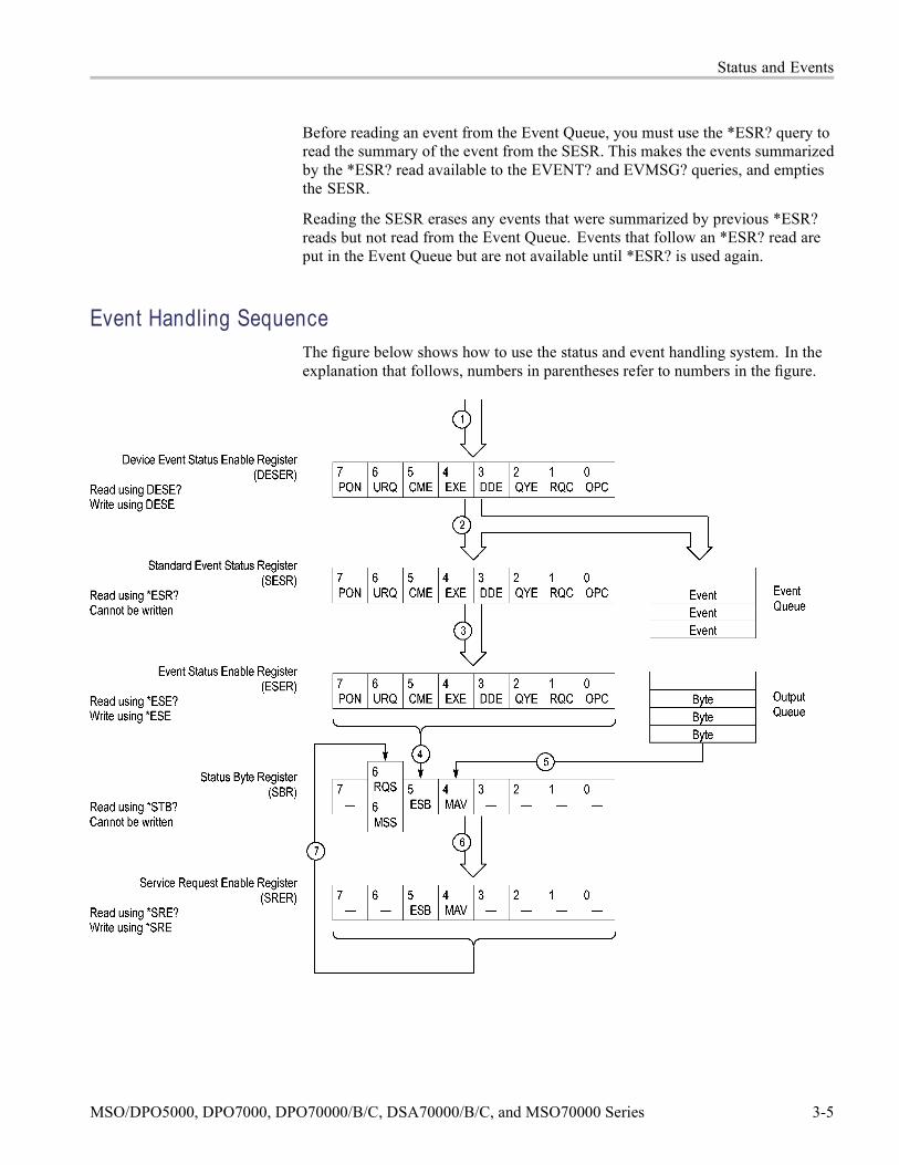
Status and Events
Before reading an event from the Event Queue, you must use the *ESR? query toread the summary of the event from the SESR. This makes the events summarizedby the *ESR? read available to the EVENT? and EVMSG? queries, and emptiesthe SESR.
Reading the SESR erases any events that were summarized by previous *ESR?reads but not read from the Event Queue. Events that follow an *ESR? read areput in the Event Queue but are not available until *ESR? is used again.
Event Handling SequenceThe figure below shows how to use the status and event handling system. In theexplanation that follows, numbers in parentheses refer to numbers in the figure.
MSO/DPO5000, DPO7000, DPO70000/B/C, DSA70000/B/C, and MSO70000 Series 3-5

Status and Events
When an event occurs, a signal is sent to the DESER (1). If that type of eventis enabled in the DESER (that is, if the bit for that event type is set to 1), theappropriate bit in the SESR is set to one, and the event is recorded in the EventQueue (2). If the corresponding bit in the ESER is also enabled (3), then theESB bit in the SBR is set to one (4).
When output is sent to the Output Queue, the MAV bit in the SBR is set to one (5).
When a bit in the SBR is set to one and the corresponding bit in the SRERis enabled (6), the MSS bit in the SBR is set to one and a service request isgenerated (7).
Synchronization MethodsOverview Although most GPIB commands are completed almost immediately after being
received by the instrument, some commands start a process that requires moretime. For example, once a single sequence acquisition command is executed,depending upon the applied signals and trigger settings, it may be a few secondsbefore the acquisition is complete. Rather than remain idle while the operation isin process, the instrument will continue processing other commands. This meansthat some operations will not be completed in the order that they were sent.
Sometimes the result of an operation depends on the result of an earlier operation.A first operation must complete before the next one gets processed. Theinstrument status and event reporting system provides ways to do this.
For example, a typical application might involve acquiring a single-sequencewaveform and then taking a measurement on the acquired waveform. You coulduse the following command sequence to do this:
/** Set up conditional acquisition **/
ACQUIRE:STATE OFF
SELECT:CH1 ON
HORIZONTAL:MODE:RECORDLENGTH 1000
ACQUIRE:MODE SAMPLE
ACQUIRE:STOPAFTER SEQUENCE
/** Acquire waveform data **/
ACQUIRE:STATE ON
/** Set up the measurement parameters **/
MEASUREMENT:IMMED:TYPE AMPLITUDE
MEASUREMENT: IMMED:SOURCE CH1/** Take amplitude measurement **/
MEASUREMENT:IMMED:VALUE?
The acquisition of the waveform requires extended processing time. It may notfinish before the instrument takes an amplitude measurement (see the followingfigure). This can result in an incorrect amplitude value.
3-6 MSO/DPO5000, DPO7000, DPO70000/B/C, DSA70000/B/C, and MSO70000 Series

Status and Events
To ensure that the instrument completes waveform acquisition before taking themeasurement on the acquired data, you can synchronize the program.
You can use four commands to synchronize the operation of the instrument withyour application program: *WAI, BUSY, *OPC, and *OPC?
*WAI The *WAI command forces completion of previous commands that generatean OPC message. No commands after the *WAI are processed before the OPCmessage(s) are generated
The same command sequence using the *WAI command for synchronizationlooks like this:
/* Set up conditional acquisition */
ACQUIRE:STATE OFF
SELECT:CH1 ON
HORIZONTAL:MODE:RECORDLENGTH 1000
ACQUIRE:MODE SAMPLE
ACQUIRE:STOPAFTER SEQUENCE
/* Acquire waveform data */
ACQUIRE:STATE ON
/* Set up the measurement parameters */
MEASUREMENT:IMMED:TYPE AMPLITUDE
MEASUREMENT:IMMED:SOURCE CH1
/* Wait until the acquisition is complete before taking
the measurement*/
*/
*WAI
/* Take amplitude measurement */
MEASUREMENT:IMMED:VALUE?
The controller can continue to write commands to the input buffer of theinstrument, but the commands will not be processed by the instrument until allOPC operations in process are complete. If the input buffer becomes full, the
MSO/DPO5000, DPO7000, DPO70000/B/C, DSA70000/B/C, and MSO70000 Series 3-7

Status and Events
controller will be unable to write more commands to the buffer. This can cause atime-out.
BUSY The BUSY? query allows you to find out whether the instrument is busyprocessing a command that has an extended processing time such assingle-sequence acquisition.
The same command sequence, using the BUSY? query for synchronization, lookslike this:
/* Set up conditional acquisition */
ACQUIRE:STATE OFF
SELECT:CH1 ON
HORIZONTAL:MODE:RECORDLENGTH 1000
ACQUIRE:MODE SAMPLE
ACQUIRE:STOPAFTER SEQUENCE
/* Acquire waveform data */
ACQUIRE:STATE ON
/* Set up the measurement parameters */
MEASUREMENT:IMMED:TYPE AMPLITUDE
MEASUREMENT:IMMED:SOURCE CH1
/* Wait until the acquisition is complete before taking
the measurement */
While BUSY keep looping
/* Take amplitude measurement */
MEASUREMENT:IMMED:VALUE
This sequence lets you create your own wait loop rather than using the *WAIcommand. The BUSY? query helps you avoid time-outs caused by writing toomany commands to the input buffer. The controller is still tied up though, and therepeated BUSY? query will result in more bus traffic.
*OPC
If the corresponding status registers are enabled, the *OPC command sets theOPC bit in the Standard Event Status Register (SESR) when an operation iscomplete. You achieve synchronization by using this command with either aserial poll or service request handler.
Serial Poll Method: Enable the OPC bit in the Device Event Status EnableRegister (DESER) and the Event Status Enable Register (ESER) using the DESEand *ESE commands.
When the operation is complete, the OPC bit in the Standard Event Status Register(SESR) will be enabled and the Event Status Bit (ESB) in the Status Byte Registerwill be enabled.
The same command sequence using the *OPC command for synchronization withserial polling looks like this:
/* Set up conditional acquisition */
3-8 MSO/DPO5000, DPO7000, DPO70000/B/C, DSA70000/B/C, and MSO70000 Series

Status and Events
ACQUIRE:STATE OFF
SELECT:CH1 ON
HORIZONTAL:MODE:RECORDLENGTH 1000
ACQUIRE:MODE SAMPLE
ACQUIRE:STOPAFTER SEQUENCE
/* Enable the status registers */
DESE 1
*ESE 1
*SRE 0
/* Acquire waveform data */
ACQUIRE:STATE ON
/* Set up the measurement parameters */
MEASUREMENT:IMMED:TYPE AMPLITUDE
MEASUREMENT:IMMED:SOURCE CH1
/* Wait until the acquisition is complete before taking the measurement.
*/
*OPC
While serial poll = 0, keep looping
/* Take amplitude measurement */
MEASUREMENT:IMMED:VALUE
This technique requires less bus traffic than did looping on BUSY.
Service Request Method: Enable the OPC bit in the Device Event Status EnableRegister (DESER) and the Event Status Enable Register (ESER) using the DESEand *ESE commands.
You can also enable service requests by setting the ESB bit in the Service RequestEnable Register (SRER) using the *SRE command. When the operation iscomplete, a Service Request will be generated.
The same command sequence using the *OPC command for synchronizationlooks like this
/* Set up conditional acquisition */
ACQUIRE:STATE OFF
SELECT:CH1 ON
MSO/DPO5000, DPO7000, DPO70000/B/C, DSA70000/B/C, and MSO70000 Series 3-9
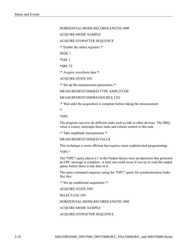
Status and Events
HORIZONTAL:MODE:RECORDLENGTH 1000
ACQUIRE:MODE SAMPLE
ACQUIRE:STOPAFTER SEQUENCE
/* Enable the status registers */
DESE 1
*ESE 1
*SRE 32
/* Acquire waveform data */
ACQUIRE:STATE ON
/* Set up the measurement parameters */
MEASUREMENT:IMMED:TYPE AMPLITUDE
MEASUREMENT:IMMED:SOURCE CH1
/* Wait until the acquisition is complete before taking the measurement
*/
*OPC
The program can now do different tasks such as talk to other devices. The SRQ,when it comes, interrupts those tasks and returns control to this task.
/* Take amplitude measurement */
MEASUREMENT:IMMED:VALUE
This technique is more efficient but requires more sophisticated programming.
*OPC?
The *OPC? query places a 1 in the Output Queue once an operation that generatesan OPC message is complete. A time out could occur if you try to read the outputqueue before there is any data in it.
The same command sequence using the *OPC? query for synchronization lookslike this:
/* Set up conditional acquisition */
ACQUIRE:STATE OFF
SELECT:CH1 ON
HORIZONTAL:MODE:RECORDLENGTH 1000
ACQUIRE:MODE SAMPLE
ACQUIRE:STOPAFTER SEQUENCE
3-10 MSO/DPO5000, DPO7000, DPO70000/B/C, DSA70000/B/C, and MSO70000 Series

Status and Events
/* Acquire waveform data */
ACQUIRE:STATE ON
/* Set up the measurement parameters */
MEASUREMENT:IMMED:TYPE AMPLITUDE
MEASUREMENT:IMMED:SOURCE CH1
/* Wait until the acquisition is complete before taking the measurement
*/
*OPC?
Wait for read from Output Queue.
/* Take amplitude measurement */
MEASUREMENT:IMMED:VALUE
This is the simplest approach. It requires no status handling or loops. However,you must set the controller time-out for longer than the acquisition operation.
Messages Overview. The information contained in the topic tabs above covers all theprogramming interface messages the instrument generates in response tocommands and queries.
For most messages, a secondary message from the instrument gives more detailabout the cause of the error or the meaning of the message. This message is partof the message string and is separated from the main message by a semicolon.
Each message is the result of an event. Each type of event sets a specific bit in theSESR and is controlled by the equivalent bit in the DESER. Thus, each messageis associated with a specific SESR bit. In the message tables, the associated SESRbit is specified in the table title, with exceptions noted with the error message text.
No Event. The following table shows the messages when the system has no eventsor status to report. These have no associated SESR bit.
Table 3-3: No Event Messages
Code Message0 No events to report; queue empty1 No events to report; new events pending *ESR?
Command Error. The following table shows the command error messagesgenerated by improper syntax. Check that the command is properly formed andthat it follows the rules in the section on command Syntax.
MSO/DPO5000, DPO7000, DPO70000/B/C, DSA70000/B/C, and MSO70000 Series 3-11

Status and Events
Table 3-4: Command Error Messages (CME Bit 5)
Code Message100 Command error101 Invalid character102 Syntax error103 Invalid separator104 Data type error105 GET not allowed108 Parameter not allowed109 Missing parameter110 Command header error111 Header separator error112 Program mnemonic too long113 Undefined header114 Header suffix out of range120 Numeric data error121 Invalid character in numeric123 Exponent too large124 Too many digits128 Numeric data not allowed130 Suffix error131 Invalid suffix134 Suffix too long138 Suffix not allowed140 Character data error141 Invalid character data144 Character data too long148 Character data not allowed150 String data error151 Invalid string data158 String data not allowed160 Block data error161 Invalid block data168 Block data not allowed170 Command expression error171 Invalid expression178 Expression data not allowed180 Macro error181 Invalid outside macro definition
3-12 MSO/DPO5000, DPO7000, DPO70000/B/C, DSA70000/B/C, and MSO70000 Series

Status and Events
Table 3-4: Command Error Messages (CME Bit 5) (cont.)
Code Message183 Invalid inside macro definition184 Macro parameter error190 Communication option not present191 Unable to open or parse arbitrary filter file
Execution Error. The following table lists the execution errors that are detectedduring execution of a command.
Table 3-5: Execution Error Messages (EXE Bit 4)
Code Message200 Execution error201 Invalid while in local202 Settings lost due to RTL210 Trigger error211 Trigger ignored212 Arm ignored213 Init ignored214 Trigger deadlock215 Arm deadlock219 Trigger delay not available220 Parameter error221 Settings conflict222 Data out of range223 Too much data224 Illegal parameter value225 Out of memory226 Lists not same length230 Data corrupt or stale231 Data questionable240 Hardware error241 Hardware missing244 Invalid printer selected245 Hardcopy/Export operation timed out250 Mass storage error251 Missing mass storage252 Missing media253 Corrupt media
MSO/DPO5000, DPO7000, DPO70000/B/C, DSA70000/B/C, and MSO70000 Series 3-13

Status and Events
Table 3-5: Execution Error Messages (EXE Bit 4) (cont.)
Code Message254 Media full255 Directory full256 File name not found257 File name error258 Media protected259 File system error260 Execution expression error261 Math error in expression270 Execution macro error271 Macro syntax error272 Macro execution error273 Illegal macro label274 Execution macro parameter error275 Macro definition too long276 Macro recursion error277 Macro redefinition not allowed278 Macro header not found280 Program error281 Cannot create program282 Illegal program name283 Illegal variable name284 Program currently running285 Program syntax erro286 Program runtime error2200 Measurement error, Measurement system error2201 Measurement error, Zero period2202 Measurement error, No period found2203 Measurement error, No period, second waveform2204 Measurement error, Low signal amplitude2205 Measurement error, Low amplitude, second waveform2206 Measurement error, Invalid gate2207 Measurement error, Measurement overflow2208 Measurement error, Waveform does not cross Mid Ref2209 Measurement error, No second Mid Ref crossing2210 Measurement error, No Mid Ref crossing, second waveform2211 Measurement error, No backward Mid Ref Crossing2212 Measurement error, No negative crossing
3-14 MSO/DPO5000, DPO7000, DPO70000/B/C, DSA70000/B/C, and MSO70000 Series

Status and Events
Table 3-5: Execution Error Messages (EXE Bit 4) (cont.)
Code Message2213 Measurement error, No positive crossing2214 Measurement error, No crossing2215 Measurement error, No crossing, second waveform2216 Measurement error, No crossing, target waveform2217 Measurement error, Constant waveform2218 Measurement error, Unused2219 Measurement error, No valid edge – No arm sample2220 Measurement error, No valid edge – No arm cross2221 Measurement error, No valid edge – No trigger cross2222 Measurement error, No valid edge – No second cross2223 Measurement error, Waveform mismatch2225 Measurement error, No waveform to measure2226 Measurement error, Null Waveform2227 Measurement error, Positive and Negative Clipping2228 Measurement error, Positive Clipping2229 Measurement error, Negative Clipping2230 Measurement error, High Ref < Low Ref2231 Measurement error, no statistics available2233 Requested waveform is temporarily unavailable2241 Waveform requested is invalid2243 The measurement cannot be turned on because the source for the
measurement is incompatible2244 Source waveform is not active2248 This reference waveform cannot be activated2249 Reference deletion error, the reference waveform is in use for math2250 Reference error, the reference waveform file is invalid2251 Reference error, Waveform preamble does not match actual2252 Reference error, Source waveform is not valid2253 Reference error, Too many points received2254 Reference error, Too few points received2255 Reference error, destination reference is used by a math source2256 Reference error, cannot reposition or rescale a reference waveform that
was saved in FastAcq mode2257 Reference warning, saving a previewed waveform results in an empty
reference2258 Reference warning, saving a FastAcq waveform may result in an empty
reference2259 File too big
MSO/DPO5000, DPO7000, DPO70000/B/C, DSA70000/B/C, and MSO70000 Series 3-15

Status and Events
Table 3-5: Execution Error Messages (EXE Bit 4) (cont.)
Code Message2261 Calibration error, wait for the warm-up interval to expire before invoking SPC2270 Alias error2271 Alias syntax error2273 Illegal alias label2276 Alias expansion error2277 Alias redefinition not allowed2278 Alias header not found2287 You have 4 free trials left for this application2288 You have 3 free trials left for this application2289 You have 2 free trials left for this application2294 You have 1 free trial left for this application2295 This is the last free trial for this application2296 To guarantee accuracy the vertical amplifiers must use the same coupling
and the same model probes2297 CH1 and AUX cannot be selected as the A trigger event and the B trigger
event respectively or vice versa2298 CAL: failed to read NVram, will use uncalibrated factory defaults. The scope
must be calibrated at the factory2299 Failed to read SPC Calibration file, will use uncalibrated factory defaults
until SPC is performed2309 Video Trigger does not allow selection of default trigger holdoff2310 CAL: invalid command2312 Deskew not applied when FastAcq is on2313 Probe error, wait for the warmup interval to expire before doing probe
calibration2318 Consider system bandwidth when testing at this bit rate2319 Deskew is re-enabled2321 Histogram warning, histogram turned off because Zoom or FastFrame was
enabled2322 Histogram warning, turning histogram on turned other features off2330 FastFrame time stamp query requested too many time stamps2350 When FastFrame is active, the reference waveform source must be
displayed2351 Acquire Modes (Avg|Env) incompatible with FastFrame2352 Acquire Modes (Avg|Env) incompatible with FastFrame. Set to Sample2360 FastAcq warning, FastAcq turned Off2370 Zoom warning, Zoom turned Off2371 Zoom error, Zoom has circular definition
3-16 MSO/DPO5000, DPO7000, DPO70000/B/C, DSA70000/B/C, and MSO70000 Series

Status and Events
Table 3-5: Execution Error Messages (EXE Bit 4) (cont.)
Code Message2372 Zoom error, Source zoom is not active2400 Not enough memory available2401 This channel cannot be activated2402 Math/Meas/Histo have circular definition2403 Cannot enter XYZ mode because Channel 4 is active (in use)2404 XY waveform error, cannot activate channel while in XY mode2405 XYZ waveform error, cannot activate channel while in XYZ mode2410 Empty math string2411 Syntax error in math string2412 Semantic error in math string2413 Math expression is too complex2414 Spectral Function Syntax Error, can operate only on single Channel or
Math source2415 Spectral Function Semantic Error, cannot operate on static (Reference)
sources2420 Histogram cannot be performed on this type of waveform2425 Mask counting cannot be performed on this type of wfm2430 WfmDB cannot be built on this type of wfm2470 Trigger error, cannot enter Random holdoff unless type is set to Edge2471 Trigger error, cannot enter Random holdoff unless source is set to Channel
1-42472 Trigger error; cannot enter Random holdoff unless A->B Sequence is set to
A Only2473 Trigger T cannot be turned on when in XY display format mode2474 Trigger slope not available, coerced to Rise2475 Either trigger slope not available when in MultiScope AND mode2476 Trigger type not available in MultiScope AND mode2477 Pattern lock trigger not available when MultiScope triggering is enabled2500 Setup error, file does not look like a setup file2501 Setup warning, could not recall all values from external setup2510 iCapture source selection failed; new source already in use2511 Busses may not contain iCapture signals as members2512 iCapture sources were reassigned to support serial bus triggering2513 Clocked Parallel Bus clock source changed because previous source was
added as member signal2600 Mask testing complete2601 Mask testing failed2610 Standard Mask Autoset failed, not allowed for Math or Ref Waveforms
MSO/DPO5000, DPO7000, DPO70000/B/C, DSA70000/B/C, and MSO70000 Series 3-17

Status and Events
Table 3-5: Execution Error Messages (EXE Bit 4) (cont.)
Code Message2611 Standard Mask Autoset failed, source of selected mask type not found2612 Turn off Optical Filtering to allow this to work2613 Optical Filtering not allowed2614 Autoset is not allowed during Edit User Mask2615 Mask setup error, file does not look like a setup file2620 Mask error, too few points received2700 Limit Test Error: Reference and source channel have different horizontal
settings2701 Limit Test Failure: Incompatible record lengths2702 Template creation error: Source waveform not compatible2703 Template creation error: Target reference is being used in an active limit test2704 Limit Test Error: Reference is not a valid template2705 Limit Test Failure: Cannot compare a reference to itself2706 Limit Test Error: Disk Full2707 Limit testing failed2708 Select a source and template to compare before turning on the limit test2740 No SMTP Server address is entered2741 Sending E-mail...2742 Email on Trigger is disabled when Fast Acquisitions are enabled2743 Email error; must have measurements active before selecting this option2750 H-Bar cursors are not supported in xy mode2751 V-Bar cursors are not supported in xy mode2752 Cursor Error; the current source is invalid or inactive2760 Mark limit reached2761 No mark present2762 Search copy failed2763 Unable to recall the Marks2764 Reference error, the reference waveform file is unsupported2765 The Search cannot be turned on due to FastAcq or WfmDB mode2766 Advanced Search Option not present2767 Inputs CH1-CH4 incompatible; set state clock source to CH42768 Inputs incompatible; first set CH1-CH4 inputs to XXXX2769 Search Mark sources must have matching record lengths2770 Trigger Pulse source must be CH1-CH4 for this pulse class2771 This Trigger Pulse class is not available for D0-D152772 D15-D0 is already used by A Event2773 D15-D0 is already used by B Event
3-18 MSO/DPO5000, DPO7000, DPO70000/B/C, DSA70000/B/C, and MSO70000 Series
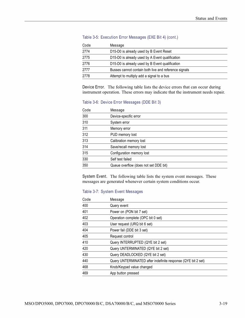
Status and Events
Table 3-5: Execution Error Messages (EXE Bit 4) (cont.)
Code Message2774 D15-D0 is already used by B Event Reset2775 D15-D0 is already used by A Event qualification2776 D15-D0 is already used by B Event qualification2777 Busses cannot contain both live and reference signals2778 Attempt to multiply add a signal to a bus
Device Error. The following table lists the device errors that can occur duringinstrument operation. These errors may indicate that the instrument needs repair.
Table 3-6: Device Error Messages (DDE Bit 3)
Code Message300 Device-specific error310 System error311 Memory error312 PUD memory lost313 Calibration memory lost314 Save/recall memory lost315 Configuration memory lost330 Self test failed350 Queue overflow (does not set DDE bit)
System Event. The following table lists the system event messages. Thesemessages are generated whenever certain system conditions occur.
Table 3-7: System Event Messages
Code Message400 Query event401 Power on (PON bit 7 set)402 Operation complete (OPC bit 0 set)403 User request (URQ bit 6 set)404 Power fail (DDE bit 3 set)405 Request control410 Query INTERRUPTED (QYE bit 2 set)420 Query UNTERMINATED (QYE bit 2 set)430 Query DEADLOCKED (QYE bit 2 set)440 Query UNTERMINATED after indefinite response (QYE bit 2 set)468 Knob/Keypad value changed469 App button pressed
MSO/DPO5000, DPO7000, DPO70000/B/C, DSA70000/B/C, and MSO70000 Series 3-19

Status and Events
Table 3-7: System Event Messages (cont.)
Code Message470 TekScope minimized471 TekScope restored472 Application variable changed485 Ch1 probe button pressed486 Ch2 probe button pressed487 Ch3 probe button pressed488 Ch4 probe button pressed489 Aux probe button pressed
Execution Warning. The following table lists warning messages that do notinterrupt the flow of command execution. These notify you that you may getunexpected results.
Table 3-8: Execution Warning Messages (EXE Bit 4)
Code Message532 Curve data too long, Curve truncated533 Curve error, Preamble values are inconsistent535 Curve error, Reference data sources not allowed in streaming or
next-waveform mode536 Curve error, Acquisition mode must be set to Run for streaming or
next-waveform mode537 Curve error, Cannot stream or next-waveform math waveforms while in
roll mode540 Measurement warning541 Measurement warning, Low signal amplitude542 Measurement warning, Unstable histogram543 Measurement warning, Low resolution544 Measurement warning, Uncertain edge545 Measurement warning, Invalid min max546 Measurement warning, Need 3 edges547 Measurement warning, Clipping positive/negative548 Measurement warning, Clipping positive549 Measurement warning, Clipping negative551 FASTAcq mode is active – deactivate to use math590 Diagnostic warning, running GPIB diagnostic over GPIB may affect
talk/listen program
Internal Warning. The following table shows internal errors that indicate aninternal fault in the instrument.
3-20 MSO/DPO5000, DPO7000, DPO70000/B/C, DSA70000/B/C, and MSO70000 Series

Status and Events
Table 3-9: Internal Warning Messages
Code Message600 Internal warning630 Internal warning, Input overload
External Application Error. The following table shows external application errorsin the instrument.
Table 3-10: External Application Error
Code Message2800 External application error
MSO/DPO5000, DPO7000, DPO70000/B/C, DSA70000/B/C, and MSO70000 Series 3-21

Status and Events
3-22 MSO/DPO5000, DPO7000, DPO70000/B/C, DSA70000/B/C, and MSO70000 Series

Appendix A: Character Set
MSO/DPO5000, DPO7000, DPO70000/B/C, DSA70000/B/C, and MSO70000 Series A-1

Appendix A: Character Set
A-2 MSO/DPO5000, DPO7000, DPO70000/B/C, DSA70000/B/C, and MSO70000 Series

Appendix B: Reserved WordsThis is a list of reserved words for your instrument. Capital letters identify therequired minimum spelling.
*CAL*CLS*DDT*ESE*ESR*IDN*LRN*OPC*OPT*PSC*PUD*RCL*RST*SAV*SDS*SRE*STB*TRG*TST*WAI0110010Bit5077Bit8809AABSoluteACACCeptACKACKMISSACQDURATIONACQLENGTHACQuireACTIVEACTUalADDR10ADDR7ADDRANDDATAADDRessADVANCEafter
ALIGNALIGNCHARacterALIGNPRIMitiveALIasALLALLEvALLFieldsALLLinesALLMatchedALLOcateALLQStringAMIAMPlitudeANDANNOTationANYAOFFSetAPPLYtoallAREAASCIiATAG1ATAG2ATAG3ATARXG1ATARXG2ATARXG3ATATXG1ATATXG2ATATXG3ATRIGgerATTEN1000XATTEN100XATTEN10XATTEN125XATTEN12_5XATTEN150XATTEN15XATTEN175XATTEN17_5XATTEN1XATTEN1_25XATTEN1_5XATTEN1_75XATTEN200XATTEN20XATTEN250X
ATTEN25XATTEN2XATTEN2_5XATTEN300XATTEN30XATTEN350XATTEN35XATTEN3XATTEN3_5XATTEN400XATTEN40XATTEN450XATTEN45XATTEN4XATTEN4_5XATTEN500XATTEN50XATTEN550XATTEN55XATTEN5XATTEN5_5XATTEN600XATTEN60XATTEN650XATTEN65XATTEN6XATTEN6_5XATTEN700XATTEN70XATTEN750XATTEN75XATTEN7XATTEN7_5XATTEN800XATTEN80XATTEN850XATTEN85XATTEN8XATTEN8_5XATTEN900XATTEN90XATTEN950XATTEN95XATTEN9XATTEN9_5XATTempts
AUTHLoginAUTHPasswordAUTOAUTOAdjustAUTOBitrateAUTOBrightAUTOReflevelAUTOSCaleAUTOSetAUTOZeroAUXAUXInAUXLevelAUXiliaryAUXoutAVErageBB1B10B11B12B13B14B15B16B2B3B3ZSB4B5B6B6ZSB7B8B8ZSB9BACKLightBACKWardsBADCHARSBANdwidthBASeBAUdBEEPBELlBETWeenBILevelcustom
MSO/DPO5000, DPO7000, DPO70000/B/C, DSA70000/B/C, and MSO70000 Series B-1

Appendix B: Reserved Words
BINaryBITBITCOUNTBITDURATIONBITOrderBITRATEBITSTUFFingBIT_NrBLACKANDWhiteBLACKMANHarrisBMPBN_FmtBOFFSetBOThBOXBOXPcntBTRIGgerBULKBURstBUSBUSYBYBYPassBYT_NrBYT_OrBlockBlt;x>BxCALProbeCALibrateCANCANHCANLCAPSCAReaCARetCATalogCENTERCENTeredCH1CH14CH2CH3CH4CHARACTERCHECKSUMDRCHlt;x>CHxCJTPCLAssCLEARCLOCKCoaxCLOCKSymmetrical
CLOCkCMDBatchCMEanCMICMOFFSetCODeCOEFFSCOLOrCOLUMNCOMMunicationCOMPLetionCOMPletedCOMbinationCOMmonmodeCOMpareCONDitionCONNectionCONStantCONSumerCONTROLCOPyCOUNTCOUPlingCQCQ0CQlt;x>CRCRC16CRC5CREATECRMsCROSSHairCSActiveCSLevelCSModeCSPLITCSSourceCURSorCURVENextCURVEStreamCURVeCUSTOMPctCUSTomCWDD0D1D10D11D12D13D14D15D15CH1
D2D3D3D4D4D5D6D7D8D9DALLDASHedDATADATA0DATA1DATA2DATABitsDATAPacketDATASourceDATEDAYSDBDBMDCDCHANDCREJectDDRDDR2DDR3DDRMemoryDDRREADWriteDDRReadDDRWriteDECOdeDECimalDEFAULTDEFineDEGAUSSDEGreesDELEteDELIMiterDELTATimeDELTaDELayDELayedDESEDESKEWDESTinationDETAiledDIAgDIFFerentialDIGITALALLQStringDIGTracesDIGital
DIRDIREctionDISPARITYDISPCOUNTDISPRATEDISTDUtyDISableDISplayDISplaymodeDIVisionsDMINusDMOFFSetDONEDOTsDPLUsDREFDS0ContraDS0DoubleDS0SingleDS0TimingDS1DS1ADS1CDS2DS2RATECoaxDS2RATESymmetricalDS3DS4NADS4NA_MaxDURATIONDlt;x>DxE1E1CoaxE1SymmetricalE2E3E4E4_0E4_1ECLEDGEEDGE2EDGE[1]EDGElt;x>EIGHtytwentyEITHEREMBOssEMailENABLEENCdgENDENDPoint
B-2 MSO/DPO5000, DPO7000, DPO70000/B/C, DSA70000/B/C, and MSO70000 Series

Appendix B: Reserved Words
ENDeventENET100ENET1000BCX_ATP2ENET1000BCX_ATP3ENET1000BCX_NTP2ENET100FXENET100STPENET100UTPENET1250ENETXAUIENETXAUI2ENETXAUI_FarENETXAUI_NearENGRaveENHancedENTERSWindowENVENVelopeENableEOFEOPEQUalERRERRORERRORLIMITERRORdetectorERRTYPEETEVENEVENTEVENTSEVMsgEVQtyEXECUTEEXITSWindowEXPonentEXPortEXTAttenEXTDBattenEXTENdedEXTINCTDBEXTINCTPCTEXTINCTRATIOEXTUnitsEXTernalEYEEYEHeightEYEWIdthEYEdiagramFACtoryFAILURESFAILureFALL
FALSeFALlingFASTFASTAcqFASTERthanFASTframeFAStestFC1063FC1063DraftFC1063EFC1063E_ABRFC1063E_ABTFC1063E_ADRFC1063E_ADTFC1063E_AGRFC1063E_AGTFC1063E_NBTFC1063E_NDTFC1063E_NGTFC133FC133EFC2125FC2125E_ABRFC2125E_ABTFC2125E_ADRFC2125E_ADTFC2125E_AGRFC2125E_AGTFC2125E_NBTFC2125E_NDTFC2125E_NGTFC266FC266EFC4250FC4250E_ABRFC4250E_ABTFC4250E_ADRFC4250E_ADTFC4250E_AGRFC4250E_AGTFC4250E_NBTFC4250E_NDTFC4250E_NGTFC531FC531EFFWDFIELDFIELD1FIELD2FIFtyfiftyFILEFILEFormatFILEName
FILESystemFILTerFILeFILepathFIRstFIVeFLATTOP2FOCUSFONTCOlorFONTEFfectFONTNAmeFONTSIzeFONTSTyleFORCEDRangeFORCeFORMatFORWardsFPFPANelFPBinaryFRAMEFRAMELockFRAMESTARtFRAMESTOPFRAMEtypeFRAMeFREEFREETRIALBurnFREETRIALsleftFREQuencyFREVFROMSearchxFROmFSTFST1FST2FST3FST4FST5FST6FULLFULLNOmenuFULLSCREENFULLSPeedFULlFUNCtionFW1394BS1600BFW1394BS1600BT1FW1394BS1600BT2FW1394BS400BFW1394BS400BT1FW1394BS400BT2FW1394BS800B
FW1394BS800BT1FW1394BS800BT2FWDFuLlG703DS1G703DS3GAINGATEPOSGATEWIDTHGATingGAUSSianGDDR3GENeralcallGLItchGNDGPIBUsbGRAticuleGRIdGROUPDelayHALTHAMMingHANDSHAKEPacketHANDShaketypeHANNingHARDCopyHBArsHBWStraightflexHD1080I50HD1080I60HD1080P24HD1080P25HD1080P30HD1080P50HD1080P60HD1080SF24HD480P60HD576P50HD720P30HD720P50HD720P60HD875I60HDB3HDELTAHDRHEADerHEIghtHERtzHEXHEXadecimalHFRejHFTPHIACQRATEHIGH
MSO/DPO5000, DPO7000, DPO70000/B/C, DSA70000/B/C, and MSO70000 Series B-3

Appendix B: Reserved Words
HIGHLIGHTHitsHIGHLOWXHIGHLimitHIResHIStogramHITSHIVALueHLSHOLDTimeHOLDoffHORizontalHORizontal[HOSTwantedHOURSHPOSHPOSlt;x>HSCAleHSTHST1HST2HST3HST4HST5HST6HTRIGPOSHUBHWAccountantHWVersionHYSterisisI2CICAPtureIDIDANDDATAIDENTifierIMAGEViewIMAGeIMMEDSTAteIMMedININDependentINF2_5GINF2_5GEINFINIBANDINFIniteINFPersistINHERITINITINITIALCRCVALueINKSaverINPUTINPUTModeINSIDEGreaterINSide
INTENSIFiedINTENSITyINTERLAcedINTERNalINTERPEightbitINTERPRatioINTERRUPTINVERTedINVertINrangeIREISCLOCKEDISOALLISOENDISOMIDISOSTARTISOchronousITITEMJPEGKAISERBesselLABELLABelLABellt;x>LANdscapeLARgeLASTLAYoutLBPTLEARNLENGTHLESSEQualLESSLimitLESSThanLEVELLFLFRejLFTPLIMITrecordlenLIMitLINELINEArLINEPeriodLINESLINESTyleLINE_XLISTLIStLIVELOCKLOCKLenLOCKOffsetLOG
LOGIcLONGLOOPLOOPSLOWLOWLimitLOWPASSfilterLOWSPeedLOWerthresholdLPDDRLSBLSSTstatuslt;x>LVLSrcpreferenceMAGMAGnivuMAInMAIn]MANChesterMANUALMARKMARKSINCOLumnMARginMASKMASKHighlightMASKPREMAT1MATH1MATH14MATH2MATH3MATH4MATHArbfltlt;x>MATHCOLOrMATHCadMATHVARMATHlt;x>MATHxMATHyMATLabMAXALIGNSMAXCasMAXFRamesMAXSamplerateMAXSizeMAX_APMAXimumMDATAMEANMEANSTDdevMEAS1MEAS2MEAS3MEAS4
MEAS5MEAS6MEAS7MEAS8MEASUrementMEASlt;x>MEDianMEDiumMETHodMFTPMHZ10MHZ100MIDMIDlt;x>MINCasMINImumMINMaxMINUSOneMINUTESMISOMISOMOSIMKDirMLT3MODEMONOGRAYMONOGREENMOREEQualMORELimitMOREThanMOSIMRTTimeMSBMULTiscopeMULtipleframesMVNAKNAMENANdNCROssNDUtyNEGAtiveNEWpassNEXTNONOCARENOISErejNOISeNONENORNORMALIZedNORMalNOVershootNR1
B-4 MSO/DPO5000, DPO7000, DPO70000/B/C, DSA70000/B/C, and MSO70000 Series

Appendix B: Reserved Words
NR1NR1NR1NR1NR1NR1QStringNR2NR2NR2NR2NR2NR3NR3NR3NR3NR3NRFNRZNR_FRNR_PtNTSCNTScNULLNUMACqNUMAVgNUMCOEFFSNUMEMailsNUMERicNUMEnvNUMFRAMESACQuiredNUMFRamesNUMITEMSNUMSAMplesNUMXNUMYNWIdthNoOC1OC12OC3OC48OC48_FECOCCursODDOFFOFFGRAticuleOFFSETAdjOFFSetONONEONEfiftyONGRAticuleONLYOVERlayOPTIMnoiseOPTionORORROTHerOUTOUTSIDEGreaterOUTrangeOUTside
OVERLOADOVERlayOWNerOffPACKETPALPALEttePARItyerrorPARallelPARityPASSPASSWordPATTERNBITSPATTERNNAMEPATternPBASePCIEXPRESSPCIEXPRESS_RcvPCIEXPRESS_XmitPCIExpressPCIExpress2PCROssPCTCROssPCXPDUtyPEAKHitsPEAKdetectPENDINGPERCentPERIodPERSistencePHASEPIDPINGPK2PkPKPKJitterPKPKNoisePLOCKPLOCK BITRatePLUSOnePNGPOINTSPOLARCoordPOLarityPORTPORTRaitPOSITIONlt;x>POSITIVePOSitionPOSitionlt;x>POSlt;x>POVershootPRE
PRESAMPBITSPRESSPREViousPRINTERPRIntPROBEPROBECOntrolPROBECalPROBEFuncPRODDELtaPRODUCTIDPRODUCTlt;x>PRODucerPRODuctPROGressivePRObestatePTOPPT_FmtPT_ORderPT_OffPULSEFormPULsePWIdthQFACtorQStringQStringQStringQUALIFIERQUALificationQUAlifyQUERYRESPonseRADIUSlt;x>RADiansRANDOMRANgeRATDELtaRATERATE1RATE2RATE3RATE32MbitRATE4RATE5RATE97MbitRATIOlt;x>RATioRDELtaRDMINUSRDPLUSREADREADFileREADOUTREADOutsREADY
RECALLRECORDViewRECOVeredRECOrdlengthRECTANGularRECTXlt;x>RECTYlt;x>RECTangularREFREF1REF14REF2REF3REF4REFCOLOrREFClkREFLEVELOffsetREFLevelREFOutREFlt;x>REFxREJectRELoadREMREMoteRENameREPEATstartREPeatRESBwRESERVEDRESETRESETLiveRESULTRESULTSRESUMERESetRESistanceREVRIRIBinaryRIO_1GRIO_1_5GRIO_2GRIO_500MRIO_750MRIO_DRV1GRIO_DRV1_5GRIO_DRV2GRIO_DRV500MRIO_DRV750MRIO_EDRV1GRIO_EDRV1_5GRIO_EDRV2G
MSO/DPO5000, DPO7000, DPO70000/B/C, DSA70000/B/C, and MSO70000 Series B-5

Appendix B: Reserved Words
RIO_EDRV500MRIO_EDRV750MRIO_RCV1GRIO_RCV1_5GRIO_RCV2GRIO_RCV500MRIO_RCV750MRIO_SERIAL_1GRIO_SERIAL_2GRIO_SERIAL_2_5GRIO_SERIAL_3GRISERISetimeRISingRMDirRMSRMSJitterRMSNoiseROLLROLeROScRPRPBinaryRS232RS232cRTRUNRUNSTopRUNTRWINADDRRWINCludeRXS8B10BS8BPATternSAMPLERateSAMPlingmodeSAMpleSAS1_5SAS1_5_CRSAS1_5_CR_AASJSAS1_5_IRSAS1_5_IR_AASJSAS1_5_SATASAS1_5_XRSAS1_5_XR_AASJSAS3_SAS3_0_CRSAS3_0_CR_AASJSAS3_0_IRSAS3_0_IR_AASJSAS3_0_SATASAS3_0_XRSAS3_0_XR_AASJ
SAS6_0SATA1_5SATA3_0SATA6_0SAVESAVEWFMSCSCANSCAleSCLKSCRAMBLEDSCREENSCREENSAVERSCREENSAVERDELAYSCREENTExtSCROLLSCROLLLockSDASHedSESEARCHSEARCHlt;x>SEARCHtotriggerSECAMSECONDSSECOndsSEGlt;m>SELECTEDSELectSENSITivitySEQUENTIALSEQuenceSERIALSERIALTRIGSERIALnumberSERnumberSETSETCHANGESETHoldSETLOGICSETLevelSETROLESETSTATESETTimeSETUPSFI5_2SFI5_3SFI5_RCVBCLK2SFI5_RCVBCLK3SFI5_RCVBDATA2SFI5_RCVBDATA3SFI5_RCVDCLK2SFI5_RCVDCLK3SFI5_RCVDDATA2
SFI5_RCVDDATA3SFI5_XMITACLK2SFI5_XMITACLK3SFI5_XMITADATA2SFI5_XMITADATA3SFI5_XMITCCLK2SFI5_XMITCCLK3SFI5_XMITCDATA2SFI5_XMITCDATA3SFPbinarySHADowSHIFtedSHORtSHOWREmoteSIGMA1SIGMA2SIGMA3SIGNALSIGTypeSINGleendedSINXSIXSigmajitSIZESKIPSETPRIMitiveSLOWERthanSLOpeSMAllSMTPPortSMTPServerSNApSNRatioSOFSOLIDSOURCESOURCESSOUrcelt;x>SPANSPCSPECIALPacketSPECIALTypeSPECTralSPEEDSPISPLITSPREADSHEETCsvSPREADSHEETTxtSPaceSRCDependentSRCIndependentSRIbinarySRPbinarySRQSS
SSCSSPLITSTABleSTALLSTANDARDSTARTSTARTeventSTARtbyteSTATESTATIsticsSTATUSSTAYSHighSTAYSLowSTDdevSTM0_0STM0_1STM0_CMISTM0_HDBXSTM1ESTM1E_0STM1E_1STOPSTOPAfterSTOPOnviolationSTOPWHENSTOReSTRESSSTROBESTROBEsourceSTRingSTS1STS1EyeSTS1PulseSTS3STS3_MaxSTYleSUBITEMSSUBSYSSUMFrameSUPPressSUSPENDSYMBOLSYMBolicSYNCSYNCIntervalSYNCPATternSYNCSOUrcesTEKEXPonentialTEKLinkTEKSecureTEMPEratureTEMPlateTENbit
B-6 MSO/DPO5000, DPO7000, DPO70000/B/C, DSA70000/B/C, and MSO70000 Series
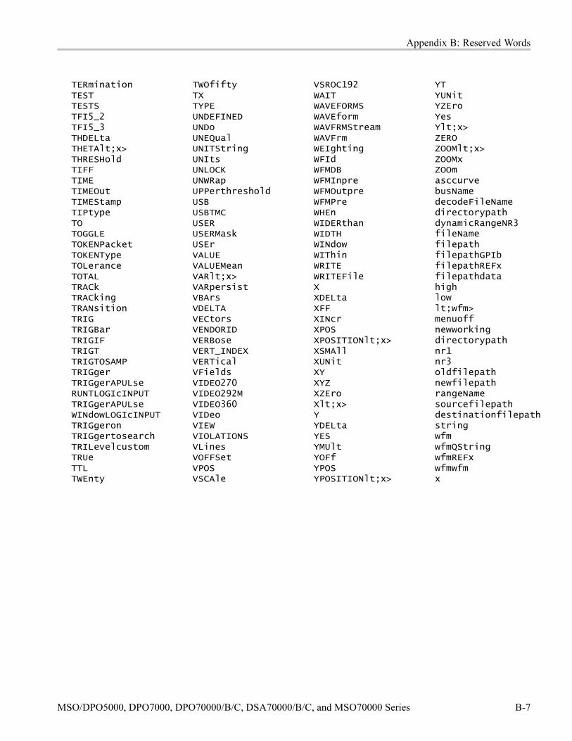
Appendix B: Reserved Words
TERminationTESTTESTSTFI5_2TFI5_3THDELtaTHETAlt;x>THRESHoldTIFFTIMETIMEOutTIMEStampTIPtypeTOTOGGLETOKENPacketTOKENTypeTOLeranceTOTALTRACkTRACkingTRANsitionTRIGTRIGBarTRIGIFTRIGTTRIGTOSAMPTRIGgerTRIGgerAPULseRUNTLOGIcINPUTTRIGgerAPULseWINdowLOGIcINPUTTRIGgeronTRIGgertosearchTRILevelcustomTRUeTTLTWEnty
TWOfiftyTXTYPEUNDEFINEDUNDoUNEQualUNITStringUNItsUNLOCKUNWRapUPPerthresholdUSBUSBTMCUSERUSERMaskUSErVALUEVALUEMeanVARlt;x>VARpersistVBArsVDELTAVECtorsVENDORIDVERBoseVERT_INDEXVERTicalVFieldsVIDEO270VIDEO292MVIDEO360VIDeoVIEWVIOLATIONSVLinesVOFFSetVPOSVSCAle
VSROC192WAITWAVEFORMSWAVEformWAVFRMStreamWAVFrmWEIghtingWFIdWFMDBWFMInpreWFMOutpreWFMPreWHEnWIDERthanWIDTHWINdowWIThinWRITEWRITEFileXXDELtaXFFXINcrXPOSXPOSITIONlt;x>XSMAllXUNitXYXYZXZEroXlt;x>YYDELtaYESYMUltYOFfYPOSYPOSITIONlt;x>
YTYUNitYZEroYesYlt;x>ZEROZOOMlt;x>ZOOMxZOOmasccurvebusNamedecodeFileNamedirectorypathdynamicRangeNR3fileNamefilepathfilepathGPIbfilepathREFxfilepathdatahighlowlt;wfm>menuoffnewworkingdirectorypathnr1nr3oldfilepathnewfilepathrangeNamesourcefilepathdestinationfilepathstringwfmwfmQStringwfmREFxwfmwfmx
MSO/DPO5000, DPO7000, DPO70000/B/C, DSA70000/B/C, and MSO70000 Series B-7

Appendix B: Reserved Words
B-8 MSO/DPO5000, DPO7000, DPO70000/B/C, DSA70000/B/C, and MSO70000 Series

Appendix C: Factory Default Setup Values
Default SetupThe following tables list the default setup values by command group. Theinstrument sets these values when you press the front panel DEFAULT SETUPbutton or send the FACtory command. Only those commands that have values setby the DEFAULT SETUP function are listed in these tables.
NOTE. The following commands do not affect the DATa parameters: TEKSecure,*RST, RECALL:SETUP FACtory. These are the initial factory default settings forDATa :DATA:DESTINATION REF1;ENCDG RIBINARY;SOURCE CH1;START1;STOP 5000;FRAMESTART 1;FRAMESTOP 5000.
NOTE. Find the most up-to-date values for your instrument and software bypressing default setup and looking at the instrument to get the default values.
Acquisition Default Values The following table lists the Acquisition factory default setup values.
Command Default ValuesACQuire:MAGnivu OFF
NOTE. This programmer manualsupports many oscilloscope modelsfrom Tektronix. This feature is onlyavailable on some models.
ACQuire:MODe SAMPLEACQuire:NUMAVg 16ACQuire:NUMEnv 10ACQuire:NUMSAMples 16000ACQuire:SAMPlingmode ITACQuire:STATE 1 (ON)ACQuire:STOPAfter RUNSTOPFASTAcq:STATE 0
Alias Default Values The following table lists the Alias factory default setup values.
Command Default ValuesALIas:STATE 0 (OFF)
MSO/DPO5000, DPO7000, DPO70000/B/C, DSA70000/B/C, and MSO70000 Series C-1

Appendix C: Factory Default Setup Values
Bus Default ValuesNOTE. This programmer manual supports many oscilloscope models fromTektronix. This feature is only available on some models.
The following table lists the Bus factory default setup values.
Command Default ValuesBUS:B<x>:DISplay:DECOde:STAte OFFBUS:B<x>:DISplay:TYPe BusformBUS:B<x>:I2C:CLOCk:SOUrce D1BUS:B<x>:I2C:DATa:SOUrce D0BUS:B<x>:I2C:RWINADDR NoBUS:B<x>:LABel “Bus 1”BUS:B<x>:PARallel:CLOCk:EDGE RisingBUS:B<x>:PARallel:CLOCk:SOUrce D15BUS:B<x>:PARallel:ISCLOCKED NoBUS:B<x>:POSition 0.0 divBUS:B<x>:RS232c:BITRate 9600 bits-per-secondBUS:B<x>:RS232c:DATABits 8BUS:B<x>:RS232c:DISplaymode FrameBUS:B<x>:RS232c:PARity NoneBUS:B<x>:RS232c:POLarity NormalBUS:B<x>:RS232c:SOUrce Ch1BUS:B<x>:SPI:BITOrder MSBBUS:B<x>:SPI:CLOCk:POLarity RisingBUS:B<x>:SPI:CLOCk:SOUrce D2BUS:B<x>:SPI:DATa:POLarity NormalBUS:B<x>:SPI:DATa:SIZE 8BUS:B<x>:SPI:DATa:SOUrce D0BUS:B<x>:SPI:SELect:POLarity Active lowBUS:B<x>:SPI:SELect:SOUrce D1BUS:B<x>:TYPe ParallelBUS:B<x>:USB:BITRate FullBUS:B<x>:USB:PRObe DifferentialBUS:B<x>:USB:SOUrce Ch1BUS:B<x>:USB:SOUrce:DMINus Ch1BUS:B<x>:USB:SOUrce:DPLUs Ch1SELect:B<x> OFF
Cursor Default Values The following table lists the Cursor factory default setup values.
C-2 MSO/DPO5000, DPO7000, DPO70000/B/C, DSA70000/B/C, and MSO70000 Series
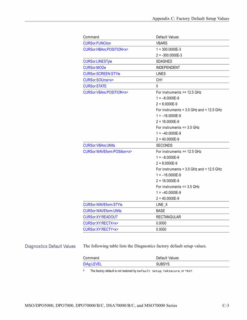
Appendix C: Factory Default Setup Values
Command Default ValuesCURSor:FUNCtion VBARSCURSor:HBArs:POSITION<x> 1 = 300.0000E-3
2 = -300.0000E-3CURSor:LINESTyle SDASHEDCURSor:MODe INDEPENDENTCURSor:SCREEN:STYle LINESCURSor:SOUrce<x> CH1CURSor:STATE 0CURSor:VBArs:POSITION<x> For instruments >= 12.5 GHz
1 = –8.0000E-92 = 8.0000E-9For instruments > 3.5 GHz and < 12.5 GHz1 = –16.0000E-92 = 16.0000E-9For instruments <= 3.5 GHz1 = –40.0000E-92 = 40.0000E-9
CURSor:VBArs:UNIts SECONDSCURSor:WAVEform:POSition<x> For instruments >= 12.5 GHz
1 = –8.0000E-92 = 8.0000E-9For instruments > 3.5 GHz and < 12.5 GHz1 = –16.0000E-92 = 16.0000E-9For instruments <= 3.5 GHz1 = –40.0000E-92 = 40.0000E-9
CURSor:WAVEform:STYle LINE_XCURSor:WAVEform:UNIts BASECURSor:XY:READOUT RECTANGULARCURSor:XY:RECTX<x> 0.0000CURSor:XY:RECTY<x> 0.0000
Diagnostics Default Values The following table lists the Diagnostics factory default setup values.
Command Default ValuesDIAg:LEVEL SUBSYS1 The factory default is not restored by Default Setup, TekSecure, or *RST.
MSO/DPO5000, DPO7000, DPO70000/B/C, DSA70000/B/C, and MSO70000 Series C-3

Appendix C: Factory Default Setup Values
Digital Default ValuesNOTE. This programmer manual supports many oscilloscope models fromTektronix. This feature is only available on some models.
The following table lists the Digital factory default setup values.
Command Default ValuesDISplay:DIGital:HEIght LargeD<x>:POSition –4.66 divD<x>:THRESHold 1.4 VREF<x>:THRESHold 1.0 mV
Display Control DefaultValues
The following table lists the Display factory default setup values.
Command Default ValuesDISplay:CLOCk 1DISplay:COLOr:MATHCOLOr DEFAULTDISplay:COLOr:PALEtte:IMAGEView 1 TEMPERATUREDISplay:COLOr:PALEtte:RECORDView NORMALDISplay:COLOr:PALEtte:USEr:CARet 150, 50, 100DISplay:COLOr:PALEtte:USEr:CH<x> 1 1 = 180, 50, 100
2 = 300, 50, 1003 = 60, 50, 1004 = 240, 50, 100
DISplay:COLOr:PALEtte:USEr:GRAticule 1 On DPO7000 series of products it is320, 10, 0On MSO70000 series of products itis 165, 50, 15
DISplay:COLOr:PALEtte:USEr:HIStogram 1 On DPO7000 series of products it is320,10, 0On MSO70000 series of products itis 320, 50,100
DISplay:COLOr:PALEtte:USEr:MASK 1 On DPO7000 series of products it is320, 10, 0On MSO70000 series of products it is0, 40, 100
DISplay:COLOr:PALEtte:USEr:MASKHighlight 1 On DPO7000 series of products it is320,10, 0On MSO70000 series of products itis 140, 50, 100
C-4 MSO/DPO5000, DPO7000, DPO70000/B/C, DSA70000/B/C, and MSO70000 Series

Appendix C: Factory Default Setup Values
Command Default ValuesDISplay:COLOr:PALEtte:USEr:MATH<x> 1 = 160, 50, 100
2 = 40, 60, 1003 = 120, 60, 1004 = 195, 50, 100
DISplay:COLOr:PALEtte:USEr:REF<x> 1 = 0, 90, 02 = 0, 90, 1003 = 60, 90, 1004 = 240, 90, 100
DISplay:COLOr:REFCOLOr DEFAULTDISplay:FILTer SINXDISplay:FORMat YTDISplay:GRAticule FULLDISplay:INTENSITy:BACKLight HighDISplay:INTENSITy:WAVEform:IMAGEView 75.0000DISplay:INTENSITy:WAVEform:RECORDView 75.0000DISplay:PERSistence OFFDISplay:SCREENTExt:LABel<x>:NAMe ""DISplay:SCREENTExt:LABel<x>:XPOS 100DISplay:SCREENTExt:LABel<x>:YPOS 1 = 5
2 = 203 = 354 = 505 = 656 = 807 = 958 = 110
DISplay:SCREENTExt:STATE 0DISplay:STYle VECTORSDISplay:TRIGBar SHORTDISplay:TRIGT 1DISplay:VARpersist 500.0000E-31 The factory default is not restored by Default Setup, TekSecure, Factory, or *RST. The factory default is restored
by the DISplay:COLOr:PALEtte:USEr Reset command.
E-mail Default Values The following table lists the E-mail setup values.
Command Default ValuesEMail:ATTempts 1 1EMail:AUTHLogin ""
MSO/DPO5000, DPO7000, DPO70000/B/C, DSA70000/B/C, and MSO70000 Series C-5

Appendix C: Factory Default Setup Values
Command Default ValuesEMail:FROm 1 "DPO7104_<Instrument Serial Number>"EMail:HOSTwanted 1 ""EMail:IMAGe 0EMail:MASK 0EMail:MAXSize 1EMail:MEASUrement 0EMail:NUMEMails 1EMail:SMTPPort 1 25EMail:SMTPServer ""EMail:TIMEOut 1 30EMail:TO ""EMail:TRIGger 0EMail:WAVEform 01 These factory defaults are not reset to factory defaults by Default Setup.
Error Detector DefaultValues
NOTE. This programmer manual supports many oscilloscope models fromTektronix. This feature is only available on some models.
The following table lists the Error Detector setup values.
Command Default ValuesTRIGger:A:SERIAL:ERRORdetector:ALIGNCHARacter:RDMINUS
“0011111010"
TRIGger:A:SERIAL:ERRORdetector:ALIGNCHARacter:RDPLUS
“1100000101"
TRIGger:A:SERIAL:ERRORdetector:ALIGNPRIMitive:RDMINUS:PATtern
SATA default is“0011111010010101010101010101010010011100"
TRIGger:A:SERIAL:ERRORdetector:ALIGNPRIMitive:RDPLUS:PATtern
SATA default is“1100000101010101010101010101011101100011"
TRIGger:A:SERIAL:ERRORdetector:BIT:SYNCPATtern
K28.5, “0011111010”, and “1100000101”
TRIGger:A:SERIAL:ERRORdetector:DURATION:COUNT
-1
TRIGger:A:SERIAL:ERRORdetector:ENAble OFFTRIGger:A:SERIAL:ERRORdetector:FRAME:INITIALCRCVALue
SATA
TRIGger:A:SERIAL:ERRORdetector:MAXALIGNS
8
TRIGger:A:SERIAL:ERRORdetector:SCRAMBLED
ON
C-6 MSO/DPO5000, DPO7000, DPO70000/B/C, DSA70000/B/C, and MSO70000 Series

Appendix C: Factory Default Setup Values
Command Default ValuesTRIGger:A:SERIAL:ERRORdetector:SKIPSETPRIMitive:RDMINUS:PATtern
“0011111010001111101000111110101010101010"
TRIGger:A:SERIAL:ERRORdetector:SKIPSETPRIMitive:RDPLUS:PATtern
“1100000101110000010111000001011010101010"
TRIGger:A:SERIAL:ERRORdetector:SSC ONTRIGger:A:SERIAL:ERRORdetector:STANDARD
SATA
TRIGger:A:SERIAL:ERRORdetector:STOPWHEN
MANUAL
TRIGger:A:SERIAL:ERRORdetector:TYPE BIT
Hard Copy Default Values The following table lists the Hardcopy factory default setup values.
Command Default ValuesHARDCopy:FILEName ""HARDCopy:PORT FILE
Histogram Default Values The following table lists the Histogram factory default setup values.
Command Default ValuesHIStogram:BOXPcnt 30.0000, 25.1000, 70.0000, 75.2000HIStogram:DISplay LINEARHIStogram:FUNCtion HORIZONTALHIStogram:SIZe 2.0000HIStogram:SOUrce CH1HIStogram:STATE 0
Horizontal Default Values The following table lists the Horizontal factory default setup values.
Command Default ValuesHORizontal:ACQDURATION? 40 nsHORizontal:ACQLENGTH? 1000HORizontal:DIGital:RECOrdlength? 10000HORizontal:DIGital:RECOrdlength:MAGnivu? 8250
NOTE. This programmermanual supports manyoscilloscope models fromTektronix. This feature is onlyavailable on some models.
MSO/DPO5000, DPO7000, DPO70000/B/C, DSA70000/B/C, and MSO70000 Series C-7
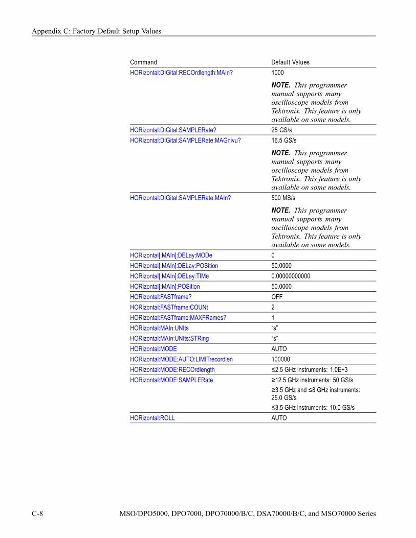
Appendix C: Factory Default Setup Values
Command Default ValuesHORizontal:DIGital:RECOrdlength:MAIn? 1000
NOTE. This programmermanual supports manyoscilloscope models fromTektronix. This feature is onlyavailable on some models.
HORizontal:DIGital:SAMPLERate? 25 GS/sHORizontal:DIGital:SAMPLERate:MAGnivu? 16.5 GS/s
NOTE. This programmermanual supports manyoscilloscope models fromTektronix. This feature is onlyavailable on some models.
HORizontal:DIGital:SAMPLERate:MAIn? 500 MS/s
NOTE. This programmermanual supports manyoscilloscope models fromTektronix. This feature is onlyavailable on some models.
HORizontal[:MAIn]:DELay:MODe 0HORizontal[:MAIn]:DELay:POSition 50.0000HORizontal[:MAIn]:DELay:TIMe 0.00000000000HORizontal[:MAIn]:POSition 50.0000HORizontal:FASTframe? OFFHORizontal:FASTframe:COUNt 2HORizontal:FASTframe:MAXFRames? 1HORizontal:MAIn:UNIts “s”HORizontal:MAIn:UNIts:STRing “s”HORizontal:MODE AUTOHORizontal:MODE:AUTO:LIMITrecordlen 100000HORizontal:MODE:RECOrdlength ≤2.5 GHz instruments: 1.0E+3HORizontal:MODE:SAMPLERate ≥12.5 GHz instruments: 50 GS/s
≥3.5 GHz and ≤8 GHz instruments:25.0 GS/s≤3.5 GHz instruments: 10.0 GS/s
HORizontal:ROLL AUTO
C-8 MSO/DPO5000, DPO7000, DPO70000/B/C, DSA70000/B/C, and MSO70000 Series

Appendix C: Factory Default Setup Values
Low Speed Serial TriggerDefault Values
The following table lists the Low Speed Serial Trigger factory default setup values.
Command Default valuesTRIGger:A:I2C:ADDRess:MODe 10 BitTRIGger:A:I2C:ADDRess:RWINClude OFFTRIGger:A:I2C:ADDRess:TYPe NoneTRIGger:A:I2C:CONDition StartTRIGger:A:I2C:DATa:DIRection Don’t Care (X)TRIGger:A:I2C:DATa:SOUrce Ch 1TRIGger:A:RS232:BAUd 19.2 kBTRIGger:A:RS232:DATa:SOUrce Ch 1TRIGger:A:RS232:DATa:VALue XXXX XX01TRIGger:A:RS232:FORMat BinaryTRIGger:A:RS232:PARity NoneTRIGger:A:SPI:CONDition MOSITRIGger:A:SPI:DATa:MISO:ACTIVE HIGHTRIGger:A:SPI:DATa:MISO:SOUrce Ch 1TRIGger:A:SPI:DATa:MOSI:ACTIVE HIGHTRIGger:A:SPI:DATa:MOSI:SOUrce Ch 1TRIGger:A:SPI:SCLK:ACTIVE RisingTRIGger:A:SPI:SCLK:LEVel 0.0 VTRIGger:A:SPI:SCLK:SOUrce Ch 2TRIGger:A:SPI:SS:ACTIVE LTRIGger:A:SPI:SS:LEVel 0.0 VTRIGger:A:SPI:SS:SOUrce Ch 3
Mask Default Values The following table lists the Mask factory default setup values.
Command Default ValuesMASK:AUTOAdjust 10MASK:AUTOAdjust:HDELTA 10MASK:AUTOAdjust:VDELTA 10MASK:AUTOSet:AUTOAdjust 1MASK:AUTOSet:HPOS 1MASK:AUTOSet:HSCAle 1MASK:AUTOSet:MODe MANUALMASK:AUTOSet:OFFSETAdj 1MASK:AUTOSet:STANdard NONEMASK:AUTOSet:TRIGger 1MASK:AUTOSet:VPOS 1
MSO/DPO5000, DPO7000, DPO70000/B/C, DSA70000/B/C, and MSO70000 Series C-9

Appendix C: Factory Default Setup Values
Command Default ValuesMASK:AUTOSet:VSCAle 1MASK:COUNt:STATE 0MASK:DISplay 1MASK:FILTer 0MASK:HIGHLIGHTHits 1MASK:INVert 0MASK:LOCk 1MASK:MARgin:PERCent 5.0000MASK:MARgin:STATE 0MASK:MASKPRE:AMPlitude 100.0000E-3MASK:MASKPRE:HSCAle 200.0000E-9MASK:MASKPRE:HTRIGPOS 500.0000E-3MASK:MASKPRE:PATTERNBITS 1MASK:MASKPRE:PRESAMPBITS 0MASK:MASKPRE:RECOrdlength 5000MASK:MASKPRE:TRIGTOSAMP 0.0000MASK:MASKPRE:VOFFSet 0.0000MASK:MASKPRE:VPOS 0.0000MASK:MASKPRE:VSCAle 1.0000E-3MASK:MASKPRE:WIDth 0.0000MASK:POLarity POSITIVEMASK:SOUrce CH1MASK:STANdard NONEMASK:STOPOnviolation 0MASK:TESt:BEEP:COMPLetion 0MASK:TESt:BEEP:FAILure 0MASK:TESt:DELay 0.0000MASK:TESt:HARDCopy 0MASK:TESt:LOG:FAILure 0MASK:TESt:REPeat 0MASK:TESt:SAMple:THReshold 1MASK:TESt:SAVEWFM 0MASK:TESt:SAVEWFM:FILEName “C:/TekScope/Waveforms/”MASK:TESt:SRQ:COMPLetion 0MASK:TESt:SRQ:FAILure 0MASK:TESt:STATE 0MASK:TESt:STOP:FAILure 0MASK:TESt:THReshold 1
C-10 MSO/DPO5000, DPO7000, DPO70000/B/C, DSA70000/B/C, and MSO70000 Series

Appendix C: Factory Default Setup Values
Command Default ValuesMASK:TESt:WAVEform 20MASK:USER:AMPlitude 100.0000E-3MASK:USER:BITRate 1544000MASK:USER:HSCAle 200.0000E-9MASK:USER:HTRIGPOS 500.0000E-3MASK:USER:LABel “User Mask”MASK:USER:PATTERNBITS 1MASK:USER:PRESAMPBITS 0MASK:USER:RECOrdlength 5000MASK:USER:TRIGTOSAMP 0.0000MASK:USER:VOFFSet 0.0000MASK:USER:VPOS 0.0000MASK:USER:VSCAle 1.0000E-3MASK:USER:WIDth 0.0000
Math Default Values The following table lists the Math factory default setup values.
Command Default ValuesMATHVAR:VAR<x> 0.0000MATH<x>:DEFine “ ”MATH<x>:LABel:NAMe “”MATH<x>:LABel:XPOS 1.0000
1 = 600.0000E-32 = 200.0000E-33 = -200.0000E-3
MATH<x>:LABel:YPOS
4 = -600.0000E-3MATH<x>:NUMAVg 2MATH<x>:SPECTral:CENTER 625.0000E+6MATH<x>:SPECTral:GATEPOS 0.0000MATH<x>:SPECTral:GATEWIDTH 2.0000E-6MATH<x>:SPECTral:LOCk 0MATH<x>:SPECTral:MAG DBMATH<x>:SPECTral:PHASE DEGREESMATH<x>:SPECTral:REFLevel 20.0000MATH<x>:SPECTral:REFLEVELOffset 223.6000E-3MATH<x>:SPECTral:RESBw 1000.0000E+3MATH<x>:SPECTral:SPAN 1.2500E+9MATH<x>:SPECTral:SUPPress –200.0000
MSO/DPO5000, DPO7000, DPO70000/B/C, DSA70000/B/C, and MSO70000 Series C-11

Appendix C: Factory Default Setup Values
Command Default ValuesMATH<x>:SPECTral:UNWRap 0MATH<x>:SPECTral:WINdow GAUSSIANMATH<x>:UNITString “V”MATH<x>:VERTical:POSition 0.0000MATH<x>:VERTical:SCAle 1.0000
Measurement DefaultValues
The following table lists the Measurement factory default setup values.
Command Default ValuesMEASUrement:GATing OFFMEASUrement:IMMed:DELay:DIREction FORWARDSMEASUrement:IMMed:DELay:EDGE[1] RISEMEASUrement:IMMed:DELay:EDGE2 RISEMEASUrement:IMMed:METHod HISTOGRAMMEASUrement:IMMed:NOISe HIGHMEASUrement:IMMed:REFLevel:ABSolute:HIGH 0.0000MEASUrement:IMMed:REFLevel:ABSolute:LOW 0.0000MEASUrement:IMMed:REFLevel:ABSolute:MID<x> 0.0000MEASUrement:IMMed:REFLevel:METHod PERCENTMEASUrement:IMMed:REFLevel:PERCent:HIGH 90.0000MEASUrement:IMMed:REFLevel:PERCent:LOW 10.0000MEASUrement:IMMed:REFLevel:PERCent:MID<x> 50.0000MEASUrement:IMMed:SOUrce<x> CH1MEASUrement:IMMed:SOUrce<x>:SIGType PULSEMEASUrement:IMMed:TYPe UNDEFINEDMEASUrement:MEAS<x>:DELay:DIREction FORWARDSMEASUrement:MEAS<x>:DELay:EDGE<x> RISEMEASUrement:MEAS<x>:METHod HISTOGRAMMEASUrement:MEAS<x>:NOISe HIGHMEASUrement:MEAS<x>:REFLevel:ABSolute:HIGH 0.0000MEASUrement:MEAS<x>:REFLevel:ABSolute:LOW 0.0000MEASUrement:MEAS<x>:REFLevel:ABSolute:MID<x> 0.0000MEASUrement:IMMed:REFLevel:METHod PERCENTMEASUrement:MEAS<x>:REFLevel:PERCent:HIGH 0.0000MEASUrement:MEAS<x>:REFLevel:PERCent:LOW 0.0000MEASUrement:MEAS<x>:REFLevel:PERCent:MID<x> 0.0000MEASUrement:MEAS<x>:SOUrce<x> CH1MEASUrement:MEAS<x>:SOUrce<x>:SIGType PULSE
C-12 MSO/DPO5000, DPO7000, DPO70000/B/C, DSA70000/B/C, and MSO70000 Series

Appendix C: Factory Default Setup Values
Command Default ValuesMEASUrement:MEAS<x>:STATE 0MEASUrement:MEAS<x>:TYPe UNDEFINEDMEASUrement:STATIstics:MODe ALLMEASUrement:STATIstics:WEIghting 32
Miscellaneous DefaultValues
The following table lists the Miscellaneous factory default setup values.
Command Default ValuesAUXout:EDGE FALLINGAUXout:SOUrce ATRIGGERCMDBatch 1 (ON)HEADer 1 (ON)LOCk NONEROSc:TRACking STABLEUSBTMC:PRODUCTID:DECimal? 0USBTMC:PRODUCTID:HEXadecimal? 0x0000USBTMC:VENDORID:DECimal? 0USBTMC:VENDORID:HEXadecimal? 0x0000VERBose 1 (ON)
Save and Recall DefaultSettings
The following table lists the Save and Recall factory default setup values.
Command Default ValuesRECAll:SETUp:DESKew OFFSAVe:WAVEform:FILEFormat INTERNAL
Search and Mark DefaultValues
The following table lists the Search and Mark factory default setup values.
Command Default ValuesSEARCH:SEARCH<x>:TRIGger:A:DDRMemory:AUTOBitrate
AUTO
SEARCH:SEARCH<x>:TRIGger:A:DDRMemory:AUTOReflevel
AUTO
SEARCH:SEARCH<x>:TRIGger:A:DDRMemory:BITRate
9.9000E+36
SEARCH:SEARCH<x>:TRIGger:A:DDRMemory:DATASource
CH1
SEARCH:SEARCH<x>:TRIGger:A:DDRMemory:REFLevel:DATa:HIGH
9.9000E+36
MSO/DPO5000, DPO7000, DPO70000/B/C, DSA70000/B/C, and MSO70000 Series C-13

Appendix C: Factory Default Setup Values
Command Default ValuesSEARCH:SEARCH<x>:TRIGger:A:DDRMemory:REFLevel:DATa:LOW
9.9000E+36
SEARCH:SEARCH<x>:TRIGger:A:DDRMemory:REFLevel:DATa:MID
9.9000E+36
SEARCH:SEARCH<x>:TRIGger:A:DDRMemory:REFLevel:STROBE:HIGH
9.9000E+36
SEARCH:SEARCH<x>:TRIGger:A:DDRMemory:REFLevel:STROBE:LOW
9.9000E+36
SEARCH:SEARCH<x>:TRIGger:A:DDRMemory:REFLevel:STROBE:MID
9.9000E+36
SEARCH:SEARCH<x>:TRIGger:A:DDRMemory:STANdard
DDR3
SEARCH:SEARCH<x>:TRIGger:A:DDRMemory:STROBEsource
CH2
TekLink Default Values The following table lists the TekLink factory default setup values.
Command Default ValuesTEKLink:CONNection? OFFTEKLink:REFClk INTERNALTRIGger:MULTiscope:ALIGN DONETRIGger:MULTiscope:ALIGN:COMPleted? DONETRIGger:MULTiscope:LOGic DONE
Trigger Default Values The following table lists the Trigger factory default setup values.
Command Default ValuesTRIGger:A:COMMunication:AMI|HDB3|B3ZS|B6ZS|B8ZS:PULSEForm
AMI = PLUSONECMI = PLUSONE
TRIGger:A:COMMunication:AMI|HDB3|B3ZS|B6ZS|B8ZS:THReshold:HIGH
AMI = 0.0000
TRIGger:A:COMMunication:AMI|HDB3|B3ZS|B6ZS|B8ZS:THReshold:LOW
AMI = 0.0000
TRIGger:A:COMMunication:BITRate 1544000TRIGger:A:COMMunication:CLOCk:POLarity RISETRIGger:A:COMMunication:CODe NRZTRIGger:A:COMMunication:SOUrce CH1TRIGger:A:COMMunication:SOUrce:TYPe DATATRIGger:A:COMMunication:STANdard CUSTOMTRIGger:A|B:EDGE:COUPling DC
C-14 MSO/DPO5000, DPO7000, DPO70000/B/C, DSA70000/B/C, and MSO70000 Series

Appendix C: Factory Default Setup Values
Command Default ValuesTRIGger:A|B:EDGE:SLOpe RISETRIGger:A|B:EDGE:SOUrce A = CH1
B = CH1TRIGger:A:HOLDoff:BY DEFAULTTRIGger:A:HOLDoff:TIMe 1.5000E-6TRIGger:A|B:LEVel 0.0000TRIGger:A|B:LOGIc:CLAss PATTERNTRIGger:A|B:LOGIc:FUNCtion ANDTRIGger:A|B:LOGIc:INPut:CH<x> CH1 = HIGH
CH2 = XCH3 = X
TRIGger:A|B:LOGIc:PATtern:INPut:CH<x> CH4 = XTRIGger:A|B:LOGIc:PATtern:WHEn TRUETRIGger:A|B:LOGIc:PATtern:WHEn:LESSLimit 5.0000E-12TRIGger:A|B:LOGIc:PATtern:WHEn:MORELimit 5.0000E-12TRIGger:A|B:LOGIc:SETHold:CLOCk:EDGE RISETRIGger:A|B:LOGIc:SETHold:CLOCk:SOUrce CH2TRIGger:A|B:LOGIc:SETHold:CLOCk:THReshold 1.2000TRIGger:A|B:LOGIc:SETHold:DATa:SOUrce CH1TRIGger:A|B:LOGIc:SETHold:DATa:THReshold 1.2000TRIGger:A|B:LOGIc:SETHold:HOLDTime 2.0000E-9TRIGger:A|B:LOGIc:SETHold:SETTime 1.0000E-9TRIGger:A|B:LOGIc:STATE:INPut:CH<x> CH4 = RISETRIGger:A|B:LOGIc:STATE:WHEn TRUETRIGger:A|B:LOGIc:THReshold:CH<x> CH4 = 1.2000TRIGger:A:MODe AUTOTRIGger:A|B:PULse:CLAss GLITCHTRIGger:A|B:PULse:GLItch:POLarity POSITIVETRIGger:A|B:PULse:GLItch:TRIGIF ACCEPTTRIGger:A|B:PULse:GLItch:WIDth 2.0000E-9TRIGger:A|B:PULse:RUNT:POLarity POSITIVETRIGger:A|B:PULse:RUNT:THReshold:HIGH 1.2000TRIGger:A|B:PULse:RUNT:THReshold:LOW 800.0000E-3TRIGger:A|B:PULse:RUNT:WHEn OCCURSTRIGger:A|B:PULse:RUNT:WIDth 2.0000E-9TRIGger:A|B:PULse:SOUrce CH1TRIGger:A|B:PULse:TIMEOut:POLarity STAYSHIGHTRIGger:A|B:PULse:TIMEOut:TIMe 2.0000E-9
MSO/DPO5000, DPO7000, DPO70000/B/C, DSA70000/B/C, and MSO70000 Series C-15

Appendix C: Factory Default Setup Values
Command Default ValuesTRIGger:A|B:PULse:TRANsition:DELTATime 2.0000E-9TRIGger:A|B:PULse:TRANsition:POLarity POSITIVETRIGger:A|B:PULse:TRANsition:THReshold:HIGH 1.2000TRIGger:A|B:PULse:TRANsition:THReshold:LOW 800.0000E-3TRIGger:A|B:PULse:TRANsition:WHEn FASTERTHANTRIGger:A|B:PULse:WIDth:HIGHLimit 2.0000E-9TRIGger:A|B:PULse:WIDth:LOWLimit 2.0000E-9TRIGger:A|B:PULse:WIDth:POLarity POSITIVETRIGger:A|B:PULse:WIDth:WHEn WITHINTRIGger:A|B:PULse:WINdow:THReshold:HIGH 1.2000TRIGger:A|B:PULse:WINdow:THReshold:LOW 800.0000E-3TRIGger:A|B:PULse:WINdow:WIDTH 2.0000E-9TRIGger:A|B:PULse:WINdow:POLarity EITHERTRIGger:A|B:PULse:WINdow:POLarity:CH<x> EITHERTRIGger:A|B:TYPe EDGETRIGger:A:VIDeo:CUSTom:FORMat INTERLACEDTRIGger:A:VIDeo:FIELD ALLFIELDSTRIGger:A:VIDeo:HOLdoff:FIELD 0.0000TRIGger:A:VIDeo:LINE 1TRIGger:A:VIDeo:POLarity NORMALTRIGger:A:VIDeo:SCAN RATE1TRIGger:A:VIDeo:SOUrce CH1TRIGger:A:VIDeo:STANdard NTSCTRIGger:B:BY EVENTSTRIGger:B:EVENTS:COUNt 2TRIGger:B:STATE 0TRIGger:B:TIMe 16.0000E-9
Vertical Default Values The following table lists the Vertical factory default setup values.
Command Default ValuesCH<x>:BANdwidth 500.0000E+6CH<x>:COUPling DCCH<x>:DESKew 0.0000
0CH<x>:LABel:NAMe “”CH<x>:LABel:XPOS CH1 = 1.0000
C-16 MSO/DPO5000, DPO7000, DPO70000/B/C, DSA70000/B/C, and MSO70000 Series

Appendix C: Factory Default Setup Values
Command Default ValuesCH1 = 2.2000CH2 = 1.8000CH3 = 1.4000
CH<x>:LABel:YPOS
CH4 = 1.000CH<x>:OFFSet 0.0000CH<x>:POSition 0.0000CH<x>:PROBECOntrol AUTOCH<x>:PROBEFunc:EXTAtten 1.0000CH<x>:PROBEFunc:EXTUnits “V”CH<x>:SCAle 100.0000E-3CH<x>:TERmination 1.0000E+6REF<x>:LABel:NAMe “”REF<x>:LABel:XPOS 1.0000REF<x>:LABel:YPOS –1.0000SELect:<wfm> CH1 = 1
CH2 = 0CH3 = 0CH4 = 0
SELect:CONTROl CH1
Waveform Default Values The following table lists the Waveform factory default setup values.
NOTE. These are not set to factory values when a default setup is executed.:DATa INIT is used to reset these values.
Command Default ValuesDATa:DESTination REF1DATa:ENCdg RIBINARYDATa:SOUrce CH1DATa:STARt 1DATa:STOP 1000
Zoom Default Values The following table lists the Zoom factory default setup values.
Command Default ValuesZOOm:GRAticule:SIZE 80ZOOm:MODe 0
MSO/DPO5000, DPO7000, DPO70000/B/C, DSA70000/B/C, and MSO70000 Series C-17

Appendix C: Factory Default Setup Values
Command Default ValuesZOOm:SCROLL:DIREction STOPZOOm:SCROLL:LOCk 0ZOOm:SCROLL:SPEED 1ZOOm:ZOOM<x>:<wfm>:DISplay 0ZOOm:ZOOM<x>:<wfm>:HORizontal:POSition Zoom1
50.0000Zoom230.0000Zoom370.0000Zoom490.0000
ZOOm:ZOOM<x>:<wfm>:HORizontal:SCAle 5ZOOm:ZOOM<x>:<wfm>:VERTical:POSition 0.0000ZOOm:ZOOM<x>:<wfm>:VERTical:SCAle 1.0000ZOOm:ZOOM<x>:SCROLLLock 1ZOOm:STATE 1
C-18 MSO/DPO5000, DPO7000, DPO70000/B/C, DSA70000/B/C, and MSO70000 Series

Appendix D: GPIB Interface SpecificationsThis topic describes details of the GPIB remote interface of the instrument.Normally, you will not need this information to use the instrument, but thisinformation may be useful if you are connecting to controllers with unusualconfigurations.
Interface MessagesThe following table shows the standard interface messages that the instrumentsupports.
Table D-1: Standard Interface Messages
Message InterfaceDCL YesGET YesGTL YesLLO YesPPC NoPPD NoPPE NoPPU NoSDC YesSPD YesSPE YesTCT NoUNL YesUNT YesListen Addresses YesTalk Addresses Yes
GPIB FunctionsThe following table lists the interface functions and electrical functions subsetssupported by this instrument with brief descriptions of each.
Table D-2: Interface Functions
Interface Function Subset MeaningAcceptor Handshake AH1 The instrument can receive multiline messages
across the interface from other devices.
MSO/DPO5000, DPO7000, DPO70000/B/C, DSA70000/B/C, and MSO70000 Series D-1

Appendix D: GPIB Interface Specifications
Table D-2: Interface Functions (cont.)
Interface Function Subset MeaningController C1 Controller capability, the instrument can control other
devices.Device Clear DC1 The instrument can respond to both the DCL (Device
Clear) interface message and to the Selected DeviceClear (SDC) interface message when the instrumentis listen-addressed.
Device Trigger DT1 Device Trigger capability, the instrument doesrespond to the GET (Group Execute Trigger)interface message.
Electrical E2 The instrument uses tri-state buffers, which areoptimal for high-speed data transfer.
Listener L4 The instrument becomes a listener when it detectsthe listen address being sent over the bus with theATN line asserted. The instrument ceases to be alistener and becomes a talker when it detects thetalk address being sent over the bus with the ATNline asserted.
Parallel Poll PP0 No Parallel Poll Capability, the instrument doesnot respond to PPC (Parallel Poll Configure), PPO(Parallel POll Disable, PPE (Parallel Poll Enable), orPPU (Parallel Poll Unconfigure) interface messages,nor does it send a status message when the ATNand EOI lines are asserted simultaneously.
Remote/Local RL1 The instrument can respond to both GTL (Go ToLocal) and LLO (Local Lock Out) interface messages.
Service Request SR1 The instrument can assert the SRQ line to notify thecontroller in charge that it requires service.
Source Handshake SH1 The instrument can initiate multiline messages tosend across the interface to other devices.
Talker T5 The instrument becomes a talker when it detects thetalk address being sent over the bus with the ATNline asserted. The instrument ceases to be a talkerand becomes a listener when it detects the listenaddress being sent over the bus with the ATN lineasserted. The instrument also ceases to be a talkerwhen it detects the talk address of another devicebeing sent over the data lines with ATN asserted.
D-2 MSO/DPO5000, DPO7000, DPO70000/B/C, DSA70000/B/C, and MSO70000 Series

GlossaryASCIIAcronym for the American Standard Code for Information Interchange.Controllers transmit commands to the instrument using ASCII character encoding.
AddressA 7-bit code that identifies an instrument on the communication bus. Thedigitizing instrument must have a unique address for the controller to recognizeand transmit commands to it.
Backus-Naur Form (BNF)A standard notation system for command syntax diagrams. The syntax diagramsin this manual use BNF notation.
ControllerA computer or other device that sends commands to and accepts responses fromthe digitizing instrument.
EOIA mnemonic referring to the control line End or Identify on the GPIB interfacebus. One of the two possible end-of-message terminators.
EOMA generic acronym referring to the end-of-message terminator. Theend-of-message terminator can be either an EOI or the ASCII code for line feed(LF).
Equivalent-Time Sampling (ET)A sampling mode in which the instrument acquires signals over many repetitionsof the event. This instrument uses a type of equivalent time sampling calledrandom equivalent time sampling. It utilizes an internal clock that runsasynchronously with respect to the input signal and the signal trigger. Theinstrument takes samples continuously, independent of the trigger position, anddisplays them based on the time difference between the sample and the trigger.Although the samples are taken sequentially in time, they are random with respectto the trigger.
Real-Time SamplingA sampling mode where the instrument samples fast enough to completely fill awaveform record from a single trigger event. Use real-time sampling to capturesingle-shot or transient events.
GPIBAn acronym for General Purpose Interface Bus, the common name for theinterface system defined in IEEE Std-488.
IEEEAn acronym for the Institute for Electrical and Electronic Engineers.
MSO/DPO5000, DPO7000, DPO70000/B/C, DSA70000/B/C, and MSO70000 Series Glossary-1

Glossary
TEKSecureA Tektronix custom command that initializes both waveform and setup memories.This overwrites any previously stored data.
Serial PollA device on the GPIB bus can request service from the GPIB Controller byasserting the GPIB SRQ line (a Hardware line that is only present on the GPIBcommunications bus). When a controller acknowledges the SRQ, it “serial polls”each open device on the bus to determine which device on the bus requestedservice. Any device requesting service returns a status byte with bit 6 set andthen unasserts the SRQ line. Devices not requiring service return a status bytewith bit 6 cleared.
Glossary-2 MSO/DPO5000, DPO7000, DPO70000/B/C, DSA70000/B/C, and MSO70000 Series

Index
AACQuire:INTERPEightbit, 2-107ACQuire:NUMFRAMESACQuired?, 2-111ACQuire:SAMPlingmode, 2-112ACQuire:MAGnivu, 2-107ACQuire:MODe, 2-108ACQuire:NUMACq?, 2-109ACQuire:NUMAVg, 2-110ACQuire:NUMEnv, 2-110ACQuire:NUMSAMples, 2-111ACQuire:STATE, 2-113ACQuire:STOPAfter, 2-114ALIas, 2-114ALIas:CATalog?, 2-115ALIas:DEFine, 2-115ALIas:DELEte, 2-116ALIas:DELEte:ALL, 2-116ALIas:DELEte:NAMe, 2-117ALIas:STATE, 2-117ALLEv?, 2-118ALLOcate:WAVEform:REF<x>?, 2-118AUTOSet, 2-118AUXIn:PRObe:AUTOZero, 2-121AUXIn:PRObe:DEGAUSS:STATE?, 2-122AUXIn:PRObe:FORCEDRange, 2-122AUXIn:PRObe:ID:SERnumber?, 2-123AUXIn:PRObe:ID:TYPe?, 2-123AUXIn:PRObe:INPUTMode, 2-123AUXIn:PRObe:INPUTMode:AOFFSet, 2-124AUXIn:PRObe:INPUTMode:BOFFSet, 2-124AUXIn:PRObe:INPUTMode:CMOFFSet, 2-125AUXIn:PRObe:INPUTMode:DMOFFSet, 2-125AUXIn:PRObe:RESistance?, 2-126AUXIn:PROBEFunc:EXTAtten, 2-129AUXIn:PROBEFunc:EXTDBatten, 2-130AUXIn:PROBEFunc:EXTUnits, 2-131AUXIn:BANdwidth, 2-119AUXIn:COUPling, 2-120AUXIn:OFFSet, 2-120AUXIn:PRObe:DEGAUSS, 2-121AUXIn:PRObe:GAIN?, 2-122AUXIn:PRObe:RANge, 2-126AUXIn:PRObe:SET, 2-127AUXIn:PRObe:SIGnal, 2-128
AUXIn:PRObe:TIPtype, 2-128AUXIn:PRObe:UNIts?, 2-129AUXout?, 2-131AUXout:EDGE, 2-132AUXout:SOUrce, 2-132
BBELl, 2-133BUS:B<x>:DISplay:DECOde:FILe, 2-133BUS:B<x>:DISplay:DECOde:STAte, 2-134BUS:B<x>:DISplay:FORMat, 2-135BUS:B<x>:DISplay:TYPe, 2-135BUS:B<x>:I2C:CLOCk:SOUrce, 2-136BUS:B<x>:I2C:DATa:SOUrce, 2-137BUS:B<x>:I2C:RWINADDR, 2-137BUS:B<x>:PARallel:CLOCk:EDGE, 2-139BUS:B<x>:PARallel:CLOCk:SOUrce, 2-139BUS:B<x>:PARallel:ISCLOCKED, 2-140BUS:B<x>:PARallel:SOURCES, 2-141BUS:B<x>:POSition, 2-142BUS:B<x>:RS232c:BITRate, 2-142BUS:B<x>:RS232c:DATABits, 2-143BUS:B<x>:RS232c:DELIMiter, 2-144BUS:B<x>:RS232c:DISplaymode, 2-144BUS:B<x>:RS232c:PARity, 2-145BUS:B<x>:RS232c:POLarity, 2-146BUS:B<x>:RS232c:SOUrce, 2-146BUS:B<x>:SPI:BITOrder, 2-147BUS:B<x>:SPI:CLOCk:POLarity, 2-147BUS:B<x>:SPI:CLOCk:SOUrce, 2-148BUS:B<x>:SPI:DATa:POLarity, 2-149BUS:B<x>:SPI:DATa:SIZE, 2-149BUS:B<x>:SPI:DATa:SOUrce, 2-150BUS:B<x>:SPI:SELect:POLarity, 2-151BUS:B<x>:SPI:SELect:SOUrce, 2-151BUS:B<x>:USB:BITRate, 2-153BUS:B<x>:USB:PRObe, 2-153BUS:B<x>:USB:SOUrce, 2-154BUS:B<x>:USB:SOUrce:DMINus, 2-155BUS:B<x>:USB:SOUrce:DPLUs, 2-155BUS:B<x>:LABel, 2-138BUS:B<x>:TYPe, 2-152BUSY?, 2-156
MSO/DPO5000, DPO7000, DPO70000/B/C, DSA70000/B/C, and MSO70000 Series Index-1

Index
C*CAL?, 2-156CALibrate:CALProbe:CH<x>?, 2-157CALibrate:INTERNal:STARt, 2-158CALibrate:INTERNal:STATus?, 2-159CALibrate:PRObestate:CH<x>?, 2-159CALibrate:RESults:SPC?, 2-160CALibrate?, 2-157CALibrate:INTERNal, 2-158CALibrate:RESults?, 2-160CH<x>:BANdwidth:ENHanced, 2-162CH<x>:BANdwidth:ENHanced:APPLYtoall, 2-163CH<x>:BANdwidth:ENHanced:FORCe, 2-164CH<x>:BANdwidth:ENHanced:STATE?, 2-164CH<x>:ICAPture:SOUrce, 2-166CH<x>:ICAPture:STATE, 2-167CH<x>:PRObe:AUTOZero, 2-171CH<x>:PRObe:DEGAUSS, 2-171CH<x>:PRObe:DEGAUSS:STATE?, 2-172CH<x>:PRObe:FORCEDRange, 2-172CH<x>:PRObe:GAIN?, 2-173CH<x>:PRObe:ID:SERnumber?, 2-174CH<x>:PRObe:ID:TYPe?, 2-174CH<x>:PRObe:INPUTMode, 2-174CH<x>:PRObe:INPUTMode:AOFFSet, 2-175CH<x>:PRObe:INPUTMode:BOFFSet, 2-175CH<x>:PRObe:INPUTMode:CMOFFSet, 2-176CH<x>:PRObe:INPUTMode:DMOFFSet, 2-176CH<x>:PRObe:RANge, 2-177CH<x>:PRObe:RESistance?, 2-178CH<x>:PRObe:SIGnal, 2-179CH<x>:PRObe:TIPtype, 2-180CH<x>:PRObe:UNIts?, 2-180CH<x>:PROBECOntrol, 2-181CH<x>:PROBEFunc:EXTAtten, 2-182CH<x>:PROBEFunc:EXTDBatten, 2-183CH<x>:PROBEFunc:EXTUnits, 2-183CH<x>:TERmination, 2-185CH<x>?, 2-161CH<x>:BANdwidth, 2-161CH<x>:COUPling, 2-165CH<x>:DESKew, 2-165CH<x>:LABel:NAMe, 2-167CH<x>:LABel:XPOS, 2-168CH<x>:LABel:YPOS, 2-168CH<x>:OFFSet, 2-169CH<x>:POSition, 2-170
CH<x>:PRObe?, 2-170CH<x>:PRObe:ID?, 2-173CH<x>:PRObe:SET, 2-178CH<x>:PROBECal?, 2-181CH<x>:SCAle, 2-184CH<x>:THRESHold, 2-186*CLS, 2-186CMDBatch, 2-187Command Groups, 2-11CQ<x>:THRESHold, 2-187CURSor:HBArs:POSITION<x>, 2-190CURSor:SCREEN:XPOSITION<x>, 2-192CURSor:SCREEN:YPOSITION<x>, 2-193CURSor:VBArs:POS<x>, 2-197CURSor:VBArs:POSITION<x>, 2-196CURSor:WAVEform:HDELTA?, 2-199CURSor:WAVEform:HPOS<x>?, 2-199CURSor:WAVEform:POSition<x>, 2-199CURSor:WAVEform:STYle, 2-200CURSor:WAVEform:UNIts, 2-200CURSor:WAVEform:VDELTA?, 2-201CURSor:XY:PRODDELta?, 2-202CURSor:XY:PRODUCT<x>?, 2-202CURSor:XY:RADIUS<x>?, 2-203CURSor:XY:RATIO<x>?, 2-204CURSor:XY:RECTX<x>, 2-205CURSor:XY:RECTY<x>, 2-206CURSor:XY:THETA<x>?, 2-207CURSor?, 2-188CURSor:FUNCtion, 2-188CURSor:HBArs?, 2-189CURSor:HBArs:DELTa?, 2-190CURSor:HBArs:UNIts?, 2-191CURSor:LINESTyle, 2-191CURSor:MODe, 2-191CURSor:SCREEN:STYle, 2-192CURSor:SOUrce<x>, 2-194CURSor:STATE, 2-194CURSor:VBArs, 2-195CURSor:VBArs:DELTa?, 2-196CURSor:VBArs:UNIts, 2-197CURSor:WAVEform, 2-198CURSor:XY?, 2-201CURSor:XY:RATDELta?, 2-203CURSor:XY:RDELta?, 2-204CURSor:XY:READOUT, 2-204CURSor:XY:THDELta?, 2-206
Index-2 MSO/DPO5000, DPO7000, DPO70000/B/C, DSA70000/B/C, and MSO70000 Series

Index
CURSor:XY:XDELta?, 2-207CURSor:XY:YDELta?, 2-207CURVe, 2-208CURVENext?, 2-209CURVEStream, 2-210
DD<x>:PROBE:ID:SERnumber?, 2-261D<x>:PROBE:ID:TYPe?, 2-262D<x>:LABEL, 2-260D<x>:POSition, 2-261D<x>:THRESHold, 2-262DATa, 2-211DATa:DESTination, 2-211DATa:ENCdg, 2-212DATa:FRAMESTARt, 2-214DATa:FRAMESTOP, 2-215DATa:SOUrce, 2-215DATa:STARt, 2-216DATa:STOP, 2-217DATE, 2-218*DDT, 2-218DELEte:SETUp, 2-219DELEte:WAVEform, 2-219DESE, 2-220DIAg:RESults:VERBose?, 2-230DIAg:CONTROL:HALT, 2-221DIAg:CONTROL:LOOP, 2-221DIAg:EXECUTE, 2-222DIAg:FAILURES:CLEAR, 2-223DIAg:ITEM?, 2-223DIAg:ITEM:FAILURES?, 2-224DIAg:ITEM:NAMe?, 2-224DIAg:ITEM:RESULT?, 2-225DIAg:ITEM:SUBITEMS?, 2-225DIAg:LEVEL, 2-226DIAg:LOOPS?, 2-226DIAg:NAMe?, 2-227DIAg:NAMe:AREA?, 2-227DIAg:NAMe:SUBSYS?, 2-228DIAg:NAMe:TEST?, 2-228DIAg:NUMITEMS?, 2-229DIAg:RESults?, 2-229DIAg:SELect:ALL, 2-230DIAg:SELect:AREA, 2-231DIAg:SELect:LAST, 2-231DIAg:SELect:SUBSYS, 2-232
DIAg:SELect:TEST, 2-233DIAg:STATE, 2-233DIAg:STOP, 2-234DISplay:COLOr:MATHCOLOr, 2-236DISplay:COLOr:PALEtte:IMAGEView, 2-237DISplay:COLOr:PALEtte:RECORDView, 2-238DISplay:COLOr:PALEtte:USEr, 2-238DISplay:COLOr:PALEtte:USEr:CARet, 2-239DISplay:COLOr:PALEtte:USEr:CH<x>, 2-240DISplay:COLOr:PALEtte:USEr:GRAticule, 2-240DISplay:COLOr:PALEtte:USEr:HIStogram, 2-241DISplay:COLOr:PALEtte:USEr:MASK, 2-241DISplay:COLOr:PALEtte:USEr:
MASKHighlight, 2-242DISplay:COLOr:PALEtte:USEr:MATH<x>, 2-242DISplay:COLOr:PALEtte:USEr:REF<x>, 2-243DISplay:COLOr:PALEtte:USEr:WAVEform, 2-244DISplay:COLOr:REFCOLOr, 2-244DISplay:DIGital:HEIght, 2-245DISplay:INTENSITy:BACKLight, 2-248DISplay:INTENSITy:WAVEform:
IMAGEView, 2-249DISplay:INTENSITy:WAVEform:
RECORDView, 2-249DISplay:PERSistence:RESET, 2-250DISplay:SCREENTExt:LABel<x>:
FONTCOlor, 2-252DISplay:SCREENTExt:LABel<x>:
FONTNAme, 2-252DISplay:SCREENTExt:LABel<x>:FONTSIze, 2-253DISplay:SCREENTExt:LABel<x>:
FONTSTyle, 2-253DISplay:SCREENTExt:LABel<x>:NAMe, 2-254DISplay:SCREENTExt:LABel<x>:STATE, 2-254DISplay:SCREENTExt:LABel<x>:XPOS, 2-255DISplay:SCREENTExt:LABel<x>:YPOS, 2-255DISplay:SCREENTExt:LABel<x>?, 2-251DISplay:SCREENTExt:STATE, 2-256DISplay?, 2-234DISplay:CLOCk, 2-235DISplay:COLOr?, 2-236DISplay:FILTer, 2-246DISplay:FORMat, 2-246DISplay:GRAticule, 2-247DISplay:INTENSITy?, 2-248DISplay:PERSistence, 2-250DISplay:SCREENTExt?, 2-251
MSO/DPO5000, DPO7000, DPO70000/B/C, DSA70000/B/C, and MSO70000 Series Index-3
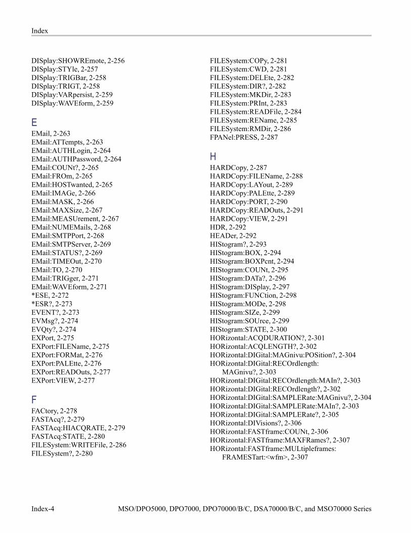
Index
DISplay:SHOWREmote, 2-256DISplay:STYle, 2-257DISplay:TRIGBar, 2-258DISplay:TRIGT, 2-258DISplay:VARpersist, 2-259DISplay:WAVEform, 2-259
EEMail, 2-263EMail:ATTempts, 2-263EMail:AUTHLogin, 2-264EMail:AUTHPassword, 2-264EMail:COUNt?, 2-265EMail:FROm, 2-265EMail:HOSTwanted, 2-265EMail:IMAGe, 2-266EMail:MASK, 2-266EMail:MAXSize, 2-267EMail:MEASUrement, 2-267EMail:NUMEMails, 2-268EMail:SMTPPort, 2-268EMail:SMTPServer, 2-269EMail:STATUS?, 2-269EMail:TIMEOut, 2-270EMail:TO, 2-270EMail:TRIGger, 2-271EMail:WAVEform, 2-271*ESE, 2-272*ESR?, 2-273EVENT?, 2-273EVMsg?, 2-274EVQty?, 2-274EXPort, 2-275EXPort:FILEName, 2-275EXPort:FORMat, 2-276EXPort:PALEtte, 2-276EXPort:READOuts, 2-277EXPort:VIEW, 2-277
FFACtory, 2-278FASTAcq?, 2-279FASTAcq:HIACQRATE, 2-279FASTAcq:STATE, 2-280FILESystem:WRITEFile, 2-286FILESystem?, 2-280
FILESystem:COPy, 2-281FILESystem:CWD, 2-281FILESystem:DELEte, 2-282FILESystem:DIR?, 2-282FILESystem:MKDir, 2-283FILESystem:PRInt, 2-283FILESystem:READFile, 2-284FILESystem:REName, 2-285FILESystem:RMDir, 2-286FPANel:PRESS, 2-287
HHARDCopy, 2-287HARDCopy:FILEName, 2-288HARDCopy:LAYout, 2-289HARDCopy:PALEtte, 2-289HARDCopy:PORT, 2-290HARDCopy:READOuts, 2-291HARDCopy:VIEW, 2-291HDR, 2-292HEADer, 2-292HIStogram?, 2-293HIStogram:BOX, 2-294HIStogram:BOXPcnt, 2-294HIStogram:COUNt, 2-295HIStogram:DATa?, 2-296HIStogram:DISplay, 2-297HIStogram:FUNCtion, 2-298HIStogram:MODe, 2-298HIStogram:SIZe, 2-299HIStogram:SOUrce, 2-299HIStogram:STATE, 2-300HORizontal:ACQDURATION?, 2-301HORizontal:ACQLENGTH?, 2-302HORizontal:DIGital:MAGnivu:POSition?, 2-304HORizontal:DIGital:RECOrdlength:
MAGnivu?, 2-303HORizontal:DIGital:RECOrdlength:MAIn?, 2-303HORizontal:DIGital:RECOrdlength?, 2-302HORizontal:DIGital:SAMPLERate:MAGnivu?, 2-304HORizontal:DIGital:SAMPLERate:MAIn?, 2-303HORizontal:DIGital:SAMPLERate?, 2-305HORizontal:DIVisions?, 2-306HORizontal:FASTframe:COUNt, 2-306HORizontal:FASTframe:MAXFRames?, 2-307HORizontal:FASTframe:MULtipleframes:
FRAMESTart:<wfm>, 2-307
Index-4 MSO/DPO5000, DPO7000, DPO70000/B/C, DSA70000/B/C, and MSO70000 Series

Index
HORizontal:FASTframe:MULtipleframes:MODe, 2-308
HORizontal:FASTframe:MULtipleframes:NUMFRames:<wfm>, 2-309
HORizontal:FASTframe:REF:FRAme, 2-309HORizontal:FASTframe:REF:SOUrce, 2-310HORizontal:FASTframe:SELECTED:CH<x>, 2-310HORizontal:FASTframe:SELECTED:
MATH<x>, 2-311HORizontal:FASTframe:SELECTED:REF<x>, 2-311HORizontal:FASTframe:SELECTED:SOUrce, 2-312HORizontal:FASTframe:SEQuence, 2-312HORizontal:FASTframe:STATE, 2-313HORizontal:FASTframe:SUMFrame, 2-314HORizontal:FASTframe:TIMEStamp:ALL:
<wfm>?, 2-314HORizontal:FASTframe:TIMEStamp:BETWeen:
<wfm>?, 2-315HORizontal:FASTframe:TIMEStamp:DELTa:
<wfm>?, 2-316HORizontal:FASTframe:TIMEStamp:FRAMe:
<wfm>?, 2-316HORizontal:FASTframe:TIMEStamp:REF?, 2-317HORizontal:FASTframe:TIMEStamp:SELECTED:
<wfm>?, 2-317HORizontal:FASTframe:TRACk, 2-318HORizontal:FASTframe:XZEro:ALL:CH<x>?, 2-319HORizontal:FASTframe:XZEro:ALL:
REF<x>?, 2-319HORizontal:FASTframe:XZEro:FRAme:
CH<x>?, 2-320HORizontal:FASTframe:XZEro:FRAme:
REF<x>?, 2-320HORizontal:FASTframe:XZEro:REF?, 2-321HORizontal:FASTframe:XZEro:SELECTED:
CH<x>?, 2-321HORizontal:FASTframe:XZEro:SELECTED:
REF<x>?, 2-321HORizontal:FASTframe?, 2-306HORizontal:MAIn:INTERPRatio?, 2-324HORizontal:MAIn:UNIts, 2-325HORizontal:MAIn:UNIts:STRing, 2-325HORizontal:MODE:AUTO:LIMITrecordlen, 2-327HORizontal:MODE:RECOrdlength, 2-327HORizontal:MODE:SAMPLERate, 2-328HORizontal:MODE:SCAle, 2-328HORizontal:TIMEStamp:CH<x>?, 2-330
HORizontal:TIMEStamp:REF<x>?, 2-330HORizontal?, 2-301HORizontal[:MAIn]:DELay:MODe, 2-322HORizontal[:MAIn]:DELay:POSition, 2-323HORizontal[:MAIn]:DELay:TIMe, 2-323HORizontal[:MAIn]:POSition, 2-324HORizontal:MAIn?, 2-322HORizontal:MODE, 2-326HORizontal:POSition, 2-328HORizontal:ROLL, 2-329
IID?, 2-330*IDN?, 2-331
LLIMit:COMpare:CH<x>, 2-333LIMit:COMpare:MATH<x>, 2-333LIMit:COMpare:REF<x>, 2-334LIMit:HIGHLIGHTHits:RESet, 2-337LIMit:SAVEWFM:FILEName, 2-339LIMit:STOPOnviolation, 2-341LIMit:TEMPlate:DESTination, 2-342LIMit:TEMPlate:SOUrce, 2-342LIMit:TEMPlate:STORe, 2-343LIMit:TEMPlate:TOLerance:HORizontal, 2-344LIMit:TEMPlate:TOLerance:VERTical, 2-344LIMit?, 2-331LIMit:BEEP, 2-332LIMit:COMpare, 2-332LIMit:EMail, 2-334LIMit:HARDCopy, 2-335LIMit:HIGHLIGHTHits, 2-336LIMit:LOCk, 2-337LIMit:LOG, 2-338LIMit:SAVEWFM, 2-338LIMit:SRQ, 2-340LIMit:STATE, 2-340LIMit:STATus?, 2-341LOCk, 2-345*LRN?, 2-346
MMARK, 2-346MARK:SELECTED:FOCUS?, 2-349MARK:SELECTED:MARKSINCOLumn?, 2-350
MSO/DPO5000, DPO7000, DPO70000/B/C, DSA70000/B/C, and MSO70000 Series Index-5

Index
MARK:SELECTED:OWNer?, 2-350MARK:SELECTED:SOUrce?, 2-350MARK:SELECTED:STARt?, 2-351MARK:SELECTED:ZOOm:POSition?, 2-351MARK:SELECTED:ZOOm:SCAle?, 2-352MARK:CREATE, 2-347MARK:DELEte, 2-348MARK:FREE?, 2-348MARK:SELECTED:END?, 2-348MARK:SELECTED:LABel, 2-349MARK:SELECTED:STATE, 2-351MARK:TOTal?, 2-352MASK:AUTOAdjust:HDELTA, 2-353MASK:AUTOAdjust:VDELTA, 2-354MASK:AUTOSet:AUTOAdjust, 2-354MASK:AUTOSet:OFFSETAdj, 2-357MASK:AUTOSet:STANdard, 2-357MASK:AUTOSet:TRIGger, 2-363MASK:AUTOSet:USER:ONE, 2-364MASK:AUTOSet:USER:TYPe, 2-364MASK:AUTOSet:USER:ZERo, 2-365MASK:COUNt:FAILURES?, 2-367MASK:COUNt:SEG<m>:HITS?, 2-368MASK:COUNt:VIOLATIONS?, 2-370MASK:COUNt:WAVEFORMS?, 2-370MASK:MASKPRE:AMPlitude, 2-374MASK:MASKPRE:HTRIGPOS, 2-376MASK:MASKPRE:PATTERNBITS, 2-376MASK:MASKPRE:PRESAMPBITS, 2-377MASK:MASKPRE:RECOrdlength, 2-377MASK:MASKPRE:TRIGTOSAMP, 2-378MASK:MASKPRE:VOFFSet, 2-378MASK:SEG<m>:NR_Pt?, 2-382MASK:SEG<m>:POINTS, 2-382MASK:STOPOnviolation, 2-390MASK:TESt:AUX:COMPLetion, 2-391MASK:TESt:AUX:FAILure, 2-391MASK:TESt:BEEP:COMPLetion, 2-392MASK:TESt:BEEP:FAILure, 2-392MASK:TESt:LOG:FAILure, 2-394MASK:TESt:SAMple:THReshold, 2-396MASK:TESt:SAVEWFM:FILEName, 2-397MASK:TESt:SRQ:COMPLetion, 2-398MASK:TESt:SRQ:FAILure, 2-398MASK:TESt:STOP:FAILure, 2-400MASK:USER:PATTERNBITS, 2-404MASK:USER:PRESAMPBITS, 2-405
MASK:USER:RECOrdlength, 2-405MASK:USER:SEG<m>:NR_Pt?, 2-406MASK:USER:SEG<m>:POINTS, 2-406MASK:USER:TRIGTOSAMP, 2-407MASK?, 2-352MASK:AUTOAdjust, 2-353MASK:AUTOSet:HPOS, 2-355MASK:AUTOSet:HSCAle, 2-356MASK:AUTOSet:MODe, 2-356MASK:AUTOSet:VPOS, 2-365MASK:AUTOSet:VSCAle, 2-366MASK:COPy:USER, 2-366MASK:COUNt, 2-367MASK:COUNt:HITS?, 2-368MASK:COUNt:STATE, 2-368MASK:COUNt:TESTS?, 2-369MASK:COUNt:TOTal?, 2-369MASK:DISplay, 2-371MASK:FILTer, 2-371MASK:HIGHLIGHTHits, 2-372MASK:INVert, 2-372MASK:LOCk, 2-373MASK:MARgin:PERCent, 2-373MASK:MARgin:STATE, 2-374MASK:MASKPRE:HSCAle, 2-375MASK:MASKPRE:VPOS, 2-379MASK:MASKPRE:VSCAle, 2-379MASK:MASKPRE:WIDth, 2-380MASK:POLarity, 2-381MASK:SEG<m>, 2-381MASK:SOUrce, 2-383MASK:STANdard, 2-383MASK:TESt:DELay, 2-393MASK:TESt:HARDCopy, 2-393MASK:TESt:REPeat, 2-395MASK:TESt:SAMple, 2-395MASK:TESt:SAVEWFM, 2-396MASK:TESt:STATE, 2-399MASK:TESt:STATUS?, 2-399MASK:TESt:THReshold, 2-400MASK:TESt:WAVEform, 2-401MASK:USER:AMPlitude, 2-401MASK:USER:BITRate, 2-402MASK:USER:HSCAle, 2-402MASK:USER:HTRIGPOS, 2-403MASK:USER:LABel, 2-404MASK:USER:SEG<m>, 2-406
Index-6 MSO/DPO5000, DPO7000, DPO70000/B/C, DSA70000/B/C, and MSO70000 Series

Index
MASK:USER:VOFFSet, 2-408MASK:USER:VPOS, 2-408MASK:USER:VSCAle, 2-409MASK:USER:WIDth, 2-409MATH<x>:FILTer:MODe, 2-413MATH<x>:FILTer:RISetime, 2-414MATH<x>:LABel:NAMe, 2-414MATH<x>:LABel:XPOS, 2-415MATH<x>:LABel:YPOS, 2-415MATH<x>:SPECTral:CENTER, 2-417MATH<x>:SPECTral:GATEPOS, 2-418MATH<x>:SPECTral:GATEWIDTH, 2-418MATH<x>:SPECTral:LOCk, 2-419MATH<x>:SPECTral:MAG, 2-420MATH<x>:SPECTral:PHASE, 2-421MATH<x>:SPECTral:REFLevel, 2-421MATH<x>:SPECTral:REFLEVELOffset, 2-422MATH<x>:SPECTral:RESBw, 2-423MATH<x>:SPECTral:SPAN, 2-423MATH<x>:SPECTral:SUPPress, 2-424MATH<x>:SPECTral:UNWRap, 2-425MATH<x>:SPECTral:WINdow, 2-425MATH<x>:SPECTral?, 2-417MATH<x>:THRESHold, 2-426MATH<x>:UNITString, 2-427MATH<x>:VERTical:POSition, 2-427MATH<x>:VERTical:SCAle, 2-428MATH<x>?, 2-412MATH<x>:DEFine, 2-412MATH<x>:NUMAVg, 2-416MATHArbflt<x>:FILepath, 2-410MATHArbflt<x>:READFile, 2-410MATHVAR?, 2-411MATHVAR:VAR<x>, 2-411MEASUrement:ANNOTation:IMMEDSTAte, 2-430MEASUrement:ANNOTation:NUMX?, 2-431MEASUrement:ANNOTation:NUMY?, 2-431MEASUrement:ANNOTation:STATE, 2-431MEASUrement:ANNOTation:TYPe, 2-432MEASUrement:ANNOTation:X<x>?, 2-432MEASUrement:ANNOTation:Y<x>?, 2-433MEASUrement:IMMed:DELay:DIREction, 2-435MEASUrement:IMMed:DELay:EDGE[1], 2-435MEASUrement:IMMed:DELay:EDGE2, 2-436MEASUrement:IMMed:DELay?, 2-434MEASUrement:IMMed:METHod, 2-437MEASUrement:IMMed:NOISe, 2-437
MEASUrement:IMMed:REFLevel:ABSolute:HIGH, 2-438
MEASUrement:IMMed:REFLevel:ABSolute:LOW, 2-439
MEASUrement:IMMed:REFLevel:ABSolute:MID<x>, 2-439
MEASUrement:IMMed:REFLevel:METHod, 2-440MEASUrement:IMMed:REFLevel:PERCent:
HIGH, 2-441MEASUrement:IMMed:REFLevel:PERCent:
LOW, 2-442MEASUrement:IMMed:REFLevel:PERCent:
MID<x>, 2-442MEASUrement:IMMed:REFLevel?, 2-438MEASUrement:IMMed:SOUrce<x>, 2-443MEASUrement:IMMed:SOUrce<x>:SIGType, 2-444MEASUrement:IMMed:TYPe, 2-444MEASUrement:IMMed:UNIts?, 2-449MEASUrement:IMMed:VALue?, 2-449MEASUrement:MEAS<x>:COUNt?, 2-450MEASUrement:MEAS<x>:DELay:DIREction, 2-451MEASUrement:MEAS<x>:DELay:EDGE<x>, 2-452MEASUrement:MEAS<x>:DELay?, 2-451MEASUrement:MEAS<x>:MAXimum?, 2-452MEASUrement:MEAS<x>:MEAN?, 2-453MEASUrement:MEAS<x>:METHod, 2-453MEASUrement:MEAS<x>:MINImum?, 2-454MEASUrement:MEAS<x>:NOISe, 2-454MEASUrement:MEAS<x>:REFLevel:ABSolute:
HIGH, 2-455MEASUrement:MEAS<x>:REFLevel:ABSolute:
LOW, 2-456MEASUrement:MEAS<x>:REFLevel:ABSolute:
MID<x>, 2-456MEASUrement:MEAS<x>:REFLevel:
METHod, 2-457MEASUrement:MEAS<x>:REFLevel:PERCent:
HIGH, 2-458MEASUrement:MEAS<x>:REFLevel:PERCent:
LOW, 2-458MEASUrement:MEAS<x>:REFLevel:PERCent:
MID<x>, 2-459MEASUrement:MEAS<x>:REFLevel?, 2-455MEASUrement:MEAS<x>:SOUrce<x>, 2-460MEASUrement:MEAS<x>:SOUrce<x>:
SIGType, 2-460MEASUrement:MEAS<x>:STATE, 2-461
MSO/DPO5000, DPO7000, DPO70000/B/C, DSA70000/B/C, and MSO70000 Series Index-7

Index
MEASUrement:MEAS<x>:STDdev?, 2-462MEASUrement:MEAS<x>:TYPe, 2-462MEASUrement:MEAS<x>:UNIts?, 2-467MEASUrement:MEAS<x>:VALue?, 2-467MEASUrement:MEAS<x>?, 2-450MEASUrement:REFLevel:ABSolute:HIGH, 2-469MEASUrement:REFLevel:ABSolute:LOW, 2-470MEASUrement:REFLevel:ABSolute:MID<x>, 2-471MEASUrement:REFLevel:METHod, 2-471MEASUrement:REFLevel:PERCent:HIGH, 2-472MEASUrement:REFLevel:PERCent:LOW, 2-473MEASUrement:REFLevel:PERCent:MID<x>, 2-474MEASUrement:SOUrce<x>:SIGType, 2-475MEASUrement:STATIstics:COUNt, 2-475MEASUrement:STATIstics:MODe, 2-476MEASUrement:STATIstics:WEIghting, 2-476MEASUrement?, 2-429MEASUrement:GATing, 2-433MEASUrement:IMMed?, 2-434MEASUrement:METHod, 2-468MEASUrement:NOISe, 2-469
NNEWpass, 2-477
O*OPC, 2-477*OPT?, 2-478
PPASSWord, 2-479*PSC, 2-479*PUD, 2-480
R*RCL, 2-480RECAll:MASK, 2-481RECAll:SETUp, 2-482RECAll:SETUp:DESKew, 2-482RECAll:WAVEform, 2-483REF<x>:HORizontal:POSition, 2-484REF<x>:LABel:NAMe, 2-485REF<x>:LABel:XPOS, 2-485REF<x>:LABel:YPOS, 2-486REF<x>:VERTical:POSition, 2-487
REF<x>:VERTical:SCAle, 2-488REF<x>:LABel?, 2-484REF<x>:THRESHold, 2-487REM, 2-489ROSc:OUT:FREQuency, 2-489ROSc:SOUrce, 2-490ROSc:STATE?, 2-491ROSc:TRACking, 2-491*RST, 2-492
S*SAV, 2-493SAVe:WAVEform:FILEFormat, 2-495SAVe:MASK, 2-493SAVe:SETUp, 2-494SAVe:WAVEform, 2-494*SDS, 2-497SEARCH:SEARCH<x>:COPy, 2-498SEARCH:SEARCH<x>:STATE, 2-498SEARCH:SEARCH<x>:TOTAL?, 2-499SEARCH:SEARCH<x>:TRIGger:A:DDRMemory:
AUTOBitrate, 2-499SEARCH:SEARCH<x>:TRIGger:A:DDRMemory:
AUTOReflevel, 2-499SEARCH:SEARCH<x>:TRIGger:A:DDRMemory:
BITRate, 2-500SEARCH:SEARCH<x>:TRIGger:A:DDRMemory:
CSActive, 2-501SEARCH:SEARCH<x>:TRIGger:A:DDRMemory:
CSLevel, 2-501SEARCH:SEARCH<x>:TRIGger:A:DDRMemory:
CSMode, 2-502SEARCH:SEARCH<x>:TRIGger:A:DDRMemory:
CSSource, 2-502SEARCH:SEARCH<x>:TRIGger:A:DDRMemory:
DATASource, 2-503SEARCH:SEARCH<x>:TRIGger:A:DDRMemory:
HYSterisis, 2-503SEARCH:SEARCH<x>:TRIGger:A:DDRMemory:
MARgin, 2-504SEARCH:SEARCH<x>:TRIGger:A:DDRMemory:
MAXCas, 2-504SEARCH:SEARCH<x>:TRIGger:A:DDRMemory:
MINCas, 2-505SEARCH:SEARCH<x>:TRIGger:A:DDRMemory:
REFLevel:DATa:HIGH, 2-505
Index-8 MSO/DPO5000, DPO7000, DPO70000/B/C, DSA70000/B/C, and MSO70000 Series

Index
SEARCH:SEARCH<x>:TRIGger:A:DDRMemory:REFLevel:DATa:LOW, 2-506
SEARCH:SEARCH<x>:TRIGger:A:DDRMemory:REFLevel:DATa:MID, 2-506
SEARCH:SEARCH<x>:TRIGger:A:DDRMemory:REFLevel:STROBE:HIGH, 2-507
SEARCH:SEARCH<x>:TRIGger:A:DDRMemory:REFLevel:STROBE:LOW, 2-508
SEARCH:SEARCH<x>:TRIGger:A:DDRMemory:REFLevel:STROBE:MID, 2-508
SEARCH:SEARCH<x>:TRIGger:A:DDRMemory:STANdard, 2-509
SEARCH:SEARCH<x>:TRIGger:A:DDRMemory:STROBEsource, 2-509
SEARCH:SEARCH<x>:TRIGger:A:EDGE:SLOpe:CH<x>, 2-510
SEARCH:SEARCH<x>:TRIGger:A:EDGE:SLOpe:MATH<x>, 2-511
SEARCH:SEARCH<x>:TRIGger:A:EDGE:SLOpe:REF<x>, 2-511
SEARCH:SEARCH<x>:TRIGger:A:EDGE:SOUrce, 2-512
SEARCH:SEARCH<x>:TRIGger:A:GLItch:POLarity:CH<x>, 2-512
SEARCH:SEARCH<x>:TRIGger:A:GLItch:POLarity:MATH<x>, 2-513
SEARCH:SEARCH<x>:TRIGger:A:GLItch:POLarity:REF<x>, 2-513
SEARCH:SEARCH<x>:TRIGger:A:GLItch:TRIGIF, 2-514
SEARCH:SEARCH<x>:TRIGger:A:GLItch:WIDth, 2-515
SEARCH:SEARCH<x>:TRIGger:A:LEVel:CH<x>, 2-515
SEARCH:SEARCH<x>:TRIGger:A:LEVel:MATH<x>, 2-516
SEARCH:SEARCH<x>:TRIGger:A:LEVel:REF<x>, 2-516
SEARCH:SEARCH<x>:TRIGger:A:LOGIc:FUNCtion, 2-517
SEARCH:SEARCH<x>:TRIGger:A:LOGIc:INPut:CH<x>, 2-517
SEARCH:SEARCH<x>:TRIGger:A:LOGIc:INPut:MATH<x>, 2-518
SEARCH:SEARCH<x>:TRIGger:A:LOGIc:INPut:REF<x>, 2-518
SEARCH:SEARCH<x>:TRIGger:A:LOGIc:THReshold:CH<x>, 2-519
SEARCH:SEARCH<x>:TRIGger:A:LOGIc:THReshold:MATH<x>, 2-519
SEARCH:SEARCH<x>:TRIGger:A:LOGIc:THReshold:REF<x>, 2-520
SEARCH:SEARCH<x>:TRIGger:A:PATtern:WHEn, 2-520
SEARCH:SEARCH<x>:TRIGger:A:PATtern:WHEn:LESSLimit, 2-521
SEARCH:SEARCH<x>:TRIGger:A:PATtern:WHEn:MORELimit, 2-522
SEARCH:SEARCH<x>:TRIGger:A:PULse:SOUrce, 2-522
SEARCH:SEARCH<x>:TRIGger:A:RUNT:POLarity:CH<x>, 2-523
SEARCH:SEARCH<x>:TRIGger:A:RUNT:POLarity:MATH<x>, 2-524
SEARCH:SEARCH<x>:TRIGger:A:RUNT:POLarity:REF<x>, 2-524
SEARCH:SEARCH<x>:TRIGger:A:RUNT:THReshold:HIGH:CH<x>, 2-525
SEARCH:SEARCH<x>:TRIGger:A:RUNT:THReshold:HIGH:MATH<x>, 2-525
SEARCH:SEARCH<x>:TRIGger:A:RUNT:THReshold:HIGH:REF<x>, 2-526
SEARCH:SEARCH<x>:TRIGger:A:RUNT:THReshold:LOW:CH<x>, 2-526
SEARCH:SEARCH<x>:TRIGger:A:RUNT:THReshold:LOW:MATH<x>, 2-527
SEARCH:SEARCH<x>:TRIGger:A:RUNT:THReshold:LOW:REF<x>, 2-527
SEARCH:SEARCH<x>:TRIGger:A:RUNT:WHEn, 2-528
SEARCH:SEARCH<x>:TRIGger:A:RUNT:WIDth, 2-529
SEARCH:SEARCH<x>:TRIGger:A:SETHold:CLOCk:EDGE, 2-529
SEARCH:SEARCH<x>:TRIGger:A:SETHold:CLOCk:SOUrce, 2-530
SEARCH:SEARCH<x>:TRIGger:A:SETHold:CLOCk:THReshold:CH<x>, 2-530
SEARCH:SEARCH<x>:TRIGger:A:SETHold:CLOCk:THReshold:MATH<x>, 2-531
SEARCH:SEARCH<x>:TRIGger:A:SETHold:CLOCk:THReshold:REF<x>, 2-531
MSO/DPO5000, DPO7000, DPO70000/B/C, DSA70000/B/C, and MSO70000 Series Index-9
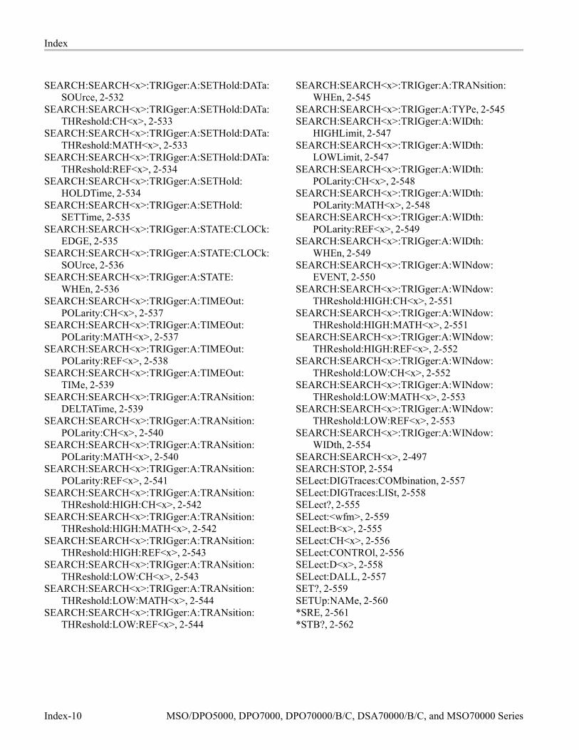
Index
SEARCH:SEARCH<x>:TRIGger:A:SETHold:DATa:SOUrce, 2-532
SEARCH:SEARCH<x>:TRIGger:A:SETHold:DATa:THReshold:CH<x>, 2-533
SEARCH:SEARCH<x>:TRIGger:A:SETHold:DATa:THReshold:MATH<x>, 2-533
SEARCH:SEARCH<x>:TRIGger:A:SETHold:DATa:THReshold:REF<x>, 2-534
SEARCH:SEARCH<x>:TRIGger:A:SETHold:HOLDTime, 2-534
SEARCH:SEARCH<x>:TRIGger:A:SETHold:SETTime, 2-535
SEARCH:SEARCH<x>:TRIGger:A:STATE:CLOCk:EDGE, 2-535
SEARCH:SEARCH<x>:TRIGger:A:STATE:CLOCk:SOUrce, 2-536
SEARCH:SEARCH<x>:TRIGger:A:STATE:WHEn, 2-536
SEARCH:SEARCH<x>:TRIGger:A:TIMEOut:POLarity:CH<x>, 2-537
SEARCH:SEARCH<x>:TRIGger:A:TIMEOut:POLarity:MATH<x>, 2-537
SEARCH:SEARCH<x>:TRIGger:A:TIMEOut:POLarity:REF<x>, 2-538
SEARCH:SEARCH<x>:TRIGger:A:TIMEOut:TIMe, 2-539
SEARCH:SEARCH<x>:TRIGger:A:TRANsition:DELTATime, 2-539
SEARCH:SEARCH<x>:TRIGger:A:TRANsition:POLarity:CH<x>, 2-540
SEARCH:SEARCH<x>:TRIGger:A:TRANsition:POLarity:MATH<x>, 2-540
SEARCH:SEARCH<x>:TRIGger:A:TRANsition:POLarity:REF<x>, 2-541
SEARCH:SEARCH<x>:TRIGger:A:TRANsition:THReshold:HIGH:CH<x>, 2-542
SEARCH:SEARCH<x>:TRIGger:A:TRANsition:THReshold:HIGH:MATH<x>, 2-542
SEARCH:SEARCH<x>:TRIGger:A:TRANsition:THReshold:HIGH:REF<x>, 2-543
SEARCH:SEARCH<x>:TRIGger:A:TRANsition:THReshold:LOW:CH<x>, 2-543
SEARCH:SEARCH<x>:TRIGger:A:TRANsition:THReshold:LOW:MATH<x>, 2-544
SEARCH:SEARCH<x>:TRIGger:A:TRANsition:THReshold:LOW:REF<x>, 2-544
SEARCH:SEARCH<x>:TRIGger:A:TRANsition:WHEn, 2-545
SEARCH:SEARCH<x>:TRIGger:A:TYPe, 2-545SEARCH:SEARCH<x>:TRIGger:A:WIDth:
HIGHLimit, 2-547SEARCH:SEARCH<x>:TRIGger:A:WIDth:
LOWLimit, 2-547SEARCH:SEARCH<x>:TRIGger:A:WIDth:
POLarity:CH<x>, 2-548SEARCH:SEARCH<x>:TRIGger:A:WIDth:
POLarity:MATH<x>, 2-548SEARCH:SEARCH<x>:TRIGger:A:WIDth:
POLarity:REF<x>, 2-549SEARCH:SEARCH<x>:TRIGger:A:WIDth:
WHEn, 2-549SEARCH:SEARCH<x>:TRIGger:A:WINdow:
EVENT, 2-550SEARCH:SEARCH<x>:TRIGger:A:WINdow:
THReshold:HIGH:CH<x>, 2-551SEARCH:SEARCH<x>:TRIGger:A:WINdow:
THReshold:HIGH:MATH<x>, 2-551SEARCH:SEARCH<x>:TRIGger:A:WINdow:
THReshold:HIGH:REF<x>, 2-552SEARCH:SEARCH<x>:TRIGger:A:WINdow:
THReshold:LOW:CH<x>, 2-552SEARCH:SEARCH<x>:TRIGger:A:WINdow:
THReshold:LOW:MATH<x>, 2-553SEARCH:SEARCH<x>:TRIGger:A:WINdow:
THReshold:LOW:REF<x>, 2-553SEARCH:SEARCH<x>:TRIGger:A:WINdow:
WIDth, 2-554SEARCH:SEARCH<x>, 2-497SEARCH:STOP, 2-554SELect:DIGTraces:COMbination, 2-557SELect:DIGTraces:LISt, 2-558SELect?, 2-555SELect:<wfm>, 2-559SELect:B<x>, 2-555SELect:CH<x>, 2-556SELect:CONTROl, 2-556SELect:D<x>, 2-558SELect:DALL, 2-557SET?, 2-559SETUp:NAMe, 2-560*SRE, 2-561*STB?, 2-562
Index-10 MSO/DPO5000, DPO7000, DPO70000/B/C, DSA70000/B/C, and MSO70000 Series

Index
TTEKLink:CONNection?, 2-562TEKLink:REFClk, 2-563TEKSecure, 2-563TEST, 2-564TEST:RESults:VERBose?, 2-565TEST:RESults?, 2-564TEST:STOP, 2-565TIME, 2-566*TRG, 2-566TRIGger, 2-566TRIGger:A|B:EDGE:COUPling, 2-568TRIGger:A|B:EDGE:COUPling:CH<x>, 2-569TRIGger:A|B:EDGE:SLOpe, 2-570TRIGger:A|B:EDGE:SLOpe:AUX, 2-570TRIGger:A|B:EDGE:SLOpe:CH<x>, 2-571TRIGger:A|B:EDGE:SOUrce, 2-572TRIGger:A|B:LEVel:CH<x>, 2-573TRIGger:A|B:LOGIc:CLAss, 2-574TRIGger:A|B:LOGIc:FUNCtion, 2-575TRIGger:A|B:LOGIc:INPut:ALL, 2-576TRIGger:A|B:LOGIc:INPut:CH<x>, 2-577TRIGger:A|B:LOGIc:INPut:FORMat, 2-578TRIGger:A|B:LOGIc:INPut?, 2-576TRIGger:A|B:LOGIc:PATtern:INPut:CH<x>, 2-579TRIGger:A|B:LOGIc:PATtern:WHEn, 2-580TRIGger:A|B:LOGIc:PATtern:WHEn:
LESSLimit, 2-581TRIGger:A|B:LOGIc:PATtern:WHEn:
MORELimit, 2-581TRIGger:A|B:LOGIc:PATtern?, 2-578TRIGger:A|B:LOGIc:SETHold:CLOCk:
EDGE, 2-583TRIGger:A|B:LOGIc:SETHold:CLOCk:
SOUrce, 2-584TRIGger:A|B:LOGIc:SETHold:CLOCk:
THReshold, 2-585TRIGger:A|B:LOGIc:SETHold:CLOCk:
THReshold:CH<x>, 2-586TRIGger:A|B:LOGIc:SETHold:CLOCk?, 2-583TRIGger:A|B:LOGIc:SETHold:DATa:
SOUrce, 2-587TRIGger:A|B:LOGIc:SETHold:DATa:
THReshold, 2-588TRIGger:A|B:LOGIc:SETHold:DATa:THReshold:
CH<x>, 2-588TRIGger:A|B:LOGIc:SETHold:DATa?, 2-586
TRIGger:A|B:LOGIc:SETHold:HOLDTime, 2-589TRIGger:A|B:LOGIc:SETHold:QUAlify, 2-590TRIGger:A|B:LOGIc:SETHold:SETTime, 2-591TRIGger:A|B:LOGIc:SETHold?, 2-582TRIGger:A|B:LOGIc:STATE:CLOck:
SOUrce, 2-592TRIGger:A|B:LOGIc:STATE:INPut:CH<x>, 2-593TRIGger:A|B:LOGIc:STATE:WHEn, 2-593TRIGger:A|B:LOGIc:STATE?, 2-592TRIGger:A|B:LOGIc:THReshold:CH<x>, 2-595TRIGger:A|B:LOGIc:THReshold?, 2-594TRIGger:A|B:LOGIc?, 2-573TRIGger:A|B:LOWerthreshold:CH<x>, 2-596TRIGger:A|B:PULse:CLAss, 2-597TRIGger:A|B:PULse:GLItch:POLarity, 2-599TRIGger:A|B:PULse:GLItch:POLarity:
CH<x>, 2-600TRIGger:A|B:PULse:GLItch:QUAlify, 2-600TRIGger:A|B:PULse:GLItch:TRIGIF, 2-601TRIGger:A|B:PULse:GLItch:WIDth, 2-602TRIGger:A|B:PULse:GLItch?, 2-598TRIGger:A|B:PULse:RUNT:POLarity, 2-604TRIGger:A|B:PULse:RUNT:POLarity:
CH<x>, 2-604TRIGger:A|B:PULse:RUNT:QUAlify, 2-605TRIGger:A|B:PULse:RUNT:THReshold:
BOTh, 2-607TRIGger:A|B:PULse:RUNT:THReshold:
HIGH, 2-607TRIGger:A|B:PULse:RUNT:THReshold:
LOW, 2-608TRIGger:A|B:PULse:RUNT:THReshold?, 2-606TRIGger:A|B:PULse:RUNT:WHEn, 2-609TRIGger:A|B:PULse:RUNT:WIDth, 2-609TRIGger:A|B:PULse:RUNT?, 2-603TRIGger:A|B:PULse:SOUrce, 2-610TRIGger:A|B:PULse:TIMEOut:POLarity, 2-611TRIGger:A|B:PULse:TIMEOut:POLarity:
CH<x>, 2-612TRIGger:A|B:PULse:TIMEOut:QUAlify, 2-613TRIGger:A|B:PULse:TIMEOut:TIMe, 2-614TRIGger:A|B:PULse:TIMEOut?, 2-611TRIGger:A|B:PULse:TRANsition:
DELTATime, 2-615TRIGger:A|B:PULse:TRANsition:POLarity, 2-616TRIGger:A|B:PULse:TRANsition:POLarity:
CH<x>, 2-617
MSO/DPO5000, DPO7000, DPO70000/B/C, DSA70000/B/C, and MSO70000 Series Index-11

Index
TRIGger:A|B:PULse:TRANsition:QUAlify, 2-618TRIGger:A|B:PULse:TRANsition:THReshold:
BOTh, 2-619TRIGger:A|B:PULse:TRANsition:THReshold:
HIGH, 2-620TRIGger:A|B:PULse:TRANsition:THReshold:
LOW, 2-620TRIGger:A|B:PULse:TRANsition:
THReshold?, 2-619TRIGger:A|B:PULse:TRANsition:WHEn, 2-621TRIGger:A|B:PULse:TRANsition?, 2-615TRIGger:A|B:PULse:WIDth:HIGHLimit, 2-623TRIGger:A|B:PULse:WIDth:LOWLimit, 2-623TRIGger:A|B:PULse:WIDth:POLarity, 2-624TRIGger:A|B:PULse:WIDth:POLarity:
CH<x>, 2-625TRIGger:A|B:PULse:WIDth:QUAlify, 2-625TRIGger:A|B:PULse:WIDth:WHEn, 2-626TRIGger:A|B:PULse:WIDth?, 2-622TRIGger:A|B:PULse:WINdow:EVENT, 2-628TRIGger:A|B:PULse:WINdow:POLarity, 2-629TRIGger:A|B:PULse:WINdow:POLarity:
CH<x>, 2-629TRIGger:A|B:PULse:WINdow:QUAlify, 2-630TRIGger:A|B:PULse:WINdow:THReshold:
BOTh, 2-632TRIGger:A|B:PULse:WINdow:THReshold:
HIGH, 2-632TRIGger:A|B:PULse:WINdow:THReshold:
LOW, 2-633TRIGger:A|B:PULse:WINdow:THReshold?, 2-631TRIGger:A|B:PULse:WINdow:WIDTH, 2-633TRIGger:A|B:PULse:WINdow?, 2-627TRIGger:A|B:PULse?, 2-596TRIGger:A|B:READY?, 2-634TRIGger:A|B:UPPerthreshold:CH<x>, 2-636TRIGger:A:BUS:DATa:FORMat, 2-638TRIGger:A:BUS:DATa:VALue, 2-639TRIGger:A:BUS:I2C:ADDRess:FORMat, 2-639TRIGger:A:BUS:I2C:ADDRess:MODe, 2-640TRIGger:A:BUS:I2C:ADDRess:VALue, 2-640TRIGger:A:BUS:I2C:CONDition, 2-641TRIGger:A:BUS:I2C:DATa:DIRection, 2-642TRIGger:A:BUS:I2C:DATa:SIZe, 2-642TRIGger:A:BUS:I2C:DATa:VALue, 2-643TRIGger:A:BUS:RS232c:CONDition, 2-644TRIGger:A:BUS:RS232c:DATA:SIZe, 2-644
TRIGger:A:BUS:RS232c:DATA:VALue, 2-645TRIGger:A:BUS:SOUrce, 2-645TRIGger:A:BUS:SPI:CONDition, 2-646TRIGger:A:BUS:SPI:DATA:SIZe, 2-647TRIGger:A:BUS:SPI:DATA:VALue, 2-647TRIGger:A:BUS:USB:ADDRess:HIVALue, 2-648TRIGger:A:BUS:USB:ADDRess:VALue, 2-649TRIGger:A:BUS:USB:CONDition, 2-649TRIGger:A:BUS:USB:DATa:HIVALue, 2-650TRIGger:A:BUS:USB:DATa:OFFSet, 2-651TRIGger:A:BUS:USB:DATa:SIZe, 2-651TRIGger:A:BUS:USB:DATa:TYPe, 2-652TRIGger:A:BUS:USB:DATa:VALue, 2-653TRIGger:A:BUS:USB:ENDPoint:HIVALue, 2-653TRIGger:A:BUS:USB:ENDPoint:VALue, 2-654TRIGger:A:BUS:USB:ERRTYPE, 2-655TRIGger:A:BUS:USB:HANDShaketype, 2-655TRIGger:A:BUS:USB:QUALIFIER, 2-656TRIGger:A:BUS:USB:SPECIALType, 2-657TRIGger:A:BUS:USB:SPLIT:ET:VALUE, 2-658TRIGger:A:BUS:USB:SPLIT:HUB:VALUE, 2-659TRIGger:A:BUS:USB:SPLIT:PORT:VALUE, 2-659TRIGger:A:BUS:USB:SPLIT:SC:VALUE, 2-660TRIGger:A:BUS:USB:SPLIT:SE:VALUE, 2-660TRIGger:A:BUS:USB:TOKENType, 2-661TRIGger:A:CAN:CONDition, 2-662TRIGger:A:CAN:DATa:DIRection, 2-663TRIGger:A:CAN:DATa:LEVel, 2-663TRIGger:A:CAN:DATa:SOUrce, 2-664TRIGger:A:CAN:DATa:VALue, 2-664TRIGger:A:CAN:FORMat, 2-665TRIGger:A:CAN:FRAMEtype, 2-665TRIGger:A:CAN:IDENTifier:MODe, 2-666TRIGger:A:CAN:IDENTifier:VALue, 2-667TRIGger:A:COMMunication:
AMI|HDB3|B3ZS|B6ZS|B8ZS:PULSEForm, 2-668
TRIGger:A:COMMunication:AMI|HDB3|B3ZS|B6ZS|B8ZS:THReshold:HIGH, 2-669
TRIGger:A:COMMunication:AMI|HDB3|B3ZS|B6ZS|B8ZS:THReshold:LOW, 2-669
TRIGger:A:COMMunication:BITRate, 2-670TRIGger:A:COMMunication:CLOCk:
POLarity, 2-671
Index-12 MSO/DPO5000, DPO7000, DPO70000/B/C, DSA70000/B/C, and MSO70000 Series

Index
TRIGger:A:COMMunication:CMI:PULSEForm, 2-671
TRIGger:A:COMMunication:CODe, 2-672TRIGger:A:COMMunication:SOUrce, 2-673TRIGger:A:COMMunication:SOUrce:TYPe, 2-673TRIGger:A:COMMunication:STANdard, 2-674TRIGger:A:HOLDoff:ACTUal?, 2-677TRIGger:A:HOLDoff:BY, 2-678TRIGger:A:HOLDoff:TIMe, 2-678TRIGger:A:I2C:ADDRess:MODe, 2-679TRIGger:A:I2C:ADDRess:RWINClude, 2-679TRIGger:A:I2C:ADDRess:TYPe, 2-680TRIGger:A:I2C:ADDRess:VALue, 2-680TRIGger:A:I2C:CLOCk:LEVel, 2-681TRIGger:A:I2C:CLOCk:SOUrce, 2-681TRIGger:A:I2C:CONDition, 2-682TRIGger:A:I2C:DATa:DIRection, 2-683TRIGger:A:I2C:DATa:LEVel, 2-683TRIGger:A:I2C:DATa:SOUrce, 2-684TRIGger:A:I2C:DATa:STARt, 2-684TRIGger:A:I2C:DATa:VALue, 2-684TRIGger:A:I2C:FORMat, 2-685TRIGger:A:RS232:BAUd, 2-686TRIGger:A:RS232:DATa:LEVel, 2-686TRIGger:A:RS232:DATa:SOUrce, 2-687TRIGger:A:RS232:DATa:VALue, 2-687TRIGger:A:RS232:FORMat, 2-688TRIGger:A:RS232:PARity, 2-688TRIGger:A:SERIAL:BITRate, 2-689TRIGger:A:SERIAL:CLOCk:LEVel, 2-689TRIGger:A:SERIAL:CLOCk:POLarity, 2-690TRIGger:A:SERIAL:CLOCk:SOUrce, 2-691TRIGger:A:SERIAL:CODe, 2-691TRIGger:A:SERIAL:DATa:FORMat, 2-692TRIGger:A:SERIAL:DATa:PATtern, 2-692TRIGger:A:SERIAL:DATa:PATtern:NRZ, 2-693TRIGger:A:SERIAL:DATa:PATtern:S8B10B, 2-694TRIGger:A:SERIAL:ERRORdetector:
ALIGNCHARacter:RDMINUS, 2-696TRIGger:A:SERIAL:ERRORdetector:
ALIGNCHARacter:RDPLUS, 2-696TRIGger:A:SERIAL:ERRORdetector:
ALIGNCHARacter?, 2-695TRIGger:A:SERIAL:ERRORdetector:
ALIGNPRIMitive:RDMINUS:ENABLE, 2-698TRIGger:A:SERIAL:ERRORdetector:
ALIGNPRIMitive:RDMINUS:PATtern, 2-698
TRIGger:A:SERIAL:ERRORdetector:ALIGNPRIMitive:RDMINUS?, 2-697
TRIGger:A:SERIAL:ERRORdetector:ALIGNPRIMitive:RDPLUS:ENABLE, 2-699
TRIGger:A:SERIAL:ERRORdetector:ALIGNPRIMitive:RDPLUS:PATtern, 2-700
TRIGger:A:SERIAL:ERRORdetector:ALIGNPRIMitive:RDPLUS?, 2-699
TRIGger:A:SERIAL:ERRORdetector:ALIGNPRIMitive:S8BPATtern, 2-700
TRIGger:A:SERIAL:ERRORdetector:ALIGNPRIMitive?, 2-697
TRIGger:A:SERIAL:ERRORdetector:BIT:LENGTH, 2-701
TRIGger:A:SERIAL:ERRORdetector:BIT:SYNCPATtern, 2-701
TRIGger:A:SERIAL:ERRORdetector:BIT:TEST, 2-702
TRIGger:A:SERIAL:ERRORdetector:BIT:TEST:COUNT?, 2-702
TRIGger:A:SERIAL:ERRORdetector:BIT:TEST:DURATION?, 2-703
TRIGger:A:SERIAL:ERRORdetector:BIT:TEST:MAXALIGNS?, 2-703
TRIGger:A:SERIAL:ERRORdetector:BIT:TEST:RATE?, 2-703
TRIGger:A:SERIAL:ERRORdetector:BIT:TEST:RESULTS?, 2-704
TRIGger:A:SERIAL:ERRORdetector:BIT:TEST:SECONDS?, 2-704
TRIGger:A:SERIAL:ERRORdetector:BIT:TEST:STATUS:LOCK?, 2-705
TRIGger:A:SERIAL:ERRORdetector:BIT:TEST:STATUS:MAX_AP?, 2-705
TRIGger:A:SERIAL:ERRORdetector:BIT:TEST:STATUS:SIGNAL?, 2-706
TRIGger:A:SERIAL:ERRORdetector:BIT:TEST:STATUS:START?, 2-706
TRIGger:A:SERIAL:ERRORdetector:BIT:TEST:STATUS:SYNC?, 2-707
TRIGger:A:SERIAL:ERRORdetector:BIT:TEST:STATUS?, 2-704
TRIGger:A:SERIAL:ERRORdetector:BIT:TEST:TIME:DAYS?, 2-707
TRIGger:A:SERIAL:ERRORdetector:BIT:TEST:TIME:HOURS?, 2-708
MSO/DPO5000, DPO7000, DPO70000/B/C, DSA70000/B/C, and MSO70000 Series Index-13

Index
TRIGger:A:SERIAL:ERRORdetector:BIT:TEST:TIME:MINUTES?, 2-708
TRIGger:A:SERIAL:ERRORdetector:BIT:TEST:TIME:SECONDS?, 2-708
TRIGger:A:SERIAL:ERRORdetector:BIT:TEST:TIME?, 2-707
TRIGger:A:SERIAL:ERRORdetector:CHARACTER:TEST, 2-709
TRIGger:A:SERIAL:ERRORdetector:CHARACTER:TEST:COUNT?, 2-710
TRIGger:A:SERIAL:ERRORdetector:CHARACTER:TEST:DISPCOUNT?, 2-710
TRIGger:A:SERIAL:ERRORdetector:CHARACTER:TEST:DISPRATE?, 2-710
TRIGger:A:SERIAL:ERRORdetector:CHARACTER:TEST:DURATION?, 2-711
TRIGger:A:SERIAL:ERRORdetector:CHARACTER:TEST:MAXALIGNS?, 2-711
TRIGger:A:SERIAL:ERRORdetector:CHARACTER:TEST:RATE?, 2-711
TRIGger:A:SERIAL:ERRORdetector:CHARACTER:TEST:RESULTS?, 2-712
TRIGger:A:SERIAL:ERRORdetector:CHARACTER:TEST:SECONDS?, 2-713
TRIGger:A:SERIAL:ERRORdetector:CHARACTER:TEST:STATUS:LOCK?, 2-714
TRIGger:A:SERIAL:ERRORdetector:CHARACTER:TEST:STATUS:MAX_AP?, 2-713
TRIGger:A:SERIAL:ERRORdetector:CHARACTER:TEST:STATUS:SIGNAL?, 2-714
TRIGger:A:SERIAL:ERRORdetector:CHARACTER:TEST:STATUS:START?, 2-715
TRIGger:A:SERIAL:ERRORdetector:CHARACTER:TEST:STATUS?, 2-713
TRIGger:A:SERIAL:ERRORdetector:CHARACTER:TEST:TIME:DAYS?, 2-716
TRIGger:A:SERIAL:ERRORdetector:CHARACTER:TEST:TIME:HOURS?, 2-716
TRIGger:A:SERIAL:ERRORdetector:CHARACTER:TEST:TIME:MINUTES?, 2-716
TRIGger:A:SERIAL:ERRORdetector:CHARACTER:TEST:TIME:SECONDS?, 2-717
TRIGger:A:SERIAL:ERRORdetector:CHARACTER:TEST:TIME?, 2-715
TRIGger:A:SERIAL:ERRORdetector:CHARACTER?, 2-709
TRIGger:A:SERIAL:ERRORdetector:DURATION:COUNT, 2-717
TRIGger:A:SERIAL:ERRORdetector:DURATION:SECONDS, 2-718
TRIGger:A:SERIAL:ERRORdetector:DURATION:TIME, 2-718
TRIGger:A:SERIAL:ERRORdetector:DURATION:TIME:DAYS, 2-719
TRIGger:A:SERIAL:ERRORdetector:DURATION:TIME:HOURS, 2-720
TRIGger:A:SERIAL:ERRORdetector:DURATION:TIME:MINUTES, 2-720
TRIGger:A:SERIAL:ERRORdetector:DURATION:TIME:SECONDS, 2-721
TRIGger:A:SERIAL:ERRORdetector:ENAble, 2-721TRIGger:A:SERIAL:ERRORdetector:
ERRORLIMIT, 2-722TRIGger:A:SERIAL:ERRORdetector:FILE:
RECALL, 2-722TRIGger:A:SERIAL:ERRORdetector:FILE:
SAVE, 2-723TRIGger:A:SERIAL:ERRORdetector:FRAME:
EOF, 2-724TRIGger:A:SERIAL:ERRORdetector:FRAME:
INITIALCRCVALue, 2-725TRIGger:A:SERIAL:ERRORdetector:FRAME:
SOF, 2-725TRIGger:A:SERIAL:ERRORdetector:FRAME:
TEST, 2-726TRIGger:A:SERIAL:ERRORdetector:FRAME:TEST:
BADCHARS?, 2-727TRIGger:A:SERIAL:ERRORdetector:FRAME:TEST:
COUNT?, 2-727TRIGger:A:SERIAL:ERRORdetector:FRAME:TEST:
DISPARITY?, 2-728TRIGger:A:SERIAL:ERRORdetector:FRAME:TEST:
DURATION?, 2-728TRIGger:A:SERIAL:ERRORdetector:FRAME:TEST:
MAXALIGNS?, 2-728TRIGger:A:SERIAL:ERRORdetector:FRAME:TEST:
RATE?, 2-729TRIGger:A:SERIAL:ERRORdetector:FRAME:TEST:
RESULTS?, 2-729TRIGger:A:SERIAL:ERRORdetector:FRAME:TEST:
SECONDS?, 2-730TRIGger:A:SERIAL:ERRORdetector:FRAME:TEST:
STATUS:LOCK?, 2-731
Index-14 MSO/DPO5000, DPO7000, DPO70000/B/C, DSA70000/B/C, and MSO70000 Series

Index
TRIGger:A:SERIAL:ERRORdetector:FRAME:TEST:STATUS:MAX_AP?, 2-731
TRIGger:A:SERIAL:ERRORdetector:FRAME:TEST:STATUS:SIGNAL?, 2-732
TRIGger:A:SERIAL:ERRORdetector:FRAME:TEST:STATUS:START?, 2-732
TRIGger:A:SERIAL:ERRORdetector:FRAME:TEST:STATUS?, 2-730
TRIGger:A:SERIAL:ERRORdetector:FRAME:TEST:TIME:DAYS?, 2-733
TRIGger:A:SERIAL:ERRORdetector:FRAME:TEST:TIME:HOURS?, 2-734
TRIGger:A:SERIAL:ERRORdetector:FRAME:TEST:TIME:MINUTES?, 2-734
TRIGger:A:SERIAL:ERRORdetector:FRAME:TEST:TIME:SECONDS?, 2-735
TRIGger:A:SERIAL:ERRORdetector:FRAME:TEST:TIME?, 2-733
TRIGger:A:SERIAL:ERRORdetector:FRAME?, 2-724
TRIGger:A:SERIAL:ERRORdetector:MAXALIGNS, 2-735
TRIGger:A:SERIAL:ERRORdetector:PATTERNNAME, 2-736
TRIGger:A:SERIAL:ERRORdetector:SCRAMBLED, 2-736
TRIGger:A:SERIAL:ERRORdetector:SKIPSETPRIMitive:RDMINUS:ENABLE, 2-737
TRIGger:A:SERIAL:ERRORdetector:SKIPSETPRIMitive:RDMINUS:PATtern, 2-738
TRIGger:A:SERIAL:ERRORdetector:SKIPSETPRIMitive:RDMINUS?, 2-737
TRIGger:A:SERIAL:ERRORdetector:SKIPSETPRIMitive:RDPLUS:ENABLE, 2-739
TRIGger:A:SERIAL:ERRORdetector:SKIPSETPRIMitive:RDPLUS:PATtern, 2-740
TRIGger:A:SERIAL:ERRORdetector:SKIPSETPRIMitive:RDPLUS?, 2-739
TRIGger:A:SERIAL:ERRORdetector:SKIPSETPRIMitive:S8BPATtern, 2-741
TRIGger:A:SERIAL:ERRORdetector:SSC, 2-741TRIGger:A:SERIAL:ERRORdetector:
STANDARD, 2-742TRIGger:A:SERIAL:ERRORdetector:
STOPWHEN, 2-742TRIGger:A:SERIAL:ERRORdetector:SYMBOL:
TEST, 2-744
TRIGger:A:SERIAL:ERRORdetector:SYMBOL:TEST:BADCHARS?, 2-744
TRIGger:A:SERIAL:ERRORdetector:SYMBOL:TEST:BITCOUNT?, 2-745
TRIGger:A:SERIAL:ERRORdetector:SYMBOL:TEST:BITDURATION?, 2-745
TRIGger:A:SERIAL:ERRORdetector:SYMBOL:TEST:BITRATE?, 2-746
TRIGger:A:SERIAL:ERRORdetector:SYMBOL:TEST:COUNT?, 2-746
TRIGger:A:SERIAL:ERRORdetector:SYMBOL:TEST:DISPARITY?, 2-746
TRIGger:A:SERIAL:ERRORdetector:SYMBOL:TEST:DURATION?, 2-747
TRIGger:A:SERIAL:ERRORdetector:SYMBOL:TEST:MAXALIGNS?, 2-747
TRIGger:A:SERIAL:ERRORdetector:SYMBOL:TEST:RATE?, 2-748
TRIGger:A:SERIAL:ERRORdetector:SYMBOL:TEST:RESULTS?, 2-748
TRIGger:A:SERIAL:ERRORdetector:SYMBOL:TEST:SECONDS?, 2-749
TRIGger:A:SERIAL:ERRORdetector:SYMBOL:TEST:STATUS:LOCK?, 2-751
TRIGger:A:SERIAL:ERRORdetector:SYMBOL:TEST:STATUS:MAX_AP?, 2-750
TRIGger:A:SERIAL:ERRORdetector:SYMBOL:TEST:STATUS:SIGNAL?, 2-751
TRIGger:A:SERIAL:ERRORdetector:SYMBOL:TEST:STATUS:START?, 2-752
TRIGger:A:SERIAL:ERRORdetector:SYMBOL:TEST:STATUS?, 2-750
TRIGger:A:SERIAL:ERRORdetector:SYMBOL:TEST:TIME:DAYS?, 2-753
TRIGger:A:SERIAL:ERRORdetector:SYMBOL:TEST:TIME:HOURS?, 2-753
TRIGger:A:SERIAL:ERRORdetector:SYMBOL:TEST:TIME:MINUTES?, 2-754
TRIGger:A:SERIAL:ERRORdetector:SYMBOL:TEST:TIME:SECONDS?, 2-754
TRIGger:A:SERIAL:ERRORdetector:SYMBOL:TEST:TIME?, 2-752
TRIGger:A:SERIAL:ERRORdetector:SYMBOL?, 2-743
TRIGger:A:SERIAL:ERRORdetector:TYPE, 2-755TRIGger:A:SERIAL:LOCKLen, 2-755TRIGger:A:SERIAL:LOCKOffset, 2-756
MSO/DPO5000, DPO7000, DPO70000/B/C, DSA70000/B/C, and MSO70000 Series Index-15
Index
TRIGger:A:SERIAL:SOUrce, 2-756TRIGger:A:SERIAL:STANdard, 2-757TRIGger:A:SERIAL:TRIGgeron, 2-758TRIGger:A:SPI:CONDition, 2-759TRIGger:A:SPI:DATa:MISO:ACTIVE, 2-759TRIGger:A:SPI:DATa:MISO:LEVel, 2-760TRIGger:A:SPI:DATa:MISO:SOUrce, 2-761TRIGger:A:SPI:DATa:MISO:VALue, 2-761TRIGger:A:SPI:DATa:MOSI:ACTIVE, 2-762TRIGger:A:SPI:DATa:MOSI:LEVel, 2-762TRIGger:A:SPI:DATa:MOSI:SOUrce, 2-763TRIGger:A:SPI:DATa:MOSI:VALue, 2-763TRIGger:A:SPI:DATa:STARt, 2-764TRIGger:A:SPI:FORMat, 2-765TRIGger:A:SPI:SCLK:ACTIVE, 2-765TRIGger:A:SPI:SCLK:LEVel, 2-766TRIGger:A:SPI:SCLK:SOUrce, 2-766TRIGger:A:SPI:SS:ACTIVE, 2-767TRIGger:A:SPI:SS:LEVel, 2-767TRIGger:A:SPI:SS:SOUrce, 2-768TRIGger:A:VIDeo:CUSTom:FORMat, 2-769TRIGger:A:VIDeo:CUSTom:LINEPeriod, 2-770TRIGger:A:VIDeo:CUSTom:SYNCInterval, 2-770TRIGger:A:VIDeo:CUSTom?, 2-769TRIGger:A:VIDeo:FIELD, 2-771TRIGger:A:VIDeo:HOLdoff:FIELD, 2-772TRIGger:A:VIDeo:LINE, 2-772TRIGger:A:VIDeo:POLarity, 2-774TRIGger:A:VIDeo:SCAN, 2-774TRIGger:A:VIDeo:SOUrce, 2-775TRIGger:A:VIDeo:STANdard, 2-776TRIGger:B:EVENTS:COUNt, 2-779TRIGger:B:RESET:SOUrce, 2-780TRIGger:B:RESET:STATE, 2-781TRIGger:B:RESET:THReshold, 2-781TRIGger:B:RESET:TIMEOut, 2-782TRIGger:B:RESET:TRANsition, 2-782TRIGger:B:RESET:TYPe, 2-783TRIGger:B:SCAN:ADVANCEafter, 2-784TRIGger:B:SCAN:ENAble, 2-784TRIGger:B:SCAN:ENDevent, 2-785TRIGger:B:SCAN:STARTevent, 2-786TRIGger:LVLSrcpreference, 2-788TRIGger:MULTiscope:ALIGN, 2-789TRIGger:MULTiscope:ALIGN:COMPleted?, 2-790TRIGger:MULTiscope:ALIGN:DESKEW?, 2-790TRIGger:MULTiscope:ALIGN:MRTTime, 2-790
TRIGger:MULTiscope:ALIGN:SETSTATE, 2-791TRIGger:MULTiscope:ALIGN:VALue?, 2-791TRIGger:MULTiscope:DELay?, 2-792TRIGger:MULTiscope:LOGic, 2-792TRIGger:MULTiscope:ROLe, 2-793TRIGger:QUALification:BUS:FORMat, 2-793TRIGger:QUALification:BUS:SOUrce, 2-794TRIGger:QUALification:BUS:VALue, 2-794TRIGger:A|B:EDGE?, 2-568TRIGger:A|B:LEVel, 2-572TRIGger:A|B:TYPe, 2-635TRIGger:A, 2-637TRIGger:A:CAN:PROBE, 2-667TRIGger:A:CAN:SPEed, 2-668TRIGger:A:HOLDoff?, 2-677TRIGger:A:MODe, 2-685TRIGger:A:VIDeo?, 2-768TRIGger:AUXLevel, 2-777TRIGger:B, 2-778TRIGger:B:BY, 2-778TRIGger:B:EVENTS?, 2-779TRIGger:B:SCAN:MODE, 2-785TRIGger:B:STATE, 2-787TRIGger:B:TIMe, 2-787TRIGger:ENHanced, 2-788TRIGger:MULTiscope, 2-789TRIGger:SENSITivity, 2-795TRIGger:STATE?, 2-796*TST?, 2-796
UUNLock, 2-797USBTMC:PRODUCTID:DECimal?, 2-797USBTMC:PRODUCTID:HEXadecimal?, 2-798USBTMC:SERIALnumber?, 2-798USBTMC:VENDORID:DECimal?, 2-798USBTMC:VENDORID:HEXadecimal?, 2-799
VVERBose, 2-799
W*WAI, 2-800WAVFrm?, 2-800WAVFRMStream?, 2-801WFMInpre?, 2-802
Index-16 MSO/DPO5000, DPO7000, DPO70000/B/C, DSA70000/B/C, and MSO70000 Series

Index
WFMInpre:BIT_Nr, 2-803WFMInpre:BN_Fmt, 2-803WFMInpre:BYT_Nr, 2-804WFMInpre:BYT_Or, 2-804WFMInpre:ENCdg, 2-805WFMInpre:NR_FR, 2-806WFMInpre:NR_Pt, 2-806WFMInpre:PT_Fmt, 2-807WFMInpre:PT_Off, 2-807WFMInpre:WFId, 2-808WFMInpre:XINcr, 2-808WFMInpre:XUNit, 2-809WFMInpre:XZEro, 2-809WFMInpre:YMUlt, 2-810WFMInpre:YOFf, 2-811WFMInpre:YUNit, 2-811WFMInpre:YZEro, 2-812WFMOutpre?, 2-812WFMOutpre:BIT_Nr, 2-813WFMOutpre:BN_Fmt, 2-813WFMOutpre:BYT_Nr, 2-814WFMOutpre:BYT_Or, 2-815WFMOutpre:ENCdg, 2-815WFMOutpre:NR_FR?, 2-816WFMOutpre:NR_Pt?, 2-816WFMOutpre:PT_Fmt?, 2-817WFMOutpre:PT_Off?, 2-817WFMOutpre:PT_ORder?, 2-818WFMOutpre:WFId?, 2-818WFMOutpre:XINcr?, 2-819WFMOutpre:XUNit?, 2-820WFMOutpre:XZEro?, 2-820WFMOutpre:YMUlt?, 2-821WFMOutpre:YOFf?, 2-821WFMOutpre:YUNit?, 2-822
WFMOutpre:YZEro?, 2-822
ZZOOm, 2-823ZOOm:HORizontal:POSition, 2-824ZOOm:HORizontal:SCAle, 2-824ZOOm:MATH<x>:HORizontal:POSition, 2-825ZOOm:MATH<x>:HORizontal:SCAle, 2-825ZOOm:MATH<x>:VERTical:POSition, 2-826ZOOm:MATH<x>:VERTical:SCAle, 2-826ZOOm:REF<x>:HORizontal:POSition, 2-827ZOOm:REF<x>:HORizontal:SCAle, 2-828ZOOm:REF<x>:VERTical:POSition, 2-828ZOOm:REF<x>:VERTical:SCAle, 2-829ZOOm:SCROLL:DIREction, 2-829ZOOm:VERTical:POSition, 2-831ZOOm:ZOOM<x>:<wfm>:DISplay, 2-834ZOOm:ZOOM<x>:<wfm>:HORizontal:
POSition, 2-835ZOOm:ZOOM<x>:<wfm>:HORizontal:SCAle, 2-836ZOOm:ZOOM<x>:<wfm>:VERTical:
POSition, 2-836ZOOm:ZOOM<x>:<wfm>:VERTical:SCAle, 2-837ZOOm:ZOOM<x>:DCHAN:DISplay, 2-833ZOOm:ZOOM<x>:SCROLLLock, 2-833ZOOm:ZOOM<x>:STATE, 2-834ZOOm:GRAticule:SIZE, 2-823ZOOm:MODe, 2-827ZOOm:SCROLL:LOCk, 2-830ZOOm:SCROLL:SPEED, 2-830ZOOm:STATE, 2-831ZOOm:VERTical:SCAle, 2-832ZOOm:ZOOM<x>, 2-832
MSO/DPO5000, DPO7000, DPO70000/B/C, DSA70000/B/C, and MSO70000 Series Index-17