yamaha dt100a, b, c - dt125a, b, c - dt175a, b, c (1974-1976)
Upload
khangminh22Category
view
0download
0
CA
M L
AB
CNC System (Color English Version) X.Z Axes Feeding Motor: Step Motor and Driver Spindle Motor: Two-speed Motor 4 / 6 ( 3 phase 2.2/2.8kw)Manual three jaw chuck 1pc Gang Tool Carriage& Gang Tool Holder(3pcs)Hand Wheel Thread FunctionCoolant Pump Working Lamp Enclosed Shield for Ball Screw RS232 Communication Cable& Communication SoftwareCD( To connect CNC Controller with PC) Tricolor Lamp for Machining State Indication
CNC PRODUCTION LATHE
Item Specifications Unit Parameter
Capacity
Spindle
X.ZAxes
ToolPost
Other
Max. Swing Dia. over Bed
Max. Swing Dia. over Slide
Max. Through Dia. of Bar
Max. Machining Length
Thread Metric
Range Inch
mm
mm
mm
mm
mm
TPI
Ö
Ö150
Ö28
200
0.25-100
100-4
320
SL-10001
CNC Production Lathe
Speed Range Frequency Conversion
Spindle Bore
Taper of Spindle
Tube Bore
Size of Chuck
Power of Spindle Motor
Feeding Speed of X-axes
Feeding Speed of Z-axes
Power of X-axes Motor
Power of Z-axes Motor
Torque of X-axes Motor
Torque of Z-axes Motor
Min. Setting Unit of X-axes
Min. Setting Unit of Z-axes
Type of Tool Post
No. of Tools
Size of Tools Shank
Power of Lubrication Oil Pump Motor
Power of Coolant Pump Motor
Overall Dimension
Net Weight
CNC System
r/min
mm
0
mm
mm
kw
m/min
m/min
kw
kw
Nm
Nm
mm
mm
-----
mm
W
W
mm
kg
-----
50-3000
Ö380Ö45
Ö38
Ö120
Two Speed 4/6 (3 phase 2.2 kw)
3
6
1
1
12Nm (Step)
12Nm (Step)
0.001
0.001
Gang Tool Carriage
1-8 Station (Gang Tool Holder)
15 x 15 or 20 x 20
4
40
1270(L)*950(W)*1450(H)
800
GSK928TC/980TB
01 GLOBAL ENGINEERING MACHINERIES SERVICE

53
CA
M L
AB
CNC PRODUCTION MILL with inbuilt CNC system consist of 3 axis stepper motors, ball screws, variable speed spindle motor, limit/home switch provided with inverter Standard accessories:
1. Machine with casting base2. BT 30 arbor 1 no3. Work piece clamping kit 1 set4. Sample work piece5. End mill 4 nos6. Drill chuck 1 no7. chuck sleeve 1 no8. multi colour display in controller 9. Coolant tank with pumps and fittings
CNC PRODUCTION MILL
SPECIFICATION
Size of worktable (length x width)
T slot width x qty x space
max loading weight on worktable
X-Axis Travel
Y-Axis Travel
Z-Axis Travel
Distance between spindle nose and table
Distance between spindle center and column
Spindle taper
Max. spindle speed
Spindle motor power
Feeding Motor power: X Axis
Y Axis
Z Axis
Rapid feeding speed: X, Y, Z axis
Feeding speed
Min. set unit
Max. size of tool
Loosing and clamping way for tool
800mm x 240 mm
16mm x 3 x 60mm
60kg
430mm
290mm
400mm
50-450mm
297mm
BT-30
4000r/min
1.5Kw
1Kw
1Kw
1Kw
6m/min
0-2000mm/min
0.01mm
60x175mm
Clamp by disc spring
Loose manually
Clamp by disc spring
Loose pneumatically
CNC Production Mill
SL-10002
02GLOBAL ENGINEERING MACHINERIES SERVICE

01
HE
AT
TR
AN
SF
ER
L
AB
01
EMMISSIVITY MEASUREMENT APPARATUS
Platesa. Diameter :150b. Material :Brassc. Heater :250Wd. Specimen :Black Body and Grey
Body
Rectangular Ducta. Material :MS with Power Coating
Front AcrylicMeasuring Instrumentsa. Digital Voltmeter Range :0 to 300 Vb. Digital Ammeter & Range :0 to 10 Ampsc. Digital Temperature Indicator with Selector switch Range :Ambient to 0-400Deg.c
Thermocouplesa. Type :Cr. AIb. Length :1 Mt.05. Voltage Varaic :2 Nos, 1.5 kw
THERMAL CONDUCTIVITY INSULATING POWDER Outer Sphere (top And Bottom)a. Diameter : 200mm (Approx.)b. Material : Copper
Inner Sphere (top And Bottom)a. Diameter : 100b. Materail : Copper
Measuring Instruments:a. Digital voltmeter, Range :0 to 300Vb. Digital Ammeter & Range:0 to 5 Ampsc. Digital Temperature Indicator with selector switch:
0Range :Ambient to 0-400 c
Thermocouples:a. Type : Cr. AIb. Length : 1 Mtr.05. Electronic Dimmer : 1 No., 1.5 kw
SL-5001
Heat Transfer Through Lagged Pipe
HEAT TRANSFER THROUGH LAGGED PIPEPipesa. Diameter :50/100/150mm
Inner/Outer (Approx.)b. Length :450mm (Approx.)c. Material :G.I./MSd Quantity :1 No. EachMeasuring Instrumentsa. Digital Voltmeter Range :0 to 300 Vb. Digital Ammeter & Range :0 to 5 Ampsc. Digital Temperature Indicator with Selector switch Range :Ambient to 0-400 Deg.cThermocouplesa. Type :Cr. AIb. Length :1 Mt.04. Voltage Varaic :1 No., 1.5 kw05: Insulation : Glass wool
SL-5002 SL-5003
Thermal Connductivity Insulating PowderEmmissivity Measurement Apparatus
GLOBAL ENGINEERING MACHINERIES SERVICE

01
HE
AT
TR
AN
SF
ER
L
AB
02
Heat Transfer in Natural Convection
HEAT TRANSFER IN FORCED CONVECTION
Blower
a. Capacity :350 watts/1.5 cumts/m
Test Section
a. Diameter :40mm
b. Length :300mm
Cooling Water Chamber
a. Diameter :50 mm Optional
b. Length :300mm (Approx.)
Material :Copper
Measuring Instruments
a. Digital Voltmeter Range :0 to 300 V
b. Digital Ammeter & Range :0 to 10 Amps
c. Digital Temperature Indicator with 0 Selector switch Range :Ambient to 400 c.
Thermocouples
a. Type :Cr. AI
b. Length :1 Mt.
Electronic Dimmer :1 No.
07. Measuring Jar & “u” Tube Manometer 1 No. Each
HEAT TRANSFER FROM PIN-FIN
Blower
a. Capacity :350 watts/1.5 cumts/m
Test Section
a. Diameter :12mm
b. Length :150mm
c. Material :Brass
Duct
a. Size :100x150x500mm
b. Material :MS with Powder Coating
Measuring Instruments
a. Digital Voltmeter Range :0 to 300 V
b. Digital Ammeter & Range :0 to 10 Amps
c. Digital Temperature Indicator with 0 Selector switch Range :Ambient to 400 c.
Thermocouples
a. Type :Cr. AI
b. Length :1 Mt.
Electronic Dimmer :1 No.
“U” Tube Manometer:
a. Material :Glass
HEAT TRANSFER IN NATURAL CONVECTION
S.S. Cylindrical Tube
a. Diameter :40mm
b. Length :400/500mm
Measuring Instruments
a. Digital Voltmeter Range :0 to 300 V
b. Digital Ammeter Range :0 to 10 Ampsc.
c. Temperature Indicator with 0Selector switch Range :Ambient to 400 c
Thermocouples:
a. Type :Cr. AI
b. Length :1 Mtr.
Electronic Dimmer :1 No.
Heat Transfer in Forced Convection Heat Transfer from Pin-Fin
SL-5004
SL-5005 SL-5006
GLOBAL ENGINEERING MACHINERING SERVICE
01
HE
AT
TR
AN
SF
ER
L
AB
03
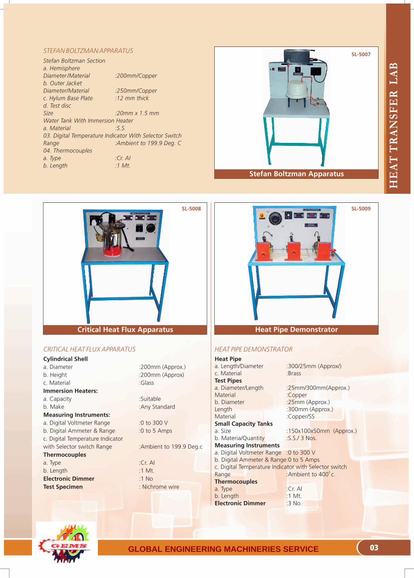
Stefan Boltzman Apparatus
CRITICAL HEAT FLUX APPARATUS
Cylindrical Shella. Diameter :200mm (Approx.)b. Height :200mm (Approx)c. Material :GlassImmersion Heaters:a. Capacity :Suitableb. Make :Any StandardMeasuring Instruments:a. Digital Voltmeter Range :0 to 300 Vb. Digital Ammeter & Range :0 to 5 Ampsc. Digital Temperature Indicator with Selector switch Range :Ambient to 199.9 Deg.c Thermocouplesa. Type :Cr. AIb. Length :1 Mt.Electronic Dimmer :1 NoTest Specimen : Nichrome wire
HEAT PIPE DEMONSTRATOR
Heat Pipea. Length/Diameter :300/25mm (Approx/)c. Material :BrassTest Pipesa. Diameter/Length :25mm/300mm(Approx.) Material :Copperb. Diameter :25mm (Approx.)Length :300mm (Approx.) Material :Copper/SSSmall Capacity Tanksa. Size :150x100x50mm (Approx.)b. Materia/Quantity :S.S./ 3 Nos.Measuring Instrumentsa. Digital Voltmeter Range :0 to 300 Vb. Digital Ammeter & Range:0 to 5 Ampsc. Digital Temperature Indicator with Selector switch
0 Range :Ambient to 400 c.Thermocouplesa. Type :Cr. AIb. Length :1 Mt.Electronic Dimmer :3 No.
STEFAN BOLTZMAN APPARATUS
Stefan Boltzman Section
a. Hemisphere
Diameter /Material :200mm/Copper
b. Outer Jacket
Diameter/Material :250mm/Copper
c. Hylum Base Plate :12 mm thick
d. Test disc
Size :20mm x 1.5 mm
Water Tank With Immersion Heater
a. Material :S.S.
03. Digital Temperature Indicator With Selector Switch
Range :Ambient to 199.9 Deg. C
04. Thermocouples
a. Type :Cr. AI
b. Length :1 Mt.
Critical Heat Flux Apparatus Heat Pipe Demonstrator
SL-5007
SL-5008 SL-5009
GLOBAL ENGINEERING MACHINERIES SERVICE

01
HE
AT
TR
AN
SF
ER
L
AB
04
Heat Transfer Through Composite wall
HEAT TRANSFER THROUGH COMPOSITE WALL
Mild Steel, Asbestos & Brass Slabs/wood
a. Thickness :150 od 6 mm Thick
Measuring Instruments
a. Digital Voltmeter Range :0 to 300 V
b. Digital Ammeter & Range :0 to 10 Amps
c. Digital Temperature Indicator with 0 Selector switch Range :Ambient to 400 c.
Thermocouples
a. Type :Cr. AI
b. Length :1 Mt.
Electronic Dimmer :1 Nos.
PARALLEL/COUNTER FLOW HEAT EXCHANGER
Geyser
a. Capacity :3 KW
Heat Exchanger Outer Pipe Insulated By Asbestos Rope
a. Diameter :25mm
b. Material :G.I
Heat Exchanger Inner Pipe
a. Length :1000mm
b. Diameter :12.5 mm OD
c. Material :Copper
Digital Temperature Indicator With Selector Switch
a. Range :Ambient to 199.9 Deg. c
Thermocouples
a. Type :Cr. AI
b. Length :1 Mt.
Measuring Jar :1 Ltr. Capacity
HEAT PIPE DEMONSTRATOR
Glass Tubea. Diameter/Height :100mm OD/275mm (Approx.)Copper Tube a. Diameter :9mm OD (Approx.)b. Material :150mm (Approx.)Measuring Instrumentsa. Digital Voltmeter Range :0 to 300 Vb. Digital Ammeter & Range:0 to 5 Ampsc. Digital Temperature Indicator with Selector switch Range :Ambient to 199.9 Deg. cThermocouplesa. Type :Cr. AIb. Length :1 Mt.Dimmer/ Electronica. Make :Agro/Equivalentb. Range :0 to 10 AmpsRotametera. Material :Acrylicb. Range :40 to 60 cc/secSump Tank:a. Size :200 x 200x 400mm (Approx.)b. Materail :S.S
Parallel/Counter Flow Heat Exchanger Boiling Heat Transfer Unit
SL-5010
SL-5011 SL-5012
GLOBAL ENGINEERING MACHINERIES SERVICE

HE
AT
TR
AN
SF
ER
L
AB
05
SL-5013 SL-5014
Shell and Tube Heat ExchangerDrop & Film Condensation
DROP & FILM CONDENSATION
Glass Tube
a. Diameter :100mm OD (Approx.)
b. Height :275mm (Approx.)
c. Quantity :2 Nos.
Measuring Instruments
c. Digital Temperature Indicator with
Selector switch Range :Ambient to 199.9 Deg.c
Thermocouples
a. Type :Cr. AI
b. Length :1 Mt.
Rotameter
a. Material :Acrylic
b. Range :40 to 60 cc/sec
Sump Tank:
a. Size :200 x 200x 400mm
(Approx.)
b. Material :S.S
Steam Generator
a. Diameter :200mm (Approx.)
b. Height :300mm (Approx.)
c. Material :M.S.
D. Heater used :2KW/ 1 No.
SHELL AND TYBE HEAT EXCHANGER
Control Panel Stand Alone Metallic powder coated panel
SpecimenShell: 200mm dia, 5mm thick, 1m long MS pipe Tubes: ½” dia, 1020mm long Copper or seamless MS tubes
InsulationAsbestos Cloth / Rope
Geyser1 liter, 3 kW, Instantaneous (SS hot water tank with pump at extra cost)
Flow measurement Measuring Jar with digital stop watch (Rota meters at extra cost).
Temperature IndicatorDigital Temperature Indicator ,0-199.9°C with TSS
ThermocouplesTeflon coated Cr –Al (K-type)-4 no.
Measuring JarPlastic-1000ml
Stop WatchDigital, 1/10 of a second, Racer/Pacer Make
Experimental CapabilityOver All Heat transfer Co-Efficient, Effectiveness
ManualSelf explanatory Instruction manual with sample calculation
Optional Feature @ ExtraComputerized data acquisition system with software
GLOBAL ENGINEERING MACHINERIES SERVICE

01
HE
AT
TR
AN
SF
ER
L
AB
06
SL-5015 SL-5016
Unsteady state Heat Transfer Test Rig Plate Type Heat Exchanger
Control Panel Stand Alone Metallic powder coated panel
SpecimenCopper 30mm dia, 30mm long,
Duct / EnclosureMS powder coated duct of 8”x8” in size 8” dia MS shell with glass wool insulation
HeaterBand Heater-500W
Cooling Fan 8” dia exhaust fan
VoltmeterDigital voltmeter of range 0-300V AC
Ammeter Digital ammeter of range 0-20A AC
Temperature IndicatorDigital Temperature Indicator ,0-400°C with TSS
Thermocouples Teflon coated Cr –Al (K-type)-8 no.
StopwatchDigital Stop Watch.
Regulator Electronic Dimmer 1kW. (2Amps Variac At extra cost)
Experimental CapabilityNusslet No. And Biot No.
ManualSelf explanatory Instruction manual with sample calculation
Optional Feature @ ExtraComputerized data acquisition system with software
UNESTEADY STATE HEAT TRANSFER TEST RIG
Control Panel Stand Alone Metallic powder coated panel
SpecimenAn industrial Plate Heat exchanger made of SS of size 200 mm x 75 mm, Number of plates are 14
Flow typeBoth Parallel and Counter Flow
Geyser1 liter, 3 kW, Instantaneous (SS hot water tank with pump at extra cost)
Flow measurement Measuring Jar with digital stop watch(Rota meters at extra cost – 2 nos).
Temperature IndicatorDigital Temperature Indicator ,0-199.9°C with TSS
ThermocouplesTeflon coated Cr –Al (K-type)-4 no.
Measuring JarPlastic-1000ml
Stop WatchDigital, 1/10 of a second, Racer/Pacer Make
Experimental CapabilityOver All Heat transfer Co-Efficient, Effectiveness
ManualSelf explanatory Instruction manual with sample calculation
Optional Feature @ ExtraComputerized data acquisition system with software
PLATE TYPE HEAT EXCHANGER
GLOBAL ENGINEERING MACHINERIES SERVICE

01
HE
AT
TR
AN
SF
ER
L
AB
07
Thermal Conductivity by Guarded Hot Plate Thermal Conductivity of Metal Rod
THERMAL CONDUCTIVITY OF METAL ROD
Control Panel Stand Alone Metallic powder coated panel
SpecimenShell: 200mm dia, 5mm thick, 1m long MS pipe Tubes: ½” dia, 1020mm long Copper or seamless MS tubes
InsulationAsbestos Cloth / Rope
Geyser1 liter, 3 kW, Instantaneous (SS hot water tank with pump at extra cost)
Flow measurement Measuring Jar with digital stop watch (Rota meters at extra cost).
Temperature IndicatorDigital Temperature Indicator ,0-199.9°C with TSS
ThermocouplesTeflon coated Cr –Al (K-type)-4 no.
Measuring JarPlastic-1000ml
Stop WatchDigital, 1/10 of a second, Racer/Pacer Make
Experimental CapabilityOver All Heat transfer Co-Efficient, Effectiveness
ManualSelf explanatory Instruction manual with sample calculation
Optional Feature @ ExtraComputerized data acquisition system with software
THERMAL CONDUCTIVITY BY GUARDED HOT PLATE
Guarded Plate Sectiona. Main Heater Plate :b. Diameter : 90mmc. Material : Brassd. Ring Heater Diameter : 100ID/150 OD mme. Material : MICAf. Ring Heater Plate g. Diameter : 100 ID/150 mm ODh. Material : Brassi. Asbestos plate :150OD/12 mm thickj. Cooling jacketk. Diameter :150ODl. Material : Brassm. Size :123mm thick
Measuring Instrumentsa. Digital Voltmeter Range : 0 to 300 Vb. Digital Ammeter & Range :0 to 10 Ampsc. Digital Temperature Indicator with Selector switchRange : Ambient to 199.9 Deg.c
Thermocouples:a. Type : Cr. AIb. Length : 1 Mtr.
Electronic Dimmer : 2 Nos.
SL-5018SL-5017
GLOBAL ENGINEERING MACHINERIES SERVICE

RE
F. &
AIR
CO
ND
ITIO
NIN
G L
AB
01
WINDOW TYPE AIR CONDITIONER TEST RIG
Aim : This laboratory scale working model housed on a M.S. Square tube frame further mounted on a wheels (CI) with instrumentation panel is used i) To study the Vapour compression Cycle ii) To calculate co-efficient of performance (COP) iii) To evaluate tonnage capacity.01.Hermitically Sealed Compressor
02. Air Cooled Condenser :1 NO.
03. Condenser Cooling Fan :1 NO.
04.Rota Meter (refrigerant R 22) :1 No
05.Charging Valves : ¼”
06.Filter Drier : DM 50, (3/8”)
07. Energy Meter :1 NO.
08.Pressure / Compound Gauges :1 NO. eacha) Range : 0 to 300 psi / 30 “
Hg to +150 psi
09. Measuring Instruments 0a)Digital Temperature Indicator :Ambient 50 to 199.9 c
.OPTIONAL: AT EXTRA COSTLINE VOLTAGE CORRECTORCapacity :4KVAOutput :230V+/- 10%Anemometer
10. ThermocoupleType : Cr-Al
ICE PLANT TEST RIG
Aim :This laboratory scale working model housed on a M.S. Angle frame further mounted on a wheels with instrumentation panel is used to determine i) The working of ICE Plant ii) Co-efficient of performance (COP) and iii) Refrigeration circuit.
01. Hermitically Sealed Compressor Make :Tecumesh/Kirloskar
02. Air Cooled Condenser :12 x 13 x 2 row03. Fan Motor :a) Capacity :1/83 HPb) Make :AUE04. Hand Shut off Valvesa) Size :¼ ”05. Filter Drier a) Make :Danfoss 06. Energy Meters Make :Bentex/equivalent07. Stirrera) Make :Remi/Tullu08. Pressure/ Compound Gauges Range :0 to 300 psi/-30” Hg
to +150psi
09. Brine Tank :Stainless steel tank of 304 grade
10. Evaporator cooling coil :3/8” Copper with accumulator
11. Ice Cans : GI / 4 Nos
12. Voltage stabilizer : 2KVA(Optical)
13. Expansion device : Capalury/Tev
14.Brain Solution : Calcium Chloride015. Digital Temp. Ind. : 50-199.9 c
16. Thermocouple : Cr-Al
Window Type Air Conditioner Test Rig Ice Plant Test Rig
SL-7002SL-7001
GLOBAL ENGINEERING MACHINERIES SERVICE

RE
F. &
AIR
CO
ND
ITIO
NIN
G L
AB
02
AIR CONDITIONING TEST RIG
Aim :This laboratory scale working model housed on a M.S. Square tube frame further mounted on a wheels (CI) with instrumentation panel is used i) To study the Vapour Compression Cycle ii) To calculate co-efficient to performance (COP) iii) To evaluate tonnage capacity iv) To study humidification and dehumidification.
01. Hermitically Sealed Compressor Capacity :1.0 Ton
02. Air Cooled Condenser Capacity :1.0 Ton 03. Condenser Cooling Fan Capacity :1/10 HP04. Rota Meter (Refrigerant R 22) :1 No05. Hand Shut Off ValvesSize :3/8 & 1/4” 06. Filter Drier :DM 50 (3/8 )” Type 07. Energy Meters :2 NO.08. Thermostat :1 NO09. Pressure/ Compound Gauges1 Nos Each. Range :0 to 300 psi/-30” Hg
to + 150 Psi 10. Measuring Instruments a) Digital Temperature Indicator :50 to199.9deg. c.11. Finned Heater :1 NO.12. Electronic Dimmer :1 NO13. Hp/Lpcutout :1 NO.14. Air Conditioning Duct :1 SET15. Steam Generator :1 SETOPTIONAL: AT EXTRA COST LINE VOLTAGE CORRECTOR Capacity :4KVAOutput :230V+/- 10%Anemometer :1 No.16. Wet & Dry bulb Thermocouple: 2 No.
COLD STORAGE TEST RIG
Aim:This laboratory scale working model housed on a M.S. Square tube frame and further mounted on a wheels(CI) with instrumentation panel is used. i) To study the vapor compression refrigeration cycle ii) To calculate Co-efficient of performance (C.O.P.)
01. Hermitically Sealed Compressor Capacity :1/3 TON
02. Air Cooled Condenser Capacity :½ HP
03. Condenser Cooling Fan Capacity :1/83 HP
04. Rotameter (Referigerant R 12) :1 No
05. Cold Storage Cabinet :5 Cft With Insulation
06. Filter Drier :DM 50 (1/4”)
07. Energy Meter :1 NO
08. Thermostatic Expansion Valve :1 NO.
09. Pressure / Compound Gauges :1 NO. each
Range :0 to 300 psi /- 30 “ Hg to 150 psi
10. Measuring Instruments Digital Temperature Indicator :50 to 199.9 deg.c.
OPTIONAL: AT EXTRA COST LINE VOLTAGE CORRECTORCapacity :2KVAOutput :230V+/- 10%
Air Conditioning Test Rig Cold Storage Test Rig
SL-7003 SL-7004
GLOBAL ENGINEERING MACHINERIES SERVICE

RE
F. &
AIR
CO
ND
ITIO
NIN
G L
AB
03
AIR WASHER TEST RIG
Aim:
To treat the air by humidifying Or by dehumidifying it to the
required comfort.
AIR WASHER SECTION:
A. Directly cooled evaporator of 3/8” dia.
B. Water tank of SS 304 to 10 litre capacity.
C. Hot and cold water pump.
D. Immersion heater of 500 watts.
E. Spray jets with heater arrangement.
F. Eliminator of coir or filets.
G. Ac duct suitable for handle water spray.
H. Blower and motor to the capacity.
Refrigeration Systems:
Will be corporate with compressor, condenser filter drier, and
condenser fan motor, capillary expansion.
The system will be controlled through temperature indicator
cum controller for both heating and cooling and the station
temperature can be read from wet and dry bulb temp and also
with 'k' type thermocouple, the velocity of air will be arrived
through anemometer.
The above unit is self-contained in all respect except power and
water facility.
MECHANICAL HEAT PUMP TEST RIG
Aim :This laboratory scale working model housed on a M.S. Square tube frame and further mounted on a wheels (CI) with instrumentation panel is used i) To study the performance of vapour compression Refrigeration system using water cooled condenser / water cooled evaporator, ii) Co efficient of performance (COP) of the system.01. Hermitically Sealed Compressor Capacity :1/3 HPMake & Model :SHRIRAM/KIRLOSKAR 02. Condenser Type :Shell and Coil with
Refrigerant inside the tube
03. Evaporator Water CooledType :Shell and Coil with
refrigerant Inside the tube
04. ROTA METER :1 NoMake :Eureka 05. Hand Shut Off Valves Size : ¼”Make :Kim/vanaz/equivalenT06.Filter Drier Make :Danfoss/equivalent 07. Energy Meters Make :Bhel/indimeter/equivalent08. ThermostatMake :Danfoss/equivalent09. Compound Gauges :1 NORange :-30 “ Hg to +150 psiMake :Fiebig/equivalent10. Measuring Instruments
0a) Digital Temperature Indicator :50 to 199.9 c 11. Sump Tanka) Capacity :Suitableb) Material :S.S
Mechanical Heat Pump Test Rig
SL-7005 SL-7006
Air Washer Test Rig
GLOBAL ENGINEERING MACHINERIES SERVICE

RE
F. &
AIR
CO
ND
ITIO
NIN
G L
AB
04
COOLING TOWER TEST RIG
Aim :This laboratory scale working model housed on a M.S. Square tube frame along with instrumentation panel is used To determine i) the tower characteristic (KVA/L Value), ii) The made up water flow rate and iii) To plot end states on a psychometric chart which can be used to draw energy balance.01. Cooling Tower a) Size : 250 x 250 mmb) Height :1000 mmc) Material :Aluminum body with acrylic
frame D) Packing Sheets :Perforated Aluminum
corrugated02. Blowera. Capacity :1HPb. Make :Any reputed make.03. Geyasera. Capacity :3KWb. Make :RACOLD/ BAJAJ04. Psychometrics Guna) Material :Acrylic05. Digital Temperature Indicator:a. No. of Digits :4 Digits
0b. Range :Ambient to 200 c. Resolution06. Thermocouplesa) Length :1 Mtr.b) Type :Cr. Alc) Sheathing :Wire mesh sheathing07. Air Flow measurement :U Tube Manometera. Material :Glassb. Size :300mmc. Media :Mercury08. Water flow measurement :Rotametera. Range :0 to 60 cc/sec09. Calibrated water tanka. Material :S.S/18 Swgb. Size :200 x 25010. Startera. Make :Crompton/Any Reputed
Make.
REFRIGERATION TEST RIG
Aim: This laboratory scale working model housed on a M.S. Square tube frame and further mounted on a wheels (CI) with instrumentation panel is used i) To study the vapor compression refrigeration cycle ii) To calculate Co-efficient of performance (COP).
01. Hermitically Sealed Compressor Capacity :1/3 Ton
02. Air Cooled Condenser Capacity :½ HP
03. Condenser Cooling Fan Capacity :1/83 HP
04. Rotameter R 134a Gas (Echo Friendly Gas) :1 No
05. Hand Shut Off ValvesSize :¼”
06. Filter Drier :DM 50 ¼ “
07. Energy Meter :1 NO.
08. Thermostat :1 NO
09. Pressure/compound Gauges:
1 NO. Each Range :0 to 300 psi/-30” Hg
to+150 psi
10. Measuring Instrumentsa) Digital Temperature Indicator :-30 to 199.9 deg. C.
OPTIONAL: AT EXTRA COST LINE VOLTAGE CORRECTORCapacity :2KVAOutput :230V+/- 10%
Cooling Tower Test Rig
SL-7007 SL-7008
Refrigeration Test Rig
GLOBAL ENGINEERING MACHINERIES SERVICE

FL
UID
MA
CH
INE
RY
L
AB
01
CLOSED CIRCUIT PELTON WHEEL TURBINE TEST RIG 5 HP
Pelton WheelType : ImpulseCapacity : 5HPRated Speed : 1000 RPMDischarge Capacity: 750 Liters/MinuteSupply Head : 50 MetersBuckets : Gun Metal
Loading :Rope BrakeMaterial : Cast IronDrum Size : 300 mm diameter
Supply Pump SetSize : 3 ½ X 2 ½Discharge : 750 Liters/MinuteMotor Capacity : 15 HP, 3 Phase, 400 Volts,
50 HZ, ACMake : CRI/Sugna/CoimbatoreStarter for Motor : Star Delta type- 3Phase
TC/CROMPTON Make
Flow MeasurementVenturimeter : C.I BodyManometer Fluid : MercuryPressure Measurement Pressure gauge
RPM Indicator : Digital
Sump TankMaterial of Construction : MS Powder Coating /M.S. FRP
Lining/S.S Unit
Service Required : Electrical supply-15 HP, 3Phase, 440 Volts,
CLOSED CIRCUIT FRANCIS TURBINE TEST RIG 5HP
Francis TurbineType : Inward Flow Reaction TurbineCapacity : 5 HPRated Speed : 1250 RPMDischarge Capacity : 1800 Liters/MinuteSupply Head : 25 MetersGuide Vanes : Gun Metal Vanes
(Aerofoil Blade Shaped)Loading : Rope BrakeMaterial :Cast IronDrum Size :300 mm diameter
Supply Pump SetSize : 4” X 4”Discharge : 1800 Liters/MinuteTotal Head : 30 MetersMotor Capacity : 15 HPMake : CRI/Sugna/CoimbatoreStarter for Motor : Star Delta-TC/Crompton Make
Flow MeasurementVenturimeter : C.I BodyManometer Fluid : Mercury
Pressure Measurement Pressure & Vacuum gauge
RPM Indicator : Digital
Sump Tank
Material of Construction : MS Powder Coating /M.S. FRP Lining/S.S Unit
Service Required : Electrical supply-15 HP, 3Phase, 440 Volts, 50HZ AC Supply
SL-6002SL-6001
Pelton Wheel Turbine Test Rig Francis Turbine Test Rig
GLOBAL ENGINEERING MACHINERIES SERVICE

FL
UID
MA
CH
INE
RY
L
AB
02
Kaplan TurbineType : Axial Flow Reaction TurbineCapacity : 5 HPRated Speed : 1500RPMDischarge Capacity : 4500 Liters/MinuteSupply Head : 7 MetersGuide Vanes : Gun Metal Vanes
(Aerofoil Blade Shaped)
Loading : Rope BrakeMaterial : Cast IronDrum Size : 300 mm diameter
Supply Pump SetSize : 10” X 10”Discharge : 5000 Liters/MinuteTotal Head : 8 MetersMotor Capacity : 20 HPStarter for Motor : Star Delta Crompton Make
Flow MeasurementVenturimeter : C.I BodyManometer Fluid : Mercury
Pressure Measurement Pressure & Vacuum gauge
RPM Indicator : Digital
Sump Tank
Material of Construction : MS Powder Coating /M.S. FRP Lining/S.S Unit
Service Required : Electrical supply-7.5 HP, 3Phase, 440 Volts, 50HZ AC Supply
CLOSED CIRCUIT KAPLAN TURBINE TEST RIG 5 HP
Pump :A Centrifugal pump of size 40mm to discharge about 250LPM at 15 total head.
Motor :3Hp, 2880 RPM. Three phase, 400/440V, AC Supply. (ISI Marked)
Speed Variation :Stepped pulley “V” belt drive to run the pump at 3 different speeds.
Electrical Panel :Starter and Energy meter for the measurement of input power
Sump Tank :M.S. Powder Coating/M.S. FRP Lining/S.S Unit of suitable size provided with standard fittings for measuring discharge of water.
Others : Piping system consisting of Pipes, Pressure relief valve, Gate valve and fitting with Pressure gauge.
CLOSED CIRCUIT MULTISPEED (SINGLE STAGE) CENTRIFUGAL PUMP TEST RIG-3HP
Closed Circuit Kaplan Turbine Test Rig Centrifugal Pump Test Rig
SL-6003 SL-6004
GLOBAL ENGINEERING MACHINERIES SERVICE

FL
UID
MA
CH
INE
RY
L
AB
03
Closed Circuit Hydraulic Ram Test Rig Closed Circuit Gear Oil Pump Test Rig
CLOSED CIRCUIT HYDRAULIC RAM TEST RIGHydraulic Ram :Hydraulic Ram of size 50 x 15m to work against a delivery head up to 20m from a supply head of 2.5metres to discharge about 250LPH at 10m head.
Supply Tank :M.S Powder Coating/M.S FRP Lining/S.S Unit tank of suitable size with over flow arrangement for supply of water at constant head of 2.5 meters.
Supply & Delivery Pipings :Supply pipe of size 50mm & 6 meter length connecting supply tank & Hydraulic Ram and delivery pipe of ½ ” size to deliver useful water from Hydraulic Ram to measuring tank.
Measuring Tank :M.S Powder Coating/M.S. FRP Lining/ S.S Unit of suitable size provided with standard fittings for measuring of useful water.
Notch Tank :M.S. Unit with FRP Lining/S.S Unit with a brass Notch plate and hook gauge for measurement of waste water.
Sump Tank : M.S. Unit with FRP Lining/S.S Unit of suitable size for independent circulation of water through the unit.
Supply Pump Set :0.5HP, Single phase to supply water from the sump to the supply tank.
CLOSED CIRCUIT GEAR OIL PUMP TEST RIGPump :A Gear oil pump of size 25mm to discharge about 30LPM against a
2maximum working pressure of 2Kg/Cm
Motor :1Hp, 1400RPM, Single phase, 200/220V, AC supply.
Electrical Panel :Switch and Energy meter for the measurement of power input
Sump Tank :M.S. Powder Coating/M.S. FRP Lining/S.S Unit of suitable size store sufficient water for independent circulation through the unit.
Measuring Tank :M.S. Powder Coating/M.S.FRP Lining/S.S Unit suitable size provided with standard fittings for measuring discharge of water.
Others:Piping system consisting of Pipes, Pressure relief valve, Gate valve and fitting with Pressure gauge.
Service Required :Oil/High speed diesel of about 60lts.
SL-6005 SL-6006
GLOBAL ENGINEERING MACHINERIES SERVICE

FL
UID
MA
CH
INE
RY
L
AB
04
Reciprocating Pump Test Rig Axial Flow Pump Test Rig
CLOSED CIRCUIT RECIPROCATING PUMP TEST RIG
Pump :Double acting reciprocating pump of size 25 x 20mm with air vessel to discharge about 20LPM at 20 meters total head. (Make: Suguna)
Motor :1Hp, 1400RPM, Single phase, 200/220V, AC supply.
Speed Variation :Stepped pulley reduction “V” belt drive to run the pump at 3 different speeds
Electrical Panel :Switch and Energy meter for the measurement of power input
Sump Tank :M.S. Powder Coating/M.S. FRP Lining/S.S Unit of suitable size To store sufficient water for independent circulation through the unit.
Measuring Tank :M.S. Powder Coating/M.S.FRP Lining/S.S Unit suitable size capacity provided with standard fittings for measuring discharge of water.
Others :Piping system consisting of Pipes, Pressure relief valve, Gate valve And fitting with Pressure gauge.
CLOSED CIRCUIT AXIAL FLOW PUMP TEST RIG
Pump :Axial Flow Pump to Discharge About 150LPM
Motor :3HP, Three phase. 400/440V, AC supply
Electrical Panel :Switch & Energy meter for the measurement of power Input.
Sump Tank :M.S. Unit with FRP Lining/S.S Unit of suitable size to store sufficient water for independent circulation through the unit.
Measuring Tank :M.S. Unit with FRP Lining/ S.S. Unit of suitable size provided with standard fittings for measuring discharge of water
Others :Piping system consisting of Pipes, Pressure relief valve, Gate valve and fitting with pressure gauge.
SL-6007 SL-6008
GLOBAL ENGINEERING MACHINERIES SERVICE

FL
UID
ME
CH
AN
ICS
LA
B
SL-3001 SL-3002
CC, CD, CV Apparatus Notch Tank Apparatus
CLOSED CIRCUIT APPARATUS FOR DETERMINATION OF CO-EFFICIENT DISCHARGE (CD) CO-EFFICIENT OF CONTRACTION (CC) CO-EFFICIENT OF VELOCITY (CV) OF ORIFICES AND MOUTHPIECE
Supply Tank: M.S Powder Coating/M.S.FRP Lining/S.S Unit of suitable size with a fixture arrangement to mount 2 replaceable orifices. A scale & Sliding arrangement for measurement of X & Y ordinate to find the velocity traverse of the water jet from orifice & provided with a micrometer contraction gauge for the measurement of contraction of water jet at the throat of the orifice.
Orifices & Mouthpiece : Two Orifices made of gunmetal/Brass
Measuring Tank:M.S, Power coating/M.S.FRP Lining/S.S Unit of suitable size with and overflow arrangement & provided with a PVC control valve & elbow.
Sump Tank: M.S. Powder Coating /MS.FRP Lining/SS. Unit of suitable size for storage of water to circulate through experimental unit.
Supply Pump Set: 0.5 HP single phase[ISI marked] to pump water from the sumpfitted with a control valve (Gun metal gate valve)
Main Switch : Single phase main switch
Frame Work Mounting: Mounted on frame work & completely fitted with all the aboveitems as self contained unit suitable for operation without foundation.
Services Required:Single phase power supply 200/220V & water to fill up sump Tank.
CLOSED CIRCUIT NOTCH TANK APPARATUS
Notch Tank :Notch Tank of suitable size having arrangement to fix replaceable notches with a set of welded mesh baffles for accommodating ¾ ”/1” crusher stones for steadying the flow of water
Notches- (Brass): a. Trapezoidal Notch b. Rectangular Notch-100mm widthc. V.Notch
Hook Gauge: 30cm range with mounting provision
Measuring Tank:M.S, Power Coating/M.S.FRP Lining/S.S Unit of auditable size with overflow arrangement & provided with a PVC control valve & an elbow.
Sump Tank:M.S. Powder Coating /MS.FRP Lining/SS. Unit of suitable sizefor storage of water to circulate through experimental unit.
Supply Pump Set:0.5 HP single phase [ISI marked] to pump water from the sumpfrom the sump fitted with a control valve
Main switch : Single phase main switch
Frame Work Mounting:Mounted on frame work & completely fitted with all the above items as self contained unit suitable for operation without foundation.
Services Required:Single phase power supply 200/220V & water to fill up sumpTank.
01 GLOBAL ENGINEERING MACHINERIES SERVICE

FL
UID
ME
CH
AN
ICS
LA
B
02
SL-3003 SL-3004
Closed Circuit jet on Vane Apparatus Venturi Meter & Orifice Meter
Nozzle & Vane Housing : Made of FRP lined M.S. sheet having provision for mounting interchangeable G.M nozzles with two opposite transparent sides made of acrylic sheets and accommodating mechanism to measure the force due to impact of jet on water on different vanes in KG units & having bracket to mount interchangeable vanes of different typesa.Hemisphereb.Flatc. Inclined
Force Measuring: Weighing scaled 1 ever
Measuring Tank:M.S, Power Coating/M.S.FRP Lining/S.S Unit of suitable size with overflow arrangement & provided with a PVC control valve & an elbow.
Sump Tank:M.S. Powder Coating /MS.FRP Lining/SS. Unit of suitable size for storage of water to circulate through experimental unit.
Supply Pump Set:0.5 HP single phase [ISI marked] to pump water from the sump from the sump fitted with a control valve
Main Switch : Single phase main switch
Frame Work Mounting:Mounted on frame work & completely fitted with all the above items as self contained unit suitable for operation without and foundation.
Services Required:Single phase power supply 200/220V & water to fill up sumpTank.
CLOSED CIRCUIT JET ON VANE APPARATUS
Piping System: Consisting of Two G.I. Pipe lines, each line fitted with a venture meter & orifice meter of size 25 mm with a gate valve & provided with a set of distribution chamber having isolating cocks to facilitate experiment on individual venture meter or orifice meter.
Differential Head Measurement:Differential u tube manometer with mercury.
Measuring Tank: M.S. Powder Coating/M.S.FRP Lining/S.S. Unit of suitable size with an overflow arrangement & Provided with a PVC control valve & an elbow.
Sump Tank:M.S. Powder Coating /MS.FRP Lining/SS. Unit of suitable size for storage of water to circulate through experimental unit.
Supply Pump Set:0.5 HP single phase [ISI marked] to pump water from the sump from the sump fitted with a control valve (Gun Metal gate Valve)
Main switch : Single phase main switch
Frame Work Mounting:Mounted on frame work & completely fitted with all the above items as self contained unit suitable for operation without foundation.
Services Required:Single phase power supply 200/220V & water to fill up sump tank.
CLOSED CIRCUIT APPARATUS FOR DETERMINATION OF FLOW THROUGH VENTURI METER & ORIFICE
GLOBAL ENGINEERING MACHINERIES SERVICE

FL
UID
ME
CH
AN
ICS
LA
B
03
Closed Circuit Bernoulli's Theorem Closed Circuit Reynold's Apparatus
CLOSED CIRCUIT BERNOULLI'S THEOREM
Sump Tank :Made of M.S. Powder Coating/M.S. FRP Lining/S.S. Unit of suitable size and provided with a small storage tank for supply of colored liquid with tubing & cock
Transparent Glass Tube:A transparent tube of 12mm OD & 8mm ID & 600mm length for flow observation provided with a GM control valve.
Measuring Tank:M.S. Powder Coating /MS.FRP Lining/SS. Unit of suitable size for suitable size with and overflow arrangement & provided with a PVC control valve & an elbow.
Supply Pump Set:0.25 HP single phase [ISI marked] to pump water from thesump fitted with a control valve (Gun Metal gate valve.)
Main Switch: Single phase main switch
Frame Work Mounting:Mounted on frame work & completely fitted with all theabove items as self contained unit suitable for operationwithout and foundation.
Services Required:Single phase power supply 200/220V & water to fill up Sumptank.
CLOSED CIRCUIT REYNOLD'S APPARATUS
Supply Tank: M.S. Powder Coating/M.S.FRP Lining/S.S. Unit of suitable size provided with piezo meter for the measurement of total potential head.
Variable Cross Section Transparent Duct:A transparent duct made of acrylic and of smooth variable cross section with suitably spaced 0.5m height replaceable high quality graduated glass tubes to measure the pressure head along the duct and a GM flow control valve.
Measuring Tank:M.S. Powder Coating /MS.FRP Lining/SS. Unit of suitable size for suitable size with and overflow arrangement & provided with a PVC control valve & an elbow
Supply Tank:M.S. Powder Coating M.S. FRP Lining/S.S Unit ofSuitable size for storage of water to circulate throughexperimental unit.
Supply Pump Set:0.25 HP single phase [ISI marked] to pump water from thesump fitted with a control valve (Gun Metal gate valve.)
Switch & Starter: Single phase main switch
Frame work Mounting:Mounted on frame work & completely fitted with allthe above items as self contained unit suitable foroperation without and foundation.
Services Required:Single phase power supply 200/220V & water to fill Up sump tank.
SL-3005 SL-3006
GLOBAL ENGINEERING MACHINERIES SERVICE

FL
UID
ME
CH
AN
ICS
LA
B
04
Rota Meter Test Rig
CLOSED CIRCUIT CALIBRATION TEST RIG FOR MEASURING DISCHARGE OF ROTA METER TEST RIG
Rota Meter:Two Rota meters of size 20mm & 25mm for flow measurement fitted with respective pipeline
Measuring Tank:M.S. Powder Coating/M.S.FRP Lining/S.S. Unit Measuring Tank of suitable size provided with overflow arrangement and a drain valve.
Sump Tank:M.S. Powder Coating /MS.FRP Lining/SS. Unit of suitable size for suitable to store sufficient water for independent circulation through the unit for experimentation and arranged within the floor space of the Main unit
Supply Pump Set:Supply Pump set to pump water from the sump to the unitthrough proper piping system with a gate valve to control therate of flow and connected with a suitable switch.
Switch & Starter: Single phase main switch
Frame work Mounting:Rigid M.S. Frame work, Compactly fitted with all the above items, as a self sufficient package unit, suitable for operation without foundation.
Services Required:Single phase power supply 200/220V & water to fill up sumpTank.
Pipe Friction Apparatus
CLOSED CIRCUIT PIPE FRICTION APPARATUS (MAJOR LOSSES)
Piping System: Two G.I. Pipe lines of size 20 & 25mm with taping at 2m having a set of individual gate valves & distribution chamber with isolating cocks to facilitate individual experiment on piping system
Frictional Head Loss:Differential u tube manometer with mercury.
Measuring Tank: M.S. Powder Coating/M.S.FRP Lining/S.S. Unit of suitable size with an overflow arrangement & Provided with a PVC control valve & an elbow
Sump Tank:M.S. Powder Coating /MS.FRP Lining/SS. Unit of suitable size for storage of water to circulate through experimental unit.
Supply Pump Set:0.5 HP single phase [ISI marked] to pump water from the sump from the sump fitted with a control valve (Gun Metal gate Valve)
Main Switch:Single phase main switch
Frame Work Mounting:Mounted on frame work & completely fitted with all the above items as self contained unit suitable for operation without foundation.
Services Required: Single phase power supply 200/220V & water to fill up sumpTank.
SL-3007 SL-3008
GLOBAL ENGINEERING MACHINERIES SERVICE

FL
UID
ME
CH
AN
ICS
LA
B
05
Closed Circuit Bernoulli's Theorem
MINOR LOSSES APPARATUS
Pump set0.5 HP, 1Ph, Monoblock, Make: Kirloskar /CRI/CG/Equavalent
Sump tank 1000 x 300 x 400 mm, SS304 or MS with FRP coat
Collecting Tank300 x 300 x 400 mm, SS304 or MS with FRP coat
Pipes & fittings¾ “ pipe line with various fittings like bend, elbow, collar, expansion, contraction and gate valve
Head MeasurementAcrylic body Manometer,200-0-200 mm with Mercury
PiezometerA graduated glass tube ( graduation in cm)
Experimental CapabilityActual Discharge, loss of head for different fittings/ loss factor
ManualSelf explanatory Instruction manual with sample calculation
Optional Feature @ ExtraComputerized data acquisition system with software
WATER METER TEST RIG
Pump set:0.5 HP, 1Ph, Monoblock, Make: Kirloskar /CRI/CG/Equavalent
Sump tank: 1000 x 300 x 400 mm, SS304 or MS with FRP coat
Collecting Tank:300 x 300 x 400 mm, SS304 or MS with FRP coat
Flow meter:A turbine type flow meter 1” x 1”
Piezometer:A graduated glass tube ( graduation in cm)
Experimental Capability:Actual & Theoretical Discharge, Co-Efficient of Discharge
Manual:Self explanatory Instruction manual with sample calculation
Optional Feature @ Extra:Computerized data acquisition system with software
SL-3009 SL-3010
Minor Losses Apparatus
GLOBAL ENGINEERING MACHINERIES SERVICE

FL
UID
ME
CH
AN
ICS
LA
B
06
Apparatus for Determination of Metacentric Height
Model : Semi Circular Sectioned hollow ship model, provision for loading as Cargo and warship, fine arrangement for accurate angle measurement extra weight in Metric Unit for tilting coupled
Sump Tank : M.S. Powder Coating/MS. FRP Lining/S.S. Unit water tank of suitable size a drain plug for floating the model ship.
Pitot Tube Apparatus Metacentric Height Apparatus
PITOT TUBE APPARATUS
Sump Tank: 1.0x0.3x0.4m (LBH)
Collecting Tank: 0.3 x 0.3 x 0.4m
Pump: 0.5 HP Pump set
OBJECTIVE:To determine the Velocity of flow of water using Pitot Tube
DESCRIPTION:The experimental set up consists of fiber glass coated MS / SS sump tank and collecting tank, suitable pump set with control valves to regulate flow. The equipment consists of Pitot Tube fixed on the pipe line. A Piezo meter arrangement is provided on the collecting tank for discharge measurement.
INSTRUCTION MANUAL:Self-explanatory operating manual provided with the system, which contains brief theory and practical exercises and a set of sample calculation report.
Utilities required to be arranged by the customer:
Electric supply:230 V, 5 Amps AC, 50 Hz, single phase electric supply with proper earthing.
SL-3011 SL-3012
GLOBAL ENGINEERING MACHINERIES SERVICE
ASPHALT / BITUMEN
31www.labtekindia.com
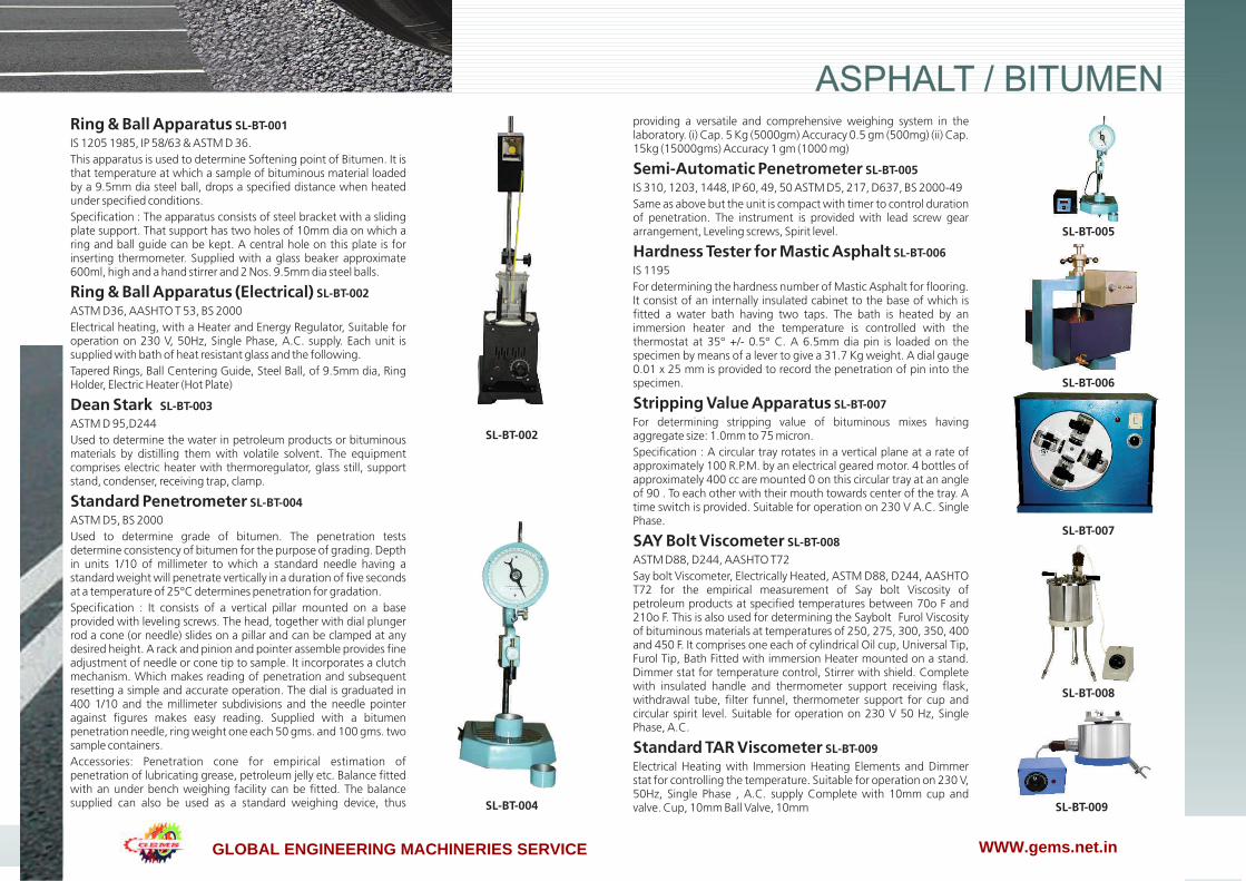
Ring & Ball Apparatus SL-BT-001IS 1205 1985, IP 58/63 & ASTM D 36.This apparatus is used to determine Softening point of Bitumen. It is that temperature at which a sample of bituminous material loaded by a 9.5mm dia steel ball, drops a specified distance when heated under specified conditions.Specification : The apparatus consists of steel bracket with a sliding plate support. That support has two holes of 10mm dia on which a ring and ball guide can be kept. A central hole on this plate is for inserting thermometer. Supplied with a glass beaker approximate 600ml, high and a hand stirrer and 2 Nos. 9.5mm dia steel balls.
Ring & Ball Apparatus (Electrical) SL-BT-002ASTM D36, AASHTO T 53, BS 2000Electrical heating, with a Heater and Energy Regulator, Suitable for operation on 230 V, 50Hz, Single Phase, A.C. supply. Each unit is supplied with bath of heat resistant glass and the following.Tapered Rings, Ball Centering Guide, Steel Ball, of 9.5mm dia, Ring Holder, Electric Heater (Hot Plate)
Dean Stark SL-BT-003ASTM D 95,D244Used to determine the water in petroleum products or bituminous materials by distilling them with volatile solvent. The equipment comprises electric heater with thermoregulator, glass still, support stand, condenser, receiving trap, clamp.
Standard Penetrometer SL-BT-004ASTM D5, BS 2000Used to determine grade of bitumen. The penetration tests determine consistency of bitumen for the purpose of grading. Depth in units 1/10 of millimeter to which a standard needle having a standard weight will penetrate vertically in a duration of five seconds at a temperature of 25°C determines penetration for gradation.Specification : It consists of a vertical pillar mounted on a base provided with leveling screws. The head, together with dial plunger rod a cone (or needle) slides on a pillar and can be clamped at any desired height. A rack and pinion and pointer assemble provides fine adjustment of needle or cone tip to sample. It incorporates a clutch mechanism. Which makes reading of penetration and subsequent resetting a simple and accurate operation. The dial is graduated in 400 1/10 and the millimeter subdivisions and the needle pointer against figures makes easy reading. Supplied with a bitumen penetration needle, ring weight one each 50 gms. and 100 gms. two sample containers.Accessories: Penetration cone for empirical estimation of penetration of lubricating grease, petroleum jelly etc. Balance fitted with an under bench weighing facility can be fitted. The balance supplied can also be used as a standard weighing device, thus
providing a versatile and comprehensive weighing system in the laboratory. (i) Cap. 5 Kg (5000gm) Accuracy 0.5 gm (500mg) (ii) Cap. 15kg (15000gms) Accuracy 1 gm (1000 mg)
Semi-Automatic Penetrometer SL-BT-005IS 310, 1203, 1448, IP 60, 49, 50 ASTM D5, 217, D637, BS 2000-49Same as above but the unit is compact with timer to control duration of penetration. The instrument is provided with lead screw gear arrangement, Leveling screws, Spirit level.
Hardness Tester for Mastic Asphalt SL-BT-006IS 1195For determining the hardness number of Mastic Asphalt for flooring. It consist of an internally insulated cabinet to the base of which is fitted a water bath having two taps. The bath is heated by an immersion heater and the temperature is controlled with the thermostat at 35° +/- 0.5° C. A 6.5mm dia pin is loaded on the specimen by means of a lever to give a 31.7 Kg weight. A dial gauge 0.01 x 25 mm is provided to record the penetration of pin into the specimen.
Stripping Value Apparatus SL-BT-007For determining stripping value of bituminous mixes having aggregate size: 1.0mm to 75 micron.Specification : A circular tray rotates in a vertical plane at a rate of approximately 100 R.P.M. by an electrical geared motor. 4 bottles of approximately 400 cc are mounted 0 on this circular tray at an angle of 90 . To each other with their mouth towards center of the tray. A time switch is provided. Suitable for operation on 230 V A.C. Single Phase.
SAY Bolt Viscometer SL-BT-008ASTM D88, D244, AASHTO T72Say bolt Viscometer, Electrically Heated, ASTM D88, D244, AASHTO T72 for the empirical measurement of Say bolt Viscosity of petroleum products at specified temperatures between 70o F and 210o F. This is also used for determining the Saybolt Furol Viscosity of bituminous materials at temperatures of 250, 275, 300, 350, 400 and 450 F. It comprises one each of cylindrical Oil cup, Universal Tip, Furol Tip, Bath Fitted with immersion Heater mounted on a stand. Dimmer stat for temperature control, Stirrer with shield. Complete with insulated handle and thermometer support receiving flask, withdrawal tube, filter funnel, thermometer support for cup and circular spirit level. Suitable for operation on 230 V 50 Hz, Single Phase, A.C.
Standard TAR Viscometer SL-BT-009Electrical Heating with Immersion Heating Elements and Dimmer stat for controlling the temperature. Suitable for operation on 230 V, 50Hz, Single Phase , A.C. supply Complete with 10mm cup and valve. Cup, 10mm Ball Valve, 10mm
SL-BT-002
SL-BT-005
SL-BT-006
SL-BT-007
SL-BT-008
SL-BT-009SL-BT-004
GLOBAL ENGINEERING MACHINERIES SERVICE WWW.gems.net.in

ASPHALT / BITUMEN
www.labtekindia.com32
Straight Edge (3 Meters) SL-BT-014
A straight edge approximately 3 metres in length may be used to determine lateral surface regularity of a road surface. This lightweight apparatus is made up of mild steel or aluminum as per customers requirement and is equally supported at both ends producing a set height between the road surface & the beam. Any vertical irregularity is measured using incremented wedges.
Ductility Testing Apparatus SL-BT-015
IS 1208-1058, ASTM D 113, IP32, 55, AASHTO T 51Designed to test three specimens simultaneously. The machine consists of a carriage moving over a lead screw. An electric motor driven reduction gear unit ensures smooth constant speed and continuous operation. The entire assembly is mounted with a stainless steel lined water bath completely encased in metal bound hardwood. It is equipped with an electric pump circulator and heater. The temperature is controlled thermostatically. Two rates of travel i.e. 5 cm/min and 1 cm/min are provided. Suitable for operation on 230 V, 50 Hz, Single Phase, A.C. supply.COMPLETE WITH: Ductility Mould , with Base Plate 3 Nos.Thermometer IP 38 C, Range: 23o C to 27o C
Compaction Mould SL-BT-016
BS 598Comprising Mould body, base plate and combined filling / extraction collar. Satisfies
Compaction Pedestal SL-BT-017
BS 598Comprising a 300mm sq x 25mm thick steel plate complete with 4 tie rods and securing nuts. A mould clamp and hammer guide are fitted to the plate. The unit is supplied complete with a laminated hardwood block.
Compaction Pedestal SL-BT-018
Comprising a 12” square x 1 inch thick steel plate secured to an 8” square x 18” high wooden block. 4 angle brackets are supplied for securing the block. A specimen mould holder is fitted to the steel plate.
Compaction Hammer SL-BT-019
Satisfies BS 598. The hammer has a 4535 g sliding weight with a free fall of 457mm.
Steel Block SL-BT-020
100mm diameter x 50mm height. For heating the compaction hammer foot according to BS 598-107.Accessories: Proctor/core Cutter Extruder Spares, Base Plate for compaction mould, Base plate for compaction mould, Filling / Extraction Collar For Compaction Mould
Reflux Extractor 4000 GMS SL-BT-010
ASTM D 2172- AASHTO T 164The simple apparatus working on the same operation principle of consisting of cylindrical glass jar supporting two metal cones of stainless steel cloth and a metal condenser on top of the jar. Supplied complete with 100 filter papers & wire gauge, Hot Plate.NOTE: Spare Cylindrical glass jar can be supplied at an extra cost.
Centrifuge Extractor (Manually) SL-BT-011
ASTM D2172, AASHTO T-58, T-164The Instrument is used for determination and checking of Bitumen percentage in Bituminous mix, the mix is added with a solvent and dissolved bitumen is removed by centrifugal action. Consists of a removable Aluminum rotor bowl, Capacity 1500 gms. With a cap and tightening nut. The bowl assembly is mounted on a vertical shaft, which protrudes from a cast housing. This shaft and thus the bowl is rotated fast manually by enclosed gears in the cast body and handle. Solvent is introduced during the test through the holes in the cap of the housing. A drain is provided to collect dissolved Bitumen coming out of the rotating bowl and getting collected in the housing.
Centrifuge Extractor (Motorized) SL-BT-012
ASTM D2172 AASHTO T-58, T-164Centrifuge Extractor, Electrical Operation, Capacity 1500g, with a Dimmer stat for speed control from 2,400 to 3,600 rpm. Suitable for operation on 230 V, 50 Hz, Single Phase, A.C. supply. Used for the determination of bitumen percentage in bituminous mixtures. It consists of a removable, precision machined aluminum rotor bowl (accessory 1500 or 3000 g capacity), housed in a cylindrical aluminum box. The separate control panel incorporates an electronic card fitted with AC drive that automatically drives the bowl speed rotation ramp from 0 to 3600 R.P.M. as requested by Standards, with automatic fast stop bowl rotation at the end of the test. Supplied complete with speed regulator and digital display monitoring the frequency. Power supply: 230 V A.C. Single Phase.
Benkelman Beam SL-BT-013
AASHTO T 256Lightweight Aluminum construction, Ease of Transportation, Unique Telescopic Design Simplifying Field set up, Compact, Thereby reducing the amount of storage space needed. Benkelman Beam utilizes the technique of using balanced beam in conjunction with a suitable vehicle to measure road flexure The improved Benkelman Beam is a convenient, accurate device for measuring the deflection of flexible pavements under moving wheel loads. Operating on a simple lever arm principle, the unit consists. Supplied with carrying case.NOTE :Benkelman Beam with Digital Dial Gauge also available at an extra cost
SL-BT-010SL-BT-014
SL-BT-015
SL-BT-016
SL-BT-018/19
SL-BT-011
SL-BT-012
SL-BT-013
GLOBAL ENGINEERING MACHINERIES SERVICE WWW.gems.net.in

ASPHALT / BITUMEN
33www.labtekindia.com
Marshal Stability Test Apparatus SL-BT-021
Motorized ASTM: D 1559- T –62.Generally the test is applicable to hot mix designs using bitumen and aggregates upto a maximum size of 25mm. In this method, the resistance to plastic deformation of cylindrical specimen of bituminous mixture is measured when the same is loaded at periphery at 5 cm per min. This test procedure is used in designing and evaluating bituminous paving mixes. The test procedure is extensively used in routine test programmers for paving jobs. There are two major features of the Marshall method of designing mixes namely, a) density – voids analysis b) Stability – flow tests. The marshall stability of mix is defined as a maximum load carried by a compacted specimen at a standard test temperature of 60ºC. The flow value is deformation the marshall test specimen under goes during the loading upto the maximum load, 0.25 mm units. In this test and attempt is made to determine optimum binder content for the type of aggregate mix and traffic intensity.The apparatus consists of: 1) A loading unit motorized, capacity 5000kgf with two telescopic pillars and an adjustable cross head. Limit switches are fitted inside to control upward or downward movement of the pillars. On-off reversing switch and indicator lamps are on the front side while a hand wheel to manually move the pillars is on the right. The load frameStandard Accessories: Marshal Mould:3 Nos, Marshal Rammer:2 Nos, Pedestal :1 Nos, Braking Head:1 Nos
Mixer with Heating Jacket SL-BT-022
BS 598:107A 6-litre Mixer Used in conjunction with an Iso Mantle, is suitable for mixing samples of asphalt. Bench mounting Mixer, 6 liter nominal capacity. Supplied with bowl, beater and whisk. Motorised with two s p e e d o p e r a t e d o n 2 3 0 V A . C . , S i n g l e P h a s e .ISO Mantle Electric Heater: For use of Bench Mounting mixer. For 230 VAC.,50Hz, Single Phase
Automatic Compactor SL-BT-023
BS 598-107Automatic Compactor for Bituminous Mixes Rugged construction to withstand hard work Fully automatic and easy to operate Uniform compaction Automatic Preset Blow CounterSpecification : The Automatic Compactor eliminates the laborious process of manual compaction and an even degree of compaction is achieved. The driven mechanism lifts the weight of 4.5kg and drops it through a correct height of 457 mm. The rammer foot is removable, which facilitates preheating. A compaction pedestal with specimen holder is fixed to the base. An Automatic Blow counter enables the number of blows to be present before each test and automatically stops the machine on completion. Suitable for operation on 230 V, 50 Hz, Single Phase, A.C. supply.
Core Cutting/ Drilling Machine SL-BT-024
(Diesel Engine Driven) Suitable to cut/drill cores of concrete, rocks, stones, tiles or the similar materials. The machine is suitable for core samples of size upto 150 mm diameter with the help of thin walled diamond bits which are at extra cost. The machine has sturdy base with pillar support in which rack and pinion is provided for adjustment in height and penetration assembly. The leveling screws are provided at the base. For gripping the sample in position suitable grips are provided. A suitable diesel engine is fitted in the machine with cooling arrangement with water. The base frame is also fitted with wheels for ease of transportation.Dimension approx, are as under: Height : 1300 mm, Base : 600 x 1200 mm, Head travel on rack : 350mm, Drill speeds : 900 R.P.M. for soft samples and 350 R.P.M. for hard Samples, Water swivel : Built in the machines. Accessories: (1) Thin wall diamond bits. (2) Core barrel.
Core Cutting/ Drilling Machine SL-BT-025
(Motorized) Rated Voltage: ~220 V / 50Hz, Power Input: 2800W, No-Load Speed: 840rpm, Max. bit diameter: Ø50mm/100mm/150mm Shaft Male: 1 1/4"UNCFeatures : 1. Compact size with light weight as well as safety in operation, 2. The drills are equipped with a friction clutch as well as over load current protection for protecting motor, 3. High-strength gear to keep the drill working long hours constantly, 4. Excellent speed, smooth and stability during drilling, 5. Out setting water swivel seal facilitate making replacement when the seal worn out, 6. Bits capacity: 25mm Dia - 150mm Dia Complete Combination : The core drill includes drill motor, base, column, carriage, control panel, friction clutch, motor mount plate, rack, gear-box, out setting water swivel seal, hydraulic system. Optional parts include water pump, rod for ceiling jack, water container, adapters. Application : The Core Drill is the industry standard, designed for concrete, reinforced concrete, Asphalt and brick in construction.
Rock/ Concrete Cutting Machine SL-BT-026Electrically operated with cooling system.MASONARY TABLE SAWFor people who work with stone, brick, large tiles or blocks, it goes without saying that precision is crucial to the end result. But the efficiency of the machine should never compromise the need for good ergonomics and a reasonable workload. Put simply, the stone or tile you cut must fit perfectly, just as the machine and the blade you use must fit your work situation perfectly. Universal table saw with a unique super-stable height adjustment device, lockable in any position. max. cutting depth in top position is 230 mm, by turning the material over.
SL-BT-021
SL-BT-022
SL-BT-023
SL-BT-024
SL-BT-025
SL-BT-026
GLOBAL ENGINEERING MACHINERIES SERVICE WWW.gems.net.in

ASPHALT / BITUMEN
www.labtekindia.com34
Asphalt & Concrete Floor Saw SL-BT-027
Driven by electrical motor or by engine as per customers requirement. Diamond bit of 100 mm to 600 mm maximum can be supplied as per requirement. The trolley in which the engine is fitted is supplied with cooling arrangements with the help of a water tank. Arrangements to control the depth is also provided. A safety guard is also provided on the diamond blade. Two wheels are provided for easy movability of the machine.
Loss on Heating/ Thin Film Oven SL-BT-028
Precise, Hot Air Drying Better Mineral / Blanket Insulation for high Temperature & to avoid heat loss Silent Hot Air Blower, Unique design of Air Circulation provide through out uniform Air movement Unique design of ventilation keeps the surface of the instruments from being Burnt even when the instruments i.e. Oven Temperature maintained at 200°C Polish / Hair Line 304 grade S. Steel sheet interior, long operation, corrosion resistant Kanthal A-1 Super quality coil shaped & Air heater tubular model wound on side/on the back of the Oven for better accuracy Full feature with Digital Temperature Controller cum Indicator having Alarm facility (On Customer request) Toughened Glass view window to observe /Test the material without disturbing the Temperature condition of the chamber. Working Temperature required as per IS : ASTM is 163°C+- 1°C Provide with detachable metal shaft (Both for Loss on Heating / Thin Film Oven) Reduction gear is fitted from outside rotated by a vertical shaft having 5-6 RPM.Applications : For Bitumen Testing Loss of weight, softening Paint, Penetration Loss of wt in Bitumen & Flux Oils (For Construction / Road Projects Department / Industries) Specifications : Size: 16" x 16" x 16”, Capacity: 60 ltr, Heater Wattage: 1.5 KW
Rolling Thin Film Oven SL-BT-029
ASTM D2872Certified temperature control, Digital Display Internal FanThe Rolling Thin Film Oven Test is used to obtain homogeneously aged material by the application of heat and air in order to simulate these affects in conventional mixing. The oven is of double wall construction with side vents and of the heated convection type of air Circulation. An electronic controller maintains the temperature at 163+ 0.5° C. A vertical, carriage is supplied to support 8 glass sample containers, which are rotated at 15+ 0.2rpm. An outlet orifice 1mm in diameter is connected to a 7.6m length of copper tubing and flow meter which controls the airflow at 4000 ml/min. Air is blown into the sample containers at their lowest point of travel by an internal airjet. The oven is supplied with 8 glass sample containers and a thermometer (IP 47C/ASTM 13C). Internal dimensions 483 x 450 x 381mm. A separate source of compressed air is required to operate this oven. Operating Voltage 230 V A.C., Single Phase
Core Cutting Grinding Machine SL-BT-030
Table MountedStable Construction Feed arrangement for cuttingFeed arrangement for cuttingCooling water arrangementHeavy Duty, Single Phase Motor 230 V A.C.Specification : This unit is designed for cutting and grinding cylindrical rock specimens upto NX size. The outfit includes 200mm dia diamond impregnated cutter, a fine diamond impregnated grinding wheel a water supply system and sampler holder. A V-Vice, to hold the sample up to 55mm dia x 140mm long to be cut parallel and square to the longitudinal axis is provided. Cores longer that 140mm can be prepared by reversing the specimen and holding. against the vice, A hand feed arrangement is provided to facilitate the specimen with a uniform and smooth feeding motions. This unit is provided with a 1 HP, Single Phase, 230 V A.C. Motor.
SL-BT-027
SL-BT-028
SL-BT-029
SL-BT-030
GLOBAL ENGINEERING MACHINERIES SERVICE WWW.gems.net.in

01
HE
AT
TR
AN
SF
ER
L
AB
01
EMMISSIVITY MEASUREMENT APPARATUS
Platesa. Diameter :150b. Material :Brassc. Heater :250Wd. Specimen :Black Body and Grey
Body
Rectangular Ducta. Material :MS with Power Coating
Front AcrylicMeasuring Instrumentsa. Digital Voltmeter Range :0 to 300 Vb. Digital Ammeter & Range :0 to 10 Ampsc. Digital Temperature Indicator with Selector switch Range :Ambient to 0-400Deg.c
Thermocouplesa. Type :Cr. AIb. Length :1 Mt.05. Voltage Varaic :2 Nos, 1.5 kw
THERMAL CONDUCTIVITY INSULATING POWDER Outer Sphere (top And Bottom)a. Diameter : 200mm (Approx.)b. Material : Copper
Inner Sphere (top And Bottom)a. Diameter : 100b. Materail : Copper
Measuring Instruments:a. Digital voltmeter, Range :0 to 300Vb. Digital Ammeter & Range:0 to 5 Ampsc. Digital Temperature Indicator with selector switch:
0Range :Ambient to 0-400 c
Thermocouples:a. Type : Cr. AIb. Length : 1 Mtr.05. Electronic Dimmer : 1 No., 1.5 kw
SL-5001
Heat Transfer Through Lagged Pipe
HEAT TRANSFER THROUGH LAGGED PIPEPipesa. Diameter :50/100/150mm
Inner/Outer (Approx.)b. Length :450mm (Approx.)c. Material :G.I./MSd Quantity :1 No. EachMeasuring Instrumentsa. Digital Voltmeter Range :0 to 300 Vb. Digital Ammeter & Range :0 to 5 Ampsc. Digital Temperature Indicator with Selector switch Range :Ambient to 0-400 Deg.cThermocouplesa. Type :Cr. AIb. Length :1 Mt.04. Voltage Varaic :1 No., 1.5 kw05: Insulation : Glass wool
SL-5002 SL-5003
Thermal Connductivity Insulating PowderEmmissivity Measurement Apparatus
GLOBAL ENGINEERING MACHINERIES SERVICE

01
HE
AT
TR
AN
SF
ER
L
AB
02
Heat Transfer in Natural Convection
HEAT TRANSFER IN FORCED CONVECTION
Blower
a. Capacity :350 watts/1.5 cumts/m
Test Section
a. Diameter :40mm
b. Length :300mm
Cooling Water Chamber
a. Diameter :50 mm Optional
b. Length :300mm (Approx.)
Material :Copper
Measuring Instruments
a. Digital Voltmeter Range :0 to 300 V
b. Digital Ammeter & Range :0 to 10 Amps
c. Digital Temperature Indicator with 0 Selector switch Range :Ambient to 400 c.
Thermocouples
a. Type :Cr. AI
b. Length :1 Mt.
Electronic Dimmer :1 No.
07. Measuring Jar & “u” Tube Manometer 1 No. Each
HEAT TRANSFER FROM PIN-FIN
Blower
a. Capacity :350 watts/1.5 cumts/m
Test Section
a. Diameter :12mm
b. Length :150mm
c. Material :Brass
Duct
a. Size :100x150x500mm
b. Material :MS with Powder Coating
Measuring Instruments
a. Digital Voltmeter Range :0 to 300 V
b. Digital Ammeter & Range :0 to 10 Amps
c. Digital Temperature Indicator with 0 Selector switch Range :Ambient to 400 c.
Thermocouples
a. Type :Cr. AI
b. Length :1 Mt.
Electronic Dimmer :1 No.
“U” Tube Manometer:
a. Material :Glass
HEAT TRANSFER IN NATURAL CONVECTION
S.S. Cylindrical Tube
a. Diameter :40mm
b. Length :400/500mm
Measuring Instruments
a. Digital Voltmeter Range :0 to 300 V
b. Digital Ammeter Range :0 to 10 Ampsc.
c. Temperature Indicator with 0Selector switch Range :Ambient to 400 c
Thermocouples:
a. Type :Cr. AI
b. Length :1 Mtr.
Electronic Dimmer :1 No.
Heat Transfer in Forced Convection Heat Transfer from Pin-Fin
SL-5004
SL-5005 SL-5006
GLOBAL ENGINEERING MACHINERIES SERVICE

01
HE
AT
TR
AN
SF
ER
L
AB
03
Stefan Boltzman Apparatus
CRITICAL HEAT FLUX APPARATUS
Cylindrical Shella. Diameter :200mm (Approx.)b. Height :200mm (Approx)c. Material :GlassImmersion Heaters:a. Capacity :Suitableb. Make :Any StandardMeasuring Instruments:a. Digital Voltmeter Range :0 to 300 Vb. Digital Ammeter & Range :0 to 5 Ampsc. Digital Temperature Indicator with Selector switch Range :Ambient to 199.9 Deg.c Thermocouplesa. Type :Cr. AIb. Length :1 Mt.Electronic Dimmer :1 NoTest Specimen : Nichrome wire
HEAT PIPE DEMONSTRATOR
Heat Pipea. Length/Diameter :300/25mm (Approx/)c. Material :BrassTest Pipesa. Diameter/Length :25mm/300mm(Approx.) Material :Copperb. Diameter :25mm (Approx.)Length :300mm (Approx.) Material :Copper/SSSmall Capacity Tanksa. Size :150x100x50mm (Approx.)b. Materia/Quantity :S.S./ 3 Nos.Measuring Instrumentsa. Digital Voltmeter Range :0 to 300 Vb. Digital Ammeter & Range:0 to 5 Ampsc. Digital Temperature Indicator with Selector switch
0 Range :Ambient to 400 c.Thermocouplesa. Type :Cr. AIb. Length :1 Mt.Electronic Dimmer :3 No.
STEFAN BOLTZMAN APPARATUS
Stefan Boltzman Section
a. Hemisphere
Diameter /Material :200mm/Copper
b. Outer Jacket
Diameter/Material :250mm/Copper
c. Hylum Base Plate :12 mm thick
d. Test disc
Size :20mm x 1.5 mm
Water Tank With Immersion Heater
a. Material :S.S.
03. Digital Temperature Indicator With Selector Switch
Range :Ambient to 199.9 Deg. C
04. Thermocouples
a. Type :Cr. AI
b. Length :1 Mt.
Critical Heat Flux Apparatus Heat Pipe Demonstrator
SL-5007
SL-5008 SL-5009
GLOBAL ENGINEERING MACHINERIES SERVICE

01
HE
AT
TR
AN
SF
ER
L
AB
04
Heat Transfer Through Composite wall
HEAT TRANSFER THROUGH COMPOSITE WALL
Mild Steel, Asbestos & Brass Slabs/wood
a. Thickness :150 od 6 mm Thick
Measuring Instruments
a. Digital Voltmeter Range :0 to 300 V
b. Digital Ammeter & Range :0 to 10 Amps
c. Digital Temperature Indicator with 0 Selector switch Range :Ambient to 400 c.
Thermocouples
a. Type :Cr. AI
b. Length :1 Mt.
Electronic Dimmer :1 Nos.
PARALLEL/COUNTER FLOW HEAT EXCHANGER
Geyser
a. Capacity :3 KW
Heat Exchanger Outer Pipe Insulated By Asbestos Rope
a. Diameter :25mm
b. Material :G.I
Heat Exchanger Inner Pipe
a. Length :1000mm
b. Diameter :12.5 mm OD
c. Material :Copper
Digital Temperature Indicator With Selector Switch
a. Range :Ambient to 199.9 Deg. c
Thermocouples
a. Type :Cr. AI
b. Length :1 Mt.
Measuring Jar :1 Ltr. Capacity
HEAT PIPE DEMONSTRATOR
Glass Tubea. Diameter/Height :100mm OD/275mm (Approx.)Copper Tube a. Diameter :9mm OD (Approx.)b. Material :150mm (Approx.)Measuring Instrumentsa. Digital Voltmeter Range :0 to 300 Vb. Digital Ammeter & Range:0 to 5 Ampsc. Digital Temperature Indicator with Selector switch Range :Ambient to 199.9 Deg. cThermocouplesa. Type :Cr. AIb. Length :1 Mt.Dimmer/ Electronica. Make :Agro/Equivalentb. Range :0 to 10 AmpsRotametera. Material :Acrylicb. Range :40 to 60 cc/secSump Tank:a. Size :200 x 200x 400mm (Approx.)b. Materail :S.S
Parallel/Counter Flow Heat Exchanger Boiling Heat Transfer Unit
SL-5010
SL-5011 SL-5012
GLOBAL ENGINEERING MACHINERIES SERVICE

HE
AT
TR
AN
SF
ER
L
AB
05
SL-5013 SL-5014
Shell and Tube Heat ExchangerDrop & Film Condensation
DROP & FILM CONDENSATION
Glass Tube
a. Diameter :100mm OD (Approx.)
b. Height :275mm (Approx.)
c. Quantity :2 Nos.
Measuring Instruments
c. Digital Temperature Indicator with
Selector switch Range :Ambient to 199.9 Deg.c
Thermocouples
a. Type :Cr. AI
b. Length :1 Mt.
Rotameter
a. Material :Acrylic
b. Range :40 to 60 cc/sec
Sump Tank:
a. Size :200 x 200x 400mm
(Approx.)
b. Material :S.S
Steam Generator
a. Diameter :200mm (Approx.)
b. Height :300mm (Approx.)
c. Material :M.S.
D. Heater used :2KW/ 1 No.
SHELL AND TYBE HEAT EXCHANGER
Control Panel Stand Alone Metallic powder coated panel
SpecimenShell: 200mm dia, 5mm thick, 1m long MS pipe Tubes: ½” dia, 1020mm long Copper or seamless MS tubes
InsulationAsbestos Cloth / Rope
Geyser1 liter, 3 kW, Instantaneous (SS hot water tank with pump at extra cost)
Flow measurement Measuring Jar with digital stop watch (Rota meters at extra cost).
Temperature IndicatorDigital Temperature Indicator ,0-199.9°C with TSS
ThermocouplesTeflon coated Cr –Al (K-type)-4 no.
Measuring JarPlastic-1000ml
Stop WatchDigital, 1/10 of a second, Racer/Pacer Make
Experimental CapabilityOver All Heat transfer Co-Efficient, Effectiveness
ManualSelf explanatory Instruction manual with sample calculation
Optional Feature @ ExtraComputerized data acquisition system with software
GLOBAL ENGINEERING MACHINERIES SERVICE

01
HE
AT
TR
AN
SF
ER
L
AB
06
SL-5015 SL-5016
Unsteady state Heat Transfer Test Rig Plate Type Heat Exchanger
Control Panel Stand Alone Metallic powder coated panel
SpecimenCopper 30mm dia, 30mm long,
Duct / EnclosureMS powder coated duct of 8”x8” in size 8” dia MS shell with glass wool insulation
HeaterBand Heater-500W
Cooling Fan 8” dia exhaust fan
VoltmeterDigital voltmeter of range 0-300V AC
Ammeter Digital ammeter of range 0-20A AC
Temperature IndicatorDigital Temperature Indicator ,0-400°C with TSS
Thermocouples Teflon coated Cr –Al (K-type)-8 no.
StopwatchDigital Stop Watch.
Regulator Electronic Dimmer 1kW. (2Amps Variac At extra cost)
Experimental CapabilityNusslet No. And Biot No.
ManualSelf explanatory Instruction manual with sample calculation
Optional Feature @ ExtraComputerized data acquisition system with software
UNESTEADY STATE HEAT TRANSFER TEST RIG
Control Panel Stand Alone Metallic powder coated panel
SpecimenAn industrial Plate Heat exchanger made of SS of size 200 mm x 75 mm, Number of plates are 14
Flow typeBoth Parallel and Counter Flow
Geyser1 liter, 3 kW, Instantaneous (SS hot water tank with pump at extra cost)
Flow measurement Measuring Jar with digital stop watch(Rota meters at extra cost – 2 nos).
Temperature IndicatorDigital Temperature Indicator ,0-199.9°C with TSS
ThermocouplesTeflon coated Cr –Al (K-type)-4 no.
Measuring JarPlastic-1000ml
Stop WatchDigital, 1/10 of a second, Racer/Pacer Make
Experimental CapabilityOver All Heat transfer Co-Efficient, Effectiveness
ManualSelf explanatory Instruction manual with sample calculation
Optional Feature @ ExtraComputerized data acquisition system with software
PLATE TYPE HEAT EXCHANGER
GLOBAL ENGINEERING MACHINERIES SERVICE

01
HE
AT
TR
AN
SF
ER
L
AB
07
Thermal Conductivity by Guarded Hot Plate Thermal Conductivity of Metal Rod
THERMAL CONDUCTIVITY OF METAL ROD
Control Panel Stand Alone Metallic powder coated panel
SpecimenShell: 200mm dia, 5mm thick, 1m long MS pipe Tubes: ½” dia, 1020mm long Copper or seamless MS tubes
InsulationAsbestos Cloth / Rope
Geyser1 liter, 3 kW, Instantaneous (SS hot water tank with pump at extra cost)
Flow measurement Measuring Jar with digital stop watch (Rota meters at extra cost).
Temperature IndicatorDigital Temperature Indicator ,0-199.9°C with TSS
ThermocouplesTeflon coated Cr –Al (K-type)-4 no.
Measuring JarPlastic-1000ml
Stop WatchDigital, 1/10 of a second, Racer/Pacer Make
Experimental CapabilityOver All Heat transfer Co-Efficient, Effectiveness
ManualSelf explanatory Instruction manual with sample calculation
Optional Feature @ ExtraComputerized data acquisition system with software
THERMAL CONDUCTIVITY BY GUARDED HOT PLATE
Guarded Plate Sectiona. Main Heater Plate :b. Diameter : 90mmc. Material : Brassd. Ring Heater Diameter : 100ID/150 OD mme. Material : MICAf. Ring Heater Plate g. Diameter : 100 ID/150 mm ODh. Material : Brassi. Asbestos plate :150OD/12 mm thickj. Cooling jacketk. Diameter :150ODl. Material : Brassm. Size :123mm thick
Measuring Instrumentsa. Digital Voltmeter Range : 0 to 300 Vb. Digital Ammeter & Range :0 to 10 Ampsc. Digital Temperature Indicator with Selector switchRange : Ambient to 199.9 Deg.c
Thermocouples:a. Type : Cr. AIb. Length : 1 Mtr.
Electronic Dimmer : 2 Nos.
SL-5018SL-5017
GLOBAL ENGINEERING MACHINERIES SERVICE

AUT
OM
OB
ILE
EN
GIN
EE
RIN
G L
AB
01
AUT
OM
OB
ILE
EN
GIN
EE
RIN
G L
AB
The engine and gearbox assembly, sectioning of maximum parts an accessories like Cylinder, Cylinder Head, Valve ports, Gear box, housing, Oil sump, etc will be carried out to show the internal constructional details such as Piston, Piston rings, Valves, cam, connecting rod ,etc. the model will be mounted on stand. The above model will be painted with Spl Duco painting, Electroplating of hardware will be carried out
CUT SECTIONAL MODEL OF FOUR STROKE SINGLE CYLINDER ENGINE ASSEMBLY (HERO HONDA)
This model is made out of full size original parts, suitably sectioned and to demonstrate the working of Steering wheel worms, Steering arm, etc., is mounted on a sturdy iron frame.
CUT SECTION MODEL OF STEERING GEAR BOX (WORKING )
This model is made out of used BAJAJ engine, suitably sectioned to show the internal construction of the engine, gear box, clutch and rear wheel mechanism and the model is fitted on a sturdy iron frame. The complete internal details can be demonstrated by operating the kicker lever to show the working of the piston, sparks from the spark plugs can also be shown
CUT SECTION MODEL OF TWO STROKE SINGLE CYLINDER ENGINE (WORKING)
SL-8001 SL-8002
Four Stroke Single Cylinder Two Stroke Single Cylinder
SL-8004
2. Worm and Roller Type 1.Rack and Pinion Type.
3. Recirculating Ball Type 4. Power Steering
SL-8005
SL-8003
SL-8006
GLOBAL ENGINEERING MACHINERIES SERVICE

AUT
OM
OB
ILE
EN
GIN
EE
RIN
G L
ABAU
TO
MO
BIL
E E
NG
INE
ER
ING
LAB
02
1. Rack and Pinion Type
Model of Steering of Jeep with Stub Axle
2. Worm and Roller Type
This model is made out of full size original parts, suitably sectioned and to demonstrate the working of Steering wheel worms, Steering arm, etc., The Arrangement of Wheels And Axle Connecting To steering system will be done so the movement of the wheels when rotating the steering wheels can be displayed .The model will be mounted on to a tubular frame, Suitable color imported painting will be carried out along with Miracle coating for the model will be done for extra gloss and shine. The painting will be carried out in such a way that different colors will be use for different components such as identification of sectioned area etc according to the colors code for easy identification of different systems and mechanisms. All the hardware's and gears will be suitably electroplated
CUT SECTION MODEL OF STEERING GEAR BOX (WORKING) WITH WHEEL AND AXLE
This model is made out of original used parts, will be suitably sectioned And Arranged to demonstrate the internal construction details showing the minute information such as steering gear box, bell assembly, tyre rod , linkages, stub axle etc., and working of the same can be show by steering the steering wheel provided, the model will be suitably painted and The entire model is mounted on a sturdy iron frame.
CUT SECTION MODEL OF STEERING OF JEEP WITH STUB AXLE
3. Recirculating Ball Type
SL-8007 SL-8008
SL-8009
SL-8010
GLOBAL ENGINEERING MACHINERIES SERVICE

AUT
OM
OB
ILE
EN
GIN
EE
RIN
G L
AB
03
Fully Floating Differential and Rear Wheel Semi Floating Deferential and Wheel
SL-8011 SL-8012
This model is made out of original used heavy vehicle parts, suitably sectioned to show clearly the action of Differential gear box, such as pinion crown wheel in Differential and Brake drums in Rear axle, A Crank handle is provided to demonstrate the model. The model is mounted on a sturdy iron frame.
CUT SECTION MODEL OF FULLY FLOATING DIFFERENTIAL AND REAR WHEEL MECHANISM (WORKING)
This model is made out of original used parts such as Brake drum, Brake Shoes, Brake peddle, etc., suitably sectioned and mounted on a wooden base. By operating the Brake drum and applying the Brake pedal this model can be demonstrated.a
CUT SECTION MODEL OF MECHANICAL BRAKE SYSTEM (WORKING)
The model is made out of Original parts such as Air compressor, Unloader valve, foot valve, Booster, Wheel assembly, air tank, control valve etc Suitably sectioned and mounted on a sturdy iron frame.
CUT SECTION MODEL OF AIR BRAKE SYSTEM (NON WORKING)
This model is made out of original used light vehicle, suitably sectioned to show the action of Differential gear box and Brake drums in Rear axle. A Crank handle is provided to demonstrate the model. The whole model is mounted on a sturdy iron frame.
CUT SECTION MODEL OF SEMI FLOATING DEFERENTIAL AND WHEEL MECHANISM (WORKING)
SL-8013 SL-8014
Model of Air brake SystemModel of Mechanical Brake System
GLOBAL ENGINEERING MACHINERIES SERVICEGLOBAL ENGINEERING MACHINERIES SERVICE

AUT
OM
OB
ILE
EN
GIN
EE
RIN
G L
AB
04
The model is made out of Original parts such as Air compressor, Unloader valve, foot valve, Booster, Wheel assembly, air tank, control valve etc The Brake system will be fitted with two front wheel assembly complete ( with out axle) and the drum will be suitably sectioned to show the working of the brake shoe. Other system will be mounted as it is and will be made to function ( foot brake, hand brake etc will be functional.)the entire system will be mounted on a sturdy iron frame. A F.H.P Single phase220/230 V AC motor will be coupled to the compressor for generation of the air, which is used for the operation of the model.
MODEL OF AIR BRAKE SYSTEM (WORKING)
This model is made out of original parts such as Two Brake drum assembly, two master cylinder (one sectioned), wheel cylinders (one sectioned), Brake Shoes, etc., the model can be demonstrated by operating the lever provided.
CUT SECTION MODEL OF DRUM BRAKE UNIT (HYDRAULIC WORKING)
This model contain two disc brakes in the front and two drum brakes at the rear and it is made out of original parts such as two master cylinder Assembly (one sectioned and one working), wheel cylinder, Brake drum, Brake Shoes, calipers etc., suitably sectioned and mounted on a sturdy iron frame. By operating the lever provided, the working procedure of the model can be demonstrated.
CUT SECTION MODEL OF HYDRAULIC BRAKE UNIT FOUR WHEEL TYPE (CUT SECTIONED AND WORKING WITH TWO DISC AND TWO DRUM BRAKES)
Model of Air Brake System (Working)
The Model is made out of Orginal parts such as Two Brake disc, two Caliper assembly (one sectioned), two master cylinder (one sectioned) etc, the model is mounted on a sturdy iron frame and can be demonstrated by operating the lever provided.
CUT SECTION MODEL OF DISC BRAKE SYSTEM (WOIKING)
Model of Hydraulic Brake Unit
SL-8015 SL-8016
Model of Drum Brake Unit Model of Disc Brake System
SL-8017 SL-8018
GLOBAL ENGINEERING MACHINERIES SERVICE

AUT
OM
OB
ILE
EN
GIN
EE
RIN
G L
AB
05
SL-8019
SL-8021
SL-8020
SL-8022
Valve Timing Diagram Port Timing Diagram
Hydraulic Braking System with vacum Booster Model of Disc Brake System Two Wheeler
The model will be made out of Used TATA Indica brake aggregates which will be suitably sectioned, Left Front disc and Left rear drum will be made working, using necessary hydraulic connection from the Master cylinder, By operating the brake pedal connected to the Master cylinder through booster, the functioning of disc and drum brake can be demonstrated. The aggregates on the other side will be suitably sectioned to show the internal details and will be kept dummy. All the aggregates will paint finished The entire setup will be mounted on a sturdy iron frame.
MODEL OF HYDRAULIC BRAKING SYSTEM WITH VACUM BOOSTER (TATA INDICA)
This model is made out of original used parts, will be suitably sectioned And Arranged to demonstrate the internal construction details showing the minute information such as the disc brake assembly, master cylinder on the handle, its piping, front wheel assembly with disc , handle bar with cylinder and brake lever etc., and working of the same can be show by operating the brake lever, the model will be suitably painted and The entire model is mounted on a sturdy iron frame.
CUT SECTION MODEL OF DISC BRAKE SYSTEM TWO WHEELER
GLOBAL ENGINEERING MACHINERIES SERVICE

01
STR
EN
GT
H O
F M
AT
ER
IAL
LA
B
UNIVERSAL TESTING MACHINE (MECHANICAL)
SALIENT FEATURE:
§
§
§
§
§
§
§
§
§
§
§
Loading accuracy: As high as + 1 %
Speeds: Straining at variable speeds to suit wide range of materials
Facilities for tests: Motor-driven threaded columns for quick and convenient adjustment of lower crosshead to facilitate rapid fixing of test specimen.
Autographic recorder: Simultaneous roll autographic recorder supplied as standard to enable study of the behaviors of materials.
Ideal Dia: High reading accuracy due to large size ideal design of dial.
Large columns: Large effective clearance between columns enables testing of standard specimen as well as structures.
Easy changeability: Easy change from plain to threaded and screwed specimens
Simple & Safe: Simple to operate.
Robust construction
Chrome planted metal components
Wide range of standard and special attachments accessories available.
UNIVERSAL TESTING MACHINE HYDRAULIC COMPUTERIZED VERSION
APPLICATION SYSTEM:
SAFETY FEATURES:
§
§
§
§
§
§
§
§
§
§
§
§
§
§
Peak Load along with on line load
Maximum elongation with online elongation
Ultimate Tensile Strength
Graphical Display of load vs. time
Graphical Display of elongation vs. time
Graphic Display of load vs. elongation
Graphic Display of stress vs. strain
Complete Statistical Analysis
Data report management
Machine stops after specimen failure
Safety against over travel of piston
Surge protector
Auto machine diagnosis
Safety against overload
State of The Art Technology Electronic Circuit
SC Model Torque Compensated Power Pack Lindlay Type Extensometer Extensometer
Universal Testing Machine Universal Testing Machine
GLOBAL ENGINEERING MACHINERIES SERVICE

02
STR
EN
GT
H O
F M
AT
ER
IAL
LA
B
Max. Capacity
Model UNITS SL-10
100
kN 0-1000.20
0-2000.40
0-4000.80
0-6001.00
0-10002.00
0-20004.00
0-500.10
0-1000.20
0-2000.40
0-3000.50
0-5001.00
0-10002.00
0.01
kN
0.02
kN
0.05
kN
0.05
kN
0.10
kN
0.20
kN
0-250.05
0-500.10
0-1000.20
0-1200.20
0-2500.50
0-5001.00
0-100.02
0-200.04
0-400.08
0.600.10
0.1000.20
0-2000-40
kN
kN
kN
mm 50-700
0-700
500
150
0-300
1.0
0-700
500
200
0-150
1.0
0-700
500
200
0-150
1.75
0-800
600
250
0-100
1.9
0-850
750
250
0-80
2.6
0-900
850
300
0-45
3.0
50-700 50-700 50-800 50-850 50-900
mm
mm
mm
mmmin
kw
200 400 600 1000 2000
SL-10E SL-20 SL-20E SL-40 SL-40E SL-60 SL-60E SL-100 SL-100E SL-200 SL-200E
1st Measuring RangeResolution
2nd Measuring RangeResloution
3rd Measuring RangeResolution
4th Measuring RangeResloution
Max. Clearance for Tensile Test
Max. Clearance for Compression Test
Clearance betweenColumns
RAM Stroke
Straining/Piston Speed at no load
Electric Supply
TECHNICAL DATA
STANDARD ACCESSORIES
FOR TRANSVERSE TEST:
FOR TENSION TEST:Clamping Jaws for round Specimen
Width for rollers
Diameters of rollers
Max. Clearance between support
Radius of punch Top
Technical Specifications for higher capacity machine will be sent on request.0 Special accessories: This include load stabilizer, Brinell test attachment, 180 Bend test attachment, Shear test attachment and a wide
range of accessories offering on request, at additional cost.Installation: It is recommended that machine be erected on a foundation.
Due to Constant R & D, specification and features are subject to change without notice
mm
mm
mm
mm
mm
10-20
20-30
160
30
500
6,12
10-20
20-30
160
30
500
6,12
10-25
25-40
160
30
500
12,16
10-2525-4040-55
160
50
600
16,22
10-2025-4045-70
160
50
800
16,22
20-4040-6060-80
160
70
900
30,40
0-1010-20
0-1010-20
0-1515-30
0-1515-30
0-2222-4444-65
0-2020-4545-70
50 50 65 70 70 100
120 120 120 120 160 220
mm
mm
mm
Clamping Jaws for FlatSpecimen
Width
For Compression Test: Pair of compression plate of diameter
GLOBAL ENGINEERING MACHINERIES SERVICE

03
STR
EN
GT
H O
F M
AT
ER
IAL
LA
B
Impact Testing Machine(Izod)
IMPACT TESTING MACHINE
This Pendulum impact Tester is designed for conducting CHARPY, IZOD AND IMPACT Test. The test Method confirm to IS: 1973, and IS 1499-1977, and BS: 131 Part 2 & 3-1972 IS: 1598-1977, BS: 131 Part I- 1972
The impact energy absorbed by the specimen during rupture is measured as the difference between the height of drop before rupture and the height of rise after rupture of the test specimen and is read on the dial scale.
TECHNICAL DATA
Pendulum drop angle
Effective weight
Speed
Impact energy
Min. graduation
Distance of axis of hammer rotation and centre of test piece/[pint of test piece hit by hammer
Max permissible loss by friction
Charpy and Impact Tension Test Izod Test
Charpy Test Izod Test Impact Tension Test
A) Striking edge0 0Angle : 30 + 1
Radius of curvature: 2.25 mm
width : 18 mm
A) Striking edge0Angle : 75
Radius of curvature: 0.750Horizontal Relief : 10
0Vertical Relief : 5
A) Striking edge
Distance between forks : 36mm
Radius of curvature : 1mm
B) Support
Distance between arm 40 mm0Slopping angle : 0
0Relief angle : 10
Radius of curvature: 1.25 mm
B) Support
For gripping specimen with
dimension of 10 x 10 mm
B) Support
For clamping specimen with
dimensions of following
Diameter : 6.4 mm
Length (Total) : 68 mm
Length (Measuring) : 25.4 mm
Thread of supporting M10 x 1.5
Izod Striker Charpy Striker
Max. CAPACITY available upto 100kgmalso available in Electronic Digital version
0 0 '140 85 21
20.59 kg. 21.79 kg.
* 5.3465m/sec 3.857m/sec
30 kgm (300J) 16.4kgm (164J)
2J
825 mm 825 mm
0.5of max. impact energy
GLOBAL ENGINEERING MACHINERIES SERVICE

04
STR
EN
GT
H O
F M
AT
ER
IAL
LA
B
LabTek Torsion Testing Machine is designed for conducting Torison and Twist Tests on various metal wire, tubes sheet materials. Torque measurement by pendulum Dynamometer System. Torque ranges can be adjusted. Torque can be applied to specimen by geared motor through gear box, Autographic recorder can be provided to know the relation between torque and angle of twist on specific request
Torsion Testing Machine
TORISON TESTING MACHINE
§
§
§
§
§
§
§
§
Unique "TALCON-CLAW" Grips for Round and Flat specimens
Torisonal Speed of 0.1/0.2 RPM
Torque Compensated Motors
Maintenance Free Gear Box
Auto Range Selection with Range Selector Wheel (Optional)
3 or 4 Torque Ranges for Higher Accuracy (Optional)
Load-unload Capability
Variable Speed Drive (Optional)
TECHNICAL SPECIFICATIONS
Model
Capacitykg-m
Ranges in kg-m
No. of divn. on dial
Torsion Speed & Direction
Fixed one way
0-400
4-12
1-5
25
0.5 0.5 0.5 0.5 0.5 2.0 3.0 5.0
4-12
2-8
25
7-20
3-10
30
10-30
5-12
40
10-34
5-15
50
20-50
10-20
60
30-60
15-25
60
40-70
25-40
70
0-420 0-450 0-500 0-500 0-1000 0-1000 0-1500
Fixed Reverse
Fixed Reverse
Fixed Reverse
Fixed Reverse
Fixed Reverse
Fixed Reverse
Fixed Reverse
Clearance BetweenGrips (mm)
Grips for roundbars (mm)
Grips for flatbars (mm)
Width (mm)
Gear motor 3 ph (ph)
500 500 500 500 500 500 600 600
6 & 3 10, 5 & 2 20, 10 & 5 50, 25 & 10 100, 50 & 20 200, 100 60 & 30
300,150, 100 & 60
600, 300 & 100
SL-3a
6
SL-3b
10
SL-3c
20
SL-3d
50
SL-3e
100
SL-3f
200
SL-3g
300
SL-3h
600
Universal Spring Testing Machine Erichen Cupping Testing Machine
GLOBAL ENGINEERING MACHINERIES SERVICE

05
STR
EN
GT
H O
F M
AT
ER
IAL
LA
B
TENSILE TESTING MACHINE
§
§
TENSILE TESTERS are electrically operated machines for t e s t i ng tensi le strength and elongation of materials l ike plywood, wires, cables, conductors, ferrous and non-ferrous materials
TENSILE TESTERS are manufactured in various capacities and tests can be conducted on these machines by simply incorporating appropriate traverse speeds and using suitable grips in conformity with the adopted BIS, BS, ASTM, DIN & ISO standards.
Tensile Testing Machine
uTENSILE TESTERS are quite capable of conducting Compression and Bending tests apart from performing Tensile and Elongation tests.
uTENSILE TESTERS are manufactured in different capacities upto 10,000Kgf. in our LabTek ensuring + 1% accuracy in the test results.
uTENSILE TESTERS are extra elegant, best quality, durable and accurate with matchless perfection.
uTENSILE TESTERS are also offered on specific requirements
with load graduation in kilograms. Newton Electronic up
Based & computerized Tensile Testers can also be
manufactured on specific requirements Besides a wide
range of accessories depending upon the individual
requirements, for the tests involved, of the suers and a
prompt and reliable after-sales service facilities are also
available with LabTek
Traverse Speedper specification(mm/min) or as
Grip SeparationMinimumMaximum
PowerRequirement
Over-travelSafety Switches
300 and 100
25mm1000mm
25mm1000mm
25mm750mm
25mm750mm
25mm750mm
25mm600mm
3 ph 440 V50 Hz AC
3 ph 440 V50 Hz AC
3 ph 440 V50 Hz AC
3 ph 440 V50 Hz AC
3 ph 440 V50 Hz AC
3 ph 440 V50 Hz AC
Included Included Included Included Included Included
100 100 100 100 25 and 12.5
Model
Cap. N
5N 5N 10N 20N 20N 50N
2500
0-500N x 0.01
0-1000N x 0.01
0-2500N x 0.01
0-1000N x 0.2N 0-10000N x 0.01 0-25000N x 50N 0-50000N x 50N 100000N x 200N
0-50000N x 100N
0-2500N x 50N
0-10000N x 20N
0-5000N x 10N
0-10000N x 2N
0-5000N x 1N
0-5000N x 0.01
0-2500N x 0.01
0-2500N x 0.2N
0-5000N x 10N
5000 10000 25000 50000 100000
Ranges
Unit SL-2a SL-2ae SL-2b SL-2be SL-2c SL-2ce SL-2d SL-2de SL-2e SL-2ee SL-2f SL-2fe
Technical Data
GLOBAL ENGINEERING MACHINERIES SERVICE

06
STR
EN
GT
H O
F M
AT
ER
IAL
LA
B
ROCKWELL HARDNESS TESTER
SL-5 : Manual weight selection an Manual zero adjustment of Dial gaugeSL-5A : Manual weight selection with Automatic zero setting dial GaugeSL-5B : Automatic weight selection with automatic zero setting dial gaugeSL- 5C: Arrangement similar to SL 5B with one additional weight of
187.5 kg for Brinell testsSL- 5D: Arrangement similar to SL 5B with two additional weight of
187.5 kg and 250kg for Brinell tests on this machine small pin having dia 2mm can be tested as plunger is guided with a set of six bearings.
SL- 5E : Rockwell Superficial Hardness Tester with automatic zero setting dial gauge, manual load selection. The major load are N scale besides all fifteen Rockwell Superficial scales. Can be used with this tester
SL-5F : This model is double purpose Hardness Tester suitable for Both Rockwell & Rockwell Superficial hardness test. The Major load of 15,30, 45,60, 100 and 150 kg are applied. Rockwell Hardness Tester
STANDARD ACCESSORIES
TECHNICAL SPECIFICATIONS
Model
Testing Table 50mm Ø
Ø
with 'V' groove for
round jobs 6 to 45 mm Ø0Diamond indentor 120
Stell ball indenter 1/16"
Test block Rockwell'c
Test block Rockwell 'B'
Tet block Rockwell Superficial N
Allien Spanners
Clamping device
Dash pot oil
Instructional Manual
Brinell Microscope
Stell Ball Indentor 2.5mm
Stell Ball Indentor 5 mm
Test Block HB-2.5/187.5
Testing Table 40mm
SL5
5A, 5B
1 Pc.
1 Pc.
1 Pc.
1 Pc.
1 Pc.
1 Pc.
Nil
2Pca
1 Pc
1 bottle
1 book
Nil
Nil
Nil
Nil
SL5C
1 Pc.
1 Pc.
1 Pc.
1 Pc.
1 Pc.
1 Pc.
Nil
2Pcs
1 Pc
1 bottle
1 book
1 Pc
1 Pc
1 Pc
1 Pc
SL5D
1 Pc.
1 Pc.
1 Pc.
1 Pc.
1 Pc.
1 Pc.
Nil
2Pcs
1 Pc
1 bottle
1 book
1 Pc
1 Pc
1 Pc
1 Pc
SL5E
1 Pc.
1 Pc.
1 Pc.
1 Pc.
Nil
Nil
1 Pc
2 Pcs
1 Pc
1 bottle
1 book
Nil
Nil
Nil
Nil
SL5F
1 Pc.
1 Pc.
1 Pc.
1 Pc.
1 Pc
1 Pc
1 Pc
2 Pcs
1 Pc
1 bottle
1 book
Nil
Nil
Nil
Nil
Model
Max Load (kgf)
Load range (kgf)
Initial Load range (kgf)
Max. test height (mm)
Depth of throat (mm)
Size of base (mm)
Machine height (mm)
Nett. weight (Approx). kg.
Test Performed
SL- 5A, 5B
150
60, 100, 150
10
216
133
171 x 445
635
77
Rockwell
SL- 5C
187.5
60, 100,150,
187.5
10
216
133
171 x 445
635
77
Rockwell & Brinell
SL- 5D
250
60, 100, 150,
187.5, 250
10
290
148
210 x 510
845
137
Rockwell & Brinell
SL- 5E
45
15, 30, 45
-
-
148
210 x 510
845
137
Superficial
SL- 5F
150
15, 30, 45
60, 100, 150
3, 10
290
148
210, 510
845
137
Rockwell & Superficial
GLOBAL ENGINEERING MACHINERIES SERVICE

07
STR
EN
GT
H O
F M
AT
ER
IAL
LA
B
FATIGUE TESTING MACHINE
SPECIFICATIONS:
uLight weight, compact size, simple design
uTable model
uSimple lever system for changing load
uAccurately calibrated as per IS075
u10 Digit electronic counter instead of mechanical counter can be supplied at additional price and the model is termed at additional price and the model is termed as SL-F 10
uMachine with maximum bending movement upto 400kg/cm can be offered on request
TECHNICAL SPECIFICATIONS
BRINELL HARDNESS TESTER
The machine is designed with a Hydraulic Power pack and control circuit for effortless loading unloading operation. A dial gauge in from measures depth of ball penetration. This facilitates production testing within tolrance limits by comparison method.
STANDARD ACCESSORIES
Model
Testing Table 200 mm
Testing Table 200 mm
Ball holder 5 mm
Ball holder 10 mm
Test block HB-5/750
Test block HB 10/3000
Brinell Microscope
Allen Spanner
Telescopic cover for elevating screw protection
Instruction Manual
Ø
Ø with 'V' grove for round jobs-10 to 80 mm dia
SL 3000
1 pc.
1 pc.
1 pc.
1 pc.
1 pc.
1 pc.
1 pc.
1 pc.
1 set
1 book
Technical Specification
Model
Max load (kgf)
Load range (kgf)
Initial Load range (kgf)
Max. test height (mm)
Depth of throat (mm)
Size of base (mm)
Machine height (mm)
Nett. weight (Approx. Kg.
Test Performed
Sl-3000
3000
In stage of 250 kgf
250
410
200
670 x 370
1127 mm
450 kg
Brinell
1) Maximum bending moment
2) Bending movement adjustable
3) Ranges
4) Gripping dia of specimen
5) Testing dia of specimen
6) Rotating Speed
7) Accuracy of applied bending
8) Digital counter No. of digits
9) Power required
10) Main supply
kg cm
kg cm
I-kg cm
II-kg cm
mm
mm
rpm
moment
HP
A.C.Ph
200
0-200
30-100
100-200
12
8
4200
+1%
100.5
220V, 50
Hz
Fatigue Testing Machine Brinell Hardness Tester
GLOBAL ENGINEERING MACHINERIES SERVICE

08
STR
EN
GT
H O
F M
AT
ER
IAL
LA
B
METALLURGICAL INVERTED MICROSCOPE
Magnification Range: 20x to 400 x (Standard)0 Observation Head: Binocular 45 with interpupillary and
diopter adjustmentStand: Sturdy and Durable pressure Die cast Aluminium stand.Mechanical Stage: Co-Axial low drive double plate mechanism system travel on ball bearing guide ways.Focusing System: Co-axial coarse & fine mechanism system with ball bearing guide ways.Epi-Illumination: Built in base 12V-50W Halogen lamp with light intensity control system.Quadruple Nose Piece: A precision mechanism ensures the accuracy and optical alignment of the system.Filters: Green & Blue.DIN-LWD Objectives: M4 x M10x, M20x & M40x (SL). Anti Fungal & infinity corrected.Eye Pieces: 5x & 10x Paired. Extra wide field, Anti fungal & Anti reflected Binocular Metalugrical MicroscopeInverted
SL-1008
LabTek Rectangular Muffle Furnace Maximum Temp. 950 deg. C working Temp. 1200 deg. C
A. 100 x 100 x 225mm. (4" x 4" x 9")
B.
C. 150 x 150 x 300mm (6" x 6" x 12")
D 200
150 x 150 x 300mm. (5" x 5" x10")
x 200 x 300mm (8" x 8" x 12")
This is double disc polishing machine for met allographic samples. Two independent polishing units is mounted on a common MS frame, other specification as per single disc.
This Machine is portable model for polishing of met allographic sample. Disc dia 200 mm made of Aluminum. Speed continuously variable up to 950 RPM. Rating- 0.25 HP single phase 220 Volt A.C. Provided with sink and swing type laboratory water tap. Water prrof Formica table top.
MUFFLE FURNACE DOUBLE DISC POLISHING MACHINE
Double Disc Polishing Machine
SL-1009 SL-1010
Muffle Furnace
Specimen Mounting PressBelt Grinder
SL-1012SL-1011
GLOBAL ENGINEERING MACHINERIES SERVICE

DY
NA
MIC
S O
F M
AC
HIN
E L
AB
01
SL-4003
WHIRLING OF SHAFT APPARATUS This compact and simple apparatus incorporated two features. Firstly, kinematics coupling at the driven end of the shaft to slide freely in longitudinal direction while revolving readily. The directional clamping of this end of the shaft is achieved by and interchangeable chuck without self aligning radial ball bearing.The shaft is driven through a dynamically balanced flexible coupling by a universal motor, the speed of which can be controlled by a control unit. The speed of rotation of the shaft can be measured by a stroboscope. Tachometer can be also used for speed measurement. The following shafts made from steel will be supplied.Dia. (MM) Length (MM)2 or 3 100004 100006 100008 10000One kinematics coupling and bearing for fixed of fee end. One sliding chuck for fixed end with lateral movement.POWER REQUIREMENT220 V, 50 Hz single phaseRange of experiments: Investigation of various models of whirl for shafts with:a) Both ends directionally fee.b) Both ends directionally fixed
Note: STROBOMETER AND TACHOMETER NOT INCLUDED IN THE SCOPE OF SUPPLY.
VIBRATION LAB APPARATUS
MOTORIZED GYROSCOPE
Vibration Lab- No I:
Vibration Lab- No II:
Vibration lab machine for performing experiments on longitudinal
and torsional vibrations with control panels and speed indicators.
Exp.1-Equivalent spring mass system to study the undamped free
vibration.
Exp. 2- Equivalent spring mass system to study forced calibration
Vibration lab machine for performing experiments on longitudinal
and torsional vibrations with control panels and speed indicators.
Exp.1-Simple pendulum
Exp. 2- Compound Pendulum
Exp. 3- Bifiler suspension
Exp. 4- Spring mass system
Exp. 5- Equivalent spring mass system to study the undamped free
vibration
Exp. 6- Equivalent spring mass system to study forced calibration.
Exp. 7- Verification of Dukerley's rule
Exp. 8- To study of force vibration for various amount of damping.
Exp. 9- Torisional vibration for the single rotor system
Exp. 10- Torisional vibration for the two rotor system
Exp. 11- Single rotor with viscous damping
This is to demonstrate the relationship between applied torque and the rate and direction of rotation. This is motorized and mounted on a frame such that free to rotate about three perpendicular axis. This facilitates to observe the laws of stability and justification of equation.
Whirling of Shaft Apparatus Vibration Lab Apparatus
SL-4002SL-4001
Motorized Gyroscope
GLOBAL ENGINEERING MACHINERIES SERVICE

DY
NA
MIC
S O
F M
AC
HIN
E L
AB
02
UNIVERSAL GOVERNOR APPARATUSThe set up consists of a small electric motor connected bevel reduction gear box or belt and pulley system through a flexible coupling. The Governor spindle is driven by a solid coupling connected to the gear box output shaft and is supported on ball bearing. The optional governor mechanism can be mounted on spindle. Speed control unit is provided to regulate speed and extension to the spindle shaft can be sued to use hand tachometer. The center sleeve to the porter and proell governors incorporates a weight sleeve to which weights are added. The Hartnell Governor can be operated as a stable or unstable Governor.
The following range of experiments can bePerformed:a) The effect of varying mass of the center sleeve.b) The effect of varying the rotating mass.c) Determination of characteristic curves of sleeve position against
speed of rotation.The effect of varying the initial spring compression.
STATIC AND DYNAMIC APPARATUS
CAM ANALYSIS APPARATUS
This is suitable for conducting experiments on static balancing and dynamic balancing with different weights. This consists of rectangular frame of steel perfectly balance with four different blocks. A protractor scale of the disc is provided to reach exact angular position of each weight to be measured. A linear scale provided below the frame provides the measurement of each weight along the shaft. The unit is hanging from a rigid steel frame through chain for dynamic balancing and can be fixed rigidly for static balancing.
The machine facilitates the study of dynamic behavior of cam follower. It consists of a DC Motor coupled to an extension shaft whose and carries a cam. A cam follower, mounted on the end of a vertical bar, is loaded on the cam face by compression spring is retained by a cross bar mounted on two vertical pillars attached to the base plate. Facility is provided to vary the pre compression of spring. The inertia of follower can be altered using weights.Note: Motor is provided only to demonstrate the actual water of system. However while drawing the graph the motor shall be
SL-4004 SL-4005
Universal Governor Apparatus Static and Dynamic Apparatus
SL-4006
Cam Analysis Apparatus
GLOBAL ENGINEERING MACHINERIES SERVICE

DY
NA
MIC
S O
F M
AC
HIN
E L
AB
03
Journal Bearing Apparatus Epicylic Gear Apparatus
JOURNAL BEARING APPARATUS The Equipment shall have following test facility:1) Simple Demonstrations Observation of the pressure profile at the various conditions of load and speed2) Experimental Investigation After noting the pressure profile
for any chosen conditions the following analysis may be conducted. Plotting the Cartesian and polar pressure curvesParts/Component Details:
1) Journal 50 mm diameter (Nominal)2) Bearing 55 mm diameter3) Weights 4 adjustable weights.4) Recommended oil SAE 105) DC Motor with speed 150-1500 rev/min in both the
direction 6) Suitable speed Control Unit is provided along with
apparatus 7) Manometer Panel 16 tubes mounted on a wooden
backboard
EPICYLIC GEAR APPARATUS
COROLLIS COMPONENT OF ACCELERATION
The Equipment shall have following facility:1) To measure epicyclic gear ratio between input Shaft and
output shaft.2) To measure epicyclic gear ratio between input shaft and
holding drum.3) To measure input torque, holding Torque and output Torque
Parts/Component Details:A) External Type Epicyclic Gear Train.1) Bearing blocks for input and output Shafts are mounted on
on a base frame.2) A gear Train with Holding drum and a handle.B) Internal Type Epicyclic Gear Train:1) A compact Gear Train (Industrial)2) Variable Speed D.C. Shunt Motor, 1hp 1500rpm, 230 volts.3) Rope brake arrangement to measure output torque and
holding torque.C) Control Panel consisting of Digital Ammeter and Voltmeter
RPM Indicator, on off switch. Speed control unit
Coriolli's components of Acceleration can be determined at various speeds of rotation at water flow rates.Parts/Component Details:1) Main Tank Fabricated out of fiberglass plastic sheet. 2) Rotating Arms 9 mm/ 6mm orifice diameter, 300mm logn.3) Rotameter 300 to 3000 LPH4) Electrical Motor D C. Swinging field, 0.5 H.P. 1500 RPM.5) Mono-block Pump Single phase, pump with Motor 2400
LPM discharge.6) Control Unit consisting of
a) pump switch, b) Speed Control, c) Speed Indicator d) Main Switch.
7) Rigid Support Structures
SL-4007 SL-4008
Corollis Component of Acceleration
SL-4009
GLOBAL ENGINEERING MACHINERIES SERVICE

DY
NA
MIC
S O
F M
AC
HIN
E L
AB
04
MODELS OF DIFFERENT TYPES OF GEAR TRAINS
Three Stage Spur Gear Spur, Helical, Bevel Gear
Scotch Yoke Mechanism Cam & Follower with Rciprocating
Rack & Pinon Whit Worth Quick Return Mechanism
SL-4014
SL-4012
SL-4010
SL-4015
SL-4013
SL-4011
GLOBAL ENGINEERING MACHINERIES SERVICEWWW.gems.net.in

DY
NA
MIC
S O
F M
AC
HIN
E L
AB
05
MODELS OF DIFFERENT TYPES OF GEAR TRAINS
SL-4020
SL-4018
SL-4016
SL-4021
SL-4019
SL-4017
Pawl & Ratchet Motion Herring Bone Gear
Oldham CouplingInternal Gear Pinion Drive
Reversing Gear Cam & Follower with Translating
GLOBAL ENGINEERING MACHINERIES SERVICE WWW.gems.net.in

TH
ER
MA
L E
NG
INE
ER
ING
LA
B
01
DESCRIPTION:Three main components from main parts of the test rig.
Welded steel base plate, complete with Mechanical Brake or A.C. Alternator or D.C. Generator or Eddy Current Dynamometer, Drive coupling and with safety guard, anti vibration mounting.
Resistance loading (Resistance bank) with selector switches to load the engine from no load to full load (Only for A.C. Alternator & D.C. Generator)
Panel board positioned over the base plate consisting of fuel system with flow measurement by burette, air flow measurement system, temperature indicator, Speed Indicator
DYNAMOMETER (as applicable
a. The dynamometer used is a mechanical Brake capable of absorbing a maximum load of 2.5 HP at a speed to 2800 RPM.b. The Loading device used in an AC alternator of matching capacity to load the engine up to 2.5 HP at 2800 RPM along with
Resistance loading arrangement for alternator with selector switches.c. The Loading device used is DC Generator of matching capacity to load the engine up to 2.5 HP at 2800 RPM along with
Resistance loading arrangement provided with selector switches.d. The loading device used is Eddy Current Dynamometer of matching capacity to load the engine up to 2.5 HP at 2800 RPM.
INSTRUMENTATION (as applicable):
The following instrumentation is provided.
?'U' tube manometer for air flow rate?Burette for fuel flow rate?Speed indicator-Digital?Digital Temperature Indicator-Multi point selector switch with thermocouples.?Digital Voltmeter, Ammeter
CONTROLS:
The test rig is arranged for manual control of the engine with a kick start arrangement for engine starting & manual throttle control.
FUEL MEASURING ARRANGEMENT:
Fuel Measuring Arrangement consists of fuel tank, burette and suitable cock all mounted on a suitable frame work and panel board and supplied with fuel piping from fuel tank to Engine.
AIR INTAKE MEASUREMENT & HEAT CARRIED AWAY BY EXHAUST GAS:
Consisting of an air tank mounted on an iron stand fitted with a suitable orifice plate, manometer, Thermocouple for measuring the exhaust gas temperature with pocket connection with instruments suitably mounted on a panel board.
ENGINE:
Single Cylinder two stroke Air Cooled Petrol Engine to develop 2.5 HP @ 2800 RPM
SERVICES:
Electrical supply of 230V, Single Phase, 50Hz AC.
SINGLE CYLINDER AIR COOLED TWO STROKE PETROL ENGINE TEST RIG (2.5HP @ 2800 RPM) WITH MECHANICAL BRAKE OR A.C ALTERNATOR OR D.C GENERATOR OR EDDY CURRENT DYNAMOMETER
INTRODUCTION:The test rig is designed to provide self-contained facility for teaching spark Ignition engine principles. The unit is instrumented so that the following experiments can be carried out.
1. BHP MEASUREMENT2. BRAKE THERMAL EFFICIENCY 3. FUEL CONSUMPTION MEASUREMENT4. AIR INTAKE MEASUREMENT
THE ENGINE TEST RIG FACILITATE TO EVALUATE THE FOLLOWING:Performance at various throttle position BHP measurement from no load to full load
??
Single Cylinder 2 Stroke Petrol Engine
SL-2002
GLOBAL ENGINEERING MACHINERIES SERVICE

TH
ER
MA
L E
NG
INE
ER
ING
LA
B
02
INTRODUCTION:The test rig is designed to provide self-contained facility for teaching spark Ignition engine principles. The unit is instrumented so that the following experiments can be carried out.
1. BHP MEASUREMENT2. BRAKE THERMAL EFFICIENCY 3. FUEL CONSUMPTION MEASUREMENT4. AIR INTAKE MEASUREMENT5. MOTORING TEST TO MEASURE I HP & F HP
THE ENGINE TEST RIG FACILITATE TO EVALUATE THE FOLLOWING:Performance at various throttle position BHP measurement from no load to full load
?
?
Single Cylinder 4 Stroke Petrol Engine
SL-2003
DESCRIPTION:Three main components from main parts of the test rig.
Welded steel base plate, complete with Mechanical Brake or A.C. Alternator or D.C. Generator or Eddy Current Dynamometer, Drive coupling and with safety guard, anti vibration mounting.
Resistance loading (Resistance bank) with selector switches to load the engine from no load to full load (Only for A.C. Alternator & D.C. Generator)
Panel board positioned over the base plate consisting of fuel system with flow measurement by burette, air flow measurement system, temperature indicator.
DYNAMOMETER (as applicable
Mechanical Brake (Belt brake) Dynamometer arrangement with a brake drum fitted on the Engine shaft and provided with cooling water arrangement, spring balance. A set of dead weights in kg units.
AC Alternator of matching capacity to load the engine upto 3HP at 3600 RPM along with Resistance loading arrangement provided with selector switches.
DC Generator of matching capacity to load the engine upto 3HP at 3600 RPM along with Resistance loading arrangement provided with selector switches.
Eddy current dynamometer of matching capacity to load the engine up to 3 HP at 3600 RPM.
INSTRUMENTATION (as applicable):
The following instrumentation is provided.
?'U' tube manometer for air flow rate?Burette for fuel flow rate?Digital Temperature Indicator-Multi point selector switch with thermocouples.?Digital Voltmeter, Ammeter
CONTROLS:
The test rig is arranged for manual control of the engine with a Rope & Pulley start arrangement for engine starting & manual throttle control.
FUEL MEASURING ARRANGEMENT:
Fuel Measuring Arrangement consists of fuel tank, burette and suitable cock all mounted on a suitable framework and panel board and supplied with fuel piping from fuel tank to Engine.
AIR INTAKE MEASUREMENT & HEAT CARRIED AWAY BY EXHAUST GAS:
Consisting of an air tank mounted on an iron stand fitted with a suitable orifice plate, manometer, Thermocouple for measuring the exhaust gas temperature with pocket connection with instruments suitably mounted on a panel board.
ENGINE:
Brand New engine Single Cylinder Four stroke Air Cooled Petrol Engine to develop 3 HP @ 3600 RPM
SERVICES:
Electrical supply of 230V, Single Phase, 50Hz & Cooling water supply.
SINGLE CYLINDER AIR COOLED FOUR STROKE PETROL ENGINE TEST RIG (3HP @ 3600 RPM) WITH MECHANICAL BRAKE OR A.C ALTERNATOR OR D.C GENERATOR OR EDDY CURRENT .DYNAMOMETER
GLOBAL ENGINEERING MACHINERIES SERVICE

TH
ER
MA
L E
NG
INE
ER
ING
LA
B
03
INTRODUCTION:The test rig is designed to provide self-contained facility for teaching Internal Combustion (spark Ignition) engine principles. The equipment is instrumented so that the following experiments could be performed.
1. BHP MEASUREME2. IHP MEASUREMENT (BY MORSE TEST ARRANGEMENT)3. FUEL CONSUMPTION MEASUEMENT4. AIR INTAKE MEASUREMENT5. MEASUREMENT OF HEAT REJECTED TO WATER JACKET6. HEAT BALANCE TEST
THE ENGINE TEST RIG FACILITATE TO EVALUATE THE FOLLOWING:Performance (BHP Measurement) from no load to full load, Performance at various throttle position, Heat Balance Sheet and Morse test
???
SL-2004 MULTICYLINDER FOUR STROKE PETROL ENGINE TEST RIG WITH HYDRAULIC DYNAMOMETER OR A.C ALTERNATOR WITH RESISTANCE LOADING WITH MORSE TEST FACILITY
DESCRIPTION:
Two main components from main parts of the test rig.Welded steel base plate, complete with Dynamometer, Drive shaft with safety guard, engine starting battery of 12V capacity and cooling water arrangement. Panel board positioned over the base plate consisting of fuel system with flow measurement by burette, air flow measurement system, temperature and speed indicator.
DYNAMOMETER (as applicable) :
a. The Dynamometer used is a Hydraulic Dynamometer capable of absorbing a maximum load of 10 BHP at a speed of 1500 RPM.b. The Loading device used is an AC Alternator of matching capacity to load the engine upto 10HP at 1500 RPM along with
Resistance loading arrangement with selector switches.
INSTRUMENTATION (as applicable):The following instrumentation is provided.
ENGINE STARTING:
The test rig incorporates a 12V DC electrical system designed for use with typical engine self starter system. The battery is included in the scope of supply.
CONTROLS:
The test rig is arranged for manual control with Ignition switch for engine starting, manual throttle control, manual control for hydraulic dynamometer loading and a manul operated cultch actuator arrangement to drive the engine with load or without load (For No Load testing).
FUEL MEASURING ARRANGEMENT:
Fuel Measuring Arrangement consists of fuel tank, burette and suitable cock all mounted on a suitable framework and panel board and supplied with fuel piping from fuel tank to Engine.
AIR INTAKE MEASUREMENT & HEAT CARRIED AWAY BY EXHAUST GAS:
Consisting of an air tank mounted on an iron stand fitted with a suitable orifice plate, manometer, Thermocouple for measuring the exhaust gas temperature with pocket connection with instruments suitably mounted on a panel board.
HEAT CARRIED AWAY BY COOLING WATER:
Consists of suitable inlet and outlet piping with flow control valve. Rota meter to measure the rate of flow of cooling water and Thermocouple with pocket connections for measuring inlet and outlet water temperature.
ENGINE (as applicable) :
Four Cylinder Four Stroke Water Cooled Vertical Petrol Engine to develop 10 HP @ 1500 RPM. (Make: “Isuzu” used)Three Cylinder Four Stroke Water Cooled Vertical Petrol Engine to develop 8 HP @ 1500 RPM. (Make: Maruti-New)Four Cylinder Four Stroke Water Cooled Vertical Petrol Engine to develop 10 HP @ 1500 RPM. (Make: Ambassador-New)
SERVICES: Electrical supply of 230V, Single Phase, 50Hz AC & external cooling water supply.
?Engine oil pressure gauge ?Engine charging circuit ammeter?'U' tube manometer for air flow rate?Burette for fuel flow rate,
?Digital Voltmeter, ?Ammeter?Speed Indicator-Digital ?Digital Temperature Indicator-Multi point selector switch with thermocouples.
Multicylinder 4 Stroke Petrol Engine
GLOBAL ENGINEERING MACHINERIES SERVICE

TH
ER
MA
L E
NG
INE
ER
ING
LA
B
04
INTRODUCTION:The test rig is designed to provide self-contained facility for teaching Internal Combustion (spark Ignition) engine principles. The equipment is instrumented so that the following experiments could be performed.
1. BHP MEASUREMENT2. IHP MEASUREMENT (BY MORSE TEST ARRANGEMENT)3. FUEL CONSUMPTION MEASUEMEN4. AIR INTAKE MEASUREMENT5. MEASUREMENT OF HEAT REJECTED TO WATER JACKET6. HEAT BALANCE TEST
THE ENGINE TEST RIG FACILITATE TO EVALUATE THE FOLLOWING:Performance (BHP Measurement) from no load to full load, Performance at various throttle position, Heat Balance Sheet and Morse test
???
SL-2005 MPFI MULTICYLINDER FOUR STROKE PETROL ENGINE TEST RIG WITH HYDRAULIC DYNAMOMETER OR A.C ALTERNATOR OR D.C. GENERATOR OR EDDY CURRENT DYNAMOMETER LOADING WITH MORSE TEST FACILITY
DESCRIPTION:Two main components from main parts of the test rig.
Welded steel base plate, complete with Dynamometer, Drive shaft with safety guard, engine starting battery of 12V capacity and cooling water arrangement.
Panel board positioned over the base plate consisting of fuel system with flow measurement by burette, air flow measurement system, temperature and speed indicator.
DYNAMOMETER (as applicable) :
a. The Dynamometer used is a Hydraulic Dynamometer capable of absorbing a maximum load of 8 BHP at a speed of 1500 RPM.b. The Loading device used is an AC Alternator of matching capacity to load the engine upto 8HP at 1500 RPM along with
Resistance loading arrangement with selector switches.c. The Loading device used is an Eddy Current of matching capacity to load the engine upto 8 HP at 1500 RPM
INSTRUMENTATION (as applicable):
The following instrumentation is provided
ENGINE STARTING:
The test rig incorporates a 12V DC electrical system designed for use with typical engine self starter system. The battery is included in the scope of supply.
CONTROLS:The test rig is arranged for manual control with Ignition switch for engine starting, manual throttle control, manual control for hydraulic dynamometer loading and a manual operated cultch actuator arrangement to drive the engine with load or without load (For No Load testing).
FUEL MEASURING ARRANGEMENT:
Fuel Measuring Arrangement consists of fuel tank, burette and suitable cock all mounted on a suitable framework and panel board and supplied with fuel piping from fuel tank to Engine.
AIR INTAKE MEASUREMENT & HEAT CARRIED AWAY BY EXHAUST GAS:Consisting of an air tank mounted on an iron stand fitted with a suitable orifice plate, manometer, Thermocouple for measuring the exhaust gas temperature with pocket connection with instruments suitably mounted on a panel board.
HEAT CARRIED AWAY BY COOLING WATER:Consists of suitable inlet and outlet piping with flow control valve. Rota meter to measure the rate of flow of cooling water and Thermocouple with pocket connections for measuring inlet and outlet water temperature.
ENGINE (as applicable) :Four Cylinder Four Stroke Water Cooled Vertical Petrol Engine to develop 8 HP @ 1500 RPM. (Make: “Isuzu” used)
SERVICES:Electrical supply of 230V, Single Phase, 50Hz AC & external cooling water supply.
?Engine oil pressure gauge?Engine charging circuit ammeter?'U' tube manometer for air flow rate?Burette for fuel flow rate
?Speed Indicator-Digital?Digital Temperature Indicator-Multi point
selector switch with thermocouples.?Digital Voltmeter, Ammeter
Multicylinder 4 Stroke Petrol Engine
GLOBAL ENGINEERING MACHINERIES SERVICE

TH
ER
MA
L E
NG
INE
ER
ING
LA
B
05
SL-2006
INTRODUCTION:The test rig is designed to provide self-contained facility for teaching Internal spark Ignition engine principles. The unit is instrumented so that the following experiments could be performed.
1. BHP MEASUREMENT2. BRAKE THERMAL EFFICIENCY3. FUEL CONSUMPTION MEASUREMENT4. AIR INTAKE MEASUREMENT
THE ENGINE TEST RIG FACILITATE TO EVALUATE THE FOLLOWING:
Performance at various throttle positionBHP Measurement from no load to full load
??
1 CYLINDER/ 4 STROKE/MAIN CYLINDER AIR COOLED/ AUXILIARY CYLINDER WATER COOLED/ 2.5 HP/ 2800 RPM/ VERTICAL VARIABLE COMPRESSION RATIO/ PETROL ENGINE/ DIRECTLY COUPLED TO EDDY CURRENT DYNAMOMETER. THE COMPRESSION RACIO IS VARIABLE FROM 2.5:1 TO 10:1
DESCRIPTION:Three main components from main parts of the test rig.
Welded steel base plate, complete with Dynamometer, coupling and with safety guard, anti vibration mounting.
Panel board positioned over the base plate consisting of fuel system with flow measurement by burette, air flow measurement system, temperature indicator.
DYNAMOMETER (as applicable) :
Eddy current dynamometer of matching capacity to load the engine up to 2.5 HP at 2800 RPM.
INSTRUMENTATION
?The following instrumentation is provided.?Speed Indicator-Digital?'U' tube manometer for air flow rate?Burette for fuel flow rate?Digital Temperature Indicator-Multi point selector switch with thermocouples.?Digital Voltmeter, Ammeter for ac/dc generator
CONTROLS:
The test rig is arranged to manual control of the engine with a Hand start arrangement for engine starting & manual throttle control.
FUEL MEASURING ARRANGEMENT:
Fuel Measuring Arrangement consists of fuel tank, burette and suitable cock all mounted on a suitable framework and panel board and supplied with fuel piping from fuel tank to Engine.
AIR INTAKE MEASUREMENT & HEAT CARRIED AWAY BY EXHAUST GAS:
Consisting of an air tank mounted on an iron stand fitted with a suitable orifice plate, manometer, Thermocouple for measuring the exhaust gas temperature with pocket connection with instruments suitably mounted on a panel board.
ENGINE :
Single Cylinder four Stroke Air Cooled Engine to develop 2.5 HP @ 2800RPM.
SERVICES:
Electrical supply of 230V, Single Phase, 50Hz AC & external cooling water supply.
1 cylinder/4 stroke Variable Compression
GLOBAL ENGINEERING MACHINERIES SERVICE

TH
ER
MA
L E
NG
INE
ER
ING
LA
B
06
SL-2007 SINGLE CYLINDER FOUR STROKE WATER COOLED VERTICAL DIESEL ENGINE (KIRLOSKAR) TEST RIG WITH MECHANICAL BRAKE (ROPE BRAKE) OR A.C. ALTERNATOR OR D.C. GENERATOR OR EDDY CURRENT DYNAMOMETER LOADING
INTRODUCTION:The test rig is designed to provide self-contained facility for teaching Compression Ignition engine principles. The equipment is instrumented so that the following experiments could be performed.
1. BHP MEASUREMENT2. BRAKE THERMAL EFFICIENCY3. FUEL CONSUMPTION MEASUREMENT4. AIR INTAKE MEASUREMENT5. 1 HP MEASUREMENT (By Retardation arrangement)
THE ENGINE TEST RIG FACILITATE TO EVALUATE THE FOLLOWING:
Heat Balance SheetBHP Measurement from no load to full load
??
DESCRIPTION:
Two main components from main parts of the test rig.
Welded steel base plate, complete with Rope Brake Dynamometer/ A.C. DC Generator/Eddy Current Dynamometer provided with cooling water arrangement.Panel board positioned over the base plate consisting of fuel system with flow measurement by burette, air flow measurement system, temperature and speed indicator.
DYNAMOMETER (as applicable) :
a. The Dynamometer used is a Mechanical Brake capable of absorbing a maximum load of 5HP at a speed of RPM.
b. The Loading device used is an AC Alternator of matching capacity to load the engine upto 5HP at 1500 RPM along with Resistance loading arrangement with selector switches.
c. DC Generator of matching capacity to load the engine upto 5 HP at 1500 RPM along with Resistance loading arrangement provided with selector switches.
d. The loading device used is an Eddy Current Dynamometer of matching capacity to load the engine upto 5HP at 1500 RPM.
INSTRUMENTATION (as applicable):
The following instrumentation is provided.
?'U' tube manometer for air flow rate?Burette for fuel flow rate?Digital Temperature Indicator-Multi point selector switch with thermocouples.?Digital Voltmeter, Ammeter?Digital Speed indicator
CONTROLS:The test rig is arranged for manual control with Hand cranking start arrangement for engine starting.
FUEL MEASURING ARRANGEMENT:
Fuel Measuring Arrangement consists of fuel tank, burette and suitable cock all mounted on a suitable framework and panel board and supplied with fuel piping from fuel tank to Engine.
AIR INTAKE MEASUREMENT & HEAT CARRIED AWAY BY EXHAUST GAS:Consisting of an air tank mounted on an iron stand fitted with a suitable orifice plate, manometer, Thermocouple for measuring the exhaust gas temperature with pocket connection with instruments suitably mounted on a panel board.
HEAT CARRIED AWAY BY COOLING WATER:Consists of suitable inlet and outlet piping with flow control valve. Rota meter to measure the rate of flow of cooling water and Thermocouple with pocket connections for measuring inlet and outlet water temperature.
ENGINE Single Cylinder Four Stroke Water Cooled Vertical Diesel Engine to develop 5 HP @ 1500 RPM. (Make: Kirloskar)
SERVICES:
Electrical supply of 230V, Single Phase, 50Hz AC & external cooling water supply.
Single Cylinder Four Stroke water cooled
GLOBAL ENGINEERING MACHINERIES SERVICE

TH
ER
MA
L E
NG
INE
ER
ING
LA
B
07
SL-2008
INTRODUCTION:The test rig is designed to provide self-contained facility for teaching Compression Ignition engine principles. The equipment is instrumented so that the following experiments could be performed.
1. BHP MEASUREMENT2. BRAKE THERMAL EFFICIENCY3. FUEL CONSUMPTION MEASUREMENT4. AIR INTAKE MEASUREMENT
THE ENGINE TEST RIG FACILITATE TO EVALUATE THE FOLLOWING:
Heat Balance Sheet.BHP Measurement from no load to full load.
??
SINGLE CYLINDER FOUR STROKE WATER COOLED SLOW SPEED DIESEL ENGINE TEST RIG (KIRLOSKAR) WITH MECHANICAL BRAKE (ROPE BRAKE) LOADING
DESCRIPTION:
Two main components from main parts of the test rig.
Welded steel base plate, complete with Rope Brake Dynamometer provided with cooling water arrangement.
Panel board positioned over the base plate consisting of fuel system with flow measurement by burette, air flow measurement system, temperature and speed indicator.
DYNAMOMETER (as applicable) :
a. The Dynamometer used is a Mechanical Brake capable of absorbing a maximum load of 6HP @ 650 RPM/8 HP @ 850RPM
INSTRUMENTATION
The following instrumentation is provided.
?'U' tube manometer for air flow rate?Burette for fuel flow rate?Digital Temperature Indicator-Multi point selector switch with thermocouples.?Digital speed indicator
CONTROLS:
The test rig is arranged for manual control with Hand cranking start arrangement for engine starting.
FUEL MEASURING ARRANGEMENT:
Fuel Measuring Arrangement consists of fuel tank, burette and suitable cock all mounted on a suitable framework and panel board and supplied with fuel piping from fuel tank to Engine.
AIR INTAKE MEASUREMENT & HEAT CARRIED AWAY BY EXHAUST GAS:
Consisting of an air tank mounted on an iron stand fitted with a suitable orifice plate, manometer, Thermocouple for measuring the exhaust gas temperature with pocket connection with instruments suitably mounted on a panel board.
HEAT CARRIED AWAY BY COOLING WATER:
Consists of suitable inlet and outlet piping with flow control valve. Rota meter to measure the rate of flow of cooling water and Thermocouple with pocket connections for measuring inlet and outlet water temperature.
ENGINE
Single Cylinder Four Stroke Water Cooled Vertical Diesel Engine to develop 6 HP @ 650 RPM./8 HP @ 850 RPM. (Make: Kirloskar/Equivalent)
SERVICES:
Electrical supply of 230V, Single Phase, 50Hz AC & external cooling water supply.
Four Stroke Slow Speed Diesel Engine
GLOBAL ENGINEERING MACHINERIES SERVICE

TH
ER
MA
L E
NG
INE
ER
ING
LA
B
08
SL-2009 TWIN CYLINDER FOUR STROKE WATER COOLED DIESEL ENGINE TEST RIG (MAKE : KIRLOSKAR) WITH MECHANICAL BRAKE OR HYDRAULIC DYNAMOMETER OR A/C ELECTRICAL ALTERNATOR OR EDDY CURRENT.
INTRODUCTION:The test rig is designed to provide self-contained facility for teaching Compression Ignition engine principles. The equipment is instrumented so that the following experiments could be performed.
1. BHP MEASUREMENT2. BRAKE THERMAL EFFICIENCY3. FUEL CONSUMPTION MEASUREMENT4. AIR INTAKE MEASUREMENT5. MEASUREMENT OF HEAT REJECTED TO WATER JACKET
THE ENGINE TEST RIG FACILITATE TO EVALUATE THE FOLLOWING:
Heat Balance Sheet.BHP Measurement from no load to full load.
??
DESCRIPTION:
Two/Three main components from main parts of the test rig.
Welded steel base plate, complete with A.C. Alternator/Mechanical Brake/ Hydraulic Dynamometer/ Eddy Current Dynamometer, Drive shaft with safe guard and anti vibration mounting.
Resistance loading (Resistance bank) with selector switches to load the engine from no load to full load (as applicable)Panel board positioned over the base plate consisting of fuel system with flow measurement by burette, air flow measurement system, temperature and speed indicator.
DYNAMOMETER (as applicable) :a. The Dynamometer used is a Mechanical Brake capable of absorbing a maximum load of 10HP at a speed of 1500RPM.b. The Dynamometer used is a Hydraulic Dynamometer capable of absorbing a maximum load of 10 HP at a speed of 1500 RPM.c. The loading device used is and AC alternator of matching capacity to load the engine up to 10 HP at 1500 RPM along with
Resistance loading arrangement with selector switches.d. The loading device used is and Eddy Current Dynamometer of matching capacity to load the engine up to 10 Hp at 1500 RPM
INSTRUMENTATION The following instrumentation is provided.?'U' tube manometer for air flow rate?Burette for fuel flow rate?Digital Temperature Indicator- Multi point selector switch with thermocouples.?Digital Voltmeter, Ammeter?Digital speed indicator
CONTROLS:The test rig is arranged for manual control with Hand cranking start arrangement for engine starting.
FUEL MEASURING ARRANGEMENT:Fuel Measuring Arrangement consists of fuel tank, burette and suitable cock all mounted on a suitable framework and panel board and supplied with fuel piping from fuel tank to Engine.
AIR INTAKE MEASUREMENT & HEAT CARRIED AWAY BY EXHAUST GAS:Consisting of an air tank mounted on an iron stand fitted with a suitable orifice plate, manometer, Thermocouple for measuring the exhaust gas temperature with pocket connection with instruments suitably mounted on a panel board.
HEAT CARRIED AWAY BY COOLING WATER:Consists of suitable inlet and outlet piping with flow control valve. Rota meter to measure the rate of flow of cooling water and Thermocouple with pocket connections for measuring inlet and outlet water temperature.
ENGINE Single Cylinder Four Stroke Water Cooled Vertical Diesel Engine to develop 10 HP @ 1500 (Make: Kirloskar/Equivalent)
SERVICES:
Electrical supply of 230V, Single Phase, 50Hz AC & external cooling water supply.
Twin Cylinder Four Stroke Diesel Engine
GLOBAL ENGINEERING MACHINERIES SERVICE

TH
ER
MA
L E
NG
INE
ER
ING
LA
B
09
SL-2010
INTRODUCTION:The test rig is designed to provide self-contained facility for teaching Internal Combustion (Compression Ignition) engine principles. The equipment is instrumented so that the following experiments could be performed.
1. BHP MEASUREMENT2. IHP MEASUREMENT3. FHP MEASUREMENT4. FUEL CONSUMPTION MEASUREMENT4. AIR INTAKE MEASUREMENT5. MEASUREMENT OF HEAT REJECTED TO WATER JACKET6. HEAT BALANCE TEST
THE ENGINE TEST RIG FACILITATE TO EVALUATE THE FOLLOWING:
Performance at various throttle positionHeat Balance Sheet.Performance (BHP Measurement) from no load to full load.
???
MULTICYLINDER FOUR STROKE DIESEL ENGINE TEST RIG WITH HYDRAULIC DYNAMOMETER OR A.C. ALTERNATOR WITH RESISTANCE OR EDDY CURRENT DYNAMOMETER LOADING
?Engine oil Pressure gauge?Engine charging circuit ammeter?'U' tube manometer for air flow rate?Burette for fuel flow rate
?Digital Temperature Indicator- Multi point selector switch with thermocouples.
?Digital Voltmeter, Ammeter?Digital speed indicator
DESCRIPTION:
Two main components from main parts of the test rig.
Welded steel base plate, complete with Dynamometer, drive shaft with safety guard, engine starting battery of 12V capacity and cooling water arrangement
Panel board positioned over the base plate consisting of fuel system with flow measurement by burette, air flow measurement system, temperature and speed indicator.
DYNAMOMETER (as applicable) :a. The Dynamometer used is a Hydraulic Dynamometer capable of absorbing a maximum load of 10 HP at a speed of 1500 RPMb. The Loading device used is an AC Alternator of matching capacity to load the engine up to 10 HP at 1500 RPM along with
Resisistance loading arrangement for alternator.c. The loading device used is an Eddy Current Dynamometer of matching capacity to load the engine up to 10 HP at 1500 RPM.
INSTRUMENTATION (as applicable):
The following instrumentation is provided.
ENGINE STARTING:
The test rig incorporates a 12 V DC electrical system designed for use with typical engine self starter system. The battery is included in the scope of supply.
CONTROLS:
The test rig is arranged for manual control with Ignition switch for engine starting manual throttle control, manual control for hydraulic dynamometer loading and a manual operated clutch actuator arrangement to drive the engine with load or without load (For No Load testing)
FUEL MEASURING ARRANGEMENT:
Fuel Measuring Arrangement consists of fuel tank, burette and suitable cock all mounted on a suitable framework and panel board and supplied with fuel piping from fuel tank to Engine.
AIR INTAKE MEASUREMENT & HEAT CARRIED AWAY BY EXHAUST GAS:
Consisting of an air tank mounted on an iron stand fitted with a suitable orifice plate, manometer, Thermocouple for measuring the exhaust gas temperature with pocket connection with instruments suitably mounted on a panel board.
HEAT CARRIED AWAY BY COOLING WATER:
Consists of suitable inlet and outlet piping with flow control valve. Rota meter to measure the rate of flow of cooling water and Thermocouple with pocket connections for measuring inlet and outlet water temperature.
ENGINE
Four Cylinder Four Stroke Water Cooled Vertical Diesel Engine to develop 10 HP @ 1500 RPM (Make: Hindustan Stride/Isuzu)
SERVICES:
Electrical supply of 230V, Single Phase, 50Hz AC & external cooling water supply.
Multicylinder Four Stroke Diesel Engine
GLOBAL ENGINEERING MACHINERIES SERVICE

TH
ER
MA
L E
NG
INE
ER
ING
LA
B
10
SL-2011 SL-2012
SINGLE/TWO STAGE RECIPROCATING AIR COMPRESSOR TEST RIG
TWO STAGE RECIPROCATING AIR COMPRESSOR TEST RIG
COMPRESSOR:
Single Stage, Single Cylinder air compressor with a displacement capacity of about 150 LPM and to work against maximum
2 pressure 8Kg/Cm The Unit is mounted on a storage tank.
CONTROLS:
The Unit is supplied with pressure switch, suction filter safety valve, pressure gauge, water drain valve air delivery valve etc.
AIR INTAKE MEASUREMENT
An orifice tank with orifice plat, manometer with pressure tapings are provided to measure the volume of air sucked by the compressor.
INSTRUMENTATION:Digital temperature indicator to measure suction and delivery side temperature of the compressor.Pressure gauges to measure stage pressure.Digital speed indicator. u tube manometer
COMPRESSOR:
Two Stage, Twin Cylinder air compressor-3 HP with a displace-ment capacity of about 300 LPM and to work against maximum
2 pressure 12Kg/Cm The Unit is mounted on a storage tank.
CONTROLS:Same as above.
AIR INTAKE MEASUREMENT Same as above.
ELECTRIC MOTOR:3 HP/3 Phase electric motor
INSTRUMENTAION:Same as above.
VARIABLE SPEED AIR BLOWER TEST RIG (DYNAMOMETER TYPE):
BLOWER:
An experimental Centrifugal type air Blower suitable for experiments. It consists of interchangeable impellers of backward, radial and forward curved vanes, so that the effect of different types of blading could be well demonstrated. The approximate discharge of air is 30 cubic meter per minute at a pressure of 25cm of water column.
DISCHARGE MEASUREMENT:
One Orifice meter and a differential manometer of 1.0m height to measure the discharge.
PRESSURE MEASURMENT
Two number of pitot tubes mounted at the inlet duct and outlet duct to determine the total pressure developed at inlet and outlet of the blower.
Motor:
The Blower is coupled to an induction motor of 3HP. The Blower is coupled with a Dynamometer type motor with a stepped pulley arrangement to run at three different speeds, balance arm, dial type spring balance with a large size dial etc., to determine the input power of the blower.
INSTRUMENTAION:
Digital temperature indicator to measure suction and delivery side temperature of the blower.
Pressure gauges to measure stage pressure.
Single/Two Stage Reciprocating Air Compressor Variable Speed Air Blower Test Rig
GLOBAL ENGINEERING MACHINERIES SERVICE

CEMENT & CONCRETE
01www.labtekindia.com
Compressive Strength Testing Equipment
Compressive Strength Testing Equipment to test cement, brick and concrete is offered by us. The range we offer includes Manually (Hand) Operated, Semi Automatic Compression Testing Equipment, Electrically Cum Manually Operated equipment and more. These strength testing equipment are extremely handy and are easy to use for testing cement, concrete and mortar cubes. We lay utmost importance on equipment design and construct with emphasis on ease of operation. As present day buyers expect more power, speed and highest level of accuracy in material testing system, we continue to offer research based Compressive Strength Testing Equipment of international standard, at affordable prices.
Compression Testing Machine (Manually)(2 Pillar Model): Compression Testing Equipment Manually (Hand) Operated fitted with single load gauge. The loads are measured on Bourdon tube type load gauges which are calibrated against certified proving rings. The load gauges are fitted with a maximum load pointer.
Compression Testing Machine ( Manually)
Cube Mould For concrete compressive strength testing we offer highly sophisticated testing machines duly made by our engineers and technicians keeping in mind the overall usages. Our concrete compressive strength testing machines includes concrete strength testing moulds like Cube Moulds, Beam Moulds, Cylindrical Moulds along with Flexural Strength Testing Machine that are equipped with the latest designs and operating principle.Four standard sizes of cube moulds are offered and supplied complete with base plate.
SL-CC-008
Capacity (in KN) 250 KN 500 KN 1000 KN 1500 KN 2000 KN
250 KN 500 KN 1000 KN 1500 KN 2000 KN
1 KN 2 KN 5 KN 5 KN 10 KN
200 200 200 200 200
310 Adj 310 Adj 310 Adj 310 Adj 410 Adj
210 210 260 280 330
200 200 220 250 300
83 117 165 181 234
50 50 50 50 50
50mm70.6mm
----- ----- 100 x 200150 x 300
100 x 200150 x 300
100 x 200150 x 300
50mm 70.6mm100mm
100mm 150mm
100mm 150mm
100mm 150mm
Pressure Gauge (In KN)
Least Count (In KN)
Pressure Gauge Diameter (mm)
Vertical Daylight (mm)
Horizontal Clearance(mm)
Platen Diameter(mm)
Ram Diameter (mm)
Ram Travel (mm)
Specimen Size (Can be Tested)
Cube
Capacity (in KN)
Capacity (In KN) 1000 KN 1000 KN1000 KN 1000 KN
5 KN 5 KN
150 200
310 (Adi) 310 260 240
240 x 165 220165 165
50 50
Channel ModelFour Pillar
(Portable) Model
100mm x 150mm 100mm x 150mm
100mm x 200mm150mm x 300mm
100mm x 200mm150mm x 300mm
100 x 100 x225 mm -------
Pressure Gauge (In KN)Least Count (In KN)
Vertical Daylight (mm)Horizontal Clearance (mm)Platen Size (mm)Ram Diameter (mm)
Ram Travel (mm)
Type of Loading Unit
Cube
Cylindrical
Brick
Specimen Size (Can be Tested)
Pressure Gauge Diameter (mm)
Description
A. Cube Mould Mortar Cube Mould 50 x 50 x 50mm with loose base plate. Made of Mild Steel.
B. Cube Mould Mortar Cube Mould 50 x 50 x 50mm with base plate. Made of Cast Iron
C. Cube Mould Mortar Cube Mould 70.6 x 70.6 x 70.6mm with loose base plate. Made of Mild SteelMortar Cube Mould 70.6 x 70.6 x 70.6mm with base plate. Made of Cast IronD. Cube Mould
E. Cube Mould Concrete Cube Mould 100 x 100mm with base plate. Made of Cast Iron
Concrete Cube Mould 150 x 150 x 150mm with base plate. Made of Cast Iron
Concrete Cube Mould 150 x 150 x 150mm with base plate. Made of Cast IronAccuracy Equivalent to ISI Marked
F. Cube Mould
G. Cube Mould
Model
Model
SL-CC-001
SL-CC-001
SL-CC-006
Model SL-CC-008
SL-CC-007
SL-CC-007SL-CC-002 SL-CC-003 SL-CC-005SL-CC-004
SL-CC-008
GLOBAL ENGINEERING MACHINERIES SERVICE WWW.gems.net.in

CEMENT & CONCRETE
www.labtekindia.com02
Compression Testing Equipment Electrically cum Manually (Hand) Operated. The loads are measured on Bourdon tube type load gauges which are calibrated against certified proving rings. The load gauges are fitted with a maximum load pointer. In the Electrically Operated Pumping Units, load gauges are fitted with micro switches to switch-off the motor when the load approaches the maximum capacity of the gauge, avoiding any over loading. Relays are incorporated so that the motor does not restart on its own after a power breakdown. The electrically operated pumping units are provided with a control knob to adjust the pace rate which can be effectively controlled by an experienced operator during the course of testing, by observing the progress of the load gauge reading. The electrically operated pumping units are also fitted with hand operated pump.
A) Compression Testing Machine Electrically cum Manually (Hand) Operated fitted with single load gauge:
B) Compression Testing Machine Electrically cum Manually (Hand) Operated fitted with Two/Three load gauge:
Semi Automatic Compression Testing Machine(Electrically Cum Manually Operated (2 Pillar Model)
Digital Compression Testing MachinesSemi Automatic Digital Compression Testing Machine ( Electrically Operated )(2 Pillar Model):The Digital Compression Testing Machine has been designed to meet the need for a simple, economic and reliable means to test concrete for its compressive strength. The Digital Indicator incorporates a 4-Digits display calibrated in Kilo Newton (KN) and preset to maximum load capacity fitted with micro switches to switch-off the motor when the load approaches the maximum capacity of the gauge, avoiding any over loading. Relays are incorporated so that the motor does not restart on its own after a power breakdown. The electrically operated pumping units are provided with a control knob to adjust the pace rate which can be effectively controlled by an experienced operator during the course of testing, by observing the progress of the Digital Indicator readings.
Pressure Gauge (In KN)
Least Count (In KN)
Pressure Gauge Diameter(mm)
Capacity (In KN) 250 KN
250 KN
1 KN
200
210
200
83 117 165 181 234 234
50 50 50 50 50 75
0.5
220V, 1Ph50Hz
50mm,70.6mm
----- ----- 100 x 200150 x 300
100 x 200150 x 300
100 x 200150 x 300
100 x 200150 x 300
50mm,70.6mm,100 mm
100mm,150mm
100mm150mm
100mm150mm
100mm150mm
220V, 1Ph50Hz
440V, 3Ph50Hz
440V, 3Ph50Hz
440V, 3Ph50Hz
440V, 3Ph50Hz
0.5 1 1 1 2
200 220 250 300 300
210 260 280 330 380
310 (Adj) 310 (Adj) 310 (Adj) 310 (Adj) 310 (Adj) 310 (Adj)
200 200 200 200200
500 KN 1000KN 1500KN 2000KN 3000KN
500 KN 1000KN 1500KN 2000KN 3000KN
2 KN 5 KN 5 KN 10 KN 15 KN
Vertical Daylight (mm)
Horizontal Clearance(mm)
Platen Diameter (mm)
Ram Diameter (mm)
Ram Travel (mm)
Motor H.P
Motor Voltage
Cube
Cylindrical
Specimen Size (Can be Tested):
5KN, 1KN
200 200 200 200
5KN, 2KN
Capacity (In KN) 1000KN
1000KN250KN
10KN, 2KN
15KN, 5KN
1500KN500KN
2000KN500KN
2000KN500KN
1500KN 2000KN 3000KN
Pressure Gauge (In KN)
Least Count (In KN)
Pressure Gauge Diameter (mm)
Capacity (In KN) 1000KN 1500KN 2000KN 3000KN
Pressure Gauge (In KN)1000KN,
500KN, 250KN1500KN,
1000KN, 500KN2000KN,
1000KN, 500KN3000KN,
2000KN, 1000KN
Least Count (In KN) 5KN, 2KN, 1KN 5KN, 5KN, 2KN 10KN, 5KN, 2KN 15KN, 10KN, 5KN
Pressure Gauge Diameter (mm) 200 200 200 200
Capacity (In KN) 250 KN 1500 KN
1500 KN
1000 KN 3000 KN
3000 KN
2000 KN
2000 KN
500 KN
250 KN 500 KN 1000 KN
1 KN 1 KN 1 KN1 KN1 KN 1 KN
Digital Indicator (In KN)
Least Count (In KN)
Model
Model
Model
Model
SL-CC-009
SL-CC-015
SL-CC-019
SL-CC-023 SL-CC-024 SL-CC-025 SL-CC-026 SL-CC-027
SL-CC-027
SL-CC-028
SL-CC-020 SL-CC-021 SL-CC-022
SL-CC-016 SL-CC-017
SL-CC-017
SL-CC-018
SL-CC-010 SL-CC-011 SL-CC-012 SL-CC-013
SL-CC-013
SL-CC-014
GLOBAL ENGINEERING MACHINERIES SERVICE WWW.gems.net.in

CEMENT & CONCRETE
03www.labtekindia.com
Compression Testing Equipment Electrically cum Manually (Hand) Operated. The loads are measured on Bourdon tube type load gauges which are calibrated against certified proving rings. The load gauges are fitted with a maximum load pointer. In the Electrically Operated Pumping Units, load gauges are fitted with micro switches to switch-off the motor when the load approaches the maximum capacity of the gauge, avoiding any over loading. Relays are incorporated so that the motor does not restart on its own after a power breakdown. The electrically operated pumping units are provided with a control knob to adjust the pace rate which can be effectively controlled by an experienced operator during the course of testing, by observing the progress of the load gauge reading. The electrically operated pumping units are also fitted with hand operated pump.
Semi Automatic Compression Testing Equipment (Electrically Cum Manually Operated (2 Pillar Model)
Semi Automatic Digital Compression Testing Machine ( Electrically Operated - Fabricated Model)The Digital Compression Testing Machine has been designed to meet the need for a simple, economic and reliable means to test concrete for its compressive strength. The Digital Indicator incorporates a 4-Digits display calibrated in Kilo Newton (KN) and preset to maximum load capacity fitted with micro switches to switch-off the motor when the load approaches the maximum capacity of the gauge, avoiding any over loading. Relays are incorporated so that the motor does not restart on its own after a power breakdown. The electrically operated pumping units are provided with a control knob to adjust the pace rate which can be effectively controlled by an experienced operator during the course of testing, by observing the progress of the Digital Indicator readings.
Compression Testing Machine has been designed to meet the need for a simple, economic and reliable means to test concrete for its compressive strength. The Load is displayed simultaneously on the Digital Load Indicator which incorporates a 4-Digits display calibrated in Kilo Newton (KN), preset to maximum load capacity and also on Bourdon tube type Load Gauge with a maximum load pointer. The Indicators are fitted with micro switches to switch-off the motor when the load approaches the maximum capacity of the gauge, avoiding any over loading. Relays are incorporated so that the motor does not restart on its own after a power breakdown. The electrically operated pumping units are provided with a control knob to adjust the pace rate which can be effectively controlled by an experienced operator during the course of testing, by observing the progress of the Digital Indicator readings or the Load Gauge readings. The electrically operated pumping units are also fitted with hand operated pump.
Semi Automatic Digital Compression Testing Machine ( Electrically cum Manually Operated - Fabricated Model with Load Gauge )
Capacity (In KN) 250KN
250KN,250KN
1KN, 1KN
200 200200200200200
2KN, 1KN 5KN, 1KN 5KN, 1KN 10KN, 1KN 10KN, 1KN
500KN
500KN,500KN
1000KN
1000KN,1000KN
1500KN
1500KN,1500KN
2000KN
2000KN,2000KN
3000KN
3000KN,3000KN
Pressure Gauge (In KN), Digital Indicator (In KN)
Least Count (In KN)
Pressure Gauge Diameter (mm)
Capacity (In KN) 3000KN2000KN1500KN1200KN
5KN, 1KN200 200 200 200
10KN, 1KN 15KN, 1KN5KN, 1KN
1200KN,1200KN
1500KN,1500KN
3.00KN,3000KN
2000KN,2000KN
Pressure Gauge (In KN), Digital Indicator (In KN)
Least Count (In KN)
Pressure Gauge Diameter (mm)
Digital Indicator (In KN)
Least Count (In KN)
Vertical Daylight mm
Capacity (In KN)
Horizontal Clearance(mm)
Platen Diameter (mm)
Ram Diameter (mm)
Ram Travel (mm)
Motor H.P
Motor Voltage
Cube
Cylindrical
Specimen Size (Can be Tested):
1200KN 3000KN2000KN1500KN
1200KN 3000KN2000KN1500KN
1KN 1KN1KN1KN
310 (Adj) 410 (Adj)410 (Adj)310 (Adj)
230 335310260
220 300300250
165 234234181
50 757550
1 211
440V, 3Ph, 50Hz
100mm, 150mm
100mm x 200mm150mm x 300mm
100mm x 200mm150mm x 300mm
100mm x 200mm150mm x 300mm
100mm x 200mm150mm x 300mm
100mm, 150mm
100mm, 150mm
100mm, 150mm
440V, 3Ph, 50Hz 440V, 3Ph, 50Hz 440V, 3Ph, 50Hz
Model
Model
Model
SL-CC-029
SL-CC-042SL-CC-041
SL-CC-041
SL-CC-040SL-CC-039
SL-CC-038SL-CC-037
SL-CC-037
SL-CC-036SL-CC-035
SL-CC-030 SL-CC-032 SL-CC-033
SL-CC-033
SL-CC-034SL-CC-031
GLOBALENGINEERING MACHINERIES SERVICE WWW.gems.net.in

CEMENT & CONCRETE
www.labtekindia.com04
Flexural Strength Testing Machine The Flexure Strength Testing Machines are designed to provide maximum rigidity throughout their working range. The load is applied by the upward movement of a hydraulic ram. The jack can be raised or lowered for testing different size beams. The load is indicated on a calibrated Bourdon tube type Pressure Gauge of range: 0-100kN x 0.5kN (0-10,000 kgf x 50 Kgf). The load gauge is calibrated against NPL/ NCCBM certified proving ring.
Beam Mould SL-CC-046
Two standard sizes of Beam Moulds are offered for casting concrete specimens for flexural strength testing. These beam moulds are made of cast iron and are supplied complete with a base plate.
Cylindrical MouldMoulds for testing concrete cylinders for Compressive Strength Testing are offered in two different sizes. These cylindrical moulds are made of Cast Iron and split into two parts longitudinally. These are supplied complete with a base plate and top plate
Proving RingsSpecification: The Proving Rings are made of special steel, carefully forged to provide high and stable accuracy, dependability and repeatability. The dial gauge and anvil are mounted on U-brackets clamped to the ring body by set screws. The indicator has a sensitivity of 0.002mm/ div and the deflection is directly proportional to the applied load. The rings are supplied complete with dial gauge and Works Calibration Chart, individually packed in polished wooden boxes. NPL (India) / NCCBM Calibration Certificates can also be arranged for any proving ring at an additional cost. Separate Pair of Loading Pads are provided to suit each proving ring.
Cement Sampler IS 7535 1986 ASTM C183 AASHTO T127 This is a brass tube approximately 53 cm long and 2.8 cm I.D. with a wooden handle. Total length approximately 73cm. The tube has the sharp angular edge which conveniently pierces cement bags. An air hole of approximately 3mm dia is drilled on the tube near handle. Total sample collected at one time is 300 cm approximately
Blaine's Air Permeability Apparatus IS 4031, 5516, 1727 & 4828, ASTM C-204 BS 4359-2The apparatus is used for determining the fineness of cement in terms of specific surface expressed as total surface area in square centimeters per gram of cement. This is a variable flow type are permeability. Specification: The apparatus consists one each of permeability cell 12.5mm I.D. manometer 'U' type mounted on stand with a built in stop cock, perforated disc, plunger rubber stopper, rubber tube 30cm long. Packet of 12 filter paper disc and a bottle of 100ml dibutylphthalate liquid.
SL-CC-061
SL-CC-062
Description
A. Beam Mould
B. Beam Mould
Flexure Beam Strength Testing Beam Mould 100 x 100 x 500 with base plate.Made of Cast Iron
Flexure Beam Strength Testing Beam Mould 100 x 100 x 700 with base plate.Made of Cast Iron
Description
Cylindrical Mould 100mm dia. x 200 mm ht. with base plate. Made of Cast IronCylindrical Mould 150mm dia. x 300 mm ht. with base plate. Made of Cast Iron
A. Cylindrical Mould
B. Cylindrical Mould
Capacity25kgf to 100kgf (1KN)
200kgf (2KN)250kgf (2.5KN)1000kgf (10KN)2000kgf (20KN)2500kgf (25KN)3000kgf (30KN)5000kgf (50KN)100KN (10Tons)200KN (20Tons)500KN (50Tons)
1000KN (100Tons)2000KN (200Tons)
Proving Ring Proving Ring Model SL-CC-049
Proving Ring Model SL-CC-050
Proving Ring Model SL-CC-051
Proving Ring Model SL-CC-052
Proving Ring Model SL-CC-053
Proving Ring Model SL-CC-054
Proving Ring Model SL-CC-055
Proving Ring Model SL-CC-056
Proving Ring Model SL-CC-057
Proving Ring Model SL-CC-058
Proving Ring Model SL-CC-059
Proving Ring Model SL-CC-060
Model SL-CC-048Pressure GaugeDiameter (mm)
Capacity (In KN)
Pressure Gauge (In KN)
Least Count (In KN)
Vertical Daylight (mm)
Horizontal Clearance(mm)
Ram Diameter (mm)
Ram Travel (mm)
Motor H.P
Motor Voltage
Specimen Size (Can be Tested) Beams (cm)
220V, 1Ph, 50Hz
10 x 10 x5015 x 15 x 70
100KN
100KN
½ KN
200
310 (Adj) 310 (Adj)310 (Adj)21083
50
----
----
200
21083
50
0.50
200
21083
50
0.50
½ KN 0.1 KN
100KN -----
100KN 100KNModel
Model SL-CC-046
Model SL-CC-047
SL-CC-043
SL-CC-043
SL-CC-044 SL-CC-045
Model
SL-CC-046
SL-CC-047
SL-CC-061
SL-CC-062
GLOBAL ENGINEERING MACHINERIES SERVICE WWWWWW. gems.net.in

CEMENT & CONCRETE
05www.labtekindia.com
Vicat Needle Apparatus IS 4031, 2645, 2542 ( PART-1), 1727, 5513 & 712 BS 12, 146, 915, 1370, 4027, 4246, 4248 AASHTO T 129, E 131.This instrument is used for determining the normal consistency and setting times of cement and 'A' class limes.Specification: The apparatus consists of a metallic frame bearing a freely movable and with a cap at top, one vicat mould and glass base plate and one set of needles one each initial needle, final needle and consistency plunger.
Vicat Needle App. with Dashpot IS 4031, 2645, 2542 ( PART-1), 1727, 5513 & 712 BS 12, 146, 915, 1370, 4027, 4246, 4248 AASHTO T 129, E 131.Specification: Same as Vicat Needle Apparatus but in addition is fitted with a dashpot which facilities gentle lowering of the needles.Accessories: Mild steel base plate 5 inches x 5 inches.Fulcrum mould, brass, 70mm i.d. base dia. x 60mm i.d. top dia., 40 mm height.Note:1) Normally set of needles and mould which meet is requirements as per I.S. 5513 are supplied. While ordering please specify the specification code of the instrument required.2) Vicat needle apparatus for determining consistency of hydraulic cement. Gypsum plaster, lime etc. As per ASTM C 187-58 C 472-62 C 110-58, IS 2542 (Part-1) can also be supplied.
Gillmore Needle Apparatus ASTM C 266 This instrument is used for determining the time setting of hydrauliccement.Specification: A base with a Vertical shaft and Two horizontal arms. The lower arms is adjustable for height. 1 no. Initial needle 1/12-inch dia. ¼ lb. Wt. 1 no. Final needle 1/24 inch dia. ¼ lb. Wt. 1 no. Glass base plate. Complete as above.
Kelley Ball Penetration Apparatus ASTM C-360The apparatus is used to determine the work ability of Portland cement & concrete. The Kelly ball test is considered to be simple and much faster than the slump test. Twice the Kelly ball reading approximately equals the slump. It consists of a cylinder with a ball shaped bottom and handle, together weighing 15 kg. A strip frame, guides the handle and serves as a reference for measuring the depth of penetration. The handle is graduated in mm. Penetration can be recorded to the nearest 0.5mm.
Kelley Ball Penetration Apparatus Heavy-duty, cast-aluminum design with quick release latches. Provides convenience for the operator and protection to Kelly ball when transporting to and from the job site.
SL-CC-063
SL-CC-064
SL-CC-065
SL-CC-066
SL-CC-067
Flow Table IS : 6932 ( PART VIII) ASTM C 230,BS 4551:1 This is used for determining the work ability of building limes.Specification: The flow table consists of a 30 cm dia. polish steel plate with 3 engraved annular circles 7, 11 and 19cm dia. The table top is arranged for a free fall of 12.5mm by a cam action. Supplied complete with one brass conical mould, 65mm i.d. at base and 40mm i.d. at top, height of the mould 90mm.
Flow Table IS 1199-1959, ASTM C-124, AASHTO-T-120. It is used for determining the flow of cement concrete.Specification: Consists of a steel table top 76.2cm (30 inch. Dia) Finely machined. The integral cast ribs are designed for support and strength. The stand is fabricated out of cast iron and is of study construction. Holes for mounting in foundations are drilled in the base plate. The ground and hardened steel cam is designed to fit and drop the table by 12.5mm. The hand wheel makes it simple to operate the table. Supplied with one conical mould with two handles, 12cm height, having17cm. Inside Dia. at the top and 25cm inner dia. at the base. Complete with a tamping rod 16mm dia x 600mm long one end rounded.
Flow Table (Motorized) IS 1199, ASTM C-124, AASHTO-T-120 Same as above but electrically operated to raise and drop the table top, approx. 15 times in 15 seconds, Suitable for operation on 230 Volts, 50 cycles, A.C. supply.
Flow Table: IS 5512 & BS 4551-1 This used for measuring the consistency of pozzolana and also cement mortar and hydrated lime.Specification : It consists of a machined brass table top 250+/- 2.5mm dia. Mounted on a rigid stand. The table top is reinforced with equally disposed ribs and allowed to conical brass mould100mm i.d. top dia. and 50mm high.Accessories : Mild steel plate 25mm thick and 25cm square for fixing to the underside of the base. Same as ZI 1008 but electrically operated to raise and drop the table top, approx. 15 times in 15 seconds, Suitable for operation on 230 Volts, 50 cycles, A.C. supply.
Flow Table (Motorized) IS 5512 & BS 4551-1 Same as above but electrically operated. Fitted with a motor, connected to the cam shaft through a reduction gear to give approximately 100 R.P.M. Suitable for operation in Single Phase 230 V A.C. 50 Cycles, Supply.
SL-CC-068
SL-CC-069
SL-CC-070
SL-CC-071
SL-CC-072
SL-CC-063
SL-CC-065
SL-CC-066
SL-CC-068
SL-CC-069
SL-CC-070
SL-CC-071
SL-CC-072
GLOBAL ENGINEERING MACHINERIES SERVICE WWW.gems.net.in

CEMENT & CONCRETE
www.labtekindia.com06
Ve Bee Consistometer IS 1199 & BS EN 12350. The instrument is used for work ability as well as consistency of fresh concrete. A slump Cone and a graduated rod supplied with the instrument helps the operator to find out slump values and vibration table with container and acrylic disc is used to find out work ability of concrete expressed in Vee Bee degrees, which is defined as the time in seconds to complete required vibrating at which the fresh concrete flows out sufficiently to come in contract of the entire face of acrylic disc.
Specification : The equipment consists of : A vibrating table size 380mm long and 260mm wide, resting upon elastic support at a height of about 305mm above the floor, complete with Start/Stop switch, cord and plug. A holder is fixed to the base in to which a swivel arm is telescoped with funnel and guide swivel arm is also detachable from the vibrating table. The divisions of scale on the rod record the slump of the concrete in millimeters. Supplied complete with a sheet metal container with lifting handles which can easily be fixed to the vibrating table. A slump cone open at both ends with lifting handles and a tamping rod of size 16mm dia and 600mm long rounded at both ends.
Slump Test Apparatus As Per IS 1199, IS 7320
Specification : The slump cone in these slump test apparatus is filled with freshly mixed concrete and tamped with a tamping rod in three or four layers. The top of the concrete is leveled off with the top of the slump cone, the cone is lifted vertically up and the slump of the sample is immediately measured. The complete slump test apparatus set comprises of a Steel Octagon Base Plate (8 faces) with carrying handle, Graduated Tamping Rod 16mm dia. x 600mm long with one bullet end, slump cone having base 200mm, height 300mm fitted with handle.
Compaction Factor Apparatus IS 1199, 5515. & BS 1881-103
The apparatus is used for determining the work ability of fresh concrete, provided the maximum size of the aggregate does not exceed 38mm. The test is particularly useful for concrete mixes of very low work ability where true slump values are not reliable.
Specifications: It consists of two rigid conical hoppers and a cylinder mounted on a rigid metal frame. The lower openings of the hoppers are fitted with hinged trapdoors having quich release catches. A circular metal plate is provided to cover the top of the cylinder. Supplied complete with one plasterer’s trowel and one tamping rod, 16mm diax600 mm long, one end rounded.
SL-CC-073
SL-CC-074
SL-CC-075
Lab. Concrete Mixer (Manually) Our hand operated concrete mixers are easy to operate. Durable in quality and requiring low maintenance cost, our machines are widely used in construction of buildings, houses, road and other construction purposes. Highly resistant to corrosion and better performing, these machines have been widely demanded by our clients across the globe.
Lab. Concrete Mixer (Motorized) Specification: The Laboratory Concrete Mixer is used for preparing Mix Design of Concrete. It consists of a steel vessel of 55/ 110 Litres capacity, mounted on a frame. The vessel is rotated at 20-22 RPM with the help of a motor and a pulley arrangement. The vessel of laboratory concrete mixer can be titled to any angle by a hand wheel and counter weight. This facilitates mixing and discharge. Blades are provided inside the vessel to mix the material thoroughly. The large pulley wheel facilitates manual rotation of the drum during power failure. The drum, pulley wheel, and motor, etc, are mounted on a steel frame in these laboratory concrete mixer. The concrete mixer is fitted with ½ HP motor. Suitable for Operation on 220V, Single Phase, 50Hz, AC Supply
Cement Mortar Mixer IS : 4031,1727It is used for mixing cement pastes, mortars and pozzolanas.Specification: The apparatus consists of an epicyclic type stainless steel paddle imparting both planetary and revolving motion, by means of gears. It has two speeds of 140 + 5 r.p.m. and 285 + 10 r.p.m. with planetary motions of approximately 62 r.p.m. + 5 r.p.m. and 125 r.p.m.+/-10 r.p.m. respectively. The stand of the mixer has arrangement to raise or lower the bowl. Complete with stainless steel bowl of about six litres capacity. Suitable for operation on 230 volts, 50 cycles, single phase, A.C. supply.
Cone Penetrometer for Mortar IS 2250-1965 For determining the consistency of masonry mortar Consists of a movable bearing rod to which a cone 145mm. Long and 75mm dia at a base is fixed. The bearing rod passes freely through a bracket which is provided with release mechanism. A dial graduated in mm with rack and pinion is provided for measuring the penetration. Complete with a conical container 150mm id x 180mm deep and a platform.
Gang Mould (Three Gang) BS 1881-108 Moulding of 40mm, 50mm, 100mm specimens. Manufactured from Mild Steel / Cast Iron / Bronze and supplied complete with base plate.
SL-CC-076
SL-CC-077
SL-CC-078
SL-CC-079
SL-CC-080
SL-CC-073
SL-CC-074
SL-CC-075
SL-CC-077
SL-CC-078
SL-CC-079
SL-CC-080
GLOBAL ENGINEERING MACHINERIES SERVICE WWW.gems.net.in

CEMENT & CONCRETE
07www.labtekindia.com
LE Chatelier Mould IS 269, 712, 5514, 1727, 2645, 6932 (PART IX) BS 6463 It is used for the determination of soundness by expansion method of ordinary and rapid hardening Portland cement, low heat Portland cement and class 'A' Limes.Specification : It consists of a small split cylinder forming a mould. On either side of the split cylinder. Two parallel indicating arms with pointed ends are attached. Supplied complete with two glass plates and a lead weight.
LE Chatelier Flask IS 4031 1968, ASTM C 188 Used for finding specific gravity of hydraulic cement. Made from Borosilicate glass. The flask is 243mm in total height, having a bulb of 90mm dia of 250ml approximate capacity. The long neck of the flask has at top a funnel of 50mm dia in that fits a ground glass stopper. The neck has over-all 11mm i.d. upper portion is graduated from 18ml to 24ml with 1 ml graduation. Just at the bottom of the neck 1 ml capacity is marked in between there is 17 ml capacity bulb.
Shrinkage Bar Mould (One Gang) IS 4031, 10086, ASTM C 227. & BS 1881. The mould is used for casting specimens of cement & aggregate combinations for measuring the potential expansive alkali reactivity.Specification : The mould, which has 25 mm x 25 mm x 250 mm, effective gauge length is made of mild steel and has accurately machined faces. The parts of the moulds are tight fitting and firmly held together when assembled. Supplied complete with base plate and four stainless steel smooth reference pins.
Shrinkage Bar Mould (Two Gang) Same as above but with Two compartments assembled on angle base plate.
Shrinkage Bar Mould (Three Gang) Same as above but Three compartments.
Shrinkage Bar Mould (Four Gang) Same as above but having Four Compartments. Note: Bar mould as above but in gun metal as well as with knurled and threaded reference pins are also available.
Volume Change Apparatus ASTM C 490, IS 4031 & BS 1881 The instrument is used for determining the volume change of cement concrete. Specification : The apparatus comprises of one mould effective gauge length complete with base plate, four reference pins, one length comparator frame, one stainless reference bar with insulated grip, and one dial gauge, 0.002mm x 10mm
SL-CC-081
SL-CC-082
SL-CC-083
SL-CC-084
SL-CC-085
SL-CC-086
SL-CC-087
Length Comparator IS 1199-1959, IS 4031 1968 BS 1881, ASTM C 151, C490 It is used to measure the dying shrinkage of concrete autoclave expansion of Portland cement and potential expansive reactivity of cement aggregate combinations in mortar bars during storage, on self drying. Specification : The instrument consists of a channeled base over which two vertical pillars are fixed. An adjustable cross plate is at the top. A dial gauge, reading to .002mm x 12mm. Can be located upon a 6.5mm. dia ball or other reference point cemented in the specimen. On the base there is similar recessed seating in which can be placed a second ball or reference point in the specimen.Complete with a stainless steel standardization bar with insulated grip and with 6.5mm dia. Balls mounted in the ends. The unit can be supplied with an Electronic Dial Gauge at extra cost if indicated at the time of placing the order.
Laboratory Cement Autoclave IS 4031-1968, IS 1624-1960 & ASTM C 151, C 141 The autoclave is suitable for conducting accelerated soundness tests on cements or the autoclave expansion test requiring constant steam pressure with the correspondent constant pressure. It consists of a stainless steel cylinder with a welded heat insulated metal housing attractively finished. The attached control unit encloses a sensitive pressure regulator and pressure gauge. Power switches and pilot lights for controlling the electric heating units. Inside chamber dimensions 10.5 cm diameter x 40.5cm height suitable for operation on 230 V, 50 Hz Single Phase A. C. supply. Supplied complete with test bar holder, special rack to hold specimens above water level in the autoclave and in a vertical position to expose them in the same manner. A Digital PID Controller is fitted for controlling the desired temperature.Note : Ordinary laboratory cement autoclave with mild steel chambers are also available.
Heat of Hydration Apparatus IS 11262-1985, ASTM C 186 This equipment is required to determine the heat of hydration of cement as expressed in calories per gram.The equipment comprises of the following :1) A wide mounted double walled vacuum flask with a stop cock 38 mm & a insulating container for the flask2) A Beckman thermometer (Range 5° C )held tightly by the cock stopper in such a way as to avoid accidental contact with the stirrer blade & the reading lens. To facilitate the easy removal the cock stopper is in two halves.3) A constant speed stirrer (double bladed propeller type)extended to within 38 mm from the bottom of the flask.4) A funnel (Gooch type)with a stem of 6 mm inner dia & a body approx 25 mm long and 25 mm dia is fitted to the cock stopper for introducing the sample All the above to combine to form the calorimeter for the determination of heat of hydration of cement. Suitable To Operate on 230 V A.C. 50 Hz
SL-CC-088
SL-CC-089
SL-CC-090
SL-CC-081
SL-CC-082
SL-CC-083
SL-CC-084
SL-CC-085
SL-CC-086
SL-CC-087
SL-CC-088
SL-CC-089
SL-CC-090
GLOBAL ENGINEERING MACHINERIES SERVICE WWW.gems.net.in

CEMENT & CONCRETE
www.labtekindia.com08
Vibrating Table Specification:Proper compaction of cement and concrete while casting specimens for compressive or flexural strength testing essential to achieve a better and more consistent mixture. The cement and concrete vibrating table top has stops along its edges to prevent moulds from sliding off the table during operation. The maximum load capacity is 140 kg. The concrete vibrating tables are offered in 3 different table top sizes:
Mortar Cube Vibrating Machine Quality Standard : As Per IS 4031, IS 10080Vibrating Machine is used for vibrating the mix in moulds at a frequency of 12,000 ± 400 cycles per minute. The vibrator is mounted over 4 coiled springs and the vibrations are developed by means of a revolving eccentric shaft. The centre of gravity of the vibrator, including the cube mould, is either at the centre of eccentric shaft or within 25mm below it. The simple design of the machine facilitates easy assembly and dismantling of the cube moulds.
Jolting Apparatus IS 1727 1967, IS 4031 1968, ASTM C 394, C 64 For making standard rectangular specimens of 40 x 40 x 160mm. of Portland and pozzolana cement mortar for determining the transverse strength. Specification : The jolting apparatus consists of a rectangular table rigidly connected by two support arms to a spindle at a horizontal distance of 800 mm from the centre of the table. There is a projecting lug with a plane face on the upper face of the table beneath which is a stop with a rounded upper surface. The table can be raised and allowed to fall freely on the stop by a cam which is connected to a motor and gearbox through a V-belt an pulleys. The cam rotates at a rate of 60 Rev/Min. A stroke counter fitted with micro-switch is provided which stops the machine after 60 Jolts. Locating pins are provided for mounting the mould compartments on the table. The mould surmounted by the hopper can be clamped rigidly to the table. Supplied complete with mould and hopper. Suitable for operation on 230 Volts, Single Phase, A.C. Supply. A Digital Preset Counter can be supplied at an extra cost. Accessories: Steel mould with base plate having three compartments each having 40mm x 40mm x 160mm.
SL-CC-091
SL-CC-092
SL-CC-093
Tensile Strength Tester (Manually) IS: 269 1950, BS 12Using for making tensile strength test on cement briquettes.Specification : A loading Machine, double lever type, with steel scale marked from 0-500 Newtons in 10 Newton division. Maximum loading capacity 5 kN. Automatic Loading system using Lead Shot. Lead shot 15 kg supplied with the machine. Set of weights for weighing lead shot comprising one each for weighing upto 0.5 kN, 1 kN, 1.5 kN & 2.0 kN. One standard Briquette Mould with Base Plate also Supplied.
Tensile Strength Tester (Elec.) IS 269 1958, BS 12 The instrument employs a friction free, accurate, double lever system, the load being applied by means of sliding weight on the top lever. The capacity of the units is 900 kgs. After fixing the briquette in the jaws, the machine is switched on. The sliding weight slides over the calibrated lever thus applying tension to the specimen. A micro switch fitted instantly stop the machine on failure of the briquette and on failure the tensile load is accurately 0.5kg. By means of a marker provided on the sliding weight to its zero position. Suitable for operation on 230 V, 50 cycles, Single Phase, A.C. supply. Complete with one brass briquette mould and one base plate.
Briquette Mould (Single/Three) IS 269 1958, Bs12., For casting of cement briquettes for tensile strength tests. It is a two part split mould made of gun metal. Two thumb screws facilitate easy and quick assembling and dismantling of the mould. The minimum cross section of the briquettes cast is 25.4 mm x 25.4 mm. Supplied complete with a steel base plate.
Prism Mould Three gang IS 1727 1967, IS 4031 1968, ASTM C 394, C 64 (40.1x40x160mm) It is supplied complete with base. All parts are marked with their dentification number for correct assembly. Each mould is individually verified in the dimensional tolerances, hardness, squareness, flatness & roughness.
Mortar Needle Penetrometer ASTM: C 403 It is used for finding out the rate of hardening of mortar sieved from concrete spring and a stem graduated from 0-70 kg x 1 kg. Six interchangeable penetration needles of areas 645, 323, 65 32 and 16mm sq. Is provided . The penetration resistance is measured by the force exerted to penetrate the mortar by 25mm and is indicated by a sliding ring on the stem, which is graduated. Needle shanks are marked at every 12.5mm. Complete in a wooden carrying case.
SL-CC-094
SL-CC-095
SL-CC-096
SL-CC-097
SL-CC-098
SL-CC-091.AModel
SL-CC-091.BSL-CC-091.C
SL-CC-092.A
Model
SL-CC-092.B
Table Top Size (mm) Motor Electrical Supply1000mm x 1000 mm1000mm x 1000 mm 1 HP 440V, Three Phase, 50 Hz AC Supply
440V, Three Phase, 50 Hz AC Supply440V, Three Phase, 50 Hz AC Supply
1 HP1 HP
600 mm x 600 mm500 mm x 500 mm500 mm x 500 mm
Motor Electrical SupplyType
Analogue ½ HP 2880 RPM 220V, Single Phase, 50Hz AC Supply
220V, Single Phase, 50Hz AC Supply½ HP 2880 RPMDigital
SL-CC-091
SL-CC-092
SL-CC-093
SL-CC-094
SL-CC-095
SL-CC-096
SL-CC-097
SL-CC-098
GLOBAL ENGINEERING MACHINERIES SERVICE WWW.gems.net.in

Flame Photometer BS 4550, ASTM C 114-17 1) Extremely useful for medical and laboratory use 2) Highly Accurate using Micro controller Technology3) 3 Point Calibration using curve fitting software4) Direct results in PPM and MEQMICROPROCESSOR BASED FLAME PHOTOMETER is an ideal instrument for the determination of Sodium, Potassium, Calcium and Lithium. It uses the latest Micro-controller technology and advanced engineering techniques so as to give enhanced accuracy and reproducibility. The System has 3 point calibration facility using curve fitting software. It has soft touch membrane keys for ease of operation. The solution is aspirated through an atomiser. Air, sample and the fuel are mixed in the mixing chamber which is then sprayed as a very fine mist into the flame. The color of the flame is changed depending upon the concentration of elements present. Radiations form the flame passes through the sensing system and specific narrow band interference filter which permits only the characteristic radiation to pass to the photo-detector. The output of the photodetector is then processed by the micro-controller and the final results are displayed on the digital display.
SL-CC-102
Melting Pot Used to melt Capping compound this pot comprises a metal container in a well lagged steel jacket. A thermostatic control and stand by heat switch are fitted. Supplied complete with lift off cover.Warmer : An electrically heated and thermostatically controlled bath for melting the capping compound. Supplied with cover and handle. Suitable for operation on 230 Volts A.C. Single Phase.Capping Compound : Used for capping the ends of concrete cylinders to be tested. Available in packs of 5 kg.Bowl & Ladle : Metallic bowl is used to carry the capping compound and ladle is used to pout molten capping compound in to the groves between specimen and capping plate. Supplied as a set.Specification: Dimensions (Diameter x Depth) Internal 140 x 150mm, External:250 x 165mm, Capacity :2.4 Liters, Rated Power :750 W , Temperatures :40 to 3400C
SL-CC-103
CEMENT & CONCRETE
09www.labtekindia.com
Pocket Concrete Penetrometer ASTM C-403 For fast evaluation of the initial setting of concrete. It can be used on light weight concrete, special roof deck mixes and concrete additives.Specification : Consists of a needle having face area 3/10 sq. cm. and graduated at a distance of 25cm. The needles point is an integral part of barrel which houses a calibrated spring. The spring is confined in a sleeve. The resistance offered by the concrete mortar is shown on the direct reading scale with a marker ring which holds its
2position when released. 2 Scale range is 0-50kg/cm when the 2penetration resistance reaches a 2 value of 35kg/cm the concrete is
assumed initially set. Supplied complete in carrying case.
Concrete Test Hammer (Small) The concrete test hammer is an instrument which is easy to use, for quick and approximate measurement of the resistance to pressure of manufactured concrete products. The principles on which it works are based on the rebound impact of a hammer on a piston which rests against the surface of the concrete products. The Greater the resistance of the concrete, greater is the rebounded impact. By reading this rebound impact on a scale and relating it to curves on graphs supplied with the instrument, the resistance to compression in MPa or PSI can be found, with 20% of actual.Specifications : Consists of a barrel in which is housed a hammer mass attached to an impact spring which slides on a guide bar. A plunger is attached to the guide bar which is pressed against the surface to be tested. As the piston is pressed against the surface to be tested, on reaching the compressive strength, the hammer mass is released and rebounds to a certain extent (according to the strength of the surface) which is indicated by a rider on a calibrated scale. A lock button fixed on the body of the hammer locks the rider in place and the rider can be recared to zero position by using the same button. The equivalent compressive strength can be computed from the chart supplied. Each hammer is calibrated against at standard test hammer, and is suitable for specimen of compressive strengths 100 - 700 kg/cm. The instrument, complete with a grinding stone for polishing the test surface, is supplied in carrying case.
Concrete Test Hammer (Big) It is similar to the above but is used for testing concrete with over size aggregates (for which test, cubes promise no reliable results) and for testing concrete roads. Its plunger is wider as such, the amount of concrete reached by the impact is considerbly greater. With this model also the results obtained are within 20% of the actual compressive strength. The instrument is supplied with two handles which can be attached to the body of the concrete test hammer for carrying out the test easily. Complete with grinding stones.
SL-CC-099
SL-CC-100
SL-CC-101
Range
Na: 0.1 to 100
K: 1 to 100
Ca: 15 to 100
Li : 0.5 to 100
Power
230V+10% AC, 50Hz
Air Supply :By oil free mini compressor unit with pressure regulator
Sensitivity
01.ppm
Accuracy
+1% up to 40ppm
Readout
+2% above 40ppm
Serum
0.435-435
0.256-256
-
0.724-144.8
Urine
0.87-870
0.512-512
-
-
SL-CC-099
SL-CC-102
SL-CC-103
SL-CC-100
SL-CC-101
GLOBAL ENGINEERING MACHINERIES SERVICE WWW.gems.net.in

CEMENT & CONCRETE
www.labtekindia.com10
Lateral Extensometer This is for determining the lateral extension of 15cm dia x 30 cm high cement concrete cylinders while testing them under compression.
Specification : The unit consists of two movable frames pivoted at one end. The extensometer is fixed to the specimen with the help of tightening screws. The lateral extension is indicated on a dial gauge of 0.002mm x 5mm is mounted on the upper ring and the tip of the dial gauge rests on an anvil. The zero on the dial gauge can be set by adjusting the anvil screw. Supplied in a wooden carrying case. Mechanical Strain Gauge BS 1881-206.
It is used for finding out the linear deformation caused on two reference points fixed on a loading member.
Specification : This portable gauge is designed for a gauge length of 20 cm. of the reference pins. The deformation is indicated by a 0.002 x 5mm dial gauge attached to the instrument. Complete with two standard bars for 20 cm gauge length supplied in a wooden case.
Accessories : Reference pins in packet of 100 nos. at an extra cost.
Air Entrainment Meter IS 1199 1959 & BS 1881-106
As entrainment of air in limited percentage improves durability of concrete and very low percentages deteriorate it ,measurement of air entrapped in freshly mixed concrete becomes important. The use of chemical additives to increase work ability of concrete in turn requires an air content check to be made. Air entrainment meters are used to determine air entrained in freshly mixed concrete by pressure method.
Specification : The apparatus consists of a pressure tight flanged cylindrical measuring bowl of 0.005 cubic meter capacity for maximum size of aggregate 38mm. The bowl is fitted with a removable flanged conical cover assembly with the help of a seal. The conical cover has an air valve and a petcock for bleeding off the water. A transparent cylindrical stand pipe which is graduated in air content is fixed to the conical cover assembly. Pressure is applied to the specimen with the help of a pressure bulb and the pressure is recorded on the pressure gauge which is mounted on the stand pipe. The whole assembly is mounted on a flat base. The instrument is supplied complete with one each following accessories.
Other Size are also available.
0.007 cubic meter capacity for maximum size of aggregates 38mm,
0.01cubic meter capacity for maximum size of aggregate 75mm.
0.1 cubic meter capacity for maximum size of aggregate 150mm.
SL-CC-107
SL-CC-108
SL-CC-109
Capping Set (Horizontal) IS: 516 1959, BS 1881-120, ASTM C31, C 617,
For 15cm dia x 30cm length cylinders
For 100mm dia x 200mm length cylinder specification . 2027 but for use with specimens 100mm dia x 200mm long.
Specification: The set comprises of a cylinder capper, a cylinder carrier and a ladle. The cylinder capper consists of a base on which two accurately machined plates are mounted vertically. One plate is firmly fixed and the other one is adjustable horizontally. Two plates are provided with holders for holding the cylinder in position. The holder are split and the bottom half of each holder is fixed firmly and the top half of each is removable and bolted down to the lower half. On the upper parts of the vertical plates 'V' s are provided for pouring the capping compound. Two spacers are also provided. Complete with cylinder carrier and ladle for molten compound.
Capping Set (Vertical) IS : 516 1959, BS 1881-120
For capping compression cylinder specimens. This apparatus can be used both in the laboratory and in the field. The specimens capped in this apparatus have plane parallel faces.
Specification: For cylinders 150mm dia x 300mm long
Consists of a base with an upright. The upright serves as a guide for positioning the capping plate and cylinder. The 19mm thick capping plate is machined accurately. There is a recess in the plate for keeping the molten capping compound and to position cylinder. Complete with cylinder carrier and ladle.
For cylinder 100mm x 200mm long, for cylinders 100mm x 200mm long. For carrying the concrete cylinders in the laboratory and in the field. Double handles make it easy to hold the cylinder during capping operations. Complete with snap clamp and cushioning lining. Capping mould : For capping the concrete cylinders, it consists of an accurately machined plate with a recess for 100mm dia specimen.
Longitudinal Compressometer ASTM C 469
It is designed for finding out the deformation and strains on 15cms. Diameter and 30 cms high cement and concrete cylinders when subjected to compressive loads.
Specification : Consists of a frame with a bottom ring and a top ring with tightening screws to firmly clamp the compressometer over the cylinder. A dial gauge .002mm x 5mm is mounted on the upper ring and the tie of the dial gauge rests on an anvil. The zero on the dial gauge can be set by adjusting the anvil screw. Supplied in a wooden carrying case.
SL-CC-104
SL-CC-105
SL-CC-106
SL-CC-104SL-CC-104
SL-CC-106
SL-CC-107
SL-CC-108
SL-CC-109
GLOBAL ENGINEERING MACHINERIES SERVICE WWW. gems.net.in
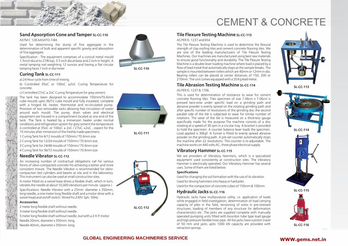
CEMENT & CONCRETE
11www.labtekindia.com
Tile Flexure Testing Machine AS PER IS: 1237 and 654The Tile Flexure Testing Machine is used to determine the flexural strength of clay roofing tiles and cement concrete flooring tiles. We are one of the leading manufacturers of Tile Flexure Testing Machines. Our machines are manufactured using best raw materials to ensure good functionality and durability. The Tile Flexure Testing Machine is a double lever loading machine where load is placed by a flow of lead metal that automatically stops as the sample breaks. The sample is mounted between rollers which are 40mm or 12mm in dia. Bearing rollers can be placed at center distances of 150, 200 or 270mm. The unit comes equipped with a 20 Kg lead metal.
Tile Abrasion Testing Machine AS PER IS: 1237 & 1706.This is used for determination of resistance to wear for cement concrete flooring tiles. Tiles specimen of size 7.06cm x 7.06cm is pressed tace-wise under specific load on a grinding path and abrasive powder is evenly spread on the rotating grinding path and after specific number of revolutions of the grinding disc the second parallel side of the tile is subjected to wear for similar number of rotations. The wear of the tile is measured on a thickness gauge specifically made fro the purpose.The machine consists of a disc rotating at a speed of 30 rpm in a circular tray. A bracket is provided to hold the specimen. A counter balance lever loads the specimen. Load applied is 30kgf. A funnel is fitted to evenly spread abrasive powder on the grinding path. A pre-set counter automatically stops the machine after 22 revolutions. This counter is re-adjustable. The machine works on 440 volts AC, three phase electrical supply.
Vibratory Hammer We are providers of Vibratory Hammers, which is a specialized equipment used consistently at construction sites. The Vibratory Hammer is electrically operated. Our Vibratory Hammer has several uses. Some of them are listed below.SpecificationsUsed for changing the soil formation with the use of its vibrationUsed for driving hammers into heavy or hard pilesUsed for the compaction of concrete cubes of 150mm & 100mm
Hydraulic Jacks Hydraulic Jacks have multipurpose utility, i.e. application of loads while engaged in field investigation, determination of load carrying capacity of piles in the field, tensioning of wires in pre-stressed structures, loading of members of any structure for deformation characteristics etc. The jacks are supplied complete with manually operated pumping units fitted with bourdon tube type load gauge and high pressure flexible hose pipe. All the jacks have a piston travel of 50 mm and jacks upto 1000 kN capacity are provided with retraction springs.
SL-CC-113
SL-CC-114
SL-CC-115
SL-CC-116
Sand Apsorption Cone and Tamper ASTM C 128 AASHTO-T-84.Used for determining the slump of fine aggregate in the determination of bulk and apparent specific gravity and absorption of fine aggregate.Specification : The equipment comprises of a conical metal mould 1.5inch dia at to 27/8 top, 3.5 inch dia at base and 2 inch in height. A metal tamping rod weighting 12 ounces and having a flat circular tamping faces 1 inch in dia meter
Curing Tank a) 24 Hour cycle from time of mixing.b) Controlled 35oC or 100oC ±2oC Curing Temperature for concrete.c) Controlled 27oC ± 2oC Curing Temperature for grey cement.The tank has been designed to accommodate 150mm/70.6mm cube moulds upto 36/72 cube mould and fully insulated, complete with a hinged lid, heater, thermostat and re-circulated pump. Provision of two removable racks allowing free circulation of water around each mould. The pump, drain valves and electrical equipment are housed in a compartment located at one end of the tank. The Tank is heated by a immersion heater under normal conditions and refrigeration system for grey cement the temperature is controlled at 35oC or 100oC ± 2oC / 27oC +2oC , expect for the 15 minutes after immersion of the freshly made specimens.1 Curing Tank for 6/12 moulds of 150mm / 70.6mm size2 Curing Tank for 12/24 moulds of 150mm / 70.6mm size3 Curing Tank for 24/48 moulds of 150mm / 70.6mm size4 Curing Tank for 36/72 moulds of 150mm / 70.6mm size
Needle Vibrator An increasing number of contractual obligations call for various forms of vibro-compacted concrete fro achieving a better and more consistent mixute. The Needle Vibrator is recommended for vibro-compaction test cylinders and beams at site and in the laboratory. This instrument can also be used at small construction sites.A motor fitted on a swivel base drives a flexible shaft, which in turn, vibrates the needle at about 10,000 vibrations per minute. (approx.)Specifications: Needle Vibrator with a 25mm. diameter x 350mm, long needle, a one meter long flexible shaft and a motor drive with a swivel head and on/off switch. Wired fro 230V. Sph. 50Hz.Accessories:2 meter long flexible shaft without needle.3 meter long flexible shaft without needle.5 meter long flexible shaft without needle, but with a 2 H.P. motor.Needle 20mm, diameter x 350mm. long.Needle 40mm, diameter x 350mm. long.
SL-CC-110
SL-CC-111
SL-CC-112
SL-CC-110
SL-CC-111
SL-CC-112
SL-CC-113
SL-CC-114
SL-CC-115
SL-CC-116
GLOBAL ENGINEERING MACHINERIES SERVICE WWW.gems.net.in

CEMENT & CONCRETE
www.labtekindia.com12
rubber hose pipe with end connections. The cell assembly consists of one base plate, one metal funnel and one top plate. The pressure chamber is fitted with a pressure regulator which helps in regulating the pressure from 0-15kg/cm sq. Gauge is for indicating the pressure in the cell. A foot pump and a pressure tube is supplied to develop pressure in the chamber. The apparatus is supplied with a measuring cylinder 500cc to measure percolated quantity to water. Pressure can also be applied; by a pressure air line or by a compressor which can be supplied at an extra cost.
Permeability App. (3 Cell Model) Same as above but supplied with three individual cells with stand. Three pressure gauges for indicating pressure in each cell are supplied apart from the main pressure gauge which indicates pressure chamber.
SL-CC-121
POZZOLANA Cement Mortar Permeability Apparatus (Three Cell Model) IS 1727-2645For water proofing of concrete admixture and special water proof cements are used. Water proofing of these compounds, is established by measuring permeability of standard mortar. Specimen with or without such water proofing compounds. Permeability apparatus in used to determine permeability to water of cement mortar specimens with or without water proofing compound.Specification : The mortar permeability apparatus comprises three brass/ gun metal cells mounted on a stand and a pressure chamber with a pressure regulator. The cell can accommodate 100mm dia x 50mm high specimen. Each cell assembly consists of the base plate. The base plate has one outlet for water and is recessed to hold the specimen in place with a ring washer in between. The top plate has an inlet for water and a suitable connector for the application of pressurized water in the cell the mount and collar are clamped between the base plate and the top plate with the help of four tension rods and nuts. The cells are mounted on a stand.The pressure chamber is fitted with a pressure regulator which helps in regulating the pressure from 0-7kg/sq. cm. The regulator has two pressure gauges, one for indicating the pressure in the chamber (0-10.5kg/sq.cm.) The pressure chamber is connected to the cells with pressure hoses and with couplings. This pressure chamber is fitted with valve. Pressure is applied to the pressure chamber with help of a foot pump and rubber hose which are supplied with the instrument.Cement Mortar Permeability App. (6 Cell Model) Cement Mortar Permeability App. (12 Cell Model) Same as above but twelve cells , mounted on a stand.Accessories : Specimen casting mould C.I. with base plate 100mm dia x 50mm height.Note : Where Larger Number Of Cells Are Used A Suitable Compressor In Place Of Pressure Chamber Is Recommended. This Compressor Can Be Supplied At Extra Cost.
Concrete Permeability Test App. As Per IS 3085 / DIN Standard(Single Cell Model)One of the durability test of concrete is to determine permeability of water through specimen. Permeability apparatus is used for determining the permeability of cement mortar and concrete specimens of 15cm cubes cast in the laboratory.Specification :The concrete permeability apparatus comprises of a brass / gunmetal cell of Square/Round cross-section mounted on a stand and a pressure chamber is connected to the cell through copper tubing and T-connector mounted on the stand with sleeve packed valve and
SL-CC-117
SL-CC-118SL-CC-119
SL-CC-120
SL-CC-118
SL-CC-121
SL-CC-120
GLOBAL ENGINEERING MACHINERIES SERVICE WWW. gems.net.in
Copyright © 2022 FDOKUMEN