mpt user instructions english 85392699 06-09 - ПромХимТех
41
MPT USER INSTRUCTIONS ENGLISH 85392699 06-09 1of 41 ® ® Pump Division Type MPT Centrifugal Pumps USER INSTRUCTIONS: INSTALLATION, OPERATION, MAINTENANCE PCN=85392699 07-09 (E) These instructions must be read prior to installing, operating, using and maintaining this equipment. ПромХимТех - официальный дистрибьютор и сервис-партнер www.promhimtech.ru [email protected] 8 800 250 0154
-
Upload
khangminh22 -
Category
Documents
-
view
0 -
download
0
Transcript of mpt user instructions english 85392699 06-09 - ПромХимТех

MPT USER INSTRUCTIONS ENGLISH 85392699 06-09
1of 41
®
®
Pump Division
Type MPT
Centrifugal Pumps
USER INSTRUCTIONS: INSTALLATION, OPERATION, MAINTENANCE PCN=85392699 07-09 (E)
These instructions must be read prior to installing , operating, using and maintaining this equipment.
ПромХимТех - официальный дистрибьютор и сервис-партнер www.promhimtech.ru [email protected] 8 800 250 0154

MPT USER INSTRUCTIONS ENGLISH 85392699 06-09
Page 2 of 41
®
CONTENTS Page
CONTENTS............................................................... 2
1 INTRODUCTION AND SAFETY ........................... 4 1.1 General ........................................................... 4 1.2 CE marking and approvals.............................. 4 1.3 Disclaimer ....................................................... 4 1.4 Copyright......................................................... 4 1.5 Duty conditions................................................ 4 1.6 Safety .............................................................. 5
1.6.1 Summary of safety markings .................. 5 1.6.2 Personnel qualification and training........ 5 1.6.3 Safety action ........................................... 5 1.6.4 Products used in potentially explosive
atmospheres .......................................... 6 1.7 Safety Labels .................................................. 9
1.7.1 Nameplates............................................. 9 1.7.2 Warning labels ........................................ 9
1.8 Noise level..................................................... 10
2 TRANSPORT AND STORAGE ........................... 11 2.1 Consignment receipt and unpacking............. 11 2.2 Handling ........................................................ 11 2.3 Lifting............................................................. 11 2.4 Storage.......................................................... 11
2.4.1 Storage – General................................. 12 2.4.2 Storage – Long Term ............................ 12
2.5 Recycling and end of product life.................. 12
3 DESCRIPTION .................................................... 12 3.1 General ......................................................... 12 3.2 Design of major parts .................................... 13
3.2.1 Pump casing ......................................... 13 3.2.2 Valve flap .............................................. 13 3.2.3 Impeller ................................................. 13 3.2.4 Wear plate............................................. 13 3.2.5 Cover Plate ........................................... 13 3.2.6 Shaft...................................................... 13 3.2.7 Stuffing box (Seal housing)................... 13 3.2.8 Shaft seal .............................................. 13 3.2.9 Bearing housing.................................... 13 3.2.10 Pump bearings and lubrication ........... 13 3.2.11 Impeller adjustment............................. 13 3.2.12 Driver .................................................. 13 3.2.13 Flexible coupling ..Error! Bookmark not
defined. 3.2.14 Coupling guards.................................. 14 3.2.15 Baseplates .......................................... 14
3.3 Performance and operating limits ................. 14 3.3.1 Performance ......................................... 14 3.3.2 Pressure limits ...................................... 14 3.3.3 Flange loads ......................................... 14 3.3.4 Pump lubricant data.............................. 15 3.3.5 Recommended bolting and screw
torques ................................................. 15
3.3.6 Temperature limitations .........................15
4 INSTALLATION....................................................15 4.1 Location .........................................................15 4.2 Foundation......................................................15
4.2.1 Install pump units ..................................15 4.2.2 Mount baseplate....................................15 4.2.3 Install baseplate ....................................16
4.3 Grouting .........................................................16 4.3.1 Grouting foundation bolts ......................16 4.3.2 Grouting baseplate ................................16 4.3.3 Grouting baseplate prevents movement
..............................................................16 4.4 Initial alignment..............................................16
4.4.1 Thermal expansion................................16 4.4.2 Alignment methods................................16
4.5 Piping.............................................................17 4.5.1 Protective covers...................................17 4.5.2 Forces and moments on pump flanges.17 4.5.3 Inlet pipe................................................17 4.5.4 Flow and pump suction .........................17 4.5.5 Fitting valves and easy maintenance ....17 4.5.6 Piping and fittings should be flushed
before use.............................................17 4.5.7 Corrosive liquids....................................17
4.6 Electrical Connections ...................................17 4.6.1 Qualified electrician ...............................17 4.6.2 Wiring motor ..........................................18 4.6.3 Emergency stopping..............................18 4.6.4 Rotation direction ..................................18
4.7 Final shaft alignment check ...........................18
5 COMISSIONING STARTUP, OPERATION, AND SHUTDOWN.......................................................18
5.1 Making ready for operation............................18 5.1.1 Lubrication.............................................18 5.1.2 Pre-operation check list..........................18
5.2 Starting the pump ...........................................19 5.2.1 Start-up ..................................................19 5.2.2 Priming plug ..........................................19 5.2.3 Discharge line........................................19 5.2.4 Correct rotation......................................19 5.2.5 Check outlet pressure and flow. ............19 5.2.6 Pressure ................................................19 5.2.7 Outlet valve ...........................................19 5.2.8 Check the pump unit for vibration or
overheating. ..........................................19 5.3 Running .........................................................19
5.3.1 Mechanical seals...................................19 5.3.2 Stop/start frequency ..............................19
5.4 Stopping and shutdown ..................................19 5.4.1 Close the outlet valve ............................19 5.4.2 Stop the pump .......................................19 5.4.3 Prolonged shutdowns............................19
6 MAINTENANCE ...................................................20
MPT USER INSTRUCTIONS ENGLISH 85392699 06-09
Page 3 of 41
®
6.1 Maintenance schedule .................................. 20 6.1.1 Routine inspection (daily/weekly) ......... 20 6.1.2 Periodic inspection (6 monthly) ............ 20
6.2 Lubrication data............................................. 20 6.2.1 Oil lubricated bearings and mechanical
seals ..................................................... 20 6.3 Mechanical seals........................................... 20 6.4 Dismantling ................................................... 20
6.4.1 General ................................................. 20 6.4.2 Dismantling the pump........................... 20 6.4.3 Genuine Flowserve parts...................... 20 6.4.4 Part numbers and identification ............ 21 6.4.5 Replacing coupling parts ...................... 21 6.4.6 Complete disassembly.......................... 21
6.5 Examination of parts ..................................... 21 6.5.1 Used parts............................................. 21 6.5.2 Casing, impeller, wear plate, and seal
housing................................................. 21 6.5.3 Shaft, keys, and impeller setscrew ....... 21 6.5.4 Gaskets, O-rings, and lip seals............. 21 6.5.5 Bearings................................................ 22 6.5.6 Suction flange and flap valve................ 22 6.5.7 Mechanical seal .................................... 22
6.6 Assembly....................................................... 22 6.6.1 To assemble the pump consult the
sectional drawings................................ 22 6.6.2 Prepare ................................................. 22 6.6.3 Bearings................................................ 22 6.6.4 Mechanical seal .................................... 22 6.6.5 Impeller ................................................. 22 6.6.6 Suction flange ....................................... 22 6.6.7 Coverplate/wear plate........................... 22 6.6.8 Back pull-out assembly/case ................ 23 6.6.9 Lubrication ............................................ 23 6.6.10 Final assembly..................................... 23
6.7 Spare Parts ................................................... 23 6.7.1 Ordering of spares ................................ 23 6.7.2 Pump details ......................................... 23 6.7.3 Genuine parts ....................................... 23 6.7.4 Recommended spares.......................... 23 6.7.5 Storage of spares.................................. 24
7 FAULTS; CAUSES AND REMEDIES.................. 23
8 PARTS LIST AND DRAWINGS........................... 27 8.1 Sectional Arrangement and Parts List
Drawings – MODEL 20 .................................. 27 8.2 Sectional Arrangement and Parts List
Drawings – MODEL 30 .................................. 29 8.3 Sectional Arrangement and Parts List
Drawings – MODEL 40 .................................. 31 8.4 Sectional Arrangement and Parts List
Drawings – MODEL 60 .................................. 31 8.5 Sectional Arrangement and Parts List
Drawings – MODEL 80 .................................. 35 8.6 Mechanical Seal Sectional Arrangement and
Parts List Drawing –
8.7 General Arrangement Drawing .................Error! Bookmark not defined.
9 CERTIFICATION..................................................37
10 OTHER RELEVANT DOCUMENTATION AND MANUALS...........................................................37
10.1 Supplementary Instruction Manuals ............37 10.2 Change notes ..............................................37
MPT USER INSTRUCTIONS ENGLISH 85392699 06-09
Page 4 of 41
®
1 INTRODUCTION AND SAFETY
1.1 General
These instructions must always be kept close to the product's operating location or directly with the product. Flowserve’s products are designed, developed, and manufactured with state-of-the-art technologies in modern facilities. The unit is produced with great care and commitment to continuous quality control, utilizing sophisticated quality techniques and safety requirements. Flowserve is committed to continuous quality improvement and being at your service for any further information about the product in its installation and operation or about its support products, repair, and diagnostic services. These instructions are intended to facilitate familiarization with the product and its permitted use. Operating the product in compliance with these instructions is important to help ensure reliability in service and avoid risks. The instructions may not take into account local regulations; ensure such regulations are observed by all, including those installing the product. Always coordinate repair activity with operations personnel, and follow all plant safety requirements and applicable safety and health laws/regulations.
These instructions must be read prior to installing, operating, using, and maintaining the equipment in any region worldwide. The equipment must not be put into service until all the conditions relating to safety, noted in the instructions, have been met. 1.2 CE marking and approvals It is a legal requirement that machinery and equipment put into service within certain regions of the world shall conform with the applicable CE Marking Directives covering Machinery and, where applicable, Low Voltage Equipment, Electromagnetic Compatibility (EMC), Pressure Equipment Directive (PED), and Equipment for Potentially Explosive Atmospheres (ATEX). Where applicable, the Directives and any additional Approvals cover important safety aspects relating to machinery and equipment and the satisfactory provision of technical documents and safety instructions. Where applicable, this document incorporates information relevant to these Directives and Approvals.
To confirm the Approvals applying and if the product is CE marked, check the serial number plate markings and the Certification. (See section 9, Certification.) 1.3 Disclaimer Information in these User Instructions is believed to be reliable. In spite of all the efforts of Flowserve to provide sound and all necessary information the content of this manual may appear insufficient and is not guaranteed by Flowserve as to its completeness or accuracy . Flowserve manufactures products to exacting International Quality Management System Standards as certified and audited by external Quality Assurance organizations. Genuine parts and accessories have been designed, tested, and incorporated into the products to help ensure continued product quality and performance in use. As Flowserve cannot test parts and accessories sourced from other vendors, the incorrect incorporation of such parts and accessories may adversely affect the performance and safety features of the products. The failure to properly select, install, or use authorized Flowserve parts and accessories is considered to be misuse. Damage or failure caused by misuse is not covered by Flowserve’s warranty. In addition, any modification of Flowserve products or removal of original components may impair the safety of these products in their use. 1.4 Copyright All rights reserved. No part of these instructions may be reproduced, stored in a retrieval system, or transmitted in any form or by any means without prior permission of Flowserve Pump Division. 1.5 Duty conditions This product has been selected to meet the specifications of your purchase order. The acknowledgement of these conditions has been sent separately to the Purchaser. A copy should be kept with these instructions.
The product must not be operated beyond the parameters specified for the application. If there is any doubt as to the suitability of the product for the application intended, contact Flowserve for advice, quoting the serial number. If the conditions of service on your purchase order are going to be changed (for example liquid pumped, temperature, or duty), it is requested that the user seeks Flowserve’s written agreement before start-up.

MPT USER INSTRUCTIONS ENGLISH 85392699 06-09
Page 5 of 41
®
1.6 Safety 1.6.1 Summary of safety markings These User Instructions contain specific safety markings where non-observance of an instruction would cause hazards. The specific safety markings are:
This symbol indicates electrical safety instructions where non-compliance will involve a high risk to personal safety or the loss of life.
This symbol indicates safety instructions where non-compliance would affect personal safety and could result in loss of life.
This symbol indicates “hazardous and toxic fluid” safety instructions where non-compliance would affect personal safety and could result in loss of life.
This symbol indicates safety instructions where non-compliance will involve some risk to safe operation and personal safety and would damage the equipment or property.
This symbol indicates explosive atmosphere zone marking according to ATEX. It is used in safety instructions where non-compliance in the hazardous area would cause the risk of an explosion.
This sign is not a safety symbol but indicates an important instruction in the assembly process. 1.6.2 Personnel qualification and training All personnel involved in the operation, installation, inspection, and maintenance of the unit must be qualified to carry out the work involved. If the personnel in question do not already possess the necessary knowledge and skill, appropriate training and instruction must be provided. If required, the operator may commission the manufacturer/supplier to provide applicable training. Always coordinate repair activity with operations and health and safety personnel and follow all plant safety requirements and applicable safety and health laws and regulations. 1.6.3 Safety action This is a summary of conditions and actions to help prevent injury to personnel and damage to the environment and to equipment. For products used in potentially explosive atmospheres section 1.6.4 also applies.
NEVER DO MAINTENANCE WORK WHEN THE UNIT IS CONNECTED TO POWER (Lock out.)
DRAIN THE PUMP AND ISOLATE PIPING BEFORE DISMANTLING THE PUMP The appropriate safety precautions should be taken where the pumped liquids are hazardous.
FLUOROELASTOMERS (When fitted.) When a pump has experienced temperatures over 250 °C (482 °F), partial decomposition of fluoroelastomers (example: Viton) will occur. In this condition these are extremely dangerous and skin contact must be avoided.
HANDLING COMPONENTS Many precision parts have sharp corners and the wearing of appropriate safety gloves and equipment is required when handling these components. To lift heavy pieces above 25 kg (55 lb) use a crane appropriate for the mass and in accordance with current local regulations.
NEVER OPERATE THE PUMP WITHOUT THE COUPLING GUARD AND ALL OTHER SAFETY DEVICES CORRECTLY INSTALLED
GUARDS MUST NOT BE REMOVED WHILE THE PUMP IS OPERATIONAL
THERMAL SHOCK Rapid changes in the temperature of the liquid within the pump can cause thermal shock, which can result in damage or breakage of components and should be avoided.
NEVER APPLY HEAT TO REMOVE IMPELLER Trapped lubricant or vapor could cause an explosion.
HOT (and cold) PARTS If hot or freezing components or auxiliary heating equipment can present a danger to operators and persons entering the immediate area, action must be taken to avoid accidental contact (such as shielding). If complete protection is not possible, the machine access must be limited to maintenance staff only with clear visual warnings and indicators to those entering the immediate area. Note: bearing housings must not be insulated and drive motors and bearings may be hot. If the temperature is greater than 68 °C (175 °F), below 5 °C (20 °F) in a restricted zone, or exceeds local regulations, action as above shall be taken.

MPT USER INSTRUCTIONS ENGLISH 85392699 06-09
Page 6 of 41
®
HAZARDOUS LIQUIDS When the pump is handling hazardous liquids, care must be taken to avoid exposure to the liquid by appropriate pump placement, limiting personnel access, and by operator training. If the liquid is flammable and/or explosive, strict safety procedures must be applied. Gland packing must not be used when pumping hazardous liquids.
PREVENT EXCESSIVE EXTERNAL PIPE LOAD Do not use pump as a support for piping. Do not mount expansion joints, unless allowed by Flowserve in writing, so that their force, due to internal pressure, acts on the pump flange.
ENSURE CORRECT LUBRICATION (See section 6.2, Lubrication Data.)
NEVER EXCEED THE MAXIMUM DESIGN PRESSURE (MDP) AT THE TEMPERATURE SHOWN ON THE PUMP NAMEPLATE (See section 3.3, Performance and operating limits, for pressure versus temperature ratings based on the material of construction.)
NEVER OPERATE THE PUMP WITH THE DISCHARGE VALVE CLOSED (Unless otherwise instructed at a specific point in the User Instructions.)
NEVER RUN THE PUMP DRY OR WITHOUT PROPER PRIME (Casing flooded)
NEVER OPERATE THE PUMP WITH THE SUCTION VALVE CLOSED It should be fully opened when the pump is running.
NEVER OPERATE THE PUMP AT ZERO FLOW OR FOR EXTENDED PERIODS BELOW THE MINIMUM CONTINUOUS FLOW
THE PUMP SHAFT MUST TURN CLOCKWISE WHEN VIEWED FROM THE MOTOR END It is absolutely essential that the rotation of the motor be checked before installation of the coupling spacer and starting the pump. Incorrect rotation of the pump for even a short period can unscrew the impeller, which can cause significant damage.
1.6.4 Products used in potentially explosive atmospheres Always check that the driver, drive coupling assembly and pump equipment are suitably rated and/or certified for the classification of the specific atmosphere in which they are installed. See section 9, Certification.
Measures are required to: • Avoid excess temperature • Prevent build up of explosive mixtures • Prevent the generation of sparks • Prevent leakages • Maintain the pump to avoid hazard The following instructions for pumps and pump units when installed in potentially explosive atmospheres must be followed to help ensure explosion protection. Both electrical and non-electrical equipment must meet the requirements of European Directive 94/9/EC. 1.6.4.1 Scope of compliance
Use equipment only in the zone for which it is appropriate. Always check that the driver, drive coupling assembly, seal and pump equipment are suitably rated and/or certified for the classification of the specific atmosphere in which they are to be installed. Where Flowserve has supplied only the bare shaft pump, the Ex rating applies only to the pump. The party responsible for assembling the pump set shall select the coupling, driver, seal and any additional equipment, with the necessary CE Certificate/ Declaration of Conformity establishing it is suitable for the area in which it is to be installed. The output from a variable frequency drive (VFD) can cause additional heating effects in the motor. On pump installations controlled by a VFD, the ATEX Certification for the motor must state that it covers the situation where electrical supply is from the VFD. This particular requirement still applies even if the VFD is in a safe area.

MPT USER INSTRUCTIONS ENGLISH 85392699 06-09
Page 7 of 41
®
1.6.4.2 Marking An example of ATEX equipment marking is shown below. The actual classification of the pump will be engraved on the nameplate.
II 2 GD c IIC 135 ºC (T4) Equipment Group I = Mining II = Non-mining
Category 2 or M2 = High level protection 3 = normal level of protection
Gas and/or dust G = Gas D= Dust
c = Constructional safety (in accordance with En13463-5)
Gas Group (Equipment Category 2 only) IIA – Propane (Typical) IIB – Ethylene (Typical) IIC – Hydrogen (Typical)
Maximum surface temperature (Temperature Class) (see section 1.6.4.3) 1.6.4.3 Avoiding excessive surface temperatures
ENSURE THE EQUIPMENT TEMPERATURE CLASS IS SUITABLE FOR THE HAZARD ZONE Pump liquid temperature Pumps have a temperature class as stated in the ATEX Ex rating on the nameplate. These are based on a maximum ambient temperature of 40 °C (104 °F); refe r to Flowserve for higher ambient temperatures. The surface temperature on the pump is influenced by the temperature of the liquid handled. The maximum permissible liquid temperature depends on the temperature class and must not exceed the values in the table applicable below. The temperature rise at the seals and bearings and due to the minimum permitted flow rate is taken into account in the temperatures stated. Maximum permitted liquid temperature for pumps
Temperature class to
EN 13463-1
Maximum surface
temperature permitted
Temperature limit of liquid handled (* depending on material and construction
variant – check which is lower) T6 T5 T4 T3 T2 T1
85 °C (185 °F) 100 °C (212 °F) 135 °C (275 °F) 200 °C (392 °F) 300 °C (572 °F) 450 °C (842 °F)
Consult Flowserve Consult Flowserve
115 °C (239 °F)* 180 °C (356 °F)* 275 °C (527 °F)* 400 °C (752 °F)*
Maximum permitted liquid temperature for pumps with self priming casing
Temperature class to
EN 13463-1
Maximum surface
temperature permitted
Temperature limit of liquid handled (* depending on material and construction
variant – check which is lower) T6 T5 T4 T3 T2 T1
85 °C (185 °F) 100 °C (212 °F) 135 °C (275 °F) 200 °C (392 °F) 300 °C (572 °F) 450 °C (842 °F)
Consult Flowserve Consult Flowserve
110 °C (230 °F)* 175 °C (347 °F)* 270 °C (518 °F)* 350 °C (662 °F)*
The responsibility for compliance with the specifie d maximum liquid temperature is with the plant operator. Temperature classification “Tx” is used when the liquid temperature varies and the pump could be installed in different hazardous atmospheres. In this case the user is responsible for ensuring that the pump surface temperature does not exceed that permitted in the particular hazardous atmosphere. Do not attempt to check the direction of rotation with the coupling element/pins fitted due to the risk of severe contact between rotating and stationary components. Where there is any risk of the pump being run against a closed valve generating high liquid and casing external surface temperature, it is recommended that users fit an external surface temperature protection device. Avoid mechanical, hydraulic or electrical overload by using motor overload trips, temperature monitor, or a power monitor and perform routine vibration monitoring. In dirty or dusty environments, regular checks must be made and dirt removed from areas around close clearances, bearing housings, and motors. Additional requirements for self-priming casing pumps Where the system operation does not ensure control of priming, as defined in the User Instructions, and the maximum permitted surface temperature of the T Class could be exceeded, it is recommended that user install an external surface temperature protection device. 1.6.4.4 Preventing the build up of explosive mixtures
ENSURE PUMP IS PROPERLY FILLED AND VENTED AND DOES NOT RUN DRY Ensure that the pump and relevant suction and discharge piping is totally filled with liquid at all times during the pumps operation so that an explosive atmosphere is prevented.
MPT USER INSTRUCTIONS ENGLISH 85392699 06-09
Page 8 of 41
®
In addition, it is essential to make sure that seal chambers, auxiliary shaft seal systems and any heating and cooling systems are properly filled. If the operation of the system can not avoid this condition it is recommended that you fit an appropriate dry run protection device (for example liquid detection or a power monitor). To avoid potential hazards from fugitive emissions of vapor or gas to atmosphere, the surrounding area must be well ventilated. 1.6.4.5 Preventing sparks
To prevent a potential hazard from mechanical contact, the coupling guard must be non-sparking for Category 2. To avoid the potential hazard from random induced current generating a spark, the baseplate must be properly grounded. Avoid electrostatic charge. Do not rub non-metallic surfaces with a dry cloth; ensure the cloth is damp. The coupling must be selected to comply with 94/9/EC and correct alignment must be maintained. Additional requirements for pumps on non-metallic baseplates When metallic components are fitted on a non-metallic baseplate they must be individually earthed. 1.6.4.6 Preventing leakage
Pumps with mechanical seal. The pump must only be used to handle liquids for which it has been approved to have the correct corrosion resistance. Avoid entrapment of liquid in the pump and associated piping due to closing of suction and discharge valves, which could cause dangerous excessive pressures to occur if there is heat input to the liquid. This can occur if the pump is stationary or running. Bursting of liquid containing parts due to freezing must be avoided by draining or protecting the pump and auxiliary systems. Where there is the potential hazard of a loss of a seal barrier fluid or external flush, the fluid must be monitored. If leakage of liquid to atmosphere can result in a hazard, the installation of a liquid detection device is recommended.
1.6.4.7 Maintenance of the centrifugal pump to avoid a hazard
CORRECT MAINTENANCE IS REQUIRED TO AVOID POTENTIAL HAZARDS WHICH GIVE A RISK OF EXPLOSION The responsibility for compliance with maintenance instructions is with the plant operator. To avoid potential explosion hazards during maintenance, the tools, cleaning and painting materials used must not give rise to sparking or adversely affect the ambient conditions. Where there is a risk from such tools or materials, maintenance must be conducted in a safe area. It is recommended that a maintenance plan and schedule is adopted. (See section 6, Maintenance.)
MPT USER INSTRUCTIONS ENGLISH 85392699 06-09
Page 9 of 41
®
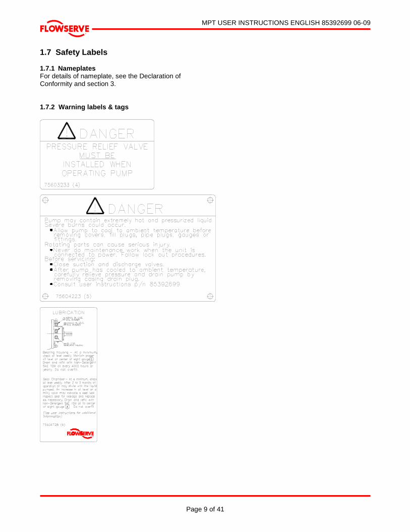
1.7 Safety Labels 1.7.1 Nameplates For details of nameplate, see the Declaration of Conformity and section 3. 1.7.2 Warning labels & tags
MPT USER INSTRUCTIONS ENGLISH 85392699 06-09
Page 10 of 41
®
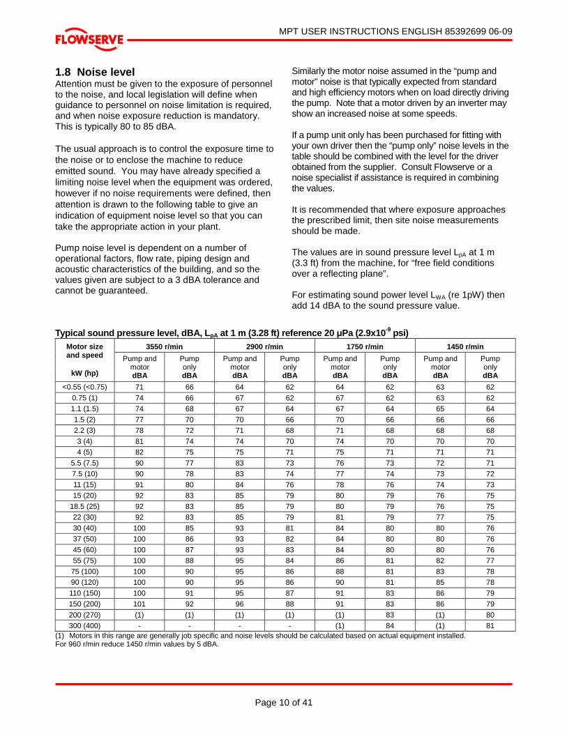
1.8 Noise level Attention must be given to the exposure of personnel to the noise, and local legislation will define when guidance to personnel on noise limitation is required, and when noise exposure reduction is mandatory. This is typically 80 to 85 dBA. The usual approach is to control the exposure time to the noise or to enclose the machine to reduce emitted sound. You may have already specified a limiting noise level when the equipment was ordered, however if no noise requirements were defined, then attention is drawn to the following table to give an indication of equipment noise level so that you can take the appropriate action in your plant. Pump noise level is dependent on a number of operational factors, flow rate, piping design and acoustic characteristics of the building, and so the values given are subject to a 3 dBA tolerance and cannot be guaranteed.
Similarly the motor noise assumed in the “pump and motor” noise is that typically expected from standard and high efficiency motors when on load directly driving the pump. Note that a motor driven by an inverter may show an increased noise at some speeds. If a pump unit only has been purchased for fitting with your own driver then the “pump only” noise levels in the table should be combined with the level for the driver obtained from the supplier. Consult Flowserve or a noise specialist if assistance is required in combining the values. It is recommended that where exposure approaches the prescribed limit, then site noise measurements should be made. The values are in sound pressure level LpA at 1 m (3.3 ft) from the machine, for “free field conditions over a reflecting plane”. For estimating sound power level LWA (re 1pW) then add 14 dBA to the sound pressure value.
Typical sound pressure level, dBA, L pA at 1 m (3.28 ft) reference 20 µPa (2.9x10⁻⁹ psi) 3550 r/min 2900 r/min 1750 r/min 1450 r/min Motor size
and speed
kW (hp)
Pump and motor dBA
Pump only dBA
Pump and motor dBA
Pump only dBA
Pump and motor dBA
Pump only dBA
Pump and motor dBA
Pump only dBA
<0.55 (<0.75) 71 66 64 62 64 62 63 62
0.75 (1) 74 66 67 62 67 62 63 62 1.1 (1.5) 74 68 67 64 67 64 65 64
1.5 (2) 77 70 70 66 70 66 66 66 2.2 (3) 78 72 71 68 71 68 68 68
3 (4) 81 74 74 70 74 70 70 70 4 (5) 82 75 75 71 75 71 71 71
5.5 (7.5) 90 77 83 73 76 73 72 71 7.5 (10) 90 78 83 74 77 74 73 72
11 (15) 91 80 84 76 78 76 74 73 15 (20) 92 83 85 79 80 79 76 75
18.5 (25) 92 83 85 79 80 79 76 75 22 (30) 92 83 85 79 81 79 77 75
30 (40) 100 85 93 81 84 80 80 76 37 (50) 100 86 93 82 84 80 80 76
45 (60) 100 87 93 83 84 80 80 76 55 (75) 100 88 95 84 86 81 82 77
75 (100) 100 90 95 86 88 81 83 78 90 (120) 100 90 95 86 90 81 85 78
110 (150) 100 91 95 87 91 83 86 79 150 (200) 101 92 96 88 91 83 86 79
200 (270) (1) (1) (1) (1) (1) 83 (1) 80
300 (400) - - - - (1) 84 (1) 81 (1) Motors in this range are generally job specific and noise levels should be calculated based on actual equipment installed. For 960 r/min reduce 1450 r/min values by 5 dBA.
MPT USER INSTRUCTIONS ENGLISH 85392699 06-09
Page 11 of 41
®
2 TRANSPORT AND STORAGE 2.1 Consignment receipt and unpacking Immediately after receipt of the equipment it must be checked against the delivery/shipping documents for its completeness and that there has been no damage in transportation. Any shortage and/or damage must be reported immediately to Flowserve Pump Division and must be received in writing within ten days of receipt of the equipment. Later claims cannot be accepted. Check any crate, boxes or wrappings for any accessories or spare parts that may be packed separately with the equipment or attached to side walls of the box or equipment. Each product has a unique serial number. Check that this number corresponds with that advised and always quote this number in correspondence as well as when ordering spare parts or further accessories. 2.2 Handling Boxes, crates, pallets, or cartons may be unloaded using forklift vehicles or slings dependent on their size and construction. 2.3 Lifting
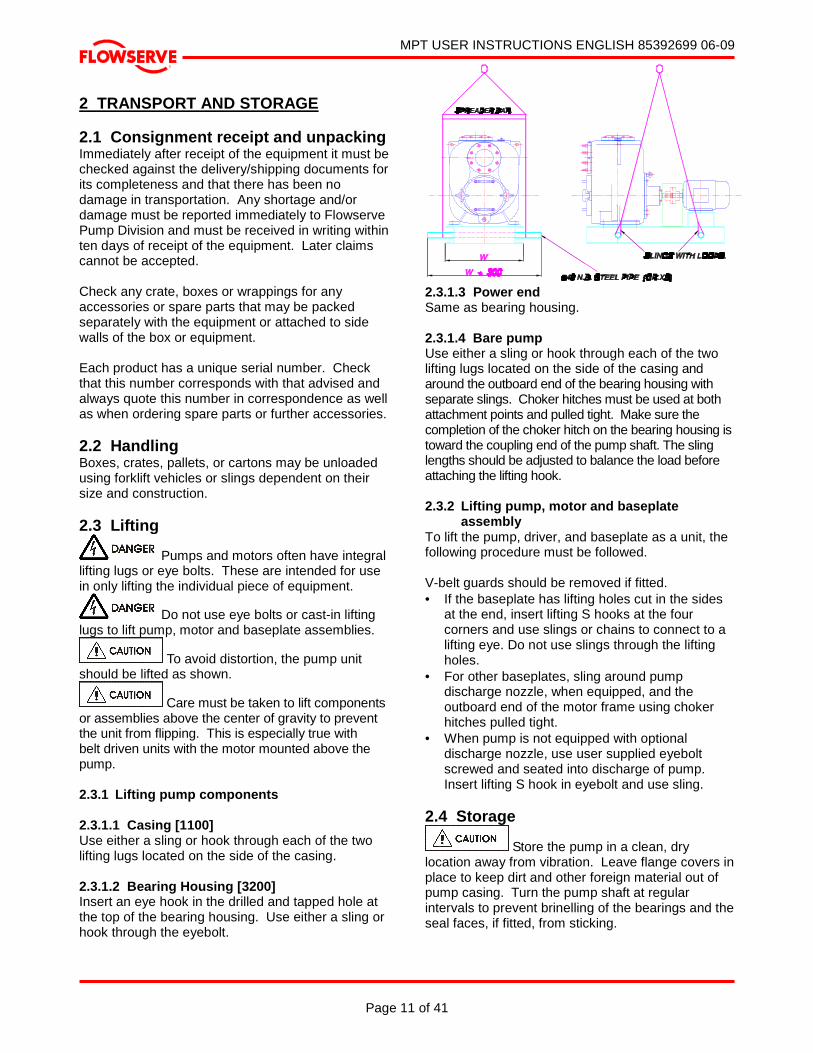
Pumps and motors often have integral lifting lugs or eye bolts. These are intended for use in only lifting the individual piece of equipment.
Do not use eye bolts or cast-in lifting lugs to lift pump, motor and baseplate assemblies.
To avoid distortion, the pump unit should be lifted as shown.
Care must be taken to lift components or assemblies above the center of gravity to prevent the unit from flipping. This is especially true with belt driven units with the motor mounted above the pump. 2.3.1 Lifting pump components 2.3.1.1 Casing [1100] Use either a sling or hook through each of the two lifting lugs located on the side of the casing. 2.3.1.2 Bearing Housing [3200] Insert an eye hook in the drilled and tapped hole at the top of the bearing housing. Use either a sling or hook through the eyebolt.
2.3.1.3 Power end Same as bearing housing. 2.3.1.4 Bare pump Use either a sling or hook through each of the two lifting lugs located on the side of the casing and around the outboard end of the bearing housing with separate slings. Choker hitches must be used at both attachment points and pulled tight. Make sure the completion of the choker hitch on the bearing housing is toward the coupling end of the pump shaft. The sling lengths should be adjusted to balance the load before attaching the lifting hook. 2.3.2 Lifting pump, motor and baseplate
assembly To lift the pump, driver, and baseplate as a unit, the following procedure must be followed. V-belt guards should be removed if fitted. • If the baseplate has lifting holes cut in the sides
at the end, insert lifting S hooks at the four corners and use slings or chains to connect to a lifting eye. Do not use slings through the lifting holes.
• For other baseplates, sling around pump discharge nozzle, when equipped, and the outboard end of the motor frame using choker hitches pulled tight.
• When pump is not equipped with optional discharge nozzle, use user supplied eyebolt screwed and seated into discharge of pump. Insert lifting S hook in eyebolt and use sling.
2.4 Storage
Store the pump in a clean, dry location away from vibration. Leave flange covers in place to keep dirt and other foreign material out of pump casing. Turn the pump shaft at regular intervals to prevent brinelling of the bearings and the seal faces, if fitted, from sticking.

MPT USER INSTRUCTIONS ENGLISH 85392699 06-09
Page 12 of 41
®
The pump may be stored as above for up to 6 months. Consult Flowserve for preservative actions when a longer storage period is needed. 2.4.1 Storage – General Normal packaging is designed to protect the pump and parts during shipment and for dry, indoor storage for up to six months or less. The following is an overview of our normal packaging: • All loose unmounted items are packaged in a
water proof plastic bag and placed under the coupling guard
• Inner surfaces of the bearing housing, shaft (area through bearing housing) and bearings are coated with Cortec VCI-329 rust inhibitor, or equal.
Bearing housings are not filled with oil prior to shipment
• The internal surfaces of ferrous casings, covers, seal chamber, flange faces, and the impeller surface are sprayed with Cortec VCI-389, or equal
• Exposed shafts are taped with Polywrap • Flange covers are secured to both the suction
and discharge flanges or face. • In some cases with assemblies ordered with
external piping, components may be disassembled for shipment
• The pump must be stored in a covered, dry location
2.4.2 Storage – Long Term Long term storage is defined as more than six months, but less than 12 months. The procedure Flowserve follows for long term storage of pumps is given below. These procedures are in addition to the short term procedure. • Each assembly is hermetically (heat) sealed
from the atmosphere by means of tack wrap sheeting and rubber bushings (mounting holes)
• Desiccant bags are placed inside the tack wrapped packaging
• A solid wood box is used to cover the assembly This packaging will provide protection for up to twelve months from humidity, salt laden air, dust etc. Warranty for the pumps will normally be for 12 months. Extension of this period can only be achieved with the prior agreement of Flowserve and would necessitate inspection prior to putting the pump into service. After unpacking, protection will be the responsibility of the user. Addition of oil to the bearing housing will remove the inhibitor. If units are to be idle for extended
periods after addition of lubricants, inhibitor oils should be used. Every three months, the pump shaft should be rotated approximately 10 revolutions. 2.5 Recycling and end of product life At the end of the service life of the product or its parts, the relevant materials and parts should be recycled or disposed of using an environmentally acceptable method and in accordance with local regulations. If the product contains substances that are harmful to the environment, these should be removed and disposed of in accordance with current local regulations. This also includes the liquids and/or gases that may be used in the "seal system" or other utilities.
Make sure that hazardous substances are disposed of safely and that the correct personal protective equipment is used. The safety specifications must be in accordance with the current local regulations at all times. 3 DESCRIPTION 3.1 General The Flowserve MPT single stage pump has a back pull-out rotating assembly with suction and discharge facings on the fixed casing to allow removal of the rotating element without breaking the pipe joints or moving the driver. Mounting feet are rigidly connected to the casing so piping strains allowed in section 2.3, Flange Loads, are readily transmitted to the foundation. No special tools are required for dismantling and maintenance. An example of the nameplate used on the MPT pump, which is always mounted on the casing, is shown below.
Serial No. Equipment No.
Purchase Order Model
Size MDP
Material Date

MPT USER INSTRUCTIONS ENGLISH 85392699 06-09
Page 13 of 41
®
3.2 Design of major parts 3.2.1 Pump casing The volute type casing with integral priming chamber is of rugged heavy duty construction for minimum wear under the toughest operating conditions. Removal of the casing is not required when performing maintenance of the rotating element. The pump is designed with radial o-ring seals allowing the rotating element and cover plate to be easily removed (back pull out). 3.2.2 Valve flap The pump suction opening is fitted with a non-return flap valve. The flap is a solid one-piece design and is easily removed for cleaning or replacement. 3.2.3 Impeller A fully balanced semi-open two vane impeller is spigotted and screwed to the shaft. The back of the impeller has integrally cast clearing vanes. 3.2.4 Wear plate The casing is fitted with a reversible and renewable steel front wear plate which is a close clearance against the impeller vanes. If the wear plate becomes excessively worn, it can be reversed to present its unworn face to the impeller. The Model 80 wear plate is not reversible. 3.2.5 Cover Plate A large cover plate below the suction facing retained by two hand nuts is easily removed to access the impeller and wear plate for fast cleanout of clogged or tangled solids.
A PRESSURE RELIEF VALVE IS FITTED TO THE COVER PLATE AND MUST NOT BE REMOVED, PLUGGED OR MODIFIED. 3.2.6 Shaft The shaft is of ample size to transmit the maximum power required and to minimize deflection and vibration even during intermittent stop-start operation. Keys are used to transmit the torque. The shaft drive end and keyway are in accordance with ANSI B17.1. 3.2.7 Stuffing box (Seal housing) The seal housing is positively located, sealed and fastened to the bearing housing and forms an oil chamber in which the seal runs fully immersed. The oil cools and lubricates the seal faces and prevents seal damage if the pump is run dry. The oil level is monitored via the sight glass fitted high on the
bearing housing allowing the pump to be shut down in the event of a seal failure – indicated by a sudden drop in oil level or product showing in the oil. A vent is also fitted at the top of the housing to maintain even atmospheric pressure in the oil chamber. The seal housing is easily replaceable if wear from the impeller back sealing vanes becomes excessive. 3.2.8 Shaft seal The stuffing box is fitted with a double mechanical seal; the pump end has a hard faced balanced rotary unit to prevent liquid and grit entering the seal chamber. The outboard end separates the seal and bearing oil chambers. 3.2.9 Bearing housing The robustly designed bearing housing is rigidly bolted and sealed to the pump casing. The housing is fitted with oil breather/fillers and sight glasses to indicate fill and low oil levels. The end cover is fitted with a lip seal to exclude dirt and moisture. An eyebolt is fitted to the housing for back pull-out withdrawal. 3.2.10 Pump bearings and lubrication The pump is fitted with two different types of ball bearings. The thrust bearing is a double row angular contact ball bearing, and the radial bearing a single row deep groove ball bearing. The thrust bearing is fitted at the outboard end in all pumps except the MODEL 80, which has it fitted at the inboard end. Both bearings run in a common oil bath and are sized for a long service life. 3.2.11 Impeller adjustment The bearing housing (back pull-out assembly) is fastened to the casing with four locknuts; these locknuts pass through four adjustable spacers in the bearing housing flange. Accurate impeller setting is affected by adjustment of these spacer and locking with the locknuts. The correct adjustment is 0.38/0.25 mm (0.015/0.010 in.) clearance between impeller vanes and wear plate. Clearance between the impeller and seal housing is fixed and does not need adjustment. 3.2.12 Driver The driver is normally an electric motor. Different drive configurations may be fitted such as an internal combustion engine, turbines, hydraulic motors, etc driving via couplings, belts, gearboxes, drive shafts, etc.

MPT USER INSTRUCTIONS ENGLISH 85392699 06-09
Page 14 of 41
®
If the driver is an internal combustion engine which has not been supplied by Flowserve, a torsional analysis must be undertaken by the supplier to select the correct type of coupling in order to avoid shaft failure. 3.2.13 Guards Fabricated heavy duty sheet steel or aluminum solid or vented guards are provided to suit customer specific needs. 3.2.14 Baseplates Standard baseplates are steel fabrications. Long coupled and v-belt driven arrangement are available. Horizontal driver alignment screws and baseplate vertical leveling screws are provided as an option. Special baseplates can be supplied to suit individual installation needs.
3.3 Performance and operating limits 3.3.1 Performance MPT pumps are furnished for a particular duty and service conditions advised on your order (See section 1.5, Duty Conditions). Changes in the hydraulic system will affect the pump’s performance. 3.3.2 Pressure limits The operating pressure has been selected to meet your specific requirements. See section 1.5, Duty Conditions for details.
The pressure and temperature operating limits for the flanges are in accordance with the relevant National or International standards unless advised otherwise.
3.3.3 Flange loads The permissible flange loading has been listed in the table below.
Maximum forces (kN (lbf)) and Moments (kN.m (lbf.ft)) Pump Size Fx Fy Fz Mx My Mz
MODEL 20 293.7
(66 023.8) 234.3
(526 703.6) 191.4
(43 026.7) 151.8
(111 967.7) 75.9
(55 983.8) 115.5
(85 192.8)
MODEL 30 438.9
(98 664.7) 353.1
(79 376.9) 293.7
(66 023.8) 313.5
(231 237.6) 155.1
(114 401.8) 237.6
(175 253.8)
MODEL 40 587.4
(132 047.5) 468.6
(105 341.3) 382.8
(86 053.4) 438.9
(323 732.6) 224.4
(165 517.4) 330
(243 408)
MODEL 60 1026.3
(230 712.2) 821.7
(184 718.2) 676.5
(152 077.2) 759
(229 838.4) 389.4
(287 221.4) 580.8
(428 398.1)
Suc
tion
MODEL 80 1613.7
(362 759.8) 1247.4
(280 415.5) 1026.3
(230 712.2) 1164.9
(859 230.2) 580.8
(428 398.1) 851.4
(627 992.6)
MODEL 20 234.3
(52 670.6) 191.4
(43 026.7) 293.7
(66 023.8) 151.8
(111 967.7) 75.9
(55 983.8) 115.5
(85 192.8)
MODEL 30 353.1
(79 376.9) 293.7
(66 023.8) 438.9
(98 664.7) 313.5
(231 237.6) 155.1
(114 401.8) 237.6
(175 253.8)
MODEL 40 468.6
(105 341.3) 382.8
(86 053.4) 587.4
(132 047.5) 438.9
(323 732.6) 224.4
(165 517.44) 330
(243 408)
MODEL 60 234.3
(52 670.6) 191.4
(43 026.7) 293.7
(66 023.8) 151.8
(111 967.7) 75.9
(55 983.8) 115.5
(85 192.8)
Dis
char
ge
MODEL 80
1247.4 (280 415.5)
1026.3 (230 712.2)
1613.7 (262 759.8)
1164.9 (859 230.2)
580.8 (428 398.08)
851.4 (627 992.6)
MPT USER INSTRUCTIONS ENGLISH 85392699 06-09
Page 15 of 41
®
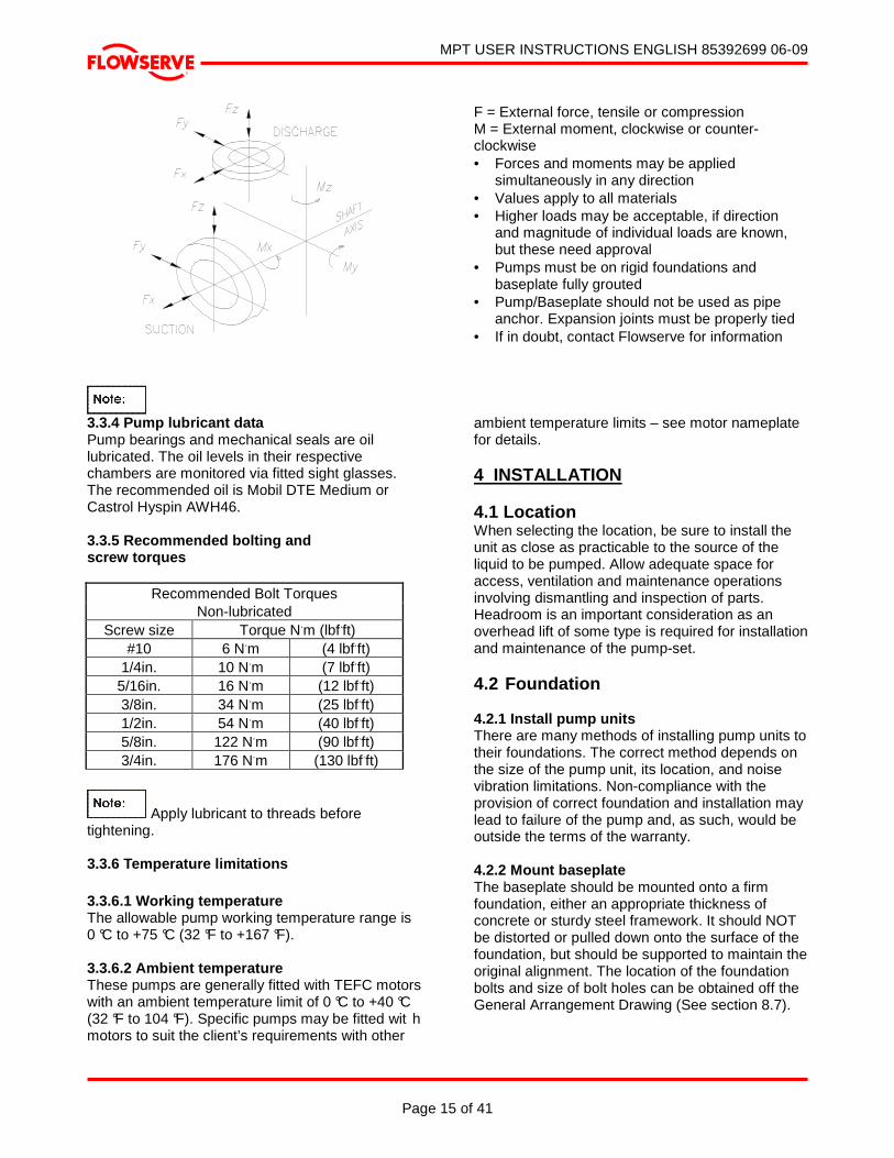
F = External force, tensile or compression M = External moment, clockwise or counter-clockwise • Forces and moments may be applied
simultaneously in any direction • Values apply to all materials • Higher loads may be acceptable, if direction
and magnitude of individual loads are known, but these need approval
• Pumps must be on rigid foundations and baseplate fully grouted
• Pump/Baseplate should not be used as pipe anchor. Expansion joints must be properly tied
• If in doubt, contact Flowserve for information
3.3.4 Pump lubricant data Pump bearings and mechanical seals are oil lubricated. The oil levels in their respective chambers are monitored via fitted sight glasses. The recommended oil is Mobil DTE Medium or Castrol Hyspin AWH46. 3.3.5 Recommended bolting and screw torques
Recommended Bolt Torques Non-lubricated
Screw size Torque N.m (lbf.ft) #10 6 N.m (4 lbf.ft)
1/4in. 10 N.m (7 lbf.ft) 5/16in. 16 N.m (12 lbf.ft) 3/8in. 34 N.m (25 lbf.ft) 1/2in. 54 N.m (40 lbf.ft) 5/8in. 122 N.m (90 lbf.ft) 3/4in. 176 N.m (130 lbf.ft)
Apply lubricant to threads before tightening. 3.3.6 Temperature limitations 3.3.6.1 Working temperature The allowable pump working temperature range is 0 °C to +75 °C (32 °F to +167 °F). 3.3.6.2 Ambient temperature These pumps are generally fitted with TEFC motors with an ambient temperature limit of 0 °C to +40 °C (32 °F to 104 °F). Specific pumps may be fitted wit h motors to suit the client’s requirements with other
ambient temperature limits – see motor nameplate for details. 4 INSTALLATION 4.1 Location When selecting the location, be sure to install the unit as close as practicable to the source of the liquid to be pumped. Allow adequate space for access, ventilation and maintenance operations involving dismantling and inspection of parts. Headroom is an important consideration as an overhead lift of some type is required for installation and maintenance of the pump-set. 4.2 Foundation 4.2.1 Install pump units There are many methods of installing pump units to their foundations. The correct method depends on the size of the pump unit, its location, and noise vibration limitations. Non-compliance with the provision of correct foundation and installation may lead to failure of the pump and, as such, would be outside the terms of the warranty. 4.2.2 Mount baseplate The baseplate should be mounted onto a firm foundation, either an appropriate thickness of concrete or sturdy steel framework. It should NOT be distorted or pulled down onto the surface of the foundation, but should be supported to maintain the original alignment. The location of the foundation bolts and size of bolt holes can be obtained off the General Arrangement Drawing (See section 8.7).
MPT USER INSTRUCTIONS ENGLISH 85392699 06-09
Page 16 of 41
®
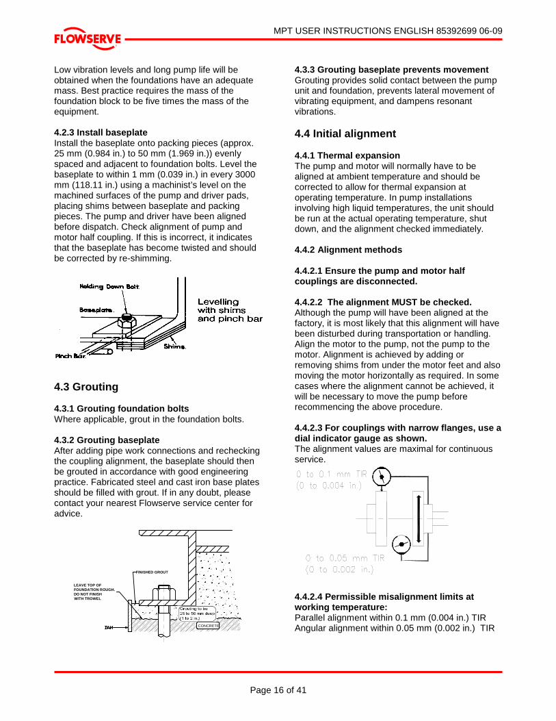
Low vibration levels and long pump life will be obtained when the foundations have an adequate mass. Best practice requires the mass of the foundation block to be five times the mass of the equipment. 4.2.3 Install baseplate Install the baseplate onto packing pieces (approx. 25 mm (0.984 in.) to 50 mm (1.969 in.)) evenly spaced and adjacent to foundation bolts. Level the baseplate to within 1 mm (0.039 in.) in every 3000 mm (118.11 in.) using a machinist’s level on the machined surfaces of the pump and driver pads, placing shims between baseplate and packing pieces. The pump and driver have been aligned before dispatch. Check alignment of pump and motor half coupling. If this is incorrect, it indicates that the baseplate has become twisted and should be corrected by re-shimming.
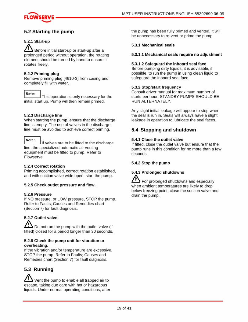
4.3 Grouting 4.3.1 Grouting foundation bolts Where applicable, grout in the foundation bolts. 4.3.2 Grouting baseplate After adding pipe work connections and rechecking the coupling alignment, the baseplate should then be grouted in accordance with good engineering practice. Fabricated steel and cast iron base plates should be filled with grout. If in any doubt, please contact your nearest Flowserve service center for advice.
GROUTING TO BE 25 TO 50mm DEEP
FINISHED GROUT
LEAVE TOP OF FOUNDATION ROUGH.
CONCRETE
DO NOT FINISH WITH TROWEL
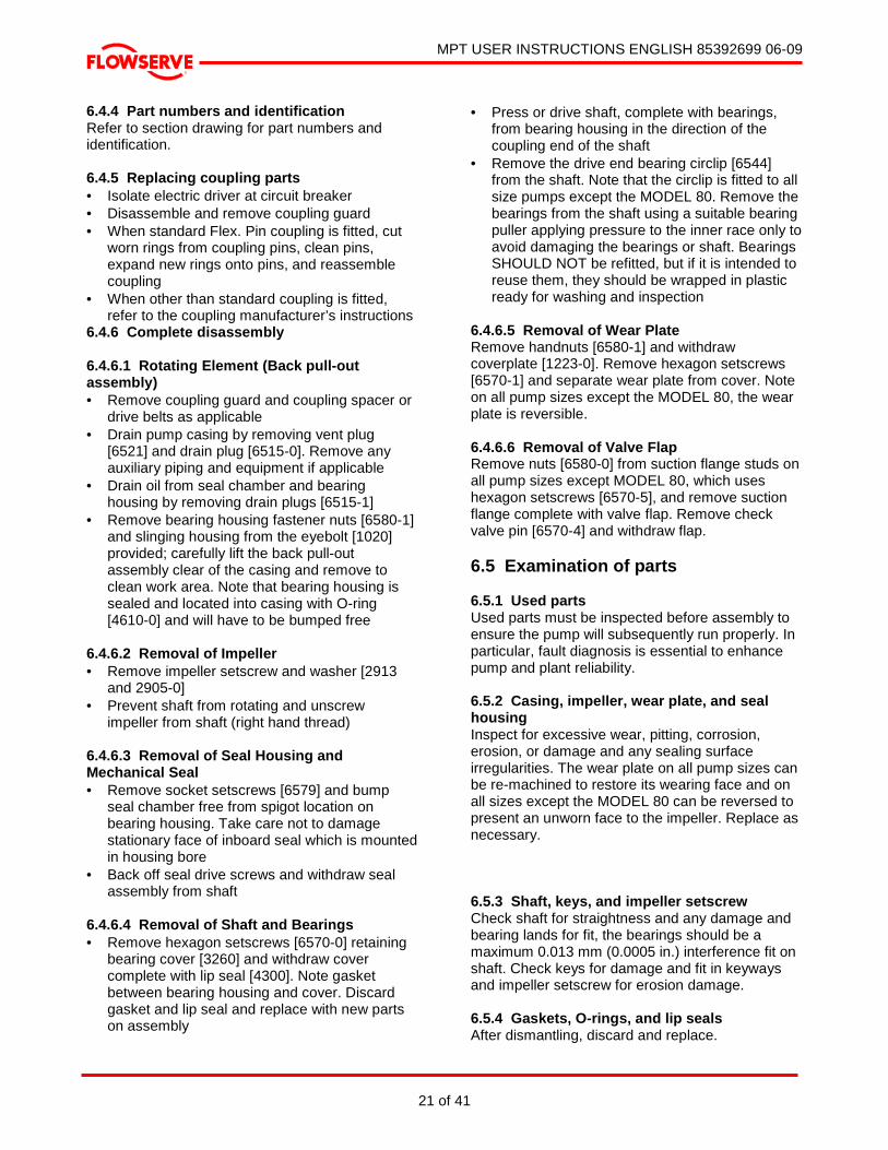
4.3.3 Grouting baseplate prevents movement Grouting provides solid contact between the pump unit and foundation, prevents lateral movement of vibrating equipment, and dampens resonant vibrations. 4.4 Initial alignment 4.4.1 Thermal expansion The pump and motor will normally have to be aligned at ambient temperature and should be corrected to allow for thermal expansion at operating temperature. In pump installations involving high liquid temperatures, the unit should be run at the actual operating temperature, shut down, and the alignment checked immediately. 4.4.2 Alignment methods 4.4.2.1 Ensure the pump and motor half couplings are disconnected. 4.4.2.2 The alignment MUST be checked. Although the pump will have been aligned at the factory, it is most likely that this alignment will have been disturbed during transportation or handling. Align the motor to the pump, not the pump to the motor. Alignment is achieved by adding or removing shims from under the motor feet and also moving the motor horizontally as required. In some cases where the alignment cannot be achieved, it will be necessary to move the pump before recommencing the above procedure. 4.4.2.3 For couplings with narrow flanges, use a dial indicator gauge as shown. The alignment values are maximal for continuous service.
4.4.2.4 Permissible misalignment limits at working temperature: Parallel alignment within 0.1 mm (0.004 in.) TIR Angular alignment within 0.05 mm (0.002 in.) TIR

MPT USER INSTRUCTIONS ENGLISH 85392699 06-09
Page 17 of 41
®
4.4.2.5 Measure face gap Face gaps may be measured between the machined faces using feeler gauges, measuring wedge, calipers, or suitable micrometer. 4.5 Piping 4.5.1 Protective covers Protective covers are fitted to the pipe connections to prevent foreign bodies entering during transportation and installation. Ensure that these covers are removed from the pump before connecting any pipes. 4.5.2 Forces and moments on pump flanges Maximum forces and moments allowed on the pump flanges vary with the pump size and type and are shown in section 3.3.3, Flange Loads. To minimize these forces and moments that may cause misalignment, hot bearings, worn couplings, vibration, and the possible failure of the pump casing, the following points should be strictly followed: • Prevent excessive external pipe load • Never draw piping into place by applying force
to pump flange connections • Do not mount expansion joints so that their
force, due to internal pressure, acts on the pump flange
4.5.3 Inlet pipe The inlet pipe should be one or two sizes larger than the pump inlet bore and pipe bends should be as large a radius as possible. On suction lift the piping should be inclined up towards the pump inlet with long eccentric taper pipes incorporated to prevent air locks. On positive suction, the inlet piping must have a constant fall towards the pump. 4.5.4 Flow and pump suction Flow should enter the pump suction with uniform profile to minimize noise and wear. It is preferable to have a straight length of suction pipe (approx. 8 to 10 times the pipe diameter) immediately upstream of the suction nozzle and a straight length of discharge pipe (approx. 5 to 8 times the pipe diameter) immediately downstream of the discharge nozzle. Do not attach a short radius 90° bend directly on the suction branch. A long radius suction bend may be used as long as the bend is perpendicular to the shaft center line of the unit. Do not install elbows at an angle other than perpendicular to the shaft axis. Elbows parallel to the shaft axis will cause uneven flow into the impeller eyes.
Inlet strainers, when used, should have a net ‘free area’ of at least three times the inlet pipe area and a differential pressure device fitted to check for blockage. Except in unusual circumstances, strainers are not recommended in inlet piping. If considerable foreign matter is expected, a screen installed at the entrance to the wet well is preferable. 4.5.5 Fitting valves and easy maintenance Fitting an isolator and non-return valves can allow easier maintenance. Never throttle pump on suction side and never place a valve directly on the pump inlet nozzle. If butterfly valves are used in the suction line, the spindle must be parallel to the pump shaft. 4.5.6 Piping and fittings should be flushed before use. 4.5.7 Corrosive liquids Piping for corrosive liquids should be arranged to allow pump flushing before removal of a unit. 4.5.8 Air Release Valve When a discharge check valve is applied an Air Release Valve should be placed between the pump discharge and the check valve. The Air Release Valve’s function is to vent air from the pump during the priming cycle. Flowserve Air Release Valves are available. 4.6 Electrical Connections 4.6.1 Qualified electrician
Electrical connections should be made by a qualified electrician in accordance with the relevant local, national, and international regulations. It is important to be aware of the EUROPEAN DIRECTIVE on electromagnetic compatibility when wiring up and installing equipment on site. Attention must be paid to ensure that the techniques used during wiring/installation do not increase electromagnetic emissions or decrease the electromagnetic immunity of the equipment, wiring, or any connected devices. If in any doubt, contact Flowserve for advice.

MPT USER INSTRUCTIONS ENGLISH 85392699 06-09
Page 18 of 41
®
4.6.2 Wiring motor
The motor must be wired up in accordance with the motor manufacturer's INSTRUCTIONS (normally supplied within the terminal box), including any temperature, earth leakage, current, and other protective devices as appropriate. The identification nameplate should be checked to ensure the power supply is appropriate. 4.6.3 Emergency stopping
A device to provide emergency stopping shall be fitted. 4.6.4 Rotation direction
Check required direction of rotation before connecting the motor to the pump. Ensure that the motor over power protection device is set 5% above the maximum power that the pump unit is expected to absorb. 4.7 Final shaft alignment check After connecting piping to the pump, rotate the shaft several times by hand to ensure there is no binding and all parts are free. The above operation should be repeated with piping and pump completely filled with water.
5 COMISSIONING STARTUP, OPERATION, AND SHUTDOWN 5.1 Making ready for operation 5.1.1 Lubrication 5.1.1.1 Bearings and mechanical seals Pump bearings and mechanical seals are not lubricated by Flowserve. See section 6.2 for oil chamber filling instructions. • Bearing housing requires approx.
one liter (33.81 fl. oz.) of oil • Mechanical seal chamber requires
approx. 350 ml (11.83 fl. oz.) of oil • Check oil level at the sight glasses
provided before putting into service 5.1.1.2 Driver bearing Driver bearing lubrication should be in accordance with the driver manufacturer’s instruction manual. 5.1.1.3 Coupling lubrication Coupling lubrication, if required, should be in accordance with the coupling manufacturer’s instruction manual.
5.1.2 Pre-operation check list Pre-operation Check List Checked by Date
6.2.1 With pump uncoupled start the driver to ensure correct direction of rotation. 6.2.2 Check alignment of piping, valves, and motor pump assembly.
Alignment shall be such that joints can be bolted without placing any stress on the piping or pump.
6.2.3 Check all fasteners for tightness. 6.2.4 Visually inspect footing for cracks, etc. 6.2.5 Examine motor shims to ensure that any vibration during operation will
not cause them to dislodge.
6.2.6 CHECK THAT ALL ELECTRICAL, HYDRAULIC, SEALANT AND
LUBRICATION SYSTEMS (AS APPLICABLE) ARE CONNECTED AND OPERATIONAL.
6.2.7 Check pump and motor for lubrication.
6.2.8 ENSURE ALL TERMINAL BOXES AND GUARDS ARE IN PLACE. 6.2.9 Check all valves and fittings to ensure that they are installed to allow
flow in the intended direction.
6.2.10 Prime the pump. Ensure that the pump casing and all pipe work are completely filled with liquid. Filling plug must be replaced after priming.
6.2.11 Ensure pump/driver-coupling alignment is within the limits specified in 5.6.2.4. 6.2.12 Check all piping, seals, joints, and fittings for leaks.
MPT USER INSTRUCTIONS ENGLISH 85392699 06-09
19 of 41
®
5.2 Starting the pump 5.2.1 Start-up
Before initial start-up or start-up after a prolonged period without operation, the rotating element should be turned by hand to ensure it rotates freely. 5.2.2 Priming plug Remove priming plug [4610-3] from casing and completely fill with water.
This operation is only necessary for the initial start up. Pump will then remain primed. 5.2.3 Discharge line When starting the pump, ensure that the discharge line is empty. The use of valves in the discharge line must be avoided to achieve correct priming.
If valves are to be fitted to the discharge line, the specialized automatic air venting equipment must be fitted to pump. Refer to Flowserve. 5.2.4 Correct rotation Priming accomplished, correct rotation established, and with suction valve wide open, start the pump. 5.2.5 Check outlet pressure and flow. 5.2.6 Pressure If NO pressure, or LOW pressure, STOP the pump. Refer to Faults; Causes and Remedies chart (Section 7) for fault diagnosis. 5.2.7 Outlet valve
Do not run the pump with the outlet valve (if fitted) closed for a period longer than 30 seconds. 5.2.8 Check the pump unit for vibration or overheating. If the vibration and/or temperature are excessive, STOP the pump. Refer to Faults; Causes and Remedies chart (Section 7) for fault diagnosis. 5.3 Running
Vent the pump to enable all trapped air to escape, taking due care with hot or hazardous liquids. Under normal operating conditions, after
the pump has been fully primed and vented, it will be unnecessary to re-vent or prime the pump. 5.3.1 Mechanical seals 5.3.1.1 Mechanical seals require no adjustment 5.3.1.2 Safeguard the inboard seal face Before pumping dirty liquids, it is advisable, if possible, to run the pump in using clean liquid to safeguard the inboard seal face. 5.3.2 Stop/start frequency Consult driver manual for maximum number of starts per hour. STANDBY PUMPS SHOULD BE RUN ALTERNATELY. Any slight initial leakage will appear to stop when the seal is run in. Seals will always have a slight leakage in operation to lubricate the seal faces. 5.4 Stopping and shutdown 5.4.1 Close the outlet valve If fitted, close the outlet valve but ensure that the pump runs in this condition for no more than a few seconds. 5.4.2 Stop the pump 5.4.3 Prolonged shutdowns
For prolonged shutdowns and especially when ambient temperatures are likely to drop below freezing point, close the suction valve and drain the pump.

MPT USER INSTRUCTIONS ENGLISH 85392699 06-09
20 of 41
®
6 MAINTENANCE 6.1 Maintenance schedule Our specialist service personnel can help with preventative maintenance records and provide condition monitoring for temperature and vibration to identify the onset of potential problems if required. This schedule is a recommendation only and is intended to be amended by site experience of the prevailing conditions. It outlines recommendations for the pump only and must be supplemented by schedules for other equipment on the package. 6.1.1 Routine inspection (daily/weekly) The following checks should be made and the appropriate action taken to remedy any deviations: • Check operating behavior. Ensure performance,
noise, vibration, and bearing temperatures are normal
• Check that there is no abnormal fluid or lubricant leakage
• Check running hours since last oil change. Change if required
• Refer to the manuals of any associated equipment for routine checks needed
• Check oil levels in seal chamber and bearing housing
6.1.2 Periodic inspection (6 monthly) • Check foundation bolts for security of
attachment and corrosion • The coupling should be checked for correct
alignment and worn driving elements • Check all paint or protective coatings • Check all cable glands for tightness • Refer to the manuals of any associated
equipment for periodic checks needed 6.2 Lubrication data 6.2.1 Oil lubricated bearings and mechanical seals Normal intervals between oil changes are 4000 operating hours or a 12-month period. The characteristics of the installation and severity of service will determine the frequency of lubrication change. See Section 3.3.4, Pump lubricant data. Any sudden change in oil level should be investigated without delay. A rise in bearing housing oil level, together with a drop in the seal chamber oil level, indicates a secondary seal failure allowing oil leakage from the seal chamber to the bearing housing. A drop in bearing housing oil level
indicates an external leak and a check of the pump would show the source as a failure of the bearing cover lip seal or gasket or a loose drain plug. An abnormal rise or fall in the seal chamber oil level with no change in the bearing housing oil level indicates a primary seal failure with product leaking into seal chamber or oil leaking into the pump.
Always use the recommended Type and grade of oil, Mobil DTE Medium or Castrol Hyspin AWS 46. Never mix oil types. 6.3 Mechanical seals When leakage becomes unacceptable as determined above, the seal will need to be repaired or replaced. 6.4 Dismantling 6.4.1 General
Cleanliness is extremely important and care must be taken to prevent any foreign material from entering the pump or its components. This pump is of the back pull-out design; it is not necessary to remove the casing, to detach the suction and delivery piping, or to remove the driver to dismantle pump. 6.4.2 Dismantling the pump
Refer to Safety section before dismantling the pump. 6.4.3 Genuine Flowserve parts
Before dismantling the pump for overhaul, ensure genuine Flowserve replacement parts are available.
MPT USER INSTRUCTIONS ENGLISH 85392699 06-09
21 of 41
®
6.4.4 Part numbers and identification Refer to section drawing for part numbers and identification. 6.4.5 Replacing coupling parts • Isolate electric driver at circuit breaker • Disassemble and remove coupling guard • When standard Flex. Pin coupling is fitted, cut
worn rings from coupling pins, clean pins, expand new rings onto pins, and reassemble coupling
• When other than standard coupling is fitted, refer to the coupling manufacturer’s instructions
6.4.6 Complete disassembly 6.4.6.1 Rotating Element (Back pull-out assembly) • Remove coupling guard and coupling spacer or
drive belts as applicable • Drain pump casing by removing vent plug
[6521] and drain plug [6515-0]. Remove any auxiliary piping and equipment if applicable
• Drain oil from seal chamber and bearing housing by removing drain plugs [6515-1]
• Remove bearing housing fastener nuts [6580-1] and slinging housing from the eyebolt [1020] provided; carefully lift the back pull-out assembly clear of the casing and remove to clean work area. Note that bearing housing is sealed and located into casing with O-ring [4610-0] and will have to be bumped free
6.4.6.2 Removal of Impeller • Remove impeller setscrew and washer [2913
and 2905-0] • Prevent shaft from rotating and unscrew
impeller from shaft (right hand thread) 6.4.6.3 Removal of Seal Housing and Mechanical Seal • Remove socket setscrews [6579] and bump
seal chamber free from spigot location on bearing housing. Take care not to damage stationary face of inboard seal which is mounted in housing bore
• Back off seal drive screws and withdraw seal assembly from shaft
6.4.6.4 Removal of Shaft and Bearings • Remove hexagon setscrews [6570-0] retaining
bearing cover [3260] and withdraw cover complete with lip seal [4300]. Note gasket between bearing housing and cover. Discard gasket and lip seal and replace with new parts on assembly
• Press or drive shaft, complete with bearings, from bearing housing in the direction of the coupling end of the shaft
• Remove the drive end bearing circlip [6544] from the shaft. Note that the circlip is fitted to all size pumps except the MODEL 80. Remove the bearings from the shaft using a suitable bearing puller applying pressure to the inner race only to avoid damaging the bearings or shaft. Bearings SHOULD NOT be refitted, but if it is intended to reuse them, they should be wrapped in plastic ready for washing and inspection
6.4.6.5 Removal of Wear Plate Remove handnuts [6580-1] and withdraw coverplate [1223-0]. Remove hexagon setscrews [6570-1] and separate wear plate from cover. Note on all pump sizes except the MODEL 80, the wear plate is reversible. 6.4.6.6 Removal of Valve Flap Remove nuts [6580-0] from suction flange studs on all pump sizes except MODEL 80, which uses hexagon setscrews [6570-5], and remove suction flange complete with valve flap. Remove check valve pin [6570-4] and withdraw flap. 6.5 Examination of parts 6.5.1 Used parts Used parts must be inspected before assembly to ensure the pump will subsequently run properly. In particular, fault diagnosis is essential to enhance pump and plant reliability. 6.5.2 Casing, impeller, wear plate, and seal housing Inspect for excessive wear, pitting, corrosion, erosion, or damage and any sealing surface irregularities. The wear plate on all pump sizes can be re-machined to restore its wearing face and on all sizes except the MODEL 80 can be reversed to present an unworn face to the impeller. Replace as necessary. 6.5.3 Shaft, keys, and impeller setscrew Check shaft for straightness and any damage and bearing lands for fit, the bearings should be a maximum 0.013 mm (0.0005 in.) interference fit on shaft. Check keys for damage and fit in keyways and impeller setscrew for erosion damage. 6.5.4 Gaskets, O-rings, and lip seals After dismantling, discard and replace.

MPT USER INSTRUCTIONS ENGLISH 85392699 06-09
22 of 41
®
6.5.5 Bearings Bearings generally MUST NOT BE reused after removal from any shaft; however, due to the small interference fit of the bearings in these pumps, if they are removed carefully by pulling on the inner ring only without the use of heat and if thorough cleaning and inspection shows them fit for further service, they may be reused. It is strongly recommended, however, that they be replaced as a matter of course. Thoroughly clean the inside of the bearing housing, bearing cover, and seal housing, removing any sign of contamination or rust and dry out with lint-free cloths or dry air. 6.5.6 Suction flange and flap valve Check the valve seating on the suction flange for erosion damage and the flap valve for deterioration of the neoprene sealing surface and replace if necessary. 6.5.7 Mechanical seal Carefully inspect seal faces for cracks, chips, or scoring and O-rings for any obvious damage. If in doubt either replace or return seal to Flowserve service center for inspection. 6.6 Assembly 6.6.1 To assemble the pump consult the sectional drawings. 6.6.2 Prepare Ensure all parts are on hand; clean and fit for further service. Pay particular attention to threads and gasket and O-ring sealing faces. Lightly apply anti-seize compound to all threads and close fitting surfaces. Do not unwrap bearings and seals or expose the bearing housing and seal chamber inner surfaces until time to fit. Immediately prior to assembly, wipe clean with lint-free cloth. 6.6.3 Bearings • Carefully press the bearings onto the shaft,
applying load to inner ring only; ensure bearings are pushed hard up against the location shoulder on the shaft. It is not necessary to use heat to fit MPT bearings as only light press fits are involved. If desired, bearings can be heated to approx. 100 °C (212 °F) with an induction heater, but under no circumstances use a flame on the bearings. Fit the circlip [6544] to the shaft at the outboard bearing [3041]. Note that a circlip is fitted on all pump sizes except the MODEL 80
• Support shaft/bearing assembly on clean vee blocks under the bearings and check shaft runout at coupling end and mechanical seal area. Runout is not to exceed 0.05 mm (0.002 in.) TIR
• Push shaft/bearing assembly into bearing housing from drive end, ensuring that thrust bearing bottoms against shoulder in bearing housing and that shaft rotates freely
• Fit new lip seal [4300] into bearing cover [3260]. Note orientation of lip seal (spring loaded lip faces toward coupling)
• Fit new gasket at bearing housing face and refit cover; ensure that seal lip is lightly oiled and care is taken easing it over shaft shoulder. Refit and tighten cover fasteners. Check that shaft rotates freely
6.6.4 Mechanical seal • Fit mechanical stationary face holder in recess
at inboard end of bearing cover and fit stationary face. Take extreme care to keep face clean and prevent damage. Lightly oil seal rotating assembly and carefully slide over shaft to seat against stationary
• Fit inboard stationary face holder in recess in seal chamber and carefully fit stationary face
• Fit new O-ring to recess in bearing housing joint, fit seal chamber over end of shaft, and locate on bearing housing spigot. Refit and tighten fasteners
6.6.5 Impeller • Lightly coat shaft and impeller threads with anti-
seize. Preventing shaft from rotating, screw impeller onto shaft and bottom firmly against shaft shoulder. Fit and tighten impeller setscrew [2913] complete with washer [2905-0]
• Check impeller to seal housing axial clearance, which should be within the range 0.05/1.35 mm (0.002/ 0.053 in.) on a new assembly
6.6.6 Suction flange • Refit valve flap to suction flange with check
valve pin [6570-4] and nylon washer [2905-1] • Fit suction flange to casing with new gasket
[4510-1] 6.6.7 Coverplate/wear plate • Refit new, re-machined, or reversed wear plate
[1915] to the cover plate [1223-0] • Fit new O-ring [4610-2] to cover and lightly oil • Fit cover into casing and retain with hand nuts
[6580-1]
MPT USER INSTRUCTIONS ENGLISH 85392699 06-09
23 of 41
®
6.6.8 Back pull-out assembly/case • Fit new O-ring [4610-0] to bearing housing
spigot and lightly oil • Ensure that spacing bushes [1680] are screwed
fully home in bearing housing flange. This will give maximum impeller clearance on assembly
• Sling from eyebolt [1020] and fit back pull-out assembly into casing, taking care not to damage machined casing bores and O-ring. Tighten fasteners finger tight only
• Back off stud nuts [6580-1] and spacing bushes in turn by equal amounts, at the same time pushing back pull-out assembly into casing until impeller contacts wear plate. At this stage check the gap between the bearing housing and case at four places to ensure that assembly is fully seated on wear plate
• To obtain correct clearance at wear plate turn spacing bushes each one flat in a clockwise direction. This will give a clearance of 0.30 mm (0.012 in.) and the nuts [6580-1] can now be fully tightened
6.6.9 Lubrication Ensure oil chamber drain plugs are tightly fitted, remove air vents [3854] from bearing housing and seal chamber, and fill both chambers to the correct level on the sight glasses [3858] with Mobil DTE Medium or Castrol Hyspin AWS 46 oil. Approximately one liter (33.81 fl. oz.) of oil in seal chamber and 350 ml (11.83 fl. oz.) in the bearing housing are needed. Refit vents and check for leaks. Now that seals are lubricated, check element for free rotation. 6.6.10 Final assembly • Refit coupling and connect driver. Check driver
alignment • Refit guards • Refit suction and discharge piping with new
gaskets • Check all fasteners and plugs for tightness 6.7 Spare Parts 6.7.1 Ordering of spares Flowserve keeps records of all pumps that have been supplied. When ordering spares the following information should be quoted: (1) Pump serial and service number(s) (2) Pump type and size (3) Part name (4) Part number (5) Number of parts required
6.7.2 Pump details The pump size and serial number are shown on the pump nameplate. 6.7.3 Genuine parts To ensure continued satisfactory operation, replacement parts to the original design specification should be obtained from Flowserve. Any change to the original design specification, modification or use of a non-standard part) will invalidate the pumps safety certification. 6.7.4 Recommended spares Start up spares: Normal maintenance spares: 1 – complete set of O-rings, gaskets, and lip seal 1 – mechanical sea 1 – set of bearings 1 – bearing circlip (not applicable MODEL 80) 1 – check valve flap 1 – wear plate Critical service: 1 – complete set of O-rings, gaskets and lip seal 1 – mechanical seal 1 – set of bearings 1 – bearing circlip (not applicable MODEL 80) 1 – check valve flap 1 – wear plate 1 – impeller 1 – shaft 6.7.5 Storage of spares Spares should be stored in a clean, dry area away from vibration. Inspection and re-treatment of metallic surfaces (if necessary) with preservative is recommended at six monthly intervals.
MPT USER INSTRUCTIONS ENGLISH 85392699 06-09
24 of 41
®
Page left intentionally blank

MPT USER INSTRUCTIONS ENGLISH 85392699 06-09
25 of 41
®
7 FAULTS; CAUSES AND REMEDIES FAULT SYMPTOM
Pump overheats and seizes
⇓⇓⇓⇓⇓⇓⇓⇓ Bearings have short life
⇓⇓⇓⇓⇓⇓⇓⇓ Pump vibrates or is noisy
⇓⇓⇓⇓⇓⇓⇓⇓ Mechanical seal has short life
⇓⇓⇓⇓⇓⇓⇓⇓ Mechanical seal leaks excessively
⇓⇓⇓⇓⇓⇓⇓⇓ Pump requires excessive power
⇓⇓⇓⇓⇓⇓⇓⇓ Pump loses prime after starting
⇓⇓⇓⇓⇓⇓⇓⇓ Insufficient pressure developed
⇓⇓⇓⇓⇓⇓⇓⇓ Insufficient capacity delivered
⇓⇓⇓⇓⇓⇓⇓⇓ Pump does not deliver liquid
⇓⇓⇓⇓⇓⇓⇓⇓ PROBABLE CAUSES POSSIBLE REMEDIES
A. SYSTEM TROUBLES ���� ���� Pump not primed. Check complete filling
���� ���� ���� ���� Pump or suction pipe not completely filled with liquid.
Check and complete filling
���� ���� ���� ���� ���� Suction lift too high or level too low. Check NPSHa>NPSHr, proper submergence, losses at strainers and fittings
���� ���� ���� Excessive amount of air or gas in liquid. Check and purge from pipes
���� ���� ���� Air or vapour pocket in suction line. Check suction line design for pockets
���� ���� Air leaks into suction line. Check airtight pipe then joints and gaskets
���� ���� Air leaks into pump through mechanical seal, sleeve joints, casing joint or pipe lugs.
Check airtight assembly then joints and gaskets
���� ���� Foot valve too small. Investigate replacing the foot valve
���� ���� Foot valve partially clogged. Clean foot valve
���� ���� ���� ���� Inlet of suction pipe insufficiently submerged. Check cut out system design
���� ���� ���� Total head of system higher than differential head of pump.
Check discharge head and head losses in discharge pipe at the valve settings. Check back pressure is not too high
���� Total head of system lower than pump design head.
Throttle at discharge valve or ask Flowserve if the impeller can be trimmed
���� Specific gravity of liquid different from design. Consult Flowserve
���� ���� ���� Viscosity of liquid differs from design. Consult Flowserve
���� ���� Operation at very low capacity. Measure value and check minimum permitted
���� ���� ���� Operation at high capacity. Measure value and check maximum permitted
B. MECHANICAL TROUBLES
���� ���� ���� ���� ���� ���� Misalignment due to pipe strain. Check the flange connections and eliminate strains using elastic couplings or a method permitted
���� Improperly designed foundation. Check setting of baseplate: tighten, adjust, grout base as required
���� ���� ���� ���� ���� Shaft bent. Check shaft runouts within acceptable values
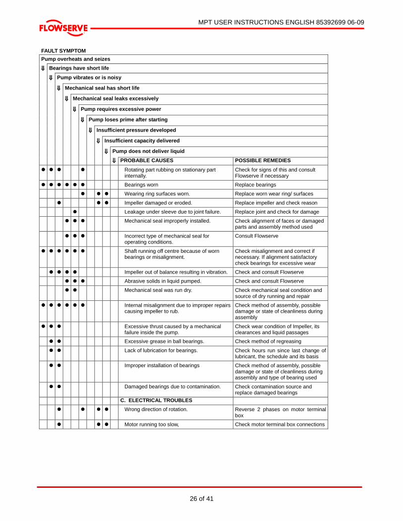
MPT USER INSTRUCTIONS ENGLISH 85392699 06-09
26 of 41
®
FAULT SYMPTOM
Pump overheats and seizes
⇓⇓⇓⇓⇓⇓⇓⇓ Bearings have short life
⇓⇓⇓⇓⇓⇓⇓⇓ Pump vibrates or is noisy
⇓⇓⇓⇓⇓⇓⇓⇓ Mechanical seal has short life
⇓⇓⇓⇓⇓⇓⇓⇓ Mechanical seal leaks excessively
⇓⇓⇓⇓⇓⇓⇓⇓ Pump requires excessive power
⇓⇓⇓⇓⇓⇓⇓⇓ Pump loses prime after starting
⇓⇓⇓⇓⇓⇓⇓⇓ Insufficient pressure developed
⇓⇓⇓⇓⇓⇓⇓⇓ Insufficient capacity delivered
⇓⇓⇓⇓⇓⇓⇓⇓ Pump does not deliver liquid
⇓⇓⇓⇓⇓⇓⇓⇓ PROBABLE CAUSES POSSIBLE REMEDIES
���� ���� ���� ���� Rotating part rubbing on stationary part internally.
Check for signs of this and consult Flowserve if necessary
���� ���� ���� ���� ���� ���� Bearings worn Replace bearings
���� ���� ���� Wearing ring surfaces worn. Replace worn wear ring/ surfaces
���� ���� ���� Impeller damaged or eroded. Replace impeller and check reason
���� Leakage under sleeve due to joint failure. Replace joint and check for damage
���� ���� ���� Mechanical seal improperly installed. Check alignment of faces or damaged parts and assembly method used
���� ���� ���� Incorrect type of mechanical seal for operating conditions.
Consult Flowserve
���� ���� ���� ���� ���� ���� Shaft running off centre because of worn bearings or misalignment.
Check misalignment and correct if necessary. If alignment satisfactory check bearings for excessive wear
���� ���� ���� ���� Impeller out of balance resulting in vibration. Check and consult Flowserve
���� ���� ���� Abrasive solids in liquid pumped. Check and consult Flowserve
���� ���� Mechanical seal was run dry. Check mechanical seal condition and source of dry running and repair
���� ���� ���� ���� ���� ���� Internal misalignment due to improper repairs causing impeller to rub.
Check method of assembly, possible damage or state of cleanliness during assembly
���� ���� ���� Excessive thrust caused by a mechanical failure inside the pump.
Check wear condition of Impeller, its clearances and liquid passages
���� ���� Excessive grease in ball bearings. Check method of regreasing
���� ���� Lack of lubrication for bearings. Check hours run since last change of lubricant, the schedule and its basis
���� ���� Improper installation of bearings Check method of assembly, possible damage or state of cleanliness during assembly and type of bearing used
���� ���� Damaged bearings due to contamination. Check contamination source and replace damaged bearings
C. ELECTRICAL TROUBLES
���� ���� ���� ���� Wrong direction of rotation. Reverse 2 phases on motor terminal box
���� ���� ���� Motor running too slow, Check motor terminal box connections
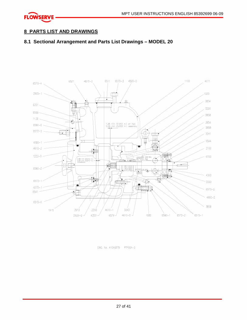
MPT USER INSTRUCTIONS ENGLISH 85392699 06-09
27 of 41
®
8 PARTS LIST AND DRAWINGS
8.1 Sectional Arrangement and Parts List Drawings – MODEL 20

MPT USER INSTRUCTIONS ENGLISH 85392699 06-09
28 of 41
®
ITEM DESCRIPTION No. OF DRG. No. MATERIAL CCN No. 7000 INSTRUCTION MANUAL 1 PAPER 85392699
6821 DRIVE SCREWS (NAMEPLATE) 4 122A2R37 SS 95330452
9322-3 WARNING TAG - ALIGNMENT 1 9323 DECAL - PRIMING 1
9322-0 NAMEPLATE 1 AY51851A SS 78800505 ABOVE ITEMS NOT SHOWN ON DRAWING
SPARES ITEM DESCRIPTION No. OF DRG. No. MATERIAL CCN No.
6700 KEY 1 11A9C85 C. STL. 95264024- 6580-2 HAND NUT 2 1038A020MPTA001 C. I. 75533802- 6580-1 HEX NUT – BEARING HOUSING 4 38A4S5 ST. STL. 95296992- 6580-0 HEX NUT – SUCTION FLANGE 4 38A4C7 C. STL. 95084760- 6579 FERRYHEAD SCREW 4 143A2A39 AL. STL. 95309803- 6572-3 STUD – SUCTION FLANGE 4 13A3J399 C. STL. 95150314- 6572-2 STUD – BEARING HOUSING 4 12A3S254 ST. STL. 75543421- 6572-1 STUD – HAND NUT 2 13A3J250 ST. STL. 95236378- 6570-4 CAPSCREW (PIN) - VALVE 1 2714A020MPTA001 C. STL. 75534222- 6570-3 CAPSCREW – DISCHARGE 4 35A2C325 C. STL. 95002168- 6570-1 CAPSCREW – WEAR PLATE 2 35A2C108 C. STL. 95079711- 6570-0 CAPSCREW – BEARING COVER 4 35A2C4 C. STL. 95211393- 6569 PLUG SQ. HEAD – SUCTION FLANGE 1 30A7C3 C. STL. 95061479- 2 6544 RETAINING RING 1 162A13S118 C. STL. 95223368- 6541 LOCKWASHER – WEAR PLATE 2 14A5C76 C. STL. 95081857- 6541-1 LOCKWASHER – A & B SUCTION FLG 4 14A5C120 C. STL. 95081790- 6521 PLUG SQ. HEAD – CASING 2 30A7C3 C. I. 95061479- 6515-1 PLUG SQ. HEAD – BEARING HOUSING 2 30A7C3 C. I. 95061479- 6515-0 PLUG SQ. HEAD – CASING DRAIN 1 30A7C6 C. I. 95033544- 6511 PRIMING PLUG 1 565A10S10 C. STL. 95663803- 2 6301 FLAPPER VALVE 1 2214A020MPTA001 NEOPRENE 75530899- 2 4610-3 O-RING – PRIMING PLUG 1 20A11EM222 VITON 95022232- 1 4610-2 O-RING – COVER PLATE/CASING 1 20A11CM437 Buna N 95087243- 1 4610-1 O-RING – BEARING HSG/SEAL HSG 1 20A11CM244 Buna N 95086666- 1 4610-0 O-RING – CASING /BEARING HSG 1 20A11CM360 Buna N 95277265- 1 4590-2 GASKET – END COVER 1 2584A020MPTA001 NTL/SYN 75530964- 1 4590-1 GASKET – FLANGE SUCTION 1 2586A020MPTA001 NTL/SYN 75516666- 1 4590-0 GASKET – DISCHARGE 1 32A11X6 NTL/SYN 60669868- 1 4300 LIP SEAL – BEARING COVER 1 2796A118DIAC001 NITRILE 75554071- 2 4200 MECHANICAL SEAL 1 1802A112MPTA001 BX/C F X/JF 75555284- 4011 SEAL HOUSING 1 2632A020MPTA001 C. I. 75531004- 3858 SIGHT GLASS 3 4260A000MPTA001 POLYMIDE 75553578- 3854 AIR VENT 2 - STEEL 81300261- 3260 BEARING COVER 1 0573A020MPTA001 C. I. 75530931- 3200 BEARING HOUSING 1 1109A020MPTA001 C. I. 75533869- 2 3043 BALL BEARING - NDE 1 26A19X206 STEEL 95200630- 2 3041 BALL BEARING - DE 1 27A19X306 STEEL 95200762- 2913 CAPSCREW - IMPELLER 1 35A2T58 ST. STL. 95269189- 2905-1 WASHER - VALVE 1 11A5X4 NYLON 97461974- 2905-0 WASHER - IMPELLER 1 2888A020MPTA001 ST. STL. 75529636- 3 2200 IMPELLER 1 1129A020MPTA001 D. I. 75516617- 3 2100 SHAFT 1 2807A020MPTA001 ST. STL. 75533315- 2 1915 WEAR PLATE 1 1869A020MPTA001 C. I. 75529487- 1680 SPACER BUSHING 4 2454A020MPTA001 ST. STL. 75533232- 1223-0 COVER PLATE 1 2729A020MPTA001 C. I. 75531038- 1139 SUCTION FLANGE - 2” NPT 1 0850A020MPTA001 C. I. 75530113- 1100 CASING 1 2469A020MPTA001 C. I. 75533893- 1020 EYE BOLT 1 124A2C3X0.5 C. STL. 75536938-
RECOMMENDED SPARES INDICATED THUS :- 1 = START-UP SPARES 2 = NORMAL MAINTENANCE SPARES (INCLUDES START-UP) 3 = CRITICAL SERVICE (INCLUDES START-UP/MAINTENANCE) RECOMMENDED OIL :- Mobil DTE Medium or Castrol Hyspin AWS 46 oil OIL QUANTITY :- SEAL CHAMBER APPROX. 1 L (33.81 fl. oz.) BEARING HOUSING APPROX. 350 ml (11.83 fl. oz.)

MPT USER INSTRUCTIONS ENGLISH 85392699 06-09
29 of 41
®
8.2 Sectional Arrangement and Parts List Drawings – MODEL 30

MPT USER INSTRUCTIONS ENGLISH 85392699 06-09
30 of 41
®
ITEM DESCRIPTION No. OF DRG. No. MATERIAL CCN No. 7000 INSTRUCTION MANUAL 1 PAPER 85392699
6821 DRIVE SCREWS (NAMEPLATE) 4 122A2R37 SS 95330452
9322-3 WARNING TAG - ALIGNMENT 1 9323 DECAL - PRIMING 1
9322-0 NAMEPLATE 1 AY51851A SS 78800505 ABOVE ITEMS NOT SHOWN ON DRAWING
SPARES ITEM DESCRIPTION No. OF DRG. No. MATERIAL CCN No. 6700 KEY 1 11A9C137 C. STL. 95293080- 6580-2 HAND NUT 2 1038A020MPTA001 C. I. 75533802- 6580-1 HEX NUT - BEARING HOUSING 4 38A4S7 ST. STL. 95370581- 6580-0 HEX NUT - SUCTION FLANGE 4 38A4C7 C. STL. 95084760- 6579 FERRYHEAD SCREW 4 143A2A79 AL. STL. 95410577- 6572-3 STUD - SUCTION FLANGE 4 13A3J398 C. STL. 95688156- 6572-2 STUD - BEARING HOUSING 4 12A2S254 ST. STL. 75543439- 6572-1 STUD - HAND NUT 2 13A3J389 ST. STL. 95159166- 6570-4 CAPSCREW (PIN) - VALVE 1 2714A030MPTA001 C. STL. 75534230- 6570-3 CAPSCREW - DISCHARGE 4 35A2C325 C. STL. 95002168- 6570-2 CAPSCREW - HANDLE 2 35A2C110 C. STL. 95053146- 6570-1 CAPSCREW - WEAR PLATE 4 35A2C110 C. STL. 95053146- 6570-0 CAPSCREW - BEARING COVER 4 35A2C111 C. STL. 68885607- 6569 PLUG SQ. HEAD - SUCTION FLANGE 1 30A7C3 C. STL. 95061479- 2 6544 RETAINING RING 1 173A13S175 C. STL. 95391264- 6541 LOCKWASHER - WEAR PLATE 4 14A5C76 C. STL. 95081857- 6521 PLUG SQ. HEAD - CASING 2 30A7C3 C. I. 95061479- 6515-1 PLUG SQ. HEAD - BEARING HOUSING 2 30A7C4 C. I. 95078606- 6515-0 PLUG SQ. HEAD - CASING DRAIN 1 30A7C7 C. I. 95033551- 6511 PRIMING PLUG 1 565A10S10 C. STL. 95663803- 2 6301 FLAPPER VALVE 1 2214A030MPTA001 NEOPRENE 75518555- 1 4610-3 O-RING - PRIMING PLUG 1 20A11EM222 VITON 95022232- 1 4610-2 O-RING - COVER PLATE/CASING 1 20A11CM447 Buna N 95017919- 1 4610-1 O-RING - BEARING HSG/SEAL HSG 1 20A11CM260 Buna N 95086898- 1 4610-0 O-RING - CASING /BEARING HSG 1 20A11CM446 Buna N 95017901- 1 4590-2 GASKET - END COVER 1 2586A030MPTA001 NTL/SYN 75530345- 1 4590-1 GASKET - FLANGE SUCTION 1 2586A030MPTA001 NTL/SYN 75516674- 1 4590-0 GASKET - DISCHARGE 1 32A11X8 NTL/SYN 60669876- 1 4300 LIP SEAL - BEARING COVER 1 2796A175DIAB001 NITRILE 75554055- 2 4200 MECHANICAL SEAL 1 1802A150MPTA001 BX/C F X/JF 75555300- 4011 SEAL HOUSING 1 2632A030MPTA001 C. I. 75517375- 3858 SIGHT GLASS 3 4260A000MPTA001 POLYMIDE 75553578- 3854 AIR VENT 2 0319A00VENTB003 STEEL 60610474- 3260 BEARING COVER 1 0573A030MPTA001 C. I. 75516971- 3200 BEARING HOUSING 1 1109A030MPTA001 C. I. 75518134- 2 3043 BALL BEARING - NDE 1 27A19X308 STEEL 95213963- 2 3041 BALL BEARING - DE 1 24A19X309 STEEL 95213237- 2913 CAPSCREW - IMPELLER 1 35A2T323 ST. STL. 95251856- 2905-1 WASHER - VALVE 1 11A5X4 NYLON 97461974- 2905-0 WASHER - IMPELLER 1 2888A030MPTA001 ST. STL. 75529644- 3 2200 IMPELLER 1 1129A030MPTA001 D. I. 75516625- 3 2100 SHAFT 1 2807A030MPTA001 ST. STL. 75532895- 2 1915 WEAR PLATE 1 1869A030MPTA001 C. I. 75518381- 1680 SPACER BUSHING 4 2454A030MPTA001 ST. STL. 75517524- 1223-1 HANDLE - COVER PLATE 1 1032A000MPTA001 D. I. 75516906- 1223-0 COVER PLATE 1 2729A020MPTA001 C. I. 75517953- 1139 SUCTION FLANGE - 3” NPT 1 0850A030MPTA001 C. I. 75516740- 1100 CASING 1 2469A030MPTA001 C. I. 75530329- 1020 EYE BOLT 1 124A2C3X0.5 C. STL. 75536938-
RECOMMENDED SPARES INDICATED THUS :- 1 = START-UP SPARES 2 = NORMAL MAINTENANCE SPARES (INCLUDES START-UP) 3 = CRITICAL SERVICE (INCLUDES START-UP/MAINTENANCE) RECOMMENDED OIL :- Mobil DTE Medium or Castrol Hyspin AWS 46 oil OIL QUANTITY :- SEAL CHAMBER APPROX. 1 L (33.81 fl. oz.) BEARING HOUSING APPROX. 350 ml (11.83 fl. oz.)
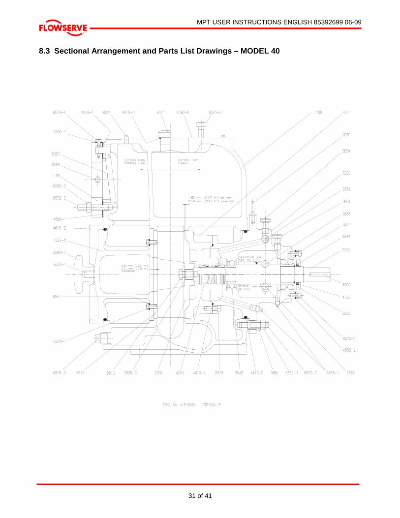
MPT USER INSTRUCTIONS ENGLISH 85392699 06-09
31 of 41
®
8.3 Sectional Arrangement and Parts List Drawings – MODEL 40

MPT USER INSTRUCTIONS ENGLISH 85392699 06-09
32 of 41
®
ABOVE ITEMS NOT SHOWN ON DRAWING
SPARES ITEM DESCRIPTION No. OF DRG. No. MATERIAL CCN No. 6700 KEY 1 11A9C142 C. STL. 95293031- 6580-2 HAND NUT 2 1038A020MPTA001 C. I. 75533802- 6580-1 HEX NUT - BEARING HOUSING 4 38A4S7 ST. STL. 95370581- 6580-0 HEX NUT - SUCTION FLANGE 8 38A4C7 C. STL. 95084760- 6579 FERRYHEAD SCREW 4 143A2A79 AL. STL. 95410577- 6572-3 STUD - SUCTION FLANGE 8 13A3J398 C. STL. 95688156- 6572-2 STUD - BEARING HOUSING 4 12A3S394 ST. STL. 75543439- 6572-1 STUD - HAND NUT 2 13A3J389 ST. STL. 95159166- 6570-4 CAPSCREW (PIN) - VALVE 1 2714A030MPTA001 C. STL. 75534230- 6570-3 CAPSCREW - DISCHARGE 8 35A2C326 C. STL. 95054110- 6570-2 CAPSCREW - HANDLE 2 35A2C110 C. STL. 95053146- 6570-1 CAPSCREW - WEAR PLATE 4 35A2C110 C. STL. 95053146- 6570-0 CAPSCREW - BEARING COVER 4 35A2C111 C. STL. 68885607- 6569 PLUG SQ. HEAD - SUCTION FLANGE 1 30A7C3 C. STL. 95061479- 2 6544 RETAINING RING 1 173A13S175 C. STL. 95391264- 6541 LOCKWASHER - WEAR PLATE 4 14A5C120 C. STL. 95081790- 6521 PLUG SQ. HEAD - CASING 2 30A7C3 C. I. 95061479- 6515-1 PLUG SQ. HEAD - BEARING HOUSING 2 30A7C4 C. I. 95078606- 6515-0 PLUG SQ. HEAD – CASING DRAIN 1 30A7C7 C. I. 95033551- 6511 PRIMING PLUG 1 565A10S10 C. STL. 95663803- 2 6301 FLAPPER VALVE 1 2214A040MPTA001 NEOPRENE 75518563- 1 4610-3 O-RING - PRIMING PLUG 1 20A11EM222 VITON 95022232- 1 4610-2 O-RING - COVER PLATE/CASING 1 20A11CM449 Buna N 95018321- 1 4610-1 O-RING - BEARING HSG/SEAL HSG 1 20A11CM260 Buna N 95086898- 1 4610-0 O-RING - CASING /BEARING HOUSING 1 20A11CM448 Buna N 95017927- 1 4590-2 GASKET - END COVER 1 2584A030MPTA001 NTL/SYN 75530345- 1 4590-1 GASKET - FLANGE SUCTION 1 2586A040MPTA001 NTL/SYN 75516682- 1 4590-0 GASKET - DISCHARGE 1 32A11X10 NTL/SYN 60669884- 1 4300 LIP SEAL - BEARING COVER 1 2796A175DIAB001 NITRILE 75554055- 2 4200 MECHANICAL SEAL 1 1802A150MPTA002 BX/C F X/JF 75555318- 4011 SEAL HOUSING 1 2632A040MPTA001 C. I. 75517383- 3858 SIGHT GLASS 3 4260A000MPTA001 POLYMIDE 75553578- 3854 AIR VENT 2 0319A00VENTB003 STEEL 60610474- 3260 BEARING COVER 1 0573A030MPTA001 C. I. 75516971- 3200 BEARING HOUSING 1 1109A040MPTA001 C. I. 75518142- 2 3043 BALL BEARING - NDE 1 27A19X308 STEEL 95213963- 2 3041 BALL BEARING - DE 1 24A19X309 STEEL 95213237- 2913 CAPSCREW - IMPELLER 1 35A2T323 ST. STL. 95251856- 2905-1 WASHER - VALVE 1 11A5X4 NYLON 97461974- 2905-0 WASHER - IMPELLER 1 2888A030MPTA001 ST. STL. 75529644- 3 2200 IMPELLER 1 1129A040MPTA001 D. I. 75516633- 3 2100 SHAFT 1 2807A040MPTA001 ST. STL. 75532903- 2 1915 WEAR PLATE 1 1869A040MPTA001 C. I. 75518399- 1680 SPACER BUSHING 4 2454A030MPTA001 ST. STL. 75517524- 1223-1 HANDLE - COVER PLATE 1 1032A000MPTA001 D. I. 75516906- 1223-0 COVER PLATE 1 2729A040MPTA001 C. I. 75517961- 1139 SUCTION FLANGE - 4” NPT 1 0850A040MPTA001 C. I. 75516757- 1100 CASING 1 2469A040MPTA001 C. I. 75525253- 1020 EYE BOLT 1 124A2C3X0.5 C. STL. 75536938-
RECOMMENDED SPARES INDICATED THUS :- 1 = START-UP SPARES 2 = NORMAL MAINTENANCE SPARES (INCLUDES START-UP) 3 = CRITICAL SERVICE (INCLUDES START-UP/MAINTENANCE) RECOMMENDED OIL :- Mobil DTE Medium or Castrol Hyspin AWS 46 oil OIL QUANTITY :- SEAL CHAMBER APPROX. 1 L (33.81 fl. oz.) BEARING HOUSING APPROX. 350 ml (11.83 fl. oz.)
ITEM DESCRIPTION No. OF DRG. No. MATERIAL CCN No. 7000 INSTRUCTION MANUAL 1 PAPER 85392699
6821 DRIVE SCREWS (NAMEPLATE) 4 122A2R37 SS 95330452
9322-3 WARNING TAG - ALIGNMENT 1 9323 DECAL - PRIMING 1
9322-0 NAMEPLATE 1 AY51851A SS 78800505
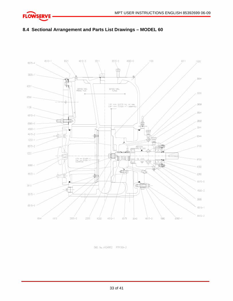
MPT USER INSTRUCTIONS ENGLISH 85392699 06-09
33 of 41
®
8.4 Sectional Arrangement and Parts List Drawings – MODEL 60
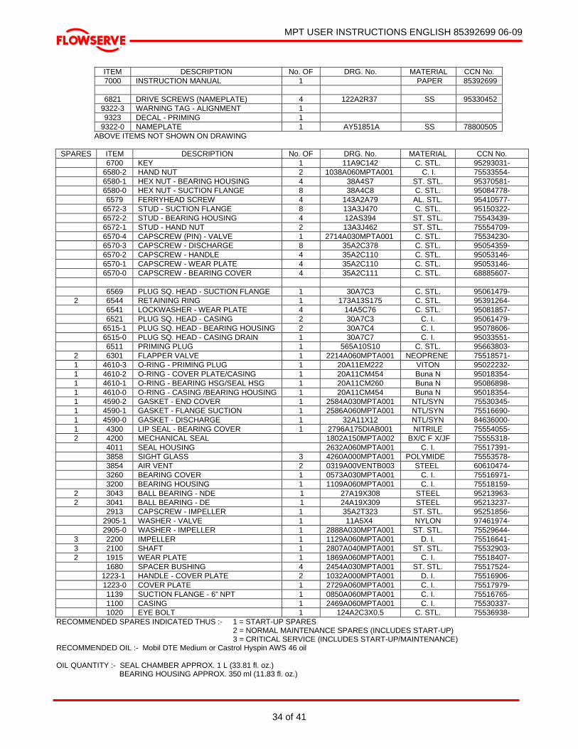
MPT USER INSTRUCTIONS ENGLISH 85392699 06-09
34 of 41
®
ITEM DESCRIPTION No. OF DRG. No. MATERIAL CCN No. 7000 INSTRUCTION MANUAL 1 PAPER 85392699
6821 DRIVE SCREWS (NAMEPLATE) 4 122A2R37 SS 95330452
9322-3 WARNING TAG - ALIGNMENT 1 9323 DECAL - PRIMING 1
9322-0 NAMEPLATE 1 AY51851A SS 78800505 ABOVE ITEMS NOT SHOWN ON DRAWING
SPARES ITEM DESCRIPTION No. OF DRG. No. MATERIAL CCN No. 6700 KEY 1 11A9C142 C. STL. 95293031- 6580-2 HAND NUT 2 1038A060MPTA001 C. I. 75533554- 6580-1 HEX NUT - BEARING HOUSING 4 38A4S7 ST. STL. 95370581- 6580-0 HEX NUT - SUCTION FLANGE 8 38A4C8 C. STL. 95084778- 6579 FERRYHEAD SCREW 4 143A2A79 AL. STL. 95410577- 6572-3 STUD - SUCTION FLANGE 8 13A3J470 C. STL. 95150322- 6572-2 STUD - BEARING HOUSING 4 12AS394 ST. STL. 75543439- 6572-1 STUD - HAND NUT 2 13A3J462 ST. STL. 75554709- 6570-4 CAPSCREW (PIN) - VALVE 1 2714A030MPTA001 C. STL. 75534230- 6570-3 CAPSCREW - DISCHARGE 8 35A2C378 C. STL. 95054359- 6570-2 CAPSCREW - HANDLE 4 35A2C110 C. STL. 95053146- 6570-1 CAPSCREW - WEAR PLATE 4 35A2C110 C. STL. 95053146- 6570-0 CAPSCREW - BEARING COVER 4 35A2C111 C. STL. 68885607- 6569 PLUG SQ. HEAD - SUCTION FLANGE 1 30A7C3 C. STL. 95061479- 2 6544 RETAINING RING 1 173A13S175 C. STL. 95391264- 6541 LOCKWASHER - WEAR PLATE 4 14A5C76 C. STL. 95081857- 6521 PLUG SQ. HEAD - CASING 2 30A7C3 C. I. 95061479- 6515-1 PLUG SQ. HEAD - BEARING HOUSING 2 30A7C4 C. I. 95078606- 6515-0 PLUG SQ. HEAD - CASING DRAIN 1 30A7C7 C. I. 95033551- 6511 PRIMING PLUG 1 565A10S10 C. STL. 95663803- 2 6301 FLAPPER VALVE 1 2214A060MPTA001 NEOPRENE 75518571- 1 4610-3 O-RING - PRIMING PLUG 1 20A11EM222 VITON 95022232- 1 4610-2 O-RING - COVER PLATE/CASING 1 20A11CM454 Buna N 95018354- 1 4610-1 O-RING - BEARING HSG/SEAL HSG 1 20A11CM260 Buna N 95086898- 1 4610-0 O-RING - CASING /BEARING HOUSING 1 20A11CM454 Buna N 95018354- 1 4590-2 GASKET - END COVER 1 2584A030MPTA001 NTL/SYN 75530345- 1 4590-1 GASKET - FLANGE SUCTION 1 2586A060MPTA001 NTL/SYN 75516690- 1 4590-0 GASKET - DISCHARGE 1 32A11X12 NTL/SYN 84636000- 1 4300 LIP SEAL - BEARING COVER 1 2796A175DIAB001 NITRILE 75554055- 2 4200 MECHANICAL SEAL 1802A150MPTA002 BX/C F X/JF 75555318- 4011 SEAL HOUSING 2632A060MPTA001 C. I. 75517391- 3858 SIGHT GLASS 3 4260A000MPTA001 POLYMIDE 75553578- 3854 AIR VENT 2 0319A00VENTB003 STEEL 60610474- 3260 BEARING COVER 1 0573A030MPTA001 C. I. 75516971- 3200 BEARING HOUSING 1 1109A060MPTA001 C. I. 75518159- 2 3043 BALL BEARING - NDE 1 27A19X308 STEEL 95213963- 2 3041 BALL BEARING - DE 1 24A19X309 STEEL 95213237- 2913 CAPSCREW - IMPELLER 1 35A2T323 ST. STL. 95251856- 2905-1 WASHER - VALVE 1 11A5X4 NYLON 97461974- 2905-0 WASHER - IMPELLER 1 2888A030MPTA001 ST. STL. 75529644- 3 2200 IMPELLER 1 1129A060MPTA001 D. I. 75516641- 3 2100 SHAFT 1 2807A040MPTA001 ST. STL. 75532903- 2 1915 WEAR PLATE 1 1869A060MPTA001 C. I. 75518407- 1680 SPACER BUSHING 4 2454A030MPTA001 ST. STL. 75517524- 1223-1 HANDLE - COVER PLATE 2 1032A000MPTA001 D. I. 75516906- 1223-0 COVER PLATE 1 2729A060MPTA001 C. I. 75517979- 1139 SUCTION FLANGE - 6” NPT 1 0850A060MPTA001 C. I. 75516765- 1100 CASING 1 2469A060MPTA001 C. I. 75530337- 1020 EYE BOLT 1 124A2C3X0.5 C. STL. 75536938-
RECOMMENDED SPARES INDICATED THUS :- 1 = START-UP SPARES 2 = NORMAL MAINTENANCE SPARES (INCLUDES START-UP) 3 = CRITICAL SERVICE (INCLUDES START-UP/MAINTENANCE) RECOMMENDED OIL :- Mobil DTE Medium or Castrol Hyspin AWS 46 oil OIL QUANTITY :- SEAL CHAMBER APPROX. 1 L (33.81 fl. oz.) BEARING HOUSING APPROX. 350 ml (11.83 fl. oz.)
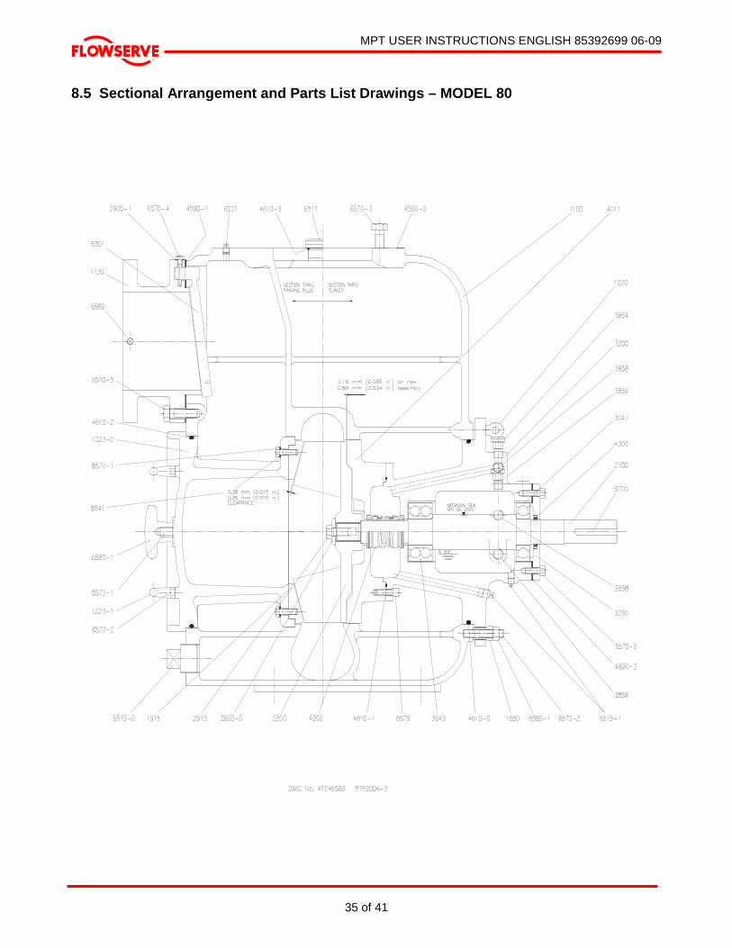
MPT USER INSTRUCTIONS ENGLISH 85392699 06-09
35 of 41
®
8.5 Sectional Arrangement and Parts List Drawings – MODEL 80
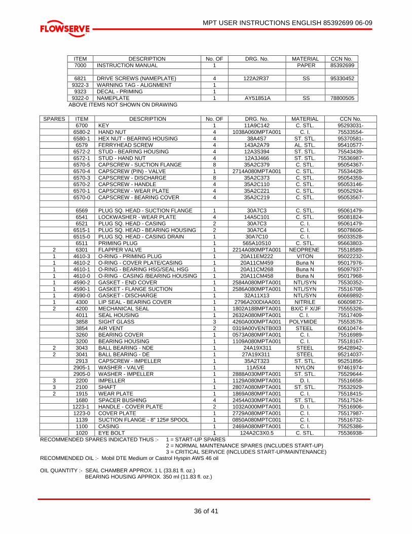
MPT USER INSTRUCTIONS ENGLISH 85392699 06-09
36 of 41
®
ITEM DESCRIPTION No. OF DRG. No. MATERIAL CCN No. 7000 INSTRUCTION MANUAL 1 PAPER 85392699
6821 DRIVE SCREWS (NAMEPLATE) 4 122A2R37 SS 95330452
9322-3 WARNING TAG - ALIGNMENT 1 9323 DECAL - PRIMING 1
9322-0 NAMEPLATE 1 AY51851A SS 78800505 ABOVE ITEMS NOT SHOWN ON DRAWING
SPARES ITEM DESCRIPTION No. OF DRG. No. MATERIAL CCN No. 6700 KEY 1 11A9C142 C. STL. 95293031- 6580-2 HAND NUT 4 1038A060MPTA001 C. I. 75533554- 6580-1 HEX NUT - BEARING HOUSING 4 38A4S7 ST. STL. 95370581- 6579 FERRYHEAD SCREW 4 143A2A79 AL. STL. 95410577- 6572-2 STUD - BEARING HOUSING 4 12A3S394 ST. STL. 75543439- 6572-1 STUD - HAND NUT 4 12A3J466 ST. STL. 75536987- 6570-5 CAPSCREW - SUCTION FLANGE 8 35A2C379 C. STL. 95054367- 6570-4 CAPSCREW (PIN) - VALVE 1 2714A080MPTA001 C. STL. 75534428- 6570-3 CAPSCREW - DISCHARGE 8 35A2C373 C. STL. 95054359- 6570-2 CAPSCREW - HANDLE 4 35A2C110 C. STL. 95053146- 6570-1 CAPSCREW - WEAR PLATE 4 35A2C221 C. STL. 95052924- 6570-0 CAPSCREW - BEARING COVER 4 35A2C219 C. STL. 95053567- 6569 PLUG SQ. HEAD - SUCTION FLANGE 1 30A7C3 C. STL. 95061479- 6541 LOCKWASHER - WEAR PLATE 4 14A5C101 C. STL. 95081824- 6521 PLUG SQ. HEAD - CASING 2 30A7C3 C. I. 95061479- 6515-1 PLUG SQ. HEAD - BEARING HOUSING 2 30A7C4 C. I. 95078606- 6515-0 PLUG SQ. HEAD - CASING DRAIN 1 30A7C10 C. I. 95033528- 6511 PRIMING PLUG 1 565A10S10 C. STL. 95663803- 2 6301 FLAPPER VALVE 1 2214A080MPTA001 NEOPRENE 75518589- 1 4610-3 O-RING - PRIMING PLUG 1 20A11EM222 VITON 95022232- 1 4610-2 O-RING - COVER PLATE/CASING 1 20A11CM459 Buna N 95017976- 1 4610-1 O-RING - BEARING HSG/SEAL HSG 1 20A11CM268 Buna N 95097937- 1 4610-0 O-RING - CASING /BEARING HOUSING 1 20A11CM458 Buna N 95017968- 1 4590-2 GASKET - END COVER 1 2584A080MPTA001 NTL/SYN 75530352- 1 4590-1 GASKET - FLANGE SUCTION 1 2586A080MPTA001 NTL/SYN 75516708- 1 4590-0 GASKET - DISCHARGE 1 32A11X13 NTL/SYN 60669892- 1 4300 LIP SEAL - BEARING COVER 1 2796A200DIAA001 NITRILE 60609872- 2 4200 MECHANICAL SEAL 1 1802A188MPTA001 BX/C F X/JF 75555326- 4011 SEAL HOUSING 1 2632A080MPTA001 C. I. 75517409- 3858 SIGHT GLASS 3 4260A000MPTA001 POLYMIDE 75553578- 3854 AIR VENT 2 0319A00VENTB003 STEEL 60610474- 3260 BEARING COVER 1 0573A080MPTA001 C. I. 75516989- 3200 BEARING HOUSING 1 1109A080MPTA001 C. I. 75518167- 2 3043 BALL BEARING - NDE 1 24A19X311 STEEL 95428942- 2 3041 BALL BEARING - DE 1 27A19X311 STEEL 95214037- 2913 CAPSCREW - IMPELLER 1 35A2T323 ST. STL. 95251856- 2905-1 WASHER - VALVE 1 11A5X4 NYLON 97461974- 2905-0 WASHER - IMPELLER 1 2888A030MPTA001 ST. STL. 75529644- 3 2200 IMPELLER 1 1129A080MPTA001 D. I. 75516658- 3 2100 SHAFT 1 2807A080MPTA001 ST. STL. 75532929- 2 1915 WEAR PLATE 1 1869A080MPTA001 C. I. 75518415- 1680 SPACER BUSHING 4 2454A030MPTA001 ST. STL. 75517524- 1223-1 HANDLE - COVER PLATE 2 1032A000MPTA001 D. I. 75516906- 1223-0 COVER PLATE 1 2729A080MPTA001 C. I. 75517987- 1139 SUCTION FLANGE - 8” 125# SPOOL 1 0850A080MPTC001 C. I. 75516732- 1100 CASING 1 2469A080MPTA001 C. I. 75525386- 1020 EYE BOLT 1 124A2C3X0.5 C. STL. 75536938-
RECOMMENDED SPARES INDICATED THUS :- 1 = START-UP SPARES 2 = NORMAL MAINTENANCE SPARES (INCLUDES START-UP) 3 = CRITICAL SERVICE (INCLUDES START-UP/MAINTENANCE) RECOMMENDED OIL :- Mobil DTE Medium or Castrol Hyspin AWS 46 oil OIL QUANTITY :- SEAL CHAMBER APPROX. 1 L (33.81 fl. oz.) BEARING HOUSING APPROX. 350 ml (11.83 fl. oz.)

MPT USER INSTRUCTIONS ENGLISH 85392699 06-09
37 of 41
®
8.7 General Arrangement Drawing The typical general arrangement drawing and any specific drawings required by the Contract will be sent to the Purchaser separately. If required, these should be obtained from the Purchaser and retained with this manual. 9 CERTIFICATION Certificates determined from the Contract requirements are provided with these instructions where applicable. Examples are certificates for CE marking, ATEX marking, etc. If required, copies of other certificates sent separately to the Purchaser should be obtained from the Purchaser for retention with these User Instructions.
10 OTHER RELEVANT DOCUMENTATION AND MANUALS 10.1 Supplementary Instruction Manuals See also the supplementary instruction manuals supplied with this manual, e.g., for electric motors, controllers, engines, gearboxes, sealant systems, etc. 10.2 Change notes If any changes, agreed with Flowserve Pump Division, are made to the product after its supply, a record of the details should be maintained with these User Instructions.

MPT USER INSTRUCTIONS ENGLISH 85392699 06-09
38 of 41
®
NOTES
MPT USER INSTRUCTIONS ENGLISH 85392699 06-09
39 of 41
®
NOTES
MPT USER INSTRUCTIONS ENGLISH 85392699 06-09
40 of 41
®
NOTES
MPT USER INSTRUCTIONS ENGLISH 85392699 06-09
41of 41
®
FLOWSERVE REGIONAL SALES OFFICES:
USA and Canada Flowserve Corporation (Pump Division) 5215 North O’Connor Blvd. Suite 2300 Irving, Texas 75039, USA Telephone: 1 972 443 6500 Toll Free: 1 800 728 PUMP (7867) Fax: 1 972 443 6800 Europe, Middle East and Africa Flowserve Limited (Pump Division) Harley House, 94 Hare Lane Claygate, Esher, Surrey KT10 0RB United Kingdom Telephone: +44 (0)1372 463 700 Fax: +44 (0)1372 460 190
Latin America and Caribbean Flowserve Corporation (Pump Division) 6840 Wynnwood Lane Houston, Texas 77008, USA Telephone: 1 713 803 4434 Fax: 1 713 803 4497 Asia Pacific Flowserve Pte Ltd (Pump Division) 200 Pandan Loop, 06-03/04 Pantech 21, Singapore 128388 Telephone: +65 775 3003 Fax: +65 779 4607
Visit our web site at: www.flowserve.com
Your Flowserve factory contact: Flowserve Pump Division 3900 Cook Boulevard Chesapeake, VA 23323-1626 USA Telephone: 1 757 485 8000 Fax: 1 757 485 8149
Your local Flowserve representative:
To find your local Flowserve representative, please use the Sales Support Locator System found at www.flowserve.com
ПромХимТех - официальный дистрибьютор и сервис-партнер www.promhimtech.ru
[email protected] 8 800 250 0154