Coexistence of Fermi arcs and Fermi pockets in a high-Tc copper oxide superconductor
Upload
khangminh22Category
view
0download
0
UNITED STATES NUCLEAR REGULATORY COMMISSION
REGION III 2443 WARRENVILLE ROAD, SUITE 210
LISLE, IL 60532-4352
October 29, 2013 Mr. Joseph Plona Senior Vice-President and Chief Nuclear Officer DTE Electric Company Fermi Unit 2 - 210 NOC 6400 North Dixie Highway NEWPORT, MI 48166
SUBJECT: FERMI POWER PLANT, UNIT 2 COMPONENT DESIGN BASES INSPECTION (CDBI) INSPECTION REPORT 05000341/2013008
Dear Mr. Plona:
On September 6, 2013, the U.S. Nuclear Regulatory Commission (NRC) completed a Component Design Bases Inspection (CDBI) at your Fermi Power Plant, Unit 2. The enclosed report documents the results of this inspection, which were discussed on September 6, 2013, with Mr. L. Peterson, and other members of your staff.
The inspection examined activities conducted under your license as they relate to safety and compliance with the Commission’s rules and regulations and with the conditions of your license. The inspectors reviewed selected procedures and records, observed activities, and interviewed personnel.
Based on the results of this inspection, five NRC-identified findings of very low safety significance were identified, all of which involved violations of NRC requirements. However, because of their very low safety significance, and because the issues were entered into your Corrective Action Program, the NRC is treating the issues as Non-Cited Violations (NCVs) in accordance with Section 2.3.2 of the NRC Enforcement Policy.
If you contest the subject or severity of the NCVs, you should provide a response within 30 days of the date of this inspection report, with the basis for your denial, to the U.S. Nuclear Regulatory Commission, ATTN: Document Control Desk, Washington, DC 20555-0001, with a copy to the Regional Administrator, U.S. Nuclear Regulatory Commission - Region III, 2443 Warrenville Road, Suite 210, Lisle, IL 60532-4352; the Director, Office of Enforcement, U.S. Nuclear Regulatory Commission, Washington, DC 20555-0001; and the Resident Inspectors Office at the Fermi Power Plant. In addition, if you disagree with the cross-cutting aspect assigned to any finding in this report, you should provide a response within 30 days of the date of this inspection report, with the basis for your disagreement, to the Regional Administrator, Region III, and the NRC Resident Inspector at the Fermi Power Plant.

M. Plona -2-
In accordance with 10 CFR 2.390 of the NRC's "Rules of Practice," a copy of this letter and its enclosure, and your response (if any) will be available electronically for public inspection in the NRC Public Document Room or from the Publicly Available Records System (PARS) component of NRC's Agencywide Documents Access and Management System (ADAMS), accessible from the NRC Web site at http://www.nrc.gov/reading-rm/adams.html (the Public Electronic Reading Room).
Sincerely, /RA/ Benny Jose, Acting Chief Engineering Branch 2
Division of Reactor Safety
Docket No. 50-341 License No. NPF-43
Enclosure: Inspection Report 05000341/2013008 w/Attachment: Supplemental Information
cc w/encl: Distribution via ListServ™

Enclosure
U.S. NUCLEAR REGULATORY COMMISSION
REGION III
Docket Nos: 05000341 License Nos: NPF-43
Report No: 05000341/2013008
Licensee: DTE Electric Company
Facility: Fermi Power Plant, Unit 2
Location: Newport, MI
Dates: July 8 through September 6, 2013
Inspectors: J. Neurauter, Senior Engineering Inspector, Lead C. Brown, Engineering Inspector, Electrical M. Jones, Engineering Inspector, Mechanical B. Palagi, Senior Operations Inspector P. Wagner, Electrical Contractor S. Spiegelman, Mechanical Contractor R. Petitti, Observer
Approved by: Benny Jose, Acting Chief Engineering Branch 2
Division of Reactor Safety
1 Enclosure
SUMMARY
IR 05000341/2013008; 07/08/2013 – 09/06/2013; Fermi Power Plant, Unit 2; Component Design Bases Inspection (CDBI).
The inspection was a 3-week onsite baseline inspection that focused on the design of components. The inspection was conducted by regional engineering inspectors and two consultants. Five (Green) findings were identified by the inspectors, all with associated Non-Cited Violations (NCVs) of NRC regulations. The significance of inspection findings are indicated by their color (i.e., greater than Green, or Green, White, Yellow, Red) and determined using IMC 0609, “Significance Determination Process,” dated June 2, 2011. Cross-cutting aspects are determined using IMC 0310, “Components Within the Cross Cutting Areas,” dated October 28, 2011. All violations of NRC requirements are dispositioned in accordance with the NRC’s Enforcement Policy dated January 28, 2013. The NRC's program for overseeing the safe operation of commercial nuclear power reactors is described in NUREG-1649, “Reactor Oversight Process” Revision 4, dated December 2006.
A. NRC-Identified and Self-Revealed Findings
Cornerstone: Mitigating Systems
• Green. The inspectors identified a finding of very low safety significance and associated Non-Cited Violation of 10 CFR Part 50, Appendix B, Criterion III, “Design Control,” for the failure to assure the battery rack end rail configuration for battery 2P-29 was in accordance with the design basis Seismic Category I qualification. Specifically, the licensee failed to install battery 2P-29 with the battery rack end rails within 1/8 inch from the battery. The inspectors found one end rail gap for battery 2P-29 greater than 1/8 inch and up to approximately 1/4 inch. The licensee entered this concern into its corrective action program, provided reasonable assurance the installed oversized battery rack end rail gap did not result in a loss of battery 2P-29 battery rack system functionality, completed corrective actions to install a battery rack end rail shim and readjust the battery rack end rail gap within 1/8 inch.
The performance deficiency was determined to be more than minor because it was associated with the Mitigating Systems cornerstone attribute of design control and affected the cornerstone objective of ensuring the capability and reliability of systems that respond to initiating events to prevent undesirable consequences. The finding screened as very low safety significance (Green), because the finding was a design deficiency that did not result in a loss of battery functionality. The inspectors did not identify a cross-cutting aspect associated with this finding, because the finding was not representative of current performance. (Section 1R21.3.b.(1))
Green: The inspectors identified a finding of very low safety significance and associated Non-Cited Violation of 10 CFR Part 50, Appendix B, Criterion III, “Design Control,” for the failure to establish measures to assure the design basis was correctly translated into specifications, drawings, procedures, and instructions. These measures shall include provisions to assure appropriate quality standards are specified and deviations from such standards are controlled. Specifically, the design loads used in a calculation that supported the emergency-core-cooling system suction strainer modification deviated from the loads used in the original design analysis of torus attached piping without providing sufficient justification the design load changes were in conformance with the original torus attached piping design and licensing basis.

2 Enclosure
The performance deficiency was determined to be more than minor because it was associated with the Mitigating Systems cornerstone attribute of design control and affected the cornerstone objective of ensuring the capability and reliability of systems that respond to initiating events to prevent undesirable consequences. The finding screened as very low safety significance (Green) because the finding was a design deficiency that did not result in a loss of piping system functionality. The inspectors did not identify a cross-cutting aspect associated with this finding because the finding was not representative of current performance. (Section 1R21.3.b.(2))
Green: The inspectors identified a finding of very low safety significance and associated Non-Cited Violation of 10 CFR Part 50, Appendix B, Criterion XVI, “Corrective Action,” for the failure to ensure a non-conservative battery technical specification (TS) was corrected in a timely manner. Specifically, the licensee failed to apply for a license amendment to correct the maximum allowed 150 micro-ohm resistance values for the battery cell-to-cell and terminal connections to an acceptable value.
The performance deficiency was determined to be more than minor because it was associated with the Mitigating Systems cornerstone attribute of equipment performance and affected the cornerstone objective of ensuring capability and reliability of systems that respond to initiating events to prevent undesirable consequences. The finding screened as very low safety significance (Green), because the licensee provided test results that indicated the measured resistance values had never approached the TS allowed values. The inspectors determined this finding has a cross-cutting aspect in the area of human performance associated with decision making – systematic processes, because the licensee did not make safety significant or risk significant decisions using a systematic process. (Section 1R21.3.b.(3))
Green. The inspectors identified a finding of very low safety significance and associated Non-Cited Violation of 10 CFR Part 50, Appendix B, Criterion III, “Design Control,” for the failure to correctly translate the requirements of IEEE 450-1972 into TS surveillance requirements. Specifically, TS surveillance requirements (SR) 3.8.4.8 required verifying battery capacity every “18 months when the battery shows degradation or has reached 85 percent of expected life,” contrary to the requirements for annual capacity tests in the IEEE standard, which the licensee was committed to follow.
The performance deficiency was determined to be more than minor because it was associated with the Mitigating Systems cornerstone attribute of design control and affected the cornerstone objective of ensuring capability and reliability of systems that respond to initiating events to prevent undesirable consequences. The finding screened as very low safety significance (Green), because the finding was a design deficiency that did not result in a loss of battery functionality. The inspectors did not identify a cross-cutting aspect associated with this finding because the finding was not representative of current performance. (Section 1R21.3.b.(4))
• Green. The inspectors identified a finding of very low safety significance and associated Non-Cited Violation of 10 CFR Part 50, Appendix B, Criterion III, “Design Control,” for the failure to translate the design standard requirements for battery test periodicity into procedures and instructions. Specifically, after calculations determined battery 2B-1 had an expected life of less than 20 years, the licensee failed to adjust the capacity test periodicity and 85 percent life point in accordance with the battery design standard or provide for battery replacement at 97.1 percent of rated capacity.

3 Enclosure
The performance deficiency was determined to be more than minor because it was associated with the Mitigating Systems cornerstone attribute of design control and affected the cornerstone objective of ensuring capability and reliability of systems that respond to initiating events to prevent undesirable consequences. The finding screened as very low safety significance (Green), because the finding was a design deficiency that did not result in a loss of battery functionality. The inspectors identified the finding had a cross-cutting aspect in the area of problem identification and resolution, Corrective Action Program because the licensee failed to ensure issues potentially impacting nuclear safety are promptly identified and fully evaluated such that the resolutions address causes and extent of conditions, as necessary. (Section 1R21.3.b.(5))
B. Licensee-Identified Violations
No violations were identified.

4 Enclosure
REPORT DETAILS
1. REACTOR SAFETY
Cornerstone: Initiating Events, Mitigating Systems, and Barrier Integrity
1R21 Component Design Bases Inspection (71111.21)
.1 Introduction
The objective of the component design bases inspection is to verify the design bases have been correctly implemented for the selected risk significant components and the operating procedures and operator actions are consistent with design and licensing bases. As plants age, their design bases may be difficult to determine and an important design feature may be altered or disabled during a modification. The Probabilistic Risk-Assessment model assumes the capability of safety systems and components to perform their intended safety function successfully. This inspectable area verifies aspects of the Initiating Events, Mitigating Systems, and Barrier Integrity cornerstones for which there are no indicators to measure performance.
Specific documents reviewed during the inspection are listed in the Attachment to the report.
.2 Inspection Sample Selection Process
The inspectors used information contained in the licensee’s Probabilistic Risk-Assessment and the Fermi Unit 2 Standardized Plant Analysis Risk-Model to identify one scenario to use as the basis for component selection. The scenario consisted of a loss of offsite power (LOOP), which caused a turbine trip. Based on this scenario, a number of risk significant components were selected for the inspection.
The inspectors also used additional component information such as a margin assessment in the selection process. This design margin assessment considered original design reductions caused by design modification, power uprates, or reductions due to degraded material condition. Equipment reliability issues were also considered in the selection of components for detailed review. These included items such as performance test results, significant corrective actions, repeated maintenance activities, Maintenance Rule (a)(1) status, components requiring an operability evaluation, NRC resident inspectors input of problem areas or equipment, and system health reports. Consideration was also given to the uniqueness and complexity of the design, operating experience, and the available defense-in-depth margins. A summary of the reviews performed and the specific inspection findings identified are included in the following sections of the report.
The inspectors also identified procedures and modifications for review that were associated with the selected components. In addition, the inspectors selected operating experience issues associated with the selected components.
This inspection constituted 22 samples as defined in Inspection Procedure 71111.21.

5 Enclosure
.3 Component Design
a. Inspection Scope
The inspectors reviewed the Updated Final Safety Analysis Report (UFSAR), Technical Specifications (TS), design basis documents, drawings, calculations and other available design basis information, to determine the performance requirements of the selected components. The inspectors used applicable industry standards, such as the American Society of Mechanical Engineers (ASME) Code, Institute of Electrical and Electronics Engineers (IEEE) Standards and the National Electric Code, to evaluate acceptability of the systems’ design. The NRC also evaluated licensee actions, if any, taken in response to NRC issued operating experience, such as Bulletins, Generic Letters (GLs), Regulatory Issue Summaries (RISs), and Information Notices (INs). The review was to verify the selected components would function as designed when required and support proper operation of the associated systems. The attributes that were needed for a component to perform its required function included process medium, energy sources, control systems, operator actions, and heat removal. The attributes to verify the component condition and tested capability was consistent with the design bases and was appropriate, may include installed configuration, system operation, detailed design, system testing, equipment and environmental qualification, equipment protection, component inputs and outputs, operating experience, and component degradation.
For each of the components selected, the inspectors reviewed the maintenance history, preventive maintenance activities, system health reports, operating experience-related information, vendor manuals, electrical and mechanical drawings, and licensee’s Corrective Action Program documents. Field walkdowns were conducted for all accessible components to assess material condition and to verify the as-built condition was consistent with the design. Other attributes reviewed are included as part of the scope for each individual component.
The following 16 components (samples) were reviewed:
• 260 Volts Direct Current (Vdc) Distribution Panels 2PB-2 (R3200S027) and 2PB-2-15 (R3200S065): The inspectors reviewed the Division 2 260Vdc system loading and short circuit calculations to determine system loading and available short circuit current under faulted conditions. The inspectors also reviewed the bus, breaker, fuse, and cable ratings to confirm their capability to carry maximum loading and interrupt maximum faulted conditions. The cable separation design was reviewed to confirm compliance with single failure and Title 10, Code of Federal Regulations (CFR), Part 50, Appendix R, “Fire Protection Program for Nuclear Power Facilities Operating Prior to January 1, 1979,” criteria. The inspectors reviewed voltage drop calculations to determine whether adequate control voltage was available for the 4160 volts alternating current (Vac) and 480Vac circuit breakers. Breaker and/or fuse coordination were reviewed to ensure overloads and faulted conditions were properly interrupted.
• Emergency Diesel Generator-13 and Associated Output Breaker (electrical only): The inspectors reviewed selected electrical components for emergency diesel generator (EDG) 13. The inspectors reviewed the ability of the EDG to start at the end of a station blackout, using starting air, and to close the output breaker at the lowest battery voltage. The voltage drop, degraded voltage, and short-circuit calculations were reviewed to ensure the EDG would perform during a design

6 Enclosure
basis event. The inspectors performed an evaluation of EDG-13 to determine whether various design features and commitments were being satisfied. The inspectors reviewed system health reports, the UFSAR, the TS, and design basis documents (DBDs). The inspectors reviewed electrical diagrams to verify the interlocks and protective features that had been credited in the design, had been implemented. The inspectors reviewed the EDG testing procedures to ensure the TS requirements were being satisfied. The inspectors also reviewed modifications related to the EDG.
• 480 Volt Alternating Current (Vac) Engineered Safety System Bus 72E: As part of the review of Electrical Calculation DC-6447, the inspectors verified the capability of Bus 72E was adequate to handle and clear potential short circuit currents. The inspectors also reviewed the degraded-voltage and loss-of-voltage protection schemes to determine whether the voltage setpoints were selected based on the voltage requirements for safety-related loads at the 480Vac level and were in accordance with the requirements of the TS. The inspectors verified appropriate voltage coordination had been established. The inspectors reviewed a sample of schematic diagrams to verify appropriate interlocks and protective features had been provided in accordance with design commitments. The inspectors reviewed system health reports and corrective action documents to determine whether there were any adverse operating trends. In addition, the inspectors performed a visual inspection of 480Vac safety buses to assess the material condition and the presence of potential hazards. The inspectors also reviewed the design and controls for the voltage regulator installed in the power supply feeder cables from ESS Bus No. 72E Transformer, powered from 4160 Volt Bus No. 65E, to the 480 Volt Bus. The inspectors reviewed procedures to verify the maintenance and calibration recommendations provided in the General Electric Instructions for the Model GEK-26050 Inductrol Regulator (Vendor Manual Number VME8-11, Revision B), had been properly included.
• Residual Heat Removal Pump B (E1102C002B): The inspectors Reviewed pump hydraulic calculations, net positive suction head (NPSH) calculations, in-service testing (IST) data, minimum flow requirements, and test acceptance criteria to ensure TS and design basis requirements were met and the pump would be capable of operating under limiting design basis conditions. In addition, the inspectors reviewed the operation of the pump in the event of a postulated medium-break loss of coolant accident (LOCA) or LOOP scenario. The inspectors also reviewed system abnormal operating procedures to ensure acceptance criteria were correctly translated from the design basis.
The inspectors reviewed portions of Electrical Calculation DC-6447 to determine if the RHR pump motor had been properly evaluated and incorporated into the overall electrical system design evaluation. The inspectors also evaluated various aspects of the RHR Pump motor and its controls to determine if the design features and commitments contained in the UFSAR, the TS, system health reports, and the DBDs were being satisfied. In addition, the inspectors reviewed component sizing and protection features. The inspectors reviewed the electrical diagrams to verify the interlocks and protective features had been credited in the design had been implemented. The inspectors also verified the control and power cables utilized for the RHR pump motors had adequate ampacity.

7 Enclosure
During the 2010 CDBI, the inspectors had determined available voltage levels derived in Calculation DC-0919 were non-conservative because motor starting voltage requirements were based on 70 percent of motor rated voltage at the terminals, rather than on the voltages stipulated in the motor specifications (NCV 05000341/2010006-02 – Inadequate Motor Starting Voltage Calculations). The condition was entered into the licensee’s Corrective Action Program as Condition Assessment and Resolution Documents (CARDs) 10-20748 and 10-21733. The licensee also initiated CARD 10-20823 to conduct an overall evaluation of the electrical response issues raised during the 2010 CDBI. As stated in the CARD resolution, the voltage change between taps on the load tap changer had been incorrectly assumed to be 0.58 percent while the actual change would be 0.9375 percent. This value was verified by field measurements and resulted in a voltage recovery time of 20 seconds as opposed to the 44 seconds had been previously determined. During this inspection, the inspectors verified motor voltage ratings and starting transients had been included in the newly completed overall Electrical Calculation DC-6447 for selected motors.
The inspectors also conducted a walk down of the RHR pump areas to evaluate the material conditions and equipment protection features. The inspectors noted the RHR Pump D motor had a nameplate rating of 2250 horsepower while the other three RHR pump motors are rated for 2000 horsepower. The inspectors questioned the difference and were informed the motor was a replacement had originally been designed as a high pressure core spray pump motor for a nuclear plant that had been subsequently cancelled. The inspectors verified the motor had been appropriately refurbished and the correct horse power rating, including higher full load amperes, for this motor had been utilized in Calculation DC-6447, Attachment K, Motor Data.
• Residual Heat Removal Service Water Pump B (E1151C001B): The inspectors reviewed piping and instrumentation diagrams, pump line up, pump capacities, minimum flow, and IST data for the residual heat removal service water (RHRSW) pumps. Design calculations related to pump head, minimum required flow, net positive suction head (NPSH), and vortexing were reviewed to ensure the pumps were capable of performing their intended safety function during design basis accident scenarios. The inspectors also reviewed surveillance procedures for the RHRSW pump to verify TS surveillance requirements were met. The RHR reservoir condition was also reviewed to verify design basis temperature limits, water volume requirements, and mechanical draft cooling tower performance was maintained.
• Division II Safety Relief Valves (B2104F013 C,D,F,G,K,L,M,N): The inspectors reviewed calculations used for sizing the air accumulator supplying SRV G, and the backup nitrogen bottles supplying the remaining SRVs (C,D,F,K,L,M, and N) to ensure the valves are capable of functioning under loss of normal air supply, considering the maximum allowable system leak rate. The inspectors also reviewed recently completed leak rate testing performed on the air system piping and header connected to the valves to verify the acceptance criteria were appropriate and acceptable. The inspectors also reviewed selected electrical components for the SRVs. The design basis documentation, USAR, and TS surveillance tests were reviewed to ensure design and licensing bases were met. The inspectors reviewed the direct current (DC) control power to the solenoids

8 Enclosure
and the control logic and interlocks to ensure the solenoids would operate as designed during an event. The review included assessing portions of DC-6480, “130/260V DC System Analysis,” and DC-6447, “Auxiliary Power Systems Analysis.”
• Reactor Building Component Cooling Water Return Valve (P4400F601B): The inspectors reviewed closure time of Valve P4400F601B, together with closure time of Valve P4400F603B to determine if this action will isolate a section of the general water cooling system, designated the emergency equipment cooling water (EECW) system, to enable cooling of equipment essential to safe reactor shutdown. The inspectors reviewed the function of these valves by performing walk downs, interviewing knowledgeable personnel, discussing past operation, modification and analysis of the valves and system, and reviewing test results, including corrective action documents.
The inspectors’ walk down of the valves included observations of the physical condition of the valve, supports and piping, and of surrounding equipment to consider potential failure modes. In addition, the inspectors conducted interviews with the systems engineer, motor-operated valve (MOV) lead engineer, mechanical, and civil design engineers to address questions regarding test results related to closing time, weak link analysis, and modifications to address the closing times. The inspectors reviewed the electrical control logic and power schematics to confirm the valve operations met the design requirements. The inspectors also reviewed the effects of degraded voltage and ambient conditions on valve operation along with the voltage drop calculations, thermal overload testing, environmental qualifications, and any limitations on the operators. The inspectors reviewed system operating, periodic testing, and maintenance procedures to assure consistency with vendor technical manuals.
• Reactor Building Component Cooling Water Supply Valve (P4400F603B): The inspectors performed a walk down of valve P4400F603B to examine its physical condition, environment, access for maintenance, and to determine if any operations or maintenance restrictions were identified as indicated by deficiency tags. An interview was conducted with the systems engineer to discuss recent operational history and maintenance activity. In addition, the systems engineer provided information regarding the surface condition of the valve and access to the valve and the operator. The inspectors reviewed the vendor manuals to evaluate consistency with the maintenance and inspection procedures. Historical records were examined in regard to closing time and stem lubrication. Operator timing was compared with the corresponding outlet valve (P4400F601B) to examine the impact on pump NPSH. The inspectors reviewed the pump weak link analysis to determine if the high stress components, the valve and operator, were adequately evaluated in the MOV tests. The results of the weak link analysis and the valve closing times were discussed with the senior valve engineer and MOV engineer to evaluate the analysis and test results. The inspectors also reviewed the electrical power and control schematics for the valve along with the degraded voltage effects, voltage drop calculations, ambient effects, environmental qualifications, and any operator control limitations.
• Division 2 Emergency Equipment Cooling Water Pump (P4400C001B): The inspectors reviewed the system hydraulic calculations including NPSH, system

9 Enclosure
flow, and vortex mitigation to evaluate if the pump was capable of providing sufficient flow under accident conditions. The inspectors performed a walk down of the pump, piping, and associated supports to examine the physical condition of the pump. The inspectors reviewed surveillance test procedures, the acceptance bases for the periodic test program to assure the testing complied with the ASME Operation and Maintenance (OM) Code for the designated acceptance criteria to verify the tests would ensure the pumps were capable of meeting their required performance. The inspectors also reviewed the minimum flow protection for the pump to verify adequate performance under all conditions and the NPSH requirements were met for design conditions. The inspectors reviewed a design change associated with replacing the pump. The inspectors interviewed the systems and design engineers to examine present and past pump performance as presented in the system health report. The vendor operating manual was reviewed to assure consistency between vendor maintenance recommendations, the pump maintenance procedure and IST program. The inspectors also reviewed industry communications for the pump and motor.
The inspectors performed an evaluation of various aspects of the EECW Pump B motor and its controls to determine whether the design features and commitments contained in the UFSAR, the TS, system health reports, and the DBDs were being satisfied. The evaluation included reviewing the component sizing and protection features. The inspectors reviewed those portions of Electrical Calculation DC-6447 to verify the EECW Pump motors had been properly evaluated and included in the voltage regulation and coordination evaluations. The inspectors also reviewed the electrical diagrams to verify the interlocks and protective features had been incorporated. The inspectors verified the control and power cables utilized for the EECW pump motor had appropriate ampacity and protection. The inspectors also reviewed surveillance procedures for the assembly to ensure the design features were being tested and verified.
• Division 2 Emergency Equipment Service Water Pump (P4500C002B): The inspectors performed an inspection of Pump P4500C002B which supplies water to the EESW System in the event of loss of off-site power, high drywell pressure or upon failure of the RBCCW system. Water is supplied from the ultimate heat sink (UHS). The inspectors reviewed pump/system pump hydraulic analysis to verify an adequate supply of water pressure was available from the P4500C002B pump. The inspectors reviewed test results and design margin along with scheduled replacement of the pump motor. The NPSH was reviewed for minimum flow conditions to assure an adequate inlet condition existed at the pump at design flow conditions. The inspectors examined the temperature and level history of the UHS to assure NPSH can be established. The inspectors evaluated the preventative maintenance (PM) program in relation to vendor recommendations and reviewed the performance curves for the installed pump. The basis of the IST acceptance requirements were reviewed by the inspectors for low margin conditions including the basis for the low pressure setpoint. The systems engineer and mechanical design engineer were interviewed by the inspectors to discuss the trend curves and setpoint basis.
The inspectors performed an evaluation of various aspects of the EESW Pump B motor and its controls to determine whether the design features and

10 Enclosure
commitments contained in the UFSAR, the TS, system health reports, and the DBDs were being satisfied. In addition, the inspectors reviewed those portions of Calculation DC-6447 related to component sizing, protection, and coordination. The inspectors verified the control and power cables utilized for this EESW pump motor had been adequately sized. The inspectors also reviewed the electrical diagrams to verify the interlocks and protective features, credited in the design documentation, had been properly implemented. The inspectors also reviewed procedures for testing the assembly to ensure the design features were being verified.
• Residual Heat Removal Heat Exchanger (E1101B001B): The inspectors reviewed RHR systems calculations, including the RHR System hydraulic calculation, Design Basis for in-service performance testing of the RHR heat exchanger calculation, and the tube plugging limit calculation. Inspectors also reviewed recent performance test trend data and eddy current test results to assess the performance of this heat exchanger. The inspectors performed visual non-intrusive inspections to assess the installation configuration and material condition of the heat exchanger and its support structures.
• Residual Heat Removal Heat Exchanger Outlet Valve (E1150F003B): The inspectors reviewed the MOV calculations, including required thrust, weak link, and maximum differential pressure, to ensure the valve was capable of functioning under design and licensing bases conditions. Diagnostic and IST results were reviewed to verify acceptance criteria were met and performance degradation would be identified prior to valve failure. The inspectors reviewed the licensee MOV program and test procedures to ensure proper valve classification and testing has been performed. The inspectors confirmed licensee testing ensures the valve has remained capable of meeting its intended design function during limiting design basis operating conditions.
• Division 2 (B) 130/260 Vdc Batteries, and 130 Vdc Battery Chargers: The inspectors reviewed portions of the newly completed DC-6480 Vol 1, “130/260V DC System Analysis,” Revision A. The analysis included all aspects of the DC systems in a comprehensive power-flow dynamic analysis. In particular, the inspectors reviewed the battery sizing calculation to verify the capability of the battery to support momentary and continuous loading for the duration of the duty cycle. The voltage drop calculation was also reviewed to confirm the capability of the battery to supply adequate voltage to the loads under limiting conditions for the duration of the duty cycle. The inspectors reviewed battery testing procedures to verify periodic tests conformed to the TS requirements and industry standards and to confirm the inter-cell resistance was maintained sufficiently low to have minimal impact on the voltage drop calculations. The inspectors reviewed the battery charger sizing calculation to confirm their capability to maintain the associated batteries in a charged state and to recharge the batteries, in a timely manner, following a LOOP event. The battery charger testing procedures were also reviewed to confirm they conformed to the TS requirements and test results supported operability. The inspectors also reviewed the batteries capability to sustain the DC loads for the minimum coping period during a design basis station blackout (SBO) event.

11 Enclosure
• Torus Emergency Core Cooling System Strainer - Residual Heat Removal Suction: The inspectors reviewed the design modification for ECCS suction strainer replacement. The inspectors reviewed the design basis for the torus and torus attached piping systems, calculations for the replacement strainer hydrodynamic loading, hydraulic sizing, and structure. The inspectors also reviewed calculations affected by the replacement RHR strainer. In addition, the inspectors verified the licensee periodically removed torus sludge, visually examined the torus internals, and repaired the torus internal coating to maintain the torus internal debris below the amount evaluated in the replacement strainer design calculation.
• Combustion Turbine Generator 11-1: The inspectors reviewed those portions of Electrical Calculation DC-6447 related to the off-site power from the 120 kilo-volt (kV) and 345kV switchyards to verify design assumptions were being satisfied. The inspectors reviewed the interface agreements between the Fermi Plant and the power transmission systems to verify procedures had been established to control the voltage and frequency available at the Fermi Plant switchyards. The interface agreement was provided in NUC-001, “Nuclear Plant Operating Agreement for the Fermi Unit 2 Nuclear Plant,” Revision 2, that became effective on April 1, 2013. The inspectors also reviewed the control room operator instructions for monitoring off-site power and verified training had been conducted.
During the 2010 CDBI, the inspectors determined the licensee had failed to ensure the design basis for the degraded voltage relay setpoint had been correctly translated into procedures. Specifically, on two occasions the licensee failed to perform conservative calculations to demonstrate the Division 1 degraded voltage relays would reset when required to maintain the availability of offsite power (NCV 05000341/2010006-01 – Inadequate Calculations for Availability of 120kV System Offsite Power). This violation was entered into the licensee’s Corrective Action Program as CARD 10-21733.
During this inspection, electrical calculation DC-6447 was reviewed and the setpoints for the under-voltage and loss-of-voltage relays were verified to have been re-evaluated and the values being utilized were in accordance with TS requirements. The inspectors verified the agreement with the transmission system for maintaining off-site power systems voltage and frequency contained appropriate restrictions and guidance had been provided to control room operators for monitoring and addressing off-site power conditions. The inspectors also reviewed ECR-35621 and revisions to DC-0919 to verify the motor starting transients study and error evaluations for time delay string for degraded voltage with a concurrent LOCA had been incorporated.
During the 2010 CDBI, the inspectors had also determined the licensee had failed to translate the 2.1 percent switchyard voltage drop criteria assumed in calculation DC-0919 into station Operating Procedures ODE-12, “Operations Department Expectations,” Revision 18; MOP05, “Control of Equipment,” Revision 30, and 20.300.Grid, “Grid Disturbance,” Revision 2. The inspectors noted procedures intended to control voltages, on the offsite power system, within acceptable ranges only addressed the minimum and maximum discrete voltages for the 120 kV systems, and did not address the magnitude of the

12 Enclosure
sudden voltage decrease that could be tolerated, i.e., voltage decreases at a rate faster than the load tap changer (LTC) response time (NCV 05000341/2010006-03 - Inadequate Procedures for Controlling Availability of 120kV System Voltage).
During this inspection, the inspectors reviewed the latest revisions of the above guidance and procedures and noted appropriate instructions had been included. In addition to new control measures and operator awareness for ensuring 120 kV switchyard voltage levels, as stated above, the licensee determined the LTC response time was faster than had been previously considered because the voltage change resulting from changing the tap position was greater than had been previously assumed.
The inspectors also reviewed the assumptions and provisions related to the use of the CTG. The inspectors reviewed the procedures and records related to the operation of the CTG to ensure the controls were adequate to ensure the availability of the unit to supply electrical power for SBO coping and fire response/restoration activities as committed to in the UFSAR and as required by TS limiting condition for operation (LCO) 3.8.1 Action Statements A-3 and A-5. The reviews included the operating procedures and instructions for monitoring and testing the CTG from the control room, the dedicated shutdown panel, or locally. The inspectors also reviewed the tests conducted to verify the capability of “black starting” the CTG (Work Order 32869531 dated December 13, 2012). The inspectors evaluated the precautions included in plant procedures to ensure the required fuel oil supply inventory was maintained. The inspectors also reviewed the work orders related to inspection, maintenance, and test activities involving the diesel starting engine, its fuel supply, lube oil system, starting battery, and the CTG auxiliary components including the electrical components for connecting the CTG to the plant’s electrical system. The inspectors reviewed the electrical schematic diagrams to ensure interlocks were provided to preclude inadvertent connection of the CTG to the plant electrical systems.
• Residual Heat Removal Pump B Room Cooler (T41100B019): The inspectors reviewed the room cooler specifications, as well as the design calculations to ensure the design basis for required RHR pump room cooling was met. Interviews were conducted with licensee staff to discuss thermal data, vibration data, current performance, and future actions. Vibration trend data, showing an increasing level of vibration, prompted further meetings with licensee engineers responsible for the cooler vibration program. The blower motor was recently replaced and the licensee had increased the frequency of surveillance on the motor. The licensee had the vendor perform independent modal analysis of blower vibrations, and the results of this analysis resulted in a successful modification of the room cooler fan motor and a reduction of fan vibration to within the acceptance level. The inspectors also performed walkdowns to evaluate the physical condition of the room cooler. A general review of other related material was performed, including startup and operating procedures and vendor manuals.

13 Enclosure
b. Findings
(1) Battery Rack Configuration Not in Accordance with Design Basis
Introduction: The inspectors identified a finding of very low safety significance (Green) and associated NCV of 10 CFR Part 50, Appendix B, Criterion III, “Design Control,” for the failure to assure the battery rack end rail configuration for battery 2P-29 was in accordance with the design-basis, Seismic-Category-I qualification. Specifically, the licensee failed to install battery 2P-29 with the battery rack end rails within 1/8 inch from the battery. The inspectors found one battery rack end rail gap for battery 2P-29 greater than 1/8 inch and up to approximately 1/4 inch.
Description: On July 9, 2013, the inspectors observed one gap between battery 2P-29 and the battery rack end rails appeared excessive during a walk down of the Division 2 battery room. All other gaps between the batteries and end rails were snug, within 1/8 inch. On July 10, 2013, the licensee entered the concern into its Corrective Action Program (CAP) as corrective action report document (CARD) 13-24832, “2013 CDBI – NRC Identified – Gap between Battery No. 29 and the End Rail.” CARD 13-24832 indicated battery 2P-29 was seismically qualified by test with the battery rack end rails snug against the battery. CARD 13-24832 also concluded sliding during an earthquake event would be minimal due to friction between the battery and battery rack rails and the battery rack system would be functional during a design basis earthquake with the oversized gap. The inspectors reviewed the battery seismic qualification report QR-284030-01, Revision 0, “Environmental and Seismic Qualification Report of 250 Volt DC Power Batteries and Racks, Battery System 2PB, Cell Type LCR-21 and Single Row Battery Racks,” and found it described the tested conditions for the battery end rails as “snug fitting end restraint rails.” The inspectors also reviewed vendor manual ME 11-1, Revision F, “24/48 and 130/260 VDC Stationary Batteries,” and verified the “end rails should be placed within 1/8 inch from end cells.” The inspectors reviewed the work that replaced battery 2P-29 and determined work order (WO) 29100910, completed on April 30, 2009, did not include a specific gap requirement between the battery rack end rails and battery. The inspectors further verified the installed battery rack end rail gaps on the Division 1 battery were within the 1/8 inch requirement. During the inspection period, the inspectors verified the licensee installed a shim and readjusted the 2P-29 battery rack end rail gap to within the design basis requirements, correcting the nonconforming condition.
Analysis: The inspectors determined the failure to ensure Seismic Category I battery racks were installed in accordance with its design basis seismic qualification was contrary to 10 CFR Part 50, Appendix B, Criterion III, “Design Control,” and was a performance deficiency.
The performance deficiency was determined to be more than minor because it was associated with the Mitigating Systems Cornerstone attribute of protection against external factors and affected the cornerstone objective to ensure the availability and reliability of systems that respond to initiating events to prevent undesirable consequences (i.e., core damage). Specifically, the licensee failed to ensure battery 2P-29 was adequately constrained from sliding along the rack to avoid over stressing the battery terminals, battery casing, or rack end rails during a seismic event.
The inspectors determined the finding could be evaluated using the Significance Determination Process (SDP) in accordance with Inspection Manual Chapter

14 Enclosure
(IMC) 0609, “Significance Determination Process,” Attachment 0609.04, “Initial Characterization of Findings,” dated June 19, 2012, and Appendix A, “The Significance Determination Process for Findings At-Power,” dated June 19, 2012, Exhibit 2, “Mitigating Systems Screening Questions.” The inspectors answered “Yes” to Question 1, and screened the finding as having very low safety significance (Green). Specifically, the licensee provided reasonable assurance the battery rack system for battery 2P-29 would have been functional during a design basis earthquake with the oversized gap
The inspectors did not identify a cross-cutting aspect associated with this finding because the finding was not representative of current performance. Specifically, the finding was related to battery 2P-29 replacement in April 2009.
Enforcement: Title 10 CFR Part 50, Appendix B, Criterion III, “Design Control,” requires, in part, that measures shall be established to assure that applicable regulatory requirements and the design basis are correctly translated into specifications, drawings, procedures, and instructions.
Contrary to the above, on April 30, 2009, the licensee failed to translate the seismic design basis for battery 2P-29 into procedures and instructions. Specifically, in WO 29100910, the licensee did not specify a requirement to maintain battery rack end rail gaps to within 1/8 inch of the battery. Because this violation was of very low safety significance, and the licensee entered it into its Corrective Action Program as CARD 13 24832, this violation is being treated as an NCV, consistent with Section 2.3.2 of the NRC Enforcement Policy. The licensee completed corrective actions to install a shim and readjust the battery rack end rail gap for battery 2P-29 to within 1/8 inch from the battery. (NCV 05000341/2013008-01: Battery Rack Configuration Not In Accordance With Design Basis)
(2) Design Loads for ECCS Suction Strainer Modification Not in Conformance with Design Basis Plant Unique Analysis Report
Introduction: The inspectors identified a finding of very low safety significance (Green) and associated NCV of 10 CFR Part 50, Appendix B, Criterion III, “Design Control,” for the failure to establish measures to assure the design basis was correctly translated into specifications, drawings, procedures, and instructions. These measures shall include provisions to assure appropriate quality standards are specified and deviations from such standards are controlled. Specifically, the design loads used in calculation DC-6003 VOL I, that supported ECCS suction strainer modification, deviated from the loads used in the original design analysis of torus attached piping (TAP) without providing sufficient justification the design load changes were in conformance with the original TAP design and licensing basis.
Description: To address a potential safety concern based on industry operating experience described in NRC Bulletin 96-03, “Potential Plugging of Emergency Core Cooling Suction Strainers by Debris in Boiling Water Reactors,” dated May 6, 1996, licensee modification EDP-29024, “ECCS Suction Strainer Replacement,” installed replacement strainers to reduce the potential for clogging of ECCS suppression pool suction strainers by debris generated during a LOCA. For TAP piping systems, Fermi Unit 2 utilized analysis methods and criteria established in NRC Safety Evaluation Report NUREG-0661, "Mark I Containment Long-Term Program," dated July 1980; including Supplement I, dated August 1982. The structural analysis for TAP, piping

15 Enclosure
supports, and related equipment were described in report , DET-19-076-6, “Enrico Fermi Atomic Power Plant Unit 2, Plant Unique Analysis Report for Torus Attached Piping,” Revision 0 dated June 1983.
During the review of modification EDP-29024, the inspectors reviewed calculation DC-6003, Vol. I: “Evaluation of New ECCS Suction Strainers on Existing TAP Analysis,” Revision A. The purpose of calculation DC-6003 was to document the effect of the replacement strainer on the existing plant unique analysis for the RHR and core spray suction piping and torus penetrations, and to develop bounding loads for structural qualification of the replacement strainers. The inspectors noted calculation DC-6003 offset the effect of the increase in replacement strainer weight by modifying original design basis loads and load combinations considered conservative. Design load reduction from the original plant unique analysis included:
• The SRV discharge load factor was changed from 0.8 to 0.5 based on Fermi Unit 2 in-plant SRV tests.
• The 1.5 multimode factor used for SRV, LOCA Bubble Drag, Vent Clearing, and Pool Swell submerged structure drag loads was removed. Calculation DC-6003 considered these loads to be a dynamic pulse, or a single-frequency forcing function, where a static load coupled with a dynamic load factor was appropriate for an analysis. The additional 1.5 multimode factor used in the original analysis was considered conservative and not applied.
The inspector reviewed original TAP design and licensing basis documents to determine whether calculation DC-6003 design load reductions were appropriate.
• Licensee document DET-22-103, “Final Test Report, In-Plant Safety Relief Valve Discharge Test,” Revision 0, provided justification for the 0.8 SRV discharge load reduction factor used in the original Fermi Unit 2 TAP analyses. The inspectors determined that in the NRC Safety Evaluation by the Office of Nuclear Regulation related to the in-plant test results (Attachment to NRC letter to Detroit Edison Company dated January 18, 1990, Subject: Fermi Unit 2 – In-Plant Safety Relief Valve Discharge Test Results, License Condition 2.C.(4)), NRC staff noted the licensee used 90-90 statistical results instead of 95-95 statistical results. However, NRC staff concluded the 95-95 statistical results would be bounded by the plant unique analysis results because “margins in the plant unique analysis results compared to the test 90-90 data are appreciably high.”
The licensee could not confirm the in-plant test using 95-95 statistical results would justify the 0.5 SRV discharge load factor used for the ECCS suction strainer replacement. Therefore, the inspectors concluded calculation DC-6003 analysis results could be non-conservative. The licensee entered the concern into its Corrective Action Program as CARD-13-25504.
• Licensee document DET-19-076-6, “Enrico Fermi Atomic Power Plant Unit 2, Plant Unique Analysis Report for Torus Attached Piping and Suppression Chamber Penetrations,” Revision 0, documented design loads utilized in the original plant unique analysis. Section 2.4.3, “Methods of Analysis for Hydrodynamic Loads,” described loads subjected to hydrodynamic drag loads as a result of SRV discharge and LOCA events. For SRV discharge, LOCA Bubble, Vent Clearing, and Pool Swell fallback submerged structure drag loads, the
16 Enclosure
inspectors determined the original method of analysis was “equivalent static” defined as a peak force multiplied by an appropriate dynamic load factor (DLF) further multiplied by a scale factor of 1.5 to account for the effects of multimode response using the methods provided in IEEE Standard 344-1975, “Recommended Practices for Seismic Qualification of Class 1E Equipment for Nuclear Power Generating Stations.” Licensee calculation DC-6003 indicated LOCA loads are essentially a dynamic pulse or single frequency forcing function, a static load coupled with a DLF; and therefore, the 1.5 multimode factor used in the original plant unique analysis was conservative.
The inspectors reviewed DET-19-076-6 and could not conclude that the 1.5 scale factor utilized by the original design organization, NUTECH Engineers, was conservative. The licensee could not confirm that removal of the 1.5 scale factor used in the original plant unique analysis was in conformance with TAP analysis methods and criteria established in NRC Safety Evaluation Report NUREG-0661. Therefore, the inspectors concluded calculation DC-6003 analysis results could be non-conservative. The licensee entered the concern into its Corrective Action Program as CARD-13-25504, “2013 CDBI: ECCS Suction Strainer Modification Calculation Deficiencies,” dated August 6, 2013.
Analysis: The inspectors determined the failure to ensure the replacement ECCS suctions strainers were evaluated in accordance with its design and licensing basis loads was contrary to 10 CFR Part 50, Appendix B, Criterion III, “Design Control,” and was a performance deficiency.
The performance deficiency was determined to be more than minor because it was associated with the Mitigating Systems Cornerstone attribute of design control and affected the cornerstone objective to ensure the availability and reliability of systems that respond to initiating events to prevent undesirable consequences (i.e., core damage). Specifically, the licensee failed to ensure the design and licensing basis for the replacement ECCS suction strainers was maintained to assure associated piping, and torus piping penetrations were not over-stressed during a safety relief valve discharge or LOCA event.
The inspectors determined the finding could be evaluated using the SDP in accordance with IMC 0609, “Significance Determination Process,” Attachment 0609.04, “Phase I-Initial Screening and Characterization of Findings,” Table 4a for the Mitigating System cornerstone. The finding screened as very low safety significance (Green) because the finding was a design deficiency that did not result in a loss of operability or functionality. Specifically, the licensee provided reasonable assurance the replacement ECCS suction strainers and associated piping systems maintained sufficient stress margin against failure during a safety relief valve discharge or LOCA event.
The inspectors did not identify a cross-cutting aspect associated with this finding because the finding was not representative of current performance. Specifically, the finding was related to engineering judgment used in a 1998 design calculation.
Enforcement: Title 10 CFR Part 50, Appendix B, Criterion III, “Design Control,” requires, in part, that measures shall be established to assure that applicable regulatory requirements and the design basis are correctly translated into specifications, drawings, procedures, and instructions. These measures shall include provisions to assure

17 Enclosure
appropriate quality standards are specified and deviations from such standards are controlled.
Contrary to the above, on July 28, 1998, the licensee failed to assure the design loads used for the evaluation of replacement ECCS suction strainers were in conformance with the original TAP design and licensing basis, and that deviations from appropriate quality standards were controlled. Specifically, the licensee changed design loads as defined in the original TAP plant unique analysis report without providing adequate justification the revised loads were in accordance with the TAP design basis guidelines. Because this violation was of very low safety significance and it was entered into the licensee’s Corrective Action Program as CARD 13-25504, this violation is being treated as an NCV, consistent with Section 2.3.2 of the NRC Enforcement Policy (NCV 05000341/2013008-02, Design Loads for ECCS Suction Strainer Modification Not in Conformance with Design Basis Plant Unique Analysis Report).
(3) Untimely Resolution of Non-Conservative Technical Specification
Introduction: The inspectors identified a finding of very low safety significance (Green) and associated NCV of 10 CFR Part 50, Appendix B, Criterion XVI, “Corrective Action,” for the failure to ensure a non-conservative battery TS was corrected in a timely manner. Specifically, from September 2009 through August 2013, the licensee failed to apply for a license amendment to correct the maximum allowed 150 micro-ohm resistance values for the battery cell-to-cell and terminal connections to an acceptable value.
Description: When reviewing the current TS surveillance requirements (SRs), the inspectors noted SRs 3.8.4.2 and 3.8.4.5 required verifying “each battery cell-to-cell and terminal connection resistance is < 1.5E-4 ohm. The inspectors reviewed the maximum total connection resistance assumed in DC-6480 and found it equal to 27E-4 ohm. The inspectors completed a quick calculation of the total connection resistance if all 59 connections for a simple 58-cell battery were at 1.5E-4 ohms and found the total to be 88.5E-4 ohms; much larger than 27E-4 ohm total resistance used in the current dc system calculation. The inspectors reviewed the licensee’s justification for using 27E-4 instead of about 88.5E-4 ohms total resistance in the current calculation.
The licensee provided CARD 09-27471, “2009 Configuration Design Bases Inspection (CDBI) Self-Assessment – The Cell-to-cell and Terminal Connection Resistance May Need to be addressed in DC-213 (09SA-RFI-001),” dated September 25, 2009, in which the licensee had identified the possible non-conservative TS SRs during a focused area self-assessment activity. The licensee also provided a time-line of events from their identification to the present date.

18 Enclosure
Timeline of licensee actions
09/25/2009 CARD 09-27471 identified non-conservative TS values
02/20/2010 EFA-R32-10-003, “Analysis to Determine Battery Functionality due to Incomplete Accounting of Intercell Resistance in the DC-0213 Calculation for Terminal Voltage,” Revision 0, issued. Determined 2700 micro-ohms (µΩ) maximum total connection resistance across each battery to ensure meeting all design bases conditions.
03/24/2010 CARD 09-27471 extended to 12/31/2010 due to TSTF-500 [Technical Specifications task force 500] not approved yet and the need to allow three quarters to review the TSTF and to consider licensee actions.
04/2010 Revisions to surveillance procedures completed and the 2700 µΩ administrative limit on the maximum aggregate measured connection resistance for each 130 Vdc battery established.
10/27/2010 CARD 09-27471 identified as part of electrical calculations reconstitution and completion due date extended to 12/16/2011 to allow licensing to change the TS and the recalculation efforts expected end date of 8/3/2011.
12/30/2010 Licensee extended CARD 09-27471 closure to 6/1/2012 based on the assumption that both the TS change and the calculation reconstitution would be completed well ahead to allow related corrective actions to be completed.
04/20/2011 Licensee noted the NRC did not release the new TS TSTF-500; extended the CARD due date to 07/01/2012
06/18/2012 Due to the required TS change and the current Electrical Design Calculation Reconstitution, licensee extended CARD 09-27471 due date to 11/15/2013
11/2012 Design Calculation 6480 (DC-6480, Vol [Volume] 1, Revision 0, issued; demonstrated no SSC operability issues.
09/2011 NRC issued TSTF-500 for adaptation by individual stations. Licensee had intended to disposition NRC Administrative Letter (AL) 98-10 for the non-conservative TS by submitting the TSTF-500 license amendment request (LAR). DC-6480, Rev 0, revealed inadequate battery margin to support TSTF-500 implementation.
05/2013 An independent assessment of DC-6480, Rev 0, was completed and margin improvements recommended. Licensee made the decision to make Revision A to DC-6480 to regain margin.

19 Enclosure
07/09/2013 Revision A of DC-6480 issued. Revision A demonstrated no near term concern with SSC operability and corrected some overly-conservative assumptions with short-circuit calculations in Rev 0.
07/12/2013 Licensee in process of drafting and reviewing a plant specific LAR for a TS change to address issues with the allowed connection resistance values; specifically to impose a 2700 µΩ aggregate connection resistance value on the 130 volts direct current (Vdc) SR batteries.
08/02/2013 CARD 13-25428, “2013 CDBI Untimely Resolution of Non-Conservative Tech Spec for Battery Intercell Resistance,” issued August 2, 2013, acknowledged that although EFA-R32-10-003 had been incorporated into DC-6480, it had not demonstrated sufficient margin for submitting a TSTF-500 TS change. Administrative controls had been in place and this CARD was written to address the NRC concern of untimely resolution of the AL 98-10 actions (submit an LAR to resolve a non-conservative TS).
The inspectors reviewed AL 98-10 and determined the licensee had correctly implemented administrative controls to ensure the non-conservative resistance values in TS SRs 3.8.4.2 and 3.8.4.5 were controlled to a value that ensured the operability of the 130Vdc safety-related batteries under all conditions. However, AL 98-10 required prompt actions to correct the TS, usually by the end of the next refueling outage. As the time line above demonstrates, the licensee had not submitted an LAR to change the TS values at the time of this inspection; almost 4 years from discovery; more than two refueling cycles and over 2 years from issuance of TSTF-500. The inspectors determined the licensee had submitted other LARs during this period but had delayed submitting an LAR to change the TS battery SR resistance values due mainly to the expectation that the results of the calculation reconstitution efforts would allow moving the resistance values out of TS under the provisions of TSTF-500. However, the calculation results did not meet the TSTF-500 requirements for margin, a result that the licensee had not anticipated; therefore, the licensee had not effectively tracked the period of time the administrative controls had been in effect under the provisions of AL 98-10.
Generic Letter 91-18, Revision 1, "Information to Licensees Regarding NRC Inspection Manual Section on Resolution of Degraded and Nonconforming Conditions," referenced in AL 98-10, provided guidance to licensees on the type and time frame of any required corrective action. As stated in the GL, whenever degraded or nonconforming conditions are discovered, 10 CFR Part 50, Appendix B, requires prompt corrective action to correct or resolve the condition. For a deficient TS case, this includes the evaluation of compensatory measures, such as administrative controls, in accordance with 10 CFR 50.59 and prompt actions to correct the TS. If the licensee does not resolve the degraded or nonconforming condition, the staff would conclude corrective action has been inadequate and would consider taking enforcement action.
In summary, imposing administrative controls onto the inadequate TS is considered an acceptable short-term corrective action, and corrective action to correct the degraded or non-conforming condition must follow in a timely manner.
20 Enclosure
The licensee implemented CARD 13-25428, “2013 CDBI Untimely Resolution of Non-Conservative Technical Specification for Battery Intercell Resistance,” on August 02, 2013, and acknowledged EFA-R32-10-003 had been incorporated into DC-6480; however, it had not demonstrated sufficient margin for submitting a TSTF-500 TS change. Administrative controls had been in place and this CARD was written to address the NRC concern of untimely resolution of the AL 98-10 actions (submit an LAR to resolve a non-conservative TS). The licensee also plans to complete battery modifications in two stages by year 2015. The first stage adds an additional cell to each 130 Vdc safety-related battery by refueling outage 16 in early 2014. The second stage will add two new 260 Vdc strings to power the 260 Vdc devices, eliminating the center tapped battery configurations. When completed, both stages are expected to add considerable margin to the safety-related batteries capacity and the ability to support operability under any operational condition. The licensee has corrective actions in-place to submit an LAR to change the TS allowed battery-resistance values and plans to submit another LAR to implement TSTF-500 if the planned modifications to the batteries gain sufficient margin, as expected.
Analysis: The inspectors determined the failure to correct a degraded or non-conforming condition (a non-conservative TS resistance value), in accordance with the timeliness guidance of NRC Administrative Letter 98-10, was a performance deficiency. The performance deficiency was determined to be more than minor because it was associated with the Mitigating Systems’ cornerstone attribute of equipment performance and affected the cornerstone objective of ensuring capability and reliability of systems that respond to initiating events to prevent undesirable consequences. Specifically, the failure to submit a license amendment request to change the allowable resistance value(s) in Technical Specification Surveillance Requirements 3.8.4.2 and 3.8.4.5 for almost 4 years from discovery constituted a failure to correct a degraded or non-conforming condition in a timely manner. Although the licensee provided test results that indicated the measured resistance values had never approached the TS allowed values, the 130Vdc safety-related batteries would have been inoperable if the Intercell and connector resistance values had increased to the maximum allowed value. The administrative controls, that the licensee had implemented, were considered to be only a short-duration corrective action.
The inspectors determined the finding could be evaluated using the SDP in accordance with IMC 0609, “Significance Determination Process,” Attachment 0609.04, “Phase I-Initial Screening and Characterization of Findings,” Table 4a for the Mitigating System cornerstone. The finding screened as very low safety significance (Green) because the inspector answered “No” to all five questions.
The inspectors determined the finding had a cross-cutting aspect, in the human performance area associated with decision making – systematic processes, because the licensee did not make safety significant or risk significant decisions using a systematic process when they decided to delay submitting a license amendment request to correct a non-conservative TS value in a timely manner. [H.1(a)]
Enforcement: Title 10 CFR Part 50, Appendix B, Criterion XVI, “Corrective Action,” requires, in part, that measures shall be established to assure that conditions adverse to quality, such as failures, malfunctions, deficiencies, deviations, defective material and equipment, and non-conformances are promptly identified and corrected.

21 Enclosure
Contrary to the above, from September 25, 2009, to August 2, 2013, the licensee’s Corrective Action Program failed to correct a degraded or nonconforming condition. Specifically, the licensee failed to take actions to correct a non-conservative Technical Specification allowable value for safety-related battery inter-cell and connection resistance. This was a violation of the requirement to promptly correct identified conditions adverse to quality.
Because this violation was of very low safety significance and it was entered into the licensee’s Corrective Action Program, as CARD 13-25428, “2013 CDBI Untimely Resolution of Non-Conservative Tech Spec for Battery Intercell Resistance,” which confirmed the LAR submittal was untimely and the 2700 micro-ohm (µΩ) Administrative limit established in EFA-R32-10-003 was incorporated in DC-6480 Vol. 1, Revision A (the current calculation of record), this violation is being treated as an NCV, consistent with Section 2.3.2 of the NRC Enforcement Policy (NCV 5000341/2013008-03, Untimely Resolution of Non-Conservative Battery Technical Specification).
(4) Degraded Battery Testing Not in Conformance with Design Standard
Introduction: The inspectors identified a finding of very low safety significance (Green) and associated NCV of 10 CFR Part 50, Appendix B, Criterion III, “Design Control,” for the failure to correctly translate the requirements of IEEE 450-1972 into TS surveillance requirements (SRs). Specifically, TS SR 3.8.4.8 required, in-part, verifying battery capacity every “18 months when the battery shows degradation or has reached 85 percent of expected life,” contrary to the requirements for annual capacity tests in the IEEE standard, which the licensee was committed to follow.
Description: During review, the inspectors noted TS SR 3.8.4.8 required the licensee to verify the battery capacity is greater than or equal to 80 percent of the manufacturers rating every 60 months and every 18 months when the battery showed degradation or has reached 85 percent of the expected life. The inspectors noted 18 months did not meet the requirements of IEEE 450-1972, which specified testing every 12 months when the battery met the same conditions. The inspectors verified Section 8.3.2.1.4, Maintenance and Testing, Revision 18, of the UFSAR stated: “Service and testing are accomplished on a routine basis in accordance with the manufacturer recommendations and requirements of IEEE 450-1972.” The inspectors verified the licensee was committed to follow IEEE 450-1972 in both the USFAR and the TS. When queried about the basis for the 18-month periodicity vice annual for capacity testing a degraded battery, the licensee initially stated the 18 months was based on previously accepted industry practice. Further discussions revealed the “industry practice” referred to TS formatted requirements in use at Fermi Unit 2 before the implementation of Improved Technical Specifications (ITS) and had been in their TS since initial licensing. The licensee informed the inspectors the 18-month periodicity was not linked to the IEEE 450 standard but was brought forward from NUREG-0123, “Standard Technical Specifications,” Revision 1, of April 1, 1978.
The inspectors verified the original operating license had contained the 18-month testing periodicity for a degraded battery. However, when reviewing NUREG 0123, the inspectors noted Surveillance Requirements, Section 4.8.2.3.2, stated: “Each 125-volt battery bank and charger shall be demonstrated OPERABLE: [Section] d. At least once per 18 months, during shutdown, by verifying either of two capacity test results was adequate to supply the emergency loads.” Section “e.” of 4.8.2.3.2 required verifying the capacity of the battery, “is at least 80 percent of the manufacturers rating when

22 Enclosure
subjected to a performance discharge test.” The inspectors noted no other periodicity was specified in Section “e.” The inspectors reviewed IEEE 450-1972, “IEEE Recommended Practice for Maintenance, Testing, and Replacement of Large Stationary Type Power Plant and Substation Lead Storage Batteries,” Section 4.2 Performance, Paragraph (3) states: “Annual performance tests of battery capacity should be given to any battery that shows signs of degradation.” Degradation was defined as when the battery drops more than 10 percent from its average on previous performance tests or is below 90 percent of the manufacturer’s rating. The inspectors concluded the licensee had incorrectly interpreted the standard TS requirement, to perform a capacity test “at least every 18 months,” as a basis to allow not performing annual capacity tests on a battery that had reached 85 percent of its expected life or was degraded. The licensee had apparently melded the two sections (“d” and “e”) of the standard TS with the necessity of being in a shutdown condition to do the test (presumed by the licensee to be intended to be done only during the 18-month refueling outages) and had written the initial Fermi Unit 2 TS for an 18-month periodicity capacity testing SR 3.8.4.2 for degraded batteries. The inspectors also confirmed the licensee had consistently changed all subsequent TS submittals to conform to this 18-month periodicity despite later revisions of standard TS and improved TS explicitly stating a 12-month periodicity, and none of the NRC reviewers for the TS submittals had noted and accepted the incorrect periodicity for capacity test for a battery that had reached 85 percent of its expected life or was degraded. The inspectors reviewed the purpose of the annual testing requirement and found that the battery can degrade rapidly after reaching 85 percent of expected life and/or exhibited degradation so the annual testing was intended to detect rapidly changing battery capacity; preventing unintentional loss of battery operability. The inspectors consulted with the licensing and the electrical branch in the Office of Nuclear Reactor Regulation and confirmed no 18-month degraded-battery testing periodicity had ever been approved when it was a specific portion of the review process. Additionally, the licensee did not have any evaluation justifying extending the testing periodicity of a degraded battery from 12 to 18 months.
Analysis: The inspectors determined the failure to correctly incorporate IEEE 450-1972 requirements into the TS SRs was a performance deficiency. The performance deficiency was determined to be more than minor because it was associated with the Mitigating Systems cornerstone attribute of design control and affected the cornerstone objective of ensuring capability and reliability of systems that respond to initiating events to prevent undesirable consequences. Specifically, not testing a safety-related battery that reached 85 percent of its expected life or had exhibited degradation on an annual basis could allow undetected loss of operability of the battery (inability to perform its safety function and supply the associated emergency loads for the specified duration).
The inspectors determined the finding could be evaluated using the SDP in accordance with IMC 0609, “Significance Determination Process,” Attachment 0609.04, “Phase I-Initial Screening and Characterization of Findings,” Table 4a for the Mitigating System cornerstone. The finding screened as very low safety significance (Green) because the finding was a design deficiency that did not result in a loss of operability or functionality. Specifically, the licensee records demonstrated no previously or currently installed safety-related battery had ever reached 85 percent of its expected life or had become degraded; therefore, the 18-month periodicity for SR 3.8.4.8 had not affected the batteries ability to perform their safety function.

23 Enclosure
The inspectors did not identify a cross-cutting aspect associated with this finding because the finding was not representative of current performance. Specifically, the finding was related to an error in the original Technical Specifications, which was carried forward in subsequent revisions and had not been reviewed as part of recent licensee activities. The licensee plans to submit an LAR to revise the TS SR periodicity to 12 months in the same submittal as for the allowed inter-cell resistance value detailed in Section 1R21.3.(3) of this report. The licensee was also going to revise all the affected procedures under Al 98-10 to reflect annual testing for a degraded battery pending approval of the license amendment.
Enforcement: Title 10 CFR Part 50, Appendix B, Criterion III, “Design Control,” requires, in part, that measures shall be established to assure that applicable regulatory requirements and the design basis are correctly translated into specifications, drawings, procedures, and instructions.
Contrary to the above, as of August, 9, 2013, the licensee had failed to assure the original plant design requirements for capacity testing the safety-related batteries were correctly translated into plant specific specifications, drawings, procedures, and instructions. Specifically, when determining the periodicity for capacity testing a battery reached 85 percent of its expected life or was degraded, the licensee failed to adhere to the IEEE 450-1972 requirements for annual testing. Because this violation was of very low safety significance and it was entered into the licensee’s Corrective Action Program as CARD 13-25426, which recognized that TS SR 3.8.4.8 was potentially inadequate, this violation is being treated as an NCV, consistent with Section 2.3.2 of the NRC Enforcement Policy (NCV 05000341/2013008-04, Degraded Battery Testing Not in Conformance with Design Standard).
(5) Battery Testing Not in Conformance with Design Standard
Introduction: The inspectors identified a finding of very low safety significance (Green) and associated Non-Cited Violation of 10 CFR Part 50, Appendix B, Criterion III, “Design Control,” for the failure to translate the design standard requirements for battery test periodicity into procedures and instructions. Specifically, after calculations determined battery 2B-1 had an expected life of less than 20 years, the licensee failed to adjust the capacity test periodicity and 85 percent life point in accordance with the battery design standard or provide for battery replacement at 97.1 percent of rated capacity.
Description: While reviewing DC 6480, 130/260V DC System Analysis, Vol. 1, the inspectors noted the results for battery 2B-1 showed 0.64 percent battery capacity remaining with an aging factor of 1.03 and a sizing voltage of 110.2 Vdc or 1.90Vdc/cell in the station blackout coping event. When completing DC 6480, the licensee had to reduce the aging factor in iterative steps to 1.03, vice the desired 1.25, in order to achieve satisfactory results for the calculation. This meant battery replacement will be required when the battery is at 97.1 percent of the battery’s rated capacity versus the typical value of 80 percent of the battery’s rated capacity (using a 1.25 aging factor means designing the battery with a rated capacity of 125 percent of the calculated maximum required load so, at end of the 20-year battery life when 80 percent of the rated capacity is expected to remain, the battery can still provide 100 percent of the required load (0.8 X 1.25 = 1.00)). When first queried about the low design capacity, the licensee stated, “the statement refers to the SBO scenario and the applicable Safety Analyses section of the Fermi Unit 2 TS Bases, Section B 3.8.4 points to the accident

24 Enclosure
analysis for the DC system in the event of Loss-of-Offsite Power (LOOP) and not SBO. Therefore, there is no effect or impact on the Fermi Unit 2 TS.” The license took this to mean SBO coping was not a “design event.”
The inspectors consulted with the staff in the Division of Policy and Rulemaking, Office of Nuclear Reactor Regulation (NRR) and confirmed SBO coping is a design event. Specifically, the Revised Response to Task Interface Agreement – Requirements for Testing Station Batteries for Station Blackout Conditions at the San Onofre Nuclear Generating Station, TIA2009-002 (TIA 2011-014), dated April 26, 2012, provides NRR Staff’s conclusions to four Questions: 1) If the SBO event duty cycle should be considered a design duty cycle; 2) If the SBO event duty cycle is considered a design duty cycle, does this require SONGS to test the batteries, in accordance with the Technical Specification surveillance requirements to the SBO conditions; 3) If the SBO event is not considered a design duty cycle, what, if any NRC requirements exist for testing the batteries to the SBO event duty cycle; and 4) Is testing to demonstrate battery performance using the SBO event duty cycle a backfit for 10 CFR 50.63, the Technical Specifications, or other regulatory requirement? The staff found the following: 1) The LOV/SIAS [loss-of-voltage/safety injection actuation signal] and SBO event duty cycles should both be considered design duty cycles. However, only the LOV/SIAS duty cycle is required to be tested in accordance with the TS SR 3.8.4.7; 2) The licensee is not required to test the station batteries to the SBO duty cycle in accordance with TS SR 3.8.4.7; 3) Requiring the licensee to test the station batteries in accordance with TS SR 3.8.4.7 would be a backfit. In their evaluation, the NRR staff had also concluded it was not necessary to do additional battery capacity testing under the SBO coping profile as the battery capacity was already being determined by existing testing. Additionally, requiring more performance tests could lead to battery degradation.
The inspectors confirmed the SBO coping scenario is in the Fermi Unit 2 USFAR Section 8.4 and SR 3.8.4.7 is in the Fermi Unit 2 TS; therefore, the NRR staff conclusion also applies to Fermi Unit 2 because the same questions also apply for Fermi Unit 2. When apprised that the SBO event duty cycle is considered a design event, that the inspectors had concerns that TS SR 3.8.4.8 was inadequate, and that the operators may not be fully cognizant of the attendant SBO operability concerns; the licensee generated CARD 13-25403, “2013 CDBI: DC-6480 VOL I, Revision A, Battery 2B-1, Low Capacity Margin Impact on Design Function,” dated August 1, 2013, and had operations review it for operability, along with a current Administrative Control implemented via Tracking LCO 2012-0561A under CARD 12-28848 which had been returned to operations twice for review before implementing the administrative controls stated in LCO 2012-0561A, “Required battery capacity is greater than or equal to 100 percent for 2A-1, 2A-2, 2B-1, and 2B-2 at 70F electrolyte temperature.” The administrative limits were recommended to operations on January 9, 2013, to ensure control of capacity limits based on the results from DC-6480 Vol 1, Revision 0; however, CARD 12-28848 did not separately state the SBO scenario for Operations attention.
The inspectors did not disagree with the licensee conclusion that the 2B-1 battery would have to be replaced at 97.1 percent of the rated capacity (100 percent required load divided by battery rating (1.03 X required load) = 97.08 percent of battery rating). However, the inspectors questioned why the licensee had not made any changes to the battery testing schedule for battery 2B-1 based on a shortened life (only used a 1.03 aging factor in the calculation). In response, the licensee computed the expected battery life to be 17.5 years vice the normal 20 year life for a battery with a 1.25 aging factor.

25 Enclosure
Battery 2B-1 was procured, installed, and tested at 100 percent rated capacity in 2009. It was shown to be at 105 percent capacity when tested again 18 months later. At about 4.5 years of age, the battery had another 10 years before reaching the 85 percent of expected life when accelerated capacity testing may be required if signs of degradation (rapidly lowering capacity) are present. The licensee noted IEEE Std 450-2002 recommended the performance test interval should not be greater than 25 percent of the expected service life (17.5/4 = 4.375 years); however, because Fermi Unit 2 is committed to IEEE Std. 450-1972, which does not contain the same requirement on performance test intervals, there was no reduction in testing intervals when the expected service life is reduced. Also, the licensee had already identified the need to increase the battery margin in CARD 12-28848 and an approved Project Initiation Request was in place to perform the necessary battery modifications. The Inspectors pointed out that the 60-month periodicity for performance discharge (capacity) testing, in IEEE Std. 450-1972, was based on the IEEE-485 guidance that a battery should be designed with a 1.25 aging factor (125 percent of required load) for a 20 year life and if the aging factor was less, the battery life was reduced because the normal aging causes the battery capacity to begin to rapidly degrade as it nears the end of the expected service life. This physical trait of aging batteries is demonstrated in the manufacturer’s curves of expected capacity over the battery life which the licensee compares to the testing results to detect if a given battery is performing as expected. The “not greater than 25 percent of expected life periodicity” recommended by IEEE Std. 450-2002 was not a new expectation, it was just clearly stating what the 5-year periodicity (25 percent of the expected life of a properly designed battery that has a 1.25 aging factor) was based on. The inspectors noted that a battery with a 1.25 aging factor would have had three capacity tests (performance or modified-performance) before reaching 85 percent of expected life. However, the licensee was not planning to change the performance tests schedule, currently at 60-month intervals. The inspectors noted neither TS SR 3.8.4.8 which requires the licensee to, “Verify the battery capacity is greater than 80 percent of the manufacturer’s rating when subjected to a performance discharge test,” nor IEEE Std. 450-1972 had any prohibition against doing the performance tests earlier than a frequency of 60 months. Since the licensee was aware of the expectation to do performance discharge tests at no greater than 25 percent of expected life and the 80 percent capacity in the TS SR was equal to 100 percent of the capacity to keep all loads operable in a design basis event. The inspectors informed the licensee the performance discharge tests should be scheduled 52 months apart (17.5 yr/ 4 = 4.375 yr X 12 mo/yr = 52.5 mo) and the test should verify the capacity > 97.1 percent of the battery rating to ensure SBO coping operability. Conversely, the licensee’s proposed adherence to the current scheduling, for a battery with a 1,25 aging factor, would put the third performance discharge test at 15 years, exceeding 85 percent (14.9 yr) of the expected 2B-1 service life. This would schedule the third performance test at 156 months, about 13.125 years. If the licensee took an extra 25 percent for only one of the 5-year periods (allowed for scheduling convenience), the time for the third test could have extended to 16.25 years; about 93 percent of the expected service life. At that point, the battery would be expected to be rapidly degrading in capacity and could even have become inoperable before the third performance test was performed, along with no accelerated testing at 85 percent of expected life. The licensee documented the inspector’s concerns on CARD 13-25403, “2013 CDBI: DC-6480 VOL I, Revision A, Battery 2B-1, Low Capacity Margin Impact on Design Function,” dated August 1, 2013.
Analysis: The inspectors determined the failure to understand the bases for the IEEE Std. 450-1972 periodicity for performance discharge testing and to correctly incorporate

26 Enclosure
these requirements into the battery testing periodicity – despite being aware of the explicit wording in the 2002 version of the standard -- was a performance deficiency. Specifically, not testing a safety-related battery based on current expected 2B-1 battery life for a design event could allow undetected loss of operability of the battery (inability to perform its safety function and supply the associated emergency loads for the SBO coping specified duration).
The performance deficiency was determined to be more than minor because it was associated with the Mitigating Systems cornerstone attribute of design control and affected the cornerstone objective of ensuring capability and reliability of systems that respond to initiating events to prevent undesirable consequences.
The inspectors determined the finding could be evaluated using the SDP, in accordance with IMC 0609, “Significance Determination Process,” Attachment 0609.04, “Phase I-Initial Screening and Characterization of Findings,” Table 4a for the Mitigating System cornerstone. The finding screened as very low safety significance (Green) because the finding was a design deficiency that did not result in a loss of operability or functionality.
The inspectors identified the finding had a cross-cutting aspect in the area of problem identification and resolution, Corrective Action Program because the licensee failed to ensure that issues potentially impacting safety are promptly identified and fully evaluated such that the resolutions address causes and extent of conditions, as necessary. [P.1(c)]
Enforcement: Title 10 CFR Part 50, Appendix B, Criterion III, “Design Control,” requires, in part, that measures shall be established to assure that applicable regulatory requirements and the design basis are correctly translated into specifications, drawings, procedures, and instructions.
Contrary to the above, as of August 9, 2013, the licensee failed to incorporate known guidance from IEEE Std. 450-2002 and IEEE Std. 485-1997 into the schedule for safety-related battery 2B-1. Specifically, the licensee failed to adjust battery 2B-1 performance discharge (capacity) test periodicity based on current projected battery life calculations, in accordance with the battery design standards. As part of their corrective actions, the licensee was evaluating entering AL 98-10 administrative controls to ensure battery 2B-1 was properly tested for the SBO coping event and the bases for the current periodicity is properly understood by the licensee staff. Because this violation was of very low safety significance, and it was entered into the licensee’s Corrective Action Program as CARD 13-25403, this violation is being treated as an NCV, consistent with Section 2.3.2 of the NRC Enforcement Policy (NCV 05000341/2013008-05, Battery Testing Not in Conformance with Design Standard).
.4 Operating Experience
a. Inspection Scope
The inspectors reviewed six operating experience issues (samples) to ensure NRC generic concerns had been adequately evaluated and addressed by the licensee. The operating experience issues listed below were reviewed as part of this inspection:
• IN 2002-12, “Submerged Safety-Related Electrical Cables”;

27 Enclosure
• IN 2006-05, “Possible Defect in Bussmann KWN-R and KTN-R Fuses”;
• IN 2006-29, “Potential Common Cause Failure of Motor-Operated Valves As a Result of Stem Nut Wear”;
• IN 2010-25, “Inadequate Electrical Connections”;
• OE 2012-1637, “Station Battery DC System Voltage Drop Calculation Deficiency (Indian Point, U3)”; and
• OE 2011-0580, “OE34380 – Update to OE31011 – Loss of the 1B Safety-Related DC Bus (St Lucie).”
b. Findings
No findings of significance were identified.
.5 Modifications
a. Inspection Scope
The inspectors reviewed three permanent plant modifications related to selected risk significant components to verify the design bases, licensing bases, and performance capability of the components had not been degraded through modifications. The modifications listed below were reviewed as part of this inspection effort:
• ECR-35621, Degraded Voltage Improvements;
• EDP-29024, ECCS Suction Strainer Replacement; and
• EDP-31341, Motor and Operator Replacement for P4400F603B (reviewed for valve closure speed only).
b. Findings
Refer to Section 1R21.3.b.(2): Design Loads for Torus Strainer Modification Not in Conformance with Design Basis Plant Unique Analysis Report.
No additional findings of significance were identified.
.6 Operating Procedure Accident Scenarios
a. Inspection Scope
The inspectors performed a detailed reviewed of the procedures listed below associated with the selected scenarios, LOOP, turbine trip, and Midsize LOCA. For the procedures listed, time critical operator actions were reviewed for reasonableness, in-plant action(s) were walked down with a qualified operator, and any interfaces between departments were evaluated. The procedures were compared to the UFSAR, design assumptions, industry guidance, and training materials to identify any inconsistency. Additionally, a simulator scenario was developed and run. The scenario consisted of a LOOP which caused a turbine trip, and then once the plant was stabilized following the LOOP, a medium sized LOCA was introduced. Operator actions during the scenario were

28 Enclosure
evaluated for consistency with the procedures and the need for action external to the control room.
The following operating procedures were reviewed in detail:
• 29.100.01 SH1, “RPV Control”;
• 29.100.01 SH2, “Primary Containment Control”;
• 29.100.01 SH3, “RPV Flooding, Emergency Depress, and Steam Cooling”;
• 20.000.21, “Reactor Scram”;
• 20.109.01, “Turbine/Generator Trip”; and
• 20.300, Offsite, “Loss of Offsite Power.”
b. Findings
No findings of significance were identified.
4. OTHER ACTIVITIES
4OA2 Identification and Resolution of Problems
.1 Review of Items Entered Into the Corrective Action Program
a. Inspection Scope
The inspectors reviewed a sample of the selected component problems that were identified by the licensee and entered into the Corrective Action Program. The inspectors reviewed these issues to verify an appropriate threshold for identifying issues and to evaluate the effectiveness of corrective actions related to design issues. In addition, corrective action documents written on issues identified during the inspection were reviewed to verify adequate problem identification and incorporation of the problem into the Corrective Action Program. The specific corrective action documents that were sampled and reviewed by the inspectors are listed in the attachment to this report.
The inspectors also selected six issues that were identified during previous CDBIs to verify the concern was adequately evaluated and corrective actions were identified and implemented to resolve the concern, as necessary. The following issues were reviewed:
• NCV; 05000341/2007003-01; EDG Cable Design Deficiency;
• NCV; 05000341/2007003-02; HPCI Vortex and Available NPSH Calculations Were Not Based on Maximum System Flow Rate;
• NCV; 05000341/2010006-01; Inadequate Calculations for Availability of 120kV System Offsite Power;
• NCV; 05000341/2010006-02; Inadequate Motor Starting Voltage Calculations;

29 Enclosure
• NCV; 05000341/2010006-03; Inadequate Procedures for Controlling Availability of 120kV System Voltage; and
• NCV; 05000341/2010006-05; Inadequate Calculation for DC Short Circuit Analysis.
b. Findings
No findings of significance were identified.
4OA6 Meeting(s)
.1 Exit Meeting Summary
On August 9, 2013, the inspectors presented the inspection results to Mr. T. Conner, Site Vice President, and other members of the licensee staff. The licensee acknowledged the issues presented. Several documents reviewed by the inspectors were considered proprietary information and were either returned to the licensee or handled in accordance with NRC policy on proprietary information.
.2 Interim Exit Meeting Summary
On September 6, 2013, the inspectors presented the inspection results to Mr. L. Peterson, and other members of the licensee staff. The licensee acknowledged the issues presented.
Documents reviewed by the inspectors were not considered proprietary information.
ATTACHMENT: SUPPLEMENTAL INFORMATION

1 Attachment
SUPPLEMENTAL INFORMATION
KEY POINTS OF CONTACT
Licensee
T. Conner, Site Vice President M. Caragher, Director, Engineering J. Dudlets, Plant Support Engineering - Electrical J. Hulderman, Plant Support Engineering - Electrical K. Hullum-Lawson, Supervisor, Plant Support Engineering, Mechanical/Civil M. Kramer, Operations L. Peterson, Manager, Plant Support Engineering - R. Salmon, Supervisor, Compliance/Licensing R. Sloan, Principal Engineer, Plant Support Engineering G. Strobel, Manager, Operations J. Thorson, Manager, Plant Engineering M. Williams, Technical Expert, Plant Support Engineering J. Yeager, Supervisor, Engineering Assurance
Nuclear Regulatory Commission
B. Jose, Acting Chief, Engineering Branch 2 B. Kemker, Senior Resident Inspector R. Jones, Resident Inspector

2 Attachment
LIST OF ITEMS OPENED, CLOSED, AND DISCUSSED
Opened
05000341/2013008-01 NCV Battery Rack Configuration Not in Accordance with Design Basis (Section 1R21.3.b.(1))
05000341/2013008-02 NCV Design Loads for ECCS Suction Strainer Modification Not in Conformance with Design Basis Plant Unique Analysis Report (Section 1R21.3.b.(2))
05000341/2013008-03 NCV Failure to Correct Non-Conservative Technical Specification (Section 1R21.3.b.(3))
05000341/2013008-04 NCV Untimely Resolution of Non-Conservative Battery Technical Specification (Section 1R21.3.b.(4))
05000341/2013008-05 NCV Battery Testing Not in Conformance with Design Standard (Section 1R21.3.b.(5))
Closed
05000341/2013008-01 NCV Battery Rack Configuration Not in Accordance with Design Basis (Section 1R21.3.b.(1))
05000341/2013008-02 NCV Design Loads for ECCS Suction Strainer Modification Not Maintained in Accordance with Design Basis Plant Unique Analysis Report (Section 1R21.3.b.(2))
05000341/2013008-03 NCV Untimely Resolution of Non-Conservative Battery Technical Specification (Section 1R21.3.b.(3))
05000341/2013008-04 NCV Degraded Battery Testing Not in Conformance with Design Standard (Section 1R21.3.b.(4))
05000341/2013008-05 NCV Battery Testing Not in Conformance with Design Standard (Section 1R21.3.b.(5))
Discussed
None

3 Attachment
LIST OF DOCUMENTS REVIEWED
The following is a list of documents reviewed during the inspection. Inclusion on this list does not imply that the NRC inspectors reviewed the documents in their entirety, but rather, that selected sections of portions of the documents were evaluated as part of the overall inspection effort. Inclusion of a document on this list does not imply NRC acceptance of the document or any part of it, unless this is stated in the body of the inspection report.
CALCULATIONS Number Description or Title Revision DC-0182 RHRSW Mech. Draft Cooling Towers – Heat Load and Water
Losses F
DC-0367 Hydraulic Calculations for the RHR System P DC-0469 Essential Accumulators for Class I Valves (MSIVs. ADS-SRVs. LLS-
SRVs) F
DC-2712 Vol. I Specifications of Motor Operated Valve Stroke Times Z DC-4367 Reactor and Aux Building Cubicle ESF Cooling A DC-4934 Vol. III Hydraulic Analysis EECW Division 2 0 DC-4959 Locked Valve Program Evaluations, Vol. XXIX H DC-5036 Maximum Expected Differential Pressure Calculation for MOVs
E1150-F003A and E1150-F003B 0
DC-5051 Maximum Expected Differential Pressure for Valve P4400F603B B DC-5051 Vol. IV Maximum Expected Differential Pressure For P4400F603A B DC-5405 Third Party Review for Thrust Capabilities of Wm. Powell Co. MOV’s G DC-5719 Minimum Required Target Thrust for GL-89-10 R DC-5803 RHRSW Design Basis Requirements B DC-5805 Vol. I EESW Design Basis Requirements B DC-5805 Vol. I EESW Design Basis Requirements B DC-5806 Vol. I EECW Design Basis Requirements Calculation B DC-5966 WS05 Heat Capacity Temperature Limit C DC-5992 LOCA Bubble Loads on ECCS Suction Strainers 0 DC-5993 SRV Bubble Loads (T-Quencher) on ECCS Suction Strainers 0 DC-5994 Condensation Oscillation and Chugging Loads on ECCS Suction
Strainers 0
DC-6003 Evaluation of New ECCS Suction Strainers on Existing TAP Analysis A DC-6023 Vol. I EECW Heat Exchanger Parametric Analysis, Part 1 of 3 0 DC-6033 Vol. I EECW System Calibrated Hydraulic Model and Deliverable Flows,
Book 1 of 3 A
DC-6110 Vol. II EECW Division I and II Makeup System Hydraulic Analysis 0 DC-6110 Vol. I EECW Division I and II Makeup System Hydraulic Analysis, Part 1 of
2 A
DC-6121 Design Basis for RHR Heat Exchanger Thermal Performance Test Criteria
B
DC-6121 Design Basis for Inservice Performance Testing of the RHR Heat Exchanger
B
DC-6249 Vol. I Service Water Systems Calibrated Hydraulic Model, Book 1 of 2 0

4 Attachment
CALCULATIONS Number Description or Title Revision DC-6447 Auxiliary Power Systems Analysis B DC-6447 Auxiliary Power Systems Analysis, Vol. 1 B DC-6480 130/260V DC System Analysis, Vol. 1 A GE-NE-0000-0098-7285-R2
Enrico Fermi Unit 2, ECCS Suction Strainers Stress Analysis Report 2
GENE-E11-00096-2
ECCS Suction Strainer Hydraulic Sizing Report 1
TE-P45-12-022 Hydraulic Impact of P45F400 Plugging and Cold Weather Flow Margin
0
TE-P45-12-023 Dose Assessment at WWCW TCV (P44F400A,B) Bypass Manual Valves P4500F147A,B Following a Design Basis LOCA
0
TSR-31341-2 Technical Service Request: Motor and Operator Replacement for P4400F603-B
0
TSR-34207 Technical Service Request: Increase in ESF Fan Cooler Loads 0 TSR-35443 Technical Service Request: Inclusion of Instrument Accuracy in
ECCS Pump NPSH and Minimum Submergence 0
TSR-36108 Technical Service Request: Increases in ECCS Suction Strainer Debris Loads
0
TSR-36828 Technical Service Request: Incorporation of Reflective Metal Insulation (RMI) Debris Head Loss into RHR and CS Hydraulic Design Bases
A
TSR-37205 Technical Service Request: Revise Primary Power Fuse Sizes for R1600S014A
0
CORRECTIVE ACTION DOCUMENTS GENERATED DUE TO THE INSPECTION
CARD Number Description or Title Date 13-24811 2013 CDBI: 29.100.01 Sheet 1 (rev 14) Needs to Be Revised 07/09/13 13-24817 2013 CDBI: Recommend Inclusion of Confirmatory Analysis in
DC-5803 Vol. I RHRSW Design Calculation 07/10/13
13-24832 2013 CDBI: NRC Identified - Gap between Battery #29 and the End Rail
07/10/13
13-24837 2013 CDBI: Recommended Updates to UFSAR Section 5.5 07/10/13 13-24850 2013 CDBI: Attachment 1 Missing from PEP03, Motor Operated
Valve Program 07/11/13
13-24861-01 120kV and 345kV Switchyard MVA Ratings 07/17/13 13-24868 2013 CDBI: Re-evaluation of Classification and Maintenance
Strategies of RHR Heat Exchangers 07/11/13
13-24872 2013 CDBI: Installation of Washers on 2PB Battery Terminal Connections
07/11/13
13-24874 DC-6447 Vol. I Rev. B Calculation Improvements 07/11/13 13-24877 2013 CDBI: DC-6447 Vol. I Rev. B Underground/Exposed Cables
Short Circuit Temperature 07/12/13
13-24934 2013 CDBI: DC-6447 Vol. I Rev. B Calculation Enhancement 07/15/13 13-24968 2013 CDBI: Packing Leak On E1100F014B 07/17/13
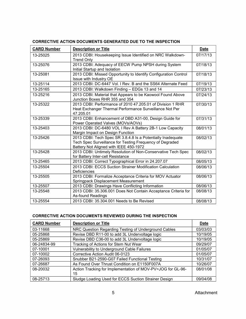
5 Attachment
CORRECTIVE ACTION DOCUMENTS GENERATED DUE TO THE INSPECTION
CARD Number Description or Title Date 13-25025 2013 CDBI: Housekeeping Issue Identified on NRC Walkdown-
Trend Only 07/17/13
13-25076 2013 CDBI: Adequacy of EECW Pump NPSH during System Initial Startup and Isolation
07/18/13
13-25081 2013 CDBI: Missed Opportunity to Identify Configuration Control Issue with Industry OE
07/18/13
13-25114 2013 CDBI: DC-6447 Vol. I Rev. B and the SS64 Alternate Feed 07/19/13 13-25165 2013 CDBI: Walkdown Finding – EDGs 13 and 14 07/23/13 13-25216 2013 CDBI: Material that Appears to be Kaowool Found Above
Junction Boxes RHR 355 and 354 07/24/13
13-25322 2013 CDBI: Performance of 2010 47.205.01 of Division 1 RHR Heat Exchanger Thermal Performance Surveillance Not Per 47.205.01
07/30/13
13-25339 2013 CDBI: Enhancement of DBD A31-00, Design Guide for Power Operated Valves (MOVs/AOVs)
07/31/13
13-25403 2013 CDBI: DC-6480 VOL I Rev A Battery 2B-1 Low Capacity Margin Impact on Design Function
08/01/13
13-25426 2013 CDBI: Tech Spec SR 3.8.4.8 Is a Potentially Inadequate Tech Spec Surveillance for Testing Frequency of Degraded Battery Not Aligned with IEEE 450-1972
08/02/13
13-25428 2013 CDBI: Untimely Resolution of Non-Conservative Tech Spec for Battery Inter-cell Resistance
08/02/13
13-25465 2013 CDBI: Correct Typographical Error in 24.207.07 08/05/13 13-25504 2013 CDBI: ECCS Suction Strainer Modification Calculation
Deficiencies 08/06/13
13-25505 2013 CDBI: Formalize Acceptance Criteria for MOV Actuator Springpack Displacement Measurement
08/06/13
13-25507 2013 CDBI: Drawings Have Conflicting Information 08/06/13 13-25548 2013 CDBI: 35.306.001 Does Not Contain Acceptance Criteria for
As-found Readings 08/08/13
13-25554 2013 CDBI: 35.304.001 Needs to Be Revised 08/08/13
CORRECTIVE ACTION DOCUMENTS REVIEWED DURING THE INSPECTION
CARD Number Description or Title Date 03-11668 NRC Question Regarding Testing of Underground Cables 03/03/03 05-25868 Revise DBD R11-00 to add 3L Undervoltage logic 10/19/05 05-25869 Revise DBD C36-00 to add 3L Undervoltage logic 10/19/05 06-24834-99 Tracking of Actions for Stem Nut Wear 09/29/07 07-10001 Vulnerability to Underground Cable Failures 01/05/07 07-10002 Corrective Action Audit 06-0123 01/05/07 07-26093 Snubber B21-2590-G07 Failed Functional Testing 10/31/07 07-26687 As Found Over Thrust Condition on E1150F007A 10/26/07 08-20032 Action Tracking for Implementation of MOV-PV=JOG for GL-96-
15 08/01/08
08-25713 Sludge Loading Used for ECCS Suction Strainer Design 09/04/08

6 Attachment
CORRECTIVE ACTION DOCUMENTS REVIEWED DURING THE INSPECTION
CARD Number Description or Title Date 09-27471 2009 Configuration Design Bases Inspection (CDBI) Self-
Assessment – The Cell-to-cell and Terminal Connection Resistance May Need to Be Addressed in DC-213 (09SA-RFI-001)
09/25/09
10-20748 CDBI Identified Cancelled DC-5264 may have to be reinstated 01/28/10 10-20823 CDBI 2010 Concern Revise DC-0919 for LTC 01/29/10 10-21287 2010 CDBI – Installation of Washers on 2PA Found Reversed 02/11/10 10-21733 2010 CDBI DC-0919 LTC and Motor Starting 02/25/10 11-20181 Document Applicability of NRC Information Notice 2010-25,
Inadequate Electrical Connections, to Fermi 01/07/11
11-23123-01 Potential ENG HU Event 04/10/11 11-23123-02 Revise Drawing 1-2441-04 04/26/11 11-23487 Packing Leak on P4400F601 04/05/11 11-29637 Elevate the E1100 Maintenance Rule 10/26/11 12-23096 Trend CARD: Division 1 ECCS Suction Strainer Inspection
Findings 04/11/12
12-23185 Conditions Identified during Torus Underwater Diving Inspections 04/13/12 12-23186 Possible Foreign Material Identified in Torus 04/13/12 12-23392 Trend CARD: Division 2 ECCS Suction Strainer Inspection
Findings 04/17/12
12-23800 MOV P4400F601B Stroked on Own, No Operator Action 04/26/12 12-25262 Declutch Shaft Fell Off MOV 06/14/12 12-26381 IN 2012-14 MOV Inoperable Due to Stem Disc Separation 07/30/12 12-26381 Revise PEP03 to Include IN 2012-14 Guidance 11/29/12 12-26873 Packing Leak on P4400F601-B 04/27/12 12-28650 Self-Assessment Deficiency 10/22/12 12-28843-03 Review Reference Document [IEEE 450] to Identify
Discrepancies Between 1972 and 2002 Versions 12/19/12
12-28848 Non-Conservative Tech Specification for Battery Capacity Based on DC-6480 Vol. 1 Rev 0
10/30/12
12-28848-06 Revise the 42-309-xx Procedures and Other Required SR Procedures
12/19/12
12-28848-08 Perform new Service and Capacity Tests [per new profile] 01/22/13 12-28921 Periodic Testing Required for Devices Analyzed in DC-6480 Vol1 11/01/12 13-24739 Concerns with Penetration X105A Fuse Protection 07/04/13 13-24807 Pipe Damage on DIV 2 EECW Recirc Line 07/29/13 13-24841 EDG Steady State Voltage and Frequency Tech Spec Ranges 07/10/13 13-24848 DC-6447 Vol. 1, Rev. B, BOP Equipment Ratings 07/11/13 13-24860 BOP Short Circuit Issues in DC-6447 Vol. 1 Rev. B 07/11/13 13-24861 Short Circuit Issues in DC-6447 Vol. 1 Rev. B 07/11/13 13-24861-01 120kV and 345kV Switchyard MVA Ratings 07/17/13 13-24869 EDG Long Term Manual Loading Procedure Enhancements 07/11/13 13-24873 Conflicting Drawing Information 07/11/13 13-24874 DC-6447 Vol. 1, Rev. B, Calc. Improvements 07/11/13

7 Attachment
CORRECTIVE ACTION DOCUMENTS REVIEWED DURING THE INSPECTION
CARD Number Description or Title Date 13-24877 2013 CDBI DC-6447 Vol. 1 Rev. B, Underground/Exposed
Cables Short Circuit Temperature [non-conservative assumption]. 07/12/13
13-24896 DC-6447 Vol. 1, Rev. B Calc. Improvements 07/12/13 13-24897 Degraded Voltage Relay Timer Evaluation 07/12/13 13-24934 2013 CDBI DC-6447 Vol. 1, Rev. B Calc. Enhancements 07/15/13 13-24941 DC-6538, Vol. 1, Rev. 0 EDG Voltage and Frequency Tolerances 07/15/13 13-25114 2013 CDBI DC-6447 Vol. 1, Rev. B, and the SS64 Alternate Feed 07/19/13 13-25216 RHR EDG 13 SWGR Room 07/24/13 13-25342 Evaluation of Division 2 RHRSW Supply Piping Pitting 07/31/13 13-25465 CDBI 2013 Correct Typographical Error in 24.207.07 08/05/13 13-25507 2013 CDBI Drawings Have Conflicting Information 08/06/13 13-25548 2013 CDBI 35.306.001 does not contain acceptance criteria for
as-found readings 08/08/13
13-25554 2013 CDBI 35.304.001 Needs to Be Revised 08/08/13
DRAWINGS
Number Description or Title Date or Revision
105E2626 Suction Strainer RHR 3 147D8668 Pressure Switch 5 5I721-2591-04 One Line Synchronizing Diagram – 345 KV Lines M 5M721-6019 10 inch 300 No. Powell OSY Gate Valve with Limitorque Operator 0 5SD721-0001 Plant One Line Diagram 120KV-4800 and 480 Volt Systems K 63154 10 inch 300 No. Powell OSY Gate Valve with Limitorque Operator 09/01/01 6I721-2201-02 Schematic Diagram RHR Pump No. 2 [B] O 6I721-2201-04 Schematic Diagram RHR Pump “D” P 6I721-2441-02 Schematic Diagram EECW Pump B Q 6I721-2572-13 Schematic Diagram Bus 64C – Pos. C8 M 6I721-2572-15 Schematic Diagram Bus 64C – Pos. C6 T 6I721-2572-21 Schematic Diagram Diesel Bus 13EC – Pos. EC3 T 6I721-2572-23 Schematic Diagram Bus 65E – Pos. E8 K 6I721-2572-24 Schematic Diagram Bus 65E – Pos. E9 K 6I721-2572-25 Schematic Diagram Bus 65E – Pos. E6 M 6I721-2572-29 Schematic Diagram Buses 65 E and 65F Load Shedding N 6I721-2572-53 Schematic Diagram Bus 64B – Pos. B8 M 6I721-2572-55 Schematic Diagram Bus 64B – Pos. B6 P 6I721-2714-43 Electric Schematic EDG Automatic Load Sequencing H 6I721N-2441-10 Schematic Diagram EESW Pump A W 6I721N-2441-11 Schematic Diagram EESW Pump B W 6I721N-2573-45 Schematic Diagram 480V Load Shedding Strings S 6M721-2053 Service Water System Division 2 (P&ID) AH 6M721-2083 Residual Heat Removal Division 2 (P&ID) BP 6M721-5356 Reactor Building Closed Cooling Water System AE 6M721-5357 Emergency Equipment Cooling Water System Division 2 BN

8 Attachment
DRAWINGS
Number Description or Title Date or Revision
6M721-5357 Emergency Equipment Cooling Water (P&ID) Division 2 BU 6M721-5358 Reactor Building Closed Cooling Water (P&ID) AE 6SD721-2500-01 One Line Diagram 4160 and 480 Volt Systems AW 6SD721-2500-02 One Line Diagram 13.8 KV System AL 6SD721-2500-03 One Line Diagram 4160 Volt System Buses 64B, 64C T 6SD721-2500-04 One Line Diagram 4160 Volt System Buses 65 E, F and G T 6SD721-2500-05 One Line Diagram 4160 Volt System Buses 64A, D and L Z 6SD721-2500-06 One Line Diagram 4160 Volt System Buses 66H, 68K, 69J U 6SD721-2500-08 One Line Diagram 4160 Volt EDG Buses EDG Bldg. S 6SD721-2510-01 One Line Diagram 480 Volt E.S.S. Buses 72 B, C. E, and F AI 6SD721-2510-05 One Line Diagram 480 Volt EDG Buses 72 EA, EB, EC and ED N 6SD721-2512-17 Frontal Elevation 480 Volt MCC 72-F AG 6SD721-2530-10 One Line Diagram 260/130V ESS Dual Battery 2PA Distribution
Division I AK
6SD721-2530-11 One Line Diagram 260/130V ESS Dual Battery 2PB Distribution Division II
AK
6SD721-2530-17 One Line Diagram 48/24V DC Instrumentation Batteries Distribution Z 6SD721-2530-18 UPS One Line Diagram Units A and B AG 6SD721M-0070 Interconnection Diagram Switch Yard and Relay House 0 6SD721N-2712-32 Wiring Diagram 480 Volt Switchgear Bus 72ED J A2359-01 Wall Penetrations Sealants and Schedule 0 E-2807-17 Underground Duct Identification A E-2980-19A Underground to Reactor Bldg. Cable Bundle Schedule A E-2980-19C Underground to Reactor Bldg. Cable Bundle Schedule A E-2980-36 Underground Ducts A E-2980-37 Underground Ducts A E-2980-49 Duct Banks Div. I and II South Yard 0 E-N-0006 Cable Trays – RHR First Floor A E-N-0007 Cable Trays – RHR First Floor A E-N-0011 Cable Trays – RHR Second Floor B E-N-0015 Cable Trays – RHR El. 590 B E-N-0031 Cable Trays – RHR Second Floor 0 E-N-0035 RHR Complex Junction Box Schedule and Details B I-2572-23 Schematic Diagram 4160V ESS Bus 65E 0 M-2053 RHR Service Water System Div 2 AH M-2083 Diagram Residual Heat Removal Diagram BP M-2131 Division II – RHR Complex F M-2151 Division II – RHR Complex B M-5007 Diagram Primary Containment Pneumatic Supply Z M-5538 Nuclear Boiler System Instrument Information Diagram L SD-2501-40 Wiring Diagram 4160V Bus 65E A SD-N-2712-03 Wiring Diagram 4160V Swgr. EDG 11EA A SD-N-2712-13 Wiring Diagram 4160V Swgr. EDG 13EC A

9 Attachment
MISCELLANEOUS
Number Description or Title Date or Revision
3071-128-EJ Specification: Equipment Fusing Standards FV 3071-128-EZ-04 Specification: Instructions for Control and Power Cable Ampacities C 47.426.01 ESF Area Fan Cooling Unit Performance Assessment 0 COLR-15 Fermi Unit 2 Core Operating Limits Report Cycle 15 Revision 1 1 COLR-16 Fermi Unit 2 Core Operating Limits Report Cycle 16 Revision 0 0 COLR-16 Fermi Unit 2 Core Operating Limits Report Cycle 16 Revision 1 1 DBD A31-00 Valves 04/21/06 DBD XXX-02 Design Basis Document for Design Basis Event Combinations A DET-04-028-1 Enrico Fermi Atomic Power Plant Unit 2, Plant Unique Analysis
Report, Volume 1, General Criteria and Loads Methodology
0
DET-19-076-6 Enrico Fermi Atomic Power Plant Unit 2, Plant Unique Analysis Report for Torus Attached Piping and Suppression Chamber Penetrations
0
DET-22-103 Final Test Report, In-Plant Safety Relief Valve Discharge Test, Enrico Fermi Atomic Power Plant Unit 2
0
DSN 3071-128-EJ Electrical Engineering Standard Class 1E, 1M, and BOP Equipment Fusing Requirements
FX
DTE Letter Response to NRC Generic Letter 91-06 10/25/91 EFA-R32-10-003 Analysis to determine Battery functionality due to incomplete
accounting of intercell resistance in the DC-0213 Vol. 1 calculation for terminal voltage
0
ERE 32092 MOV Lubrication Change C ERE-34463 Replacement of EDG Bearing Thermocouples A FBP-55 Margin Management Program 3 G.L. 2007-01 NRC Generic Letter, Inaccessible Or Underground Power Cable
Failures That Disable Accident Mitigation Systems or Cause Plant Transients
02/07/07
IEEE 308-1971 IEEE Standard Criteria for Class 1E Electric Systems for Nuclear Power Generating Stations
1971
IEEE 450-1972 IEEE Recommended Practice for Maintenance, Testing, and Replacement of Large Stationary Type Power Plant and Substation Lead Storage Batteries
1972
IN 2002-12 NRC Information Notice, Submerged Safety-Related Electrical Cables
03/21/02
IN 2006-05 Possible Defect In Bussmann KWN-R and KTN-R Fuses 03/03/06 IN 2006-31 NRC Information Notice, Inadequate Fault Interrupting Ratings of
Breakers 12/26/06
IN 2010-26 Submerged Electrical Cables 12/02/10 K-503718-RC-001 Kinectrics Electrical Testing of New EDG Cables – Fermi Unit 2 04/16/12 LCR 99-051-UFS EDG Loading Revision to Accommodate New Motor for
P4400F603B 0
ME11-1 Vendor Manual: 24/48 and 130/260 VDC Stationary Batteries F

10 Attachment
MISCELLANEOUS
Number Description or Title Date or Revision
MES52 GL 89-13 Safety-Related Service Water Monitoring Program 08/22/12 MQA11 Fermi Unit 2 Quality Assurance Conduct Manual MQA11 -
Condition Assessment Resolution Document 36
NAPI-12-0081 Focused Self-Assessment Report – Operating Experience Program 10/21/12 NFWI-108 Fermi Unit 2 Core Operating Limits Report Preparation 4 NRC Letter Closeout of Generic Letter 91-06, “Resolution of Generic Issue A-
30; Adequacy of Safety-Related DC Power Supplies Pursuant to 10 CFR 50.54(f)”
11/27/91
NRC Letter to Detroit Edison Company
Subject: Fermi-2 – In-Plant Safety Relief Valve Discharge Test Results, License Condition 2.C.(4)
01/18/90
NUC2009103 Underwater Engineering Services, Inc. Report: Torus Desludge, Inspection and Coating Repair – Immersion Area
0
NUC2012102 Underwater Engineering Services, Inc. Report: Torus Desludge, Inspection and Coating Repair – Immersion Area
0
NUREG/CR-7000 Essential Elements of an Electric Cable Condition Monitoring Program
January 2010
NUREG-0123 Standard Technical Specifications General Electric (GE-STS) 1 NUREG-0123 Standard Technical Specifications General Electric (GE-STS) 2 NUREG-0123 Standard Technical Specifications for General Electric Boiling
Water Reactors (BWR/5) 3
NUREG-0798, Supplement No. 3
Safety Evaluation Report Related to the Operation of Enrico Fermi Atomic Power Plant, Unit 2
January 1983
NUREG-0798, Supplement No. 5
Safety Evaluation Report Related to the Operation of Fermi-2 March 1985
OE 2011-0580 OE34380 – Update to OE31011 – Loss of the 1B Safety-Related DC Bus (St Lucie)
04/11/10
OE 2012-1637 Station Battery DC System Voltage Drop Calculation Deficiency (Indian Point, U3)
05/24/12
P4500C002-B DP DP Trend 2006 to 2013
PEP 03 Motor Operated Valves Program 6 PO 470196322 Battery Cells LCR-21, 1200 A-H(4-hr rating) 12/15/08 QR-284030-01 C&D Report: Fig. 4.3 Average and Lower Bound Battery Capacity
Model “LC” Plotting the Capacity and Life Characteristics of the Fermi Unit 2 Safety-Related Battery 2B-1
0
QR-284030-01 Environmental and Seismic Qualification Report of 250 Volt DC Power Batteries and Racks, Battery System 2PB, Cell Type LCR-21 and Single Row Battery Racks
0
R.G. 1.128 NRC Regulatory Guide, Condition-Monitoring Techniques For Electric Cables Used In Nuclear Power Plants
April 2012
R11-00 Design Basis Document: Combustion Turbine Generator B R30-00 Design Basis Document: Emergency Diesel Generator G R32-00 Design Basis Document: DG Electrical Systems A

11 Attachment
MISCELLANEOUS
Number Description or Title Date or Revision
RIS 2011-12 Adequacy Of Station Electric Distribution System Voltages, Revision 1
12/ 29/11
RXX-00 Design Basis Document: ESS Electrical Systems C SE98-0016 Replacement of Residual Heat Removal (RHR) and Core Spray
(CS) System Torus Suction Strainers 0
SE99-0019 Stem Speed of MOV P4400F603 B Increased to Resolve Potential Over Pressuring of Division 2 EECW System Piping
0
Specification 3071-389
Design Specification: Emergency Core Cooling System (ECCS) Suction Strainers
C
Specification 3071-534
Design Specification for Mark I Evaluation of Torus Attached Piping, Enrico Fermi Atomic Power Plant, Unit 2
0
TIA 2009-002 Revised Response to Task Interface Agreement – Requirements for Testing Station Batteries for Station Blackout Conditions at the San Onofre Nuclear Generating Station (ADAMS ML101130021)
04/26/12
TP 12 Requirements for Use of Linear Regression Data Normalization Related to Pump Curves
06/16/11
VMC2-24.4 Vendor Manual: Limitorque Actuator Motors B VME8-1.2.4 Vendor Manual: Two Bearing, Spherical Roller, Oil Lubricated
Alternator B
VME8-11 Vendor Manual: General Electric Inductrol Voltage Regulator B VME8-2.2 Vendor Manual: Instruction Manual for Generator Excitation
System 0
VMR1-45.1 Vendor Manual – RHR Pumps 12/26/07 VMR4-27 Vendor Manual: Enertech Horizontal Split Pump 0 VMS22-1.1 Vendor Manual: Vertical Industrial Turbine Type Pumps A VMS22-1.3 Vendor Manual: Enertech 2 Stage Pump 0 VMS25.24 Vendor Manual: Air Conditioning Units for T4400C001-B A VMS25.27 Vendor Manual: Pump Motor for P4500C002-B B VMS25.9.2 Vendor Manual: Pump Motor for P4400C001-B B VMS25-27 Vendor Manual: P45000C002B Motor and Pump B
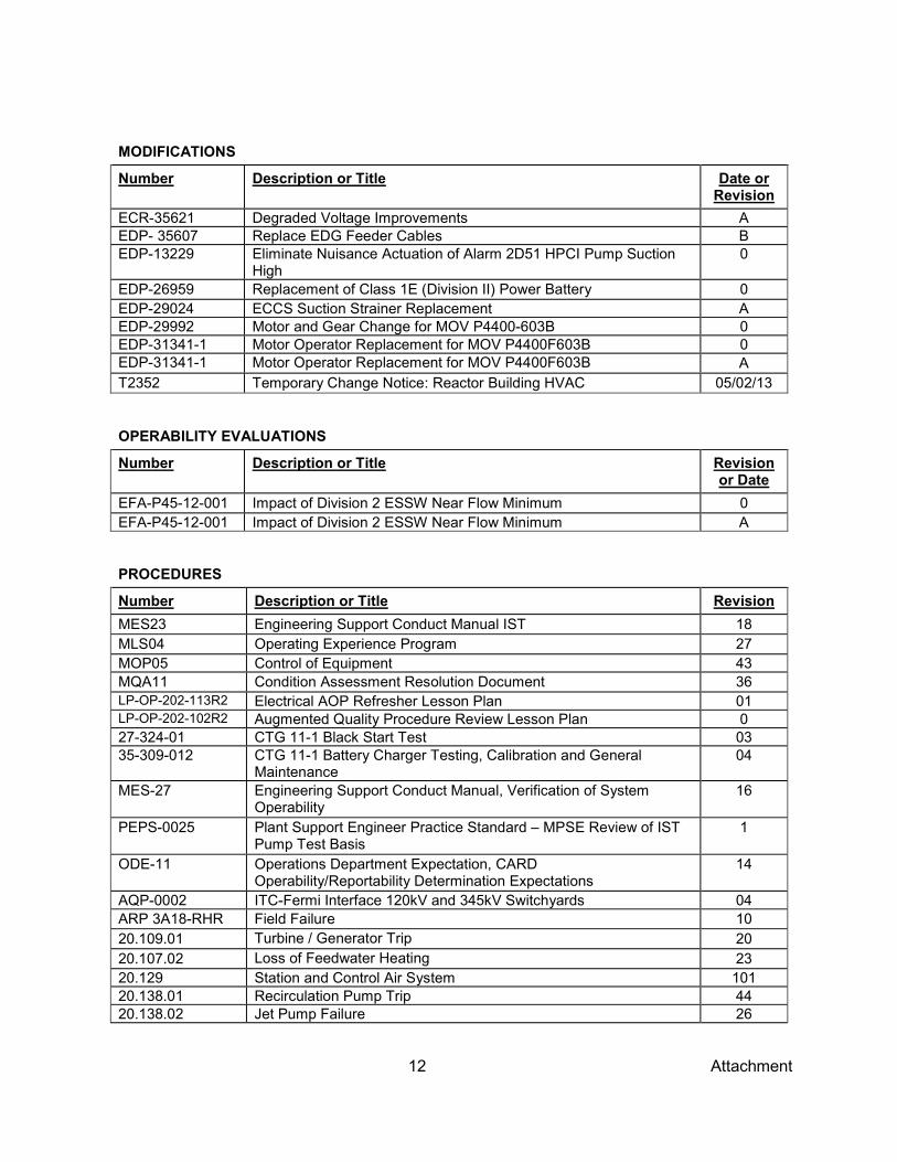
12 Attachment
MODIFICATIONS
Number Description or Title Date or Revision
ECR-35621 Degraded Voltage Improvements A EDP- 35607 Replace EDG Feeder Cables B EDP-13229 Eliminate Nuisance Actuation of Alarm 2D51 HPCI Pump Suction
High 0
EDP-26959 Replacement of Class 1E (Division II) Power Battery 0 EDP-29024 ECCS Suction Strainer Replacement A EDP-29992 Motor and Gear Change for MOV P4400-603B 0 EDP-31341-1 Motor Operator Replacement for MOV P4400F603B 0 EDP-31341-1 Motor Operator Replacement for MOV P4400F603B A T2352 Temporary Change Notice: Reactor Building HVAC 05/02/13
OPERABILITY EVALUATIONS
Number Description or Title Revision or Date
EFA-P45-12-001 Impact of Division 2 ESSW Near Flow Minimum 0 EFA-P45-12-001 Impact of Division 2 ESSW Near Flow Minimum A
PROCEDURES
Number Description or Title Revision MES23 Engineering Support Conduct Manual IST 18 MLS04 Operating Experience Program 27 MOP05 Control of Equipment 43 MQA11 Condition Assessment Resolution Document 36 LP-OP-202-113R2 Electrical AOP Refresher Lesson Plan 01 LP-OP-202-102R2 Augmented Quality Procedure Review Lesson Plan 0 27-324-01 CTG 11-1 Black Start Test 03 35-309-012 CTG 11-1 Battery Charger Testing, Calibration and General
Maintenance 04
MES-27 Engineering Support Conduct Manual, Verification of System Operability
16
PEPS-0025 Plant Support Engineer Practice Standard – MPSE Review of IST Pump Test Basis
1
ODE-11 Operations Department Expectation, CARD Operability/Reportability Determination Expectations
14
AQP-0002 ITC-Fermi Interface 120kV and 345kV Switchyards 04 ARP 3A18-RHR Field Failure 10 20.109.01 Turbine / Generator Trip 20 20.107.02 Loss of Feedwater Heating 23 20.129 Station and Control Air System 101 20.138.01 Recirculation Pump Trip 44 20.138.02 Jet Pump Failure 26

13 Attachment
PROCEDURES
Number Description or Title Revision 20.138.03 Uncontrolled Recirc Flow Change 15 20.000.18 AOP Control of Plant from Dedicated Shutdown Panel 50 20.000.21 Reactor Scram 64 20.300. MPU Loss of an MPU 8 20.300.GRID AOP Grid Disturbance 03 20.300.Offsite Loss of Offsite Power 10 20.300.SBO AOP Loss of Offsite and Onsite Power 18 20.307.01 Emergency Diesel Generator Failure 21 20.300.120kV Loss of 120KV 14 DNS 23.127 Reactor building closed Cooling Water / Emergency Cooling Water
System Operating Procedure 128
23.201 Safety Relief Valves and Automatic Depressurization System 26 23.205 Residual Heat Removal System 122 23.307 Emergency Diesel Generator System 117 23.324 Supervisory Control – 120 KV Switchyard and CTG11 Generators 80 24.000.01 Situational Surveillances / LCO Action Tracking 68 24.207.07 EECW/EESW Actuation Functional Test – Div. 2 37 24.207.09 Division 2 EECW Pump and Valve Operability Test 36 24.324 120KV Switchyard and CTG11 Generators 80 24.324.01 CTG 11 Unit 1 Monthly Operability Check 45 24.307.03 EDG 13 – Loss of Offsite Power and ECCS Start 42 27.000.01 Locked Valve Lineup Verification 78 29.100.01 SH1 RPV Control 14 29.100.01 SH2 Primary Containment Control 12 29.100.01 SH3 RPV Flooding, Emerg. Depress, and Steam Cooling 9 32.106 Control Rod Drive Hydraulic System 105 35.304.001 480 Volt Unit Station Maintenance and Calibration 32 35.306.003 Limitorque Motor Operator – Periodic Inspection 53 35.306.006 Motor Operated Valve Set Up 36 35.306.020 Motor Operated Valve Mini Periodic Inspection 5 37.000.024 CTG11-1 Battery Capacity Test 29 42.302.04 Logic System Functional Test of Div. 2 4160 Volt Emergency Bus
65E and 13EC Undervoltage Circuits 40
44.030.052 ECCS – RHR Div. 2 Logic Functional Test 42 44.010.151 Rod Block Monitor (RBM) Channel A Calibration Test 45 44.030.218 ECCS – RHR Pump B Discharge Pressure Calibration 32 53.000.07 Process Computer Cycle Databank Verification 12
SURVEILLANCES (COMPLETED)
Number Description or Title Revision 42.309.02 Division ½ Quarterly 130/260 VDC Battery Check 37 42.309.03 Division 1 18 Month 130/260V DC Battery Check 40
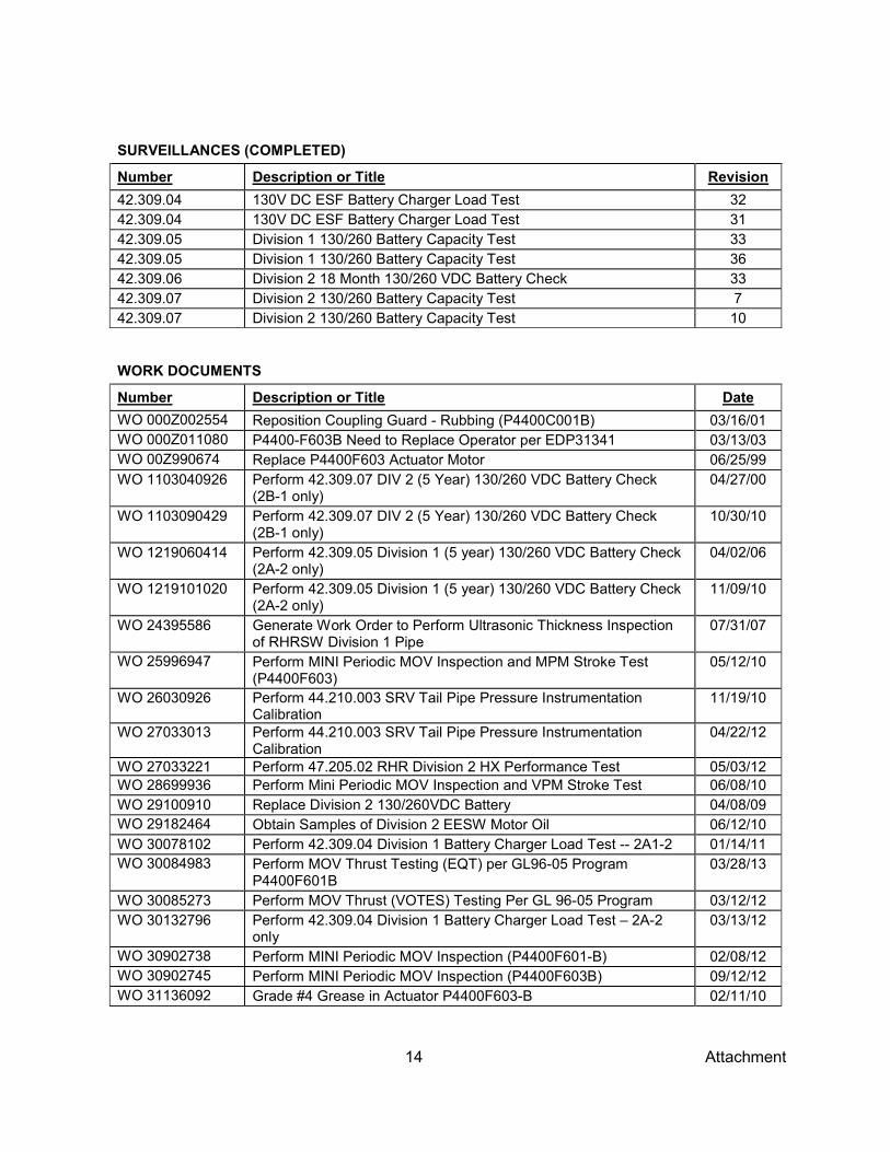
14 Attachment
SURVEILLANCES (COMPLETED)
Number Description or Title Revision 42.309.04 130V DC ESF Battery Charger Load Test 32 42.309.04 130V DC ESF Battery Charger Load Test 31 42.309.05 Division 1 130/260 Battery Capacity Test 33 42.309.05 Division 1 130/260 Battery Capacity Test 36 42.309.06 Division 2 18 Month 130/260 VDC Battery Check 33 42.309.07 Division 2 130/260 Battery Capacity Test 7 42.309.07 Division 2 130/260 Battery Capacity Test 10
WORK DOCUMENTS
Number Description or Title Date WO 000Z002554 Reposition Coupling Guard - Rubbing (P4400C001B) 03/16/01 WO 000Z011080 P4400-F603B Need to Replace Operator per EDP31341 03/13/03 WO 00Z990674 Replace P4400F603 Actuator Motor 06/25/99 WO 1103040926 Perform 42.309.07 DIV 2 (5 Year) 130/260 VDC Battery Check
(2B-1 only) 04/27/00
WO 1103090429 Perform 42.309.07 DIV 2 (5 Year) 130/260 VDC Battery Check (2B-1 only)
10/30/10
WO 1219060414 Perform 42.309.05 Division 1 (5 year) 130/260 VDC Battery Check (2A-2 only)
04/02/06
WO 1219101020 Perform 42.309.05 Division 1 (5 year) 130/260 VDC Battery Check (2A-2 only)
11/09/10
WO 24395586 Generate Work Order to Perform Ultrasonic Thickness Inspection of RHRSW Division 1 Pipe
07/31/07
WO 25996947 Perform MINI Periodic MOV Inspection and MPM Stroke Test (P4400F603)
05/12/10
WO 26030926 Perform 44.210.003 SRV Tail Pipe Pressure Instrumentation Calibration
11/19/10
WO 27033013 Perform 44.210.003 SRV Tail Pipe Pressure Instrumentation Calibration
04/22/12
WO 27033221 Perform 47.205.02 RHR Division 2 HX Performance Test 05/03/12 WO 28699936 Perform Mini Periodic MOV Inspection and VPM Stroke Test 06/08/10 WO 29100910 Replace Division 2 130/260VDC Battery 04/08/09 WO 29182464 Obtain Samples of Division 2 EESW Motor Oil 06/12/10 WO 30078102 Perform 42.309.04 Division 1 Battery Charger Load Test -- 2A1-2 01/14/11 WO 30084983 Perform MOV Thrust Testing (EQT) per GL96-05 Program
P4400F601B 03/28/13
WO 30085273 Perform MOV Thrust (VOTES) Testing Per GL 96-05 Program 03/12/12 WO 30132796 Perform 42.309.04 Division 1 Battery Charger Load Test – 2A-2
only 03/13/12
WO 30902738 Perform MINI Periodic MOV Inspection (P4400F601-B) 02/08/12 WO 30902745 Perform MINI Periodic MOV Inspection (P4400F603B) 09/12/12 WO 31136092 Grade #4 Grease in Actuator P4400F603-B 02/11/10

15 Attachment
WORK DOCUMENTS
Number Description or Title Date WO 31423700 EDP35621 (Revise MOVs TOL Relay Heater Sizes for
P4400F603B) 01/13/10
WO 31859205 Perform 42.309.03 Division 1 18 Month 130/260 VDC Battery Check (2A-2 only)
03/30/12
WO 32003811 Perform 43.137.001 Main Steam Safety Relief Valves Setpoint Test 05/04/12 WO 32342865 Perform 42.309.04 Division 1 Battery Charger Load Test – 2A1-2 08/13/12 WO 32459673 Inspect/Test Bus 72E and Transformer and Disassemble and
Refurbish Regulator 03/08/11
WO 33409202 Perform 24.205.06 Division 2 RHRSW Pump and Valve Operability 03/05/13 WO 33416600 Perform 24.204.06 Division 2 LPCI and Torus Cooling/ Spray
Pump and Valve OPER Test 03/05/13
WO 33738006 Clean, Inspect and Test Bus 72E Voltage Regulator 12/08/11 WO 33826776 Perform 24.205.06 Division 2 RHRSW Pump and Valve Operability 06/03/13 WO 33829315 Perform 24.204.06 Division 2 LPCI and Torus Cooling/ Spray
Pump and Valve OPER Test 06/07/13
WO 33969251 Perform 20.208.03 D2 EESW Pump and Valve Operability 07/10/13 WO 34380468 P4400F601B RBCCW Division 2 RTRN ISO MOV Stroked on Its
Own with No Operator Action 04/28/12
WO 34380468 RBCCW Division 2 Return ISO MOV 07/24/12 WO 36068018 Perform 39.NDE.008 for ID Pitting Corrosion on RHR Complex
Piping (Division. 1 South Pump Room) 03/13/13
WO 36068034 Perform 39.NDE.008 for ID Pitting Corrosion on RHR Complex Piping (Division 2 North Pump Room)
03/07/13
WO B134060100 Perform Eddy Current Examination of Heat Exchanger 04/02/09 WO B861060100 Eddy current Examination of Heat Exchanger 10/21/07 WO D073090100 Perform non-Operational Electrical Checks (P4400-C001B) 11/09/11 WO Q86108100 Perform MAXI MOV Inspection and Diagnostic Stroke
TestP4400F601B 03/04/10
WO TG25090425 Perform 47.205.02 RHR Division 2 HX Performance Test 04/18/09 WR E354971112 Perform MAXI Periodic MOV Inspection 09/16/04
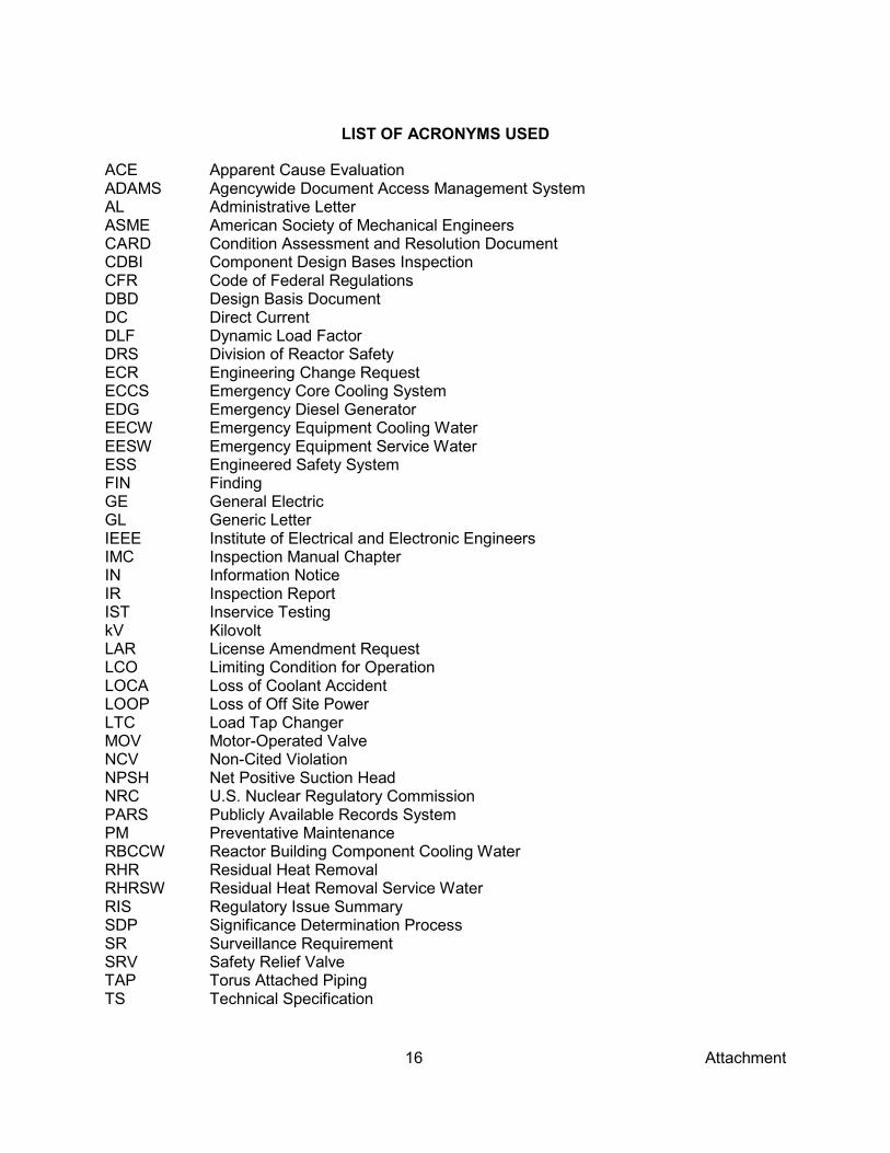
16 Attachment
LIST OF ACRONYMS USED
ACE Apparent Cause Evaluation ADAMS Agencywide Document Access Management System AL Administrative Letter ASME American Society of Mechanical Engineers CARD Condition Assessment and Resolution Document CDBI Component Design Bases Inspection CFR Code of Federal Regulations DBD Design Basis Document DC Direct Current DLF Dynamic Load Factor DRS Division of Reactor Safety ECR Engineering Change Request ECCS Emergency Core Cooling System EDG Emergency Diesel Generator EECW Emergency Equipment Cooling Water EESW Emergency Equipment Service Water ESS Engineered Safety System FIN Finding GE General Electric GL Generic Letter IEEE Institute of Electrical and Electronic Engineers IMC Inspection Manual Chapter IN Information Notice IR Inspection Report IST Inservice Testing kV Kilovolt LAR License Amendment Request LCO Limiting Condition for Operation LOCA Loss of Coolant Accident LOOP Loss of Off Site Power LTC Load Tap Changer MOV Motor-Operated Valve NCV Non-Cited Violation NPSH Net Positive Suction Head NRC U.S. Nuclear Regulatory Commission PARS Publicly Available Records System PM Preventative Maintenance RBCCW Reactor Building Component Cooling Water RHR Residual Heat Removal RHRSW Residual Heat Removal Service Water RIS Regulatory Issue Summary SDP Significance Determination Process SR Surveillance Requirement SRV Safety Relief Valve TAP Torus Attached Piping TS Technical Specification

17 Attachment
UFSAR Updated Final Safety Analysis Report UHS Ultimate Heat Sink Vac Volts Alternating Current Vdc Volts Direct Current WO Work Order WR Work Request µΩ Micro-ohm

M. Plona -2-
In accordance with 10 CFR 2.390 of the NRC's "Rules of Practice," a copy of this letter and its enclosure, and your response (if any) will be available electronically for public inspection in the NRC Public Document Room or from the Publicly Available Records System (PARS) component of NRC's Agencywide Documents Access and Management System (ADAMS), accessible from the NRC Web site at http://www.nrc.gov/reading-rm/adams.html (the Public Electronic Reading Room). Sincerely,
/RA/ Benny Jose, Acting Chief Engineering Branch 2
Division of Reactor Safety
Docket No. 50-341 License No. NPF-43
Enclosure: Inspection Report 05000341/2013008 w/Attachment: Supplemental Information
cc w/encl: Distribution via ListServ™
DISTRIBUTION: Daniel Rich RidsNrrDorlLpl3-1 Resource RidsNrrPMFermi2 Resource RidsNrrDirsIrib Resource Cynthia Pederson Anne Boland Steven Orth Allan Barker Carole Ariano Linda Linn DRPIII DRSIII Patricia Buckley Tammy Tomczak [email protected]
DOCUMENT NAME: G:\DRSIII\DRS\Work in Progress\FER 2013 008 CDBI.docx Publicly Available Non-Publicly Available Sensitive Non-Sensitive To receive a copy of this document, indicate in the concurrence box "C" = Copy without attach/encl "E" = Copy with attach/encl "N" = No copy
OFFICE RIII RIII RIII NAME CBrown for JNeurauter:ls PLougheed for SOrth BJose DATE 10/28/13 10/29/13 10/28/13
OFFICIAL RECORD COPY
Copyright © 2022 FDOKUMEN