Motor Development for Electric Drive Systems Collection of ...
81
Motor Development for Electric Drive Systems Collection of Exercises Source: ELIN EBG Motoren GmbH, Weiz, Austria Advice: Try to solve the test examples first by yourself only with the aid of the text book. Compare afterwards your results with the solutions given here. If you find differences compared with your way of solution, the try again by going through the solutions presented here. If there are afterward still questions to be answered, do not hesitate to contact us. Issue SS 2017 Prof. Dr.-Ing. habil. Dr. h. c. A. Binder Institut für Elektrische Energiewandlung
-
Upload
khangminh22 -
Category
Documents
-
view
1 -
download
0
Transcript of Motor Development for Electric Drive Systems Collection of ...
MMoottoorr DDeevveellooppmmeenntt ffoorr EElleeccttrriicc DDrriivvee SSyysstteemmss
CCoolllleeccttiioonn ooff EExxeerrcciisseess
Source: ELIN EBG Motoren GmbH, Weiz, Austria
Advice:
Try to solve the test examples first by yourself only with the aid of the text book. Compare
afterwards your results with the solutions given here. If you find differences compared with
your way of solution, the try again by going through the solutions presented here. If there are
afterward still questions to be answered, do not hesitate to contact us.
Issue SS 2017 Prof. Dr.-Ing. habil. Dr. h. c. A. Binder
Institut für Elektrische
Energiewandlung
DARMSTADT UNIVERSITY OF TECHNOLOGY
Institute of Electrical Energy Conversion
1
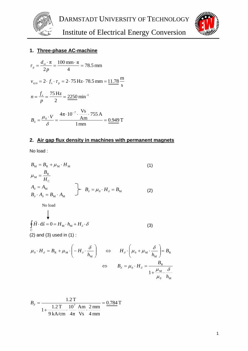
1. Three-phase AC-machine
A machine has following specifications:
4 poles
bore diameter: 100 mm
the air gap fundamental field wave has a frequency of 75 Hz
the magnetomotive force / magnetic voltage has an amplitude of 755 A
air gap width: 1 mm
unsaturated iron with Fe
Task: Calculate the velocity vsyn of the air gap fundamental field wave, the rotational speed n of the
rotor and the air gap flux density B.
2. Air gap flux density in machines with permanent magnets
Task: The air gap flux density B of a machine must be calculated.
The machine is built with permanent magnets on its rotor. The magnet material has a remanence flux
density BR of 1.2 T and the coercive field HC equals 9 kA/cm. The magnets, which are mounted as
surface magnets, have following geometrical specification:
Magnet height hM = 4 mm
Air gap = 2 mm
The machine is operating under no load. It should be considered that the permeability of the iron parts
of the machine is much higher than the permeability of air. Furthermore, the cross section of each
magnet and the air gap over it is the same.
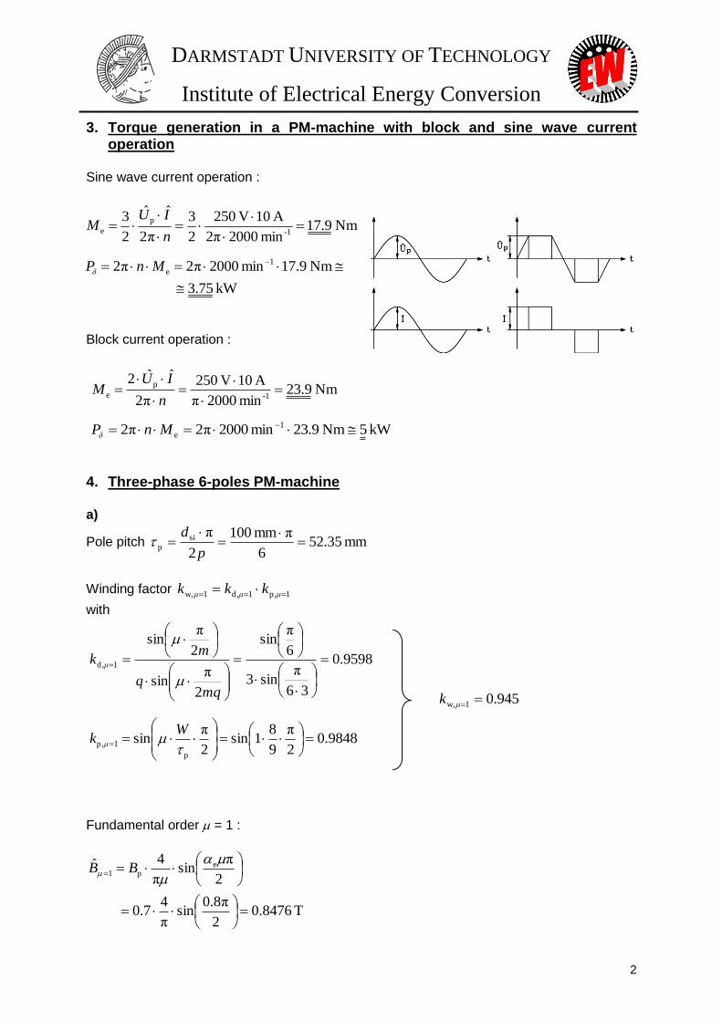
3. Torque generation in a PM-machine with block and sine wave current operation
The machine has a rated speed of 2000 rpm and will be driven by a converter with block and sine
wave current operation. The converter injects current with an amplitude of 10 A into each stator phase.
All three phases are symmetrical and star-connected. In both current operations, the rotor flux induces
voltage with an amplitude of 250 V in the stator windings.
Task: Based on these details, the torque Me generated in each current operation and the corresponding
inner power P should be calculated.
DARMSTADT UNIVERSITY OF TECHNOLOGY
Institute of Electrical Energy Conversion
2
4. Three-phase 6-pole PM-machine
A three-phase 6-pole PM-machine has a rotor using surface mounted magnet technology with a pole
coverage ratio e of 0.8. A flux density Bp of 0.7 T is generated by the permanent magnets. Star-
connected AC windings are arranged in the stator (bore diameter dsi = 100 mm, stack length lFe = 120
mm) with 3 slots per pole and phase. The pitched coil provides a relation of 9
8
p
W and number of
turns per phase Ns equals 40. The machine is operated at 1500 rpm as a generator under no load.
Based on these specifications, following calculations should be performed:
a) Fundamental voltage per phase: amplitude, frequency, RMS value
b) Line-to-line voltage: frequency, RMS value
c) 5th harmonic voltage: frequency, RMS value
d) Which harmonics are measured in the line-to-line voltage and the phase voltage (the ordinal
number) ?
5. Sine wave operated brushless DC-machine
The machine is built with following parameters:
2p = 8
n = 1000 rpm
pΨ = 0.36 Vs
Is = Isq = 15 A
Lq = 11.1 mH
Rs = 0.25
a) Determine the parameters Xq and Up (back-EMF per phase).
b) Calculate voltage drop RsIs and XqIs.
c) What is the magnitude of stator voltage Us ?
d) Draw the phasor diagram comprising current and all voltages. Use the scales: 10V/cm, 1,5A/cm.
How big is power factor cos ?
6. Torque-speed limit of sine wave operated brushless DC machine
The 4 poles machine is designed with a rated current IN of 10 A r.m.s. and a rated frequency fN of 100
Hz in motor operation. Its stator resistance Rs is negligible, and the inductance Lq equals 18 mH.
Magnets on the rotor generate flux linkage p with an amplitude of 0.3 Vs.
The machine is driven by an inverter which has following specifications:
Inverter voltage limit Us,max = 230 V r.m.s. per phase
Inverter current limit Imax = 40 A r.m.s.
a) Up to which theoretical maximum speed can we drive the motor ?
b) Which maximum torque is possible to be generated ?
c) At which speed can we still generate that possible maximum torque ?
d) Draw the torque-speed limit diagram along with the rated torque-speed operating point ! Use
scale: cm 1ˆNm 5 ; cm 1ˆrpm 500
DARMSTADT UNIVERSITY OF TECHNOLOGY
Institute of Electrical Energy Conversion
3
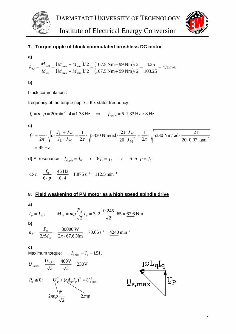
7. Torque ripple of block commutated brushless DC motor
The motor is designed with 2p = 8. Using a shaft torque-meter the torque is measured at a speed of 20
rpm, yielding following measurement values:
Maximum torque Mmax = 107.5 Nm
Minimum torque Mmin = 99 Nm
a) Calculate per-unit torque ripple !
b) Which frequency does the load-dependent torque ripple have ?
c) Now the motor will be coupled to a load via an elastic coupling with a stiftness c = 5330 Nm/rad.
The motor inertia JM equals 0.07 kgm2, the load inertia JL equals 20 JM. Calculate torsional natural
frequency !
d) The load-dependent torque ripple can excite resonance at that torsional frequency. At which speed
would that excitation occur ?
8. Field weakening of PM motor as a high speed spindle drive
Stator of the 4-pole motor is designed with a line-to-line voltage limit of US,LL = UN = 400 V RMS.
Permitted current in the stator Imax is 1.5 times higher than rated current, with IN = 65 A. Inductances
of d- and q-axis are the same with a value of Ld = Lq =1.38 mH. The permanent magnets on the rotor
generates flux linkage p = 0.245 Vs. At load operation, the motor delivers its rated power PN = 30
kW at a speed of 4240 rpm.
a) Calculate rated torque!
b) Calculate rated speed of motor!
c) At particular speed, the motor reaches the line-to-line voltage limit at a maximum torque.
Calculate that speed ! (Neglect Rs!) d) Is it still possible to drive the motor with 30 kW at 15000 rpm ?
9. Operation boundaries of flux-weakened PM-motor
A machine distributor delivers a PM-motor with following specifications:
nN = 4240 rpm
PN = 30 kW
UN = 400 V RMS sine wave (line-to-line)
cosN = 0.78
N = 0.85
Mmax = 1.5 MN short time overload (at low speed)
For an operation with variable speed and torque, the motor has its limit in two speed intervals:
0 n nN (Isd = 0) : limited by M = MN steady state thermal limit
nN n 2.2 nN (Isd < 0) : limited by P = PN
a) Calculate rated current IN.
b) Calculate rated and overload torque MN, Mmax.
c) How big is the current at overload?
d) Draw thermal limit curve of the motor for M(n), P(n).

DARMSTADT UNIVERSITY OF TECHNOLOGY
Institute of Electrical Energy Conversion
4
e) Due to the motor capability for a short time overload, the motor shall be operated up to its
maximum torque Mmax without exceeding the rated power PN. Up to which speed is this still
possible ? Add the overload capability line Mmax(n) to the drawing of your thermal limit curve.
10. Single-sided linear PM-drive in tooling machine
The machine comprises:
1) A linear motor
Primary part with AC windings
Secondary part with NdFeB permanent magnets ( BR = 1.1 T, magnet 1.06 0 )
2) Working piece and table
The primary part together with the working piece and table build moving part of the PM-drive, and
have a mass of 1000 kg totally. The primary part has following specification:
Active surface Amot = 0.35 m2
Winding factor kW = 0.93
Steady state current loading A = 1000 A/cm
Indirect water cooling
The secondary part has a length of 4 m. The magnets height is 5 mm.
Air gap of the PM-drive is = 2 mm and equivalent pole coverage ratio e equals 0.8. The iron parts
of the drive are unsaturated with Fe .
a) Calculate fundamental flux density amplitude under no load.
b) Calculate tangential thrust and normal pull under no load.
c) The machine is operated with rated current. How much time is necessary to move the primary part
from one end to the other, beginning from standstill and ending in standstill position, too?
d) Draw graph of acceleration a and velocity v of the moving part depending on its position. (Use
units: m/s 2.5 ˆcm 1 ; m/s 10 ˆcm 1 ; m 5.0ˆcm 1 2 )
11. Linear motor as rocket propulsion
A rocket must accelerate up to a velocity of E2 2 rgv in order to overcome earth gravity and
therefore will be leaving earth towards space. The rocket will be
accelerated by a linear motor with l = 3 km long track built in earth
(see sketch).
Gravitation constant g = 9.81 m/s2
Earth radius rE = 6370 km
a) Calculate necessary acceleration and acceleration time.
b) Considering pole pitch p = 1 m, how big is the maximum
frequency ?
c) The rocket has a mass of 5000 kg. Calculate necessary tangential
thrust.
DARMSTADT UNIVERSITY OF TECHNOLOGY
Institute of Electrical Energy Conversion
5
d) We assume that during the acceleration a current load of 15000 A/cm is possible at an air gap flux
density of 1.5 T (with flux concentration) and a winding factor kW = 1. How big is the active motor
surface needed according to the thrust in point c) ? Give also your interpretation for the results.
12. Hi-torque ring motor for cylindrical mill
An inverter-fed ring-like hi-torque motor has a PM-rotor which is mounted on the mill and a stator
with water-jacket cooling system. This motor will be used as driving system for the mill to pulverise
ore.
The specification of the motor is:
Stator bore diameter dsi = 3.025 m
Iron stack length lFe = 75 mm
Current load A = 270 A/cm
Number of poles 2p = 128
Winding factor kW = 1
Pole coverage ratio e = 1
Airgap PM flux density Bp = 0.67 T
a) Calculate fundamental air gap flux density amplitude.
b) Calculate electromagnetic torque!
c) With yoke flux density By = 1.35 T, calculate stator and rotor yoke height.
d) Determine motor frequency and rotor surface velocity at n = 100 rpm.
13. Modular synchronous machine
A three-phase modular synchronous machine with tooth wound coils is given with three slots per four
poles.
a) Ampere turns per tooth coil equals 1800 A RMS. The machine is supplied by a sinusoidal three-
phase current system. Air gap together with magnet have a total height res = 9 mm. Draw
magnetic air gap flux density of stator field at time of maximum current in phase U. The iron
saturation and the slot openings will be neglected.
b) The Fourier-analysis of stator flux density distribution is performed. Which one of the Fourier-
harmonics is considered to generate torque with rotor permanent magnets ?
14. Transversal flux machine
Magnetic circuit of the machine is designed according to figure 1.5.3-1 in the text book. The machine
has following specification:
h = 28 mm
= 0.8 mm
hM = 6.5 mm
bp = p = 17.5 mm
2p = 30
/0 = 1.06
Ns = 22 Ring coil
Is = 95 A Nominal current
BR = 1.095 T Remanence flux density
a) Determine air gap flux density under no load and with Fe .
b) Determine armature reaction ( = stator field at rated current).
DARMSTADT UNIVERSITY OF TECHNOLOGY
Institute of Electrical Energy Conversion
6
c) Determine no-load induced voltage as time function at a speed of 900 rpm.
d) Determine time fundamental of back EMF according to point c).
15. Transversal flux machine as vehicle drive system
A car uses transversal flux machine as motor. A battery as DC-link with a voltage of 300 V is
available as power source to drive the motor. The machine has rated torque MN = 750 Nm and rated
power PN = 60 kW. It is built with 80 poles (2p = 80).
The car uses direct wheel drive with wheel diameter dW = 0.8 m. Maximum speed of the car equals
120 km/h.
a) Calculate maximum rotational speed of motor.
b) Sketch appropriate inverter leg of one phase between the DC-link and one phase of the motor
winding. Furthermore, describe direction of voltages and currents during a block voltage operation
(four step switching mode).
c) Sketch voltage per phase at maximum speed.
16. Switched reluctance machine
Following parameters are available for the machine:
3-phase, 4 poles
Qs/Qr = 12/8 slot number
Nc = 61 number of turns per coil
= 0.45 mm air gap
lFe = 193 mm iron stack length
bs = 16 mm stator tooth width
br = bs rotor tooth width
dsi = 122.2 mm inner stator diameter
a) Calculate rotor and stator tooth width and slot width angles in mechanical degree.
b) Determine air gap inductance in d-axis with saturation neglected.
c) How much torque can be generated at a coil current of 10 A. Lqh = 10 mH and saturation is
neglected.
d) Draw time function of inductance and torque per phase when current angle W . What is the
value of W in electrical degree ?
17. Torque-speed characteristic of a switched reluctance machine A switched reluctance machine with the following parameters is given:
m = 4 phases, 2p = 2 poles
Ud = 560 V dc-link voltage
Qs/Qr = 8/6 slot number
Ld = 12 mH air gap inductance in d-axis
Lq = 1.8 mH air gap inductance in q-axis
bs = 26 mm stator tooth width
br = 35 mm rotor tooth width
dsi = 197 mm stator inner diameter
DARMSTADT UNIVERSITY OF TECHNOLOGY
Institute of Electrical Energy Conversion
7
a) Calculate the period of stator unipolar current in terms of mechanical rotor angle.
b) How big is the conducting angle of the stator current, if phases do not overlap ? Sketch the stator
current time function in mechanical and electrical degrees.
c) Calculate the torque at Î = 70 A (unsaturated).
d) Give the speed ng , when the voltage limit is reached with Î = Îmax = 70 A. (Neglect Rs!)
e) Draw the torque limit – speed curve for 0 n 2ng.
18. Synchronous reluctance machine
The 3 phase motor with Y-connected stator windings has the following parameters:
Rated power PN = 2.2 kW
Line-to-line voltage ULL = 400 V
Stator frequency f = 50 Hz
Number of poles 2p = 4
Reactance in d-axis Xd = 33
Reactance in q-axis Xq = 8
Stator resistance can be neglected (Rs = 0)
a) Calculate the pull-out torque Mpo at 400 V.
b) Sketch the torque characteristic versus load angle for –180°< <180°.
c) Determine the load angle ( N) at rated motor torque and the overload capability of the motor.
19. Synchronous reluctance motor Consider a synchronous reluctance motor with the following parameters:
m = 3 phases, Y-connection
Rated power PN = 3.5 kW
Rated voltage UN = 400 V
Stator frequency f = 50 Hz
Number of poles 2p = 4
Inductance in d-axis Ld = 0.11
Inductance in q-axis Lq = 0.029
Stator resistance can be neglected (Rs = 0)
a) Calculate the reactances Xd and Xq.
b) Calculate the rated load angle ( N).
c) Draw the phasor diagram of voltage and current (use scale: cm 1ˆA 1 ; cm 1ˆV 52 ). Determine
the stator current Is.
d) How big is the rated power factor (cos) ?
DARMSTADT UNIVERSITY OF TECHNOLOGY
Institute of Electrical Energy Conversion
8
20. High speed PM synchronous motor with rotor squirrel cage for voltage-controlled inverter operation
The 4 poles, 3 phase (Y-connected) PM synchronous motor, supplied with a rated line-to-line voltage
of 400 V, produces a rated mechanical power of 15 kW (rated power factor cosN = 0.7, rated
efficiency N = 0.9) at 24000 /min rated speed.
- Stator data:
Iron stack length lFe = 75 mm
Stator bore diameter dsi = 75 mm
Winding turns per phase Ns = 24
Winding factor kws = 0.96
- Rotor data:
Buried magnets
Air gap flux density Bp = 0.7 T
a) Calculate the flux per pole at no-load .
b) Determine the rated stator frequency fs and the no-load voltage U0.
c) Which ratio “voltage versus frequency” is necessary for rated flux operation? (Neglect influence
of Rs!)
d) Calculate ESSON’s number C from stator apparent power.
21. PM synchronous motor with buried magnets and squirrel cage rotor for line operation
Motor data:
m = 3 phases, Y-connection
Line-to-line voltage UN = 130 V
Rated stator current IN = 3.8 A
Stator frequency fN = 50 Hz
Rated phase back EMF UpN = 30 V
Number of poles 2p = 4
Reactance in d-axis Xd = 15.7
Reactance in q-axis Xq = 19
Stator resistance can be neglected (Rs = 0)
Efficiency N = 0.63
Power factor cosN = 0.63
a) Calculate the absolute value of pull-out torque Mpo and the load angle at pull-out p.
b) Calculate rated torque.
c) Calculate overload ratio Mpo / MN.
22. Asynchronous start up of a PM synchronous motor with rotor squirrel cage
The 3 phase motor with Y-connected stator windings has the following specifications:
Rated power PN = 15 kW
Rated line-to-line voltage UN = 400 V
Number of poles 2p = 4
PM generated flux linkage p = 0.045 Vs
Rated speed nN = 24000 /min
DARMSTADT UNIVERSITY OF TECHNOLOGY
Institute of Electrical Energy Conversion
9
Inductance in d-axis Ld = 0.001
Inductance in q-axis Lq Ld
Stator resistance Rs = 0.35
Asynchronous starting torque is given by the KLOSS’s function with break down slip sb = 0.2 and
break down torque Mb = 10 Nm.
s
s
s
sM
M
b
b
b
asyne
2,
a) Sketch the asynchronous starting torque in dependence of speed for slip values s = 0, 0.2, 0.4,
0.6, 0.8 and 1.
b) Calculate the speed where the maximum breaking torque Mp,max due to permanent magnets occurs
during start-up.
c) Determine maximum braking torque Mp,max.
d) Sketch braking torque in dependence of speed at slip values 0, 0.5 and 1.
e) Sketch the resulting starting torque in dependence of speed between 0 and nsyn.
23. Electromagnetic aircraft launch system on aircraft carrier
A linear induction motor of 103 m length as long stator configuration has to accelerate the aircraft
from 0 speed to 370 km/h launch speed in 3 seconds. Secondary is aluminium cage as carriage on
rollers, where the aircraft is hooked in.
Data:
- aircraft mass mAircraft = 45 t, motor pole pitch p = 0.5 m, power factor of motor cosN = 0.5,
efficiency N = 0.63.
a) Calculate kinetic energy of moved mass at launch.
b) How big is the stator frequency at launch?
c) How big is the motor’s power at launch, if frequency of motor is rising linear with time and the
thrust force is constant?
d) Sketch the rise of kinetic energy during launch.
e) At 103 Hz maximum frequency, the motor line-to-line voltage reaches 10.6 kV. According to
which function must voltage rise with time t for constant thrust force, if the motor current is
constant?
f) Determine the motor current for that thrust.

DARMSTADT UNIVERSITY OF TECHNOLOGY
Institute of Electrical Energy Conversion
10
24. Standard cage induction motor
A cage induction motor has the following data:
Rated voltage UN = 400 V Y
Rated current IN = 44 A
Rated power PN = 22 kW
Rated speed nN = 1455 min-1
Power factor cos φN = 0.82
No load current I0 / IN = 0.4
Breakdown torque Mb / MN = 3.4
The motor is operated at the grid.
a) Calculate for rated operation: The slip sN, the torque MN, the electrical input power Pe,N, the total
losses Pd,N, the efficiency ηN.
b) The stator losses are assumed to be PFe,s = Pd,N/6 and PCu,s = Pd,N/2. Calculate the numerical values
of the stator losses and the airgap power Pδ.
c) Calculate the rotor cage losses PCu,r.
d) The additional load losses Pad,1 are 7% of the total losses Pd,N. Calculate the friction and windage
losses Pfr+w.
e) Calculate the stator copper losses PCu,s0 at no load. Assume the winding temperature to be the
same as at rated operation.
f) Calculate the total no-load losses Pd0.
g) With Pd0, calculate the load losses Pd1,N for rated operation. If you did not solve 6), please perform
your calculation with Pd0 = 850 W.
h) For a partial load of M = 0.5 MN, calculate the output power Pout, the load losses Pd1 and the
efficiency η for this load point.
i) Calculate the load point Mopt, where the efficiency η = ηmax is maximum. Also, calculate this
efficiency ηmax.
25. PM motor as High-speed compressor drive, Hi-Speed-Kompressor-Antrieb
A 4-pole synchronous motor with permanent magnet rotor, stator water jacket cooling and Y-
connected three-phase stator winding is used to drive an air turbo-compressor at high Speed.
The motor is fed by a voltage source d.c. link inverter. Maximum inverter voltage is
Umax = 230 V, maximum inverter current is Imax = 250 A (fundamental phase values, r.m.s.).
Inverter data: V230max,1kphase, U , A250max1,kphase, I
Compressor data: min/24000Nn , kW65N P
Motor data: 42 p , mH169,0qd LL , V25.6p U (at 50 Hz, phase value, r.m.s.)
For the following, neglect all motor losses!
1. Determine rated motor frequency!
2. Calculate at rated speed back EMF UpN!
3. Evaluate motor rated current for q-current operation (Is = Isq, Isd = 0)!
4. Determine stator phase voltage for rated operation according to 3)! Is inverter voltage and
current limit sufficient?
DARMSTADT UNIVERSITY OF TECHNOLOGY
Institute of Electrical Energy Conversion
11
5. Draw voltage and current phasor diagram for rated operation 3) (Scale: 20 V/cm, 20
A/cm). Evaluate motor apparent power and power factor! Is the motor running over- or
under-excited?
Ein Synchronmotor mit Permanentmagnetläufer und einer Wassermantelkühlung soll einen
Luftverdichter (Turbokompressor) mit hoher Drehzahl (“Hi-Speed”) antreiben. Der Motor wird mit
einem Spannungszwischenkreisumrichter gespeist, dessen maximale Spannung Umax = 230 V und
dessen maximaler Strom Imax = 250 A (jeweils Strangwert, Grund-schwingung, Effektivwert) beträgt.
Umrichterdaten: V230max,1kStrang, U , A250max1,kStrang, I
Kompressordaten: min
124000n , kW65N P
Motordaten: 42 p , mH169,0qd LL
V25,6p U (bei 50 Hz, Effektivwert, Strangspannung, Y-Schaltung)
Anmerkung: Im Folgenden sollen die Verluste im Motor vernachlässigt werden!
1. Mit welcher Ausgangsfrequenz muss der Umrichter den Motor mit Spannung versorgen?
2. Wie groß ist die Polradspannung bei 24000 /min?
3. Wie groß ist der erforderliche Motorstrom, wenn der Umrichter über eine Polradlagesteuerung
den Strom in Phase mit der Polradspannung Up einprägt (Is = Isq, Isd = 0)?
4. Wie groß ist zu 3. die erforderliche Strangspannung an den Klemmen des Motors? Ist der
Umrichter dafür ausreichend dimensioniert?
5. Zeichnen Sie das Strom-Spannungs-Zeigerdiagramm je Phase maßstäblich (Maßstab
angeben!) und berechnen Sie die Motorscheinleistung und den Leistungsfaktor. Wird der
Motor über- oder untererregt betrieben?
26. Permanent magnet motor as a machine tool drive, Permanentmagnetmotor als Werkzeugmaschinenantrieb
A 6 pole permanent magnet motor has surface mounted magnets on the rotor with a height of
hM = 3.5 mm. The stator core and winding data are:
dsi = 100 mm (bore diameter) l = 100 mm (iron length)
Q = 36 (number of stator slots) Nc = 20 (number of turns per coil)
a = 1 (all coils series connected)
The three phases of the single-layer winding are in Y-connection. The mechanical air gap and
the thickness of the non-magnetic rotor bandage sum up to an overall height of = 1.4 mm.
Magnet data: Material NdFeB, at 20°C: BR = 1.1 T (magnetic remanence flux density)
HCB = 875 kA/m (coercive field strength)
1) How big is the magnetic flux density in the air gap at no load (stator current is zero) ?
Assume infinite permeability for iron! Give a rough sketch of the air gap flux density
field curve, if there are no gaps between the magnets!
DARMSTADT UNIVERSITY OF TECHNOLOGY
Institute of Electrical Energy Conversion
12
2) How big is the amplitude of the fundamental flux density field wave of 1)?
3) Calculate the r.m.s. value of the fundamental harmonic of the back EMF at a stator
frequency of fs =100 Hz!
4) Verify with the magnetic data, that the rare earth magnets behave passively like air
(M = 0)!
5) How big is the unsaturated magnetizing reactance Xh ?
6) How big must be the r.m.s. phase value of the fundamental harmonic voltage Us of the
inverter output voltage at 100 Hz, so that maximum torque can be reached at a phase
current of 10 A r.m.s.? Neglect Rs and assume Xs = 1.4 .
7) Draw a voltage phasor diagram for operation point 6) with scale 25 V/cm and 2 A/cm!
Ein 6-poliger Permanentmagnetmotor mit den Statorblechpaket- und Wicklungs-Daten:
dsi = 100 mm, l = 100 mm, Q = 36, Einschichtwicklung, Nc = 20, a = 1, Y-Schaltung,
hat im Läufer aufgeklebte Magnete mit der Höhe hM = 3.5 mm. Der mechanische Luftspalt und die
amagnetische Läuferbandage ergeben zusammen = 1.4 mm.
Magnetdaten: Material NdFeB, bei 20°C gilt: BR = 1.1 T, HCB = 875 kA/m
1) Wie groß ist die magnetische Flussdichte im Luftspalt bei stromloser Ständerwicklung und
wie sieht ihr räumlicher Verlauf längs des Umfangs aus, wenn keine Lücken zwischen den
Magneten unterschiedlicher Polarität vorhanden sind ?
2) Wie groß ist zu 1) die Amplitude der Feldgrundwelle ?
3) Berechnen Sie den Effektivwert der Grundschwingung der Polradspannung bei einer
Ständerfrequenz fs =100 Hz !
4) Die Magnete verhalten sich passiv wie Luft! Überprüfen Sie anhand der Magnetdaten, ob dies
wirklich zutrifft.
5) Wie groß ist die ungesättigte Hauptreaktanz Xh ?
6) Wie groß ist der Effektivwert der erforderlichen Grundschwingung Us (Strangwert) der
Umrichterausgangsspannung bei 100 Hz, damit der PM-Motor bei 10 A Strangstrom
(Effektivwert) maximales Moment abgibt? Vernachlässigen Sie für diese Betrachtung Rs und
nehmen Sie für Xs = 1.4 an.
7) Zeichnen Sie zu 5) das maßstäbliche Zeigerdiagramm und wählen Sie dafür einen geeigneten
Strom- und Spannungsmaßstab!
27. Permanent magnet synchronous motor as robot drive, Roboterantrieb
An 8-pole permanent magnet synchronous machine is fed by an inverter and used as drive for
a robot arm of a welding robot. By rotor position control the motor is operated with q-current
to get maximum torque. The maximum thermal continuous current is 12 A r.m.s.. For a short
time of a few seconds the motor winding can be overloaded with 4 times rated current. It was
measured Us = 90 V Y phase no-load voltage r.m.s. at fs = 50 Hz stator frequency. The
maximum inverter output phase voltage (fundamental) is Us = 230 V r.m.s.
Motor data:
DARMSTADT UNIVERSITY OF TECHNOLOGY
Institute of Electrical Energy Conversion
13
fsN = 100 Hz (rated frequency), Ld = 4.5 mH (synchronous inductance)
The stator resistance is neglected.
1.) The machine is tested in the test bay of the manufacturer. It is driven as generator with
another motor between 0 and 6000/min. At open stator winding terminals no-load voltage
is measured. Draw the function of no-load voltage (line-to-line, r.m.s.) versus speed
(Scale: abscissa: 1000/min 2 cm, ordinate: 500 V 2 cm).
2.) Is it possible to determine by measurement acc. to 1), if the magnets are properly
magnetized? Do we need to know magnet temperature to draw a correct conclusion?
3.) Draw the voltage phasor diagram for rated frequency
a) at nominal current, b) at maximum current (Scale: 25 V/cm, 5 A/cm)
4.) Determine nominal speed of the motor !
5.) What is the motor torque for 3 a.) and 3 b.), if the motors losses are neglected ?
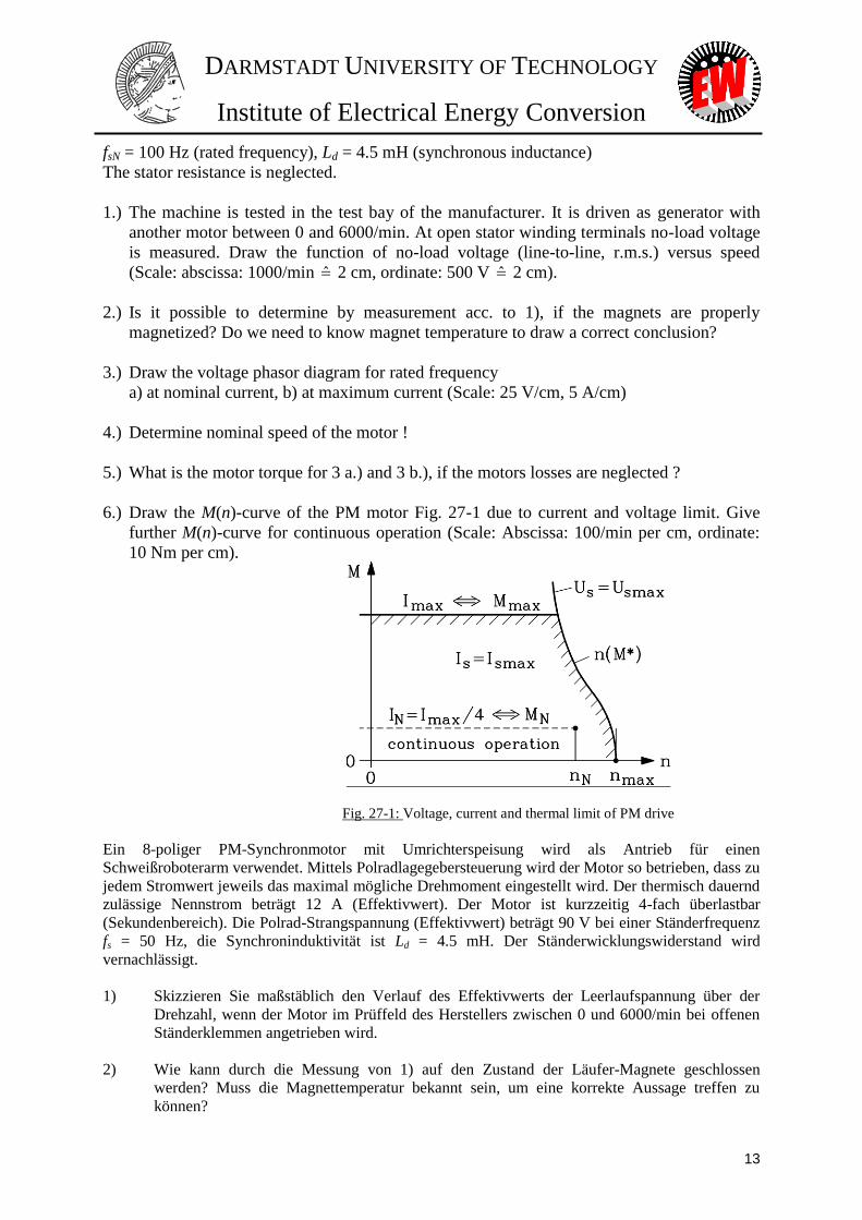
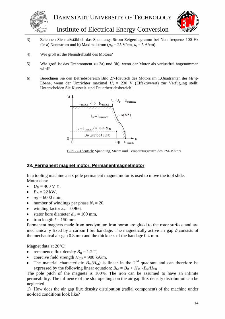
6.) Draw the M(n)-curve of the PM motor Fig. 27-1 due to current and voltage limit. Give
further M(n)-curve for continuous operation (Scale: Abscissa: 100/min per cm, ordinate:
10 Nm per cm).
Fig. 27-1: Voltage, current and thermal limit of PM drive
Ein 8-poliger PM-Synchronmotor mit Umrichterspeisung wird als Antrieb für einen
Schweißroboterarm verwendet. Mittels Polradlagegebersteuerung wird der Motor so betrieben, dass zu
jedem Stromwert jeweils das maximal mögliche Drehmoment eingestellt wird. Der thermisch dauernd
zulässige Nennstrom beträgt 12 A (Effektivwert). Der Motor ist kurzzeitig 4-fach überlastbar
(Sekundenbereich). Die Polrad-Strangspannung (Effektivwert) beträgt 90 V bei einer Ständerfrequenz
fs = 50 Hz, die Synchroninduktivität ist Ld = 4.5 mH. Der Ständerwicklungswiderstand wird
vernachlässigt.
1) Skizzieren Sie maßstäblich den Verlauf des Effektivwerts der Leerlaufspannung über der
Drehzahl, wenn der Motor im Prüffeld des Herstellers zwischen 0 und 6000/min bei offenen
Ständerklemmen angetrieben wird.
2) Wie kann durch die Messung von 1) auf den Zustand der Läufer-Magnete geschlossen
werden? Muss die Magnettemperatur bekannt sein, um eine korrekte Aussage treffen zu
können?
DARMSTADT UNIVERSITY OF TECHNOLOGY
Institute of Electrical Energy Conversion
14
3) Zeichnen Sie maßstäblich das Spannungs-Strom-Zeigerdiagramm bei Nennfrequenz 100 Hz
für a) Nennstrom und b) Maximalstrom (U = 25 V/cm, I = 5 A/cm).
4) Wie groß ist die Nenndrehzahl des Motors?
5) Wie groß ist das Drehmoment zu 3a) und 3b), wenn der Motor als verlustfrei angenommen
wird?
6) Berechnen Sie den Betriebsbereich Bild 27-1deutsch des Motors im 1.Quadranten der M(n)-
Ebene, wenn der Umrichter maximal Us = 230 V (Effektivwert) zur Verfügung stellt.
Unterscheiden Sie Kurzzeit- und Dauerbetriebsbereich!
Bild 27-1deutsch: Spannung, Strom und Temperaturgrenze des PM-Motors
28. Permanent magnet motor, Permanentmagnetmotor
In a tooling machine a six pole permanent magnet motor is used to move the tool slide.
Motor data:
UN = 400 V Y,
PN = 22 kW,
nN = 6000 /min,
number of windings per phase Ns = 20,
winding factor kw = 0.966,
stator bore diameter ds,i = 100 mm,
iron length l = 150 mm.
Permanent magnets made from neodymium iron boron are glued to the rotor surface and are
mechanically fixed by a carbon fibre bandage. The magnetically active air gap consists of
the mechanical air gap 0.8 mm and the thickness of the bandage 0.4 mm.
Magnet data at 20°C:
remanence flux density BR = 1.2 T,
coercive field strength HCB = 900 kA/m.
The material characteristic BM(HM) is linear in the 2nd
quadrant and can therefore be
expressed by the following linear equation: BM = BR + HM BR/HCB . The pole pitch of the magnets is 100%. The iron can be assumed to have an infinite
permeability. The influence of the slot openings on the air gap flux density distribution can be
neglected.
1) How does the air gap flux density distribution (radial component) of the machine under
no-load conditions look like?
DARMSTADT UNIVERSITY OF TECHNOLOGY
Institute of Electrical Energy Conversion
15
2) How big do we have to choose the magnet height hM to obtain a fundamental wave of the
air gap flux density of 0.9 T at 20°C under no-load conditions?
3) How big is the stator frequency fs at rated speed? How big is the induced no-load voltage
per phase Us,0 (r.m.s.-value), which can be measured between the open terminals, if the motor
is driven by a second machine in the manufacturer’s test laboratory?
4) How big is the torque in field oriented operation (Id = 0, Is = Iq = IN)? Draw a sketch of the
voltage phasors for motor operation with consideration of Rs. What is the relation of the
absolute values of phase angle and load angle?
5) Prove, that in field oriented operation the torque only depends on the stator current and is
directly proportional to it ("brushless dc drive"). How big is the rated stator current? Plot the
M(I)-characteristic for 0 I IN.
In einer Werkzeugmaschine ist ein sechspoliger Permanentmagnetmotor als Antrieb für einen
Werkzeugschlitten eingesetzt.
Motordaten:
UN = 400 V Y,
PN = 22 kW,
nN = 6000 /min,
Windungszahl je Strang Ns = 20,
Wicklungsfaktor kw = 0.966,
Ständerbohrung ds,i = 100 mm,
Blechpaketlänge l = 150 mm.
Der Läufer ist mit Magneten aus Neodym-Eisen-Bor an der Oberfläche beklebt, die durch eine
Kunststoffbandage fixiert sind. Der magnetisch wirksame Luftspalt setzt sich aus dem mechanischen
Luftspalt 0.8 mm und der Bandagendicke 0.4 mm zusammen.
Magnetwerkstoffdaten bei 20 °C:
Remanenzflussdichte BR = 1.2 T,
Koerzitivfeldstärke HCB = 900 kA/m.
Die Werkstoffkennlinie BM(HM) ist im zweiten Quadranten linear und kann daher durch folgende
Geradengleichung ersetzt werden: BM = BR + HM BR/HCB.
Die Polbedeckung der Magnete beträgt 100 %. Das Eisen ist als unendlich permeabel anzunehmen.
Der Einfluss der Nutöffnungen auf das Luftspaltfeld ist zu vernachlässigen.
1) Wie sieht die Verteilung des Luftspaltfelds (Radialkomponente) bei stromloser Maschine aus?
2) Wie groß muss die Magnethöhe hM sein, damit bei stromloser Maschine und 20 °C eine Amplitude
der Grundwellenflussdichte von 0.9 T entsteht?
3) Wie groß ist die Ständerfrequenz fs bei Nenndrehzahl? Wie groß ist die induzierte Leerlauf-
strangspannung Us,0 (Effektivwert), die gemessen wird, wenn der Motor im Prüffeld des Herstellers
bei offenen Klemmen angetrieben wird?
4) Wie groß ist das Drehmoment bei feldorientiertem Betrieb (Id = 0, Is = Iq = IN)? Fertigen Sie eine
Prinzipskizze des Spannungszeigerdiagramms im Motorbetrieb mit Berücksichtigung von Rs an. Wie
verhalten sich die Beträge von Polrad- und Phasenwinkel zueinander?
5) Zeigen Sie, dass das Drehmoment im feldorientierten Betrieb nur vom Ständerstrom abhängt und
diesem direkt proportional ist ("bürstenloser Gleichstrommotor"). Wie groß ist der Ständerstrom im
Nennpunkt? Zeichnen Sie die M(I) – Kennlinie für 0 I IN.
DARMSTADT UNIVERSITY OF TECHNOLOGY
Institute of Electrical Energy Conversion
1
1. Three-phase AC-machine
2. Air gap flux density in machines with permanent magnets No load :
δ
C
HhHsH MM0d
(2) and (3) used in (1) :
T 784.0
mm 4
mm 2
Vs
Am
π4
10
kA/cm 9
T 2.11
T 2.17
B
mm 5.784
πmm 100
2
πsi
p
p
d
s
m 78.11mm 5.78Hz 7522 pssyn fv
1-s min 22502
Hz 75
p
fn
T 949.0mm 1
A 755Am
Vs10π4 7
0
VBδ
MM
M
C
RM
MMRM
ABAB
AA
H
B
HBB
δδ
δ
No load
M0 BHB δδ
(1)
(3)
(2)
M0
M
R0
R
M
M0
M
MR0
1
h
BHB
Bh
Hh
HBH δ
DARMSTADT UNIVERSITY OF TECHNOLOGY
Institute of Electrical Energy Conversion
2
3. Torque generation in a PM-machine with block and sine wave current operation
Sine wave current operation :
Block current operation :
4. Three-phase 6-poles PM-machine a)
Pole pitch mm 35.526
πmm 100
2
πsi
p
p
d
Winding factor 1p,1d,1w, μμμ kkk
with
Fundamental order = 1 :
T 8476.02
π8.0sin
π
47.0
2
πsin
π
4ˆ ep1
BB
Nm 9.23min 2000π
A 10V 250
π2
ˆˆ21-
p
e
n
IUM
kW 5Nm 9.23min 2000π2π2 1
e MnPδ
9598.0
36
πsin3
6
πsin
2
πsin
2
πsin
1d,
mqq
mk μ
9848.02
π
9
81sin
2
πsin
p
1p,
Wk μ
945.01w, μk
Nm 9.17min 20002π
A 10V 250
2
3
π2
ˆˆ
2
31-
p
e
n
IUM
kW 75.3
Nm 9.17min 2000π2π2 1
e
MnPδ
DARMSTADT UNIVERSITY OF TECHNOLOGY
Institute of Electrical Energy Conversion
3
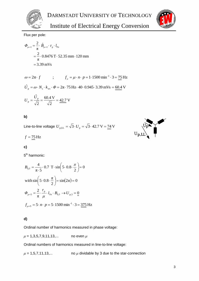
Flux per pole:
b)
Line-to-line voltage V 74V 7.4233 pLLp, UU
c) 5th harmonic:
d) Ordinal number of harmonics measured in phase voltage:
= 1,3,5,7,9,11,13,... no even Ordinal numbers of harmonics measured in line-to-line voltage:
= 1,5,7,11,13,... no dividable by 3 due to the star-connection
mVs 39.3
mm 120mm 35.52T 8476.0π
2
ˆπ
2Fep11
lBΦ
V 4.60mVs 39.3945.040Hz 752πˆsp ΦkNU ws
Hz 753min 15001 ; π2 -1 pnff μ
V 7.422
V 4.60
2
ˆp
p U
U
Hz 75f
02
8.05sinT 7.05π
4δ,5
B
0π2sin2
π8.05sinwith
Hz 3753min 150055 -1
5 pnf
0π
2p,5δ,5Fe
p
5 UBlΦ
DARMSTADT UNIVERSITY OF TECHNOLOGY
Institute of Electrical Energy Conversion
4
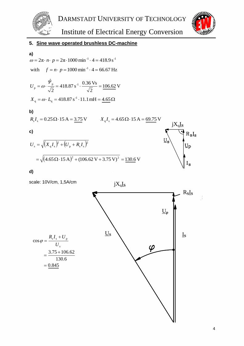
5. Sine wave operated brushless DC-machine a)
b)
c)
d) scale: 10V/cm, 1,5A/cm
65.4mH 1.11s 87.418 -1
qq LX
-1-1 s 9.4184min 1000π2π2 pn
Hz 67.664min 1000with -1 pnf
V 62.1062
Vs 36.0s 87.418
2
ˆ1-p
p Ψ
U
V 75.3A 15 25.0ss IR V 75.69A 15 65.4sq IX
2ssp
2
sqs IRUIXU
V 6.130)V 75.3V 62.106(A 15 65.4 22
845.0
6.130
62.10675.3
coss
pss
U
UIR
jXqIS
RSIS
Up
US IS
jXqIS
DARMSTADT UNIVERSITY OF TECHNOLOGY
Institute of Electrical Energy Conversion
5
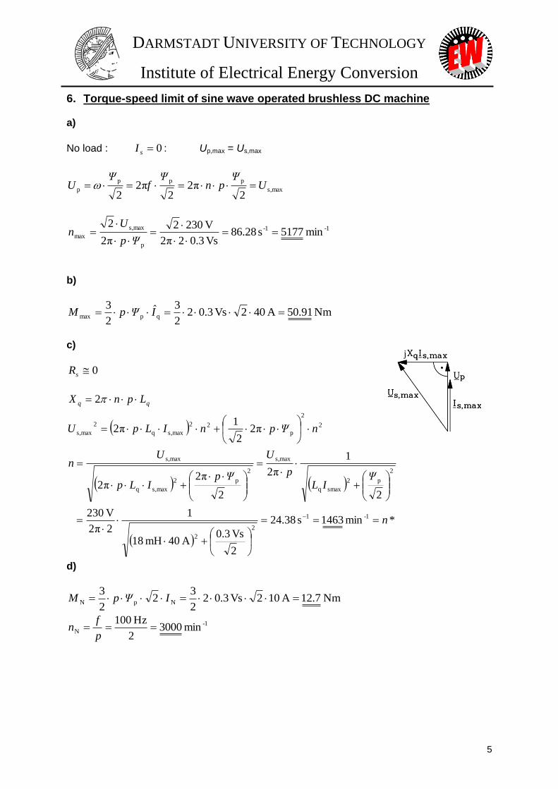
6. Torque-speed limit of sine wave operated brushless DC machine a)
No load : 0sI : Up,max = Us,max
maxs,
ppp
p2
π22
π22
UΨ
pnΨ
fΨ
U
1-1-
p
maxs,
max min 5177s 28.86Vs 3.02π2
V 2302
π2
2
Ψp
Un
b)
Nm 91.50A 402Vs 3.022
3ˆ2
3qpmax IΨpM
c)
0sR
*min 1463s 38.24
2
Vs 3.0A 40mH 18
1
2π2
V 230
2
1
π2
2
π2π2
π22
1π2
2
1-1
2
2
2
p2
smaxq
maxs,
2
p2
maxs,q
maxs,
2
2
p
22
maxs,q
2
maxs,
n
ΨIL
p
U
ΨpILp
Un
nΨpnILpU
LpnX qq
d)
Nm 7.12A 102Vs 3.022
32
2
3NpN IΨpM
1-
N min 30002
Hz 100
p
fn
j
DARMSTADT UNIVERSITY OF TECHNOLOGY
Institute of Electrical Energy Conversion
6
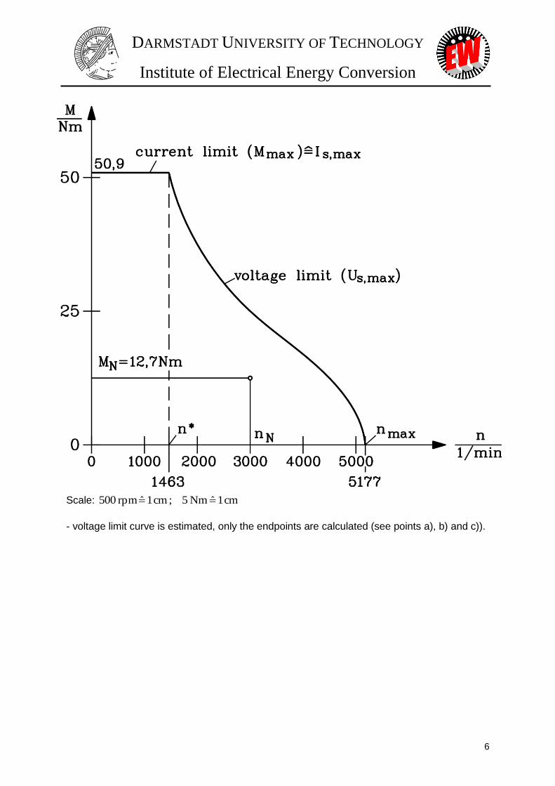
Scale: cm 1ˆNm 5 ; cm 1ˆrpm 500
- voltage limit curve is estimated, only the endpoints are calculated (see points a), b) and c)).
DARMSTADT UNIVERSITY OF TECHNOLOGY
Institute of Electrical Energy Conversion
7
7. Torque ripple of block commutated brushless DC motor a)
% 12.425.103
25.4
2/Nm 99Nm 5.107
2/Nm 99Nm 5.107
2/
2/ˆˆ
minmax
minmax
av
cog
M
MM
MM
M
Mw
b) block commutation : frequency of the torque ripple = 6 x stator frequency
Hz 8Hz 33.16 Hz 33.14min20 ripple
1
s fpnf
c)
Hz 45
kgm 07.020
21Nm/rad 5330
2
1
20
21Nm/rad 5330
2
1
2
122
M
M
ML
ML0
J
J
JJ
JJcf
d) At resonance : 00s0ripple 6 6 fpnffff
110 min 5.112 875.146
Hz 45
6
sp
fn
8. Field weakening of PM motor as a high speed spindle drive
a)
NII q ; Nm 6.67652
245.023
2 q
p
N IΨ
mpM
b)
1-1- min 4240s 66.70Nm 6.672
W30000
2
N
NN
M
Pn
c)
Maximum torque: Nmax 51 I.II qs
V2303
V400
3
,
max LLs
s
UU
:0sR 2
max
22 )( sqqp UILU
2
2pΨ
np np2
j
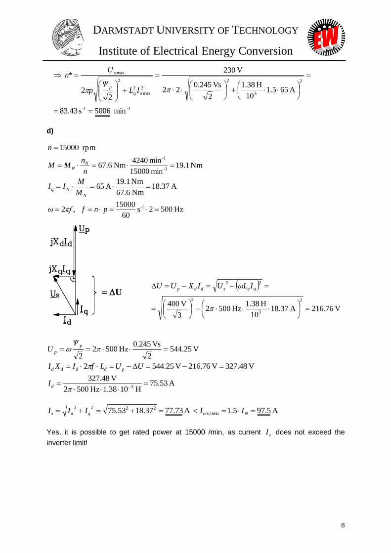
DARMSTADT UNIVERSITY OF TECHNOLOGY
Institute of Electrical Energy Conversion
8
1-1-
2
3
2
2
max
2
2
max
min 5006s 43.83
A 655.110
H 38.1
2
Vs 245.022
V 230
22
*
sq
p
s
ILΨ
p
Un
d)
Hz 5002s 60
15000 ,2
A 37.18Nm 6.67
Nm 1.19A 65
Nm 1.19min 15000
min 4240Nm 6.67
rpm 15000
1-
1-
1-
pnfπfω
M
MII
n
nMM
n
N
Nq
NN
V 76.216A 37.1810
H 38.1Hz 5002
3
V 4002
3
2
22
qqsddp ILUIXUU
V 25.5442
Vs 245.0Hz 5002
2
p
p
ΨU
V 48.327V 76.216V 25.5442 UULfIXI pdddd
A 53.75H 1038.1Hz 5002
V 48.3273
dI
A 5.975.1A 73.7737.1853.75 limit,
2222 Ninvqds IIIII
Yes, it is possible to get rated power at 15000 /min, as current sI does not exceed the
inverter limit!
U
DARMSTADT UNIVERSITY OF TECHNOLOGY
Institute of Electrical Energy Conversion
9
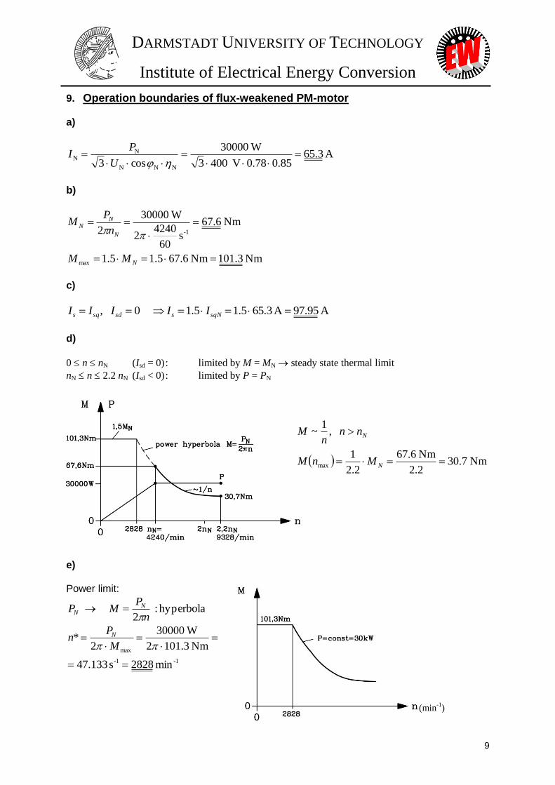
9. Operation boundaries of flux-weakened PM-motor
a)
A 3.6585.078.0V 4003
W30000
cos3 NNN
NN
U
PI
b)
Nm 3.101Nm 6.675.15.1
Nm 6.67
s 60
42402
W30000
2
max
1-
N
N
NN
MM
n
PM
c)
A 95.97A 3.655.15.1 0 , sqNssdsqs IIIII
d)
0 n nN (Isd = 0) : limited by M = MN steady state thermal limit
nN n 2.2 nN (Isd < 0) : limited by P = PN
Nm 7.302.2
Nm 6.67
2.2
1
,1
~
max
N
N
MnM
nnn
M
e) Power limit:
hyperbola : 2
n
PMP N
N
1-1-
max
min 2828s 133.47
Nm 3.1012
W30000
2*
M
Pn N
(min-1
)

DARMSTADT UNIVERSITY OF TECHNOLOGY
Institute of Electrical Energy Conversion
10
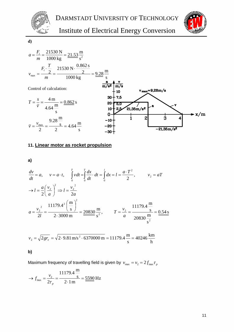
10. Single-sided linear PM-drive in tooling machine
a)
T 935.02
8.0sinT 77.04
2sin
4ˆ
T 77.0T 1.1
06.1
mm 5
1
mm 2
06.1/mm 5/
1
0
ep
M
M
RMMp
BB
h
BhB
b)
N 85785m 35.08.0
Am
Vs 1042
T 77.0
2
2
N 21530m 35.0T 935.0m
A 100000
2
93.0ˆ
2
2
7
22
0
2
0
2
2
1
mote
p
nn
motw
t
AB
FB
f
ABAk
F
Note: For tangential force we only consider the fundamental wave for force generation. For magnetic pull at no-load, we consider the flux distribution at no-load.
Ratio Fn/Ft = 4 !
c)
Rated current Rated current load: A/cm 1000A .
Stand still from x = 0 to x = 4 m: acceleration at 0 x 2 m, braking at 2 m x 4 m.
ed)(accumulatposition :s
velocity:
onaccelerati :
v
a
0)()(0 ,2
)(0 ,
0000
2
000
2
2
txtssstF
xm
tvvvtFdt
dxm
Famdt
xdm
t
t
t
s 862.0N 21530
4m 4kg 1000
2
2
2
2
t
t
F
smT
TF
sm
DARMSTADT UNIVERSITY OF TECHNOLOGY
Institute of Electrical Energy Conversion
11
d)
s
m 28.9
kg 10002
s 862.0N 21530
2
s
m 53.21
kg 1000
N 21530
max
2
m
TF
v
m
Fa
t
t
Control of calculation:
s
m 64.4
2
s
m 28.9
2
s 862.0
s
m 64.4
m 4
max
vv
v
sT
11. Linear motor as rocket propulsion
a)
h
km 40246
s
m 4.11179m 6370000m/s 81.922
s 54.0
s
m 20830
s
m 4.11179
,s
m 20830
m 30002
s
m 4.11179
2
22
,2
, ,
2
2
2
2
2
2
22
2
2
2
2
2
2
2
000
e
lTT
grv
a
vT
l
va
a
vl
a
val
aTvTa
ldxdtdt
dxvdttava
dt
dv
b)
Maximum frequency of travelling field is given by pfvv max2max 2
Hz 5590m 12
s
m 4.11179
2
2max
p
vf
DARMSTADT UNIVERSITY OF TECHNOLOGY
Institute of Electrical Energy Conversion
12
c)
kN 104150s
m 20830kg 5000
2 amFt
d)
2m 46.65
T 5.1m
A 1500000
2
1
N 104150000ˆ2
motmotwt AABA
kF
Comment: Surface is too big to correspond with relatively small mass of 5000 kg. So force density has to be maximised by increasing A and B e.g. by superconducting coils or/and the linear motor has to be built longer (e.g. 20 km).
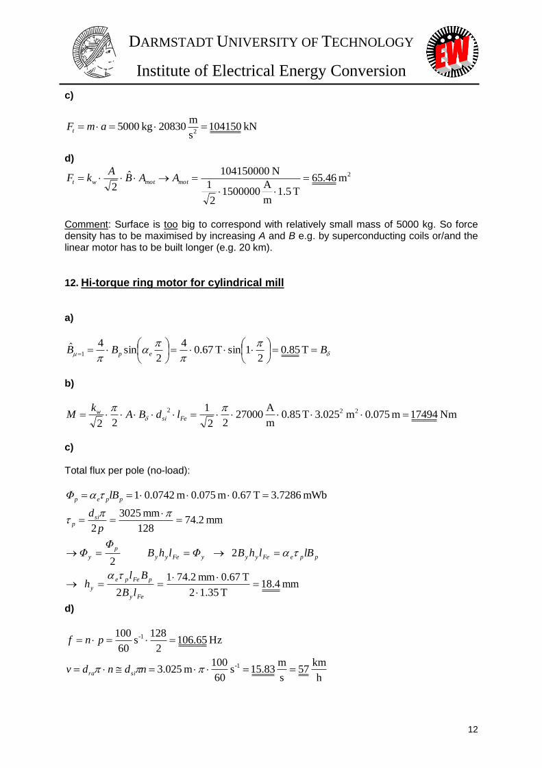
12. Hi-torque ring motor for cylindrical mill a)
BBB ep
T 85.0
21sinT 67.0
4
2sin
4ˆ1
b)
Nm 17494m 075.0m 025.3T 85.0m
A 27000
22
1
22
222
Fesi
w ldBAk
M
c) Total flux per pole (no-load):
mm 2.74128
mm 3025
2
mWb 7286.3T 67.0m 075.0m 0742.01
p
d
lBΦ
sip
ppep
mm 4.18T 35.12
T 67.0mm 2.741
2
2 2
Fey
pFepe
y
ppeFeyyyFeyy
p
y
lB
Blh
lBlhBΦlhBΦ
Φ
d)
h
km 57
s
m 83.15s
60
100m 025.3
Hz 65.1062
128s
60
100
1-
1-
ndndv
pnf
sira
DARMSTADT UNIVERSITY OF TECHNOLOGY
Institute of Electrical Energy Conversion
13
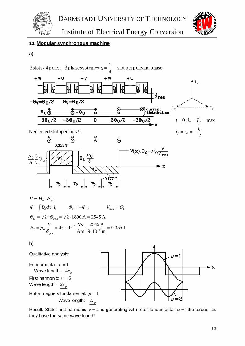
13. Modular synchronous machine
a)
phase and poleper slot 4
1system phase 3 , poles 4 / slots 3 q
maxˆ:0 UU Iit
Neglected slot openings !! 2
ˆU
WV
Iii
T 355.0m 109
A 2545
Am
Vs 104
A 2545A 180022
; ;
3
7
0
max
ges
rmsU
U
res
VB
ΘΘ
ΘVΦΦldxBΦ
HV
b) Qualitative analysis:
Fundamental: 1
Wave length: p4
First harmonic: 2
Wave length: p2
Rotor magnets fundamental: 1
Wave length: p2
Result: Stator first harmonic 2 is generating with rotor fundamental 1 the torque, as
they have the same wave length!
Picture
-
U
0
2
3
DARMSTADT UNIVERSITY OF TECHNOLOGY
Institute of Electrical Energy Conversion
14
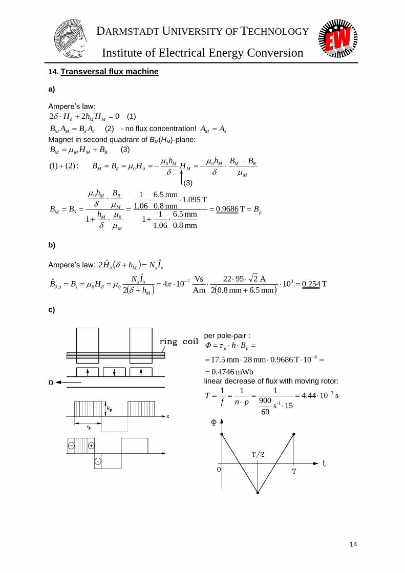
14. Transversal flux machine
a) Ampere’s law:
022 MM HhH (1)
ABAB MM (2) - no flux concentration! AAM
Magnet in second quadrant of BM(HM)-plane:
RMMM BHB (3)
M
RMMM
MM
BBhH
hHBB
00
0 :)2()1(
(3)
p
M
M
M
RM
M Bh
Bh
BB
T 9686.0
mm 8.0
mm 5.6
06.1
11
T 095.1mm 8.0
mm 5.6
06.1
1
1 0
0
b)
Ampere’s law: ssM INhH ˆˆ2
T 254.010
mm 5.6mm 8.02
A 29522
Am
Vs 104
2
ˆˆ 37
00,
M
ssss
h
INHBB
c)
per pole-pair :
mWb 4746.0
10T 9686.0mm 28mm 5.17 6
pp BhΦ
linear decrease of flux with moving rotor:
s 1044.4
15s 60
900
111 3
1-
pnf
T

DARMSTADT UNIVERSITY OF TECHNOLOGY
Institute of Electrical Energy Conversion
15
V 14115s 1044.410
Wb4746.0422
2/
233
p
T
ΦNp
dt
dΦNu ssi
d) Fourier-Analysis:
V 65.179V 1414ˆ
ˆ41
2cosˆ4
2
2cos
ˆ422sinˆ422
sin)(2ˆ
)1(
4/
0
4/
00
)1(
i
ii
T
i
T
i
T
ii
U
UU
T
T
t
T
Udt
T
tU
Tdt
T
ttu
TU
15. Transversal flux machine as vehicle drive system a)
1-1-
max
maxmax
min 795s 26.13m 8.0
s
m
6.3
120
n
ndv w
b)
v
v

DARMSTADT UNIVERSITY OF TECHNOLOGY
Institute of Electrical Energy Conversion
16
c)
ms 88.1
Hz 5.530s 26.1340
:802
1-
max
T
f
p
16. Switched reluctance machine a)
30158
360360 ,15360
151512
360360 ,15360
mm 2.122
mm 16360
r
r
rgs
si
rr
s
s
sg
si
ss
Qd
b
Qd
b
b)
mH 3.128m 193.0mm 45.0
mm 1661
Am
Vs 104422 272
0
Fes
ccd lb
NpLpLh
c)
Nm 5.22Nm rad 262.010
H 10H 3.128A 10
2
1
2
1
2
13
2222
hh qdqd
LLI
LLIM
LLLLLLhh qqdd ,
rad 262.02360
15 , 15)15,15min(),min(
rs
d)
151530
15
0:
srg
s
srsr
DARMSTADT UNIVERSITY OF TECHNOLOGY
Institute of Electrical Energy Conversion
17
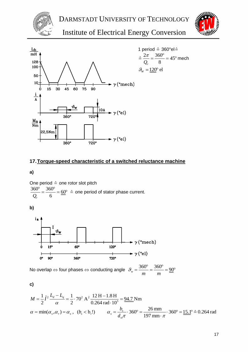
1 period 360°el
458
3602
rQ
mech
el 120W
17. Torque-speed characteristic of a switched reluctance machine a)
One period one rotor slot pitch
606
360360
rQ one period of stator phase current.
b)
No overlap four phases conducting angle
90360360
mmw
c)
Nm 7.9410rad 264.0
H 8.1H 12A 70
2
1ˆ2
13
222
qd LLIM
rad 264.0ˆ 1.15360mm 197
mm 26360 )!b( , ),min( r
si
ssssrs
d
bb
DARMSTADT UNIVERSITY OF TECHNOLOGY
Institute of Electrical Energy Conversion
18
d)
1-1-
3max
min 1977s 95.32
10rad 264.0
H 8.1H 12A 70
V 560
2
1
ˆ2
1
qd
dg LL
I
Un
e)
2
2
1
m
d
qde
U
LLM
at gn2 :
-1-1 s 414s 95.322222 gm n
Nm 68.23eM
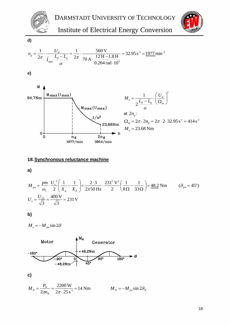
18. Synchronous reluctance machine a)
Nm 2.48 33
1
8
1
2
V 231
Hz 502
3211
2
222
dq
s
s
poXX
UpmM )45( po
V 2313
V 400
3 LL
s
UU
b)
2sinpoe MM
c)
Nm 14s 252
W2200
2 1-
N
NN
n
PM NpoN MM 2sin
DARMSTADT UNIVERSITY OF TECHNOLOGY
Institute of Electrical Energy Conversion
19
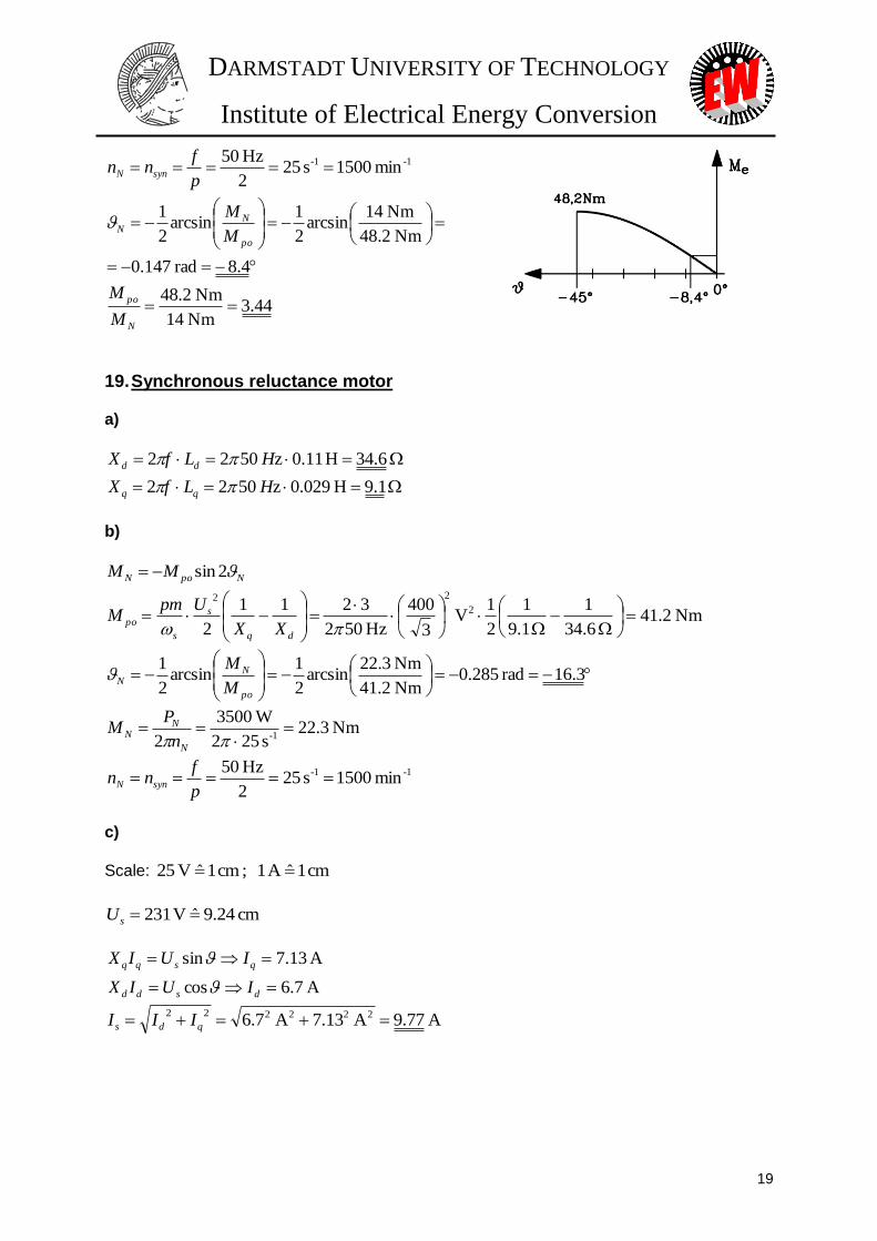
1-1- min 1500s 252
Hz 50
p
fnn synN
4.8rad 147.0
Nm 2.48
Nm 14arcsin
2
1arcsin
2
1
po
NN
M
M
44.3Nm 41
Nm 8.24
N
po
M
M
19. Synchronous reluctance motor a)
1.9H 029.0z 5022
6.34H 11.0z 5022
HLfX
HLfX
dd
b)
NpoN MM 2sin
Nm 2.41 6.34
1
.19
1
2
1V
3
400
Hz 502
3211
2
2
22
dq
s
s
poXX
UpmM
3.16rad 285.0
Nm 2.41
Nm 2.32arcsin
2
1arcsin
2
1
po
NN
M
M
Nm 3.22s 252
W3500
2 1-
N
NN
n
PM
1-1- min 1500s 252
Hz 50
p
fnn synN
c)
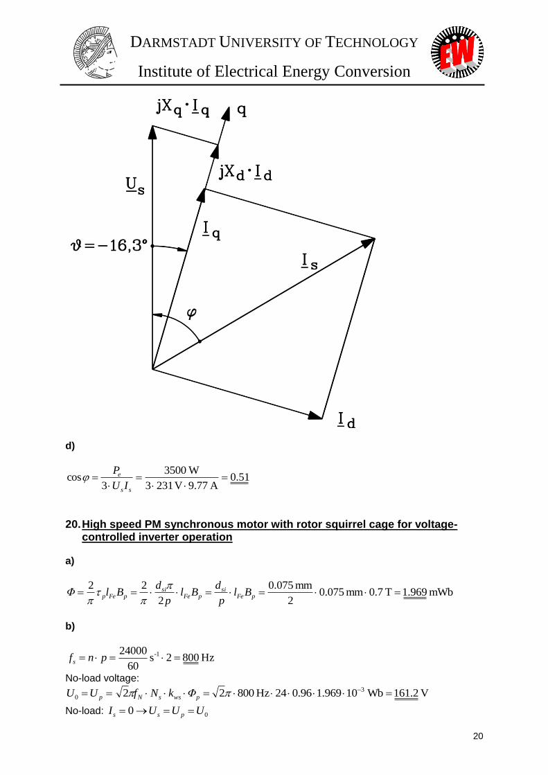
Scale: cm 1ˆA 1 ; cm 1ˆV 52
cm 24.9ˆV 231 sU
A 7.6cos
A 13.7sin
dsdd
qsqq
IUIX
IUIX
A 77.9A 13.7A 7.6 222222 qds III
DARMSTADT UNIVERSITY OF TECHNOLOGY
Institute of Electrical Energy Conversion
20
d)
51.0A 77.9V 2313
W3500
3cos
ss
e
IU
P
20. High speed PM synchronous motor with rotor squirrel cage for voltage-controlled inverter operation
a)
mWb 969.1T 7.0mm 075.02
mm 075.0
2
22 pFe
sipFe
sipFep Bl
p
dBl
p
dBlΦ
b)
Hz 8002s 60
24000 1- pnfs
No-load voltage:
V 2.161 Wb10969.196.024Hz 80022 3
0 pwssNp ΦkNfUU
No-load: 00 UUUI pss
DARMSTADT UNIVERSITY OF TECHNOLOGY
Institute of Electrical Energy Conversion
21
c)
Neglecting Rs : sN
sNsNswssNsN
f
UΦNkU sNΦ
Hz
V 288.0
32
1
Hz 800
1
3
V 400
sN
sN
f
U
d)
motor: outmN PPP
31-222m
minkVA 35.2
min 24000m 075.0m 075.0
kVA 810.23
VA 238109.07.0
W15000
cos
nld
SC
PS
Fesi
i
NN
N
21. PM synchronous motor with buried magnets and squirrel cage rotor for line operation
a)
2sin11
2
3sin
3 2
dq
s
d
ps
es
XX
U
X
UUM
p
02cosB2cosA :0
2sinBsinA
d
dM
Mp
e
es
02
1
B4
A
0B2AB4
012B2A cos
01cos2B2cosA1cos22cos
2
2
2
22
xx
xx
xxx
2
1
8B
A
8B
Acos
2
2,12,1
x
0 2
1
8B
A
8B
Acos
!! 0cos2
2
p
pp
> 0
p
DARMSTADT UNIVERSITY OF TECHNOLOGY
Institute of Electrical Energy Conversion
22
575.0
19
7.151
1
V 06.754
V 30
1
1
411
2
3
1
8
3
8B
A2
q
ds
p
qd
sd
ps
X
XU
U
XX
UX
UU
V 06.753
130sU
33626.05.0575.0575.0cos 2 p
Generator 65.109
Motor 65.109
p
p
s
p
qd
sp
d
ps
p
p
XX
U
X
UUM
2sin
11
2
3sin
3 2
Nm 956.2377.05797.2
502
2)65.1092sin(
19
1
7.15
1
2
06.753)65.109sin(
7.15
3006.753 2
pM
b)
W34063.063.0A 8.3V1303cos3
min 1500 Hz 50 ,42
Nm 16.2
s 60
15002
W340
2
1-
1-
NNNNN
N
N
NN
IUP
nfp
n
PM
c)
36.1Nm 16.2
Nm 956.2
N
po
M
M
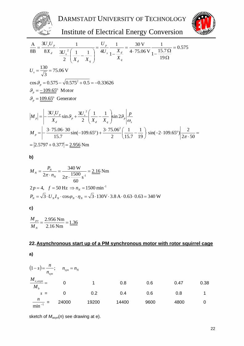
22. Asynchronous start up of a PM synchronous motor with rotor squirrel cage a)
Nsyn
syn
nnn
ns ;1
b
asyne
M
M , 0 1 0.8 0.6 0.47 0.38
s = 0 0.2 0.4 0.6 0.8 1
1min
n = 24000 19200 14400 9600 4800 0
sketch of Masyn(n) see drawing at e).
DARMSTADT UNIVERSITY OF TECHNOLOGY
Institute of Electrical Energy Conversion
23
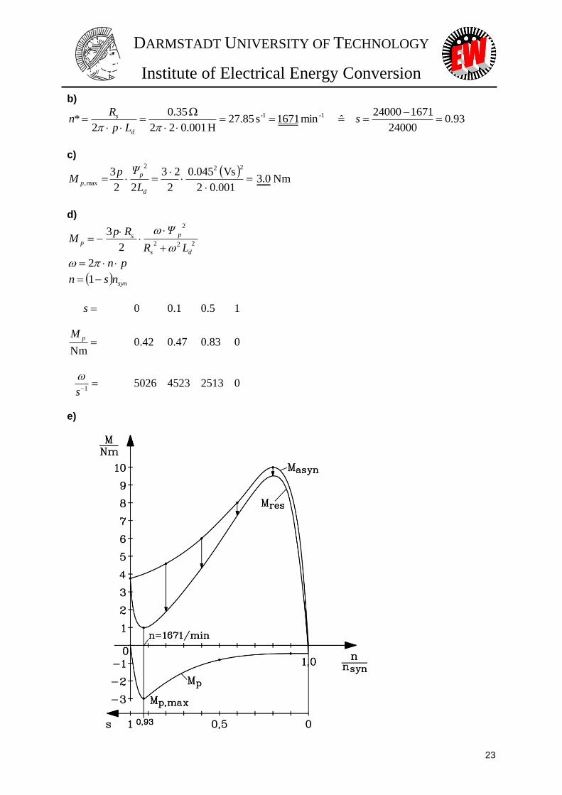
b)
93.024000
167124000 ˆ min 1671s 85.27
H 001.022
35.0
2* 1-1-
s
Lp
Rn
d
s
c)
Nm 0.3
001.02
Vs 045.0
2
23
22
3222
max,
d
p
pL
ΨpM
d)
222
2
2
3
ds
psp
LR
ΨRpM
pn 2
synnsn 1
s 0 0.1 0.5 1
Nm
pM 0.42 0.47 0.83 0
1s
5026 4523 2513 0
e)

DARMSTADT UNIVERSITY OF TECHNOLOGY
Institute of Electrical Energy Conversion
24
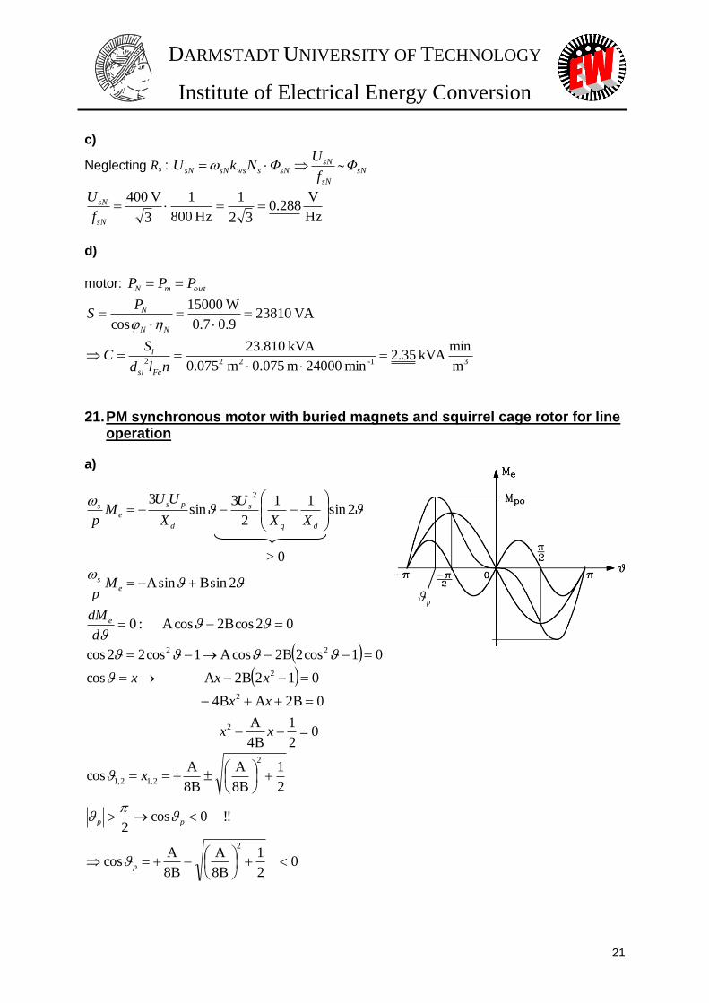
23. Electromagnetic aircraft launch system on aircraft carrier a)
MJ 67.237s
m
6.3
370
2
1kg 45000
2
222
launch
Aircraftkin
vmW
b)
Hz 103m 5.02
s
m
6.3
370
2 2
p
launchp
vffv
c)
tfFtvtFtP p ~2)()()(
Fxm , ax
v rises linear with time t~v
dt
dva const.
2
2
s
m 3.34
s 3
s
m
6.3
370
kN 6.15413.34kg 45000
launch
launch
t
va
s
mamF
MW 5.1586.3
370N 1541666
s
mvFP launchlaunch
d)
2)(
2
000
tv
T
Ftdt
T
vFvdtFdttPW launch
t
launch
tt
kin
Check of result: 2222
)(22
launchlaunchlaunchlaunchkin
vm
vTam
vTF
Tv
T
FTtW
(see a))
T
vlaunch
DARMSTADT UNIVERSITY OF TECHNOLOGY
Institute of Electrical Energy Conversion
25
e)
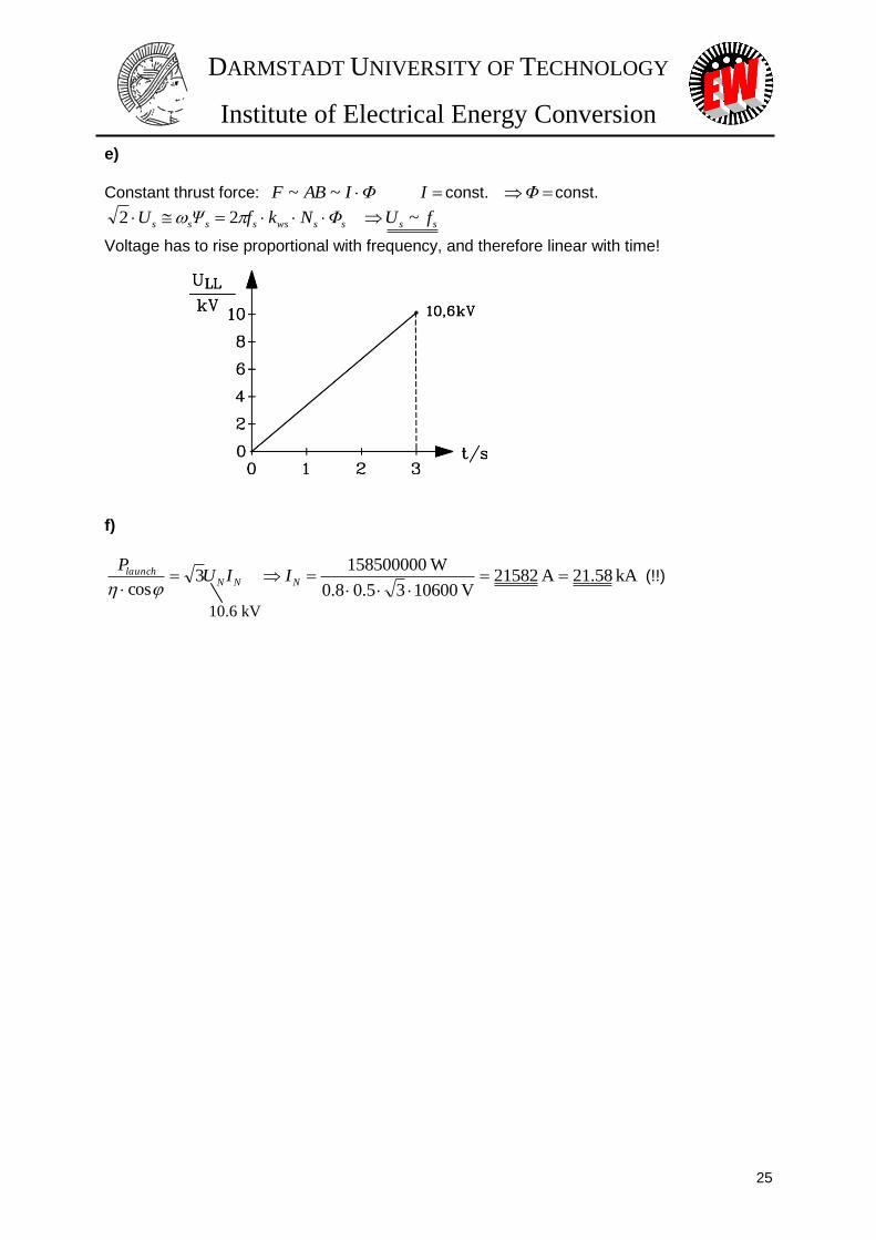
Constant thrust force: ΦIABF ~~ I const. Φ const.
sswsssss ΦNkfΨU 22 ss fU ~
Voltage has to rise proportional with frequency, and therefore linear with time! f)
NNlaunch IU
P3
cos
kA 58.21A 21582
V 1060035.08.0
W158500000
NI (!!)
10.6 kV
DARMSTADT UNIVERSITY OF TECHNOLOGY
Institute of Electrical Energy Conversion
26
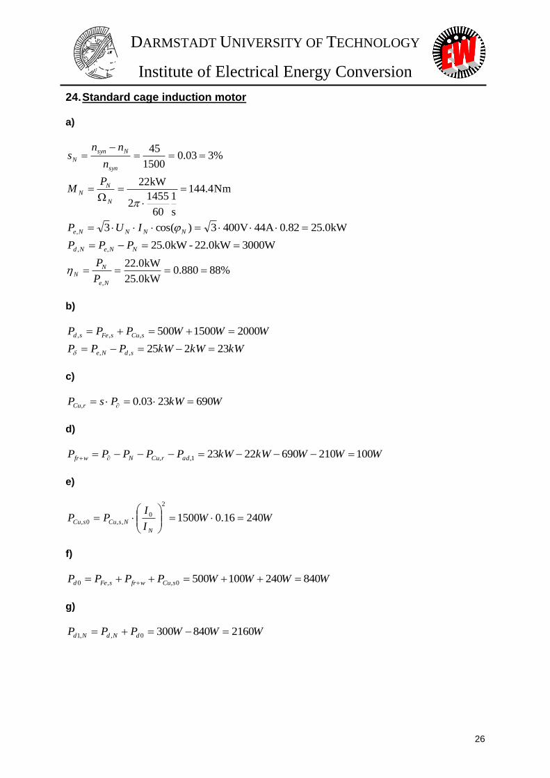
24. Standard cage induction motor a)
%303.01500
45
syn
Nsyn
Nn
nns
Nm4.144
s
1
60
45512
kW22
N
NN
PM
kW0.2582.0A44V4003)cos(3, NNNNe IUP
3000WkW0.22-kW0.25,, NNeNd PPP
%88880.0kW0.25
kW0.22
,
Ne
NN
P
P
b)
WWWPPP sCusFesd 20001500500,,,
kWkWkWPPP sdNe 23225,,
c)
WkWPsP rCu 6902303.0,
d)
WWWkWkWPPPPP adrCuNwfr 10021069022231,,
e)
WWI
IPP
N
NsCusCu 24016.01500
2
0
,,0,
f)
WWWWPPPP sCuwfrsFed 8402401005000,,0
g)
WWWPPP dNdNd 21608403000,,1
DARMSTADT UNIVERSITY OF TECHNOLOGY
Institute of Electrical Energy Conversion
27
h)
kWPM
MPP N
N
Nout 115.0
WPM
MPP Nd
N
Ndd 54025.0,1
2
,11
%85.88540W840WkW11
kW11
10
ddout
out
PPP
P
i)
NmMW
W
P
P
M
Mopt
Nd
d
N
opt0.906236.0
2160
840
,1
0
%1.89840840226236.0
226236.0max
WWkW
kW
25. Hi-Speed-Compressor Drive, Hi-Speed-Kompressor-Antrieb
1) 8002)60/24000( pnf NsN Hz
2) 10025.650
800 p
sNpN U
f
fU V
3) 65000,, Noutmine PPP W
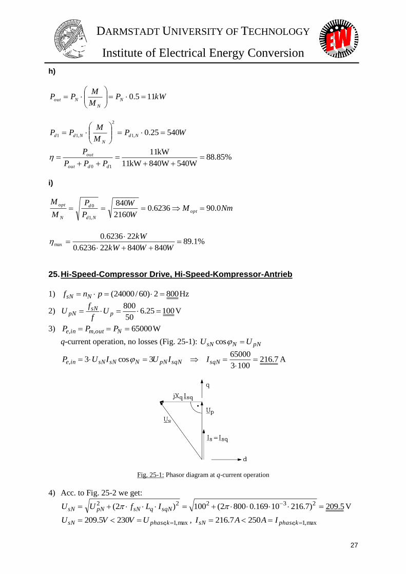
q-current operation, no losses (Fig. 25-1): pNNsN UU cos
7.2161003
650003cos3,
sqNsqNpNNsNsNine IIUIUP A
Fig. 25-1: Phasor diagram at q-current operation
4) Acc. to Fig. 25-2 we get:
5.209)7.21610169.08002(100)2( 23222 sqNqsNpNsN ILfUU V
max,1,2305.209 kphasesN UVVU , max,1,2507.216 kphasesN IAAI

DARMSTADT UNIVERSITY OF TECHNOLOGY
Institute of Electrical Energy Conversion
28
The inverter rating is sufficient for that drive purpose.
5) 2.1367.2165.20933 sNsNN IUS kVA
477.0136200/65000/cos NNN SP
Motor current is lagging; motor is inductive consumer = under-excited operation.
Fig. 25-2: Voltage and phasor diagram of PM motor at rated load and speed
1) 8002)60/24000( pnf NsN Hz
2) 10025.650
800 p
sNpN U
f
fU V
3) 65000,, Noutmine PPP W
q-Strombetrieb, keine Verluste berücksichtigt (Bild 25-1deutsch): pNNsN UU cos
7.2161003
650003cos3,
sqNsqNpNNsNsNine IIUIUP A
4) Gemäß Bild 25-2deutsch erhalten wir:
5.209)7.21610169.08002(100)2( 23222 sqNqsNpNsN ILfUU V
max,1,2305.209 kphasesN UVVU , max,1,2507.216 kphasesN IAAI
Der Umrichter ist für den Antrieb ausreichend bemessen.
5) 2.1367.2165.20933 sNsNN IUS kVA
477.0136200/65000/cos NNN SP
Der Motorstrom eilt der Spannung nach; der Motor ist ein induktiver Verbraucher = untererregter
Betrieb.
DARMSTADT UNIVERSITY OF TECHNOLOGY
Institute of Electrical Energy Conversion
29
Bild 25-1deutsch: Zeigerdiagramm bei q-Strombetrieb Bild 25-2deutsch: Spannung- und Stromzeiger des
PM-Motors bei Nenndrehzahl und -drehmoment
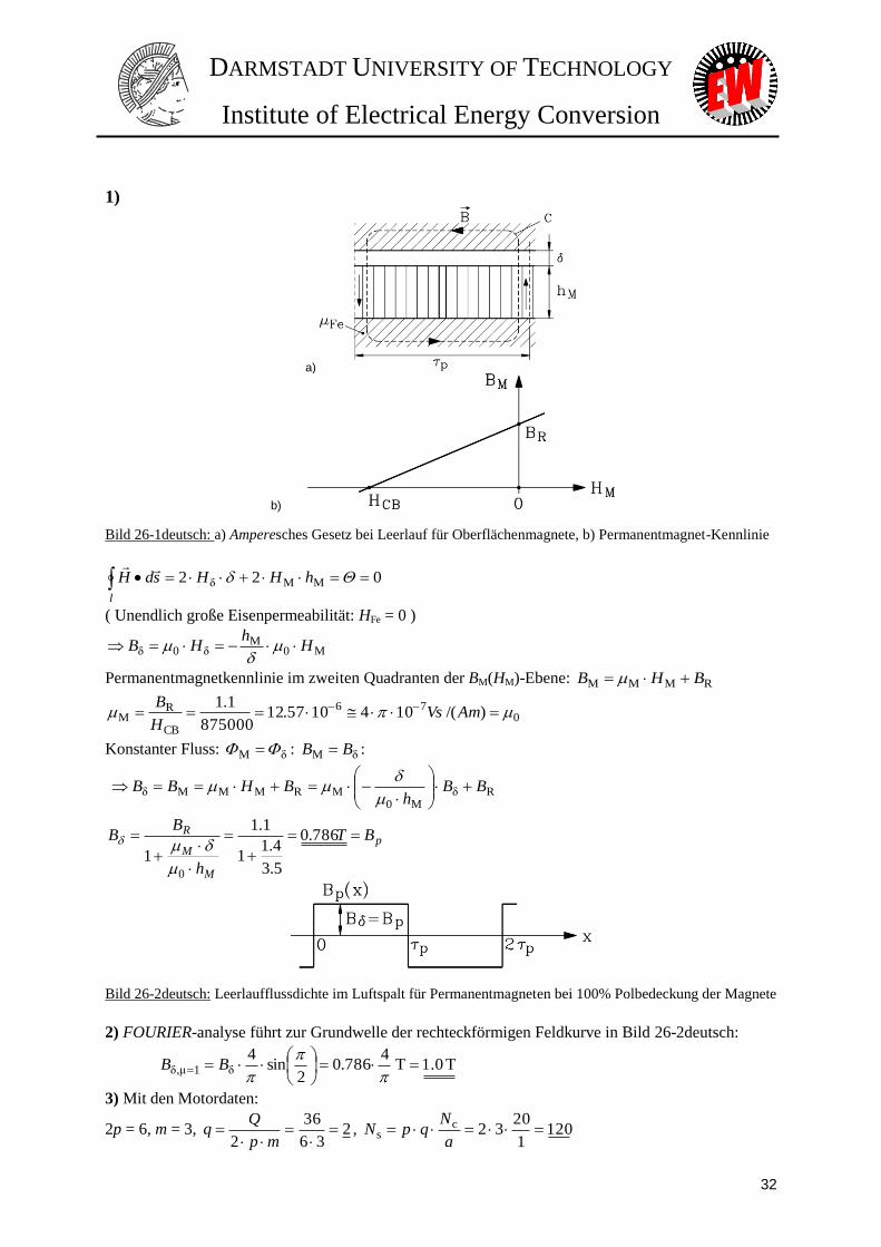
26. Permanent magnet motor as a machine tool drive, Permanentmagnetmotor als Werkzeugmaschinenantrieb 1)
a) b)
Fig. 26-1: a) Ampere´s law at no-load for surface mounted permanent magnets, b) Permanent magnet
characteristic
l
hHHsdH 022 MMδ
(infinite iron permeability: HFe = 0 )
M0M
δ0δ Hh
HB
Permanent magnet characteristic in second quadrant of BM(HM)-plane: RMMM BHB
(Fig. 26-1)
076
CB
RM )/(1041057.12
875000
1.1 AmVs
H
B
Constant magnetic flux: δM : δM BB :

DARMSTADT UNIVERSITY OF TECHNOLOGY
Institute of Electrical Energy Conversion
30
RδM0
MRMMMδ BBh
BHBB
p
M
M
R BT
h
BB
786.0
5.3
4.11
1.1
10
Fig. 26-2: No-load permanent magnet air gap flux density curve at 100% pole coverage ratio of magnets
2) FOURIER analysis leads to fundamental harmonic of a rectangular field curve of Fig. 26-2:
T1.0T4
786.02
sin4
δ1μδ,
BB
3) With following motor data:
2p = 6, m = 3, 236
36
2
mp
Qq , 120
1
2032c
s a
NqpN
mm 52.4mm6
100
2
sip
p
d, fs = 100 Hz,
fundamental winding factor: p,1d,1w,1 kkk
single layer winding has full-pitched coils: 1p,1 k
w,1d,1 9659.0
26sin2
6sin
2sin
2sin
k
qmq
mk
we get:
V171.50.11.00524.02
9659.012010022
2 1,1,p,1
BlkNfU pwss
4) Permeability of magnets:
076
CB
RM )/(1041057.12
875000
1.1 AmVs
H
B
Rare earth permanent magnets have the same permeability as air.
5)
Ω3.2
105.34.13
0524.01.0329659.01201041002
22
32
227
M
p
2
21,
2s0s1h,
hp
lmkNfX w
0M resulting magnetic effective air gap is + hM.
6) Maximum torque at given current is reached, if stator current is only q-axis current: Is = Iq
DARMSTADT UNIVERSITY OF TECHNOLOGY
Institute of Electrical Energy Conversion
31
Fig. 26-3: Voltage diagram for q-current, motor operation, Rs neglected
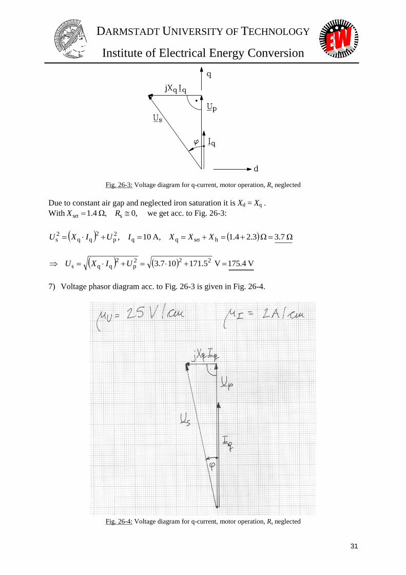
Due to constant air gap and neglected iron saturation it is Xd = Xq .
With 0,Ω,4.1 ssσ RX we get acc. to Fig. 26-3:
Ω3.7Ω3.21.4A,10, hsσqq2p
2qq
2s XXXIUIXU
V175.4V5.171107.3 222p
2qqs UIXU
7) Voltage phasor diagram acc. to Fig. 26-3 is given in Fig. 26-4.
Fig. 26-4: Voltage diagram for q-current, motor operation, Rs neglected
DARMSTADT UNIVERSITY OF TECHNOLOGY
Institute of Electrical Energy Conversion
32
1)
a)
b)
Bild 26-1deutsch: a) Amperesches Gesetz bei Leerlauf für Oberflächenmagnete, b) Permanentmagnet-Kennlinie
l
hHHsdH 022 MMδ
( Unendlich große Eisenpermeabilität: HFe = 0 )
M0M
δ0δ Hh
HB
Permanentmagnetkennlinie im zweiten Quadranten der BM(HM)-Ebene: RMMM BHB
076
CB
RM )/(1041057.12
875000
1.1 AmVs
H
B
Konstanter Fluss: δM : δM BB :
RδM0
MRMMMδ BBh
BHBB
p
M
M
R BT
h
BB
786.0
5.3
4.11
1.1
10
Bild 26-2deutsch: Leerlaufflussdichte im Luftspalt für Permanentmagneten bei 100% Polbedeckung der Magnete
2) FOURIER-analyse führt zur Grundwelle der rechteckförmigen Feldkurve in Bild 26-2deutsch:
T1.0T4
786.02
sin4
δ1μδ,
BB
3) Mit den Motordaten:
2p = 6, m = 3, 236
36
2
mp
Qq , 120
1
2032c
s a
NqpN

DARMSTADT UNIVERSITY OF TECHNOLOGY
Institute of Electrical Energy Conversion
33
mm 52,4mm6
100
2
sip
p
d, fs = 100 Hz,
Grundwickelfaktor: p,1d,1w,1 kkk
Einschichtwicklung ungesehnt: 1p,1 k
w,1d,1 9659,0
26sin2
6sin
2sin
2sin
k
qmq
mk
erhält man:
V171.50.11.00524.02
9659.012010022
2 1,1,p,1
BlkNfU pwss
4) Permeabilität der Magnete:
076
CB
RM )/(1041057.12
875000
1.1 AmVs
H
B
Seltenerd-Magnete haben annähernd dieselbe Permeabilität wie Luft.
5)
M
p
2
21,
2s0s1h,
22
hp
lmkNfX w
Ω3.2
105.34.13
0524.01.0329659.01201041002
32
227
0M Resultierender magnetisch wirksamer Luftspalt ist + hM.
6) Maximales Moment bei gegebenem Strom wird erreicht, wenn Is = Iq.
Wegen des konstanten Luftspalts und vernachlässigter Eisensättigung gilt Xd = Xq .
Mit 0,Ω,4.1 ssσ RX ergibt sich nach Bild 26-3deutsch:
Bild 26-3deutsch: Spannungszeigerdiagramm für q-Strom, Motorbetrieb, Rs vernachlässigt
Ω3.7Ω3.21.4A,10, hsσqq2p
2qq
2s XXXIUIXU
V175.4V5.171107.3 222p
2qqs UIXU
7) Spannungszeigerdiagramm gemäß Bild 26-3deutsch ist in Bild 26-4deutsch zu sehen.

DARMSTADT UNIVERSITY OF TECHNOLOGY
Institute of Electrical Energy Conversion
34
Bild 26-4deutsch: Spannungszeigerdiagramm für q-Strom, Motorbetrieb, Rs vernachlässigt
27. Permanent magnet synchronous motor as robot drive, Roboterantrieb
1.) Up = 90 V, fs = 50 Hz, n = fs / p = 50 / 4 = 12.5 /s = 750 / min
ppppspsp nUpnfU ~2/22/22/
Open circuit no-load phase voltage = back EMF:
72090750
6000maxmax, pp U
n
nU V,
Line-to-line voltage (Y): 12477203, LLpU V ... Diagram Up,LL(n): Fig. 27-2
2.) Up is proportional to speed and permanent magnet flux Up ~ p
Due to 1,
2
ppwp BlkN , pp BB
41, and
M
M
Rp
h
BB
0
1
the back
EMF is directly proportional to remanence flux density BR. Therefore it is possible to
determine by back EMF measurement, if the magnets are properly magnetized. For that,
the magnet temperature must be known, as remanence depends on temperature: BR = BR
() !
3.) mHLd 5.4 , 0sR , Due to constant magnetic air-gap and neglected iron saturation
we may assume: Ld = Lq
83.2105.410022 3 dsNdsNdN LfLX

DARMSTADT UNIVERSITY OF TECHNOLOGY
Institute of Electrical Energy Conversion
35
a.) Nsq IAII 12 : NqNNdN IXVIX 9.331283.2
b.) AIII Nsq 484 : NqNNdN IXVIX 47.1359.3344
1809050
100 p
s
sNpN U
f
fU V
a.) VIXUU NqNps 2.1839.33180)( 2222
b.) VIXUU NqNps 4.2257.135180)4( 2222
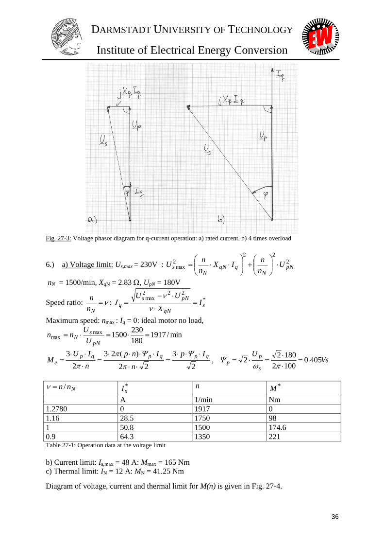
Voltage phasor diagram Fig. 27-3.
4) min/1500/254
100 s
p
fn sN
N
5) No losses considered: 1 : spsseeinmout IUIUPPPPP cos3
ps UU cos , syn
spemsyne
IUMPM
3, 157.1/s2522
p
fsNsyn
a.) NmIU
Msyn
spe 25.41
1.157
1218033
, b.) Nm
IUM
syn
spe 165
1.157
4818033
Fig. 27-2: Back EMF (r.m.s., line-to-line) versus speed, measured at open circuit, no-load generator operation
DARMSTADT UNIVERSITY OF TECHNOLOGY
Institute of Electrical Energy Conversion
36
Fig. 27-3: Voltage phasor diagram for q-current operation: a) rated current, b) 4 times overload
6.) a) Voltage limit: Us,max = 230V : 2
22
2max pN
NqqN
Ns U
n
nIX
n
nU
nN = 1500/min, XqN = 2.83 , UpN = 180V
Speed ratio: *
22max
sqN
pNs
qN
IX
UU
n
n
Maximum speed: nmax : Iq = 0: ideal motor no load,
min/1917180
2301500max
max pN
sN
U
Unn
2
3
22
)23
2
3 qpqpqpe
Ip
n
Inp
n
IUM
, Vs
U
s
pp 405.0
1002
18022
Nnn / *sI n *M
A 1/min Nm
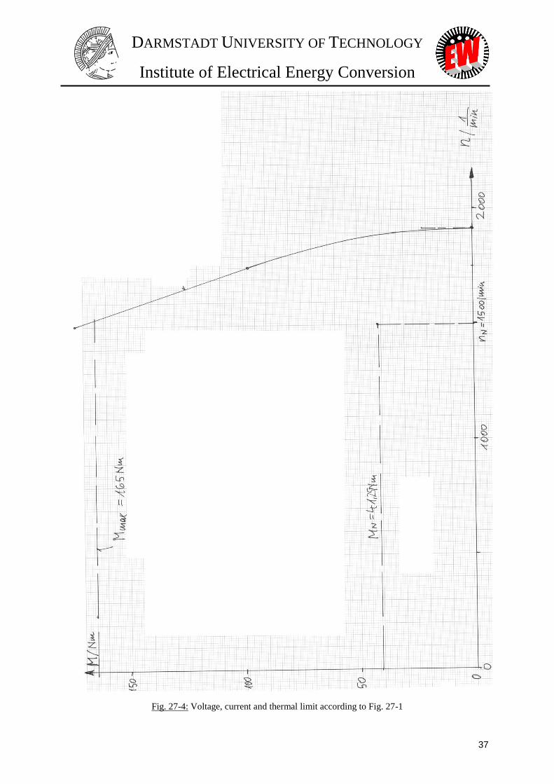
1.2780 0 1917 0
1.16 28.5 1750 98
1 50.8 1500 174.6
0.9 64.3 1350 221 Table 27-1: Operation data at the voltage limit
b) Current limit: Is,max = 48 A: Mmax = 165 Nm
c) Thermal limit: IN = 12 A: MN = 41.25 Nm
Diagram of voltage, current and thermal limit for M(n) is given in Fig. 27-4.
DARMSTADT UNIVERSITY OF TECHNOLOGY
Institute of Electrical Energy Conversion
37
Fig. 27-4: Voltage, current and thermal limit according to Fig. 27-1

DARMSTADT UNIVERSITY OF TECHNOLOGY
Institute of Electrical Energy Conversion
38
1) Up = 90 V, fs = 50 Hz, n = fs / p = 50 / 4 = 12.5 /s = 750 / min
ppppspsp nUpnfU ~2/22/22/
Leerlauf-Strangspannung = Polradspannung: 72090750
6000maxmax, pp U
n
nU V,
Verkettete Spannung (Y): 12477203, LLpU V Diagramm Up,LL(n): Bild 27-2deutsch
2) Up ist proportional zur Drehzahl und zur Permanentmagnet-Flussverkettung Up ~ p
Wegen 1,
2
ppwp BlkN , pp BB
41, und
M
M
Rp
h
BB
0
1
kann von der
gemessenen Leerlauf-Polradspannung direkt auf die Remanenzflussdichte geschlossen werden.
Die Magnettemperatur muss dabei bekannt sein, da BR = BR()!
3) mHLd 5.4 , 0sR . Wegen des konstanten magnetisch wirksamen Luftspaltes und
vernachlässigter Eisensättigung kann angenommen werden, dass Ld = Lq.
Ω 83.2105.410022 3 dsNdsNdN LfLX
a) Nsq III A 12 : NqNNdN IXIX V 9.331283.2
b) A 484 Nsq III : NqNNdN IXIX 4V 7.1359.3344
1809050
100 p
s
sNpN U
f
fU V, Spannungszeigerdiagramm in Bild 27-3deutsch.
a) V 2.1839.33180)( 2222 NqNps IXUU
b) V 4.2257.135180)4( 2222 NqNps IXUU
4) min/1500s/254
100
p
fn sN
N
5) Keine Verluste berücksichtigt:
1 : spsseeinmout IUIUPPPPP cos3
ps UU cos , syn
spemsyne
IUMPM
3, 157.1/s2522
p
fsNsyn
a) Nm 25.411.157
1218033
syn
spe
IUM
, b) Nm 165
1.157
4818033
syn
spe
IUM
6) a) Spannungsgrenze: Us,max = 230V : 2
22
2max pN
NqqN
Ns U
n
nIX
n
nU
nN = 1500/min, XqN = 2.83 , UpN = 180V
Drehzahlverhältnis: *
22max
sqN
pNs
qN
IX
UU
n
n
Maximaldrehzahl: nmax : Iq = 0: idealer Leerlauf, min/1917180
2301500max
max pN
sN
U
Unn
2
3
22
)23
2
3 qpqpqpe
Ip
n
Inp
n
IUM
, Vs 405.0
1002
18022
s
pp
U

DARMSTADT UNIVERSITY OF TECHNOLOGY
Institute of Electrical Energy Conversion
39
Nnn / *sI
n *M
A 1/min Nm
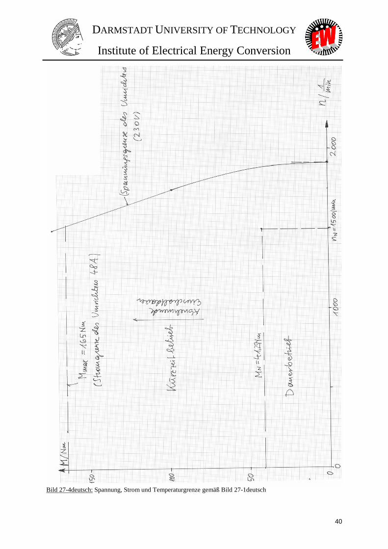
1.2780 0 1917 0
1.16 28.5 1750 98
1 50.8 1500 174.6
0.9 64.3 1350 221
b) Stromgrenze: Is,max = 48 A: Mmax = 165 Nm
c) Temperaturgrenze: IN = 12 A: MN = 41.25 Nm
Bild 27-2deutsch: Polradspannung (Effektivwert, verkettet) gegen Drehzahl, gemessen im Generatorbetrieb bei
Leerlauf
Bild 27-3deutsch: Spannungszeigerdiagramm für Betrieb mit q-Strom: a) Nennstrom, b) 4-fache Überlastung
DARMSTADT UNIVERSITY OF TECHNOLOGY
Institute of Electrical Energy Conversion
40
Bild 27-4deutsch: Spannung, Strom und Temperaturgrenze gemäß Bild 27-1deutsch
DARMSTADT UNIVERSITY OF TECHNOLOGY
Institute of Electrical Energy Conversion
41
28. Permanent magnet motor, Permanentmagnetmotor
Solutions:
1) The air gap flux density distribution has a rectangular shape.
2) hM = 1.83 mm,
3) fs,N = 300 Hz , Us,0 = 115.8 V,
4) MN = 35 Nm, ,
5) qs,2
3 IpMp
, Is,N = 63.3 A.
Lösungen:
1) Die Luftspaltfeldverteilung ist rechteckförmig.
2) hM = 1.83 mm,
3) fs,N = 300 Hz , Us,0 = 115.8 V,
4) MN = 35 Nm, ,
5) qsp
IpM ,2
3
, Is,N = 63.3 A.

MMoottoorr DDeevveellooppmmeenntt ffoorr EElleeccttrriicc DDrriivvee SSyysstteemmss 1 PPrreeppaarraattiioonn ffoorr eexxaammiinnaattiioonn
Darmstadt University of Technology Institute of Electrical Energy Conversion
Prof. Dr.-Ing. habil. Dr. h. c. A. Binder
PPrreeppaarraattiioonn ffoorr EExxaammiinnaattiioonn
Examination is in writing, where your ability to calculate some problems, is examined, and where
your understanding of theory is checked.
We recommend preparation for examination in the following way: Calculate the examples, given in
the Collection of Exercises, and test yourself by comparing your solutions with those given in the
Collection. The problems at the test in writing are very similar to those. For theory part of
examination only those questions, which you find hereafter included, will be asked. Thus the content
for learning is exactly defined.
Please note, that the text book contains much more information about motors, than you will need for
examination. We advice you to prepare the collection of questions, when you are learning for exam,
and try to find the answers from the text book. If you have difficulties in answering the questions, do
not hesitate to consult us.
If you have any further questions concerning examination, either theory or method of calculation, do
not hesitate to contact us.
Yours sincerely
A. Binder Darmstadt, 18.7.2014
MMoottoorr DDeevveellooppmmeenntt ffoorr EElleeccttrriicc DDrriivvee SSyysstteemmss 2 PPrreeppaarraattiioonn ffoorr eexxaammiinnaattiioonn
Darmstadt University of Technology Institute of Electrical Energy Conversion
Prof. Dr.-Ing. habil. Dr. h. c. A. Binder
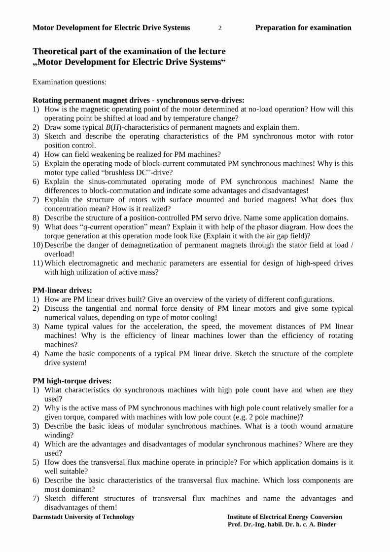
TThheeoorreettiiccaall ppaarrtt ooff tthhee examination of the lecture
„MMoottoorr DDeevveellooppmmeenntt ffoorr EElleeccttrriicc DDrriivvee SSyysstteemmss“
Examination questions:
Rotating permanent magnet drives - synchronous servo-drives:
1) How is the magnetic operating point of the motor determined at no-load operation? How will this
operating point be shifted at load and by temperature change?
2) Draw some typical B(H)-characteristics of permanent magnets and explain them.
3) Sketch and describe the operating characteristics of the PM synchronous motor with rotor
position control.
4) How can field weakening be realized for PM machines?
5) Explain the operating mode of block-current commutated PM synchronous machines! Why is this
motor type called “brushless DC”-drive?
6) Explain the sinus-commutated operating mode of PM synchronous machines! Name the
differences to block-commutation and indicate some advantages and disadvantages!
7) Explain the structure of rotors with surface mounted and buried magnets! What does flux
concentration mean? How is it realized?
8) Describe the structure of a position-controlled PM servo drive. Name some application domains.
9) What does “q-current operation” mean? Explain it with help of the phasor diagram. How does the
torque generation at this operation mode look like (Explain it with the air gap field)?
10) Describe the danger of demagnetization of permanent magnets through the stator field at load /
overload!
11) Which electromagnetic and mechanic parameters are essential for design of high-speed drives
with high utilization of active mass?
PM-linear drives:
1) How are PM linear drives built? Give an overview of the variety of different configurations.
2) Discuss the tangential and normal force density of PM linear motors and give some typical
numerical values, depending on type of motor cooling!
3) Name typical values for the acceleration, the speed, the movement distances of PM linear
machines! Why is the efficiency of linear machines lower than the efficiency of rotating
machines?
4) Name the basic components of a typical PM linear drive. Sketch the structure of the complete
drive system!
PM high-torque drives:
1) What characteristics do synchronous machines with high pole count have and when are they
used?
2) Why is the active mass of PM synchronous machines with high pole count relatively smaller for a
given torque, compared with machines with low pole count (e.g. 2 pole machine)?
3) Describe the basic ideas of modular synchronous machines. What is a tooth wound armature
winding?
4) Which are the advantages and disadvantages of modular synchronous machines? Where are they
used?
5) How does the transversal flux machine operate in principle? For which application domains is it
well suitable?
6) Describe the basic characteristics of the transversal flux machine. Which loss components are
most dominant?
7) Sketch different structures of transversal flux machines and name the advantages and
disadvantages of them!

MMoottoorr DDeevveellooppmmeenntt ffoorr EElleeccttrriicc DDrriivvee SSyysstteemmss 3 PPrreeppaarraattiioonn ffoorr eexxaammiinnaattiioonn
Darmstadt University of Technology Institute of Electrical Energy Conversion
Prof. Dr.-Ing. habil. Dr. h. c. A. Binder
Switched reluctance drives:
1) Describe the motor and inverter design, and the operation modes of switched reluctance drives!
2) What are the advantages and disadvantages of the switched reluctance drive, compared to
traditional rotating field machines?
3) Explain the torque generation of the switched reluctance machine on the basis of the variation of
phase inductance at rotor rotation!
4) Sketch the “maximum torque vs. speed”-curve of the switched reluctance drive and explain the
particular speed sections!
5) Why is for switched reluctance machines a high saturation aimed to get high machine utilization?
Explain the principle by means of the “flux linkage –current”-characteristic for different rotor
positions!
6) Explain the causes of torque ripple generated by switched reluctance machines!
7) Why do switched reluctance machines tend to generate electromagnetically excited acoustic
noise? Describe the mechanism of this effect! With which dominant frequency does this noise
generation occur?
8) Name typical application domains for switched reluctance drives, and the reasons why they are
used.
Synchronous reluctance motors:
1) Describe the stator and rotor design and the operation modes of synchronous reluctance motors!
Which parameters are significant for torque generation?
2) Draw the phasor diagram of the synchronous reluctance machine in motor operation! Explain the
main parameter load angle, phase angle, voltage and current!
3) The synchronous reluctance machine is supplied by fixed stator voltage and frequency: Sketch
the torque’s dependency on load angle at neglected stator resistance and give the formula.
How does the stator resistance change the torque curve?
4) Sketch rotor structures of the synchronous reluctance motor for increased ratio Xd/Xq!
5) Name typical application domains for synchronous reluctance motors, and the reasons why they
are used. Why are synchronous reluctance motors built and used only in lower power range?
PM synchronous motors with rotor cage:
1) Describe the stator and rotor design of a PM synchronous machine with rotor cage. Give
applications, where these motors are used!
2) Explain the flux concentration effect and sketch possible rotor configurations! What is the
concentration factor?
3) Give the characteristic “torque vs. load angle” for grid-operated PM synchronous machines with
buried rotor magnets! Which condition is necessary for minimum magnet strength?
4) Discuss the peculiarities of the starting characteristic “torque vs. speed” of grid-operated PM
synchronous machines with rotor cage!
5) Describe the synchronization process of the line-started PM synchronous machine with rotor cage!
What is the critical slip?
Grid-operated asynchronous machines with squirrel-cage rotor – standard motors:
1) Explain the dependence of motor efficiency and the efficiency maximum at variable load!
2) Name the basic components of standard asynchronous motors! What is “standardized” at these
motors and up to which shaft height?
3) Sketch the speed-torque characteristic of squirrel-cage asynchronous motors by mains supply
with fixed voltage and frequency! What are “torque classifications”?
4) What are the main loss groups in line-operated squirrel-cage asynchronous machines? How do
they influence the operational behaviour?
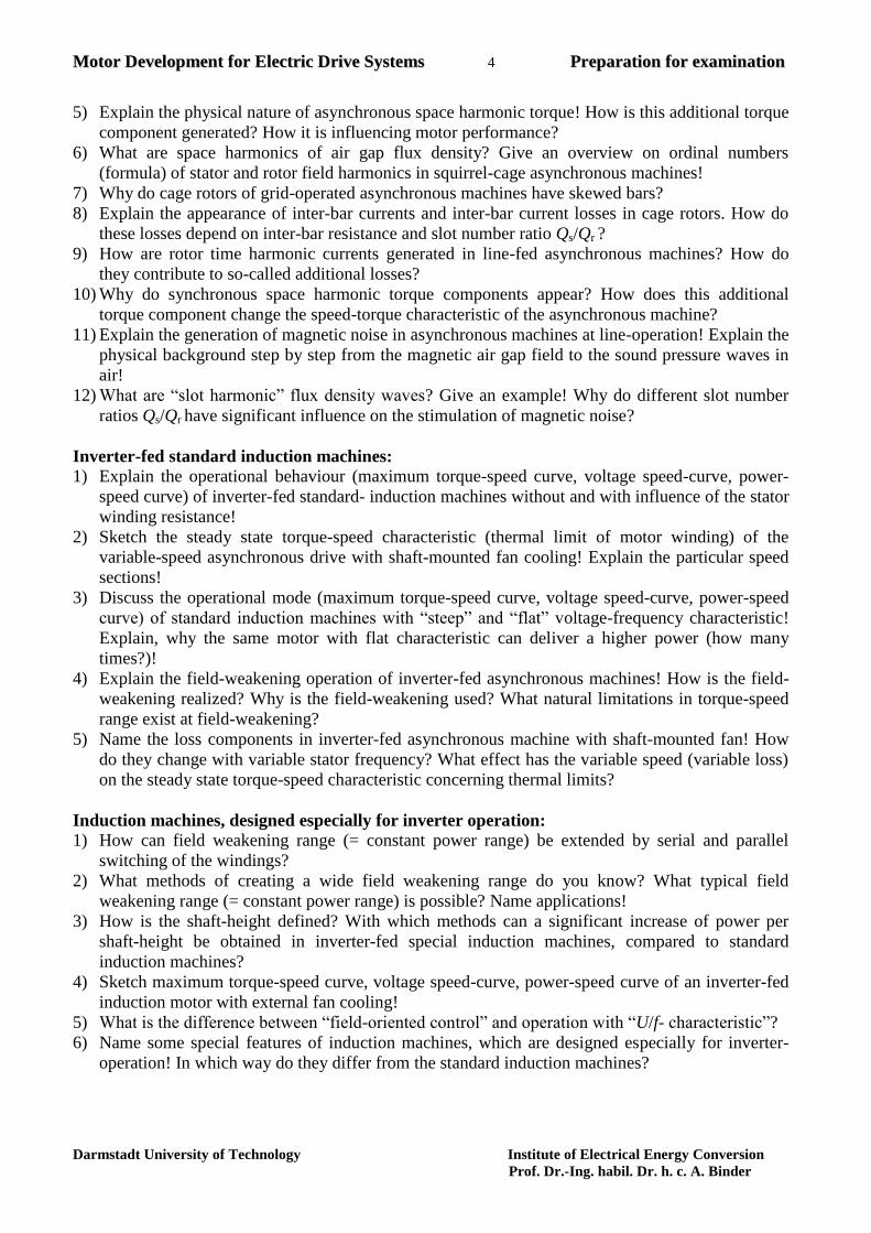
MMoottoorr DDeevveellooppmmeenntt ffoorr EElleeccttrriicc DDrriivvee SSyysstteemmss 4 PPrreeppaarraattiioonn ffoorr eexxaammiinnaattiioonn
Darmstadt University of Technology Institute of Electrical Energy Conversion
Prof. Dr.-Ing. habil. Dr. h. c. A. Binder
5) Explain the physical nature of asynchronous space harmonic torque! How is this additional torque
component generated? How it is influencing motor performance?
6) What are space harmonics of air gap flux density? Give an overview on ordinal numbers
(formula) of stator and rotor field harmonics in squirrel-cage asynchronous machines!
7) Why do cage rotors of grid-operated asynchronous machines have skewed bars?
8) Explain the appearance of inter-bar currents and inter-bar current losses in cage rotors. How do
these losses depend on inter-bar resistance and slot number ratio Qs/Qr ?
9) How are rotor time harmonic currents generated in line-fed asynchronous machines? How do
they contribute to so-called additional losses?
10) Why do synchronous space harmonic torque components appear? How does this additional
torque component change the speed-torque characteristic of the asynchronous machine?
11) Explain the generation of magnetic noise in asynchronous machines at line-operation! Explain the
physical background step by step from the magnetic air gap field to the sound pressure waves in
air!
12) What are “slot harmonic” flux density waves? Give an example! Why do different slot number
ratios Qs/Qr have significant influence on the stimulation of magnetic noise?
Inverter-fed standard induction machines:
1) Explain the operational behaviour (maximum torque-speed curve, voltage speed-curve, power-
speed curve) of inverter-fed standard- induction machines without and with influence of the stator
winding resistance!
2) Sketch the steady state torque-speed characteristic (thermal limit of motor winding) of the
variable-speed asynchronous drive with shaft-mounted fan cooling! Explain the particular speed
sections!
3) Discuss the operational mode (maximum torque-speed curve, voltage speed-curve, power-speed
curve) of standard induction machines with “steep” and “flat” voltage-frequency characteristic!
Explain, why the same motor with flat characteristic can deliver a higher power (how many
times?)!
4) Explain the field-weakening operation of inverter-fed asynchronous machines! How is the field-
weakening realized? Why is the field-weakening used? What natural limitations in torque-speed
range exist at field-weakening?
5) Name the loss components in inverter-fed asynchronous machine with shaft-mounted fan! How
do they change with variable stator frequency? What effect has the variable speed (variable loss)
on the steady state torque-speed characteristic concerning thermal limits?
Induction machines, designed especially for inverter operation:
1) How can field weakening range (= constant power range) be extended by serial and parallel
switching of the windings?
2) What methods of creating a wide field weakening range do you know? What typical field
weakening range (= constant power range) is possible? Name applications!
3) How is the shaft-height defined? With which methods can a significant increase of power per
shaft-height be obtained in inverter-fed special induction machines, compared to standard
induction machines?
4) Sketch maximum torque-speed curve, voltage speed-curve, power-speed curve of an inverter-fed
induction motor with external fan cooling!
5) What is the difference between “field-oriented control” and operation with “U/f- characteristic”?
6) Name some special features of induction machines, which are designed especially for inverter-
operation! In which way do they differ from the standard induction machines?
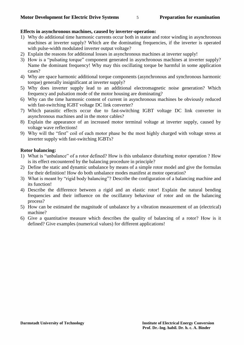
MMoottoorr DDeevveellooppmmeenntt ffoorr EElleeccttrriicc DDrriivvee SSyysstteemmss 5 PPrreeppaarraattiioonn ffoorr eexxaammiinnaattiioonn
Darmstadt University of Technology Institute of Electrical Energy Conversion
Prof. Dr.-Ing. habil. Dr. h. c. A. Binder
Effects in asynchronous machines, caused by inverter-operation:
1) Why do additional time harmonic currents occur both in stator and rotor winding in asynchronous
machines at inverter supply? Which are the dominating frequencies, if the inverter is operated
with pulse-width modulated inverter output voltage?
2) Explain the reasons for additional losses in asynchronous machines at inverter supply!
3) How is a “pulsating torque” component generated in asynchronous machines at inverter supply?
Name the dominant frequency! Why may this oscillating torque be harmful in some application
cases?
4) Why are space harmonic additional torque components (asynchronous and synchronous harmonic
torque) generally insignificant at inverter supply?
5) Why does inverter supply lead to an additional electromagnetic noise generation? Which
frequency and pulsation mode of the motor housing are dominating?
6) Why can the time harmonic content of current in asynchronous machines be obviously reduced
with fast-switching IGBT voltage DC link converter?
7) Which parasitic effects occur due to fast-switching IGBT voltage DC link converter in
asynchronous machines and in the motor cables?
8) Explain the appearance of an increased motor terminal voltage at inverter supply, caused by
voltage wave reflections!
9) Why will the “first” coil of each motor phase be the most highly charged with voltage stress at
inverter supply with fast-switching IGBTs?
Rotor balancing:
1) What is “unbalance” of a rotor defined? How is this unbalance disturbing motor operation ? How
is its effect encountered by the balancing procedure in principle?
2) Define the static and dynamic unbalance by means of a simple rotor model and give the formulas
for their definition! How do both unbalance modes manifest at motor operation?
3) What is meant by “rigid body balancing”? Describe the configuration of a balancing machine and
its function!
4) Describe the difference between a rigid and an elastic rotor! Explain the natural bending
frequencies and their influence on the oscillatory behaviour of rotor and on the balancing
process?
5) How can be estimated the magnitude of unbalance by a vibration measurement of an (electrical)
machine?
6) Give a quantitative measure which describes the quality of balancing of a rotor? How is it
defined? Give examples (numerical values) for different applications!

DARMSTADT UNIVERSITY OF TECHNOLOGY
Department of Electrical Energy Conversion
MD_Tutorial1_PMSM1 Blatt 1
Motor Development for Electric Drive Systems
Tutorial 1
Permanent magnet excited synchronous motor with position encoder and surface magnets
A four-pole permanent magnet synchronous motor shall provide 30 kW continuous power at
a speed of 24000 rpm. It is supplied by an inverter, which uses a filter to provide approxi-
mately sinusoidal voltages. By interpreting the signals of a position encoder, the inverter can
align the current phasor with the back EMF E0. The cooling of the machine is realised using a
water jacket cooling of the stator housing. The main dimensions of the machine are as fol-
lows:
Stator outer/inner diameter 150 mm/90 mm; core length 90 mm; number of stator slots 36;
slot dimension according to the drawing.
Two layer winding; short-pitching 7/9 to reduce the influence of higher harmonics armature
reaction; number of turns per coil 4;
number of parallel paths 2; Y-connection;
diameter of copper wires 0.85 mm; number of conductor elements 7;
magnet material Sm2Co17; magnet height 3.5 mm; pole-pitch factor 87 %;
mechanical air gap 0.7 mm; thickness of bandage 2.8 mm;
end connector length 115 mm
BR T 1.07 1.03
BHC kA/m 720 650
Temp. °C 20 150
1) Calculate the number of turns per phase, the phase resistance at 20°C and 145°C (tem-
perature class F with 40°C water inlet temperature) and the leakage impedance. Take in-
to account the slot and end winding leakage. Due to the large active air gap, the high or-
der harmonics leakage is too small and can be neglected, therefore, like the large syn-
chronous generators, the tooth-top leakage is dominating.
2) Calculate the magnetic operating point under no-load conditions and 150°C magnet tem-
perature (worst case) and the back EMF E0.
3) Estimate the efficiency to be 95% and determine the current consumption and the re-
quired stator voltage for 30kW output power. What is the current density inside the cop-
per conductors?
4) Determine the maximum possible magnitude of the sudden short circuit current. Are the
magnets protected against permanent demagnetisation?

DARMSTADT UNIVERSITY OF TECHNOLOGY
Department of Electrical Energy Conversion
MD_Tutorial2_PMSM2Speed Blatt 1
Motor Development For Electric Drive Systems
Tutorial 2
Permanent magnet synchronous machine with surface magnets
A permanent magnet synchronous machine with 30 kW rated power at 24000 rpm shall be designed with a commercial motor design software. Use the motor calculated in tutorial 1 as benchmark. The most relevant data from tutorial 1 are listed below:
Main dimensions: Stator outer/inner diameter 150 mm/90 mm Stator iron length 90 mm Number of stator slots 36 Mechanical air gap 0.7 mm Bandage thickness 2.8 mm Pole-pitch factor 87%
Slot dimensions: See drawing Slot height 15.66 mm Slot opening 2.3 mm Tooth height 0.64 mm Tooth width 4.15 mm
Magnet data: (20°C) Magnet height 3.5 mm Remanent flux density BR 1.07 T Coercive field strength HC 720 kA/m Material Sm2Co17
Winding data: Y-connection Number of turns per coil 4 Number of parallel paths 2 Copper wire diameter 0.85 mm Number of conductor elements 7 The data for the permanent magnets and the characteristics for the core stack are already prepared and can be found in the files RECOMA 28 and V 250 35. Page 2 shows the labelling of the motor parameters as used by the SPEED software. Fig. 1 shows the geometry of the whole motor, Fig. 2 depicts the rotor parameters and Fig. 3 shows the slot parameters.

DARMSTADT UNIVERSITY OF TECHNOLOGY
Department of Electrical Energy Conversion
MD_Tutorial2_PMSM2Speed Blatt 2
Labelling of the motor parameters as used by SPEED PC-BDC
Fig. 1 Motor dimensions
Fig.3 Slot dimensions
Fig. 2 Rotor dimensions
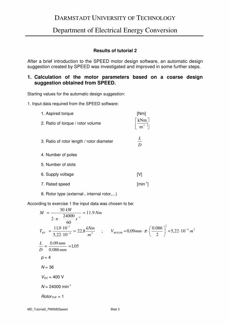
DARMSTADT UNIVERSITY OF TECHNOLOGY
Department of Electrical Energy Conversion
MD_Tutorial2_PMSM2Speed Blatt 3
Results of tutorial 2 After a brief introduction to the SPEED motor design software, an automatic design suggestion created by SPEED was investigated and improved in some further steps.
1. Calculation of the motor parameters based on a coarse design suggestion obtained from SPEED.
Starting values for the automatic design suggestion: 1. Input data required from the SPEED software:
1. Aspired torque [Nm]
2. Ratio of torque / rotor volume
3. Ratio of rotor length / rotor diameter D
L
4. Number of poles
5. Number of slots 6. Supply voltage [V] 7. Rated speed [min-1] 8. Rotor type (external-, internal rotor,...) According to exercise 1 the input data was chosen to be: p = 4 N = 36 VDC = 400 V N = 24000 min-1 RotorTYP = 1
3m
kNm
Nm
s π
kWM 9.11
60
240002
30
1
=
⋅⋅
=
−
34
2
34
3
1022,52
086.009,0;8,22
1022,5
10911mmmV
m
kNm,T
ROTOR
-
RV
−
−⋅=
⋅⋅==
⋅
⋅= π
05,1086.0
09.0==
mm
mm
D
L
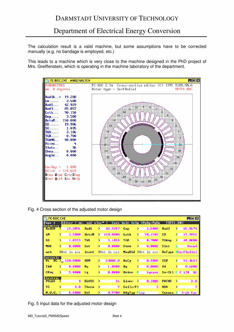
DARMSTADT UNIVERSITY OF TECHNOLOGY
Department of Electrical Energy Conversion
MD_Tutorial2_PMSM2Speed Blatt 4
The calculation result is a valid machine, but some assumptions have to be corrected manually (e.g. no bandage is employed, etc.) This leads to a machine which is very close to the machine designed in the PhD project of Mrs. Greiffenstein, which is operating in the machine laboratory of the department.
Fig. 4 Cross section of the adjusted motor design
Fig. 5 Input data for the adjusted motor design

DARMSTADT UNIVERSITY OF TECHNOLOGY
Department of Electrical Energy Conversion
MD_Tutorial2_PMSM2Speed Blatt 5
Fig. 6 Winding arrangement of one phase
Fig. 7 Simulation results for sinusoidal current supply
Fig. 8 Simulation results for block voltage supply
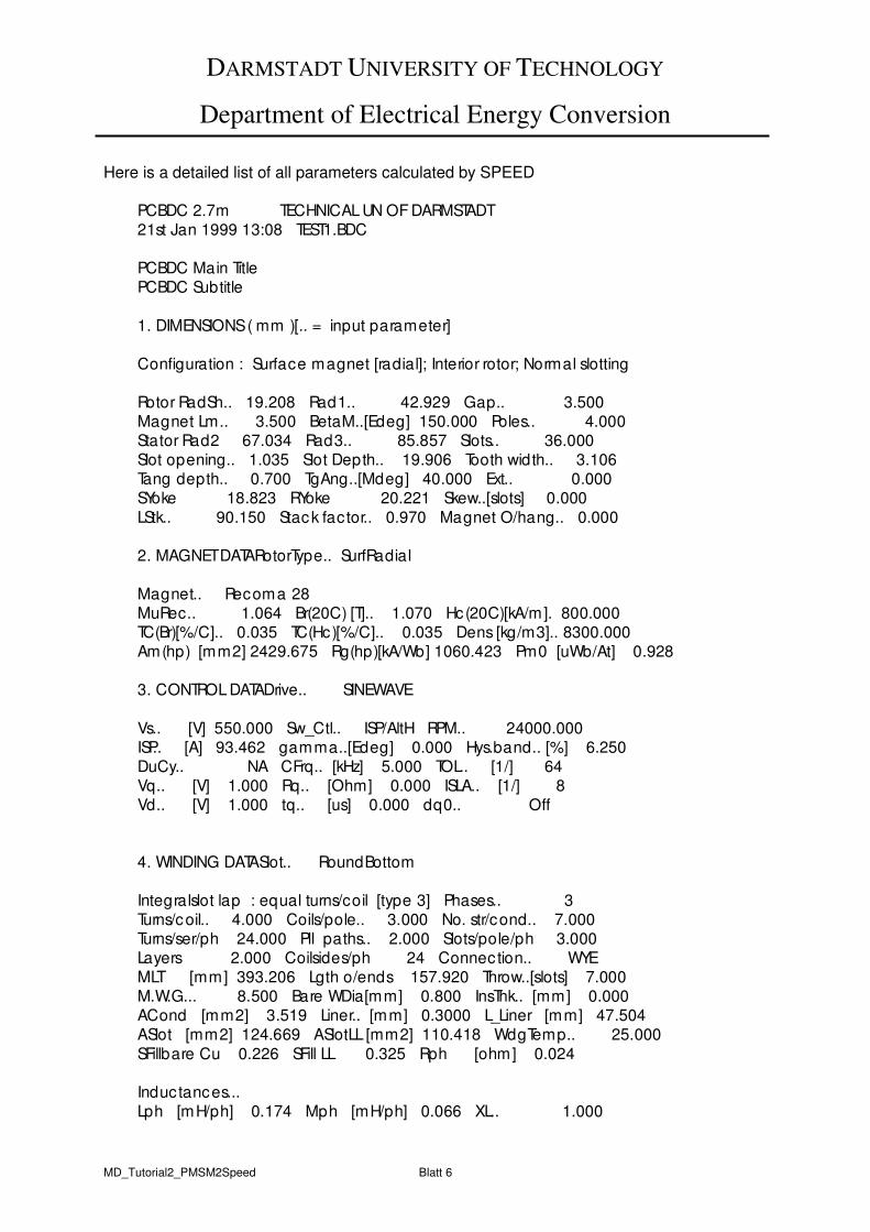
DARMSTADT UNIVERSITY OF TECHNOLOGY
Department of Electrical Energy Conversion
MD_Tutorial2_PMSM2Speed Blatt 6
Here is a detailed list of all parameters calculated by SPEED
PCBDC 2.7m TECHNICAL UN OF DARMSTADT
21st Jan 1999 13:08 TEST1.BDC
PCBDC Main Title
PCBDC Subtitle
1. DIMENSIONS ( mm )[.. = input parameter]
Configuration : Surface magnet [radial]; Interior rotor; Normal slotting
Rotor RadSh.. 19.208 Rad1.. 42.929 Gap.. 3.500
Magnet Lm.. 3.500 BetaM..[Edeg] 150.000 Poles.. 4.000
Stator Rad2 67.034 Rad3.. 85.857 Slots.. 36.000
Slot opening.. 1.035 Slot Depth.. 19.906 Tooth width.. 3.106
Tang depth.. 0.700 TgAng..[Mdeg] 40.000 Ext.. 0.000
SYoke 18.823 RYoke 20.221 Skew..[slots] 0.000
LStk.. 90.150 Stack factor.. 0.970 Magnet O/hang.. 0.000
2. MAGNET DATARotorType.. SurfRadial
Magnet.. Recoma 28
MuRec.. 1.064 Br(20C) [T].. 1.070 Hc(20C)[kA/m]. 800.000
TC(Br)[%/C].. 0.035 TC(Hc)[%/C].. 0.035 Dens [kg/m3].. 8300.000
Am(hp) [mm2] 2429.675 Rg(hp)[kA/Wb] 1060.423 Pm0 [uWb/At] 0.928
3. CONTROL DATADrive.. SINEWAVE
Vs.. [V] 550.000 Sw_Ctl.. ISP/AltH RPM.. 24000.000
ISP.. [A] 93.462 gamma..[Edeg] 0.000 Hys.band.. [%] 6.250
DuCy.. NA CFrq.. [kHz] 5.000 TOL.. [1/] 64
Vq.. [V] 1.000 Rq.. [Ohm] 0.000 ISLA.. [1/] 8
Vd.. [V] 1.000 tq.. [us] 0.000 dq0.. Off
4. WINDING DATASlot.. RoundBottom
Integralslot lap : equal turns/coil [type 3] Phases.. 3
Turns/coil.. 4.000 Coils/pole.. 3.000 No. str/cond.. 7.000
Turns/ser/ph 24.000 Pll paths.. 2.000 Slots/pole/ph 3.000
Layers 2.000 Coilsides/ph 24 Connection.. WYE
MLT [mm] 393.206 Lgth o/ends 157.920 Throw..[slots] 7.000
M.W.G... 8.500 Bare WDia[mm] 0.800 InsThk.. [mm] 0.000
ACond [mm2] 3.519 Liner.. [mm] 0.3000 L_Liner [mm] 47.504
ASlot [mm2] 124.669 ASlotLL [mm2] 110.418 WdgTemp.. 25.000
SFillbare Cu 0.226 SFill LL 0.325 Rph [ohm] 0.024
Inductances...
Lph [mH/ph] 0.174 Mph [mH/ph] 0.066 XL.. 1.000
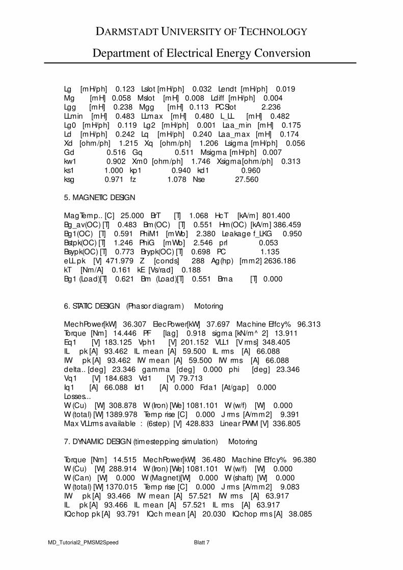
DARMSTADT UNIVERSITY OF TECHNOLOGY
Department of Electrical Energy Conversion
MD_Tutorial2_PMSM2Speed Blatt 7
Lg [mH/ph] 0.123 Lslot [mH/ph] 0.032 Lendt [mH/ph] 0.019 Mg [mH] 0.058 Mslot [mH] 0.008 Ldiff [mH/ph] 0.004 Lgg [mH] 0.238 Mgg [mH] 0.113 PCSlot 2.236
LLmin [mH] 0.483 LLmax [mH] 0.480 L_LL [mH] 0.482 Lg0 [mH/ph] 0.119 Lg2 [mH/ph] 0.001 Laa_min [mH] 0.175 Ld [mH/ph] 0.242 Lq [mH/ph] 0.240 Laa_max [mH] 0.174 Xd [ohm/ph] 1.215 Xq [ohm/ph] 1.206 Lsigma [mH/ph] 0.056
Gd 0.516 Gq 0.511 Msigma [mH/ph] 0.007 kw1 0.902 Xm0 [ohm/ph] 1.746 Xsigma[ohm/ph] 0.313 ks1 1.000 kp1 0.940 kd1 0.960 ksg 0.971 fz 1.078 Nse 27.560
5. MAGNETIC DESIGN
MagTemp.. [C] 25.000 BrT [T] 1.068 HcT [kA/m] 801.400
Bg_av(OC) [T] 0.483 Bm(OC) [T] 0.551 Hm(OC) [kA/m] 386.459 Bg1(OC) [T] 0.591 PhiM1 [mWb] 2.380 Leakage f_LKG 0.950 Bstpk(OC) [T] 1.246 PhiG [mWb] 2.546 prl 0.053 Bsypk(OC) [T] 0.773 Brypk(OC) [T] 0.698 PC 1.135
eLL pk [V] 471.979 Z [conds] 288 Ag(hp) [mm2] 2636.186 kT [Nm/A] 0.161 kE [Vs/rad] 0.188 Bg1 (Load)[T] 0.621 Bm (Load)[T] 0.551 Bma [T] 0.000
6. STATIC DESIGN (Phasor diagram) Motoring
MechPower[kW] 36.307 ElecPower[kW] 37.697 Machine Effcy% 96.313 Torque [Nm] 14.446 PF [lag] 0.918 sigma [kN/m^ 2] 13.911 Eq1 [V] 183.125 Vph1 [V] 201.152 VLL1 [V rms] 348.405 IL pk [A] 93.462 IL mean [A] 59.500 IL rms [A] 66.088
IW pk [A] 93.462 IW mean [A] 59.500 IW rms [A] 66.088 delta.. [deg] 23.346 gamma [deg] 0.000 phi [deg] 23.346 Vq1 [V] 184.683 Vd1 [V] 79.713
Iq1 [A] 66.088 Id1 [A] 0.000 Fda1 [At/gap] 0.000 Losses... W (Cu) [W] 308.878 W (Iron) [We] 1081.101 W (w/f) [W] 0.000 W (total) [W] 1389.978 Temp rise [C] 0.000 J rms [A/mm2] 9.391
Max VLLrms available : (6step) [V] 428.833 Linear PWM [V] 336.805
7. DYNAMIC DESIGN (timestepping simulation) Motoring
Torque [Nm] 14.515 MechPower[kW] 36.480 Machine Effcy% 96.380 W (Cu) [W] 288.914 W (Iron) [We] 1081.101 W (w/f) [W] 0.000 W (Can) [W] 0.000 W (Magnet)[W] 0.000 W (shaft) [W] 0.000
W (total) [W] 1370.015 Temp rise [C] 0.000 J rms [A/mm2] 9.083 IW pk [A] 93.466 IW mean [A] 57.521 IW rms [A] 63.917 IL pk [A] 93.466 IL mean [A] 57.521 IL rms [A] 63.917 IQchop pk [A] 93.791 IQch mean [A] 20.030 IQchop rms [A] 38.085
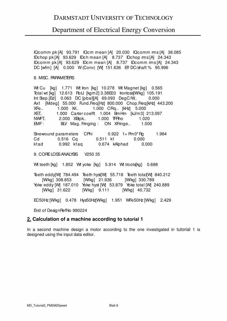
DARMSTADT UNIVERSITY OF TECHNOLOGY
Department of Electrical Energy Conversion
MD_Tutorial2_PMSM2Speed Blatt 8
2. Calculation of a machine according to tutorial 1
In a second machine design a motor according to the one investigated in tutorial 1 is designed using the input data editor.
IQcomm pk [A] 93.791 IQcm mean [A] 20.030 IQcomm rms [A] 38.085 IDchop pk [A] 93.629 IDch mean [A] 8.737 IDchop rms [A] 24.343
IDcomm pk [A] 93.629 IDcm mean [A] 8.737 IDcomm rms [A] 24.343 DC [wfm] [A] 0.000 W (Conv) [W] 151.636 Eff DC/shaft % 95.996
8. MISC. PARAMETERS
Wt Cu [kg] 1.771 Wt Iron [kg] 10.278 Wt Magnet [kg] 0.565 Total wt [kg] 12.613 RotJ [kgm2] 3.38E03 Ironloss[W/kg] 105.191
Int Step.[Ed] 0.063 DC [pbal][A] 69.093 DegC/W.. 0.000 Ax1 [Mdeg] 55.000 Fund.Freq[Hz] 800.000 Chop.Freq[kHz] 443.200
XFe.. 1.000 Xrl.. 1.000 CFrq.. [kHz] 5.000 XET.. 1.000 Carter coefft 1.004 BmHm [kJ/m3] 213.097 NWFT.. 2.000 XBtpk.. 1.000 TFRho 1.020
EMF : BLV Mag. Fringing : ON XFringe.. 1.000
Sinewound parameters CPhi 0.922 1+ Pm0*Rg 1.984 Cd 0.516 Cq 0.511 k1 0.000
k1ad 0.992 k1aq 0.674 kAlphad 0.000
9. CORE LOSS ANALYSIS V250 35
Wt teeth [kg] 1.852 Wt yoke [kg] 5.914 Wt troots[kg] 0.688
Teeth eddy[W] 784.494 Teeth hyst[W] 55.718 Teeth total[W] 840.212
[W/kg] 308.853 [W/kg] 21.936 [W/kg] 330.789 Yoke eddy [W] 187.010 Yoke hyst [W] 53.879 Yoke total [W] 240.889 [W/kg] 31.622 [W/kg] 9.111 [W/kg] 40.732
EC50Hz [W/kg] 0.478 Hys50Hz[W/kg] 1.951 WFe50Hz [W/kg] 2.429
End of DesignRefNo 980224
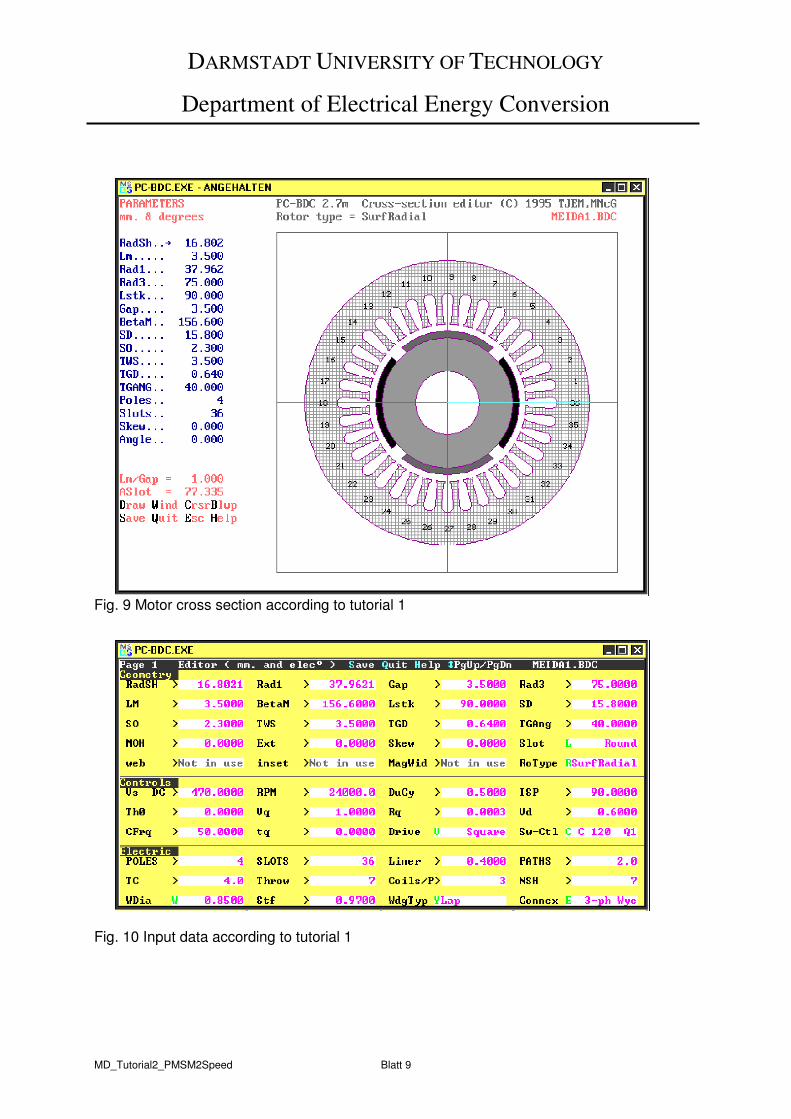
DARMSTADT UNIVERSITY OF TECHNOLOGY
Department of Electrical Energy Conversion
MD_Tutorial2_PMSM2Speed Blatt 9
Fig. 9 Motor cross section according to tutorial 1
Fig. 10 Input data according to tutorial 1
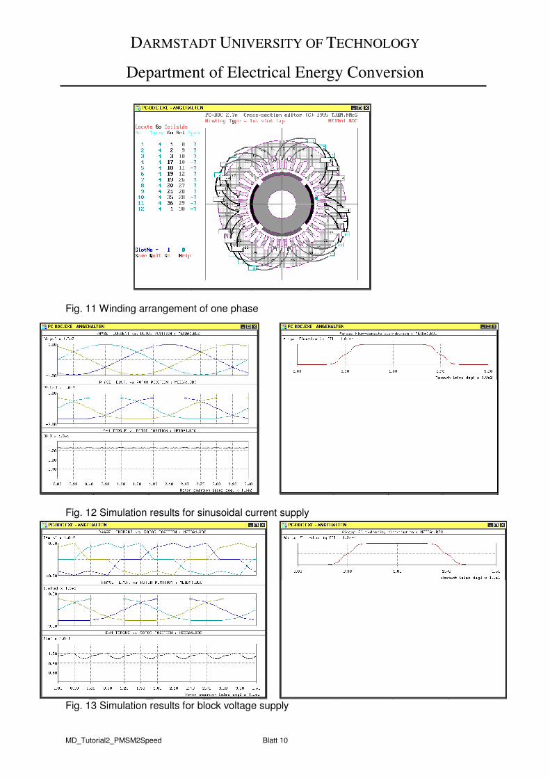
DARMSTADT UNIVERSITY OF TECHNOLOGY
Department of Electrical Energy Conversion
MD_Tutorial2_PMSM2Speed Blatt 10
Fig. 11 Winding arrangement of one phase
Fig. 12 Simulation results for sinusoidal current supply
Fig. 13 Simulation results for block voltage supply

DARMSTADT UNIVERSITY OF TECHNOLOGY
Department of Electrical Energy Conversion
MD_Tutorial2_PMSM2Speed Blatt 11
PCBDC 2.7m TECHNICAL UN OF DARMSTADT
21st Jan 1999 15:20 MEIDA1.BDC
PCBDC Main Title PCBDC Subtitle
1. DIMENSIONS ( mm )[.. = input parameter]
Configuration : Surface magnet [radial]; Interior rotor; Normal slotting
Rotor RadSh.. 16.802 Rad1.. 37.962 Gap.. 3.500
Magnet Lm.. 3.500 BetaM..[Edeg] 156.600 Poles.. 4.000 Stator Rad2 57.902 Rad3.. 75.000 Slots.. 36.000
Slot opening.. 2.300 Slot Depth.. 15.800 Tooth width.. 3.500
Tang depth.. 0.640 TgAng..[Mdeg] 40.000 Ext.. 0.000 SYoke 17.098 RYoke 17.660 Skew..[slots] 0.000
LStk.. 90.000 Stack factor.. 0.970 Magnet O/hang.. 0.000
2. MAGNET DATARotorType.. SurfRadial
Magnet.. Recoma 28
MuRec.. 1.064 Br(20C) [T].. 1.070 Hc(20C)[kA/m]. 800.000
TC(Br)[%/C].. 0.035 TC(Hc)[%/C].. 0.035 Dens [kg/m3].. 8300.000 Am(hp) [mm2] 2226.921 Rg(hp)[kA/Wb] 1163.269 Pm0 [uWb/At] 0.851
3. CONTROL DATADrive.. SQUAREWAVE
Vs.. [V] 470.000 Sw_Ctl.. C 120 Q1 RPM.. 24000.000 ISP.. [A] 90.000 Th0.. [Edeg] 0.000 Hys.band.. [%] 0.391
DuCy.. 0.500 CFrq.. [kHz] 50.000 TOL.. [1/] 2 Vq.. [V] 1.000 Rq.. [Ohm] 0.000 ISLA.. [1/] 32
Vd.. [V] 1.000 tq.. [us] 0.000 dq0.. Off R_s.. [ohm] 0.000
4. WINDING DATASlot.. RoundBottom
Integralslot lap : equal turns/coil [type 3] Phases.. 3
Turns/coil.. 4.000 Coils/pole.. 3.000 No. str/cond.. 7.000
Turns/ser/ph 24.000 Pll paths.. 2.000 Slots/pole/ph 3.000 Layers 2.000 Coilsides/ph 24 Connection.. WYE
MLT [mm] 370.477 Lgth o/ends 150.631 Throw..[slots] 7.000 WDia.. [mm] 0.850 Bare WDia[mm] 0.850 InsThk.. [mm] 0.000
ACond [mm2] 3.972 Liner.. [mm] 0.4000 L_Liner [mm] 38.251
ASlot [mm2] 77.335 ASlotLL [mm2] 62.034 WdgTemp.. 25.000 SFillbare Cu 0.411 SFill LL 0.652 Rph [ohm] 0.020
Inductances...
Lph [mH/ph] 0.151 Mph [mH/ph] 0.058 XL.. 1.000
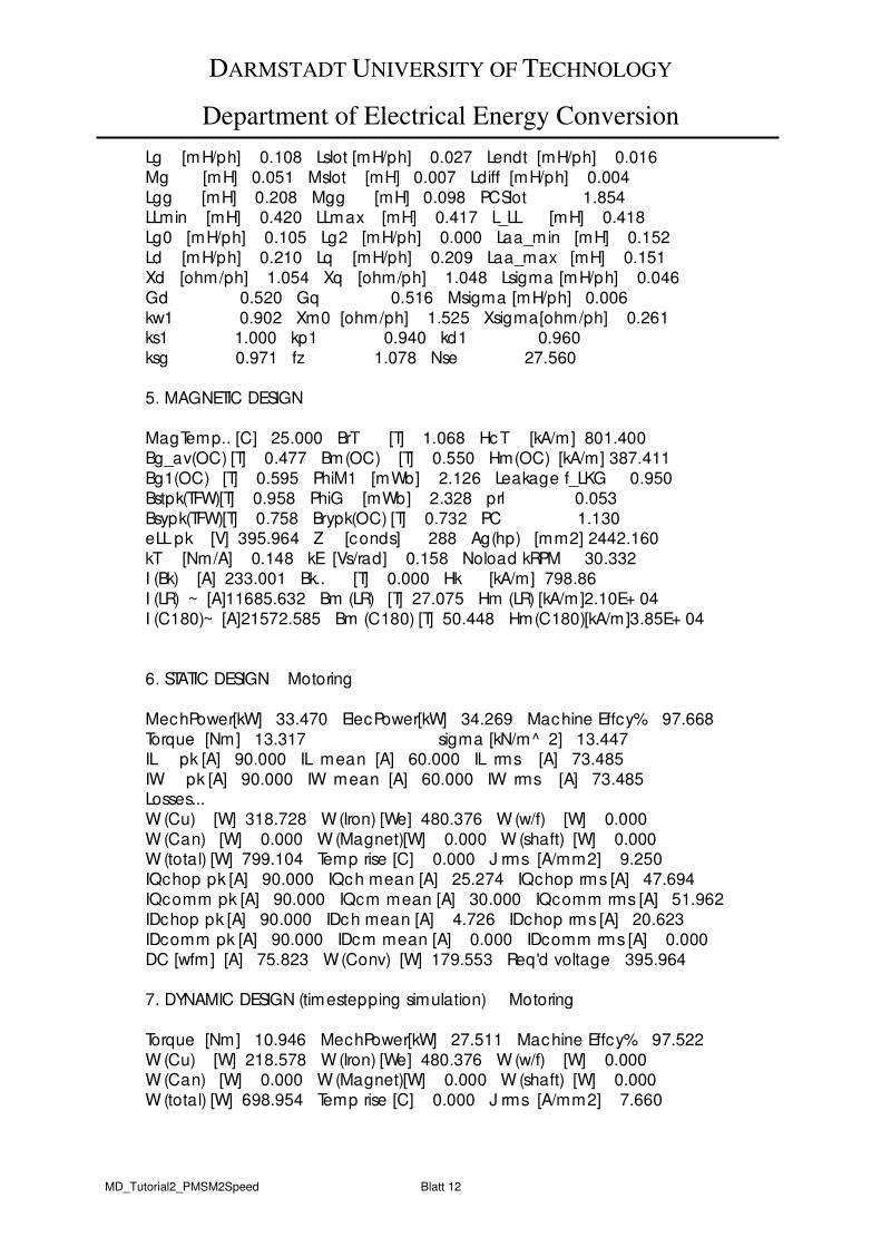
DARMSTADT UNIVERSITY OF TECHNOLOGY
Department of Electrical Energy Conversion
MD_Tutorial2_PMSM2Speed Blatt 12
Lg [mH/ph] 0.108 Lslot [mH/ph] 0.027 Lendt [mH/ph] 0.016
Mg [mH] 0.051 Mslot [mH] 0.007 Ldiff [mH/ph] 0.004
Lgg [mH] 0.208 Mgg [mH] 0.098 PCSlot 1.854 LLmin [mH] 0.420 LLmax [mH] 0.417 L_LL [mH] 0.418
Lg0 [mH/ph] 0.105 Lg2 [mH/ph] 0.000 Laa_min [mH] 0.152
Ld [mH/ph] 0.210 Lq [mH/ph] 0.209 Laa_max [mH] 0.151
Xd [ohm/ph] 1.054 Xq [ohm/ph] 1.048 Lsigma [mH/ph] 0.046
Gd 0.520 Gq 0.516 Msigma [mH/ph] 0.006
kw1 0.902 Xm0 [ohm/ph] 1.525 Xsigma[ohm/ph] 0.261 ks1 1.000 kp1 0.940 kd1 0.960
ksg 0.971 fz 1.078 Nse 27.560
5. MAGNETIC DESIGN
MagTemp.. [C] 25.000 BrT [T] 1.068 HcT [kA/m] 801.400
Bg_av(OC) [T] 0.477 Bm(OC) [T] 0.550 Hm(OC) [kA/m] 387.411
Bg1(OC) [T] 0.595 PhiM1 [mWb] 2.126 Leakage f_LKG 0.950
Bstpk(TFW)[T] 0.958 PhiG [mWb] 2.328 prl 0.053
Bsypk(TFW)[T] 0.758 Brypk(OC) [T] 0.732 PC 1.130 eLL pk [V] 395.964 Z [conds] 288 Ag(hp) [mm2] 2442.160
kT [Nm/A] 0.148 kE [Vs/rad] 0.158 Noload kRPM 30.332
I (Bk) [A] 233.001 Bk.. [T] 0.000 Hk [kA/m] 798.86
I (LR) ~ [A]11685.632 Bm (LR) [T] 27.075 Hm (LR) [kA/m]2.10E+ 04
I (C180)~ [A]21572.585 Bm (C180) [T] 50.448 Hm(C180)[kA/m]3.85E+ 04
6. STATIC DESIGN Motoring
MechPower[kW] 33.470 ElecPower[kW] 34.269 Machine Effcy% 97.668
Torque [Nm] 13.317 sigma [kN/m^ 2] 13.447 IL pk [A] 90.000 IL mean [A] 60.000 IL rms [A] 73.485
IW pk [A] 90.000 IW mean [A] 60.000 IW rms [A] 73.485 Losses...
W (Cu) [W] 318.728 W (Iron) [We] 480.376 W (w/f) [W] 0.000
W (Can) [W] 0.000 W (Magnet)[W] 0.000 W (shaft) [W] 0.000 W (total) [W] 799.104 Temp rise [C] 0.000 J rms [A/mm2] 9.250
IQchop pk [A] 90.000 IQch mean [A] 25.274 IQchop rms [A] 47.694
IQcomm pk [A] 90.000 IQcm mean [A] 30.000 IQcomm rms [A] 51.962
IDchop pk [A] 90.000 IDch mean [A] 4.726 IDchop rms [A] 20.623
IDcomm pk [A] 90.000 IDcm mean [A] 0.000 IDcomm rms [A] 0.000
DC [wfm] [A] 75.823 W (Conv) [W] 179.553 Req'd voltage 395.964
7. DYNAMIC DESIGN (timestepping simulation) Motoring
Torque [Nm] 10.946 MechPower[kW] 27.511 Machine Effcy% 97.522
W (Cu) [W] 218.578 W (Iron) [We] 480.376 W (w/f) [W] 0.000 W (Can) [W] 0.000 W (Magnet)[W] 0.000 W (shaft) [W] 0.000
W (total) [W] 698.954 Temp rise [C] 0.000 J rms [A/mm2] 7.660

DARMSTADT UNIVERSITY OF TECHNOLOGY
Department of Electrical Energy Conversion
MD_Tutorial2_PMSM2Speed Blatt 13
IW pk [A] 89.955 IW mean [A] 51.145 IW rms [A] 60.854
IL pk [A] 89.955 IL mean [A] 51.145 IL rms [A] 60.854 IQchop pk [A] 90.006 IQch mean [A] 22.567 IQchop rms [A] 40.863 IQcomm pk [A] 90.006 IQcm mean [A] 22.770 IQcomm rms [A] 41.085
IDchop pk [A] 90.006 IDch mean [A] 3.004 IDchop rms [A] 13.474 IDcomm pk [A] 89.933 IDcm mean [A] 2.802 IDcomm rms [A] 12.781
DC [wfm] [A] 59.295 W (Conv) [W] 149.986 Eff DC/shaft % 97.007
8. MISC. PARAMETERS
Wt Cu [kg] 1.884 Wt Iron [kg] 8.075 Wt Magnet [kg] 0.518 Total wt [kg] 10.477 RotJ [kgm2] 2.09E03 Ironloss[W/kg] 59.488
Int Step.[Ed] 0.016 DC [pbal][A] 60.341 DegC/W.. 0.000 Ax1 [Mdeg] 55.000 Fund.Freq[Hz] 800.000 Chop.Freq[kHz] 28.800
XFe.. 1.000 Xrl.. 1.000 CFrq.. [kHz] 50.000 XET.. 1.000 Carter coefft 1.020 BmHm [kJ/m3] 213.128 NWFT.. 2.000 XBtpk.. 1.000 TFRho 1.020
EMF : Constructed wfm Mag. Fringing : ON XFringe.. 1.000 ET_rms [mV] 1662.151 EY_rms [mV] 3798.642
9. CORE LOSS ANALYSIS V250 35
Wt teeth [kg] 1.499 Wt yoke [kg] 4.662 Wt troots[kg] 0.703
Teeth eddy[W] 280.461 Teeth hyst[W] 29.498 Teeth total[W] 309.958
[W/kg] 127.364 [W/kg] 13.396 [W/kg] 140.759 Yoke eddy [W] 129.947 Yoke hyst [W] 40.471 Yoke total [W] 170.417 [W/kg] 27.875 [W/kg] 8.681 [W/kg] 36.556
EC50Hz [W/kg] 0.478 Hys50Hz[W/kg] 1.951 WFe50Hz [W/kg] 2.429
End of DesignRefNo 980224
DARMSTADT UNIVERSITY OF TECHNOLOGY
Department of Electrical Energy Conversion
MD_Tutorial3_PM_LinMot1 Blatt 1
Motor Development For Electric Drive Systems
Tutorial 3
Linear motors: generation and characteristics of moving magnetic fields
1) Perform a qualitative comparison of the field excitation (m.m.f.) curve V(x,t) of both a
linear moving and a rotating magnetic field with the following data: q = 1, m = 3, unchorded two-layer winding, sinusoidal three-phase system at time t with iU = 0, iV =
-iW = .ˆ23 I⋅ Check the compliance with the third MAXWELL equation ( 0=Bvdirr
)!
a) Draw 2 poles of the rotating field. b) Generate the linear moving field by "cutting" a four-pole rotating field winding, so that
the end poles only consist of upper or lower layer conductors. How many poles does this moving field winding span? What do the end-pole m.m.f. curves look like, compared to the interior field curves?
2) Fundamental harmonic analysis for task 1): Assume the electric loading A(x,t) to be
sinusoidally distributed and calculate, neglecting iron saturation and slot opening effects
a) the rotating air gap field Bδ(x,t),
b) the linear moving air gap field Bδ(x,t). Take into account that the electric loading is reduced to its half at the end of the winding. Divide the winding zone into the end sections I and III and the middle section II. What special characteristic occurs in the field of the end zones I and III ?
3) Plot the rotating and the linear moving air gap flux density from 2) for three different times
ω t = 0, ω t = π/2, ω t = π. 4) Assume the secondary to be a linear squirrel-cage armature (linear induction machine),
moving with vm, whereas the primary, carrying the linear winding, stands still. Is there any tangential force on the armature if slip s = 0 ? If so, why is that and how does this force act?
5) Like 4), but with a permanent magnet synchronous armature. Does the armature
experience any tangential force? If so, why and which way does this force act?
DARMSTADT UNIVERSITY OF TECHNOLOGY
Department of Electrical Energy Conversion
MD_Tutorial4_PM_LinMot2 Blatt 1
Motor Development For Electric Drive Systems
Tutorial 4
Linear motors with tooth-wound coils A permanent magnet linear motor can also be designed using tooth-wound coils (see also "modular synchronous machine", "fractional slot windings"): In this tutorial we consider a tooth wound linear motor with the following specification: number of slots per pole and phase q = 2/7
air gap δ = 2 mm rated current Ir = 13 A maximum current Imax = 40 A rated speed vr = 2 m/s number of turns per coil NC = 150 number of parallel paths a = 2 wire cross section 0.83 mm number of poles 2p = 14 magnet height hm = 5 mm magnet width 11 mm (2 magnets per pole) remanence flux density BR = 1.2 T
relative magnet permeability µr = 1.05
pole pitch factor αe = 100 % slot-/pole pitch: 26.8/23 mm open rectangular slots:
slot width: 11.8 mm slot height: 23 mm
stator slots skewed by one slot pitch. water jacket cooling 1) Calculate the winding factor of the fundamental harmonic. 2) Calculate the rated normal force and the rated thrust. 3) Calculate the ohmic losses and the efficiency at rated speed vr. Is the motor protected
against permanent demagnetisation if maximum current is employed?
DARMSTADT UNIVERSITY OF TECHNOLOGY
Department of Electrical Energy Conversion
MD_Tutorial5_SRM Blatt 1
Motor Development For Electric Drive Systems
Tutorial 5
Switched Reluctance Machines A four-pole, three phase switched reluctance motor with 7.5 kW rated output power at 1500 rpm (3000 rpm maximum speed) has a rated current of 12 A (rms-value) per phase for temperature class B. The maximum inverter output current is 30 A, the supply voltage is 400 V at 50 Hz. The motor is fan-cooled with a ribbed housing like a standard inverter motor. The following main dimensions have been chosen: Stator outer/inner diameter 209.5 mm/120.9 mm; stator core length 193 mm; air gap
δ = 0.45 mm; number of stator/rotor teeth 12/8; stator/rotor tooth width 16.0/16.7 mm; stator/rotor tooth height 30.5/19 mm; number of turns per coil 61; series connection of all coils; round wire diameter 1.8 mm; coil width/height 9/22.5 mm. 1) Calculate the ratio of peak to r.m.s. current at 120° current flow duration and ideal block
current shape. 2) Calculate the coil resistance at 20°C and at maximum temperature for temperature class
B, according to VDE 0530/1. The end winding length is 43 mm. 3) Determine the direct- and quatrature-axis inductivity for the non-saturated machine using
the CARTER-model. 4) Calculate the internal torque at low speed with 120° block current supply from the change
of the magnetic coenergy, if the flux linkage of the d-axis of the saturated machine has the following charateristic: 5A/0.69Vs, 10A/1.1Vs, 15A/1.25Vs, 24A/1.38Vs, 30A/1.43Vs. Use the data for 15A/1.25Vs and 30A/1.43Vs to linearize the characteristic. In the highly saturated area d- and q-axis flux linkage shall be parallel to each other. Use this data to determine the internal torque at maximum inverter output current and at rated motor current.
5) Check the results from 4) for rated speed (1500 /min), if the measured total losses are
1220 W and if temperature class B is fully exploited. Calculate the electric loading
("current layer") A, the current density J and the product A⋅J and compare it with that of standard induction motors of similar size, temperature class and number of poles (electric loading ca. 300 A/cm, current density ca. 7.5 A/mm2).
6) Estimate the current rise time and assess the maximum speed for pulse control
operation. (guide value: current flow time > 10 times the current rise time)
DARMSTADT UNIVERSITY OF TECHNOLOGY
Department of Electrical Energy Conversion
MD_Tutorial6_IM_Harmonics Blatt 1
Motor Development For Electric Drive Systems
Tutorial 6
Effects of high order harmonics on the grid connected induction motor An induction motor has the following dimensions: Rated voltage UN = 690 V Y, rated current IN = 60 A, rated speed nN = 960 /min, rated
frequency fN = 50 Hz, efficiency η = 0.9, power factor cos ϕN = 0.87. Measured no-load current: I0 = 20 A. Winding data:
Number of turns per coil Nc = 5, chorded two-layer winding w/τp = 7/9 Series connection of all coils per phase: a = 1, number of pole pairs 2p = 6. Dimensions: Stator inner diameter: Di = 250 mm, length of laminated core lFe =250 mm
Number of Stator / Rotor slots Qs/Qr = 54/42, air gap δ = 1 mm Calculate 1) the rated motor power PN, the rated slip sN, the number of turns per phase NPh, the pole
pitch τp, the number of stator slots per pole and phase q, the synchronous rotational speed nsyn and the synchronous speed of the fundamental harmonic vsyn.
2) the ordinal numbers under no-load conditions of the field waves up to the first slot
harmonics pair, the corresponding chording-, distribution- and winding-factors and the magnitudes of the field waves, if saturation of iron is neglected.
3) the slip sν of the νth-harmonic with respect the rotating armature in general and for the 5th harmonic.
4) the slip s of the rotor with respect to the synchronous speed, if the rotor runs
synchronously with the νth harmonic, in general and for the 5th harmonic. 5) the slip condition for the generation of synchronous harmonic torque. Which are the
major synchronous harmonic torque slips for this non-saturated induction machine? 6) the ordinal numbers of the force wave and the excited frequencies generated by the
sinusoidally distributed forces around the surface that are generated by the air gap harmonics and by the magnetic pull.
7) the ordinal numbers of the force wave and the exited frequencies for the induction motor
described above, assuming no eccentricity and draw the corresponding deformation of the stator lamination.
DARMSTADT UNIVERSITY OF TECHNOLOGY
Department of Electrical Energy Conversion
MD_Tutorial7_IM_inverter Blatt 1
Motor Development For Electric Drive Systems
Tutorial 7
Induction motor, fed by a voltage source inverter For an electric vehicle application, an induction motor with a voltage source inverter has to be designed. The battery delivers 120 V and 200 A. The motor is connected to a single-stage gear box and shall provide 14 kW rated power at 1600 min-1. Temporary (2 min.) 20 kW output power is requested. The motor shall operate in constant power mode between 1600 min-1 and 5500 min-1. The following motor with water jacket cooling has been chosen: Stator outer/inner diameter: 180/114.5 mm, length of stator iron core: 165 mm, number of poles: 4, single layer winding, number of stator/rotor slots 36/28, aluminium diecast cage, stator slot fill factor: 42%, stator slot cross section: 80 mm2, air gap 0.5 mm, Blondel leakage
coefficient σ = 0.1. 1) At its voltage limit, the inverter operates with block shape voltages to provide a maximum
possible fundamental harmonic. What is the number of turns per phase if the air gap flux density (fundamental wave) is aspired to be 0.9 T at rated speed?
2) Determine the rated and maximum torque at rated speed. What is the apparent inverter
output power? (Estimate reasonable values for both efficiency and fundamental harmonic power factor) Is the maximum battery current sufficient for maximum torque at rated speed?
3) Calculate the ESSON coefficient of this motor. What are the values of current layer and
current density for this motor? Are these values permitted for water jacket cooled motors?
4) Determine the magnetizing inductance Lh, the leakage inductance Lσ and the breakdown torque Mb at rated speed. (Assume that the total magnetization is 1.5 times that of the air gap magnetization!)
5) What is the maximum speed for constant power operation with 20 kW and 14 kW? Draw
the P(n)-diagram for rated power within a speed range of 0..5500 min-1. 6) Estimate the harmonic currents up to the 13th harmonic. Neglect the influence of ohmic
resistance, take only inductances into consideration. What are the additional ohmic losses in the stator compared to the ohmic losses of the fundamental current?