Motor Control Solutions
56
Motor Control Solutions for the North American Market Data Bulletin 8536DB0901 Rev. 11/11, 1/2013 Retain for future use.
-
Upload
khangminh22 -
Category
Documents
-
view
0 -
download
0
Transcript of Motor Control Solutions
Motor Control Solutionsfor the North American Market
Data Bulletin
8536DB0901
Rev. 11/11, 1/2013
Retain for future use.
Motor Control Solutions 8536DB0901
Table of Contents Rev. 11/11, 1/2013
© 2013 Schneider Electric All Rights Reserved2
Table of Contents
Introduction ................................................................................................ 4
Overview of U.S. Standards and Regulations ......................................... 4
Certification Process ................................................................................. 54
Acceptance of Electrical Equipment in the U.S. .......................................... 4
Structure of a Motor Starter in Accordance with UL508A...................... 5
Feeder Circuits and Branch Circuits ........................................................... 5
Group Motor Installations ...................................................................... 6
Required Functions of Combination Starters .............................................. 7
Combination Starter Construction Types................................................ 8
Disconnecting Means on a Feeder or Branch Circuit ................................ 11
Motor Starter Line Diagrams...................................................................... 11
Disconnecting Means .............................................................................. 11
Industrial Machinery requirements (NFPA79 Section 5.3.3.1 and
UL508A Section 65, 66) ............................................................................ 12
SCCR requirement in UL508A................................................................. 13
Ratings: Tested Combination vs. Component............................................ 13
UL508A Support Websites......................................................................... 14
Combination Starter Components.......................................................... 15
UL98 Manual Disconnect Switches............................................................ 15
TeSys™ GS Disconnect Switches ...................................................... 15
Class 9422 Disconnect Switches ........................................................ 16
UL248 Fuses.............................................................................................. 16
TeSys DF Fuse Holder ......................................................................... 16
Type FB Fuse Holder ........................................................................... 16
UL489 Molded-Case Circuit Breakers........................................................ 17
PowerPact Circuit Breakers and Motor Circuit Protectors.................... 17
UL508 Contactors ...................................................................................... 18
TeSys K, D and F Contactors............................................................... 18
Type S Contactors................................................................................ 23
Definite Purpose Contactors ................................................................ 24
UL508 Overload Relays ............................................................................. 26
TeSys K, D and F Overload Relays ..................................................... 26
TeSys T Motor Management System................................................... 28
UL508 Starters ........................................................................................... 29
Type S Starters .................................................................................... 29
Definite Purpose Starters ..................................................................... 29
UL508 Self-Protected Combination Motor Controller................................. 30
TeSys U................................................................................................ 30
UL508 Manual Self-Protected Combination Motor Controller .................... 30
TeSys GV ............................................................................................. 30
Combination Starter Solutions ............................................................... 31
UL508 Type A ............................................................................................ 31
UL508 Type B ............................................................................................ 31
UL508 Type C............................................................................................ 31
UL508 Type D............................................................................................ 32
UL508 Type E ............................................................................................ 33
UL508 Type F ............................................................................................ 33

8536DB0901 Motor Control Solutions
Rev. 11/11, 1/2013 Table of Contents
© 2013 Schneider Electric All Rights Reserved 3
Group Motor Installations ......................................................................... 6
UL508 Group Motor Installations ............................................................... 35
TeSys™ GV ........................................................................................ 30
Short Circuit Protection for Drives......................................................... 37
Altivar™ 12................................................................................................. 37
Altivar 32 .................................................................................................... 38
Altivar 212 .................................................................................................. 39
Altivar 312 .................................................................................................. 41
Altivar 61 .................................................................................................... 44
Altivar 71 .................................................................................................... 47
Short Circuit Protection for Soft Starters .............................................. 50
Altistart™ 22............................................................................................... 50
Altistart 48 .................................................................................................. 53
Specific Requirements for the Canadian Market .................................. 54
Installation and Product Standards ........................................................... 54
Certification Process ........................................................................... 54
Technical Differences between Canadian and U.S. Standards ........... 54
Full-Load Current, Three-Phase Alternating-Current Motors .............. 55
Motor Control Solutions 8536DB0901
Introduction Rev. 11/11, 1/2013
© 2013 Schneider Electric All Rights Reserved4
Introduction Schneider Electric offers a wide range of solutions to meet your motor
control and protection needs. This data bulletin contains information
regarding the application of those solutions in the United States and
Canada.
Overview of U.S. Standards
and Regulations
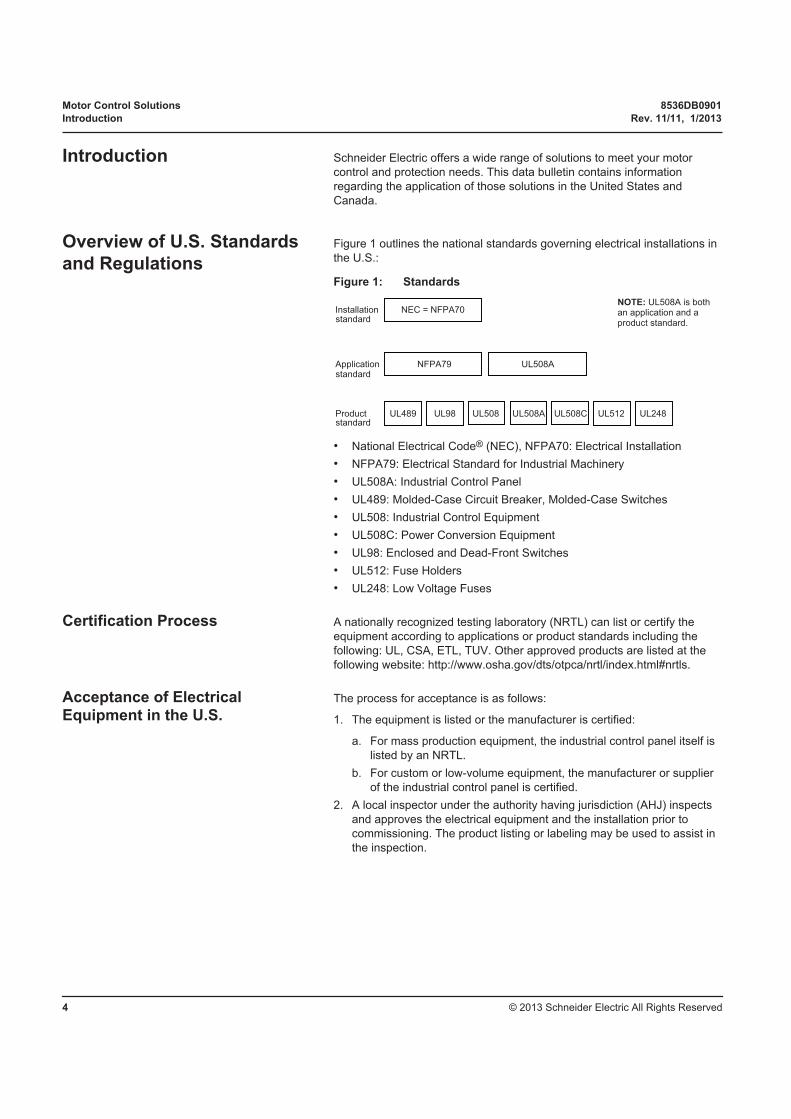
Figure 1 outlines the national standards governing electrical installations in
the U.S.:
• National Electrical Code® (NEC), NFPA70: Electrical Installation
• NFPA79: Electrical Standard for Industrial Machinery
• UL508A: Industrial Control Panel
• UL489: Molded-Case Circuit Breaker, Molded-Case Switches
• UL508: Industrial Control Equipment
• UL508C: Power Conversion Equipment
• UL98: Enclosed and Dead-Front Switches
• UL512: Fuse Holders
• UL248: Low Voltage Fuses
Certification Process A nationally recognized testing laboratory (NRTL) can list or certify the
equipment according to applications or product standards including the
following: UL, CSA, ETL, TUV. Other approved products are listed at the
following website: http://www.osha.gov/dts/otpca/nrtl/index.html#nrtls.
Acceptance of Electrical Equipment in the U.S.
The process for acceptance is as follows:
1. The equipment is listed or the manufacturer is certified:
a. For mass production equipment, the industrial control panel itself is
listed by an NRTL.
b. For custom or low-volume equipment, the manufacturer or supplier
of the industrial control panel is certified.
2. A local inspector under the authority having jurisdiction (AHJ) inspects
and approves the electrical equipment and the installation prior to
commissioning. The product listing or labeling may be used to assist in
the inspection.
Figure 1: Standards
Installation NEC = NFPA70
Application NFPA79
Product UL489 UL98 UL512 UL248
standard
standard
standardUL508A
UL508A
UL508CUL508
NOTE: UL508A is both an application and a product standard.
8536DB0901 Motor Control Solutions
Rev. 11/11, 1/2013 Structure of a Motor Starter in Accordance with UL508A
© 2013 Schneider Electric All Rights Reserved 5
Structure of a Motor Starter
in Accordance with UL508A
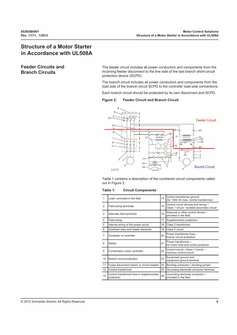
Feeder Circuits and Branch Circuits
The feeder circuit includes all power conductors and components from the
incoming feeder disconnect to the line side of the last branch short-circuit
protection device (SCPD).
The branch circuit includes all power conductors and components from the
load side of the branch circuit SCPD to the controller load-side connections.
Each branch circuit should be protected by its own disconnect and SCPD.
Table 1 contains a description of the numbered circuit components called
out in Figure 2.
Figure 2: Feeder Circuit and Branch Circuit
Table 1: Circuit Components
1 Load—provided in the field 14Control transformer ground (for 1000 VA max. control transformer)
2 Field wiring terminals 15Control circuit devices and wiring—Class 1 circuit—isolated secondary circuit
3 Alternate field terminals 16Solenoid or other control device—provided in the field
4 Field wiring 17 Supplementary protection
5 Internal wiring of the power circuit 18 Class 2 transformer
6 Overload relay and heater elements 19 Class 2 circuit
7 Contactor or controller 20Power transformer fuse—branch circuit protection
8 Starter 21Power transformer—for motor load and control protector
9 Combination motor controller 22Control circuit—Class 1 circuit—common control circuit
10 Branch circuit protection 23Equipment ground and equipment ground terminal
11 Fused disconnect switch or circuit breaker 24 Bonding conductor—bonding jumper
12 Control transformer 25 Grounding electrode conductor terminal
13Control transformer fuse or supplementary protection
26Grounding electrode conductor—provided in the field

Motor Control Solutions 8536DB0901
Structure of a Motor Starter in Accordance with UL508A Rev. 11/11, 1/2013
© 2013 Schneider Electric All Rights Reserved6
Group Motor Installations In a group motor installation, a single disconnecting means and SCPD can
be used for a group of motors. The specific rules are described in NEC
Sections 430-112 and 430-53.
Group motor installations are used in the following applications:
• Fractional hp motors—NEC Section 430.53 (A):
For several motors, each rated 1 hp maximum on a branch circuit of
600 V maximum, a single SCPD not exceeding 15 A is permitted under
the following circumstances:
— No single motor is rated greater than 6 A.
— The branch short-circuit device rating marked on any controller
(UL508 circuit breaker, switch or contactor) is not exceeded.
— Appropriate motor overload protection is used.
• Smallest rated motor protected—NEC Section 430.53 (B):
The SCPD is sized for the motor in the group with the lowest rating.
• Other group installations—NEC Section 430.53 (C):
Two or more motors of any rating, or one or more motors and other
loads, where all the following conditions are met:
— Each motor controller and overload protection device carries a
Motor Group Installation listing.
— Each circuit breaker (if used) is listed and is of the inverse time type.
— The SCPD (fuse or circuit breaker) is sized for the largest motor plus
the sum of all other motors and loads.
— The sizing of the SCPD (fuse or circuit breaker) does not exceed the
maximum allowed for overload protection of the smallest motor.
— Appropriate overcurrent protection is provided for non-motor loads.
Tap Conductor Sizing Rules The tap conductor sizing rules for group motor installations are governed by
NEC Section 430.53 (D). Conductors from the load side of the SCPD for the
motor group must comply with one of the following:
• The ampacity is not less than that of the branch circuit conductors.
• The ampacity is not less than 1/3 of the branch circuit conductors, and
the length is not more than 7.5 m (25 ft).
• The ampacity is not less than 1/10 of the SCPD for the motor group, the
length is not more than 3 m (10 ft), and the manual motor controller is
marked “Suitable for Tap Conductor Protection in Group Installations.”
NOTE: Products certified for motor grouping must carry the markings on the
product label or instruction sheet required by NEC and UL (such as
“Suitable for Tap Conductor Protection in Group Installations”).
For more information, see data bulletin #8502DB0701 entitled “Group Motor
Installations: Understanding NEC 430.53 Requirements.”

8536DB0901 Motor Control Solutions
Rev. 11/11, 1/2013 Required Functions of Combination Starters
© 2013 Schneider Electric All Rights Reserved 7
Required Functions of
Combination Starters
Combination starters are the most common type of packaged motor
controllers. They are called combination because of their construction and
combined functions. NEC Article 430 defines the required functions of
combination starters. Underwriters Laboratories, Inc.® (UL) specifies the
tests and verifications that the components must pass before they can be
listed as suitable for use for those functions.
See Figure 3 for the four component functions that compose a complete
motor branch circuit as defined by the NEC.
Figure 3: Required Functions of Combination Starters
Motor Disconnect
Motor Branch Circuit Protection
Motor Controller
Motor OverloadProtection
Motor Control Solutions 8536DB0901
Combination Starter Construction Types Rev. 11/11, 1/2013
© 2013 Schneider Electric All Rights Reserved8
Combination Starter
Construction Types
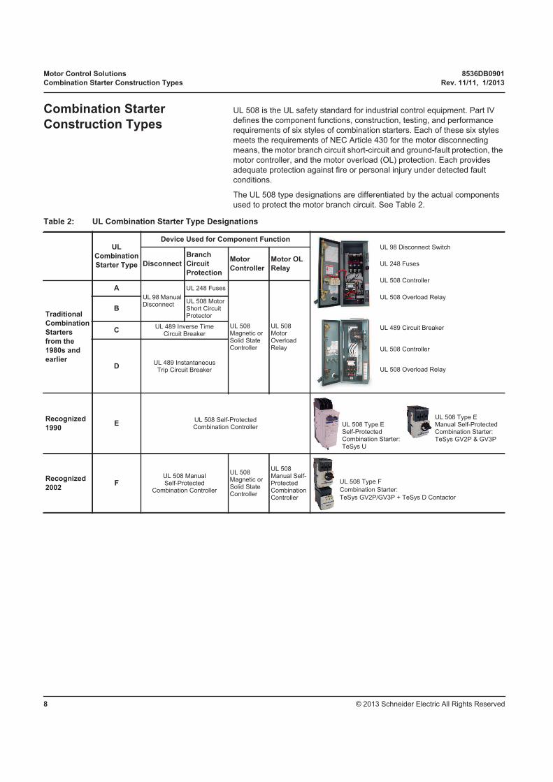
UL 508 is the UL safety standard for industrial control equipment. Part IV
defines the component functions, construction, testing, and performance
requirements of six styles of combination starters. Each of these six styles
meets the requirements of NEC Article 430 for the motor disconnecting
means, the motor branch circuit short-circuit and ground-fault protection, the
motor controller, and the motor overload (OL) protection. Each provides
adequate protection against fire or personal injury under detected fault
conditions.
The UL 508 type designations are differentiated by the actual components
used to protect the motor branch circuit. See Table 2.
Table 2: UL Combination Starter Type Designations
UL
Combination
Starter Type
Device Used for Component Function
Disconnect
Branch
Circuit
Protection
Motor
Controller
Motor OL
Relay
Traditional
Combination
Starters
from the
1980s and
earlier
A
UL 98 Manual Disconnect
UL 248 Fuses
UL 508 Magnetic or Solid State Controller
UL 508 Motor Overload Relay
BUL 508 Motor Short Circuit Protector
CUL 489 Inverse Time
Circuit Breaker
DUL 489 Instantaneous
Trip Circuit Breaker
Recognized
1990E
UL 508 Self-Protected Combination Controller
Recognized
2002F
UL 508 Manual Self-Protected
Combination Controller
UL 508 Magnetic or Solid State Controller
UL 508 Manual Self-Protected Combination Controller
UL 98 Disconnect Switch
UL 248 Fuses
UL 508 Controller
UL 508 Overload Relay
UL 489 Circuit Breaker
UL 508 Controller
UL 508 Overload Relay
UL 508 Type E Self-Protected Combination Starter:
TeSys U
UL 508 Type E Manual Self-Protected Combination Starter:
TeSys GV2P & GV3P
UL 508 Type F
Combination Starter:
TeSys GV2P/GV3P + TeSys D Contactor

8536DB0901 Motor Control Solutions
Rev. 11/11, 1/2013 Combination Starter Construction Types
© 2013 Schneider Electric All Rights Reserved 9
UL Combination Starter Types A through D UL 508 Types A through D combination starters are traditional style starters
that use either a listed disconnect switch and fuses or a listed circuit breaker
as the disconnect means and short circuit protection. Each type uses a
separate UL 508 listed motor controller and overload relay. These starters
are evaluated by UL under the same set of short circuit performance tests.
Each type of combination starters clears detected faults without causing a
fire or posing an electrical shock hazard to personnel. Each type is allowed
to sustain damage that is contained within enclosures and may require the
repair or replacement of devices after performing their protective function.
UL Combination Starter Type E The concept of a self-protected combination starter was introduced from
Europe during the 1980’s. This concept unveiled an integrated device that
performed all the required functions of a combination starter.
The first self-protected combination starters were manual, but by the
mid-1980s, electromechanical self-protected combination starters were also
on the market. These starters cleared detected faults within their rating
without sustaining damage and could be put back into operation.
UL recognized this concept in 1990 and added the Type E self-protected
category for both manual and electromechanical combination starters. UL
added a separate set of short circuit and endurance performance tests to
their 508 standard just for the Type E self-protected category.
UL Combination Starter Type F Many manufacturers and users started combining a manual UL 508 Type E
self-protected starter with a UL 508 contactor and called the combination
“self-protected.” This is not an accurate description since the combination
was not tested in accordance with the requirements of the UL 508 Type E
standard as a combination.
UL addressed this by recognizing a Type F category in 2002. This
combination starter consisted of the manual self-protected starter and
contactor combination. It is evaluated under the same short circuit tests as
Types A through D, but it is not considered self-protected.
Motor Control Solutions 8536DB0901
Combination Starter Construction Types Rev. 11/11, 1/2013
© 2013 Schneider Electric All Rights Reserved10
Self-Protected Designation and Implications
A combination starter must pass certain performance tests specified by
UL 508 before it can be designated as self-protected. The required test
sequence for the Type E self-protected combination starters is listed in UL
508, Table 77.4A. The test sequence includes both high fault and interrupting
ability short circuit (low fault) detection tests, followed by an endurance test.
The tests required for Types A through D and Type F combination starters
are listed in UL 508 Table 77.4. This test sequence does not include the
detection of low fault short circuit tests followed by the endurance test.
This is the difference between the testing and performance of a Type E
self-protected combination starter and the starter types.
Construction Type Selection Panel designers may choose any of the six construction types for their motor
control panel with each construction type offering different advantages.
Construction Types A through D all utilize the same motor controllers and
overload relays. However, they feature different methods to perform
disconnect and branch circuit protection functions:
• Construction Type A is the only construction type that features fuses.
• Type B, which uses an UL 508 motor short circuit protector, is no longer
commercially available.
• Type C utilizes UL 489 inverse time circuit breakers.
• Type D utilizes UL 489 instantaneous trip circuit breakers.
The key distinction between Type A and Type C or D can be simplified to
the selection of a circuit breaker or a fuse for branch circuit protection. A
fuse is an overcurrent protection with a circuit opening fusible part that is
heated and severed by the passage of overcurrent through it. A circuit
breaker is a device designed to open and close a circuit by non-automatic
means and to open the circuit automatically on a predetermined overcurrent
without damage to itself when properly applied within its rating. The key
difference between a fuse and a circuit breaker is that a fuse must be
replaced once it experiences an overcurrent condition while a circuit breaker
is resettable. Additionally, fuses operate independently on each phase while
circuit breakers have three-phase common trip.
Construction Type E self-protected combination controllers and Type F
combination controllers both offer the following advantages for panel
designers:
• Higher coordinated short-circuit withstand ratings on UL 508A panels
• Easier component selection to meet the requirements of group motor
applications
• Reduced panel space by reducing the number of components
• Required product markings to help designers quickly and accurately
select components
• Increased productivity by reducing the number of wiring connections
UL 508 Type E self-protected combination starters also offer the advantage
of reliability. UL 508's special endurance and short-circuit tests ensure a
coordinated combination starter that will clear a detected fault and protect
itself from damage. It is the only category of combination starter that a
designer can easily identify as self-protected due to the required “Self-
Protected Combination Motor Controller” product marking.
8536DB0901 Motor Control Solutions
Rev. 11/11, 1/2013 Combination Starter Construction Types
© 2013 Schneider Electric All Rights Reserved 11
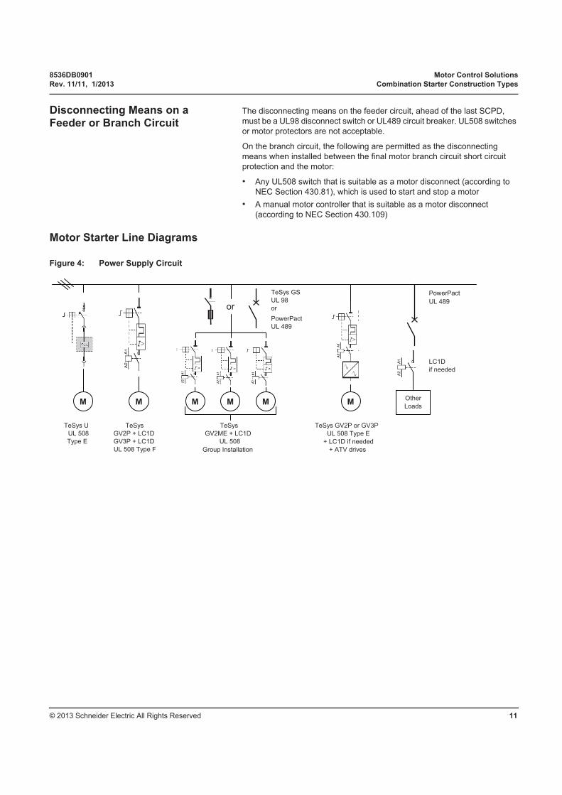
Disconnecting Means on a Feeder or Branch Circuit
The disconnecting means on the feeder circuit, ahead of the last SCPD,
must be a UL98 disconnect switch or UL489 circuit breaker. UL508 switches
or motor protectors are not acceptable.
On the branch circuit, the following are permitted as the disconnecting
means when installed between the final motor branch circuit short circuit
protection and the motor:
• Any UL508 switch that is suitable as a motor disconnect (according to
NEC Section 430.81), which is used to start and stop a motor
• A manual motor controller that is suitable as a motor disconnect
(according to NEC Section 430.109)
Motor Starter Line Diagrams
Figure 4: Power Supply Circuit
or
TeSys GS
UL 98
or
PowerPact
UL 489
PowerPact
UL 489
M
TeSys U
UL 508
Type E
TeSys
GV2P + LC1D
GV3P + LC1D
UL 508 Type F
TeSys
GV2ME + LC1D
UL 508
Group Installation
M M M M M
TeSys GV2P or GV3P
UL 508 Type E
+ LC1D if needed
+ ATV drives
Other
Loads
LC1D
if needed
Motor Control Solutions 8536DB0901
Disconnecting Means Rev. 11/11, 1/2013
© 2013 Schneider Electric All Rights Reserved12
Disconnecting Means A disconnecting means must be provided for each incoming supply (branch)
circuit, and must open each ungrounded conductor of the supply circuit.
The disconnecting means may be one of the following:
• UL489 inverse-time or instantaneous-trip circuit breaker
• UL489 molded-case switch
• UL98 switch unit, either open type or enclosed
For a motor starter, the disconnecting means could be a UL508 Type E
self-protected combination motor controller.
The sizing of the disconnecting means must meet UL508A Section 30.2.
An UL508 manual motor controller or switch (such as the TeSys™ Vario
device) is certified for use on the load side of a motor's branch circuit
protection. This is commonly called a load break switch.
Industrial Machinery Requirements (NFPA79 Section 5.3.3.1 and UL508A Section 65, 66)
These requirements cover industrial control panels for industrial machinery
(NFPA 79-2002, Electrical Standard for Industrial Machinery). The following
types of machines are identified as industrial machinery:
• Metalworking machine tools, including machines that cut or form metal
• Plastics machinery, including injection molding, extrusion, blow molding,
specialized processing, thermoset molding, and size reduction
machines
• Wood machinery, including woodworking, laminating, and sawmill
machines
• Assembly machines
• Material handling machines, including industrial robots and transfer
machines
• Inspection and testing machines, including coordinate measuring and
in-process gauging machines
An operating mechanism for the disconnecting means must have the
following characteristics:
• Readily accessible when the enclosure doors are in the open or closed
position
• Installed so that its operation is not restricted by the enclosure door
while in the open position
• Operable independent of the door position without the use of accessory
tools or devices
• Lockable in the Off position independent of the door position; and, when
the mechanism is locked, the disconnect cannot be closed
The UL98 TeSys GS disconnect switches meet these characteristics:
• The TeSys GS1 disconnect switch requires the use of operating
mechanism GS1AD010 and GS1AD020.
• The TeSys GS2 disconnect switch provides these features (coming
soon).
The UL489 PowerPact Circuit breakers meet these characteristics when
used in conjunction with a Class 9422 or 9421L operating mechanism and
9421LH79 handle.

8536DB0901 Motor Control Solutions
Rev. 11/11, 1/2013 SCCR requirement in UL508A
© 2013 Schneider Electric All Rights Reserved 13
SCCR requirement in UL508A NEC Article 409, NFPA 79, and UL508A require that the SCCR be marked
on all control panels.
The final builder or assembler of the equipment inside the panel is
responsible for providing the SCCR for the overall panel, determined by one
of the following three options:
• Testing each panel construction and recording the construction in the
follow-up procedure. With the multitude of possible product
combinations within a panel, this option may require much testing and
maintenance. Third party testing and certification may also be required.
• Purchasing previously tested constructions (combinations) from a major
supplier of equipment that can be tabulated in the control or machine
panel builder's procedure. Once you have all the component ratings,
either use an outside service or UL 508A, Supplement SB.
• Using a method described in UL 508A, Supplement SB
NOTE: Using the interrupting rating of the main OCPD for the panel is not
an acceptable practice.
Ratings: Tested Combination vs.
Component
UL508A, Supplement SB describes three steps to determine the SCCR of
an industrial control panel. One of those steps is to determine the SCCR of
all the individual power panel components using one of the following
methods:
• Use the SCCR value marked on the component.
• Use assumed SCCRs in Table SB4.1 of Supplement SB.
• Use the tested SCCR from component combinations per UL508.
Method 1 is often called component rating. Component rating involves
looking at each individual component in the circuit and applying the lowest
component rating to the overall system.
Method 2 uses Table SB4.1 (see Table 3) of Supplement SB, which applies
a blanket maximum SCCR for all components. The SCCR for motor
controllers is graduated based on its horsepower rating.
WARNING
INADEQUATE SHORT CIRCUIT INTERRUPTING RATING
Do not use the interrupting rating of the main OCPD as the SCCR rating
for the controller.
Failure to follow these instructions can result in death, serious
injury, or equipment damage.
Table 3: Extract of Table SB4.1
Component Short Circuit Current Rating
Motor controllers (rated in hp)
a. 0–50 5 kA
a. 51–200 10 kA
b. 201–400 18 kA
c. 401–600 30 kA
d. 601–900 42 kA
e. 901–1500 85 kA
Motor Control Solutions 8536DB0901
SCCR requirement in UL508A Rev. 11/11, 1/2013
© 2013 Schneider Electric All Rights Reserved14
Method 3 is often called tested combination rating. Individual motor branch
circuit components are tested together in specific combinations to achieve a
system rating. This system rating is not specifically limited by each
individual component rating.
It is important to note that use of one method only is not required. It is very
common to find systems that utilize two, if not all three, methods for
determinging SCCRs.
Component SCCR ratings offer the user of power control products a great
deal of flexibility in the application of these products. A component SCCR
rating for a contactor and overload relay typically calls for a maximum circuit
breaker size which is not tied to a specific part number or combination of
multiple specific part numbers. A similar scenario exists when using fuses
for short circuit protection of a power control product. A fuse class and
maximum size are what’s called for, not a specific fuse or fuse holder; part
numbers are not necessary. The component ratings for Schneider Electric
contactors, overload relays, and motor starters are printed on the product
labels and/or the product instruction sheets.
UL508A Support Websites Schneider Electric offers UL508A support on our website at
www.Schneider-Electric.us. A number of educational and product search
tools are available on the website, including overview information, a UL
508A SCCR determination flow chart, or information on our individual or
combination product SCCRs. The UL also publishes SCCR tested
combination ratings on its website. Schneider Electric’s updated tested
combination ratings can be found on both websites and is free to download.
Schneider Electric’s UL508A Support Website:
http://www.schneider-electric.us/sites/us/en/support/product-support-
resources/ul-508a-support/ul-508a-support.page
(In the “What’s New” area, select “Fully UL508A Tested and Approved
Combination Spreadsheets Now Available.”)
UL’s UL508A Combination Motor Controller Website:
http://www.ul.com/global/eng/pages/offerings/industries/powerandcontrols/
industrialcontrolequipment/
8536DB0901 Motor Control Solutions
Rev. 11/11, 1/2013 Combination Starter Components
© 2013 Schneider Electric All Rights Reserved 15
Combination Starter Components
UL 98 Manual Disconnect Switches
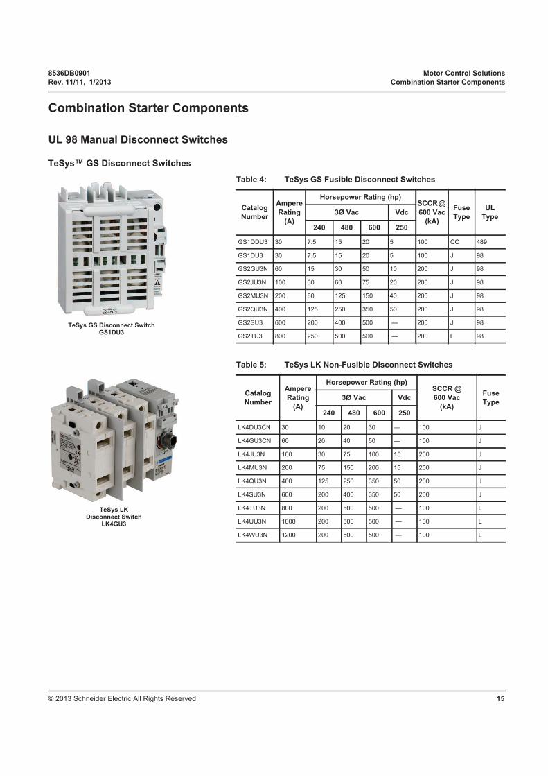
TeSys™ GS Disconnect Switches
Table 4: TeSys GS Fusible Disconnect Switches
Catalog
Number
Ampere
Rating
(A)
Horsepower Rating (hp)SCCR @
600 Vac
(kA)
Fuse
Type
UL
Type3Ø Vac Vdc
240 480 600 250
GS1DDU3 30 7.5 15 20 5 100 CC 489
GS1DU3 30 7.5 15 20 5 100 J 98
GS2GU3N 60 15 30 50 10 200 J 98
GS2JU3N 100 30 60 75 20 200 J 98
GS2MU3N 200 60 125 150 40 200 J 98
GS2QU3N 400 125 250 350 50 200 J 98
GS2SU3 600 200 400 500 — 200 J 98
GS2TU3 800 250 500 500 — 200 L 98
TeSys GS Disconnect SwitchGS1DU3
Table 5: TeSys LK Non-Fusible Disconnect Switches
Catalog
Number
Ampere
Rating
(A)
Horsepower Rating (hp)SCCR @
600 Vac
(kA)
Fuse
Type3Ø Vac Vdc
240 480 600 250
LK4DU3CN 30 10 20 30 — 100 J
LK4GU3CN 60 20 40 50 — 100 J
LK4JU3N 100 30 75 100 15 200 J
LK4MU3N 200 75 150 200 15 200 J
LK4QU3N 400 125 250 350 50 200 J
LK4SU3N 600 200 400 350 50 200 J
LK4TU3N 800 200 500 500 — 100 L
LK4UU3N 1000 200 500 500 — 100 L
LK4WU3N 1200 200 500 500 — 100 L
TeSys LK Disconnect Switch
LK4GU3
Motor Control Solutions 8536DB0901
Combination Starter Components Rev. 11/11, 1/2013
© 2013 Schneider Electric All Rights Reserved16
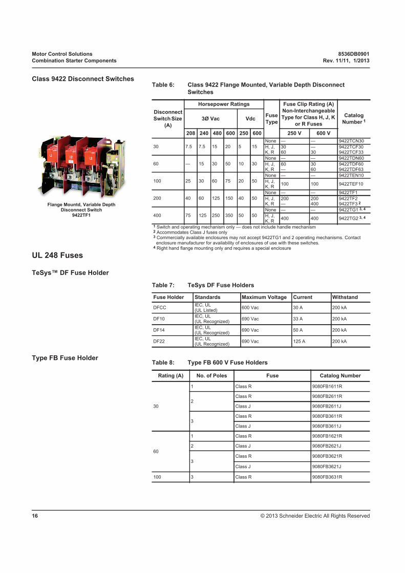
Class 9422 Disconnect Switches
UL 248 Fuses
TeSys™ DF Fuse Holder
Type FB Fuse Holder
Table 6: Class 9422 Flange Mounted, Variable Depth Disconnect
Switches
Disconnect
Switch Size
(A)
Horsepower Ratings
Fuse
Type
Fuse Clip Rating (A)
Non-Interchangeable
Type for Class H, J, K
or R Fuses
Catalog
Number 13Ø Vac Vdc
208 240 480 600 250 600 250 V 600 V
30 7.5 7.5 15 20 5 15
None — — 9422TCN30
H, J,K, R
3060
—30
9422TCF309422TCF33
60 — 15 30 50 10 30
None — — 9422TDN60
H, J,K, R
60—
3060
9422TDF609422TDF63
100 25 30 60 75 20 50
None — — 9422TEN10
H, J,K, R
100 100 9422TEF10
200 40 60 125 150 40 50
None — — 9422TF1
H, J,K, R
200—
200400
9422TF29422TF3 2
400 75 125 250 350 50 50
None — — 9422TG1 3, 4
H, J,K, R
400 400 9422TG2 3, 4
1 Switch and operating mechanism only — does not include handle mechanism2 Accommodates Class J fuses only3 Commercially available enclosures may not accept 9422TG1 and 2 operating mechanisms. Contact
enclosure manufacturer for availability of enclosures of use with these switches.4 Right hand flange mounting only and requires a special enclosure
Flange Mountd, Variable DepthDisconnect Switch
9422TF1
Table 7: TeSys DF Fuse Holders
Fuse Holder Standards Maximum Voltage Current Withstand
DFCCIEC, UL (UL Listed)
600 Vac 30 A 200 kA
DF10IEC, UL (UL Recognized)
690 Vac 33 A 200 kA
DF14IEC, UL (UL Recognized)
690 Vac 50 A 200 kA
DF22IEC, UL (UL Recognized)
690 Vac 125 A 200 kA
Table 8: Type FB 600 V Fuse Holders
Rating (A) No. of Poles Fuse Catalog Number
30
1 Class R 9080FB1611R
2Class R 9080FB2611R
Class J 9080FB2611J
3Class R 9080FB3611R
Class J 9080FB3611J
60
1 Class R 9080FB1621R
2 Class J 9080FB2621J
3Class R 9080FB3621R
Class J 9080FB3621J
100 3 Class R 9080FB3631R

8536DB0901 Motor Control Solutions
Rev. 11/11, 1/2013 Combination Starter Components
© 2013 Schneider Electric All Rights Reserved 17
UL 489 Molded-Case Circuit Breakers
PowerPact Circuit Breakers and Motor Circuit Protectors
Table 9: PowerPact Catalog Numbering System
Frame Rating Termination Poles Voltage Amperage Suffix Code Suffix Code
H G L 3 6 150 AB SA
Frame DesignationInterrupting Rating
Termination Poles Voltage
H 150 A Frame See Table 10 A I-Line 2 2 Poles 2 240 V
J 250 A Frame D Drawout 3 3 Poles 4 480 V
L 600 A Frame F Bus Bar (No Lugs) 4 4 Poles 6 600 V
M 800 A Frame L Lugs on Both Ends
P 1200 A Frame M Lugs Line Side Only
R 3000 A Frame N Plug-in
P Lugs Load Side Only
S Rear Connected Studs
Table 10: PowerPact Interrupting Ratings System
VoltageInterrupting Rataing
D G J K L R
240 Vac 25 kA 65 kA 100 kA 65 kA 125 kA 200 kA
480 Vac 18 kA 35 kA 65 kA 65 kA 100 kA 200 kA
600 Vac 14 kA 13 kA 25 kA 65 kA 50 kA 100 kA
Frame ( X = available)
H-Frame (15-150 A) X X X X X
J-Frame (150-250 A) X X X X X
L-Frame (200-600 A) X X X X X
M-Frame (300-800 A) X X
P-Frame (250-1200 A) X X X 1 X 2
R-Frame (600-3000 A) X X X X
1 P-Frame K-interrupting level is 50kA at 480 Vac and 600 Vac2 P-Frame L-interrupting level is 25kA at 600 Vac

Motor Control Solutions 8536DB0901
Combination Starter Components Rev. 11/11, 1/2013
© 2013 Schneider Electric All Rights Reserved18
UL508 Contactors
TeSys™ K Contactors
Table 11: PowerPact H- and J-Frame Electronic Motor Circuit Protectors (MCP)
Frame CurrentFull Load
(A)
Adjustable
InstantaneousSuffix
J Interrupting L Interrupting
Cat. No. Cat. No.
H-Frame
30 A 1.5–25 A 9–325 A M71 HJL36030M71 HLL36030M71
50 A 14–42 A 84–546 A M72 HJL36050M72 HLL36050M72
100 A 30–80 A 180–1040 A M73 HJL36100M73 HLL36100M73
150 A 58–130 A 348–1690 A M74 HJL36150M74 HLL36150M74
J-Frame 250 A 114–217 A 684–2500 A M75 JJL36250M75 JLL36250M75
Table 12: TeSys K Contactors
Catalog Number
Standard Motor Ratings @ 50/60 Hz (hp)Max. Inductive
AC3
Current (A)
Max. Resistive
AC1
Current (A)
Max. Component
SCCR (kA) 1
1 Ø 3 Ø Circuit
Breakers
@ 480 V 2
Fuses
@ 600 V 3120 V 240 V 208 V 240 V 480 V 600 V
LC1K06 0.5 1.5 1.5 1.5 3 3 6 15 65 100
LC1K09 0.5 1.5 2 3 5 5 9 20 65 100
LC1K12 0.5 1.5 3 3 7.5 10 12 20 65 100
1 Ratings apply to circuits with voltages no greater than those listed.2 When protected by any circuit breaker, including thermal-magnetic and magnetic.3 When protected by any Class J or CC time-delay fuse meeting the size limites in Table 13.NOTE: This table lists the maximum SCCR of the component when protected by any circuit breaker or fuse. If the maximum component SCCR is 65 kA and a 25 kA rated circuit breaker is used, then the system will be 25 kA as the circuit breaker becomes the weakest link.
Table 13: TeSys K Contactor Maximum Component SCCR 1
Catalog Number
Circuit Breakers
@ 480 V 2
Fuses
@ 600 V 3
Max. Breaker Size
(A)
Max.
SCCR (kA)
Max. Fuse Size
(A)
Max.
SCCR (kA)
LC1K06 20 65 25 100
LC1K09 20 65 30 100
LC1K12 20 65 30 100
1 Ratings apply to circuits with voltages no greater than those listed.2 When protected by any circuit breaker, including thermal-magnetic and magnetic-only3 When protected by any Class J or CC time-delay fuseNOTE: This table lists the maximum SCCR of the component when protected by any circuit breaker or fuse. If the maximum component SCCR is 65 kA and a 25 kA rated circuit breaker is used, then the system will be 25 kA as the circuit breaker becomes the weakest link.TeSys K Contactor
LC1K09

8536DB0901 Motor Control Solutions
Rev. 11/11, 1/2013 Combination Starter Components
© 2013 Schneider Electric All Rights Reserved 19
TeSys™ D Contactors
Table 14: TeSys D Contactors
Catalog
Number
Standard Motor Ratings @ 50/60 Hz (hp) Max.
Inductive
AC3
Current
(A)
Max.
Resistive
AC1
Current
(A)
Max. Component SCCR
(kA) 1
1 Ø 3 Ø Circuit Breakers @
480 V 2Fuses @
600 V 3120 V 240 V 208 V 240 V 480 V 600 V
LC1D09 0.5 1 2 2 5 7.5 9 20 85 100
LC1D12 1 2 3 3 7.5 10 12 25 85 100
LC1D18 1 3 5 5 10 15 18 32 85 100
LC1D25 2 3 7.5 7.5 15 20 25 40 85 100
LC1D32 2 5 10 10 20 30 32 50 85 100
LC1D40A 3 5 10 10 30 30 40 60 100 100
LC1D50A 3 7.5 15 15 40 40 50 80 100 100
LC1D65A 5 10 20 20 40 50 65 80 100 100
LC1D80 7.5 15 25 30 60 60 80 125 100 100
LC1D115 — — 30 40 75 100 115 200 100 100
LC1D150 — — 40 50 100 125 150 200 100 100
1 Ratings apply to circuits with voltages no greater than those listed.2 When protected by any circuit breaker, including thermal-magnetic and magnetic-only, meeting the size limits in Table 15.3 When protected by any Class J or CC time-delay fuse meeting the size limites in Table 15.NOTE: This table lists the maximum SCCR of the component when protected by any circuit breaker or fuse. If the maximum component SCCR is 100 kA and a 25 kA rated circuit breaker is used, then the system will be 25 kA as the circuit breaker becomes the weakest link.
TeSys D ContactorLC1D12
Table 15: TeSys D Contactor Maximum Component SCCR 1
Catalog Number
Circuit Breakers
@ 480 V 2
Fuses
@ 600 V 3
Max. Breaker Size
(A)
Max. SCCR
(kA)
Max. Fuse Size
(A)
Max. SCCR
(kA)
LC1D09 35 85 25 100
LC1D12 35 85 30 100
LC1D18 60 85 40 100
LC1D25 60 85 60 100
LC1D32 60 85 80 100
LC1D40A 110 100 90 100
LC1D50A 110 100 110 100
LC1D65A 110 100 125 100
LC1D80 150 100 175 100
LC1D115 250 100 250 100
LC1D150 250 100 300 100
1 Ratings apply to circuits with voltages no greater than those listed.2 When protected by any circuit breaker, including thermal-magnetic and magnetic-only.3 When protected by any Class J or CC time-delay fuse (Class CC applicable up to 30A only).NOTE: This table lists the maximum SCCR of the component when protected by any circuit breaker or fuse. If the maximum component SCCR is 100 kA and a 25 kA rated circuit breaker is used, then the system will be 25 kA as the circuit breaker becomes the weakest link.

Motor Control Solutions 8536DB0901
Combination Starter Components Rev. 11/11, 1/2013
© 2013 Schneider Electric All Rights Reserved20
Additional TeSys™ D Contactor Ratings
1 480 V max.
Table 16: UL/CSA Lighting Ratings @ 575 / 600V
Device Ballast Tungsten
LC1D09 (AC coil only) 20 A 20 A
LC1D12 (AC coil only) 25 A 20 A
LC1D18 (AC coil only) 32 A 25 A
LC1D25 (AC coil only) 40 A 40 A
LC1D32 (AC coil only) 50 A 50 A
LC1DT20 (AC coil only) 20 A 20 A
LC1DT25 (AC coil only) 25 A 25 A
LC1DT32 (AC coil only) 32 A 32 A
LC1DT40 (AC coil only) 40 A 40 A
LC1D40A 60 A 60 A
LC1D50A 70 A 70 A
LC1D65A 80 A 70 A
LC1D80, LC1D80004 100 A 100 A1
LC1D115, LC1D1150004 115 A 115 A1
LC1D150, LC1D1500004 150 A 150 A1
Table 17: Elevator Duty Ratings (hp)
Catalog
Number
1 Ø 3 Ø
240 V 208 V 240 V 480 V 600 V
LC1D12 (AC) 1.5 2 3 7.5 7.5
LC1D25 (AC) 3 5 7.5 15 20
LC1D32 (AC) 5 10 — — —
LC1D40A (AC) — — — — —
LC1D50A (AC) 7.5 10 15 25 30
LC1D65A (AC) 10 15 20 25 30
LC1D80 15 20 25 50 50
LC1D115 — — — — —
LC1D150 15 25 30 60 75
8536DB0901 Motor Control Solutions
Rev. 11/11, 1/2013 Combination Starter Components
© 2013 Schneider Electric All Rights Reserved 21
Additional TeSys™ D Contactor Ratings
Continued
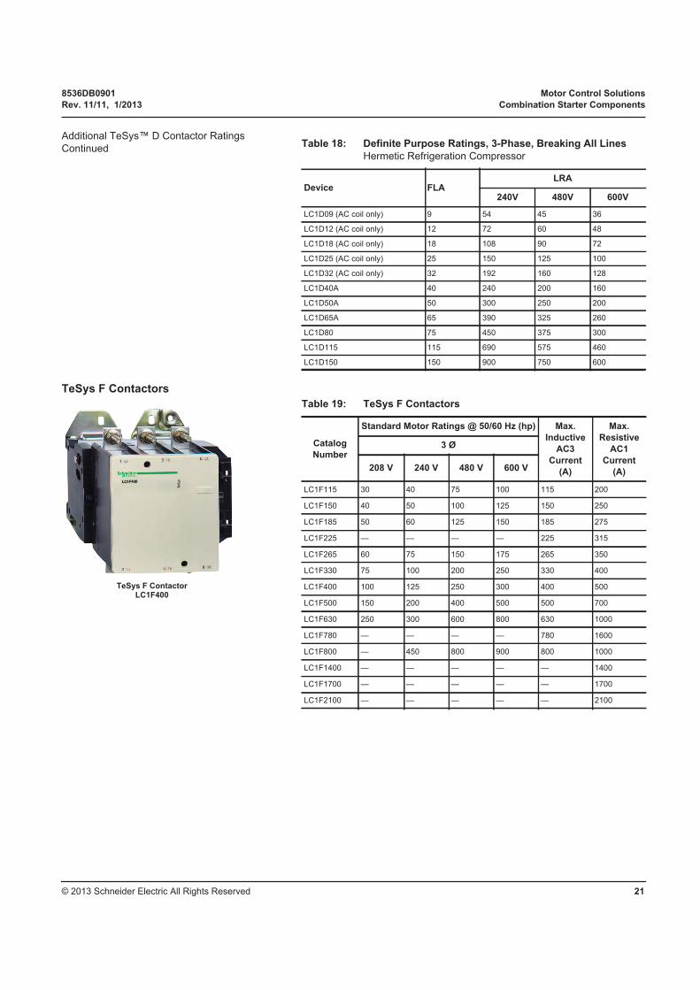
TeSys F Contactors
Table 18: Definite Purpose Ratings, 3-Phase, Breaking All Lines
Hermetic Refrigeration Compressor
Device FLALRA
240V 480V 600V
LC1D09 (AC coil only) 9 54 45 36
LC1D12 (AC coil only) 12 72 60 48
LC1D18 (AC coil only) 18 108 90 72
LC1D25 (AC coil only) 25 150 125 100
LC1D32 (AC coil only) 32 192 160 128
LC1D40A 40 240 200 160
LC1D50A 50 300 250 200
LC1D65A 65 390 325 260
LC1D80 75 450 375 300
LC1D115 115 690 575 460
LC1D150 150 900 750 600
Table 19: TeSys F Contactors
Catalog
Number
Standard Motor Ratings @ 50/60 Hz (hp) Max.
Inductive
AC3
Current
(A)
Max.
Resistive
AC1
Current
(A)
3 Ø
208 V 240 V 480 V 600 V
LC1F115 30 40 75 100 115 200
LC1F150 40 50 100 125 150 250
LC1F185 50 60 125 150 185 275
LC1F225 — — — — 225 315
LC1F265 60 75 150 175 265 350
LC1F330 75 100 200 250 330 400
LC1F400 100 125 250 300 400 500
LC1F500 150 200 400 500 500 700
LC1F630 250 300 600 800 630 1000
LC1F780 — — — — 780 1600
LC1F800 — 450 800 900 800 1000
LC1F1400 — — — — — 1400
LC1F1700 — — — — — 1700
LC1F2100 — — — — — 2100
TeSys F ContactorLC1F400
Motor Control Solutions 8536DB0901
Combination Starter Components Rev. 11/11, 1/2013
© 2013 Schneider Electric All Rights Reserved22
Additional TeSys™ F Contactor Ratings
Table 20: UL/CSA Lighting ratings @ 480 V
3-Pole or 4-Pole Contactor Tungsten Rating Ballast Rating
LC1F115 115 A 115 A
LC1F150 150 A 150 A
LC1F185 200 A 200 A
LC1F265 265 A 265 A
LC1F330 300 A 300 A
Table 21: Elevator Duty Ratings (hp)
Contactor1Ø 3Ø
240 V 208 V 240 V 480 V 600 V
LC1F185 20 25 30 75 75
LC1F265 — 40 40 — —
LC1F330 — 50 50 — —
LC1F400 — 60 60 — —
LC1F500 — 75 75 — —
LC1F630 — 100 100 — —
Table 22: Definite Purpose Ratings, 3-Phase, Breaking All Lines
Hermetic Refrigeration Compressor
Contactor FLALRA
240 V 480 V 600 V
LC1F115 135 800 800 520
LC1F150 150 900 750 700
LC1F185 220 1500 1500 1200
LC1F225 220 1500 1500 1200
LC1F265 270 1800 1900 1500
LC1F400 350 2000 2000 1800
LC1F500 700 4500 4500 4200
LC1F630 880 5000 5000 4850
LC1F780 1330 7500 7500 7290

8536DB0901 Motor Control Solutions
Rev. 11/11, 1/2013 Combination Starter Components
© 2013 Schneider Electric All Rights Reserved 23
Type S Contactors
Type S Contactor8502SAO12
Table 23: Type S Contactors
Catalog
Number
Standard Motor Ratings
@ 50/60 Hz (hp) Max.
Resistive
AC1
Current (A)
NEMA
Size
Max. Component
SCCR (kA) 1
3 Ø Circuit
Breakers
@ 480 V 2
Fuses
@ 600 V200 V 230 V 460 V 575 V
8502SAO12 1.5 1.5 2 2 9 00 100 100 3
8502SBO2 3 3 5 5 18 0 100 100 3
8502SCO2 7.5 7.5 10 10 27 1 100 100 3
8502SDO2 10 15 25 25 45 2 100 100 3
8502SEO2 25 30 50 50 90 3 100 100 3
8502SFO2 40 50 100 100 135 4 100 100 4
8502SGO2 75 100 200 200 270 5 100 100 4
8502SHO2 150 200 400 400 540 6 65 100 4
8502SJO2 — 300 600 600 810 7 30 30
1 Ratings apply to circuits with voltages no greater than those listed.2 When protected by any circuit breaker, including thermal-magnetic and magnetic-only, meeting
the size limits in Table 24.3 When protected by any Class RK5, RK1, T or J fuse, meeting the size limits in Table 24.4 When protected by any Class T or J fuse, meeting the size limits in Table 24.NOTE: This table lists the maximum SCCR of the component when protected by any circuit breaker or fuse. If the maximum component SCCR is 100 kA and a 25 kA rated circuit breaker is used, then the system will be 25 kA as the circuit breaker becomes the weakest link.
Table 24: Type S Contactor Maximum Component SCCR1
Catalog
Number
Circuit Breakers @ 480 V 2 Fuses @ 600 V
Max. Breaker
Size (A)
Max. SCCR
(kA)
Max. Fuse
Size (A)
Max. SCCR
(kA)
8502SAO12 70 100 60 3 100
8502SBO2 70 100 60 3 100
8502SCO2 70 100 60 3 100
8502SDO2 100 100 100 3 100
8502SEO2 150 100 200 3 100
8502SFO2 225 100 200 4 100
8502SGO2 400 100 400 4 100
8502SHO2 800 65 600 4 100
8502SJO2 2000 30 1500 30
1 Ratings apply to circuits with voltages no greater than those listed.2 When protected by any circuit breaker, including thermal-magnetic and magnetic-only.3 When protected by any Class RK5, RK1, T or J fuse.4 When protected by any Class T or J fuse.NOTE: This table lists the maximum SCCR of the component when protected by any circuit breaker or fuse. If the maximum component SCCR is 100 kA and a 25 kA rated circuit breaker is used, then the system will be 25 kA as the circuit breaker becomes the weakest link.
Motor Control Solutions 8536DB0901
Combination Starter Components Rev. 11/11, 1/2013
© 2013 Schneider Electric All Rights Reserved24
Additional Type S Contactor
Ratings
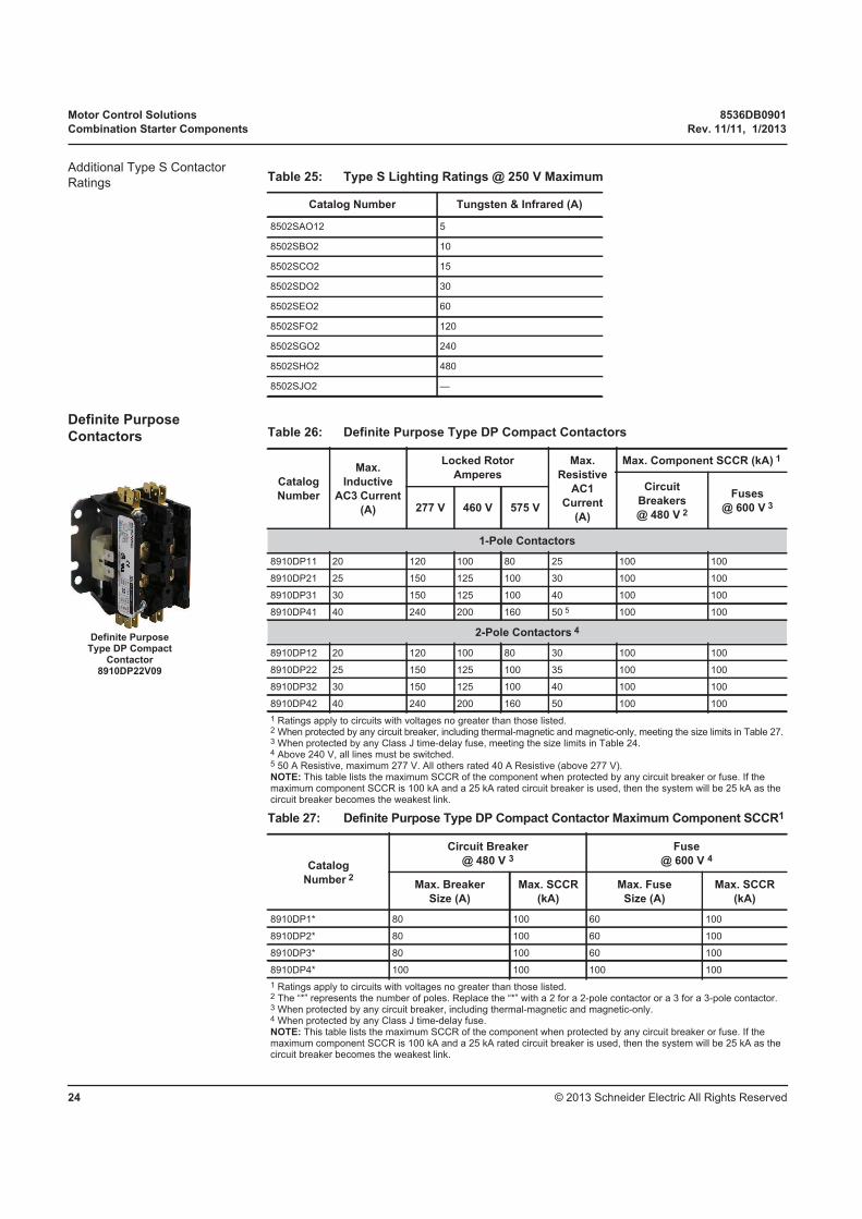
Definite Purpose Contactors
Table 25: Type S Lighting Ratings @ 250 V Maximum
Catalog Number Tungsten & Infrared (A)
8502SAO12 5
8502SBO2 10
8502SCO2 15
8502SDO2 30
8502SEO2 60
8502SFO2 120
8502SGO2 240
8502SHO2 480
8502SJO2 —
Table 26: Definite Purpose Type DP Compact Contactors
Catalog
Number
Max.
Inductive
AC3 Current
(A)
Locked Rotor
Amperes
Max.
Resistive
AC1
Current
(A)
Max. Component SCCR (kA) 1
Circuit
Breakers
@ 480 V 2
Fuses
@ 600 V 3277 V 460 V 575 V
1-Pole Contactors
8910DP11 20 120 100 80 25 100 100
8910DP21 25 150 125 100 30 100 100
8910DP31 30 150 125 100 40 100 100
8910DP41 40 240 200 160 50 5 100 100
2-Pole Contactors 4
8910DP12 20 120 100 80 30 100 100
8910DP22 25 150 125 100 35 100 100
8910DP32 30 150 125 100 40 100 100
8910DP42 40 240 200 160 50 100 100
1 Ratings apply to circuits with voltages no greater than those listed.2 When protected by any circuit breaker, including thermal-magnetic and magnetic-only, meeting the size limits in Table 27.3 When protected by any Class J time-delay fuse, meeting the size limits in Table 24.4 Above 240 V, all lines must be switched.5 50 A Resistive, maximum 277 V. All others rated 40 A Resistive (above 277 V).NOTE: This table lists the maximum SCCR of the component when protected by any circuit breaker or fuse. If the maximum component SCCR is 100 kA and a 25 kA rated circuit breaker is used, then the system will be 25 kA as the circuit breaker becomes the weakest link.
Table 27: Definite Purpose Type DP Compact Contactor Maximum Component SCCR1
Catalog
Number 2
Circuit Breaker
@ 480 V 3Fuse
@ 600 V 4
Max. Breaker
Size (A)
Max. SCCR
(kA)
Max. Fuse
Size (A)
Max. SCCR
(kA)
8910DP1* 80 100 60 100
8910DP2* 80 100 60 100
8910DP3* 80 100 60 100
8910DP4* 100 100 100 100
1 Ratings apply to circuits with voltages no greater than those listed.2 The “*” represents the number of poles. Replace the “*” with a 2 for a 2-pole contactor or a 3 for a 3-pole contactor.3 When protected by any circuit breaker, including thermal-magnetic and magnetic-only.4 When protected by any Class J time-delay fuse.NOTE: This table lists the maximum SCCR of the component when protected by any circuit breaker or fuse. If the maximum component SCCR is 100 kA and a 25 kA rated circuit breaker is used, then the system will be 25 kA as the circuit breaker becomes the weakest link.
Definite PurposeType DP Compact
Contactor8910DP22V09
8536DB0901 Motor Control Solutions
Rev. 11/11, 1/2013 Combination Starter Components
© 2013 Schneider Electric All Rights Reserved 25
Table 28: Definite Purpose Type DPA Contactors 1
Catalog
Number
Max.
Inductive
AC3
Current
(A)
Locked Rotor
Amperes
Max.
Resistive
AC1
Current
(A)
Horsepower Ratings
Po
les
Max. Component
SCCR (kA) 2
1Ø 3Ø Circuit
Breakers
@ 480 V 3
Fuses
@
600 V 4230 V 460 V 575 V 115 V 230 V 230 V 460 V 575 V
8910DPA12
20 120 100 80 30 1.5 3 7.5 7.5 7.5
2
100 1008910DPA13 3
8910DPA14 4
8910DPA22
25 150 125 100 35 2 5 10 15 20
2
100 1008910DPA23 3
8910DPA24 4
8910DPA32
30 180 150 120 40 2 5 10 15 20
2
100 1008910DPA33 3
8910DPA34 4
8910DPA42
40 240 200 160 50 3 7.5 10 20 25
2
100 1008910DPA43 3
8910DPA44 4
8910DPA5250 300 250 200 65 3 10 15 30 30
2100 100
8910DPA53 3
8910DPA6260 360 300 240 75 5 10 25 30 30
2100 100
8910DPA63 3
8910DPA7275 450 375 300 94 5 15 25 40 40
2100 100
8910DPA73 3
8910DPA9290 540 450 360 120 7.5 20 30 50 50
2100 100
8910DPA93 3
1 Above 240 V, all lines must be switched.2 Ratings apply to circuits with voltages no greater than those listed.3 When protected by any circuit breaker, including thermal-magnetic and magnetic-only, meeting the size limits in Table 29.4 When protected by any Class RK5 or J time-delay fuse, meeting the size limits in Table 29.NOTE: This table lists the maximum SCCR of the component when protected by any circuit breaker or fuse. If the maximum component SCCR is 100 kA and a 25 kA rated circuit breaker is used, then the system will be 25 kA as the circuit breaker becomes the weakest link.
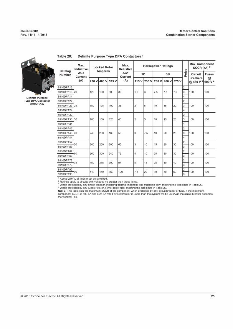
Definite PurposeType DPA Contactor
8910DPA32
Motor Control Solutions 8536DB0901
Combination Starter Components Rev. 11/11, 1/2013
© 2013 Schneider Electric All Rights Reserved26
UL 508 Overload Relays
TeSys™ K Overload Relays
Table 29: Definite Purpose Type DPA Contactor Maximum
Component SCCR1
Catalog
Number 2
Circuit Breaker
@ 480 V 3Fuse
@ 600 V 4
Max. Breaker
Size (A)
Max. SCCR
(kA)
Max. Fuse
Size (A)
Max. SCCR
(kA)
8910DPA1* 80 100 60 100
8910DPA2* 80 100 60 100
8910DPA3* 80 100 60 100
8910DPA4* 100 100 100 100
8910DPA5* 150 100 200 100
8910DPA6* 150 100 200 100
8910DPA7* 225 100 200 100
8910DPA9* 225 100 200 100
1 Ratings apply to circuits with voltages no greater than those listed.2 The “*” represents the number of poles. Replace the “*” with a 2 for a 2-pole contactor or a 3 for
a 3-pole contactor or a 4 for a 4-pole contactor.3 When protected by any circuit breaker, including thermal-magnetic and magnetic-only.4 When protected by any Class RK5 or Class J time-delay fuse.NOTE: This table lists the maximum SCCR of the component when protected by any circuit breaker or fuse. If the maximum component SCCR is 100 kA and a 25 kA rated circuit breaker is used, then the system will be 25 kA as the circuit breaker becomes the weakest link.
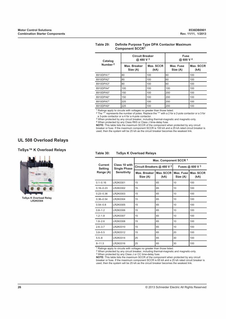
TeSys K Overload RelayLR2K0304
Table 30: TeSys K Overload Relays
Current
Setting
Range (A)
Class 10 with
Single Phase
Sensitivity
Max. Component SCCR 1
Circuit Breakers @ 480 V 2 Fuses @ 600 V 3
Max. Breaker
Size (A)
Max. SCCR
(kA)
Max. Fuse
Size (A)
Max. SCCR
(kA)
0.1–0.16 LR2K0301 15 65 10 100
0.16–0.23 LR2K0302 15 65 10 100
0.23–0.36 LR2K0303 15 65 10 100
0.36–0.54 LR2K0304 15 65 10 100
0.54–0.8 LR2K0305 15 65 10 100
0.8–1.2 LR2K0306 15 65 10 100
1.2–1.8 LR2K0307 15 65 10 100
1.8–2.6 LR2K0308 15 65 10 100
2.6–3.7 LR2K0310 15 65 10 100
3.8–5.5 LR2K0312 15 65 20 100
5.5–8 LR2K0314 25 65 30 100
8–11.5 LR2K0316 25 65 30 100
1 Ratings apply to circuits with voltages no greater than those listed. 2 When protected by any circuit breaker, including thermal-magnetic and magnetic-only.3 When protected by any Class J or CC time-delay fuse.NOTE: This table lists the maximum SCCR of the component when protected by any circuit breaker or fuse. If the maximum component SCCR is 65 kA and a 25 kA rated circuit breaker is used, then the system will be 25 kA as the circuit breaker becomes the weakest link.
8536DB0901 Motor Control Solutions
Rev. 11/11, 1/2013 Combination Starter Components
© 2013 Schneider Electric All Rights Reserved 27
TeSys™ D Overload Relays
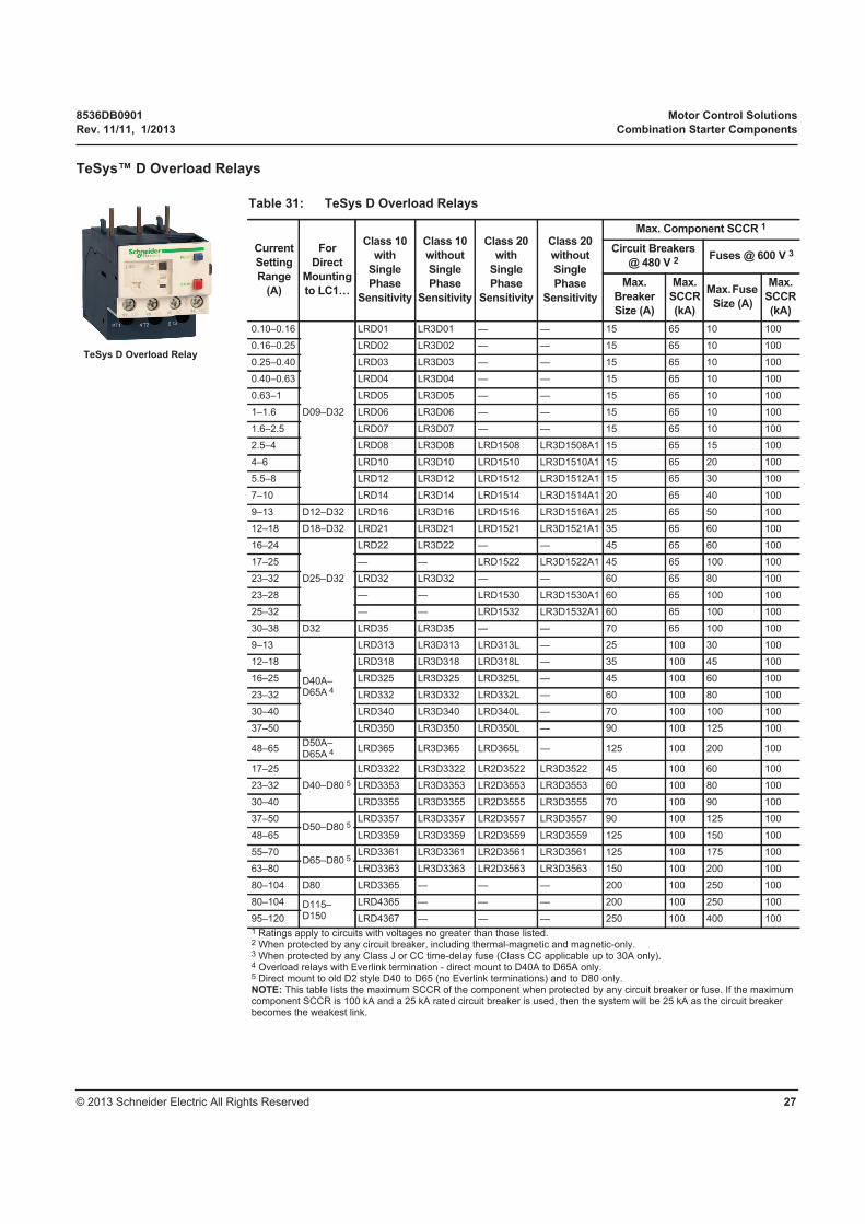
TeSys D Overload Relay
Table 31: TeSys D Overload Relays
Current
Setting
Range
(A)
For
Direct
Mounting
to LC1…
Class 10
with
Single
Phase
Sensitivity
Class 10
without
Single
Phase
Sensitivity
Class 20
with
Single
Phase
Sensitivity
Class 20
without
Single
Phase
Sensitivity
Max. Component SCCR 1
Circuit Breakers
@ 480 V 2Fuses @ 600 V 3
Max.
Breaker
Size (A)
Max.
SCCR
(kA)
Max. Fuse
Size (A)
Max.
SCCR
(kA)
0.10–0.16
D09–D32
LRD01 LR3D01 — — 15 65 10 100
0.16–0.25 LRD02 LR3D02 — — 15 65 10 100
0.25–0.40 LRD03 LR3D03 — — 15 65 10 100
0.40–0.63 LRD04 LR3D04 — — 15 65 10 100
0.63–1 LRD05 LR3D05 — — 15 65 10 100
1–1.6 LRD06 LR3D06 — — 15 65 10 100
1.6–2.5 LRD07 LR3D07 — — 15 65 10 100
2.5–4 LRD08 LR3D08 LRD1508 LR3D1508A1 15 65 15 100
4–6 LRD10 LR3D10 LRD1510 LR3D1510A1 15 65 20 100
5.5–8 LRD12 LR3D12 LRD1512 LR3D1512A1 15 65 30 100
7–10 LRD14 LR3D14 LRD1514 LR3D1514A1 20 65 40 100
9–13 D12–D32 LRD16 LR3D16 LRD1516 LR3D1516A1 25 65 50 100
12–18 D18–D32 LRD21 LR3D21 LRD1521 LR3D1521A1 35 65 60 100
16–24
D25–D32
LRD22 LR3D22 — — 45 65 60 100
17–25 — — LRD1522 LR3D1522A1 45 65 100 100
23–32 LRD32 LR3D32 — — 60 65 80 100
23–28 — — LRD1530 LR3D1530A1 60 65 100 100
25–32 — — LRD1532 LR3D1532A1 60 65 100 100
30–38 D32 LRD35 LR3D35 — — 70 65 100 100
9–13
D40A–D65A 4
LRD313 LR3D313 LRD313L — 25 100 30 100
12–18 LRD318 LR3D318 LRD318L — 35 100 45 100
16–25 LRD325 LR3D325 LRD325L — 45 100 60 100
23–32 LRD332 LR3D332 LRD332L — 60 100 80 100
30–40 LRD340 LR3D340 LRD340L — 70 100 100 100
37–50 LRD350 LR3D350 LRD350L — 90 100 125 100
48–65D50A–D65A 4 LRD365 LR3D365 LRD365L — 125 100 200 100
17–25
D40–D80 5
LRD3322 LR3D3322 LR2D3522 LR3D3522 45 100 60 100
23–32 LRD3353 LR3D3353 LR2D3553 LR3D3553 60 100 80 100
30–40 LRD3355 LR3D3355 LR2D3555 LR3D3555 70 100 90 100
37–50D50–D80 5
LRD3357 LR3D3357 LR2D3557 LR3D3557 90 100 125 100
48–65 LRD3359 LR3D3359 LR2D3559 LR3D3559 125 100 150 100
55–70D65–D80 5
LRD3361 LR3D3361 LR2D3561 LR3D3561 125 100 175 100
63–80 LRD3363 LR3D3363 LR2D3563 LR3D3563 150 100 200 100
80–104 D80 LRD3365 — — — 200 100 250 100
80–104 D115–D150
LRD4365 — — — 200 100 250 100
95–120 LRD4367 — — — 250 100 400 100
1 Ratings apply to circuits with voltages no greater than those listed.2 When protected by any circuit breaker, including thermal-magnetic and magnetic-only.3 When protected by any Class J or CC time-delay fuse (Class CC applicable up to 30A only).4 Overload relays with Everlink termination - direct mount to D40A to D65A only.5 Direct mount to old D2 style D40 to D65 (no Everlink terminations) and to D80 only.NOTE: This table lists the maximum SCCR of the component when protected by any circuit breaker or fuse. If the maximum component SCCR is 100 kA and a 25 kA rated circuit breaker is used, then the system will be 25 kA as the circuit breaker becomes the weakest link.
Motor Control Solutions 8536DB0901
Combination Starter Components Rev. 11/11, 1/2013
© 2013 Schneider Electric All Rights Reserved28
TeSys F Overload Relays
TeSys T Motor Management System
Table 32: TeSys™ D Overload Relays — Solid State
Current
Setting
Range
(A)
For Direct
Mounting
to LC1…
Class 10 Class 20
Class 10
or 20
Selectable
Max. Component SCCR 1
Circuit Breakers
@ 480 V 2Fuses
@ 600 V 3
Max.
Breaker
Size (A)
Max.
SCCR
(kA)
Max.
Fuse
Size (A)
Max.
SCCR
(kA)
60–100 D115–D150 LR9D5367 LR9D5567 LR9D67 175 100 225 100
90–150 D115–D150 LR9D5369 LR9D5569 LR9D69 250 100 400 100
1 Ratings apply to circuits with voltages no greater than those listed.2 When protected by any circuit breaker, including thermal-magnetic and magnetic-only.3 When protected by any Class J time-delay fuse.NOTE: This table lists the maximum SCCR of the component when protected by any circuit breaker or fuse. If the maximum component SCCR is 100 kA and a 25 kA rated circuit breaker is used, then the system will be 25 kA as the circuit breaker becomes the weakest link.
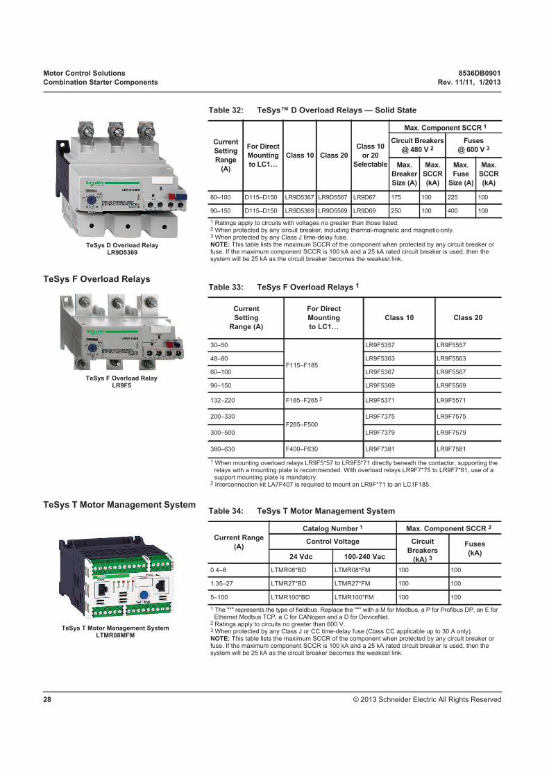
TeSys D Overload RelayLR9D5369
Table 33: TeSys F Overload Relays 1
Current
Setting
Range (A)
For Direct
Mounting
to LC1…
Class 10 Class 20
30–50
F115–F185
LR9F5357 LR9F5557
48–80 LR9F5363 LR9F5563
60–100 LR9F5367 LR9F5567
90–150 LR9F5369 LR9F5569
132–220 F185–F265 2 LR9F5371 LR9F5571
200–330
F265–F500
LR9F7375 LR9F7575
300–500 LR9F7379 LR9F7579
380–630 F400–F630 LR9F7381 LR9F7581
1 When mounting overload relays LR9F5*57 to LR9F5*71 directly beneath the contactor, supporting the relays with a mounting plate is recommended. With overload relays LR9F7*75 to LR9F7*81, use of a support mounting plate is mandatory.
2 Interconnection kit LA7F407 is required to mount an LR9F*71 to an LC1F185.
TeSys F Overload RelayLR9F5
Table 34: TeSys T Motor Management System
Current Range
(A)
Catalog Number 1 Max. Component SCCR 2
Control Voltage Circuit
Breakers
(kA) 3
Fuses
(kA)24 Vdc 100-240 Vac
0.4–8 LTMR08*BD LTMR08*FM 100 100
1.35–27 LTMR27*BD LTMR27*FM 100 100
5–100 LTMR100*BD LTMR100*FM 100 100
1 The "*" represents the type of fieldbus. Replace the "*" with a M for Modbus, a P for Profibus DP, an E for Ethernet Modbus TCP, a C for CANopen and a D for DeviceNet.
2 Ratings apply to circuits no greater than 600 V.3 When protected by any Class J or CC time-delay fuse (Class CC applicable up to 30 A only).NOTE: This table lists the maximum SCCR of the component when protected by any circuit breaker or fuse. If the maximum component SCCR is 100 kA and a 25 kA rated circuit breaker is used, then the system will be 25 kA as the circuit breaker becomes the weakest link.
TeSys T Motor Management SystemLTMR08MFM
8536DB0901 Motor Control Solutions
Rev. 11/11, 1/2013 Combination Starter Components
© 2013 Schneider Electric All Rights Reserved 29
UL508 Starters
Type S Starters
Definite Purpose Starters
Table 35: Type S Starters 1
Catalog
Number
Standard Motor Ratings
@ 50/60 Hz (hp) Continuous
Current
Rating (A)
NEMA
Size3 Ø
200 V 230 V 460 V 575 V
8536SAO12 1.5 1.5 2 2 9 00
8536SBO2 3 3 5 5 18 0
8536SCO2 7.5 7.5 10 10 27 1
8536SDO1 10 15 25 25 45 2
8536SEO1 25 30 50 50 90 3
8536SFO1 40 50 100 100 135 4
8536SGO1 75 100 200 200 270 5
8536SHO2 150 200 400 400 540 6
8536SJO2 — 300 600 600 810 7
1 Type S starters with TeSys T overload relays have the same component short-circuit current ratings as the Type S contactor, shown in Table 23.
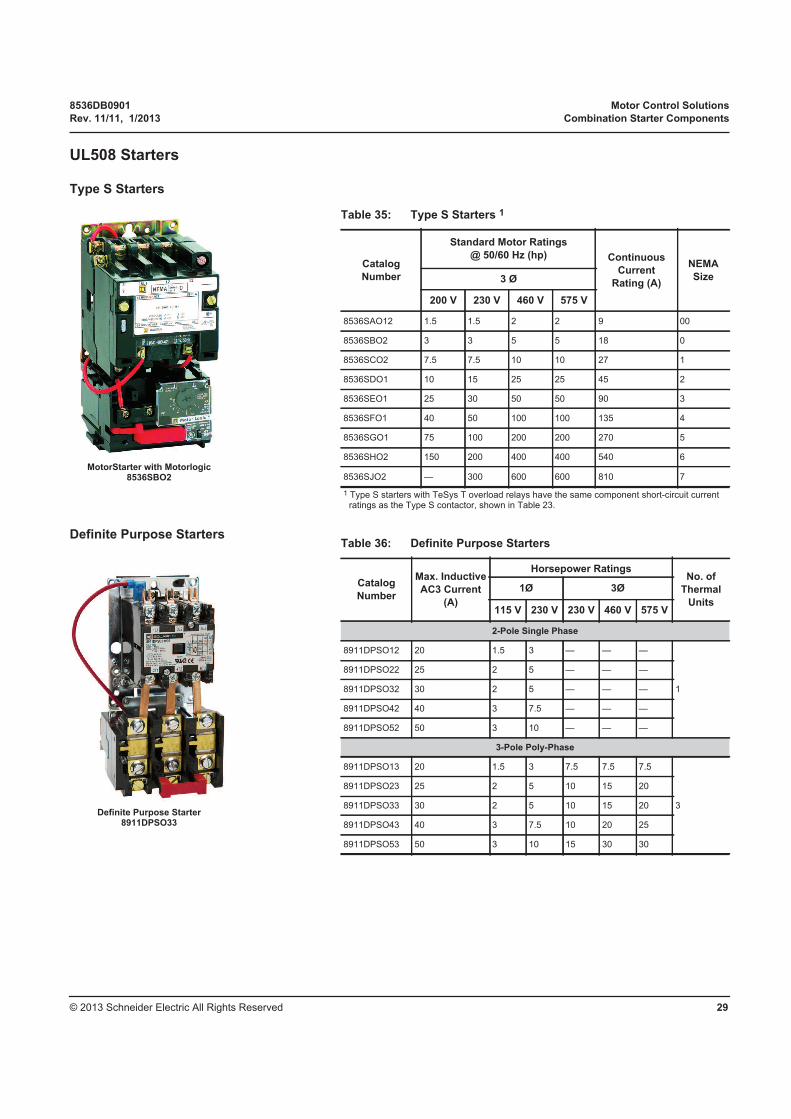
MotorStarter with Motorlogic8536SBO2
Table 36: Definite Purpose Starters
Catalog
Number
Max. Inductive
AC3 Current
(A)
Horsepower RatingsNo. of
Thermal
Units
1Ø 3Ø
115 V 230 V 230 V 460 V 575 V
2-Pole Single Phase
8911DPSO12 20 1.5 3 — — —
1
8911DPSO22 25 2 5 — — —
8911DPSO32 30 2 5 — — —
8911DPSO42 40 3 7.5 — — —
8911DPSO52 50 3 10 — — —
3-Pole Poly-Phase
8911DPSO13 20 1.5 3 7.5 7.5 7.5
3
8911DPSO23 25 2 5 10 15 20
8911DPSO33 30 2 5 10 15 20
8911DPSO43 40 3 7.5 10 20 25
8911DPSO53 50 3 10 15 30 30
Definite Purpose Starter8911DPSO33
Motor Control Solutions 8536DB0901
Combination Starter Components Rev. 11/11, 1/2013
© 2013 Schneider Electric All Rights Reserved30
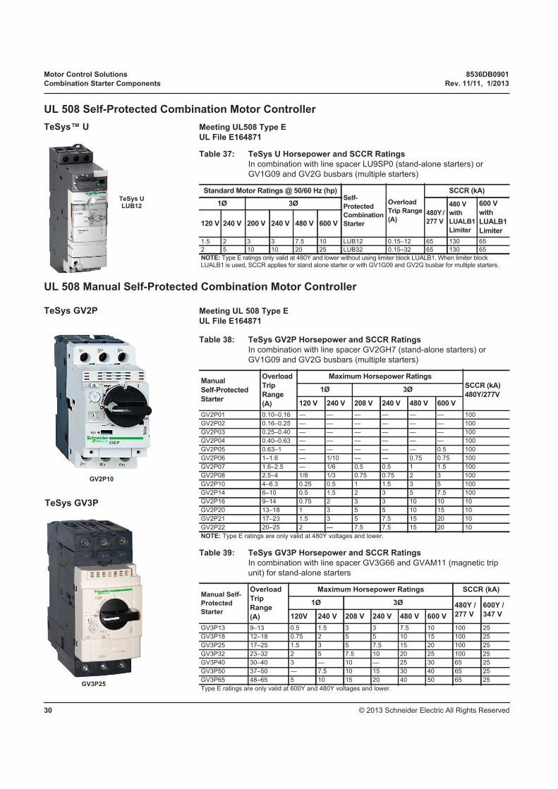
UL 508 Self-Protected Combination Motor Controller
TeSys™ U Meeting UL508 Type E
UL File E164871
UL 508 Manual Self-Protected Combination Motor Controller
TeSys GV2P Meeting UL 508 Type E
UL File E164871
Table 37: TeSys U Horsepower and SCCR Ratings
In combination with line spacer LU9SP0 (stand-alone starters) or
GV1G09 and GV2G busbars (multiple starters)
Standard Motor Ratings @ 50/60 Hz (hp)Self-
Protected
Combination
Starter
Overload
Trip Range
(A)
SCCR (kA)
1Ø 3Ø
480Y /
277 V
480 V
with
LUALB1
Limiter
600 V
with
LUALB1
Limiter 120 V 240 V 200 V 240 V 480 V 600 V
1.5 2 3 3 7.5 10 LUB12 0.15–12 65 130 65
2 5 10 10 20 25 LUB32 0.15–32 65 130 65
NOTE: Type E ratings only valid at 480Y and lower without using limiter block LUALB1. When limiter block LUALB1 is used, SCCR applies for stand alone starter or with GV1G09 and GV2G busbar for multiple starters.
TeSys ULUB12
Table 38: TeSys GV2P Horsepower and SCCR Ratings
In combination with line spacer GV2GH7 (stand-alone starters) or
GV1G09 and GV2G busbars (multiple starters)
Manual
Self-Protected
Starter
Overload
Trip
Range
(A)
Maximum Horsepower Ratings
SCCR (kA)
480Y/277V1Ø 3Ø
120 V 240 V 208 V 240 V 480 V 600 V
GV2P01 0.10–0.16 — — — — — — 100
GV2P02 0.16–0.25 — — — — — — 100
GV2P03 0.25–0.40 — — — — — — 100
GV2P04 0.40–0.63 — — — — — — 100
GV2P05 0.63–1 — — — — — 0.5 100
GV2P06 1–1.6 — 1/10 — — 0.75 0.75 100
GV2P07 1.6–2.5 — 1/6 0.5 0.5 1 1.5 100
GV2P08 2.5–4 1/8 1/3 0.75 0.75 2 3 100
GV2P10 4–6.3 0.25 0.5 1 1.5 3 5 100
GV2P14 6–10 0.5 1.5 2 3 5 7.5 100
GV2P16 9–14 0.75 2 3 3 10 10 10
GV2P20 13–18 1 3 5 5 10 15 10
GV2P21 17–23 1.5 3 5 7.5 15 20 10
GV2P22 20–25 2 — 7.5 7.5 15 20 10
NOTE: Type E ratings are only valid at 480Y voltages and lower.
Table 39: TeSys GV3P Horsepower and SCCR Ratings
In combination with line spacer GV3G66 and GVAM11 (magnetic trip
unit) for stand-alone starters
Manual Self-
Protected
Starter
Overload
Trip
Range
(A)
Maximum Horsepower Ratings SCCR (kA)
1Ø 3Ø 480Y /
277 V
600Y /
347 V 120V 240 V 208 V 240 V 480 V 600 V
GV3P13 9–13 0.5 1.5 3 3 7.5 10 100 25
GV3P18 12–18 0.75 2 5 5 10 15 100 25
GV3P25 17–25 1.5 3 5 7.5 15 20 100 25
GV3P32 23–32 2 5 7.5 10 20 25 100 25
GV3P40 30–40 3 — 10 — 25 30 65 25
GV3P50 37–50 — 7.5 10 15 30 40 65 25
GV3P65 48–65 5 10 15 20 40 50 65 25
Type E ratings are only valid at 600Y and 480Y voltages and lower.
GV2P10
GV3P25
TeSys GV3P
8536DB0901 Motor Control Solutions
Rev. 11/11, 1/2013 Combination Starter Solutions
© 2013 Schneider Electric All Rights Reserved 31
Combination Starter
Solutions
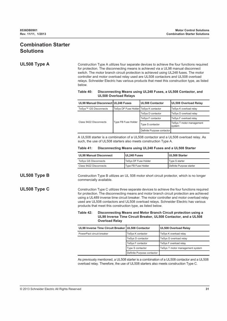
UL508 Type A Construction Type A utilizes four separate devices to achieve the four functions required
for protection. The disconnecting means is achieved via a UL98 manual disconnect
switch. The motor branch circuit protection is achieved using UL248 fuses. The motor
controller and motor overload relay used are UL508 contactors and UL508 overload
relays. Schneider Electric has various products that meet this construction type, as listed
below.
A UL508 starter is a combination of a UL508 contactor and a UL508 overload relay. As
such, the use of UL508 starters also meets construction Type A.
UL508 Type B Construction Type B utilizes an UL 508 motor short circuit protector, which is no longer
commercially available.
UL508 Type C Construction Type C utilizes three separate devices to achieve the four functions required
for protection. The disconnecting means and motor branch circuit protection are achieved
using a UL489 inverse time circuit breaker. The motor controller and motor overload relay
used are UL508 contactors and UL508 overload relays. Schneider Electric has various
products that meet this construction type, as listed below.
As previously mentioned, a UL508 starter is a combination of a UL508 contactor and a UL508
overload relay. Therefore, the use of UL508 starters also meets construction Type C.
Table 40: Disconnecting Means using UL248 Fuses, a UL508 Contactor, and
UL508 Overload Relays
UL98 Manual Disconnect UL248 Fuses UL508 Contactor UL508 Overload Relay
TeSys™ GS Disconnects TeSys DF Fuse Holder TeSys K contactor TeSys K overload relay
Class 9422 Disconnects Type FB Fuse Holder
TeSys D contactor TeSys D overload relay
TeSys F contactor TeSys F overload relay
Type S contactorTeSys T motor management system
Definite Purpose contactor
Table 41: Disconnecting Means using UL248 Fuses and a UL508 Starter
UL98 Manual Disconnect UL248 Fuses UL508 Starter
TeSys GS Disconnects TeSys DF Fuse Holder Type S starter
Class 9422 Disconnects Type FB Fuse Holder Definite Purpose starter
Table 42: Disconnecting Means and Motor Branch Circuit protection using a
UL98 Inverse Time Circuit Breaker, UL508 Contactor, and a UL508
Overload Relay
UL98 Inverse Time Circuit Breaker UL508 Contactor UL508 Overload Relay
PowerPact circuit breaker TeSys K contactor TeSys K overload relay
TeSys D contactor TeSys D overload relay
TeSys F contactor TeSys F overload relay
Type S contactor TeSys T motor management system
Definite Purpose contactor
Motor Control Solutions 8536DB0901
Combination Starter Solutions Rev. 11/11, 1/2013
© 2013 Schneider Electric All Rights Reserved32
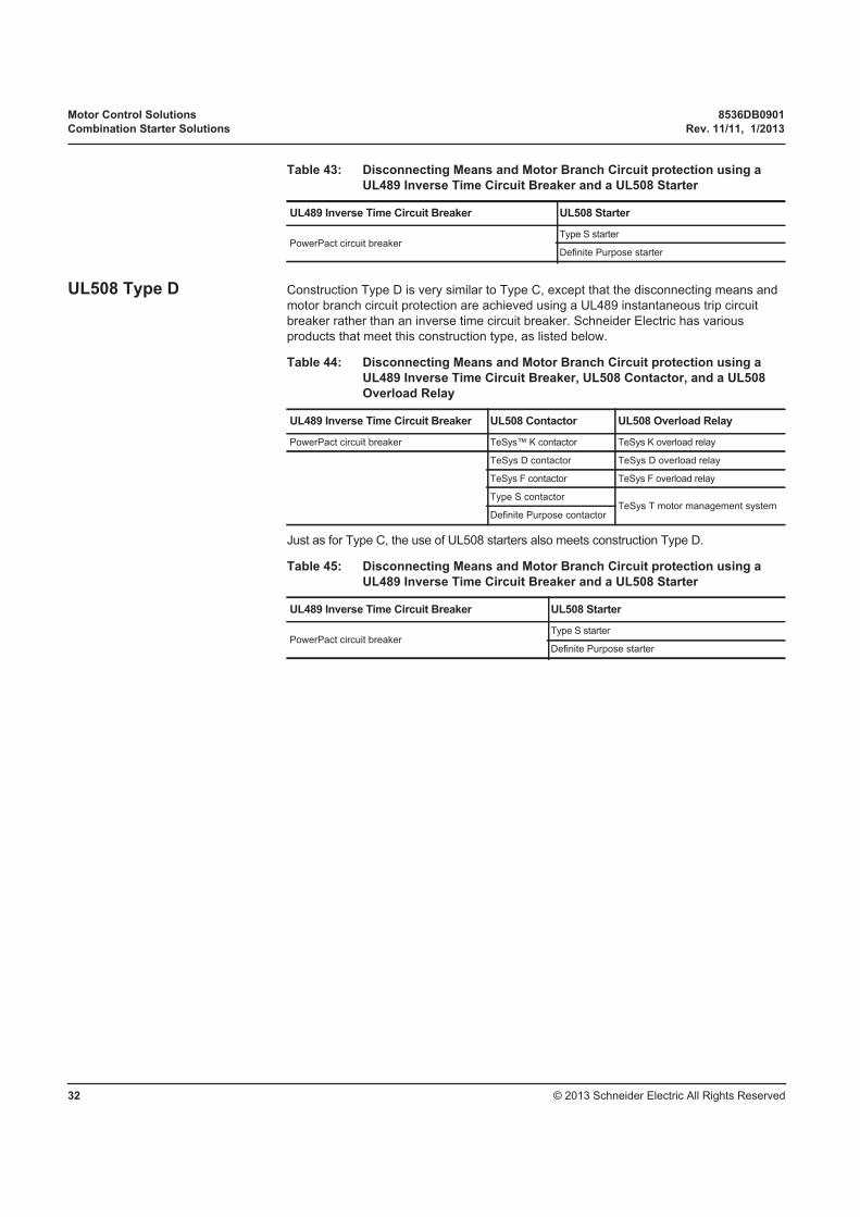
UL508 Type D Construction Type D is very similar to Type C, except that the disconnecting means and
motor branch circuit protection are achieved using a UL489 instantaneous trip circuit
breaker rather than an inverse time circuit breaker. Schneider Electric has various
products that meet this construction type, as listed below.
Just as for Type C, the use of UL508 starters also meets construction Type D.
Table 43: Disconnecting Means and Motor Branch Circuit protection using a
UL489 Inverse Time Circuit Breaker and a UL508 Starter
UL489 Inverse Time Circuit Breaker UL508 Starter
PowerPact circuit breakerType S starter
Definite Purpose starter
Table 44: Disconnecting Means and Motor Branch Circuit protection using a
UL489 Inverse Time Circuit Breaker, UL508 Contactor, and a UL508
Overload Relay
UL489 Inverse Time Circuit Breaker UL508 Contactor UL508 Overload Relay
PowerPact circuit breaker TeSys™ K contactor TeSys K overload relay
TeSys D contactor TeSys D overload relay
TeSys F contactor TeSys F overload relay
Type S contactorTeSys T motor management system
Definite Purpose contactor
Table 45: Disconnecting Means and Motor Branch Circuit protection using a
UL489 Inverse Time Circuit Breaker and a UL508 Starter
UL489 Inverse Time Circuit Breaker UL508 Starter
PowerPact circuit breakerType S starter
Definite Purpose starter
8536DB0901 Motor Control Solutions
Rev. 11/11, 1/2013 Combination Starter Solutions
© 2013 Schneider Electric All Rights Reserved 33
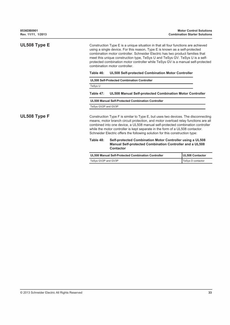
UL508 Type E Construction Type E is a unique situation in that all four functions are achieved
using a single device. For this reason, Type E is known as a self-protected
combination motor controller. Schneider Electric has two product families that
meet this unique construction type, TeSys U and TeSys GV. TeSys U is a self-
protected combination motor controller while TeSys GV is a manual self-protected
combination motor controller.
UL508 Type F Construction Type F is similar to Type E, but uses two devices. The disconnecting
means, motor branch circuit protection, and motor overload relay functions are all
combined into one device, a UL508 manual self-protected combination controller
while the motor controller is kept separate in the form of a UL508 contactor.
Schneider Electric offers the following solution for this construction type:
Table 46: UL508 Self-protected Combination Motor Controller
UL508 Self-Protected Combination Controller
TeSys U
Table 47: UL508 Manual Self-protected Combination Motor Controller
UL508 Manual Self-Protected Combination Controller
TeSys GV2P and GV3P
Table 48: Self-protected Combination Motor Controller using a UL508
Manual Self-protected Combination Controller and a UL508
Contactor
UL508 Manual Self-Protected Combination Controller UL508 Contactor
TeSys GV2P and GV3P TeSys D contactor
Motor Control Solutions 8536DB0901
Combination Starter Solutions Rev. 11/11, 1/2013
© 2013 Schneider Electric All Rights Reserved34
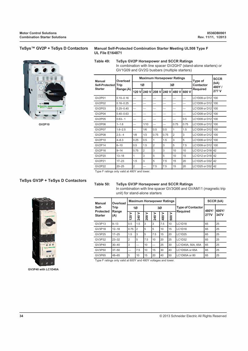
TeSys™ GV2P + TeSys D Contactors Manual Self-Protected Combination Starter Meeting UL508 Type F
UL File E164871
TeSys GV3P + TeSys D Contactors
Table 49: TeSys GV2P Horsepower and SCCR Ratings
In combination with line spacer GV2GH7 (stand-alone starters) or
GV1G09 and GV2G busbars (multiple starters)
Manual
Self-Protected
Starter
Overload
Trip
Range (A)
Maximum Horsepower RatingsType of
Contactor
Required
SCCR
(kA)
480Y /
277 V
1Ø 3Ø
120 V 240 V 208 V 240 V 480 V 600 V
GV2P01 0.10–0.16 — — — — — — LC1D09 or D12 100
GV2P02 0.16–0.25 — — — — — — LC1D09 or D12 100
GV2P03 0.25–0.40 — — — — — — LC1D09 or D12 100
GV2P04 0.40–0.63 — — — — — — LC1D09 or D12 100
GV2P05 0.63– 1 — — — — — 0.5 LC1D09 or D12 100
GV2P06 1–1.6 — 1/10 — — 0.75 0.75 LC1D09 or D12 100
GV2P07 1.6–2.5 — 1/6 0.5 0.5 1 1.5 LC1D09 or D12 100
GV2P08 2.5– 4 1/8 1/3 0.75 0.75 2 3 LC1D09 or D12 100
GV2P10 4–6.3 0.25 0.5 1 1.5 3 5 LC1D09 or D12 100
GV2P14 6–10 0.5 1.5 2 3 5 7.5 LC1D09 or D12 100
GV2P16 9–14 0.75 2 3 3 10 10 LC1D12 or D18 42
GV2P20 13–18 1 3 5 5 10 15 LC1D12 or D18 42
GV2P21 17–23 1.5 3 5 7.5 15 20 LC1D25 or D32 42
GV2P22 20–25 2 — 7.5 7.5 15 20 LC1D25 or D32 42
Type F ratings only valid at 480Y and lower.
GV2P10
Table 50: TeSys GV3P Horsepower and SCCR Ratings
In combination with line spacer GV3G66 and GVAM11 (magnetic trip
unit) for stand-alone starters
Manual
Self-
Protected
Starter
Overload
Trip
Range
(A)
Maximum Horsepower Ratings
Type of Contactor
Required
SCCR (kA)
1Ø 3Ø480Y/
277V
600Y/
347V
120 V
240 V
208 V
240 V
480 V
600 V
GV3P13 9–13 0.5 1.5 3 3 7.5 10 LC1D18 65 25
GV3P18 12–18 0.75 2 5 5 10 15 LC1D18 65 25
GV3P25 17–25 1.5 3 5 7.5 15 20 LC1D25 65 25
GV3P32 23–32 2 5 7.5 10 20 25 LC1D32 65 25
GV3P40 30–40 3 — 10 — 25 30 LC1D40A, 50A, 65A 65 25
GV3P50 37–50 — 7.5 10 15 30 40 LC1D50A or 65A 65 25
GV3P65 48–65 5 10 15 20 40 50 LC1D65A or 80 65 25
Type F ratings only valid at 600Y and 480Y voltages and lower.
GV3P40 with LC1D40A

8536DB0901 Motor Control Solutions
Rev. 11/11, 1/2013 Group Motor Installations
© 2013 Schneider Electric All Rights Reserved 35
Group Motor Installations
UL508 Group Motor Installations
TeSys™ GV2ME
GV2ME: UL File E164864
GV2ME07
Table 51: TeSys GV2ME Horsepower and SCCR Ratings
In association with LC1D contactors, suitable for Group Installation when protected by fuses or a circuit breaker
(including multi starter with GV1G09 or GV2G05 blocks plus GV2G busbars)
Manual
Motor Starter
Overload Trip
Range
(A)
Maximum Horsepower Ratings SCCR (kA) 1
1Ø 3ØType of
Contactor
Required
480 V600Y /
347 V
480 V
with
GV1L3
Limiter
Contactor
for 600 V
with
LA9LB920
600 V
with
LA9LB920120 V 240 V 208 V 240 V 480 V 600 V
GV2ME01 0.10–0.16 — — — — — — LC1D09 or D12 65 42 65 LC1D09 or D12 42
GV2ME02 0.16–0.25 — — — — — — LC1D09 or D12 65 42 65 LC1D09 or D12 42
GV2ME03 0.25–0.40 — — — — — — LC1D09 or D12 65 42 65 LC1D09 or D12 42
GV2ME04 0.40–0.63 — — — — — — LC1D09 or D12 65 42 65 LC1D09 or D12 42
GV2ME05 0.63–1 — — — — — 0.5 LC1D09 or D12 65 42 65 LC1D09 or D12 42
GV2ME06 1–1.6 — 1/10 — — 0.75 0.75 LC1D09 or D12 65 42 65 LC1D09 or D12 42
GV2ME07 1.6–2.5 — 1/6 0.5 0.5 1 1.5 LC1D09 or D12 65 42 65 LC1D09 or D12 42
GV2ME08 2.5–4 1/8 1/3 0.75 0.75 2 3 LC1D09 or D12 65 42 65 LC1D09 or D12 42
GV2ME10 4–6.3 0.25 0.5 1 1.5 3 5 LC1D09 or D12 65 42 65 LC1D09 or D12 42
GV2ME14 6–10 0.5 1.5 2 3 5 7.5 LC1D09 or D12 65 42 65 LC1D09 or D12 42
GV2ME16 9–14 0.75 2 3 3 10 10 LC1D12 or D18 22 10 65 LC1D32 or D38 42
GV2ME20 13–18 1 3 5 5 10 15 LC1D12 or D18 22 10 65 LC1D32 or D38 42
GV2ME21 17–23 1.5 3 5 7.5 15 20 LC1D25 or D32 10 10 65 LC1D32 or D38 42
GV2ME22 20–25 2 — 7.5 7.5 15 20 LC1D25 or D32 10 10 65 LC1D32 or D38 42
GV2ME32 24–32 2 5 7.5 10 20 25 LC1D25 or D32 5 5 65 LC1D32 or D38 42
1 Ratings apply to circuit with voltages no greater than those listed.
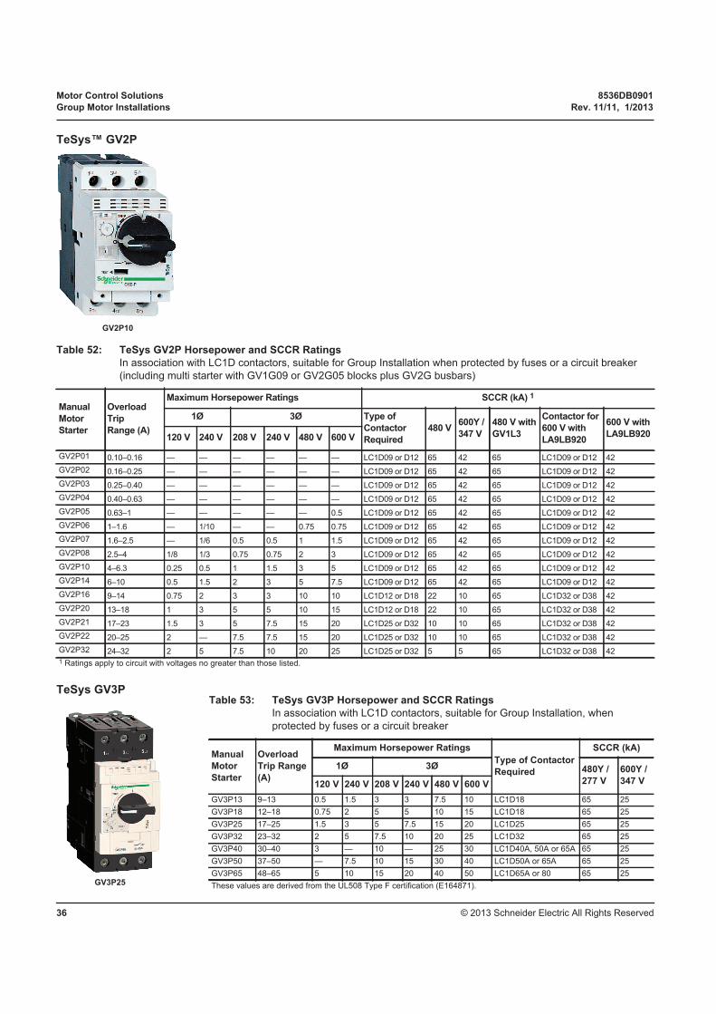
Motor Control Solutions 8536DB0901
Group Motor Installations Rev. 11/11, 1/2013
© 2013 Schneider Electric All Rights Reserved36
TeSys™ GV2P
TeSys GV3P
GV2P10
Table 52: TeSys GV2P Horsepower and SCCR Ratings
In association with LC1D contactors, suitable for Group Installation when protected by fuses or a circuit breaker
(including multi starter with GV1G09 or GV2G05 blocks plus GV2G busbars)
Manual
Motor
Starter
Overload
Trip
Range (A)
Maximum Horsepower Ratings SCCR (kA) 1
1Ø 3Ø Type of
Contactor
Required
480 V600Y /
347 V
480 V with
GV1L3
Contactor for
600 V with
LA9LB920
600 V with
LA9LB920120 V 240 V 208 V 240 V 480 V 600 V
GV2P01 0.10–0.16 — — — — — — LC1D09 or D12 65 42 65 LC1D09 or D12 42
GV2P02 0.16–0.25 — — — — — — LC1D09 or D12 65 42 65 LC1D09 or D12 42
GV2P03 0.25–0.40 — — — — — — LC1D09 or D12 65 42 65 LC1D09 or D12 42
GV2P04 0.40–0.63 — — — — — — LC1D09 or D12 65 42 65 LC1D09 or D12 42
GV2P05 0.63–1 — — — — — 0.5 LC1D09 or D12 65 42 65 LC1D09 or D12 42
GV2P06 1–1.6 — 1/10 — — 0.75 0.75 LC1D09 or D12 65 42 65 LC1D09 or D12 42
GV2P07 1.6–2.5 — 1/6 0.5 0.5 1 1.5 LC1D09 or D12 65 42 65 LC1D09 or D12 42
GV2P08 2.5–4 1/8 1/3 0.75 0.75 2 3 LC1D09 or D12 65 42 65 LC1D09 or D12 42
GV2P10 4–6.3 0.25 0.5 1 1.5 3 5 LC1D09 or D12 65 42 65 LC1D09 or D12 42
GV2P14 6–10 0.5 1.5 2 3 5 7.5 LC1D09 or D12 65 42 65 LC1D09 or D12 42
GV2P16 9–14 0.75 2 3 3 10 10 LC1D12 or D18 22 10 65 LC1D32 or D38 42
GV2P20 13–18 1 3 5 5 10 15 LC1D12 or D18 22 10 65 LC1D32 or D38 42
GV2P21 17–23 1.5 3 5 7.5 15 20 LC1D25 or D32 10 10 65 LC1D32 or D38 42
GV2P22 20–25 2 — 7.5 7.5 15 20 LC1D25 or D32 10 10 65 LC1D32 or D38 42
GV2P32 24–32 2 5 7.5 10 20 25 LC1D25 or D32 5 5 65 LC1D32 or D38 42
1 Ratings apply to circuit with voltages no greater than those listed.
Table 53: TeSys GV3P Horsepower and SCCR Ratings
In association with LC1D contactors, suitable for Group Installation, when
protected by fuses or a circuit breaker
Manual
Motor
Starter
Overload
Trip Range
(A)
Maximum Horsepower Ratings
Type of Contactor
Required
SCCR (kA)
1Ø 3Ø 480Y /
277 V
600Y /
347 V 120 V 240 V 208 V 240 V 480 V 600 V
GV3P13 9–13 0.5 1.5 3 3 7.5 10 LC1D18 65 25
GV3P18 12–18 0.75 2 5 5 10 15 LC1D18 65 25
GV3P25 17–25 1.5 3 5 7.5 15 20 LC1D25 65 25
GV3P32 23–32 2 5 7.5 10 20 25 LC1D32 65 25
GV3P40 30–40 3 — 10 — 25 30 LC1D40A, 50A or 65A 65 25
GV3P50 37–50 — 7.5 10 15 30 40 LC1D50A or 65A 65 25
GV3P65 48–65 5 10 15 20 40 50 LC1D65A or 80 65 25
These values are derived from the UL508 Type F certification (E164871).GV3P25
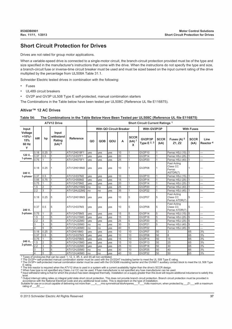
8536DB0901 Motor Control Solutions
Rev. 11/11, 1/2013 Short Circuit Protection for Drives
© 2013 Schneider Electric All Rights Reserved 37
Short Circuit Protection for Drives
Drives are not rated for group motor applications.
When a variable-speed drive is connected to a single-motor circuit, the branch-circuit protection provided must be of the type and
size specified in the manufacturer's instructions that come with the drive. When the instructions do not specify the type and size,
a branch-circuit fuse or inverse-time circuit breaker must be used and must be sized based on the input current rating of the drive
multiplied by the percentage from UL508A Table 31.1.
Schneider Electric tested drives in combination with the following:
• Fuses
• UL489 circuit breakers
• GV2P and GV3P UL508 Type E self-protected, manual combination starters
The Combinations in the Table below have been tested per UL508C (Reference UL file E116875).
Altivar™ 12 AC Drives
Table 54: The Combinations in the Table Below Have Been Tested per UL508C (Reference UL file E116875)
ATV12 Drive Short Circuit Current Ratings 1
Input
Voltage
+10%/-
15%
60 Hz
Y
kW hp
Input
withstand
Rating
(kA) 6
Reference
With QO Circuit Breaker With GV2P/3P With Fuses
QO QOB QOU A
SCCR
(kA) 7
X
GV2P/3P
Type E 2, 3
SCCR
(kA)
Fuses (A) 5
Z1, Z2
SCCR
(kA)
Line
Reactor 4
120 V,
1-phase
0.18 0.25 1 ATV12H018F1 yes yes yes 10 1 GV2P10 1 Ferraz HSJ (15) 1 —
0.37 0.5 1 ATV12•037F1 yes yes yes 20 1 GV2P14 1 Ferraz HSJ (25) 1 —
0.75 1 1 ATV12H075F1 yes yes yes 25 1 GV2P20 1 Ferraz HSJ (40) 1 —
240 V,
1-phase
0.18 0.25 1 ATV12H018M2 yes yes yes 10 1 GV2P08 1
Fast Acting Class CC Ferraz ASTDR(7)
1 —
0.37 0.5 1 ATV12•037M2 yes yes yes 10 1 GV2P10 1 Ferraz HSJ (15) 1 —
0.55 0.75 1 ATV12•055M2 yes yes yes 15 1 GV2P14 1 Ferraz HSJ (25) 1 —
0.75 1 1 ATV12•075M2 yes yes yes 20 1 GV2P14 1 Ferraz HSJ (25) 1 —
1.5 2 1 ATV12HU15M2 no no yes 25 1 GV2P20 1 Ferraz HSJ (40) 1 —
2.2 3 1 ATV12HU22M2 no no yes 35 1 GV2P22 1 Ferraz HSJ (45) 1 —
240 V,
3-phase
0.18 0.25 5 ATV12H018M3 yes yes yes 10 5 GV2P07 5Fast Acting Class CC Ferraz ATDR(7)
5 —
0.37 0.5 5 ATV12•037M3 yes yes yes 10 5 GV2P08 5Fast Acting Class CC Ferraz ATDR(7)
5 —
0.75 1 5 ATV12•075M3 yes yes yes 15 5 GV2P14 5 Ferraz HSJ (15) 5 —
1.5 2 5 ATV12•U15M3 yes yes yes 15 5 GV2P16 5 Ferraz HSJ (25) 5 —
2.2 3 5 ATV12•U22M3 yes yes yes 25 5 GV2P20 5 Ferraz HSJ (25) 5 —
3 3 5 ATV12•U30M3 no no yes 30 5 GV2P21 5 Ferraz HSJ (40) 5 —
4 5 5 ATV12•U40M3 no no yes 40 5 GV2P22 Ferraz HSJ (45) 5 —
240 V,
3-phase
0.18 0.25 5 ATV2H018M3 yes yes yes 10 10 GV2P07 50 3 65 3%
0.37 0.5 5 ATV12•037M3 yes yes yes 10 10 GV2P08 50 8 65 3%
0.75 1 5 ATV12•075M3 yes yes yes 15 10 GV2P14 50 15 65 3%
1.5 2 5 ATV12•U15M3 yes yes yes 15 10 GV2P13 50 25 65 3%
2.2 3 5 ATV12•U22M3 yes yes yes 25 10 GV2P18 50 30 65 3%
3 3 5 ATV12•U30M3 no no yes 30 10 GV2P25 50 40 65 3%
4 5 5 ATV12•U40M3 no no yes 40 10 GV2P32 50 50 65 3%1 Types of enclosures that can be used: 1, 12, 3, 3R, 4, and 4X-all non-ventilated.2 The GV2P•• self-protected manual combination starter must be used with the GV2GH7 insulating barrier to meet the UL 508 Type E rating.3 The GV3P•• self-protected manual combination starter must be used with the GV3G66 insulating barrier and the GVAM11 auxiliary contact block to meet the UL 508 Type
E rating.4 The line reactor is required when the ATV12 drive is used in a system with a current availability higher than the drive’s SCCR design.5 When fuse type is not specified any Class J or CC can be used. If fuse manufacturer is not specified any fuse manufacturer can be used.6 Input withstand rating is that for which the product has been designed thermally. Installation on a supply greater than this level will require additional inductance to satisfy this
level.7 Output interrupt rating relies on integral solid state short circuit protection. This does not provide branch circuit protection. Branch circuit protection must be provided in
accordance with the National Electrical Code and any additional local codes. This is dependant on the type of installation.Suitable for use on a circuit capable of delivering not more than ___x___rms symmetrical kiloAmperes___Y___Volts maximum, when protected by___Z1___with a maximum
rating of ___Z2___.
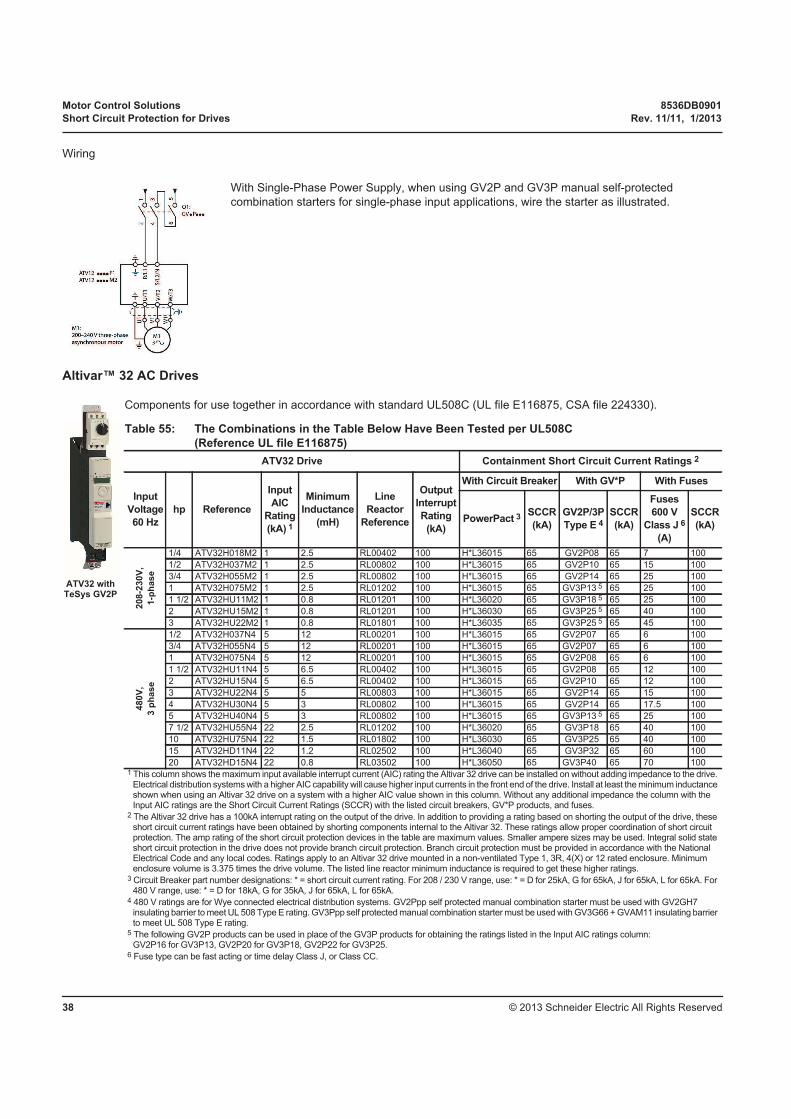
Motor Control Solutions 8536DB0901
Short Circuit Protection for Drives Rev. 11/11, 1/2013
© 2013 Schneider Electric All Rights Reserved38
Wiring
Altivar™ 32 AC Drives
Components for use together in accordance with standard UL508C (UL file E116875, CSA file 224330).
With Single-Phase Power Supply, when using GV2P and GV3P manual self-protected
combination starters for single-phase input applications, wire the starter as illustrated.
Table 55: The Combinations in the Table Below Have Been Tested per UL508C
(Reference UL file E116875)
ATV32 Drive Containment Short Circuit Current Ratings 2
Input
Voltage
60 Hz
hp Reference
Input
AIC
Rating
(kA) 1
Minimum
Inductance
(mH)
Line
Reactor
Reference
Output
Interrupt
Rating
(kA)
With Circuit Breaker With GV*P With Fuses
PowerPact 3SCCR
(kA)
GV2P/3P
Type E 4
SCCR
(kA)
Fuses
600 V
Class J 6
(A)
SCCR
(kA)
208-2
30V
,
1-p
hase
1/4 ATV32H018M2 1 2.5 RL00402 100 H*L36015 65 GV2P08 65 7 100
1/2 ATV32H037M2 1 2.5 RL00802 100 H*L36015 65 GV2P10 65 15 100
3/4 ATV32H055M2 1 2.5 RL00802 100 H*L36015 65 GV2P14 65 25 100
1 ATV32H075M2 1 2.5 RL01202 100 H*L36015 65 GV3P13 5 65 25 100
1 1/2 ATV32HU11M2 1 0.8 RL01201 100 H*L36020 65 GV3P18 5 65 25 100
2 ATV32HU15M2 1 0.8 RL01201 100 H*L36030 65 GV3P25 5 65 40 100
3 ATV32HU22M2 1 0.8 RL01801 100 H*L36035 65 GV3P25 5 65 45 100
480V
,
3 p
hase
1/2 ATV32H037N4 5 12 RL00201 100 H*L36015 65 GV2P07 65 6 100
3/4 ATV32H055N4 5 12 RL00201 100 H*L36015 65 GV2P07 65 6 100
1 ATV32H075N4 5 12 RL00201 100 H*L36015 65 GV2P08 65 6 100
1 1/2 ATV32HU11N4 5 6.5 RL00402 100 H*L36015 65 GV2P08 65 12 100
2 ATV32HU15N4 5 6.5 RL00402 100 H*L36015 65 GV2P10 65 12 100
3 ATV32HU22N4 5 5 RL00803 100 H*L36015 65 GV2P14 65 15 100
4 ATV32HU30N4 5 3 RL00802 100 H*L36015 65 GV2P14 65 17.5 100
5 ATV32HU40N4 5 3 RL00802 100 H*L36015 65 GV3P13 5 65 25 100
7 1/2 ATV32HU55N4 22 2.5 RL01202 100 H*L36020 65 GV3P18 65 40 100
10 ATV32HU75N4 22 1.5 RL01802 100 H*L36030 65 GV3P25 65 40 100
15 ATV32HD11N4 22 1.2 RL02502 100 H*L36040 65 GV3P32 65 60 100
20 ATV32HD15N4 22 0.8 RL03502 100 H*L36050 65 GV3P40 65 70 1001 This column shows the maximum input available interrupt current (AIC) rating the Altivar 32 drive can be installed on without adding impedance to the drive.
Electrical distribution systems with a higher AIC capability will cause higher input currents in the front end of the drive. Install at least the minimum inductance shown when using an Altivar 32 drive on a system with a higher AIC value shown in this column. Without any additional impedance the column with the Input AIC ratings are the Short Circuit Current Ratings (SCCR) with the listed circuit breakers, GV*P products, and fuses.
2 The Altivar 32 drive has a 100kA interrupt rating on the output of the drive. In addition to providing a rating based on shorting the output of the drive, these short circuit current ratings have been obtained by shorting components internal to the Altivar 32. These ratings allow proper coordination of short circuit protection. The amp rating of the short circuit protection devices in the table are maximum values. Smaller ampere sizes may be used. Integral solid state short circuit protection in the drive does not provide branch circuit protection. Branch circuit protection must be provided in accordance with the National Electrical Code and any local codes. Ratings apply to an Altivar 32 drive mounted in a non-ventilated Type 1, 3R, 4(X) or 12 rated enclosure. Minimum enclosure volume is 3.375 times the drive volume. The listed line reactor minimum inductance is required to get these higher ratings.
3 Circuit Breaker part number designations: * = short circuit current rating. For 208 / 230 V range, use: * = D for 25kA, G for 65kA, J for 65kA, L for 65kA. For 480 V range, use: * = D for 18kA, G for 35kA, J for 65kA, L for 65kA.
4 480 V ratings are for Wye connected electrical distribution systems. GV2Ppp self protected manual combination starter must be used with GV2GH7 insulating barrier to meet UL 508 Type E rating. GV3Ppp self protected manual combination starter must be used with GV3G66 + GVAM11 insulating barrier to meet UL 508 Type E rating.
5 The following GV2P products can be used in place of the GV3P products for obtaining the ratings listed in the Input AIC ratings column: GV2P16 for GV3P13, GV2P20 for GV3P18, GV2P22 for GV3P25.
6 Fuse type can be fast acting or time delay Class J, or Class CC.
ATV32 with TeSys GV2P

8536DB0901 Motor Control Solutions
Rev. 11/11, 1/2013 Short Circuit Protection for Drives
© 2013 Schneider Electric All Rights Reserved 39
Altivar™ 212 Components for use together in accordance with standard UL508C
(UL file E116875, CSA file 224330).
Table 56: ATV212 Combination Ratings
ATV212 AC Drive Containment Short Circuit Current Rating 1
Input
Voltage
60 Hz
hp Reference
Output
Interrupt
Rating
(kAIC)
With Circuit Breaker With GV*P With Fuses
PowerPactSCCR
(kA) 2SCCR
(kA) 3GV2P/3P
Type E 4
SCCR
(kA) 2, 3
Fuses (A)
600 V 5SCCR
(kA) 2, 3
208V, 3 phase
1 ATV212H075M3X 100 HDL36015 22 22 GV2P10 22 10 100
2 ATV212HU15M3X 100 HDL36015 22 22 GV2P14 22 15 100
3 ATV212HU22M3X 100 HDL36020 22 22 GV2P16 22 30 100
4 ATV212HU30M3X 100 HDL36030 22 22 GV2P20 22 35 100
5 ATV212HU40M3X 100 HDL36040 22 22 GV2P20 22 35 100
7.5 ATV212HU55M3X 100 HDL36050 22 22 GV2P22 22 50 100
10 ATV212HU75M3X 100 HDL36070 22 22 GV2P32 22 60 100
15 ATV212HD11M3X 100 HDL36100 22 22 GV3P50 22 100 100
20 ATV212HD15M3X 100 HDL36125 22 22 GV3P65 22 125 100
25 ATV212HD18M3X 100 JDL36175 22 22 — — 150 100
30 ATV212HD22M3X 100 JDL36200 22 22 — — 175 100
40 ATV212HD30M3X 100 JDL36250 22 22 — — 200 100
230V,3 phase
1 ATV212H075M3X 100 HDL36015 22 22 GV2P10 22 10 100
2 ATV212HU15M3X 100 HDL36015 22 22 GV2P10 22 15 100
3 ATV212HU22M3X 100 HDL36020 22 22 GV2P14 22 30 100
4 ATV212HU30M3X 100 HDL36030 22 22 GV2P20 22 35 100
5 ATV212HU40M3X 100 HDL36035 22 22 GV2P20 22 35 100
7.5 ATV212HU55M3X 100 HDL36045 22 22 GV2P21 22 45 100
10 ATV212HU75M3X 100 HDL36060 22 22 GV2P32 22 60 100
15 ATV212HD11M3X 100 HDL36090 22 22 GV3P40 22 90 100
20 ATV212HD15M3X 100 HDL36125 22 22 GV3P50 22 110 100
25 ATV212HD18M3X 100 HDL36150 22 22 — — 150 100
30 ATV212HD22M3X 100 JDL36175 22 22 — — 175 100
40 ATV212HD30M3X 100 JDL36225 22 22 — — 200 100
ATV212 DriveATV212HU55M3X

Motor Control Solutions 8536DB0901
Short Circuit Protection for Drives Rev. 11/11, 1/2013
© 2013 Schneider Electric All Rights Reserved40
ATV212 AC Drive Containment Short Circuit Current Rating 1
Input
Voltage
60 Hz
hp Reference
Output
Interrupt
Rating
(kAIC)
With Circuit Breaker With GV*P With Fuses
PowerPactSCCR
(kA) 2SCCR
(kA) 3GV2P/3P
Type E 4
SCCR
(kA) 2, 3
Fuses (A)
600 V 5SCCR
(kA) 2, 3
480V,3 phase
1 ATV212H075N4 100 HDL36015 — 22 GV2P07 22 5 100
2 ATV212HU15N4 100 HDL36015 — 22 GV2P08 22 7.5 100
3 ATV212HU22N4 100 HDL36015 — 22 GV2P10 22 10 100
4 ATV212HU30N4 100 HDL36020 — 22 GV2P14 22 15 100
5 ATV212HU40N4 100 HDL36020 — 22 GV2P14 22 15 100
7.5 ATV212HU55N4 100 HDL36025 — 22 GV2P16 22 20 100
10 ATV212HU75N4 100 HDL36030 — 22 GV2P20 22 30 100
15 ATV212HD11N4 100 HDL36045 — 22 GV2P21 22 45 100
20 ATV212HD15N4 100 HDL36060 10 22 GV2P22 22 60 100
25 ATV212HD18N4 100 HDL36070 10 22 GV2P32 22 80 100
30 ATV212HD22N4S 100 HDL36090 10 22 GV3P40 22 90 100
30 ATV212HD22N4 100 HDL36090 — 22 — — 90 100
40 ATV212HD30N4 100 HDL36125 — 22 — — 110 100
50 ATV212HD37N4 100 HDL36125 10 10 — — 125 100
60 ATV212HD45N4 100 HDL36150 10 10 — — 150 100
75 ATV212HD55N4 100 JDL36175 10 10 — — 200 100
100 ATV212HD75N4 100 JDL36225 10 10 — — 250 100
1 The Altivar™ 212 has a 100k SCC rating on the output of the drive as many other drives are rated. In addition to providing a rating based on shorting the output of the drive, these short circuit rating have been obtained by testing the weakest point internal to the ATV212 per UL508C. These ratings allow proper coordination of short circuit protection. The amp rating of the short circuit protection devices in the table are maximum values. Smaller amp sizes may be used.
2 Ratings also apply to ATV212 Type 1 product, ie: an ATV212 fitted with a conduit box.3 Ratings apply to an ATV212 mounted in a non-ventilated Type 1, 3R, 4(X) or 12 rated enclosure. Minimum enclosure volume is
3.375 times the drive volume.4 480 V ratings are for Wye connected electrical distribution systems. GV2P** self protected manual combination starter must be
used with GV2GH7 insulating barrier to meet UL 508 Type E rating.5 Fuse type can be Class J, fast acting or time delay, or Class CC.
Table 56: ATV212 Combination Ratings (continued)

8536DB0901 Motor Control Solutions
Rev. 11/11, 1/2013 Short Circuit Protection for Drives
© 2013 Schneider Electric All Rights Reserved 41
Altivar™ 312 AC Drives Components for use together in accordance with standard UL508C.
ATV312
Table 57: ATV312 Combination Ratings
ATV312 Drive Short Circuit Current Ratings
Input Voltage
+10%/-15%
60 Hz
hp Reference
Input
AIC
Rating
(kA)
Minimun
Inductance
(mH)
Line
Reactor
Reference
Output
Interrupt
rating:
(kA) 1
With Circuit
BreakerWith GV*P With Fuses
PowerPactSCCR
(kA) 3GV2P/3P
Type E 3, 4
SCCR
(kA)
Fuse
(A) 5SCCR
(kA) 2, 3
Three-phase with or without line reactor
208/2
30V
Thre
e-p
hase
Without lin
ere
acto
r
0.25 ATV312H018M3 5 — — 100 HxL36015 22 — — 3 22
0.5 ATV312H037M3 5 — — 100 HxL36015 22 — — 6 22
0.75 ATV312H055M3 5 — — 100 HxL36015 22 — — 10 22
1 ATV312H075M3 5 — — 100 HxL36015 22 — — 10 22
1.5 ATV312HU11M3 5 — — 100 HxL36015 22 — — 15 22
2 ATV312HU15M3 5 — — 100 HxL36015 22 — — 15 22
3 ATV312HU22M3 5 — — 100 HxL36020 22 — — 20 22
— ATV312HU30M3 5 — — 100 HxL36020 22 — — 25 22
5 ATV312HU40M3 5 — — 100 HxL36030 22 — — 35 22
7.5 ATV312HU55M3 22 — — 100 HxL36040 22 — — 50 22
10 ATV312HU75M3 22 — — 100 HxL36060 22 — — 60 22
15 ATV312HD11M3 22 — — 100 HxL36070 22 — — 80 22
20 ATV312HD15M3 22 — — 100 HxL36090 22 — — 110 22
With lin
ere
acto
r
0.25 ATV312H018M3 5 3 RL-00401 100 HxL36015 65 GV2P07 65 3 22
0.5 ATV312H037M3 5 3 RL-00401 100 HxL36015 65 GV2P08 65 6 22
0.75 ATV312H055M3 5 3 RL-00401 100 HxL36015 65 GV2P10 65 10 22
1 ATV312H075M3 5 3 RL-00401 100 HxL36015 65 GV2P10 65 10 22
1.5 ATV312HU11M3 5 1.5 RL-00801 100 HxL36015 65 GV2P14 65 15 22
2 ATV312HU15M3 5 1.5 RL-00801 100 HxL36015 65 GV2P14 65 15 22
3 ATV312HU22M3 5 1.25 RL-01201 100 HxL36020 65GV3P13 or GV3P18
65 20 22
— ATV312HU30M3 5 1.25 RL-01801 100 HxL36020 65 GV3P18 65 25 22
5 ATV312HU40M3 5 1.25 RL-01801 100 HxL36030 65 GV3P25 65 35 22
7.5 ATV312HU55M3 22 0.5 RL-02501 100 HxL36040 65GV3P32 orGV3P40
65 50 22
10 ATV312HU75M3 22 0.4 RL-03501 100 HxL36060 65 GV3P50 65 60 22
15 ATV312HD11M3 22 0.3 RL-04501 100 HxL36070 65 GV3P65 65 80 22
20 ATV312HD15M3 22 0.2 RL-08001 100 HxL36090 65 — — 110 22
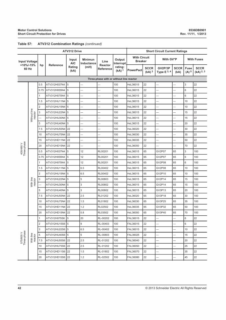
Motor Control Solutions 8536DB0901
Short Circuit Protection for Drives Rev. 11/11, 1/2013
© 2013 Schneider Electric All Rights Reserved42
ATV312 Drive Short Circuit Current Ratings
Input Voltage
+10%/-15%
60 Hz
hp Reference
Input
AIC
Rating
(kA)
Minimun
Inductance
(mH)
Line
Reactor
Reference
Output
Interrupt
rating:
(kA) 1
With Circuit
BreakerWith GV*P With Fuses
PowerPactSCCR
(kA) 3GV2P/3P
Type E 3, 4
SCCR
(kA)
Fuse
(A) 5SCCR
(kA) 2, 3
Three-phase with or without line reactor
400/4
80 V
Thre
e-p
hase
Without lin
ere
acto
r
0.5 ATV312H037N4 5 — — 100 HxL36015 22 — — 3 22
0.75 ATV312H055N4 5 — — 100 HxL36015 22 — — 6 22
1 ATV312H075N4 5 — — 100 HxL36015 22 — — 6 22
1.5 ATV312HU11N4 5 — — 100 HxL36015 22 — — 10 22
2 ATV312HU15N4 5 — — 100 HxL36015 22 — — 10 22
3 ATV312HU22N4 5 — — 100 HxL36015 22 — — 15 22
— ATV312HU30N4 5 — — 100 HxL36015 22 — — 15 22
5 ATV312HU40N4 5 — — 100 HxL36015 22 — — 20 22
7.5 ATV312HU55N4 22 — — 100 HxL36020 22 — — 30 22
10 ATV312HU75N4 22 — — 100 HxL36030 22 — — 35 22
15 ATV312HD11N4 22 — — 100 HxL36035 22 — — 50 22
20 ATV312HD15N4 22 — — 100 HxL36050 22 — — 70 22
With lin
ere
acto
r
0.5 ATV312H037N4 5 12 RL00201 100 HxL36015 65 GV2P07 65 3 100
0.75 ATV312H055N4 5 12 RL00201 100 HxL36015 65 GV2P07 65 6 100
1 ATV312H075N4 5 12 RL00201 100 HxL36015 65 GV2P08 65 6 100
1.5 ATV312HU11N4 5 6.5 RL00402 100 HxL36015 65 GV2P08 65 10 100
2 ATV312HU15N4 5 6.5 RL00402 100 HxL36015 65 GV2P10 65 10 100
3 ATV312HU22N4 5 5 RL00803 100 HxL36015 65 GV2P14 65 15 100
— ATV312HU30N4 5 3 RL00802 100 HxL36015 65 GV2P14 65 15 100
5 ATV312HU40N4 5 3 RL00802 100 HxL36015 65 GV3P13 65 20 100
7.5 ATV312HU55N4 22 2.5 RL01202 100 HxL36020 65 GV3P18 65 30 100
10 ATV312HU75N4 22 1.5 RL01802 100 HxL36030 65 GV3P25 65 35 100
15 ATV312HD11N4 22 1.2 RL02502 100 HxL36035 65 GV3P32 65 50 100
20 ATV312HD15N4 22 0.8 RL03502 100 HxL36050 65 GV3P40 65 70 100
575/6
00 V
Thre
e-p
hase
With lin
ere
acto
r
1 ATV312H075S6 5 20 RL-00202 100 FAL36015 22 — — 6 22
2 ATV312HU15S6 5 9 RL-00403 100 FAL36015 22 — — 6 22
3 ATV312HU22S6 5 6.5 RL-00402 100 FAL36015 22 — — 10 22
5 ATV312HU40S6 5 5 RL-00803 100 FAL36025 22 — — 15 22
7.5 ATV312HU55S6 22 2.5 RL-01202 100 FAL36040 22 — — 20 22
10 ATV312HU75S6 22 2.5 RL-01202 100 FAL36050 22 — — 25 22
15 ATV312HD11S6 22 1.5 RL-01802 100 FAL36070 22 — — 35 22
20 ATV312HD15S6 22 1.2 RL-02502 100 FAL36080 22 — — 45 22
Table 57: ATV312 Combination Ratings (continued)

8536DB0901 Motor Control Solutions
Rev. 11/11, 1/2013 Short Circuit Protection for Drives
© 2013 Schneider Electric All Rights Reserved 43
ATV312 Drive Short Circuit Current Ratings
Input Voltage
+10%/-15%
60 Hz
hp Reference
Input
AIC
Rating
(kA)
Minimun
Inductance
(mH)
Line
Reactor
Reference
Output
Interrupt
rating:
(kA) 1
With Circuit
BreakerWith GV*P With Fuses
PowerPactSCCR
(kA) 3GV2P/3P
Type E 3, 4
SCCR
(kA)
Fuse
(A) 5SCCR
(kA) 2, 3
Single-phase with or without line reactor
208/2
30 V
Sin
gle
-phase
Without lin
ere
acto
r
0.25 ATV312H018M2 1 — — 100 — — — — 6 22
0.5 ATV312H037M2 1 — — 100 — — — — 10 22
0.75 ATV312H055M2 1 — — 100 — — — — 10 22
1 ATV312H075M2 1 — — 100 — — — — 15 22
1.5 ATV312HU11M2 1 — — 100 — — — — 20 22
2 ATV312HU15M2 1 — — 100 — — — — 20 22
3 ATV312HU22M2 1 — — 100 — — — — 30 22
5 ATV312HU75M3 2 — — 100 HxL36060 22 — — 60 22
7.5 ATV312HD11M3 2 — — 100 HxL36070 22 — — 80 22
10 ATV312HD15M3 2 — — 100 HxL36090 22 — — 110 22
With lin
ere
acto
r 5 ATV312HU75M3 22 0.75 RL-03502 100 HxL36060 65 GV3P50 65 60 22
7.5 ATV312HD11M3 22 0.375 RL-05502 100 HxL36070 65 GV3P65 65 80 22
10 ATV312HD15M3 22 0.278 RL-08002 100 HxL36090 65 — — 110 22
400/4
80 V
Sin
gle
-phase
Without lin
ere
acto
r
0.5 ATV312H075N4 5 — — 100 HxL36015 22 — — 6 22
0.75 ATV312HU11N4 5 — — 100 HxL36015 22 — — 10 22
1 ATV312HU15N4 5 — — 100 HxL36015 22 — — 10 22
1.5 ATV312HU22N4 5 — — 100 HxL36015 22 — — 15 22
2 ATV312HU30N4 5 — — 100 HxL36015 22 — — 15 22
3 ATV312HU40N4 5 — — 100 HxL36015 22 — — 20 22
3 ATV312HU55N4 22 — — 100 HxL36020 22 — — 30 22
5 ATV312HU75N4 22 — — 100 HxL36030 22 — — 35 22
7.5 ATV312HD11N4 22 — — 100 HxL36035 22 — — 50 22
10 ATV312HD15N4 22 — — 100 HxL36050 22 — — 70 22
With lin
ere
acto
r
0.5 ATV312H075N4 5 5.79 RL-00402 100 HxL36015 65 GV2P08 65 6 22
0.75 ATV312HU11N4 5 4.27 RL-00402 100 HxL36015 65 GV2P08 65 10 22
1 ATV312HU15N4 5 4.27 RL-00803 100 HxL36015 65 GV2P10 65 10 22
1.5 ATV312HU22N4 5 2.77 RL-00802 100 HxL36015 65 GV2P14 65 15 22
2 ATV312HU30N4 5 2.77 RL-00802 100 HxL36015 65 GV2P14 65 15 22
3 ATV312HU40N4 5 1.68 RL-01202 100 HxL36015 65 GV3P13 65 20 22
3 ATV312HU55N4 22 1.29 RL-01802 100 HxL36020 65 GV3P18 65 30 22
5 ATV312HU75N4 22 0.912 RL-02502 100 HxL36030 65 GV3P25 65 35 22
7.5 ATV312HD11N4 22 0.694 RL-03502 100 HxL36035 65 GV3P32 65 50 22
10 ATV312HD15N4 22 0.569 RL-04502 100 HxL36050 65 GV3P40 65 70 22
1 The Altivar™ 312 has a 100k SCC rating on the output of the drive as many other drives are rated. In addition to providing a rating based on shorting the output of the drive, these short circuit rating have been obtained by testing the weakest point internal to the ATV312 per UL508C. These ratings allow proper coordination of short circuit protection. The amp rating of the short circuit protection devices in the table are maximum values. Smaller amp sizes may be used.
2 Ratings also apply to ATV312 Type 1 product, ie: an ATV312 fitted with a conduit box.3 Ratings apply to an ATV312 mounted in a non-ventilated Type 1, 3R, 4(X) or 12 rated enclosure. Minimum enclosure volume is 3.375 times the drive volume .4 480 V ratings are for Wye connected electrical distribution systems. GV2P* self protected manual combination starter must be used with GV2GH7 insulating barrier
to meet UL 508 Type E rating. GV3P** must be used with GV3G66 and GVAM11 in order to meet UL508 rating.5 Fuse type can be Class J, fast acting or time delay, or Class CC.
Table 57: ATV312 Combination Ratings (continued)
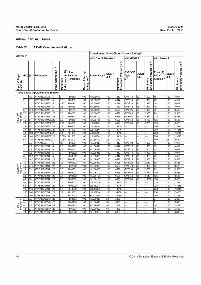
Motor Control Solutions 8536DB0901
Short Circuit Protection for Drives Rev. 11/11, 1/2013
© 2013 Schneider Electric All Rights Reserved44
Altivar™ 61 AC Drives
Table 58: ATV61 Combination Ratings
Altivar 61Containment Short Circuit Current Rating 2
with Circuit Breaker 3 with GVxP 3 with Fuses 3
Inp
ut
Vo
ltag
e
50/6
0 H
z
(hp) (A) Reference:
Inp
ut
Rati
ng
: (k
A)
1
Mim
imu
m
ind
ucta
nce (
mH
)
Line
Reactor
Reference
Ou
tpu
t In
terr
up
t
rati
ng
: kA
IC
PowerPact 4SCCR
(kA)
Mim
imu
m
En
clo
su
re V
olu
me (
in 3
)
GV2P/3P
Type
E 5
SCCR
(kA)
Mim
imu
m
En
clo
su
re V
olu
me (
in 3
)
Fuse (A)
600 V
Class J 6
SCCR
(kA)
Mim
imu
m
En
clo
su
re V
olu
me (
in 3
)
Three-phase Input, with line reactor
200/2
40 V
Thre
e-p
hase
1 4.8 ATV61H075M3 5 3 RL00401 100 HJL36015 100 4017 GV2P10 65 1600 15 100 4017
2 8 ATV61HU15M3 5 1.5 RL00801 100 HJL36025 100 4017 GV2P14 65 1600 25 100 4017
3 11 ATV61HU22M3 5 1.25 RL01201 100 HJL36040 100 4017 GV3P18 65 1920 40 100 4017
— 13.7 ATV61HU30M3 5 0.8 RL01801 100 HJL36040 100 4017 GV3P18 65 1920 40 100 4017
5 17.5 ATV61HU40M3 5 0.8 RL01801 100 HJL36060 100 6528 GV3P25 65 1920 60 100 6528
7.5 27.5 ATV61HU55M3 22 0.5 RL02501 100 HJL36070 100 6528 GV3P40 65 2880 70 100 6528
10 33 ATV61HU75M3 22 0.4 RL03501 100 HJL36110 100 6528 GV3P50 65 4032 110 100 6528
15 54 ATV61HD11M3X 22 0.3 RL04501 100 HJL36125 100 6528 GV3P50 65 5760 125 100 6528
20 66 ATV61HD15M3X 22 0.25 RL05501 100 JJL36175 100 6528 GV3P65 65 5760 175 100 6528
25 75 ATV61HD18M3X 22 0.2 RL08001 100 JJL36200 100 13215 — — — 200 100 13215
30 88 ATV61HD22M3X 22 0.15 RL10001 100 JJL36250 100 13215 — — — 250 100 13215
40 120 ATV61HD30M3X 22 0.1 RL13001 100 JJL36250 100 13215 — — — 250 100 13215
50 144 ATV61HD37M3X 22 0.075 RL16001 100 JJL36250 100 13215 — — — 250 100 13215
60 176 ATV61HD45M3X 10 0.055 RL20001 100 LAL36400 22 8640 — — — 400 22 8640
380/4
80 V
Thre
e-p
hase
1 2.3 ATV61H075N4 5 12 RL00201 100 HLL36015 100 4017 GV2P08 65 1600 15 100 4017
2 4.1 ATV61HU15N4 5 6.5 RL00402 100 HLL36015 100 4017 GV2P10 65 1600 15 100 4017
3 5.8 ATV61HU22N4 5 6.5 RL00402 100 HLL36015 100 4017 GV2P14 65 1600 15 100 4017
— 7.8 ATV61HU30N4 5 3 RL00802 100 HLL36015 100 4017 GV2P14 65 1920 15 100 4017
5 10.5 ATV61HU40N4 5 3 RL00802 100 HLL36025 100 4017 GV3P13 65 1920 25 100 4017
7.5 14.3 ATV61HU55N4 22 2.5 RL01202 100 HLL36035 100 6528 GV3P25 65 2880 35 100 6528
10 17.6 ATV61HU75N4 22 1.5 RL01802 100 HLL36050 100 6528 GV3P25 65 2880 50 100 6528
15 27.7 ATV61HD11N4 22 1.2 RL02502 100 HLL36060 100 6528 GV3P40 65 4032 60 100 6528
20 33 ATV61HD15N4 22 0.8 RL03502 100 HLL36080 100 6528 GV3P50 65 5760 80 100 6528
25 41 ATV61HD18N4 22 0.8 RL03502 100 HLL36100 100 6528 GV3P50 65 8640 100 100 6528
30 48 ATV61HD22N4 22 0.7 RL04502 100 HLL36125 100 6528 GV3P50 65 8640 125 100 6528
40 66 ATV61HD30N4 22 0.5 RL05502 100 HLL36150 100 6528 GV3P65 65 10368 150 100 6528
50 79 ATV61HD37N4 22 0.4 RL08002 100 JLL36175 100 13215 — — — 175 100 13215
60 94 ATV61HD45N4 22 0.4 RL08002 100 JLL36225 100 13215 — — — 225 100 13215
75 116 ATV61HD55N4 22 0.3 RL10002 100 JLL36250 100 13215 — — — 250 100 13215
100 160 ATV61HD75N4 22 0.2 RL13002 100 JLL36250 100 38250 — — — 250 100 38250
100 160 ATV61HD75N4 22 0.2 RL13002 100 KCL34250 100 38250 — — — 250 100 38250
575 V
Thre
e-p
hase 3 3.9 ATV61HU22S6X 22 9 RL00403 100 HLL36015 50 3898 — — — 6 100 3898
— 5.8 ATV61HU30S6X 22 9 RL00403 100 HLL36015 50 3898 — — — 6 100 3898
5 6.1 ATV61HU40S6X 22 5 RL00803 100 HLL36015 50 3898 — — — 10 100 3898
7.5 9 ATV61HU55S6X 22 3 RL01203 100 HLL36020 50 3898 — — — 15 100 3898
10 11 ATV61HU75S6X 22 2.5 RL01203 100 HLL36025 50 3898 — — — 20 100 3898
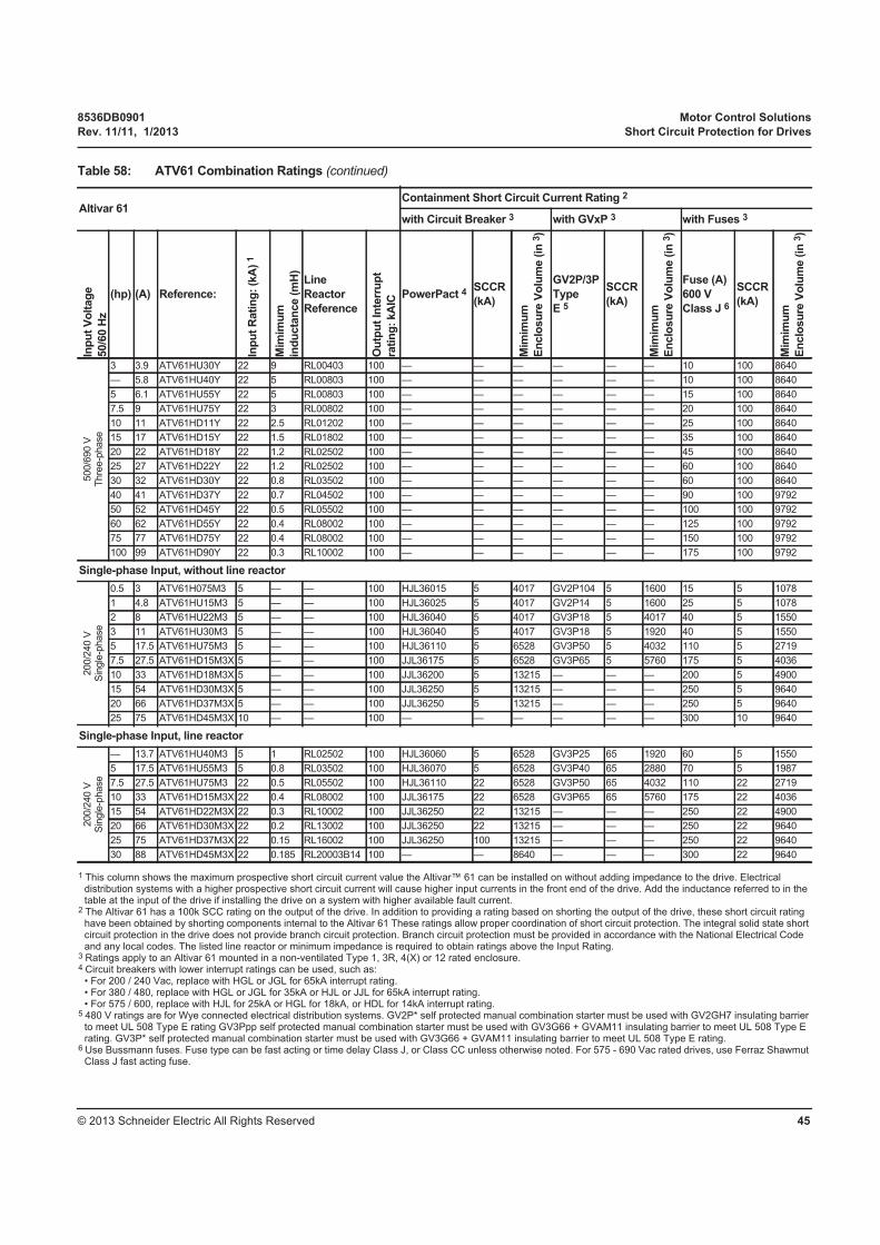
8536DB0901 Motor Control Solutions
Rev. 11/11, 1/2013 Short Circuit Protection for Drives
© 2013 Schneider Electric All Rights Reserved 45
1 This column shows the maximum prospective short circuit current value the Altivar™ 61 can be installed on without adding impedance to the drive. Electrical distribution systems with a higher prospective short circuit current will cause higher input currents in the front end of the drive. Add the inductance referred to in the table at the input of the drive if installing the drive on a system with higher available fault current.
2 The Altivar 61 has a 100k SCC rating on the output of the drive. In addition to providing a rating based on shorting the output of the drive, these short circuit rating have been obtained by shorting components internal to the Altivar 61 These ratings allow proper coordination of short circuit protection. The integral solid state short circuit protection in the drive does not provide branch circuit protection. Branch circuit protection must be provided in accordance with the National Electrical Code and any local codes. The listed line reactor or minimum impedance is required to obtain ratings above the Input Rating.
3 Ratings apply to an Altivar 61 mounted in a non-ventilated Type 1, 3R, 4(X) or 12 rated enclosure.4 Circuit breakers with lower interrupt ratings can be used, such as:
• For 200 / 240 Vac, replace with HGL or JGL for 65kA interrupt rating.• For 380 / 480, replace with HGL or JGL for 35kA or HJL or JJL for 65kA interrupt rating. • For 575 / 600, replace with HJL for 25kA or HGL for 18kA, or HDL for 14kA interrupt rating.
5 480 V ratings are for Wye connected electrical distribution systems. GV2P* self protected manual combination starter must be used with GV2GH7 insulating barrier to meet UL 508 Type E rating GV3Ppp self protected manual combination starter must be used with GV3G66 + GVAM11 insulating barrier to meet UL 508 Type E rating. GV3P* self protected manual combination starter must be used with GV3G66 + GVAM11 insulating barrier to meet UL 508 Type E rating.
6 Use Bussmann fuses. Fuse type can be fast acting or time delay Class J, or Class CC unless otherwise noted. For 575 - 690 Vac rated drives, use Ferraz Shawmut Class J fast acting fuse.
500/6
90 V
Thre
e-p
hase
3 3.9 ATV61HU30Y 22 9 RL00403 100 — — — — — — 10 100 8640
— 5.8 ATV61HU40Y 22 5 RL00803 100 — — — — — — 10 100 8640
5 6.1 ATV61HU55Y 22 5 RL00803 100 — — — — — — 15 100 8640
7.5 9 ATV61HU75Y 22 3 RL00802 100 — — — — — — 20 100 8640
10 11 ATV61HD11Y 22 2.5 RL01202 100 — — — — — — 25 100 8640
15 17 ATV61HD15Y 22 1.5 RL01802 100 — — — — — — 35 100 8640
20 22 ATV61HD18Y 22 1.2 RL02502 100 — — — — — — 45 100 8640
25 27 ATV61HD22Y 22 1.2 RL02502 100 — — — — — — 60 100 8640
30 32 ATV61HD30Y 22 0.8 RL03502 100 — — — — — — 60 100 8640
40 41 ATV61HD37Y 22 0.7 RL04502 100 — — — — — — 90 100 9792
50 52 ATV61HD45Y 22 0.5 RL05502 100 — — — — — — 100 100 9792
60 62 ATV61HD55Y 22 0.4 RL08002 100 — — — — — — 125 100 9792
75 77 ATV61HD75Y 22 0.4 RL08002 100 — — — — — — 150 100 9792
100 99 ATV61HD90Y 22 0.3 RL10002 100 — — — — — — 175 100 9792
Single-phase Input, without line reactor
200/2
40 V
Sin
gle
-phase
0.5 3 ATV61H075M3 5 — — 100 HJL36015 5 4017 GV2P104 5 1600 15 5 1078
1 4.8 ATV61HU15M3 5 — — 100 HJL36025 5 4017 GV2P14 5 1600 25 5 1078
2 8 ATV61HU22M3 5 — — 100 HJL36040 5 4017 GV3P18 5 4017 40 5 1550
3 11 ATV61HU30M3 5 — — 100 HJL36040 5 4017 GV3P18 5 1920 40 5 1550
5 17.5 ATV61HU75M3 5 — — 100 HJL36110 5 6528 GV3P50 5 4032 110 5 2719
7.5 27.5 ATV61HD15M3X 5 — — 100 JJL36175 5 6528 GV3P65 5 5760 175 5 4036
10 33 ATV61HD18M3X 5 — — 100 JJL36200 5 13215 — — — 200 5 4900
15 54 ATV61HD30M3X 5 — — 100 JJL36250 5 13215 — — — 250 5 9640
20 66 ATV61HD37M3X 5 — — 100 JJL36250 5 13215 — — — 250 5 9640
25 75 ATV61HD45M3X 10 — — 100 — — — — — — 300 10 9640
Single-phase Input, line reactor
200/2
40 V
Sin
gle
-phase
— 13.7 ATV61HU40M3 5 1 RL02502 100 HJL36060 5 6528 GV3P25 65 1920 60 5 1550
5 17.5 ATV61HU55M3 5 0.8 RL03502 100 HJL36070 5 6528 GV3P40 65 2880 70 5 1987
7.5 27.5 ATV61HU75M3 22 0.5 RL05502 100 HJL36110 22 6528 GV3P50 65 4032 110 22 2719
10 33 ATV61HD15M3X 22 0.4 RL08002 100 JJL36175 22 6528 GV3P65 65 5760 175 22 4036
15 54 ATV61HD22M3X 22 0.3 RL10002 100 JJL36250 22 13215 — — — 250 22 4900
20 66 ATV61HD30M3X 22 0.2 RL13002 100 JJL36250 22 13215 — — — 250 22 9640
25 75 ATV61HD37M3X 22 0.15 RL16002 100 JJL36250 100 13215 — — — 250 22 9640
30 88 ATV61HD45M3X 22 0.185 RL20003B14 100 — — 8640 — — — 300 22 9640
Table 58: ATV61 Combination Ratings (continued)
Altivar 61Containment Short Circuit Current Rating 2
with Circuit Breaker 3 with GVxP 3 with Fuses 3
Inp
ut
Vo
ltag
e
50/6
0 H
z
(hp) (A) Reference:
Inp
ut
Rati
ng
: (k
A)
1
Mim
imu
m
ind
ucta
nce (
mH
)Line
Reactor
Reference
Ou
tpu
t In
terr
up
t
rati
ng
: kA
IC
PowerPact 4SCCR
(kA)
Mim
imu
m
En
clo
su
re V
olu
me (
in 3
)
GV2P/3P
Type
E 5
SCCR
(kA)
Mim
imu
m
En
clo
su
re V
olu
me (
in 3
)
Fuse (A)
600 V
Class J 6
SCCR
(kA)
Mim
imu
m
En
clo
su
re V
olu
me (
in 3
)
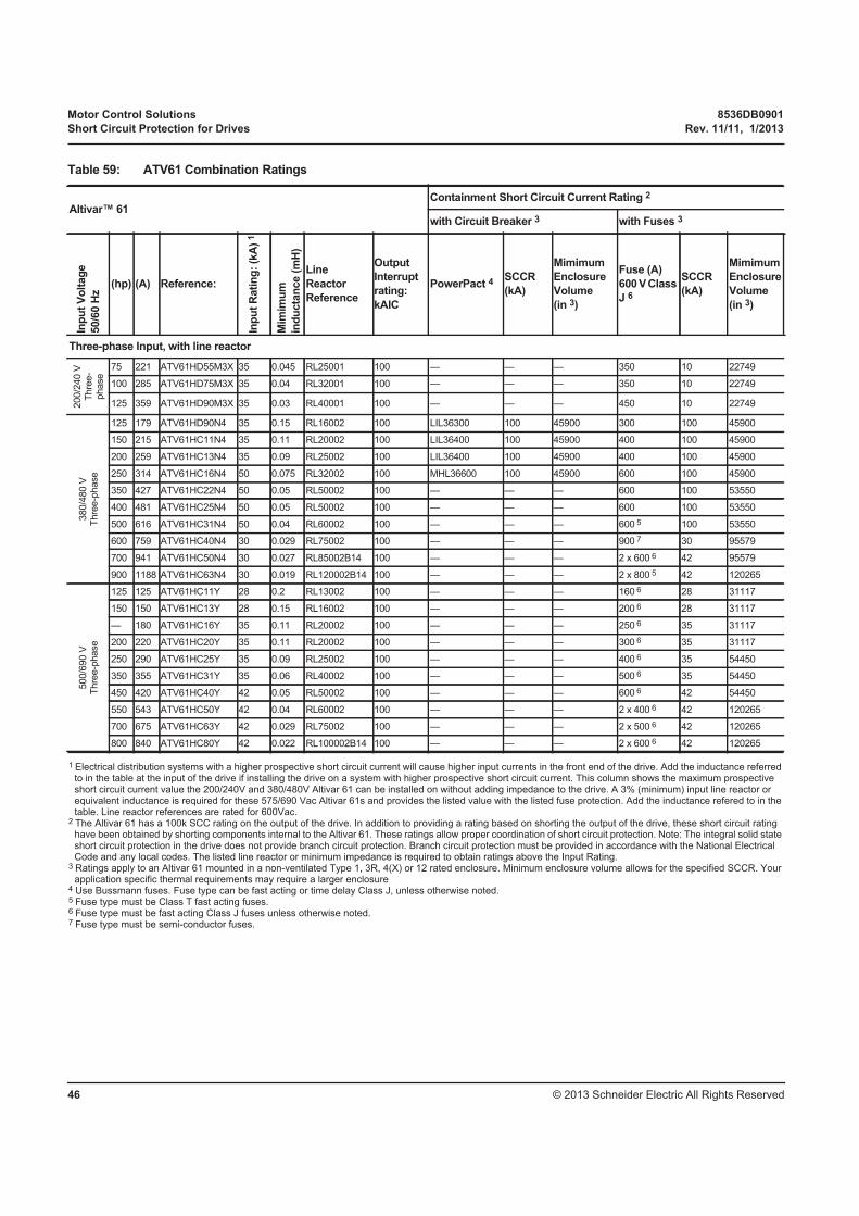
Motor Control Solutions 8536DB0901
Short Circuit Protection for Drives Rev. 11/11, 1/2013
© 2013 Schneider Electric All Rights Reserved46
1 Electrical distribution systems with a higher prospective short circuit current will cause higher input currents in the front end of the drive. Add the inductance referred to in the table at the input of the drive if installing the drive on a system with higher prospective short circuit current. This column shows the maximum prospective short circuit current value the 200/240V and 380/480V Altivar 61 can be installed on without adding impedance to the drive. A 3% (minimum) input line reactor or equivalent inductance is required for these 575/690 Vac Altivar 61s and provides the listed value with the listed fuse protection. Add the inductance refered to in the table. Line reactor references are rated for 600Vac.
2 The Altivar 61 has a 100k SCC rating on the output of the drive. In addition to providing a rating based on shorting the output of the drive, these short circuit rating have been obtained by shorting components internal to the Altivar 61. These ratings allow proper coordination of short circuit protection. Note: The integral solid state short circuit protection in the drive does not provide branch circuit protection. Branch circuit protection must be provided in accordance with the National Electrical Code and any local codes. The listed line reactor or minimum impedance is required to obtain ratings above the Input Rating.
3 Ratings apply to an Altivar 61 mounted in a non-ventilated Type 1, 3R, 4(X) or 12 rated enclosure. Minimum enclosure volume allows for the specified SCCR. Your application specific thermal requirements may require a larger enclosure
4 Use Bussmann fuses. Fuse type can be fast acting or time delay Class J, unless otherwise noted.5 Fuse type must be Class T fast acting fuses.6 Fuse type must be fast acting Class J fuses unless otherwise noted.7 Fuse type must be semi-conductor fuses.
Table 59: ATV61 Combination Ratings
Altivar™ 61Containment Short Circuit Current Rating 2
with Circuit Breaker 3 with Fuses 3
Inp
ut
Vo
ltag
e
50/6
0 H
z
(hp) (A) Reference:
Inp
ut
Rati
ng
: (k
A)
1
Mim
imu
m
ind
ucta
nce (
mH
)
Line
Reactor
Reference
Output
Interrupt
rating:
kAIC
PowerPact 4SCCR
(kA)
Mimimum
Enclosure
Volume
(in 3)
Fuse (A)
600 V Class
J 6
SCCR
(kA)
Mimimum
Enclosure
Volume
(in 3)
Three-phase Input, with line reactor
200/2
40 V
Thre
e-
phase
75 221 ATV61HD55M3X 35 0.045 RL25001 100 — — — 350 10 22749
100 285 ATV61HD75M3X 35 0.04 RL32001 100 — — — 350 10 22749
125 359 ATV61HD90M3X 35 0.03 RL40001 100 — — — 450 10 22749
380/4
80 V
Thre
e-p
hase
125 179 ATV61HD90N4 35 0.15 RL16002 100 LIL36300 100 45900 300 100 45900
150 215 ATV61HC11N4 35 0.11 RL20002 100 LIL36400 100 45900 400 100 45900
200 259 ATV61HC13N4 35 0.09 RL25002 100 LIL36400 100 45900 400 100 45900
250 314 ATV61HC16N4 50 0.075 RL32002 100 MHL36600 100 45900 600 100 45900
350 427 ATV61HC22N4 50 0.05 RL50002 100 — — — 600 100 53550
400 481 ATV61HC25N4 50 0.05 RL50002 100 — — — 600 100 53550
500 616 ATV61HC31N4 50 0.04 RL60002 100 — — — 600 5 100 53550
600 759 ATV61HC40N4 30 0.029 RL75002 100 — — — 900 7 30 95579
700 941 ATV61HC50N4 30 0.027 RL85002B14 100 — — — 2 x 600 6 42 95579
900 1188 ATV61HC63N4 30 0.019 RL120002B14 100 — — — 2 x 800 5 42 120265
500/6
90 V
Thre
e-p
hase
125 125 ATV61HC11Y 28 0.2 RL13002 100 — — — 160 6 28 31117
150 150 ATV61HC13Y 28 0.15 RL16002 100 — — — 200 6 28 31117
— 180 ATV61HC16Y 35 0.11 RL20002 100 — — — 250 6 35 31117
200 220 ATV61HC20Y 35 0.11 RL20002 100 — — — 300 6 35 31117
250 290 ATV61HC25Y 35 0.09 RL25002 100 — — — 400 6 35 54450
350 355 ATV61HC31Y 35 0.06 RL40002 100 — — — 500 6 35 54450
450 420 ATV61HC40Y 42 0.05 RL50002 100 — — — 600 6 42 54450
550 543 ATV61HC50Y 42 0.04 RL60002 100 — — — 2 x 400 6 42 120265
700 675 ATV61HC63Y 42 0.029 RL75002 100 — — — 2 x 500 6 42 120265
800 840 ATV61HC80Y 42 0.022 RL100002B14 100 — — — 2 x 600 6 42 120265
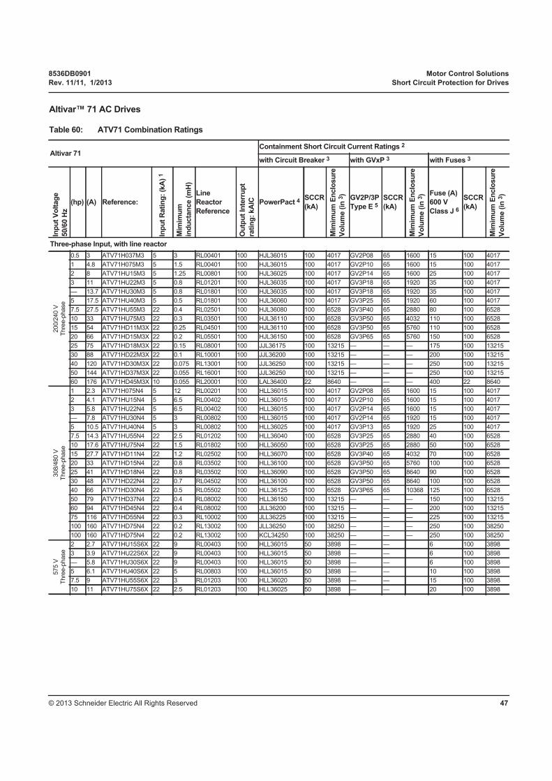
8536DB0901 Motor Control Solutions
Rev. 11/11, 1/2013 Short Circuit Protection for Drives
© 2013 Schneider Electric All Rights Reserved 47
Altivar™ 71 AC Drives
Table 60: ATV71 Combination Ratings
Altivar 71Containment Short Circuit Current Ratings 2
with Circuit Breaker 3 with GVxP 3 with Fuses 3
Inp
ut
Vo
ltag
e
50/6
0 H
z
(hp) (A) Reference:
Inp
ut
Rati
ng
: (k
A)
1
Mim
imu
m
ind
ucta
nce (
mH
)Line
Reactor
Reference
Ou
tpu
t In
terr
up
t
rati
ng
: kA
IC PowerPact 4SCCR
(kA)
Mim
imu
m E
nclo
su
re
Vo
lum
e (
in 3
)
GV2P/3P
Type E 5SCCR
(kA)
Mim
imu
m E
nclo
su
re
Vo
lum
e (
in 3
) Fuse (A)
600 V
Class J 6
SCCR
(kA)
Mim
imu
m E
nclo
su
re
Vo
lum
e (
in 3
)
Three-phase Input, with line reactor
200/2
40 V
Thre
e-p
hase
0.5 3 ATV71H037M3 5 3 RL00401 100 HJL36015 100 4017 GV2P08 65 1600 15 100 4017
1 4.8 ATV71H075M3 5 1.5 RL00401 100 HJL36015 100 4017 GV2P10 65 1600 15 100 4017
2 8 ATV71HU15M3 5 1.25 RL00801 100 HJL36025 100 4017 GV2P14 65 1600 25 100 4017
3 11 ATV71HU22M3 5 0.8 RL01201 100 HJL36035 100 4017 GV3P18 65 1920 35 100 4017
— 13.7 ATV71HU30M3 5 0.8 RL01801 100 HJL36035 100 4017 GV3P18 65 1920 35 100 4017
5 17.5 ATV71HU40M3 5 0.5 RL01801 100 HJL36060 100 4017 GV3P25 65 1920 60 100 4017
7.5 27.5 ATV71HU55M3 22 0.4 RL02501 100 HJL36080 100 6528 GV3P40 65 2880 80 100 6528
10 33 ATV71HU75M3 22 0.3 RL03501 100 HJL36110 100 6528 GV3P50 65 4032 110 100 6528
15 54 ATV71HD11M3X 22 0.25 RL04501 100 HJL36110 100 6528 GV3P50 65 5760 110 100 6528
20 66 ATV71HD15M3X 22 0.2 RL05501 100 HJL36150 100 6528 GV3P65 65 5760 150 100 6528
25 75 ATV71HD18M3X 22 0.15 RL08001 100 JJL36175 100 13215 — — — 175 100 13215
30 88 ATV71HD22M3X 22 0.1 RL10001 100 JJL36200 100 13215 — — — 200 100 13215
40 120 ATV71HD30M3X 22 0.075 RL13001 100 JJL36250 100 13215 — — — 250 100 13215
50 144 ATV71HD37M3X 22 0.055 RL16001 100 JJL36250 100 13215 — — — 250 100 13215
60 176 ATV71HD45M3X 10 0.055 RL20001 100 LAL36400 22 8640 — — — 400 22 8640
308/4
80 V
Thre
e-p
hase
1 2.3 ATV71H075N4 5 12 RL00201 100 HLL36015 100 4017 GV2P08 65 1600 15 100 4017
2 4.1 ATV71HU15N4 5 6.5 RL00402 100 HLL36015 100 4017 GV2P10 65 1600 15 100 4017
3 5.8 ATV71HU22N4 5 6.5 RL00402 100 HLL36015 100 4017 GV2P14 65 1600 15 100 4017
— 7.8 ATV71HU30N4 5 3 RL00802 100 HLL36015 100 4017 GV2P14 65 1920 15 100 4017
5 10.5 ATV71HU40N4 5 3 RL00802 100 HLL36025 100 4017 GV3P13 65 1920 25 100 4017
7.5 14.3 ATV71HU55N4 22 2.5 RL01202 100 HLL36040 100 6528 GV3P25 65 2880 40 100 6528
10 17.6 ATV71HU75N4 22 1.5 RL01802 100 HLL36050 100 6528 GV3P25 65 2880 50 100 6528
15 27.7 ATV71HD11N4 22 1.2 RL02502 100 HLL36070 100 6528 GV3P40 65 4032 70 100 6528
20 33 ATV71HD15N4 22 0.8 RL03502 100 HLL36100 100 6528 GV3P50 65 5760 100 100 6528
25 41 ATV71HD18N4 22 0.8 RL03502 100 HLL36090 100 6528 GV3P50 65 8640 90 100 6528
30 48 ATV71HD22N4 22 0.7 RL04502 100 HLL36100 100 6528 GV3P50 65 8640 100 100 6528
40 66 ATV71HD30N4 22 0.5 RL05502 100 HLL36125 100 6528 GV3P65 65 10368 125 100 6528
50 79 ATV71HD37N4 22 0.4 RL08002 100 HLL36150 100 13215 — — — 150 100 13215
60 94 ATV71HD45N4 22 0.4 RL08002 100 JLL36200 100 13215 — — — 200 100 13215
75 116 ATV71HD55N4 22 0.3 RL10002 100 JLL36225 100 13215 — — — 225 100 13215
100 160 ATV71HD75N4 22 0.2 RL13002 100 JLL36250 100 38250 — — — 250 100 38250
100 160 ATV71HD75N4 22 0.2 RL13002 100 KCL34250 100 38250 — — — 250 100 38250
575 V
Thre
e-p
hase
2 2.7 ATV71HU15S6X 22 9 RL00403 100 HLL36015 50 3898 — — 6 100 3898
3 3.9 ATV71HU22S6X 22 9 RL00403 100 HLL36015 50 3898 — — 6 100 3898
— 5.8 ATV71HU30S6X 22 9 RL00403 100 HLL36015 50 3898 — — 6 100 3898
5 6.1 ATV71HU40S6X 22 5 RL00803 100 HLL36015 50 3898 — — 10 100 3898
7.5 9 ATV71HU55S6X 22 3 RL01203 100 HLL36020 50 3898 — — 15 100 3898
10 11 ATV71HU75S6X 22 2.5 RL01203 100 HLL36025 50 3898 — — 20 100 3898
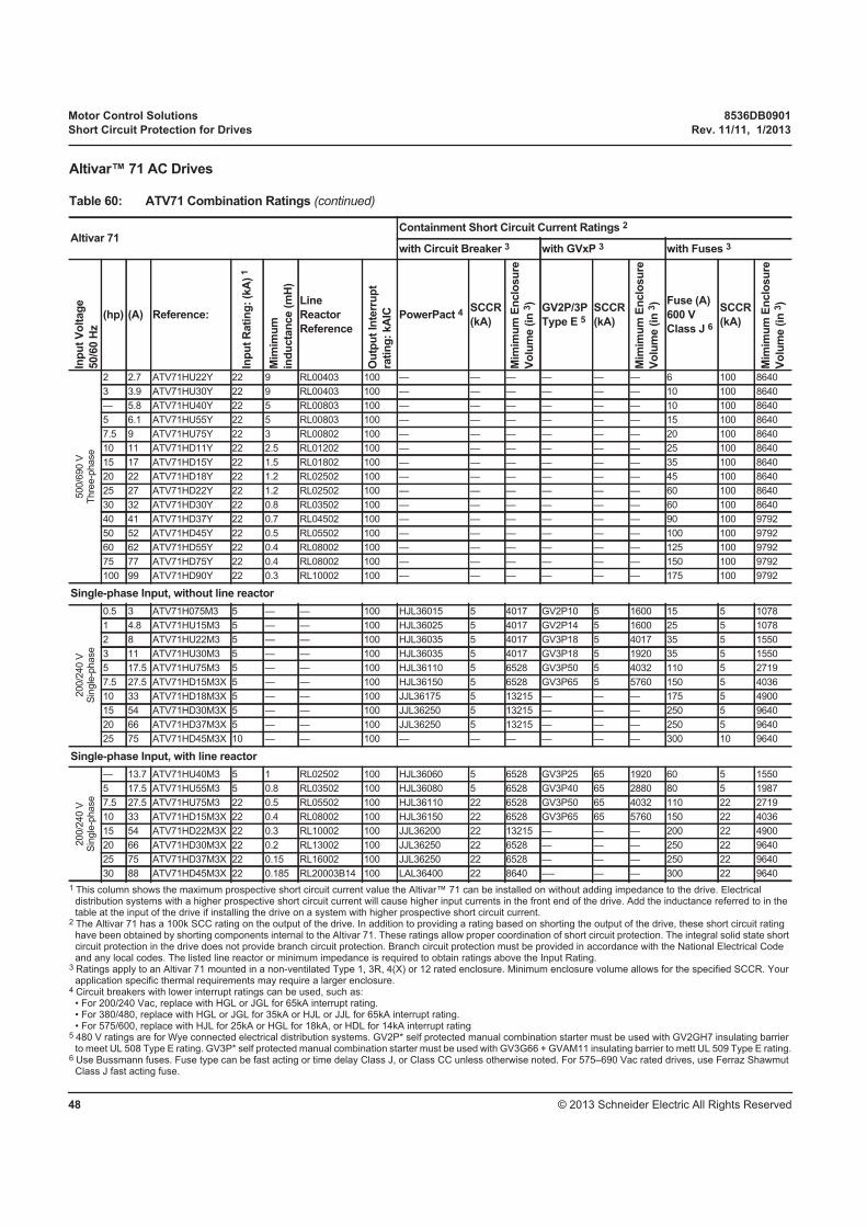
Motor Control Solutions 8536DB0901
Short Circuit Protection for Drives Rev. 11/11, 1/2013
© 2013 Schneider Electric All Rights Reserved48
1 This column shows the maximum prospective short circuit current value the Altivar™ 71 can be installed on without adding impedance to the drive. Electrical distribution systems with a higher prospective short circuit current will cause higher input currents in the front end of the drive. Add the inductance referred to in the table at the input of the drive if installing the drive on a system with higher prospective short circuit current.
2 The Altivar 71 has a 100k SCC rating on the output of the drive. In addition to providing a rating based on shorting the output of the drive, these short circuit rating have been obtained by shorting components internal to the Altivar 71. These ratings allow proper coordination of short circuit protection. The integral solid state short circuit protection in the drive does not provide branch circuit protection. Branch circuit protection must be provided in accordance with the National Electrical Code and any local codes. The listed line reactor or minimum impedance is required to obtain ratings above the Input Rating.
3 Ratings apply to an Altivar 71 mounted in a non-ventilated Type 1, 3R, 4(X) or 12 rated enclosure. Minimum enclosure volume allows for the specified SCCR. Your application specific thermal requirements may require a larger enclosure.
4 Circuit breakers with lower interrupt ratings can be used, such as:• For 200/240 Vac, replace with HGL or JGL for 65kA interrupt rating. • For 380/480, replace with HGL or JGL for 35kA or HJL or JJL for 65kA interrupt rating. • For 575/600, replace with HJL for 25kA or HGL for 18kA, or HDL for 14kA interrupt rating
5 480 V ratings are for Wye connected electrical distribution systems. GV2P* self protected manual combination starter must be used with GV2GH7 insulating barrier to meet UL 508 Type E rating. GV3P* self protected manual combination starter must be used with GV3G66 + GVAM11 insulating barrier to mett UL 509 Type E rating.
6 Use Bussmann fuses. Fuse type can be fast acting or time delay Class J, or Class CC unless otherwise noted. For 575–690 Vac rated drives, use Ferraz Shawmut Class J fast acting fuse.
500/6
90 V
Thre
e-p
hase
2 2.7 ATV71HU22Y 22 9 RL00403 100 — — — — — — 6 100 8640
3 3.9 ATV71HU30Y 22 9 RL00403 100 — — — — — — 10 100 8640
— 5.8 ATV71HU40Y 22 5 RL00803 100 — — — — — — 10 100 8640
5 6.1 ATV71HU55Y 22 5 RL00803 100 — — — — — — 15 100 8640
7.5 9 ATV71HU75Y 22 3 RL00802 100 — — — — — — 20 100 8640
10 11 ATV71HD11Y 22 2.5 RL01202 100 — — — — — — 25 100 8640
15 17 ATV71HD15Y 22 1.5 RL01802 100 — — — — — — 35 100 8640
20 22 ATV71HD18Y 22 1.2 RL02502 100 — — — — — — 45 100 8640
25 27 ATV71HD22Y 22 1.2 RL02502 100 — — — — — — 60 100 8640
30 32 ATV71HD30Y 22 0.8 RL03502 100 — — — — — — 60 100 8640
40 41 ATV71HD37Y 22 0.7 RL04502 100 — — — — — — 90 100 9792
50 52 ATV71HD45Y 22 0.5 RL05502 100 — — — — — — 100 100 9792
60 62 ATV71HD55Y 22 0.4 RL08002 100 — — — — — — 125 100 9792
75 77 ATV71HD75Y 22 0.4 RL08002 100 — — — — — — 150 100 9792
100 99 ATV71HD90Y 22 0.3 RL10002 100 — — — — — — 175 100 9792
Single-phase Input, without line reactor
200/2
40 V
Sin
gle
-phase
0.5 3 ATV71H075M3 5 — — 100 HJL36015 5 4017 GV2P10 5 1600 15 5 1078
1 4.8 ATV71HU15M3 5 — — 100 HJL36025 5 4017 GV2P14 5 1600 25 5 1078
2 8 ATV71HU22M3 5 — — 100 HJL36035 5 4017 GV3P18 5 4017 35 5 1550
3 11 ATV71HU30M3 5 — — 100 HJL36035 5 4017 GV3P18 5 1920 35 5 1550
5 17.5 ATV71HU75M3 5 — — 100 HJL36110 5 6528 GV3P50 5 4032 110 5 2719
7.5 27.5 ATV71HD15M3X 5 — — 100 HJL36150 5 6528 GV3P65 5 5760 150 5 4036
10 33 ATV71HD18M3X 5 — — 100 JJL36175 5 13215 — — — 175 5 4900
15 54 ATV71HD30M3X 5 — — 100 JJL36250 5 13215 — — — 250 5 9640
20 66 ATV71HD37M3X 5 — — 100 JJL36250 5 13215 — — — 250 5 9640
25 75 ATV71HD45M3X 10 — — 100 — — — — — — 300 10 9640
Single-phase Input, with line reactor
200/2
40 V
Sin
gle
-phase
— 13.7 ATV71HU40M3 5 1 RL02502 100 HJL36060 5 6528 GV3P25 65 1920 60 5 1550
5 17.5 ATV71HU55M3 5 0.8 RL03502 100 HJL36080 5 6528 GV3P40 65 2880 80 5 1987
7.5 27.5 ATV71HU75M3 22 0.5 RL05502 100 HJL36110 22 6528 GV3P50 65 4032 110 22 2719
10 33 ATV71HD15M3X 22 0.4 RL08002 100 HJL36150 22 6528 GV3P65 65 5760 150 22 4036
15 54 ATV71HD22M3X 22 0.3 RL10002 100 JJL36200 22 13215 — — — 200 22 4900
20 66 ATV71HD30M3X 22 0.2 RL13002 100 JJL36250 22 6528 — — — 250 22 9640
25 75 ATV71HD37M3X 22 0.15 RL16002 100 JJL36250 22 6528 — — — 250 22 9640
30 88 ATV71HD45M3X 22 0.185 RL20003B14 100 LAL36400 22 8640 -— — — 300 22 9640
Altivar™ 71 AC Drives
Table 60: ATV71 Combination Ratings (continued)
Altivar 71Containment Short Circuit Current Ratings 2
with Circuit Breaker 3 with GVxP 3 with Fuses 3
Inp
ut
Vo
ltag
e
50/6
0 H
z
(hp) (A) Reference:
Inp
ut
Rati
ng
: (k
A)
1
Mim
imu
m
ind
ucta
nce (
mH
)Line
Reactor
Reference
Ou
tpu
t In
terr
up
t
rati
ng
: kA
IC PowerPact 4SCCR
(kA)
Mim
imu
m E
nclo
su
re
Vo
lum
e (
in 3
)
GV2P/3P
Type E 5SCCR
(kA)
Mim
imu
m E
nclo
su
re
Vo
lum
e (
in 3
) Fuse (A)
600 V
Class J 6
SCCR
(kA)
Mim
imu
m E
nclo
su
re
Vo
lum
e (
in 3
)
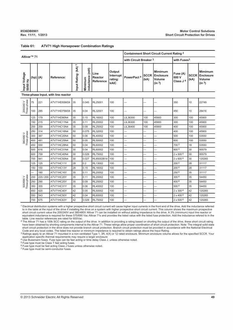
8536DB0901 Motor Control Solutions
Rev. 11/11, 1/2013 Short Circuit Protection for Drives
© 2013 Schneider Electric All Rights Reserved 49
1 Electrical distribution systems with a higher prospective short circuit current will cause higher input currents in the front end of the drive. Add the inductance referred to in the table at the input of the drive if installing the drive on a system with higher prospective short circuit current. This column shows the maximum prospective short circuit current value the 200/240V and 380/480V Altivar 71 can be installed on without adding impedance to the drive. A 3% (minimum) input line reactor or equivalent inductance is required for these 575/690 Vac Altivar 71s and provides the listed value with the listed fuse protection. Add the inductance refered to in the table. Line reactor references are rated for 600Vac.
2 The Altivar 71 has a 100k SCC rating on the output of the drive. In addition to providing a rating based on shorting the output of the drive, these short circuit rating have been obtained by shorting components internal to the Altivar 71. These ratings allow proper coordination of short circuit protection. Note: The integral solid state short circuit protection in the drive does not provide branch circuit protection. Branch circuit protection must be provided in accordance with the National Electrical Code and any local codes. The listed line reactor or minimum impedance is required to obtain ratings above the Input Rating.
3 Ratings apply to an Altivar 71 mounted in a non-ventilated Type 1, 3R, 4(X) or 12 rated enclosure. Minimum enclosure volume allows for the specified SCCR. Your application specific thermal requirements may require a larger enclosure
4 Use Bussmann fuses. Fuse type can be fast acting or time delay Class J, unless otherwise noted.5 Fuse type must be Class T fast acting fuses.6 Fuse type must be fast acting Class J fuses unless otherwise noted.7 Fuse type must be semi-conductor fuses.
Table 61: ATV71 High Horsepower Combination Ratings
Altivar™ 71Containment Short Circuit Current Rating 2
with Circuit Breaker 3 with Fuses3
Inp
ut
Vo
ltag
e
50/6
0 H
z
(hp) (A) Reference:In
pu
t R
ati
ng
: (k
A)
1
Mim
imu
m
ind
ucta
nce (
mH
)
Line
Reactor
Reference
Output
Interrupt
rating:
kAIC
PowerPact 4SCCR
(kA)
Mimimum
Enclosure
Volume
(in 3)
Fuse (A)
600 V
Class J 4
SCCR
(kA)
Mimimum
Enclosure
Volume
(in 3)
Three-phase Input, with line reactor
200/2
40 V
Thre
e-p
hase
75 221 ATV71HD55M3X 35 0.045 RL25001 100 — — — 350 10 22749
100 285 ATV71HD75M3X 35 0.04 RL32001 100 — — — 450 10 28416
380/4
80 V
Thre
e-p
hase
125 179 ATV71HD90N4 35 0.15 RL16002 100 LIL36300 100 45900 300 100 45900
150 215 ATV71HC11N4 35 0.11 RL20002 100 LIL36300 100 45900 300 100 45900
200 259 ATV71HC13N4 35 0.09 RL25002 100 LIL36400 100 45900 400 100 45900
250 314 ATV71HC16N4 50 0.075 RL32002 100 — — — 400 100 45900
300 387 ATV71HC20N4 50 0.06 RL40002 100 — — — 500 100 53550
400 481 ATV71HC25N4 50 0.05 RL50002 100 — — — 600 100 53550
450 550 ATV71HC28N4 50 0.04 RL60002 100 — — — 700 5 18 53550
500 616 ATV71HC31N4 30 0.04 RL60002 100 — — — 800 5 30 95579
600 759 ATV71HC40N4 30 0.029 RL75002 100 — — — 2 x 500 6 30 95579
700 941 ATV71HC50N4 30 0.027 RL85002B14 100 — — — 2 x 600 6 30 120265
500/6
90 V
Thre
e-p
hase
125 125 ATV71HC11Y 28 0.2 RL13002 100 — — — 200 6 28 31117
150 150 ATV71HC13Y 28 0.15 RL16002 100 — — — 200 6 28 31117
— 180 ATV71HC16Y 35 0.11 RL20002 100 — — — 250 6 35 31117
200 220 / 200 ATV71HC20Y 35 0.11 RL20002 100 — — — 300 6 35 54450
250 290 ATV71HC25Y 35 0.09 RL25002 100 — — — 400 6 35 54450
350 355 ATV71HC31Y 35 0.06 RL40002 100 — — — 500 6 35 54450
450 420 ATV71HC40Y 42 0.05 RL50002 100 — — — 2 x 300 6 42 120265
550 543 ATV71HC50Y 42 0.04 RL60002 100 — — — 2 x 400 6 42 120265
700 675 ATV71HC63Y 42 0.029 RL75002 100 — — — 2 x 500 6 42 120265
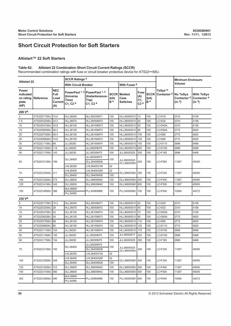
Motor Control Solutions 8536DB0901
Short Circuit Protection for Soft Starters Rev. 11/11, 1/2013
© 2013 Schneider Electric All Rights Reserved50
Short Circuit Protection for Soft Starters
Altistart™ 22 Soft Starters
Table 62: Altistart 22 Combination Short Circuit Current Ratings (SCCR)
Recommended combination ratings with fuse or circuit breaker protective device for ATS22•••S6U.
Altistart 22SCCR Ratings 5
TeSys™
Contactor 8
Minimum Enclosure
VolumeWith Circuit Breaker With Fuses 6
Power
indicated
on rating
plate
(HP)
Reference
NEC
Full
Load
Current
(A)
PowerPact 1, 2
(Innverse
Time)
C1, C2 4
PowerPact 1, 2
(Instantaneous-
Trip)
C1, C2 4
SCCR
(kA)
B 4
Molded
Case
Switches
Fuse
(A)
C1,
C2 4
SCCR
(kA)
B 4
No TeSys
Contactor 4
(in 3)
With TeSys
Contactor 4
(in 3)
208 VA
3 ATS22D17S6U 10.6 HLL36040 HLL36030M71 100 HLL36000S15 15 100 LC•D18 2310 4158
7.5 ATS22D32S6U 24.2 HLL36070 HLL36050M72 100 HLL36000S15 40 100 LC•D32 2310 4158
10 ATS22D47S6U 30.8 HLL36100 HLL36100M73 100 HLL36000S15 50 100 LC•D40A 2310 4158
15 ATS22D62S6U 46.2 HLL36125 HLL36100M73 100 HLL36000S15 80 100 LC•D50A 2772 4620
20 ATS22D75S6U 59.4 HLL36150 HLL36150M74 100 HLL36000S15 100 100 LC•D80 2772 4620
25 ATS22D88S6U 74.8 HLL36150 HLL36150M74 100 HLL36000S15 125 100 LC•D80 2772 4620
30 ATS22C11S6U 88 JLL36250 HLL36150M74 100 HLL36000S15 150 100 LC•D115 3696 6468
40 ATS22C14S6U 114 JLL36250 JLL36250M75 100 HLL36000S15 200 100 LC•D150 3696 6468
50 ATS22C17S6U 143 JLL36250 JLL36250M75 100 JLL36000S25 250 100 LC•F185 3696 6468
60 ATS22C21S6U 169DLL36400
JLL36250M75100 JLL36000S25
DLL36600S60250 100 LC•F265 11267 45000DLL36400M36
LHL36350 LHL3640031M 42
75 ATS22C25S6U 211LHL36400 LHL3640032M 42
DLL36600S60 350 100 LC•F330 11267 45000DLL36400 DLL36400M36 100
100 ATS22C32S6U 273 DLL36600 DLL36600M42 100 DLL36600S60 450 100 LC•F400 11267 45000
125 ATS22C41S6U 343 DLL36600 DLL36600M42 100 DLL36600S60 600 100 LC•F500 11267 45000
150 ATS22C48S6U 396MJL36800
PLL34080M68 100 PLL34000S60 700 100 LC•F500 10584 34272PLL34080
230 VA
5 ATS22D17S6U 15.2 HLL36040 HLL36030M71 100 HLL36000S15 30 100 LC•D25 2310 4158
10 ATS22D32S6U 28 HLL36070 HLL36050M72 100 HLL36000S15 45 100 LC•D32 2310 4158
15 ATS22D47S6U 42 HLL36100 HLL36100M73 100 HLL36000S15 70 100 LC•D50A 2310 4158
20 ATS22D62S6U 54 HLL36125 HLL36100M73 100 HLL36000S15 90 100 LC•D65A 2772 4620
25 ATS22D75S6U 68 HLL36150 HLL36150M74 100 HLL36000S15 110 100 LC•D80 2772 4620
30 ATS22D88S6U 80 HLL36150 HLL36150M74 100 HLL36000S15 125 100 LC•D115 2772 4620
40 ATS22C11S6U 104 JLL36250 HLL36150M74 100 HLL36000S15 175 100 LC•D150 3696 6468
50 ATS22C14S6U 130 JLL36250 JLL36250M75 100 JLL36000S17 225 100 LC•D150 3696 6468
60 ATS22C17S6U 154 JLL36250 JLL36250M75 100 JLL36000S25 250 100 LC•F185 3696 6468
75 ATS22C21S6U 192DLL36400
JLL36250M75100 JLL36000S25
DLL36600S60300 100 LC•F330 11267 45000DLL36400M36
LHL36350 LHL3640031M 42
100 ATS22C25S6U 248LHL36400 LHL3640032M 42
DLL36600S60 400 100 LC•F330 11267 45000DLL36400 DLL36400M36 100
125 ATS22C32S6U 312 DLL36600 DLL36600M42 100 DLL36600S60 500 100 LC•F400 11267 45000
150 ATS22C41S6U 360 DLL36600 DLL36600M42 100 DLL36600S60 600 100 LC•F500 11267 45000
200 ATS22C59S6U 480MJL36800
PLL34080M68 100 PLL34000S80 800 100 LC•F630 10584 34272PLL34080

8536DB0901 Motor Control Solutions
Rev. 11/11, 1/2013 Short Circuit Protection for Soft Starters
© 2013 Schneider Electric All Rights Reserved 51
460 VA
10 ATS22D17S6U 14 HLL36040 HLL36030M71 100 HLL36000S15 20 100 LC•D18 2310 4158
20 ATS22D32S6U 27 HLL36070 HLL36050M72 100 HLL36000S15 35 100 LC•D32 2310 4158
30 ATS22D47S6U 40 HLL36100 HLL36100M73 100 HLL36000S15 70 100 LC•D50A 2310 4158
40 ATS22D62S6U 52 HLL36125 HLL36100M73 100 HLL36000S15 90 100 LC•D65A 2772 4620
50 ATS22D75S6U 65 HLL36150 HLL36150M74 100 HLL36000S15 110 100 LC•D80 2772 4620
60 ATS22D88S6U 77 HLL36150 HLL36150M74 100 HLL36000S15 125 100 LC•D115 2772 4620
75 ATS22C11S6U 96 JLL36250 HLL36150M74 100 HLL36000S15 150 100 LC•D115 3696 6468
100 ATS22C14S6U 124 JLL36250 JLL36250M75 100 JLL36000S17 200 100 LC•D150 3696 6468
125 ATS22C17S6U 156 JLL36250 JLL36250M75 100 JLL36000S25 250 100 LC•F185 3696 6468
150 ATS22C21S6U 180
DLL36400 JLL36250M75100 JLL36000S25
DLL36600S60300 100 LC•F265 11267 45000LIL36350 DLL36400M36
LHL36350 LHL3640031M 42
200 ATS22C25S6U 240
LHL36400 LHL3640032M 42
DLL36600S60 400 100 LC•F330 11267 45000DLL36400DLL36400M36 100
LIL36400
250 ATS22C32S6U 302DLL36600
DLL36600M42 100 DLL36600S60 500 100 LC•F400 11267 45000LIL36500
300 ATS22C41S6U 361DLL36600
DLL36600M42 100 DLL36600S60 600 100 LC•F500 11267 45000LIL36600
350 ATS22C48S6U 414MJL36800 — 65
PLL34000S60 700 100 LC•F500 10584 34272PLL34080 PLL34080M68 100
400 ATS22C59S6U 477MJL36800 — 65
PLL34000S60 800 100 LC•F360 10584 34272PLL34080 PLL34080M68 100
575 VA
15 ATS22D17S6U 17 HLL36040 HLL36030M71 50 HLL36000S15 25 100 LC•D40A 2310 4158
25 ATS22D32S6U 27 HLL36070 HLL36050M72 50 HLL36000S15 45 100 LC•D40A 2310 4158
40 ATS22D47S6U 41 HLL36100 HLL36100M73 50 HLL36000S15 70 100 LC•D50A 2310 4158
50 ATS22D62S6U 52 HLL36125 HLL36100M73 50 HLL36000S15 90 100 LC•D80 2772 4620
60 ATS22D75S6U 62 HLL36150 HLL36150M74 50 HLL36000S15 100 100 LC•D80 2772 4620
75 ATS22D88S6U 77 HLL36150 HLL36150M74 50 HLL36000S15 125 100 LC•D115 2772 4620
100 ATS22C11S6U 99 JLL36250 HLL36150M74 50 HLL36000S15 150 100 LC•D115 3696 6468
125 ATS22C14S6U 125 JLL36250 JLL36250M75 50 JLL36000S17 200 100 LC•D150 3696 6468
150 ATS22C17S6U 144 JLL36250 JLL36250M75 50 JLL36000S25 250 100 LC•F185 3696 6468
200 ATS22C21S6U 192
DLL364003 JLL36250M7550 JLL36000S25
DLL36600S60300 100 LC•F330 11267 45000LIL36350 DLL36400M363
LHL36350 LHL3640031M 18
250 ATS22C25S6U 242
DLL364003
DLL36400M363 50DLL36600S60 400 100 LC•F330 11267 45000LIL36400
LHL36400 LHL3640032M 18
300 ATS22C32S6U 289DLL366003
DLL36600M423 50 DLL36600S60 500 100 LC•F400 11267 45000LIL36500
Table 62: Altistart 22 Combination Short Circuit Current Ratings (SCCR) (continued)
Recommended combination ratings with fuse or circuit breaker protective device for ATS22•••S6U.
Altistart 22SCCR Ratings 5
TeSys™
Contactor 8
Minimum Enclosure
VolumeWith Circuit Breaker With Fuses 6
Power
indicated
on rating
plate
(HP)
Reference
NEC
Full
Load
Current
(A)
PowerPact 1, 2
(Innverse
Time)
C1, C2 4
PowerPact 1, 2
(Instantaneous-
Trip)
C1, C2 4
SCCR
(kA)
B 4
Molded
Case
Switches
Fuse
(A)
C1,
C2 4
SCCR
(kA)
B 4
No TeSys
Contactor 4
(in 3)
With TeSys
Contactor 4
(in 3)

Motor Control Solutions 8536DB0901
Short Circuit Protection for Soft Starters Rev. 11/11, 1/2013
© 2013 Schneider Electric All Rights Reserved52
350 ATS22C41S6U 336DLL366003
DLL36600M423 50 DLL36600S60 500 100 LC•F500 11267 45000LIL36600
400 ATS22C48S6U 382MJL36800 — 25
PKL36000S60 600 100 LC•F500 10584 34272PKL36080 PKL36080M68 50
500 ATS22C59S6U 472MJL36800 — 25
PKL36000S80 800 100 LC•F630 10584 34272PKL36080 PKL36080M68 50
1 Square D PowerPact circuit breakers. Maximum breaker size for SCCR is shown. The third character of the breaker catalog number may be an “L”, an “F”, an “M” or a “P”. The following types of Square D breakers with lower interrupting ratings may be substituted for the breakers shown: HD, HG, HJ, JD, JG, JJ, DG, DJ, MG, PG, PJ, PK.
2 A smaller ampacity breaker within the same product family may be substituted for the one described.3 Short circuit rating of the combination exceeds the rating of the circuit breaker. Combinations including F500 contactor are rated 35 kA at 600 V.4 Suitable for use on a circuit capable of delivering not more than ___B___rms symmetrical kiloAmperes, ___A___Volts maximum, when protected by ___C1___ with a
maximum rating of ___C2___.5 For all models, rating indicates standard use conditions. For heavy duty condition, the user manual must be referred to.6 Molded case switches provide the disconnecting means, and fuses provide the short circuit protection. The molded case switch part numbers are only suggestions. Customer
may choose to use similar approved disconnecting means.7 JLL36000S17 may be replaced by JLL36000S25.8 Contactor may be LC1 or LC2 type. The next larger contactor may be substituted for the one shown. Contactors may be used in conjuction with circuit breaker protection
and ATS22 soft starter for line and load isolation applications.
Table 62: Altistart 22 Combination Short Circuit Current Ratings (SCCR) (continued)
Recommended combination ratings with fuse or circuit breaker protective device for ATS22•••S6U.
Altistart 22SCCR Ratings 5
TeSys™
Contactor 8
Minimum Enclosure
VolumeWith Circuit Breaker With Fuses 6
Power
indicated
on rating
plate
(HP)
Reference
NEC
Full
Load
Current
(A)
PowerPact 1, 2
(Innverse
Time)
C1, C2 4
PowerPact 1, 2
(Instantaneous-
Trip)
C1, C2 4
SCCR
(kA)
B 4
Molded
Case
Switches
Fuse
(A)
C1,
C2 4
SCCR
(kA)
B 4
No TeSys
Contactor 4
(in 3)
With TeSys
Contactor 4
(in 3)
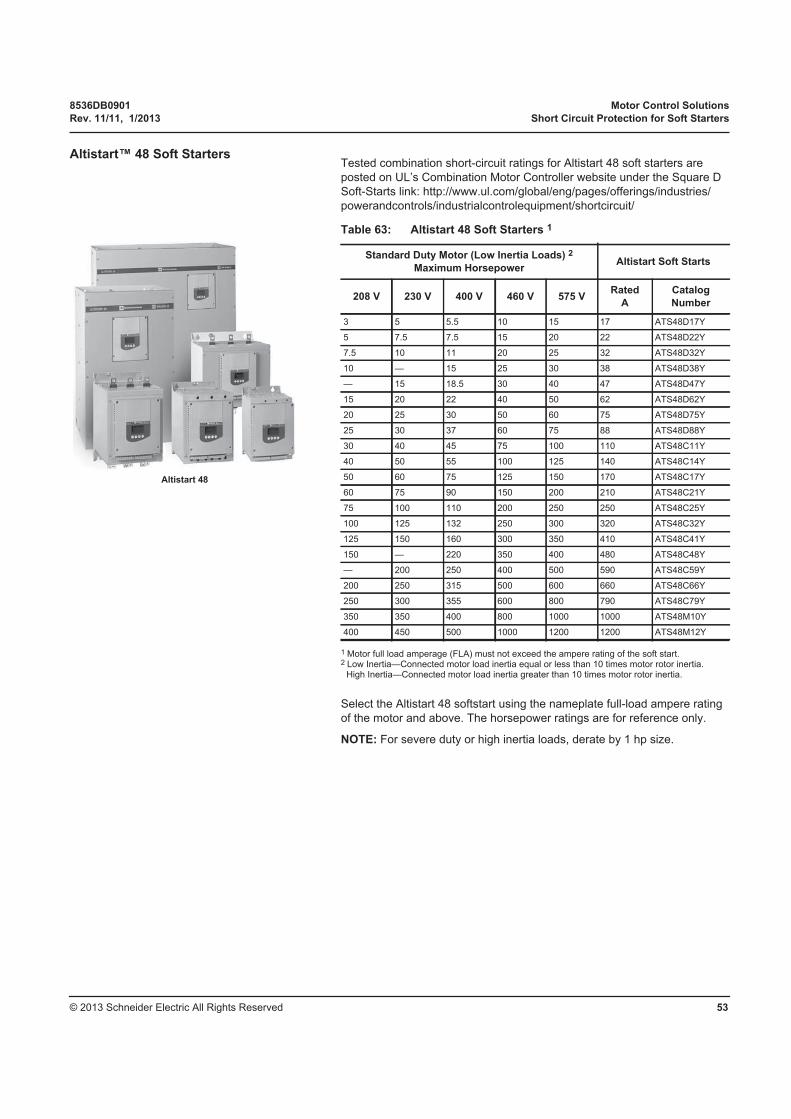
8536DB0901 Motor Control Solutions
Rev. 11/11, 1/2013 Short Circuit Protection for Soft Starters
© 2013 Schneider Electric All Rights Reserved 53
Altistart™ 48 Soft StartersTested combination short-circuit ratings for Altistart 48 soft starters are
posted on UL’s Combination Motor Controller website under the Square D
Soft-Starts link: http://www.ul.com/global/eng/pages/offerings/industries/
powerandcontrols/industrialcontrolequipment/shortcircuit/
1 Motor full load amperage (FLA) must not exceed the ampere rating of the soft start.2 Low Inertia—Connected motor load inertia equal or less than 10 times motor rotor inertia.
High Inertia—Connected motor load inertia greater than 10 times motor rotor inertia.
Select the Altistart 48 softstart using the nameplate full-load ampere rating
of the motor and above. The horsepower ratings are for reference only.
NOTE: For severe duty or high inertia loads, derate by 1 hp size.
Table 63: Altistart 48 Soft Starters 1
Standard Duty Motor (Low Inertia Loads) 2
Maximum HorsepowerAltistart Soft Starts
208 V 230 V 400 V 460 V 575 VRated
A
Catalog
Number
3 5 5.5 10 15 17 ATS48D17Y
5 7.5 7.5 15 20 22 ATS48D22Y
7.5 10 11 20 25 32 ATS48D32Y
10 — 15 25 30 38 ATS48D38Y
— 15 18.5 30 40 47 ATS48D47Y
15 20 22 40 50 62 ATS48D62Y
20 25 30 50 60 75 ATS48D75Y
25 30 37 60 75 88 ATS48D88Y
30 40 45 75 100 110 ATS48C11Y
40 50 55 100 125 140 ATS48C14Y
50 60 75 125 150 170 ATS48C17Y
60 75 90 150 200 210 ATS48C21Y
75 100 110 200 250 250 ATS48C25Y
100 125 132 250 300 320 ATS48C32Y
125 150 160 300 350 410 ATS48C41Y
150 — 220 350 400 480 ATS48C48Y
— 200 250 400 500 590 ATS48C59Y
200 250 315 500 600 660 ATS48C66Y
250 300 355 600 800 790 ATS48C79Y
350 350 400 800 1000 1000 ATS48M10Y
400 450 500 1000 1200 1200 ATS48M12Y
Altistart 48

Motor Control Solutions 8536DB0901
Specific Requirements for the Canadian Market Rev. 11/11, 1/2013
© 2013 Schneider Electric All Rights Reserved54
Specific Requirements for
the Canadian Market
Installation and Product Standards
The installation standard in Canada is the Canadian Electrical Code (CEC).
The CEC and the NEC are similar but not 100% equivalent.
The same is true for the CSA standards and corresponding UL standards
(see Table 64 below). Some of the major differences are detailed below.
Certification Process As in the U.S., nationally recognized testing laboratories (such as: CSA,
ETL, TUV, and UL) are able to certify equipment according to these CSA
standards. Refer to “Acceptance of Electrical Equipment in the U.S.” on
page 4.
Technical Differences between Canadian and U.S. Standards
Some examples of differences between the Canadian and U.S. standards
that currently apply to motor starters are listed below in Table 53. The
TeSys™ product line is designed for compliance and capatibility with both
the UL and the CSA requirements.
• Type E combination motors starters are recognized in Canada,
however, the Type F combination starters are not currently accepted in
Canada.
• Type E applications don't require the use of large spacing adapters
when used in Canada.
• Group installation is recognized but the rules to define the common
branch-circuit protection setting is quite different.
• Industrial control panels must meet CSA C22.2 No. 14
• Elevator equipment appliances must comply with the specific
CSA Nr. B44.1 standard.
• Product marking requirements differ slightly.
Table 64: Comparison of CSA and UL Standards
Standard Name CSA Standard UL Standard
Enclosed and Dead-Front Switches CSA C22.2 No. 4 UL98
Low-Voltage Fuses: Part 1: General Requirements
CSA C22.2 No. 248 UL248
Molded-Case Circuit Breakers, Molded-Case Switches, and Circuit-Breaker Enclosures
CSA C22.2 No. 5 UL489
Industrial Control Equipment CSA C22.2 No. 14 UL508
Elevator Equipment CSA No. B44.1 Partially UL508

8536DB0901 Motor Control Solutions
Rev. 11/11, 1/2013 Full-Load Current, Three-Phase Alternating-Current Motors
© 2013 Schneider Electric All Rights Reserved 55
Full-Load Current,
Three-Phase
Alternating-Current Motors
The following full-load current values conform to NEC requirements. These
value are indicative; they vary according to the type of motor, the number of
poles, and the manufacturer.
Table 65: Induction-Type Squirrel Cage and Wound Rotor (A)
Horsepower
(hp)115 V 200 V 208 V 230 V 460 V 575 V
0.5 4.4 2.5 2.4 2.2 1.1 0.9
0.75 6.4 3.7 3.5 3.2 1.6 1.3
1 8.4 4.9 4.6 4.2 2.1 1.7
1.5 12.0 6.9 6.6 6.0 3.0 2.4
2 13.6 7.8 7.5 6.8 3.4 2.7
3 — 11.0 10.6 9.6 4.8 3.9
5 — 17.5 16.7 15.2 7.6 6.1
7.5 — 25.3 24.2 22 11 9
10 — 32.2 30.8 28 14 11
15 — 48.3 46.2 42 21 17
20 — 62.1 59.4 54 27 22
25 — 78.2 74.8 68 34 27
30 — 92 88 80 40 32
40 — 120 114 104 52 41
50 — 150 143 130 65 52
60 — 177 169 154 77 62
75 — 221 211 192 96 77
100 — 285 273 248 124 99
125 — 359 343 312 156 125
150 — 414 396 360 180 144
200 — 552 528 480 240 192
250 — — — — 302 242
300 — — — — 361 289
350 — — — — 414 336
400 — — — — 477 382
450 — — — — 515 412
500 — — — — 590 472
Electrical equipment should be installed, operated, serviced, and maintained only by qualified personnel. No responsibility is assumed by Schneider Electric for any consequences arising out of the use of this material.
Square D™ and Schneider Electric™ are trademarks or registered trademarks of Schneider Electric. Other trademarks used herein are the property of their respective owners.
8536DB0901 Rev. 11/11, 1/2013Replaces 8536DB0901 11/2009© 2013 Schneider Electric All Rights Reserved
Schneider Electric 8001 Knightdale Blvd.Knightdale, NC 275451-888-778-2733www.schneider-electric.us
Motor Control Solutions
Data Bulletin