Process control solutions - Renishaw
27
Pocket guide to probing solutions for CNC machine tools Improve part quality and accuracy and increase the efficiency of your CNC machining centre Process control solutions
-
Upload
khangminh22 -
Category
Documents
-
view
0 -
download
0
Transcript of Process control solutions - Renishaw
Pocket guide to probing solutions for CNC machine tools
Improve part quality and accuracy and increase theefficiency of your CNC machining centre
Process control solutions

Contents
Renishaw profile . . . . . . . . . . . . . . . . . . . . . . . . . . . . . . . . . . . . . . . . . . . . . . . . . . . . . . . . . 1Why probe? . . . . . . . . . . . . . . . . . . . . . . . . . . . . . . . . . . . . . . . . . . . . . . . . . . . . . . . . . . . . . 3The Productive Process Pyramid™ . . . . . . . . . . . . . . . . . . . . . . . . . . . . . . . . . . . . . . . . . . . 5 Process foundation . . . . . . . . . . . . . . . . . . . . . . . . . . . . . . . . . . . . . . . . . . . . . . . 7 Process setting . . . . . . . . . . . . . . . . . . . . . . . . . . . . . . . . . . . . . . . . . . . . . . . . . . 8 In-process control . . . . . . . . . . . . . . . . . . . . . . . . . . . . . . . . . . . . . . . . . . . . . . . . 9 Post-process monitoring . . . . . . . . . . . . . . . . . . . . . . . . . . . . . . . . . . . . . . . . . . 10 Product application guide . . . . . . . . . . . . . . . . . . . . . . . . . . . . . . . . . . . . . . . . . . . . . . . . . 11 Industry-leading technology and performance . . . . . . . . . . . . . . . . . . . . . . . . . . . . . . . . . 13 Standard and high accuracy probing . . . . . . . . . . . . . . . . . . . . . . . . . . . . . . . . . . . . . . . . . 15On-machine scanning system . . . . . . . . . . . . . . . . . . . . . . . . . . . . . . . . . . . . . . . . . . . . . . 21 Tool setting and broken tool detection . . . . . . . . . . . . . . . . . . . . . . . . . . . . . . . . . . . . . . . . 23 Software for machine tool applications . . . . . . . . . . . . . . . . . . . . . . . . . . . . . . . . . . . . . . . 29On-machine programming Inspection Plus . . . . . . . . . . . . . . . . . . . . . . . . . . . . . . . . . . . . . . . . . . . . . . . . . 30 GoProbe . . . . . . . . . . . . . . . . . . . . . . . . . . . . . . . . . . . . . . . . . . . . . . . . . . . . . . 31 Set and Inspect . . . . . . . . . . . . . . . . . . . . . . . . . . . . . . . . . . . . . . . . . . . . . . . . . 32 Graphical user interfaces (GUIs) . . . . . . . . . . . . . . . . . . . . . . . . . . . . . . . . . . . . 33 Tool setting . . . . . . . . . . . . . . . . . . . . . . . . . . . . . . . . . . . . . . . . . . . . . . . . . . . . . 34Off-machine (PC-based) programming Productivity+™ software . . . . . . . . . . . . . . . . . . . . . . . . . . . . . . . . . . . . . . . . . . 35 PowerINSPECT OMV Pro . . . . . . . . . . . . . . . . . . . . . . . . . . . . . . . . . . . . . . . . . 37 Renishaw CNC Reporter . . . . . . . . . . . . . . . . . . . . . . . . . . . . . . . . . . . . . . . . . . 39Machine tool diagnostics for process foundation QC20-W telescopic ballbar . . . . . . . . . . . . . . . . . . . . . . . . . . . . . . . . . . . . . . . . 40 AxiSet™ Check-Up . . . . . . . . . . . . . . . . . . . . . . . . . . . . . . . . . . . . . . . . . . . . . . 41 SPRINT™: Machine Health Check . . . . . . . . . . . . . . . . . . . . . . . . . . . . . . . . . . 42Off-machine gauging and measurement systems . . . . . . . . . . . . . . . . . . . . . . . . . . . . . . . 43 Styli and accessories . . . . . . . . . . . . . . . . . . . . . . . . . . . . . . . . . . . . . . . . . . . . . . . . . . . . . 44 Custom solutions . . . . . . . . . . . . . . . . . . . . . . . . . . . . . . . . . . . . . . . . . . . . . . . . . . . . . . . . 45 Service, support and training . . . . . . . . . . . . . . . . . . . . . . . . . . . . . . . . . . . . . . . . . . . . . . . 46Further information . . . . . . . . . . . . . . . . . . . . . . . . . . . . . . . . . . . . . . . . . . . . . . . . . . . . . . 47 Notes . . . . . . . . . . . . . . . . . . . . . . . . . . . . . . . . . . . . . . . . . . . . . . . . . . . . . . . . . . . . . . . . . 48
CNC machine tool probing solutions …
Renishaw’s range of process control solutions provides a systematic approach to
eliminating variation at all stages of your machining process, backed by innovative
technology, proven methods and expert support . This pocket guide provides an overview
of Renishaw’s solutions for CNC machine tools and the benefits that these can bring to
your manufacturing business .
Probing is an established best practice for maximising the efficiency, quality, capability and
accuracy of machine tools . As such, the integration of Renishaw probing hardware and
software is widely adopted within machining processes .
This booklet explains the basics of probing, from its many benefits; through process
control; to product specifications and selection .
Further information can be found via the links provided
throughout, or by contacting your local Renishaw office .
www.renishaw.com/contact
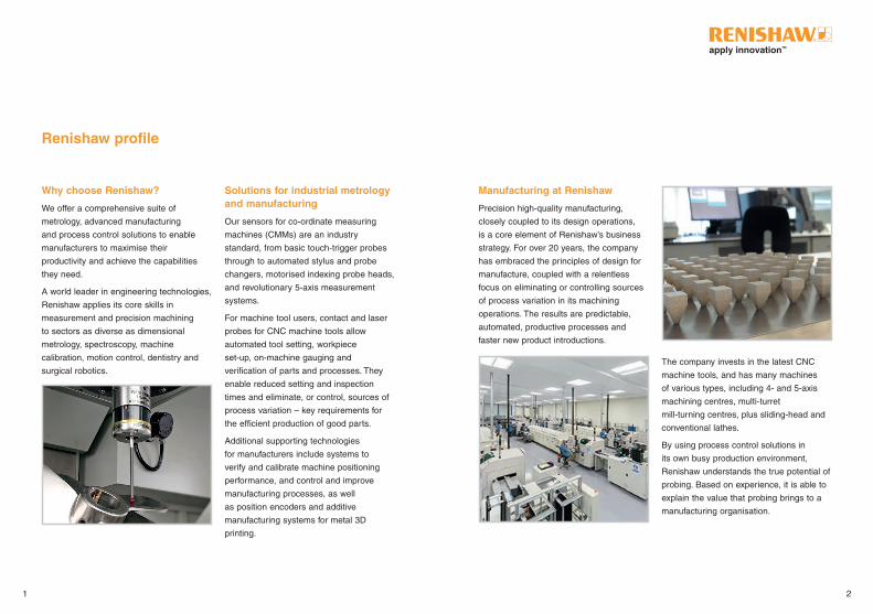
Manufacturing at Renishaw
Precision high-quality manufacturing,
closely coupled to its design operations,
is a core element of Renishaw’s business
strategy . For over 20 years, the company
has embraced the principles of design for
manufacture, coupled with a relentless
focus on eliminating or controlling sources
of process variation in its machining
operations . The results are predictable,
automated, productive processes and
faster new product introductions .
The company invests in the latest CNC
machine tools, and has many machines
of various types, including 4- and 5-axis
machining centres, multi-turret
mill-turning centres, plus sliding-head and
conventional lathes .
By using process control solutions in
its own busy production environment,
Renishaw understands the true potential of
probing . Based on experience, it is able to
explain the value that probing brings to a
manufacturing organisation .
Why choose Renishaw?
We offer a comprehensive suite of
metrology, advanced manufacturing
and process control solutions to enable
manufacturers to maximise their
productivity and achieve the capabilities
they need .
A world leader in engineering technologies,
Renishaw applies its core skills in
measurement and precision machining
to sectors as diverse as dimensional
metrology, spectroscopy, machine
calibration, motion control, dentistry and
surgical robotics .
Solutions for industrial metrology and manufacturing
Our sensors for co-ordinate measuring
machines (CMMs) are an industry
standard, from basic touch-trigger probes
through to automated stylus and probe
changers, motorised indexing probe heads,
and revolutionary 5-axis measurement
systems .
For machine tool users, contact and laser
probes for CNC machine tools allow
automated tool setting, workpiece
set-up, on-machine gauging and
verification of parts and processes . They
enable reduced setting and inspection
times and eliminate, or control, sources of
process variation – key requirements for
the efficient production of good parts .
Additional supporting technologies
for manufacturers include systems to
verify and calibrate machine positioning
performance, and control and improve
manufacturing processes, as well
as position encoders and additive
manufacturing systems for metal 3D
printing .
Renishaw profile
1 2

Time is money, and time spent manually setting workpiece positions and inspecting
finished products will impact on your manufacturing performance and profitability .
Renishaw probing systems eliminate this costly machine down-time and associated
scrapping of components .
Increase throughput from your existing assets
If your machines are overloaded, you could
face a sizeable capital investment to make
up the shortfall, a large sub-contract bill, or
worse still, turn away profitable work .
But what if you could extract more
throughput from your existing
machinery? You could:
• defer capital expenditure
• reduce your sub-contract and
overtime bills
• pursue additional business
Increase automation and reduce human intervention
Are you reliant on skilled operators to keep
your machines running, leading to high
labour costs and a substantial overtime
bill? Or perhaps your engineers are tied up
with shop support?
What impact would lower direct labour
and shop support costs have on your
competitiveness? You could:
• automate manual setting and
measurement processes
• reduce direct labour costs
• redeploy staff into proactive engineering
roles
Reduce rework, concessions and scrap
Scrapping parts is a waste of time, effort
and materials . Similarly, rework and
concessions lead to late deliveries,
fire-fighting and overtime .
If you could largely eliminate such
quality costs, how would this help your
responsiveness and profitability?
You could:
• improve conformance and consistency
• lower unit costs
• have shorter lead times
Enhance your capability and take on more work
Customers are demanding ever more
complex work whilst regulations are
driving greater traceability throughout
the manufacturing process . Are your
capabilities keeping pace with the needs of
your market?
Do you need a cost-effective way to
boost the capability of your machining
and inspection processes? You could:
• offer your customers state-of-the-art
capabilities
• take on more complex work
• meet customer demands for traceability
Reduce your total cost of ownership
Buying and maintaining manufacturing
equipment presents an up-front and
ongoing cost to your business . Are you
tied to inflexible, out-dated metrology
equipment with high running costs?
What impact would reduced total cost
of ownership have on your bottom line?
You could:
• buy fewer, more productive machines
• eliminate expensive, inflexible
custom gauges
• reduce calibration and
maintenance costs
Why Probe?
3 4
Manufacturing
Machining
Metal cutting
PREVENTATIVE PREDICTIVE
Post-processmonitoring
timelinein advance just before afterduring
ACTIVE
Processfoundation
Processsetting
In-process control
INFORMATIVE
Predictive controlsapplied just before cutting
Active controlsapplied during metal cutting
Informative controlsapplied after machining is complete
Preventative controlsapplied in advance
Process setting
In-process control
Post-process
monitoring
Process foundation
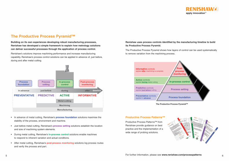
Building on its own experiences developing robust manufacturing processes,
Renishaw has developed a simple framework to explain how metrology solutions
can deliver successful processes through the application of process control.
Renishaw’s solutions improve machining performance and increase manufacturing
capability . Renishaw’s process control solutions can be applied in advance of, just before,
during and after metal cutting .
Productive Process Patterns™
Productive Process Patterns ™ from
Renishaw provide guidance on best
practice and the implementation of a
wide range of probing solutions .
Renishaw uses process controls identified by the manufacturing timeline to build
its Productive Process Pyramid.
The Productive Process Pyramid shows how layers of control can be used systematically
to remove variation from the machining process .
The Productive Process Pyramid™
The Productive Process Pyramid™
For further information, please see www.renishaw.com/processpatterns5 6
• In advance of metal cutting, Renishaw’s process foundation solutions maximise the
stability of the process, environment and machine .
• Just before metal cutting, Renishaw’s process setting solutions establish the location
and size of machining system elements .
• During metal cutting, Renishaw’s in-process control solutions enable machines
to respond to inherent variation and actual conditions .
• After metal cutting, Renishaw’s post-process monitoring solutions log process routes
and verify the process and part .

PREDICTIVE solutions
Process-setting controls are on-machine activities, required just before metal cutting,
which predict whether the process will be successful .
Tool setting establishes:
• length from the spindle gauge-line to establish a height
offset, and to check that length is within the specified
tolerance .
• diameter when spinning to establish a tool size offset .
Part setting establishes:
• component identification to select the correct
NC program .
• position of a datum feature to establish a work
co-ordinate system (WCS) .
• billet/component size to determine stock condition and
roughing cut sequence .
• orientation of a component (relative to machine axes) to
establish the co-ordinate rotation .
Machine setting establishes:
• alignment of a rotary axis, indexer or fixturing elements
required to position and hold components .
• position of an indexer’s centre of rotation and/or
reference points on fixture elements .
PREVENTATIVE solutions
Controls in the base layer of the Pyramid are targeted at maximising the stability of the
environment in which the process is to be performed . These preventative controls stop
special causes of variation having an impact on the machining process .
Controls in the process foundation layer include:
• Design for manufacture – approaches to product and
process design based on a thorough understanding of
current capability and a drive towards best practice .
• Control of process inputs – involves the use of FMEA
and similar techniques to understand and control all
the upstream factors that can affect machining process
outcomes .
• Environmental stability – addresses external sources of
non-conformance that cannot be eliminated in advance .
• Process design – a systematic approach to sequencing
the manufacturing process to enhance process stability
and automation . This includes integrating process
feedback into the process at critical stages .
• Machine condition optimisation – an inaccurate
machine cannot make consistently accurate parts . A
rigorous process of performance assessment, calibration
and (where required) refurbishment can bring the
machine’s performance in line with the process requirements .
Process foundation
Process setting
Predictive controlsapplied just before cutting
Active controlsapplied during metal cutting
Informative controlsapplied after machining is complete
Preventative controlsapplied in advance
Process setting
In-process control
Post-process
monitoring
Process foundation
Predictive controlsapplied just before cutting
Active controlsapplied during metal cutting
Informative controlsapplied after machining is complete
Preventative controlsapplied in advance
Process setting
In-process control
Post-process
monitoring
Process foundation
7 8
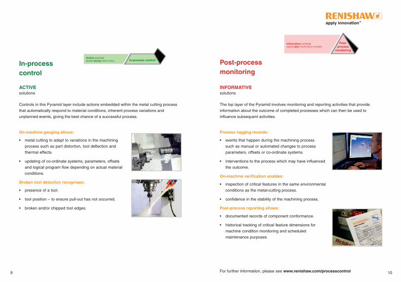
ACTIVE solutions
Controls in this Pyramid layer include actions embedded within the metal cutting process
that automatically respond to material conditions, inherent process variations and
unplanned events, giving the best chance of a successful process .
On-machine gauging allows:
• metal cutting to adapt to variations in the machining
process such as part distortion, tool deflection and
thermal effects .
• updating of co-ordinate systems, parameters, offsets
and logical program flow depending on actual material
conditions .
Broken tool detection recognises:
• presence of a tool .
• tool position – to ensure pull-out has not occurred .
• broken and/or chipped tool edges .
INFORMATIVE solutions The top layer of the Pyramid involves monitoring and reporting activities that provide
information about the outcome of completed processes which can then be used to
influence subsequent activities .
Process logging records:
• events that happen during the machining process
such as manual or automated changes to process
parameters, offsets or co-ordinate systems .
• interventions to the process which may have influenced
the outcome .
On-machine verification enables:
• inspection of critical features in the same environmental
conditions as the metal-cutting process .
• confidence in the stability of the machining process .
Post-process reporting allows:
• documented records of component conformance .
• historical tracking of critical feature dimensions for
machine condition monitoring and scheduled
maintenance purposes .
In-process control
Post-process monitoring
Predictive controlsapplied just before cutting
Active controlsapplied during metal cutting
Informative controlsapplied after machining is complete
Preventative controlsapplied in advance
Process setting
In-process control
Post-process
monitoring
Process foundation
Predictive controlsapplied just before cutting
Active controlsapplied during metal cutting
Informative controlsapplied after machining is complete
Preventative controlsapplied in advance
Process setting
In-process control
Post-process
monitoring
Process foundation
9 10For further information, please see www.renishaw.com/processcontrol

Machine types
Vertical CNC machining centres
Horizontal CNC machining centres
Gantry CNC machining centres
CNC lathes
CNC multi-tasking machines
CNC grinders
Products S* M* L* S* M* L* All S§ M§ L§ S‡ M‡ L‡ All
Standard accuracy probes repeatability 1.00 μm (40 μin) 2σ
OMP40-2
OLP40
OMP60
RMP40
RLP40
RMP60
LP2
High accuracy probes repeatability 0.25 μm (10 μin) 2σ
OMP400
OMP600
RMP600
MP250
Contact tool setters and broken tool detection
OTS
RTS
TS27R
LTS
Non-contact tool setters and broken tool detection
NC4
Non-contact broken tool detection
TRS2
Contact tool setting arms
HPRA
HPPA
HPMA
HPGA
Identify which machine tool probes are suited to your application
Product application guide
*Table sizesS (Small) M (Medium) L (Large)
<700 mm × 600 mm <1200 mm × 600 mm >1200 mm × 600 mm
S (Small) M (Medium) L (Large)
§ Chuck size 6 in to 8 in or smaller Chuck size 10 in to 15 in Chuck size 18 in to 24 in
‡ Working range <1500 mm Working range <3500 mm Working range >3500 mm
11 12

Modulated optical transmission is used for all new
generation 'OMP' probes, providing the highest level of
resistance to light interference .
Frequency hopping spread spectrum (FHSS) is a unique
transmission system that does not use a dedicated radio
channel . Instead, the probe and receiver ‘hop’ together
through a sequence of frequencies, enabling multiple probe
systems and other industrial equipment to coexist, with
negligible chance of interference .
RMI-Q multiple probing is a combined transmitter,
receiver and interface unit that enables individual radio
turn-on and operation of up to four separate Renishaw
radio probes . This permits numerous combinations of radio
probes and/or radio tool setters to be used on the same
machine tool . Unlike the optical transmission systems,
line-of-sight between the probe and receiver is not
necessary .
RENGAGE™ strain gauge technology brings unrivalled
3D measurement performance and repeatability and
is used in the OMP400, OMP600, RMP600 and
MP250 probes .
MicroHole™ and PassiveSeal™ technologies are used
in Renishaw's NC4 non-contact system providing unique
environmental protection from the harsh machining
environment . This ensures IPX8 protection 100% of
the time .
ToolWise™ technology is used in Renishaw's TRS2
non-contact broken tool detection system and
can distinguish between the tool and coolant or swarf .
SwarfStop™ technology is an additional metal sealing
device on the HPGA, positioned between the hub and
base, acting as a physical barrier for environmental
protection .
SupaTouch technology automatically optimises
on-machine measurement cycles to minimise cycle time
and maximise productivity .
SPRINT™ on-machine scanning technology enables
measurement strategies that allow fast and accurate form
and profile data capture from both prismatic and complex
3D components .
Breakthrough solutions are at the heart of Renishaw’s business strategy, which is
captured by the phrase ‘apply innovation’. The innovative product design is a result
of unparalleled investment into R&D, allowing Renishaw to offer you market leading
solutions to help your business .
Industry-leading technology and performance
13 14
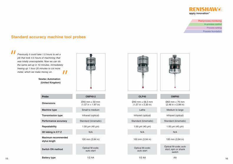
Probe OMP40-2 OLP40 OMP60
Dimensions Ø40 mm × 50 mm (1 .57 in × 1 .97 in)
Ø40 mm × 58 .3 mm (1 .57 in × 2 .30 in)
Ø63 mm × 76 mm (2 .48 in × 2 .99 in)
Machine type Small to medium Lathe Medium to large
Transmission type Infrared (optical) Infrared (optical) Infrared (optical)
Performance accuracy Standard (kinematic) Standard (kinematic) Standard (kinematic)
Repeatability 1 .00 µm (40 µin) 1 .00 µm (40 µin) 1 .00 µm (40 µin)
3D lobing in X Y Z N/A N/A N/A
Maximum recommended
stylus length100 mm (3 .94 in) 100 mm (3 .94 in) 100 mm (3 .94 in)
Switch ON method Optical M-code; auto start
Optical M-code; auto start
Optical M-code; auto start; spin or shank
switch
Battery type 1/2 AA 1/2 AA AA
Standard accuracy machine tool probes
Previously it could take 1.5 hours to set a
job that took 4.5 hours of machining; that
was totally unacceptable. Now we can do
the same set-up in 10 minutes, immediately
freeing up 1 hour 20 minutes to cut more
metal, which we make money on.
Sewtec Automation
(United Kingdom)
15 16
Post-process monitoring
In-process control
Process setting
Process foundation

18
Probe RLP40 RMP40 RMP60 LP2
Dimensions Ø40 mm × 58 .3 mm(1 .57 in × 2 .30 in)
Ø40 mm × 50 mm (1 .57 in × 1 .97 in)
Ø63 mm × 76 mm(2 .48 in × 2 .99 in)
Ø24 .8 mm × 33 .2 mm(0 .98 in × 1 .31 in)
Machine type Lathe Small to medium Medium to large Small to large
Transmission type Radio (FHSS) Radio (FHSS) Radio (FHSS)O/RMP40M O/RMP60M
hard-wired
Performance accuracy Standard (kinematic) Standard (kinematic) Standard (kinematic) Standard (kinematic)
Repeatability 1 .00 µm (40 µin) 1 .00 µm (40 µin) 1 .00 µm (40 µin) 1 .00 µm (40 µin)
3D lobing in X Y Z N/A N/A N/A N/A
Maximum recommended
stylus length100 mm (3 .94 in) 100 mm (3 .94 in) 100 mm (3 .94 in) 100 mm (3 .94 in)
Switch ON method Radio M-code; spin Radio M-code; spinRadio M-code; spin or
shank switchN/A
Battery type 1/2 AA 1/2 AA AA N/A
Standard accuracy machine tool probes
Through Renishaw we discovered machine
tool probe measurement solutions that
could deliver in-process measurement
control and real-time data feedback … This
was a massive help in terms of increasing
production efficiency and precision.
17
SuperAlloy Industrial Company Ltd
(Taiwan)
Post-process monitoring
In-process control
Process setting
Process foundation

Probe OMP400 OMP600 RMP600 MP250
Dimensions Ø40 mm × 50 mm (1 .57 in × 1 .97 in)
Ø63 mm × 76 mm (2 .48 in × 2 .99 in)
Ø63 mm × 76 mm(2 .48 in × 2 .99 in)
Ø25 mm × 36 mm(0 .98 in × 1 .42 in)
Machine type Small to medium Medium to large Medium to large Grinder
Transmission type Infrared (optical) Infrared (optical) Radio (FHSS) Hard-wired
Performance accuracy High (strain gauge) High (strain gauge) High (strain gauge) High (strain gauge)
Repeatability 0 .25 µm (10 µin) 0 .25 µm (10 µin) 0 .25 µm (10 µin) 0 .25 µm (10 µin)
3D lobing in X Y Z ±1 .00 µm (40 µin) ±1 .00 µm (40 µin) ±1 .00 µm (40 µin) ±1 .00 µm (40 µin)
Maximum recommended
stylus length200 mm (7 .88 in) 200 mm (7 .88 in) 200 mm (7 .88 in) 100 mm (3 .94 in)
Switch ON method Optical M-code; auto start
Optical M-code; auto start; spin or shank
switch
Radio M-code; spin or shank switch
N/A
Battery type 1/2 AA AA AA N/A
High accuracy machine tool probes
We are very happy with the accuracy of
RMP600 and, in particular, the consequent
reduction in scrap parts further down the
production line. These are large expensive
components and we use the probe to identify
and avoid errors.
19 20
Tods Composite Solutions
(United Kingdom)
Post-process monitoring
In-process control
Process setting
Process foundation
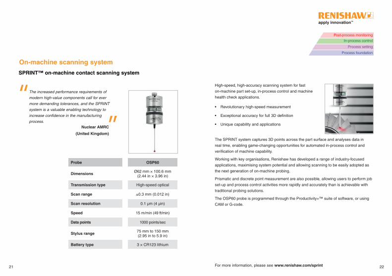
The increased performance requirements of
modern high-value components call for ever
more demanding tolerances, and the SPRINT
system is a valuable enabling technology to
increase confidence in the manufacturing
process.
SPRINT™ on-machine contact scanning system
On-machine scanning system
Probe OSP60
Dimensions Ø62 mm × 100 .6 mm(2 .44 in × 3 .96 in)
Transmission type High-speed optical
Scan range ±0 .3 mm (0 .012 in)
Scan resolution 0 .1 µm (4 µin)
Speed 15 m/min (49 ft/min)
Data points 1000 points/sec
Stylus range 75 mm to 150 mm(2 .95 in to 5 .9 in)
Battery type 3 × CR123 lithium
For more information, please see www.renishaw.com/sprint
High-speed, high-accuracy scanning system for fast
on-machine part set-up, in-process control and machine
health check applications .
• Revolutionary high-speed measurement
• Exceptional accuracy for full 3D definition
• Unique capability and applications
The SPRINT system captures 3D points across the part surface and analyses data in
real time, enabling game-changing opportunities for automated in-process control and
verification of machine capability .
Working with key organisations, Renishaw has developed a range of industry-focused
applications, maximising system potential and allowing scanning to be easily adopted as
the next generation of on-machine probing .
Prismatic and discrete point measurement are also possible, allowing users to perform job
set-up and process control activities more rapidly and accurately than is achievable with
traditional probing solutions .
The OSP60 probe is programmed through the Productivity+™ suite of software, or using
CAM or G-code .
21 22
Nuclear AMRC
(United Kingdom)
Post-process monitoring
In-process control
Process setting
Process foundation
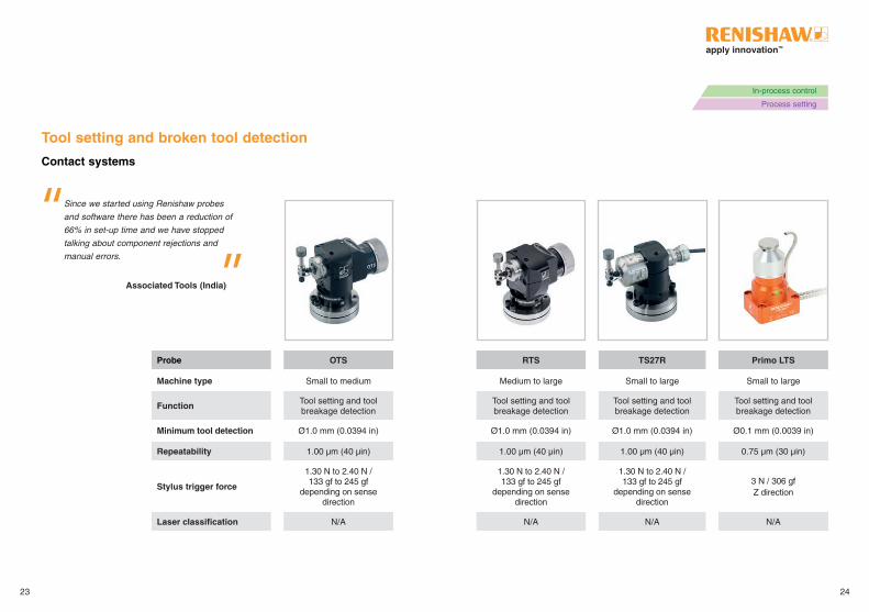
Probe OTS RTS TS27R Primo LTS
Machine type Small to medium Medium to large Small to large Small to large
Function Tool setting and tool breakage detection
Tool setting and tool breakage detection
Tool setting and tool breakage detection
Tool setting and tool breakage detection
Minimum tool detection Ø1 .0 mm (0 .0394 in) Ø1 .0 mm (0 .0394 in) Ø1 .0 mm (0 .0394 in) Ø0 .1 mm (0 .0039 in)
Repeatability 1 .00 µm (40 µin) 1 .00 µm (40 µin) 1 .00 µm (40 µin) 0 .75 µm (30 µin)
Stylus trigger force
1 .30 N to 2 .40 N / 133 gf to 245 gf
depending on sense direction
1 .30 N to 2 .40 N / 133 gf to 245 gf
depending on sense direction
1 .30 N to 2 .40 N / 133 gf to 245 gf
depending on sense direction
3 N / 306 gfZ direction
Laser classification N/A N/A N/A N/A
Tool setting and broken tool detection
Contact systems
Since we started using Renishaw probes
and software there has been a reduction of
66% in set-up time and we have stopped
talking about component rejections and
manual errors.
23 24
Associated Tools (India)
In-process control
Process setting

26
Probe RP3 NC4 TRS2
Machine type Small to large lathes Small to large Small to large
Function Tool setting using Renishaw arms
Tool setting and tool breakage detection
Tool breakage detection
Minimum tool detection Ø1 .0 mm (0 .0394 in) Ø0 .03 mm (0 .0012 in) Ø0 .2 mm (0 .008 in)
Repeatability 1 .00 µm (40 µin) ±0 .10 µm (4 µin) N/A
Stylus trigger force1 .50 N to 3 .50 N /
153 gf to 357 gf in XY plane
N/A N/A
Laser classification N/AClass 2
<1 mW 670nmClass 2
<1 mW 650nm
Tool setting and broken tool detection
Contact systems Non-contact systems
If it wasn’t for the Renishaw system, the machine
could, for example, operate with a broken cutting
tip, with disastrous results. Furthermore, since
tools are checked for breakage automatically,
one operator can easily manage both machines.
Ducati Motor (Italy)
25
In-process control
Process setting
Post-process monitoring
In-process control
Process setting
Process foundation
27 28
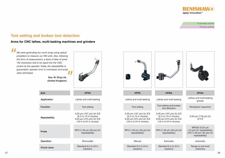
Arms for CNC lathes, multi-tasking machines and grinders
Tool setting and broken tool detection
We were generating too much scrap using optical
presetters to measure our KM units. Also, following
this form of measurement, a bank of data of some
150 characters had to be typed into the CNC
control by the operator. Today, the repeatability is
guaranteed, operator error is minimised, and scrap
rates eliminated.
Geo. W. King Ltd.
(United Kingdom)
In-process control
Process setting
Arm HPRA HPPA HPMA HPGA
Application Lathes and multi-tasking Lathes and multi-tasking Lathes and multi-tasking Lathes and multi-tasking
grinder
Function Tool setting Tool settingTool setting and broken
tool detectionWorkpiece inspection
Repeatability
5 .00 µm (197 µin) 2σ X/Z (6 in to 15 in chucks)
8 .00 µm (315 µin) 2σ X/Z (18 in to 24 in chucks)
5 .00 µm (197 µin) 2σ X/Z (6 in to 15 in chucks)
8 .00 µm (315 µin) 2σ X/Z (18 in to 24 in chucks)
5 .00 µm (197 µin) 2σ X/Z (6 in to 15 in chucks)
8 .00 µm (315 µin) 2σ X/Z (18 in to 24 in chucks)
3 .00 µm (118 µin) 2σ X/Y/Z
Probe RP3 (1 .00 µm (40 µin) 2σ repeatability)
RP3 (1 .00 µm (40 µin) 2σ repeatability)
RP3 (1 .00 µm (40 µin) 2σ repeatability)
MP250 (0 .25 µm (10 µin) 2σ repeatability) LP2 (1 .00 µm (40 µin) 2σ
repeatability)
Operation Removable Manual Automatic Automatic
Chuck sizes Standard 6 in to 24 in solutions
Standard 6 in to 24 in solutions
Standard 6 in to 24 in solutions
Range to suit most machines
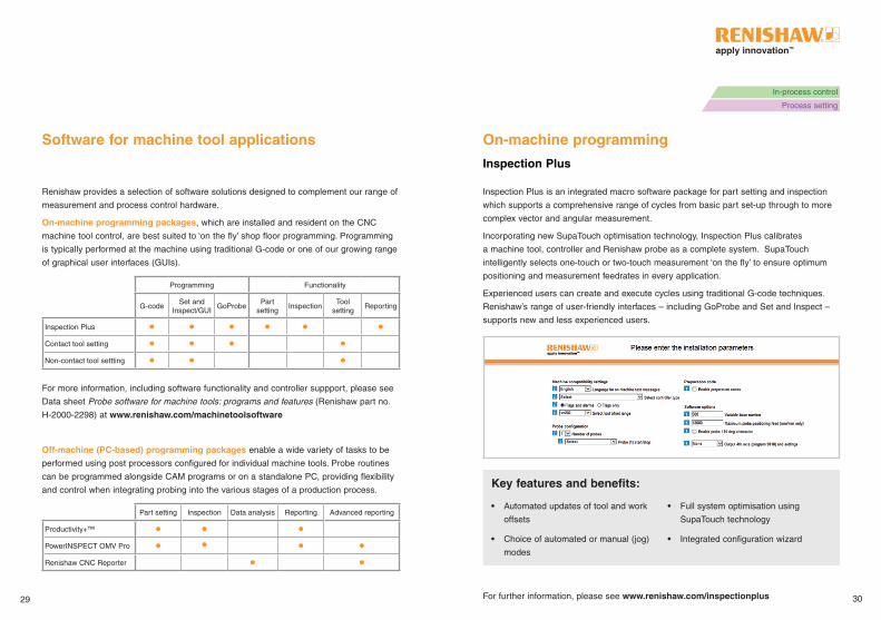
Software for machine tool applications On-machine programming
Renishaw provides a selection of software solutions designed to complement our range of
measurement and process control hardware .
On-machine programming packages, which are installed and resident on the CNC
machine tool control, are best suited to ‘on the fly’ shop floor programming . Programming
is typically performed at the machine using traditional G-code or one of our growing range
of graphical user interfaces (GUIs) .
Programming Functionality
G-codeSet and
Inspect/GUIGoProbe
Part setting
InspectionTool
settingReporting
Inspection Plus
Contact tool setting
Non-contact tool settting
For more information, including software functionality and controller suppport, please see
Data sheet Probe software for machine tools: programs and features (Renishaw part no .
H-2000-2298) at www.renishaw.com/machinetoolsoftware
Off-machine (PC-based) programming packages enable a wide variety of tasks to be
performed using post processors configured for individual machine tools . Probe routines
can be programmed alongside CAM programs or on a standalone PC, providing flexibility
and control when integrating probing into the various stages of a production process .
Part setting Inspection Data analysis Reporting Advanced reporting
Productivity+™
PowerINSPECT OMV Pro
Renishaw CNC Reporter
Inspection Plus is an integrated macro software package for part setting and inspection
which supports a comprehensive range of cycles from basic part set-up through to more
complex vector and angular measurement .
Incorporating new SupaTouch optimisation technology, Inspection Plus calibrates
a machine tool, controller and Renishaw probe as a complete system . SupaTouch
intelligently selects one-touch or two-touch measurement ‘on the fly’ to ensure optimum
positioning and measurement feedrates in every application .
Experienced users can create and execute cycles using traditional G-code techniques .
Renishaw’s range of user-friendly interfaces – including GoProbe and Set and Inspect –
supports new and less experienced users .
For further information, please see www.renishaw.com/inspectionplus
Key features and benefits:
• Automated updates of tool and work
offsets
• Choice of automated or manual (jog)
modes
• Full system optimisation using
SupaTouch technology
• Integrated configuration wizard
29 30
In-process control
Process setting
Inspection Plus
On-machine programming
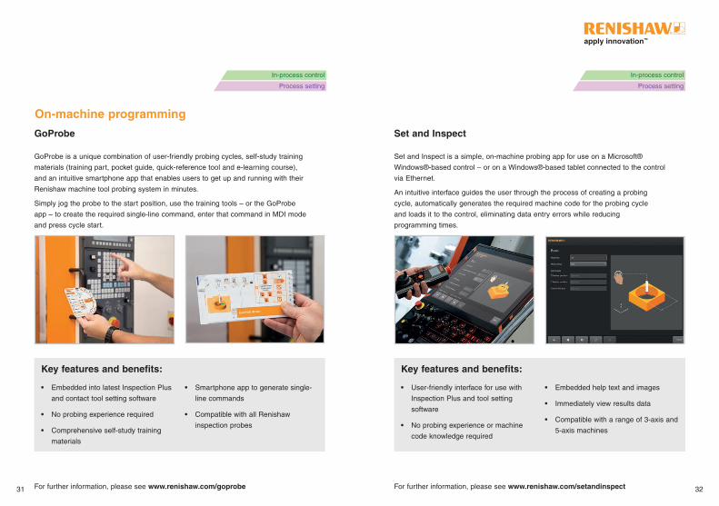
GoProbe is a unique combination of user-friendly probing cycles, self-study training
materials (training part, pocket guide, quick-reference tool and e-learning course),
and an intuitive smartphone app that enables users to get up and running with their
Renishaw machine tool probing system in minutes .
Simply jog the probe to the start position, use the training tools – or the GoProbe
app – to create the required single-line command, enter that command in MDI mode
and press cycle start .
For further information, please see www.renishaw.com/goprobe
Set and Inspect is a simple, on-machine probing app for use on a Microsoft®
Windows®-based control – or on a Windows®-based tablet connected to the control
via Ethernet .
An intuitive interface guides the user through the process of creating a probing
cycle, automatically generates the required machine code for the probing cycle
and loads it to the control, eliminating data entry errors while reducing
programming times .
For further information, please see www.renishaw.com/setandinspect31 32
Key features and benefits:
• Embedded into latest Inspection Plus
and contact tool setting software
• No probing experience required
• Comprehensive self-study training
materials
• Smartphone app to generate single-
line commands
• Compatible with all Renishaw
inspection probes
Key features and benefits:
• User-friendly interface for use with
Inspection Plus and tool setting
software
• No probing experience or machine
code knowledge required
• Embedded help text and images
• Immediately view results data
• Compatible with a range of 3-axis and
5-axis machines
In-process control
Process setting
In-process control
Process setting
GoProbe Set and Inspect
Graphical user interfaces (GUIs)
For further information, please see www.renishaw.com/gui
Tool setting
For further information, please see www.renishaw.com/toolsettingsoftware
On-machine programming
33 34
Key features and benefits:
• User-friendly interface
• Supports probe calibration, part
setting, contact tool setting and
inspection cycles
• AxiSet™ Check-Up pivot point
compensation and non-contact tool
setting (package dependent)
Key features and benefits:
• Significant time savings
• Automated tool length and diameter
setting
• Reduced scrap
• Eliminate manual setting errors
• In-cycle tool breakage detection
In-process control
Process setting
In-process control
Process setting
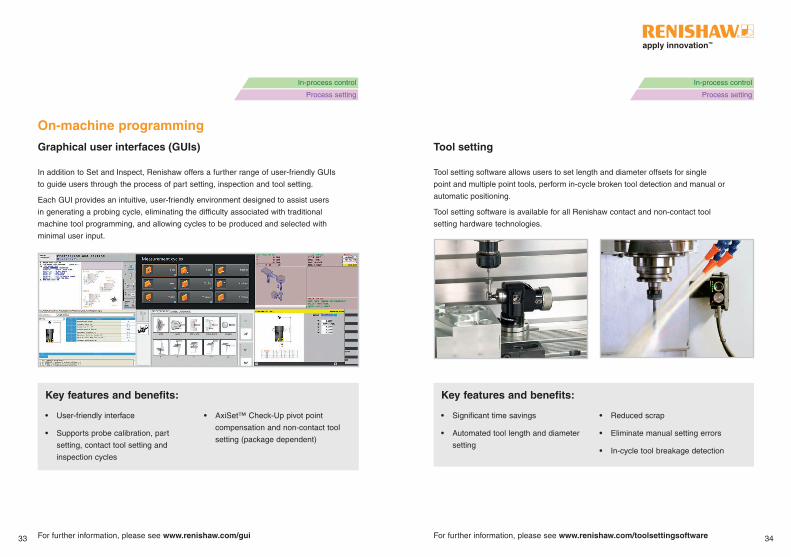
In addition to Set and Inspect, Renishaw offers a further range of user-friendly GUIs
to guide users through the process of part setting, inspection and tool setting .
Each GUI provides an intuitive, user-friendly environment designed to assist users
in generating a probing cycle, eliminating the difficulty associated with traditional
machine tool programming, and allowing cycles to be produced and selected with
minimal user input .
Tool setting software allows users to set length and diameter offsets for single
point and multiple point tools, perform in-cycle broken tool detection and manual or
automatic positioning .
Tool setting software is available for all Renishaw contact and non-contact tool
setting hardware technologies .
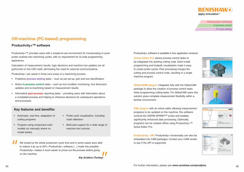
Productivity+ software is available in four application versions:
Active Editor Pro: allows process control tasks to
be integrated into existing cutting code . Solid model
programming and toolpath visualisation make it easy
to create probe cycles . Post processing merges the
cutting and process control code, resulting in a single
machine program .
GibbsCAM® plug-in: integrates fully with the GibbsCAM
package to allow the creation of process control tasks
while programming cutting tasks . For GibbsCAM users this
solution gives complete measurement flexibility within a
familiar environment .
CNC plug-in: with an online editor allowing measurement
programs to be updated on the machine, this software
controls the OSP60 SPRINT™ probe and enables
significantly enhanced data processing . Optionally,
programs can be created offline using Productivity+™
Active Editor Pro .
Productivity+ API: Productivity+ functionality can also be
embedded into CAM packages . Contact your CAM vendor
to see if the API is supported .
Productivity+™ software
Productivity+™ provides users with a simple-to-use environment for incorporating in-cycle
probe routines into machining cycles, with no requirement for G-code programming
experience .
Calculation of measurement results, logic decisions and machine tool updates are all
performed on the CNC itself, eliminating the need for external communications .
Productivity+ can assist in three core areas of a machining process:
• Predictive process-setting tasks – such as job set-up, part and tool identification
• Active in-process control tasks – such as tool condition monitoring, tool dimension
updates and re-machining based on measurement results
• Informative post-process reporting tasks – providing users with information about
a completed process and helping to influence decisions for subsequent operations
and processes
Off-machine (PC-based) programming
For further information, please see www.renishaw.com/prodplus
We looked at the whole production cycle time and in some cases were able
to reduce it by up to 50%. Productivity+ software […] made this possible.
Productivity+ makes it much easier to prove out the process before going
on the machine.
Alp Aviation (Turkey)
35 36
Key features and benefits:
• Automatic, real time, adaptation of
cutting programs
• Program using component solid
models (or manually where no
model exists)
• Probe cycle visualisation, including
crash detection
• Multi-axis support for a wide range of
machine tool controls
Post-process monitoring
In-process control
Process setting
37 38
Post-process monitoring
Geometric dimensioning and tolerancing (GD&T):
create elements to determine relationships between
features for full comparison of machine measurements
against manufacturing drawings before component
removal.
Constructed features: create additional measurements
and data points using previously measured features.
This function is particularly useful when inspecting
components with a large number of prismatic features.
Machine simulation: extend program simulation to
include a 3D machine model; invaluable when using
multi-axis machines and components with complex
geometries.
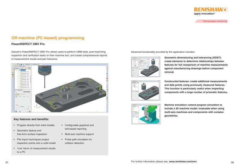
Delcam’s PowerINSPECT OMV Pro allows users to perform CMM-style, post-machining
inspection and verification tasks on their machine tool, and create comprehensive reports
of measurement results and part tolerance .
For further information please see, www.renishaw.com/omv
Advanced functionality provided by the application includes:
Off-machine (PC-based) programming
Key features and benefits:
• Program directly from solid models
• Geometric feature and
free-form surface inspection
• File import techniques project
inspection points onto a solid model
• ‘Live’ return of measurement results
to a PC
• Configurable graphical and
text-based reporting
• Multi-axis machine support
• Probe path simulation for
collision detection
PowerINSPECT OMV Pro
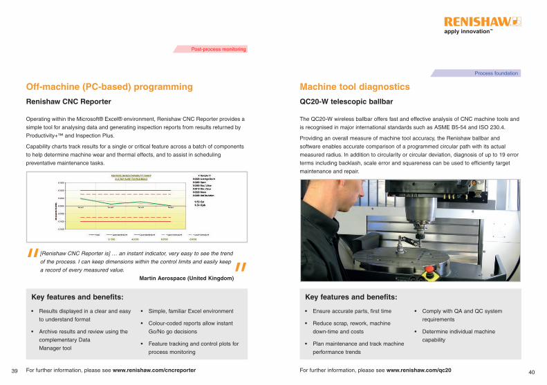
Operating within the Microsoft® Excel® environment, Renishaw CNC Reporter provides a
simple tool for analysing data and generating inspection reports from results returned by
Productivity+™ and Inspection Plus .
Capability charts track results for a single or critical feature across a batch of components
to help determine machine wear and thermal effects, and to assist in scheduling
preventative maintenance tasks .
Off-machine (PC-based) programming
[Renishaw CNC Reporter is] … an instant indicator, very easy to see the trend
of the process. I can keep dimensions within the control limits and easily keep
a record of every measured value.
Martin Aerospace (United Kingdom)
Machine tool diagnostics
For further information, please see www.renishaw.com/qc20For further information, please see www.renishaw.com/cncreporter
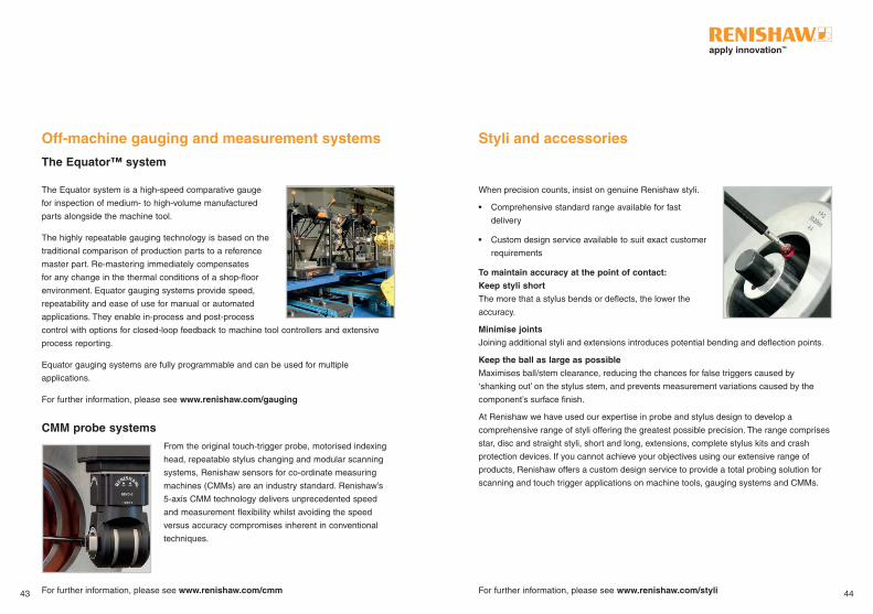
The QC20-W wireless ballbar offers fast and effective analysis of CNC machine tools and
is recognised in major international standards such as ASME B5-54 and ISO 230 .4 .
Providing an overall measure of machine tool accuracy, the Renishaw ballbar and
software enables accurate comparison of a programmed circular path with its actual
measured radius . In addition to circularity or circular deviation, diagnosis of up to 19 error
terms including backlash, scale error and squareness can be used to efficiently target
maintenance and repair .
39 40
Key features and benefits:
• Results displayed in a clear and easy
to understand format
• Archive results and review using the
complementary Data
Manager tool
• Simple, familiar Excel environment
• Colour-coded reports allow instant
Go/No go decisions
• Feature tracking and control plots for
process monitoring
Key features and benefits:
• Ensure accurate parts, first time
• Reduce scrap, rework, machine
down-time and costs
• Plan maintenance and track machine
performance trends
• Comply with QA and QC system
requirements
• Determine individual machine
capability
Post-process monitoring
Process foundation
Renishaw CNC Reporter QC20-W telescopic ballbar

AxiSet™ Check-Up
Machine tool diagnostics
A complete solution for checking the alignment and positioning performance of rotary
axes . In just a few minutes, users of multi-axis machining centres and multi-tasking
machines can identify and – where possible – automatically correct for poor machine
alignments and geometry .
Providing a fast and accurate check of rotary axis pivot points, AxiSet™ Check-Up helps
users to maintain a stable machining environment . When used alongside Renishaw’s
QC20-W ballbar system and laser interferometers, AxiSet Check-Up gives an unparalleled
machine diagnosis solution .
SPRINT™: Machine Health Check
The SPRINT™ Machine Health Check application is designed for sustainable machining
processes on 3-axis and 5-axis table/table milling centres . It can verify machine tool
performance in less than one minute using simple tests based on the SPRINT system’s
exceptionally accurate 3D measurement capability .
Fast enough to be used automatically prior to machining to detect warm-up issues and
previously unidentified problems, the application can also be used as part of a regular
maintenance regime providing long-term sustainability and performance monitoring .
For further information, please see www.renishaw.com/healthcheckFor further information, please see www.renishaw.com/axiset41 42
Key features and benefits:• Determine pivot point and lathe
centre-line errors
• Measure and report critical
errors quickly
• Reliably check and track machine
performance trends
• Automatically update machine
pivot points
Key features and benefits:• Determine machine capability in less
than one minute
• Immediate Go/No go decision
• Assists in long term machine
condition monitoring
• Minimal operator intervention
• Supplied with unique test artefact
• Linear test for 3-axis machine tools;
kinematic text for 5-axis machine tools
Process foundationProcess foundation
When precision counts, insist on genuine Renishaw styli .
• Comprehensive standard range available for fast
delivery
• Custom design service available to suit exact customer
requirements
To maintain accuracy at the point of contact:
Keep styli short
The more that a stylus bends or deflects, the lower the
accuracy .
Minimise joints
Joining additional styli and extensions introduces potential bending and deflection points .
Keep the ball as large as possible
Maximises ball/stem clearance, reducing the chances for false triggers caused by
‘shanking out’ on the stylus stem, and prevents measurement variations caused by the
component’s surface finish .
At Renishaw we have used our expertise in probe and stylus design to develop a
comprehensive range of styli offering the greatest possible precision . The range comprises
star, disc and straight styli, short and long, extensions, complete stylus kits and crash
protection devices . If you cannot achieve your objectives using our extensive range of
products, Renishaw offers a custom design service to provide a total probing solution for
scanning and touch trigger applications on machine tools, gauging systems and CMMs .
The Equator system is a high-speed comparative gauge
for inspection of medium- to high-volume manufactured
parts alongside the machine tool .
The highly repeatable gauging technology is based on the
traditional comparison of production parts to a reference
master part . Re-mastering immediately compensates
for any change in the thermal conditions of a shop-floor
environment . Equator gauging systems provide speed,
repeatability and ease of use for manual or automated
applications . They enable in-process and post-process
control with options for closed-loop feedback to machine tool controllers and extensive
process reporting .
Equator gauging systems are fully programmable and can be used for multiple
applications .
For further information, please see www.renishaw.com/gauging
CMM probe systemsFrom the original touch-trigger probe, motorised indexing
head, repeatable stylus changing and modular scanning
systems, Renishaw sensors for co-ordinate measuring
machines (CMMs) are an industry standard . Renishaw’s
5-axis CMM technology delivers unprecedented speed
and measurement flexibility whilst avoiding the speed
versus accuracy compromises inherent in conventional
techniques .
For further information, please see www.renishaw.com/cmm
The Equator™ system
Styli and accessoriesOff-machine gauging and measurement systems
For further information, please see www.renishaw.com/styli43 44

Custom solutions
Established for over 30 years, our Custom Products team
has unparalleled experience in providing custom-designed
inspection products and accessories ranging from
specialist styli to full probing systems .
We offer:
• Engineering and applications advice
• Design services from concept through to one-off or
low-volume production
• Realistic timescales
• Clear supporting documentation
In 30 years we have produced a vast range of bespoke
system components, interfaces, calibration kits, accessories
and specialised probing systems .
Every Renishaw custom product is hand-built to the same
high quality as our standard product range and is backed by our unrivalled global sales
and support network .
Renishaw’s expedited delivery made our customer happy enough to request a
quote for two additional arms. I have lost track of how many times the product
has materialised seemingly out of thin air to meet our needs.
CNC Engineering Inc.
(United States)
For further information please see, www.renishaw.com/customsolutions
Renishaw provides a high level of support to all its customers through a network of over 70
service and support offices in 35 countries .
Renishaw’s experienced global staff have the commitment and applications expertise
necessary to provide comprehensive support; from initial installation, to supplying
ongoing applications assistance and a range of service packages to keep your system in
operational condition .
UpgradesWhere possible, the option to upgrade worn-out, damaged or obsolete product to a more
modern equivalent will always be offered when contacting us .
RepairsThere are several levels of repairs, so if your equipment only has a minor fault, you only
pay a minor charge . However, all repaired items have to pass the same stringent final tests
as new equipment .
RBE (Repair by exchange)If immediate despatch is required, we have stocks of service exchange items (RBEs) .
These items have been subject to the stringent ‘as new’ final tests and a complete
refurbishment with the replacement of all parts subject to wear . *
TrainingWe offer a comprehensive programme of user maintenance and application courses .
Our experienced engineers recognise individual requirements and can offer flexible dates
for courses either at our facilities or at your site . Our goal is to build process and system
knowledge, enabling you to run and maintain your systems, and reduce cost of ownership .
*Compliance to Renishaw T&Cs is required .
Service, support and training
45 46
Further information Notes ...
For more information on anything covered in this pocket guide, please refer to the
Probing systems for CNC machine tools document (Renishaw part no . H-2000-3020),
or visit www.renishaw.com/mtp
47 48

For worldwide contact details, visit www.renishaw.com/contact
About Renishaw
Renishaw is an established world leader in engineering technologies, with a strong history
of innovation in product development and manufacturing . Since its formation in 1973, the
company has supplied leading-edge products that increase process productivity, improve
product quality and deliver cost-effective automation solutions .
A worldwide network of subsidiary companies and distributors provides exceptional
service and support for its customers .
*H-2000-3006-06*
RENISHAW HAS MADE CONSIDERABLE EFFORTS TO ENSURE THE CONTENT OF
THIS DOCUMENT IS CORRECT AT THE DATE OF PUBLICATION BUT MAKES NO
WARRANTIES OR REPRESENTATIONS REGARDING THE CONTENT . RENISHAW
EXCLUDES LIABILITY, HOWSOEVER ARISING, FOR ANY INACCURACIES IN THIS
DOCUMENT .
© 2007-2016 Renishaw plc. All rights reserved.
Renishaw reserves the right to change specifications without notice .
RENISHAW and the probe symbol used in the RENISHAW logo are registered trade marks
of Renishaw plc in the United Kingdom and other countries .apply innovation and names and
designations of other Renishaw products and technologies are trade marks of Renishaw plc or its
subsidiaries .
Microsoft, Windows and Excel are either registered trademarks or trademarks of Microsoft
Corporation in the United States and/or other countries . All other brand names and product names
used in this document are trade names, trade marks or registered trade marks of their respective
owners .
T +44 (0) 1453 524524F +44 (0) 1453 524901E uk@renishaw .com
www.renishaw.com
Renishaw plc
New Mills, Wotton-under-EdgeGloucestershire, GL12 8JRUnited Kingdom
Part no.: H-2000-3006-06-A
Issued: 04.2016