Motor Control & Protection - Himel
35
Motor Control & Protection
-
Upload
khangminh22 -
Category
Documents
-
view
4 -
download
0
Transcript of Motor Control & Protection - Himel

Motor Control & Protection

Himel is a multinational manufacturer and provider of electrical products
successfully combining global expertise with local knowledge.
Founded by a Spanish entrepreneur in 1958, the company pioneered in
exporting quality electrical enclosures, establishing Himel brand globally.
Today, our global footprint and technology enable us to provide the best
combination of affordable and reliable offers for Low Voltage Power
distribution, Industry Automation and Home Electric to our long-term
customers and partners in over 50 countries where we are present.
Himel. Reliable made affordable
About Himel
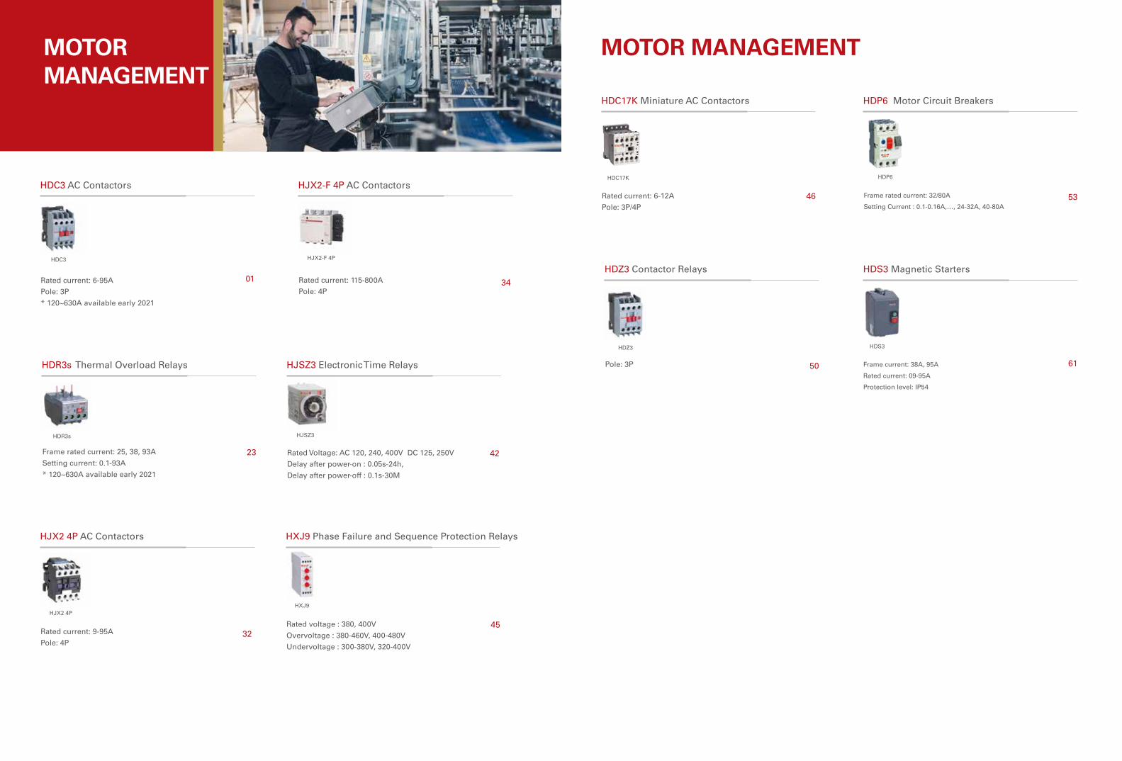
MOTOR MANAGEMENT
HDC3 AC Contactors
Rated current: 6-95A
Pole: 3P
* 120~630A available early 2021
HDC3
01
HDR3s Thermal Overload Relays
Frame rated current: 25, 38, 93A
Setting current: 0.1-93A
* 120~630A available early 2021
HDR3s
23
HJX2 4P AC Contactors
Rated current: 9-95A
Pole: 4P
HJX2 4P
32
HJSZ3 Electronic Time Relays
Rated Voltage: AC 120, 240, 400V DC 125, 250V
Delay after power-on : 0.05s-24h,
Delay after power-off : 0.1s-30M
HJSZ3
42
HJX2-F 4P AC Contactors
Rated current: 115-800A
Pole: 4P
HJX2-F 4P
34
MOTOR MANAGEMENT
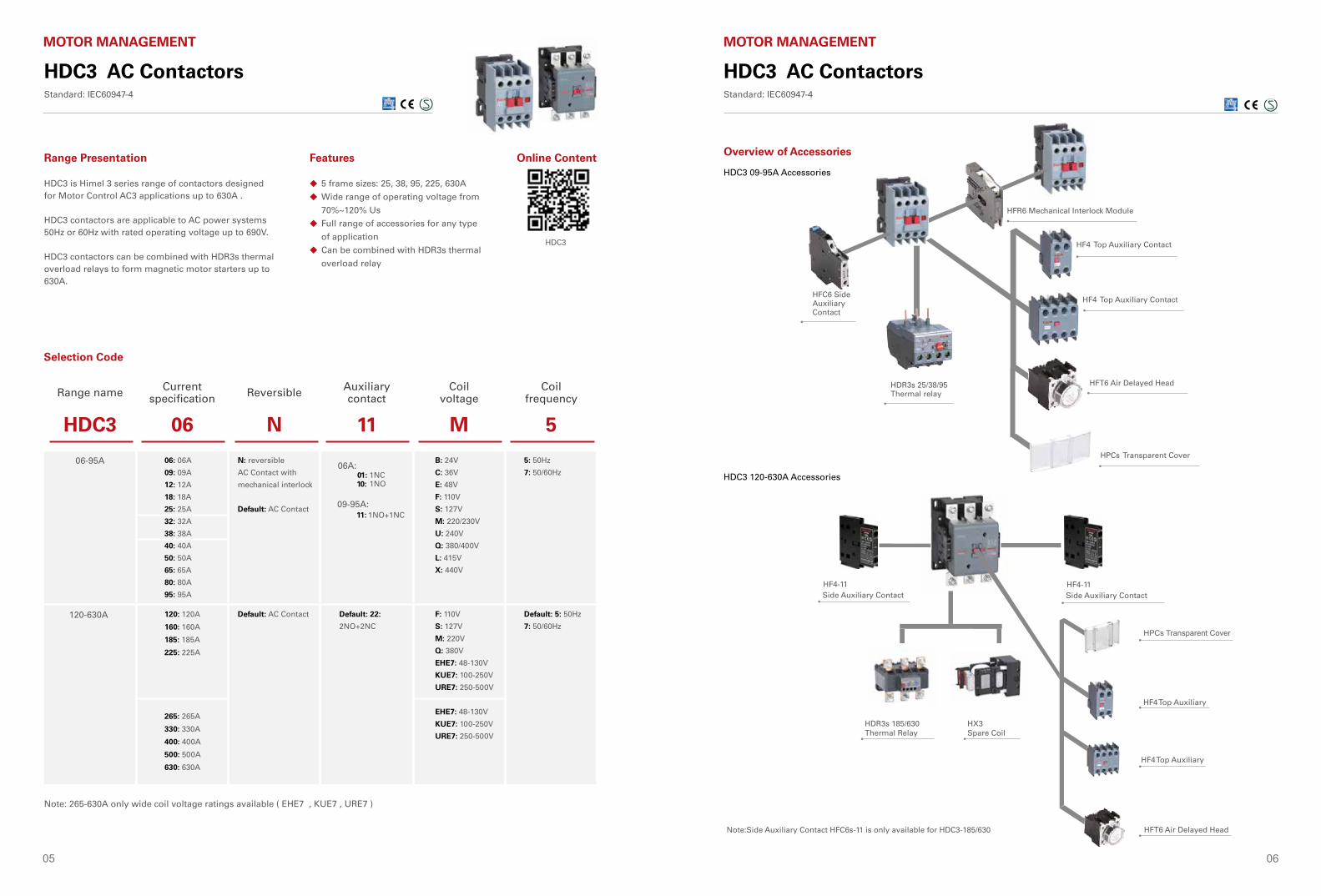
HDC17K Miniature AC Contactors
HDC17K
Rated current: 6-12A
Pole: 3P/4P46
HDZ3 Contactor Relays
HDZ3
Pole: 3P 50
HDP6 Motor Circuit Breakers
Frame rated current: 32/80A
Setting Current : 0.1-0.16A,…, 24-32A, 40-80A
HDP6
53
HDS3 Magnetic Starters
HDS3
Frame current: 38A, 95A
Rated current: 09-95A
Protection level: IP54
61
HXJ9
HXJ9 Phase Failure and Sequence Protection Relays
Rated voltage : 380, 400V
Overvoltage : 380-460V, 400-480V
Undervoltage : 300-380V, 320-400V
45
05 06
H H
H
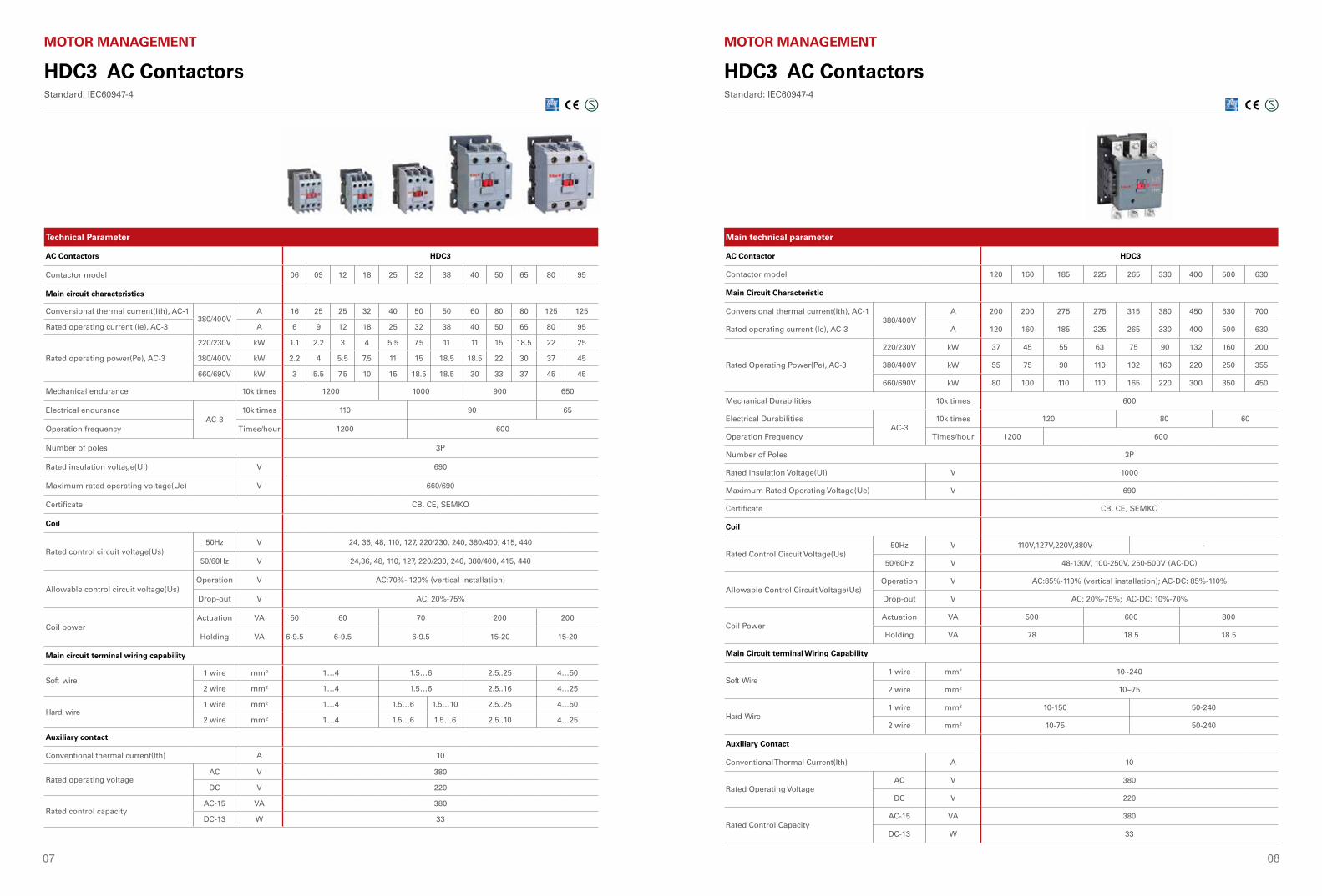
HFC6 Side Auxiliary Contact
HFD6 Top of Auxiliary Contact
HFD6 Top of Auxiliary Contact
HFT6 Air Delayed Head
HFR6 Mechanical Interlock Module
HFT6 Air Delayed Head (Breaking time-delay)H
HFC6 SideAuxiliaryContact
HDR3s 25/38/95Thermal relay
HF4 Top Auxiliary Contact
HF4 Top Auxiliary Contact
HFT6 Air Delayed Head
HPCs Transparent Cover
HFR6 Mechanical Interlock Module
HDC3 AC Contactors Standard: IEC60947-4
MOTOR MANAGEMENT
PC透明防尘盖
F4 顶辅助F4 顶辅助
JRS3D X3线圈
F4 顶辅助
F4 顶辅助
SK4 空气延时头
HF4-11 Side Auxiliary Contact
HF4-11 Side Auxiliary Contact
HPCs Transparent Cover
HF4 Top Auxiliary
HF4 Top Auxiliary
HFT6 Air Delayed Head Note:Side Auxiliary Contact HFC6s-11 is only available for HDC3-185/630
HDR3s 185/630Thermal Relay
HX3 Spare Coil
HDC3 09-95A Accessories
HDC3 120-630A Accessories
Overview of Accessories
HDC3 AC ContactorsStandard: IEC60947-4
MOTOR MANAGEMENT
5 frame sizes: 25, 38, 95, 225, 630A
Wide range of operating voltage from
70%~120% Us
Full range of accessories for any type
of application
Can be combined with HDR3s thermal
overload relay
◆
◆
◆
◆
Range Presentation Features
HDC3 is Himel 3 series range of contactors designed for Motor Control AC3 applications up to 630A .
HDC3 contactors are applicable to AC power systems 50Hz or 60Hz with rated operating voltage up to 690V.
HDC3 contactors can be combined with HDR3s thermal overload relays to form magnetic motor starters up to 630A.
Selection Code
Range name Current specification Reversible Auxiliary
contactCoil
voltageCoil
frequency
HDC3 06 N 11 M 5
06-95A 06: 06A
09: 09A
12: 12A
18: 18A
25: 25A
32: 32A
38: 38A
40: 40A
50: 50A
65: 65A
80: 80A
95: 95A
N: reversible
AC Contact with
mechanical interlock
Default: AC Contact11: 1NO+1NC
B: 24V
C: 36V
E: 48V
F: 110V
S: 127V
M: 220/230V
U: 240V
Q: 380/400V
L: 415V
X: 440V
5: 50Hz
7: 50/60Hz
120-630A 120: 120A
160: 160A
185: 185A
225: 225A
265: 265A
330: 330A
400: 400A
500: 500A
630: 630A
Default: AC Contact Default: 22:
2NO+2NC
F: 110V
S: 127V
M: 220V
Q: 380V
EHE7: 48-130V
KUE7: 100-250V
URE7: 250-500V
EHE7: 48-130V
KUE7: 100-250V
URE7: 250-500V
Default: 5: 50Hz
7: 50/60Hz
HDC3
Online Content
Note: 265-630A only wide coil voltage ratings available ( EHE7 , KUE7 , URE7 )
06A: 1NC01:
10: 1NO
09-95A:
07 08
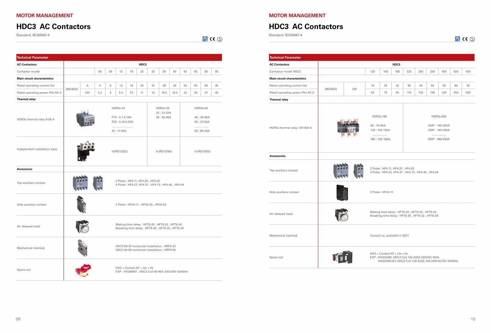
Technical Parameter
AC Contactors HDC3
Contactor model 06 09 12 18 25 32 38 40 50 65 80 95
Main circuit characteristics
Conversional thermal current(Ith), AC-1380/400V
A 16 25 25 32 40 50 50 60 80 80 125 125
Rated operating current (Ie), AC-3 A 6 9 12 18 25 32 38 40 50 65 80 95
Rated operating power(Pe), AC-3
220/230V kW 1.1 2.2 3 4 5.5 7.5 11 11 15 18.5 22 25
380/400V kW 2.2 4 5.5 7.5 11 15 18.5 18.5 22 30 37 45
660/690V kW 3 5.5 7.5 10 15 18.5 18.5 30 33 37 45 45
Mechanical endurance 10k times 1200 1000 900 650
Electrical enduranceAC-3
10k times 110 90 65
Operation frequency Times/hour 1200 600
Number of poles 3P
Rated insulation voltage(Ui) V 690
Maximum rated operating voltage(Ue) V 660/690
Certificate CB, CE, SEMKO
Coil
Rated control circuit voltage(Us)50Hz V 24, 36, 48, 110, 127, 220/230, 240, 380/400, 415, 440
50/60Hz V 24,36, 48, 110, 127, 220/230, 240, 380/400, 415, 440
Allowable control circuit voltage(Us)Operation V AC:70%~120% (vertical installation)
Drop-out V AC: 20%-75%
Coil powerActuation VA 50 60 70 200 200
Holding VA 6-9.5 6-9.5 6-9.5 15-20 15-20
Main circuit terminal wiring capability
Soft wire1 wire mm² 1…4 1.5…6 2.5..25 4…50
2 wire mm² 1…4 1.5…6 2.5..16 4…25
Hard wire1 wire mm² 1…4 1.5…6 1.5…10 2.5..25 4…50
2 wire mm² 1…4 1.5…6 1.5…6 2.5..10 4…25
Auxiliary contact
Conventional thermal current(Ith) A 10
Rated operating voltageAC V 380
DC V 220
Rated control capacityAC-15 VA 380
DC-13 W 33
HDC3 AC Contactors Standard: IEC60947-4
MOTOR MANAGEMENT
Main technical parameter
AC Contactor HDC3
Contactor model 120 160 185 225 265 330 400 500 630
Main Circuit Characteristic
Conversional thermal current(Ith), AC-1380/400V
A 200 200 275 275 315 380 450 630 700
Rated operating current (Ie), AC-3 A 120 160 185 225 265 330 400 500 630
Rated Operating Power(Pe), AC-3
220/230V kW 37 45 55 63 75 90 132 160 200
380/400V kW 55 75 90 110 132 160 220 250 355
660/690V kW 80 100 110 110 165 220 300 350 450
Mechanical Durabilities 10k times 600
Electrical DurabilitiesAC-3
10k times 120 80 60
Operation Frequency Times/hour 1200 600
Number of Poles 3P
Rated Insulation Voltage(Ui) V 1000
Maximum Rated Operating Voltage(Ue) V 690
Certificate CB, CE, SEMKO
Coil
Rated Control Circuit Voltage(Us)50Hz V 110V,127V,220V,380V -
50/60Hz V 48-130V, 100-250V, 250-500V (AC-DC)
Allowable Control Circuit Voltage(Us)Operation V AC:85%-110% (vertical installation); AC-DC: 85%-110%
Drop-out V AC: 20%-75%; AC-DC: 10%-70%
Coil PowerActuation VA 500 600 800
Holding VA 78 18.5 18.5
Main Circuit terminal Wiring Capability
Soft Wire1 wire mm² 10~240
2 wire mm² 10~75
Hard Wire1 wire mm² 10-150 50-240
2 wire mm² 10-75 50-240
Auxiliary Contact
Conventional Thermal Current(Ith) A 10
Rated Operating VoltageAC V 380
DC V 220
Rated Control CapacityAC-15 VA 380
DC-13 W 33
HDC3 AC Contactors Standard: IEC60947-4
MOTOR MANAGEMENT
09 10
HDC3 AC ContactorsStandard: IEC60947-4
MOTOR MANAGEMENT
Technical Parameter
AC Contactors HDC3
Contactor model 06 09 12 18 25 32 38 40 50 65 80 95
Main circuit characteristics
Rated operating current (Ie)380/400V
A 6 9 12 18 25 32 38 40 50 65 80 95
Rated operating power (Pe) AC-3 kW 2.2 4 5.5 7.5 11 15 18.5 18.5 22 30 37 45
Thermal relay
HDR3s thermal relay 6-95 A
HDR3s-25
P16 : 0.1-0.16A
P25 : 0.16-0.25A
………………….
25 : 17-25A
HDR3s-38
32 : 23-32A
38 : 30-40A
HDR3s-95
40 : 30-40A
50 : 37-50A
…………...
93 : 80-93A
Independent installation baseHJRS1D25J HJRS1D38J HJRS1D93J
Accessorys
Top auxiliary contact2 Poles : HF4-11, HF4-20 , HF4-024 Poles : HF4-22, HF4-31 , HF4-13 , HF4-40 , HF4-04
Side auxiliary contact 2 Poles : HFC6-11 , HFC6-20 , HFC6-02
Air delayed headMaking time delay : HFT6-20 , HFT6-22 , HFT6-24Breaking time delay : HFT6-30 , HFT6-32 , HFT6-34
Mechanical interlockHDC3 09-32 horizontal installation : HRF6-32HDC3 40-95 horizontal installation : HRF6-95
Spare coilHX3 + Contact AF + Ue + HzEXP : HX395M7 , HDC3 Coil 80-95A 220/230V 50/60Hz
HDC3 AC ContactorsStandard: IEC60947-4
MOTOR MANAGEMENT
Technical Parameter
AC Contactors HDC3
Contactor model HDC3 120 160 185 225 265 330 400 500 630
Main circuit characteristics
Rated operating current (Ie)380/400V kW
18 25 32 38 40 50 65 80 95
Rated operating power (Pe) AC-3 55 75 90 110 132 160 220 250 355
Thermal relay
HDR3s thermal relay 120-630 A
HDR3s-185
95 : 75-95A
135 : 105-135A
…………...
185 : 150-185A
HDR3s-630
200F : 145-200A
250F : 180-250A
…………...
630F : 460-630A
Accessories
Top auxiliary contact2 Poles : HF4-11, HF4-20 , HF4-024 Poles : HF4-22, HF4-31 , HF4-13 , HF4-40 , HF4-04
Side auxiliary contact 2 Poles : HFC4-11
Air delayed headMaking time delay : HFT6-20 , HFT6-22 , HFT6-24Breaking time delay : HFT6-30 , HFT6-32 , HFT6-34
Mechanical interlock Consult us, available in 2021
Spare coilHX3 + Contact AF + Ue + HzEXP : HX3225M, HDC3 Coil 120-225A 220VAC 50Hz HX3225KUE7, HDC3 Coil 120-225A 100-250VAC/DC 50/60Hz
11 12
HDC3 AC ContactorsStandard: IEC60947-4
MOTOR MANAGEMENT
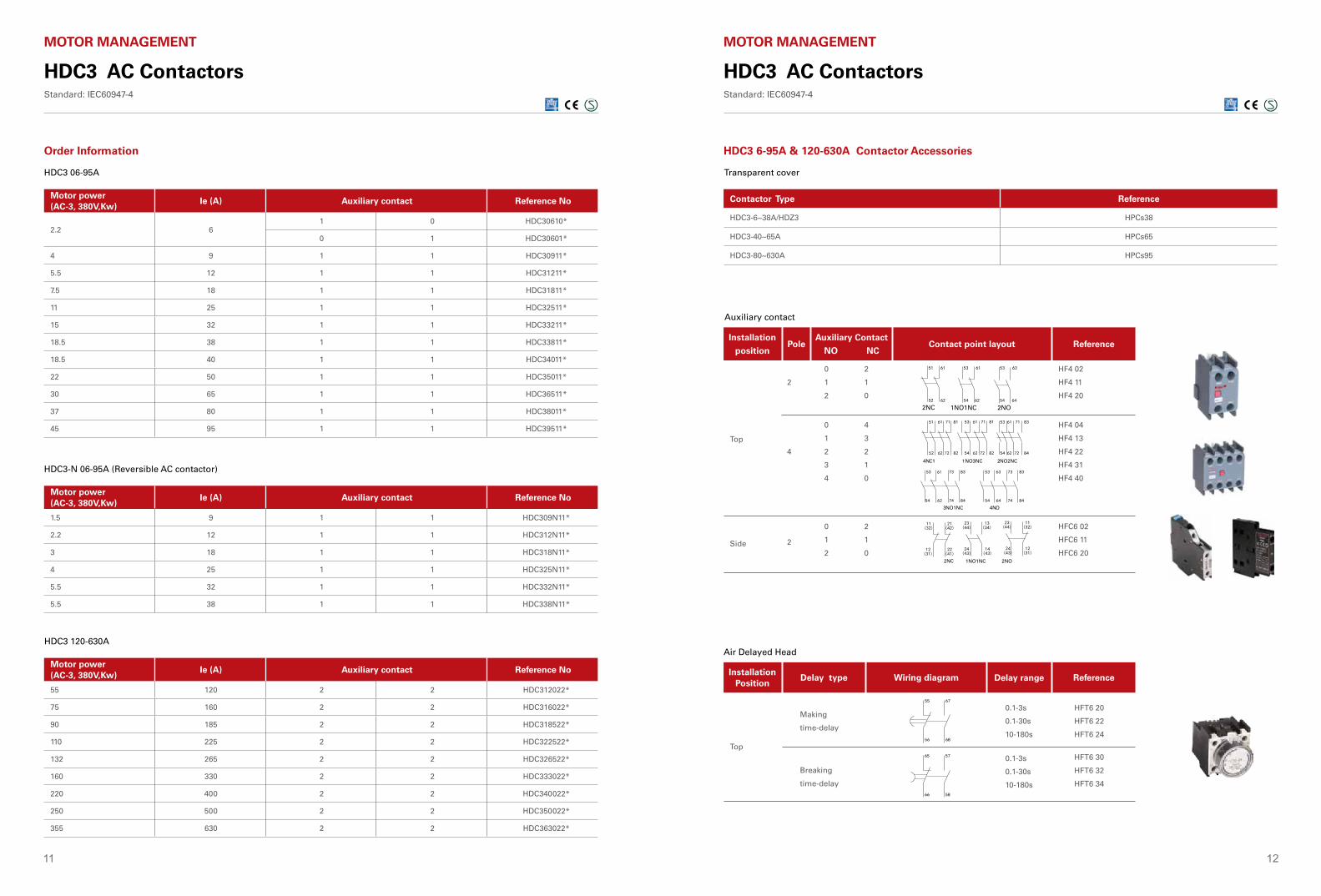
Order Information
HDC3 06-95A
Motor power (AC-3, 380V,Kw)
Ie (A) Auxiliary contact Reference No
2.2 61 0 HDC30610*
0 1 HDC30601*
4 9 1 1 HDC30911*
5.5 12 1 1 HDC31211*
7.5 18 1 1 HDC31811*
11 25 1 1 HDC32511*
15 32 1 1 HDC33211*
18.5 38 1 1 HDC33811*
18.5 40 1 1 HDC34011*
22 50 1 1 HDC35011*
30 65 1 1 HDC36511*
37 80 1 1 HDC38011*
45 95 1 1 HDC39511*
HDC3-N 06-95A (Reversible AC contactor)
Motor power (AC-3, 380V,Kw)
Ie (A) Auxiliary contact Reference No
1.5 9 1 1 HDC309N11*
2.2 12 1 1 HDC312N11*
3 18 1 1 HDC318N11*
4 25 1 1 HDC325N11*
5.5 32 1 1 HDC332N11*
5.5 38 1 1 HDC338N11*
HDC3 120-630A
Motor power (AC-3, 380V,Kw)
Ie (A) Auxiliary contact Reference No
55 120 2 2 HDC312022*
75 160 2 2 HDC316022*
90 185 2 2 HDC318522*
110 225 2 2 HDC322522*
132 265 2 2 HDC326522*
160 330 2 2 HDC333022*
220 400 2 2 HDC340022*
250 500 2 2 HDC350022*
355 630 2 2 HDC363022*
HDC3 6-95A & 120-630A Contactor Accessories
Auxiliary contact
2NC 1NO1NC 2NO
62
52
62
54
61 51 61 53 63 53
64
54
3NO1NC 4NO
4NC1 NO3NC 2NO2NC
61 51
62
52
81 71
82
72
53
54
61
62
81 71
82
72
53
54
61
62
83 71
84
72
53
54
61
62
83 73
84
74
53
54
63
64
83 73
84
74
2NC 1NO1NC 2NO
12(31)
24 (43)
22(41)
12 (31)
11(32)
23 (44)
21(42)
11 (32)
13(34)
23 (44)
14(43)
24 (43)
1
Installation
positionPole
Auxiliary Contact
NO NCContact point layout Reference
HF4 02
HF4 11
HF4 20
0 2
1 1
2 0
2
Top
Side
HF4 04
HF4 13
HF4 22
HF4 31
HF4 40
HFC6 02
HFC6 11
HFC6 20
0 4
1 3
2 2
3 1
4 0
0 2
1 1
2 0
4
2
55 67
56 68
65 57
66 58
Installation Position
Delay type Wiring diagram Delay range Reference
Air Delayed Head
HFT6 20
HFT6 22
HFT6 24
Making
time-delay
TopHFT6 30
HFT6 32
HFT6 34
0.1-3s
0.1-30s
10-180s
0.1-3s
0.1-30s
10-180s
Breaking
time-delay
PoleInstallation Position
Installation Position
Top
Side
2
4
Composition Contact Point Layout Reference
Reference
NO NC
0 2 HFD6 02
1 1 HFD6 11
2 0 HFD6 20
2
0
1
2
2
1
0
HFD6 02
HFD6 11
HFD6 20
0 4 HFD6 04
1 3 HFD6 13
2 2 HFD6 22
3 1 HFD6 31
4 0 HFD6 40
3NO1NC 4NO
2NC 1NO1NC 2NO
HFT6 Air Delayed Contact
Delay Type
Top
Making time-delay
Breaking time-delay
Wiring Diagram Delay Range
0.1-3s HFT6 20
0.1-30s HFT6 2210-180s HFT6 24
0.1-3s HFT6 30
0.1-30s HFT6 32
10-180s HFT6 34
2NC 1NO1NC 2NO
62
52
62
54
61 51 61 53 63 53
64
54
4NC 1NO3NC 2NO2NC
61 51
62
52
81 71
82
72
53
54
61
62
81 71
82
72
53
54
61
62
83 71
84
72
53
54
61
62
83 73
84
74
53
54
63
64
83 73
84
74
12(31)
24 (43)
22(41)
12 (31)
11(32)
23 (44)
21(42)
11 (32)
13(34)
23 (44)
14(43)
24 (43)
55 67
56 68
65 57
66 58
Auxiliary Contact
PoleInstallation Position
Installation Position
Top
Side
2
4
Composition Contact Point Layout Reference
Reference
NO NC
0 2 FD6 02
1 1 FD6 11
2 0 FD6 20
2
0
1
2
2
1
0
FD6 02
FD6 11
FD6 20
0 4 FD6 04
1 3 FD6 13
2 2 FD6 22
3 1 FD6 31
4 0 FD6 40
3NO1NC 4NO
4NC 1NO3NC 2NO2NC
2NC 1NO1NC 2NO
FT6 Air Delayed Contact
Delay Type
Top
Making time-delay
Breaking time-delay
Wiring Diagram Delay Range
0.1-3s FT6 20
0.1-30s FT6 2210-180s FT6 24
0.1-3s FT6 30
0.1-30s FT6 32
10-180s FT6 34
FD6 Top of Auxiliary Contact
FD6 Top of Auxiliary Contact
FT6 Air Delayed Head
FT6 Air Delayed Head
4 poles: FD6-22, FD6-13, FD6-31, FD6-40, FD6-04
Available to adopt CDR6-185, CDR6-630 of Thermal
2NC 1NO1NC 2NO
62
52
62
54
61 51 61 53 63 53
64
54
61 51
62
52
81 71
82
72
53
54
61
62
81 71
82
72
53
54
61
62
83 71
84
72
53
54
61
62
83 73
84
74
53
54
63
64
83 73
84
74
12(31)
24 (43)
22(41)
12 (31)
11(32)
23 (44)
21(42)
11 (32)
13(34)
23 (44)
14(43)
24 (43)
55 67
56 68
65 57
66 58
H H
HDC6-9~32
HDC6-40~95
HDC6-115~150
HDC6-185~225
HDC6-265~330
HDC6-400~500
HDC6-630
HFR6 32 H
HFR6 95 H
HFR6 FF H
HFR6 GGH
HFR6 HH H
HFR6 KK H
HFR6 LL H
HDC6-115
or
HDC6-150
HDC6-115
HDC6-150
HDC6-185
HDC6-225
HDC6-265
HDC6-330
HDC6-400
HDC6-500
HDC6-630
HFR6
HFR6
HFR6
HFR6
HFR6
HFR6
HFR6
HFR6
HFR6
FF V
FF V
FG V
FG V
FH V
FH V
FH V
FH V
FL V
HDC6-185
or
HDC6-225
HDC6-185
HDC6-225
HDC6-265
HDC6-330
HDC6-400
HDC6-500
HDC6-630
HFR6
HFR6
HFR6
HFR6
HFR6
HFR6
HFR6
GG V
GG V
GK V
GK V
GK V
GK V
GL V
HDC6-265
or
HDC6-330
HDC6-400
HDC6-500
HDC6-630
HDC6-265
HDC6-330
HDC6-400
HDC6-500
HDC6-630
HFR6
HFR6
HFR6
HFR6
HFR6
HK V
HK V
HK V
HK V
HL V
HDC6-400
HDC6-500
HDC6-630
HDC6-500
HDC6-630
HDC6-630
HFR6
HFR6
HFR6
HFR6
HFR6
HFR6
HK V
HK V
HL V
HK V
HL V
LL V
H
HDC3 AC ContactorsStandard: IEC60947-4
MOTOR MANAGEMENT
Contactor Type Reference
HDC3-6~38A/HDZ3 HPCs38
HDC3-40~65A HPCs65
HDC3-80~630A HPCs95
Transparent cover
13 14
HDC3 AC ContactorsStandard: IEC60947-4
MOTOR MANAGEMENT
Product Ith(A)
AC-4
Ie(A) Pe(kW)
380/400V 660/690 380/400V 660/690
HDC3-06 25 2.6 1 1.1 0.75
HDC3-09 25 3.5 1.5 1.5 1.1
HDC3-12 25 5 2 2.2 1.5
HDC3-18 32 7.7 3.8 3.3 3
HDC3-25 40 8.5 4.4 4 3.7
HDC3-32 50 12 7.5 5.4 5.5
HDC3-38 50 14 8.9 5.5 6
HDC3-40 60 18.5 9 7.5 7.5
HDC3-50 80 24 12 11 10
HDC3-65 80 28 14 15 11
HDC3-80 125 37 17.3 18.5 15
HDC3-95 125 44 21.3 22 18.5
Motor power of HDC3 (AC-4)
Motor Power
HDC3 AC ContactorsStandard: IEC60947-4
MOTOR MANAGEMENT
Product Ith(A)
AC-4
Ie(A) Pe(kW)
380/400V 660/690 380/400V 660/690
HDC3-09 25 3.5 1.5 1.5 1.1
HDC3-12 25 5 2 2.2 1.5
HDC3-18 32 7.7 3.8 3.3 3
HDC3-25 40 8.5 4.4 4 3.7
HDC3-32 50 12 7.5 5.4 5.5
HDC3-38 50 14 8.9 5.5 6
HDC3-40 60 18.5 9 7.5 7.5
HDC3-50 80 24 12 11 10
HDC3-65 80 28 14 15 11
HDC3-80 125 37 17.3 18.5 15
HDC3-95 125 44 21.3 22 18.5
Motor power of HDC3 (Reversible AC contactor)
HX3 6-95A
HX3 120-630A
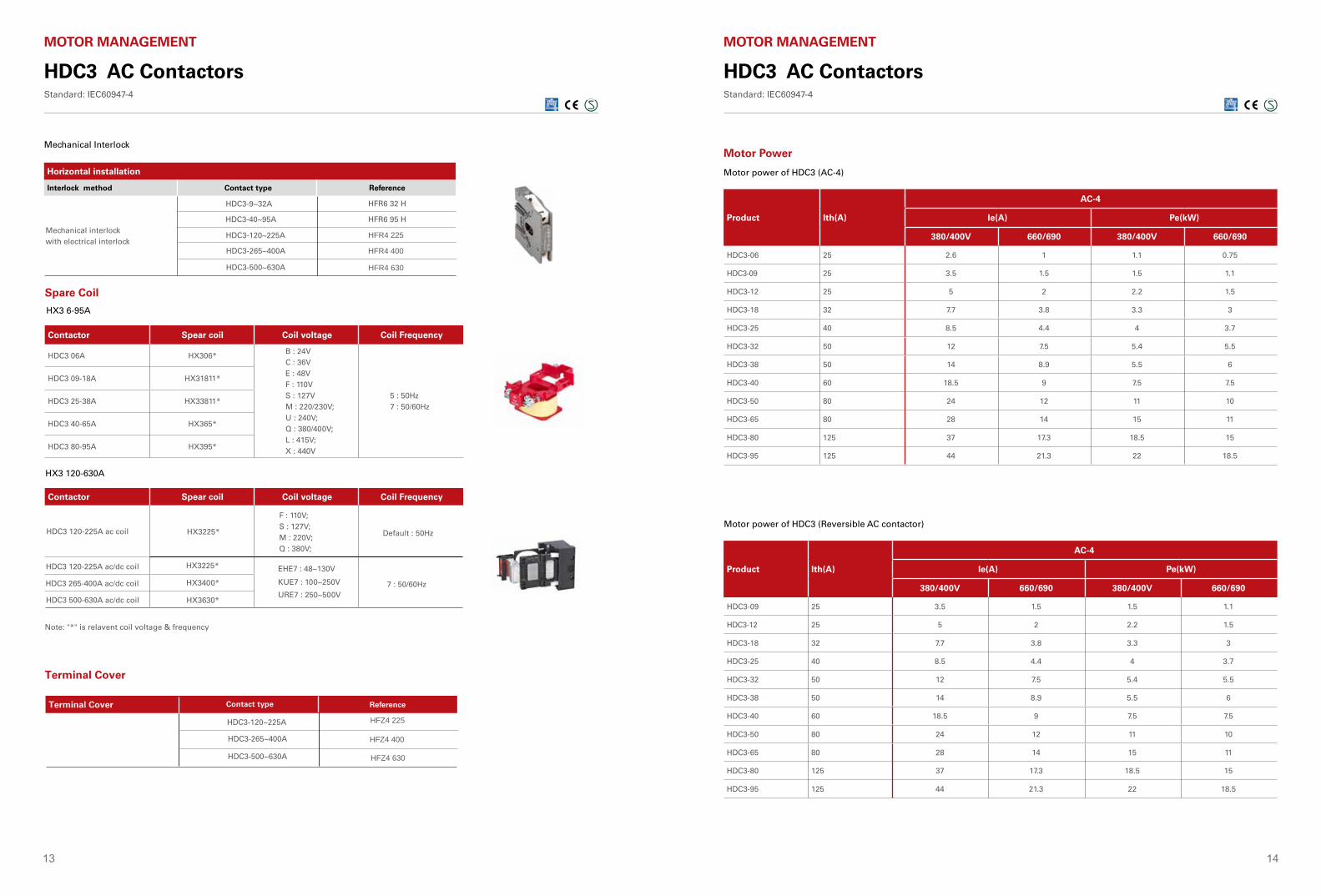
Spare Coil
Contactor Spear coil Coil voltage Coil Frequency
HDC3 06A HX306* B : 24VC : 36VE : 48VF : 110VS : 127VM : 220/230V;U : 240V;Q : 380/400V;L : 415V;X : 440V
5 : 50Hz7 : 50/60Hz
HDC3 09-18A HX31811*
HDC3 25-38A HX33811*
HDC3 40-65A HX365*
HDC3 80-95A HX395*
Contactor Spear coil Coil voltage Coil Frequency
HDC3 120-225A ac coil HX3225*
F : 110V;S : 127V;M : 220V;Q : 380V;
EHE7 : 48~130V
KUE7 : 100~250V
URE7 : 250~500V
Default : 50Hz
7 : 50/60Hz
HX3225*
HX3400*
HX3630*
Note: "*" is relavent coil voltage & frequency
Mechanical Interlock
Horizontal installation
Interlock method Contact type Reference
Mechanical interlockwith electrical interlock
HDC3-9~32A HFR6 32 H
HDC3-40~95A HFR6 95 H
HDC3 120-225A ac/dc coil
HDC3 265-400A ac/dc coil
HDC3 500-630A ac/dc coil
HFR4 225
HFR4 400
HFR4 630
HDC3-120~225A
HDC3-265~400A
HDC3-500~630A
Terminal Cover Contact type Reference
HFZ4 225
HFZ4 400
HFZ4 630
HDC3-120~225A
HDC3-265~400A
HDC3-500~630A
Terminal Cover
15 16
Reversible Product (Horizontal installation)
Ith(A)Ie(A) AC-3 Pe(kW) AC-3
380V 660V 380V 660V
HDC3-120N200
120 86 55 80
HDC3-160N 160 107 75 100
HDC3-185N275
185 107 90 110
HDC3-225N 225 118 110 110
HDC3-265N 315 265 170 132 165
HDC3-330N 380 330 225 160 220
HDC3-400N 450 400 303 220 300
HDC3-500N 630 500 353 250 350
HDC3-630N 700 630 400 355 450
Motor power of HDC3 (Reversible AC contactor)
HDC3 AC ContactorsStandard: IEC60947-4
MOTOR MANAGEMENT
Max. Starting Frequency: 30 times/h; Max. Starting Time: 30s
Class AC-3 50Hz 3-Phase Electromotor Delta Connection
Contactor
Thermal RelayStraight Connection Delta Connection Star Connection
KM2 KM3 KM1
In (A) IrD (A) Type Type Type Type Setting Range (A)
3.5 2 HDC3-09 HDC3-09 HDC3-09 HDR3s-25 1.8~2.5
5 3 HDC3-09 HDC3-09 HDC3-09 HDR3s-25 2.5~3.6
6.6 4 HDC3-09 HDC3-09 HDC3-09 HDR3s-25 3.5~4.8
8.5 5 HDC3-09 HDC3-09 HDC3-09 HDR3s-25 4.5~6.3
11.5 6 HDC3-09 HDC3-09 HDC3-09 HDR3s-25 5~7
15.5 9 HDC3-12 HDC3-12 HDC3-09 HDR3s-25 9~12
18.5 11 HDC3-18 HDC3-18 HDC3-12 HDR3s-25 11~15
22 13 HDC3-18 HDC3-18 HDC3-12 HDR3s-25 11~15
30 16 HDC3-25 HDC3-25 HDC3-18 HDR3s-25 14~18
37 22 HDC3-25 HDC3-25 HDC3-18 HDR3s-25 18~25
44 26 HDC3-32 HDC3-32 HDC3-25 HDR3s-38 23~32
60 35 HDC3-40 HDC3-40 HDC3-32 HDR3s-38 30~40
72 40 HDC3-50 HDC3-50 HDC3-40 HDR3s-95 37~50
85 47 HDC3-65 HDC3-65 HDC3-50 HDR3s-95 37~50
105 58 HDC3-80 HDC3-80 HDC3-65 HDR3s-95 55~70
138 78 HDC3-95 HDC3-95 HDC3-80 HDR3s-95 63~80
Contactor (HDC3-09~95)
Star-Delta Stater
Product Ith(A)
AC-4 Intermittent work; rated operating frequency at 40% load factorIe(A) Pe(kW)
220/230V 380/400V 660/690V 220/230V 380/400V 660/690V AC-4
HDC3-120200
54 54 48 18.5 30 50
220/380V : 120times/h660V : 30times/h
HDC3-160 68 68 57 22 37 55
HDC3-185275
81 81 65 30 45 63
HDC3-225 96 96 85 30 55 80
HDC3-265 315 117 117 105 37 63 100
HDC3-330 380 125 125 115 40 75 110
HDC3-400 450 150 150 135 45 90 132
HDC3-500 630 175 175 150 55 100 150
HDC3-630 700 225 225 200 75 110 185
Motor power of HDC3 (AC-4)
Motor Power
HDC3 AC ContactorsStandard: IEC60947-4
MOTOR MANAGEMENT
17 18
HDC3 AC ContactorsStandard: IEC60947-4
MOTOR MANAGEMENT
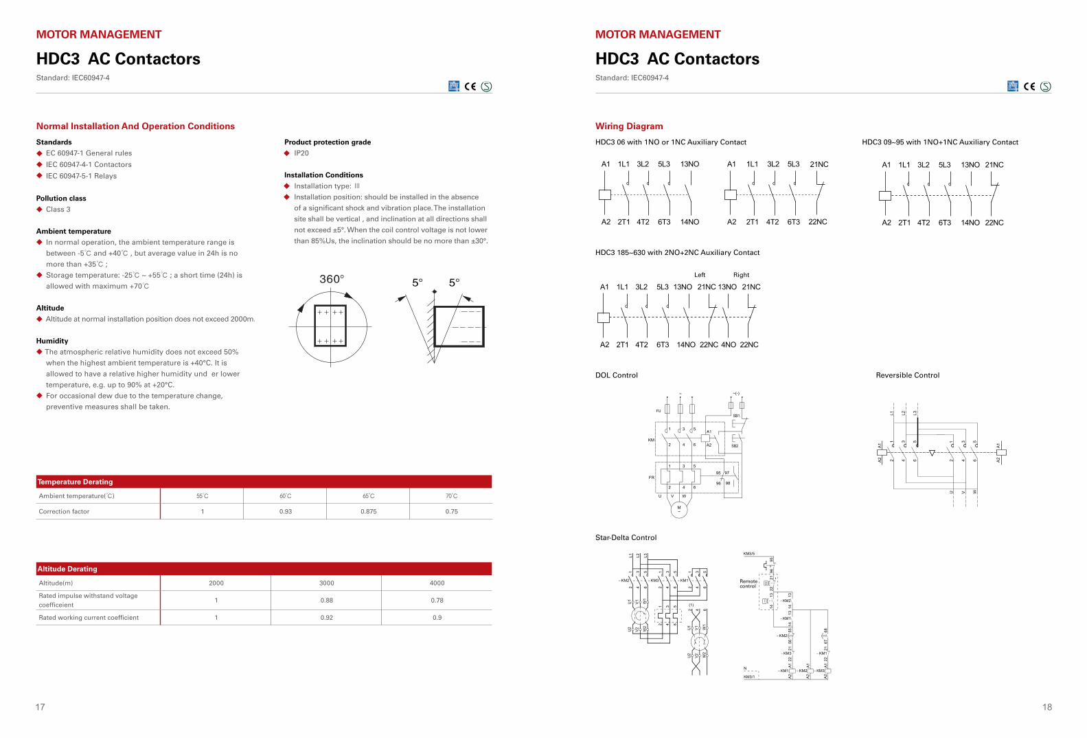
Normal Installation And Operation Conditions
Standards
EC 60947-1 General rules
IEC 60947-4-1 Contactors
IEC 60947-5-1 Relays
Pollution class
Class 3
Ambient temperature
In normal operation, the ambient temperature range is
between -5℃ and +40℃ , but average value in 24h is no
more than +35℃ ;
Storage temperature: -25℃ ~ +55℃ ; a short time (24h) is
allowed with maximum +70℃
Altitude
Altitude at normal installation position does not exceed 2000m.
Humidity
The atmospheric relative humidity does not exceed 50%
when the highest ambient temperature is +40°C. It is
allowed to have a relative higher humidity und er lower
temperature, e.g. up to 90% at +20°C.
For occasional dew due to the temperature change,
preventive measures shall be taken.
◆
◆
◆
◆
◆
◆
◆
◆
◆
◆
◆
◆
Product protection grade
IP20
Installation Conditions
Installation type: Ⅲ
Installation position: should be installed in the absence
of a significant shock and vibration place. The installation
site shall be vertical , and inclination at all directions shall
not exceed ±5°. When the coil control voltage is not lower
than 85%Us, the inclination should be no more than ±30°.
Motor C
ontrol & Protection
HJX2-F4P AC ContactorStandard: IEC 60947-4-1
Working Conditions
■ Ambient temperature for operating:-5℃~+40℃, the daily average temperature ≤ 35℃.■ Ambient temperature for storage and transportation: -25…+55 °C and can reach 70°C in short time.■ Altitude: ≤ 2000 m, and the altitude could be higher under lower operating voltage and operating current.■ Humidity: Maximum temperature is +40℃, air relative humidity of not more than 50%, at a lower temperature allows a higher relative humidity. For example, when at 20℃, can up to 90%, and occasionally due to temperature changes resulting from Gel should take special measures.■ Pollution Level: 3■ Installation Type: Ⅲ■ Protection class: IP00 (IP20 if with terminal protection cover)■ Installation position: Should be installed in the absence of a significant shake and shock and vibration place. The installation site shall be vertical , with inclination at all directions not exceeding ±5°. When the coil controling voltage no lower than 85%Us, the inclination should be no more than ±30°.
InstallLocation
Overall Dimensions
■ HJX2-F115~330
237
Temperature Derating
Ambient temperature(℃) 55℃ 60℃ 65℃ 70℃
Correction factor 1 0.93 0.875 0.75
Altitude Derating
Altitude(m) 2000 3000 4000
Rated impulse withstand voltage coefficeient
1 0.88 0.78
Rated working current coefficient 1 0.92 0.9
HDC3 AC ContactorsStandard: IEC60947-4
MOTOR MANAGEMENT
HDC3 06 with 1NO or 1NC Auxiliary Contact HDC3 09~95 with 1NO+1NC Auxiliary Contact
HDC3 185~630 with 2NO+2NC Auxiliary Contact
Wiring Diagram
DOL Control Reversible Control
Star-Delta Control
Remote control
Left Right
19 20
HDC3 AC ContactorsStandard: IEC60947-4
MOTOR MANAGEMENT
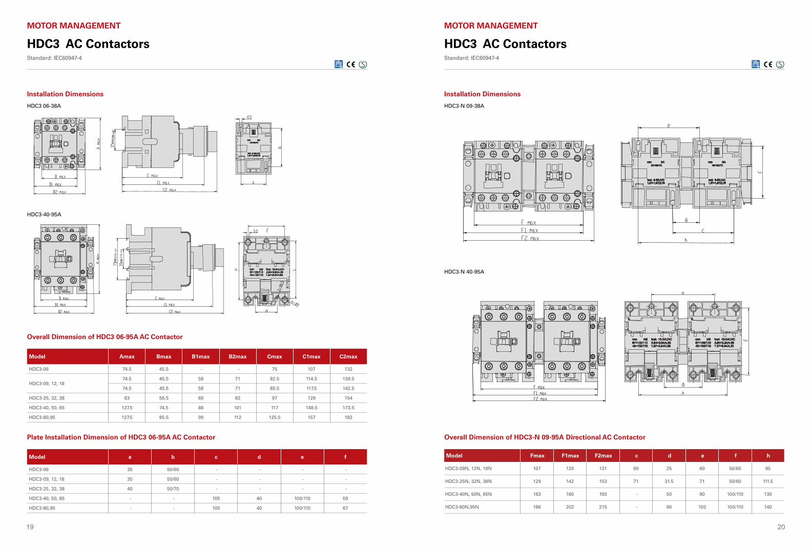
Installation Dimensions
HDC3-40-95A
f
×
×
e
HDC3 06-38A
D
IN ra
il
Overall Dimension of HDC3 06-95A AC Contactor
Model Amax Bmax B1max B2max Cmax C1max C2max
HDC3-06 74.5 45.5 - - 75 107 132
HDC3-09, 12, 1874.5 45.5 58 71 82.5 114.5 139.5
74.5 45.5 58 71 85.5 117.5 142.5
HDC3-25, 32, 38 83 56.5 69 82 97 129 154
HDC3-40, 50, 65 127.5 74.5 88 101 117 148.5 173.5
HDC3-80,95 127.5 85.5 99 112 125.5 157 182
Plate Installation Dimension of HDC3 06-95A AC Contactor
Model a b c d e f
HDC3-06 35 50/60 - - - -
HDC3-09, 12, 18 35 50/60 - - - -
HDC3-25, 32, 38 40 50/70 - - - -
HDC3-40, 50, 65 - - 105 40 100/110 59
HDC3-80,95 - - 105 40 100/110 67
HDC3-N 09-38A
HDC3-N 40-95A
Installation Dimensions
HDC3 AC ContactorsStandard: IEC60947-4
MOTOR MANAGEMENT
Overall Dimension of HDC3-N 09-95A Directional AC Contactor
Model Fmax F1max F2max c d e f h
HDC3-09N, 12N, 18N 107 120 131 60 25 60 50/60 95
HDC3-25N, 32N, 38N 129 142 153 71 31.5 71 50/60 111.5
HDC3-40N, 50N, 65N 163 180 193 - 50 90 100/110 130
HDC3-80N,95N 186 202 215 - 60 100 100/110 140
21 22
HDC3 AC ContactorsStandard: IEC60947-4
MOTOR MANAGEMENT
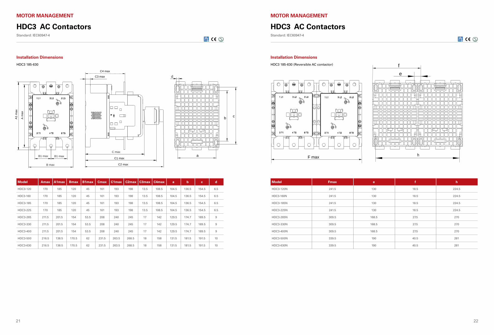
HDC3 185-630
Installation Dimensions
Model Amax A1max Bmax B1max Cmax C1max C2max C3max C4max a b c d
HDC3-120 170 185 120 45 161 193 198 13.5 108.5 104.5 136.5 154.5 6.5
HDC3-160 170 185 120 45 161 193 198 13.5 108.5 104.5 136.5 154.5 6.5
HDC3-185 170 185 120 45 161 193 198 13.5 108.5 104.5 136.5 154.5 6.5
HDC3-225 170 185 120 45 161 193 198 13.5 108.5 104.5 136.5 154.5 6.5
HDC3-265 211.5 201.5 154 53.5 208 240 245 17 142 129.5 174.7 189.5 9
HDC3-330 211.5 201.5 154 53.5 208 240 245 17 142 129.5 174.7 189.5 9
HDC3-400 211.5 201.5 154 53.5 208 240 245 17 142 129.5 174.7 189.5 9
HDC3-500 216.5 138.5 170.5 62 231.5 263.5 268.5 18 158 131.5 181.5 191.5 10
HDC3-630 216.5 138.5 170.5 62 231.5 263.5 268.5 18 158 131.5 181.5 191.5 10
HDC3 185-630 (Reversible AC contactor)
Installation Dimensions
HDC3 AC ContactorsStandard: IEC60947-4
MOTOR MANAGEMENT
Model Fmax e f h
HDC3-120N 241.5 130 18.5 224.5
HDC3-160N 241.5 130 18.5 224.5
HDC3-185N 241.5 130 18.5 224.5
HDC3-225N 241.5 130 18.5 224.5
HDC3-265N 309.5 168.5 27.5 270
HDC3-330N 309.5 168.5 27.5 270
HDC3-400N 309.5 168.5 27.5 270
HDC3-500N 339.5 190 40.5 281
HDC3-630N 339.5 190 40.5 281
F max h
fe
C max
C1 max
C2 max
B1 max B1 max
B max
C3 max
C4 max
A1 m
ax
A m
ax
d
a
b c
23 24
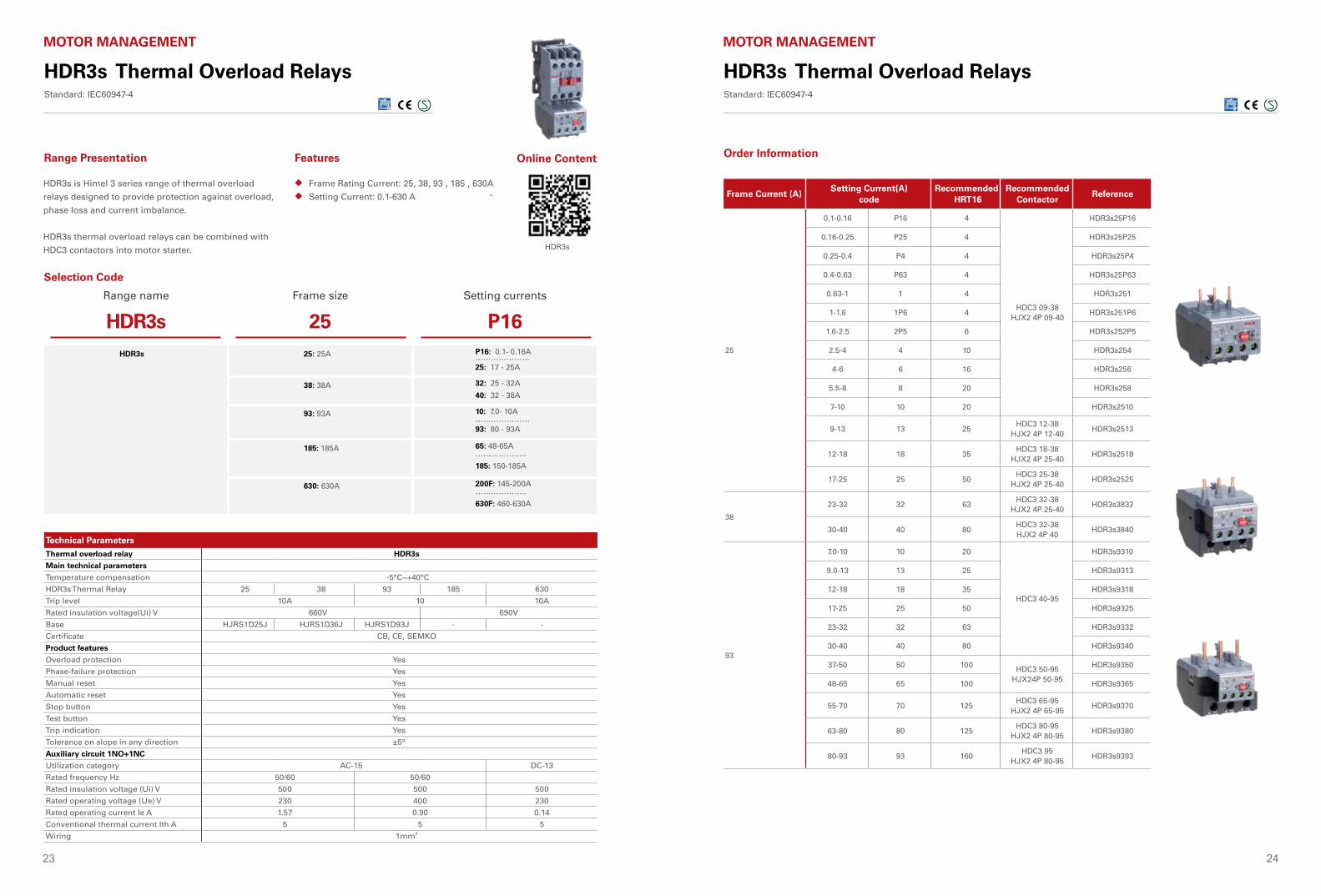
HDR3s Thermal Overload RelaysStandard: IEC60947-4
HDR3s is Himel 3 series range of thermal overload
relays designed to provide protection against overload,
phase loss and current imbalance.
HDR3s thermal overload relays can be combined with
HDC3 contactors into motor starter.
Frame Rating Current: 25, 38, 93 , 185 , 630A
Setting Current: 0.1-630 A
◆
◆
Range Presentation Features
Selection Code
Technical Parameters
MOTOR MANAGEMENT
Range name Frame size Setting currents
HDR3s 25 P16HDR3s 25: 25A P16: 0.1- 0.16A
…………………25: 17 - 25A
38: 38A 32: 25 - 32A
40: 32 - 38A
93: 93A 10: 7.0- 10A…………………93: 80 - 93A
185: 185A 65: 48-65A………………..
185: 150-185A
630: 630A 200F: 145-200A………………..
630F: 460-630A
Thermal overload relay HDR3s
Main technical parameters
Temperature compensation -5°C~+40°C
HDR3s Thermal Relay 25 38 93 185 630
Trip level 10A 10 10A
Rated insulation voltage(Ui) V 660V 690V
Base HJRS1D25J HJRS1D36J HJRS1D93J - -
Certificate CB, CE, SEMKO
Product features
Overload protection Yes
Phase-failure protection Yes
Manual reset Yes
Automatic reset Yes
Stop button Yes
Test button Yes
Trip indication Yes
Tolerance on slope in any direction ±5°
Auxiliary circuit 1NO+1NC
Utilization category AC-15 DC-13
Rated frequency Hz 50/60 50/60
Rated insulation voltage (Ui) V 500 500 500
Rated operating voltage (Ue) V 230 400 230
Rated operating current le A 1.57 0.90 0.14
Conventional thermal current Ith A 5 5 5
Wiring 1mm2
Online Content
HDR3s
Frame Current (A)Setting Current(A)
codeRecommended
HRT16Recommended
ContactorReference
25
0.1-0.16 P16 4
HDC3 09-38HJX2 4P 09-40
HDR3s25P16
0.16-0.25 P25 4 HDR3s25P25
0.25-0.4 P4 4 HDR3s25P4
0.4-0.63 P63 4 HDR3s25P63
0.63-1 1 4 HDR3s251
1-1.6 1P6 4 HDR3s251P6
1.6-2.5 2P5 6 HDR3s252P5
2.5-4 4 10 HDR3s254
4-6 6 16 HDR3s256
5.5-8 8 20 HDR3s258
7-10 10 20 HDR3s2510
9-13 13 25HDC3 12-38
HJX2 4P 12-40HDR3s2513
12-18 18 35HDC3 18-38
HJX2 4P 25-40HDR3s2518
17-25 25 50HDC3 25-38
HJX2 4P 25-40HDR3s2525
38
23-32 32 63HDC3 32-38
HJX2 4P 25-40HDR3s3832
30-40 40 80HDC3 32-38 HJX2 4P 40
HDR3s3840
93
7.0-10 10 20
HDC3 40-95
HDR3s9310
9.0-13 13 25 HDR3s9313
12-18 18 35 HDR3s9318
17-25 25 50 HDR3s9325
23-32 32 63 HDR3s9332
30-40 40 80 HDR3s9340
37-50 50 100 HDC3 50-95 HJX24P 50-95
HDR3s9350
48-65 65 100 HDR3s9365
55-70 70 125HDC3 65-95
HJX2 4P 65-95HDR3s9370
63-80 80 125HDC3 80-95
HJX2 4P 80-95HDR3s9380
80-93 93 160HDC3 95
HJX2 4P 80-95HDR3s9393
HDR3s Thermal Overload RelaysStandard: IEC60947-4
MOTOR MANAGEMENT
Order Information
25 26
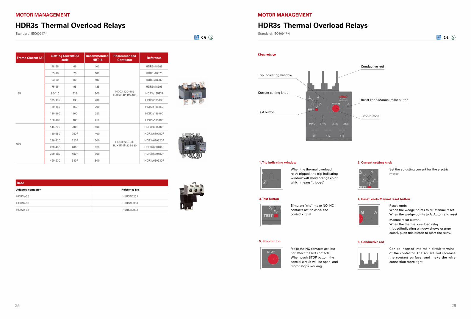
Frame Current (A)Setting Current(A)
codeRecommended
HRT16Recommended
ContactorReference
185
48-65 65 100
HDC3 120~185HJX2F 4P 115-185
HDR3s18565
55-70 70 100 HDR3s18570
63-80 80 100 HDR3s18580
75-95 95 125 HDR3s18595
90-115 115 200 HDR3s185115
105-135 135 200 HDR3s185135
120-150 150 200 HDR3s185150
130-160 160 250 HDR3s185160
150-185 185 250 HDR3s185185
630
145-200 200F 400
HDC3 225~630HJX2F 4P 225-630
HDR3s630200F
180-250 250F 400 HDR3s630250F
230-320 320F 500 HDR3s630320F
290-400 400F 630 HDR3s630400F
350-480 480F 800 HDR3s630480F
460-630 630F 800 HDR3s630630F
Base
Adapted contactor Reference No
HDR3s-25 HJRS1D25J
HDR3s-38 HJRS1D36J
HDR3s-93 HJRS1D93J
HDR3s Thermal Overload RelaysStandard: IEC60947-4
MOTOR MANAGEMENT
HDR3s Thermal Overload RelaysStandard: IEC60947-4
MOTOR MANAGEMENT
1, Trip indicating window 2, Current setting knob
4, Reset knob/Manual reset button
6, Conductive rod
3, Test button
5, Stop button
HDR3s-25
HDR3s-25
HDR3s-25
HDR3s-25
HDR3s-25
HDR3s-25
When the thermal overload relay tripped, the trip indicating window will show orange color, which means "tripped"
Set the adjusting current for the electric motor
Simulate "trip"(make NO, NC contacts act) to check the control circuit
Reset knob:When the wedge points to M: Manual resetWhen the wedge points to A: Automatic reset
Manual reset button:When the thermal overload relay tripped(indicating window shows orange color), push this button to reset the relay.
Make the NC contacts act, but not affect the NO contacts. When push STOP button, the control circuit will be open, and motor stops working.
Can be inserted into main circuit terminal of the contactor. The square rod increase the contact surface, and make the wire connection more tight.
HDR3s-25
Trip indicating window
Conductive rod
Reset knob/Manual reset button
Stop button
Current setting knob
Test button
Overview
27 28
HDR3s Thermal Overload RelaysStandard: IEC60947-4
MOTOR MANAGEMENT
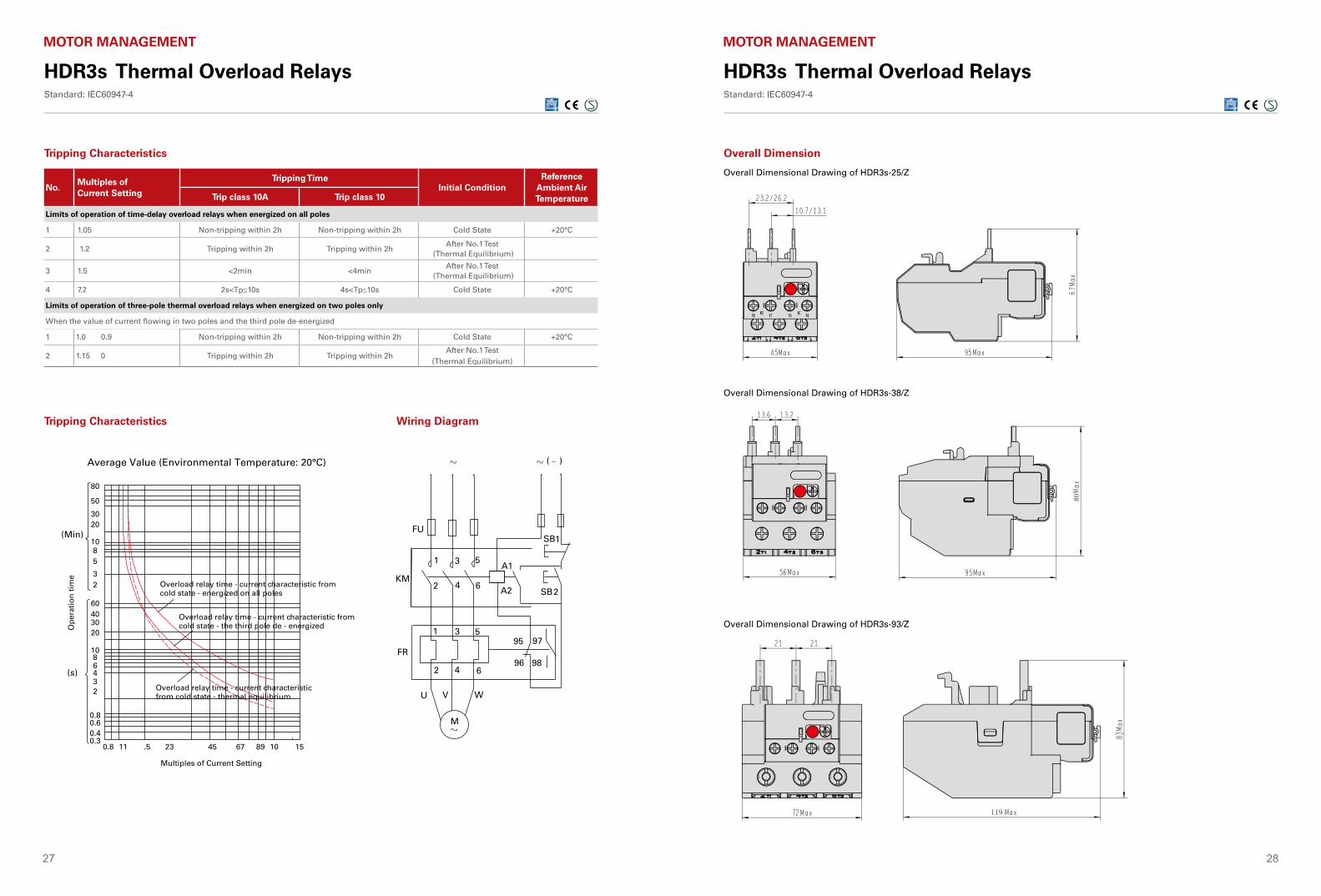
No.Multiples of Current Setting
Tripping TimeInitial Condition
Reference Ambient Air TemperatureTrip class 10A Trip class 10
Limits of operation of time-delay overload relays when energized on all poles
1 1.05 Non-tripping within 2h Non-tripping within 2h Cold State +20°C
2 1.2 Tripping within 2h Tripping within 2hAfter No.1 Test
(Thermal Equilibrium)
3 1.5 <2min <4minAfter No.1 Test
(Thermal Equilibrium)
4 7.2 2s<Tp≤10s 4s<Tp≤10s Cold State +20°C
Limits of operation of three-pole thermal overload relays when energized on two poles only
When the value of current flowing in two poles and the third pole de-energized
1 1.0 0.9 Non-tripping within 2h Non-tripping within 2h Cold State +20°C
2 1.15 0 Tripping within 2h Tripping within 2hAfter No.1 Test
(Thermal Equilibrium)
Average Value (Environmental Temperature: 20°C)
Tripping Characteristics Wiring Diagram
M
FR
U
KM
FU
A1
A2
SB1
SB2
1
2
3
4
5
6
1
2
3
4
5
6
( )
98
9795
96
VW VW
(Min)
80
50
3020
1085
32
60403020
1086432
11 .5 23 45 67 89 10 15
0.8
0.8
0.60.40.3
(s)
Op
erat
ion
tim
e
Overload relay time - current characteristic from cold state - energized on all poles
Overload relay time - current characteristic from cold state - the third pole de - energized
Overload relay time - current characteristic from cold state - thermal equilibrium
Multiples of Current Setting
Tripping Characteristics
HDR3s Thermal Overload RelaysStandard: IEC60947-4
MOTOR MANAGEMENT
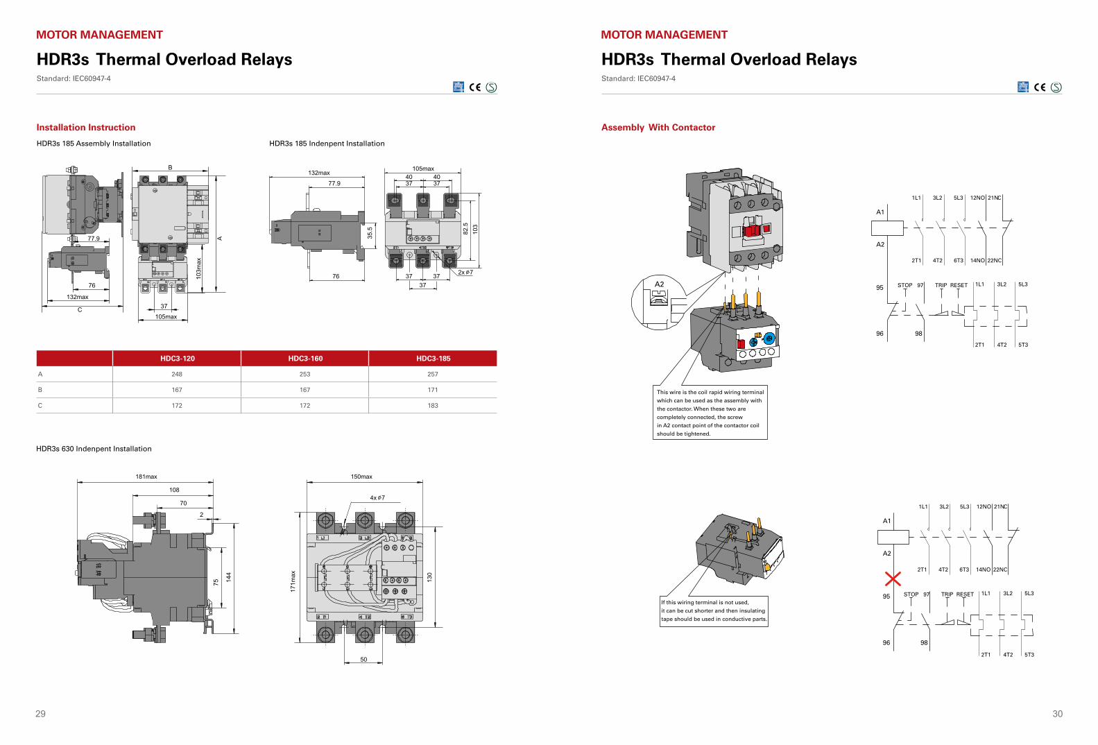
Overall Dimensional Drawing of HDR3s-25/Z
Overall Dimensional Drawing of HDR3s-38/Z
Overall Dimensional Drawing of HDR3s-93/Z
Overall Dimension
29 30
HDR3s Thermal Overload RelaysStandard: IEC60947-4
MOTOR MANAGEMENT
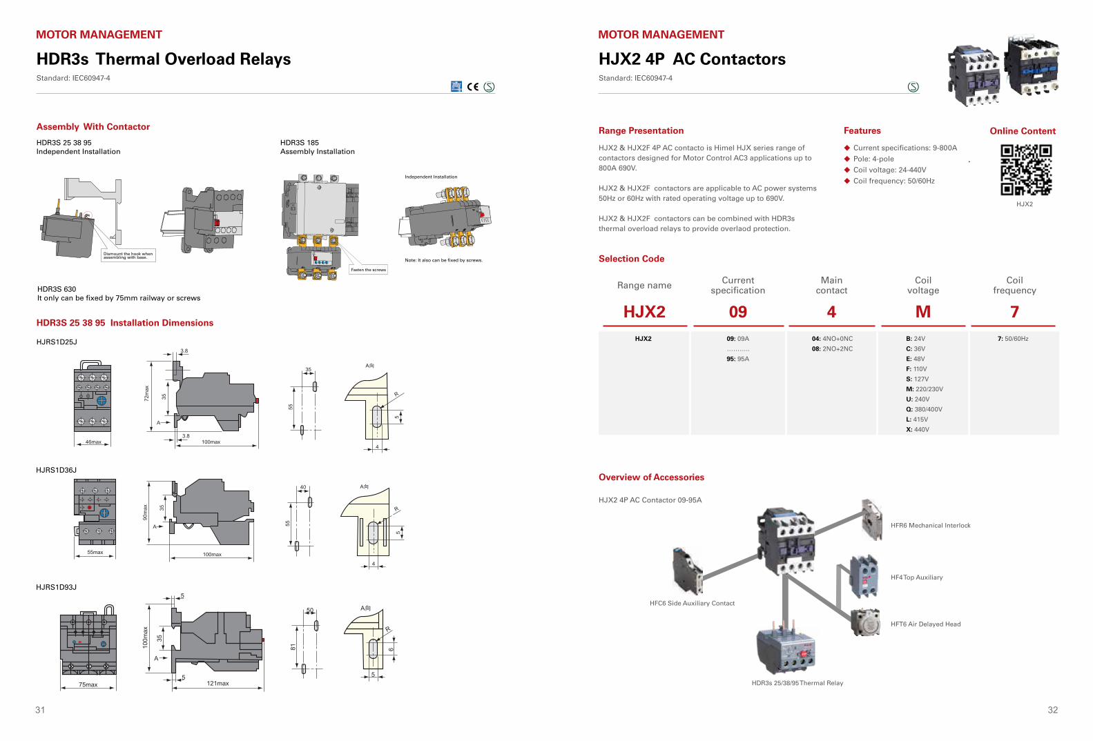
HDR3s 185 Assembly Installation HDR3s 185 Indenpent Installation
HDR3s 630 Indenpent Installation
HDC3-120 HDC3-160 HDC3-185
A 248 253 257
B 167 167 171
C 172 172 183
HDR3s Thermal Overload RelaysStandard: IEC60947-4
MOTOR MANAGEMENT
A1
A1
A2
95
96 98
1L1
1L1
2T1
STOP TRIP RESET 1L1 3L2 5L3
2T1 4T2 5T3
2T1 4T2 5T3
97
STOP TRIP RESET 1L1 3L2 5L397
4T2 6T3 14NO 22NC
2T1 4T2 6T3 14NO 22NC
3L2 5L3 12NO 21NC
3L2 5L3 12NO 21NC
A2
A2 95
96 98
This wire is the coil rapid wiring terminal
which can be used as the assembly with
the contactor. When these two are
completely connected, the screw
in A2 contact point of the contactor coil
should be tightened.
If this wiring terminal is not used,
it can be cut shorter and then insulating
tape should be used in conductive parts.
Assembly With ContactorInstallation Instruction
31 32
HDR3s Thermal Overload RelaysStandard: IEC60947-4
MOTOR MANAGEMENT
HDR3S 25 38 95Independent Installation
HDR3S 25 38 95 Installation Dimensions
HJRS1D25J
HJRS1D36J
HJRS1D93J
HDR3S 185Assembly Installation
Independent Installation
HDR3S 630It only can be fixed by 75mm railway or screws
Note: It also can be fixed by screws.
Fasten the screws
Dismount the hook when assembling with base.
Dismount the hook when assembling with base.
Assembly With Contactor
JR28(LR2)
7.
JR28(LR2)-D13
JR28(LR2)-D33
JR28(LR2)-D23
JR28(LR2)
7.
JR28(LR2)-D13
JR28(LR2)-D33
JR28(LR2)-D23
JR28(LR2)
8.
10.
JR28(LR2)-D13 7~10A 50
9.
JR28(LR2)-D13
JR28(LR2)-D23
JR28(LR2)-D33
LA7-D1064
LA7-D2064
LA7-D3064
HJX2 4P AC ContactorsStandard: IEC60947-4
MOTOR MANAGEMENT
Current specifications: 9-800A
Pole: 4-pole
Coil voltage: 24-440V
Coil frequency: 50/60Hz
◆
◆
◆
◆
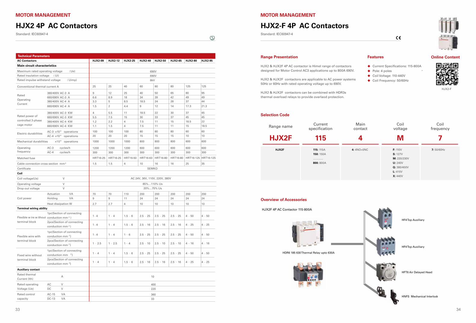
Range Presentation Features
HJX2 & HJX2F 4P AC contacto is Himel HJX series range of contactors designed for Motor Control AC3 applications up to 800A 690V.
HJX2 & HJX2F contactors are applicable to AC power systems 50Hz or 60Hz with rated operating voltage up to 690V.
HJX2 & HJX2F contactors can be combined with HDR3s thermal overload relays to provide overlaod protection.
Selection Code
Overview of Accessories
Range name Current specification
Main contact
Coil voltage
Coil frequency
HJX2 09 4 M 7HJX2 09: 09A
………..
95: 95A
04: 4NO+0NC
08: 2NO+2NC
B: 24V
C: 36V
E: 48V
F: 110V
S: 127V
M: 220/230V
U: 240V
Q: 380/400V
L: 415V
X: 440V
7: 50/60Hz
Order Information
nction
HJX2-4P AC ContactorStandard: IEC 60947-4-1
Rated current(A)AC-3 380/400V
ReferenceMain contactMotor P(kW)AC-380/400V
Coil voltage code
Coil voltage*
Motor C
ontrol & Protection
HJX2-4P AC contactors provide: Remote make & break of circuits Frequent start and stop of motors
4
5.5
11
18.5
22
30
37
45
9
12
25
40
50
65
80
95
4
2
4
2
4
2
4
2
4
2
4
2
4
2
4
2
0
2
0
2
0
2
0
2
0
2
0
2
0
2
0
2
HJX20904*7
HJX20908*7
HJX21204*7
HJX21208*7
HJX22504*7
HJX22508*7
HJX24004*7
HJX24008*7
HJX25004*7
HJX25008*7
HJX26504*7
HJX26508*7
HJX28004*7
HJX28008*7
HJX29504*7
HJX29508*7
Reference Description
Product name
HJX2
Rated Current
09
Main Contact
04
Coil Voltage
* 7
Coil Frequency
09:9A12:12A...95:95A
04:4NO+0NC08:2NO+2NC
B:24V...X:440V
7:50/60Hz
24V
B
36V
C
48V
E
110V
F
127V
S
220V
M
230V
N
240V
U
380V
Q
400V
V
415V
L
440V
X
2 5
Motor C
ontrol & Protection
Contactor
9 12 25 40 50 65 80 95
Top auxiliary contact
Thermal overload relays
Air delayed head
Mechanical interlocking module
Side auxiliary contact
HJX2-4P Contactor Accessories
9-25A:HFR632HX
40-95A:HFR695HX
2 Poles:HF411,HF402,HF420
4 Poles:HF404,HF413,HF422,HF431,HF440
2 Poles:HFC611,HFC602,HFC620
Making time-delay:HSK420,HSK422,HSK424
Breaking time-delay:HSK430,HSK432,HSK434
HDR3-25/HDR3s-25 HDR3-36/HDR3s-38 HDR3-93/HDR3s-93
0.1-0.16A...17-25A
23-32A30-40A
23-32A...80-93A
235
HJX2-4P AC ContactorStandard: IEC 60947-4-1
Top auxiliary contact
Thermal overload relays
Air delayed headSide auxiliary contact
Mechanical interlock module
HJX2 4P AC Contactor 09-95A
HFT6 Air Delayed Head
HDR3s 25/38/95 Thermal Relay
HFC6 Side Auxiliary Contact
HFR6 Mechanical Interlock
HF4 Top Auxiliary
Online Content
HJX2
33 34
HJX2 4P AC ContactorsStandard: IEC60947-4
MOTOR MANAGEMENTHJX2-4P AC ContactorStandard: IEC 60947-4-1
Technical Data
AC Contactors
Main circuit characteristics
Maximum rated operating voltage (Ue)
Rated insulation voltage (Ui)
Rated impulse withstand voltage (Uimp)
Conventional thermal current A
Motor C
ontrol & Protection
Rated
Operating
Current
380/400V AC-3 A
660/690V AC-4 A
380/400V AC-3 KW
660/690V AC-3 KW
380/400V AC-4 KW
660/690V AC-4 KW
Rated power of
controlled 3-phase
cage motor
Electric durabilitiesAC-3 ×10 4 operations
AC-4 ×10 4 operations
Mechanical durabilities ×10 4
Operating
operations
frequencyAC-3 cycles/h
AC-4 cycles/h
Matched fuse
Cable connection cross section mm
Coil voltage(Us)
Operating voltage
Drop-out voltage
Coil power
V
V
V
Actuation VA
Holding VA
Heat dissipation W
Terminal wiring ability
Flexible w ire w ithout
terminal block
Flexible wire with
terminal block
Fixed wire without
terminal block
1pc(Section of connecting
conduction mm )
2pcs(Section of connecting
conduction mm )
1pc(Section of connecting
conduction mm 2
2
2
2
)2pcs(Section of connecting
conduction mm 2)
1pc(Section of connecting
conduction mm 2)2pcs(Section of connecting
conduction mm 2)
Auxiliary contact
Rated thermal
Current (Ith)
Rated operating
Voltage (Ue)
Rated control
capacity
A
AC V
DC V
AC-15 VA
DC-13 VA
HJX2-09 HJX2-12 HJX2-25 HJX2-40 HJX2-50 HJX2-65 HJX2-80 HJX2-95
690V
690V
8kV
25
9
1.5
4
5.5
1.2
1.1
100
20
1000
1200
300
HRT16-25
1.5
Certificate SEMKO
25
12
2
5.5
7.5
2.2
1.5
100
20
1000
1200
300
HRT16-25
1.5
40
25
4.4
11
15
4
4
100
20
1000
1200
300
HRT16-50
4
60
40
9
18.5
30
7.5
7.5
80
15
800
600
300
HRT16-63
10
80
50
12
22
33
11
11
80
15
800
600
300
HRT16-80
16
80
65
14
30
37
15
11
80
15
800
600
300
HRT16-80
16
125
80
17.3
37
45
18.5
15
60
10
600
600
300
HRT16-125
25
125
95
380/400V AC-4 A 3.3 5 8.5 18.5 24 28 37 44660/690V AC-3 A 6.6 8.9 18 34 39 42 49 49
21.3
45
45
22
18.5
60
10
600
600
300
HRT16-125
35
AC 24V, 36V, 110V, 220V, 380V
85%…110% Us
20%…75% Us
70
9
2.7
70
9
2.7
110
11
4
200
24
10
200
24
10
200
24
10
200
24
10
200
24
10
1 - 4
1 -
-
-
-
-4
1 -
-
-
-
-
-
-
-
-
-
-
-
-
-
-
-
-
-
-
-
-
-
-
-
-
-
-
-
-
-
-
-
-
-
-
-
-
-
-
-
-
-
4
1 2.5
1 4
1 4
1 4
1 4
1 4
1 2.5
1 4
1 4
1.5 6
1.5 6
1 6
1 4
1.5 6
1.5 6
2.5 25
2.5 16
2.5 25
2.5 10
2.5 25
2.5 16
2.5 25
2.5 16
2.5 25
2.5 10
2.5 25
2.5 16
2.5 25
2.5 16
2.5 25
2.5 10
2.5 25
2.5 16
4 50
4 25
4 50
4 16
4 50
4 25
4 50
4 25
4 50
4 16
4 50
4 25
10
400
220
360
33
Coil
Technical Parameters
HJX2-F 4P AC ContactorsStandard: IEC60947-4
MOTOR MANAGEMENT
Current Specifications: 115-800A
Pole: 4 poles
Coil Voltage: 110-440V
Coil Frequency: 50/60Hz
◆
◆
◆
◆
Range Presentation Features
HJX2 & HJX2F 4P AC contactor is Himel range of contactors designed for Motor Control AC3 applications up to 800A 690V.
HJX2 & HJX2F contactors are applicable to AC power systems 50Hz or 60Hz with rated operating voltage up to 690V.
HJX2 & HJX2F contactors can be combined with HDR3s thermal overload relays to provide overlaod protection.
Selection Code
Range name Current specification
Main contact
Coil voltage
Coil frequency
HJX2F 115 4 M 7HJX2F 115: 115A
150: 150A
………..
800: 800A
4: 4NO+0NC F: 110V
S: 127V
M: 220/230V
U: 240V
Q: 380/400V
L: 415V
X: 440V
7: 50/60Hz
Order Information
nction
HJX2-F4P AC ContactorStandard: IEC 60947-4-1
Rated current(A)AC-3 380/400V
ReferenceMain contactMotor P(kW)AC-380/400V
Coil voltage code
Coil voltage*
Motor C
ontrol & Protection
HJX2-F4P AC contactors provide: Remote make & break of circuits Frequent start and stop of motors
55
75
90
100
132
160
200
250
335
400
115
150
185
225
265
330
400
500
630
800
4
4
4
4
4
4
4
4
4
4
0
0
0
0
0
0
0
0
0
0
HJX2F1154*7
HJX2F1504*7
HJX2F1854*7
HJX2F2254*7
HJX2F2654*7
HJX2F3304*7
HJX2F4004*7
HJX2F5004*7
HJX2F6304*7
HJX2F8004*7
Reference Description
Product name
HJX2F
Rated current
115
Main Contact
4
Coil Voltage
* 7
Coil Frequency
115:115A150:150A...800:800A
4:4NO+0NC F:110V...X:440V
7:50/60Hz
110V
F
220V
M
230V
N
240V
U
380V
Q
400V
V
415V
L
440V
X
HJX2F 4P AC Contactor 115-800A
Motor C
ontrol & Protection
HJX2-F4P AC ContactorStandard: IEC 60947-4-1
Terminal Wiring Ability - Main Circuit
Flexible WireWithout TerminalBlock
Flexible Wire WithTerminal Block
Fixed Wire WithoutTerminal Block
1pc(Section of ConnectingConduction mm2)2pcs(Section of ConnectingConduction mm2)1pc(Section of ConnectingConduction mm2)2pcs(Section of ConnectingConduction mm2)1pc(Section of ConnectingConduction mm2)2pcs(Section of ConnectingConduction mm2)N.m
Auxiliary Contact
Rated ThermalCurrent (Ith)Rated OperatingVoltage (Ue) Rated ControlCapacity
A
AC VDC VAC-15 VADC-13 VA
1~4
1~4
1~4
1~2.5
1~4
1~4
1.2
10
40022036033
Fastening Torque
HJX2-F4P Contactor Accessories
Top auxiliary contact
Top auxiliary contact
Air delayed head
235
Mechanical interlock
HF4 Top Auxiliary
HF4 Top Auxiliary
HFT6 Air Delayed Head
HNFS Mechanical Interlock
Overview of Accessories
HDR6 185 630 Thermal Relay upto 630A
Online Content
HJX2-F
35 36
HJX2-F 4P AC ContactorsStandard: IEC60947-4
MOTOR MANAGEMENT
Technical Parameters
HJX2-F4P Standard: IEC 60947-4-1
2 4
Technical Data
AC Contactors
Main circuit characteristics
Maximum Rated Operating voltage (Ue)
Rated Insulation Voltage (Ui)
Rated Impulse Withstand Voltage (Uimp)
Conventional thermal current
Coil
Rated Operating
Current
440V AC-3 A
440V AC-4 A
660V AC-3 A
660V AC-4 A
Ie max AC-1 Aθ ≤ 40 °C
220/240V
380/400V
415V
440V
500V
660/690V
1000V
Rated power of AC-3
Electric durabilities
Mechanical durabilities ×10 4
Operating frequency
cycles/h
AC-3 ×10 4 operations
AC-4 ×10 4 operations
operations
AC-1, AC-2, AC-3
AC-4
Model
Rated current(A)Matched fuse
Cable connection cross section mm
Certificate CE
2
Coil Voltage(Us)
Operating voltage
Drop-out voltage
Average Coil Power
V
Pull in voltage V
Drop-out voltage AC V
Drop-out voltage DC V
Actuation AC VA
Holding AC VA
Actuation DC VA
Holding DC VA
Heat Dissipation W
Terminal Wiring Ability - Main Circuit
HJX2-F115 HJX2-F150 HJX2-F185 HJX2-F225 HJX2-F265 HJX2-F330 HJX2-F400 HJX2-F630HJX2-F500 HJX2-F800
660/690V
690V
8kV
200
115
52
86
49
200
30
55
59
59
75
80
65
60
15
300
600
150
HRT16-1
200
95
250
150
60
107
57
250
40
75
80
80
90
100
65
60
15
300
600
150
HRT16-1
250
120
275
185
79
118
69
275
55
90
100
100
110
120
100
50
15
300
600
150
HRT16-2
315
150
315
225
85
135
82
315
63
100
110
110
129
129
140
50
15
300
600
150
HRT16-2
315
185
350
265
105
170
98
350
75
132
140
140
160
180
147
50
15
300
600
150
HRT16-2
400
240
400
330
117
235
107
400
100
160
180
180
200
220
160
50
15
300
600
150
HRT16-3
500
240
500
400
138
305
135
500
129
200
220
220
257
280
185
30
8
100
300
150
HRT16-3
500
2*150
630
500
147
355
145
630
147
250
280
280
335
355
335
30
8
100
300
150
HRT16-3
500
2*240
110V, 220V, 230V, 240V, 380V, 400V, 415V, 440V
85%…110% Us
20%…75% Us
10%…75% Us
855
8.1
665
4.83
7.2
2
20×3
95
95
10
855
8.1
665
4.83
7.2
2
25×3
120
120
18
1180
10.9
902
5.07
9.8
2
25×3
150
150
18
1180
10.9
902
5.07
9.8
2
32×3
185
185
35
700
10
803
4.53
10.4
2
32×4
240
240
35
700
10
803
4.53
10.4
2
30×5
240
---
35
1150
18
1140
7.5
14
2
30×5
2×150
---
35
1150
20
1220
8
18
2
40×5
2×240
---
35
1730
25
1920
12.5
20
2
60×5
---
---
58
1730
25
1920
12.5
20
2
60×5
---
---
58
Wiring Bar
Wire With Lug Plate
Wire With Coupler
Fastening Torque
Bar quantity
Dimensions
mm
mm
N.m
800
630
188
460
170
800
200
335
375
375
400
450
450
20
5
100
300
150
HRT16-3
630
2*60*5
800
800
195
493
175
800
220
400
425
425
450
475
450
15
4
100
300
150
HRT16-4
800
2*60*5
2
2
HJX2 4P AC ContactorsStandard: IEC60947-4
MOTOR MANAGEMENT
Order Information
nction
HJX2-4P AC ContactorStandard: IEC 60947-4-1
Rated current(A)AC-3 380/400V
ReferenceMain contactMotor P(kW)AC-380/400V
Coil voltage code
Coil voltage*
Motor C
ontrol & Protection
HJX2-4P AC contactors provide: Remote make & break of circuits Frequent start and stop of motors
4
5.5
11
18.5
22
30
37
45
9
12
25
40
50
65
80
95
4
2
4
2
4
2
4
2
4
2
4
2
4
2
4
2
0
2
0
2
0
2
0
2
0
2
0
2
0
2
0
2
HJX20904*7
HJX20908*7
HJX21204*7
HJX21208*7
HJX22504*7
HJX22508*7
HJX24004*7
HJX24008*7
HJX25004*7
HJX25008*7
HJX26504*7
HJX26508*7
HJX28004*7
HJX28008*7
HJX29504*7
HJX29508*7
Reference Description
Product name
HJX2
Rated Current
09
Main Contact
04
Coil Voltage
* 7
Coil Frequency
09:9A12:12A...95:95A
04:4NO+0NC08:2NO+2NC
B:24V...X:440V
7:50/60Hz
24V
B
36V
C
48V
E
110V
F
127V
S
220V
M
230V
N
240V
U
380V
Q
400V
V
415V
L
440V
X
Order Information
Order Information
nction
HJX2-F4P AC ContactorStandard: IEC 60947-4-1
Rated current(A)AC-3 380/400V
ReferenceMain contactMotor P(kW)AC-380/400V
Coil voltage code
Coil voltage*
Motor C
ontrol & Protection
HJX2-F4P AC contactors provide: Remote make & break of circuits Frequent start and stop of motors
55
75
90
100
132
160
200
250
335
400
115
150
185
225
265
330
400
500
630
800
4
4
4
4
4
4
4
4
4
4
0
0
0
0
0
0
0
0
0
0
HJX2F1154*7
HJX2F1504*7
HJX2F1854*7
HJX2F2254*7
HJX2F2654*7
HJX2F3304*7
HJX2F4004*7
HJX2F5004*7
HJX2F6304*7
HJX2F8004*7
Reference Description
Product name
HJX2F
Rated current
115
Main Contact
4
Coil Voltage
* 7
Coil Frequency
115:115A150:150A...800:800A
4:4NO+0NC F:110V...X:440V
7:50/60Hz
110V
F
220V
M
230V
N
240V
U
380V
Q
400V
V
415V
L
440V
X
Motor P(kW)AC-380/400V
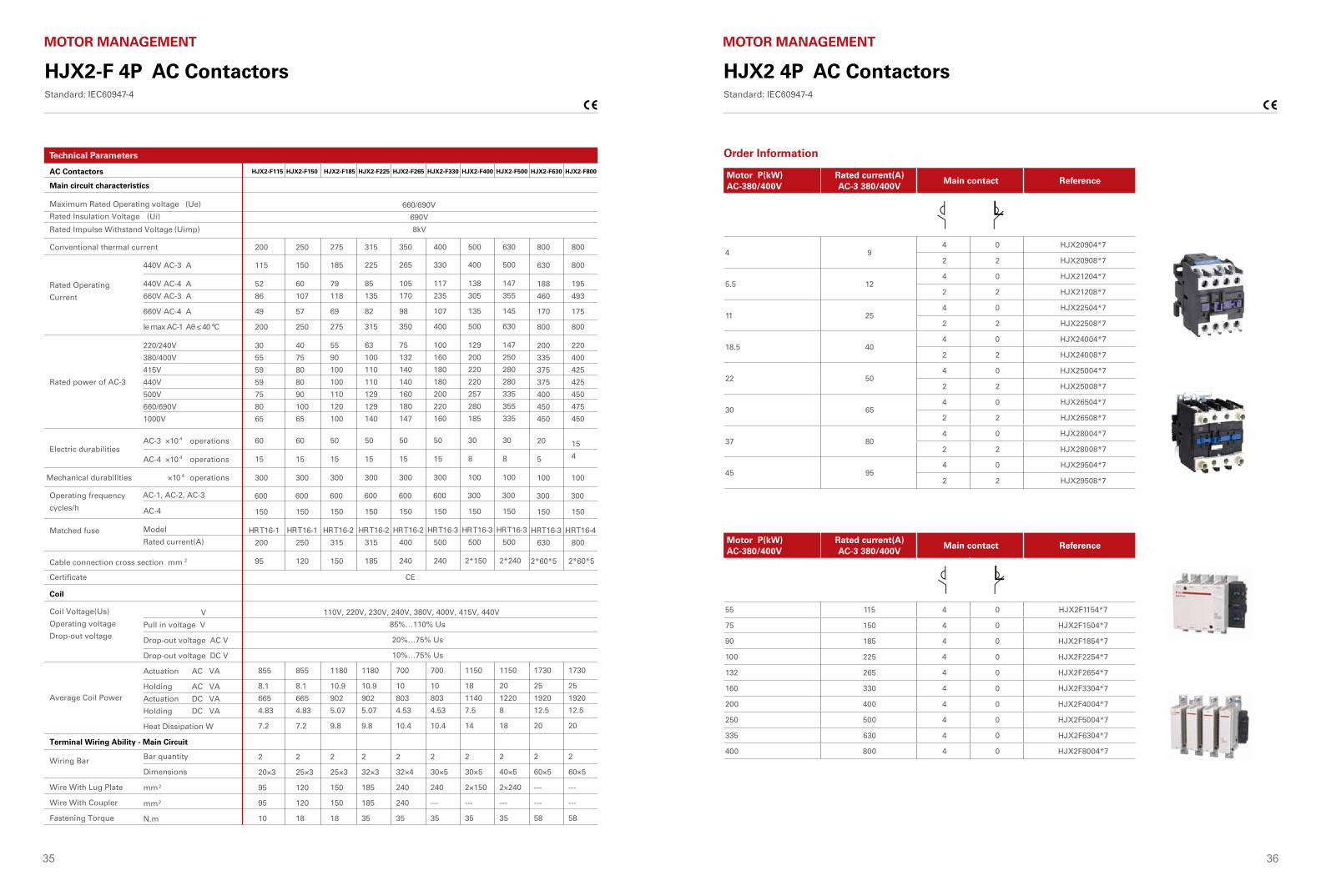
Rated current(A)AC-3 380/400V
Main contact Reference
4 94 0 HJX20904*7
2 2 HJX20908*7
5.5 124 0 HJX21204*7
2 2 HJX21208*7
11 254 0 HJX22504*7
2 2 HJX22508*7
18.5 404 0 HJX24004*7
2 2 HJX24008*7
22 504 0 HJX25004*7
2 2 HJX25008*7
30 654 0 HJX26504*7
2 2 HJX26508*7
37 804 0 HJX28004*7
2 2 HJX28008*7
45 954 0 HJX29504*7
2 2 HJX29508*7
Motor P(kW)AC-380/400V
Rated current(A)AC-3 380/400V
Main contact Reference
55 115 4 0 HJX2F1154*7
75 150 4 0 HJX2F1504*7
90 185 4 0 HJX2F1854*7
100 225 4 0 HJX2F2254*7
132 265 4 0 HJX2F2654*7
160 330 4 0 HJX2F3304*7
200 400 4 0 HJX2F4004*7
250 500 4 0 HJX2F5004*7
335 630 4 0 HJX2F6304*7
400 800 4 0 HJX2F8004*7
37 38
HJX2 4P AC ContactorsStandard: IEC60947-4
MOTOR MANAGEMENT
Motor Control &
Protection2 6
Accessories
SK4 Air delayed head
S
0 1- S
0 1- 0S
10-180S
0 1-
0 1- 0S
10-180S
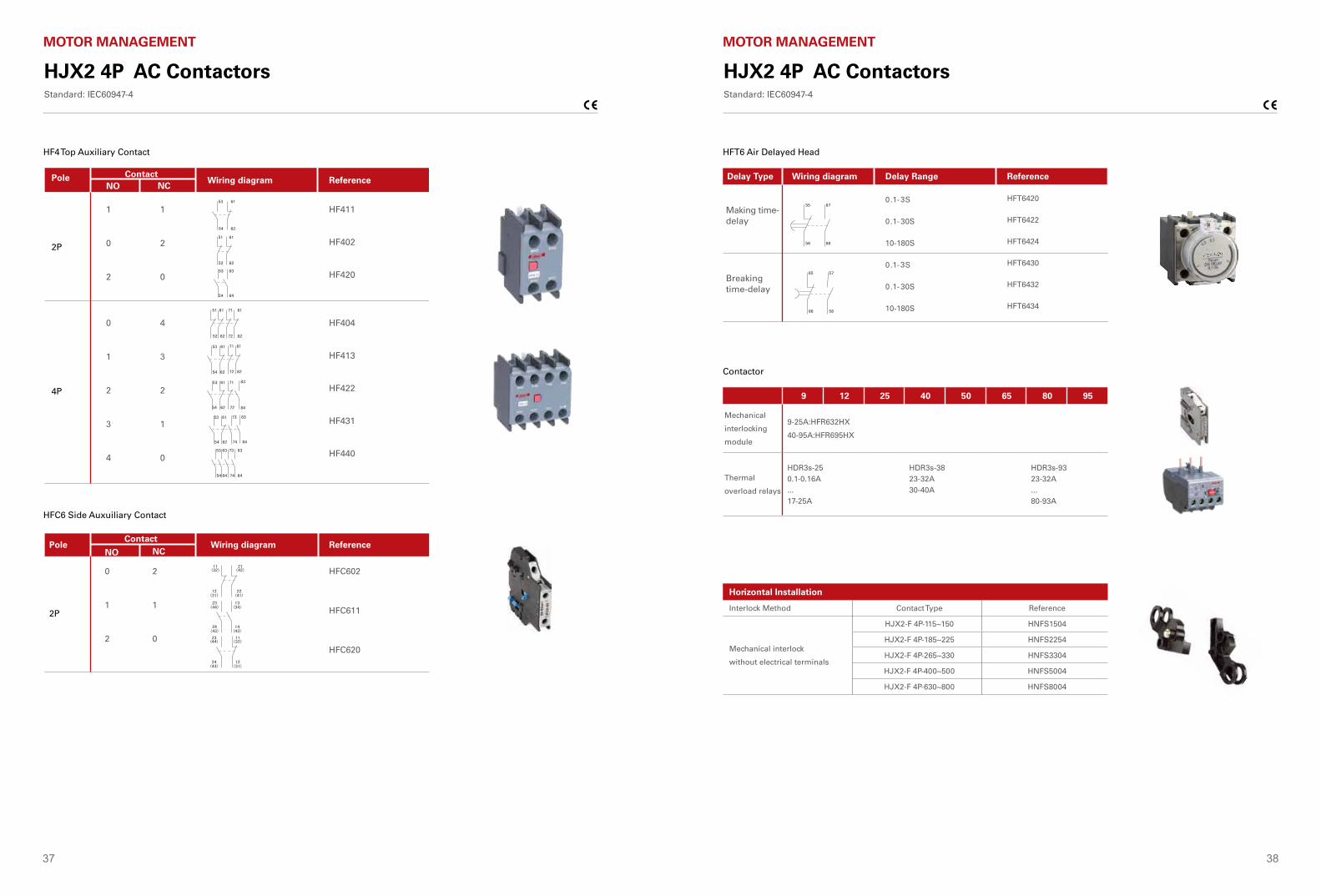
F4 Top of auxiliary contact
FC6 Side auxiliary contact
1
2
0
4
2
1
0
1
0
2
0
1
2
4
HF411
HF402
HF420
HF404
HF413
HF422
HF431
HF440
HFT6420
HFT6422
HFT6424
HFT6430
HFT6432
HFT6434
0
1
2
2
1
0
HFC602
HFC611
HFC620
Delay Type Delay Range Reference
Making time-delay
Breaking time-delay
Wiring diagram
NCNOContact
ReferenceWiring diagram
NO NCPole
ContactWiring diagram
2P
4P
2P
Pole
Reference
HJX2-4P AC ContactorStandard: IEC 60947-4-1
Motor Control &
Protection
2 6
Accessories
SK4 Air delayed head
S
0 1- S
0 1- 0S
10-180S
0 1-
0 1- 0S
10-180S
F4 Top of auxiliary contact
FC6 Side auxiliary contact
1
2
0
4
2
1
0
1
0
2
0
1
2
4
HF411
HF402
HF420
HF404
HF413
HF422
HF431
HF440
HFT6420
HFT6422
HFT6424
HFT6430
HFT6432
HFT6434
0
1
2
2
1
0
HFC602
HFC611
HFC620
Delay Type Delay Range Reference
Making time-delay
Breaking time-delay
Wiring diagram
NCNOContact
ReferenceWiring diagram
NO NCPole
ContactWiring diagram
2P
4P
2P
Pole
Reference
HJX2-4P AC ContactorStandard: IEC 60947-4-1
HF4 Top Auxiliary Contact
HFC6 Side Auxuiliary Contact
HFT6 Air Delayed Head
Contactor
HJX2 4P AC ContactorsStandard: IEC60947-4
MOTOR MANAGEMENT
Motor Control &
Protection
2 6
Accessories
SK4 Air delayed head
S
0 1- S
0 1- 0S
10-180S
0 1-
0 1- 0S
10-180S
F4 Top of auxiliary contact
FC6 Side auxiliary contact
1
2
0
4
2
1
0
1
0
2
0
1
2
4
HF411
HF402
HF420
HF404
HF413
HF422
HF431
HF440
HFT6420
HFT6422
HFT6424
HFT6430
HFT6432
HFT6434
0
1
2
2
1
0
HFC602
HFC611
HFC620
Delay Type Delay Range Reference
Making time-delay
Breaking time-delay
Wiring diagram
NCNOContact
ReferenceWiring diagram
NO NCPole
ContactWiring diagram
2P
4P
2P
Pole
Reference
HJX2-4P AC ContactorStandard: IEC 60947-4-1
9 12 25 40 50 65 80 95
Mechanical
interlocking
module
9-25A:HFR632HX
40-95A:HFR695HX
Thermal
overload relays
HDR3s-250.1-0.16A...17-25A
HDR3s-3823-32A30-40A
HDR3s-9323-32A...80-93A
2 5
Motor C
ontrol & Protection
Contactor
9 12 25 40 50 65 80 95
Top auxiliary contact
Thermal overload relays
Air delayed head
Mechanical interlocking module
Side auxiliary contact
HJX2-4P Contactor Accessories
9-25A:HFR632HX
40-95A:HFR695HX
2 Poles:HF411,HF402,HF420
4 Poles:HF404,HF413,HF422,HF431,HF440
2 Poles:HFC611,HFC602,HFC620
Making time-delay:HSK420,HSK422,HSK424
Breaking time-delay:HSK430,HSK432,HSK434
HDR3-25/HDR3s-25 HDR3-36/HDR3s-38 HDR3-93/HDR3s-93
0.1-0.16A...17-25A
23-32A30-40A
23-32A...80-93A
235
HJX2-4P AC ContactorStandard: IEC 60947-4-1
Top auxiliary contact
Thermal overload relays
Air delayed headSide auxiliary contact
Mechanical interlock module
Horizontal Installation
Interlock Method Contact Type Reference
Mechanical interlock
without electrical terminals
HJX2-F 4P-115~150 HNFS1504
HJX2-F 4P-185~225 HNFS2254
HJX2-F 4P-265~330 HNFS3304
HJX2-F 4P-400~500 HNFS5004
HJX2-F 4P-630~800 HNFS8004
39 40
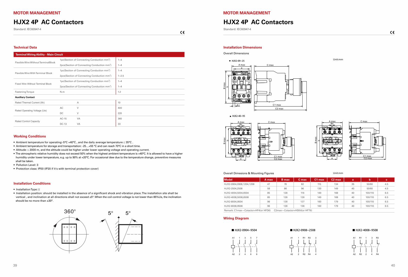
Terminal Wiring Ability - Main Circuit
Flexible Wire Without TerminalBlock1pc(Section of Connecting Conduction mm2) 1~4
2pcs(Section of Connecting Conduction mm2) 1~4
Flexible Wire With Terminal Block1pc(Section of Connecting Conduction mm2) 1~4
2pcs(Section of Connecting Conduction mm2) 1~2.5
Fixed Wire Without Terminal Block1pc(Section of Connecting Conduction mm2) 1~4
2pcs(Section of Connecting Conduction mm2) 1~4
Fastening Torque N.m 1.2
Auxiliary Contact
Rated Thermal Current (Ith) A 10
Rated Operating Voltage (Ue) AC V 400
DC V 220
Rated Control CapacityAC-15 VA 360
DC-13 VA 33
HJX2 4P AC ContactorsStandard: IEC60947-4
MOTOR MANAGEMENT
Technical Data
Motor C
ontrol & Protection
HJX2-F4P AC ContactorStandard: IEC 60947-4-1
Working Conditions
■ Ambient temperature for operating:-5℃~+40℃, the daily average temperature ≤ 35℃.■ Ambient temperature for storage and transportation: -25…+55 °C and can reach 70°C in short time.■ Altitude: ≤ 2000 m, and the altitude could be higher under lower operating voltage and operating current.■ Humidity: Maximum temperature is +40℃, air relative humidity of not more than 50%, at a lower temperature allows a higher relative humidity. For example, when at 20℃, can up to 90%, and occasionally due to temperature changes resulting from Gel should take special measures.■ Pollution Level: 3■ Installation Type: Ⅲ■ Protection class: IP00 (IP20 if with terminal protection cover)■ Installation position: Should be installed in the absence of a significant shake and shock and vibration place. The installation site shall be vertical , with inclination at all directions not exceeding ±5°. When the coil controling voltage no lower than 85%Us, the inclination should be no more than ±30°.
InstallLocation
Overall Dimensions
■ HJX2-F115~330
237
Working Conditions
Installation Conditions
• Ambient temperature for operating:-5°C +40°C , and the daily average temperature ≤ 35°C .• Ambient temperature for storage and transportation: -25…+55 °C and can reach 70°C in a short time.• Altitude: ≤ 2000 m, and the altitude could be higher under lower operating voltage and operating current.• The atmospheric relative humidity does not exceed 50% when the highest ambient temperature is +40°C. It is allowed to have a higher humidity under lower temperature, e.g. up to 90% at +20°C. For occasional dew due to the temperature change, preventive measures shall be taken.• Pollution Level: 3• Protection class: IP00 (IP20 if it's with terminal protection cover)
• Installation Type: • Installation position: should be installed in the absence of a significant shock and vibration place. The installation site shall be vertical , and inclination at all directions shall not exceed ±5°. When the coil control voltage is not lower than 85%Us, the inclination should be no more than ±30°.
HJX2 4P AC ContactorsStandard: IEC60947-4
MOTOR MANAGEMENT
Installation Dimensions
Overall Dimesions & Mounting Figures
Wiring Diagram
Unit:mm
Unit:mm
Motor Control &
Protection
2 8
Overall Dimensions
HJX2-09~25
nit:mm
nit:mm
HJX2-40~95
Overall dimesions & mounting figures
A max B max C max C1 max C2 max a b cModel
Wiring diagram
HJX2-4P AC ContactorStandard: IEC 60947-4-1
■ HJX2-0904~9504
A1 1 3 5 7
A2 2 4 6 8
A1 R1 1 3 R3
A2 R2 2 4 R4
A1 1 R1 R3 3
A2 2 R2 R4 4
■ HJX2-4008~9508■ HJX2-0908~2508
HJX2-0904,0908,1204,1208
HJX2-2504,2508
HJX2-4004,5004,6504
HJX2-4008,5008,6508
HJX2-8004,9504
HJX2-8008,9508
Remark: C1max—Cotactor+HF4(or HFD6) C2max—Cotactor+HSK4(or HFT6)
47
58
85
85
96
96
76
86
128
128
128
128
82
96
116
126
127
136
115
130
149
149
160
160
134
149
168
168
179
179
35
40
40
40
40
40
50/60
50/60
100/110
100/110
100/110
100/110
4.5
4.5
6.5
6.5
6.5
6.5
Overall Dimensions
Model A max B max C max C1 max C2 max a b c
HJX2-0904,0908,1204,1208 47 76 82 115 134 35 50/60 4.5
HJX2-2504,2508 58 86 96 130 149 40 50/60 4.5
HJX2-4004,5004,6504 85 128 116 149 168 40 100/110 6.5
HJX2-4008,5008,6508 85 128 126 149 168 40 100/110 6.5
HJX2-8004,9504 96 128 127 160 179 40 100/110 6.5
HJX2-8008,9508 96 128 136 160 179 40 100/110 6.5
Remark: C1max—Cotactor+HF4(or HFD6) C2max—Cotactor+HSK4(or HFT6)
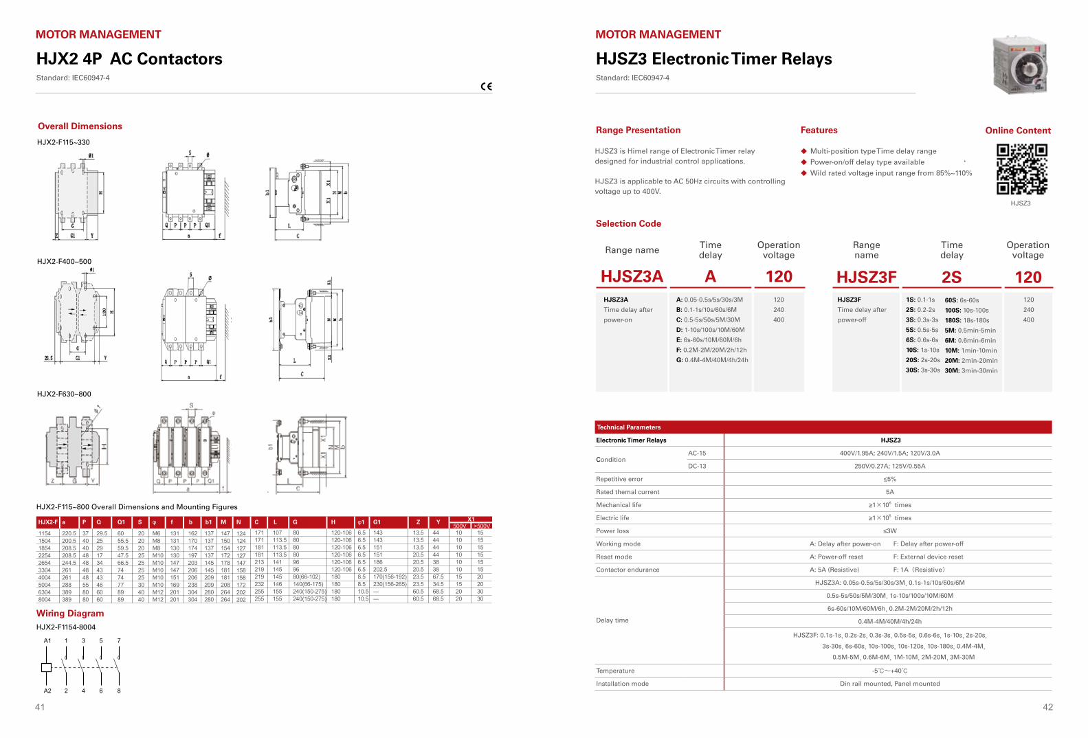
41 42
HJX2 4P AC ContactorsStandard: IEC60947-4
MOTOR MANAGEMENT
Motor Control &
Protection
HJX2-F4P AC ContactorStandard: IEC 60947-4-1
■ HJX2-F400~500
■ HJX2-F630~800
238
HJX2-F115~800 Overall dimensions and mounting figures
X1P Q Q1 S φ f b b1 M N C L G H φ1 G1 Z YaHJX2-F
Wiring diagram
■ HJX2-F1154-8004A1 1 3 5 7
A2 2 4 6 8
171171181181213219219232255255
107113.5113.5113.5141145145146155155
80808080969680(66-102)140(66-175)240(150-275)240(150-275)
120-106120-106120-106120-106120-106120-106180180180180
6.56.56.56.56.56.58.58.510.510.5
143143151151186202.5170(156-192)230(156-265)------
1154150418542254265433044004500463048004
220.5200.5208.5208.5244.5261261288389389
37404048484848558080
29.5252917344343466060
6055.559.547.566.57474778989
20202025252525304040
M6M8M8M10M10M10M10M10M12M12
131131130130147147151169201201
162170174197203206206238304304
137137137137145145209209280280
147150154172178181181208264264
124124127127147158158172202202
13.513.513.520.520.520.523.523.560.560.5
44444444383867.534.568.568.5
10101010101015152020
15151515151520203030
500V >500V
Motor C
ontrol & Protection
HJX2-F4P AC ContactorStandard: IEC 60947-4-1
Working Conditions
■ Ambient temperature for operating:-5℃~+40℃, the daily average temperature ≤ 35℃.■ Ambient temperature for storage and transportation: -25…+55 °C and can reach 70°C in short time.■ Altitude: ≤ 2000 m, and the altitude could be higher under lower operating voltage and operating current.■ Humidity: Maximum temperature is +40℃, air relative humidity of not more than 50%, at a lower temperature allows a higher relative humidity. For example, when at 20℃, can up to 90%, and occasionally due to temperature changes resulting from Gel should take special measures.■ Pollution Level: 3■ Installation Type: Ⅲ■ Protection class: IP00 (IP20 if with terminal protection cover)■ Installation position: Should be installed in the absence of a significant shake and shock and vibration place. The installation site shall be vertical , with inclination at all directions not exceeding ±5°. When the coil controling voltage no lower than 85%Us, the inclination should be no more than ±30°.
InstallLocation
Overall Dimensions
■ HJX2-F115~330
237
Overall Dimensions
HJX2-F400~500
HJX2-F630~800
HJX2-F115~330
HJX2-F115~800 Overall Dimensions and Mounting Figures
Motor Control &
Protection
HJX2-F4P AC ContactorStandard: IEC 60947-4-1
■ HJX2-F400~500
■ HJX2-F630~800
238
HJX2-F115~800 Overall dimensions and mounting figures
X1P Q Q1 S φ f b b1 M N C L G H φ1 G1 Z YaHJX2-F
Wiring diagram
■ HJX2-F1154-8004A1 1 3 5 7
A2 2 4 6 8
171171181181213219219232255255
107113.5113.5113.5141145145146155155
80808080969680(66-102)140(66-175)240(150-275)240(150-275)
120-106120-106120-106120-106120-106120-106180180180180
6.56.56.56.56.56.58.58.510.510.5
143143151151186202.5170(156-192)230(156-265)------
1154150418542254265433044004500463048004
220.5200.5208.5208.5244.5261261288389389
37404048484848558080
29.5252917344343466060
6055.559.547.566.57474778989
20202025252525304040
M6M8M8M10M10M10M10M10M12M12
131131130130147147151169201201
162170174197203206206238304304
137137137137145145209209280280
147150154172178181181208264264
124124127127147158158172202202
13.513.513.520.520.520.523.523.560.560.5
44444444383867.534.568.568.5
10101010101015152020
15151515151520203030
500V >500V
Wiring DiagramHJX2-F1154-8004
HJSZ3 Electronic Timer RelaysStandard: IEC60947-4
MOTOR MANAGEMENT
Multi-position type Time delay range
Power-on/off delay type available
Wild rated voltage input range from 85%~110%
◆
◆
◆
Range Presentation Features
HJSZ3 is Himel range of Electronic Timer relay designed for industrial control applications.
HJSZ3 is applicable to AC 50Hz circuits with controlling voltage up to 400V.
Technical Parameters
Electronic Timer Relays HJSZ3
ConditionAC-15 400V/1.95A; 240V/1.5A; 120V/3.0A
DC-13 250V/0.27A; 125V/0.55A
Repetitive error ≤5%
Rated themal current 5A
Mechanical life ≥1×10⁶ times
Electric life ≥1×10⁵ times
Power loss ≤3W
Working mode A: Delay after power-on F: Delay after power-off
Reset mode A: Power-off reset F: External device reset
Contactor endurance A: 5A (Resistive) F: 1A(Resistive)
Delay time
HJSZ3A: 0.05s-0.5s/5s/30s/3M, 0.1s-1s/10s/60s/6M
0.5s-5s/50s/5M/30M, 1s-10s/100s/10M/60M
6s-60s/10M/60M/6h, 0.2M-2M/20M/2h/12h
0.4M-4M/40M/4h/24h
HJSZ3F: 0.1s-1s, 0.2s-2s, 0.3s-3s, 0.5s-5s, 0.6s-6s, 1s-10s, 2s-20s,
3s-30s, 6s-60s, 10s-100s, 10s-120s, 10s-180s, 0.4M-4M,
0.5M-5M, 0.6M-6M, 1M-10M, 2M-20M, 3M-30M
Temperature -5℃~+40℃
Installation mode Din rail mounted, Panel mounted
Selection Code
Range name Time delay
Operation voltage
HJSZ3A A 120HJSZ3A
Time delay after
power-on
A: 0.05-0.5s/5s/30s/3M
B: 0.1-1s/10s/60s/6M
C: 0.5-5s/50s/5M/30M
D: 1-10s/100s/10M/60M
E: 6s-60s/10M/60M/6h
F: 0.2M-2M/20M/2h/12h
G: 0.4M-4M/40M/4h/24h
120
240
400
Range name
Time delay
Operation voltage
HJSZ3F 2S 120HJSZ3F
Time delay after
power-off
1S: 0.1-1s
2S: 0.2-2s
3S: 0.3s-3s
5S: 0.5s-5s
6S: 0.6s-6s
10S: 1s-10s
20S: 2s-20s
30S: 3s-30s
120
240
400
60S: 6s-60s
100S: 10s-100s
180S: 18s-180s
5M: 0.5min-5min
6M: 0.6min-6min
10M: 1min-10min
20M: 2min-20min
30M: 3min-30min
Online Content
HJSZ3
Motor C
ontrol & Protection
HJX2-F4P AC ContactorStandard: IEC 60947-4-1
Working Conditions
■ Ambient temperature for operating:-5℃~+40℃, the daily average temperature ≤ 35℃.■ Ambient temperature for storage and transportation: -25…+55 °C and can reach 70°C in short time.■ Altitude: ≤ 2000 m, and the altitude could be higher under lower operating voltage and operating current.■ Humidity: Maximum temperature is +40℃, air relative humidity of not more than 50%, at a lower temperature allows a higher relative humidity. For example, when at 20℃, can up to 90%, and occasionally due to temperature changes resulting from Gel should take special measures.■ Pollution Level: 3■ Installation Type: Ⅲ■ Protection class: IP00 (IP20 if with terminal protection cover)■ Installation position: Should be installed in the absence of a significant shake and shock and vibration place. The installation site shall be vertical , with inclination at all directions not exceeding ±5°. When the coil controling voltage no lower than 85%Us, the inclination should be no more than ±30°.
InstallLocation
Overall Dimensions
■ HJX2-F115~330
237
Motor Control &
Protection
HJX2-F4P AC ContactorStandard: IEC 60947-4-1
■ HJX2-F400~500
■ HJX2-F630~800
238
HJX2-F115~800 Overall dimensions and mounting figures
X1P Q Q1 S φ f b b1 M N C L G H φ1 G1 Z YaHJX2-F
Wiring diagram
■ HJX2-F1154-8004A1 1 3 5 7
A2 2 4 6 8
171171181181213219219232255255
107113.5113.5113.5141145145146155155
80808080969680(66-102)140(66-175)240(150-275)240(150-275)
120-106120-106120-106120-106120-106120-106180180180180
6.56.56.56.56.56.58.58.510.510.5
143143151151186202.5170(156-192)230(156-265)------
1154150418542254265433044004500463048004
220.5200.5208.5208.5244.5261261288389389
37404048484848558080
29.5252917344343466060
6055.559.547.566.57474778989
20202025252525304040
M6M8M8M10M10M10M10M10M12M12
131131130130147147151169201201
162170174197203206206238304304
137137137137145145209209280280
147150154172178181181208264264
124124127127147158158172202202
13.513.513.520.520.520.523.523.560.560.5
44444444383867.534.568.568.5
10101010101015152020
15151515151520203030
500V >500V
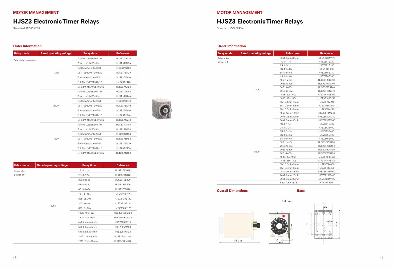
43 44
HJSZ3 Electronic Timer RelaysStandard: IEC60947-4
MOTOR MANAGEMENT
HJSZ3 Electronic Timer RelaysStandard: IEC60947-4
MOTOR MANAGEMENT
Order Information Order Information
Relay mode Rated operating voltage Relay time Reference
Relay after power-on
120V
A: 0.05-0.5s/5s/30s/3M HJSZ3AA120
B: 0.1-1s/10s/60s/6M HJSZ3AB120
C: 0.5-5s/50s/5M/30M HJSZ3AC120
D: 1-10s/100s/10M/60M HJSZ3AD120
E: 6s-60s/10M/60M/6h HJSZ3AE120
F: 0.2M-2M/20M/2h/12h HJSZ3AF120
G: 0.4M-4M/40M/4h/24h HJSZ3AG120
240V
A: 0.05-0.5s/5s/30s/3M HJSZ3AA240
B: 0.1-1s/10s/60s/6M HJSZ3AB240
C: 0.5-5s/50s/5M/30M HJSZ3AC240
D: 1-10s/100s/10M/60M HJSZ3AD240
E: 6s-60s/10M/60M/6h HJSZ3AE240
F: 0.2M-2M/20M/2h/12h HJSZ3AF240
G: 0.4M-4M/40M/4h/24h HJSZ3AG240
400V
A: 0.05-0.5s/5s/30s/3M HJSZ3AA400
B: 0.1-1s/10s/60s/6M HJSZ3AB400
C: 0.5-5s/50s/5M/30M HJSZ3AC400
D: 1-10s/100s/10M/60M HJSZ3AD400
E: 6s-60s/10M/60M/6h HJSZ3AE400
F: 0.2M-2M/20M/2h/12h HJSZ3AF400
G: 0.4M-4M/40M/4h/24h HJSZ3AG400
Relay mode Rated operating voltage Relay time Reference
Relay after
power-off
240V
30M: 3min-30min HJSZ3F30M120
1S: 0.1-1s HJSZ3F1S240
2S: 0.2-2s HJSZ3F2S240
3S: 0.3s-3s HJSZ3F3S240
5S: 0.5s-5s HJSZ3F5S240
6S: 0.6s-6s HJSZ3F6S240
10S: 1s-10s HJSZ3F10S240
20S: 2s-20s HJSZ3F20S240
30S: 3s-30s HJSZ3F30S240
60S: 6s-60s HJSZ3F60S240
100S: 10s-100s HJSZ3F100S240
180S: 18s-180s HJSZ3F180S240
4M: 0.4min-4min HJSZ3F4M240
5M: 0.5min-5min HJSZ3F5M240
6M: 0.6min-6min HJSZ3F6M240
10M: 1min-10min HJSZ3F10M240
20M: 2min-20min HJSZ3F20M240
30M: 3min-30min HJSZ3F30M240
400V
1S: 0.1-1s HJSZ3F1S400
2S: 0.2-2s HJSZ3F2S400
3S: 0.3s-3s HJSZ3F3S400
5S: 0.5s-5s HJSZ3F5S400
6S: 0.6s-6s HJSZ3F6S400
10S: 1s-10s HJSZ3F10S400
20S: 2s-20s HJSZ3F20S400
30S: 3s-30s HJSZ3F30S400
60S: 6s-60s HJSZ3F60S400
100S: 10s-100s HJSZ3F100S400
180S: 18s-180s HJSZ3F180S400
5M: 0.5min-5min HJSZ3F5M400
6M: 0.6min-6min HJSZ3F6M400
10M: 1min-10min HJSZ3F10M400
20M: 2min-20min HJSZ3F20M400
30M: 3min-30min HJSZ3F30M400
Base for HJSZ3 HTP28XEDZ
Relay mode Rated operating voltage Relay time Reference
Relay after
power-off
120V
1S: 0.1-1s HJSZ3F1S120
2S: 0.2-2s HJSZ3F2S120
3S: 0.3s-3s HJSZ3F3S120
5S: 0.5s-5s HJSZ3F5S120
6S: 0.6s-6s HJSZ3F6S120
10S: 1s-10s HJSZ3F10S120
20S: 2s-20s HJSZ3F20S120
30S: 3s-30s HJSZ3F30S120
60S: 6s-60s HJSZ3F60S120
100S: 10s-100s HJSZ3F100S120
180S: 18s-180s HJSZ3F180S120
4M: 0.4min-4min HJSZ3F4M120
5M: 0.5min-5min HJSZ3F5M120
6M: 0.6min-6min HJSZ3F6M120
10M: 1min-10min HJSZ3F10M120
20M: 2min-20min HJSZ3F20M120
Overall Dimensions Base
Unit: mm
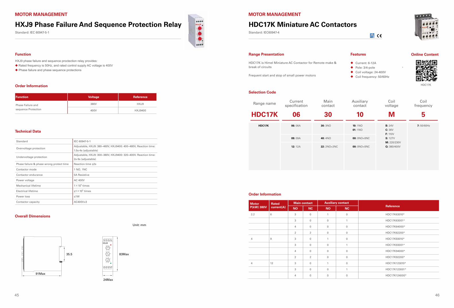
45 46
HXJ9 Phase Failure And Sequence Protection RelayStandard: IEC 60947-5-1
MOTOR MANAGEMENT
Technical Data
Overall Dimensions
Unit: mm
91Max
35.5 83Max
24Max
Function Voltage Reference
Phase Failure and
sequence Protection
380V HXJ9
400V HXJ9400
Function
HXJ9 phase failure and sequence proctection relay provides:◆ Rated frequency is 50Hz, and rated control supply AC voltage is 400V◆ Phase failure and phase sequence protections
Order Information
Standard IEC 60947-5-1
Overvoltage protectionAdjustable, HXJ9: 380~460V, HXJ9400: 400~480V, Reaction time:
1.5s-4s (adjustable)
Undervoltage protectionAdjustable, HXJ9: 300~380V, HXJ9400: 320~400V. Reaction time:
2s-9s (adjustable)
Phase failure & phase wrong protect time Reaction time ≤2s
Contactor mode 1 NO, 1NC
Contactor endurance 5A Resistive
Power voltage AC 400V
Mechanical lifetime 1×10⁶ times
Electrical lifetime ≥1×10⁵ times
Power loss ≤1W
Contactor capacity AC400V×3
HDC17K Miniature AC ContactorsStandard: IEC60947-4
MOTOR MANAGEMENT
Current: 6-12A
Pole: 3/4-pole
Coil voltage: 24-400V
Coil frequency: 50/60Hz
◆
◆
◆
◆
Range Presentation Features
HDC17K is Himel Miniature AC Contactor for Remote make & break of circuits
Frequent start and stop of small power motors
Range name Current specification
Main contact
Auxiliary contact
Coil voltage
Coil frequency
HDC17K 06 30 10 M 5HDC17K 06: 06A
09: 09A
12: 12A
30: 3NO
40: 4NO
22: 2NO+2NC
10: 1NO
01: 1NO
00: 0NO+0NC
00: 0NO+0NC
B: 24V
C: 36V
F: 110V
S: 127V
M: 220/230V
Q: 380/400V
7: 50/60Hz
Selection Code
Order Information
Rated current(A)
6
9
12
Main contact Auxiliary contact
NO NC NO NC
3
3
4
2
3
3
4
2
3
3
4
0
0
0
2
0
0
0
2
0
0
0
1
0
0
0
1
0
0
0
1
0
0
0
1
0
0
0
1
0
0
0
1
0
MotorP(kW) 380V
2.2
4
4
HDC17K63010*
HDC17K63001*
HDC17K64000*
HDC17K62200*
HDC17K93010*
HDC17K93001*
HDC17K94000*
HDC17K92200*
HDC17K123010*
HDC17K123001*
HDC17K124000*
Reference
Online Content
HDC17K
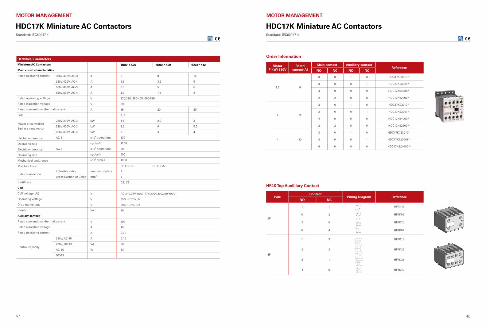
47 48
Technical Parameters
Miniature AC Contactors
Main circuit characteristics
Rated operating current
Rated operating voltage
Rated insulation voltage
Rated conventional thermal current
Pole
Power of controlled
3-phase cage motor
Electric endurance
Operating rate
Electric endurance
Operating rate
Mechanical endurance
Matched Fuse
Cable connection
Certificate
Coil
Coil voltage(Us)
Operating voltage
Drop-out voltage
Inrush
Auxliary contact
Rated conventional thermal current
Rated insulation voltage
Rated operating current
Control capacity
6
2.6
3.5
1.2
220/230, 380/400, 660/690
690
16
3, 4
1.5
2.2
3
100
1200
20
600
1000
2
4
CB, CE
AC 24V,36V,110V,127V,220/230V,380/400V
85%~110% Us
20%~75% Us
30
690
10
0.95
0.15
360
33
9
3.5
5
1.5
20
2.2
4
4
HDC17-K06 HDC17-K09 HDC17-K12
12
5
6
2
20
3
5.5
4
380V/400V, AC-3
380V/400V, AC-4
660V/690V, AC-3
660V/690V, AC-4
220V/230V, AC-3
380V/400V, AC-3
660V/690V, AC-3
AC-3
AC-4
Inflexible cable
Cross Section of Cable
380V, AC-15
220V, DC-13
AC-15
DC-13
HRT16-16 HRT16-20
A
A
A
A
V
V
A
kW
kW
kW
×104 operations
cycles/h
×104 operations
cycles/h
×104 cycles
number of piece
mm2
V
V
V
VA
V
A
A
A
VA
W
HDC17K Miniature AC ContactorsStandard: IEC60947-4
MOTOR MANAGEMENT
Order Information
HF4K Top Auxilliary Contact
Motor Control &
Protection
2 6
Accessories
SK4 Air delayed head
S
0 1- S
0 1- 0S
10-180S
0 1-
0 1- 0S
10-180S
F4 Top of auxiliary contact
FC6 Side auxiliary contact
1
2
0
4
2
1
0
1
0
2
0
1
2
4
HF411
HF402
HF420
HF404
HF413
HF422
HF431
HF440
HFT6420
HFT6422
HFT6424
HFT6430
HFT6432
HFT6434
0
1
2
2
1
0
HFC602
HFC611
HFC620
Delay Type Delay Range Reference
Making time-delay
Breaking time-delay
Wiring diagram
NCNOContact
ReferenceWiring diagram
NO NCPole
ContactWiring diagram
2P
4P
2P
Pole
Reference
HJX2-4P AC ContactorStandard: IEC 60947-4-1
MotorP(kW) 380V
Rated current(A)
Main contact Auxiliary contactReference
NO NC NO NC
2.2 6
3 0 1 0 HDC17K63010*·
3 0 0 1 HDC17K63001*·
4 0 0 0 HDC17K64000*·
2 2 0 0 HDC17K62200*·
4 9
3 0 1 0 HDC17K93010*·
3 0 0 1 HDC17K93001*·
4 0 0 0 HDC17K94000*·
2 2 0 0 HDC17K92200*·
4 12
3 0 1 0 HDC17K123010*·
3 0 0 1 HDC17K123001*·
4 0 0 0 HDC17K124000*·
PoleContact
Wiring Diagram ReferenceNO NC
2P
1 1 HF4K11
0 2 HF4K02
2 0 HF4K20
0 4 HF4K04
4P
1 3 HF4K13
2 2 HF4K22
3 1 HF4K31
4 0 HF4K40
HDC17K Miniature AC ContactorsStandard: IEC60947-4
MOTOR MANAGEMENT
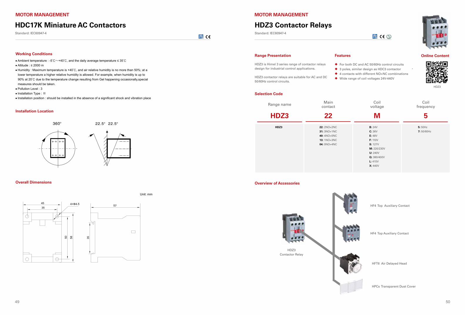
49 50
HDC17K Miniature AC ContactorsStandard: IEC60947-4
MOTOR MANAGEMENT
Working Conditions
■ Ambient temperature : -5℃~+40℃, and the daily average temperature ≤ 35℃ ■ Altitude : ≤ 2000 m ■ Humidity : Maximum temperature is +40℃, and air relative humidity is no more than 50%; at a
lower temperature a higher relative humidity is allowed. For example, when humidity is up to 90% at 20℃ due to the temperature change resulting from Gel happening occasionally,special measures should be taken.
■ Pollution Level : 3 ■ Installation Type : Ⅲ ■ Installation position : should be installed in the absence of a significant shock and vibration place
Installation Location
Overall Dimensions
.7
HDZ3 Contactor RelaysStandard: IEC60947-4
MOTOR MANAGEMENT
Range name Main contact
Coil voltage
Coil frequency
HDZ3 22 M 5HDZ3 22: 2NO+2NC
31: 3NO+1NC
40: 4NO+0NC
13: 1NO+3NC
04: 0NO+4NC
B: 24V
C: 36V
E: 48V
F: 110V
S: 127V
M: 220/230V
U: 240V
Q: 380/400V
L: 415V
X: 440V
5: 50Hz
7: 50/60Hz
For both DC and AC 50/60Hz control circuits
3 poles, similar design as HDC3 contactor
4 contacts with different NO+NC combinations
Wide range of coil voltages 24V-440V
◆
◆
◆
◆
Range Presentation Features
HDZ3 is Himel 3 series range of contactor relays design for industrial control applications.
HDZ3 contactor relays are suitable for AC and DC 50/60Hz control circuits.
Selection Code
H
HFD6 Top of Auxiliary Contact
HFD6 Top of Auxiliary Contact
HFT6 Air Delayed Head
H HDZ6-32
HDZ3 Contactor Relay
HF4 Top Auxiliary Contact
HF4 Top Auxiliary Contact
HFT6 Air Delayed Head
HPCs Transparent Dust Cover
Overview of Accessories
Online Content
HDZ3
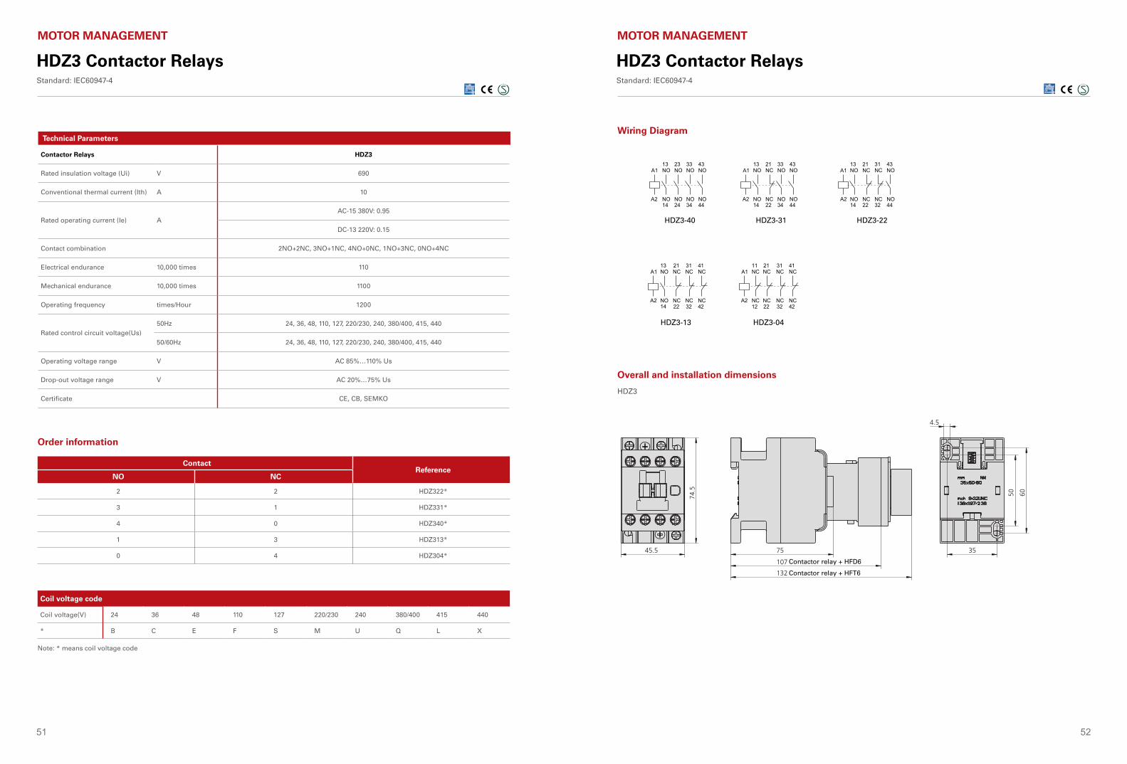
51 52
Technical Parameters
Contactor Relays HDZ3
Rated insulation voltage (Ui) V 690
Conventional thermal current (Ith) A 10
Rated operating current (Ie) A AC-15 380V: 0.95
DC-13 220V: 0.15
Contact combination 2NO+2NC, 3NO+1NC, 4NO+0NC, 1NO+3NC, 0NO+4NC
Electrical endurance 10,000 times 110
Mechanical endurance 10,000 times 1100
Operating frequency times/Hour 1200
Rated control circuit voltage(Us) 50Hz 24, 36, 48, 110, 127, 220/230, 240, 380/400, 415, 440
50/60Hz 24, 36, 48, 110, 127, 220/230, 240, 380/400, 415, 440
Operating voltage range V AC 85%…110% Us
Drop-out voltage range V AC 20%…75% Us
Certificate CE, CB, SEMKO
HDZ3 Contactor RelaysStandard: IEC60947-4
MOTOR MANAGEMENT
Order information
Coil voltage code
Coil voltage(V) 24 36 48 110 127 220/230 240 380/400 415 440
* B C E F S M U Q L X
Note: * means coil voltage code
ContactReference
NO NC
2 2 HDZ322*
3 1 HDZ331*
4 0 HDZ340*
1 3 HDZ313*
0 4 HDZ304*
Wiring Diagram
外形及安装尺寸(mm)
接线图
J ZC 4 接触器式继电器
额定绝缘电压 Ui V约定发热电流 Ith A额定工作电流 Ie A
电气寿命 次
机械寿命 次
操作频率 次/h触头组合
线圈额定控制电压 Us V线圈吸合电压 V线圈释放电压 V重量 kg产品认证
技术参数
3805AC-15 380V :0.95DC-13 220V :0.635 x 10⁵
30 x 105
1200常开 常闭
4 45 36 27 18 0AC:12 24 36 110 127 220 380AC:85%~110%UsAC:20%~75%Us0.44CCC
选型指南
线圈电压代码
线圈电压 (V)*
24B
48E
110F
36C
220M
380Q
注:对于JZ7订货编码中的“*”可由线圈电压代码来表示
产品名称 触头类型 线圈电压
JZ7 44 M
44: 4常开+4常闭
62: 6常开+2常闭
80: 8常开+0常闭
C: 36V...Q: 380V
触头 订货编码
常开NO 常闭NC
4 4 JZ7 44 *
3 3 JZ7 53 *
6 2 JZ7 62 *
7 1 JZ7 71 *
8 0 JZ7 80 *
J Z7 接触器式继电器
接触器式继电器 接触器式继电器
电动控制与保护
电动控制与保护
121 122
JZC4s-13 JZC4s-04
JZC4s-40 JZC4s-31 JZC4s-22HDZ3-40 HDZ3-31 HDZ3-22
HDZ3-13 HDZ3-04
HDZ3
45.5
74.5
75
4.5
50 60
35
107(接触器+FD6时的尺寸)
132(接触器+FT6时的尺寸)
Contactor relay + HFD6
Contactor relay + HFT6
HDZ3 Contactor RelaysStandard: IEC60947-4
MOTOR MANAGEMENT
Overall and installation dimensions
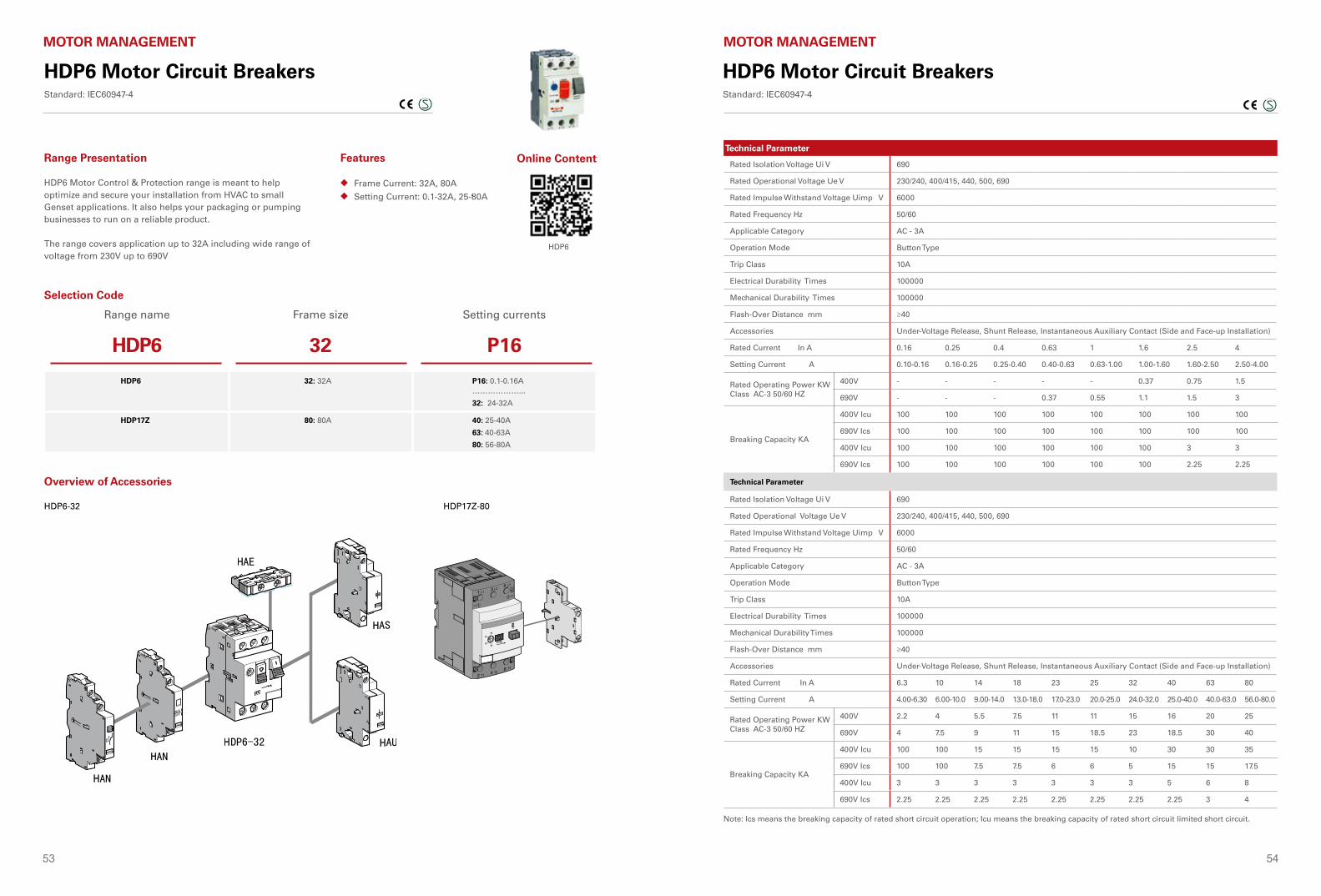
53 54
HDP6 Motor Circuit BreakersStandard: IEC60947-4
MOTOR MANAGEMENT
Frame Current: 32A, 80A
Setting Current: 0.1-32A, 25-80A
◆
◆
Range Presentation Features
HDP6 Motor Control & Protection range is meant to help optimize and secure your installation from HVAC to small Genset applications. It also helps your packaging or pumping businesses to run on a reliable product.
The range covers application up to 32A including wide range of voltage from 230V up to 690V
Selection Code
Range name Frame size Setting currents
HDP6 32 P16
HDP6 32: 32A P16: 0.1-0.16A………………...
32: 24-32A
HDP17Z 80: 80A 40: 25-40A
63: 40-63A
80: 56-80A
Online Content
HDP6
Overview of Accessories
HDP17Z-80HDP6-32
HDP6 Motor Circuit BreakersStandard: IEC60947-4
MOTOR MANAGEMENT
Technical Parameter
Rated Isolation Voltage Ui V 690
Rated Operational Voltage Ue V 230/240, 400/415, 440, 500, 690
Rated Impulse Withstand Voltage Uimp V 6000
Rated Frequency Hz 50/60
Applicable Category AC - 3A
Operation Mode Button Type
Trip Class 10A
Electrical Durability Times 100000
Mechanical Durability Times 100000
Flash-Over Distance mm ≥40
Accessories Under-Voltage Release, Shunt Release, Instantaneous Auxiliary Contact (Side and Face-up Installation)
Rated Current In A 0.16 0.25 0.4 0.63 1 1.6 2.5 4
Setting Current A 0.10-0.16 0.16-0.25 0.25-0.40 0.40-0.63 0.63-1.00 1.00-1.60 1.60-2.50 2.50-4.00
Rated Operating Power KW Class AC-3 50/60 HZ
400V - - - - - 0.37 0.75 1.5
690V - - - 0.37 0.55 1.1 1.5 3
Breaking Capacity KA
400V Icu 100 100 100 100 100 100 100 100
690V Ics 100 100 100 100 100 100 100 100
400V Icu 100 100 100 100 100 100 3 3
690V Ics 100 100 100 100 100 100 2.25 2.25
Technical Parameter
Rated Isolation Voltage Ui V 690
Rated Operational Voltage Ue V 230/240, 400/415, 440, 500, 690
Rated Impulse Withstand Voltage Uimp V 6000
Rated Frequency Hz 50/60
Applicable Category AC - 3A
Operation Mode Button Type
Trip Class 10A
Electrical Durability Times 100000
Mechanical Durability Times 100000
Flash-Over Distance mm ≥40
Accessories Under-Voltage Release, Shunt Release, Instantaneous Auxiliary Contact (Side and Face-up Installation)
Rated Current In A 6.3 10 14 18 23 25 32 40 63 80
Setting Current A 4.00-6.30 6.00-10.0 9.00-14.0 13.0-18.0 17.0-23.0 20.0-25.0 24.0-32.0 25.0-40.0 40.0-63.0 56.0-80.0
Rated Operating Power KW Class AC-3 50/60 HZ
400V 2.2 4 5.5 7.5 11 11 15 16 20 25
690V 4 7.5 9 11 15 18.5 23 18.5 30 40
Breaking Capacity KA
400V Icu 100 100 15 15 15 15 10 30 30 35
690V Ics 100 100 7.5 7.5 6 6 5 15 15 17.5
400V Icu 3 3 3 3 3 3 3 5 6 8
690V Ics 2.25 2.25 2.25 2.25 2.25 2.25 2.25 2.25 3 4
Note: Ics means the breaking capacity of rated short circuit operation; Icu means the breaking capacity of rated short circuit limited short circuit.
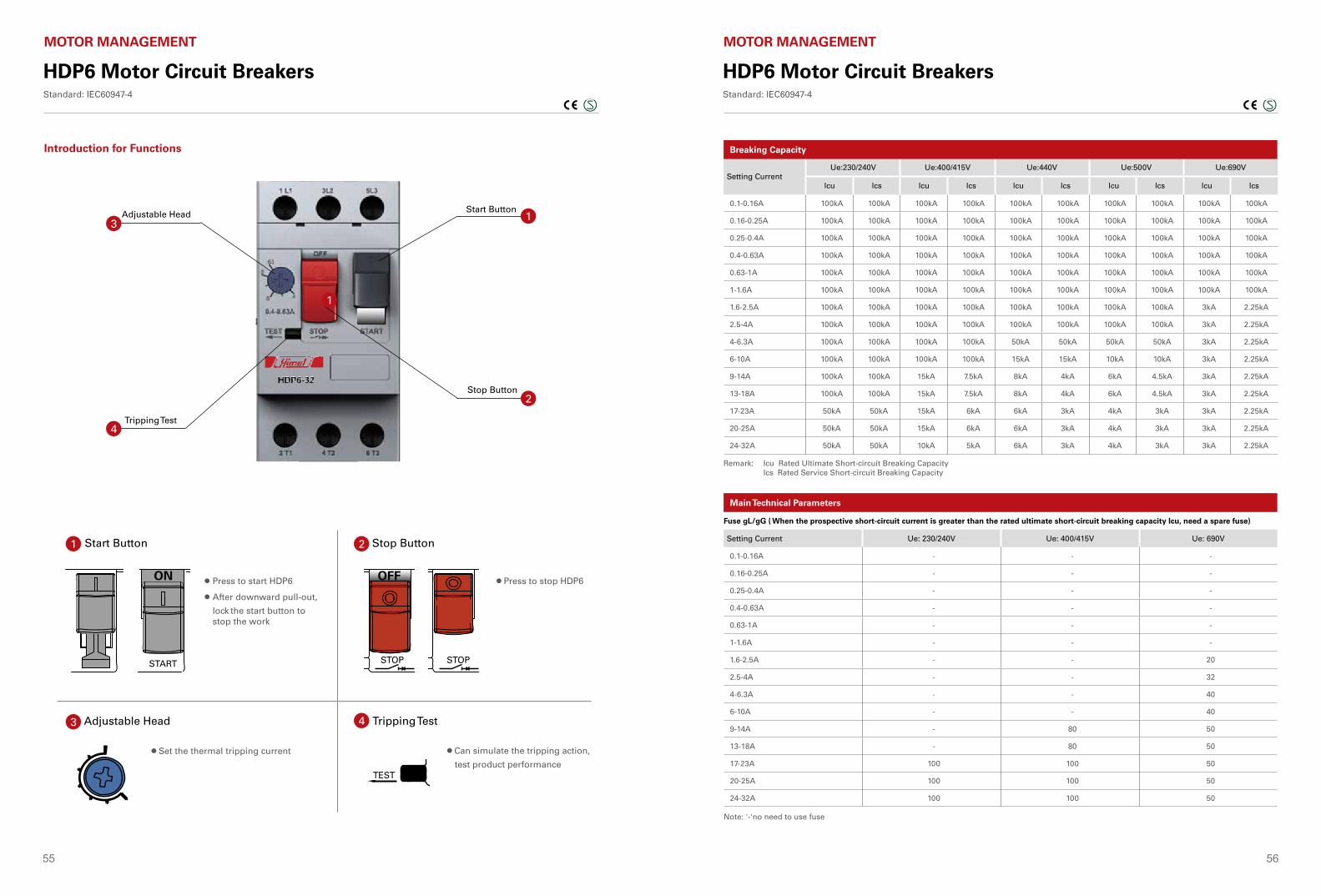
55 56
HDP6 Motor Circuit BreakersStandard: IEC60947-4
MOTOR MANAGEMENT
Introduction for Functions
Adjustable Head
Tripping Test
Start Button
Stop Button
1
3
4
1
2
Adjustable Head
• Press to start HDP6
• After downward pull-out,
lock the start button to stop the work
• Set the thermal tripping current • Can simulate the tripping action,
test product performance
• Press to stop HDP6
Stop Button Start Button
Tripping Test
1
3
2
4
START
TEST
OFFON
HDP6 Motor Circuit BreakersStandard: IEC60947-4
MOTOR MANAGEMENT
Setting CurrentUe:230/240V Ue:400/415V Ue:440V Ue:500V Ue:690V
lcu lcs lcu lcs lcu lcs lcu lcs lcu lcs
0.1-0.16A 100kA 100kA 100kA 100kA 100kA 100kA 100kA 100kA 100kA 100kA
0.16-0.25A 100kA 100kA 100kA 100kA 100kA 100kA 100kA 100kA 100kA 100kA
0.25-0.4A 100kA 100kA 100kA 100kA 100kA 100kA 100kA 100kA 100kA 100kA
0.4-0.63A 100kA 100kA 100kA 100kA 100kA 100kA 100kA 100kA 100kA 100kA
0.63-1A 100kA 100kA 100kA 100kA 100kA 100kA 100kA 100kA 100kA 100kA
1-1.6A 100kA 100kA 100kA 100kA 100kA 100kA 100kA 100kA 100kA 100kA
1.6-2.5A 100kA 100kA 100kA 100kA 100kA 100kA 100kA 100kA 3kA 2.25kA
2.5-4A 100kA 100kA 100kA 100kA 100kA 100kA 100kA 100kA 3kA 2.25kA
4-6.3A 100kA 100kA 100kA 100kA 50kA 50kA 50kA 50kA 3kA 2.25kA
6-10A 100kA 100kA 100kA 100kA 15kA 15kA 10kA 10kA 3kA 2.25kA
9-14A 100kA 100kA 15kA 7.5kA 8kA 4kA 6kA 4.5kA 3kA 2.25kA
13-18A 100kA 100kA 15kA 7.5kA 8kA 4kA 6kA 4.5kA 3kA 2.25kA
17-23A 50kA 50kA 15kA 6kA 6kA 3kA 4kA 3kA 3kA 2.25kA
20-25A 50kA 50kA 15kA 6kA 6kA 3kA 4kA 3kA 3kA 2.25kA
24-32A 50kA 50kA 10kA 5kA 6kA 3kA 4kA 3kA 3kA 2.25kA
Remark: Icu Rated Ultimate Short-circuit Breaking Capacity Ics Rated Service Short-circuit Breaking Capacity
Breaking Capacity
Setting Current Ue: 230/240V Ue: 400/415V Ue: 690V
0.1-0.16A - - -
0.16-0.25A - - -
0.25-0.4A - - -
0.4-0.63A - - -
0.63-1A - - -
1-1.6A - - -
1.6-2.5A - - 20
2.5-4A - - 32
4-6.3A - - 40
6-10A - - 40
9-14A - 80 50
13-18A - 80 50
17-23A 100 100 50
20-25A 100 100 50
24-32A 100 100 50
Note: '-'no need to use fuse
Fuse gL/gG ( When the prospective short-circuit current is greater than the rated ultimate short-circuit breaking capacity Icu, need a spare fuse)
Main Technical Parameters
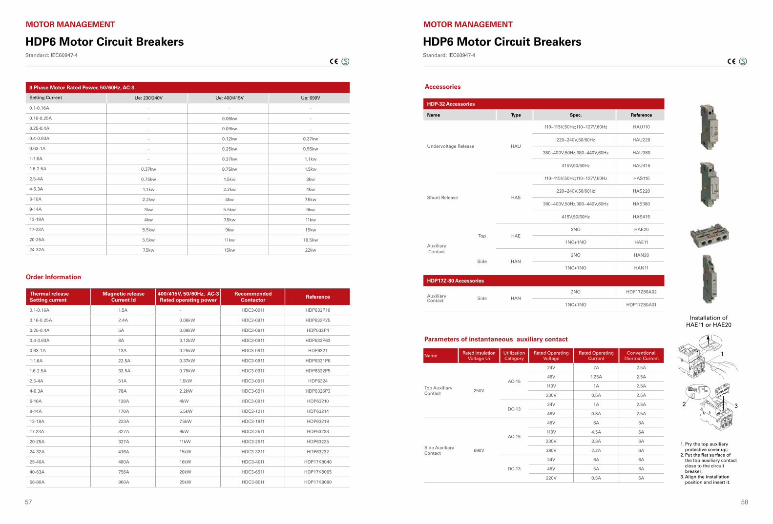
57 58
HDP6 Motor Circuit BreakersStandard: IEC60947-4
MOTOR MANAGEMENT
Setting Current Ue: 230/240V Ue: 400/415V Ue: 690V
0.1-0.16A - - -
0.16-0.25A - 0.06kw -
0.25-0.4A - 0.09kw -
0.4-0.63A - 0.12kw 0.37kw
0.63-1A - 0.25kw 0.55kw
1-1.6A - 0.37kw 1.1kw
1.6-2.5A 0.37kw 0.75kw 1.5kw
2.5-4A 0.75kw 1.5kw 3kw
4-6.3A 1.1kw 2.2kw 4kw
6-10A 2.2kw 4kw 7.5kw
9-14A 3kw 5.5kw 9kw
13-18A 4kw 7.5kw 11kw
17-23A 5.5kw 9kw 15kw
20-25A 5.5kw 11kw 18.5kw
24-32A 7.5kw 15kw 22kw
3 Phase Motor Rated Power, 50/60Hz, AC-3
Order Information
Thermal releaseSetting current
Magnetic releaseCurrent Id
400/415V, 50/60Hz, AC-3Rated operating power
RecommendedContactor
Reference
0.1-0.16A 1.5A - HDC3-0911 HDP632P16
0.16-0.25A 2.4A 0.06kW HDC3-0911 HDP632P25
0.25-0.4A 5A 0.09kW HDC3-0911 HDP632P4
0.4-0.63A 8A 0.12kW HDC3-0911 HDP632P63
0.63-1A 13A 0.25kW HDC3-0911 HDP6321
1-1.6A 22.5A 0.37kW HDC3-0911 HDP6321P6
1.6-2.5A 33.5A 0.75kW HDC3-0911 HDP6322P5
2.5-4A 51A 1.5kW HDC3-0911 HDP6324
4-6.3A 78A 2.2kW HDC3-0911 HDP6326P3
6-10A 138A 4kW HDC3-0911 HDP63210
9-14A 170A 5.5kW HDC3-1211 HDP63214
13-18A 223A 7.5kW HDC3-1811 HDP63218
17-23A 327A 9kW HDC3-2511 HDP63223
20-25A 327A 11kW HDC3-2511 HDP63225
24-32A 416A 15kW HDC3-3211 HDP63232
25-40A 480A 16kW HDC3-4011 HDP17K8040
40-63A 756A 20kW HDC3-6511 HDP17K8065
56-80A 960A 25kW HDC3-8011 HDP17K8080
HDP6 Motor Circuit BreakersStandard: IEC60947-4
MOTOR MANAGEMENT
1
2 3
Parameters of instantaneous auxiliary contact
NameRated Insulation
Voltage UiUtilization Category
Rated Operating Voltage
Rated Operating Current
Conventional Thermal Current
Top AuxiliaryContact
250V
AC-15
24V 2A 2.5A
48V 1.25A 2.5A
110V 1A 2.5A
230V 0.5A 2.5A
DC-1324V 1A 2.5A
48V 0.3A 2.5A
Side AuxiliaryContact
690V
AC-15
48V 6A 6A
110V 4.5A 6A
230V 3.3A 6A
380V 2.2A 6A
DC-13
24V 6A 6A
48V 5A 6A
220V 0.5A 6A
Installation of HAE11 or HAE20
1. Pry the top auxiliary protective cover up;
2. Put the flat surface of the top auxiliary contact close to the circuit breaker;
3. Align the installation position and insert it.
Name Type Spec. Reference
Undervoltage Release HAU
110~115V,50Hz;110~127V,60Hz HAU110
220~240V,50/60Hz HAU220
380~400V,50Hz;380~440V,60Hz HAU380
415V,50/60Hz HAU415
Shunt Release HAS
110~115V,50Hz;110~127V,60Hz HAS110
220~240V,50/60Hz HAS220
380~400V,50Hz;380~440V,60Hz HAS380
415V,50/60Hz HAS415
Auxiliary Contact
Top HAE2NO HAE20
1NC+1NO HAE11
Side HAN2NO HAN20
1NC+1NO HAN11
Auxiliary Contact Side HAN
2NO HDP17Z80A02
1NC+1NO HDP17Z80A01
HDP-32 Accessories
HDP17Z-80 Accessories
Accessories
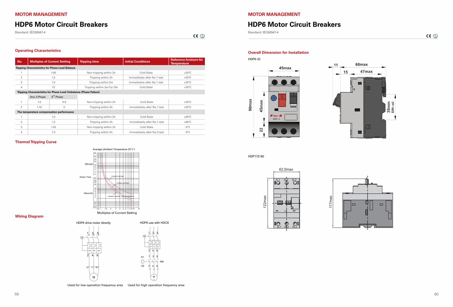
59 60
HDP6 Motor Circuit BreakersStandard: IEC60947-4
MOTOR MANAGEMENT
I > I > I >
1 3 5
2 4 6
U V W
M
I > I > I >
M~
1 3 5
2 4 6
A1
A2
KM
1 3 5
2 4 6
HDP6 drive motor directly HDP6 use with HDC6
Used for low operation frequency area
Multiples of Current Setting
Used for high operation frequency area
Wiring Diagram
Thermel Tripping Curve
No. Multiples of Current Setting Tripping time Initial ConditionsReference Ambient Air Temperature
Tripping Characteristics for Phase Load Balance
1 1.05 Non-tripping within 2h Cold State +20°C
2 1.2 Tripping within 2h Immediately after No.1 test +20°C
3 1.5 Tripping within 2m Immediately after No.1 test +20°C
4 7.2 Tripping within 2s<Tp≤10s Cold State +20°C
Tripping Characteristics for Phase Load Unbalance (Phase Failure)
Any 2-Phase 3rd Phase
1 1.0 0.9 Non-tripping within 2h Cold State +20°C
2 1.15 0 Tripping within 2h Immediately after No.1 test +20°C
The temperature compensation performance
1 1.0 Non-tripping within 2h Cold State +40°C
2 1.2 Tripping within 2h Immediately after No.1 test +40°C
3 1.05 Non-tripping within 2h Cold State -5°C
4 1.3 Tripping within 2h Immediately after No.3 test -5°C
Operating Characteristics
Average (Ambient Temperature 20°C )
(Minute)
(Second)
Action Time
Multiple of Setting Current
3-phase cold state
2-phase cold state
3-phase cold state - thermal equilibrium
HDP6 Motor Circuit BreakersStandard: IEC60947-4
MOTOR MANAGEMENT
Overall Dimension for Installation
HDP6-32
HDP17Z-80
193
Motor C
ontrol &P
rotection
HDP17Z Motor protectorStandards: IEC 60947-1 IEC 60947-2 and IEC 60947-4-1
Installation Dimensions
Name Type ������������ ReferenceUnder-voltage Release
AU(32AF)
110 ~ 127V220 ~ 240V380 ~ 415V
HDP17Z32AU110HDP17Z32AU220HDP17Z32AU380
Shunt Release AS(32AF)
110 ~ 127V220 ~ 240V380 ~ 415V
HDP17Z32AU110HDP17Z32AU220HDP17Z32AU380
Instantaneous Auxiliary Contact
Face-Up Installation
AE(32AF)
2NO1NC+1NO
HDP17Z32AE20HDP17Z32AE11
Side Installation AN(32AF)
2NO1NC+1NO
HDP17Z32AE20HDP17Z32AE11
A (80AF)
1NC+1NO2NO
HDP17Z80A01HDP17Z80A02
Basic Parameters of Instantaneous Auxiliary ContactName Rated Isolation
Voltage UiApplicable Type
Rated Operational Voltage
Rated Operational Current
Conventional thermal current
Face-Up Installed Auxiliary Contact AE
250V AC-15 24V48V110230V
2A1.25A1A0.5A
2.5A2.5A2.5A2.5A
DC-13 24V48V
1A0.3A
2.5A2.5A
Side Installed Auxiliary Contact AN
690V AC-15 48V110V230V380V
6A4.5A3.3A2.2A
6A6A6A6A
DC-13 24V48V220V
6A5A0.5A
6A6A6A
HDP17Z-32
Accessories
HDP17Z-80
45±0
.32
44.5±0.8
117m
ax
62,5max
122m
ax
1L1 3L2 5L3
2L1 4L2 6L3
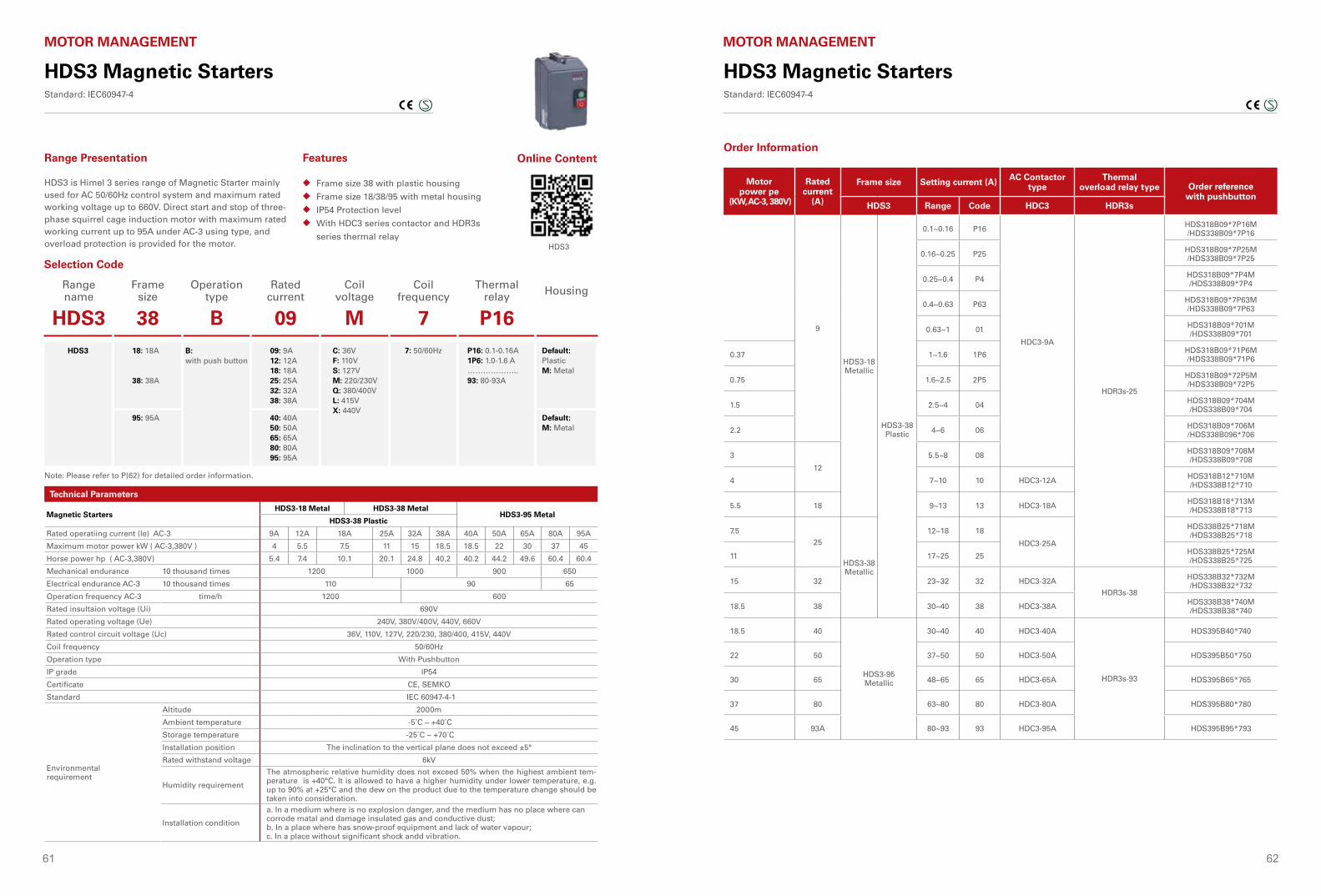
61 62
HDS3 Magnetic StartersStandard: IEC60947-4
MOTOR MANAGEMENT
Motor power pe
(KW, AC-3, 380V)
Rated current
(A)
Frame size Setting current (A) AC Contactor type
Thermal overload relay type Order reference
with pushbuttonHDS3 Range Code HDC3 HDR3s
9
HDS3-18Metallic
HDS3-38Plastic
0.1~0.16 P16
HDC3-9A
HDR3s-25
HDS318B09*7P16M/HDS338B09*7P16
0.16~0.25 P25 HDS318B09*7P25M /HDS338B09*7P25
0.25~0.4 P4 HDS318B09*7P4M /HDS338B09*7P4
0.4~0.63 P63 HDS318B09*7P63M /HDS338B09*7P63
0.63~1 01 HDS318B09*701M /HDS338B09*701
0.37 1~1.6 1P6 HDS318B09*71P6M /HDS338B09*71P6
0.75 1.6~2.5 2P5 HDS318B09*72P5M /HDS338B09*72P5
1.5 2.5~4 04 HDS318B09*704M /HDS338B09*704
2.2 4~6 06 HDS318B09*706M /HDS338B096*706
3
12
5.5~8 08 HDS318B09*708M /HDS338B09*708
4 7~10 10 HDC3-12A HDS318B12*710M /HDS338B12*710
5.5 18 9~13 13 HDC3-18A HDS318B18*713M /HDS338B18*713
7.525
HDS3-38Metallic
12~18 18
HDC3-25A
HDS338B25*718M /HDS338B25*718
11 17~25 25 HDS338B25*725M /HDS338B25*725
15 32 23~32 32 HDC3-32AHDR3s-38
HDS338B32*732M /HDS338B32*732
18.5 38 30~40 38 HDC3-38A HDS338B38*740M /HDS338B38*740
18.5 40
HDS3-95Metallic
30~40 40 HDC3-40A
HDR3s-93
HDS395B40*740
22 50 37~50 50 HDC3-50A HDS395B50*750
30 65 48~65 65 HDC3-65A HDS395B65*765
37 80 63~80 80 HDC3-80A HDS395B80*780
45 93A 80~93 93 HDC3-95A HDS395B95*793
Order Information
HDS3 Magnetic StartersStandard: IEC60947-4
MOTOR MANAGEMENT
Range name
Frame size
Operation type
Rated current
Coil voltage
Coil frequency
Thermal relay Housing
HDS3 38 B 09 M 7 P16HDS3 18: 18A
38: 38A
B: with push button
09: 9A12: 12A18: 18A25: 25A32: 32A38: 38A
C: 36VF: 110VS: 127VM: 220/230VQ: 380/400VL: 415VX: 440V
7: 50/60Hz P16: 0.1-0.16A1P6: 1.0-1.6 A………………..93: 80-93A
Default: PlasticM: Metal
95: 95A 40: 40A50: 50A65: 65A80: 80A95: 95A
Default: M: Metal
Frame size 38 with plastic housing
Frame size 18/38/95 with metal housing
IP54 Protection level
With HDC3 series contactor and HDR3s
series thermal relay
◆
◆
◆
◆
Range Presentation Features
HDS3 is Himel 3 series range of Magnetic Starter mainly used for AC 50/60Hz control system and maximum rated working voltage up to 660V. Direct start and stop of three-phase squirrel cage induction motor with maximum rated working current up to 95A under AC-3 using type, and overload protection is provided for the motor.
Note: Please refer to P(62) for detailed order information.
Selection Code
Technical Parameters
Magnetic StartersHDS3-18 Metal HDS3-38 Metal
HDS3-95 MetalHDS3-38 Plastic
Rated operatiing current (le) AC-3 9A 12A 18A 25A 32A 38A 40A 50A 65A 80A 95A
Maximum motor power kW ( AC-3,380V ) 4 5.5 7.5 11 15 18.5 18.5 22 30 37 45
Horse power hp ( AC-3,380V) 5.4 7.4 10.1 20.1 24.8 40.2 40.2 44.2 49.6 60.4 60.4
Mechanical endurance 10 thousand times 1200 1000 900 650
Electrical endurance AC-3 10 thousand times 110 90 65
Operation frequency AC-3 time/h 1200 600
Rated insultaion voltage (Ui) 690V
Rated operating voltage (Ue) 240V, 380V/400V, 440V, 660V
Rated control circuit voltage (Uc) 36V, 110V, 127V, 220/230, 380/400, 415V, 440V
Coil frequency 50/60Hz
Operation type With Pushbutton
IP grade IP54
Certificate CE, SEMKO
Standard IEC 60947-4-1
Environmental requirement
Altitude 2000m
Ambient temperature -5˚C ~ +40˚C
Storage temperature -25˚C ~ +70˚C
Installation position The inclination to the vertical plane does not exceed ±5°
Rated withstand voltage 6kV
Humidity requirement
The atmospheric relative humidity does not exceed 50% when the highest ambient tem-perature is +40°C. It is allowed to have a higher humidity under lower temperature, e.g. up to 90% at +25°C and the dew on the product due to the temperature change should be taken into consideration.
Installation condition
a. In a medium where is no explosion danger, and the medium has no place where can corrode matal and damage insulated gas and conductive dust;b. In a place where has snow-proof equipment and lack of water vapour;c. In a place without significant shock andd vibration.
Online Content
HDS3
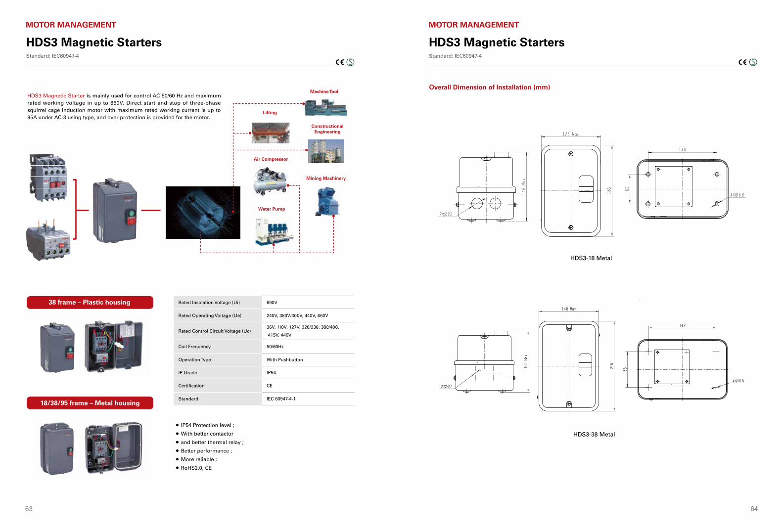
63 64
HDS3 Magnetic StartersStandard: IEC60947-4
MOTOR MANAGEMENT
541
Mo
tor C
on
trol an
d P
rotectio
n
HDS3 Magnetic Starter Standard: IEC 60947-4-1
HDS3 Magnetic Starter is mainly used for control AC 50/60 Hz and maximum rated working voltage in up to 660V. Direct start and stop of three-phase squirrel cage induction motor with maximum rated working current is up to 95A under AC-3 using type, and over protection is provided for the motor.
IP54 Protection level ;
With better contactor
and better thermal relay ;
Better performance ;
More reliable ;
RoHS2.0, CE
Machine Tool
Lifting
Constructional Engineering
Air Compressor
Mining Machinery
Water Pump
38 frame – Plastic housing
18/38/95 frame – Metal housing
Rated Insolation Voltage (Ui) 690V
Rated Operating Voltage (Ue) 240V, 380V/400V, 440V, 660V
Rated Control Circuit Voltage (Uc)36V, 110V, 127V, 220/230, 380/400,
415V, 440V
Coil Frequency 50/60Hz
Operation Type With Pushbutton
IP Grade IP54
Certification CE
Standard IEC 60947-4-1
HDS3 Magnetic StartersStandard: IEC60947-4
MOTOR MANAGEMENT
544
Mo
tor C
on
trol an
d P
rotectio
n
Overall Dimension of Installation (mm)
HDS3 Magnetic Starter Standard: IEC 60947-4-1
HDS3-18 Metal
HDS3-38 Metal
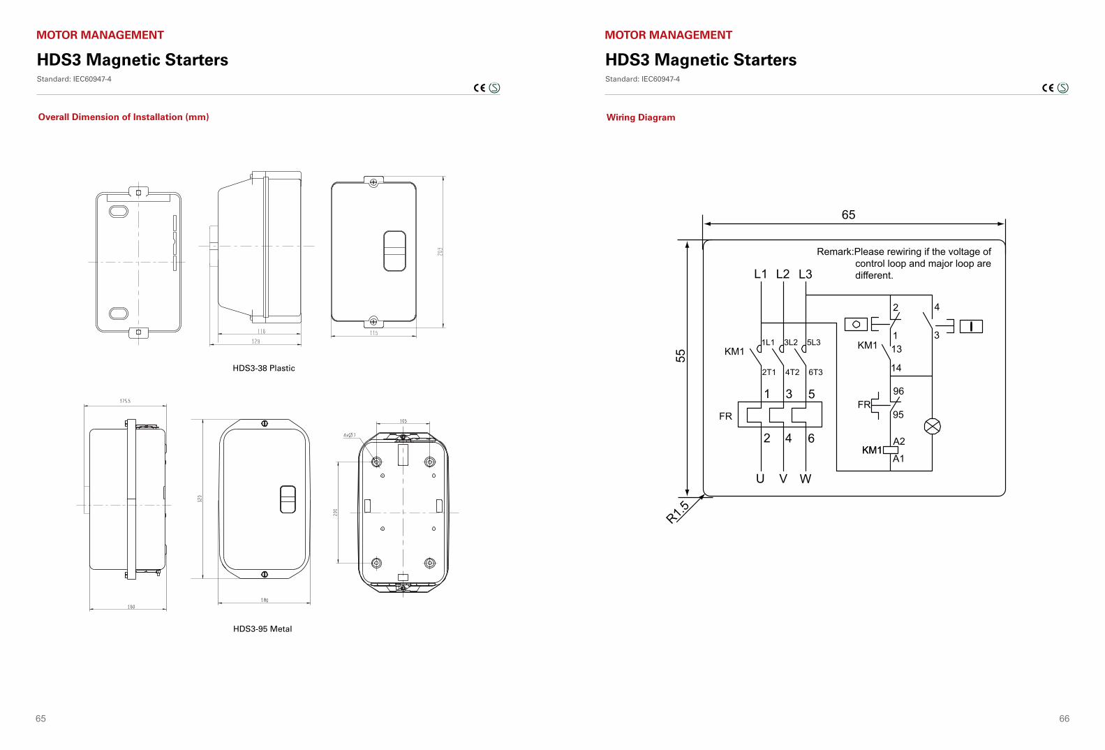
65 66
HDS3 Magnetic StartersStandard: IEC60947-4
MOTOR MANAGEMENT
545
Mo
tor C
on
trol an
d P
rotectio
n
Overall Dimension of Installation (mm)
HDS3 Magnetic Starter Standard: IEC 60947-4-1
HDS3-95 Metal
HDS3-38 Plastic
HDS3 Magnetic StartersStandard: IEC60947-4
MOTOR MANAGEMENT
546
Mo
tor C
on
trol an
d P
rotectio
n
Wiring Diagram
HDS3 Magnetic Starter Standard: IEC 60947-4-1
L1 L2 L3
1L1 3L2 5L3
1 3 5
2 4 6
U V W
KM1
FR
2
113
14
96
95
4
3
A2
A1KM1KM1
FR
KM1
Remark:Please rewiring if the voltage of control loop and major loop are different.
R1.5
65
55
2T1 4T2 6T3
546
Mo
tor C
on
trol an
d P
rotectio
n
Wiring Diagram
HDS3 Magnetic Starter Standard: IEC 60947-4-1
L1 L2 L3
1L1 3L2 5L3
1 3 5
2 4 6
U V W
KM1
FR
2
113
14
96
95
4
3
A2
A1KM1KM1
FR
KM1
Remark:Please rewiring if the voltage of control loop and major loop are different.
R1.5
65
55
2T1 4T2 6T3

67
©20
20 H
IME
L
Himelwww.himel.com
Sep 2020
Scan me