Monitoring Programme for Munitions Clearance Finland
56
Page 1 of 54 Project Title: Nord Stream Project Document Title: Monitoring Programme for Munitions Clearance Finland Document No.: G-GE-PER-REP-000- EMPFINMU Revision: G Date: 2010-08-30 Nord Stream Project G 2010-08-30 Re-issue for use TSA/MTU JKU SBO Rev. Date Description Prepared Checked Approved Nord Stream AG Document Title Monitoring Programme for Munitions Clearance Finland Company Representative : Matthias Warnig Country Code: Reference : PO. No. : Contractor Representative : Document-No. G-PE-PER-REP-000-EMPFINMU Rev. G Document Owner : Tiina Salonen Pipe line Sub project Discipline Doc. Type Originator ID Unifier
-
Upload
khangminh22 -
Category
Documents
-
view
0 -
download
0
Transcript of Monitoring Programme for Munitions Clearance Finland

Page 1 of 54
Project Title: Nord Stream Project Document Title: Monitoring Programme for Munitions Clearance Finland Document No.: G-GE-PER-REP-000-
EMPFINMU
Revision: G Date: 2010-08-30
Nord Stream Project
G 2010-08-30 Re-issue for use TSA/MTU JKU SBO
Rev. Date Description Prepared Checked Approved
Nord Stream AG
Document Title
Monitoring Programme for
Munitions Clearance Finland
Company Representative : Matthias Warnig Country Code:
Reference :
PO. No. :
Contractor Representative :
Document-No.
G-PE-PER-REP-000-EMPFINMU
Rev.
G
Document Owner : Tiina Salonen Pipe
line
Sub
project
Discipline Doc.
Type
Originator
ID
Unifier

Page 2 of 54
Project Title: Nord Stream Project Document Title: Monitoring Programme for Munitions Clearance Finland Document No.: G-GE-PER-REP-000-
EMPFINMU
Revision: G Date: 2010-08-30
Table of Contents
1 Introduction ................................................................................................................................................ 3
2 General Approach ...................................................................................................................................... 5
3 Construction and Monitoring Time Schedules ........................................................................................ 6
4 Baseline Investigations ............................................................................................................................. 9
5 Monitoring during Clearance Works......................................................................................................... 10 5.1 Seabed Morphology......................................................................................................................... 12 5.2 Water and Sediment Quality ............................................................................................................ 14 5.3 Pressure waves ............................................................................................................................... 25 5.4 Cultural Heritage, Barrels and Existing Infrastructure ...................................................................... 27 5.5 Ecological Impacts – Mitigation and Monitoring Measures............................................................... 35 5.6 Interference to Commercial Shipping – Mitigation and Monitoring Measures................................... 39 5.7 Interference to Commercial Fishing - Mitigation Measures .............................................................. 39
6 Compliance Assurance during Clearance Works.................................................................................... 41
7 Reporting of Monitoring Results............................................................................................................... 43
8 References.................................................................................................................................................. 44
9 Revision Record......................................................................................................................................... 45
Appendix 1 Munitions to be cleared from the security corridor in the Finnish EEZ
Appendix 2 Summary of the impacts from munitions clearance on a munition by munition basis - phase 1
Appendix 3 Summary of the sediment spreading due to munitions clearance on a munition by munition basis - phase 1
Appendix 4A Distances between barrels and munitions in [km] on a munition by munition basis
Appendix 4B Expected displacements of barrels in [m] due to munitions clearance on a munition by munition basis
Appendix 5 Locations for water and sediment quality monitoring
Appendix 6 Extended layouts for environmental mitigation equipment at selected clearance sites

Page 3 of 54
Project Title: Nord Stream Project Document Title: Monitoring Programme for Munitions Clearance Finland Document No.: G-GE-PER-REP-000-
EMPFINMU
Revision: G Date: 2010-08-30
1 In troduction
Nord Stream AG is installing and plans to operate an offshore natural gas pipeline from Russia to Germany. The Nord Stream Pipeline will connect the large natural gas resources of Russia with the European natural gas pipeline network. At full capacity, it will provide 55 billion cubic metres (bcm) of natural gas per year to European consumers. The length of the entire two-pipeline system (‘the Nord Stream Pipeline’) will be approximately 1,220 km. The pipeline crosses the exclusive economic zones (EEZ) of Russia, Finland, Sweden, Denmark and Germany, and territorial waters (TW) of Russia, Denmark and Germany. The pipeline construction works are planned to commence in 2010, with the second pipeline being completed in 2012. The Nord Stream Pipeline is designed to operate for 50 years. To ensure safe installation and the long-term integrity of the pipeline, some clearance of conventional munitions will be required. The Baltic Sea is an area of strategic naval importance. The conventional munitions encountered along the route are principally a legacy of World War I (WWI) and World War II (WWII). These conventional munitions are categorized generally as deployed sea mines, depth charges, torpedoes and aircraft dropped bombs, and dumped munitions. /1/ The munitions clearance work involves the disposal through detonation of mines and other underwater explosive ordnance that could inhibit the safe construction and operation of the pipelines within the security corridor. This security corridor extends 25 m either side of each pipeline route. The number of identified conventional munitions to be cleared in the security corridor in the Finnish EEZ1 is 27 at 26 locations (Figure 3 and Appendix 1) /2/. The details (i.e. the frequency, time and location of monitoring, and methods) of the monitoring programme have been developed further during the permitting process and prior to the commencement of munitions clearance work, in cooperation with the munitions clearance Contractor, Finnish Environment Institute, Geological Survey of Finland, Finnish Meteorological Institute, The Finnish Border Guard, Regional Environment Centres and Employment and Economic Development Centres2. The “Monitoring Programme for Munitions Clearance Finland” was approved by the decision No. 83/2009/2 of the Western Finland Environmental Permit Authority on 2 October 2009. Based on lessons learned during munitions clearance in 2009 and the results of munition buffer zone surveys a proposal for specifying the monitoring programme was submitted to the Centres for Economic Development, Transport and the Environment of Uusimaa and Southwest Finland on 21 April 2010. Furthermore, notifications according to permit provisions, e.g. minor pipeline re-routings to avoid the
1 Munitions were cleared under the permit No. 83/2009/2 granted on 2 October 2009 by Western Finland Environmental Permit Authority 2 As a result of the restructuring of the administration, the regional Employment and Economic Development Centres and Environment Centres were integrated and on 1 January 2010 their names were changed to Centres for Economic Development, Transport and the Environment.

Page 4 of 54
Project Title: Nord Stream Project Document Title: Monitoring Programme for Munitions Clearance Finland Document No.: G-GE-PER-REP-000-
EMPFINMU
Revision: G Date: 2010-08-30
clearance of munitions, including specifications to monitoring programmes were made to the Centres during the clearance works in 2010. The Uusimaa Centre for Economic Development, Transport and the Environment has approved the proposed changes in a letter dated on 4 June 2010 (UUDELY/742/07.00/2010) and a letter dated on 23 June 2010 (UUDELY/742/07.00/2010). This revision G of the monitoring programme accommodates the approved changes.

Page 5 of 54
Project Title: Nord Stream Project Document Title: Monitoring Programme for Munitions Clearance Finland Document No.: G-GE-PER-REP-000-
EMPFINMU
Revision: G Date: 2010-08-30
2 General Approach
The Monitoring Programme for Munitions Clearance Finland will form an integral part of Nord Stream’s overall Project environmental and social monitoring programme. The purpose of the monitoring programme is to define how Nord Stream will monitor the impacts of the works, in this case munitions clearance in the Finnish Exclusive Economic Zone (EEZ), as regards to statutory monitoring pursuant to the Water Act and to demonstrate that appropriate mitigation measures are implemented and effective. Nord Stream will also implement a focused, overall Environmental Monitoring Programme Finland for main construction activities that will be inline with this monitoring programme for munitions clearance. The Monitoring Programme for Munitions Clearance Finland has been developed with the following objectives:
To confirm that the munitions clearance does not cause impacts not previously identified or greater impacts than predicted;
To monitor that munitions clearance is carried out in accordance with national permit conditions;
To monitor the recovery of the environment after munitions clearance. (Related monitoring activities are included in the overall environmental monitoring programme for Finland)
To verify the modeling results used to predict environmental impacts
Environmental and social monitoring together with a specific Environmental and Social Management Plan (ESMP) (Construction) will be an integral part of the overall Nord Stream Health, Safety, Environment and Social Management System (HSES MS) that is consistent with ISO 14001 and OHSAS 18001. The environmental monitoring for munitions clearance comprises three major phases:
baseline investigations (planning/permitting phase)
monitoring during clearance works
monitoring after clearance works
Although these steps require different actions, they are seen as part of a single overall approach. The munitions clearance will take place prior to all other pipe-lay activities. Monitoring, after clearance works, which will include monitoring of the recovery of the benthic environment, will be included in the overall environmental monitoring programme for Finland and documented during the pipeline operation phase.

Page 6 of 54
Project Title: Nord Stream Project Document Title: Monitoring Programme for Munitions Clearance Finland Document No.: G-GE-PER-REP-000-
EMPFINMU
Revision: G Date: 2010-08-30
3 Construction and Monitoring Time Schedules
The pipeline construction period is estimated to last for approximately 2.5 years (Figure 1). According to plans, the building of the first pipeline (North-West pipeline) will take place from ca. April 2010 to October 2011 and the second pipeline (South-East pipeline) from ca. May 2011 to October 2012, except for the pre-lay works that will be done for both pipelines in 2010. Before the pipeline construction can start, munitions have to be cleared from the security corridor and partially from the anchor corridor. Impacts from munitions clearance are mainly related to pressure waves and spreading of sediments containing contaminants and nutrients. Impacts from pressure waves to marine mammals, seabirds and fish are mitigated by implementing different measures. The aim of these mitigation measures is to ensure that marine mammals, seabirds or fish shoals are not present at the site during detonation. Timing of clearance works is an important part of mitigation of impacts. The impact on marine mammals will be the lowest during the ice free period as ice and drift ice are the breeding areas of ringed seal and gray seal. On the other hand, during the ice free period there are potentially impacts on seabirds as these are their migration and breeding seasons. However, this impact is not likely as the munitions to be cleared are located far away from nesting grounds and partly in shipping lanes with heavy traffic, which are not likely resting or feeding areas of migrating or breeding seabirds. Spawning seasons of sprat and herring are during the ice free period, but their spawning areas do not coincide with the munitions clearance sites. During the autumn and spring turnover and in the winter phytoplankton growth is not limited by nutrients and at those times the small release of nutrients from sediment has no impact on phytoplankton growth. As a conclusion, the best timing for munitions clearance is in the autumn or spring during the ice free period without temperature stratification in the water column. As shown in Figure 1 the first clearance phase was carried out during the ice-free period in late autumn 2009. The second clearance phase will commence in April 2010 after break-up of the ice. The clearance will last for approximately two months for each phase. The current construction time schedule, based on a start of the main construction activities in April 2010, for different construction related activities in Finland is shown in Figure 1.

Page 7 of 54
Project Title: Nord Stream Project Document Title: Monitoring Programme for Munitions Clearance Finland Document No.: G-GE-PER-REP-000-
EMPFINMU
Revision: G Date: 2010-08-30
Q4 Q1 Q2 Q3 Q4 Q1 Q2 Q3 Q4 Q1 Q2 Q3 Q4
Pre-Construction activities
M unitions clearance
Construction activities
NORTH-WEST PIPELINE
Pre-Lay Works (Seabed Preparation)
M ain Pipe Lay
Post-Lay Works (Stabilization)
(Pre-) Commissioning & Tie-ins
SOUTH-EAST PIPELINE
Pre-Lay Works (Seabed Preparation)
M ain Pipe Lay
Post-Lay Works (Stabilization)
(Pre-) Commissioning & Tie-ins
CONSTRUCTION
2009 2010 2011 2012
Anchored lay barge moving from KP 420 to 350
Anchored lay barge moving from KP 498 to 420
Anchored lay barge moving from KP 350 to 498
Tie-in at KP 297
Tie-in at KP 297
DP lay barge moving from KP 123 to 297
DP lay barge moving from KP 350 to 297
DP lay barge moving from KP 123 to 297
DP lay barge moving from KP 350 to 297
Figure 1. Nord Stream construction schedule in Finland (as of January 2010). Timing of monitoring during construction follows the construction and therefore the monitoring activities will in many cases not be a continuous process. The time schedule for different monitoring activities in Finland, based on a start of the main construction activities in April 2010, is shown in Figure 2.

Page 8 of 54
Project Title: Nord Stream Project Document Title: Monitoring Programme for Munitions Clearance Finland Document No.: G-GE-PER-REP-000-
EMPFINMU
Revision: G Date: 2010-08-30
Q4 Q1 Q2 Q3 Q4 Q1 Q2 Q3 Q4 Q1 Q2 Q3 Q4
DURING CONSTRUCTION
ADCP-stations with turbidity sensor
CTD-profiling
Fixed sensors
Current measurement from vessel
Vessel operated automatic sensoring
Water sampling
Sediment sampling
Benthos sampling (soft seabed)
Benthos sampling (HELCOM stations)
Pressure wave sensors
Visual and acoustic observations
ROV visual inspections
Multi-beam echo sounding
2010 2011 2012MONITORING
2009
Monitoring will continue during operation
Figure 2. Overview of the Nord Stream monitoring schedule during construction in Finland (as of
February 2010). More detailed information about the monitoring activities during munitions clearance is presented in Chapter 5.

Page 9 of 54
Project Title: Nord Stream Project Document Title: Monitoring Programme for Munitions Clearance Finland Document No.: G-GE-PER-REP-000-
EMPFINMU
Revision: G Date: 2010-08-30
4 Baseline Investigations
The Nord Stream EIA report for the pipeline section in Finland ‘Environmental impact assessment in the exclusive economic zone of Finland’ /2/, presents in chapter 5 ‘Present situation in the project area’ the baseline conditions in the project area. This addresses the following:
Physical and chemical environment Biological environment Protected areas Socio-economic environment
Baseline field investigations have been performed during the EIA phase in 2005-2008. After the submission of the Finnish EIA report (March 2009) Nord Stream decided to strengthen the baseline along the exact pipeline route regarding sediment quality, nutrients and contaminants with particular emphasis on selected munitions clearance and rock placement sites in sedimentation areas. In June and July 2009, a sampling and analysis programme was performed to sample sediments in the main rock placement areas and in the vicinity of selected munitions clearance sites /3/. The sediment samples were analyzed for nutrients, organic contaminants and heavy metals according to the same program as conducted by FIMR in 2007 and 2008. Dioxins were included as an additional parameter into the analysis. Therefore the dioxin concentrations in the sediment at locations where monitoring of water quality during munitions clearance will be performed are known (except for VOHE1). Additional water samples were taken near surface and near bottom. Some further sediment samples were taken along the pipeline route for mainly dioxin analysis making the total number of sampled locations to 33.

Page 10 of 54
Project Title: Nord Stream Project Document Title: Monitoring Programme for Munitions Clearance Finland Document No.: G-GE-PER-REP-000-
EMPFINMU
Revision: G Date: 2010-08-30
5 Monitoring during Clearance Works
The monitoring during clearance works aims to document that the environmental thresholds for the project, defined through the EIA and permitting procedures will be maintained or if necessary further mitigation measures may be implemented if the thresholds are exceeded. Following completion of the munitions clearance the overall environmental impact of the works will be documented. According to the Finnish EIA potential impacts of munitions clearance include:
Underwater noise and pressure waves from detonation, leading to:
o Physical changes in the seabed morphology (craters)
o Re-suspension of sediment and contaminants and nutrients contained in it
o Mortality or injury of benthic invertebrates, fishes, seabirds and marine mammals
o Behavioural disturbance of marine mammals
o Potential damage to cultural heritage sites
o Relocation and possible damage to debris (barrels)
o Potential damage to existing infrastructure (cables)
Interference to commercial shipping
Interference to commercial fishing.
This Monitoring Programme for Munitions Clearance will therefore address these impacts as defined in the following sub-sections. Summary of the monitoring programme for munitions clearance is presented in Table 1 and the corresponding locations are presented in Table 2.

Page 11 of 54
Project Title: Nord Stream Project Document Title: Monitoring Programme for Munitions Clearance Finland Document No.: G-GE-PER-REP-000-
EMPFINMU
Revision: G Date: 2010-08-30
Table 1. Summary of the monitoring programme for munitions clearance.
Locations
Monitoring activities for munitions clearance
VOM1 VOM2 VOM3
VOHE1 CONTROL1 CONTROL2
FIX1 FIX2
NOISE1 NOISE2 NOISE3 NOISE4
Cultural Heritage, Barrels and Existing
Infrastructure
All identified munitions
Current measurement from vessel1 X
Vessel operated automatic sensoring 2
X X
Fixed sensors 3 X
Water sampling for analysis and calibration 4
X X X X
Water sampling for analyses 5 X X
Sediment sampling for analysis 6 X X
CTD-profiling 7 X X
ROV visual inspections 8 X X
Multi beam Echo Sounding 9 X
ADCP-stations with a turbidity sensor 10
X
Pressure wave sensors 11 X X
Visual and acoustic observations12 X
Parameters: 1 Current velocity and direction
2 Turbidity, temperature, conductivity and depth 3 Turbidity, oxygen concentration, temperature and conductivity 4 Turbidity, suspended solids, oxygen concentration and conductivity, total and dissolved P and N 5 Metals 6 Metals, dioxins and organic tin compounds 7 Conductivity, temperature and depth 8 Crater size and integrity of cultural heritage sites, barrels or cables
9 Crater size 10 Current velocity and direction, turbidity, conductivity, oxygen concentration and temperature 11 Pressure waves 12 The presence of marine mammals, seabirds and fish shoals

Page 12 of 54
Project Title: Nord Stream Project Document Title: Monitoring Programme for Munitions Clearance Finland Document No.: G-GE-PER-REP-000-
EMPFINMU
Revision: G Date: 2010-08-30
Table 2. The coordinates of monitoring locations. (Note: The mine coordinates are classified and are not presented here.)
Locations X, m WGS84 Y, m WGS84
VOM1
VOM2 Vessel operated automatic sensoring
VOM3
Mine coordinates classified
Vessel operated automatic sensoring for HELCOM stations
VOHE1 Mine coordinates classified
FIX1 3008968 8407035 Fixed sensors
FIX2 2975377 8393203
CONTROL1 2614305 8303632 Control stations with ADCP and turbidity sensor CONTROL2 2983939 8410301
NOISE1
NOISE2
NOISE3 Pressure wave sensors
NOISE4
Mine coordinates classified
5.1 Seabed Morphology The assessment of the changes in the seabed morphology resulting from munitions clearance has been performed within the EIA (Chapter 8.1.1 Impacts on seabed) /4/. This assessment has been extended for munitions clearance on a munition by munition basis /2/. To verify the results of the environmental assessments, the possible changes in seabed morphology will be surveyed by means of a multi-beam echo sounder and visual inspection via ROV prior to the detonation of identified munitions. After the detonation the crater size created will be surveyed using the same devices. These pre- and post-detonation surveys will be carried out by the munitions clearance Contractor. All 27 munitions at 26 different locations identified within the 50 meter wide security corridor will be monitored (Figure 3). The monitoring programme for seabed morphology during munitions clearance is presented in Table 3.

Page 13 of 54
Project Title: Nord Stream Project Document Title: Monitoring Programme for Munitions Clearance Finland Document No.: G-GE-PER-REP-000-
EMPFINMU
Revision: G Date: 2010-08-30
Figure 3. Locations of 27 identified munitions at 26 different locations within the 50 m wide
security corridor in the Finnish EEZ where multi-beam echo sounding and ROV visual inspections will be carried out and the locations of 43 identified munitions in Russian waters.
Table 3. The monitoring programme for seabed morphology during munitions clearance.
Seabed morphology monitoring
Project activity Parameter Unit M ethod Location Timing
Munitions clearance
Crater / depression
m (depth, radius), m3 (volume)
Multi-beam echo sounder and visual inspection via ROV
All munitions to be cleared
Prior to and after detonation

Page 14 of 54
Project Title: Nord Stream Project Document Title: Monitoring Programme for Munitions Clearance Finland Document No.: G-GE-PER-REP-000-
EMPFINMU
Revision: G Date: 2010-08-30
Reporting of Results The results of the ROV based seabed morphology survey will present the seabed features prior to and after the clearance in the immediate vicinity of the detonation site. The report will present an assessment of a crater size. For each detonation site reporting will include:
Contoured bathymetric data presented in A3 format 3 dimensional visualisation of the crater Assessment of the volume of displaced soil based on comparison of pre and post survey
results. Digital data will include:
CD-ROM based reports in browse-capable .pdf format Charts in AutoCad 2000 compatible format Bathymetry in ASCII xyz-format (cleaned and gridded data) Video data
5.2 Water and Sediment Quality The assessment of sediment re-suspension and spreading resulting from munitions clearance has been performed within the EIA (Chapter 8.1.1 Impacts on seabed and 8.1.2 Impacts on water quality) /4/. This assessment has been extended for munitions clearance on a munition by munition basis /5/. In order to reduce the dispersion of sediment and potential associated impacts detonations will be avoided at times, during which there are continuous strong currents due to weather conditions. Currents are considered to be strong either when the bottom close current speed (5 m from the seabed) or the average current speed throughout the water column exceeds 0.3 m/ s within the sector of 120 - 210 degrees (flow direction). At each munitions clearance site current measurement will be performed once prior to the detonation. Current speed and direction will be measured in intervals of ten meters from 1 m below the surface to 5 m above the seabed by lowering a sensor from a support vessel through the water column. The measured results will be depicted as current profiles as a function of depth and provided to the competent Centres for Economic Development, Transport and the Environment and included in monitoring reports. Sediment re-suspension and dispersion from munitions clearance will be investigated through a combination of in-situ measurements and water sampling to verify the assessment results with respect to:
Total amount of re-suspended sediment Spatial range of sediment spreading Duration of sediment spreading

Page 15 of 54
Project Title: Nord Stream Project Document Title: Monitoring Programme for Munitions Clearance Finland Document No.: G-GE-PER-REP-000-
EMPFINMU
Revision: G Date: 2010-08-30
The quantification of the total amount of re-suspended sediment will be based on precise survey of the seabed prior to the detonation and following the detonation to determine the resulting crater size. The verification of the assessment results with respect to the spatial range and duration of sediment spreading (turbidity) will be conducted using a combination of monitoring methods. These methods will include optic sensors to perform both vertical profiling and horizontal transects of the sediment plume, with measurements of turbidity, temperature, conductivity and depth. The selected methods are described in detail below. Monitoring of re-suspension of sediments from munitions clearance will be performed mainly via in situ measurements at selected locations (Figure 4, Table 4 and Appendix 5). The in-situ measurements will be conducted over time intervals to allow assessment of the predicted migration of the sediment plume. The following sensoring will be performed for monitoring the munitions clearance in the Finnish EEZ:
Vessel operated automatic sensoring (3 locations, VOM1, VOM2 and VOM3) Vessel operated automatic sensoring for HELCOM stations (1 location, VOHE1)
In addition to these in-situ measurements, the following sensors will be installed in the Eastern Gulf of Finland to monitor potential transboundary impacts of sediment dispersion from munitions clearance in Russia:
Fixed sensoring (2 locations, FIX1 and FIX2) Furthermore, the following stations will be installed for control purposes:
Long term monitoring with ADCP station (2 locations, CONTROL1 and CONTROL2) The locations of sensoring are shown in Figure 4. Summary of methods and parameters to be analysed are presented in Table 4.

Page 16 of 54
Project Title: Nord Stream Project Document Title: Monitoring Programme for Munitions Clearance Finland Document No.: G-GE-PER-REP-000-
EMPFINMU
Revision: G Date: 2010-08-30
Figure 4. Locations where water quality monitoring will be carried out during the munitions
clearance. An A3 size map is presented in Appendix 5.

Page 17 of 54
Project Title: Nord Stream Project Document Title: Monitoring Programme for Munitions Clearance Finland Document No.: G-GE-PER-REP-000-
EMPFINMU
Revision: G Date: 2010-08-30
Table 4. The monitoring programme for water and sediment quality
Water quality monitoring Project activity Parameter Unit Method Location Timing /
frequency Current speed and direction
m/s (current speed) and degree (direction)
Sensoring from vessel
All munitions to be cleared
Once prior to the detonation
Vessel operated automatic sensoring
3 locations based on large charge sizes, seabed of hard clay or mud or close to the Estonian border (VOM1-3)
Once before and two times directly after detonation
Sediment, nutrients and contaminant dispersion, conductivity, depth and temperature
NTU (turbidity), km (distance and height), h (duration), μs/cm (conductivity), ˚C (temperature) and m (depth)
Vessel operated automatic sensoring for HELCOM stations
1 location based on the close proximity to a HELCOM station (VOHE1)
Once before and two times directly after detonation
Water samples for metal and nutrient analysis and calibration of sensors
mg/l and FTU (turbidity), mg/l (oxygen), μs/cm (conductivity) and µg/l (total and dissolved P and N, metals)
Water sampling for analysis and calibration
VOM1-3 and VOHE1 locations
Directly after detonation
Munitions clearance
Sediment sampling for analyses of metals, dioxins and organic tin compounds and for normalization of the results
mg/kg, (As, Cd, Cr, Co, Cu, Hg, Ni, Pb, Zn), ng/kg (dioxines) and ug/kg (organic tin compounds). Grain size distribution, clay content and m -% (total organic carbon - TOC)
Sediment sampling with GEMAX-core sampler or similar
VOM1-3 and VOHE1 locations
Once before and once after detonation
Current speed and direction, turbidity, conductivity, temperature and oxygen concentration
m/s (current speed), degree (direction), NTU (turbidity), μs/cm (conductivity), ˚C (temperature) and mg/l (oxygen)
ADCP with a turbidity sensor and CTD-profile
2 stations close to Natura 2000 area in Tammisaari archipelago and Eastern Gulf of Finland (CONTROL1-2)
Starts ca. 2 weeks before the clearance and continues ca. two weeks after the finalization of the pipeline construction, CTD-profile when uploading data
Sediment dispersion, conductivity, temperature and oxygen concentration
NTU (turbidity), μs/cm (conductivity), ˚C (temperature) and mg/l (oxygen)
Fixed sensoring and CTD-profile
2 locations in the Eastern Gulf of Finland (FIX1-2)
Starts ca. 2 weeks before the clearance and continues ca. two weeks after the clearance, CTD-profile when uploading data
Long term monitoring during munitions clearance
Water samples for nutrient analysis and calibration of sensors
mg/l and FTU (turbidity), mg/l (oxygen), μs/cm (conductivity) and µg/l (total and dissolved P and N)
Water sampling for analyses and calibration of ADCP and turbidity sensors
FIX1-2 and CONTROL1-2 stations
Every time when data is uploaded.

Page 18 of 54
Project Title: Nord Stream Project Document Title: Monitoring Programme for Munitions Clearance Finland Document No.: G-GE-PER-REP-000-
EMPFINMU
Revision: G Date: 2010-08-30
The nearest existing Natura 2000 area is Kallbådan islet and water area (FI0100089) at a distance of 10.8 km from the closest munitions and the nearest proposed new Natura 2000 area is Sandkallans southern marine area (FI0100106) at a distance of 10.7 km from the closest munitions. As Natura 2000 areas are in excess of 10 km from the closest munitions clearance site no reference station in these areas will be established to monitor sedimentation during the munitions clearance. Vessel operated automatic sensoring during munitions clearance will be carried out at 4 locations. Altogether 3 locations (VOM1-3) have been selected for monitoring based on the sediment types at the munition sites (focus on soft sediment) and charge weight of munitions (focus on large charge sizes) or the proximity of munitions to the Estonian EEZ border (Figure 4):
VOM1 – In location of munition F27 (R-12-3463) with 300 kg charge close to KP 366 VOM2 – In location of munition F22 (R-09-192) with 115 kg charge, 0.46 km to the Finnish/
Estonian EEZ border at KP 265 VOM3 – In location of munition F17 (R-08-2805) with 350 kg charge close to KP 243
All selected munitions lie at the depth of 61-80 m. The seabed under munitions is very soft clay or silt and fine sand, which will result in sediment dispersion during the detonation. Altogether 1 location (VOHE1) has been selected for monitoring considering a HELCOM station as a potential impact target of turbidity spreading from munitions clearance based on guidance of the Meteorological Institute of Finland, Geological Survey of Finland and Finnish Environmental Institute. This location is (Table 5 and Figure 5).
VOHE1 – In location of munition F4 (R-07-2655) with a charge of 150 kg and 4.55 km from HELCOM-station LL7
Vessel operated automatic sensoring at these 4 locations will be carried out with multi parameter sonde that will measure vertical turbidity, temperature, conductivity and depth. This automatic sonde is lowered from a support vessel through the water column. Data will be gathered from surface to bottom with 20 to 50 cm intervals. Research line grid (distance from one research spot to another along the line) depends on the charge size of the munition to be cleared and will be assigned prior to the measurement. The amount of lines during measurement is two. For munitions clearance the measurements at one sensoring location will be done once prior to the detonation and two times after the detonation in order to receive sufficient data from the spreading and dilution of the sediment plume. The first measurement prior to detonation at each location is a reference measurement and represents natural background level of turbidity. Data from vessel operated automatic sensoring will be shown as transect figures. Data is presented as a function of distance from a munition, depth and turbidity. Results will be shown for both two perpendicular transects for each measurement round to present how the particulate matter in a plume behaves. Similar figures will be generated for salinity and temperature.

Page 19 of 54
Project Title: Nord Stream Project Document Title: Monitoring Programme for Munitions Clearance Finland Document No.: G-GE-PER-REP-000-
EMPFINMU
Revision: G Date: 2010-08-30
Table 5. Distances from HELCOM stations to the munitions clearance sites in the Finnish project area. The selected location is highlighted in yellow.
Munitions clearance
HELCOM station
Distance km Number /Code Charge, kg Seabed VOHE sensoring
site
LL3A 53.9 F1B / R-W6F-10740 350 sand
LL4A 37.3 F1B / R-W6F-10740 350 sand
GF2 23.5 F1B / R-W6F-10740 350 sand
LL5 8.3 F1B / R-W6F-10740 350 sand
LL6A 2.25 F2 / R-E7B-10466 0.8 gravelly sand
LL7 4.55 F4 / R-07-2655 150 very soft clay VOHE1
GF1 12.0 F7 / R-E8C-10223 30 silt and fine sand
LL9 5.84 F22 / R-09-192 115 silt and fine sand
JML 26.2 F23 / R-11-3395 100 very soft clay
LL11A 12.7 F23 / R-11-3395 100 very soft clay
LL11 8.49 F23 / R-11-3395 100 very soft clay
LL12 16.7 F23 / R-11-3395 100 very soft clay
LL13 8.35 F25/F26 / R-12-008 64 gravelly sand, large boulders
AS7 25.0 F27 / R-12-3463 300 very soft clay
LL15 44.9 F27 /R-12-3463 300 very soft clay
LL17 86.0 F27 /R-12-3463 300 very soft clay
NCB 124.1 F27 /R-12-3463 300 very soft clay

Page 20 of 54
Project Title: Nord Stream Project Document Title: Monitoring Programme for Munitions Clearance Finland Document No.: G-GE-PER-REP-000-
EMPFINMU
Revision: G Date: 2010-08-30
Figure 5. Nord Stream vessel operated monitoring for HELCOM station during munitions
clearance. Fixed sensors (FIX) will be used at two locations in order to monitor possible sediment dispersion from munitions clearance in the Russian EEZ to the proposed or existing Finnish Natura 2000 areas. The measurements will be done with multi parameter sondes that will measure vertical turbidity, temperature, conductivity and oxygen concentration. These sensors will be anchored to the seabed and installed approximately 1 to 2 meters from the seabed. The sensors will collect data every 30 to 60 minutes from two weeks before until two weeks after munitions clearance. Two locations have been selected for fixed sensors close to the Russian border (Figure 4):
FIX1 - close to the proposed Länsiletto Natura 2000 area at a depth of 50 m, approximately 2 km from the Russian EEZ border at KP 84

Page 21 of 54
Project Title: Nord Stream Project Document Title: Monitoring Programme for Munitions Clearance Finland Document No.: G-GE-PER-REP-000-
EMPFINMU
Revision: G Date: 2010-08-30
FIX2 - in the Eastern Gulf of Finland at a depth of 40 m, approximately 0.43 km from the Russian EEZ border close to KP 101
Distances from the FIX stations to the closest munitions clearance sites in Russia are 5-7 km. In order to obtain background information of temperature and salinity stratification, CTD-profiling will be conducted during service visits to upload data from the stations. At the same time the vertical distribution of turbidity will also be determined. The measurements will be performed using an automatic sonde that is lowered from a support vessel through the water column. The data will be gathered from the surface to the bottom with 20 to 50 cm intervals. Fixed sensoring data will be presented as time series figures together with the CTD profiling data from the same period. CTD data will be shown as a function of depth on each site. Long term monitoring with Acoustic Doppler Current Profiler (ADCP) stations (CONTROL) with a turbidity sensor will be carried out at two different locations. These locations include (Figure 4):
CONTROL1 - close to Natura 2000 area in Tammisaari archipelago, at the depth of approximately 22 metres
CONTROL 2 - in the Eastern Gulf of Finland at the depth of approximately 37 metres ADCP will measure changes in underwater current field (current speed and direction) throughout the whole water column. The station will be instrumented also with an automatic turbidity sensor. The turbidity sensor will be installed near the seabed and will monitor the turbidity, conductivity, temperature and oxygen concentration. The ADCP will be placed near the seabed ca. two weeks before the clearance works start. Data will be collected approximately every 1 to 2 metres from the seabed to the surface averaged over 30 to 60 minutes intervals. Data from the station will be used as a comparison for results obtained from other locations and to study the natural variability and seasonal changes. Monitoring will continue for ca. two weeks after the completion of the munitions clearance. In order to obtain background information of temperature and salinity stratification, CTD-profiling will be conducted during service visits to upload data from the stations. At the same time the vertical distribution of turbidity will also be determined. The measurements will be performed using an automatic sonde that is lowered from a support vessel through the water column. The data will be gathered from the surface to the bottom with 20 to 50 cm intervals. ADCP data will be presented as time series figures together with the CTD profiling data from the same period. In addition, current data will be analyzed and shown as distribution figures for current magnitude and direction. CTD data will be shown as a function of depth on each site. Water sampling from VOM and VOHE stations will be carried out in order to calibrate the results (turbidity, suspended solids and conductivity) of the automatic sensoring. In addition, oxygen concentration, phosphate phosphorous (PO4) and total phosphorus (P), nitrate-nitrite nitrogen (NO3-NO2) ammonium nitrogen (NH4)and total nitrogen (N) as well as total metal concentrations (As, Cd,

Page 22 of 54
Project Title: Nord Stream Project Document Title: Monitoring Programme for Munitions Clearance Finland Document No.: G-GE-PER-REP-000-
EMPFINMU
Revision: G Date: 2010-08-30
Cr, Co, Cu, Hg, Ni, Pb, Zn) will be analysed from the water samples. At one location, that will be monitored during munitions clearance phase 1 or phase 2, also 8-10 water samples will be taken for the analysis of soluble metal concentrations. These samples will be taken at the first monitoring station where the munition has high ordered. All parameters will be analysed with standards presented in Table 6 or similar with same accuracy and reliability. The results will be combined with turbidity measurements to calculate the possible spreading of metals with suspended sediment from munitions clearance. At each sampling site (VOM1-3 and VOHE1) water samples will be taken in intervals of ten meters and also from near surface and seabed (1 m from the surface and seabed). In addition, 4 to 6 samples will be taken according to the sensoring data from sites that either represent the maximum turbidity concentration or at which elevated turbidity concentrations are no longer observed. Depths of the water samples will be decided in the field according to the vessel operated automatic sensoring data. All samples will be analyzed by an accredited laboratory with normal laboratory methods used for quantification from brackish water. The munitions clearance monitoring programme for water quality is presented in Table 4. Water sampling from FIX and CONTROL stations will be carried out during data upload visits in order to calibrate the results (turbidity, suspended solids, conductivity and oxygen concentration) of the automatic sensoring and to analyze the concentration of both dissolved phosphate phosphorus (PO4), nitrate-nitrite (NO3 - NO2) nitrogen and ammonium (NH4) nitrogen as well as total phosphorus (P) and nitrogen (N). These parameters will be analysed with standards presented in Table 6 or similar with same accuracy and reliability. At each FIX and CONTROL station one water sample will be taken from the same depth as the actual sensor is located. Samples will be analyzed by an accredited laboratory. The munitions clearance monitoring programme for water quality is presented in Table 4. Results from water sampling at VOM, VOHE, FIX and CONTROL stations will be presented as tables with locations and analyzed concentrations.

Page 23 of 54
Project Title: Nord Stream Project Document Title: Monitoring Programme for Munitions Clearance Finland Document No.: G-GE-PER-REP-000-
EMPFINMU
Revision: G Date: 2010-08-30
Table 6. Water analysis will be performed in line with the following standards or similar with same accuracy and reliability using an accredited laboratory and methods
Parameter Accredited Unit Limit of quantification Standard Sample amount
uncertainty +/- %
Turbidity Yes FTU 0.1 SFS-EN ISO 7027 100 ml 10
Oxygen concentration
Yes mg/l 0.5 SFS- 3040 100 ml 10
Phosphorus, total Yes µg/l 5 SFS 3036- MOD 100 ml 15
Phosphorus, PO4, 0,40 µm
Yes µg/l 2 SFS 3036- MOD 100 ml 15
Nitrogen, total Yes µg/l 50 SFS-EN ISO 11905 100 ml 15
Nitrogen, NO3+NO2, 0,40 µm
Yes µg/l 5 SFS-EN ISO 11905 100 ml 15
Nitrogen, NH4, 0,40 µm
Yes µg/l 7 SFS-EN ISO 11905 100 ml 15
Limit of quantification Parameter Accredited Unit
Total Soluble Standard Sample
amount uncertainty
+/- %
Arsenic, As Yes µg/l 0.1 0.1 SFS-EN ISO 17294 :2005 100 ml * 20
Kadmium, Cd Yes µg/l 0.01 0.01 SFS-EN ISO 17294 :2005 100 ml * 15
Cobolt, Co Yes µg/l 0.05 0.05 SFS-EN ISO 17294 :2005 100 ml * 20
Chrome, Cr Yes µg/l 0.2 0.05 SFS-EN ISO 17294 :2005 100 ml * 20
Copper, Cu Yes µg/l 0.1 0.05 SFS-EN ISO 17294 :2005 100 ml * 20
Nickel, Ni Yes µg/l 0.2 0.05 SFS-EN ISO 17294 :2005 100 ml * 20
Lead, Pb Yes µg/l 0.05 0.05 SFS-EN ISO 17294 :2005 100 ml * 20
Zinc, Zn Yes µg/l 0.5 0.5 SFS-EN ISO 17294 :2005 100 ml * 25
Mercury, Hg Yes µg/l 0.05 0.005 SFS-EN 1483:1997, modified 100 ml * 20
* = all metals from the same 100 ml sample
Sediment sampling from VOM and VOHE stations will be performed in order to gather data on the concentrations of metals, dioxins and organic tin compounds and their possible spreading during munitions clearance (Table 8). Metals to be analysed from sediment samples are the same as from water samples (As, Cd, Cr, Co, Cu, Hg, Ni, Pb, Zn). Also the grain size distribution / clay content and total organic carbon (TOC) required for the normalization of the results will be analysed. Samples will be taken with a GEMAX-core sampler or similar. Sampling in VOM1-2 and VOHE1 stations will be done once prior to the detonation and once after the detonation. At station VOM3, which is the same as SED33, sampling will be performed once before the munitions clearance and once after the clearance as well as once after the completion of the construction of the first and once after the completion of the construction of the second pipeline. Samples at all stations will be taken at seven locations situated 50 m, 100 m, 200 m, 400 m, 800 m, 1600 m and 3600 m to the North of the monitored munition. At all locations surface sediment samples (0-2 cm) will be taken and at a distance of 50 m and 100 m from the munition also samples from 2-10 cm will be taken. The parameters to be analysed from the sediment samples are listed in
3 See Chapter 6.3 of the Baltic Sea Natural Gas Pipeline Environmental Monitoring Programme – Finland.

Page 24 of 54
Project Title: Nord Stream Project Document Title: Monitoring Programme for Munitions Clearance Finland Document No.: G-GE-PER-REP-000-
EMPFINMU
Revision: G Date: 2010-08-30
Table 7. Samples will be analysed using the standards presented in Table 7 or similar with same accuracy and reliability. The samples will be analysed in an accredited laboratory. In addition to sediment samples, at VOM 3 station a water sample will be taken near bottom (above the sediment) at a distance of 50 m from the munition while sediment sampling. This sample will be analyzed for soluble and total phosphorous and nitrogen. The nutrient concentrations will be analysed with standards presented in Table 6 or similar with same accuracy and reliability. Table 7. Sediment samples will be analysed according to these standards or similar with same
accuracy and reliability. Parameters Accredited Unit Limit of
quantification Description/ reference standards Uncertainty +/– %
Grain size yes Sedigraph (micromeritic) X-ray method Measures grain size with a diameter of 300 to 0.10 µm (spherical)
10
Dry weight yes SFS 3008
Loss of ignition, LOI yes SFS 3008
Total organic carbon, TOC yes ISO10694
Arsenic, As yes mg/ kg 5.0 ISO 17294-2, EPA 3051A, ISO 11466 25
Mercury, Hg yes mg/ kg 0.1 ISO 17294-2, EPA 3051A, ISO 11466 35
Cadmium, Cd yes mg/ kg 0.4 ISO 17294-2, EPA 3051A, ISO 11466 20
Cobalt, Co yes mg/ kg 5.0 ISO 17294-2, EPA 3051A, ISO 11466 25
Chrome, Cr yes mg/ kg 5.0 ISO 17294-2, EPA 3051A, ISO 11466 25
Copper, Cu yes mg/ kg 5.0 ISO 17294-2, EPA 3051A, ISO 11466 25
Lead, Pb yes mg/ kg 10.0 ISO 17294-2, EPA 3051A, ISO 11466 25
Nickel, Ni yes mg/ kg 5.0 ISO 17294-2, EPA 3051A, ISO 11466 30
Zinc, Zn yes mg/ kg 5.0 ISO 17294-2, EPA 3051A, ISO 11466 30
Organic tin compounds yes µg/ kg 1 DIN ISO 23161
Dioxins yes ŋg/ kg 0.455 EPA 16131, EPA 82902 and DIN 38414-243, all in combination with EN ISO 17025:2005
20-30
Pre-treatment (microwave) EPA 3051A, ISO 11466
The sedimentation data from all monitored munitions (Table 8) will be combined in graphs in order to present the spreading of sediment due to detonation of munitions with different charge sizes in relation to distance. Metal concentrations in sediment samples before and after detonation will also be provided.

Page 25 of 54
Project Title: Nord Stream Project Document Title: Monitoring Programme for Munitions Clearance Finland Document No.: G-GE-PER-REP-000-
EMPFINMU
Revision: G Date: 2010-08-30
Table 8. Information about monitored munitions at VOM1-3 and VOHE1 stations /5/
Calculated spreading of suspended sediment and contaminations
Concentration > 10 mg/l for max. 18 hrs.
Sample point
Munition location
Munitions number / ID
Charge Water Depth
Sediment / Seabed Type
Diameter crater
Released sediment
Extent Area
KP kg m m tonnes km km2
VOM1 366 F27 / R-12-3463 300 7 8 Very soft clay 7.0 583 4.3 2.5
VOM2 264 F22 / R-09-192 115 6 1 Silt and fine
sand 5.4 2 70 2.8 0.9
VOM3 243 F17 / R-08-2805 350 7 1 Very soft clay 7.3 667 4.1 2.7
VOHE1 213 F4 / R-07-2655 150 7 4 Very soft clay 5.8 329 2.8 2.4
5.3 Pressure waves The assessment of the pressure wave and the resulting acoustic pulse has been performed within the EIA (Chapter 8.1.4 Noise impacts) /4/ to evaluate the effects of the detonation of underwater explosives on marine mammals and fish. This assessment has been extended on a munition by munition basis to consider the impact to cultural heritage, barrels and existing infrastructure /2/. To verify the assessment, the pressure wave and the resulting acoustic pulse will be measured to document peak pulse and attenuation over distance at four selected locations. During the measurements one blast wave sensor will be located close to the seabed4 at the distance of 500 m from the munition and another close to the selected object of protection or both sensors will be located close to selected objects of protection. The following four measurement locations have been selected based on charge sizes of munitions and objects of protection on the seabed:
NOISE1 - during the detonation of the first munition with a larger charge size (> 100 kg). Upon the finalization of the clearance plan, the measurement was decided to be carried out during the detonation of the munition F5 (R-8AG-W-014). Blast wave sensors will be located at the distance of 500 m and 1000 m from the munition.
NOISE2 - during the detonation of the munition F4 (R-07-2655) with a charge size of 150 kg. The munition is located at the distance of 1.17 km from the wreck Rusalka (MB-07-2736). Blast wave sensors will be located at the distance of 500 m from the munition and close to the wreck.
NOISE3 - during the detonation of the munition F17 (R-08-2805) with a charge size of 350 kg in the vicinity of the Estlink cable (owner: Energia). Blast wave sensors will be located at Joint 9 and Joint 6, at distances of 1.01 km and 2.36 km from the munition respectively.
NOISE4 - during the detonation of the munition F18 (R-08-159) with a charge size of 115 kg in the vicinity of the Estlink cable (owner: Energia). Blast wave sensors will be located at Joint 9 and Joint 6, at distances of 1.22 km and 0.87 km from the munition respectively.
4 Since 29 April 2010 the sensors were located in midwater due to loss of sensors situated close to the seabed in two occasions.

Page 26 of 54
Project Title: Nord Stream Project Document Title: Monitoring Programme for Munitions Clearance Finland Document No.: G-GE-PER-REP-000-
EMPFINMU
Revision: G Date: 2010-08-30
The locations for NOISE1, 2, 3 and 4 are shown in Figure 6. In addition, one blast wave sensor is deployed on the passive acoustic monitoring (PAM) buoy in the water column at the distance of about 300 m from the munition at each detonation site. The blast wave sensors include a hydrophone with an operating frequency of up to 400 kHz and a pressure range of 0 to 200 bar. The over pressure produced by the detonation is recorded in psi. The blast wave sensors are radio linked to the vessel. The recording frequency is up to 500 kHz and sensors will be active 5-10 min before each blast. Data gathered is presented graphically showing the pressure in relation to time. The summary of the monitoring programme for pressure waves from munitions clearance is presented in Table 9.
Figure 6. Locations where pressure wave monitoring will be carried out during the munitions
clearance.

Page 27 of 54
Project Title: Nord Stream Project Document Title: Monitoring Programme for Munitions Clearance Finland Document No.: G-GE-PER-REP-000-
EMPFINMU
Revision: G Date: 2010-08-30
Table 9. The monitoring programme for pressure waves from munitions clearance.
Underwater noise Monitoring
Project activity Parameter Unit Me thod Location Timing Pressure wave psi (pressure),
s (time) Pressure wave sensor close to the seabed
4 locations (Noise1-4) During detonation
Munitions clearance Pressure wave psi (pressure),
s (time) Pressure wave sensor on the PAM buoy
Each detonation site During detonation
5.4 Cultural Heritage, Barrels and Existing Infrastructure An assessment of the potential impacts from the munitions clearance on cultural heritage sites and existing infrastructure has been performed within the EIA (Chapter 8.4.4 Impacts on existing and planned infrastructure and Chapter 8.4.5 Impacts on cultural heritage) /4/. This assessment has been extended on a munition by munition basis to consider the impact of the pressure wave resulting from the munitions clearance to individual cultural heritage sites, barrels and existing infrastructure /2/. The distances of and impacts on individual cultural heritage sites, barrels with environmental risk classes 2 and 3 and existing infrastructure from munitions clearance on a munition by munition basis are shown in Appendix 2. Cultural Heritage As shown in Appendix 2, the pressure waves from munitions clearance are anticipated to cause no impact on the cultural heritage sites. Therefore the monitoring will concentrate on wrecks that are located within 1.0 km from munitions that need to be cleared. These wrecks include (Figure 7):
S-08-2939 (0.98 km from the munition F6, R-8AG-W-009 with a charge size of 30 kg) 3_95 (0.87 km from the munition F7, R-E8C-10223 with a charge size of 30 kg and 0.92 km
from the munition F9, R-8CG-E004 with a charge size of 30 kg), 4_9 (0.54 km from the munition F21, R-09-04 with a charge size of 0.8 kg) S-09-49167 (0.87 km from the munition F21, R-09-04 with a charge size of 0.8 kg) R-07-41172 (0.7 km from the munition F3, R-07-004 with a charge size of 150 kg).
Based on the consultation with the Finnish National Board of Antiquities, the following wrecks located further away from the munitions to the cleared will also be inspected (Figure 7):
S-11-3138 (1.29 km from the munition F23, R-11-3395 with a charge size of 100 kg) MB-07-2736 - Rusalka (1.17 km from the munition F4, R-07-2655 with a charge size of 150
kg) The cultural heritage sites will be inspected via ROV visual inspection prior to the detonation and following the detonation to confirm that there has been no adverse impact. These pre- and post-detonation surveys will be carried out by the munitions clearance Contractor. The Finnish National
5 Same wreck as R-08-45980. The as-left survey of the wreck after the detonation was repeated on 21 July 2010 to clarify location uncertainties.

Page 28 of 54
Project Title: Nord Stream Project Document Title: Monitoring Programme for Munitions Clearance Finland Document No.: G-GE-PER-REP-000-
EMPFINMU
Revision: G Date: 2010-08-30
Board of Antiquities will be notified prior to the clearance activities and will be provided with the monitoring reports after the clearance activities. The locations of the wrecks included into the survey are presented in Figure 7 and the monitoring programme for cultural heritage sites in Table 12.
Figure 7. Identified cultural heritage sites (wrecks) to be monitored by ROV visual inspection
prior to and after detonation of munitions in the security corridor. Barrels Appendix 4A shows the distances of all barrels from individual munitions and Appendix 4B the expected displacements of all barrels due to munitions clearance on a munition by munition basis. As presented in Appendix 2 munitions clearance is anticipated to cause no release of content from barrels having an environmental risk class 2 or 36. 6 Classification of the environmental risk class of barrels according to the condition and exposure of
Page 29 of 54
Project Title: Nord Stream Project Document Title: Monitoring Programme for Munitions Clearance Finland Document No.: G-GE-PER-REP-000-
EMPFINMU
Revision: G Date: 2010-08-30
Until May 6 2010 all barrels identified within 1.0 km from the munitions to be cleared were monitored. Beyond the distance of 1 km from a detonation the peak pressure is too low to cause any measurable impact (a displacement of more than 0.5 m) /2/. Upon receiving the Decision No. 68/2010/4 by the Regional State Administrative Agency for Southern Finland7 effective on May 7 2010 the monitoring of barrels concentrated on barrels classified as environmental risk class 2 or 3 that had been identified within 1.0 km from the munitions to be cleared. Barrels classified as environmental risk class 0 and 1 are excluded from the monitoring because their content is already fully or at least partly exposed to sea water. The barrels to be inspected are listed in Table 10 and shown in Figure 8. These barrels will be monitored via ROV visual inspection prior to the detonation and following the detonation to confirm that there has been no adverse impact on them. The pre- and post-detonation surveys will be carried out by the munitions clearance contractor. The monitoring programme for barrels is presented in Table 12.
the content to the sea water:
Class 0: barrels in which the content is and has been fully exposed to sea water Class 1: barrels which have holes, ruptures or punctures, and in which the content has been at least
partly exposed to sea water Class 2: barrels which most likely have holes, ruptures or punctures, and in which the content has
propably been partly exposed to sea water Class 3: barrels with no observed openings, and most likely contain the very same substances as they
did at dropping or drop moment 7 Due to the application submitted to the Regional State Administrative Agency following the interim monitoring report for munitions clearance in 2009, the Agency amended “the first chapter of the permit provision 1) of the decision no 83/2009/2 of the Western Finland Environmental Permit Authority of 2 October 2009 to read as follows: Before the detonation, a remote-controlled device must be used to check the object to be detonated, and to inspect the previously identified barrels classified as belonging to risk category 2 or 3 and located within a 1,000-metre radius. The inspection must be carried out again after the detonation to ensure that the munition has been made harmless by the detonation, and to note any movement of the barrels, and the condition of the barrels.”

Page 30 of 54
Project Title: Nord Stream Project Document Title: Monitoring Programme for Munitions Clearance Finland Document No.: G-GE-PER-REP-000-
EMPFINMU
Revision: G Date: 2010-08-30
Table 10. Barrels to be monitored via ROV visual inspection prior to and after detonation
Munition ID Barrels within 1 km to be monitored Environmental risk class 1 R-W6F-10747 (F1B) R-06-20629 1 1 R-07-004 (F3) R-07-40688 0 1 R-07-2655 (F4) 07-S-73 3
R-08-44156 0 R-W8A-10041 0
R-08-2938 0 R-08-45979 3 R-08-42672 0
1 R-8AG-W-009 (F6)
R-08-321109 3 R-08-44156 0 R-W8A-10041 0 R-08-46223 0 R-08-45979 3 R-08-42672 0
1 R-E8C-10223 (F7)
R-08-321109 3 R-08-42672 0 R-08-44339 0 08-S-33 0
1 R-W8A-10317-A (F8)
R-08-44744 0 R-E8C-10227 3 R-08-46223 0 R-08-45575 0 08-S-33 0 R-08-44744 0 R-08-58162 3 R-08-45979 3 R-08-45629 0 R-E8C-10226A 0 R-E8C-10226B 3 R-08-44339 0
1 R-8CG-E-004 (F9)
R-08-321109 3 R-E8C-10227 3 R-08-58162 3
2 R-8CG-E-003 (F10) 2 R-W8A-10312 (F11) 2 R-W8A-10313 (F12) 2 R-08-009 (F13) 2 R-W8A-10005 (F14) 2 R-8CG-E-002-A (F15) 2 R-08-44944 (F15B) 2 R-8CG-E-001 (F16)
R-E8C-10226B 3
2 R-08-2805 (F17) R-08-45237 3 1 R-08-159 (F18) R-08-44979 1
R-09-48197 0 1 R-09-27 (F19) R-09-48198 0
1 R-09-04 (F21) R-09-47641 0

Page 31 of 54
Project Title: Nord Stream Project Document Title: Monitoring Programme for Munitions Clearance Finland Document No.: G-GE-PER-REP-000-
EMPFINMU
Revision: G Date: 2010-08-30
Munition ID Barrels within 1 km to be monitored Environmental risk class R-09-48737 3 R-09-49088 1 09-S-14 1 R-09-48535 0 R-09-49717 1 R-09-49742 0 R-09-49719 1 R-09-326883 1 R-09-326892 0 R-09-49718 1 R-09-49716 1 R-09-49727A 1 R-09-49736 1 R-09-49740 0 R-09-49750 1
1 R-09-192 (F22)
R-09-49727B 1 R-11-26568 0 R-11-3396 2 R-11-26567 1 RPS-11-1330 1 RPS-11-42 0 R-11-26569A 0 R-11-26569B 3 R-11-3397 1 R-11-26249 0 R-11-25305 0 R-11-26112 0 R-11-3321 0 R-11-25639 0 R-11-26043 0 RPS-11-2216 3 RPS-11-241 3 RPS-11-41 3 RPS-11-2219 0 R-11-25197 0 R-11-26257 3
R-11-300686 0
R-11-26250 0
RPS-11-2218 0
1 R-11-3395 (F23)
R-11-26247 0 1 R-12-008 (F25 + F26) R-12-380 0 2 R-12-3463 (F27) R-12-130141 2
1 Munitions cleared until 6 May 2010 2 Munitions cleared from 7 May to 15 June 2010

Page 32 of 54
Project Title: Nord Stream Project Document Title: Monitoring Programme for Munitions Clearance Finland Document No.: G-GE-PER-REP-000-
EMPFINMU
Revision: G Date: 2010-08-30
Figure 8. Identified barrels located within 1 km from the munitions. These barrels will be
monitored by ROV visual inspection prior to and after detonation Cables As shown in Appendix 2, the pressure waves from munitions clearance are anticipated to cause no impact on the existing infrastructure (cables). Therefore the monitoring will concentrate on cables that are located within 1.0 km from munitions that need to be cleared. The cables to be inspected are listed in Table 11 and shown in Figure 9.

Page 33 of 54
Project Title: Nord Stream Project Document Title: Monitoring Programme for Munitions Clearance Finland Document No.: G-GE-PER-REP-000-
EMPFINMU
Revision: G Date: 2010-08-30
Table 11. Cables to be monitored via ROV visual inspection prior to and after detonation
Munition ID Charge weight, [kg TNT]
Cable Distance to munition, [km]
R-8AG-W-009 (F6) 30 0.67 R-E8C-10223 (F7) 30 0.92 R-W8A-10317 (F8) 30 0.34 R-8CG-E-004 (F9) 30 0.14 R-8CG-E-003 (F10) 30 0.39 R-W8A-10312 (F11) 30 0.98 R-W8A-10313 (F12) 30 1.02 R-08-009 (F13) 30 1.01 R-W8A-10005 (F14) 30 1.02 R-8CG-E-002 (F15) 30 0.70 R-08-44944 (F15B) 30 0.70 R-8CG-E-001 (F16) 300
EE-SF3 Lauttasaari - Meremoisa
(owner: Elion)
0.83 R-08-2805 (F17) 350 0.47 R-08-159 (F18) 115 0.58 R-09-27 (F19) 115
UESF2 Helsinki - Hanko
(owner: Telenor Sweden) 0.35
R-08-159 (F18) 115 Estlink
Helsinki-Tallinn (owner: Energia)
0.44
R-08-159 (F18) 115 FEC1
Porkkala-Kakumäe (owner: Elisa)
0.47
These cables will be surveyed to inspect the cable seabed configuration prior to and following the detonation to confirm the assessment results. The pre- and post-detonation surveys will be carried out by the munitions clearance contractor. In addition, the cable operators will be informed prior to and following the clearance activities in case of any adverse impact to the cable performance. The monitoring programme for cables is presented in Table 12.

Page 34 of 54
Project Title: Nord Stream Project Document Title: Monitoring Programme for Munitions Clearance Finland Document No.: G-GE-PER-REP-000-
EMPFINMU
Revision: G Date: 2010-08-30
Figure 9. Cables located within 1 km from munitions that will be monitored by ROV visual
inspection prior to and after detonation. The purple circles with a 1 km radius around the munitions show the cable inspection areas

Page 35 of 54
Project Title: Nord Stream Project Document Title: Monitoring Programme for Munitions Clearance Finland Document No.: G-GE-PER-REP-000-
EMPFINMU
Revision: G Date: 2010-08-30
Table 12. The munitions clearance monitoring programme for cultural heritage, barrels and existing infrastructure.
Cultural Heritage, Barrels and Existing Infrastructure Monitoring
Project activity Parameter Unit Me thod Location Timing Integrity of cultural heritage sites
Intact / damage Visual inspection by ROV All wrecks (5) within 1.0 km from munitions and wrecks S-11-3138 and MB-07-2736 close to munitions F23 and F4
Prior to and after detonation
Integrity of barrels
Intact / damage and
displacement Visual inspection by ROV Until May 6 2010 all barrels
within 1.0 km from munitions; from May 7 2010 all barrels with environmental risk class 2 or 3 within 1.0 km from munitions
Prior to and after detonation Munitions
clearance
Integrity of cables
Intact / damage Visual inspection by ROV All cables (4) within 1.0 km from munitions
Prior to and after detonation
Reporting of Results ROV inspections will be reported in the form of a catalogue of all features inspected. These catalogues will present feature type, description, coordinates and images and link to associated video files. ROV inspections will entail the following:
Wrecks: general overview highlighting sensitive objects Barrels: 360 degree visual inspection Cables: longitudinal traverse – visual inspection and bathymetry
Direct comparison between pre- and post-survey will be presented, together with indications of movement / condition of wrecks and barrels and de-burial / movement / condition of cables. Reports will be submitted in both hard copy and digital format. The digital report will include:
CD-ROM based reports Charts in AutoCad 2000 compatible format All acquired processed data in commonly accepted digital data formats.
5.5 Ecological Impacts – Mitigation and Monitoring Measures An assessment of potential impacts on fish, marine mammals and seabirds caused by noise emissions and pressure waves resulting from munitions clearance has been performed within the EIA (Chapter 8.2.3 Impacts on fish and fish stocks, 8.2.4 Impacts on marine mammals and 8.2.5 Impacts on seabirds) /4/. This assessment has been extended on a munition by munition basis to consider the impact of the pressure wave resulting from the clearance of individual munitions on fish, marine mammals and seabirds /2/.

Page 36 of 54
Project Title: Nord Stream Project Document Title: Monitoring Programme for Munitions Clearance Finland Document No.: G-GE-PER-REP-000-
EMPFINMU
Revision: G Date: 2010-08-30
As defined in Nord Stream’s Munitions Construction Management Plan the primary approach to mitigate impacts on fish, seabirds and marine mammals during clearance works is to displace them from the safety zone prior to the detonation. The Appendix 2 shows the estimated lethal, injury and safe ranges for marine mammals, seabirds and fish. As presented, the anticipated safe range is estimated to vary from 600 m to 3000 m and the injury range from 80 m to 500 m for detonations to be performed in phase 1. The implementation of the mitigation approach will be designed separately to all munitions by the clearance Contractor in the munition specific clearance plans. The approach for all single detonations except for F16 and the simultaneous detonation of F15 and F15B involves the measures presented below: 1. Observations to determine, to the extent practicable, whether marine mammals, fish shoals or
seabirds are within the injury/safety zone around the detonation location. Observations will commence at least 60 minutes prior to planned detonation. Observation methods will include:
Visual observation of the presence of marine mammals and seabirds by qualified
Marine Mammal Observers (MMOs) from the survey vessel. To support effective observations they will be carried out in calm to slight sea conditions and daylight hours.
Passive Acoustic Monitoring (PAM) to detect vocalisations of marine mammals. The
PAM buoy is equipped with a high sensitivity hydrophone (operating frequency up to 150 kHz).. The PAM system will be deployed at the distance of about 300 m from the munition prior to each detonation and the signals will be transmitted to the survey vessel by radio. The range of detection is determined by the frequency and source level of the animals’ calls. The vocalizations are recorded in dB starting 1 hour prior to the detonation. The recorded results will be presented graphically or in audio format.
Active acoustic fish surveys by sonar sweep to detect the presence of fish shoals. The
sonar sweep is sensitive to frequencies of 50-200 kHz and has a 50/200 kHz transducer. The recorded data is shown on a high resolution display. Acoustic fish survey will be carried out from the support vessel prior to each detonation.
If marine mammals, seabirds or fish shoals are identified within the injury/ safety zone, the detonation will be delayed. 2. The displacement activities within the safety zone of the detonation site will be undertaken
after the observations. The methods will include:
Acoustic deterrent devices ("seal scrammer") to displace seals and harbour porpoises from the clearance site prior to the detonation. The scrammers produce high frequency sound with a maximum acoustic output of 189 dB. Their anticipated effective range for seals ca. 300 m. The number of planned scrammers is four: one next to the PAM 300 m from the munition, two anchored on the seabed 300 m from the munition and one from the support vessel. The standard layout of the environmental mitigation equipment prior to the detonation is shown in Figure 10.

Page 37 of 54
Project Title: Nord Stream Project Document Title: Monitoring Programme for Munitions Clearance Finland Document No.: G-GE-PER-REP-000-
EMPFINMU
Revision: G Date: 2010-08-30
Acoustic fish scarers comprising detonation of small explosive charges (50 to 500 g) to displace fish. They will be deployed from the support vessel at ca. 20 m below the surface and within 30 seconds of the detonation of each munition.
3. Marine mammals may be attracted to the munitions clearance area in case of dead or injured
fish after the detonation. To minimise this effect the Contractor will recover any fish killed during the clearance activity by using a surface trawl from the support vessel.
Scrammer Scrammer
PAM, scrammer
Surveyvessel
Scrammer fromsupport vessel
300 m300 m
1000 m
Munition
300 m300 m
300 m
300 m
Scrammer Scrammer
PAM, scrammer
Surveyvessel
Scrammer fromsupport vessel
300 m300 m
1000 m
Munition
300 m300 m
300 m
300 m
Figure 10. Standard layout of the environmental mitigation equipment prior to the detonation
View is from above.

Page 38 of 54
Project Title: Nord Stream Project Document Title: Monitoring Programme for Munitions Clearance Finland Document No.: G-GE-PER-REP-000-
EMPFINMU
Revision: G Date: 2010-08-30
The mitigation approach for the single detonation of F16 and the simultaneous detonation of F11, F12, F13 and F14 involves similar measures, but the layout and extent of the mitigation equipment will differ from that presented in Figure 10. The extended layouts for environmental mitigation equipment at these locations are presented in Appendix 6. Extended layout is required for the single detonation of F16 because due to the presence of other munitions on the seabed the deployment of mitigation equipment closer to F16 is not regarded safe. Further, the extended layout complies with the precautionary principle, should the detonation of F16 lead to the associated detonation of any other of the surrounding munitions. For the simultaneous detonation of F11, F12, F13 and F14 an extended layout is required to provide enough coverage over the larger impact area. Further, due to the presence of other munitions on the seabed the deployment of mitigation equipment closer to these munitions is not regarded safe either on the northern or southern sides of the munitions. Ecological supervision will be provided during the course of the clearance campaign to ensure that the displacement activities are properly implemented. The monitoring programme for marine mammals, seabirds and fish shoals is presented in Table 13. Table 13. The munitions clearance monitoring programme for marine mammals, seabirds and
fish shoals.
Marine mammals, seabirds and fish monitoring
Project activity Parameter Unit Me thod Location Timing Presence of marine mammals or seabirds
Present / absent,
number and
species
Visual observation by MMO, PAM
All munitions Prior to detonation
Presence of fish shoals
Present / absent Sonar sweep All munitions Prior to detonation
Injured marine mammals or seabirds
Yes / no,
number and
species
Visual observation All munitions After detonation Munitions clearance
Mortality of fish Yes / no,
estimated amount and species
Visual observation and surface trawl
All munitions After detonation
Reporting of Observations Qualified MMOs onboard will have daily log sheets which will record every sighting of marine mammals, seabirds and fish shoals prior to the detonation and also any incidents of injured seabirds or marine mammals and mortality of fish after the detonation. The clearance Contractor will report this data to Nord Stream within the daily reporting. The observation records will be provided to the authorities as a copy of the log book.

Page 39 of 54
Project Title: Nord Stream Project Document Title: Monitoring Programme for Munitions Clearance Finland Document No.: G-GE-PER-REP-000-
EMPFINMU
Revision: G Date: 2010-08-30
5.6 Interference to Commercial Shipping – Mitigation and Monitoring Measures An assessment of the potential impacts from the construction activities on commercial shipping has been performed within the EIA (Chapter 8.4.1 Impacts on ship traffic) /4/. This assessment has been extended for all construction activities in the report “Nord Stream Construction and the Impact to Ship Traffic” /6/ and for munitions clearance in the report “Phase 1 Munitions Clearance: Impacts to Third Party Shipping within Estonian EEZ” /7/. All movements of vessels of 300 GT or more are monitored by the GOFREP (Gulf of Finland Reporting system in international waters of the Gulf of Finland). GOFREP is a mandatory ship reporting system and adopted by the International Maritime Organization (IMO). GOFREP was established to improve maritime safety, to protect the maritime environment and to monitor compliance with the International Regulations for Preventing Collisions at Sea. The sea areas in the Gulf of Finland are monitored jointly by Finland, Estonia and the Russian Federation. Minor vessels outside of GOFREP will be notified about the clearance works through notices to mariners. During the munitions clearance activities vessel movements will be monitored in accordance with a ship traffic management plan. The ship traffic management plan will be developed by the munitions clearance contractor in close consultation with the Finnish Maritime Administration and will interface with GOFREP to ensure the safety of third party shipping. The Finnish Maritime Administration will be notified of the clearance operations well in advance of the commencement of work. Daily and weekly based reporting will be provided to the relevant GOFREP Vessel Traffic Service (VTS) centres whilst the activities are on-going. A further mitigation measure to avoid adverse impacts on the commercial shipping is the establishment of a safety zone around each munitions clearance site during the clearance works. During the pre-detonation and post-detonation inspection surveys the safety zone will be a radial distance of 1 km from the cleared munition and during the detonation phase 2 km from the cleared munition. The safety zones on a munition by munition basis in different phases of the clearance procedure are presented in /7/. In the detonation phase the detonation may only proceed after the Party Chief of the Clearance Contractor has confirmed that all party representatives onboard including a ship’s captain, a marine mammal observer, a supervisor and the Nord Stream technical representative are in agreement to continue. The ship’s captain will be responsible for VHF announcements and notifications and for monitoring that the safety zone and its vicinity are clear of third party vessels. Notification on the imminent subsea detonations is transmitted for the benefit of any vessels in the area and any land based local authorities. 5.7 Interference to Commercial Fishing - Mitigation Measures An assessment of the potential impacts from the munitions clearance on commercial fishing has been performed within the EIA (Chapter 8.4.2 Impacts on fishery) /4/. To mitigate the adverse impacts on commercial fishing vessels a safety zone will be established around each munitions clearance site during the clearance works. During the pre-detonation and

Page 40 of 54
Project Title: Nord Stream Project Document Title: Monitoring Programme for Munitions Clearance Finland Document No.: G-GE-PER-REP-000-
EMPFINMU
Revision: G Date: 2010-08-30
post-detonation inspection surveys the safety zone will be a radial distance of 1 km from the cleared munition and during the detonation phase 2 km from the cleared munition. The safety zones on a munition by munition basis in different phases of the clearance procedure are presented in /7/. The negative impact of this mitigation measure is that potential fishing activities are excluded from the safety zone during the works. Nord Stream will notify the fishing associations about these exclusion zones prior to the commencement of munitions clearance works.

Page 41 of 54
Project Title: Nord Stream Project Document Title: Monitoring Programme for Munitions Clearance Finland Document No.: G-GE-PER-REP-000-
EMPFINMU
Revision: G Date: 2010-08-30
6 Compliance Assurance during Clearance Works
The objective of Nord Stream’s compliance assurance is to control that the munitions clearance Contractor properly implements the agreed munitions clearance operations, for which it is responsible. These operations comprise the following tasks /8/:
1. Confirmation of munitions type and size of contained charge; 2. Visual inspection of ‘objects of protection’ (wrecks, barrels or similar) located within the
surrounding seabed area to a distance of 1.0 km from the ordnance item; 3. Implementation of the environmental mitigation measures; 4. Establish and monitor an area clear of shipping in accordance with the ship traffic
management plan and in conjunction with the coastguard and local authorities; 5. Placement of appropriate calculated detonation charges to dispose of the identified munitions; 6. Detonation of ‘detonation charge’ by appropriate methods and from a safe distance; 7. Inspection of munitions and immediate seabed area following detonation to demonstrate
successful clearance of the munitions; 8. Removal of any remaining debris for proper disposal onshore; 9. Removal of dead fish; 10. Inspection of blast area influence zone to conform no adverse impact to other objects (i.e. third
party infrastructure, cultural heritage sites and barrels) that may be impacted by the clearance and to determine the crater size;
11. Confirm successful completion of operations; 12. Field report following each detonation including lessons learnt section for implementation to
subsequent clearance activities. The individual tasks will be carried out according to the procedures agreed upon between the Contractor and Nord Stream. The procedural documentation will be included into a munition by munition Clearance Plan that the Contractor shall develop and issue for Nord Stream review minimum two months prior to vessel mobilization. Procedural documentation particularly relevant to environmental monitoring during munitions clearance comprises the following: o Emergency Response Plan o Environmental Management Plan including:
International standards and national legislation and regulations Commitments from National EIAs and ‘Espoo Report’ Development of procedures to achieve the environmental objectives Mitigation and monitoring measures and implementation plan Waste management and disposal plans for recovered ‘debris’ associated with the
munitions clearance o Ship traffic management plan to interface with the national maritime authorities, ensuring the
safety of third party shipping The Contractor’s compliance with the defined procedures will be audited through offshore inspections and reporting. The offshore inspections will be conducted by a technical representative and an environmental specialist from Nord Stream, who will stay on-board the Contractor’s vessel during clearance operations. The reports particularly relevant to environmental monitoring during munitions clearance include a daily progress report and a field report. The daily progress report

Page 42 of 54
Project Title: Nord Stream Project Document Title: Monitoring Programme for Munitions Clearance Finland Document No.: G-GE-PER-REP-000-
EMPFINMU
Revision: G Date: 2010-08-30
provides a concise description of daily operations and has to be issued by the Contactor to Nord Stream the following day. The Contractor is also requested to deliver a field report on the clearance of each individual munition on an on-going basis. This will include the results related to the implementation of the Environmental Management Plan and lessons learnt to pursue the continuous improvement of clearance operations. Moreover, the Contractor shall maintain regular notification and liaison with the relevant local and national authorities and associations as well as the cable operators throughout the execution of the clearance work.

Page 43 of 54
Project Title: Nord Stream Project Document Title: Monitoring Programme for Munitions Clearance Finland Document No.: G-GE-PER-REP-000-
EMPFINMU
Revision: G Date: 2010-08-30
7 Reporting of Monitoring Results
Nord Stream is committed to report publically on its monitoring activities on a regular basis. At national levels monitoring results will be shared with competent authorities as agreed upon. The national monitoring results for Finland will be summarized in a report on yearly basis in the Finnish and Swedish languages and submitted to the following authorities in the end of each year during the planned monitoring period.
Uusimaa Regional Environment Centre Southwest Finland Regional Environment Centre Uusimaa Employment and Economic Development Centre Employment and Economic Development Centre for Southwestern Finland Environmental Authority of the City of Länsi-Turunmaa Environmental Authority of the City of Espoo Environmental Authority of the City of Hanko Environmental Authority of the City of Helsinki Environmental Authority of the City of Raasepori Environmental Authority of the City of Porvoo Environmental Authority of the Municipality of Kemiönsaari Environmental Authority of the Municipality of Inkoo Environmental Authority of the Municipality of Kirkkonummi Environmental Authority of the Municipality of Siuntio Environmental Authority of the Municipality of Pernaja Environmental Authority of the Municipality of Sipoo
In terms of the activity munitions clearance, the annual report will provide a summary of the impacts from munitions clearance based on the monitoring results. The report will cover the monitoring results for all monitored parameters, including the observations of marine mammals, seabirds and fish shoals, in a summarized manner. The impacts of released contaminants and nutrients contained in particulate matter and dissolved in the water column will be evaluated. For munitions clearance in the security corridor a separate monitoring report in the Finnish and Swedish languages will be prepared within 3 months after the finalization of the activity and a hard copy of the report will be delivered to the above listed authorities as agreed. Unexpected events and chance finds will be reported immediately according to the procedure that will be developed in consultation with relevant authorities. If the munitions will be cleared in two phases having a period of at least two months in between, a clarifying report about the impacts of the detonations and a comparison of the actual impacts with the assessed ones will be prepared based on the monitoring and observations during the work. The report will be submitted to the Western Finland Environmental Permit Authority approximately one month after the completion of the first phase, depending on the availability of laboratory results.

Page 44 of 54
Project Title: Nord Stream Project Document Title: Monitoring Programme for Munitions Clearance Finland Document No.: G-GE-PER-REP-000-
EMPFINMU
Revision: G Date: 2010-08-30
8 Refer ences
/1/ Nord Stream AG, 2009, Nord Stream Espoo Report: Key Issue Paper Munitions: Conventional
and Chemical /2/ Witteveen+Bos, 2010, Nord Stream Munitions clearance: Environmental impacts on munition
by munition basis Finnish EEZ /3/ Ramboll, 2009, Environmental Field Survey Finland 2009 /4/ Nord Stream AG, 2009, Environmental impact assessment report, Natural gas pipeline through
the Baltic Sea, Environmental impact assessment in the exclusive economic zone of Finland. /5/ Witteveen+Bos, 2010, Nord Stream Munitions clearance in Finnish Exclusive Economic Zone:
Sediment and contaminant spreading on munition by munition basis Gulf of Finland /6/ Nord Stream AG, 2009, Nord Stream Construction and the Impact to Ship Traffic /7/ Nord Stream AG, 2009, Phase 1 Munitions Clearance: Impacts to Third Party Shipping within
Estonian EEZ /8/ Nord Stream AG, 2009, Munitions Clearance Services: Baltic Sea.

Page 45 of 54
Project Title: Nord Stream Project Document Title: Monitoring Programme for Munitions Clearance Finland Document No.: G-GE-PER-REP-000-
EMPFINMU
Revision: G Date: 2010-08-30
9 Revision Record
Rev. Date Description Prepared Checked Approved
Nord Stream
G 2010-08-30 Re-issue for use TSA/ MTU JKU SBO
F 2010-04-19 Re-issue for use TSA/ MTU JKU SBO
E 2009-10-27 Issue for use TSA/ MTU JKU SBO
D1 2009-09-11 Issue for consultation TSA/ MTU JKU SBO
D 2009-09-01 Issue for consultation TSA/ MTU JKU SBO
C 2009-08-23 Issue for consultation TSA/ MTU JKU SBO
B 2009-08-06 Issue for consultation TSA/ MTU JKU SBO
A 2009-05-22 Issue for consultation TSA JKU SBO
01 2009-05-05 Issue for comments TSA SBO

Page 46 of 54
Project Title: Nord Stream Project Document Title: Monitoring Programme for Munitions Clearance Finland Document No.: G-GE-PER-REP-000-
EMPFINMU
Revision: G Date: 2010-08-30
Appendix 1 Munitions to be cleared from the security corridor in the Finnish EEZ8 Munition number
Munition ID Charge, kg
Simultaneous detonation (SD)
Seabed Monitoring station
F1B R-W6F-10740 350 sand F2 R-E7B-10466 0.8 gravelly sand F3 R-07-004 150 clay with coarse sediments F4 R-07-2655 150 very soft clay VOHE1 F5 R-8AG-W-014 300 crystalline bedrock F6 R-8AG-W-009 30 clay with coarse sediments F7 R-E8C-10223 30 silt and fine sand / some gravel F8 R-W8A-10317 30 silt and fine sand F9 R-8CG-E-004 30 silt and fine sand F10 R-8CG-E-003 30 silt and fine sand / some gravel F11 R-W8A-10312 30 silt and fine sand F12 R-W8A-10313 30 silt and fine sand F13 R-08-009 30 silt and fine sand F14 R-W8A-10005 30
SD
silt and fine sand F15 R-8CG-E-002 30 silt and fine sand / gravel patches F15B R-08-44944 30
SD
F16 R-8CG-E-001 300 silt and fine sand
F17 R-08-2805 350
very soft clay VOM3, SED3
F18 R-08-159 115 silt and fine sand
F19 R-09-27 115 crystalline bedrock / coarse
sediments
F20 S-09-3135 300 gravelly sand / sandy clay F21 R-09-04 0.8 gravelly sand F22 R-09-192 115 silt and fine sand VOM2 F23 R-11-3395 100 very soft clay F25/F26 R-12-008 2 X 32 gravelly sand, large boulders F27 R-12-3463 300 very soft clay VOM1
8 The munitions were cleared under the permit No. 83/2009/2 granted on 2 October 2009 by Western Finland Environmental Permit Authority.

Page 47 of 54
Project Title: Nord Stream Project Document Title: Monitoring Programme for Munitions Clearance Finland Document No.: G-GE-PER-REP-000-EMPFINMU
Revision: G Date: 2010-08-02
Appendix 2 (I) Summary of the impacts from munitions clearance on a munition by munition basis - phase 1 /2/
MU1 MU2 MU3 MU4 MU5 MU7 MU8 MU9 MU10 MU11 MU12 MU13 MF1 MF2 MF3 I1 I2 I3 I4 I5 I6 C1 C2 C3 C4 C5 B1 B2 B3 B4 B5 B6 B7
Munitions ID Charge
Distance to the nearest
pipeC16-5
Distances to nearest munition
Water Depth
Sediment / Seabed
Type
Munition Discription
Radius crater
Released sediment
Safe
ran
ge f
or
mam
mals
an
d f
ish
Inju
ry r
an
ge f
or
mam
mals
/p
rob
. fi
sh
mort
ality
2
5-7
5%
Leth
al
ran
ge f
or
mam
mals
/p
rob
. fi
sh
mo
rtality
7
5-1
00
%
DistancePeak
pressureOwner Cable
From/to StatusImpact
assessmentDistance
Peak pressure
ID DescriptionImpact
assessmentDistan
cePeak
pressureBarrel ID Description
Estimated horizontal
displacement
Impact assesment
Firing danger
area
Restricted area
KP kg m m m m tonnes m m m km MPa km MPa km MPa m km Area ID km km km St. km
F1B 181.135 R-W6F-10740 350 7.3 N 69.0 SandFinnish EMZ SE
mine 5.8 333 2100 280 35 20.3 FI0100077 11.0 20.1 8.1 LL5 2.35
F2 206.497 R-E7B-10466 0.8 4.1 NW 4079 68.3 Gravelly sandGerman burst buoy (Spreng
buoy).2.0 14 600 80 10 22.9 2.6 8.7 2.2 LL6A 2.72
0.35 0.59S-07-2744
Assessed as skeletal remains - possibly a
whale skeleton
0.70 0.27R-07-41172
Wreck of a wooden boat, ~12 m long,
height 1 - 2.5 m above seabed
F4 213.402 R-07-2655 150 1.1 NW 2795 74.0 Very soft clayContact mine
Russian origin. 5.8 329 1700 220 30 1.17 0.15MB-07-2736
Rusalka: Ironclad vessel built in 1868, sank in storm in 1893; half
embedded in seabed.
0.10 2.35 07-S-73200 lt barrel, slightly
corroded; undamaged.3 1.95 No impact 19.3 4.8 12.9 4.6 LL7 1.27
F5 223.229 R-8AG-W-014 300 2.9 NW 5353 41.0Crystalline bedrock
German EMC mine. 2000 260 35 1.80 0.12
Linx: Pangea SEG3
Helsinki (FIN)-Tallinn (EST)
yin
1 m
deep
tr
ench
and
par
tly
expose
d o
n
seab
ed
15.4 5.2 17.0 1.94
0.90 0.14 R-08-45979
200 lt barrel, both ends closed, fairly corroded
but apparently undamaged.
3 0.04
1.35 0.00
0.87 0.15 0.42 0.33 3 0.18
1.43 0.00S-08-2939
See above 0.42 0.34 3 0.18
1.33 0.09 3 0.02
1.30 0.09 3 0.02
1.10 0.11 R-08-58162200 lt barrel, slightly corroded, cap holes
closed.3 0.02
1.02 0.12 R-E8C-10226B200 lt barrel, top and cap hole closed, quite
corroded.3 0.03
1.02 0.12 R-E8C-10227201 lt barrel, top and cap hole closed, quite
corroded.3 0.03
0.99 0.13 3 0.00
0.96 0.13 3 0.03
0.99 0.13 3 0.03
0.90 0.14 3 0.04
0.92 0.14 3 0.04
1.82 0.06 3 0.01
1.80 0.07 3 0.01
0.14 1.14 3 0.95
0.07 2.69 3 1.83
0.08 2.26 3 1.65
F11 240.094 R-W8A-10312 30 22.0 SE 103 64.0Silt and fine
sandGerman UMA
mine. 4.2 127 0.98
0.51 0.59 0.61 0.64
0.27 3 0.12 11.2 5.2 4.2 2.44
F12 240.198 R-W8A-10313 30 21.8 SE 43 65.0Silt and fine
sandGerman UMA
mine. 4.2 127 1.02 11.2 5.2 4.2 2.45
F13 240.232 R-08-009 30 3.7 NW 32 65.0Silt and fine
sandGerman UMA
mine. 4.2 127 1.01 11.2 5.2 4.2 2.42
F14 240.265 R-W8A-10005 30 1.9 SE 32 64.0Silt and fine
sandGerman UMA
mine. 4.2 127 1.02
0.58 0.66 0.68 0.71
0.23 3 0.09 11.2 5.2 4.2 2.44
0.38 0.35
0.82 3 0.67
0.46 0.43
0.65 3 0.50
0.63 0.38 3 0.20
0.72 0.32 3 0.12
0.71 0.33 3 0.16
No impact
No impact
No impact
No impact
See R-08-45979 at F6
See R-08-321109 at F6
See R-08-321109 at F6
0.07
0.59 0.67 0.69 0.72
See R-E8C-10227 at F8
0.48
Military areas
0.14
5.4
Protected Areas (Natura-2000)
0.15
Wooden sailing vessel. Est. age latter half of
the 19th century. Considered to be of
cultural heritage interest.
5.26.0 1.63
2.2
1.95
Dis
tan
ce t
o F
IN/ E
ST-E
EZ
bo
un
dary
5.9
6.4
Dis
tan
ce t
o l
on
g t
erm
m
on
ito
rin
g s
tati
on
s
4.0 11.0
1.196.1
5.8
GF1
1.65
20 0.14
0.20
Barrels
0.98 0.13
Mammals and fish
0.88
Munitions
German UMA contact mine. 20
F3
237.320
78.0Clay with coarse
sediments
F6
No crater; munition on bedrock
R-8AG-W-009
R-E8C-10223237.357F7 20.9 S30
1.4 S30 528
Silt and fine sand
597
Approx. KP and W or E pipe (C16)
0.92160Silt and fine sand/some
gravel
German UMA contact mine. 127 1200
1200 160 0.67
F9 238.596
R-W8A-10317F8
R-8CG-E-004
238.668German UMA
mine.
4.2 N
24.5 S
65.0
4.2
4.230
30
Wreck identified from SSS only. Significance
of the wreck is not assessed
528
Clay with coarse
sediments
64.5 127
127
4.266.0
66.0
Infrastructure Cultural Heritage
3_9
20
3_9
1.41 0.090.43
Wreck identified from SSS only. Significance
of the wreck is not assessed
1.62
4.2
German UMA mine. 63
German UMA mine.
Silt and fine sand
0.3420
0.70
500
1200
127
0.70
20160
1.16Silt and fine
sand597
2300 350 70
63
Sim
ult
an
eo
usl
y
1601200
F16 240.219 R-8CG-E-001 300 11.1 NW
F15B
3.3
30239.966 R-08-44944 3.3
253
160
F15 239.966 R-8CG-E-002 30 2.7 NW
Silt and fine sand/some
gravel
Silt and fine sand/gravel
patches65.0
63
1200
20
3000
Sim
ula
neo
usl
y
65.0
F10 239.449 R-8CG-E-003 30 8.0 N 658 66.0
1200 160
German UMA mine. 3.3 63
583
German UMA mine.
German UMA mine. 7.0
0.39 0.37
0.65
Elion: EE-SF3
0.23
0.47 0.44
0.38
0.920.14
3 0.04
200 lt barrel, one end closed, other not
visible, quite corroded but apparently undamaged.
See R-08-321109 at F6
See R-08-45979 at F6
See R-08-321109 at F6
See R-08-45979 at F6
See R-08-45979 at F6
210.607 R-07-004 150 3.6 NW 2795
100
R-08-321109
See R-E8C-10227 at F8
See R-08-58162 at F8
220 30
11.9
12.4
13.2
Contact mine Russian origin. 4.6 165 1700
S-08-2939
12.9
20.9
Det
ecte
d.
Buried b
etw
een 0
.2 t
o 0
.5 m
.
See R-E8C-10226B at F8
See R-08-58162 at F8
See R-08-58162 at F8
See R-E8C-10226B at F8
See R-E8C-10226B at F8
See R-E8C-10227 at F8
See R-08-58162 at F8
See R-E8C-10226B at F8
See R-E8C-10226B at F8
5.6 4.7
4.5
See R-E8C-10227 at F8
3 0.48
3 0.09
See R-E8C-10227 at F8
See R-08-58162 at F8
FI0100026
5.4 4.4 2.2
5.5
4.8
FI0100089
1.46
12
63
2.13
11.4
Lautt
asaa
ri (
FIN
)- M
erem
ois
a (L
AT)
0.83 0.28
11.5
11.8
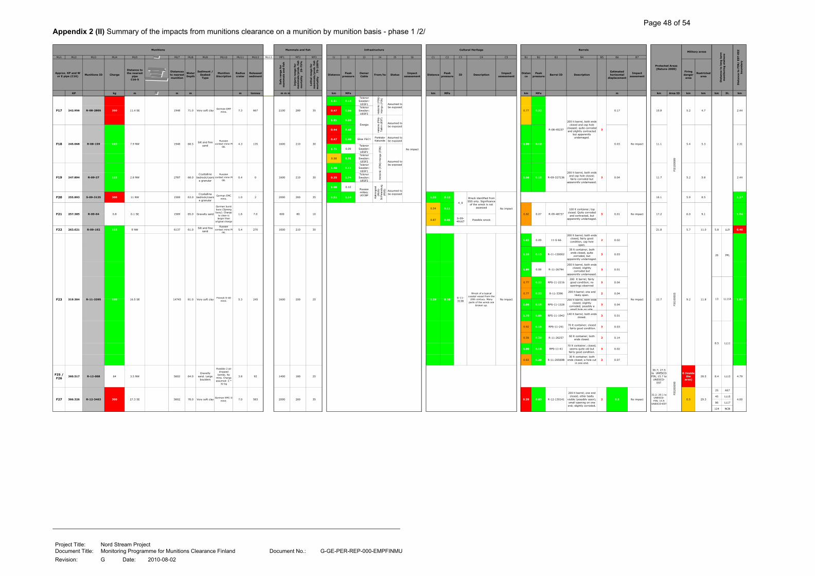
Page 48 of 54
Project Title: Nord Stream Project Document Title: Monitoring Programme for Munitions Clearance Finland Document No.: G-GE-PER-REP-000-EMPFINMU
Revision: G Date: 2010-08-02
Appendix 2 (II) Summary of the impacts from munitions clearance on a munition by munition basis - phase 1 /2/
MU1 MU2 MU3 MU4 MU5 MU7 MU8 MU9 MU10 MU11 MU12 MU13 MF1 MF2 MF3 I1 I2 I3 I4 I5 I6 C1 C2 C3 C4 C5 B1 B2 B3 B4 B5 B6 B7
Munitions ID Charge
Distance to the nearest
pipeC16-5
ates
Distances to nearest munition
Water Depth
Sediment / Seabed
Type
Munition Discription
Radius crater
Released sediment
Safe
ran
ge f
or
mam
mals
an
d f
ish
Inju
ry r
an
ge f
or
mam
mals
/p
rob
. fi
sh
mort
ality
2
5-7
5%
Leth
al
ran
ge f
or
mam
mals
/p
rob
. fi
sh
mo
rtality
7
5-1
00
%
DistancePeak
pressureOwner Cable
From/to StatusImpact
assessmentDistance
Peak pressure
ID DescriptionImpact
assessmentDistan
cePeak
pressureBarrel ID Description
Estimated horizontal
displacement
Impact assesment
Firing danger
area
Restricted area
KP kg m m m m tonnes m m m km MPa km MPa km MPa m km Area ID km km km St. kmF1 181 140 R 06 003 350 7 3 N 413688 1 E 69 1 Sand 5 8 333
1.61 0.14Telenor Sweden: UESF1
0.47 0.56Telenor Sweden: UESF2
1.01 0.23
0.44 0.42
0.47 0.40 Elisa: FEC1Porkkala-Kakumäe
Assumed to be exposed
1.71 0.09Telenor Sweden: UESF1
0.58 0.31Telenor Sweden: UESF2
1.46 0.11Telenor Sweden: UESF1
0.35 0.74Telenor Sweden: UESF2
1.60 0.10
F20 255.893 S-09-3135 300 11 NW 1569 63.0Crystalline
bedrock/coarse granular
German EMC mine.
1.0 2 2000 260 35 1.51 0.14 1.55 0.12 16.1 5.9 8.5 1.37
0.54 0.11
0.87 0.06S-09-49167
Possible wreck
F22 263.621 R-09-192 115 9 NW 6137 61.0Silt and fine
sand
Russian contact mine M-
08.5.4 270 1600 210 30 21.8 5.7 11.0 5.8 LL9 0.46
1.63 0.09 11-S-66
200 lt barrel; both ends closed, fairly good condition, cap hole
open.
2 0.02
1.26 0.13 R-11-130002
35 lt container, both ends closed, quite
corroded, but apparently undamaged.
3 0.03
1.89 0.08 R-11-26794
200 lt barrel, both ends closed; slightly corroded but
apparently undamaged.
3 0.01
0.77 0.22 RPS-11-2216200 lt barrel; fairly good condition; no openings observed
3 0.04
0.77 0.22 R-11-3396200 lt barrel; one end
likely open.2 0.04
1.08 0.15 RPS-11-1328
200 lt barrel, both ends closed; slightly
corroded; possibly a small hole on side.
3 0.04
1.70 0.09 RPS-11-1942140 lt barrel; both ends
closed.3 0.01
0.92 0.18 RPS-11-24170 lt container; closed ; fairly good condition.
3 0.03
0.59 0.29 R-11-2625760 lt container; both
ends closed.3 0.14
1.00 0.16 RPS-11-4170 lt container; closed,
seems quite old but fairly good condition.
3 0.02
0.83 0.20 R-11-26569B30 lt container; both
ends closed; a hole cut in one end.
3 0.07
F25 / F26
360.517 R-12-008 64 3.5 NW 5602 64.0Gravelly
sand. Large boulders
Possible 2 air dropped
bombs. No mine. Charge assumed: 2 *
32 kg
3.8 92 1400 180 25
30.7; 27.5 to UNESCO-FIN; 15.7 to
UNESCO-EST
0 (inside the
area)28.5 8.4 LL13 4.79
25 AS7
45 LL15
86 LL17
124 NCB
0.17
0.03
10.8
0.01
Munitions Mammals and fish Infrastructure Cultural Heritage Barrels
Protected Areas (Natura-2000)
Military areas
Dis
tan
ce t
o l
on
g t
erm
m
on
ito
rin
g s
tati
on
s
Dis
tan
ce t
o F
IN/ E
ST-E
EZ
bo
un
dary
Approx. KP and W or E pipe (C16)
F17 242.956 R-08-2805 350 11.4 SE 1948 71.0 Very soft clayGerman EMF
mine. 7.3 667 2100 280 35
Hel
sinki
(FI
N)-
Han
gö
(FIN
)
0.77 0.32
R-08-45237
0.12
5.2 4.7 2.44
Energia
He
lsin
ki (
FIN
)-T
alli
nn
(E
ST
)
Assumed to be exposed
1.38 5.3 2.31
Assumed to be exposed
F18 245.068 R-08-159 115 7.9 NW 1948 68.5Silt and fine
sand
Russian contact mine M-
08.4.3 135 1600 210 30 11.1 5.4
No impact
No impact
No impact
FI0100089
200 lt barrel, both ends closed and cap hole
clogged; quite corroded and slightly contracted
but apparently undamaged.
3
Hel
sinki
(FI
N)-
Han
gö (
FIN
)
Assumed to be exposed
R-09-327236
200 lt barrel, both ends and cap hole closed; fairly corroded but
apparently undamaged.
31.08 0.15 11.7 5.2F19 247.894 R-09-27 115 2.8 NW 2787 68.0Crystalline
bedrock/coarse granular
Russian contact mine M-
08.0.4 0 1600 210 30
Russian military: UCCBF
Ka
linin
gra
d
(RU
S)-
St.P
ete
rsb
urg
(R
US
)
Assumed to be exposed
0.04 5.8 2.44
4_9
Wreck identified from SSS only. Significance
of the wreck is not assessed
0.82 0.07 R-09-48737
100 lt container; top closed. Quite corroded
and contracted, but apparently undamaged.
3F21 257.385 R-09-04 0.8 0.1 SE 1569 65.0 Gravelly sand
German burst buoy (Spreng buoy). Charge
to clear is larger than
original charge
1.6 7.0 600 80 10
2000 260 35
S-11-3138
Wreck of a typical coastal vessel from the
20th century. Many parts of the wreck are
broken up.
No impact1.29 0.10
No impact 17.2 6.0 9.1 1.04
F23 319.304 R-11-3395 100 16.5 SE 14745 81.0 Very soft clayFinnish S-40
mine. 5.3 245 1600 200 25 No impact 22.7
FI0100005
9.2 11.8
26 JML
1.8113 LL11A
8.5 LL11
FI0200090
F27 366.326 R-12-3463 300 27.3 SE 5602 78.0 Very soft clayGerman EMC II
mine. 7.0 583 4.00R-12-130141
200 lt barrel; one end closed; other badly
visible (possibly open); small opening on one end; slightly corroded.
2 0.5 No impact
32.2; 29.1 to UNESCO-FIN; 14.5
UNESCO-EST
0.39 0.65 0.5 29.3
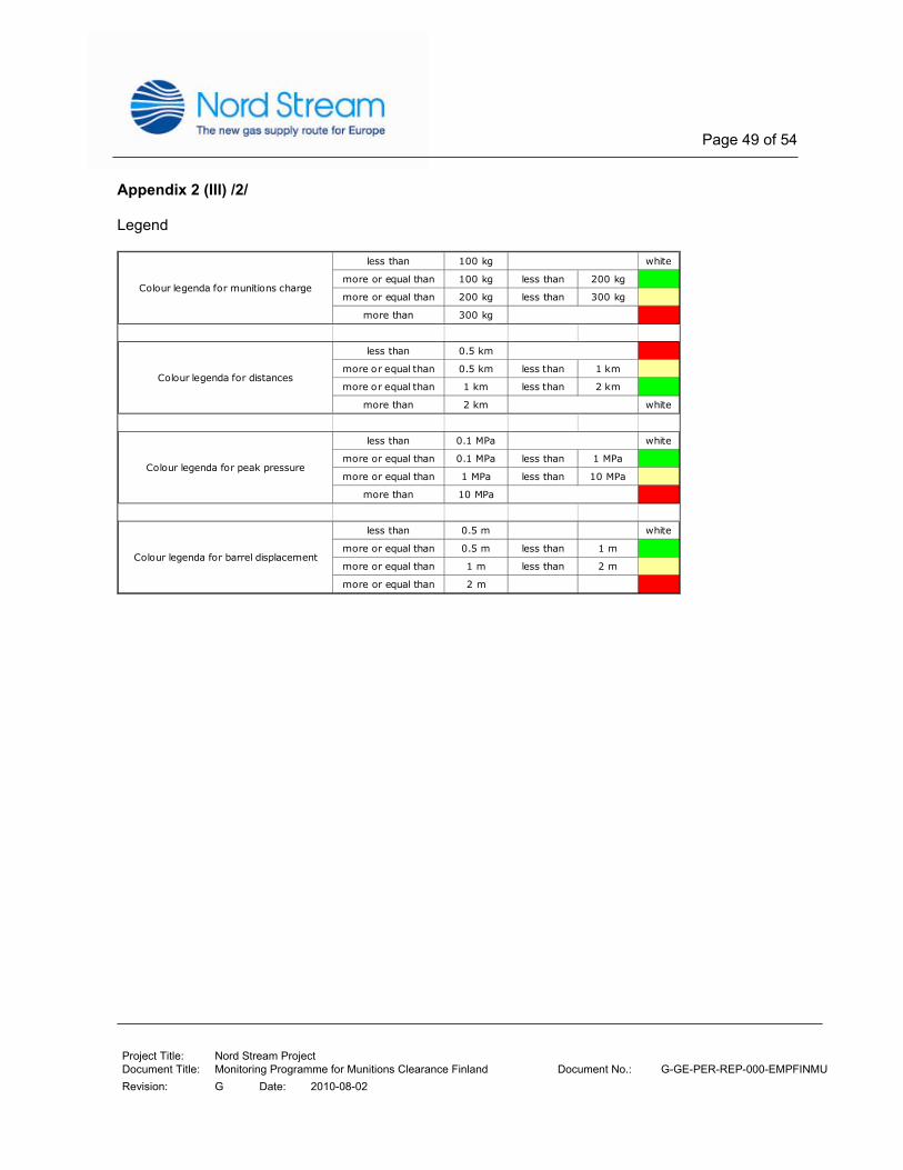
Page 49 of 54
Project Title: Nord Stream Project Document Title: Monitoring Programme for Munitions Clearance Finland Document No.: G-GE-PER-REP-000-EMPFINMU
Revision: G Date: 2010-08-02
Appendix 2 (III) /2/ Legend
less than 100 kg white
more or equal than 100 kg less than 200 kg
more or equal than 200 kg less than 300 kg
more than 300 kg
less than 0.5 km
more or equal than 0.5 km less than 1 km
more or equal than 1 km less than 2 km
more than 2 km white
less than 0.1 MPa white
more or equal than 0.1 MPa less than 1 MPa
more or equal than 1 MPa less than 10 MPa
more than 10 MPa
less than 0.5 m white
more or equal than 0.5 m less than 1 m
more or equal than 1 m less than 2 m
more or equal than 2 m
Colour legenda for barrel displacement
Colour legenda for munitions charge
Colour legenda for distances
Colour legenda for peak pressure

Page 50 of 54
Project Title: Nord Stream Project Document Title: Monitoring Programme for Munitions Clearance Finland Document No.: G-GE-PER-REP-000-EMPFINMU
Revision: G Date: 2010-08-02
Appendix 3 Summary of the sediment spreading due to munitions clearance on a munition by munition basis - phase 1 /5/
MU1 MU2 MU3 MU4 MU7 MU8 MU9 MU11 MU12 MU13 SS1 SS2 SS3 SS4 SS5 SS6 SS7 SS8 SC1 SC2 SC3 SC4
Extent Area Extent Area Extent Area Extent Area Extent Area Extent Area
KP kg m m m tonnes km km2 km km2 km km2 km km2 km km2 km km2 km
F1B 181.135 R-W6F-10740 350 69.0 sand 5.8 333 4.3 2.7 1.9 1.2 7.8 8.9 5.5 6.2 3.9 4.4 1.5 1.7 2.35
F2 206.497 R-E7B-10466 0.8 4079 68.3 Gravelly sand 2.0 14 0.6 0.4 0.0 0.0 0.0 0.0 0.0 0.0 0.0 0.0 0.0 0.0 2.72
F3 210.607 R-07-004 150 2795 78.0Clay with coarse
sediments4.6 165 4.8 3.8 3.3 2.7 7.3 10.6 5.8 8.5 5.8 8.4 4.3 6.2 1.46
F4 213.402 R-07-2655 150 2795 74.0 Very soft clay 5.8 329 2.8 2.4 1.6 1.3 6.2 6.4 4.9 5.1 4.1 4.2 2.8 2.9 1.27
F5 223.229 R-8AG-W-014 300 5353 41.0 Crystalline bedrock 0.0 0.0 0.0 0.0 0.0 0.0 0.0 0.0 0.0 0.0 0.0 0.0 1.94
F6 237.320 R-8AG-W-009 30 528 66.0Clay with coarse
sediments4.2 127 0.4 0.2 1.65
F7 237.357 R-E8C-10223 30 528 66.0Silt and fine
sand/some gravel4.2 127 0.4 0.2 1.19
F8 238.668 R-W8A-10317 30 597 64.5 Silt and fine sand 4.2 127 1.2 0.7 2.2
F9 238.596 R-8CG-E-004 30 597 65.0 Silt and fine sand 4.2 127 0.4 0.2 1.63
F10 239.449 R-8CG-E-003 30 658 66.0Silt and fine
sand/some gravel3.3 63 0.5 0.3 1.95
F11 240.094 R-W8A-10312 30 103 64.0 Silt and fine sand 4.2 127
F12 240.198 R-W8A-10313 30 43 65.0 Silt and fine sand 4.2 127
F13 240.232 G-08-009 30 32 65.0 Silt and fine sand 4.2 127
F14 240.265 R-W8A-10005 30 32 64.0 Silt and fine sand 4.2 127
F15 239.966 R-8CG-E-002 30 253 65.0Silt and fine
sand/gravel patches3.3 63
F15B 239.666 R-08-44944 30 65.0Silt and fine
sand/gravel patches3.3 63
F16 240.219 R-8CG-E-001 30 253 65.0 Silt and fine sand 4.2 127 2.2
F17 242.956 R-08-2805 350 1948 71.0 Very soft clay 7.3 667 4.1 2.7 2.44
F18 245.068 R-08-159 115 1948 68.5 Silt and fine sand 4.3 135 2.3 1.2 2.31
F19 247.894 R-09-27 115 2787 68.0 0.4 0 0.0 0.0 2.44
F20 255.893 S-09-3135 300 1569 63.0 1.0 2 0.0 0.0 0.0 0.0 0.0 0.0 0.0 0.0 0.0 0.0 0.0 0.0 1.37
F21 257.385 R-09-04 0.8 1569 65.0 Gravelly sand 1.6 7 0.6 0.4 0.0 0.0 0.0 0.0 0.0 0.0 0.0 0.0 0.0 0.0 1.04
F22 263.621 R-09-192 115 6137 61.0 Silt and fine sand 5.4 270 2.8 0.9 2.4 0.8 6.6 3.9 6.1 3.7 3.3 1.9 2.8 1.7 0.46
F23 319.304 R-11-3395 100 14745 81.0 Very soft clay 5.3 245 2.2 0.7 0.4 0.1 5.2 3.0 3.4 1.9 2.3 0.7 0.5 0.1 1.81
F25/25 360.517 R-12-008 64 5602 64.0Gravelly sand. Large
boulders3.8 92 0.0 0.0 0.0 0.0 0.0 0.0 0.0 0.0 0.0 0.0 0.0 0.0 4.79
F27 366.326 R-12-3463 300 5602 78.0 Very soft clay 7.0 583 4.3 2.5 0.3 0.2 6.5 5.3 2.5 2.0 4.8 7.8 0.8 1.3 4.00
Crystalline bedrock/coarse
granular
Note 2
25
4.0
Note 3
Sim
ult
an
eo
usl
yS
imu
ltan
eou
sly
2.13
2.42
90
2.0
Into Estonian EEZ
No crater; munition on bedrock
2.0 1.0
Gulf of FinlandApprox. KP and W or
E pipe (C16)Diameter
craterReleased sediment
Spreading of suspended sediment and contaminations
Concentration > 10 mg/l for max. 18 hrs. Maximum concentration > 3 mg/l Maximum concentration > PNEC of SUM16PAH
Gulf of Finland Gulf of Finland
Distance to FIN/ EST-
EEZ boundary
Munitions ID ChargeDistances to nearest munition
Water Depth
Sediment / Seabed Type
Munitions
Note 1
Into Estonian EEZ Into Estonian EEZ
12 40 23.0 80.0 10.0 35.0
Notes
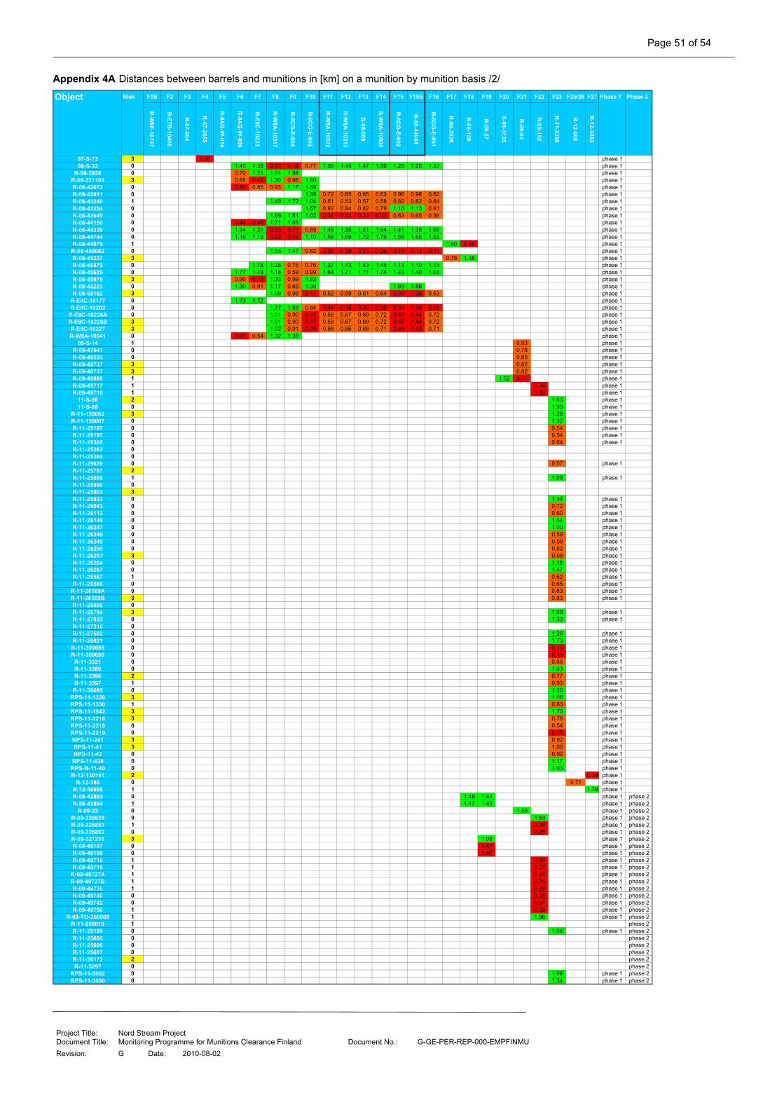
Page 51 of 54
Project Title: Nord Stream Project Document Title: Monitoring Programme for Munitions Clearance Finland Document No.: G-GE-PER-REP-000-EMPFINMU
Revision: G Date: 2010-08-02
Appendix 4A Distances between barrels and munitions in [km] on a munition by munition basis /2/
Object Risk F1B F2 F3 F4 F5 F6 F7 F8 F9 F10 F11 F12 F13 F14 F15 F15B F16 F17 F18 F19 F20 F21 F22 F23 F25/26 F27 Phase 1 Phase 2
R-W
6F-10747
R-E7B
-10466
R-07-004
R-07-2655
R-8A
G-W
-014
R-8A
G-W
-009
R-E8C
-10223
R-W
8A-10317
R-8C
G-E-004
R-8C
G-E-003
R-W
8A-10312
R-W
8A-10313
G-08-009
R-W
8A-10005
R-8C
G-E-002
R-08-44944
R-8C
G-E-001
R-08-2805
R-08-159
R-09-27
S-09-3135
R-09-04
R-09-192
R-11-3395
R-12-008
R-12-3463
07-S-73 3 0.10 phase 108-S-33 0 1.45 1.35 0.43 0.19 0.77 1.35 1.45 1.47 1.50 1.28 1.25 1.53 phase 1
R-08-2938 0 0.70 1.21 1.74 1.98 phase 1R-08-321109 3 0.88 0.42 1.30 0.96 1.80 phase 1R-08-42672 0 0.50 0.85 0.93 1.17 1.89 phase 1R-08-43011 0 1.38 0.72 0.65 0.65 0.63 0.96 0.98 0.82 phase 1R-08-43240 1 1.49 1.72 1.04 0.51 0.53 0.57 0.58 0.82 0.82 0.84 phase 1R-08-43254 0 1.57 0.92 0.84 0.82 0.79 1.10 1.13 0.91 phase 1R-08-43649 0 1.69 1.81 1.02 0.36 0.32 0.33 0.32 0.63 0.65 0.56 phase 1R-08-44156 0 0.44 0.45 1.71 1.65 phase 1R-08-44339 0 1.34 1.21 0.50 0.11 0.89 1.49 1.58 1.61 1.64 1.41 1.38 1.66 phase 1R-08-44744 0 1.16 1.19 0.22 0.49 1.10 1.59 1.69 1.72 1.76 1.58 1.56 1.83 phase 1R-08-44979 1 1.60 0.49 phase 1R-08-450082 0 1.55 1.47 0.62 0.30 0.28 0.25 0.26 0.10 0.13 0.15 phase 1R-08-45237 3 0.76 1.38 phase 1R-08-45575 0 1.78 1.28 0.76 0.76 1.37 1.43 1.43 1.45 1.13 1.10 1.33 phase 1R-08-45629 0 1.77 1.43 1.18 0.59 0.99 1.64 1.71 1.71 1.74 1.43 1.40 1.65 phase 1R-08-45979 3 0.90 0.42 1.33 0.99 1.82 phase 1R-08-46223 0 1.30 0.91 1.17 0.65 1.39 1.89 1.86 phase 1R-08-58162 3 1.09 0.99 0.14 0.52 0.59 0.61 0.64 0.38 0.35 0.63 phase 1
R-E8C-10177 0 1.73 1.72 phase 1R-E8C-10202 0 1.77 1.69 0.84 0.44 0.36 0.32 0.30 0.33 0.36 0.08 phase 1
R-E8C-10226A 0 1.01 0.90 0.07 0.59 0.67 0.69 0.72 0.47 0.44 0.72 phase 1R-E8C-10226B 3 1.01 0.90 0.07 0.59 0.67 0.69 0.72 0.47 0.44 0.72 phase 1R-E8C-10227 3 1.02 0.91 0.08 0.58 0.66 0.68 0.71 0.46 0.43 0.71 phase 1R-W8A-10041 0 0.03 0.54 1.32 1.39 phase 1
09-S-14 1 0.93 phase 1R-09-47641 0 0.78 phase 1R-09-48535 0 0.85 phase 1R-09-48737 3 0.82 phase 1R-09-48737 3 0.82 phase 1R-09-49088 1 1.52 0.37 phase 1R-09-49717 1 0.34 phase 1R-09-49718 1 0.32 phase 1
11-S-66 2 1.63 phase 111-S-88 0 1.95 phase 1
R-11-130002 3 1.26 phase 1R-11-130007 0 1.32 phase 1R-11-25197 0 0.54 phase 1R-11-25197 0 0.54 phase 1R-11-25305 0 0.64 phase 1R-11-25363 0R-11-25364 0R-11-25639 0 0.57 phase 1R-11-25787 2R-11-25868 1 1.09 phase 1R-11-25890 0R-11-25903 3R-11-25933 0 1.54 phase 1R-11-26043 0 0.72 phase 1R-11-26112 0 0.60 phase 1R-11-26148 0 1.54 phase 1R-11-26247 0 1.00 phase 1R-11-26249 0 0.59 phase 1R-11-26249 0 0.59 phase 1R-11-26250 0 0.62 phase 1R-11-26257 3 0.59 phase 1R-11-26264 0 1.18 phase 1R-11-26267 0 1.57 phase 1R-11-26567 1 0.62 phase 1R-11-26568 0 0.65 phase 1
R-11-26569A 0 0.83 phase 1R-11-26569B 3 0.83 phase 1R-11-26698 0R-11-26794 3 1.89 phase 1R-11-27035 0 1.33 phase 1R-11-27310 0R-11-27502 0 1.26 phase 1R-11-28021 0 1.73 phase 1R-11-300686 0 0.15 phase 1R-11-300686 0 0.15 phase 1
R-11-3321 0 0.86 phase 1R-11-3380 0 1.63 phase 1R-11-3396 2 0.77 phase 1R-11-3397 1 0.93 phase 1
R-11-38095 0 1.20 phase 1RPS-11-1328 3 1.08 phase 1RPS-11-1330 1 0.83 phase 1RPS-11-1942 3 1.70 phase 1RPS-11-2216 3 0.76 phase 1RPS-11-2218 0 0.54 phase 1RPS-11-2219 0 0.15 phase 1RPS-11-241 3 0.92 phase 1RPS-11-41 3 1.00 phase 1RPS-11-42 0 0.92 phase 1
RPS-11-630 0 1.17 phase 1RPS-B-11-40 0 1.03 phase 1R-12-130141 2 0.39 phase 1
R-12-380 0 0.71 phase 1R-12-56658 1 1.79 phase 1R-08-42893 0 1.49 1.44 phase 1 phase 2R-08-42894 1 1.47 1.43 phase 1 phase 2
R-09-23 0 1.88 phase 1 phase 2R-09-326635 0 1.53 phase 1 phase 2R-09-326883 1 0.29 phase 1 phase 2R-09-326892 0 0.25 phase 1 phase 2R-09-327236 3 1.08 phase 1 phase 2R-09-48197 0 0.47 phase 1 phase 2R-09-48198 0 0.47 phase 1 phase 2R-09-49716 1 0.29 phase 1 phase 2R-09-49719 1 0.27 phase 1 phase 2
R-09-49727A 1 0.24 phase 1 phase 2R-09-49727B 1 0.25 phase 1 phase 2R-09-49736 1 0.28 phase 1 phase 2R-09-49740 0 0.33 phase 1 phase 2R-09-49742 0 0.31 phase 1 phase 2R-09-49750 1 0.29 phase 1 phase 2
R-09-TO-260005 1 1.96 phase 1 phase 2R-11-200019 1 phase 2R-11-25199 0 1.06 phase 1 phase 2R-11-25605 0 phase 2R-11-25606 0 phase 2R-11-25607 0 phase 2R-11-26172 2 phase 2R-11-3297 0 phase 2
RPS-11-3662 0 1.98 phase 1 phase 2RPS-11-3800 0 1.34 phase 1 phase 2

Page 52 of 54
Project Title: Nord Stream Project Document Title: Monitoring Programme for Munitions Clearance Finland Document No.: G-GE-PER-REP-000-EMPFINMU
Revision: G Date: 2010-08-02
Appendix 4B Expected displacements of barrels in [m] due to munitions clearance on a munition by munition basis /2/
F1B F2 F3 F4 F5 F6 F7 F8 F9 F10 F11 F12 F13 F14 F15 F15B F16 F17 F18 F19 F20 F21 F22 F23 F25/26 F27
R-W
6F-10747
R-E7B
-10466
R-07-004
R-07-2655
R-8A
G-W
-014
R-8A
G-W
-009
R-E8C
-10223
R-W
8A-10317
R-8C
G-E-004
R-8C
G-E-003
R-W
8A-10312
R-W
8A-10313
G-08-009
R-W
8A-10005
R-8C
G-E-002
R-08-44944
R-8C
G-E-001
R-08-2805
R-08-159
R-09-27
S-09-3135
R-09-04
R-09-192
R-11-3395
R-12-008
R-12-3463
07-S-73 3 1.69 phase 1
08-S-33 0 0.01 0.02 0.17 0.66 0.05 0.04 phase 1
R-08-2938 0 0.06 0.02 0.01 0.01 phase 1
R-08-321109 3 0.04 0.19 0.02 0.03 0.01 phase 1
R-08-42672 0 0.13 0.04 0.03 0.02 0.01 phase 1
R-08-43011 0 0.01 0.13 phase 1
R-08-43240 1 0.01 0.01 0.03 0.13 phase 1
R-08-43254 0 0.01 0.11 phase 1
R-08-43649 0 0.01 0.01 0.03 0.27 phase 1
R-08-44156 0 0.16 0.16 0.01 0.01 phase 1
R-08-44339 0 0.02 0.02 0.13 1.27 0.04 0.03 phase 1
R-08-44744 0 0.02 0.02 0.54 0.13 0.02 0.02 phase 1
R-08-44979 1 0.04 0.22 phase 1
R-08-450082 0 0.01 0.01 0.08 1.46 phase 1
R-08-45237 3 0.17 0.03 phase 1
R-08-45575 0 0.01 0.02 0.05 0.05 0.05 phase 1
R-08-45629 0 0.01 0.01 0.02 0.09 0.03 0.03 phase 1
R-08-45979 3 0.04 0.18 0.02 0.03 0.01 phase 1
R-08-46223 0 0.02 0.04 0.02 0.07 0.01 phase 1
R-08-58162 3 0.02 0.03 0.95 0.22 phase 1
R-E8C-10177 0 0.01 0.01 phase 1
R-E8C-10202 0 0.01 0.01 0.04 2.30 phase 1
R-E8C-10226A 0 0.03 0.04 1.83 0.17 phase 1
R-E8C-10226B 3 0.03 0.04 1.83 0.17 phase 1
R-E8C-10227 3 0.03 0.04 1.65 0.18 phase 1
R-W8A-10041 0 2.85 0.11 0.02 0.01 phase 1
09-S-14 1 0.01 phase 1
R-09-47641 0 0.01 phase 1
R-09-48535 0 0.01 phase 1
R-09-48737 3 0.01 phase 1
R-09-48737 3 0.01 phase 1
R-09-49088 1 0.04 0.05 phase 1
R-09-49717 1 0.41 phase 1
R-09-49718 1 0.47 phase 1
11-S-66 2 0.02 phase 1
11-S-88 0 0.01 phase 1
R-11-130002 3 0.03 phase 1
R-11-130007 0 0.03 phase 1
R-11-25197 0 0.17 phase 1
R-11-25197 0 0.17 phase 1
R-11-25305 0 0.12 phase 1
R-11-25363 0 phase 1
R-11-25364 0 phase 1
R-11-25639 0 0.16 phase 1
R-11-25787 2 phase 1
R-11-25868 1 0.04 phase 1
R-11-25890 0 phase 1
R-11-25903 3 phase 1
R-11-25933 0 0.02 phase 1
R-11-26043 0 0.10 phase 1
R-11-26112 0 0.14 phase 1
R-11-26148 0 0.02 phase 1
R-11-26247 0 0.05 phase 1
R-11-26249 0 0.14 phase 1
R-11-26249 0 0.14 phase 1
R-11-26250 0 0.13 phase 1
R-11-26257 3 0.14 phase 1
R-11-26264 0 0.03 phase 1
R-11-26267 0 0.02 phase 1
R-11-26567 1 0.13 phase 1
R-11-26568 0 0.12 phase 1
R-11-26569A 0 0.07 phase 1
R-11-26569B 3 0.07 phase 1
R-11-26698 0 phase 1
R-11-26794 3 0.01 phase 1
R-11-27035 0 0.03 phase 1
R-11-27310 0 phase 1
R-11-27502 0 0.03 phase 1
R-11-28021 0 0.01 phase 1
R-11-300686 0 1.13 phase 1
R-11-300686 0 1.12 phase 1
R-11-3321 0 0.07 phase 1
R-11-3380 0 0.02 phase 1
R-11-3396 2 0.08 phase 1
R-11-3397 1 0.05 phase 1
R-11-38095 0 0.03 phase 1
RPS-11-1328 3 0.04 phase 1
RPS-11-1330 1 0.07 phase 1
RPS-11-1942 3 0.01 phase 1
RPS-11-2216 3 0.08 phase 1
RPS-11-2218 0 0.17 phase 1
RPS-11-2219 0 1.11 phase 1
RPS-11-241 3 0.06 phase 1
RPS-11-41 3 0.05 phase 1
RPS-11-42 0 0.06 phase 1
RPS-11-630 0 0.03 phase 1
RPS-B-11-40 0 0.04 phase 1
R-12-130141 2 0.50 phase 1
R-12-380 0 0.08 phase 1
R-12-56658 1 0.02 phase 1
R-08-42893 0 0.02 0.02 phase 1 phase 2
R-08-42894 1 0.02 0.02 phase 1 phase 2
R-09-23 0 0.00 phase 1 phase 2
R-09-326635 0 0.02 phase 1 phase 2
R-09-326883 1 0.52 phase 1 phase 2
R-09-326892 0 0.64 phase 1 phase 2
R-09-327236 3 0.04 phase 1 phase 2
R-09-48197 0 0.24 phase 1 phase 2
R-09-48198 0 0.24 phase 1 phase 2
R-09-49716 1 0.53 phase 1 phase 2
R-09-49719 1 0.60 phase 1 phase 2
R-09-49727A 1 0.69 phase 1 phase 2
R-09-49727B 1 0.66 phase 1 phase 2
R-09-49736 1 0.56 phase 1 phase 2
R-09-49740 0 0.43 phase 1 phase 2
R-09-49742 0 0.47 phase 1 phase 2
R-09-49750 1 0.52 phase 1 phase 2
R-09-TO-260005 1 0.01 phase 1 phase 2
R-11-200019 1 phase 1 phase 2
R-11-25199 0 0.04 phase 1 phase 2
R-11-25605 0 phase 1 phase 2
R-11-25606 0 phase 1 phase 2
R-11-25607 0 phase 1 phase 2
R-11-26172 2 phase 1 phase 2
R-11-3297 0 phase 1 phase 2
RPS-11-3662 0 0.01 phase 1 phase 2
RPS-11-3800 0 0.02 phase 1 phase 2
0.12 0.67
0.02 0.02
0.02 0.02
0.02 0.02
Object
0.02
0.15 0.06
0.09 0.48
0.09 0.50
0.35 0.10
0.12 0.20
0.50 1.80
0.02 0.03
0.40 0.35
Phase 2
0.03 0.03
0.06 0.03
0.09 0.04
Risk Phase 1

Page 53 of 54
Project Title: Nord Stream Project Document Title: Monitoring Programme for Munitions Clearance Finland Document No.: G-GE-PER-REP-000-EMPFINMU
Revision: G Date: 2010-08-02
Appendix 5 Locations for water and sediment quality monitoring during munitions clearance

Page 54 of 54
Project Title: Nord Stream Project
Document Title:
Monitoring Programme for Munitions Clearance Finland
Document No.: G-GE-PER-REP-000-EMPFINMU
Revision: G Date: 2010-08-02
Appendix 6 Extended layouts for environmental mitigation equipment at selected clearance sites