Stretch-regulated Exocytosis/Endocytosis in Bladder Umbrella Cells
Upload
khangminh22Category
view
3download
0
r{y f ORNL-TM-4867
Modification V to the Computer Code, Stretch, tor Predicting Coated-Particle Behavior
K . H . V a l e n t i n e
Vuhiim
• 3
t
- i ^ r f t t.
f.'KSSJ*-'
P I P
* 1 J ® IS.
« t I
I S p i P S
^..-./.VA**^
! —
*
^ ? r
- "o-V . fi&B*. v
m m - J
• y u 7 , ; ; v 4 3 T '
$ j
m ® 'i.l'^tr;')
OAK R^QGE NATIONAL LABORATORY OPERATED BY" UNION CARBIDE CORPORATION - l . FOR T R F U.S. ATOMIC ENERGY .COMMISSION

BLANK

Printed in the Uni ted States of America. Available f rom National Technical Information Service
U.S. Department of Commerce 5 2 8 5 Port Royal Road, Springfield, Virginia 2 2 1 6 1
Price: Printed Copy $ 4 . 0 0 ; Microfiche S2.25
This report was prepared as an account of work sponsored bv the United States Government . Neither the United States nor the Energy Research and Development Adminis trat ion, nor any of their employees , nor any of their cont rac tors , subcontractors , or their employees , makes any war ran ty , express or implied, or assumes any legal liability or responsibility for the accuracy, completeness or usefulness of any in format ion , apparatus , product or process disclosed, o r represents that its use would not infringe privately owned rights.

ORNL-TM-4867 UC-77 — Gas Cooled Reactor Technology
Contract No. W-7405-feng-26
METALS AND CERAMICS DIVISION
MODIFICATION V TO THE COMPUTER CODE, STRETCH FOR PREDICTING COATED-PARTICLE BEHAVIOR '
K. H. Valentine
APRIL 1975
Tiis report wns prepared as an account of work sponso.M by the United States Government. Neither the United States nor the United States Energy Research and Development Administration, nor any of their employees, nor any of their contractors, subcontractors, or their employees, makes any warranty, express or implied, or assumes any legal liability or responsibility for the accuracy, completeness or usefulness of any information, apparatus, product or process disclosed, or represents that its use would not infringe privately owned rights.
OAK RIDGE NATIONAL LABORATORY Oak Ridge, Tennessee 37830
operated by UNION CARBIDE CORPORATION
for the U.S. ENERGY RESEARCH AND DEVELOPMENT ADMINISTRATION
DISTRIBUTION OF THIS DOCUMENT UNLIMITED

CONTENTS
Abstract 1
Introduction 1
Modifications 2
Temporal Particle Surface Temperature . 2
Neutron-Induced Densification Equation 4
Creep Coefficient 8
Neutron Flux Values 9
Analysis of Experiments HT-12 through rIT-15 9
Experimental Description 9
Calculational Procedure 10
Results 10
Conclusions 16
Appendix 19
iii

MODIFICATION V TO THE COMPUTER CODE, STRETCH, FOR PREDICTING COATED-PARTICLE BEHAVIOR
K. H. Valentine
ABSTRACT
Several modifications have been made to the stress analysis code, STRETCH, in an attempt to improve agreement between the calculated and observed behavior of pyrocarbon-coated fuel parti-cles during irradiation in a reactor environment. Specific areas of the code that have been modified are the neutron-induced densi-fication model and the neutron-induced creep calculation., Also, the capability for modeling surface temperature variations has been added. HFIR Target experiments HT-12 through HT-15 have been simulated with the modified code, and the neutron-fluence vs particle-failure predictions compare favorably with the experi-mental results. Listings of the modified FORTRAN IV main source program and additional FORTRAN IV functions are provided along with instructions far supplying the additional input data.
INTRODUCTION
The starting version of the code used for this work is known as STRETCH, Modification IV and is already well documented.1'2 It mathe-matically models the development of stresses and strains in the outer pyrocarbon coating of a fuel particle having Biso geometry (a high-density pyrocarbon coating over a low-density buffer coating). In the code, stresses arise from neutron-induced dimensional changes, thermally induced dimensional changes, and fission gas pressures; stresses can be partially relieved by secondary or steady-state creep (primary or tran-sient creep is handled by modification of the elastic constants, see ref. 1). The irradiation environment is characterized by a constant particle outside surface temperature, a thermal neutron flux value, and a fast-to-thermal neutron flux ratio. In the course of a typical STRETCH calculation, the tangential coating stress increases with neu-tron fluence until it reaches a preset fracture stress?. This condition constitutas failure of the coating, and the calculation is terminated.
1J. W. Prados and T. G. Godfrey, STRETCH, a Computer Program for Predicting Coated-Particls Irradiation Behavior; Modification IV, Decem-ber 1967, ORNL-TM-2127 (April 1968).
J. W. Prados and J. L. Scott, Mathematical Model for Predicting Coated-Particle Behavior, ORNL-TM-1405 (March 1966).
1

2
While Modification IV is a useful analytical tool for parametric studies concerning particle design, it is of limited use for modeling real experiments because of the inherent restrictions on characterization of the irradiation environment. For instance, a large fraction of the accelerated testing done at ORNL is carried out at the HFIR (High Flux Isotope Reactor), which operates on a 25-day fuel cycle (23 days at power, 2 days for refueling). During a cycle, local temperatures and neutron fluxei; can vary widely because of driver fuel burnup and motion of the control cylinders. Further temperature variations are caused First by burnup of fissile heavy metal that is initially present in the test fuel kernel and later by fissioning of converted fertile mate-rial. However, it was not formerly possible to input any of this infor-mation since Modification IV accepts only a single value for the particle sur.face temperature.
A major problem encountered in a preliminary analysis made with Modification IV was the relatively rapid decrease in the tangential coat-ing stress following the maximum fission heat generation rate. This made it difficult to reconcile experimentally observed failures that occurred aftt-r the maximum heat rate. Two further modifications were therefore incorporated into the code to alleviate this problem. One of the modifications deals with the neutron-induced densification equation and the other deals with the neutron-induced creep calculation. Either one of these modifications can produce continued increase in the calcu-lated stresses beyond the occurrence of the maximum heat rate.
All modifications and additions are written in FORTRAN IV, H-Level, for IBM System 360 computers, as is the main body of the STRETCH program. Also, the convention of using double-precision arithmetic to mitigate the effects of round-off errors has been retained. Listings of the modified main program ar"l additional function subprograms ar<.. included in the Appendix. Data input guides as well as sample input £.nd output may also be found in the Appendix.
M O D I F I C A T I O N S
Modification IV consists of a main program, designated S5-IV, seven subroutines, and two function subprograms. Of these, only the main program is revised here, and the scope of revision has been confinad to implementation of the modifications described below. Unless stated otherwise, all logic, equations, and calculational procedures remain as described in refs. 1 and 2. All the original input statements have been retained, so in a few isolated cases, an input parameter is redundant or superfluous. For reference purposes, the entire program package, as described in this report, will be called Modification V.
Temporal Particle Surface Temperature
This modification allows the user to override the constant surface temperature boundary condition by entering the temporal surface temperature as tabular input. The tabular input consists of a set of cards, each of

3
which contains a temperature (°C) and the time (days) to which the temperature applies (the set must be ordered according to increasing time). Programming changes include additional read statessnts in the main program and an additional function subprogram called TCOAT, which computes the surface temperature as a function of time. TCOAT accesses the tabular data through labeled common (BL0CK3) and calculates surface temperature by searching the table for two time values that bracket the argument. It then linearly interpolates between the two corresponding temperature values.
Figures 1 and 2 show the temperature histories used to simulate the HT-12 through -15 experiments. Each of the histories was entered as a
ORNL-WW 71-12154
80 100 120 TIME (doyl)
140 200
Fig. 1. Particle Surface Temperature History for HT-12 through -15 Low-Temperature Sleeves. The four points denoted by open circles were obtained from computer calculations.
set of 22 data cards (one for each vertex). Values of surface temperature calculated by TCOAT for any arbitrary time would then lie on one of the line segments connecting the vertices;. To keep the total fluence in step with real time, the neutron flux is set to zero whenever the surface temperature drops below 200°C (interpreted as reactor shutdown).
In Modification IV, thermal strains are calculated at the beginning of a problem on the basis of the initial temperature profile. Since the user may wish to input temperature histories involving large temperature excurs-ions, the thermal strain calculation was moved inside the time incre-ment 1< op so that the thermal strains are updated along with the other stress-strain variables.

4
OflNL-CMfG 7»-l ?»J5
400
01 0 20 40 60 80 100 120 140 160 180 200
TIME (*>yt)
Fig. 2. Particle Surface Temperature History for HT-12 through -15 High-Temperature Sleeves. The four points denoted by open circles were obtained from computer calculations.
Neutron-Induced Densification Equation
The neutron-induced densification equations used in Modification IV are based on the linear superposition of effects due to isotropic expo-nential densification and anisotropic distortion.3 Strains due to densi-fication are calculated as
kd(Pf ~ P°)e
P y - ( P f ~ P o ) e ~ ^ Y
AY , ( 1 )
where e. = e, or Ci> = neutron-induced strain in direction perpendicular % ~~ or parallel to the coating surface, respectively;
Y = fast neutron fluence (>0.18 MeV) ;
« average crystallite strain rate in the e direction;
3J. C. Bokros and A. S. Schwartz, Carbon 5: 481-92, (1967).

5
R 1 ~ 2/(2 + BAF), (BAF = Bacon Anisotropy Factor);
R|| = 1 ~ R i / 2 ;
Po, P = initial and final coating density, respectively;
k^ = densification constant.
The strain rate in Eq. (1) can also be integrated analytically. When this is done, the result is
^ - ^ - ^ m h s - . - ^ S H ] .
where the initial condition e^(0) = 0 has been assumed. In ref. 3, Eqs. (1) and(2) are shown to give good agreement with experimental data for damage fluences (>0.18 rfeV) in the range of 2 to 3 x 10²¹ neutrons/cm2. However, other data11 indicate that f:or damage fluences exceeding about 5 x 10²¹
neutrons/cm2, these equations do not adequately describe the behavior of many pyrocarbons. Since the fluence range of interest for the HT-12 through -15 experiments was 0 to 16 x i o 2 1 neutrons/cm2, the densification calculation was modified to give at least qualitative agreement with higher fluence data.
The densification data of ref. 4 are plotted m Fig. 3. The tempera-ture range for these data extends from 850 to 1450°C, which may explain some of the scatter. The curves are visual fits of the data, and the extrapolations beyond a fluence of 8 x 10²¹ neutrons/cm2 are strictly qualitative based on the following qualitative trends.1* 1. low-density LTI (low-temperature isotropic) pyrocarbons continue to
densify with decreasing rates of dimensional change; 2. intermediate-density pyrocarbons remain at a constant density and
change dimensions at constant rates; 3. high-density pyrocarbons undergo volume increases (dedensification)
accompanied by accelerations in the dimensional change rate. The curve for po = 1.9 g/cm3 is not too unlike some ORNL data5 for a pyrocarbon with similar initial density.
For comparison the approximate density change implied by Eq. (2) is convenient to calculate. To first order, the volume change is
1>Gulf General Atomic, HTGR Base Program Quart. Progr. Rep. May 31, 1972, Gulf-GA-12150, pp. 92-124.
SD. M. Hewette, R. B. Fitts, C. B. Pollock, J. I. Federer, and J. L. Scott, Effects of Neutron Irradiation on Loose and Bonded Inert Parti-cles Coated with Pyrolytic Carbon and Silicon Carbide, ORNL-TM-4551 (August 1974), p. 32.

6
ORNI.-DWG 7 4 - 9 9 3 1
FAST (>CH8M«V) NEUTRON FLUENCE (n/cma)
Fig. 3. Neutron-Induced Densification of Pyrocarbon Coatings for Four Different Initial Densities. The legend associates curves with data points-
= + or V = (1 + 2£„ + ^ ) .
Thus, the change in density is:
V = 1 + 2ej° + E l % p o ( 1 ~ 2 e | i ~ e l > ' O )
Using strains from Eq. (2), Eq. (3) is plotted as the dotted curve of Fig. 4 for (de /dy)* 0.03 cm2/l02° neutrons.. BAF = 1.05, k d = 0.05 cm2/1020
neutrons, and P~/Po ~ 1.06. Note that this strain model predicts that the density is a motiotonic function of fluence, with the user-supplied final density as an asymptote, thus precluding the possibility of high-fluence dedensification.

7
ORNL-DWG 7 4 - 9 9 5 2
Fig. A. Analytical Model for Neutron-Induced Densification of Pyro-carbon Coatings. The dotted curve was calculated with the densification model employed in Modification IV, and the two solid curves were calcu-lated from Eq. (3) using £|j from Eq. (2) and e^ from Eq. (4).
The starting point for modeling the high-fluence dedensification suggested by Fig. 3 was Che introduction of a fluence-dependent BAF (there is some experimental evidence to support this rpproach).6 Thus, the anisotropy was modeled as BAF(y) = BAF0(1 + By) and substituted into the expression for the strain rate. Upon integration, the resulting neutron-induced strains are given by
/de e {(r) - f/— T\dy / Y -
3 B8o
In + 2 V 5 7 ) " 3 l n [ Pf ~ (.Pf — Po)g
Po
~kdy-(4)
6K. Koizlik, On the Anisotropy tion in Pyrocarbon Coatings of Fuel Irradiation, GERHTR-87 (April 1973)
Variation of Crystallographio Orienta-Particles by Annealing arid Neutron

8
where f. = 1 for the perpendicular direction and —1/2 for the parallel direction.
The densification implied by Eq. (4) is the same as that of Eq. (2). However, since the magnitudes of the dimensional changes predicted by Eq. (4) are larger, an analytic dedensification model is obtained by using Eq. (2) to calculate £|| and Eq. (4) to calculate ej_. The resulting densi-fication behavior for two initial densities is shown as the solid curves of Fig. 4 for pj> = 2.2 g/cm3 and ft = 0.003 cmVlO 2 neutrons. Also, the data from Fig. 3 for Po = 2.0 g/cm3 are repeated for comparison. Although the value 8 = 0.003 was obtained from a parametric study to yield reasonable agreement with data at Po = 2.0 g/cm3, it agrees within a factor of 2 with data presented in ref. 6. For this particular model, it is probably better to interpret as a theoretical density since there is no distinct final density.
A comparison of Figs. 3 and 4 shows that the predicted dependence of densification on initial density does not agree with the data. This was not considered a problem for the present application since the initial coating densities of particles used in the HT-12 through -15 experiments were nominally about 2.0 g/cm3. Further improvements in the model can probably be obtained by incorporating the concept of initial porosity depletion with subsequent generation of new porosity,7 although the validity is questionable.
Creep Coefficient
In Modification.IV, neutron-induced steady-state creep is calculated as £ = A'ycr, where e is the effective creep strain rate, CT is the effective creep stress, and K is the steady-state creep coefficient (a constant).8 An equation of this form implies that there is no cumulative degradation in the effectiveness of the creep mechanism for relieving stress. In view of some work with graphite,7 which indicates that the creep rate may decrease at higher fluences, changes were made in Modification IV to allow the creep coefficient to decrease as a linear function of fluence: K = Ko + (dK/dy)y.
The desired functional dependence of the creep coefficient on fluence is obtained by supplying an additional data card that contains a value for the initial creep coefficient and a set of values (K>y) with y ^ 0. Then dKfdy is computed as (X — J£o)/Y« If the y value supplied on the data card is exceeded during the course of a calculation, the creep coefficient is set t o K o / l O O .
7W. J. Gray, Carbon 11: 383-92 (1973). 8J. W. Prados and T. G. Godfrey, STRETCH, a Computer Program for
Predicting Coated-Particle Irradiation Behavior; Modification IV, December 1967, ORNL-TM-2127 (April 1968).

9
Neutron Flux Values
As mentioned in the Introduction, Modification IV is oriented primar-ily toward parametric studies. The input format is arranged in such a way that a portion of the input is associated with the fuel kernel, another portion with temperature-dependent properties (including neutron flux characteristics), and the remainder with the coating design. All combinations of fuels, temperatures, and coating designs are used so that two fuel descriptions, three irradiation temperatures, and four particle designs yield 2 * 3 x 4 = 24 separate cases. Thus to accurately model a particular set of experiments, each case must be entered as a separate problem in order to avoid cases that bear no relation to the experiment. This requires that all input data be repeated, even if most of the parameter values are the same as in the preceding case.
Although a complete overhaul of the input format would be necessary to optimize STRETCH's utility for simulation calculations, a partial solu-tion was implemented. It furnishes the user the option of entering a separate thermal flux value for each irradiation temperature and particle design. The flux was singled out because it affects almost all phases of the calculation (fission gas generation, fission heat generation, densi-fication, creep). The user informs the program that he intends to use this option by setting a flag on the first data card of a problem. The flux values are supplied in a single section at the end of the data deck.
ANALYSIS OF EXPERIMENTS HT-12 THROUGH -15
Experimental Description
The HT-12 through -15 experiments have been described previously.9'10
Briefly, this series was a set of four experiments designed to evaluate the performance of Biso-coated Th02 fertile fuel particles as a function of fluence. Sixteen batches of coated particles, fabricated by ORNL and GAC (General Atomic Company), were irradiated in four capsules placed in radially symmetric positions in the target region of the HFIR. Each con-tained 52 specimen holders, 32 of which contained test particles and 20 of which contained uranium to smooth out the axial temperature profile. The specimen holders in each capsule were equally divided into four magazines or sleeves. The operating temperatures of the two sleeves nearest the horizontal midplane of HFIR were about 250°C higher than the two sleeves located at the ends of the capsules. Different total fluences were obtained for each capsule by removing HT-12 after two cycles, HT-13 after four, HT-14 after six, and HT-15 after seven.
9B. H. Montgomery et al., Gas-Cooled Reactor* Programs Anna. Progr. Rep. Deo. Sly 1972s 0RNL-4911, pp. 113-15.
1°HFGB Fuels and Core Development Program Quart. Progr. Rep. Aug. 30, 19743 GA-A13126, pp. 52-74,

10
Calculatlonal Procedure
Model calculations for HT-12 through -*15 were run with Modification V. The particle design data that were used are compiled in Table 1 and the neutron flux data in Table 2. While separate thermal neutron flux values were input for each sample holder, average values of 0.415 and 0.388 were used for the fast-to-thermal flux ratios in the low- and high-temperature sleeves, respectively. Note also that anisotropy of the coatings is reported as the OPTAF (optical anisotropy factor), whereas STRETCH calcu-lations are based on the BAF (Bacon anisotropy factor). Although the two measures of anisotropy are not identical, each is a monotonically increas-ing function of the other.6 Sinca the reported OPTAF's are either esti-mated design values or else approximate values measured at the midradius of the coating, they were supplied to the code directly as BAF's.
The temperature histories shown in Figs. 1 and 2 were used to describe the particle surface temperature in the low- and high-temperature sleeves. Four points of each history (denoted b y Q ) were obtained from heat transfer calculations11 that considered temporal fission heat generation in the ker-nel and variations in gap thermal conductances due to neutron-induced dimen-sional changes. The dashed curves have approximately the shape of the fission heat rate curve.
We ran a series of calculations using different values for Ko and dK/dy in the creep coefficient equation. As expected, large negative values of dK/dy resulted in substantially higher coating stresses, although the corre-lation with experimental results was not significantly improved over the correlation obtained with a constant creep coefficient. Since no data were available to support any particular choice for a value of dK/dy, the final calculations were run with K = Ko.
No a pvi-ovi. value for the coating fracture stress was assumed. Instead, an unrealistically high value (60,000 psi, 414 MPa) was entered into the code so the calculations would extend well beyond the range of possible stresses that could be survived by the coatings. Fracture stresses were then chosen after the calculations were completed to give approximately the best correlation with experiment.
Finally, a different approach was taken in interpreting the experimen-tal data. In previous analyses, samples were generally assumed to have failed if a single particle In the sample failed, unless the failure was anomalous; e.g., if a similar sample exposed to a higher fluence did not fail. In the analysis presented here, the statistical nature of the design parameter distributions was considered.
Results
Figure 5 shows the results obtained from measurements of all 75 parti-cles (Batch OR-1846) that went into sample holder 18 of HT-12. Numerical
1 Unpublished calculations performed by Robert Olstad using HTTEMP and HEATING3 heat transfer codes.

11
Table 1. Fabrication Data for Particles in HT-12, -13, -14, and -15
Sample Holder Temperature
Low High - Batch3 Design*5 Case
Buffer Density (g/cm3)
Pyrocarbon Density OPTAF
2 15 GGA 4252-08 499-39-119 1 1.08 1.95 1.14 4 17 ORNL OR-1850 508-45-48 2 c 1.99 d 5 18 0R11L 0R-1846 400-20-21 3 c 1.99 d 7 20 GGA 4252-00 405-81-76 4 1.26 2.00 1.14 8 21 ORNL OR-1840 402-25-50 5 c 2.01 d
10 23 GGA 4252-06 514-80-74 6 1.10 1.82 1.14 11 24 ORNL 0R-1749 402-33-36 7 c 1.92 d 13 26 ORNL 0R-1849 508-79-75 8 c 1.99 d 40 27 GGA 4252-02 508-83-75 9 1.08 1.84 1.07 42 29 ORNL 0R-1838 402-32-64 10 c 1.96 d 43 30 GGA 4252-03 501-32-67 11 1.00 2.00 e 45 32 ORNL OR-1826 402-21-31 12 c 2.01 d 46 33 GGA 4252-01 487-61-76 13 1,11 2.02 1.16 48 35 ORNL OR-1830 402-1-38 14 c 2.01 d 49 36 GGA 4252-07 485-46-50 15 1.03 1.96f 1.20 51 38 ORNL 0R-1837 402-1-24 16 c 2.02 d
aGGA denotes material from Gulf General Atomic, presently General Atomic Company. bDesign given as kernel diameter, buffer thickness, outer pyrocarbon thickness,
all in micrometers. cThe design density for all ORNL buffer coatings was 1.1 g/cm3, however,
these have not yet been measured. The design OPTAF for ORNL outer pyrocarbon coatings was <1.1; however, these
have not yet been measured. Q Steep OPTAF gradient across outer pyrocarbon layer varying from about 1.1 to
greater than 2.0. ^The buffer and outer pyrocarbon layers could not be separated from split samples
sent for density determinations.

12
Table 2. Neutron-Fluxes for Irradiation Experiments3
HT-12 through -15
.'ample Flux, n cm sec „ _. ^ . , -Sample Holder Ratxo, fast/thermal Holder Location Thermal Fast Fast e V
(in.) <1.86 eV >1.86 eV >0.18 MeV
Low-Temperature Samples xlO15 xlO15 xlO15
2 8.909 1.75 1.41 0.59 0.81 0.42 4 8.344 1.87 1.57 0.67 0.84 0.43 5 8.061 1.93 1.67 0.70 0.87 0.42 7 7.496 2.05 1.85 0.76 0.90 0.41 8 7.214 2.11 1.92 0.80 0.91 0.42
10 6.649 2.24 2.08 0.85 0.93 0.41 11 6.366 2.31 2.16 0.88 0.94 0.41 13 5.801 2.42 2.30 0.93 0.95 0.40 40 5.801 2.42 2.30 0.93 0.95 0.40 42 6.366 2.31 2.16 0.88 0.94 0.41 43 6.649 2.24 2.08 0.85 0.93 0.41 45 7.214 2.11 1.92 0.80 0.91 0.42 46 7.496 2.05 1.85 0.76 0.90 0.41 48 8.061 1.93 1.67 0.70 0.87 0.42 49 8.344 1.87 1.57 0.67 0.84 0.43 51 8.909 1.75 1.41 0.59 0.81 0.42
High-Temperature Samples 15 3.909 2.83 2.70 1.06 0.95 0.39 17 3.344 2.94 2.80 1.09 0.95 0.39 18 3.061 3.00 2.83 1.11 0.94 0.39 20 2.496 3.10 2.91 1.13 0.94 0.39 21 2.214 3.13 2.94 1.14 0.94 0.39 23 1.649 3.19 3.00 1.16 0.94 0.39 24 1.366 3.22 3.03 1.16 0.94 0.38 26 0 . 8 0 1 3.25 3.11 1.17 0.96 0.38 27 0.8C1 3.25 3.11 1.17 0.96 0.38 29 1.366 3.22 3.03 1.16 0.94 0.38 30 1.649 3.19 3.00 1.16 0.94 0.39 32 2.214 3.13 2.94 1.14 0.94 0.39 33 2.496 3.10 2.91 1.13 0.94 0.39 35 3.061 3.00 2.83 1.11 0.94 0.39 36 3.344 2.94 2.80 1.09 0.95 0.39 38 3.909 2.83 2.70 1.06 0.95 0.39
aH. T. Kerr, "Nuclear Analysis in Support of Irradiation Experiments," Gas Cooled Reactors Program Annu. Progr. Rep. Deo. 31, 2S7Ss 0RNL-4975 (in press).
^Distance from reactor horizontal midplane. Multiply by 25.4 to convert to millimeters.

13
OANL-DWG 74-10262
20
10
0
30
20
y io fc g & 0 cc IU m § 20 z
10
o
20
10
0 0 Q75 1.00 1.25 1.50 1.75 2X30 2.25
Fig. 5. Preirradiation Design Parameter Distributions for Particles used in High-Temperature Sleeve of HT-12 (Batch OR-1846, 75 particles).
data are tabulated in Table 3. These measurements were obtained from pre-irradiation microradiographs using a transmission microscope. The buffer and LTI thicknesses are the averages of two measurements on opposite sides of each particle.
In order to gain some insight into how the design parameter distri-butions might affect the analysis, all perrnutations of the extreme measured dimensions (Table 3) were run using STRETCH in a simulation of the HT-15 experiment. The maximum coating stresses (assuming the coatings do not fail) are listed in Table 4. If an entire batch of particles is to be characterized by a single value of fracture stress, it is clear from Table 4 that failure fractions of a few percent should not be interpreted as fail-ure of the batch (for computer modeling purposes).
The figure of merit (Fig. 5) was devised to give some idea of the distribution of particle "strengths" or their ability to withstand irradi-ation. Thick buffers ami thick LTI's generally lead to longer survival, whereas a small kernel would imply less fuel and lower fission-gas pressure.

14
Table 3. Design Statistics for OR-1846 (75 Particles)
Dimension, ym
Minimum Maximum . Mean /Variance
(ym) Number of Particles Above Mean
Kernel diameter
390.4 406.4 399.06 3.03 38
LTI thickness 12.4 36.9 24.01 3.72 36 Buffer thickness
1 1 . 0 33.9 22.30 4.16 39
Figure of merit
0.80 2.08 1.32 0.21 35
Table 4. Maximum Coating Stresses Calculated by STRETCH for Various Particle Designs
Kernel Thickness, ym Case Diameter
(Um) Buffer LTI
1 390.4 33.9 36.9 2 406.4 33.9 36.9 3 390.4 1 1 . 0 36.9 4 406.4 1 1 . 0 36.9 5 390.4 33.9 12.4 6 406.4 33.9 12.4 7 390.4 1 1 . 0 12.4 8 406.4 1 . 1 . 0 12.4
Mean Values 399.1 22.3 24.0
a max
Low-Temperature High-Temperature Sleeve Sleeve
(MPa) (psi) (MPa)
183 28.4 x 10³ 195 188 29.1 201 216 32.2 222 219 32.6 225 268 41.5 286 275 42.5 293 301 45.4 313 305 46.1 318
232 35.3 243
(psi)
2 6 . 6 x 1 0 3
27.3 31.3 31.7 38.9 39.9 43.6 44.3
33.7

15
Thus, a large value of the quantity buffer thickness x LTI thickness/ kernel diameter should imply design conservatism.
Since mean values of the design parameters were used as input for the calculations and all the distributions shown in Fig. 5 are approxi-mately symmetric about their means, a sample was not assumed to have failed unless about 50% of the particles in the sample failed. In otb< words, an attempt is made to compare failure of the mean particle with calculations based on mean values of the design parameters. This interpretation removes all experimental anomalies except for sample holder 24, which was assumed to fail in either HT-14 or -15 (experi-mental survival fractions are listed in Table 5).
Table 5. Survival Fractions for Coated Particles in Irradiation Experiments HT-12 through -15
Sample Holder
Particle Survivors, Z Sample Holder HT-12 HT-13 HT-14 H:-15
low-Temperature 2 100 0 2 Not Opened 4 100 100 96 94 5 100 . 100 98 100 7 100 92 2 13 8 100 100 100 100 10 98 100 100 100 11 100 87 96 87 13 100 100 100 100 40 100 100 100 55 42 100 100 100 100 43 100 0 0 0 45 100 100 81 79 46 100 68 0 0 48 100 100 100 96 49 100 62 0 0 51 100 100 100 91
Hiph-Tempe ra ture 15 40 0 0 0 17 100 3 0 0 18 100 0 0 0 20 97 0 0 0 21 100 100 100 7 23 100 0 15 19 24 100 100 7 100 26 100 100 100 97 27 100 12 11 0 29 100 100 97 100 30 0 0 0 0 32 100 23 11 44 33 73 0 0 0 35 100 0 0 0 36 75 0 0 0 38 45 0 0 0

16
The correlations between experiment and calculation are shown in Fig. 6. The low-temperature correlation is based on a fracture stress of 31,600 psi (219 MPa), and the high-temperature correlation is based on 27,600 psi (190 MPa). Different values of failure stress were chosen because no attempt was made to model the temperature dependence of such processes as creep, thermal expansion, heat transfer, and densification.
CONCLUSIONS
The diagonal lines drawn in Fig. 6 represent perfect correlation between prediction and experiment. As can be seen, not all experi-mental fluence intervals intersect these lines, and thus the correlation is not perfect. However, the degree of correlation is sufficiently good to warrent a certain amount of optimism that the program modifications and the method of data interpretation described in this report represent a significant improvement.
A close examination of the STRETCH output for these calculations showed that for some particle designs, the tangential coating stress increased monotonically while for other designs, it peaked and then decreased slowly toward the end of the calculation. In the neighborhood of the maximum of the stress vs fluence curve, the slope do^dy is small and dy/dO)! is large, so that a small error in the fracture stress can result in a large error in the calculated failure fluence. In view of this fact, it should be noted that in several cases where STRETCH pre-dicted erroneous survival or failure, a small change in the fracture stress would have corrected the error.
Ideally, STRETCH should contain provision for modeling the tempera-ture and fluence dependence of all the mechanical properties. However, parameter studies have shown that the sensitivity of calculational results to some of the mechanical modeling parameters (e.g., Young's modulus and Poisson's ratio) is small. On the other hand, changes in such parameters as the creep coefficient, the densification constant, the BAF, and the fracture stress can materially effect the calculated behavior of a fuel particle. As relevant data become available, thexi Inclusion in the calculations should further improve experimental correlations. Also, reliable pyrocarbon strength data would obviate the need of treating the fracture stress as a pseudovariable.
j

(mo*) ISO
0 R N L - W G 7 H 0 I 6 4 R WO2') ORNL-OWG T«HRI65
ao 40 ao ao 100 120 14.0 160 (shj") MEASURED FUJENCE W5.18M*/)TO FAILURE (n*m«)
ISO
I 1 4 0
ui IE
4 120
i 2 <D
100
~ ao LJ
60 D d o IS 5 40
2.0
(b)
/ (271 / /
<4 PLOT 2 FM-
AND
TEO JP-Z w DlL- NOT
PREDICT FAIL
T:D / 16 /
(2 * / (17) /
(21) , (21) ,
(15)
/ I (23) (24)
(15) / (32) f . - J .(36).
(S
. (38).
m 35) (S
. (38). /
/ 2 0 4 0 60 80 100 120 140 160 (*10")
MEASURED FLUENCE (>0.13MeV)TO FAILURE (nton1)
Fig. 6. Comparison of Measured and Predicted Failure Fluences for Samples in HT-12, -13, -14, and -15 Using Modification V. The numbers in parentheses are sample holder numbers, and the bar widths denote the fluence interval in which the sample is known to have failed. Outcome for samples not plotted is shown in the legends, (a) Low-temperature samples, (b) High-temperature samples.

19
APPENDIX

21
* * F T N , G , L , E , H . C STRETCH PACKAGE, MODIFICATION 7, WRITTEN IN FORTRAN IV, H-LEVEL, FOR S5 1005 C IBM SYSTEV360 COMPUTERS. S5 1010 C S5 1015
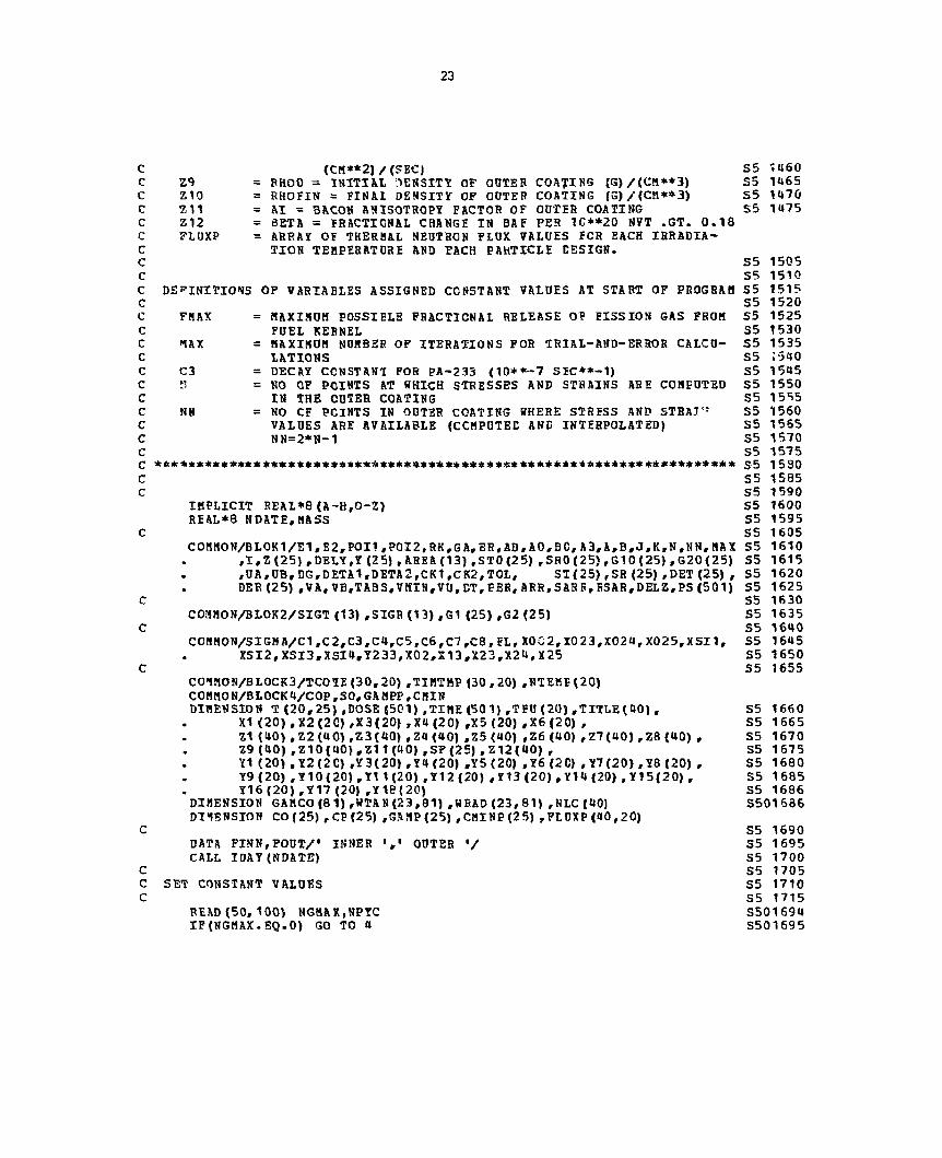
*****^*^m**it*^******************************************************** S5 1020 C S5 1025 C MAIN PROGRAM S5- V-B **** SCOTT INPUT FORMAT, 8/71 **** S5 1030 C *** MODIFIED 8/72 TC ACCEPT INTEGRAL TIME INCREMENTS (DATS), S5 1031 C *** READS TABULAR DIMENSIONAL-CHANGE DATA ******** S501031 C INDEPENDENT THERMAL CONDUCTIVITIES IN OUTER PIC, AND TO S5 1032 C PRINT EVERY NDLPRT'TH INCREMENT ************************** S5 1033 C *****MODIFIED AUGUST 197U BY K. H. VALENTINE TO REMOVE RESTRICTION C OF CONSTANT TEMPERATURE BOUNDARY CONDITION AT OUTER SURFACE OF C FUEL PARTICLE- ALSO THE DENSIFICATION EQUATION, CREEP COEFFICIENT C CALCULATION, AND THERMAL FLUX INPUT HAVE BEEN MODIFIED***** C S5 1035 £ ****************** S5 IOUO C S5 1045 C S5 1050 C DEFINITIONS OF VARIABLES READ IN, IN ORDER OF APPEARANCE. S5 1055 C S5 1060 C NSETS = NUHBER CF COMPLETE DATA SETS TO BE PROCESSED S5 1065 C IFREL = FISSION GAS RELEASE INDICATOR, IF IFREL = BLANK OR ZERO S5 1070 C USE RELEASE FRACTION SUPPLIED AS INPUT DATA, OTHERWISE S5 107r, C CALCULATE RELEASE FRACTION 5R0M DIFFUSION EQUATIONS S5 10S0 C JFLUX = NONZERO INTEGER IF SEPARATE FLUX DATA IS SUPPLIED. C SMAX = FAILURE STRESS FOR COATING (PSI). S5 1085 C TOL = FRACTIONAL CONVERGENCE TOLERANCE FOB ITERATIVE CALC. S5 1090 C VA = CONSTANT IN REDLICH-KWONG EQUATION CF STATE, S5 1095 C ( (ATM) * ( (DEG K)**0.5)*(CH*»6))/((G-nOL)**2) S5 1100 C VB = CONSTANT IN REDLICH-KWONG EQUATION CF STATE, S5 1105 C (CM**3)/(G-MOL) S5 1110 C DETO = INITIAL FRACTIONAL INCREMENT IN TANGENTIAL AND RADIAL S5 1115 C DERO CREEP STRAIN COMPONENTS, RESPECTIVELY S5 1120 C CI = CROSS SECTION FOR FISSION IN U-235 (BARNS) S5 1125 C C5 = CROSS SECTION FOR NON-FISSION CAPTURE IN U-235 (BARNS) S5 1130 C C7 = CROSS SECTION 70R AESCRETION IN U-23U S5 1135 C CU a CROSS SECTION FOR FISSION IN U-233 S5 11H0 C C6 = CROSS SECTION FOR NON-FISSION CAPTURE IN U-233 S5 1145 C C8 = CROSS SECTION POR ABSORPTION IN PA-233 S5 1150 C C2 = CROSS SECTION FOR ABSORPTION IN TH-232 S5 1155 C DT = TIME INCREMENT (DAYS) TO BE USED IN CA1CULATI0NS S5 1160 C NDT = NO. OF TIKE VALUES AT WHICH CALCULATIONS WILL BE MADE S5 1165 C NPRTNT = PRINTOUT INDICATOR, IF NPRINT IS NON-ZERO PRINT COM- S5 1170 C PLETE RADIAL DISTRIBUTION OF TEMPERATURE, STRAINS, AND 55 1175 C STRESSES AFTER LAST FLUENCE INCREMENT CALCULATED. S5 1180 C NDLPRT = PRINT COUNTER. IF NDLPRT IS BLANK CR ONE, PRINT EVERY S5 1181 C LINE OF OUTPUT. IF NDLPRT IS GREATER THAN ONE, PRINT S5 1182 C EV2RY NDLPRT'TH LINE. S5 1183 C NFUEL = NUMBER CF DIFFERENT FUEL COMPOSITIONS TO USE S5 1185 C XI = X00 = INITIAL ATOMS OF TH-232 FER ATOM OF HEAVY METAL S5 1190 C X2 = X023 = INITIAL ATCMS OF U-233 PER ATOM OF HEAVY METAL S5 1195 C X3 = X024 = INITIAL ATOMS OF U-231 PER ATOM OF HEAVY METAL S5 1200 C Xtt = X025 = INITIAL ATOMS OF U-235 PER ATOM OP HEAVY METAL S5 1205 C X5 = FVOL = FUEL VOLUME (CM**3) / (G-ATOM HEAVY METAL) S5 1210 C X6 = FPHI s FRACTIONAL POROSITY OF FUEL KERNEL S5 1215 C NTT = NUMBER OF IRRADIATION TEMPERATURES TO USE S5 1220

22
C T = IRRADIATION TEMPERATURE (DEG C) S5 1225 C Y1 = FL = THERMAL FLUX (10**13 NEUTRONS) /( (CH**2)* (SEC)) S5 1230 C Y2 = FATHER = RATIO OF FAST(ABOVE .18 BEV» TO THERMAL FLUX S5 1235 C Y3 = FETAC = UNRESTRAINED FAST NEUTRON EXPANSION IN S5 1240 C C—CRYSTALLITE DIRECTION IN CUTER COATING SD 1245 C MATERIAL, 1/(10**20 N/CS2 ABOVE 0.18 MSV) S5 1250 C Y4 = DENSK = DENSIFICATION COEFFICIENT FCR CUTER S5 1255 C COATING, 1/(10**20 N/CH2 ABOVE 0,18 MEV) S5 1260 C Y5 = CK1 = STEADY STATE CREEP COEFFICIEKT FOR OUTER COATING S5 1265 C (IN.) / ((IN.) *(PSI) * (10**20 NVT ABOVE .18 HEV)) S5 1270 C Y6 = CK2 = COEFFICIENT IN CHEEP RELATION (NOT NOW USED) S5 1275 C Y7 = E1 = YOUNG'S MODULUS OF OUTER COATING IN TANGENTIAL S5 1280 C DIRECTION (PSI) S5 1285 C Y8 = E2 = YOUNG'S MODULUS OF OUTER COATING IN RADIAL S5 1290 C DIRECTION (PSI) S5 1295 C Y9 = POI1 = POISSON'S RATIO FOR OUTER COATING, DELATING 35 1300 C TANGENTIAL STRAIN TO TANGENTIAL STRESS S5 1305 C Y10 = POI2 = POISSON'S RATIO FOR OUTER COATING, RELATING S5 1310 C 5ADIAL STRAIN TO TANGENTIAL STRESS S5 1315 C Y11 = ALF1 = PARALLEL-DIRECTION THERMAL EXPANSION COEFF. S5 1320 C FOR OUTER COATING, 1/(DEG C) S5 1325 C Y18 = ALF2 = PERPENEICULAR-DIRECTION THERMAL EXPANSION COEFE. S5 1330 C FOR OUTER COATING, 1/(DEG C) S5 1335 C Y12 = TC = DEPOSITION (ZERO-STRESS) TEMPERATURE FOR OUTER S5 1340 C COATING (DEG C) S5 13U5 C Y13 = EK = "SOUNG'S MODULUS FOR FUEL KERNEL (PSI) S5 1350 C Y14 = POIK = JCISSON'S RATIO FOR FUEL KERNEL S5 1355 C Y15 = ALFK = THERMAL EXPANSION COEFF FOR FUEL KERNEL 1/{DEG C) S5 1360 C Y16 = RFRA = EEACTION OF PISSION GAS RELEASED FROM FUEL KERNEL S5 1365 C Y17 = DPRIME = DIFFUSION PARAMETEB GOVERNING RELEASE OF S5 1370 C FISSION GAS FRCM FUEL S5 1375 C CO = INITIAL STEADY STATE CREEP COEFFICIENT C CP = VALUE OF STEADY STATE CREEP COEFFICIENT WHEN THE FAST C FLUENCE IS EQUAL TO GANI C AS A FUNCTION OF FLUENCE, THE STEADY STATE CFEEP COEFFI-C CIENT IS JOINED BY STRAIGHT LINES FROM CO TO CP TO CO/100 C NTEHP = NUMBER CF ORDERED DATA SETS OF THE FORM (TEMP,TIME) USED C TO DESCRIBE THE SURFACE TEMP. OF THE FUEL PARTICLE. C TCOTE = PARTICLE SURPACE TEMPERATURE (DEG-C) C TIMTMP = TIME FOR WHICH CORRESPONDING SURFACE TEMPERATURE C APPLIES (CAYS) C NAB = NUMBER CF COATED-PARTICIE CONFIGURATIONS TO USE S5 1380 C Z1 = BO = KERNEL DIAMETER (MICRONS) S5 1385 C Z2 = AO = BUFFER COATING THICKNESS (MICRCNS) S5 1390 C Z3 = AFO = OUTER CCATING THICKNESS (MICRCNS) S5 1395 C TITLE = ALPHANUMERIC DESIGNATION FOR GIVEN COATED PARTICLE S5 1«00 C ZU = RH01 = INITIAL DENSITY OF BUFFER COATING (G)/(CM**3) S5 1405 C Z5 = EPI = FRACTION OF TOTAL BUFFER-COATING POROSITY THAT IS S5 1410 C AVAILABLE TO ACCOMMODATE FUEL SWELLING AND FISSION S5 1415 C GAS S5 1420 C Z6 = CONCTG = THERMAL CONDUCTIVITY (RADIAL DIRECTION) OF S5 1425 C OUTER COATING («ATT) / ((CM) * (DEG C) ) , IF Z9 IS S5 1430 C LEFT BLANK, CONCTG IS TAKEN AS .05 S5 1435 C 11 = CONBUF = THERMAL CONDUCTIVITY (RADIAL EIRECTION) OF S5 1440 C BUFFER COATING (WATT)/( (CM)* (DEG C)), IF Z10 IS S5 1445 C LEFT BLANK, CONBUF IS TAKEN AS .0015 S5 1450 C Z8 = PER = PERMEABILITY OF OUTER COATING TC FISSION GAS S5 1455
23
C (CM**2) /(SEC) S5 1U60 C Z9 = FHOO = INITIAL DENSITY OF OOTER COALING (G)/(CM**3) S5 1465 C Z10 = RHOFIN = FINAL DENSITY OF OOTER COATING (G)/(Cil**3) S5 147G C 7,11 = Al = BACON ANISOTROPY FACTOR OF OOTER COATING S5 1475 C Z12 = BETA = FRACTIONAL CHANGE IN BAF PER 1C**20 NVT .GT. 0.18 C FLOXP = ARRAY OF THERHAL NEUTRON FLUX VALUES FCR EACH IRRADIA-C TION TEHPERATURE AND EACH PAHTICLE EESIGN. C S5 1505 C S5 1510 C DEFINITIONS OF VARIABLES ASSIGNED CONSTANT VALUES AT START OF PROGRAM S5 1515 C S5 1520 C FHAX = MAXIMUM POSSIBLE FRACTIONAL RELEASE OF FISSION GAS FROM S5 1525 C FUEL KERNEL S5 1530 C 1AX = MAXIMUM NOMBER OF ITERATIONS FOR TRIAL-AND-ERROR CALCU- S5 1535 C LATIONS S5 !540 C C3 = DECAY CONSTANT FOR PA-233 <10**-7 SIC**-1) S5 1545 C II = NO OF POINTS AT WHICH STRESSES AND STRAINS ARE COMPUTED S5 1550 C IN THE CUTER COATING S5 1555 C NN = NO CF POINTS IN OUTER COATING WHERE STRESS AND STRAIN S5 1550 C VALUES ARE AVAILABLE (CCMPUTEE AND INTERPOLATED) S5 1565 C NN=2*N-1 S5 1570 C S5 1575 C *&******************+***************+******:********************•******* s5 1530 C S5 1585 C S5 1590
IMPLICIT REAL*8(A-H,0-Z) S5 1600 REAL*8 NDATE,MASS S5 1595
C S5 1605 COHMON/BLOK1/E1,E2,POI1,P0I2,RK,GA,EH,AB,A0,BC,A3,A,B,J,K,N,NN,MA X S5 1610
,I,Z(25) ,DELY,Y (25) , AREA(13) ,ST0(25) rSR0(25),G10 (25) ,G20(25) S5 1615 ,UA,UB,DG,DETA1,DETA2,CK1,CK2,TOL, ST(25),SR(25),DET(25), S5 1620 DER(25),VA,VB,TABS,VKIN,VU,DT,FER,ARR,SARB,HSAR,DELZ,PS(501) S5 1625
C S5 1630 C0MM0N/B10K2/SIGT (13) ,SIGR (13) ,G1 (25) ,G2 (25) S5 1635
C S5 1640 CCMMON/SIGMA/C1,C2,C3,C4,C5,C6,C7,C8,FLr X0G2,X023,X024,X025,XSI1, S5 1645
XSI2,XSI3,XSI"»rY233,X02,X13,X23,X24,X25 S5 1650 C S5 1655
C01M0N/BL0CK3/TC01E(30,20) ,TIMTMP (30,20) ,NTEME (20) COMMON/BLOCK4/COP,SO,GAHPP,CMIN DIMENSION T(20,25),DOSE (501),TIME(501),TEU(20),TITLE(40) , S5 1660
X1 (20) ,X2(2C) ,X3(20) ,X4 (20) ,X5 (20) ,X6 (20) , S5 1665 Z1 (40) ,Z2(4C) ,Z3(40) ,Z« (40) ,Z5 (40) ,Z6 (40) ,Z7(40) ,Z8 (40) , S5 1670 Z9 (40) ,Z10(40) ,Z11 (40) ,SF(25) ,Z12(40) , S5 1675 Y1 (20) , Y2(2C) ,Y3(20) ,Y4 (20) ,Y5 (20) ,Y6 (2C) ,Y7(20) ,Y8 (20) , S5 1680 Y9 (20) ,Y10(20) ,Y1 1(20) ,Y12 (20) ,Y13 (20) ,Y14 (20) ,Y15(20) , S5 1685 Y16(20),Y17 (20) ,Yie(20) S5 1686
DIMENSION GAMCO(81),WTAN(23,81) ,WRAD(23,81) ,NLC(40) S501 606 DIMENSION CO (25) , CP (25) ,GAMP(25) rCMINP(25) , FL UXP (40 , 20)
C S5 1690 DATA FINN,FOUT/' INNER OUTER •/ S5 1695 CALL IDAY(NDATE) S5 1700
C S5 1705 C SET CONSTANT VALUES S5 1710 C S5 1715
READ(50, 100) NGMAX.NPYC S501694 IF(NGMAX.EQ.O) GO TO 4 S501695

24
DGAN=1. GAMCO (1) =0. DO 1 LG=1,NGMAX GAMCO (LG+1)=GAMCO(LG) + DGAM DO 2 LC0=1,NPYC READ (50, 108) LDU, (WTAN(LDU,LG),LG=1,NGMAX) CONTINUE DO 3 LCO=1,NP YC READ(50, 108) LDU, («RAD(LDU,LG) ,LG=1,NGMAX) CONTINUE
5501696 5501697 5501698 5501699 S501716
S501718
u FHAX=1. S501720 MAX=40 S5 1725 C3=2.93 S5 1730 N = 11 S5 1735 NN=2 1 S5 1740 Z(1) =0.D0 S5 1745 NN1= NN-1 S5 1750 DELZ=1./DFLCAT(NN1) S5 1755 DO 5 J=1,NN 1 S5 1760
5 Z(.1*1)=Z(J)+DELZ S5 1765 READ (50, 100)NSETS,IFREL,JFLUX S5 1770 HRITE(51,100) NSETS,IFREL,JFLUX
c S5 1775 c BEGIN CALCULATION FOB FIRST DATA SET S5 1780 c S5 1785
DO 90 KDATA=1,NSETS S5 1790 c S5 1795 c DATA INPUT S5 1800 c S5 1805
READ (50,101)SUAX,TOL,TA,VB,DETO,DERO S5 1810 WRITE (51,101)SB AX,TOL,VA,V8,DETO,DERO VMIN=1.1*V3 S5 1815 PS(1) =0. DC S5 1820 READ(50,107) C1,C5,C7,C4,C6,C8,C2 S5 1825 WRITE (51,107)C1,C5,C7,C«,C6,C8,C2 REAO(50,101) DT S5 1830 WRITE (51, 101) DT READ (50,100) NDT,NPRINT,NDLPRT S5 1835 WRITE (51,100) NDT,NPRINT,NDLPRT I F ( N D L P R T . 0 ) NDLPRT=1 S5 1836 TIME(1) = O.DO S5 1840 DOSE(1)=0.DO S5 1840 DO 10 1=2,NDT S5 1845
10 TIME (I) = TIME (I- 1) +DT S5 1850 c S5 1855 c DOSE IS IN UNITS OF 1.E20 NEUTRONS/SQ CM S5 1860 c TINE IS IN UNITS OF CAYS S5 1861 c S5 1865
READ(50, 100) NFUEL S5 1870 WRITE(51,100) NFUEL READ (50, 102) (X1(L),X2(L),X3(L),X» (L) ,X5(L) ,X6 (L) # L= 1, NFUEL) S5 1875 WRITE (51, 102) (X1(I) ,X2(L),X3(L) , x 4(L) ,X5 (L) ,L=1, NFUEL) READ (50, 100) NIT S5 1880 WRITE(51,100) NTT READ (50,10U) (1 (NT ,NN) ,NT=1,NTT) S5 1885 WRITE(51,104) (T(NT,NN) ,NT=1,NTT) READ(50, 105) (Y1(NT) ,Y2(NT) ,Y3 (NT) ,Y« (NT) ,Y5 (NT) , Y6(N7),Y7 (NT) ,Y8(N S5 1890

25
77
78
T) , Y9(HT) ,Y10(NT),Y11(NT),Y18(NT),Y12(NT),Y13 (NT), Y14(NT) rY15 (NT),Y16(NT) rY17 (NT),NT=1,NTT)
WRITE(51,105) (Y1(NT),Y2 (NT),Y3 (NT),Y4(NT),Y5(NT) ,Y6 (NT) ,Y7(NT),Y8 (NT) , Y9 (NT) ,Y10 (NT) ,Y11 (NT) ,Y18(NT) ,Y12(NT) ,Y13 (NT) , Y14(NT),Y15(NT), Y16(NT),Y17 (NT),NT=1,NTT)
READ (50,110) (CO (NT) ,CP(NT) ,GAMP (NT) ,CHINP (Nl) ,NT=1, NIT) WRITE (51,110) (CC(NT),CP(NT),GANP(NT),CHINP(NT),NT=1,NTT) CO 77 NT=1,NTT READ (50,100) NTEHP(NT) WRITE (51,100) NTEMF(NT) READ (50,109) (TCCTE (NTNP,KT),TINTMP (NTHP,NT),NTMP=1,NTE1P(NT)) WRITE (51,109) (TCOTE (NTMP,NT) ,TIBTKE (NTtIP, NT) , BTHP=1,NTEMF (NT) ) CONTINUE READ(50, 100) NAB WRITE(51,100) NAB READ (50, 106) (Z1 (NA) ,Z2(NA) ,Z3 (NA) ,TITLE(NA) ,Z4 (N A) , Z5 (NA) , Z6 (NA) ,
Z7 (N A) ,Z8 (NA) ,Z9(NA) ,Z10 (NA) , Z11 (N A) ,Z12 (NA) , NLC(NA) ,NA=1,NAB)
WRITE (51, 106) (Z1 (NA) ,Z2 (NA) ,Z3 (NA) , TITLE (NA) ,Z4 (NA) ,Z5(NA) , Z6(»A) , Z7 (NA) , Z8 (NA) ,Z9 (N A) ,Z10(NA),Z11 (NA) ,Z1<J(NA) ,NLC(NA) , NA=1,NAB)
IF (JFLUX.EQ.O) GC TO 79 DO 78 1=1,NAB READ (50,111) (FLUXP (I,J),J=1,NTT) WRITE (51,111) (FLUXP(I,J) ,J = 1,NTT) CONTINUE
S5 1895 S5 1900
C C C C C C
C c c
c c
S5 1905
S5 1910 S5 1915 S501920
BEGIN CALCULATIONS FOR EACH COATIKG CONFIGURATION
79 DO 80 NA=1,NtB
ESTABLISH COATED PARTICLE CONFIGURATION
AF0= . 5*Z 1 (NA) AO = Z2(NA)+AT0 BO = Z3(NA)+A0 RH01= Z4(NA) EPI =Z5(NA) CONCTG=Z6 (NA) C0NBUF=Z7 (NA) PER= Z8(NA) RHOO=Z9(NA) RHOFIN=Z10 (NA) Al = 7,11 (NA) BETA=Z12(NA) nASS=RHOO*(BO**3-AO**3) LCO=NLC(NA) GPHI= (2. 22-RH01) *EPI/2. 22
SUPPLY THERMAL CONDUCTIVITIES IF NOT READ IN
IF(CONCTG.EQ.0.) CONCTG=.05 IF(CONBUF.EQ.0.) CONBUF=.0015 CF1=1./(12.56636E-4+CONCTG) CF2=1./(12.56636E-4*CONBUF)
CALCULATE OUTER COATING DIMENSIONAL CHANGES PER E20 FAST NEUTRONS/CH*2
S5 1925 S5 1930 S5 1935 S5 1940 S5 1945 S5 1950 S5 1955 S5 1965 S5 1965 S5 1970 S5 1975 S5 1980 S5 1985 S5 1990 S5 1995 S5 2000 S5 2005 S5 2010
S502011 S5 2015 S5 20 20 S5 2025 S5 2030 S5 2035 S5 2040 S5 2045 S5 2050 S5 2055 S5 2060

26
C C c
c c c
RDO=RHOFIN-RH 00 82=2./ (2. •AX) R1=1.-.5*R2 AB0= AO/BO AF03=AF0**3
CALCULATE INITIAL FRACTIONAL FREE VOIOHE FOB FISSION GAS
V0= (1.-GPHI)* (A0**3-AF03)
BEGIN CALCULATIONS FOR EACH TEHPBRATUEE
DO 70 NT=1, NTT COP=CO (NT) $ GAMPP=GAHP(NT) « SO=(COP-CP(NT))/GAHPP CHIN=CNINP(NT) $ IF (CHIN. NE.O. 0) GO TO 19
35 2080 S5 2085 S5 2090 S5 2095 S5 2155 S5 2160 S5 2165 S5 2170 S5 2175 S5 2180 S5 2195 S5 2200 S5 2205 S5 2210
C SS 2220 C ESTABLISH MECHANICAL PROPERTIES SC 2225 c S5 2230
19 FL= Y1(NT) S5 2235 IF (JFLUX. NE.O) FL=FLUXP (N A # NT) FATHER=Y2 (NT) S5 2240 FETAC=Y3(»T) S5 2242 DENSK=Y4(NT) S5 2244 CK1= Y5(NT) S5 2246 CK2= Y6(NT) S5 2248 E1= Y7(NT) S5 2250 E2= Y8(NT) S5 2252 P0I1=Y9(NT) S5 2254 POI2=Y10(NT) S5 2256 ALF1 = Y11 (NT) S5 2258 ALF2 = Y18(NT) S5 2259 TC= Y12(NT) S5 2260 EK= Y13 (NT) S5 2262 POIK=Y14(NT) S5 2264 A1FK=Y15(NT) S5 2266 RFRA=Y16(NT) S5 2268 DPRIME=Y17fNT) S5 2270 FETA1=(1.-1.5*R1) *FETAC S5 2275 FETA2= (1.-1. 5*R2) *FETAC S5 2280 RK= (1.-2. *POIK) /EK S5 2300 SR= E1/(1.-POI1) S5 2305 ARR = E1/E2 S5 2320 SASR=DSQRT (ARR) S5 2325 RSAH= 1./SARR S5 2330
c S5 2335 c BEGIN CALCULATIONS FOR BACH FUEL COMPOSITION S5 2340 c S5 2345
DO 60 L=1,NFUEL S5 2350 c S5 2355 c ESTABLISH FUEL COMPOSITION, FLUX, AND GAS PRODUCTION PER UNIT BURNUP S5 2360 c S5 2365
X002=X1(L) S5 2370 X023=X2(L) S5 2375 X024=X3(L) S5 2380 X025=X4(L) S5 2385

FV0L=X5(L) S5 2390 FPHI=X6(L) S5 2395 AF3= (1. -PPHX)*AF03 S5 2400 FREV =(FPHI+GPHI*( (AO/APO)**3-1.) ) /(1.-FPHI) S5 2402 PROD=1.0053E-14*AF3/FVOL S5 2405
c PROD=1.0053E-14*AF3/FVOL
S5 2410 c SET DIMENSIONS AT STARTING VALUES S5 2415 c S5 2420
A=A0 S5 202*. B=B0 S5 2430 AB=AB0 S5 2435 AF=AF0 S5 2440
c S5 2445 c CALCULATE INITIAL COATING TEMPERATURE PROFILE ANE THERMAL EXPANSION S5 2450 c S5 2455
PFAC=7.0665E-6*AF3/FVOL S5 2460 DELTAR=(B-A) /EFLOAT (NN- 1) S5 2465 POWER=PPAC*(X025*C1+X023*C4) *FL S5 2470 R ADIUS=B S5 2475 POWER 1=PO If ER*CF1 S5 2480 POWER2=POWER*C72 S5 2485 TIME (1) =0.DO S5 2565 T (NT,NN) =TCOAT (TIME (1) , »<T) DO 25 JR=2,NN S5 2490 J=NN-JR+1 S5 2495 RADIUS=RADIUS-DELTAR S5 2500
25 T(NT,J) =T(NT,NN)•E0WER1*(B-RADKUS)/(B*RACIUS) S5 2505 TFU(NT) =T(NT,1)+POWEF2* (A-AF)/(A*AF) S5 2510 TABS=.5*(T(NT,1)+TFO(NT))+273. S5 2515 GA= ALFK* (TFO (NT)-TC) S5 2520 DO 30 J~1,NN 35 2525 G1 (J) =ALF1*(T (NT, J) —TC) S5 2530 DER(J)=DERO S5 2535 DET(J)=DETO S5 2540
30 G2(J)=ALF2*(T (NT, J)-TC) S5 2545 CEFR = .0086401*FL S5 2550 DC = CEFR*DT S5 2551 FA=FL*1.E13 S5 2555 DG=DD*FATHER S5 2560
c S5 2570 c TIME IS IN UNITS OF CAYS S5 2575 c S5 2580
CALL XS2(DOSE (1)) S5 2590 c S5 2595 c WRITE INPUT INFORMATION S5 2600 c S5 2605
WRITE(51,200) NA,NT,L,TITLE(NA) ,NDATE S5 2610 WRtTE(51,201) S5 2615 WRITE (51, 202) E1, POI1 r AX.F1 ,FETA 1,CK 1 ,PER,BO,E2, P0?.2, ALF2, FETA2, AO , S5 2620
EK,POIK,ALFK,FPHI,EPRIME, AFO S5 2625 WFITE(51 ,208) CONBUF,RHC1,EPI,GPHI,CONCTG,DENSK,Fj',TAC S5 2630 WRITE (51,203) X002,FVOL,RFRA,FA,FATHER,Al,AB0„FREV,TC, T(NT,NN), S5 2635
X023,X024,X025 S5 2640 WRITE(51,204) S5 2645 FBILX=FINN S5 2650
c S5 2655 c SET STARTING VALUES S5 2660

28
c SS 2Wi RHO »RHO0 SS 2670 GAS!1OL=0.D0 55 26«0 BURN=0.D0 55 26ft*> SIGTH«0.D0 SS 2^90 Y233=0.D0 SS HNNPR « 1 55 LGAHBA=2 SS02&«H TIRRsO.DO $ TOLD«C.DO
c SS 2700 c BEGIN CALCULATIONS FCB EACH FLUENCE 1WCSSWEST SS 2765 c
BEGIN CALCULATIONS FCB EACH FLUENCE 1WCSSWEST SS 2710
DO 50 1=1,NOT 55 2711 CALL SIGHftl(0.,G1,62,SIGT,SXCR) 55 2720 BURHO=BURH 55 2725 GO»GASMOL SS 2710 S0«SIGTH S$ 27J5
C C c c c
c c c
TPOLD»T(HT,ttH) ? <*T,HH> =»TCOAT (tlHS (I) , ST)
A COATTNG SURFACE TEHPR8ATORS OP IBSS T8*8 200 EIG. C IS t » m -PRBTED AS A FLAG TO INDICATE THAT TBI REACTOR IS SHOT CO»» FOR REPtlELING. NEOTRCK PtUX IS SET ?C«At TO fcEBO.
IF (T(MT,NN) . GT.2C0.) DOSE(I)bCBFR*TIRB FDOS»FATHBR*DQS8{3} IF{I.NS.1) GO TO 36
TIRR««TIBR»TXKE(I)-TOtC
C C C
CALCULATE STRESS AfiD STRAIN DIBECTLT FOB PtBST I RCRSKSHT
CALL SIGNAStO.OO.Gt.GZ^SIGT^SIGR) CALL THTBR(SIGR,K,S8) CALL INTER(SIGT,N,S?) ETA»SIGT(1)/BR-t?OI2*SIGB(1)/B2 ET8=SIGT(N)/2R UA=PTA*C1 (1) UB=ETB*G1(NN) UAK=GA A=A*t1.*0A) B»B* (1 .•UB) FFEL«0. RHOP^HASS/(B**3-A**3) SO TO 46
36 RHOP=HASS/<B**3-A**3> IF(IFREL.EQ.O) GO TO 44
CALCULATE FRACTIONAL FISSION-GAS RELEASE PROM KBRHEL I? IPREL NONZERO
DTP=DPRIHE*TIHK(I)*8.60E« IF(DTP.GT.0.06) GO TO 43 FREL = (2.2S676*CSQRT(DTP)-1.5*DTP)*P5AX
45 43
44
GO TO FREL
%
GO TO FREL
HJ = (1.-(.066667/DTP)*{1.-.92394*(DSXP(-9.86S6*DTP)•.0625*
DEXP (-39. 478* DTP) • .0123<»6*DEXP<-88.82«j*DTP> ) J )*PHAX f i C 45 = RFRA
SS 3126 55 2795 SS 27S0 55 27S5 55 27SC 55 2765 S5 2770 SS 2775 55 2780 35 2735 SS 2790 S5 2795 SS 2800 SS 280S SS 2810 SS 28 IS
S5 2820
SS 282S SS 2830 SS 2835 SS 2840 SS 284$ SS 2850 SS 2855 SS 2860 SS 2865 S5 2870 S5 2875 SS 2880

2?
f f { t C O . J t t . m CO TC .1.1 i r ( j i i > o . e » i i . o . ) eo t o 32
m a a m J f r c m i m t O £ 3 $ m c * t t 0 » Q? q n t l C Q A t t » R I f « * 9 t u m
8 «. fc 0 Q * f t £ X { - t l M * $ # » *t>0 S)
{ 3 .
T o 13 C m t t S t t S . He s * fcfinattfcaa^ucnJix
V GO TO 39
f t n » » ( i . » n r A i « 3 c * « j r « « » 2 - t t * i ) / { n * t i e * » i CO t o tS c c r r T i i U j :
?< ISH4Tt '0 f i t * « » I T I X C * t O « 0 V ' O * i
e c TO 3« t c M i f t a - t G - i
SHO* s a a o / ( 1 . *KttA* 3 .
CAtCM-AT* tSCfeSHSVTS X» nSt-»E3T»0*-I»fcaC5£» t>*«*KStO*AL ClIABGES I» o a t s * c « * t t # f i
o r r A 2 » < F « T A 2 - m * s x ) * 8 < ;
C O s m S S r o s t S t f t l L Z X C , FSSSJOii CAS PSOO0CT1C*, «SAT 6 £ 8 S ! ! m 0 ? < t»V?S, AHfi COflTIHC T S A P t B A T M S ? 3 0 ? I U
C A t t X 5 I ( O O S E ( 1 } } 8 t 3 j i } r » t O O . * { X S I U X S i a )
GASJtQl«6&*9*Q&s (8UUJt-jjyBSD) •fSSI. 0£t?AP«{»-A) » { I U
I F { T f 8 T , Htf) . 1 , 1 . 2 0 0 . ) ?a* i?8»G.OO BAt>rOS»l)
C I - X t F I * (T t * 7 -TtOfcOl • « ! <H») «2<NHJ » A t r 2 » ( T ( « T , 5 ) « ) - T P O t O ) *G2{St t ) HO 62 JR«2,S5»
- 1 2 . 3 3 1 * X S I 1 - t t . 7 7 » X S X 2 - 2 . 9 1 5 * X S t 3 »
$ rt 2 « a s 5 5 0 2 8 8 ^
JH 2 8 9 0 SS 289S SS ztco SS 290S SS 2 9 1 0 ss 2 < m
s«i 2 * 2 5 S S 0 2 9 1 0 S 5 0 2 9 3 2 SS029 J1 S S O m a
s s o 2 < m 5 5 0 2 9 3 7 5 5 0 2 9 3 8 5 5 0 2 9 3 9 S5<52<»*0
$ S 0 2 9 * 2 SS029<»3
S $ 0 2 9 « 5 SS02«»a6 S S 0 2 9 « 7 S S 0 2 9 « 8 SS029a«! SS 2935 S5 2 9 « 0 SS 2 9 8 S SS 2 9 5 0 SS 29SS SS 2 9 6 0 SS 296S SS 2 9 7 0 SS 2 9 7 5 SS 2 9 8 0 SS 2 9 8 5 SS 2 9 9 0 S5 299S SS 3 0 0 0 SS 3Q0S SS 3 0 1 0 SS 3 0 1 5 SS 3 0 2 0 SS 302S
SS 3 0 J 0 S5 3 0 3 5 SS 30U0
SS 30US

30
c c c
J*»N-JR*1 8ADIUS=RADIUS-DELTAR TPOLD=T(NT,J) T (NT.J)»T(NT,NN)•FOHER1*(B-RAOIOS|/(B*RADIUS) G1(4)*ALP1* |T (NT, J) -TP0LD) *G1 |J)
62 G2(J) »ALP2*(T(NT,J)-TPOLO)*G2(J) TPOLD=TPU(NT) TFU(NT)=T(NT,1) •PCWER2» (A-AP)/(A*AP) TABS®.5* (T(HT,1) •'IPO(NT)) >273. GA=ALPK»(TFO(NT)-TPOLD) *GA CJtl«CK1FUN (POOS)
CALCULATE PISSIOH GAS PRESSURE, COATING STRESS AND STRAIN
C C C
C C C C C
C C C
C C
CALL PCALC(GASMOL) 66 COKTINUE
DO 61 J»1,NN 61 SP (J) *DABS (ST (J) —SB (J) ) •SARR
CALL BIG(3F,NN,SIGTM,KB) DA=(A-A0)/A0 DB=(B-Bft) /BO AE=A/B
WRITE RESULTS POP EACH PLOENCE INCREMENT
TOLD«TIME (I) IF(I.MB,NNNPR) GO TO 501 WRITE(51y 205) I,TIME(I) ,FDOS ,BURN,TFU(NT),PS(I) , POWER,
DA, SIGT (1) ,DB,SIGT (N) ,SF (1) ,SF (NN) ,RHOP NNNPR = NNNPR+NDLPRT
501 IF((SIGTB.LT.SBAX).OR.(I.EQ.1) ) GO TO 50
IF EFFECTIVE CREEP STRESS EXCEEDS SMAX, STOP CALCULATION FOR THIS CASE AND WRITE OUT THERMAL FLUENCE, FAST FLUENCE, BURNUP (PCT FIMA), AND TIME AT FAILURE
09 SINTER=(SWAX-SO)/(SIGTH-SO) D0FAIL=D0SE(I-1) • (DOSE ( I)-DOSE (1-1) ) »SINTER CALL "SI(DOFAIL) B!JPAIL=100.» (XSI1 •XSIU) DOFAIL=DOFA3L«1.E20 FDOFAI =DOFAIX.»FATHER TIMEF=TIHE(I-1)•(TIME (I)-TIHE (1-1))*SINTER IP(KB.GT.I) FAILX=FOUT WRITE(51,206) PAIIX.DOPAIL,BUFAIL,FDOFAI,TIMEF GO TO 51
50 CONTINUE 1 = 1 - 1
51 IF(NPRINT.NE.O) WHITE (51,207) I , (J,T (NT,J) ,G1 (J) ,G2(J) ,ST (J) , SR (J) , SF (J) , J=1, NN)
60 CONTINUE
ENO OP CALCULATION FCR THIS FUEL COMPOSITION CASE
70 CONTIHUB
END OF CALCULATION PCR THIS TEMPERATURE
S5 3050 S5 3055
S5 3065 S5 3070
S5 3075 S5 3080 S5 3085 S5 3090 S5 3095 S5 3100 S5 3105 S5 3110 S5 3115 S5 3120 S5 3125 S5 3130 S5 3135 S5 3140
S5 3141 S5 3145 S5 3150 S5 3151 S5 3155 S5 3160 S5 3165 S5 3170 S5 3175 S5 3180 S5 3185 S5 3190 S5 3195 S5 3200 S5 3205 S5 3210 S5 3215 S5 3220 S5 3225 S5 3230 S5 3235 S5 3240 S5 3245 S5 3250 S5 3255 S5 3260 S5 3265 S5 3270 S5 3275 S5 3280 S5 3285

31
C S5 3290 80 CONTINUE SS 3295
C S5 3300 C END OF CALCULATION FCR THIS COATED PARTICLE CONPIGUBATION i>5 3305 C S5 3310
90 CONTINUE S5 3315 C S5 ?320 C END OF CALCULATION FCR THIS DATA SET S5 3325 C 55 3330 C FORMATS FOR INPUT S5 3335 C S5 3340
100 FORM AT(3110) S5 3345 101 FORMAT (F10.2,F10.6,F10.0,P10.3,2F10.6,2P10.3) S5 3350 102 F0RMAT(4F10.3/2F1C.3) S5 3355 104 FORMAT(F10.3) S5 3360 105 FORMAT(2F10.3/2F1C.3,E10.3,F10.3/2F10.0,2F10.3,2f10.9,10X,P10.0/ S5 3365
.F10.0,F10.3,F10.9»F10.3,E10.3) S5 3366 106 FORMAT(3F10.3.42X,A8/4F10.3,E10.3/4F10.3 ,110) SS 3370 107 FORMAT(4P7F10.3) S5 3375 108 FORMAT(I10/(6E12.6)) S503376 109 FORMAT (2F10.0) 110 FORMAT (2D10.3,F10.4,D10.3) 111 FORMAT (8F10.3)
C S5 3380 C FORMATS FOR OUTPUT S5 3385 C SS 3390
2000FORMAT(' 1' ,'CASE NO • 1 2 , ' - « 1 2 , 1 2 , 1 O X ' P A R T I C L E TYPE »A8,10X«DATE S5 3395 1 'A3///) S5 3400
201OFORMAT(IX*PROPERTIES YOUNGS MOD POISSONS EXP COEF FAST FLU S5 3405 1ENCE CREEP COEF FRACTIONAL PERMEABILITY RADII '/18X'P S5 3410 2SI*7X,RATIO'8X'/C'7X'EXPANSION /PSI E20NVT POROSITY•21X'MICR S5 3415 30NS'/2X* COATING*42X'/E2 0 NVT*) S5 3420
2020FORKAT(3X' TANGENTIAL ' 1PE10. 3,0PF9.3, 1PE 14. 3,E1 3.3,E1 4. 3, 6X, • S5 3425 1, E17.3,5X'OR *0PF7.1/3X'RADIAL'5X,1PE10.3,0PF9.3,1PE14.3,E13«3,8X, S5 3430 2 * — *10X'— '24X"IR',0PF7.1/92X*(D FRIME)'/2X'FUEL KERNEL«1PE11.3, S5 3435 30FF9.3,1PE14.3T32X,0PF5.3,1PE17.3,5X*0R«0PF7.1//) S5 3440
2030FCRMAT(' FUEL COMP SPECIFIC RELEASE FLUX FAST/ ANI S5 3445 1S0TR0PY OUTER COATING FREE VOL TEMPERATURES'/^' PCT S5 3450 2FUEL VOL FRACTION NV THERMAL FACTOR ID/OD S5 3455 3 RATIO DEPOSITION IRRADIATION«//2PF6.1,• 232TH»0PF8.2,F11.2 S5 3460 4, 1PE13.3, 0PF7 .3rF11.2,Fl5.4,Fl3.4 ,F9.0, ' C',F11.0,« C / 2 P F 6 . 1 , ' 23 S5 3465 53U'/F6.1,' 234U*/F6.1,' 235U'///) S5 3470
204OFORMAT(' INC TIME FAST BURNUP FUEL INTERNAL POWER I S5 3475 INNER TANGENTIAL OUTER TANGENTIAL EFF. CREEP STRESS DENSITY«/6X, S5 3480 2'BAYS FLUENCE PCT FINA TEME PRESSURE W/PART STRAIN STRE S5 3485 3SS STRAIN STRESS INNER CUTER 0UTER'/12X,»E20 N V T ' , 1 2 X S 5 3490 4,'DEG C PSI',15X,'IN/IN PSI IN/IN PSI PSI S5 3495 5 PSI COATING'/) S5 3500
205OFORMAT(1X,I3,F7.1,F7.2,F9.2,F9.1,F9.0,F10.5,F9.5,F9.0,F9.5,F9.0, S5 3505 1 F10.0,F8.0 3F9.3) S5 3510
2O6OFORMAT(1H0,/' COATING FAILED AT',A7,«SURFACE, THERMAL DOSE =«1PE11 S5 3515 1.3,' NVT, BURNUP =',0PF6.2,« PCT FIMA*/37X,'FAST DOSE ««1PB11.3,* SS 3520 2NVT, TIME =•,0PF6.2,® DAYS') S5 3525
2070FORHAT(1H1,' RADIAL DISTRIBUTION OF TEMPERATURE AND STRESS ACROSS S5 3530 10UTER COATING FOR FLUENCE INCREMENT NO. ',13////' RADIAL TEMP. S5 3535 2 TOTAL NOR-ELASTIC STRAIN # * * * STRESS, ESI * * * *•/• NODE S5 3540 3 DEG C TANGENTIAL RADIAL TANGENTIAL RADIAL CREEP' S5 3545

32
V / < l 5 , P 1 O . O , 2 * , 2 F l 2 . 6 # 2 X ( 3 r i Q . 0 l ) s 5 3 5 5 0
2080FOa*A?{2X'BUPPEB C O W 18E8S.COKO." * , F7. « li/C«-C, X*rt.OE»S« ,# SS 35S5
1P5.2,' C/CC, FBACt.POSOSITt M « l . * • ,FS-2, • , EPF. PQROSTTT"'F6 .3/ S5 3560 2/2X«OUTS» COAT 1HEB«-C0HD.»*,F?*tt»' tf/C»-C, CEIJSXFICATXO* CONST SS 3565 3A»?«*,r6.3,« /E20 »rr, FBACT.C-AXIS EXP.«« ,F6.3,« /E20 J>VT«//) S5 3570
SS 3 5 7 5 CALL EXIT SS 3580 STOP SS 3S3S F.Kfl SS 3590
ADOITIOHAI FUNCTION SUBROUTINES
DOUBLE PRECISIOH fONCTXOK TCOAT (?»IE ,»T) IMPLICIT REAL*6 (A-R,0-Z) C0MHON/BLOCK3/T(30,20) ,DAT (30,20) ,I«AX(20)
C C TCOAT CALCULATES fARTICLE SURFACE TEMFERATURE AS A FUNCTION OP C TIME (IN DATS). C
1 = 1 1 I=I»1 J IF (I.GT.IMAX(NI)) GO TO 2
IF (TIME.GT.DAT (I,HT)) GO TO 1 IM1=I-1 $ GO TO 3
2 TCGAT=T(INAX,NT) 1 RETC3H 3 TC0AT=T(IB1.H1)•(TIME-DAT(IB1,NT))•(T (I,NT)—T(INI,NT) )/(DAT(I,NT)-
DAT (IM1,NT)) RETURN END
DOUBLE PRECISION FUNCTION CKlEUN(EDOS) IMPLICIT REAL*8 (A-P,0-Z) CCBHON/BLOCKt/CO,?C,GAME,CMIN
C C CK1PUH CALCULATES THE CREEP COEFFICIENT AS A FUNCTION OF FAST C FLUEHCE. C
CK1FUN=CHIN $ IF (FDOS.LT.GAMP) CR1FUN=C0-SC*ID0S RETURN END

Data Arrangement for STRETCH, Modification 3Z

DATA PREPARATION GUIDE FOR STRETCH, MODIFICATION Y (August 1974) (Al l f o r m a t s are F10.0 un less specified otherwise)
cigp rs flioi ~ ~ ma
Or it CAPO wet p I**C >*.» wr$. ffrii. W CT 5rt*.MUt../? T
fyIF ip»f t= WOK* '«Oft U KHS'»1' «<fM IQ O A W "r'il CUrt
D " 4 friMC ifCRfwiNt <Mrti
[us* -iii
lv* cwo-»A>wac<"y 'wits iti tuxmAroA ««l at tutt
A'OM »» rutL •A'cm >H ruft Ct mtii
I.' MwWVMiU'
]uNt CMO-HUMBTft V OrriMKT »{ ANCW WUHN' 51 0» l|UP fO jtm u*S
FLTJA I <C'"NRF
i ~" fLu« SANO
Vits »AST «ur«OH STRAIN 'MwirrfAfioN ccirt'wt TC»ff P ooi»r<ci*t IEKJJI I
frtu»ics wooiaos'pv' " ««ij<i M»p<WMS _ W&OUTVS PVL
HWSCA6 !•«*** HAT© S*TCIC»>__ UJ GITCTCN y
• [ca»» **** (• (TLTCF COCRF TMLQM (AMNSA>»C*CI4 UMACHUN V FL&UN<JLS J0 FT* »LFL ^ __ [*UM«0 #«0M rutt _ jt*OV 'wl4
W i>
P„T,At C«fP CUIIKHM. , lt_tl » MFRNTTF*. »0«A W* T «
FJB'ACI FJMP R«C» Al CMP K" vr
IIMl (40 1
"'wHt CJ»0 ~L»M«P TAPM SF»
OF PI AT MR T'MLI
TX'CCNTSS <XTC* COAF ITQ TH<«MSS Jetvowto*
IttCfjS'fTO OR RMCR M /S <X*F>»C .'OT/FEA COITIV; /ITY* (I I'.OA'I'IO KflOlT 4vAii»BTC V O * '.W III" L _ L,,*5ES1 l i
M
« ffHtoMil co#»j)ucT<v'iTr ] V Vwi^ f f •* a •iMC !<j(/reff COITiV: (Auf't* X; t »03- n wr/
—r ' FMTCOEHCTL V tOOtfR CO*t»NO FITCOH IH>YP*OI>I ricfLH \F*ICRC»*LI \HIMA « I
_ —— f ~ T J —•

35
Sample Input for Modification V (Used for HT-12 through HT-I5 Calculations)
toost.oa •it.Mt 1.0* 1»J I I.Ht >«.•» I iais.no 090.900 112.000 B.010 1000000, t i i tnu .
JJS.OOO s.oio toooooo. 29000009. 0.1000*91 o.iooo-oi
0 1 o.aooioo tuo«or>. 01.009 11.130 10.190 •11.099 •.000410 <0.000
0.00*4(0 •1.100
i.»IS 0.0)0 S.1900-M 3H»n. 0.159 0.191.000991219 O.HI O.CIO 0.1000-C6 • 000099. e.i'.i 9,))i .o«nit;i o. iooo>9f JOO.OT:; i, o.iooo-;< 299.9:39 a.
O.HO. 099001 J11.000005577 1.000 0.1100-00
0.250.059905111.00000157? 1.990 0.1100-01
12 1M5. 0. 1095. 21. 100. 29. 1150. 25. 1190. • 9. 100. •«. 12*5. 59. 1)15. 11. 109. M. 1115. 75. 1X5. 99. too. 99. 1160. 109. 11*0. 121. 100. 111. 1175. 125.
1«0S. 1»9. 100. !•», 1150. iso. 1100. in . 100. i»«. 100. 200. 22 . 1190. 0. IMS. 21. 100. 21. • ••0. 25. 1«5S. • 9.
100. • 9. 1510. 50. 1515. 71. 100. 71. 1925. 75.
1390. 99. 100. 91. 1950. 109. 19 IS. 121. ioo. 121. 1(«S. 125. 1610. 199. 100. 1»1. 192S. 150. 1S90. 171. 100. 171. 100. 200. 16 •95.030 39.000 119.909 i.ota 1.090 0.0 0.0 1.950 2.200 1.110 9.001 501.000 15.030 •9.013
1.100 1.000 0.0 0.0 1.090 2.290 i.:53 0.001 • 01.000 20.090 21.0)1 MOO 1.0D0 0.9 0.0 1.990 2.290 1.350 0.091 •05,000 91.090 79.M0 1.260 1.090 0.3 a.o 2.000 2.290 l . l l t 0.001 • 01. ooo 25.090 50.032 1.100 1.090 0.9 0.0 2.010 2.;oo 1.050 9.091 SI 1.000 90.990 71.330 1.100 1.090 0.0 0.0 1*620 2.200 1.1>0 0.001 •02.000 11.000 36.&30 1,100 1.000 0.0 0.0 1.920 2. 200 1.050 o.oos S09.000 79.094 75.000 1. 100 1.000 0.0 0.0 1.990 2.200 1.950 O.OOI S09.000 91.000 75.93C 1.080 1.000 0.0 0.0
1.9«0 2.290 1.013 0.001 •02.000 12.000 69.939 1.100 1.000 0.0 0.0 I.96Q 2.200 1.050 0.001 SO 1.000 92.000 67.03C 1.000 1.000 O.O 0.0 2.000 2.200 1.53 0 0.001
•J53-09
I1I110
onto*
9152-00
011990
9152-00
0«17«9
0119*1
•252-02
011939
•252-01

36
Sample Input for Modification V (Used for HT-12 through HT-15 Calculations)
(continued) •02-030 21.000 11.030 0lt(2t 1. 100 1.000 0.0 0.0 0.0 2.010 2.200 t.oso 0.001 • •u.ooo •1.000 11.090 « « • « «. 110 1.000 S.0 o.o 0.0 2.020 2.200 1.1(0 o.otl 0 >02.000 1.000 11.030 011110 1.100 1.000 0.0 0.0 0.0 2.010 2.200 f.059 0.031 0 •<5.000 x.oos so.oo: «252-«» 1.0)0 1.000 o.o o.o 0.0 1.1it 2. 200 1.23C 0.001 0 1(2.000 1.000 21.000 s u m 1.100 1.000 0.0 0.0 0.9 1.020 2.200 1.050 0.001 0 ITS. 000 211.200 1ST.OOO 211.000 111.000 IOO.OOO 2TS.OOO 310.000 211.000 111.000 220.000 111.000 l i t . 000 122.090 2*2.000 123.000 202.000 125.030 231.000 122.000 22«-000 311.000
111.000 111.090 203.000 110.000 111.000 100.000 1IT.00S 211.000 1T5.000 211.000
I

37
Sample Output from Modification V
CISC II 1- 1- 1 H1TICU IB! "252-01 D1TB 11-06-71
ttomriu TOBBBS BOB IOXBSOBS «x» cosr H3T n.0E*cz CI EE? cosr nicno>»i n u u u u T i B1BII MI • mo /c ZIfilSIOl /PSI l i l lR miosm i taso
COftTXBg /B20 KTT 0> >1)7.} ITBCETTIU b.OOOO 06 0.250 5.3110-06 - i . U I M I 1.OOOff-97 —— B.B 0> >1)7.} •1011L •.oooo et e.xu S.5770-0* 1.33ID-03 (B r«mr>
i i n i t n u n 2. BOOB 0? 0.302 B.200D-0C a. o 3.2000-09 01 lll.S
mrrtt CO»T Tnr.nn.cons.- e.oois veii-c. I»IS.B»m- I.OB o/cc, W»CT.M»<wiit» »«»it.» i.BB, ipp.ro9or.nl- o.5i« m i l COIT TKOI.COIO.. o.osoo • /«< • onnnctnn eo»si»IT" o.oso /tio BIT. PB»CT.C-»IU NR.- o.03«i /tio ITT
NZL CORF icr 100.0 232TB O.O 3339 O.e 3110 0.0 3150
BPZCIPIC rotL tot
i s i u i rmcrioi n n BT m v TI I IUl i n n n o n MCXOB
1.7500 13 S.IilS
coin C01TMC id /oo
rase rot TEBPEBITOIIS UIIO D2M31TIOI IMTBILIIOI
tic Ti l l n n BOBPBP FOB. i m i u i POll IB IftPBB T<M<1<TIM. OOTfcB TllBBBTIll irr. enzr STBBS OIHSITT uis PIOIBCB ret r m Kir n n i n i W/TIBT STU» mass 3791II JIIUS I9RSI OOTSB 001X9
S20 I I I BSC C RI W/TIBT i«/i« PSI IB/IB HI PSI PSI C01TJBB i 0. .0 0.0 O.L. 1035. 0 0. 0.0 -0, ,00113 62. •0.00115 ••a. 62. ft*. 1, 957 2 1, ,0 0.63 o.oo 103C. ,5 0. 0.00051 -0. ,00310 -1211. -0.00269 960* 1211. 960. 1. ,957 3 2. .0 1.2* o.oo 103 8. 2 0. 0.00206 -0, 00502 •2302. -0.00016 163", 2302. 1630. 1, ,960 ft 3. .0 I.BB 0.00 10ft 0. 2 1. 0 .00**8 00690 -3238. -0.00559 2299. 3237. 2298. 1. 972 9 ft, .0 2.5T 0.00 10*2. 5 i . 0.4S770 .A, ,0087FT -ft 003. •0.00698 2870. 0001. 207 0. 1. ,979 t 5. .0 3.1* 0.00 10FT«. 9 3. 0.1116FT -4. 01C43 -•737. -0.00833 3363. •73FT. 3343. 1. 996 7 t, ,0 3.76 0.01 10H7. ,5 ft. 0.01621 "3. '.•J29 -5337. -0.00963 3791. 5)32. 3791. 1. 912 0 7, .0 9.39 0.01 1950. 2 7. 0.C2M5 -0. CIJOL -5847. •0.01089 • 163, 5050. Olt). 1. 999 9 8. ,0 5.02 0.02 1053. ,0 11. 0 .FL.-iiS -0. 01570 -6 31B. -0.O1212 • •99. 6299. >>88. I . ,005 10 9, ,0 5.65 O.02 1055. 9 16. -'.0.M05 -0. 01735 -6705. •0.01330 • 77ft. 6689. >77 ft. 2. 011
11 10. ,0 6.27 0. 03 105B. .9 22. 0.05151 -0. 01897 -7040. •O.OIOftS 5027." 7029. 5027. 2. ,016 12 11, .0 6.90 O.OFT 1061. 9 29. 0.0rS29 -0, ,02055 -7140. -0.01557 5253. 7324. 5243. 2. 022 13 12, .0 7.53 0.05 1061. 9 39. 0.05336 -0. 02211 -7622. -0.01665 »». 749ft. 5ft5t. 2. >0*7 1» 13, .0 a.16 0.06 1069. 0 <9. 0.06 067 -0. 02363 -7959. -0.01770 5600. 7810. StftO. 2. 0)2 15 1ft, .0 Q.7S 0. 07 1071. ,1 63. 0.06910 -0. 02513 -9069. -0.0187 2 5109. 9006. 5809. 2. 017 It 15.0 9.ft1 0. 09 107k. 2 78. 0.07596 -0. .02660 -9244. • 0.C1970 596ft. 8177. 5961. 2. .012 17 16, .0 10.0« 0.11 1077. 3 96. 0.09367 -0. 0200FT —9021, -0.02066 6109. 9325. 6109. 2. 0*6 15 17, .0 10.67 0.12 1090. ,ft 119. 0.09159 -0. ,02906 -0549. -0.02159 62*6. 6041. 6216. 2* 051 15 10, .0 11.29 0.1ft 1093. .5 1>3. 0.09959 -0. ,03090 -9700. •0.02208 6377. 9547. t377. 2. 045 20 19, ,0 11.92 0.17 1096, 5 171. 0.10765 -0, ,03 221 -9915. -0.02336 350ft. OtBft. I50FT. 2. 059 21 20. .0 12.55 0.19 1089. .5 20ft. 0.11573 -0. 03355 -8917. -0.02020 6629. 9713. 6 629. 2. 063 22 21, .0 13.18 0.21 1092. 5 ,201. 0.1236FT -0. 03O07 -9006. -0.02502 6750. 974ft. 6750. 2. 066 21 22, ,0 13.80 0.2ft 1095, ,ft 29FT. 0.1J193 -0. 03616 -90^1. -0.02592 6871. 8797. 6971. 2. ,070 2ft 23, .0 1ft.>3 0.27 1099. 3 313. O.lftOQI -0. ,037«3 —91JO. -0.02659 699ft. 8911. 999FT. 2. 073 25 2>, .0 1ft.«3 0.27 100. ,0 70. 0.0 -0. 03879 -9590. -0.02700 6967. 9502. 6967. 2. .076 26 25 .0 15.06 <1.30 1180. ft • k2. 0.1*905 -0. ,03995 -9221. -0.02911 7222. 9790. 7223. 2. ,090 27 It, .0 15.69 0.33 1167.2 515. 0.15605 -0, iQft!16 -9233. -0.02902 7 309. 8719. 73«9. 2.003 29 27 .0 16.31 0.3S 1170, ,0 599. 0.14379 -0. ,00235 -9230. -0.02952 7*9ft. 9431. 7*8 ft. 2. .086 27 29 .0 16.9ft O.ftO 1192. .7 695. 0.17195 -0. .00351 -9211. -0.03019 7626. 8516. 7626. 2. .018 3? 27 .0 17.57 O.ftl 117 5, ,3 005. 0.17763 -0, ,00<,65 -9170. -0.0309ft 7779. 8349. 7779. 2. .011 31 JO, .0 16.20 0.ft7 1197.9 911. 0.19733 -0.00576 -9116. -0.031*6 79B3. 8196. 79ft 3. 2. .041 32 31, .0 11.12 0.51 1200. ,ft 1075. 0, 19*90 -0, , 0ft66ft -90)0. -0.01206 0120. 79«0. 9120. 2, ,096 33 32, .0 0.55 1202.9 12«0. 0.?02*5 -9. , 0ft790 -9925. -0.0126FT 83D. 7694. 9313. 2. ,096 3* 11 .0 20.01 o.to 1205. ,3 1«11. 0.20194 -0, ,00992 -9790. -0.O1119 8424. 7141. 9425. 2, , 100 39 3>, ,0 20.71 O.tft 1207, 7 1650. 0.2171ft -0, Oft 990 -9606. —0.03)72 8759. 6956. 9759, 2, ,102 56 K .0 21.33 0.69 1210. .0 1903. 0.22031 -0. . 05095 -839FT. -0.03022 9014* 6ft01. 9016. 2. 100 37 36 .0 21.96 0.73 1212. ,3 2116. 0.23137 -0. ,05176 -011FT. -0.03»69 9303. 5918. 9303. 2. , 1C6 J9 37, .0 22.59 0.78 1210. ,6 253a. 0.23931 -0. ,05342 -7705. -0.0351• 9620. 5251. 9421. 2.107 39 39, .0 23.22 0.93 1211. ,8 2925. 0.21513 -0, ,0S3ftft -7391. -0.03555 9995. FT«66. 9995. 2. ,199 «0 39, .0 23. 0" 0.99 1219, 0 3375. 0.25103 -0. ,04020 -6921. -0.0119) 10319. 3506. 10309. 2. 110 • 1 •0, .0 2«.«7 0.9FT 1221. .2 3992. 0.24990 -0. , 04ft90 -6)69. -0.01629 109ft). 2«75. 1090 3. 2. ,112 <2 • 1, .0 25.10 0.99 1223. ,3 0092. 0.26080 -0. -5723. -0.01660 11350. 1201. ID'.O. 2. .113 • 3 • 2, .0 25.73 1.05 1225. .5 5111. 0.27116 -0. ,05609 -•99FT. -0.03699 11913. 162. 11913. 2. ,11* ft* • 3. ,0 26.35 1.10 1227. 6 5086. 0.27735 -0. ,05658 - f t 151. -0.03712 12511. 1736. 12531. 2. 11FT >5 ftl, .0 26.98 1.16 1229. .7 6695.. 0.243«1 -0. .05699 -3230. -0.03732 13200. 3ftt5. 13200. 2, ,115 • 6 • 5, .0 27.61 1.22 1231.9 7562. 0.29935 -0. ,05732 -2217. -0.037FT8 13911. 5325. 13911. 2.116 »7 • 6, .0 20. 2> 1.29 1230. ,0 8170. 0.29516 -0. ,05757 -1192. -0.03760 10652. 7279. 11652. 2, ,116 •a • 7, .0 20.86 1.35 1236. ,2 9)99. 0.3009O -0. .05775 -119. -0.03770 15*09. 9280. 15*09. 2. 117, • 9 • 9, .0 29.99 l.ftl 1238.3 10329. 0.306*1 -0, ,05796 95ft. -0.03776 16163. 11283. 16163. 2, ,117 SO • 9, .0 59.09 1.81 100. 0 11U. 0.0 -0. ,06107 -10593. -0.03929 9332. 9<>9. 93*2. 2. ,117 51 50. ,0 30.12 1.FT7 1302. , 1 1300O. 0.3110FT -0. .0S919 •606. -0.03796 10523. 19006. 19523. 2, ,121 52 51, .0 30.75 1.5ft ' 1306. ,2 1»220. 0.31716 -0, , oseo7 5ft96. -0.03793 19162. 19716. 19162. 2. ,117 53 52, .0 31.37 1.40 1309. .ft 1»907. 0.32235 -0.05793 6270. -0.03779 19732. 21178. 19732. 2. .117 50 IS, .0 32.DO 1.67 1310. ,7 15522. 0.32703 -0. .05775 6946. -0.0377ft 20209. 22076. 2020 9. 2, ,117 » 5ft, .0 32.63 1.7« 1312, .9 16071 . 0.33230 -0, .05753 7559. -0.M767 20710. 236)0. 2071ft. 2. .117 St 55, .0 33.26 1.91 1315. ,1 16557. 0.33723 -0. .05733 808O, -0.03759 21133. 20601. 21133. 2. .117 57 St, .0 33.88 1.99 1317. 3 16995. 0.3ft196 -0, ,05709 8539. -0.037FT9 21510. 2552ft. 21510. 2, .117 56 57 .0 3ft.51 1.95 1319. ,5 17343. 0.30657 -0, .05693 8930. -0.01739 31B>«. 26243. 21008. 2. ,117 59 5ft .0 35.1FT 2.02 1321, ,7 17610. 0.35107 -0, ,05645 9243. -0.03727 22152. 26957. 22152. 2, .117 60 59 .0 35.77 2.10 1323. ,9 1799ft. 0.34507 -0, .05637 9507. -0.03715 22026. 275)1. 22>26. 2, ,U7 61 60, ,0 36.39 2.17 1326. ,1 19239. 0.35976 -0, ,05597 9765. •0.03702 22673. 29025. 2267 3. 2, .117 <2 61, .0 37.01 2.25 1329. ,3 19>tft. 0.16)90 -0. .05566 9996. -0.03699 22997. 29119. 22997. 2, .116 63 U .0 37.65 2.32 1330, • ft 19660. 0.16902 -0, ,0553ft 10152. -0.03673 23100. 29913. 23100. 2, .116 «• 61 .0 39.20 2.*0 1 >12. ,6 IHOJFT. 0.37199 -0, ,04401 10270. -0,01657 23296. 2912FT. 23296. 2, .115 65 Aft .0 10.90 2.BO 1110, .7 10907. 0.17597 -0, ,04069 10002. -O.OLTFTO 21*57. 291119. 21047. 2, .115 ET 65 .0 39.53 2.5t 1116, .9 19122, 0.)7"65 -0, .050)3 10 ftl 2. -0.0)423 23610. 2941ft. 2361FT. 2, .115 47 66 .0 • 0.16 2.6ft 1330, .9 H1IJ. 0.39)1ft -0 .04)40 10543. -0.0)600 23760. 29006. 2)760. 2. ,11FT <> 67, .0 • 0.79 2.72 1JFT 1. ,0 193*9. 0.30693 -0. ,03162 10618. -0.03595 23095. 29947. 23995. 2.113 «9 6B .0 • l.ftl 2.90 13»3, ,0 19005. 0.31040 -0, ,04)26 10659. -0.03566 2002). 30100. 20023. 2, ,113 70 61 .0 • 2.0ft 2.FiS 1305. . 1 195)1. 0.1D93 -0 ,05299 10687. -0.03505 2ol«). 30219. 20103. 2, .112 71 70 .0 • 2.67 2.It 1507. , 1 moo. 0.39716 -0, ,04!4I 10 706. -0.03520 2o246. 30)10. 20256. 2, ,111 •12 71 .0 • 1.30 3.0FT 1109, ,1 19679. O.ftO0)9 -0. .04210 10715. -0.03503 2* 16ft. 3J39ft. 2036*. 2, .110 73 72 .0 • 1.92 V13 1351. ,2 197B3. 0.00340 -0, .05174 10716. -0. Oloot, 20047. 30049. ' '20*1.7. 2, .110 7* 71, .0 •ft.55 3.21 1J53, .2 19002. 0.00661 -0 ,051)6 10712. -0.01O47 2*567, 3051FT. 20547. 2, , 109 75 7ft .0 • ft. 55 3.21 100. ,0 1Q70. 0.0 -0, .04669 11072. -0.0370) 10062. 10101. 10962. 2. .109 76 75 .0 >5.10 3.10 1309, ,5 21060. 0.40960 -0, ,05120 129ft3. -0.01027 26026. 30003. 26026. 2. .110 77 74, .0 • 5.81 3.38 1J95, ,7 21752. O.ft1251 -0 .04077 12712. -0.01001 21,002. 30063. 26002. 2. .105 79 77, .0 • '..1.1 3.07 1.197, ,7 21406, O.FT1410 -0 •»5012 12017. -0.01)75 24909. 3O0O)• 25109, 2, .100 79 70 .0 •7.06 3.'.5 119 7, ,7 21*192. 0.01910 -0, . r„4n7 12191. -0.0)LFT 9 24FL). 3367). 2491). 2. .10)

38
Sample Output from Modification V (con't)
ao 74.0 49 1,44 0,a2078 -0.0 2 -0.01122 25841. 25(191. 2.102 ei nt>.o 12 1.71 0.42139 -0.03997 -0.01295 25800. 25800. 2. 101 i l ai.o 94 1.02 3.4259a -0.0 2 . -0.01267 25879. 25679. 2.190 a) «j.o S7 1.91 0,42841 -0.0 7 -0.0)2)1 25888. . 25909. 2,091 la ai.o 20 a.on 0,4 309. 2 -0.01210 25903. 2S40). 2.097 as ««.o S) a.09 0.41114 -0.0 7 -0.01180 25925. . 25425. 2.094 H »s.o as a. 14 0.4isa) -0.0 ) -o.onsi 25952. 2S952. 2.045 «7 84.0 09 a.27 0.4)755 -0.0 8 -0.01120 254115. 25K15. 2.09) •a 87.0 71 a. 16 a. 0.4)989 -0.0 1 -0.03090 25022. 24022. 2.992 a* an.o 14 a.as 0.4410a -0.0 a -0.0)058 24042. 26062. 2.090 <0 ai.o '4 a.sa 0.44191 -0.0 1 -0.01027 26106. 26106. 2.099 n 90.0 54 a.41 . 0.44S91 -0.0 7 -0.0299S 25152. 44sl 26152. 2.997 12 '1.0 22 a.71 0,44753 -0.0 2 -0.02962 26201. 26201. 2.095 t) 92.0 as a.02 0.44970 -0.9 7 -0.02929 242S2. 25252. 2.094 9* >1.0 • 7 a.91 0.451S2 -0.0 1 —0.02894 26305. 24305. 2.082 91 !>.0 10 S.oi 0.4S12S -0.0 6 a. -0.02842 26159. 26351. 2.180 H 45.0 7) 5.10 0.45499 -o.o 0 —0.02828 26a IS. 26415. 2.079 9T 95.0 IS 4.20 0.4S666 -0.0 5 -0.02791 24072. 24472. 2.077 98 97.0 9a 3.24 0,45828 -0.0 9 -0.02758 26530. 265)0. 2.075 99 99.0 91 S. 19 0.4S9BS -0.3 1 -0.02723 24590. 2S590. 2.07) 100 14.0 (1 S.19 0.0 -0.0 1 -0.02170 11944. 1194a. 2.071 101 >01.0 24 S. 48 0.46117 -0.0 8 -0.02682 27460. 27440. 2.C77 102 101.0 07 9.5a 0.4628S -0.0 - •0.024aa 27487. 0. 27487. 2.067 101 101.0 49 s.w 0.a»»28 -0.0 7 -0.02607 2147B. 27979. 2.065 10. 101. 0 12 S.77 0.46S68 -0.0 7 —9.02549 27477. 27477. 2.06) 10S 10a.0 75 S.B7 0.4* »01 -0.0 7 —0.02531 27402. 27482. 2.061 tot 105.0 la 5.97 o.a6aia -0.0 8 -0.0-a92 27494. 27«44. 2.959 101 101.0 00 4. OS 0.4S961 -0.0 9 -0.02053 27511. 27511. 2.057 ton lOT.O 41 «.1( 9.47084 -0.0 9 -0.02aia 27511. 27531. 2.055 K9 104.0 29 4.24 9.47201 -0.0 1 -0.02373 275S9. 27S51. 2.03) 110 104.0 aa 4.14 0.47319 -0.0 2 -0.02)33 27S89. 27599. 2.0S1 111 110.0 SI 4.46 0.47411 -0.0 1 -0.92795 27421. 27423. 2.949 111 111.0 14 4.55 0.475)1 -0.0 a •0.02255 27I.-.1. 27 459. 2.046 111 111.) 77 4.45 0.a744a -0.0 6 -0.02219 27449. 27491. 2.044 11a 111.0 40 4.75 0,a77a6 -0.0 9 -0.02171 217.0. . 277.0. 2.04.' IIS 1li.O 02 4.95 0.a7ftaa -0.0 9 -0.071)2 2778a. 17764. 2.040 114 115.0 45 4.44 o.479ao -ft, ft 1 -9.02090 27* 10. 27810. 2.037 i l l 114.0 2« 7. IIS a.4nnn -11.ft 1 -0.0.-oat 27(178. 2747(1. 2.01S 1 id 1 17 , ft 91 7.IS 411 9,44170 -ft.ft '.a -0.(12004 2712(1. 27424. 2.0.11 119 114.0 « T.25 0.4-IJ04 -0.0 (14 -o.oiiaa 27977. 27917. 2.010
110 119.0 14 9.>5 1« O.aijni -0.0 t . -0.01421 20021. 211024. 2,024 111 I1J.0 79 7.4S U 0.49149 •0.0 0 -0. 01(174 2(1002. . 2H0H2. 2.025 •22 121.0 • 2 7. SS 0.4naa4 -O.fl 2 -o.oinis 24116. 24116. 2.021 111 121.0 04 7,45 o.5«'.2i .0.0 & -0.01791 29191. 28191. 2.020 11 a 111.0 47 9.73 o.aassi -0.0 4 -0.017a7 24245. 28 245. 2.018 US 121.0 47 1. 75 0.0 -0.0 9 •0,02009 12946. 12944. 2.015 111 US.9 10 M l 9.49542 -0.0 a -0.01701 29618. 28618. 2.020 127 i2».e 91 7.94 0.447:9 -0.0 2 -O.OISSS 28493. 24 69). 2.010 •la 117.0 SS • . 04 9,48792 -0.0 2 -0.01410 28721. 28723. 2.407 119 129.0 19 a, 16 0,49054 -0.0 7 -0.01S4S 28740. a. 28760. 2.003 110 129.0 ai 0.24 a. 0.48911 •0.0 1 -0.01SI9 28795. 28795. 2.C02 Hi 119.0 • 4 a. 14 0.48970 -0.0 1 -0.01971 28014. 2a014. 1.949 IJj 111.0 04 «.44 . 9.49025 •0.0 a -0.01424 29874. 24876. 1.947
111.0 49 0.57 0.49077 •0.0 S -0.01180 28910. 0. 28918. 1.994 iia 111.0 12 4.67 I 0.49127 -0.0 6 •0.011)1 24942. 29962. 1.491 us lla.O 94 9.77 0.49I7S •0.0 7 •0.01284 24008. . 21009. 1.999 IM 11S.0 57 a. 97 ; 0.a»221 -0.0 a -0.01238 24056. 24054. 1.946 >11 l l l ,« 20 0.90 0.49243 -0.0 1 -0,01191 29101. 29101. 1,461 119 1)7.0 91 9.09 0.44106 -0.0 1 -0.01143 29 IS). 29151. 1.180 119 1)1,9 44 9.1a O.allaa —4,0 2 -0.0109S 24202. 29202. 1.977 110 114.0 09 9.28 . O.aaisa -0.0 a -0.01046 2423). 29253. 1.975 1>1 140.0 71 4.19 0.a4»20 -o.o S -0.0099a 29304. . 29304. 1.972 111 lal.o 14 a.aa O.aaasa -1.0 7 -0.00949 21357. 30020. 29357. 1,969 !«1 l>2.0 97 9.59 9.49a84 -0.0 1 -o.coaoo 29411. 29411. 1.946 laa lal.o S' 9.49 0.a9S17 •0.0 1 •0.00930 29464. 29464. 1,441 US 144.0 27 9.80 O.aisas -c.o 2 -0.00901 21511. 24519. 1.960 1a4 111,3 as 9.90 0.49S71 -0.0 la -0.00731 21/74. . 21574. 1.957 147 14*-. 0 aa 10.00 0.49S99 •0.0 4 -0.CQ701 24410. 21410. 1.15a 148 147.0 10 10. t l 0.49422 -0.0 « -0. 06-150 24694. 29696. 1.151 1.9 149.0 7) 10. 2 • 0.49444 •0.0 1 •O.OOaOO 24741. 21741. t.iaa ISO 144.0 71 10.21 9.0 -0.9 a -0.00447 14011. 14031. 1.94S 151 iso.o 14 10.11 0.494F5 -0.0 ft •o.onssa 2754). 1 21561. 1.150 142 151.0 99 10.al 9.494H4 -0.9 0 , -0.00*02 21474. 42. 2147a, 1.131 HI 1*1.0 41 10. SI 0.41701 •0.0 1 -0.00451 24742. 29742. 1.114 14a ui.o 2a in, 42 1,14111 -o.o 7 •O.rnaQO 2*11' 10. 25410, 1.115 155 1M,0 117 M. 71 o.a'1712 -0,0 n -U,0'I14(1 27517. , 21917. 1,110 15« liv.a 49 in. 4| 4,«*>7.5 -ft.4 a -II.ml 244 21".9. 24*1.4, 1.727 IM 154.11 1/ 111.41 1 1 I M -II.0 1 -ll,n>W44 Id II 111, lilliill. 1.121 111* 151,11 l» 11,<I4 ,1 ir.1 -Il ,«l 1 •«,«" !•!„ t,111 fa. 1 ,4 211 l»i 15a.rt 14 11.14 H.41MI • II, 4 .H.iiiil It in 1 in. 1,1 1 in. 1.111 lan 1'.1.P nl I1,,'l i . t t ;n*. • n.n n in,. I'l 1, 1 '1 /'( 1, 1,714 in IMI.II «1 11. 1-. l . i u i l •n.n > • ft, ll'll 11 M .-'.5. l'W.5. 1.1 11
2« ll.as 0,.*»7*»7 -n.a *, 11 1 11. in 1 m. 1 ,91ft IH i«:.o • 9 11. SS o.amoi •0,0 9 0.f(ifi7a 30191. 10 17 J. 1.9114 Ha 191.0 52 11.44 o.amoa -0.0 1 0,00127 10454. 30454, 1.151 165 1*4,0 14 11.74 0.49005 -0.0 4 0.00191 30519. 30519. 1,490 164 lts.0 77 11.84 9.49804 -0.0 0 0.00214 33582. . 10562. 1.995 111 144.0 40 11.17 0.49004 -0.0 a 0,03290 30545. 1044 5. i.an in 197.0 01 12,07 9.49904 -a.o 9 0.30143 39707. 30707. 1,888 lav 144,0 44 17.17 O.al-ifll -0.0 2 0,03490 10749. 1.845 ITO 144,0 lit 17,79 9.44714 •Daft r. 0.0(1454 101111. 19411. 1,881 111 1 tn.o al 12,14 1,49741 -1.0 4 1,1)1111 11411, 14411, 1.4 14 111 171.B 44 12,an II..97117 -9.0 1 , B.ftn547 1(1415, 1(1455, 1,475 111 14 12.4a Hnl, •1,41 In <1 -n.c n ft, II'1421 110 15, 111114, 1.411 Via 111,11 ii ; 0.41 III -11 ; 0,011 mill il'i In, 11 ii! n. 1.444 111 1 f 1,0 79 12.44 9.U '0.11 a . 0.904 11 15J48, tsiaa. 1,944
Copyright © 2022 FDOKUMEN