Modeling TCP SACK performance over wireless channels with semi-reliable ARQ/FEC
32
INTERNATIONAL JOURNAL OF COMMUNICATION SYSTEMS Int. J. Commun. Syst. (2011) Published online in Wiley Online Library (wileyonlinelibrary.com). DOI: 10.1002/dac.1230 Modeling TCP SACK performance over wireless channels with completely reliable ARQ/FEC Roman Dunaytsev ∗, † , Dmitri Moltchanov, Yevgeni Koucheryavy and Jarmo Harju Department of Communications Engineering, Tampere University of Technology, P.O. Box 553, Tampere, Finland SUMMARY In this paper, we propose an analytical cross-layer model for a Transmission Control Protocol (TCP) connection running over a covariance-stationary wireless channel with a completely reliable Automatic Repeat reQuest scheme combined with Forward Error Correction (FEC) coding. Since backbone networks today are highly overprovisioned, we assume that the wireless channel is the only one bottleneck in the system which causes packets to be buffered at the wired/wireless interface and dropped as a result of buffer overflow. We develop the model in two steps. At the first step, we consider the service process of the wireless channel and derive the probability distribution of the time required to successfully transmit an IP packet over the wireless channel. This distribution is used at the next step of the modeling, where we derive expressions for the TCP long-term steady-state throughput, the mean round-trip time, and the spurious timeout probability. The developed model allows to quantify the joint effect of many implementation- specific parameters on the TCP performance over both correlated and non-correlated wireless channels. We also demonstrate that TCP spurious timeouts, reported in some empirical studies, do not occur when wireless channel conditions are covariance-stationary and their presence in those measurements should be attributed to non-stationary behavior of the wireless channel characteristics. Copyright 2011 John Wiley & Sons, Ltd. Received 10 October 2009; Revised 22 November 2010; Accepted 22 November 2010 KEY WORDS: TCP; wireless; ARQ; FEC 1. INTRODUCTION The Transmission Control Protocol (TCP) is the de facto standard transport protocol for providing a reliable end-to-end data transfer service over best-effort IP networks. Recent measurements show that about 90% of today’s Internet traffic is carried by TCP [1]. Since TCP controls the vast majority of bytes and packets traversed over the Internet, predicting TCP behavior in various environments and optimizing its performance is extremely important for satisfying user needs and providing quality of service (QoS) in modern networks. The massive deployment of wireless networks has attracted a lot of attention of researchers and practitioners to the TCP performance in wireless and wired-cum-wireless environments (e.g. see [2–4] and references therein), both because the widespread use of TCP on the Internet and because wireless networks used to transport TCP traffic present very different characteristics from those TCP was tuned to. As long as wired networks are highly reliable and much less than 1% of all packet losses can be attributed to transmission errors, TCP assumes that all losses are due to ∗ Correspondence to: Roman Dunaytsev, Department of Communications Engineering, Tampere University of Tech- nology, P.O. Box 553, Tampere, Finland. † E-mail: [email protected].fi Copyright 2011 John Wiley & Sons, Ltd.
Transcript of Modeling TCP SACK performance over wireless channels with semi-reliable ARQ/FEC

INTERNATIONAL JOURNAL OF COMMUNICATION SYSTEMSInt. J. Commun. Syst. (2011)Published online in Wiley Online Library (wileyonlinelibrary.com). DOI: 10.1002/dac.1230
Modeling TCP SACK performance over wireless channels withcompletely reliable ARQ/FEC
Roman Dunaytsev∗,†, Dmitri Moltchanov, Yevgeni Koucheryavy and Jarmo Harju
Department of Communications Engineering, Tampere University of Technology, P.O. Box 553, Tampere, Finland
SUMMARY
In this paper, we propose an analytical cross-layer model for a Transmission Control Protocol (TCP)connection running over a covariance-stationary wireless channel with a completely reliable AutomaticRepeat reQuest scheme combined with Forward Error Correction (FEC) coding. Since backbone networkstoday are highly overprovisioned, we assume that the wireless channel is the only one bottleneck in thesystem which causes packets to be buffered at the wired/wireless interface and dropped as a result ofbuffer overflow. We develop the model in two steps. At the first step, we consider the service process of thewireless channel and derive the probability distribution of the time required to successfully transmit an IPpacket over the wireless channel. This distribution is used at the next step of the modeling, where we deriveexpressions for the TCP long-term steady-state throughput, the mean round-trip time, and the spurioustimeout probability. The developed model allows to quantify the joint effect of many implementation-specific parameters on the TCP performance over both correlated and non-correlated wireless channels.We also demonstrate that TCP spurious timeouts, reported in some empirical studies, do not occur whenwireless channel conditions are covariance-stationary and their presence in those measurements shouldbe attributed to non-stationary behavior of the wireless channel characteristics. Copyright � 2011 JohnWiley & Sons, Ltd.
Received 10 October 2009; Revised 22 November 2010; Accepted 22 November 2010
KEY WORDS: TCP; wireless; ARQ; FEC
1. INTRODUCTION
The Transmission Control Protocol (TCP) is the de facto standard transport protocol for providinga reliable end-to-end data transfer service over best-effort IP networks. Recent measurements showthat about 90% of today’s Internet traffic is carried by TCP [1]. Since TCP controls the vast majorityof bytes and packets traversed over the Internet, predicting TCP behavior in various environmentsand optimizing its performance is extremely important for satisfying user needs and providingquality of service (QoS) in modern networks.
The massive deployment of wireless networks has attracted a lot of attention of researchersand practitioners to the TCP performance in wireless and wired-cum-wireless environments (e.g.see [2–4] and references therein), both because the widespread use of TCP on the Internet andbecause wireless networks used to transport TCP traffic present very different characteristics fromthose TCP was tuned to. As long as wired networks are highly reliable and much less than 1% ofall packet losses can be attributed to transmission errors, TCP assumes that all losses are due to
∗Correspondence to: Roman Dunaytsev, Department of Communications Engineering, Tampere University of Tech-nology, P.O. Box 553, Tampere, Finland.
†E-mail: [email protected]
Copyright � 2011 John Wiley & Sons, Ltd.

R. DUNAYTSEV ET AL.
network congestion and invokes congestion control procedures every time a packet loss is detected[5]. As a result, TCP reduces its sending rate in an attempt to alleviate the congestion. It is worthnoting that the current stability of the Internet largely depends on this TCP congestion controlmechanism. However, the situation is much more complicated in wireless and wired-cum-wirelessnetworks, where, in addition to packet losses induced by buffer overflow, TCP encounters lossesand abrupt delay variations occurring due to unreliable nature of wireless transmission media.Unfortunately, TCP cannot distinguish packet losses due to bit corruption in wireless channelsfrom those due to network congestion, so any packet loss or excessive delay caused by wirelesschannel impairments lead to unnecessary execution of the TCP congestion control algorithms and,hence, sub-optimal performance.
Being inherently prone to transmission errors, wireless networks take advantage of differenterror control techniques to alleviate the effects of non-congestion-related losses on the TCP perfor-mance. Among the most commonly used are Automatic Repeat reQuest (ARQ), Forward ErrorCorrection (FEC), and their combination (also known as hybrid ARQ/FEC). In ARQ, the receiveruses an error-detecting code, typically a Cyclic Redundancy Check (CRC), to detect whether areceived frame is in error or not. If the received frame is error-free, the sender is notified bysending a positive acknowledgment. If an error is detected, the receiver discards the received frameand notifies the sender via the feedback channel by sending a negative acknowledgment (or bythe lack of a positive acknowledgment). In response to the negative acknowledgement (or if thesender does not receive the positive acknowledgment before the timeout), the sender retransmitsthe corresponding frame. There are three types of ARQ in use: Stop-and-Wait (SW), Go-Back-N(GBN), and Selective Repeat (SR). SW is the simplest ARQ scheme and ensures that each trans-mitted frame is correctly received before sending the next one, whereas GBN and SR ARQ allowtransmitting a number of frames continuously without waiting for an immediate acknowledgement.In GBN ARQ, when a certain frame is received in error the sender retransmits all frames, startingfrom the incorrectly received one. According to SR ARQ, only incorrectly received frames shouldbe retransmitted. Obviously, when the wireless channel conditions are relatively ‘bad’ (e.g. dueto short-term fading, long-term shadowing, mobility of mobile terminals, surrounding obstacles),ARQ introduces significant delays in data delivery due to multiple retransmissions. In contrast toARQ, FEC uses certain codes that are designed to be self-correcting for errors occurred duringtransmission. Thus, the receiver can detect and correct errors (but only within certain limits)without requiring a retransmission. However, this is achieved at the expense of greater bandwidthoverhead than that in ARQ: adding more redundant information reduces the amount of availablebandwidth but enables the receiver to correct more errors. Owing to complementary advantages,FEC and ARQ are often used in combination. But even in the presence of these local errorrecovery mechanisms, transmission errors may still propagate to the higher layers, resulting inloss or excessive delay of IP packets and, consequently, TCP segments encapsulated into thesepackets [6].
As long as the choice of ARQ and FEC parameters may severely affect the TCP performance,their interaction with TCP has been extensively studied during the last decade. The studies reportedto date can be split into two broad classes: simulation and measurement studies (e.g. [7–9]) andanalytical modeling. Although experiments are extremely useful in performance evaluation, it is adifficult task to simulate and explore the TCP behavior across the range of all possible operationalconditions and different settings of lower-layer protocols. In this case, analytical modeling isextremely beneficial because it allows to study the performance of TCP over the entire parameterspace and very easily apply a ‘what if’ test to different scenarios.
In [10–12], the authors explored long-term steady-state behavior of a TCP connection in wired-cum-wireless networks. These studies use a simple two-state Markov chain to model the packetloss process directly and do not attempt to derive it from stochastic properties of the wirelesschannel characteristics. Moreover, the vast majority of TCP analytical models require the end-to-end packet delay and the packet loss rate to be given. However, a cross-layer model capable topredict the TCP performance from primary network characteristics (e.g. the raw data rate of thebottleneck link and the bottleneck link buffer size) together with statistical characteristics of thewireless channel would be more usable.
Copyright � 2011 John Wiley & Sons, Ltd. Int. J. Commun. Syst. (2011)DOI: 10.1002/dac
MODELING TCP SACK PERFORMANCE OVER WIRELESS CHANNELS
Recently, a big effort has been done to model the TCP performance as a function of the wirelesschannel characteristics, the amount of FEC, the ARQ persistency, etc. In [13], the authors studiedthe combined effects of FEC, SR ARQ, and power management on the TCP throughput. It wasshown that increasing the transmission power, FEC redundancy, and the number of retransmissionsallowed for the ARQ scheme always improves the TCP performance by reducing the number ofnon-congestion losses. The performance of TCP over a wireless channel implementing hybrid SRARQ/FEC and shared by a number of long-lived TCP flows has been considered in [14]. Usingthe Bernoulli loss model to model non-congestion losses induced by wireless channel impairments,the authors provided results for different characteristics of the wireless channel and for differenttraffic loads. It was shown that the throughput of the wireless channel is an increasing function ofthe persistency of ARQ. In [15], the authors analyzed the TCP throughput over a wireless channelwith NAK-based SR ARQ in the presence of correlated errors at the physical layer. They observedthat the TCP throughput mainly depends on the throughput limit of the wireless data link layer,the residual error probability after data link layer retransmissions, and the correlation degree ofthe residual errors. An analytical model, capturing the joint effect of SR ARQ and FEC on TCPperformance over a correlated Rayleigh wireless channel, was presented in [16]. One of the mainadvantages of the model is that it uses wireless channel-related characteristics (the signal to noiseratio and the Doppler shift) to parameterize the service process of the wireless channel, while theother models [13–15] require the frame error rate to be given.
In this paper, we consider the performance of a TCP SACK connection running over a wirelesschannel with completely reliable ARQ/FEC as a function of the bit error rate (BER), the normalizedautocorrelation function of bit error observations at lag 1 (lag-1 NACF), the strength of the FECcode, the use of ARQ, the size of protocol data units at different layers, the raw data rate ofthe wireless channel, and the bottleneck link buffer size. The wireless channel characteristics areassumed to be covariance-stationary and modeled by a homogenous Markov process. The noveltyof the proposed model is two-fold. First, the model allows to evaluate the joint effect of stochasticproperties of the wireless channel characteristics and various implementation-specific parameterson the TCP performance over both correlated and non-correlated wireless channels. Second, themodel explicitly takes into account packet losses due to buffer overflow at the Internet layer andthe high correlation between the TCP window size and the round-trip time (RTT). Among otherconclusions, we demonstrate that TCP spurious timeouts, reported in some empirical studies, donot occur when wireless channel conditions are covariance-stationary and should be attributedto non-stationary behavior of the wireless channel characteristics. This paper is a revised andsubstantially extended version of the work presented in [17].
The remainder of this paper is organized as follows. The system model and the assumptionswe made are described in Section 2. The analytical cross-layer model is introduced in Sections 3and 4. Numerical results are discussed in Section 5. Finally, Section 6 concludes the paper.
2. SYSTEM MODEL AND ASSUMPTIONS
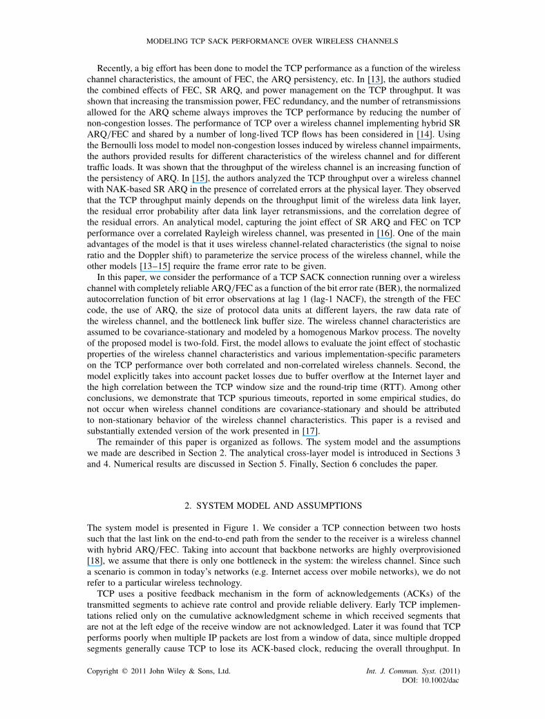
The system model is presented in Figure 1. We consider a TCP connection between two hostssuch that the last link on the end-to-end path from the sender to the receiver is a wireless channelwith hybrid ARQ/FEC. Taking into account that backbone networks are highly overprovisioned[18], we assume that there is only one bottleneck in the system: the wireless channel. Since sucha scenario is common in today’s networks (e.g. Internet access over mobile networks), we do notrefer to a particular wireless technology.
TCP uses a positive feedback mechanism in the form of acknowledgements (ACKs) of thetransmitted segments to achieve rate control and provide reliable delivery. Early TCP implemen-tations relied only on the cumulative acknowledgment scheme in which received segments thatare not at the left edge of the receive window are not acknowledged. Later it was found that TCPperforms poorly when multiple IP packets are lost from a window of data, since multiple droppedsegments generally cause TCP to lose its ACK-based clock, reducing the overall throughput. In
Copyright � 2011 John Wiley & Sons, Ltd. Int. J. Commun. Syst. (2011)DOI: 10.1002/dac
R. DUNAYTSEV ET AL.
TCPInernet
DLInternet
TCPInternet
modem modem
App. App.Sender Receiver
Intermediate system
wireless channel
DL DL DL
Sender Receiver
Intermediate system
IP packets carrying TCP ACKs
IP packets carrying data traffic
PHYPHY PHYPHY
wired network
Figure 1. System model.
order to improve the TCP performance during loss recovery in the face of bursty losses, the Selec-tive Acknowledgement (SACK) option, the use of the SACK option for acknowledging duplicatepackets (the D-SACK extension), and the SACK-based loss recovery algorithm have been specifiedin [19–21], respectively. Using selective acknowledgments, the receiver can inform the senderabout all segments that have arrived successfully (including non-contiguous and duplicate blocksof data), hence, the sender needs to retransmit only those segments that have actually been lost.Since the current status is that nearly all TCP implementations now support the SACK option[22], we assume that the sender and the receiver are both SACK-capable and use the SACK optionunder all permitted circumstances.
We consider an application process which always has data to send; hence, the sender alwayssends full-sized TCP segments (i.e. containing MSS bits of application layer data) whenever thecongestion window (cwnd) allows. It is assumed that the TCP receive buffer is sufficiently largeand, consequently, the actual sending rate of the TCP connection is not limited by the receivewindow size. We also assume that the time needed to send a window of segments is smaller thanthe total RTT. These assumptions are justified for modern high-performance computers. Since weare focusing on the performance of a single TCP connection running over a wireless channel, wedo not consider here competing traffic effects and assume that application layer data are transmittedin one direction only: from the sender to the receiver (Figure 1).
Let the round-trip delay of the wired network be � seconds, the raw data rate of the wirelesschannel be � bits per second, and the buffer size of the intermediate system be B full-sized packets.Data packets are buffered at the Internet layer of the intermediate system and transmitted oneafter another to the data link layer. The queue management algorithm is assumed to be First-In,First-Out Drop-Tail, so any packet arriving when the buffer is full will be lost. However, we do notmodel packet losses in the direction from the receiver to the sender and assume that TCP ACKsare always delivered to the sender. In other words, packet losses happen only in the direction fromthe sender to the receiver due to buffer overflow at the intermediate system. We believe that theimpact of this omission is quite small because the cumulative nature of TCP ACKs ensures thatthe most recent ACK can cover all previously received data.
Between the Internet and data link layers IP packets are segmented to a number of frames. ThenFEC block coding is applied and the frames start to be transmitted. A data block composed ofboth data and FEC redundancy bits is called a codeword. In this paper, we assume that the terms‘frame’ and ‘codeword’ refer to the same entity and each frame consists of exactly one codeword.Additionally, we assume that exactly one bit is transmitted using a single channel symbol anduse the terms ‘channel symbol’ and ‘bit’ interchangeably. Since extensions of the model for thecases with multiple codewords within a frame and/or multiple bits carried by a single symbolare straightforward, these assumptions are not fundamental and can be relaxed when needed. Theprocess of encapsulation and segmentation of protocol data units is shown in Figure 2.
The size of IP packets and frames is assumed to be constant. This assumption is not restrictiveas long as only a single TCP bulk data flow is assumed to be active at a time. Moreover, frames
Copyright � 2011 John Wiley & Sons, Ltd. Int. J. Commun. Syst. (2011)DOI: 10.1002/dac

MODELING TCP SACK PERFORMANCE OVER WIRELESS CHANNELS
MSS bitsTransport layer
1 2 3 v
Application layer dataHeader
Header
Internet layer MTU bits
Data link layer
TCP segment
IP packet
Segmented IP packet
Frames(FEC codewords)
...
1 2 v
m bits
3 ...
FEC redundancy bits
Figure 2. Encapsulation and segmentation.
are usually of fixed-size. The ARQ scheme is assumed to be completely reliable, thus a frame isalways delivered irrespective of the number of retransmissions it takes. However, if the number ofdata link retransmissions causes the RTT to exceed the current value of the TCP retransmissiontimeout (i.e. RTO seconds) [23], the TCP retransmission timer expires, leading to a spurious TCPtimeout followed by unnecessary retransmissions and congestion control procedures invocation.It is important to note that talking about ‘completely reliable operation’ here, we neglect thepossibility that one of the devices fails or connectivity is entirely lost for some reason.
We assume that the ARQ receiver immediately sends back a feedback frame (carrying either apositive or a negative acknowledgement) about every incoming data frame it gets. This assumptionallows to use a single model to capture different variants of ARQ, including the SW, GBN, and SRmodes [24, 25]. Finally, we assume that the wireless channel in the reverse direction is completelyreliable and that feedback frames are delivered instantaneously over the wireless channel. Indeed,feedback frames are usually small in size and well protected by an FEC code. Moreover, theseassumptions were used in many studies and found to be appropriate for wireless links with a shortpropagation time [26, 27].
3. SERVICE PROCESS OF THE WIRELESS CHANNEL
3.1. Bit error model
In this paper, we represent the bit error process of the wireless channel using a covariance-stationarytwo-state Markov modulated process. Using the relatively simple algorithm outlined below, it ispossible to capture first- and second-order statistical characteristics in terms of the BER and thelag-1 NACF. Note that extension to the case of a general finite-state Markov chain (FSMC) andits variants are straightforward [28].
We model the bit error process using a two-state Markov modulated process. Let {WE (l), l=0,1, . . .}, WE (l)∈{0,1}, denote the model with the modulating Markov chain {SE (l), l=0,1, . . .},SE (l)∈{0,1}. The model is completely defined using the set of matrices DE (k), k=0,1, containingtransition probabilities from state i to state j with or without incorrect reception of a channelsymbol. To parameterize a covariance-stationary binary process, only the mean and the lag-1NACF have to be captured. In our previous work, it was shown that there is a unique switchedBernoulli process (SBP), matching the mean and the lag-1 NACF of covariance-stationary bit errorobservations [29]. This model is given by
�E = (1−KE (1))E[WE ],
�E = (1−KE (1))(1−E[WE ]),
{f1,E (1) = 0,
f2,E (1) = 1,(1)
where �E and �E are transition probabilities from state 1 to state 2 and from state 2 to state 1,respectively; KE (1) is the normalized autocorrelation coefficient of bit error observations at lag 1
Copyright � 2011 John Wiley & Sons, Ltd. Int. J. Commun. Syst. (2011)DOI: 10.1002/dac
R. DUNAYTSEV ET AL.
(lag-1 NACF); E[WE ] is the mean of bit error observations (BER); f1,E (1) and f2,E (1) areprobabilities of error in states 1 and 2, respectively.
Details of the algorithm are outlined in [29].
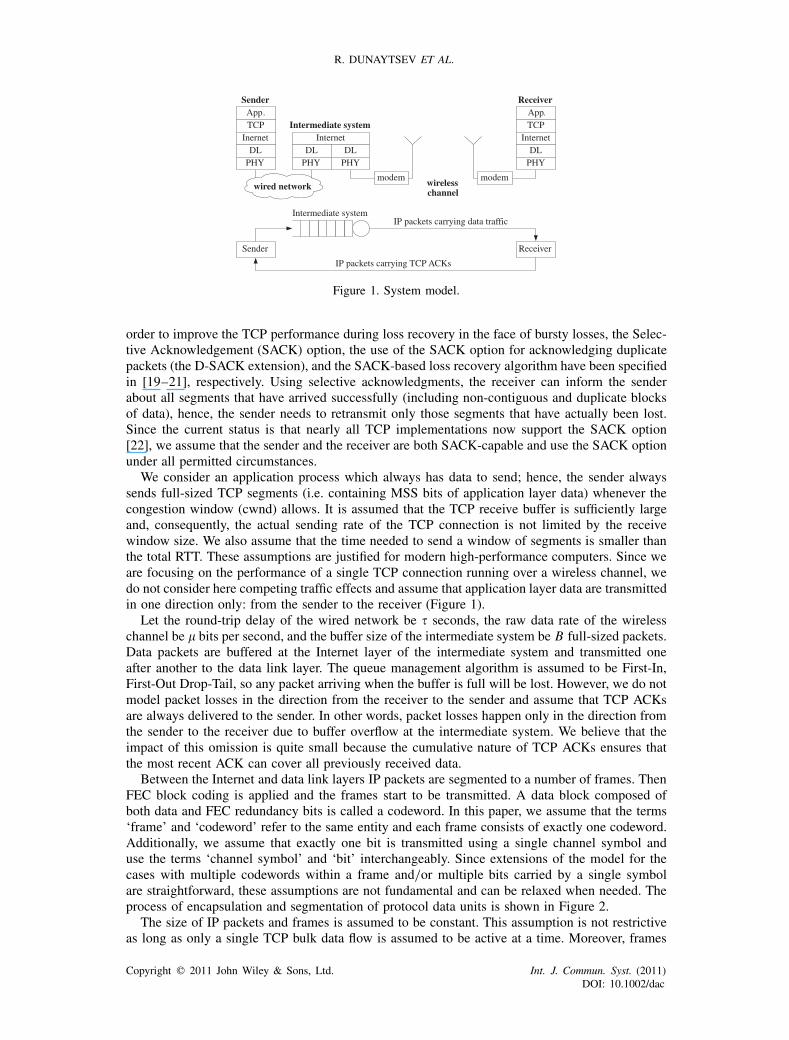
3.2. Frame error model
Let the frame length is constant and equals to m bits (Figure 2). Consider the stochastic process{WN (n),n=0,1, . . .}, WN (n)∈{0,1, . . . ,m}, n= lm, describing the number of incorrectly receivedbits in consecutive bit patterns of length m. This process is doubly stochastic, modulated by theunderlying Markov chain {SN (n),n=0,1, . . .} and can be completely parameterized via parametersof the bit error process {WE (l), l=0,1, . . .} as shown below.
To parameterize {WN (n), n=0,1, . . .}, we have to determine m-step transition probabilitiesof the modulating Markov chain {SE (l), l=0,1, . . .} with exactly k, k=0,1, . . . ,m, incorrectlyreceived bits. Denote the probability of transition from state i to state j for the Markov chain{SN (n), n=0,1, . . .} with exactly k, k=0,1, . . . ,m, incorrectly received bits in a bit pattern oflength m by dN ,i j (k)=Pr{WN (n)=k, SN (n)= j |SN (n−1)= i}. Let the set of matrices DN (k),k=0,1, . . . ,m, contains these transition probabilities. These matrices can be found using DE (k),k=0,1, as given in (2), were DN (i), i =3,4, . . . ,m−2, can be obtained by induction from DN (1)or DN (m−1). The easiest way is to induce DN (i), i =2,3, . . . ,�m/2�, from DN (1) and DN (i),i =m−2,m−3, . . . ,�m/2�, from DN (m−1):
DN (0) = DmE (0),
DN (1) =0∑
k=m−1Dm−k−1
E (0)DE (1)DkE (0),
DN (2) =m−2∑k=0
DkE (0)DE (1)
0∑i=m−k−2
Dm−i−k−2E (0)DE (1)D
iE (0),
...
DN (m−1) =0∑
k=m−1Dm−k−1
E (1)DE (0)DkE (1),
DN (m) = DmE (1).
(2)
Note that the computation according to (2) is a challenging task and becomes impossible when mis large. Instead, one may use a recursive method as outlined below.
Let us extend the definition of DN (k), k=0,1, . . . ,m, as follows. We denote the probabilityof transition from state i to state j for the Markov chain {SN (n),n=0,1, . . .} with exactly k,k=0,1, . . . ,m, incorrectly received bits in a bit pattern of length m by dN ,i j (k,m). Let the set ofmatrices DN (k,m), k=0,1, . . . ,m, contain these transition probabilities. Since at most two errorsmay occur in two consecutive slots, we have the following expression for DN (i,2), i =0,1,2:
DN (i,2)=i∑
k=0DN (k)DE (i−k), i =0,1,2, (3)
where DE (2) is a matrix of zeros.Recursively, we get:
DN (i,3)=i∑
k=0DN (k,2)DE (i−k), i =0,1, . . . ,3,
DN (i,4)=i∑
k=0DN (k,3)DE (i−k), i =0,1, . . . ,4,
... (4)
Copyright � 2011 John Wiley & Sons, Ltd. Int. J. Commun. Syst. (2011)DOI: 10.1002/dac
MODELING TCP SACK PERFORMANCE OVER WIRELESS CHANNELS
DN (i,m−1)=i∑
k=0DN (k,m−2)DE (i−k), i =0,1, . . . ,m−1,
DN (i,m)=i∑
k=0DN (k,m−1)DE (i−k), i =0,1, . . . ,m,
where DE (k), k�2, and DN (i,m), i�m+1, are all zero matrices.Taking this into account, we finally obtain:
DN (i,k)={DN (i,k−1)DN (0,1), i =0,
DN (i,k−1)DN (0,1)+DN (i−1,k−1)DN (1,1), i �=0,(5)
where DN (i,1)=DE (i), i =0,1.Expression (5) defines DN (k), k=0,1, . . . ,m, for a given m. Using the proposed approach, the
computational complexity decreases significantly and the model can be used for large values of m.Consider now the frame error process {WF (n), n=0,1, . . .}, WF (n)∈{0,1}, where ‘0’ indicates
correct reception of a frame, ‘1’ denotes incorrect reception of a frame. Let us denote the transitionprobability from state i to state j for the Markov chain {SF(n), n=0,1, . . .} with exactly k, k=0,1,incorrectly received frames by dF,i j (k), k=0,1. These probabilities are then combined in thematrices DF (0) and DF (1). The process {WN (n), n=0,1, . . .}, WN (n)∈{0,1, . . . ,m}, describingthe number of bit errors in consecutive frames, is related to the frame error process {WF (n), n=0,1, . . .}, WF (n)∈{0,1}, as follows:
DF (0)=FT−1∑k=0
DN (k), DF (1)=m∑
k=FT
DN (k) (6)
where FT, FT= l+1, is the so-called frame error threshold, determining whether a certain frameis correctly received or not; l is the number of errors that can be corrected by the FEC code.
Expressions (6) have the following interpretation: if the number of incorrectly received bits ina frame is greater than or equal to the value of the frame error threshold (k�FT), then the frameis incorrectly received and WF (n)=1. Otherwise (k<FT), it is correctly received and WF (n)=0.Thus, the transition probability matrices (6) take the following form:
DF (0)=FT−1∑k=0
DN (k), DF (1)=m∑
k=FT
DN (k). (7)
One may note that in (5) it is not required to compute DN (k) for all k=0,1, . . . ,m. Alternatively,DF (1) can be found using the following relation:
DF (1)=DmE −
(FT−1∑k=0
DN (k)
). (8)
Note that the model proposed in this subsection assumes that an FEC block code of BCH-type (named after its inventors, Bose, Chaudhuri, Hocquengham) with one bit per data symbolis used at the wireless channel. However, this model can be extended to estimate the perfor-mance of FEC codes with more than one bit per data symbol. For example, a system with M-aryReed-Solomon block codes can be analyzed. In order to provide this extension, an additionalsegmentation/reassembly procedure (bits to M-ary data symbols) should be carried out using theanalytical tool presented above.
3.3. Packet service model
Consider now the frame service process at the data link layer. We assume that each frame requiresexactly a single time slot to be transmitted over the wireless channel (m/�seconds). All IP packetsare of the same length (MTU bits) and segmented to � frames at the data link layer (Figure 2).
Copyright � 2011 John Wiley & Sons, Ltd. Int. J. Commun. Syst. (2011)DOI: 10.1002/dac

R. DUNAYTSEV ET AL.
1 1 2 2 2 3 4 4 4 4 5 6 ... v v
Time,slots
i failures out of (v+i ) transmission attempts
Figure 3. Sequence of frame transmissions in an IP packet.
Owing to impairments introduced by the wireless transmission medium, successful delivery of aframe may take a random amount of time. As a result, successful delivery of an IP packet is alsoa random variable with a certain distribution. To parameterize the packet service process, we haveto find the IP packet service time distribution.
Consider the packet service process describing the number of slots required to successfullytransmit an IP packet. Let fP (k), k=v,v+1, . . . , be the probability function (PF) of the timerequired to transmit an IP packet over the wireless channel. In order to correctly transmit an IPpacket, we have to correctly transmit all frames to which this packet was segmented. Thus, theminimum time to transmit an IP packet is the amount of time to successfully transmit all v framesfrom the first try. Since the data link layer is completely reliable, the maximum transmission timeof a packet is virtually unlimited.
First, consider the situation when all frames in a packet are successfully transmitted in theirfirst attempts. In this case, the duration of packet transmission is exactly v slots. In order to theservice time of a packet be (v+1) slots, there should be exactly one incorrectly transmitted framein a sequence of v frames. Generalizing to (v+i) slots delay, we note that there should be exactlyi transmission attempts that failed to transmit a frame correctly. Note that any packet transmissionshould accomplish with a correctly received frame. The sequence of frame transmissions in an IPpacket is illustrated in Figure 3, where the gray rectangles denote a failed transmission attemptand the white rectangles stand for a successful transmission attempt.
Let {Wi,P (u), u=0,1, . . .}, i =v,v+1, . . . , Wi,N (u)∈{0,1, . . . , i}, u=ni , be the set of stochasticprocesses describing the number of incorrectly received frames in a sequence of i , i =v,v+1, . . . ,attempts. Each of these processes contributes one term to the PF describing the transmission timeof an IP packet over the wireless channel. For example, Wv+i,N (u)= i describes the case whenthe transmission delay of an IP packet consisting of � frames is exactly (v+i) slots with i failedtransmission attempts. As a result, in order to determine fP (k), k=m,m+1, . . . , we have to obtainprobabilities Wv+i,N (u)= i for all {Wi,P (u), u=0,1, . . .}, i =v,v+1, . . . . These processes aredoubly stochastic, modulated by the underlying Markov chain {Si,P(u), u=0,1, . . .}, and can becompletely parameterized via parameters of the frame error processes {WF (n), n=0,1, . . .}.
To parameterize {Wi,P (u), u=0,1, . . .}, i =v,v+1, . . . , for each process, we have to determinei-step transition probabilities between states of the modulating Markov chain {SF(n), n=0,1, . . .}with exactly k, k=0,1, . . . ,m, incorrectly received bits. Let the set of matrices Di,P (k), k=0,1, . . . , i , contain transition probabilities from state i to state j for the Markov chain {Si,P(u), u=0,1, . . .} with exactly k, k=0,1, . . . , i , incorrectly received frames in a frame pattern of length i .These matrices can be found using DF (k), k=0,1, . . . , and expressions similar to (2):
Di,N (0)= DiF (0),
Di,N (1)=0∑
k=i−1Di−k−1
F (0)DF (1)DkF (0),
Di,N (2)=i−2∑k=0
DkF (0)DF (1)
0∑j=m−k−2
Di− j−k−2F (0)DF (1)D
jF (0), (9)
...
Copyright � 2011 John Wiley & Sons, Ltd. Int. J. Commun. Syst. (2011)DOI: 10.1002/dac
MODELING TCP SACK PERFORMANCE OVER WIRELESS CHANNELS
Di,N (i−1)=0∑
k=i−1Di−k−1
F (1)DF (0)DkF (1),
Di,N (i)= DiF (1).
Note that the computation of Di,P (k), k=0,1, . . . , i , is a challenging task that becomes impos-sible when i is large. Instead, we propose to use the recursive algorithm explained below. LetdP,i j (k,m) be the probability of transition from state i to state j for the Markov chain {SF(n), n=0,1, . . .} with exactly k, k=0,1, . . . ,m, incorrectly received frames in a frame pattern of length m,m=v,v+1, . . . . Let the set of matrices DP (k,m) contain these transition probabilities. SettingDP (k,1)=DF (k), k=0,1, we find DP (k,m) using DF (k), k=0,1, as:
DP (i,k)={DP (i,k−1)DP (0,1), i =0,
DP (i,k−1)DP (0,1)+DP (i−1,k−1)DP (1,1), i �=0.(10)
Recalling that the successful packet transmission is only possible when the last frame is alsosuccessfully transmitted, the expression for fP (k), k=m,m+1, . . . , is given by
fP (k)= �k(DP (k−v,k−1)DF(0))e, (11)
where e is a vector of ones of the appropriate size; �k is the steady-state probability vector of{Wk,P (n), n=0,1, . . .}.
The vector �k , k=v,v+1, . . . , can be found as the solution of the following matrix equations:�k Dk
F = �k , �k e=1. Finally, the mean time (expressed in seconds) required to transmit an IP packetover the wireless channel can be obtained as:
ε= m
�
∞∑k=v
f P(k)k. (12)
4. TCP SACK MODEL
In this section, we consider the evolution of a long-lived TCP SACK connection and deriveexpressions for its long-term steady-state throughput, the mean RTT, and the spurious timeoutprobability. The developed model is based on the renewal-reward approach proposed in [30, 31].
To begin with, let us examine steady-state TCP SACK behavior in the absence of delay spikescaused by wireless channel impairments. Consider the system model depicted in Figure 1. Inhigh-speed and long-distance wired networks, the bit length of links is usually greater that thepacket length, so multiple IP packets can be sent back-to-back. Here the bit length of a link standsfor the number of bits present on the link at an instant of time when a stream of bits fully occupiesthis link [32, p. 211]. The bit length of a link can be found as a product of the data rate of the link(in bits per second) and its propagation delay (in seconds). In terrestrial wireless networks, such asmobile networks, the bit length of wireless links is smaller than the length of a typical data packet.To illustrate this point, let us consider a 10 Mbit/s wireless channel where the distance between thetransmitter and the receiver is 3 km. In free space, the propagation speed of radio waves is almostthe same as that of light (approximately 300 000 km/s), so they would arrive at the receiver inabout 0.01ms. Then the bit length of the link is equal to 100 bits, which is much smaller than thelength of a typical full-sized 1500-byte (12 000 bits) data packet. At the same time, a 100Mbit/swired link, connecting the sender and the receiver located 200 km apart, has the bit length of100 000 bits (note that wired media slow down signal propagation to about 200 000 km/s). Thus,in contrast to the wired network (Figure 1), where IP packets are usually sent back-to-back, thewireless channel cannot hold multiple packets at once. Moreover, assuming that the ARQ receiverimmediately acknowledges the reception of every incoming data frame (either using a positiveacknowledgement or an NAK), we get that all frames to which a previous packet was segmented
Copyright � 2011 John Wiley & Sons, Ltd. Int. J. Commun. Syst. (2011)DOI: 10.1002/dac
R. DUNAYTSEV ET AL.
should be successfully transmitted before starting a new transmission. Consequently, at most oneIP packet can be in transit on the wireless channel at a time.
Let the mean time required to transmit an IP packet over the wireless channel be ε seconds,where ε is from (12). Since the system bottleneck is solely determined by the wireless channeland at most one packet can be carried on the wireless channel at a time, the average networkthroughput is equal to MTU/ε bits per second, assuming that there is always at least one packetwaiting for transmission on the wireless channel (e.g. see Figure 13). Therefore, to fully utilize thewireless channel, we need to ensure that the buffer does not become empty to force the wirelesschannel to go idle, while the sender does not pause too long to make the buffer go empty. Theseconditions hold when the buffer size is at least as large as the end-to-end path capacity and allpacket losses can be detected within one RTT by the reception of three duplicate ACKs [33]. Asit will be shown later, it does not practically limit the generality of our model and really holds inpractice.
Let the average end-to-end path capacity (the wired network plus the wireless channel) be Cfull-sized IP packets. To fully utilize the wireless channel, the buffer at the intermediate systemshould be sized as B�C and C+B�3. This is caused by the fact that at least three duplicate ACKsare required to trigger fast retransmit (if not enough duplicate ACKs arrive from the TCP receiver,the fast retransmit algorithm is never triggered and a timeout will be required to resend the lostpacket) [5, 21]. In this case, the capacity of the wired network can be found as the bandwidth-delayproduct (expressed in packets of the MTU size), while the capacity of the wireless channel is equalto just one packet:
C= 1
MTU
(MTU
ε�+MTU
)= �
ε+1. (13)
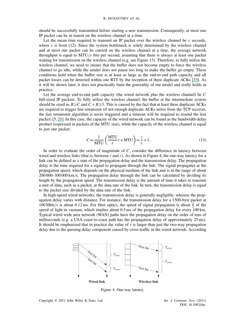
In order to evaluate the order of magnitude of C , consider the difference in latency betweenwired and wireless links (that is, between � and ε). As shown in Figure 4, the one-way latency for alink can be defined as a sum of the propagation delay and the transmission delay. The propagationdelay is the time required for a signal to propagate through the link. The signal propagates at thepropagation speed, which depends on the physical medium of the link and is in the range of about200 000–300000 km/s. The propagation delay through the link can be calculated by dividing itslength by the propagation speed. The transmission delay is the amount of time it takes to transmita unit of data, such as a packet, at the data rate of the link. In turn, the transmission delay is equalto the packet size divided by the data rate of the link.
In high-speed wired networks, the transmission delay is generally negligible, whereas the prop-agation delay varies with distance. For instance, the transmission delay for a 1500-byte packet at100Mbit/s is about 0.12ms. For fiber optics, the speed of signal propagation is about 2
3 of thespeed of light in vacuum, which implies about 0.5ms of the propagation delay for every 100 km.Typical wired wide area network (WAN) paths have the propagation delay on the order of tens ofmilliseconds (e.g. a USA coast-to-coast path has the propagation delay of approximately 25ms).It should be emphasized that in practice the value of � is larger than just the two-way propagationdelay due to the queuing delay component caused by cross-traffic in the wired network. According
Wired link Wireless link
first bitlast bit
Tprop
Ttranslast bit
first bit Tprop
Ttrans
Figure 4. One-way latency.
Copyright � 2011 John Wiley & Sons, Ltd. Int. J. Commun. Syst. (2011)DOI: 10.1002/dac
MODELING TCP SACK PERFORMANCE OVER WIRELESS CHANNELS
to large-scale Internet measurements [34–36], RTTs of the vast majority of TCP connections arebelow 500ms. In addition, note that � will reach its maximum value (up to several hundreds ofmilliseconds) in case of one or more satellite hops along the path. However, in this paper we donot consider the presence of both satellite links and a terrestrial wireless link on the same pathof a given TCP connection and assume that the value of � is mainly determined by the distancebetween the sender and the intermediate system (Figure 1).
The distance in wireless access networks is short enough compared with that in wired WANsbecause the distance does not exceed the cell size. Moreover, radio waves propagate at approx-imately the speed of light in vacuum. On the other hand, terrestrial wireless networks supportmuch lower data rates than do today’s wired networks, whereas the implemented FEC and ARQschemes can significantly increase the transmission delay since adding FEC bits implies more bitsto transmit, while retransmissions of frames received in error cause delayed delivery of correctlyreceived frames. In addition, data rates are inversely proportional to distance: as the data rateincreases, the distance that the rate can be sustained decreases. Consequently, a terrestrial wirelesslink introduces a larger transmission delay than most wired networks, but its propagation delayis negligibly small (in the range of a few microseconds). For example, assuming that the FECcode has the code rate of 1
2 and neglecting other types of overhead, the transmission delay for a1500-byte packet at 10Mbit/s is 2.4ms. Suppose the distance between the base station and themobile terminal is 3 km. Then the propagation delay is 0.01ms.
As a result of our calculations, we conclude that the values of � and ε in (13) have approximatelythe same order of magnitude and, hence, the average end-to-end path capacity C is in the range ofseveral to tens of full-sized packets. In practice, buffers are significantly overprovisioned in orderto prevent packet losses due to buffer overflow [33]. Thus, our assumption that B�C is quitereasonable.
The maximum number of IP packets that can be accommodated in the network is approximatelyequal to (C+B), assuming that there are C packets in flight and the buffer at the intermediatesystem is fully occupied. SinceC�2 and B�C , it implies that C+B�4. In this case, the connectionexperiences periodic packet losses: each time the cwnd exceeds the maximum number of packetsthat can be accommodated in the network, the last packet in the transmitted window is dropped dueto buffer overflow at the intermediate system. According to the TCP sliding window algorithm,after the lost segment, (C+B−1) more segments are sent, triggering duplicate ACKs. As long asC+B�4 and at least three duplicate ACKs are required in order to trigger a fast retransmissionwithout the need to wait for a timeout event, the sender receives enough duplicate ACKs to triggerthe loss recovery algorithm [21]. Since any lost segment can be recovered within a single RTT byusing the SACK-based loss recovery algorithm, we are neglecting the details of the loss recoveryphase as having negligible effect on TCP SACK performance. Thus, a congestion avoidance phasestarts after a segment loss is detected via three duplicate ACKs. Then the current value of thecwnd is set to approximately (C+B)/2 and the congestion avoidance phase begins. The receiversends one ACK for every bth segment it gets, so the cwnd increases linearly with a slope of 1/bsegments per RTT until cwnd=C+B (Figure 5). The factor b depends on the acknowledgementpolicy of the receiver: as specified in [37], the receiver should use delayed ACKs, sending anACK for every other received segment (b=2), unless the delayed ACK timer expires; however, itis also allowed to send an ACK for every received segment (b=1). The next additive increase ofthe cwnd leads to a new buffer overflow and the current congestion avoidance phase ends. Hence,considering the evolution of the cwnd between (C+B)/2 and (C+B) (Figure 5), we get:
E[ACA]=b
(C+B
2
), E[YCA]= 3b
2
(C+B
2
)2
, p= 1
E[YCA], (14)
where E[ACA] is the expected duration of a congestion avoidance (CA) phase in rounds (a roundstarts when the sender begins the transmission of a window of segments and ends when it receivesthe first ACK for one or more of these segments); E[YCA] is the expected number of packets sentduring this phase; p is the packet loss rate due to buffer overflow.
Copyright � 2011 John Wiley & Sons, Ltd. Int. J. Commun. Syst. (2011)DOI: 10.1002/dac
R. DUNAYTSEV ET AL.
+
2
C B⎛ ⎞⎜ ⎟⎝ ⎠
( )C B+
Time,rounds
bufferoverflows
ACAACAACA
cwnd, pkts
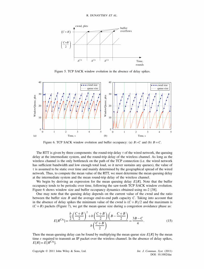
Figure 5. TCP SACK window evolution in the absence of delay spikes.
0 1 2 3 4 50
10
20
30
40cwnd sizequeue size
Time, s
Win
dow
/Que
ue, p
kts
0 1 2 3 4 50
10
20
30
40cwnd sizequeue size
Time, s
Win
dow
/Que
ue, p
kts
(a) (b)
Figure 6. TCP SACK window evolution and buffer occupancy: (a) B>C and (b) B=C.
The RTT is given by three components: the round-trip delay � of the wired network, the queuingdelay at the intermediate system, and the round-trip delay of the wireless channel. As long as thewireless channel is the only bottleneck on the path of the TCP connection (i.e. the wired networkhas sufficient bandwidth and low enough total load, so it never sustains any queues), the value of� is assumed to be static over time and mainly determined by the geographical spread of the wirednetwork. Thus, to compute the mean value of the RTT, we must determine the mean queuing delayat the intermediate system and the mean round-trip delay of the wireless channel.
We begin by deriving an expression for the mean queuing delay E[R]. Note that the bufferoccupancy tends to be periodic over time, following the saw-tooth TCP SACK window evolution.Figure 6 shows window size and buffer occupancy dynamics obtained using ns-2 [38].
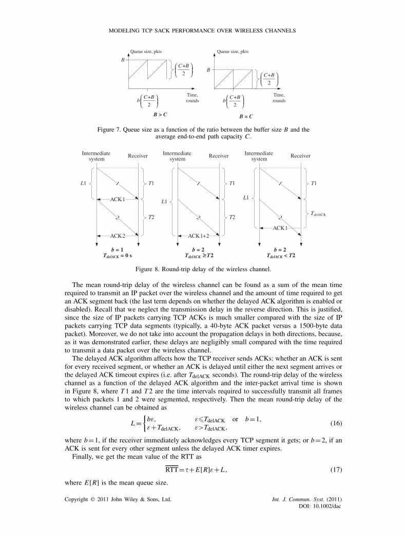
One may note that the queuing delay depends on the current value of the cwnd and the ratiobetween the buffer size B and the average end-to-end path capacity C . Taking into account thatin the absence of delay spikes the minimum value of the cwnd is (C+B)/2 and the maximum is(C+B) packets (Figure 7), we get the mean queue size during a congestion avoidance phase as:
E[RCA]=b
2
(C+B
2
)2
+b
(C+B
2
)(B− C+B
2
)
b
(C+B
2
) = 3B−C
4. (15)
Then the mean queuing delay can be found by multiplying the mean queue size E[R] by the meantime ε required to transmit an IP packet over the wireless channel. In the absence of delay spikes,E[R]= E[RCA].
Copyright � 2011 John Wiley & Sons, Ltd. Int. J. Commun. Syst. (2011)DOI: 10.1002/dac
MODELING TCP SACK PERFORMANCE OVER WIRELESS CHANNELS
B
B
B > C B = C
+
2
C Bb
⎛ ⎞⎜ ⎟⎝ ⎠
+
2
C Bb
⎛ ⎞⎜ ⎟⎝ ⎠
+
2
C B⎛ ⎞⎜ ⎟⎝ ⎠
Queue size, pkts Queue size, pkts
Time,rounds
Time,rounds
+
2
C B⎛ ⎞⎜ ⎟⎝ ⎠
Figure 7. Queue size as a function of the ratio between the buffer size B and theaverage end-to-end path capacity C.
Intermediate system Receiver
1
2
ACK1
ACK2
T1
T2
Intermediate system Receiver
1
2
ACK1+2
T1
T2
Intermediate system Receiver
1
2
ACK1
T1
b = 2TdelACK T2
L1
L1L1
b = 1TdelACK = 0 s
b = 2TdelACK < T2
TdelACK
Figure 8. Round-trip delay of the wireless channel.
The mean round-trip delay of the wireless channel can be found as a sum of the mean timerequired to transmit an IP packet over the wireless channel and the amount of time required to getan ACK segment back (the last term depends on whether the delayed ACK algorithm is enabled ordisabled). Recall that we neglect the transmission delay in the reverse direction. This is justified,since the size of IP packets carrying TCP ACKs is much smaller compared with the size of IPpackets carrying TCP data segments (typically, a 40-byte ACK packet versus a 1500-byte datapacket). Moreover, we do not take into account the propagation delays in both directions, because,as it was demonstrated earlier, these delays are negligibly small compared with the time requiredto transmit a data packet over the wireless channel.
The delayed ACK algorithm affects how the TCP receiver sends ACKs: whether an ACK is sentfor every received segment, or whether an ACK is delayed until either the next segment arrives orthe delayed ACK timeout expires (i.e. after TdelACK seconds). The round-trip delay of the wirelesschannel as a function of the delayed ACK algorithm and the inter-packet arrival time is shownin Figure 8, where T 1 and T2 are the time intervals required to successfully transmit all framesto which packets 1 and 2 were segmented, respectively. Then the mean round-trip delay of thewireless channel can be obtained as
L={bε, ε�TdelACK or b=1,ε+TdelACK, ε>TdelACK,
(16)
where b=1, if the receiver immediately acknowledges every TCP segment it gets; or b=2, if anACK is sent for every other segment unless the delayed ACK timer expires.
Finally, we get the mean value of the RTT as
RTT=�+E[R]ε+L, (17)
where E[R] is the mean queue size.
Copyright � 2011 John Wiley & Sons, Ltd. Int. J. Commun. Syst. (2011)DOI: 10.1002/dac
R. DUNAYTSEV ET AL.
Now let us consider the effect of delay spikes on the long-term steady-state throughput of aTCP SACK connection. As it was pointed out in [3], a TCP spurious timeout occurs when theRTT value suddenly increases to the extent that it exceeds the duration of the TCP retransmissiontimer (i.e. RTO seconds). In the considered scenario, the completely reliable data link layer cancause a sudden delay due to bit errors on the wireless channel and a large number of subsequentretransmissions of the incorrectly received frames.
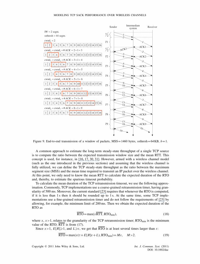
Consider the transmission of packets during the initial slow start (SS) phase when the delayedacknowledgement algorithm is disabled and the receiver acknowledges every segment it gets(Figure 9). For simplicity of illustration, let us assume that the initial window (IW) is equal totwo full-sized segments [39] and the SS threshold (ssthresh) is sufficiently high. Once the TCPconnection has been established, the sender begins sending data packets. When the sender transmitsthe first packet, it starts the TCP retransmission timer so that it will expire after RTO seconds. Afterapproximately �/2 seconds the first packet arrives at the intermediate system. Since the wirelesschannel is idle and the buffer is empty, the incoming packet will be serviced immediately: at thedata link layer it will be segmented to a number of frames and these frames will be transmitted oneafter another over the wireless channel. Packet 2 arriving at the intermediate system will find thewireless channel busy and will be buffered for later transmission. Let T1 be the time required tosuccessfully transmit all frames to which packet 1 was segmented. The receiver then replies with anACK segment (ACK1). As soon as the wireless channel becomes idle, the packet service processstarts all over again: packet 2 is passed to the data link layer for segmentation and subsequenttransmission over the wireless channel. Since we assume that the wireless channel in the reversedirection is completely reliable and that the feedback is almost instantaneous, it will take only�/2 seconds to deliver ACK1 to the sender. The next ACK (ACK2) will arrive after T 2 seconds,where T2 is the time required to successfully transmit all frames to which packet 2 was segmented.Similarly, ACK3 will arrive at the sender after T3 seconds and so on. Note that these arrivals areseparated by the time required to transmit a corresponding IP packet over the wireless channel.When the delayed ACK algorithm is enabled, the receiver acknowledges every other incomingsegment or delays an ACK for TdelACK seconds (Figure 10). In this case, the mean inter-ACKgap is given by (16). In accordance with [23], when an ACK is received that acknowledges newdata, the TCP retransmission timer should be restarted so that it will expire after RTO seconds(see Step 5.3 in [23]). Thus, every time a new ACK arrives, the TCP retransmission timer willbe restarted (denoted by gray diamonds in Figures 9 and 10). Therefore, the only possibility for aTCP spurious timeout to occur is to transmit an IP packet over the wireless channel within RTOseconds or more.
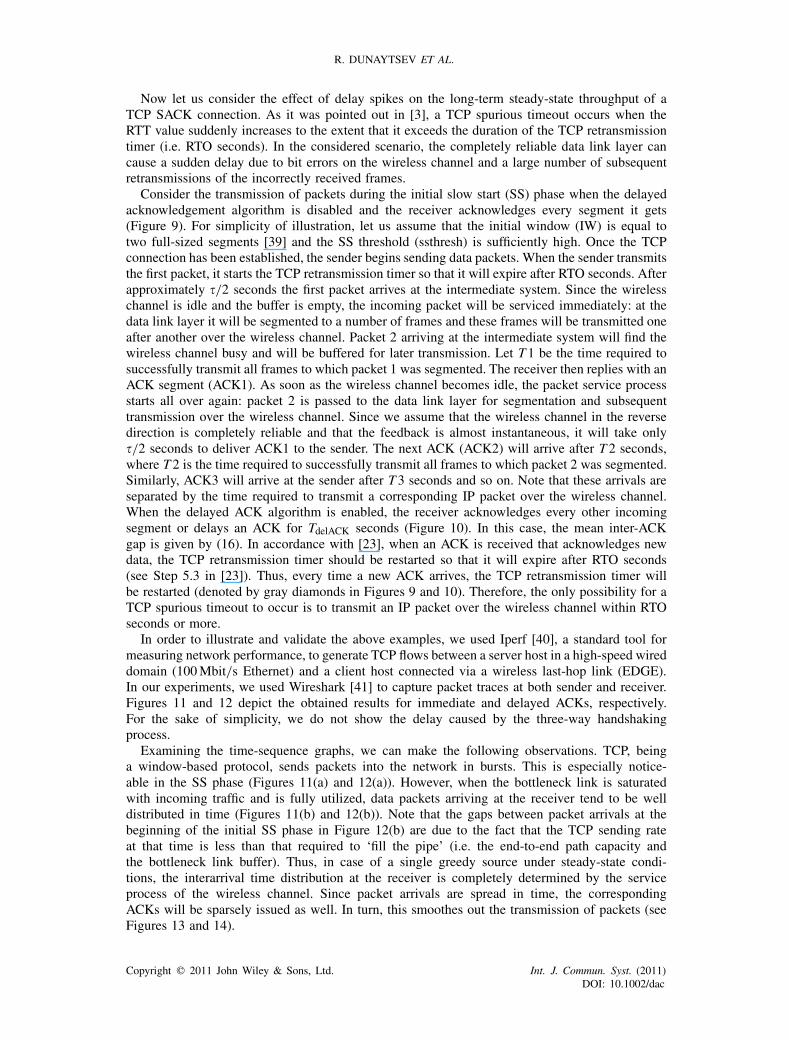
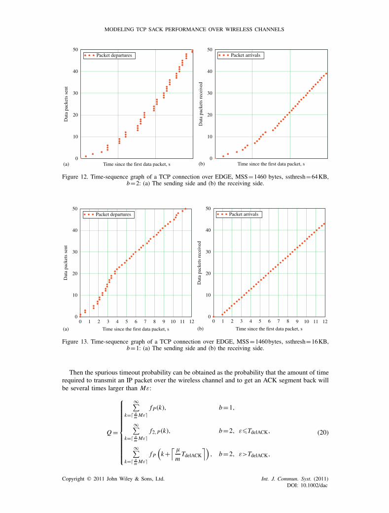
In order to illustrate and validate the above examples, we used Iperf [40], a standard tool formeasuring network performance, to generate TCP flows between a server host in a high-speed wireddomain (100Mbit/s Ethernet) and a client host connected via a wireless last-hop link (EDGE).In our experiments, we used Wireshark [41] to capture packet traces at both sender and receiver.Figures 11 and 12 depict the obtained results for immediate and delayed ACKs, respectively.For the sake of simplicity, we do not show the delay caused by the three-way handshakingprocess.
Examining the time-sequence graphs, we can make the following observations. TCP, beinga window-based protocol, sends packets into the network in bursts. This is especially notice-able in the SS phase (Figures 11(a) and 12(a)). However, when the bottleneck link is saturatedwith incoming traffic and is fully utilized, data packets arriving at the receiver tend to be welldistributed in time (Figures 11(b) and 12(b)). Note that the gaps between packet arrivals at thebeginning of the initial SS phase in Figure 12(b) are due to the fact that the TCP sending rateat that time is less than that required to ‘fill the pipe’ (i.e. the end-to-end path capacity andthe bottleneck link buffer). Thus, in case of a single greedy source under steady-state condi-tions, the interarrival time distribution at the receiver is completely determined by the serviceprocess of the wireless channel. Since packet arrivals are spread in time, the correspondingACKs will be sparsely issued as well. In turn, this smoothes out the transmission of packets (seeFigures 13 and 14).
Copyright � 2011 John Wiley & Sons, Ltd. Int. J. Commun. Syst. (2011)DOI: 10.1002/dac
MODELING TCP SACK PERFORMANCE OVER WIRELESS CHANNELS
Sender
12τ
T1
Intermediatesystem Receiver
1
2
ACK1ACK1
34
5
T2
2
2τ
T6
T7
1 2 3 4 5 6 7 8 9 10 11 12
1 2 3 4 5 6 7 8 9 10 11 12
T8
T9
13 14 15
13 14 15
1cwnd 2=
2 1cwnd cwnd # 2 1 3ACK= + = + =
ACK2
3
ACK3
4
ACK4
5
6
ACK5
6
ACK6
7
ACK7
8
ACK8
9
ACK910
1 2 3 4 5 6 7 8 9 10 11 12 13 14 15
3 2cwnd cwnd # 3 1 4ACK= + = + =
78
T3
910
1112
1314
1516
T4
T5
1718
19
16
16
16
1 2 3 4 5 6 7 8 9 10 11 12 13 14 15
4 3cwnd cwnd # 4 1 5ACK= + = + =
16
1 2 3 4 5 6 7 8 9 10 11 12 13 14 15
5 4cwnd cwnd # 5 1 6ACK= + = + =
16
1 2 3 4 5 6 7 8 9 10 11 12 13 14 15
6 5cwnd cwnd # 6 1 7ACK= + = + =
16
1 2 3 4 5 6 7 8 9 10 11 12 13 14 15
7 6cwnd cwnd # 7 1 8ACK= + = + =
16
1 2 3 4 5 6 7 8 9 10 11 12 13 14 15
8 7cwnd cwnd # 8 1 9ACK= + = + =
16
IW 2 segm.
ssthresh 44 segm.
=
=
Figure 9. End-to-end transmission of a window of packets, MSS=1460 bytes, ssthresh=64KB, b=1.
A common approach to estimate the long-term steady-state throughput of a single TCP sourceis to compute the ratio between the expected transmission window size and the mean RTT. Thisconcept is used, for instance, in [16, 17, 30, 31]. However, armed with a wireless channel model(such as the one introduced in the previous sections) and assuming that the wireless channel isfully utilized, we can define the TCP steady-state throughput as the ratio between the maximumsegment size (MSS) and the mean time required to transmit an IP packet over the wireless channel.At this point, we only need to know the mean RTT to calculate the expected duration of the RTOand, thereby, to estimate the spurious timeout probability.
To calculate the mean duration of the TCP retransmission timeout, we use the following approx-imation. Commonly, TCP implementations use a coarse-grained retransmission timer, having gran-ularity of 500 ms. Moreover, the current standard [23] requires that whenever the RTO is computed,if it is less than 1 s then it should be rounded up to 1 s. At the same time, some TCP imple-mentations use a fine-grained retransmission timer and do not follow the requirements of [23] byallowing, for example, the minimum limit of 200ms. Then we obtain the expected duration of theRTO as
RTO=max(xRTT,RTOmin), (18)
where x , x>1, relates to the granularity of the TCP retransmission timer; RTOmin is the minimumvalue of the RTO; RTT is from (17).
Since x>1, E[R]�1, and L�ε, we get that RTO is at least several times larger than ε:
RTO=max(x(�+E[R]ε+L),RTOmin)=Mε, M>2. (19)
Copyright � 2011 John Wiley & Sons, Ltd. Int. J. Commun. Syst. (2011)DOI: 10.1002/dac

R. DUNAYTSEV ET AL.
14 15
Sender
12τ
T1
Intermediatesystem Receiver
1
2
ACK1+2ACK1+2
345
ACK3+4
6
3
4
ACK3+4
5
78
6
ACK5+6
7ACK5+6
91011
T2
2
2τ
T5
T6
1 2 3 4 5 6 7 8 9 10 11 12
1 2 3 4 5 6 7 8 9 10 11 12
1 2 3 4 5 6 7 8 9 10 11 12
1 2 3 4 5 6 7 8 9 10 11 12
8
ACK7+8ACK7+8
9
13 14 15
12
T7
T8
1 2 3 4 5 6 7 8 9 10 11 12 13
13 14 15
13 14 15
13 14 15
1cwnd 2=
2 1cwnd cwnd # 2 1 3ACK= + = + =
3 2cwnd cwnd # 3 1 4ACK= + = + =
4 3cwnd cwnd # 4 1 5ACK= + = + =
5 4cwnd cwnd # 5 1 6ACK= + = + =
16
16
16
16
16
IW 2 segm.
ssthresh 44 segm.
=
=
Figure 10. End-to-end transmission of a window of packets, MSS=1460 bytes, ssthresh=64KB, b=2.
0 1 2 3 4 5 6 7 80
10
20
30
40
50Packet departures
Time since the first data packet, s
Dat
a pa
cket
s se
nt
0 1 2 3 4 5 6 7 80
10
20
30
40
50Packet arrivals
Time since the first data packet, s
Dat
a pa
cket
s re
ceiv
ed
(a) (b)
Figure 11. Time-sequence graph of a TCP connection over EDGE, MSS=1460 bytes, ssthresh=64KB,b=1: (a) The sending side and (b) The receiving side.
Copyright � 2011 John Wiley & Sons, Ltd. Int. J. Commun. Syst. (2011)DOI: 10.1002/dac
MODELING TCP SACK PERFORMANCE OVER WIRELESS CHANNELS
0
10
20
30
40
50Packet departures
Time since the first data packet, s
Dat
a pa
cket
s se
nt
0
10
20
30
40
50Packet arrivals
Time since the first data packet, s
Dat
a pa
cket
s re
ceiv
ed
(a) (b)
Figure 12. Time-sequence graph of a TCP connection over EDGE, MSS=1460 bytes, ssthresh=64KB,b=2: (a) The sending side and (b) the receiving side.
0 1 2 3 4 5 6 7 8 9 10 11 12 9 10 11 120
10
20
30
40
50Packet departures
Time since the first data packet, s
Dat
a pa
cket
s se
nt
0 1 2 3 4 5 6 7 80
10
20
30
40
50Packet arrivals
Time since the first data packet, s
Dat
a pa
cket
s re
ceiv
ed
(a) (b)
Figure 13. Time-sequence graph of a TCP connection over EDGE, MSS=1460bytes, ssthresh=16KB,b=1: (a) The sending side and (b) the receiving side.
Then the spurious timeout probability can be obtained as the probability that the amount of timerequired to transmit an IP packet over the wireless channel and to get an ACK segment back willbe several times larger than Mε:
Q=
⎧⎪⎪⎪⎪⎪⎪⎪⎪⎪⎪⎨⎪⎪⎪⎪⎪⎪⎪⎪⎪⎪⎩
∞∑k=� �
m Mε�f P(k), b=1,
∞∑k=� �
m Mε�f2,P(k), b=2, ε�TdelACK,
∞∑k=� �
m Mε�f P(k+
⌈ �
mTdelACK
⌉), b=2, ε>TdelACK,
(20)
Copyright � 2011 John Wiley & Sons, Ltd. Int. J. Commun. Syst. (2011)DOI: 10.1002/dac
R. DUNAYTSEV ET AL.
Sender
12τ
T1
Intermediatesystem Receiver
1
2
ACK1ACK1
34
5
T2
2
2τ
T6
T7
T8
T9
1FlightSize 0, cwnd 2= =
FlightSize 1, cwnd cwnd # 2 1 3ACK= = + = + =
ACK2
3
ACK3
4
ACK4
5
6
ACK5
6
ACK6
7
ACK7
8
ACK8
9
ACK9
10
FlightSize 2, cwnd cwnd # 3 1 4ACK= = + = + =
78
T3
910
1112
1314
1516
T4
T5
1718
19
FlightSize 3, cwnd cwnd # 4 1 5ACK= = + = + =
FlightSize 4, cwnd cwnd # 5 1 6ACK= = + = + =
FlightSize 5, cwnd cwnd # 6 1 7ACK= = + = + =
FlightSize 6, cwnd cwnd # 7 1 8ACK= = + = + =
FlightSize 7, cwnd cwnd # 8 1 9ACK= = + = + =
20 ACK10
2111
ACK1122
12
ACK1213
1 2 3 4 5 6 7 8 9 10 11 12 13 14 15 16 17 18 19 20 21 22 23 24
1 2 3 4 5 6 7 8 9 10 11 12 13 14 15 16 17 18 19 20 21 22 23 24
1 2 3 4 5 6 7 8 9 10 11 12 13 14 15 16 17 18 19 20 21 22 23 24
1 2 3 4 5 6 7 8 9 10 11 12 13 14 15 16 17 18 19 20 21 22 23 24
1 2 3 4 5 6 7 8 9 10 11 12 13 14 15 16 17 18 19 20 21 22 23 24
1 2 3 4 5 6 7 8 9 10 11 12 13 14 15 16 17 18 19 20 21 22 23 24
1 2 3 4 5 6 7 8 9 10 11 12 13 14 15 16 17 18 19 20 21 22 23 24
1 2 3 4 5 6 7 8 9 10 11 12 13 14 15 16 17 18 19 20 21 22 23 24
FlightSize 8, cwnd cwnd # 9 1 10ACK= = + = + =
1 2 3 4 5 6 7 8 9 10 11 12 13 14 15 16 17 18 19 20 21 22 23 24
FlightSize 9, cwnd cwnd # 10 1 11ACK= = + = + =
1 2 3 4 5 6 7 8 9 10 11 12 13 14 15 16 17 18 19 20 21 22 23 24
1 2 3 4 5 6 7 8 9 10 11 12 13 14 15 16 17 18 19 20 21 22 23 24
FlightSize 11, cwnd cwnd 1 cwnd 12.08= = + ≈
1 2 3 4 5 6 7 8 9 10 11 12 13 14 15 16 17 18 19 20 21 22 23 24 23
FlightSize 10, cwnd cwnd # 12 ssthreshACK= = + = >
IW 2 segm.
ssthresh 11 segm.
=
=
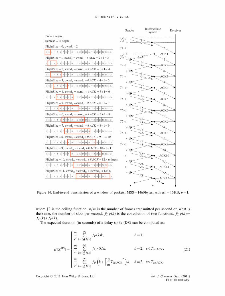
Figure 14. End-to-end transmission of a window of packets, MSS=1460bytes, ssthresh=16KB, b=1.
where �� is the ceiling function; �/m is the number of frames transmitted per second or, what isthe same, the number of slots per second; f2,P (k) is the convolution of two functions, f2,P(k)=fP (k)∗ fP (k).The expected duration (in seconds) of a delay spike (DS) can be computed as:
E[ZDS]=
⎧⎪⎪⎪⎪⎪⎪⎪⎪⎪⎪⎨⎪⎪⎪⎪⎪⎪⎪⎪⎪⎪⎩
m
�
∞∑k=� �
m Mε�fP (k)k, b=1,
m
�
∞∑k=� �
m Mε�f2,P (k)k, b=2, ε�TdelACK,
m
�
∞∑k=� �
m Mε�fP(k+
⌈ �
mTdelACK
⌉)k, b=2, ε>TdelACK.
(21)
Copyright � 2011 John Wiley & Sons, Ltd. Int. J. Commun. Syst. (2011)DOI: 10.1002/dac
MODELING TCP SACK PERFORMANCE OVER WIRELESS CHANNELS
delay spike i
cycle i
1delay
spike (i –1)
+
2
C B
cwnd, pkts
Time, rounds
( )C B+bufferoverflows
( )max 2, 2W
WW
ssthresh
A A ASS
... n1CA
1
CA
2
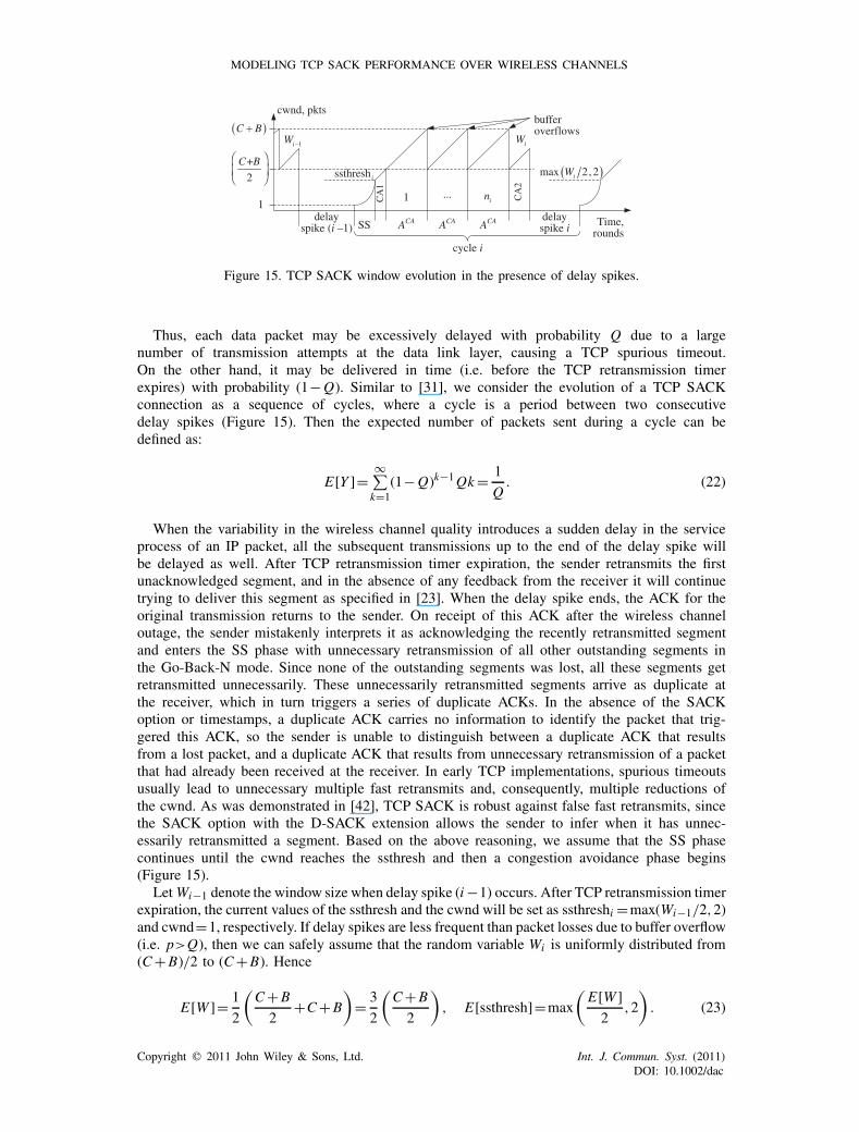
Figure 15. TCP SACK window evolution in the presence of delay spikes.
Thus, each data packet may be excessively delayed with probability Q due to a largenumber of transmission attempts at the data link layer, causing a TCP spurious timeout.On the other hand, it may be delivered in time (i.e. before the TCP retransmission timerexpires) with probability (1−Q). Similar to [31], we consider the evolution of a TCP SACKconnection as a sequence of cycles, where a cycle is a period between two consecutivedelay spikes (Figure 15). Then the expected number of packets sent during a cycle can bedefined as:
E[Y ]=∞∑k=1
(1−Q)k−1Qk= 1
Q. (22)
When the variability in the wireless channel quality introduces a sudden delay in the serviceprocess of an IP packet, all the subsequent transmissions up to the end of the delay spike willbe delayed as well. After TCP retransmission timer expiration, the sender retransmits the firstunacknowledged segment, and in the absence of any feedback from the receiver it will continuetrying to deliver this segment as specified in [23]. When the delay spike ends, the ACK for theoriginal transmission returns to the sender. On receipt of this ACK after the wireless channeloutage, the sender mistakenly interprets it as acknowledging the recently retransmitted segmentand enters the SS phase with unnecessary retransmission of all other outstanding segments inthe Go-Back-N mode. Since none of the outstanding segments was lost, all these segments getretransmitted unnecessarily. These unnecessarily retransmitted segments arrive as duplicate atthe receiver, which in turn triggers a series of duplicate ACKs. In the absence of the SACKoption or timestamps, a duplicate ACK carries no information to identify the packet that trig-gered this ACK, so the sender is unable to distinguish between a duplicate ACK that resultsfrom a lost packet, and a duplicate ACK that results from unnecessary retransmission of a packetthat had already been received at the receiver. In early TCP implementations, spurious timeoutsusually lead to unnecessary multiple fast retransmits and, consequently, multiple reductions ofthe cwnd. As was demonstrated in [42], TCP SACK is robust against false fast retransmits, sincethe SACK option with the D-SACK extension allows the sender to infer when it has unnec-essarily retransmitted a segment. Based on the above reasoning, we assume that the SS phasecontinues until the cwnd reaches the ssthresh and then a congestion avoidance phase begins(Figure 15).
LetWi−1 denote the window size when delay spike (i−1) occurs. After TCP retransmission timerexpiration, the current values of the ssthresh and the cwnd will be set as ssthreshi =max(Wi−1/2,2)and cwnd=1, respectively. If delay spikes are less frequent than packet losses due to buffer overflow(i.e. p>Q), then we can safely assume that the random variable Wi is uniformly distributed from(C+B)/2 to (C+B). Hence
E[W ]= 1
2
(C+B
2+C+B
)= 3
2
(C+B
2
), E[ssthresh]=max
(E[W ]
2,2
). (23)
Copyright � 2011 John Wiley & Sons, Ltd. Int. J. Commun. Syst. (2011)DOI: 10.1002/dac
R. DUNAYTSEV ET AL.
The expected durations of the CA1 and CA2 phases (Figure 15) can be found as
E[ACA1] = b
(C+B
2− E[W ]
2
)= b
4
(C+B
2
),
E[ACA2] = b
(E[W ]− C+B
2
)= b
2
(C+B
2
),
(24)
and the expected number of segments sent during these phases can be defined as:
E[YCA1] = b
(C+B
2− E[W ]
2
)E[W ]
2+ b
2
(C+B
2− E[W ]
2
)2
= 7b
32
(C+B
2
)2
,
E[YCA2] = b
(E[W ]− C+B
2
)(C+B
2
)+ b
2
(E[W ]− C+B
2
)2
= 5b
8
(C+B
2
)2
.
(25)
The number of segments transmitted during an SS phase can be closely approximated as ageometric series Y SS
i =1+�+�2+·· ·+�Ni−1= (�Ni −1)/(�−1), where �=1+1/b [43]. Takinginto account that in the SS phase of the i th cycle the cwnd growths exponentially from one tossthreshi packets, we get that �Ni−1=max(Wi−1/2,2). Then the expected duration (in rounds) ofthe SS phase and the expected number of segments sent during this phase can be expressed as:
E[ASS]=max
(log�
(�E[W ]
2
),2
), E[Y SS]=max
(�E[W ]−2
2(�−1),3
). (26)
Neglecting those segments that were unnecessarily retransmitted during the delay spike, thetotal number of segments sent during the i th cycle is Yi =Y SS
i +YCA1i +niYCA+YCA2
i (Figure 15).Combining (14), (22), (25), and (26), we obtain the expected number of buffer overflows withina cycle:
E[n]= E[Y ]−E[Y SS]−E[YCA1]−E[YCA2]
E[YCA]. (27)
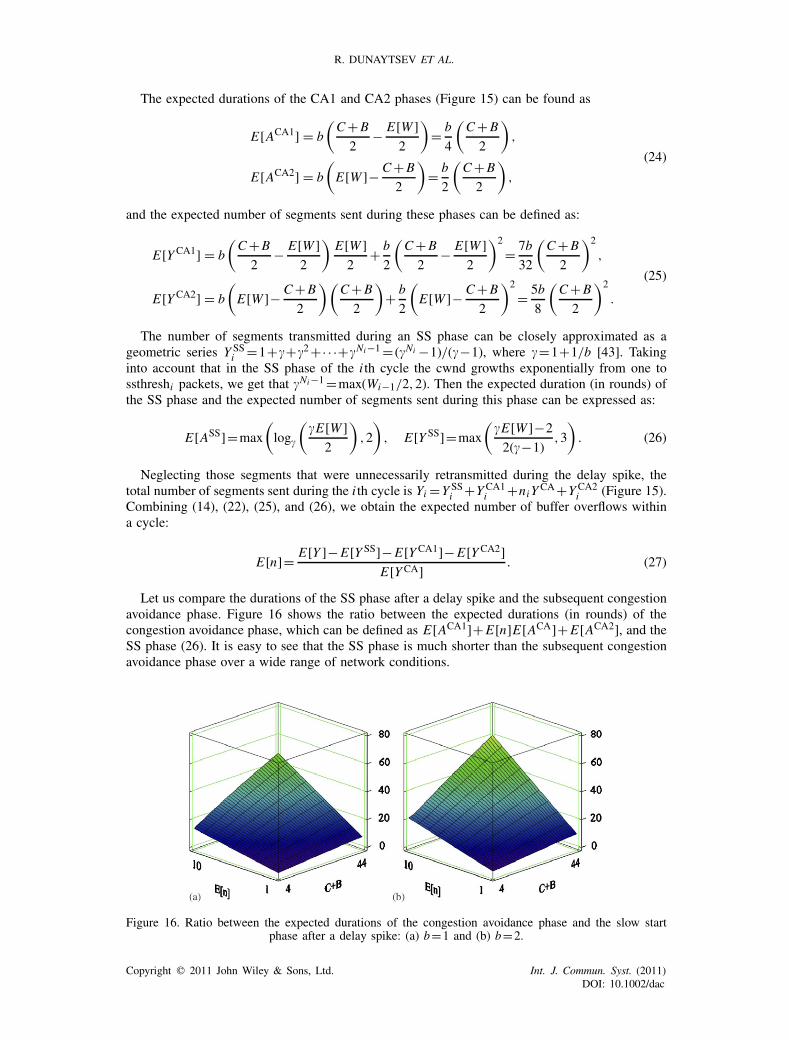
Let us compare the durations of the SS phase after a delay spike and the subsequent congestionavoidance phase. Figure 16 shows the ratio between the expected durations (in rounds) of thecongestion avoidance phase, which can be defined as E[ACA1]+E[n]E[ACA]+E[ACA2], and theSS phase (26). It is easy to see that the SS phase is much shorter than the subsequent congestionavoidance phase over a wide range of network conditions.
Figure 16. Ratio between the expected durations of the congestion avoidance phase and the slow startphase after a delay spike: (a) b=1 and (b) b=2.
Copyright � 2011 John Wiley & Sons, Ltd. Int. J. Commun. Syst. (2011)DOI: 10.1002/dac
MODELING TCP SACK PERFORMANCE OVER WIRELESS CHANNELS
Bit error model
Frame error model
Packet service model
TCP model
• FEC code parameters
• lag-1 NACF• BER
• MTU size • Bottleneck buffer size• Data rate of the wireless
channel• RTT of the wired network• Number of segments
ACKed by one ACK• RTO granularity
• TCP steady -state throughput
• Mean RTT• Spurious timeout
probability
Figure 17. Proposed model.
Since the SS phase after a delay spike is short compared to the subsequent CA phases and,hence, can be safely neglected, the mean queue size during a cycle can be found as
E[R]= E[RCA]E[n]E[ACA]+E[RCA1]E[ACA1]+E[RCA2]E[ACA2]
E[n]E[ACA]+E[ACA1]+E[ACA2]. (28)
Similar to (15), the expected queue size during the CA1 and CA2 phases can be found as:
E[RCA1]=
⎧⎪⎪⎨⎪⎪⎩7B−9C
16, B>
5C
3,
(B−C)2
C+B, B∈
[C,
5C
3
],
E[RCA2]= 5B−3C
8. (29)
Taking into consideration that the expected number of packets sent during a cycle is given by(22) and the mean time required to transmit an IP packet over the wireless channel is equal to ε
seconds, we define the TCP long-term steady-state throughput as
T = E[Y ]MSS
E[Y ]ε+E[ZDS]= MSS
ε+QE[ZDS], (30)
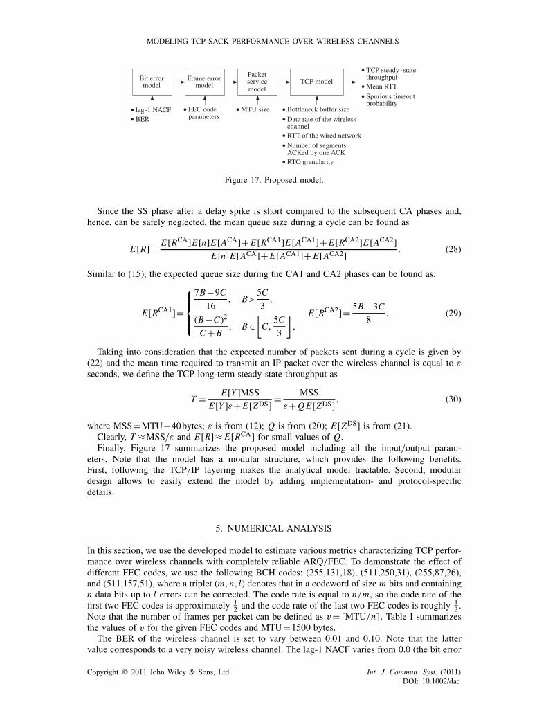
where MSS=MTU−40bytes; ε is from (12); Q is from (20); E[ZDS] is from (21).Clearly, T ≈MSS/ε and E[R]≈ E[RCA] for small values of Q.Finally, Figure 17 summarizes the proposed model including all the input/output param-
eters. Note that the model has a modular structure, which provides the following benefits.First, following the TCP/IP layering makes the analytical model tractable. Second, modulardesign allows to easily extend the model by adding implementation- and protocol-specificdetails.
5. NUMERICAL ANALYSIS
In this section, we use the developed model to estimate various metrics characterizing TCP perfor-mance over wireless channels with completely reliable ARQ/FEC. To demonstrate the effect ofdifferent FEC codes, we use the following BCH codes: (255,131,18), (511,250,31), (255,87,26),and (511,157,51), where a triplet (m,n, l) denotes that in a codeword of size m bits and containingn data bits up to l errors can be corrected. The code rate is equal to n/m, so the code rate of thefirst two FEC codes is approximately 1
2 and the code rate of the last two FEC codes is roughly 13 .
Note that the number of frames per packet can be defined as v=�MTU/n�. Table I summarizesthe values of v for the given FEC codes and MTU=1500 bytes.
The BER of the wireless channel is set to vary between 0.01 and 0.10. Note that the lattervalue corresponds to a very noisy wireless channel. The lag-1 NACF varies from 0.0 (the bit error
Copyright � 2011 John Wiley & Sons, Ltd. Int. J. Commun. Syst. (2011)DOI: 10.1002/dac
R. DUNAYTSEV ET AL.
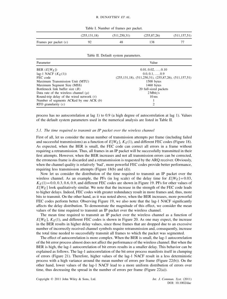
Table I. Number of frames per packet.
(255,131,18) (511,250,31) (255,87,26) (511,157,51)
Frames per packet (v) 92 48 138 77
Table II. Default system parameters.
Parameter Value
BER (E[WE ]) 0.01,0.02, . . . ,0.10lag-1 NACF (KE (1)) 0.0,0.1, . . . ,0.9FEC code (255,131,18), (511,250,31), (255,87,26), (511,157,51)Maximum Transmission Unit (MTU) 1500 bytesMaximum Segment Size (MSS) 1460 bytesBottleneck link buffer size (B) 20 full-sized packetsData rate of the wireless channel (�) 2Mbit/sRound-trip delay of the wired network (�) 10msNumber of segments ACKed by one ACK (b) 1RTO granularity (x) 2
process has no autocorrelation at lag 1) to 0.9 (a high degree of autocorrelation at lag 1). Valuesof the default system parameters used in the numerical analysis are listed in Table II.
5.1. The time required to transmit an IP packet over the wireless channel
First of all, let us consider the mean number of transmission attempts per frame (including failedand successful transmissions) as a function of E[WE ], KE (1), and different FEC codes (Figure 18).As expected, when the BER is small, the FEC code can correct all errors in a frame withoutrequiring a retransmission. Thus, all frames in an IP packet will be successfully transmitted in theirfirst attempts. However, when the BER increases and not all transmission errors can be corrected,the erroneous frame is discarded and a retransmission is requested by the ARQ receiver. Obviously,when the channel quality is relatively ‘bad’, more powerful FEC codes provide better performance,requiring less transmission attempts (Figure 18(b) and (d)).
Now let us consider the distribution of the time required to transmit an IP packet over thewireless channel. As an example, the PFs (in log scale) of the delay time for E[WE ]=0.03,KE (1)=0.0,0.3,0.6,0.9, and different FEC codes are shown in Figure 19. PFs for other values ofE[WE ] look qualitatively similar. We note that the increase in the strength of the FEC code leadsto higher delays. Indeed, FEC codes with greater redundancy result in more frames and, thus, morebits to transmit. On the other hand, as it was noted above, when the BER increases, more powerfulFEC codes perform better. Observing Figure 19, we also note that the lag-1 NACF significantlyaffects the delay distribution. To demonstrate the magnitude of this effect, we consider the meanvalues of the time required to transmit an IP packet over the wireless channel.
The mean time required to transmit an IP packet over the wireless channel as a function ofE[WE ], KE (1), and different FEC codes is shown in Figure 20. As one may expect, the increasein the BER results in higher delay values, since those frames that are dropped due to an excessivenumber of incorrectly received channel symbols require retransmission and, consequently, increasethe total time needed to successfully transmit all frames to which the packet was segmented.
The effect of autocorrelation is more complex. When the BER is small, the lag-1 autocorrelationof the bit error process almost does not affect the performance of the wireless channel. But when theBER is high, the lag-1 autocorrelation of bit errors results in a smaller delay. This behavior can beexplained as follows. The lag-1 autocorrelation of the bit error process manifests itself in clumpingof errors (Figure 21). Therefore, higher values of the lag-1 NACF result in a less deterministicprocess with a high variance around the mean number of errors per frame (Figure 22(b)). On theother hand, lower values of the lag-1 NACF lead to a more uniform distribution of errors overtime, thus decreasing the spread in the number of errors per frame (Figure 22(a)).
Copyright � 2011 John Wiley & Sons, Ltd. Int. J. Commun. Syst. (2011)DOI: 10.1002/dac

MODELING TCP SACK PERFORMANCE OVER WIRELESS CHANNELS
Figure 18. The mean number of transmission attempts per frame, including failed andsuccessful transmissions: (a) (255,131,18) FEC code; (b) (255,87,26) FEC code; (c)
(511,250,31) FEC code; and (d) (511,157,51) FEC code.
As an example, let us consider the (255,131,18) FEC code. For large values of the BER andsmall values of the lag-1 NACF, bit errors, even being well distributed in time, result in moreincorrectly received channel symbols per frame than the FEC code can correct, so almost allframes are received incorrectly. As a consequence, this increases the amount of time required totransmit an IP packet over the wireless channel. For instance, the frame length of 255 bits andE[WE ]=0.10 imply that the mean number of errors per frame is equal to 25.5, while the errorcorrecting capability of the (255,131,18) FEC code allows to correct just 18 erroneous channelsymbols within a frame. However, when the lag-1 autocorrelation of bit errors is sufficiently high,bit errors tend to occur in groups. Given the same BER, this unequal distribution results in moreframes received correctly. This effect remains the same for all FEC codes. The only reason why itis not so noticeable in Figure 20(b) and (d) is that we do not show the region of BER values forwhich higher values of the lag-1 NACF lead to better performance.
At the same time, the lag-1 autocorrelation of the bit error process may affect the performanceof the wireless channel even when the BER is small (this is more visible in Figure 27(a), whenKE (1)=0.9 and E[WE ]=0.01). That is, it leads to slightly worse performance for FEC codes witha small error correcting capability. Indeed, large values of the lag-1 NACF lead to more lengthybursts of errors within a frame that the FEC code cannot correct (Figure 23(b)). This, in turn,increases the number of transmission attempts required to successfully transmit an IP packet overthe wireless channel.
Figures 24 and 25 illustrate the impact of the raw data rate of the wireless channel on the meantime required to transmit an IP packet over this channel. For the sake of briefness, we present theresults for the (255,131,18) and (255,87,26) FEC codes only. It is easy to see that the change in
Copyright � 2011 John Wiley & Sons, Ltd. Int. J. Commun. Syst. (2011)DOI: 10.1002/dac
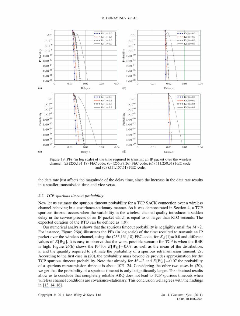
R. DUNAYTSEV ET AL.
0 0.01 0.02 0.03 0.04–20
–18
–16
–14
–12
–10
–8
–6
1×10
1×10
1×10
1×10
1×10
1×10
1×10
1×10
1×10
–4
–20
–18
–16
–14
–12
–10
–8
–6
1×10
1×10
1×10
1×10
1×10
1×10
1×10
1×10
1×10
–4
–20
–18
–16
–14
–12
–10
–8
–6
1×10
1×10
1×10
1×10
1×10
1×10
1×10
1×10
1×10
–4
–20
–18
–16
–14
–12
–10
–8
–6
1×10
1×10
1×10
1×10
1×10
1×10
1×10
1×10
1×10
–4
0.01
1Ke(1) = 0.0
Ke(1) = 0.3
Ke(1) = 0.6
Ke(1) = 0.9
Delay, s
Prob
abili
tyPr
obab
ility
0.01
1
0.01
1
Prob
abili
ty
0.01
1
Prob
abili
ty
0 0.01 0.02 0.03 0.04
Ke(1) = 0.0
Ke(1) = 0.3
Ke(1) = 0.6
Ke(1) = 0.9
Delay, s
0 0.01 0.02 0.03 0.04
Ke(1) = 0.0
Ke(1) = 0.3
Ke(1) = 0.6
Ke(1) = 0.9
Delay, s
0 0.01 0.02 0.03 0.04
Ke(1) = 0.0
Ke(1) = 0.3
Ke(1) = 0.6
Ke(1) = 0.9
Delay, s
(a) (b)
(c) (d)
Figure 19. PFs (in log scale) of the time required to transmit an IP packet over the wirelesschannel: (a) (255,131,18) FEC code; (b) (255,87,26) FEC code; (c) (511,250,31) FEC code;
and (d) (511,157,51) FEC code.
the data rate just affects the magnitude of the delay time, since the increase in the data rate resultsin a smaller transmission time and vice versa.
5.2. TCP spurious timeout probability
Now let us estimate the spurious timeout probability for a TCP SACK connection over a wirelesschannel behaving in a covariance-stationary manner. As it was demonstrated in Section 4, a TCPspurious timeout occurs when the variability in the wireless channel quality introduces a suddendelay in the service process of an IP packet which is equal to or larger than RTO seconds. Theexpected duration of the RTO can be defined as (19).
Our numerical analysis shows that the spurious timeout probability is negligibly small for M>2.For instance, Figure 26(a) illustrates the PFs (in log scale) of the time required to transmit an IPpacket over the wireless channel, using the (255,131,18) FEC code, for KE (1)=0.0 and differentvalues of E[WE ]. It is easy to observe that the worst possible scenario for TCP is when the BERis high. Figure 26(b) shows the PF for E[WE ]=0.07, as well as the mean of the distribution,ε, and the quantity required to estimate the probability of a spurious retransmission timeout, 2ε.According to the first case in (20), the probability mass beyond 2ε provides approximation for theTCP spurious timeout probability. Note that already for M=2 and E[WE ]=0.07 the probabilityof a spurious retransmission timeout is about 10E−24. Considering the other two cases in (20),we get that the probability of a spurious timeout is only insignificantly larger. The obtained resultsallow us to conclude that completely reliable ARQ does not lead to TCP spurious timeouts whenwireless channel conditions are covariance-stationary. This conclusion well agrees with the findingsin [13, 14, 16].
Copyright � 2011 John Wiley & Sons, Ltd. Int. J. Commun. Syst. (2011)DOI: 10.1002/dac

MODELING TCP SACK PERFORMANCE OVER WIRELESS CHANNELS
Figure 20. The mean time (in seconds) required to transmit an IP packet over the wireless channel at2Mbit/s: (a) (255,131,18) FEC code; (b) (255,87,26) FEC code; (c) (511,250,31) FEC code, εmax≈11.3s;
and (d) (511,157,51) FEC code.
0 500 1×10³ 1×1030
1
20 = ok, 1 = error
Received channel symbols
Indi
cato
r
0 500
0
1
20 = ok, 1 = error
Received channel symbols
Indi
cato
r
(a) (b)
Figure 21. The effect of autocorrelation on the bit error process, E[WE ]=0.10: (a)KE (1)=0.0 and (b) KE (1)=0.9.
5.3. TCP SACK steady-state throughput
The TCP SACK long-term steady-state throughput as a function of E[WE ], KE (1), and differentFEC codes is shown in Figure 27. As one may note, it is inverse proportional to the mean timerequired to transmit an IP packet over the wireless channel (Figure 20).
Copyright � 2011 John Wiley & Sons, Ltd. Int. J. Commun. Syst. (2011)DOI: 10.1002/dac
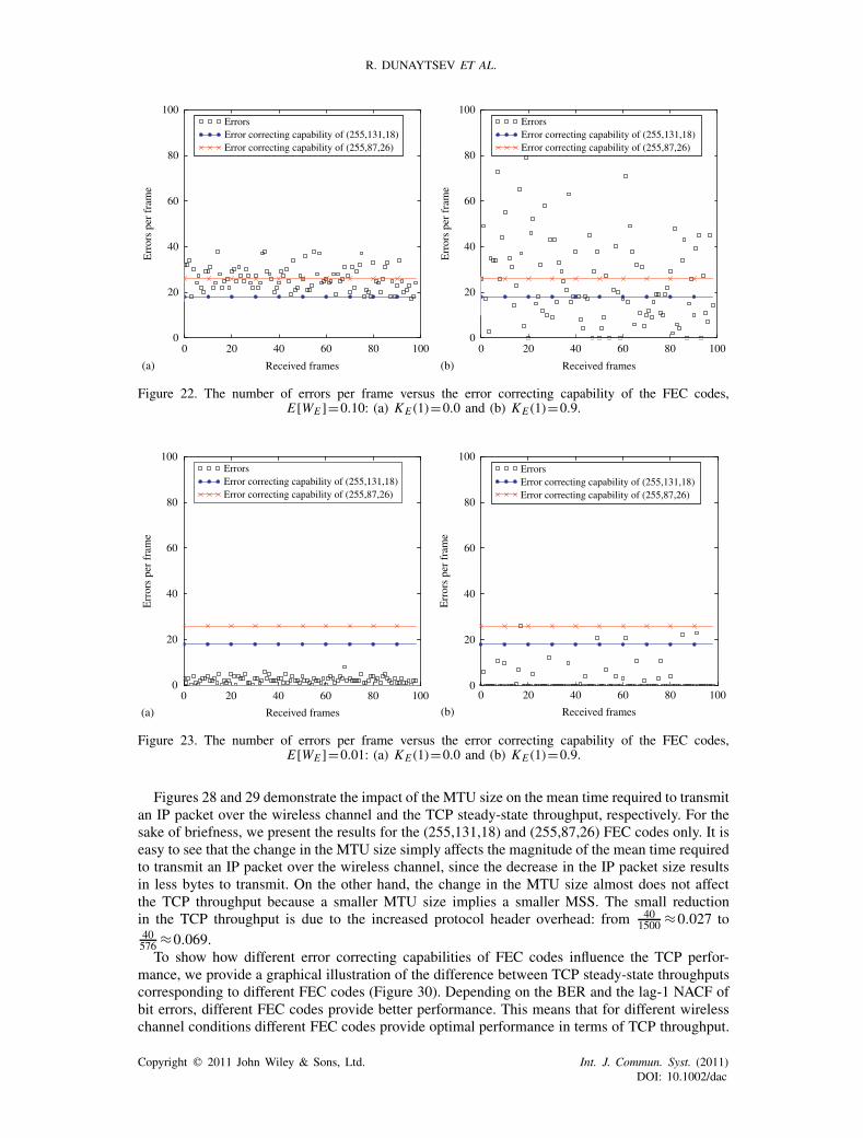
R. DUNAYTSEV ET AL.
0 20 40 60 80 1000
20
40
60
80
100ErrorsError correcting capability of (255,131,18)Error correcting capability of (255,87,26)
Received frames
Err
ors
per
fram
e
0 20 40 60 80 1000
20
40
60
80
100ErrorsError correcting capability of (255,131,18)Error correcting capability of (255,87,26)
Received frames
Err
ors
per
fram
e
(a) (b)
Figure 22. The number of errors per frame versus the error correcting capability of the FEC codes,E[WE ]=0.10: (a) KE (1)=0.0 and (b) KE (1)=0.9.
0 20 40 60 80 1000
20
40
60
80
100ErrorsError correcting capability of (255,131,18)Error correcting capability of (255,87,26)
Received frames
Err
ors
per
fram
e
0 20 40 60 80 1000
20
40
60
80
100
Received frames
Err
ors
per
fram
e
(a) (b)
ErrorsError correcting capability of (255,131,18)Error correcting capability of (255,87,26)
Figure 23. The number of errors per frame versus the error correcting capability of the FEC codes,E[WE ]=0.01: (a) KE (1)=0.0 and (b) KE (1)=0.9.
Figures 28 and 29 demonstrate the impact of the MTU size on the mean time required to transmitan IP packet over the wireless channel and the TCP steady-state throughput, respectively. For thesake of briefness, we present the results for the (255,131,18) and (255,87,26) FEC codes only. It iseasy to see that the change in the MTU size simply affects the magnitude of the mean time requiredto transmit an IP packet over the wireless channel, since the decrease in the IP packet size resultsin less bytes to transmit. On the other hand, the change in the MTU size almost does not affectthe TCP throughput because a smaller MTU size implies a smaller MSS. The small reductionin the TCP throughput is due to the increased protocol header overhead: from 40
1500 ≈0.027 to40576 ≈0.069.To show how different error correcting capabilities of FEC codes influence the TCP perfor-
mance, we provide a graphical illustration of the difference between TCP steady-state throughputscorresponding to different FEC codes (Figure 30). Depending on the BER and the lag-1 NACF ofbit errors, different FEC codes provide better performance. This means that for different wirelesschannel conditions different FEC codes provide optimal performance in terms of TCP throughput.
Copyright � 2011 John Wiley & Sons, Ltd. Int. J. Commun. Syst. (2011)DOI: 10.1002/dac
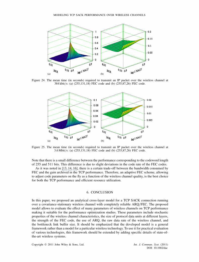
MODELING TCP SACK PERFORMANCE OVER WIRELESS CHANNELS
Figure 24. The mean time (in seconds) required to transmit an IP packet over the wireless channel at384 kbit/s: (a) (255,131,18) FEC code and (b) (255,87,26) FEC code.
Figure 25. The mean time (in seconds) required to transmit an IP packet over the wireless channel at3.6Mbit/s: (a) (255,131,18) FEC code and (b) (255,87,26) FEC code.
Note that there is a small difference between the performance corresponding to the codeword lengthof 255 and 511 bits. This difference is due to slight deviations in the code rate of the FEC codes.
As it was noted in [13, 14, 16], there is a certain trade-off between the bandwidth consumed byFEC and the gain archived in the TCP performance. Therefore, an adaptive FEC scheme, allowingto adjust code parameters on the fly as a function of the wireless channel quality, is the best choicefor both the TCP performance and efficient resource utilization.
6. CONCLUSION
In this paper, we proposed an analytical cross-layer model for a TCP SACK connection runningover a covariance-stationary wireless channel with completely reliable ARQ/FEC. The proposedmodel allows to evaluate the effect of many parameters of wireless channels on TCP performancemaking it suitable for the performance optimization studies. These parameters include stochasticproperties of the wireless channel characteristics, the size of protocol data units at different layers,the strength of the FEC code, the use of ARQ, the raw data rate of the wireless channel, andthe bottleneck link buffer size. It should be emphasized that the developed model is a generalframework rather than a model for a particular wireless technology. To use it for practical evaluationof various technologies, this framework should be extended by adding specific details of state-of-the-art wireless systems.
Copyright � 2011 John Wiley & Sons, Ltd. Int. J. Commun. Syst. (2011)DOI: 10.1002/dac
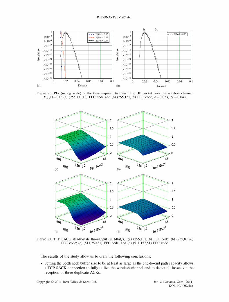
R. DUNAYTSEV ET AL.
0 0.02 0.04 0.06 0.08 0.1
E[We] = 0.03E[We] = 0.05E[We] = 0.07
Delay, s0 0.02 0.04 0.06 0.08 0.1
10−40×1
10−36×1
10−32×1
10−28×1
10−24×1
10−20×1
10−16×1
1 10−12×1 10−8×1×10−4
1E[We] = 0.07
Delay, s
Prob
abili
ty
10−40×1
10−36×1
10−32×1
10−28×1
10−24×1
10−20×1
10−16×1
1 10−12×1 10−8×1×10−4
1
Prob
abili
ty
1ε 2ε
(a) (b)
Figure 26. PFs (in log scale) of the time required to transmit an IP packet over the wireless channel,KE (1)=0.0: (a) (255,131,18) FEC code and (b) (255,131,18) FEC code, ε=0.02s, 2ε=0.04s.
Figure 27. TCP SACK steady-state throughput (in Mbit/s): (a) (255,131,18) FEC code; (b) (255,87,26)FEC code; (c) (511,250,31) FEC code; and (d) (511,157,51) FEC code.
The results of the study allow us to draw the following conclusions:
• Setting the bottleneck buffer size to be at least as large as the end-to-end path capacity allowsa TCP SACK connection to fully utilize the wireless channel and to detect all losses via thereception of three duplicate ACKs.
Copyright � 2011 John Wiley & Sons, Ltd. Int. J. Commun. Syst. (2011)DOI: 10.1002/dac
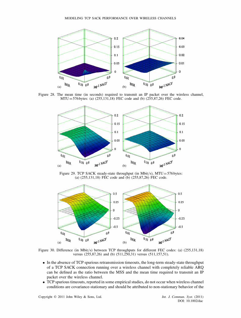
MODELING TCP SACK PERFORMANCE OVER WIRELESS CHANNELS
Figure 28. The mean time (in seconds) required to transmit an IP packet over the wireless channel,MTU=576bytes: (a) (255,131,18) FEC code and (b) (255,87,26) FEC code.
Figure 29. TCP SACK steady-state throughput (in Mbit/s), MTU=576bytes:(a) (255,131,18) FEC code and (b) (255,87,26) FEC code.
Figure 30. Difference (in Mbit/s) between TCP throughputs for different FEC codes: (a) (255,131,18)versus (255,87,26) and (b) (511,250,31) versus (511,157,51).
• In the absence of TCP spurious retransmission timeouts, the long-term steady-state throughputof a TCP SACK connection running over a wireless channel with completely reliable ARQcan be defined as the ratio between the MSS and the mean time required to transmit an IPpacket over the wireless channel.
• TCP spurious timeouts, reported in some empirical studies, do not occur when wireless channelconditions are covariance-stationary and should be attributed to non-stationary behavior of the
Copyright � 2011 John Wiley & Sons, Ltd. Int. J. Commun. Syst. (2011)DOI: 10.1002/dac
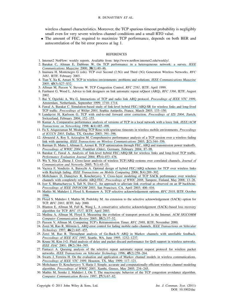
R. DUNAYTSEV ET AL.
wireless channel characteristics. Moreover, the TCP spurious timeout probability is negligiblysmall even for very severe wireless channel conditions and a small RTO value.
• The amount of FEC, required to maximize TCP performance, depends on both BER andautocorrelation of the bit error process at lag 1.
REFERENCES
1. Internet2 NetFlow: weekly reports. Available from: http://www.netflow.internet2.edu/weekly/.2. Barakat C, Altman E, Dabbous W. On TCP performance in a heterogeneous network: a survey. IEEE
Communications Magazine 2000; 38(1):40–46.3. Inamura H, Montenegro G (eds). TCP over Second (2.5G) and Third (3G) Generation Wireless Networks, RFC
3481, IETF, February 2003.4. Tian Y, Xu K, Ansari N. TCP in wireless environments: problems and solutions. IEEE Communications Magazine
2005; 43(3):S27–S32.5. Allman M, Paxson V, Stevens W. TCP Congestion Control, RFC 2581, IETF, April 1999.6. Fairhurst G, Wood L. Advice to link designers on link automatic repeat reQuest (ARQ), RFC 3366, IETF, August
2002.7. Bai Y, Ogielski A, Wu G. Interactions of TCP and radio link ARQ protocol. Proceedings of IEEE VTC 1999,
Amsterdam, Netherlands, September 1999; 1710–1714.8. Fawal A, Barakat C. Simulation-based study of link-level hybrid FEC/ARQ-SR for wireless links and long-lived
TCP traffic. Proceedings of WiOpt 2003, Sophia Antipolis, France, March 2003; 133–150.9. Lundqvist H, Karlsson G. TCP with end-to-end forward error correction. Proceedings of IZS 2004, Zurich,
Switzerland, February 2004; 152–155.10. Kumar A. Comparative performance analysis of versions of TCP in a local network with a lossy link. IEEE/ACM
Transactions on Networking 1998; 6(4):485–498.11. Fu S, Atiquzzaman M. Modelling TCP Reno with spurious timeouts in wireless mobile environments. Proceedings
of ICCCN 2003, Dallas, TX, October 2003; 391–396.12. Abouzeid A, Roy S, Azizoglou M. Comprehensive performance analysis of a TCP session over a wireless fading
link with queueing. IEEE Transactions on Wireless Communications 2003; 2(2):344–356.13. Barman D, Matta I, Altman E, Azouzi R. TCP optimization through FEC, ARQ and transmission power tradeoffs.
Proceedings of WWIC 2004, Frankfurt (Oder), Germany, February 2004; 87–98.14. Barakat C, Fawal A. Analysis of link-level hybrid FEC/ARQ-SR for wireless links and long-lived TCP traffic.
Performance Evaluation Journal 2004; 57(4):453–476.15. Wu Y, Niu Z, Zheng J. Cross-layer analysis of wireless TCP/ARQ systems over correlated channels. Journal of
Communication and Networks 2005; 7(1):45–53.16. Vacirca F, Vendictis A, Baiocchi A. Optimal design of hybrid FEC/ARQ schemes for TCP over wireless links
with Rayleigh fading. IEEE Transactions on Mobile Computing 2006; 5(4):289–302.17. Moltchanov D, Dunaytsev R, Koucheryavy Y. Cross-layer modeling of TCP SACK performance over wireless
channels with completely reliable ARQ/FEC. Proceedings of WWIC 2008, Tampere, Finland, May 2008; 13–26.18. Iyer S, Bhattacharyya S, Taft N, Diot C. An approach to alleviate link overload as observed on an IP backbone.
Proceedings of IEEE INFOCOM 2003, San Francisco, CA, April 2003; 406–416.19. Mathis M, Mahdavi J, Floyd S, Romanow A. TCP selective acknowledgement options. RFC 2018, IETF, October
1996.20. Floyd S, Mahdavi J, Mathis M, Podolsky M. An extension to the selective acknowledgement (SACK) option for
TCP. RFC 2883, IETF, July 2000.21. Blanton E, Allman M, Fall K, Wang L. A conservative selective acknowledgement (SACK)-based loss recovery
algorithm for TCP. RFC 3517, IETF, April 2003.22. Medina A, Allman M, Floyd S. Measuring the evolution of transport protocol in the Internet. ACM SIGCOMM
Computer Communication Review 2005; 35(2):37–52.23. Paxson V, Allman M. Computing TCP’s Retransmission Timer. RFC 2988, IETF, November 2000.24. Zorzi M, Rao R, Milstein L. ARQ error control for fading mobile radio channels. IEEE Transactions on Vehicular
Technology 1997; 46(2):445–455.25. Zorzi M, Rao R. Throughput analysis of Go-Back-N ARQ in Markov channels with unreliable feedback.
Proceedings of IEEE ICC 1995, Seattle, WA, June 1995; 1232–1237.26. Krunz M, Kim J-G. Fluid analysis of delay and packet discard performance for QoS support in wireless networks.
IEEE JSAC 2001; 19(2):384–395.27. Fantacci A. Queuing analysis of the selective repeat automatic repeat request protocol for wireless packet
networks. IEEE Transactions on Vehicular Technology 1996; 45(2):258–264.28. Swarts J, Ferreira H. On the evaluation and application of Markov channel models in wireless communications.
Proceedings of IEEE VTC 1999, Houston, TX, May 1999; 117–121.29. Moltchanov D, Koucheryavy Y, Harju J. Simple, accurate and computationally efficient wireless channel modeling
algorithm. Proceedings of WWIC 2005, Xanthi, Greece, May 2005; 234–245.30. Mathis M, Semke J, Mahdavi J, Ott T. The macroscopic behavior of the TCP congestion avoidance algorithm.
Computer Communication Review 1997; 27(3):67–82.
Copyright � 2011 John Wiley & Sons, Ltd. Int. J. Commun. Syst. (2011)DOI: 10.1002/dac
MODELING TCP SACK PERFORMANCE OVER WIRELESS CHANNELS
31. Padhye J, Firoiu V, Towsley D, Kurose J. Modeling TCP Reno performance: a simple model and its empiricalvalidation. IEEE/ACM Transactions on Networking 2000; 8(2):133–145.
32. Stallings W. Data and Computer Communications (8th edn). Prentice-Hall Inc: Englewood Cliffs, NJ, 2007.33. Appenzeller G, Keslassy I, McKeown N. Sizing router buffers. ACM SIGCOMM Computer Communication
Review 2004; 34(4):281–292.34. Shakkottai S, Srikant R, Brownlee N, Broido A, Claffy KC. The RTT distribution of TCP flows in the Internet
and its impact on TCP-based flow control. CAIDA Technical Report, TR-2004-02, January 2004.35. Aikat J, Kaur J, Donelson Smith F, Jeffay K. Variability in TCP round-trip times. Proceedings of ACM SIGCOMM
Internet Measurement Conference, Miami, FL, October 2003; 279–284.36. Wang Y, Ye S, Li X. Understanding current IPv6 performance: a case study from CERNET. Proceedings of
IEEE ISCC 2005, Cartagena, Spain, June 2005; 71–76.37. Braden R. Requirements for Internet Hosts—Communication Layers. RFC 1122, IETF, October 1989.38. The network simulator ns-2. Available from: http://www.isi.edu/nsnam/ns/.39. Allman M, Floyd S, Partridge C. Increasing TCP’s Initial Window, RFC 3390, IETF, October 2002.40. Iperf. Available from: http://iperf.sourceforge.net/.41. Wireshark: go deep. Available from: http://www.wireshark.org.42. Guan Y, Van den Broeck B, Potemans J, Theunis J, Li D, Van Lil E, Van de Capelle A. Simulation study of
TCP Eifel algorithms. Proceedings of OPNETWORK 2005, Washington, DC, August 2005.43. Cardwell N, Savage S, Anderson T. Modeling TCP latency. Proceedings of IEEE INFOCOM 2000, Tel-Aviv,
Israel, March 2000; 1742–1751.
AUTHORS’ BIOGRAPHIES
Roman Dunaytsev is a research fellow in the Department of Communications Engi-neering at Tampere University of Technology, Finland. He received his MSc and Candi-date of Science degrees from Saint-Petersburg State University of Telecommunications,Russia, in 1999 and 2005, correspondingly, and a PhD degree from Tampere Univer-sity of Technology, Finland, in 2010. His research interests include TCP performanceevaluation and P2P networks.
Dmitri Moltchanov is a senior research scientist in the Department of CommunicationsEngineering at Tampere University of Technology, Finland. He received his MSc andCandidate of Science degrees from Saint-Petersburg State University of Telecommu-nications, Russia, in 2000 and 2002, respectively, and a PhD degree from TampereUniversity of Technology, Finland, in 2006. His research interests include performanceevaluation and optimization issues of wired and wireless IP networks, ad hoc and sensornetworks, and P2P networks. Dmitri Moltchanov serves as TPC member in a numberof international conferences. He authored more than 40 publications.
Yevgeni Koucheryavy is a professor in the Department of Communications Engineeringat Tampere University of Technology, Finland. He received his MSc degree from Saint-Petersburg State University of Telecommunications, Russia, and a PhD degree fromTampere University of Technology, Finland, in 1997 and 2004, correspondingly. Beforejoining Tampere University of Technology, he spent five years in industry with the R&DInstitute of Telecommunications (LONIIS) in Saint-Petersburg, Russia, where he heldvarious technical and managerial positions. Yevgeni actively participates in IST projects,in particular he chaired ESF COST 290 ‘Wi-QoST: Traffic and QoS Management inWireless Multimedia Networks’ ran from 2004 to 2008. Yevgeni has authored and co-authored over 60 papers in the field of advanced wired and wireless networking andteletraffic theory. He co-edited several proceedings’ books published in LNCS, Springer.Yevgeni serves on TPC of a number of conferences and workshops; he also serves as
an editor for several international journals. His current research interests include various networking aspects in
Copyright � 2011 John Wiley & Sons, Ltd. Int. J. Commun. Syst. (2011)DOI: 10.1002/dac

R. DUNAYTSEV ET AL.
wireless/mobile/mesh and heterogeneous communications, network and services performance evaluation, andcross-layer techniques.
Jarmo Harju received his MSc degree from Helsinki University of Technology in 1979and PhD degree in mathematics from the University of Helsinki in 1984. Between 1985and 1989 he was a senior researcher at the Telecommunications Laboratory of the Tech-nical Research Center of Finland, working with the development of protocol software.From 1989 to 1995 he was a professor of data communications at Lappeenranta Univer-sity of Technology, Finland. Since 1996 he has been a professor of telecommunicationsin the Department of Communications Engineering at Tampere University of Technology,Finland, where he is leading a research group in the area of networking. His researchinterests include TCP, QoS mechanisms, P2P networks, and network architectures ingeneral.
Copyright � 2011 John Wiley & Sons, Ltd. Int. J. Commun. Syst. (2011)DOI: 10.1002/dac


![Ej Arq Soft200405[1]](https://static.fdokumen.com/doc/165x107/631a67acd5372c006e037ada/ej-arq-soft2004051.jpg)