Modeling of a Mobile Robot on Mecanum Wheels Kinematics
13
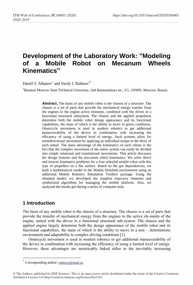
Development of the Laboratory Work: "Modeling of a Mobile Robot on Mecanum Wheels Kinematics” Daniil S. Alhanov 1 and Vasily I. Rubtsov 1* 1 Bauman Moscow State Technical University, 2nd Baumanskaya str., 5/1, 105005, Moscow, Russia Abstract. The basis of any mobile robot is the chassis of a structure. The chassis is a set of parts that provide the mechanical energy transfer from the engines to the engine active elements, combined with the drives in a functional structural subsystem. The chassis and the applied propulsion determine both the mobile robot design appearance and its functional capabilities, the main of which is the ability to move in given conditions. Omnicycle movement is used in modern robotics to get additional maneuverability of the device in combination with increasing the efficiency of using a limited level of energy. Such systems allow for omnidirectional movement by applying an individual torque to the drive of each wheel. The main advantage of the kinematics of such robots is the fact that the complex movement of the entire system can easily be divided into simple rotational and translational movements. This article discusses the design features and the mecanum wheel kinematics. We solve direct and inverse kinematics problems for a four-wheeled mobile robot with this type of propellers on a flat surface. Based on the got dependencies, we built a mathematical model in the Matlab Simulink environment using an additional Mobile Robotics Simulation Toolbox package. Using the obtained model, we developed the simplest trajectory elements and synthesized algorithms for managing the mobile platform. Also, we analyzed the results got during a series of computer tests. 1 Introduction The basis of any mobile robot is the chassis of a structure. The chassis is a set of parts that provide the transfer of mechanical energy from the engines to the active ele-ments of the engine, united with the drives in a functional structural sub-system. The chassis and the applied engine largely determine both the design appearance of the mobile robot and its functional capabilities, the main of which is the ability to move in a non – deterministic environment and adaptability to complex driving conditions [1]. Omnicycle movement is used in modern robotics to get additional maneuverability of the device in combination with increasing the efficiency of using a limited level of energy. However, these advantages are inextricably linked either to the inevitably increasing * Corresponding author: [email protected] © The Authors, published by EDP Sciences. This is an open access article distributed under the terms of the Creative Commons Attribution License 4.0 (http://creativecommons.org/licenses/by/4.0/). ITM Web of Conferences 35, 04001 (2020) ITEE-2019 https://doi.org/10.1051/itmconf/20203504001
-
Upload
khangminh22 -
Category
Documents
-
view
1 -
download
0
Transcript of Modeling of a Mobile Robot on Mecanum Wheels Kinematics
Development of the Laboratory Work: "Modeling of a Mobile Robot on Mecanum Wheels Kinematics”
Daniil S. Alhanov1 and Vasily I. Rubtsov1*
1Bauman Moscow State Technical University, 2nd Baumanskaya str., 5/1, 105005, Moscow, Russia
Abstract. The basis of any mobile robot is the chassis of a structure. The
chassis is a set of parts that provide the mechanical energy transfer from
the engines to the engine active elements, combined with the drives in a
functional structural subsystem. The chassis and the applied propulsion
determine both the mobile robot design appearance and its functional
capabilities, the main of which is the ability to move in given conditions.
Omnicycle movement is used in modern robotics to get additional
maneuverability of the device in combination with increasing the
efficiency of using a limited level of energy. Such systems allow for
omnidirectional movement by applying an individual torque to the drive of
each wheel. The main advantage of the kinematics of such robots is the
fact that the complex movement of the entire system can easily be divided
into simple rotational and translational movements. This article discusses
the design features and the mecanum wheel kinematics. We solve direct
and inverse kinematics problems for a four-wheeled mobile robot with this
type of propellers on a flat surface. Based on the got dependencies, we
built a mathematical model in the Matlab Simulink environment using an
additional Mobile Robotics Simulation Toolbox package. Using the
obtained model, we developed the simplest trajectory elements and
synthesized algorithms for managing the mobile platform. Also, we
analyzed the results got during a series of computer tests.
1 Introduction
The basis of any mobile robot is the chassis of a structure. The chassis is a set of parts that
provide the transfer of mechanical energy from the engines to the active ele-ments of the
engine, united with the drives in a functional structural sub-system. The chassis and the
applied engine largely determine both the design appearance of the mobile robot and its
functional capabilities, the main of which is the ability to move in a non – deterministic
environment and adaptability to complex driving conditions [1].
Omnicycle movement is used in modern robotics to get additional maneuverability of
the device in combination with increasing the efficiency of using a limited level of energy.
However, these advantages are inextricably linked either to the inevitably increasing
* Corresponding author: [email protected]
© The Authors, published by EDP Sciences. This is an open access article distributed under the terms of the Creative Commons Attribution License 4.0 (http://creativecommons.org/licenses/by/4.0/).
ITM Web of Conferences 35, 04001 (2020)ITEE-2019
https://doi.org/10.1051/itmconf/20203504001

complexity of the mechanical design of propellers or to the complexity of the control
algorithm structure [2].
Using roller wheels allows you to find a compromise and simplify the structure of the
control program of the mobile robot. Such systems allow for omnidirectional movement by
applying individual torque to the drive of each wheel. The resulting complex movement of
the entire system can easily be divided into simple rotational and translational movements,
which simplifies the algorithms for analyzing the flow state and controlling the mobile
robot [3].
The advantage of using roller wheels is the ability to turn in place with minimal friction
and low torque, combined with the absence of significant ground defor-mation [4]. Such a
wheel platform is controlled by individually controlling the speed and direction of rotation
of each drive [5]. The contact forces from each wheel even-tually form the resultant force,
which is the robot's motion vector. Because the above-described forces of contact
interaction depend on the spatial orientation of the wheel and the rollers on it, it is
necessary to ensure the preservation of the engine position relative to the support surface
[6]. To perform a maneuver, the drive of such a wheel need not to develop a large moment,
but the weight and cost of the final design are significantly higher compared to the chassis
on conventional engines [7].
2 Methods
2.1 Mecanum Wheel Design Analysis
Most often, the following version of the design of the roller wheel is used in practice – the
so-called mecanum wheel. In such a wheel, rollers are fixed on the periphery (outer rim), so
that the wheel rests on the bearing surface only with one of the rollers. Each roller rotates
freely around an axis that is stationary relative to the disk plane, and the wheel can roll in a
straight line that is a fixed angle with the wheel plane. For mecanum wheels, the roller axis
is fixed at an angle of γ=45° to the wheel plane. There are two versions of the design of
such roller wheels (see Fig. 1).
Fig. 1. Mecanum wheel design options.
The difference in the design of mecanum wheels is reflected in their characteristics. The
wheel presented in option a) is capable of handling heavy loads and is more stable than the
wheel of option b), but the possibility of such a wheel on an uneven surface is lower since
there is a risk of hitting the metal attachment on an obstacle during lateral movement.
However, kinematic dependencies are not affected by design differences.
At the initial design stage, wheels are defined with the number of the rollers on the
wheel and their geometric parameters. The peculiar shape of the rollers forms a circular
2
ITM Web of Conferences 35, 04001 (2020)ITEE-2019
https://doi.org/10.1051/itmconf/20203504001

silhouette of the wheel, ensuring smooth running in a straight line, despite the discreteness
of contact with the surface. The curve of the forming roller must satisfy equation [8]:
(1)
The location of the rollers and their minimum number also significantly affect the
rolling character of the wheel. The initial data for the design are the roller length and the
radius of the wheel . The design scheme for calculating the parameters of the elements of
the mecanum wheel is simplified in the figure below (see Fig. 2).
Fig. 2. The wheel design parameter calculation scheme.
Let be the angle between the lines connecting the geometric center of the wheel and
the projection of the roller ends on the disk plane. Then the required number of rollers can
be determined from the ratio:
(2)
If the number of rollers n is defined, we can write an expression for the length of the
roller:
(3)
At the last stage of calculation, the disk width is determined :
(4)
In the case of a mecanum wheel, the angle is defined, which simplifies the
calculation formula for the roller length:
√
(5)
The ratio for disk width is simplified in the same way:
(6)
This article will consider the kinematics of a wheel designed in the research (see Fig. 3).
3
ITM Web of Conferences 35, 04001 (2020)ITEE-2019
https://doi.org/10.1051/itmconf/20203504001

Fig. 3. General view of the mecanum wheel under consideration.
We choose a typical configuration of a mobile robot on a mecanum wheel - a four-
wheeled vehicle - as a mobile platform. When installing roller wheels, several requirements
must be met. There are left-hand and right-hand versions of mecanum wheels. The
difference between them is the location of the rollers – on the left – hand wheels, the rollers
are located from the lower right edge to the upper left, and on the right-hand side-from the
lower left to the upper right. A four-wheeled mobile robot must be equipped with two left-
hand and two right-hand roller wheels [9]. It is recommended to install the wheels so that
the axis of rotation of the upper roller points to the center of the platform, which will
facilitate system modeling and control algorithms [10]. As a mobile platform, this article
considers a simplified model of the mobile robot chassis prototype presented below (see
Fig. 4).
Fig. 4. General view of the mobile platform under consideration.
2.2 Kinematic Dependencies Analysis
In Fig. 5 you can see the configuration of the system parameters for an arbitrary robot
position relative to a fixed coordinate system associated with the earth.
4
ITM Web of Conferences 35, 04001 (2020)ITEE-2019
https://doi.org/10.1051/itmconf/20203504001

Fig. 5. Mobile robot parameters at any time.
You can see the wheel parameters in the coordinate system associated with the robot's
center of mass in Fig. 6.
Fig. 6. Caption of the Figure 1. Below the figure. Fig. 6. Wheel parameters in the robot's coordinate
system.
We have entered the following notation:
coordinate system – the underlying inertial coordinate system;
coordinate system – coordinate system associated with the robot's
center of mass;
coordinate system – coordinate system of the -th wheel with the center at a
point coinciding with the geometric center of the wheel;
– the distance between the geometric centers of the wheels along the width
and length of the platform, respectively;
– the distances from the robot center of mass to the axis of the wheels
geometric centers;
– the distance between the center of the wheel and the robot center of mass ;
5
ITM Web of Conferences 35, 04001 (2020)ITEE-2019
https://doi.org/10.1051/itmconf/20203504001

– current coordinates of the robot's center of mass in the base
coordinate system and the orientation angle of the platform – the angle between
the axes and ;
– the robot linear velocity;
– the robot angular velocity;
– angular velocity of the -th wheel;
– linear velocity of the -th wheel;
– linear velocity of the roller on the -th wheel;
– vector of the distance from the robot's center of mass to the geometric center
of the -th wheel;
– wheel radius (distance from the wheel geometric center to the roller
geometric center);
– roller radius;
– the angle between vector and axis – the angle between roller linear velocity and axis .
The system kinematics analysis begins with the consideration of the wheel movement
principle on the surface. The wheel rolling can be represented as the sum of translational
movement and rotational movement. For an ordinary wheel of a standard design, there are
two possible cases of surface movement: non-slip and non-slip movement [11]. In the case
of motion without slippage, the statement about the instantaneous center of speeds and zero
speed at the point of contact is valid (see Fig. 7).
Fig. 7. Diagram of the wheel movement without slipping.
Each of the mecanum wheel rollers can move independently of the disk. Therefore,
when moving the disk of the mecanum wheel "slips" on the surface of the rotating rollers.
We assumed that the rollers themselves do not slip when they contact the surface. We
should also note that in the absence of an angle between the roller and the disk, the wheel
would have to be rotated in the opposite direction to the movement. This does not happen
because of the presence of an angle and the formation of a kind of stop. This complex
movement can be considered as the movement of a standard-design wheel with a slip (see
Fig. 8).
Fig. 8. Diagram of the wheel movement in the presence of slippage.
6
ITM Web of Conferences 35, 04001 (2020)ITEE-2019
https://doi.org/10.1051/itmconf/20203504001

Configuration in which the wheel disk contacts the surface through a single roller is
convenient to study the wheel movement kinematic dependencies. In this case, the axis
from the point of roller attachment on the disk to the disk geometric center is perpendicular
to the wheel coordinate system (see Fig. 9).
Since each roller is fixed directly on the wheel disk, continuously moves together with the
disk, and is in contact with the surface for a short time, the angular speed of the wheel and
the roller are assumed to be equal [12].
Fig. 9. Diagram of the wheel movement when the roller contacts the surface.
Since we assumed that the roller moves on the surface without slipping, we made the
following expression:
(7)
The wheel disk moves with "slippage", so its velocity will be determined by the sum of
two components:
(8)
(9)
You can found the projection of the linear velocity of the wheel on the axis as:
(10)
The equation for the wheel linear velocity projections in matrix form is written as:
[
] [
] [
]
[
] (11)
Thus, the matrix in equation (11) is the transition matrix to the coordinate system
associated with the wheel geometric center. Since in this case of a four-wheeled mobile
robot, there is no angle between the coordinate system associated with the robot center of
mass and the coordinate system associated with the wheel geometric center, the velocity of
the -th wheel is projected without changes:
[
] [
] [
] [
] (12)
7
ITM Web of Conferences 35, 04001 (2020)ITEE-2019
https://doi.org/10.1051/itmconf/20203504001
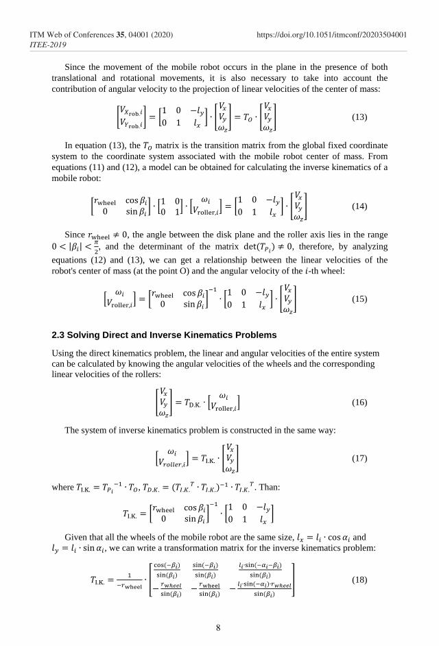
Since the movement of the mobile robot occurs in the plane in the presence of both
translational and rotational movements, it is also necessary to take into account the
contribution of angular velocity to the projection of linear velocities of the center of mass:
[
] [
] [
] [
] (13)
In equation (13), the matrix is the transition matrix from the global fixed coordinate
system to the coordinate system associated with the mobile robot center of mass. From
equations (11) and (12), a model can be obtained for calculating the inverse kinematics of a
mobile robot:
[
] [
] [
] [
] [
] (14)
Since , the angle between the disk plane and the roller axis lies in the range
| |
, and the determinant of the matrix
, therefore, by analyzing
equations (12) and (13), we can get a relationship between the linear velocities of the
robot's center of mass (at the point O) and the angular velocity of the -th wheel:
[
] [
]
[
] [
] (15)
2.3 Solving Direct and Inverse Kinematics Problems
Using the direct kinematics problem, the linear and angular velocities of the entire system
can be calculated by knowing the angular velocities of the wheels and the corresponding
linear velocities of the rollers:
[
] [
] (16)
The system of inverse kinematics problem is constructed in the same way:
[
] [
] (17)
where
,
. Than:
[
]
[
]
Given that all the wheels of the mobile robot are the same size, and
, we can write a transformation matrix for the inverse kinematics problem:
[
] (18)
8
ITM Web of Conferences 35, 04001 (2020)ITEE-2019
https://doi.org/10.1051/itmconf/20203504001

Similarly, you can get the matrix of a direct kinematics problem:
[
(
)
(
)
]
(19)
Assuming that there is no slippage between the rollers of the mecanum wheels and the
movement surface, we can get the final expression for the inverse kinematics problem of
the system:
[
]
[
]
[
] (20)
You are free to use colour illustrations for the online version of the proceedings, but any
print version will be printed in black and white unless special arrangements have been
made with the conference organiser. Please check whether or not this is the case. If the print
version will be black and white only, you should check your figure captions carefully and
remove any reference to colour in the illustration and text. In addition, some colour figures
will degrade or suffer loss of information when converted to black and white, and this
should be considered when preparing them.
2.4 Kinematic Model Development
During the mathematical model development, we simplified kinematic dependencies,
taking into account the specific values of the design angles of the mobile robot. These
parameters are summarized in Table 1. The distance from the mobile robot center of mass
to the wheel geometric centers was replaced with the overall dimensions of the platform.
Table 1.
Wheel number
1
2
3
4
You can see the final simplified calculation scheme with the parameters used for the
mathematical model in Fig. 10.
9
ITM Web of Conferences 35, 04001 (2020)ITEE-2019
https://doi.org/10.1051/itmconf/20203504001

Fig. 10. Calculation scheme of the mathematical model.
Notation on the calculation scheme of the mathematical model:
– mobile robot linear velocity;
– mobile robot angular velocity;
– mobile robot orientation (the yaw angle);
– the platform overall dimensions (the distance between the geometric
centers of the wheels);
– mobile robot wheels’ angular velocities.
With this configuration, the transformation matrix for the inverse (equation 21) and
forward (equation 22) kinematics problems will take the following form:
[
]
(21)
[
] (22)
Following equations (21) and (22), we derived the final formulations of kinematics
problems. The direct kinematics problem is defined by the following dependencies:
[ ]
[
] [
] (23)
Mobile robot longitudinal velocity:
(24)
10
ITM Web of Conferences 35, 04001 (2020)ITEE-2019
https://doi.org/10.1051/itmconf/20203504001

Mobile robot transverse velocity:
(25)
Mobile robot angular velocity:
(26)
Mobile robot full velocity:
√
(27)
The direction of the mobile robot's motion vector:
(
) (28)
The inverse kinematics problem is defined by the following dependencies:
[
]
[
]
[ ] (29)
The angular speed of each wheel of the mobile robot:
{
( (
) )
( (
) )
( (
) )
( (
) )
(30)
2.5 Mathematical Model Implementation
We performed the implementation of the kinematic model provided in 2.4. in the Matlab
Simulink software environment using an additional Mobile Robotics Simula-tion Toolbox
package. This package provides a Toolkit for the simulation of the mobile robot and the
development of control algorithms. In particular, the Mobile Robotics Simulation Toolbox
provides 2D visualization capabilities, working with the leader model and detecting
obstacles, etc.
As a result, we developed a debugging mathematical model of a mobile robot on
mecanum-wheels, the structural and functional scheme of which is shown in Fig. 11.
11
ITM Web of Conferences 35, 04001 (2020)ITEE-2019
https://doi.org/10.1051/itmconf/20203504001

Fig. 11. Debugging mathematical model of robot kinematics
Kinematic dependencies are specified in the blocks for calculating forward and re-verse
kinematics problems using Matlab functions. The model uses the wheel radius, geometric
parameters of the platform, and the initial orientation of the robot as its initial parameters.
Management can be implemented either by using specific parame-ters or by using a certain
law. The control signals are either the velocities of each of the mobile robot's wheels or the
linear and angular velocities of the center of mass. You can see the result of the
mathematical model in Fig. 12. On the left, you can see the result of working with the
model when the trajectory is set explicitly (in this case, for a circle), and on the right, you
can see the result when working with complex par-ametrically defined trajectory elements.
Fig. 12. Modeling results
3 Conclusion
As a result of this work, we describe the main features of the mecanum-wheel design and
analyzed the kinematic dependencies of the four-wood mobile robot using this type of
propellers. We solved direct and inverse kinematics problems for this device configuration
and developed a kinematic model of a mobile robot in the Matlab Simulink software
environment using an additional Mobile Robotics Simulation Toolbox package. According
to the results of 32 computer tests, during which the trajectory elements varied, we accepted
the developed mathematical model as work-able.
Based on the results got, we formed a laboratory work on the course "RTS Design" for
students of the SM7 Department, which is aimed at:
familiarization with the design features and design methods of mecanum-wheel;
learning the functionality of the additional Matlab Mobile Robotics Simulation
Toolbox package;
solution of direct and inverse kinematics problems on the example of a mobile
robot on mecanum-wheels;
12
ITM Web of Conferences 35, 04001 (2020)ITEE-2019
https://doi.org/10.1051/itmconf/20203504001

building a mathematical model based on the got dependencies.
References
1. A.V. Vasil'ev, Principy postroeniya i klassifikaciya shassi mobil'nyh robotov
nazemnogo primeneniya i planetohodov [Principles of Construction and Classification
of Chassis of Mobile Robots for Ground Use and Planetary Vehicles], Nauchno-
tekhnicheskie vedomosti SPbGPU. Informatika. Telekommunikacii. Upravlenie
[Scientific and Technical Bulletin of SPbGPU. Computer Science.
Telecommunications. Management] (2013).
2. E.U. Kolesnichenko, V.E. Pavlovskij, D.A. Gribkov, I.A. Orlov, A.P. Alisejchik,
Kinematicheskoe upravlenie dvizheniem shestikolesnogo mekanum-robota [Kinematic
Motion Control of a Six-wheeled Mecanum Robot], izdatel'stvo instituta prikladnoj
matematiki M.V.Keldysha, RAN [Publishing House of the Keldysh Institute of
Applied Mathematics, RAS] (2016).
3. F. Becker, O. Bondarev, I. Zeidis, K. Zimmermann, An Approach to the Kinematics
and Dynamics of a Four-wheel Mecanum Vehicle, Special Issue of Scientific Journal
of IFToMM “PROBLEMS OF MECHANICS”, № 2(55) (2014).
4. U.G. Martynenko, A.M. Formal'skij, O dvizhenii mobil'nogo robota s rolikone-
sushchimi kolesami [About the Movement of a Mobile Robot with Roller Wheels],
Izvestiya RAN. Teoriya i sistemy upravleniya [Izvestiya RAS. Theory and Control
Systems], № 6, pp. 142–149 (2007).
5. Giovanni Indiveri, Swedish wheeled omnidirectional mobile robots: kinematics
analysis and control, Dipartimento Ingegneria Innovazione, University of Salento,
Lecce, Italy.
6. A.A. Kilin, A.D. Bobykin, Upravlenie telezhkoj s omniwheelmi na ploskosti [Control
of a Cart with Omnicycles on a Plane], Nelinejnaya dinamika [Nonlinear Dynamics],
vol. 10, № 4, pp. 473–481 (2014).
7. Olaf Diegel, Apama Badve, Glen Bright, Johan Potgieter, Sylvester Tlale, Imoroved
Mechanum Wheel Design for Omni-directional Robots, Australian Conference on
Robotics and Automation (2002).
8. I. Doroftei, V. Spinu, V. Grosu, Omnidirectional Mobile Robot – Design and
Implementation, Bioinspiration and Robotics: Walking and Climbing Robots (2007).
9. R. P. A. van Haendel, Design of an omnidirectional universal mobile platform,
Eindhoven University of Technology (2005).
10. Xiang Li, Andreas Zell, Motion Control of an Omnidirectional Mobile Robot,
Wilhelm-Schickard-Institute, Departmant of Computer Architecture, University of
Tubingen (2012).
11. Hamid Taheri, Bing Qiao, Nurallah Ghaeminezhad, Kinematic Model of a Four
Mecanum Wheeled Mobile Robot, International Journal of Computer Applications
(0975 – 8887), vol. 113, No. 3.
12. D.U. Motorina, Algoritm postroeniya zapazdyvayushchego upravleniya dlya
mobil'nogo kolesnogo robota pri uchete effekta proskal'zyvaniya koles [Algorithm for
Constructing a Delayed Control for a Mobile Wheeled Robot with the Account of the
Wheel Slip Effect], Matematicheskoe mode-lirovanie, chislennye metody i kompleksy
program. Avtomatizaciya processov upravleniya [Mathematical Modeling, Numerical
Methods and Software Complexes. Automation of Management Processes], № 3 (25) (2011).
13
ITM Web of Conferences 35, 04001 (2020)ITEE-2019
https://doi.org/10.1051/itmconf/20203504001