Modeling magnetic nanoparticle dipole-dipole interactions inside living cells
11
PHYSICAL REVIEW B 84, 075480 (2011) Modeling magnetic nanoparticle dipole-dipole interactions inside living cells Michael L´ evy, Florence Gazeau, Jean-Claude Bacri, Claire Wilhelm, and Martin Devaud * Laboratoire Mati` ere et Syst` emes Complexes (MSC), UMR CNRS 7057, Universit´ e Paris-Diderot, Bˆ atiment Condorcet-Case 7056, F-75205 Paris Cedex 13, France (Received 8 February 2011; revised manuscript received 27 May 2011; published 16 August 2011) Biomedical applications based on superparamagnetic nanoparticles injected in vivo may be affected by the cellular uptake of these nanoparticles. Living cells indeed capture and internalize nanoparticles, concentrating them into intracellular vesicles called lysosomes. As a consequence, nanoparticles interact magnetically with each other, modifying their magnetic properties. The effects of cellular uptake can be observed on the temperature dependence of zero-field cooled (ZFC) magnetization, which is known to be sensitive to magnetic interactions. In this paper, a theoretical model is proposed to account for weak magnetic interactions between nanoparticles aggregated into spherical compartments. This model suggests a new interpretation of the maximum of the ZFC curve, uncorrelated with the nanoparticle relaxation time but with the extent of interaction effects. It focuses on the local field felt by each nanoparticle, which is the sum of the applied magnetic field and the field created by all the other nanoparticles. For the considered organization of nanoparticles, only the field created by touching neighbors has to be taken into account, setting up the local nanoparticle volume fraction as the unique parameter of the model. This parameter relates the global magnetization measurements to the local distribution of nanoparticles in cells and tissues or in other complex media with aggregated organization. DOI: 10.1103/PhysRevB.84.075480 PACS number(s): 75.75.Jn, 87.85.Tu, 87.55.de I. INTRODUCTION Biomedical science develops an increasing number of applications based on the magnetic properties of superpara- magnetic nanoparticles (NPs). These applications, such as using superparamagnetic NPs as MRI contrast agents 1,2 or as nanoheaters in magnetic hyperthermia, 3–5 involve injecting NPs into the body. Yet, it has been shown that for a majority of cases, NPs do not stay free in the body. They are captured and internalized by living cells, especially macrophages, sequestering them in intracellular compartments called lysosomes, 6 which are specialized organelles in charge of digesting nonusable substances. Remarkably, in the course of cell internalization, the nanoparticles change their local distribution from dilute NPs in the blood flow to highly concentrated organization inside lysosomes with typical size of 0.2–2 μm. The same intracellular confinement occurs for cells cultured in vitro and exposed to magnetic NPs diluted in their extracellular medium. Such a local sequestration of NPs is revealed by transmission electron microscopy (TEM) observations at the nanoscale. While the distribution of NPs is biologically orchestrated at the subcellular level, it may have fundamental consequences on their magnetic behavior. A precise knowledge of NP organization in cells is thus mandatory to optimize their magnetic properties with respect to the considered medical application. Recently we raised the issue that dipolar interparticle interactions may affect the magnetic behavior of NPs sequestered in a lysosome. 7 We indeed observed that the temperature-dependent magnetiza- tion was modified by cell internalization of NPs, revealing collective magnetic effects. The maximum of zero-field cooled (ZFC) magnetization was shifted toward higher temperature and its amplitude was decreased for cell-internalized NPs as compared to isolated NPs in colloidal suspension. Interestingly similar phenomena were observed in other complex systems with a mesoscopic organization of NPs. 8–10 The general approach of this paper is to provide a theoretical framework to describe the magnetic behavior of NPs confined in spherical compartments. A first objective is to link up the magnetic properties of NPs to their local distribution. If the local organization of NPs can be deduced from global magnetization measurements, it could be of primary interest to assess the mesoscopic distribution of NPs in biological samples. Secondly, our approach is the first attempt to delineate the modification of magnetic properties due to cell internalization process. For this purpose and for the sake of simplicity, our analysis is restricted to the interpretation of the ZFC magnetization behavior (at low field), which is sensitive to the whole distribution of relaxation times in the NP assembly with a well-known sensitivity to interparticle magnetic interactions. Previous experimental and theoretical studies investigated the role of dipole-dipole magnetic interactions on the dy- namical behavior of NPs. 8–20 Concerning weak interactions, conflicting models have been proposed. In the Dormann- Bessais-Fiorani (DBF) approach, 11,13 interactions result in an increase of the energy barrier of individual NPs which, as a consequence, increases their magnetic relaxation time. However, the Mørup-Tronc model (MT) using a mean-field approximation, predicts the opposite trend 12,13 with a decrease of relaxation times. Let us notice that these two models analyze the magnetization relaxation time but do not consider the evolution of the magnetization value itself. On the other hand, a third model, known as the interacting superparamagnetic model (ISP), describes the effects of interaction on the mag- netization value by adding a phenomenological temperature T ∗ to the real one. 10,14 This temperature T ∗ is supposed to mimic the disorder of the NP magnetic moments caused by the random dipolar magnetic field they experiment. It must be noted that these models and the majority of experimental and numerical studies consider concentrated ferrofluids or powders. By contrast, in the present paper, we propose a model to interpret ZFC experiments on compartmentalized NPs which can be regarded as finite aggregates at a submicron scale. 075480-1 1098-0121/2011/84(7)/075480(11) ©2011 American Physical Society
-
Upload
independent -
Category
Documents
-
view
2 -
download
0
Transcript of Modeling magnetic nanoparticle dipole-dipole interactions inside living cells

PHYSICAL REVIEW B 84, 075480 (2011)
Modeling magnetic nanoparticle dipole-dipole interactions inside living cells
Michael Levy, Florence Gazeau, Jean-Claude Bacri, Claire Wilhelm, and Martin Devaud*
Laboratoire Matiere et Systemes Complexes (MSC), UMR CNRS 7057, Universite Paris-Diderot, Batiment Condorcet-Case 7056,F-75205 Paris Cedex 13, France
(Received 8 February 2011; revised manuscript received 27 May 2011; published 16 August 2011)
Biomedical applications based on superparamagnetic nanoparticles injected in vivo may be affected by thecellular uptake of these nanoparticles. Living cells indeed capture and internalize nanoparticles, concentratingthem into intracellular vesicles called lysosomes. As a consequence, nanoparticles interact magnetically witheach other, modifying their magnetic properties. The effects of cellular uptake can be observed on the temperaturedependence of zero-field cooled (ZFC) magnetization, which is known to be sensitive to magnetic interactions.In this paper, a theoretical model is proposed to account for weak magnetic interactions between nanoparticlesaggregated into spherical compartments. This model suggests a new interpretation of the maximum of the ZFCcurve, uncorrelated with the nanoparticle relaxation time but with the extent of interaction effects. It focuses on thelocal field felt by each nanoparticle, which is the sum of the applied magnetic field and the field created by all theother nanoparticles. For the considered organization of nanoparticles, only the field created by touching neighborshas to be taken into account, setting up the local nanoparticle volume fraction as the unique parameter of themodel. This parameter relates the global magnetization measurements to the local distribution of nanoparticlesin cells and tissues or in other complex media with aggregated organization.
DOI: 10.1103/PhysRevB.84.075480 PACS number(s): 75.75.Jn, 87.85.Tu, 87.55.de
I. INTRODUCTION
Biomedical science develops an increasing number ofapplications based on the magnetic properties of superpara-magnetic nanoparticles (NPs). These applications, such asusing superparamagnetic NPs as MRI contrast agents1,2 oras nanoheaters in magnetic hyperthermia,3–5 involve injectingNPs into the body. Yet, it has been shown that for amajority of cases, NPs do not stay free in the body. Theyare captured and internalized by living cells, especiallymacrophages, sequestering them in intracellular compartmentscalled lysosomes,6 which are specialized organelles in chargeof digesting nonusable substances. Remarkably, in the courseof cell internalization, the nanoparticles change their localdistribution from dilute NPs in the blood flow to highlyconcentrated organization inside lysosomes with typical sizeof 0.2–2 μm. The same intracellular confinement occurs forcells cultured in vitro and exposed to magnetic NPs dilutedin their extracellular medium. Such a local sequestration ofNPs is revealed by transmission electron microscopy (TEM)observations at the nanoscale. While the distribution of NPsis biologically orchestrated at the subcellular level, it mayhave fundamental consequences on their magnetic behavior.A precise knowledge of NP organization in cells is thusmandatory to optimize their magnetic properties with respectto the considered medical application. Recently we raisedthe issue that dipolar interparticle interactions may affect themagnetic behavior of NPs sequestered in a lysosome.7 Weindeed observed that the temperature-dependent magnetiza-tion was modified by cell internalization of NPs, revealingcollective magnetic effects. The maximum of zero-field cooled(ZFC) magnetization was shifted toward higher temperatureand its amplitude was decreased for cell-internalized NPs ascompared to isolated NPs in colloidal suspension. Interestinglysimilar phenomena were observed in other complex systemswith a mesoscopic organization of NPs.8–10
The general approach of this paper is to provide a theoreticalframework to describe the magnetic behavior of NPs confined
in spherical compartments. A first objective is to link upthe magnetic properties of NPs to their local distribution. Ifthe local organization of NPs can be deduced from globalmagnetization measurements, it could be of primary interestto assess the mesoscopic distribution of NPs in biologicalsamples. Secondly, our approach is the first attempt todelineate the modification of magnetic properties due to cellinternalization process. For this purpose and for the sakeof simplicity, our analysis is restricted to the interpretationof the ZFC magnetization behavior (at low field), which issensitive to the whole distribution of relaxation times in theNP assembly with a well-known sensitivity to interparticlemagnetic interactions.
Previous experimental and theoretical studies investigatedthe role of dipole-dipole magnetic interactions on the dy-namical behavior of NPs.8–20 Concerning weak interactions,conflicting models have been proposed. In the Dormann-Bessais-Fiorani (DBF) approach,11,13 interactions result inan increase of the energy barrier of individual NPs which,as a consequence, increases their magnetic relaxation time.However, the Mørup-Tronc model (MT) using a mean-fieldapproximation, predicts the opposite trend12,13 with a decreaseof relaxation times. Let us notice that these two models analyzethe magnetization relaxation time but do not consider theevolution of the magnetization value itself. On the other hand,a third model, known as the interacting superparamagneticmodel (ISP), describes the effects of interaction on the mag-netization value by adding a phenomenological temperatureT ∗ to the real one.10,14 This temperature T ∗ is supposed tomimic the disorder of the NP magnetic moments caused bythe random dipolar magnetic field they experiment. It mustbe noted that these models and the majority of experimentaland numerical studies consider concentrated ferrofluids orpowders. By contrast, in the present paper, we propose amodel to interpret ZFC experiments on compartmentalizedNPs which can be regarded as finite aggregates at a submicronscale.
075480-11098-0121/2011/84(7)/075480(11) ©2011 American Physical Society

LEVY, GAZEAU, BACRI, WILHELM, AND DEVAUD PHYSICAL REVIEW B 84, 075480 (2011)
FIG. 1. TEM experiments on the two biological systems. NPs arein dark. (a) TEM on AMNP internalized in macrophages culturedin vitro. Magnetic NPs are localized in intracellular vesicles calledlysosomes. The inset shows a zoom on a particular lysosome.(b) TEM on P904 NPs internalized in a mouse liver, 3 days afterinjection. Magnetic NPs are localized in lysosomes, too, which arebigger and more concentrated than in (a). The inset shows a zoom ona particular lysosome.
We analyze the effects of weak interactions on both therelaxation time and the magnetization itself. Similarities anddifferences with previous models are underlined. In particular,our approach suggests a new interpretation of the maximumof the ZFC curve, which is not directly correlated with theNP relaxation time. In addition, we show that this simpleexperiment, when analyzed within the framework of thepresent model, can give an assessment of the local distributionof NPs in cells and organs or in other complex systems withaggregated organization.
The present paper is organized as follows. After presentingthe experimental results on biological samples (II), we remindthe standard theory of ZFC magnetization for noninteractingNPs and apply it to NPs in diluted colloidal suspensions(III). Then we propose an expression for the distribution oflocal fields experienced by NPs aggregated in a sphericalcompartment. The consequence of these local fields on thetemperature dependence of ZFC magnetization is finallyderived (IV) and discussed with respect to other models andexperimental results (V).
II. EXPERIMENTS
ZFC magnetization measurements were made on twobiological systems representative of most in vitro andin vivo localizations of iron oxide NPs. On the one hand,the in vitro model system consisted of macrophages derivedfrom the activation of human monocytes. These cells wereincubated with different concentrations of anionic citrate-coated maghemite NPs (referred to as AMNP) in order totune the amount of cell-internalized NPs.21 The internal-ization pathway of these NPs has been described earlierand their cellular uptake has been quantified by single-cellmagnetophoresis.6,22 TEM pictures of macrophages reveal theintracellular localization of NPs and their confinement intosubmicron lysosomes23 [Fig. 1]. On the other hand, similarmagnetic NPs (used as MRI contrast agents and referred toas P904) were administrated to mice by intravenous injection.As liver and spleen concentrate large populations of residentmacrophages,24 NPs mainly accumulate in these organs.25
They are specifically uptaken by macrophages and sequesteredwithin their intracellular lysosomes at remarkably high densityas exemplified in Fig. 1(b).
Magnetization measurements were performed on cell sus-pension or dried organ using a SQUID magnetometer (MPMSXL Quantum Design). The global NP volume fraction φ
in biological samples was small enough (φ ∼ 10−4 − 10−5)to neglect any demagnetizing effect linked to their globalmagnetization. As a comparison, the same measurementswere done on the corresponding noninteracting NPs dilutedin glycerol (φ ∼ 10−3 − 10−4). Samples were cooled down to5 K without any applied field (ZFC), next applying a magneticfield of 50 Gauss and heating slowly up to room temperature,while measuring the magnetization of the sample as a functionof temperature. The experimental magnetization Mexp wasnormalized by the maximum magnetization for each sampleMmax = φMs which represents the magnetization when allNPs in a unit volume have their magnetic moments aligned inthe field direction. Here, Ms is the saturation magnetization ofthe bulk material at 300 K (we ignore the slight temperaturedependence of Ms).
(a) (b)
FIG. 2. Reduced magnetization Mexp/Mmax in ZFC experiments on (a) AMNP in dilute ferrofluid and internalized in macrophages (thecontent in AMNP increases from 5 to 60 pg of AMNP per cell); (b) P904 in dilute ferrofluid and internalized in a mouse liver, 3 days afterinjection.
075480-2
MODELING MAGNETIC NANOPARTICLE DIPOLE-DIPOLE . . . PHYSICAL REVIEW B 84, 075480 (2011)
ZFC magnetization observed in biological systems showclear differences with the corresponding dilute ferrofluidconsisting of noninteracting NPs [Figs. 2(a) and 2(b)]:
(1) The magnetization measured in the ZFC experiment islower for NPs in biological systems than for free NPs and thisdifference decreases with temperature.
(2) The temperature corresponding to the maximum of theZFC curve, referred to as the blocking temperature TB , ishigher for NPs in biological systems than in dilute ferrofluids,
(3) More precisely [see Fig. 2(a)], the higher the concentra-tion of internalized nanoparticles, the lower the magnetizationand the higher TB .
It is important to note that NPs are not significantlydegraded or transformed by the cells at the time of theexperiments (maximum of 3 days postinjection). It has beenshown that the metabolization process actually takes a longertime.25,26 We also verified that the NP size distributionis identical in the dilute suspension and inside the cells.Therefore the modifications of ZFC magnetization comparedto noninteracting NPs appear directly linked up to the degreeof intracellular confinement of NPs. Consistently with TEMobservations, the effects are accentuated in ex vivo livercompared to in vitro macrophages. The larger the intracellularclustering (which also increased with the cell NP load), thehigher the effects on ZFC magnetization. More extensiveexperiments reported elsewhere7 show similar modificationsdepending on cellular sequestration of NPs in different organs.We also verified that NPs enclosed in submicron polymer beadsdisplay the same behavior. Similar effects were reported beforein other systems with interacting NPs.8–10 The theory wepropose in this paper aims at accounting for these observations.Before presenting it, we first recall in the next section thestandard ZFC theory for noninteracting NPs.27,28
III. THE STANDARD ZFC THEORY
Let us consider a sample of polydisperse dilute super-paramagnetic NPs: Due to the dilution, magnetic interactionsbetween them can be neglected. These NPs are fixed in a solidsolvent so that they cannot rotate. The distribution P (dm) of theparticle magnetic diameters dm is described by the log-normalfunction:
P (dm) = 1√2πσmdm
e
[− ln2(dm/d0)
2σ2m
], (1)
with d0 the characteristic magnetic diameter and σm thepolydispersity index (a log-normal function is commonlyused to describe the size distribution of NPs synthesized bycoprecipitation). Note that the real diameter dr of an NP isconsidered slightly larger than the magnetic one to take the“nonmagnetic layer” at the surface of the NP and its potentialcoating into account: dr = dm + 2δ, with δ the thickness ofthe “nonmagnetic layer” plus the coating (δ is typically 1 nm;we suppose it independent of dm). It will be useful thereafterto define dmean as the mean real diameter and μmean as themagnetic moment of an NP with real diameter dmean:
dmean = 〈dm + 2δ〉 = d0e2σ 2m + 2δ. (2)
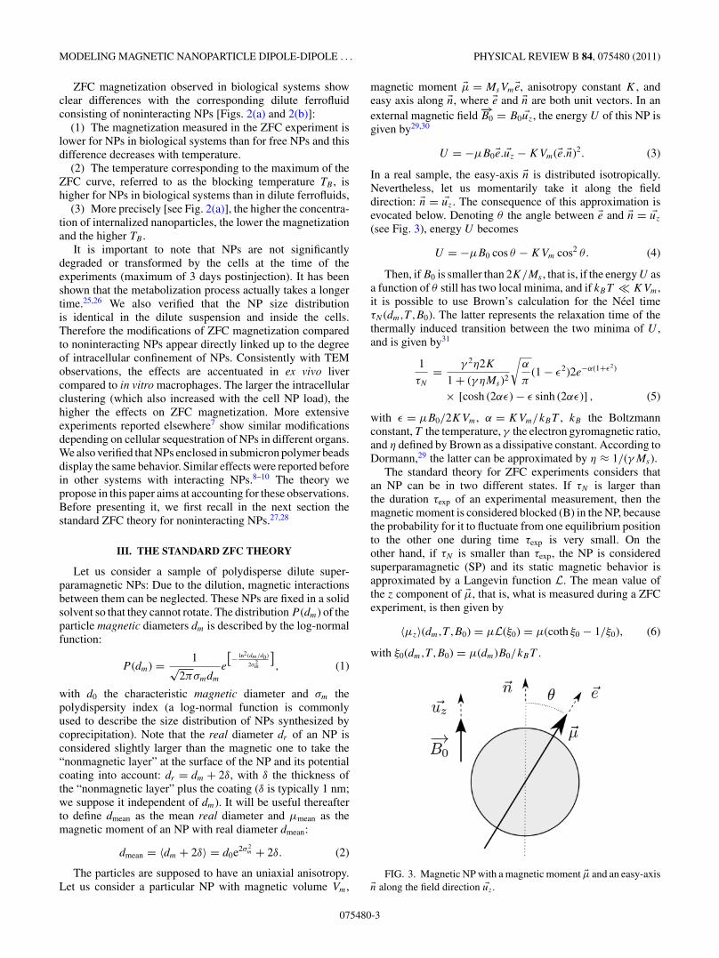
The particles are supposed to have an uniaxial anisotropy.Let us consider a particular NP with magnetic volume Vm,
magnetic moment �μ = MsVm�e, anisotropy constant K , andeasy axis along �n, where �e and �n are both unit vectors. In anexternal magnetic field
−→B0 = B0 �uz, the energy U of this NP is
given by29,30
U = −μB0�e. �uz − KVm(�e.�n)2. (3)
In a real sample, the easy-axis �n is distributed isotropically.Nevertheless, let us momentarily take it along the fielddirection: �n = �uz. The consequence of this approximation isevocated below. Denoting θ the angle between �e and �n = �uz
(see Fig. 3), energy U becomes
U = −μB0 cos θ − KVm cos2 θ. (4)
Then, if B0 is smaller than 2K/Ms , that is, if the energy U asa function of θ still has two local minima, and if kBT KVm,it is possible to use Brown’s calculation for the Neel timeτN (dm,T ,B0). The latter represents the relaxation time of thethermally induced transition between the two minima of U ,and is given by31
1
τN
= γ 2η2K
1 + (γ ηMs)2
√α
π(1 − ε2)2e−α(1+ε2)
× [cosh (2αε) − ε sinh (2αε)] , (5)
with ε = μB0/2KVm, α = KVm/kBT , kB the Boltzmannconstant, T the temperature, γ the electron gyromagnetic ratio,and η defined by Brown as a dissipative constant. According toDormann,29 the latter can be approximated by η ≈ 1/(γMs).
The standard theory for ZFC experiments considers thatan NP can be in two different states. If τN is larger thanthe duration τexp of an experimental measurement, then themagnetic moment is considered blocked (B) in the NP, becausethe probability for it to fluctuate from one equilibrium positionto the other one during time τexp is very small. On theother hand, if τN is smaller than τexp, the NP is consideredsuperparamagnetic (SP) and its static magnetic behavior isapproximated by a Langevin function L. The mean value ofthe z component of �μ, that is, what is measured during a ZFCexperiment, is then given by
〈μz〉(dm,T ,B0) = μL(ξ0) = μ(coth ξ0 − 1/ξ0), (6)
with ξ0(dm,T ,B0) = μ(dm)B0/kBT .
FIG. 3. Magnetic NP with a magnetic moment �μ and an easy-axis�n along the field direction �uz.
075480-3

LEVY, GAZEAU, BACRI, WILHELM, AND DEVAUD PHYSICAL REVIEW B 84, 075480 (2011)
(a) (b)
FIG. 4. (Color online) Comparison between the ZFC standard theory and the experiments on dilute ferrofluids. (a) ZFC experiment onAMNP in dilute ferrofluid and corresponding theoretical curve; (b) ZFC experiment on P904 in dilute ferrofluid and corresponding theoreticalcurve.
In a ZFC experiment, one actually measures Mz(T ), thetotal magnetization of a sample along the applied fielddirection �uz: the z components of all magnetic momentsshould be added and renormalized by the sample volume.The sample was frozen in absence of any field. Then, themagnetic moments of the NPs in the (B) state are isotropicallydistributed. As a consequence, the latter do not contributeto Mz. Only the magnetic moments of the NPs in the (SP)state at the considered temperature contribute to Mz, adding〈μz〉(dm,T ,B0) for each of them:
Mz(T ,B0) = N
∫sp(T ,B0)
ddmP (dm)〈μz〉(dm,T ,B0), (7)
with N the mean number of NPs per unit volume. As explainedabove, the integration is made only over the NPs in the (SP)state at the considered temperature T and field B0, that is,over dm values smaller than a critical diameter depending onT and B0. Since the number of these NPs in the (SP) stateincreases with temperature, Mz starts to increase accordingly.But the contribution to Mz of a given NP in the (SP) state,〈μz〉(dm,T ,B0), decreases with temperature according to theLangevin function (6). So, when most of the NPs have transitedto the (SP) state, Mz(T ) starts to decrease. Note that thetemperature corresponding to the maximum of Mz(T ) (alreadyreferred to as the blocking temperature TB) depends on B0.
In Figs. 4(a) and 4(b), theoretical as well as experimentalcurves are plotted for the two dilute ferrofluids. No fittingparameters are used. Ms is taken as the saturation magne-tization (Ms = 412 kA.m−1) of bulk maghemite, K valuesare experimentally determined from hysteresis loops at lowtemperature (5 K) using the Stoner-Wohlfarth model32 (datanot shown), and d0 and σm are deduced from the polydisperseLangevin fits of magnetization curves at room temperature(data not shown). The parameters values are summarized inTable I.
Two comments may be made about the approximationsused:
(1) The two dynamical behaviors, blocked (B) or superpara-magnetic (SP), respectively, correspond to the two limit casesτN � τexp and τN τexp. The approximation that the NPsare either in the (B) state or in the (SP) state (and never in an
intermediate one) is justified by the fact that τN varies abruptlywith the size of the NP (as the exponential of the volume), sothat there are very few NPs in an intermediate state. We cantherefore introduce the proportions Psp and Pb of NPs in the(SP) and (B) state, respectively:
Psp(T ,B0) =∫
sp(T ,B0)ddmP (dm),
(8)Pb(T ,B0) = 1 − Psp(T ,B0).
(2) As indicated above, the assumption that the easy-axis�n is in the direction of the field allows us to use the Brownexpression (5) for τN . For those NPs with an easy axis inanother direction, it can be argued that τN is shorter. Thissuggests that the standard theory underestimates the (SP)population. Note that it would be possible to take into accountthe isotropic easy-axis distribution in the τN expression aspresented in Refs. 12, 13, 33 and 34. here. Nevertheless, itwould complicate the model without modifying the physics.Actually, the standard ZFC theory is often presented usingan approximation rougher than (5) for the τN expression:τN ≈ τ0e
α , with τ0 a constant parameter of the order of 10−9.We have preferred expression (5) to keep the field dependenceof τN .
Despite the approximations made, the standard theory forZFC experiments on superparamagnetic NPs satisfactorilydescribe the experimental results for the two dilute ferrofluids.However, this theory evidently fails for the two biologicalsystems as shown by Figs. 2(a) and 2(b). In the present paper,we make and discuss the assumption that this failure is due tothe magnetic interactions that prevail between the NPs as soonas the latter are internalized in lysosomes.
TABLE I. Sample parameters used for the theoretical calculation.
Sample d0(nm) σm K(J m−3) Ms(kA m−1) δ(nm)
AMNP 6.5 0.33 2.06 × 10⁴ 412 1P904 7.2 0.24 2.47 × 10⁴ 412 1
075480-4

MODELING MAGNETIC NANOPARTICLE DIPOLE-DIPOLE . . . PHYSICAL REVIEW B 84, 075480 (2011)
FIG. 5. (Color online) Model of spherical lysosome with amagnetization Mlys under an applied magnetic field B0. The Lorentzcavity around a particular (SP) NP (in dark) is displayed and thesurface currents I and i on the surface of the lysosome and of thecavity, respectively, are also represented.
IV. AN ALTERNATIVE THEORY DESIGNED FOR NPSAGGREGATED IN A SPHERICAL COMPARTMENT
A. Modeling of the lysosome
We model the considered lysosomes as spherical compart-ments nonhomogeneously filled with aggregated NPs (Fig. 5).Let notice that most NPs are touching some neighbors, contraryto an homogeneous concentrated ferrofluid where each NP isseparated from its neighbors by some nonzero mean distance.Magnetic interactions between lysosomes are neglected (weconsider that the majority of them are separated from eachother by more than a mean lysosome diameter).
B. Local magnetic field
As in the standard theory, NPs are considered to be eitherin the (B) or in the (SP) state, depending on their Neel time τN .The latter time τN still depends not only on the temperatureT, but also on the intensity of the local magnetic field
−→Bloc =
Bloc−→uloc (−→uloc unit vector) felt by each given NP. Note that the
expression (5) of τN we are using still has a meaning as long asthe energy U conserves two local minima (i.e., as long as Bloc
is not too high). That is the reason why the model is limitedto weak interactions. The restriction induced by this conditionwill be discussed in Sec. V.
The magnetic moments of the NPs in the (B) state, exactlyas in the standard theory, do not contribute to Mz (thenumber of such NPs in the lysosomes being large enough toaverage their collective contribution to zero). At the mean-fieldapproximation, NPs in the (SP) state behave according to theLangevin function, but now in the local magnetic field
−→Bloc they
undergo, and no longer in the mere applied magnetic field−→B0,
which can be written [compare with (6)] as
〈μz〉(dm,T ,−→Bloc) = μL(ξloc)−→uloc. �uz, (9)
with ξloc(dm,T ,Bloc) = μ(dm)Bloc/kBT . Observe that−→Bloc,
contrary to−→B0, depends on the particular (SP) NP under
consideration.In order to determine
−→Bloc, the Lorentz method is available.
It leads one to introduce a local spherical Lorentz cavity, withcenter at the considered (SP) NP. The local field
−→Bloc is then
defined as the field created at the center of the Lorentz cavity
by all magnetic field sources except this considered (SP) NP.Field
−→Bloc can be expressed as a sum of four terms:
(1)−→B0 the applied magnetic field,
(2)−→BI the field created by the surface current I (see Fig. 5)
of the lysosome:−→BI = μ0
23−−→Mlys,
(3)−→Bi the field created by the surface current i (see Fig. 5)
of the Lorentz cavity:−→Bi = −μ0
23−−→Mlys,
(4)−→Bn the field created at the center of the Lorentz cavity
by the neighbors (n) located inside this Lorentz cavity, when−→B0 is applied.
−→Bn is itself the sum of two contributions: one
(−→Bb) from the neighbors being in the (B) state and one (
−→Bsp)
from the neighbors being in the (SP) state:−→Bn = −→
Bb + −→Bsp.
Note that, contrary to what turns out when the contributions ofall the NPs of the whole lysosome in the (B) state are summedup (as explained above),
−→Bb is now nonzero: There are too few
neighbors in the (B) state to average−→Bb to zero.
Because of the spherical symmetry of the lysosome,−→BI =
−−→Bi (i.e., the resulting effect of magnetic interactions in the
lysosome is consequently only due to the neighbors inside theLorentz cavity):
−→Bloc = −→
B0 + −→Bn.
When−→B0 is not applied, the neighbors inside the Lorentz
cavity create a field−→B0
n which is still the sum of two
contributions−→B0
b and−→B0
sp from the neighbors in the (B) and
the (SP) state, respectively. Let−→B0
loc = −→B0 + −→
B0n = B0
loc−→u 0
loc
(−→u 0loc unit vector) be the local magnetic field felt by the NP at
the center of the Lorentz cavity when−→B0 is not applied.
(1) Since μB0/KVm is of the order of 10−2, the NPs in the(B) state are not affected by
−→B0. Thus, they create the same field
in the presence or absence of−→B0:
−→Bb = −→
B0b ( �= 0 as explained
above).(2) However, the NPs in the (SP) state (and therefore the
field−→Bsp they create) are affected by
−→B0. Let us consequently
set−→Bsp = −→
B0sp + −→
δB with−→δB = δB−→uδB (−→uδB unit vector).
Using these definitions and the above remarks (1) and (2),we have
−→Bloc = −→
B0 + −→Bb + −→
Bsp
= −→B0 + −→
B0n + −→
δB
= −→B0
loc + −→δB. (10)
Assuming that−→B0
n and−→δB are uncorrelated, with probability
densities P (−→B0
n) and P (−→δB), respectively, the total magnetiza-
tion Mz(T ,B0) of the sample can be expressed as [comparewith (7)]
Mz(T ,B0) = N
∫d3B0
nP (−→B0
n)∫
d3δBP (−→δB)
∫sp(T ,Bloc)
× ddmP (dm)〈μz〉(dm,T ,−→B0
n,−→δB). (11)
Note that 〈μz〉 depends on−→Bloc [see (9)]; then, it can be ex-
pressed either as a function of−→B0
n and−→δB [〈μz〉(dm,T ,
−→B0
n,−→δB)
like in the above Eq. (11)] or as a function of−→B0
loc and−→δB
075480-5

LEVY, GAZEAU, BACRI, WILHELM, AND DEVAUD PHYSICAL REVIEW B 84, 075480 (2011)
[〈μz〉(dm,T ,−→B0
loc,−→δB) like in Eq. (13) below], for the sake of
calculation convenience.
C. Approximations on δB and P(δB)
The mean-field intensity created around a magnetic momentμ at a distance r is given by
Bm(μ,r) = μ0
4π
√2μ
r3. (12)
According to (12), the mean-field intensity created at a distancer = dmean around a typical nanoparticle considered in thispaper is of the order of 300 Gauss. As a consequence, theapplied field
−→B0 (50 Gauss) should have just a small influence
on−→Bsp. So we can assume that δB B0
loc.
According to (9), we can expand 〈μz〉(dm,T ,−→B0
loc,−→δB) at the
(included) first order in δB/B0loc:
〈μz〉(dm,T ,
−→B0
loc,−→δB
) μ
[L
(ξ 0
loc
)−→u 0loc.
−→uz + −→δB.
×(
∂
∂−→Bloc
(L(ξloc)−→u loc.−→uz )
)−→δB=0
],
(13)
with ξ 0loc(dm,T ,B0
loc) = μ(dm)B0loc/kBT .
Because of the random position of the NPs in the (SP) stateinside the Lorentz cavity, the probability density P (
−→δB) of
−→δB
is assumed isotropic: P (−→δB) = P (δB). Then, the integration
over the angular components of−→δB in (11) cancels the
contribution of the first-order term in the right-hand side of(13). The only term that contributes to Mz is therefore thezero-order term.
On the other hand, because−→B0
n is the field created bythe neighbors when
−→B0 is not applied, there is no privileged
direction and the probability density P (−→B0
n) is isotropic too(as assumed in the MT model12,13). Then Eq. (11) becomes
(B0n,θ0,φ0) standing for the spherical coordinates of
−→B0
n :
Mz(T ,B0) = N
∫ ∞
0dB0
n
(B0
n
)2P
(−→B0
n
) ∫ π
0dθ02π sin θ0
∫sp(T ,B0
n )
× ddmP (dm)μ(dm)L(ξ 0
loc
)B0n cos θ0 + B0
B0loc
, (14)
with
B0loc = ((
B0n
)2 + 2B0nB0 cos θ0 + B2
0
) 12 . (15)
D. Determination of an approximate expression for P(
B0n
)
We should now determine P (−→B0
n). All neighbors localized in
the Lorentz cavity contribute in principle to−→B0
n . Nevertheless,we can assume that the closer they are to the center of
the Lorentz cavity, the more they contribute to−→B0
n for thefollowing reason. The field created by an infinity of magnetic(or electric) dipoles uniformly located on the surface of asphere and having either the same direction or a random one,is equal to zero at the center of the sphere. In our case, if we
consider populations of neighbors at a given distance fromthe center of the Lorentz cavity, the shorter this distance is,the smaller the corresponding population is and the fartherwe are from this theoretical case where all dipoles canceleach other’s contribution to the field. Moreover, the closestneighbors create, at the center of the Lorentz cavity, a fieldmuch more inhomogeneous than the other neighbors (becauseof the r−3 dependence of a dipolar field) which has no chanceat all to be compensated.
In this study, we will thus take only the “touching”neighbors (in direct contact) into account, considering that they
are responsible for the largest part of−→B0
n . An improvement ofour model would be to take more neighbors into account, butwe do not think that it would much change the physics of theproblem.
At a given temperature T , let Nb(T ) and Nsp(T ) be themean number of touching neighbors in the (B) and the (SP)state, respectively, db(T ) and dsp(T ) be the mean real (i.e.,including the nonmagnetic layer) diameters of these NPs inthe (B) and the (SP) states, respectively, and Pb(T ) and Psp(T )be the probabilities of being in the (B) and in the (SP) state,respectively, (Pb(T ) and Psp(T ) as displayed by (16) belowrepresent a simple generalization of (8). Let ρ be the meanneighbor volume fraction (note that ρ is a very local volumefraction concerning only these touching neighbors).
Then, Nb(T ) and Nsp(T ) can easily be calculated as follows.(1) The volume in which the (B) or (SP) neighbors are
included is determined [e.g., the (SP) neighbors are includedin a volume equal to (3dsp)3π/6 − d3
spπ/6 = 26d3spπ/6].
(2) Next, the latter volume is multiplied by ρ to get the totalvolume occupied by the NPs.
(3) We then divide by the mean NP volume d3meanπ/6 to get
the corresponding number of neighbors.(4) At last, multiplying by the proportion Psp or Pb of NPs
in the (SP) or the (B) state, respectively, we obtain Nsp(T ) andNb(T ).
Nsp(T ) = 26ρ
d3mean
d3spPsp(T ),
Psp(T ) =∫
d3B0nP
(−→B0
n
) ∫sp(T ,B0
n )P (dm)ddm,
(16)Nb(T ) = ρ
d3mean
((2db + dsp)3 − d3
sp
)Pb(T ),
Pb(T ) = 1 − Psp(T ).
In order to determine an approximate expression for P (−→B0
n),−→B0
n is again considered as the sum of−→B0
b and−→B0
sp where−→B0
b
and−→B0
sp are now, according to our assumption, the fieldscreated by the mere touching neighbors in the (B) and the
(SP) state, respectively. Our calculation of P (−→B0
n) involves thefollowing three steps (detailed below): First, the probability
densities P (B0bi) and P (B0
spi) of the i component of−→B0
b and−→B0
sp, respectively, are calculated (with i being x, y, or z); then,
the probability density P (B0ni) of the i component of
−→B0
n is
deduced; and finally P (−→B0
n) is evaluated. Let us detail thisthree-step calculation.
075480-6

MODELING MAGNETIC NANOPARTICLE DIPOLE-DIPOLE . . . PHYSICAL REVIEW B 84, 075480 (2011)
Step 1. We provisionally focus on P (B0bi) for the sake of
simplicity. Let us consider that each neighbor in the (B) statecontributes to B0
bi by simply adding or subtracting a constantBb = Bm(μb,rb)/
√3 [see (12)] with rb the mean center-to-
center distance: rb = (dsp + db)/2 and μb the mean magneticmoment of the NPs in the (B) state:
μb =∫
d3B0nP
(−→B0
n
)∫b(T ,B0
n ) ddmP (dm)μ(dm)∫b(T ,B0
n ) ddmP (dm). (17)
More precisely, let n+ be the number of (B) neighbors whichcontribute to B0
bi by addingBb, n− the number of (B) neighborswhich contribute to B0
bi by subtracting Bb, and m = n+ − n−the difference between these numbers. Thus, B0
bi = mBb. Theprobability density P (B0
bi) is then equivalent to the probabilitydensity of m, P (m).
Another approximation is required to evaluate P (m). Asexposed above, if there were enough touching neighbors inthe (B) state (they then should have an infinitely small sizeand constitute a shell), the field created by these (B) touchingneighbors at the center of the Lorentz sphere would be exactly
zero. In fact, the nonzero field−→B0
b results from a “poor”statistics: The number of neighbors in the (B) state is too
small to average it to zero. Consequently,−→B0
b can be treated as astatistical fluctuation which goes to zero when there are enoughneighbors in the (B) state. Let N be the minimum number of
(B) neighbors such that the sum of their contributions to−→B0
b
can reasonably be considered equal to 0. We can now add thefollowing condition: if Nb = N then m = 0.
With this condition, P (m) is given by
P (m) = Nb!(Nb−m
2
)!(
Nb+m
2
)!
(N − Nb)!
N !
(N2
)!(N
2 − Nb−m
2
)!
×(N
2
)!(N
2 − Nb+m
2
)!. (18)
The Stirling formula on the Taylor development of ln[P (m)]at the second order in m leads to express P (m) as a normaldistribution with a standard deviation σ given by σ 2 =Nb(N − Nb)/N . Consequently, an approximate expression ofP (B0
bi) is found:
P (B0bi) = 1√
2πσb
e−(B0bi )
2/2σ 2b with σ 2
b = BbNb(N − Nb)
N .
(19)
The first step of the calculation can be carried all the samewith the (SP) touching neighbors, in order to determine theprobability density P (B0
spi). The arguments are mostly thesame. We just have to substitute index “sp” for “b”. The onlydifferences concern the mean center-to-center distance rsp =dsp and the mean magnetic moment μsp of the NPs in the (SP)state which is slightly different from μb to take the thermalfluctuations into account:
μsp =∫
d3B0nP
(−→B0
n
)∫sp(T ,B) ddmP (dm)μ(dm)L
(ξ 0
loc
)∫sp(T ,B) ddmP (dm)
. (20)
We then get expressions of P (B0spi) and σ 2
sp analogous to
(19). As a conclusion,−→B0
sp (just like−→B0
b ) can be regarded as a
statistical fluctuation that goes to zero when there are enoughneighbors in the (SP) state.
Step 2. Because B0ni = B0
bi + B0spi , the probability density
of B0ni can be derived from P (B0
bi) and P (B0spi):
P (B0ni)=
∫ +∞
−∞dB0
bi
∫ +∞
−∞dB0
spiP(B0
bi
)P
(B0
spi
)δ(B0
ni −B0bi −B0
spi
)
= 1√2π
(σ 2
b + σ 2sp
)e−(B0ni )
2/2(σ 2b +σ 2
sp), (21)
according to (19) and to its equivalent for (SP) neighbors.
Step 3. At last, the probability density P (−→B0
n) can becalculated.
P (−→B0
n) = P(B0
nx
)P
(B0
ny
)P
(B0
nz
)
= 1(2π
(σ 2
b + σ 2sp
)) 32
e−(B0n )2/2(σ 2
b +σ 2sp). (22)
It is noteworthy that we justify here an approached Gaussian
distribution for−→B0
n which is assumed in the MT model.12,13
Now, all functions appearing in the expression (14) of Mz(T )are defined. The three integrations on dm, B0
n , and θ0 can beperformed numerically. The reader not interested in the way thenumerical resolution is carried out can jump to the next section.
E. Numerical resolution
The above theory deserves a further comment. According
to (16), (17), and (20), P (−→B0
n) is needed to calculate Nb(T ),Nsp(T ), μb(T ), and μsp(T ). But according to (19) and (22),Nb(T ), Nsp(T ), μb(T ), and μsp(T ) are also needed to calculate
P (−→B0
n). This entangled problem can be solved perturbatively.For the lowest temperature, T0 = 3K , all neighbors are sup-posed to be in the (B) state (at the zero order of our perturbativeresolution): Nb(T0) = 26ρ, Nsp(T0) = 0, μb(T0) = μmean [asindicated after Eq. (2), μmean is the magnetic moment of an
NP with real diameter dmean) and μsp(T0) = 0. Then, P (−→B0
n)
can be calculated. This zero-order P (−→B0
n) is then used tocalculate more accurately Nb(T0), Nsp(T0), μb(T0), and μsp(T0)at the first order. These new values give in turn a more
accurate P (−→B0
n) (at the first order) which is used in (14) toevaluate Mz(T0). Then, for the next temperature, T0 + �T ,the same approach is used with Nb(T0), Nsp(T0), μb(T0), andμsp(T0) at the first order playing the role of Nb(T0 + �T ),Nsp(T0 + �T ), μb(T0 + �T ), and μsp(T0 + �T ) at the zeroorder. This method is iterated for all temperatures Ti . Usingthe values calculated at Ti at the first order to evaluate them atTi+1 at the zero order is justified if �T = Ti+1 − Ti is smallenough toconsider that very few NPs change their state from(B) to (SP) between Ti and Ti+1. In the following theoreticalresults, �T is taken equal to 1 K.
V. RESULTS AND DISCUSSION
A. Experimental observations are predicted by the model
Figure 6(a) displays ZFC theoretical curves with ρ in-creasing from 0 (noninteracting NPs) to 0.2. We observe that
075480-7

LEVY, GAZEAU, BACRI, WILHELM, AND DEVAUD PHYSICAL REVIEW B 84, 075480 (2011)
(a) (b)
(c) (d)
FIG. 6. The model predicts the experimental observations. (a) ZFC theoretical curves for different ρ values using the P904 parameters,(b) theoretical blocking temperature TB as a function of ρ for AMNP and P904, (c) theoretical normalized magnetization M(TB ) at blockingtemperature as a function of ρ for AMNP and P904, (d) ZFC theoretical curves for ρ = 0.1 and different N values; the curves do not dependon N .
the trends found in the in vitro and in vivo experiments arereproduced by the theoretical model.
First, the larger ρ, the more shifted the blocking temperatureTB . This behavior is represented in Fig. 6(b) where thetheoretical TB is plotted as a function of ρ for the P904 andAMNP samples. The increase of TB is almost linear with ρ.
Second, the magnetization is found lower for interactingNPs (ρ �= 0) than for noninteracting ones. As in experiments,this effect increases with ρ but decreases at high temperature.Figure 6(c) displays the theoretical magnetization at TB ,M(TB), renormalized per Mmax, as a function of ρ for bothP904 NPs and AMNP.
In the above-exposed theory, N and ρ are two unknownparameters. But actually, as long as N is much larger than thetotal number of touching neighbors, its value does not reallymatter. To illustrate this point, ZFC theoretical curves for threeN values (N = 30, N = 100, N = 1000) are displayed inFig. 6(d) in which we set ρ = 0.1 and use the parameters ofthe P904 sample: The three curves are hardly distinguishable.The local NP volume fraction ρ is thus the unique relevantunknown parameter in this model. We conclude that, accordingto the model, the ZFC response of our interacting systemis only sensitive to the very local NP distribution ratherthan to the global NP density or to the lysosome size, forinstance. Experiments made on samples containing differentsizes of spherical submicron polymer assembly of NPs and yet
resulting in a very similar effect confirm this independency inthe global aggregate size (data not shown). The experimental ρvalue can be deduced comparing the experimental results andthe model predictions. We can then access to a parameter whichcharacterizes in situ the intracellular organization of NPs bymeans of a simple macroscopic experiment. A study focusingon the biological interest of such information is presentedelsewhere.7
Let us add that, in the model exposed here, the ρ valueand then the total number of touching neighbors is fixed: Itis considered the same for all NPs. Yet, in real biologicalsystems, this number is obviously distributed following anunknown probability density. Consequently we only access toan average value.
B. Study of the local magnetic field and its consequences
It is of interest to study the real local field felt by the NPsand its evolution with ρ and with temperature. To do so, let us
investigate the behavior of the mean intensity Bmean of−→B0
loc =−→B0 + −→
B0n . Considering δB B0
loc,−→B0
loc is indeed almost thereal field felt by the NPs and Bmean gives an idea of its intensity:
Bmean(T ,B0) =∫
d3B0nP
(−→B0
n
)B0
loc, (23)
075480-8
MODELING MAGNETIC NANOPARTICLE DIPOLE-DIPOLE . . . PHYSICAL REVIEW B 84, 075480 (2011)
(a) (b)
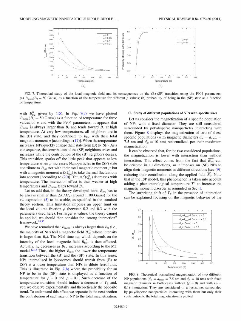
FIG. 7. Theoretical study of the local magnetic field and its consequences on the (B)-(SP) transition using the P904 parameters.(a) Bmean(B0 = 50 Gauss) as a function of the temperature for different ρ values; (b) probability of being in the (SP) state as a functionof temperature.
with B0loc given by (15). In Fig. 7(a) we have plotted
Bmean(B0 = 50 Gauss) as a function of temperature for threevalues of ρ and with the P904 parameters. It appears thatBmean is always larger than B0 and tends toward B0 at hightemperature. At very low temperatures, all neighbors are inthe (B) state, and they contribute to Bloc with their totalmagnetic moment μ [according to (17)]. When the temperatureincreases, NPs quickly change their state from (B) to (SP). As aconsequence, the contribution of the (SP) neighbors arises andincreases while the contribution of the (B) neighbors decays.This transition sparks off the little peak that appears at lowtemperature when ρ increases. Nanoparticles in the (SP) statecontribute to Bloc not with their total magnetic moment μ butwith a magnetic moment μL(ξ 0
loc) to take thermal fluctuationsinto account [according to (20)]. Yet, μL(ξ 0
loc) decreases withtemperature. The interaction effect is thus weaker at hightemperatures and Bmean tends toward B0.
Let us add that, in the theory developed here, Bloc has tobe always smaller than 2K/Ms (around 1100 Gauss) for theτN expression (5) to be usable, as specified in the standardtheory section. This limitation imposes an upper limit onthe local volume fraction ρ (between 0.2 and 0.3 with theparameters used here). For larger ρ values, the theory cannotbe applied; we should then consider the “strong interaction”framework.18,35
We have remarked that Bmean is always larger than B0 (i.e.,the majority of NPs feel a magnetic field
−→Bloc whose intensity
is larger than B0). The Neel time τN , which depends on theintensity of the local magnetic field
−→Bloc, is then affected.
Actually, τN decreases as Bloc increases according to the MTmodel.12,13 Thus, the higher Bloc, the lower the temperaturetransition between the (B) and the (SP) state. In this sense,NPs internalized in lysosomes should transit from (B) to(SP) at a lower temperature than NPs in dilute ferrofluids.This is illustrated in Fig. 7(b) where the probability for anNP to be in the (SP) state is displayed as a function oftemperature for ρ = 0 and ρ = 0.1. Such decrease of thetemperature transition should induce a decrease of TB and,yet, we observe experimentally and theoretically the oppositetrend. To understand this effect we separate in the next sectionthe contribution of each size of NP to the total magnetization.
C. Study of different populations of NPs with specific sizes
Let us consider the magnetization of a specific populationof NPs with a fixed diameter. They are still consideredsurrounded by polydisperse nanoparticles interacting withthem. Figure 8 displays the magnetization of two of thesespecific populations (with magnetic diameters dm = dmean =7.5 nm and dm = 10 nm) renormalized per their maximummagnetization.
It can be observed that, for the two considered populations,the magnetization is lower with interaction than withoutinteraction. This effect comes from the fact that
−→Bloc can
be oriented in all directions, so it imposes on (SP) NPs toalign their magnetic moments in different directions [see (9)]reducing their contribution along the applied field
−→B0. Note
that in the ISP model, this phenomenon is taken into accountadding a phenomenological temperature T ∗ to increase themagnetic moment disorder as reminded in Sec. I.
The surprising shift of TB in the presence of interactioncan be explained focusing on the magnetic behavior of the
FIG. 8. Theoretical normalized magnetization of two differentNP populations (dm = dmean = 7.5 nm and dm = 10 nm) with fixedmagnetic diameter in both cases without (ρ = 0) and with (ρ =0.1) interaction. They are considered in a lysosome, surroundedby polydisperse nanoparticles interacting with them but only theircontribution to the total magnetization is plotted.
075480-9

LEVY, GAZEAU, BACRI, WILHELM, AND DEVAUD PHYSICAL REVIEW B 84, 075480 (2011)
population with dm = 10 nm in Fig. 8. The presence of amaximum for a temperature much higher than the temperatureof the (B)-(SP) transition on the curve with interaction is thesource of the high TB value. This maximum can be appre-hended in the following way. When the temperature increases,the (SP) contribution to Bloc decreases (as underlined above),and consequently the interaction effect decreases [see also thedecrease of Bmean in Fig. 7(a)]. The magnetization gets closerto its value without interaction, and thus it can increase toreach this value if the difference between the magnetizationswith and without interaction is high enough. This increaseproduces a maximum which has nothing to do with the(B)-(SP) transition: It is only the consequence of the inter-action effect decrease with temperature, contrary to the usualinterpretation which considers the TB increase as a signatureof a slowing down of the magnetic moment dynamics.11,17–20
The above analysis represents then a new interpretation ofthe maximum of the ZFC curve (poorly correlated with the NPrelaxation time) which could presumably be generalized to ACmeasurements, too.
Let us note that there is not a maximum at high temperaturefor all populations of NPs with interactions. For example,the population with dm = dmean = 7.5 nm in Fig. 8 does notpresent such a maximum. The presence of a maximum athigh temperature is based indeed on the decrease of the (SP)contribution to Bloc. If a population with a too small size isconsidered, the (B) contribution to Bloc dominates the (SP)contribution up to a temperature for which the differencebetween the magnetization with and without interactionis too small to produce an increase of the magnetizationwith interaction. In this case, no maximum is likely to befound.
A last observation can be made about Fig. 8. It appears thatthe increase of magnetization at low temperature is less abruptwith interaction than without interaction. In the latter case(i.e., without interaction), the magnetization of the populationis zero until (B) NPs become (SP). Then all NPs contributethe same way according to (6). They all become (SP) atthe same temperature because they all have the same Neeltime. In the former case (i.e., with interaction), there is adistribution of Neel times for each temperature because of thedistribution of
−→Bloc. NPs become (SP) at different temperatures,
depending on the local field they feel. Moreover, they become(SP) mostly at a lower temperature than in the case withoutinteraction because this local field is generally larger thanB0 as explained above. This is why the increase of themagnetization at low temperature is less abrupt with inter-
action than without interaction and why it occurs for a lowertemperature.
VI. CONCLUSION
The theoretical “weak interaction” model exposed here de-scribes a very specific experimental system and this specificityallows some simplifications. For example, the fact that thetotal volume fraction φ is small and the lysosome is assumedspherical allows us to neglect all interaction sources exceptneighbors inside the Lorentz cavity. For a larger φ value or/andanother system geometry, global interaction effects should betaken into account (as the demagnetizing field). Nevertheless,concerning the specific biological case of magnetic NPsinternalized in lysosomes, the system described here seemsquite general: In different types of cells or in different organs,the same simplifications should be possible.
According to this model the local field felt by intralysoso-mal NPs is approximately described by a well-characterizedisotropic Gaussian distribution. Moreover, the unique relevantparameter influencing the magnetic response of our interactingsystems is the very local NP distribution inside lysosomes. Thisvaluable information would be then accessible by means of asimple macroscopic ZFC experiment.
The exposed model also suggests a new interpretation of themaximum of the ZFC curve not depending on the NP relaxationtime as widely assumed but on the decrease of interactioneffects with temperature.
Finally, the presented work only focuses on ZFC experi-ment and its interpretation. Nevertheless, the way the localfield is analyzed is quite general and can presumably beused as a start to study how biomedical applications usingmagnetic NPs at room temperature are modified after thecellular internalization of NPs.
ACKNOWLEDGMENTS
We are grateful to F. Gendron for fruitful discussionsand for his valuable assistance concerning the SQUIDexperiments. We acknowledge Guerbet and the laboratoryPECSA (UMR7195, UPMC) (especially Christine Menagerand Sebastien Ballet) for providing us with the nanoparticles.We are indebted to Christine Pechoux and Sophie Chat forTEM observations and to Nathalie Luciani, Alain Luciani, andVanessa Deveaux for animal experiments. This work has beensupported by the Agence Nationale de la Recherche (ANR)TecSan “Inflam” and by the European project Magnifyco(Contract No. NMP4-SL-2009-228622).
*[email protected]. Gillis and S. H. Koenig, Magn. Reson. Med. 5, 323 (1987).2A. S. Arbab and J. A. Frank, Regen. Med. 3, 199 (2008).3M. Johannsen, U. Gneveckow, L. Eckelt, A. Feussner, N. Waldofner,R. Scholz, S. Deger, P. Wust, S. A. Loening, and A. Jordan, Int. J.Hyperther. 21, 637 (2005).
4A. Jordan, R. Scholz, K. Maier-Hauff, M. Johannsen, P. Wust,J. Nadobny, H. Schirra, H. Schmidt, S. Deger, S. Loening,W. Lanksch, and R. Felix, J. Magn. Magn. Mater. 225, 118 (2001).
5B. Thiesen and A. Jordan, Int. J. Hyperther. 24, 467 (2008).6C. Wilhelm and F. Gazeau, Biomaterials. 29, 3161 (2008).7M. Levy, M. Devaud, N. Luciani, V. Deveaux, D. Elgrabli,F. Gendron, A. Luciani, C. Wilhelm, and F. Gazeau, ACS Nano.(submitted).
8J. M. Vargas, W. C. Nunes, L. M. Socolovsky, M. Knobel, andD. Zanchet, Phys. Rev. B 72, 184428 (2005).
9S. Koutani, G. Gavoille, and R. Gerardin, J. Magn. Magn. Mater.123, 175 (1993).
075480-10

MODELING MAGNETIC NANOPARTICLE DIPOLE-DIPOLE . . . PHYSICAL REVIEW B 84, 075480 (2011)
10M. Knobel, W. C. Nunes, A. L. Brandl, J. M. Vargas, L. M.Socolovsky, and D. Zanchet, Physica B 354, 80 (2004).
11J. L. Dormann, D. Fiorani, and E. Tronc, J. Magn. Magn. Mater.202, 251 (1999).
12S. Mørup and E. Tronc, Phys. Rev. Lett. 72, 3278 (1994).13M. F. Hansen and S. Mørup, J. Magn. Magn. Mater. 184, 262
(1998).14P. Allia, M. Coisson, P. Tiberto, F. Vinai, M. Knobel, M. A. Novak,
and W. C. Nunes, Phys. Rev. B 64, 144420 (2001).15R. W. Chantrell, N. Walmsley, J. Gore, and M. Maylin, Phys. Rev.
B 63, 024410 (2000).16M. Azeggagh and H. Kachkachi, Phys. Rev. B 75, 174410
(2007).17J. L. Dormann, R. Cherkaoui, L. Spinu, M. Nogues, F. Lucari,
F. D’Orazio, D. Fiorani, A. Garcia, E. Tronc, and J. P. Jolivet, J.Magn. Magn. Mater. 187, L139 (1998).
18M. F. Hansen, P. E. Jonsson, P. Norblad, and P. Svendinhl, J. Phys.Condens. Matter 14, 4901 (2002).
19C. R. Vestal, Q. Song, and Z. J. Zhang, J. Phys. Chem. B 108, 18222(2004).
20M. Suzuki, S. I. Fullem, I. S. Suzuki, L. Wang, and C. J. Zhong,Phys. Rev. B 79, 024418 (2009).
21N. Luciani, F. Gazeau, and C. Wilhelm, J. Mater. Chem. 19, 6373(2009).
22C. Wilhelm, F. Gazeau, and J. C. Bacri, Eur. Biophys. J. 31, 118(2002).
23C. Riviere, C. Wilhelm, F. Cousin, V. Dupuis, F. Gazeau, andR. Perzynski, Eur. Phys. J. E 22, 1 (2007).
24A. Tanimoto and S. Kuribayashi, Eur. J. Radiol. 58, 200(2006).
25M. Levy, N. Luciani, D. Alloyeau, D. Elgrabli, V. Deveaux, C.Pechoux, S. Chat, G. Wang, N. Vats, F. Gendron, C. Factor, S.Lotersztajn, A. Luciani, C. Wilhelm, and F. Gazeau, Biomaterials32, 3988 (2011).
26M. Levy, F. Lagarde, V.-A. Maraloiu, M.-G. Blanchin, F. Gendron,C. Wilhelm, and F. Gazeau, Nanotechnology 21, 395103 (2010).
27R. Sappey, E. Vincent, N. Hadacek, F. Chaput, J. P. Boilot, andD. Zins, Phys. Rev. B 56, 14551 (1997).
28T. Bitoh, K. Ohba, M. Takamatsu, T. Shirane, and S. Chikazawa,J. Phys. Soc. Jpn. 64, 1305 (1995).
29J. Dormann, Rev. Phys. Appl. 16, 275 (1981).30Y. Raikher and M. Shliomis, Adv. Chem. Phys. 87, 595 (1994).31W. F. Brown, Phys. Rev. 130, 1677 (1963).32C. Tannous and J. Gieraltowski, Eur. J. Phys. 29, 475 (2008).33W. T. Coffey, D. S. F. Crothers, J. L. Dormann, L. J. Geoghegan,
Y. P. Kalmykov, J. T. Waldron, and A. W. Wickstead, Phys. Rev. B52, 15951 (1995).
34W. T. Coffey, D. S. F. Crothers, J. L. Dormann, Y. P. Kalmykov,E. C. Kennedy, and W. Wernsdorfer, Phys. Rev. Lett. 80, 5655(1998).
35S. A. Majetich and M. Sachan, J. Phys. D: Appl. Phys. 39, R407(2006).
075480-11