Modeling and robust control of Blu-ray disc servo-mechanisms
11
Modeling and robust control of Blu-ray disc servo-mechanisms John J. Martinez * , Olivier Sename, Alina Voda GIPSA-lab, UMR 5216, Département Automatique, Grenoble-INP., BP. 46, 38402 St. Martin D’Hères, France article info Article history: Received 22 December 2006 Accepted 9 February 2009 Keywords: Optical disc drives Opto-mechanical coupling Robustness H1 control abstract This paper deals with the modeling and the robust control of the next generation of optical disc drives servo-mechanisms. While in many industrial servo-control implementations, the radial and focus loops are considered as decoupled, e.g. DVD drives, this is no longer true for HD-DVD and Blu-ray disc (BD) for- mats which are more sensitive to opto-mechanical interactions at high frequencies. The impact of such phenomena on the robustness of the servo is evaluated by using experimental data, and an H 1 controller is designed to reduce the coupling effect, by using a suitable disturbance model into the problem formu- lation. Simulations using experimental data illustrate the performance improvement of the compensated system despite the parametric uncertainties in mass-production optical disc drives. Ó 2009 Elsevier Ltd. All rights reserved. 1. Introduction The advances of new display technologies such as liquid crystal, plasma and liquid crystal on silicon in consumer electronic termi- nals, large high-definition (HD) screens will become increasingly affordable. A natural next step will be wider adoption of HD imag- ing. However, this will also depend upon the availability of suitable removable storage media to contain the large volumes of data required for distribution of feature-length films and other HD con- tent [18,19]. The Blu-ray Disc (BD) is a next-generation optical disk data format developed by a group of leading consumer electronics and personal computer companies including BLAZE partners Philips and Thomson now known as the Blu-ray Disc Association. Because the technology uses blue lasers, which have shorter wave- lengths than traditional red lasers, BD makes it possible to store substantially more data than existing CDs or DVDs on the same amount of physical space. Consequently it is likely to become a universal standard for video distribution, hybrid networking and streaming media applications, making it an essential component of future home entertainment systems and portable appliances [18–20]. A major innovation is that Blu-ray is aiming to store 50 GB on a dual-layer disk of CD format through innovative high numerical aperture optics and new low cost, high resolution recording mate- rial. Further innovations in optics, drive technology and cost-effec- tive transcoding chips will be required as multiple HD video standards emerge globally. High numerical aperture lenses and shorter wavelength lasers will narrow the servo margins substan- tially [21,17]. Methods of getting around this, will give rise to a variety of servo and reliability issues to be solved. The main control problem in the CD-based mechanisms concerns the control of the radial and axial (for focus) position of the laser beam, the role of which is to read optical coded information from the disc. This task becomes more difficult for non perfect discs, as the optical disc deformations cause undesired perturbations in the vertical and ra- dial control servos. The accurate positioning of the laser spot in both directions should be achieved despite of the presence of such disturbances (for which only the maximal magnitude is known). Advanced robust control is therefore unavoidable to ensure the track following with suitable accuracy [3,4,15]. Although in current industrial control implementations the ra- dial and focus loops are considered as decoupled, in practice there are several causes of interaction, e.g. mechanical, electro-magnetic and/or optical cross-coupling [1]. The radial control-loop cannot see the grooves until the focus control-loop is locked and disk is in focus. The grooves show up in the focus signal. Decoupling of the focus and radial signals depends upon proper alignment of the detectors. Any slight misalignment leads to cross coupling [17]. Contrary to the CD and DVD formats, this problem becomes rel- evant in HD-DVD and BD formats, because the system should guar- antee much more performance in presence of similar disc deformations by using limited bandwidth controllers. Thus, the problem suggests to explore new alternatives to improve perfor- mances, using more accurate models of perturbations and design- ing less conservative controllers. Some works have been performed in modeling and identifica- tion of opto-mechanical interactions in DVDs. In [10] a study of the control loop coupling is made. It is found that at low frequen- cies the dynamic interaction between the focus and the radial loop is negligible with respect to the main disturbances (eccentricity and tilt), as it is also stated in [1,4,14]. In fact, instead of the radial 0957-4158/$ - see front matter Ó 2009 Elsevier Ltd. All rights reserved. doi:10.1016/j.mechatronics.2009.02.006 * Corresponding author. Tel.: +33 (0) 476 82 62 32; fax: +33 (0) 476 82 63 88. E-mail address: [email protected] (J.J. Martinez). Mechatronics 19 (2009) 715–725 Contents lists available at ScienceDirect Mechatronics journal homepage: www.elsevier.com/locate/mechatronics
-
Upload
independent -
Category
Documents
-
view
1 -
download
0
Transcript of Modeling and robust control of Blu-ray disc servo-mechanisms
Mechatronics 19 (2009) 715–725
Contents lists available at ScienceDirect
Mechatronics
journal homepage: www.elsevier .com/ locate/mechatronics
Modeling and robust control of Blu-ray disc servo-mechanisms
John J. Martinez *, Olivier Sename, Alina VodaGIPSA-lab, UMR 5216, Département Automatique, Grenoble-INP., BP. 46, 38402 St. Martin D’Hères, France
a r t i c l e i n f o
Article history:Received 22 December 2006Accepted 9 February 2009
Keywords:Optical disc drivesOpto-mechanical couplingRobustnessH1 control
0957-4158/$ - see front matter � 2009 Elsevier Ltd. Adoi:10.1016/j.mechatronics.2009.02.006
* Corresponding author. Tel.: +33 (0) 476 82 62 32E-mail address: [email protected] (J.J
a b s t r a c t
This paper deals with the modeling and the robust control of the next generation of optical disc drivesservo-mechanisms. While in many industrial servo-control implementations, the radial and focus loopsare considered as decoupled, e.g. DVD drives, this is no longer true for HD-DVD and Blu-ray disc (BD) for-mats which are more sensitive to opto-mechanical interactions at high frequencies. The impact of suchphenomena on the robustness of the servo is evaluated by using experimental data, and an H1 controlleris designed to reduce the coupling effect, by using a suitable disturbance model into the problem formu-lation. Simulations using experimental data illustrate the performance improvement of the compensatedsystem despite the parametric uncertainties in mass-production optical disc drives.
� 2009 Elsevier Ltd. All rights reserved.
1. Introduction
The advances of new display technologies such as liquid crystal,plasma and liquid crystal on silicon in consumer electronic termi-nals, large high-definition (HD) screens will become increasinglyaffordable. A natural next step will be wider adoption of HD imag-ing. However, this will also depend upon the availability of suitableremovable storage media to contain the large volumes of datarequired for distribution of feature-length films and other HD con-tent [18,19]. The Blu-ray Disc (BD) is a next-generation optical diskdata format developed by a group of leading consumer electronicsand personal computer companies including BLAZE partnersPhilips and Thomson now known as the Blu-ray Disc Association.Because the technology uses blue lasers, which have shorter wave-lengths than traditional red lasers, BD makes it possible to storesubstantially more data than existing CDs or DVDs on the sameamount of physical space. Consequently it is likely to become auniversal standard for video distribution, hybrid networking andstreaming media applications, making it an essential componentof future home entertainment systems and portable appliances[18–20].
A major innovation is that Blu-ray is aiming to store 50 GB on adual-layer disk of CD format through innovative high numericalaperture optics and new low cost, high resolution recording mate-rial. Further innovations in optics, drive technology and cost-effec-tive transcoding chips will be required as multiple HD videostandards emerge globally. High numerical aperture lenses andshorter wavelength lasers will narrow the servo margins substan-tially [21,17]. Methods of getting around this, will give rise to a
ll rights reserved.
; fax: +33 (0) 476 82 63 88.. Martinez).
variety of servo and reliability issues to be solved. The main controlproblem in the CD-based mechanisms concerns the control of theradial and axial (for focus) position of the laser beam, the role ofwhich is to read optical coded information from the disc. This taskbecomes more difficult for non perfect discs, as the optical discdeformations cause undesired perturbations in the vertical and ra-dial control servos. The accurate positioning of the laser spot inboth directions should be achieved despite of the presence of suchdisturbances (for which only the maximal magnitude is known).Advanced robust control is therefore unavoidable to ensure thetrack following with suitable accuracy [3,4,15].
Although in current industrial control implementations the ra-dial and focus loops are considered as decoupled, in practice thereare several causes of interaction, e.g. mechanical, electro-magneticand/or optical cross-coupling [1]. The radial control-loop cannotsee the grooves until the focus control-loop is locked and disk isin focus. The grooves show up in the focus signal. Decoupling ofthe focus and radial signals depends upon proper alignment ofthe detectors. Any slight misalignment leads to cross coupling [17].
Contrary to the CD and DVD formats, this problem becomes rel-evant in HD-DVD and BD formats, because the system should guar-antee much more performance in presence of similar discdeformations by using limited bandwidth controllers. Thus, theproblem suggests to explore new alternatives to improve perfor-mances, using more accurate models of perturbations and design-ing less conservative controllers.
Some works have been performed in modeling and identifica-tion of opto-mechanical interactions in DVDs. In [10] a study ofthe control loop coupling is made. It is found that at low frequen-cies the dynamic interaction between the focus and the radial loopis negligible with respect to the main disturbances (eccentricityand tilt), as it is also stated in [1,4,14]. In fact, instead of the radial
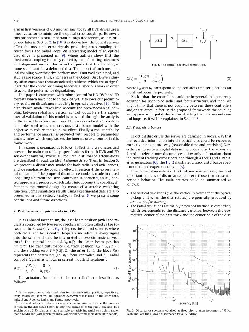
Fig. 1. The optical disc drive control loop.
716 J.J. Martinez et al. / Mechatronics 19 (2009) 715–725
arm in first versions of CD mechanisms, today all DVD drives use alinear actuator to minimize the optical cross couplings. However,this phenomena is still important at high frequencies, as it is dis-cussed later in Section 3. In [16] it is shown how the optical sensorsaffect the measured error signals, producing cross-coupling be-tween focus and radial loops. An interesting model of an opticaldisc drive is presented in [9], where authors show that themechanical coupling is mainly caused by manufacturing tolerancesand alignment errors. This aspect suggests that the coupling ismore significant for a deformed disc. The impact of such mechan-ical coupling over the drive performance is not well explained, andstudies are scarce. Thus, engineers in the Optical Disc Drive indus-try often encounter these associated problems, which are so signif-icant that the controller tuning becomes a laborious work in orderto avoid the performance degradation.
This paper is concerned with robust control for HD-DVD and BDformats which have not been tackled yet. It follows our prelimin-ary results on disturbance modeling in optical disc drives [14]. Thisdisturbance model takes into account the opto-mechanical cou-pling between radial and vertical control loops. Here the experi-mental validation of this model is provided through the analysisof the closed loop tracking errors. Then, a new robust H1 control-ler is designed using the previous disturbance model with theobjective to reduce the coupling effect. Finally a robust stabilityand performance analysis is provided with respect to parametersuncertainties which emphasizes the interest of H1 control in thisframe-work.
This paper is organized as follows. In Section 2 we discuss andpresent the main control loop specifications for both DVD and BDservo-mechanisms, where all required disturbance attenuationsare described through an ideal Reference Servo. Then, in Section 3,we present a disturbance model for both radial and axial servos,and we emphasize the coupling effect. In Section 4, the experimen-tal validation of the proposed disturbance model is made in closedloop using a current industrial controller. In Section 5, an H1 con-trol approach is proposed which takes into account the coupling ef-fect into the control design, by means of a suitable weightingfunction. Some simulation results using experimental data are alsopresented in this Section. Finally, in Section 6, we present someconclusions and future directions.
10−3
10−2
10−1
100
101
102
Rad
ial T
rack
Spe
ctru
m [µ
m]
2. Performance requirements in BD’s
In a CD-based mechanism, the laser beam position (axial and ra-dial) is controlled by two servo mechanisms, often called as the Fo-cus and the Radial servos. Fig. 1 depicts the control scheme, whereboth radial and focus control loops are included, i.e. every signalinto the scheme should be interpreted as two-dimensional vec-tors.1 The control input u , ½uR uF �0; the laser beam positionr , ½x z�0; the track disturbance (i.e. track position) rref , ½xref zref �0;and the tracking error �r , ½�x �z�0. On the other hand, the block KðsÞrepresents the controllers (i.e. KF: focus controller, and KR: radialcontroller), given as follows in current industrial solutions2:
KðsÞ ¼KRðsÞ 0
0 KFðsÞ
� �: ð1Þ
The actuators (or plants to be controlled) are described asfollows:
1 In the sequel, the symbols x and z denote radial and vertical position, respectively.Every associated index will be explained everywhere it is used. In the other hand,index R and F denote Radial and Focus, respectively.
2 Focus and radial controllers are started at different time instants, i.e. the drive hasto turn-on the disc focus before to start the operation of the radial tracking. Thisexplain why a SISO solution is more suitable, to satisfy industrial constraints, ratherthan a MIMO one (with which the initial conditions become more difficult to handle).
GðsÞ ¼GRðsÞ 0
0 GFðsÞ
� �: ð2Þ
where GR and GF correspond to the actuators transfer functions forradial and focus, respectively.
Notice that the controllers could be in general independentlydesigned for uncoupled radial and focus actuators, and then, wemight think that there is not coupling between these controllersand/or actuators. In fact, in the proposed framework, the couplingwill appear as output disturbances affecting the independent con-trol loops, as it will be explained in Section 3.
2.1. Track disturbances
In optical disc drives the servos are designed in such a way thatthe recorded information into the optical disc could be recoveredcorrectly in an optimal way (reasonable time and precision). Nev-ertheless, to recover digital data in the optical disc the servos areforced to reject strong disturbances using only information aboutthe current tracking error �r obtained through a Focus and a Radialerror generators [6]. The Fig. 2 illustrates a track disturbance spec-trum obtained experimentally in [3].
Due to the rotary nature of the CD-based mechanisms, the mostimportant sources of disturbances concern those that present aperiodic behavior. The main sources could be summarized asfollows:
� The vertical deviations (i.e. the vertical movement of the opticalpickup unit when the disc rotates) are generally produced bydisc tilt and/or warping.
� The radial deviations are mainly produced by the disc eccentricitywhich corresponds to the distance variation between the geo-metrical center of the data track and the center hole of the disc.
102
103
10−4
Frequency [Hz]
Fig. 2. Disturbance spectrum obtained at fixed disc rotation frequency of 33 Hz.Dash lines are the allowed disturbance for a DVD drive.
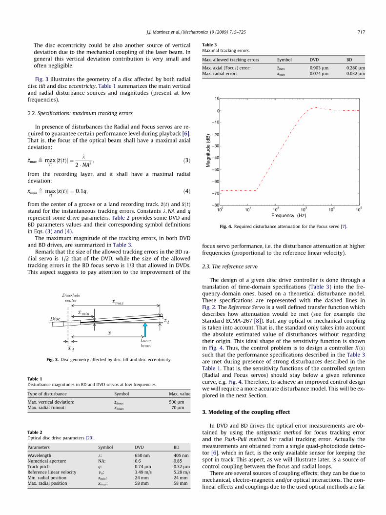
Table 3Maximal tracking errors.
Max. allowed tracking errors Symbol DVD BD
Max. axial (Focus) error: �zmax 0.903 lm 0.280 lmMax. radial error: �xmax 0.074 lm 0.032 lm
100
101
102
103
104
105
−80
−70
−60
−50
−40
−30
−20
−10
0
10
Mag
nitu
de (
dB)
Frequency (Hz)
Fig. 4. Required disturbance attenuation for the Focus servo [7].
J.J. Martinez et al. / Mechatronics 19 (2009) 715–725 717
The disc eccentricity could be also another source of verticaldeviation due to the mechanical coupling of the laser beam. Ingeneral this vertical deviation contribution is very small andoften negligible.
Fig. 3 illustrates the geometry of a disc affected by both radialdisc tilt and disc eccentricity. Table 1 summarizes the main verticaland radial disturbance sources and magnitudes (present at lowfrequencies).
2.2. Specifications: maximum tracking errors
In presence of disturbances the Radial and Focus servos are re-quired to guarantee certain performance level during playback [6].That is, the focus of the optical beam shall have a maximal axialdeviation:
�zmax , max8tj�zðtÞj ¼ k
2 � NA2 ; ð3Þ
from the recording layer, and it shall have a maximal radialdeviation:
�xmax , max8tj�xðtÞj ¼ 0:1q; ð4Þ
from the center of a groove or a land recording track. �zðtÞ and �xðtÞstand for the instantaneous tracking errors. Constants k;NA and qrepresent some drive parameters. Table 2 provides some DVD andBD parameters values and their corresponding symbol definitionsin Eqs. (3) and (4).
The maximum magnitude of the tracking errors, in both DVDand BD drives, are summarized in Table 3.
Remark that the size of the allowed tracking errors in the BD ra-dial servo is 1/2 that of the DVD, while the size of the allowedtracking errors in the BD focus servo is 1/3 that allowed in DVDs.This aspect suggests to pay attention to the improvement of the
Fig. 3. Disc geometry affected by disc tilt and disc eccentricity.
Table 1Disturbance magnitudes in BD and DVD servos at low frequencies.
Type of disturbance Symbol Max. value
Max. vertical deviation: zdmax 500 lmMax. radial runout: xdmax 70 lm
Table 2Optical disc drive parameters [20].
Parameters Symbol DVD BD
Wavelength k: 650 nm 405 nmNumerical aperture NA: 0.6 0.85Track pitch q: 0.74 lm 0.32 lmReference linear velocity va: 3.49 m/s 5.28 m/sMin. radial position xmin: 24 mm 24 mmMax. radial position xmax: 58 mm 58 mm
focus servo performance, i.e. the disturbance attenuation at higherfrequencies (proportional to the reference linear velocity).
2.3. The reference servo
The design of a given disc drive controller is done through atranslation of time-domain specifications (Table 3) into the fre-quency-domain ones, based on a theoretical disturbance model.These specifications are represented with the dashed lines inFig. 2. The Reference Servo is a well defined transfer function whichdescribes how attenuation would be met (see for example theStandard ECMA-267 [8]). But, any optical or mechanical couplingis taken into account. That is, the standard only takes into accountthe absolute estimated value of disturbances without regardingtheir origin. This ideal shape of the sensitivity function is shownin Fig. 4. Thus, the control problem is to design a controller KðsÞsuch that the performance specifications described in the Table 3are met during presence of strong disturbances described in theTable 1. That is, the sensitivity functions of the controlled system(Radial and Focus servos) should stay below a given referencecurve, e.g. Fig. 4. Therefore, to achieve an improved control designwe will require a more accurate disturbance model. This will be ex-plored in the next Section.
3. Modeling of the coupling effect
In DVD and BD drives the optical error measurements are ob-tained by using the astigmatic method for focus tracking errorand the Push-Pull method for radial tracking error. Actually themeasurements are obtained from a single quad-photodiode detec-tor [6], which in fact, is the only available sensor for keeping thespot in track. This aspect, as we will illustrate later, is a source ofcontrol coupling between the focus and radial loops.
There are several sources of coupling effects; they can be due tomechanical, electro-magnetic and/or optical interactions. The non-linear effects and couplings due to the used optical methods are far

718 J.J. Martinez et al. / Mechatronics 19 (2009) 715–725
of the scope of this paper. Here, we are interested in the opto-mechanical effects produced by the control loop interactions,regarding only the geometry position of the spot with respect tothe center of the track.
3.1. Radial sensitivity function and disturbances
Based on Fig. 3 the radial tracking error obtained from the radialoptical sensor is described as follows:
�x , xref � x; ð5Þ
where x corresponds to the laser spot position driven by the radialcontroller, and xref stands for the track position signal that should befollowed by the laser spot. The controlled signal x is computed asx ¼ LRðsÞ�x, where the transfer function LRðsÞ corresponds to the openloop transfer function given by the series connection between theradial actuator and the radial controller. Therefore, we have
�x ¼ 11þ LRðsÞ
xref : ð6Þ
The reference signal xref can be modelled as xref ¼ x0ref þ xd,
where x0ref corresponds to the nominal track location and xd corre-
sponds to the disturbance signal produced by the disc eccentricity.Since the nominal track location x0
ref has a very slow variation (gen-erally a ramp signal during playback), the main problem concernsthe minimization of the radial tracking error �x affected by the dis-turbance xd, i.e. we are interested in minimizing the following sen-sitivity function
SR ,�xxd¼ 1
1þ LRðsÞ: ð7Þ
Due to the rotary nature of the opto-mechanical system, thedisturbance signal xd can be described by a sum of sinusoidal sig-nals with frequencies multiple of the disc rotation frequency frot
(e.g. frot 2 [20.5 Hz, 50 Hz] in the BD). Thus, if we assume that onlythe Nth-harmonic of this signal is relevant, the perturbation, in thetime-domain, could be modelled as
xdðtÞ ¼ xdmaxN� sinð2pNfrott þ /xN
Þ; ð8Þ
where xdmaxNstands for the maximal perturbation value (of the Nth-
harmonic) and /xNstands for an unknown perturbation-signal
phase (of the Nth-harmonic).
3.2. Focus sensitivity function and disturbances
Fig. 5 depicts a disc affected by disc tilt. Note that, at a given po-sition of the laser spot, the servo tries to focus a pseudo-track (atthe center of the spot) at the position z0ref instead of the actual centerof the track at the position zref . As a consequence, the focus trackingerror measurement will be:
�z , z0ref � z; ð9Þ
Fig. 5. Geometry of a disc affected by disc tilt (no scale).
where the signal z corresponds to the vertical position of the laserspot driving by the focus controller. The controlled signal z is calcu-lated as z ¼ LFðsÞ�z, where the transfer function LFðsÞ corresponds tothe open loop transfer function given by the series connection be-tween the focus actuator and the focus controller. Hence, the focussensitivity function is:
SF ,�z
z0ref
¼ 11þ LFðsÞ
: ð10Þ
However, the signal z0ref is not an exogenous input, i.e. the laserspot tries to focus a vertical reference that depends directly of theradial position x of the laser spot. From Fig. 5 we have
z0ref ¼ x tanðhÞ: ð11Þ
The symbol h stands for the inclination angle of the disc (i.e. thetilt angle). Therefore, assuming that h varies slowly with respect tothe x variations at high frequencies, and using the fact thatx ¼ LRðsÞ�x, and �x given by (5), we have
z0ref
zref¼ LRðsÞ
1þ LRðsÞ|fflfflfflfflfflffl{zfflfflfflfflfflffl}TR
; ð12Þ
where zref ¼ xref tanðhÞ (see Fig. 5. Notice that the Eq. (12) corre-sponds to the complementary sensitivity function of the radial ser-vo, which we will denote as TR. Therefore, substituting (12) into(10), the focus tracking error could be calculated as follows:
�z ¼ LRðsÞð1þ LFðsÞÞð1þ LRðsÞÞ|fflfflfflfflfflfflfflfflfflfflfflfflfflfflfflfflfflfflffl{zfflfflfflfflfflfflfflfflfflfflfflfflfflfflfflfflfflfflffl}
SF � TR
zref : ð13Þ
The reference signal zref , is modelled as zref ¼ z0ref þ zd, where z0
ref
corresponds to the nominal focus position (without presence ofvertical deviations) and zd corresponds to the disturbance signalproduced by the disc tilt, warping or disc vibration. Then, the Eq.(12) could be rewritten as follows:
z0dzd¼ LRðsÞ
1þ LRðsÞ|fflfflfflfflfflffl{zfflfflfflfflfflffl}TR
; ð14Þ
Thus, we are interested in the following relationship:
�zzd¼ LRðsÞð1þ LFðsÞÞð1þ LRðsÞÞ
¼ SF � TR; ð15Þ
where the signal zd could be suitably modelled from Fig. 5 asfollows:
zdðtÞ ,x0
ref
xmax
!zdmaxN
� sinð2pNfrott þ /zNÞ: ð16Þ
xmax is the maximal radial position (defined in Table 2) zdmaxN themaximal vertical deviation at the Nth-harmonic, and frot the discrotational frequency.
The coupled sensitivity function (15) is depicted in the Fig. 6.Note that the mechanical coupling effect appears as an amplifica-tion of the vertical disturbances around the middle frequencies(i.e. between 300 Hz and 30 kHz). This effect can not be neglected,and the control design requires to reinforce attenuation at suchfrequencies.
4. Experimental validation
In order to validate the disturbance model proposed in Section3, we make use of former experimental data obtained from anindustrial optical disc servo control [2,3]. Actually, the benchmark

101
102
103
104
105
0
0.5
1
1.5
Mag
nitu
de (
abs)
Frequency (Hz)
Radial complementarysensitivity function T
R
Focus sensitivity function S
F
Coupling effectS
FT
R
Fig. 6. Disturbance amplification (coupling effect) obtained from reference servos.
J.J. Martinez et al. / Mechatronics 19 (2009) 715–725 719
uses a DVD servo-mechanism at 1.5 times its reference linearspeed, which emulates the behavior (in terms of disturbances mag-nitudes and frequencies) of a BD working at its nominal speed (seeTable 3). In our context we will use these obtained data to computethe disturbance magnitudes and the control tracking errors. Themain objective is to try to evaluate the impact of the theoreticalcoupling effect on the performance of a given optical drive, andcompare/validate the frequency regions where the disturbanceamplification are present.
4.1. Set-up description
Fig. 7 depicts the employed set-up, where a digital signal ana-lyzer (DSA) is used. The scheme includes both radial and verticalcontrol loops as in Fig. 1. The available signals are: the controlleroutput u, and the signal ðuþ vÞ which corresponds to the actuatorinput. The signal v acts as an external excitation injected by theDSA into the loop . CðsÞ is the actual controller and gopt is the sensor(optical gain). In the sequel, we take KðsÞ , CðsÞgopt as thecontroller.
The DSA sample frequency has been set in 12.8 kHz; The mea-surement span covers from 1 Hz to 51.2 kHz. Experiments wereset with a sweep resolution of 100 points/sweep, the integrationtime 5 swept sine cycles, to have longer integration times at lowfrequencies, where the sweep sine cycles occurs slower. Four hun-dred resolution lines was considered, performed with 4 averagingper frequency point (RMS averaging mode), to reduce the measure-ment noise to its mean value.
The chosen injected swept sine was performed with an ampli-tude of 30 mVpk and a DC offset of 1 V, i.e. enough small injectedsignal in order to guarantee the ‘‘playability” property of the system
Fig. 7. Experimental set-up including a digital signal analyzer.
during the test. That is, the tracking errors have to be small enoughin such a way that the optical sensors continues to work insidetheir linear regions to avoid losing the radial seek action.
4.2. Computation of the sensitivities
In this Section, it is assumed that the controllers and the plantmodels are well known. That is, we take average models of boththe controller KðsÞ and the servo-mechanism obtained during iden-tification tests [3]. The actuator model GðsÞ, including amplifiers, isdescribed by a third order system, while the optical sensors weremodeled as simple gains gopt . The focus and radial controllers arelead-lag type controllers.
Therefore, the corresponding sensitivity functions magnitudes(in the frequency domain) are obtained by using the DSA, whichcomputes the frequency response bSijðxÞ by dividing the cross spec-trum between the input and output by the power spectrum of theinput. Eq. (17) indicates the equivalent relationship between theindividual Fourier spectra, that is
jbSijðxÞj ,j½Uj þ Vj�ðxÞjjViðxÞj
; ð17Þ
where U þ V and V stand for the individual Fourier spectra of thesignals uþ v and v , respectively. The indexes i; j stand for the cor-responding focus or radial loop (e.g. i ¼ F and j ¼ R or viceversa).This notation will be used in the sequel.
Here we are interested in obtaining cross sensitivity functions ofthe servomechanism. To this aim, we must to apply a stimulus sig-nal in one of the loop (e.g. radial loop) and appreciate the effect onthe second loop (e.g. focus loop), yielding
jbSRFðxÞj ,jUFðxÞjjVRðxÞj
¼ KF
1þ KF GF
jZ0dðxÞjjVRðxÞj
; ð18Þ
where UF is obtained from the scheme depicted in Fig. 7 for VF ¼ 0.That is, the only external signal injected into the focus loop comesfrom the vertical disturbance z0d (see Eqs. (14) and (16)). On theother hand, following a similar procedure for the radial loop wehave:
jbSFRðxÞj ,jURðxÞjjVFðxÞj
¼ KR
1þ KRGR
jXdðxÞjjVFðxÞj
; ð19Þ
where UR is obtained from the scheme depicted in Fig. 7 for VR ¼ 0.Here, the only external repetitive (or periodical) disturbance comesfrom the radial disturbance xd (see Eq. (8)). The left hand side of Eqs.(18) and (19) are obtained from experiments, while the right handones are theoretical approximations of the expected sensitivityfunctions.
Therefore, it is clear that the frequency spectrum of distur-bances z0d and xd can be estimated from Eqs. (18) and (19), respec-tively, as follows:
jZ0dðxÞj ¼1þ KFGF
KFjbSRFðxÞj � jVRðxÞj ð20Þ
jXdðxÞj ¼1þ KRGR
KRjSFRðxÞj � jVFðxÞj ð21Þ
Fig. 8a illustrates the estimated disturbances obtained from theabove equations. Notice that the main disturbances, i.e. aroundthe rotational disc frequency, represent the highest disturbancesto attenuate (eccentricity and disc tilt). From Fig. 8b, also remarkthat the disturbances at middle and high frequencies are more rel-evant into the focus servo and the experimental values match wellthe theoretical disturbance model (Eq. 14). Remember that the cou-pling model (15) describes the frequency region where vertical dis-turbance will appear. In the case of the radial servo, the mostimportant disturbances are found, as expected, around the low
100
101
102
103
104
105
0
50
100
150
200
250
Frequency [Hz]
Dis
turb
ance
s m
agni
tude
[µm
]
Vertical disturbances
Radial disturbances x 10
100
101
102
103
104
105
0
0.5
1
1.5
2
2.5
3
3.5
4
Dis
turb
ance
s m
agni
tude
(µm
)
Frequency (Hz)
Vertical disturbances
Radial disturbances x 10
Vertical disturbancesmodel (coupling): T
R
a
b
Fig. 8. (a) Estimated vertical jZ0dðxÞj (solid line) and radial disturbances10� jXdðxÞj (dashed line); and (b) at zoom scale.
100
101
102
103
104
105
0
0.2
0.4
0.6
0.8
1
1.2
1.4
Frequency [Hz]
Foc
us tr
acki
ng e
rror
[µ m
]
Amplification of vertical disturbances (coupling effect)
Coupling effect model
Allowed deviation for DVD’s
100
101
102
103
104
105
0
0.01
0.02
0.03
0.04
0.05
0.06
0.07
0.08
Frequency [Hz]
Rad
ial t
rack
ing
erro
r [µ
m]
Allowed deviation for DVD’s
Radial disturbances
a
b
Fig. 9. Tracking error estimations for (a) focus jZðxÞj and (b) radial jXðxÞj.
720 J.J. Martinez et al. / Mechatronics 19 (2009) 715–725
frequencies. Notice in Fig. 8b, that the radial disturbances at middlefrequencies could be neglected.
In order to estimate the impact on the performance of the drive,the focus and radial tracking errors could be estimated from (20)and (21) by substituting SF and SR from (10) and (7), respectively.That is,
j�ZðxÞj , SF � jZ0dðxÞj ¼1
KFjSRFðxÞj � jVRðxÞj; ð22Þ
jXðxÞj , SR � jXdðxÞj ¼1
KRjSFRðxÞj � jVFðxÞj: ð23Þ
The estimated tracking errors are plotted in Figs. 9a and b.Notice that for the radial servo, the desired performance (necessaryattenuation of disturbances) is clearly met. Nevertheless, for thefocus servo, there is an important sensitivity (with respect to dis-turbances) at middle and at high frequencies. Note that the magni-tude of the focus tracking error �z is higher than that specified forDVD’s. In fact, according to this result, the focus loop could workuntil the limit of the allowed deviation, e.g. less than 3 lm (i.e. intothe linear region of sensors, generally described by S-curves inoptics, see for example [2], where the linear region is estimatedto cover up to 6 lm peak to peak).
The optical gain gopt is actually unknown, and this could pro-duce inaccuracies in the plotted curves. Then, we may think thatunmodeled sensor dynamics could change the measured value of
the tracking errors. Nevertheless, the behavior and the magnitudesin the focus servo are manifestly enough for accepting that theproposed model match well the frequency regions where the totalvertical disturbance appear. These results cannot be obtained innormal operation since disturbances are mainly at low frequen-cies; however, the results suggest the necessity to increase attenu-ation around middle frequencies to increase the robustness of thesystem.
5. Reducing the coupling effect by H1 control
In this section we will design independent robust controllers forfocus and radial servos. To tackle the coupling effect problem, wewill integrate the disturbance model, obtained in Section 3, intothe H1 problem formulation to set a generic robust controlproblem.
5.1. Mixed-sensitivity H1 controller design
Recall that the H1 control problem is to find an input controluR ¼ KRðsÞ�x such that the radial sensitivity function of the con-trolled system (equivalently for the focus system) stay below a gi-ven reference curve (as it is depicted in Fig. 4). But, in addition, werequire to minimize the coupling effect (15).

Fig. 10. The H1 control problem scheme for the radial loop.
J.J. Martinez et al. / Mechatronics 19 (2009) 715–725 721
As in [11], a third order actuator model is sufficient to deal withcontrol design subject to implementation constraints, e.g. for radialactuator we have,
GRðsÞ ¼KemL
s3 þ RL þ h
m
� �s2 þ hR
mLþ kmþ
K2e
mL
� �sþ kR
mL
ð24Þ
where Ke;m; L; k;R and h correspond to the servo physical parame-ters. Similarly, we have an equivalent model for the focus actuator,denoted here as GFðsÞ.
The Fig. 10 depicts the generic robust control problem for theradial loop. The functions W1 and W2 weight the controlled out-puts y1 and y2, and should be chosen according to the performancespecifications. Moreover, the weighting function W3 will incorpo-rate the coupling model.
The generalized plant P (i.e. the interconnection of the plant andthe weighting functions) is given by:
y1
y2
�x
0B@1CA ¼ W1W3 �W1W4GR �W1GR
0 0 W2
W3 �W4GR �GR
0B@1CA
|fflfflfflfflfflfflfflfflfflfflfflfflfflfflfflfflfflfflfflfflfflfflfflfflfflfflfflfflfflfflfflfflffl{zfflfflfflfflfflfflfflfflfflfflfflfflfflfflfflfflfflfflfflfflfflfflfflfflfflfflfflfflfflfflfflfflffl}P
xref
du
uR
0B@1CA ð25Þ
Thus, the H1 control problem is described as follows [12]: Finda stabilizing controller KRðsÞ which minimize c such that
W1W3SR �W1W4SRGR
W2W3KRSR �W2W4GRKRSR
� � 1< c ð26Þ
Remember that the obtained controller KR has the same numberof state variables as P. Then, the choice of the weighting functionsis a key issue in the H1 control problem. Here, the repetitive dis-turbances should be attenuated in a particular frequency range.Then we will choose the weighting functions, for radial and focusdesign, as follows:
(1) W1 is used to impose a performance specification on SR [12].That is,
W1ðsÞ ¼ð1=MsÞsþwb
sþwbAs; ð27Þ
where Ms ¼ 1:0 to introduce a margin of robustness limitingthe peak of SR;wb ¼ 2p250 [rad/sec] to have a sensible atten-uation of disturbances from low frequencies up to 250 Hz,and As ¼ 0:02 to reduce the steady-state error.
(2) W2 is aimed to respect the actuator limitations similar to theDVD. It is chosen as follows [12]:
W2ðsÞ ¼sþ ðwbc=MuÞ�sþwbc
; ð28Þ
where Mu ¼ 1:5 to impose limitations on the maximum valueof the controller output signal up to 30 kHz, wbc ¼ 2p30� 103
[rad/sec] to limit the effect of measurement noise and plant
uncertainties at high frequencies, and � ¼ 0:01 to ensure ahigh-frequency controller roll-off of �40 dB/decade.
(3) W3 (or disturbance model) is chosen as follows:
W3 ¼ 0:25; ð29Þ
for radial control design, and
W3ðsÞ ¼ 0:1þ k � TRðsÞ; ð30Þ
for focus control design (to incorporate the disturbance mod-el). The constant k allows to normalize (as an additionalweight) the level of the vertical disturbances with respectto the radial ones (e.g. k ¼ 0:5).
(4) W4 is a constant. That is, W4 ¼ 0:005 for radial and W4 ¼ 0:1for focus control design. All these values allow to obtain rea-sonable trade-off between control effort and disturbanceattenuation.
Similarly, using the previous control design and the correspond-ing weighting functions, the focus controller KFðsÞ for focus systemGFðsÞ is obtained.
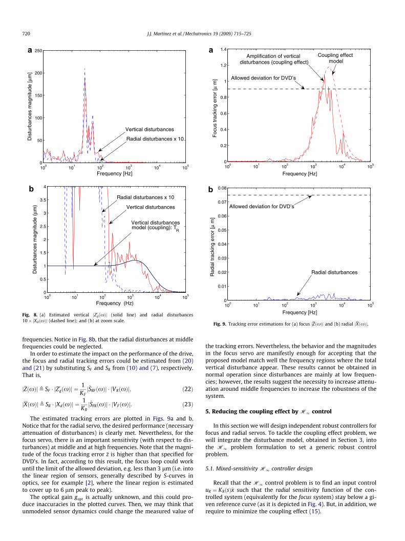
After computation, the minimal cost achieved for the radial con-trol design was c ¼ 0:286, while the minimal cost achieved for thefocus control design was c ¼ 0:304. These values mean that the ob-tained sensitivity functions match nearly the desired loop shaping.Fig. 11 illustrates the Bode magnitude of the obtained sensitivityfunctions. Remark that the radial sensitivity function SR is less con-servative at low frequencies, and its bandwidth is much smallerthan the theoretical reference servo dictated by the ECMA-stan-dard [8]. Although the reference radial servo is not completely sat-isfied for the robust controller, we will see in the simulation resultsthat this controller achieves the allowed radial tracking error. Thisemphasizes the fact that, for the radial loop, the reference servo istoo conservative.
Fig. 12 depicts the Bode magnitude of the designed H1 control-lers. The order of the designed H1 controllers are equal to 8th(after use a reduced 3th order disturbance model TR). The control-ler order could be reduced before implementation, i.e. taking intoaccount actual industrial constraints as in [12].
Thus, the amplification due to the coupling effect has been re-duced, and the system performance is improved at middle fre-quencies, all that respecting the actuators constraints. Fig. 11band c illustrate the sensitivity function related to the control effort.This response is near to these reported in [3], which makes to thinkthat the proposed controller could be realistic.
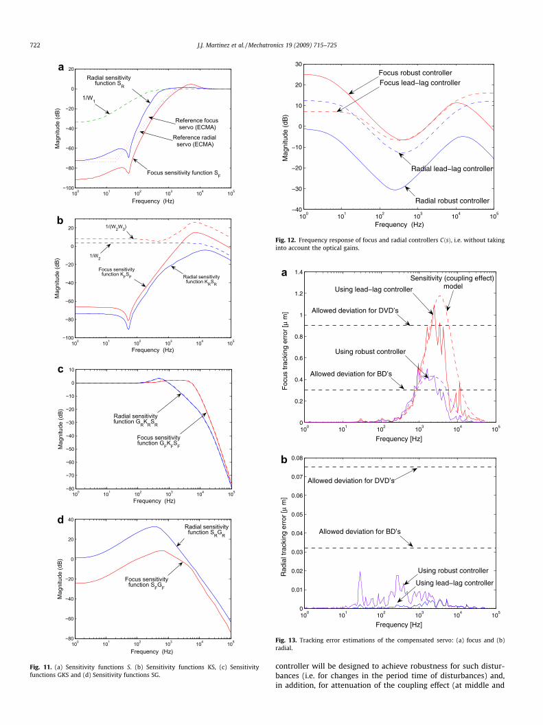
5.2. Simulation results using experimental data
The performance of the H1 controller is here evaluated underthe presence of disturbances. For simulations, we use the esti-mated disturbances (20) and (21). Fig. 13a illustrates the distur-bance attenuation achieved by using the robust controller. Noticethat we can achieve more robust focus servo. In the case of theBD servos, this aspect becomes a key issue. On the other hand,the disturbance attenuation in the radial servo is lower for the ro-bust controller. This is not a surprise, because we reduce the radialservo bandwidth to contribute to compensate the coupling effect.Nevertheless, the experimental results show that these frequencybounds are quite conservative, in the radial case, and the trackspectrum is well below them.
Major improvements could be obtained by taken into accountother particular solutions. For example, the proposed controllercan be improved by adding a repetitive control (i.e. a memory-loopterm) as it is explained in [26]. In this way, the memory-loop termwill be designed for attenuation of well known repetitive distur-bances (at low frequency for example), while the proposed H1
100 101 102 103 104 105−100
−80
−60
−40
−20
0
20
Mag
nitu
de (d
B)
Frequency (Hz)
1/W1
Radial sensitivity function SR
Focus sensitivity function SF
Reference focus servo (ECMA)
Reference radial servo (ECMA)
100 101 102 103 104 105−100
−80
−60
−40
−20
0
20
Mag
nitu
de (d
B)
Frequency (Hz)
Radial sensitivityfunction KRSR
Focus sensitivityfunction KFSF
1/W2
1/(W2W3)
100 101 102 103 104 105−80
−70
−60
−50
−40
−30
−20
−10
0
10
Mag
nitu
de (d
B)
Frequency (Hz)
Radial sensitivityfunction GRKRSR
Focus sensitivityfunction GFKFSF
100 101 102 103 104 105−80
−60
−40
−20
0
20
40
Mag
nitu
de (d
B)
Frequency (Hz)
Radial sensitivityfunction SRGR
Focus sensitivityfunction SFGF
a
b
c
d
Fig. 11. (a) Sensitivity functions S. (b) Sensitivity functions KS, (c) Sensitivityfunctions GKS and (d) Sensitivity functions SG.
100
101
102
103
104
105
−40
−30
−20
−10
0
10
20
30
Mag
nitu
de (
dB)
Frequency (Hz)
Radial lead−lag controller
Focus lead−lag controller
Radial robust controller
Focus robust controller
Fig. 12. Frequency response of focus and radial controllers CðsÞ, i.e. without takinginto account the optical gains.
100
101
102
103
104
105
0
0.2
0.4
0.6
0.8
1
1.2
1.4
Frequency [Hz]
Foc
us tr
acki
ng e
rror
[µ m
]Using lead−lag controller
Using robust controller
Sensitivity (coupling effect) model
Allowed deviation for DVD’s
Allowed deviation for BD’s
100
101
102
103
104
105
0
0.01
0.02
0.03
0.04
0.05
0.06
0.07
0.08
Frequency [Hz]
Rad
ial t
rack
ing
erro
r [µ
m]
Allowed deviation for BD’s
Allowed deviation for DVD’s
Using robust controller
Using lead−lag controller
a
b
Fig. 13. Tracking error estimations of the compensated servo: (a) focus and (b)radial.
722 J.J. Martinez et al. / Mechatronics 19 (2009) 715–725
controller will be designed to achieve robustness for such distur-bances (i.e. for changes in the period time of disturbances) and,in addition, for attenuation of the coupling effect (at middle and

100
101
102
103
104
105
−60
−50
−40
−30
−20
−10
0
Mag
nitu
de (
dB)
Frequency (Hz)
Fig. 14. Relative plant errors GD ðsÞ�GðsÞGðsÞ
��� ���, of 250 random parametric combinations.
100
101
102
103
104
105
0
0.1
0.2
0.3
0.4
0.5
0.6
0.7
0.8
0.9
1
Frequency (Hz)
Sin
gula
r va
lue
µ (
abs) Singular value
(Robust stability)
Singular value(Robust performance)
0.5
0.6
0.7
0.8
0.9
1
alue
µ (
abs)
Singular value(Robust performance)
Singular value(Robust stability)
a
b
J.J. Martinez et al. / Mechatronics 19 (2009) 715–725 723
high frequencies) as it is intended for in this paper. For other kindof improvements, as for example, increasing robustness with re-spect to disc surface defects and/or including anti-shock propertiesinto the control design, we encourage readers to consult [13,5,22–25], respectively.
5.3. Uncertainty modeling and robustness analysis
The nominal model, used for control design, is obtained for con-sidering the average values of physical parameters of severalindustrial pick-up’s. The stability and the performance of the mod-eled system is guaranteed by using a suitable robust controller.However, in practice, there is always a mismatch between themodel and the system to be controlled. In the case of the mass pro-duction of Blu-ray disc players, the manufacturing tolerancesshould be increased in order to reduce production costs. As a con-sequence, the designed controller will be implemented in a wideset of pick-ups, that differ of the average model. Here, we are inter-ested to evaluate the stability and the performance of the wholeset of possible real servo-mechanisms. The whole set of systemsis modeled as the average model subject to parametric uncertain-ties. Table 4 encloses several physical parameters of the nominalradial actuator together with their percentage of variations (ob-tained from a commercial drive datasheet discussed in [3]).
Notice the high uncertainty of the parameter L (inductance) andKe (electromagnetic constant). We will take into account theseparameters in order to build an uncertain model enough accuracyfor robust analysis.
5.3.1. Uncertain modelingTake the following actuator model (radial or focus servo) de-
scribed by the following electrical and mechanical systems:
LdiðtÞ
dtþ RiðtÞ ¼ DE � vðtÞ � Ke
dxðtÞdt
�ð31Þ
md2xðtÞ
dt2 þ hdxðtÞ
dtþ kxðtÞ ¼ DM � KeiðtÞ ð32Þ
where DE and DM globalize the electrical and the mechanical para-metric uncertainties, respectively. For example, the nominal modelcould be obtained for fixing DE ¼ DM ¼ 1. It is easy to see that theuncertain actuator model could be described by the following trans-fer function (i ¼ R; F, radial or focus actuator):
GiðsÞ ,XðsÞVðsÞ ¼
KeD0EM
c1s3 þ c2s2 þ ðc3 þ K2eDEMÞsþ c4
ð33Þ
The constants c’s are calculated from the physical parameters de-scribed in Table 4, and the uncertain parameter DEM is defined asfollows: DEM , DE � DM .
This uncertain model could be very conservative, but permits toanalyze a system respecting the physical constraints between theelectrical and mechanical elements, for example the electromag-netic constant Ke which couples both subsystems. In addition, inpractical situations it is very difficult to estimate the value of theindependent parameters because much of them are strongly
Table 4Radial actuator parameters variation. Source [3].
Parameter Nominal value % of variation
Resistant of coil R½X� 4.83 15Inductance of coil L½lH� 12 33Electromagnetic constant Ke½Wb=m� 0.1212 26Moving mass m½g� 0.30 10Damping factor h½Ns=m� 0.0160 15Elastic constant k½N=m� 45.35 20
related (e.g. L=R). Fig. 14 depicts the relative plant errors of 250random servo parametric combinations. These are more conserva-tive than those reported in [3].
100
101
102
103
104
105
0
0.1
0.2
0.3
0.4
Frequency (Hz)
Sin
gula
r v
Fig. 15. Singular values l for (a) radial servo, and (b) focus servo.

Table 5Robust stability and performance margins for radial servo.
Parameter % % Robust stability % Robust performance
Ke ±26 ±53 ±37DEM ±25 ±50 ±35
Table 6Robust stability and performance margins for focus servo.
Parameter % % Robust stability % Robust performance
Ke ±26 ±53 ±34DEM ±25 ±50 ±33
100
101
102
103
104
105
0
0.2
0.4
0.6
0.8
1
1.2
1.4
Cou
plin
g ef
fect
mag
nitu
de (
abs)
Frequency (Hz)
Reduced coupling effect(Robust control − nominal servos)
Coupling effect(Industrial lead−lag solution)
Coupling effect(Reference servos)
Reduced coupling effect(Robust control − random servos)
Fig. 16. Robust reduction of the coupling effect for 250 combinations of focus andradial servos.
724 J.J. Martinez et al. / Mechatronics 19 (2009) 715–725
5.3.2. Robust stability and performance analysisThe controlled system can be analyzed using the l-analysis [11].
The structured singular value is, in the case of Robust stability anal-ysis, a measure of how big a perturbation to a system must be in or-der to make the closed-loop system unstable, or in the case ofRobust performance analysis, a measure of how big a perturbationto a system can be to assure the desired closed loop performance.For the case of optical disc drives systems, we are particularly con-cerned with the robustness (stability and performance) of theclosed-loop system with respect to variations in two global param-eters (Ke and DEM). In the robust stability analysis framework, modeluncertainties are represented using linear fractional transforma-tions. The uncertain continuous system is described by 3 States, 1Output, 1 Input, with nominal Ke ¼ 0:121;�26%, 3 occurrences,and nominal DEM ¼ 1;�25%, 2 occurrences. Fig. 15 illustrates theachieved singular values l for radial and focus servos. Tables 5and 6 summarizes the obtained robustness margins.
Remark that even using a conservative uncertain model the sta-bility and the performance of the controlled set of systems areguaranteed for important variations in the nominal parameters,as illustrates the Fig. 15. As expected, the performance is guaran-teed for smaller variations of parameters, but it is still a consider-able allowed variation. This point is very important since the linearmodel of the drive (24) is only valid as long as the optical detectorsare in the linear region that is actually very tight, robust perfor-mance is highly necessary for guaranteeing the stability of thesystem.
To evaluate the impact of the parameter variation in theachieved coupling effect, that is not clearly observed into the
robust analysis, we have performed 250 random combinations ofparameters for radial and focus servos. Fig. 16 illustrates the ex-pected coupling effect for these combinations. Notice that the cou-pling effect should be bounded by an unit gain, which is anadmissible value for ‘‘playability”. Thus, the proposed controllersare quite robust with respect to the obtained ones from the refer-ence servos (see Fig. 6) and those obtained from the current indus-trial controllers (see also Fig. 9a).
6. Conclusion
In this paper a disturbance model for BD servomechanisms hasbeen validated under experimental data and a suitable robust H1controller has been designed. The control design process takes intoaccount the disturbance model for the purpose of reducing thecoupling effect.
The proposed disturbance model describes the opto-mechanicalcoupling between, the independent-designed, radial and the verti-cal control loops in Optical Disc Drives. The main result concernsthe fact that the coupling effect appears as an amplification of thevertical disturbances around the middle and the high frequenciesin the vertical control loop. The proposed coupling model has beenvalidated by using experimental data. It is found that the model isenough accurate to describe the coupling behavior, and it could beuseful for high-bandwidth controller design.
In terms of control, the proposed robust controllers are able tocompensate the coupling effect, thanks to the fact that the distur-bance model is used into the H1 control problem formulation. Theobtained radial controller is less conservative at very low frequen-cies, using lower bandwidth control. However, this fact permits tosuitably attenuate the coupling effect by using a higher bandwidthfocus controller. A robust stability and performance analysis hasbeen done, yielding considerable margins of stability and perfor-mance of the parametric uncertain BD model. This is quite promis-ing in mass-production BD drives.
The achieved attenuation of the coupling effect aims to guaran-tee the playability of the low quality media, contributing to reducedrives and disc production costs.
Acknowledgement
This work was supported by MEDEA+ Project in the context ofthe European BLAZE Program. See http://www.medea.org.
References
[1] Dettori M. LMI techniques for control – with application to a Compact Discplayer mechanism. Ph.D. Thesis, Technische Universiteit Delft, TheNetherlands; 2001.
[2] Hnilicka B. Contribution on identification in closed-loop and control design(Application to DVD players). Ph.D. Thesis, Joseph Fourier University,Grenoble; 2004.
[3] Filardi G. Robust control design strategies applied to a DVD-video player. Ph.D.Thesis, Joseph Fourier University. Grenoble; 2003.
[4] Dettori M, Scherer CW. MIMO control design for a compact disc player withmultiple normspecifications. IEEE Trans Control Syst Technol 2002;10(5):635–45.
[5] Vidal-Sanchez E. Robust and fault tolerant control of CD players. Ph.D. Thesis,Department of Control Engineering. Aalborg University, Denmark; 2003.
[6] Stan SG. The CD-ROM drive: a brief system description. Dordrecht, TheNetherlands: Kluwer Academic Publishers; 1998.
[7] Standard ECMA-350. ECMA International, Rue du Rhône 114 CH-1204, Geneva;December 2003.
[8] ECMA, Standard ECMA-267: 120 mm DVD-Read-Only Disk, ECMAInternational; April 2001.
[9] Yeh, Ting-Jen, Pan, Yi-Chuan. Modeling and identification of opto-mechanicalcoupling and backlash nonlinearity in optical disk drives. In: Proceedings of theAmerican control conference, Chicago, IL; June 2000. p. 3076–80.
[10] Filardi, G., Besançon-Voda, A, Sename, O, Schroeder, HJ. Modeling,identification and performance analysis of a DVD player. In: IEEEinternational conference on control applications, Glasgow, Scotland; 2002.
J.J. Martinez et al. / Mechatronics 19 (2009) 715–725 725
[11] Filardi G, Sename O, Besançon-Voda A, Schroeder HJ. Robust H1 control of aDVD drive under parametric uncertainties. European Control Conference,Cambridge, UK; 2003.
[12] Skogestad S, Postlethwaite M. Multivariable feedback control: analysis anddesign. John Wiley and Sons; 1996.
[13] Odgaard PF. Feature based control of compact disc players. Ph.D. Thesis,Department of Control Engineering, Aalborg University, Denmark; September2004.
[14] Martinez J, Sename O, Voda A. Modelling and control in optical disk drives:reducing the opto-mechanical coupling effect. In: Proceedings of the IFAC onmechatronic systems, Heidelberg; 2006. p. 397–402.
[15] Steinbuch M, Schootstra G, Bosgra OH. Robust control of compact disc player.In: Proceedings IEEE conference on decision and control, Tucson, AZ; 1992. p.2596–2600.
[16] Odgaard PF, Stoustrup J, Andersen P, Mikkelsen HF. Modelling of the opticaldetector system in a compact disc player servo system. In: Proceedings ofAmerican control conference, vol. 4; June 2003. p. 3101–6.
[17] Daniel Abramovitch. Magnetic and optical disk control: parallels and contrasts.In: Proceedings of American control conference, vol. 1, Arlington, VA, USA;2001. p. 421–8.
[18] Choi GoangSeog. The front-end SOC for a Blu-ray disc recorder. IEEE CommunMagn 2004;42(12):124–31.
[19] Choi Goang Seog, Kim Joo Seon, Park Hyun Jeong, Ahn Young Jun, Park HyunSoo, Bae Jum Han, et al. A 018-lm CMOS front-end processor for a Blu-ray discrecorder with an adaptive PRML. IEEE J Solid-State Circ 2005;40(1):342–50.
[20] White paper Blu-ray Disc Format 1B physical format specifications for BD-R.Blu-ray disc founders; August 2004. 33p.
[21] Dong-Ju. Development of three-axis actuator for HD-DVD. IEEE Trans Magn2005;41(2).
[22] Heertjes MF, van de Wouw N, Pastink HA, Pavlov AV, Nijmeijer H, Steinbuch M.Performance of variable-gain optical storage drives. In: Proceedings ofAmerican control conference, Minneapolis, USA; 2006. p. 1976–81
[23] Heertjes MF, Cremers F, Rieck M, Steinbuch M. Nonlinear dynamic servocontrol for optical storage drives with improved shock performance. ControlEng Pract 2005;13(10):1295–305.
[24] Heertjes MF, Steinbuch M. Stability and performance of variable gaincontrollers with application to a DVD storage drive. Automatica2004;40(4):591–602.
[25] Zhou Yu, Steinbuch Maarten, Van Der Aa Michael, Ladegaard Henrik. Anti-shock controller design for optical drives. Control Eng Pract 2004;12(7):811–7.
[26] Steinbuch Maarten, Weiland Siep, Singh Tarunraj. Design of noise and period-time robust high-order repetitive control, with application to optical storage.Automatica 2007;43(12):2086–95.