Modeling and analysis of thermal damping in heat exchanger tube bundles
13
Nuclear Engineering and Design 240 (2010) 1906–1918 Contents lists available at ScienceDirect Nuclear Engineering and Design journal homepage: www.elsevier.com/locate/nucengdes Modeling and analysis of thermal damping in heat exchanger tube bundles Shahab Khushnood a,1 , Zaffar Muhammad Khan b , Muhammad Afzaal Malik b , Qamar Iqbal a,∗ , Sajid Bashir a , Muddasar Khan a , Zafarullah Koreshi d , Mahmood Anwar Khan b , Tahir Nadeem Malik a , Arshad Hussain Qureshi c a University of Engineering and Technology, Taxila, Pakistan b National University of Sciences and Technology, Rawalpindi, Pakistan c University of Engineering and Technology, Lahore, Pakistan d Air University, Islamabad, Pakistan article info Article history: Received 26 August 2009 Received in revised form 16 March 2010 Accepted 23 March 2010 Keywords: Modeling and analysis Thermal damping Cross-flow-induced vibration Tube bundles abstract Most structures and equipment used in nuclear power plant and process plant, such as reactor internals, fuel rods, steam generator tubes bundles, and process heat exchanger tube bundles, are subjected to flow-induced vibrations (FIV). Costly plant shutdowns have been the source of motivation for continuing studies on cross-flow-induced vibration in these structures. Damping has been the target of various research attempts related to FIV in tube bundles. A recent research attempt has shown the usefulness of a phenomenon termed as ‘thermal damping’. The current paper focuses on the modeling and analysis of thermal damping in tube bundles subjected to cross-flow. It is expected that the present attempt will help in establishing improved design guidelines with respect to damping in tube bundles. © 2010 Elsevier B.V. All rights reserved. 1. Introduction Damping is known to be dependent on fluid properties (in particular, fluid density and viscosity) as well as functions of component geometry and adjacent boundaries, whether rigid or elastic. Nuclear reactor components are typically immersed in a liquid coolant and are also, often closely spaced (Wambsganss et al., 1974). Several studies (Wambsganss et al., 1974; Lowery and Moretti, 1975; Jones, 1970; Chen et al., 1994; Rogers et al., 1984; Noghrekar et al., 1995; Carlucci, 1980; Pettigrew et al., 1994, 1986, 1998; Zhou and Rogers, 1997) have targeted damping in heat exchanger tube bundles in single-phase and two-phase cross-flow. Rogers et al. (1984) give identification of seven separate sources of damping. Relatively little information exists on two-phase cross-flow- induced vibration. This is not surprising as single-phase flow induced vibration; a simpler topic is not yet fully understood. Vibra- tion in two-phase is much more complex because it depends upon ∗ Corresponding author at: Mechanical Engineering Department, University of Engineering and Technology, Taxila, Rawalpindi, 47080, Pakistan. Tel.: +92 51 4437980; fax: +92 51 9047690. E-mail addresses: [email protected] (S. Khushnood), [email protected] (Z.M. Khan), [email protected] (Q. Iqbal), [email protected] (Z. Koreshi). 1 Fax: +92 51 9047690. two-phase flow regime and involves an important consideration, the void fraction, which is the ratio of volume of gas to the volume of the liquid gas mixture. Damping in two-phase is highly dependent on void fraction and two-phase flow regimes. Very few researchers have studied effect of temperature on the damping of heat exchanger tubes in a bundle. Taylor et al. (1998) carried out tests at different temperatures 25 ◦ C, 60 ◦ C and 90 ◦ C. Their results indicated no appreciable (slight increase) change in damping over the range of temperatures tested. Hartlen and Simpson’s results found the response of tubes to be somewhat sen- sitive to temperature. Nakamura et al. (1993) have emphasized the importance of carrying out two-phase tests at high temperature and pressure. It is out lined that two-phase flow is a complex phe- nomenon and there are many parameters that affect it. In addition, two-phase flow testing which accurately models the actual phe- nomenon in heat exchangers is difficult to perform (Nakamura et al., 1993). Their work describes the relative dependence of flow regime, for example slug flow and froth flow, etc. on the various excitation mechanism like turbulent buffeting, fluid-elastic insta- bility, etc. Nakamura’s focus has been on the practical conditions of two-phase flow (steam–water) and not on the simplified sim- ulated flow (air–water). Steam–water flow tests are technically difficult and costly and an alternative is the Freon–water two-phase test (Gay et al., 1988). Axisa et al. (1984) carried out their testing on steam–water two-phase flow test up to 2.5 MPa pressure and 210 ◦ C, indicated existence of fluid-elastic instability which could 0029-5493/$ – see front matter © 2010 Elsevier B.V. All rights reserved. doi:10.1016/j.nucengdes.2010.03.038
-
Upload
independent -
Category
Documents
-
view
0 -
download
0
Transcript of Modeling and analysis of thermal damping in heat exchanger tube bundles

M
SSTa
b
c
d
a
ARRA
KMTCT
1
pcelea11eRd
iit
ET
mz
0d
Nuclear Engineering and Design 240 (2010) 1906–1918
Contents lists available at ScienceDirect
Nuclear Engineering and Design
journa l homepage: www.e lsev ier .com/ locate /nucengdes
odeling and analysis of thermal damping in heat exchanger tube bundles
hahab Khushnooda,1, Zaffar Muhammad Khanb, Muhammad Afzaal Malikb, Qamar Iqbala,∗,ajid Bashira, Muddasar Khana, Zafarullah Koreshid, Mahmood Anwar Khanb,ahir Nadeem Malika, Arshad Hussain Qureshic
University of Engineering and Technology, Taxila, PakistanNational University of Sciences and Technology, Rawalpindi, PakistanUniversity of Engineering and Technology, Lahore, PakistanAir University, Islamabad, Pakistan
r t i c l e i n f o
rticle history:eceived 26 August 2009eceived in revised form 16 March 2010
a b s t r a c t
Most structures and equipment used in nuclear power plant and process plant, such as reactor internals,fuel rods, steam generator tubes bundles, and process heat exchanger tube bundles, are subjected toflow-induced vibrations (FIV). Costly plant shutdowns have been the source of motivation for continuing
ccepted 23 March 2010
eywords:odeling and analysis
hermal dampingross-flow-induced vibration
studies on cross-flow-induced vibration in these structures. Damping has been the target of variousresearch attempts related to FIV in tube bundles. A recent research attempt has shown the usefulnessof a phenomenon termed as ‘thermal damping’. The current paper focuses on the modeling and analysisof thermal damping in tube bundles subjected to cross-flow. It is expected that the present attempt willhelp in establishing improved design guidelines with respect to damping in tube bundles.
© 2010 Elsevier B.V. All rights reserved.
ube bundles. Introduction
Damping is known to be dependent on fluid properties (inarticular, fluid density and viscosity) as well as functions ofomponent geometry and adjacent boundaries, whether rigid orlastic. Nuclear reactor components are typically immersed in aiquid coolant and are also, often closely spaced (Wambsgansst al., 1974). Several studies (Wambsganss et al., 1974; Lowerynd Moretti, 1975; Jones, 1970; Chen et al., 1994; Rogers et al.,984; Noghrekar et al., 1995; Carlucci, 1980; Pettigrew et al., 1994,986, 1998; Zhou and Rogers, 1997) have targeted damping in heatxchanger tube bundles in single-phase and two-phase cross-flow.ogers et al. (1984) give identification of seven separate sources ofamping.
Relatively little information exists on two-phase cross-flow-nduced vibration. This is not surprising as single-phase flownduced vibration; a simpler topic is not yet fully understood. Vibra-ion in two-phase is much more complex because it depends upon
∗ Corresponding author at: Mechanical Engineering Department, University ofngineering and Technology, Taxila, Rawalpindi, 47080, Pakistan.el.: +92 51 4437980; fax: +92 51 9047690.
E-mail addresses: [email protected] (S. Khushnood),[email protected] (Z.M. Khan), [email protected] (Q. Iqbal),
[email protected] (Z. Koreshi).1 Fax: +92 51 9047690.
029-5493/$ – see front matter © 2010 Elsevier B.V. All rights reserved.oi:10.1016/j.nucengdes.2010.03.038
two-phase flow regime and involves an important consideration,the void fraction, which is the ratio of volume of gas to the volume ofthe liquid gas mixture. Damping in two-phase is highly dependenton void fraction and two-phase flow regimes.
Very few researchers have studied effect of temperature on thedamping of heat exchanger tubes in a bundle. Taylor et al. (1998)carried out tests at different temperatures 25 ◦C, 60 ◦C and 90 ◦C.Their results indicated no appreciable (slight increase) changein damping over the range of temperatures tested. Hartlen andSimpson’s results found the response of tubes to be somewhat sen-sitive to temperature. Nakamura et al. (1993) have emphasized theimportance of carrying out two-phase tests at high temperatureand pressure. It is out lined that two-phase flow is a complex phe-nomenon and there are many parameters that affect it. In addition,two-phase flow testing which accurately models the actual phe-nomenon in heat exchangers is difficult to perform (Nakamura etal., 1993). Their work describes the relative dependence of flowregime, for example slug flow and froth flow, etc. on the variousexcitation mechanism like turbulent buffeting, fluid-elastic insta-bility, etc. Nakamura’s focus has been on the practical conditionsof two-phase flow (steam–water) and not on the simplified sim-
ulated flow (air–water). Steam–water flow tests are technicallydifficult and costly and an alternative is the Freon–water two-phasetest (Gay et al., 1988). Axisa et al. (1984) carried out their testingon steam–water two-phase flow test up to 2.5 MPa pressure and210 ◦C, indicated existence of fluid-elastic instability which could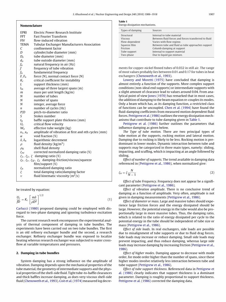
S. Khushnood et al. / Nuclear Engineering and Design 240 (2010) 1906–1918 1907
Nomenclature
EPRI Electric Power Research InstituteFFT Fast Fourier TransformFIV flow-induced vibrationTEMA Tubular Exchanger Manufacturers AssociationC confinement factorD cylinder/tube diameter (mm)De tube diameter (mm)do tube outside diameter (mm)fa natural frequency in air (Hz)f frequency of tube vibrationfn fundamental frequencyF, Fn force (N), normal contact force (N)Kc critical coefficient for instabilityL support thickness (mm)lm average of three largest spans (m)m mass per unit length (kg/m)N number of tubesN number of spansN integer, average forcen number of cycles (Hz)P/D pitch-to-diameter ratioS Stokes numbertb baffle support plate thickness (mm)Uc critical flow velocityWo effective tube weight (kg)x1, xn amplitude of vibration at first and nth cycles (mm)˛ void fraction (%)ı, ın logarithmic decrement� fluid density (kg/m3)�0 shell fluid density�nc corrected normalized damping ratio (%)�1, �2, � damping ratio (%)�F , �v, �SF , �S damping-friction/viscous/squeeze
film/support (%)�n normalized damping ratio
b
Crf
yeiehfl
2
vtiafl
Table 1Energy dissipation mechanisms.
Types of damping Sources
Structural Internal to tube materialViscous Between fluid forces and forces transferred to fluidFlow-dependent Varies with flow regime.Squeeze film Between tube and fluid as tube approaches support
� total damping ratio/damping factor� fluid kinematic viscosity (m2/s)
e treated by equation:
Uc
fD= Kc
[mı
�D2
]1/2
(1)
arlucci (1980) proposed damping could be employed with dis-egard to two-phase damping and ignoring turbulence excitationorce.
The current research work encompasses the experimental anal-sis of thermal component of damping in tube bundles. Thexperiments have been carried out on two tube bundles. The firsts an old refinery exchanger bundle and the second, a researchxchanger. Refinery exchanger bundle was exposed to localizeeating whereas research exchanger was subjected to water cross-ow at variable temperatures and pressures.
. Damping in tube bundles
System damping has a strong influence on the amplitude of
ibration. Damping depends upon the mechanical properties of theube material, the geometry of intermediate supports and the phys-cal properties of the shell-side fluid. Tight tube-to-baffle clearancesnd thick baffles increase damping, as does very viscous shell-sideuid (Chenoweth et al., 1993). Coit et al. (1974) measured log decre-Friction Columb damping at supportTube support Internal to support materialTwo-phase Due to liquid gas mixture.
ments for copper-nickel finned tubes of 0.032 in still air. The rangeof most values probably lies between 0.01 and 0.17 for tubes in heatexchangers (Chenoweth et al., 1993).
Lowery and Moretti (1975) have concluded that damping isalmost entirely a function of the supports. More complex supportconditions (non-ideal end supports) or intermediate supports witha slight amount of clearance lead to values around 0.04. From ana-lytical point of view Jones (1970) has remarked that in most cases,the addition of damping to the beam equation re-couples its modes.Only a beam which has, as its damping function, a restricted classof functions can be uncoupled. Chen et al. (1994) have found thefluid-damping coefficients from measured motion dependent fluidforces. Pettigrew et al. (1986) outlines the energy dissipation mech-anisms that contribute to tube damping given in Table 1.
Pettigrew et al. (1986) further outlines the parameters thatinfluence damping as given below.
The Type of tube motion. There are two principal types oftube motion at the supports, rocking motion and lateral motion.Damping due to rocking is likely to be less. Rocking motion is pre-dominant in lower modes. Dynamic interaction between tube andsupports may be categorized in three main types, namely: sliding,impacting, and scuffing, which is impacting at an angle followed bysliding.
Effect of number of supports. The trend available in damping datareferenced in (Pettigrew et al., 1986), when normalized give:
�n = �N
N − 1(2)
Effect of tube Frequency. Frequency does not appear be a signifi-cant parameter (Pettigrew et al., 1986).
Effect of vibration amplitude. There is no conclusive trend ofdamping as a function of amplitude. Very often, amplitude is notgiven in damping measurements (Pettigrew et al., 1986).
Effect of diameter or mass. Large and massive tubes should expe-rience large friction forces and the energy dissipated should belarge. However, the potential energy in the tube would also be pro-portionally large in more massive tubes. Thus, the damping ratio,which is related to the ratio of energy dissipated per cycle to thepotential energy in the tube should be independent of tube size ormass (Pettigrew et al., 1986).
Effect of side loads. In real exchangers, side loads are possibledue to misalignment of tube supports or due to fluid drag forces.Side loads may increase or reduce damping. Small side loads mayprevent impacting, and thus reduce damping, whereas large sideloads may increase damping by increasing friction (Pettigrew et al.,1986).
Effect of higher modes. Damping appear to decrease with modeorder, for mode order higher than the number of spans, since thesehigher modes involve relatively less interaction between tube andtube support (Pettigrew et al., 1986).
Effect of tube support thickness. Referenced data in Pettigrew etal. (1986) clearly indicates that support thickness is a dominantparameter. Damping is roughly proportional to support thickness.Pettigrew et al. (1986) corrected the damping data.
1 ering
di
3C
(
(
wll
3
r
�
w
(fv
3
�
3
s(
�
3
g
(
�
wtt
�
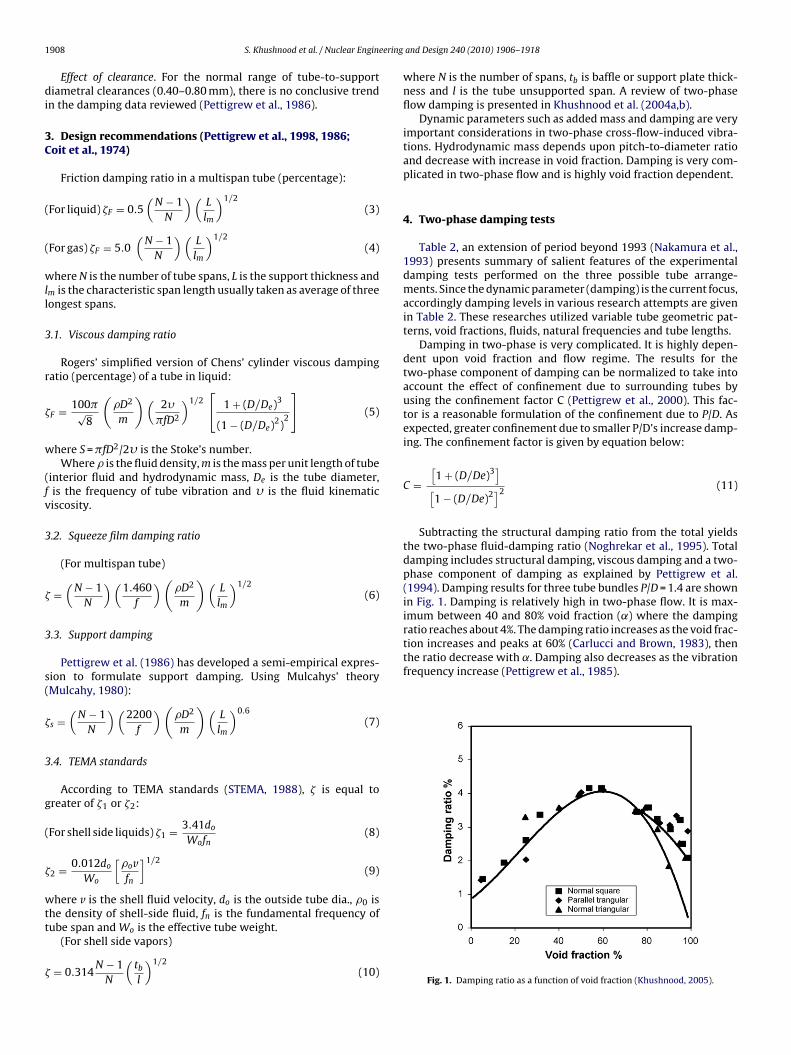
tion increases and peaks at 60% (Carlucci and Brown, 1983), thenthe ratio decrease with ˛. Damping also decreases as the vibrationfrequency increase (Pettigrew et al., 1985).
908 S. Khushnood et al. / Nuclear Engine
Effect of clearance. For the normal range of tube-to-supportiametral clearances (0.40–0.80 mm), there is no conclusive trend
n the damping data reviewed (Pettigrew et al., 1986).
. Design recommendations (Pettigrew et al., 1998, 1986;oit et al., 1974)
Friction damping ratio in a multispan tube (percentage):
For liquid) �F = 0.5(
N − 1N
)(L
lm
)1/2(3)
For gas) �F = 5.0(
N − 1N
)(L
lm
)1/2(4)
here N is the number of tube spans, L is the support thickness andm is the characteristic span length usually taken as average of threeongest spans.
.1. Viscous damping ratio
Rogers’ simplified version of Chens’ cylinder viscous dampingatio (percentage) of a tube in liquid:
F = 100�√8
(�D2
m
)(2�
�fD2
)1/2[
1 + (D/De)3
(1 − (D/De)2)2
](5)
here S = �fD2/2� is the Stoke’s number.Where � is the fluid density, m is the mass per unit length of tube
interior fluid and hydrodynamic mass, De is the tube diameter,is the frequency of tube vibration and � is the fluid kinematiciscosity.
.2. Squeeze film damping ratio
(For multispan tube)
=(
N − 1N
)(1.460
f
)(�D2
m
)(L
lm
)1/2(6)
.3. Support damping
Pettigrew et al. (1986) has developed a semi-empirical expres-ion to formulate support damping. Using Mulcahys’ theoryMulcahy, 1980):
s =(
N − 1N
)(2200
f
)(�D2
m
)(L
lm
)0.6(7)
.4. TEMA standards
According to TEMA standards (STEMA, 1988), � is equal toreater of �1 or �2:
For shell side liquids) �1 = 3.41do
Wofn(8)
2 = 0.012do
Wo
[�ovfn
]1/2(9)
here v is the shell fluid velocity, do is the outside tube dia., �0 ishe density of shell-side fluid, fn is the fundamental frequency of
ube span and Wo is the effective tube weight.(For shell side vapors)
= 0.314N − 1
N
(tb
l
)1/2(10)
and Design 240 (2010) 1906–1918
where N is the number of spans, tb is baffle or support plate thick-ness and l is the tube unsupported span. A review of two-phaseflow damping is presented in Khushnood et al. (2004a,b).
Dynamic parameters such as added mass and damping are veryimportant considerations in two-phase cross-flow-induced vibra-tions. Hydrodynamic mass depends upon pitch-to-diameter ratioand decrease with increase in void fraction. Damping is very com-plicated in two-phase flow and is highly void fraction dependent.
4. Two-phase damping tests
Table 2, an extension of period beyond 1993 (Nakamura et al.,1993) presents summary of salient features of the experimentaldamping tests performed on the three possible tube arrange-ments. Since the dynamic parameter (damping) is the current focus,accordingly damping levels in various research attempts are givenin Table 2. These researches utilized variable tube geometric pat-terns, void fractions, fluids, natural frequencies and tube lengths.
Damping in two-phase is very complicated. It is highly depen-dent upon void fraction and flow regime. The results for thetwo-phase component of damping can be normalized to take intoaccount the effect of confinement due to surrounding tubes byusing the confinement factor C (Pettigrew et al., 2000). This fac-tor is a reasonable formulation of the confinement due to P/D. Asexpected, greater confinement due to smaller P/D’s increase damp-ing. The confinement factor is given by equation below:
C =[1 + (D/De)3][1 − (D/De)2]2
(11)
Subtracting the structural damping ratio from the total yieldsthe two-phase fluid-damping ratio (Noghrekar et al., 1995). Totaldamping includes structural damping, viscous damping and a two-phase component of damping as explained by Pettigrew et al.(1994). Damping results for three tube bundles P/D = 1.4 are shownin Fig. 1. Damping is relatively high in two-phase flow. It is max-imum between 40 and 80% void fraction (˛) where the dampingratio reaches about 4%. The damping ratio increases as the void frac-
Fig. 1. Damping ratio as a function of void fraction (Khushnood, 2005).

S. Khushnood et al. / Nuclear Engineering and Design 240 (2010) 1906–1918 1909
Table 2Two-phase damping tests.
Researchers Published Fluid Tube array Void fraction Tube length Natural frequency Dampingratio/dampingcontribution(Khushnood et al.,2004a,b)
Pettigrew & Goman 1973 Air–water Triangular/parallel,square/rotated square
10–20%(quality)
50.8 mm 17 Hz, 30 Hz 2.5–2.7%
Heiker & Vincent 1980 Air–water Triangular/rotatedsquare
0.5–0.87 910 mm 56–62 Hz 0.8–4%
Hara & Ohtani 1981 Air–water Single tube 0.02–0.61 60 mm Rigid –Remy 1982 Air–water Square 0.65–0.85 1000 mm 56.6 Hz 0.6–1.75%Nakamura et al. 1982 Air–water Square/rotated square 0.2–0.94 190 mm 142 Hz 1.3–1.7%Pettigrew et al. 1984 Air–water Triangular/square 0.05–0.98 600 mm 26–32 Hz 0.9–8.0%Axisa et al. 1984 Steam–water Square 0.52–0.98 1190 mm 74 Hz 0.2–3.0%Nakamura et al. 1986 Steam–water Square 0.75–0.95 174 mm 15.2–16 Hz 4.0–8.0%Hara. 1987 Air–water Single/row 0.01–0.5 58 mm 6.0–8.4 Hz 2.9–15.6%Goyader. 1987 Air–water Triangular 0.5–0.8 360 mm 175 Hz –Gay et al. 1988 Freon Triangular 0.58–0.84 1000 mm 39.8 Hz 0.89–1.7%Nakamura & Fujita 1988 Air–water Square 0.02–0.95 600 mm 52 Hz 2.1%Funakawa et al. 1989 Air–water Square/triangular 0.0–0.6 100 mm 12.8 Hz 3.3%Nakamura et al. 1990 Steam–water Square 0.33–0.91 174 mm 94–137 Hz –Axisa et al. 1990 Steam–water Square/triangular
parallel/triangular0.52–0.99 1190 mm 72 Hz 0.2–4%
Papp & Chen 1994 – Normaltriangular/normalsquare/paralleltriangular
25–98% – – –
Pettigrew, Taylor, Jong &Currie
1995 Freon Rotated triangular 40–90%, 10–90% 609 mm 28–150 Hz 0.15%
Noghrehkar, Kawaji & Chan 1995 Air–water Square 5th & 6th row 0–90% 200 mm 15–25 Hz 0.3–3.9%Taylor, Boucher & Yetisir 1995 Air–water U-bend tube bundle
with 180◦ U-tubesparallel triangularconfiguration
0–90% U-tube radii0.6–0.7 m
23–114 Hz 1.5–2%
Marn & Catton 1996 Air–water Normal triangular,parallel triangular, &rotated square
5–99% – – 0.7–21
Taylor & Pettigrew 2000 Freon Rotated triangular &rotated square
50–98% 609 mm – 0.2–5%
Pettigrew, Taylor & Kim 2000 Air–water Normal 30◦ & rotated60◦triangular, normal90◦& rotated 45◦
square
0–100% 600 mm 30–160 Hz 1–5%
Inada, Kawamura Yasuo &Yoneda
2000 Air–water Square 0–70% 198 mm 15 Hz −2.5 to +1.6% Eq. addeddamping coefficient
Nakamura, Hirota, &Tomomatsu (Summaryof Takei et al.,)
2000 Freon 46 × 5 U-bend tubes,specification of actualwestinghouse type-51series steam generator.
(Notconsidered)based onConnorssingle-phaserelation.
– 16–26 Hz Damping ratio <1%
Feenstra, Judd & Weaver 2000 R-11 Parallel/triangular 0–0.99 – 0–100 Hz 1.1–2.9%Malik, Khushnood, & Badar
et al. (Khushnood et al.,2005)
2005 Water Triangular 0–100% 0.49 1–10 Hz 0.125 N s/m
Khushnood (Khushnood,2005)
2005 Water Triangular 0.100% 0.28 m, 0.49 m,0.395 m,.207 m
81–140 Hz 100% (equivalent), 75%(support), 9% (viscous),7% (squeeze film)
R
5
nT
bt(sa
Table 3Tube bundle parameters.
Tube material BrassTotal weight 247 kgNumber of tubes 52 (60◦ triangular)Tube diameter outer/inner 19 mm/17 mmNumber of baffles 44
esults 1973–1993 (Nakamura et al., 1993).
. Results and discussion
The first phase of experimentation has been carried out undero-flow simulated (using pulse, sinusoidal and random) excitation.ube bundle parameter is given in Table 3.
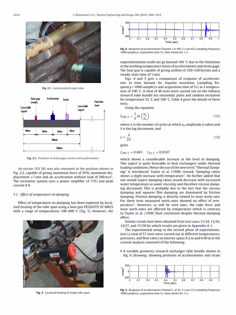
The research heat exchanger tube bundle was mounted on
ungees to isolate it from any external effects. The targetube shown in Fig. 2.1 was instrumented with accelerometerPAC/20/M), self-energized transducer (MM, WA series), and atacked rosette strain gage capable of giving strain in lift, drag andxial directions, at the positions shown in Fig. 2.2.Baffle hole clearance 2 mmTube-side fluid Water inlet 90 FShell-side fluid (sp. gravity 0.915) Cut 4. inlet 415 F, outlet 300 FModulus of elasticity 109 GPa (10.8 × 10⁹ kg/m2)Density 8500 kg/m3
Damping coefficient 0.125 N s/m
1910 S. Khushnood et al. / Nuclear Engineering and Design 240 (2010) 1906–1918
Fig. 2.1. Instrumented target tube.
FpTc
5
iw
Fig. 2.2. Positions of strain gage, exciter and accelerometer.
An exciter (EX 58) was also mounted at the position shown inig. 2.2, capable of giving maximum force of 50 N, maximum dis-lacement ±7 mm and an acceleration without load of 500 m/s2.he excitation system uses a power amplifier (A 735) and peakurrent 8 A.
.1. Effect of temperature on damping
Effect of temperature on damping has been explored by local-zed heating of the tube span using a heat gun FELISATTI SV 600/S
ith a range of temperatures 100–600 ◦C (Fig. 3). However, the
Fig. 3. Localized heating of target tube span.
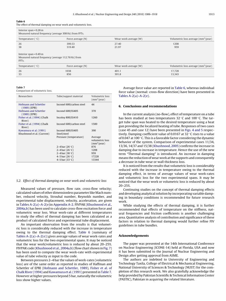
Fig. 4. Response of accelerometer Channel 1 at 100 ◦C (case 45) (sampling frequency1000 samples/s, acquisition time 5 s. Data shown for 1 s).
experimentation could not go beyond 100 ◦C due to the limitationin the working temperature limits of accelerometer and strain gage.The heat gun is capable of giving airflow of 250–520 lit/min and asteady-state time of 1 min.
Figs. 4 and 5 give a comparison of response of accelerom-eter in time domain for impulse excitation (sampling fre-quency = 1000 samples/s and acquisition time of 5 s) at a tempera-ture of 100 ◦C. A total of 46 tests were carried out on the refineryresearch tube bundle are sinusoidal, pulse and random excitationfor temperature 32 ◦C and 100 ◦C. Table 4 gives the details of thesetests.
Using the equation:
ı100 ◦C = 1n
ln(
x1
xn
)(12)
where n is the number of cycles at which xn amplitude is taken andı is the log decrement, and
� ≈ ı
2�(13)
gives
�100 ◦C = 0.047, �32 ◦C = 0.0167
which shows a considerable increase in the level of damping.This aspect is quite favorable in heat exchangers under thermalloading conditions. Hence the use of the new term “Thermal Damp-ing” is introduced. Taylor et al. (1998) remark “damping ratiosshows a slight increase with temperature”. He further added thatone would expect damping ratios would decrease with increasedwater temperature as water viscosity and therefore viscous damp-ing decreased. This is probably due to the fact that the viscousdamping and squeeze film damping are dominated by frictiondamping. Friction damping is directly related to wear work-rate.For these tests measured work-rates showed no effect of tem-perature”. However, as will be seen later, the tube force andwear work-rates are affected by temperature which is contraryto Taylor et al. (1998) final conclusion despite thermal dampingeffect.
Similar trends have been obtained from test cases 11/34, 13/36,14/37, and 15/38 for which results are given in Appendix A-1.
The experimental setup in the second phase of experimenta-tion (a total of 57 tests were carried out at different temperatures,pressures, and flow rates) on interior spans 0.2 m and 0.49 m in the
current analysis consisted of the following:• A variable geometry research exchanger tube bundle shown inFig. 6 (drawing: showing positions of accelerometer and strain
Fig. 5. Response of accelerometer Channel 1, at 32 ◦C (case 12) (sampling frequency1000 samples/s, acquisition time 5 s. Data shown for 1 s).

S. Khushnood et al. / Nuclear Engineering and Design 240 (2010) 1906–1918 1911
Table 4Excitation types and levels at 32 ◦C and 100 ◦C.
Case number Frequencies (Hz) Force (N) Temp. ( ◦C) Case number Frequencies (Hz) Force (N) Temp. ( ◦C)
Sinusoidal excitation Sinusoidal excitation1 10 25 32 24 10 25 1002 50 25 32 25 50 25 1003 100 25 32 26 100 25 1004 10 12.5 32 27 10 12.5 1005 50 12.5 32 28 50 12.5 1006 100 12.5 32 29 100 12.5 1007 300 12.5 32 30 300 12.5 1008 500 12.5 32 31 500 12.5 1009 800 12.5 32 32 800 12.5 10010 1000 12.5 32 33 1000 12.5 100
Pulse excitation Pulse excitation11 25 32 34 25 10012 50 32 35 50 10013 20 32 36 20 10014 10 32 37 10 10015 5 32 38 5 100
Random excitation Random excitation16 32 39 10017 32 40 10018 32 41 10019 32 42 10020 32 43 100
Pulse excitation Pulse excitation21 50 32 44 30 10022 20 32 45 50 10023 40 32 46 10 100
e and target tube locations.
•
•
••
•
Table 5Variable geometry research exchanger tube bundle parameters (Nakamura et al.,1993).
Tube/support material SteelNumber of tubes 10Tube dia. outer/inner 13 mm/11 mmNumber of baffles 07Baffle hole clearance/thickness 1.5 mm/2 mmTube-side fluid Dummy (water)
◦ ◦
Fig. 6. Tube span, baffl
gage) specifically manufactured to simulate real conditions. Tubebundle parameters are given in Table 5.Test loop consists of water tunnel, with a pump capable of sup-plying 17.65 m3/h.Target intermediate tube (triangular pattern) was instrumentedwith (PAC/20/M) accelerometer, self-energized transducer, andtriaxial (WA series) strain gage, capable of giving strain in lift,drag and side directions.
Data acquisition system.A flow meter, portable type ultrasonic (PORATFLOW X) type: con-verter FLC-2, detector FLD-1 was used to record flow and velocityof flow.Radiation pyrometer was used to record temperatures.Shell-side fluid Water inlet 26 C/33 CModulus of elasticity (tube) 21.1 × 10⁹ kg/m2
Density (tube) 7850 kg/m3
Tube pitch (triangular)/(pitch-to-dia. ratio) 15.875 mm/1.221 mm

1912 S. Khushnood et al. / Nuclear Engineering and Design 240 (2010) 1906–1918
Fig. 7. Flow chart of FIV PAK code (Khushnood et al., 2004a,b).
S. Khushnood et al. / Nuclear Engineering and Design 240 (2010) 1906–1918 1913
Table 6The effect of thermal damping on wear work and volumetric loss.
Interior span = 0.28 mMeasured natural frequency (average 308 Hz) from FFTs.
Temperature ( ◦C) Force average (N) Wear work average (W) Volumetric loss average (mm3/year)
26 399.53 27.40 120838 319.40 21.97 959
Interior span = 0.49 mMeasured natural frequency (average 112.76 Hz) fromFFTs.
Temperature ( ◦C) Force average (N) Wear work average (W) Volumetric loss average (mm3/year)
26 1038 40133 856 301
Table 7Comparison of volumetric loss.
Researchers Tube/support material Volumetric loss(mm3/year)
Hofmann and Schettler(1989) (EPRI)
Inconel 600/carbon steel 44
Hofmann and Schettler(1989) (EPRI)
Inconel 600/SS405 370
Fisher et al. (1994) (ChalkRiver)
Incoloy 800/SS410 1260
Fisher et al. (1994) (ChalkRiver)
Inconel 600/carbon steel 1500
Kawamura et al. (1991) Inconel 600/SS405 390Khushnood et al. (Current) Steel/steel
Pressure (temperature) Averagevolumetric loss(mm3/year)
2–4 bar (26 ◦C) 8762–4 bar (26 ◦C) 12082–4 bar (38 ◦C) 9594–5 bar (26 ◦C) 172284–5 bar (33 ◦C) 13344
5
cbei2vtp
roTvtFhv
lSCHl
Technology Taxila, College of Electrical & Mechanical Engineering,National University of Sciences & Technology (NUST) for the com-
.2. Effect of thermal damping on wear work and volumetric loss
Measured values of pressure, flow rate, cross-flow velocity;alculated values of other dimensionless parameter like Mach num-er, reduced velocity, Strouhal number, Reynolds number, andxperimental tube displacement, velocity, acceleration, are givenn Tables A-2(a)–A-2(e)in Appendix A-2. FIVPAK (Khushnood et al.,004a,b) has been used to calculate cross-flow excitation force andolumetric wear loss. Wear work-rate at different temperatureso study the effect of thermal damping has been calculated as aroduct of calculated force and experimental tube displacement.
An important observation from the results is that volumet-ic loss is considerably reduced with the increase in temperaturewing to the thermal damping effect. Table 6 (summary ofables A-2(a)–A-2(e)) gives average values of wear work-rates andolumetric loss for the two experimental spans. It may be noticedhat the wear work/volumetric loss is reduced by about 20–25%.IVPAK code (Khushnood et al., 2004a,b) (flow chart shown in Fig. 7)as been used to compute the wear work-rate with experimentalalue of tube velocity as input to the code.
Between pressures 2–4 bar the values of work-rates (volumetricoss) are of the same order as reported in studies of Haffman andchettler of EPRI (Hofmann and Schettler, 1989), Fisher et al. of
halk River (1994) and Kawamura et al. (1991) presented in Table 7.owever at higher pressures beyond 5 bar, naturally the volumetricoss show higher values.
.1 17,728
.8 13,343
Average force value are reported in Table 6, whereas individualforce value (normal: cross-flow direction) have been presented inTables A-2(a)–A-2(e).
6. Conclusions and recommendations
In the current analysis (no-flow), effect of temperature on a tubehas been studied at two temperatures 32 ◦C and 100 ◦C. The tar-get tube span was heated to the desired temperature using a heatgun providing the localized heating of tube. Responses of two cases(case 45 and case 12) have been presented in Figs. 4 and 5 respec-tively. Damping coefficient value of 0.0167 at 32 ◦C rises to a valueof 0.047 at 100 ◦C. This is a favorable factor considering the dynamicbehavior of the system. Comparison of experimental cases 11/34,13/36, 14/37 and 15/38 (Khushnood, 2005) confirms the increase indamping due to increase in temperature. Hence the use of the newterm “Thermal damping” is introduced. An increase in dampingmeans the reduction of wear work at the supports and consequentlya decrease in tube wear or wall thickness loss.
It is noticed from the results that volumetric loss is considerablyreduced with the increase in temperature owing to the thermaldamping effect, in terms of average values of wear work-ratesand volumetric loss for the two experimental spans. It may benoticed that the wear work or volumetric loss is reduced by about20–25%.
Continuing studies on the concept of thermal damping effectsand developing analytical solution by incorporating variable damp-ing in boundary conditions is recommended for future researchwork.
While studying the effects of thermal damping, it is furtherrecommended that effects of temperature on the stiffness, nat-ural frequencies and friction coefficients is another challengingarea. Quantitative analysis of contribution and significance of thesefactors in relation to thermal damping would further refine FIVguidelines in tube bundles.
Acknowledgements
The paper was presented at the 14th International Conferenceon Nuclear Engineering (ICONE-14) held at Florida, USA and nowit has been submitted to the Journal of Nuclear Engineering andDesign after getting approval from ASME.
The authors are indebted to University of Engineering and
pletion of this research work. We also gratefully acknowledge thehelp provided by Pakistan Scientific & Technical Information Center(PASTIC), Pakistan in acquiring the related literature.

1 ering
A Appendix B. Appendix A-2
.
914 S. Khushnood et al. / Nuclear Engine
ppendix A. Appendix A-1
and Design 240 (2010) 1906–1918

S.Khushnood
etal./N
uclearEngineering
andD
esign240 (2010) 1906–1918
1915
Table A-2(a)Experimental data on research exchanger (variable geometry). Natural frequency (fn = 301 Hz). Pump supply head = 0.65 m (positive suction). Tube span = 0.28 m (interior). Temperature (26 ◦C).
Test no. P (bar) Q (m3/h) U (m/s) Up (m/s) M S Vr Re y (mm) y (m/s) y (m/s2) Force (N) Wear work (W) Vol. loss (mm3/year)
01 2.0 12.0 3.60 19.87 0.0138 0.1969 5.078 2.893 × 10⁵ 1.0331 0.0649 4.0785 606 39.3 17372 2.2 10.5 3.16 17.44 0.01184 0.2243 4.457 2.539 × 10⁵ – – – 471 – –3 2.4 10.0 3.02 16.67 0.01131 0.2347 4.260 2.426 × 10⁵ 0.8532 0.0536 3.3681 430 23 10174 2.6 9.6 2.8 15.45 0.01048 0.2532 3.948 2.25 × 10⁵ 0.7045 0.0443 2.7813 369 16.4 7255 2.8 9.0 2.9 16.01 0.01086 0.2444 4.091 2.33 × 10⁵ 1.2180 0.0567 4.8084 397 30.4 13446 3.0 10.4 3.0 16.56 0.01124 0.236 4.232 2.41 × 10⁵ 1.0758 0.0676 4.2471 425 28.7 12687 3.2 10.2 2.9 16.01 0.01096 0.2444 4.091 2.33 × 10⁵ 1.1688 0.0734 4.6143 397 29.2 12918 3.4 10.6 2.96 16.34 0.01109 0.2394 4.175 2.37 × 10⁵ 1.6478 0.1035 6.5053 413 42.7 18879 3.6 7.9 2.4 13.25 0.00899 0.2953 3.386 1.928 × 10⁵ 0.9085 0.0571 3.5866 272 15.5 65810 3.8 4.15 1.25 6.9 0.00468 0.567 1.763 1.0045 × 10⁵ 1.5228 0.0957 6.0119 74 7 30911 4.2 2.3 0.675 3.73 0.00253 1.049 0.9532 5.424 × 10⁴ 1.1980 0.0753 4.7294 22 1.66 7312 4.0 3.3 0.98 5.4 0.00366 0.724 1.38 7.875 × 10⁴ 1.4070 0.0884 5.5546 45 4 17613 4.4 1.6 0.49 2.7 0.00183 1.45 0.69 3.973 × 10⁴ 1.0796 0.0678 4.2619 11 0.75 33
Average vol. loss 876
Table A-2(b)Experimental data on research exchanger (variable geometry). Natural frequency (fn = 295.5 Hz). Pump supply head = 0.65 m (positive suction). Tube span = 0.28 m (interior). Temperature (26 ◦C).
Test no. P (bar) Q (m3/h) U (m/s) Up (m/s) M S Vr Re y (mm) y (m/s) y (m/s2) Force (N) Wear work (W) Vol. loss (mm3/year)
14 2.0 12.05 3.6 19.87 0.01348 0.193 5.172 2.893 × 10⁵ 0.9487 0.0596 3.7418 611.96 36.47 161215 2.2 11.8 3.45 19.04 0.01292 0.202 4.95 2.772 × 10⁵ 1.0002 0.0628 3.9488 561.9 35.28 156016 2.4 11.8 3.44 18.98 0.01288 0.202 4.94 2.764 × 10⁵ 0.9002 0.0566 3.5538 558.4 31.60 139717 2.6 11.7 3.43 18.93 0.01285 0.202 4.92 2.765 × 10⁵ 0.7913 0.0497 3.1239 555.4 27.60 122018 2.8 11.7 3.40 18.98 0.01288 0.202 4.94 2.764 × 10⁵ 0.9415 0.0592 3.7168 558.3 33.058 146019 3.0 11.5 3.40 18.76 0.01273 0.204 4.88 2.732 × 10⁵ 0.9627 0.0605 3.8006 545.5 33.01 146020 3.2 11.4 3.40 18.76 0.01273 0.204 4.88 2.732 × 10⁵ 1.5979 0.1004 6.3081 545.5 54.76 242021 3.4 11.11 3.25 17.94 0.01217 0.214 4.67 2.661 × 10⁵ 1.6753 0.1053 6.6137 498.8 52.53 232222 3.6 7.47 2.20 12.14 0.00824 0.316 3.16 1.766 × 10⁵ 0.9315 0.0585 3.6776 228.6 13.37 59123 3.8 4.68 1.39 7.67 0.00520 0.500 2 1.116 × 10⁵ 1.3198 0.0829 5.2105 91.2 7.56 33424 4.0 2.64 0.78 4.305 0.00292 0.892 1.12 6.267 × 10⁴ 1.2003 0.0754 4.7387 28.7 2.166 9525 4.4 1.56 0.46 2.54 0.00172 1.512 0.66 3.696 × 10⁴ 1.0694 0.0672 4.2217 10 0.672 28
Average vol. loss 1208

1916S.K
hushnoodet
al./Nuclear
Engineeringand
Design
240 (2010) 1906–1918
Table A-2(c)Experimental data on research exchanger (variable geometry). Natural frequency (fn = 324.8 Hz). Pump supply head = 0.65 m (positive suction). Tube span = 0.28 m (interior). Temperature (38 ◦C).
Test no. P (bar) Q (m3/h) U (m/s) Up (m/s) M S Vr Re y (mm) y (m/s) y (m/s2) Force (N) Wear work (W) Vol. loss (mm3/year)
26 2.0 10.58 3.248 17.92 0.0121 0.235 4.24 2.61 × 10⁵ 0.9519 0.0598 3.7581 497.7 29.76 131527 2.2 10.73 3.19 17.61 0.01195 0.239 4.17 2.56 × 10⁵ 1.1282 0.0709 4.4539 480.6 34.08 150628 2.4 10.65 3.085 17.03 0.01156 0.247 4.03 2.47 × 10⁵ 0.9561 0.0601 3.7744 449.5 27.02 119429 2.6 10.64 3.14 17.33 0.01176 0.243 4.1 2.527 × 10⁵ 0.8218 0.0516 3.2444 465.5 24.02 106230 2.8 10.4 3.02 16.67 0.01131 0.253 3.95 2.427 × 10⁵ 0.9140 0.0574 3.6083 430.7 24.72 109331 3.0 10.63 3.12 17.22 0.01169 0.245 4.07 2.500 × 10⁵ 1.1087 0.0697 4.3768 459.6 32.04 141632 3.4 10.22 3.05 16.83 0.01142 0.25 4 2.450 × 10⁵ 1.6647 0.1046 6.5721 439 45.92 203033 3.6 6.84 2.04 11.26 0.00764 0.375 2.667 1.64 × 10⁵ 1.2088 0.0759 4.7721 196.5 14.92 65934 3.8 3.85 1.145 6.32 0.00430 0.67 1.5 9.21 × 10⁴ 1.5145 0.0952 5.9789 61.9 3.67 16235 4.0 2.22 0.66 3.64 0.00247 1.16 0.86 5.30 × 10⁴ 1.2539 0.0788 4.9503 20.5 1.62 7236 4.4 1.68 0.51 2.82 0.00190 1.5 0.67 4.098 × 10⁴ 1.2259 0.0770 4.8396 12.4 0.95 42
Average vol. loss 959
Table A-2(d)Experimental data on research exchanger (variable geometry). Natural frequency (fn = 116 Hz). Pump supply head = 0.76 m (positive suction). Tube span = 0.49 m (interior). Temperature (26 ◦C).
Test no. P (bar) Q (m3/h) U (m/s) Up (m/s) M S Vr Re y (mm) y (m/s) y (m/s2) Force (N) Wear work (W) Vol. loss (mm3/year)
37 3.9 17.65 5.18 28.6 0.0194 0.0528 18.96 4.16 × 10⁵ 7.1113 0.4468 28.07 2219 991 4381838 4.0 17.26 5.08 28.04 0.01903 0.0538 18.6 4.08 × 10⁵ 6.9893 0.4391 27.5925 2133 937 4139339 4.2 14.7 4.405 24.31 0.0165 0.062 16.12 3.53 × 10⁵ 4.9569 0.3115 19.5692 1603 499 22071a40 4.4 11.49 3.39 18.71 0.0127 0.0805 12.4 2.72 × 10⁵ a12.4313 0.7811 49.077 950 742 3278341 4.6 7.55 2.19 12.08 0.0082 0.125 8.02 1.76 × 10⁵ 2.0030 0.1259 7.9076 396 49.8 220242 4.8 2.94 0.884 4.88 0.00332 0.309 3.23 7.1 × 10⁴ 1.5387 0.0967 6.07447 6406 6.3 27643 5.0 0.30 0.098 0.54 0.00036 2.8 0.358 7.8 × 10³ 1.2328 0.0775 4.8668 0.79 0.062 2.7444 4.8 3.5 1.07 5.9 0.00400 0.255 3.91 8.6 × 10⁴ 1.3714 0.0862 5.4140 94.42 8.2 35945 4.5 10.58 3.12 17.22 0.001169 0.0875 11.42 2.5 × 10⁵ 2.9402 0.1847 11.6076 804 148.6 656646 4.3 13.5 3.98 21.97 0.01492 0.0686 14.56 3.2 × 10⁵ 4.3807 0.2753 17.2945 1309 361 1593247 4.1 15.69 4.74 26.17 0.0172 0.0576 17.35 3.8 × 10⁵ 5.7697 0.3625 22.777 1848 670 29607
Average vol. loss 17225
a Showing instability.

S. Khushnood et al. / Nuclear Engineering
Tab
leA
-2(e
)N
atu
ralf
requ
ency
(fn
=12
0.7
Hz)
.Pu
mp
sup
ply
hea
d=
0.76
m(p
osit
ive
suct
ion
).Tu
besp
an=
0.49
m(i
nte
rior
).Te
mp
erat
ure
(33
◦ C).
Test
no.
P(b
ar)
Q(m
3/h
)U
(m/s
)U
p(m
/s)
MS
Vr
Re
y(m
m)
y(m
/s)
y(m
/s2)
Forc
e(N
)W
ear
wor
k(W
)V
ol.l
oss
(mm
3/y
ear)
483.
916
.64.
9827
.50.
0866
0.05
717
.52
4.10
5×
105 7.
4825
0.47
0129
.539
2015
946
4262
549
4.0
16.1
74.
739
26.1
60.
0176
0.06
016
.67
3.8
×10
57.
3995
0.46
4929
.211
918
5686
338
146
504.
214
.34.
2923
.68
0.01
600.
066
15.1
3.44
×10
55.
4414
0.34
1921
.481
615
2152
022
984
514.
312
.63.
7520
.70.
0140
0.07
5713
.23.
00×
1054.
4506
0.27
9617
.570
311
6232
514
365
524.
411
.06
3.22
17.7
70.
0120
0.08
8311
.32
2.58
×10
53.
5605
0.22
3714
.056
585
6.6
192
8470
534.
59.
382.
7615
.20.
0103
0.10
39.
682.
2×
105
2.44
890.
1539
9.66
7962
797
4263
544.
67.
162.
133
11.7
70.
0080
0.13
337.
51.
71×
1051.
7893
0.11
247.
0638
376
4218
7055
4.7
4.55
1.31
97.
280.
0049
40.
2155
4.64
1.06
×10
51.
7606
0.11
066.
6505
144
1670
356
4.8
0.73
790.
223
1.23
0.00
083
1.27
0.78
41.
79×
1040.
7925
0.04
983.
1286
4.1
0.20
49
574.
90.
290.
089
0.49
0.00
043
3.20
0.31
27.
15×
1030.
8942
0.05
623.
5300
0.65
0.03
661.
62
Ave
rage
vol.
loss
1334
4
Not
e:S
and
Vr
valu
esar
eba
sed
up
onth
eav
erag
efr
equ
ency
inth
atse
tof
dat
a.
and Design 240 (2010) 1906–1918 1917
References
Axisa, F., Villard, B., Gibert, R.J., Hostroni, G., Sundheimer, P., 1984. Vibration of tubebundles subjected to air–water and steam–water cross-flow. In: ASME WinterAnnual Meeting, p. 269.
Carlucci, L.N., 1980. Damping and hydrodynamic mass of a cylinder insimulated two-phase flow. Journal of Mechanical Design 102, 597–602.
Carlucci, L.N., Brown, J.D., 1983. Experimental studies of damping andhydrodynamic mass of a cylinder in confined two-phase flow. ASMEJournal of Vibration, Acoustics, Stress Reliability in Design 105, 83–89.
Chen, S.S., Zhu, S., Jendrzejczyk, J.A., 1994. Fluid damping and fluid stuffiness of atube row in cross-flow. ASME Journal of Pressure Vessel Technology 116, 370–383.
Chenoweth, J.M., Chisholm, D., Cowie, R.C., Harris, D., Illingworth, A., Loncaster, J.F.,Morris, M., Murray, I., North, C., Ruiz, C., Saunders, E.A.D., Shipes, K.V., DennisUsher, Webb, R.L., 1993. Heat Exchanger Design Handbook, HEDH. HemispherePublishing Corporation.
Coit, R.L., Ritland, P.D., Rabas, T.J., Viscovich, P.W., 1974. Moisture SeparatorReheater: Entering the Second Decade, Two-phase Flow in Turbines. ShortCourse. Rhode–Saint–Genese, Belguim.
Fisher, N.J., Chow, A.B., Weckwerth, M.K., 1994. Experimental fretting wear studiesof steam generation materials ASME, PVP, vol. 273. In: Au-Wang, M.K. (Ed.),Flow-Induced Vibration.
Gay, N., Decembre, P., Launay, J., 1988. Comparison of air–water to water–freontwophase cross-flow effects on the vibrationary behavior of a tube bundle. In:ASME Winter Annual Meeting, p. 139.
Hartlen, R.T., Simpson, F.J., Ontario hydro research division report-26479 (new4–74). Presented to Director of Research Mr. J. H., Waghorne, “Win tunnel deter-mination of fluid-elastic vibration threshold for typical heat exchanger tubepatterns”.
Hofmann, P.J., Schettler, T., 1989. PWR steam generator tube fretting and fatiguewear. In: EPRI Report NP-6341.
Jones, A.T., 1970. Vibration of beams immersed in liquid. Experimental Mechanics,84–88.
Kawamura, K., Yasuo, A., Inada, F., 1991. Tube-to-support dynamic interaction andwear of heat exchanger tubes caused by turbulent flow-induced vibration ASME,PVP, vol. 206. In: Au-Yang, M.K., Hara, F. (Eds.), Flow-Induced Vibration andWear.
Khushnood, S., 2005, Vibration analysis of a multi-span tube in a bundle. Ph.D. The-sis, Department of Mechanical Engineering, National University of Sciences andTechnology, Pakistan.
Khushnood, S., Khan, Z.M., Afzaal Malik, M., Zafarullah Koreshi, Mahmood AnwarKhan, May 2004. A review of heat exchanger tube bundle vibrations in two-phase cross-flow. Journal of Nuclear Engineering and Design 230 (1–3), Elsevier,Reference NED-3985.
Khushnood, S., Khan, Z.M., Afzaal Malik, M., Zafarullah Koreshi, Mahmood AnwarKhan, 2004b. Modelling and simulation of cross-flow induced vibrationin a multi-span tube bundle. In: Proceedings of 12th International Con-ference on Nuclear Engineering, ICONE12, Arlington, VA, USA, April 25–29.
Khushnood, S., Malik, A.M., Badar Rashid, 2005. A comparative study of cross-flowinduced vibrations in heat exchanger tube bundles using bond graph approach.In: Proceedings of 2005 ASME International Mechanical Engineering Congressand Exposition, Orlando, FL, USA, November 5–11.
Lowery, R.L., Moretti, P.M., 1975. Natural frequencies and damping of tubes on multi-span supports. In: Proceedings of the 15th National Heat Transfer Conference,AIChE, San Francisco, Paper No. 1.
Mulcahy, T.J., 1980. Fluid forces on rods vibrating in finite length annular regions.Journal of Applied Mechanics 47, 234–240.
Nakamura, T., Fujita, K., Tsuge, A., 1993. Two-phase cross-flow induced vibra-tion of tube arrays. JSME International Journal, Series B 36 (3), 429–438.
Noghrekar, R., Kawaji, M., Chan, A.M.C., 1995. An experimental study of localtwo-phase parameters in cross-flow induced vibration in tube bundles. In: Pro-ceedings of the 6th International Conference on Flow Induced Vibration, London,April 10–12, pp. 373–382.
Pettigrew, M.J., Tromp, J.H., Mastorakos, J., 1985. Vibration of tube bundles subjectedto two-phase cross-flow. Journal of Pressure Vessel Technology-Transactions ofthe ASME 107, 335.
Pettigrew, M.J., Goyder, H.G.D., Qiao, Z.L., Axisa, F., 1986. Damping of multispan heatexchanger tubes part I and II. In: Proceedings of Pressure Vessel and PipingConference, ASME, 104, pp. 81–87.
Pettigrew, M.J., Taylor, C.E., Yasuo, A., 1994. Vibration Damping of Heat ExchangerTube Bundles in Two-Phase Flow. Welding Research Council, New York, BulletinNo. 389, pp. 1–41.
Pettigrew, M.J., Dickinson, T.J., Currie, I.G., Vidalou, P., 1998. Vibration damping inmultispan heat exchanger tubes. ASME Journal of Pressure Vessel Technology120, 283–289.
Pettigrew, M.J., Taylor, C.E., Kim, B.S., 2000. The effects of tube bundle geometryon vibration in two-phase cross-flow. In: Proceedings of the Int. Conf. on Flow-Induced Vibrations, FIV-2000, Lucerne, Switzerland, June 19–22, ISBN 90 5809129 5, pp. 561–568.
Rogers, R.J., Taylor, C., Pettigrew, M.J., 1984. Fluid effects on multispanheat exchanger tube vibration. ASME Journal of Pressure Vessel and

1 ering
S
T
Wambsganss, M.W., Chen, S.S., Jendrzejcyk, J.A., 1974. Added Mass and Damping of a
918 S. Khushnood et al. / Nuclear Engine
Piping, 17–26, ASME Publication H00316, Topics in Fluid Structure
Interaction.tandards of Tubular Exchanger Manufacturers Associate, 1988, 7th ed., TEMA, NewYork.
aylor, C.E., Pettigrew, M.J., Dickinson, T.J., Currie, I.G., Vidalou, P., 1998. Vibrationdamping in multi-span heat exchanger tubes. ASME Journal of Pressure VesselTechnology 120, 283–289.
and Design 240 (2010) 1906–1918
Vibrating Rod in Confined Viscous Field ANL-CT-75-08 Report. Argonne NationalLaboratory, Argonne, IL, p. 14.
Zhou, T., Rogers, R.J., 1997. Simulation of two-dimensional squeeze film and solidcontact forces acting on a heat exchanger tube. Journal of Sound and Vibration203 (4), 621–639.