Model-X_Service-GUIDE.pdf - DTG Connection
111
-
Upload
khangminh22 -
Category
Documents
-
view
0 -
download
0
Transcript of Model-X_Service-GUIDE.pdf - DTG Connection


Important Notice
ForUsersinEurope
IMPORTANT:
ThisisaClassAproductapprovedforindustrialenvironments.Insomeenvironmentsthisproductmaycauseradiointerferenceinwhichcaseyoumayberequiredtotakemeasurestore‐locatethisproduct.
ForUsersintheUnitedStates
ThisequipmenthasbeentestedandfoundtocomplywiththelimitsforaClassAdigitaldevice,pursuanttoPart15oftheFCCRules.Theselimitsaredesignedtoprovidereasonableprotectionagainstharmfulinterferencewhentheequipmentisoperatedinacommercialenvironment.
Thisequipmentgenerates,uses,andcanradiateradiofrequencyenergyand,ifnotinstalledandusedinaccordancewiththeinstructionmanual,maycauseharmfulinterferencetoradiocommunications.Operationofthisequipmentinaresidentialareaislikelytocauseharmfulinterferenceinwhichcasetheuserwillberequiredtocorrecttheinterferenceathisownexpense.
TrademarksMentionedinthisManual:
DTG‐CandModelXareregisteredtrademarksorproductnamesofDTGCONNECTIONPtyLtd.EPSON®andEPSONSTYLUS®areregisteredtrademarksofSeikoEpsonCorporation.Microsoft®,Windows®,andWindowsVista®areregisteredtrademarksofMicrosoftCorporation.Apple®andMacintosh®areregisteredtrademarksofAppleInc.Intel®isaregisteredtrademarkofIntelCorporation.PowerPC®isaregisteredtrademarkofInternationalBusinessMachinesCorporation.Adobe®,Photoshop®,Elements®,Lightroom®andAdobe®RGBareregisteredtrademarksofAdobeSystemsIncorporated.
G e n e r a l N o t i c e : O t h e r p r o d u c t n am e s u s e d h e r e i n a r e f o r i d e n t i f i c a t i o n p u r p o s e s o n l y a n d m a y b e t r a d e m a r k s o f t h e i r r e s p e c t i v e o w n e r s . D T G C o n n e c t i o n d i s c l a i m s a n y a n d a l l r i g h t s i n t h o s e m a r k s .
Inthismanual,safetyinstructionsareprecededbythesymbol .Alwaysreadandfollowtheinstructionsbeforeperformingtherequiredprocedures.
DTGConnectionisnotresponsibleforanybreakdownofmachinesduetoinfectionofcomputervirusorcomputerhacking.
Warranty Limitations
IMPORTANT: No part of this product or publication may be stored, reproduced, copied, or transmitted in any form or by any means without the express permission of DTG CONNECTION.
The product and the contents of this publication may be changed at any time without prior notification.
DTG CONNECTION has made the best efforts to keep this publication free from error, but if you find any uncertainties or misprints, please call us or the shop where you bought this equipment.
DTG CONNECTION shall not be liable for any damages or troubles resulting from the use or mis‐use of this equipment or this manual either directly or indirectly.

DTGCONNECTIONwarrantspartrepairorreplacementasasolemeasureonlyifafailureisfoundinthesystemorinthematerialsandworkmanshipoftheproductthesellerproduced.
However,ifthecauseoffailureisuncertainorcannotbeconclusivelyprovedtobedirectlyrelatedtodefectinworkmanshipanypartrepairorreplacementshallbesolelyatthediscretionofDTGCONNECTION.
Thewarrantyshallnotapplytoanydirectorindirectloss,orcompensationforthelossduetotheproductthathasbeensubjecttomisuse,neglect,orimproperalternationwhetherdirectlyorindirectly.
ALLINFORMATIONCONTAINEDINTHISDOCUMENTISPROVIDEDASISWITHOUTWARRANTYOFANYKIND.THECREATOROFTHISDOCUMENT,HEREINAFTERREFERREDTOASTHE'WRITER'HEREBYDISCLAIMSALLWARRANTIES,EXPRESSED,IMPLIEDOROTHERWISE,INCLUDINGWARRANTIESOFMERCHANTABILITY,FITNESSFORAPARTICULARPURPOSE,ANDNON‐INFRINGEMENTOFINTELLECTUALPROPERTYRIGHTS.THEWRITERDOESNOTASSUMEORAUTHORIZEANYOTHERPERSONTOASSUMEFORITANYOTHERLIABILITYINCONNECTIONWITHTHISSITECONTENT.INNOEVENTSHALLTHEWRITERBELIABLETOTHEREADEROFTHECONTENTOFTHISSITE,ORANYSUBSEQUENTUSER,INCLUDINGTHEULTIMATEEND‐USER,INCONTRACT,TORT,WARRANTY,STRICTLIABILITY,OROTHERWISEFORANYSPECIAL,INDIRECT,INCIDENTALORCONSEQUENTIALDAMAGES,INCLUDINGBUTNOTLIMITEDTO,THECOSTOFLABOR,REQUALIFICATION,DELAY,LOSSOFPROFITSORGOODWILL,EVENIFTHEWRITERISADVISEDOFTHEPOSSIBILITYOFSUCHDAMAGES.BYLOOKINGATTHECONTENTOFTHISDOCUMENTTHEREADERAGREESTHATTHEYHAVEREADANDAGREETOTHEABOVECONDITIONSENTIRELY.

1 Contents
1 INTRODUCTION
1.1 General Specifications ............................................................................................................................................. 4
1.2 Overview Of User Interface ..................................................................................................................................... 5
1.2.1 Home Screen ............................................................................................................................................. 5
1.2.2 Status Screen ............................................................................................................................................. 5
1.2.3 Printing Screen .......................................................................................................................................... 6
1.2.4 Maintenance Screen .................................................................................................................................. 6
1.2.5 Adjustment Screen .................................................................................................................................... 7
1.2.6 Replacement Screen .................................................................................................................................. 7
1.2.7 Setting Screen ............................................................................................................................................ 8
2 INSTALLATION
2.1 Installation ............................................................................................................................................................... 9
2.2 Printing .................................................................................................................................................................. 11
2.2.1 Setting Platen .......................................................................................................................................... 13
2.2.2 Pause & Cancel The Printing .................................................................................................................... 14
2.2.3 Data Path Flowchart ................................................................................................................................ 16
3 USER INTERFACE
3.1 Home Screen ......................................................................................................................................................... 17
3.1.1 Setting Platen .......................................................................................................................................... 17
3.1.2 Stored Job ................................................................................................................................................ 17
3.1.3 USB Printing ............................................................................................................................................. 18
3.2 Maintenance Screen .............................................................................................................................................. 19
3.2.1 Nozzle Check ........................................................................................................................................... 20
3.2.2 Automatic Head Cleaning ........................................................................................................................ 21
3.2.3 Manual Head Cleaning ............................................................................................................................ 22
3.2.4 Agitating White Cartridge Alarm ............................................................................................................. 23
3.2.5 Manual Cleaning Alarm ........................................................................................................................... 23
3.2.6 Circulation ............................................................................................................................................... 23
3.2.7 Empty the Waste Ink Bottle..................................................................................................................... 24
3.3 Adjustment Screen ................................................................................................................................................ 25
3.3.1 Adjusting Head ........................................................................................................................................ 26
3.3.2 Adjusting Platen ...................................................................................................................................... 27
3.3.3 Adjusting The Printing Position ............................................................................................................... 29
4 REPLACING CONSUMABLE PARTS
4.1 Replacing Carriage Related Parts ........................................................................................................................... 31
4.1.1 Encoder Strip 17Inch ............................................................................................................................... 31
4.1.2 Carriage Unit............................................................................................................................................ 34
4.1.3 Ink Tube .................................................................................................................................................................... 38
4.1.4 Timing Belt – X Axis ................................................................................................................................. 42
4.1.5 Pressure Roller Assembly ........................................................................................................................ 43

Contents
4.1.6 Dc Motor Carriage Module ..................................................................................................................... 44
4.1.7 Main Controller Board Module ............................................................................................................... 45
4.1.8 Actuator Unit Valve Module .................................................................................................................... 48
4.2 Replacing Maintenance Unit ................................................................................................................................. 49
4.3 Replacing Spitting Box ........................................................................................................................................... 51
4.3.1 Left Ink Sump Replacement .................................................................................................................... 51
4.3.2 Right Ink Sump Replacement .................................................................................................................. 52
4.4 Replacing Ink Supply Module ................................................................................................................................ 53
4.4.1 Ink Supply Unit ........................................................................................................................................ 53
5 SETTING SCREEN
5.1 Ink Path Control ..................................................................................................................................................... 54
5.1.1 Charging White Channel with Cleaner ..................................................................................................... 55
5.1.2 Charging All Channels with Ink ................................................................................................................ 55
5.1.3 Charging With White Ink ......................................................................................................................... 55
5.2 Option .................................................................................................................................................................... 56
5.2.1 Ip Address ................................................................................................................................................ 56
5.2.2 Temperature ....................................................................................................................................................... 57
5.2.3 Factory Reset of Adjustment Setting ...................................................................................................... 57
5.2.4 Setting Obstacle Sensor .......................................................................................................................... 57
5.3 Operation Panel Messages .................................................................................................................................... 58
5.3.1 Terminology ............................................................................................................................................ 58
5.3.2 Overview Of Status .................................................................................................................................. 58
5.3.3 Messages ................................................................................................................................................. 59
5.3.4 Service Call .............................................................................................................................................. 62
6 SERVICE MENU
6.1 How To Get In The Service Menu ........................................................................................................................... 65
6.2 Service Menu ......................................................................................................................................................... 65
6.3 Android System Menu ........................................................................................................................................... 66
6.4 Printer System Menu ............................................................................................................................................. 66
6.4.1 Ink Path Management [DBG] ....................................................................................................... 66
6.4.2 ID Chip [DBG) ............................................................................................................................. 67
6.4.3 White Management [DBG] .......................................................................................................... 67
6.4.4 Ink Stage [SVC] ......................................................................................................................................... 67
6.4.5 Display OPU [SVC] ........................................................................................................................ 68
6.4.6 Endurance Test [SVC/MFG] ...................................................................................................................... 68
6.4.7 Initialize Waste Counter [SVC] ................................................................................................................. 68
6.4.8 Waste Ink Counter [SVC] ............................................................................................................... 69
6.4.9 Increase Spitting Amount [DBG] ................................................................................................... 69
6.4.10 Set Auto Start Printing [DBG] ....................................................................................................... 69
6.4.11 Set Temperature [DBG] ................................................................................................................ 69
6.4.12 Lifetime Counter [SVC] ................................................................................................................. 70
6.4.13 Lifetime Setting [DBG]................................................................................................................. 70

Contents... continued
6.4.14 Set Head Rank [DBG] .................................................................................................................. 70
6.4.15 Time Set [SVC/MFG] ..................................................................................................................... 71
6.4.16 Ip Initialize [SVC] .......................................................................................................................... 71
6.4.17 White Timer Reset Config [DBG] .................................................................................................. 71
6.4.18 Ink End Threshold & Purge Interval [DBG] ..................................................................................... 72
6.4.19 Set Ink Type [SVC/MFG] ................................................................................................................ 72
6.4.20 Set Temperature Offset [DBG] ...................................................................................................... 72
6.4.21 Reset Initial Charging Flag [SVC] .................................................................................................... 73
6.4.22 Drop Count Management [DBG] .................................................................................................. 73
6.4.23 Table Adjust [SVC/MFG] ................................................................................................................ 73
6.4.24 Z Axis Config [DBG] ..................................................................................................................... 74
6.5 Serial Number ........................................................................................................................................................ 74
7 TROUBLE SHOOTING
7.1 CR Encoder Error ................................................................................................................................................... 75
7.2 PF Motor Error ....................................................................................................................................................... 78
7.3 Z‐Axis Encoder Error .............................................................................................................................................. 78
7.4 Diagnostic Flow for Initialize Sequence ................................................................................................................. 79
7.5 Table Homing Detail ............................................................................................................................................... 82
7.6 Android Screen Error ............................................................................................................................................. 83
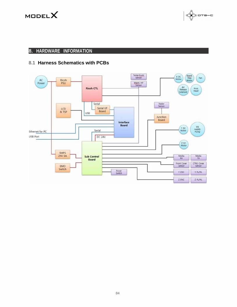
8 HARDWARE INFORMATION
8.1 Harness Schematics With PCBS ............................................................................................................................. 84
8.2 Harness Connections on SCB ................................................................................................................................. 85
8.3 Setting The Media Sensor ...................................................................................................................................... 86
9 REPLACEMENT AND ADJUSTMENT FOR SERVICE PART
9.1 Adjustment Of X‐Y Orthogonality .......................................................................................................................... 92
9.2 Check Head Gap ..................................................................................................................................................... 94
9.3 Replacing MODEL X DTG‐C Sub Control Board ...................................................................................................... 95
9.4 Replacing Temperature and Humidity Sensor ........................................................................................................ 96
9.5 Replacing LCD and TSP Module .......................................................................................................................... 97
9.6 Replacing Y AXIS MOTOR BELT_227ST1.5‐6.0 ....................................................................................................... 98
9.7 Replacing Encoder SUB SCANNING _4800 MELTEC ....................................................................................................... 98
9.8 Replacing TIMING PULLEY TRANSPORT ROLLER Module ....................................................................................... 99
9.9 Replacing DC MOTOR SUB SCANNING Module ..................................................................................................... 99
9.10 Replacing PCB SENC TOS/PIE ............................................................................................................................... 100

This guide explains the basic functions, specifications, theory of electrical, mechanical operations and replace procedures of the
DTG‐C MODEL X printer.
This guide included herein are intended for the experienced replacement technicians and attention should be given to the
precautions.
And also this document is written with android panel v.1.31.4.
1.1. General Specifications
CONTENTS SPECIFICATIONS
Size (with housing) / Weight 34” x 52” x 18” / about 216lbs–
Maximum Print Size (Bed Size) Large 406 x 508mm (16″ x 20″)
Medium 320 x 457mm (12.6″ x 18″)
Small 266 x 330mm (10.5″ x 13″)
Table Height Adjustment Automatic / 1.25” (depends on bed height)
Ink Type Pigment garment ink
Ink Channels K/C/M/Y/W/W
Ink Delivery System Cartridge type and pump system
User Interface 7″ Touch resistance display (Android ICS 4.03)
Standard Connectivity 10/100 Base‐T internet
Driver Operating Condition Pentium i5 2.3Ghz or faster / 4GB or more / 100GB or more disc space
Display Resolution SVGA or better / 1024 x 768 or better / 24bit colour or better
AC Power AC 100~120V / 50~60Hz (±3Hz)
Power Consumption Standby: 20W, Max: 70W / 0.635A (AC)
Environment Operating condition Standard: 50~90ºF / 15~80%
Standby condition Recommended: 59~77ºF / 30~70%
1. INTRODUCTION

1.2. Model X Printer Overview
1.2.1. Printer’s Front
1.2.2. Printer’s Rear Main Power Switch
Front Cover
Open the front cover for
maintenance. Otherwise
keep it closed.
Ink Cartridges
Access
Touch Panel
Platen
Place the T‐shirt here.
A medium‐sized platen is already
installed. Optional larger and
smaller platens are available.
Sub Power
It turns machineon/off
USB Port (2.0)
Normally leave it on.
When the machine is not in use for a
long period or when you move the
machine, turn the main power switch off
Network
Connector
Connect the
ethernet cable
Waste Ink Bottle Connector
Connect the tube
from waste ink bottle
Power Connector

1.2.3. Under the Cover
Flushing/spitting Box
It collects the ink discharged during the flushing operation.
A message will be displayed when it
needs to be replaced
Carriage
Underneath there is the print
head and the head nozzle.
It moves left and right
when printing.
The carriage requires
regular cleaning
Head Cap
It prevents the print
head from drying out
Wiper
It is a gum plate that wipes the
ink off on the print head

Power On/Off
CAUTION ‐ Make sure that the main power switch and sub power are always turned on while white ink is loaded.
If off for more than 12 hours with white ink loaded, the warranty may be voided on the print head
carriage.
1.3. Regarding Use • Do not turn the power off. This printer periodically circulates ink internally and automatically performs head cleaning. If you do not use the printer
for more than 7 days, it is recommended to flush white ink out with cleaning carts.
• Perform maintenance at least once per week.
This printer performs automatic maintenance periodically. But it requires manual maintenance weekly, the ink in the
cartridge could settle and/or coagulate, causing poor image quality or printer failure. If weekly maintenance is neglected,
carriage warranty will be voided
• Some parts require periodical replacement.
This printer includes parts that require replacement due to usage.
• Keeping the printer maintained will help to avoid getting “Errors”.
If this printer gets an error, maintenance function may not be working. Then watch the printer status periodically and
report to technical support right away.
1.4. Power
Power Connector AC Power Switch
• To turn the power on ‐ hold down the
sub power for more than 1 second.
• To turn the power off ‐ hold down the sub power for more than 3 seconds.
START

1.5. Overview of User Interface
1.5.1. Home Screen
Item # Item name Description
1 Print home screen with print preview
2 Set position of platen, print, eject, pause and stop
3 Adjust platen height by pressing or holding this button
4 Select platen height adjustment method, auto or manual
5 Select from recent print jobs
6 Select to access the maintenance menu
7 Select to access the USB to find print jobs on USB drive
8 Select to access the printer settings menu
9 Printer status display, ready, notifications and errors, etc.
10 Display shows temp and humidity, if pressed takes you to ink and waste levels screen

1.5.2 Recent Jobs
The user can check the print information of recently printed jobs and select the reprint function. It also can remove
recently printed information.
The user can view and print a list of print image data stored in a USB.
Item # Item name Description
1 View recently printed job from image
2 Select highlighted job for reprinting
3 Save the highlighted job, don't allow deletion
4 Save highlighted job to inserted USB
5 Delete highlighted job
6 Return to the home screen

1.5.3 USB
You can access the USB by selecting the [USB] button on [Stored job] dialogue box.
Item # Item name Description
1 Check and select print files on the USB drive
2 Select highlighted job for reprinting
3 Save the highlighted job, don't allow deletion
4 Save highlighted job to inserted USB
5 Delete highlighted job
6 Return to the home screen

1.5.4 Maintenance Screen
Item # Item name Description
1 Print a nozzle check pattern (Must set table first)
2 Access parts replacement screen
3 Access automatic print head cleaning screen
4 Release carriage to perform manual maintenance
5 Adjust platen height
6 Set platen in or out (must be in to perform a nozzle check)
7 Activate automatic platen height adjustment
8 Return to home screen

1.5.5. Settings Screen
Item # Item name Description
1 Access alignment menu to align table, heads, etc
2 Access IP address and network settings menu
3 Access temp menu to change between C and F
4 Activate or deactivate obstruction sensor (turning off may result in carriage damage)
5 Reset printer to factory settings
6 Access sounds menu
7 Access printer system info screen
8 Return to home screen

1.5.6 Alignment Screen
1.2.1 Replacement Screen
Item # Item name Description
1 Print head adjustment pattern
2 Print platen adjustment pattern
3 Print adjustment pattern for print position
4 Access new table alignment menu
5 Set or eject platen
6 Manually adjust platen height
7 Activate or deactivate auto platen height
8 Return to home screen

Display the usage, date of replacement for the replacement parts. And perform replacing process for each part.
Left spitting box/sump
Print head carriage
Right spitting box/sump
Maintenance station/capping station

White ink bay
Cyan and Black ink bay
Magenta and Yellow ink bay
Return to home screen

2. INSTALLATION
2.1 Installation
1. Open the front cover and
remove bracket fix platen.
2. Connect waste ink bottle tube to valve on
the right‐back side of printer.
3. Connect the power cable and turn on the AC power switch.
Power Connector AC Power Switch
4. Insert ink cartridge.
WARNING - The printer will not know if waste ink bottle is connected, be sure the waste ink bottle is connected.

CAUTION - Make sure that the main power switch and sub power are always turned on. If you do not, the ink in head could settle and/or coagulate, causing poor image quality or printer failure.
WARNING - During the initial ink charging, don’t open cartridge cover or cut power.
5. Hold down the sub power button for more than 3 seconds.
• To turn the power on ‐ hold
down the sub power for
more than 3 seconds.
• To turn the power off ‐ hold
down the sub power for more
than 5 seconds.
6. The printer will start to initialize.
7. After initializing, the printer will perform initial ink charging if the printer is not already charged ‐ initial ink charging
takes about 34 minutes.
STAR T

8. Finishing initial charging, the printer shows “Ready”
2.2 Setting platen
For printing, platen should be set as close to head as possible.
REFERENCE - This printer uses ethernet to send the printing data. If ethernet is not set up, you will need to use an external USB drive to print.
WARNING If ’t t th t k t k i f i t
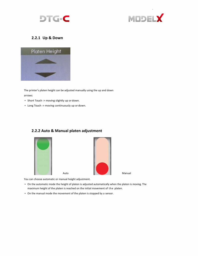
2.2.1 Up & Down
The printer’s platen height can be adjusted manually using the up and down
arrows:
• Short Touch ‐> moving slightly up or down.
• Long Touch ‐> moving continuously up or down.
2.2.2 Auto & Manual platen adjustment
Auto Manual
You can choose automatic or manual height adjustment.
• On the automatic mode the height of platen is adjusted automatically when the platen is moving. The
maximum height of the platen is reached on the initial movement of the platen.
• On the manual mode the movement of the platen is stopped by a sensor.

2.2.3 Moving the Platen
Set
This is used for moving the platen to print position.
• Platen starts out, for loading garment.
• In the automatic mode, height of platen is adjusted automatically
• If the platen is stopped when moving to print position you have to select [Eject] to return to the position for placing T-shirt on platen.
Stop
• This is used to stop the platen.
• When the platen is moving this is activated.
.1.1.1.1 Eject
• This returns the platen to the position for T‐shirt placement.
• This is activated where platen is not moving and not on the
position for T‐shirt placement.
.1.1.1.2 Pause
• Pause used to stop printing.
• This is activated when printing.

2.2.4 Obstacle Detection
If obstacle sensor detects
something when repositioning
platen in manual mode this
dialogue box is displayed.
Lower the height of platen.
2.2.5 Cancel, Pause and Resume printing
Press the [CANCEL] to cancel the printing
On the printing, press to [stop], printer is paused and pop‐up dialogue box as below.
Press the [RESUME] button to re‐start the printing.
• .

2.3 Data Path Flowchart
If you have installed RIP software and MODEL X DTG‐C has no error, you are ready to print.
But, remember the requirements below:
1. At anytime the MODEL X DTG‐C can receive (or pend) the print data.
2. But, to start printing, platen should be set to print start position. To set the platen press button “LOAD” on the panel.
3. If print data is pending into printer has no error and platen is set ‐ printing process is started.

3. USER INTERFACE
3.1 Home Screen
3.1.1 Setting Platen
Please refer 2.2.3 Setting Platen

WARNING - If the printer is off or has an error status, the maintenance function will not operate.
Always keep the printer ready. If cartridge is removed or ink supply slot is opened, maintenance will fail.
3.2 Maintenance Screen
You should perform regular maintenance to maintain the printer’s performance. The user
can access these functions through this tab.
Built‐in scheduled maintenance is listed below.
Every hour White ink circulation
Every 3 hours White channel cleaning
Every 12 hours All ink cleaning ‐ alarm for agitating white cartridge
Every 7days Alarm for manual cleaning
Maintenance can be cancelled by:
• Cartridge cover is opened
• Ink cartridge is empty
• CR encoder error
• Service call
“Front cover open” will not cause maintenance failure, but it can delay sequence of maintenance.

3.2.1 Nozzle check
• You can check the nozzle condition with this button.
• Make sure to check the nozzle condition before printing T‐shirt.
• If there is nozzle clogging, perform head cleaning until the
problem is resolved.
1. Prepare the A4 transparent media to check nozzle condition (to
check white nozzle, transparent media is required).
2. Prepare medium‐size platen. Nozzle check pattern is based on
medium platen, aligned on top‐center. (Additionally, all built‐in
patterns are based on this platen).
3. Attach media on the platen aligned top center using masking tape
or sticky spray.
4. Move the platen to the printing position, press [Nozzle
Check] button.
5. And check the results of printed nozzle check pattern.
If there is nozzle clogging (missing lines) or faded lines, proceed with cleaning procedure.

WARNING - Strong cleaning consumes more ink. (Normal cleaning 0.49cc, Strong Cleaning 3.09cc)
3.2.2 Automatic Head Cleaning
When there is nozzle clogging or faded lines the print head will need to be cleaned. This
printer has an automatic head cleaning function.
You can press this button to perform automatic print head cleaning.
In this box, user can choose the channel to clean, with the option of normal and strong.
On Off
If after normal cleaning is complete and nozzle condition is not improved, then perform strong cleaning.

Onc
Once the carriage has moved to the center, power down the machine at the switch in the back. Use a damp lint free wipe or swab to gently rub off dried ink around the heads. Dry area with lint free wipe when done
Manual cleaning function can be used for cleaning of maintenance unit.
Using lint‐free swab wetted with
cleaner liquid, clean the wiper of
maintenance unit.
3.2.3 Manual Head Cleaning
If nozzle status has not recovered with automatic head cleaning, then you have to clean the head manually.
** Weekly, regular manual cleaning is mandatory! Selecting this moves the print head to the center of bridge.
Then you can clean the face of nozzle manually.
When the manual cleaning is finished, select [END] to release manual head cleaning mode.

WARNING - DO NOT shake cartridge too fast or hard too avoid tearing the ink bag inside cartridge.
3.2.4 Agitating White Cartridge Alarm
When using white ink, shake the ink cartridge every 12 hours to avoid ink sedimentation and coagulation.
When this alarm dialogue is
displayed you have to shake
the white cartridges smoothly
to prevent damaging the ink
bag inside of cartridge.
This dialog will be closed by
opening cartridge cover.
3.2.5 Manual Cleaning Alarm
Every 7 days, this dialog box below will appear to notify user to perform manual cleaning.
3.2.6 Circulation
This printer has an automatic function for circulating white ink every hour.

WARNING - Ensure you have to emptied the waste ink bottle before resetting the waste ink counter.
3.2.7 Empty the Waste Ink Bottle
When the waste ink bottle is full the following message is displayed on the touch panel.
You can check the amount of waste ink on the [Status Panel] and reset the waste ink counter.
To reset the waste ink counter after emptying the waste ink bottle, select [WASTE INK RESET].

3.3 Adjustment Screen
This section describes how to adjust this printer for good image quality with the touch panel.
Although the printer head nozzle status is good, the print quality may not be good. You will need to perform this adjustment
process.
These functions can be performed through the [Maintenance] screen.
1. Prepare the A4 transparent media and
medium‐size platen.
2. Attach media on the platen aligned Top‐
Center using masking tape or sticky spray.
3. Move the platen to the printing position
then press each adjustment button.

WARNING - If machine was idle for a long time, nozzles of print-head can be dry. For fine adjustment, perform cleaning before adjustment process
3.3.1 Adjusting Head
This function adjusts the print head position. When the print result is not clear (for example, vertical lines are
misaligned, or colour is not clear.) this adjustment may improve the result.
Select this button, the pattern of
adjusting head is printed.
After pattern is printed find an
appropriate adjustment value from
the print result to adjust pattern.
Find a pattern with a square in the lightest colour and with
vertical lines on both sides aligned.
A value indicated over the pattern indicates an appropriate
adjustment value.
An appropriate adjustment value is “+2”.
Check adjustment values for all the rows.

3.3.2 Adjusting Platen
The printing position can be adjusted.
If the print result has a line of horizon, you need to do this function.
Select this button for print position.
Find an appropriate adjustment value
from the print result of adjustment
patterns.

Find a pattern with a square in the lightest color
and horizontal lines on both sides aligned.
A value on the upper of the pattern indicates an
appropriate adjustment value.
An appropriate adjustment value is “+6”.
In some cases, an adjustment value is an in‐
between value of patterns
When a square is in the lightest colour but
horizontal lines on both sides are misaligned.
In the this illustration a square in the lightest
colour is “+6”, but horizontal lines on both sides
are misaligned. In this case check horizontal lines
for one pattern above and one pattern below of
the square.
The horizontal lines for “+2” and “+6” are misaligned in the same direction, but the horizontal lines for “+14” are misaligned in
the opposite direction.
In this case, a value that horizontal lines align exists somewhere in between “+6” and “+14”. After passing the value, the
horizontal lines begin to be misaligned in the opposite direction as getting closer to “+14”
By referring to the alignment of the lines, decide a value between “+6” and “+14” as an appropriate adjustment value.

3.3.3 Adjusting the Printing Position
The printing position can be finely adjusted within the range of ±4mm.
Position the paper so that the cross
on the test print paper comes at the
right bottom corner.
The upper button is for adjusting the
printing position.
After printing the pattern of
adjusting printing position you have
to find appropriate value.
• Values can be selected between “‐4.0” ~ “+4.0” in increments of 0.1mm.
• To move the print position to the “A” direction, input a value between “‐1” and “‐4”.
• To move the print position to the “B” direction input a value between “+1” and “+4”.
• To move the print position to the “C” direction input a value between “+1” and “+4”.
• To move the print position to the “D” direction input a value between “‐1” and “‐4”.

4. 4. REPLACING CONSUMABLE PARTS
This printer has some replaceable consumable parts. You can check the status these parts with [Replace] screen shown as
below.
Each button indicates the
parts requiring
replacement.
Select the button, the part replacement
dialogue box is displayed. Also it shows the
information of part counts and replaced
date.
The green means
normal.
The yellow means
warning.
(Usage 80%)
The red means
danger. (Usage
100%)
The colour of image can be displayed
Green, Yellow or Red.


4.1 Replacing Carriage Related Parts 4.1.1 Encoder Strip 17 Inch
1. Turn off the printer power.
2. Unlock the carriage and push it completely to the left side or center of the printer as below.
Rotate the black lever counter‐clockwise until the
arrow on the lever aligns with the arrow marked “C”
below. When the triangles are aligned, the carriage
is unlocked.
3. Move printhead to the middle.
4. Release encoder strip on maintenance unit side. The
encoder strip is elastic so it can be pulled. Pull and
remove strip.

5. Remove encoder strip on print head.
6. Release encoder strip on left spitting box side.
7. Hang encoder strip on the left spitting box side.
8. Insert encoder strip into print‐head.
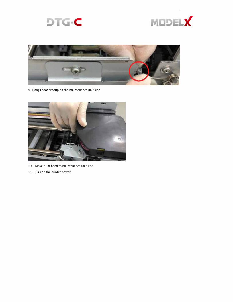
9. Hang Encoder Strip on the maintenance unit side.
10. Move print head to maintenance unit side.
11. Turn on the printer power.
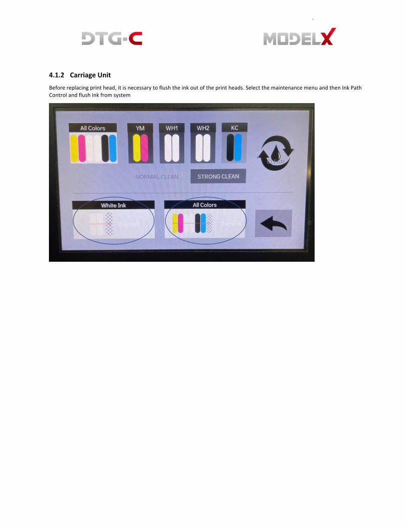
4.1.2 Carriage Unit
Before replacing print head, it is necessary to flush the ink out of the print heads. Select the maintenance menu and then Ink Path Control and flush ink from system

Select the manual maintenance button and once the carriage moves to the center of the rail, flip the power switch to the off position. If the carriage needs to be released manually, shut down printer at power switch and release carriage from maintenance station by rotating the white lever counterclockwise to align triangles. Then slide carriage to middle of rails.
1. Open the printer top cover case.
2. Unlock the carriage
3. Push the carriage to the center. Press on
the carriage itself as shown, not the top
cover.

.1.1.2
4. Remove the Encoder strip 17 inch.
(Reference 4.1.1).
6. Remove the guide lock linkage.
8. Attach the jigs.
5. Disconnect the vertical arm of the spring and remove
it.
7. Push the carriage all the way to the left side of the
machine until it stops.
9. Remove screw and cam.

10. Attach the holder to the end of the rod
and pull the rod out as far as the first
jig.
11. Disconnect the bottom half of the carriage
timing belt from the back of the carriage.
12. Remove the carriage and HRB cover.
13. Remove the FFC harness and ink tube.
(Reference 4.1.3).
14. Replace the carriage.
15. Assemble in reverse order of
disassembly.
When complete this dialogue box will appear to reset the amount of
head usage and replacement date.

4.1.3 Ink Tube
1. Turn off the printer power.
2. Open the printer top cover.
3. Remove the cover of carriage and MODEL X DTG‐C junction board.
4. Remove the Ink tube attached to the old carriage and insert the cap to end of ink tube.

5. Separate the tube from the plate tube rhe ‐ loosen one bolt.
6. Remove the ink tube fix bracket ‐ loosen the four bolts.
7. Remove the Ink tube on the ink supply unit (Reference 4.4.1).

8. Assemble the ink tube to the plate tube and ink tube fix bracket. Align
the guide line to the middle of the plate tube hole.
9. Assemble the ink tube to the carriage.

10. Assemble the new ink tube to the ink supply unit.
11. Turn on the printer power.

4.1.4 Timing Belt – X Axis
1. Turn off the printer power.
2. Remove the encoder strip (Reference 4.1.1).
3. Remove the carriage unit (reference 4.1.2).
4. Remove the spring pressure roller ‐ remove using long nose pliers.
5. Push the pressure roller inward and remove the timing belt.
6. Assemble a new timing belt.
7. Assemble the carriage unit and encoder strip.
8. Turn on the printer power.

4.1.5 Pressure Roller Assembly
1. Turn off the printer power.
2. Remove the carriage unit (reference 4.1.2).
3. Using long nose pliers remove the spring pressure roller and remove the timing belt (reference 4.1.5).
4. Push the pressure roller inward to remove it. Pull to the marked hole and remove.
5. Assemble the new pressure roller by pushing it outward. Insert into the marked hole and push to
assemble.
6. Assemble the timing belt, the carriage unit and encoder strip.
7. Turn on the printer power

4.1.6 DC Motor Carriage Module
1. Turn off the printer power.
2. Remove the encoder strip. (Reference 4.1.1)
3. Remove the carriage unit. (Reference 4.1.2)
4. Remove the timing belt x‐axis. (Reference 4.1.5)
5. Remove the harness connected to the DC motor.
6. Loosen the two bolts.
7. Assemble the new DC motor.
8. Assemble the timing belt, carriage unit and encoder strip.
9. Turn on the printer power.

4.1.7 Main Controller Board Module
4.1.7.1 Main Controller Board Unit
1. Turn off the printer power.
2. Remove the printer top cover case.
3. Remove the CTL cover. Loosen the four bolts.
4. Remove the harness connected to the CTL board.
5. Loosen the six bolts.

6. Assemble the new CTL board and connect harness.
7. Assemble the CTL cover and printer top cover.
8. Turn on the printer power.
4.1.7.2 Serial I/F Board
1. Turn off the printer power.
2. Remove the printer top cover case.
3. Remove the FFC harness to the SCB. The
FFC harness to the MODEL X DTG‐C
connection board and the SCB.
4. Remove the BKT cell board. Loosen the six bolts

5. Remove the harness connected to the serial
board. The harness to the MODEL X DTG-C
interface board and serial board.
7. Remove the harness connected to the serial board.
The harness to the CTL board and serial board.
6. Loosen the four bolts and separate the serial board
from bracket.
8. Loosen the four bolts and separate the serial
board from bracket.
9. Assemble the new serial board in reverse order of disassembly.
10. Turn on the printer power.

4.1.8 Actuator Unit Valve Module
1. Turn off the printer power.
2. Open the printer top cover.
3. Unlock the carriage (reference 4.1.2.) and push the carriage to the center.
4. Remove the harness connected to the actuator unit valve
5. Loosen the two bolts and remove the actuator unit valve and remove the actuator unit valve.
6. Assemble the new actuator unit valve.
7. Close the printer top cover.
8. Turn on the printer power.

4.2 Replacing Maintenance Unit
1. Turn off the printer power.
2. Unlock the carriage and push it completely to the left side or center of the printer as below.
Insert the tip of a screwdriver into the hole [B] and
turn it counter‐clockwise to rotate the lower triangle
up to the other triangle [C] until they
are aligned. When the triangles are aligned, the
carriage is unlocked.
3. Remove the two bolts.

4. Disconnect maintenance unit sensor, motor and waste tube.
5. Move the maintenance unit.
6. Assemble is reverse order of disassembly.
Touch the maintenance unit on the [replace] tab.
After this procedure is done, the amount of maintenance and the
date of replacement can be reset.

4.3 Replacing Spitting Box 4.3.1 Left Ink Sump Replacement
1. Turn off the printer power.
2. Open the top cover case.
3. Remove one bolt.
4. Lift the left ink sump out of the machine.
5. Lift the left ink sump out of the machine.
(Never touch the surface vertical encoder wheel around
its edges).
6. Assembly in reverse order of disassembly.
Touch the spitting box on the [Replace] tab.
After this procedure is done the amount of spitting box
and the date of replacement can be reset.
.1.2
.1.3
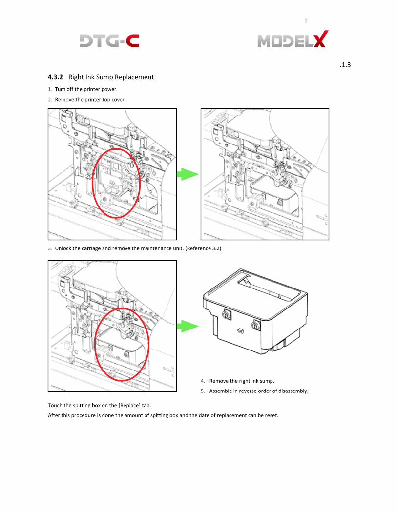
4.3.2 Right Ink Sump Replacement
1. Turn off the printer power.
2. Remove the printer top cover.
3. Unlock the carriage and remove the maintenance unit. (Reference 3.2)
4. Remove the right ink sump.
5. Assemble in reverse order of disassembly.
Touch the spitting box on the [Replace] tab.
After this procedure is done the amount of spitting box and the date of replacement can be reset.

4.4 Replacing Ink Supply Module 4.4.1 Ink Supply Unit
1. Turn off the printer power.
2. The cartridge slot is located at the printer’s right.
3. Pull the cartridge slot.
.1.3.1 4. Remove the ink cartridges. 5. Loosen the eight bolts on the cover guide ink pump.
6. Remove the harness and the ink tube and insert the cap to end of ink tube. Loosen the
two bolts on guide ink pump bracket.
.1.3.2
8. Assemble in reverse order of disassembly.
After this procedure is done, amount of spitting box and the date of replacement. Select

the ink pump button on the [Replace] tab.

5. SETTING SCREEN
5.1 Ink Path Control
You can set several settings on Setting
[Screen].
Ink (or Cleaner) charging, several options and
information.
This printer has 3 ink status and the user can switch them by ink path control.
STATUS PRINTABLE MEDIA REMARKS
Ink in all channels White media, Black media. All kinds of color media.
Color ink in color channel Cleaner in white channel
White media. For colored media except black media.
The Cleaner in white channel is for protect the nozzle of
print head.
Cleaner in all channels Unprintable. For long term storage.

IMPORTANT - In the case of all channels charged with inks you can insert cleaner cartridges in white channel only.
IMPORTANT - In the state of all channels charged with cleaner you can insert ink cartridges in all channels.
IMPORTANT - In case of channels with colours (CMYK) charged with inks and white channel is charged with cleaner, you can insert ink cartridges for all channels.
To change the setting of ink path control, select the [INK PATH CONTROL] on the [SETTING] tab.
This dialogue box will be displayed to charge ink or
cleaner. You can select [INK CHARGING] for ink,
[CLEANER CHARGING] for cleaner.
If you choose the ink charging this dialogue box is displayed to charge
for all colour channel or white only channel.
For the cleaner, the dialogue box displayed is the same.
When you store the printer in long‐term period or transport, it is
necessary to charging cleaner in all channels.
5.1.1 Charging White Channel With Cleaner
If you don’t want to print on black media you have to charge the cleaner in the white channel.
This will help to reduce ink consumption because of white channel cleaning procedure is not work in every 3 hours. Also it’s
good to maintain nozzles of head.
But in this case, cleaning procedure of all channels every12 hours works.
5.1.2 Charging All Channels With Ink
In the condition of all channels charged with cleaner, for printing, channels should be charged with ink.
5.1.3 Charging With White Ink
If you want to print on black media you have to charge the white ink in the white channel.
IMPORTANT - In the case of all channel is charged with ink or only white channel is charged with cleaner.
You can insert the cleaner cartridges for all channels.

5.2 Option
If you select [OPTION] this dialog box is shown.
5.2.1 IP Address
To change the setting of network, select [IP ADDRESS].
After inserting the changed value select
[CHANGE] to apply.

WARNING - When obstacle sensor is off,
head could strike the table.
5.2.2 Temperature
You can switch unit of temperature by this
[Temperature] button.
5.2.3 Factory Reset of Adjustment Setting
Below items are initialized by selecting [FACTORY RESET]
button.
All kind of adjustment. (Head alignment, table
alignment, and print position)
5.2.4 Setting Obstacle Sensor
This function turns on/off the sensor that detects
obstacles on the platen.
To turn off the obstacle sensor, select [OBSTACLE SENSOR]
button.
ON OFF
When the obstacle sensor is on, color of button on center is blue.

WORD DEFINITION
5.3 Operation Panel Messages 5.3.1 Terminology
Ink Stage What material is filled into ink path in printer?
• After Ink Charging (ink is filled in printer)
• After Ink Without White (ink is filled in printer, but cleaner is filled into only white channel
• After Cleaner Charging (Cleaner is filled in printer)
4-Color In other word, “After Ink Without White”
6-Color In other word, “After Ink Charging”
DFU Denotes “Design or Factory Use”. Do not change this value or Ignore it.
5.3.2 Overview of Status
LEVEL DEFINITION TYPICAL ERROR
Service Call Operation is impossible. Machine
is critical damaged.
Service Call (SC Code)
Error Operation is impossible. (be able to recover) Cover Open
JAM (PF,CR Error) Ink Cartridge Not Set Ink Cartridge End Waste Ink Tank Full
Warning Operation is possible.
Later, operation can be stopped.
Ink Cartridge Near End
Waste Ink Tank Near Full
Replace Part Lifetime
Information N/A N/A

5.3.3 Messages
MESSAGE DEFINITION
Cleaning. Printer is cleaning except for change ink path maintenance
4-color only. Current Ink stage is “After Ink Without white”
Cancelling printing. Please wait. Printing is cancelling.
Cartridge error. Please check cartridge and try again.
(Ink or Cleaner) Mixed cartridges are inserted.
An error status - To recover, insert correct type cartridge set.
Cartridge is not loaded. Any cartridge is not set
An error status - To recover, insert cartridge.
Charging cancelled. (Ink or Cleaner) White channel filling has failed
It is warning status ‐ To recover, retry (ink or cleaner) filling of white channel
Cleaner cartridge is loaded. (W1)
Mixed cartridge (CL,W,K,C,M,Y) when current ink stage is “after ink charging”
An error status - To recover, insert white1 ink cartridge.
Cleaner cartridge is loaded. (W2)
Mixed cartridge (W,CL,K,C,M,Y) when current ink stage is “after ink charging”
An error status - To recover, insert White2 ink cartridge.
Cleaner cartridges are loaded. Cleaner cartridge is inserted when ink is already filled in printer.
An error status - To recover, insert ink cartridge and filling ink.
Cleaner cartridges are loaded. (W1,W2)
Mixed cartridge (CL,CL,K,C,M,Y) when current ink stage is “after ink charging”
An error status - To recover, do white cleaner filling process or insert ink cartridge.
Cleaner filling cancelled. Cleaner filling is failed
It is warning status - To recover, Do cleaner filling process again.
Cleaner is filled in printer. Fill ink for printing.
Currently cleaner is filled in ink path.
An error status - To recover, do ink filling process to use printer.
Cleaning Failed. Please retry. Cleaning is failed because of some reason.
It is warning status - To recover, retry cleaning again.
CR Encoder Error Please reboot the printer.
Carriage (X‐Axis) JAM
It is error - To recover, the printer should be turned off/on. For details, please call your service representative..
Part lifetime notice (PARTNAME)
Part has reached the end of its life and needs to be replaced.
It is warning - To recover, replace the part.
Filling cleaner Cleaner is filling
Filling cleaner (White only) Cleaner is filling using only white ink

MESSAGE DEFINITION
Front Cover Open The front cover is opened.
It is error - To recover, close the front cover
Initial Ink Filling Ink is filling.
Initializing. Please wait. Machine is booting up ~ wait untill initialisation is complete
Ink cartridges are loaded. Ink cartridge is inserted when current ink stage is not “ink charging complete”
An error status - Do ink charging for using printer if current ink stage is
“Cleaner Charging complete”.
Do white ink charging for using white ink if current ink stage is “After ink
Without White”
Ink Empty (COLOR) Cartridge is empty.
An error status - To recover, insert new cartridge.
Ink filling (White only) White ink is filling
Ink Filling cancelled: Ink filling is failed
It is warning status - To recover, do ink filling process again.
Ink low (COLOR) Remain amount of cartridge is low (Under 20%)
It is warning status - Prepare new cartridge.
Ink Supply Error Service Call 988 or 990 or 991 But printer operation is possible.
It is warning status - To recover, reboot machine. It
can be caused by:
1. Air interfuse in head
2. Nozzle clogging
For the detail, refer service call list.
Job Pending. Please SET table. Table is not in printing position when printer receives print data.
Left flushing box full. Empty the box before reset the left flushing box counter.
Left flushing box is full
It is error - To recover, replace left ink sump
Left flushing box is nearly full. Left flushing box is nearly full
It is warning - To recover, prepare to replace left ink sump
Load garment and tap SET button.
Table is media load position
Non-supported cartridge is loaded.
Cartridge ID chip is not available
An error status - To Recover, insert genuine cartridge.
Pausing. Close front cover. Printing is paused by open front cover or Moving table is stopped by open front
cover
It is error - To recover, close the front cover
Pausing. Tap SET or EJECT button to start table moving.
Moving table is stopped
Pausing. Tap STOP button to start printing.
Printing is pausing.

MESSAGE DEFINITION
Performing white ink circulation While W1W2 circulation
Please wait Table is moving
Printing Machine is printing.
Receiving data Receiving the Job data
Right flushing box full Right flushing box is full
An error status - To recover, replace right ink sump
Right flushing box is nearly full Printer will stop working when the box comes to full
Right flushing box is nearly full
It is warning - To recover, prepare to replace left ink sump
Room temperature is too high, it can cause printing quality problem
Room temperature is higher than 30.0
Room temperature is too low, it can cause printing quality problem
Room temperature is lower than 10.0
The temperature is too high When it’s in the operation state already, if the temperature become high (more than
approximately 40 ), it will occur. It is necessary to do power off.
The temperature is too high. Able to print.
When an operator turns power on, but the temperature is high (more than
approximately 40 ). Wait a moment, if the temperature is less than 40 ,
printer will become active.
The temperature is too low When it’s in the operation state already, if the temperature is low (below
approximately 1 ), it will occur. It is necessary to do power off.
The temperature is too low. Able to print.
When an operator turns power on, but the temperature is low (below
approximately 1 ). Wait a moment, if the temperature is more than 1 ,
printer will become active
Updating CTL Firmware. Please wait.
While update MODEL X DTG‐C Controller
Updating SCB Firmware. Please wait.
While update SCB
Waste ink bottle is nearly full Waste ink is nearly full
It is warning status - Prepare to empty waste ink bottle.
Waste Ink Full Empty the waste ink bottle before reset the waste ink counter.
Waste ink is full
An error status - To recover, Empty waste ink bottle.

5.3.4 Service Call
CODE DESCRIPTION
900 HRB Fuse Blown
The fuse on the HRB (Head Relay Board) mounted behind the print heads on the carriage unit has blown.
The fuse cannot be replaced.
1. Replace the carriage unit
2. Replace CTL
971 Flash ROM Write Error
The device writing to the Flash ROM generated an error.
• Flash ROM device defective.
1. Cycle printer on/off, check result.
2. Replace control board.
972 Flash ROM Verify Error
• The verify operation after write failed (the data written to the Flash ROM did not match the content of the
data in the Flash ROM).
• Flash ROM device defective.
1. Cycle printer on/off, check result.
2. Replace control board.
973 EEPROM Write Error
• An EEPROM write error was detected at power on, or during a print job.
• The EEPROM device is defective.
1. Cycle printer on/off, check result.
2. Replace control board.
974 RTC Abnormal
The RTC (Real Time Clock) malfunctioned.
• Electrical flow to RTC interrupted.
• Excessive condensation in machine.
1. Check the ambient temperature and humidity.
2. Make sure the readings are within the ranges for optimum operation of the machine. (See
installation”).
984 DRV Circuit Temperature Abnormal
The temperature of the DRV board (driver board) is out of range.
• The temperature of the DRV board (driver board) circuit is not within the specified range: ‐13°C to 55°C
(11.2°F to 131°F)
1. Cycle printer on/off, check result.
2. Check fan operation.
3. Replace control board.

CODE DESCRIPTION
986 Humidity Sensor Abnormal
The printer detected that the humidity sensor was abnormal.
• Sensor connector loose, damaged, or defective.
• Sensor defective
1. Cycle printer on/off, check result.
2. Check control board connections.
3. Replace control board.
988 Ink Supply Error (Air Sensor Abnormal) DFU
Printer detected air sensor was abnormal when suction was applied 3 times when the printer was powered on
for the first time for ink tank filling or print head refreshing, but no air was detected.
• Cycle the printer off and on and try again.
• If the problem persists, the print head air sensors may be defective.
1. Replace the air release lever sensor and solenoid.
990 Ink Level Feeler Position Error DFU
The position of one or more ink level feelers could not be detected at initial filling.
Correct voltage could not be created for operation of the print head tank, so the print heads cannot operate.
• Ink level sensor defective
• Horizontal encoder film dirty, installed incorrectly, broken
• Maintenance unit dirty, defective
• Ink nozzles clogged
1. Cycle printer on/off, check result.
2. Clean suction cap.
3. Replace horizontal encoder film strip.
4. Replace maintenance unit.
5. Check the position of the feelers attached to the sides of the tanks.
991 Ink Pump Timeout Error DFU
The feeler of the ink lever sensor could not be detected.
• Obstruction blocking operation of the feeler
• Ink tube twisted, broken
• Tube disconnected causing an air leak
• Ink pump motor defective
996 No Input Signal from the Horizontal Encoder
No input signal from the horizontal encoder was detected during operation of the horizontal motor.
• Horizontal encoder sensor loose, broken, or defective.
• Horizontal encoder film broken, disconnected, or installed upside down.
• HRB defective
1. Cycle printer on/off, check result.
2. Confirm film encoder not loose.
3. Replace horizontal motor.

CODE DESCRIPTION
997 Input Signal from the Horizontal Encoder Abnormal
When the carriage moved to the right, the carriage did not stop at the HP. Or, the carriage scan check
failed.
• Horizontal encoder sensor loose, broken, or defective.
• Horizontal encoder film broken, disconnected, or installed upside down.
• HRB defective
1. Cycle printer on/off, check result.
2. Replace encoder sensor.
3. Check encoder film position.
4. Check carriage FFC (Flat Film Connector).
999 Maintenance Stepping Motor Out of Home Position
The maintenance motor HP sensor failed to detect the motor at the home position.
• Maintenance HP sensor connector loose, broken, or defective
• Maintenance motor connector loose, broken, or defective
• Movable Feeder connector loose, broken.
1. Cycle printer on/off, check result.
2. Clean wiper.
3. Check HP sensor connector.
4. Replace maintenance unit.

1
2
6. SERVICE MENU
CAUTION
Current MODEL X DTG‐C provides Service Menu for supporting advanced maintenance of the printer and providing several test
features, experimental features and debugging features. Service Menu allows to access to very critical configuration of the
printer. Therefore, if someone who do not have enough knowledge operates in Service Menu, it can make unrecoverable
malfunction of the printer.
6.1 How To Get In The Service Menu
1. Move to [Setting] Screen on UI
Panel.
2. Touch 3 points as following figure.
6.2 Service Menu
Version Information.
Open [Android System] menu.
3 Open [Printer System] menu.
4 Quit UI Panel Application.
5 Open [Serial Number] menu.
6 Print White Media sample image.
7 Print Black Media sample image.
8 Exit Service Menu.
2
3
41
56 7
8
1

6.3 Android System Menu
6.4 Printer System Menu
6.4.1 Ink Path Management [DBG]

1. Android Setting:
Open Android OS setting menu.
2. Reboot Android System: Reboot Android Board (GIB).
3. ADB Connection:
Select ADB Connection method. (USB/Ethernet).
• [DBG]: Debugging features. Do not use this item in normal case.
• [MFG]: Manufacturing features.
• [SVC]: Service features.
Debug menu for operate ink path control by manual.
DO NOT operate in this menu. It can make unrecoverable malfunction of the
printhead.

67
6.4.2 ID Chip [DBG)
6.4.3 White Management [DBG]
6.4.4 Ink Stage [SVC]
Read chip information of inserted cartridges.
Configure white ink maintenance settings for
debugging.
Set internal flag of ink charging status. Should be
matched with actual situation of the printer after
replacing the Android Board.
• After Ink Filling: Ink has been charged in the
printer.
• After Cleaner Filling: Cleaner has been
charged in the printer.
• After Discharging: Ink has been discharged in
the printer. There are no liquid in the printer.
• Not Use White: Cleaner for white channels
and Ink for color channels has been charged.

68
6.4.5 Display OPU [SVC]
6.4.6 Endurance Test [SVC/MFG]
Emulate physical OPU of Ricoh CTL.
Performs endurance test for X(Carriage) and
Y(Table Feeding) axis.
6.4.7 Initialize Waste Counter [SVC]
Initialize Warning, Error Threshold of Main waste tank/Left spitting box/Right spitting box as default value and reset their
counters to zero. Should be performed after replacing CTL.

69
6.4.8 Waste Ink Counter [SVC]
6.4.9 Increase Spitting Amount [DBG]
6.4.10 Set Auto Start Printing [DBG]
It is only for debugging. DO NOT change this value.
6.4.11 Set Temperature [DBG]
Configure Warning/Error threshold of Main
waste tank/Left spitting box/Right
spitting box. Counter should be reset after
replacing.
Increase spitting amount before printing.
(0~255%) Adjust spitting drops during the
printing. (50~2500)
Fake the temperature that CTL measures. CTL
will take the waveform by given temperature
always regardless actual temperature. In order
to reset, need to reboot the printer.
But, to use this function, ink type is required
as TP‐3 (Ricoh Original Ink) Refer “Set Ink
Type” on service menu.

70
6.4.12 Lifetime Counter [SVC]
6.4.13 Lifetime Setting [DBG]
6.4.14 Set Head Rank [DBG]
Display and reset lifetime counter of
replacement parts.
Change lifetime threshold of the replaceable
parts.
Set head rank value of CTL (0~7). Do not
recommended to change this value.

71
6.4.15 Time Set [SVC/MFG]
6.4.16 IP Initialize [SVC]
Initialize IP configuration as below.
• IP: 192.168.1.253
• Netmask: 255.255.255.0
• Gateway: 192.168.1.254
6.4.17 White Timer Reset Config [DBG]
Set date/time of CTL and GIB. Date/Time
information will be stored and kept by RTC on
the CTL. Should be set after replacing CTL.
Choose whether if reset the white auto
cleaning timer after white layer printing or
not.
• On: Reset the timer after white layer
printing. (Default)
• Off: Do not reset the timer after white
layer printing.

72
6.4.18 Ink End Threshold & Purge Interval [DBG]
6.4.19 Set Ink Type [SVC/MFG]
6.4.20 Set Temperature Offset [DBG]
• Ink End Threshold:
Adjust timeout threshold for ink‐end
judgement by CTL. (0: Default of CTL)
• Purge Interval:
Adjust spitting interval during the printing.
(0: Default of CTL)
Choose temperature vs viscosity matrix
depends on the ink.
• 3: TP‐3
• 5: Dupont P5000
• 6: Dupont P6000
• 35: Dupont P3500 (Actually White
P3500, Color P6000)
Set offset between measured temperature by
CTL and actual temperature.

73
6.4.21 Reset Initial Charging Flag [SVC]
Reset the initial charging flag of the CTL. After performing this, CTL do not start initial ink charging during the boot up.
Should be perform this after replacing CTL on already charged printer.
6.4.22 Drop Count Management [DBG]
6.4.23 Table Adjust [SVC/MFG]
Configure after printing maintenance
threshold.
Support adjusting media detect sensor height
and table balance.

74
6.4.24 Z Axis Config [DBG]
Experimental function.
• Soft Margin: Move table down as specified
distance after automatic height detection for
protecting nozzle surface from the nap.
• Z‐Axis Config: Specify Z axis distance
when user tap up/down button.
6.5 Serial Number
Input the serial number of the printer.

75
7. TROUBLE SHOOTING
7.1 CR Encoder Error
If interference of moving carriage (Print‐head) is
detected, CR Encoder Error occurs. To resolve cause
of this problem, check below.
• Check obstacle on the path of print‐ head.
Reboot machine after removing any
obstacles.
• Still CR Encoder error occurs even if there is no
any obstacle. Check if encoder strip is stained,
and clean it as following.
1. Turn off the printer power.
2. Unlock the carriage and push it completely to the left side or center of the printer as below.
Insert the tip of a screwdriver into the hole [B] and turn it counter‐clockwise to rotate the lower triangle up to the other
triangle [C] until they are aligned. When the triangles are aligned, the carriage is unlocked.
3. Move printhead on the middle.
4. Release encoder strip on maintenance unit side.
There is elasticity so encoder strip can be pulled. Pull
and remove strip.

76
5. Remove encoder strip on print head.
6. Release encoder strip on left spitting box side.
9. Hang encoder strip on the left spitting box side.
7. Clean encoder strip using
cotton with alcohol.
10. Insert encoder strip into print head.

77
9. Hang encoder strip on the maintenance unit side.
10. Move print head to maintenance unit side.
11. Turn on the printer power.

78
7.2 PF Motor Error
• If interference of moving platen is
detected, PF Motor Error occurs.
• To resolve cause of this problem reboot the
printer after remove obstacle on platen
path.
• And also below item is target of
consideration.
1. Overload of platen movement.
2. Dirty encoder strip of Y‐Axis.
3. Not installed (or broken) encoder sensor of
Y‐Axis.
7.3 Z-AXIS ENCODER ERROR
• If interference of platen Up‐Down is
detected, Z‐AXIS ENCODER ERROR
occurs.
• To resolve cause of this problem reboot the
printer after removing obstacle on
mechanical of Z‐Axis assembly.
• And also below item is target of
consideration.
1. Overload Media.
2. Broken Z‐Axis assembly.
3. Not installed (or broken) sensor on Z‐
Axis assembly.

79
7.4 Diagnostic Flow For Initialize Sequence
If initializing is not correctly finished, machine is running until each problem is resolved.
Below sequence is diagnostic flow for initializing. Refer this to resolve endless initializing problem.

80
1. If USB connection failure or CTL is not turned on, this dialog box will appear. To
recover, check connection of USB cable (GIB‐CTL) and if CTL is turned on.
You can also check if CTL is turned on by below 4 LED on SCB. If below
LED in red box are lit, it means CTL is turned on.
For your information, these LED are emulated for Ricoh Original OPU (OPU: Operation Panel Unit)

81
2. If front cover is abnormal, this message will appear “Close Front Cover” To recover, close front cover or check connection
of front cover sensor.
3. If table is not moving, check SCB version.
If you can’t check SCB version, it is communication error.
You should check serial communication cable between GIB and SCB.
Meanwhile, if you can check Sub
Control version, you check verify Y‐
Axis motor & encoder.
4. If Y‐Axis limit sensor is defected, table is backward moving forever. To recover, check the Y‐Axis limit sensor.
5. If table is not moved up, check 2 case as below.
First, check if Y‐Axis limit sensor is correctly installed. If table is not detected by this sensor, table homing is not finished. For the
detail, refer table homing detail
Second, check if Z‐Axis limit sensor is correctly installed. For the detail, refer table homing detail

82
7.5 Table Homing Detail
Homing sequence of Y & Z‐Axis are basically same and It use the below element to check for table path.
1. Limit sensors.
2. Encoder sensor.
3. Encoder strip.
4. Motor.
So, if any element has problem, homing cannot be finished it cause endless sequence.

83
7.6 Android Screen Error
When Android screen is acting abnormally. To recover follow the procedures below.
If this screen is displayed, select “MODEL X”
If you see this screen, select
[:::] and “MODEL X”
If printer is not working,
try turning the printer off/on.
Model X
Model X
84
8. HARDWARE INFORMATION
8.1 Harness Schematics with PCBs

85
8.2 Harness Connections on SCB
.1.3.2.1 Connector Description
5. J1 : Sub Control Board Input Power DC24V
6. J2 : Android Power Switch
7. J3 : Power Switch
8. J4 : Cartridge Cover Open Switch – SCB to CTL
9. J5 : Y Axis Positive Limit Sensor
10. J6 : Y Axis Negative Limit Sensor
11. J7 : Z Axis Positive Limit Sensor
12. J8 : Z Axis Negative Limit Sensor
13. J9 : Android RS422
14. J10 : Media Sensor RX
15. J11 : Media Sensor TX
16. J12 : Android Board Output Power DC24V
17. J14 : CTL OPU
18. J16 : Y Axis DC Motor
19. J17 : Z Axis DC Motor
20. J18 : Top Cover Open Sensor – SCB to Top Cover Sensor
21. J19 : Cartridge Cover Open Sensor – SCB to
Cartridge Cover Sensor
22. J27 : Top Cover Switch – SCB to CTL
23. J35 : Mist FAN (DC 24V / Max. 900mA)
24. J40 : CTL to SCB – Ink Pump
25. J41 : SCB to Cartridge Slot – Ink Pump
26. J42 : Feeler Sensor FFC
27. J43 : Emergency Stop Switch

86
LED DETECTED OBSTACLE
Receiving Emitting
8.3 Setting the Media Sensor
Obstacle sensor displays 4 kinds of status.
Not detected No
Not detected (unstable) No
Detected(unstable) Yes
Detected Yes
The media sensors can both emit and receive
1. Install media sensor,
down to the lowest
position.
The lowestposition

87
.1.3.3
2. The obstacle sensor bracket must be secured.
3. Check the reflected light of red color at the light receiving position. The light emitting portion is adjusted so that the
reflected light comes to the center of the light receiving portion.

88
Unstable detecting
Unstable not detected
.1.3.4
4. Move the JIG#1 to the receiving side, check the signal light of sensor is stable detect.
5. Raising up receiving sensor screwing the adjust screw. (Slightly loosen the media sensor bracket so that the
adjustment screws move.)
Make sure the state of unstable detect, then screwing the adjust screw till the state of sensor is unstable not detected.
6. Screwing the adjust screw continually, in
the state of stable not detected you
should fix the bracket of media sensor.
Stable detecting
Move JIG#1 to receiving side
Stable not detected

89
Emitting Side
Remove JIG#2
Stable detecting
.1.3.5
7. Check the state of stable detected inserting JIG#2. If it is not, return to the No. 1 procedure.
Stable detecting
Insert JIG#2

90
8. Checking the state of receiving sensor, adjust the height of the emitting sensor till the unstable detect. (Slightly,
loosen the media sensor bracket so that the adjustment screws move.)
Then, screwing till the state of the sensor is stable not detect.
9. Screwing the adjust screw continually, in the state of stable not detected you should fix the bracket of media
sensor.
Unstable detecting Unstable not detecting

91
Insert JIG#2
Stable detecting
.1.3.6
10. Insert JIG#2, check the state of the sensor is stable detect. If it is not, return to No. 6 procedure.
11. Remove JIG#2 and move JIG#1 to the
center of bridge. Check the state of
receiving sensor is stable not detect, If it
is not, return to No. 1 procedure.
12. Insert JIG#2, check stable detecting status. If it
is not, return to No. 1 procedure.
.1.3.6.1 * Because of tolerance, unstable detecting is also good.
Stable detecting Insert JIG#2
Stable not detecting

92
9. REPLACEMENT AND ADJUSTMENT FOR SERVICE PART
9.1 Adjustment of X-Y Orthogonality
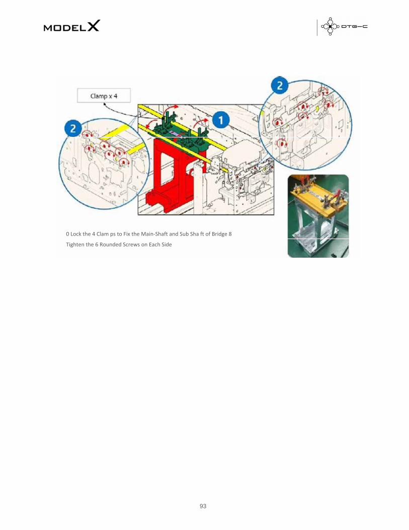
93
0 Lock the 4 Clam ps to Fix the Main‐Shaft and Sub Sha ft of Bridge 8
Tighten the 6 Rounded Screws on Each Side

94
9.2 Check Head GAP

95
9.3 Replacing MODEL X DTG-C Sub Control Board
1. Turn off the printer power.
2. Remove the printer top cover case.
3. Loosen the four bolts and remove the SCB cover.
5. Loosen the four support bolts and remove the SCB.
4. Remove the harness connected to SCB.
6. Assemble the new SCB and connect the harness.
7. Assemble the SCB cover.
8. Assemble the printer top cover case.
9. Turn on the printer power.
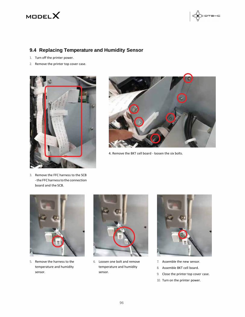
96
9.4 Replacing Temperature and Humidity Sensor
1. Turn off the printer power.
2. Remove the printer top cover case.
4. Remove the BKT cell board ‐ loosen the six bolts.
3. Remove the FFC harness to the SCB
‐ the FFC harness to the connection
board and the SCB.
5. Remove the harness to the
temperature and humidity
sensor.
6. Loosen one bolt and remove
temperature and humidity
sensor.
7. Assemble the new sensor.
8. Assemble BKT cell board.
9. Close the printer top cover case.
10. Turn on the printer power.

97
9.5 Replacing LCD and TSP Module
1. Turn off the printer power.
2. Remove the printer top cover case.
3. Loosen the two bolts and remove the LCD frame from the
right cover case.
4. Remove the harness connected to the interface
board.
5. Loosen the four bolts.
6. Assemble the New LCD and TSP module and connect the harness.
7. Turn on the printer power.

98
Y AXIS MOTOR BELT227ST1.5-6.0
Encoder Sub Scanning4800 Meltec
9.6 Replacing Y AXIS MOTOR BELT_227ST1.5-6.0
9.7 Replacing Encoder SUB SCANNING _4800 MELTEC

99
Timing Pulley Transport Roller
DC Motor Sub ScanningAssembly
9.8 Replacing TIMING PULLEY TRANSPORT ROLLER Module
9.9 Replacing DC MOTOR SUB SCANNING Module

100
PCB SENC TOS/PIE
9.10 Replacing PCB SENC TOS/PIE