Model-integrated development of embedded software
20
Model-Integrated Development of Embedded Software GABOR KARSAI, MEMBER, IEEE, JANOS SZTIPANOVITS, FELLOW, IEEE, AKOS LEDECZI, MEMBER, IEEE, AND TED BAPTY, MEMBER, IEEE Invited Paper The paper describes a model-integrated approach for em- bedded software development that is based on domain-specific, multiple-view models used in all phases of the development process. Models explicitly represent the embedded software and the environment it operates in, and capture the requirements and the design of the application, simultaneously. Models are descriptive, in the sense that they allow the formal analysis, verification, and validation of the embedded system at design time. Models are also generative, in the sense that they carry enough information for automatically generating embedded systems using the techniques of program generators. Because of the widely varying nature of embedded systems, a single modeling language may not be suitable for all domains; thus, modeling languages are often domain-specific. To decrease the cost of defining and integrating domain-specific modeling languages and corresponding analysis and synthesis tools, the model-integrated approach is applied in a metamodeling architecture, where formal models of domain-spe- cific modeling languages—called metamodels—play a key role in customizing and connecting components of tool chains. This paper discusses the principles and techniques of model-in- tegrated embedded software development in detail, as well as the capabilities of the tools supporting the process. Examples in terms of real systems will be given that illustrate how the model-integrated approach addresses the physical nature, the assurance issues, and the dynamic structure of embedded software. Keywords—Automated software engineering, design-space exploration, embedded systems, model verification, model-based development, model-integrated computing, software generators, system and software engineering. I. INTRODUCTION The development of software for embedded systems is dif- ficult, as these systems are part of a physical environment whose complex dynamics and timing requirements they have Manuscript received December 20, 2001; revised August 31, 2002. This work was supported by the Defense Advanced Research Projects Agency’s Model-Based Integrated of Embedded Software program under Contract F30602–00-1–0580. The authors are with the Institute for Software-Integrated Systems, Van- derbilt University, Nashville, TN 37235, USA. Digital Object Identifier 10.1109/JPROC.2002.805824 to adhere to. Embedded real-time systems should produce not only correct outputs, but should produce them at the right time. Furthermore, a “reasonable” behavior is expected from these systems, even under fault scenarios, when hardware or software components fail. Conventional software devel- opment considers timing, reliability, robustness, power con- sumption as “nonfunctional” requirements, which are typi- cally secondary to the logical (or functional) correctness of computations. In embedded software development, logical correctness is only one aspect of the design; physical char- acteristics of computations are equally important hence they must be included in the design process. Unfortunately, current design and implementation strate- gies used in the practice do not provide enough support for this. Consequently, decisions in seemingly unrelated aspects of the design can impact the physical behavior of the resulting embedded computing systems unexpectedly. For example, an aircraft will handle rather differently if its fly-by-wire system works with 25-Hz frame time instead of 80 Hz. The increase in the length of the frame time may be the result of a thread allocation decision (for instance, placing a highly utilized computing thread on a processor with a slow network connection). Such impact of design decisions is often not detected until it is too late—at system integration time, or, even worse, in operation. In this paper we describe an approach, called Model-In- tegrated Computing (MIC) [1], which is based on models and generation, and which provides a flexible framework to address essential needs of embedded software development. MIC fully adopts the model-based development paradigm: models are used not only to design and represent, but also to synthesize, analyze, integrate, test, and operate embedded systems. Models capture not only what the dynamics and the expected properties of the system are, but also what is as- sumed about the system’s environment. MIC introduces modeling languages that allow repre- senting all relevant information in the form of models. 0018-9219/03$17.00 © 2003 IEEE PROCEEDINGS OF THE IEEE, VOL. 91, NO. 1, JANUARY 2003 145
-
Upload
independent -
Category
Documents
-
view
1 -
download
0
Transcript of Model-integrated development of embedded software
Model-Integrated Development of EmbeddedSoftware
GABOR KARSAI, MEMBER, IEEE, JANOS SZTIPANOVITS, FELLOW, IEEE,AKOS LEDECZI, MEMBER, IEEE, AND TED BAPTY, MEMBER, IEEE
Invited Paper
The paper describes a model-integrated approach for em-bedded software development that is based on domain-specific,multiple-view models used in all phases of the developmentprocess. Models explicitly represent the embedded software and theenvironment it operates in, and capture the requirements and thedesign of the application, simultaneously. Models are descriptive,in the sense that they allow the formal analysis, verification, andvalidation of the embedded system at design time. Models are alsogenerative, in the sense that they carry enough information forautomatically generating embedded systems using the techniquesof program generators. Because of the widely varying natureof embedded systems, a single modeling language may not besuitable for all domains; thus, modeling languages are oftendomain-specific. To decrease the cost of defining and integratingdomain-specific modeling languages and corresponding analysisand synthesis tools, the model-integrated approach is applied in ametamodeling architecture, where formal models of domain-spe-cific modeling languages—called metamodels—play a key role incustomizing and connecting components of tool chains.
This paper discusses the principles and techniques of model-in-tegrated embedded software development in detail, as well as thecapabilities of the tools supporting the process. Examples in termsof real systems will be given that illustrate how the model-integratedapproach addresses the physical nature, the assurance issues, andthe dynamic structure of embedded software.
Keywords—Automated software engineering, design-spaceexploration, embedded systems, model verification, model-baseddevelopment, model-integrated computing, software generators,system and software engineering.
I. INTRODUCTION
The development of software for embedded systems is dif-ficult, as these systems are part of a physical environmentwhose complex dynamics and timing requirements they have
Manuscript received December 20, 2001; revised August 31, 2002. Thiswork was supported by the Defense Advanced Research Projects Agency’sModel-Based Integrated of Embedded Software program under ContractF30602–00-1–0580.
The authors are with the Institute for Software-Integrated Systems, Van-derbilt University, Nashville, TN 37235, USA.
Digital Object Identifier 10.1109/JPROC.2002.805824
to adhere to. Embedded real-time systems should producenot only correct outputs, but should produce them at the righttime. Furthermore, a “reasonable” behavior is expected fromthese systems, even under fault scenarios, when hardwareor software components fail. Conventional software devel-opment considers timing, reliability, robustness, power con-sumption as “nonfunctional” requirements, which are typi-cally secondary to the logical (or functional) correctness ofcomputations. In embedded software development, logicalcorrectness is only one aspect of the design; physical char-acteristics of computations are equally important hence theymust be included in the design process.
Unfortunately, current design and implementation strate-gies used in the practice do not provide enough supportfor this. Consequently, decisions in seemingly unrelatedaspects of the design can impact the physical behavior ofthe resulting embedded computing systems unexpectedly.For example, an aircraft will handle rather differently if itsfly-by-wire system works with 25-Hz frame time insteadof 80 Hz. The increase in the length of the frame time maybe the result of a thread allocation decision (for instance,placing a highly utilized computing thread on a processorwith a slow network connection). Such impact of designdecisions is often not detected until it is too late—at systemintegration time, or, even worse, in operation.
In this paper we describe an approach, called Model-In-tegrated Computing (MIC) [1], which is based onmodelsandgeneration, and which provides a flexible framework toaddress essential needs of embedded software development.MIC fully adopts the model-based development paradigm:models are used not only to design and represent, but alsoto synthesize, analyze, integrate, test, and operate embeddedsystems. Models capture not only what the dynamics and theexpected properties of the system are, but also what is as-sumed about the system’s environment.
MIC introduces modeling languages that allow repre-senting all relevant information in the form of models.
0018-9219/03$17.00 © 2003 IEEE
PROCEEDINGS OF THE IEEE, VOL. 91, NO. 1, JANUARY 2003 145
We do not believe that a single modeling language issuitable for all embedded systems. Rather, embeddedsystems should be modeled usingdomain-specific mod-eling languages(DSML) that are tailored to the needs ofthe particular domain. To address the needs of definingand implementing DSMLs, MIC has a built-in extensionmechanism: metamodeling, and the corresponding meta-generation. Domain-specific modeling tools can be createdusing metaprogrammable modeling environments, and themodels created by those tools can be translated into otherforms using metageneration technology.
The paper introduces the concepts of MIC through anexample, then it discusses the modeling and metamodelingtechniques and the supporting tools. Next, it shows howmodel-based generators could be implemented, and givesan example for the model-based development process. Thepaper concludes with the overview of related work and adiscussion on research directions for the future.
II. OVERVIEW OF MIC
To illustrate the concepts and techniques of MIC, we con-sider an example: the building of a high-performance dig-ital signal processing (HDSP) system. “High-performance”means that high I/O bandwidth and throughput requirementsmandate the use of multiple signal processors configured inan application-specific hardware architecture. There are anumber of highly relevant application areas for HDSP sys-tems, e.g., high-frequency vibration analysis of mechanicalsystems [45], real-time image processing [44], distributedsensor networks [46], and adaptive target acquisition andtracking systems [47], which require high throughput andhigh degree of flexibility in the architecture. If the HDSPsystem is not a point design but need to serve a categoryof applications, an additional requirement is emerging: thesystem has to be configurable by engineers who understandthe HDSP application domain in terms of the “language”of signal processing and hardware architecture, without theneed to deal with low-level hardware and software details.
A specific example we mention here is a simplified versionof an adaptiveautomatic target recognition (ATR)system[47]. The ATR system has to execute significantly differentsignal processing algorithms in different operational modes:target acquisition, long-range tracking, midrange tracking,short-range tracking and aim-point selection. Performancerequirements, changing power constraints and differencein the algorithms require that not only the signal flow,but the hardware architecture, too, is changing betweenthe operational states. This means that the adaptive ATRneeds to be implemented on a configurable HDSP plat-form, where configurability of the hardware architecture issupported by field programmable gate array components[48]. For the designers, the adaptive ATR represents fivedifferent applications with different hardware and softwarearchitecture.
The design of any application on the configurable HDSPplatform requires the design of the hardware and softwareconfiguration. These two aspects of the design are obviously
interdependent owing to performance requirements: onecannot design and build one independently from the other.This implies that integration of the two aspects should bea concern of the designer from early on in the process.Furthermore, an HDSP application is designed for a specificapplication environment. The environment imposes explicitrequirements on the design (e.g., expected I/O bandwidth,throughput, data rates, power constraints.), against whichthe design must be validated. To summarize, the designermust carefully consider and balance the selected two aspectsof the design and create the final application accordingly.
In MIC, the key vehicle to facilitate the design processis themodel. A model is a formal structure representing se-lected aspects of the engineering artifact and its environment.Models are suitable for formal reasoning about the propertiesof the system, and for deriving and generating a significantportion of the implementation. In the configurable HDSPplatform example, the models encompass the following as-pects.
1) The hardware architecture aspect: represents thehardware components used (e.g., DSP-s, networkswitches, communication links), describes their struc-ture and characterizes their properties (e.g., processingpower, communication link throughput) on that levelof abstraction, which is suitable for verifying thedesign and configuring the application.
2) Thesignal-flow aspect: represents the software com-ponents of the application (DSP algorithm blocks, userinterface components) the configurable components ofrun-time platform components (I/O channels, sched-uler), describes their structure and characterizes theirproperties [worst case execution time (WCET), IT la-tency, etc.].
3) The environment aspect: represents the assumptionsabout the system’s environment (e.g., sampling fre-quency required on each input channels, the numberand types of targets expected, etc.).
When MIC is used to build applications on a configurableHDSP platform, modeling languages are designed first thatallow capturing the models described previously. Looselyspeaking, a modeling language consists of acollection ofconcepts[e.g., digital signal processing (DSP) processor,DSP algorithm block, etc.] withattributes (e.g., WCET),a set of composition rulesfor building complex models(e.g., how to form DSP signal flow models from elementaryprocessing blocks), aconcrete syntax(textual or visual), andsemanticsthat captures what a model means. For the HDSPexample, we have defined a number of “small” modelinglanguages, with visual syntax that allowed constructingsystems of this category [55]. Fig. 1 shows example modelsbuilt using these languages. On the top window, the signalflow model is shown as a collection of signal processingblocks and the data flows among them. On the bottom left,the hardware architecture model is shown, as hardwarenodes (with communication ports) and hardware connectionamong them. On the bottom right, the model shows anotheraspect of the design: the allocation of a (software) signalprocessing block to a hardware resource: a node. Models of
146 PROCEEDINGS OF THE IEEE, VOL. 91, NO. 1, JANUARY 2003

Fig. 1 Example HDSP models.
the hardware architecture are defined in terms of networksof processors with communication ports; signal flow modelsare defined in the form of block-oriented signal-flow dia-grams, and models for software/hardware allocation in theform of diagrams that mix objects from the two previousmodels.
The signal-flow aspect and hardware architecture aspect ofthe design cannot be considered independently. The aspectsinteract, and design decisions made in one aspect have a sig-nificant impact on the other because of crosscutting designconstraints. For example, latency between the input from theimage sensors and an update in the target track depends onthe selected processing algorithms, the structure of the signalflow, its allocation to a node of the hardware architecture andthe characteristics of the processors and communication linksinvolved. The overall performance of the design depends onthe properties of the software: algorithms and architecture;the hardware: processors, networks, and architecture; and theassignment: the mapping of software components to hard-ware resources. The final, overall properties of the designemerge from the properties of and the interactions among thethree aspects. Therefore, it is a key requirement for any com-plex modeling language that it must allow modeling frommultiple, interacting points of view.
Models not only represent the system under design andits environment, but also used topredict characteristics ofthe design. In the HDSP application, the models can be usedto configure a functional simulator (like Matlab’s Simulink[3]) to verify the signal processing algorithms, or a perfor-mance simulator (like SPN [4]) to predict expected perfor-mance. However, the simulator’s modeling language may besyntactically and/or semantically different from the one usedin the domain modeling. The solution requires thetransla-tion of modelsbetween two different domains: the domainof the application-specific design models (e.g., HDSP) andthe domain of the simulators (e.g., Simulink).Model transla-tion is a common, fundamental ingredient of the model-baseddevelopment process. Model translators implement syntacticand semantic mapping between domains—if such a mappingexists. Implementation of model translators is an importanttechnology challenge in MIC.
Using models for analysis helps the designer verify thatthe product will work as expected—provided the models ofthe system are correctly translated into the analysis models.However, models can also be used insystem synthesis; in thecreation of the fully specified final, eexecutable model of theproduct. The role of synthesis tools in the design process isthe full or partial automation of selected phases of the de-sign. For example, in the HDSP domain, the selection ofsignal flow components among alternative implementationsand their allocation to hardware resources can be supportedby a synthesis tool, which uses performance, resource, andcomposability constraints in the search process [49].
After the application models are fully specified and ver-ified, configurable components of the HDSP platform needto be configured. This step includes tasks such as genera-tion of glue code for connecting the selected software com-ponents, generation of executable code from software models(like Matlab’s Real-time Workshop) generation of structuralVery High Speed Integrated Circuits Hardware DescriptionLanguage from the hardware models specifying the hardwarearchitecture, and generation of scheduling table for the staticscheduler.Generatorsare model translators: they translatemodels into components of execution platforms: program-ming languages, executable models, and data structures usedby components of therun-time environment.
The evolution and maintenance of systems built usingthe MIC approach is centered on models. As the bulk ofthe system is generated automatically from models (that arealso analyzed and verified using design tools), one has tochange the models and reverify and regenerate the system.This approach works very well in the domain defined bythe DSMLs used during the design. However, when themodeling language itself has to undergo changes (e.g., newconcepts and/or new semantics have to be introduced), thenthe migration of existing models becomes a requirement.
To summarize, the model-integrated development of sys-tems includes:
1) modelingof the system and its environment, from mul-tiple, interacting aspects;
2) automated synthesisof design models to accelerate themodeling process;
3) analysisof the system using analysis/simulation tools,which may necessitatemodel transformations;
4) generation of the executable system using generatortools (that map models into implementation domainartifacts).
Fig. 2 gives a high-level view of this process.
III. M ODELING
Model-based system development uses DSMLs that canbe textual or visual. “Programmers” of model-based systemsare primarily modelers, whose domain knowledge allowsthem to construct models of: 1) the application to be built;and 2) the environment providing its context. These modelsare analyzed to verify required properties of the design, andused for generating components of the final application.
KARSAI et al.: MODEL-INTEGRATED DEVELOPMENT OF EMBEDDED SOFTWARE 147
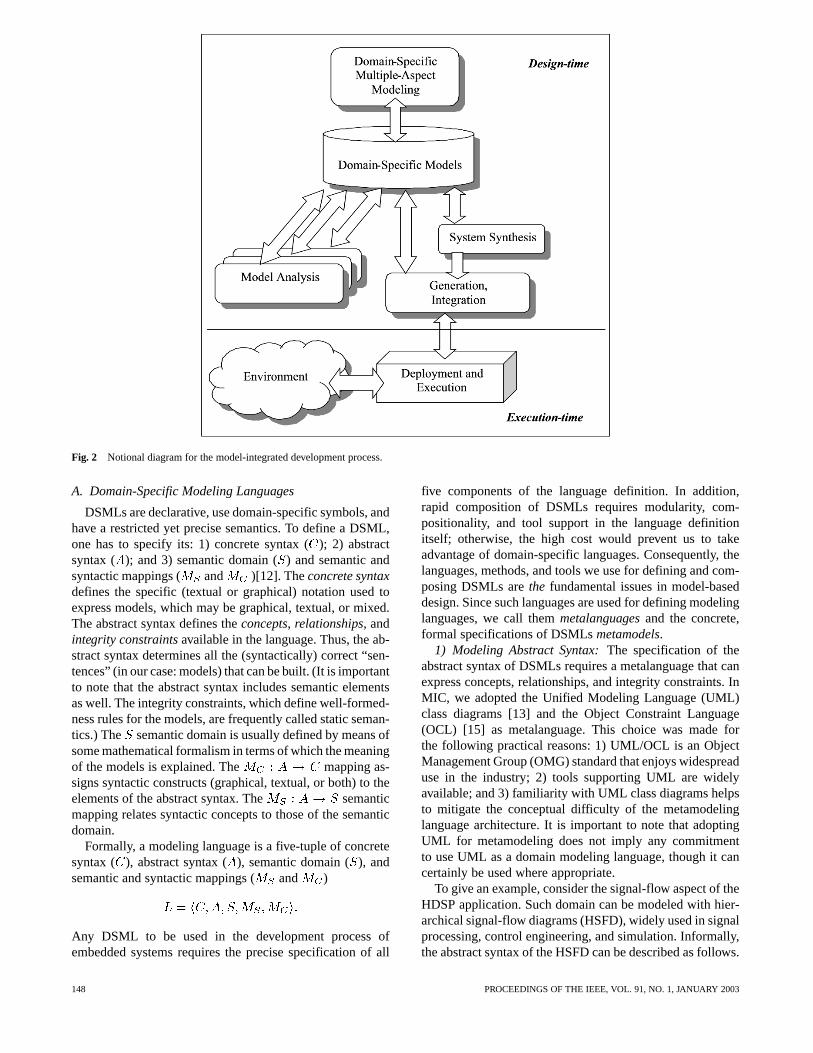
Fig. 2 Notional diagram for the model-integrated development process.
A. Domain-Specific Modeling Languages
DSMLs are declarative, use domain-specific symbols, andhave a restricted yet precise semantics. To define a DSML,one has to specify its: 1) concrete syntax (); 2) abstractsyntax ( ); and 3) semantic domain () and semantic andsyntactic mappings ( and )[12]. Theconcrete syntaxdefines the specific (textual or graphical) notation used toexpress models, which may be graphical, textual, or mixed.The abstract syntax defines theconcepts, relationships, andintegrity constraintsavailable in the language. Thus, the ab-stract syntax determines all the (syntactically) correct “sen-tences” (in our case: models) that can be built. (It is importantto note that the abstract syntax includes semantic elementsas well. The integrity constraints, which define well-formed-ness rules for the models, are frequently called static seman-tics.) The semantic domain is usually defined by means ofsome mathematical formalism in terms of which the meaningof the models is explained. The mapping as-signs syntactic constructs (graphical, textual, or both) to theelements of the abstract syntax. The semanticmapping relates syntactic concepts to those of the semanticdomain.
Formally, a modeling language is a five-tuple of concretesyntax ( ), abstract syntax (), semantic domain (), andsemantic and syntactic mappings ( and )
Any DSML to be used in the development process ofembedded systems requires the precise specification of all
five components of the language definition. In addition,rapid composition of DSMLs requires modularity, com-positionality, and tool support in the language definitionitself; otherwise, the high cost would prevent us to takeadvantage of domain-specific languages. Consequently, thelanguages, methods, and tools we use for defining and com-posing DSMLs arethe fundamental issues in model-baseddesign. Since such languages are used for defining modelinglanguages, we call themmetalanguagesand the concrete,formal specifications of DSMLsmetamodels.
1) Modeling Abstract Syntax:The specification of theabstract syntax of DSMLs requires a metalanguage that canexpress concepts, relationships, and integrity constraints. InMIC, we adopted the Unified Modeling Language (UML)class diagrams [13] and the Object Constraint Language(OCL) [15] as metalanguage. This choice was made forthe following practical reasons: 1) UML/OCL is an ObjectManagement Group (OMG) standard that enjoys widespreaduse in the industry; 2) tools supporting UML are widelyavailable; and 3) familiarity with UML class diagrams helpsto mitigate the conceptual difficulty of the metamodelinglanguage architecture. It is important to note that adoptingUML for metamodeling does not imply any commitmentto use UML as a domain modeling language, though it cancertainly be used where appropriate.
To give an example, consider the signal-flow aspect of theHDSP application. Such domain can be modeled with hier-archical signal-flow diagrams (HSFD), widely used in signalprocessing, control engineering, and simulation. Informally,the abstract syntax of the HSFD can be described as follows.
148 PROCEEDINGS OF THE IEEE, VOL. 91, NO. 1, JANUARY 2003
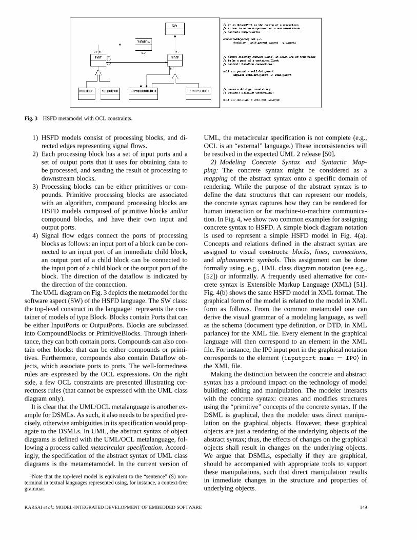
Fig. 3 HSFD metamodel with OCL constraints.
1) HSFD models consist of processing blocks, and di-rected edges representing signal flows.
2) Each processing block has a set of input ports and aset of output ports that it uses for obtaining data tobe processed, and sending the result of processing todownstream blocks.
3) Processing blocks can be either primitives or com-pounds. Primitive processing blocks are associatedwith an algorithm, compound processing blocks areHSFD models composed of primitive blocks and/orcompound blocks, and have their own input andoutput ports.
4) Signal flow edges connect the ports of processingblocks as follows: an input port of a block can be con-nected to an input port of an immediate child block,an output port of a child block can be connected tothe input port of a child block or the output port of theblock. The direction of the dataflow is indicated bythe direction of the connection.
The UML diagram on Fig. 3 depicts the metamodel for thesoftware aspect (SW) of the HSFD language. The SW class:the top-level construct in the language1 represents the con-tainer of models of type Block. Blocks contain Ports that canbe either InputPorts or OutputPorts. Blocks are subclassedinto CompoundBlocks or PrimitiveBlocks. Through inheri-tance, they can both contain ports. Compounds can also con-tain other blocks: that can be either compounds or primi-tives. Furthermore, compounds also contain Dataflow ob-jects, which associate ports to ports. The well-formednessrules are expressed by the OCL expressions. On the rightside, a few OCL constraints are presented illustrating cor-rectness rules (that cannot be expressed with the UML classdiagram only).
It is clear that the UML/OCL metalanguage is another ex-ample for DSMLs. As such, it also needs to be specified pre-cisely, otherwise ambiguities in its specification would prop-agate to the DSMLs. In UML, the abstract syntax of objectdiagrams is defined with the UML/OCL metalanguage, fol-lowing a process calledmetacircular specification. Accord-ingly, the specification of the abstract syntax of UML classdiagrams is the metametamodel. In the current version of
1Note that the top-level model is equivalent to the “sentence” (S) non-terminal in textual languages represented using, for instance, a context-freegrammar.
UML, the metacircular specification is not complete (e.g.,OCL is an “external” language.) These inconsistencies willbe resolved in the expected UML 2 release [50].
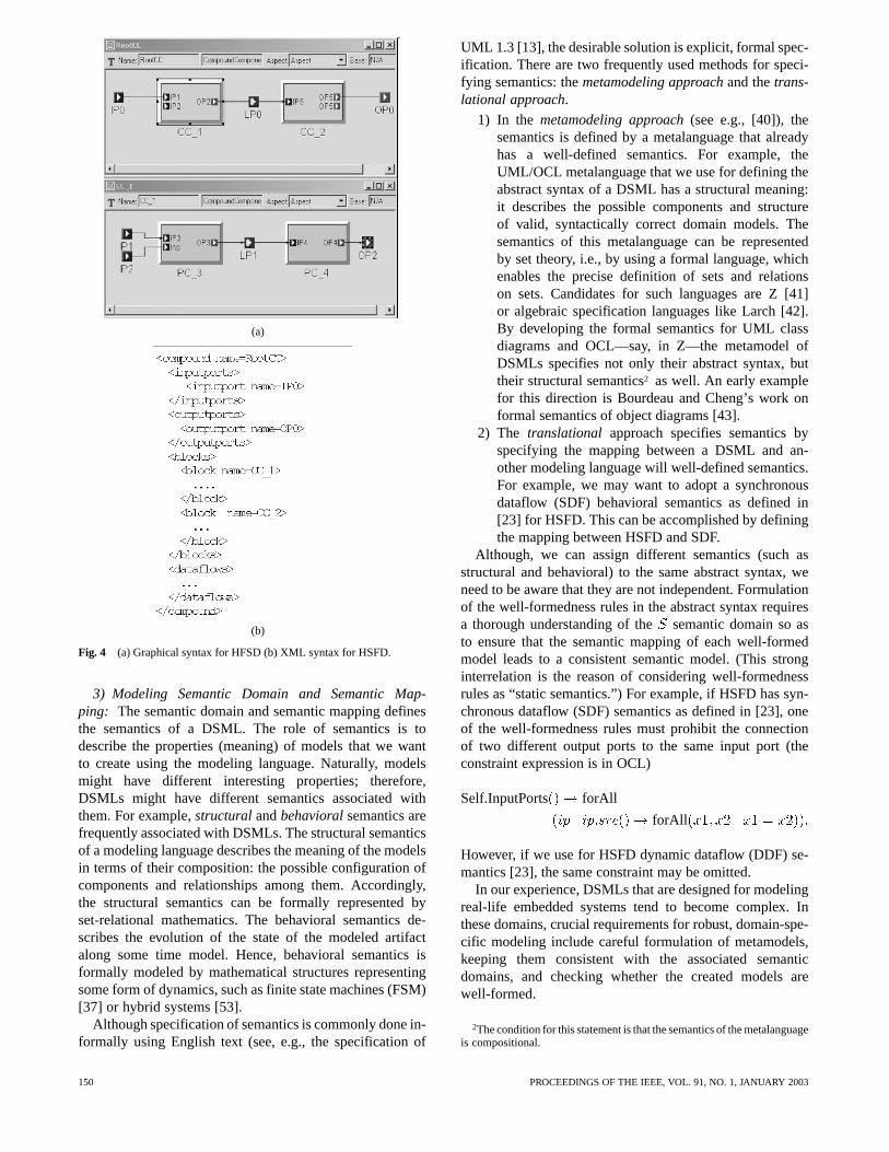
2) Modeling Concrete Syntax and Syntactic Map-ping: The concrete syntax might be considered as amappingof the abstract syntax onto a specific domain ofrendering. While the purpose of the abstract syntax is todefine the data structures that can represent our models,the concrete syntax captures how they can be rendered forhuman interaction or for machine-to-machine communica-tion. In Fig. 4, we show two common examples for assigningconcrete syntax to HSFD. A simple block diagram notationis used to represent a simple HSFD model in Fig. 4(a).Concepts and relations defined in the abstract syntax areassigned to visual constructs:blocks, lines, connections,and alphanumeric symbols. This assignment can be doneformally using, e.g., UML class diagram notation (see e.g.,[52]) or informally. A frequently used alternative for con-crete syntax is Extensible Markup Language (XML) [51].Fig. 4(b) shows the same HSFD model in XML format. Thegraphical form of the model is related to the model in XMLform as follows. From the common metamodel one canderive the visual grammar of a modeling language, as wellas the schema (document type definition, or DTD, in XMLparlance) for the XML file. Every element in the graphicallanguage will then correspond to an element in the XMLfile. For instance, the IP0 input port in the graphical notationcorresponds to the element inthe XML file.
Making the distinction between the concrete and abstractsyntax has a profound impact on the technology of modelbuilding: editing and manipulation. The modeler interactswith the concrete syntax: creates and modifies structuresusing the “primitive” concepts of the concrete syntax. If theDSML is graphical, then the modeler uses direct manipu-lation on the graphical objects. However, these graphicalobjects are just a rendering of the underlying objects of theabstract syntax; thus, the effects of changes on the graphicalobjects shall result in changes on the underlying objects.We argue that DSMLs, especially if they are graphical,should be accompanied with appropriate tools to supportthese manipulations, such that direct manipulation resultsin immediate changes in the structure and properties ofunderlying objects.
KARSAI et al.: MODEL-INTEGRATED DEVELOPMENT OF EMBEDDED SOFTWARE 149
(a)
(b)
Fig. 4 (a) Graphical syntax for HFSD (b) XML syntax for HSFD.
3) Modeling Semantic Domain and Semantic Map-ping: The semantic domain and semantic mapping definesthe semantics of a DSML. The role of semantics is todescribe the properties (meaning) of models that we wantto create using the modeling language. Naturally, modelsmight have different interesting properties; therefore,DSMLs might have different semantics associated withthem. For example,structuralandbehavioralsemantics arefrequently associated with DSMLs. The structural semanticsof a modeling language describes the meaning of the modelsin terms of their composition: the possible configuration ofcomponents and relationships among them. Accordingly,the structural semantics can be formally represented byset-relational mathematics. The behavioral semantics de-scribes the evolution of the state of the modeled artifactalong some time model. Hence, behavioral semantics isformally modeled by mathematical structures representingsome form of dynamics, such as finite state machines (FSM)[37] or hybrid systems [53].
Although specification of semantics is commonly done in-formally using English text (see, e.g., the specification of
UML 1.3 [13], the desirable solution is explicit, formal spec-ification. There are two frequently used methods for speci-fying semantics: themetamodeling approachand thetrans-lational approach.
1) In the metamodeling approach(see e.g., [40]), thesemantics is defined by a metalanguage that alreadyhas a well-defined semantics. For example, theUML/OCL metalanguage that we use for defining theabstract syntax of a DSML has a structural meaning:it describes the possible components and structureof valid, syntactically correct domain models. Thesemantics of this metalanguage can be representedby set theory, i.e., by using a formal language, whichenables the precise definition of sets and relationson sets. Candidates for such languages are Z [41]or algebraic specification languages like Larch [42].By developing the formal semantics for UML classdiagrams and OCL—say, in Z—the metamodel ofDSMLs specifies not only their abstract syntax, buttheir structural semantics2 as well. An early examplefor this direction is Bourdeau and Cheng’s work onformal semantics of object diagrams [43].
2) The translational approach specifies semantics byspecifying the mapping between a DSML and an-other modeling language will well-defined semantics.For example, we may want to adopt a synchronousdataflow (SDF) behavioral semantics as defined in[23] for HSFD. This can be accomplished by definingthe mapping between HSFD and SDF.
Although, we can assign different semantics (such asstructural and behavioral) to the same abstract syntax, weneed to be aware that they are not independent. Formulationof the well-formedness rules in the abstract syntax requiresa thorough understanding of thesemantic domain so asto ensure that the semantic mapping of each well-formedmodel leads to a consistent semantic model. (This stronginterrelation is the reason of considering well-formednessrules as “static semantics.”) For example, if HSFD has syn-chronous dataflow (SDF) semantics as defined in [23], oneof the well-formedness rules must prohibit the connectionof two different output ports to the same input port (theconstraint expression is in OCL)
Self.InputPorts forAll
forAll
However, if we use for HSFD dynamic dataflow (DDF) se-mantics [23], the same constraint may be omitted.
In our experience, DSMLs that are designed for modelingreal-life embedded systems tend to become complex. Inthese domains, crucial requirements for robust, domain-spe-cific modeling include careful formulation of metamodels,keeping them consistent with the associated semanticdomains, and checking whether the created models arewell-formed.
2The condition for this statement is that the semantics of the metalanguageis compositional.
150 PROCEEDINGS OF THE IEEE, VOL. 91, NO. 1, JANUARY 2003
B. Composition of Metamodels and Models
One justification for using the model-based approachto system development is that models offer better waysto manage complexity, than currently used procedural orobject-oriented languages. Composition in model-baseddesign appears on two levels: 1) composition of DSMLs bymeans of metamodel composition; and 2) composition ofmodels in the context of specific DSMLs. In this section wediscuss the composition of DSMLs and the composition ofmodels.
1) Metamodel Composition:Compositional construc-tion of DSMLs requires the compo-sition of metamodels from component DSMLs. While thecomposition of orthogonal (independent) sublanguages isa simple task, construction of DSMLs from nonorthogonalsublanguages is a complex problem. Nonorthogonalitymeans that component DSMLs share concepts and wellformed-ness rules span across the individual modelingaspects.
Composition of DSMLs from sublanguages is partic-ularly important in embedded systems, which frequentlyrequire many modeling aspects. Since the current versionof our metamodeling language bases UML and OCL doesnot support modular composition of metamodels,3 weintroduced new facilities in our metamodeling environ-ment, which leave the component metamodels intact andcreates metamodels that are further composable [19]. Thecomposition is accomplished by using three new operatorsfor combining metamodels (see Table 1). Two of theseoperators are a specialization of the inheritance relationshipof UML. The principle here is that that language designerspecifies metamodels, and then composes and extendsthem to create new metamodels using these operators. Theoperators allow specific composition operations on the(read-only) base classes to derive new classes. The firstoperator, “Equivalence,” asserts that two classes (in differentclass diagrams) are to be considered identical, and in thecomposed metamodel they are merged. The second operator“Implementation Inheritance,” asserts that the derivedclasses will inherit the attributes of the base class and allthose associations where the base class plays the role of acontainer. The third operator, “Interface Inheritance,” statesthat the derived classes will inherit only those associationswhere the parent class is not a container.4 Application ofthese operators generates a new metamodel, which conformsto the underlying semantics of UML. Decomposition ofthe UML inheritance operation allows finer control overmetamodel composition (details are discussed in [19]).
Unfortunately, metamodel composition is not complete byexecuting the composition operators. If the component meta-models are not orthogonal, it is possible that the resultingmetamodel is not consistent, which means that conflictingwell-formedness rules are created during the composition
3The upcoming version of UML 2 is expected to include explicit supportfor metamodel composition.
4Note that the composition of the two (partial) inheritance operator yieldsthe same result as the original inheritance operator of UML.
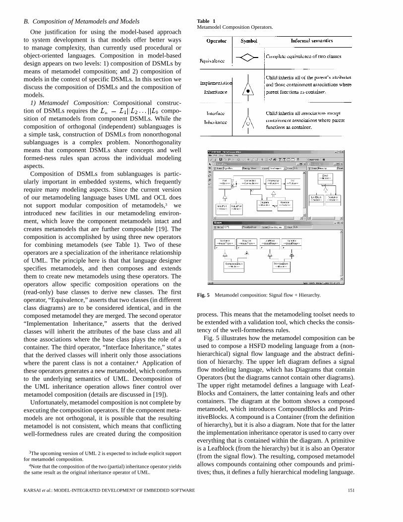
Table 1Metamodel Composition Operators.
Fig. 5 Metamodel composition: Signal flow + Hierarchy.
process. This means that the metamodeling toolset needs tobe extended with a validation tool, which checks the consis-tency of the well-formedness rules.
Fig. 5 illustrates how the metamodel composition can beused to compose a HSFD modeling language from a (non-hierarchical) signal flow language and the abstract defini-tion of hierarchy. The upper left diagram defines a signalflow modeling language, which has Diagrams that containOperators (but the diagrams cannot contain other diagrams).The upper right metamodel defines a language with Leaf-Blocks and Containers, the latter containing leafs and othercontainers. The diagram at the bottom shows a composedmetamodel, which introduces CompoundBlocks and Prim-itiveBlocks. A compound is a Container (from the definitionof hierarchy), but it is also a diagram. Note that for the latterthe implementation inheritance operator is used to carry overeverything that is contained within the diagram. A primitiveis a Leafblock (from the hierarchy) but it is also an Operator(from the signal flow). The resulting, composed metamodelallows compounds containing other compounds and primi-tives; thus, it defines a fully hierarchical modeling language.
KARSAI et al.: MODEL-INTEGRATED DEVELOPMENT OF EMBEDDED SOFTWARE 151

Fig. 6 Metamodel composition: Signal flow and FSM models.
Note that in this example, the semantics of models did notchange: everything is still a signal flow diagram; we merelyallowed the arbitrary hierarchical nesting of diagrams. Thereason for this is that the hierarchy is an abstract structuringprinciple and does not have a run-time semantics on its own.When models are assigned semantics through translation intoa run-time environment (as discussed later), the hierarchy is“compiled away,” and we execute a flat signal flow graph,with homogeneous components and behavior. This is in con-trast with the next example.
Fig. 6 shows another example for the composition ofmetamodels. The metamodel in the upper part defines a“SignalFlow” modeling language (essentially the same asthe HSFD language defined previously). The metamodel onthe lower left defines an FSM modeling language, consistingof states and transitions. The lower right metamodel definesa composition of the two: it introduces a new type of model:FSMNode, which is a new kind of Primitive that contains anFSM specifying its implementation (otherwise, it works justlike a Primitive, has input and output signals, etc). This is ex-pressed by the (unrestricted) inheritance between Primitiveand FSMNode. However, we do not want a State to containan FSMNode. This is expressed by the implementationinheritance between State and FSMNode. Furthermore, wewant to make selected InputSignals and OutputSignals ofany FSMNode to be mapped to certain States it containsusing connections. (This could mean, for example, that thedata values associated with those signals are accessible fromthe implementation associated with the given State.) This isexpressed by the new SignalMap association class allowingthe connecting of FSMNodes to Signals.
Note that, in this example, metamodel composition hasa profound impact on semantics. The dynamic semanticsof signal flow blocks and FSMs is different. When weintroduce the FSMNode as a variation of the Primitiveconcept, we—implicitly—allow (compound) models thatcontain both FSMs and signal flow blocks: primitivesand compounds. The two kinds of blocks follow differentmodels of computation, and their composition requires
the precise specification of semantics for the composedmodel. [56] describes a framework for comparing, and [57]shows examples of how to compose models with differentsemantics.
Up to this point we have discussed the composition ofDSMLs from the point of view of their abstract syntax. To de-rive an integrated semantics for the composed modeling lan-guage is a complex problem, which requires careful analysis.In simpler cases—for example, composing a modeling lan-guage for HSFDs—the semantic domain describing behav-ioral semantics does not change. Therefore, semantics canbe defined by the straightforward application of the transla-tional approach. However, if we intend to compose modelinglanguage for FSMs and continuous dynamics, the integratedbehavioral semantics leads to the theory hybrid systems [53],with qualitatively different characteristics from its sublan-guages.
2) Model Composition:Composition of models in aDSML is an essential task; thus, a number of techniquesmust be made available for the modeler. The abstractsyntax of a DSML defines what composition techniquesare available in the language. However, these compositiontechniques are always specific to that language, so it is veryhard to make general statements about composition. Onthe other hand, there are a number of techniques that arerelevant across many application domains.
1) Abstractionis arguably the most powerful technique inmodeling. Here, we define it as the capability for rep-resenting systems on different levels of detail, simulta-neously. A DSML should allow creating such models,but also their seamlessvertical composition: i.e., ahigher-level, more abstract model should always becompatible with a lower-level, less abstract model, andsubstituting a lower-level model with a higher-levelone must be allowed. The most common way to sup-port abstraction is hierarchy: both in the part-wholeand general-special sense. Thus, models built using theabstraction technique are usually organized into two,distinct trees: one tree for the part-whole hierarchy,and another one for type hierarchy. See Fig. 7.
2) Modularization is an implementation technique,which helps not only in the construction, but alsoin supporting abstraction in the practice. To modela complex system, one needs to break it down intoself-consistent entities: modules and models ex-pressed in a DSML should form modules and shouldbe composable.Composabilitymeans that the com-position of two or more modules should also be amodule itself. In the HSFD example, the modulesare the processing blocks, and compound blocks cancontain primitive blocks or other compound blocks.Note that a compound block also serves as the vehiclefor abstraction: if it is considered as a “black box,” ithides the details of its internal implementation, thusproviding an actual implementation for abstraction.
3) Interfaces and ported components(aka module inter-connection language) extend the simple part-whole hi-erarchy concept with modules that have distinguished
152 PROCEEDINGS OF THE IEEE, VOL. 91, NO. 1, JANUARY 2003
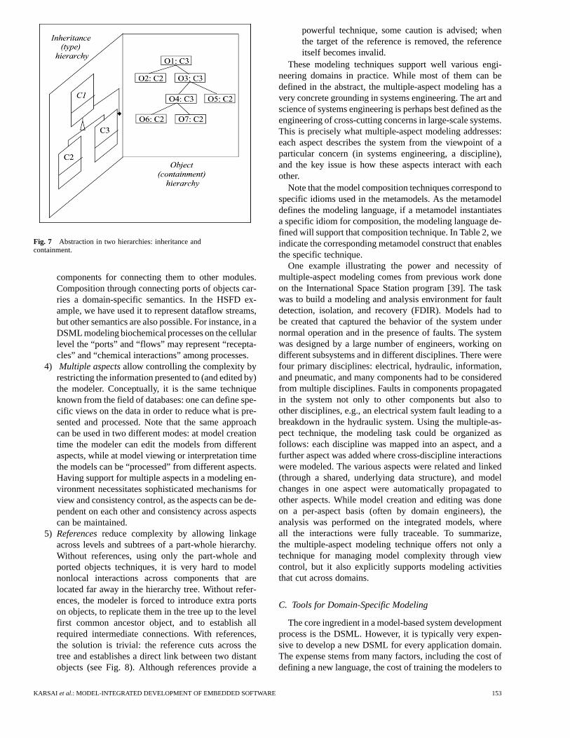
Fig. 7 Abstraction in two hierarchies: inheritance andcontainment.
components for connecting them to other modules.Composition through connecting ports of objects car-ries a domain-specific semantics. In the HSFD ex-ample, we have used it to represent dataflow streams,but other semantics are also possible. For instance, in aDSML modeling biochemical processes on the cellularlevel the “ports” and “flows” may represent “recepta-cles” and “chemical interactions” among processes.
4) Multiple aspectsallow controlling the complexity byrestricting the information presented to (and edited by)the modeler. Conceptually, it is the same techniqueknown from the field of databases: one can define spe-cific views on the data in order to reduce what is pre-sented and processed. Note that the same approachcan be used in two different modes: at model creationtime the modeler can edit the models from differentaspects, while at model viewing or interpretation timethe models can be “processed” from different aspects.Having support for multiple aspects in a modeling en-vironment necessitates sophisticated mechanisms forview and consistency control, as the aspects can be de-pendent on each other and consistency across aspectscan be maintained.
5) Referencesreduce complexity by allowing linkageacross levels and subtrees of a part-whole hierarchy.Without references, using only the part-whole andported objects techniques, it is very hard to modelnonlocal interactions across components that arelocated far away in the hierarchy tree. Without refer-ences, the modeler is forced to introduce extra portson objects, to replicate them in the tree up to the levelfirst common ancestor object, and to establish allrequired intermediate connections. With references,the solution is trivial: the reference cuts across thetree and establishes a direct link between two distantobjects (see Fig. 8). Although references provide a
powerful technique, some caution is advised; whenthe target of the reference is removed, the referenceitself becomes invalid.
These modeling techniques support well various engi-neering domains in practice. While most of them can bedefined in the abstract, the multiple-aspect modeling has avery concrete grounding in systems engineering. The art andscience of systems engineering is perhaps best defined as theengineering of cross-cutting concerns in large-scale systems.This is precisely what multiple-aspect modeling addresses:each aspect describes the system from the viewpoint of aparticular concern (in systems engineering, a discipline),and the key issue is how these aspects interact with eachother.
Note that the model composition techniques correspond tospecific idioms used in the metamodels. As the metamodeldefines the modeling language, if a metamodel instantiatesa specific idiom for composition, the modeling language de-fined will support that composition technique. In Table 2, weindicate the corresponding metamodel construct that enablesthe specific technique.
One example illustrating the power and necessity ofmultiple-aspect modeling comes from previous work doneon the International Space Station program [39]. The taskwas to build a modeling and analysis environment for faultdetection, isolation, and recovery (FDIR). Models had tobe created that captured the behavior of the system undernormal operation and in the presence of faults. The systemwas designed by a large number of engineers, working ondifferent subsystems and in different disciplines. There werefour primary disciplines: electrical, hydraulic, information,and pneumatic, and many components had to be consideredfrom multiple disciplines. Faults in components propagatedin the system not only to other components but also toother disciplines, e.g., an electrical system fault leading to abreakdown in the hydraulic system. Using the multiple-as-pect technique, the modeling task could be organized asfollows: each discipline was mapped into an aspect, and afurther aspect was added where cross-discipline interactionswere modeled. The various aspects were related and linked(through a shared, underlying data structure), and modelchanges in one aspect were automatically propagated toother aspects. While model creation and editing was doneon a per-aspect basis (often by domain engineers), theanalysis was performed on the integrated models, whereall the interactions were fully traceable. To summarize,the multiple-aspect modeling technique offers not only atechnique for managing model complexity through viewcontrol, but it also explicitly supports modeling activitiesthat cut across domains.
C. Tools for Domain-Specific Modeling
The core ingredient in a model-based system developmentprocess is the DSML. However, it is typically very expen-sive to develop a new DSML for every application domain.The expense stems from many factors, including the cost ofdefining a new language, the cost of training the modelers to
KARSAI et al.: MODEL-INTEGRATED DEVELOPMENT OF EMBEDDED SOFTWARE 153
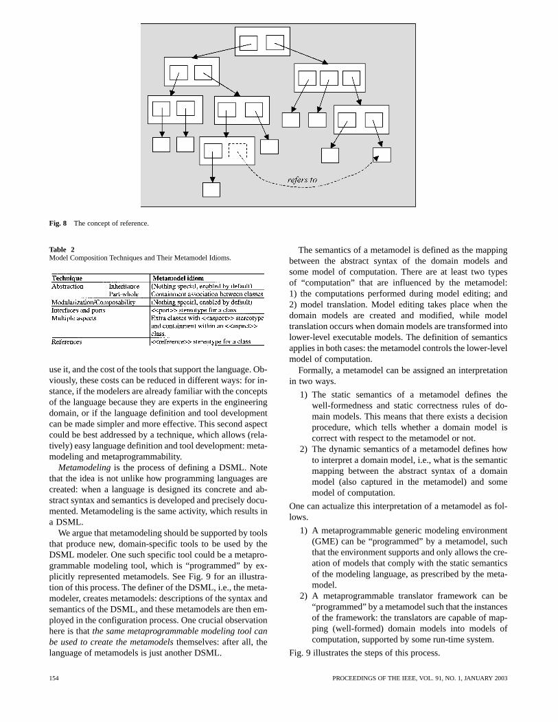
Fig. 8 The concept of reference.
Table 2Model Composition Techniques and Their Metamodel Idioms.
use it, and the cost of the tools that support the language. Ob-viously, these costs can be reduced in different ways: for in-stance, if the modelers are already familiar with the conceptsof the language because they are experts in the engineeringdomain, or if the language definition and tool developmentcan be made simpler and more effective. This second aspectcould be best addressed by a technique, which allows (rela-tively) easy language definition and tool development: meta-modeling and metaprogrammability.
Metamodelingis the process of defining a DSML. Notethat the idea is not unlike how programming languages arecreated: when a language is designed its concrete and ab-stract syntax and semantics is developed and precisely docu-mented. Metamodeling is the same activity, which results ina DSML.
We argue that metamodeling should be supported by toolsthat produce new, domain-specific tools to be used by theDSML modeler. One such specific tool could be a metapro-grammable modeling tool, which is “programmed” by ex-plicitly represented metamodels. See Fig. 9 for an illustra-tion of this process. The definer of the DSML, i.e., the meta-modeler, creates metamodels: descriptions of the syntax andsemantics of the DSML, and these metamodels are then em-ployed in the configuration process. One crucial observationhere is thatthe same metaprogrammable modeling tool canbe used to create the metamodelsthemselves: after all, thelanguage of metamodels is just another DSML.
The semantics of a metamodel is defined as the mappingbetween the abstract syntax of the domain models andsome model of computation. There are at least two typesof “computation” that are influenced by the metamodel:1) the computations performed during model editing; and2) model translation. Model editing takes place when thedomain models are created and modified, while modeltranslation occurs when domain models are transformed intolower-level executable models. The definition of semanticsapplies in both cases: the metamodel controls the lower-levelmodel of computation.
Formally, a metamodel can be assigned an interpretationin two ways.
1) The static semantics of a metamodel defines thewell-formedness and static correctness rules of do-main models. This means that there exists a decisionprocedure, which tells whether a domain model iscorrect with respect to the metamodel or not.
2) The dynamic semantics of a metamodel defines howto interpret a domain model, i.e., what is the semanticmapping between the abstract syntax of a domainmodel (also captured in the metamodel) and somemodel of computation.
One can actualize this interpretation of a metamodel as fol-lows.
1) A metaprogrammable generic modeling environment(GME) can be “programmed” by a metamodel, suchthat the environment supports and only allows the cre-ation of models that comply with the static semanticsof the modeling language, as prescribed by the meta-model.
2) A metaprogrammable translator framework can be“programmed” by a metamodel such that the instancesof the framework: the translators are capable of map-ping (well-formed) domain models into models ofcomputation, supported by some run-time system.
Fig. 9 illustrates the steps of this process.
154 PROCEEDINGS OF THE IEEE, VOL. 91, NO. 1, JANUARY 2003
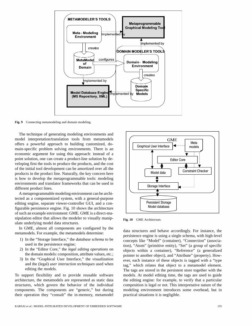
Fig. 9 Connecting metamodeling and domain modeling.
The technique of generating modeling environments andmodel interpretation/translation tools from metamodelsoffers a powerful approach to building customized, do-main-specific problem solving environments. There is aneconomic argument for using this approach: instead of apoint solution, one can create a product-line solution by de-veloping first the tools to produce the products, and the costof the initial tool development can be amortized over all theproducts in the product line. Naturally, the key concern hereis how to develop the metaprogrammable tools: modelingenvironments and translator frameworks that can be used indifferent product lines.
A metaprogrammable modeling environment can be archi-tected as a componentized system, with a general-purposeediting engine, separate viewer-controller GUI, and a con-figurable persistence engine. Fig. 10 shows the architectureof such an example environment: GME. GME is a direct-ma-nipulation editor that allows the modeler to visually manip-ulate underlying model data structures.
In GME, almost all components are configured by themetamodels. For example, the metamodels determine:
1) In the “Storage Interface,” thedatabase schemato beused in the persistence engine;
2) In the “Editor Core,” thelegal editing operationsonthe domain models: composition, attribute values, etc.;
3) In the “Graphical User Interface,” thevisualizationand the (legal)user interaction techniquesused whenediting the models.
To support flexibility and to provide reusable softwarearchitecture, the metamodels are represented as static datastructures, which govern the behavior of the individualcomponents. The components are “generic,” but duringtheir operation they “consult” the in-memory, metamodel
Fig. 10 GME Architecture.
data structures and behave accordingly. For instance, thepersistence engine is using a single schema, with high-levelconcepts like “Model” (container), “Connection” (associa-tion), “Atom” (primitive entity), “Set” (a group of specificobjects within a container), “Reference” (a generalizedpointer to another object), and “Attribute” (property). How-ever, each instance of these objects is tagged with a “typetag,” which relates that object to a metamodel element.The tags are stored in the persistent store together with themodels. At model editing time, the tags are used to guidethe editing engine: for example, to verify that a particularcomposition is legal or not. This interpretative nature of themodeling environment introduces some overhead, but inpractical situations it is negligible.
KARSAI et al.: MODEL-INTEGRATED DEVELOPMENT OF EMBEDDED SOFTWARE 155
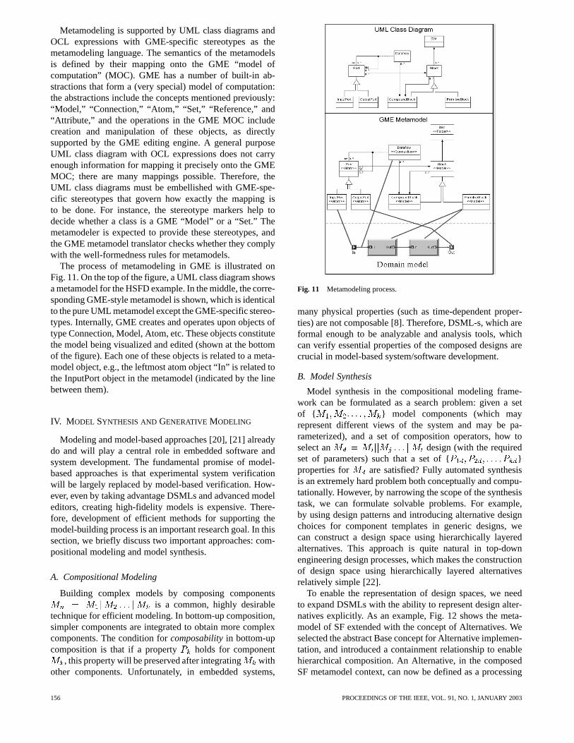
Metamodeling is supported by UML class diagrams andOCL expressions with GME-specific stereotypes as themetamodeling language. The semantics of the metamodelsis defined by their mapping onto the GME “model ofcomputation” (MOC). GME has a number of built-in ab-stractions that form a (very special) model of computation:the abstractions include the concepts mentioned previously:“Model,” “Connection,” “Atom,” “Set,” “Reference,” and“Attribute,” and the operations in the GME MOC includecreation and manipulation of these objects, as directlysupported by the GME editing engine. A general purposeUML class diagram with OCL expressions does not carryenough information for mapping it precisely onto the GMEMOC; there are many mappings possible. Therefore, theUML class diagrams must be embellished with GME-spe-cific stereotypes that govern how exactly the mapping isto be done. For instance, the stereotype markers help todecide whether a class is a GME “Model” or a “Set.” Themetamodeler is expected to provide these stereotypes, andthe GME metamodel translator checks whether they complywith the well-formedness rules for metamodels.
The process of metamodeling in GME is illustrated onFig. 11. On the top of the figure, a UML class diagram showsa metamodel for the HSFD example. In the middle, the corre-sponding GME-style metamodel is shown, which is identicalto the pure UML metamodel except the GME-specific stereo-types. Internally, GME creates and operates upon objects oftype Connection, Model, Atom, etc. These objects constitutethe model being visualized and edited (shown at the bottomof the figure). Each one of these objects is related to a meta-model object, e.g., the leftmost atom object “In” is related tothe InputPort object in the metamodel (indicated by the linebetween them).
IV. M ODEL SYNTHESIS AND GENERATIVE MODELING
Modeling and model-based approaches [20], [21] alreadydo and will play a central role in embedded software andsystem development. The fundamental promise of model-based approaches is that experimental system verificationwill be largely replaced by model-based verification. How-ever, even by taking advantage DSMLs and advanced modeleditors, creating high-fidelity models is expensive. There-fore, development of efficient methods for supporting themodel-building process is an important research goal. In thissection, we briefly discuss two important approaches: com-positional modeling and model synthesis.
A. Compositional Modeling
Building complex models by composing componentsis a common, highly desirable
technique for efficient modeling. In bottom-up composition,simpler components are integrated to obtain more complexcomponents. The condition forcomposabilityin bottom-upcomposition is that if a property holds for component
, this property will be preserved after integrating withother components. Unfortunately, in embedded systems,
Fig. 11 Metamodeling process.
many physical properties (such as time-dependent proper-ties) are not composable [8]. Therefore, DSML-s, which areformal enough to be analyzable and analysis tools, whichcan verify essential properties of the composed designs arecrucial in model-based system/software development.
B. Model Synthesis
Model synthesis in the compositional modeling frame-work can be formulated as a search problem: given a setof { } model components (which mayrepresent different views of the system and may be pa-rameterized), and a set of composition operators, how toselect an design (with the requiredset of parameters) such that a set of { }properties for are satisfied? Fully automated synthesisis an extremely hard problem both conceptually and compu-tationally. However, by narrowing the scope of the synthesistask, we can formulate solvable problems. For example,by using design patterns and introducing alternative designchoices for component templates in generic designs, wecan construct a design space using hierarchically layeredalternatives. This approach is quite natural in top-downengineering design processes, which makes the constructionof design space using hierarchically layered alternativesrelatively simple [22].
To enable the representation of design spaces, we needto expand DSMLs with the ability to represent design alter-natives explicitly. As an example, Fig. 12 shows the meta-model of SF extended with the concept of Alternatives. Weselected the abstract Base concept for Alternative implemen-tation, and introduced a containment relationship to enablehierarchical composition. An Alternative, in the composedSF metamodel context, can now be defined as a processing
156 PROCEEDINGS OF THE IEEE, VOL. 91, NO. 1, JANUARY 2003
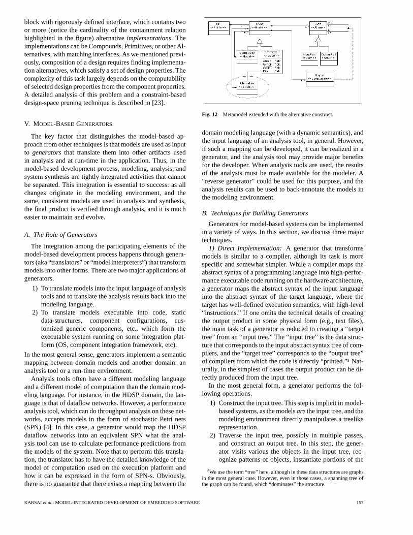
block with rigorously defined interface, which contains twoor more (notice the cardinality of the containment relationhighlighted in the figure) alternativeimplementations. Theimplementations can be Compounds, Primitives, or other Al-ternatives, with matching interfaces. As we mentioned previ-ously, composition of a design requires finding implementa-tion alternatives, which satisfy a set of design properties. Thecomplexity of this task largely depends on the computabilityof selected design properties from the component properties.A detailed analysis of this problem and a constraint-baseddesign-space pruning technique is described in [23].
V. MODEL-BASED GENERATORS
The key factor that distinguishes the model-based ap-proach from other techniques is that models are used as inputto generatorsthat translate them into other artifacts usedin analysis and at run-time in the application. Thus, in themodel-based development process, modeling, analysis, andsystem synthesis are tightly integrated activities that cannotbe separated. This integration is essential to success: as allchanges originate in the modeling environment, and thesame, consistent models are used in analysis and synthesis,the final product is verified through analysis, and it is mucheasier to maintain and evolve.
A. The Role of Generators
The integration among the participating elements of themodel-based development process happens through genera-tors (aka “translators” or “model interpreters”) that transformmodels into other forms. There are two major applications ofgenerators.
1) To translate models into the input language of analysistools and to translate the analysis results back into themodeling language.
2) To translate models executable into code, staticdata-structures, component configurations, cus-tomized generic components, etc., which form theexecutable system running on some integration plat-form (OS, component integration framework, etc).
In the most general sense, generators implement a semanticmapping between domain models and another domain: ananalysis tool or a run-time environment.
Analysis tools often have a different modeling languageand a different model of computation than the domain mod-eling language. For instance, in the HDSP domain, the lan-guage is that of dataflow networks. However, a performanceanalysis tool, which can do throughput analysis on these net-works, accepts models in the form of stochastic Petri nets(SPN) [4]. In this case, a generator would map the HDSPdataflow networks into an equivalent SPN what the anal-ysis tool can use to calculate performance predictions fromthe models of the system. Note that to perform this transla-tion, the translator has to have the detailed knowledge of themodel of computation used on the execution platform andhow it can be expressed in the form of SPN-s. Obviously,there is no guarantee that there exists a mapping between the
Fig. 12 Metamodel extended with the alternative construct.
domain modeling language (with a dynamic semantics), andthe input language of an analysis tool, in general. However,if such a mapping can be developed, it can be realized in agenerator, and the analysis tool may provide major benefitsfor the developer. When analysis tools are used, the resultsof the analysis must be made available for the modeler. A“reverse generator” could be used for this purpose, and theanalysis results can be used to back-annotate the models inthe modeling environment.
B. Techniques for Building Generators
Generators for model-based systems can be implementedin a variety of ways. In this section, we discuss three majortechniques.
1) Direct Implementation:A generator that transformsmodels is similar to a compiler, although its task is morespecific and somewhat simpler. While a compiler maps theabstract syntax of a programming language into high-perfor-mance executable code running on the hardware architecture,a generator maps the abstract syntax of the input languageinto the abstract syntax of the target language, where thetarget has well-defined execution semantics, with high-level“instructions.” If one omits the technical details of creatingthe output product in some physical form (e.g., text files),the main task of a generator is reduced to creating a “targettree” from an “input tree.” The “input tree” is the data struc-ture that corresponds to the input abstract syntax tree of com-pilers, and the “target tree” corresponds to the “output tree”of compilers from which the code is directly “printed.”5 Nat-urally, in the simplest of cases the output product can be di-rectly produced from the input tree.
In the most general form, a generator performs the fol-lowing operations.
1) Construct the input tree. This step is implicit in model-based systems, as the modelsarethe input tree, and themodeling environment directly manipulates a treelikerepresentation.
2) Traverse the input tree, possibly in multiple passes,and construct an output tree. In this step, the gener-ator visits various the objects in the input tree, rec-ognize patterns of objects, instantiate portions of the
5We use the term “tree” here, although in these data structures are graphsin the most general case. However, even in those cases, a spanning tree ofthe graph can be found, which “dominates” the structure.
KARSAI et al.: MODEL-INTEGRATED DEVELOPMENT OF EMBEDDED SOFTWARE 157
target tree, calculate attributes of output objects fromattributes of input objects, etc.
3) “Print out” the product. This step creates the result ofthe generation in the required form: a network of ob-jects, a text file, a sequence of commands issued to ahardware device, etc.
Following the previously described approach, a generatoris straightforward to construct: after designing the input andoutput data structures (which are determined by the meta-models of the input and target languages already), one has todesign the appropriate code sequences for traversal and targetobject construction. The implementation can follow an ob-ject-oriented approach: the traversal code can be embeddedas methods of the input objects, and by directly coding thetraversals and the target construction one can easily realizethe generation algorithms. Similarly, the output “printing”can be embedded as methods of the target objects, and byprogramming the traversal of theoutputone can realize theoutput-producing algorithms. This direct implementation issimple and works well for situations where the transforma-tions are easy to capture in a procedural form.
2) Pattern-Based Approach:The scheme described pre-viously can also be implemented in a more structured way, byusing the Visitor design pattern [26]. The main task of a gen-erator involves thetraversalof the input tree andtaking ac-tionsat specific points during the traversal. This is clearly inthe purview of the Visitor pattern, which offers a common so-lution for coding the generic algorithm previously described.In this pattern, avisitor object implements the actions to beperformed at various nodes in the at tree, while the tree nodescontain code thatacceptsthe visitor object and calls the ap-propriate, node-specific operation on it (while passing itselfto the operation as a parameter). The Visitor pattern allowsthe concise and maintainable implementation of generators,both for the transformation and the printing phases.
While the implementation of a generator following theVisitor pattern is straightforward, it can be significantly im-proved by using some automation. In previous work on de-sign tool integration [31], we have developed a technique forthe structured capturing of the “traversal/action” code of gen-erators. The approach was based on the observation that tra-versal sequences and actions to be taken at specific pointsin the input tree are separate concerns, and that the traversalcan be specified using higher-level constructs (than proce-dural code). A language was designed that allowed the spec-ification of traversal paths and the capturing of actions to beexecuted at specific nodes. Generators written using this ap-proach were very compact and readable, and have been suc-cessfully applied in various projects. The approach is similarto Adaptive Programming [32], but it is more focused on theneeds of generators.
3) Metagenerators:The approach based on the Visitorpattern has a serious shortcoming: most of the logic of thegenerator is still realized as procedural code; therefore, it ishard to verify or to reason about. A better technique wouldallow the mathematically precise modeling of the generator’sworking and the generation of the code of the generator from
that model. This process is calledmetageneration. Fig. 13illustrates this process.
A “model of a generator” is much simpler than that ofa compiler and can be defined operationally: it is an ab-stract description of what the generator does. Following theprevious generic description of a generator, the main taskof a generator can be modeled in terms of: 1) the traversalsequences; and 2) the transformation actions the generatortakes during its operation. The approach described in the pre-vious section allowed the specification of 2) only in imper-ative ways (in a programming language), but 2) can also bespecified declaratively: using graph-transformation rules.
Graph grammars and graph rewriting [33], [60] offer astructured, formal, and mathematically precise method ofrepresenting how a generator constructs the output tree fromthe input tree. There are several practical systems ([62], [63])available. Graph rewriting has been used to specify variousprogram analysis and transformation tasks successfully [61].In MIC, its scope is extended to include transformation onthe models (instead of the abstract syntax tree of a program).One elementary rewriting operation performed by a trans-lator is called atransform. A transform is a specification of amapping between a portion of the input graph and a portionof the output graph. Note that the metamodels of the inputand the output of a generator is a compact description of allthe possible input and output structures. Ifand denote the input and the outputmetamodels consisting of classes and associations, a trans-form can be described using the following elements:
1) : subgraph formed from a subsetof the input classes and a subset of the
input associations;2) : a Boolean condition, calledfilter,
over ;3) : subgraph formed from a subset
of the output classes and a subsetof the output associations;
4) a mapping where ,, and .
A transform is a specific rewrite rule that converts a sub-graph of the input into a subgraph of the output. The inputsubgraph must also satisfy the filter. The mapping shouldalso specify how the attributes of the output objects and linksshould be calculated from the attributes of the input objectsand links.
While graph transformations are very descriptive, theyfare less well in implementation. Matching the left side ofa rewriting rule against an input graph involves searchingfor a subgraph, which can be of exponential complexity.However, in generators one can almost always avoid the(global) search by specifying the traversal and order inwhich the transformation rules should be applied; thus, thesearch can be reduced to a (local) matching. This latter onecan be accomplished by introducing “pivot nodes,” whichare bound by the higher-level, traversal strategy, so the leftside of the transform is partially bound already when therule is fired.
158 PROCEEDINGS OF THE IEEE, VOL. 91, NO. 1, JANUARY 2003
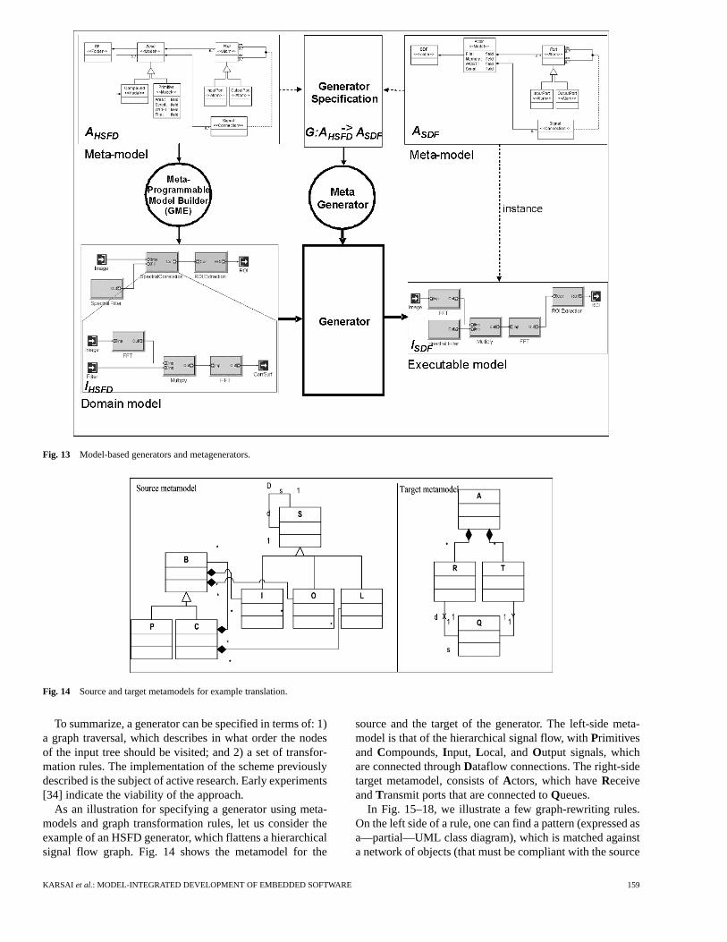
Fig. 13 Model-based generators and metagenerators.
Fig. 14 Source and target metamodels for example translation.
To summarize, a generator can be specified in terms of: 1)a graph traversal, which describes in what order the nodesof the input tree should be visited; and 2) a set of transfor-mation rules. The implementation of the scheme previouslydescribed is the subject of active research. Early experiments[34] indicate the viability of the approach.
As an illustration for specifying a generator using meta-models and graph transformation rules, let us consider theexample of an HSFD generator, which flattens a hierarchicalsignal flow graph. Fig. 14 shows the metamodel for the
source and the target of the generator. The left-side meta-model is that of the hierarchical signal flow, withPrimitivesand Compounds,Input, Local, andOutput signals, whichare connected throughDataflow connections. The right-sidetarget metamodel, consists ofActors, which haveReceiveandTransmit ports that are connected toQueues.
In Fig. 15–18, we illustrate a few graph-rewriting rules.On the left side of a rule, one can find a pattern (expressed asa—partial—UML class diagram), which is matched againsta network of objects (that must be compliant with the source
KARSAI et al.: MODEL-INTEGRATED DEVELOPMENT OF EMBEDDED SOFTWARE 159
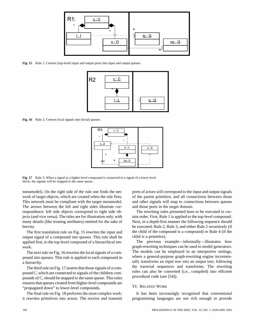
Fig. 15 Rule 1: Convert (top-level) input and output ports into input and output queues.
Fig. 16 Rule 2: Convert local signals into (local) queues.
Fig. 17 Rule 3: When a signal in a higher-level compound is connected to a signal of a lower-levelblock, the signals will be mapped to the same queue.
metamodel). On the right side of the rule one finds the net-work of target objects, which are created when the rule fires.This network must be compliant with the target metamodel.The arrows between the left and right sides illustrate cor-respondence: left side objects correspond to right side ob-jects (and vice versa). The rules are for illustration only, withmany details (like treating attributes) omitted for the sake ofbrevity.
The first translation rule on Fig. 15 rewrites the input andoutput signal of a compound into queues. This rule shall beapplied first, to the top-level compound of a hierarchical net-work.
The next rule on Fig. 16 rewrites the local signals of a com-pound into queues. This rule is applied to each compound ina hierarchy.
The third rule on Fig. 17 asserts that those signals of a com-pound C, which are connected to signals of the children com-pounds of C, should be mapped to the same queue. This rulesensures that queues created from higher-level compounds are“propagated down” to lower-level compounds.
The final rule on Fig. 18 performs the most complex work:it rewrites primitives into actors. The receive and transmit
ports of actors will correspond to the input and output signalsof the parent primitive, and all connections between thoseand other signals will map to connections between queuesand those ports in the target domain.
The rewriting rules presented have to be executed in cer-tain order. First, Rule 1 is applied to the top-level compound.Next, in a depth-first manner the following sequence shouldbe executed: Rule 2, Rule 3, and either Rule 2 recursively (ifthe child of the compound is a compound) or Rule 4 (if thechild is a primitive).
The previous example—informally—illustrates howgraph-rewriting techniques can be used to model generators.The models can be employed in an interpretive settings,where a general-purpose graph-rewriting engine incremen-tally transforms an input tree into an output tree, followingthe traversal sequences and transforms. The rewritingrules can also be converted (i.e., compiled) into efficientprocedural code (see [54]).
VI. RELATED WORK
It has been increasingly recognized that conventionalprogramming languages are not rich enough to provide
160 PROCEEDINGS OF THE IEEE, VOL. 91, NO. 1, JANUARY 2003
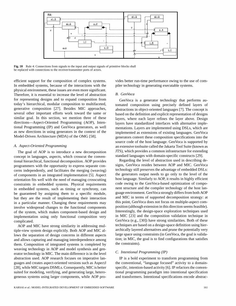
Fig. 18 Rule 4: Connections from signals to the input and output signals of primitive blocks shallbe replaced with connections to the receiver/transmitter ports of actors.
efficient support for the composition of complex systems.In embedded systems, because of the interactions with thephysical environment, these issues are even more significant.Therefore, it is essential to increase the level of abstractionfor representing designs and to expand composition fromtoday’s hierarchical, modular composition to multifaceted,generative composition [27]. Besides MIC approaches,several other important efforts work toward the same orsimilar goal. In this section, we mention three of thesedirections—Aspect-Oriented Programming (AOP), Inten-tional Programming (IP) and GenVoca generators, as wellas new directions in using generators in the context of theModel-Driven Architecture (MDA) of the OMG [58].
A. Aspect-Oriented Programming
The goal of AOP is to introduce a new decompositionconcept in languages,aspects, which crosscut the conven-tional hierarchical, functional decomposition. AOP providesprogrammers with the opportunity to express separate con-cerns independently, and facilitates the merging (weaving)of components in an integrated implementation [5]. Aspectorientation fits well with the need of managing crosscuttingconstraints in embedded systems. Physical requirementsin embedded systems, such as timing or synchrony, canbe guaranteed by assigning them to a specific module,but they are the result of implementing their interactionin a particular manner. Changing these requirements mayinvolve widespread changes to the functional componentsof the system, which makes component-based design andimplementation using only functional composition verycomplicated.
AOP and MIC have strong similarity in addressing mul-tiple-view system design explicitly. Both AOP and MIC al-lows the separation of design concerns in different aspectsand allows capturing and managing interdependence amongthem. Composition of integrated systems is completed byweaving technology in AOP and model synthesis and gen-erator technology in MIC. The main difference is in the levelabstraction used. AOP research focuses on imperative lan-guages and creates aspect-oriented versions such as AspectJ[28], while MIC targets DSMLs. Consequently, MIC is bettersuited for modeling, verifying, and generating large, hetero-geneous systems using larger components, while AOP pro-
vides better run-time performance owing to the use of com-piler technology in generating executable systems.
B. GenVoca
GenVoca is a generator technology that performs au-tomated composition using precisely defined layers ofabstractions in object-oriented languages [7]. The concept isbased on the definition and explicit representation of designslayers, where each layer refines the layer above. Designlayers have standardized interfaces with alternative imple-mentations. Layers are implemented using DSLs, which areimplemented as extensions of existing languages. GenVocagenerators convert these composition specifications into thesource code of the host language. GenVoca is supported byan extensive toolsuite called the Jakarta Tool Suite (known asJTS), which provides a common infrastructure for extendingstandard languages with domain-specific constructs [29].
Regarding the level of abstraction used in describing de-signs, GenVoca resides between AOP and MIC. GenVocatechnology still preserves the advantage of embedded DSLs:the generators output needs to go only to the level of thehost language. Similarly to AOP, it results in highly efficientcode owing to the GenVoca-based optimization of compo-nent structure and the compiler technology of the host lan-guage environment. GenVoca strongly differs from both AOPand MIC in terms of supported decomposition strategy: atthis point, GenVoca does not focus on multiple-aspect com-position (although extension in this direction seems feasible).Interestingly, the design-space exploration techniques usedin MIC [23] and the composition validation technique inGenVoca (e.g., [30]) have strong similarities. Both of thesetechniques are based on a design-space definition using hier-archically layered alternatives and prune the potentially verylarge space using constraints (in GenVoca, the goal is valida-tion; in MIC, the goal is to find configurations that satisfiesthe constraints).
C. Intentional Programming (IP)
IP is a bold experiment to transform programming fromthe conventional, “language focused” activity to a domain-specific, intention-based activity [6]. IP refactors the conven-tional programming paradigm into intentional specificationand transformers. Intentional specifications encode abstrac-
KARSAI et al.: MODEL-INTEGRATED DEVELOPMENT OF EMBEDDED SOFTWARE 161
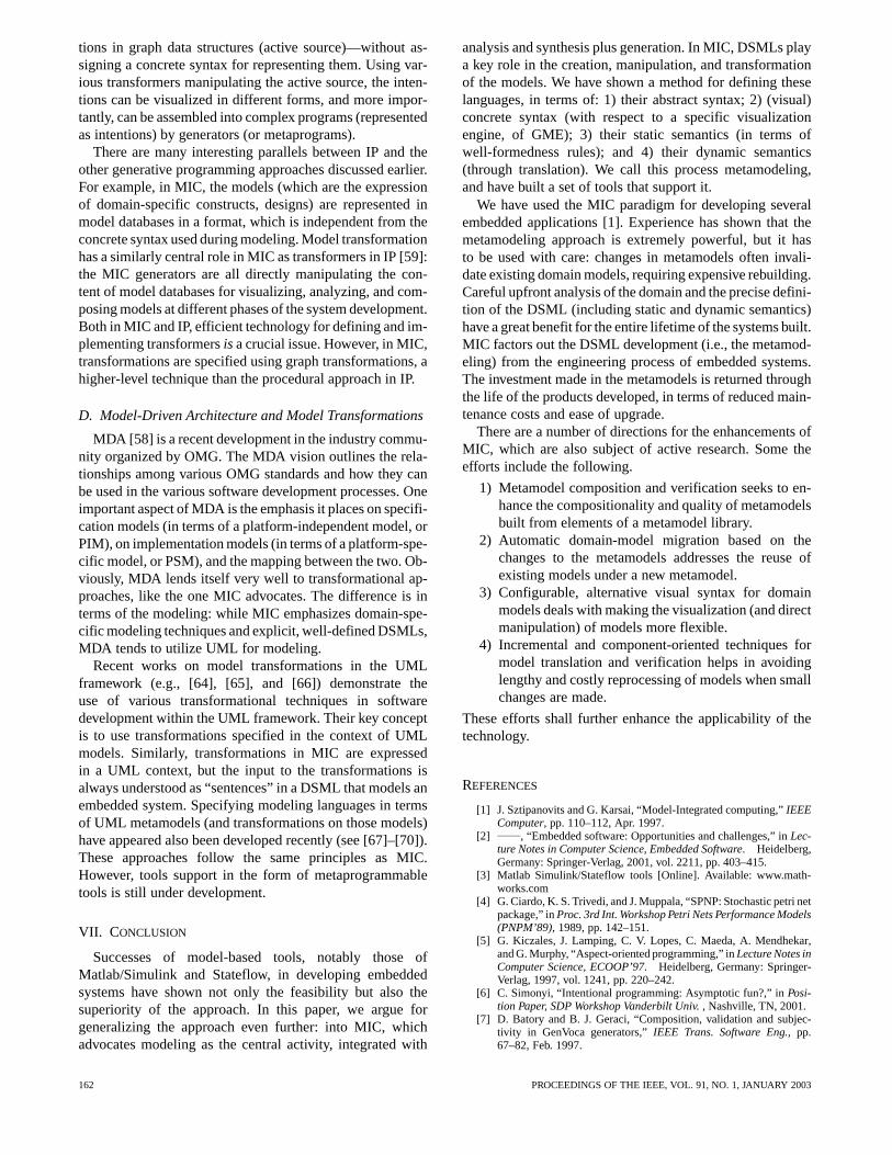
tions in graph data structures (active source)—without as-signing a concrete syntax for representing them. Using var-ious transformers manipulating the active source, the inten-tions can be visualized in different forms, and more impor-tantly, can be assembled into complex programs (representedas intentions) by generators (or metaprograms).
There are many interesting parallels between IP and theother generative programming approaches discussed earlier.For example, in MIC, the models (which are the expressionof domain-specific constructs, designs) are represented inmodel databases in a format, which is independent from theconcrete syntax used during modeling. Model transformationhas a similarly central role in MIC as transformers in IP [59]:the MIC generators are all directly manipulating the con-tent of model databases for visualizing, analyzing, and com-posing models at different phases of the system development.Both in MIC and IP, efficient technology for defining and im-plementing transformersis a crucial issue. However, in MIC,transformations are specified using graph transformations, ahigher-level technique than the procedural approach in IP.
D. Model-Driven Architecture and Model Transformations
MDA [58] is a recent development in the industry commu-nity organized by OMG. The MDA vision outlines the rela-tionships among various OMG standards and how they canbe used in the various software development processes. Oneimportant aspect of MDA is the emphasis it places on specifi-cation models (in terms of a platform-independent model, orPIM), on implementation models (in terms of a platform-spe-cific model, or PSM), and the mapping between the two. Ob-viously, MDA lends itself very well to transformational ap-proaches, like the one MIC advocates. The difference is interms of the modeling: while MIC emphasizes domain-spe-cific modeling techniques and explicit, well-defined DSMLs,MDA tends to utilize UML for modeling.
Recent works on model transformations in the UMLframework (e.g., [64], [65], and [66]) demonstrate theuse of various transformational techniques in softwaredevelopment within the UML framework. Their key conceptis to use transformations specified in the context of UMLmodels. Similarly, transformations in MIC are expressedin a UML context, but the input to the transformations isalways understood as “sentences” in a DSML that models anembedded system. Specifying modeling languages in termsof UML metamodels (and transformations on those models)have appeared also been developed recently (see [67]–[70]).These approaches follow the same principles as MIC.However, tools support in the form of metaprogrammabletools is still under development.
VII. CONCLUSION
Successes of model-based tools, notably those ofMatlab/Simulink and Stateflow, in developing embeddedsystems have shown not only the feasibility but also thesuperiority of the approach. In this paper, we argue forgeneralizing the approach even further: into MIC, whichadvocates modeling as the central activity, integrated with
analysis and synthesis plus generation. In MIC, DSMLs playa key role in the creation, manipulation, and transformationof the models. We have shown a method for defining theselanguages, in terms of: 1) their abstract syntax; 2) (visual)concrete syntax (with respect to a specific visualizationengine, of GME); 3) their static semantics (in terms ofwell-formedness rules); and 4) their dynamic semantics(through translation). We call this process metamodeling,and have built a set of tools that support it.
We have used the MIC paradigm for developing severalembedded applications [1]. Experience has shown that themetamodeling approach is extremely powerful, but it hasto be used with care: changes in metamodels often invali-date existing domain models, requiring expensive rebuilding.Careful upfront analysis of the domain and the precise defini-tion of the DSML (including static and dynamic semantics)have a great benefit for the entire lifetime of the systems built.MIC factors out the DSML development (i.e., the metamod-eling) from the engineering process of embedded systems.The investment made in the metamodels is returned throughthe life of the products developed, in terms of reduced main-tenance costs and ease of upgrade.
There are a number of directions for the enhancements ofMIC, which are also subject of active research. Some theefforts include the following.
1) Metamodel composition and verification seeks to en-hance the compositionality and quality of metamodelsbuilt from elements of a metamodel library.
2) Automatic domain-model migration based on thechanges to the metamodels addresses the reuse ofexisting models under a new metamodel.
3) Configurable, alternative visual syntax for domainmodels deals with making the visualization (and directmanipulation) of models more flexible.
4) Incremental and component-oriented techniques formodel translation and verification helps in avoidinglengthy and costly reprocessing of models when smallchanges are made.
These efforts shall further enhance the applicability of thetechnology.
REFERENCES
[1] J. Sztipanovits and G. Karsai, “Model-Integrated computing,”IEEEComputer, pp. 110–112, Apr. 1997.
[2] , “Embedded software: Opportunities and challenges,” inLec-ture Notes in Computer Science, Embedded Software. Heidelberg,Germany: Springer-Verlag, 2001, vol. 2211, pp. 403–415.
[3] Matlab Simulink/Stateflow tools [Online]. Available: www.math-works.com
[4] G. Ciardo, K. S. Trivedi, and J. Muppala, “SPNP: Stochastic petri netpackage,” inProc. 3rd Int. Workshop Petri Nets Performance Models(PNPM’89), 1989, pp. 142–151.
[5] G. Kiczales, J. Lamping, C. V. Lopes, C. Maeda, A. Mendhekar,and G. Murphy, “Aspect-oriented programming,” inLecture Notes inComputer Science, ECOOP’97. Heidelberg, Germany: Springer-Verlag, 1997, vol. 1241, pp. 220–242.
[6] C. Simonyi, “Intentional programming: Asymptotic fun?,” inPosi-tion Paper, SDP Workshop Vanderbilt Univ., Nashville, TN, 2001.
[7] D. Batory and B. J. Geraci, “Composition, validation and subjec-tivity in GenVoca generators,”IEEE Trans. Software Eng., pp.67–82, Feb. 1997.
162 PROCEEDINGS OF THE IEEE, VOL. 91, NO. 1, JANUARY 2003
[8] H. Kopetz, Real-Time Systems: Design Principles for DistributedEmbedded Applications. Norwell, MA: Kluwer, 1997.
[9] D. C. Schmidt, D. L. Levine, and S. Mungee, “The design and per-formance of real-time object request brokers,”Comput. Commun.,vol. 21, pp. 294–324, Apr. 1988.
[10] A. Sangiovanni-Vincentelli, “Defining platform-based design,”EEDesign, Feb. 2002.
[11] P. Hudak. (1997) Keynote address at the Usenix DSL Conference.[Online]. Available: http://www.cs.yale.edu/HTML/YALE/CS/Hy-Plans/hudak-paul/hudak-dir/dsl/index.htm
[12] T. Clark, A. Evans, S. Kent, and P. Sammut. The MMF approach toengineering object-oriented design languages. presented at Work-shop Lang. Descriptions, Tools Applicat. (LDTA2001). [Online]Available: http://www-sop.inria.fr/oasis/LDTA/ldta.html
[13] (1999) OMG Unified Modeling Language Specification. [Online].Available: (http://www.rational.com/media/uml/)
[14] CDIF Meta Model documentation [Online]. Available:http://www.metamodel.com/cdif-metamodel.html
[15] (1997) Object Constraint Language Specification . Rational Soft-ware Corporation et al.. [Online] Available: http://www.rational.com
[16] G. Karsai, G. Nordstrom, A. Ledeczi, and J. Sztipanovits,“Specifying graphical modeling systems using constraint-basedmetamodels,” presented at the IEEE Symp. Comput. Aided ControlSyst. Design Conf., Anchorage, AK, 2000.
[17] Generic Modeling Environment (GME 2000)Documentation [Online]. Available: http://www.isis.vander-bilt.edu/projects/gme/Doc.html
[18] A. Girault, B. Lee, and E. A. Lee, “Hierarchical finite state machineswith multiple concurrency models,” Univ. of California, Berkeley,Berkeley, Tech. Memo. UCB/ERL M97/57, 1997.
[19] A. Ledeczi, G. Nordstrom, G. Karsai, P. Volgyesi, and M. Maroti,“On metamodel composition,” presented at the IEEE Conf. ControlApplicat. 2001, Mexico City, Mexico, 2001.
[20] J. Sifakis, “Modeling real-time systems—Challenges and work di-rections,” inLecture Notes in Computer Science, Embedded Soft-ware. Heidelberg, Germany: Springer-Verlag, 2001, vol. 2211, pp.373–389.
[21] E. A. Lee and Y. Xiong, “System-level types for component-baseddesign,” in Lecture Notes in Computer Science, Embedded Soft-ware. Heidelberg, Germany: Springer-Verlag, 2001, vol. 2211,pp. 37–253.
[22] K. Butts, D. Bostic, A. Chutinan, J. Cook, B. Milam, and Y. Wand,“Usage scenarios for an automated model compiler,” inLectureNotes in Computer Science, Embedded Software. Heidelberg,Germany: Springer-Verlag, 2001, vol. 2211, pp. 66–79.
[23] S. Neema, “Design space representation and management for em-bedded systems synthesis,” Inst. Software-Integrated Syst., Vander-bilt Univ., Nashville, TN, Tech. Rep. ISIS-01–203, 2001.
[24] M. D. Rice and S. B. Seidman, “A formal model for module intercon-nection languages,”IEEE Trans. Software Eng., vol. 20, pp. 88–101,Jan. 1994.
[25] E. A. Lee and A. Sangiovanni-Vincentelli, “A Denotational Frame-work for Comparing Models of Computations,” Univ. of California,Berkeley, Berkeley, Tech. Memo., UCB/ERL M97/11, 1997.
[26] E. Gamma, R. Helm, R. Johnson, and J. Vlissides,Design Pat-terns. Reading, MA: Addison-Wesley, 1995.
[27] A. Porter. (2001) New visions for software design and productivity:Research and applications. Vanderbilt University, Workshop Reportof the Interagency Working Group for Information Technology Re-search and Development (ITRD) Software Design and Productivity(SDP) Coordinating Group . [Online]. Available: http://isis.vander-bilt.edu/sdp
[28] AspectJ [Online]. Available: http://aspectj.org[29] D. Batory, B. Lofaso, and Y. Smaragdakis, “JTS: Tools for imple-
menting domain-specific languages,” presented at the 5th Int. Conf.Software Reuse, Victoria, BC, 1998.
[30] K. Czarniecki and U. W. Eisenecker,Generative Program-ming. Reading, MA: Addison-Wesley, 2000.
[31] G. Karsai and J. Gray, “Component generation technology for se-mantic tool integration,” inProc. IEEE Aerosp. 2000, vol. 4, 2000,pp. 491–499.
[32] K. Lieberherr,Adaptive Object-Oriented Software. Pacific Grove,CA: Brooks/Cole, 1995.
[33] Handbook on Graph Grammars and Computing by Graph Transfor-mation: Foundations, vol. 1–2, G. Rozenberg, Ed., World Scientific,Singapore, 1997.
[34] T. Levendovszky, G. Karsai, M. Maroti, A. Ledeczi, and H. Charaf,“Model reuse with metamodel-based transformations,” inProc. Int.Conf. Software Reuse 2002, pp. 166–178.
[35] G. Heiner, “Automotive applications,” presented at the Proc. JointWorkshop Advanced Real-time Syst., Vienna, Austria, 2001.
[36] E. A. Lee and D. G. Messerschmitt, “Synchronous data flow,”Proc.IEEE, vol. 75, pp. 1235–1245, Sept. 1987.
[37] D. Harel and M. Politi,Modeling Reactive Systems with Statecharts:The STATEMATE Approach. New York: McGraw-Hill, 1998.
[38] D. Hatley and I. Pirbhai,Strategies for Real-Time System Specifica-tion. New York: Dorset House, 1987.
[39] J. Carnes and A. Misra, “Model-integrated toolset for faultdetection, isolation and recovery (FDIR),” presented at the Int.Conf. Workshop Eng. Comput. Based Syst., Friedrichshafen,Germany, 1996.
[40] T. Clark, A. Evans, and S. Kent, “Engineering modeling lan-guages: A precise metamodeling approach,” inLecture Notes inComputer Science, Fundamental Approaches to Software Engi-neering, R. Kutsche and H. Weber, Eds. Heidelberg, Germany:Springer-Verlag, 2002, vol. 2306, pp. 159–173.
[41] J. M. Spivey,The Z Notation: A Reference Manual. EnglewoodCliffs, NJ: Prentice-Hall, 1992.
[42] J. V. Guttag and J. Horning,Larch: Languages and Tools for FormalSpecification. Berlin, Germany: Springer-Verlag, 1993.
[43] R. H. Bourdeau and B. E. C. Cheng, “A formal semantics for objectmodel diagrams,”IEEE Trans. Software Eng., vol. 21, pp. 799–821,Oct. 1995.
[44] M. Moore, J. Sztipanovits, G. Karsai, and J. Nichols, “A model-in-tegrated program synthesis environment for parallel/real-time imageprocessing,” inProc. SPIE Conf. Parallel Distributed MethodsImage Process., 1997, pp. 31–45.
[45] T. Bapty, A. Ledeczi, J. Davis, B. Abbott, L. Howard, andT. Tibbals, “Turbine engine diagnostics using a parallelsignal processor,” presented at the Joint Technology ShowcaseIntegrated Monitoring, Diagnostics, Failure Prevention, Mobile,AL, 1996.
[46] M. Chu, H. Haussecker, and F. Zhao, “Scalable information-drivensensor querying and routing for ad hoc heterogeneous sensor net-works,” Int. J. High Performance Comput. Applicat., vol. 16, no. 3,pp. 293–314, 2002.
[47] G. Szedo, S. Neema, J. Scott, and T. Bapty, “Reconfigurable targetrecognition system,” presented at the ACM Int. Symp. Field-Pro-grammable Gate Arrays, Monterey, CA, 2000.
[48] T. Nelson, “Implementation of image processing algorithms onFPGA hardware,” masters thesis, Electrical Engineering, VanderbiltUniversity, Nashville, TN, 2000.
[49] “ISIS-02–301,” Inst. Software-Integrated Syst., Vanderbilt Univ.,Nashville, TN, Tech. Rep. ISIS-02–301, 2002.
[50] C. Kobryn,Commun. ACM, vol. 42, no. 10, Oct. 1999.[51] Extensible Markup Language [Online]. Available:
http://www.w3.org/XML/[52] J. Sprinkle, G. Karsai, A. Ledeczi, and G. Nordstrom, “The new
metamodeling generation,”Proc. IEEE Eng. Comput. Based Syst.,p. 275, 2001.
[53] T. A. Henzinger, “The theory of hybrid automata,” inProc. 11thAnnu. Symp. Logic Comput. Sci., 1996, pp. 278–292.
[54] A. Zündorf, Lecture Notes in Computer Science, Graph Gram-mars and Their Application to Computer Science. Heidelberg,Germany: Springer-Verlag, 1994, vol. 1073, pp. 454–468.
[55] A. Ledeczi, “System synthesis for parallel signal processing,”in Proc. Int. Conf. Signal Process. Applicat. Technol., 1995, pp.1507–1511.
[56] E. A. Lee and A. Sangiovanni-Vincentelli, “A framework for com-paring models of computation,”IEEE Trans. Computer-Aided De-sign, vol. 17, Dec. 1998.
[57] W.-T. Chang, S.-H. Ha, and E. A. Lee, “Heterogeneous simula-tion—Mixing discrete-event models with dataflow,”J. VLSI SignalProcess., vol. 13, no. 1, Jan. 1997.
[58] Model-Driven Architecture at the Object Management Group’s web-site [Online]. Available: http://www.omg.org/mda/
[59] W. Aitken, B. Dickens, P. Kwiatkowski, O. de Moor, D. Richter, andC. Simonyi, “Transformation in intentional programming,” inProc.5th Int. Conf. Software Reuse, 1998, pp. 114–123.
[60] D. Blostein and A. Schürr, “Computing with graphs and graphtransformations,”Software—Practice Experience, vol. 29, no. 3,pp. 197–217, 1999.
KARSAI et al.: MODEL-INTEGRATED DEVELOPMENT OF EMBEDDED SOFTWARE 163
[61] U. Aßmann, “How to uniformly specify program analysis andtransformation,” in Lecture Notes in Computer Science, Com-piler Construction, T. Gyimóthy, Ed. Heidelberg, Germany:Springer-Verlag, 1996, vol. 1060.
[62] A. Schürr,PROGRES for Beginners. Aachen, Germany: RWTH.[63] G. Taentzer, “AGG: A tool enviroment for algebraic graph trans-
formation,” in Lecture Notes in Computer Science, Applicationsof Graph Transformation with Industrial Relevance. Heidelberg,Germany: Springer-Verlag, 2000, vol. 1799.
[64] D. Milicev, “Automatic Model Transformations Using ExtendedUML Object Diagrams in Modeling Environments,”IEEE Trans.Software Eng., vol. 28, pp. 413–431, Apr. 2002.
[65] W.-M. Ho, J.-M. Jézéquel, A. Le Guennec, and F. Pennaneac’h,“UMLAUT: An extendible UML transformation framework,”presented at the 14th Conf. Automat. Software Eng., Cocoa Beach,FL, 1999.
[66] H. A. David, “Model translation: A uml-based specification tech-nique and active implementation approach,” Ph.D. dissertation,Dept. Comput. Sci. Kent Univ., Kent, U.K., 2000.
[67] T. Clark, A. Evans, and S. Kent, “Engineering modeling languages:A precise meta-modeling approach,” inFundamental ApproachesSoftware Eng. 2002, pp. 159–173.
[68] , “The metamodeling language calculus: Foundation semanticsfor UML,” in Fundamental Approaches Software Eng. 2001, pp.17–31.
[69] R. Lemesle, “Transformation rules based on meta-modeling ,” inProc. Enterprise Distributed Object Comput. Workshop’98, 1998,pp. 113–122.
[70] R. Heckel, J. Küster, and G. Taentzer, “Toward automatic translationof UML models into semantic domains,” inProc. APPLIGRAPHWorkshop Applied Graph Transformation (AGT 2002), 2002, pp.11–22.
Gabor Karsai (Member, IEEE) received theB.Sc., M.Sc., and Technical Doctorate degreesfrom the Technical University of Budapest,Budapest, Hungary, in 1982, 1984, and 1988, re-spectively, and the Ph.D. degree from VanderbiltUniversity, Nashville, TN, in 1988.
He is currently Associate Professor of Elec-trical and Computer Engineering at VanderbiltUniversity and Technical Director of the Institutefor Software-Integrated Systems at Vanderbilt.He conducts research in model-integrated
computing (MIC), in the field of development environments, automaticprogram synthesis, and the application of MIC in various government andindustrial projects. Since 1988, he has been involved in various projectson fault diagnostics modeling and algorithms that have been applied anddemonstrated in various embedded systems, including chemical manufac-turing plants, the Space Station, and next-generation fighter aircraft. Heis currently Principal Investigator on various Defense Advanced ResearchProjects Agency–sponsored research projects on fault-adaptive controlsystems, on autonomic logistics, and on software synthesis for embeddedsystems. He is the TC on Computer-Based Systems.
Dr. Janos Sztipanovits (Fellow, IEEE) gradu-ated from the Technical University of Budapest,Budapest, Hungary, in 1970. He received theCandidate of Technical Sciences degree fromthe Hungarian Academy of Sciences, Budapest,in 1980, and the Distinguished Doctor degree(Golden Ring of the Republic) in 1982.
From 1999 to 2001, he was Program Managerand Acting Deputy Director of the InformationTechnology Office, Defense Advanced ResearchProjects Agency, Arlington, VA, where he
worked on the Autonomous Negotiating Teams, Model-Based Integrationof Embedded Software, and Networked Embedded Software Technologyprograms. He is currently E. Bronson Ingram Distinguished Professorof Engineering in the Electrical Engineering and Computer ScienceDepartment, Vanderbilt University, Nashville, TN. He is founding directorof the Institute for Software Integrated Systems. His research interestsinclude model-integrated computing, structurally adaptive systems, andembedded software and systems. He has published more than 150 papersand is the coauthor of two books.
Ákos Lédeczi (Member, IEEE) received theM.Sc. degree in electrical engineering from theTechnical University of Budapest, Budapest,Hungary, in 1989, and the Ph.D. degree in elec-trical engineering from Vanderbilt University,Nashville, TN, in 1995.
He is currently a Senior Research Scientistat the Institute for Software Integrated Systems,Vanderbilt University. His research interestsinclude tools for visual modeling of complexsystems, model-based synthesis, and simulation
of embedded systems and distributed systems.
Ted Bapty (Member, IEEE) received the B.S. de-gree in electrical engineering from the Universityof Pennsylvania, Philadelphia, in 1985 and theM.S. and Ph.D degrees in electrical engineeringfrom Vanderbilt University, Nashville, TN, in1992 and 1995, respectively.
He is a Senior Research Scientist at the Insti-tute for Software Integrated Systems at Vander-bilt University, Nashville, TN. He has led severallarge programs resulting in production-level par-allel digital signal processing systems for turbo-
machinery evaluation for the Air Force and NASA, including the vibrationmonitoring integrated vehicle health monitoring system for the space shuttle.His research interests include model-based synthesis of flexible real-timeparallel/distributed systems hardware and software, embedded systems, ap-plication of parallel high-performance digital signal processing for large-scale, high performance real-time instrumentation systems, and tools forbuilding, optimizing, and maintaining these systems.
164 PROCEEDINGS OF THE IEEE, VOL. 91, NO. 1, JANUARY 2003