Model GX10/GX20/GP10/GP20 Paperless Recorder User's ...
531
User’s Manual IM 04L51B01-01EN 4th Edition Model GX10/GX20/GP10/GP20 Paperless Recorder User’s Manual
-
Upload
khangminh22 -
Category
Documents
-
view
0 -
download
0
Transcript of Model GX10/GX20/GP10/GP20 Paperless Recorder User's ...

User’sManual
IM 04L51B01-01EN4th Edition
Model GX10/GX20/GP10/GP20
Paperless RecorderUser’s Manual

iIM 04L51B01-01EN
IntroductionThank you for purchasing the SMARTDAC+ Series GX10/GX20/GP10/GP20 (hereafter referred to as the GX or GP).This manual explains how to use the GX/GP. Although the display of GX20 is used in this manual, GX10/GP10/GP20 can be operated similarly.In this manual, the GX20/GP20 standard type and large memory type are distinguished using the following notations.• Standard type: GX20-1/GP20-1• Large memory type: GX20-2/GP20-2
To ensure correct use, please read this manual thoroughly before beginning operation.The following manuals are provided for the GX/GP.
• PaperManualsManual Title Manual No. DescriptionModels GX10/GX20/GP10/GP20Paperless RecorderFirst Step Guide
IM 04L51B01-02EN Explains the basic operations of the GX/GP.
Quick, Easy Steps IM 04L51B01-04Z1 Describes how to operate the GX/GP.
• DownloadableElectronicManualsYou can download the latest manuals from the following website.www.smartdacplus.com/manual/en/
Manual Title Manual No. Description
Models GX10/GX20/GP10/GP20Paperless RecorderFirst Step Guide
IM 04L51B01-02EN This is the electronic version of the paper manual.
Models GX10/GX20/GP10/GP20Paperless RecorderUser’s Manual
IM 04L51B01-01EN Describes how to use the GX/GP. The communication control commands and some of the options are excluded.
Models GX10/GX20/GP10/GP20Paperless RecorderCommunication Command User’s Manual
IM 04L51B01-17EN Describes how to use command control communication functions.
SMARTDAC+ Standard Universal Viewer User’s Manual
IM 04L61B01-01EN Describes how to use Universal Viewer, which is a software that displays GX/GP measurement data files.
SMARTDAC+ Standard Hardware Configurator User’s Manual
IM 04L61B01-02EN Describes how to use the PC software for creating setting parameter for various GX/GP functions.
Models GX10/GX20/GP10/GP20Advanced Security Function (/AS)User’s Manual
IM 04L51B01-05EN Describes how to use the advanced security function (/AS option).
Models GX10/GX20/GP10/GP20Log Scale (/LG1)User’s Manual
IM 04L51B01-06EN Describes how to use the log scale (/LG option).
Models GX10/GX20/GP10/GP20EtherNet/IP (/E1) Communication User’s Manual
IM 04L51B01-18EN Describes how to use the communication functions through the EtherNet/IP (/E1 option).
Models GX10/GX20/GP10/GP20WT Communication (/E2)User’s Manual
IM 04L51B01-19EN Describes how to use WT communication (/E2 option).
DXA170DAQStudio
IM 04L41B01-62EN Describes how to create custom displays (/CG option).
4th Edition: May 2014 (YK)All Right Reserved, Copyright © 2012-2014, Yokogawa Electric Corporation

ii IM 04L51B01-01EN
Notes• Thecontentsofthismanualaresubjecttochangewithoutpriornoticeasaresultof
continuing improvements to the instrument’s performance and functions.• Everyefforthasbeenmadeinthepreparationofthismanualtoensuretheaccuracyofits
contents. However, should you have any questions or find any errors, please contact your nearest YOKOGAWA dealer.
• Copyingorreproducingalloranypartofthecontentsofthismanualwithoutthepermission of YOKOGAWA is strictly prohibited.
Trademarks• vigilantplantandSMARTDAC+areregisteredtrademarksofYokogawaElectric
Corporation.• SMARTDAC+isatrademarkofYokogawaElectricCorporation.• MicrosoftandWindowsareregisteredtrademarksortrademarksofMicrosoftCorporation
in the United States and/or other countries.• PentiumisatrademarkofIntelCorporationintheUnitedStatesand/orothercountries.• AdobeandAcrobatareregisteredtrademarksortrademarksofAdobeSystems
Incorporated.• KerberosisatrademarkofMassachusettsInstituteofTechnology(MIT).• Companyandproductnamesthatappearinthismanualareregisteredtrademarksor
trademarks of their respective holders.• Thecompanyandproductnamesusedinthismanualarenotaccompaniedbythe
registered trademark or trademark symbols (® and ™).
UsingOpenSourceSoftware• TheTCP/IPsoftwareofthisproductandthedocumentconcerningtheTCP/IPsoftware
have been developed/created by YOKOGAWA based on the BSD Networking Software, Release 1 that has been licensed from University of California.
• ThereporttemplatefunctionofthefollowingproductsusesExpatsourcecodeforreport creation. In accordance with the Expat license agreement, the copyright notice, redistribution conditions, and license are listed below.
GX10, GX20, GP10, GP20 Paperless Recorder Copyright (c) 1998, 1999, 2000 Thai Open Source Software Center Ltd
Permission is hereby granted, free of charge, to any person obtaining a copy of this software and associated documentation files (the “Software”), to deal in the Software without restriction, including without limitation the rights to use, copy, modify, merge, publish, distribute, sublicense, and/or sell copies of the Software, and to permit persons towhomtheSoftwareisfurnishedtodoso,subjecttothefollowingconditions:
The above copyright notice and this permission notice shall be included in all copies or substantial portions of the Software.
THE SOFTWARE IS PROVIDED “AS IS”, WITHOUT WARRANTY OF ANY KIND, EXPRESS OR IMPLIED, INCLUDING BUT NOT LIMITED TO THE WARRANTIES OF MERCHANTABILITY, FITNESS FOR A PARTICULAR PURPOSE AND NONINFRINGEMENT. IN NO EVENT SHALL THE AUTHORS OR COPYRIGHT HOLDERS BE LIABLE FOR ANY CLAIM, DAMAGES OR OTHER LIABILITY, WHETHER IN AN ACTION OF CONTRACT, TORT OR OTHERWISE, ARISING FROM, OUT OF OR IN CONNECTION WITH THE SOFTWARE OR THE USE OR OTHER DEALINGS IN THE SOFTWARE.
RevisionsDecember 2012 1st EditionFebruary 2013 2nd EditionMay 2013 3rd EditionMay 2014 4th Edition

iiiIM 04L51B01-01EN
GX/GP Version and Functions Described in This Manual
The contents of this manual correspond to the GX/GP with release number 2 (see the STYLE S number) and style number 1 (see the STYLE H number).
GX/GP Versions and Functions
For the procedure to check the version, see page 2-52 in section 2.3.8, “Displaying the GX/GP System Information”.Edition Product Addition and Change Refer To1 Version 1.01 – –2 Version 1.02 All data display for historical trend has been added. section 2.2.7
A feature that displays the maximum and minimum values and the date and time of the data at the left edge of the scale image has been added.
section 2.2.7
The password input operation on the operation lock release screen has been changed.
section 2.9.2
An icon for changing the report data on the report screen has been added.
section 2.3.4
USB flash memory has been added as one of the possible alarm data save destinations.
section 2.3.1
Web application version display has been added to the system information screen and reconfiguration screen.
section 1.24.2, section 2.3.7
German, French, Russian, Chinese, and Korean have been added to the available languages.
section 1.18.1
A/D calibration password is no longer initialized when the GX/GP is initialized.
section 1.24.1, section 5.1.3
Changeshavebeenmadetopreventadjustmenterrorsduringtouchscreenadjustment.
section 5.1.4
3 Version 1.03 Electromagnetic relay type analog input modules have been added.
section 1.2.1, section 1.6.1, section 1.7.1, section 1.7.3, section 1.7.4, section 1.8.1, section 5.1.3, section 5.1.5
A shortcut for the Context menu has been added. section 2.2.5, section 2.2.6, section 2.2.7, section 2.3.3,
Icons have been added for scrolling the tab area of the menu screen.
–
A swipe feature has been added for selecting channels. section 1.8.24 Version 2.01 Support for GX20/GP20 large memory type and expandable
I/O has been added.–
Support for new modules (current (mA) input, low withstand voltage relay, and DI/DO) has been added.
section 1.2, section 1.3, section 1.4, section 5.1.2, section 5.1.3
New operators have been added. section 1.5Burnout criteria settings have been added. section 1.7.5Record confirmation action setting has been added. section 1.8.1, section 2.1.1PDF electronic signature has been added. section 1.11.1Event action function has been added. section 1.14SSL communication function has been added. section 1.16.2, section 1.16.3, section
1.16.9, section 1.20.5, section 1.21.5, section 1.25, section 2.4.11
DARWIN compatible communication has been added. section 1.16.9, section 1.26Communication command execution using serial bar-codes has been added.
section 1.17.1
Individual alarm acknowledge has been added. section 1.18.3, section 2.4.1Communication command execution using USB bar-codes has been added.
section 1.18.11, section 2.6.3
Advanced security function (/AS option) has been added section 1.19Custom display function (/CG option) has been added. section 1.20.6, section 1.21.6DO channel and internal switch status display has been added. section 2.3.7User function key has been added. section 2.4.10, section 1.14Firmware update function has been added. section 5.1.6Web application function has been added. section 3.1EtherNet/IP communication (/E1 option) has been added. EtherNet/IP Communication User’s Manual
(IM04L51B01-18EN)WT communication (/E2 option) has been added. WT Communication User’s Manual
(IM04L51B01-19EN)Log scale function (/LG option) has been added. Log Scale User’s Manual
(IM04L51B01-06EN)

iv IM 04L51B01-01EN
HowtoUseThisManual
Structure of the ManualRead the First Step Guide (IM04L51B01-02EN) first to familiarize yourself with the basic operation of the GX/GP, and then read this manual. For a description of the communication control command functions and the accompanying software programs—Standard Hardware Configurator and Universal Viewer—read the respective manuals.This user’s manual consists of the following sections.Chapter Title and Description1 Configuring the GX/GP
Explains how to configure the GX/GP.2 Operating the GX/GP
Explains how to operate the GX/GP.3 UsingNetworkFunctions(Ethernetinterface)
Explains how to use network functions.4 UsingModbusFunctions(CommunicatingwithModbusdevices)
Explains how to use the Modbus functions.5 Maintenance and Troubleshooting
Explains how to inspect and calibrate the GX/GP and describes error messages and troubleshooting.– Appendix
Explains measurement data file size, the types of data that the GX/GP can generate and how to use them, the text file data format, and so on.
– General SpecificationsProvides the specifications of the GX/GP.
Note• Thisuser’smanualcoversinformationregardingGX/GPswhosedisplaylanguageisEnglish
(language suffix code “E”).• For the procedure to set the display language, see page 1-146 in section 1.18.1, “Setting the
Display Language, Temperature Unit, Decimal Point Type, and Date Format”.

vIM 04L51B01-01EN
How to Use This Manual
Conventions Used in This ManualUnit
K Denotes 1024. Example: 768K (file size)k Denotes 1000.
MarkingsImproper handling or use can lead to injury to the user or damage to the instrument. This symbol appears on the instrument to indicate that the user must refer to the user’s manual for special instructions. The same symbol appears in the corresponding place in the user’s manual to identify those instructions. In the manual, the symbol is used in conjunctionwiththeword“WARNING”or“CAUTION.”
WARNING Calls attention to actions or conditions that could cause serious or fatal injurytotheuser,andprecautionsthatcanbetakentopreventsuchoccurrences.
CAUTION Calls attention to actionsor conditions that could cause light injuryto the user or cause damage to the instrument or user’s data, and precautions that can be taken to prevent such occurrences.
Note Calls attention to information that is important for the proper operation of the instrument.
Reference ItemReference to related operation or explanation is indicated after this mark.Example: section 4.1
ConventionsUsedintheProceduralExplanationsBold characters Denotes key or character strings that appear on the screen.
Example: VoltA a # 1 Indicates the character types that can be used.
a symbol, uppercase alphabet, numbers
A
1
lowercase alphabet, #
Procedure Carry out the procedure according to the step numbers. All procedures are written with inexperienced users in mind; depending on the operation, not all steps need to be taken.Explanation gives information such as limitations related the procedure.
Explanation
Path Indicates the setup screen and explains the settings.
Description

Blank

viiIM 04L51B01-01EN
1
2
3
4
5
App
Index
Contents
Introduction ........................................................................................................................................... iGX/GP Version and Functions Described in This Manual ...................................................................iiiHow to Use This Manual ......................................................................................................................iv
Basic Functions of the GX/GPMeasurement .....................................................................................................................................xiiiRecording ..........................................................................................................................................xiiiDisplay ................................................................................................................................................xvSaving ...............................................................................................................................................xviiData Utilization ................................................................................................................................. xviii
Chapter 1 Configuring the GX/GPWhat Do You Want to Configure? .....................................................................................................1-11.1 Setting the Date and Time .................................................................................................1-101.2 Configuring AI Channels (Analog (including DI) input) channels and AI (mA) channels ... 1-11
1.2.1 Setting the Range ................................................................................................................ 1-111.2.2 Setting Alarms ......................................................................................................................1-171.2.3 Setting the Display ...............................................................................................................1-211.2.4 Setting Calibration Correction (Linearizer approximation, linearizer bias) ...........................1-34
1.3 Configuring DI Channels (Digital input channels) .............................................................1-361.3.1 Setting the Range ................................................................................................................1-361.3.2 Setting Alarms ......................................................................................................................1-371.3.3 Setting the Display ...............................................................................................................1-39
1.4 Configuring DO Channels (Digital output channels) .........................................................1-421.4.1 Setting the Range ................................................................................................................1-421.4.2 Setting the Display ...............................................................................................................1-46
1.5 Configuring Math Channels (/MT option) ..........................................................................1-481.5.1 Setting Basic Computation Operations (Error indications, operation at start, and overflow
handling) ..............................................................................................................................1-481.5.2 Setting Expressions .............................................................................................................1-491.5.3 Writing Expressions .............................................................................................................1-541.5.4 Setting Alarms ......................................................................................................................1-621.5.5 Setting the Display ...............................................................................................................1-631.5.6 Setting Constants to Use in Computation ............................................................................1-66
1.6 Setting Display Conditions ................................................................................................1-671.6.1 Setting the Trend Interval .....................................................................................................1-671.6.2 Setting Display Groups ........................................................................................................1-681.6.3 Setting Messages .................................................................................................................1-701.6.4 Setting Trend Display Conditions .........................................................................................1-711.6.5 Setting Basic Screen Items ..................................................................................................1-74
1.7 Setting Measurement Conditions (Scan interval, A/D integrate, etc.) ...............................1-761.7.1 Setting the Scan Interval ......................................................................................................1-761.7.2 Setting the Over-range Detection Method ............................................................................1-761.7.3 Setting the Operation Mode of a Module .............................................................................1-771.7.4 Setting the A/D Integral Time ...............................................................................................1-781.7.5 Setting the Burnout Criteria (Release number 2 and later) ..................................................1-79
1.8 Setting Recording Conditions (Recording mode, recording interval, saving interval) .......1-801.8.1 Setting the Type of Data to Record (Display or event data) and Recording Conditions ......1-801.8.2 Configuring Recording Channels .........................................................................................1-88
1.9 Setting the Conditions for Saving Data Files .....................................................................1-911.9.1 Setting the Save Directory, File Header, and File Name ......................................................1-911.9.2 Setting the Save Method to Media (Auto save or manual save) and Media FIFO ...............1-931.9.3 Setting the File Format of Display Data and Event Data ......................................................1-97
1.10 Configuring the Batch Function .........................................................................................1-981.10.1 Configuring the Batch Function (Lot-No. digit and Auto increment) .....................................1-981.10.2 Setting Batch Text ................................................................................................................1-98

viii IM 04L51B01-01EN
1.11 Configuring the Report Function (/MT option) .................................................................1-1001.11.1 Setting the Report Type, Creation Time, Data Type, Etc....................................................1-1001.11.2 Setting the Channels to Output Reports ............................................................................1-102
1.12 Using the Report Template Function (/MT option)...........................................................1-1041.12.1 Excel Report Files ..............................................................................................................1-1041.12.2 PDF Report Files ................................................................................................................1-1051.12.3 Printing on a Printer over the LAN .....................................................................................1-1051.12.4 Creating Template-Based Report Files ..............................................................................1-1061.12.5 Loading and Saving Report Template Files .......................................................................1-106
1.13 Setting the Timers ...........................................................................................................1-1071.13.1 Setting the Timers ..............................................................................................................1-1071.13.2 Setting the Match Time Timer ............................................................................................1-108
1.14 Configuring the Event Action Function ............................................................................ 1-1101.14.1 Setting Event Action Numbers and Actions ........................................................................ 1-1101.14.2 Event Action Examples ...................................................................................................... 1-117
1.15 Configuring Communication Channels (/MC option) ....................................................... 1-1191.15.1 Enabling Communication Channels and Setting the Span, Decimal Point, and Unit ......... 1-1191.15.2 Setting Alarms ....................................................................................................................1-1211.15.3 Setting the Display .............................................................................................................1-122
1.16 Configuring the Ethernet Communication Function ........................................................1-1261.16.1 Setting Basic Communication Conditions ..........................................................................1-1261.16.2 Configuring the FTP Client Function ..................................................................................1-1281.16.3 Configuring the SMTP Client Function ...............................................................................1-1301.16.4 Setting E-mail Transmission Conditions (When the SMTP client function is on) ...............1-1311.16.5 Setting the SNTP Client Function ......................................................................................1-1341.16.6 Configuring the Modbus Client Function (/MC option) .......................................................1-1351.16.7 Configuring the Server Function ........................................................................................1-1381.16.8 Limiting the Connection to the Modbus Server (GX/GP) ...................................................1-1391.16.9 Setting the Server Functions to Use (FTP, HTTP, SNTP, MODBUS, GENE, DARWIN
compatible communication) ...............................................................................................1-139
1.17 Configuring the Serial Communication Function (/C2 and /C3 options) ..........................1-1421.17.1 Setting Basic Communication Conditions ..........................................................................1-1421.17.2 Enabling or Disabling the Modbus Master Function (/MC option) and Setting Communication
Conditions ..........................................................................................................................1-1431.17.3 Setting Modbus Master Transmission Commands ............................................................1-144
1.18 Configuring System Settings (Time zone, display language, status relay, etc.) ..............1-1461.18.1 Setting the Display Language, Temperature Unit, Decimal Point Type, and Date Format .1-1461.18.2 Setting the Interval for Calculating the Rate-of-Change for Rate-of-Change Alarms .........1-1471.18.3 Setting the Alarm Display Hold/Nonhold and Individual Alarm ACK Operation ..................1-1481.18.4 SettingtheTimeZone,GradualTimeAdjustment,andDaylightSavingTime ...................1-1481.18.5 Setting Internal Switches ....................................................................................................1-1511.18.6 Setting the FAIL Relay and Instrument Information Output (/FL option) ............................1-1521.18.7 Setting the Printer Output Conditions .................................................................................1-1541.18.8 Configuring the Sound (Touch sound and warning sound) and LED Settings ...................1-1551.18.9 Setting Instrument Tags .....................................................................................................1-1551.18.10 Setting Comments to Setting Files .....................................................................................1-1561.18.11 Setting USB Input Devices (/UH option) ............................................................................1-157
1.19 Configuring the Security Functions .................................................................................1-1591.19.1 Configuring the Security Functions ....................................................................................1-1591.19.2 Setting Items to Lock the Operation Of (When touch operation is set to operation lock) ...1-1601.19.3 Setting Registered User Conditions (When touch operation or communication is set to login)
...........................................................................................................................................1-1621.19.4 Setting User Restrictions (When touch operation or communication is set to login) ..........1-163
1.20 Loading Settings .............................................................................................................1-1641.20.1 Loading Setting Parameters ...............................................................................................1-1641.20.2 Loading and Deleting Scale Images ..................................................................................1-1661.20.3 Loading Report Templates (/MT option) .............................................................................1-1671.20.4 Loading Setting Parameters, Scale Images, Report Templates, Trusted Certificates (Release
number 2 and later), Custom Display (/CG option) (Release number 2 and later) at Once ...........................................................................................................................................1-168
1.20.5 Loading and Deleting Trusted Certificates (Release number 2 and later) .........................1-1691.20.6 Loading and Deleting Custom Displays (/CG option) (Release number 2 and later) .........1-170
1.21 Saving Setting Parameters .............................................................................................1-1731.21.1 Saving the Setting Parameters ..........................................................................................1-1731.21.2 Saving a Scale Image ........................................................................................................1-174
Contents

ixIM 04L51B01-01EN
1
2
3
4
5
App
Index
1.21.3 Saving a Report Template ..................................................................................................1-1751.21.4 Saving Setting Parameters, Scale Images, Report Templates, Trusted Certificates (Release
number 2 and later), Custom Display (/CG option) (Release number 2 and later) at Once ...........................................................................................................................................1-176
1.21.5 Saving Trusted Certificates (Release number 2 and later) ................................................1-1761.21.6 Saving Custom Displays (/CG option) (Release number 2 and later) ................................1-177
1.22 Listing Files That Are on the External Storage Medium ..................................................1-1791.23 Formatting the External Storage Medium .......................................................................1-1801.24 Initializing and Calibrating the System (Initialization, reconfiguration, touch screen
calibration) .......................................................................................................................1-1811.24.1 Initializing the Settings and the Internal Memory ...............................................................1-1811.24.2 Reconfiguring the GX/GP ...................................................................................................1-1831.24.3 AdjustingtheTouchScreen ...............................................................................................1-184
1.25 Configuring Key Creation, Certificate Management, and Encryption/Certificate (SSL communication, PDF electronic signature) (Release number 2 and later) ......................1-1851.25.1 Enabling the Encryption Function ......................................................................................1-1851.25.2 Creating a Key ...................................................................................................................1-1851.25.3 Configuring Certificate Management (Creating self-signed certificates, creating certificate
signature requests (CSRs), installing certificates, and installing intermediate certificates) ...........................................................................................................................................1-186
1.25.4 Viewing Certificate Details and Removing Certificates ......................................................1-1891.25.5 Configuring the Encryption of the Server Function and Client Function, and Applying PDF
Electronic Signatures .........................................................................................................1-1911.25.6 Loading, Deleting, and Saving a Trusted Certificate ..........................................................1-1911.25.7 Verification Confirmation of Unverified Certificates ............................................................1-191
1.26 Using the DARWIN Compatible Communication Function (Release number 2 and later) ........................................................................................................................................1-1921.26.1 Overview ............................................................................................................................1-1921.26.2 Supported Commands .......................................................................................................1-1941.26.3 Configuring the DARWIN Compatible Communication Function .......................................1-1961.26.4 Configuring the GX/GP IP Address, Subnet Mask, and the Like........................................1-196
Chapter 2 Operating the GX/GP2.1 Starting and Stopping Recording and Computation ............................................................2-1
2.1.1 Starting and Stopping Recording ...........................................................................................2-12.1.2 Using the Batch Function .......................................................................................................2-32.1.3 Applying a Record Start Trigger for Event Data .....................................................................2-52.1.4 Starting, Stopping, and Resetting Computation .....................................................................2-62.1.5 Clearing Computation Data Dropout Displays .......................................................................2-8
2.2 Configuration of Measured Data Display ............................................................................2-92.2.1 Displaying Measured Data Using Waveforms, Numeric Values, Bar Graph, or Custom Display
(/CG option) (Trend, digital, bar graph, and custom displays)................................................2-92.2.2 Switching the Group to Display ............................................................................................2-132.2.3 Displaying the Statuses of All Channels on One Screen (Overview Display) ......................2-152.2.4 Displaying the Multi Panel (GX20/GP20 only) .....................................................................2-172.2.5 Writing Registered Messages and Free Messages .............................................................2-182.2.6 Writing Freehand Messages ................................................................................................2-222.2.7 Displaying Previously Measured Data (Historical trend display) ..........................................2-242.2.8 Switching to the Secondary Trend Interval ...........................................................................2-312.2.9 Registering and Showing the Standard Display ...................................................................2-322.2.10 Loading and Displaying Display Data and Event Data from the External Storage Medium .2-32
2.3 Displaying Various Types of Information ...........................................................................2-332.3.1 Listing the Log of Alarm Occurrences and Releases (Alarm Summary) .................2-332.3.2 Displaying the Log of Written Messages (Message summary) ............................................2-352.3.3 Displaying a List of Data Files in the Internal Memory and Saving Data (Memory summary)
.............................................................................................................................................2-362.3.4 Displaying Reports ...............................................................................................................2-402.3.5 Displaying Logs ....................................................................................................................2-422.3.6 Checking the Command Status of the Modbus Client and Modbus Master .........................2-492.3.7 Displaying the DO Channel and Internal Switch Status (Release number 2 and later) .......2-512.3.8 Displaying the GX/GP System Information ..........................................................................2-522.3.9 Displaying Network Information ...........................................................................................2-56
2.4 Executing Various Functions .............................................................................................2-572.4.1 Releasing Alarm Output (Alarm ACK and individual alarm ACK operation) .........................2-572.4.2 Disabling and Enabling Operation (Operation lock function) ...............................................2-582.4.3 Resetting Timers (Relative timers) .......................................................................................2-58
Contents

x IM 04L51B01-01EN
2.4.4 Resetting Match Time Timers ...............................................................................................2-592.4.5 Generating a Record Start Trigger for Event Data ...............................................................2-592.4.6 Using, Registering, and Deleting Favorite Screens .............................................................2-592.4.7 Performing a Test Print .........................................................................................................2-602.4.8 Clearing the Buzzer Sound ..................................................................................................2-602.4.9 AdjustingtheClockManually ...............................................................................................2-602.4.10 Using the User Function Keys (Release number 2 and later) ..............................................2-602.4.11 Verifying Unverified Certificates (Release number 2 and later) ...........................................2-61
2.5 Saving Various Types of Data ...........................................................................................2-622.5.1 Automatically Saving Measured Data ..................................................................................2-622.5.2 Manually Saving Measured Data (Collectively saving unsaved data) ..................................2-622.5.3 Manually Saving Instantaneous Values of Measured Data (Manual sample) ......................2-622.5.4 Saving and Printing Screen Image Data (Snapshot) ...........................................................2-632.5.5 Saving Internal Memory Files to an SD Memory Card or USB Flash Memory ....................2-642.5.6 Saving Display Data or Event Data during Recording through Touch Operation .................2-642.5.7 Removing the SD Memory Card or USB Flash Memory ......................................................2-64
2.6 Using USB Peripheral Devices .........................................................................................2-662.6.1 Using a Keyboard or Bar Code Reader ...............................................................................2-662.6.2 Using a Mouse .....................................................................................................................2-672.6.3 Executing Communication Commands with a USB Bar code Reader (Release number 2 and
later) .....................................................................................................................................2-68
2.7 Performing Network Related Operations ..........................................................................2-692.7.1 Performing an Mail Transmission Test .................................................................................2-692.7.2 Starting and Stopping Mail Transmission .............................................................................2-692.7.3 Checking FTP File Transfers (FTP transmission test) ..........................................................2-702.7.4 AdjustingtheClockManually(SNTPtimeadjustment) ........................................................2-702.7.5 Outputting Snapshots or Report Data to a Network Printer .................................................2-712.7.6 Displaying Network Connection Information ........................................................................2-712.7.7 Obtaining and Releasing Network Information Received through DHCP ............................2-71
2.8 Performing File Operations ...............................................................................................2-732.8.1 Initializing the Internal Memory ............................................................................................2-732.8.2 Loading and Displaying the Measured Data (Display data and event data) from the Storage
Medium ...............................................................................................................................2-732.8.3 Formatting the External Storage Medium ............................................................................2-74
2.9 Disabling Operation (Operation lock function) ..................................................................2-752.9.1 Locking the Operation ..........................................................................................................2-752.9.2 Releasing the Operation Lock ..............................................................................................2-75
2.10 Allowing Only Registered Users to Operate ......................................................................2-762.10.1 Logging In and Logging Out .................................................................................................2-762.10.2 Changing the Password .......................................................................................................2-77
Chapter 3 UsingNetworkFunctions(Ethernetinterface)3.1 Using a Web Browser to Change the GX/GP Settings, Monitor Data, and Control the GX/GP
(Web server function) ..........................................................................................................3-13.1.1 Connecting to a Network ........................................................................................................3-13.1.2 Starting and Closing the Main Application ..............................................................................3-23.1.3 Controlling the GX/GP ............................................................................................................3-93.1.4 Monitoring the GX/GP Data and Controlling the GX/GP from the Monitor Screen ..............3-153.1.5 Changing Settings ................................................................................................................3-403.1.6 Saving and Loading Settings ...............................................................................................3-533.1.7 Changing the Display Settings on the Browser ....................................................................3-573.1.8 Changing the Password .......................................................................................................3-58
3.2 Transmitting E-mail Messages ..........................................................................................3-593.2.1 Configuring the SMTP Client Function .................................................................................3-593.2.2 Setting the Mail Content .......................................................................................................3-593.2.3 Performing an Mail Transmission Test .................................................................................3-603.2.4 Starting and Stopping E-mail Transmission .........................................................................3-603.2.5 E-mail Format .......................................................................................................................3-61
3.3 Accessing the Measurement Data File on the GX/GP from a PC (FTP server function) ..3-683.3.1 Configuring FTP Server Settings .........................................................................................3-683.3.2 Accessing the GX/GP from a PC .........................................................................................3-68
3.4 Transferring Data Files from the GX/GP (FTP client function) ..........................................................................................................3-703.4.1 Configuring the FTP Client Function ....................................................................................3-703.4.2 Testing the FTP Transfer ......................................................................................................3-72
Contents

xiIM 04L51B01-01EN
1
2
3
4
5
App
Index
3.5 Synchronizing the Time (SNTP client function) .................................................................3-733.5.1 Configuring the SNTP Client Function .................................................................................3-733.5.2 AdjustingtheClockManually ...............................................................................................3-73
3.6 Transmitting Time Information from the GX/GP to SNTP Client Devices (SNTP server function) ............................................................................................................................3-743.6.1 Configuring the SNTP Server Function ................................................................................3-74
Chapter 4 UsingModbusFunctions(CommunicatingwithModbusdevices)4.1 Using Modbus/TCP to Enable Other Devices to Read Data from and Write Data to the GX/
GP (Modbus server function) ..............................................................................................4-14.1.1 Setting Basic Network Communication Conditions ................................................................4-14.1.2 Configuring the Modbus Server Function ...............................................................................4-14.1.3 Reading from and Writing to the GX/GP from Other Devices ................................................4-2
4.2 Using Modbus/TCP to Enable the GX/GP to Read Data from and Write Data to Other Devices (Modbus client function) ........................................................................................4-34.2.1 Setting Basic Network Communication Conditions ................................................................4-34.2.2 Configuring the Modbus Client Function ................................................................................4-34.2.3 Configuring the destination server .........................................................................................4-44.2.4 Setting Commands .................................................................................................................4-44.2.5 Checking the Modbus Operation Status ................................................................................4-7
4.3 Using Modbus to Enable Other Devices to Read Data from and Write Data to the GX/GP (Modbus slave function) ......................................................................................................4-84.3.1 Setting Serial Communication Conditions ..............................................................................4-84.3.2 Reading from and Writing to the GX/GP from Other Devices ................................................4-8
4.4 Using Modbus to Enable the GX/GP to Read Data from and Write Data to Other Devices (Modbus master function) ...................................................................................................4-94.4.1 Setting Serial Communication Conditions ..............................................................................4-94.4.2 Configuring the Modbus Master Function ..............................................................................4-94.4.3 Setting Commands .................................................................................................................4-94.4.4 Checking the Modbus Operation Status ..............................................................................4-10
4.5 Modbus Function and Register Assignments .................................................................... 4-114.5.1 Modbus Client/Master Function ........................................................................................... 4-114.5.2 Modbus Server/Slave Function ............................................................................................4-134.5.3 Register Assignments (Shared with the Modbus server/slave function) ..............................4-134.5.4 Input Registers (Shared with the Modbus server/slave function) .........................................4-164.5.5 Hold Registers (Shared with the Modbus server/slave function) .........................................4-34
Chapter 5 Maintenance and Troubleshooting5.1 Maintenance ........................................................................................................................5-1
5.1.1 Periodic Inspection .................................................................................................................5-15.1.2 Calibrating AI Modules ...........................................................................................................5-15.1.3 PerformingA/DCalibrationandAdjustingtheInputAccuracy ...............................................5-45.1.4 AdjustingandCheckingtheTouchScreen ............................................................................5-75.1.5 Recommended Replacement Periods for Worn Parts ...........................................................5-95.1.6 Updating the Firmware (Release number 2 and later) ......................................................... 5-11
5.2 Troubleshooting.................................................................................................................5-145.2.1 Messages .............................................................................................................................5-145.2.2 Troubleshooting ....................................................................................................................5-28
AppendixAppendix 1 File Size of Display Data and Event Data .......................................................................App-1Appendix 2 Types of Data Files That the GX/GP Can Create and How They Can Be Used .............App-4Appendix 3 Text File Data Format ......................................................................................................App-5Appendix 4 Creating Report Templates ...........................................................................................App-16Appendix 5 Power Recovery Operation ...........................................................................................App-23Appendix 6 Creating Scale Images ..................................................................................................App-25Appendix 7 Terminology ...................................................................................................................App-28
Index
Contents

xii IM 04L51B01-01EN
GX10/GX20 General Specifications
GP10/GP20 General Specifications
GX60ExpandableI/O/GX90EXExpansionModuleGeneralSpecifications
GX90XA/GX90XD/GX90YD/GX90WDI/OModuleGeneralSpecifications
Contents

xiiiIM 04L51B01-01JA
2
3
4
5
App
Index
Basic Functions of the GX/GP
The basic functions of the GX/GP includes measurement, recording, display, storage, and data utilization.This section provides an overview of each function.
MeasurementThe GX/GP can measure signals from thermocouples, RTD sensor input, DC voltage, On/Off (voltage-free contact, level), and DC current (mA) input. (The input type varies depending on the module type.)The GX/GP samples the signals received through the input modules at a specified scan interval and performs A/D conversion. These values become the measured values of each channel.
Temperature (sensor)
DC voltage
Contact
DC current (mA) I/O module
A/D conversionLevel
I
Sampling
1.23Measured value
Input
Related Setup ItemsItem ReferenceScan interval →page1-76
RecordingData TypeThe GX/GP can record two types of measured data: display data and event data.Data sampled at the scan interval is recorded in the internal memory as measured data for each specified data type (display data and event data).
Measured value at each scan interval
Data type
Event data
Display data Measured data
Measured data
Measured value at each recording interval

xiv IM 04L51B01-01JA
Display DataDisplay data can be likened to recording to chart paper on conventional pen recorders. Using the data sampled at the scan interval, the GX/GP records the maximum and minimum sampling data values within each recording interval (interval determined by the trend interval[/div]). Detailed data of each sample is not retained, but because the maximum and minimum data values are recorded, display data expresses the fluctuation range in each recording interval. In addition, because the number of data values can be reduced, display data allows long-term data recording to the internal memory.
Scan interval
Min.
Max.
Recording interval (determined by the trend interval [/div])
Max.
Min.
Max.
Min.
Max.Max.
Min.
Min.
Max.
Min.
Recording data
Time
Display data recording
The measured data of display data is divided at the interval specified by the saving interval and saved to files.
Time
File File File Adding data
Saving interval
EventDataIn the case of event data, the GX/GP records the data sampled at the scan interval at the specified recording interval.Event data can be likened to the data acquired using data loggers and the like where data is sampled at the scan interval (or recording interval). Detailed data is recorded, but the data size becomes large.
Scan interval
Recording data
Time
Event data recording
Recording interval
The measured data of event data is divided at the interval determined by the data length and saved to files.Event data can be recorded using the following recording modes.• Free:Recordsdataatalltimes• Single:Recordsdatawhenthetriggerconditionismet• Repeat:Recordsdataeverytimethetriggerconditionismet
Related Setup ItemsItem ReferenceFile type →page1-80Saving intervalTrend interval [/div] (display data) →page1-67Recording interval (event data) →page1-80Data lengthRecording mode
Basic Functions of the GX/GP

xvIM 04L51B01-01JA
2
3
4
5
App
Index
DisplayMeasured data acquired in the internal memory can be displayed on the screen as trend waveforms, numeric values, bar graphs, and the like. In addition, in accordance with the application or the situation at the actual site, measured data can be displayed on a custom display (/CG option) that the user designs using DXA170 DAQStudio.
Trend Digital
Bar graph Multi panel
Custom display
Trend Display of Display DataThe GX/GP shows display data according to the specified trend interval [/div].The trend interval is specified as the time span per division of the screen.For example, if the screen shows 19 divisions, setting the trend interval to 1 min/div will cause the screen to display 19 minutes of data.
1 div
19 minutes
19 div
(1 min)
Basic Functions of the GX/GP

xvi IM 04L51B01-01JA
TrendDisplayofEventDataThe GX/GP shows event data according to the trend interval [/div] that is determined by the recording interval setting.The relationship between the recording interval and trend interval [/div] is shown below.
Recording Interval and Trend IntervalRecording interval 100ms 200ms 500ms 1s 2s 5s 10s 15s 20sTrend interval[/div]
5s 10s 15s 30s 1min 150s 5min 450s 10min
Recording interval 1min 2min 5min 10min 15min 20min 30minTrend interval[/div]
30min 1h 150min 5h 450min 10h 15h
Trend Interval and the Speed of Movement of WaveformsThe trend interval is analogous to the paper feeding speed of pen recorders and the like.The relationship between the trend interval and the speed of movement of waveforms is shown below.
GX20/GP20RecordingInterval(Trendinterval) 5s1 10s1 15s 30s 1minTime corresponding to one dot (s) 0.1 0.2 0.5 1 2Speed of waveform movement (approximation in mm/h)
11070 5535 2214 1107 554
RecordingInterval(Trendinterval) 2min 5min 10min 15min 20minTime corresponding to one dot (s) 4 10 20 30 40Speed of waveform movement (approximation in mm/h)
277 111 55 37 28
RecordingInterval(Trendinterval) 30min 1h 2h 4h 10hTime corresponding to one dot (s) 60 120 240 480 1200Speed of waveform movement (approximation in mm/h)
18 9.2 4.6 2.3 0.9
1 50 dots per division
GX10/GP10RecordingInterval(Trendinterval) 5s1 10s1 15s 30s 1minTime corresponding to one dot (s) 0.1 0.2 0.5 1 2Speed of waveform movement (approximation in mm/h)
6534 3267 1307 653 327
RecordingInterval(Trendinterval) 2min 5min 10min 15min 20minTime corresponding to one dot (s) 4 10 20 30 40Speed of waveform movement (approximation in mm/h)
163 65 33 22 16
RecordingInterval(Trendinterval) 30min 1h 2h 4h 10hTime corresponding to one dot (s) 60 120 240 480 1200Speed of waveform movement (approximation in mm/h)
11 5.4 2.7 1.4 0.5
1 50 dots per division
Related Setup ItemsItem ReferenceTrend interval [/div] (display data) →page1-67Recording interval (event data) →page1-80
Basic Functions of the GX/GP

xviiIM 04L51B01-01JA
2
3
4
5
App
Index
SavingData files that are divided at a specific time interval (saving interval) and held in the internal memory are automatically saved to an SD memory card (when auto save is set to On). Data files can also be exported to USB flash memory.
GX/GP
SD memory card
USB flash memory
Auto save ormanual save
manual save
Internal memory
Media FIFO FunctionIf not enough free space is available when saving a new data file to the SD memory card, files are deleted in order from the oldest data update date/time to save the new file. This operation is referred to as FIFO (first in first out).When saving the data files automatically, you can save the data so that the most recent data files are constantly retained in the SD memory card. This method allows you to use the GX/GP continuously without having to replace the SD memory card.
File 1 File 2 File 3 File 4Deleted Saved
Update date
Medium
Old New
Related Setup ItemsItem ReferenceSaving interval →page1-80Auto save →page1-93Media FIFO
Basic Functions of the GX/GP

xviii IM 04L51B01-01JA
Data UtilizationMeasurement data files can be loaded into the standard software (Universal Viewer) to display trend waveforms and values.Moreover, data values at the cursor position can be read, statistics (maximum, minimum, P-P, average, rms) can be calculated, and so forth.The loaded data can be converted into Excel or text format to be analyzed with other software applications or used in other ways.
Basic Functions of the GX/GP

1-1IM 04L51B01-01EN
Configuring the G
X/GP
1
2
3
4
5
App
Index
WhatDoYouWanttoConfigure?
1. Measurement SourceYou can assign DC voltages, thermocouples, RTDs, and on/off signals based on contacts and voltages to channels to take measurements. The measurement section is modular, so it can be expanded as necessary.Input signals are sampled at the scan interval and converted to measured values through A/D conversion.
SettingMeasurementConditions(Settingmenu:Measurementsettings)Item ReferenceSetting the scan interval →page1-76Setting the operation mode of a module (AI module: 2ch mode/10ch mode, DI module: normal/remote) →page1-77
Setting the A/D integration time of an AI module (analog input module) →page1-78Setting how to detect over-range values →page1-76Setting the burnout criteria →page1-79
2. Configuring Measurement ChannelsYou can set measurement conditions for each channel based on the input. You can calculate the difference between two input values or convert input values to measurement values with units that suit your purpose.Alarms can be generated when measured data exceeds or goes below specified values. Information that indicates alarm occurrence can be shown on the screen. Digital output channels (DO channels) can be used to transmit relay contact signals.You can change channel colors and assign tags to channels.
ConfiguringAnalogInputChannels(Settingmenu:AIchannelsettings,AI(mA)channel)
Source module: Analog input module (GX90XA)
Setting the RangeItem ReferenceInput range (type, range, span lower, span upper)
→page1-11
Performing input calculation (delta, linear scaling, square root)Taking the moving average of input values (suppressing noise)Settingthereferencejunctioncompensationmode(internal,external)Setting burnout detectionAdding bias to input values
Setting AlarmsItem ReferenceSetting alarms (type, value, hysteresis, logging, output, alarm delay) →page1-17
Setting the DisplayItem ReferenceSetting channel tags (characters, No.)
→page1-21Setting display colorsDividing display areas to prevent waveform overlap (setting zones)Setting the scale display position and divisionsSetting the base position and divisions of the bar graph displayEnabling the partial expanded display →page1-21
→page1-71Displaying the color scale band (band area (in, out), color)
→page1-21Displaying alarm point marks (mark kind, alarm mark color)Displaying on/off (1/0) signals with characters (when the range type is DI)
Chapter 1 Configuring the GX/GP

1-2 IM 04L51B01-01EN
Performing Calibration CorrectionItem ReferencePerforming calibration correction (linearizer approximation, linearizer bias) →page1-34
ConfiguringDigitalInputChannels(Settingmenu:DIchannelsettings)Source module: Digital input module (GX90XD)
Setting the RangeItem ReferenceSetting the input range (type, span lower, span upper) →page1-36Performing input calculation (delta, linear scaling)
Setting AlarmsItem ReferenceSetting alarms (type, value, hysteresis, logging, output type, alarm delay) →page1-37
Setting the DisplayItem ReferenceSetting channel tags (characters, No.)
→page1-39
Setting Display ColorsDividing display areas to prevent waveform overlap (setting zones)Setting the scale display positionSetting the base position and divisions of the bar graph displayDisplaying alarm point marks (mark kind, alarm mark color)Displaying on/off (1/0) signals with characters
ConfiguringDigitalOutputChannels(Settingmenu:DOchannelsettings)Source module: Digital output module (GX90YD)
Setting the RangeItem ReferenceSetting the range (type, span lower, span upper, unit)
→page1-42Setting the action (energize/de-energize, action (and, or, reflash), hold, relay action on ACK)
Setting the DisplayItem ReferenceSetting channel tags (characters, No.)
→page1-46
Setting Display ColorsDividing display areas to prevent waveform overlap (setting zones)Setting the scale display position and divisionsSetting the base position and divisions of the bar graph displayDisplaying on/off (1/0) states with characters
WhatDoYouWanttoConfigure?

1-3IM 04L51B01-01EN
Configuring the G
X/GP
1
2
3
4
5
App
Index
3. Displaying Measured DataMeasured data acquired in the internal memory can be displayed on the operation screen as trend waveforms, values, or bar graphs. In addition, in accordance with the application or the situation at the actual site, measured data can be displayed on a monitor screen (custom display (/CG option)) that the user designs using DXA170 DAQStudio. A list of alarm conditions can be displayed.
Trend Digital
Bar graph Multi panel
Custom display
Configuringthedisplaysettings(Settingmenu:Displaysettings)Setting the Trend IntervalItem ReferenceSetting the trend interval (/div) →page1-67Using the second trend interval
Configuring the DisplayItem ReferenceSetting the bar graph display direction, LCD brightness, view angle (GX10/GP10 only) and backlight saver
→page1-74Settingthemonitorbackgroundcolor,scrolltime,andjumpdefaultdisplaySetting the first weekday of the calendar displayEnabling changes to each value (alarm values, DO output operation) from the monitor display
WhatDoYouWanttoConfigure?

1-4 IM 04L51B01-01EN
Setting Trend Display ConditionsItem ReferenceSetting the trend display direction, trend line, and grid
→page1-71
Clearing displayed waveforms when recording startsConfiguring the trend scale settings (digit, value indicator, digit of mark)Enabling the trend partial expanded displaySetting the message writing feature for power failures and trend interval changes (power-fail message, change message)
Setting Display GroupsItem ReferenceSetting group names and channels
→page1-68Displaying the scale using the scale image you createdDisplaying lines at specified positions in the waveform display range (trip line) (trend display)
Setting messagesItem ReferenceSetting messages →page1-70
4. Saving DataMeasured data is recorded to internal memory. Recorded measurement data can be automatically saved to an SD memory card or retrieved on a USB flash memory device.AI channels, DI channels, DO channels, math channels, communication channels as well as information such as reports, alarms, messages, and time stamps are saved.
GX/GP
SD memory card
USB flash memory
SettingRecordingConditions(Settingmenu:Recordingsettings)Item ReferenceSetting the type of recording data (display data, event data)
→page1-80
Setting the interval for saving data files of display dataSetting the recording interval of event data, recording mode (free, trigger), and recording time.Setting the record confirmation screen (record start, record stop) display for when the START/STOP key is usedSetting the measurement data (display data, event data, manual sampled data) channels to record (IO channel, math channnel, communication channel) →page1-88
SettingConditionsforSavingDataFiles(Settingmenu:Datasavesettings)Item ReferenceSetting the data file’s save directory, file header, and data file name →page1-91Setting how to save data files to the storage medium (auto save, manual save)
→page1-93Configure the GX/GP so that when there is no free space on the storage medium during auto saving, files are deleted in order starting with the oldest file and new files are saved. (Media FIFO)Setting the file format of display data and event data (binary, text) →page1-97
SettingtheBatchFunction(Settingmenu:Batchsettings)Item ReferenceEnabling the batch function and setting the lot number digits and auto incrementation →page1-98Setting batch text
WhatDoYouWanttoConfigure?

1-5IM 04L51B01-01EN
Configuring the G
X/GP
1
2
3
4
5
App
Index
5.EventActionFunctionThe event action function is used to execute a specified action when certain events occur. For example, you can use the event action function to do the following:a) Start recording when the remote control input (DI channel) turns on.b) Record a message when an alarm occurs.c) Create a record file at a specific time.
ConfiguringtheEventActionFunction(Settingmenu:Eventaction)Item ReferenceConfiguring the event action →page1-110Event action examples →page1-117
SettingTimers(Settingmenu:Timersettings)Item ReferenceSetting timers (type (relative timer, absolute timer), interval, action on math start, reference time) →page1-107
Setting the match time timer (type, timer match condition, timer action) →page1-108
6.ComputationandReportFunctions(/MToption)You can use math channels to write expressions that refer to measured data and math data as variables.The maximum or minimum value in measured data recorded over a day or the sum of the measured data recorded over a day can be recorded.
SettingMathChannels(/MToption)(Settingmenu:Mathchannelsettings)SettingExpressionsItem ReferenceSetting expressions (expression, decimal place, span (upper, lower), unit)
→page1-49Setting the TLOG computation (timer type, timer No., sum scale, reset)Performing rolling averageHow to write expressions →page1-54Setting constants to use in computation →page1-66
Setting AlarmsItem ReferenceSetting alarms (type, value, hysteresis, logging, output, alarm delay) →page1-62
Setting the DisplayItem ReferenceSetting channel tags (characters, No.)
→page1-63Setting display colorsDividing display areas to prevent waveform overlap (setting zones)Setting the scale display position and divisionsSetting the base position and divisions of the bar graph displayEnabling the partial expanded display →page1-63
→page1-71Displaying the color scale band (band area (in, out), color) →page1-63Displaying alarm point marks (mark kind, alarm mark color)
Setting ConstantsItem ReferenceSetting constants to use in computation →page1-66
Setting the Computation OperationItem ReferenceSetting error displays (+over, –over)
→page1-48Starting recording and computation simultaneouslySetting how to process computation overflow data
SettingInternalSwitchesItem ReferenceSetting internal switch types (alarm, manual), action (and, or) →page1-151
WhatDoYouWanttoConfigure?

1-6 IM 04L51B01-01EN
ConfiguringtheReportFunction(/MToption)(Settingmenu:Reportsettings)Item ReferenceSetting the report type, creation time, data type, file type (combine, separate), and report template output (Excel, PDF, printer) →page1-100
Setting the PDF electronic signature →page1-100Setting the channels to output reports →page1-102Using the report template function →page1-104
7. Configuring System SettingsYou can change the displayed language, date and time, network printer settings, operation sound, warning sound, etc.
ConfiguringSystemSettings(Settingmenu:Systemsettings)Setting the Displayed Language, Temperature unit and Decimal Point TypeItem ReferenceSetting the displayed language, Temperature unit and decimal point type (point, comma)
→page1-146
Setting the Date and Time, Time Zone, Time Adjustment Function, and DST (Daylightsavingtime)
Item ReferenceSetting the date and time →page1-10Setting the time offset from Greenwich Mean Time (time zone)
→page1-148Settingthefunctionthatgraduallyadjuststhetimewhenthetimeischangedinthemiddle of recordingSetting the date format →page1-146Setting the DST (daylight saving time) →page1-148
SettingtheFAILOutputandInstrumentInformationOutput(/FLoption)Item ReferenceSetting the FAIL output and instrument information output →page1-152
Configuring the PrinterItem ReferenceSetting the printer output conditions (IP address, paper size, paper orientation, resolution, number of copies, snapshot, fit to page size) →page1-154
ConfiguringtheSoundandLEDSettingsItem ReferenceEnabling touch and warning sounds →page1-155Displaying alarm status with LEDs
Setting Instrument TagsItem ReferenceSetting the GX/GP’s instrument tag and instrument tag No. →page1-155
Setting Comments to Setting FilesItem ReferenceSetting comments to setting files →page1-156
Setting USB Input DevicesItem ReferenceSetting USB input devices (keyboard type, execution of communication commands using bar codes)
→page1-157
SettingtheAlarmBasicOperation(Settingmenu:Systemsettings)Item ReferenceSetting the interval for calculating the rate of change for rate-of-change alarms (decrease, increase) →page1-147Setting the alarm display hold/nonhold and individual alarm ACK operation
WhatDoYouWanttoConfigure?

1-7IM 04L51B01-01EN
Configuring the G
X/GP
1
2
3
4
5
App
Index
WhatDoYouWanttoConfigure?
8. Security FunctionYou can set the lock function to prohibit tap operations and also allow only registered users to operate the GX/GP.
ConfiguringtheSecurityFunction(Settingmenu:Securitysettings)Basic SettingsItem ReferenceApplying security features to tap operation and communication (login, ope lock)
→page1-159Automatically logging out users when there is no tapping activity for a specified time (login)Setting items to lock the operation of (ope lock) →page1-160Registering users (administrators, users) (login) →page1-162Setting user limitation conditions (login) →page1-163
9.CommunicationFunctionYou can use the communication interface (Ethernet or serial) to perform the following operations.• ConfigureandoperatetheGX/GP.• MonitortheGX/GPmeasureddata.• RetrievefilesontheexternalstoragemediumoftheGX/GP.• AutomaticallytransfermeasurementdatafilestoanFTPserver.• MonitorandconfiguretheGX/GPthroughaWebbrowser.• Transmite-mailstospecifiedaddresseswhenalarmsandothereventsoccur.• ReaddatafromadeviceconnectedtothenetworkorwriteGX/GPdata.
GX/GP
PCE-mail transmission
FTP Server
Automatically transfer measurement data files
Read/write data
View on a Web browser
Control operation, configure, and monitor measured data
Ethernet
ConfiguringtheEthernetCommunicationFunction(Settingmenu:Communication(Ethernet)settings)
Configuring Basic SettingsItem ReferenceAutomatically obtaining the IP address (DHCP) or setting it manually
→page1-126Automatically obtaining the DNS server addresses or manually setting them (primary, secondary, domain suffixes)Setting the host informationRegistering the host name
ConfiguringtheFTPClientFunction(FiletransferfromtheGX/GPusingFTP)Item ReferenceEnabling the FTP client function and setting the files to transfer
→page1-128Delaying data transfers to the FTP server (transfer wait time)Setting SSL encryption on data sent via FTPSetting the destination server (primary, secondary)

1-8 IM 04L51B01-01EN
ConfiguringtheSMTPClientFunction(E-mailtransmission)Item ReferenceSetting the user authentication method
→page1-130Setting SSL encryption on data sent via SMTPSetting the SMTP serverSetting the POP3 serverSettingthee-mailtransmissionconditions(recipients,subject,header,cause,etc.) →page1-131
ConfiguringtheSNTPClientFunction(Timesynchronizationviacommunication)Item ReferenceConfiguring the SNTP server →page1-134Settingthequeryoperation(interval,timeout,timeadjustonstartaction)
ConfiguringtheModbusClientFunction(ExternaldeviceconnectionviaModbusprotocol;/MCoption)Item ReferenceEnabling the Modbus client function and configuring basic settings (communication interval, recovery action, keep connection) →page1-135Configuring the destination serverSetting the commands to transmit (type, data type, register, etc.)
LimitingtheConnectiontotheModbusServer(GX/GP)Item ReferenceLimiting the connection to the Modbus server (GX/GP) →page1-139
Configuring the Operation of the Server FunctionsItem ReferenceSetting the operation of the server functions (keep alive, timeout, FTP server output directory format, Modbus server delay response) →page1-138
Setting the Server Functions to UseItem ReferenceSetting the server functions to use (FTP, HTTP, SNTP, MODBUS, GENE) →page1-139Setting SSL encryption on data sent and received by the FTP server and HTTP serverSetting DARWIN compatible communication
ConfiguringtheSerialCommunicationFunction(/C2and/C3options)(Settingmenu:Communication(serial)settings)
Configuring Basic SettingsItem ReferenceConfiguring the serial communication function (normal, Modbus master, Modbus slave, execution of communication commands using bar codes) →page1-142Setting communication conditions (baud rate, parity, handshake, etc.)Setting auto logout
Configuring the Modbus Master FunctionItem ReferenceConfiguring the Modbus master function (communication interval, communication timeout, gap between messages, recovery action) →page1-143
Setting the Modbus master transmission commands (type, data type, register, etc.) →page1-144
WhatDoYouWanttoConfigure?

1-9IM 04L51B01-01EN
Configuring the G
X/GP
1
2
3
4
5
App
Index
SettingCommunicationChannels(/MCoption)(Settingmenu:Communicationchannelsettings)
Item ReferenceSetting communication channels (decimal place, span (upper, lower), unit)
→page1-119Replacing values with preset values when communication data is not updated for a specified time period (watchdog timer function)
Setting AlarmsItem ReferenceSetting alarms (type, value, hysteresis, logging, output, alarm delay) →page1-121
Setting the DisplayItem ReferenceSetting channel tags (characters, No.)
→page1-122Setting display colorsDividing display areas to prevent waveform overlap (setting zones)Setting the scale display position and divisionsSetting the base position and divisions of the bar graph displayEnabling the partial expanded display →page1-122
→page1-71Displaying the color scale band (band area (in, out), color) →page1-122Displaying alarm point marks (mark kind, alarm mark color)
10. Miscellaneous
SavingSettingstoExternalStorageMedia(Savesettings)Item ReferenceSaving setting parameters →page1-173Saving scale images →page1-174Saving report templates (/MT option) →page1-175Saving setting parameters, scale images, report templates, and trusted certificates at once
→page1-176
Saving trusted certificates →page1-176Saving custom displays (/CG option) →page1-177
LoadingSettingFilesintotheGX/GPfromExternalStorageMedia(Loadsettings)
Item ReferenceLoading setting parameters →page1-164Loading scale images and clearing them from the screen →page1-166Loading report templates (/MT option) →page1-167Loading setting parameters, scale images, and report templates (/MT option)at once
→page1-168
Listing files that are on the external storage medium →page1-179Formatting the external storage medium →page1-180
Initializing,Reconfiguring,andAdjustingtheTouchScreen(Initializationandreconfiguration)
Item ReferenceInitializing the settings and internal memory →page1-181Reconfiguring the GX/GP →page1-183AdjustingtheTouchScreen →page5-7
CreatingKeys,ManagingCertificates,ViewingCertificates,andRemovingCertificates
Item ReferenceEnabling the encryption function →page1-185Creating keys →page1-185Configuring certificate management (creating self-signed certificates, creating certificate signature requests (CSRs), installing certificates, and installing intermediate certificates)
→page1-186
Viewing certificate details and removing certificates →page1-189
WhatDoYouWanttoConfigure?

1-10 IM 04L51B01-01EN
1.1 Setting the Date and Time
Set the date and time.
PathGX/GP: MENUkey > Universal tab > Date/Time settingWeb browser: Operation tab > Date/Time setting
DescriptionSetup Item Selectable Range or Options Default ValueDate 2001 to 2035 —Time — —
Date/time SettingsSet the date using the calendar and the time.
Procedure
1 Tap the Date tab. Use the switch icons to set the Year and Month.The year and month are set.
Switch the year Switch the monthTime tab
Date tab
The content of the screen varies depending on the Date format setting.See page 1-146 in section 1.18.1, “Setting the Display Language, Temperature Unit, Decimal
Point Type, and Date Format”
2 Tap the Time tab. Enter the time using the keyboard, and tap OK.The time is set.
Operation complete

1-11IM 04L51B01-01EN
Configuring the G
X/GP
1
2
3
4
5
App
Index
1.2 ConfiguringAIChannels(Analog(includingDI)input)channelsandAI(mA)channels
Set the AI channels’ and AI (mA) channels’ input range, alarm, display, and calibration correction.Set the necessary setup items in order from the top.
1.2.1 Setting the Range
PathGX/GP: MENU key > Browse tab > Setting > Setting menu AI channel settings or AI(mA)
channel settings > RangeWeb browser: Config. tab > AI channel settings or AI(mA)channelsettings > Channel
range (display example: 0001-0010) > RangeHardware configurator: AI channel settings or AI(mA)channelsettings > Channel range
(display example: 0001-0010) > Range
DescriptionSetup Item Selectable Range or Options Default ValueFirst-CH AI channel —Last-CH AI channel —
First-CH, Last-CHSet the target channels. The channels that you can specify appear depending on the module configuration.
RangeSetup Item Selectable Range or Options Default ValueType Skip, Volt4/GS (general signal)4/TC
(thermocouple)4/RTD (resistance temperature detector)1, 4/DI (contact, voltage level)4, current (0 to 20 mA)3, GS (4 to 20 mA) (general signal)3
Volt
Range4 See “Range Details.” See “Range Details.”Span Lower Numeric value (depends on the range) –2.0000Span Upper Numeric value (depends on the range) 2.0000Calculation Off, Delta, Linear scaling, Square root,
log input5, pseudo-log input5, linear-log input5
Off
Reference channel2 Number (I/O channel number) —
1 Cannot be specified for the electromagnetic relay type (Type suffix code -T1) or low withstand voltage relay type (Type suffix code -L1) analog input module.
2 Appears when Calculation is set to Delta.3 Appears for AI (mA) channels.4 Does not appear for AI (mA) channels.5 Appears on models with the log scale (/LG) option when the range type is Volt.
TypeSet the input signal type.Options DescriptionSkip Not measured.Volt, GS, TC, RTD, DI, current (0 to 20 mA),GS (4 to 20 mA)
Input type. Represents DC voltage, GS (0.4-2V, 1-5V inputs), thermocouple, RTD, ON/OFF input, current (0 to 20 mA), and GS (4 to 20 mA general signal), respectively.
NoteIf you are not using an electromagnetic relay type module, set the range type of each channel to Skip.
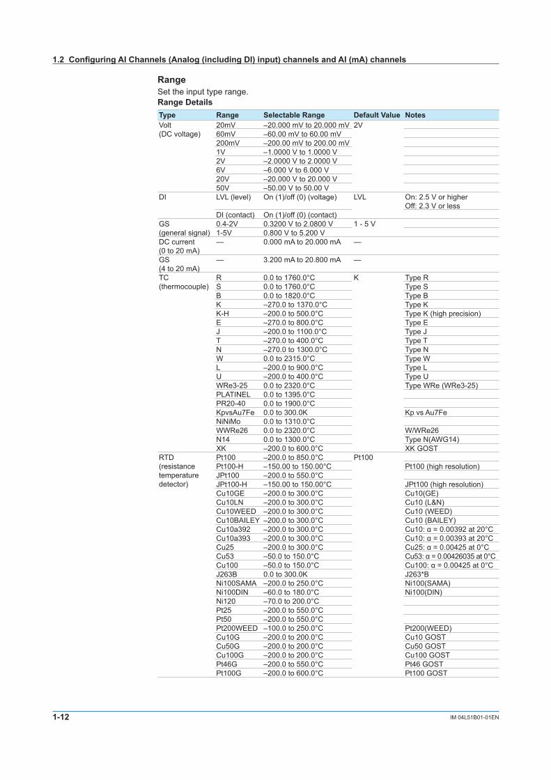
1-12 IM 04L51B01-01EN
RangeSet the input type range.Range DetailsType Range Selectable Range Default Value NotesVolt(DC voltage)
20mV –20.000 mV to 20.000 mV 2V60mV –60.00 mV to 60.00 mV200mV –200.00 mV to 200.00 mV1V –1.0000 V to 1.0000 V2V –2.0000 V to 2.0000 V6V –6.000 V to 6.000 V20V –20.000 V to 20.000 V50V –50.00 V to 50.00 V
DI LVL (level) On (1)/off (0) (voltage) LVL On: 2.5 V or higherOff: 2.3 V or less
DI (contact) On (1)/off (0) (contact)GS(general signal)
0.4-2V 0.3200 V to 2.0800 V 1 - 5 V1-5V 0.800 V to 5.200 V
DC current(0 to 20 mA)
— 0.000 mA to 20.000 mA —
GS(4 to 20 mA)
— 3.200 mA to 20.800 mA —
TC (thermocouple)
R 0.0 to 1760.0°C K Type RS 0.0 to 1760.0°C Type SB 0.0 to 1820.0°C Type BK –270.0 to 1370.0°C Type KK-H –200.0 to 500.0°C Type K (high precision)E –270.0 to 800.0°C Type EJ –200.0 to 1100.0°C Type JT –270.0 to 400.0°C Type TN –270.0 to 1300.0°C Type NW 0.0 to 2315.0°C Type WL –200.0 to 900.0°C Type LU –200.0 to 400.0°C Type UWRe3-25 0.0 to 2320.0°C Type WRe (WRe3-25)PLATINEL 0.0 to 1395.0°CPR20-40 0.0 to 1900.0°CKpvsAu7Fe 0.0 to 300.0K Kp vs Au7FeNiNiMo 0.0 to 1310.0°CWWRe26 0.0 to 2320.0°C W/WRe26N14 0.0 to 1300.0°C Type N(AWG14)XK –200.0 to 600.0°C XK GOST
RTD(resistance temperature detector)
Pt100 –200.0 to 850.0°C Pt100Pt100-H –150.00 to 150.00°C Pt100 (high resolution)JPt100 –200.0 to 550.0°CJPt100-H –150.00 to 150.00°C JPt100 (high resolution)Cu10GE –200.0 to 300.0°C Cu10(GE)Cu10LN –200.0 to 300.0°C Cu10 (L&N)Cu10WEED –200.0 to 300.0°C Cu10 (WEED)Cu10BAILEY –200.0 to 300.0°C Cu10 (BAILEY)Cu10a392 –200.0 to 300.0°C Cu10:α=0.00392at20°CCu10a393 –200.0 to 300.0°C Cu10:α=0.00393at20°CCu25 –200.0 to 300.0°C Cu25:α=0.00425at0°CCu53 –50.0 to 150.0°C Cu53:α=0.00426035at0°CCu100 –50.0 to 150.0°C Cu100:α=0.00425at0°CJ263B 0.0 to 300.0K J263*BNi100SAMA –200.0 to 250.0°C Ni100(SAMA)Ni100DIN –60.0 to 180.0°C Ni100(DIN)Ni120 –70.0 to 200.0°CPt25 –200.0 to 550.0°CPt50 –200.0 to 550.0°CPt200WEED –100.0 to 250.0°C Pt200(WEED)Cu10G –200.0 to 200.0°C Cu10 GOSTCu50G –200.0 to 200.0°C Cu50 GOSTCu100G –200.0 to 200.0°C Cu100 GOSTPt46G –200.0 to 550.0°C Pt46 GOSTPt100G –200.0 to 600.0°C Pt100 GOST
1.2ConfiguringAIChannels(Analog(includingDI)input)channelsandAI(mA)channels

1-13IM 04L51B01-01EN
Configuring the G
X/GP
1
2
3
4
5
App
Index
SpanLower,Span UpperSet the input range. The selectable range varies depending on the range setting.For the selectable ranges, see “Range Details.”
Note• YoucannotsetthesamevaluetoSpanLower and Span Upper.
CalculationWhen performing input calculation, set the calculation type.
• Linear scaling Converts the unit to obtain the measured value.
Input value Measured value
10 V
0 V
300°C
–100°C
• Delta Difference calculation. The measured value of the channel is set to the difference with
respect to the measured value of the reference channel.
Input value Measured value
Measured value on the reference channel
—
NoteDifference calculation is executed even if the input type or range is not the same between the difference calculation channel and the reference channel.Differences in the decimal place is considered but the difference in the unit is ignored in the calculation. Then, the decimal place and the unit of the difference calculation channel are applied.Example 1: If the input value of the difference calculation channel is 10.00 and the measured value
ofthereferencechannelis100.0,thecalculatedresultis10.00–100.0=–90.00.Example 2: If the input value of the difference calculation channel is 10.00 V and the measured
valueofthereferencechannelis5.00mV,thecomputedresultis10.00V–5.00mV=5.00 V.
• Square Root Takes the square root of the input value and converts the unit to obtain the measured
value. In a differential pressure flowmeter, the output signal is proportional to the square of the
flow rate. Therefore, to measure on a recorder, square rooting is required.
Input value Measured valuea
b
x
a b
B
B
X
A
AX = (B – A) + A
x – a
b – a
Reference channelSet the reference channel for the difference calculation.
1.2ConfiguringAIChannels(Analog(includingDI)input)channelsandAI(mA)channels
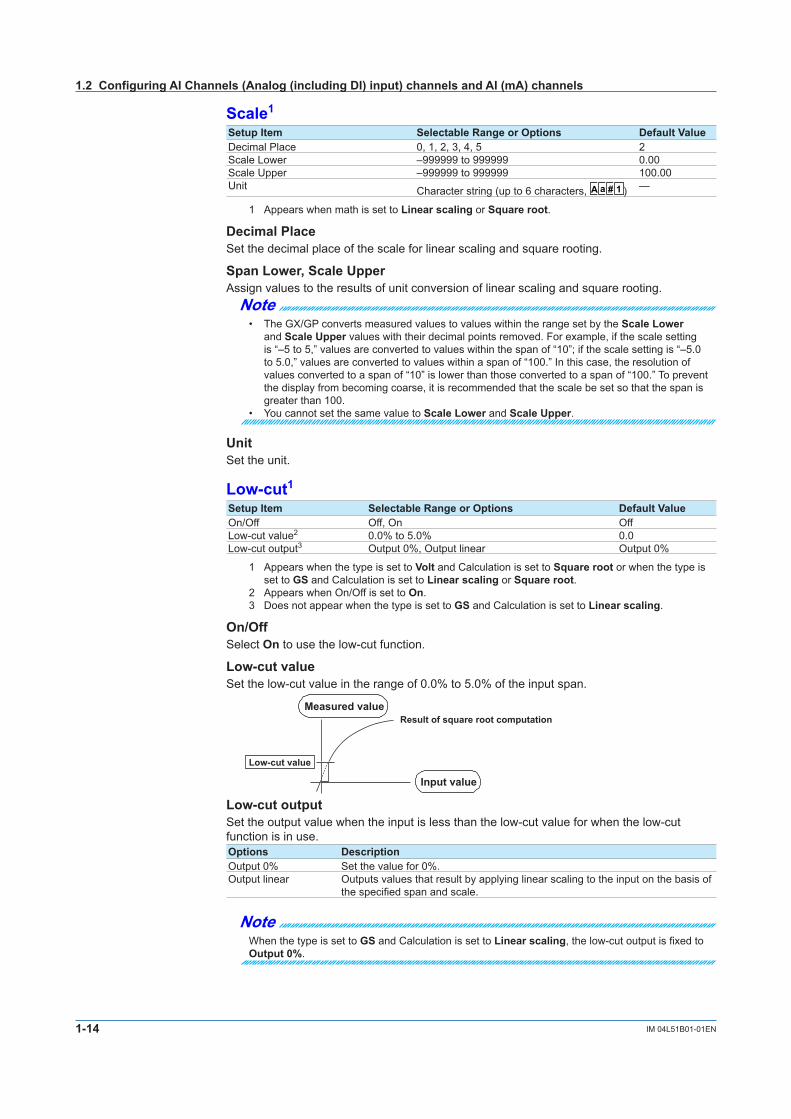
1-14 IM 04L51B01-01EN
Scale1
Setup Item Selectable Range or Options Default ValueDecimal Place 0, 1, 2, 3, 4, 5 2Scale Lower –999999 to 999999 0.00Scale Upper –999999 to 999999 100.00Unit Character string (up to 6 characters, A a # 1 ) —
1 Appears when math is set to Linear scaling or Square root.
Decimal PlaceSet the decimal place of the scale for linear scaling and square rooting.
SpanLower,Scale UpperAssign values to the results of unit conversion of linear scaling and square rooting.
Note• TheGX/GPconvertsmeasuredvaluestovalueswithintherangesetbytheScaleLower
and Scale Upper values with their decimal points removed. For example, if the scale setting is “–5 to 5,” values are converted to values within the span of “10”; if the scale setting is “–5.0 to 5.0,” values are converted to values within a span of “100.” In this case, the resolution of values converted to a span of “10” is lower than those converted to a span of “100.” To prevent the display from becoming coarse, it is recommended that the scale be set so that the span is greater than 100.
• YoucannotsetthesamevaluetoScaleLower and Scale Upper.
UnitSet the unit.
Low-cut1Setup Item Selectable Range or Options Default ValueOn/Off Off, On OffLow-cut value2 0.0% to 5.0% 0.0Low-cut output3 Output 0%, Output linear Output 0%
1 Appears when the type is set to Volt and Calculation is set to Square root or when the type is set to GS and Calculation is set to Linear scaling or Square root.
2 Appears when On/Off is set to On.3 Does not appear when the type is set to GS and Calculation is set to Linear scaling.
On/OffSelect On to use the low-cut function.
Low-cutvalueSet the low-cut value in the range of 0.0% to 5.0% of the input span.
Input value
Measured valueResult of square root computation
Low-cut value
Low-cutoutputSet the output value when the input is less than the low-cut value for when the low-cut function is in use.Options DescriptionOutput 0% Set the value for 0%.Output linear Outputs values that result by applying linear scaling to the input on the basis of
the specified span and scale.
NoteWhen the type is set to GS and Calculation is set to Linear scaling, the low-cut output is fixed to Output 0%.
1.2ConfiguringAIChannels(Analog(includingDI)input)channelsandAI(mA)channels

1-15IM 04L51B01-01EN
Configuring the G
X/GP
1
2
3
4
5
App
Index
Moving averageSetup Item Selectable Range or Options Default ValueOn/Off Off, On OffCount1 2 to 100 2
1 Appears when On/Off is set to On.
On/OffSet this to On to perform moving average.
CountSet the number of data points to take the moving average of.
Average
Scan interval
Sampling count
Average
RJC1, 3(Referencejunctioncompensation)Setup Item Selectable Range or Options Default ValueMode Internal/External InternalTemperature2 –20.0 to 80.0°C, 253.1 to 353.2K (KpvsAu7Fe) (when the
measurement range is in Fahrenheit: –4.0 to 176.0, 253.1 to 353.2K)
0.0°C,273.2K (KpvsAu7Fe)
1 Appears when the range type is set to TC.2 Appears when the mode is set to External.3 Does not appear for AI (mA) channels.
ModeSetthereferencejunctioncompensationmethodofthethermocouple.Options DescriptionInternal UsesthereferencejunctioncompensationfunctionoftheGX/GP.External Usesanexternalreferencejunctioncompensationfunction.
External reference junction
Internal reference junction
GX/GP
Thermocouple
Thermocouple
TemperatureWhen the RJC is set to external, set the compensation temperature.
1.2ConfiguringAIChannels(Analog(includingDI)input)channelsandAI(mA)channels

1-16 IM 04L51B01-01EN
Burnout set1
Setup Item Selectable Range or Options Default ValueMode Off, Up, Down Off
1 Appears when the range type is set to GS, GS(4-20mA), TC, or RTD.
ModeWhen the range type is set to TC, GS, GS(4-20mA), or RTD, the GX/GP detects sensor burnouts.Options DescriptionOff Does not detect burnouts in the sensor.Up When the sensor burns out, the measured result is set to +over range. The measured
value is displayed as “Burnout.”When the input type is set to GS or GS(4-20mA), the GX/GP assumes that the sensor has burned out when the measured value moves out of the range defined by the upper and lower limits of burnout specified on the specified span width. (Example: If the lower limit of burnout is set to -10% and the upper limit to 110%, when the measured value is less than –10 or greater than 110 when the scale is set to 0 to 100 in linear scaling)
Down When the sensor burns out, the measured result is set to –over range. The measured value is displayed as “Burnout.”When the input type is set to GS or GS(4-20mA), the GX/GP assumes that the sensor has burned out when the measured value moves out of the range defined by the upper and lower limits of burnout specified on the specified span width. (Example: If the lower limit of burnout is set to -10% and the upper limit to 110%, when the measured value is less than –10 or greater than 110 when the scale is set to 0 to 100 in linear scaling)
For details on setting the upper and lower limits of burnout, see page 1-79 in section 1.7.5, “Setting the Burnout Criteria (Release number 2 and later)”.
Thermocouple Examples
Burnout
Burnout
1 - 5 V
Detected on the 1-5 V valueIndicated as Burnout
Indicated as BurnoutThermoelectromotive force
Bias1
Setup Item Selectable Range or Options Default ValueValue Numeric value (–999999 to 999999) 0
1 Does not appear if the range is set to DI.
ValueSet the bias to add to input values or linear scaling values (input calculation).
Input value Measured value
Bias (a constant value)
+
Channel on which bias is added
1.2ConfiguringAIChannels(Analog(includingDI)input)channelsandAI(mA)channels

1-17IM 04L51B01-01EN
Configuring the G
X/GP
1
2
3
4
5
App
Index
1.2.2 Setting Alarms
PathGX/GP: MENU key > Browse tab > Setting > Setting menu AI channel settings or AI(mA)
channel settings > AlarmWeb browser: Setting tab > AI channel settings or AI(mA)channelsettings > Channel
range (display example: 0001-0010) > AlarmHardware configurator: AI channel settings or AI(mA)channelsettings > Channel range
(display example: 0001-0010) > Alarm
DescriptionSetup Item Selectable Range or Options Default ValueFirst-CH AI channel —Last-CH AI channel —
First-CH, Last-CHSet the target channels. The channels that you can specify appear depending on the module configuration.
Level 1, Level 2, Level 3, Level 4Setup Item Selectable Range or Options Default ValueOn/Off Off, On OffType1 H: High limit, L: Low limit, R: High limit on rate-of-
change, r: Low limit on rate-of-change, T: Delay high limit, t: Delay low limit,h: Difference high limit,2 l: Difference low limit2
H: High limit
Value1 Within the setting range 0Hysteresis1, 4 Numeric value
When Calculation is set to Off or Delta: 0 to 5% of range settingWhen math is set to Linear scaling or Square root: 0 to 100000
5
Logging1 Off, On OnOutput type1 Off, Relay5, Internal switch6 OffOutput No.3 DO channel or internal switch —
1 Appears when Level (1 to 4) is set to On.2 Appears when Calculation of the range setting is set to Delta.3 Appears when Output type is not set to Off.4 Appears when Type is set to high limit, low limit, difference high limit, or difference low limit.5 Appears when the range type of any of the DO channels is set to Alarm.6 Appears when any of the internal switch type is set to Alarm.
On/OffTo use an alarm level (1 to 4), set this to On.
1.2ConfiguringAIChannels(Analog(includingDI)input)channelsandAI(mA)channels

1-18 IM 04L51B01-01EN
TypeSet the alarm type.Options DescriptionH: High limit An alarm is activated when the measured value is greater than or equal to the
alarm value.L: Low limit An alarm is activated when the measured value is less than or equal to the
alarm value.R: High limit on rate-of-change
An alarm is activated if the increasing rate-of-change of measured values over a certain interval is greater than or equal to the specified value.
r: Low limit on rate-of-change
An alarm is activated if the decreasing rate-of-change of measured values over a certain interval is greater than or equal to the specified value.
T: Delay high limit An alarm is activated if measured values remain greater than or equal to the alarm value for a specified time period (delay period).
t: Delay low limit An alarm is activated if measured values remain less than or equal to the alarm value for a specified time period (delay period).
h: Difference high limit An alarm is activated when the difference in the measured values of two channels is greater than or equal to the specified value. This alarm can be specified on measurement channels set to difference calculation.
l: Difference low limit An alarm is activated when the difference in the measured values of two channels is less than or equal to the specified value. This alarm can be specified on measurement channels set to difference calculation.
Alarms of channels set to difference calculation are set in the position shown in the figure below.
Input value
Measured value on the reference channel
H, L, T, t, R, r h, l
Measured value—
ValueSet the alarm value for the specified alarm type.
Options Value ExamplesofAlarmValueRangeH, L A value within the measurable range –2.0000 to 2.0000 V for 2 V range
–270.0 to 1370.0°C for thermocouple type KR, r 1 digit to the upper limit of the width of the
measurable range0.0001 to 4.0000 V for 2 V range0.1 to 1640.0°C for thermocouple type K
T, t Same as H and L Same as H and L
When the Channel Calculation Is Set to DeltaOptions Value ExamplesofAlarmValueRangeH, L A value within the measurable range –2.0000 to 2.0000 V for 2 V range
–270.0 to 1370.0°C for thermocouple type Kh, l A value within the measurable range –4.0000 to 4.0000 V for 2 V range
–1640.0 to 1640.0°C for thermocouple type KR, r 1 digit to the upper limit of the width of the
measurable range0.0001 to 4.0000 V for 2 V range0.1 to 1640.0°C for thermocouple type K
T, t Same as H and L Same as H and L
When the Channel Calculation Is Set to Linear Scaling or Square RootOptions Value ExamplesofAlarmValueRangeH, L –5% to 105% of the scale width However,
within –999999 to 999999 excluding the decimal point.
–5.0 to 105.0 when the scale is 0.0 to 100.0–120.00 to 320.00 when the scale is –100.00 to 300.00
R, r 1 to the scale width but within 1 to 999999 excluding the decimal point.
0.1 to 100.0 when the scale is 0.0 to 100.00.01 to 400.00 when the scale is –100.00 to 300.0
T, t Same as H and L Same as H and L
1.2ConfiguringAIChannels(Analog(includingDI)input)channelsandAI(mA)channels

1-19IM 04L51B01-01EN
Configuring the G
X/GP
1
2
3
4
5
App
Index
HysteresisSet this to establish an offset between the value used to activate and release alarms.This is fixed at 0 for the DI range.
Example:H: If you set the alarm value of a high limit alarm to 1.0000 V and the hysteresis to 0.0005 V, an alarm is activated when the measured value is greater than or equal to 1.0000 V and is released when the measured value is less than 0.9995 V.
LoggingSet this On to display an alarm (notify you) when an alarm occurs. If set to Off, when an alarm occurs, the GX/GP outputs signals to alarm output DO channels or internal switches but does not display the alarm. Alarms are also not recorded in the alarm summary.
Output typeSet the alarm output destination.Alarm status can be output to the relay (DO channel) or internal switches (100 software switches). Internal switch values are shown below. Like the DO output relay, you can specify AND/OR operation.
AlarmAlarm occurrence
Alarm release
Internal switch1
0Internal switches can be used as events of the event action function (see page 1-110 in section 1.14, “Configuring the Event Action Function”). In addition, they can also be written in calculation expressions of math channels (/MT option).
Output No.Set the number of the relay (DO channel) or internal switch to output alarms to.
Alarm delay1
Setup Item Selectable Range or Options Default ValueHour 1 to 24 0Minute 0 to 59 0Second 0 to 59 10
1 Appears when Level 1, Level 2, Level 3, or Level 4 is On.
Hour, Minute, and SecondSet the alarm delay. These values are valid when the delay high limit or delay low limit is in use.
1.2 Configuring AI Channels (Analog (including DI) input) channels and AI (mA) channels

1-20 IM 04L51B01-01EN
ExplanationAlarm TypeThe character inside the parentheses is the symbol denoting each alarm.
High Limit Alarm (H)
Alarm value
Alarm output ON
Alarm output ON
HysteresisMeasured value
Low Limit Alarm (L)
Alarm output ON
Alarm value
Measured value Hysteresis
Alarm output ON
Delay period
Alarm value
Measured valueDelay High Limit Alarm (T) Delay Low Limit Alarm (t)
Alarm output ON
Delay period
Alarm valueMeasured value
High Limit on Rate-of-Change Alarm (R) Low Limit on Rate-of-Change Alarm (r)
Alarm value
HysteresisDifference in the measured values of two channels
Difference High Limit Alarm (h) Difference Low Limit Alarm (l)
Alarm output ON
Alarm value
HysteresisDifference in the measured values of two channels
Change in the measured value
Measured value
TimeInterval (t2 – t1)
T2
T1
t1 t2 Change in the measured value
Measured value
TimeInterval (t2 – t1)
Amount of change in the setting| |
T2
T1
t1 t2
T1 – T2
Amount of change in the setting| |T1 – T2
HighLimitAlarmandLowLimitAlarmAn alarm is activated when the measured value is greater or less than or equal to the alarm value.
DelayHighLimitAlarmandDelayLowLimitAlarmAn alarm is activated if measured values remain greater or less than or equal to the alarm value for a specified time period (delay period).
HighLimitonRate-of-ChangeAlarmandLowLimitonRate-of-ChangeAlarmAn alarm is activated if the increasing or decreasing rate-of-change of measured values over a certain interval is greater than or equal to the specified value.The alarm value of an rate-of-change alarm is set using an absolute value. The interval is derived using the following equation and set using the number of samples.Interval=thescaninterval×thenumberofsamples
For the number of samples, see page 1-147 in section 1.18.2, “Setting the Interval for Calculating the Rate-of-Change for Rate-of-Change Alarms”.
DifferenceHighLimitAlarmandDifferenceLowLimitAlarmAn alarm is activated when the difference in the measured values of two channels is greater or less than or equal to the specified value.This alarm can be specified on measurement channels set to difference calculation.
1.2ConfiguringAIChannels(Analog(includingDI)input)channelsandAI(mA)channels

1-21IM 04L51B01-01EN
Configuring the G
X/GP
1
2
3
4
5
App
Index
1.2.3 Setting the Display
PathGX/GP: MENU key > Browse tab > Setting > Setting menu AI channel settings or AI(mA)
channel settings > Display settingsWeb browser: Setting tab > AI channel settings or AI(mA)channelsettings > Channel
range (display example: 0001-0010) > Display settingsHardware configurator: AI channel settings or AI(mA)channelsettings > Channel range
(display example: 0001-0010) > Alarm > Display settings
DescriptionSetup Item Selectable Range or Options Default ValueFirst-CH AI channel —Last-CH AI channel —
First-CH, Last-CHSet the target channels. The channels that you can specify appear depending on the module configuration.
TagSetup Item Selectable Range or Options Default ValueCharacters Character string (up to 32 characters, A a # 1 ) —
No. Character string (up to 16 characters, A a # 1 ) —
CharactersSet the tag.Not all characters may be displayed due to space constraints.
No.Set the tag number.
Precedence in Displaying Characters and Numbers Tag numbers are displayed with higher precedence than tag characters. When tag numbers are not assigned, tag characters are displayed. If neither the tag numbers nor tag characters are assigned, channel numbers are
displayed.
ColorSetup Item Selectable Range or Options Default ValueColor 24 colors (red, green, blue, blue violet, brown, orange,
yellow-green, light blue, violet, gray, lime, cyan, dark blue, yellow, light gray, purple, black, pink, light brown, light green, dark gray, olive, dark cyan, and spring green) and a user-defined color (1 color)
—
ColorSet channel display colors. The colors apply to the trend display and bar graph display.
1.2ConfiguringAIChannels(Analog(includingDI)input)channelsandAI(mA)channels

1-22 IM 04L51B01-01EN
Setting the User-Defined Color
1 Tap Color.The setup screen appears.
2 Tap Advanced setting.Setup keys appear in the right area.
Advanced settings
Color settings
Select the color to set (R, G, or B).
Recently used colors
Color set in the user-defined color
3 Select R, G, B one at a time, and set each value using the numeric keypad or the bars.
4 Tap OK.Theuser-definedcolorisset.
The color that you created is registered under Recently used color (up to 10 colors). You can select a color from here.
Operation complete
ZoneSetup Item Selectable Range or Options Default ValueLower 0 to 95% 0Upper 5 to 100% 100
LowerandUpperSet these values when you want to divide the waveform displays of channels into separate zones so that waveforms do not overlap. Set the Lower and Upper positions as percentages of the maximum display width. Set Lower to a value less than Upper, and set the zone width (Upper – Lower) to be 5% or greater.
Example:Set the channel 1 zone to 0 to 30%, the channel 2 zone to 30 to 60%, and the channel 3 zone to 60 to 100%.
Zone 2
Zone 1
Zone 3
100%
Time axis
30%
60%
100%
0%0%Time axis
When zone display is not used When zone display is used
CH3
CH2
CH1
1.2ConfiguringAIChannels(Analog(includingDI)input)channelsandAI(mA)channels

1-23IM 04L51B01-01EN
Configuring the G
X/GP
1
2
3
4
5
App
Index
ScaleSetup Item Selectable Range or Options Default ValuePosition GX20/GP20: Off, 1, 2, 3, 4, 5, 6, 7, 8, 9, 10
GX10/GP10: Off, 1, 2, 3, 4, 5, 61
Division 4, 5, 6, 7, 8, 9, 10, 11, 12, C10 10
PositionSet the scale display positions when you want to display multiple scales on the trend display. Set this to Off to not display scales.
DivisionSet the number of divisions to make with the main scale marks.C10: The scale is equally divided into 10 sections by main scale marks, and scale values are indicated at 0, 30, 50, 70, and 100% positions.
The figure below is an example in which each scale is displayed with the position shifted.
Horizontal Trend Display
Number of scale divisions: 4Number of scale divisions: 5Number of scale divisions: 6Number of scale divisions: 7Number of scale divisions: 8Number of scale divisions: 9Number of scale divisions: 10Number of scale divisions: 11Number of scale divisions: 12Number of scale divisions: C10
Scale position
12345678910
1.2ConfiguringAIChannels(Analog(includingDI)input)channelsandAI(mA)channels

1-24 IM 04L51B01-01EN
Vertical Trend Display
Scale position
Number of scale divisions: 4Number of scale divisions: 5Number of scale divisions: 6Number of scale divisions: 7Number of scale divisions: 8Number of scale divisions: 9Number of scale divisions: 10Number of scale divisions: 11Number of scale divisions: 12Number of scale divisions: C10
123456789
10
Note• Ifthescalesofmultiplechannelsaresettothesameposition,thescaleofthechannelassigned
first to the group is displayed. Example: If the order of assignment of a group is 0003.0002.0001, and the scale display
position of all channels is set to 1, the scale of channel 3 is displayed at display position 1.• Evenifsomeofthescaledisplaypositionsareskipped,thescaleispackedtowardsdisplay
position 1. Example: Suppose the assignment of channels to a group is 0001.0002.0003, and the display
positions of the scales are set to 1, 3, and 6, respectively. The scales are actually displayed at positions 1, 2, and 3, respectively.
• Thescaleisdividedinto4to12sectionsbythemainscalemarks.Thesectionbetweenthe main scale marks is divided into 5 or 10 subsections by medium and small scale marks. However, small scale marks are not displayed in the following cases.• Whentheresolutionoftheinputrangeissmallerthanthetotalnumberofsmallscalemarks.• Whenzonedisplayisused.• Whenpartialexpandeddisplayisused(numbersaredisplayedattheendsofthescaleand
at the boundary position).• Thescalevaluesaredisplayedaccordingtothefollowingrules.
• Ifthenumberofscaledivisionsis4to7fortheverticaltrenddisplay,valuesaredisplayedatall main scale marks. If the number of scale divisions is 8 to 12, the values are displayed at every other main scale marks.
• Scaleupperandlowerlimitsaredisplayedattheendsofthescale.• Scalevaluesaredisplayeduptothreedigitsexcludingtheminussign.However,ifthe
integer part of values at the ends of the scale is both one digit or the integer part is zero, two digits are displayed.
Example: If the scale is –0.05 to 0.50, the lower limit is “–0.0” and the upper limit is “0.5.”• Iftheintegerpartofeitherendofthescaleistwoorthreedigits,thefractionalpartis
truncated. Example: If the scale is 0.1 to 100.0, the lower limit is “0” and the upper limit is “100.”• Iftheintegerpartofeitherendofthescaleisfourormoredigits,thevalueisdisplayedusing
athree-digitmantissaandexponentlike“×10”or“×102”. Example:Ifthescaleis10to2000,thelowerlimitis“1”andtheupperlimitis“200×10”.
• Theunitisdisplayednearthelowerlimit.Ifpartialexpandeddisplayisused,itisdisplayednearthe boundary line. The number of characters that can be displayed is up to six.
1.2ConfiguringAIChannels(Analog(includingDI)input)channelsandAI(mA)channels

1-25IM 04L51B01-01EN
Configuring the G
X/GP
1
2
3
4
5
App
Index
Bar graphSetup Item Selectable Range or Options Default ValueBase position Lower, Center, Upper LowerDivision 4, 5, 6, 7, 8, 9, 10, 11, 12 10
Base positionSet the bar graph base position. Depending on the setting, the bar graph is displayed as follows. This setting is applied on the bar graph display and when you are displaying the current value on the scale as a bar graph on the trend displays.
When the Display Direction of the Bar Graph Is VerticalThe span lower limit (or scale lower limit) is at the bottom edge of the bar graph, and the span upper limit (or scale upper limit) is at the top edge of the bar graph.Starting point of the bar Center: Center Lower: Bottom edge Upper: Top edge
Vupper: Span upper limit (or scale upper limit)Vlower: Span lower limit (or scale lower limit) : Starting point of the bar
Center
–100.0
0.0
Lower
–100.0
0.0
Upper
–100.0
0.0
Example: When the span lower and upper limits of the input range are 0.0 and –100.0, respectively
Center Lower Upper
Vlower Vlower
Vupper
Vlower
VupperVupper
1.2ConfiguringAIChannels(Analog(includingDI)input)channelsandAI(mA)channels

1-26 IM 04L51B01-01EN
When the Display Direction of the Bar Graph Is HorizontalThe span lower limit (or scale lower limit) is at the left edge of the bar graph, and the span upper limit (or scale upper limit) is at the right edge of the bar graph.
Starting point of the bar Center: Center Lower: Left edge Upper: Right edge
Upper
LowerVlower Vupper
Vlower Vupper
CenterVlower Vupper
Vupper: Span upper limit (or scale upper limit)Vlower: Span lower limit (or scale lower limit) : Starting point of the bar
Center
Upper
Lower
0.0 –100.0
0.0 –100.0
0.0 –100.0
Example: When the span lower and upper limits of the input range are 0.0 and –100.0, respectively
When Displaying the Current Value on the Scale Using the Bar Graph
Vlower VupperCenter Lower Upper
Vlower
Vupper Center
Upper
Lower
DivisionSet the number of divisions to make with the main scale marks.
1.2ConfiguringAIChannels(Analog(includingDI)input)channelsandAI(mA)channels

1-27IM 04L51B01-01EN
Configuring the G
X/GP
1
2
3
4
5
App
Index
Partial1Setup Item Selectable Range or Options Default ValueOn/Off Off, On OffExpand 1 to 99(%) 50%Boundary Span lower limit + 1 digit to span upper limit – 1 digit 0
1 Appears when in the Display settings of the setting menu, Partial On/Off is set to On.
On/OffSet this to On to enable partial expanded display of waveforms.
For details on this function, see page 1-71 in section 1.6.4, “Setting Trend Display Conditions”.
ExpandSet at which position to display the value specified by Boundary within the display width. Specify a percentage.
BoundarySet the value that is to be the boundary between the reduced section and the expanded section in the range of “minimum span value + 1 digit to maximum span value – 1 digit.” For channels that are set to scaling, the selectable range is “minimum scale value + 1 digit to maximum scale value – 1 digit.”
Example: Input range: –6 V to 6V. Expand: 30. Boundary: 0The –6 V to 0 V range is displayed in the 0% to 30% range, and the 0 V to 6 V range is displayed in the 30% to 100% range.
Color scale bandSetup Item Selectable Range or Options Default ValueBand area Off, In, Out OffColor 24 colors (red, green, blue, blue violet, brown, orange,
yellow-green, light blue, violet, gray, lime, cyan, dark blue, yellow, light gray, purple, black, pink, light brown, light green, dark gray, olive, dark cyan, and spring green) and a user-defined color (1 color)
—
Display position Lower Span (scale) lower limit to span (scale) upper limit 0Display position Upper Span (scale) lower limit to span (scale) upper limit 100
Band areaDisplays a specified section of the measurement range using a color band on the scale. This setting is shared with the bar graph display.Options DescriptionOff Disables the function.In Displays the area inside using the color band.Out Displays the area outside using the color band.
ColorSet the display color.
For instructions on how to set the user-defined color, see page 1-21 in section 1.2.3, “Setting the Display”.
1.2ConfiguringAIChannels(Analog(includingDI)input)channelsandAI(mA)channels

1-28 IM 04L51B01-01EN
Display position Lower and Display position UpperSet the display position. Set a value within the span or scale range.
Color scale band (out)
Color scale band (in)
Display position Lower
Display position Upper
Alarm point markSetup Item Selectable Range or Options Default ValueIndicate on Scale Off, On OnMark kind Alarm, Fixed AlarmAlarm 1 color to Alarm 4 color1
24 colors (red, green, blue, blue violet, brown, orange, yellow-green, light blue, violet, gray, lime, cyan, dark blue, yellow, light gray, purple, black, pink, light brown, light green, dark gray, olive, dark cyan, and spring green) and a user-defined color (1 color)
—
1 Appears when the Mark kind is set to Fixed.
Indicate on ScaleSet this to On to display alarm point marks on the scale. Set this to Off to not display them. This setting is shared with the bar graph display.
Mark kindOptions Description Mark ShapeAlarm Displayed normally in green. Displayed in the specified color
when an alarm occurs. or
Fixed Displayed with a fixed color.
Alarm 1 color to Alarm 4 colorWhen Mark kind is set to Fixed, set the display colors of point marks for alarm levels 1 to 4.
Alarm point mark (alarm)
Alarm point mark (fixed)
1.2 Configuring AI Channels (Analog (including DI) input) channels and AI (mA) channels

1-29IM 04L51B01-01EN
Configuring the G
X/GP
1
2
3
4
5
App
Index
Display characters of each value1
Setup Item Selectable Range or Options Default Value0 Character string (up to 8 characters, A a # 1 ) —
1 Character string (up to 8 characters, A a # 1 ) —
1 Appears when in the range settings, type is set to DI and Calculation is set to Off.
0Set the character string to display when the measured value is 0.
1Set the character string to display when the measured value is 1.
ExamplesofdisplaycharactersofeachvalueReceive a device operation status through DI input and display measured values (0 and 1) as “Running” and “Stopped.”You can select whether to display measured values (0 or 1) or characters.
See page 2-9 in section 2.2.1, “Displaying Measured Data Using Waveforms, Numeric Values, Bar Graph, or Custom Display (/CG option) (Trend, digital, bar graph, and custom displays)”
Running Stopped01
1.2ConfiguringAIChannels(Analog(includingDI)input)channelsandAI(mA)channels

1-30 IM 04L51B01-01EN
ExplanationCommon Display Items
Screen ConfigurationThe screen consists of the status display section and the data display section.
Status display section
Data display section
• StatusDisplaySection The status display section shows the display name, date/time, batch name (when using
the batch function), user name (when using the login function), usage of the internal memory or SD memory card, alarm occurrence, computation status (/MT option), and usage of operation lock or e-mail transmission.
• DataDisplaySection The data display section shows the measured data using waveforms, numeric values,
and bar graphs.
Group DisplayOn the trend, digital, and bar graph displays, the data of channels is displayed in groups that are set in advance.Groups are shared among the trend, digital, and bar graph displays.The displayed group can be switched automatically at a specified time interval (5 s to 1 min).
Number of Groups That Can Be RegisteredGX20-1/GP20-1: 50 groupsGX20-2/GP20-2: 60 groupsGX10/GP10: 30 groups
Number of Channels That Can Be Assigned to a GroupGX20/GP20: Up to 20GX10/GP10: Up to 10
Update Interval of Measured ValuesValues are updated every 0.5 seconds. However, if the scan interval is greater than 1 s, values are updated at the scan interval.
Alarm IndicationAlarms that are set for each channel are checked at all times and are indicated with the symbol representing the alarm type on each display.Alarm Type Symbol Alarm Type SymbolHigh limit alarm H High limit on rate-of-change alarm RLow limit alarm L Low limit on rate-of-change alarm rDifference high limit alarm h Delay high limit alarm TDifference low limit alarm l (lowercase L) Delay low limit alarm t
1.2ConfiguringAIChannels(Analog(includingDI)input)channelsandAI(mA)channels

1-31IM 04L51B01-01EN
Configuring the G
X/GP
1
2
3
4
5
App
Index
Status Display SectionThe status display section shows the following information.
Recording stopped
Recording in progress
Alarm icon
E-mail transmission is enabled.
Operation lock is enabled.
Date and time
When using the batch function
Math icon (/MT option)
SD memory card icon
When using the login function
Data typeDISP: Display dataEVENT: Event data
Recording progress
Error in internal memory. Contact your YOKOGAWA dealer for repairs.
Displays the remaining recording time for the left bar graph.Recording status icon
Display name or group name
When using the login and batch functions
Displays the progress using a green bar graph. The frameindicates the file save interval (display data)or the data length (event data).
Status iconThe condition assigned to instrument information output is occurring.
Displayed when any alarm is activated.
Blinks when there are alarms that are occurring but have not been acknowledged.All alarms have been released after they have occurred, but there are alarms that have not been acknowledged.
Gray icon: Computation started
Yellow icon: Computation data dropout occurred
Remaining memory space 50% or less
Remaining memory space 10% or less
Rremaining memory space 50% or more
External memory error
A user has been invalidated (for the /AS option).** When all administrators have been invalidated:
Bar GraphIf pre-trigger is specified for event data recording, the GX/GP will start recording pre-trigger data when recording is started and the GX/GP enters the trigger-wait state. “Waiting” appears in the bar graph. At this time, the progress bar turns orange.When the pre-trigger time elapses, the length of the bar is fixed at that point. However, the pre-trigger data is continuously updated in the background until the trigger condition is met. When the trigger condition is met, the bar turns green, and data is recorded after the data in the pre-trigger section.
1.2ConfiguringAIChannels(Analog(includingDI)input)channelsandAI(mA)channels

1-32 IM 04L51B01-01EN
TrendDisplay(T-Y)Measured data is displayed in a waveform.
Numeric display section
Trip lines (up to four lines)Waveform (displayed using the channel display color)
Message
Current value mark
Trend interval
Time at the grid position
Tag or channel number, measured value, and unit
Scale
Alarm point mark
Color scale band
• AlarmIndication Alarm mark, alarm type, and measured value are displayed as follows depending on the
alarm status. They are shared with the digital and bar graph displays.
AlarmRelease
Blinkingred,brown
Blinkinggray
Blinkingred,brownNone Red RedNone None None None None
Alarm ACK Alarm ACKOccurrence
When indication is set to non-hold
When indication is set to hold
Alarm mark(type)
Red Black RedBlack Red RedBlack Black Black Black BlackMeasured value
Blinking red,brown
Blinking gray
Blinking red,brown
None Red RedNone None NoneNone NoneAlarm icon
Digital DisplayThe digital display shows measured data using large numbers.
Unit
Alarm mark
Channel number, tag, or tag No.
Measured value
1.2ConfiguringAIChannels(Analog(includingDI)input)channelsandAI(mA)channels

1-33IM 04L51B01-01EN
Configuring the G
X/GP
1
2
3
4
5
App
Index
Note• Numericdisplayofanaloginputchannels If a measured value of an analog input channel is over range (see below), the measured
value is indicated as “+Over” or “–Over.” If a burnout is detected on a channel whose burnout detection function is enabled, the word “Burnout” is indicated. For all other cases, a numeric value is displayed.
Over range of analog input channels • Anoverrangeoccurswhenthemeasuredvalueofananaloginputchannelexceeds±5%
of the measurable range. For example, the measurable range when the measurement range is 2 V is –2.000 to 2.000 V. If the measured value exceeds 2.200 V, +over range occurs; if the measured value falls below –2.200 V, –over range occurs.
• ForachannelusingLinearscalingorSquareroot,overrangeoccursifthemeasuredvaluefalls outside the –5% to 105% range of the specified span. You can also change the setting so that over range occurs when the measured value falls outside the –5% to 105% range of the measurable span range. However, +over range occurs if the value excluding the decimal point exceeds 999999 and –over range if it falls below –999999. Setup: See page 1-76 in section 1.7.2, “Setting the Over-range Detection Method”.
Bar Graph DisplayMeasured data is displayed in a bar graph.
Vertical
Channel number, tag, or tag No.Alarm mark
Alarm point mark
Bar graph (displayed using the channel display color)
Lower limit of span
Scale
Measured value
Upper limit of span
Unit
Horizontal
Bar graph base position is set to Lower.
Bar graph base position is set to Center.
Bar graph base position is set to Upper.
• BarGraphUpdating The bar graph is updated at the same interval as numeric values.
1.2ConfiguringAIChannels(Analog(includingDI)input)channelsandAI(mA)channels

1-34 IM 04L51B01-01EN
1.2.4 Setting CalibrationCorrection(Linearizer approximation, linearizerbias)
PathGX/GP: MENU key > Browse tab > Setting > Setting menu AI channel settings or AI(mA)
channel settings > Calibration correctionWeb browser: Setting tab > AI channel settings or AI(mA)channelsettings > Channel
range (display example: 0001-0010) > Calibration correctionHardware configurator: AI channel settings or AI(mA)channelsettings > Channel range
(display example: 0001-0010) > Calibration correction
DescriptionSetup Item Selectable Range or Options Default ValueFirst-CH AI channel —Last-CH AI channel —
First-CH, Last-CHSet the target channels. You can set consecutive channels whose range is set to the same value as the first channel.
ModeSetup Item Selectable Range or Options Default ValueMode Off, Linearizer Approximation, Linearizer Bias OffNumber of set points1 2 to 12 2
1 Appears when the mode is not set to Off.
ModeSet the correction mode when performing calibration correction.When the range is set to DI or Skip, the mode is fixed to Off.
Number of set pointsSet the number of points that make up the segments (including the start and end points).
1 to 121
Setup Item Selectable Range or Options Default ValueLinearizer input –999999 to 999999 —Linearizer output –999999 to 999999 —
Execution of the input measurement
— —
1 The number of displayed points varies depending on the number of set points.
Linearizer input, Linearizer outputEnter the value of the set point. For linearizer input, set a value that is greater than the previous value.
Selectable Range of Linearizer Input and Output Values• Channelsusinglinearscaling –999999 to 999999 (the decimal place is the same as that for the scale value)• Otherchannels Values inside parentheses are examples for the 2 V range.
Linearizer approximationSelectable range of linearizer input: Measurable range (–2.0000 to 2.0000 V)Selectable range of linearizer output: Display range (–2.2000 to 2.2000 V)
Linearizer biasSelectable range of linearizer input: Measurable range (–2.0000 to 2.0000 V)
Selectablerangeoflinearizeroutput:Measurementspanwidth±100%(–4.0000to4.0000 V)
1.2ConfiguringAIChannels(Analog(includingDI)input)channelsandAI(mA)channels

1-35IM 04L51B01-01EN
Configuring the G
X/GP
1
2
3
4
5
App
Index
ExecutionoftheInputMeasurement(Releasenumber2andlater)The linearizer input value is set to the current measured value.
ProcedureTapping Executionoftheinputmeasurement displays a confirmation screen.Tap OK to set the linearizer input value to the current measured value.
Measured value
Executes input measurement
Note• IfyouchangetheMode or Range setting, the calibration correction setting is set to Off.• CalibrationcorrectioncannotbespecifiedonchannelssettoSkip or DI.
ExplanationLinearizer ApproximationCorrects input values using characteristics specified with segments to derive output values.
Output value
Measured valueInput value
Number of setpoints: 2 to 12
( )
Linearizer BiasCorrects input values using bias values specified with segments to derive output values.
Input value
Number of setpoints: 2 to 12
Linearizer bias
After correction
Output value
Measured value( )
1.2ConfiguringAIChannels(Analog(includingDI)input)channelsandAI(mA)channels

1-36 IM 04L51B01-01EN
1.3 ConfiguringDIChannels(Digitalinputchannels)
Set the input range, alarm, and display conditions of DI channels (including the DI channels of DI/DO modules).To use the DI module as a remote control input, set the operation mode of the module to Remote. Refer to page 1-77 in section 1.7.3, “Setting the Operation Mode of a Module”.Set the remote control action using event action. Refer to page 1-110 in section 1.14, “Configuring the Event Action Function”.
1.3.1 Setting the Range
PathGX/GP: MENU key > Browse tab > Setting > Setting menu DI channel settings > RangeWeb browser: Setting tab > DI channel settings > Channel range (display example: 0501-
0516) > RangeHardware configurator: DI channel settings > Channel range (display example: 0501-0516)
> Range
DescriptionSetup Item Selectable Range or Options Default ValueFirst-CH DI channel —Last-CH DI channel —
First-CH, Last-CHSet the target channels. The channels that you can specify appear depending on the module configuration.
RangeSetup Item Selectable Range or Options Default ValueType Skip, DI DISpan Lower 0, 1
Delta: –1 to 10
Span Upper 0, 1Delta: –1 to 1
1
Calculation Off, Delta, Linear scaling OffReference channel1 Value (I/O channel) —
1 Appears when Calculation is set to Delta.
TypeSet the input type.Options DescriptionSkip Not measured.DI Displays contact input or voltage input signals by mapping them to 0% or 100% of the
display range.
SpanLower,SpanUpperSet the input range.
CalculationWhen performing input calculation, set the calculation type. You can set this when the range type is set to DI.
For details on the input calculation function, see page 1-11 in section 1.2.1, “Setting the Range”.
Reference channelSet the reference channel for the difference calculation.

1-37IM 04L51B01-01EN
Configuring the G
X/GP
1
2
3
4
5
App
Index
Scale1
Setup Item Selectable Range or Options Default ValueDecimal place 0, 1, 2, 3, 4, 5 2Scale Lower –999999 to 999999 0.00Scale Upper –999999 to 999999 100.00Unit Character string (up to 6 characters, A a # 1 ) —
1 Appears when Calculation is set to Linear scaling.
Decimal placeSet the decimal place of the scale for linear scaling.
ScaleLower,Scale UpperAssign values to the results of unit conversion of linear scaling.
UnitSet the unit.
1.3.2 Setting Alarms
PathGX/GP: MENU key > Browse tab > Setting > Setting menu DI channel settings > AlarmWeb browser: Setting tab > DI channel settings > Channel range (display example: 0501-
0516) > AlarmHardware configurator: DI channel settings > Channel range (display example: 0501-0516)
> Alarm
DescriptionSetup Item Selectable Range or Options Default ValueFirst-CH DI channel —Last-CH DI channel —
First-CH, Last-CHSet the target channels. The channels that you can specify appear depending on the module configuration.
Level 1, Level 2, Level 3, Level 4Setup Item Selectable Range or Options Default ValueOn/Off Off, On OffType1 H: High limit, L: Low limit, R: High limit on rate-of-
change, r: Low limit on rate-of-change, T: Delay high limit, t: Delay low limit, h: Difference high limit,2 l: Difference low limit2
Off
Value1 H, L, T, t: 0/1R, r: Fixed at 1h, l: –1, 0, 1
0
Hysteresis1, 4 0 (fixed) 0Logging1 Off, On OnOutput type1 Off, Relay, Internal switch OffOutput No.3 DO channel or internal switch number —
1 Appears when Level (1 to 4) is set to On.2 Appears when Calculation of the range setting is set to Delta.3 Appears when Output No. is not set to Off.4 Appears when the type is set to high limit, low limit, difference high limit, or difference low limit.
On/OffTo use an alarm level (1 to 4), set this to On.
1.3ConfiguringDIChannels(Digitalinputchannels)

1-38 IM 04L51B01-01EN
TypeSet the alarm type.
For details, see page 1-17 in section 1.2.2, “Setting Alarms”.
Alarms of channels set to difference calculation are set in the position shown in the figure below.
Input value
Measured value on the reference channel
H, L, T, t R, r, h, l
Measured value—
ValueSet the alarm value for the specified alarm type.
For details, see page 1-17 in section 1.2.2, “Setting Alarms”.
HysteresisFixed to 0.
LoggingSet this On to display an alarm (notify you) when an alarm occurs. If set to Off, when an alarm occurs, the GX/GP outputs signals to alarm output DO channels or internal switches but does not display the alarm. Alarms are also not recorded in the alarm summary.
Output typeSet the alarm output destination.
Output No.Set the number of the DO channel or internal switch to output alarms to.
Alarmdelay(fordelayhigh/lowlimitalarms)Setup Item Selectable Range or Options Default ValueHour 1 to 24 0Minute 0 to 59 0Second 0 to 59 10
Hour, Minute, and SecondSet the alarm delay. These values are valid when the delay high limit or delay low limit is in use.
1.3ConfiguringDIChannels(Digitalinputchannels)

1-39IM 04L51B01-01EN
Configuring the G
X/GP
1
2
3
4
5
App
Index
1.3.3 Setting the Display
PathGX/GP: MENU key > Browse tab > Setting > Setting menu DI channel settings > Display
settingsWeb browser: Setting tab > DI channel settings > Channel range (display example: 0501-
0516) > Display settingsHardware configurator: DI channel settings > Channel range (display example: 0501-0516)
> Display settings
DescriptionSetup Item Selectable Range or Options Default ValueFirst-CH DI channel —Last-CH DI channel —
First-CH, Last-CHSet the target channels. The channels that you can specify appear depending on the module configuration.
TagSetup Item Selectable Range or Options Default ValueCharacters Character string (up to 32 characters, A a # 1 ) —
No. Character string (up to 16 characters, A a # 1 ) —
CharactersSet the tag.Not all characters may be displayed due to space constraints.
No.Set the tag number.
ColorSetup Item Selectable Range or Options Default ValueColor 24 colors (red, green, blue, blue violet, brown,
orange, yellow-green, light blue, violet, gray, lime, cyan, dark blue, yellow, light gray, purple, black, pink, light brown, light green, dark gray, olive, dark cyan, and spring green) and a user-defined color (1 color)
—
ColorSet channel display colors. The colors apply to the trend display and bar graph display.
For instructions on how to set the user-defined color, see page 1-21 in section 1.2.3, “Setting the Display”.
ZoneSetup Item Selectable Range or Options Default ValueLower 0 to 95% 0Upper 5 to 100% 100
Lower,UpperSet these values when you want to divide the waveform displays of channels into separate zones so that waveforms do not overlap. Set the Lower and Upper positions as percentages of the maximum display width. Set Lower to a value less than Upper, and set the zone width (Upper – Lower) to be 5% or greater.
1.3ConfiguringDIChannels(Digitalinputchannels)

1-40 IM 04L51B01-01EN
ScaleSetup Item Selectable Range or Options Default ValuePosition GX20, GP20: Off, 1, 2, 3, 4, 5, 6, 7, 8, 9, 10
GX10, GP10: Off, 1, 2, 3, 4, 5, 61
PositionSet this to set the scale display position of the trend display. Set this to Off to not display scales.
For display examples, see the scale settings on page 1-21 in section 1.2.3, “Setting the Display”.
Bar graphSetup Item Selectable Range or Options Default ValueBase position Lower, Center, Upper Lower
Base positionSet the bar graph base position. This setting is applied on the bar graph display and when you are displaying the current value on the scale as a bar graph on the trend displays.
For display examples, see the bar graph settings on page 1-21 in section 1.2.3, “Setting the Display”.
Alarm point markSetup Item Selectable Range or Options Default ValueIndicate on Scale Off, On OnMark kind Alarm, Fixed AlarmAlarm 1 color to Alarm 4 color1 24 colors (red, green, blue, blue violet, brown,
orange, yellow-green, light blue, violet, gray, lime, cyan, dark blue, yellow, light gray, purple, black, pink, light brown, light green, dark gray, olive, dark cyan, and spring green) and a user-defined color (1 color)
—
1 Appears when the Mark kind is set to Fixed.
Indicate on ScaleSet this to On to display alarm point marks on the scale. Set this to Off to not display them. This setting is shared with the bar graph display.
Mark kindOptions Description Mark ShapeAlarm Displayed normally in green. Displayed in the specified color
when an alarm occurs. or
Fixed Displayed with a fixed color.
Alarm 1 color to Alarm 4 colorWhen Mark kind is set to Fixed, set the display colors of point marks for alarm levels 1 to 4.
1.3ConfiguringDIChannels(Digitalinputchannels)

1-41IM 04L51B01-01EN
Configuring the G
X/GP
1
2
3
4
5
App
Index
Display characters of each value1
Setup Item Selectable Range or Options Default Value0 Character string (up to 8 characters, A a # 1 ) —
1 Character string (up to 8 characters, A a # 1 ) —
1 Appears when Calculation is set to Off.
0Set the character string to display when the measured value is 0.
1Set the character string to display when the measured value is 1.
For usage examples, see page 1-21 in section 1.2.3, “Setting the Display”.
1.3ConfiguringDIChannels(Digitalinputchannels)

1-42 IM 04L51B01-01EN
1.4 ConfiguringDOChannels(Digitaloutputchannels)
Set the input range and display conditions of DO channels (including the DO channels of DI/DO modules).In addition to alarm output, DO output is possible through touch operation (manual operation).
1.4.1 Setting the Range
PathGX/GP: MENU key > Browse tab > Setting > Setting menu DO channel settings > RangeWeb browser: Setting tab > DO channel settings > Channel range (display example:
0701-0706) > RangeHardware configurator: DO channel settings > Channel range (display example: 0701-
0706) > Range
DescriptionSetup Item Selectable Range or Options Default ValueFirst-CH DO channel —Last-CH DO channel —
First-CH, Last-CHSet the target channels. The channels that you can specify appear depending on the module configuration.
RangeSetup Item Selectable Range or Options Default ValueType Alarm, Manual AlarmSpan Lower 0, 1 0Span Upper 0, 1 1Unit Character string (up to 6 characters, A a # 1 ) —
TypeSet the input type.To output through touch operation (manual operation), “Changing each value from monitoring” must be set to On. Refer to page 1-74 in section 1.6.5, “Setting Basic Screen Items”
For the procedure, see page 2-9 in section 2.2.1, “Displaying Measured Data Using Waveforms, Numeric Values, Bar Graph, or Custom Display (/CG option) (Trend, digital, bar graph, and custom displays)”.Options DescriptionAlarm Alarm outputManual Manual output and event action output
SpanLower,Span UpperSpecify 0 or 1. You cannot set the same value to Span Lower and Span Upper.
UnitSet the unit.

1-43IM 04L51B01-01EN
Configuring the G
X/GP
1
2
3
4
5
App
Index
ActionSetup Item Selectable Range or Options Default ValueEnergize/De-energize Energize, De-energize EnergizeAction1 And, Or, Reflash OrHold1, 2 Hold, Nonhold NonholdRelay action on ACK1 Normal, Reset NormalRelay deactivated interval1, 3 500 ms, 1 s, 2 s 500 ms
1 Does not appear when Type is set to Manual.2 Does not appear when Action is set to Reflash.3 Appears when Action is set to Reflash.
Energize/De-energizeSet whether to Energize or De-energize the DO output when an alarm occurs.
ActionOptions DescriptionAnd Activated when all assigned alarms are occurring simultaneously.Or Activated when any of the specified alarms is occurring.Reflash When multiple alarms are assigned to one alarm output relay, the GX/GP
notifies the occurrence of subsequent alarms after the relay is activated by the first alarm.
HoldSet the DO channel output operation.Options DescriptionHold Holds the output relay at ON until an alarm acknowledge operation is
performed.Nonhold Turns the output relay off when the alarm condition is released (returns to
normal condition).
Relay action on ACKSet what the output state of the DO channel would be after an alarm ACK operation.If Individual alarm ACK is set On, this is set to Reset.Options DescriptionNormal The relay is deactivated when an alarm ACK is executed. If the condition for
activating the alarm output relay is met in the next 100 ms, the relay will be activated. This operation is valid only when the alarm output relay is set to Hold.
Reset The relay is deactivated when an alarm ACK is executed. If the condition for activating the alarm output relay is met again, the relay will be activated.
Example:An example of the relay action when alarm ACK is executed is shown below. In this example, the relay is set to Or and Hold.Normal
Alarm ACK
Alarm output relay
Alarm 2
Alarm 1
Relay is activated after 100 ms.
Activated
Deactivated
Occurrence
Occurrence
1.4ConfiguringDOChannels(Digitaloutputchannels)

1-44 IM 04L51B01-01EN
Reset
Alarm ACK
Alarm output relay
Alarm 2
Alarm 1
Relay is activated on the next alarm occurrence.
Activated
Deactivated
Occurrence
Occurrence
Relay deactivated intervalSet the relay’s not-active interval for reflash operation.
ExplanationAND/OR OperationWhen multiple alarms are assigned to one alarm output relay, you can select which condition below will activate the output relay. You can also specify AND operation for internal switches.• AND:Activatedwhenallassignedalarmsareoccurringsimultaneously• OR:Activatedwhenanyofthespecifiedalarmsisoccurring
ReflashWhen multiple alarms are assigned to one alarm output relay, this function notifies the occurrence of subsequent alarms after the relay is activated by the first alarm. When subsequent alarms occur, the output relay is released temporarily. The duration for which the relays are deactivated can be set to 500 ms, 1 s, or 2 s.Relays set to Reflash will operate using Or and Nonhold settings.
EnergizeorDe-energizeOperationYou can select whether the alarm output relay is energized or de-energized when an alarm occurs. If you select de-energize, the alarm output relays will be in the same state when the GX/GP is shut down as they are when an alarm occurs.
Nonhold/HoldThe alarm output relay can be set to operate in the following fashion when the alarm condition is no longer met.• TurnOFFtherelayoutput(nonhold).• HoldtherelayatONuntilthealarmACKisexecuted(hold).
Alarm ACK OperationAcknowledgingallAlarmsThe alarm acknowledge (alarm ACK) operation releases all alarm indications and relay outputs.
AcknowledgingIndividualAlarms(Releasenumber2andlater)Individual alarm ACK operation releases specific alarms.
For the behavior of alarm indication and alarm output relay when you execute an alarm ACK operation, see the next page.
1.4ConfiguringDOChannels(Digitaloutputchannels)

1-45IM 04L51B01-01EN
Configuring the G
X/GP
1
2
3
4
5
App
Index
DO Output Relay OperationThe DO output relay operation is shown below.
Alarm
DO output relay(Reflash on)
DO output relay(Reflash off)
Channel 1
Channel 3Channel 2
500 ms, 1 s, 2 s
Energize or De-energize
AND/OR
AlarmChannel 1
AND
Channel 2
OR
DO output relayorInternal switch
NOEnergize
De-energize
C NC NO C NC NO C NC
NO C NC NO C NCNO C NC
When power is shut down
NO: Normally OpenedC: CommonNC: Normally Closed
Normal operation
When an alarm is occurring
Alarm
Normal
Alarm
Normal
Reflash
(You can set AND/OR for the DO output relay and internal switch.)
(when a relay is set to OR logic)
Nor
mal
Res
etR
elay
act
ion
on A
CK
Rel
ay a
ctio
n on
AC
K
occurrence
Activated
Deactivated
Activated
Deactivated
Activated
Deactivated
release
Activated
Deactivated
Dis
play
Ala
rmH
old
Non
-hol
dD
O o
utpu
t rel
ay
Hol
dN
on-h
old
Hol
dN
on-h
old
Non-hold/Hold
Relay is activated after 100 ms.
Relay is deactivateduntil the nextalarm occurs.
Alarm ACKAlarm ACK
1.4ConfiguringDOChannels(Digitaloutputchannels)

1-46 IM 04L51B01-01EN
1.4.2 Setting the Display
PathGX/GP: MENU key > Browse tab > Setting > Setting menu DO channel settings >
Display settingsWeb browser: Setting tab > DO channel settings > Channel range (display example:
0701-0706) > Display settingsHardware configurator: DO channel settings > Channel range (display example: 0701-
0706) > Display settings
DescriptionSetup Item Selectable Range or Options Default ValueFirst-CH DO channel —Last-CH DO channel —
First-CH, Last-CHSelect the target channels. The channels that you can specify appear depending on the module configuration.
TagSetup Item Selectable Range or Options Default ValueCharacters Character string (up to 32 characters, A a # 1 ) —
No. Character string (up to 16 characters, A a # 1 ) —
CharactersSet the tag.Not all characters may be displayed due to space constraints.
No.Set the tag number.
ColorSetup Item Selectable Range or Options Default ValueColor 24 colors (red, green, blue, blue violet, brown,
orange, yellow-green, light blue, violet, gray, lime, cyan, dark blue, yellow, light gray, purple, black, pink, light brown, light green, dark gray, olive, dark cyan, and spring green) and a user-defined color (1 color)
—
ColorSet channel display colors. The colors apply to the trend display and bar graph display.
For instructions on how to set the user-defined color, see page 1-21 in section 1.2.3, “Setting the Display”.
ZoneSetup Item Selectable Range or Options Default ValueLower 0 to 95% 0Upper 5 to 100% 100
LowerandUpperSet these values when you want to divide the waveform displays of channels into separate zones so that waveforms do not overlap. Set the Lower and Upper positions as percentages of the maximum display width. Set Lower to a value less than Upper, and set the zone width (Upper – Lower) to be 5% or greater.
1.4ConfiguringDOChannels(Digitaloutputchannels)

1-47IM 04L51B01-01EN
Configuring the G
X/GP
1
2
3
4
5
App
Index
ScaleSetup Item Selectable Range or Options Default ValuePosition GX20/GP20: Off,1,2,3,4,5,6,7,8,9,10
GX10/GP10: Off,1,2,3,4,5,61
PositionSet this to set the scale display position of the trend display. Set this to Off to not display scales.
For display examples, see the scale settings on page 1-21 in section 1.2.3, “Setting the Display”.
Bar graphSetup Item Selectable Range or Options Default ValueBase position Lower, Center, Upper Lower
Base positionSet the bar graph base position. This setting is applied on the bar graph display and when you are displaying the current value on the scale as a bar graph on the trend displays.
For display examples, see the bar graph settings on page 1-21 in section 1.2.3, “Setting the Display”.
Display characters of each valueSetup Item Selectable Range or Options Default Value0 Character string (up to 8 characters, A a # 1 ) —
1 Character string (up to 8 characters, A a # 1 ) —
0Set the character string to display when the measured value is 0.
1Set the character string to display when the measured value is 1.
For usage examples, see page 1-21 in section 1.2.3, “Setting the Display”.
1.4ConfiguringDOChannels(Digitaloutputchannels)

1-48 IM 04L51B01-01EN
1.5 ConfiguringMathChannels(/MToption)
Configure math channels. You can define expressions using measured data and computed data as variables, compute expressions, and display and save the results.
1.5.1 SettingBasicComputationOperations(Errorindications,operationatstart,andoverflowhandling)
PathGX/GP: MENU key > Browse tab > Setting > Setting menu Math channel settings > Math
action settingsWeb browser: Config. tab > Math channel settings > Math action settingsHardware configurator: Math channel settings > Math action settings
DescriptionSetup Item Selectable Range or Options Default ValueValue on Error +Over, –Over +OverSTART/STOP key action Off, Start/Stop, Reset + Start/Stop Start/Stop
ValueonErrorSet how to display computation errors.
START/STOP key actionSet the action to execute when the START/STOP key is pressed.Options DescriptionOff Computation does not start or stop when the START/STOP key is pressed.Start/Stop Computation starts or stops when the START/STOP key is pressed.Reset + Start/Stop
Computation starts or stops when the START/STOP key is pressed. Before computation starts, computation is reset.
ValueonOverflowSetup Item Selectable Range or Options Default ValueSUM, AVE Error, Skip, Limit SkipMAX, MIN, P-P Over, Skip Over
SUM,AVESet how to handle overflow data when it is detected in the SUM or AVE computation of TLOG or CLOG. This setting is also applied to report generation.Options DescriptionError Sets the computation result to computation error.Skip Discards overflow data and continues the computation.Limit Replaces overflow data with the limit value and continues the computation.
MAX, MIN, P-PSet how to handle overflow data when it is detected in the MAX, MIN, or P-P computation of TLOG or CLOG. This setting is also applied to report generation.Options DescriptionOver Computes by using the overflow data.Skip Discards overflow data and continues the computation.

1-49IM 04L51B01-01EN
Configuring the G
X/GP
1
2
3
4
5
App
Index
1.5.2 SettingExpressions
PathGX/GP: MENU key > Browse tab > Setting > Setting menu Math channel settings >
Calculation expressionWeb browser: Setting tab > Math channel settings > Channel range (display example:
A001-A020) > Calculation expressionHardware configurator: Math channel settings > Channelrange(displayexample:A001
toA020) > Calculation expression
DescriptionSetup Item Selectable Range or Options Default ValueFirst-CH GX20/GP20: A001 to A100
GX10/GP10: A001 to A050A001
Last-CH Same as the first channel A001
First-CH, Last-CHSet the target channels.
Math rangeSetup Item Selectable Range or Options Default ValueOn/Off Off, On OffCalculation expression1 Character string (up to 120 characters) 001Decimal place1 0, 1, 2, 3, 4, 5 2Span Lower1 –9999999 to 99999999 0.00Span Upper1 –9999999 to 99999999 100.00Unit1 Character string (up to 6 characters, A a # 1 ) —
1 Appears when On/Off is set to On.
On/OffSet the channels that you want to use to On.Computation is performed every scan interval, starting with the smallest channel number.Example:IfyouspecifyA002=A001+A003,thevalueofthepreviousscanintervalisusedforA003.
Calculation expressionSet the expression.In computations, measured values are handled as values without units. For example, if the measured data from channel 0001 is 20 mV and the measured data from channel 0002 is 20 V, the computed result of 0001 + 0002 is 40.
1.5ConfiguringMathChannels(/MToption)

1-50 IM 04L51B01-01EN
DataThatCanBeUsedinExpressionsYou can use the data shown below in expressions.Data Notation DescriptionI/O channel data 0001, etc. Specify channel numbers.Math channel data1 A001, etc. Specify channel numbers.Constant K001 to K100 Values.Communication channel data2 GX20-1/GP20-1: C001 to C300
GX20-2/GP20-2: C001 to C500GX10/GP10: C001 to C050
Specify communication channel numbers.
Internal switch status S001 to S100 1 or 0.Flag F01 to F20 1 or 0. Use the event action function
to set the flag (for details, see section 1.6).
Recording status (release number 2 and later)
REC01 Set to 1 if recording is in progress and 0 if recording is stopped.
1 /MT option2 /MC option
Only the following types of data that are checked in the table below can be used in TLOG, CLOG, and PRE.
DataComp. Type
I/Ochannel
Mathchannel
Communicationchannel
Constant Internalswitch
Flag Recording status
TLOG CLOG PRE Other computations
Bad examples: TLOG.SUM(S01), CLOG.AVE(0001.0002.K01), PRE(S01)
Decimal PlaceSet the decimal place for span lower and span upper.
SpanLower,Span UpperSet the measurement range.The decimal place is determined by the Decimal place setting.
UnitSet the unit of computed values.
TLOGSetup Item Selectable Range or Options Default ValueTimer type Timer, Match Time Timer TimerTimer No. 1, 2, 3, 4 1Sum scale Off, sec, min, hour OffReset Off, On Off
Timer typeSet the timer type.
Timer No.Set the number of the timer that you want to use.
Sum scaleSet the sum scale depending on the unit of measured values.Set the sum scale when using sum computation (TLOG.SUM).Example: If the unit of the measured value is “m3/min,” select /min.
If you select Off, the measured data is summed as-is once per scan interval.
1.5ConfiguringMathChannels(/MToption)

1-51IM 04L51B01-01EN
Configuring the G
X/GP
1
2
3
4
5
App
Index
ResetTo reset the TLOG computed value at each interval, select On.The figure below illustrates the reset operation of sum computation (TLOG.SUM).Example: Result of the TLOG.SUM computationWhen reset is On, the sum value is computed over each interval. When set to Off, the sum value from computation start is computed.
1 2 3ResetReset Reset
Reset: On
Timer timeout
Reset: Off
Rolling averageSetup Item Selectable Range or Options Default ValueOn/Off Off, On OffInterval1 1s, 2s, 3s, 4s, 5s, 6s, 10s, 12s, 15s, 20s, 30s,
1min, 2min, 3min, 4min, 5min, 6,in, 10min, 12min, 15min, 20min, 30min, 1h
10s
Number of samples1 1 to 1500 1
1 Appears when rolling average is On.
On/OffSet this to On to perform rolling average.
IntervalSet the sampling interval for performing rolling average. The sampling interval takes on a value that is an integer multiple of the scan interval. For example, if the sampling interval is set to 5 s when the scan interval is 2 s, the actual sampling interval is 6 s.
Number of samplesSet the number of samples for performing rolling average.Therollingaveragetimeisequaltothesamplinginterval×thenumberofsamples.
Note• Ifthenumberofdatapointstobeaveragedhasnotreachedthespecifiednumberofsamples
immediately after computation is started, the average of the available data is computed.• Computationerrordataisexcludedfromtherollingaveragecomputation.• Ifthecomputeddataexceedstheupperorlowerlimit,thedataisclippedattheupperorlower
limit,andtherollingaverageiscomputed.Theupperandlowerlimitsare“±100000000”ignoringthe decimal point. The decimal place is the same as that of the span lower limit.
1.5ConfiguringMathChannels(/MToption)

1-52 IM 04L51B01-01EN
ExplanationTLOG ComputationTLOG computation determines the sum, maximum, minimum, average, or the difference between the maximum and minimum of a specific channel for each interval determined by a timer.
Computation Data DropoutA computation data dropout occurs if the computation is not completed within the scan interval.• Themathiconinthestatusdisplaysectionturnsyellow.• Whenacomputationdatadropoutoccurs,thecomputeddataofthescanintervalinwhich
the dropout occurred is set to the data immediately before the dropout.• Ifcomputationdatadropoutoccursfrequently,reducetheloadontheCPUbyreducing
the number of math channels or setting a longer scan interval.
Numeric Display and RecordingThe range of displayed values of computed data is from –9999999 to 99999999 excluding the decimal point. The decimal place corresponds to the decimal place of the lower limit span of the math channel. On the numeric display, values are displayed if the computed result is within the above range regardless of the upper and lower limits of span.The following table indicates special displays.Display/Recording Computed Data Status+Over • +Displayover:Whenacomputedresultexceeds99999999
• +Computationover:Whenavalueexceedsapproximately1.79E+308inthe middle of the computation
• Whenacomputationerror1 occurs (you can select +Over or –Over.)–Over • –Displayover:Whenacomputedresultislessthan–9999999
• –Computationover:Whenavalueislessthanapproximately–1.79E+308 in the middle of the computation
• Whenacomputationerror1 occurs (you can select +Over or –Over.)
1 Computation error occurs when the following computation is carried out.• /0,SQR(–X),orLOG(–X)• IfachannelnumbersettoskiporOffisusedintheequation
Special Data ProcessingThis section explains the handling of special data in TLOG computation, CLOG computation, and reports.
PowerFailureOperation(TLOGandReports)If a power failure occurs when the report function is enabled or in the middle of the TLOG computation, the report operation and TLOG computation resume when the GX/GP recovers from the power failure. The operation varies depending on whether the GX/GP recovers from the power failure before or after the time to create a report or the TLOG interval timeout.Time of Recovery OperationAfter the time to create the data
The report data is created immediately after the GX/GP recovers. The measured data up to when the power failure occurred is used to create the report. When the time to create the next report data arrives, the data after the recovery is used. The interval timer for TLOG data expires immediately after the GX/GP recovers.
Before the time to create the data
After the GX/GP recovers, report data is created at the normal time to create the data.The measured data excluding the power failure period is used to create the report.The interval timer for TLOG data expires after the GX/GP recovers.
ErrorDataHandling(TLOG,CLOG,andReports)If an error occurs in the channel data, the error data is discarded, and the computation continues. If all the data are in error, an error results.The following types of data are considered error data.• ChannelssettoskiporOff.• ThemeasuredresultonanI/Ochanneliserror(A/Dconverterfailure,etc.).• I/Ochannelinputisinaburnoutcondition.• Thecomputedresultonamathchanneliserror.
1.5ConfiguringMathChannels(/MToption)

1-53IM 04L51B01-01EN
Configuring the G
X/GP
1
2
3
4
5
App
Index
HandlingofOverflowData1
1 Refers to over range on an I/O channel, computation overflow on a math channel, and over range on a communication channel.
For TLOG, CLOG, and ReportsWhen the channel data is overflow data, the GX/GP handles it as follows:Computation Type DescriptionAverage value or sum value Set the handling to Error, Skip, or Limit.
Error: Sets the computation result to computation error.Skip: Discards overflow data and continues the computation.Limit: Replaces overflow data with the limit value and continues the
computation.Limit value: Span upper or lower limit or the scale upper or lower limit of the channel
Maximum, minimum, Maximum – minimum
Set the handling to Over or Skip.Over: Computes by using the overflow data.Skip: Discards overflow data and continues the computation.
ForMultiplicationandRelationComputationEQandNEComputation Type Computation Computed ResultMultiplication 0*(+Over) 0
0*(–Over) 0(+Over)*0 0(–Over)*0 0
.EQ. (+Over).EQ.(+Over) 0(–Over).EQ.(–Over) 0
.NE. (+Over).NE.(+Over) 1(–Over).NE.(–Over) 1
1.5ConfiguringMathChannels(/MToption)

1-54 IM 04L51B01-01EN
1.5.3 WritingExpressions
Common ItemsFollow the rules below when writing expressions.• Useupto120characterstowriteexpressions.• Theprecedenceofcomputingtermscanbespecifiedusingparentheses.• Specifychannelsinexpressionsusingchannelnumbers. Example: 0001, 0012, A001, C001• The“0”inthetopdigitofI/Ochannelnumbers(0101),mathchannelnumbers(A001),
communication channel numbers (C010), constants (K), internal switch numbers (S), flags (F), and recording status (REC) can be omitted.
Examples: 101, A1, C10, K1, S1, F1, REC1• Thedataofthepreviousscanisusedinthecomputationforitsownchannelnumberand
channel numbers greater than its own channel number in the expression.• Writespecialcomputations(HOLD,RESET,andCARRY)andconditionalexpressionsat
the beginning of expressions.
Order of Precedence in ComputationsThe order of precedence of computation in expressions is as follows:Type ComputingElementFunction ABS(), SQR(), LOG(), LN(), EXP(), TLOG.MAX(), TLOG.MIN(), TLOG.
AVE(), TLOG.SUM(), TLOG.P-P(), CLOG.MAX(), CLOG.MIN(), CLOG.AVE(), CLOG.SUM(), CLOG.P-P(), BIT, INT, SIN, COS
Special computation and conditional expression
PRE, HOLD, RESET, CARRY, [a?b:c]
Power **Logical negation NOTMultiplication and division *, /, MODAddition and subtraction +, –Greater than and less than .GT.(or>),.LT.(or<),.GE.(or>=),.LE.(or<=)Equal and not equal .EQ.(or=),.NE.(or<>)Logical product ANDLogical sum and exclusive logical sum
OR, XOR
LimitationsThe following limitations exists in expressions.Type LimitationsTLOG Computation A computing element cannot be written inside the parentheses.
Only one TLOG computation can be specified in a single expression.CLOG computation The number of channels that can be written in the parentheses is up to 30
channels.A computing element cannot be written inside the parentheses.Only one CLOG computation can be specified in a single expression.
PRE A computing element cannot be written inside the parentheses.HOLD(a):b Can only be written at the beginning of an expression.
Only one HOLD computation can be specified in a single expression.RESET(a):b Can only be written at the beginning of an expression.
Only one RESET computation can be specified in a single expression.CARRY(a):b Can only be written at the beginning of an expression.
Only one CARRY computation can be specified in a single expression.Only TLOG.SUM can be written in b.
Conditional equation [a?b:c]
RESET, CARRY, or HOLD cannot be written to a, b, or c.Other computing elements cannot be combined (example: [a?b:c]+0001). However, conditional equations can be specified for a, b, and c.
1.5ConfiguringMathChannels(/MToption)

1-55IM 04L51B01-01EN
Configuring the G
X/GP
1
2
3
4
5
App
Index
Basic ArithmeticExpressionExamples• Addition0001+0002 (Determines the sum of the measured values of channels 0001 and 0002)• Subtraction0001–0002 (Determines the difference of the measured values of channels 0001 and 0002)• Multiplication0001*K003 (Multiplies constant K003 to the measured value of channel 0001)• Division0001/K002 (Divides the measured value of channel 0001 by constant K002)
PowerandOtherComputationsExpressionExamples• Power0001**0002 (Determines the measured value of channel 0001 to the power of the measured value of
channel 0002)• SquarerootSQR(0002) (Determines the square root of the measured value of channel 0002)• AbsolutevalueABS(0002) (Determines the absolute value of the measured value of channel 0002)• CommonlogarithmLOG(0001) (Determines the common logarithm (log10) of the measured value of channel 0001)• NaturallogarithmLN(0001) (Determines the natural logarithm of the measured value of channel 0001)• ExponentEXP(0001) (Determines e to the power of the measured value of channel 0001)
Relational ComputationExpressionExamples0002.LT.0003, 0002<0003If the measured value of channel 0002 is less than the measured value of channel 0003, the computed result is 1.Otherwise, the result is 0.0002.GT.0003, 0002>0003If the measured value of channel 0002 is greater than the measured value of channel 0003, the computed result is 1.Otherwise, the result is 0.0002.EQ.0003,0002=0003If the measured value of channel 0002 is equal to the measured value of channel 0003, the computed result is 1.Otherwise, the result is 0.0002.NE.0003,0002<>0003If the measured value of channel 0002 is not equal to the measured value of channel 0003, the computed result is 1.Otherwise, the result is 0.0002.GE.0003,0002>=0003If the measured value of channel 0002 is greater than or equal to the measured value of channel 0003, the computed result is 1. Otherwise, the result is 0.0002.LE.0003,0002<=0003If the measured value of channel 0002 is less than or equal to the measured value of channel 0003, the computed result is 1. Otherwise, the result is 0.
1.5ConfiguringMathChannels(/MToption)

1-56 IM 04L51B01-01EN
Logical ComputationChecks whether the two data values, e1 and e2 (e1 only for NOT), are zeros or non-zeros, and computes according to the conditions.
ANDLogical product(Syntax) e1ANDe2(Condition) If the two data values e1 and e2 are both non-zeros, the computed result is 1.
Otherwise, it is 0.(Explanation)e1=0,e2=0→e1ANDe2=0 e1≠0,e2=0→e1ANDe2=0 e1=0,e2≠0→e1ANDe2=0 e1≠0,e2≠0→e1ANDe2=1
ORLogical sum(Syntax) e1ORe2(Condition) If the two data values e1 and e2 are both zeros, the computed result is 0.
Otherwise, it is 1.(Explanation)e1=0,e2=0→e1ORe2=0 e1≠0,e2=0→e1ORe2=1 e1=0,e2≠0→e1ORe2=1 e1≠0,e2≠0→e1ORe2=1
XORExclusive OR(Syntax) e1XORe2(Condition) If the two data values e1 and e2 are zero and non-zero or non-zero and zero,
the computed result is 1. Otherwise, it is 0.(Explanation)e1=0,e2=0→e1XORe2=0 e1≠0,e2=0→e1XORe2=1 e1=0,e2≠0→e1XORe2=1 e1≠0,e2≠0→e1XORe2=0
NOTLogical negation(Syntax) NOTe1(Condition) The result is the inverse of the status of data e1 (zero or non-zero).(Explanation)e1=0→NOTe1=1 e1≠0→NOTe1=0
ExpressionExample0001–0002OR0003.GT.0004Determines the OR of the computed results of “0001–0002” and “0003.GT.0004”.
1.5ConfiguringMathChannels(/MToption)

1-57IM 04L51B01-01EN
Configuring the G
X/GP
1
2
3
4
5
App
Index
TLOG ComputationTLOG computation determines the sum, maximum, minimum, average, or the difference between the maximum and minimum of a specific channel for each interval determined by a timer.In the explanation below, an expression containing a computing element, an internal switch (S), and a flag (F) cannot be written in e1. In addition, only one TLOG computation can be specified in a single computing expression.
TLOG.MAX()Maximum value(Syntax) TLOG.MAX(e1)(Condition) Determines the maximum value of channel e1.
TLOG.MIN()Minimum value (Syntax) TLOG.MIN(e1)(Condition) Determines the minimum value of channel e1.
TLOG.AVE()Average value(Syntax) TLOG.AVE(e1)(Condition) Determines the average value of channel e1.
TLOG.SUM()Sum value(Syntax) TLOG.SUM(e1)(Condition) Determines the sum of channel e1.
TLOG.P-P()Maximum – minimum value(Syntax) TLOG.P-P(e1)(Condition) Determines the maximum - minimum value of channel e1.
ExpressionExampleTLOG.MAX(0001)+K001*SQR(0002)
ExamplesofEquationsThatAreNotAllowedTLOG.AVE(0001)+TLOG.AVE(0002)Reason: TLOG appears twice in one equation.
TLOG.AVE(ABS(0001))Reason: A computing element is used inside the parentheses.
1.5ConfiguringMathChannels(/MToption)

1-58 IM 04L51B01-01EN
CLOG ComputationOnly data of I/O channels, math channels, and communication channels can be used in CLOG computations. Up to 30 channels can be written in the parentheses.In the explanation below, an expression containing a computing element cannot be written to e1, etc. In addition, only one CLOG computation can be specified in a single computing expression.
CLOG.SUM()Sum value(Syntax) CLOG.SUM(e1.e2.e4-e6)(Condition) Determines the sum of the data of channels e1, e2, e4, e5, and e6 that are
measured at the same time.
CLOG.MAX()Maximum value(Syntax) CLOG.MAX(e1.e2.e4-e6)(Condition) Determines the maximum value among the data of channels e1, e2, e4, e5,
and e6 that are measured at the same time.
CLOG.MIN()Minimum value(Syntax) CLOG.MIN(e1.e2.e5.e7)(Condition) Determines the minimum value among the data of channels e1, e2, e5, and
e7 that are measured at the same time.
CLOG.AVE()Average value(Syntax) CLOG.AVE(e1-e6)(Condition) Determines the average value among the data of channels e1 to e6 that are
measured at the same time.
CLOG.P-P()Maximum – minimum value(Syntax) CLOG.P-P(e1.e2.e5.e7)(Condition) Determines the difference between the maximum and minimum values among
the data of channels e1, e2, e5, and e7 that are measured at the same time.
ExpressionExampleCLOG.MAX(0001.0002.A004-A006)+K001*SQR(0002)
ExamplesofEquationsThatAreNotAllowedCLOG.AVE(0001.0003.0005)+CLOG.AVE(0002.0004.0006)Reason: CLOG appears twice in one equation.
CLOG.AVE(001.ABS(001))Reason: A computing element is used inside the parentheses.
1.5ConfiguringMathChannels(/MToption)

1-59IM 04L51B01-01EN
Configuring the G
X/GP
1
2
3
4
5
App
Index
Special ComputationsPRE()(Syntax) PRE(e1)(Condition) Determines the previous value of e1.
HOLD(a):b(Syntax) HOLD(a):b(Condition) When a is zero, b is carried out to derive the computed value. Otherwise, the
previous computed value is held. ExpressionExample Under normal conditions, TLOG.SUM(0001) is carried out to derive the computed value.
When [0001] exceeds K01, the previous computed value is held.
HOLD(0001.GT.K001):TLOG.SUM(0001)
K001
RESET(a):b(Syntax) RESET(a):b(Condition) When a is zero, b is carried out to derive the computed value. Otherwise,
the previous computed value of b is reset, and b is carried out to derive the computed value.
ExpressionExample Under normal conditions, TLOG.SUM(0001) is carried out to derive the computed value.
When [A001] exceeds K01, the previous computed value is reset, and TLOG.SUM(0001) is carried out.
RESET(A001.GT.K001):TLOG.SUM(0001)
K001 Reset
CARRY(a):b(Syntax) CARRY(a):b(Condition) Only TLOG.SUM can be specified for b. If the computed value X of b is
less than a, the computed result is X. If X is greater than or equal to a, the computed result is the excess (X – a).
(Explanation) When a value such as the flow rate is summed and the threshold value is reached or exceeded, the sum value is reset while carrying over the amount that exceeded the threshold value.
ExpressionExample Expression that sums the values of channel 0001 and resets the value when it reaches or
exceeds 10000.
K001=10000 CARRY(K001):TLOG.SUM(0001)
K001
ExamplesofEquationsThatAreNotAllowed0002+HOLD(K001):TLOS.SUM(0001)Reason: HOLD is not at the beginning of the expression.
RESET(A001.GT.K001):TLOG.SUM(0001)+RESET(A001.GT.K001):0002Reason: RESET appears twice in one equation.
1.5ConfiguringMathChannels(/MToption)

1-60 IM 04L51B01-01EN
ConditionalExpression[a?b:c](Syntax) [0001.GT.K001?0002:0003](Condition) If the measured value of channel 0001 is greater than constant K001, the
computed result is the measured value of channel 0002. Otherwise, the computed result is the measured value of channel 0003.
ExamplesofEquationsThatAreNotAllowed[0001.GT.K001?0002:0003]*K002Reason: Used in combination with another computing element.
NestedConditionalExpressionsA conditional expression can be written to Expression1, Expression2, and Expression3 in the equation [Expression1?Expression2:Expression3]. For example, the following expression is allowed: [Equation1?[Equation2-1?Equation2-2:Equation2-3]:[Equation3-1?Equation3-2:Equation3-3]].Expressions can be nested as long as the number of characters of the expression does not exceed 120 characters.
BitOperation(Releasenumber2andlater)BIT(Syntax) BIT.Bnn (0001)(Condition) Assuming that the channel 0001 data (positive integer) is bit data, the nnth
(B00 to B31) bit is output. If the target bit is 1, the computed result is 1. If the target bit is 0, the computed result is 0.
The higher digit “0” in “Bnn” cannot be omitted.(Explanation) The status information (e.g., test information) of a lower-level device can be
extracted via Modbus communication and processed using bit operation. The result can be used in alarms, event action, and so on.
If the value includes a decimal, the value is rounded to the nearest integer before performing calculation.
If the input data is 0 or a negative number, the output value is 0. Iftheinputvalueisnotanumber(e.g.,±Overorerror),thecomputedresultis
error. The error display varies depending on the Value on Error setting in Math action settings.
If computation is performed on a communication channel (maximum data value: 99999999) the valid bit specification is up to B26.
Example when the data value is 3 (0000 0000 0000 0000 0000 0000 0000 0011)
For B02 BIT.B02(C001)=1 For B03 BIT.B03(C001)=0
1.5ConfiguringMathChannels(/MToption)

1-61IM 04L51B01-01EN
Configuring the G
X/GP
1
2
3
4
5
App
Index
IntegerExtractionOperation(Releasenumber2andlater)INT(Syntax) INT (0001)(Condition) Determines the maximum integer that does not exceed the channel 0001 data
value. If the channel 0001 data value is 123.45, the computed result is 123.(Explanation) Operation example When channel 0001 is 4.3 INT(0001)=4.0 When channel 0001 is 5.5 INT(0001)=5.0 When channel 0001 is -2.2 INT(0001)=-3.0 When channel 0001 is -3.8 INT(0001)=-4.0
RemainderExtractionOperation(Releasenumber2andlater)MOD(Syntax) 0001.MOD.K001(Condition) Determines the remainder when channel 0001 is divided by constant K001.(Explanation) Operation example When channel 0001 is 10 and channel K001 is 3 0001.MOD.K001=1 When channel 0001 is 7.5 and channel K001 is -2 0001.MOD.K001=-0.5 When channel 0001 is -6 and channel K001 is 2.5 0001.MOD.K001=1.5 When channel 0001 is -8.5 and channel K001 is -4.5 0001.MOD.K001=-4.0
TrigonometricFunctions(Releasenumber2andlater)SIN(Syntax) SIN (0001)(Condition) Determines the sine value assuming the channel 0001 data value to be an
angle in degrees.
COS(Syntax) COS (0001)(Condition) Determines the cosine value assuming the channel 0001 data value to be an
angle in degrees.
NoteIf the input data to a trigonometric function is in radians, you can use the following equation to convert into degrees.(degrees)[°]=(radians)[rad]×180/Pi
1.5ConfiguringMathChannels(/MToption)

1-62 IM 04L51B01-01EN
1.5.4 Setting Alarms
PathGX/GP: MENU key > Browse tab > Setting > Setting menu Math channel settings >
AlarmWeb browser: Setting tab > Math channel settings > Channel range (display example:
A001-A020) > AlarmHardware configurator: Setting tab > Math channel settings > Channel range (display
example: A001-A020) > Alarm
DescriptionSetup Item Selectable Range or Options Default ValueFirst-CH GX20/GP20: A001 to A100
GX10/GP10: A001 to A050A001
Last-CH Same as the first channel A001
First-CH, Last-CHSet the target channels.
Level 1, Level 2, Level 3, Level 4Setup Item Selectable Range or Options Default ValueOn/Off Off, On OffType1 H: High limit, L: Low limit, T: Delay high limit,
t: Delay low limitH: High limit
Value1 -9999999 to 99999999 0Hysteresis1, 3 Numeric value (0 to 100000) 0Logging1 Off, On OnOutput type1 Off, Relay, Internal switch OffOutput No.2 DO channel or internal switch —
1 Appears when On/Off is set to On.2 Appears when Output type is not set to Off.3 Appears when the type is set to H:High limit or L:Lowlimit.
On/OffTo use an alarm level (1 to 4), set this to On.
TypeSet the alarm type.
For details, see page 1-17 in section 1.2.2, “Setting Alarms”.
ValueSet the alarm value for the specified alarm type.Options ValueH, L Within –9999999 to 99999999 excluding the decimal point.T, t Same as H and L
1.5ConfiguringMathChannels(/MToption)

1-63IM 04L51B01-01EN
Configuring the G
X/GP
1
2
3
4
5
App
Index
HysteresisSet this to establish an offset between the value used to activate and release alarms.
LoggingSet this On to display an alarm (notify you) when an alarm occurs. If set to Off, when an alarm occurs, the GX/GP outputs signals to alarm output DO channels or internal switches but does not display the alarm. Alarms are also not recorded in the alarm summary.
Output typeSet the alarm output destination type.
Output No.Set the number of the DO channel or internal switch to output alarms to.
Alarm delaySetup Item Selectable Range or Options Default ValueHour 0 to 24 0Minute 0 to 59 0Second 0 to 59 10
Hour, Minute, and SecondSet the alarm delay value. These values are valid when the delay high limit or delay low limit is in use.
1.5.5 Setting the Display
PathGX/GP: MENU key > Browse tab > Setting > Setting menu Math channel settings >
Display settingsWeb browser: Setting tab > Math channel settings > Channel range (display example:
A001-A020) > Display settingsHardware configurator: Math channel settings > Channelrange(displayexample:A001
toA020) > Display settings
DescriptionSetup Item Selectable Range or Options Default ValueFirst-CH GX20/GP20: A001 to A100
GX10/GP10: A001 to A050A001
Last-CH Same as the first channel A001
First-CH, Last-CHSelect the target channels.
TagSetup Item Selectable Range or Options Default ValueCharacters Character string (up to 32 characters, A a # 1 ) —
No. Character string (up to 16 characters, A a # 1 ) —
CharactersSet the tag.Not all characters may be displayed due to space constraints.
No.Set the tag number.
1.5ConfiguringMathChannels(/MToption)

1-64 IM 04L51B01-01EN
ColorSetup Item Selectable Range or Options Default ValueColor 24 colors (red, green, blue, blue violet, brown,
orange, yellow-green, light blue, violet, gray, lime, cyan, dark blue, yellow, light gray, purple, black, pink, light brown, light green, dark gray, olive, dark cyan, and spring green) and a user-defined color (1 color)
—
ColorSet channel display colors. The colors apply to the trend display and bar graph display.
For instructions on how to set the user-defined color, see page 1-21 in section 1.2.3, “Setting the Display”.
ZoneSetup Item Selectable Range or Options Default ValueLower 0 to 95% 0Upper 5 to 100% 100
LowerandUpperSet these values when you want to divide the waveform displays of channels into separate zones so that waveforms do not overlap. Set the Lower and Upper positions as percentages of the maximum display width. Set Lower to a value less than Upper, and set the zone width (Upper – Lower) to be 5% or greater.
For display examples, see page 1-21 in section 1.2.3, “Setting the Display”.
ScaleSetup Item Selectable Range or Options Default ValuePosition GX20/GP20: Off,1,2,3,4,5,6,7,8,9,10
GX10/GP10: Off,1,2,3,4,5,61
Division 4, 5, 6, 7, 8, 9, 10, 11, 12, C10 10
PositionSet this to set the scale display position of the trend display. Set this to Off to not display scales.
DivisionSet the number of divisions to make with the main scale marks.C10: The scale is equally divided into 10 sections by main scale marks, and scale values are indicated at 0, 30, 50, 70, and 100% positions.
For scale display examples, see page 1-21 in section 1.2.3, “Setting the Display”.
Bar graphSetup Item Selectable Range or Options Default ValueBase position Lower, Center, Upper LowerDivision 4, 5, 6, 7, 8, 9, 10, 11, 12 10
Base positionSet the bar graph base position. This setting is applied on the bar graph display and when you are displaying the current value on the scale as a bar graph on the trend displays.
For bar graph display examples, see page 1-21 in section 1.2.3, “Setting the Display”.
DivisionSet the number of divisions to make with the main scale marks.
1.5ConfiguringMathChannels(/MToption)

1-65IM 04L51B01-01EN
Configuring the G
X/GP
1
2
3
4
5
App
Index
Partial1Setup Item Selectable Range or Options Default ValueOn/Off Off, On OffExpand 1 to 99(%) 50%Boundary Span lower limit + 1 digit to span upper limit – 1 digit 1
1 Appears when in the Display settings of the setting menu, the trend partial expansion On/Off is set to On.
On/OffSet this to On to enable partial expanded display.
ExpandSet at which position to display the value specified by Boundary within the display width. Specify a percentage.
BoundarySet the value that is to be the boundary between the reduced section and the expanded section in the range of “minimum span value + 1 digit to maximum span value – 1 digit.” For channels that are set to scaling, the selectable range is “minimum scale value + 1 digit to maximum scale value – 1 digit.”
Example: Computation span: 0 to 100. Expand: 30. Boundary: 50The 0 to 50 range is displayed in the 0% to 30% range, and the 50 to 100 range is displayed in the 30% to 100% range.
For details on this function, see page 1-71 in section 1.6.4, “Setting Trend Display Conditions”.
Color scale bandSetup Item Selectable Range or Options Default ValueBand area Off, In, Out OffColor 24 colors (red, green, blue, blue violet, brown,
orange, yellow-green, light blue, violet, gray, lime, cyan, dark blue, yellow, light gray, purple, black, pink, light brown, light green, dark gray, olive, dark cyan, and spring green) and a user-defined color (1 color)
Display position Lower Span Lower to Span Upper 0Display position Upper Span Lower to Span Upper 100
Band areaDisplays a specified section of the measurement range using a color band on the scale. This setting is shared with the bar graph display.Options DescriptionOff Disables the function.In Displays the area inside using the color band.Out Displays the area outside using the color band.
ColorSet the display color.
For instructions on how to set the user-defined color, see page 1-21 in section 1.2.3, “Setting the Display”.
DisplaypositionLower,DisplaypositionUpperSet the display position. Set a value within the span or scale range.
For color band display examples, see page 1-21 in section 1.2.3, “Setting the Display”.
1.5ConfiguringMathChannels(/MToption)

1-66 IM 04L51B01-01EN
Alarm point markSetup Item Selectable Range or Options Default ValueIndicate on scale Off, On OnMark kind Alarm, Fixed AlarmAlarm 1 color to Alarm 4 color1 24 colors (red, green, blue, blue violet, brown,
orange, yellow-green, light blue, violet, gray, lime, cyan, dark blue, yellow, light gray, purple, black, pink, light brown, light green, dark gray, olive, dark cyan, and spring green) and a user-defined color (1 color)
1 Appears when the Mark kind is set to Fixed.
Indicate on scaleSet this to On to display alarm point marks on the scale. Set this to Off to not display them. This setting is shared with the bar graph display.
Mark kindOptions Description Mark ShapeAlarm Displayed normally in green. Displayed in the specified color
when an alarm occurs. or
Fixed Displayed with a fixed color.
Alarm 1 color to Alarm 4 colorWhen Mark kind is set to Fixed, set the display colors of point marks for alarm levels 1 to 4.
1.5.6 Setting Constants to Use in Computation
PathGX/GP: MENU key > Browse tab > Setting > Setting menu Math channel settings >
ConstantWeb browser: Config. tab > Math channel settings > ConstantHardware configurator: Math channel settings > Constant
DescriptionSetup Item Selectable Range or Options Default ValueNumber of constant K001-K010, K011-K020, K021-K030,
K031-K040, K041-K050, K051-K060, K061-K070, K071-K080, K081-K090, K091-K100
K001-K010
Number of constantSelect a range of constant numbers you want to set (in units of 10 numbers).
ConstantSetup Item Selectable Range or Options Default ValueK001 to K100 –9.999999E+29 to 9.999999E+29
–9.9999999E+29 to –1.0000000E–30, 0, 1.0000000E–30 to 9.9999999E+29
0
K001 to K100Set constants. The number of significant digits of a constant is eight. When specifying a constant using exponential notation, set the mantissa using up to 8 digits and the exponent using up to 2 digits. The constants in the range specified by Number of constant are displayed.
1.5ConfiguringMathChannels(/MToption)

1-67IM 04L51B01-01EN
Configuring the G
X/GP
1
2
3
4
5
App
Index
1.6 Setting Display Conditions
Set the display conditions.
1.6.1 Setting the Trend Interval
PathGX/GP: MENU key > Browse tab > Setting > Setting menu Display settings > Trend
intervalWeb browser: Config. tab > Display settings > Trend intervalHardware configurator: Display settings > Trend interval
DescriptionSetup Item Selectable Range or Options Default ValueTrend interval [/div]1 5s2, 3, 10s2, 3, 15s2, 30s, 1min, 2min, 5min,
10min, 15min, 20min, 30min, 1h, 2h, 4h, 10h1min
Trend rate switching Off, On OffSecond interval [/div]1 5s2, 10s2, 15s2, 30s, 1min, 2min, 5min, 10min,
15min, 20min, 30min, 1h, 2h, 4h, 10h1min
1 Does not appear if the recording mode is set to Event in basic settings under recording settings Appears when trend rate switching is set to On.2 Cannot be specified if an electromagnetic relay type (type suffix code -T1) analog input module
is in use (configured).3 Cannot be specified if a low withstand voltage relay type (type suffix code -L1) analog input
module is in use (configured).
Trend interval [/div]Set the trend interval.
RelationshipbetweentheScanIntervalandTrendIntervalThe shortest trend interval that you can specify varies depending on the scan interval.Scan Interval Shortest Trend Interval100 ms 5 s200 ms 10 s500 ms 15 s1 s 30 s2 s 1 min5 s 5 min
TrendrateswitchingSet this to On to enable the function that switches the trend interval while the recording is in progress.During data acquisition, you can switch from the normal trend interval to the secondary trend interval. You can also switch back to the normal trend interval.
NoteOnly the displayed time axis changes when you switch to the secondary trend interval. The trend interval of recording data does not change.
Second interval [/div]Set the time per division for the secondary interval. You cannot choose a secondary interval that is shorter than the scan interval.

1-68 IM 04L51B01-01EN
Explanation
If the recording mode is set to Event and trend rate switching (Second interval) is set to On, the trend interval depends on the recording interval of event data. If trend rate switching (Second interval) is set to On, you can specify any trend interval you want. However, the minimum trend interval that you can set depends on the scan interval.
RecordingIntervalofEventDataandTrend IntervalRecording interval 100ms 200ms 500ms 1s 2s 5s 10sTrend interval [/div] 5s 10s 15s 30s 1min 150s 5minRecording interval 15s 20s 30s 1min 2min 5min 10minTrend interval [/div] 450s 10min 15min 30min 1h 150min 5hRecording interval 15min 20min 30minTrend interval [/div] 450min 10h 15h
1.6.2 Setting Display GroupsAssign channels and set the group name for each display group. Set lines at specifiedpositions in the waveform display range on the Trend display. Set to display a scale with a scale image.
PathGX/GP: MENU key > Browse tab > Setting > Setting menu Display settings > Group
settingsWeb browser: Setting tab > Display settings > Group settings > GroupNo.(display
example:1-20)Hardware configurator: Display settings > Group settings > GroupNo.(display
example:1-20)
DescriptionSetup Item Selectable Range or Options Default ValueGroup number GX20-1/GP20-1: 1 to 50
GX20-2/GP20-2: 1 to 60GX10/GP10: 1 to 30
1
Group numberSelect the target group number.
Group settingsSetup Item Selectable Range or Options Default ValueOn/Off Off, On OffGroup name Character string (up to 16 characters, A a # 1 ) —
Channel set GX20/GP20: Up to 20GX10/GP10: Up to 10
—
On/OffSet this to On to use the target group number.
Group nameSet the group name.
Channel setSelect from AI channels, DI channels, DO channels, math channels (/MT option), and communication channels (/MC option).
1.6 Setting Display Conditions

1-69IM 04L51B01-01EN
Configuring the G
X/GP
1
2
3
4
5
App
Index
Scale imageSetup Item Selectable Range or Options Default ValueOn/Off Off, On Off
On/OffSet this to On to display a scale with a scale image.
For instructions on how to create scale images, see page App-25 in section Appendix 6, “Creating Scale Images”
For details on loading, deleting, and saving scale images, see page 1-166 in section 1.20.2, “Loading and Deleting Scale Images”
Trip line 1 to 4Set lines at specified positions in the waveform display range on the Trend display.Setup Item Selectable Range or Options Default ValueOn/Off Off, On OffPosition 0 to 100% 50Color 24 colors (red, green, blue, blue violet, brown,
orange, yellow-green, light blue, violet, gray, lime, cyan, dark blue, yellow, light gray, purple, black, pink, light brown, light green, dark gray, olive, dark cyan, and spring green) and a user-defined color (1 color)
—
Line width Thick, Normal, Thin Normal
On/OffSet this to On to display trip lines.
PositionSet the display position in the range of 0 to 100% of the display width.
ColorSet the display color.
LinewidthSet the trip line width.
1.6 Setting Display Conditions

1-70 IM 04L51B01-01EN
1.6.3 Setting Messages
PathGX/GP: MENU key > Browse tab > Setting > Setting menu Display settings >
Message settingsWeb browser: Config. tab > Display settings > Message settingsHardware configurator: Display settings > Message settings
DescriptionSetup Item Selectable Range or Options Default ValueMessage number 1-10, 11-20, 21-30, 31-40, 41-50, 51-60,
61-70, 71-80, 81-90, 91-1001-10
Message numberSelect a range of message numbers you want to set (in units of 10 numbers).
MessageSetup Item Selectable Range or Options Default ValueMessage 1 to 100 Character string (up to 32 characters, A a # 1 ) —
Message 1 to 100Set messages in the range specified by Message number.
Writing Messages You can recall preset messages and write them. With free messages, you can set
messages when you need to write them.
Trend displayPreset messages
Free messageSet the message when writing the message
1234
STARTHOLD
1.6 Setting Display Conditions

1-71IM 04L51B01-01EN
Configuring the G
X/GP
1
2
3
4
5
App
Index
1.6.4 Setting Trend Display Conditions
PathGX/GP: MENU key > Browse tab > Setting > Setting menu Display settings > Trend
settingsWeb browser: Config. tab > Display settings > Trend settingsHardware configurator: Display settings > Trend settings
DescriptionSetup Item Selectable Range or Options Default ValueDirection Horizontal, Vertical GX20/GP20/GP10:
HorizontalGX10: Vertical
Trend clear Off, On OffTrend line Thick, Normal, Thin NormalGrid Auto, 4, 5, 6, 7, 8, 9, 10, 11, 12 Auto
DirectionSet the trend waveform display direction.
Trend clearOptions DescriptionOn Clears displayed waveforms when recording starts.Off Does not clear displayed waveforms when recording starts.
Trend lineSet the trend waveform line width.
GridSelect the number of grid lines to display in the waveform display area of the trend display.Options Description4 to 12 Displays a grid that divides the display width into 4 to 12 sections.Auto Divides the grid into the number of scale divisions of the first assigned
channel of the group.
ScaleSetup Item Selectable Range or Options Default ValueDigit Normal, Fine NormalValue indicator Mark, Bar graph MarkDigit of mark 0 digit, 3 digits, 4 digits 3 digits
DigitThe number of displayed digits.Fine: If scale values are two digits, you can change them to display three digits.For example, if the scale range is 49.0 to 51.0 and you select Normal, the scale values are displayed using two digits (“49” for example). ( See the note in page 1-21 in section 1.2.3, “Setting the Display”.)If you select Fine, the scale values are displayed using 3 digits as shown below.
1.6 Setting Display Conditions

1-72 IM 04L51B01-01EN
Value indicatorSet the value indicator type.
Bar graph
Mark
Digit of markSet the number of channel number digits to display for the digit of mark. If set to zero, the channel number is not displayed.
PartialSetup Item Selectable Range or Options Default ValueOn/Off Off, On Off
On/OffSet this to On to enable the partial expanded display function. You can set this for AI channels, math channels, and communication channels.By compressing a section of the waveform display range, the rest of the section is expanded.In the example below, 0 V (boundary value) is moved to the 30% position of the display range (new boundary position). The 30% area below the boundary corresponds to “–6 V to 0 V” and 70% area above the boundary corresponds to “0 V to 6 V.”
Percentage with respect to the display span
100
Percentage with respect to the display spanMeasured value
Boundary value New
boundaryposition
Measured value100
300
500
6V6V
0–6 V–6 V 0
Reducesection
Time axis Time axis
When partial expanded display is used
When partial expanded display is not used
Expa
nded
sec
tion
1.6 Setting Display Conditions

1-73IM 04L51B01-01EN
Configuring the G
X/GP
1
2
3
4
5
App
Index
MessageSetup Item Selectable Range or Options Default ValueWrite group Common, Separate CommonPower-fail message Off, On OffChange message Off, On Off
Write groupSet the group to write messages to.Options DescriptionCommon Writes messages to all groups.Separate Writes messages to only the groups that are displayed.
Power-failmessageSet this to On to write power-fail messages.When the GX/GP recovers from a power failure, a message is written.Options DescriptionOn Automatically writes the message when the GX/GP recovers from a power
failure.Example message:
「18:20:06 Power-fail message 2012/12/18 18:19:53」
Recovers time Power-fail date/timeOff Disables the feature.
Change messageSet this to On to record a message when the trend interval is changed.When the trend interval is changed during recording, a message is written.A message is also written when a portion of the settings is changed during recording if the advanced security function (/AS option) is in use.
Options DescriptionOn Writes a message consisting of the time of change and the new trend
interval when the trend interval is changed.Display example: “15:12 1min/div”
A message is written when any of the following settings is changed if the advanced security function is in use.Alarm On/Off
TypeValueHysteresisLoggingOutput typeOutput No.
Alarm delay Alarm delay (hour/minute/second)Calibration correction Mode
Number of set pointsInput value (1 to 12)Output value (1 to 12)
Off Disables the feature.
1.6 Setting Display Conditions

1-74 IM 04L51B01-01EN
1.6.5 Setting Basic Screen Items
PathGX/GP: MENU key > Browse tab > Setting > Setting menu Display settings > Screen
display settingsWeb browser: Config. tab > Display settings > Screen display settingsHardware configurator: Display settings > Screen display settings
DescriptionBar graphSetup Item Selectable Range or Options Default ValueDirection Vertical, Horizontal Vertical
DirectionSets the bar graph display direction.
LCDSetup Item Selectable Range or Options Default ValueBrightness Brightness 1 to 6 GX20/GP20:
Brightness 3GX10/GP10: Brightness 4
View angle1 Upper, Lower Upper
1 Appears when GX10/GP10.
BrightnessSet the screen brightness. The larger the number, the brighter the screen.
Viewangle(GX10/GP10Only)Set the LCD view angle.Options DescriptionUpper Makes it easier to view from aboveLower Makes it easier to view from below
Backlight saverSetup Item Selectable Range or Options Default ValueMode Off, Dimmer, Time-off OffSaver time1 1min, 2min, 5min, 10min, 30min, 1h 1hRestore1 Key & Touch screen, Key & Touch screen &
AlarmKey & Touch screen & Alarm
1 Appears when the mode is not set to Off.
ModeSet the backlight saver mode.Options DescriptionOff Disables the backlight saverDimmer Dims the display if there is no operation for a given time.Time-off Turns the backlight off if there is no operation for a given time.
Saver timeSet the length of time that needs to elapse before the backlight saver operates. If the specified time elapses without any key or touch operation or alarm occurrence, the LCD backlight switches to the condition specified by Mode.
1.6 Setting Display Conditions

1-75IM 04L51B01-01EN
Configuring the G
X/GP
1
2
3
4
5
App
Index
RestoreSet the conditions for the LCD to recover from the backlight saver condition.Options DescriptionKey & Touch screen The LCD returns to its original brightness when a key is pressed or a touch
operation occurs.Key & Touch screen & Alarm
The LCD returns to its original brightness when a key is pressed, a touch operation occurs, or an alarm occurs.
Note• Ifthebacklightsaverfunctionhasdimmedorturnedoffthebacklight,pressinganykeyor
touching the screen on the GX/GP will cause the backlight to return to its original brightness. This key or touch operation will not cause its original function to be executed.
• ThebrighterthatyousettheLCD,thefasteritsbrightnesswilldegradeanditscolorwillchange.We do not recommend that you use an unnecessarily high brightness setting for a prolonged period of time. We recommend that you use the backlight saver function.
MonitorSetup Item Selectable Range or Options Default ValueDisplay background Black, White WhiteScroll time 5s, 10s, 20s, 30s, 1min 10sJump default display Off, 1min, 2min, 5min, 10min, 20min, 30min, 1h Off
Display backgroundSet the screen background color.
Scroll timeSet the scroll interval. The group will change in the following order: group 1, group 2, group 3, and so on.You can set whether to scroll or not using the display menu (Context tab).
For the procedure, see page 2-13 in section 2.2.2, “Switching the Group to Display”.
Jump default displayIf there is no key or touch operation for the specified time, the screen returns to the standard display.Options Description1min to 1h The time until the screen switches.Off Disables the function.
Calendar displaySetup Item Selectable Range or Options Default Value1st weekday Sunday, Monday Sunday
1stweekdaySet the first weekday of the calendar.
Changing each value from monitoringSetup Item Selectable Range or Options Default ValueOn/Off Off, On Off
On/OffSet this to On to enable users to change alarm values and control DO from the monitor displays (trend, digital, bar graph, and overview).
For the procedure, see page 2-9 in section 2.2.1, “Displaying Measured Data Using Waveforms, Numeric Values, Bar Graph, or Custom Display (/CG option) (Trend, digital, bar graph, and custom displays)”.
1.6 Setting Display Conditions

1-76 IM 04L51B01-01EN
1.7 SettingMeasurementConditions(Scaninterval,A/Dintegrate,etc.)
Set the scan interval, A/D integrate, measurement groups, etc.
1.7.1 Setting the Scan Interval
PathGX/GP: MENU key > Browse tab > Setting > Setting menu Measurement settingsWeb browser: Config. tab > Measurement settings > Scan intervalHardware configurator: Measurement settings > Scan interval
DescriptionScan intervalSetup Item Selectable Range or Options Default ValueScan interval 100ms1, 3, 200ms1, 3, 500ms1, 1s, 2s, 5s 1s2
1 Cannot be specified if an electromagnetic relay type (type suffix code -T1) analog input module is in use (configured).
2 2 s if an electromagnetic relay type analog input module is in use.3 Cannot be specified if a low withstand voltage relay type (type suffix code -L1) analog input
module is in use (configured).
Scan intervalSet the scan interval. The scan intervals that you can set are displayed depending on the installed modules.
1.7.2 Setting the Over-range Detection Method
PathGX/GP: MENU key > Browse tab > Setting > Setting menu Measurement settingsWeb browser: Config. tab > Measurement settings > Over-rangeHardware configurator: Measurement settings > Over-range
DescriptionOver-rangeSetup Item Selectable Range or Options Default ValueValue on over-range Free, Over Over
Value on over-rangeSet how to detect over-range values on linearly scaled or square-rooted I/O channels.In either case, +over range occurs if the value excluding the decimal point exceeds 99999 and –over range if it falls below –999999.
Options DescriptionFree The value is set to –over range if the value is less than –5% of the measurable
span range and +over range if the value is greater than 105%.Over The value is set to –over range if the value is less than –5% of the span setting
(Linear scaling or , Square root span) and +over range if the value is greater than 105%.Example: If the linear scaling scale is 0.0 to 200.0, a value less than –10.0 results in a –over range, and a value greater than 210.0 results in a +over range.

1-77IM 04L51B01-01EN
Configuring the G
X/GP
1
2
3
4
5
App
Index
1.7.3 Setting the Operation Mode of a Module
PathGX/GP: MENU key > Browse tab > Setting > Setting menu Measurement settings >
Select unit Main unit or Unit1 to 6 > Module0to91
Web browser: Config. tab > Measurement settings > Module settingsHardware configurator: Measurement settings > Module settings
1 The module numbers that appear depend on the GX/GP module configuration.
DescriptionAI ModulesOperation modeSetup Item Selectable Range or Options Default ValueOperation mode2 2ch Only, Low noise mode; 10ch Normal mode 10ch Normal mode
2 Fixed to 10ch mode for the electromagnetic relay type (Type suffix code -T1) or low withstand voltage relay type (Type suffix code -L1) analog input module.
Operation modeSet the operation mode to use. For details on the operation modes, see the explanation.
DI ModulesOperation modeSetup Item Selectable Range or Options Default ValueOperation mode Remote, Normal Normal
Operation modeSet the operation mode to use. For details on the operation modes, see the explanation.
Explanation2ch Mode and 10chMode(AImodules)In 10ch mode, measurement is possible on CH1 to CH10.In 2ch mode, measurement is possible only on CH1 and CH2. (CH3 to CH10 are fixed to Skip.)In 10ch mode, when the scan interval is set to 100 ms or 200 ms, the A/D integration time is fixed at 1.67 ms. This prevents power frequency noise from being eliminated, causing measured values to wobble (especially for temperature).In 2ch mode, when the scan interval is 100 ms or 200 ms, the A/D integration time is 16.67 ms or 20 ms. This allows power frequency noise to be eliminated. Note that the selectable A/D integration times vary depending on the 2ch/10ch mode and scan interval settings.
NormalandRemote(DImodules)Specify Remote to use the DI module as a remote control input.When there are multiple DI modules, only one of them can be set to Remote.Remote can only be specified for a DI module or DI/DO module installed in the GX/GP main unit.For normal DI input, specify Normal.
When using Event action, set to Remote.For details on report control using event action, see page 1-110 in section 1.14, “Configuring the Event Action Function”.
01
Event Action Setting
DI Record
Remote control
DI Record
DI Channel
Remote
Normal
Operation mode
DI Channel
DI input
1.7SettingMeasurementConditions(Scaninterval,A/Dintegrate,etc.)

1-78 IM 04L51B01-01EN
1.7.4 Setting the A/D Integral Time
PathGX/GP: MENU key > Browse tab > Setting > Setting menu Measurement settings >
Select unit Main unit or Unit1 to 6 > Module0to91
Web browser: Config. tab > Measurement settings > Module settingsHardware configurator: Measurement settings > Module settings
1 The module numbers that appear depend on the GX/GP module configuration.
DescriptionA/D integrateSetup Item Selectable Range or Options Default ValueA/D integrate Auto, 50Hz, 60Hz, Common2 Auto
2 Common appears when the scan interval is 500 ms or longer.
A/D integrateSet the module’s A/D integration time. The available options appear depending on the scan interval setting.Options DescriptionAuto •TheGX/GPautomaticallydetectsthepowersupplyfrequencyandsetsthe
A/D integration time to 16.67 ms for 60 Hz and 20 ms for 50 Hz.However, if the module operation mode is 10ch and the scan interval is 100 ms or 200 ms, the A/D integration time is fixed at 1.67 ms.•Ifyouareusingthe24VDCpowersupplyonmodelswiththe24VDC/ACpower supply (/P1 option), the A/D integration time is fixed to 20 ms (50 Hz).
50Hz Sets the integration time to 20 ms.60Hz Sets the integration time to 16.67 ms.Common Sets the integration time to 16.67ms, 36.67 ms or 100 ms.
Integration time and scan interval by module
Type Integration timeScan interval
10ch Normal mode
2chOnly,Lownoise mode
Semiconductor relayCurrent input
36.67ms 1s or more100ms 2s or 5s
Electromagnetic relay 36.67ms 2s –100ms 5s –
ExplanationIntegration Time of the A/D ConverterThe GX/GP uses an A/D converter to convert sampled analog signals to digital signals. By setting the integration time of the A/D converter to match the time period corresponding to one cycle of the power supply or an integer multiple of one cycle, the power supply frequency noise can be effectively eliminated.Common (36.67 ms/100 ms) can specified to effectively eliminate power supply frequency noise for both 50 Hz and 60 Hz.
1.7SettingMeasurementConditions(Scaninterval,A/Dintegrate,etc.)

1-79IM 04L51B01-01EN
Configuring the G
X/GP
1
2
3
4
5
App
Index
1.7.5 Setting the BurnoutCriteria(Releasenumber2andlater)Set the upper and lower limits for determining burnout for when the range type is set to GS or GS (4-20mA).
PathGX/GP: MENU key > Browse tab > Setting > Setting menu Measurement settings >
Select unit Main unit or Unit1 to 6 > Module0to91
Web browser: Setting tab > Measurement settings > Module operation settingsHardware configurator: Measurement settings > Module operation settings
1 The module numbers that appear depend on the GX/GP module configuration.
DescriptionGeneral signalSetup Item Selectable Range or Options Default ValueLower limit of burnout -20.0 to -5.0% -10.0Upper limit of burnout 105.0 to 120.0% 110.0
LowerLimitofBurnoutSet the lower limit for determining burnout.Set as a percentage of the specified span width.
Upper Limit of BurnoutSet the upper limit for determining burnout.Set as a percentage of the specified span width.
1.7SettingMeasurementConditions(Scaninterval,A/Dintegrate,etc.)

1-80 IM 04L51B01-01EN
1.8 SettingRecordingConditions(Recordingmode,recordinginterval,savinginterval)
Set the type of data to record (display or event data), the recording interval, and the interval for saving measurement data files to an SD memory card.
1.8.1 SettingtheTypeofDatatoRecord(Displayoreventdata)andRecordingConditions
PathGX/GP: MENU key > Browse tab > Setting > Setting menu Recording settings > Basic
settingsWeb browser: Config. tab > Recording settings > Recording basic settingsHardware configurator: Recording settings > Recording basic settings
DescriptionRecording modeSetup Item Selectable Range or Options Default ValueFile type Display, Display + Event1, Event GX10/GX20: Display
GP10/GP20: Event
1 Does not appear for the advanced security function (/AS option).
File typeSet the type of data to record.Setup Item DescriptionDisplay Records display dataDisplay + Event Records display and event dataEvent Records event data
Display Data, Trend WaveformSetup Item Selectable Range or Options Default ValueSaving interval1 10min, 20min, 30min, 1h, 2, h, 3h, 4h, 6h,
8h, 12h, 1day, 2day, 3day, 5day, 7day, 14day, 31day
2
1 Does not appear when the file type is set to Event.2 The minimum effective saving interval based on the trend interval of display data and the
number of recording channels.
Note• ThemaximumnumberofchannelsthattheGX20/GP20canrecordvariesdependingonthe
trend interval and file type (for the GX20-2/GP20-2).Trend Interval (Unit:/div)
GX20-1/GP20-1 GX20-2/GP20-2Display Display+Event Display Display+Event
5s 100ch 100ch 200ch 100ch10s 200ch 200ch 500ch 200ch15s 500ch 500ch 1000ch 500ch30s or more 500ch 500ch 1000ch 1000ch
• TheGX10/GP10canrecordupto100channelsregardlessofthetrendintervalorfiletype.

1-81IM 04L51B01-01EN
Configuring the G
X/GP
1
2
3
4
5
App
Index
Saving intervalSet the size of recording data per file. Recording data is divided at the specified file size. The options vary depending on the number of channels to record and the Saving interval setting.
Time
File File File Adding data
A file is also created in the following instances.• Whenafileiscreatedmanually• Whenrecordingisstopped• Whenfilecreationisexecutedwiththeeventactionfunction• Afterrecoveringfromapowerfailure
Trend Interval and Display Data Recording IntervalTrend Interval1 5 s 10 s 15 s 30 s 1minRecording Interval 100 ms 200 ms 500 ms 1 s 2 sSelectable range of file save interval
10 min to 12 hours
10 min to 1 days
10 min to 3 days
10 min to 7 days
10 min to 14 days
Trend Interval1 2 min 5 min 10 min 15 min 20 minRecording Interval 4 s 10 s 20 s 30 s 40 sSelectable range of file save interval
10 min to 14 days
10 min to 31 days
10 min to 31 days
10 min to 31 days
1 hour to 31 days
Trend Interval1 30 min 1 h 2 h 4 h 10 hRecording Interval 1 min 2 min 4 min 8 min 20 minSelectable range of file save interval
1 hour to 31 days
1 hour to 31 days
2 hour to 31 days
4 hour to 31 days
8 hour to 31 days
1 You cannot choose a recording interval that is shorter than the scan interval.
Eventdata1
Setup Item Selectable Range or Options Default ValueRecording Interval 100ms4, 200ms4, 500ms4, 1s, 2s, 5s, 10s, 15s, 20s,
30s, 1min, 2min, 5min, 10min, 15min, 20min, 30min1s5
Recording mode Free, Single6, Repeat6 FreeData length 10min, 20min, 30min, 1h, 2, h, 3h, 4h, 6h, 8h, 12h,
1day, 2day, 3day, 5day, 7day, 14day, 31day2
Pre-trigger3 0%, 5%, 25%, 50%, 75%, 95%, 100% 0%Trigger source operation3 Off, On On
1 Appears when the file type is set to Display + Event or Event.2 The minimum effective data length based on the recording interval of event data and the
number of recording channels.3 Appears when the recording mode is not set to Free.4 Cannot be specified if an electromagnetic relay type (type suffix code -T1) analog input module
is in use (configured).5 2 s if an electromagnetic relay type analog input module is in use.6 Does not appear for the advanced security function (/AS option).
Recording IntervalSet the event data recording interval. You cannot choose a recording interval that is shorter than the scan interval.
Note• ThemaximumnumberofchannelsthattheGX20/GP20canrecordvariesdependingonthe
recording interval and file type (for the GX20-2/GP20-2).Recording Interval GX20-1/GP20-1 GX20-2/GP20-2
Event Display+Event Event Display+Event100ms 100ch 100ch 500ch 100ch200ms 200ch 200ch 500ch 200ch500 ms or more 500ch 500ch 1000ch 500ch1s or more 500ch 500ch 1000ch 1000ch
• TheGX10/GP10canrecordupto100channelsregardlessoftherecordingintervalorfiletype.
1.8SettingRecordingConditions(Recordingmode,recordinginterval,savinginterval)

1-82 IM 04L51B01-01EN
Recording modeSet the mode for recording event data.Options DescriptionFree Records data at all timesSingle Records data when the trigger condition is metRepeat Records data every time the trigger condition is met
• Free Recording starts when you start it and stops when you stop it.
Time
File File File Adding data
• Single The GX/GP enters the trigger-wait state when you start recording. After a trigger event
occurs, the GX/GP will record data for the specified time (data length) and stop. From this point, the GX/GP will not record even if the trigger condition is met.
Time
File
Trigger condition met
• Repeat The GX/GP enters the trigger-wait state when you start recording. After a trigger event
occurs, the GX/GP will record data for the specified time (data length) and stop. Then, it enters the trigger-wait state again and repeats recording for the specified time (data length) every time the trigger condition is met. To stop recording event data, stop the recording.
Time
File File
Trigger condition met Trigger condition met
Data lengthSet the size of recording data per file. Recording data is divided at the specified file size. The selectable data lengths vary depending on the number of channels to record and the Recording Interval setting.
A file is also created in the following instances.• Whenafileiscreatedmanually• Whenrecordingisstopped• Whenfilecreationisexecutedwiththeeventactionfunction• Afterrecoveringfromapowerfailure
Recording Interval1 100 ms 200 ms 500 ms 1 s 2 sSelectable range of data length 10 min to
1 days10 min to 2 days
10 min to 3 days
10 min to 7 days
10 min to 14 days
Recording Interval1 5 s 10 s 15 s 20 s 30 sSelectable range of data length 10 min to
31 days10 min to 31 days
10 min to 31 days
10 min to 31 days
1 hour to 31 days
Recording Interval1 1 min 2 min 5 min 10 min 15 minSelectable range of data length 1 hour to
31 days1 hour to 31 days
1 hour to 31 days
1 hour to 31 days
1 hour to 31 days
Recording Interval1 20 min 30 minSelectable range of data length 1 hour to
31 days1 hour to 31 days
1 You cannot choose a recording interval that is shorter than the scan interval.
1.8SettingRecordingConditions(Recordingmode,recordinginterval,savinginterval)

1-83IM 04L51B01-01EN
Configuring the G
X/GP
1
2
3
4
5
App
Index
Pre-triggerSet the range of data to record before the trigger point. Set this value as a percentage of the data length. If you do not want to record data before the trigger point, set this to 0%.Pre-trigger enables you to record data before an event, such as an alarm.
Time
Trigger condition met
Data before the trigger Data after the trigger
Trigger source operationIn trigger mode, set this to On to apply triggers through touch operation.
Note• Inadditiontooperatingfromthescreen,theeventactionfunctioncanbeusedtostart
recording.• Whenyoustartrecording,recordingwillstartifthetriggerconditionismet.
RecordConfirmationAction(Releasenumber2andlater)Setup Item Selectable Range or Options Default ValueConfirmation screen Off, On Off
Confirmation ScreenSet this to On to display a record start or record stop confirmation screen when the START/STOP key is used.If you set this to Off, recording starts or stops immediately when the START/STOP key is used.
1.8SettingRecordingConditions(Recordingmode,recordinginterval,savinginterval)

1-84 IM 04L51B01-01EN
ExplanationDisplayDataandEventDataThere are two file types: display data and event data.Display data can be likened to the conventional recording on the chart sheet and are useful for long-term recording.In the case of display data, the GX/GP records the maximum and minimum values from the measured values within each recording interval (Instantaneous data in each scan interval).Event data is useful when you wish to record the measured data in detail.In the case of event data, the GX/GP records the measured values at every recording interval (Instantaneous data in each scan interval).
Measured data perscan interval
Display data
Event data
Recording interval of display data
Scan intervalTime
Recording interval of event data
Maximum value per recording intervalMinimum value per recording interval
Instantaneous value during recording
Refer to the examples below, and record data that suits your purpose.
Example 1: Continuously record the waveform data as with the conventional chart recorder.Record the display data.
Setup itemsFile type: Display data
Example 2: Record waveform data under normal conditions but record details around the point of alarm occurrence when alarms occur.Continuously record display data and record event data when alarms occur.
Setup itemsFile type: Display + Event dataRecording mode: Single or Repeat
Example 3: Record the most-detailed data at all times.Record event data by specifying the recording interval.
Setup itemsFile type: Event dataRecording mode: Free
Example 4: No need to continuously record data. Record data only when alarms occur.Record event data only when alarms occur.
Setup itemsFile type: Event dataRecording mode: Single or Repeat
1.8SettingRecordingConditions(Recordingmode,recordinginterval,savinginterval)

1-85IM 04L51B01-01EN
Configuring the G
X/GP
1
2
3
4
5
App
Index
Waveform UpdatingOn the screen, 30 dots along the time axis is represented by a unit called division.The displayed waveform is updated at an interval corresponding to one dot. This interval is determined by the specified recording interval (which corresponds to one division referred to as the trend interval).The table below shows the relationship between the trend interval and the speed of movement of waveforms on the screen.
1 div
Trend Interval and the Speed of Movement of Waveforms
GX20/GP20RecordingInterval(Trendinterval) 5 s1 10 s1 15 s 30 s 1 minTime corresponding to one dot (s) 0.1 0.2 0.5 1 2Speed of waveform movement (approximation in mm/h)
11070 5535 2214 1107 554
RecordingInterval(Trendinterval) 2 min 5 min 10 min 15 min 20 minTime corresponding to one dot (s) 4 10 20 30 40Speed of waveform movement (approximation in mm/h)
277 111 55 37 28
RecordingInterval(Trendinterval) 30 min 1 h 2 h 4 h 10 hTime corresponding to one dot (s) 60 120 240 480 1200Speed of waveform movement (approximation in mm/h)
18 9.2 4.6 2.3 0.9
1 50 dots per division
GX10/GP10RecordingInterval(Trendinterval) 5 s1 10 s1 15 s 30 s 1 minTime corresponding to one dot (s) 0.1 0.2 0.5 1 2Speed of waveform movement (approximation in mm/h)
6534 3267 1307 653 327
RecordingInterval(Trendinterval) 2 min 5 min 10 min 15 min 20 minTime corresponding to one dot (s) 4 10 20 30 40Speed of waveform movement (approximation in mm/h)
163 65 33 22 16
RecordingInterval(Trendinterval) 30 min 1 h 2 h 4 h 10 hTime corresponding to one dot (s) 60 120 240 480 1200Speed of waveform movement (approximation in mm/h)
11 5.4 2.7 1.4 0.5
1 50 dots per division
1.8SettingRecordingConditions(Recordingmode,recordinginterval,savinginterval)

1-86 IM 04L51B01-01EN
Data TypesThe GX/GP can record the following types of data.If you are using the advanced security function (/AS option), see section 1.2.1, “Data Types,” in the Advanced Security Function User’s Manual (IM 04L51B01-05EN).Data Type DescriptionDisplay data • Waveformdatadisplayedonthetrenddisplay.Themeasureddatais
recorded at the specified trend interval.• Theminimumandmaximumvaluesamongthemeasureddatawithinthe trend interval are saved.• Aheaderstring(sharedwithotherfiles)canbewritteninthefile.• Displaydatacontainsalarmandmessageinformation.• Dataformat:Binary(undisclosed),text
Event data • Measureddatathatisrecordedatthespecifiedrecordinginterval.There are two modes. One mode starts recording when a trigger occurs. The other mode records at all times.• Aheaderstring(sharedwithotherfiles)canbewritteninthefile.• Displaydatacontainsalarmandmessageinformation.• Dataformat:Binary(undisclosed),text
Manual sampled data • Instantaneousvalueofthemeasureddatawhenamanualsampleoperation is executed.• Aheaderstring(sharedwithotherfiles)canbewritteninthefile.• Dataformat:Text
Report data (/MT option) • Hourly,daily,weekly,monthly,batch,dailycustomreportdata.Reportdata is created at an interval that is determined by the report type (one hour for hourly reports, one day for daily reports, and so on).• Aheaderstring(sharedwithotherfiles)canbewritteninthefile.• Dataformat:Text• ThedatacanbeconvertedtoExcelandPDFformats.
Snapshot data (screen image data)
• GX/GPscreenimagedata.• ThedatacanbesavedtoanSDmemorycard.• Dataformat:PNG
Setting parameter • ThesettingparametersoftheGX/GP.• Dataformat:Text
1.8SettingRecordingConditions(Recordingmode,recordinginterval,savinginterval)

1-87IM 04L51B01-01EN
Configuring the G
X/GP
1
2
3
4
5
App
Index
FlowofDataRecordingandStorageMeasured data is recorded once to the internal memory and then saved to the external storage medium.
I/Ochannel
Mathchannel
Communicationchannel
......
...
Recording
Load
Save
SD memory card USB flash memory (/UH option)
External storage media
Setting parametersDisplay
Internal memory
FTP server onthe network
Save data
Data of another device(via communication)
Screen imagedata
Display/event data
Internal MemoryDisplay data and event data are held in files in the internal memory. This data is also saved as files to a storage medium.
Directory on the external storage medium
Manualsampled data Report dataDisplay data and event data
FTP server onthe network
Internal memory
File
......
......
Recording
Save data
1.8SettingRecordingConditions(Recordingmode,recordinginterval,savinginterval)

1-88 IM 04L51B01-01EN
1.8.2 Configuring Recording Channels
PathGX/GP: MENU key > Browse tab > Setting > Setting menu Recording settings >
Recording channel settingsWeb browser: Config. tab > Recording settings > Recording channel settingsHardware configurator: Recording settings > Recording channel settings
DescriptionSetup Item Selectable Range or Options Default ValueDisplay data, Trend waveform AI, DI, DO, math, communication channels —Event data AI, DI, DO, math, communication channels —Manual sample AI, DI, DO, math, communication channels —
Displaydata,TrendwaveformSet the channels for recording display data. Channels that you can specify are displayed.
EventdataSet the channels for recording event data. Channels that you can specify are displayed.
Manual sampleSet the channels for recording manual sampled data. Channels that you can specify are displayed.Number of Recording ChannelsModel Maximum Number of ChannelsGX10/GP10 50GX20-1/GP20-1 50GX20-2/GP20-2 100
Manual sampled data is recorded to internal memory. If the number of manual sampled data entries exceeds 400, the data is overwritten from the oldest entry.
Time
Manual sampled data
Note• ThemaximumnumberofchannelsthattheGX20/GP20canrecordvariesdependingonthe
recording interval and file type (for the GX20-2/GP20-2). Display dataRecording Interval (Unit:/div)
GX20-1/GP20-1 GX20-2/GP20-2Display Display+Event Display Display+Event
5s 100ch 100ch 200ch 100ch10s 200ch 200ch 500ch 200ch15s 500ch 500ch 1000ch 500ch30s or more 500ch 500ch 1000ch 1000ch
Event dataRecording Interval GX20-1/GP20-1 GX20-2/GP20-2
Event Display+Event Event Event+Display100ms 100ch 100ch 500ch 100ch200ms 200ch 200ch 500ch 200ch500ms 500ch 500ch 1000ch 500ch1s or more 500ch 500ch 1000ch 1000ch
• TheGX10/GP10canrecordupto100channelsregardlessoftherecordingintervalorfiletype.
1.8SettingRecordingConditions(Recordingmode,recordinginterval,savinginterval)

1-89IM 04L51B01-01EN
Configuring the G
X/GP
1
2
3
4
5
App
Index
SettingChannelsthroughSwipingIn addition to tapping, you can swipe to set channels.You can set the channels in the following two ways.ON mode: The states of the channels change from not selected (off) to selected (on).OFF mode: The states of the channels change from selected to not selected.
ProcedureON mode
1 Tap a channel button.
2 Swipe to set the channels.
1.8SettingRecordingConditions(Recordingmode,recordinginterval,savinginterval)

1-90 IM 04L51B01-01EN
3 Lift your finger from the last channel.Thechannelsthatyouswipedthroughareconfirmed.
If flick before you lift your finger (before you confirm the settings), the channel states are reset. To finalize the settings, after you lift your finger, perform the following step.
4 Tap OK.Thechannelsarefinalized.
Operation complete
OFF modePerform the same operation as you would for ON mode on the channels that are selected.
1.8SettingRecordingConditions(Recordingmode,recordinginterval,savinginterval)

1-91IM 04L51B01-01EN
Configuring the G
X/GP
1
2
3
4
5
App
Index
1.9 Setting the Conditions for Saving Data Files
Set the conditions for saving data files.
1.9.1 Setting the Save Directory, File Header, and File Name
PathGX/GP: MENU key > Browse tab > Setting > Setting menu Data save settingsWeb browser: Config. tab > Data save settingsHardware configurator: Data save settings
DescriptionSave directorySetup Item Selectable Range or Options Default ValueDirectory name Character string (up to 20 characters, A a # 1 ) DATA0
Directory nameSet the name of the directory on the storage medium for saving data.Characters that cannot be used: ' ; " * / : < > ? \ |
Spaces are not allowed in the beginning or end of names. Names cannot be all spaces.
Strings that cannot be used: AUX, CON, PRN, NUL, CLOCK, CLOCK$, COM0 to COM9, LPT0 to LPT9
File headerSetup Item Selectable Range or Options Default ValueCharacters Character string (up to 50 characters, A a # 1 ) —
CharactersEnter a header comment to write into data files.
Data file nameSetup Item Selectable Range or Options Default ValueStructure Date, Serial, Batch DateIdentified strings Character string (up to 16 characters, A a # 1 ) —
StructureSets the structure of the file name when saving data.Options DescriptionDate Serial number + specified string + dateSerial Serial number + specified stringBatch Serial number + batch (when using the batch function)
Identified stringsSet the user-assigned character string.Characters that cannot be used: ' ; " * / : < > ? \ |

1-92 IM 04L51B01-01EN
ExplanationFile nameYou can select what type of file name to use to save measured data to an SD memory card. The following three types are available. If you are using the advanced security function (/AS option), see section 1.2.8, “Saving Data to External Storage Medium,” in the Advanced Security Function User’s Manual (IM 04L51B01-05EN).
Date
Serial
Batch
Display dataEvent dataManual sampled dataSnapshot dataAlarm data
Report data
Display dataEvent dataManual sampled dataSnapshot dataAlarm data
Report data
Display dataEvent data
Report data
Manual sampled dataSnapshot dataAlarm data
Specified stringSerial . Date Extension
Example: 000123_AAAAAAAAAAA121231_174633.GDS
Specified string . Extension
Example: 000123_AAAAAAAAAAA.GDS
Specified string . Type Extension
Example: 000123_AAAAAAAAAAAHD.GRE
. ExtensionBatch name
Example: 000123_BBBBBBBBBBBBBBBBBBBBBBBBBB.GDS
. TypeSerial Date Extension
Example: 000123_121231_174633HD.GRE
. Serial Date Extension
Example: 000123_121231_174633.GMN
Specified stringSerial . TypeDate Extension
Example: 000123_AAAAAAAAAAA121231_174633HD.GRE
Item
Date YYMMDD_hhmmss YY: Year (lower two digits), MM: Month, DD: Dayhh: Hour, mm: minute, ss: Second
Specifiedstring AAAAAAAAAAAAA Up to 16 alphanumeric characters can be used.
Batch name BBBBBBBBBBBBBB•••B Up to 41 alphanumeric characters can be used.
Serial
6-digit number
Type H_, D_, W_, M_,HD, DW, DM, B_, C_
Report data typesH_: Hourly, D_: Daily, W_: Weekly, M_: Monthly,HD: Hourly and daily, DW: Daily and weekly, DM: Daily and monthly, B_: Batch, C_: Daily custom
Description
Structure Description
Display data: GDSEvent data: GEVManual sampled data: GMNManual summary data: GALSnapshot data: png
Extension
Display data (text): GTDEvent data (text): GTEReport data: GREReport data: xlsx or xlsm (report template function)Report data: pdf (report template function)
1-character delimiter
6-digit number 1-character delimiter+
A number that indicates the file’s order of occurrence. The number ranges from 000001 to 999999. If the number reaches 999999, it returns to 000000.
Starts with ‘ _’ and takes on the following values: A to Z and 0 to 9.If a file with the same name exists in the specified directory, the file is saved by changing the delimiter to prevent overwriting.Example: If a file named “000123_AAAAAAAAAAA.GDS” already exists, the file is saved to the name “000123AAAAAAAAAAAA.GDS.”
Serial
Serial
Serial
1.9SettingtheConditionsforSavingDataFiles

1-93IM 04L51B01-01EN
Configuring the G
X/GP
1
2
3
4
5
App
Index
1.9.2 SettingtheSaveMethodtoMedia(Autosaveormanualsave)andMediaFIFO
PathGX/GP: MENU key > Browse tab > Setting > Setting menu Data save settingsWeb browser: Config. tab > Data save settingsHardware configurator: Data save settings
DescriptionMedia saveSetup Item Selectable Range or Options Default ValueAuto save Off, On OnMedia FIFO1 Off, On Off
1 Appears when Auto save is set to On.
Auto saveSet this to On to automatically save measured data. To save measured data manually, set this to Off.Options DescriptionOn Automatically saves measured data to an SD memory card. Set this to On to
use the media FIFO.Off Measured data is not saved automatically. Carry out a manual save operation
to save measured data to an SD memory card or USB flash memory (/UH option).
Media FIFOSet this to On to use media FIFO.Options DescriptionOn Enables media FIFO. Constantly retains the most recent data files in an SD
memory card.Off Disables media FIFO. Replace the SD memory card if the free space on it
drops low.
NoteIf you are not using media FIFO, the SD memory card must have adequate free space to store all the data; otherwise, the GX/GP will not be able to save the data from the internal memory. Replace the SD memory card before the data in the internal memory is overwritten.
1.9SettingtheConditionsforSavingDataFiles

1-94 IM 04L51B01-01EN
ExplanationInternal MemoryThe recorded measured data is divided at a specific time interval (saving interval) and saved to files. If the internal memory is full or if the number of display data files and event data files exceeds 500 for GX10/GP10 and GX20-1/GP20-1 or 1000 for GX20-2/GP20-2, files are overwritten from the oldest file.
Auto Save• WhenMediaFIFOIsNotinUse Keep the SD memory card inserted in the drive at all times. The data in the internal
memory is automatically saved to the SD memory card. If there is not enough free space on the SD memory card, the GX/GP cannot save the
data in the internal memory to the SD memory card. Replace the SD memory card and save the data before the data in the internal memory is
overwritten.• AutoSaveTimingData Type DescriptionDisplay data The file is saved when the file is created.
Time
Saved to storage medium
File File File
Event data Same as the display data.Manualsampled data
The first time manual sample is executed, a manual sampled data file is created on the SD memory card. The data is appended to this file for each subsequent manual sample operation. A new file is created after manual sampled data is stored 100 times.
For operating instructions, see page 2-62 in section 2.5.3, “Manually Saving Instantaneous Values of Measured Data (Manual sample)”.
Report data The first time report data is generated, a report data file is created on the SD memory card and report data is stored. The report data is appended to this file every time a report is created.Dividing of the report filesThe appending of the report data to the file is stopped at a specified time, and subsequent reports are saved to a new file. The file is divided in the unit shown in the table below. Also, when recording is stopped, all report files are divided.Report templateEvery time a report file is divided, a report file is created according to the specified template format such as an XML spreadsheet format or PDF format. The report file can also be printed.
For the setup procedure, see page 1-100 in section 1.11, “Configuring the Report Function (/MT option)”.
Report kind Report FileSeparate Combine
Hourly and daily reports a file for each daily report hourly reports for a day and a daily
reporthourly reports for a day
Daily and weekly reports a file for each weekly report daily reports for a week and a weekly
reportdaily reports for a week
Daily and monthly reports a file for each monthly report daily reports for a month and a
monthly reportdaily reports for a month
Batch reports a file for each recording start/stop operation The file will be divided if the number of data entries exceeds 200.
a file for each recording start/stop operation The file will be divided if the number of data entries exceeds 200.
Day custom a file for each file creation unit a file for each file creation unit
1.9SettingtheConditionsforSavingDataFiles

1-95IM 04L51B01-01EN
Configuring the G
X/GP
1
2
3
4
5
App
Index
• WhenMediaFIFOIsinUseIf not enough free space is available when saving a new data file to the SD memory card, files are deleted in order from the oldest data update date/time to save the new file. This operation is referred to as FIFO (First In First Out).When saving the data files automatically, you can save the data so that the most recent data files are constantly retained in the SD memory card. This method allow you to use the GX/GP continuously without having to replace the SD memory card.
File 1 File 2 File 3 File 4deleted Saved
Update date
Medium
Old New
Media FIFO Save Operation• TheFIFOoperationiscarriedoutonlywhenthefollowingfilesaresavedautomatically.It
is not carried out when files are saved to the save destination directory through another method. Display data files, event data files, report data files, manual sample data files, and
snapshot data files• Filesthataredeleted
All the files in the save destination directory are applicable to be deleted. However, the following files are excluded.
Hidden files, read-only files, files in the subdirectory within the save destination directory• Themostrecent1000filesareretained.Ifthenumberoffilesinthesavedestination
directory exceeds 1000, the number of files is held at 1000 by deleting old files even if there is enough free space.
• Iftherearemorethan1000filesalreadyinthesavedestinationdirectory,oneormorefiles are always deleted before saving the new file. The number of files is not kept within 1000 in this case.
1.9SettingtheConditionsforSavingDataFiles

1-96 IM 04L51B01-01EN
ManualSave(Collectivelystoringunsaveddata)Unsaved data in the internal memory is stored in unit of files to the external storage medium (SD memory card or USB flash memory) when an external storage medium is inserted and a given operation is carried out.When using manual save, it is important that you save the data in the internal memory to the external storage medium before the data is overwritten. Determine the usage condition of the internal memory and save the data to the external storage medium at appropriate times.
For details on the manual save operation, see page 2-62 in section 2.5.2, “Manually Saving Measured Data (Collectively saving unsaved data)”.
Time
Saved the previous time
Save operation
FileFile File
Saved this time
1.9SettingtheConditionsforSavingDataFiles

1-97IM 04L51B01-01EN
Configuring the G
X/GP
1
2
3
4
5
App
Index
Saving Data from the ScreenYou can carry out the following data save operations regardless of whether auto save or manual save is used.Data Storage DescriptionAll save Collectively saves all the data in the internal memory.Selective save Saves the specified display data or event data file.Manual sampled data save Collectively saves all the manual sampled data in the internal memory.Report data save Collectively saves all the report data in the internal memory.
Save DestinationYou can select an SD memory card or USB flash memory (/UH option).
Data Save Destination DirectoryCreates a directory with the name of the data save destination directory name with the date/time added and saves the data.Directory name: “Specified string”_YYMMDD_HHMMSSExample: If the data is saved at 17 hours 6 minutes 42 seconds on December 30,2012, the data is saved to a directory named “DATA0_121230_170642.”“DATA0” is the specified string.
NoteThe number of directories that you can create on the external storage medium varies depending on the length of the directory names. If the length of the “specified string” is 5 characters, approximately 170 directories can be created. If it is 20 characters, approximately 120 directories can be created. An error occurs if you try to create directories exceeding this limit.
1.9.3 SettingtheFileFormatofDisplayDataandEventData
PathGX/GP: MENU key > Browse tab > Setting > Setting menu Data save settingsWeb browser: Config. tab > Data save settingsHardware configurator: Data save settings
DescriptionFile formatSetup Item Selectable Range or Options Default ValueDisplay/Event data Binary, Text1 Binary
1 Does not appear for the advanced security function (/AS option).
Display/EventdataSet the file format of display data and event data.Text format is TSV (tab separated).
1.9SettingtheConditionsforSavingDataFiles

1-98 IM 04L51B01-01EN
1.10 Configuring the Batch Function
Set the batch function. You can add batch information to display data and event data files. You can manage display data and event data files using batch information.
1.10.1 ConfiguringtheBatchFunction(Lot-No.digitandAutoincrement)
PathGX/GP: MENU key > Browse tab > Setting > Setting menu Batch settingsWeb browser: Config. tab > Batch settings > Batch functionHardware configurator: Batch settings > Batch function
DescriptionBatch functionSetup Item Selectable Range or Options Default ValueOn/Off Off, On OffLot-No. digit1 Off, 4, 6, 8 6Auto increment1 Off, On On
1 Appears when the batch function is set to On.
On/OffSet this to On to use the batch function.
Lot No.Set the number of digits of lot numbers. To disable lot numbers, set this to Off.
Auto incrementOptions DescriptionOn Automatically sets the lot number of the next measurement to the current lot
number + 1.Off Turns auto increment off.
1.10.2 Setting Batch Text
PathGX/GP: MENU key > Browse tab > Setting > Setting menu Batch settings > Batch text
Batch textWeb browser: Config. tab > Batch settings > Batch textHardware configurator: Batch settings > Batch text
DescriptionSetup Item Selectable Range or Options Default ValueText field number 1 to 24 1
Text field numberSelect the text field number to assign text to.
Text fieldSetup Item Selectable Range or Options Default ValueTitle of field Character string (up to 20 characters, A a # 1 ) —
Characters Character string (up to 30 characters, A a # 1 ) —

1-99IM 04L51B01-01EN
Configuring the G
X/GP
1
2
3
4
5
App
Index
Title of fieldSet the title for the text field number you selected.
CharactersSet the characters for the text field number you selected.
ExplanationBatch function
• BatchNumberandLotNumber Display data and event data files can be identified by their “batch number-lot number”
(hereinafter referred to as batch name). The lot number does not have to be specified. • Batchnumber(upto32characters) • Lotnumber(upto8digits)
• AutomaticIncrementoftheLotNumber The lot number can be automatically incremented when the recording is stopped.• TextField You can enter text fields into a file. There are 24 available text fields. Each text field
consists of the following: • Fieldtitle(upto20characters) • Fieldstring(upto30characters) You can use the touch screen to display text fields on the GX/GP screen.• BatchComment You can enter up to three comments in a file. You can enter each comment once during
recording. Comment 1, Comment 2, and Comment 3 (up to 50 characters each)
Using the Batch FunctionYou can enter text in measurement data files.See the figure below.For example, you can enter the operator name and administrator name in text fields.
Time
Record start Record stop
Data file
CommentBatch number + lot number
Text field
Comment
For the procedure, see page 2-3 in section 2.1.2, “Using the Batch Function”.
1.10 Configuring the Batch Function

1-100 IM 04L51B01-01EN
1.11 ConfiguringtheReportFunction(/MToption)
Set the report function.
1.11.1 SettingtheReportType,CreationTime,DataType,Etc.
PathGX/GP: MENU key > Browse tab > Setting > Setting menu Report settings > Basic
settingsWeb browser: Config. tab > Report settings > Report basic settingsHardware configurator: Report settings > Report basic settings
DescriptionTypeSetup Item Selectable Range or Options Default ValueType Off, Hourly + Daily, Daily + Weekly, Daily +
Monthly, Batch, Daily customOff
TypeSet the kind of report to create.Options DescriptionOff Disables the report function.Hourly + Daily Creates hourly and daily reports.
Hourly report: Creates report data every hour on the hour for the previous one hour.Daily report: Creates report data every day at a specified time for the previous one day.
Daily + Weekly Creates hourly and weekly reports.Weekly report: Creates report data every week at a specified time at a specified day of the week for the previous one week.
Daily + Monthly Monthly report: Creates report data every month at a specified time at a specified day for the previous one month.
Batch Creates a report in unit of batches.Daily custom Creates daily reports by dividing it at the specified time intervals.
Creation time1
Setup Item Selectable Range or Options Default ValueDay 1 to 28 1Day of week Sunday, Monday, Tuesday, Wednesday,
Thursday, Friday, SaturdaySunday
Hour 1 to 23 0Minute 0 to 59 0Save interval2 2min, 3min, 4min, 5min, 10min, 15min, 30min, 1h 10minFile creation interval 4h, 6h, 8h, 12h, 24h 4h
1 Appears when the kind of report is not set to Off.2 Appears when the type is set to Batch or Daily custom.
Depending on the kind of report, set the items with check marks in the table below.
Setup Item KindHourly + Daily Daily + Weekly Daily + Monthly Batch Daily custom
Day Day of week Hour Minute Save interval File creation interval

1-101IM 04L51B01-01EN
Configuring the G
X/GP
1
2
3
4
5
App
Index
Day,Dayofweek,Hour,MinuteSet the day or day of week and the time to create reports.
Saveinterval(forBatchandDaycustom)Set the data recording interval.
Filecreationinterval(forDaycustom)Set the time interval for dividing files.
Data typeSetup Item Selectable Range or Options Default ValueReport 1 to 5 Ave, Max, Min, Sum, Inst —
Report 1 to 5Set the data type to output as reports.Options DescriptionAve Outputs average values.Max Outputs maximum values.Min Outputs minimum values.Sum Outputs sum values.Inst Outputs instantaneous values.
File type1
Setup Item Selectable Range or Options Default ValueFile type Separate/Combine Combine
1 Appears when the Type is not set to Batch or Daily custom.
File typeSet this item when creating two types of reports such as daily report and monthly report.Options DescriptionSeparate Saves each type of report to a separate file. For information about
how files are divided, see page 1-93 in section 1.9.2, “Setting the Save Method to Media (Auto save or manual save) and Media FIFO”.
Combine Saves the report data of two types in a single file.
Report template outputSetup Item Selectable Range or Options Default ValueExcel file Off, On OffPDF file Off, On OffPrinter Off, On Off
ExcelfileSet this to On to output in Excel format.
PDF fileSet this to On to output in PDF format.
PrinterSet this to On to output to a printer.
For instructions on how to set the output destination printer, see page 1-154 in section 1.18.7, “Setting the Printer Output Conditions”.
1.11ConfiguringtheReportFunction(/MToption)

1-102 IM 04L51B01-01EN
ElectronicSignature(Releasenumber2andlater)Setup Item Selectable Range or Options Default ValuePDF electronic signature Off, On Off
PDFElectronicSignatureSet this to On to electronically sign a PDF file.To use electronic signature, you need to create a key and a certificate.
See page 1-185 in section 1.25, “Configuring Key Creation, Certificate Management, and Encryption/Certificate (SSL communication, PDF electronic signature) (Release number 2 and later)”.
ExplanationReport Data ValuesThe range of report data values is from –9999999 to 99999999 excluding the decimal point.
Saving the Report DataReport data is saved to the internal memory. If the number of report data entries exceeds 800, the data is overwritten from the oldest entry.
Time
Report data
Day customYou can create daily reports by dividing files at the specified time interval (file creation interval).For example, in a three-shift system, you can set the file creation interval to 8 hours to create a file for each shift.
1.11.2 Setting the Channels to Output Reports
PathGX/GP: MENU key > Browse tab > Setting > Setting menu Report settings > Report
channel settingsWeb browser: Config. tab > Report settings > Report channel settingsHardware configurator: Report settings > Report channel settings
DescriptionSetup Item Selectable Range or Options Default ValueReport channel number GX20/GP20: 1 to 60
GX10/GP10: 1 to 501
Report channel numberSelect the report channel number. The GX/GP generates reports in order by this number.
Report channelSetup Item Selectable Range or Options Default ValueChannel type I/O channel, Math channel, Communication
channel, Off—
Channel no1 Channels that you can set —Sum scale1 Off, /s, /min, /h, /day —
1 Appears when the channel type is not set to Off.
1.11ConfiguringtheReportFunction(/MToption)

1-103IM 04L51B01-01EN
Configuring the G
X/GP
1
2
3
4
5
App
Index
Channel typeSet the channel type to assign to the report channel.
Channel noSet the channel number to assign to the report channel. All channels can be assigned, but reports are not created for channels set to Skip or Off even if they are assigned.
Sum scaleSet the sum scale to match the unit of the measured values.Example: If the unit of the measured value is “m3/min,” select /min.Off: The measured data is summed as-is once per scan interval.
ExplanationUnit of Sum ComputationIn sum computation, data is summed over the scan interval. However, for flow values that have units /s, /min, /h, or /day a simple summation results in the actual value not matching the computed result, because the scan interval and the unit of the input values are different. In such cases, set the sum scale to match the unit of the input value. In effect, the sum value with the same unit as that of the input value is computed.For example, if the scan interval is 2 s, and the input value is 100 m3/min, a simple summation would add 100 every 2 s resulting in 3000 after one minute. However, if the sum scale is set to /min, then 2 s/60 s is multiplied every scan interval before the value is added giving a result that has an m3/min unit.The following converting equations are used to compute the sum. The scan interval unit is seconds.Off:Σ(measureddataeveryscaninterval)/s:Σ(measureddataeveryscaninterval)×scaninterval/min:Σ(measureddataeveryscaninterval)×scaninterval/60/h:Σ(measureddataeveryscaninterval)×scaninterval/3600/day:Σ(measureddataeveryscaninterval)×scaninterval/86400
1.11ConfiguringtheReportFunction(/MToption)

1-104 IM 04L51B01-01EN
1.12 Using the ReportTemplateFunction(/MToption)
You can create report templates and use them to automatically create custom report files. Load a report template file that you have created into the GX/GP internal memory. The GX/GP will automatically create report files using the report template file.A report template file can be used to create report files in Excel format, create report files in PDF format, and print reports on a printer connected over the LAN.The GX/GP can handle template files that are 1 MB or smaller.
Report template fileReport file based on a template
Save OutputExcel
Printer
Internal memory
Creating a report template: page App-16 in section Appendix 4, “Creating Report Templates”Loading and saving report templates: page 1-167 in section 1.20.3, “Loading Report Templates
(/MT option)”page 1-175 in section 1.21.3, “Saving a Report Template”
1.12.1 ExcelReportFilesFor instructions on how to create templates, see page App-16 in section Appendix 4, “Creating
Report Templates”.
TemplateItem DescriptionFormat, extension Excel format. The extension is .xlsx or .xlsm (with macro) (lowercase).File name Assign a file name of your choosing.Kind Creates a report template for each kind of report file. The kinds of report files
available are hourly, daily, weekly, monthly, hourly + daily, daily + weekly, daily + monthly, batch, and day custom.
Creation method Create templates using Microsoft Office 2007 or 2010.
ExcelReportFilesItem DescriptionFormat, extension Excel format. You can open the file with Excel. The extension is .xlsx or
.xlsm (with macro).File name The file name excluding the extension is the same as the report file with the
.GRE extension.File name: page 1-91 in section 1.9.1, “Setting the Save Directory, File
Header, and File Name”Kind For each kind of report file, a corresponding template file is used to create
the appropriate report files.The report file that you create is based on the report creation setting. For example, if the GX/GP is not configured to create daily reports, you will not be able to use a report template to create daily reports. However, regardless of this setting, you can output the data of all data types (average, maximum, minimum, sum, and instantaneous).

1-105IM 04L51B01-01EN
Configuring the G
X/GP
1
2
3
4
5
App
Index
1.12.2 PDF Report FilesFor instructions on how to create templates, see page App-16 in section Appendix 4, “Creating
Report Templates”.TemplateItem DescriptionFormat, extension Yokogawa proprietary format. The extension is .tpl (lowercase).File name Assign a file name of your choosing.Kind Creates a report template for each kind of report file. The kinds of report files
available are hourly, daily, weekly, monthly, hourly + daily, daily + weekly, daily + monthly, batch, and day custom.
Creation method Create templates using a YOKOGAWA’s original tool.
PDF Report FilesItem DescriptionFormat, extension PDF format. The extension is .pdf (lowercase).File name The file name excluding the extension is the same as the report file with the
.GRE extension.File name: page 1-91 in section 1.9.1, “Setting the Save Directory, File Header,
and File Name”Kind For each kind of report file, a corresponding template file is used to create the
appropriate report files.The report file that you create is based on the report creation setting. For example, if the GX/GP is not configured to create daily reports, you will not be able to use a report template to create daily reports. However, regardless of this setting, you can output the data of all data types (average, maximum, minimum, sum, and instantaneous).
1.12.3 Printing on a Printer over the LANReport templateThe report template for PDF reports is used to output data to the printer.
Printer outputItem DescriptionCompatible printers Printers supporting the HP PCL5c language and can print through port 9100
on a LAN connectionFor configuring the printer, see page 1-154 in section 1.18.7, “Setting the Printer
Output Conditions”.Kind For each kind of report file, the specified template file is used to create the
appropriate report files. The report file that you create is based on the report creation setting. For example, if the GX/GP is not configured to create daily reports, you will not be able to create daily reports. However, regardless of this setting, you can output the data of all data types (average, maximum, minimum, sum, and instantaneous).
1.12UsingtheReportTemplateFunction(/MToption)

1-106 IM 04L51B01-01EN
1.12.4 Creating Template-Based Report FilesTemplate-based report files are created (the creation of template-based report files will hereinafter be referred to as “template conversion”) in the following cases.
For instructions on how to set the type of files to output, see page 1-100 in section 1.11.1, “Setting the Report Type, Creation Time, Data Type, Etc.”.
PDFReportFilesandExcelReportFiles
• AutoSave When a report file is created (when file division occurs), template conversion is
performed, and the report file is saved to the SD memory card. Template conversion is also performed when recording stops.
• ManualSave(Collectivelystoringunsaveddata) When you save a report file manually, template conversion is performed on the report
files in the internal memory that have not yet been converted. Converted files are saved to the external storage medium.
• CollectiveStoringofDatathroughtheTouchScreen When you execute All save or Report save from the display menu, template conversion
is performed on all the report files in the internal memory. Converted files are saved to the external storage medium.
Printer OutputWhen a report file is created (when file division occurs), template conversion is performed, and the report is output to a printer.Template conversion is also performed when recording stops.
1.12.5 Loading and Saving Report Template FilesFor details on loading report template files, see page 1-167 in section 1.20.3, “Loading Report
Templates (/MT option)”.
For details on saving templates, see page 1-175 in section 1.21.3, “Saving a Report Template”.
1.12UsingtheReportTemplateFunction(/MToption)

1-107IM 04L51B01-01EN
Configuring the G
X/GP
1
2
3
4
5
App
Index
1.13 Setting the Timers
Set the timers that are used in the event action function and the TLOG computation of the math function (/MT option). There are two types of timers: absolute and relative. You can set up to four timers for each type. You cannot change timers during recording or computing.
1.13.1 Setting the Timers
PathGX/GP: MENU key > Browse tab > Setting > Setting menu Timer settings > Timer Timer
1 to 4Web browser: Config. tab > Timer settings > TimerHardware configurator: Timer settings > Timer
DescriptionTypeSetup Item Selectable Range or Options Default ValueType Off/Relative/Absolute Off
TypeSet the timer type.Options DescriptionRelative timer Times out at specified intervals.Absolute timer Expires at the times determined by the reference time and the interval.
Interval1Setup Item Selectable Range or Options Default ValueDay2 0 to 31 0Hour2 0 to 23 1Minute2 0 to 59 0Interval3 1min, 2min, 3min, 4min, 5min, 6min, 10min,
12min, 15min, 20min, 30min, 1h, 2, h, 3h, 4h, 6h, 8h, 12h, 24h
1h
1 Appears when the type is not set to Off.2 Appears when the type is set to Relative timer.3 Appears when the type is set to Absolute timer.
Day, Hour, MinuteSet the interval for the relative timer.
IntervalSet the interval for the absolute timer.
Action on Math Start1
Setup Item Selectable Range or Options Default ValueReset Off, On On
1 Appears when the type is set to Relative timer.
ResetSet this to On to reset the timer when starting computation. Set this to Off to not reset. The timer does not expire (if the timer is specified as an event, the action will not be executed).

1-108 IM 04L51B01-01EN
Reference time1
Setup Item Selectable Range or Options Default ValueHour 0 to 23 0Minute 0 to 59 0
1 Appears when the type is set to Absolute timer.
Hour, MinuteSet the reference time for the absolute timer.
ExplanationTimers• RelativeTimer The timer is started when the timer is set, and the timer expires every specified interval.
In this mode, the timer stops when a power failure occurs. Example: Interval: 00:15
The timer expires every 15 minutes.• AbsoluteTimer The timer expires at the times determined by the reference time and the interval. The
reference time is set on the hour (00 to 23). Example: Reference time: 00:00
Interval: 10 minThe timer expires at 0 hour, 0 hour 10 min, 0 hour 20 min, . . . 23 hour 40 min, and 23 hour 50 min.For example, if the timer is set at 9 hour 36 min, the timer expires at 09 hour 40 min,09 hour 50 min, 10 hour, and so on.
Time
Relative timerAbsolute timerSet the timerReset the timer
B: IntervalTimeout
TimeSet the timer Ref. time
A: IntervalA BBA A A
1.13.2 Setting the Match Time Timer
PathGX/GP: MENU key > Browse tab > Setting > Setting menu Timer settings > Match time
timer Match time timer 1 to 4Web browser: Config. tab > Timer settings > Match time timerHardware configurator: Timer settings > Match time timer
DescriptionTypeSetup Item Selectable Range or Options Default ValueType Off, Day, Week, Month, Year Off
TypeSet the kind of match time timer.Options DescriptionOff Disables the function.Day Set the time match condition of a day.Week Set the time match condition of a week.Month Set the time match condition of a month.Year Set the time match condition of a year.
1.13 Setting the Timers

1-109IM 04L51B01-01EN
Configuring the G
X/GP
1
2
3
4
5
App
Index
Timer match condition1
Setup Item Selectable Range or Options Default ValueDay of week Sunday to Saturday SundayMonth January to December JanuaryDay 1 to 312 1Hour 0 to 23 0Minute 0 to 59 0
1 Appears when the type of timer is not set to Off. The items that are displayed varies depending on the Type setting.
2 If Type is set to Year, the range varies depending on the timer match condition Month. If Type is set to Month, the range is 1 to 28.
Day of Week, Month, Day, Hour, MinuteSet each timer match condition.Depending on the Type setting, set the items with check marks in the table below.
Setup ItemKind
Day Week Month YearMonth Day Day of week Hour:Minute
Timer actionSetup Item Selectable Range or Options Default ValueTimer action Single, Repeat Repeat
Timer actionSet the timer action.Options DescriptionSingle Executes the action once when the condition is met.Repeat Executes the action at every specified time.
1.13 Setting the Timers

1-110 IM 04L51B01-01EN
1.14 ConfiguringtheEventActionFunction
The event action function is used to execute a specified action on the basis of events that occur. The settings explained here are also used to configure the remote control function.
1.14.1 SettingEventActionNumbersandActionsSelect an event action number, and set event action to On.Set the even type and event-specific conditions.Then, set the action for the event and the action conditions.
PathGX/GP: MENU key > Browse tab > Setting > Setting menu EventactionWeb browser: Setting tab > Eventaction > Eventactionnumber(displayexample:1-20)Hardware configurator: Eventaction > Eventactionnumber(displayexample:1-20)
DescriptionSetup Item Selectable Range or Options Default ValueEvent action number 1 to 50 1
EventactionnumberSelect the event action number to assign an event action.
EventactionSetup Item Selectable Range or Options Default ValueOn/Off Off, On Off
On/OffSelect On to use the event action function.
Event1Setup Item Selectable Range or Options Default ValueType Internal switch, Remote,4 Relay, Alarm - IO channel,
Alarm - Math channel, Alarm - Communication channel, Any alarm, Timer, Match time timer, User function key8, Status8
Internal switch
Number2 IO channel, Math channel, Communication channel, Internal switch, Timer, Match time timer, User function key, Relay, Remote
1
Alarm level3 1 to 4 1Event details6 Recording, Math, User lock out7, Under login7, Memory/
Media error, Measurement error, Communication errorRecording
Operation mode Rising edge, Falling edge, Rising/Falling edge, Edge5 Rising edge
1 Appears when Event action is set to On.2 Does not appear when Type is set to Any alarm.3 Appears when the Type is to Alarm - I/O channel, Alarm - Math channel, or Alarm -
Communication channel.4 Appears when the operation mode of the DI module is set to Remote.5 Appears when the event is set to Timer or Match time timer.6 Appears when the type is set to Status.7 Appears for the advanced security function (/AS option).8 Release number 2 and later.

1-111IM 04L51B01-01EN
Configuring the G
X/GP
1
2
3
4
5
App
Index
TypeSet the event conditions for executing the action.EventType DescriptionInternal switch Select the internal switch number.Remote Select the DI channel number of the remote control input.Relay Select the DO channel number.Alarm - I/O channel Set the alarm of an I/O channel1.Alarm - Math channel Set the alarm of a math channel1.Alarm - Communication channel
Set the alarm of a communication channel1.
Any alarm The change from no active alarms to one or more active alarms is regarded as an event.
Timer Select a timer number. Timer timeout.Match time timer Select a match time timer number. When the time matches.User function key Select the user function key number.Status Select the status.
1 Alarms whose Logging is set to Off in the alarm settings are also applicable.
NumberSet a number from the following table depending on the event type.EventType DescriptionInternal switch Internal switch numberRelay Output relay number (DO channel number)Alarm - I/O channel I/O channel numberAlarm - Math channel Math channel numberAlarm - Communication channel
Communication channel number
Timer Timer numberMatch time timer Match time timer numberUser function key User function key number
Alarm levelSet the alarm level (1 to 4).
Eventdetails(releasenumber2andlater)Set the status.Detail DescriptionRecording Recording in progress.Math Math in progress.User lock out User lock out occurring.Under login There is a user logged in.Memory/Media error1 Internal memory or external media errorMeasurement error1 Measurement error status.Communication error1 Communication error status.
1 For details, see page 1-152 in section 1.18.6, “Setting the FAIL Relay and Instrument Information Output (/FL option)”.
Operation modeSet the edge type for performing actions.Operation mode DescriptionRising edge The action is executed when the event changes from off to on.Falling edge The action is executed when the event changes from on to off.Rising / Falling edge When the event changes from off to on, the action is changed from off to
on. When the event changes from on to off, the action is changed from on to off.You can set this on events other than Timer and Match time timer.
Edge The action is executed when an event occurs.This applies when the event is set to Timer or Match time timer.
1.14ConfiguringtheEventActionFunction

1-112 IM 04L51B01-01EN
OperationModesThatCanBeSpecifiedDependingontheEventThe settings with check marks in the table below are possible.Event Rising
edgeFallingedge
Rising / Falling edge
Edge
Remote (DI) Internal switch Relay (DO) Alarm - I/O channel Alarm - Math channel Alarm - Communication channel Any alarm Timer Match time timer User function key Status
Rising / Falling edge
Event occurrence
Event occurrence
Falling edge Rising edge
Event occurrence
Edge (timer, match time timer)
Event occurrence
Action
FlagON
OFF
Action
FlagON
OFF
Action
Flag
Execution Execution
Execution Execution
ON
OFF
Action
FlagON ON
OFF
ON
1.14ConfiguringtheEventActionFunction

1-113IM 04L51B01-01EN
Configuring the G
X/GP
1
2
3
4
5
App
Index
ActionSetup Item Selectable Range or Options Default ValueType When the operation mode is rising edge, falling edge, or
edgeRecorded, Computation, Switch the display rate, Flag, Manual sample,AlarmAck,Snapshot,Adjustthetime,Savedisplaydata,Save event data, Event trigger7, Message, Switch the display group, Reset the relative timer, Load Settings, Show the favorite display, Relay, Internal switch
When the operation mode is Rising/Falling edgeRecording start/stop, Computation start/stop, Switch the display rate 1/2, Flag On/Off, Relay On/Off, Internal switch On/Off
—
Number1 Depends on the typeDetail2 Start,4 Stop,4 Reset,5 All groups,6 Specified group,6 On/Off8 —Group number3 GX20-1/GP20-1: 1 to 50
GX20-2/GP20-2: 1 to 60GX10/GP10: 1 to 30
1
1 Appears when the type is set to Switchthedisplayrate, Flag, Message, Switchthedisplaygroup, Reset the relative timer, Showthefavoritedisplay, Flag On/Off, Relay, Relay On/Off, Internalswitch, or InternalswitchOn/Off.
2 Appears when the type is set to Recorded, Computation, Message, Relay, or Internal switch.
3 Appears when the type is set to Message and Detail is set to Specified group.4 Appears when the type is set to Recorded, or Computation.5 Appears when the type is set to Computation.6 Appears when the type is set to Message.7 Does not appear for the advanced security function (/AS option).8 Appears when the type is set to Relay or Internalswitch.
TypeSet the action to execute when an event occurs.
WhentheEventOperationModeIsRisingEdgeorFallingEdgeOptions DescriptionRecorded Starts or stops recording.Computation Starts or stops computation (/MT option) or resets the computed values
of all math channels.Switch the display rate Switches the trend interval and the secondary trend interval.
You can specify this setting when Trend rate switching is set to On.Flag Sets the flag to 1 (On). (/MT option).Manual sample Executes manual sampling.Alarm ACK Clears the alarm output.Snapshot Saves the screen image data.Save display data Saves the display data being recorded to a file in the internal memory.
You can specify this when the GX/GP is configured to record display data.
Save event data Saves the event data being recorded to a file in the internal memory. You can specify this when the GX/GP is configured to event display data.
Event trigger Applies a trigger that starts event data recording. You can specify this when the GX/GP is configured to event display data.
Message Writes a message. Specify the message number and the message write destination. Set the destination to all groups, or specify a write destination group number. You can execute this while recording is in progress.
Switch the display group Switches the display group in trend, digital, or bar graph display. Specify the number of the group to display.
Reset the relative timer Resets a relative timer. The timer starts immediately.Show the favorite display Switches to the specified favorite screenLoad settings Loads the setting parameter file in the root directory of the SD memory
card and configures the GX/GP accordingly. (See the explanation.)Adjustthetime Sets the clock to the nearest hour.Relay Set the relay output to On or Off.Internal switch Set the internal switch to On or Off.
1.14ConfiguringtheEventActionFunction

1-114 IM 04L51B01-01EN
WhentheEventOperationModeIsRising/FallingEdgeOptions DescriptionRecording start/stop Repeats recording start and stop on every event occurrence.Computation start/stop Repeats computation (/MT option) start and stop on every event
occurrence.Switch the display rate 1, 2 Switches the display rate on every event occurrence.Flag On/Off Repeats the operation of setting the flag to 1 (On) and 0 (Off) on every
event occurrence.Relay On/Off Repeats the operation of setting the relay to On and Off on every event
occurrence.Internal switch On/Off Repeats the operation of setting the internal switch to On and Off on
every event occurrence.
DetailSet the details when the action type is set to Recorded, Computation, or Message.
When Set to Recorded or ComputationOptions DescriptionStart Starts recording or computation.Stop Stops recording or computation.Reset (Computation only) Resets computation.
When Set to MessageOptions DescriptionAll groups Writes the message to all groups.Specified group Writes the message to the specified group. Set the destination by
specifying a group number.
WhenSettoRelayorInternalswitchOptions DescriptionOn Sets to On.Off Sets to Off.
NumberSet the target number for Message, Show the specified display, Reset the relative timer, Switch the display group, Event trigger, Save event data, Flag, or Switch the display rate, user function key.Operation mode Type Setup Item
Rising edge,Falling edge
Switch the display rate Display rate number (First, Second)Flag Flag number 1 to 20Save event data Scan group 1Event trigger Scan group 1Message Message number 1 to 100Switch the display group Display Group
GX20/GP20: 1 to 50GX20-2/GP20-2: 1 to 60GX10/GP10: 1 to 30
Reset the relative timer Timer number 1 to 4 (relative time)Show the favorite display Screen number 1 to 20Load settings Load number 1 to 10
Rising / Falling edge Flag On/Off Flag number 1 to 20
Group numberSet the display group number to write the message to when Specified group is specified.
1.14ConfiguringtheEventActionFunction

1-115IM 04L51B01-01EN
Configuring the G
X/GP
1
2
3
4
5
App
Index
ExplanationResetting a Relative TimerResets a timer and starts it.If you reset a relative timer, it is considered to have expired (if the timer is being used as an event, the corresponding action is executed).
Resetting a Match Time TimerResets a match time timer after it expires so that it is enabled again.• Resettingamatchtimetimerisnotconsideredatimeout(evenifitisbeingusedasan
event in the event action function, the corresponding action is not executed).• Thisoperationcanbeusedwithmatchtimetimerswhosetimeractionissettosingle.
Loading Setting ParametersThis action can be specified only when the event is set to remote control input.This action loads a setup data file from the root directory of the SD memory card and configures the GX/GP accordingly. Setup data files are named “LOAD1.GNL,” “LOAD2.GNL,” and so on up to “LOAD10.GNL.” If the advanced security function is enabled, the extension is .GSL.You must create a setting parameter file and save it to the SD memory card in advance.If the advanced security function (/AS option) is in use, security settings are not loaded.
Time AdjustmentTimeadjustmentcanbespecifiedasanactiononlywhentheeventissettoremotecontrolinput. This action sets the GX/GP internal clock to the nearest hour.• OperationWhenRecordingIsStopped
Difference from the Nearest Hour
Operation
00 min 00 s to 01 min to 59 s Truncates the minutes and seconds.Example: 10 hours 01 min 50 s becomes 10 hours 00 min 00 s.
02 min 00 s to 57 min to 59 s The time is not changed.58 min 00 s to 59 min to 59 s Rounds up the minutes and seconds.
Example: 10 hours 59 min 50 s becomes 11 hours 00 min 00 s.
• OperationduringRecording If the time difference between the event occurrence time and the nearest hour is within
the time specified by Gradually adjusting the time of Time basic settings, the time is gradually corrected. Otherwise, the time is corrected according to Time adjustment beyond limit.
See the explanation in page 1-148 in section 1.18.4, “Setting the Time Zone, Gradual Time Adjustment,andDaylightSavingTime”.
1.14ConfiguringtheEventActionFunction

1-116 IM 04L51B01-01EN
LimitationsontheCombinationsofEventsandActionsThe combinations that are checked in the table below can be used.
Event
Action
RemoteDI4
Relay(DO)
Internalswitch
Alarm- IO
channel
Alarm- Math
channel
Alarm- Communication
channel
Any alarm
Timer Matchtimer
Userfunction key2
Status
Recording Recording start/stop1
Computation Computation start/stop1
Manual sample Alarm ACK Snapshot Save display data
Save event data
Event trigger Message Switch the display group
Reset the relative timer
Load settings Adjustthetime Show the favorite display
Switch the display rate
Switch the display rate 1/21
Flag Flag On/Off1 Relay output3 Relay On/Off1, 3 Internal Switch3 Internal switch On/Off1, 3
1 When the operation mode is Rising/Falling edge.2 Operation lock is applied to the user function keys according to the action specified by event
action.3 Action can be set to Relay output, Relay On/Off, Internal switch, or Internal switch On/Off only
when the DO channel range type and internal switch type is set to Manual.4 Only for DI modules installed in the GX/GP main unit whose operation mode is set to Remote.
1.14ConfiguringtheEventActionFunction

1-117IM 04L51B01-01EN
Configuring the G
X/GP
1
2
3
4
5
App
Index
1.14.2 EventActionExamples
Example1:Starting/StoppingRecordingthroughRemoteControlStarts or stops recording when a remote control signal is applied to DI channel 0101. This example assumes that a DI module is installed in slot 1 of the GX/GP.Use event action number 1.
Setting the Mode of the DI Module• SetupScreen MENU key > Browse tab > Setting > Setting menu Measurement settings > Module
settings Select module > Module 1 GX90XD-16-11N• SetupItemsSetup Item ValueOperation mode Operation mode Remote
ConfiguringtheEventAction• SetupScreen MENU key > Browse tab > Setting > Setting menu Display settings > Eventaction• SetupItemsSetup Item ValueEvent action number 1Event action On/Off OnEvent Type Remote
Number 0101Operation mode Rising / Falling edge
Action Type Recording start/stop
OperationIf the DI channel 0101 input is turned on when recording is stopped, recording starts. If the DI channel 0101 input is turned off when recording is in progress, recording stops.
Example2:WritingaMessageWhenanAlarmOccursWrite the message “Channel 1 Alarm” to group 1 when an alarm occurs on channel 0001. This example assumes that an AI module is installed in slot 0 of the GX/GP. Use event action number 2.
ConfiguringtheEventAction• SetupScreen MENU key > Browse tab > Setting > Setting menu Display settings > Eventaction• SetupItems
Setup Item ValueEvent action number 2Event action On/Off OnEvent Type Alarm - IO channel
Number 0001Alarm level 1Operation mode Rising edge
Action Type MessageNumber 1
Other Settings• SetAIchannel0001toalarmlevel1. Setup: See page 1-17 in section 1.2.2, “Setting Alarms”.• Register“Channel1Alarm”inmessagenumber1. Setup: See page 1-70 in section 1.6.3, “Setting Messages”.
1.14ConfiguringtheEventActionFunction

1-118 IM 04L51B01-01EN
Example3:SavingtheDataEveryDayatHour17Save recorded data to the SD memory card every day at hour 17. Use event action number 3. Use match time timer number 1.
Setting Match Time Timer 1• SetupScreen GX/GP: MENU key > Browse tab > Setting > Setting menu Timer settings > Match time
timer 1• SetupItemsSetup Item ValueKind Kind DayTimer match condition Hour 17
Minute 00Timer action Timer action Repeat
ConfiguringtheEventAction• SetupScreen MENU key > Browse tab > Setting > Setting menu Display settings > Eventaction• SetupItemsSetup Item ValueEvent action number 3Event action On/Off OnEvent Type Match time timer
No. 1Operation mode Edge
Action Type Save display data
Other SettingsSet the display data to be saved automatically. Set the file save interval to 1day or longer. If a file save interval shorter than 1day is specified, the data is also saved at the file save interval.
Setup: See page 1-80 in section 1.8.1, “Setting the Type of Data to Record (Display or event data) and Recording Conditions”.
Setup: See page 1-93 in section 1.9.2, “Setting the Save Method to Media (Auto save or manual save) and Media FIFO”.
1.14ConfiguringtheEventActionFunction

1-119IM 04L51B01-01EN
Configuring the G
X/GP
1
2
3
4
5
App
Index
1.15 ConfiguringCommunicationChannels(/MCoption)
Set communication channels.Set these items to make the GX/GP record data from Modbus devices or PCs.
1.15.1 EnablingCommunicationChannelsandSettingtheSpan,DecimalPoint,and Unit
PathGX/GP: MENU key > Browse tab > Setting > Setting menu Communication channel
settings > On/Off, SpanWeb browser: Setting tab > Communication channel settings > Channel range (display
example: C001-C020) > On/Off, SpanHardware configurator: Communication channel settings > Channel range (display
example: C001-C020) > On/Off, Span
DescriptionSetup Item Selectable Range or Options Default ValueFirst-CH GX20-1/GP20-1: C001 to C300
GX20-2/GP20-2: C001 to C500GX10/GP10: C001 to C050
C001
Last-CH Same as the first channel C001
First-CH, Last-CHSet the target channels.
On/Off, SpanSetup Item Selectable Range or Options Default ValueOn/Off Off, On OffDecimal place1 0, 1, 2, 3, 4, 5 0Span Lower1 –9999999 to 99999999 0Span Upper1 –9999999 to 99999999 100Unit1 Character string (up to 6 characters, A a # 1 ) —
1 Appears when a communication channel is set to On.
On/OffSelect On to use the communication channels.
Decimal placeSet the decimal place for span lower and span upper.
SpanLower,Span UpperSet the input range.
UnitSet the unit.
AtPoweron1
Setup Item Selectable Range or Options Default ValueValue at power on Last value, Preset value Last value
1 Appears when On/Off is set to On.
ValueatpoweronSet the value to replace the communication channel value at power-on.

1-120 IM 04L51B01-01EN
Preset value1
Setup Item Selectable Range or Options Default ValuePreset value –9.999999E+29 to 9.999999E+29
–9.9999999E+29 to –1.0000000E–30, 0,1.0000000E-30 to 9.9999999E+29
0
1 Appears when On/Off is set to On.
Preset valueSet the preset value.
Watchdog timerSetup Item Selectable Range or Options Default ValueOn/Off Off, On OffTimer1 1 to 120 (s) 30Value at timer-expired1 Last value, Preset value Last value
1 Appears when the watchdog timer is set to On.
On/OffSet this to On to use the watchdog timer.
TimerSet the duration for monitoring values that fail to be updated.If a value is not updated within the specified duration, the value is replaced.
Value at timer-expiredSet whether to set the value when the timer expires to the last value or preset value.
ExplanationWatchdog Timer FunctionData may fail to be updated due to Modbus or other communication problems. The watchdog timer function replaces values with preset values or last values when values are not updated within the specified duration (timer).Data replacement occurs immediately when the timer expires, and the values are held until the next read cycle.
Timer
Data not updated
Communication channel data
A B C D E E E
Preset value: Z
Z
F G
Read cycle
Replace data
Communication data
H
1.15ConfiguringCommunicationChannels(/MCoption)

1-121IM 04L51B01-01EN
Configuring the G
X/GP
1
2
3
4
5
App
Index
1.15.2 Setting Alarms
PathGX/GP: MENU key > Browse tab > Setting > Setting menu Communication channel
settings > AlarmWeb browser: Setting tab > Communication channel settings > Channel range (display
example: C001-C020) > AlarmHardware configurator: Setting tab > Communication channel settings > Channel range
(display example: C001-C020) > Alarm
DescriptionSetup Item Selectable Range or Options Default ValueFirst-CH GX20-1/GP20-1: C001 to C300
GX20-2/GP20-2: C001 to C500GX10/GP10: C001 to C050
C001
Last-CH Same as the first channel C001
First-CH, Last-CHSet the target channels.
Level 1, Level 2, Level 3, Level 4Setup Item Selectable Range or Options Default ValueOn/Off Off, On OffType1 H: High limit, L: Low limit, T: Delay high limit, t: Delay low limit H: High limitValue1 –9999999 to 99999999 0Hysteresis1, 3 Numeric value (0 to 100000) 0Logging1 On/Off OnOutput type1 Off, Relay, Internal switch OffOutput No.2 DO channel or internal switch —
1 Appears when a level (1 to 4) is set to On.2 Appears when Output type is not set to Off.3 Appears when the type is set to H: High limit or L:Lowlimit.
On/OffSet this to On to set alarms.
TypeSet the alarm type.
ValueSet the alarm value for the specified alarm type.Options ValueH, L Within –9999999 to
99999999 excluding the decimal point.T, t Same as H and L
HysteresisSet this to establish an offset between the value used to activate and release alarms.
LoggingSet this On to display an alarm (notify you) when an alarm occurs. If set to Off, when an alarm occurs, the GX/GP outputs signals to alarm output DO channels or internal switches but does not display the alarm. Alarms are also not recorded in the alarm summary.
Output typeSet the alarm output destination.
Output No.Set the number of the DO channel or internal switch to output alarms to.
1.15ConfiguringCommunicationChannels(/MCoption)

1-122 IM 04L51B01-01EN
Alarm delay1
Setup Item Selectable Range or Options Default ValueHour 1 to 24 0Minute 0 to 59 0Second 0 to 59 10
1 Appears when Level 1, Level 2, Level 3, or Level 4 is On.
Hour, Minute, and SecondSet the alarm delay. These values are valid when the delay high limit or delay low limit is in use.
For details on alarm types, see page 1-17 in section 1.2.2, “Setting Alarms”.
1.15.3 Setting the Display
PathGX/GP: MENU key > Browse tab > Setting > Setting menu Communication channel
settings > Display settingsWeb browser: Setting tab > Communication channel settings > Channel range (display
example: C001-C020) > Display settingsHardware configurator: Communication channel settings > Channel range (display
example: C001-C020) > Display settings
DescriptionSetup Item Selectable Range or Options Default ValueFirst-CH GX20-1/GP20-1: C001 to C300
GX20-2/GP20-2: C001 to C500GX10/GP10: C001 to C050
C001
Last-CH Same as the first channel C001
First-CH, Last-CHSelect the target channels.
TagSetup Item Selectable Range or Options Default ValueCharacters Character string (up to 32 characters, A a # 1 ) —
No. Character string (up to 16 characters, A a # 1 ) —
CharactersSet the tag.Not all characters may be displayed due to space constraints.
No.Set the tag number.
1.15ConfiguringCommunicationChannels(/MCoption)

1-123IM 04L51B01-01EN
Configuring the G
X/GP
1
2
3
4
5
App
Index
ColorSetup Item Selectable Range or Options Default ValueColor 24 colors (red, green, blue, blue violet, brown,
orange, yellow-green, light blue, violet, gray, lime, cyan, dark blue, yellow, light gray, purple, black, pink, light brown, light green, dark gray, olive, dark cyan, and spring green) and a user-defined color (1 color)
—
ColorSet channel display colors. The colors apply to the trend display and bar graph display.
For instructions on how to set the user-defined color, see page 1-21 in section 1.2.3, “Setting the Display”.
ZoneSetup Item Selectable Range or Options Default ValueLower 0 to 95% 0Upper 5 to 100% input 100
LowerandUpperSet these values when you want to divide the waveform displays of channels into separate zones so that waveforms do not overlap. Set the Lower and Upper positions as percentages of the maximum display width. Set Lower to a value less than Upper, and set the zone width (Upper – Lower) to be 5% or greater.
For zone display examples, see page 1-21 in section 1.2.3, “Setting the Display”.
ScaleSetup Item Selectable Range or Options Default ValuePosition GX20/GP20: Off,1,2,3,4,5,6,7,8,9,10
GX10/GP10: Off,1,2,3,4,5,61
Division 4, 5, 6, 7, 8, 9, 10, 11, 12, C10 10
PositionSet the scale display position of the trend display. Set this to Off to not display scales.
DivisionSet the number of divisions to make with the main scale marks.C10: The scale is equally divided into 10 sections by main scale marks, and scale values are indicated at 0, 30, 50, 70, and 100% positions.
For scale display examples, see page 1-21 in section 1.2.3, “Setting the Display”.
Bar graphSetup Item Selectable Range or Options Default ValueBase position Lower, Center, Upper LowerDivision 4, 5, 6, 7, 8, 9, 10, 11, 12 10
Base positionSet the bar graph base position.This setting is applied on the bar graph display and when you are displaying the current value on the scale as a bar graph on the trend displays.
For bar graph display examples, see page 1-21 in section 1.2.3, “Setting the Display”.
DivisionSet the number of divisions to make with the main scale marks.
1.15ConfiguringCommunicationChannels(/MCoption)

1-124 IM 04L51B01-01EN
Partial1Setup Item Selectable Range or Options Default ValueOn/Off Off, On OffExpand 1 to 99(%) 50%Boundary Span lower limit + 1 digit to span upper limit – 1 digit 0
1 Appears when in the Display settings of the setting menu, the trend partial expansion On/Off is set to On.
On/OffSet this to On to enable partial expanded display of waveforms.
For details on this function, see page 1-71 in section 1.6.4, “Setting Trend Display Conditions”.
ExpandSet at which position to display the value specified by Boundary within the display width. Specify a percentage.
BoundarySet the value that is to be the boundary between the reduced section and the expanded section in the range of “minimum span value + 1 digit to maximum span value – 1 digit.” For channels that are set to scaling, the selectable range is “minimum scale value + 1 digit to maximum scale value – 1 digit.”
Example: Span: 0 to 100. Expand: 30. Boundary: 50The 0 to 50 range is displayed in the 0% to 30% range, and the 50 to 100 range is displayed in the 30% to 100% range.
Color scale bandSetup Item Selectable Range or Options Default ValueBand area Off, In, Out OffColor 24 colors (red, green, blue, blue violet, brown,
orange, yellow-green, light blue, violet, gray, lime, cyan, dark blue, yellow, light gray, purple, black, pink, light brown, light green, dark gray, olive, dark cyan, and spring green) and a user-defined color (1 color)
—
Display position Lower Span (scale) lower limit to span (scale) upper limit 0Display position Upper Span (scale) lower limit to span (scale) upper limit 100
Band areaDisplays a specified section of the measurement range using a color band on the scale. This setting is shared with the bar graph display.Options DescriptionOff Disables the function.In Displays the area inside using the color band.Out Displays the area outside using the color band.
ColorSet the display color.
DisplaypositionLower,DisplaypositionUpperSet the display position. Set a value within the span range.
1.15ConfiguringCommunicationChannels(/MCoption)

1-125IM 04L51B01-01EN
Configuring the G
X/GP
1
2
3
4
5
App
Index
Alarm point markSetup Item Selectable Range or Options Default ValueIndicate on Scale Off, On OnMark kind Alarm, Fixed AlarmAlarm 1 color to Alarm 4 color1 24 colors (red, green, blue, blue violet, brown,
orange, yellow-green, light blue, violet, gray, lime, cyan, dark blue, yellow, light gray, purple, black, pink, light brown, light green, dark gray, olive, dark cyan, and spring green) and a user-defined color (1 color)
1 Appears when the Mark kind is set to Fixed.
Indicate on ScaleSet this to On to display alarm point marks on the scale. Set this to Off to not display them. This setting is shared with the bar graph display.
Mark kindOptions Description Mark ShapeAlarm Displayed normally in green. Displayed in the
specified color when an alarm occurs. or
Fixed Displayed with a fixed color.
Alarm 1 color to Alarm 4 colorWhen Mark kind is set to Fixed, set the display colors of point marks for alarm levels 1 to 4.
1.15ConfiguringCommunicationChannels(/MCoption)

1-126 IM 04L51B01-01EN
1.16 ConfiguringtheEthernetCommunicationFunction
Set the Ethernet communication conditions.For the WT connection client settings (WT communication (/E2 option)), see the WT Communication (/E2) User’s Manual (IM 04L51B-19EN).
1.16.1 Setting Basic Communication Conditions
PathGX/GP: MENU key > Browse tab > Setting > Setting menu Communication(Ethernet)
settings > Basic settingsWeb browser: Setting tab > Communication(Ethernet)settings > Communication
(Ethernet)BasicsettingsHardware configurator: Communication(Ethernet)settings > Ethernetbasicsettings
DescriptionAutomatic IP settingsSetup Item Selectable Range or Options Default ValueObtain IP address automatically
Off, On Off
Obtain IP address automaticallySet this to On to automatically obtain the IP address (DHCP).
IP Address1
Setup Item Selectable Range or Options Default ValueIP address 0.0.0.0 to 255.255.255.255 0.0.0.0Subnet mask 0.0.0.0 to 255.255.255.255 0.0.0.0Default gateway 0.0.0.0 to 255.255.255.255 0.0.0.0
1 Appears when Obtain IP address automatically is set to Off.
IP AddressSet a fixed IP address to assign to the GX/GP.
Subnet maskSet the subnet mask. Set this in accordance with the system or network that the GX/GP belongs to.
DefaultgatewaySet the IP address of the default gateway.
Automatic DNS settings1
Setup Item Selectable Range or Options Default ValueObtain DNS address automatically Off, On Off
1 Appears when Obtain IP address automatically is set to On.
Obtain DNS address automaticallySet this to On to automatically obtain the DNS server address. Otherwise, set this to Off. If you set this to Off, you need to set the primary and secondary DNS servers and domain suffixes.

1-127IM 04L51B01-01EN
Configuring the G
X/GP
1
2
3
4
5
App
Index
DNS settings1
Setup Item Selectable Range or Options Default ValuePrimary DNS server 0.0.0.0 to 255.255.255.255 0.0.0.0Secondary DNS server 0.0.0.0 to 255.255.255.255 0.0.0.0
1 Appears when Obtain DNS address automatically is set to Off.
Primary DNS serverSet the IP address of the primary DNS server.
Secondary DNS serverSet the IP address of the secondary DNS server.
Domain suffixSetup Item Selectable Range or Options Default ValuePrimary domain suffix Character string (up to 64, A a # 1 ) —
Secondary domain suffix Character string (up to 64, A a # 1 ) —
Primary domain suffixSet the primary domain name. You do not have to set this.
Secondary domain suffixSet the secondary domain name. You do not have to set this.
Host settingsSetup Item Selectable Range or Options Default ValueHost name Character string (up to 64, A a # 1 ) —
Domain name Character string (up to 64, A a # 1 ) —
Host nameSet the GX/GP host name.
Domain nameSet the domain name of the network that the GX/GP belongs to. This is valid when Obtain DNS address automatically is set to Off.
Host name registration1
Setup Item Selectable Range or Options Default ValueHost name registration Off, On Off
1 Appears when Obtain IP address automatically is set to On.
Host name registrationSet this to On to register the host name.
NoteFor information on IP address, subnet mask, default gateway, DNS, and other settings, check with your network administrator.
1.16ConfiguringtheEthernetCommunicationFunction

1-128 IM 04L51B01-01EN
1.16.2 Configuring the FTP Client Function
PathGX/GP: MENU key > Browse tab > Setting > Setting menu Communication(Ethernet)
settings > FTP client settingsWeb browser: Config. tab > Communication(Ethernet)settings > FTP client settingsHardware configurator: Communication(Ethernet)settings > FTP client settings
DescriptionFTP client functionSetup Item Selectable Range or Options Default ValueOn/Off Off, On Off
On/OffSelect On to use the FTP client function.
Transfer file1
Setup Item Selectable Range or Options Default ValueDisplay & Event data Off, On OffReport Off, On OffManual sampled data Off, On OffAlarm summary Off, On OffSnap shot Off, On OffSetting file2 Off, On Off
1 Appears when the FTP client function is set to On.2 Appears for the advanced security function (/AS option).
Display&EventdataSet this to On to automatically transfer display and event data files.
ReportSet this to On to automatically transfer report data files (including those based on report templates).
Manual sampled dataSet this to On to automatically transfer manual sampled data.
Alarm summarySet this to On to automatically transfer alarm summaries.
Snap shotSet this to On to automatically transfer snapshot data files.
Settingfile(fortheadvancedsecurityfunction(/ASoption))Set to On to automatically transfer the setting file when settings are changed.
Transferwaittime1
Setup Item Selectable Range or Options Default ValueDisplay & Event data 0 to 120 (minute) 0Report 0 to 120 (minute) 0
1 Appears when the FTP client function is set to On.
Display&EventdataSet the time to delay the data transfer to the FTP server.
ReportSet the time to delay the data transfer to the FTP server.
1.16ConfiguringtheEthernetCommunicationFunction

1-129IM 04L51B01-01EN
Configuring the G
X/GP
1
2
3
4
5
App
Index
Encryption(releasenumber2andlater)Setup Item Selectable Range or Options Default ValueEncryption Off, On OffVerification of certificate Off, On On
EncryptionSet to On to encrypt using SSL the data transferred via FTP.
Verification of CertificateSet to On to verify the certificate received from the server using the certificate installed in the GX/GP.
FTP connection Primary1
Setup Item Selectable Range or Options Default ValueFTP server name Character string (up to 64, A a # 1 ) —
Port number Numeric value (1 to 65535) 21User name Character string (up to 32, A a # 1 ) —
Password Character string (up to 32, A a # 1 ) —
Directory Character string (up to 64, A a # 1 ) —
PASV mode Off, On Off
1 Appears when the FTP client function is set to On.
FTP server nameSet the name of the FTP server to transfer files to.If the DNS is available, you can set the host name as a server name.You can also set the IP address. In this case, the DNS is not required.
For details on DNS, see page 1-126 in section 1.16.1, “Setting Basic Communication Conditions”.
Port numberSet the port number of the FTP server to transfer files to.
User nameSet the user name (login name) for accessing the FTP server.
PasswordSet the password for accessing the FTP server.
DirectorySet the directory of the file transfer destination. The delimiter for directories varies depending on the implementation of the destination FTP server.Example: When transferring files to the “data” directory in the “home” directory of an FTP server on a UNIX file system./home/data
PASV modeSet this to On when using the GX/GP behind a firewall that requires the PASV mode.
FTP connection SecondaryConfigure the secondary FTP server. The settings are the same as those for “FTP connection Primary.”
1.16ConfiguringtheEthernetCommunicationFunction

1-130 IM 04L51B01-01EN
1.16.3 Configuring the SMTP Client Function
PathGX/GP: MENU key > Browse tab > Setting > Setting menu Communication(Ethernet)
settings > SMTP client settingsWeb browser: Config. tab > Communication(Ethernet)settings > SMTP client settingsHardware configurator: Communication(Ethernet)settings > SMTP client settings
DescriptionSMTP client functionSetup Item Selectable Range or Options Default ValueOn/Off Off, On Off
On/OffSelect On to use the SMTP client function.
Authentication1
Setup Item Selectable Range or Options Default ValueAuthentication Off, SMTP Authentication, POP before SMTP, APOP Off
1 Appears when the SMTP client function is set to On. You cannot change this item from the Web browser.
AuthenticationSet the authentication method for authenticated e-mail transmission.
Encryption1(releasenumber2andlater)Setup Item Selectable Range or Options Default ValueEncryption Off, On OffVerification of certificate Off, On On
1 Appears when authentication is set to Off or SMTP Authentication.
EncryptionSet to On to encrypt using SSL the data transferred via SMTP.
Verification of CertificateSet to On to verify the certificate received from the server using the certificate installed in the GX/GP.
SMTP server1
Setup Item Selectable Range or Options Default ValueSMTP server name Character string (up to 64, A a # 1 ) —
Port number Numeric value (1 to 65535) 25User name2
Character string (up to 32, A a # 1 ) —
Password2Character string (up to 32, A a # 1 ) —
1 Appears when the SMTP client function is set to On.2 Appears when authentication is set to SMTP Authentication.
SMTP server nameSet the host name or IP address of the SMTP server.
Port numberSet the port number to use. Unless specified otherwise, you do not need to change this number.
User nameSet the login name for accessing the server using SMTP authentication.
PasswordSet the password for accessing the server using SMTP authentication.
1.16ConfiguringtheEthernetCommunicationFunction

1-131IM 04L51B01-01EN
Configuring the G
X/GP
1
2
3
4
5
App
Index
POP3 server1
Setup Item Selectable Range or Options Default ValuePOP3 server name Character string (up to 64, A a # 1 ) —
Port number Numeric value (0 to 65535) 110User name2
Character string (up to 32, A a # 1 ) —
Password2Character string (up to 32, A a # 1 ) —
1 Appears when the SMTP client function is set to On.2 Appears when authentication is set to POP Before SMTP or APOP.
POP3 server nameIf you need to use POP before SMTP, set the host name or IP address of the POP3 server.
Port numberSet the port number to use. Unless specified otherwise, you do not need to change this number.
User nameSet the login name for accessing the POP3 server.
PasswordSet the login password for accessing the POP3 server.
1.16.4 SettingE-mailTransmissionConditions(WhentheSMTPclientfunctionison)
Set the server configuration and the contents of the e-mail transmission.For the mail format, see page 3-61 in section 3.2.5, “E-mail Format”.
PathGX/GP: MENU key > Browse tab > Setting > Setting menu Communication(Ethernet)
settings > E-mailsettings1
Web browser: Config. tab > Communication(Ethernet)settings > E-mailsettingsHardware configurator: Communication(Ethernet)settings > E-mailsettings
1 Appears when the SMTP function is set to On.
DescriptionMail headerSetup Item Selectable Range or Options Default ValueRecipient 1 Character string (up to 150, A a # 1 ) —
Recipient 2 Character string (up to 150, A a # 1 ) —
Sender Character string (up to 64, A a # 1 ) —
Subject Character string (up to 32, A a # 1 ) —
Recipient 1Set the address of recipient 1. You can enter multiple e-mail address in a recipient box. When entering multiple addresses, delimit each address with a space.
Recipient 2Set the address of recipient 2. You can enter multiple e-mail address in a recipient box. When entering multiple addresses, delimit each address with a space.
SenderSet the sender address. Set this if necessary.
SubjectSetthesubjectofe-mails.
1.16ConfiguringtheEthernetCommunicationFunction

1-132 IM 04L51B01-01EN
E-mailcontentsSetup Item Selectable Range or Options Default ValueHeader Character string (up to 128, A a # 1 ) —
Include source URL Off, On Off
HeaderSets the mail header.
Include source URLSet this to On to include the source URL. The URL is attached when the Web server is enabled.
Alarm settingsSetup Item Selectable Range or Options Default ValueAlarm notification Off, Recipient 1, Recipient 2, Recipient 1 & Recipient 2 OffChannel set Up to 50 channels; I/O channels, Math channels,
Communication channels—
Attach instantaneous data Off, On OffSend alarm action Occurrence & Release, Occurrence Occurrence &
ReleaseIncludetag/chinSubject Off, On Off
Alarm notificationSet the recipients that will receive e-mails when alarms occur and are released.
Channel setSet the source channel for detecting alarm occurrence and release.
Attach instantaneous dataSet this to On to include instantaneous data. The data that is attached is the instantaneous value at the time an e-mail is transmitted.
Send alarm actionSet the type of alarm notification mail to transmit.
Include tag/ch in SubjectSet this to On to include the channel number and tag of the alarm detection channel in the subject.
Report settingsSetup Item Selectable Range or Options Default ValueReport notification Off, Recipient 1, Recipient 2, Recipient 1 & Recipient 2 Off
Report notificationSet the recipients that will receive report e-mails.
Scheduled settingsSetup Item Selectable Range or Options Default ValueScheduled notification Off, Recipient 1, Recipient 2, Recipient 1 & Recipient 2 OffAttach instantaneous data Off, On OffInterval (Recipient 1) 1h, 2h, 3h, 4h, 6h, 8h, 12h, 24h 24hRef. time hour (Recipient 1) 0 to 23 0Ref. time minute (Recipient 1) 0 to 59 0Interval (Recipient 2) 1h, 2h, 3h, 4h, 6h, 8h, 12h, 24h 24 hRef. time hour (Recipient 2) 0 to 23 0Ref. time minute (Recipient 2) 0 to 59 0
Scheduled notificationSet the recipients that will receive scheduled e-mail transmissions.
1.16ConfiguringtheEthernetCommunicationFunction

1-133IM 04L51B01-01EN
Configuring the G
X/GP
1
2
3
4
5
App
Index
Attach instantaneous dataSet this to On to include instantaneous data. The data that is attached is the instantaneous value at the scheduled times.
Interval(Recipient1)Set the interval for transmitting e-mails to recipient 1.
Ref.timehour,Ref.timeminute(Recipient1)Set the time used as a reference for sending e-mails at specific intervals to Recipient 1.
Interval(Recipient2)Set the interval for transmitting e-mails to recipient 2.
Ref.timehour,Ref.timeminute(Recipient2)Set the time used as a reference for sending e-mails at specific intervals to Recipient 2.
System settingsSetup Item Selectable Range or Options Default ValueMemory full notification Off, Recipient 1, Recipient 2, Recipient 1 & Recipient 2 OffPower failure notification Off, Recipient 1, Recipient 2, Recipient 1 & Recipient 2 OffSystem error notification Off, Recipient 1, Recipient 2, Recipient 1 & Recipient 2 OffUser lockout notification1 Off, Recipient 1, Recipient 2, Recipient 1 & Recipient 2 Off
1 Appears for the advanced security function (/AS option).
Memory full notificationSends a message when the free space on the external storage medium or internal memory is low.
For details, see page 1-152 in section 1.18.6, “Setting the FAIL Relay and Instrument Information Output (/FL option)”
PowerfailurenotificationSet recipients if you want e-mails to be sent when the GX/GP is powered on or recovers from a power failure.
System error notificationSet recipients if you want e-mails to be sent when system errors occur.
UserLockoutNotification(fortheadvancedsecurityfunction(/ASoption))Set recipients if you want an e-mail to be sent when a user lock out (user invalidation) occurs.
Mail Format
See page 3-61 in section 3.2.5, “E-mail Format”.
1.16ConfiguringtheEthernetCommunicationFunction

1-134 IM 04L51B01-01EN
1.16.5 Setting the SNTP Client FunctionSet the function used to query the time information server on the network for the time and synchronize the time.
PathGX/GP: MENU key > Browse tab > Setting > Setting menu Communication(Ethernet)
settings > SNTP client settingsWeb browser: Config. tab > Communication(Ethernet)settings > SNTP client settingsHardware configurator: Communication(Ethernet)settings > SNTP client settings
DescriptionSNTP client functionSetup Item Selectable Range or Options Default ValueOn/Off Off, On Off
On/OffSelect On to use the SNTP client function.
SNTP server1
Setup Item Selectable Range or Options Default ValueSNTP server name Character string (up to 64 characters, A a # 1 ) —
Port number Numeric value (1 to 65535) 123
1 Appears when the SNTP client function is set to On.
SNTP server nameSet the SNTP server name.If the DNS is available, you can set the host name as a server name.You can also set the IP address. In this case, the DNS is not required.
For details on DNS, see page 1-126 in section 1.16.1, “Setting Basic Communication Conditions”.
Port numberSet the port number of the SNTP server. Unless specified otherwise, you do not need to change this number.
Queryaction1
Setup Item Selectable Range or Options Default ValueRef. time (Hour) 0 to 23 0Ref. time (Minute) 0 to 59 0Interval 6h, 12h, 24h 6 hTimeout 10s, 30s, 90s 30sTimeadjustonStartaction Off, On Off
1 Appears when the SNTP client function is set to On.
Ref.time(Hour),Ref.time(Minute)Set the reference time for making queries.
IntervalSet the time interval for synchronizing the time with the server. If you select OFF, you can synchronize the time manually from the Context menu. The time is not synchronized if the difference in the time between the GX/GP and the server is greater than equal to the value specified in System settings > Time basic settings > Time deviation limit.
TimeoutSet the time to wait for the response from the SNTP server when querying the time.
Time adjust on Start actionSet this to On to synchronize the time using SNTP when recording is started.When set to ON,theclockisadjustedwhenrecordingstartsandwhentheGX/GPrecoversfrom power failures when recording is in progress.
1.16ConfiguringtheEthernetCommunicationFunction

1-135IM 04L51B01-01EN
Configuring the G
X/GP
1
2
3
4
5
App
Index
1.16.6 ConfiguringtheModbusClientFunction(/MCoption)
Configuring Basic Settings
PathGX/GP: MENU key > Browse tab > Setting > Setting menu Communication(Ethernet)
settings > Modbus client settings > Basic settingsWeb browser: Config. tab > Communication(Ethernet)settings > Modbus client
settingsHardware configurator: Communication(Ethernet)settings > Modbus client settings
DescriptionModbus client functionSetup Item Selectable Range or Options Default ValueOn/Off Off, On Off
On/OffSelect On to use the Modbus client function.
Communication1
Setup Item Selectable Range or Options Default ValueInterval 100ms, 200ms, 500ms, 1s, 2s, 5s, 10s, 20s,2
30s,2 1 min21 s
1 Appears when the Modbus client function is set to On.2 Release number 2 and later.
IntervalSet the communication interval.
Recovery action1
Setup Item Selectable Range or Options Default ValueWait time Off, 5s, 10s, 30s, 1min, 2min, 5min 2min
1 Appears when the Modbus client function is set to On.
Wait timeSet the interval for retrying the connection when the connection is interrupted for some reason. Set this to Off to not retry connections.If communication fails, communication stops.
Connection1
Setup Item Selectable Range or Options Default ValueKeep connection Off, On OffConnection timeout2 1 to 10 (s) 1
1 Appears when the Modbus client function is set to On.2 Appears when Keep connection is set to On.
Keep connectionSet this to On to maintain the connection with the external device.
Connection timeoutIf you set Keep connection to On, set the duration to maintain the TCP connection with the external Modbus device.
1.16ConfiguringtheEthernetCommunicationFunction

1-136 IM 04L51B01-01EN
ExplanationKeep connectionSet whether to connect and disconnect TCP connections every time the GX/GP accesses an external device.If you set Keep connection to On, the TCP connection/disconnection procedure is skipped, thereby reducing the amount of communication traffic between the devices.However, some devices do not support this feature. Use this feature after you check the specifications of the connected devices.Even if Keep connection is set to OFF, if the communication interval is less than 1 s, communication is performed as if Keep connection set to ON.
Configuring the Destination Server
PathGX/GP: MENU key > Browse tab > Setting > Setting menu Communication(Ethernet)
settings > Modbus client settings > Modbus server settingsWeb browser: Config. tab > Communication(Ethernet)settings > Modbus server
settingsHardware configurator: Communication(Ethernet)settings > Modbus server settings
DescriptionSetup Item Selectable Range or Options Default ValueServer number GX20-1/GP20-1: 1 to 16
GX20-2/GP20-2: 1 to 32GX10/GP10: 1 to 16
1
Server numberSet the registration number of the server.
Modbus server settingsSetup Item Selectable Range or Options Default ValueServer name Character string (up to 64 characters, A a # 1 ) —
Port number Numeric value (1 to 65535) 502
Server nameSet the destination Modbus server name.If the DNS is available, you can set the host name as a server name.You can also set the IP address. In this case, the DNS is not required.
Port numberSet the port number of the selected server.Unless specified otherwise, you do not need to change this number.
1.16ConfiguringtheEthernetCommunicationFunction

1-137IM 04L51B01-01EN
Configuring the G
X/GP
1
2
3
4
5
App
Index
Setting Commands
PathGX/GP: MENU key > Browse tab > Setting > Setting menu Communication(Ethernet)
settings > Modbus client settings > Command settingsWeb browser: Config. tab > Communication(Ethernet)settings > Modbus client
commandsettings>Clientcommandnumber(displayexample:1-20)Hardware configurator: Communication(Ethernet)settings > Modbus client command
settings>Clientcommandnumber(displayexample:1-20)
DescriptionSetup Item Selectable Range or Options Default ValueClient command number GX20-1/GP20-1: 1 to 100
GX20-2/GP20-2: 1 to 200GX10/GP10: 1 to 50
1
Client command numberSelect the transmission command number you want to set.
Command settingSetup Item Selectable Range or Options Default ValueType Off, Read, Write OffServer1 GX20-1/GP20-1: 1 to 16
GX20-2/GP20-2: 1 to 32GX10/GP10: 1 to 16
1
Unit No.1 1 to 255 1Data type1 INT16, UINT16, INT32_B, INT32_L, UINT32_B,
UINT32_L, FLOAT_B, FLOAT_L, BITINT16
Register1 30001 to 39999, 300001 to 36553640001 to 49999, 400001 to 465536
40001
Channel type1 Read: Communication channelWrite: IO channel, Math channel, Communication channel
Read: Communication channelWrite: I/O channel
First-CH1 Same as the channel type 1Last-CH1 Same as the channel type 1
1 Appears when the type is not set to Off.
TypeSet the command type.
ServerSet the server number.
Unit No.Set the fixed port number.The unit number is used to specify a device connected through the Modbus gateway function.To connect to the Modbus/TCP master of a UTAdvanced series, set the unit number to 1.
Data typeSet the data type. The data types that you can specify vary depending on the type of command. See page 4-11 in section 4.5, “Modbus Function and Register Assignments”
RegisterSet the register number of the server.You can specify an input register in the range of 30001 to 39999 or 300001 to 365536. You can specify a hold register in the range of 40001 to 49999 or 400001 to 465536.The register numbers that you can specify vary depending on the type of command.
1.16ConfiguringtheEthernetCommunicationFunction

1-138 IM 04L51B01-01EN
Channel typeWhen the type is set to Read, only communication channels are available.When the type is set to Write, set the channel type of the data to send.
First-CH, Last-CHSet the first channel number and the last channel number in accordance with the channel type.
1.16.7 Configuring the Server Function
PathGX/GP: MENU key > Browse tab > Setting > Setting menu Communication(Ethernet)
settings > Server settings > Server functionWeb browser: Config. tab > Communication(Ethernet)settings > Server functionHardware configurator: Communication(Ethernet)settings > Server function
DescriptionKeep alive functionSetup Item Selectable Range or Options Default ValueOn/Off Off, On On
On/OffSet this to On to disconnect when there is no response to test packets that are periodically sent. Otherwise, set this to Off.
Timeout functionSetup Item Selectable Range or Options Default ValueOn/Off Off, On OffTimeout (minute) 1 to 120 1
On/OffSelect On to use the communication timeout function.
Timeout(minute)Set the timeout value.
FTP serverSetup Item Selectable Range or Options Default ValueOutput Directory Format MS-DOS, UNIX UNIX
Output Directory FormatSets the directory output format.
Modbus serverSetup Item Selectable Range or Options Default ValueModbus delay response Off, 10ms, 20ms, 50ms Off
Modbus delay responseTo delay the responses to queries from the client, set the response delay value.
1.16ConfiguringtheEthernetCommunicationFunction

1-139IM 04L51B01-01EN
Configuring the G
X/GP
1
2
3
4
5
App
Index
1.16.8 LimitingtheConnectiontotheModbusServer(GX/GP)
PathGX/GP: MENU key > Browse tab > Setting > Setting menu Communication(Ethernet)
settings > Server settings > AllowedModbusclientsWeb browser: Config. tab > Communication(Ethernet)settings > AllowedModbus
clientsHardware configurator: Communication(Ethernet)settings > AllowedModbusclients
DescriptionModbus client connect limits functionSetup Item Selectable Range or Options Default ValueOn/Off Off, On Off
On/OffSet this to On to limit the IP addresses that can connect to the GX/GP Modbus server function. IP addresses other than those specified here will not be able to connect. To not limit connections, set this to Off.
1 to 10Setup Item Selectable Range or Options Default ValueOn/Off Off, On OffIP Address Numerical value (0.0.0.0 to 255.255.255.255) 0.0.0.0
On/OffSet this to On to limit connections. You can register up to 10 IP addresses.
IP AddressSet the IP addresses to allow connection (0.0.0.0 to 255.255.255.255). You cannot specify host names.
1.16.9 SettingtheServerFunctionstoUse(FTP,HTTP,SNTP,MODBUS,GENE,DARWINcompatiblecommunication)
PathGX/GP: MENU key > Browse tab > Setting > Setting menu Communication(Ethernet)
settings > Server settings > Server listWeb browser: Config. tab > Communication(Ethernet)settings > Server listHardware configurator: Communication(Ethernet)settings > Server list
DescriptionFTPSetup Item Selectable Range or Options Default ValueOn/Off On, Off OnEncryption On, Off OffPort number Numeric value (1 to 65535) 21
On/OffSelect On to use the FTP server function.Encryption(releasenumber2andlater)Set to On to encrypt using SSL the data exchanged via FTP.You need to create a key and a certificate.
See page 1-185 in section 1.25, “Configuring Key Creation, Certificate Management, and Encryption/Certificate (SSL communication, PDF electronic signature) (Release number 2 and later)”.
NoteNote that even if FTP encryption is set to On, when FTP download is performed from the Web application, the user name and password will not be encrypted.
1.16ConfiguringtheEthernetCommunicationFunction

1-140 IM 04L51B01-01EN
Port numberSet the port number of the FTP server. Unless specified otherwise, you do not need to change this number.
HTTPSetup Item Selectable Range or Options Default ValueOn/Off On, Off OnEncryption On, Off OffPort number Numeric value (1 to 65535) 80
On/OffSelect On to use the Web server function.
Encryption(releasenumber2andlater)Set to On to encrypt using SSL the data exchanged via HTTP.You need to create a key and a certificate.
See page 1-185 in section 1.25, “Configuring Key Creation, Certificate Management, and Encryption/Certificate (SSL communication, PDF electronic signature) (Release number 2 and later)”.
Port numberSet the port number of the HTTP server. Unless specified otherwise, you do not need to change this number.If encryption is set to On, the port number will be set to 443.
SNTPSetup Item Selectable Range or Options Default ValueOn/Off On, Off OffPort number Numeric value (1 to 65535) 123
On/OffSelect On to use the SNTP server function.
Port numberSet the SNTP port number. Unless specified otherwise, you do not need to change this number.
MODBUSSetup Item Selectable Range or Options Default ValueOn/Off On, Off OffPort number Numeric value (1 to 65535) 502
On/OffSelect On to use the Modbus server function.
Port numberSet the port number of the Modbus server. Unless specified otherwise, you do not need to change this number.
GENESetup Item Selectable Range or Options Default ValueOn/Off On, Off OnPort number Numeric value (1 to 65535) 34434
On/OffSelect On to use the general purpose communication.General purpose communication is a function for communicating with the GX/GP using dedicated commands.
Port numberSet the port number to use for general purpose communication. Unless specified otherwise, you do not need to change this number.
1.16ConfiguringtheEthernetCommunicationFunction

1-141IM 04L51B01-01EN
Configuring the G
X/GP
1
2
3
4
5
App
Index
DARWIN(Releasenumber2andlater)Setup Item Selectable Range or Options Default ValueOn/Off On, Off OffChannel conversion Stand-alone type, extended type Stand-alone type
On/OffSelect On to use DARWIN compatible communication.
Channel ConversionSet the DARWIN model type.The model type, channel number, and relay number are converted as follows.
Stand-alone typeDARWIN↔GX/GP Example
Channel number 0xx—0?0↔0x0x—0x?0 031↔0301,040↔0310Relay number 0xx—0?0↔0x0x—0x?0 031↔0301,040↔0310
ExtendedtypeDARWIN↔GX/GP Example
Channel number 0xx—5?0↔1x0x—6x?0 031↔1301,040↔1310Relay number Ixx—I?0↔0x0x—0x?0 I31↔0301,I40↔0310
For details on the DARWIN compatible communication function, see page 1-192 in section 1.26, “Using the DARWIN Compatible Communication Function (Release number 2 and later)”.
NoteThe following numbers cannot be used for the port number of any of the server functions.44818, 2222, 34150, 34151
1.16ConfiguringtheEthernetCommunicationFunction
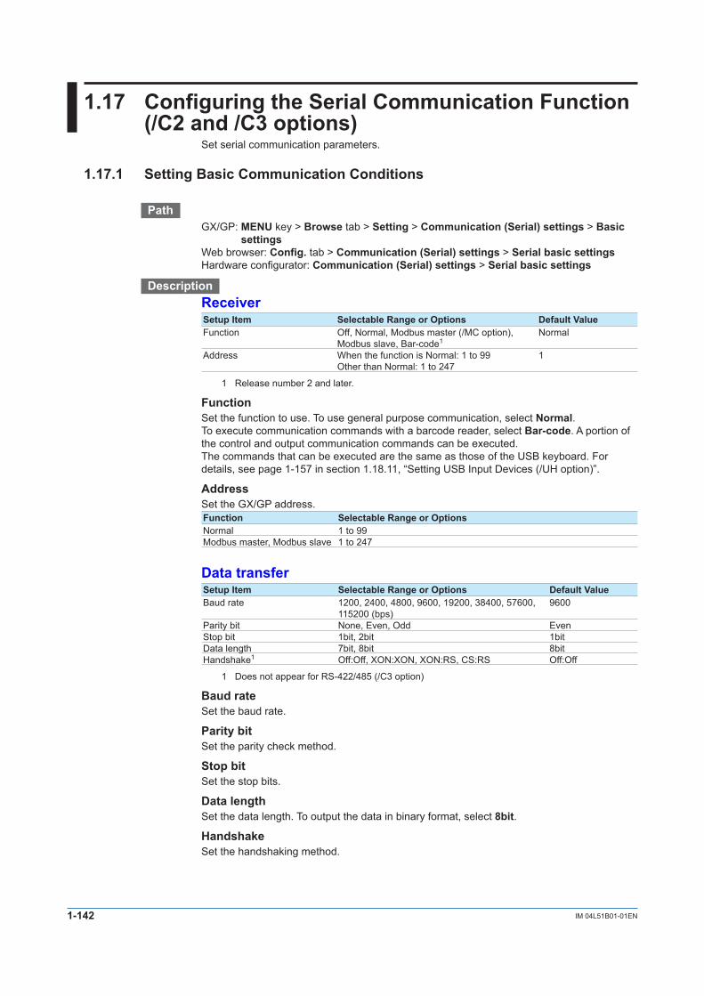
1-142 IM 04L51B01-01EN
1.17 Configuring the Serial Communication Function (/C2and/C3options)
Set serial communication parameters.
1.17.1 Setting Basic Communication Conditions
PathGX/GP: MENU key > Browse tab > Setting > Communication(Serial)settings > Basic
settingsWeb browser: Config. tab > Communication(Serial)settings > Serial basic settingsHardware configurator: Communication(Serial)settings > Serial basic settings
DescriptionReceiverSetup Item Selectable Range or Options Default ValueFunction Off, Normal, Modbus master (/MC option),
Modbus slave, Bar-code1Normal
Address When the function is Normal: 1 to 99Other than Normal: 1 to 247
1
1 Release number 2 and later.
FunctionSet the function to use. To use general purpose communication, select Normal.To execute communication commands with a barcode reader, select Bar-code. A portion of the control and output communication commands can be executed.The commands that can be executed are the same as those of the USB keyboard. For details, see page 1-157 in section 1.18.11, “Setting USB Input Devices (/UH option)”.
AddressSet the GX/GP address.Function Selectable Range or OptionsNormal 1 to 99Modbus master, Modbus slave 1 to 247
Data transferSetup Item Selectable Range or Options Default ValueBaud rate 1200, 2400, 4800, 9600, 19200, 38400, 57600,
115200 (bps)9600
Parity bit None, Even, Odd EvenStop bit 1bit, 2bit 1bitData length 7bit, 8bit 8bitHandshake1 Off:Off, XON:XON, XON:RS, CS:RS Off:Off
1 Does not appear for RS-422/485 (/C3 option)
Baud rateSet the baud rate.
Parity bitSet the parity check method.
Stop bitSet the stop bits.
Data lengthSet the data length. To output the data in binary format, select 8bit.
HandshakeSet the handshaking method.

1-143IM 04L51B01-01EN
Configuring the G
X/GP
1
2
3
4
5
App
Index
Logout1(Releasenumber2andlater)Setup Item Selectable Range or Options Default ValueAuto logout Off, 1min, 2min, 5min, 10min Off
1 Appears when the receiver function is set to Normal, and in the security settings, communication is set to Login.
Auto LogoutOptions DescriptionOff Stays logged in until the user logs out.1min to 10min When you log in through serial communication, you will be automatically
logged out when there is no communication control for the specified duration.
1.17.2 EnablingorDisablingtheModbusMasterFunction(/MCoption)andSetting Communication Conditions
PathGX/GP: MENU key > Browse tab > Setting > Setting menu Communication(Serial)
settings > Modbus master > Basic settingsWeb browser: Config. tab > Communication(Serial)settings > Modbus master Basic
settingsHardware configurator: Communication(Serial)settings > Modbus master Basic
settings
DescriptionMaster functionSetup Item Selectable Range or Options Default ValueOn/Off Off, On Off
On/OffSelect On to use the Modbus master function.
CommunicationSetup Item Selectable Range or Options Default ValueInterval 100ms, 200ms, 500ms, 1s, 2s, 5s, 10s, 20s,
30s, 1min1s
Communication timeout 100ms, 200ms, 250ms, 500ms, 1s, 2s, 5s, 10s, 1min
1s
Gap between messages Off, 5ms, 10ms, 20ms, 50ms, 100ms Off
IntervalSet the data read cycle.
Communication timeoutSet the timeout value for the response from the specified slave when a command is sent from the GX/GP.
GapbetweenmessagesSet the amount of time to wait after receiving a response to a command to send the next command.To connect a UTAdvanced series, set the gap between messages to 20 ms.
1.17ConfiguringtheSerialCommunicationFunction(/C2and/C3options)

1-144 IM 04L51B01-01EN
Recovery actionSetup Item Selectable Range or Options Default ValueRetransmission Off, Once, Twice, 3 times, 4 times, 5 times,
10 times, 20 times1
Wait time Off, 5s, 10s, 30s, 1min, 2min, 5min 5s
RetransmissionSet the number of retransmissions when there is no response from the slave device.
Wait timeSet the auto recovery time from communication halt.
1.17.3 Setting Modbus Master Transmission Commands
PathGX/GP: MENU key > Browse tab > Setting > Setting menu Communication(Serial)
settings > Modbus master > Command settingsWeb browser: Config. tab > Communication(Serial)settings > Modbus master
Commandsettings>Mastercommandnumber(displayexample:1-20)Hardware configurator: Communication(Serial)settings > Modbus master Command
settings>Mastercommandnumber(displayexample:1-20)
DescriptionSetup Item Selectable Range or Options Default ValueMaster command number GX20/GP20: 1 to 100
GX10/GP10: 1 to 501
Master command numberSelect the command number you want to set.
Command settingsSetup Item Selectable Range or Options Default ValueType Off, Read, Write OffSlave1 1 to 247 1Data type1 INT16, UINT16, INT32_B, INT32_L, UINT32_B,
UINT32_L, FLOAT_B, FLOAT_L, BITINT16
Register1 30001 to 39999, 300001 to 36553640001 to 49999, 400001 to 465536
30001
Channel type1 Read: Communication channelWrite: IO channel, Math channel, Communication channel
Communication channel
First-CH1 Channel of the channel type —Last-CH1 Channel of the channel type —
1 Appears when the type is not set to Off.
TypeSet the transmission command operation.
SlaveSet the address of the slave device.
Data typeSet the data type.The data types that you can specify vary depending on the type of command. For information on the workflow, see page 4-11 in section 4.5, “Modbus Function and Register Assignments”.
1.17ConfiguringtheSerialCommunicationFunction(/C2and/C3options)

1-145IM 04L51B01-01EN
Configuring the G
X/GP
1
2
3
4
5
App
Index
RegisterSet the register number of the slave.You can specify an input register in the range of 30001 to 39999 or 300001 to 365536. You can specify a hold register in the range of 40001 to 49999 or 400001 to 465536.The register numbers that you can specify vary depending on the type of command. See page 4-11 in section 4.5, “Modbus Function and Register Assignments”.
Channel typeWhen the type is set to Read, only communication channels are available.When the type is set to Write, set the channel type of the data to send.
First-CH, Last-CHSet the first channel number and the last channel number in accordance with the channel type.
1.17ConfiguringtheSerialCommunicationFunction(/C2and/C3options)

1-146 IM 04L51B01-01EN
1.18 ConfiguringSystemSettings(Timezone,displaylanguage,statusrelay,etc.)
Set the system environment such as the time zone and display language.
1.18.1 Setting the Display Language, Temperature Unit, Decimal Point Type, and Date Format
PathGX/GP: MENU key > Browse tab > Setting > Setting menu System settings >
Environment(Language)settingsWeb browser: Config. tab > System settings > Environment(Language)settingsHardware configurator: System settings > Environment(Language)settings
DescriptionSetup Item Selectable Range or Options Default ValueLanguage Japanese, English, German, French, Russian,
Chinese, KoreanEnglish
Temperature unit C, F CDecimal Point Type Point, Comma Point
LanguageSet the language to use.
NoteWhen you tap Save after changing the language, the message “Restart is required to reflect this changes. Continue?” may appear. Tap OK, and the GX/GP will automatically restart with the specified language.
Temperature unitSet the temperature unit.
Decimal Point TypeSet the decimal point type.Options DisplayExamplePoint 1234.56Comma 1234,56
This is applied to the following files and displays. The decimal point of any file or setting not listed below (the setup screen for example) is displayed using a period.Type ItemFile output Manual sampled data file
Report filePrinter output
Screen Trend displayDigital displayBar graph displayOverview displayHistorical trendMulti panelReport data display
E-mail The instantaneous value data in alarm e-mails and scheduled e-mails. The report data in report e-mails
Date formatSetup Item Selectable Range or Options Default ValueDate format Year Month Day, Month Day Year, Day Month Year Year, month, dayDelimiter Slash (/), Point (.), Hyphen (-) Slash (/)Month indicator Characters, Numerical Numerical

1-147IM 04L51B01-01EN
Configuring the G
X/GP
1
2
3
4
5
App
Index
Date formatSet the date display format.Options Display example1
Year Month Day 2012/12/30Month Day Year 12/30/2012Date Month Year 30/12/2012
1 In the display examples, the delimiter is a slash (/).
ScopeThe format is applied to the date displayed on the screen. It does not change the date format on the date in the output data via communications, the date saved along with the data, and the date used in the data file names.
DelimiterSet the date delimiter.
Month indicatorSet whether to spell out months or use numbers on the screen.
1.18.2 Setting the Interval for Calculating the Rate-of-Change for Rate-of-Change Alarms
PathGX/GP: MENU key > Browse tab > Setting > Setting menu System settings > Alarm
basic settingsWeb browser: Config. tab > System settings > Alarm basic settingsHardware configurator: System settings > Alarm basic settings
DescriptionRate of changeSetup Item Selectable Range or Options Default ValueDecrease 1 to 32 1Increase 1 to 32 1
DecreaseSet the interval for the rate-of-change computation of the low limit on rate-of-change alarm in terms of the number of measured data values (1 to 32).1 The actual interval is obtained by multiplying the value specified here by the scan interval.
1 The number of measured data values is the number of samples.
IncreaseSet the interval for the rate-of-change computation of the high limit on rate-of-change alarm in the same manner as the interval for the low limit on rate-of-change alarm.
1.18ConfiguringSystemSettings(Timezone,displaylanguage,statusrelay,etc.)

1-148 IM 04L51B01-01EN
1.18.3 Setting the Alarm Display Hold/Nonhold and Individual Alarm ACK OperationPath
GX/GP: MENU key > Browse tab > Setting > Setting menu System settings > Alarm basic settings
Web browser: Config. tab > System settings > Alarm basic settingsHardware configurator: System settings > Alarm basic settings
DescriptionIndicatorSetup Item Selectable Range or Options Default ValueHold/Nonhold Hold/Nonhold Nonhold
Hold/NonholdSet the alarm display behavior.Options DescriptionNonhold Clears the alarm indication when the alarm condition is released (returns to
normal condition).Hold Holds the alarm indication until an alarm acknowledge operation is
performed.
AlarmACK(Releasenumber2andlater)Setup Item Selectable Range or Options Default ValueIndividual alarm ACK Off, On Off
Individual alarm ACKSet to On to perform individual alarm acknowledge.You can acknowledge alarms separately by channel and level.If set to On, Display settings are automatically set Hold.The Relay Action on ACK of all DO channels when an acknowledge is performed is Reset.
1.18.4 Setting the Time Zone, Gradual Time Adjustment, and Daylight Saving Time
PathGX/GP: MENU key > Browse tab > Setting > Setting menu System settings > Time basic
settingsWeb browser: Config. tab > System settings > Time basic settingsHardware configurator: System settings > Time basic settings
DescriptionTime zoneSetup Item Selectable Range or Options Default ValueHour -13 to 13 9Minute 0 to 59 0
Hour, MinuteSet the time zone of the region in which the GX/GP will be used in terms of the time difference from GMT. A negative value indicates that the local time is behind the GMT.Example: The standard time in Japan is ahead of the GMT by 9 hours. In this case, set Hour
to 9 and Minute to 0.
1.18ConfiguringSystemSettings(Timezone,displaylanguage,statusrelay,etc.)

1-149IM 04L51B01-01EN
Configuring the G
X/GP
1
2
3
4
5
App
Index
Gradually adjusting the timeSetup Item Selectable Range or Options Default ValueTime deviation limit Off, 5s, 10s, 15s 5sTimeadjustmentbeyondlimit Not Change the time/Change the time Not Change the time
Time deviation limitTo gradually correct the time when the time is changed while recording is in progress, set the deviation limit for gradually correcting the time. Only when the time deviation between theGX/GP’stimeandthespecifiedtimeiswithin±(thevaluethatyouspecifyhere)istheGX/GP’s time gradually corrected. Otherwise, the time is corrected according to Time adjustment beyond limit.
Options Description5 s to 15 s The time deviation limit.Off Disables the function that gradually corrects the time.
Time deviation limit
Current time Specified time
Time adjustment beyond limitSet the behavior when a time that exceeds the time deviation limit is specified.Options DescriptionNot Change the time Time is not corrected.Change the time Time is immediately corrected.
Daylight Saving TimeSetup Item Selectable Range or Options Default ValueUse/Not Not, Use Not
Use/NotSet this to On to set Daylight Saving Time.
Start time1
Setup Item Selectable Range or Options Default ValueMonth January to December MarchDay order 1st, 2nd, 3rd, 4th, Last 2ndDay of the week Sunday to Saturday SundayHour of the day 0 to 23 2
1 Appears when DST (Daylight Saving Time) Use/Not is set to On.
Month,Dayorder,Dayoftheweek,HourofthedaySet the date and time when daylight saving time starts.Setup Item DescriptionMonth Set the month.Day order Set the week in the month.Day of the week Set the day of the week.Hour of the day Set the hour. 0 to 23.
1.18ConfiguringSystemSettings(Timezone,displaylanguage,statusrelay,etc.)

1-150 IM 04L51B01-01EN
Endtime1
Setup Item Selectable Range or Options Default ValueMonth January to December NovemberDay order 1st, 2nd, 3rd, 4th, Last 1stDay of the week Sunday to Saturday SundayHour of the day 0 to 23 2
1 Appears when DST (Daylight Saving Time) Use/Not is set to On.
Month,Dayorder,Dayoftheweek,HourofthedaySet the date and time when daylight saving time ends. The settings here are the same as those for Start time.
ExplanationOperation of Gradually Correcting the Internal ClockIf the time deviation between the time of the GX/GP internal clock and the correct time (the specifiedtime)iswithinaspecifiedvalue,theGX/GPclockisadjustedgraduallyatarateof 1 ms per second. The maximum value of time deviation (tm in the figure below) can be selected in the range of 5 s to 15 s.
Time specified using keys orretrieved from an SNTP server
Range in which the time is gradually adjusted
Nearesthour
Time deviation
Time when the remote control signal is applied(GX/GP time)
tm tmRange in which the time is gradually adjusted
GX/GPtime
Time deviation
tm tm
Example: When changing the time to 12 hours 55 minutes 35 seconds when the internal clock is 12 hours 55 minutes 32 seconds
Thetimedeviationof3secondsisadjusted1mspersecond.Theinternalclockwill be synchronized to the specified time 50 minutes later.
1.18ConfiguringSystemSettings(Timezone,displaylanguage,statusrelay,etc.)

1-151IM 04L51B01-01EN
Configuring the G
X/GP
1
2
3
4
5
App
Index
1.18.5 SettingInternalSwitches
PathGX/GP: MENU key > Browse tab > Setting > Setting menu System settings > Internal
switchsettingsWeb browser: Config. tab > System settings > InternalswitchsettingsHardware configurator: System settings > Internalswitchsettings
DescriptionSetup Item Selectable Range or Options Default ValueFirst number 1 to 100 1Last number 1 to 100 1
First numberSelect the first internal switch number that you want to set.
Last numberSelect the last internal switch number that you want to set.
InternalswitchSetup Item Selectable Range or Options Default ValueType Alarm, Manual AlarmAnd/Or1 AND, OR OR
1 Appears when the type is not set to Alarm.
TypeSet the item to assign to the internal switch.Options DescriptionAlarm Assigns the internal switch as an alarm output destination.Manual Specify this to manually operate with the “OCmdRelay” communication
command.
And/OrSet the internal switch operation conditions when multiple alarm outputs are assigned to the switch.When the channel 1 alarm output and channel 2 alarm output are assigned, And and Or operations are as shown in the figure below.
When set to AND When set to OR
CH1 alarm
Internal switchS001
CH2 alarmOn On On
1.18ConfiguringSystemSettings(Timezone,displaylanguage,statusrelay,etc.)

1-152 IM 04L51B01-01EN
1.18.6 Setting the FAIL Relay and InstrumentInformationOutput(/FLoption)
PathGX/GP: MENU key > Browse tab > Setting > Setting menu System settings > Status
relayWeb browser: Config. tab > System settings > Status relayHardware configurator: System settings > Status relay
DescriptionSetup Item Selectable Range or Options Default ValueFail relay Fail, Status FailMemory/Media status1 Off, On OffMeasurement error1 Off, On OffCommunication error1 Off, On OffRecord stop1 Off, On OffAlarm1 Off, On Off
1 Appears when Fail relay is set to Status.
Fail relaySet whether to output CPU errors to the relay or the instrument status to the relay.Options DescriptionFail Outputs failures.Status Outputs instrument information.
Memory/Media statusSet this to On to output the internal memory and SD memory card status to the relay.
Measurement errorSet this to On to output measurement errors to the relay.
Communication errorSet this to On to output communication errors to the relay.
Record stopSet this to On to output record stop to the relay.
AlarmSet this to On to output alarms to the relay. Alarms whose indications are hidden ( for details, see page 1-17 in section 1.2.2, “Setting Alarms”) are not output to the relay. Relay output stops after all alarms are released (if no other relay output conditions are met).
ExplanationFAILWhen a failure occurs in the GX/GP CPU, a relay contact signal (1 signal) is output. The relay is energized when the CPU is normal and is de-energized when a CPU error occurs. Therefore, relay output is carried out also when the power is off (including a power failure). You cannot change this behavior.
Relay Operation
NO C NCDuring normal operation
NO C NCWhen a Failure Occurs
NO C NCWhen power is turned off
1.18ConfiguringSystemSettings(Timezone,displaylanguage,statusrelay,etc.)

1-153IM 04L51B01-01EN
Configuring the G
X/GP
1
2
3
4
5
App
Index
Status OutputThe status below is output with a relay contact signal. You can select whether each status is output to the relay. The relay is energized when the status occurs.You cannot change this behavior.Status Description Corrective ActionInternal memory or SD card status
Error in the internal memory. Contact your nearest YOKOGAWA dealer for repairs.
When the auto save function to the SD memory card is On•ThefreespaceontheSDmemorycarddropped to 10% of the total size (only when the media FIFO ( see page 1-93 in section 1.9.2, “Setting the Save Method to Media (Auto save or manual save) and Media FIFO”) is disabled).
Replace the SD memroy card.
The status of the internal memory is output when the SD memory card is not inserted or error in the SD memory card.•Theavailablespaceintheinternalmemory dropped to 25 MB or less.1•Thenumberoffilesintheinternalmemory for which Auto Save to the SD memory card has not been completed has exceeded 490 or 980 (GX20-2/GP20-2).
Insert an SD memory card.
When the auto save function to the SD memory card is Off•The available space in the internalmemory dropped to 25 MB or less.1•Thenumberof files in internalmemoryfor which Manual Save has not been completed has exceeded 490.
Save the data in the internal memory to the SD memory card.
Measurement error
Error in the A/D converter. Contact your nearest YOKOGAWA dealer for repairs.
Burnout has been detected. A burnout can occur when thermocouple or RTD wires are disconnected or when unified signals are outside the specifications.
Check the cause of the burnout.
Module error has been detected. On the system information screen, check whether the module is connected correctly and whether it is being recognized properly.
Communication error
A Modbus master, Modbus client, or WT communication error has occurred.
Check the error in the Modbus master, Modbus client, or WT client screen and carry out the corrective action.
Record stop Recording has stopped. Start recording.Alarm occurrence An alarm has occurred. Check the alarm.
1 The internal memory’s “available space” refers to the following quantities. •Unusedareas •AreasofdataforwhichAutoSaveorManualSave( see page 1-93 in section 1.9.2, “Setting the
Save Method to Media (Auto save or manual save) and Media FIFO”) has been completed.
Relay Operation
NO C NCDuring normal operation
NO C NCWhen the specified status occurs
NO C NCWhen power is turned off
1.18ConfiguringSystemSettings(Timezone,displaylanguage,statusrelay,etc.)
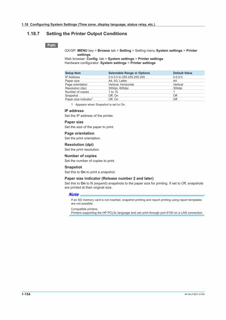
1-154 IM 04L51B01-01EN
1.18.7 Setting the Printer Output Conditions
PathGX/GP: MENU key > Browse tab > Setting > Setting menu System settings > Printer
settingsWeb browser: Config. tab > System settings > Printer settingsHardware configurator: System settings > Printer settingsDescriptionSetup Item Selectable Range or Options Default ValueIP Address 0.0.0.0 to 255.255.255.255 0.0.0.0Paper size A4, A3, Letter A4Page orientation Vertical, Horizontal VerticalResolution (dpi) 300dpi, 600dpi 300dpiNumber of copies 1 to 10 1Snapshot Off, On OffPaper size indicator1 Off, On Off
1 Appears when Snapshot is set to On.
IP addressSet the IP address of the printer.
Paper sizeSet the size of the paper to print.
Page orientationSet the print orientation.
Resolution(dpi)Set the print resolution.
Number of copiesSet the number of copies to print.
SnapshotSet this to On to print a snapshot.
Papersizeindicator(Releasenumber2andlater)Set this to On to fit (expand) snapshots to the paper size for printing. If set to Off, snapshots are printed at their original size.
NoteIf an SD memory card is not inserted, snapshot printing and report printing using report templates are not possible.
Compatible printersPrinters supporting the HP PCL5c language and can print through port 9100 on a LAN connection
1.18ConfiguringSystemSettings(Timezone,displaylanguage,statusrelay,etc.)

1-155IM 04L51B01-01EN
Configuring the G
X/GP
1
2
3
4
5
App
Index
1.18.8 ConfiguringtheSound(Touchsoundandwarningsound)andLEDSettings
PathGX/GP: MENU key > Browse tab > Setting > Setting menu System settings > Sound,
LEDWeb browser: Config. tab > System settings > Sound,LEDHardware configurator: System settings > Sound,LED
DescriptionSoundSetup Item Selectable Range or Options Default ValueTouch Off, On OnWarning Off, On Off
TouchSet this to On to play touch operation sounds.
WarningSet this to On to play a warning sound when an alarm occurs.
LEDSetup Item Selectable Range or Options Default ValueMENU key LED Off, Alarm Off
MENUkeyLEDSet the MENU key LED operation mode.Set this to Alarm to display alarm status.
Options DescriptionOff Lights in blue. Power-on state.Alarm Indicates alarm status with colors.
LEDcolorandstatus StatusLit in blue No alarms; all alarms acknowledgedBlinking in blue No alarms; unacknowledged alarms presentLit in red At least one alarm; all alarms acknowledgedBlinking in red At least one alarm; unacknowledged alarms present
1.18.9 Setting Instrument Tags
PathGX/GP: MENU key > Browse tab > Setting > Setting menu System settings >
Instruments tagWeb browser: Config. tab > System settings > Instruments tagHardware configurator: System settings > Instruments tag
DescriptionSetup Item Selectable Range or Options Default ValueInstruments Tag Character string (up to 32 characters, A a # 1 ) —
Instruments tag No. Character string (up to 16 characters, A a # 1 ) —
Instruments TagSet the GX/GP instrument tag.
Instruments tag No.Set the GX/GP instrument tag number.
1.18ConfiguringSystemSettings(Timezone,displaylanguage,statusrelay,etc.)

1-156 IM 04L51B01-01EN
1.18.10 Setting Comments to Setting Files
PathGX/GP: MENU key > Browse tab > Setting > Setting menu System settings > Setting fileWeb browser: Config. tab > System settings > Setting fileHardware configurator: System settings > Setting file
DescriptionSetup Item Selectable Range or Options Default ValueSetting file comment Character string (up to 50 characters, A a # 1 ) —
Setting file commentSet the comment to attach to the setting parameter file.
Configurationchangescomment(fortheadvancedsecurityfunction(/ASoption))Setup Item Selectable Range or Options Default ValueInput comment Off, On Off
Input commentSet this to On to enter comments in setting files when settings are changed.Tapping Save displays a screen for setting and saving a comment.If you enter a comment, it is set in Setting file comment.From this point, when you change settings, a comment setting screen will appear.
Procedure
1 Tap Comment, and set the comment.
2 Tap OK.ThecommentissetinSettingfilecomment.
3 Tap Close to return to the original screen.
Operation complete
1.18ConfiguringSystemSettings(Timezone,displaylanguage,statusrelay,etc.)

1-157IM 04L51B01-01EN
Configuring the G
X/GP
1
2
3
4
5
App
Index
1.18.11 SettingUSBInputDevices(/UHoption)Path
GX/GP: MENU key > Browse tab > Setting > Setting menu System settings > USB input device
Web browser: Config. tab > System settings > USB input deviceHardware configurator: System settings > USB input device
DescriptionSetup Item Selectable Range or Options Default ValueUSB input device Japanese keyboard (109), US keyboard(104),
barcode readerUS keyboard(104)
USB input deviceSet the type of keyboard to connect to the USB port.If you are connecting a USB bar code reader, select the type that matches the specifications of your bar code reader.If you specify Bar-code reader, you will be able to execute communication commands from the barcode reader. If you connect a keyboard, you can execute what you enter as communication commands.
ExecutingCommunicationCommandswithaUSBBarcodeReader(Releasenumber2andlater)
ExecutableCommandsGroup Command DescriptionOutput FData Outputs the most recent channel data
FRelay Outputs the most recent relay (DO channel) and internal switch status
FStar Outputs the GX/GP statusControl ORec Starts or stops recording
OAlarmAck Clears alarm output (Alarm ACK)OExecRec Manual trigger, manual sample, snapshot, timeoutOExecSNTP Queries the time using SNTPOMessage Write messagesOMath Starts, stops, resets math or clears the computation dropout status
displayOSaveConf Saves setting dataOCommCh Sets a value to a communication channelOEMail Starts or stops the e-mail transmission functionOMBRestore Recovers Modbus manuallyORTReset Resets a relative timerOMTReset Reset a match time timerOCmdRelay Outputs the DO channel and internal switch statusOBatName Sets a batch nameOBatComment Sets a batch commentOBatText Sets a batch textODispRate Switches the trend intervalOLoadConf Loads setting dataOInit Clears measured data and initializes setting dataOUserLockACK User Locked ACK (for the advanced security function (/AS option))OLoginAssist Assists loginOSendValue Assists character input
1.18ConfiguringSystemSettings(Timezone,displaylanguage,statusrelay,etc.)

1-158 IM 04L51B01-01EN
TerminatorsThe following input is considered a terminator. The barcode entered up to the terminator is executed as a communication command.Terminator NotesENTER key You cannot create a barcode for the ENTER key. Set it as a footer
or suffix on the USB barcode reader.Barcode “/////” —
Input Conditions• Thecodesthatcanbeinputareuppercaseandlowercasealphabetcharacters,numbers,
symbols, spaces, and returns.• ThebarcodecharactertypethattheGX/GPcanreadisASCIIcharacters(numbers,
symbols, and uppercase and lowercase alphabet characters).• Thelongestbarcodethatcanbeinputis200charactersexcludingtheterminator.• Ifaninvalidcharacterisinput,itisnotexecuted.• Passwords(inputdisplayedwithasterisks)cannotbesetorinput.
CommandsThatCanBeExecutedDependingonTouch-OperationSecuritySettingsDepending on the touch-operation security settings and login status, the following communication commands can be executed.Group Command No Security With Security
No Logged-in User With Logged-in UserOutput FData
FRelay FStar
Control ORec 1 OAlarmAck 1 OExecRec 1 OExecSNTP 1 OMessage 1 OMath 1 OSaveConf 1 OCommCh OEMail 1 OMBRestore 1 ORTReset 1 OMTReset 1 OCmdRelay 1 OBatName 1 OBatComment 1 OBatText 1 ODispRate 1 OLoadConf 1 OInit 1 OUserLockACK 1 OLoginAssist 2 3OSendValue 3
1 Will result in communication error and display error2 Will result in a negative response (E0) but no display error3 Will result in a negative response (E0) and display error
1.18ConfiguringSystemSettings(Timezone,displaylanguage,statusrelay,etc.)

1-159IM 04L51B01-01EN
Configuring the G
X/GP
1
2
3
4
5
App
Index
1.19 Configuring the Security Functions
Set the security function. The operation lock function prohibits touch screen operation (including the operation through the START/STOP key). To clear the operation lock, enter the password.The login function allows only registered users to use the GX/GP. Access from communication functions can also be limited to users registered here.Authority of user can be configured to restrict the items that each user is allowed to use. (Up to 10 conditions can be set.)If you are using the advanced security function (/AS option), see the Advanced Security Function User’s Manual (IM 04L51B01-05EN).
Operation lock
Login
Operation restrictionUser
Admin
Security features
Only registeredusers can log in
Restrict operations × Memory× Setting operation○ Screen operation× Data save
• User name• Password
Touch operation
Touch operation Operation lock
LoginCommunication
1.19.1 Configuring the Security Functions
PathGX/GP: MENU key > Browse tab > Setting > Setting menu Security settings > Basic
settingsWeb browser: Setting tab > Security settings > Security basic settingsHardware configurator: Setting tab > Security settings > Security basic settings
DescriptionSecurity functionSetup Item Selectable Range or Options Default ValueTouch operation Off, Login, Operation Lock1 OffCommunication Off, Login Off
1 Does not appear for the advanced security function.
Touch operationSet the type of touch screen security to apply.Options DescriptionOff Disables the security function.Login Enables the login function.Operation lock Enables the function that prohibits touch screen operation (including
the operation through the START/STOP key)
CommunicationTo apply communication access security, set this to Login.Options DescriptionOff Disables the security function.Login Allows only registered users to access the GX/GP via communication.
NoteIf Touch operation is set to Login, configure “User settings” and “Authority of user” and then save the settings. If you save immediately after setting Login, you will exit from the setup menu and be logged out. You must log in to configure “User settings” and “Authority of user.”

1-160 IM 04L51B01-01EN
Logout1(touchoperationitem)Setup Item Selectable Range or Options Default ValueAuto logout Off, 1min, 2min, 5min, 10min OffOperation without Login Off, On Off
1 Appears when touch operation is set to Login.
Auto logoutOptions DescriptionOff Stays logged in until the user logs out.1min to 10min When you log in through touch operation, you will be automatically logged out
when there is no activity for the specified duration.
OperationwithoutLoginSet the operations that users can carry out without being logged in.Options DescriptionOff Allows only login operation.On Allows login operation and switching the operation screen.
ExplanationLogin and LogoutLog in by entering the user name and password in the following situations.GX/GP Access Login NecessaryTouch operation • Whenthepoweristurnedon
• WhenyoulogoutandloginagainCommunication When accessing general purpose communication, FTP server, or Web server
1.19.2 SettingItemstoLocktheOperationOf(Whentouchoperationissettooperationlock)
This is not available when you are using the advanced security function (/AS option).
PathGX/GP: MENU key > Browse tab > Setting > Setting menu Security settings > Operation
Lock1
Web browser: Setting tab > Security settings > Operation Lock1
Hardware configurator: Setting tab > Security settings > Operation Lock1
1 Appears when the touch operation of the security function is set to Operation Lock. Does not appear for the advanced security function.
DescriptionOperation Lock functionSetup Item Selectable Range or Options Default ValuePassword Character string (up to 20 characters, A a # 1 ) —
PasswordSets the password that is used to release the operation lock.The password1 is displayed as “*****.”
1 No default password is set.
1.19ConfiguringtheSecurityFunctions

1-161IM 04L51B01-01EN
Configuring the G
X/GP
1
2
3
4
5
App
Index
LimitationsSetup Item Selectable Range or Options Default ValueRecord Free, Lock FreeMath Free, Lock FreeData save Free, Lock FreeMessage Free, Lock FreeBatch Free, Lock FreeAlarmACK Free, Lock FreeCommunication Free, Lock FreeTouch operation Free, Lock FreeTime set Free, Lock FreeSetting operation Free, Lock FreeExternal media Free, Lock FreeSystem operation1 Free, Lock FreeOutput operation1 Free, Lock Free
1 Release number 2 and later.
RecordSet this to Lock to restrict record start/stop operation.This also applies to the corresponding operation using START/STOP key.
MathSet this to Lock to restrict the math operations below.This also applies to the corresponding operation using START/STOP key.OperationStart computationStop computationReset computation
Data saveSet this to Lock to restrict the data save operations below.OperationSave display dataSave event dataEvent triggerManual sampleSnap shotReset timerReset match time timer
MessageSet this to Lock to restrict message writing operation.
BatchSet this to Lock to restrict the batch operations below.OperationWrite batch numbersWrite lot numbersWrite commentsWrite in text fields
AlarmACKSet this to Lock to restrict alarm ACK operation.
Touch operationSet this to Lock to restrict the touch operations below.OperationRegister the standard displayRegister favoritesSwitch screen contentSwitch the display rate
1.19ConfiguringtheSecurityFunctions

1-162 IM 04L51B01-01EN
CommunicationSet this to Lock to restrict the following operations: start, stop, and test mail; test FTP, get and release network information; KDC test operation (/AS option); test printer output; test KDC; manually recover Modbus master; and manually recover Modbus client
Time setSet this to LocktorestrictmanualSNTPservertimeadjustmentanddate/timeadjustment.
Setting operationSet this to Lock to restrict setting operation.
ExternalmediaSet this to Lock to restrict the following operations: save, load, and list files; manually save data; save data at insertion; save alarms; abort saving; create certificate requests; install certificates; and install intermediate certificates.
SystemOperation(Releasenumber2andlater)Set this to Lock to restrict the following operations: initialize; reconfigure system; manage, display, and delete certificates; and execute unverified certificates.
OutputOperation(Releasenumber2andlater)Set this to Lock to restrict internal switch operations and relay operations.
1.19.3 SettingRegisteredUserConditions(Whentouchoperationorcommunicationissettologin)
PathGX/GP: MENU key > Browse tab > Setting > Setting menu Security settings > User
settings1
Web browser: Setting tab > Security settings > User settings1
Hardware configurator: Setting tab > Security settings > User settings1
1 Appears when Touch operation or Communication of the security function is set to Login
DescriptionSetup Item Selectable Range or Options Default ValueUser number 1 to 501 1
1 1 to 100 for the advanced security function (/AS option).
User numberSelect the user number to register.
User settingsSetup Item Selectable Range or Options Default ValueUser level Off, Admin, User —Mode Touch operation, Communication, Touch
operation + CommunicationTouch operation + Communication
User name Character string3 (up to 20 characters, A a # 1 ) —
Initialize password Back, Initialize password —Authority of user1 Off, On OffAuthority number2 Authority number 1 to 10 1
1 Appears when the user level is set to User.2 Appears when Authority of user is set to On.3 NULL is not allowed.
User levelSet the user level. System administrators (Admin) are users that can perform all operations on the GX/GP. When using the login function, at least one user must be registered as a system administrator. The user level of User number 1 is fixed to Admin.
1.19ConfiguringtheSecurityFunctions

1-163IM 04L51B01-01EN
Configuring the G
X/GP
1
2
3
4
5
App
Index
ModeOptions DescriptionTouch operation You can log in to the GX/GP through touch operation.Communication1 You can log in to the GX/GP via communication.Touch operation + Communication
You can log in to the GX/GP through touch operation and communication.
1 Communication cannot be specified for user number 1.
User nameSet the user name. Duplicate user names are not allowed.User names cannot contain spaces.
InitializepasswordSelect Initializepassword to initialize a password. To cancel the initialization, select Back.
Authority of userWhen the user level is User, set this to On to apply user restrictions.
Authority numberWhen Authority of user is set to On, set the authority number.For details on setting user restrictions, see the next section.
NoteThe default user name for user number 1 is “User01”.The default password is “default.”To change the password, log in and perform Passwordchange.Even if you want to set only communication to Login, set Touch operation to Login once and set a password.
For the procedure, see page 2-77 in section 2.10.2, “Changing the Password”.
1.19.4 SettingUserRestrictions(Whentouchoperationorcommunicationissettologin)
PathGX/GP: MENU key > Browse tab > Setting > Setting menu Security settings > Authority
of userWeb browser: Setting tab > Security settings > Authority of useHardware configurator: Setting tab > Security settings > Authority of user
DescriptionSetup Item Selectable Range or Options Default ValueAuthority number 1 to 10 1
Authority numberSelect the user number to apply user restrictions.
Authority of userFor the user restriction items, see page 1-160 in section 1.19.2, “Setting Items to Lock the
Operation Of (When touch operation is set to operation lock)”.
1.19ConfiguringtheSecurityFunctions

1-164 IM 04L51B01-01EN
1.20 Loading Settings
Load setting parameters and report templates, and load and delete scale images.
1.20.1 Loading Setting Parameters
PathGX/GP: MENU key > Browse tab > Save load > Menu Load settings > Setting
parametersWeb browser: Data tab > Save/Load > Setting parameters
DescriptionSetup Item Selectable Range or Options Default ValueMedia kind SD, USB 1
Select file — —
1 Default value of Media kindMedia status Default ValueNon Media is not recognizedSD memory card SDSD memory card, USB flash memory (/UH option)
SD
USB meory (/UH option) USB
Media kindSet the type of media.
Select fileSet the setting parameter file to load.
Setup Item Selectable Range or Options Default ValueAll settings Off, On On
All settingsSet this to On to load all settings. Set this to Off to load security, IP address, and other settings separately.
Setup Item Selectable Range or Options Default ValueSecurity1 Off, On OnIP address1 Off, On OnOther1 Off, On On
1 Appears when All settings is set to Off.
SecuritySet this to On to load only the security settings.
NoteIf the advanced security function (/AS option) is in use, passwords are not loaded except for monitor users. All administrator and user passwords are set to their defaults.
See “Reusing Setting Parameters” section 1.3.3, “User Levels,” in the Advanced Security Function (/AS) User’s Manual (IM 04L51B01-05EN).
IP addressSet this to On to load only the IP address settings.
OtherSet this to On to load settings other than security and IP address settings.

1-165IM 04L51B01-01EN
Configuring the G
X/GP
1
2
3
4
5
App
Index
ProcedureLoading All Stings
1 Tap Media kind, set the medium.
2 Tap Select file, set the file.
3 Tap All settings, set to On.
4 Tap Execute.Thesettingparametersthatyouspecifiedareloaded.
5 Tap Exit.The GX/GP returns to the original screen.
Operation complete
Loading Specific Items
1 Tap Media kind, set the medium.
2 Tap Select file, set the file.
3 Tap All settings, set to Off.
4 Set the items that you want to load to On.
5 Tap Execute.Thesettingparametersthatyouspecifiedareloaded.
6 Tap Exit.The GX/GP returns to the original screen.
Operation complete
NoteWhen the language setting is changed, the GX/GP may restart.
ExplanationSetting Parameter Files
• Theextensionis.GNL. When the advanced security function (/AS option) is in use, the extension is .GSL.• Thefollowingsettingsarealsosaved. • Currentmonitordisplayconditions • Standarddisplayregistrationdata • Favoritescreenregistrationdata
Loading Setting Parameters
• Themonitordisplayconditions,registeredstandarddisplay,andregisteredfavoritescreens are also loaded.
• Iftheloadedsettingparametersarenotapplied,checktheerrorlog( see page 2-42 in section 2.3.5, “Displaying Logs”).
1.20 Loading Settings

1-166 IM 04L51B01-01EN
1.20.2 Loading and Deleting Scale Images
Loading
PathGX/GP: MENU key > Browse tab > Save load > Menu Load settings > Scale image >
Load scale image
DescriptionSetup Item Selectable Range or Options Default ValueMedia kind SD, USB 1
Select file — —
1 See page 1-152 in section 1.20.1, “Loading Setting Parameters”
Media kindSet the type of media.
Select fileSet the scale image to load.
Setup Item Selectable Range or Options Default ValueGroup number GX20-1/GP20-1: 1 to 50
GX20-2/GP20-2: 1 to 60GX10/GP10: 1 to 30
1
Data — —
Group numberSet the group number to load the scale image to.
DataDisplays the presence or absence of the specified file.
Procedure
1 Tap Media kind, set the medium.
2 Tap Select file, set the file.
3 Tap Group number, set the group number to load the scale image to.
4 Tap Execute.Thescaleimageisloadedtothespecifiedgroup.
5 Tap Exit.The GX/GP returns to the original screen.
Operation complete
In Display settings, under Group settings, Scale image must be set to On.See page 1-68 in section 1.6.2, “Setting Display Groups”
1.20 Loading Settings

1-167IM 04L51B01-01EN
Configuring the G
X/GP
1
2
3
4
5
App
Index
Deleting
PathGX/GP: MENU key > Browse tab > Save load > Menu Load settings > Scale image >
Delete scale image
DescriptionSetup Item Selectable Range or Options Default ValueGroup number GX20-1/GP20-1: 1 to 50
GX20-2/GP20-2: 1 to 60GX10/GP10: 1 to 30
1
Data — —
Group numberSet the group number to delete the scale image from.
DataDisplays the presence or absence of the specified file.
Procedure
1 Set the group number to delete the scale image form.
2 Tap Execute.Ifamessageappearsforconfirming,tapOK.Thescaleimageisdeletedfromthespecifiedgroup.
3 Tap Exit.The GX/GP returns to the original screen.
Operation complete
1.20.3 Loading ReportTemplates(/MToption)
PathGX/GP: MENU key > Browse tab > Save load > Menu Load settings > Report templateWeb browser: Data tab > Save/Load > Report template
DescriptionSetup Item Selectable Range or Options Default ValueMedia kind SD, USB 1
File type Excel file, PDF/Printer file Excel fileSelect file — —
1 See page 1-152 in section 1.20.1, “Loading Setting Parameters”
Media kindSet the type of media.
File typeSet the file type.
Select fileSet the file to load.
Setup Item Selectable Range or Options Default ValueReport kind Hourly, Daily, Weekly, Monthly, Hourly + Daily, Daily +
Weekly, Daily + Monthly, Batch, Daily customHourly
Data — —
1.20 Loading Settings

1-168 IM 04L51B01-01EN
Report kindSet the kind of report template.
DataDisplays the presence or absence of the specified file.
ProcedureLoading a Report Template File
1 Tap Media kind, set the medium.
2 Tap Select file, set the file.
3 Tap Select file, select the file to load, and tap OK.
4 Tap Report kind and then the kind of report template to load.
5 Tap Execute.The report template is loaded.
6 Tap Exit.The GX/GP returns to the original screen.
Operation complete
1.20.4 Loading Setting Parameters, Scale Images, Report Templates, Trusted Certificates(Releasenumber2andlater),CustomDisplay(/CGoption)(Releasenumber2andlater)atOnce
PathGX/GP: MENU key > Browse tab > Save load > Menu Load settings > All above
DescriptionSetup Item Selectable Range or Options Default ValueMedia kind SD, USB 1
Select folder — —
1 See page 1-152 in section 1.20.1, “Loading Setting Parameters”
Media kindSet the type of media.
Select folderSet the folder.
Procedure
1 Tap Media kind, set the medium.
2 Tap Select folder, set the folder.
3 Tap Execute.Allfilesareloaded.
4 Tap Exit.The GX/GP returns to the original screen.
Operation complete
NoteThe conditions for loading files depend on the contents of setting parameters, scale images, and report templates. Check the contents before loading them.
1.20 Loading Settings

1-169IM 04L51B01-01EN
Configuring the G
X/GP
1
2
3
4
5
App
Index
1.20.5 Loading and Deleting TrustedCertificates(Releasenumber2andlater)To use this function, you must set Encryptionfunction to On under Encryption/Certificate of Init/Calib.
Loading a Certificate
PathGX/GP: MENU key > Browse tab > Save load > Menu Load settings > Trusted
Certificate > Load trusted certificate
DescriptionSetup Item Selectable Range or Options Default ValueMedia type SD, USB 1
Select file — —
1 See section 1.20.1, “Loading Setting Parameters.”
Certificate InformationSetup Item Selectable Range or Options Default ValueIssuer — —Subject — —Valid not before — —Validity not after — —Front half of hash value (SHA1) — —Latter half of hash value (SHA1) — —
Issuer, Subject, Valid Not Before, Valid Not Before, Front Half of Hash Value (SHA1),LatterHalfofHashValue(SHA1)The items in the file to be loaded are displayed.
For details, see page 1-189 in section 1.25.4, “Viewing Certificate Details and Removing Certificates”.
Procedure
1 Tap Media type to select the medium.
2 Tap Select file to set the file to be loaded.CertificateInformationshowstheitemsinthecertificate.
3 Tap Execute.Thecertificateisloaded.
4 Tap Exit.The GX/GP returns to the original screen.
Operation complete
Deleting a Certificate
PathGX/GP: MENU key > Browse tab > Save load > Menu Load settings > Trusted
Certificate > Deleting trusted certificate
DescriptionSetup Item Selectable Range or Options Default ValueSelect file — —
Select FileSet the file you want to delete.
1.20 Loading Settings

1-170 IM 04L51B01-01EN
Certificate InformationSetup Item Selectable Range or Options Default ValueIssuer — —Subject — —Valid not before — —Validity not after — —Front half of hash value (SHA1) — —Latter half of hash value (SHA1) — —
Issuer, Subject, Valid Not Before, Valid Not Before, Front Half of Hash Value (SHA1),LatterHalfofHashValue(SHA1)The items in the certificate to be deleted are displayed.
For details, see page 1-189 in section 1.25.4, “Viewing Certificate Details and Removing Certificates”.
Procedure
1 Tap Select file to set the certificate to be deleted.
2 Tap Execute.Aconfirmationscreenisdisplayed.
3 Tap OK.Thecertificateisdeleted.
4 Tap Exit.The GX/GP returns to the original screen.
Operation complete
1.20.6 Loading and Deleting CustomDisplays(/CGoption)(Releasenumber2andlater)
Loading a Specific Display
PathGX/GP: MENU key > Browse tab > Save load > Menu Load settings > Custom display >
Load custom display screen Load custom display on specified screen
DescriptionSetup Item Selectable Range or Options Default ValueMedia type SD, USB 1
Select file — —Display Name —
Display No. 1 to 30 1Data — —
1 See section 1.20.1, “Loading Setting Parameters.”
Media TypeSet the type of media.
Select FileSet the file.
Display NameDisplays the name of the custom display.
Display No.Set the display number to assign the custom display to.
DataDisplays the presence or absence of the specified data in the GX/GP.
1.20 Loading Settings
1-171IM 04L51B01-01EN
Configuring the G
X/GP
1
2
3
4
5
App
Index
Procedure
1 Tap Media type to select the medium.
2 Tap Select file to set the file.
3 Tap Display No. to set the display number.
4 Tap Execute.The selected custom display is loaded.
5 Tap Exit.The GX/GP returns to the original screen.
Operation complete
Loading All Displays
PathGX/GP: MENU key > Browse tab > Save load > Menu Load settings > Custom display >
Load custom display screen Load custom display on all screen
DescriptionSetup Item Selectable Range or Options Default ValueMedia type SD, USB 1
Select folder — —
1 See section 1.20.1, “Loading Setting Parameters.”
Media TypeSet the media.
Select FolderSet the folder.
Procedure
1 Tap Media type to select the medium.
2 Tap Select folder to set the folder.
3 Tap Execute.All custom displays are loaded.
4 Tap Exit.The GX/GP returns to the original screen.
Operation complete
1.20 Loading Settings

1-172 IM 04L51B01-01EN
Deleting a Specific Display
PathGX/GP: MENU key > Browse tab > Save load > Menu Load settings > Custom display >
Delete custom display screen Delete custom display from specified screen
DescriptionSetup Item Selectable Range or Options Default ValueDisplay No. 1 to 30 1Data — —
Display No.Set the number of the custom display to delete.
DataDisplays the presence or absence of the specified data in the GX/GP.
Procedure
1 Tap Display No. to set the number of the custom display to delete.
2 Tap Execute.The custom display is deleted.
3 Tap Exit.The GX/GP returns to the original screen.
Operation complete
1.20 Loading Settings

1-173IM 04L51B01-01EN
Configuring the G
X/GP
1
2
3
4
5
App
Index
1.21 Saving Setting Parameters
Save setting parameters, report templates, and scale images.
1.21.1 Saving the Setting Parameters
PathGX/GP: MENU key > Browse tab > Save load > Menu Save settings > Setting
parametersWeb browser: Data tab > Save/Load > Setting parameters
DescriptionSetup Item Selectable Range or Options Default ValueMedia kind SD, USB 1
File name Character string (up to 32 characters) —Comment Character string (up to 50 characters) —
1 See page 1-152 in section 1.20.1, “Loading Setting Parameters”
Media kindSet the save destination medium.
File nameSet the file name.
CommentSet this to attach a comment to the file that you are saving.
Procedure
1 Tap Media kind, set the medium.
2 Tap File name, set the file name.
3 Tap Comment, set the commnet.
4 Tap Execute.Thefileissaved.
5 Tap Exit.The GX/GP returns to the original screen.
Operation complete

1-174 IM 04L51B01-01EN
1.21.2 Saving a Scale Image
PathGX/GP: MENU key > Browse tab > Save load > Menu Save settings > Scale image
DescriptionSetup Item Selectable Range or Options Default ValueMedia kind SD, USB 1
File name — —
1 See page 1-152 in section 1.20.1, “Loading Setting Parameters”
Media kindSet the save destination medium.
File nameSet the file name.
Setup Item Selectable Range or Options Default ValueGroup number GX20-1/GP20-1: 1 to 50
GX20-2/GP20-2: 1 to 60GX10/GP10: 1 to 30
1
Data — —
Group numberSet the group number to save the scale image to.
DataDisplays the presence or absence of the specified file.
Procedure
1 Tap Media kind, set the medium.
2 Tap File name, set the file name.
3 Tap Group number, set the gropu number.
4 Tap Execute.The scale image is saved.
5 Tap Exit.The GX/GP returns to the original screen.
Operation complete
1.21 Saving Setting Parameters

1-175IM 04L51B01-01EN
Configuring the G
X/GP
1
2
3
4
5
App
Index
1.21.3 Saving a Report Template
PathGX/GP: MENU key > Browse tab > Save load > Menu Save settings > Report templateWeb browser: Data tab > Save/Load > Report template
DescriptionSetup Item Selectable Range or Options Default ValueMedia kind SD, USB 1
File type Excel file, PDF/Printer file Excel fileFile name — —
1 See page 1-152 in section 1.20.1, “Loading Setting Parameters”
Media kindSet the save destination medium.
File typeSet the type of file to save.
File nameSet the file name.
Setup Item Selectable Range or Options Default ValueReport kind Hourly, Daily, Weekly, Monthly, Hourly + Daily, Daily +
Weekly, Daily + Monthly, Batch, Daily customHour
Data — —
Report kindSet the kind of report template.
DataDisplays the presence or absence of the specified file.
Procedure
1 Tap Media kind, set the medium.
2 Tap File type, set the file type.
3 Tap File name, enter the file name, and tap OK.
4 Tap Report kind and then the kind of report template to save.
5 Tap Execute.Thereporttemplatefileissaved.
6 Tap Exit.The GX/GP returns to the original screen.
Operation complete
1.21 Saving Setting Parameters
1-176 IM 04L51B01-01EN
1.21.4 Saving Setting Parameters, Scale Images, Report Templates, Trusted Certificates(Releasenumber2andlater),CustomDisplay(/CGoption)(Releasenumber2andlater)atOncePath
GX/GP: MENU key > Browse tab > Save load > Menu Save settings > All above
DescriptionSetup Item Selectable Range or Options Default ValueMedia kind SD, USB 1
Folder name — —
1 See page 1-152 in section 1.20.1, “Loading Setting Parameters”
Media kindSet the save destination medium.
Folder nameSet the folder name.
Procedure
1 Tap Media kind, set the medium.
2 Tap Folder name, set the folder name.
3 Tap Execute.Allfilesaresaved.
4 Tap Exit.The GX/GP returns to the original screen.
Operation complete
NoteThe conditions for saving files depend on the contents of setting parameters, scale images, and report templates. Check the contents before saving them.
1.21.5 Saving TrustedCertificates(Releasenumber2andlater)
PathGX/GP: MENU key > Browse tab > Save load > Menu Save settings > Trusted
Certificate
DescriptionSetup Item Selectable Range or Options Default ValueMedia type SD, USB —
Certificate — —
Media TypeSet the media type.
CertificateDisplays the presence or absence of a certificate.
1.21 Saving Setting Parameters

1-177IM 04L51B01-01EN
Configuring the G
X/GP
1
2
3
4
5
App
Index
Procedure
1 Tap Media type to select the medium.
2 Tap Execute.Thecertificateissaved.
3 Tap Exit.The GX/GP returns to the original screen.
Operation complete
1.21.6 Saving CustomDisplays(/CGoption)(Releasenumber2andlater)
Saving a Specific Display
PathGX/GP: MENU key > Browse tab > Save load > Menu Save settings > Custom display >
Save custom display on specified screen
DescriptionSetup Item Selectable Range or Options Default ValueMedia type SD, USB 1
File name — —
Display No. 1 to 30 —Display Name — —Data — —
1 See section 1.20.1, “Loading Setting Parameters.”
Media TypeSet the save destination medium.
File NameSet the name of the file that you want to save.
Display No.Set the display number of the custom display to save.
Display NameDisplays the display name.
DataDisplays the presence or absence of data.
Procedure
1 Tap Media type to select the medium.
2 Tap File name, and set the file name.
3 Tap Display No. to select the display number to save to.
4 Tap Execute.The custom display is saved.
5 Tap Exit.The GX/GP returns to the original screen.
Operation complete
1.21 Saving Setting Parameters

1-178 IM 04L51B01-01EN
Saving All Displays
PathGX/GP: MENU key > Browse tab > Save load > Menu Save settings > Custom display >
Save custom display on all screen
DescriptionSetup Item Selectable Range or Options Default ValueMedia type SD, USB 1
Folder name — —
1 See section 1.20.1, “Loading Setting Parameters.”
Media TypeSet the save destination medium.
Folder NameSet the save destination folder name.
Procedure
1 Tap Media type to select the medium.
2 Tap Folder name, and set the folder name.
3 Tap Execute.All custom displays are saved.
4 Tap Exit.The GX/GP returns to the original screen.
Operation complete
1.21 Saving Setting Parameters
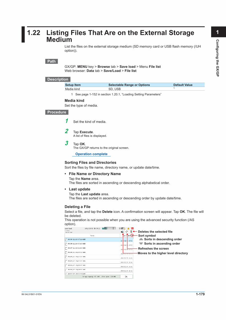
1-179IM 04L51B01-01EN
Configuring the G
X/GP
1
2
3
4
5
App
Index
1.22 ListingFilesThatAreontheExternalStorageMedium
List the files on the external storage medium (SD memory card or USB flash memory (/UH option)).
PathGX/GP: MENU key > Browse tab > Save load > Menu File listWeb browser: Data tab > Save/Load > File list
DescriptionSetup Item Selectable Range or Options Default ValueMedia kind SD, USB 1
1 See page 1-152 in section 1.20.1, “Loading Setting Parameters”
Media kindSet the type of media.
Procedure
1 Set the kind of media.
2 Tap Execute.Alistoffilesisdisplayed.
3 Tap OK.The GX/GP returns to the original screen.
Operation complete
Sorting Files and DirectoriesSort the files by file name, directory name, or update date/time.
• FileNameorDirectoryName Tap the Name area. The files are sorted in ascending or descending alphabetical order.
• Lastupdate Tap the Last update area. The files are sorted in ascending or descending order by update date/time.
Deleting a FileSelect a file, and tap the Delete icon. A confirmation screen will appear. Tap OK. The file will be deleted.This operation is not possible when you are using the advanced security function (/AS option).
Deletes the selected file
Refreshes the screenMoves to the higher level directory
Sort symbolSorts in descending orderSorts in ascending order

1-180 IM 04L51B01-01EN
1.23 FormattingtheExternalStorageMedium
Format the external storage medium (SD memory card or USB flash memory (/UH option)).This operation is not possible when you are using the advanced security function (/AS option).
PathGX/GP: MENU key > Browse tab > Save load > Menu Format
DescriptionSetup Item Selectable Range or Options Default ValueMedia kind SD, USB 1
Volume name Up to 11 characters (0 to 9, uppercase alphabet)
—
1 See page 1-152 in section 1.20.1, “Loading Setting Parameters”
Media kindSet the storage medium to format.
Volume nameSet the medium volume name.
Procedure
1 Tap Media kind to select the medium.
2 Set the medium volume name.
3 Tap Execute.The external storage medium will be formatted.
4 Tap Exit.The GX/GP returns to the original screen.
Operation complete

1-181IM 04L51B01-01EN
Configuring the G
X/GP
1
2
3
4
5
App
Index
1.24 Initializing and Calibrating the System (Initialization,reconfiguration,touchscreencalibration)
Initialize the settings or the internal memory, reconfigure the GX/GP, and calibrate the touch screen.
For details on A/D calibration, see page 5-4 in section 5.1.3, “Performing A/D Calibration and AdjustingtheInputAccuracy”.
For details on the advanced security settings (when the advanced security function (/AS option) is in use), see section 2.1, “Enabling the Advanced Security Function,” in the Advanced Security Function (/AS) User’s Manual (IM 04L51B01-05EN).
For details on encryption and certificates, see page 1-185 in section 1.25, “Configuring Key Creation, Certificate Management, and Encryption/Certificate (SSL communication, PDF electronic signature) (Release number 2 and later)”.
For details on updating the firmware (Web application, I/O module, and expansion module), see page 5-11 in section 5.1.6, “Updating the Firmware (Release number 2 and later)”.
1.24.1 Initializing the Settings and the Internal Memory
PathGX/GP: MENU key > Browse tab > Initialize Calibration > Menu Initialize
DescriptionSetup Item Selectable Range or Options Default ValueInitialize all Off, On Off
Initialize allSet this to On to initialize all settings and return the GX/GP to its factory default condition.However, the A/D calibration password is not initialized.
Setup Item Selectable Range or Options Default ValueSecurity settings Off, On OffOther than Security settings Off, On Off
Security settingsSet this to On to initialize the security settings.
Other than Security settingsSet this to On to initialize settings other than the security settings.
Setup Item Selectable Range or Options Default ValueInternal Data Off, On Off
Internal dataSet this to On to initialize all data in the internal memory.
ProcedureInitializing All Settings
1 Press MENU.The menu screen appears.
2 Tap the Browse tab and then Initialize Calibration.The menu screen appears.
3 Tap Initialize all under Initialize and then On.
4 Tap Execute.Aconfirmationscreenisdisplayed.

1-182 IM 04L51B01-01EN
5 Tap OK.The settings are initialized.
Operation complete
Note• Beforeinitializing,backupnecessarysetupparametersandotherdata. Refer to page 1-173 in section 1.21.1, “Saving the Setting Parameters”• InitializationdoesnotinitializetheA/Dcalibrationpassword. If you forget the password, you will not be able to perform A/D calibration. Make sure you do not
forget the password.• Whenexecuteinitialization,themessage“Restartisrequiredtoreflectthischanges.Continue?”
may appear. Tap OK, and the GX/GP will automatically restart with the specified language.
Initializing a Specific Item
1 Press MENU.The menu screen appears.
2 Tap the Browse tab and then Initialize Calibration.The menu screen appears.
3 Tap Initialize all under Initialize and then Off.
4 To initialize the security settings, tap Security settings and then On. Otherwise, tap Off.
5 To initialize the settings other than the security settings, tap Other than Security settings and then On. Otherwise, tap Off.
6 To initialize the data in the internal memory, tap Internal data and then On. Otherwise, tap Off.
7 Tap Execute.Aconfirmationscreenisdisplayed.
8 Tap OK.The settings are initialized. The message “Execution is complete.” will appear.
Operation complete
Note• Beforeinitializing,backupnecessarysetupparametersandotherdata. Refer to page 1-173 in section 1.21.1, “Saving the Setting Parameters”
ExplanationChannel Assignment in Group Settings through InitializationIf you initialize, channels will be automatically assigned on the basis of the installed modules. If necessary, change the channel assignments for your purpose.
1.24InitializingandCalibratingtheSystem(Initialization,reconfiguration,touchscreencalibration)

1-183IM 04L51B01-01EN
Configuring the G
X/GP
1
2
3
4
5
App
Index
1.24.2 Reconfiguring the GX/GPWhen you reconfigure the GX/GP, the I/O modules installed in the GX/GP and expandable I/O are detected, and the settings are changed accordingly.Reconfiguration is necessary in the following situations.• Whenyouinstallanewlypurchasedmodule• Whenyouchangethemodules(changetodifferentmodules)• Whenyouaddorremovemodules• WhenyouconnectoraddanexpandableI/O
IfyoupurchasedaI/Omodulepreinstalledoption(/U□□0or/CR□□0),thereisnoneedtoreconfigure if you are going to use the GX/GP as-is.However, if you change modules, add modules, or delete modules, you will need to reconfigure.
PathGX/GP: MENU key > Browse tab > Initialize Calibration > Menu Reconfiguration
Procedure
1 Tap Execute.The system information appears.
Switches the display
XXXXXXXXXXX-XX-XX-XX-XX-XX
RX.XX.XXRX.XX.XX
2 Tap Restructure.Aconfirmationscreenisdisplayed.
3 Tap OK.TheGX/GPwillreconfigure.
Operation complete
1.24InitializingandCalibratingtheSystem(Initialization,reconfiguration,touchscreencalibration)

1-184 IM 04L51B01-01EN
Note• DonotcarryoutthefollowingoperationswhiletheGX/GPisreconfiguring.Doingsomaycause
damage. Turn the power off and on. Insert or remove modules.•IfthetotalnumberofI/Ochannelsoftheinstalledmodulesexceeds100ontheGX10/GP10/
GX20-1/GP20-1 or 500 on the GX20-2/GP20-2, no additional modules can be reconfigured. For example, if the maximum number of I/O channels are assigned and the last channel is
assigned to an intermediate channel of a module, that module (channel) and subsequent modules (channels) will not be reconfigured or recognized.
1
10
100
81
90
91Module 1 Module n
: ::
• • •:
Maximum number of I/O channels
• AsingleDI/DOmodule(GX90WD)canbeinstalledintheGX/GPmainunitandalsointheexpandable I/O.
1.24.3 Adjusting the Touch Screen
Seepage5-7insection5.1.4,“AdjustingandCheckingtheTouchScreen”.
1.24InitializingandCalibratingtheSystem(Initialization,reconfiguration,touchscreencalibration)

1-185IM 04L51B01-01EN
Configuring the G
X/GP
1
2
3
4
5
App
Index
1.25 Configuring Key Creation, Certificate Management, andEncryption/Certificate(SSLcommunication,PDFelectronicsignature)(Releasenumber2andlater)
Configure these settings when using SSL encryption and PDF electronic signatures.To use encryption on the FTP server and HTTP server and to use PDF electronic signature, you must create a key and install a certificate.SSL (Secure Sockets Layer)SSL is a function for encrypting data communication between devices on the Internet and other networks. It ensures safe data transmission such as by preventing spoofing by other devices and data eavesdropping.
1.25.1 EnablingtheEncryptionFunctionWhen you enable the encryption function, the GX/GP restarts. After the GX/GP restarts, you need to perform various configuration and operations.
PathGX/GP: MENU key > Browse tab > Init/Calib > menu Encryption/Certificate
DescriptionSetup Item Selectable Range or Options Default ValueEncryption function Off, On Off
EncryptionFunctionSelect On to use the encryption function.
Procedure
1 Tap Encryptionfunction to select On.
2 Tap Execute.Aconfirmationscreenisdisplayed.
3 Tap OK.The GX/GP restarts, and you can set the various items of the encryption function.
Operation complete
1.25.2 Creating a Key
PathGX/GP: MENU key > Browse tab > Init/Calib > menu Encryption/Certificate > Create a key
DescriptionSetup Item Selectable Range or Options Default ValueKey — —
KeyDisplays the presence or absence of a key.

1-186 IM 04L51B01-01EN
Procedure
1 Tap Execute.Aconfirmationscreenisdisplayed.
2 Tap OK.The GX/GP switches to key creation mode, and a key is created.
To cancel the operation, tap Cancel.Aconfirmationscreenwillappear.TapYes. The GX/GP will restart.If you tap No, key creation will continue.
3 After the key is created, a confirmation screen appears. Tap OK.The GX/GP restarts.
Operation complete
1.25.3 ConfiguringCertificateManagement(Creatingself-signed certificates, creating certificatesignaturerequests(CSRs),installingcertificates,andinstallingintermediatecertificates)
PathGX/GP: MENU key > Browse tab > Init/Calib > menu Encryption/Certificate > Certificate
management
DescriptionSetup Item Selectable Range or Options Default ValueCertificate for communication — —Certificate for PDF signature — —
Certificate for CommunicationDisplays the presence or absence of a certificate for communication.
Certificate for PDF SignatureDisplays the presence or absence of a certificate for PDF signature.
Creating a Self-Signed Certificate
PathGX/GP: MENU key > Browse tab > Init/Calib > menu Encryption/Certificate > Certificate
management > Creating a self-signed certificate
DescriptionSetup Item Selectable Range or Options Default ValueCountry Character string (up to 2 characters, A a ) —
State Character string (up to 64 characters, A a # 1 ) —
City Character string (up to 64 characters, A a # 1 ) —
Common name Character string (up to 64 characters, A a # 1 ) —
Organization Character string (up to 64 characters, A a # 1 ) —
Organization unit Character string (up to 64 characters, A a # 1 ) —
E-mail Character string (up to 64 characters, A a # 1 ) —
Use Communication/PDF signature Communication
CountrySet the ISO country code. (United States country code: US)
StateSet the state.
1.25ConfiguringKeyCreation,CertificateManagement,andEncryption/Certificate(SSLcommunication,PDFelectronicsignature)(Releasenumber2andlater)

1-187IM 04L51B01-01EN
Configuring the G
X/GP
1
2
3
4
5
App
Index
CityEnter the city name.
Common NameSet the URL (FQDN) of the site that will use SSL encrypted communication. This must match the URL that the clients specify to establish SSL connection.
OrganizationSet the official English name of the organization that will manage the server. Enter the official organization name including the suffix such as inc., Co.ltd, K.K.
Organization UnitSet the division, department, or other names for identification.
E-mailSet the E-mail address.
UseSet the use of the self-signed certificate.
Procedure
1 Tap Country, State, City, Common name, Organization, Organization unit, and E-mail, and set them.
2 Tap Use, and set the use of the self-signed certificate.
3 Tap Execute.Aself-signedcertificateiscreated.
4 Tap Close to return to the original screen.
Operation complete
Creating a CertificateSignatureRequest(CSR)To apply and obtain a certificate, create a certificate signature request (CSR) to be submitted to a certification authority.
PathGX/GP: MENU key > Browse tab > Init/Calib > menu Encryption/Certificate > Certificate
management > Creatingacertificaterequest(CSR)
DescriptionSetup Item Selectable Range or Options Default ValueCountry Character string (up to 2 characters, A a ) —
State Character string (up to 64 characters, A a # 1 ) —
City Character string (up to 64 characters, A a # 1 ) —
Common name Character string (up to 64 characters, A a # 1 )Organization Character string (up to 64 characters, A a # 1 ) —
Organization unit Character string (up to 64 characters, A a # 1 ) —
E-mail Character string (up to 64 characters, A a # 1 ) —
Country, State, City, Common Name, Organization, Organization Unit, and E-mail
These items are the same as those explained in “Creating a Self-Signed Certificate.”
Setup Item Selectable Range or Options Default ValueMedia type SD, USB 1
File name — —
1 See section 1.20.1, “Loading Setting Parameters.”
1.25ConfiguringKeyCreation,CertificateManagement,andEncryption/Certificate(SSLcommunication,PDFelectronicsignature)(Releasenumber2andlater)

1-188 IM 04L51B01-01EN
Media TypeSet the save destination medium.
File NameSet the name of the file that you want to save.
Procedure
1 Tap Country, State, City, Common name, Organization, Organization unit, and E-mail, and set them.
2 Tap Media type to select the storage medium.
3 Tap File name, and set the file name.
4 Tap Execute.Acertificatesignaturerequest(CSR)iscreated.
5 Tap Close to return to the original screen.
Operation complete
Installing a CertificateYou need to place the certificate to be installed in an external storage medium.
PathGX/GP: MENU key > Browse tab > Init/Calib > menu Encryption/Certificate > Certificate
management > Installation of certificate
DescriptionSetup Item Selectable Range or Options Default ValueMedia type SD, USB 1
Select file — —
Use Communication/PDF signature Communication
1 See section 1.20.1, “Loading Setting Parameters.”
Media TypeSet the storage medium to load from.
Select FileSelect the certificate to install.
UseSet the use of the certificate.
Procedure
1 Tap Media type to select the medium.
2 Tap Select file to select the certificate to install.
3 Tap Use, and set the use of the certificate.
4 Tap Execute.Thecertificateisinstalled.
5 Tap Close to return to the original screen.
Operation complete
1.25ConfiguringKeyCreation,CertificateManagement,andEncryption/Certificate(SSLcommunication,PDFelectronicsignature)(Releasenumber2andlater)

1-189IM 04L51B01-01EN
Configuring the G
X/GP
1
2
3
4
5
App
Index
Installing an Intermediate CertificateYou need to place the intermediate certificate to be installed in an external storage medium.
PathGX/GP: MENU key > Browse tab > Init/Calib > menu Encryption/Certificate > Certificate
management > Installation of intermediate certificate
DescriptionSetup Item Selectable Range or Options Default ValueMedia type SD, USB 1
Select file — —
Use Communication/PDF signature Communication
1 See section 1.20.1, “Loading Setting Parameters.”
Media TypeSet the storage medium to load from.
Select FileSelect the intermediate certificate to install.
UseSet the use of the certificate.
Procedure
1 Tap Media type to select the medium.
2 Tap Select file to select the intermediate certificate to install.
3 Tap Use, and set the use of the intermediate certificate.
4 Tap Execute.Theintermediatecertificateisinstalled.
5 Tap Close to return to the original screen.
Operation complete
1.25.4 ViewingCertificateDetailsandRemovingCertificatesViewingCertificateDetails
PathGX/GP: MENU key > Browse tab > Init/Calib > menu Encryption/Certificate > View
certificate
DescriptionSetup Item Selectable Range or Options Default ValueSelect file — —
Select FileSelect the certificate that you want to view.
Certificate InformationSetup Item Selectable Range or Options Default ValueIssuer — —Subject — —Valid not before — —Validity not after — —Front half of hash value (SHA1) — —Latter half of hash value (SHA1) — —
1.25ConfiguringKeyCreation,CertificateManagement,andEncryption/Certificate(SSLcommunication,PDFelectronicsignature)(Releasenumber2andlater)

1-190 IM 04L51B01-01EN
IssuerDisplays the issuer information.
SubjectDisplaysthesubjectinformation.
Valid Not BeforeDisplays the start date of the valid period.
Validity Not AfterDisplays the end date of the valid period.
FrontHalfofHashValue(SHA1)Displays the front half of the certificate’s hash value.
LatterHalfofHashValue(SHA1)Displays the latter half of the certificate’s hash value.
Instrument informationSetup Item Selectable Range or Options Default ValueSerial No. — —
Serial No.Displays the GX/GP serial number.
Procedure
1 Tap Select file to set the certificate you want to view.
2 Tap OK.Thecertificatedetailsaredisplayed.
3 Tap Close to return to the original screen.
Operation complete
Deleting a Certificate
PathGX/GP: MENU key > Browse tab > Init/Calib > menu Encryption/Certificate > Remove
certificate
DescriptionThe displayed items are the same as those described in “Viewing Certificate Details.”
Procedure
1 Tap Select file to set the certificate to be deleted.Thecertificatedetailsaredisplayed.
2 Tap Execute.Aconfirmationscreenisdisplayed.
3 Tap OK.Thecertificateisdeleted.
4 Tap Close to return to the original screen.
Operation complete
1.25ConfiguringKeyCreation,CertificateManagement,andEncryption/Certificate(SSLcommunication,PDFelectronicsignature)(Releasenumber2andlater)

1-191IM 04L51B01-01EN
Configuring the G
X/GP
1
2
3
4
5
App
Index
1.25.5 ConfiguringtheEncryptionoftheServerFunctionandClientFunction,andApplyingPDFElectronicSignatures
Configuring the Server FunctionSet the encryption of the FTP server and HTTP server.
For details on the settings, see page 1-139 in section 1.16.9, “Setting the Server Functions to Use (FTP, HTTP, SNTP, MODBUS, GENE, DARWIN compatible communication)”.
Configuring the Client FunctionSet the encryption of the FTP client and SMTP client.
For details on the settings, see page 1-128 in section 1.16.2, “Configuring the FTP Client Function” and page 1-130 in section 1.16.3, “Configuring the SMTP Client Function”.
SettingthePDFElectronicSignatureSet the electronic signature of PDF files.
For details on the settings, see page 1-100 in section 1.11.1, “Setting the Report Type, Creation Time, Data Type, Etc.”.
1.25.6 Loading, Deleting, and Saving a Trusted Certificate For details on loading and deleting, page 1-169 in section 1.20.5, “Loading and Deleting
Trusted Certificates (Release number 2 and later)”. For details on saving, see page 1-176 in section 1.21.5, “Saving Trusted Certificates (Release number 2 and later)”.
1.25.7 Verification Confirmation of Unverified CertificatesIf a certificate that you have cannot be verified as a new certificate, an error message (E782) appears, and a Unverified certificate icon appears in the Universal menu.Communication continues by performing verification confirmation.
For details on the verification confirmation, see page 2-61 in section 2.4.11, “Verifying Unverified Certificates (Release number 2 and later)”.
1.25ConfiguringKeyCreation,CertificateManagement,andEncryption/Certificate(SSLcommunication,PDFelectronicsignature)(Releasenumber2andlater)

1-192 IM 04L51B01-01EN
1.26 Using the DARWIN Compatible Communication Function(Releasenumber2andlater)
This section provides an outline on how to use the DARWIN compatible communication function and how to configure it.
1.26.1 OverviewA portion of the DARWIN’s setting and control commands is supported.Measured data, math data, and so on can be output in DARWIN format.You can use an existing program that has been created for DARWIN to communicate with the GX/GP.
Output
GX/GP
Ethernet
Command
Existing controlprogram
DARWIN
NoteThe following application programs and API are not supported.You cannot communicate with the GX/GP using the following programs and API through the
DARWIN compatible communication function.• DAQ32,DAQ32Plus,DAQLogger• MX190(APIforMX100/DARWIN)• LabVIEWdriver(forDARWIN)
Instrument ConfigurationTo control the GX/GP using the DARWIN compatible communication function, you must configure the GX/GP (module type, channel numbers (unit numbers and slot numbers)) to match DARWIN.
ModuleConfigurationExampleUnit DARWIN(Extendedtype) GX/GPMain unit Main GX/GP main unit
Slots 0 to 8 — No moduleSub unit, extended unit DS600 GX60
Slot 0 DU100-11 GX90XASlot 1 DU100-11 GX90XASlot 2 DU100-11 GX90XASlot 3 No module No moduleSlot 4 DU100-11 GX90XASlot 5 No module No module
InterfaceEthernet

1-193IM 04L51B01-01EN
Configuring the G
X/GP
1
2
3
4
5
App
Index
Communication Ports and Maximum Number of ConnectionsPort Number Maximum Number of
ConnectionsNotes
34150 1 RS232C command support, configuration port34151 4 Loading instantaneous data
• Therearenolimitationsoncommandsoneitherport.Allsupportedcommandsworkonboth ports.
• Port34159(communicationstatusverification)cannotbeused.
TerminatorClassification TerminatorInput CR+LF or LFOutput CR+LF
Limitations• Ifcommunicationsecurityisenabledinsecuritysettings,thisfunctioncannotbeused.
Procedure to Use the GX/GP
Set the GX/GP IP address, subnet mask, and the like.
Align the GX/GP configuration to DARWIN.• Connect expandable I/Os.• Install modules.
For the setting procedure, see section 1.16.9, “Setting the Server Functions to Use (FTP, HTTP, SNTP, MODBUS, GENE, DARWIN).”
For the setting procedure, see section 1.16.1, “Setting Basic Communication Conditions.”
As necessary, configure the GX/GP functions according to DARWIN.
Make the GX/GP recognize the modules.
For setting procedure, see section 1.
For the setting procedure, see section 1.24.2, “Reconfiguring the GX/GP.”
Configure the system
Execute reconfiguration
Configure the DARWIN compatible communication function
Configure communication settings
Configure functions
Preparation complete
1.26UsingtheDARWINCompatibleCommunicationFunction(Releasenumber2andlater)

1-194 IM 04L51B01-01EN
1.26.2 Supported CommandsThe commands supported by the DARWIN compatible communication function are as follows.
Instantaneous Data Output CommandsCommand DescriptionEF Outputs measured data and math data in binary format.EL Outputs unit and decimal point information of a specified channel in ASCII
format.EB Sets the byte output order.
ESC+TCommandIf a “Esc+T” command is received, time-synchronized measured value and math value are held in the local buffer until the next “Esc+T” command is received.Command DescriptionEsc+T Prepares to output the data selected with the TS command.
Setting CommandsCommand DescriptionSR Sets the range.SN Sets the unit (scale unit).SA Sets an alarm.SD Sets the date and time.SV Sets moving average.CM Sets math input data (option).
SR Command ParametersIf a setting parameter that the GX/GP does not support is received, a negative response is returned.Item DescriptionMode RRJCRange PT2, JPT2, PT2S, JPT2SModule AC, STRAIN, PULSE
Data Output Request CommandsCommand Parameter DescriptionTS 0: Measured data Selects the talker output data.
1: Setting parameters2: Unit information5: System configuration information9: Setup mode setting data output
FM 0: Measured data (ASCII) Selects the output format of measured/math data.1: Math data (binary)
2: Math data (ASCII)3: Math channel (binary)
LF — Sets the output channel for the setting data output, unit, and decimal place information.
CF — Sets the system configuration data format.
VF — Relay status output requestBO — Sets the byte output order.
1.26UsingtheDARWINCompatibleCommunicationFunction(Releasenumber2andlater)

1-195IM 04L51B01-01EN
Configuring the G
X/GP
1
2
3
4
5
App
Index
Module Names Output by the CF CommandGX/GP Module Module NameAI module INPUTDI module DIDO module RELAYExpansion module Module not connectedModule error XXXXXXDI/DO module REMOTE
ControlExecutionCommandsCommand DescriptionAR Resets alarms.IR Resets timers.EX Starts, stops, resets, clears (option) math.RS System reconfigurationRC Clears RAM (initializes operation mode setting parameters).VD Turns on and off relays externally.CF System configuration data output request (diagnosis)PS Starts or stops recording.MS Starts message printing.
Handling of Commands for Functions Not Available on the GX/GPIf a command or parameter for a function not available on the GX/GP is received, a negative response (E1) is returned.However, if the command does not constitute a functional problem, a positive response (E0) is returned without performing any operation.
Commands That the GX/GP Returns Positive Responses ForCommand Description Response OperationDS Switches the setting mode. Positive
responseNo operation
XE Confirms setup setting parameters.IM Sets the interrupt mask.SM Sets the auxiliary mask.UD Sets the display mode of the top display.
CommandsThatDoNotAffecttheOperation(Negativeresponse)Command Description Response OperationSX Sets a math group. Negative
responseNo effect
SI Sets a timer (option).SQ Sets a match time timer (option).SL Sets event/action (option).SO Sets a calculation expression (option).SK Sets a calculation constant (option).AO Assigns a transmission channel.YO Sets the time constant for transmission output.ET Sets a timeout.
IfASCIIcodesE2toE6(Ω,μ,ε,ʊ)arereceived,theyareconvertedtospaces,andnoerrorresults. The E1 character (°) is converted to the GX/GP character code C2B0 and applied.
1.26UsingtheDARWINCompatibleCommunicationFunction(Releasenumber2andlater)

1-196 IM 04L51B01-01EN
1.26.3 Configuring the DARWIN Compatible Communication Function
PathGX/GP: MENU key > Browse tab > Setting > Setting menu Communication(Ethernet)
settings > Server settings > Server listWeb browser: Setting tab > Communication(Ethernet)settings > Server settings Server listHardware configurator: Communication(Ethernet)settings > Server settings Server list
DescriptionDARWINSetup Item Selectable Range or Options Default ValueOn, Off Off, On OffChannel conversion1 Stand-alone type, extended type Stand-alone type
1 Appears when the On/Off settings is set to On.
On/OffSelect On to use the DARWIN compatible communication function.
Channel ConversionSet the DARWIN type to perform channel conversion.
1.26.4 Configuring the GX/GP IP Address, Subnet Mask, and the Like
See page 1-126 in section 1.16.1, “Setting Basic Communication Conditions”.
1.26UsingtheDARWINCompatibleCommunicationFunction(Releasenumber2andlater)

2-1IM 04L51B01-01EN
Operating the G
X/GP
1
2
3
4
5
App
Index
2.1 Starting and Stopping Recording and Computation
This section explains how to start recording and computation.
2.1.1 Starting and Stopping RecordingStart and stop recording.
ProcedureStarting Recording
For the procedure when the batch function is in use, see page 2-3 in section 2.1.2, “Using the Batch Function”.
1 Press MENU.The menu screen appears.
Recording
2 Tap Recording.The record start screen appears.
3 Tap Rec+Math, Rec+Math(Mathreset), or Record.Recording starts. The recording status icon in the status display section changes from stopped to started.
On models with the math option (/MT option), you can select Rec+Math. Computa-tion starts when recording starts.
Stopped Sampling
Alternates
Operation complete
• YoucanalsousetheSTART/STOP key. However, whether the record start screen appears or the recording starts immediately will depend on the Record confirmation action (release number 2 and later) setting.
For details on the settings, see page 1-80 in section 1.8.1, “Setting the Type of Data to Record (Display or event data) and Recording Conditions”.
To also start computing, in the math channel settings, you need to set START/STOP key action to Start / Stop or Reset + Start / Stop.
For details on the settings, see page 1-48 in section 1.5.1, “Setting Basic Computation Operations (Error indications, operation at start, and overflow handling)”.
• Ifyouarerecordingdisplayoreventdatainfreerunmode,theGX/GPstartsrecordingwhen you start recording. If you are recording event data in trigger mode, the GX/GP enters the trigger-wait state.
Digital values are updated, but waveform data will not appear until a trigger occurs. For instructions on how to display waveforms, see the reference below.
For the procedure to apply record start triggers, see page 2-5 in section 2.1.3, “Applying a Record Start Trigger for Event Data”.
• For starting and stopping recording using event actions, see page 1-110 in section 1.14, “Configuring the Event Action Function”.
Chapter 2 Operating the GX/GP
2-2 IM 04L51B01-01EN
Stopping Recording
For the procedure when the batch function is in use, see page 2-3 in section 2.1.2, “Using the Batch Function”.
1 Press MENU.The menu screen appears.
2 Tap Record.The record stop screen appears.
3 Tap Rec+Math or Record.Recording stops. The recording status icon indicates stopped.
When computation (/MT option) is in progress, you can select Rec+Math. Computation stops when recording stops.
Operation complete
• YoucanalsousetheSTART/STOP key. However, whether the record stop screen appears or the recording stops immediately will depend on the Record confirmation action setting.
• IfSTART/STOP key action in the math channel settings is set to Start / Stop or Reset + Start / Stop, computation also stops when you press the START/STOP key.
ExplanationOperations That Start When Recording Starts• Waveformdisplayupdatingonthetrenddisplay• Reporting(/MToption)• Computation(/MToption;whenSTART/STOP key action is set to Start / Stop or Reset
+ Start / Stop)
Operations That Stop When Recording Stops• Waveformdisplayupdatingonthetrenddisplay• Reporting(/MToption)• Computation(/MToption;dependsonthesettingspecifiedintheprocedureabove)
Performance While Data Is Being SavedIf the internal memory or external storage medium is continuously accessed, the following phenomena may occur. When such phenomena occur, the storage medium access indicator frequently illuminates.• Filesbeingsavedtotheexternalstoragemediumdropout.• AccessingtheGX/GPthroughcommunicationtakesalongtime.If these conditions occur, take the following measures.• Ifyouarecreatingdatafilesatshortintervalsconsecutivelyusingtheeventaction
function, increase the data file save interval.• Ifyouarecreatingnumerousfilesinasingledirectoryontheexternalstoragemedium,
change the destination directory name at approximately every 1000 files.• Ifdatarecordinganddisplayareusingupresources(forexampleifyouarerecording
on multiple channels at a fast rate and displaying trend displays on all the multi panels), reduce the recording interval, or change the display.
2.1 Starting and Stopping Recording and Computation

2-3IM 04L51B01-01EN
Operating the G
X/GP
1
2
3
4
5
App
Index
2.1.2 Using the Batch Function
ProcedureSettingtheBatchName(Batchname-No.LotNo.)andComments
1 Press MENU.The menu screen appears.
2 Tap the Universal tab and then Batch.A screen for setting the batch name and comments appears.
3 Tap Batch name-No., and set the batch number. (Up to 32 characters)If you are using lot numbers, set the lot number.
4 Tap Comment 1, Comment 2, or Comment 3, and enter the comment. (Up to 50 characters)
5 Tap Exit.The batch screen closes.
Operation complete
Note• BatchnumbersandlotnumberscannotbechangedaftertheGX/GPstartsrecording.• YoucanchangethecommentsasmanytimesasyouwishbeforetheGX/GPstartsrecording.
The last specified comment is valid.After the GX/GP starts recording, you can only set comments in empty comment boxes. However, comments that you have confirmed cannot be changed.
• ThecommentsareclearedwhentheGX/GPstopsrecording.• Thetextfieldsthatyousetbeforeyoustartrecording(see“StartingRecording(Recordstart)”
on the next page) are cleared when the GX/GP stops recording.• Thebatchnumber,lotnumber,andcommentsaresavedtothedisplaydatafileoreventdata
file. They are not saved to the setting parameter file.
Displaying the Text Field Settings
1 Press MENU.The menu screen appears.
2 Tap the Universal tab and then Text field.Thebatchtextfieldsettingsappear.
Displays approximately 12 text fields
ScrollScroll
You can drag or flick to scroll through the batch text field.
3 Tap Exit.The screen closes.
Operation complete
2.1 Starting and Stopping Recording and Computation

2-4 IM 04L51B01-01EN
Starting Recording
1 Press MENU.The menu screen appears.
2 Tap Recording.The record start screen appears.
Edit the text field
3 Tap Batch name-No., Lot No., and Comment 1 to Comment 3, and set each item.Ifyouneedtoeditthetextfields,proceedtostep4.
4 Tap Edittextfield.Thebatchtextfieldscreenappears.
Scroll Scroll
Tap the text field you want to edit, and set Characters. You cannot change the title.
Tap Exit.The GX/GP returns to the record start screen.
The text fields that you specify here will only be saved to the measurement data file that you are about to start recording to. The text fields that you have set from the setting menu will not change.
5 Tap Rec+Math or Record.Recording starts. The recording status icon in the status display section changes from stopped to started.
Operation complete
• YoucanalsousetheSTART/STOP key. For details, see page 2-1 in section 2.1.1, “Starting and Stopping Recording”.
2.1 Starting and Stopping Recording and Computation

2-5IM 04L51B01-01EN
Operating the G
X/GP
1
2
3
4
5
App
Index
• Ifyouarerecordingdisplayoreventdatainfreerunmode,theGX/GPstartrecordingwhen you start recording. If you are recording event data in trigger mode, the GX/GP enters the trigger-wait state.
For the procedure to apply a record start trigger, see page 2-5 in section 2.1.3, “Applying a Record Start Trigger for Event Data”.
• For starting and stopping recording using event action, see page 1-110 in section 1.14, “Configuring the Event Action Function”.
Stopping Recording
1 Press MENU.The menu screen appears.
2 Tap Record.The record stop screen appears.
3 Tap Rec+Math or Record.Recording stops.
When computation (/MT option) is in progress, you can select Rec+Math. Computation stops when recording stops.
4 Tap the Exit icon to close the menu screen.
Operation complete
• YoucanalsousetheSTART/STOP key. If you use this key, recording will stop immediately.
• IfSTART/STOP key action in the math channel settings is set to Start / Stop or Reset + Start / Stop, computation also stops when you press the START/STOP key.
2.1.3 ApplyingaRecordStartTriggerforEventDataThe procedure below can be carried out when recording event data in trigger mode and the GX/GP is configured so that the start trigger is applied through trigger source operation.In Recording settings, under Basic settings, event data Trigger source operation must be set to On.
For details on the settings, see page 1-80 in section 1.8.1, “Setting the Type of Data to Record (Display or event data) and Recording Conditions”.
ProcedureTriggering through Trigger Source OperationCarry out the following procedure when the GX/GP is in the trigger-wait state.
1 Press MENU.The menu screen appears.
2 Tap the Universal tab.
3 Tap Eventtrigger.Recording starts.
Operation complete
TriggeringBasedonEvents(Eventactionfunctionmustbeconfigured.)Recording starts when an event occurs.
For setting the event action function, see page 1-110 in section 1.14, “Configuring the Event Action Function”.
2.1 Starting and Stopping Recording and Computation

2-6 IM 04L51B01-01EN
Note• IfthefiletypeoftherecordingmodeisEvent, the trend interval will correspond to the recording
interval of event data.• Iftherecordingmodeofeventdataissettotriggerinbasicsettingsunderrecordingsettings,
digital values will be updated, but waveform data will not be displayed until a trigger occurs. To display waveform data, set Trend rate switching under Display settings to On.
2.1.4 Starting, Stopping, and Resetting Computation
ProcedureStaring Computation
• StartingComputationWhenRecordingStarts
See page 2-1 in section 2.1.1, “Starting and Stopping Recording”.
• StartingOnlytheComputation
1 Press MENU.The menu screen appears.
Math
2 Tap Computing.The Start math computations screen appears.
3 Tap Start.Computation starts. The math icon is displayed in the status display section.
Math icon
Operation complete
2.1 Starting and Stopping Recording and Computation

2-7IM 04L51B01-01EN
Operating the G
X/GP
1
2
3
4
5
App
Index
2.1 Starting and Stopping Recording and Computation
Stopping Computation
• StoppingComputationWhenRecordingStops
1 Press MENU.The menu screen appears.
2 Tap Recording.The record stop screen appears.
3 Tap Rec+Math.Recording and computation stops, and the math icon in the status display section disappears.
4 Tap the Close icon to close the menu screen.
Operation complete
• StoppingOnlytheComputation
1 Press MENU.The menu screen appears.
2 Tap Computing.The Stop math computations screen appears.
3 Tap Stop.Computation stops, and the math icon in the status display section disappears.
Operation complete
NoteWhen you stop computation, the computed value for math channels is set to the value held immediately prior to computation stopping. When recording, this retained value is recorded.
Resetting the Computed Results on All Math ChannelsYou can carry out this procedure when computation is stopped and when computation is in progress.
1 Press MENU.The menu screen appears.
2 Tap Computing.The Start math computations or Stop math computations screen appears.
3 Tap Reset.The computation is reset.
Operation complete

2-8 IM 04L51B01-01EN
2.1.5 Clearing Computation Data Dropout DisplaysYou can carry out this procedure when a computation data dropout occurs. When a computation data dropout occurs, the math icon turns yellow.
Procedure
1 Press MENU.The menu screen appears.
2 Tap Computing.The computation operation screen appears.
3 Tap ACK.The math icon turns gray.
ACK on the computation operation screen is valid only when a computation data dropout occurs.
Operation complete
NoteA computation data dropout occurs if the computation is not completed within the scan interval. If computation data dropout occurs frequently, reduce the load on the CPU by reducing the number of math channels or setting a longer scan interval. When a computation data dropout occurs during recording, the computed data of the scan interval in which the dropout occurred is set to the data immediately before the dropout.
2.1 Starting and Stopping Recording and Computation

2-9IM 04L51B01-01EN
Operating the G
X/GP
1
2
3
4
5
App
Index
2.2 Configuration of Measured Data Display
This section explains how to display various measured data.
2.2.1 Displaying Measured Data Using Waveforms, Numeric Values, Bar Graph,orCustomDisplay(/CGoption)(Trend,digital,bargraph,andcustomdisplays)
ProcedureDisplaying the Trend, Digital, or Bar Graph Display
1 Press MENU.The menu screen appears.
2 Tap the Browse tab.
Trend display
Digital display
Bar graph display
3 Tap Trend, Digital, or Bar graph.The display that you selected appears.
Blinking
No alarms; all acknowledged
No alarms; some not acknowledged
Alarms present; some not acknowledged
Alarms present; all acknowledged
Channel number or tag
Unit
Alarm mark
GX20 digital display example
PrecedenceinDisplayingTags(Charactersandnumbers) Tag numbers are displayed with higher precedence than tag characters. When tag numbers are not assigned, tag characters are displayed. If neither the tag numbers nor tag characters are assigned, channel numbers are
displayed.
Maximum Number of Channels That Can Be Displayed in a Group GX20/GP20: 20 channels GX10/GP10: 10 channels
Operation complete

2-10 IM 04L51B01-01EN
ShowingtheCustomDisplay(Releasenumber2andlater)The procedure below is performed after loading a custom display.
For the procedure to load a custom display, see page 1-170 in section 1.20.6, “Loading and Deleting Custom Displays (/CG option) (Release number 2 and later)”.
1 Press MENU.The menu screen appears.
2 Tap the Browse tab and then Custom display.IfthedisplayisthefirstoneshownOf the custom displays that have been assigned, the one with the smallest display number is shown.
IfthecurrentlyshowndisplayisnotacustomdisplayThe custom display whose display number was shown previously is shown.
IfthecurrentlyshowndisplayisacustomdisplayThe Custom Display Selection screen appears.
3 Tap the custom display (display number) you want to show.The custom display appears.
Operation complete
Displaying Channel InformationYou can carry out this procedure on the trend, digital, bar graph, overview and report displays.
1 Tap the channel data digital display section to display the information about the selected channel. On the trend display, double-tap the digital display section.The channel information screen appears.
Trend displayReturns the waveform displayed on top to the original condition.
On the trend display, tapping the digital display section once shows the tapped waveform on the top.
2 Tap the Close icon.The channel information screen closes.
Operation complete
2.2 Configuration of Measured Data Display

2-11IM 04L51B01-01EN
Operating the G
X/GP
1
2
3
4
5
App
Index
Changing Alarm Values from the MonitorYou can carry out this procedure on the trend, digital, bar graph, and overview displays.This procedure is applicable to channels that have alarms assigned to them.In Display settings, under Screen display settings, Setting Changing each value from monitoring On/Off must be set to On.
1 Tap a channel that has alarms assigned to it.The channel information screen appears.
Edit alarm values.
2 Tap Editalarm.The alarm edit screen appears.
3 Tap the alarm level you want to edit.A keyboard will appear.
4 Set the alarm value, and tap OK.The new alarm value is applied.
Operation complete
DO Channel Operation from the MonitorThis procedure is for when, in the DO channel range settings, type is set to Manual.In the Display settings, under Screen display settings, Changing each value from monitoring must be set to On. For the setting procedure, see page 1-74 in section 1.6.5, “Setting Basic Screen Items”.
1 Tap a DO channel.The channel information appears.
“ON” or “OFF”The specified character string is shown in parentheses.
2 Tap ON or OFF.The tapped value (ON or OFF) takes effect.
3 Tap the Close icon to close the channel information screen.
Operation complete
2.2 Configuration of Measured Data Display

2-12 IM 04L51B01-01EN
Starting the Waveform Display of the Trend Display and Stopping the Waveform UpdatingWhen recording starts, the waveform display on the trend display starts. When recording stops, waveform updating stops.
ShowingtheTrendDisplayintheGroupDisplayandShowingAllChannelsIn the group display, the waveforms of the channels that are registered to the group are displayed.In all channel display, the waveforms of all channels that are configured to record data are displayed on the current group display. The waveforms of channels that are not assigned to the group are displayed in the waveform display area, but the scales, current value marks, and digital values of the channels are not displayed.All channel display is not possible when the trend interval is less than 30 s/div.
Number of displayable channelsGX20/GP20: 100 channelsGX10/GP10: 30 channels
1 Press MENU.The menu screen appears.
2 Tap the Context tab and then Display Group/All Channel.The display switches.
Each time you tap Display Group/All Channel, the setting toggles between group and all channel.
3 Tap the Close icon to close the menu screen.
Operation complete
Changing Where the Digital Display Appears on the Trend DisplayThe digital display on the trend display can be shown in any of the four edges of the screen.Drag the digital display section to the top, bottom, left, or right edge.
ShowingorHidingtheDigitalDisplayontheTrendDisplaySelect whether to show or hide the digital display section.
1 Press MENU.The menu screen appears.
2 Tap the Context tab and then Digital ON OFF.The digital display section is shown or hidden.
Each time you tap Digital ON OFF, the setting toggles between shown and hidden.
3 Tap the Close icon to close the menu screen.
Operation complete
2.2 Configuration of Measured Data Display

2-13IM 04L51B01-01EN
Operating the G
X/GP
1
2
3
4
5
App
Index
SwitchingtheDigitalDisplaybetweenCharactersandDigit(Whendisplaycharacterofeachvalueisset)
1 Press MENU.The menu screen appears.
2 Tap the Universal tab and then Digital label Character/Digit.The digital display section is character or digit.
Each time you tap Digital label Character/Didit, the setting toggles between character and digit.
If display character of each value is not set, numbers (digits) will be displayed even if you change the digital display to characters.
3 Tap the Close icon to close the menu screen.
Operation complete
2.2.2 SwitchingtheGrouptoDisplayYou can carry out this procedure on the trend, digital, bar graph, and historical trend displays.
ProcedureSwitchingtheGroupUsingtheGroupSwitchIcons
1 Press MENU.The menu screen appears.
2 Tap the group switch icons to switch the displayed group.The group that you selected appears.
Goes back1 group
Goes back 10 groups
Advances 1 group
Advances 10 groups
3 Tap the Close icon to close the menu screen.
Operation complete
2.2 Configuration of Measured Data Display

2-14 IM 04L51B01-01EN
SwitchingtheGroupbyFlicking
Digital, Bar Graph, or Multi Panel DisplayAdvance 1 group: Flick the screen left
Flick the screen upGo back 1 group: Flick the screen right
Flick the screen down
Trend DisplayDirection is Horizontal Advance 1 group: Flick the screen upGo back 1 group: Flick the screen down
Direction is Vertical Advance 1 group: Flick the screen leftGo back 1 group: Flick the screen right
Flick
Advances 1 group Goes back 1 group
EnablingorDisablingAutoSwitchingIf you set auto scroll to On, groups can be automatically switched at the specified interval. The display switches in ascending order by group number: Group 1, 2, 3, and so on.You can set the interval by setting monitor Scroll time under Screen display settings in Display Settings.
1 Press MENU.The menu screen appears.
2 Tap the Context tab and then Auto scroll ON/OFF.Auto switching of groups is turned on or off.
Each time you tap Auto scroll ON/OFF, the setting toggles between ON and OFF.
Operation complete
2.2 Configuration of Measured Data Display

2-15IM 04L51B01-01EN
Operating the G
X/GP
1
2
3
4
5
App
Index
2.2.3 DisplayingtheStatusesofAllChannelsonOneScreen(OverviewDisplay)
This section explains how to use the overview display.
ProcedureDisplayingtheOverview
1 Press MENU.The menu screen appears.
2 Tap the Browse tab and then Overview.The overview is displayed.
All channel overview display
Measured value and unit
Channel number, tag, or tag No.
Channels on which alarms are occurring are displayed in red.
Operation complete
NoteIf the number of used channels (the total of IO channels, math channels, and communication channels) exceeds the maximum number of the overview display (30 for the GX10/GP10 and 100 for the GX20/GP20), all channel display is not possible.
DisplayingtheChannelOverviewandGroupOverview
1 Press MENU.The menu screen appears.
2 Tap the Context tab and then Display Grouping/All channel.Either the overview at the channel level or the overview at the group level is displayed.
Each time you tap Display Grouping/All channel, the setting toggles between displaying at the channel level and group level.
Switch between groups and all channels
3 Tap the Close icon to close the menu screen.
Operation complete
2.2 Configuration of Measured Data Display

2-16 IM 04L51B01-01EN
DisplayingtheChannelOverviewofaGroupintheDisplayedGroupOverview
1 Tap a group.The channel overview of the group appears.
Grouping overview
Switches the groupGrouping overview display
Flick to switch the group
Trend display
You can switch the group using the group switch icons. Tap Jump to trend to show the trend display.
2 Tap Go back to return to the group overview display.
Operation complete
ShowingtheTrendThatIncludestheSpecifiedChannelYou can carry out this procedure on the channel overview display.For the procedure on the group overview display, see the previous section.
1 Tap a channel.The channel information screen appears.
Switches to the trend display
2 Tap Jump to trend.The trend display appears.
Operation complete
2.2 Configuration of Measured Data Display

2-17IM 04L51B01-01EN
Operating the G
X/GP
1
2
3
4
5
App
Index
2.2.4 DisplayingtheMultiPanel(GX20/GP20only)You can divide the screen into several areas and assign the displays of your choosing to the areas.There are nine display division patterns available.You can set up to 20 multi panels.
ProcedureDisplaying the Multi Panel
1 Press MENU.The menu screen appears.
2 Tap the Browse tab and then Multi panel.The multi panel appears.
Operation complete
SwitchingtheMultiPanel
1 Press MENU.The menu screen appears.
2 Tap the multi panel switch icons to change the multi panel.The selected multi panel appears.
Goes back 1 screen
Goes back 10 screens Advances 1 screen
Advances 10 screens
Register screens.
3 Tap the Close icon to close the menu screen.
Operation complete
Changing the Number of Areas on the Multi Panel
1 Press MENU.The menu screen appears.
2 Tap the Context tab.
3 Tap a multi panel icon.The multi panel with the selected number of areas appears.
4 Tap the Close icon to close the menu screen.
Operation complete
2.2 Configuration of Measured Data Display

2-18 IM 04L51B01-01EN
Changing the Displayed Content of an Area of the Multi Panel
1 Tap the display area you want to change.The multi panel edit screen appears.
2 Tap the display icon that you want to change to. To change the group, tap the display group switch icons.Thespecifieddisplayappears.
3 Tap the Close icon.The multi panel edit screen closes.
Operation complete
RegisteringtheMultiPanelThatYouChanged
1 Press MENU.The menu screen appears.
2 Tap the Context tab and then Multi panel setting.The multi panel setting screen appears.
3 Set the multi panel name, and tap OK.The multi panel is registered.
Operation complete
2.2.5 Writing Registered Messages and Free MessagesYou can recall preset messages and write them. You can also create messages and write them (free messages).
ProcedureWriting a Registered Message
1 Display the group that you want to write a message to.
• Ifadisplayunrelatedtoagroupsuchastheoverviewdisplayisshown,messagesare written to all groups even when Write group is set to Separate. In multi panel, messages are written to the displayed groups.
• MessagesarewrittentoallgroupswhenWrite group is set to Common.
2 Press MENU.The menu screen appears.
3 Tap the Universal tab and then Message.A message list appears.
If Trend rate switching (Second interval) is set to On and you specify the message input position by moving the scale image or by scrolling the waveform, a screen for switching to the historical trend screen will appear. Tap a data type to switch to the historical trend.
In trend display, Message also appears on the Context tab.
4 Select the message field to write, and tap OK.The message is written.
If the historical trend is displayed, press MENU, select the Context tab, and tap Exit to return to the original screen.
Operation complete
2.2 Configuration of Measured Data Display

2-19IM 04L51B01-01EN
Operating the G
X/GP
1
2
3
4
5
App
Index
ShortcutIconOperation(forregisteredandfreemessages)You can touch the screen to display shortcut icons; you do not have to display the menu screen first.You can tap these shortcut icons to operate the GX/GP.
Shortcut icon
Writing a Free MessageYou can create a message on the spot and write it.You can set up to 10 free messages.
1 Press MENU.The menu screen appears.
2 Tap the Universal tab.The menu appears.
3 Tap Free message.A message list appears.
If Trend rate switching (Second interval) is set to On and you specify the message input position by moving the scale image or by scrolling the waveform, a screen for switching to the historical trend screen will appear. Tap a data type to switch to the historical trend.
In trend display, Free message also appears on the Context tab.
4 Tap the message field to write in.A keyboard will appear.
5 Set the message to write, and tap OK.The message that you entered is written.
If the historical trend is displayed, press MENU, select the Context tab, and tap Exit to return to the original screen.
Operation complete
NoteYou cannot write messages when recording is stopped.
2.2 Configuration of Measured Data Display

2-20 IM 04L51B01-01EN
Writing an Added MessageYou can add messages to past data.
See page 2-24 in section 2.2.7, “Displaying Previously Measured Data (Historical trend display)”.
• WritingaRegisteredMessage
1 Display the historical trend, and drag the scale image to align the left edge of the scale image to the write position.
2 Press MENU.The menu screen appears.
3 Tap the Context tab and then Message.A message list appears.
4 Select the message field to write to, and tap OK.The message is written.
Operation complete
ShortcutIconOperation(forregisteredandfreemessages)You can touch the screen to display shortcut icons; you do not have to display the menu screen first.You can tap these shortcut icons to operate the GX/GP.
• WritingaFreeMessageYou can create a message on the spot and write it.
1 Display the historical trend, and drag the scale image to align the left edge of the scale image to the write position.
2 Press MENU.The menu appears.
3 Tap the Context tab and then Free message.A message list appears.
4 Tap the message field to write in.A keyboard will appear.
5 Set the message to write, and tap OK.The message that you entered is written.
Operation complete
2.2 Configuration of Measured Data Display

2-21IM 04L51B01-01EN
Operating the G
X/GP
1
2
3
4
5
App
Index
ExplanationDisplay Color of MessagesThe message colors on the trend display are shown below. You cannot change them.No. 1 2 3 4 5 6 7 8 9 10Color Red Green Blue Violet Brown Orange Yellow
greenLight blue
magenta Gray
The colors for messages 11 to 100 are repetitions of the colors above.
Added Messages• Thetimestampsofaddedmessagesaredatatimes.
Added message(displayed in blue)
Message summary display example
• Upto50messagescanbewritten.• Messagescannotbeaddedtodatathathasbeenloadedfromtheexternalstorage
medium.
2.2 Configuration of Measured Data Display

2-22 IM 04L51B01-01EN
2.2.6 Writing Freehand MessagesYou can write freehand messages on the trend and historical trend displays.
ProcedureWriting on the Trend Display
1 Press MENU.The menu screen appears.
2 Tap the Context tab and then Freehand message.A tool box appears on the right side of the screen. Displayed in the upper right when the trend display direction is vertical
Set the pen thickness and color.
Erase a portion of the message
RedoClears the entire message
Select the pen.
Cancels the message
No-writing area (displayed in gray)
Saves separatelyWrites to the displayed group.
Saves globallyWrites to the all groups.
If Trend rate switching (Second interval) is set to On, a screen for switching to the historical trend screen will appear.
3 Write the message, and then tap Save or Common.The message is written.
If the historical trend is displayed, press MENU, select the Context tab, and tap Exit to return to the original screen.
Operation complete
ShortcutIconOperation(fortrendandhistricaltrend)You can touch the screen to display shortcut icons; you do not have to display the menu screen first.You can tap these shortcut icons to operate the GX/GP.
NoteIf you perform any of the following operations, the written message section is displayed with dotted lines.• Changethewaveformmagnification(pinchapart/together).• Changethewaveformdirection(verticaltohorizontalorhorizontaltovertical).• Changethepositionofthedigitalvaluesonthetrendscreen.
2.2 Configuration of Measured Data Display

2-23IM 04L51B01-01EN
Operating the G
X/GP
1
2
3
4
5
App
Index
Writing on the Historical Trend
1 Display the historical trend, and show the location where you want to write a freehand message.
2 Press MENU.The menu screen appears.
3 Tap the Universal tab and then Freehand message.A tool box appears on the right side of the screen. Displayed in the upper right when the trend display direction is vertical
4 Write the message, and then tap Save or Common.The message is written.
5 Press MENU. Tap the Context tab and then Exit.The GX/GP returns to the original screen.
Operation complete
NoteIf you perform any of the following operations, the written message section is displayed with dotted lines.• Changethewaveformmagnification(pinchapart/together).• Changethewaveformdirection(verticaltohorizontalorhorizontaltovertical).• Changethepositionofthedigitalvaluesonthetrendscreen.
2.2 Configuration of Measured Data Display

2-24 IM 04L51B01-01EN
2.2.7 DisplayingPreviouslyMeasuredData(Historicaltrenddisplay)There are five methods to display the previously measured data.Recall from the display (explained in this section)Display from the alarm summary ( page 2-33 in section 2.3.1, “Listing the Log of Alarm
Occurrences and Releases (Alarm Summary)”)Display from the message summary ( page 2-35 in section 2.3.2, “Displaying the Log of Written
Messages (Message summary)”)Display from the memory summary ( page 2-36 in section 2.3.3, “Displaying a List of Data
Files in the Internal Memory and Saving Data (Memory summary)”)
Show the measured data stored on an external storage medium ( page 2-73 in section 2.8.2, “Loading and Displaying the Measured Data (Display data and event data) from the Storage Medium”)
The waveform display area of historical trends shown from an alarm summary, message summary, memory summary, external storage medium, or written message is displayed in gray.
ProcedureDirection is HorizontalDrag or flick the screen to the right on the trend display.The waveform scrolls, and previously measured data appears.To display the current data, scroll to the right edge.
Direction is VerticalDrag or flick the screen to the top on the trend display.The waveform scrolls, and previously measured data appears.To display the current data, scroll to the top edge.
Touching the screen shows a scroll icon.You can touch the icon to scroll.
Returns to the most recent timeMoves towards more recent time
Moves towards older timeWhen you touch the icon, the area around it is highlighted.
Time at the left edge of the scale image
ExittheHistoricalTrendDisplayYou can carry out this procedure on the historical display(screen?).
1 Press MENU.The menu screen appears.
2 Tap the Context tab and then Exit.The screen returns to the display that was showing before you switched to the historical trend.
Operation complete
2.2 Configuration of Measured Data Display

2-25IM 04L51B01-01EN
Operating the G
X/GP
1
2
3
4
5
App
Index
DisplayingtheEntireMeasuredData
1 Press MENU.The menu screen appears.
2 Tap the Context tab and then All data display.The entire measured data is displayed.
It may not be possible to display all the measured data depending on the measure data size. You can use the switch icons to change the range to load.If there is measured data that can be loaded, switch icons appear in gray and are enabled.Otherwise, switch icons appear dimmed (light gray) and are disabled.
Clears all display
All display
Highlighted areaThe waveform section that is currentlydisplayed.Drag this area to move the display area.
Date and time of the all display areaTop line: Time of the oldest data (the left edge of the waveform).Bottom line: Time of the most recent data (right edge of the waveform).
Current entire display range (Loaded data range)
All measured data
Half of the displayed data is replaced with older data.All the displayed data is replaced with older data.The oldest data is loaded.
The most recent data is displayed.All the displayed data is replaced with more recent data.Half of the displayed data is replaced with more recent data.
Half of the data is replaced.
All the data is replaced.
The oldest data is loaded.
Shortcut icon
Operation complete
Shortcut Icon OperationYou can touch the screen to display shortcut icons; you do not have to display the menu screen first.You can tap these shortcut icons to operate the GX/GP.
2.2 Configuration of Measured Data Display

2-26 IM 04L51B01-01EN
ExpandingandReducingtheTimeAxisPinch together to reduce the screen; pinch apart to expand the screen.• Displaydata:1xto1/8xofthetrenddisplay• Theexpansionandreductionratiosfordisplaydatavarydependingonthetrendinterval.
The ratios for event data vary depending on the recording interval.
Pinch together (reduce) Pinch apart (expand)
Displaying the Trend Waveform of the Selected Channel on TopYou can display the waveform and the scale image marker of the selected channel on top. The waveform display area shows the grid for the selected channel.If you change the historical trend display to another display, the top channel display setting will be cleared. All other channels are displayed in order according to their order of assignment to the display group.
Displaying the Waveform of the Selected Channel on Top
1 Tap a channel on the digital display.The tapped area is selected, and the trend waveform of the corresponding channel is displayed on top.
Release top channel display
2 Tap the Close icon to close the channel information screen.
Operation complete
Clearing the Top Channel Display
1 Tap the selected digital display area.The channel information screen appears.
2 Tap Unselect.The top channel display is cleared.
Operation complete
2.2 Configuration of Measured Data Display

2-27IM 04L51B01-01EN
Operating the G
X/GP
1
2
3
4
5
App
Index
Reading Measured ValuesDrag the scale image.The measured value of the scale’s left edge position is shown in the digital display section.For display data, the maximum measured value is displayed. For event data, the measured value is displayed.
Scale image
Measured value displayDisplay data: Maximum valueEvent data: Measured data
DisplayingMeasuredDatawithMaximumvaluesorMin/MaxValues
1 Press MENU.The menu screen appears.
2 Tap the Context tab and then Valu Max Max/Min.The digital display switches to Maximum or Min/Max display.
Each time you tap Min/Max (Value Max Min/Max), the display switches between Maximum and Min/Max.
Maximum and minimum values amongthe entire waveform data currently displayed
Time at the left edge of the scale image
Maximum and minimum values of the data at the left edge of the scale image
Data position
3 Tap the Exiticon ( ).Close the menu screen.
Operation complete
NoteIf the scale image had been moved, after you switch the display, the image will return to its original position.
2.2 Configuration of Measured Data Display

2-28 IM 04L51B01-01EN
SwitchingtheGrouptoDisplaypage 2-13 in section 2.2.2, “Switching the Group to Display”
Writing Registered Messages and Free Messages
page 2-18 in section 2.2.5, “Writing Registered Messages and Free Messages”
Writing Freehand Messages
page 2-22 in section 2.2.6, “Writing Freehand Messages”
Displaying the Alarm Summary of the Loaded Data
• DisplayingtheAlarmSummary
1 Press MENU.The menu screen appears.
2 Tap the Context tab and then Alarm summary.The alarm summary appears.
Operation complete
For details on the alarm summary, see page 2-33 in section 2.3.1, “Listing the Log of Alarm Occurrences and Releases (Alarm Summary)”.
• ReturningtotheHistoricalTrendDisplay
1 Press MENU.The menu screen appears.
2 Tap the Context tab and then Trend.The screen returns to the historical display.
Operation complete
Displaying the Message Summary of the Loaded Data
• DisplayingtheMessageSummary
1 Press MENU.The menu screen appears.
2 Tap the Context tab and then Message summary.The message summary appears.
Operation complete
For details on the message summary, see page 2-35 in section 2.3.2, “Displaying the Log of Written Messages (Message summary)”.
• ReturningtotheHistoricalTrendDisplay
1 Press MENU.The menu screen appears.
2 Tap the Context tab and then Trend.The screen returns to the historical display.
Operation complete
2.2 Configuration of Measured Data Display

2-29IM 04L51B01-01EN
Operating the G
X/GP
1
2
3
4
5
App
Index
Displaying Data File InformationYou can display the memory information of the measured data that is currently displayed.
1 Press MENU.The menu screen appears.
2 Tap the Context tab and then Data information.The data information appears.
Display switch iconsSwitch the page
Display DescriptionFile name Data in the internal memory that has not been made into a file is
indicated as “Memory.” For data that has been made into a file, the file name is displayed.
Data type Display data is displayed as “Display.” Event data is displayed as “Event.”
Serial No. The serial number of the GX/GP that was used.Batch number and lot number
These appear when the file was created using the batch function.
Start time, End time The record start and end times.Start user The name of the user that started recording. This appears when the
login function was used.Stop user The name of the user that stopped recording. This appears when the
login function was used.Comment Comment (when the batch function was used).Text field Text field (when the batch function was used).
3 Tap Exit.The data information screen closes.
Operation complete
NoteWhen measured data on the external storage medium is displayed, the serial number corresponds to that of the GX/GP that was used to save the data.
2.2 Configuration of Measured Data Display

2-30 IM 04L51B01-01EN
Displaying the Measured Data from a Specified Date and TimeYou can search for measured data at the specified date and time and display the results. You can search the display data or event data in the GX/GP internal memory.
1 Press MENU.The menu screen appears.
2 Tap the Context tab and then Data search.A calendar appears.
3 Tap a date.The data search screen appears.
4 Set the data kind and search time, and tap OK.Data will appear.
Operation complete
Display Conditions• Thescale’sleftedgepositionisthespecifiedsearchtime.• Allotherdisplayconditionsarethesameasthoseofthecurrentdisplay.• Ifthereisnodataatthedateandtimethatyouspecify,datafromalatertimeinthesame
day is displayed. If such data does not exist, an error message will appear.• Ifthedetecteddatadoesnotcontainthesamedisplaygroupasthegroupsthatare
displayed currently, the first group among the displayed groups is displayed.
Searchable RangeYou can search for data between the year 2001 and the year 2035.“DISP”and“EVENT”Indications“DISP” appears when there is display data on the specified day.“EVENT” appears when there is event data on the specified day.
You can configure the calendar so that weeks start with Sunday or Monday. For details on the settings, see page 1-74 in section 1.6.5, “Setting Basic Screen Items”.
SigningIn(Whenusingtheadvancedsecurityfunction(/ASoption)) See section 2.4, “Signing Display and Event Data,” in the Advanced Security Function (/
AS) User’s Manual (IM 04L51B01-05EN).
2.2 Configuration of Measured Data Display

2-31IM 04L51B01-01EN
Operating the G
X/GP
1
2
3
4
5
App
Index
2.2.8 SwitchingtotheSecondaryTrendIntervalYou can switch the trend interval.To do so, in Display settings, under Trend interval, you need to set Trendrateswitching to On.
For the setup procedure, see page 1-67 in section 1.6.1, “Setting the Trend Interval”.You can configure the GX/GP so that a message is written automatically when the trend interval is changed. To do so, in Display settings, under Trend setting, you need to set message Change message to On.
For details on the settings, see page 1-71 in section 1.6.4, “Setting Trend Display Conditions”.
Procedure
1 Press MENU.The menu screen appears.
2 Tap the Context tab and then DispRate First/Second.The trend interval switches from First to Second. A message appears in the trend display (if the function is enabled).Display example: 10:53 1min/div
Each time you tap DispRate First/Second, the setting toggles between First and Second.
3 Tap the Close icon to close the menu screen.
Operation complete
NoteOnly the displayed time axis changes when you switch to the secondary trend interval. The trend interval of recording data does not change.
2.2 Configuration of Measured Data Display

2-32 IM 04L51B01-01EN
2.2.9 RegisteringandShowingtheStandardDisplay
ProcedureRegistering the Standard Display
1 Show the display that you want to register as the standard display.
2 Press MENU.The menu screen appears.
2 Tap the Universal tab and then Standard display.The standard display setting screen appears.
3 Tap OK.The standard display is registered.
Operation complete
ShowingtheStandardDisplay
1 Press MENU.The menu screen appears.
2 Tap the Standard icon.The standard display is shown.
Shows the standard display
Operation complete
NoteIf you register the standard display on the historical trend screen, the trend display of the displayed group will be registered as the standard display.
2.2.10 LoadingandDisplayingDisplayDataandEventDatafromtheExternalStorage Medium
See page 2-73 in section 2.8.2, “Loading and Displaying the Measured Data (Display data and event data) from the Storage Medium”.
2.2 Configuration of Measured Data Display

2-33IM 04L51B01-01EN
Operating the G
X/GP
1
2
3
4
5
App
Index
2.3 Displaying Various Types of Information
This section explains how to display various types of information.
2.3.1 ListingtheLogofAlarmOccurrencesandReleases(AlarmSummary)
This section explains how to use the alarm summary.
ProcedureDisplaying the Alarm Summary
1 Tap MENU.The menu screen appears.
2 Tap the Browse tab and then Alarm summary.The alarm summary appears.
Scroll
Ascending sortDescending sort
Sort symbol
Sort item
Drag or flickto scroll
Channels on which alarms are occurringAlarm level
Date/time of alarm occurrence/releaseAlarm type
Alarm occurrence( blinks until the alarm ACK operation is carried out if “Indicator” is set to “Hold.” )
Alarm release
Alarm output release (when alarm ACK is performed)
All alarm ACK
Individual alarm ACK
Operation complete
Scrolling the Alarm DisplayYou can scroll the display in the following manner.• Dragorflickthedatadisplayareaupordown.• Scrollicons UP: Scrolls the alarm information up Down: Scrolls the alarm information down

2-34 IM 04L51B01-01EN
Sorting Items in Ascending or Descending OrderTap a sort item to sort the list.You can sort alarms in ascending or descending order by the following items. The sort symbol is displayed next to the sort item (see the figure on the previous page).• Channelnumber:Sortsthealarmsbychannelnumberevenwhentagsareinuse.Alarms
within a single channel are displayed in order according to the occurrence and release times.
• Level:Sortsthealarmsbythealarmlevelnumber.• Type:Sortsthealarmsinthefollowingorder:H:Highlimit,L:Lowlimit,R:Highlimiton
rate-of-change, r: Low limit on rate-of-change, T: Delay high limit, t: Delay low limit, h Difference high limit, and l Difference low limit.
• Occurrenceandreleasetimes
Displaying the Historical Trend at the Alarm Occurrence Time
1 Tap the alarm display.The alarm information screen appears.
2 Tap Gototrend(Disp) or Gototrend(Event).The selected type of data is displayed in the historical trend.
Operation complete
For the historical display procedure, see page 2-24 in section 2.2.7, “Displaying Previously Measured Data (Historical trend display)”.
SwitchingtheDisplayMode
1 Tap MENU.The menu screen appears.
2 Tap the Context tab and then Display Watch/List.List: Displays all alarms.Watch: Displays only the alarms that are occurring.
Operation complete
Saving Alarm Summary
1 Tap MENU.The menu screen appears.
2 Tap the Context tab and then Save alarm.A save destination selection screen is displayed.
3 Set the save destination, and tap OK.Thealarmsummaryinformationintheinternalmemoryissavedtoatextfile.
Operation complete
DisplayingMilliseconds(Releasenumber2andlater)
1 Tap MENU.The menu screen appears.
2 Tap the Context tab and then Milli Second ON/OFF.Time display or Milli second display is shown.
Each time you tap Milli Second ON/OFF, the display toggles between time display and Milli sec-ond display.
Operation complete
2.3 Displaying Various Types of Information

2-35IM 04L51B01-01EN
Operating the G
X/GP
1
2
3
4
5
App
Index
2.3.2 DisplayingtheLogofWrittenMessages(Messagesummary)This section explains how to use the message summary.The message summary displays a list of written messages and their timestamps. Up to 450 messages can be displayed.Up to 50 added messages (messages that have been added to previously measured data) can be displayed.
ProcedureDisplaying the Message Summary
1 Press MENU.The menu screen appears.
2 Tap the Browse tab and then Message summary.The message summary appears.
Ascending sortDescending sort
Sort symbol
Sort by item.Scroll
Drag or flickto scroll
Date and time when the message was writtenDestination group to write the message
MessageAdded message (displayed in blue)
Operation complete
Scrolling the Message DisplayYou can scroll the messages in the following manner.• Dragorflickthedatadisplayareaupordown.• Scrollicons UP: Scrolls the messages up DOWN: Scrolls the messages down
Sorting Items in Ascending or Descending OrderTap a sort item to sort the list.You can sort messages in ascending or descending order by the following items. The sort symbol is displayed next to the sort item (see the figure above).• Message• Timewhenthemessagewaswritten• Group
2.3 Displaying Various Types of Information

2-36 IM 04L51B01-01EN
Displaying the Historical Trend at the Time a Message Was Written
1 Tap a message.The message information screen appears.
2 Tap Gototrend(Disp) or Gototrend(Event).The selected type of data is displayed in the historical trend.
Operation complete
For the historical display procedure, see page 2-24 in section 2.2.7, “Displaying Previously Measured Data (Historical trend display)”.
2.3.3 Displaying a List of Data Files in the Internal Memory and Saving Data (Memorysummary)
This section explains how to use the memory summary.The memory summary displays display data and event data information of the internal memory.Number of displayed filesGX10/GP10/GX20-1/GP20-1: 500 max.GX20-2/GP20-2: 1000 max.
ProcedureDisplaying the Memory Summary
1 Press MENU.The menu screen appears.
2 Tap the Browse tab and then Memory summary.The memory summary appears.
Switch data type and display
Scroll
Drag or flickto scroll
Number of data entries in the internal memory/Maximum number of data entries that can be recorded in the internal memory
Time of the most recent manual sampled data and report data
File nameStatus
Recorded data entryRecording start/stop date and time
Select data.
Operation complete
2.3 Displaying Various Types of Information

2-37IM 04L51B01-01EN
Operating the G
X/GP
1
2
3
4
5
App
Index
Displaying the Historical Trend of the Data Specified in the Memory Summary
1 Tap a memory item.The memory information screen appears.
2 Tap Gototrend(Disp) or Gototrend(Event).The selected type of data is displayed in the historical trend.
Operation complete
For the historical display procedure, see page 2-24 in section 2.2.7, “Displaying Previously Measured Data (Historical trend display)”.
Saving DataYou can save the internal memory data to an SD memory card or USB flash memory (/UH option).
• SavingaSpecificFile
1 On the memory summary display, select the check box next to the file you want to save.
Select the file check box.
Shortcut icons.
2 Press MENU.The menu screen appears.
3 Tap the Context tab and then Select save.The select save screen appears.
4 Set the save destination, and tap OK.The progress of the save operation appears. Data whose check box is selected is saved.
5 Tap the Close icon.The screen closes.
Operation complete
2.3 Displaying Various Types of Information

2-38 IM 04L51B01-01EN
Shortcut Icon OperationYou can touch the screen to display shortcut icons; you do not have to display the menu screen first.You can tap these shortcut icons to operate the GX/GP.
NoteTo cancel the data save operation, carry out the following procedure.MENU > Universal > Save stop
• WhenSavingAllData,ManualSampledData,orCollectivelySavingDisplayandEventDataorReportData(Releasenumber2andlater)
1 Press MENU.The menu screen appears.
2 Tap the Context tab and then All save, Disp/Eventsave, M.sample save or Report save.The all data, display/event data, manual sampled data, or report data save screen appears.
3 Set the save destination, and tap OK.The data is saved.
Operation complete
NoteTo cancel the data save operation, carry out the following procedure.MENU > Universal > Save stop
• ProgressIndicationWhenSavingtheDataintheInternalMemory If you execute Select save, All save, M. sample save, or Report save on the memory
summary display, the progress of the operation is indicated on the screen.
Note• Thisscreenappearsonlywhenthememorysummarydisplayisshowing.• IfyoutaptheClose icon, the screen will temporarily disappear but will reappear about 10
seconds later.• Theestimatedlengthoftimetosavealldataisshowninthetablebelow(whenthememoryis
full of data). It will take longer depending on the GX/GP operating conditions.Estimated Length of Time to Save All Data
Save Destination SD memory card, USB flash memoryInternal memory size 500 MB (GX20-1/GP20-1/GX10/GP10)
Approx. 30 minutes
Internal memory size 1.2 GB (GX20-2/GP20-2)
Approx. 1 hour
• Tocancelthedatasaveoperation,carryoutthefollowingprocedure. MENU > Universal > Save stop (when saving all data or report data)
2.3 Displaying Various Types of Information

2-39IM 04L51B01-01EN
Operating the G
X/GP
1
2
3
4
5
App
Index
SigningIn(Whenusingtheadvancedsecurityfunction(/ASoption))See section 2.4, “Signing Display and Event Data,” in the Advanced Security Function (/AS) User’s Manual (IM 04L51B01-05EN).
ExplanationSaving Data• TheGX/GPwillcreateanewdirectorytostorethedataineachtimeyousavedata. Directory name: Specified string_YYMMDD_HHMMSS (the values of YY to SS are the
date and time of operation).
Save directory
• Displaydataoreventdatathatisintheprocessofaddingdatacannotbesaved.• Thesaveoperationexplainedheremerelycopiesthedataintheinternalmemory.Itdoes
not save the unsaved data in the internal memory ( see the explanation in page 1-93 in section 1.9.2, “Setting the Save Method to Media (Auto save or manual save) and Media FIFO”).
• Datasavingisabortedwhenthestoragemediumbecomesfull.Useastoragemediumwith sufficient free space when saving data.
2.3 Displaying Various Types of Information

2-40 IM 04L51B01-01EN
2.3.4 Displaying ReportsYou can display the report data in the internal memory.
ProcedureDisplaying Report Data
1 Press MENU.The menu screen appears.
2 Tap the Browse tab and then Report.Reports appear.
Switching the Report Data
Scroll the report channelsNumber of the displayed report data entryNumber of report data entries in the internal memory
Denominator: Number of all report channelsNumerator: The last displayed channel number
Report data statusIndicates that the following occurred between the report interval.B: BurnoutE: Error dataO: OverflowP: Power failureC: Time change
Average, maximum, minimum, sum, or instantaneous valueUnitTag or channel number
The report window shows “the number of the displayed report data entry/the number of report data entries in the internal memory.” The largest report data number is the most recent report data entry.
Operation complete
2.3 Displaying Various Types of Information

2-41IM 04L51B01-01EN
Operating the G
X/GP
1
2
3
4
5
App
Index
SwitchingtheReportDataEntrytoDisplayYou can change the report data entry to display in the following manner.• Flickthedatadisplayareatotheleftandright• Tapthereportdataswitchicons.
Previous report data entry10 entries before the current report data entry
10 entries after the current report data entry
Next report data entry
Scrolling Report ChannelsUp to 10 (GX20/GP20) or 6 (GX10/GP10) report channels can be displayed on one screen.When there are more than 10 or 6 channels, they are displayed on separate screens.You can scroll the report channels to display in the following manner.• Tapthescrollicons(seethefigurein“DisplayingReportData”)• Dragorflickthedatadisplayareaupordown.
Displaying the Channel InformationTap a report to display the channel information. Tap the Close icon to close.
2.3 Displaying Various Types of Information

2-42 IM 04L51B01-01EN
2.3.5 Displaying LogsYou can display the following logs.Operate log, error log, GENE log, FTP log, web log, mail log, Modbus log, SNTP log, and DHCP log.
Procedure
1 Press MENU.The menu screen appears.
2 Tap the Browse tab and then Log.The log select screen appears.
3 Tap the log to display.The selected log is displayed.
Operation complete
2.3 Displaying Various Types of Information

2-43IM 04L51B01-01EN
Operating the G
X/GP
1
2
3
4
5
App
Index
Operate log
Scroll
Operation (see the table below)Operation method (see the table below)User name
Date and time
Drag or flickto scroll
Action DescriptionLogi LoginLogout LogoutNewTime Time change when recording is stoppedTimeChg Time change through touch operationPowerOff Power off (including power failures)PowerOn Power on (including recoveries from power failures)TRevStart StartofgraduallyadjustingthetimeTRevEnd EndofgraduallyadjustingthetimeSNTPtimeset Time change by SNTPDSTStart Start of Daylight Saving TimeDSTEnd End of Daylight Saving Time
Factor DescriptionOPERATE Key operation, touch operationCOMMU Operation via communicationREMOTE Operation through the remote control functionACTION Operation through event actionSYSTEM Operation by the systemSERIAL Operation through serial communication
ErrorLog
Error messageError codeDate and time
Scroll
Drag or flickto scroll
For the error codes and error messages, see page 5-14 in section 5.2.1, “Messages”.
2.3 Displaying Various Types of Information
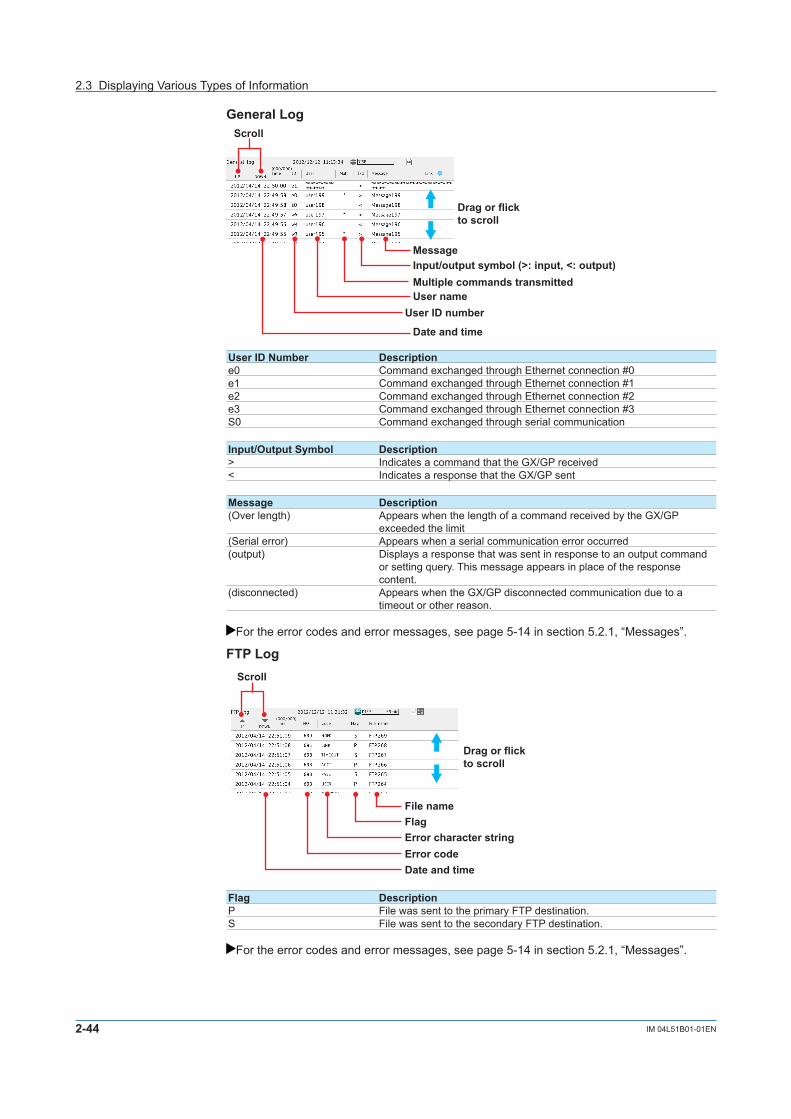
2-44 IM 04L51B01-01EN
General Log
Scroll
Message
User ID number
Date and time
User name
Input/output symbol (>: input, <: output)
Drag or flickto scroll
Multiple commands transmitted
User ID Number Descriptione0 Command exchanged through Ethernet connection #0e1 Command exchanged through Ethernet connection #1e2 Command exchanged through Ethernet connection #2e3 Command exchanged through Ethernet connection #3S0 Command exchanged through serial communication
Input/Output Symbol Description> Indicates a command that the GX/GP received< Indicates a response that the GX/GP sent
Message Description(Over length) Appears when the length of a command received by the GX/GP
exceeded the limit(Serial error) Appears when a serial communication error occurred(output) Displays a response that was sent in response to an output command
or setting query. This message appears in place of the response content.
(disconnected) Appears when the GX/GP disconnected communication due to a timeout or other reason.
For the error codes and error messages, see page 5-14 in section 5.2.1, “Messages”.
FTP Log
Scroll
Error character string
Date and time
FlagFile name
Error code
Drag or flickto scroll
Flag DescriptionP File was sent to the primary FTP destination.S File was sent to the secondary FTP destination.
For the error codes and error messages, see page 5-14 in section 5.2.1, “Messages”.
2.3 Displaying Various Types of Information

2-45IM 04L51B01-01EN
Operating the G
X/GP
1
2
3
4
5
App
Index
WEBLog
Scroll
Code, message
Method, IP addressDate and time
URI
Drag or flickto scroll
Method, IP address DescriptionGET Displays the HTTP method in which an error occurred. The IP address
of the external device in which the error occurred is also displayed.POST
For the error codes and error messages, see page 5-14 in section 5.2.1, “Messages”.
Mail Log
Scroll
Cause (see table below)Date and time
Error code, Error Character stringRecipient/error
Drag or flickto scroll
Type DescriptionALARM Alarm mail transmissionTIMER Scheduled mail transmissionPOWER Power-on, power failure recoveryMEMORY Memory full notificationERROR Error message mailREPORT Report file transmissionTEST Test mail transmissionPASSWORD User lock out
For the error codes and error messages, see page 5-14 in section 5.2.1, “Messages”.
2.3 Displaying Various Types of Information

2-46 IM 04L51B01-01EN
Modbus Log
Scroll
Communication type (C: client, M: master)Date and time
Communication statusCommand number, command type
Drag or flickto scroll
Flag DescriptionC Communication by the Modbus client function (Ethernet)M Communication by the Modbus master function (serial)
Status Factor DescriptionW WriteR ReadBlue Normal communication.
Yellow An external Modbus device returned an error response.
Orange TCP connection in progress.
Red Failed to connect to an external Modbus device.Common to colors other than blue
Skip Command not set.INVALID Command cannot be executed.
WAITING Communication with an external device is congested. Waiting for recovery. Check the connection with the external device.
CLOSED Modbus communication was stopped, and connection to the external device was closed.
RESOLVING Server/slave connection being established (resolving address).CONNNECTING Server/slave connection being established (requesting connection).UNREACH The external device was not found on the network. Check the Modbus
server address setting and Ethernet cable connection.TIMEOUT The response from the external device timed out. Check the
connection with the external device.BROKEN A CRC error was detected in the serial communication with the external
device. Check the serial communication baud rate and other settings.ERR_FC The external device returned an error response. Check whether the
Modbus registers are set correctly to match the external device.ERR_ADDRERR_VALUEERR_DEVICEERR_ACKERR_BUSYERR_NEGATIVEERR_GATE_PATHERR_GATE_TARGETBAD_SLAVE The external device returned an invalid response. Check whether the
external device is operating properly.BAD_FCBAD_ADDRBAD_NUMBAD_CNTVALID Modbus communication was established normally.START Modbus communication started.STOP Modbus communication stopped.DROPOUT Failed to send all commands within the specified communication
interval. Check the number of Modbus commands and the baud rate.
2.3 Displaying Various Types of Information

2-47IM 04L51B01-01EN
Operating the G
X/GP
1
2
3
4
5
App
Index
Command Type DescriptionR Read commandW Write commandO Immediate writing1 N Other
1 For immediate writing, the number (server number or slave number) of the write destination device appears after “O.”
SNTP Log
Error code
Date and time
Scroll
Drag or flickto scroll
ErrorCode DescriptionELINK The Ethernet cable is not connected. Check the GX/GP Ethernet cable
connection.EDORMANT An internal processing error occurred. Contact your nearest
YOKOGAWA dealer.EHOSTNAME The SNTP server host name is invalid. Check the GX/GP Ethernet cable
connection, IP address setting, and SNTP server address setting.ETCPIP An internal processing error occurred. Contact your nearest YOKOGAWA
dealer.ESEND Failed to transmit data to the SNTP server. Check the GX/GP Ethernet
cable connection and IP address setting.ERECV Failed to receive data from the SNTP server. Check the GX/GP Ethernet
cable connection and IP address setting.EBROKEN The SNTP server returned an invalid response. The SNTP server may
in a condition that cannot deliver time information. Check the SNTP server status.
ETIMEDOUT The response from the SNTP server timed out. Check the GX/GP Ethernet cable connection.
EOVER The time difference between the GX/GP and SNTP server has exceeded the limit for correcting the time. Check whether the SNTP server is running properly and the limit for correcting the time.
2.3 Displaying Various Types of Information

2-48 IM 04L51B01-01EN
DHCP Log
MessageTypeDate and time
Scroll
Drag or flickto scroll
Type Message DescriptionLINK ON Ethernet cable connection was detected.
OFF Ethernet cable disconnection was detected.SET Address (e.g., 10.0.122.3) The IP address of the GX/GP was set.DHCP OFF The DHCP function was disabled.
ON The DHCP function was enabled.RENEWING The IP address obtained from the DHCP server was renewed.RELEASING The IP address obtained from the DHCP server was released.REJECTING TheIPaddressobtainedfromtheDHCPserverwasrejected.
Check whether the DHCP server is operating properly.1 RENEWED IP address was renewed.RELEASED IP address was released.EXTENDED IP address extension application complete.ESEND DHCP message transmission failed. Check the Ethernet cable
connection.ESERVER DHCP server not found. Check whether the DHCP server is
available.ESERVFAIL The response from the DHCP server timed out. Check the
Ethernet cable connection. Check whether the DHCP server is operating properly.
ERENEWED IP address renewal failed. Check the Ethernet cable connection. Check whether the DHCP server is operating properly.
ERELEASED IP address release failed. Check the Ethernet cable connection.EEXTENDED IP address extension application failed. Check the Ethernet
cable connection. Check whether the DHCP server is operating properly.
EEXPIRED IP address lease period expired. IP address was reset to 0.0.0.0. Check the Ethernet cable connection. Check whether the DHCP server is operating properly.
DNS UPDATED DNS host name registration complete.REMOVED DNS host name removal complete.EFORMERR DNS message syntax error was found. Check whether the DNS
server is operating properly.ESERVFAIL An internal processing error occurred in the DNS server. Check
whether the DNS server is operating properly.EINTERNALENONAMEENXDOMAIN QuerytotheDNSserverwaverejected.CheckwhethertheGX/
GP domain name setting is correct.The GX/GP does not support DNS servers that require host name registration authentication. Check whether the DNS server supports host name registration without authentication.
EREFUSEDEYXDOMAINEYXRESETENXRESETENOTAUTHENOTZONE
1 IftheGX/GPcannotaccepttheIPaddressobtainedfromtheDHCPserver,theGX/GPrejectsthe address and immediately returns a response to the DHCP server.
2.3 Displaying Various Types of Information

2-49IM 04L51B01-01EN
Operating the G
X/GP
1
2
3
4
5
App
Index
2.3.6 Checking the Command Status of the Modbus Client and Modbus Master
ProcedureDisplaying the Command Status
1 Press MENU.The menu screen appears.
2 Tap the Browse tab and then Modbus client or Modbus master.The Modbus operation status appears.
Scroll Register numberTap a command to display Modbusinformation.
Resume command transmission
Communication
status
Modbus client
Server nameRead channels
Modbus master
Register numberSlave address
Comand dropout iconAppears when a data dropout occurs. The icon remains displayed until you tap it. Command execution times are displayed in red while the icon is displayed. The icon is the same for both client and master.
3 Tap a command to display the Modbus information.
Operation complete
SwitchingbetweenListandOverviewDisplaysYou can switch between list and overview displays.
1 Press MENU.The menu screen appears.
2 Tap the Context tab and then DisplayOverview/List.The list display or overview display appears.
Each time you tap DisplayOverview/List, the setting toggles between list display and overview display.
Operation complete
2.3 Displaying Various Types of Information

2-50 IM 04L51B01-01EN
Communication ConditionThe following settings are displayed. The setting display varies between Modbus client and Modbus master.Function Setup Item DisplayModbus client Wait time Auto recoveryModbus master Interval Read cycle
Communication timeout Time outRetransmission RetrialsWait time Auto recovery
Communication StatusSee page 2-42 in section 2.3.5, “Displaying Logs”.
Resuming Command TransmissionYou can use touch operation to resume command transmission to a server to which communication is stopped (red status lamp).
1 Select the command to send to the server.The Modbus information appears.
2 Tap Refresh.TheGX/GPstartscommandtransmissiontothespecifiedserver.
Operation complete
Data When Communication Is Stopped and during Connection RetrialsIf the command transmission stops such as due to a connection drop, the status turns orange or red, and the communication channel data is held at the previous value or is reset.
Data DropoutData drop occurs when the commands from 1 to 100 from the GX20-1/GP20-1, from 1 to 200 from the GX20-2/GP20-2, or from 1 to 50 from the GX10/GP10 do not complete within the read cycle. When a data dropout occurs, the communication channel data is held at the previous value. In addition, command execution times are displayed in red on the Modbus operating status display, and a command dropout icon appears.Tap the icon to clear it. If another data dropout occurs, the icon will reappear.A message indicating the data dropout is also displayed on the Modbus operation status display. If this happens, take measures such as making the read cycle longer or reducing the number of commands. Confirm that no data dropout occurs on the Modbus status log screen.
2.3 Displaying Various Types of Information

2-51IM 04L51B01-01EN
Operating the G
X/GP
1
2
3
4
5
App
Index
2.3.7 DisplayingtheDOChannelandInternalSwitchStatus(Releasenumber2andlater)
ProcedureDisplaying the Status
1 Press MENU.The menu screen appears.
2 Tap the Browse tab and then Switch/Relay.The internal switch/relay status is displayed.Tap the internal switch or relay display area to expand the area.Tap a channel to display the channel information.
Switch displays
Display all
Display all
Channel information
Control the DO or internal switch.
Operation complete
ControllingtheInternalSwitchandDOThe procedure below applies to internal switches when in the internal switch settings in system settings, Type is set to Manual.The procedure below applies to DO channels whose Type is set to Manual in the range setting of DO channels.In Display settings, under Screen display settings, Changing each value from monitoring must be set to On.
1 Tap the status display area of the internal switch that you want to control or the relay status display area of the relay that you want to use DO control.The area is expanded.
2 Tap the internal switch or relay you want to control.The internal switch information or channel information appears.
3 Tap ON or OFF.The tapped value (ON or OFF) takes effect.
Operation complete
2.3 Displaying Various Types of Information

2-52 IM 04L51B01-01EN
2.3.8 Displaying the GX/GP System InformationYou can display the GX/GP system information.
Procedure
1 Press MENU.The menu screen appears.
2 Tap the Browse tab and then System information.The system information appears.
WhenanExpandableI/OIsNotInstalled
XXXXXXXXXXX-XX-XX-XX-XX-XX
RX.XX.XXRX.XX.XX
Activates modules(for the advanced security function (/AS option))
Tap a module to display detailed information.
Drag or flick
Switch the page
Drag or flick up and down to switch pages.
2.3 Displaying Various Types of Information

2-53IM 04L51B01-01EN
Operating the G
X/GP
1
2
3
4
5
App
Index
WhenanExpandableI/OIsInstalled
Detailed information
Switch displays
Drag or flick
System information
XX-XX-XX-XX-XX-XX
RX.XX.XX
XXXXXXXXX
RX.XX.XX
Unit information
Module information
Detailed information
Activates modules(for the advanced security function (/AS option))
Unit status
Module statusTap to link to the corresponding unit on the Module Info tab.
Switches units Tap a module to display detailed information.
RX.XX.XX
XXXXXXXXX
XXXXXXXXX
RX.XX.XX
2.3 Displaying Various Types of Information

2-54 IM 04L51B01-01EN
Displayed ContentItem Displayed Content DetailsSystem Info •Channelinformation
•Internalmemorycapacity•Optioninformation•MACaddress•Serialnumber•Versioninformation•Webapplicationversioninformation•Advancedsecurityfunction(/ASoption)usage
—
Unit Info(when an expandable I/O is installed)
•Mainunitmodel•ExpandableI/Omodel•ExpandableI/OstatusIcon Description
The expandable I/O is operating normally.
An error is occurring in the expandable I/O.
A critical error is occurring in the expandable I/O, and the unit is not operating.The expandable I/O that is recognized does not match the unit that is connected.Examples:•Connectedbutnotrecognized•Recognizedbutnotconnected
(Blank) No expandable I/Os are connected or recognized.
•ExpandableI/Onumber•RecognizedexpandableI/Omodels•ConnectedexpandableI/Omodels•StatusofmodulesintheexpandableI/OIcon Description
The modules in the expandable I/O are operating normally.
An error is occurring in a module in the expandable I/O.
A discrepancy is occurring between a connected module in the expandable I/O and the module recognized by the system.
(Blank) Information on the modules in the expandable I/O cannot be retrieved.Examples:•NomodulesareconnectedtotheexpandableI/O.•TheexpandableI/Oisnotconnected.•TheexpandableI/Oisnotoperatingnormally,andtheinformationon the modules in the unit cannot be retrieved.
•Versioninformation•Serialnumber•Optioninformation•Errorinformation
Module Info •ModulestatusIcon Description
The module is operating normally.
An error is occurring in the module.
A critical error is occurring in the module, and it is not operating.
The module that is recognized does not match the module that is connected.Examples:•Connectedbutnotrecognized•Recognizedbutnotconnected
(Blank) No modules are connected or recognized.
•Slotnumber•Recognizedmodulemodels•Connectedmodulemodels
•Numberofchannels•Versioninformation•Serialnumber•Errorinformation
Operation complete
2.3 Displaying Various Types of Information

2-55IM 04L51B01-01EN
Operating the G
X/GP
1
2
3
4
5
App
Index
ActivatingModules(Whenusingtheadvancedsecurityfunction(/ASoption))If modules that need to be activated are installed, “Module activation” appears under the system information.
For details on module activation, see section 2.2.7, “Activating Modules,” in the Advanced Security Function (/AS) User’s Manual (IM 04L51B01-05EN).
2.3 Displaying Various Types of Information

2-56 IM 04L51B01-01EN
2.3.9 DisplayingNetworkInformationYou can display the GX/GP network information.
Procedure
1 Press MENU.The menu screen appears.
2 Tap the Browse tab and then Networkinformation.The network information appears.
XX-XX-XX-XX-XX-XX
Operation complete
Display ItemThe following items are displayed.• IPaddress• SubnetmaskIPaddress• DefaultgatewayIPaddress• MACaddress• DNSserverIPaddresses(primaryandsecondary)• Domainsuffixes(primaryandsecondary)• Hostname• Domainname• Theusageconditionsofthefollowingserverfunctions FTP, Web, Modbus, SNTP, GENE (general purpose communication), EtherNet/IP (/E1
option), DARWIN When in use: USE When not in use: NOT
2.3 Displaying Various Types of Information

2-57IM 04L51B01-01EN
Operating the G
X/GP
1
2
3
4
5
App
Index
2.4 ExecutingVariousFunctions
This section explains how to execute various functions.
2.4.1 ReleasingAlarmOutput(AlarmACKandindividualalarmACKoperation)This operation is valid when the GX/GP is configured as follows:• InSystem settings, under Alarm basic settings, Indicator’s Hold/Nonhold is set to
Hold.• UnderDO channel settings, Action’s Hold is set to Hold or Relay Action on ACK is set
to Reset
When an alarm acknowledge operation is carried out, the indicators and outputs (relays) of all activated alarms are cleared.
ProcedureAcknowledgingAllAlarmsWhen an alarm acknowledge operation is carried out, the indicators and outputs (relays) of all activated alarms are cleared.You can carry out this procedure after an alarm occurs.
1 Press MENU.The menu screen appears.
2 Tap the Alarm icon.Thealarmacknowledgeconfirmationscreenappears.
Alarm icon
3 Tap OK.The alarm output is released.
Operation complete

2-58 IM 04L51B01-01EN
AcknowledgingIndividualAlarms(Releasenumber2andlater)Active alarms are acknowledged separately by channel and level.Even when Individual alarm ACK is specified, it is possible to acknowledge all alarms at once.The individual alarm ACK function must be enabled. See page 1-148 in section 1.18.3, “Setting the Alarm Display Hold/Nonhold and Individual Alarm ACK Operation”.You can carry out this procedure after an alarm occurs.
1 Tap the digital display area of a channel.The channel information appears.
2 Tap the Alarm ACK icon.The individual alarm ACK selection screen appears.
Select the level.
3 Select the level to acknowledge, and tap OK.The alarm output is released.
Operation complete
Individual alarm ACK can be executed from the following screens.• Trend• Digital• Bargraph• Overview• Customdisplay
2.4.2 DisablingandEnablingOperation(Operationlockfunction)See page 2-75 in section 2.9, “Disabling Operation (Operation lock function)”.
2.4.3 ResettingTimers(Relativetimers)
Procedure
1 Press MENU.The menu screen appears.
2 Tap the Universal tab and then Timer reset.The reset selection screen (timer number or all) appears.
3 Select the timer to reset, and tap OK.The timer is reset.
Operation complete
2.4 Executing Various Functions
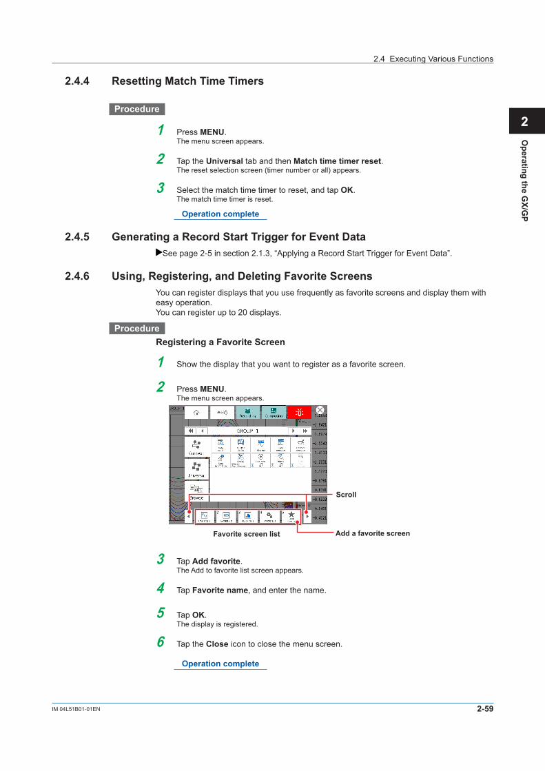
2-59IM 04L51B01-01EN
Operating the G
X/GP
1
2
3
4
5
App
Index
2.4.4 Resetting Match Time Timers
Procedure
1 Press MENU.The menu screen appears.
2 Tap the Universal tab and then Match time timer reset.The reset selection screen (timer number or all) appears.
3 Select the match time timer to reset, and tap OK.The match time timer is reset.
Operation complete
2.4.5 GeneratingaRecordStartTriggerforEventDataSee page 2-5 in section 2.1.3, “Applying a Record Start Trigger for Event Data”.
2.4.6 Using, Registering, and Deleting Favorite ScreensYou can register displays that you use frequently as favorite screens and display them with easy operation.You can register up to 20 displays.
ProcedureRegistering a Favorite Screen
1 Show the display that you want to register as a favorite screen.
2 Press MENU.The menu screen appears.
Add a favorite screen
Scroll
Favorite screen list
3 Tap Add favorite.The Add to favorite list screen appears.
4 Tap Favorite name, and enter the name.
5 Tap OK.The display is registered.
6 Tap the Close icon to close the menu screen.
Operation complete
2.4 Executing Various Functions

2-60 IM 04L51B01-01EN
Deleting a Favorite Screen
1 Press MENU.The menu screen appears.
2 Tap the Universal tab and then Remove favorite.The Remove favorite list screen appears.
3 Select the screen to delete, and tap OK.The favorite screen is deleted.
4 Tap the Close icon to close the menu screen.
Operation complete
2.4.7 Performing a Test Print
1 Press MENU.The menu screen appears.
2 Tap the Universal tab and then Test print.A test print is performed.
Operation complete
2.4.8 Clearing the Buzzer Sound
1 Press MENU.The menu screen appears.
2 Tap the Universal tab and then Buzzer ACK.The buzzer sound is cleared.
Operation complete
2.4.9 Adjusting the Clock ManuallySeepage2-70insection2.7.4,“AdjustingtheClockManually(SNTPtimeadjustment)”.
2.4.10 Using the User FunctionKeys(Releasenumber2andlater)You must configure the event action function.
For details on the settings, see page 1-110 in section 1.14, “Configuring the Event Action Function”.
1 Press MENU.The menu screen appears.
2 Tap the Universal tab and then User function 1 or User function 2.The action assigned to the key is executed.
Operation complete
2.4 Executing Various Functions

2-61IM 04L51B01-01EN
Operating the G
X/GP
1
2
3
4
5
App
Index
2.4.11 VerifyingUnverifiedCertificates(Releasenumber2andlater)If a certificate that you have fails verification and FTP transfer or mail transmission is not possible, an error message (E782) appears, and a Unverified certificate icon appears in the Universal menu.FTP transfer or mail transmission will not be possible until a verification confirmation is performed, a root certificate is installed, or other appropriate measure is taken.When verification confirmation is performed, data that was not transmitted will be transmitted in the next transmission opportunity.
Procedure
1 Press MENU, tap Universal and then Unverified certificate.ASelectunverifiedcertificatescreenappears.
2 From the available buttons, tap the server to display the certificate information.Thecertificateinformationappears,andyouwillbepromptedtoinstallarootcertificateorconfirmthecertificate.
3 Check the information, and tap OK.
Clicking Cancel aborts the procedure and the Select unverified certificate screen closes.
Operation complete
Certificate InformationItem DescriptionValidity OK or not OKVerification OK or not OKIssuer Name of the issuerSubject SubjectValid not before Start date and time of validityValid not after End date and time of validityHash value (SHA1) Hash value
2.4 Executing Various Functions

2-62 IM 04L51B01-01EN
2.5 Saving Various Types of Data
This section explains how to save various types of data.
2.5.1 Automatically Saving Measured DataMeasured data is saved automatically when in Data save settings, Media save Auto save is set to On.The save destination is an SD memory card.Have an SD memory card inserted in the slot at all times. While recording, the measured data recorded in the internal memory is automatically saved to the SD memory card.Behavior when Media FIFO is not enabled: If data storage to the storage medium is not complete such as due to insufficient free space, the unsaved data is saved the next time the data is automatically saved.
2.5.2 ManuallySavingMeasuredData(Collectivelysavingunsaveddata)Manual saving of measured data is possible when in Data save settings, Media save Auto save is set to Off.The save destination is an SD memory card or USB flash memory (/UH option). The procedure below is for saving unsaved data to an SD memory card.
Procedure
1 Set an SD memory card in the slot.The media operation screen appears.
2 Tap Save manual.The unsaved data in the internal memory is saved to the SD memory card.
3 Remove the SD memory card by following the procedure below.Tap the MENU key > Media eject icon > SD.
When the message “Media can be removed safely” appears, remove the SD memory card.
Operation complete
For details on manually saving from the memory summary, see page 2-36 in section 2.3.3, “Displaying a List of Data Files in the Internal Memory and Saving Data (Memory summary)”.
Note• Ifthereisnotenoughspaceonthestoragemedium,themessage“Notenoughfreespace
on media” appears, and the data is not saved. If this message appears, replace the storage medium. Then, carry out the procedure again.
• Youcannotabortadatasaveoperationwhileitisinprogress.
2.5.3 ManuallySavingInstantaneousValuesofMeasuredData(Manual sample)
This section explains how to save the instantaneous values of channels whose manual sample recording is enabled (excluding those set to Skip or Off) through touch operation.
Procedure
1 Press MENU.The menu screen appears.
2 Tap the Universal tab and then Manual sample.Manual sampling is executed.
Operation complete

2-63IM 04L51B01-01EN
Operating the G
X/GP
1
2
3
4
5
App
Index
ExplanationNumberofManualSampledDataEntriesintheInternalMemoryYou can view the number of manual sampled data entries in the internal memory on the memory summary display ( see page 2-36 in section 2.3.3, “Displaying a List of Data Files in the Internal Memory and Saving Data (Memory summary)”).
Saving Manual Sampled Data• IfautosaveisOn, the manual sampled data is saved to the SD memory card when you
carry out manual sampling.• YoucansavethemanualsampleddatatotheSDmemorycardorUSBflashmemory
(/UH option) by following the procedure for manually saving the data ( see page 2-62 in section 2.5.3, “Manually Saving Instantaneous Values of Measured Data (Manual sample)”) regardless of the Auto save setting.
2.5.4 SavingandPrintingScreenImageData(Snapshot)This section explains how to save the screen image data of the active display to an SD memory card or USB flash memory (/UH option). This operation is called snapshot, and the screen image data file is called snapshot data file. The screen image data can also be printed. To use these functions, you need to set Snapshot to On under Printer settings in System settings. See page 1-154 in section 1.18.7, “Setting the Printer Output Conditions”.If the auto transferring of snapshots is set to On for the FTP client function, the data is transferred via FTP.
Procedure
1 Press MENU.The menu screen appears.
2 Tap the Universal tab and then Snap shot.IfbothanSDmemorycardandUSBflashmemoryareinserted,ascreenforselectingthesavedestination appears. If only one of the two is inserted, the screen does not appear, and the snap-shotdatafileissavedtotheinsertedmedium.
3 Tap the save destination.ThesnapshotdatafileissavedtotheSDmemorycardorUSBflashmemory. If you are taking a snapshot through touch operation, the menu screen and pop-up
screen are not saved. If you are taking a snapshot through a communication com-mand or event action, all displayed contents are saved.
Operation complete
• SnapshotdatafilesareinPNGformat.• For file names, see page 1-91 in section 1.9.1, “Setting the Save Directory, File Header, and
File Name”.
NoteNote that if you take a snapshot, you will not be able to take another snapshot for approximately 10 seconds.
If you are taking a snapshot through a communication command or event action, the snapshot data file is saved to the SD memory card.
2.5 Saving Various Types of Data

2-64 IM 04L51B01-01EN
2.5.5 Saving Internal Memory Files to an SD Memory Card or USB Flash Memory
See page 2-36 in section 2.3.3, “Displaying a List of Data Files in the Internal Memory and Saving Data (Memory summary)”.
2.5.6 SavingDisplayDataorEventDataduringRecordingthroughTouchOperation
The save destination is the SD memory card in the GX/GP.You can carry out this procedure when display data or event data is being recorded in Free mode. Unsaved measured data is saved to the SD memory card.
Time
Saved the previous time
Save operation
FileFile FileSaved this time
Procedure
1 Press MENU.The menu screen appears.
2 Tap the Universal tab.The menu screen appears.
3 Tap Save display or Save event.The display data or event data is saved to the SD card.
Operation complete
2.5.7 Removing the SD Memory Card or USB Flash Memory
Procedure
1 Press MENU.The menu screen appears.
2 Tap the Media eject icon.Aconfirmationscreenisdisplayed.
Eject externalstorage medium
3 Tap SD or USB.YoucannowremovetheSDmemorycardorUSBflashmemory.
Operation complete
2.5 Saving Various Types of Data
2-65IM 04L51B01-01EN
Operating the G
X/GP
1
2
3
4
5
App
Index
NoteIf you remove the SD memory card or USB flash memory without performing the above procedure, the data stored on it may be damaged.
ExplanationOperationsThatYouCanPerformonanSDMemoryCardorUSBFlashMemoryYou can perform the following data save/load and file operations.Save and load setting parameter files ( see page 1-164 in section 1.20.1, “Loading Setting Parameters”, page 1-173 in section 1.21.1, “Saving the Setting Parameters”)Save display data and event data files ( see page 2-36 in section 2.3.3, “Displaying a List of Data Files in the Internal Memory and Saving Data (Memory summary)”)Load display data and event data files ( see page 2-73 in section 2.8.2, “Loading and Displaying the Measured Data (Display data and event data) from the Storage Medium”)List files and delete files ( see page 1-179 in section 1.22, “Listing Files That Are on the External Storage Medium”)Format ( see page 1-180 in section 1.23, “Formatting the External Storage Medium”)
2.5 Saving Various Types of Data

2-66 IM 04L51B01-01EN
2.6 Using USB Peripheral Devices
This section explains how to connect peripheral devices to USB ports (/UH option).
2.6.1 Using a Keyboard or Bar Code ReaderYou can connect a keyboard or bar code reader to a USB port.
For specifying the keyboard or bar code reader to use, see page 1-157 in section 1.18.11, “Setting USB Input Devices (/UH option)”.
ProcedureConnecting a Keyboard or Bar Code ReaderConnect a keyboard or bar code reader to the GX/GP USB port.
USB port
Removing the Keyboard or Bar Code ReaderDisconnect the keyboard or bar code reader from the GX/GP USB port.
Note• Youcanconnectanddisconnectakeyboardorbarcodereaderatanytime,regardlessofwhat
is shown on the display and whether the GX/GP is on or off.• YoucanconnectonlyonekeyboardoronebarcodereadertotheGX/GP.Youcannotusea
keyboard and a bar code reader at the same time.• UseakeyboardthatmatchestheUSBinputdevicesetting.• TheCapsLockkeystateisclearedwhenthepoweristurnedoffandthenonorwhentheUSB
keyboard is disconnected.• TheNumLockkeyisalwaysenabledregardlessofthekeyboardstate.

2-67IM 04L51B01-01EN
Operating the G
X/GP
1
2
3
4
5
App
Index
Operating from a KeyboardWhen a text input keyboard is showing on the GX/GP screen, you can enter alphabet characters, numbers, and symbols from the connected keyboard.
Valid KeysKeys enclosed in frames are valid.
PC 109 Keyboard (Japanese)
PC 104 Keyboard (US)
Operating from a Bar Code ReaderWhen a text input keyboard is showing on the GX/GP screen, you can enter alphabet characters, numbers, and symbols that the connected bar code reader reads.ASCII characters (128 characters: numbers, symbols, and uppercase and lowercase alphabet characters) can be read.
• ConfiguringtheBarCodeReader Configure the bar code reader as follows:
USB Host Parameter SettingUSB device type HID keyboard simulationUSB keyboard type Set the type in accordance with the GX/GP USB input device setting.
•WhentheGX/GPsettingisUSkeyboard(104)Bar code reader: Standard US USB keyboard•WhentheGX/GPsettingisJapanesekeyboard(109)Bar code reader: Japanese Windows (ASCII)
• HowtoUse Follow the operating procedure of the bar cord reader that you are using.
2.6.2 Using a MouseYou can use a mouse simply by connecting it to a USB port.
Mouse OperationTap: Click the left buttonDrag: Drag while holding down the left buttonDisplay the menu: Click the center button (mouse wheel)
2.6 Using USB Peripheral Devices

2-68 IM 04L51B01-01EN
2.6.3 ExecutingCommunicationCommandswithaUSBBarcodeReader(Releasenumber2andlater)
You can execute communication commands from a USB bar code reader. You need to set USB input device to Bar-code reader.Input from the keyboard is also executed as a communication command.
For details on the commands that you can set and execute, see page 1-157 in section 1.18.11, “Setting USB Input Devices (/UH option)”.
• ConfiguringtheBarCodeReader Configure the bar code reader as follows:USB Host Parameter SettingUSB device type HID keyboard simulationUSB keyboard type Set the type in accordance with the GX/GP USB input device
setting.•WhentheGX/GPsettingisBar-codereaderBar code reader: US standard USB keyboard
2.6 Using USB Peripheral Devices

2-69IM 04L51B01-01EN
Operating the G
X/GP
1
2
3
4
5
App
Index
2.7 PerformingNetworkRelatedOperations
This section explains how to perform network related operations.
2.7.1 Performing an Mail Transmission TestYou can send a test mail to check whether you have configured the mail settings correctly.
Procedure
1 Press MENU.The menu screen appears.
2 Tap the Universal tab and then E-Mailtest.The mail transmission test screen appears.
3 Tap Recipient 1 or Recipient 2.A test mail is sent.
Operation complete
2.7.2 Starting and Stopping Mail TransmissionYou can enable or disable the mail transmission function.
ProcedureStarting Mail Transmission
1 Press MENU.The menu screen appears.
2 Tap the Universal tab and then E-Mailstart.Mail transmission function is enabled.
Operation complete
Stopping Mail Transmission
1 Press MENU.The menu screen appears.
2 Tap the Universal tab and then E-Mailstop.Mail transmission function is disabled. Unsent mails are cleared.
Operation complete
Mail RetransmissionIf mail transmission fails, the message is retransmitted up to twice at 30-second and 1-minute intervals.If retransmission fails, the message is discarded.

2-70 IM 04L51B01-01EN
2.7.3 CheckingFTPFileTransfers(FTPtransmissiontest)You can check whether files can be sent from the GX/GP to the FTP server using a test file.
Procedure
1 Press MENU.The menu screen appears.
2 Tap the Universal tab and then FTP test.The FTP transmission test screen appears.
3 Tap Primary or Secondary.Thetestfileissent.
Operation complete
Items to Check before Performing This Test• ConnecttheEthernetcablecorrectly. For the connection procedure, see section 3.6,
“Optional Terminal Wiring” in the First Step Guide.• CheckthattheEthernetinterfacesettingsarecorrect. For the setup procedure, see
page 1-126 in section 1.16, “Configuring the Ethernet Communication Function”.
Checking the Results of the FTP Test• WhenanFTPtestisexecuted,atestfilenamedFTP_TEST.TXTistransferredtothe
specified FTP destination directory.• YoucanalsochecktheresultofanFTPtestusingtheFTPlog( see page 2-42 in section
2.3.5, “Displaying Logs”), Web display ( see section 3.1, “Using a Web Browser to Change the GX/GP Settings, Monitor Data, and Control the GX/GP (Web server function)”), and FLog command (see the setting commands in the communication command manual).
2.7.4 AdjustingtheClockManually(SNTPtimeadjustment)Youcanadjusttheclockmanuallythroughtouchoperation.TheSNTPclientmustbeenabled.
For details on the SNTP function, see page 1-134 in section 1.16.5, “Setting the SNTP Client Function”.
Procedure
1 Press MENU.The menu screen appears.
2 Tap the Universal tab and then SNTP.Theclockisadjusted.
Operation complete
2.7 Performing Network Related Operations

2-71IM 04L51B01-01EN
Operating the G
X/GP
1
2
3
4
5
App
Index
2.7.5 OutputtingSnapshotsorReportDatatoaNetworkPrinterYou can output snapshots or report data to a network printer.To enable snapshot output, you need to set Snapshot to On under Printer settings in System settings.To enable report data output, you need to set Report Template Output Printer to On under Basic settings in Report Settings.
ProcedureOutputting a Snapshot
1 Press MENU.The menu screen appears.
2 Tap the Universal tab and then Snap shot.A snapshot is output to a network printer.
Operation complete
Outputting ReportsWhen report data is generated, it is automatically output to the printer.
2.7.6 DisplayingNetworkConnectionInformationSee page 2-56 in section 2.3.9, “Displaying Network Information”.
2.7.7 ObtainingandReleasingNetworkInformationReceivedthroughDHCPYou can manually obtain or release network information such as the IP address. You can carry out this procedure when Obtain IP address automatically is set to On. You will show the network information screen and then obtain or release information.
ProcedureObtainingNetworkInformation
1 Press MENU.The menu screen appears.
2 Tap the Browse tab and then Networkinformation.The network information appears.
3 Press MENU.The menu screen appears.
4 Tap the Context tab and then Request IP address.The obtained IP address is displayed.
Operation complete
2.7 Performing Network Related Operations

2-72 IM 04L51B01-01EN
ReleasingNetworkInformation
1 Press MENU.The menu screen appears.
2 Tap the Browse tab and then Networkinformation.The network information appears.
3 Press MENU.The menu screen appears.
4 Tap the Context tab and then Release IP address.The network information is released.
Operation complete
2.7 Performing Network Related Operations

2-73IM 04L51B01-01EN
Operating the G
X/GP
1
2
3
4
5
App
Index
2.8 Performing File Operations
This section explains file operations.
2.8.1 Initializing the Internal MemoryYou can initialize the settings. When you initialize the settings, the internal memory data is also initialized.
For the procedure, see page 1-181 in section 1.24.1, “Initializing the Settings and the Internal Memory”.
2.8.2 LoadingandDisplayingtheMeasuredData(Displaydataandeventdata)from the Storage Medium
This section explains how to load display data or event data from the external storage medium and display it as waveforms. The loaded data is shown on the historical trend display.
For details on operating the historical trend display, see page 2-24 in section 2.2.7, “Displaying Previously Measured Data (Historical trend display)”.
Procedure
1 Press MENU.The menu screen appears.
2 Tap the Browse tab and then Save load.The menu screen appears.
3 On the menu, Tap Load display data or Load event data.
4 Tap Media kind and then SD or USB.
5 Tap Select file, select the file, and tap OK.
6 Tap Execute.Thefileisloadedandshowninthehistoricaldisplay.
Operation complete
Note• Theextensionstodisplaydatafilesandeventdatafilesvarydependingonwhetherthe
advanced security function (/AS option) is installed and whether the function is enabled or disabled.Advanced Security Function Display Data File EventDataFilesNot available or disabled .GDS .GEVEnabled .GSD .GSE
• Youcansortthefilesbyfilename,directoryname,orupdatedate/time.

2-74 IM 04L51B01-01EN
2.8.3 FormattingtheExternalStorageMediumFormatting will remove the contents of the storage medium.
Procedure
1 Press MENU.The menu screen appears.
2 Tap the Browse tab and then Save load.The menu screen appears.
3 Tap Format Media kind and then SD or USB.
4 Tap Volume name, and set the volume name.
5 Tap Execute.Aconfirmationscreenisdisplayed.
6 Tap OK.The message “Execution is complete.” will appear. Tap the Close icon to close.
7 Tap Exit.The GX/GP returns to the original screen.
Operation complete
2.8 Performing File Operations

2-75IM 04L51B01-01EN
Operating the G
X/GP
1
2
3
4
5
App
Index
2.9 DisablingOperation(Operationlockfunction)
This section explains how to disable operation.You need to set Security function Touch operation to Operation Lock under Basic settings in Security settings.This operation is not possible when you are using the advanced security function (/AS option).
2.9.1 Locking the Operation
1 Press MENU.The menu screen appears.
2 Tap the Universal tab and then Ope lock Lock/Unlock.The operation lock is enabled. The operation lock icon is displayed in the status display section.
2.9.2 Releasing the Operation Lock
1 Press MENU.The menu screen appears.
2 Tap the Universal tab and then Ope lock Lock/Unlock.The screen for entering a password appears.
3. Enter the password, and then tap OK.The operation lock is released. The operation lock icon disappears from the status display sec-tion.The password that you enter is displayed as a string of asterisks.
Operation complete

2-76 IM 04L51B01-01EN
2.10 AllowingOnlyRegisteredUserstoOperate
This section explains security related operations.If you are using the advanced security function (/AS option), see section 2.3, “Logging In and Out,” in the Advanced Security Function (/AS) User’s Manual (IM 04L51B01-05EN).
2.10.1 Logging In and Logging OutThis section explains how to log in through touch operation.For the procedure to log in via communication, see the Communication Interface User’s Manual, IM04L51B01-17EN.
ProcedureLogging In
1 Press MENU.The menu screen appears. If OperationwithoutLogin is set to OFF, a password input screen will appear.
2 Tap the Universal tab and then Login.The screen for entering a password appears.
3. Enter the user name and password, and then tap OK.You can now operate the GX/GP. The user name is displayed in the status display section.The password that you enter is displayed as a string of asterisks.
Thefirsttimeyoulogin,thepasswordissettothedefaultpassword.You can set the password after you log in.
For the setting procedure, page 2-77 in section 2.10.2, “Changing the Password”.
4 Tap the Close icon to close the menu screen.
Operation complete
DefaultUserNamesandPasswordUser Number User Name Password1 User01 default2 User02: :50 User50

2-77IM 04L51B01-01EN
Operating the G
X/GP
1
2
3
4
5
App
Index
Logging Out
• UsingTouchOperation
1 Press MENU.The menu screen appears.
2 Tap the Universal tab and then Logout.You are logged out. The user name disappears from the status display section.
Operation complete
• AutoLogout If auto logout is enabled, you will be logged out when there is no key or touch operation
for the specified length of time.
2.10.2 ChangingthePasswordYou can carry out this procedure when in Security settings, under Basic settings, Security Touch operation is set to Login.
Procedure
1 Press MENU. The menu screen appears. If OperationwithoutLogin is set to OFF, a password input screen will appear.
2 Tap the Universal tab and then Changepassword.The screen for changing the password appears.
3 Tap OldPassword, and enter the old password.
4 Tap NewPassword, and enter the new password.
5 Tap NewPasswordAgain, and enter the new password.
6 Tap OK.The screen closes, and the new password takes effect.
7 Tap the Exit icon to close the menu screen.
Operation complete
NoteDefault password: defaultFor the default password when you are using the advanced security function (/AS option), see section 2.3.1, “Logging In,” in the Advanced Security Function (/AS) User’s Manual (IM 04L51B01-05EN).
2.10 Allowing Only Registered Users to Operate

Blank

3-1IM 04L51B01-01EN
UsingN
etworkFunctions(Ethernetinterface)
1
2
3
4
5
App
Index
3.1 UsingaWebBrowsertoChangetheGX/GPSettings, Monitor Data, and Control the GX/GP (Webserverfunction)
3.1.1 ConnectingtoaNetworkConfiguringtheGX/GPforNetworkConnectionTo connect the GX/GP to an Ethernet network, you need to configure the GX/GP in accordance with the network environment. For the configuration procedure, see page 1-126 in section 1.16, “Configuring the Ethernet Communication Function”
ConnectinganEthernetCable
Do not connect an Ethernet cable whose plug does not comply with FCC specifications. Doing so may damage the GX/GP.
Connect an Ethernet cable from your network to the Ethernet port on the GX/GP rear panel. The figure below shows the position of the Ethernet port on the GX20.
Ethernet port
Chapter 3 UsingNetworkFunctions(Ethernetinterface)

3-2 IM 04L51B01-01EN
3.1.2 Starting and Closing the Main ApplicationFunctionalOverview
You can use the main application (hereafter referred to as the Web application) to do the following:• Control the GX/GP• Monitor data• Change settings
There is no need to install the Web application. Specify the GX/GP IP address on the Web browser to display the application screen. If a GX/GP is accessed from multiple browsers simultaneously, the Web application performance may degrade.
You can access a single GX/GP from multiple browsers at once.
PC System RequirementsThe system requirements are shown below.HardwareItem SpecificationsCPU Windows XP (32 bit edition) Intel Pentium IV, 3 GHz or faster x64
or x86 processorWindows Vista (32 bit edition)Windows 7 (32 bit edition)Windows 7 (64 bit edition) Intel Pentium IV, 3 GHz or faster x64
processorWindows 8.1Internal memory 2 GB or moreHard disk 100 MB or more free space; NTFS recommendedPrinter Printer compatible with the OSMouse Mouse compatible with the OSDisplay A video card compatible with the OS and a display that has a
resolutionof1024×768orhigher,andthatcanshow65,536colors(16-bit, high color) or more
Communication ports
Ethernet port compatible with the OS and TCP/IP protocol
OSWindows XP Home Edition SP3 (excluding 64-bit editions)
Professional SP3 (excluding 64-bit editions)Windows Vista Home Premium SP2 (excluding 64-bit editions)
Business SP2 (excluding 64-bit editions)Windows 7 Home Premium SP1 (32- or 64-bit edition)
Professional SP1 (32- or 64-bit edition)Windows 8.1 No edition name (32- or 64-bit edition)
Pro (32- or 64-bit edition)
WebbrowserInternet Explorer 8, Internet Explorer 9, Internet Explorer 10, Internet Explorer 11Use HTTP1.1 and JavaScript.
SoftwareJava Runtime Environment 1.7.0_xx (Version 7 Update xx), where xx is 51 or higher
GX/GP ConfigurationSet the GX/GP’s HTTP server function to On. For the procedure, see page 1-139 in section 1.16.9, “Setting the Server Functions to Use (FTP, HTTP, SNTP, MODBUS, GENE, DARWIN compatible communication)”
3.1 Using a Web Browser to Change the GX/GP Settings, Monitor Data, and Control the GX/GP (Web server function)

3-3IM 04L51B01-01EN
UsingN
etworkFunctions(Ethernetinterface)
1
2
3
4
5
App
Index
Starting the Web ApplicationIf a message appears in the information bar or dialog box when you start or while you are using the Web application, see the note on the next page or “Installing Java Runtime Environment (JRE).”
Procedure
1 Start the Web browser.
2 In the Address box, enter “http://” followed by the GX/GP IP address and press the Enter key. If DNS is available, you can specify the host name in place of the IP address.Example 1: When the IP address is “127.1.1.1,” enter the following in the Address box.
http://127.1.1.1Example 2: If the HTTP server port has been changed from its default value (80)
to “1024,” enter a colon after the IP address and then the port number.http://127.1.1.1:1024
Example 3: If the HTTP server encryption is set to on https://127.1.1.1
Example 4: If the HTTP server encryption is set to on and the port is changed from the default value of 443 to 1024 https://127.1.1.1:1024
The Web application starts, and the screen appears.If the login function is enabled, a user authentication dialog box appears. Proceed to step 3.
3 Enter the correct user name and password, and click OK. When a Java authentication dialog box appears, enter the user name and password of the user
trying to log in, and then click OK.The Web application starts, and the screen appears.
Start ScreenThe Web application starts with the default display conditions or the display conditions that were in use when the application was closed the previous time (see “Closing the Web Application”). For a description of the window, see “Screen” on page 3-6
3.1 Using a Web Browser to Change the GX/GP Settings, Monitor Data, and Control the GX/GP (Web server function)

3-4 IM 04L51B01-01EN
Note• IftheGX/GPloginfunctionischangedwhiletheWebapplicationisinuse,youmayneedto
reload the page or restart the browser. Follow the instructions in the message.• IfyouareusingtheWebapplicationwiththeSavethispasswordinyourpasswordlistcheck
box selected in the Java authentication screen that appears when you start the Web application (this screen appears when you are using the communication login function) and change the GX/GP Security settings > User settings, you must clear the Java temporary files on the PC. If you do not, the old user registration information will be sent to the GX/GP, and the Web application will not operate properly. You must also clear the Java temporary files if you save an invalid user name or password.
ClearingJavaTemporaryFiles(forJava1.7(Version7)) From the Control Panel, choose Java > General tab > Temporary Internet Files > Settings >
Delete Files. Select the Trace and Log Files and Cached Applications and Applets check boxes, and click OK.
• Thisapplicationissignedwithanelectronicsignature.Whentheapplicationstarts,itautomatically connects to the Internet and checks if the electronic signature has been revoked. As such, if you use the application in an environment where Internet connection is not available (i.e., on an intranet), it may take several minutes for the application to start. To disable the electronic signature revocation check, configure your PC as follows.
Control Panel > Java > Advanced tab > Perform certificate revocation checks on > Do not check
• IfyoucannotconnectfromInternetExplorer10orInternetExplorer11toaGX/GPwhoseloginfunction is in use, disable the Enhanced Protection Mode of Internet Explorer.
Click the Tools button (gear icon) > Internet options > Advanced tab, and clear the EnableEnhancedProtectionMode check box. Restart the PC, and then start the Web application.
• Duringoperation,amessagegeneratedbytheWebapplicationortheGX/GPmayappear.Fordetails on these messages, see page 5-14 in section 5.2.1, “Messages”
Installing the JavaRuntimeEnvironment(JRE)The Web application’s trend, digital, bar graph, and overview monitor displays require JRE. If you are using a PC that does not have JRE installed, JRE will be downloaded automatically from the GX/GP when you start the Web application. After the application starts, the JRE installation screen appears. Follow the instructions on the screen to install JRE.• The time need to download and install JRE varies depending on your PC environment. It
may take several minutes before the installation window appears.• WhentheJREinstallationiscomplete,restartthebrowser,andstartusingtheWeb
application.• Messages may appear in the information bar or dialog box. The possible messages and
how to handle them are provided below.Message Corrective ActionTo help protect your security, Internet Explorer stopped this site from installing an ActiveX control on your computer. Click here for options...
Information bar
Click the information bar, and select Install ActiveX Control or Install This Add-on for All Users on This Computer.
This website wants to install the following add-on: 'Java (TM) SE Runtime Environment 7.0 Update 51' from 'Sun Microsystems, Inc.'. If you trust the website and the add-on and want to install it, click here...Internet Explorer - Security WarningWindows has blocked this software because it can't verify the publisher.Name: liked file name (see the table below)
Click Internet Options > Security > Internet/Local intranet > Custom Level > ActiveX controls and plug-ins, and then select the Prompt check boxes for DownloadsignedActiveXcontrols and Downloadunsigned ActiveX controls.
Your security settings do not allow Web sites to use ActiveX controls installed on your computer. This page may not display correctly.Click here for options...An add-on for this website failed to run. Check the security settings in Internet Options for potential conflicts.
3.1 Using a Web Browser to Change the GX/GP Settings, Monitor Data, and Control the GX/GP (Web server function)

3-5IM 04L51B01-01EN
UsingN
etworkFunctions(Ethernetinterface)
1
2
3
4
5
App
Index
You can also install JRE directly from the GX/GP.1 Onyoubrowser,connecttohttp://[theGX/GPIPaddress]/jre.html.Forexample,ifthe
GX/GPIPaddressis127.1.1.1,accesshttp://127.1.1.1/jre.html.2 JavaRuntimeEnvironmentDownloadpage appears. Select the appropriate link to
download it.Link Descriptionjre-7u51-windows-i586.exe(for Internet Explorer 32bit)
32-bit Internet Explorer Java runtime installer
jre-7u51-windows-x64.exe(for Internet Explorer 64bit)
64-bit Internet Explorer Java runtime installer
• AMessageAskingforPermissiontoRunaJava Applet Even if JRE is installed, a message asking for permission to run a Java applet may
appear. Click Run.Warning - SecurityThe application’s digital signature cannot be verified. Do you want to run the application?Name: (ndx.monitor.Apple or ndx.monitor.LookAheadApplet)
If the following message appears, click Don’t Block.Security WarningBlock potentially unsafe components from being run?Application: ndx.monitor.Applet
Closing the Web ApplicationWhen close the browser, the Web application also closes.
Display Condition Storage and the Application of the Display Conditions the Next Time the Application Starts
When the Web application closes, the display conditions are saved to the GX/GP. If the login function is enabled, the display conditions that are in use when the Web application is closed are saved for each user.The next time the Web application starts, it will apply the display conditions saved in the GX/GP. If the GX/GP configuration has been changed and it conflicts with the saved display conditions, the default display conditions will be used.
3.1 Using a Web Browser to Change the GX/GP Settings, Monitor Data, and Control the GX/GP (Web server function)

3-6 IM 04L51B01-01EN
ScreenThe screen configuration is shown below.
NoteSet the browser’s zoom (on the View menu, click Zoom) to 100%. Otherwise, the layout may appear crooked.
Menu bar
Content selection treeSplit bar Content area
Name DescriptionMenu bar Consists of three tabs: SMARTDAC+ Web Service, Operation,
and Option.Content selection tree Used to select the contents to display in the content area. There are
two tabs: Data and Config.Content area Area for displaying content.Split bar Drag the split bar to change the panel width of the content selection
tree and content area. While you drag the split bar, the content area displays an alternate screen (see the note on page 3-9 ). Click the show/hide button (indicated with a red circle) to show or hide the content selection tree.
3.1 Using a Web Browser to Change the GX/GP Settings, Monitor Data, and Control the GX/GP (Web server function)

3-7IM 04L51B01-01EN
UsingN
etworkFunctions(Ethernetinterface)
1
2
3
4
5
App
Index
Status IndicationsThe menu bar shows the GX/GP status.
61
2 3 4
7 8 10 11, 12
13 14
5 9
15 16
Number Description1 Communication status. Turns on in yellow when communication with the GX/GP is
normal. If you move the mouse pointer over the icon and hold it there for about 1 second, “Normal” or “Error” will appear in a pop-up window. If communication with the GX/GP is disconnected or recovers, a bubble message indicating the condition will appear for a few seconds.
2 Recording status. Turns on in green when recording.3 Indicates the computation status of computation channels.
Status DescriptionOff Computation stopped.Blinking yellow Computation stopped with error.Blue Computing.Alternating blue and yellow
Computing with error.
4 Alarm status.Status DescriptionOff No alarms. All alarms acknowledged.Red Alarms present. All alarms acknowledged.Blinking green No alarms. Unacknowledged alarms present.Blinking red Alarms present. Unacknowledged alarms present.
5 Login user name.6 GX/GP date and time.7 Batch name. Displayed when the batch function is in use. If the information does
not fit in the area, the information will scroll at certain intervals.8 Internal memory information.
Capacity used
Capacity remaining
Total capacity
42% Capacity remaining
9 Recording progress status.Icon DescriptionD icon Display data fileE icon Event data file
Time already recorded
Time until the file is generated
Time remaining
Time needed to generate file
00:12:56
10 Recording progress status. Event data file information when both display data and event data are recorded.
3.1 Using a Web Browser to Change the GX/GP Settings, Monitor Data, and Control the GX/GP (Web server function)

3-8 IM 04L51B01-01EN
Number Description11 SD memory card capacity information.
Capacity used
Capacity remaining
Total capacity
42% Capacity remaining
12 USB flash memory information. Appears when USB flash memory is connected.
Capacity used
Capacity remaining
Total capacity
42% Capacity remaining
13 Mail transmission function. Displayed when the mail transmission function is in use.
14 Error information. Displayed when an error occurs. Click the icon to clear it.15 Data save information. Appears when the internal memory data is being saved
to the external storage medium. Clicking the icon displays a data save cancel dialog box.
16 User lock out occurring. Appears when there is a locked out user.
3.1 Using a Web Browser to Change the GX/GP Settings, Monitor Data, and Control the GX/GP (Web server function)

3-9IM 04L51B01-01EN
UsingN
etworkFunctions(Ethernetinterface)
1
2
3
4
5
App
Index
3.1.3 Controlling the GX/GPYou can carry out the following operations on the Web application. Note that you cannot carry out these operation on a GX/GP whose advanced security function (/AS) is enabled.• Start and stop recording• Start, stop, reset, and acknowledge computing• AlarmACK• Individual alarm ACK (see “Digital” on 3-26.)• Set the date and time• Start, stop, and test mail transmission• Trigger the starting of event data recording• Execute manual sampling• Save event data• Save display data• Reset relative timers• Reset match time timers• Change a batch number, lot number, and batch comment• View the batch text• Change the time using SNTP• Perform a test print• Execute a file transmission test on the FTP server• Write messages (see “Writing Messages” in page 3-15 in section 3.1.4, “Monitoring the GX/
GP Data and Controlling the GX/GP from the Monitor Screen”)• Change the alarm value (see “Digital” on 3-26)• Change the DO channel output (see “Digital” on 3-26)• Change the internal switch value (see “Displaying the Internal Switch Status and
Changing the Values” on 3-33)• Change the login password (see page 3-58 in section 3.1.8, “Changing the Password”)
Use the following buttons.
If an operation cannot be carried out from the GX/GP, it will not be possible from the Web application either. For operations that cannot be carried out, the corresponding buttons will not be displayed or will not be selectable.• If the GX/GP does not have the function or is not using the function.• User restriction is placed on the operation.• The GX/GP is not in a condition to accept the operation. For example, if the GX/GP is not
recording, you cannot write a message.
Note The following alternate screen may appear temporarily during operation. This is not an error.
3.1 Using a Web Browser to Change the GX/GP Settings, Monitor Data, and Control the GX/GP (Web server function)
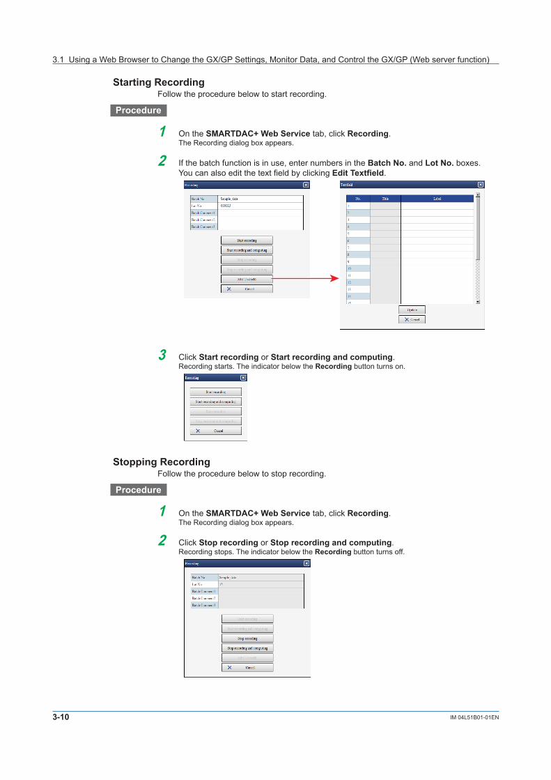
3-10 IM 04L51B01-01EN
Starting RecordingFollow the procedure below to start recording.
Procedure
1 On the SMARTDAC+ Web Service tab, click Recording.The Recording dialog box appears.
2 If the batch function is in use, enter numbers in the Batch No. and Lot No. boxes. You can also edit the text field by clicking EditTextfield.
3 Click Start recording or Start recording and computing.Recording starts. The indicator below the Recording button turns on.
Stopping RecordingFollow the procedure below to stop recording.
Procedure
1 On the SMARTDAC+ Web Service tab, click Recording.The Recording dialog box appears.
2 Click Stop recording or Stop recording and computing.Recording stops. The indicator below the Recording button turns off.
3.1 Using a Web Browser to Change the GX/GP Settings, Monitor Data, and Control the GX/GP (Web server function)

3-11IM 04L51B01-01EN
UsingN
etworkFunctions(Ethernetinterface)
1
2
3
4
5
App
Index
Starting,Stopping,Resetting,andAcknowledgingComputingProcedure
1 On the SMARTDAC+ Web Service tab, click Computing.The Computing dialog box appears.
2 Click a button.Start computing: Starts computing on math channels The indicator below the Comput-ing button turns on in blue.Stop computing: Stops computing on math channels The indicator below the Comput-ing button turns off.Reset computing: Resets computing on math channelsMath ACK: Clears the icon that appears (on the GX/GP) when a computation data dropout occurs.
Alarm ACKFollow the procedure below to acknowledge all alarms that are occurring.
Procedure
1 On the SMARTDAC+ Web Service tab, click Alarm.The Alarm dialog box appears.
2 Click Alarm ACK.Alarms are acknowledged. If the alarm sound is on, it is stopped.
IndicatorbelowtheAlarmbuttonSee “Status Indications.”
Setting the Date and TimeFollow the procedure below to set the GX/GP’s date and time.
Procedure
1 On the Operation tab, click Date/Time Settings.The Date/Time settings dialog box appears.
2 Enter the date and time, and click Update.The GX/GP’s date and time are changed.
You may not be able to change the time depending on the GX/GP settings or condition. Follow the instructions in the message to handle it.
3.1 Using a Web Browser to Change the GX/GP Settings, Monitor Data, and Control the GX/GP (Web server function)

3-12 IM 04L51B01-01EN
Starting, Stopping, and Testing Mail TransmissionProcedure
1 On the Operation tab, click E-Mailfunction.The Mail function dialog box appears.
2 Click a button. Start E-mail transmission: Enables the mail transmission function. Stop E-mail transmission: Disables the mail transmission function. E-Mail test for recipient 1 or E-Mail test for recipient 2: Sends a test mail to the
recipient.
TriggeringtheStartingofEventDataRecordingFollow the procedure below to apply a start trigger for event data recording.
Procedure
1 On the Operation tab, click Eventtrigger.The Event trigger dialog box appears.
2 Click Executeeventtrigger.Event data recording that is in the trigger-wait state starts.
ExecutingManual SamplingFollow the procedure below to execute manual sampling.
Procedure
1 On the Operation tab, click Manual sample.A Manual sample dialog box appears.
2 On the Operation tab, click Executeamanualsample.Manual sampling is executed.
Saving EventDataUnsaved event data stored in the internal memory is saved to the SD memory card.
Procedure
1 On the Operation tab, click Eventsave.An Event save dialog box appears.
2 Click Save event data.The event data is saved.
Aborting Data SavingA data save information icon appears in the status display section while data is being saved. Clicking the this icon displays a Data save dialog box. Clicking Quitsavedata aborts data saving.
Data save information icon
3.1 Using a Web Browser to Change the GX/GP Settings, Monitor Data, and Control the GX/GP (Web server function)

3-13IM 04L51B01-01EN
UsingN
etworkFunctions(Ethernetinterface)
1
2
3
4
5
App
Index
Saving Display DataFollow the procedure below to save unsaved display data stored in the internal memory to the SD memory card.
Procedure
1 On the Operation tab, click Display save.A Display save dialog box appears.
2 Click Save display data.The display data is saved.
Resetting a Relative TimerFollow the procedure below to reset and start a relative timer.
Procedure
1 On the Operation tab, click Timer reset.The Timer reset dialog box appears.
2 Click the timer you want to reset.The timer is reset.
Resetting a Match Time TimerFollow the procedure below to reset a timer that has expired.
Procedure
1 On the Operation tab, click Reset Match Time Timer.The Match time timer reset dialog box appears.
2 Click the match time timer you want to reset.The match time timer is reset.
Changing the batch number, lot number, and batch commentFollow the procedure below to change the batch number, lot number, and batch comment. When the GX/GP is recording, you can enter only batch comments that have not been entered yet.
Procedure
1 On the Operation tab, click Batch.The Batch box appears.
2 Enter the batch number, lot number, and batch comment, and click Change.The batch number, lot number, and batch comment are changed.
For the procedure to enter the batch number, lot number, and batch comment, see page 1-98 in section 1.10, “Configuring the Batch Function”
3.1 Using a Web Browser to Change the GX/GP Settings, Monitor Data, and Control the GX/GP (Web server function)

3-14 IM 04L51B01-01EN
ViewingtheBatchtextFollow the procedure below to view the batch text set on the GX/GP. You cannot change it.
Procedure
1 On the Operation tab, click Text field.TheTextfielddialogboxappears.
2 View the batch text, and click OK.
Changing the Time Using SNTPFollowtheprocedurebelowtoquerytheSNTPserverforthetimeandadjusttheGX/GPtime.
Procedure
1 On the Operation tab, click SNTP manual time adjustment.TheSNTPmanualtimeadjustmentdialogboxappears.
2 Click ExecuteSNTPmanualtimeadjustment.The GX/GP queries the SNTP server for the time.
Performing a Test PrintFollow the procedure below to perform a test print.
Procedure
1 On the Operation tab, click Test print.A Test print dialog box appears.
2 Click Executeatestprint.A test print is performed.
ExecutingaFileTransmissionTestontheFTPServerFollow the procedure below to transfer a test file to the FTP server.
Procedure
1 On the Operation tab, click FTP test.A FTP test dialog box appears.
2 Click ExecuteanFTPtesttotheprimary or ExecuteanFTPtesttothesecondary.TheGX/GPtransfersatestfiletotheFTPserver.
3.1 Using a Web Browser to Change the GX/GP Settings, Monitor Data, and Control the GX/GP (Web server function)

3-15IM 04L51B01-01EN
UsingN
etworkFunctions(Ethernetinterface)
1
2
3
4
5
App
Index
3.1.4 Monitoring the GX/GP Data and Controlling the GX/GP from the Monitor Screen
You can retrieve data and display conditions from the GX/GP and view the information using the monitors listed below. You can also perform alarm acknowledge and other operations.Monitors Trend, digital, bar graph, horizontal bar graph, overview, alarm summary,
message summary, DO channel status, internal switch status, Modbus master status, Modbus client status, WT client status, memory data list, report data list, manual sampled data list, various logs, network information, system information, and favorite monitor
On the trend monitor, digital monitor, bar graph monitor, and horizontal bar graph monitor, channel data is displayed in groups. Up to 4 groups can be displayed.The favorite monitor is a monitor that displays up to four monitors (except for network information and system information) on a single screen (this is different from the favorite screen registration function of the GX/GP).
Display Update IntervalThe channel data display is updated at the scan interval. However, the shortest update interval is 1 second.
Order of Display PrecedenceIf the display of the same type of items overlaps, the information of the smallest number takes precedence. For example, if multiple alarms are occurring, the alarm with the smallest alarm level number takes precedence.
NoteIf the GX/GP system configuration or settings change while the monitor is displayed, the monitor may not display data correctly. In such a case, reload the page.
SwitchingtheMonitorDisplayProcedure
On the Data tab, click the monitor you want to display. Favorite monitors appears when you register a favorite monitor.You can also switch the screen by clicking a monitor display switch button.
Data tab treeSwitch the monitor display
Change the channel display formatPause and resume data updating
3.1 Using a Web Browser to Change the GX/GP Settings, Monitor Data, and Control the GX/GP (Web server function)

3-16 IM 04L51B01-01EN
NoteYou can change the monitor display switch buttons that are displayed on the menu bar. For the procedure, see page 3-57 in section 3.1.7, “Changing the Display Settings on the Browser”
Pausing and Resuming Data UpdatingFollow the procedure below to pause and resume monitor data updating.
ProcedureEach time you click Pause/Resume, the monitor data updating pauses or resumes.When data updating is paused, a section of the Pause/Resume button icon blinks.
NoteIf the GX/GP settings are changed when updating is paused, the paused state may be cleared.
Changing the Channel Display FormatFollow the procedure below to set the display format of channel names and the digital I/O channel values on the monitors. The settings are applied to all monitors.
Procedure
1 Click Display format.A bar appears where you can specify the channel display.
2 Select the display format.
Item DescriptionChannel format
Set the display format of channel names to Channel No., Tag, or Tag No.
Digital label Select the value display format of digital input channels and digital output channels.Digit Displays 0s and 1s as they are (using numbers).
Character Displays 0s and 1s using predefined character strings, such as “OPEN” and “CLOSE.” If character strings are not specified, they will be blank.
3.1 Using a Web Browser to Change the GX/GP Settings, Monitor Data, and Control the GX/GP (Web server function)

3-17IM 04L51B01-01EN
UsingN
etworkFunctions(Ethernetinterface)
1
2
3
4
5
App
Index
Favorite MonitorsFollow the procedure below to create favorite monitors. You can create up to 15 monitors.
ProcedureRegistration
1 On the Data tab, click Create monitor.A screen for creating a new monitor appears.
2 Click Divide.Screen multi panel options appear.
3 Click the multi panel pattern to use.
4 From the Type list, select the screen type to display. You can also select None (to not register a screen).
5 If you select Trend, Digital, or Bar, select the display group from the Gr. list.
6 Repeat steps 4 and 5 to assign screens to all areas.
7 Click Register.The Name box appears.
8 Enter the monitor name, and click Register.The monitor name is added under Favorite monitors in the content selection tree.
Monitor name• You can enter up to 16 characters.• Tabs will be replaced with spaces.• Hats (^), single quotation marks, and semicolons will be replaced with underscores.• Preceding and trailing spaces will be deleted.
3.1 Using a Web Browser to Change the GX/GP Settings, Monitor Data, and Control the GX/GP (Web server function)

3-18 IM 04L51B01-01EN
Deleting a Favorite Monitor
1 In the content selection tree, point to the favorite monitor you want to delete.
2 Click the X mark that appears to the right of the monitor name.Aconfirmationdialogboxappears.
3 Click OK.The monitor name is deleted from the content selection tree.
NoteYou cannot edit a favorite monitor that you created before. If you want to change a favorite monitor, create a new monitor, and overwrite the old one by specifying the same name.
Trend Monitor, Digital Monitor, Bar Graph Monitor, and Horizontal Bar Graph Monitor
Trend MonitorTrend displays are shown by group.
Display groups
Display group change bar
Digital MonitorDigital displays are shown by group.
3.1 Using a Web Browser to Change the GX/GP Settings, Monitor Data, and Control the GX/GP (Web server function)

3-19IM 04L51B01-01EN
UsingN
etworkFunctions(Ethernetinterface)
1
2
3
4
5
App
Index
Bar Graph Monitor and Horizontal Bar Graph MonitorBar graph displays or horizontal bar graph displays are shown by group.
Bar Graph Monitor
Horizontal Bar Graph Monitor
Note• WhenyoustarttheWebapplicationforthefirsttime,displaygroupsaredisplayedin
accordance with the default conditions. Change the display groups if necessary.• Changesthatyoumaketothemonitorarealwaysretained.
ChangingtheDivisionSettingoftheScreen(Trend,digital,bargraphandhorizontalbargraphmonitors)
Follow the procedure below to change the division setting of the screen. If you change the division setting, check the group displayed in each area, and change it if necessary (see “Changing Display Groups”). The division setting applies to all four monitors.
Procedure
1 Click Divide.A bar appears where you can select the division setting.
2 Click the appropriate setting.The screen is divided accordingly.
3.1 Using a Web Browser to Change the GX/GP Settings, Monitor Data, and Control the GX/GP (Web server function)

3-20 IM 04L51B01-01EN
ChangingDisplayGroups(Trend,digital,bargraphandhorizontalbargraphmonitors)
Follow the procedure below to change the group to show in each area. This setting applies to all four monitors.
ProcedureOn the display group change bar, select the display group from the Gr. list.
NoteYou can change an existing monitor and register it as a favorite monitor. For the registration procedure, see “Favorite Monitor” on page 3-17 .
Writing MessagesFollow the procedure below to write a message at the current time position in the data being recorded. You can execute this procedure when a trend, digital, bar graph, horizontal bar graph, overview, alarm summary, message summary, log, DO channel status, or internal switch status is displayed. When you write a message, the screen temporarily shows an alternate screen (see note on page 3-9 ). The message is displayed on the trend. You can also view it in the message summary.
Procedure
1 Click Message.A bar appears where you can set the message to write.
2 Select Preset or Free to specify the message. Preset messages are fixed messages set in the GX/GP. Select a message from the
list. Free messages are messages that you enter on the spot. Select a message number
from the list, and enter the message string in the text box.
Free messages• Up to 32 characters• Single quotation marks and semicolons will be replaced with spaces.
3 From the Write to list, select the display group to write to. Select All groups to write the message to all groups.
4 Click Write.The message is written. See the screen example on the next page.
NoteIf you write a free message, the message string set in the GX/GP will also be replaced.
3.1 Using a Web Browser to Change the GX/GP Settings, Monitor Data, and Control the GX/GP (Web server function)

3-21IM 04L51B01-01EN
UsingN
etworkFunctions(Ethernetinterface)
1
2
3
4
5
App
Index
TrendThe description of a trend screen that can be displayed in one of the divided areas is given below.
Waveform display area Alarm displayTime axis
Splitter
Y-axis display area
Trip line
Toolbar
Active Y-axis mark
Written message
Name DescriptionToolbar Change the trend waveform display mode.Waveform display area Display channel data as waveforms.Y-axis display area Displays the Y-axis of each channel. Each Y-axis displays a scale
image, channel name, and unit. Alarm point marks and color scale bands are also displayed.
Splitter Dragthesplittertoadjustthesizesofthewaveformdisplayareaand Y-axis display area.
Note• Thetimeaxisdisplaysthetimeofday.Itdoesnotdisplaytheelapsedtimefromthestartof
recording.• Partialexpandeddisplayisnotpossible.• IfachangeismadeontheGX/GPthatdisruptsthecontinuityofthedata,thetrendwillbe
cleared.
ChangingtheTrend’sActiveY-AxisThis procedure applies to the trend display.WhatIstheActiveY-axis?The active Y-axis refers to the Y-axis that has focus among the multiple waveforms. The waveform display area shows horizontal grid lines that correspond to the active Y-axis.* The corresponding waveform is also shown in front.
* If auto zone or free zone is in use (see the next page), the horizontal grid lines of the Y-axes that are in the same column as the active Y-axis are also shown.
ProcedureIn the Y-axis area, click a Y-axis to activate it. The active waveform icon appears below the new active Y-axis.
3.1 Using a Web Browser to Change the GX/GP Settings, Monitor Data, and Control the GX/GP (Web server function)

3-22 IM 04L51B01-01EN
Changing the Trend’s Waveform DisplayThis procedure applies to the trend display. You can click the icons in the figure below to change the waveform display.
Waveform display zone
Full
Waveform display limits
Turns the alarm display on and off
Turns the cursor display on and offAuto
SlideFree
Zoom in on or out of the time axis
Waveform line thickness
Waveform Display ZoneChange the waveform display zone.Name DescriptionFull Displays all waveforms in full zones.Auto Divides the waveform display area into equally spaced zones in accordance
with the number of displayed waveforms and displays the waveforms.Slide Displays each waveform cascaded from the top to the bottom of the waveform
display area.Free Displays waveforms in zones specified on the GX/GP.
The following figure shows the Y-axes of each display zone.
Full zone Auto zone Slide zone Free zone
Waveform Display LimitsIf you apply the waveform display limit, the Y-axis display range is limited to the minimum and maximum values of the scale. Values that are less than the minimum scale value are set to the minimum value, and values that are greater than the maximum scale value are set to the maximum value.
With waveform display limits No waveform display limits
Zooming In on or Out of the Time AxisYou can zoom in on or out of the time axis.
3.1 Using a Web Browser to Change the GX/GP Settings, Monitor Data, and Control the GX/GP (Web server function)

3-23IM 04L51B01-01EN
UsingN
etworkFunctions(Ethernetinterface)
1
2
3
4
5
App
Index
Alarm DisplayAlarm information is displayed in the bottom area. Alarm levels (1, 2, 3, and 4) are displayed in order from the top. The duration of each alarm is indicated with a bar using the same color as the corresponding channel. Alarms of channels that correspond to the active Y-axis are shown in front.
Alarm level 1Alarm level 2Alarm level 3Alarm level 4
(red) channel 0001
1
3 4
(blue) channel 0002(green) channel 0003
2
Number Description1 An alarm level 1 alarm on channel 00012 An alarm level 2 alarm on channel 00013 An alarm level 3 alarm on channel 00024 An alarm level 4 alarm on channel 0003
CursorYou can use cursors to read the values at the cursor. Click the cursor display icon, and click a location on the waveform display area. A cursor appears, and the channel values at the cursor position is displayed in pop-up windows. Drag the pointer to display two cursors. You can read the values at the two positions.
TI00113.07
Channel colorChannel name
Measured value
Note• Thepop-upwindowforthewaveformthatcorrespondstotheactiveY-axisisshowninfront.• Whenwaveformdisplaylimitisenabled,“+Over,”“–Over,”and“BURNOUT”aredisplayedfor
channel values when appropriate.
Waveform Line ThicknessYou can change the waveform line thickness.
Trip LinesTrip lines are displayed for the active Y-axis and the Y-axes displayed in the same column as the active Y-axis.
3.1 Using a Web Browser to Change the GX/GP Settings, Monitor Data, and Control the GX/GP (Web server function)

3-24 IM 04L51B01-01EN
Displaying Trends’ Past DataYou can display past data as a trend. This is called historical trend.Data and Interval That Can Be Displayed as a Historical TrendThe current recording and past recording data can be displayed as historical trends over the following interval.Interval: From the point when 3600 points of data is recorded since the start of recording until the start of the next recording.
Recording duration A The next recording duration BRecording start Recording stop Recording start
Duration for which the historical trend of recording duration A can be displayed
Interval until 3600 points are recorded
Displaying the Historical TrendClick the historical trend icon to display the historical trend. You can use the scroll bar to adjustthedisplayrange.
Historical trend
Scroll bar
Retrieve historical trend data
You can carry out the following operations. The procedures are the same as those for the trend display.• Change the active waveform• Change the waveform display zone and waveform display limits• Zoom in on or out of the time axis• Show or hide alarms information• Show or hide cursors The cursor value for display data shows the minimum and maximum values.
TI00113.07 / 13.15
TI00113.07
Minimum value Maximum valueInstantaneous value
Event data Display data
• Change the waveform line thickness
3.1 Using a Web Browser to Change the GX/GP Settings, Monitor Data, and Control the GX/GP (Web server function)

3-25IM 04L51B01-01EN
UsingN
etworkFunctions(Ethernetinterface)
1
2
3
4
5
App
Index
Retrieving Historical Trend DataFollow the procedure below to retrieve historical trend data from the GX/GP.
NoteThe Web application has a buffer for historical trend data. The buffer can hold 3600 data points per channel. By retrieving the historical trend data, you can view the data that has been loaded into this buffer from the GX/GP.
1 Click the retrieve historical trend data icon.A dialog box appears where you can specify the range of historical trend data to retrieve.
2 Drag the scroll bar and selection window to specify the interval of historical trend data to retrieve.
Time axis Selection window Interval held in the buffer
Selection window time display Get button Exit button
3 Click Retrieve.Data retrieval starts. When the data retrieval is complete, the historical trend data is displayed.
NoteIftheclockwaschanged(excludinggradualtimeadjustment)orapowerfailureoccurredduringrecording, for data before the last time disruption, the time between what is selected in the dialog box for specifying the interval of historical trend data to retrieve and the actual data will be misaligned. Displaying such data is possible.
3.1 Using a Web Browser to Change the GX/GP Settings, Monitor Data, and Control the GX/GP (Web server function)

3-26 IM 04L51B01-01EN
DigitalThe description of a digital screen that can be displayed in one of the divided areas is given below.
Unit
Alarm mark
Measured value
Tag name
Alarm MarksAlarm Status Alarm ACK Background ColorOn Unacknowledged alarms
present.Alternating bright and dark red
On All alarms acknowledged. Bright redOff Unacknowledged alarms
present.Blinking gray
Off All alarms acknowledged. No change
When Information Cannot Be ReadDue to space limitations, channel information may not be displayed. If you place the pointer in a channel area and leave it there for about 1 second, the channel name, digital value, and unit will appear in a pop-up window.
ExecutingIndividualAlarmAcknowledges,ChangingAlarmValues,andChangingDOOutput(DOsettoManual)
Click a channel area to display a channel information dialog box of that channel.AI channel DO channel
• ExecutinganIndividualAlarmACK(AIchannel) Click ACK.
The individual alarm is acknowledged.• ChangingtheAlarmValue(AIchannel) Enter a value in the alarm value text box, and click Send.
The alarm value will be changed.• ChangingtheDOOutput(DOchannelsettoManual) You can control the DO output from the channel information dialog box.If the operation fails, a message appears in the bottom line of the channel information dialog box.
3.1 Using a Web Browser to Change the GX/GP Settings, Monitor Data, and Control the GX/GP (Web server function)

3-27IM 04L51B01-01EN
UsingN
etworkFunctions(Ethernetinterface)
1
2
3
4
5
App
Index
Bar Graph Monitor and Horizontal Bar Graph MonitorThe description of the bar graph or horizontal bar graph that can be displayed in one of the divided areas is given below.Bar GraphThe bar graph is shown vertically, and the starting point of bars is as according to the GX/GP setting.
Horizontal Bar GraphThe bar graph is shown horizontally, and the starting point of bars is as according to the GX/GP setting.
Bar Graph
Horizontal Bar Graph
Unit
Alarm point mark
Alarm mark
Measured value
Tag name
Alarm mark
Alarm point mark
Measured value
Unit
Tag name
Alarm MarksSee “Digital.”
When Information Cannot Be ReadDue to space limitations, channel information may not be displayed. If you place the pointer in a channel area and leave it there for about 1 second, the channel name, digital value, and unit will appear in a pop-up window.
ExecutingIndividualAlarmAcknowledges,ChangingAlarmValues,andChangingDOOutput(DOsettoManual)See “Digital” on 3-26.
3.1 Using a Web Browser to Change the GX/GP Settings, Monitor Data, and Control the GX/GP (Web server function)

3-28 IM 04L51B01-01EN
OverviewMonitorThe following four types of overview monitors are available.• All channel• Display group• Display group (detail display)• Channel in display groupAll channel overview
Display group overviewDisplay group overview (detail display)
Channel-in-display-group overview can be displayed from the display group overview.
All ChannelThe all channel overview is displayed when the number of active channels is 100 or less. The screen shows channel names, digital values, units, alarm statuses, and types of active alarms.
Display Item DescriptionChannel name Displays the channel number, tag, or tag number. If the
information does not fit, the portion that does not fit is displayed with an ellipsis (...).
Digital value If the value does not fit, it is not displayed.Unit If the value does not fit, it is not displayed.Type of active alarm Of the active alarms, the alarm type of the lowest alarm level is
displayed.Alarm status The alarm status at the channel level is displayed with a
background color.When the alarm display is set to NonholdAlarm Status Background ColorOn RedOff GreenWhen the alarm display is set to HoldAlarm Status Alarm ACK Background ColorOn Unacknowledged alarms
present.Alternating bright and dark red
On All alarms acknowledged. Bright redOff Unacknowledged alarms
present.Alternating green and white
Off All alarms acknowledged. Green
3.1 Using a Web Browser to Change the GX/GP Settings, Monitor Data, and Control the GX/GP (Web server function)

3-29IM 04L51B01-01EN
UsingN
etworkFunctions(Ethernetinterface)
1
2
3
4
5
App
Index
Due to space limitations, channel information may not be displayed. If you place the pointer in a channel cell and leave it there for about 1 second, the channel name, digital value, unit, and the type of active alarm will appear in a pop-up window.
• ExecutingIndividualAlarmAcknowledges,ChangingAlarmValues,andChangingDOOutput(DOsettoManual)
See “Digital” on 3-26.
Display GroupThe display group overview shows groups.
Display Item DescriptionDisplay group name If the information does not fit, the portion that does not fit is
displayed with an ellipsis (...).Alarm status The alarm status at the group level is displayed with a background
color.For details on the background color, see “Alarm status” in “All Channel.”
Due to space limitations, channel information may not be displayed. If you place the pointer in a group area and leave it there for about 1 second, the group name will appear in a pop-up window.
DisplayGroup(Detaildisplay)When the display group overview is shown, you can click the detail display button to enable and disable detail display mode. Channels in each group are displayed.
3.1 Using a Web Browser to Change the GX/GP Settings, Monitor Data, and Control the GX/GP (Web server function)

3-30 IM 04L51B01-01EN
Display Item DescriptionDisplay group name
If the information does not fit, the portion that does not fit is displayed with an ellipsis (...).
Channel name A channel name is displayed in the appropriate cell if the channel has an active alarm or has an unacknowledged alarm when the alarm is set to Hold. If the information does not fit, the portion that does not fit is displayed with an ellipsis (...).
Alarm status The alarm status at the channel level is displayed with a background color.For details on the background color, see “Alarm status” in “All Channel.”
Due to space limitations, channel information may not be displayed. If you place the pointer in a group name area and leave it there for about 1 second, the group name will appear in a pop-up window. If you place the pointer in a channel area and leave it there for about 1 second, the channel name will appear in a pop-up window.
Channel in Display GroupWhen the display group overview is shown, you can click one of the display group areas to display an overview of that group. The displayed information is the same as with “All channel.”
Return to the display group overview.Switch the display group.
• ExecutingIndividualAlarmAcknowledges,ChangingAlarmValues,andChangingDOOutput(DOsettoManual)
See “Digital” on 3-26.
3.1 Using a Web Browser to Change the GX/GP Settings, Monitor Data, and Control the GX/GP (Web server function)

3-31IM 04L51B01-01EN
UsingN
etworkFunctions(Ethernetinterface)
1
2
3
4
5
App
Index
Alarm Summary MonitorThe alarm summary monitor displays the GX/GP alarm summary. Up to 1000 items can be displayed. For details on the displayed information, see page 2-33 in section 2.3.1, “Listing the Log of Alarm Occurrences and Releases (Alarm Summary)”
Saving the Alarm SummaryClick Alarm save, and follow the instructions in the dialog box that appears. The alarm summary can be saved to an SD memory card or USB flash memory.
SortingClick a column title to sort the alarm summary in ascending or descending order of that column.
Rearranging ColumnsYou can rearrange columns by dragging the column title areas. However, the left most column is fixed.
Changing Column WidthsYou can change the column widths by dragging the column boundaries.
Copying to the ClipboardDrag the cursor to select the list. Press Ctrl+C on the keyboard to copy the selected list to the clipboard.
3.1 Using a Web Browser to Change the GX/GP Settings, Monitor Data, and Control the GX/GP (Web server function)

3-32 IM 04L51B01-01EN
Message Summary MonitorThe message summary monitor displays the GX/GP message summary. Up to 450 items can be displayed. For details on the displayed information, see page 2-35 in section 2.3.2, “Displaying the Log of Written Messages (Message summary)”
You can sort, rearrange columns, change column widths, and copy to clipboard.
ErrorLogMonitorThe error log monitor displays the GX/GP error log. Up to 50 items can be displayed. For details on the displayed information, see page 2-42 in section 2.3.5, “Displaying Logs”
You can sort, rearrange columns, change column widths, and copy to clipboard.The maximum number of log entries is shown below.Type MaximumNumberofDisplayedEventsEvent log 50 Without the advanced security function (/AS)
1000 With the advanced security function (/AS)Error log 50FTP log 50Web log 200Mail log 50SNTP log 200Modbus log 200DHCP log 200General log 200
3.1 Using a Web Browser to Change the GX/GP Settings, Monitor Data, and Control the GX/GP (Web server function)

3-33IM 04L51B01-01EN
UsingN
etworkFunctions(Ethernetinterface)
1
2
3
4
5
App
Index
Changing the Status Display and Output of DO ChannelsYou can display the DO channel status of the entire system. You can change the DO output that are set to Manual.
Output
Tag name
Unit
• Upto60channelscanbedisplayed.Whenthedisplayareaofeachchannelbecomessmall, some of the information will not be displayed.
• Thedisplayisupdatedeverysecond.
ChangingtheDOOutput(DOchannelsettoManual)Click a channel area to display a channel information dialog box of that channel. You can control the DO output from the channel information dialog box.
DisplayingtheInternalSwitchStatusandChangingtheValuesYou can display the internal switch status of the entire system. You can change the values of internal switches that are set to Manual.
Value
Internal switch number
• Upto100internalswitchescanbedisplayed.Whenthedisplayareaofeachchannelbecomes small, some of the information will not be displayed.
• Thedisplayisupdatedeverysecond.
ChangingtheInternalSwitchValues(InternalswitchessettoManual)Click an internal switch area to display a channel information dialog box of that switch. You can change the internal switch value from the channel information dialog box.
3.1 Using a Web Browser to Change the GX/GP Settings, Monitor Data, and Control the GX/GP (Web server function)

3-34 IM 04L51B01-01EN
Modbus Client StatusYou can display the command operation status of Modbus clients. For details on the displayed information, see page 2-49 in section 2.3.6, “Checking the Command Status of the Modbus Client and Modbus Master”.For details on how to use the command dropout icon ( ) and Refresh button, see section 2.3.6.The display is updated every 5 seconds.
Modbus Master StatusYou can display the command operation status of the Modbus master. For details on the displayed information, see page 2-49 in section 2.3.6, “Checking the Command Status of the Modbus Client and Modbus Master”.For details on how to use the command dropout icon ( ) and Refresh button, see section 2.3.6.The display is updated every 5 seconds.
WT Client StatusYou can display the connection status with the WT power meter. For details on the displayed information, see the WT Communication (/E2) User’s Manual (IM 04L51B01-19EN).The display is updated every 5 seconds.
Listing and Saving the Measured Data in the Internal MemoryYou can display a list of the measured data (display data and event data) in the internal memory.• SelectthetypeofdatatodisplayusingtheDatatypelistbox.• Clickacolumntitletosorttheitemsinascendingordescendingorderofthatcolumn.
Saving All DataYou can save the internal memory’s display data, event data, manual sampled data, and report data.
1 Click All save.A Memory data save dialog box appears.
2 Click a button to specify the save destination.The data is saved.
3.1 Using a Web Browser to Change the GX/GP Settings, Monitor Data, and Control the GX/GP (Web server function)

3-35IM 04L51B01-01EN
UsingN
etworkFunctions(Ethernetinterface)
1
2
3
4
5
App
Index
Saving Selected Data
1 Select the data you want to save from the list.
2 Click Select save.A Memory data save dialog box appears.
3 Click a button to specify the save destination.The data is saved.
DownloadingDataviaFTPYou can download the selected data to your PC via FTP.
1 Select the data you want to download.
2. Click FTPdownload.Follow the instructions in the dialog box that appears.
Listing and Saving Report DataYou can display a list of the report data in the internal memory.• SelectthetypeofreportdatatodisplayfromtheReporttypelistbox.• Clickacolumntitletosorttheitemsinascendingordescendingorderofthatcolumn.
Saving the Report Data
1 Click Save.A Report data save dialog box appears.
2 Click a button to specify the save destination.All the report data is saved.
3.1 Using a Web Browser to Change the GX/GP Settings, Monitor Data, and Control the GX/GP (Web server function)

3-36 IM 04L51B01-01EN
Listing and Saving Manual Sampled DataYou can display a list of the manual sampled data in the internal memory.• Clickacolumntitletosorttheitemsinascendingordescendingorderofthatcolumn.
Saving Manual Sampled Data
1 Click Save.A Manual sample data save dialog box appears.
2 Click a button to specify the save destination.All the manual sampled data is saved.
3.1 Using a Web Browser to Change the GX/GP Settings, Monitor Data, and Control the GX/GP (Web server function)

3-37IM 04L51B01-01EN
UsingN
etworkFunctions(Ethernetinterface)
1
2
3
4
5
App
Index
NetworkInformationMonitorThe network information monitor displays the network information of connected instruments.
Click Reload (in the lower right of the screen) to update the displayed network information.
3.1 Using a Web Browser to Change the GX/GP Settings, Monitor Data, and Control the GX/GP (Web server function)

3-38 IM 04L51B01-01EN
System Information MonitorThe system information monitor displays the GX/GP’s basic information, such as the number of channels, and the module configuration.The following figure is for when only the main unit is available. If the expandable I/O is also available, the screen will consist of a System Info tab, Unit Info tab, and Module Info tab.
Click Update connected module (in the lower right of the screen) to update the information under Connected module.
Recognized Module and Connected ModuleRecognized module shows the module configuration that the GX/GP has detected. Connected module shows the module configuration that is actually connected to the GX/GP. To align Recognized module with Connected module, you must perform reconfiguration on the GX/GP.The Special Order column is fixed to Standard. The Status column shows maintenance information.
3.1 Using a Web Browser to Change the GX/GP Settings, Monitor Data, and Control the GX/GP (Web server function)

3-39IM 04L51B01-01EN
UsingN
etworkFunctions(Ethernetinterface)
1
2
3
4
5
App
Index
Displaying Snapshot ScreensOn the SMARTDAC+ Web Service tab, click SnapshotWindow. The snapshot of the GX/GP appears in a separate window. You can use the tool buttons to perform the operations described below.
1 2 3 4
Number Button Name Description1 Auto refresh
on/offTurns on or off the auto refreshing of snapshots. When it is turned on, the screen will be refreshed at approximately 10 second intervals.
2 Refresh Refreshes the screen. Click the button when about 10 seconds has passed from the previous refresh. If you click the button before about 10 seconds has passed, the screen will show the same screen as the last.
3 Actual size Displays the snapshot in the actual size, regardless of the snapshot window size.
4 Window size Displays the snapshot fit to the snapshot window size. However, the aspect ratio of the snapshot is fixed. This may result in blank areas in the top and bottom or in the left or right of the window.
If you close the Web application window, the snapshot window also closes.
NoteThis function is not related to the snapshot function of the GX/GP.
3.1 Using a Web Browser to Change the GX/GP Settings, Monitor Data, and Control the GX/GP (Web server function)

3-40 IM 04L51B01-01EN
3.1.5 Changing SettingsFollow the procedure below to change the GX/GP settings. Note that you cannot change the settings of a GX/GP whose advanced security function (/AS) is enabled (the Config tab will not appear). The procedure below is for a GX/GP whose advanced security function (/AS) is not in use.
NoteThe items and selectable values that appear in the setup screen vary depending on the hardware system configuration. If the items that you want to configure do not appear, check the option and module configuration on the system information monitor.
Notes on Changing SettingsWhen Settings Can Be Changed• You can change settings only when the GX/GP is in a condition that allows setting
changes.• If you are logged in using an account that prohibits setting changes, you will not be able
to change the settings.
Limitations on Modifying Settings• Whennotusingtheloginfunction There are no limitations on modifying settings.• Whenusingtheloginfunction If you are connected to the GX/GP with an Admin account, there are no limitations on
modifying settings. If you are connected to the GX/GP with a User account, you cannot specify the security
settings (Security settings will not appear in the Config tab).
LimitationsonChangingtheLoginPasswordIf you click the Config tab > Security settings > User settings, you will not be able to set the user login password. You can only initialize the password. The default password is “default.” To change the user password, log in using the user’s account, click Password change on the Option tab, and change it.
Applying Setting ChangesOn each setup screen, send the changed settings to the GX/GP to apply them.
NoteWhen settings are changed, the message “Restart is required to reflect this changes. Continue?” may appear. Click OK, and the GX/GP will automatically restart.
3.1 Using a Web Browser to Change the GX/GP Settings, Monitor Data, and Control the GX/GP (Web server function)

3-41IM 04L51B01-01EN
UsingN
etworkFunctions(Ethernetinterface)
1
2
3
4
5
App
Index
Setup Change Procedure
1 Click the Config. tab.The setup item tree appears.
2 Click the item you want to change.The GX/GP settings are loaded and displayed in the content area.
Click Reload to load and update the displayed settings.
3 Edit the settings.For the procedure to set each item, see the reference table below.Setup Item Refer ToAI channel Section 1.2DI channel Section 1.3DO channel Section 1.4Math channel Section 1.5Display settings Section 1.6Measurement settings Section 1.7Recording settings Section 1.8Data save Section 1.9Batch settings Section 1.10Report settings Section 1.11Timer settings Section 1.13Event action Section 1.14Communication channel settings Section 1.15Communication (Ethernet) settings Section 1.16Communication (Serial) settings Section 1.17System settings Section 1.18Security settings Section 1.19
4 Click Update Config.The GX/GP settings are changed.
Note• Ifyoueditthesettingsandswitchtoadifferentsettingscreenbeforeapplyingthesettings,the
edited settings will be discarded.• IfyoueditthesettingsandclickReload before applying the settings, the edited settings will be
discarded.
3.1 Using a Web Browser to Change the GX/GP Settings, Monitor Data, and Control the GX/GP (Web server function)

3-42 IM 04L51B01-01EN
EditingSettingsThis section gives examples of setup editing operations.
Input Controls and Dialog BoxesThe following table shows the input controls and dialog boxes that are used to edit settings on the Web application.Control Type DisplayExample Operation
ExampleSetup Procedure
Text Box Operation example 1
Enter text and numbers.
Check box Operation example 2
Click to select the check box. A selected check box indicate “On” or “enabled.”
List Operation example 1
Click the arrow and select from the list that appears.
Option button — Click to select.
Dialog Box Type Operation Example
Setup Procedure
Channel selection Operation Example 1
When configuring a specific channel, such as an I/O channel, click a channel number button to specify the channel.
Color selection Operation Example 2
From the color selection palette in the dialog box, click a color. You can also enter RGB values to specify a color freely.
Multiple channel selection Operation Example 3
When specifying multiple channels, such as when configuring a display group, click channel number buttons to add channels as character strings to the channel configuration area of the dialog box.
Element selection Operation Example 4
When specifying an internal switch or other item, click the displayed switch number string. (This is similar to channel selection.)
Calibration correction Operation Example 5
Edit calibration correction values. Enter the values directly.
Calculation expression input
Operation Example 6
A dialog box for entering calculation expressions. Set calculation expressions by selecting operators and channels from the lists that appear.
In the following pages, representative operation examples in which the dialog boxes above appear will be given.
ExamplesofOtherEditingOperationsSee also the following examples of editing operations.
Operation Example 7
Selecting a Range
Operation Example 8
Copying and Pasting
Operation Example 9
Range selection and copying and pasting in table type screens
Operation Example 10
Editing table type screens using tool buttons
Operation Example 11
Selecting and unselecting check boxes at once
Operation Example 12
Copying and pasting check boxes at once
Operation Example 13
Jumping to a specific item in table type screens
3.1 Using a Web Browser to Change the GX/GP Settings, Monitor Data, and Control the GX/GP (Web server function)

3-43IM 04L51B01-01EN
UsingN
etworkFunctions(Ethernetinterface)
1
2
3
4
5
App
Index
OperationExample1The DI channel settings screen is shown below.
Click here (▼) to show the available values.
Click to display the channel selectiondialog box dialog box (figure below).
Click to enter the span values.
Channel selection dialog box
Show or hide by channel type(when multiple channel typesare available).
The channel that you clickis reflected in the setup screen,and the dialog box closes.
To not change or setclick Cancel to return.
OperationExample2The DI channel settings screen is shown below
Click to enter a character string.Click to select the check box.
Click to open the display color dialog box (figure below).
Display color dialog box
Click a color to select it.
To create a color, click the text boxes and enter values.
3.1 Using a Web Browser to Change the GX/GP Settings, Monitor Data, and Control the GX/GP (Web server function)

3-44 IM 04L51B01-01EN
OperationExample3This example shows how to assign channels to group 1 on the screen that appears when you click Display settings and then Group settings.
Select the check box. Click to open the group settings dialog box (figure below).
Group settings dialog box
Selectedchannels
Show or hide by channel.
Select the channel check boxes to add the channelsto the group.
Click OK to apply the settings to the configuration screen.
Group configuration channelsYou can easily change the display order of channels.Select a channel, and drag the channel to the appropriate position.
NoteIf the maximum number of selectable channels is reached, you will no longer be able to select additional channels.
OperationExample4This example shows how to set the alarm output destination on the DI channel settings screen.
Select the check box. Click to open the Alarm level 1 Output No.
dialog box (figure below).
Alarm level 1 Output No. dialog box
The internal switch number that you click is reflected in the setup screen and the dialog box closes.
To not change or setclick Cancel to return.
3.1 Using a Web Browser to Change the GX/GP Settings, Monitor Data, and Control the GX/GP (Web server function)

3-45IM 04L51B01-01EN
UsingN
etworkFunctions(Ethernetinterface)
1
2
3
4
5
App
Index
OperationExample5This example shows how to edit calibration correction on the AI channel settings screen.
Select the number of set points.Select the calibration correction mode.
Click to open the calibration correction dialog box (figure below).
Calibration correction dialog box
Calibration correction points
Edit set points.
Click OK to save the edited results.
For details on calibration correction, see page 1-34 in section 1.2.4, “Setting Calibration Correction (Linearizer approximation, linearizer bias)”
OperationExample6This is an example of entering a calculation expression in a calculation expression input dialog box in the Calculation expression setup screen of Math channel settings.
Select a On/Off check box and click Calculation expression to open a dialog box for entering an expression.
Calculation expression edit boxClick the position where you want to insert an operator.
Select the operator type from the list box or tabs to display operator buttons.
Click the button for the operator you want to insert in the calculation expression. The operator appears in the calculation expression edit box.
Click OK to close the dialog box. The entered expression appears in Calculation expression in the setup window.
3.1 Using a Web Browser to Change the GX/GP Settings, Monitor Data, and Control the GX/GP (Web server function)

3-46 IM 04L51B01-01EN
Moving the cursor over the Calculation expression column on the setup screen shows the entire expression in a pop-up. This is useful when you want to view a long expression that does not fit in the column.
When you click Update Config to send the settings to the GX/GP, if the calculation expression appears in red, the expression is invalid. Refer to the pop-up that appears showing an error message.
Range Selection and Copying and PastingYou can select a range of settings and edit them collectively or copy and paste them.This section explains how to select a range of settings and how to use the Copy, Paste, and Tool buttons.
NoteWhen you attempt to copy and paste values, Internet Explorer may show the message “Do you want to allow this webpage to access your clipboard?” Click Allowaccess to enable the copy and paste feature of the Web application. If you click Don’tallow, you will not be able to use the copy and paste feature.
OperationExample7Selecting a RangeThe screen that appears when you select Display settings and then Trend settings will be used as an example to explain the procedure.
1 Click a line name.
Click the line name.
The line is selected.
3.1 Using a Web Browser to Change the GX/GP Settings, Monitor Data, and Control the GX/GP (Web server function)

3-47IM 04L51B01-01EN
UsingN
etworkFunctions(Ethernetinterface)
1
2
3
4
5
App
Index
2 Drag the cursor and release the mouse at the last line you want to select.
Drag across line titlesto select multiple lines.
Multiple lines are selected.
NoteWhen selecting a range, you cannot select multiple nonconsecutive lines one by one. You cannot select an individual column.
OperationExample8Copying and PastingYou can edit copied information in Excel or text editor and paste it back in the Web application. Below is an example of how to edit information in Excel.
1 Select the copy source.
2 Click Copy, which is in the lower right of the screen. You can also press Ctrl+C on the keyboard.When the range is copied to the Clipboard, the color of the range changes as shown below.
3 Paste the contents of the Clipboard to an Excel spreadsheet. The figure below shows an example in which the contents are copied to cell A1 of an Excel spreadsheet. If the pasted contents do not appear correctly, check the format of the cell that you are pasting to.
4 Edit the settings in Excel.
Edit the values in the B column in Excel.
5 CopytheeditresultsfromtheExcelspreadsheet.Copynotjustthevaluesbutalsotheitem names in row A.
3.1 Using a Web Browser to Change the GX/GP Settings, Monitor Data, and Control the GX/GP (Web server function)

3-48 IM 04L51B01-01EN
6 Select the paste destination. Make the paste range the same as the range of the copied data (the number of lines).
7 Click Paste, which is located in the lower right of the window. You can also press Ctrl+V on the keyboard.
TheeditresultsfromtheExcelspreadsheetispastedtotheconfigurationwindow.
Note• DependingontheformatoftheExcelcellsthatyouarepastingto,thevaluesmaychangewhen
you paste the contents from the Clipboard. For example, if the format is set to Number, “0001” will change to “1”. You can prevent pasted values from being automatically corrected by setting Number to Text in the Format Cells dialog box of the Excel sheet that you want to paste to.
• IfthevaluescannotbepastedastheyaretotheExcelsheetevenwiththesettingsabove,werecommend that you use a text editor for copying and pasting.
• IfthevaluesthatyoueditwithExcelortexteditorareoutsidethesettingrange,whenyoupastethe data, the values will be corrected in the same way as when you enter values directly.
OperationExample9Range Selection and Copying and Pasting in Table Type ScreensThe AI channel settings screen will be used as an example to explain the procedure. In table type screens, you can also edit copied information in Excel or text editor and paste it back in the Web application (see note on page 3-48 ).
1 Select a range of channels as shown below.
Click the name of the line to select the entire line.Drag down to select multiple lines.
2 Copy the channel information (lines).
Press Ctrl+C, or click Copy to copy the lines.
3.1 Using a Web Browser to Change the GX/GP Settings, Monitor Data, and Control the GX/GP (Web server function)

3-49IM 04L51B01-01EN
UsingN
etworkFunctions(Ethernetinterface)
1
2
3
4
5
App
Index
3 Paste to different channels.
Select the cells to paste to.Press Ctrl+V, or click Paste to paste to the lines.
OperationExample10EditingTableTypeScreensUsingToolButtonsOn table type windows, you can use the tool buttons that are shown at the bottom of each table. The available types of tool buttons are “Initialize”, “Paste to all lines”, “Increment”, “Minimum”, “Maximum”, and “Change all”. You can use them to edit items collectively.In the example below, the Paste to all tool button is used to set the Type of all selected channels in the AI channel setting screen.
1 Select the line that contains the data you want to copy.CH0001 is selected.
Select the lineto copy from.
Data to copy
Paste destination
2 Drag the cursor to the last line that you want to assign the same type.Channels up to CH0004 are selected.
Drag until the last line you want to paste the same data to.
3.1 Using a Web Browser to Change the GX/GP Settings, Monitor Data, and Control the GX/GP (Web server function)

3-50 IM 04L51B01-01EN
3 Click the “Past to all” button on the tool bar.
Click the “Paste to all” tool button.
The type of CH0002 to CH0004 is set to Volt.
Note• Whenyouusethetoolbuttontopastesettingstochangethesettings,thevaluesare
automatically corrected in the same way as when you enter values directly.• Toolbuttonsareunavailablewhennolinesareselected(exceptforthe“Changeall”button).
The table below shows the different tool button types and their functions.Button Icon FunctionPast to all Pastes the value in the first selected line to all other lines.
Increment • For numeric inputPaste numbers to all selected lines by auto-incrementing the least significant digit, starting with the number in the first selected line.
• For character string inputPaste the character string of the first line appended with auto-incremented sequence numbers to all selected lines. If the character string of the first selected line ends with a number, this number will be used as the first sequence number. If the character string of the first selected line ends with a character, the sequence number 1 is appended to the character string of the first selected line.
Initialize Initializes the values of the selected lines to their defaults.
Minimize Sets the values of the selected lines to their minimum values.
Maximize Sets the values of the selected lines to their maximum values.
Change all • For check boxesSwitches the check box values of the selected lines at once.If all the check boxes of the selected lines are selected, they are cleared. If they are cleared, they are selected.
• For line name (left most) columnsSelects or unselects all lines in the table.
3.1 Using a Web Browser to Change the GX/GP Settings, Monitor Data, and Control the GX/GP (Web server function)

3-51IM 04L51B01-01EN
UsingN
etworkFunctions(Ethernetinterface)
1
2
3
4
5
App
Index
OperationExample11Selecting and Unselecting Check Boxes at OnceThe example below shows the screen that appears when you select Display settings - Group settings - Channel set.Selecting a Range of Check Boxes
Click a label in a cell to select a single cell.
Drag to select cells in a rectangular area.
Selection can be made across different blocks.
Selecting or Unselecting at OnceFollow the procedure below to select or unselect check boxes at once.
Click On/Off, or hold down Ctrl and click a check boxto select or unselect all the check boxes in the selected areaat once.
All the check boxes in the selected range are selected.
Each time you click On/Off, the check boxes in the selected range become selected or unselected at once.Hold down Ctrl and click a check box that is selected to unselect all check boxes in the selected range. Hold down Ctrl and click a check box that is not selected to select all check boxes in the selected range.
3.1 Using a Web Browser to Change the GX/GP Settings, Monitor Data, and Control the GX/GP (Web server function)

3-52 IM 04L51B01-01EN
OperationExample12Copying and Pasting Check Boxes at OnceFollow the procedure below to paste the copy source. In check box type screens, you can also edit copied information in Excel or text editor and paste it back in the Web application. In Excel, a selected check box is indicated as On; an unselected check box is indicated as Off.
Select the cells to copy from, and press Ctrl+C to copy.
Press Ctrl+V to paste.
Select the cell to paste to and drag to select a range.
NoteIf the cells whose check box is selected (on) reaches the maximum selectable number, cells whose check boxes are unselected become unavailable, and you will not be able to paste to them. You cannot paste to cells that do not have check boxes.
OperationExample13Jumping to a Specific Item in Table Type ScreensIn a table type setup screen (e.g., AI channel settings), not all the setup items fit on the screen.Insuchacase,youcanjumptoaspecificitemyouwanttoset.
1 Click the icon in the upper right of the screen.Alistboxforselectingthejumpdestinationappears.
2 Enter the target channel, and click the item that you want to set.Thespecifiedsetupitemisdisplayed.
Setup itemChannel numberIcon
Click the icon to clear the list box.
3.1 Using a Web Browser to Change the GX/GP Settings, Monitor Data, and Control the GX/GP (Web server function)

3-53IM 04L51B01-01EN
UsingN
etworkFunctions(Ethernetinterface)
1
2
3
4
5
App
Index
3.1.6 Saving and Loading SettingsThis section explains how to save and load setting parameters. Note that you cannot display, save, or load setting parameters on a GX/GP whose advanced security function (/AS) is enabled.
Saving GX/GP SettingsYou can save the GX/GP setting parameters to an SD memory card or to USB flash memory.
1 On the Data tab, click Save load.The save/load screen appears. The folders*andfilesontheSDmemorycardaredisplayed.
* Folders that have single quotation marks or semicolons in the their names are not displayed.
2 Select SD or USB from the Folder list. The folders and files on the selected folder are displayed.
Move to the higher level folder button
Click a column title to sort the items in ascending or descending order of that column.
3 Select the save destination folder. Double-click a folder to show the folders and files in that folder. Click the “move to the
higher level folder” button to move to the higher level folder.
4 Enter the file name in the File Name text box. You do not have to enter the extension. You can also click a file in the list to display the file name in the File Name text box.
5 Click Save.The Saveasconfigurationfile dialog box appears.
6 Enter a command, and click Save.To not save, click Cancel.The setting parameters are saved, and the Saveasconfigurationfile dialog box closes.
3.1 Using a Web Browser to Change the GX/GP Settings, Monitor Data, and Control the GX/GP (Web server function)

3-54 IM 04L51B01-01EN
Note• Foldersandfilesarenotdisplayediftheirnamescontainsinglequotationmasksorsemicolons.• Ifafilewiththesamenameexists,anoverwriteconfirmationmessageisdisplayed.
Loading Settings into the GX/GPYou can load GX/GP setting parameters from an SD memory card or USB flash memory into the GX/GP.
1 On the Data tab, click Save load.Thesave/loadscreenappears.ThefoldersandfilesontheSDmemorycardaredisplayed.
2 Select SD or USB from the Folder list. The folders and files on the selected folder are displayed.
3 Select the file you want to load.TheselectedfilenameappearsintheFile Name text box.
If you double-click the file name, the Load from configuration file dialog box appears. In this case, proceed to step 5.
4 Click Load.The Loadfromconfigurationfile dialog box appears.
5 Specify what types of settings to load into the GX/GP using On and Off. Settings that are set to On will be loaded.
6 Click Load.To not load, click Cancel.The setting parameters are applied to the GX/GP, and the Loadasconfigurationfile dialog box closes.
Note• Foldersandfilesarenotdisplayediftheirnamescontainsinglequotationmasksorsemicolons.• Itispossiblethatasaresultofloadingsettingparameters,theWebapplicationnolongerruns
properly or the GX/GP restarts automatically.
DownloadingFilesviaFTPYou can download files in the SD memory card or USB flash memory to your PC via FTP.
1 Under Save/Load on the Data tab, show the screen containing the file you want to download.
2 Select the file you want to download.TheselectedfilenameappearsintheFileNametextbox.
3 Click FTP download.Follow the instructions in the dialog box that appears.
3.1 Using a Web Browser to Change the GX/GP Settings, Monitor Data, and Control the GX/GP (Web server function)

3-55IM 04L51B01-01EN
UsingN
etworkFunctions(Ethernetinterface)
1
2
3
4
5
App
Index
Saving and Loading Report TemplatesYou can save the report templates stored in the GX/GP to an SD memory card or USB flash memory. You can also load the report templates from an SD memory card or USB flash memory into the GX/GP.
On the Data tab, click Save/Load and then Report template. The save/load screen appears.For the procedure, see “Saving GX/GP Settings” and “Loading Settings into the GX/GP.”
ViewingtheTemplateInformationSelect a template file and click Template information to open the Template information dialog box.
DownloadingFilesviaFTPSee “Downloading Files via FTP” provided earlier.
Displaying a List of FilesYou can list the files in the SD memory card or USB flash memory. The files that are displayed are setting files, event data files, display data files, report files, Excel files, manual sampled data files, alarm summary data files, PDF files, and PDF printer files.
On the Data tab, click Save/Load and then File list. A File list screen appears.
DownloadingFilesviaFTPSee “Downloading Files via FTP” provided earlier.
3.1 Using a Web Browser to Change the GX/GP Settings, Monitor Data, and Control the GX/GP (Web server function)

3-56 IM 04L51B01-01EN
Printing the SettingsYou can print the GX/GP settings.On the SMARTDAC+ Web Service tab, click PrintConfig.Window.The setup print window appears.
• You can enter a comment in the Comment box.• Items whose check boxes are selected under Print setting will be printed. Clear the
check boxes for the items you do not want to print.• The password is displayed using asterisks.• Click the browser’s Refresh button to refresh the displayed information.• The information is displayed in the specified display language (see page 3-57 in section
3.1.7, “Changing the Display Settings on the Browser”).
Print using the browser’s print feature.
NoteThe setup print window will work properly only when it is opened from the Web application. When you close the Web application, close also the setup print window.
3.1 Using a Web Browser to Change the GX/GP Settings, Monitor Data, and Control the GX/GP (Web server function)

3-57IM 04L51B01-01EN
UsingN
etworkFunctions(Ethernetinterface)
1
2
3
4
5
App
Index
3.1.7 ChangingtheDisplaySettingsontheBrowserYou can change the display language on the browser and add and delete monitor display switch buttons on the menu bar.
1 On the Option tab, click Display Option.A Display Option dialog box appears.
2 The Display Option dialog box appears. Change the settings, and click OK.For procedure to change the settings, see the explanation below.
LanguageSelect the language from the list. Click Getinfo.fromHardware to obtain the setting from the GX/GP and reflect it in the text box.
NoteIf you change the language, the Web application will restart.
Date Format: FormatSelect the format from the list. Click Getinfo.fromHardware to obtain the setting from the GX/GP and reflect it in the text box.
Date Format: DelimiterSelect the delimiter for the year, month, and day from the list. Click Get info. from Hardware to obtain the setting from the GX/GP and reflect it in the text box.
Month IndicatorTo display the month as words, select the check box. Click Getinfo.fromHardware to obtain the setting from the GX/GP and reflect it in the check box. You cannot select this setting when the language is set to Japanese, Chinese, or Korean.
Display Type of Decimal PointSelect the decimal point type from the list. Click Getinfo.fromHardware to obtain the setting from the GX/GP and reflect it in the text box.
Jump ButtonsYou can add up to five monitor display switch buttons to the menu bar. From the Button1 to Button5 lists, select the monitor display switch buttons you want to add. Select ----- if you do notwanttospecifyajumpbutton.
Alarm SoundIf you select ON, the PC will generate an alarm sound when an alarm occurs.• ThisfunctionisenabledwheninSystemsettings,underAlarmbasicsettings,Indicator’s
Hold/Nonhold is set to Hold.• ThealarmsoundstopswhenyouacknowledgethealarmontheGX/GPorWeb
application.
3.1 Using a Web Browser to Change the GX/GP Settings, Monitor Data, and Control the GX/GP (Web server function)

3-58 IM 04L51B01-01EN
3.1.8 ChangingthePasswordThe user that is logged in can change his or her password.
1 On the Option tab, click Passwordchange.A Password change dialog box appear.
2 Enter the password, and click Update.The password will be changed. Use the new password for subsequent logins.
3.1 Using a Web Browser to Change the GX/GP Settings, Monitor Data, and Control the GX/GP (Web server function)

3-59IM 04L51B01-01EN
UsingN
etworkFunctions(Ethernetinterface)
1
2
3
4
5
App
Index
3.2 TransmittingE-mailMessages
This section explains how to configure e-mail transmission settings.
3.2.1 Configuring the SMTP Client FunctionThe SMTP client function is used to send E-mail from the GX/GP.
Description• EnabletheSMTPclientfunction• Settheuserauthenticationmethod Set the authentication method when user authentication is necessary.• SpecifytheSMTPserversettings• SpecifythePOP3serversettings Specify the necessary settings when the user authentication method is POP3 (POP
before SMTP).
For details on the settings, see page 1-130 in section 1.16.3, “Configuring the SMTP Client Function”.
3.2.2 Setting the Mail Content
Description• Setthemailheader• Setthemailcontent• Setalarmnotificationmail Specify the necessary settings to send e-mails when alarms occur and are released.• Setreportgenerationnotificationmail Specify the necessary settings to send e-mails when reports are generated.• Setperiodicmail Specify the necessary settings to send periodic e-mails .• Sendmailwhenthepoweristurnedon,whentheGX/GPrecoversfromapowerfailure,whenthememoryisfull,orwhenanerroroccurs
For details on the settings, see page 1-131 in section 1.16.4, “Setting E-mail Transmission Conditions (When the SMTP client function is on)”.

3-60 IM 04L51B01-01EN
ExplanationTransmittingE-mailMessagesThe available types of e-mails are listed below. E-mail can be automatically transmitted for each item. You can specify two groups of destinations and specify the destination for each item. In addition, you can set a header string for each item.• Alarmnotificationmail Sends alarm information when an alarm occurs or clears or reports alarm information only
when an alarm occurs.• Powerfailurenotificationmail Sends the time of power failure and time of recovery when the GX/GP recovers from a
power failure.• Memoryfullnotificationmail Sends a message when the free space on the external storage medium or internal
memory is low. For details, see the explanation in page 1-152 in section 1.18.6, “Setting the FAIL Relay and
Instrument Information Output (/FL option)”.• Systemerrornotificationmail Sends an error code and message when an external storage medium error, internal
memory error, or FTP client error occurs.• Periodicnotificationmail Sends a message when the specified time is reached. This can be used to confirm
that the e-mail transmission function including the network is working properly. You can specify the reference time and the e-mail transmission interval for each destination.
• Reportnotificationmail(onlyonmodelswiththemathfunction(/MToption)) Sends report results.• Userlockoutnotificationmail(onlyonmodelswiththeadvancedsecurityfunction(/AS
option) Sends a list of invalidated users.
Date: Wed, 12 Nov 2012 08:00:45 +0900 (JST)[From: [email protected]: [email protected], [email protected]: [Periodic data] subjectMIME-Version: 1.0Content-Type: text/plain; charset=”iso-8859-1”Content-Transfer-Encoding: base64
TEMPERATURE
Periodic notification<Host name>GX20
<Time>2012/12/12 08:00:01
Header 1
Subject
Example of an e-mail sent periodically
3.2.3 Performing an Mail Transmission TestFor the procedure, see page 2-69 in section 2.7.1, “Performing an Mail Transmission Test”.
3.2.4 StartingandStoppingE-mailTransmissionFor the procedure, see page 2-69 in section 2.7.2, “Starting and Stopping Mail Transmission”.
3.2 Transmitting E-mail Messages

3-61IM 04L51B01-01EN
UsingN
etworkFunctions(Ethernetinterface)
1
2
3
4
5
App
Index
3.2.5 E-mailFormatThe formats of alarm notification mail, periodic notification mail, power failure notification mail, memory full notification mail, system error notification mail, report notification mail, test mail, user lockout notification (on models with the advanced security function (/AS option)) are given below.
Alarm Notification Mail Format• Subject
Subject [Alarm_Summary]sss···s-ttt···t
• SyntaxHeader block headerCRLF
CRLFGeneral block Alarm_notificationCRLF
<Host name>CRLFhostCRLFCRLF
Alarm information <CH>ccc···cCRLF<Type>lqCRLF<aaa>yyyy/mo/dd_hh:mi:ssCRLF
:CRLF
Instantaneous data <Inst. value>CRLFyyyy/mo/dd_hh:mi:ssCRLFccc···c=ddd···duuu···uCRLFCRLF :CRLF
Source URL Access_the_following_URL_in_order_to_look_at_a_screen. CRLFhttp://host.domain/CRLFCRLF
Display item descriptionttt···t Tag number or channel number (when tag or channel is attached to the
header)ccc···c Tag number, tag, or channel number
(Channels set to skip or off are not output.)lq Alarm level (1 to 4)
Alarm type (H, L, R, r, T, t, h, l)H (high limit alarm), L (low limit alarm), R (high limit on rate-of-change alarm), r (low limit on rate-of-change alarm), T (delay high limit alarm), t (delay low limit alarm), h (difference high limit alarm), l (difference low limit alarm)
aaa Alarm status (On, Off)ddd···d Measured value, computed value (up to 10 digits including the sign and
decimal point)+OVER (positive overflow)–OVER (negative overflow)Burnout******* (error data)
The GX/GP transmits channel numbers, alarm types, and alarm statuses for up to 10 events in a single e-mail. If the GX/GP is configured to include a tag number or a channel number in thee-mailsubject,onee-mailissentforeachevent.
3.2 Transmitting E-mail Messages

3-62 IM 04L51B01-01EN
Periodic Notification Mail Format
• SubjectSubject [Periodic_data]sss···s
• SyntaxHeader block headerCRLF
CRLFGeneral block Periodic_notificationCRLF
<Host name>CRLFhostCRLFCRLF
Time information <Time>CRLFyyyy/mo/dd_hh:mi:ssCRLFCRLF
Cancellation information E-mail message(s) did not reach intended recipient(s). CRLF[ttt···t]CRLFCount=nnn···nCRLFyyyy/mo/dd_hh:mi:ssCRLFCRLF :CRLF
Instantaneous data <Inst. value>CRLFyyyy/mo/dd_hh:mi:ssCRLFccc···c=ddd···duuu···uCRLF :CRLF
Source URL Access_the_following_URL_in_order_to_look_at_a_screen. CRLFhttp://host.domain/CRLFCRLF
Display item descriptionccc···c Tag number, tag, or channel number
(Channels set to skip or off are not output.ttt···t Canceled mail type
Alarm_summary (alarm notification mail)Periodic_data (periodic notification mail)System_warning (system error notification mail)Power_failure (power failure notification mail)Memory_full (memory full notification mail)Report_data (report notification mail)
nnn···n Number of canceled mailsddd···d Measured value, computed value (up to 10 digits including the sign and
decimal point)+OVER (positive overflow)–OVER (negative overflow)Burnout******* (error data)
The time that follows the type and count of canceled mails is the time when the mail is canceled last.
3.2 Transmitting E-mail Messages

3-63IM 04L51B01-01EN
UsingN
etworkFunctions(Ethernetinterface)
1
2
3
4
5
App
Index
3.2 Transmitting E-mail Messages
PowerFailureNotificationFailFormat
• SubjectSubject [Power_failure]sss···s
• SyntaxHeader block headerCRLF
CRLFGeneral block Power failure notificationCRLF
<Host name>CRLFhostCRLFCRLF
Power supply information <Power_failure>CRLFyyyy/mo/dd_hh:mi:ssCRLFCRLF<Power_recovery>CRLFyyyy/mo/dd_hh:mi:ssCRLFCRLF
Source URL Access_the_following_URL_in_order_to_look_at_a_screen. CRLFhttp://host.domain/CRLFCRLF
Memory Full Notification Mail• Subject
Subject [Memory_full]sss···s
• SyntaxHeader block headerCRLF
CRLFGeneral block Memory full notificationCRLF
<Host name>CRLFhostCRLFCRLF
Memory information yyyy/mo/dd_hh:mi:ssCRLF<Memory_remain>ppp···pMbytesCRLF<File number>bbb/500CRLF<Medium_remain>rrr···rMbytesCRLFCRLF
Source URL Access_the_following_URL_in_order_to_look_at_a_screen. CRLFhttp://host.domain/CRLFCRLF
Display item descriptionppp···p Remaining space in internal memorybbb Number of unsaved files (0 to 500)rrr···r Remaining space on external storage medium

3-64 IM 04L51B01-01EN
SystemErrorNotificationMailFormat• Subject
Subject [System_warning]sss···s
• SyntaxHeader block headerCRLF
CRLFGeneral block System error notificationCRLF
<Host name>CRLFhostCRLFCRLF
Error information yyyy/mo/dd_hh:mi:ssCRLF<ERROR>fffCRLFmmm···mCRLFCRLF
Source URL Access_the_following_URL_in_order_to_look_at_a_screen. CRLFhttp://host.domain/CRLFCRLF
Display item descriptionfff Error numbermmm···m Error message
The error message varies depending on the error type. For details on errors, see page 5-14 in section 5.2.1, “Messages”
3.2 Transmitting E-mail Messages

3-65IM 04L51B01-01EN
UsingN
etworkFunctions(Ethernetinterface)
1
2
3
4
5
App
Index
Report Notification Mail Format
• SubjectSubject [rrr···r]sss···s
• SyntaxHeader block headerCRLF
CRLFGeneral block tiCRLF
<Host name>CRLFhostCRLFCRLF
Report information yyyy/mo/dd_hh:mi:ssCRLF<CH>ccc···cCRLF<tp>eee···eCRLF<tp>eee···eCRLF<tp>eee···eCRLF<tp>eee···eCRLF<tp>eee···eCRLF<Unit>uuu···uCRLFCRLF :CRLF
Source URL Access_the_following_URL_in_order_to_look_at_a_screen. CRLFhttp://host.domain/CRLFCRLF
Display item descriptionrrr···r Report mail content (Hourly report, Daily report, Weekly report,
Monthly report, Batch report, Daily custom report)ti Report mail content (hourly, daily, weekly, monthly, batch, and daily-
custom)tp Report content (average, maximum, minimum, sum, and
instantaneous; five items from these are output)ccc···c Tag number, tag, or channel number
(Channels set to off are not output.)eee···e Measured value, computed value (up to 10 digits including the sign
and decimal point). However, for the sum value, the value is output as a combination of the sign, mantissa, E, sign, and exponent such as in -3.800000E+02.+OVER (positive overflow)–OVER (negative overflow)******* (error data)
3.2 Transmitting E-mail Messages
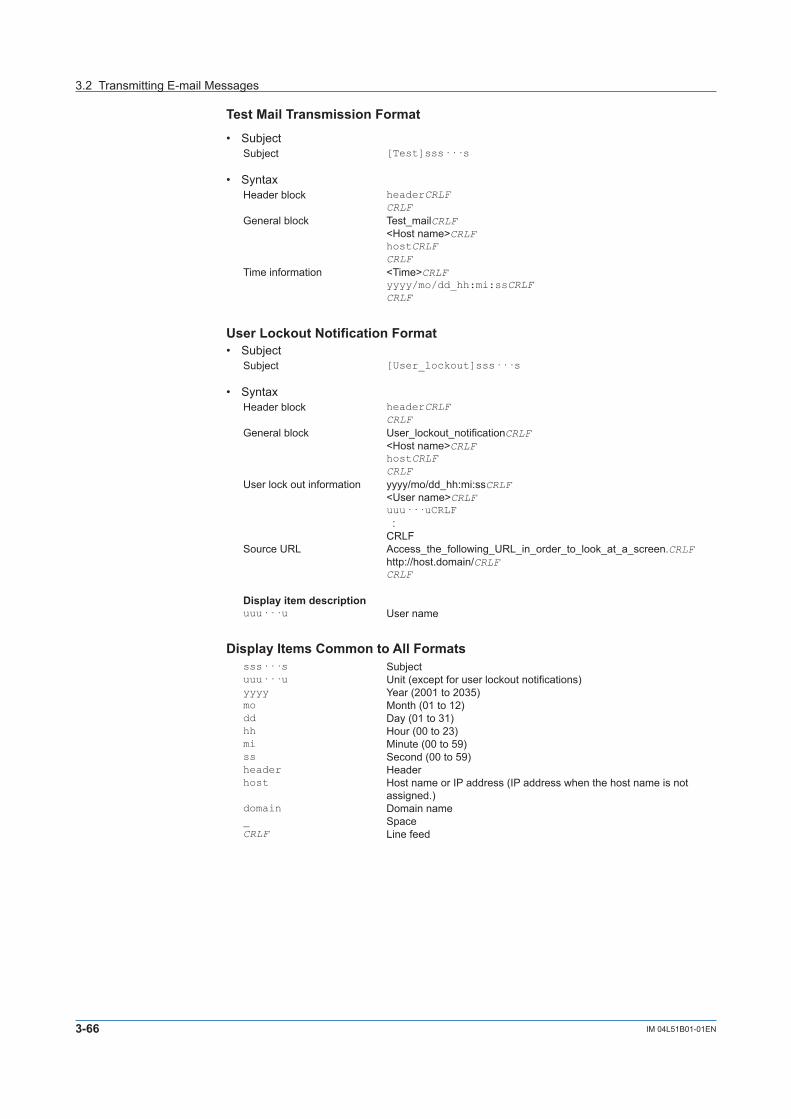
3-66 IM 04L51B01-01EN
Test Mail Transmission Format
• SubjectSubject [Test]sss···s
• SyntaxHeader block headerCRLF
CRLFGeneral block Test_mailCRLF
<Host name>CRLFhostCRLFCRLF
Time information <Time>CRLFyyyy/mo/dd_hh:mi:ssCRLFCRLF
User Lockout Notification Format• Subject
Subject [User_lockout]sss···s
• SyntaxHeader block headerCRLF
CRLFGeneral block User_lockout_notificationCRLF
<Host name>CRLFhostCRLFCRLF
User lock out information yyyy/mo/dd_hh:mi:ssCRLF<User name>CRLFuuu···uCRLF :CRLF
Source URL Access_the_following_URL_in_order_to_look_at_a_screen.CRLFhttp://host.domain/CRLFCRLF
Display item descriptionuuu···u User name
Display Items Common to All Formatssss···s Subjectuuu···u Unit (except for user lockout notifications)yyyy Year (2001 to 2035)mo Month (01 to 12)dd Day (01 to 31)hh Hour (00 to 23)mi Minute (00 to 59)ss Second (00 to 59)header Headerhost Host name or IP address (IP address when the host name is not
assigned.)domain Domain name_ SpaceCRLF Line feed
3.2 Transmitting E-mail Messages

3-67IM 04L51B01-01EN
UsingN
etworkFunctions(Ethernetinterface)
1
2
3
4
5
App
Index
Channel Number Notation and RangeType Model Notation and Range NotesI/O channel GX10/GP10 0001 to 02991 Depends on the installed
moduleGX20/GP20 0001 to 09992
Expandable I/O 1001 to 6599Math channel GX10/GP10 A001 to A050 /MT option
GX20/GP20 A001 to A100Report channel GX10/GP10 R01 to R50 /MT option
GX20/GP20 R01 to R60Communication channel GX10/GP10 C001 to C050 /MC option
GX20-1/GP20-1 C001 to C300GX20-2/GP20-2 C001 to C500
1 0001 to 0199 when the expandable I/O is connected2 0001 to 0899 when the expandable I/O is connected
3.2 Transmitting E-mail Messages

3-68 IM 04L51B01-01EN
3.3 Accessing the Measurement Data File on the GX/GPfromaPC(FTPserverfunction)
You can use a PC to access the GX/GP via FTP. You can perform operations such as retrieving directory and file lists from the external storage medium (SD memory card) of the GX/GP and transferring and deleting files. In addition, you can also retrieve the directory or file list and transfer files in the internal memory.
Files stored on the external storage medium
PC
FTP server
Ethernet
GX/GP
3.3.1 Configuring FTP Server Settings
Description• EnabletheFTPserverfunction• SettheFTPserverdirectoryoutputformat
For details on the settings, see page 1-139 in section 1.16.9, “Setting the Server Functions to Use (FTP, HTTP, SNTP, MODBUS, GENE, DARWIN compatible communication)”.
3.3.2 Accessing the GX/GP from a PCWhen Not Using the Login FunctionAccess the GX/GP from a PC via FTP using the admin, user, or anonymous account.With the admin account, you can• Retrievedirectoryandfilelistsfromtheexternalstoragemediumandtransferanddelete
directories and files on the external storage medium.• Retrievedirectoryandfilelistsfromtheinternalmemoryandtransferdirectoriesandfiles
in the internal memory.With the user or anonymous account, you can• Retrievedirectoryandfilelistsfromtheexternalstoragemedium.

3-69IM 04L51B01-01EN
UsingN
etworkFunctions(Ethernetinterface)
1
2
3
4
5
App
Index
Connecting from a PC via the FTPAn example of retrieving files using a browser is described below. In the Address box, enter ftp://host name.domain name. Drag the data you want to retrieve from the /MEM0/DATA folder in the case of internal memory data or the /DRV0 folder in the case of data on the external storage medium to the PC. You can also use the IP address in place of the “host name.domain name.”
WhenUsingtheLoginFunction(Standard)You will be prompted for a user name and password when you access the server. Enter a user name and password that are registered on the GX/GP to connect to it.
Note• Memory is linked to ftp://hostname/MEM0/DATA.• Externalmedia:SDmemorycard is linked to ftp://hostname/DRV0/.• Externalmedia:USB is linked to ftp://hostname/USB0/.• Youcannotretrievedatafilesthatarebeingcreated.• Youmustaccessusing“ftps://”whenSSLencryptionisinuse.
3.3 Accessing the Measurement Data File on the GX/GP from a PC (FTP server function)

3-70 IM 04L51B01-01EN
3.4 Transferring Data Files from the GX/GP (FTPclientfunction)
The display data, event data, report data, snapshot data, alarm summary data, and manual sample data files or setting files that are created in the internal memory of the GX/GP can be automatically transferred via FTP when the files are created.You can specify two file transfer destinations (FTP servers): primary and secondary. If the primary FTP server is down, the file is transferred to the secondary FTP server.If the report template function is in use, report files in Excel format and report files in PDF format that are created in the external storage medium of the GX/GP can be automatically transferred when the files are created.
Data file
FTP serverPrimary Secondary
Ethernet
Destination (FTP server) information
Transfer log(FTP log)
Data fileto transferFTP client
GX/GP
3.4.1 Configuring the FTP Client Function
Description• EnabletheFTPclientfunction• Setthefilestotransfer Set the files that will be transferred automatically.• Setthetransferwaittime Set the transfer wait time if you want to delay data transfers to the FTP server.• Setthedestinations(primaryandsecondary) Set the connection destination FTP servers.
For details on the settings, see page 1-128 in section 1.16.2, “Configuring the FTP Client Function”.

3-71IM 04L51B01-01EN
UsingN
etworkFunctions(Ethernetinterface)
1
2
3
4
5
App
Index
ExplanationFiles to Transfer via FTPData other than Excel report files, PDF report files, and setting files are automatically transferred regardless of whether the external storage medium is available.File Type DescriptionDisplay data file Data files are automatically transferred at each file save interval.3Event data file Files are automatically transferred when the data length of data is recorded.3Report data file When the file division mode is Separate or Combine, data files are
automatically transferred when a report file is closed (or divided). For example, data files are transferred once per month for daily+monthly reports when the file division mode is Combine. Report data files based on report templates (Excel report file, PDF report file) are also automatically transferred when they are created. 1
For details on Separate and Combine, see page 1-100 in section 1.11.1, “Setting the Report Type, Creation Time, Data Type, Etc.”.
Snapshot data file Files are automatically transferred when a snapshot is taken.2Alarm summary data file Files are automatically transferred when alarms are saved.Manual sample data file Files are automatically transferred when the next time manual sample is
executed2 and the file is divided.Setting file at the time of the setting change
The setting file in the SD memory card is automatically transferred when settings are changed.1, 4
1 Files will not be transferred automatically if the remaining space on the SD memory card is low or if the SD memory card is not connected.
2 Refers to an action triggered through touch screen operation, communication command (OExecRec), or event action function.
3 If the FTP transfer timing is set to Sign in on models with the advanced security function (/AS option), files are transferred automatically after they are signed. See section 2.2.4, “Configuring the Sign in Settings,” in the Advanced Security Function (/AS) User’s Manual (IM 04L51B01-05EN).
4 Only on models with the advanced security function (/AS option).
Shifting the Transfer TimeThere may be cases when data cannot be transferred from the GX/GP to the FTP server due to too many simultaneous connections to the FTP server. An example is when multiple files are created and need to be transferred at the same time from multiple GX/GPs. By shifting the transfer time, you can avoid having too many simultaneous connections to the FTP server. You can shift the transfer time for display data files, event data files, and report files.• EvenifaneweventthatrequiresanFTPtransferoccurswhiletheGX/GPiswaitingto
transfer the data of the previous event, it does not affect the transfer wait time of the previous event. When the transfer shift time passes, all data files of the same type that have been created (all of the files that have not been transferred) are transferred via FTP. The following figure is an example for display data.
• Toavoidaccumulatingtoomanyfilesthathavenotbeentransferred,werecommendthatyou set the transfer wait time shorter than the interval at which events that require FTP transfers occur.
Transfer wait time Transfer wait time
Display data file
FTP transferFTP transfer
1
1
1 2 3
1 2 3
3.4 Transferring Data Files from the GX/GP (FTP client function)

3-72 IM 04L51B01-01EN
Transfer Operation
• EvenifyouturnthepoweroffduringFTPtransferwaittime,theelapsedtimeisrecorded.• IfyouchangetheFTPtransfertimesettingsduringFTPtransferwaittime,thedatafiles
that are being held are transferred using the previous setting. Subsequent data files are sent according to the new setting.
• IfyouexecuteFTPfunctiontoOff,or“Initializeall”duringaFTPtransferwaittime,theelapsed time is cleared.
• IftheFTPtransfertimingissettoSigninonmodelswiththeadvancedsecurityfunction(/AS option), transfer wait time for display data files and event data files is invalid.
WhenThereIsaFilewiththeSameNameattheTransferDestinationUnder all circumstances, when there is a file with the same name at the transfer destination, it is overwritten.
Operation When the Data Transfer FailsIf the GX/GP fails to transfer files to both the primary and secondary FTP servers, the GX/GP aborts the file transfer operation. If the connection to the destination recovers, the GX/GP transfers new data files along with the files that the GX/GP failed to transfer (except for snapshot data files, alarm summary data files, and manual sample data files). Note that because the GX/GP transfers data from its internal memory, if the data that the GX/GP failed to transfer is overwritten, it is lost.
3.4.2 Testing the FTP TransferYou can check whether files can be sent from the GX/GP to the FTP server using a test file.
For the procedure, see ”page 2-70 in section 2.7.3, “Checking FTP File Transfers (FTP transmission test)”
3.4 Transferring Data Files from the GX/GP (FTP client function)

3-73IM 04L51B01-01EN
UsingN
etworkFunctions(Ethernetinterface)
1
2
3
4
5
App
Index
3.5 SynchronizingtheTime(SNTPclientfunction)
The GX/GP time can be synchronized to the time on an SNTP server (time information server on the network).The GX/GP can retrieve time information from a specified SNTP server at specified intervals.
Time query
SNTP server
SNTP client
Ethernet
GX/GP
3.5.1 Configuring the SNTP Client Function
Description• EnabletheSNTPclientfunction• SpecifytheSNTPserversettings• Setthequeryoperation
For setup details, see page 1-134 in section 1.16.5, “Setting the SNTP Client Function”.
3.5.2 Adjusting the Clock Manually
ProcedureYoucanadjusttheclockmanually.TheSNTPclientmustbeenabled.
Foroperatinginstructions,seepage2-70insection2.7.4,“AdjustingtheClockManually(SNTPtimeadjustment)”.

3-74 IM 04L51B01-01EN
3.6 Transmitting Time Information from the GX/GP toSNTPClientDevices(SNTPserverfunction)
The GX/GP can operate as an SNTP server.When an SNTP client device on the network queries the GX/GP for time information, the GX/GP sends the information.
SNTP client device
SNTP server
Ethernet
GX/GP
12:34
Query
3.6.1 Configuring the SNTP Server Function
DescriptionEnablingtheSNTPServerFunction
For details on the settings, see page 1-139 in section 1.16.9, “Setting the Server Functions to Use (FTP, HTTP, SNTP, MODBUS, GENE, DARWIN compatible communication)”.

4-1IM 04L51B01-01EN
UsingM
odbusFunctions(Com
municatingw
ithModbusdevices)
1
2
3
4
5
App
Index
4.1 UsingModbus/TCPtoEnableOtherDevicestoRead Data from and Write Data to the GX/GP (Modbusserverfunction)
The Modbus function is used by the GX/GP and external Modbus devices to perform communication and data reading and writing. The GX/GP can operate as a Modbus server. The maximum number of simultaneous connections is 4.Other devices (Modbus client devices) can carry out the following operations on the GX/GP.• ReadI/Ochannelandmathchannel(/MToption)data• Readcommunicationchannel(/MCoption)data• Writedatatocommunicationchannels• Startandstoprecording,writemessages,andperformotheroperations• Loadtherecordingstart/stopcondition,messagestrings,andothertypesofdata
Modbus client device
GX/GP
Modbus server
EthernetCommand
Input register
Hold register Read
Write
Read3XXXXX
4XXXXX Write
Read
Read
GX/GP internal register Client
4.1.1 SettingBasicNetworkCommunicationConditions
Description• ObtaintheIPaddressautomatically• SettheIPaddressmanually(whenautomaticIPaddressassignmentissettoOff)
For details on the settings, see page 1-126 in section 1.16.1, “Setting Basic Communication Conditions”.
4.1.2 Configuring the Modbus Server Function
DescriptionEnablingtheModbusServerFunction
For details on the settings, see page 1-139 in section 1.16.9, “Setting the Server Functions to Use (FTP, HTTP, SNTP, MODBUS, GENE, DARWIN compatible communication)”.
Applying Modbus Connection LimitsSet this function to limit the IP addresses that can connect to the GX/GP Modbus server function.You can register up to 10 IP addresses.
For details on the settings, see page 1-139 in section 1.16.8, “Limiting the Connection to the Modbus Server (GX/GP)”.
Chapter 4 UsingModbusFunctions(CommunicatingwithModbusdevices)
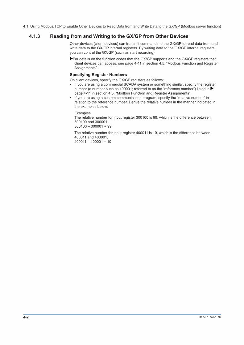
4-2 IM 04L51B01-01EN
4.1.3 Reading from and Writing to the GX/GP from Other DevicesOther devices (client devices) can transmit commands to the GX/GP to read data from and write data to the GX/GP internal registers. By writing data to the GX/GP internal registers, you can control the GX/GP (such as start recording).
For details on the function codes that the GX/GP supports and the GX/GP registers that client devices can access, see page 4-11 in section 4.5, “Modbus Function and Register Assignments”.
Specifying Register NumbersOn client devices, specify the GX/GP registers as follows:• IfyouareusingacommercialSCADAsystemorsomethingsimilar,specifytheregister
number (a number such as 400001; referred to as the “reference number”) listed in page 4-11 in section 4.5, “Modbus Function and Register Assignments”.
• Ifyouareusingacustomcommunicationprogram,specifythe“relativenumber”inrelation to the reference number. Derive the relative number in the manner indicated in the examples below.
Examples The relative number for input register 300100 is 99, which is the difference between
300100 and 300001.300100–300001=99
The relative number for input register 400011 is 10, which is the difference between 400011 and 400001.400011–400001=10
4.1 Using Modbus/TCP to Enable Other Devices to Read Data from and Write Data to the GX/GP (Modbus server function)

4-3IM 04L51B01-01EN
UsingM
odbusFunctions(Com
municatingw
ithModbusdevices)
1
2
3
4
5
App
Index
4.2 UsingModbus/TCPtoEnabletheGX/GPtoRead Data from and Write Data to Other Devices (Modbusclientfunction)
The Modbus function is used by the GX/GP and external Modbus devices to perform communication and data reading and writing.The GX/GP can operate as a Modbus client. The maximum number of connectable servers is 16 for the GX20-1/GP20-1/GX10/GP10 and 32 for the GX20-2/GP20-2.The GX/GP can connect to another device (Modbus server) via Modbus/TCP and read from and write to the device’s internal registers. Read data can be handled using communication channels. Data that can be written are I/O channel data, math channel data, and communication channel data.
Modbus server
Modbus client
Ethernet
GX/GP
CommandInput register
Hold register Read
Write
Read3XXXXX
4XXXXX Write
Read
Read
Server device internal register GX/GP
4.2.1 SettingBasicNetworkCommunicationConditions
Description• ObtaintheIPaddressautomatically• SettheIPaddressmanually(whenautomaticIPaddressassignmentissettoOff)
For details on the settings, see page 1-126 in section 1.16.1, “Setting Basic Communication Conditions”.
4.2.2 Configuring the Modbus Client Function
Description• EnabletheModbusclientfunction• Setthecommunicationinterval• Settherecoveryaction• Setthekeepconnectionfunction
For details on the settings, see “Configuring Basic settings” page 1-135 in section 1.16.6, “Configuring the Modbus Client Function (/MC option)”.

4-4 IM 04L51B01-01EN
4.2.3 Configuring the destination server
Description• Settheservernumber• Configuretheserversettings
For details on the settings, see “Configuring the Destination Server” page 1-135 in section 1.16.6, “Configuring the Modbus Client Function (/MC option)”.
4.2.4 Setting Commands
Description• Settheclientcommandnumber• Setthecommand
For details on the settings, see “Setting Commands” page 1-135 in section 1.16.6, “Configuring the Modbus Client Function (/MC option)”.
For details on the Modbus functions and registers that the GX/GP supports, see page 4-11 in section 4.5, “Modbus Function and Register Assignments”.
Server Register NumberYou can specify an input register in the range of 30001 to 39999 or 300001 to 365536. You can specify a hold register in the range of 40001 to 49999 or 400001 to 465536.The register numbers that you can specify vary depending on the type of command. See page 4-11 in section 4.5, “Modbus Function and Register Assignments”.
Specifying Register NumbersSpecify the register number on the GX/GP by using the “reference number” (such as the number 40001 written above). For example, for the YOKOGAWA UT35A digital indicating controller, the D register number corresponds to the reference number as shown in the following table.D-Reg. No. Ref. No.D2001 42001
For a server that calls the register using a “relative number,” add 30001, 300001, 40001, 400001 or a similar number to obtain a reference number.Register Type Relative Number Reference Number ExpressionHold register 1004 41005 1004+40001
14567 414568 14567+400001Input register 0000 30001 0000+30001
4.2 Using Modbus/TCP to Enable the GX/GP to Read Data from and Write Data to Other Devices (Modbus client function)

4-5IM 04L51B01-01EN
UsingM
odbusFunctions(Com
municatingw
ithModbusdevices)
1
2
3
4
5
App
Index
ExamplesofSettingCommandsThe following are command setting examples on the GX/GP when the GX/GP is a Modbus client device. If the GX/GP is a Modbus master device, substitute “master” for “client” and “slave” for “server.”
Ethernet
GX/GP(Modbus client)
Instrument A(Modbus server 1)
Instrument B(Modbus server 2)
Instrument C(Modbus server 3)
Connection example
Loading into Communication ChannelsThe GX/GP enters data loaded from the server into communication channels as floating point type data.
Example1Load the 16-bit signed integer value assigned to register 30001 of instrument A to C001.
C001 30001Communication channel data Register of instrument A
16-bit signed integer
Command settingSetup Item ValueClient command number 1Command setting Type Read
Server 1Data type INT16Register 30001Channel type Communication channelFirst-CH C001Last-CH C001
Example2Load the 32-bit signed integer value assigned to registers 30003 and 30004 (little endian) of instrument B to C003. Only the smallest register number need be specified in commands.
30003 Lower bytesHigher bytes30004
C00332-bit signed integer
Register of instrument BCommunication channel data
Command settingSetup Item ValueClient command number 2Command setting Type Read
Server 2Data type INT32_LRegister 30003Channel type Communication channelFirst-CH C003Last-CH C003
4.2 Using Modbus/TCP to Enable the GX/GP to Read Data from and Write Data to Other Devices (Modbus client function)

4-6 IM 04L51B01-01EN
Example3Load the 16-bit signed integer values assigned to registers 30001 and 30002 of instrument B to C001 and C002. Only the smallest register number need be specified in commands.
30001 16-bit signed integer16-bit signed integer30002
C001C002
Register of instrument BCommunication channel data
Command settingSetup Item ValueClient command number 3Command setting Type Read
Server 2Data type INT16Register 30001Channel type Communication channelFirst-CH C001Last-CH C002
Example4Load the 32-bit floating point values assigned to registers 30005 and 30006 (little endian) of instrument B to C004. Only the smallest register number need be specified in commands.
30005 Lower bytesHigher bytes30006
C00432-bit floating point
Register of instrument BCommunication channel data
Command settingSetup Item ValueClient command number 4Command setting Type Read
Server 2Data type FLOAT_LRegister 30005Channel type Communication channelFirst-CH C004Last-CH C004
Writing Data to a ServerExampleWrite the measured value from channel 0001 to register 40001 of instrument A.
16-bit signed integerI/O channel Register of instrument A
0001 40001
Command settingSetup Item ValueClient command number 5Command setting Type Write
Server 1Data type INT16Register 40001Channel type I/O channelFirst-CH 0001Last-CH 0001
4.2 Using Modbus/TCP to Enable the GX/GP to Read Data from and Write Data to Other Devices (Modbus client function)

4-7IM 04L51B01-01EN
UsingM
odbusFunctions(Com
municatingw
ithModbusdevices)
1
2
3
4
5
App
Index
Writing Computed Values to a ServerExampleWrite the computed values from channel A001 to registers 40001 and 40002 of instrument A, in the order lower 16 bits/higher 16 bits. Only the smallest register number need be specified in commands.
32-bit signed integer
Math channel Register of instrument A4000140002
A001 Lower bytesHigher bytes
Command settingSetup Item ValueClient command number 6Command setting Type Write
Server 1Data type INT32_LRegister 40001Channel type Math channelFirst-CH A001Last-CH A001
4.2.5 Checking the Modbus Operation Status
ProcedureFor the procedure, see page 2-49 in section 2.3.6, “Checking the Command Status of the Modbus Client and Modbus Master”.
4.2 Using Modbus/TCP to Enable the GX/GP to Read Data from and Write Data to Other Devices (Modbus client function)

4-8 IM 04L51B01-01EN
4.3 UsingModbustoEnableOtherDevicestoReadDatafromandWriteDatatotheGX/GP(Modbusslavefunction)
The GX/GP can operate as a Modbus slave device.Other devices (Modbus master devices) can carry out the following operations on the GX/GP.• ReadI/Ochannelandmathchannel(/MToption)data(inputregister)• Readcommunicationchannel(/MCoption)data(holdregister)• Writecommunicationchannel(/MCoption)data(holdregister)• Startandstoprecording,writemessages,andperformotheroperations(usingthehold
register)• Loadtherecordingstart/stopcondition,messagestrings,andothertypesofdata(using
the hold register)
Modbus master device
Modbus slave
Serial communication
GX/GP
CommandInput register
Hold register Read
Write
Read3XXXXX
4XXXXX Write
Read
Read
GX/GP internal register Master
4.3.1 Setting Serial Communication Conditions
Description• Configurethereceiverfunction• Setdatatransferconditions
For details on the settings, see page 1-142 in section 1.17.1, “Setting Basic Communication Conditions”.
4.3.2 Reading from and Writing to the GX/GP from Other DevicesOther devices (master devices) can transmit commands to the GX/GP to read data from and write data to the GX/GP. By writing data to the GX/GP registers, you can control the GX/GP (such as start recording).
For details on the function codes that the GX/GP supports and the GX/GP registers that master devices can access, see page 4-11 in section 4.5, “Modbus Function and Register Assignments”.

4-9IM 04L51B01-01EN
UsingM
odbusFunctions(Com
municatingw
ithModbusdevices)
1
2
3
4
5
App
Index
4.4 UsingModbustoEnabletheGX/GPtoReadData from and Write Data to Other Devices (Modbusmasterfunction)
The GX/GP can operate as a Modbus master device.The GX/GP can connect to another device (Modbus slave device) via Modbus and read from and write to the device’s internal registers. Read data can be handled using communication channels. Data that can be written are I/O channel data, math channel data, and communication channel data.
Modbus slave device
Modbus master
Serial communication
GX/GP
CommandInput register
Hold register Read
Write
Read3XXXXX
4XXXXX Write
Read
Read
Slave device internal register GX/GP
4.4.1 Setting Serial Communication Conditions
Description• Configurethereceiverfunction• Setdatatransferconditions
For details on the settings, see page 1-142 in section 1.17.1, “Setting Basic Communication Conditions”.
4.4.2 Configuring the Modbus Master Function
Description• Enablethemasterfunction• Setcommunicationconditions• Settherecoveryaction
For details on the settings, see page 1-143 in section 1.17.2, “Enabling or Disabling the Modbus Master Function (/MC option) and Setting Communication Conditions”.
For details on the Modbus functions and registers that the GX/GP supports, see page 4-11 in section 4.5, “Modbus Function and Register Assignments”.
4.4.3 Setting Commands
Description• Setthemastercommandnumber• Setthecommand
For details on the settings, see page 1-144 in section 1.17.3, “Setting Modbus Master Transmission Commands”.
For command setting examples, see page 4-4 in section 4.2.4, “Setting Commands”.

4-10 IM 04L51B01-01EN
4.4.4 Checking the Modbus Operation Status
ProcedureFor the procedure, see page 2-49 in section 2.3.6, “Checking the Command Status of the Modbus Client and Modbus Master”.
4.4 Using Modbus to Enable the GX/GP to Read Data from and Write Data to Other Devices (Modbus master function)

4-11IM 04L51B01-01EN
UsingM
odbusFunctions(Com
municatingw
ithModbusdevices)
1
2
3
4
5
App
Index
4.5 Modbus Function and Register Assignments
4.5.1 Modbus Client/Master FunctionFunctionThe GX/GP supports the following functions.The server (slave) must support these functions.
Function Code Function Operation1 Read the coil status
(0xxxx)The GX/GP reads the coil status of the server (slave) device.
2 Read the input relay status (1xxxx, 1xxxxx)
The GX/GP reads the input relay status of the server (slave) device.
3 Read the hold register (4XXXX, 4XXXXX)
The GX/GP reads the hold register of the server (slave) into a communication channel.
4 Read the input register (3XXXX, 3XXXXX)
The GX/GP reads the input register of the server (slave) into a communication channel.
5 Change the single coil status(0xxxx)
The GX/GP changes the single coil status of the server (slave) device (off/on).
6 Write to a single hold register (4xxxx, 4xxxxx)
The GX/GP writes to a single hold register of the server (slave) .
15 Change the coil status(0xxxx)
The GX/GP changes the coil status of the server (slave) device (off/on).
16 Write to the hold register (4XXXX, 4XXXXX)
The GX/GP writes the I/O channel data, math channel data, or communication channel data to the hold register of the server (slave).
CommandCommand type: Read, WriteNumber of commands: GX20-1/GP20-1: Set up to 100 commands GX20-2/GP20-2: Set up to 200 commands GX10/GP10: Set up to 50 commandsData type: See the table below.Symbol DescriptionINT16 16-bit signed integerUINT16 16-bit unsigned integerINT32_B 32-bit signed integer (big endian)INT32_L 32-bit signed integer (little endian)UINT32_B 32-bit unsigned integer (big endian)UINT32_L 32-bit unsigned integer (little endian)FLOAT_B 32-bit floating point (big endian)FLOAT_L 32-bit floating point (little endian)BIT Bit
Special value outputWhen a register is read or when its content is exported through the Modbus function, the GX/GP may output the following special values.Channel status Data type
Integer Floating+Over, +Burnout Maximum expressible value +∞–Over, –Burnout Minimum expressible value –∞
Example: Channel status is “–Over”Data type Output valueINT16 –32768 (0x8000)INT32 –2147483648 (0x80000000)FLOAT –∞(0xff800000)

4-12 IM 04L51B01-01EN
Loading into Communication Channels• Readvaluesfromtheserver(slave)registerintothecommunicationchannelsoftheGX/
GP.• Thecommunicationchannelfunctionisanoption(/MC).
Read
1 to 999910001 to 19999100001 to 16553530001 to 39999300001 to 36553640001 to 49999400001 to 465536
Channel type: Comm. channelNumber: C001 to C050 (GX10/GP10) C001 to C300(GX20-1/GP20-1) C001 to C500(GX20-2/GP20-2)Type: INT 16, UINT 16, INT 32_B, INT 32_L, UINT 32_B, UINT 32_L, FLOAT_B, FLOAT_L, BIT
Register
Server (Slave)
Data TypeCommandType
GX/GP
Read
INT 16, UINT 16, INT 32_B, INT 32_L, UINT 32_B, UINT 32_L, FLOAT_B, FLOAT_L, BIT
Writing I/O Channel Data• WriteI/Ochanneldatatotheserver(slave)registers.
Write
1 to 999940001 to 49999400001 to 465536
Channel type: I/O channelNumber: 0001 to 6550 Type: INT 16, UINT 16, INT 32_B, INT 32_L, UINT 32_B, UINT 32_L, FLOAT_B, FLOAT_L, BIT
Register
Server (Slave)
Data TypeCommandType
GX/GP
Write
INT 16, UINT 16, INT 32_B, INT 32_L, UINT 32_B, UINT 32_L, FLOAT_B, FLOAT_L, BIT
Writing Math Channel Data• Themathfunctionisanoption(/MT).• Writemathchanneldatatotheserver(slave)registers.
Write
1 to 999940001 to 49999400001 to 465536
Channel type: Math channelNumber: A001 to A050 (GX10/GP10) A001 to A100 (GX20/GP20)Type: INT 16, UINT 16, INT 32_B, INT 32_L, UINT 32_B, UINT 32_L, FLOAT_B, FLOAT_L, BIT
RegisterServer (Slave)
Data TypeCommandType
GX/GP
Write
INT 16, UINT 16, INT 32_B, INT 32_L, UINT 32_B, UINT 32_L, FLOAT_B, FLOAT_L, BIT
Writing Communication Channel Data• WriteGX/GPcommunicationchanneldatatotheserver(slave)registers.
Write
1 to 999940001 to 49999400001 to 465536
INT 16, UINT 16, INT 32_B, INT 32_L, UINT 32_B, UINT 32_L, FLOAT_B, FLOAT_L, BIT
Data type: Comm channel dataNumber: C001 to C050 (GX10/GP10) C001 to C300(GX20-1/GP20-1) C001 to C500(GX20-2/GP20-2)Type: INT 16, UINT 16, INT 32_B, INT 32_L, UINT 32_B, UINT 32_L, FLOAT_B, FLOAT_L, BIT
RegisterServer (Slave)
Data TypeCommandType
GX/GP
Write
4.5 Modbus Function and Register Assignments

4-13IM 04L51B01-01EN
UsingM
odbusFunctions(Com
municatingw
ithModbusdevices)
1
2
3
4
5
App
Index
4.5.2 Modbus Server/Slave FunctionFunctionThe GX/GP supports the following functions.
Function Code Function Operation1 Read the coil status
(0xxxx)The client (master) device reads the coil status of the GX/GP.
2 Read the input relay status (1xxxx, 1xxxxx)
The client (master) device reads the input relay status of the GX/GP.
3 Read the hold register (4XXXX, 4XXXXX)
The client (master) device reads the GX/GP data.
4 Read the input register (3XXXX, 3XXXXX)
The client (master) device reads the I/O, math, alarm, time data from the GX/GP.
5 Change the single coil status(0xxxx)
The client (master) device changes the single coil status (off/on) of the GX/GP.
6 Write to a single hold register (4xxxx, 4xxxxx)
The client (master) device writes to a single hold register of the GX/GP.
81 Loop-back test The master device performs a GX/GP loopback test.15 Change the coil status
(0xxxx) The client (master) device changes the coil status (off/on) of the GX/GP.
16 Write to the hold register (4XXXX, 4XXXXX)
The client (master) device writes to the GX/GP communication channels.
1 Loopback test is only for serial communication.
4.5.3 RegisterAssignments(SharedwiththeModbusserver/slavefunction)Input RegisterUnit Type GX/GP Register
Number Data TypeGX/GP main unit I/O channel I/O data 300001 to 301000 32-bit signed integer
301001 to 302000 32-bit floating point302001 to 302500 16-bit signed integer
Status information 302501 to 303000 16-bit signed integerI/O channel (continuous area)
I/O data 304001 to 304200 32-bit signed integer304201 to 304400 32-bit floating point304401 to 304500 16-bit signed integer
Status information 304501 to 304600 16-bit signed integerMath channel Math data 305001 to 305200 32-bit signed integer
305201 to 305400 32-bit floating point305401 to 305500 16-bit signed integer
Status information 305501 to 305600 16-bit signed integerGX/GP status 308001 to 308007 16-bit signed integer
Expandable I/O Unit 1I/O channel
I/O data 310001 to 311000 32-bit signed integer311001 to 312000 32-bit floating point312001 to 312500 16-bit signed integer
Status information 312501 to 313000 16-bit signed integerUnit 2I/O channel
I/O data 315001 to 316000 32-bit signed integer316001 to 317000 32-bit floating point317001 to 317500 16-bit signed integer
Status information 317501 to 318000 16-bit signed integerUnit 3I/O channel
I/O data 320001 to 321000 32-bit signed integer321001 to 322000 32-bit floating point322001 to 322500 16-bit signed integer
Status information 322501 to 323500 16-bit signed integerUnit 4I/O channel
I/O data 325001 to 326000 32-bit signed integer326001 to 327000 32-bit floating point327001 to 327500 16-bit signed integer
Status information 327501 to 328000 16-bit signed integerContinued on next page
4.5 Modbus Function and Register Assignments

4-14 IM 04L51B01-01EN
Unit Type GX/GP RegisterNumber Data Type
Expandable I/O Unit 5I/O channel
I/O data 330001 to 331000 32-bit signed integer331001 to 332000 32-bit floating point332001 to 332500 16-bit signed integer
Status information 332500 to 333000 16-bit signed integerUnit 6I/O channel
I/O data 335001 to 336000 32-bit signed integer336001 to 337000 32-bit floating point337001 to 337500 16-bit signed integer
Status information 337501 to 338000 16-bit signed integer
Client/Master device
Read
Hold RegisterUnit Type GX/GP Register
Number Data TypeGX/GP main unit I/O channel I/O data 400001 to 401000 32-bit signed integer
401001 to 402000 32-bit floating point402001 to 402500 16-bit signed integer
Status information 402501 to 403000 16-bit signed integerI/O channel(continuous area)
I/O data 404001 to 404200 32-bit signed integer404201 to 404400 32-bit floating point404401 to 404500 16-bit signed integer
Status information 404501 to 404600 16-bit signed integerCommunication channel
Communication data
405001 to 405600 32-bit signed integer406001 to 406600 32-bit floating point407001 to 407300 16-bit signed integer
Status information 407501 to 407800 16-bit signed integerInternal switch 408001 to 408100 16-bit signed integerGX/GP operation setting 409001 to 410000 16-bit signed integer
Expandable I/O Unit 1I/O channel
I/O data 410001 to 411000 32-bit signed integer411001 to 412000 32-bit floating point412001 to 412500 16-bit signed integer
Status information 412501 to 413000 16-bit signed integerUnit 2I/O channel
I/O data 415001 to 416000 32-bit signed integer416001 to 417000 32-bit floating point417001 to 417500 16-bit signed integer
Status information 417501 to 418000 16-bit signed integerUnit 3I/O channel
I/O data 420001 to 421000 32-bit signed integer421001 to 422000 32-bit floating point422001 to 422500 16-bit signed integer
Status information 422501 to 423000 16-bit signed integerUnit 4I/O channel
I/O data 425001 to 426000 32-bit signed integer426001 to 427000 32-bit floating point427001 to 427500 16-bit signed integer
Status information 427501 to 428000 16-bit signed integerUnit 5I/O channel
I/O data 430001 to 431000 32-bit signed integer431001 to 432000 32-bit floating point432001 to 432500 16-bit signed integer
Status information 432501 to 433000 16-bit signed integerUnit 6I/O channel
I/O data 435001 to 436000 32-bit signed integer436001 to 437000 32-bit floating point437001 to 437500 16-bit signed integer
I/O data 437501 to 438000 16-bit signed integer
Client/Master device
ReadWrite
4.5 Modbus Function and Register Assignments

4-15IM 04L51B01-01EN
UsingM
odbusFunctions(Com
municatingw
ithModbusdevices)
1
2
3
4
5
App
Index
CoilType GX/GP Register
Number Data TypeI/O channel I/O data 1 to 500 Bit string
Status information 501 to 1000Communication channel
Communication data 1001 to 1500Status information 1501 to 2000
Internal switch 2001 to 2100
Client/Mastre device
ReadWrite
Input RelayType GX/GP Register
Number Data TypeI/O channel I/O data 100001 to 100500 Bit string
Status information 100501 to 101000Math channel Math data 101001 to 101100
Status information 101501 to 101600
Client/Master device
Read
4.5 Modbus Function and Register Assignments

4-16 IM 04L51B01-01EN
4.5.4 InputRegisters(SharedwiththeModbusserver/slavefunction)Common Items• Theclientdevicecanonlyreadtheinputregisters.• Decimalplaceandunitarenotincluded.Specifythemontheclientdevice.• Duetothedifferentnumberofchannelsbetweenmodules,unavailablechannelnumbers
will exist. This will not cause a register read error, so you can read the data continuously.• Theregistervaluesforunavailablechannelnumbersaresetto0,andthestatus
information is set to SKIP.• Channelrangebymodel
Channel type GX20/GP20 GX10/GP10I/O channel 0001 to 6950 0001 to 6950Math channel A001 to A100 A001 to A050
• IfLogscalecalculation(/LGoption)isperformedonanAIchannel,dataofI/Ochannelsset to 32-bit signed integer or 16-bit signed integer will be an integer with two- or three-digit mantissa.
I/O Channel Data
• 32-bitSignedIntegerUnit I/O Channel Data Input Register Data TypeGX/GP main unit Lower bytes of the channel 0001 data 300001 32-bit signed integer
Higher bytes of the channel 0001 data 300002 | |Lower bytes of the channel 0050 data 300099Higher bytes of the channel 0050 data 300100Lower bytes of the channel 0101 data 300101Higher bytes of the channel 0101 data 300102 | |Lower bytes of the channel 0150 data 300199Higher bytes of the channel 0150 data 300200Lower bytes of the channel 0201 data 300201Higher bytes of the channel 0201 data 300202 | |Lower bytes of the channel 0250 data 300299Higher bytes of the channel 0250 data 300300Lower bytes of the channel 0301 data 300301Higher bytes of the channel 0301 data 300302 | |Lower bytes of the channel 0350 data 300399Higher bytes of the channel 0350 data 300400Lower bytes of the channel 0401 data 300401Higher bytes of the channel 0401 data 300402 | |Lower bytes of the channel 0450 data 300499Higher bytes of the channel 0450 data 300500Lower bytes of the channel 0501 data 300501Higher bytes of the channel 0501 data 300502 | |Lower bytes of the channel 0550 data 300599Higher bytes of the channel 0550 data 300600Lower bytes of the channel 0601 data 300601Higher bytes of the channel 0601 data 300602 | |Lower bytes of the channel 0650 data 300699Higher bytes of the channel 0650 data 300700Lower bytes of the channel 0701 data 300701Higher bytes of the channel 0701 data 300702 | |Lower bytes of the channel 0750 data 300799Higher bytes of the channel 0750 data 300800Lower bytes of the channel 0801 data 300801Higher bytes of the channel 0801 data 300802 | |Lower bytes of the channel 0850 data 300899
Continued on next page
4.5 Modbus Function and Register Assignments

4-17IM 04L51B01-01EN
UsingM
odbusFunctions(Com
municatingw
ithModbusdevices)
1
2
3
4
5
App
Index
Unit I/O Channel Data Input Register Data TypeGX/GP main unit Higher bytes of the channel 0850 data 300900 32-bit signed integer
Lower bytes of the channel 0901 data 300901Higher bytes of the channel 0901 data 300902 | |Lower bytes of the channel 0950 data 300999Higher bytes of the channel 0950 data 301000
Expandable I/O 1 Lower bytes of the channel 1001 data 310001Higher bytes of the channel 1001 data 310002 | |Lower bytes of the channel 1050 data 310099Higher bytes of the channel 1050 data 310100Lower bytes of the channel 1101 data 310101Higher bytes of the channel 1101 data 310102 | |Lower bytes of the channel 1150 data 310199Higher bytes of the channel 1150 data 310200Lower bytes of the channel 1201 data 310201Higher bytes of the channel 1201 data 310202 | |Lower bytes of the channel 1250 data 310299Higher bytes of the channel 1250 data 310300Lower bytes of the channel 1301 data 310301Higher bytes of the channel 1301 data 310302 | |Lower bytes of the channel 1350 data 310399Higher bytes of the channel 1350 data 310400Lower bytes of the channel 1401 data 310401Higher bytes of the channel 1401 data 310402 | |Lower bytes of the channel 1450 data 310499Higher bytes of the channel 1450 data 310500Lower bytes of the channel 1501 data 310501Higher bytes of the channel 1501 data 310502 | |Lower bytes of the channel 1550 data 310599Higher bytes of the channel 1550 data 310600
Expandable I/O 2 Lower bytes of the channel 2001 data 315001Higher bytes of the channel 2001 data 315002 | |Lower bytes of the channel 2050 data 315099Higher bytes of the channel 2050 data 315100Lower bytes of the channel 2101 data 315101Higher bytes of the channel 2101 data 315102 | |Lower bytes of the channel 2150 data 315199Higher bytes of the channel 2150 data 315200Lower bytes of the channel 2201 data 315201Higher bytes of the channel 2201 data 315202 | |Lower bytes of the channel 2250 data 315299Higher bytes of the channel 2250 data 315300Lower bytes of the channel 2301 data 315301Higher bytes of the channel 2301 data 315302 | |Lower bytes of the channel 2350 data 315399Higher bytes of the channel 2350 data 315400Lower bytes of the channel 2401 data 315401Higher bytes of the channel 2401 data 315402 | |Lower bytes of the channel 2450 data 315499Higher bytes of the channel 2450 data 315500Lower bytes of the channel 2501 data 315501Higher bytes of the channel 2501 data 315502 | |Lower bytes of the channel 2550 data 315599Higher bytes of the channel 2550 data 315600
Continued on next page
4.5 Modbus Function and Register Assignments

4-18 IM 04L51B01-01EN
Unit I/O Channel Data Input Register Data TypeExpandable I/O 3 Lower bytes of the channel 3001 data 320001 32-bit floating point
Higher bytes of the channel 3001 data 320002 | |Lower bytes of the channel 3050 data 320099Higher bytes of the channel 3050 data 320100Lower bytes of the channel 3101 data 320101Higher bytes of the channel 3101 data 320102 | |Lower bytes of the channel 3150 data 320199Higher bytes of the channel 3150 data 320200Lower bytes of the channel 3201 data 320201Higher bytes of the channel 3201 data 320202 | |Lower bytes of the channel 3250 data 320299Higher bytes of the channel 3250 data 320300Lower bytes of the channel 3301 data 320301Higher bytes of the channel 3301 data 320302 | |Lower bytes of the channel 3350 data 320399Higher bytes of the channel 3350 data 320400Lower bytes of the channel 3401 data 320401Higher bytes of the channel 3401 data 320402 | |Lower bytes of the channel 3450 data 320499Higher bytes of the channel 3450 data 320500Lower bytes of the channel 3501 data 320501Higher bytes of the channel 3501 data 320502 | |Lower bytes of the channel 3550 data 320599Higher bytes of the channel 3550 data 320600
Expandable I/O 4 Lower bytes of the channel 4001 data 325001Higher bytes of the channel 4001 data 325002 | |Lower bytes of the channel 4050 data 325099Higher bytes of the channel 4050 data 325100Lower bytes of the channel 4101 data 325101Higher bytes of the channel 4101 data 325102 | |Lower bytes of the channel 4150 data 325199Higher bytes of the channel 4150 data 325200Lower bytes of the channel 4201 data 325201Higher bytes of the channel 4201 data 325202 | |Lower bytes of the channel 4250 data 325299Higher bytes of the channel 4250 data 325300Lower bytes of the channel 4301 data 325301Higher bytes of the channel 4301 data 325302 | |Lower bytes of the channel 4350 data 325399Higher bytes of the channel 4350 data 325400Lower bytes of the channel 4401 data 325401Higher bytes of the channel 4401 data 325402 | |Lower bytes of the channel 4450 data 325499Higher bytes of the channel 4450 data 325500Lower bytes of the channel 4501 data 325201Higher bytes of the channel 4501 data 325502 | |Lower bytes of the channel 4550 data 325599Higher bytes of the channel 4550 data 325600
Continued on next page
4.5 Modbus Function and Register Assignments

4-19IM 04L51B01-01EN
UsingM
odbusFunctions(Com
municatingw
ithModbusdevices)
1
2
3
4
5
App
Index
Unit I/O Channel Data Input Register Data TypeExpandable I/O 5 Lower bytes of the channel 5001 data 330001 32-bit floating point
Higher bytes of the channel 5001 data 330002 | |Lower bytes of the channel 5050 data 330099Higher bytes of the channel 5050 data 330100Lower bytes of the channel 5101 data 330101Higher bytes of the channel 5101 data 330102 | |Lower bytes of the channel 5150 data 330199Higher bytes of the channel 5150 data 330200Lower bytes of the channel 5201 data 330201Higher bytes of the channel 5201 data 330202 | |Lower bytes of the channel 5250 data 330299Higher bytes of the channel 5250 data 330300Lower bytes of the channel 5301 data 330301Higher bytes of the channel 5301 data 330302 | |Lower bytes of the channel 5350 data 330399Higher bytes of the channel 5350 data 330400Lower bytes of the channel 5401 data 330401Higher bytes of the channel 5401 data 330402 | |Lower bytes of the channel 5450 data 330499Higher bytes of the channel 5450 data 330500Lower bytes of the channel 5501 data 330501Higher bytes of the channel 5501 data 330502 | |Lower bytes of the channel 5550 data 330599Higher bytes of the channel 5550 data 330600
Expandable I/O 6 Lower bytes of the channel 6001 data 335001Higher bytes of the channel 6001 data 335002 | |Lower bytes of the channel 6050 data 335099Higher bytes of the channel 6050 data 335100Lower bytes of the channel 6101 data 335101Higher bytes of the channel 6101 data 335102 | |Lower bytes of the channel 6150 data 335199Higher bytes of the channel 6150 data 335200Lower bytes of the channel 6201 data 335201Higher bytes of the channel 6201 data 335202 | |Lower bytes of the channel 6250 data 335299Higher bytes of the channel 6250 data 335300Lower bytes of the channel 6301 data 335301Higher bytes of the channel 6301 data 335302 | |Lower bytes of the channel 6350 data 335399Higher bytes of the channel 6350 data 335400Lower bytes of the channel 6401 data 335401Higher bytes of the channel 6401 data 335402 | |Lower bytes of the channel 6450 data 335499Higher bytes of the channel 6450 data 335500Lower bytes of the channel 6501 data 335501Higher bytes of the channel 6501 data 335502 | |Lower bytes of the channel 6550 data 335599Higher bytes of the channel 6550 data 335600
Continued on next page
4.5 Modbus Function and Register Assignments

4-20 IM 04L51B01-01EN
Unit I/O Channel Data Input Register Data Type•Register
Channel 0001 example
Higher bytes Lower bytes
Register 300002
Channel 0001 data
Register 300001
•Thereisnodecimalplaceinformation.
• 32-bitfloatingpointUnit I/O Channel Data Input Register Data TypeGX/GP main unit Lower bytes of the channel 0001 data 301001 32-bit floating point
Higher bytes of the channel 0001 data 301002 | |Lower bytes of the channel 0050 data 301099Higher bytes of the channel 0050 data 301100Lower bytes of the channel 0101 data 301101Higher bytes of the channel 0101 data 301102 | |Lower bytes of the channel 0150 data 301199Higher bytes of the channel 0150 data 301200Lower bytes of the channel 0201 data 301201Higher bytes of the channel 0201 data 301202 | |Lower bytes of the channel 0250 data 301299Higher bytes of the channel 0250 data 301300Lower bytes of the channel 0301 data 301301Higher bytes of the channel 0301 data 301302 | |Lower bytes of the channel 0350 data 301399Higher bytes of the channel 0350 data 301400Lower bytes of the channel 0401 data 301401Higher bytes of the channel 0401 data 301402 | |Lower bytes of the channel 0450 data 301499Higher bytes of the channel 0450 data 301500Lower bytes of the channel 0501 data 301501Higher bytes of the channel 0501 data 301502 | |Lower bytes of the channel 0550 data 301599Higher bytes of the channel 0550 data 301600Lower bytes of the channel 0601 data 301601Higher bytes of the channel 0601 data 301602 | |Lower bytes of the channel 0650 data 301699Higher bytes of the channel 0650 data 301700Lower bytes of the channel 0701 data 301701Higher bytes of the channel 0701 data 301702 | |Lower bytes of the channel 0750 data 301799Higher bytes of the channel 0750 data 301800Lower bytes of the channel 0801 data 301801Higher bytes of the channel 0801 data 301802 | |Lower bytes of the channel 0850 data 301899Higher bytes of the channel 0850 data 301900Lower bytes of the channel 0901 data 301901Higher bytes of the channel 0901 data 301902 | |Lower bytes of the channel 0950 data 301999Higher bytes of the channel 0950 data 302000
Continued on next page
4.5 Modbus Function and Register Assignments

4-21IM 04L51B01-01EN
UsingM
odbusFunctions(Com
municatingw
ithModbusdevices)
1
2
3
4
5
App
Index
Unit I/O Channel Data Input Register Data TypeExpandable I/O 1 Lower bytes of the channel 1001 data 311001 32-bit floating point
Higher bytes of the channel 1001 data 311002 | |Lower bytes of the channel 1050 data 311099Higher bytes of the channel 1050 data 311100Lower bytes of the channel 1101 data 311101Higher bytes of the channel 1101 data 311102 | |Lower bytes of the channel 1150 data 311199Higher bytes of the channel 1150 data 311200Lower bytes of the channel 1201 data 311201Higher bytes of the channel 1201 data 311202 | |Lower bytes of the channel 1250 data 311299Higher bytes of the channel 1250 data 311300Lower bytes of the channel 1301 data 311301Higher bytes of the channel 1301 data 311302 | |Lower bytes of the channel 1350 data 311399Higher bytes of the channel 1350 data 311400Lower bytes of the channel 1401 data 311401Higher bytes of the channel 1401 data 311402 | |Lower bytes of the channel 1450 data 311499Higher bytes of the channel 1450 data 311500Lower bytes of the channel 1501 data 311501Higher bytes of the channel 1501 data 311502 | |Lower bytes of the channel 1550 data 311599Higher bytes of the channel 1550 data 311600
Expandable I/O 2 Lower bytes of the channel 2001 data 316001Higher bytes of the channel 2001 data 316002 | |Lower bytes of the channel 2050 data 316099Higher bytes of the channel 2050 data 316100Lower bytes of the channel 2101 data 316101Higher bytes of the channel 2101 data 316102 | |Lower bytes of the channel 2150 data 316199Higher bytes of the channel 2150 data 316200Lower bytes of the channel 2201 data 316201Higher bytes of the channel 2201 data 316202 | |Lower bytes of the channel 2250 data 316299Higher bytes of the channel 2250 data 316300Lower bytes of the channel 2301 data 316301Higher bytes of the channel 2301 data 316302 | |Lower bytes of the channel 2350 data 316399Higher bytes of the channel 2350 data 316400Lower bytes of the channel 2401 data 316401Higher bytes of the channel 2401 data 316402 | |Lower bytes of the channel 2450 data 316499Higher bytes of the channel 2450 data 316500Lower bytes of the channel 2501 data 316501Higher bytes of the channel 2501 data 316502 | |Lower bytes of the channel 2550 data 316599Higher bytes of the channel 2550 data 316600
Continued on next page
4.5 Modbus Function and Register Assignments

4-22 IM 04L51B01-01EN
Unit I/O Channel Data Input Register Data TypeExpandable I/O 3 Lower bytes of the channel 3001 data 321001 32-bit floating point
Higher bytes of the channel 3001 data 321002 | |Lower bytes of the channel 3050 data 321099Higher bytes of the channel 3050 data 321100Lower bytes of the channel 3101 data 321101Higher bytes of the channel 3101 data 321102 | |Lower bytes of the channel 3150 data 321199Higher bytes of the channel 3150 data 321200Lower bytes of the channel 3201 data 321201Higher bytes of the channel 3201 data 321202 | |Lower bytes of the channel 3250 data 321299Higher bytes of the channel 3250 data 321300Lower bytes of the channel 3301 data 321301Higher bytes of the channel 3301 data 321302 | |Lower bytes of the channel 3350 data 321399Higher bytes of the channel 3350 data 321400Lower bytes of the channel 3401 data 321401Higher bytes of the channel 3401 data 321402 | |Lower bytes of the channel 3450 data 321499Higher bytes of the channel 3450 data 321500Lower bytes of the channel 3501 data 321501Higher bytes of the channel 3501 data 321502 | |Lower bytes of the channel 3550 data 321599Higher bytes of the channel 3550 data 321600
Expandable I/O 4 Lower bytes of the channel 4001 data 326001Higher bytes of the channel 4001 data 326002 | |Lower bytes of the channel 4050 data 326099Higher bytes of the channel 4050 data 326100Lower bytes of the channel 4101 data 326101Higher bytes of the channel 4101 data 326102 | |Lower bytes of the channel 4150 data 326199Higher bytes of the channel 4150 data 326200Lower bytes of the channel 4201 data 326201Higher bytes of the channel 4201 data 326202 | |Lower bytes of the channel 4250 data 326299Higher bytes of the channel 4250 data 326300Lower bytes of the channel 4301 data 326301Higher bytes of the channel 4301 data 326302 | |Lower bytes of the channel 4350 data 326399Higher bytes of the channel 4350 data 326400Lower bytes of the channel 4401 data 326401Higher bytes of the channel 4401 data 326402 | |Lower bytes of the channel 4450 data 326499Higher bytes of the channel 4450 data 326500Lower bytes of the channel 4501 data 326501Higher bytes of the channel 4501 data 326502 | |Lower bytes of the channel 4550 data 326599Higher bytes of the channel 4550 data 326600
Continued on next page
4.5 Modbus Function and Register Assignments

4-23IM 04L51B01-01EN
UsingM
odbusFunctions(Com
municatingw
ithModbusdevices)
1
2
3
4
5
App
Index
Unit I/O Channel Data Input Register Data TypeExpandable I/O 5 Lower bytes of the channel 5001 data 331001 32-bit floating point
Higher bytes of the channel 5001 data 331002 | |Lower bytes of the channel 5050 data 331099Higher bytes of the channel 5050 data 331100Lower bytes of the channel 5101 data 331101Higher bytes of the channel 5101 data 331102 | |Lower bytes of the channel 5150 data 331199Higher bytes of the channel 5150 data 331200Lower bytes of the channel 5201 data 331201Higher bytes of the channel 5201 data 331202 | |Lower bytes of the channel 5250 data 331299Higher bytes of the channel 5250 data 331300Lower bytes of the channel 5301 data 331301Higher bytes of the channel 5301 data 331302 | |Lower bytes of the channel 5350 data 331399Higher bytes of the channel 5350 data 331400Lower bytes of the channel 5401 data 331401Higher bytes of the channel 5401 data 331402 | |Lower bytes of the channel 5450 data 331499Higher bytes of the channel 5450 data 331500Lower bytes of the channel 5501 data 331501Higher bytes of the channel 5501 data 331502 | |Lower bytes of the channel 5550 data 331599Higher bytes of the channel 5550 data 331600
Expandable I/O 6 Lower bytes of the channel 6001 data 336001Higher bytes of the channel 6001 data 336002 | |Lower bytes of the channel 6050 data 336099Higher bytes of the channel 6050 data 336100Lower bytes of the channel 6101 data 336101Higher bytes of the channel 6101 data 336102 | |Lower bytes of the channel 6150 data 336199Higher bytes of the channel 6150 data 336200Lower bytes of the channel 6201 data 336201Higher bytes of the channel 6201 data 336202 | |Lower bytes of the channel 6250 data 336299Higher bytes of the channel 6250 data 336300Lower bytes of the channel 6301 data 336301Higher bytes of the channel 6301 data 336302 | |Lower bytes of the channel 6350 data 336399Higher bytes of the channel 6350 data 336400Lower bytes of the channel 6401 data 336401Higher bytes of the channel 6401 data 336402 | |Lower bytes of the channel 6450 data 336499Higher bytes of the channel 6450 data 336500Lower bytes of the channel 6501 data 336501Higher bytes of the channel 6501 data 336502 | |Lower bytes of the channel 6550 data 336599Higher bytes of the channel 6550 data 336600
4.5 Modbus Function and Register Assignments

4-24 IM 04L51B01-01EN
• 16-bitSignedIntegerUnit I/O Channel Data Input Register Data TypeGX/GP main unit Channel 0001 data 302001 16-bit signed integer
| |Channel 0050 data 302050Channel 0101 data 302051 | |Channel 0150 data 302100Channel 0201 data 302101 | |Channel 0250 data 302150Channel 0301 data 302151 | |Channel 0350 data 302200Channel 0401 data 302201 | |Channel 0450 data 302250Channel 0501 data 302251 | |Channel 0550 data 302300Channel 0601 data 302301 | |Channel 0650 data 302350Channel 0701 data 302351 | |Channel 0750 data 302400Channel 0801 data 302401 | |Channel 0850 data 302450Channel 0901 data 302451 | |Channel 0950 data 302500
Expandable I/O 1 Channel 1001 data 312001 | |Channel 1050 data 312050Channel 1101 data 312051 | |Channel 1150 data 312100Channel 1201 data 312101 | |Channel 1250 data 312150Channel 1301 data 312151 | |Channel 1350 data 312200Channel 1401 data 312201 | |Channel 1450 data 312250Channel 1501 data 312251 | |Channel 1550 data 312300
Expandable I/O 2 Channel 2001 data 317001 | |Channel 2050 data 317050Channel 2101 data 317051 | |Channel 2150 data 317100Channel 2201 data 317101 | |Channel 2250 data 317150Channel 2301 data 317151 | |Channel 2350 data 317200Channel 2401 data 317201 | |Channel 2450 data 317250
Continued on next page
4.5 Modbus Function and Register Assignments

4-25IM 04L51B01-01EN
UsingM
odbusFunctions(Com
municatingw
ithModbusdevices)
1
2
3
4
5
App
Index
Unit I/O Channel Data Input Register Data TypeExpandable I/O 2 Channel 2501 data 317251 16-bit signed integer
| |Channel 2550 data 317300
Expandable I/O 3 Channel 3001 data 322001 | |Channel 3050 data 322050Channel 3101 data 322051 | |Channel 3150 data 322100Channel 3201 data 322101 | |Channel 3250 data 322150Channel 3301 data 322151 | |Channel 3350 data 322200Channel 3401 data 322201 | |Channel 3450 data 322250Channel 3501 data 322251 | |Channel 3550 data 322300
Expandable I/O 4 Channel 4001 data 327001 | |Channel 4050 data 327050Channel 4101 data 327051 | |Channel 4150 data 327100Channel 4201 data 327101 | |Channel 4250 data 327150Channel 4301 data 327151 | |Channel 4350 data 327200Channel 4401 data 327201 | |Channel 4450 data 327250Channel 4501 data 327251 | |Channel 4550 data 327300
Expandable I/O 5 Channel 5001 data 332001 | |Channel 5050 data 332050Channel 5101 data 332051 | |Channel 5150 data 332100Channel 5201 data 332101 | |Channel 5250 data 332150Channel 5301 data 332151 | |Channel 5350 data 332200Channel 5401 data 332201 | |Channel 5450 data 332250Channel 5501 data 332251 | |Channel 5550 data 332300
Continued on next page
4.5 Modbus Function and Register Assignments

4-26 IM 04L51B01-01EN
Unit I/O Channel Data Input Register Data TypeExpandable I/O 6 Channel 6001 data 337001 16-bit signed integer
| |Channel 6050 data 337050Channel 6101 data 337051 | |Channel 6150 data 337100Channel 6201 data 337101 | |Channel 6250 data 337150Channel 6301 data 337151 | |Channel 6350 data 337200Channel 6401 data 337201 | |Channel 6450 data 337250Channel 6501 data 337251 | |Channel 6550 data 337300
I/O Channel Data Status InformationUnit I/O Channel Data Input Register Data TypeGX/GP main unit Channel 0001 status information 302501 16-bit signed integer
| |Channel 0050 status information 302550Channel 0101 status information 302551 | |Channel 0150 status information 302600Channel 0201 status information 302601 | |Channel 0250 status information 302650Channel 0301 status information 302651 | |Channel 0350 status information 302700Channel 0401 status information 302701 | |Channel 0450 status information 302750Channel 0501 status information 302751 | |Channel 0550 status information 302800Channel 0601 status information 302801 | |Channel 0650 status information 302850Channel 0701 status information 302851 | |Channel 0750 status information 302900Channel 0801 status information 302901 | |Channel 0850 status information 302950Channel 0901 status information 302951 | |Channel 0950 status information 303000
Expandable I/O 1 Channel 1001 status information 312501 | |Channel 1050 status information 312550Channel 1101 status information 312551 | |Channel 1150 status information 312600Channel 1201 status information 312601 | |Channel 1250 status information 312650Channel 1301 status information 312651 | |Channel 1350 status information 312700Channel 1401 status information 312701 | |Channel 1450 status information 312750
Continued on next page
4.5 Modbus Function and Register Assignments

4-27IM 04L51B01-01EN
UsingM
odbusFunctions(Com
municatingw
ithModbusdevices)
1
2
3
4
5
App
Index
Unit I/O Channel Data Input Register Data TypeExpandable I/O 1 Channel 1501 status information 312751 16-bit signed integer
| |Channel 1550 status information 312800
Expandable I/O 2 Channel 2001 status information 317501 | |Channel 2050 status information 317550Channel 2101 status information 317551 | |Channel 2150 status information 317600Channel 2201 status information 317601 | |Channel 2250 status information 317650Channel 2301 status information 317651 | |Channel 2350 status information 317700Channel 2401 status information 317701 | |Channel 2450 status information 317750Channel 2501 status information 317751 | |Channel 2550 status information 317800
Expandable I/O 3 Channel 3001 status information 322501 | |Channel 3050 status information 322550Channel 3101 status information 322551 | |Channel 3150 status information 322600Channel 3201 status information 322601 |Channel 3250 status information 322650Channel 3301 status information 322651 | |Channel 3350 status information 322700Channel 3401 status information 322701 | |Channel 3450 status information 322750Channel 3501 status information 322751 | |Channel 3550 status information 322800
Expandable I/O 4 Channel 4001 status information 327501 | |Channel 4050 status information 327550Channel 4101 status information 327551 | |Channel 4150 status information 327600Channel 4201 status information 327601 | |Channel 4250 status information 327650Channel 4301 status information 327651 | |Channel 4350 status information 327700Channel 4401 status information 327701 | |Channel 4450 status information 327750Channel 4501 status information 327751 | |Channel 4550 status information 327800
Expandable I/O 5 Channel 5001 status information 332501 | |Channel 5050 status information 332550Channel 5101 status information 332551 | |Channel 5150 status information 332600Channel 5201 status information 332601 | |Channel 5250 status information 332650
Continued on next page
4.5 Modbus Function and Register Assignments

4-28 IM 04L51B01-01EN
Unit I/O Channel Data Input Register Data TypeExpandable I/O 5 Channel 5301 status information 332651 16-bit signed integer
| |Channel 5350 status information 332700Channel 5401 status information 332701 | |Channel 5450 status information 332750Channel 5501 status information 332751 | |Channel 5550 status information 332800
Expandable I/O 6 Channel 6001 status information 337501 | |Channel 6050 status information 337550Channel 6101 status information 337551 | |Channel 6150 status information 337600Channel 6201 status information 337601 | |Channel 6250 status information 337650Channel 6301 status information 337651 | |Channel 6350 status information 337700Channel 6401 status information 337701 | |Channel 6450 status information 337750Channel 6501 status information 337751 | |Channel 6550 status information 337800
• There is no decimal place information.
Error code Meaning0 No error1 Skip2 +Over3 –Over4 +Burnout5 –Burnout6 A/D error7 Invalid data16 Computation error17 Communication error
5 bits 4 bits
Status information Alarm list
0
Reservedarea
Error code
RJC error
A/D calibrationvalue error
0 0 0 0
Level 1Level 2
Level 3Level 4
2 bytes
Higher Lower
4.5 Modbus Function and Register Assignments

4-29IM 04L51B01-01EN
UsingM
odbusFunctions(Com
municatingw
ithModbusdevices)
1
2
3
4
5
App
Index
Math Channel Data and Status InformationData Register Data TypeLower bytes of the computed data of channel A001 305001 32-bit signed integerHigher bytes of the computed data of channel A001 305002 | |Lower bytes of the computed data of channel A100 305199Higher bytes of the computed data of channel A100 305200•Registerconfigurationofcomputeddata
Channel A001 example
Higher bytes Lower bytes
Register 305002
Channel A001 computed data
Register 305001
•Thereisnodecimalplaceinformation.Lower bytes of the computed data of channel A001 305201 32-bit floating pointHigher bytes of the computed data of channel A001 305202 | |Lower bytes of the computed data of channel A100 305399Higher bytes of the computed data of channel A100 305400•Thereisnodecimalplaceinformation.Channel A001 computed data 305401 16-bit signed integer | |Channel A100 computed data 305500•Thereisnodecimalplaceinformation.Channel A001 status information 305501 16-bit signed integer | |Channel A100 status information 305600•Statusregisterconfiguration This is the same as that of the I/O channel data status information.
4.5 Modbus Function and Register Assignments

4-30 IM 04L51B01-01EN
Continuous Channel Data AreaThe GX/GP reserves up to 50 channels of register area per module.For example, reading 100 channels of data from 10 analog input modules through normal input registers would be inefficient because there would be a lot of empty registers.The “continuous channel data area” is a special area that enables continuous reading by limiting the number of channels of each module to 10. It is for I/O channels installed in the GX/GP main unit.
I/O Channel Data
• 32-bitSignedIntegerI/O Channel Data Input Register Data TypeLower bytes of the channel 0001 data 304001 32-bit signed integerHigher bytes of the channel 0001 data 304002 | |Lower bytes of the channel 0010 data 304019Higher bytes of the channel 0010 data 304020Lower bytes of the channel 0101 data 304021Higher bytes of the channel 0101 data 304022 | |Lower bytes of the channel 0110 data 304039Higher bytes of the channel 0110 data 304040Lower bytes of the channel 0201 data 304041Higher bytes of the channel 0201 data 304042 | |Lower bytes of the channel 0210 data 304059Higher bytes of the channel 0210 data 304060Lower bytes of the channel 0301 data 304061Higher bytes of the channel 0301 data 304062 | |Lower bytes of the channel 0310 data 304079Higher bytes of the channel 0310 data 304080Lower bytes of the channel 0401 data 304081Higher bytes of the channel 0401 data 304082 | |Lower bytes of the channel 0410 data 304099Higher bytes of the channel 0410 data 304100Lower bytes of the channel 0501 data 304101Higher bytes of the channel 0501 data 304102 | |Lower bytes of the channel 0510 data 304119Higher bytes of the channel 0510 data 304120Lower bytes of the channel 0601 data 304121Higher bytes of the channel 0601 data 304122 | |Lower bytes of the channel 0610 data 304139Higher bytes of the channel 0610 data 304140Lower bytes of the channel 0701 data 304141Higher bytes of the channel 0701 data 304142 | |Lower bytes of the channel 0710 data 304159Higher bytes of the channel 0710 data 304160Lower bytes of the channel 0801 data 304161Higher bytes of the channel 0801 data 304162 | |Lower bytes of the channel 0810 data 304179Higher bytes of the channel 0810 data 304180Lower bytes of the channel 0901 data 304181Higher bytes of the channel 0901 data 304182 | |Lower bytes of the channel 0910 data 304199Higher bytes of the channel 0910 data 304200
Continued on next page
4.5 Modbus Function and Register Assignments

4-31IM 04L51B01-01EN
UsingM
odbusFunctions(Com
municatingw
ithModbusdevices)
1
2
3
4
5
App
Index
I/O Channel Data Input Register Data Type•Register
Channel 0001 example
Higher bytes Lower bytes
Register 304002
Channel 0001 data
Register 304001
•Thereisnodecimalplaceinformation.
• 32-bitfloatingpointI/O Channel Data Input Register Data TypeLower bytes of the channel 0001 data 304201 32-bit floating pointHigher bytes of the channel 0001 data 304202 | |Lower bytes of the channel 0010 data 304219Higher bytes of the channel 0010 data 304220Lower bytes of the channel 0101 data 304221Higher bytes of the channel 0101 data 304222 | |Lower bytes of the channel 0110 data 304239Higher bytes of the channel 0110 data 304240Lower bytes of the channel 0201 data 304241Higher bytes of the channel 0201 data 304242 | |Lower bytes of the channel 0210 data 304259Higher bytes of the channel 0210 data 304260Lower bytes of the channel 0301 data 304261Higher bytes of the channel 0301 data 304262 | |Lower bytes of the channel 0310 data 304279Higher bytes of the channel 0310 data 304280Lower bytes of the channel 0401 data 304281Higher bytes of the channel 0401 data 304282 | |Lower bytes of the channel 0410 data 304299Higher bytes of the channel 0410 data 304300Lower bytes of the channel 0501 data 304301Higher bytes of the channel 0501 data 304302 | |Lower bytes of the channel 0510 data 304319Higher bytes of the channel 0510 data 304320Lower bytes of the channel 0601 data 304321Higher bytes of the channel 0601 data 304322 | |Lower bytes of the channel 0610 data 304339Higher bytes of the channel 0610 data 304340Lower bytes of the channel 0701 data 304341Higher bytes of the channel 0701 data 304342 | |Lower bytes of the channel 0710 data 304359Higher bytes of the channel 0710 data 304360Lower bytes of the channel 0801 data 304361Higher bytes of the channel 0801 data 304362 | |Lower bytes of the channel 0810 data 304379Higher bytes of the channel 0810 data 304380Lower bytes of the channel 0901 data 304381Higher bytes of the channel 0901 data 304382 | |Lower bytes of the channel 0910 data 304399Higher bytes of the channel 0910 data 304400
4.5 Modbus Function and Register Assignments

4-32 IM 04L51B01-01EN
• 16-bitSignedIntegerI/O Channel Data Input Register Data TypeChannel 0001 data 304401 16-bit signed integer | |Channel 0010 data 304410Channel 0101 data 304411 | |Channel 0110 data 304420Channel 0201 data 304421 | |Channel 0210 data 304430Channel 0301 data 304431 | |Channel 0310 data 304440Channel 0401 data 304441 | |Channel 0410 data 304450Channel 0501 data 304451 | |Channel 0510 data 304460Channel 0601 data 304461 | |Channel 0610 data 304470Channel 0701 data 304471 | |Channel 0710 data 304480Channel 0801 data 304481 | |Channel 0810 data 304490Channel 0901 data 304491 | |Channel 0910 data 304500
I/O Channel Data Status InformationI/O Channel Data Input Register Data TypeChannel 0001 status information 304501 16-bit signed integer | |Channel 0010 status information 304510Channel 0101 status information 304511 | |Channel 0110 status information 304520Channel 0201 status information 304521 | |Channel 0210 status information 304530Channel 0301 status information 304531 | |Channel 0310 status information 304540Channel 0401 status information 304541 | |Channel 0410 status information 304550Channel 0501 status information 304551 | |Channel 0510 status information 304560Channel 0601 status information 304561 | |Channel 0610 status information 304570Channel 0701 status information 304571 | |Channel 0710 status information 304580Channel 0801 status information 304581 | |Channel 0810 status information 304590Channel 0901 status information 304591 | |Channel 0910 status information 304600
Continued on next page
4.5 Modbus Function and Register Assignments

4-33IM 04L51B01-01EN
UsingM
odbusFunctions(Com
municatingw
ithModbusdevices)
1
2
3
4
5
App
Index
I/O Channel Data Input Register Data Type•Thereisnodecimalplaceinformation.
Error code Meaning0 No error1 Skip2 +Over3 –Over4 +Burnout5 –Burnout6 A/D error7 Invalid data16 Computation error17 Communication error
5 bits 4 bits
Status information Alarm list
0
Reservedarea
Error code
RJC error
A/D calibrationvalue error
0 0 0 0
Level 1Level 2
Level 3Level 4
2 bytes
Higher Lower
GX/GP StatusData Register Description Data TypeMeasuring 308001 0: Recording stopped
1: Recording16-bit signed integer
Computing 308002 0: Computing stopped1: Computing
Alarm activated 308003 0: No alarm1: Alarm occurrence
E-mail started 308004 0: No e-mail transmission1: E-mail transmission available
Memory end 308005 0: Space available in the internal memory or external storage1: Not much space in the internal memory or external storage
Screen login status 308006 0: No login1: Logged in
Modbus communication error 308007 0: Modbus master or client command normal1: Modbus master or client command error
User locked status(only for the advanced security function (/AS option))
308008 0: User unlocked status1: User locked status
4.5 Modbus Function and Register Assignments

4-34 IM 04L51B01-01EN
4.5.5 HoldRegisters(SharedwiththeModbusserver/slavefunction)Common Items• Theclientdevicecanreadandwritetotheholdregisters.• Communicationchannelsareanoption(/MC).• Channelrangebymodel
Channel type GX20-1/GP20-1 GX20-2/GP20-2 GX10/GP10I/O channel 0001 to 6950 0001 to 6950 0001 to 6950Math channel A001 to A100 A001 to A100 A001 to A050Communication channel C001 to C300 C001 to C500 C001 to C050
• IfLogscalecalculation(/LGoption)isperformedonanAIchannel,dataofI/Ochannelsset to 32-bit signed integer or 16-bit signed integer will be an integer with two- or three-digit mantissa.
I/O Channel Data1
• 32-bitSignedIntegerUnit I/O Channel Data Hold Register Data TypeGX/GP main unit Lower bytes of the channel 0001 data 400001 32-bit signed integer
Higher bytes of the channel 0001 data 400002 | |Lower bytes of the channel 0050 data 400099Higher bytes of the channel 0050 data 400100Lower bytes of the channel 0101 data 400101Higher bytes of the channel 0101 data 400102 | |Lower bytes of the channel 0150 data 400199Higher bytes of the channel 0150 data 400200Lower bytes of the channel 0201 data 400201Higher bytes of the channel 0201 data 400202 | |Lower bytes of the channel 0250 data 400299Higher bytes of the channel 0250 data 400300Lower bytes of the channel 0301 data 400301Higher bytes of the channel 0301 data 400302 | |Lower bytes of the channel 0350 data 400399Higher bytes of the channel 0350 data 400400Lower bytes of the channel 0401 data 400401Higher bytes of the channel 0401 data 400402 | |Lower bytes of the channel 0450 data 400499Higher bytes of the channel 0450 data 400500Lower bytes of the channel 0501 data 400501Higher bytes of the channel 0501 data 400502 | |Lower bytes of the channel 0550 data 400599Higher bytes of the channel 0550 data 400600Lower bytes of the channel 0601 data 400601Higher bytes of the channel 0601 data 400602 | |Lower bytes of the channel 0650 data 400699Higher bytes of the channel 0650 data 400700Lower bytes of the channel 0701 data 400701Higher bytes of the channel 0701 data 400702 | |Lower bytes of the channel 0750 data 400799Higher bytes of the channel 0750 data 400800Lower bytes of the channel 0801 data 400801Higher bytes of the channel 0801 data 400802 | |Lower bytes of the channel 0850 data 400899Higher bytes of the channel 0850 data 400900
Continued on next page
4.5 Modbus Function and Register Assignments

4-35IM 04L51B01-01EN
UsingM
odbusFunctions(Com
municatingw
ithModbusdevices)
1
2
3
4
5
App
Index
Unit I/O Channel Data Hold Register Data TypeGX/GP main unit Lower bytes of the channel 0901 data 400901 32-bit signed integer
Higher bytes of the channel 0901 data 400902 | |Lower bytes of the channel 0950 data 400999Higher bytes of the channel 0950 data 401000
Expandable I/O 1 Lower bytes of the channel 1001 data 410001Higher bytes of the channel 1001 data 410002 | |Lower bytes of the channel 1050 data 410099Higher bytes of the channel 1050 data 410100Lower bytes of the channel 1101 data 410101Higher bytes of the channel 1101 data 410102 | |Lower bytes of the channel 1150 data 410199Higher bytes of the channel 1150 data 410200Lower bytes of the channel 1201 data 410201Higher bytes of the channel 1201 data 410202 | |Lower bytes of the channel 1250 data 410299Higher bytes of the channel 1250 data 410300Lower bytes of the channel 1301 data 410301Higher bytes of the channel 1301 data 410302 | |Lower bytes of the channel 1350 data 410399Higher bytes of the channel 1350 data 410400Lower bytes of the channel 1401 data 410401Higher bytes of the channel 1401 data 410402 | |Lower bytes of the channel 1450 data 410499Higher bytes of the channel 1450 data 410500Lower bytes of the channel 1501 data 410501Higher bytes of the channel 1501 data 410502 | |Lower bytes of the channel 1550 data 410599Higher bytes of the channel 1550 data 410600
Expandable I/O 2 Lower bytes of the channel 2001 data 415001Higher bytes of the channel 2001 data 415002 | |Lower bytes of the channel 2050 data 415099Higher bytes of the channel 2050 data 415100Lower bytes of the channel 2101 data 415101Higher bytes of the channel 2101 data 415102 | |Lower bytes of the channel 2150 data 415199Higher bytes of the channel 2150 data 415200Lower bytes of the channel 2201 data 415201Higher bytes of the channel 2201 data 415202 | |Lower bytes of the channel 2250 data 415299Higher bytes of the channel 2250 data 415300Lower bytes of the channel 2301 data 415301Higher bytes of the channel 2301 data 415302 | |Lower bytes of the channel 2350 data 415399Higher bytes of the channel 2350 data 415400Lower bytes of the channel 2401 data 415401Higher bytes of the channel 2401 data 415402 | |Lower bytes of the channel 2450 data 415499Higher bytes of the channel 2450 data 415500Lower bytes of the channel 2501 data 415501Higher bytes of the channel 2501 data 415502 | |Lower bytes of the channel 2550 data 415599Higher bytes of the channel 2550 data 415600
Continued on next page
4.5 Modbus Function and Register Assignments

4-36 IM 04L51B01-01EN
Unit I/O Channel Data Hold Register Data TypeExpandable I/O 3 Lower bytes of the channel 3001 data 420001 32-bit signed integer
Higher bytes of the channel 3001 data 420002 | |Lower bytes of the channel 3050 data 420099Higher bytes of the channel 3050 data 420100Lower bytes of the channel 3101 data 420101Higher bytes of the channel 3101 data 420102 | |Lower bytes of the channel 3150 data 420199Higher bytes of the channel 3150 data 420200Lower bytes of the channel 3201 data 420201Higher bytes of the channel 3201 data 420202 | |Lower bytes of the channel 3250 data 420299Higher bytes of the channel 3250 data 420300Lower bytes of the channel 3301 data 420301Higher bytes of the channel 3301 data 420302 | |Lower bytes of the channel 3350 data 420399Higher bytes of the channel 3350 data 420400Lower bytes of the channel 3401 data 420401Higher bytes of the channel 3401 data 420402 | |Lower bytes of the channel 3450 data 420499Higher bytes of the channel 3450 data 420500Lower bytes of the channel 3501 data 420501Higher bytes of the channel 3501 data 420502 | |Lower bytes of the channel 3550 data 420599Higher bytes of the channel 3550 data 420600
Expandable I/O 4 Lower bytes of the channel 4001 data 425001Higher bytes of the channel 4001 data 425002 | |Lower bytes of the channel 4050 data 425099Higher bytes of the channel 4050 data 425100Lower bytes of the channel 4101 data 425101Higher bytes of the channel 4101 data 425102 | |Lower bytes of the channel 4150 data 425199Higher bytes of the channel 4150 data 425200Lower bytes of the channel 4201 data 425201Higher bytes of the channel 4201 data 425202 | |Lower bytes of the channel 4250 data 425299Higher bytes of the channel 4250 data 425300Lower bytes of the channel 4301 data 425301Higher bytes of the channel 4301 data 425302 | |Lower bytes of the channel 4350 data 425399Higher bytes of the channel 4350 data 425400Lower bytes of the channel 4401 data 425401Higher bytes of the channel 4401 data 425402 | |Lower bytes of the channel 4450 data 425499Higher bytes of the channel 4450 data 425500Lower bytes of the channel 4501 data 425501Higher bytes of the channel 4501 data 425502 | |Lower bytes of the channel 4550 data 425599Higher bytes of the channel 4550 data 425600
Continued on next page
4.5 Modbus Function and Register Assignments

4-37IM 04L51B01-01EN
UsingM
odbusFunctions(Com
municatingw
ithModbusdevices)
1
2
3
4
5
App
Index
Unit I/O Channel Data Hold Register Data TypeExpandable I/O 5 Lower bytes of the channel 5001 data 430001 32-bit signed integer
Higher bytes of the channel 5001 data 430002 | |Lower bytes of the channel 5050 data 430099Higher bytes of the channel 5050 data 430100Lower bytes of the channel 5101 data 430101Higher bytes of the channel 5101 data 430102 | |Lower bytes of the channel 5150 data 430199Higher bytes of the channel 5150 data 430200Lower bytes of the channel 5201 data 430201Higher bytes of the channel 5201 data 430202 | |Lower bytes of the channel 5250 data 430299Higher bytes of the channel 5250 data 430300Lower bytes of the channel 5301 data 430301Higher bytes of the channel 5301 data 430302 | |Lower bytes of the channel 5350 data 430399Higher bytes of the channel 5350 data 430400Lower bytes of the channel 5401 data 430401Higher bytes of the channel 5401 data 430402 | |Lower bytes of the channel 5450 data 430499Higher bytes of the channel 5450 data 430500Lower bytes of the channel 5501 data 430501Higher bytes of the channel 5501 data 430502 | |Lower bytes of the channel 5550 data 430599Higher bytes of the channel 5550 data 430600
Expandable I/O 6 Lower bytes of the channel 6001 data 435001Higher bytes of the channel 6001 data 435002 | |Lower bytes of the channel 6050 data 435099Higher bytes of the channel 6050 data 435100Lower bytes of the channel 6101 data 435101Higher bytes of the channel 6101 data 435102 | |Lower bytes of the channel 6150 data 435199Higher bytes of the channel 6150 data 435200Lower bytes of the channel 6201 data 435201Higher bytes of the channel 6201 data 435202 | |Lower bytes of the channel 6250 data 435299Higher bytes of the channel 6250 data 435300Lower bytes of the channel 6301 data 435301Higher bytes of the channel 6301 data 435302 | |Lower bytes of the channel 6350 data 435399Higher bytes of the channel 6350 data 435400Lower bytes of the channel 6401 data 435401Higher bytes of the channel 6401 data 435402 | |Lower bytes of the channel 6450 data 435499Higher bytes of the channel 6450 data 435500Lower bytes of the channel 6501 data 435501Higher bytes of the channel 6501 data 435502 | |Lower bytes of the channel 6550 data 435599Higher bytes of the channel 6550 data 435600
Continued on next page
4.5 Modbus Function and Register Assignments

4-38 IM 04L51B01-01EN
Unit I/O Channel Data Hold Register Data Type•Register
Channel 0001 example
Higher bytes Lower bytes
Register 400002
Channel 0001 data
Register 400001
•Thereisnodecimalplaceinformation.
1 When Modbus writing is performed on a channel of a DO module, a relay output occurs from the corresponding channel of the DO module.
Write a 0 to turn the relay off. Write a nonzero value to turn the relay on. To enable relay output from a DO module through Modbus writing, the DO channel range type
must be set to Manual. See page 1-42 in section 1.4.1, “Setting the Range”.
• 32-bitfloatingpointUnit I/O Channel Data Hold Register Data TypeGX/GP main unit Lower bytes of the channel 0001 data 401001 32-bit floating point
Higher bytes of the channel 0001 data 401002 | |Lower bytes of the channel 0050 data 401099Higher bytes of the channel 0050 data 401100Lower bytes of the channel 0101 data 401101Higher bytes of the channel 0101 data 401102 | |Lower bytes of the channel 0150 data 401199Higher bytes of the channel 0150 data 401200Lower bytes of the channel 0201 data 401201Higher bytes of the channel 0201 data 401202 | |Lower bytes of the channel 0250 data 401299Higher bytes of the channel 0250 data 401300Lower bytes of the channel 0301 data 401301Higher bytes of the channel 0301 data 401302 | |Lower bytes of the channel 0350 data 401399Higher bytes of the channel 0350 data 401400Lower bytes of the channel 0401 data 401401Higher bytes of the channel 0401 data 401402 | |Lower bytes of the channel 0450 data 401499Higher bytes of the channel 0450 data 401500Lower bytes of the channel 0501 data 401501Higher bytes of the channel 0501 data 401502 | |Lower bytes of the channel 0550 data 401599Higher bytes of the channel 0550 data 401600Lower bytes of the channel 0601 data 401601Higher bytes of the channel 0601 data 401602 | |Lower bytes of the channel 0650 data 401699Higher bytes of the channel 0650 data 401700Lower bytes of the channel 0701 data 401701Higher bytes of the channel 0701 data 401702 | |Lower bytes of the channel 0750 data 401799Higher bytes of the channel 0750 data 401800Lower bytes of the channel 0801 data 401801Higher bytes of the channel 0801 data 401802 | |Lower bytes of the channel 0850 data 401899Higher bytes of the channel 0850 data 401900
Continued on next page
4.5 Modbus Function and Register Assignments

4-39IM 04L51B01-01EN
UsingM
odbusFunctions(Com
municatingw
ithModbusdevices)
1
2
3
4
5
App
Index
Unit I/O Channel Data Hold Register Data TypeGX/GP main unit Lower bytes of the channel 0901 data 401901 32-bit floating point
Higher bytes of the channel 0901 data 401902 | |Lower bytes of the channel 0950 data 401999Higher bytes of the channel 0950 data 402000
Expandable I/O 1 Lower bytes of the channel 1001 data 411001Higher bytes of the channel 1001 data 411002 | |Lower bytes of the channel 1050 data 411099Higher bytes of the channel 1050 data 411100Lower bytes of the channel 1101 data 411101Higher bytes of the channel 1101 data 411102 | |Lower bytes of the channel 1150 data 411199Higher bytes of the channel 1150 data 411200Lower bytes of the channel 1201 data 411201Higher bytes of the channel 1201 data 411202 | |Lower bytes of the channel 1250 data 411299Higher bytes of the channel 1250 data 411300Lower bytes of the channel 1301 data 411301Higher bytes of the channel 1301 data 411302 | |Lower bytes of the channel 1350 data 411399Higher bytes of the channel 1350 data 411400Lower bytes of the channel 1401 data 411401Higher bytes of the channel 1401 data 411402 | |Lower bytes of the channel 1450 data 411499Higher bytes of the channel 1450 data 411500Lower bytes of the channel 1501 data 411501Higher bytes of the channel 1501 data 411502 | |Lower bytes of the channel 1550 data 411599Higher bytes of the channel 1550 data 411600
Expandable I/O 2 Lower bytes of the channel 2001 data 416001Higher bytes of the channel 2001 data 416002 | |Lower bytes of the channel 2050 data 416099Higher bytes of the channel 2050 data 416100Lower bytes of the channel 2101 data 416101Higher bytes of the channel 2101 data 416102 | |Lower bytes of the channel 2150 data 416199Higher bytes of the channel 2150 data 416200Lower bytes of the channel 2201 data 416201Higher bytes of the channel 2201 data 416202 | |Lower bytes of the channel 2250 data 416299Higher bytes of the channel 2250 data 416300Lower bytes of the channel 2301 data 416301Higher bytes of the channel 2301 data 416302 | |Higher bytes of the channel 2350 data 416399Higher bytes of the channel 2350 data 416400Lower bytes of the channel 2401 data 416401Higher bytes of the channel 2401 data 416402 | |Higher bytes of the channel 2450 data 416499Higher bytes of the channel 2450 data 416500Lower bytes of the channel 2501 data 416501Higher bytes of the channel 2501 data 416502 | |Higher bytes of the channel 2550 data 416599Higher bytes of the channel 2550 data 416600
Continued on next page
4.5 Modbus Function and Register Assignments

4-40 IM 04L51B01-01EN
Unit I/O Channel Data Hold Register Data TypeExpandable I/O 3 Lower bytes of the channel 3001 data 421001 32-bit floating point
Higher bytes of the channel 3001 data 421002 | |Lower bytes of the channel 3050 data 421099Higher bytes of the channel 3050 data 421100Lower bytes of the channel 3101 data 421101Higher bytes of the channel 3101 data 421102 | |Lower bytes of the channel 3150 data 421199Higher bytes of the channel 3150 data 421200Lower bytes of the channel 3201 data 421201Higher bytes of the channel 3201 data 421202 | |Lower bytes of the channel 3250 data 421299Higher bytes of the channel 3250 data 421300Lower bytes of the channel 3301 data 421301Higher bytes of the channel 3301 data 421302 | |Lower bytes of the channel 3350 data 421399Higher bytes of the channel 3350 data 421400Lower bytes of the channel 3401 data 421401Higher bytes of the channel 3401 data 421402 | |Lower bytes of the channel 3450 data 421499Higher bytes of the channel 3450 data 421500Lower bytes of the channel 3501 data 421501Higher bytes of the channel 3501 data 421502 | |Lower bytes of the channel 3550 data 421599Higher bytes of the channel 3550 data 421600
Expandable I/O 4 Lower bytes of the channel 4001 data 426001Higher bytes of the channel 4001 data 426002 | |Lower bytes of the channel 4050 data 426099Higher bytes of the channel 4050 data 426100Lower bytes of the channel 4101 data 426101Higher bytes of the channel 4101 data 426102 | |Lower bytes of the channel 4150 data 426199Higher bytes of the channel 4150 data 426200Lower bytes of the channel 4201 data 426201Higher bytes of the channel 4201 data 426202 | |Lower bytes of the channel 4250 data 426299Higher bytes of the channel 4250 data 426300Lower bytes of the channel 4301 data 426301Higher bytes of the channel 4301 data 426302 | |Lower bytes of the channel 4350 data 426399Higher bytes of the channel 4350 data 426400Lower bytes of the channel 4401 data 426401Higher bytes of the channel 4401 data 426402 | |Lower bytes of the channel 4450 data 426499Higher bytes of the channel 4450 data 426500Lower bytes of the channel 4501 data 426501Higher bytes of the channel 4501 data 426502 | |Lower bytes of the channel 4550 data 426599Higher bytes of the channel 4550 data 426600
Continued on next page
4.5 Modbus Function and Register Assignments

4-41IM 04L51B01-01EN
UsingM
odbusFunctions(Com
municatingw
ithModbusdevices)
1
2
3
4
5
App
Index
Unit I/O Channel Data Hold Register Data TypeExpandable I/O 5 Lower bytes of the channel 5001 data 431001 32-bit floating point
Higher bytes of the channel 5001 data 431002 | |Lower bytes of the channel 5050 data 431099Higher bytes of the channel 5050 data 431100Lower bytes of the channel 5101 data 431101Higher bytes of the channel 5101 data 431102 | |Lower bytes of the channel 5150 data 431199Higher bytes of the channel 5150 data 431200Lower bytes of the channel 5201 data 431201Higher bytes of the channel 5201 data 431202 | |Lower bytes of the channel 5250 data 431299Higher bytes of the channel 5250 data 431300Lower bytes of the channel 5301 data 431301Higher bytes of the channel 5301 data 431302 | |Lower bytes of the channel 5350 data 431399Higher bytes of the channel 5350 data 431400Lower bytes of the channel 5401 data 431401Higher bytes of the channel 5401 data 431402 | |Lower bytes of the channel 5450 data 431499Higher bytes of the channel 5450 data 431500Lower bytes of the channel 5501 data 431501Higher bytes of the channel 5501 data 431502 | |Lower bytes of the channel 5550 data 431599Higher bytes of the channel 5550 data 431600
Expandable I/O 6 Lower bytes of the channel 6001 data 436001Higher bytes of the channel 6001 data 436002 | |Lower bytes of the channel 6050 data 436099Higher bytes of the channel 6050 data 436100Lower bytes of the channel 6101 data 436101Higher bytes of the channel 6101 data 436102 | |Lower bytes of the channel 6150 data 436199Higher bytes of the channel 6150 data 436200Lower bytes of the channel 6201 data 436201Higher bytes of the channel 6201 data 436202 | |Lower bytes of the channel 6250 data 436299Higher bytes of the channel 6250 data 436300Lower bytes of the channel 6301 data 436301Higher bytes of the channel 6301 data 436302 | |Lower bytes of the channel 6350 data 436399Higher bytes of the channel 6350 data 436400Lower bytes of the channel 6401 data 436401Higher bytes of the channel 6401 data 436402 | |Lower bytes of the channel 6450 data 436499Higher bytes of the channel 6450 data 436500Lower bytes of the channel 6501 data 436501Higher bytes of the channel 6501 data 436502 | |Lower bytes of the channel 6550 data 436599Higher bytes of the channel 6550 data 436600
4.5 Modbus Function and Register Assignments

4-42 IM 04L51B01-01EN
• 16-bitSignedIntegerUnit I/O Channel Data Hold Register Data TypeGX/GP main unit Channel 0001 data 402001 16-bit signed integer
| |Channel 0050 data 402050Channel 0101 data 402051 | |Channel 0150 data 402100Channel 0201 data 402101 | |Channel 0250 data 402150Channel 0301 data 402151 | |Channel 0350 data 402200Channel 0401 data 402201 | |Channel 0450 data 402250Channel 0501 data 402251 | |Channel 0550 data 402300Channel 0601 data 402301 | |Channel 0650 data 402350Channel 0701 data 402351 | |Channel 0750 data 402400Channel 0801 data 402401 | |Channel 0850 data 402450Channel 0901 data 402451 | |Channel 0950 data 402500
Expandable I/O 1 Channel 1001 data 412001 | |Channel 1050 data 412050Channel 1101 data 412051 | |Channel 1150 data 412100Channel 1201 data 412101 | |Channel 1250 data 412150Channel 1301 data 412151 | |Channel 1350 data 412200Channel 1401 data 412201 | |Channel 1450 data 412250Channel 1501 data 412251 | |Channel 1550 data 412300
Expandable I/O 2 Channel 2001 data 417001 | |Channel 2050 data 417050Channel 2101 data 417051 | |Channel 2150 data 417100Channel 2201 data 417101 | |Channel 2250 data 417150Channel 2301 data 417151 | |Channel 2350 data 417200Channel 2401 data 417201 | |Channel 2450 data 417250
Continued on next page
4.5 Modbus Function and Register Assignments

4-43IM 04L51B01-01EN
UsingM
odbusFunctions(Com
municatingw
ithModbusdevices)
1
2
3
4
5
App
Index
Unit I/O Channel Data Input Register Data TypeExpandable I/O Channel 2501 data 417251 16-bit signed integer
| |Channel 2550 data 417300
Expandable I/O 3 Channel 3001 data 422001 | |Channel 3050 data 422050Channel 3101 data 422051 | |Channel 3150 data 422100Channel 3201 data 422101 | |Channel 3250 data 422150Channel 3301 data 422151 | |Channel 3350 data 422200Channel 3401 data 422201 | |Channel 3450 data 422250Channel 3501 data 422251 | |Channel 3550 data 422300
Expandable I/O 4 Channel 4001 data 427001 | |Channel 4050 data 427050Channel 4101 data 427051 | |Channel 4150 data 427100Channel 4201 data 427101 | |Channel 4250 data 427150Channel 4301 data 427151 | |Channel 4350 data 427200Channel 4401 data 427201 | |Channel 4450 data 427250Channel 4501 data 427251 | |Channel 4550 data 427300
Expandable I/O 5 Channel 5001 data 432001 | |Channel 5050 data 432050Channel 5101 data 432051 | |Channel 5150 data 432100Channel 5201 data 432101 | |Channel 5250 data 432150Channel 5301 data 432151 | |Channel 5350 data 432200Channel 5401 data 432201 | |Channel 5450 data 432250Channel 5501 data 432251 | |Channel 5550 data 432300
Expandable I/O 6 Channel 6001 data 437001 | |Channel 6050 data 437050Channel 6101 data 437051 | |Channel 6150 data 437100
Continued on next page
4.5 Modbus Function and Register Assignments

4-44 IM 04L51B01-01EN
Unit I/O Channel Data Input Register Data TypeExpandable I/O 6 Channel 6201 data 437101 16-bit signed integer
| |Channel 6250 data 437150Channel 6301 data 437151 | |Channel 6350 data 437200Channel 6401 data 437201 | |Channel 6450 data 437250Channel 6501 data 437251 | |Channel 6550 data 437300
I/O Channel Data Status InformationUnit I/O Channel Data Hold Register Data TypeGX/GP main unit Channel 0001 status information 402501 16-bit signed integer
| |Channel 0050 status information 402550Channel 0101 status information 402551 | |Channel 0150 status information 402600Channel 0201 status information 402601 | |Channel 0250 status information 402650Channel 0301 status information 402651 | |Channel 0350 status information 402700Channel 0401 status information 402701 | |Channel 0450 status information 402750Channel 0501 status information 402751 | |Channel 0550 status information 402800Channel 0601 status information 402801 | |Channel 0650 status information 402850Channel 0701 status information 402851 | |Channel 0750 status information 402900Channel 0801 status information 402901 | |Channel 0850 status information 402950Channel 0901 status information 402951 | |Channel 0950 status information 403000
Expandable I/O 1 Channel 1001 status information 412501 | |Channel 1050 status information 412550Channel 1101 status information 412551 | |Channel 1150 status information 412600Channel 1201 status information 412601 | |Channel 1250 status information 412650Channel 1301 status information 412651 | |Channel 1350 status information 412700
Continued on next page
4.5 Modbus Function and Register Assignments

4-45IM 04L51B01-01EN
UsingM
odbusFunctions(Com
municatingw
ithModbusdevices)
1
2
3
4
5
App
Index
Unit I/O Channel Data Input Register Data TypeExpandable I/O 1 Channel 1401 status information 412701 16-bit signed integer
| |Channel 1450 status information 412750Channel 1501 status information 412751 | |Channel 1550 status information 412800
Expandable I/O 2 Channel 2001 status information 417501 | |Channel 2050 status information 417550Channel 2101 status information 417551 | |Channel 2150 status information 417600Channel 2201 status information 417601 | |Channel 2250 status information 417650Channel 2301 status information 417651 | |Channel 2350 status information 417700Channel 2401 status information 417701 | |Channel 2450 status information 417750Channel 2501 status information 417751 | |Channel 2550 status information 417800
Expandable I/O 3 Channel 3001 status information 422501 | |Channel 3050 status information 422550Channel 3101 status information 422551 | |Channel 3150 status information 422600Channel 3201 status information 422601 | |Channel 3250 status information 422650Channel 3301 status information 422651 | |Channel 3350 status information 422700Channel 3401 status information 422701 | |Channel 3450 status information 422750Channel 3501 status information 422751 | |Channel 3550 status information 422800
Expandable I/O 4 Channel 4001 status information 427501 | |Channel 4050 status information 427550Channel 4101 status information 427551 | |Channel 4150 status information 427600Channel 4201 status information 427601 | |Channel 4250 status information 427650Channel 4301 status information 427651 | |Channel 4350 status information 427700Channel 4401 status information 427701 | |Channel 4450 status information 427750Channel 4501 status information 427751 | |Channel 4550 status information 427800
Continued on next page
4.5 Modbus Function and Register Assignments

4-46 IM 04L51B01-01EN
Unit I/O Channel Data Input Register Data TypeExpandable I/O 5 Channel 5001 status information 432501 16-bit signed integer
| |Channel 5050 status information 432550Channel 5101 status information 432551 | |Channel 5150 status information 432600Channel 5201 status information 432601 | |Channel 5250 status information 432650Channel 5301 status information 432651 | |Channel 5350 status information 432700Channel 5401 status information 432701 | |Channel 5450 status information 432750Channel 5501 status information 432751 | |Channel 5550 status information 432800
Expandable I/O 6 Channel 6001 status information 437501 | |Channel 6050 status information 437550Channel 6101 status information 437551 | |Channel 6150 status information 437600Channel 6201 status information 437601 | |Channel 6250 status information 437650Channel 6301 status information 437651 | |Channel 6350 status information 437700Channel 6401 status information 437701 | |Channel 6450 status information 437750Channel 6501 status information 437751 | |Channel 6550 status information 437800•
• There is no decimal place information.
Error code Meaning0 No error1 Skip2 +Over3 –Over4 +Burnout5 –Burnout6 A/D error7 Invalid data16 Computation error17 Communication error
5 bits 4 bits
Status information Alarm list
0
Reservedarea
Error code
RJC error
A/D calibrationvalue error
0 0 0 0
Level 1Level 2
Level 3Level 4
2 bytes
Higher Lower
4.5 Modbus Function and Register Assignments

4-47IM 04L51B01-01EN
UsingM
odbusFunctions(Com
municatingw
ithModbusdevices)
1
2
3
4
5
App
Index
Continuous Channel Data Read/Write AreaThe GX/GP reserves up to 50 channels of register area per module.For example, reading 100 channels of data from 10 analog input modules through normal input registers would be inefficient because there would be a lot of empty registers.The “continuous channel data read/write area” is a special area that enables continuous reading and writing by limiting the number of channels of each module to 10. It is for I/O channels installed in the GX/GP main unit.
I/O Channel Data
• 32-bitSignedIntegerI/O Channel Data Hold Register Data TypeLower bytes of the channel 0001 data 404001 32-bit signed integerHigher bytes of the channel 0001 data 404002 | |Lower bytes of the channel 0010 data 404019Higher bytes of the channel 0010 data 404020Lower bytes of the channel 0101 data 404021Higher bytes of the channel 0101 data 404022 | |Lower bytes of the channel 0110 data 404039Higher bytes of the channel 0110 data 404040Lower bytes of the channel 0201 data 404041Higher bytes of the channel 0201 data 404042 | |Lower bytes of the channel 0210 data 404059Higher bytes of the channel 0210 data 404060Lower bytes of the channel 0301 data 404061Higher bytes of the channel 0301 data 404062 | |Lower bytes of the channel 0310 data 404079Higher bytes of the channel 0310 data 404080Lower bytes of the channel 0401 data 404081Higher bytes of the channel 0401 data 404082 | |Lower bytes of the channel 0410 data 404099Higher bytes of the channel 0410 data 404100Lower bytes of the channel 0501 data 404101Higher bytes of the channel 0501 data 404102 | |Lower bytes of the channel 0510 data 404119Higher bytes of the channel 0510 data 404120Lower bytes of the channel 0601 data 404121Higher bytes of the channel 0601 data 404122 | |Lower bytes of the channel 0610 data 404139Higher bytes of the channel 0610 data 404140Lower bytes of the channel 0701 data 404141Higher bytes of the channel 0701 data 404142 | |Lower bytes of the channel 0710 data 404159Higher bytes of the channel 0710 data 404160Lower bytes of the channel 0801 data 404161Higher bytes of the channel 0801 data 404162 | |Lower bytes of the channel 0810 data 404179Higher bytes of the channel 0810 data 404180Lower bytes of the channel 0901 data 404181Higher bytes of the channel 0901 data 404182 | |Lower bytes of the channel 0910 data 404199Higher bytes of the channel 0910 data 404200
4.5 Modbus Function and Register Assignments

4-48 IM 04L51B01-01EN
• 32-bitfloatingpointI/O Channel Data Hold Register Data TypeLower bytes of the channel 0001 data 404201 32-bit floating pointHigher bytes of the channel 0001 data 404202 | |Lower bytes of the channel 0010 data 404219Higher bytes of the channel 0010 data 404220Lower bytes of the channel 0101 data 404221Higher bytes of the channel 0101 data 404222 | |Lower bytes of the channel 0110 data 404239Higher bytes of the channel 0110 data 404240Lower bytes of the channel 0201 data 404241Higher bytes of the channel 0201 data 404242 | |Lower bytes of the channel 0210 data 404259Higher bytes of the channel 0210 data 404260Lower bytes of the channel 0301 data 404261Higher bytes of the channel 0301 data 404262 | |Lower bytes of the channel 0310 data 404279Higher bytes of the channel 0310 data 404280Lower bytes of the channel 0401 data 404281Higher bytes of the channel 0401 data 404282 | |Lower bytes of the channel 0410 data 404299Higher bytes of the channel 0410 data 404300Lower bytes of the channel 0501 data 404301Higher bytes of the channel 0501 data 404302 | |Lower bytes of the channel 0510 data 404319Higher bytes of the channel 0510 data 404320Lower bytes of the channel 0601 data 404321Higher bytes of the channel 0601 data 404322 | |Lower bytes of the channel 0610 data 404339Higher bytes of the channel 0610 data 404340Lower bytes of the channel 0701 data 404341Higher bytes of the channel 0701 data 404342 | |Lower bytes of the channel 0710 data 404359Higher bytes of the channel 0710 data 404360Lower bytes of the channel 0801 data 404361Higher bytes of the channel 0801 data 404362 | |Lower bytes of the channel 0810 data 404379Higher bytes of the channel 0810 data 404380Lower bytes of the channel 0901 data 404381Higher bytes of the channel 0901 data 404382 | |Lower bytes of the channel 0910 data 404399Higher bytes of the channel 0910 data 404400
4.5 Modbus Function and Register Assignments

4-49IM 04L51B01-01EN
UsingM
odbusFunctions(Com
municatingw
ithModbusdevices)
1
2
3
4
5
App
Index
• 16-bitSignedIntegerI/O Channel Data Hold Register Data TypeChannel 0001 data 404401 16-bit signed integer | |Channel 0010 data 404410Channel 0101 data 404411 | |Channel 0110 data 404420Channel 0201 data 404421 | |Channel 0210 data 404430Channel 0301 data 404431 | |Channel 0310 data 404440Channel 0401 data 404441 | |Channel 0410 data 404450Channel 0501 data 404451 | |Channel 0510 data 404460Channel 0601 data 404461 | |Channel 0650 data 404470Channel 0701 data 404471 | |Channel 0710 data 404480Channel 0801 data 404481 | |Channel 0810 data 404490Channel 0901 data 404491 | |Channel 0910 data 404500
4.5 Modbus Function and Register Assignments

4-50 IM 04L51B01-01EN
I/O Channel Data Status InformationI/O Channel Data Hold Register Data TypeChannel 0001 status information 404501 16-bit signed integer | |Channel 0010 status information 404510Channel 0101 status information 404511 | |Channel 0110 status information 404520Channel 0201 status information 404521 | |Channel 0210 status information 404530Channel 0301 status information 404531 | |Channel 0310 status information 404540Channel 0401 status information 404541 | |Channel 0410 status information 404550Channel 0501 status information 404551 | |Channel 0510 status information 404560Channel 0601 status information 404561 | |Channel 0610 status information 404570Channel 0701 status information 404571 | |Channel 0710 status information 404580Channel 0801 status information 404581 | |Channel 0810 status information 404590Channel 0901 status information 404591 | |Channel 0910 status information 404600•Thereisnodecimalplaceinformation.
Error code Meaning0 No error1 Skip2 +Over3 –Over4 +Burnout5 –Burnout6 A/D error7 Invalid data16 Computation error17 Communication error
5 bits 4 bits
Status information Alarm list
0
Reservedarea
Error code
RJC error
A/D calibrationvalue error
0 0 0 0
Level 1Level 2
Level 3Level 4
2 bytes
Higher Lower
4.5 Modbus Function and Register Assignments

4-51IM 04L51B01-01EN
UsingM
odbusFunctions(Com
municatingw
ithModbusdevices)
1
2
3
4
5
App
Index
Communication ChannelData Hold Register Data TypeLower bytes of the input data of channel C001 405001 32-bit signed integerHigher bytes of the input data of channel C001 405002 | |Lower bytes of the input data of channel C500 405999Higher bytes of the input data of channel C500 406000•Thereisnodecimalplaceinformation.Lower bytes of the input data of channel C001 406001 32-bit floating pointHigher bytes of the input data of channel C001 406002 | |Lower bytes of the input data of channel C500 406999Higher bytes of the input data of channel C500 407000•Notewhenaclient(master)devicewritesdata Input range: –9.9999E29 to –1E–30, 0, 1E–30 to 9.9999E29 Values outside this range when used in a math channel will result in computation error.Channel C001 input data 407001 16-bit signed integer | |Channel C500 input data 407500Channel C001 status information 407501 | |Channel C500 status information 408000•Statusregisterconfiguration This is the same as that of the I/O channel data status information.
InternalSwitch1
Data Hold Register
Supplementary Information
Data Type
S001 input data 408001 OFF: 0, ON: Not 0 16-bit signed integer | | |S100 input data 408100 OFF: 0, ON: Not 0
1 To control internal switches through Modbus writing, the internal switch must be set to Manual. See page 1-151 in section 1.18.5, “Setting Internal Switches”.
GX/GP Operation SettingData Hold
RegisterSupplementary Information Data Type
Starts or stops recording 409001 0: Fixed at 0 when reading1: Start recording2: Stop recording
16-bit signed integer
Computation operation 409021 0: Fixed at 0 when reading1: Start computation2: Stop computation3: Reset computation4: Clear the computation dropout status display
All alarm ACK 409041 0: Fixed at 0 when reading1: Clear alarm output
Individual alarm ACK 409042 Alarm ACK channel type specification0: Fixed at 0 when reading1: I/O channel2: Math channel3: Communication channel
Continued on next page
4.5 Modbus Function and Register Assignments

4-52 IM 04L51B01-01EN
Data Hold Register
Supplementary Information Data Type
Individual alarm ACK 409043 Alarm ACK channel number specification0: Fixed at 0 when readingI/O channel: 1 to 6932Math channel: 1 to 100Communication channel: 1 to 500
16-bit signed integer
409044 Alarm ACK alarm level specification0: Fixed at 0 when reading1: Alarm level 1 ACK2: Alarm level 2 ACK3: Alarm level 3 ACK4: Alarm level 4 ACK
Manual trigger, manual sample, snapshot, timeout
409051 0: Fixed at 0 when reading1: Execute manual sampling2: Generate a manual trigger3: Take a snapshot4: Cause a timeout in display data5: Cause a timeout in event data
Synchronize time using SNTP
409052 0: Fixed at 0 when reading1: Execute manual SNTP
Start/stop the e-mail transmission function
409053 0: Fixed at 0 when reading1: Start e-mail transmission2: Stop e-mail transmission
Recover Modbus manually 409054 0: Fixed at 0 when reading1: Manually recover the Modbus client.2: Manually recover the Modbus master.
Reset a relative timer 409055 0: Fixed at 0 when reading1 to 4: Reset the specified timer100: Reset all timers
Reset a match time timer 409056 0: Fixed at 0 when reading1 to 4: Reset the specified timer100: Reset all timers
Year 4091011 0 to 65535Month 4091021 1 to 12Day 4091031 1 to 31Hour 4091041 0 to 23Minute 4091051 0 to 59Second 4091061 0 to 59
Continued on next page
4.5 Modbus Function and Register Assignments

4-53IM 04L51B01-01EN
UsingM
odbusFunctions(Com
municatingw
ithModbusdevices)
1
2
3
4
5
App
Index
Data Hold Register
Supplementary Information Data Type
Write a message(specify the write method)
409201 0: Fixed at 0 when reading1: Write a preset message2: Write a free message
16-bit signed integer
Write a message(message number)
409202 0: Fixed at 0 when readingPreset: 1 to 100Free: 1 to 10
Write a message(specify the write destination)
409203 0: All display groups; fixed at 0 when reading1 or greater: The specified display group
Write a message(batch group number)
409204 0: Fixed at 0 when reading1 or greater: Batch group number
Write a message(free message)
409205 0: Fixed at 0 when readingASCII character string (2 characters)Up to 35 characters (except the number of valid characters is 32)Ignored for preset messagesAttach a terminator at the end
| | |Write a message(free message)
409221 0: Fixed at 0 when readingASCII character string (2 characters)Up to 35 characters (except the number of valid characters is 32)Ignored for preset messagesAttach a terminator at the end
Batch, lot number 409301 Lower bytes of the lot number
32-bit signed integer
409302 Higher bytes of the lot number
409303 Batch numberTwo-character ASCII string for each registerUp to 32 characters [attach the terminator '\0' at the end]
16-bit signed integer
| |409319 Batch number
Two-character ASCII string for each registerUp to 32 characters [attach the terminator '\0' at the end]
1 Read only. Cannot be written to.
4.5 Modbus Function and Register Assignments

Blank

5-1IM 04L51B01-01EN
Maintenance and Troubleshooting
1
2
3
4
5
App
Index
5.1 Maintenance
5.1.1 Periodic InspectionCheck the operation periodically to keep the GX/GP in good working order.Perform the following inspections, and replace worn parts as needed.• Isthedisplayandstoragefunctioningproperly? If not, see section 5.2, “Troubleshooting.”• HasthebrightnessoftheLCDbacklightdeteriorated? If replacement is necessary, see section 5.1.5, “Recommended Replacement Periods for
Worn Parts.”
5.1.2 Calibrating AI ModulesTo maintain measurement accuracy, we recommend that you calibrate AI modules once a year.YOKOGAWA dealers can provide calibration servicing.For details, contact your nearest YOKOGAWA dealer.
Required InstrumentsTo calibrate the AI modules, you need calibration instruments with the following accuracy and resolution.
Recommended Instruments•DCvoltagestandard: DC Voltage/Current Standard
Must meet the following specifications (M/9100 by FLUKE or equivalent)Voltage output range: 20 mV to 100 VOutputaccuracyofoutputrange:±(0.01%+1μV)orbetter
Must meet the following specifications (for mA modules, Yokogawa Meters & Instruments GS200 or equivalent)Current output range: 0 mA to 20 mASettingoutputaccuracy:±(0.03%ofsetting+5μA)orbetter
•Resistancestandard: Must meet the following specifications (ADR3204 by Alpha Electronics or equivalent)Resistance setting range (resolution): 0.2to1999Ω(0.001Ω),0.2to19999Ω(0.01Ω)Resistance accuracy of the resistance setting range: ±(0.01%of+2mΩ)orbetter
•DigitalMultimeter Must meet the following specifications (for mA modules)Agilent 3458A or equivalentCurrent measurement range: 100 mAMeasurement accuracy: 35 ppm of reading + 5 ppm of range
•0°Cstandardtemperaturedevice: ZC-114/ZA-10 by Coper Electronics or equivalentMain specificationsStandardtemperaturestabilityaccuracy:±0.05°C
For information on purchasing these calibration instruments, contact your nearest YOKOGAWA dealer.
Chapter 5 Maintenance and Troubleshooting

5-2 IM 04L51B01-01EN
Calibration Procedure
1 Wire the GX/GP and the calibration instruments as shown in the following figure, and adequately warm up the instruments (the warm-up time of the GX/GP is at least 30 minutes).
2 Check that the operating environment such as ambient temperature and humidity is within the standard operating conditions (see “General Specifications”).
3 Apply appropriate input signals corresponding to 0, 50, and 100% of the input range and calculate the errors from the readings. For current (mA) modules, the error is determined from the difference between the measured value and the digital multimeter value. If the error does not fall within the accuracy range of the specifications, servicing is required. Contact your nearest YOKOGAWA dealer.
YoucanalsoperformtheA/DcalibrationandadjusttheGX/GPwithintheaccuracyspecifications. Follow the instructions in section 5.1.3, “Performing A/D Calibration and AdjustingtheInputAccuracy.”
NoteFor thermocouple inputs, you must measure the temperature of the input terminal and apply a voltagetakingintoaccountthereferencejunctiontemperature.
DC Voltage Measurement
CH1Hi
Lo
DC voltage/current standard
Wiring to the first channelof the module to calibrate(Channel ��01)
+–
Temperature Measurement Using an RTD
b
BACH1
HLG
Resistance standard
The resistance of threelead wires must be equal.
Wiring to the first channelof the module to calibrate(Channel ��01)
Current(mA)InputModules
+
-
CH1+
-
GS200DC VOLTAGE/CURRENT SOURCE
SAMPLEERROR
REPEAT
STORE
REMOTE
ERROR
LOCAL
ESC
POWER NUMLOCK
1 2 3 4 5 BS RANGE
6 7 8 9 0
UTILITY SETUP LIMIT MEASURE
PROGRAMEND
DEL
HOLD
STEP
RUN
PROGRAM
OUTPUT
V
mV
mA
SRQ
ENTER
SENSE OUTPUT
32VMAX
0.5VMAX
32V200mA MAX
Hi
Lo
42V10mA PEAK
G
G TERM 250 V PEAK TO
DC current source
Digital multimeter
.
5.1 Maintenance

5-3IM 04L51B01-01EN
Maintenance and Troubleshooting
1
2
3
4
5
App
Index
Temperature Measurement When Using a Thermocouple
+–
+
-CH1
Copper wires Thermocouple wires or TC extension wires
Thermocouplewires
Copper wiresDC voltage standard
(0°C standard temperature device ZC-114/ZA-10 by Coper Electronics)
Uses the reference junction compensationfunction of the GX/GP. See page 1-15
RJC of TC InputAs the measurement terminal of the GX/GP is generally at room temperature, the actual output of the thermocouple is different from the values given on the thermoelectromotive force table based on 0°C. The GX/GP performs compensation by measuring the temperature at the input terminal and adding the corresponding thermoelectromotive force to the actual output of the thermocouple. Therefore, when the measurement terminal is shorted (equivalent to the case when the detector tip is 0°C), the measured value indicates the temperature of the input terminal.When calibrating the GX/GP, this compensation voltage (thermoelectromotive force of 0°C reference corresponding to the input terminal temperature) must be subtracted from the output of the standard generator before application. As shown in the figure, by using the 0°C standardtemperaturedevicetocompensatethereferencejunctionat0°C,youcaninputthethermoelectromotive force of 0°C reference from the DC voltage standard and perform the calibration.
5.1 Maintenance

5-4 IM 04L51B01-01EN
5.1.3 Performing A/D Calibration and Adjusting the Input Accuracy
Preparing the Instruments
1 Wire the GX/GP and the calibration instruments as shown in the following figure, and adequately warm up the instruments (the warm-up time of the GX/GP is at least 30 minutes).
2 Check that the operating environment such as ambient temperature and humidity is within the standard operating conditions (see “General Specifications”).
Operation complete
Wiring for DC voltage range
Wiring for RTD range
CH1CH2
CH1CH2
+
–
DC voltage/current standard
Hi
Lo
Make the resistance of three lead wires equal.
b
A
Resistance standard
HLG
B
ABb
Short the input terminal of CH1 (apply 0 V)
Short the input terminal of CH1 (connect 0 Ω)
Input terminal of CH2
Input terminal of CH2
CH1CH2
Short the input terminal of CH1 (supply 0 A)
Wiring Current (mA) Input Modules
Input terminal of CH2
+
–
GS200DC VOLTAGE/CURRENT SOURCE
SAMPLEERROR
REPEAT
STORE
REMOTE
ERROR
LOCAL
ESC
POWER NUMLOCK
1 2 3 4 5 BS RANGE
6 7 8 9 0
UTILITY SETUP LIMIT MEASURE
PROGRAMEND
DEL
HOLD
STEP
RUN
PROGRAM
OUTPUT
V
mV
mA
SRQ
ENTER
SENSE OUTPUT
32VMAX
0.5VMAX
32V200mA MAX
Hi
Lo
42V10mA PEAK
G
G TERM 250 V PEAK TO
DC current source
Digital multimeter
.
5.1 Maintenance

5-5IM 04L51B01-01EN
Maintenance and Troubleshooting
1
2
3
4
5
App
Index
Performing A/D Calibration and Adjusting the Input AccuracyFor details on switching to the A/D calibration mode when you are using the advanced security function (/AS option), see section 2.3.1, “Logging In,” in the Advanced Security Function (/AS) User’s Manual (IM 04L51B01-05EN).
1 Tap the MENU key, Browse tab, Initialize Calibration, and menu A/D calibration.The A/D calibration call-up screen appears.
2 Tap Execute.AscreenappearsforyoutoconfirmtheswitchtoA/Dcalibrationmode.
3 Tap OK.The GX/GP restarts and enters A/D calibration mode.
4 Select the unit in which the module to calibrate is installed, and tap Next.The module selection screen appears.
5 Select the module to calibrate, and tap Next.
Saves calibration valuesReturns the calibration values to their factory defaults
Returns to the module selection screenExits from calibration mode
Calibrate the selected range.
6 For each calibration range, apply the reference values indicated in the table below.
Range CH1 CH220 mV 0 mV (Short circuit) 20 mV60 mV 0 mV (Short circuit) 60 mV200 mV 0 mV (Short circuit) 200 mV1 V 0 V (Short circuit) 1 V2 V 0 V (Short circuit) 2 V6 V 0 V (Short circuit) 6 V20 V 0 V (Short circuit) 20 V50 V 0 V (Short circuit) 50 VPt100-H1 0Ω(Shortcircuit) 160ΩPt1001 0Ω(Shortcircuit) 400Ω20mA2 0 A (short) 20mA
1 Range calibration of RTDs is not applicable to the electromagnetic relay type (Type suffix code -T1) or low withstand voltage relay type ((Type suffix code -L1)) analog input module.
2 For only the analog input modules of the current input type (Type suffix code -C1)
7 Tap Execute for the range you want to calibrate.While calibration is in progress, a message indicating this appears. When the calibration is com-plete, the message “Execution is complete” and the calibration value appear.
8 Repeat step 5 for every range.
5.1 Maintenance

5-6 IM 04L51B01-01EN
9 When all the ranges have been calibrated, tap Write.The calibration values will be saved.
To reset the A/D calibration values to their factory defaults, tap Reset. You do not have to tap Write.
10 To calibrate a different module, wire the module to calibrate, tap Back, and perform steps 4 to 7.
11 Tap Exit. A confirmation screen is displayed. Tap OK to exist calibration mode.
Operation complete
NoteDo not perform any other operations (especially turning the GX/GP off) during calibration.The GX/GP may malfunction.
UsingaPasswordYou can use a password to allow only permitted users to perform calibration.This is not available when you are using the advanced security function (/AS option).
1 Tap the MENU key, Browse tab, Initialize Calibration, and menu A/D calibration.The A/D calibration call-up screen appears.
Enable the password (On).Set the password.
2 Tap On/Off under Password settings to select On.
3 Tap Password, and set the password.The password is displayed using asterisks.
From the next time, enter the password to show the A/D calibration call-up screen.
Enter the password.
5.1 Maintenance

5-7IM 04L51B01-01EN
Maintenance and Troubleshooting
1
2
3
4
5
App
Index
4 Tap Exit to exit from the Initialize Calibration screen.
Operation complete
Note• Defaultpassword:default• InitializationdoesnotinitializetheA/Dcalibrationpassword. If you forget the password, you will not be able to perform A/D calibration. Make sure you do not
forget the password.
5.1.4 Adjusting and Checking the Touch Screen
PathGX/GP: MENU key > Browse tab > Initialize Calibration > menu Touch screen
calibration
ProcedureAdjusting and Checking
1 Tap Calibration + Confirmation.
2 Follow the instruction on the screen, and touch the crosshair with the supplied stylus pen or the tip of a pen cap that is not sharp.
3 Followtheinstructiononthescreen,andchecktheadjustmentresult.
5.1 Maintenance

5-8 IM 04L51B01-01EN
4 Ifamessageappearsforconfirmingthesavingoftheadjustmentresult,tapOK.Theadjustmentresultsaresaved.
If you do not want to save the results, tap Cancel.
Operation complete
NoteWhenyouarecheckingthetouchscreenadjustment,ifyoutouchapointoutsidetheadjustmentareathreetimes,thescreenreturnstothenormalscreen.Inthiscase,theadjustmentvaluesarenotsaved,sopleaseadjustagain.
Checking
1 Tap Confirmation.
2 Follow the instruction on the screen, and touch the crosshair with the supplied stylus pen or the tip of a pen cap that is not sharp.
Operation complete
5.1 Maintenance

5-9IM 04L51B01-01EN
Maintenance and Troubleshooting
1
2
3
4
5
App
Index
5.1.5 Recommended Replacement Periods for Worn PartsTo ensure that this instrument operates reliably and correctly for a long time, we recommend that you carry out preventative maintenance by periodically replacing its parts. As you continue to perform this preventative maintenance over time, the parts that need to be replaced may change. Be sure to check with your nearest YOKOGAWA dealer for information on part replacement.The recommended replacement periods for parts that wear down (parts that have a service life) are shown in the following table.The replacement periods listed here have been calculated under the assumption that the GX/GP is used under standard operating conditions. Use these values as a guideline when you determine the replacement periods of the parts of your GX/GP based on its actual usage conditions. Parts must be replaced by qualified YOKOGAWA technicians or technicians specified by YOKOGAWA, so contact your YOKOGAWA dealer when part replacement is necessary.
Item Replacement Period
Model Name Part No. Quantity Note
LCD 5 years GX20 Bezel Assy B8740BA 1 Not /D5/UHB8740BX 1 /D5 (not /UH)B8740GA 1 /UH (not /D5)B8740GX 1 /D5/UH
GP20 B8740KA 1 Not /D5/UHB8740KX 1 /D5 (not /UH)B8740LW 1 /UH (not /D5)B8740LX 1 /D5/UH
GX10 B8741BA 1 Not /UHB8741GA 1 /UH
GP10 B8741JA 1 /UHB8741KA 1 Not /UH
Battery 10 years GX20/GP20GX10/GP10
Battery Assembly
B9900BR 1
Dust and water protectionpacking
5 years GX20 MEDIA PACKING
B8740BS 1GX10 B8741BS 1GX20 PACKING B8706FY 1 For bezel GX10 B8705FY 1
Aluminum electrolyticcapacitor
5 years1 GX20/GP20 Standard power supply
B8740DP —
GX20 24 VDC/AC power supply
B8740EP
GX10/GP10 Standard power supply
B8741DP
GX10 24 VDC/AC power supply
B8741EP
GX60 Screw terminal type
B8741HK
Inlet type B8741HH
1 Replacement period when the GX/GP is used at the upper limit of the normal operating temperature (50°C)
The replacement period for aluminum electrolytic capacitors varies depending on the operating temperature and the GX/GP specifications. When the operating temperature is 30°C, the replacement period may be 10 years or more.
Note• ThereplacementperiodoftheLCDindicatesthepointintimewhentheLCDbrightnessis
half of its initial value. The brighter that you set the LCD, the shorter its replacement period becomes. The decrease in the LCD brightness varies depending on the usage conditions, andthejudgmentoftheLCD’sbrightnessissubjective.Keepthesepointsinmindwhenyoudetermine the actual replacement period of the LCD.
• Withthepassageoftime,theLCDmaybetingedyellow.ThebrighterthatyousettheLCD,thefaster it will discolor.
5.1 Maintenance

5-10 IM 04L51B01-01EN
ModuleElectromagnetic relay type modules make measurements by switching mechanical contact relays on and off. To ensure that the modules continue to operate reliably and correctly, replace them periodically as shown below.Module Model Measurement condition Replacement
periodNote
Analog input module (electromagnetic relay type)
GX90XA-10-T1N-3N Continuous use at measurement interval 1 s
1 year
Continuous use at measurement interval 2 s
2 years
Continuous use at measurement interval 5 s
5 years
5.1 Maintenance

5-11IM 04L51B01-01EN
Maintenance and Troubleshooting
1
2
3
4
5
App
Index
5.1.6 UpdatingtheFirmware(Releasenumber2andlater)This section explains how to update the firmware of the Web application, I/O module, and I/O expansion module (expansion module). Updating is performed in update mode. You need to place the new files in the SD memory card in advance. You cannot update while recording or math is in progress. The communication function also stops.You can download firmware from the following URL.www.smartdacplus.com/software/en/
Data Files Applicable for UpdatingTarget DescriptionWeb application Web applicationI/O expansion module I/O expansion module firmwareI/O module I/O module firmware
SwitchingtoUpdateMode
PathGX/GP: MENU key > Browse tab > Init/Calib > menu Update
Procedure
1 Tap Execute.Ascreenappearsforyoutoconfirmtheswitchtoupdatemode.
2 Tap OK.The GX/GP restarts and switches to update mode.
Operation complete
Updating the Web Application
PathGX/GP: Main Unit > Web application
DescriptionVersionSetup Item Selectable Range or Options Default
ValueCurrent — —After update — —
CurrentDisplays the current version.
After updateDisplays the version after updating.
Procedure
1 Tap Execute.Aconfirmationscreenisdisplayed.
2 Tap OK.The Web application is updated.
3 Tap Exit.Aconfirmationscreenisdisplayed.
4 Tap Yes.The GX/GP exits from the update screen and restarts.
Operation complete
5.1 Maintenance

5-12 IM 04L51B01-01EN
Updating Modules
Collectively Updating
PathGX/GP: Module > Batch update All modules
DescriptionVersion after updateSetup Item Selectable Range or Options Default ValueI/O expansion module — —I/O module — —
I/OExpansionModuleDisplays the I/O expansion module version after updating.
I/O ModuleDisplays the I/O module version after updating.
Procedure
1 Tap Execute.Aconfirmationscreenisdisplayed.
2 Tap OK.Themodulefirmwareisupdated.
3 Tap Exit.Aconfirmationscreenisdisplayed.
4 Tap Yes.The GX/GP exits from the update screen and restarts.
Operation complete
Updating Individually
PathGX/GP: Module > Individual update Main Unit or Unit1 to 6 > Slot0to9*
* GX/GP: Slots 0 to 9 Expandable I/O: Slots 0 to 5
DescriptionVersionSetup Item Selectable Range or Options Default ValueCurrent — *After update — —
CurrentDisplays the current version of the selected module.
After updateDisplays the version of the selected module after updating.
5.1 Maintenance

5-13IM 04L51B01-01EN
Maintenance and Troubleshooting
1
2
3
4
5
App
Index
Procedure
1 Tap Execute.Aconfirmationscreenisdisplayed.
2 Tap OK.Thefirmwareoftheselectedmoduleisupdated.
3 Tap Exit.Aconfirmationscreenisdisplayed.
4 Tap Yes.The GX/GP exits from the update screen and restarts.
Operation complete
5.1 Maintenance

5-14 IM 04L51B01-01EN
5.2 Troubleshooting
5.2.1 MessagesError codes and messages may appear on the screen while you are using the GX/GP. A list of the possible error codes and messages are given in the table below. Communication error codes and messages are also listed.
ErrorsRelatedtoParameterSettings•SettingErrorsCode Message Description, Corrective Action, Ref. Section1 Incorrect date or time setting. Enter a correct value.2 The setting of the parameter is wrong Please confirm
specifications.Check the communication command specifications.
3 The input numerical value exceeds the set range. Enter a proper value.4 Incorrect input character string. Enter a proper character string.5 Too many characters. Enter the correct number of characters.6 The format of the parameter is wrong. Check the communication command specifications.7 No character string saved in the clipboard. Copy a character string to the clipboard.8 The character string saved in the clipboard is too long. Paste a character string with the specified number of
characters.9 String’s length has exceeded. Enter the correct number of characters.11 The module does not exist. Check that the module is installed correctly.12 No specified input channel. Specify a channel that is installed.13 Exceeded the number of channels which can be set. Set the correct number of channels.14 The same channel exist more than one. Set a channel only once.15 The specified number is set to manual. Set the DO channel or internal switch Type to Alarm.16 Please specify at least one channel. Specify a channel.31 Invalid input value. (in ascending order) Set the calibration correction value to a value greater
than the previous value.41 No channel specified by formula. Check the channel number specified by the expression.42 MATH expression grammar is incorrect. Check that the expression grammar is correct.43 Invalid order of operators. Check that the operator used in the expression in
relation to the applicable operands meets the grammar requirements.
44 Too many operators for MATH expression. The maximum number of operators in an expression has been exceeded.Reduce the number of operators, such as by splitting up the expression into multiple math channels.
45 Nonexistent constant specified in MATH expression. Check the constant number specified by the expression.91 This username is already registered. Register another user name.92 ’quit’ string cannot be specified. Change the character string.93 String including space cannot be specified. Change the character string.94 NULL cannot be specified. Change the character string.95 User ID already registered.96 This user name cannot be specified. Change the character string.101 Duplicated port number. Enter a different port number for each function.102 IP address class error. Check the IP address.103 Masked IP address is all 0s or 1s. Check the subnet mask.104 SUBNET mask is incorrect. Check the subnet mask.105 The net part of default gateway is not equal to that of IP address. Check the IP address.106 More than one address cannot be specified. Only a single sender is allowed.107 Number entered exceeds channel number range. Use another
command.Check the syntax of the Modbus command.

5-15IM 04L51B01-01EN
Maintenance and Troubleshooting
1
2
3
4
5
App
Index
•ExecutionErrorsCode Message Description, Corrective Action, Ref. Section201 Cannot execute because other users changed setting. Perform the operation again.202 This action is not possible because recording or math computation is
in progress.Execute after stopping recording or computing.
203 This action is not possible because sampling is in progress. Execute after stopping recording.204 This action is not possible because math computation is in progress. Execute after stopping computing.211 This function is not possible now. Check the GX/GP status, and then execute again.212 This action is not possible because bar code data error. Check the character string to be read in from the
barcode.213 This function is not available with invalid user.214 This function is not available with logged out user. Log in and perform the operation.221 This function is not possible because input number is over. The limit is 50 messages (10 for free messages).222 Failed to write while recording stopped. Execute after starting recording.223 Failed to write to postscript message area. There are no data files that messages can be written
in.224 Failed to write message to outside of data range. Move within the data range.225 Failed to print. For snapshot printing, wait a moment, and re-
execute.Check the printer and network status.
226 This action is not possible because message writing. Wait until the additional message writing is finished.231 This action is not possible because saving is in progress. Wait until saving is complete.232 This action is not possible because formatting is in progress. Wait until formatting is complete.233 Data save is not possible because of insufficient media capacity. Replace the external storage medium.234 Invalid file or directory name. Use alphanumeric characters and symbols.235 This action is not possible because FTP transmission is in progress. Execute after FTP data transfer is complete.236 Cannot take successive snapshots. Wait 10 seconds or more in
between snapshots.Wait 10 seconds or more
242 End process can't proceed, because setting file is not saved to Media
Change the storage medium.
243 Exceeded max number of change. Reduce the number below the maximum number of settings that can be changed.
244 Configuration error. Failed to change settings, initialize, or reconfigure. Execute the operation again. (An error occurs if the power is interrupted while the operation is in progress.)
245 Execution error, lack of key. Set the encryption function to On in the Encryption/Certificate screen of Init/Calib, and then create a key.
246 Failed to process input value. Check that the module is installed correctly.251 Invalid user name or password. Enter the correct name or password.252 The login password is incorrect. Check the password. If the password is lost, the
password must be initialized by an administrator.253 A user already logged in. There is a user already logged in with the same
name or started the login operation.254 This entry is incorrect. The maximum number of login users has been
exceeded.255 Password entered is incorrect. Enter the correct password.256 Same password not allowed. Specify a different password.257 Password is incorrect. Enter the correct password.258 This function is locked. Log in using a user account that has permission to
use the operation.260 This user name is unable to use this mode. Users cannot switch modes.261 Wrong user ID or password. Enter the correct user ID and password.262 Log in failed, password expired. Change the password.263 No change for default password. Set a password that is different from the default
password.264 This user ID and password combination is already in use. Set them so that they are not overlapped.265 Login inputs are incorrect. Enter the correct login information.272 This password became invalid. On the GX/GP, because the wrong password has
been entered consecutively for more than the permissible number of times, this user has been locked out.
273 Invalid user. The account has been invalidated on the server.The account has been invalidated on the GX/GP.
274 Please enter more than 6 characters. The account has been invalidated on the server.The account has been invalidated on the GX/GP.
Continued on next page
5.2 Troubleshooting

5-16 IM 04L51B01-01EN
Code Message Description, Corrective Action, Ref. Section281 Exceeds time deviation setting. The time change made during recording exceeds
the time deviation limit. Set the time within the Time deviation limit, which is set in Time basic settings of System settings. page 1-148 in section 1.18.4, “Setting theTimeZone,GradualTimeAdjustment,andDaylight Saving Time”
301 No modules to download the firmware. Do not remove the module while firmware is being downloaded.
302 Firmware file not found. Check that the firmware file exists on the specified medium.
303 Failed to read firmware file. Download the firmware again. Check that the SD memory card is not damaged and that it is not disconnected while the firmware is being downloaded.
304 Corruputed firmware file. Download the appropriate firmware from our Website.305 Invalid firmware version. Download the appropriate firmware from our Website.306 Mismatch module type. Download the appropriate firmware for the module
type that you want to update from our Website.307 Firmware download error. Download the firmware again. Check that the
SD memory card is not damaged and that it is not disconnected while the firmware is being downloaded.
•OperationErrorsCode Message Description, Corrective Action, Ref. Section501 Operation aborted due to media error. Change the storage medium.502 Not enough free space on media. Not enough free space on the storage medium, or the
limit of the number of directories has been exceeded. Change the storage medium.
503 Media not recognized. Remove the storage medium, and set it again.504 Media read error. Change the storage medium.505 Media write error.506 Failed to create the file.507 No file or directory. Tried to access a file which does not exists in the
internal memory.508 Format error. Reformat.509 Unknown file type. Check the extension.511 Invalid file or directory operation. Tried to delete a directory containing files. Delete
the files and directories in the directory first before executing the operation.
512 The file is already in use. Try again later. Wait until the file is accessible.514 No setting files. Check the setting parameter file.515 A template file is abnormal. Check the report template file.516 Some items not set. Check the error log.517 Media is read-only. Make it writable.518 Scale image not loaded. Load a scale image.519 Template file not loaded. Load a template file.532 No data available. This error occurs when there is no valid data in the
internal memory. Specify valid data.536 No data after the date and time. Select an earlier time.537 The specified screen cannot be displayed Specify a valid screen.539 No selected data. This error occurs when there is no valid data in the
internal memory. Specify valid data.541 Printer not connected. Check the printer settings. Check the printer and
network conditions.542 Printer busy. Execute after printing is complete.551 Module was detached. Check that the module is installed correctly.552 Detected newer version module. Check the module version.553 Unrecognized module. Check that the module is installed correctly.
If the same message continues to appear even after you perform the procedure above, servicing is required. Contact your nearest YOKOGAWA dealer for repairs.
554 Fatal module error.
555 Non-calibrated module. Perform A/D calibration.556 RJC error module. Servicing is required. Contact your nearest
YOKOGAWA dealer for repairs.557 A/D error module.558 Activation required for attached modules. Activate modules.
Continued on next page
5.2 Troubleshooting

5-17IM 04L51B01-01EN
Maintenance and Troubleshooting
1
2
3
4
5
App
Index
Code Message Description, Corrective Action, Ref. Section570 The specified file does not exist. Specify a valid file name.571 The specified folder does not exist. Check the folder name.572 Deletion of the file went wrong. Change the storage medium.573 Deletion of the folder went wrong. Change the storage medium.581 Specified custom display file does not exist. Download the custom display file.582 Invalid custom display file. The custom display file may be corrupt. Download
the file again.583 Image file does not exist. Download the custom display file.591 Certification saving error, memory full. Delete the certificate, and then save it again.592 Key is broken. Please generate key. Create a key if you need encryption or electronic
signature.601 Error, already signed in. You cannot change a file that has already been
signed or overwrite a signature.604 This file is not allowed to sign record. Log in using a user account that has permission to
use signatures, and then sign.606 Request denied, busy while signing in data. Signature information is being written to the file. Wait
until writing is finished.607 Insufficient information to sign in. Because not all the data in the target file can be
viewed on the GX/GP, the file cannot be signed. Sign using Universal Viewer.
CommunicationApplicationErrors•ErrorsRelatedtoE-mail
Further details are provided by the character string (detail code) that appears after code.Code Message Character String Description, Corrective Action, Ref. Section651 IP address is not set or ethernet function
is not available.HOSTADDR An IP address has not been assigned to the GX/GP.
Check the IP address settings.652 SMTP server is not found. HOSTNAME The SMTP server host name is invalid. Check the DNS
address setting on the GX/GP.Also, check the SMTP server address setting.
653 Cannot initiate E-mail transmission. HELO Failed to log in to the SMTP server. Check the user authentication settings of the SMTP server.
654 Sender’saddressrejectedbytheserver. MAILFROM Failed to log in to the SMTP server. Check the user authentication settings of the SMTP server.
655 Some recipients’ addresses are invalid. RCPTTO TherecipientaddresswasrejectedtheSMTPserver.Checkthe recipient address settings.
656 SMTP protocol error. DATA ThemailbodywasrejectedbytheSMTPserver.Checkwhether the SMTP server is operating properly.
TCPIP Internal processing error. Contact your nearest YOKOGAWA dealer.
657 Ethernet cable is not connected. LINK The Ethernet cable is not connected. Check the Ethernet cable connection.
658 Could not connect to SMTP server. UNREACH Failed to connect to the SMTP server. Check the Ethernet cable connection.Also, check the SMTP server address setting.
660 E-mail transfer error. TIMEOUT The response from the SMTP server timed out. Check that the Ethernet cable is connected correctly.Also, check whether the SMTP server is operating properly.
671 Could not connect to POP3 server. POP3UNREACH Failed to connect to the POP3 server. Check the POP3 server address setting.
POP3HOSTNAME The POP3 server host name is invalid. Check the DNS address setting on the GX/GP.Also, check the POP3 server address setting.
672 Not able to login to the POP3 server. POP3TIMEOUT The response from the POP3 server timed out. Check that the Ethernet cable is connected correctly. Also, check whether the SMTP server is operating properly.
POP3AUTH User authentication on the POP3 server failed. Check whether the user name and password for POP3 authentication are correct.
673 SMTP authentication failed. SMTPAUTH Check whether the user name and password for authentication are permitted on the server.
674 The server requested an unsupported authentication method.
ANOTSUPPORT Use the appropriate authentication method, or change the server configuration.
5.2 Troubleshooting

5-18 IM 04L51B01-01EN
•ErrorsRelatedtoFTPClient Detail codes are not displayed for error messages on the screen. You can view them on the GX/GP FTP log screen or
through an FTP log output via communication. Further details are provided by the character string (detail code) that appears after code.
Code Message Character String Description, Corrective Action, Ref. Section657 Ethernet cable is not connected. LINK The Ethernet cable is not connected. Check the Ethernet
cable connection.691 IP address is not set or FTP function is
not available.HOSTADDR An IP address has not been assigned to the GX/GP.
Check the IP address settings.692 FTP control connection error. UNREACH Failed to connect to the FTP server. Check whether the GX/
GP IP address and the connection destination FTP server are set correctly.
REPLY An error response was received from the FTP server. Check whether you have privileges to write files to the destination FTP server.
SERVER An unknown response was received from the FTP server. Check whether you are using the correct FTP server.
HOSTNAME The specified FTP server host name is invalid. Check the DNS and host name settings.
693 FTP command was not accepted. COMSEND Failed to send a command to the FTP server. Check whether the Ethernet cable is connected and whether the FTP server is down.
COMRECV Failed to receive a response from the FTP server. Check whether the Ethernet cable is connected and whether the FTP server is down.
USER The specified user name is not registered on the destination FTP server. Check whether the user name is set correctly.
PASS Password authentication failed at the destination FTP server. Check whether the password is set correctly.
695 FTP data connection error. CONNECT Failed to establish a data transfer connection with the FTP server. PASV mode may be necessary depending on the network environment. Check the PASV mode settings.
RECV Failed to receive data over the data transfer connection with the FTP server. Check whether the Ethernet cable is connected and whether the FTP server is down.
SEND Failed to send data over the data transfer connection with the FTP server. Check whether the Ethernet cable is connected and whether the FTP server is down.
696 FTP file transfer error. FILE File operation failed during file transfer. Check whether the external storage medium is inserted.
698 Connection time-out occurred for FTP. TIMEOUT Connection with the FTP server timed out. Check whether the Ethernet cable is connected and whether the FTP server is down.
699 An error occurred for FTP TCPIP An internal processing error occurred. Contact your nearest YOKOGAWA dealer.NOFD
NOIDPARAM
Note• TheFTPclientfunctionontheGX/GPhasatimerfunctionthatdropstheconnectionifthereisnodatatransferfortwo
minutes. If the server does not respond within this time period, the transfer fails.• TheFTPclientfunctionontheGX/GPoverwritesfileswithoutawarningiffileswiththesamenameexistatthetransfer
destination unless the server returns a negative response.
5.2 Troubleshooting

5-19IM 04L51B01-01EN
Maintenance and Troubleshooting
1
2
3
4
5
App
Index
•SNTPErrorsCode Message Character String Description, Corrective Action, Ref. Section711 SNTP access failure. ESEND Failed to transmit data to the SNTP server. Check the GX/
GP Ethernet cable connection and IP address setting.ERECV Failed to receive data from the SNTP server. Check the GX/
GP Ethernet cable connection and IP address setting.EDORMANT An internal processing error occurred. Contact your nearest
YOKOGAWA dealer.ETCPIP712 SNTP server does not respond. ETIMEDOUT The response from the SNTP server timed out. Check the
GX/GP Ethernet cable connection.713 Incorrect SNTP server setting. EHOSTNAME The SNTP server host name is invalid.
Check the GX/GP Ethernet cable connection, IP address setting, and SNTP server address setting.
714 Invalid SNTP server reply. EBROKEN The SNTP server returned an invalid response.The SNTP server may in a condition that cannot deliver time information.Check the SNTP server status.
715 No time correction because excess time deviation with SNTP server.
EOVER The time difference between the GX/GP and SNTP server has exceeded the limit for correcting the time.Check whether the SNTP server is running properly and the limit for correcting the time.
•DHCPErrorsCode Message Character String Description, Corrective Action, Ref. Section721 IP address was released because DHCP
setting is invalid.REJECTING TheIPaddressobtainedfromtheDHCPserverwasrejected.
Check whether the DHCP server is operating properly.If the GX/GP cannot accept the IP address obtained from theDHCPserver,theGX/GPrejectstheaddressandimmediately returns a response to the DHCP server.
722 DHCP access failure. ESEND DHCP message transmission failed. Check the Ethernet cable connection.
ESERVER DHCP server search failed. Check whether the DHCP server is available.
ESERVFAIL The response from the DHCP server timed out. Check the Ethernet cable connection. Check whether the DHCP server is operating properly.
ERENEWED IP address renewal failed. Check the Ethernet cable connection. Check whether the DHCP server is operating properly.
EEXTENDED IP address extension application failed. Check the Ethernet cable connection. Check whether the DHCP server is operating properly.
EEXPIRED IP address lease period expired. IP address was reset to 0.0.0.0. Check the Ethernet cable connection. Check whether the DHCP server is operating properly.
723 Registration of the hostname to the DNS server failed.
EFORMERR DNS message syntax error was found. Check whether the DNS server is operating properly.
724 Deletion of the hostname to the DNS server failed.
ESERVFAIL An internal processing error occurred in the DNS server. Check whether the DNS server is operating properly.
ENXDOMAIN QuerytotheDNSserverwaverejected.EREFUSED Check whether the GX/GP domain name setting is correct.EINTERNALENONAMEEYXDOMAIN The GX/GP does not support DNS servers that require host
name registration authentication. Check whether the DNS server supports host name registration without authentication.
EYXRESETENXRESETENOTAUTHENOTZONE
5.2 Troubleshooting

5-20 IM 04L51B01-01EN
•OtherCommunicationErrorsCode Message Character String Description, Corrective Action, Ref. Section731 Connection has been lost. — If the GX/GP receives data of improper protocol using
general purpose communication (Ethernet or serial communication), the GX/GP generates error 731 and disconnects the connection.(1) For an Ethernet connection, check the GX/GP
Ethernet cable connection.(2) For a serial connection, check the cable
connection and the serial communication settings (baudrate, etc.).
732 The number of simultaneous connections has been exceeded.
— This message is output when an attempt is made to establish five or more connections to the GX/GP using general purpose communication (Ethernet).(1) Reduce the number of simultaneous connections.(2) Check whether there is a connection from another
PC.(3) Turn on the timeout function in server settings.
733 Communication has timed-out. — This message is output when communication times out on general purpose communication.(1) Check the timeout value in server settings.(2) Reconnect to the GX/GP.
781 Failed to establish encrypted communication. — Check the key, certificate, communication settings, and host device.
782 Communcation failed due to certificate. — Failed to verify the certificate received from the server.Select the unverified certificate, and check the details.
783 Wrong validity certificate. — There is an error in the validity of the certificate received from the server or a trusted certificate in the device.
5.2 Troubleshooting

5-21IM 04L51B01-01EN
Maintenance and Troubleshooting
1
2
3
4
5
App
Index
• ErrorsforWhentheAdvancedSecurityFunction(/ASoption)IsinUseCode Message Description, Corrective Action, Ref. Section760 Invalid KDC client configuration. Set the host principal or realm name.761 Cannot find KDC server. The KDC server cannot be found in the same
domain.762 KDC server connection error. An error occurred while the GX/GP was connecting
to the KDC server. Make sure that the network connection is not broken.
763 Not supported by this machine. Not supported by the GX/GP.764 Preauthentication failed. Enter the correct password. Also, make sure that the
times on the GX/GP and the server match.765 The encryption type is not supported by this machine. The GX/GP does not support the encryption type, or
the encryption type settings on the GX/GP and the server are different. Use the same encryption method on the GX/GP and the server.
766 Failed to receive authentication from KDC server. Check the GX/GP and server settings. Also, make sure that the times on the GX/GP and the server match.
767 Change the password. Change the password. Change the password of the user account that is registered on the server.
768 The time difference with the KDC server exceeds the limit. There is a time difference of 5 minutes or more between the GX/GP and the server. Synchronize the GX/GP time to the time on the server.
770 The host principal is not registered. The host account is not registered on the server.771 The host principal is invalid. Check the host account that is registered on the
server.772 The host password is incorrect. Make sure that the GX/GP authentication-key
password and the server’s host-account password match.
773 Preauthentication failed. An internal error occurred during preauthentication. Disable the server’s preauthentication function.
774 The realm is incorrect. Make sure that the realm name setting on the GX/GP is correct.
5.2 Troubleshooting

5-22 IM 04L51B01-01EN
CommunicationErrors For information about the GX/GP communication functions, see the Communication Command User’s Manual,
IM04L51B01-17EN.
•ExecutionErrorsCode Message Description, Corrective Action, Ref. Section351 Command is too long. Check the communication command specifications.352 Unknown command.353 This command is not permitted in this user. Log in using a user account that has permission to use the
operation.354 This command is not permitted in this mode.355 The option is not installed. Check the communication command specifications.356 This command is not permitted in this setting. Log in using a user account that has permission to use the
operation.357 Wrong command arguments number. Check the communication command specifications.358 This command does not support a query.361 Wrong error number. This is an unregistered error number. Please check the error
number.401 A user name and password is required. Log in.402 Required userID/Password. Returned by the GX/GP when the advanced security function is
enabled and connection is being established.See appendix 2, “Login Procedure” in the Communication Command Manual (IM04L51B01-17EN).
411 Exceeded number of selection. In manual select saving, set the number of specified data files to 50 or less.
412 No data exists. Check that the file specified by memory summary and the like exists.
5.2 Troubleshooting

5-23IM 04L51B01-01EN
Maintenance and Troubleshooting
1
2
3
4
5
App
Index
Status MessagesCode Message801 Execution completed.802 Please wait a moment...803 Saving data to media.804 Loading file from media.805 Memory save to media stopped.806 Data save completed.807 Sorting files now.808 Formatting...809 Post process in progress.810 Now loading historical data.811 No unsaved data.812 Media mounted.813 Safe to remove media.814 Media removed improperly.815 Failed to mount the media.816 USB device connected.817 Failed to recognize the USB device.818 Press [MENU] key to login.819 Wrong format media.821 Ethernet cable connected.822 Ethernet cable disconnected.823 Connecting to the line...824 Sending data file.825 Executing FTP test.826 Executing e-mail test.827 Now connecting to SNTP server...828 Querying to DHCP.830 Received ressponse from DHCP.831 IP address set.832 No hostname registration to DNS server in current settings.833 Registered hostname to DNS server.834 Deleted hostname in DNS server.836 KDC test connection succeeded.837 Login may be impossible in incorrect KDC client settings.841 Nowadjustingthetime.850 Saving Settings.851 Attached a module.852 Updating I/O module firmware.853 System reconstruction in progress.854 Executing A/D calibration.855 Initialization in progress.856 Writing the A/D calibration value.857 Resetting the A/D calibration value.858 Detected new modules. Required System Reconfiguration.860 Please set as recording channel.861 Noise may influence measurement in fast mode.862 Please acknowledge all active alarms before stopping this record.863 Changed the recording interval.864 Setting changes exceeded 50. Not possible to save beyond 100. Please save now.865 "Relay Action on ACK" setting of all DO channel will change to "reset".866 Not available for electric signature. Please set the certificate.867 Not available for encrypted comm. Please set the certificate.875 Failed to display some components.876 Currently in operation.881 Initialized measured data and settings.882 Initialized measured data.891 Changed the language. Please reboot the system.892 Please reboot the system.
5.2 Troubleshooting

5-24 IM 04L51B01-01EN
SystemErrors Servicing is required when a system error occurs. Contact your nearest YOKOGAWA dealer for repairs.
Code Message Description, Corrective Action, Ref. Section901 ROM failure. Servicing is required. Contact your nearest YOKOGAWA dealer
for repairs.902 RAM failure.911 A/D calibration value error.912 A/D calibration error. Check that the reference value is correct.
Check that the wiring is correct.If the same message continues to appear even after you perform the procedure above, servicing is required. Contact your nearest YOKOGAWA dealer for repairs.
913 Incorrect number for the A/D calibration. Select a number of a module that has been detected.914 Failed to write A/D calibration value. Failed to write A/D calibration values to the module. Check that
the module is installed correctly. Do not remove the module during calibration.If the same message continues to appear even after you perform the procedure above, servicing is required. Contact your nearest YOKOGAWA dealer for repairs.
915 Failed to receive A/D calibration value. Failed to receive A/D calibration values from the module. Check that the module is installed correctly. Do not remove the module during calibration.If the same message continues to appear even after you perform the procedure above, servicing is required. Contact your nearest YOKOGAWA dealer for repairs.
921 Memory acquisition failure. Perform the following tasks.1. Stop recording.2. Save the measured data that is stored in internal memory to an
external storage medium.3. Initialize the internal memory data.If the same message continues to appear even after you perform the procedure above, servicing is required. Contact your nearest YOKOGAWA dealer for repairs.
922 The ethernet module is down. Servicing is required. Contact your nearest YOKOGAWA dealer for repairs.923 A hardware test failed.
924 The backup battery is low.925 Touch screen failure Stop recording and other operations so that the power can be
turned off. Then, turn off the power and then back on.If the same message continues to appear even after you perform the procedure above, servicing is required. Contact your nearest YOKOGAWA dealer for repairs.
951 Data are not written at the flash memory area for production.
Servicing is required. Contact your nearest YOKOGAWA dealer for repairs.
952 A SUM value of the flash memory area for production is incorrect.
953 The reading of the flash memory area for production failed.
954 The writing of the flash memory area for production failed.
997 Display memory shortage.999 System error.
5.2 Troubleshooting

5-25IM 04L51B01-01EN
Maintenance and Troubleshooting
1
2
3
4
5
App
Index
Messages That the Web Application GeneratesErrorMessagesCode Title Description and Corrective Action
MessageE8001 Communication error Unable to finish processing because communication
with the GX/GP failed. Check the communication condition.
A communication error has occurred.
E8002 Authentication error Due to a change in the user registration settings on the GX/GP, an authentication procedure has occurred while the Web application was running and has failed. Click OK in the dialog box to reload the page.
Login failure; the page will be reloaded.
E8003 Configuration loading error This message appears when the Web application fails to load settings from the GX/GP. The system configuration or settings on the GX/GP have been changed, and a conflict has occurred with the settings displayed by the Web application. Check the system configuration and settings on the GX/GP. Also, check the communication condition.
Failed to load hardware configuration.Auxiliary Message1 There is a communication error or the
hardware is busy.2 The configuration you are loading is not fully
compatible with the existing configuration of hardware.
E8004 Configuration updating error This message appears when the Web application fails to change the GX/GP settings. There is a conflict in the system configuration or settings between the GX/GP and the Web application. Reload the settings to align the Web application settings to the GX/GP settings (settings that have been edited will be discarded). Error in expression.A user with the same user name is already registered.
Failed to update hardware configuration.Auxiliary Message1 There is a communication error or the
hardware is busy.2 The configuration you are updating is not fully
compatible with the existing configuration of hardware.
3 There are invalid MATH expressions.4 This username is already registered.
E8005 File Set the file name using up to 32 alphanumeric characters.The file name is invalid.
Auxiliary Message1 A file name can not contain any of the
following characters. \”*/:<>?|’;2 The length of file name is up to 32
characters.E8006 Configuration error When AI channels are being configured, the available
alarm range of channels that are set to Log scale are retrieved from the GX/GP via communication. If a communication error occurs during this process, the available range cannot be retrieved, and this message is displayed.
Failed to update favorite monitors due to communication error.Auxiliary Message1 The configuration is not fully compatible with
the existing configuration of hardware.E8601 Registration error Use 1 to 16 characters to set the favorite monitor name.
The monitor name must be 1-16 characters in length.
E8602 Registration error Delete at least one favorite monitor and start over, or overwrite an existing favorite monitor.Failed to add a monitor because the maximum
number of allowed monitors has been reached.E8603 Registration error Because the favorite monitor information that the
browser has detected is different from what is stored in the GX/GP, registering, overwriting, or deleting of the favorite monitor failed. Reload the page.
Failed to update favorite monitor information; this action has already been performed. Please reload the page.
E8604 Communication error Operation failed due to a communication error. Check the communication conditions.Failed to update favorite monitors due to
communication error.Continued on next page
5.2 Troubleshooting

5-26 IM 04L51B01-01EN
Code Title Description and Corrective ActionMessage
E8605 Communication error Follow the instruction below to restart the browser.1 Close the browser.2 Check the communication conditions.3 Start the browser, and connect to the Web
application.
Communication error occurred. Please restart the web browser.
E8608 No data. Please reload. The selected data does not exist. Reload the page to retrieve the current information.
- Failed to change value. Failed to change an alarm value, DO output value, or internal switch value.This appears in the channel information dialog box.
- Failed to ACK alarm. Individual alarm ACK failed. This appears in the channel information dialog box.
Warning MessagesCode Title Description and Corrective Action
MessageW8101 Clear the editing This confirmation message appears when you edit
settings and try to move to a different setting screen without clicking Update Config.
Are you sure you want to clear the edited content?
W8102 Reload configuration This confirmation message appears when you try to change the language setting.If the display language is changed, the page will
be reloaded.W8103 Update configuration This confirmation message appears when you click
Update Config. in a setting screen.Are you sure you want to update the hardware configuration?Auxiliary Message1 Communication will be disconnected when
you change ethernet basic settings.If it be disconnected, please reconnect with new settings.
2 Communication will be disconnected when you change to HTTP Off. You can not change HTTP On from the web application.
3 Communication will be disconnected when you change the port number for HTTP. After the configuration is completed, please reconnect with the new port number.
4 Change the communication security. After the configuration is completed, the page reload or user authentication are required.
5 Change user settings, including current log in. After the configuration is completed, page reload or user authentication are required.
W8104 Update configuration This confirmation message appears after you change the settings when the GX/GP needs to restart.Restart is required to reflect this changes.
Continue?W8105 Reload configuration This confirmation message appears when you click
Reload in a setting screen.Are you sure you want to clear the edited contents by reloading the configuration?
W8106 Destruction of editing This message appears for you to confirm whether to discard the current monitor and move to different content. If you want to save the monitor configuration, register the monitor as a favorite monitor, and then move to different content.
Are you sure you want to clear the edited monitor?
Continued on next page
5.2 Troubleshooting

5-27IM 04L51B01-01EN
Maintenance and Troubleshooting
1
2
3
4
5
App
Index
Code Title Description and Corrective ActionMessage
W8107 Login user changed Due to a change in the user registration settings on the GX/GP, an authentication procedure has occurred while the Web application was running, and as a result, the login user has changed. Click OK to reload the page.
Login user has chanded. The page will be reloaded.
W8108 Hardware configuration This message appears on the system information screen or network information screen when the system configuration changes on the GX/GP. Click OK to update the information.
Hardware system configuration has changed. The information will be updated.
W8109 Limit of configuration editing This message appears when setting parameters are loaded. It indicates that restrictions will be placed on the configuration capabilities due to the GX/GP condition or design limitations of the Web application.
This configuration includes contents that could not be changed.Auxiliary Message1 The hardware is recording data or executing
math, so the configuration cannot upload.2 The configuration you are loading includes
the contents that cannot be changed from the web application.
W8110 Limit of configuration editing This message appears when settings are being displayed. It indicates that restrictions will be placed on the configuration capabilities due to changes in the GX/GP condition.
The hardware was operated, so this operation will affect the configuration.Auxiliary Message1 The hardware is recording data or executing
math, so the configuration cannot upload.2 The hardware was operated. The
configuration is not fully compatible with the existing configuration of hardware.
W8701 Favorite monitor This message confirms whether it is okay to overwrite an existing favorite monitor. If you do not want to overwrite, click Cancel, and then register with a different name.
The monitor with the same name already exists. Do you want to overwrite it?
W8702 Favorite monitor This message confirms whether it is okay to delete a favorite monitor. The “%s” section will contain the favorite monitor name.
Are you sure you want to delete \%s\"?"
Information MessagesCode Title Description and Corrective Action
MessageM8201 Hardware configuration This message appears when the system configuration
changes on the GX/GP.Hardware system configuration has changed. M8202 Update configuration The GX/GP settings have been successfully changed.
Configurations were updated successfully.M8801 Message Message writing has been completed successfully.
The message was written successfully.M8802 Resumption of monitors The paused condition has been cleared due to a setting
change in the GX/GP that would cause the monitor to be initialized.
Monitors resumed operation following setting changes.
5.2 Troubleshooting

5-28 IM 04L51B01-01EN
5.2.2 Troubleshooting
Is the power supplyconnected properly?
Is power beingsupplied correctly?
NO
NO
NO
YES
YES
YES
The GX/GP does not work (nothing is displayed).
Is the power switchturned on? Is the switchworking properly?
Connect properly.
Turn on the power properly.
Servicing is required. Contact yournearest YOKOGAWA dealer.
F.S.G.
F.S.G.
F.S.G.: First Step Guide
F.S.G.
Supply the power at the specifiedvoltage and frequency.
5.2 Troubleshooting

5-29IM 04L51B01-01EN
Maintenance and Troubleshooting
1
2
3
4
5
App
Index
Does the input meet the specifications?
NO
NO
NO
NO
NO
YES
YES
YES
YES
• The error is large.• The trend or digital values fluctuate.• The trend is off the scale on either the 0% or 100% side.
YES
• Adjust the span and range (Sec. 1.1, 1.3, 1.4).If you use calibration correction, check the set values.
Change the input to meet the specifications.
Is the input wiring correct?
• Attach the input terminal cover properly.• Protect the input terminal from wind or fans.• Keep the temperature fluctuation near
the input terminal to a minimum.
Is the range/span setting appropriate?
Taking measuresagainst noise?
Is the environmentaltemperature kept constant(TC input)?
• Separate the input wiring from noise sources.• Ground the recorder.• Ground the object under measurement.• Insulate the TC from the object under
measurement.• Use shielded cables for input.• Change the integral time of the input A/D
converter (Sec. 1.7).• Use moving average on the input (Sec 1.2).
• Wire correctly (F.S.G.).• Install the terminal block correctly.• Fasten the terminal screws correctly.• Insulate the RTD from the ground.• If burnt, replace the TC.
Are there parallel connectionswith other devices?
NO
NO
YES
YES
Is the RJC setting correct(TC input)?
• Disable the burnout function on other devices.• Ground the GX/GP and other equipment at
one point.• Disconnect parallel wiring (use a double-element TC, for instance).
Enter the correct setting.
Servicing is required. Contact yournearest YOKOGAWA dealer.
Sec. 1.2
General Specifications
F.S.G.: First Step Guide
5.2 Troubleshooting

5-30 IM 04L51B01-01EN
Taking measuresagainst noise?
NO
YES
• Move the input and communicationwires away from noise sources.
• Ground the recorder.• Use shielded cables for input and
communication wires.• Insert an isolation transformer into
the power line.• Insert a power line filter into the
power line.• If an inductive load is used in the
alarm output line, insert a serge suppressor in the line.
Servicing is required. Contact yournearest YOKOGAWA dealer.
Display and other functions do not work properly.
Are the conditions fordisplaying the menu item met?
NO
YES
• Confirm that the GX/GP is equippedwith the necessary options.
Servicing is required. Contact yournearest YOKOGAWA dealer.
Some display menus are not displayed.
5.2 Troubleshooting

App-1IM 04L51B01-01EN
Appendix
1
2
3
4
5
App
Index
Appendix 1 FileSizeofDisplayDataandEventData
This section explains how to calculate the file size of display data files and event data files. The calculation examples are given for the display data only and event data only cases. If you are recording both display and event data, calculate the data size of each and add them together. Use the calculated file size as a rough guide.The calculations discussed here apply to a GX/GP without the advanced security function (/AS option) or a GX/GP whose advanced security function is disabled.
File SizeA file consists of the following data.Information other than the sampled data + the sampled data + system informationThe size of system information can range from 1 to 100 KB depending on how the system is configured and other conditions.The maximum size of a single display data file or event data file when there are no freehand messages is 20 MB. If a file includes freehand messages, the size is in the range of 24 MB to 50 MB.The file size when there are freehand messages is a reference.
Size of Information Other Than the Sampled DataItem Size(Bytes)File format identification block 48File information block 112Event information block 304Time zone information block 48Alarm block 104+56×thenumberofalarmsMessage block 72+200×thenumberofmessagesBatch information block 2360Display information block 224Group information block 24+264×thenumberofgroupsChannel information block 24+328×thenumberofrecordingchannelsTime change information block 280Measurement data information block 96Measurement data scan information block 40++16×thenumberofrecordingchannels
The number of recording channels is the total of all the channels that are recording.
Example1: When recording data for 30 I/O channels, 10 math channels, 50 communication channels, and 10 group channels. No messages or alarms.
48+112+304+48+104+72+2360+224+(24+264×10)+(24+328×90)+280+96+(40+16×90)=37,336bytes
Sampled Data Size• DataSizeofDisplayDataandEventData
Channel Display Data EventDataI/O channel 12 bytes/channel 6 bytes/channelMath channel 12 bytes/channel 6 bytes/channelCommunication channel 12 bytes/channel 6 bytes/channel
Time data common to all channels is added for each sample.Time data 16 bytes/sample
Appendix

App-2 IM 04L51B01-01EN
• DataSizeperSample
Display Data (NumberofI/Ochannels×12bytes)+(numberofmathchannels×12bytes)+(number
ofcommunicationchannels×12bytes)+16bytes(timedata)
EventData (NumberofI/Ochannels×6bytes)+(numberofmathchannels×6bytes)+(numberof
communicationchannels×6bytes)+16bytes(timedata)
• SampledDataSizeperFile
Display Data Datasizepersample×saving interval/sampling interval The sampling interval is determined by dividing the trend interval (in seconds) by 30 (50
if the trend interval is 5 or 10 s).
Example2: When recording the display data for 30 I/O channels, 10 math channels, and 50 communication channels at a trend interval of 30 min/div (the sampling interval of display data is 60 s), and a saving interval of 1 day (24 h)
(30×12bytes+10×12bytes+50×12bytes+16bytes)×24h×60×60/60sec =1,096bytes×24h×60×60/60sec =1,578,240bytes
EventData Datasizepersample×data length/Recording interval
Example3: When recording event data for 30 I/O channels, 10 math channels, 50 communication channels at a Recording interval of 1 s and a data length of 2 h
(30×6bytes+10×6bytes+50×6bytes+16bytes)×2h×60×60/1s =556bytes×2h×60×60/1s =4,003,200bytes
Size per FileThe size per file is the sum of the size of information other than the sampled data and the size of the sampled data and the size of system information.
Display DataExample4: When recording under the conditions of examples 1 and 2Fromexamples1and2,weobtain37,336+1,578,240=1,615,576bytes=1.541MBThen, add the size of system information (about 5 KB in this example).
EventDataExample5: When recording under the conditions of examples 1 and 3Fromexamples1and3,weobtain37,336+4,003,200=4,040,536bytes=3.853MBThen, add the size of system information (about 5 KB in this example).
Appendix1FileSizeofDisplayDataandEventData

App-3IM 04L51B01-01EN
Appendix
1
2
3
4
5
App
Index
Save Duration to the SD Memory CardWe will estimate the duration over which measured data can be saved to an SD memory card when measured data is being saved automatically.
Display DataSavedurationtoanSDmemorycard(estimate)=(SizeoftheSDmemorycard/sizeperfile)×[filesaveinterval]Example6: We will estimate the save duration to an SD memory card under the conditions of examples 1 and 2. In this example, the size of the SD memory card is assumed to be 1 GB.
1GB/1.541MB×24h1024MB/1.541MB×24h=15,948h=664days
EventDataSavedurationtoanSDmemorycard(estimate)=(SizeoftheSDmemorycard/sizeperfile)×[datalength]Example7: We will estimate the time until the SD memory card needs to be replaced under the conditions of examples 1 and 3. In this example, the size of the SD memory card is assumed to be 1 GB.
1GB/3.853MB×2h1024MB/3.853bytes×2h=531h=22.1days
NoteThe available size of an SD memory card is somewhat less than the size indicated.
Time until the Internal Memory Becomes FullIf you are manually saving the measured data in the internal memory, old data is overwritten when the internal memory is full. The maximum number of files that can be saved to the internal memory is 500. Depending on the file size, files may be overwritten before the internal memory becomes full. You need to save the measured data to the SD memory card before the data is overwritten.
Display DataTimeuntiltheinternalmemorybecomesfull(estimate)=(Sizeoftheinternalmemory/sizeperfile)×[filesaveinterval]Example8: We will estimate the time until the internal memory becomes full under the conditions of examples 1 and 2.The internal memory is standard (500 MB).
500MB/1.541bytes×24h=7,787h=324days
EventDataTimeuntiltheinternalmemorybecomesfull(estimate)=(Sizeoftheinternalmemory/sizeperfile)×[datalength]Example9: We will estimate the time until the internal memory becomes full under the conditions of examples 1 and 3.The internal memory is standard (500 MB).
500MB/3.853bytes×2h=259h=10.8days
Appendix1FileSizeofDisplayDataandEventData
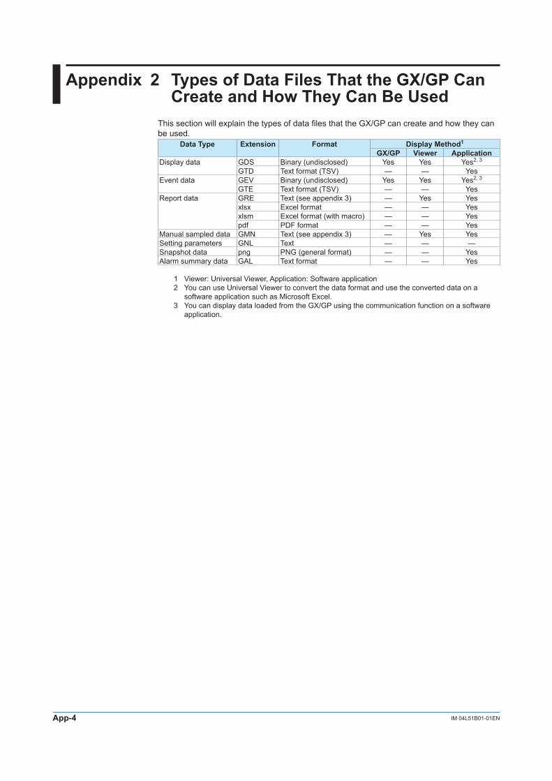
App-4 IM 04L51B01-01EN
Appendix 2 Types of Data Files That the GX/GP Can CreateandHowTheyCanBeUsed
This section will explain the types of data files that the GX/GP can create and how they can be used.
Data Type Extension Format Display Method1
GX/GP Viewer ApplicationDisplay data GDS Binary (undisclosed) Yes Yes Yes2, 3
GTD Text format (TSV) — — YesEvent data GEV Binary (undisclosed) Yes Yes Yes2, 3
GTE Text format (TSV) — — YesReport data GRE Text (see appendix 3) — Yes Yes
xlsx Excel format — — Yesxlsm Excel format (with macro) — — Yespdf PDF format — — Yes
Manual sampled data GMN Text (see appendix 3) — Yes YesSetting parameters GNL Text — — —Snapshot data png PNG (general format) — — YesAlarm summary data GAL Text format — — Yes
1 Viewer: Universal Viewer, Application: Software application2 You can use Universal Viewer to convert the data format and use the converted data on a
software application such as Microsoft Excel.3 You can display data loaded from the GX/GP using the communication function on a software
application.

App-5IM 04L51B01-01EN
Appendix
1
2
3
4
5
App
Index
Appendix 3 Text File Data Format
This section explains the format of text files. The text files that the GX/GP can create are display and event data files (when the data save format is text), manual sample data files, report files, and alarm summary files.Files contain values and character strings, each separated by a tab, in text format.
FormatofMeasurementandEventDataFilesFormat
YREC
Measure Data Version 1.01.00
Model GX10
GX20Language Code UTF-8
Serial No. SSS•••STime Correction Done
NoneSampling Interval NNN•••N ms
smin
Trigger Point NNN•••NEquip Tag SSS•••SEquip TagNo. SSS•••SFile Header SSS•••SFile ID NNN•••N NNN•••NStart Info Unknown None SSS•••S
Manual KeyAuto CommunicationBlack Out RemoteTrigger Event
End Info Unknown None SSS•••SManual KeyAuto CommunicationBlack Out RemoteTrigger Event
Extra Data Meas Max PlusOver NNN•••N •••Math Min MinusOver
Ext InstTime Zone NNN•••NDST On January FirstWeek Sunday NNN•••N January FirstWeek Sunday NNN•••N NNN•••N
Off February SecondWeek Monday February SecondWeek MondayMarch ThirdWeek Tuesday March ThirdWeek Tuesday
April FourthWeek Wednesday April FourthWeek WednesdayMay LastWeek Thursday May LastWeek ThursdayJune Friday June FridayJuly Saturday July SaturdayAugust AugustSeptember SeptemberOctober OctoberNovember November
December December
Batch Info NNN•••N SSS•••SBatch Comment TTT•••T SSS•••S SSS•••SBatch Comment TTT•••T SSS•••S SSS•••SBatch Comment TTT•••T SSS•••S SSS•••SText Info
Text Field SSS•••S SSS•••SText Field SSS•••S SSS•••SText Field SSS•••S SSS•••S
: : :
Text Field SSS•••S SSS•••SCh SSS•••S SSS•••S ••• Message
Ch Id SSS•••S SSS•••S •••Tag SSS•••S SSS•••S •••
Unit SSS•••S SSS•••S •••
Type Meas Meas ••• Message
Math Math •••
Ext Ext •••
Continued on next page

App-6 IM 04L51B01-01EN
Kind Inst Inst •••
Min Min •••
Max Max •••
Sampling Data
TTT•••T NNN•••N NNN•••N NNN•••N •••
Massage Data
TTT•••T SSS•••S None SSS•••S
Key
Communication
Remote
Event
System
Serial
NNN•••N: ValueSSS•••S: Character stringTTT•••T: Date and time
Common header YREC Fixed character stringFormat header Measure Data File type
Model Model nameLanguage –
Information header section Serial No. Serial number (up to 16 characters)Time Correction Time change informationSampling Interval Sampling intervalTrigger Point Trigger point: 0 and higherEquip Tag Equipment tag (up to 32 characters)Equip TagNo. Equipment tag number (up to 16 characters)File Header File header (up to 50 characters)File ID First: Record start number
Second: File serial number up to record stopStart Info Start user name (up to 20 characters)End Info End user name (up to 20 characters)Extra Data –Time Zone Current time zone settingDST Current DST settingBatch Info Lot number: 0 and higher
Batch number (up to 32 characters)The entire block is omitted when batch is set to off.
Batch Comment User name (up to 20 characters), comment (up to 50 characters)Text Info The entire block is omitted when batch is set to off.Text Field Title (up to 20 characters), text (up to 30 characters)
Table header section Ch Channel number (up to 4 characters)The character string “Message” is inserted at the right end.
Ch Id Tag number (up to 16 characters, spaces on the right)Tag Tag name (up to 32 characters, spaces on the right)Unit Unit name (up to 6 characters, spaces on the right)Type The character string “Message” is inserted at the right end.Kind The character string “Count” is inserted at the right end.
Measured data block Sampling Data The number of messages (up to 4 characters) is inserted in the right most column.
Message data block Massage Data Message string (up to 32 characters), user name (up to 20 characters)If the number of messages is zero, the entire block is omitted.For freehand messages, the message string is “*FreehandMessage*.”
Appendix 3 Text File Data Format

App-7IM 04L51B01-01EN
Appendix
1
2
3
4
5
App
Index
FileOutputExample• DisplayData
YRECMeasure Data Version 1.01.00Model GX20Language Code UTF-8Serial No. S5E701635Time Correction NoneSampling Interval 1 sTrigger Point 4Equip Tag tagEquip TagNo. tagnoFile Header FILE_HEADER_STRINGFile ID 34295620394 1Start Info Auto Key AdminEnd Info Auto Key AdminExtra Data Meas Max PlusOver 999999999 MinusOver -999999999Extra Data Meas Min PlusOver 999999999 MinusOver -999999999
Extra Data Math Max PlusOver 999999999 MinusOver -999999999Extra Data Math Min PlusOver 999999999 MinusOver -999999999Extra Data Ext Max PlusOver 999999999 MinusOver -999999999Extra Data Ext Min PlusOver 999999999 MinusOver -999999999Time Zone 540DST On March SecondWeek Sunday 2 November FirstWeek Sunday 2 -60Batch Info 000002 batch-name-no.Batch Comment 2012/12/12
14:50:00Admin1 comment1
Batch Comment 2012/12/12 14:50:00
Admin1 comment2
Batch Comment 2012/12/12 14:50:00
Admin1 comment3
Text InfoText Field title1 text1Text Field title2 text2Text Field title3 text3Text Field title4 text4Text Field title5 text5Text Field title6 text6Text Field title7 text7Text Field title8 text8Text Field title9 text9Text Field title10 text10Text Field title11 text11Text Field title12 text12Text Field title13 text13Text Field title14 text14Text Field title15 text15Text Field title16 text16Text Field title17 text17Text Field title18 text18Text Field title19 text19Text Field title20 text20Text Field title21 text21Text Field title22 text22Text Field title23 text23Text Field title24 text24Ch 0001 0001 A001 A001 C002 C002 MessageCh Id TagID_001 TagID_001 TagID_002 TagID_002 TagID_003 TagID_003Tag Furnace 1 Furnace 1 Furnace 2 Furnace 2 Furnace 3 Furnace 3
Unit °C °C °C °C °C °C
Type Meas Meas Math Math Ext Ext Message
Kind Min Max Min Max Min Max Count
Sampling Data
2012/12/12 14:50:00 153.2 153.3 153.2 153.3 153.2 153.3 1
2012/12/12 14:50:01 153.3 153.4 153.3 153.4 153.3 153.4 0
2012/12/12 14:50:02 153.4 153.5 153.4 153.5 153.4 153.5 2
2012/12/12 14:50:03 153.5 153.6 153.5 153.6 153.5 153.6 0
2012/12/12 14:50:04 153.6 153.7 153.6 153.7 153.6 153.7 0
Massage Data
2012/12/12 14:50:00 Message 1 Key Admin1
2012/12/12 14:50:02 Message 2 Communication Admin2
2012/12/12 14:50:02 *Freehand Massage* Key Admin3
Appendix 3 Text File Data Format

App-8 IM 04L51B01-01EN
• EventDataYRECMeasure Data Version 1.01.00Model GX20Language Code UTF-8Serial No. S5E701635Time Correction NoneSampling Interval 500 msTrigger Point 4Equip Tag tagEquip TagNo. tagnoFile Header FILE_HEADER_STRINGFile ID 6893290432 1Start Info Auto Key AdminEnd Info Auto Key AdminExtra Data Meas Inst PlusOver 999999999 MinusOver -999999999Extra Data Math Inst PlusOver 999999999 MinusOver -999999999
Extra Data Ext Inst PlusOver 999999999 MinusOver -999999999
Time Zone 540DST On March SecondWeek Sunday 2 November FirstWeek Sunday 2 -60Ch 0001 0002 0101 0102 MessageCh Id TagID_001 TagID_002 TagID_003 TagID_004
Tag Furnace 1 Furnace 2 Furnace 3 Furnace 4
Unit °C °C °C °C
Type Meas Meas Meas Meas Message
Kind Inst Inst Inst Inst Count
Sampling Data
2012/12/12 14:50:00_000 153.2 153.3 153.2 153.3 1
2012/12/12 14:50:00_500 153.3 153.4 153.3 153.4 0
2012/12/12 14:50:01_000 153.4 153.5 153.4 153.5 2
2012/12/12 14:50:01_500 153.5 153.6 153.5 153.6 0
2012/12/12 14:50:02_000 153.6 153.7 153.6 153.7 0
Massage Data
2012/12/12 14:50:00_000 Message 1 Key Admin1
2012/12/12 14:50:01_000 Message 2 Communication Admin2
2012/12/12 14:50:01_000 * Freehand Massage* Key Admin3
Appendix 3 Text File Data Format

App-9IM 04L51B01-01EN
Appendix
1
2
3
4
5
App
Index
Format of Manual Sample Data Files• Manualsampledatafilescontainvaluesandcharacterstrings,eachseparatedbyatab,
in text format.• ValuesofI/OchannelssettoSkip and math and communication channels set to Off are
not output.• Thedataisappendedtothefileeachtimemanualsampleoperationisperformed.
FormatYRECManual Sample Data Version 1.04.00Language Code UTF-8Model GX10
GX20File Status Complete
ProgressDecrease
Serial No. SSS•••SEquip Tag SSS•••SEquip TagNo. SSS•••SFile Header SSS•••SExtra Data (omitted) Inst PlusOver NNN•••N MinusOver NNN•••NTime Zone NNN•••NDST On NNN•••N January FirstWeek Sunday NNN•••N January FirstWeek Sunday NNN•••N NNN•••N
Off February SecondWeek Monday February SecondWeek MondayMarch ThirdWeek Tuesday March ThirdWeek TuesdayApril FourthWeek Wednesday April FourthWeek WednesdayMay LastWeek Thursday May LastWeek ThursdayJune Friday June FridayJuly Saturday July SaturdayAugust AugustSeptember SeptemberOctober OctoberNovember NovemberDecember December
Ch SSS•••S •••Ch Id SSS•••S •••Tag SSS•••S •••
Unit SSS•••S •••
TTT•••T NNN•••N •••
NNN•••N: ValueSSS•••S: Character stringTTT•••T: Date and time
FileOutputExampleYRECManual Sample Data Version 1.04.00Language Code UTF-8Model GX20File Status ProgressSerial No. S5KC09223Equip Tag tagEquip TagNo. tagnoFile HeaderExtra Data Inst PlusOver 999999999 MinusOver -999999999Time Zone 540DST On February SecondWeek Sunday 20 September ThirdWeek 20 -60Ch 0001 0002 0003 0004 0005 0006 0007 0008Ch Id chid001001 chid001002 chid001003 chid001004 chid001005 chid001006 chid001007 chid001008Tag
Unit V V V V V V V V
2012/12/12 14:50:01 0 0 -0.0001 -0.0003 -0.0005 -0.0007 -0.0009 -0.0002
2012/12/12 14:51:01 0 0 -0.0002 -0.0004 -0.0006 -0.0008 -0.0001 -0.0003
Appendix 3 Text File Data Format

App-10 IM 04L51B01-01EN
Note• Filestatus Complete: Completed. (100 manual sample data entries have been stored, and the file is
closed.) Progress: Data is being added. (The number of stored data entries has not reached 100 files,
and the file is open.) Decrease: Corrupted. (Some of the manual sample data in the file are missing.)• Outputwhenchanneldataisintheconditionshowninthetablebelow
Data Condition Data Handling OutputError Error (Space)+Overrange +Over Value indicated for
PlusOver in the Extra Data information header section
+Burnout+Display over+Computation over–Overrange –Over Value indicated for
MinusOver in the Extra Data information header section
–Burnout–Display over–Computation over
• Anewmanualsampleddatafileiscreatedinthefollowingcases.
• TherangeofanI/Ochannelconfiguredasamanualsamplingrecordingchannelwaschangedfrom some range other than Skip to Skip.
• TherangeofanI/Ochannelconfiguredasamanualsamplingrecordingchannelwaschangedfrom Skip to some range other than Skip.
• Amathorcommunicationchannelconfiguredasamanualsamplingrecordingchannelwaschanged from On to Off or from Off to On.
• Theunitofachannelconfiguredasamanualsamplingrecordingchannelwaschanged.• Whenthesettingsofamanualsamplingrecordingchannelarechanged.• WhenanAIchannelconfiguredasamanualsamplingrecordingchannelischangedfromtheDI
range (calculation is not set to linear scaling) to some other range, or vice versa.• WhenaDIchannelconfiguredasamanualsamplingrecordingchannelischangedfromlinear
scaling calculation to some other setting, or vice versa.• Whenthedecimalplaceofachannelconfiguredasamanualsamplingrecordingchannelis
changed.
Appendix 3 Text File Data Format

App-11IM 04L51B01-01EN
Appendix
1
2
3
4
5
App
Index
ReportFileFormat(/MToption)• Hourly,daily,weekly,andmonthlyreportfilescontainvaluesandcharacterstrings,each
separated by a tab, in text format.• ValuesofI/OchannelssettoSkip and math and communication channels set to Off are
not output.• Thedataisappendedtothisfileeverytimeareportiscreated.
FormatYRECReport Data Version 1.04.00Language Code UTF-8Model GX10
GX20File Statas Complete
ProgressDecrese
Serial No. SSS•••SEquip Tag SSS•••SEquip TagNo. SSS•••SFile Header SSS•••SExtra Data (omitted) Ave PlusOver NNN•••N MinusOver NNN•••N
MaxMinSumInst
Report Set Hourly+DailyDaily+WeeklyDaily+MonthlyBatchDailyCustom
File Data HourlyDailyWeeklyMonthlyHourly+DailyDaily+WeeklyDaily+MonthlyBatch
DailyCustomMath Set Ave •••
MaxMinSumInst
Start Time TTT•••TTime Zone NNN•••NDST On NNN•••N January FirstWeek Sunday NNN•••N January FirstWeek Sunday NNN•••N NNN•••N
Off February SecondWeek Monday February SecondWeek MondayMarch ThirdWeek Tuesday March ThirdWeek TuesdayApril FourthWeek Wednesday April FourthWeek WednesdayMay LastWeek Thursday May LastWeek ThursdayJune Friday June FridayJuly Saturday July SaturdayAugust AugustSeptember SeptemberOctober OctoberNovember November
December DecemberCh SSS•••S •••Ch Id SSS•••S •••Tag SSS•••S •••
Unit SSS•••S •••
Data Type Free
Hourly
Daily
Weekly
Monthly
Batch
DailyCustom
Time TTT•••T
Continued on next page
Appendix 3 Text File Data Format

App-12 IM 04L51B01-01EN
Elapsed Time1 (omitted) TTT•••T
Status Bo •••
Er
Ov
Pw
Cg
(Data attribute identifier)
NNN•••N •••
NNN•••N: ValueSSS•••S: Character stringTTT•••T: Date and time
1 Elapsed time is used for batch reports.
OutputExample• Hourly(hourly+daily)recordingwithfilesettoSeparate
YREC
Report Data Version 1.04.00
Language Code UTF-8
Model GX20
File Statas Complete
Serial No. S5KC09223
Equip Tag tag
Equip TagNo. tagno
File Header
Extra Data Ave PlusOver 999999999 MinusOver -999999999
Extra Data Max PlusOver 999999999 MinusOver -999999999
Extra Data Min PlusOver 999999999 MinusOver -999999999
Extra Data Inst PlusOver 999999999 MinusOver -999999999
Report Set Hourly+Daily
File Data Hourly
Math Set Ave Max Min Sum
Start Time 2012/12/12 11:01:01
Time Zone 540
DST On February SecondWeek Sunday 20 September ThirdWeek 20 -60
Ch 0001 0002 0003 0004 A001 A002 A003 C001
Ch Id chid001001 chid001002 chid001003 chid001004 chid001005 chid001006 chid001007 chid001008
Tag Point A Point B Point C Point D Point A Math Point B Math Point C Math Com
Unit V V V V °C °C °C V
Data Type Hourly
Time 2012/12/12 12:00:00
Status
Ave 0.0001 0.5010 0.7397 -1.0001 122.6 20.08 -20.98 0.2001
Max 1.9983 0.9989 1.4995 0.0010 123.4 22.02 -20.01 0.8887
Min -1.9959 -0.0053 -0.1005 -1.9952 120.3 19.79 -24.00 -0.3345
Sum 0.353900E+00 1.773039E+03 2.617798E+03 -3.53935E-03 4.338814E+05 7.099234E+04 -7.424822E-04 7.081539E+02
Data Type Hourly
Time 2012/12/12 12:06:01
Status
Ave 0.0002 0.5011 0.3301 -1.4423 121.3 20.20 -21.21 0.4411
Max 1.9984 0.9990 1.4995 0.0001 122.4 21.98 -20.95 0.8898
Min -1.9959 -0.0055 -1.4005 -1.994 120.09 19.00 -22.22 -0.1121
Sum 0.072200E+00 1.808971E+02 1.191661E+02 -5.206703E-02 4.378930E+04 7.292200E+03 -7.656810E-03 1.592371E+02
Appendix 3 Text File Data Format

App-13IM 04L51B01-01EN
Appendix
1
2
3
4
5
App
Index
• BatchReportYREC
Report Data Version 1.04.00
Language Code UTF-8
Model GX20
File Statas Complete
Serial No. S5KC09223
Equip Tag tag
Equip TagNo. tagno
File Header
Extra Data Ave PlusOver 999999999 MinusOver -999999999
Extra Data Max PlusOver 999999999 MinusOver -999999999
Extra Data Min PlusOver 999999999 MinusOver -999999999
Extra Data Inst PlusOver 999999999 MinusOver -999999999Report Set Batch
File Data Batch
Math Set Ave Max Min Sum
Start Time 2012/12/12 11:01:01
Time Zone 540
DST On February SecondWeek Sunday 20 September ThirdWeek 20 -60
Ch 0001 0002 0003 0004 A001 A002 A003 C001
Ch Id chid001001 chid001002 chid001003 chid001004 chid001005 chid001006 chid001007 chid001008
Tag
Unit V V V V °C °C °C °C
Data Type Batch
Elapsed Time 0000 00:10:00
Status
Ave 0.0001 0.5010 0.7397 -1.0001 122.6 20.08 -20.98 0.2001
Max 1.9983 0.9989 1.4995 0.0010 123.4 22.02 -20.01 0.8887
Min -1.9983 -0.0033 -0.1005 -1.9952 120.3 19.79 -24.00 -0.3345
Sum 6.000000E-02 3.006000E+02 4.438200E+02 -6.000600E+02 7.356000E+04 1.204800E+04 -1.258800E+04 1.206000E+02
Data Type Batch
Elapsed Time 0000 00:15:30
Status
Ave 0.0021 0.5110 0.7362 -1.0005 98.5 20.51 -20.42 0.1999
Max 1.9950 0.9987 1.4991 0.0011 105.2 21.01 -19.99 0.8802
Min -1.9989 -0.0053 -0.0997 -1.9960 70.5 20.01 -23.89 -0.3321
Sum 6.930000E+00 1.818300E+02 2.429460E+02 3.301650E+02 3.250500E+04 6.768300E+03 -6.738600E+03 6.596700E+01
Data Type Free
Elapsed Time 0000 00:15:30
Status
Ave 0.0008 0.5187 0.7374 -1.0002 114.0 20.23 -20.78 0.2000
Max 1.9950 0.9989 1.4995 0.0011 123.4 22.02 -19.99 0.8887
Min -1.9989 -0.0053 -0.1005 -1.9952 70.5 19.79 -24.00 -0.3345
Sum 7.530000E-01 4.824300E+02 6.858210E+02 -9.3022500E+02 1.060650E+05 1.881630E+04 -1.932660E+04 1.860270E+02
Appendix 3 Text File Data Format

App-14 IM 04L51B01-01EN
Note• Whenthechanneldataisintheconditionshowninthetablebelow,theEr,Ov,orBostatusis
output to a report.Data detection condition during report computation StatusError ErOver range data detection (including computation overflow of a math channel)
Ov
Burnout Bo
• ThereportoutputvalueofAve,Max,Min,Sum,andInstvariesdependingonthechanneldatacondition as shown in the table below.Item Data Condition Report Output
ValueMax,Min,Inst
Error/When there are no valid data (Space)+Over1 Value indicated
for PlusOver in the Extra Data information header section
–Over1 Value indicated for MinusOver in the Extra Data information header section
Ave When there are no valid data (Space)When the valid range is exceeded during computation+Over1 Value indicated
for PlusOver in the Extra Data information header section
–Over1 Value indicated for MinusOver in the Extra Data information header section
Sum/Ave When there are no valid data (Space)When the valid range is exceeded during computation
1 +Over, –Over+Over +Over range
Burnout+Display over
–Over –Over rangeBurnout–Display over
Appendix 3 Text File Data Format

App-15IM 04L51B01-01EN
Appendix
1
2
3
4
5
App
Index
Alarm Summary Format• Filescontainvaluesandcharacterstrings,eachseparatedbyatab,intextformat.• ValuesofI/OchannelssettoSkip and math and communication channels set to Off are
not output.
FormatYREC
Alarm Summary Data Version 1.01.00
Language Code UTF-8
Model GX10
GX20Serial No. SSS•••SEquip Tag SSS•••SEquip TagNo. SSS•••SFile Header SSS•••STime Zone NNN•••NDST On January FirstWeek Sunday NNN•••N January FirstWeek Sunday NNN•••N NNN•••N
Off February SecondWeek Monday February SecondWeek MondayMarch ThirdWeek Tuesday March ThirdWeek Tuesday
April FourthWeek Wednesday April FourthWeek WednesdayMay LastWeek Thursday May LastWeek ThursdayJune Friday June FridayJuly Saturday July SaturdayAugust AugustSeptember SeptemberOctober OctoberNovember November
December December
Alarm DataTTT•••T On SSS•••S SSS•••S SSS•••S
OffAck
NNN•••N: ValueSSS•••S: Character stringTTT•••T: Date and time
OutputExampleYREC
Alarm Summary Data Version 1.01.00
Language Code UTF-8
Model GX20
Serial No. S5KC09223
Equip Tag tagEquip TagNo. tagnoFile HeaderTime Zone 540DST On February SecondWeek Sunday 20 September ThirdWeek 20 -60
Alarm Data2012/12/12 11:01:10 On 0001 1 H2012/12/12 11:01:12 Off 0001 1 H2012/12/12 11:01:14 Ack All
Appendix 3 Text File Data Format

App-16 IM 04L51B01-01EN
Appendix 4 Creating Report Templates
CreatingReportTemplatesforReportFilesinExcelFormat
To create a report template, enter keywords and text in the cells of an Excel file. Keywords specify the type of data that will be entered into a cell. Text are output as they are in reports. Save the report templates that you create in Excel format (.xlsx extension) or Excel macro format (.xlsm extension).
Function: See page 1-104 in section 1.12, “Using the Report Template Function (/MT option)”.Setup: See page 1-100 in section 1.11, “Configuring the Report Function (/MT option)”.Loading and saving report templates: See page 1-106 in section 1.12.5, “Loading and Saving
Report Template Files”.
TemplateExample
Channel number $Tag(R001)$ $Tag(R002)$Name Tank 1 temperature Tank 1 pressureUnit $Unit(R001)$ $Unit(R002)$$ReportDataTime(Hour)$ $ReportDataInst(Hour, R001)$ $ReportDataInst(Hour, R002)$$Repeat$ $Repeat$ $Repeat$$Repeat$ $Repeat$ $Repeat$
ReportOutputExample
Channel number TIC-001 PIC-002Name Tank 1 temperature Tank 1 pressureUnit °C kPa2012/12/01 00:00:00 76.5 45.62012/12/01 01:00:00 78.9 56.72012/12/01 02:00:00 77.7 50.8

App-17IM 04L51B01-01EN
Appendix
1
2
3
4
5
App
Index
KeywordFormatKeywords are written by themselves or with parameters.$ Keyword(parameter)$ Example: $ReportDataSum(Hour,R001,00,23)$
Basic Rules• Thedollarsignontheleftindicatesthestartofakeyword,andthedollarsignontheright
indicates the end of a keyword.• Youcanonlywritekeywordsusinglettersofthealphabet,dollarsigns,parentheses,
commas, and spaces. You can put a space after an opening parenthesis, before and after a comma, and before a closing parenthesis. Keywords are not case sensitive. You cannot use a dollar sign inside of a keyword.
• Themaximumlengthofakeyword,includingspaces,is100characters.
Parameter Rules• Parametersareenclosedinparentheses.• Multipleparameters(upto4)areseparatedbycommas.• Examplesofhowparameterscanbeomittedareshownbelow.$ReportDataSum(Hour, R001, ,23)$ The third parameter has been omitted.$ReportDataSum(Hour, R001, 01, )$ or The fourth parameter has been omitted.$ReportDataSum(Hour, R001, 01)$
ExcelFormatRules• Setthedataformatbysettingthecellformat.• Settheproperformatforeachkeyword’scellinthecell’sNumberproperties.• Thekeywordinacellisonlyvalidwhenthekeywordnameandparametersareallinthe
same format. When a keyword’s font size or some other property is not consistent, it is invalid.
$ReportDataSum(Hour, R001, 00, 23)$ The font size of “Hour” is different, so the keyword is invalid.
• Ifasinglecellcontainstextandakeyword,onlytheformatofthekeywordhastobeconsistent. The format of the text can be different.
Date and time: $DateTime$ The format of the keyword is consistent, so it is valid.
Limitations on Report Types and Template TypesIf you violate the rules illustrated below, data will not be output.
KeywordParameter
Template Type
Report Kind Hour Day Week Month Hour + Day Day + Week
Day + Month
Batch DayCustom
Hour Day Week Month Batch Custom Free
Limitation on Report Types and Parameter OmissionsIf you violate the rules illustrated below, it will be considered a keyword format error.The keyword will not be converted and will remain as is.Report Kind Start date and time End date and time Start number End numberHour Start time (hour) End time (hour) — —Day Start day End day — —Week — — — —Month — — — —Batch Relative start time (minute) Relative end time (minute) Start number End numberCustom Start time (hour:minute) End time (hour:minute) — —Free — — — —
Appendix 4 Creating Report Templates

App-18 IM 04L51B01-01EN
KeywordDefinitionsFor examples, see “Report Template Examples.”
• SystemKeywordsOne keyword produces one item of data.Keyword Description FormatTime Current time on the GX/GP Time2
Date Current date on the GX/GP Date2
DateTime Current date and time on the GX/GPDateTimeString Current date and time on the GX/GP Character stringSerial GX/GP serial numberEquip tag GX/GP Tag stringEquipTagNo GX/GP Tag numberFileHeader GX/GP file headerCh Channel number1
Tag Tag string1
ChId Tag number1
Unit Unit1
1 The parameter is the report channel number (it cannot be omitted).2 The item becomes a character string in PDF and printer output.
• ReportDataKeywordsOne keyword produces multiple items of data.Keyword Description FormatReportDataDate Report creation date1 Date5
ReportDataTime Report creation time1 Time5
ReportDataDateTime Report creation date and time1 Date5
ReportDataDateTimeString Report creation date and time1 Character stringReportDataElapsedTimeString4 Report data time out date and time
(Relative time since the start of recording)
ReportDataStatus Report data status2
ReportDataSum Report data sum2 Number or character string3
ReportDataInst Instantaneous report data value2
ReportDataAve Average report data value2
ReportDataMax Maximum report data value2
ReportDataMin Minimum report data value2
1 Write the parameters in this order: report type (cannot be omitted), report start date and time (can be omitted), report end date, time (can be omitted), start number (can be omitted), and end number (can be omitted).
2 Write the parameters in this order: report type (cannot be omitted), report channel number (cannot be omitted), report start date and time (can be omitted), report end date and time (can be omitted), start number (can be omitted), and end number (can be omitted).
3 The decimal point type (dot or comma) depends on whether the converted data is a value or character string. Whether the converted data is a value or character string depends on the format of the cell that the keyword is written in. When the cell format is numerical, the decimal point type is determined by the cell format. When the cell format is text, the decimal point type matches the format of the report data.
4 Valid only when the report type is Batch.5 The item becomes a character string in PDF and printer output.
• SpecialKeywordsKeyword Description FormatRepeat Specifies the output location of the
data that corresponds the report data keyword and the Index keyword (a special keyword).
The same as the corresponding keyword.
Copy Outputs all data that corresponds the report data keyword and the Index keyword (a special keyword). This keyword is valid for PDF and printer output.
The same as the corresponding keyword.
Index Outputs serial numbers from the value specified by “start” to the value specified by “end.”
Number
Appendix 4 Creating Report Templates

App-19IM 04L51B01-01EN
Appendix
1
2
3
4
5
App
Index
• ParametersParameter Name Format Range Description NotesReport channel number Rxxx1 GX20/GP20:
R001 to R100GX10/GP10:R01 to R50
GX/GP report channel
Report kind Hour – Hourly reportDay – Daily reportWeek – Weekly reportMonth – Monthly reportBatch – Batch reportCustom – Daily customFree Batch and daily custom
reportsComputed results, such as sum values, of data in the file are appended to the file.This piece of data is called “Free.”
Start date and time hh2 00 to 23 Specifies the start hour Used in hourly reports
dd3 01 to 31 Specifies the start day Used in daily reports
mm4 0 to 12000 Specify the start minute Used in batch reports
hh:mm5 hh: 00 to 23mm: 00 to 59
Specifies the start hour:time Used in hourly custom reports
End date and time hh2 00 to 23 Specifies the end hour Used in hourly reports
dd3 01 to 31 Specifies the end day Used in daily reports
mm4 0 to 12000 Specify the end minute Used in batch reports
hh:mm5 hh: 00 to 23mm: 00 to 59
Specifies the end hour:minute
Used in hourly custom reports
Start number xxx1 001 to 200 Specifies the start number Used in batch reportsEnd number xxx1 001 to 200 Specifies the end number
1 xxx is a number without a limitation on the number of digits2 hh is a number without a limitation on the number of digits3 dd is a number without a limitation on the number of digits4 mm is a number without a limitation on the number of digits5 Spaces are allowed before and after colons.6 Start time and end time are relative to the record start time.
Appendix 4 Creating Report Templates

App-20 IM 04L51B01-01EN
StartingandEndingDatesandTimesUse the start date and time and end date and time to specify the parts of the report file’s report data that you will output to the file that you create with the template.You can specify the starting and ending dates (for daily reports) or times (for hourly reports).
Report Kind Start Date and Time EndDateandTimeHour Start time (hour) End time (hour)Day Start time (day) End time (day)Batch Start time (minute) End time (minute)Day custom Start time (hour:minute) End time (hour:minute)
Example when the report type is hourly and the report is created at 18:00.
18:00 19:00
Reportfile 1
Reportfile 2
Reportcreationtime
$ReportDataSum(Hour,R001,20,22)$ $ReportDataSum(Hour,R001,16,19)$
20:00 21:00 22:00 16:00 17:00 18:00 19:00
Keyword:$ReportDataSum(Hour,R001,20,22)$From the hourly data from 19:00:01 to 22:00:00, the report data (sums) of report channel R001 for 20:00, 21:00, and 22:00 is output.
Keyword:$ReportDataSum(Hour,R001,16,19)$From the hourly data from 15:00:01 to 19:00:00, the report data (sums) of report channel R001 for 16:00, 17:00, and 18:00 is output. Because the report data for 19:00 is in another report file, it is not output.
Keyword:$ReportDataSum(Hour,R001)$One file’s worth (18:00:01 to 18:00:00) of data from report channel R001 is output, starting from 19:00.When you omit the start and end times for an hourly report, the data for the hour after the report creation time until the 24th hour is output. For daily reports, the data for the day after the report creation time until the end of the month is output.
Keyword:$ReportDataSum(Hour,R001,08)$From the hourly data from 07:00:01 to 18:00:00, the report data (sums) of report channel R001 for 08:00 to 18:00 is output.
Appendix 4 Creating Report Templates

App-21IM 04L51B01-01EN
Appendix
1
2
3
4
5
App
Index
ReportTemplateExamplesSystemKeywordExamplesIntermixedKeywordandText
File header: $FileHeader$
Date and time: $DateTime$↓
File header: GX20
Date and time: 2012/12/01 12:00:00
IntermixedMultipleKeywordandText
Device number: $Serial$ File Header: $FileHeader$
↓Device number: ABCDEFG File Header: GX20
ReportDataKeywordExamplesThe following examples are for when the hourly report data for report channel R001 is 101, 102, 103, 104, and 105 and the hourly report data for report channel R002 is 201, 202, 203, 204, 205, and 206.
The $Repeat$ command applies to the closest keyword above the command in the same column.
$ReportDataInst(Hour,R001)$ 101$Repeat$ 102$Repeat$ 103$Repeat$ → 104$ReportDataInst(Hour,R002)$ 201$Repeat$ 202$Repeat$ 203$Repeat$ 204$Repeat$ 205
The $Repeat$ command applies to the keyword above it in the same column, even when that keyword is not directly above the command.
$ReportDataInst(Hour,R001)$ 101$Unit(R001)$ °C$Repeat$ 102$Unit(R001)$ → °C$Repeat$ $Unit(R001)$ 103 °C
You can mix system keywords, report data keywords, and text. If the data specified by a keyword does not exist, nothing is output.
$ReportDataInst(Hour,R001)$($Unit(R001)$)
101 (°C)
$Repeat$ 102$Repeat$ 103$Repeat$($Unit(R001)$) → 104 (°C)$Repeat$(°C) 105 (°C)$Repeat$
Appendix 4 Creating Report Templates

App-22 IM 04L51B01-01EN
Keywords in merged cells are affected by the leftmost cells above them.
$ReportDataInst(Hour,R001)$ $ReportDataInst(Hour,R002)$$Repeat$ $Repeat$
$Repeat$ $Repeat$$Repeat$ $Repeat$↓101 201102 202
203103 204
When a keyword is written incorrectly or its formatting is wrong, the keyword will be output to the file as it is written.
$ReportDataInst(Hour,R)$ $ReportDataInst(Hour,R)$→
$ReportDataInst(Hour,R002)$ 201$Repeat$ $Repeat$$Repeat$ 202$Repeat$ 203$Repeat$ 204
$ReportDataInst(Hour,R001)$$ReportDataInst(Hour,R002)$
1 101$ReportDataInst(Hour,R002)$
1 When there are multiple system keywords in the same cell, only the first keyword is valid.
Creating Report Templates for PDF Report Files and Printer OutputTo create a report template, use the editing tool provided by YOKOGAWA to enter keywords and text in the cells of table.Keywords specify the type of data that will be entered into a cell. Text are output as they are in reports.For the keywords that you can use, see “Creating Report Templates for Report Files in Excel Format.”
Appendix 4 Creating Report Templates

App-23IM 04L51B01-01EN
Appendix
1
2
3
4
5
App
Index
Appendix 5 PowerRecoveryOperation
This section explains how the GX/GP operates when it recovers from a power failure.
PowerFailureDetectionThe GX/GP power shuts down when the power is disrupted for the times indicated below.• 100to240VAC:1cycleormore• 24VDC/AC:1msormore
Basic OperationThe following operations are retained when the GX/GP recovers from a power failure.Recording Operation• IfapowerfailureoccurswhiletheGX/GPisrecording,itwillcontinuerecordingwhenit
recovers.• Displayandeventdatafilesareseparatedwhenapowerfailureoccurs.
Monitor Display• Themonitordisplayisretained.• Ifapowerfailureoccurswhenamenuisshowing,allunsavedsettingsarediscarded,
and the monitor display returns.• Exceptforthefollowingcases,trendwaveformscontinuefromtheendofwaveforms
before the power failure.• Whenthefiletypeissettoeventdataonly• Whenthetrendintervalswitchingfunctionison
Moving AverageMoving average of AI channels are not retained. When the GX/GP recovers, a new moving average will start.
Timer Action• Relativetimer Time action is retained. Relative timers do not count the power failure time.• Absolutetimer,matchtimetimer If timers expire during a power failure, timeout processing occurs when the GX/GP
recovers.
RemoteRemote conditions are retained. If remote conditions change during a power failure, the corresponding remote actions are executed when the GX/GP recovers.
Computation• IfapowerfailureoccurswhiletheGX/GPiscomputing,itwillcontinuecomputingwhenit
recovers.• Computationresultsareretainedduringapowerfailure.• Rollingaveragevaluesarealsoretainedduringapowerfailure.• Ifabsolutetimersormatchtimetimersexpireduringapowerfailure,TLOGcomputation
is performed when the GX/GP recovers.
Report Operation• IfapowerfailureoccurswhiletheGX/GPiscreatingareport,itwillcontinuetocreateit
when it recovers.• Iftimersexpireduringapowerfailure,timeoutprocessingoccursusingthedataupto
the power failure when the GX/GP recovers. If this occurs, the report data will contain a power failure mark.

App-24 IM 04L51B01-01EN
Communication OperationCommunication ports are closed when a power failure occurs.• ReestablishEthernetconnections.• Clientfunction
• WhenModbusclientisinuseandapowerfailureoccursinthemiddleofatransmission, the data will not be retransmitted.
• WhentheFTPclientfunctionisinuseandapowerfailureoccursinthemiddleofafiletransfer, the file will be re-transferred when the GX/GP recovers.
• Communicationchannelvaluesareretainedevenduringapowerfailure.TheGX/GPcanbe configured so that the values take on preset values when the GX/GP recovers.
DO OperationDO output values are not retained during a power failure.• Alarmoutput Alarms are set to off when the GX/GP recovers.• ManualDOoperation Manual DO operation is set to off, regardless of the condition before the power failure.
PowerRecoveryOperationSummaryOperation Function Held/Not Held DescriptionRecording Recording status Held If a power failure occurs during recording,
recording will continue when the GX /GP recovers.
File creation Held A power failure divides files.Trend waveform
File type: Event data only
Not held Waveforms before the power failure will be lost.
Trend rate switching Not held Waveforms before the power failure will be lost.
Other than those above Held Continues to be displayed.Timer Relative timer Held Timers do not count during the power failure
period.Absolute timerMatch time timer
Held If timers expire during a power failure, timeout processing occurs when the GX/GP recovers.
Remote Remote condition Held If remote conditions change during a power failure, the corresponding actions are executed when the GX/GP recovers.
AI channel Moving average Not held When the GX/GP recovers, a new moving average will start.
Computation Computation condition Held If a power failure occurs during computing, computing will continue when the GX/GP recovers.
Computed results Held Data before the power failure is retained.Rolling average Held Average values before the power failure is
retained.TLOG Computation Held If absolute timers or match time timers
expire during a power failure, TLOG computation is performed when the GX/GP recovers.
Communication Connection Not held Connections need to be reestablished when the GX/GP recovers.
Client Not held Modbus: Data in transmission is discarded.FTP: Files in transmission is retransmitted.
Communication channel Held Data before the power failure is retained.DO Alarm Not held Set to off.
Manual DO Not held Set to off.
Appendix5PowerRecoveryOperation

App-25IM 04L51B01-01EN
Appendix
1
2
3
4
5
App
Index
Appendix 6 Creating Scale Images
Scale ImagesIn addition to the standard scale, you can display original scales that you create. You can display scale images at the display group level.This feature is useful when you want to use your own scale or need a special scale for nonlinear input signals or other nonstandard signals.
Creating a Scale ImageYou can create a scale image based on a GX/GP trend screen that has been configured appropriately for your purpose. Using the GX/GP snapshot feature, save an image data (PNG format) of the trend screen to the SD memory card. Edit the image data using a software application that can handle PNG files (Windows Paint for example) to create the scale image.
ScaleImageCreationWorkflow
1 Configuring the trend screen settingsSet the trend screen’s display direction, scale position, and the position of digital values.
2 Displaying the trend screen and capturing image dataOn the GX/GP, display the group trend screen that you want to show the scale image in. Using the snapshot feature, save an image data of the trend screen to the SD memory card.
3 Creating the scale imageCreate the scale image by editing the image data on an image editing software application.
Scale Image Creation Procedure
Configuring the trend screen settingsSet the following items related to the scale image according to the trend scale that you will use on the GX/GP.
• Trenddisplaydirection page 1-71 in section 1.6.4, “Setting Trend Display Conditions”• Scalepositionofeachchannel AI channel: Refer to page 1-21 in section 1.2.3, “Setting the Display” DI channel: Refer to page 1-39 in section 1.3.3, “Setting the Display” DO channel: Refer to page 1-46 in section 1.4.2, “Setting the Display” Math channel: Refer to page 1-63 in section 1.5.5, “Setting the Display” Communication channel: Refer to page 1-122 in section 1.15.3, “Setting the Display”• Numberofscaledigitstodisplay Refer to page 1-71 in section 1.6.4, “Setting Trend Display Conditions”• Thepositionofthedigitalvaluesonthetrendscreen Refer to page 2-9 in section 2.2.1, “Displaying Measured Data Using Waveforms, Numeric
Values, Bar Graph, or Custom Display (/CG option) (Trend, digital, bar graph, and custom displays)”

App-26 IM 04L51B01-01EN
Position of the digital values
Scale position of each channel
Trend display direction Number of scale digits to display
Displaying the trend screen and capturing image data
1 Display the trend screen group that you want to use the scale image on.
2 Press MENU, tap Universal and then Snap shot.The image data (PNG format) of the trend screen is saved to the SD memory card.
Creating a Scale Image
1 Open the image data that has been saved to the SD memory card in an image editing software application.The area outlined in red is where the scale image will be displayed. Cut this area out, and create the data for the scale image.
Area where the scale image will be displayed
Top: Top edge of the screen display area (excluding the status bar)Bottom: Bottom of the screen
Left: Left edge of the scale display area
Right: Right edge of the scale display area
Top
Bottom
Left Right
Left
Status bar
Top
Right
Exclude
Appendix 6 Creating Scale Images

App-27IM 04L51B01-01EN
Appendix
1
2
3
4
5
App
Index
2 Create an image only of the area that has been cut out.
Area that has been cut out
3 To align the scale position to the positions where the value indicator marks will appear, create guidelines. The lines marked in red on the scale are the guidelines. Erase everything except for the lines marked in red. This image will be used as the base of the scale image.
Guidelines
4 On this base image, draw scales, warning areas, units, values, etc., as you like.
5 After you finish creating the scale image, save it in PNG format.This completes the creation of the scale image.
Appendix 6 Creating Scale Images

App-28 IM 04L51B01-01EN
Appendix 7 Terminology
This section explains the terminology related to the GX/GP.Term Explanation Notes
Display data Waveform data that is displayed on the GX/GP screen. It is a recording of measured data sampled at the display data sampling interval.
Event data Event data is a recording of measured data at a specified recording interval. This is separate from the display data.
Trend interval The interval at which the waveform display is updated. The display is updated at a time interval that corresponds to 1 dot, which is determined by the specified recording interval (time interval that corresponds to 1 division).
See page 1-67 in section 1.6.1, “Setting the Trend Interval”
I/O channel A collective term that refers to analog input channels (AI channels), digital input channels (DI channels), and digital output channels (DO channels).
AI channel Analog input channel. Analog input channels can receive and measure DC voltage, thermocouple (TC), RTD, and On/Off signals (DI).
DI channel Digital input channel. Digital input channels can measure On/Off signals.
DO channel Digital output channel. Digital output channels can be used as relay outputs.
GS (range type) Range type for 1-5VDC and 0.4-2VDC signalsGS (4-20mA) (range type)
Range type for 4 to 20 mADC signals (current input modules)
DI (range type) Range type for digital input (1, 0) based on contacts or voltage levelsRTD (range type) Range type for RTD sensorsTC (range type) Range type for thermocouple sensorsInput calculation Calculation performed on inputs, such as scaling, taking the difference
between two channels (difference in relation to a reference channel), and square rooting.
Historical trend Waveform based on past measured data as opposed to the waveform based on current data. The waveform display area of historical trends shown from a memory summary, message summary, alarm summary and so on is displayed in gray.
Color scale band Displays a specified section (inside or outside) of the measurement range using a color band on the scale.
Trip line A line displayed at a specified position in the waveform display range on the trend display.
Zone (display) Zones enable channels to be displayed in separate areas so that waveforms do not overlap.
Partial expanded display Partial expanded display compresses a section of the waveform display range so that the rest of the section is expanded.
Manual sample An action executed through a screen operation or event action function. The action saves instantaneous values of all channels (except those set to Skip or Off).
Snapshot An image of the GX/GP screen saved in PNG format to an SD memory card. Some screens cannot be saved as screenshots.
Reconfiguration A system reconfiguration that aligns the GX/GP settings to the I/O module configuration.Reconfiguration is necessary when the positions of different types of modules are changed and when modules are added or deleted.
See page 1-183 in section 1.24.2, “Reconfiguring the GX/GP”
Individual alarm ACK The operation of acknowledging alarms (clearing alarm output) separately by channel and level.
See page 1-148 in section 1.18.3, “Setting the Alarm Display Hold/Nonhold and Individual Alarm ACK Operation”, page 2-57 in section 2.4.1, “Releasing Alarm Output (Alarm ACK and individual alarm ACK operation)”
General communication (GENE)
A function for communicating with the GX/GP (configuration and control) using GX/GP dedicated communication commands.
See page 1-139 in section 1.16.9, “Setting the Server Functions to Use (FTP, HTTP, SNTP, MODBUS, GENE, DARWIN compatible communication)”

Index 1
2
3
4
5
App
Index
Symbols2ch mode .............................................................................. 1-7710ch mode ............................................................................ 1-77
AAcknowledging all alarms ..................................................... 1-44Acknowledging individual alarms................................ 1-44, 2-58Action on math start............................................................ 1-107Activating modules ............................................................... 2-55Alarm ACK operation ............................................................ 1-44Alarm delay....................................................... 1-19, 1-38, 1-63Alarm type .................................................................. 1-18, 1-20AND/OR operation................................................................ 1-44Authentication ..................................................................... 1-130Authority of user ................................................................. 1-163Auto increment ..................................................................... 1-98Automatically saving ............................................................. 2-62Auto save.................................................................... 1-93, 1-94
BBias....................................................................................... 1-16Burnout criteria ..................................................................... 1-79Burnout set ........................................................................... 1-16
CCalibration correction............................................................ 1-34Certificate for communication ............................................. 1-186Certificate for PDF signatur ................................................ 1-186Certificate signature request (CSR)........................ 1-186, 1-187Change message ................................................................. 1-73Changing each value from monitoring .................................. 1-75Collectively saving unsaved data ......................................... 2-62Collectively storing unsaved data ......................................... 1-96Color scale band............................................. 1-27, 1-65, 1-124Configuration changes comment ........................................ 1-156Continuous channel data area.............................................. 4-30Continuous channel data read/write area ............................. 4-47Count .................................................................................... 1-15Custom display ............................................. 1-170, 1-177, 2-10
DDARWIN ................................................................. 1-141, 1-192Data length ........................................................................... 1-82Data types ............................................................................ 1-86Day custom......................................................................... 1-102Decimal place ............................................................. 1-14, 1-37Delta ..................................................................................... 1-13Direction ..................................................................... 1-71, 1-74Display characters of each value...................... 1-29, 1-41, 1-47Display data .......................................................................... 1-80DO output relay operation .................................................... 1-45
EEncryption........................... 1-129, 1-130, 1-139, 1-140, 1-185Energize/De-energize ........................................................... 1-43Energize or de-energize operation ....................................... 1-44Event data .................................................................. 1-81, 3-12Excel report files ................................................................. 1-104Execution of the input measurement .................................... 1-35
F
FAIL relay ........................................................................... 1-152File format............................................................................. 1-97File type ................................................................................ 1-80Free ...................................................................................... 1-82Function key ......................................................................... 2-60
GGap between messages ..................................................... 1-143GENE ................................................................................. 1-140Graduallyadjustingthetime ............................................... 1-149GX/GP Version .......................................................................... iii
HHysteresis ............................................. 1-19, 1-38, 1-63, 1-121
IIndividual alarm ACK ................................................ 1-43, 1-148Individual alarm acknowledges............................................. 3-26Initialize password .............................................................. 1-163Instrument Information........................................................ 1-152Intermediate certificate ....................................................... 1-189
JJava applet ............................................................................. 3-5Java runtime environment (JRE) ............................................ 3-4Jump default display ............................................................. 1-75
KKey ..................................................................................... 1-185
LLarge memory type......................................................................iLinearizer approximation ............................................ 1-34, 1-35Linearizer bias ............................................................ 1-34, 1-35Linearizer input ..................................................................... 1-34Linearizer output ................................................................... 1-34Linear scaling ....................................................................... 1-13Log........................................................................................ 2-42Logging ................................................. 1-19, 1-38, 1-63, 1-121Low-cut output ...................................................................... 1-14Low-cut value ....................................................................... 1-14
MManual sample ........................................................... 1-88, 2-62Manual sampling .................................................................. 3-12Manual save ............................................................... 1-96, 2-62Media FIFO................................................................. 1-93, 1-95Moving average .................................................................... 1-15
NNonhold/Hold ........................................................................ 1-44Normal and remote ............................................................... 1-77
OOver range............................................................................ 1-33
PPartial ................................................... 1-27, 1-65, 1-72, 1-124PC system requirements ........................................................ 3-2
Index
Index-1IM04L51B01-01EN
Index

IndexPDF electronic signature .................................................... 1-102PDF report files................................................................... 1-105Power-fail message .............................................................. 1-73Pre-trigger............................................................................. 1-83
RRecommended replacement periods for worn parts............... 5-9Reconfiguring ..................................................................... 1-183Record confirmation action ................................................... 1-83Recording Interval ...................................................... 1-68, 1-81Reflash ................................................................................. 1-44Relay action on ACK............................................................. 1-43Relay deactivated interval .................................................... 1-44release number.......................................................................... iiiRepeat .................................................................................. 1-82Report template .......................................... 1-104, 1-167, 1-175Report template output ....................................................... 1-101Rolling average..................................................................... 1-51
SSaving interval ...................................................................... 1-81Scale lower ........................................................................... 1-37Scale upper ................................................................ 1-14, 1-37Scan interval ......................................................................... 1-76Scroll time ................................................................... 1-75, 2-14Second interval ..................................................................... 1-67self-signed certificates ........................................................ 1-186Shifting the transfer time....................................................... 3-71Single.................................................................................... 1-82Span lower...................................1-13, 1-14, 1-42, 1-50, 1-119Span upper ............................................1-13, 1-42, 1-50, 1-119Square root ........................................................................... 1-13Standard type ..............................................................................iSTART/STOP key action ...................................................... 1-48Status display section ........................................................... 1-31Status indications ................................................................... 3-7style number .............................................................................. iii
TTime deviation limit ............................................................. 1-149Transfer wait time ............................................................... 1-128Trend clear ........................................................................... 1-71Trend interval .......................................... 1-67, 1-68, 1-81, 1-85Trend rate switching ............................................................. 1-67Trigger source operation .............................................. 1-83, 2-5Trusted certificates ................................................. 1-169, 1-176
UUnverified certificates ......................................................... 1-191Update interval of measured values ..................................... 1-30Updating the firmware ...........................................................5-11
VVerification of certificate.......................................... 1-129, 1-130Verifying unverified certificates ............................................. 2-61
WWatchdog timer .................................................................. 1-120Write group ........................................................................... 1-73
Index-2 IM04L51B01-01EN
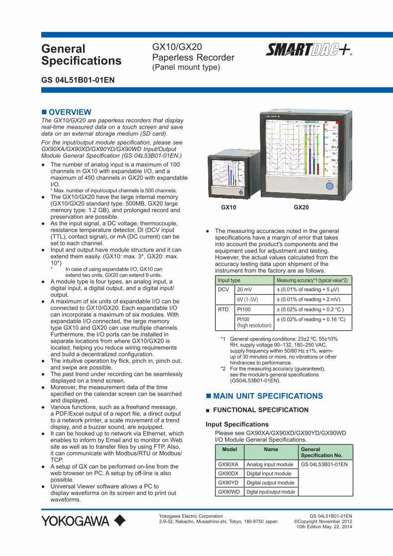
GeneralSpecifications
GX10/GX20Paperless Recorder(Panel mount type)
Yokogawa Electric Corporation2-9-32, Nakacho, Musashino-shi, Tokyo, 180-8750 Japan
GS 04L51B01-01EN
GS 04L51B01-01EN©Copyright November 201210th Edition May. 22, 2014
OVERVIEWThe GX10/GX20 are paperless recorders that display real-time measured data on a touch screen and save data on an external storage medium (SD card).For the input/output module specification, please see GX90XA/GX90XD/GX90YD/GX90WD Input/Output Module General Specification (GS 04L53B01-01EN.)● Thenumberofanaloginputisamaximumof100
channelsinGX10withexpandableI/O,andamaximumof450channelsinGX20withexpandableI/O.*Max.numberofinput/outputchannelsis500channels.
● TheGX10/GX20havethelargeinternalmemory(GX10/GX20 standard type: 500MB, GX20 large memory type: 1.2 GB), and prolonged record and preservation are possible.
● Astheinputsignal,aDCvoltage,thermocouple,resistancetemperaturedetector,DI(DCVinput(TTL),contactsignal),ormA(DCcurrent)canbeset to each channel.
● Inputandoutputhavemodulestructureanditcanextendthemeasily.(GX10:max.3*,GX20:max.10*)* IncaseofusingexpandableI/O,GX10can
extendtwounits,GX20canextend9units.● Amoduletypeisfourtypes,ananaloginput,a
digital input, a digital output, and a digital input/output.
● AmaximumofsixunitsofexpandableI/OcanbeconnectedtoGX10/GX20.EachexpandableI/Ocanincorporateamaximumofsixmodules.WithexpandableI/Oconnected,thelargememorytype GX10 and GX20 can use multiple channels. Furthermore,theI/OportscanbeinstalledinseparatelocationsfromwhereGX10/GX20islocated, helping you reduce wiring requirements andbuildadecentralizedconfiguration.
● Theintuitiveoperationbyflick,pinchin,pinchout,and swipe are possible.
● Thepasttrendunderrecordingcanbeseamlesslydisplayed on a trend screen.
● Moreover,themeasurementdataofthetimespecifiedonthecalendarscreencanbesearchedand displayed.
● Variousfunctions,suchasafreehandmessage,aPDF/Exceloutputofareportfile,adirectoutputtoanetworkprinter,ascalemovementofatrenddisplay, and a buzzer sound, are equipped.
● ItcanbehookeduptonetworkviaEthernet,whichenablestoinformbyEmailandtomonitoronWebsiteaswellastotransferfilesbyusingFTP.Also,it can communicate with Modbus/RTU or Modbus/TCP.
● AsetupofGXcanbeperformedon-linefromthewebbrowseronPC.Asetupbyoff-lineisalsopossible.
● UniversalViewersoftwareallowsaPCtodisplaywaveformsonitsscreenandtoprintoutwaveforms.
● Themeasuringaccuraciesnotedinthegeneralspecificationshaveamarginoferrorthattakesinto account the product's components and the equipmentusedforadjustmentandtesting.However,theactualvaluescalculatedfromtheaccuracytestingdatauponshipmentoftheinstrumentfromthefactoryareasfollows.Inputtype Measuring accuracy*1 (typical value*2)
DCV 20mV ±(0.01%ofreading+5μV)
6V (1-5V) ±(0.01%ofreading+2mV)
RTD Pt100 ±(0.02%ofreading+0.2°C )
Pt100(high resolution)
±(0.02%ofreading+0.16°C)
*1 General operating conditions: 23±2 ºC, 55±10% RH,supplyvoltage90–132,180–250VAC,supplyfrequencywithin50/60Hz±1%,warm-upof30minutesormore,novibrationsorotherhindrancestoperformance.
*2 For the measuring accuracy (guaranteed), seethemodule'sgeneralspecifications(GS04L53B01-01EN).
MAIN UNIT SPECIFICATIONS■ FUNCTIONALSPECIFICATION
InputSpecifications PleaseseeGX90XA/GX90XD/GX90YD/GX90WD
I/OModuleGeneralSpecifications.Model Name General
SpecificationNo.GX90XA Analoginputmodule GS 04L53B01-01EN
GX90DX Digitalinputmodule
GX90YD Digitaloutputmodule
GX90WD Digitalinput/outputmodule
GX10 GX20

2
All Rights Reserved. Copyright © 2012-2014, Yokogawa Electric Corporation GS 04L51B01-01EN May. 22, 2014-00
MeasuringFunctions• ThenumberofinstallablemodulesandI/O
channels(totalforGXandexpandableI/O)
GX10/GX20standardtypeItem GX10/GX20standardtype
Numberofmodule Max.10
Numberofinput/outputmodule Max.100
GX20largememorytypeItem GX20largememorytype
Numberofmodule Max.45
Numberofinput/outputmodule Max.500(ormax.450forAIonly)
Restrictionsofmoduleconnection:• Amaximumof10modulescanbeinstalled,as
atotalforGX90YDdigitaloutputmodulesandGX90WDdigitalI/Omodules.
• AmaximumofoneGX90WDdigitalI/OmodulecanbeinstalledinGXandineachexpandableI/O.
• ExpandableI/Oconnection Numberofconnectableunits:Max.6
Caution IfthemaximumnumberofI/Ochannelsare
assigned and the last channel is assigned to an intermediatechannelofamodule,thatmoduleandsubsequent modules will not be recognized.
1
10
100
81
90
91Module 1 Module n
: ::
• • •
:Maximum number of I/O channels
DisplayFunctionsDisplaygroups: Numberofgroups;GX10:30,GX20standard
type:50,GX20largememorytype:60 Numberofchannelsthatcanbeassignedto
eachgroup;GX10:10,GX20:20 Scan interval: 100*1*2, 200*1*2, 500 ms*1, 1, 2, 5 s*1 Cannotbespecifiedifanelectromagneticrelay
scannertype(TypeSuffixCode:-T1)analoginputmodule is in use.
*2 CannotbespecifiedforL-modelDCV/TC/DI,scannertype(TypeSuffixCode:-L1).
Displaycolor(Trend/Bargraph/Digitaldisplay): Channel:Selectfrom24colors Adesireddisplaycolorcanbeselectedfreely
using its RGB value. Background:Selectfromwhiteorblack
Displaytype:● Trenddisplay(T-Y) Displaymethod:
Direction:Horizontal,verticalTrend interval: 5*1*2, 10*1*2, 15*1, 30 s/div, 1, 2,
5, 10, 15, 20, 30 min/div, 1, 2, 4, 10 h/div*1 Cannotbespecifiedifanelectromagneticrelay
scanner type analog input module is in use.*2 CannotbespecifiedforL-modelDCV/TC/DI,
scannertype(TypeSuffixCode:-L1). Trend line width: Thick, normal, thin
Scale;GX10:Max.6,GX20:Max.10Current value bar graph, color scale band,
and alarm point marks can be displayed on the scale.
Movingscale;Scalecanbemovedonanywaveform. Abitmapimagescalecanbeattached.
Others;Grid(Auto,4to12),Tripline,Message,Zonedisplay,Partialexpandeddisplay
● Historicaltrenddisplay(T-Ydisplay) Redisplays the display data or event data in the
internalmemoryorexternalstoragemedium Timeaxisoperation:Thetimeaxiscanbe
reducedorexpanded. Datasearch:Waveformsfromtheinternal
memory can be displayed through the specificationofadateandtime,calendar,eachsummary Movingscale;Abitmapimagescalecanbeattached.
Allhistoricaltrendscanbedisplayedinonescreen.
● Bargraphdisplay Direction:Verticalorhorizontal Scale:Displayascaleforeachchannel
Color scale band, and alarm point marks can be displayed on the scale.
● Digitaldisplay Displaysmeasuredvaluesnumerically ADIinputstatecanbedisplayedasanarbitrary
characterstring(0=Off/1=On,etc.) Update rate: 0.5 s● Overviewdisplay Displayformat:Allchannels,eachgroups Displaysthemeasuredvaluesofallchannels
and the alarm statuses● Alarmsummarydisplay Displaysalogofupto1000alarms Specifyanalarmwiththecursorandjumpto
the corresponding section on the historical trend display.
● Messagesummarydisplay Timeandcontentofupto500messages
(including 50 add messages) Specifyamessagewiththecursorandjumpto
the corresponding section on the historical trend display.
● Memory summary display Displaystheinformation(upto500)ofthedata
in the memory Specifyafilewiththecursorandjumptothe
corresponding section on the historical trend display.
● Reportdisplay Displaysthereportdataresidingintheinternal
memory Formoredetails,see"MATHEMATICAL
FUNCTIONSWITHREPORTFUNCTION(/MT)."● Logdisplay Displaystheeventlog,errorlog,communication
log,FTPlog,Weblog,e-maillog,SNTPlog,DHCPlog,andModbuslog.
● Multi-paneldisplay Dividesthescreenintotwotosixsectionsand
displayssomedifferentdisplayformats.

3
All Rights Reserved. Copyright © 2012-2014, Yokogawa Electric Corporation GS 04L51B01-01EN May. 22, 2014-00
● Internalswitch/relaystatedisplay DisplaystheinternalswitchandON/OFFstateof
DO OperatestheinternalswitchandON/OFFstate● Otherdisplays Networkinformationdisplay Systeminformationdisplay Systemconfigurationdisplay
AutoscrollON/OFF: The displayed groups can be automatically
switchedataspecifiedinterval. The display switches in ascending group order.
Namesofchannels:
Channel number; Analog input: 01 to 10 Digital input: 01 to 16 Digital output: 01 to 06 Digital input/output; DI: 01 to 08, DO: 09 to 14
X X X X
Slot number; GX10: 0 to 2, GX20: 0 to 9 Expandable I/O: 0 to 5Unit number; Main unit: 0, Expandable I/O: 1 to 6
Tags:• TagandTagnumberscanbedisplayed.• Tagnumber;Numberofcharacters:Upto16 Displayablecharacters:Alphanumericcharacters Tag numbers can be enabled or disabled.• Tag;Numberofcharacters:Upto32 Displayablecharacters:Alphanumericcharacters
Message:• Writemessagestothetrenddisplay.• Numberofmessages:100• Numberofcharacters:Upto32• Writemethod:Writeapresetmessageorwrite
an arbitrary message on the spot.• Writedestination:Selectonlythedisplayed
group or all groups.• Automessage:WriteamessagewhentheGX
recoversfromapowerfailurewhilememorysampling is in progress.
Writeamessagewhenthetrendintervalisswitched during memory sampling.
Addmessage:• Writemessagestothepastdatapositions.• Message:Thesameasthe“Message”item
above Numberofwritablemessagesperfile:50
messages(including10freehandmessages)Freehandmessage:• Canbewrittenbydedicatedpen. Numberofwritablemessagesperfile:50
messages(including10Addmessages)
DataSavingFunctionsInternalmemory:• Temporarilysavesvarioustypesofdata.• Medium:Flashmemory• Filestoragecapacity; GX10, GX20 standard type: 500 MB GX20 large memory type: 1.2 GB
Externalstoragemedium:• MediumSDcard(SD/SDHC)(upto32GB)• Format:FAT32orFAT16
Datatype:• Displaydata,Eventdata,Alarmsummarydata,
Manual sampled data, Screen image data, Setup data, and Report data
Displaydata:• Target:Measurement(input/outputmodule)/
math/communication channels, alarm summary, message summary
Description:Maximumorminimumvalueperrecording interval
• Recordingintervals:Determinedbythetrendinterval, recording data type (display data/display data+eventdata,GX20largememorytype)
For GX20 standard typeTrendinterval(div) Numberofchannels5 s 100
10 s 200
15 s or longer 500
For GX20 large memory typeTrendinterval(div) Numberofchannels
Displaydata
Displaydata+Eventdata
5 s 200 100
10 s 500 200
15 s 1000 500
30 s or longer 1000 1000
Notethatthemaximumnumberofchannelsisfixedat100intheGX10.
• Datasize; Analoginputdata:12bytes/ch. DigitalI/Odata:4bytes/ch. Math channel data: 12 bytes/ch. Communication channel data: 12 bytes/ch.
• Filesize:Upto18MB• NumberoffilesforGX10,GX20standardtype:
Upto500(includingeventdata),forGX20largememorytype;Upto1000(includingeventdata) Operationintheinternalmemory:FIFO(FirstInFirstOut)
• Dataformat:Binaryortext• Recording:Recordsdataatalltimes.• Displaydatafilesampletime Measurement channel = 30. Math Channel = 0
InternalMemory 500 MB
Trend interval (minute/div) 30 minutes
Recording interval (s) 60s
Total sample time Approx.2.5years
Eventdata:• Target:Measurement(input/outputmodule)/
math/communication channels, alarm summary, message summary, operation log
Description:Instantaneousvalueperrecordinginterval
• Recordingintervals:Determinedbythesamplerate, recording data type (display data/display data+eventdata,GX20largememorytype)

4
All Rights Reserved. Copyright © 2012-2014, Yokogawa Electric Corporation GS 04L51B01-01EN May. 22, 2014-00
For GX20 standard typeSamplingrate Numberofchannels
100 ms 100
200 ms 200
500 ms or longer 500
For GX20 large memory typeTrendinterval(div) Numberofchannels
Displaydata
Displaydata+Eventdata
100 ms 500 100
200 ms 500 200
500 ms 1000 500
1 s or longer 1000 1000
Notethatthemaximumnumberofchannelsisfixedat100intheGX10.
• Datasize; Analoginputdata:6bytes/ch. DigitalI/Odata:2bytes/ch. Mathchanneldata:6bytes/ch. Communicationchanneldata:6bytes/ch.
• Filesize:Upto18MB• NumberoffilesforGX10,GX20standardtype:
Upto500(includingdisplaydata),forGX20largememorytype;Upto1000(includingdisplaydata)
• Operationintheinternalmemory:FIFO(FirstInFirstOut)
• Dataformat:Binaryortext• Mode;Free:Recordsdataatalltimes.
Trigger: Starts recording data when a certaineventoccursandrecordsforthespecifiedinterval.
Repetition trigger: Repeat Trigger mode• Eventdatafilesampletime Measurement channel = 30. Math Channel = 0
InternalMemory 500 MB
Recording interval (s) 1 s
Total sample time Approx.1month
AlarmFunctions• Numberofalarms:Uptofouralarms(level)for
each measurement channels• Alarmtype:Highlimit,lowlimit,differencehigh
limit,differencelowlimit,highlimitonrate-of-changealarm,lowlimitonrate-of-changealarm,delay high limit, and delay low limit
• Alarmdelaytime:1sto24hours(foreachchannel)
• Rate-of-changecalculationintervalofrate-of-change alarms: 1 to 32 times the scan interval (common to all channels)
• Hysteresis:0.0to5.0%ofthespan(foreachalarm (level))
• Alarmoutput:Outputtotheinternalswitch Internalswitchoperation:AND/ORoperation
selectable• Display:Displaysthestatusontherespective
operation screen and an alarm icon on the status display section when an alarm occurs.
Displayoperation:Holdornotholdthedisplayuntil the alarm acknowledge operation
• Alarmhidefunction(alarmnologgingfunction) Not display alarms nor record to the alarm
summary(foreachchannel)• Alarminformation:Displaysalogofalarm
occurrences on the alarm summary• Reflash:Thedurationforwhichthereflashrelays
are deactivated can be set to 500 ms, 1 s, or 2 s.• IndividualalarmACKfunction: Alarmdisplayandrelayoutputcanbecancelled
on individual alarms
EventActionFunctions• Eventaction:Executeaspecifiedoperation
when a given event occurs.• Numberofsettings:50 Events: Remote control input, etc. Timer;Numberoftimers:4 Matchtimetimer;Numberoftimers:4 Action:Specifymemorystart/stop,alarmACK,
etc.
SecurityFunctions• Operationlockfunction:Limitationstotouch
operation,accesstotheexternalstoragemedium, and various operations
• Loginfunction:Onlyregistereduserscanoperate the GX.
Itcanbesettoeachoftouchoperationandcommunication access.
System administrators and Users: 50 (totally) NumberofAuthorityofuser:10level
ManualSampledData• Item:Instantaneousvalueatanarbitrarytime• Target:Measurement(input/outputmodule)/
math/communication channels• Numberofrecordingchannels; GX10,GX20standardtyep:Max.50 GX20largememorytype:Max.100• Maximumnumberofdatavaluesthattheinternal
memory can store: 400• Dataformat:Text
ReportData• Item:Reportateachscheduledtimeofreport• Target:Measurement(input/outputmodule)/
math/communication channels• Maximumnumberofreportsthattheinternal
memory can store: 800• Dataformat:Text
SnapshotData• Item:Displayedscreenimagedata• Dataformat:PNG• Outputdestination:Externalmediumor
communication output
SetupData• Item:GXsetupdata• Dataformat:Text• Output/readdestination(forsaving/loading):
Externalmedium
ClockFunctions• Clock:Withacalendarfunction• Accuracy:±5ppm(0to50°C),excludingadelay
(of1second,maximum)causedeachtimethe

5
All Rights Reserved. Copyright © 2012-2014, Yokogawa Electric Corporation GS 04L51B01-01EN May. 22, 2014-00
power is turned on.• Timesetting:Usingtouchoperation,
communicationcommand,eventactionfunction,orSNTPclientfunction
• Timeadjustmentmethod: Limitinwhichthetimeisgraduallyadjusted:
Selectfromtheavailablesettingsbetween5sand 15 s.
Whethertochangeanout-of-limitoperationimmediately or report it as an error can be selected.
Whilememorysampling:Correctsthetimeby1msforeachsecond.
Whilememoryisstopped:Immediatelychangethe time.
• DST:Thedate/timeforswitchingbetweenstandardtimeandDSTcanbespecified.
• Timezone:SetsthetimedifferencefromGMT.• Dateformat:Select"YYYY/MM/DD","MM/DD/
YYYY","DD/MM/YYYY"or"DD.MM.YYYY". MMexpressioncanbeselectedfromthe
numericcharacterorellipsis.Ex.January:01orJan
Thedelimitercanbeselectedfrom"/",".","-".
EthernetCommunicationFunctions• Electricalspecifications:ConformstoIEEE802.3• Connection:Ethernet(10BASE-T/100BASE-TX)• Max.segmentlength:100m• Max.connectingconfiguration:CascadeMax.4
level(10BASE-T),Max.2level(100BASE-TX)• Connector:RJ-45• Protocols:TCP,UDP,IP,ICMP,ARP,DHCP,
HTTP, FTP, SMTP, SNTP, Modbus, and dedicated protocols
• E-mailclient:Automaticallysende-mailatspecifiedtimes.
E-mail is sent by events as below.- Alarmoccurring/alarmcanceling- Recoverfrompowerfailure- Report data generating- Storagemediumerror,FTPclientfunction
error- Specifiedtimeperiod
POPbeforeSMTPandSMTPauthentication(PLAINandCRAM-MD5)isavailable.
• FTPclient:AutomaticallytransferdatafilestotheFTP server.
Applicablefiles:Displaydata,eventdata,screenimage data, report data, etc.
• FTPServer:Transferfiles,deletefiles,manipulatedirectories,andoutputfilelistsoftheGX.
Numberofthesimultaneousconnection:Max.4• Webserver:GXreal-timemonitoringandsetting
changes/operationscanbeperformedwiththeWebbrowser.
The screen layout can be determined independentlyofthescreenoftheGXmainunit.
Numberofthesimultaneousconnection:Max.4• SNTPclient:InquiresthetimetotheSNTP
server and sets the GX.• SNTPserver:OutputstheGXtime. Time resolution: 5 ms• DHCPclient:Automaticallyobtainthenetwork
addresssettingsfromtheDHCPserver.• Modbusclient:Readsdatafromanotherdevice
and writes to the registers.
Numberofconnectablesever; GX10,GX20standardtype:Max.16 GX20largememorytype:Max.32• Modbusserver:Loadsmeasurementandmath
channel data Loads and writes communication channel data Some control commands such as memory start Modbus client* register access limitations
*: Required /MC option Numberofthesimultaneousconnection:Max.4• Setting/Measurementserver:Operate,set,and
outputdataoftheGXusingadedicatedprotocol.• DARWINcompatiblecommunicationserver:
SupportssomeDARWINcommands Communication with GX is possible using
DARWINcommunicationcommands.• Output-relatedcommands:Outputmeasurement
(IO)channeldata,Outputcalculationchanneldata,Outputrelaystatus,Outputthepositionofthedecimalpointforthemeasurement(IO)channel,Outputthepositionofthedecimalpointforthecalculationchannel,Outputtheinformationonsystemconfiguration
• Setup-relatedcommands:Range,Scaleunit,Alarm,Time,Movingaverage
• Operation-relatedcommands:Resetalarm,Resettimer,StartMATHcalculation,Rebuildsystem,Initialize,Inputcommunication,OutputcommunicationDO,Writemessage
BatchFunction• Function:Datamanagementusingbatchnames.
Entertextfieldsandbatchcommentsinthedatafile.• Batchname:Addedtothefilenameofthe
display data and event data. Structure:Batchnumber(upto32characters)+
lot number (up to 8 digits) Use/notuseselectableforlotnumber,on/off
selectableforautoincrementfunction.• Textfield:Addstexttothedisplaydataandevent
data. Thereare24availabletextfields. Up to 20 title characters and 30 other characters
canbeenteredperfield.• Batchcomment:Addstexttothedisplaydata
and event data. 3comments(max.50characters)areavailable.
PrinterOutputFunction• SnapshotDatacanbeprintedoutwithany
LAN-connectedprintersupportingtheHP-PCL5clanguage.
SSLCommunicationFunctions Communicationthatsendsandreceivesinformation
encrypted by the SSL (Secure Socket Layer) protocol is possible.• Serverfunction: Supported servers: HTTP server and FTP server
(Port number: 443 when encryption is used) Private key: Created in GX and saved in the
internal memory Servercertificate:Servercertificatescreatedby
users can be saved in the internal memory. Self-signedcertificatescanbecreatedinGX.

6
All Rights Reserved. Copyright © 2012-2014, Yokogawa Electric Corporation GS 04L51B01-01EN May. 22, 2014-00
• Clientfunction: Supported clients: FTP client and SMTP client
(Port number: 443 when encryption is used) Trustedcertificate:Trustedcertificates(atotal
ofupto100KB)canbesavedintheinternalmemory.
ElectronicSignatureFunction Electronicsignaturescanbeaddedtoreportfiles
createdinPDFformatusingthePDFformcreationfunction.Anelectronicsignatureisprovidedeachtimeareportfileiscreated.• Certificateforelectronicsignature:Certificates
forelectronicsignaturescreatedbyuserscanbesaved in the internal memory.
OtherFunctions• Buzzer:GXmakesabuzzersoundattouch
screen operation, or when alarm occurs.• Backlightsaverfunction:Dimorturnoffthe
LCDbacklightifthereisnokeyoperationforaspecifiedtime.
• Favoritedisplay:Registerfrequentlyuseddisplays to the Favorite and show them through simple operation.
• ThemainalarmisindicatedusingtheMENUkeyLED.
No alarm: Blue (same condition as power-on) Alarmcondition:Red.• Userfunctionfeature:Abutton(userfunction
key) to which the user can assign a desired functionisprovided.Itcanbeassignedtoaneventtriggeredbytheeventactionfunction.
• Firmwareupdatefunction:TheWebapplication,theIOmodule,ortheexpansionmodulefirmwarecanbeupdatedbyoperatingGX.
HARDWARE SPECIFICATIONS (MAINUNIT)
DisplayDisplayunit*:GX10:5.7-inchTFTcolorLCD(640×480dots)GX20:12.1-inchTFTcolorLCD(800×600dots)* Asmallnumberofmissingorsteady-onLCD
pixelsandminorvariationsinbrightnessuniformityisanormaldisplaycharacteristicandnotamalfunction.
Touchscreen:4 wire resistive touch screen
Construction• Mounting:Flushpanelmounting(onavertical
plane)• Mountingangle:Inclinedbackwardupto30
degreesfromahorizontalplane.Leftandrighthorizontal
• Panelthickness:2to26mm• Material;
Case: Metal plate Bezel and display cover: Polycarbonate• Color;
Case: Smoke blue Bezel: Charcoal grey light• Frontpanel:Wateranddustproof:Complieswith
IEC529-IP65andNEMANo.250TYPE4(exceptExternalIcingTest),exceptforside-by-sidemounting
• Externaldimensions: Wheninstallingmodules GX10:144(W)×144(H)×255(D)mm GX20:288(W)×288(H)×220(D)mm Whenuninstallingmodules GX10:144(W)×144(H)×174(D)mm GX20:288(W)×288(H)×169(D)mm (D:depthfromthepanelmountingplane)
• Weight: GX10:Approx.2.1kg,GX20:Approx.6.0kg (excludingmodules)
PowerSupply• Ratedsupplyvoltage:100to240VAC• Allowablepowersupplyvoltagerange:90to132,
180to264VAC• Ratedpowersupplyfrequency:50/60Hz• Powerconsumption:Supplyvoltage
LCDbacklightoff
Normaloperation
Maximum
100VAC GX10:16VAGX20:28VA
GX10:20VAGX20:34VA
GX10:48VAGX20:90VA
240VAC GX10:24VAGX20:38VA
GX10:30VAGX20:45VA
GX10:60VAGX20:110VA
* ThefollowingcombinationsareassumedforLCDbacklightoffandnormaloperation.
GX10:1AImodule,1DOmodule,1DImoduleGX20:5AImodules,4DOmodules,1DImodule
• Modulepowersupplyvoltage:Thetotalallowablepowerconsumptionofrespectivemodulesisupto6WintheGX10andupto20WintheGX20.
• Allowableinterruptiontime:Lessthan1cycleofthepowersupplyfrequency

7
All Rights Reserved. Copyright © 2012-2014, Yokogawa Electric Corporation GS 04L51B01-01EN May. 22, 2014-00
Isolation• Insulationresistance:BetweentheEthernet,
RS-422/485, and each insulation terminals and earth:20MΩorgreaterat500VDC
• Withstandvoltage: Betweenthepowerterminalandearth:3000VACat50/60Hzforoneminute
Between the contact output terminal and earth: 3000VACat50/60Hzforoneminute
Between the input/output modules and earth: DependsonthespecificationofI/Omodule.
• Grounding:Besuretosetalowgroundingresistance.
• Isolation:
Power terminal
The circuits divided by lines are insulated mutually.
Internal circuit
FAIL output terminalEthernet portRS-422/485 terminalInput and output module terminal
Input and output module internal circuitEarth (PE) terminalRS-232 terminalSD card slotUSB port
SafetyandEMCStandards• CSA:CSA22.2No.61010-1,installationcategory
II*1, pollution degree 2 *2,andCSA-C22.2NO.61010-2-030-12
• UL:UL61010-1,UL61010-2-030(CSANRTL/C)• CE: EMC directive EN61326-1compliance,ClassATable2 EN61000-3-2compliance EN61000-3-3compliance EN55011ClassAGroup1 Low voltage directive EN61010-1,EN61010-2-030 InstallationcategoryII*1 Pollution degree 2 *2
Measurement category *3
• EMCRegulatoryArrangementinAustraliaandNew Zealand (RCM): EN55011 compliance, ClassAGroup1
• KCmarking:Electromagneticwaveinterferenceprevention standard, electromagnetic wave protection standard compliance*1 Installationcategory(overvoltagecategory)II: Describesanumberwhichdefinesatransient
overvoltage condition. Impliestheregulationforimpulsewithstand
voltage. “II”appliestoelectricalequipmentwhich
issuppliedfromthefixedinstallationlikeadistribution board.
*2 Pollution degree 2: Describesthedegreetowhichasolid,liquid,
or gas which deteriorates dielectric strength or surfaceresistivityisadhering.
“2”appliestonormalindooratmosphere.Normally, only non-conductive pollution occurs.
*3 Measurementcategory:Dependsonthespecificationofeachmodules
Category Measurementcategory
Description Remarks
II CATII Availableinthetestingand measuring circuits directly connected to a usage location (receptacle or the like) ofalow-voltagemainpowersupplyfacility.
Appliances,portable equipment, etc.
III CATIII Availableinthetestingand measuring circuits connected to a power distributionportionofa low-voltage main powersupplyfacility.
Distributionboard, circuit breaker, etc.
IV CATIV Availableinthetestingand measuring circuits connected to a power sourceofalow-voltage main power supplyfacility.
verhead wire, cable systems, etc.
• WEEEDirective:Compliant
NormalOperatingConditions• Powersupplyvoltage:100to240VAC±10%• Powersupplyfrequency:50/60Hz±2%• Ambienttemperature:0to50°C• Ambienthumidity:20to80%RH(at5to40°C)
(no condensation)• Magneticfield:400A/morless(DCand50/60
Hz)• Vibration: 5≤f<8.4Hzamplitude3.5mm(peak) 8.4≤f≤160Hzacceleration9.8m/s2
• Shock(IEC-60068-2-27): Non-energization, 500 m/s2 orless,approximate10ms,6directions(±X,±Y,±Z),3timesineachdirection
• Mountingposition:Canbeinclinedupto30degreesbackward.Leftandrighthorizontalwhen installing the panel mount and wall mount.
• Altitude:2000morless• Installationlocation:Indoors• Warm-uptime:Atleast30minutesafterpower
on
OtherSpecifications• Memorybackup:Abuilt-inlithiumbatterybacks
up the settings and runs the clock• RecommendedreplacementperiodsofBattery:
Approximately10years(atroomtemperature)
TransportandStorageConditions• Ambienttemperature:–25to60°C• Ambienthumidity:5to95%RH(no
condensation)• Vibration:10to60Hz,4.9m/s2maximum• Shock:392m/s2maximum(inpackaged
condition)

8
All Rights Reserved. Copyright © 2012-2014, Yokogawa Electric Corporation GS 04L51B01-01EN May. 22, 2014-00
EXTERNAL DIMENSIONS AND PANEL CUTOUT DIMENSIONSGX10:
Panel cut dimensions
137(5.39)
+20
137(5.39)
(5.39)
+20
137(5.39)
(6.89)
(6.89)
+20
175 MIN
175 MIN
L+20
L+20
L+20
137+20
23456789
10n
282 (11.10)426 (16.77)570 (22.44)714 (28.11)858 (33.78)1002 (39.45)1146 (45.12)1290 (50.79)1434 (56.46)(144×n)-6
Side-by-Side Mounting (vertically, max. 3 units)
Side-by-Side Mounting (horizontally)
Single-Unit Mounting
Units
*1: with modules*2: without moduels
Unit: mm (approx. inch)Unless otherwise specified, tolerance is ±3% (however, tolerance is ±0.3 mm when below 10 mm).
(*1)
(*2)
(Dimension before fitting attachment)
(Dimension after fitting attachment)
MAX
Thickness of attachment panel
26.6(1.05)
(0.90)22.8
2(0.08) to 26(1.02)157.7(6.21)
173.1(6.81)
224.4(8.83)
136.5
(5.37
)(0
.30)
7.5
9.4(
0.37
)
136.5(5.37)
151.5(5.96)144(5.67)
40.9(1.61)
40.9
(1.6
1)
103.3(4.07)
103.3
(4.07
)14
4(5.
67)
151.
5(5.
96)
Rearview
Power supply terminal
I/O module (slot 1)
RS-422A/485 terminal (/C3)or RS232 terminal (/C2)USB port (/UH)Ethernet portFAIL/STATUS terminal (/FL)
I/O module (slot 2)
I/O module (slot 0)
GX20:
(14.17)
(11.06)
(14.
21)
(11.
06)
360 min.36
1 m
in.
Panel cut dimensions
281+2 0
281
+2 0
Unit: mm (approx. inch)Unless otherwise specified, tolerance is ±3% (however, tolerance is ±0.3 mm when below 10 mm).
*1: with modules*2: without moduels
(*1)(*2)
(Dimension after fitting attachment)
(Dimension before fitting attachment)
MAX
Thickness of attachment panel
7.5(
0.30
)9.
4(0.
37)
280.
2(11
.03)
247.4(9.74)32.3(1.27)
219.2(8.63)168.8(6.65)152.6(6.01)
2(0.08) to 26(1.02)(1.11)28.2
295.
2(11
.62)
288(
11.3
4)14
8(5.
67)
295.2(11.62)288(11.34)
144(5.67)
280.2(11.03)
Rearview
Power supply terminalRS-422A/485 terminal (/C3)or RS232 terminal (/C2)USB port (/UH)Ethernet portFAIL/STATUS terminal (/FL)VGA output terminal (/D5)
I/O module (slot 0)I/O module (slot 1)I/O module (slot 2)I/O module (slot 3)I/O module (slot 4)
I/O module (slot 5)I/O module (slot 6)I/O module (slot 7)I/O module (slot 8)I/O module (slot 9)

9
All Rights Reserved. Copyright © 2012-2014, Yokogawa Electric Corporation GS 04L51B01-01EN May. 22, 2014-00
SPECIFICATIONS OF OPTIONAL FUNCTIONS
ADVANCEDSECURITYFUNCTION(/AS) Securityandelectronicrecord/signaturefunctions
havebeenaddedthatarecompliantwiththeUSA’sFDAtitle21CFRPart11.• Enabling/disablingtheadvancedsecurity
function: You can enable or disable the advanced security
function.* The set values and data stored in the internal
memoryareinitializedeachtimethefunctionisenabled or disabled.
• Dataanti-tamperfunction: Settings and measured data are saved as
encryptedbinaryfiles.• Datatype: Onlyfordisplayorevent Trigger mode is not possible with event data.• Loginfunction: Usingtheloginfunctiondescribedbelow,you
can enter security settings on the instrument• Username• Password• UserID(dependonsetting)• Userlevelandnumberofusers: System administrator (all can be operated),
Generaluser(Withuserrestrictions,youcansetrestrictionsonperformingoperations and sign authority.), Monitor user (monitoring only), totally 100 users
• Userrestrictionssetting:10kinds(forgeneral users)
• Passwordexpirationtime: selectformOff,1month,3month,6month• Passwordcontrolfunction: LoginsareverifiedbyaKerberosv5
authentication server* (only user name and password)
Encryption method:AES128-CTS-HMAC-SHA1-96AES256-CTS-HMAC-SHA1-96ARCFOUR-HMAC-MD5
Pre-Authfunction:use* Thefunctionhasconfirmedcompatibilitywith
WindowsServer2003SP2/WindowsServer2008SP2/WindowsServer2012ActiveDirectory
• Signaturefunction: Aftercheckingdatathathasfinishedbeing
recorded,youcanaddthreelevelsofelectronicsignature,selectapass/fail,andentercomments(50charactersmaximum)
• Audittrailfunction: The operation log, the settings change log and
thesettingsfilewhenthechangewasmadearesaved.
SERIALCOMMUNICATIONINTERFACE(/C2,/C3)• Connection:EIARS-232(/C2)orEIARS-
422/485(/C3)• Protocol:DedicatedprotocolorModbusprotocol• Setting/measurementserverfunction:Operation,
settingoroutputofmeasurementdataareavailable by dedicated protocol.
• Synchronization:Start-stopsynchronization• Transmissionmode(RS-422/485):
RS-422:Four-wirehalf-duplexmulti-drop
connection (1:n (n = 1 to 31)) RS485:Two-wirehalf-duplexmulti-dropconnection (1:n (n = 1 to 31))
• Baudrate:1200,2400,4800,9600,19200,38400,57600,or115200bps
• Datalength7or8bits• Startbit:1bit• Stopbit:1bitor2bit• Parity:ODD,EVEN,orNONE• HandshakingOff:Off,XON:XON,XON:RS,and
CS: RS• Communicationdistance;RS-422/485:1200m,
RS-232: 15 m• Modbus/RTUcommunication:Readingorwriting
ofmeasurementdataonotherinstrumentsisavailable by Modbus protocol.
Communicationchannelfunctionoption(/MC)isneededtoreadmeasurementdatafromotherinstruments.
• Operationmodes:Masterorslave• Executionofacommunicationcommandusinga
barcode:Theenteredtextcanbeexecutedasacommunication command.
CUSTOMDISPLAY(/CG) UsingDXA170DAQStudio,screencreation
software,acustomscreencanbeconstructedanddisplayed in which display components (such as trend,digital,andbargraphs)arefreelyplaced.
ThescreendataistransferredfromDAQStudiotothe internal memory via communication, or loaded fromanexternalmediumtotheinternalmemoryand displayed.• Numberofscreens:30(internalmemory)• Displaycomponents:
• Normalcomponents(digitalvalue,bargraph, tag No., tag comment, simple digital value, simple bar graph, alarm mark, unit, alarm indicator, lower-limit span value, upper-limit span value, group name, system icon, memory sample bar, date/time view, batch name, and user name)
• Trendcomponents(trendgroupdisplay(with scale board))
• Listcomponents(alarmlistviewandmessage list view)
• Operationcomponents(DO(DOoperable),internal switch (internal switch operable), numeric value operations (viewing data ofandwritingdatatocommunicationchannels), and button operations (writing numeric values, operating bits, switching screens,andexecutingcommunicationcommands)
• Textcomponents(labels)• Figurecomponents(lineview,rectangle
view, and circle view)• Figurecomponents(lineview,rectangle
view, and circle view)• Configuringscreens:Screencreationsoftware CreationusingDXA170DAQStudio(GXdoes
nothaveacreationfunction)• Saving/loadingscreendata: Aspecifiedscreenorallthescreensis/are
loadedfromanexternalstoragemediumtotheinternalmemory,oraspecifiedscreenorallthescreens in the internal memory is/are saved on anexternalstoragemedium.

10
All Rights Reserved. Copyright © 2012-2014, Yokogawa Electric Corporation GS 04L51B01-01EN May. 22, 2014-00
VGAVIDEOOUTPUT(/D5)(OnlyforGX20)• Externaldisplay: Resolution:800×600dots(VGA) Connector:15-pinD-Sub(female)
EtheNet/IPCOMMUNICATION(/E1) CanbejoinedtoanEthernet/IPnetworkasan
adapter (or a server).• LoadingdatafromtheI/Ochannelorcalculation
channel (/MT)• Loadingandwritingdatafrom/tothe
communication channel (/MC)
WTCOMMUNICATION(/E2) CollectsdatabyconnectingtoWTequipment
manufacturedbyYokogawaMeters&InstrumentsCorp. via Ethernet communication.• Supportedmodels:WT1800,WT500,and
WT300• Numberofconnectableunits: GX10: 8 GX20:16• Communicationcycle:500ms/1s/2s/5s/10s/15
s/20 s/30 s• Typesofdatathatcanbeobtained:Voltage,
current,power,powerfactor,phase,electricalenergy,high-frequencywave,etc.
• Numberofdataallocations GX20/GP20:300 GX10/GP10:50
FAILOUTPUT(/FL)• Contact:Ccontact,1point• FAILoutput: The relay contact output on the rear panel
indicatestheoccurrenceofCPUfailure. Relay operation: Energized during normal
operationandde-energizedonCPUfailure.• Statusoutput:Therelaycontact,whichisde-
energized in normal output state, is energized upontheoccurrenceofamemory/mediaerror,measurement error, communication error, recording stop, or alarm.
• Ratedpowersupplyvoltage:24VDCor250VACorless
• Ratedloadcurrent:3A(DC)/3A(AC),resistanceload
• Min.loadcurrent:100mA• Recommendedreplacementperiodsofcontact: Electrical:30,000moreON-OFFoperations,
Mechanical:5,000,000moreON-OFFoperations
LogSCALE(/LG) Alogarithmicvoltagethathasbeenconvertedfrom
a physical value is applied to the GX, and then the GX’sLogscale(logarithmicscale)isusedtodisplayand record the physical value.• Inputtype:Loginput(logarithmicinput),Pseudo
loginput:Aninputthatsupportspseudologs,Loglinearinput:Inputthatislinearonalogarithmic scale.
• Range:20mV/60mV/200mV/1V/2V/6V/20V/50V
• Scalablerange:• Loginput: 1.00E-15to9.99E+15(15decade
maximum) Scale_L<Scale_U Ifthelowerlimitmantissais1.00,the
differencebetweentheexponentsmustbe1 or more.
Ifthelowerlimitmantissaisavalueotherthan1.00,thedifferencebetweentheexponentsmustbe2ormore.
• PseudoLogInput/Loglinearinput 1.00E-15to9.99E+15(15decade
maximum) The higher limit mantissa is the same as
the lower limit mantissa). Ifthelowerlimitmantissais1.00,thevalue
mustbebetween1.00E–15and1.00E+15,thedifferencebetweentheexponentsmustbe1ormore,andthemaximumdecadesis15.
Ifthelowerlimitmantissaisavalueotherthan 1.00, the value must be between 1.01E–15and9.99E+15,thedifferencebetweentheexponentsmustbe1ormoreandthemaximumdecadesis15.
• Alarmtype:Highlimit,lowlimit,delayhighlimit,and delay low limit
• Alarmsettingrange:TherangeconvertedintotheLOGscalecorrespondingto-5%to105%ofthe span width.
• Alarmhysteresis:Fixedto0• Greenbandsettingrange:Thelowerlimittothe
upperlimitofthescale.However,thelowerlimitofthedisplaypositionmustbesmallerthantheupper limit.
• Positionofthedecimalpoint:1to2• Misc:Nonlinearinputispossiblebycorrecting
the input value
MATHEMATICAL FUNCTIONS WITH REPORT FUNCTION(/MT)MathematicalFunction:• Numberofmathchannels;GX10:50,GX20:100• Operation: General arithmetic operations: Four arithmetic
operations(+,-,*,/),squareroot,absolute,common logarithm, natural logarithm, exponential,andpower
Relationaloperations:<,≤,>,≥,=,and≠ Logicoperations:AND,OR,NOT,andXOR Statisticaloperations:TLOGorCLOG Specialoperations:PRE,HOLD,RESET,and
CARRY Conditional operation: [a?b:c] Bitoperation:BIT Integerextractingoperation:INT Remainderextractingoperation:MOD Trigonometricfunctions:SIN,COS• Computationaccuracy:Double-precisionfloating
point• Datathatcanbeused; Channel data: Measurement channels
(GX10:0001to6516,GX20:0001to6516),mathematicalchannels(GX10:A001toA050,GX20:A001toA100),Communicationchannels(GX10 standard type: C001 to C300, GX20 large

11
All Rights Reserved. Copyright © 2012-2014, Yokogawa Electric Corporation GS 04L51B01-01EN May. 22, 2014-00
memory type: C001 to C500), Constants:100 (K001toK100),Internalswitch:100(S001toS100), Flag: 20 (F01 to F20), Recording state (REC01)
Reportfunction:• Numberofreportchannels;GX10:50,GX20:60• Reporttypes:Hourly+daily,daily+weekly,daily
+monthly,Batch,Daycustom• Computationtypes:Average,maximum,
minimum, sum, or instantaneous value• Unitofsum:OFF,/s,/min,/hour,/day• Reporttemplates:OfficeOpenXMLspreadsheet
files(whichcanbedisplayedwithMicrosoftOfficeExcel)orPDFfilescanbeoutputorprintedoutwithanyLAN-connectedprintersupporting the HP-PCL5c language.
COMMUNICATIONCHANNELFUNCTIONS(/MC)• Numberofcommunicationchannels; GX10 standard type: 300 (C001 to C300) GX20 large memory type: 500 (C001 to C500)* RequiredtorecorddatafromEtherNet/IP(/E1),
Modbus devices or PCs on the GX.
24VDC/ACPOWERSUPPLY(/P1)• Ratedpowersupply:24VDC/24VAC(50/60
Hz)• Allowablepowersupplyvoltagerange:21.6to
26.4VDC/AC• Insulationresistance:20MΩorgreaterat500V
DCbetweenpowerterminalandearth• Withstandvoltage:500VACat50/60Hzforone
minute between power terminal and earth• Ratedpowersupplyfrequency(forAC):50/60Hz• Alowwablepowersupplyfrequency(forAC):50
Hz±2%,60Hz±2%• Influenceofpowersupplyvoltagevariation:
Variationsofthemeasuredvaluemustbewithin±1digitintherangefrom21.6to26.4VAC/VDC.
• Influenceofpowersupplyfrequencyvariation(forAC):Variationsofthemeasuredvaluemustbewithin±(0.1%ofrdg+1digit)ataratedfrequencyof±2Hz.
• Powerconsumption:
Supplyvoltage
LCD backlightoff
Normaloperation
Maximum
24VDC GX10:7VAGX20:13VA
GX10:9VAGX20:16VA
GX10:24VAGX20:48VA
24VAC GX10:14VAGX20:25VA
GX10:17VAGX20:29VA
GX10:42VAGX20:76VA
* ThefollowingcombinationsareassumedforLCDbacklightoffandnormaloperation.
GX10:1AImodule,1DOmodule,1DImoduleGX20:5AImodules,4DOmodules,1DImodule
• Modulepowersupplyvoltage:Thetotalallowablepowerconsumptionofrespectivemodulesisupto6WintheGX10andupto20WintheGX20.
USBINTERFACE(/UH)• USBport:ComplieswithUSB2.0andhost
function• Numberofports:2(oneeachonthefrontpanel
and rear panel)
• Connectabledevices:Onlyconnectthedeviceslisted below to prevent damage to the devices.
Keyboard:ComplieswithHIDClassVer.1.1 104/89 keyboard (US) and 109/89
keyboard (Japanese)Mouse:ComplieswithHIDClassVer.1.1Externalmedium:USBflashmemory Doesnotguaranteetheoperationofall
USBflashmemories Externalmediumsuchasaharddisk,ZIP,
MO,andopticaldiscsarenotsupported.Barcodereader:USBHIDClassVer.1.1
compatible English (U.S.) standard USB keyboard
compatible• Executionofacommunicationcommandusinga
barcode:Theenteredtextcanbeexecutedasacommunication command.
• Powersupply:5V±10%,500mA*1*1: Deviceswhichneedmorethan500mAtotalbuspower
for2portscannotbeconnectedatthesametime. Forlowpowereddevices(buspower<100mA):
5V±5% Forhighpowereddevices(buspower<500mA):
5V±10%

12
All Rights Reserved. Copyright © 2012-2014, Yokogawa Electric Corporation GS 04L51B01-01EN May. 22, 2014-00
INPUT/OUTPUT MODULE SPECIFICATIONS
ANALOGINPUTMODULE(ModelGX90XAorOption/Uxx0)
DIGITALINPUTMODULE(ModelGX90XDorOptions/CRx1)
DIGITALOUTPUTMODULE(ModelGX90YD,orOptions/CR1x,/CR2x,/CR4x)
PleaseseeGX90XA/GX90XD/GX90YD/GX90WDInput/OutputModuleGeneralSpecification(GS04L53B01-01EN.)
APPLICATION SOFTWARESMARTDAC+STANDARD• Universalviewer• Webapplication/Hardwareconfigurator
DownloadthelatestversionofthesoftwarefromthefollowingURL; www.smartdacplus.com/software/en/
OperatingenvironmentOS:
OS TypeWindowsVista HomePremiumSP2(Exceptfor64-bits
Editions)
BusinessSP2(Exceptfor64-bitsEditions)
Windows7 HomePremiumSP1(32-bitand64-bitEditions)
ProfessionalSP1(32-bitand64-bitEditions)
Windows8.1 Pro
Processorandmainmemory:OS Processorandmainmemory
WindowsVista IntelPentium4,3GHzorfasterx64orx86,2GB or more
Windows7Windows8.1
32-biteditionIntelPentium4,3GHzorfasterx64orx86,2GBormore64-biteditionIntelx64processorthatisequivalenttoIntelPentium4,3GHzorfaster,2GB or more
Browser:Browser Version
WindowsInternetExplorerJava Runtime Environment 1.7.0xx(Version7Updatexx)xxismorethan51
InternetExplorer8,InternetExplorer9,InternetExplorer10,orInternetExplorer11
Harddisk:• 100MBormoreoffreespace
Display:• AvideocardthatisrecommendedfortheOS
andadisplaythatissupportedbytheOS,hasaresolutionof1024x768orhigher,andthatcanshow65,536colors(16-bit,highcolor)ormore.
UniversalViewersoftwareTheuniversalviewercandisplaythefollowingdatagenerated by the recorder on the screen and print it out on the printer.• Displaydatafile• Eventdatafile• Reportdatafile(IncludingHour,Day,Week
Month)• Manualsampledatafile
• Viewerfunction Waveformdisplay,digitaldisplay,circulardisplay,
list display, report display, operation log display etc.
• Dataconversion: FileconversiontoASCIIorMS-Excelformat
Webapplication/Hardwareconfigurator• OnlinesettingonWebbrowser(IE)• OfflinesettingonWebbrowser(IE)Both settings can be made using browsers such as InternetExplorer8,9,10and11.

13
All Rights Reserved. Copyright © 2012-2014, Yokogawa Electric Corporation GS 04L51B01-01EN May. 22, 2014-00
MODEL AND SUFFIX CODES
Model SuffixCode Optionalcode DescriptionGX10 Paperless recorder (Panel mount type, Small display) *13
GX20 Paperless recorder (Panel mount type, Large display) *13
Type -1 Standard(Max.measurementchannels:100ch)
-2 Largememory(Max.measurementchannels:500ch)*12
Displaylanguage E English,degF,DST(summer/wintertime)*10
Optionalfeatures /AS Advancedsecurityfunction(Part11)
/BC Black cover
/C2 RS-232 *1
/C3 RS-422/485 *1
/CG Custom display *15
/D5 VGAoutput*2
/E1 EtherNet/IPcommunication
/E2 WTcommunication*14
/FL Fail output, 1 point
/LG Log scale
/MT Mathematicalfunction(withreportfunction)
/MC Communicationchannelfunction
/P1 24VDC/ACpowersupply
/UH USBinterface(Host2ports)
Analoginputmodule,DigitalI/Omodule:Pleaseaddthefollowingsuffixcodestothemainunitmodelandspecificationcodes.
Option Optionalcode DescriptionOptionalfeatures(Analoginput)*3*11
/UC10 Withanaloginputmodule,10ch(Clampterminal)
/UC20 Withanaloginputmodule,20ch(Clampterminal)*7
/UC30 Withanaloginputmodule,30ch(Clampterminal)*8
/UC40 Withanaloginputmodule,40ch(Clampterminal)*5
/UC50 Withanaloginputmodule,50ch(Clampterminal)*5
/US10 Withanaloginputmodule,10ch(M3screwterminal)
/US20 Withanaloginputmodule,20ch(M3screwterminal)*7
/US30 Withanaloginputmodule,30ch(M3screwterminal)*8
/US40 Withanaloginputmodule,40ch(M3screwterminal)*5
/US50 Withanaloginputmodule,50ch(M3screwterminal)*5
Optionalfeatures(DigitalI/O)*4
/CR01 WithdigitalI/Omodule,(Output:0,Input:16)*8 *9
/CR10 WithdigitalI/Omodule,(Output:6,Input:0)*8 *9
/CR11 WithdigitalI/Omodule,(Output:6,Input:16)*7 *8 *9
/CR20 WithdigitalI/Omodule,(Output:12,Input:0)*6*9
/CR21 WithdigitalI/Omodule,(Output:12,Input:16)*6*9
/CR40 WithdigitalI/Omodule,(Output:24,Input:0)*6*9
/CR41 WithdigitalI/Omodule,(Output:24,Input:16)*6*9
*1 /C2and/C3cannotbespecifiedtogether.*2 /D5canbespecifiedonlyfortheGX20.*3 Onlyoneoptioncanbespecified.*4 Onlyoneoptioncanbespecified.*5 /UC40,/UC50,/US40and/US50cannotbespecifiedfortheGX10.*6 /CR20,/CR21,/CR40and/CR41cannotbespecifiedfortheGX10.*7 If/UC20or/US20isspecified,/CR11cannotbespecifiedfortheGX10.*8 If/UC30or/US30isspecified,/CR01,/CR10and/CR11cannotbespecifiedfortheGX10.*9 DigitalinputmoduleanddigitaloutputmodulehaveM3screwterminals.

14
All Rights Reserved. Copyright © 2012-2014, Yokogawa Electric Corporation GS 04L51B01-01EN May. 22, 2014-00
*10 TheDisplaylanguageisselectablefromEnglish,German,French,Russian,Korean,Chinese,Japanese.(AsofMar.,2013) Toconfirmthecurrentavailablelanguages,pleasevisitthefollowingwebsite. URL: http://www.yokogawa.com/ns/language/*11Solidstaterelayscannertype(TypeSuffixCode:-U2).Ifyouneedtheelectromagneticrelayscannertype,currentscanner
type,L-modelDCV/TC/DI,scannertype,purchaseitseparately.*12LargememorytypecanbespecifiedonlyfortheGX20.*13ToconnectanexpandableI/O,youwillneedoneexpansionmodulefortheGX.*14/MCoptionmustbeseparatelyspecifiedwhentheWTcommunicationisselected.*15CreatingcustomdisplaysrequiresDXA170DAQStudio(soldseparately).(GXdoesnothaveacreationfunction.)
Analoginputmodule,DigitalI/Omodule(soldseparately):MODELandSUFFIXCode(GX90XA)MODELandSUFFIXCode(GX90XD)MODELandSUFFIXCode(GX90YD)MODELandSUFFIXCode(GX90WD) PleaseseeGX90XA/GX90XD/GX90YD/GX90WDInput/OutputModuleGeneralSpecification(GS04L53B01-
01EN.)When connecting the Expandable I/O PleaseseeGX60ExpandableI/O,GX90EXExpansionModuleGeneralSpecification(GS04L53B00-01EN.)
StandardAccessoriesProduct Qty
Mountingbracket(forGX10orGX20) 2
SDmemorycard(1GB) 1
Stylus pen (touch pen) 1
Tagsheet(forGX10orGX20) 1
Sheet(paper)(forGX10orGX20) 1
ApplicationSoftware(SoldSeparately)Model Description OS
DXA170 DAQStudio WindowsVista/7/8/8.1
GA10 DataLoggingSoftware WindowsVista/7/8.1WindowsServer2008/2012
OptionalAccessories(SoldSeparately)Product Model/partno.
ModelSDmemorycard(1GB) 773001
Mounting bracket B8740DY
Stylus pen (touch pen) B8740BZ
ShuntresisterforM3terminal(10Ω±0.1%) X010-010-3
ShuntresisterforM3terminal(100Ω±0.1%) X010-100-3
ShuntresisterforM3terminal(250Ω±0.1%) X010-250-3
ShuntresisterforClampterminal(10Ω±0.1%) 438922
ShuntresisterforClampterminal(100Ω±0.1%) 438921
ShuntresisterforClampterminal(250Ω±0.1%) 438920
ValidationDocuments(For/ASoption)*1 773230
*1 ProvisionofValidationDocuments Alicensesheetcontainingthelicensekey
requiredforinstallationisprovided. Downloadthevalidationdocumentfromthe
followingURL. http://www.smartdacplus.com/software/en/

15
All Rights Reserved. Copyright © 2012-2014, Yokogawa Electric Corporation GS 04L51B01-01EN May. 22, 2014-00
Calibrationcertificate(soldseparately)WhenorderingtheGX10/GX20withoptions(analoginput),thecalibrationcertificateforthemodulesisincludedinandshippedwiththecalibrationcertificateofthemainunit.Whenorderingananaloginputmoduleseparately,eachmodulegetsitsowncalibrationcertificate(onecertificatepermodule).
Testcertificate(QIC,soldseparately)WhenorderingtheGX10/GX20withoptions(analog/digialI/O),theQICforeachmoduleisincludedinandshippedwiththeQICofthemainunit.WhenorderinganaloginputmodulesanddigitalI/Omodulesseparately,eachmodulegetsitsownQIC(oneQICpermodule).
User'sManualProductuser'smanualscanbedownloadedorviewedatthefollowingURL.Toviewtheuser'smanual,youneedtouseAdobeReader7orlaterbyAdobeSystems.URL:www.smartdacplus.com/manual/en/
ProductPurchaseSpecificationsTheGX10/GX20iscomposedofthemainunit,I/Omodules,ExpandableI/O,andExpansionmodule.TherearetwowaystopurchaseI/Omodules.OnewayistopurchasethemindividuallybyspecifyingmodelsGX90XA,GX90XD,andGX90YD.Theotherwayistopurchasethemasanoption(/UCxxor/USxx).Purchasingthemasanoptionisconvenient,butthisplaceslimitationsonthenumberofanaloginputsthatyoucanobtain.Ifyouwanttousemorethan50channels,pleasepurchasetheI/Omodulesindividually.ToconnectexpandableI/O(GX60)toGX10orGX20,youmustpurchaseoneunitofexpansionmodule(GX90EX)forGX10/GX20inadditiontotheexpandableI/O.
Trademarks TheTCP/IPsoftwareusedinthisproductandthedocumentforthatTCP/IPsoftwarearebasedinpartonBSDnetworkingsoftware,Release1licensedfromTheRegentsoftheUniversityofCalifornia.
•SMARTDAC+isatrademarkofYokogawaElectricCorporation.•Microsoft,MSandWindowsareregisteredtrademarksofMicrosoftCorporationUSA.•PentiumareregisteredtrademarksofIntelCorporation.•EthernetisaregisteredtrademarkofXEROXCorporation.•ModbusisaregisteredtrademarkofAEGSchneider.•KerberosisatrademarkofMIT.•JavaandJava-relatedtrademarksaretrademarksorregisteredtrademarksofSunMicrosystems,Inc.intheUnited
States and/or other countries.•Othercompanyand/orproductnamesareregisteredtrademarkoftheirmanufactures.

GeneralSpecifications
GP10/GP20Paperless Recorder(Portable type)
Yokogawa Electric Corporation2-9-32, Nakacho, Musashino-shi, Tokyo, 180-8750 Japan
GS 04L52B01-01EN
GS 04L52B01-01EN©Copyright Octorber 201210th Edition May. 22, 2014
OVERVIEWThe GP10/GP20 are portable type paperless recorders that display real-time measured data on a touch screen and save data on an external storage medium (SD card).For the input/output module specification, please see GX90XA/GX90XD/GX90YD/GX90WD Input/Output Module General Specification (GS 04L53B01-01EN.)● Thenumberofanaloginputisamaximumof100
channelsinGP10withexpandableI/O,andamaximumof450channelsinGP20withexpandableI/O.*Max.numberofinput/outputchannelsis500channels.
● TheGP10/GP20havethelargeinternalmemory(GP10/GP20 standard type: 500MB, GP20 large memorytype:1.2GB),andprolongedrecordandpreservationarepossible.
● Astheinputsignal,aDCvoltage,thermocouple,resistancetemperaturedetector,DI(DCVinput(TTL),contactsignal),ormA(DCcurrent)canbeset to each channel.
● Inputandoutputhavemodulestructureanditcanextendthemeasily.(GP10:max.3*,GP20:max.10*)* IncaseofusingexpandableI/O,GP10can
extendtwounits,GP20canextend9units.● Amoduletypeisfourtypes,ananaloginput,a
digital input, a digital output, and a digital input/output.
● AmaximumofsixunitsofexpandableI/OcanbeconnectedtoGP10/GP20.EachexpandableI/Ocanincorporateamaximumofsixmodules.WithexpandableI/Oconnected,thelargememorytypeGP10andGP20canusemultiplechannels.Furthermore,theI/OportscanbeinstalledinseparatelocationsfromwhereGP10/GP20islocated,helpingyoureducewiringrequirementsandbuildadecentralizedconfiguration.
● Theintuitiveoperationbyflick,pinchin,pinchout,and swipe are possible.
● Thepasttrendunderrecordingcanbeseamlesslydisplayed on a trend screen.
● Moreover,themeasurementdataofthetimespecifiedonthecalendarscreencanbesearchedand displayed.
● Variousfunctions,suchasafreehandmessage,aPDF/Exceloutputofareportfile,adirectoutputtoanetworkprinter,ascalemovementofatrenddisplay, and a buzzer sound, are equipped.
● ItcanbehookeduptonetworkviaEthernet,whichenablestoinformbyEmailandtomonitoronWebsiteaswellastotransferfilesbyusingFTP.Also,itcancommunicatewithModbus/RTUorModbus/TCP.
● AsetupofGPcanbeperformedon-linefromthewebbrowseronPC.Asetupbyoff-lineisalsopossible.
● UniversalViewersoftwareallowsaPCtodisplaywaveformsonitsscreenandtoprintoutwaveforms.
● Themeasuringaccuraciesnotedinthegeneralspecificationshaveamarginoferrorthattakesintoaccounttheproduct'scomponentsandtheequipmentusedforadjustmentandtesting.However,theactualvaluescalculatedfromtheaccuracytestingdatauponshipmentoftheinstrumentfromthefactoryareasfollows.Inputtype Measuringaccuracy*1(typicalvalue*2)
DCV 20mV ±(0.01%ofreading+5μV)
6V (1-5V) ±(0.01%ofreading+2mV)
RTD Pt100 ±(0.02%ofreading+0.2°C )
Pt100(high resolution)
±(0.02%ofreading+0.16°C)
*1 General operating conditions: 23±2 ºC, 55±10% RH,supplyvoltage90–132,180–250VAC,supplyfrequencywithin50/60Hz±1%,warm-upof30minutesormore,novibrationsorotherhindrancestoperformance.
*2 Forthemeasuringaccuracy(guaranteed),seethemodule'sgeneralspecifications(GS04L53B01-01EN).
MAIN UNIT SPECIFICATIONS■ FUNCTIONALSPECIFICATION
InputSpecifications PleaseseeGX90XA/GX90XD/GX90YD/GX90WD
I/OModuleGeneralSpecifications.Model Name General
SpecificationNo.GX90XA Analoginputmodule GS 04L53B01-01EN
GX90DX Digitalinputmodule
GX90YD Digitaloutputmodule
GX90WD Digitalinput/outputmodule
GP10 GP20

2
All Rights Reserved. Copyright © 2012-2014, Yokogawa Electric Corporation GS 04L52B01-01EN May. 22, 2014-00
MeasuringFunctions• ThenumberofinstallablemodulesandI/O
channels(totalforGPandexpandableI/O)
GP10/GP20standardtypeItem GP10/GP20standardtype
Numberofmodule Max.10
Numberofinput/outputmodule Max.100
GP20largememorytypeItem GP20largememorytype
Numberofmodule Max.45
Numberofinput/outputmodule Max.500(ormax.450forAIonly)
Restrictionsofmoduleconnection:• Amaximumof10modulescanbeinstalled,as
atotalforGX90YDdigitaloutputmodulesandGX90WDdigitalI/Omodules.
• AmaximumofoneGX90WDdigitalI/OmodulecanbeinstalledinGPandineachexpandableI/O.
• ExpandableI/Oconnection Numberofconnectableunits:Max.6
Caution IfthemaximumnumberofI/Ochannelsare
assigned and the last channel is assigned to an intermediatechannelofamodule,thatmoduleandsubsequentmoduleswillnotberecognized.
1
10
100
81
90
91Module 1 Module n
: ::
• • •
:Maximum number of I/O channels
DisplayFunctionsDisplaygroups: Numberofgroups;GP10:30,GP20standard
type:50,GP20largememorytype:60 Numberofchannelsthatcanbeassignedto
eachgroup;GP10:10,GP20:20 Scaninterval:100*1*2, 200*1*2,500ms*1, 1, 2, 5 s*1 Cannotbespecifiedifanelectromagneticrelay
scannertype(TypeSuffixCode:-T1)analoginputmoduleisinuse.
*2 CannotbespecifiedforL-modelDCV/TC/DI,scannertype(TypeSuffixCode:-L1).
Displaycolor(Trend/Bargraph/Digitaldisplay): Channel:Selectfrom24colors Adesireddisplaycolorcanbeselectedfreely
usingitsRGBvalue. Background:Selectfromwhiteorblack
Displaytype:● Trenddisplay(T-Y) Displaymethod:
Direction:Horizontal,verticalTrendinterval:5*1*2, 10*1*2, 15*1,30s/div,1,2,
5,10,15,20,30min/div,1,2,4,10h/div*1 Cannotbespecifiedifanelectromagneticrelay
scannertypeanaloginputmoduleisinuse.*2 CannotbespecifiedforL-modelDCV/TC/DI,
scannertype(TypeSuffixCode:-L1). Trendlinewidth:Thick,normal,thin
Scale;GP10:Max.6,GP20:Max.10Currentvaluebargraph,colorscaleband,
andalarmpointmarkscanbedisplayedonthe scale.
Movingscale;Scalecanbemovedonanywaveform. Abitmapimagescalecanbeattached.
Others;Grid(Auto,4to12),Tripline,Message,Zonedisplay,Partialexpandeddisplay
● Historicaltrenddisplay(T-Ydisplay) Redisplaysthedisplaydataoreventdatainthe
internalmemoryorexternalstoragemedium Timeaxisoperation:Thetimeaxiscanbe
reducedorexpanded. Datasearch:Waveformsfromtheinternal
memorycanbedisplayedthroughthespecificationofadateandtime,calendar,eachsummary
Movingscale;Abitmapimagescalecanbeattached.
Allhistoricaltrendscanbedisplayedinonescreen.
● Bargraphdisplay Direction:Verticalorhorizontal Scale:Displayascaleforeachchannel
Colorscaleband,andalarmpointmarkscanbe displayed on the scale.
● Digitaldisplay Displaysmeasuredvaluesnumerically ADIinputstatecanbedisplayedasanarbitrary
characterstring(0=Off/1=On,etc.) Updaterate:0.5s● Overviewdisplay Displayformat:Allchannels,eachgroups Displaysthemeasuredvaluesofallchannels
andthealarmstatuses● Alarmsummarydisplay Displaysalogofupto1000alarms Specifyanalarmwiththecursorandjumpto
the corresponding section on the historical trend display.
● Messagesummarydisplay Timeandcontentofupto500messages
(including50addmessages) Specifyamessagewiththecursorandjumpto
the corresponding section on the historical trend display.
● Memorysummarydisplay Displaystheinformation(upto500)ofthedata
inthememory Specifyafilewiththecursorandjumptothe
corresponding section on the historical trend display.
● Reportdisplay Displaysthereportdataresidingintheinternal
memory Formoredetails,see"MATHEMATICAL
FUNCTIONSWITHREPORTFUNCTION(/MT)."● Logdisplay Displaystheeventlog,errorlog,communication
log,FTPlog,Weblog,e-maillog,SNTPlog,DHCPlog,andModbuslog.
● Multi-paneldisplay Dividesthescreenintotwotosixsectionsand
displayssomedifferentdisplayformats.

3
All Rights Reserved. Copyright © 2012-2014, Yokogawa Electric Corporation GS 04L52B01-01EN May. 22, 2014-00
● Internalswitch/relaystatedisplay DisplaystheinternalswitchandON/OFFstateof
DO Operates the internal switch and ON/OFF state● Otherdisplays Networkinformationdisplay Systeminformationdisplay Systemconfigurationdisplay
Autoscroll: Thedisplayedgroupscanbeautomatically
switchedataspecifiedinterval. The display switches in ascending group order.
Namesofchannels:
Channel number; Analog input: 01 to 10 Digital input: 01 to 16 Digital output: 01 to 06 Digital input/output; DI: 01 to 08, DO: 09 to 14
X X X X
Slot number; GP10: 0 to 2, GP20: 0 to 9 Expandable I/O: 0 to 5Unit number; Main unit: 0, Expandable I/O: 1 to 6
Tags:• TagandTagnumberscanbedisplayed.• Tagnumber;Numberofcharacters:Upto16 Displayablecharacters:Alphanumericcharacters Tagnumberscanbeenabledordisabled.• Tag;Numberofcharacters:Upto32 Displayablecharacters:Alphanumericcharacters
Message:• Writemessagestothetrenddisplay.• Numberofmessages:100• Numberofcharacters:Upto32• Writemethod:Writeapresetmessageorwrite
anarbitrarymessageonthespot.• Writedestination:Selectonlythedisplayed
group or all groups.• Automessage:WriteamessagewhentheGP
recoversfromapowerfailurewhilememorysamplingisinprogress.
Writeamessagewhenthetrendintervalisswitchedduringmemorysampling.
Addmessage:• Writemessagestothepastdatapositions.• Message:Thesameasthe“Message”item
above Numberofwritablemessagesperfile:50
messages(including10freehandmessages)Freehandmessage:• Canbewrittenbydedicatedpen. Numberofwritablemessagesperfile:50
messages(including10Addmessages)
DataSavingFunctionsInternalmemory:• Temporarilysavesvarioustypesofdata.• Medium:Flashmemory• Filestoragecapacity; GP10, GP20 standard type: 500 MB GP20largememorytype:1.2GB
Externalstoragemedium:• MediumSDcard(SD/SDHC)(upto32GB)• Format:FAT32orFAT16
Datatype:• Displaydata,Eventdata,Alarmsummarydata,
Manualsampleddata,Screenimagedata,Setupdata, and Report data
Displaydata:• Target:Measurement(input/outputmodule)/
math/communicationchannels,alarmsummary,messagesummary
Description:Maximumorminimumvalueperrecordlinginterval
• Recordingintervals:Determinedbythetrendinterval,recordingdatatype(displaydata/displaydata+eventdata,GP20largememorytype)
For GP20 standard typeTrendinterval(div) Numberofchannels
5 s 100
10 s 200
15 s or longer 500
ForGP20largememorytypeTrendinterval(div) Numberofchannels
Displaydata
Displaydata+Eventdata
5 s 200 100
10 s 500 200
15 s 1000 500
30 s or longer 1000 1000
Notethatthemaximumnumberofchannelsisfixedat100intheGP10.
• Datasize; Analoginputdata:12bytes/ch. DigitalI/Odata:4bytes/ch. Math channel data: 12 bytes/ch. Communicationchanneldata:12bytes/ch.
• Filesize:Upto18MB• NumberoffilesforGP10,GP20standardtype:
Upto500(includingeventdata),forGP20largememorytype;Upto1000(includingeventdata) Operationintheinternalmemory:FIFO(FirstInFirst Out)
• Dataformat:Binaryortext• Recording:Recordsdataatalltimes.• Displaydatafilesampletime
Measurementchannel=30.MathChannel=0InternalMemory 500 MB
Trendinterval(minute/div) 30minutes
Recordinginterval(s) 60s
Totalsampletime Approx.2.5years
Eventdata:• Target:Measurement(input/outputmodule)/
math/communicationchannels,alarmsummary,messagesummary,operationlog
Description:Instantaneousvalueperrecordinginterval
• Recordingintervals:Determinedbythesamplerate, recording data type (display data/display data+eventdata,GP20largememorytype)

4
All Rights Reserved. Copyright © 2012-2014, Yokogawa Electric Corporation GS 04L52B01-01EN May. 22, 2014-00
For GP20 standard typeSamplingrate Numberofchannels
100ms 100
200ms 200
500msorlonger 500
ForGP20largememorytypeTrendinterval(div) Numberofchannels
Displaydata
Displaydata+Eventdata
100ms 500 100
200ms 500 200
500ms 1000 500
1 s or longer 1000 1000
Notethatthemaximumnumberofchannelsisfixedat100intheGP10.
Notethatthemaximumnumberofchannelsisfixedat100intheGP10.
• Datasize; Analoginputdata:6bytes/ch. DigitalI/Odata:2bytes/ch. Mathchanneldata:6bytes/ch. Communicationchanneldata:6bytes/ch.
• Filesize:Upto18MB• NumberoffilesforGP10,GP20standardtype:
Upto500(includingdisplaydata),forGP20largememorytype;Upto1000(includingdisplaydata)
• Operationintheinternalmemory:FIFO(FirstInFirst Out)
• Dataformat:Binaryortext• Mode;Free:Recordsdataatalltimes.
Trigger: Starts recording data when a certaineventoccursandrecordsforthespecifiedinterval.
Repetitiontrigger:RepeatTriggermode• Eventdatafilesampletime Measurementchannel=30.MathChannel=0
InternalMemory 500 MB
Recording period (s) 1 s
Totalsampletime Approx.1month
AlarmFunctions• Numberofalarms:Uptofouralarms(level)for
eachmeasurementchannels• Alarmtype:Highlimit,lowlimit,differencehigh
limit,differencelowlimit,highlimitonrate-of-changealarm,lowlimitonrate-of-changealarm,delayhighlimit,anddelaylowlimit
• Alarmdelaytime:1sto24hours(foreachchannel)
• Rate-of-changecalculationintervalofrate-of-changealarms:1to32timesthescaninterval(commontoallchannels)
• Hysteresis:0.0to5.0%ofthespan(foreachalarm(level))
• Alarmoutput:Outputtotheinternalswitch Internalswitchoperation:AND/ORoperation
selectable• Display:Displaysthestatusontherespective
operationscreenandanalarmicononthestatusdisplaysectionwhenanalarmoccurs.
Displayoperation:Holdornotholdthedisplayuntilthealarmacknowledgeoperation
• Alarmhidefunction(alarmnologgingfunction) Notdisplayalarmsnorrecordtothealarm
summary(foreachchannel)• Alarminformation:Displaysalogofalarm
occurrencesonthealarmsummary• Reflash:Thedurationforwhichthereflashrelays
aredeactivatedcanbesetto500ms,1s,or2s.• IndividualalarmACKfunction: Alarmdisplayandrelayoutputcanbecancelled
onindividualalarms
EventActionFunctions• Eventaction:Executeaspecifiedoperation
whenagiveneventoccurs.• Numberofsettings:50 Events:Remotecontrolinput,etc. Timer;Numberoftimers:4 Matchtimetimer;Numberoftimers:4 Action:Specifymemorystart/stop,alarmACK,
etc.
SecurityFunctions• Operationlockfunction:Limitationstotouch
operation,accesstotheexternalstoragemedium,andvariousoperations
• Loginfunction:Onlyregistereduserscanoperate the GP.
Itcanbesettoeachoftouchoperationandcommunicationaccess.
SystemadministratorsandUsers:50(totally) NumberofAuthorityofuser:10level
ManualSampledData• Item:Instantaneousvalueatanarbitrarytime• Target:Measurement(input/outputmodule)/
math/communicationchannels• Numberofrecordingchannels; GP10,GP20standardtyep:Max.50 GP20largememorytype:Max.100• Maximumnumberofdatavaluesthattheinternal
memorycanstore:400• Dataformat:Text
ReportData• Item:Reportateachscheduledtimeofreport• Target:Measurement(input/outputmodule)/
math/communicationchannels• Maximumnumberofreportsthattheinternal
memorycanstore:800• Dataformat:Text
SnapshotData• Item:Displayedscreenimagedata• Dataformat:PNG• Outputdestination:Externalmediumor
communicationoutput
SetupData• Item:GPsetupdata• Dataformat:text• Output/readdestination(forsaving/loading):
Externalmedium

5
All Rights Reserved. Copyright © 2012-2014, Yokogawa Electric Corporation GS 04L52B01-01EN May. 22, 2014-00
ClockFunctions• Clock:Withacalendarfunction• Accuracy:±5ppm(0to50°C),excludingadelay
(of1second,maximum)causedeachtimethepower is turned on.
• Timesetting:Usingtouchoperation,communicationcommand,eventactionfunction,orSNTPclientfunction
• Timeadjustmentmethod: Limitinwhichthetimeisgraduallyadjusted:
Selectfromtheavailablesettingsbetween5sand 15 s.
Whethertochangeanout-of-limitoperationimmediatelyorreportitasanerrorcanbeselected.
Whilememorysampling:Correctsthetimeby1msforeachsecond.
Whilememoryisstopped:Immediatelychangethetime.
• DST:Thedate/timeforswitchingbetweenstandardtimeandDSTcanbespecified.
• Timezone:SetsthetimedifferencefromGMT.• Dateformat:Select"YYYY/MM/DD","MM/DD/
YYYY","DD/MM/YYYY"or"DD.MM.YYYY". MMexpressioncanbeselectedfromthenumericcharacterorellipsis.Ex.January:01orJan Thedelimitercanbeselectedfrom"/",".","-".
EthernetCommunicationFunctions• Electricalspecifications:ConformstoIEEE802.3• Connection:Ethernet(10BASE-T/100BASE-TX)• Max.segmentlength:100m• Max.connectingconfiguration:CascadeMax.4
level(10BASE-T),Max.2level(100BASE-TX)• Connector:RJ-45• Protocols:TCP,UDP,IP,ICMP,ARP,DHCP,
HTTP, FTP, SMTP, SNTP, Modbus, and dedicated protocols
• E-mailclient:Automaticallysende-mailatspecifiedtimes.
E-mailissentbyeventsasbelow.- Alarmoccurring/alarmcanceling- Recoverfrompowerfailure- Report data generating- Storagemediumerror,FTPclientfunction
error- Specifiedtimeperiod
POPbeforeSMTPandSMTPauthentication(PLAINandCRAM-MD5)isavailable.
• FTPclient:AutomaticallytransferdatafilestotheFTPserver.
Applicablefiles:Displaydata,eventdata,screenimagedata,reportdata,etc.
• FTPServer:Transferfiles,deletefiles,manipulatedirectories,andoutputfilelistsoftheGP.
Numberofthesimultaneousconnection:Max.4• Webserver:GPreal-timemonitoringandsetting
changes/operationscanbeperformedwiththeWebbrowser.
Numberofthesimultaneousconnection:Max.4• SNTPclient:InquiresthetimetotheSNTP
serverandsetstheGP.• SNTPserver:OutputstheGPtime. Timeresolution:5ms• DHCPclient:Automaticallyobtainthenetwork
addresssettingsfromtheDHCPserver.
• Modbusclient:Readsdatafromanotherdeviceand writes to the registers.
Numberofconnectablesever; GP10,GP20standardtype:Max.16 GP20largememorytype:Max.32• Modbusserver:Loadsmeasurementandmath
channel data Loadsandwritescommunicationchanneldata Somecontrolcommandssuchasmemorystart Modbusclient*registeraccesslimitations
*: Required /MC option Numberofthesimultaneousconnection:Max.4• Setting/Measurementserver:Operate,set,and
outputdataoftheGPusingadedicatedprotocol.• DARWINcompatiblecommunicationserver:
SupportssomeDARWINcommands CommunicationwithGPispossibleusing
DARWINcommunicationcommands.• Output-relatedcommands:Outputmeasurement
(IO)channeldata,Outputcalculationchanneldata, Output relay status, Output the position ofthedecimalpointforthemeasurement(IO)channel,Outputthepositionofthedecimalpointforthecalculationchannel,Outputtheinformationonsystemconfiguration
• Setup-relatedcommands:Range,Scaleunit,Alarm,Time,Movingaverage
• Operation-relatedcommands:Resetalarm,Resettimer,StartMATHcalculation,Rebuildsystem,Initialize,Inputcommunication,OutputcommunicationDO,Writemessage
BatchFunction• Function:Datamanagementusingbatchnames.
Entertextfieldsandbatchcommentsinthedatafile.• Batchname:Addedtothefilenameofthe
displaydataandeventdata. Structure:Batchnumber(upto32characters)+
lotnumber(upto8digits) Use/notuseselectableforlotnumber,on/off
selectableforautoincrementfunction.• Textfield:Addstexttothedisplaydataandevent
data. Thereare24availabletextfields. Upto20titlecharactersand30othercharacters
canbeenteredperfield.• Batchcomment:Addstexttothedisplaydata
andeventdata. 3comments(max.50characters)areavailable.
PrinterOutputFunction• SnapshotDatacanbeprintedoutwithany
LAN-connectedprintersupportingtheHP-PCL5clanguage.
SSLCommunicationFunctions Communicationthatsendsandreceivesinformation
encrypted by the SSL (Secure Socket Layer) protocol is possible.• Serverfunction: Supportedservers:HTTPserverandFTPserver
(Portnumber:443whenencryptionisused) Privatekey:CreatedinGPandsavedinthe
internalmemory Servercertificate:Servercertificatescreatedby
userscanbesavedintheinternalmemory. Self-signedcertificatescanbecreatedinGP.

6
All Rights Reserved. Copyright © 2012-2014, Yokogawa Electric Corporation GS 04L52B01-01EN May. 22, 2014-00
• Clientfunction: Supported clients: FTP client and SMTP client
(Portnumber:443whenencryptionisused) Trustedcertificate:Trustedcertificates(atotal
ofupto100KB)canbesavedintheinternalmemory.
ElectronicSignatureFunction Electronicsignaturescanbeaddedtoreportfiles
createdinPDFformatusingthePDFformcreationfunction.Anelectronicsignatureisprovidedeachtimeareportfileiscreated.• Certificateforelectronicsignature:Certificates
forelectronicsignaturescreatedbyuserscanbesavedintheinternalmemory.
OtherFunctions• Buzzer:GPmakesabuzzersoundattouch
screenoperation,orwhenalarmoccurs.• Backlightsaverfunction:Dimorturnoffthe
LCDbacklightifthereisnokeyoperationforaspecifiedtime.
• Favoritedisplay:RegisterfrequentlyuseddisplaystotheFavoriteandshowthemthroughsimpleoperation.
• ThemainalarmisindicatedusingtheMENUkeyLED.
Noalarm:Blue(sameconditionaspower-on) Alarmcondition:Red.• Userfunctionfeature:Abutton(userfunction
key) to which the user can assign a desired functionisprovided.Itcanbeassignedtoaneventtriggeredbytheeventactionfunction.
• Firmwareupdatefunction:TheWebapplication,theIOmodule,ortheexpansionmodulefirmwarecanbeupdatedbyoperatingGP.
HARDWARE SPECIFICATIONS (MAINUNIT)
DisplayDisplayunit*:GP10:5.7-inchTFTcolorLCD(640×480dots)GP20:12.1-inchTFTcolorLCD(800×600dots)* Asmallnumberofmissingorsteady-onLCD
pixelsandminorvariationsinbrightnessuniformityisanormaldisplaycharacteristicandnotamalfunction.
Touchscreen:4wireresistivetouchscreen
Construction• Material;
Case: Metal plate Bezelanddisplaycover:Polycarbonate
• Color; Case:Smokeblue Bezel: Charcoal grey light
• Externaldimensions: Wheninstallingmodules GP10:144(W)×168(H)×248(D)mm
GP20:288(W)×318(H)×248(D)mm Whenuninstallingmodules
GP10:144(W)×168(H)×197(D)mm GP20:288(W)×318(H)×197(D)mm (D:depthfromthepanelmountingplane)• Weight:
GP10:Approx.1.9kg,GP20:Approx.5.4kg (excludingmodules)
PowerSupply• Ratedsupplyvoltage:100to240VAC• Allowablepowersupplyvoltagerange:90to132,
180to264VAC• Ratedpowersupplyfrequency:50/60Hz• Powerconsumption:Supplyvoltage
LCDbacklightoff
Normaloperation
Maximum
100VAC GP10:16VAGP20:28VA
GP10:20VAGP20:34VA
GP10:48VAGP20:90VA
240VAC GP10:24VAGP20:38VA
GP10:30VAGP20:45VA
GP10:60VAGP20:110VA
* ThefollowingcombinationsareassumedforLCDbacklightoffandnormaloperation.
GP10:1AImodule,1DOmodule,1DImoduleGP20:5AImodules,4DOmodules,1DImodule
• Modulepowersupplyvoltage:Thetotalallowablepowerconsumptionofrespectivemodulesisupto6WintheGP10andupto20WintheGP20.
• Allowableinterruptiontime:Lessthan1cycleofthepowersupplyfrequency
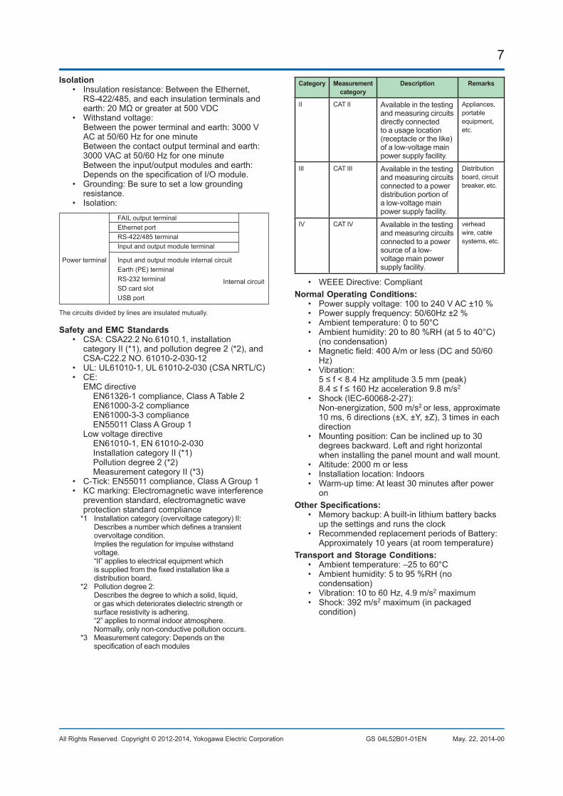
7
All Rights Reserved. Copyright © 2012-2014, Yokogawa Electric Corporation GS 04L52B01-01EN May. 22, 2014-00
Isolation• Insulationresistance:BetweentheEthernet,
RS-422/485,andeachinsulationterminalsandearth:20MΩorgreaterat500VDC
• Withstandvoltage: Betweenthepowerterminalandearth:3000VACat50/60Hzforoneminute
Betweenthecontactoutputterminalandearth:3000VACat50/60Hzforoneminute
Betweentheinput/outputmodulesandearth:DependsonthespecificationofI/Omodule.
• Grounding:Besuretosetalowgroundingresistance.
• Isolation:
Power terminal
The circuits divided by lines are insulated mutually.
Internal circuit
FAIL output terminalEthernet portRS-422/485 terminalInput and output module terminal
Input and output module internal circuitEarth (PE) terminalRS-232 terminalSD card slotUSB port
SafetyandEMCStandards• CSA:CSA22.2No.61010.1,installation
categoryII(*1),andpollutiondegree2(*2), and CSA-C22.2NO.61010-2-030-12
• UL:UL61010-1,UL61010-2-030(CSANRTL/C)• CE: EMCdirective EN61326-1compliance,ClassATable2 EN61000-3-2compliance EN61000-3-3compliance EN55011ClassAGroup1 Lowvoltagedirective EN61010-1,EN61010-2-030 InstallationcategoryII(*1) Pollution degree 2 (*2) MeasurementcategoryII(*3)• C-Tick:EN55011compliance,ClassAGroup1• KCmarking:Electromagneticwaveinterference
preventionstandard,electromagneticwaveprotectionstandardcompliance*1 Installationcategory(overvoltagecategory)II: Describesanumberwhichdefinesatransient
overvoltagecondition. Impliestheregulationforimpulsewithstand
voltage. “II”appliestoelectricalequipmentwhich
issuppliedfromthefixedinstallationlikeadistribution board.
*2 Pollution degree 2: Describesthedegreetowhichasolid,liquid,
or gas which deteriorates dielectric strength or surfaceresistivityisadhering.
“2”appliestonormalindooratmosphere.Normally,onlynon-conductivepollutionoccurs.
*3 Measurementcategory:Dependsonthespecificationofeachmodules
Category Measurementcategory
Description Remarks
II CATII Availableinthetestingandmeasuringcircuitsdirectly connected to a usage location (receptacle or the like) ofalow-voltagemainpowersupplyfacility.
Appliances,portable equipment,etc.
III CATIII Availableinthetestingandmeasuringcircuitsconnected to a power distributionportionofalow-voltagemainpowersupplyfacility.
Distributionboard, circuit breaker, etc.
IV CATIV Availableinthetestingandmeasuringcircuitsconnected to a power sourceofalow-voltagemainpowersupplyfacility.
verheadwire, cable systems,etc.
• WEEEDirective:CompliantNormalOperatingConditions:
• Powersupplyvoltage:100to240VAC±10%• Powersupplyfrequency:50/60Hz±2%• Ambienttemperature:0to50°C• Ambienthumidity:20to80%RH(at5to40°C)
(no condensation)• Magneticfield:400A/morless(DCand50/60
Hz)• Vibration: 5≤f<8.4Hzamplitude3.5mm(peak) 8.4≤f≤160Hzacceleration9.8m/s2
• Shock(IEC-60068-2-27): Non-energization,500m/s2 orless,approximate10ms,6directions(±X,±Y,±Z),3timesineachdirection
• Mountingposition:Canbeinclinedupto30degreesbackward.Leftandrighthorizontalwheninstallingthepanelmountandwallmount.
• Altitude:2000morless• Installationlocation:Indoors• Warm-uptime:Atleast30minutesafterpower
onOtherSpecifications:
• Memorybackup:Abuilt-inlithiumbatterybacksup the settings and runs the clock
• RecommendedreplacementperiodsofBattery:Approximately10years(atroomtemperature)
TransportandStorageConditions:• Ambienttemperature:–25to60°C• Ambienthumidity:5to95%RH(no
condensation)• Vibration:10to60Hz,4.9m/s2maximum• Shock:392m/s2maximum(inpackaged
condition)

8
All Rights Reserved. Copyright © 2012-2014, Yokogawa Electric Corporation GS 04L52B01-01EN May. 22, 2014-00
EXTERNAL DIMENSIONS AND PANEL CUTOUT DIMENSIONSGP10:
*1: with modules*2: without moduels
Unit: mm (approx. inch)Unless otherwise specified, tolerance is ±3% (however, tolerance is ±0.3 mm when below 10 mm).
(*1)
(*2)MAX
8(0.
31)
8(0.
31)
144.
9(5.
70)
(0.5
9)15
196.8(7.75)
247.2(9.73)144(5.67)
144.
9(5.
70)
15 (0.5
9)143.6(5.65)
Rearview
Power supply
I/O module (slot 1)
RS-422A/485 terminal (/C3)or RS232 terminal (/C2)USB port (/UH)Ethernet portFAIL/STATUS terminal (/FL)
I/O module (slot 2)
I/O module (slot 0)
GP20:
Unit: mm (approx. inch)Unless otherwise specified, tolerance is ±3% (however, tolerance is ±0.3 mm when below 10 mm).
*1: with modules*2: without moduels
(*1)
(*2)MAX
288(11.34)
196.8(7.75)
287(
11.3
0)8(
0.31
)23 (0
.91)
247.2(9.73)
288(
11.3
4)
288(11.34) 8(0.
31)
22 (0.8
7)
Rearview
Power supplyRS-422A/485 terminal (/C3)or RS232 terminal (/C2)USB port (/UH)Ethernet portFAIL/STATUS terminal (/FL)VGA output terminal (/D5)
I/O module (slot 0)I/O module (slot 1)I/O module (slot 2)I/O module (slot 3)I/O module (slot 4)
I/O module (slot 5)I/O module (slot 6)I/O module (slot 7)I/O module (slot 8)I/O module (slot 9)
9
All Rights Reserved. Copyright © 2012-2014, Yokogawa Electric Corporation GS 04L52B01-01EN May. 22, 2014-00
SPECIFICATIONS OF OPTIONAL FUNCTIONS
ADVANCEDSECURITYFUNCTION(/AS) Securityandelectronicrecord/signaturefunctions
havebeenaddedthatarecompliantwiththeUSA’sFDAtitle21CFRPart11.• Enabling/disablingtheadvancedsecurity
function: Youcanenableordisabletheadvancedsecurity
function.* Thesetvaluesanddatastoredintheinternal
memoryareinitializedeachtimethefunctionisenabled or disabled.
• Dataanti-tamperfunction: Settingsandmeasureddataaresavedas
encryptedbinaryfiles.• Datatype: Onlyfordisplayorevent Triggermodeisnotpossiblewitheventdata.• Loginfunction: Usingtheloginfunctiondescribedbelow,you
canentersecuritysettingsontheinstrument• Username• Password• UserID(dependonsetting)• Userlevelandnumberofusers: Systemadministrator(allcanbeoperated),
Generaluser(Withuserrestrictions,youcansetrestrictionsonperformingoperations and sign authority.), Monitor user(monitoringonly),totally100users
• Userrestrictionssetting:10kinds(forgeneral users)
• Passwordexpirationtime: selectformOff,1month,3month,6month• Passwordcontrolfunction: LoginsareverifiedbyaKerberosv5
authenticationserver*(onlyusernameandpassword)
Encryptionmethod:AES128-CTS-HMAC-SHA1-96AES256-CTS-HMAC-SHA1-96ARCFOUR-HMAC-MD5
Pre-Authfunction:use* Thefunctionhasconfirmedcompatibilitywith
WindowsServer2003SP2/WindowsServer2008SP2/WindowsServer2012ActiveDirectory
• Signaturefunction: Aftercheckingdatathathasfinishedbeing
recorded,youcanaddthreelevelsofelectronicsignature,selectapass/fail,andentercomments(50charactersmaximum)
• Audittrailfunction: The operation log, the settings change log and
thesettingsfilewhenthechangewasmadearesaved.
SERIALCOMMUNICATIONINTERFACE(/C2,/C3)• Connection:EIARS-232(/C2)orEIARS-
422/485(/C3)• Protocol:DedicatedprotocolorModbusprotocol• Setting/measurementserverfunction:Operation,
settingoroutputofmeasurementdataareavailablebydedicatedprotocol.
• Synchronization:Start-stopsynchronization• Transmissionmode(RS-422/485):
RS-422:Four-wirehalf-duplexmulti-drop
connection (1:n (n = 1 to 31)) RS485:Two-wirehalf-duplexmulti-dropconnection (1:n (n = 1 to 31))
• Baudrate:1200,2400,4800,9600,19200,38400,57600,or115200bps
• Datalength7or8bits• Startbit:1bit• Stopbit:1bitor2bit• Parity:ODD,EVEN,orNONE• HandshakingOff:Off,XON:XON,XON:RS,and
CS: RS• Communicationdistance;RS-422/485:1200m,
RS-232:15m• Modbus/RTUcommunication:Readingorwriting
ofmeasurementdataonotherinstrumentsisavailablebyModbusprotocol.
Communicationchannelfunctionoption(/MC)isneededtoreadmeasurementdatafromotherinstruments.
• Operationmodes:Masterorslave• Executionofacommunicationcommandusinga
barcode:Theenteredtextcanbeexecutedasacommunicationcommand.
CUSTOMDISPLAY(/CG) UsingDXA170DAQStudio,screencreation
software,acustomscreencanbeconstructedanddisplayedinwhichdisplaycomponents(suchastrend,digital,andbargraphs)arefreelyplaced.
ThescreendataistransferredfromDAQStudiototheinternalmemoryviacommunication,orloadedfromanexternalmediumtotheinternalmemoryand displayed.• Numberofscreens:30(internalmemory)• Displaycomponents:
• Normalcomponents(digitalvalue,bargraph,tagNo.,tagcomment,simpledigitalvalue,simplebargraph,alarmmark,unit,alarmindicator,lower-limitspanvalue,upper-limitspanvalue,groupname,systemicon,memorysamplebar,date/timeview,batchname,andusername)
• Trendcomponents(trendgroupdisplay(with scale board))
• Listcomponents(alarmlistviewandmessagelistview)
• Operationcomponents(DO(DOoperable),internal switch (internal switch operable), numericvalueoperations(viewingdataofandwritingdatatocommunicationchannels), and button operations (writing numericvalues,operatingbits,switchingscreens,andexecutingcommunicationcommands)
• Textcomponents(labels)• Figurecomponents(lineview,rectangle
view,andcircleview)• Figurecomponents(lineview,rectangle
view,andcircleview)• Configuringscreens:Screencreationsoftware CreationusingDXA170DAQStudio(GPdoes
nothaveacreationfunction)• Saving/loadingscreendata: Aspecifiedscreenorallthescreensis/are
loadedfromanexternalstoragemediumtotheinternalmemory,oraspecifiedscreenorallthescreensintheinternalmemoryis/aresavedonanexternalstoragemedium.

10
All Rights Reserved. Copyright © 2012-2014, Yokogawa Electric Corporation GS 04L52B01-01EN May. 22, 2014-00
VGAVIDEOOUTPUT(/D5)(OnlyforGP20)• Externaldisplay: Resolution:800×600dots(VGA) Connector:15-pinD-Sub(female)
EtheNet/IPCOMMUNICATION(/E1) CanbejoinedtoanEthernet/IPnetworkasan
adapter(oraserver).• LoadingdatafromtheI/Ochannelorcalculation
channel (/MT)• Loadingandwritingdatafrom/tothe
communicationchannel(/MC)
WTCOMMUNICATION(/E2) CollectsdatabyconnectingtoWTequipment
manufacturedbyYokogawaMeters&InstrumentsCorp.viaEthernetcommunication.• Supportedmodels:WT1800,WT500,and
WT300• Numberofconnectableunits: GP10: 8 GP20:16• Communicationcycle:500ms/1s/2s/5s/10s/15
s/20 s/30 s• Typesofdatathatcanbeobtained:Voltage,
current,power,powerfactor,phase,electricalenergy,high-frequencywave,etc.
• Numberofdataallocations GX20/GP20:300 GX10/GP10:50
FAILOUTPUT(/FL)• Contact:Ccontact,1point• FAILoutput: The relay contact output on the rear panel
indicatestheoccurrenceofCPUfailure. Relayoperation:Energizedduringnormal
operationandde-energizedonCPUfailure.• Statusoutput:Therelaycontact,whichisde-
energizedinnormaloutputstate,isenergizedupontheoccurrenceofamemory/mediaerror,measurementerror,communicationerror,recordingstop,oralarm.
• Ratedpowersupplyvoltage:24VDCor250VACorless
• Ratedloadcurrent:3A(DC)/3A(AC),resistanceload
• Min.loadcurrent:100mA• Recommendedreplacementperiodsofcontact: Electrical:30,000moreON-OFFoperations,
Mechanical:5,000,000moreON-OFFoperations
LogSCALE(/LG) Alogarithmicvoltagethathasbeenconvertedfrom
aphysicalvalueisappliedtotheGP,andthentheGP’sLogscale(logarithmicscale)isusedtodisplayandrecordthephysicalvalue.• Inputtype:Loginput(logarithmicinput),Pseudo
loginput:Aninputthatsupportspseudologs,Loglinearinput:Inputthatislinearonalogarithmicscale.
• Range:20mV/60mV/200mV/1V/2V/6V/20V/50V
• Scalablerange:• Loginput: 1.00E-15to9.99E+15(15decade
maximum) Scale_L<Scale_U Ifthelowerlimitmantissais1.00,the
differencebetweentheexponentsmustbe1ormore.
Ifthelowerlimitmantissaisavalueotherthan1.00,thedifferencebetweentheexponentsmustbe2ormore.
• PseudoLogInput/Loglinearinput 1.00E-15to9.99E+15(15decade
maximum) Thehigherlimitmantissaisthesameas
thelowerlimitmantissa). Ifthelowerlimitmantissais1.00,thevalue
mustbebetween1.00E–15and1.00E+15,thedifferencebetweentheexponentsmustbe1ormore,andthemaximumdecadesis15.
Ifthelowerlimitmantissaisavalueotherthan1.00,thevaluemustbebetween1.01E–15and9.99E+15,thedifferencebetweentheexponentsmustbe1ormoreandthemaximumdecadesis15.
• Alarmtype:Highlimit,lowlimit,delayhighlimit,anddelaylowlimit
• Alarmsettingrange:TherangeconvertedintotheLOGscalecorrespondingto-5%to105%ofthe span width.
• Alarmhysteresis:Fixedto0• Greenbandsettingrange:Thelowerlimittothe
upperlimitofthescale.However,thelowerlimitofthedisplaypositionmustbesmallerthantheupperlimit.
• Positionofthedecimalpoint:1to2• Misc:Nonlinearinputispossiblebycorrecting
theinputvalue
MATHEMATICAL FUNCTIONS WITH REPORT FUNCTION(/MT)MathematicalFunction:• Numberofmathchannels;GP10:50,GP20:100• Operation: Generalarithmeticoperations:Fourarithmetic
operations(+,-,*,/),squareroot,absolute,commonlogarithm,naturallogarithm,exponential,andpower
Relationaloperations:<,≤,>,≥,=,and≠ Logicoperations:AND,OR,NOT,andXOR Statistical operations: TLOG or CLOG Specialoperations:PRE,HOLD,RESET,and
CARRY Conditional operation: [a?b:c] Bitoperation:BIT Integerextractingoperation:INT Remainderextractingoperation:MOD Trigonometricfunctions:SIN,COS• Computationaccuracy:Double-precisionfloating
point• Datathatcanbeused; Channeldata:Measurementchannels
(GP10:0001to6516,GP20:0001to6516),mathematicalchannels(GP10:A001toA050,GP20:A001toA100),Communicationchannels(GP10 standard type: C001 to C300, GP20 large

11
All Rights Reserved. Copyright © 2012-2014, Yokogawa Electric Corporation GS 04L52B01-01EN May. 22, 2014-00
memorytype:C001toC500),Constants:100(K001toK100),Internalswitch:100(S001toS100), Flag: 20 (F01 to F20), Recording state (REC01)
Reportfunction:• Numberofreportchannels;GP10:50,GP20:60• Reporttypes:Hourly+daily,daily+weekly,daily
+monthly,Batch,Daycustom• Computationtypes:Average,maximum,
minimum,sum,orinstantaneousvalue• Unitofsum:OFF,/s,/min,/hour,/day• Reporttemplates:OfficeOpenXMLspreadsheet
files(whichcanbedisplayedwithMicrosoftOfficeExcel)orPDFfilescanbeoutputorprintedoutwithanyLAN-connectedprintersupporting the HP-PCL5c language.
COMMUNICATIONCHANNELFUNCTIONS(/MC)• Numberofcommunicationchannels; GP10 standard type: 300 (C001 to C300) GP20largememorytype:500(C001toC500)* RequiredtorecorddatafromEtherNet/IP(/E1),
ModbusdevicesorPCsontheGP.
USBINTERFACE(/UH)• USBport:ComplieswithUSB2.0andhost
function• Numberofports:2(oneeachonthefrontpanel
and rear panel)• Connectabledevices:Onlyconnectthedevices
listedbelowtopreventdamagetothedevices.Keyboard:ComplieswithHIDClassVer.1.1 104/89keyboard(US)and109/89
keyboard (Japanese)Mouse:ComplieswithHIDClassVer.1.1Externalmedium:USBflashmemory Doesnotguaranteetheoperationofall
USBflashmemories Externalmediumsuchasaharddisk,ZIP,
MO, and optical discs are not supported.Barcodereader:USBHIDClassVer.1.1
compatible English(U.S.)standardUSBkeyboard
compatible• Executionofacommunicationcommandusinga
barcode:Theenteredtextcanbeexecutedasacommunicationcommand.
• Powersupply:5V±10%,500mA*1*1: Deviceswhichneedmorethan500mAtotalbus
powerfor2portscannotbeconnectedatthesametime.
Forlowpowereddevices(buspower<100mA):5V±5%
Forhighpowereddevices(buspower<500mA):5V±10%

12
All Rights Reserved. Copyright © 2012-2014, Yokogawa Electric Corporation GS 04L52B01-01EN May. 22, 2014-00
INPUT/OUTPUT MODULE SPECIFICATIONS
ANALOGINPUTMODULE(ModelGX90XAorOption/Uxx0)
DIGITALINPUTMODULE(ModelGX90XDorOptions/CRx1)
DIGITALOUTPUTMODULE(ModelGX90YD,orOptions/CR1x,/CR2x,/CR4x)
PleaseseeGX90XA/GX90XD/GX90YD/GX90WDInput/OutputModuleGeneralSpecification(GS04L53B01-01EN.)
APPLICATION SOFTWARESMARTDAC+STANDARD• Universalviewer• Webapplication/Hardwareconfigurator
DownloadthelatestversionofthesoftwarefromthefollowingURL; www.smartdacplus.com/software/en/
OperatingenvironmentOS:
OS TypeWindowsVista HomePremiumSP2(Exceptfor64-bits
Editions)
BusinessSP2(Exceptfor64-bitsEditions)
Windows7 HomePremiumSP1(32-bitand64-bitEditions)
ProfessionalSP1(32-bitand64-bitEditions)
Windows8.1 Pro
Processorandmainmemory:OS Processorandmainmemory
WindowsVista IntelPentium4,3GHzorfasterx64orx86,2GBormore
Windows7Windows8.1
32-biteditionIntelPentium4,3GHzorfasterx64orx86,2GBormore64-biteditionIntelx64processorthatisequivalenttoIntelPentium4,3GHzorfaster,2GBormore
Browser:Browser Version
WindowsInternetExplorerJavaRuntimeEnvironment1.7.0xx(Version7Updatexx)xxismorethan51
InternetExplorer8,InternetExplorer9,InternetExplorer10,orInternetExplorer11
Harddisk:• 100MBormoreoffreespace
Display:• AvideocardthatisrecommendedfortheOS
and a display that is supported by the OS, has a resolutionof1024x768orhigher,andthatcanshow65,536colors(16-bit,highcolor)ormore.
UniversalViewersoftwareTheuniversalviewercandisplaythefollowingdatagenerated by the recorder on the screen and print it out on the printer.• Displaydatafile• Eventdatafile• Reportdatafile(IncludingHour,Day,Week
Month)• Manualsampledatafile
• Viewerfunction Waveformdisplay,digitaldisplay,circulardisplay,
list display, report display, operation log display etc.
• Dataconversion: FileconversiontoASCIIorMS-Excelformat
Webapplication/Hardwareconfigurator• OnlinesettingonWebbrowser(IE)• OfflinesettingonWebbrowser(IE)BothsettingscanbemadeusingbrowserssuchasInternetExplorer8,9,10and11.

13
All Rights Reserved. Copyright © 2012-2014, Yokogawa Electric Corporation GS 04L52B01-01EN May. 22, 2014-00
MODEL AND SUFFIX CODES
Model SuffixCode Optionalcode DescriptionGP10 Paperlessrecorder(Portabletype,Smalldisplay)*13
GP20 Paperless recorder (Portable type, Large display) *13
Type -1 Standard(Max.measurementchannels:100ch)
-2 Largememory(Max.measurementchannels:500ch)*12
Displaylanguage E English,degF,DST(summer/wintertime)*9
Power supply 1 100VAC,240VAC
Power cord D PowercordUL/CSAstandard
F PowercordVDEstandard
R PowercordASstandard
Q Power cord BS standard
H Power cord GB standard
N Power cord NBR standard
Optionalfeatures /AS Advancedsecurityfunction(Part11)
/C2 RS-232 *1
/C3 RS-422/485 *1
/CG Customdisplay*15
/D5 VGAoutput*2
/E1 EtherNet/IPcommunication
/E2 WTcommunication*14
/FL Fail output, 1 point
/LG Log scale
/MT Mathematicalfunction(withreportfunction)
/MC Communicationchannelfunction
/UH USBinterface(Host2ports)
Analoginputmodule,DigitalI/Omodule:Pleaseaddthefollowingsuffixcodestothemainunitmodelandspecificationcodes.
Option Optionalcode DescriptionOptionalfeatures(Analoginput)*3*11
/UC10 Withanaloginputmodule,10ch(Clampterminal)
/UC20 Withanaloginputmodule,20ch(Clampterminal)*7
/UC30 Withanaloginputmodule,30ch(Clampterminal)*8
/UC40 Withanaloginputmodule,40ch(Clampterminal)*5
/UC50 Withanaloginputmodule,50ch(Clampterminal)*5
/US10 Withanaloginputmodule,10ch(M3screwterminal)
/US20 Withanaloginputmodule,20ch(M3screwterminal)*7
/US30 Withanaloginputmodule,30ch(M3screwterminal)*8
/US40 Withanaloginputmodule,40ch(M3screwterminal)*5
/US50 Withanaloginputmodule,50ch(M3screwterminal)*5
Optionalfeatures(DigitalI/O)*4
/CR01 WithdigitalI/Omodule,(Output:0,Input:16)*8 *9
/CR10 WithdigitalI/Omodule,(Output:6,Input:0)*8 *9
/CR11 WithdigitalI/Omodule,(Output:6,Input:16)*7 *8 *9
/CR20 WithdigitalI/Omodule,(Output:12,Input:0)*6*9
/CR21 WithdigitalI/Omodule,(Output:12,Input:16)*6*9
/CR40 WithdigitalI/Omodule,(Output:24,Input:0)*6*9
/CR41 WithdigitalI/Omodule,(Output:24,Input:16)*6*9
*1 /C2and/C3cannotbespecifiedtogether.*2 /D5canbespecifiedonlyfortheGP20.*3 Onlyoneoptioncanbespecified.

14
All Rights Reserved. Copyright © 2012-2014, Yokogawa Electric Corporation GS 04L52B01-01EN May. 22, 2014-00
*4 Onlyoneoptioncanbespecified.*5 /UC40,/UC50,/US40and/US50cannotbespecifiedfortheGP10.*6 /CR20,/CR21,/CR40and/CR41cannotbespecifiedfortheGP10.*7 If/UC20or/US20isspecified,/CR11cannotbespecifiedfortheGP10.*8 If/UC30or/US30isspecified,/CR01,/CR10and/CR11cannotbespecifiedfortheGP10.*9 DigitalinputmoduleanddigitaloutputmodulehaveM3screwterminals.*10 TheDisplaylanguageisselectablefromEnglish,German,French,Russian,Korean,Chinese,Japanese.(AsofMar.,2013) Toconfirmthecurrentavailablelanguages,pleasevisitthefollowingwebsite. URL:http://www.yokogawa.com/ns/language/*11Solidstaterelayscannertype(TypeSuffixCode:-U2).Ifyouneedtheelectromagneticrelayscannertype,purchaseit
separately.*12LargememorytypecanbespecifiedonlyfortheGP20.*13ToconnectanexpandableI/O,youwillneedoneexpansionmodulefortheGP.*14/MCmustbeseparatelyspecifiedwhentheWTcommunicationisselected.*15CreatingcustomdisplaysrequiresDXA170DAQStudio(soldseparately).(GPdoesnothaveacreationfunction.)
Analoginputmodule,DigitalI/Omodule(soldseparately):MODELandSUFFIXCode(GX90XA)MODELandSUFFIXCode(GX90XD)MODELandSUFFIXCode(GX90YD)MODELandSUFFIXCode(GX90WD) PleaseseeGX90XA/GX90XD/GX90YD/GX90WDInput/OutputModuleGeneralSpecification(GS04L53B01-
01EN.)When connecting the Expandable I/O PleaseseeGX60ExpandableI/O,GX90EXExpansionModuleGeneralSpecification(GS04L53B00-01EN.)
StandardAccessoriesProduct Qty
SDmemorycard(1GB) 1
Stylus pen (touch pen) 1
Tagsheet(forGP10orGP20) 1
Sheet(paper)(forGP10orGP20) 1
Power cord 1
ApplicationSoftware(SoldSeparately)Model Description OS
DXA170 DAQStudiosoftware WindowsVista/7/8/8.1
GA10 DataLoggingSoftware WindowsVista/7/8.1WindowsServer2008/2012
OptionalAccessories(SoldSeparately)Product Model/partno.
ModelSDmemorycard(1GB) 773001
Stylus pen (touch pen) B8740BZ
ShuntresisterforM3terminal(10Ω±0.1%) X010-010-3
ShuntresisterforM3terminal(100Ω±0.1%) X010-100-3
ShuntresisterforM3terminal(250Ω±0.1%) X010-250-3
ShuntresisterforClampterminal(10Ω±0.1%) 438922
ShuntresisterforClampterminal(100Ω±0.1%) 438921
ShuntresisterforClampterminal(250Ω±0.1%) 438920
ValidationDocuments(For/ASoption)*1 773230
*1 ProvisionofValidationDocuments Alicensesheetcontainingthelicensekey
requiredforinstallationisprovided. Downloadthevalidationdocumentfromthe
followingURL. http://www.smartdacplus.com/software/en/

15
All Rights Reserved. Copyright © 2012-2014, Yokogawa Electric Corporation GS 04L52B01-01EN May. 22, 2014-00
Calibrationcertificate(soldseparately)WhenorderingtheGP10/GP20withoptions(analoginput),thecalibrationcertificateforthemodulesisincludedinandshippedwiththecalibrationcertificateofthemainunit.Whenorderingananaloginputmoduleseparately,eachmodulegetsitsowncalibrationcertificate(onecertificatepermodule).
Testcertificate(QIC,soldseparately)WhenorderingtheGP10/GP20withoptions(analog/digialI/O),theQICforeachmoduleisincludedinandshippedwiththeQICofthemainunit.WhenorderinganaloginputmodulesanddigitalI/Omodulesseparately,eachmodulegetsitsownQIC(oneQICpermodule).
User'sManualProductuser'smanualscanbedownloadedorviewedatthefollowingURL.Toviewtheuser'smanual,youneedtouseAdobeReader7orlaterbyAdobeSystems.URL:www.smartdacplus.com/manual/en/
ProductPurchaseSpecificationsTheGP10/GP20iscomposedofthemainunit,I/Omodules,ExpandableI/O,andExpansionmodule.TherearetwowaystopurchaseI/Omodules.OnewayistopurchasethemindividuallybyspecifyingmodelsGX90XA,GX90XD,andGX90YD.Theotherwayistopurchasethemasanoption(/UCxxor/USxx).Purchasingthemasanoptionisconvenient,butthisplaceslimitationsonthenumberofanaloginputsthatyoucanobtain.Ifyouwanttousemorethan50channels,pleasepurchasetheI/Omodulesindividually.ToconnectexpandableI/O(GX60)toGP10orGP20,youmustpurchaseoneunitofexpansionmodule(GX90EX)forGP10/GP20inadditiontotheexpandableI/O.
Trademarks TheTCP/IPsoftwareusedinthisproductandthedocumentforthatTCP/IPsoftwarearebasedinpartonBSDnetworkingsoftware,Release1licensedfromTheRegentsoftheUniversityofCalifornia.
•SMARTDAC+isatrademarkofYokogawaElectricCorporation.•Microsoft,MSandWindowsareregisteredtrademarksofMicrosoftCorporationUSA.•PentiumareregisteredtrademarksofIntelCorporation.•EthernetisaregisteredtrademarkofXEROXCorporation.•ModbusisaregisteredtrademarkofAEGSchneider.•KerberosisatrademarkofMIT.•JavaandJava-relatedtrademarksaretrademarksorregisteredtrademarksofSunMicrosystems,Inc.intheUnited
States and/or other countries.•Othercompanyand/orproductnamesareregisteredtrademarkoftheirmanufactures.

GeneralSpecifications
GX60I/O Base Unit (Expandable I/O)GX90EXExpansion Module
Yokogawa Electric Corporation2-9-32, Nakacho, Musashino-shi, Tokyo, 180-8750 Japan
GS 04L53B00-01EN
GS 04L53B00-01EN©Copyright April 2014
2nd Edition May. 7, 2014
OVERVIEWGX60 I/O Base Unit (Expandable I/O)The GX60 provides a function to expand an I/O module for recording and controlling, when it is connected to the expansion module that is connected to the GX10/GX20/GP10/GP20 using a LAN cable via a private communication network.
● OneGX60canconnectuptosixI/Omodules.● Uptosixunitscanbeadditionallyconnectedto
the GX/GP.● Thecommunicationdistancebetweenthe
GX/GP and GX60 or between GX60s can be extendedbyupto100musingaLANcable.
GX90EX Expansion ModuleThe expansion module is connected to the GX10/GX20/GP10/GP20 and GX60.
● Theexpansionmodule,whichissupportedbythe GX/GP and GX60, enables a connection betweenGX/GPandGX60oracommunicationbetween GX60s.
● AdistributedarrangementwiththedatatimesynchronizationsecuredisprovidedbyconnectingExpansionmodulesconnectedtotheGX/GPmainunitandGX60usingaLANcable.
● Dataistransferredtothehigh-orderGX/GPviatheexpansionmodule.
GX90EX
GX60 Power inlet type
Power Screw type

2
All Rights Reserved. Copyright © 2014, Yokogawa Electric Corporation GS 04L53B00-01EN May. 7, 2014-00
GX60 SPECIFICATIONSModule Connection
• I/Omodule:Max.6modules(Slots0to5)Restrictions:• Upto10GX90YDdigitaloutputmodules
andGX90WDdigitalinput/outputmodulescan be installed together in the GX/GP and GX60.
• OneGX90WDdigitalinput/outputmodulecan be installed in the GX/GP and in each GX60.
• Expansionmodule:1module(Slot("EXT")forconnectionwithExpansionmodule)
Names of Channels• ThemoduleinstalledintheGX60hasachannel
namethatconsistsoftheunitnumber,slotnumber,andchannelnumber.
012345
Channel name
Unit number
Slot number
Channel numberI/O modules
Channel number; Analog input: 01 to 10 Digital input: 01 to 16 Digital output: 01 to 06Digital input/output: DI 01 to 08
DO 09 to 14Slot number; 0 to 5Unit number; 1 to 6
Safety and EMC Standards• CSA:CSA22.2No.61010-1,installationcategory
II *1, pollution degree 2 *2
• UL:UL61010-1(CSANRTL/C)• CE: EMCdirective EN61326-1compliance,ClassATable2 EN61000-3-2compliance EN61000-3-3compliance EN55011 Class A Group 1 Lowvoltagedirective EN61010-1 Installation category II *1
Pollution degree 2 *2
• EMCRegulatoryArrangementinAustraliaandNewZealand(RCM):EN55011compliance,Class A Group 1
• KCmarking:Electromagneticwaveinterferencepreventionstandard,electromagneticwaveprotectionstandardcompliance*1 Installationcategory(overvoltagecategory)II: Describesanumberwhichdefinesatransient
overvoltagecondition. Impliestheregulationforimpulsewithstand
voltage. “II”appliestoelectricalequipmentwhich
issuppliedfromthefixedinstallationlikeadistribution board.
*2 Pollutiondegree2: Describesthedegreetowhichasolid,liquid,
or gas which deteriorates dielectric strength or surfaceresistivityisadhering.
“2”appliestonormalindooratmosphere.Normally,onlynon-conductivepollutionoccurs.
• WEEEDirective:Compliant
Construction• Frontpanel(terminal):Wateranddust-proof,
ComplieswithIEC529-IP20• Material:Polycarbonate,aluminumalloy• Color;
Front:Charcoalgreylight(CC28) Bezel:Smokeblue(CC53)
• Dimensions:412.5mm(W)x164.7mm(H)x127.8mm(D)
• Weight:Approx.3.2kg(installing6modules)
Power Supply• Ratedsupplyvoltage:100to240VAC• Allowablepowersupplyvoltagerange:90to132,
180to264VAC• Ratedpowersupplyfrequency:50/60Hz• Powerconsumption:
Supply voltage Normal operation *
Maximum
100VAC 20VA 40VA
240VAC 30VA 55VA
* Whenusing6analoginputmodules.• Allowableinterruptiontime:Lessthan1cycleof
thepowersupplyfrequency

3
All Rights Reserved. Copyright © 2014, Yokogawa Electric Corporation GS 04L53B00-01EN May. 7, 2014-00
Isolation• Insulationresistance:BetweentheEthernet,
eachinsulationterminals,andearth:20MΩorgreaterat500VDC
• Withstandvoltage: Betweenthepowerterminalandearth:3000VACat50/60Hzforoneminute
Betweentheinput/outputmodulesandearth:DependsonthespecificationofI/Omodule.
• Grounding:Besuretosetalowgroundingresistance.
• Isolation:
Power terminal
The circuits divided by lines are insulated mutually.
Internal circuit
Ethernet portInput and output module terminal
Input and output module internal circuitEarth (PE) terminal
External DimensionsPowerscrewterminaltype
127.8 (5.03)
148
(5.8
3)
412.5 (16.2)162 (6.38)48 156 (6.14)
164.
7 (6
.48)
6-Φ5 hole(1.89)
8.7
(0.3
4)
(6-Φ0.2) hole
Power inlet type
127.8 (5.03)14
8±0.
4
162±0.2156±0.2 6-Φ4.5 hole or M4
Unit: mm (approx. inch)Unless otherwise specified, tolerance is ±3% (however, tolerance is ±0.3 mm when below 10 mm).
(6.14±0.0078) (6.38±0.0078)
(5.8
3±0.
0157
)
(0.24-Φ0.18) hole or M4
148
(5.8
3)
412.5 (16.2)162 (6.38)48 156 (6.14)
8.7
(0.3
4)
164.
7 (6
.48)
6-Φ5 hole
Dimensions of fixing hole
(1.89)(6-Φ0.2) hole

4
All Rights Reserved. Copyright © 2014, Yokogawa Electric Corporation GS 04L53B00-01EN May. 7, 2014-00
Normal Operating Conditions• Powersupplyvoltage:100to240VAC±10%• Powersupplyfrequency:50/60Hz±2%• Ambienttemperature:0to50°C• Ambienthumidity:20to80%RH(at5to40°C)
(no condensation)• Magneticfield:400A/morless(DCand50/60
Hz)• Vibration:
5≤f<8.4Hzamplitude3.5mm(peak) 8.4≤f≤160Hzacceleration9.8m/s2 or less• Shock(IEC-60068-2-27):
Non-energization,500m/s2orless,approximate10ms,6directions(±X,±Y,±Z)
• Mountingposition:Canbeinclinedupto30degreesbackward.Leftandrighthorizontalwheninstallingthepanelmountandwallmount.
• Altitude:2000morless• Installationlocation:Indoors• Warm-uptime:Atleast30minutesafterpower
on
Transport and Storage Conditions• Ambienttemperature:–25to60°C• Ambienthumidity:5to95%RH(no
condensation)• Vibration:10to60Hz,4.9m/s2maximum• Shock:392m/s2maximum(inpackaged
condition)
Effects of Operating Conditions• Powersupplyvariation:Shallsatisfythe
accuracyspecificationintherangeof90to132VACor180to250VAC(frequency:50/60Hz).Powersupplyfrequencyfluctuation:Shallsatisfytheaccuracyspecificationintherangeofratedsupplyfrequency+/-2Hz(power-supplyvoltage:100VAC).
GX90EX SPECIFICATIONSCommunication Functions CommunicationbetweenGX/GPandGX60or
betweenGX60sviadedicatedcommunicationnetwork.• Baudrate:10Base-T/100Base-TX(Auto)*1• Numberofports:2• Connectioncable:STPcable,CAT5orgreater• Inter-moduleconnection:Cascadeconnection
(Ring connection is disabled.)• Maximumcommunicationdistance:100m• Connector:RJ-45*1Canbefixedto10Base-TbyDIPswitchsettings.
Display Functions• SystemstatusLEDindicators: RDY(green):LightsupwhentheCPUisrunning
normally. MASTER(green):Turnsoninmastermodeand
offinslavemode. FAIL(red):Lightsupwhenasystemerror
occurs.• 7-segmentLEDindicator:Indicatesaunit
numberoroperationerror.• EthernetstatusindicatorLED:LINKACT(green),
SPEED(orange)
Address Setting Functions Switchsettings:
Switch No. Descriptions1 Forunitnumbersetting
2
3
4
5 -
6 -
7 10 Mpbs/100 Mbps
8 MASTER/SLAVE
Master / Slave FunctionsCanbesettomastermode(wheninstalledintheGX/GP),orslavemode(wheninstalledintheGX60)usingtheDIPswitches.
10 Mbps Fixed ModeCanbesettothe10MbpsfixedmodeusingtheDIPswitches.
MountingCanbemountedintheGX/GPandGX60.• Mountingposition: GX10/GP10:Slot2 GX20/GP20:Slot9 GX60:EXTslot

5
All Rights Reserved. Copyright © 2014, Yokogawa Electric Corporation GS 04L53B00-01EN May. 7, 2014-00
Safety and EMC Standards• CSA:CSA22.2No.61010-1,installationcategory
II *1, pollution degree 2 *2
• UL:UL61010-1(CSANRTL/C)• CE: EMCdirective EN61326-1compliance,ClassATable2 EN61000-3-2compliance EN61000-3-3compliance EN55011 Class A Group 1 Lowvoltagedirective EN61010-1 Installation category II *1
Pollution degree 2 *2
• EMCRegulatoryArrangementinAustraliaandNewZealand(RCM):EN55011compliance,Class A Group 1
• KCmarking:Electromagneticwaveinterferencepreventionstandard,electromagneticwaveprotectionstandardcompliance*1 Installationcategory(overvoltagecategory)II: Describesanumberwhichdefinesatransient
overvoltagecondition. Impliestheregulationforimpulsewithstand
voltage. “II”appliestoelectricalequipmentwhich
issuppliedfromthefixedinstallationlikeadistribution board.
*2 Pollutiondegree2: Describesthedegreetowhichasolid,liquid,
or gas which deteriorates dielectric strength or surfaceresistivityisadhering.
“2”appliestonormalindooratmosphere.Normally,onlynon-conductivepollutionoccurs.
• WEEEDirective:Compliant
Construction• Frontpanel(terminal):Wateranddust-proof,
ComplieswithIEC529-IP20• Material:Polycarbonate• Color;
Front:Charcoalgreylight(CC28) Bezel:Smokeblue(CC53)
• Dimensions:45mm(W)x100mm(H)x133mm(D)(D:includingterminalcover)
• Weight:Approx.0.18kg
Power Supply SuppyfromGX/GPmainunitorGX60expandable
I/O.• Powerconsumption:1.8Worless
External DimensionsUnit: mm (approx. inch)
45.1(1.78)
107.
1
3(0.
12)
8(0.
31)10
0(3.
94)
31.9
82.1
(3.2
3)Normal Operating Conditions
• Powersupplyvoltage:100to240VAC±10%• Powersupplyfrequency:50/60Hz±2%• Ambienttemperature:0to50°C• Ambienthumidity:20to80%RH(at5to40°C)
(no condensation)• Magneticfield:400A/morless(DCand50/60
Hz)• Vibration(IEC-60068-2-6):
Power supply ON, 3 directions, 10 cycles, 1 oct/min(±10%)
5≤f<8.4Hzamplitude3.5mm(peak) 8.4≤f≤160Hzacceleration9.8m/s2 (peak)• Shock(IEC-60068-2-27):
Non-energization,500m/s2,approximate10ms,6directions(±X,±Y,±Z),3timesineachdirection
• Mountingposition:Canbeinclinedupto30degreesbackward.Leftandrighthorizontal.
• Altitude:2000morless• Installationlocation:Indoors• Warm-uptime:Atleast30minutesafterpoweron
Transport and Storage Conditions• Ambienttemperature:–25to60°C• Ambienthumidity:5to95%RH(no
condensation)• Vibration:10to60Hz,4.9m/s2maximum• Shock:392m/s2maximum(inpackaged
condition)
Effects of Operating Conditions None

6
All Rights Reserved. Copyright © 2014, Yokogawa Electric Corporation GS 04L53B00-01EN May. 7, 2014-00
MODEL AND SUFFIX CODESMODEL and SUFFIX Code (GX60)
Model Suffix Code DescriptionGX60 I/O Base Unit
Type -EX I/O Expansion
Area N General
Power supply 1 100VAC,240VAC
Power cord D Power cord UL/CSA standard
F PowercordVDEstandard
R Power cord AS standard
Q Power cord BS standard
H Power cord GB standard
N Power cord NBR standard
W Screwterminal(M3)*OneGX90EX(I/Oexpansionmodule)isprovided.MODEL and SUFFIX Code (GX90EX)
Model Suffix Code DescriptionGX90EX I/O Expansion Module
Port -02 2 ports
Type -TP1 Twisted Pair Cable
- N Always N
Area -N General
Test certificate (QIC, sold separately)When ordering the GX60, GX90EX gets its own QIC (one QIC per unit).Whenorderingtheexpansionmodulesseparately,eachmodulegetsitsownQIC(oneQICpermodule).
User's ManualProductuser'smanualscanbedownloadedorviewedatthefollowingURL.Toviewtheuser'smanual,youneedtouseAdobeReader7orlaterbyAdobeSystems.URL: www.smartdacplus.com/manual/en/
Trademarks TheTCP/IPsoftwareusedinthisproductandthedocumentforthatTCP/IPsoftwarearebasedinpartonBSDnetworkingsoftware,Release1licensedfromTheRegentsoftheUniversityofCalifornia.
•SMARTDAC+isaregisteredtrademarkofYokogawaElectricCorporation.•Microsoft,MSandWindowsareregisteredtrademarksofMicrosoftCorporationUSA.•PentiumareregisteredtrademarksofIntelCorporation.•EthernetisaregisteredtrademarkofXEROXCorporation.ModbusisaregisteredtrademarkofAEGSchneider.•Othercompanyand/orproductnamesareregisteredtrademarkoftheirmanufactures.

GeneralSpecifications
GX90XA/GX90XDGX90YD/GX90WDI/O Modules
Yokogawa Electric Corporation2-9-32, Nakacho, Musashino-shi, Tokyo, 180-8750 Japan
GS 04L53B01-01EN
GS 04L51B01-01EN©Copyright April 2014
2nd Edition May. 7, 2014
OVERVIEWI/O modules are connected to the GX/GP and Expandable I/O unit.● Amoduletypeisfourtypes,ananaloginput,a
digital input, a digital output, and a digital input/output.
● Inputandoutputhavemodulestructureanditcanextendthemeasily.
● TheGX90XAanaloginputmoduleprovidesfourtypes:(1)universaltypethatallowsthemeasurementinputforDCV(directvoltage),TC(thermocouple),RTD(resistancetemperaturedetector),andDI(operationrecord,contact,orTTLlevelvoltage),(2)currentinputtypewiththebuilt-in shunt resistor to directly input a standard signalof4-20mADC,(3)electromagneticrelayscanner type insusceptible to noises that allows the measurementinputforDCV,TC,andDI,and(4)lowwithstandvoltagerelaytypethatoffersalowcost.Ineachsystem,ameasurementinputsignalcan be assigned to each channel.
● TheGX90XDdigitalinputmodule,whichallowsupto16digitalinputs(contactorTTLlevelvoltage),canbeusedasamultipointdigitalinput.Thismodulecanalsobeusedasaremotecontrolinput.
● TheGX90YDdigitaloutputmoduleisassignedasarelayoutput(contactC)andisusedwhenanalarmactivates.Itcanalsobeusedtoturntheoutputonandoffmanuallyusingthetouchpanel.
● TheGX90WDdigitalinput/outputmoduleprovideseight digital inputs and six relay outputs. When therearesmallamountsofdigitalinputsanddigitaloutputs,youdonotneedtomounttwomodules.Thisenablesefficientchannelconfiguration.
● EachmoduleprovidesaM3screwterminalandclampterminal*1.Also,theinputterminalcanberemovedandmounted.Thisenableswiringworktobecarriedoutefficiently.
*1 M3screwterminalonlyfortheelectromagneticrelayscannertypeoftheGX90YD,GX90WD,and GX90XA
● Themeasuringaccuraciesnotedinthegeneralspecificationshaveamarginoferrorthattakesintoaccounttheproduct'scomponentsandtheequipmentusedforadjustmentandtesting.However,theactualvaluescalculatedfromtheaccuracytestingdatauponshipmentoftheinstrumentfromthefactoryareasfollows.
Input type Measuringaccuracy*2(typicalvalue*3)
DCV 20mV ±(0.01%ofreading+5μV)
6V (1-5V) ±(0.01%ofreading+2mV)
RTD Pt100 ±(0.02%ofreading+0.2°C)
Pt100(high resolution)
±(0.02%ofreading+0.16°C)
*2 Generaloperatingconditions:23±2ºC,55±10%RH,supplyvoltage90–132,180–250VAC,supplyfrequencywithin50/60Hz±1%,warm-upof30minutesormore,novibrationsorotherhindrancestoperformance.
*3 Forthemeasuringaccuracy(guaranteed),seenext page.

2
All Rights Reserved. Copyright © 2014, Yokogawa Electric Corporation GS 04L53B01-01EN May. 7, 2014-00
INPUT/OUTPUT MODULE SPECIFICATIONS
ANALOG INPUT MODULE (Model GX90XA or GX/GP main unit options /Uxx0)
• Numberofinputs:10• InputType:
Suffix Code Input Type Description
-U2 DCvoltage,standardsignal,thermocouple(TC),resistancetemperaturedetector(RTD),DI(voltage,contact),andDCcurrent(byaddinganexternalshuntresistor)
Universal
-C1 DCcurrent(mA),DCcurrentstandardsignal(4-20mA) Current input
-L1 DCvoltage,standardsignal,thermocouple(TC),DI(voltage,contact),andDCcurrent(byaddinganexternalshuntresistor)
Lowwithstandvoltagerelay
-T1 DCvoltage,standardsignal,thermocouple(TC),DI(voltage,contact),andDCcurrent(byaddinganexternalshuntresistor)
Electromagneticrelay
GX90XA
• Measurementinterval:100*1 *2, 200 *1 *2,500ms*1, 1, 2, 5 s• Inputrange:-5%ormoreand105%orless(accuracyisguaranteedintherangefrom0%to100%inclusive)• Measurementrangesandaccuracies*3(However,thenumberofdisplaydigitscanbeincreasedbyscaling.)
*1 Cannotbespecifiedfortheelectromagneticrelayscannertype(TypeSuffixCode:-T1).*2 CannotbespecifiedforL-modelDCV/TC/DI,scannertype(TypeSuffixCode:-L1).*3 Thefollowingspecificationsapplytooperationoftherecorderunderstandardoperationconditions. Temperature:23±2°C,Humidity:55%±10%RH,Powersupplyvoltage:90to132or180to250VAC,Powersupply
frequency:50/60Hz±1%,Warm-uptime:Atleast30min.Otherambientconditionssuchasvibrationshouldnotadverselyaffectrecorderoperation.
Input Type Range Measurement accuracy (digital display) Max. resolution of
digital displayA/D integration time: 16.7ms or more A/D integration time: 1.67ms
DCV 20mV -20.000 to 20.000mV ±(0.05%ofrdg+12μV) ±(0.1%ofrdg+40μV) 1μV
60mV -60.00 to 60.00mV ±(0.05%ofrdg+0.03mV) ±(0.1%ofrdg+0.15mV) 10μV
200mV -200.00 to 200.00mV ±(0.05%ofrdg+0.03mV) ±(0.1%ofrdg+0.4mV) 10μV
1V -1.0000 to 1.0000V ±(0.05%ofrdg+1.2mV) ±(0.1%ofrdg+4mV) 100μV
2V -2.0000 to 2.0000V ±(0.05%ofrdg+1.2mV) ±(0.1%ofrdg+4mV) 100μV
6V -6.000 to 6.000V ±(0.05%ofrdg+3mV) ±(0.1%ofrdg+15mV) 1mV
20V -20.000 to 20.000V ±(0.05%ofrdg+3mV) ±(0.1%ofrdg+40mV) 1mV
50V -50.00 to 50.00V ±(0.05%ofrdg+0.03V) ±(0.1%ofrdg+0.15V) 10mV
Standard signal 0.4-2V 0.3200 to 2.0800V ±(0.05%ofrdg+1.2mV) ±(0.1%ofrdg+4mV) 100μV
1-5V 0.800 to 5.200V ±(0.05%ofrdg+3mV) ±(0.1%ofrdg+15mV) 1mV
DC current 0-20mA 0.000 to 20.000mA ±(0.3%ofrdg+5μA) ±(0.3%ofrdg+90μA) 1μV
DC current(standardsignal
4-20mA 3.200 to 20.800mA
TC(ExcludingRJCaccuracy)
R 0.0 to 1760.0 °C ±(0.15%ofrdg+1.0°C)However,R,S;0.0to800.0°C:±2.2°C, B;400.0to800.0°C:±3.0°CAccuracy at less than 400.0 °C is not guaranteed.
±(0.2%ofrdg+6.0°C)However,R,S;0.0to800.0°C:±7.6°C, B;400.0to800.0°C:±11.0°CAccuracy at less than 400.0 °C is not guaranteed.
0.1 °C
S 0.0 to 1760.0 °C
B 0.0 to 1820.0 °C
K -270.0 to 1370.0 °C ±(0.15%ofrdg+0.7°C)However,-200.0to0.0°C:±(0.35%ofrdg+0.7°C)Accuracy at less than -200.0 °C is not guaranteed
±(0.2%ofrdg+5.0°C)However,-200.0to0.0°C:±(3%ofrdg+5.0°C)Accuracy at less than -200.0 °C is not guaranteed
0.1 °C
-200.0 to 500.0 °C
E -270.0 to 800.0 °C ±(0.15%ofrdg+0.5°C)However,-200.0to0.0°C:±(0.35%ofrdg+0.5°C)Accuracy at less than -200.0 °C is not guaranteed
±(0.2%ofrdg+4.0°C)However,-200.0to0.0°C:±(2%ofrdg+4.0°C)Accuracy at less than -200.0 °C is not guaranteed
0.1 °C
J -200.0 to 1100.0 °C
T -270.0 to 400.0 °C ±(0.15%ofrdg+0.5°C)However,-200.0to0.0°C:±(0.35%ofrdg+0.5°C)Accuracy at less than -200.0 °C is not guaranteed
±(0.2%ofrdg+2.5°C)However,-200.0to0.0°C:±(2%ofrdg+2.5°C)Accuracy at less than -200.0 °C is not guaranteed
0.1 °C
N -270.0 to 1300.0 °C ±(0.15%ofrdg+0.7°C)However,-200.0to0.0°C:±(0.7%ofrdg+0.7°C)Accuracy at less than -200.0 °C is not guaranteed
±(0.3%ofrdg+6.0°C)However,-200.0to0.0°C:±(5%ofrdg+6.0°C)Accuracy at less than -200.0 °C is not guaranteed
0.1 °C
W 0.0 to 2315.0 °C ±(0.15%ofrdg+1.5°C) ±(0.3%ofrdg+14.0°C)However,morethan1000.0°C:±(0.8%ofrdg+9.0°C)
0.1 °C
L -200.0 to 900.0 °C ±(0.15%ofrdg+0.5°C)Lessthan0.0°C:±(0.5%ofrdg+0.5°C)
±(0.2%ofrdg+4.0°C)Lessthan0.0°C:±(3%ofrdg+4.0°C)
0.1 °C
U -200.0 to 400.0 °C ±(0.15%ofrdg+0.5°C)Lessthan0.0°C:±(0.7%ofrdg+0.5°C)
±(0.2%ofrdg+2.5°C)Lessthan0.0°C:±(3%ofrdg+2.5°C)
0.1 °C

3
All Rights Reserved. Copyright © 2014, Yokogawa Electric Corporation GS 04L53B01-01EN May. 7, 2014-00
Continued
Input Type Range Measurement accuracy (digital display) Max. resolution of digital display
A/D integration time: 16.7ms or more A/D integration time: 1.67ms (fast sampling mode)
TC(ExcludingRJCaccuracy)
W97Re3-W75Re25 0.0 to 2320.0 °C ±(0.2%ofrdg+2.5°C) ±18.0 °CMorethan2000.0°C:±0.9%ofrdg
0.1 °C
KpvsAu7Fe 0.0 to 300.0 K ±(0.15%ofrdg+2.0K)0.15to280.15K:guaranteedrange
±(0.2%ofrdg+7.0K)0.15to280.15K:guaranteedrange
0.1 K
Platinel 2 0.0 to 1395.0 °C ±(0.25%ofrdg+2.3°C) ±(0.25%ofrdg+8.0°C) 0.1 °C
PR20-40 0.0 to 1900.0 °C ±(0.7%ofrdg+0.4°C)However,accuracyatlessthan800.0°Cis not guaranteed.
±20.0 °CHowever,accuracyatlessthan800.0°Cisnotguaranteed.
0.1 °C
NiNiMo 0.0 to 1310.0 °C ±(0.25%ofrdg+0.7°C) ±(0.5%ofrdg+5.0°C) 0.1 °C
W/WRe26 0.0 to 2320.0 °C ±(0.2%ofrdg+2.0°C)However,accuracyatlessthan300.0°Cis not guaranteed.
±(0.4%ofrdg+12.0°C)However,accuracyatlessthan300.0°Cisnotguaranteed.
0.1 °C
N(AWG14) 0.0 to 1300.0 °C ±(0.2%ofrdg+1.3°C) ±(0.5%ofrdg+7.0°C) 0.1 °C
XK GOST -200.0 to 600.0 °C ±(0.25%ofrdg+0.8°C) ±(0.5%ofrdg+4.0°C) 0.1 °C
RTD Pt100 -200.0 to 850.0 °C ±(0.15%ofrdg+0.3°C) ±(0.3%ofrdg+1.5°C) 0.1 °C
-150.00 to 150.00 °C 0.01 °C
JPt100 -200.00 to 550.00 °C 0.1 °C
-150.00 to 150.00 °C 0.01 °C
Cu10 GE -200.0 to 300.0 °C ±(0.2%ofrdg+2.0°C)guaranteed rangeCu10GE:-70.0to170.0°CCu10L&N:-75.0to150.0°CCu10WEED:-200.0to260.0°COtherrange:-200.0to300.0°C
±(0.4%ofrdg+6.0°C)guaranteed rangeCu10GE:-70.0to170.0°CCu10L&N:-75.0to150.0°CCu10WEED:-200.0to260.0°COtherrange:-200.0to300.0°C
0.1 °C
Cu10 L&N -200.0 to 300.0 °C
Cu10 WEED -200.0 to 300.0 °C
Cu10 BAILEY -200.0 to 300.0 °C
Cu10(20°C)alpha=0.00392
-200.0 to 300.0 °C
Cu10(20°C)alpha=0.00393
-200.0 to 300.0 °C
Cu25(0°C)alpha=0.00425
-200.0 to 300.0 °C ±(0.3%ofrdg+0.8°C) ±(0.5%ofrdg+3.0°C) 0.1 °C
Cu53(0°C)alpha=0.00426035
-50.0 to 150.0 °C ±(0.15%ofrdg+0.8°C) ±(0.3%ofrdg+4.0°C) 0.1 °C
Cu100(0°C)alpha=0.00425
-50.0 to 150.0 °C ±(0.2%ofrdg+1.0°C) ±(0.4%ofrdg+5.0°C) 0.1 °C
J263B 0.0 to 300.0 K ±1.0 KLessthan40.0K:±3.0K
±3.0 KLessthan40.0K:±9.0K
0.1 K
Ni100(SAMA) -200.0 to 250.0 °C ±(0.15%ofrdg+0.4°C) ±(0.3%ofrdg+2.0°C) 0.1 °C
Ni100(DIN) -60.0 to 180.0 °C
Ni120 -70.0 to 200.0 °C
Pt25 -200.0 to 550.0 °C ±(0.15%ofrdg+0.8°C) ±(0.3%ofrdg+4.0°C) 0.1 °C
Pt50 -200.0 to 550.0 °C ±(0.3%ofrdg+0.6°C) ±(0.6%ofrdg+3.0°C) 0.1 °C
Pt200 WEED -100.0 to 250.0 °C
Cu10 GOST -200.0 to 200.0 °C ±(0.2%ofrdg+2.0°C) ±(0.4%ofrdg+6.0°C) 0.1 °C
Cu50 GOST -200.0 to 200.0 °C ±(0.15%ofrdg+0.6°C) ±(0.3%ofrdg+4.0°C) 0.1 °C
Cu100 GOST -200.0 to 200.0 °C ±(0.15%ofrdg+0.3°C) ±(0.3%ofrdg+1.5°C) 0.1 °C
Pt46 GOST -200.0 to 550.0 °C ±(0.3%ofrdg+0.8°C) ±(0.6%ofrdg+4.0°C) 0.1 °C
Pt100 GOST -200.0 to 600.0 °C ±(0.15%ofrdg+0.3°C) ±(0.3%ofrdg+2.0°C) 0.1 °C
DI Level Thresholdlevel(Vth=2.4V)Accuracy:±0.1V -
Contact *4 Less than 1 kΩ:1(ON),Morethan100kΩ:0(OFF)(parallelcapacitanceof0.01μForless) -
*4 Thedetectedcurrentvalueisapprox.10μA.
Measurementaccuracyatscaling:measurementaccuracyatscaling(digits)=measurementaccuracy(digits)xscalingspan(digits)/measurementspan(digits)+2digits
*Roundingupdecimalplaces

4
All Rights Reserved. Copyright © 2014, Yokogawa Electric Corporation GS 04L53B01-01EN May. 7, 2014-00
• Burnoutdetection:Burnoutupscale,downscale,orOFFselectable(foreachchannel).
Availableinput:TC,RTD,StandardsignalDetectioncondition;TC;Normal:2kΩorless.,Burnout:200kΩor
more(parallelcapacitanceof0.01μForless) Detectioncurrent:Approx.10μARTD;Normal:wiringresistanceorless,
Burnout:200kΩormore parallelcapacitanceoflessthan0.01μFor
less Detectioncurrent:Approx.10μAStandardsignal: Normal:Withinmeasuringrange Burnout:Dependsonthesettingofthe
burnoutjudgmentvalue.Theburnoutjudgmentvalueshallbesetwiththepercentageofthespecifiedspanwidth.
Lowerlimit:-20.0to-5.0% Upperlimit:105to120%
• Inputexternalresistance:DCvoltage,thermocoupleinput:2kΩorbelowResistancetemperaturedetectorinput:10Ω
orbelowineachwire(Sameresistanceinthreewires)
• Inputbiascurrent:±10nAorless(whenburnoutfunctiondoesnotwork)
• Measuredcurrent(forRTD):Approx.1mA• Inputresistance:
10MΩormoreforTC/DCvoltage(1Vrangeorless)input Approx.1MΩforDCvoltage(2Vrangeormore)/standardsignalinput 250Ω(249.5Ωtyp)forDCmA
*typ:Typicalvalue(Typical)• Allowablesignalsourceresistance:2kΩorless
forTC/DCvoltage(1Vrangeorless)input• Effectofsignalsourceresistance:
±10μV/1kΩorlessforTC/DCvoltage(1Vrangeorless)input ±0.15%/1kΩorlessforDCvoltage(2Vrangeormore)/standardsignalinput
• Allowablewiringresistance:Max.10ΩperlineforRTDinput(conductorresistancebetweenthethreelinesshallbeequal)
• Effectofwiringresistance:±0.1°C/10ΩforRTDinput(conductorresistancebetweenthethreelinesshallbeequal)
• Allowableinputvoltage: ±10VDCforTC/DCvoltage(1Vrangeorless)/RTD/DIinput,DCmA ±60VDCforDCvoltage(2Vrangeormore)input
• Allowableinputcurrent(currentscannertype):24mA,50/60Hz,peakvalueincludingsignal
• Noisereductionratio
Integration time *1 Normal mode Common mode1.67ms 50/60Hz,nonoise
reductionMore than 80 dB *2 *4
Morethan16.7ms More than 40 dB *2 *3
More than 120 dB *2 *4
*1 Afrequencydiscriminationsettingismadeinthemainunit.
*2 Aresistancetemperaturedetectorrangeisaconvertedvalueofvoltagewhenameasuredcurrentflows.
*3 50/60Hz±0.1%*4 50/60Hz±0.1%,500Ωimbalance,between
minusmeasuringterminalandground
• NormalmodevoltageforTC/DCvoltage(1Vrangeorless)/DI(voltage):1.2timesorlessofrated range
Standardsignal0.4to2Vrange:2.4V Standardsignal1-5Vrange:6V RTD(100Ω):50mVpeak RTD(50Ω):10mVpeak* 50/60Hz,Thepeakvalueincludingthesignal.
• Normalmodecurrent(current,scannertype):24mADC(Valueconvertedtovoltage:6V)
*50/60Hz,Thepeakvalueincludingthesignal.• Maximumcommonmodevoltageformeasuring
input:30VACrms(50/60Hz)or60VDC(Maximumcommonmodenoisevoltageformeasuringinput:250VACrms)
• Maximumvoltagebetweenmeasuringinputchannels:30VACrms(50/60Hz)or60VDC(Maximumcommonmodenoisevoltagebetweenmeasuringinputchannels:250VACrms(60VACrmsforlow-voltagerelaytype)
• Referencejunctioncompensationaccuracy: Whenmeasuringtemperaturegreaterthan
orequalto0°Candwheninputterminaltemperatureisbalanced
TypeK,E,J,T,N,XKGOST:±0.5°C(23°C±2°C),±0.7°C(0to50°C),±1.0°C(-20to60°C)
TypeR,S,W,L,U,W97Re3-W75Re25,Platinel2,NiNiMo,W/WRe26,N(AWG14):±1.0°C(23°C±2°C),±1.4°C(0to50°C),±2.0°C(-20to60°C)
TypeKpvsAu7Fe:±1.0K(23°C±2°C),±1.4K(0to50°C),±2.0K(-20to60°C)
TypeB,PR20-40:Internalreferencecompensationisfixedto0°C
• Samplinginterval/A/Dintegrationtime: 10ch.mode
Solid state relay scanner type*1 / Current scanner type*1
Sampling interval Integration time100ms/200ms 1.67ms
500msormore 16.7ms/20ms
1sormore 36.7ms
2sormore 100ms
ElectromagneticrelayscannertypeSampling interval Integration time
1sormore 16.7ms/20ms
2sormore 36.7ms
5 s 100ms
Scannertype(DCV/TC/DI,400VAC,1min)Sampling interval Integration time
500msormore 16.7ms/20ms
2sormore 36.7ms
5sormore 100ms

5
All Rights Reserved. Copyright © 2014, Yokogawa Electric Corporation GS 04L53B01-01EN May. 7, 2014-00
2ch.mode*2
Sampling interval Integration time100msormore 16.7ms/20ms
1sormore 36.7ms
2sormore 100ms*1 In10chmode,whenthescanintervalissetto100
msor200ms,theA/Dintegrationtimeisfixedat1.67ms.Thispreventspowerfrequencynoisefrombeingeliminated,causingmeasuredvaluesto wobble.
*2 Cannotbespecifiedfortheelectromagneticrelayscannertype(TypeSuffixCode:-T1),Lowwithstandvoltagerelaytype(TypeSuffixCode:-L1).
• Calibrationcorrection: Mode:LinearizerApproximation,LinearizerBias Numberofsetpoints:12
• Terminaltype*:M3screwterminalorClampterminal* M3screwterminalsonlyfortheelectromagnetic
relay scanner type.• Withstandvoltage Universal,Solidstaterelayscannertype,
Electromagneticrelayscannertype;betweentheinputcircuitsandtheinternalcircuit:3000VACforoneminute
Current,Scannertype,lowwithstandvoltagetype;betweentheinputcircuitsandtheinternalcircuit:1500VACforoneminute
Betweentheanaloginputchannels:1000VACforoneminute(excludingb-terminal)
• Insulationresistance: Betweentheinputterminalandtheinternalcircuit:20MΩorgreaterat500VDC
• Recommendedreplacementperiodofelectromagneticrelayscannertypemodules:
Electromagneticrelayscannertypemodulesmakemeasurementsbyswitchingmechanicalcontactrelaysonandoff.
Toensurethatthemodulescontinuetooperatereliablyandcorrectly,replacethem
Continuoususeatmeasurementinterval1s:1year Continuoususeatmeasurementinterval2s:2years Continuoususeatmeasurementinterval5s:5years
Safety and EMC Standards• CSA:CSA22.2No.61010-1,installationcategory
II *1, pollution degree 2 *2, and CSA-C22.2 NO. 61010-2-030-12
• UL:UL61010-1,UL61010-2-030(CSANRTL/C)• CE: EMCdirective EN61326-1compliance,ClassATable2 EN61000-3-2compliance EN61000-3-3compliance EN55011 Class A Group 1 Lowvoltagedirective EN61010-1, EN 61010-2-030 Installation category II *1
Pollution degree 2 *2
MeasurementcategoryII*3• Maximuminputvoltageformeasuringinput:±60VDC• Maximumcommonmodenoisevoltagefor
measuringinput:30VACrms50/60Hzor60VDC(However,maximumcommonmodenoisevoltageformeasuringinput:250VAC)
• EMCRegulatoryArrangementinAustraliaandNewZealand(RCM):EN55011compliance,Class A Group 1
• KCmarking:Electromagneticwaveinterferencepreventionstandard,electromagneticwaveprotectionstandardcompliance*1 Installationcategory(overvoltagecategory)II: Describesanumberwhichdefinesatransient
overvoltagecondition. Impliestheregulationforimpulsewithstandvoltage. “II”appliestoelectricalequipmentwhich
issuppliedfromthefixedinstallationlikeadistribution board.
*2 Pollutiondegree2: Describes the degree to which a solid, liquid,
or gas which deteriorates dielectric strength or surfaceresistivityisadhering.
“2”appliestonormalindooratmosphere.Normally,onlynon-conductivepollutionoccurs.
*3 MeasurementcategoryII(CATII): Appliestomeasuringcircuitsconnectedtolow
voltageinstallation,andelectricalinstrumentssuppliedwithpowerfromfixedequipmentsuchaselectric switchboards.
• WEEEDirective:Compliant
Construction• Frontpanel(terminal):Wateranddust-proof,
ComplieswithIEC529-IP20• Material:Polycarbonate• Color;
Front:Charcoalgreylight(CC28) Bezel:Smokeblue(CC53)
• Dimensions:45mm(W)x100mm(H)x133mm(D)(D:includingterminalcover)
• Weight:Approx.0.3kg
Power Supply SuppyfromGX/GPmainunitorGX60expandable
I/O.• Powerconsumption: GX90XA-10-U2:0.7Worless GX90XA-10-T1:0.9Worless GX90XA-10-C1:0.7Worless GX90XA-10-L1:0.7Worless
Isolation
Functional insulation
Reinforced insulation
Analog input CH1Analog input CH2Analog input CH3Analog input CH4Analog input CH5Analog input CH6Analog input CH7Analog input CH8Analog input CH9Analog input CH10
Input circuit Internal circuit

6
All Rights Reserved. Copyright © 2014, Yokogawa Electric Corporation GS 04L53B01-01EN May. 7, 2014-00
Terminal arrangementsM3 screw terminal
No. Symbol No. Symbol No. Symbol301 CH1(/b)*1 201 CH1(-/B) 101 CH1(+/A)
302 CH2(/b)*1 202 CH2(-/B) 102 CH2(+/A)
303 CH3(/b)*1 203 CH3(-/B) 103 CH3(+/A)
304 CH4(/b)*1 204 CH4(-/B) 104 CH4(+/A)
305 CH5(/b)*1 205 CH5(-/B) 105 CH5(+/A)
306 CH6(/b)*1 206 CH6(-/B) 106 CH6(+/A)
307 CH7(/b)*1 207 CH7(-/B) 107 CH7(+/A)
308 CH8(/b)*1 208 CH8(-/B) 108 CH8(+/A)
309 CH9(/b)*1 209 CH9(-/B) 109 CH9(+/A)
310 CH10(/b)*1 210 CH10(-/B) 110 CH10(+/A)
*1 "NC"(Notconnected)fortheelectromagneticrelayscannertype,thelowwithstandvoltagetype, and the current scanner type.
* RTDinputterminalbisshortedinternallyacrossall channels.
Clamp terminal (Except Electromagnetic relay scanner type)
No. Symbol No. Symbol201 CH2(+/A) 101 CH1(+/A)
202 CH2(-/B) 102 CH1(-/B)
203 CH2(/b)*1 103 CH1(/b)*1
204 CH4(+/A) 104 CH3(+/A)
205 CH4(-/B) 105 CH3(-/B)
206 CH4(/b)*1 106 CH3(/b)*1
207 CH6(+/A) 107 CH5(+/A)
208 CH6(-/B) 108 CH5(-/B)
209 CH6(/b)*1 109 CH5(/b)*1
210 CH8(+/A) 110 CH7(+/A)
211 CH8(-/B) 111 CH7(-/B)
212 CH8(/b)*1 112 CH7(/b)*1
213 CH10(+/A) 113 CH9(+/A)
214 CH10(-/B) 114 CH9(-/B)
215 CH10(/b)*1 115 CH9(/b)*1
*1 "NC"(Notconnected)fortheelectromagneticrelayscannertype,thelowwithstandvoltagerelay type, and the current scanner type.
* RTDinputterminalbisshortedinternallyacrossallchannels.
A/D Calibration Value TwotypesofA/Dcalibrationvalues(factory
shipmentsettingandusersetting)canbesaved.Iftheusersettingisnotproper,itcanberestoredtothecalibrationvalueatfactoryshipment.
External DimensionsM3 screw terminal
107.
1(4.
22)
26(1
.02)
92(3
.62)
100(
3.94
)3(
0.12
)8(
0.31
)
(0.0
7)1.
9
45.1(1.78)
43.8(1.72)
Unit: mm(approx. inch)
Clamp terminal
107.
1(4.
22)
26(1
.02)
92(3
.62)
100(
3.94
)3(
0.12
)8(
0.31
)
(0.0
7)1.
9
45.1(1.78)
43.8(1.72)
Unit: mm(approx. inch)
Normal Operating Conditions• Powersupplyvoltage:100to240VAC±10%• Powersupplyfrequency:50/60Hz±2%• Ambienttemperature:0to50°C• Ambienthumidity:20to80%RH(at5to40°C)
(nocondensation)• Magneticfield:400A/morless(DCand50/60
Hz)• Vibration(IEC-60068-2-6):
Power supply ON, 3 directions, 10 cycles, 1 oct/min(±10%)
5≤f<8.4Hzamplitude3.5mm(peak) 8.4≤f≤160Hzacceleration9.8m/s2(peak)• Shock(IEC-60068-2-27):
Non-energization,500m/s2,approximate10ms,6directions(±X,±Y,±Z),3timesineachdirection
• Mountingposition:Canbeinclinedupto30degreesbackward.Leftandrighthorizontal.
• Altitude:2000morless

7
All Rights Reserved. Copyright © 2014, Yokogawa Electric Corporation GS 04L53B01-01EN May. 7, 2014-00
• Installationlocation:Indoors• Warm-uptime:Atleast30minutesafterpower
on
Transport and Storage Conditions• Ambienttemperature:–25to60°C• Ambienthumidity:5to95%RH(no
condensation)• Vibration:10to60Hz,4.9m/s2maximum• Shock:392m/s2maximum(inpackaged
condition)
Effects of Operating Conditions• Influenceofambienttemperature:variation
againstachangeof10°Catanaccumulationtimeof16.67msormore±(0.05%ofrdg+0.05%ofrange)orbelow. (Incaseofcurrentscannertype,±(0.075%ofrdg+0.05%ofrange)orbelow.)
KpvsAu7Fe,PR20-40:±(0.05%ofrdg+0.1%)orbelow,Cu10Ω:±(0.2%ofrdg+0.1°C)orbelow Noreferencecontactaccuracyisguaranteed.
• Influenceofpowersupplyvoltagevariation:Accuracyissatisfiedintherangeofratedpowersupplyvoltage.
• Influenceofexternalmagneticfield:VariationsagainstanACexternalmagneticfield(50/60Hz,400A/m)are±(0.1%ofrdg+0.1%)orbelow.

8
All Rights Reserved. Copyright © 2014, Yokogawa Electric Corporation GS 04L53B01-01EN May. 7, 2014-00
DIGITAL INPUT MODULE (Model GX90XD or GX/GP main unit options /CRx1)
GX90XD
• Application:Remotecontrolinput,etc• Numberofinputs:16• Measurementinterval:100ms(shortest)• Inputtype:OpencollectororVoltage-freecontact• Insulationtype:Photocoupler,Trance(power
supply)• Contactrating:12VDC,20mAormore• Inputresistance:Approx.1kΩ• Allowableinputvoltage:10V• ON/OFFdetection Opencollectorcontactinput:
VoltageinONstate:0.5VDCorlessLeakagecurrentinOFFstate:0.5mAorless
Voltage-freecontactinput:ContactresistanceinONstate:200ΩorlessContactresistanceinOFFstate:50kΩor
more• Numberofcommon:2(1point/8channels)• Terminaltype:M3screwterminalorClamp
terminal (IncaseofOptions/CRx1,adigitalinputmodulehasM3screwterminals.)
• Withstandvoltage Betweentheinputterminalsandtheinternal
circuit:1500VACforoneminute• Insulationresistance:
Betweentheinputterminalsandtheinternalcircuit:20MΩorgreaterat500VDC
Safety and EMC Standards• CSA:CSA22.2No.61010-1,installationcategory
II(*1),pollutiondegree2(*2)• UL:UL61010-1(CSANRTL/C)• CE: EMCdirective EN61326-1compliance,ClassATable2 EN61000-3-2compliance EN61000-3-3compliance EN55011 Class A Group 1 Lowvoltagedirective EN61010-1 InstallationcategoryII(*1) Pollutiondegree2(*2) Notincludedinthemeasurementcategory• EMCRegulatoryArrangementinAustraliaand
NewZealand(RCM):EN55011compliance,Class A Group 1
• KCmarking:Electromagneticwaveinterferencepreventionstandard,electromagneticwaveprotectionstandardcompliance
*1 Installationcategory(overvoltagecategory)II: Describesanumberwhichdefinesatransient
overvoltagecondition. Impliestheregulationforimpulsewithstand
voltage. “II”appliestoelectricalequipmentwhich
issuppliedfromthefixedinstallationlikeadistribution board.
*2 Pollutiondegree2: Describes the degree to which a solid, liquid,
or gas which deteriorates dielectric strength or surfaceresistivityisadhering.
“2”appliestonormalindooratmosphere.Normally,onlynon-conductivepollutionoccurs.
• WEEEDirective:Compliant
Construction• Frontpanel(terminal):Wateranddust-proof,
ComplieswithIEC529-IP20• Material:Polycarbonate• Color;
Front:Charcoalgreylight(CC28) Bezel:Smokeblue(CC53)
• Dimensions:45mm(W)x100mm(H)x133mm(D)(D:includingterminalcover)
• Weight:Approx.0.3kg
Power Supply SuppyfromGX/GPmainunitorGX60expandable
I/O.• Powerconsumption:0.7Worless
Isolation
Digital input CH1Digital input CH2Digital input CH3Digital input CH4Digital input CH5Digital input CH6Digital input CH7Digital input CH8Digital input CH9Digital input CH10Digital input CH11Digital input CH12Digital input CH13Digital input CH14Digital input CH15Digital input CH16
Non-isolated
Functional insulation
Reinforced insulation
Input circuit Internal circuit

9
All Rights Reserved. Copyright © 2014, Yokogawa Electric Corporation GS 04L53B01-01EN May. 7, 2014-00
Terminal arrangementsM3 screw terminal/Clamp terminal
No. Symbol No. Symbol21 DI9 11 DI1
22 DI10 12 DI2
23 DI11 13 DI3
24 DI12 14 DI4
25 DI13 15 DI5
26 DI14 16 DI6
27 DI15 17 DI7
28 DI16 18 DI8
29 COM 19 COM
30 - 20 -
External DimensionsM3 screw terminal
97.1
(3.8
2)
82.1
(3.2
3)
36(1
.42)
92(3
.62)
100(
3.94
)3(
0.12
)8(
0.31
)
(0.0
7)1.
9
45.1(1.78)
31.9(1.26)
Unit: mm(approx. inch)
Clamp terminal
97.1
(3.8
2)
82.1
(3.2
3)
36(1
.42)
92(3
.62)
100(
3.94
)3(
0.12
)8(
0.31
)
(0.0
7)1.
9
45.1(1.78)
31.9(1.26)
Unit: mm(approx. inch)
Normal Operating ConditionsSameastheGX90XA.
Transport and Storage ConditionsSameastheGX90XA.

10
All Rights Reserved. Copyright © 2014, Yokogawa Electric Corporation GS 04L53B01-01EN May. 7, 2014-00
DIGITAL OUTPUT MODULE (Model GX90YD, or GX/GP main unit options /CR1x, /CR2x, /CR4x)
GX90YD
• Application:Alarmoutput,etc• Numberofoutputs:6• Outputupdateinterval:100ms(shortest)• Outputtype:Relaycontactoutput,SPDT(NO-C-
NC)• Insulationtype:Mechanical• Ratedloadvoltage:30VDCor250VACorless• Max.loadcurrent:3A(DC)/3A(AC),resistance
load, each channel• Min.loadvoltage/current:5VDC/10mA• Recommendedreplacementperiodsofcontact:
Mechanical5,000,000moreON-OFFoperations Electrical30,000moreON-OFFoperations(250
VAC3Aor30VDC3A,resistanceload)• Numberofcommon:6• Powersupply:Notnecessary• Terminaltype:M3screwterminal• Withstandvoltage Betweentheoutputterminalsandtheinternal
circuit:3000VACforoneminute• Insulationresistance:
Betweentheoutputterminalsandtheinternalcircuit:20MΩorgreaterat500VDC
Safety and EMC Standards• SafetyandEMCStandards:Sameasthedigital
inputmodule• WEEEDirective:Compliant
Construction• Frontpanel(terminal):Wateranddust-proof,
ComplieswithIEC529-IP20• Material:Polycarbonate• Color;
Front:Charcoalgreylight(CC28) Bezel:Smokeblue(CC53)
• Dimensions:45mm(W)x100mm(H)x133mm(D)(D:includingterminalcover)
• Weight:Approx.0.3kg
Power Supply SuppyfromGX/GPmainunitorGX60expandable
I/O.• Powerconsumption:1.4Worless
Isolation
Digital output CH1Digital output CH2Digital output CH3Digital output CH4Digital output CH5Digital output CH6
Output circuit Internal circuit
Functional insulation
Reinforced insulation
Terminal arrangementsM3 screw terminal
No. Symbol No. Symbol21 DO4 N.C. 11 DO1 N.C.
22 DO4 COM 12 DO1 COM
23 DO4 N.O. 13 DO1 N.O.
24 DO5 N.C. 14 DO2 N.C.
25 DO5 COM 15 DO2 COM
26 DO5 N.O. 16 DO2 N.O.
27 DO6 N.C. 17 DO3 N.C.
28 DO6 COM 18 DO3 COM
29 DO6 N.O. 19 DO3 N.O.
30 - 20 -
External DimensionsM3 screw terminal
97.1
(3.8
2)
82.1
(3.2
3)
36(1
.42)
92(3
.62)
100(
3.94
)3(
0.12
)8(
0.31
)
(0.0
7)1.
9
45.1(1.78)
31.9(1.26)
Unit: mm(approx. inch)
Normal Operating ConditionsSameastheGX90XA.
Transport and Storage ConditionsSameastheGX90XA.

11
All Rights Reserved. Copyright © 2014, Yokogawa Electric Corporation GS 04L53B01-01EN May. 7, 2014-00
DIGITAL INPUT/OUTPUT MODULE (Model GX90WD)
GX90WD
Digitalinput/outputmodulecanbeusedonemoduleonGX/GPmainunitorExpandableI/O.
Digital Input Specifications• Application:Remotecontrolinput,etc• Numberofinputs:8• Measurementinterval:100ms(shortest)• Inputtype:OpencollectororVoltage-freecontact• Insulationtype:Photocoupler,Trance(power
supply)• Contactrating:Useanexternalcontactof12
VDCand20mAormore.• Inputresistance:Approx.2.4kΩ• Allowableinputvoltage:10V• ON/OFFdetection Opencollectorcontactinput:
VoltageinONstate:0.5VDCorlessLeakagecurrentinOFFstate:0.5mAorless
Voltage-freecontactinput:ContactresistanceinONstate:200ΩorlessContactresistanceinOFFstate:50kΩor
more• Numberofcommon:1(1point/8channels)• Terminaltype:M3screwterminal• Withstandvoltage Betweentheinputterminalsandtheinternal
circuit:1500VACforoneminute• Insulationresistance:
Betweentheinputterminalsandtheinternalcircuit:20MΩorgreaterat500VDC
Digital Output Specifications• Application:Alarmoutput,etc• Numberofoutputs:6• Outputupdateinterval:100ms(shortest)• Outputtype:Relaycontactoutput,SPDT(NO-C-
NC)• Insulationtype:Mechanical• Ratedloadvoltage: Max.150VACwhenconnectedtothemain
circuit(primarypowersource),Max.250VACwhenconnectedtoacircuit(secondarypowersource)derivedfromthemaincircuit,
orMax.30VDC• Max.loadcurrent:2A(DC)/2A(AC),resistance
load, each channel• Min.loadvoltage/current:5VDC/10mA• Recommendedreplacementperiodsofcontact:
Mechanical5,000,000moreON-OFFoperations Electrical30,000moreON-OFFoperations(250
VAC2Aor30VDC2A,resistanceload)• Numberofcommon:6(All-contactindependent)• Terminaltype:M3screwterminal
• Withstandvoltage Betweentheoutputterminalsandtheinternal
circuit:2700VACforoneminute• Insulationresistance:
Betweentheoutputterminalsandtheinternalcircuit:20MΩorgreaterat500VDC
Safety and EMC Standards• SafetyandEMCStandards:Sameasthedigital
inputmodule• WEEEDirective:Compliant
Construction• Frontpanel(terminal):Wateranddust-proof,
ComplieswithIEC529-IP20• Material:Polycarbonate• Color;
Front:Charcoalgreylight(CC28) Bezel:Smokeblue(CC53)
• Dimensions:45mm(W)x100mm(H)x133mm(D)(D:includingterminalcover)
• Weight:Approx.0.3kg
Power Supply SuppyfromGX/GPmainunitorGX60expandable
I/O.• Powerconsumption:1.6Worless
Isolation
Functional insulation
Digital input CH1-CH8
Reinforced insulation
Digital output CH1Digital output CH2Digital output CH3Digital output CH4Digital output CH5Digital output CH6
Output circuit
Input circuit
Internal circuit
Terminal arrangementsM3 screw terminal
No. Symbol No. Symbol No. Symbol301 DI3 201 DI2 101 DI1
302 DI6 202 DI5 102 DI4
303 DI COM 203 DI8 103 DI7
304 NC 204 NC 104 NC
305 DO1 N.O. 205 DO1 COM 105 DO1 N.C.
306 DO2 N.O. 206 DO2 COM 106 DO2 N.C.
307 DO3 N.O. 207 DO2 COM 107 DO3 N.C.
308 DO4 N.O. 208 DO4 COM 108 DO4 N.C.
309 DO5 N.O. 209 DO5 COM 109 DO5 N.C.
310 DO6 N.O. 210 DO6 COM 110 DO6 N.C.
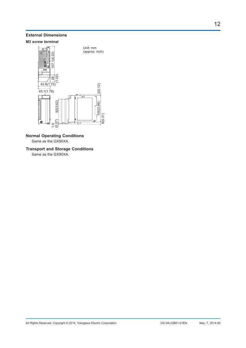
12
All Rights Reserved. Copyright © 2014, Yokogawa Electric Corporation GS 04L53B01-01EN May. 7, 2014-00
External DimensionsM3 screw terminal
107.
1(4.
22)
26(1
.02)
92(3
.62)
100(
3.94
)3(
0.12
)8(
0.31
)
(0.0
7)1.
9
45.1(1.78)
43.8(1.72)
Unit: mm(approx. inch)
Normal Operating ConditionsSameastheGX90XA.
Transport and Storage ConditionsSameastheGX90XA.

13
All Rights Reserved. Copyright © 2014, Yokogawa Electric Corporation GS 04L53B01-01EN May. 7, 2014-00
MODEL AND SUFFIX CODESAnalog input module, Digital I/O module (sold separately):MODEL and SUFFIX Code (GX90XA)
Model Suffix Code DescriptionGX90XA AnalogInputModuleforGX/GPseries
Numberofchannels -10 10 channels
Type -C1 Current,scannertype(isolatedbetweenchannels)
-L1 LowwithstandvoltageDCV/TC/DI,scannertype(isolatedbetweenchannels)
-U2 Universal,Solidstaterelayscannertype(3-wireRTDb-terminalcommon)
-T1 DCV/TC/DI,Electromagneticrelayscannertype(Isolatedbetweenchannels)
- N Always N
Terminalform -3 Screwterminal(M3)
-C Clampterminal*
Area N General* Cannotbespecifiedfortheelectromagneticrelayscannertype.
MODEL and SUFFIX Code (GX90XD)Model Suffix Code Description
GX90XD DigitalInputModuleforGX/GPseries
Numberofchannels -16 16 channels
Type -11 Opencollector/Non-voltage,contact(sharedcommon),Rated5VDC
- N Always N
Terminalform -3 Screwterminal(M3)
-C Clampterminal
Area N General
MODEL and SUFFIX Code (GX90YD)Model Suffix Code Description
GX90YD DigitalOutputModuleforGX/GPseries
Numberofchannels -06 6 channels
Type -11 Relay,SPDT(NO-C-NC)
- N Always N
Terminalform -3 Screwterminal(M3)
Area N General
MODEL and SUFFIX Code (GX90WD)Model Suffix Code Description
GX90WD DigitalIutput/OutputModuleforGX/GPseries
Numberofchannels -0806 8 channel DIs, 6 channel DOs
Type -01 Opencollector/non-voltagecontact(sharedcommon),rated5VDC;Relay,SPDT(NO-C-NC)
- N Always N
Terminalform -3 Screwterminal(M3)
Area N General

14
All Rights Reserved. Copyright © 2014, Yokogawa Electric Corporation GS 04L53B01-01EN May. 7, 2014-00
Optional Accessories (Sold Separately)Product Model/part no.
ShuntresisterforM3terminal(10Ω±0.1%) X010-010-3
ShuntresisterforM3terminal(100Ω±0.1%) X010-100-3
ShuntresisterforM3terminal(250Ω±0.1%) X010-250-3
ShuntresisterforClampterminal(10Ω±0.1%) 438922
ShuntresisterforClampterminal(100Ω±0.1%) 438921
ShuntresisterforClampterminal(250Ω±0.1%) 438920
Calibration certificate (sold separately)WhenorderingtheGX10/GX20/GP10/GP20withoptions(analoginput),thecalibrationcertificateforthemodulesisincludedinandshippedwiththecalibrationcertificateofthemainunit.Whenorderingananaloginputmodule,eachmodulegetsitsowncalibrationcertificate(onecertificatepermodule).
Test certificate (QIC, sold separately)WhenorderingtheGX10/GX20/GP10/GP20withoptions(analog/digialI/O),theQICforeachmoduleisincludedinandshippedwiththeQICofthemainunit.WhenorderinganaloginputmodulesanddigitalI/Omodules,eachmodulegetsitsownQIC(oneQICpermodule).
User's ManualProductuser'smanualscanbedownloadedorviewedatthefollowingURL.Toviewtheuser'smanual,youneedtouseAdobeReader7orlaterbyAdobeSystems.URL: www.smartdacplus.com/manual/en/
Product Purchase SpecificationsTheGX10/GX20/GP10/GP20iscomposedofthemainunit,I/Omodules,theexpandableI/O,andtheexpansionmodule.TherearetwowaystopurchaseI/Omodules.OnewayistopurchasethemindividuallybyspecifyingmodelsGX90XA,GX90XD,GX90YD,andGX90WD.Theotherwayistopurchasethemasanoption(/UCxxor/USxx).Purchasingthemasanoptionisconvenient,butthisplaceslimitationsonthenumberofanaloginputsthatyoucanobtain.Ifyouwanttousemorethan51channels,pleasepurchasetheI/Omodulesindividually.
Trademarks TheTCP/IPsoftwareusedinthisproductandthedocumentforthatTCP/IPsoftwarearebasedinpartonBSDnetworkingsoftware,Release1licensedfromTheRegentsoftheUniversityofCalifornia.
•SMARTDAC+isaregisteredtrademarkofYokogawaElectricCorporation.•Microsoft,MSandWindowsareregisteredtrademarksofMicrosoftCorporationUSA.•PentiumareregisteredtrademarksofIntelCorporation.•EthernetisaregisteredtrademarkofXEROXCorporation.ModbusisaregisteredtrademarkofAEGSchneider.•Othercompanyand/orproductnamesareregisteredtrademarkoftheirmanufactures.