Model Based Design of Automotive Embedded System
89
POLITECNICO DI TORINO Master degree course in Computer Engineering Master Degree Thesis Model Based Design of Automotive Embedded System Supervisor prof. Massimo Violante Candidate Pietro Scandale Internship Tutor Ideas & Motion s.r.l. ing. Marco Novaro October 2019
-
Upload
khangminh22 -
Category
Documents
-
view
0 -
download
0
Transcript of Model Based Design of Automotive Embedded System

POLITECNICO DI TORINO
Master degree course in Computer Engineering
Master Degree Thesis
Model Based Design ofAutomotive Embedded System
Supervisorprof. Massimo Violante
CandidatePietro Scandale
Internship TutorIdeas & Motion s.r.l.
ing. Marco Novaro
October 2019

This work is subject to the Creative Commons Licence

SummaryIn the last years the number of Embedded Systems used in the AutomotiveSector is increased drastically. Even if all car producers have worked onimprovements in the area of mechanics, the main differentiation factor be-tween brands is the electronics area. In fact, today’s trend is to replace thetraditional mechanical systems with modern embedded systems that allowto develop more advanced control strategies, providing added values for thecustomer and making vehicles smarter.
This leads software development to face challenges like shortened develop-ment times, high safety requirements and especially the growing complexityof the code because of the increasing number of functionalities. To masterthese challenges car producers and suppliers conduct a paradigm change inthe software development from hand-coded to model-based development.
A model-based development process is specifically attractive in embeddeddomains like Automotive Software due to the fact that allows a platform-independent development reducing the reengineering process caused by fastchanging hardware generation, allows to easily integrate new functions intoprevious versions of the software and accelerates the software developmentprocess.
One of the most used tool for Model Based Software Design is Simulink.It is a software integrated with Matlab and it is used principally for modelingand simulating of dynamic systems. By using Embedded Coder (that is anextension of Simulink and Matlab coder) it is possible to generate high qualityC,C++,VHDL code preserving the same behavior as the model created inSimulink. This avoids the introduction of bugs due to human errors.
The aim of this Thesis is to introduce the reader to the Model BasedSoftware Design focusing on the developing of Custom Simulink Library andto explain how to create a Simulink model and how to use Embedded Coderto generate C code, with the help of some examples.
The target board is the Aurix/Arduino-like board developed by Ideas &Motion S.r.l. It is equipped with an Aurix Tricore TC277 that with its
3

embedded safety and security features is the ideal platform for a wide rangeof automotive and industrial applications.
4

AcknowledgementsI would first like to thank my thesis advisor Massimo Violante for his supportand for his valuable advices.
I would also like to thank Marco Novaro for giving me the possibility toenter in the Ideas & Motion family and Andrea Pastore for his support duringthe Thesis work.
Finally, I must express my very profound gratitude to my parents and tomy friends for providing me unfailing support and continuous encouragementduring my years of study and also during the researching and writing processof this thesis. This accomplishment would not have been possible withoutthem. Thank you.
5

Contents
List of Figures 8
1 Model Based Software Design 111.1 What is Model Based Software Design . . . . . . . . . . . . . 121.2 Model Based Design tool: Simulink . . . . . . . . . . . . . . . 13
1.2.1 S-function . . . . . . . . . . . . . . . . . . . . . . . . . 131.2.2 Code Generation process . . . . . . . . . . . . . . . . . 14
2 Aurix/Arduino-like 172.1 Aurix™ Infineon TC277 . . . . . . . . . . . . . . . . . . . . . 192.2 Peripherals . . . . . . . . . . . . . . . . . . . . . . . . . . . . 19
2.2.1 ADC . . . . . . . . . . . . . . . . . . . . . . . . . . . . 192.2.2 CCU6 . . . . . . . . . . . . . . . . . . . . . . . . . . . 202.2.3 CAN . . . . . . . . . . . . . . . . . . . . . . . . . . . . 242.2.4 GPIO Ports . . . . . . . . . . . . . . . . . . . . . . . . 26
2.3 Real Time Operating System . . . . . . . . . . . . . . . . . . 272.3.1 OSEK/VDX Standards . . . . . . . . . . . . . . . . . . 282.3.2 Erika Enterprise RTOS . . . . . . . . . . . . . . . . . . 30
3 Getting Started 333.1 Software resources . . . . . . . . . . . . . . . . . . . . . . . . 33
3.1.1 Cygwin . . . . . . . . . . . . . . . . . . . . . . . . . . 343.1.2 Ninja Genie . . . . . . . . . . . . . . . . . . . . . . . . 353.1.3 Java Runtime Environment . . . . . . . . . . . . . . . 353.1.4 FT_Prog . . . . . . . . . . . . . . . . . . . . . . . . . 363.1.5 HighTec Free TriCore™ Entry Tool Chain . . . . . . . 36
3.2 Configuration and Build process . . . . . . . . . . . . . . . . . 373.2.1 FTDI programming . . . . . . . . . . . . . . . . . . . . 373.2.2 Import Existing Code . . . . . . . . . . . . . . . . . . 39
6

3.2.3 Build ERIKA RTOS . . . . . . . . . . . . . . . . . . . 403.2.4 Build the Project . . . . . . . . . . . . . . . . . . . . . 413.2.5 Debug . . . . . . . . . . . . . . . . . . . . . . . . . . . 43
4 Custom Simulink Library 474.1 Software resources . . . . . . . . . . . . . . . . . . . . . . . . 474.2 Simulink Library Creation . . . . . . . . . . . . . . . . . . . . 484.3 Simulink Block Generation . . . . . . . . . . . . . . . . . . . . 484.4 Add Libraries to the Library Browser . . . . . . . . . . . . . . 544.5 Aurix/Arduino-like Simulink Library Description . . . . . . . 55
4.5.1 GPIO Ports . . . . . . . . . . . . . . . . . . . . . . . . 554.5.2 ADC . . . . . . . . . . . . . . . . . . . . . . . . . . . . 584.5.3 CAN . . . . . . . . . . . . . . . . . . . . . . . . . . . . 604.5.4 PWM . . . . . . . . . . . . . . . . . . . . . . . . . . . 63
5 Code Generation 695.1 Software Resources . . . . . . . . . . . . . . . . . . . . . . . . 705.2 First Example: Blinking Led . . . . . . . . . . . . . . . . . . . 705.3 Second Example: 3-phase PWM generation . . . . . . . . . . . 775.4 Integrate the Generated File in the Project . . . . . . . . . . . 86
Bibliography 89
7
List of Figures1.1 Embedded Systems in a vehicle . . . . . . . . . . . . . . . . . . 111.2 Target Language Compiler Process, [5] . . . . . . . . . . . . . 152.1 Aurix/Arduino-like board and Ideas & Motion S.r.l logo . . . . 182.2 ADC structure overview, [8] . . . . . . . . . . . . . . . . . . . 202.3 CCU6 block diagram, [8] . . . . . . . . . . . . . . . . . . . . . 212.4 T12 Operation in Edge-Aligned Mode, [8] . . . . . . . . . . . 222.5 T12 Operation in Center-Aligned Mode, [8] . . . . . . . . . . . 232.6 Dead-Tme Generation Waveforms, [8] . . . . . . . . . . . . . . 243.1 Aurix/Arduino-like board right connection . . . . . . . . . . . 373.2 FT_Prog: Scan and Parse . . . . . . . . . . . . . . . . . . . . 383.3 FT_Prog: Apply Template . . . . . . . . . . . . . . . . . . . . 383.4 FT_Prog: Program Device . . . . . . . . . . . . . . . . . . . . 393.5 Eclipse: Select a wizard . . . . . . . . . . . . . . . . . . . . . 393.6 Eclipse: Project Configuration . . . . . . . . . . . . . . . . . . 403.7 pathcfg.mk makefile . . . . . . . . . . . . . . . . . . . . . . . . 413.8 Eclipse: Builder Configuration . . . . . . . . . . . . . . . . . . 423.9 Eclipse: Console Message . . . . . . . . . . . . . . . . . . . . 423.10 Eclipse: Debug Configuration . . . . . . . . . . . . . . . . . . 433.11 Eclipse: Universal Debug Engine Main Congifuration . . . . . 443.12 Eclipse: Universal Debug Engine Main Congifuration . . . . . 453.13 Eclipse: Universal Debug Engine Memory Programming Tool . 453.14 Eclipse: Programming Success . . . . . . . . . . . . . . . . . 464.1 Blank Library . . . . . . . . . . . . . . . . . . . . . . . . . . . 484.2 Diagram showing the correct use of Legacy Code Tool, [4] . . . 494.3 CCU6_PWM_Setup block . . . . . . . . . . . . . . . . . . . . 524.4 PARAMETERS & DIALOG pane window . . . . . . . . . . . 534.5 Block Mask . . . . . . . . . . . . . . . . . . . . . . . . . . . . 544.6 Aurix/Arduino-like Simulink library . . . . . . . . . . . . . . . 554.7 PORT_00_34_CONF block mask . . . . . . . . . . . . . . . . 564.8 PORT_40_CONF block mask . . . . . . . . . . . . . . . . . . 57
8

4.9 Dio_READ_Channel block mask . . . . . . . . . . . . . . . . 574.10 Dio_WRITE_Channel block mask . . . . . . . . . . . . . . . 584.11 Adc_StartBackgroundConvertion block mask . . . . . . . . . . 594.12 Adc_Read block mask . . . . . . . . . . . . . . . . . . . . . . . 594.13 Can_Msg_Static block mask . . . . . . . . . . . . . . . . . . . 604.14 Can_Msg_Dynamic block mask . . . . . . . . . . . . . . . . . 614.15 Can_Msg_unpacked block mask . . . . . . . . . . . . . . . . . 614.16 Packed_Can_8bytes_array block mask . . . . . . . . . . . . . 624.17 UnPacked_Can_8bytes_array block mask . . . . . . . . . . . 624.18 Can_Send block mask . . . . . . . . . . . . . . . . . . . . . . 624.19 Can_Receive block mask . . . . . . . . . . . . . . . . . . . . . 634.20 Atom_PWM_Channel_Config block mask . . . . . . . . . . . 644.21 Atom_PWM_SetDutyCycle block mask . . . . . . . . . . . . . 654.22 CCU6_PWM_Setup block mask . . . . . . . . . . . . . . . . . 664.23 CCU6_PWM_SetDutyCycle block mask . . . . . . . . . . . . 675.1 Subsystem Block . . . . . . . . . . . . . . . . . . . . . . . . . . 705.2 Subsystem Block Parameters: Main pane . . . . . . . . . . . . 715.3 Subsystem Block Parameters: Code generation pane . . . . . 715.4 Initialize Function block . . . . . . . . . . . . . . . . . . . . . 725.5 Initialize Function: Port configuration . . . . . . . . . . . . . 725.6 Model Design . . . . . . . . . . . . . . . . . . . . . . . . . . . 735.7 Set parameters for the Code Generation . . . . . . . . . . . . . 745.8 Oil file: Task configuration . . . . . . . . . . . . . . . . . . . . 755.9 Oil file: ALARM configuration . . . . . . . . . . . . . . . . . . 755.10 Extended task implementaion . . . . . . . . . . . . . . . . . . 765.11 Init Function . . . . . . . . . . . . . . . . . . . . . . . . . . . 765.12 Step Function . . . . . . . . . . . . . . . . . . . . . . . . . . . 775.13 Subsystem Block . . . . . . . . . . . . . . . . . . . . . . . . . . 785.14 Subsystem Block Parameters: Main pane . . . . . . . . . . . . 785.15 Subsystem Block Parameters: Code generation pane . . . . . . 795.16 Initialize Function block . . . . . . . . . . . . . . . . . . . . . 795.17 Initialize Function: Port configuration . . . . . . . . . . . . . 805.18 Initialize Function: Start Adc Background Convertion . . . . . 805.19 Initialize Function: CCU6 configuration . . . . . . . . . . . . 815.20 Model Design . . . . . . . . . . . . . . . . . . . . . . . . . . . 815.21 Set parameters for the Code Generation . . . . . . . . . . . . . 825.22 Oil file: Task configuration . . . . . . . . . . . . . . . . . . . . 835.23 Extended task implementaion . . . . . . . . . . . . . . . . . . 845.24 Init Function . . . . . . . . . . . . . . . . . . . . . . . . . . . 85
9

5.25 Step funtion . . . . . . . . . . . . . . . . . . . . . . . . . . . . 855.26 CCU6.c file . . . . . . . . . . . . . . . . . . . . . . . . . . . . 865.27 cpu0_main.c file . . . . . . . . . . . . . . . . . . . . . . . . . 87
10

Chapter 1
Model Based SoftwareDesignIn the last 20 years the value chain in the car industry has changed drasti-cally. Even if all car producers are still working on improvements in the areaof mechanics, quality requirements and in the logistic area, the main differen-tiation factor between brands turned out to be the electronics area. Whereasareas such as power train and body had small product development cost in-creases over the years, the costs for the development of electronic systems hasbeen tripled, [1]. In fact, today’s trend is to replace the traditional mechani-cal systems with modern embedded systems that enables the deployment ofmore advanced control strategies, providing added values for the customerand making vehicles smarter.
Figure 1.1. Embedded Systems in a vehicle
11

Model Based Software Design
This leads software development to face challenges like shortened develop-ment times, high safety requirements and especially the growing complexityof the code because of the increasing number of functionalities. To masterthese challenges car producers and suppliers conduct a paradigm change inthe software development from hand-coded to model-based development.
A model-based development process is specifically attractive in embeddeddomains like Automotive Software due to the fact that the development inthese domains is driven by two strong forces: on the one side the evolu-tionary development of automotive systems, dealing with the iterated inte-gration of new functions into a substantial amount of existing functionalityfrom previous system versions; and on the other side platform-independentdevelopment, substantially reducing the amount of reengineering/ mainte-nance caused by fast changing hardware generations, [1]. As a result, amodel-based approach is pursued to enable a shift of focus of the develop-ment process on the early phases, supporting a function based rather than acode-based engineering of automotive systems.
1.1 What is Model Based Software DesignModel-Based Design provides a mathematical and visual approach to developcomplex control and signal processing systems. It centers on the use of systemmodels throughout the development process for design, analysis, simulation,automatic code generation and verification, [2]. So with Model-Based Designthe design phase is moved from the lab and field to the desktop.
Model Based Software Design (MBSD) is a software development pro-cess that aims to tackle increasing software development complexity by us-ing abstraction and automation. Abstraction is achieved by employing suit-able models of a software system while automation systematically transformsthese models into executable source code, [3]. Engineers create a model tospecify the behavior of an embedded system; the model, which consists ofblock diagrams, textual programs, and other graphical elements, is an ex-ecutable specification that lets engineers run simulations to test ideas andverify designs throughout the development process, [2]. The benefits are thefollowing:• Improvement of the product quality: test activities during the design
and development phase improve the quality of the product;
• Development of functions with high complexity: classical software de-velopment is difficult to use to design functions with high complexity.
12

1.2 – Model Based Design tool: Simulink
Model-based development helps to develop high complex functions withviewer iterations and consequently less development effort;
• Better communication: the models provide great support in the commu-nication with other colleagues because of the graphical design. It’s alsopossible to involve people that are not familiar with software develop-ment thanks to the use of models. This helps to include extra know-howin the software development;
• Rapid Control Prototyping decreases development time by allowing cor-rections to be made early in the product process. So mistakes can becorrected and changes can be made while they are still inexpensive;
• Software bugs reduction: code can be automatically generated for em-bedded deployment, saving time and avoiding the introduction of manualerror in the code.
1.2 Model Based Design tool: SimulinkOne of the most used tool for MBSD is Simulink. It is a software for model-ing, simulation and analysis of dynamic systems, developed by MathWorkscompany. It is integrated with MATLAB.
Instead of writing manually thousands of lines of code, Embedded Codergives the possibility to automatically generate high quality C, C++,VHDLcode, which has the same behavior as the model created in Simulink. It ex-tends MATLAB Coder™ and Simulink Coder™ with advanced optimizationsfor precise control of the generated functions, files, and data.
1.2.1 S-functionS-functions (system-functions) are very useful in order to extend the capa-bilities of the Simulink environment. An S-function is a computer languagedescription of a Simulink block written in MATLAB, C, C++, or Fortran,[4]. C, C++, and Fortran S-functions are compiled as MEX files using themex utility. S-functions define how a Simulink block works and for this rea-son they are principally used to create custom Simulink blocks that can beused many times in a model. S-Function Block Parameters window allowsto specify values to pass to the corresponding S-function; so it is necessaryto read the S-function’s documentation to understand which paramaters theblock requires.
13

Model Based Software Design
The S-Function Builder generates the following source files in the currentfolder:
• sfun.c, contains the C source code representation of the standard por-tions of the generated S-function, [4]. "sfun" is the name of the S-functionspecified in the S-function name field;
• sfun.tlc, permits the generated S-function to run in Simulink Rapid Ac-celerator mode and allows for inlining the S-function during code gener-ation, [4].
Matlab Legacy Code Tool provides to transforms existing functions into CMEX S-functions that can be included in Simulink models. When EmbeddedCoder is invoked for code generation, an appropriate call to the createdfunction is inserted into the generated code.
1.2.2 Code Generation processWhen generating code from the Simulink model, Real-Time Workshop (orSimulink coder) is invoked: its task is the generation of the model.rtw file.This file contains informations about the model that is then used to generatecode: is a database whose content provide a description of the individualblocks within the Simulink model, [5]. The code is generated through callsto a utility called Target Language Compiler. It works like a text processor:after reading the model.rtw file, it generates code into the desired language(e.g. C) based on target files (.tlc), which specify particular code for eachblock, and model-wide files, which specify the overall code style.
After the creation of the model, it is possible to call the Code Generationby simply clicking the Build Model button in the Simulink Model window;this action automatically calls Real-Time Workshop and TLC. Figure 1.2shows how the Target Language Compiler works with its target files andReal-Time Workshop output in order to generate code.
All the generated files are placed in the build directory and include:
• The body for the generated C source code (model.c) that contains threemain functions: model_step, model_initialize, model_terminate;
• The header file model.h that declares model data structures and a publicinterface to the model entry points and data structures, [6]. It is includedby subsystem .c files in the model. The generated code can be includedin another existing file by simply include model.h;
14

1.2 – Model Based Design tool: Simulink
• The header file model_types.h that provides forward declarations forthe real-time model data structure and the parameters data structure.These may be needed by function declarations of reusable functions, [6] .model_types.h is included by all the generated header files in the model;
• The header file model_private.h that defines parameters and privatedata structures of the generated code.
Figure 1.2. Target Language Compiler Process, [5]
15

16

Chapter 2
Aurix/Arduino-like
The Aurix/Arduino-like board (figure 2.1) was designed and developed byIdeas & Motion S.r.l. principally for the HYPER_SDF project.
Among the different applications currently under development in the au-tomotive, the “automated vehicle” is the one which has constantly gainedimportance. In particular the Advanced Driver Assistance System (ADAS)is projected to be the most relevant growing market segment over the nextyears. The ultimate goal of the automated vehicle is to drastically improvethe road safety through a precise real-time description of the scenario sur-rounding the vehicle.
Sensor data fusion between front and rear smart sensors is key for thedevelopment and implementation of complex algorithms supporting the au-tonomous driving. The HYPER_SDF project introduces an open powerfulautomotive development platform based on the proper combination of twodiverse high-performance multi-core processors providing outstanding pro-cessing capabilities while featuring a state-of-the-art safety architecture. Itwas decided to use two processor beacause no processors with high perfor-mance that ensure ASIL D were avaliable. It was decided to use the AurixTricore because it guarantees high safety requirements and i.MX8 QM eval-uation board for the high performance. The latter is used to execute theoperations which require considerable processing power (i.e. sensor fusionetc.) while the first one has to monitor and validate all the fusion processorvalidation, using them to drive the vehicle.
The design of Aurix/Arduino-like was also driven by the aim to developan easily usable board (e.g. to be used in the University) and eventuallyexpandable: for this reason it was decided to follow the Arduino model,beacuse in this way all the existing modules are compatible and interfaceable
17

Aurix/Arduino-like
with the board.
Figure 2.1. Aurix/Arduino-like board and Ideas & Motion S.r.l logo
18
2.1 – Aurix™ Infineon TC277
2.1 Aurix™ Infineon TC277AURIX™ is Infineon’s brand new family of microcontrollers. It’s based on aninnovative multicore architecture and has been designed to meet the highestsafety standards, while simultaneously increasing performance significantly.It is equipped with a triple TriCore with 200 MHz, 4MB of Flash memoryand a Powerful Generic Timer Module (GTM). The TC27xT series aim fora reduced complexity, best-in-class power consumption and significant costsavings.
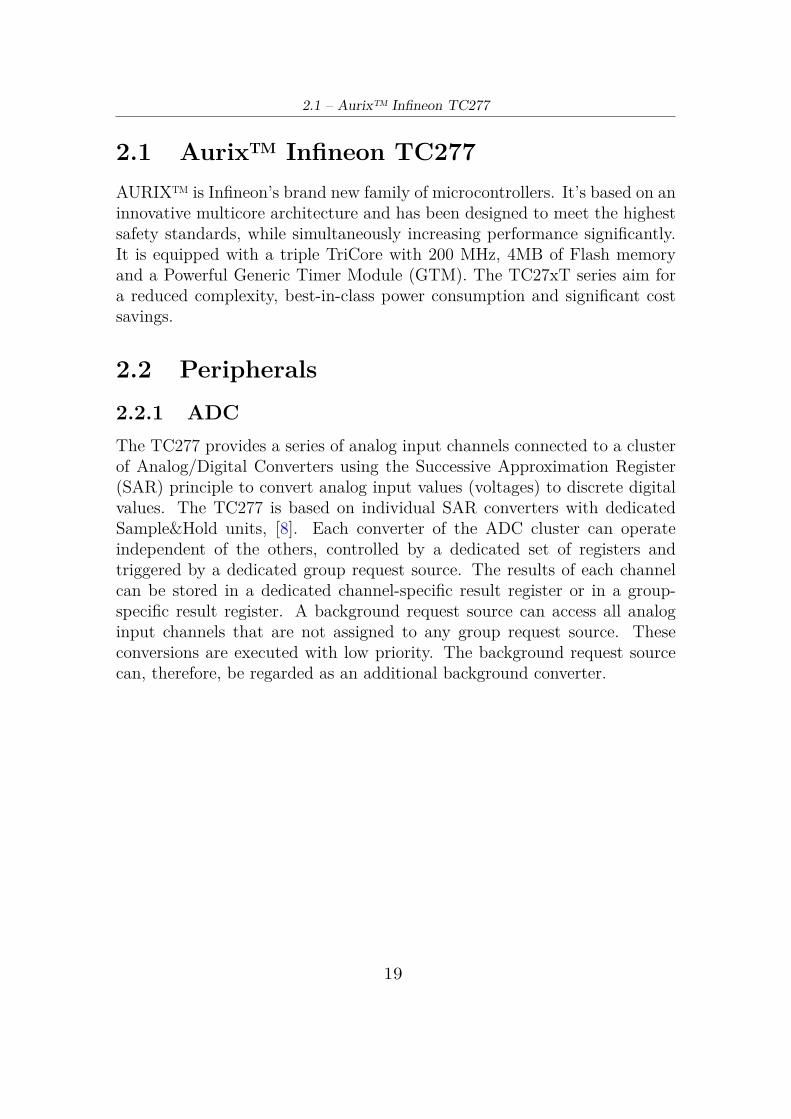
2.2 Peripherals2.2.1 ADCThe TC277 provides a series of analog input channels connected to a clusterof Analog/Digital Converters using the Successive Approximation Register(SAR) principle to convert analog input values (voltages) to discrete digitalvalues. The TC277 is based on individual SAR converters with dedicatedSample&Hold units, [8]. Each converter of the ADC cluster can operateindependent of the others, controlled by a dedicated set of registers andtriggered by a dedicated group request source. The results of each channelcan be stored in a dedicated channel-specific result register or in a group-specific result register. A background request source can access all analoginput channels that are not assigned to any group request source. Theseconversions are executed with low priority. The background request sourcecan, therefore, be regarded as an additional background converter.
19

Aurix/Arduino-like
Figure 2.2. ADC structure overview, [8]
2.2.2 CCU6The CCU6 is a high-resolution 16-bit capture and compare unit with appli-cation specific modes, mainly for AC drive control. It is made up of a TimerT12 Block with three capture/compare channels and a Timer T13 Block withone compare channel. The T12 channels can independently generate PWMsignals or accept capture triggers, or they can jointly generate control signalpatterns to drive AC-motors or inverters, [8]. The timer T12 block is themain unit to generate the 3-phase PWM signals. A 16-bit counter is con-nected to 3 channel registers via comparators, that generate a signal whenthe counter contents match one of the channel register contents. The T12block also offers options for individual compare and capture functions, aswell as dead-time control and hysteresis-like compare mode.
20

2.2 – Peripherals
Figure 2.3. CCU6 block diagram, [8]
Timer T12 has been configured in order to receive its input clock (f T12)from the module clock f CC6 (100 MHz) via a programmable prescaler andan optional 1/256 divider. The bit fields T12CLK and T12PRE are used tocontrol these options. T12 can count up or down, depending on the selectedoperation mode. CDIR is a direction flag that indicates the current countingdirection. T12 counter register is connected to a Period Register T12PRvia a comparator: this register determines the maximum count value forT12. It’s possible to select among two operations mode: Edge-Aligned andCenter-Aligned mode according to the value of the CTM flag.
In Edge-Aligned Mode (CTM = 0), timer T12 is always counting upwards(CDIR = 0). When the value given by the period register (period-matchT12_PM) is reached, the value of T12 is cleared with the next counting step
21

Aurix/Arduino-like
(saw tooth shape).
Figure 2.4. T12 Operation in Edge-Aligned Mode, [8]
In Center-Aligned Mode (CTM = 1), timer T12 is counting upwards ordownwards (triangular shape). When reaching the value given by the pe-riod register (period-match T12_PM) while counting upwards (CDIR = 0),the counting direction control bit CDIR is changed to downwards (CDIR= 1) with the next counting step. When reaching the value 0001H (one-match T12_OM) while counting downwards, the counting direction controlbit CDIR is changed to upwards with the next counting step (figure 2.5).
This operating mode is prefered in motor control applications because thecurrent sampling is synchronized with the PWM period. So CCU6 has beenconfigured to work in this way: in correspondance of the Period Match, thecurrent sampling task is executed while in correspondance of the One Match,the computed duty cycles for the following period are updated.
22

2.2 – Peripherals
Figure 2.5. T12 Operation in Center-Aligned Mode, [8]
The Period Register receives a new period value from its Shadow PeriodRegister: is controlled via the ‘T12 Shadow Transfer’ control signal, T12_ST.Providing a shadow register for the period value as well as for other valuesrelated to the generation of the PWM signal allows a concurrent updateby software for all relevant parameters. It’s possible to enable the Shadowtransfer by setting the bit STE12 only in correspondence of the T12_PM orT12_OM, otherwise the upload has no effect
There are three individual capture/compare channels associated with TimerT12; they have been configured to work in Compare Mode: the three indi-vidual compare channels CC60 CC61, and CC62 can generate a three-phasePWM pattern. Each compare channel has its own equal comparator con-nected to the T12 counter register. A match signal is generated when thecontent of the counter matches the contents of the associated compare reg-ister (CC60R, CC61R, CC62R). Foreach compare register is associated ashadow register CC6xSR, that is preloaded by software and transferred intothe compare register when signal T12 shadow transfer, T12_ST, is set.
The shadow registers are fundamental because they facilitate a concur-rent update by software for all relevant parameters of a three-phase PWM;not only for the compare value but also for the other values related to the
23

Aurix/Arduino-like
generation of the PWM signal facilitates.The generation of (complementary) signals for the high-side and the low-
side switches of one power inverter phase is based on the same comparechannel, [8]. For example, if the high-side switch should be active while theT12 counter value is above the compare value (State Bit = 1), then the low-side switch should be active while the counter value is below the comparevalue (State Bit = 0). In most cases, the switching behavior of the connectedpower switches is not symmetrical due to switch-on and switch-off times. Aproblem arises if the time for switch-on is smaller than the time for switch-off of the power device: a short-circuit can occur in the inverter bridge leg,which damage the complete system. It’s possible to solve this problem byHW, by using the programmable Dead-Time Generation Block of the CCU6unit: it inserts a programmable time that delays the passive to active edgeof the switching signals.
Figure 2.6. Dead-Tme Generation Waveforms, [8]
2.2.3 CANController Area Network, better known as CAN-bus, it is a robust vehicle busstandard designed to allow microcontrollers and devices to communicate eachother withouth a host computer. It is a message-based protocol and has been
24
2.2 – Peripherals
designed to work without problems even in environments that are stronglydisturbed by the presence of electromagnetic waves. Although initially it wasapplied only in the automotive sector, it is currently used in many embeddedindustrial applications, where it is required a high level of noise immunity.
A CAN bus consists of two or more nodes. The bus logic corresponds toa “wired-AND” mechanism. Recessive bits (equivalent to the logic 1 level)are overwritten by dominant bits (logic 0 level). As long as no bus nodeis sending a dominant bit, the bus is in the recessive state. In this state,a dominant bit from any bus node generates a dominant bus state. Themaximum CAN bus speed is, by definition, 1 Mbit/s. This speed limits theCAN bus to a length of up to 40 m. For bus lengths longer than 40 m, thebus speed must be reduced, [8].
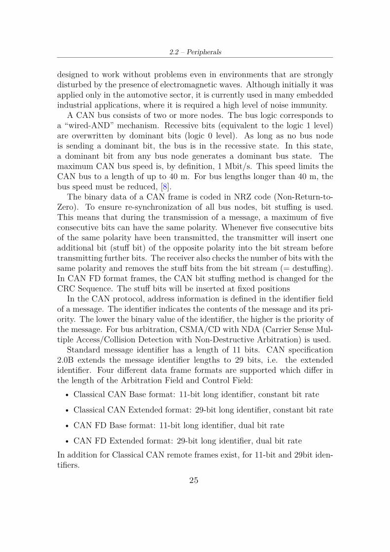
The binary data of a CAN frame is coded in NRZ code (Non-Return-to-Zero). To ensure re-synchronization of all bus nodes, bit stuffing is used.This means that during the transmission of a message, a maximum of fiveconsecutive bits can have the same polarity. Whenever five consecutive bitsof the same polarity have been transmitted, the transmitter will insert oneadditional bit (stuff bit) of the opposite polarity into the bit stream beforetransmitting further bits. The receiver also checks the number of bits with thesame polarity and removes the stuff bits from the bit stream (= destuffing).In CAN FD format frames, the CAN bit stuffing method is changed for theCRC Sequence. The stuff bits will be inserted at fixed positions
In the CAN protocol, address information is defined in the identifier fieldof a message. The identifier indicates the contents of the message and its pri-ority. The lower the binary value of the identifier, the higher is the priority ofthe message. For bus arbitration, CSMA/CD with NDA (Carrier Sense Mul-tiple Access/Collision Detection with Non-Destructive Arbitration) is used.
Standard message identifier has a length of 11 bits. CAN specification2.0B extends the message identifier lengths to 29 bits, i.e. the extendedidentifier. Four different data frame formats are supported which differ inthe length of the Arbitration Field and Control Field:• Classical CAN Base format: 11-bit long identifier, constant bit rate
• Classical CAN Extended format: 29-bit long identifier, constant bit rate
• CAN FD Base format: 11-bit long identifier, dual bit rate
• CAN FD Extended format: 29-bit long identifier, dual bit rateIn addition for Classical CAN remote frames exist, for 11-bit and 29bit iden-tifiers.
25
Aurix/Arduino-like
There are three types of CAN frames:
• Data Frames
• Remote Frames
• Error Frames
A Data Frame contains a Data Field of 0 to 8 bytes in length. A RemoteFrame contains no Data Field and is typically generated as a request for data(e.g. from a sensor). Data and Remote Frames can use an 11-bit “Standard”identifier or a 29-bit “Extended” identifier. An Error Frame can be generatedby any node that detects a CAN bus error.
2.2.4 GPIO PortsThe TC27x has digital General Purpose Input/Output (GPIO) port lineswhich are connected to the on-chip peripheral units, [8]. Each port line has anumber of control and data bits, enabling very flexible usage of the line. Eachport pin can be configured for input or output operation. In input mode,the output driver is switched off (high-impedance). The actual voltage levelpresent at the port pin is translated into a logical 0 or 1 via a Schmitt-Triggerdevice and can be read via the read-only register Pn_IN. Input signals areconnected directly to the various inputs of the peripheral units (AltDataIn).
The level of the pin can be read by software via Pn_IN or a peripheralcan use the pin level as an input. In output mode, the output driver isactivated and drives the value supplied through the multiplexer to the portpin. Switching between input and output mode is accomplished throughthe Pn_IOCR register, which enables or disables the output driver. If aperipheral unit uses a GPIO port line as a bi-directional I/O line, registerPn_IOCR has to be written for input or output selection. The Pn_IOCRregister further controls the driver type of the output driver, and determineswhether an internal weak pull-up, pull- down, or without input pull deviceis alternatively connected to the pin when used as an input. This offersadditional advantages in an application.
The output multiplexer in front of the output driver selects the signalsource for the GPIO line when used as output. If the pin is used as general-purpose output, the multiplexer is switched by software (Pn_IOCR register)to the Output Data Register Pn_OUT. Software can set or clear the bit inPn_OUT through separate Pn_OMSR or Pn_OMCR registers. The set orclear operations for the bits in Pn_OUT can also be done for up to four bits
26

2.3 – Real Time Operating System
per register in Pn_OMSRx and Pn_OMCRx (x=0,4,8,12). Alternatively,the set, clear or toggle function can be achieved through Pn_OMR, whereadjacent pins within the same port can be set, cleared or toggled within onewrite operation. The manipulation of the control bits in these registers candirectly influence the state of the port pin. If the on-chip peripheral unitsuse the pin for output signals, the alternate output lines ALT1 to ALT7 canbe switched via the multiplexer to the output driver. The data written intothe output register Pn_OUT by software can be used as input data to anon-chip peripheral.
When selected as general-purpose output line, the logic state of each portpin can be changed individually by programming the pin-related bits inthe Output Modification Set Register Pn_OMSR, Output Modification SetRegister x Pn_OMSRx (x=0,4,8,12), Output Modification Clear RegisterPn_OMCR, Output Modification Clear Register x Pn_OMCRx (x=0,4,8,12)or Output Modification Register, OMR. The bits in Pn_OMSR/Pn_OMSRxand Pn_OMCR/Pn_OMCRx make it possible to set and clear the bits in thePn_OUT register. While the bits in Pn_OMR allows the bits in Pn_OUTto be set, cleared, toggled or remain unchanged.
2.3 Real Time Operating SystemIn Real-Time System the correctness of the system behavior depends not onlyon the logical results of the computations, but also on the physical instantat which these results are produced.
It can be decomposed into a set of subsystems, i.e. the controlled objectand the real-time computer system. A real-time computer system must reactto stimuli from the controlled object within time intervals dictated by itsenvironment. The instant at which a result is produced is called a deadline.If the result has utility even after the deadline has passed, the deadline isclassified as soft; if missing its deadline makes the result useless, but missingdoes not cause serious damage, the deadline is classified as firm while if acatastrophe could happen if a deadline is missed, the deadline is hard, [9].Commands and Control systems, Air traffic control systems are examplesfor hard real-time systems. On-line transaction systems, airline reservationsystems are soft real-time systems.
An operating system is a system software that manages the hardware andsoftware resources of the machine, providing basic services to the applicationsoftware.
27

Aurix/Arduino-like
Most operating systems allow multiple programs to execute at the sametime. This is called multi-tasking. In reality there is no parallel managementof processes but they are executed in sequence: the times are so short thatthe user seems that the programs go simultaneously. A part of the operatingsystem called scheduler is responsible for deciding which program to runand when, and provides the illusion of simultaneous execution by rapidlyswitching between each program.
The type of an operating system is defined by how the scheduler decideswhich program to run when. The scheduler in a Real Time Operating System(RTOS) is designed to provide a predictable (normally described as deter-ministic) execution pattern. This is particularly of interest to embeddedsystems as embedded systems often have real time requirements. A real timerequirements is one that specifies that the embedded system must respond toa certain event within a strictly defined time. A guarantee to meet real timerequirements can only be made if the behaviour of the operating system’sscheduler can be predicted (and is therefore deterministic).
Traditional real time schedulers achieve determinism by allowing the userto assign a priority to each thread of execution. The scheduler then usesthe priority to know which thread of execution to run next. A thread ofexecution is called task.
2.3.1 OSEK/VDX StandardsOSEK (in english: "Open Systems and their Interfaces for the Electronicsin Motor Vehicles") is a standards body that has produced specificationsfor an embedded operating system, a communications stack, and a networkmanagement protocol for automotive embedded systems. It was designed toprovide a standard software architecture for the various electronic controlunits (ECUs) in a car.
OSEK was founded in 1993 by a German automotive company consor-tium (BMW, Robert Bosch GmbH, DaimlerChrysler, Opel, Siemens, andVolkswagen Group) and the University of Karlsruhe. In 1994, the Frenchcars manufacturers Renault and PSA Peugeot Citroën, which had a similarproject called VDX (Vehicle Distributed eXecutive), joined the consortium.Therefore, the official name is OSEK/VDX.
The OSEK operating system serves as a basis for application programswhich are independent of each other, and provides their environment on aprocessor, [11]. The OSEK operating system enables a controlled real-timeexecution of several processes which appear to run in parallel. The OSEK
28

2.3 – Real Time Operating System
operating system provides a defined set of interfaces for the user. Theseinterfaces are used by entities which are competing for the CPU. There aretwo types of entities:
• Interrupt service routines managed by the operating system
• Tasks (basic tasks and extended tasks)
The hardware resources of a control unit can be managed by operating systemservices. These operating system services are called by a unique interface,either by the application program or internally within the operating system.OSEK defines three processing levels:
• Interrupt level
• Logical level for scheduler
• Task level
Within the task level tasks are scheduled (non, full or mixed preemptivescheduling) according to their user assigned priority. The run time contextis occupied at the beginning of execution time and is released again once thetask is finished. The following priority rules have been established:
• Interrupts have precedence over tasks
• The interrupt processing level consists of one or more interrupt prioritylevels
• Interrupt service routines have a statically assigned interrupt prioritylevel
• Assignment of interrupt service routines to interrupt priority levels isdependent on implementation and hardware architecture
• For task priorities and resource ceiling-priorities bigger numbers refer tohigher priorities.
• The task’s priority is statically assigned by the user
The main purpose of the OSEK operating system (OS) specification is toachieve portability between application software from different electroniccontrol units (ECU). Because the specification ends with defining an APIon C-language level together with the declaration of the relevant datatypes,
29

Aurix/Arduino-like
applications still are not portable between OS-implementations of differentvendors. A new language is so defined to achieve portability. The OSEKimplementation language (OIL) specifies means to declare and define all rel-evant OS-objects, [12]. Currently it is intended to specify all OS-objects foran application in a centralized OIL-file. OIL-files have to be parsed to collectthe specified informations and translated into C data structures and proba-bly some code. This task will be typically handled by a system generationwhich will be delivered by the operating system vendor.
2.3.2 Erika Enterprise RTOSERIKA Enterprise is an innovative RTOS developed for microcontrollers.Its kernel is a complete OSEK/VDX environment, which can be used toimplement multithreading applications. The Erika Enterprise API providessupport for thread activation, mutual exclusion, alarms, events and count-ing semaphores. The ERIKA Enterprise kernel implements innovative algo-rithms such as Fixed Priority with supremacy threshold, Stack Resource Pol-icy (SRP), and Earliest Deadline First (EDF), which can be used to programtasks with real-time requirements. Erika Enterprise offers the availability ofa real-time scheduler and resource managers allowing the full exploitationof the power of new generation micro-controllers and mul- ticore platformswhile guaranteeing predictable real-time performance and retaining the pro-gramming model of conventional single processor architectures, [10]. Theadvanced features provided by Erika Enterprise are:
• Support for four conformance classes to match different application re-quirements;
• Support for preemptive and non-preemptive multitasking;
• Support for fixed priority scheduling;
• Support for stack sharing techniques, and one-shot task model to reducethe overall stack usage;
• Support for shared resources;
• Support for periodic activations using Alarms;
• Support for centralized Error Handling;
• Support for hook functions before and after each context switch;
30

2.3 – Real Time Operating System
Erika Enterprise is supported by RT-Druid, a tool suite based on EclipseFramework for the automatic configuration and deployment of embeddedapplications which enables to easily exploit multi-processor architectures andachieve the desired performance without modifying the application sourcecode.
It is an OIL language compiler, which is able to generate the ERIKA En-terprise configuration from an OIL specification. It generates all the filesneeded, such as the makefiles and the ERIKA Enterprise internal data struc-ture initializations.
31

32

Chapter 3
Getting Started
The best way to load the executable and debug the Aurix/Arduino-like boardis with the use of TRACE32: it allows to test embedded hardware andsoftware by using the on-chip debug interface (the most common is JTAG).TRACE32 tools connect to this one to control the core, so the access tothe data being processed by the core is guaranteed. It is possible to havestart, stop, step control; to read and write memory and registers; to setbreakpoints; to track values of variables and so on.
Since is not so easy to obtain this instrument (for cost reason), anothersolution has been founded in order to avoid to use it. This has been possiblethanks to the presence of the FTDI (FT2232HL) module on the target boad.This module contains a small EEPROM configuration memory and convertthe USB in JTAG + serial.
In this chapter will be explained how to set the environment before interfacingwith the Aurix/Arduino-like board. In particular the first part is dedicatedto the Software resources (section 3.1) with a short description about eachneeded software and some hints on where to download and how to installthem correctly. The second part is dedicated to explain how to program theFTDI module (section 3.1.4), import the project in Eclipse (section 3.2.2),compile ERIKA RTOS (section 3.2.3), build the project (section 3.2.4) andin the end how to program and debug the board (section 3.2.5).
3.1 Software resourcesThe following software are needed:
33

Getting Started
• Cygwin package
• Ninja Genie
• FT_Prog
• Java jre1.8.0_171 version
• HighTec Free TriCore™ Entry Tool Chain
3.1.1 CygwinDescriptionCygwin is a large collection of GNU and Open Source tools which providefunctionality similar to a Linux distribution on Windows.
How to get itInstalling and Updating Cygwin Packages from https://cygwin.com/install.html
Installation hintsThe cygwin installation folder must be C:\cygwin (or C:\cygwin64 depend-ing on the Operating System configuration). The following packages shall bedownload during the installation:
• Category: Devel
– binutils: GNU assembler, linker and similar utilities– gcc-core: GNU Compiler Collection (C, OpenMP)– make: The GNU version of the “make” utility
• Category: Basic
– sed: the GNU sed stream editor
The path C:\cygwin\bin (or C:\cygwin64\bin) must be added to theEnvironment variables of Windows to the Path (inside System variables)and then moved up to the second position.
34

3.1 – Software resources
3.1.2 Ninja Genie
DescriptionNinja is a small build system with a focus on speed. It differs from other buildsystems in two major respects: it is designed to have its input files generatedby a higher-level build system and to run builds as fast as possible.
How to get itThe two executables ninja.exe and genie.exe can be found in the Getting_Started\Ninja_Genie folder and must NOT be installed.
Installation hintsThe Ninja_Genie folder must be copied in C: and the path C:\Ninja_Geniemust be added to the Environment variables of Windows to the Path (insideSystem variables) and then moved up to the first position.
3.1.3 Java Runtime Environment
DescriptionJava Runtime Environment must be present for using RT-Druid in order towrite and compile application based on ERIKA Enterprise.
How to get itThe executable jdk-8u171-windows-x64.exe can be found in the Getting_Started folder.
Installation hintsDouble click on the executable and simply follow the instructions.
WARNING: Only with this version of Java everything works so it’s im-portant to install it.
35

Getting Started
3.1.4 FT_Prog
DescriptionFT_Prog is a free EEPROM programming utility for use with FTDI devices.It is used for modifying EEPROM contents that store the FTDI device de-scriptors to customize designs, [13].
How to get itFT_Prog is available as a free download from https://www.ftdichip.com/Support/Utilities.htm#FT_PROG
Installation hintsDownload and simply follow the instructions.
3.1.5 HighTec Free TriCore™ Entry Tool Chain
DescriptionThe tool chain consists of a compiler based on the proven high performanceGNU compiler for TriCore™ from HighTec and the Universal Debug Enginelimited to level1 functionality. The HighTec Free TriCore™ Entry Tool Chainprovides all required features to develop and test software for TriCore™ andAURIX™.
How to get itHighTec Free TriCore™ Entry Tool Chain is available as a free download fromhttps://free-entry-toolchain.hightec-rt.com/ and follow the instruc-tions in order to correctly generate the License File and obtain the program.
Installation hintsRead the manual https://free-entry-toolchain.hightec-rt.com/getting_started.pdf?d=20180608 and follow the instructions of the Installing theFree TriCore Entry Tool Chain and First Starting of Eclipse chapter.
36

3.2 – Configuration and Build process
3.2 Configuration and Build processFirst of all make sure that the board is connected to the PC in the right way(figure 3.1).
Figure 3.1. Aurix/Arduino-like board right connection
3.2.1 FTDI programmingHereby is listed a step-by-step guide in order to correctly program the FTDI:
1. Launch FT_Prog.
2. Scan for Device: click on the Scan and Parse button on the toolbar toscan the USB bus for available connected FTDI devices (figure 3.2).
37

Getting Started
Figure 3.2. FT_Prog: Scan and Parse
3. Use an Existing EEPROM Template: right-click the required devicewithin the Device Tree; select Apply Template from the menu and thenselect From File to apply these one to the target device. Find and selectthe TC277_ IFX_ EVB. XML file located in the Getting_Started folder.
Figure 3.3. FT_Prog: Apply Template
4. Program Device: right-click the required device within the Device Treeand then select Program Devices (figure 3.4).
38

3.2 – Configuration and Build process
Figure 3.4. FT_Prog: Program Device
3.2.2 Import Existing CodeSome steps has to be followed in order to correctly import existing code inEclipse:1. Launch Eclipse for TriCore.
2. From File menu select New → Project. . . and then New Project wizardappears.
3. Select C/C++ → Makefile Project with Existing Code and then clickNext.
Figure 3.5. Eclipse: Select a wizard
39

Getting Started
4. The next wizard page allows to choose a Project Name (e.g. test) andthe location of the existing project (e.g. C: \Users\ Pietro\ Desktop\Getting_ Started\ TricoreBswl ). Select Cygwin GCC in the Toolchainfor Indexer Settings.
Figure 3.6. Eclipse: Project Configuration
5. Click Finish to close the wizard and to import the project.
3.2.3 Build ERIKA RTOSTricoreBswl project contains pathcfg.mk makefile used to set all the con-figurations paths (figure 3.7). Only the values saved in the following twovariables must be modified:
− JAVA_JRE_DIR contains the path of Java Runtime Environmentbinaries;
− TRICORE_GNUDIR contains the file system location of HIGH-TECH TriCore compiler.
40

3.2 – Configuration and Build process
Figure 3.7. pathcfg.mk makefile
The configuration of ERIKA Enterprise system is defined inside oscfg.oilfile. The following command must be run on Cygwin command line eachtime oscfg.oil is modified. So first of all open Cygwin and move inside theTricoreBswl project where a make.bat file is present. Run the followingcommands in the same order:
1. ./make.bat oscfg to generate ERIKA RTOS configuration file;
2. ./make.bat os to build ERIKA RTOS.An help command can be also invoked to have the list of all acceptedcommands (./make.bat help).
In case of no errors, the outputs files are located in TricoreBswl\PrjOutput\ErikaOs_out folder.
3.2.4 Build the ProjectBefore building the project, the builder settings must be changed:
1. Right click on the top level directory of the project and then click onProperties.
2. The Properties dialog appears. Click on C/C++ Build and remove thetick from Use default build command. Now write on Build commandthe following instruction: C:\cygwin\bin\mintty.exe -e C:\Users\
41

Getting Started
Pietro\Desktop\Getting_started\TricoreBswl\make.bat > file.txtWhere the first path is the location of mintty.exe in your PC, -e in orderto treat remaining arguments as the command to execute, the secondpath is the location of the make.bat file while file.txt contains the outputmessage of the building process. Then click on Apply → Ok.
Figure 3.8. Eclipse: Builder Configuration
3. Right click on the top level directory of the project → Build Project. Ifall is done correctly the building starts and a message like below appears.
Figure 3.9. Eclipse: Console Message
42

3.2 – Configuration and Build process
4. Open file.txt and read the building report in order to understand if thecompilation successful or if there are some errors or warnings.
In case of no errors, the outputs files are located in TricoreBswl\PrjOutput\bswl_out folder.
3.2.5 DebugIn order to start a debug session:
1. Right click on the top level directory of the project → Debus As →Debug configuration....
2. The Debug Configurations dialog appears. Right click on Universal De-bug Engine as debug type → New to create a new debug launch config-uration for Universal Debug Engine.
Figure 3.10. Eclipse: Debug Configuration
3. A new debug configuration test Default is created. Fill all inputs fieldwith the appropriate values. In C/C++ Applications click on Browse. . .
43

Getting Started
and select the .elf file generated after the building (Tricore_Bswl_cpu0.elfis located in Getting_Started\TricoreBswl\PrjOutput\bswl_out). InProject write the name of the current project.
Figure 3.11. Eclipse: Universal Debug Engine Main Congifuration
4. Click on Ude Startup. The field Select UDE Workspace File is usu-ally filled automatically otherwise find manually the right file in theworkspace. In Select UDE Target Configuration File click on Browseconfiguration and select the AppKit_TC277C_singlecore.cfg file locatedin the Getting_Started folder.Push Debug to start UDE perspective
44

3.2 – Configuration and Build process
Figure 3.12. Eclipse: Universal Debug Engine Main Congifuration
5. The UDE Memory Programming Tool will appear after launching theUDE perspective.
Figure 3.13. Eclipse: Universal Debug Engine Memory Programming Tool
45
Getting Started
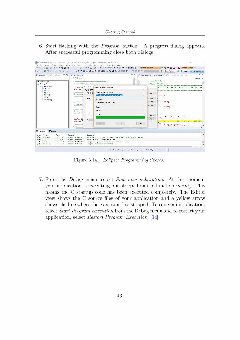
6. Start flashing with the Program button. A progress dialog appears.After successful programming close both dialogs.
Figure 3.14. Eclipse: Programming Success
7. From the Debug menu, select Step over subroutine. At this momentyour application is executing but stopped on the function main(). Thismeans the C startup code has been executed completely. The Editorview shows the C source files of your application and a yellow arrowshows the line where the execution has stopped. To run your application,select Start Program Execution from the Debug menu and to restart yourapplication, select Restart Program Execution, [14].
46

Chapter 4
Custom Simulink LibraryA Simulink library is a collection of blocks that can be used to create in-stances of those blocks in a Simulink model. It’s possible to create instancesof blocks from existing Simulink libraries, or to create custom libraries inorder to group and maintain instances of the own blocks in models. Theinstalled libraries can be accessed from the Simulink Library Browser andit’s not possible to modify them. Instead, if customized blocks want to becreated, the user can create custom library with custom blocks and add it tothe Library Browser.
In this chapter will be explained how to create a new Simulink Library (sec-tion 4.2) and fill it with custom block (section 4.3), with the help of someexample. A script is also provided (section 4.4) to deploy the Library in orderto find it in the Library Browser. The last paragraph (section 4.5) containsa description of all the basic blocks of the Aurix/Arduino-like BSP library.
4.1 Software resourcesThe following tools are needed:
• Matlab
• Simulink
47

Custom Simulink Library
4.2 Simulink Library Creation1. Start Simulink.
2. C lick on New pane → Blank Library.Now Simulink displays a new window, labeled as Library: untitled.
Figure 4.1. Blank Library
A blank library is now available and so it’s possible to drag basic block.The new library can appear in the Simulink Library Browser only if the
model property EnableLBRepository is on when the library is saved. Runthe following command in the MATLAB command prompt:
set_param(gcs,’EnableLBRepository’,’on’);Now the Library can be saved and named (e.g. Tricore_tc277c.slx).
4.3 Simulink Block GenerationMatlab Legacy Code Tool is used in order to create Simulink blocks: the tooltransforms existing C (or C++) functions into C MEX S-functions that canbe included in Simulink models.
48

4.3 – Simulink Block Generation
The following diagram illustrates a general procedure for using the LegacyCode Tool:
Figure 4.2. Diagram showing the correct use of Legacy Code Tool, [4]
An example is provided in order to better explain how to integrate anexisting C function into a Simulink model using Legacy Code Tool. It’spossible to create a MATLAB script containing the following commandsin the same order or to run the commands one by one on the MATLABcommand line:
1. def=legacy_code(’initialize’); initialize a Matlab struct def withfields that represent Legacy Code Tool properties;
49

Custom Simulink Library
2. def.HeaderFiles = {’header_file.h’}; the header file that containsthe function declaration;
3. def.SFunctionName = ’function_name’; specifies a name for theS-function;
4. def.OutputFcnSpec = ’return-spec = function-name(argument-spec)’; defines the function that the S-function calls at each time step,where
• return-spec defines the data type and variable name for the returnvalue of the existing C function. If the function does not return avalue, the return specification can be omitted or defined as as void.Otherwise the data type (i.e. uint8, uint16 ect) must be followed bya token of the form y1, y2, ..., yn, where n is the total number ofoutput arguments, [4];
• function-name is the function name and must be the same of theexisting C function name;
• argument-spec defines one or more data type (i.e. uint8, uint16 etc)and token pairs that represent the input, output, parameter, andwork vector arguments of the existing C function. The functioninput and output arguments map to block input and output portsand parameters map to workspace parameters, [4]. Token can havethe following forms:– Input — u1, u2, ..., un, where n is the total number of inputarguments;
50

4.3 – Simulink Block Generation
– Output — y1, y2, ..., yn, where n is the total number of outputarguments;
– Parameter — p1, p2, ..., pn, where n is the total number ofparameter arguments;
– Work vectors (persistent memory) — work1, work2, ..., workn,where n is the total number of work vector arguments.
An example is the following:def.OutputFcnSpec = ’uint8 y1 Dio_READ_Channel(uint32 p1),that returns as output one uint8 value and receives as input oneuint32 parameter.
5. legacy_code(’sfcn_cmex_generate’, def); generate an S-functionsource file from the existing C function.
6. legacy_code(’sfcn_tlc_generate’, def) generates the TLC file, neededto recognize the blocks of the created S-function from Embedded Coderduring the Code Generation Process.
7. legacy_code(’compile’, def); compile and link the S-function sourcefile into a dynamically loadable executable for Simulink.
8. legacy_code(’slblock_generate’, def); generate masked S-functionblocks that call the S-functions. The software places the blocks in a newmodel. From there you can copy them to an existing model.
The following script is an example used in order to generate the CCU6_PWM_Setupblock (figure 4.3):
Look at the def.HeaderFiles: in the creation of the basic blocks forAurix/Arduino-like board, it was necessary to add also the header file aswl_if.h containingthe basic type declaration in order to avoid compilation error and so "manual"intervention after the code generation.
51

Custom Simulink Library
Figure 4.3. CCU6_PWM_Setup block
Now it’s possible to create/edit a block mask. A mask is a custom userinterface for a block that hides the block’s contents, making it appear to theuser as a block with its own icon and parameter dialog box.
The following example is provided in order to better explain how to designa mask:
1. Right click on the created block and go to Mask-Edit Mask...The Mask Editor appears: it’s a dialog box that helps to create andcustomizes the block mask. It contains a set of dialog box, [4]:
• Icon & Ports pane helps you to create a block icon that containsdescriptive text, state equations, image, and graphics;
• Parameters & Dialog pane enables you to design mask dialog boxesusing the dialog controls in the Parameters, Display, and Actionpalettes;
• Initialization pane allows you to add MATLAB commands that ini-tialize the masked block;
• Documentation pane enables you to define or modify the type, de-scription, and help text for a masked block;
52
4.3 – Simulink Block Generation
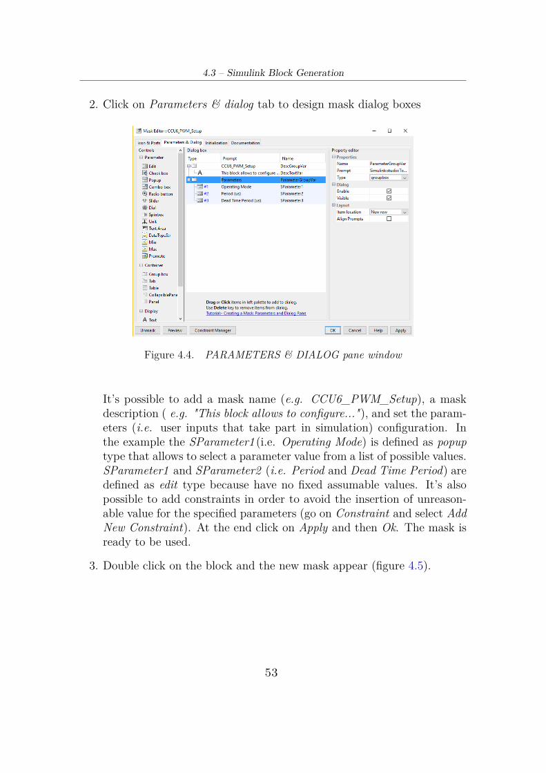
2. Click on Parameters & dialog tab to design mask dialog boxes
Figure 4.4. PARAMETERS & DIALOG pane window
It’s possible to add a mask name (e.g. CCU6_PWM_Setup), a maskdescription ( e.g. "This block allows to configure..."), and set the param-eters (i.e. user inputs that take part in simulation) configuration. Inthe example the SParameter1 (i.e. Operating Mode) is defined as popuptype that allows to select a parameter value from a list of possible values.SParameter1 and SParameter2 (i.e. Period and Dead Time Period) aredefined as edit type because have no fixed assumable values. It’s alsopossible to add constraints in order to avoid the insertion of unreason-able value for the specified parameters (go on Constraint and select AddNew Constraint). At the end click on Apply and then Ok. The mask isready to be used.
3. Double click on the block and the new mask appear (figure 4.5).
53

Custom Simulink Library
Figure 4.5. Block Mask
4.4 Add Libraries to the Library BrowserWhen the Custom Library is filled with all the needed Simulink blocks, it’stime to add the new Library to the Library Browser. This process is usefulin order to find easily the new blocks. In order to do so, the following scriptnamed as slblocks.m, must be run:
Open the Library Browser and refresh to see the new library. Right-clickthe library list and select Refresh Library Browser.
Custom library can be used in an identical way of any other Simulinklibrary: blocks are dragged from a library and placed into a model in theusual way.
54

4.5 – Aurix/Arduino-like Simulink Library Description
4.5 Aurix/Arduino-like Simulink Library De-scription
The Simulink Library for Aurix/Arduino-like board contains the basic blocksfor the configuration and use of GPIO Ports, ADC, CAN and PWM. Thefollowing subsections are introduced by a brief description of the modulesand followed by the description of all the basic blocks.
Figure 4.6. Aurix/Arduino-like Simulink library
4.5.1 GPIO PortsAurix TriCore TC277 has digital General Purpose Input/Output (GPIO)port lines which are connected to the on-chip peripheral units.
• PORT_00_34_Conf : This block allows to set the right pin config-uration of PORT 00 - 34 (figure 4.7).
55

Custom Simulink Library
Figure 4.7. PORT_00_34_CONF block mask
Parameters:
− PORTxx_PINxx allows to select the desired port pin;− Port Control Mode determines the port line functionality. When a
port line is configured as input, its hysteresis function can be ac-tivated/inactivated. When a port line is configured as output, itsspeed grade can be configured;
− Port Pin speed/Hysteresis allows to choose the speed grade whenport lines are configured as output, and determines if hysteresis isactive or inactive when port lines are configured as input;
− Port Pin Pad Level Select allows to select the pad level;− Port Pin initial level determines the port pin initial level.
• PORT_40_Conf : This block allows to set the right pin configurationof PORT40. PORT40 is an input port only (figure 4.8).
56

4.5 – Aurix/Arduino-like Simulink Library Description
Figure 4.8. PORT_40_CONF block mask
Parameters:
− PORT40_PINxx allows to select the desired PORT40 pin;− Port Control Mode determines the port line functionality;− Port Pin Analog or Digital allows to choose Analog or Digital input.
• Dio_READ_Channel: This block returns as output the digital value(unsigned 8 bits value) of the selected port pin.
Figure 4.9. Dio_READ_Channel block mask
57

Custom Simulink Library
Parameters:
− DIO_CH_xx_xx allows to select the desired digital channel.
• Dio_WRITE_Channel: This block receives as input the digitalvalue (unsigned 8 bits value) to be written on the port pin.
Figure 4.10. Dio_WRITE_Channel block mask
Parameter :
− DIO_CH_xx_xx allows to select the desired digital channel.
4.5.2 ADCAurix TriCore TC277 provides a series of analog input channels connected toa cluster of Analog/Digital Converters using the Successive ApproximationRegister (SAR) principle to convert analog input values (voltages) to discretedigital values.
Now only 5 ADCs channels have been configured: 2 channels of ADC group2 and 3 channels of ADC group 7 are available. The Port Pins configuredto work as ADCs inputs are: AnalogInA4 (ADC2.0), AnalogInA5 (ADC2.1),PORT00_PIN04 (ADC7.2), PORT00_PIN03 (ADC7.3) and PORT00_PIN02(ADC7.4). The Port Control Mode of the last three Port Pins must be con-figured as PORT_IN_TRISTATE. ADCs resolution is 12 bit.
• Adc_StartBackgroundConvertion: This block starts or stops thebackground conversions on all channels of all groups of the ADC module(figure 4.11).
58

4.5 – Aurix/Arduino-like Simulink Library Description
Figure 4.11. Adc_StartBackgroundConvertion block mask
Parameter :
− FALSE or TRUE in order to disable or enable the background con-version, respectively;
• Adc_Read: This block returns as output the converted value in bit(unsigned 12 bits) of the selected ADC group channel.
Figure 4.12. Adc_Read block mask
Parameter :
− ADC_IF_Group_Channel allows to select the desired ADC groupchannel.
59

Custom Simulink Library
4.5.3 CANCAN is an asynchronous serial bus system with one logical bus line. It hasan open, linear bus structure with equal bus participants called nodes. ACAN bus consists of two or more nodes.
WARNING: Before using CAN blocks the following command must bewritten in the Matlab console in order to import Can_tMsg type:
Simulink.importExternalCTypes(’aswl_if.h’)"aswl_if.h" file is located in theGetting_Started folder and it contains Can_tMsgtype definition.
An example of CAN message structure is the following:
Can_tMsg CanMsg= {.u8Node = 1,.u8Length = 8,.u8Data = {12,0,0,0,0,0,0,0,},.u8Standard_Extended = 0,.u32ID = 0x1800D0C0,};
• Can_Msg_Static: This block allows to create a Static Can_tMsg,i.e. a structure that cannot be modified runtime.
Figure 4.13. Can_Msg_Static block mask
60

4.5 – Aurix/Arduino-like Simulink Library Description
Parameters:
− 1st param indicates the node in which the MO has to Tx/Rx (WARNING:only MCAN_MO_NODE1 is configured);
− 2nd param represents the number of bytes to send (in the range of[1,8]);
− 3rd param is an array containing 8 data of 8 bits each to be Tx/Rx;− 4th param indicates if the ID is Standard or Extended;− 5th param indicates the ID of the MO (WARNING: the value must
be written in DECIMAL);
• Can_Msg_Dynamic: This block returns as output a Can_tMsgstruct according to the input values, so it’s possible to modify the mes-sage structure runtime. The order of the inputs values is the same usedfor Can_Msg_Static.
Figure 4.14. Can_Msg_Dynamic block mask
• Can_Msg_unpacked: This block allows to unpack a Can_tMsg. Theoutputs are respectively the number of useful bytes and a pointer to thearray of data.
Figure 4.15. Can_Msg_unpacked block mask
61

Custom Simulink Library
• Packed_Can_8bytes_array: This block receives as inputs 8 valuesof 8 bits each and returns as output a pointer to an array containingthose values.
Figure 4.16. Packed_Can_8bytes_array block mask
• UnPacked_Can_8bytes_array: This block receives as input a pointerto an 8 byte array and returns as outputs the values of each single byte.
Figure 4.17. UnPacked_Can_8bytes_array block mask
• Can_Send: This block allows to send a Can_tMsg received as input.
Figure 4.18. Can_Send block mask
• Can_Receive: This block receives as input a Can_Msg_Static and re-turns as output a Can_tMsg filled with the received values (figure 4.19).
62

4.5 – Aurix/Arduino-like Simulink Library Description
Figure 4.19. Can_Receive block mask
4.5.4 PWMPWM (i.e. Pulse-width modulation) is a type of digital modulation thatallows obtaining a variable average voltage depending on the ratio betweenthe duration of the positive and the negative pulse (duty cycle).
It’s possible to generate PWM using two different modules: ATOM andCCU6. The first one has to be used when single PWM has to be generatedwhile the second one when 3-phase PWM has to be generated.
ATOM
The ARU-connected Timer Output Module (ATOM) is able to generatecomplex output signals without CPU interaction due to its connectivity tothe ARU. In ATOM Signal Output Mode PWM (SOMP) configuration, theATOM submodule channel is able to generate complex PWM signals withdifferent duty cycles and periods, [8].
Now only the 7 channels of the ATOM0 has been configured. The relatedPort Pins are: PORT22_PIN01 (ATOM0_0), PORT22_PIN00 (ATOM0_1),PORT23_PIN05 (ATOM0_2), PORT20_PIN01 (ATOM0_3), PORT22_PIN03(ATOM0_4), PORT23_PIN00 (ATOM0_5) and PORT23_PIN01 (ATOM0_6).The Port Control Mode of the Port Pins must be configured asPORT_OUT_PUSHPULL_ALT_1.
• Atom_PWM_Channel_Config: This block allows to set the de-sired configuration for the Atom Channel (figure 4.20).
63

Custom Simulink Library
Figure 4.20. Atom_PWM_Channel_Config block mask
Parameters:
− ATOM0_Channel: Represents the ATOM0 channel that has to beconfigured;
− Period (us): Sets the PWM period. The value must be written inmicroseconds;
− Reset Type: Allows to select the reset source of CCU0 (CounterCompare Unit 0). It’s possible to reset counter register CN0 to 0 onmatching comparison with compare value CM0; or when signaled bythe trigger signal TRIG_[x-1] of the preceding channel [x-1];
− Trigger Output: Defines trigger output selection of module ATOM0_CHx;− Initial Signal Level: Defines if the initial Signal Level is Low or High.
• Atom_PWM_SetDutyCycle: This block allows to set the duty cy-cle (received as block input) of the selected PWM channel (figure 4.21).
64

4.5 – Aurix/Arduino-like Simulink Library Description
Figure 4.21. Atom_PWM_SetDutyCycle block mask
Parameter :
− ATOM0_Channel: Represents the ATOM0 channel that has to beconfigured.
CCU6
The CCU6 unit is made up of a Timer T12 Block with three capture/comparechannels and a Timer T13 Block with one compare channel.
The timer T12 block is the main unit to generate the 3-phase PWM signals.A 16-bit counter is connected to 3 channel registers via comparators, thatgenerate a signal when the counter contents match one of the channel registercontents. Besides the 3-phase PWM generation, the T12 block offers optionsfor dead-time control.
The related Port Pins are: PORT02_PIN00 (CC60), PORT34_PIN03(COUT60), PORT34_PIN04 (CC61), PORT02_PIN03 (COUT61), PORT33_PIN14(CC62) and PORT33_PIN15 (COUT62). The Port Control Mode of thePort Pins must be configured as PORT_OUT_PUSHPULL_ALT_7.
• CCU6_PWM_Setup: This block allows to configure the operatingmode of Timer T12, PWM period and dead-time period (figure 4.22).
65

Custom Simulink Library
Figure 4.22. CCU6_PWM_Setup block mask
Parameters:
− Operating Mode: It’s possibile to select among Edge Aligned Mode(timer T12 is always counting upwards) and Center Aligned Mode(timer T12 is counting upwards or downwards in order to have atriangular shape);
− Period (us): Sets the PWM period. The value must be written inmicroseconds;
− Dead Time Period: Sets the Dead Time Period. The value mustbe written in microseconds. No Dead Time insertion if the valueinserted is 0.
The CCU6 input clock is 100 MHz so the smallest value that can beentered for both periods is 0.01 us (refers to section 2.2.2).
• CCU6_PWM_SetDutyCycle: This block allows to set run-timethe duty cycle of the 3 PWM main channels. The inputs values has tobe double data types and represent the percentage of ON time (must bein the 0-100 range).
66

4.5 – Aurix/Arduino-like Simulink Library Description
Figure 4.23. CCU6_PWM_SetDutyCycle block mask
67

68

Chapter 5
Code GenerationTarget Language Compiler works with its target files and Real-Time Work-shop output to produce code. When generating code from a Simulink modelusing Real-Time Workshop, the first step in the automated process is to gen-erate a model.rtw file. This file includes all of the model-specific informationrequired for generating code from the Simulink model. model.rtw is passedto the Target Language Compiler, which uses it in combination with a set ofincluded system target files and block target files to generate the code.
In order to allow Simulink to find the custom System Target File usedto generate code for ERIKA RTOS, erika_rtos [15] folder (present insideGetting_Started folder) must be placed in the MATLAB root folder in-side \rtw\c. Moreover the Matlab folder present in the Getting_Startedlfolder must become the MATLAB working directory: it contains the S-function source files and the TLC files needed to recognize the blocks of theAurix/Arduino-like BSP Simulink library from Embedded Coder during theCode Generation Process. Without these informations, the Aurix/Arduino-like BSP blocks will not be recognized by the tool.
In this chapter will be explained how to create a Simulink model using theAurix Arduino-like BSP library and how to use Embedded Coder to gener-ate code, with the help of some examples (sections 5.2, 5.3). The generatedcode will be also analyzed in order to better understand the main part. Thelast section (5.4) is dedicated to the integration of the generated file in theproject.
69
Code Generation
5.1 Software ResourcesThe following tools are needed:
• Matlab
• Simulink
• Embedded Coder
5.2 First Example: Blinking LedGenerate a task that set ON and OFF a LED with a period of 1 s (500 msON and 500 ms OFF)
1. Start Simulink.
2. C lick on New pane → Blank Model and a new window appears.
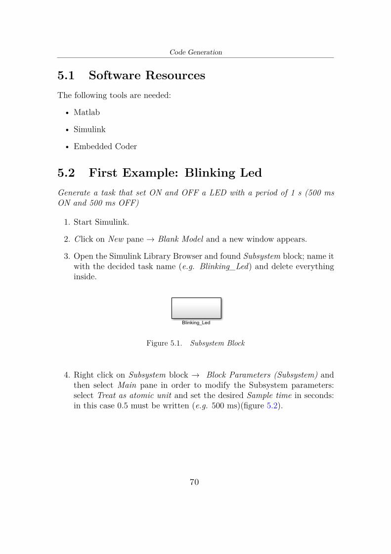
3. Open the Simulink Library Browser and found Subsystem block; name itwith the decided task name (e.g. Blinking_Led) and delete everythinginside.
Figure 5.1. Subsystem Block
4. Right click on Subsystem block → Block Parameters (Subsystem) andthen select Main pane in order to modify the Subsystem parameters:select Treat as atomic unit and set the desired Sample time in seconds:in this case 0.5 must be written (e.g. 500 ms)(figure 5.2).
70

5.2 – First Example: Blinking Led
Figure 5.2. Subsystem Block Parameters: Main pane
Now select the Code Generation pane and set the Function packagingto Nonreusable function and Function name options to Use Subsystemname.
Figure 5.3. Subsystem Block Parameters: Code generation pane
71

Code Generation
5. Drag inside the Subsystem block the Initialize Function from the SimulinkLibrary Browser and delete everything inside it except for the EventListener. This block is necessary because it’s used to "contains" all theinitialize block functions.
Figure 5.4. Initialize Function block
6. Open the Simulink Library Browser and find the Aurix Arduino-like BSPlibrary. Drag the PORT_00-34_Conf block in the Initialize Functionblock and configure the PORT10_PIN08 to work as PORT_OUT_PUSHPULL_GPIO.Look at the figure 5.5 to understand how to configure the other param-eters.
Figure 5.5. Initialize Function: Port configuration
7. Inside the Subsystem block the Dio_WRITE_Channel block is instan-tiated and configured to write a value on the desired channel, in thiscase the DIO_CH_10_08. This block is connected with some Simulinkblocks: Memory block with 0 as initial condition, NOT block in orderto complement the "memory" value and Data Type Conversion block toconvert the value to the right data type (figure 5.6).
72

5.2 – First Example: Blinking Led
Figure 5.6. Model Design
8. Once the model is created, click on (i.e. Model Configuration Pa-
rameters) to configure the Solver Type and set the System Target File:
− Solver : Select Fixed-step in Solver selection;− Hardware Implementation: Select Infineon in Device vendor and
TriCore in Device type; it’s useful only to define the correct datatype size;
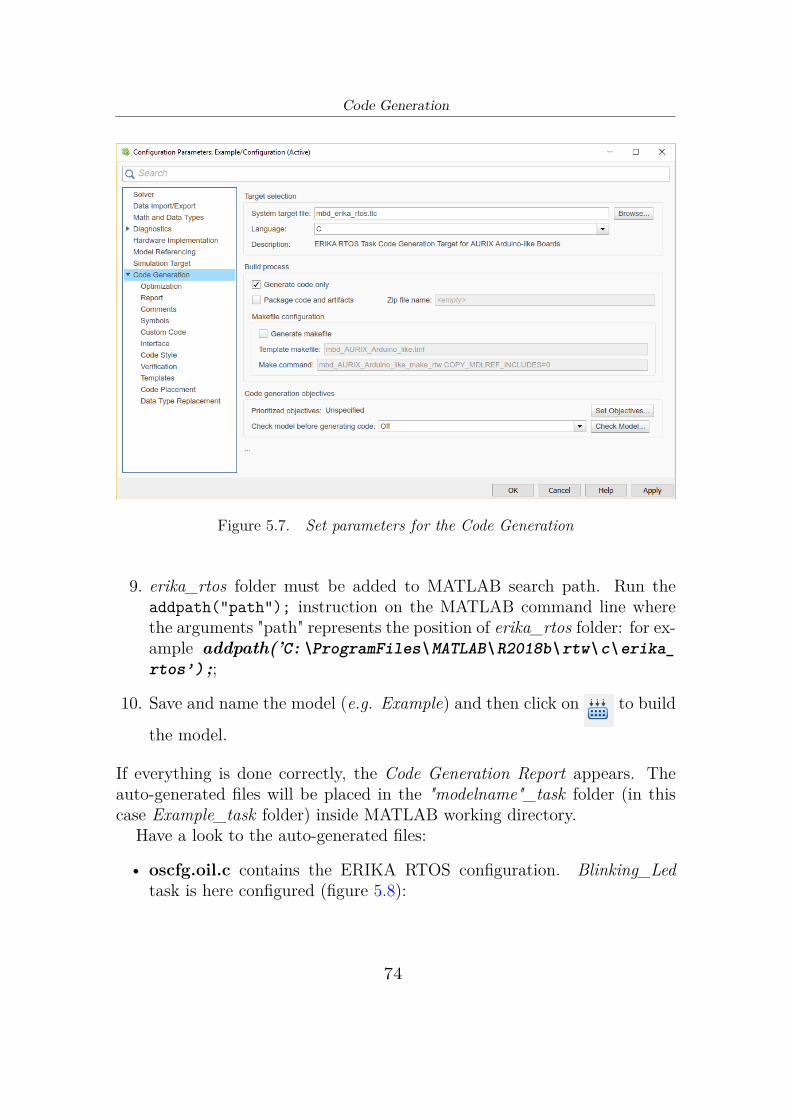
− Code Generation: Set System Target File as mbd_erika_rtos.tlc,select Generate code only and deselect Generate makefile (figure 5.7).
73
Code Generation
Figure 5.7. Set parameters for the Code Generation
9. erika_rtos folder must be added to MATLAB search path. Run theaddpath("path"); instruction on the MATLAB command line wherethe arguments "path" represents the position of erika_rtos folder: for ex-ample addpath(’C:\ProgramFiles\MATLAB\R2018b\rtw\c\erika_rtos’) ;;
10. Save and name the model (e.g. Example) and then click on to build
the model.
If everything is done correctly, the Code Generation Report appears. Theauto-generated files will be placed in the "modelname"_task folder (in thiscase Example_task folder) inside MATLAB working directory.
Have a look to the auto-generated files:
• oscfg.oil.c contains the ERIKA RTOS configuration. Blinking_Ledtask is here configured (figure 5.8):
74

5.2 – First Example: Blinking Led
Figure 5.8. Oil file: Task configuration
The ALARM is configured in order to generate the EVENT Sched-uleEvent_Blink_LED that wake up the task every CYCLETIME (inthis case 500 ms).
Figure 5.9. Oil file: ALARM configuration
• OSTasks0_ErikaOs.c contains the extented task implementation (fig-ure 5.10). Task is waiting for the "arrive" of the event configured in the.oil file, so in this case it is the ScheduleEvent_Blink_LED event gener-ated by the ALARM: the step-function (i.d. Example_Blinking_LED())is called every 500 ms.
75

Code Generation
Figure 5.10. Extended task implementaion
• The main function in Example.c are the initialize function ( that "calls"all the function blocks inside the Initialize Function) Example_Blinking_LED_Init() (figure 5.11) and the Example_Blinking_Led() (figure 5.12)corresponding to the step function
Figure 5.11. Init Function
76

5.3 – Second Example: 3-phase PWM generation
Figure 5.12. Step Function
• Example.h and Example_private.h contain the declaration of allthe generated functions while rtwtypes.h and Example_types.h con-tain the definition of the basic types. It’s not important to analyze thisfile because are useful only to avoid compilation error after the integra-tion in the Project.Read the last section 5.4 in order to understand how to integrate thegenerated files in the proect.
5.3 Second Example: 3-phase PWM genera-tion
Generate a center-aligned 3-phase PWM with a period of 100 us and deadtime of 30 ns. The value of the duty cycle of the 3 main channels, changeaccording to the value returned by one of the ADCs of the target board: when-ever the value is greater than a threshold of 2702 (i.e. 3.3 V), a 3-phase PWMwith duty cylce of 30% is generated otherwise with a duty cycle of 70%.
1. Start Simulink.
2. C lick on New pane → Blank Model and a new window appears.
3. Open the Simulink Library Browser and found Subsystem block; name
77

Code Generation
it with the decided task name (e.g. PWM_Gen) and delete everythinginside.
Figure 5.13. Subsystem Block
4. Right click on Subsystem block → Block Parameters (Subsystem) andthen select Main pane in order to modify the Subsystem parameters:select Treat as atomic unit and set the desired Sample time in seconds:in this case 0 must be written because the task has to be activated byTimer12 Period Match (section 2.2.2)
Figure 5.14. Subsystem Block Parameters: Main pane
Now select the Code Generation pane and set the Function packagingto Nonreusable function and Function name options to Use Subsystemname(figure 5.15)
78

5.3 – Second Example: 3-phase PWM generation
Figure 5.15. Subsystem Block Parameters: Code generation pane
5. Drag inside the Subsystem block the Initialize Function from the SimulinkLibrary Browser and delete everything inside it except for the EventListener. This block is necessary because it’s used to "contains" all theinitialize block function
Figure 5.16. Initialize Function block
6. Open the Simulink Library Browser and find the Aurix Arduino-like BSPlibrary. Drag six PORT_00-34_Conf blocks in the Initialize Functionblock and configure the PORT02_PIN00, PORT34_PIN03, PORT34_PIN04,PORT02_PIN03, PORT33_PIN14, PORT33_PIN15 to work asPORT_OUT_PUSHPULL_ALT_7. In this way pin P02.00, P34.04and P33.14 are configured to be the CC60, CC61, CC62 outputs respec-tively (the 3-phase PWM main channel) while P34.03, P02.03, P33.15are configured to be COUT60, COUT61, COUT62 outputs respectively(the 3-phase PWM complementary channel). Look at the figure 5.17 to
79

Code Generation
understand how to configure the other parameters.
Figure 5.17. Initialize Function: Port configuration
Figure 5.17 shows how to configure the PORT02_PIN00 and the con-figuration process must be repeated for the other five port pin.
Now drag Adc_StartBackgroundConvertion block and select TRUE inorder to enable the Adc background convertion (figure 5.18).
Figure 5.18. Initialize Function: Start Adc Background Convertion
In order to configure the CCU6 Operating Mode, PWM period and deadtime value, the CCU6_PWM_Setup must be instantiated (figure 5.19)
80

5.3 – Second Example: 3-phase PWM generation
Figure 5.19. Initialize Function: CCU6 configuration
7. Inside the Subsystem block the Adc_Read block is instantiated and con-figured to reaturn the value converted by the desired Adc group channel,in this case the ADC_IF_GR2_CH0. This block is connected with theSwitch Simulink block with a threshold set to 2072: the inputs of thisblock are two Constant double value 30 and 70. The output of theswitch is used to set the Duty Cycle of the 3-phase PWM by using theCCU6_PWM_SetDutyCycle block.
Figure 5.20. Model Design
8. Once the model is created, click on (i.e. Model Configuration Pa-
rameters) to configure the Solver Type and set the System Target File:
− Solver : Select Fixed-step in Solver selection;
81

Code Generation
− Hardware Implementation: Select Infineon in Device vendor andTriCore in Device type; it’s useful only to define the correct datatype size;
− Code Generation: Set System Target File as mbd_erika_rtos.tlc, se-lect Generate code only and deselect Generate makefile (figure 5.21).
Figure 5.21. Set parameters for the Code Generation
9. erika_rtos folder must be added to MATLAB search path. Run theaddpath("path"); instruction on the MATLAB command line wherethe arguments "path" represents the position of erika_rtos folder: for ex-ample addpath(’C:\ProgramFiles\MATLAB\R2018b\rtw\c\erika_rtos’) ;;
10. Save and name the model (e.g. Example2 ) and then click on to
build the model.
If everything is done correctly, the Code Generation Report appears. Theauto-generated files will be placed in the "modelname"_task folder (in thiscase Example2_task folder) inside MATLAB working directory. Have a lookto the auto-generated files:
82

5.3 – Second Example: 3-phase PWM generation
• oscfg.oil.c contains the ERIKA RTOS configuration. PWM_Gen taskis here configured:
Figure 5.22. Oil file: Task configuration
• OSTasks0_ErikaOs.c contains the extented task implementation (fig-ure 5.23). Task is waiting for the "arrive" of the event configured in the.oil file, so in this case it is the ScheduleEvent_Period_Match eventgenerated by the CCU6 Timer12 (section 2.2.2): the step-function (i.e.Example2_PWM_Gen()) is called every period match, so in this caseevery (PWM period/ 2 - 1) us because the selected CCU6 OperatingMode is Center Aligned (section 2.2.2).
83

Code Generation
Figure 5.23. Extended task implementaion
• The main function in Example.c are the initialize function ( that "calls"all the function blocks inside the Initialize Function)Example2_PWM_Gen_Init() (figure 5.24) and the Example2_PWM_Gen()(figure 5.25) corresponding to the step function.
84

5.3 – Second Example: 3-phase PWM generation
Figure 5.24. Init Function
Figure 5.25. Step funtion
• Example2.h and Example2_private.h contain the declaration of
85
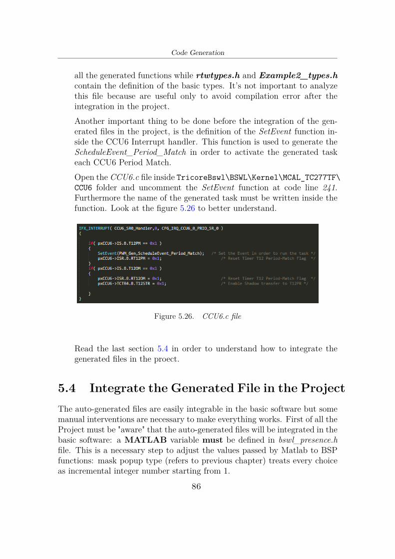
Code Generation
all the generated functions while rtwtypes.h and Example2_types.hcontain the definition of the basic types. It’s not important to analyzethis file because are useful only to avoid compilation error after theintegration in the project.Another important thing to be done before the integration of the gen-erated files in the project, is the definition of the SetEvent function in-side the CCU6 Interrupt handler. This function is used to generate theScheduleEvent_Period_Match in order to activate the generated taskeach CCU6 Period Match.Open the CCU6.c file inside TricoreBswl\BSWL\Kernel\MCAL_TC277TF\CCU6 folder and uncomment the SetEvent function at code line 241.Furthermore the name of the generated task must be written inside thefunction. Look at the figure 5.26 to better understand.
Figure 5.26. CCU6.c file
Read the last section 5.4 in order to understand how to integrate thegenerated files in the proect.
5.4 Integrate the Generated File in the ProjectThe auto-generated files are easily integrable in the basic software but somemanual interventions are necessary to make everything works. First of all theProject must be "aware" that the auto-generated files will be integrated in thebasic software: a MATLAB variable must be defined in bswl_presence.hfile. This is a necessary step to adjust the values passed by Matlab to BSPfunctions: mask popup type (refers to previous chapter) treats every choiceas incremental integer number starting from 1.
86

5.4 – Integrate the Generated File in the Project
The OIL file, the OS_Tasks0_ErikaOs file, the model C file and all theheader files have to be copied and pasted in the right Basic Software folder:
− oscfg.oil.c must be renamed in oscfg.oil and copied inside the TricoreBswl\PrjCfg\ErikaOsCfg\OilFile folder
− OS_Tasks0_ErikaOs inside TricoreBswl\BSWL\OS\OsTask_ErikaOs\cpu0 folder
− all the other files in TricoreBswl\ASWL except for ert_main.c that isnever used.
The model initialize function and the header file that contains its declarationmust be manually added in the cpu0_main.c file: the correct code locationis indicated by the comments in the file. Look at the following code (fig-ure 5.27 refers to First Example (section 5.2) to better understand where theheader file Example.h (i.e. the header file containing the delcaration of allthe generated functions) and the initialize function Example_initialize() hasto be added.
Figure 5.27. cpu0_main.c file
Now it’s time to generate configuration files for ERIKA RTOS and tocompile the operating system (section 3.2.3). Then it’s the turn to import
87

Code Generation
the Project in Eclipse (section 3.2.2) in order to build it (section 3.2.4) andprogram and debug the target board (section 3.2.5).
88

Bibliography[1] Broy M., Kirstan S., Kremar H., Schätz B., Zimmermann J., What is the
benefit of a model-based design of embedded software systems in the carindustry?, Germany
[2] The Mathworks Inc, How Small Engineering Teams Adopt Model-BasedDesign, The Mathworks
[3] Kautz O., Roth A., Rumpe B.,Achievements, Failures, and the Future ofModel-Based Software Engineering
[4] The Mathworks Inc, Simulink® Developing S-Functions, The Mathworks[5] The Mathworks Inc, Target Language Compiler™ For Use with Real-Time
Workshop®, The Mathworks[6] The Mathworks Inc, Real-Time Workshop® For Use with Real-Time
Workshop Embedded Coder, The Mathworks[7] The Mathworks Inc, Embedded Coder® User’s Guide, The Mathworks[8] Infineon Technologies AG, TC27x C-Step, Infineon Technologies[9] Violante M., Operating Systems for Embedded Systems - Course Slides,
a.y. 2016/2017[10] Evidence S.r.l., ERIKA Enterprise Manual Real-time made easy, version:
1.4.4, 2012[11] OSEK, OSEK/VDX - Operating System, version: 2.2.3, 2005[12] OSEK, OSEK/VDX - System Generation - OIL: OSEK Implementation
Language, version: 2.5, 2004[13] Future Technology Devices International Limited, User Guide for FTDI
FT_PROG Utility, 2016[14] HighTec, A Getting Started to Free TriCore ™ Entry Tool Chain, High-
Tec[15] Cottone F., A Model-Based Design Embedded Software Development
Methodology for an OSEK-Compliant RTOS - Master Thesis, Politecnicodi Torino, Luglio 2019
89