
model 225p/23op ultrasound - MR Chattanooga, LLC
52
r rn elect' OPERATOR'S MANUAL O INSTALLATION O OPERATION O MAINTENANGE O PARTS P.lrr.73778 BEV C I MODEL 225P/23OP ULTRASOUND y
-
Upload
khangminh22 -
Category
Documents
-
view
1 -
download
0
Transcript of model 225p/23op ultrasound - MR Chattanooga, LLC

rrn elect'
OPERATOR'S MANUALO INSTALLATION
O OPERATIONO MAINTENANGE
O PARTS
P.lrr.73778 BEV C
I
MODEL 225P/23OPULTRASOUND
y
table of contents
Description page
F O R E W O R D . . . . . . . . . . . . 2
WARRANTY INFORMATION . , . . 2
S A F E T Y I N S T R U C T I O N S . . . . . . 3S P E C I F | C A T | O N S . . . . . . . . 4U L T R A S O U N D T H E R A P Y I N D I C A T I O N S . . . . 5U L T R A S O U N D T H E R A P Y C O N T R A I N D I C A T I O N S . . . , . . 5INTELECT 225PI23OP OPERATING CONTROLS . . . . . . 6O P E R A T I N G P R O C E D U R E . . , . . 7D E S C R I P T I O N O F T H E U L T F I A S O U N D F I E L D . . . . . 8PLOT OF ULTRASOUND F IELD SPATIAL D ISTRIBUTIONS . . . g
A B B R E V I A T I O N S . . . . . 9T R O U B L E S H O O T | N G . . . . . . . . 1 OM A I N T E N A N C E A N D S E R V I C E I N S T R U C T I O N S . . . . . , . 1 1U L T R A S O U N D C A L I B R A T I O N . . . . . . , 1 2COMPONENT LOCATION, C IRCUIT BOARD . . . . . 17 , 19 , 21 , 29PARTS Ltsr . . . . 18, zo, zz, 24SCHEMATICS 25-39

foneword
This manuar has been prepared for the owners and operators of the Intelect@Model 225Pl23oP'
It contains general instructions on operation, safety pnactices' maintenance and parts
information. In order to obtain maximum rife and eff iciency from your Model zzsP/z3oP and to
aid in the safe operation of the unit, read and undenstani this manuar thoroughry and become
tota*y famiriar with the contrors on the paner and the a.ppricator that comes with the unit before
operating i t . The specif ications put rortn in this manuar were in effect at the t ime of publication'
However, owing to Chattanooga Co.f,o."t ion'. pol icy of continuous improvement' changes to
these specif ications may be made aL any t ime without obrigation on the part of chattanooga
Conponation.
full one Year wanrantY
chatranooga corporation (.,company") warrants that rnterect@Model 225Pl23oP ("Product"l is
free of defects in material and workmanship'
This wannanty shall nemain in effect for one (1) year fnom the date of the original consumer'
punchase of this product and extend= ,o -ny owner of the product during the warnanty peniod'
l f this Product f ai ls to f unction during the one year.wanranty period because of a defect in
mater iar and workmanship, companyi . ,n" set t ing dearer wi i r reprace on repai r th is Product
without change within a period of thir iy isor o"y= fnom the date on which rhe defective Product
is neturned to the company or the deirer. company or the dearer wii l ship the repracement or
the nepaired Product to the consumer's residence'
THIS WARRANTY DOES NOT COVEFI:
1 . Replacement parts on labor furnished by anyone othen than the company' the dealer or an
apProved ComPanY serv ice agent '
2. Defects or damage caused by labor furnished by someone other than the company' the
dealen or an approved Company service agent' rn of the owner during
3. Any malfunction or fai lure in the Product while i t ls in the possesslc
the warranty period if the malfunction or fai lure is not caused by a defect in material and
workmanship or i f the malfunction or fai lure is caused by unreasonable use, including the
fa i l u re top rov ide reasonab |eandnecessa ryma in tenance .
COMPANY SHALL NOT BE LIABLE FOR INCIDENTAL OR CONSEOUENTIAL
DAMAGES TO PROPERTY OR BUSINESS.
some states do not al low the exclusion or l imitation of incidental or consequential damages' so
the above limitation or exclusion may not apply to you'
TO OBTAIN SERVIcE from the company or the selling dealer under this warranty' the I
owner must do or abide by the following:
1. A written claim must be made within the warranty period to the company or the selling
dealer. lf the claim is made to inr corp"ny, written claim should be sent to: P'O' Box
A?ET, lO lMemor ia lD r i ve ,Cha t tanooga 'Tennessee374O5 '2. The Product must be returned to the company or the selling dealer by the owner'
This warranty gives you specific legal rights, and you may also have other rights which vary from
state to state.
company does not authorize any person or representative to create for it any o'her obligation
or liability in connection with the sale of this pnoduct. Any representative or agreement not
contained in the warranty shall be void and of no effect'

safety instrucdons
1. wABttllluc: Explosion hazard if used in the presence of flammable anesthetics'
z. wA.ttrttc: For continued pnotection against fire hazard replace fuses only with ones of the
same type and rating'
3. Read, understand and practice the safety and operatinginstructi"-1"-'-51"* the limitations and
hazards associated with the unrasouno. bb""ru" m" "Jt"ty and operationar decars praced on the
unit.
4 .Grounding-Makecer ta in that theuni t ise|ectn ica| |ygroundedbyp|uggingrntoaneIect r ica|out le twirh a ground ilr,,.,in"f recepracle iU-grornO oril"tl. Follow ine National Electric Code'
5. The Intelect Model 225PI23OP should not be connected bo any othen device when in use'
6. CAUTIOIU: Federal law restr icts this device to sale by, on on the orden of , a physician or l icensed
pnactit ioner.
7 . The genenator shourd be routinery checked bef ore each use to determine that al l controls f unction
norma | | y ;espec ia | | y tha t the lNTENS|TYcon t ro |doesp roper | yad jus t the in tens i t yo f theurtrasonic powen output in a stabre mannen. ntso oetlnmine that the TREATMENT TIME control
does actually terminate ultnasonic output power when the t imer neaches zero'
g. CAUTlOlt l :-Use of controls or adjustments or performance of procedures other than those
specif ied henein may result in hazandous exposure to ultrasonic energy'

specifications
Frequency - 1 .O MHz t 5%
Duty Cycle - 1OO% (continuous model50% t 10% (Pulse model20% t 1O% (Pulse mode)
pulse Dunation - 5 msec + 20% (50% duty cycle pulsed mode)
2 msec t 20% t20% duty cycle pulsed model
Pulse Repi t i t ion Rate - 1OO Hz t 20%
Ultrasonrc Powen - variable from 1 watt to 20 watts, Intelect 23OP
variable from 1 watt to 1O watts, lntelect 225P
Output Meten Accuracy- + 2O"/" ffor any output above 1O"/o of maximum)
remporar Peak/Averase Intensitv Ftatio- 3,1: i }}y;lZi#f !:il !I:i:.
Output:1 . cont inuous - 1 MHz s ignal that is on as long as the t imer ls runnlng '
Z. pu lse - 1 MHz s ignal modulated 1OO% by the 1OO Hz rectangular wave wi th the se lected
Duty cycle.
Timer Accuracy:1 . Less than o.5 minutes for sett ings less than 5 minutes
2. 1O% for set t ings f rom 5 minutes to 1O minutes3. 1 minute for set t ings greater than 1O minutes
Applicator:1 . Ef fect ive nadiat ing area- .8.5 CM2 + 1.5CM2, In te lect 23OP ( t 18" / " )
4.O CMz + 1.O CMz, Intelect 225P ft 25"/")
2. Maximum beam non-uniformity ratio - 6.0:1
3. Beam type - col l imating
lnput powen requirements:(Domestic) 12OV + / 60 Hz 1O% 3/4 Amps(ExPort) Z?Ov + / 50 Hz 10% 3/8 AmPs
Size - 12" wide x 5" high x 1?" deep (not including handle)
We igh t - 11 .5 l bs .

indications for ultrasound therapy {'
some indications for the use of urtrasound incrude adhesive capsuli tus, bursit is with sl ight
carcif ication, myosrt is, soft t issue i"r". i"", shortened tendons due to pas-t inluny, healing scar
rissue and pranrar warrs. Urrnasound is an effici"n, roi"iil;+ 1"g for the treatment of all
rypes of ioint "onr."ttu.es resulting it; ""psular tightness and scarning' Ultrasound is the
modatiry of choice to obtain th"."pe,ti" r"""rl ot neatinf *itnl1 ?od-y-:tl'"tures covered by
thick rayers of sotJii==r". Neither shortwave or microiave diathermy is able to heat these
underlying structures to produce t"" ' i t" comparable to ultrasound'
contraindications fon ultnasound therapy '€
Urtrasound sHouLD Nor BE usED over the eyes on the r-eproductive organs. Also ultrasound
sHouLD NOT BE USED over a pregnant utenus. other- contraindications incrude acute inf ection or
septis, deep vein thnombosis, or arterial disease, and over anesthetized areas or condit ions that
cause impairment of sensations, such as chemotherapy. Ultrasound ls NoT TO BE USED over
cancerous lesions'
REF: Lehmann, J 'F. , Therapeut ic Heat and Co|d; 13: 367-378, 1972.
2 .
. J .
operating controls
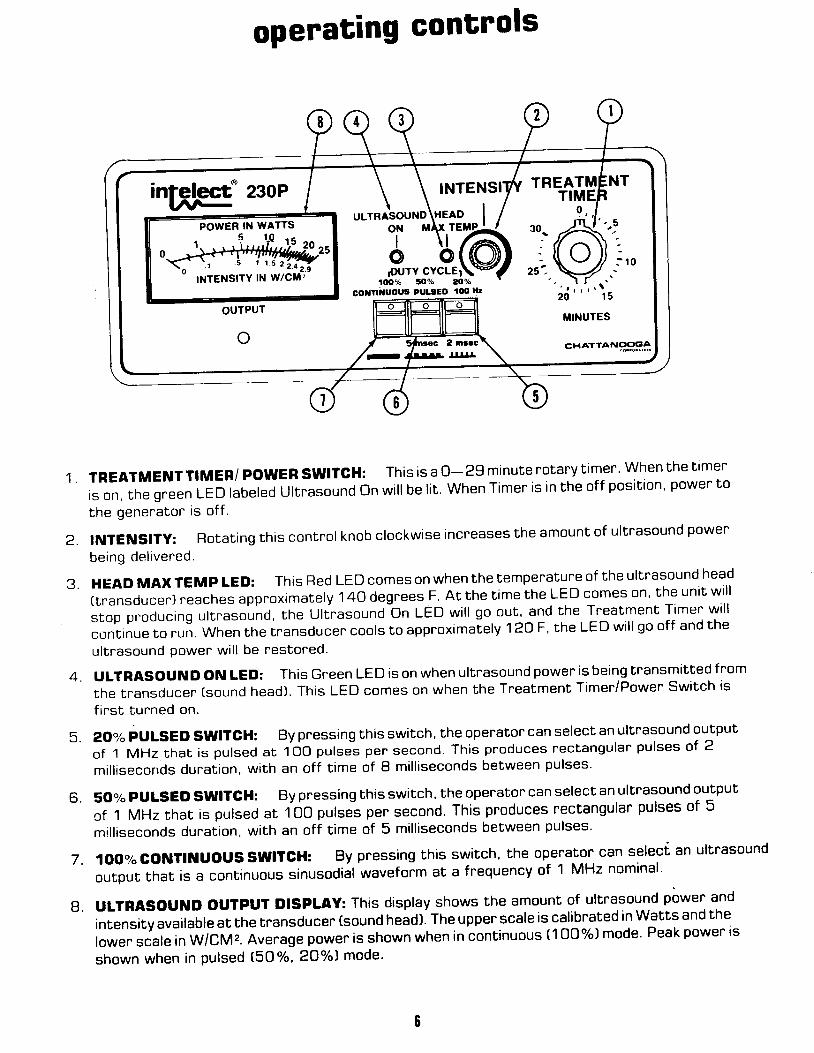
TREATMENT TrMER/ powER swrrGH: This is a 0- 2g minute notary t imer. when the ttmer
is on, the green LED labeled Ul t rasound on wi l l be l i t . when Timer is in the of f pos i t ion ' power to
the genenaton is off.
INTENSITy: Rotating this control knob clockwise increases the amount of ultrasound power
being del ivered.
HEAO MAX TEMp LED: This Red LED comes on when the tempenature of the ultrasound head
[ tnansducer) reaches approx imate ly 140 degrees F. At the t ime the LED comes on ' the uni t wi l l
s top pnoducing ut t rasound, the Ul t rasoundbn LED wi l l go out , and the Treatment T imer wi l l
con5inue to run. When the t ransducer cools to approx imate ly 120 F, the LED wi l l go of f and the
ultrasound power wil l be restored.
uLTRASOUND ON LED: This Green LED is on when ultrasound power is being transmitted from
the transducer [sound head]. This LED comes on when the Tr"eatment Timer/Power Switch is
f inst turned on.
AO% pULSED SWITGH: By pressing this switch, the operator can select an ultnasound output
of 1 MHz that is pulsed at 1OO putse-s per second. This pnoduces rectangular pulses of 2
mil l isecorrds duration, with an off t ime of I mil l iseconds between pulses'
50% pULSED SWITGH: By pr essing this switch, the operator can select an ultrasound output
of 1 MHz that is pulsed at 100 putse-s pen second. This produces rectangular pulses of 5
mil l iseconds duration, with an off t ime of 5 mil l iseconds between pulses'
4 .
5 .
6 .
7 . 1OO% CONTIi lUOUS SWITCH: By pressing this
output that is a continuous sinusodial waveform atswitch, the operator can select an ultrasound
a frequency of 1 MHz nominal.
g. uLTRASOUNO OUTPUT DISPLAY: This display shows the amount of ultrasound power and
intensity available at the transducer (sound head). The upper scale is cal ibnated in Watts and the
lower scale in w/cM2. Avenage power is shown when in continuous (100%) mode. Peak power ts
shown when in pulsed tsO%, 2O%) mode'
intelect= 230PU /l- ,.r*Aor"o\r9lg..^ |oN lrAx rErrP-
too% to"h 20corrtiuous PULaED loo ll,

operating pnocedure
1. Plug the unit into a properly grounded outlet of the proper voltage and line fne-quency. Flefer to the Nameplate on the rear of the unit'
2. Operator should adjust the applicator handle to the desired posit ion. Tighten the
thumbscrew securelY.
3. Set the Tneatment Timer at the O (Off) position, and the lntensity control at the(fully counter clockwise position).
4. At this point you may begin the treatment by applying Intelect Ultrasound Gel to the
area of the patient to be tneated.
5. Turn the Treatment Timer knob to the desired breatment time by turning the knob
beyond the desired time and then backing up to the desined time.
6. Select the operating mode by pressing the appropriate switch. Switch 5 for the
2oolo Pulsed Mode, Switch 6 for the 5O% Pulsed Mode, or Switch 7 for the 1OO7"
Continuous Mode. The 2oolo Pulsed Mode is automatically selected upon actuation
of the timer.
7. You should then place the applicator in contact with the patient 's body with a f irm
uniform pressure. You must keep the applicaton moving during the treatment'
Failure to keep the applicatop moving may result in hazardous exposune to the
ultnasound energy.
51 Adjust the Ultrasound Output by turning the Intensity control t2) until you reach the
desired output. Use the Upper scale for Watts and Lower scale foFW/CmZ.
g. lf you need to intemupt the tneatment for any reason, tunn the Treatment Timer to
thl off posit ion (Bell wil l r ing). To nesume treatment repeat steps 4-8'
1O. At the end of the treatment, the end of tneatment bell wil l sound and the unit wil l
shut off.
intelect' 23oPU rrr-
INTENSITYTREATMENTTIMER
9 , ,POWER IN WATTS
ItTEtStTY tt w/CU2
OUTPUT
30.
zst-
o 3 nrc 2 nrc-- aBl|flr
trINUTES
CHATTANC'CIOA
uLrRAsouND HEAD I3,,:ir@ro% !lo% ao%
coxflruoul Plrltco too llt

description of ultrasonic field
The spatiar distribution of the nadiated fierd is essentiaily a coilimated beam of ultrasonlc enengy
having a cross-se"t ion"r area of a.s cMrlor the t o cn,i sound head when measured at a point 5
millim-eters from the tnansducer face'
The energy distr ibution within the radiated f ield is2.4W/CM2 maximum' and takes a general ly conic
shapehav ingdecneas ing in tens i t y " ,p .og . " " s i ve | y inc reas ingd is tance f romthe faceo f thetransducer.
This f ierd dis*ibution appries for the radiation emitted into the equivarent of an inf inite medium of
dist i l led degassed water'at 30 deg. c. and with l ine voltage variat ions in the range of + 1 0 percent of
the rared rine vortage. The ur*asonic t ieto spatiat oistr iuwion of the 5 CM2 sound head is essential ly
ih" ="r" as the rlEto of the 1o CM2 sound head'
PLOT OF ULTRASONIC FIELD SPATIAL DISTRIBUTION10 cM2
1OOo/"
9O"/"
8O"/"
TOYo
60"/"
10,|,%
9OV"
8O"/"
7O"/"
60o/"
5O"/"
PERcENT
PowEB
oF
4Oo/"
3O"/"
20o/o
1Oo/"
20 toRADIAL DISTA]IIGE
o 1 0 2 0FROM GEilTER OF APPUCATOB HEAD
II!LUIIETERS

PLOT OF ULTRASONIC FIELD SPATIAL DISTRIBUTION5 CMz
1OO"/"
90%
BOV"
7Oo/o
6OV"
S,OY"
4O"/"
3O"/"
2O"/"
1O"/"
1OO"/"
9O"/"
8OV"
7O"/"
6,tJ%
5O"/"
4O"/"
30%
ztJ%
1O"/"
o%
PEBcENT
oF
PoWEROo/o
2 0 1 0 0 1 0 2 0
DISTANCE FROM CENTER OF APPLIGATOR HEADMILLIMETERS
RADIAL
abbreviationsThe following abbreviations are used on the applicator heads of the lntelect 225P1?3OP.
Area: Effective Radiating Area
Coll. :Coll imating
BNR= Beam Non-Uniformity Ratio
Freq. = Frequency
I \ / \ / \
I \-
\
I
l \I

The following problems and solutions afe presented to assist you in solving some of the
. rob lems tha tcou ldposs ib l yhappen toyour ln te lec tazsPor23OP '
Pnoblem
No Powen to unit
Unit has Power but noUltnasound outPUt'
r lS output meter on lY,dicates about half-scale
or less when INTENSITY isset at maximum.
When un i t i s eneng izedH E A D M A X . T E M P L E D(Red) l i gh ts and beePersounds.
Timer will not set
trouble shooting
1) Uni t not P lugged in '2l No power to the receptacle'
3) Input fuse blown.
4l Internal fuse blown.
5) Loose connection inside uni
6) Applicator cable loose'
7) Applicator cable broken'
8) Oscil lator detuned'
9) Crystal damaged.
1O) Shorted aPPlicator cable
1 1) Water in aPPlicator head.
12) Timer knob loose
Action To Take
1) Plug in uni t '2) ChJck for tripped circuit breaker
or blown fuse on the facilitY
circuit.
3) Change the 3/4 amP' ( '315 amP)
slo-blo fuse located in the Powerentry necePtacle on the back of
ine unit. (3/8 amP for 22O V units')
Remove Power cord prior to changing
the fuse.
$ Check the 3 amP and 1/2 amp
picofuses on the Power suPPlY
board. This should be done onlY
by a Oualified Senvice Technician'
5) Check intennal connections for
proper seating of plugs in
necePtacles and for broken wires'
6) Fteplug cable into the shield box'
7) Replace cable onlY with the same
type of cable.
8) Recalibnate.
9) Replace transducer head in theapplicator and recalibrate'
1O) Check the cable wibh an'ohmmeter'lf the cable is shorted, rePlace
the cable with the same tYPe'
1 1) Remove the transducer headand dry out the inslde of theapplicator' lf the O-ring isdefective, rePlace it' Consultthe factory.
121 Remove cap on the kndb and
tiglften the collet. Rotate the
timer fullY clock-wise and thenlossen the collet so that theknob is free. Align the whiteline on the knob with the 29
min. mark on the timer scale
and r^e-tighten the knob collet'Perform section 4 of calibrationprocedure.
l 0

1 .
2 .
maintenance and seFuice instructions
To ful ly maintain compliance with Federal Regulation Tit le 21 e1 CFRI this unit must be
recalibrated annually. l t is recommended that al l Chattanooga Corporation Ultrasound
products be returned to the factory or an authorized servicing dealer for repains or
recalibnations. l t is also necommended after the replacement or repair of any majon
component. (See Section for Calibration Pnocedures' l:;
The fol lowing itehs should be checked at least monthly to insure proper operation of this
unit:.1 Power cord and plug. check to make sure the cord is not fnayed, kinked or has torn or
cut insulation.
.2 Transducer (applicatorJ Cable. Check to make sure the cable is f lexible, f nee of kinks,
not frayed and that insulation is intact '
,3 Tnansducen (applicator) Handle. Check to make sure thaL it is not cracked or broken'
.4 Transducen (applicator] Face. Check to see that there is no build-up of gel of f oneign
material on the stainless steel face.
.5 LEO's. Check each f unction to see if the LED is on when you are using that f unction.
t l
calibration
cAUTroN: An Erectricar shock Hazard is present during severar portions of the calibration
procedure. Calibration should be periormed by a Oualif ied Senvice Technician'
1 . TEST EOUIPMENT BEOUIRED.1 power l ine monitor (expanded scale voltmeter for rated l ine voltage t ' 1o"/d' VIZ model
WV-12O8 or equivalent for 120VAC line'
.2Autotransformer,adjustab|efromgoo/oto11o"/"ofrated| inevo|tage, l50wattsorgreater.
U | t rasoundPowerMete r ,Ohmic lns t rumen tsMode |UPM-3oorequ iva |en t .
Oscil loscope, Hameg Hm 204-2 or equivalent'
Probe, voltate, X1O, Scope, low capacitance'
P robe ,cu r ren t ,Tex t ron i xP6o2 lACcur ren tp robeonequ iva |en t .
Vo l tme te r ,D ig i t a l , , g ' l 12d ig i t s , s impsonMode l46 lo requ iva len t '
Probe, tempenatune, Fluke Model 8OT-15O or equivalent'
Source of approximately 1/2 gallon of distilled de-oxygeriated (<5 PPM) waten at 30
degrees Celsuis for use in UPM-30 power meter ( i tem #3)'
.1O Counter , f requency, 1O MHz, Tnip let t TOOO or equiva lent '
.11 Stopwatch ' S i l iconix Model 7O5 or equiva lent '
.12 Appl icaton current tnansformer adapter [see F ig ' 1) '
2 . INSTRUMENT PREPABATION
.1 Remove the top cover of the unit by removing the f our #6 truss head screws (two on
each sidel and l i f t the coven off the cabinet'
.Z Remove the two #B truss head screws between the handle latches and the bezel
[one scnew on each side). The Front Panel can now be t i l ted forward for easy access
to the adiustments on the control boand'
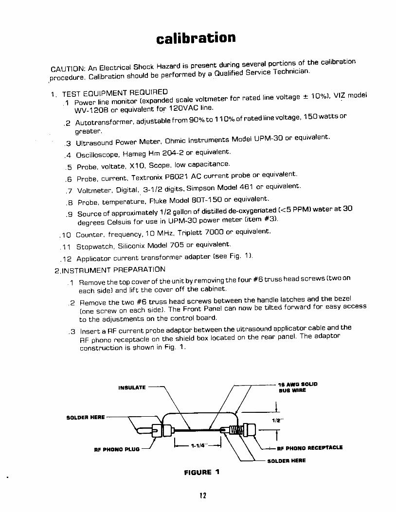
. g Insert a RF curnent probe adaptor between the ultrasound applicator cable and the
RF phono neceptacle on the shield box located on the rear panel ' The adaptor
construct ion is shown in F ig ' 1 .
. 3
. 4
. 5
. 6
. 7
. 8
. 9
1A AWG 30uDBUs WIBE
NF PHOTIO NECEPIACLE
1t2"-T
FIGURE 1
l 2
SOLDER HEBE
SOLDEN HENE
COTTIEGTTO
'r20 v 60 Hz(220 V 50 HA
POWEn SOUnCE
10&131 VAC(198-242 VAC!
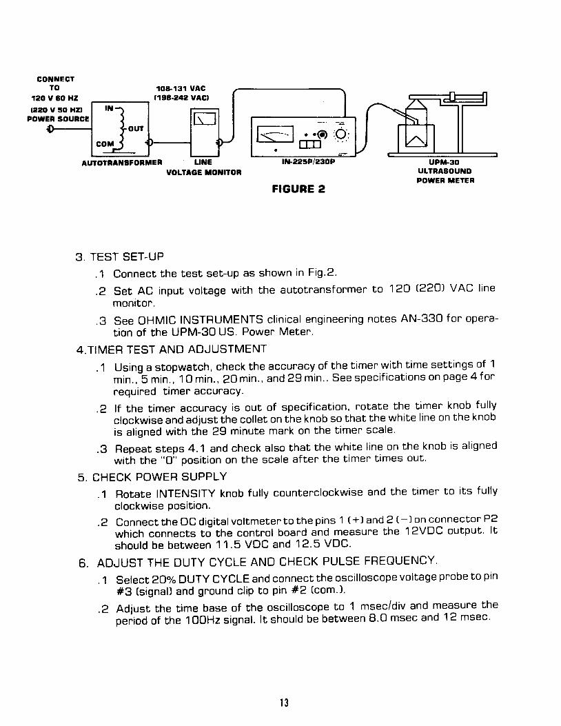
3. TEST SET-UP
.1 Connect the test set-up as shown in Fig.2.
.2 Set AC input voltage with the autotransfonmer to 120 €?CJ VAC linemontfor.
.g See OHMIC INSTRUMENTS c l in ica l eng ineer ing no tes AN-33O fon opera-t ion of the UPM-30 us. Powen Meter.
4 .T IMER TEST AND ADJUSTMENT
.1 Using a stopwatch, check the accuracy of the timen with time settings of 1
min . , -5 min . , ' t O min . , 2O min . , and 29 min . . See spec i f i ca t ions on page 4 f o rrequired timer accuracy.
.Z l f the t imer accuracy is out of speci f icat ion, rotate the t imer knob ful lyclockwise and adjust ihe col let on the knob so that the whi te l ine on the knobis al igned with the 29 minute mark on the t imen scale '
.g Repeat steps 4.1 and check also bhat the whi te l ine on the knob is al ignedwith the "o" posi t ion on the scale af ter the t imen t imes out.
5 . CHECK POWER SUPPLY
.1 Rotate INTENSITY knob ful ly counterclockwise and the t imer to i ts fu l lyclockwise position.
.2 Connect the DC digi ta lvol tmeten to the pins 1 t+l and 2 e) on connectot ' P2
which connects to the control boand and measure the 12VDC output. l t
shou ld be be tween 11 .5 VDC and 12 .5 VDC.
6 . ADJUST THE DUTY CYCLE AND CHECK PULSE FREOUENCY.
.1 Select aO"/"DUTY CYCLE and connect the osci l loscope vol tage probe to ptn
#3 (s ignal) and ground cl ip to pin #2 (com'1.
.Z Adjust the t ime base of the osci l loscope to 1 msec/div and measure thep". ioO of the I OOHz signal . l t should be between 8.0 msec and 12 msec.
l 3
FIGUBE 2

,3 Adiust Ehe scope lime base f or 1 O divisions of one cycle of the sigqal' on the
c o n E r o l b o a r d , a d j u s E R 6 f o r a p u | s e w i d t h o f T ' 9 d i v i s i o n s .
. 4 S e | e c t 5 0 % D U T Y C Y C L E a n d a d | u s E R 4 o n t h e c o n E r o | b o a r d f o r a p u | s ewidth of 4.7 divisions'
.5 select 1OO%DUTY CYCLE and observe that the signal is a DC level less
t h a n . 5 V .
T .CHECK AND ADJUST THE R.F ' OSCILLATOR
.1 Connect Ehe SCOpe current prob.e around the center conductor of the cur-
rent probe adaptor and connect the voltage probe to the outside conductor'
.2 Rotate the INTENSITY control clockwise as you observe-the voltage and
currenE waveforms on Ehe Jual channet scope, Th9 *?Ytiglts should be
wirhin 5 i;;;;;; '" i o"i"g i; i l ;;;nd oscil lation should be stable'
. 3 R e p e a t s t e p T ' 2 w i t h 5 o o / o d u t y c y c | e a n d t h e n w i t h 2 o " / o d u t y c y c | eselected.
.4 Adiusr c4 through the access hole on ifre
rgar palel (see fig' 3 f or locatton'
nemove hole capsl for phase correction and c7 through its near panel
access hole for oscil lation stabil ity in the pulse modes (2O"/" and 50o/o]'
.6 Feplace stainless hole caps on near panel '
FIGURE 3
nffir
oc4
cto
t {
8 .
g .
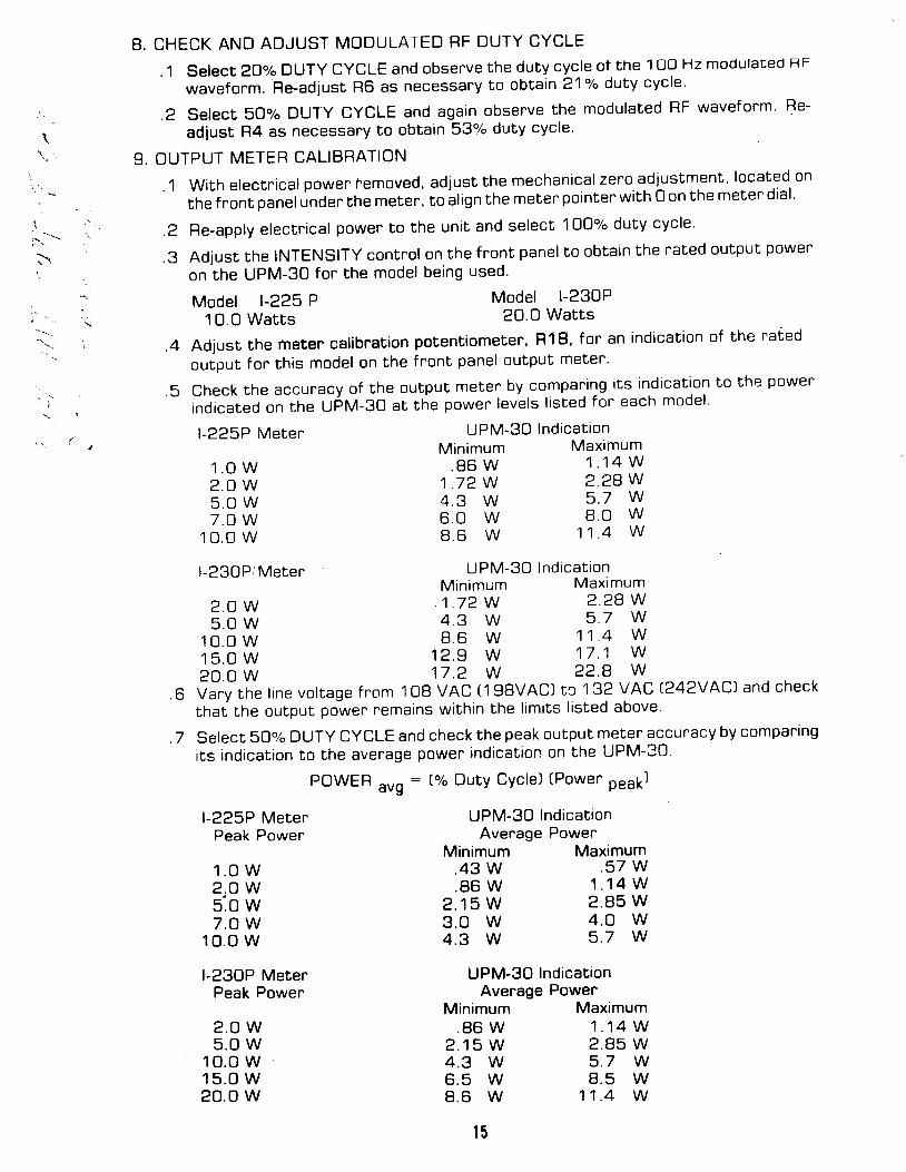
CHECK AND ADJUST MODULATED RF DUTY CYCLE
.1 Select 2oolo DUTY CYCLE and observe the duty cycle of the 1OO Hz modulaced RF
waveform. Re-adiust R6 as necessany to obtain 21"/" duEy cycle.
.2 Select 50% DUTY CYCLE and again obsenve the modulated RF wavefonm' Re-
adiust R4 as necessany to obtain 53% duty cycle'
OUTPUT METER CALIBRATION
.1 Wi th e lectn ica l power femoved, ad just the mechanica l zeno adjustment , located on
the front panel under the meter, to al ign the meten pointen with O on the meter dial '
.2 Re-apply electr. ical power to the unit and select lOOY" duty cycle'
.3 Adjust the INTENSITY contro l on the f r "ont panel to obta in the rated output power
on the UPM-30 for the model be ing used'l\
i " .
'\. i
Model l-225 P10 .0 Wat t s
l-225P Meten
1 . O W2 . 0 W5 . O W7 . 0 W
1 0 0 w
l -23OP/Meten
Model l -230P20.0 Wat ts
UPM-30 Ind icat ionMin imum Maximum
. 8 6 W 1 . 1 4 W1 7 2 w 2 ' 2 8 w4 . 3 W 5 . 7 w
8 . 0 w1 1 . 4 w
UPM-30 Ind icat tonAverage Power
Maximum. 5 7 W
1 . 1 4 W2 . 8 5 W4 . O w5 . 7 W
UPM-3O IndicationAvenage Power
.4 Adjust the meter cal ibnation potentiometer, R18, for an indication of the nated
output for this model on the front panel output meter'
.5 Check the accuracy of the output meter by compar ing i ts ind icat ton to tne power
indicated on the upNlt-go at the power levels l isted for each model'
UPM-30 Ind ica t ionMinimum Maximum
z . O W 1 7 2 W 2 2 8 W
5 . O W 4 . 3 W 5 ' 7 W
1 0 . o w 8 . 6 W 1 1 ' 4 w
1 5 . O W 1 2 . 9 W 1 7 ' 1 W
2 0 . 0 w 1 7 . 2 W 2 2 ' 8 W
.6 Vary rhe t ine vot tage f nom 1 08 VAC (1 98VACI tc 1 32 V AC Q ?VACI and check
thaf the output power remains wi th in the l imi ts l is ted above.
.7 Select 50% DUTY CYCLE and check the peak output meter accuracy by compartng
i ts rnd icat ion to the avenage power ind icat ion on the UPM-30.
POWER avg : (% Duty Cycle) [Power peak]
6 0 w8 . 6 W
Minimum.43 W.86 W
2 . 1 5 W3 . O W4 . 3 W
l -225P MeterPeak Power
1 . 0 w2 . O Ws.o w7 . O W
1 0 . o w
l-230P MeterPeak Power
2 . 0 W5 . 0 W
10 .o w1 5 . 0 W20.o w
Minimum. 8 6 W
2 . 1 5 W4 . 3 W6 . 5 W8 . 6 W
t 5
Maximum1 . 1 4 W2 . 8 5 W5 . 7 W8 . 5 W
1 1 . 4 W
l-230P MeterPeak Power
2 . 0 W5 . O w
1 0 . 0 w1 5 . O w20.o w
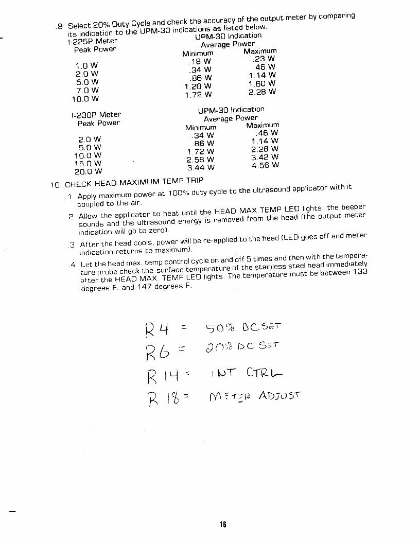
Se |ec t20%DutyCyc |eand-check th .eaccu racyo f . t heou tpu tme te rbycompar ingits indication to th;tL'Fi l-go inoi""t ions as l isted below
l-ZZSp Merer -
UPM-30 lndicattonAverage Power
Peak Powe. Minimuri '--- Manmum
1 ' o w ' 1 8 w ' 2 3 w
2 .o w ' 34 w ' 46 w
S . o w ' 8 6 w 1 ' 1 4 w
7 . O W 1 ' 2 0 w 1 ' 6 0 w
1 0 . o w t ' t i w 2 ' 2 8 w
UPM-3O lndicattonAverage Powen
Minimum -
Maximum.34 W .46 W. 8 6 W 1 . 1 4 W
1 . 7 2 W 2 ' 2 8 W
2 . 5 8 W 3 . 4 2 Wg.44 W 4 .56 W
aRRR
1 O C H E C K H E A D M A X I M U M T E M P T R I P
' l A p p | y m a x i m u m p o w e r a t l o o % d u t y c y c | e t o t h e u | t r a s o u n d a p p | i c a t o r w i t h t tcouPled to the a l r '
. 2 A | | o w t h e a p p | i c a t o r . t o h e a t u n t i | t h e H E A D M A X T E M P L E D | i g h t s . t h e b e e p e rsounds and rhe ul f fasound "; ; ; ; ; , ' ; |^" tou"o from the head t the output meter
tnd tca t ton wr l l go to zero l '
. 3 A f t e r t h e h e a d c o o | S , p o w e r w i | l b e r e - a p p | i e d t o t h e h e a d ( L E D g o e s o f f a n d m e l e rrnd ica t ron re tunns to maxtmuml
th the f ,empera-. 4 L e t t h e h e a d m a x . t e m p C o n t n o | c y c | e o n a n d o f f . S t i m e s a n d t h e n w t t
,r." p.oo"-Jh""[ rn" =r.t-".1'#p".iau." of tne slainless steel head tmmediately
afren rhe H-E;;'vrnx. iervp LEdr,gnts. rne te-mperature must be between 133
d"g . " "= F ' and 147 degnees F '
5 c% CrC- ;E '
CA ' l n bC S t f
ItJT CTRI,--
M ? (,P r\wu 5r
4
i t l =o
I Y
l L '
t6

parts - 225P/23OP rear pane! assembly 12OV
rv
\
L
x ;

Fef123A
567BI1 01 1t 1
I J
1 41 5t o
1 7
1 81 g
2 02 1222 3l 4
Par t No.70398, / + / 1 , )
7 0 1 7 97 0 3 1 67 120872167736C473605700997 9 1 1 B/ J b c c
7 3 5 7 17 5 1 1 97 2 9 7 0/ JO4+
7 1 3 6 87 1 4 0 47 1 4 0 7721D27343673424607687 3 7 7 27 2 9 7 D706247?435
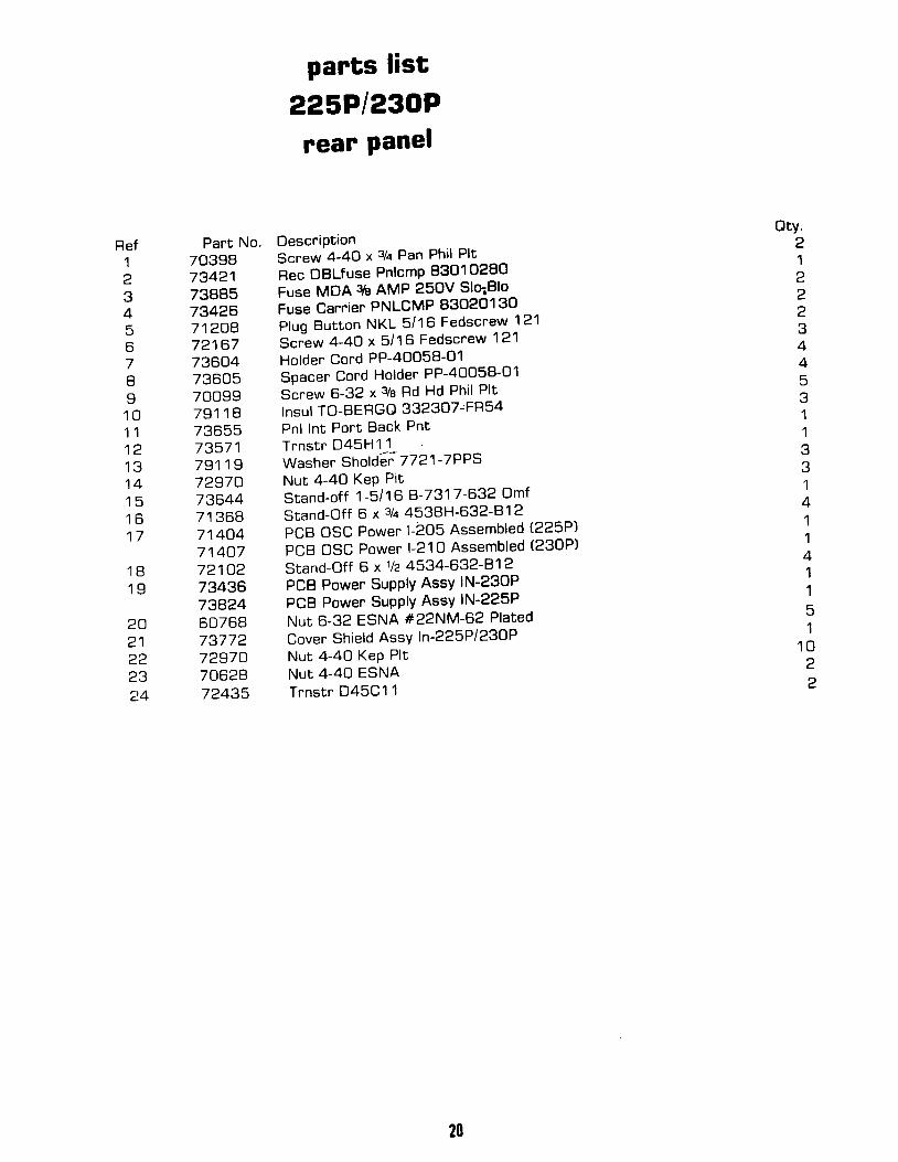
pants list
225P1230Prear panel
Descr tP t tonScrew 4-4O x 3/a Pan Hd Phil Plt
necePtac te , Power ' AC
Fuse MDA 3/q AIVIP 250V Slo-Blo
Fuseho lderP luq But ton NKL 5 / '16 Fedscrew 121
Screw 4-4A x 5 /16 Rd Ph i l P l t
F lo lder Cord PP-4OO5B-01Soacer Cond Holder PP-4O058-01
Screw 6-32 x 3/a Rd Hd Phi l Pl t
lnsu l TO-BERGG 332307-FR54Pnl In t Por t Back PntTrns t r D45H1 1Washer" Sholder ' 7721 -7PPS
Nut 4-40 KeP PltStand-off 1-5/1 6 B-7317-632-OmfStand-off 6 x 3/a 4538H-632-81 2
PCB OSC Power ' l -205 AssembledPCB OSC Power l -210 AssembledStand-off 6 x 1lz 4534-632-81 2
PCB Power SuPPIY AssY' lN-23ClPPCB Power SuPPIY AssY' lN-225P
Nut 6 -32 ESNA #22NM-62 P la ted
Cover Shre ld AssY ln -225P/230PNut 4-40 KeP PltNuI 4-40 ESNATt rNSTR D45C1 1
Gty.a
11123A
45
11
141144I
I
51
1 0c.
2
1 8

parrs - 225P123OP assembly ZZOV
{
)r, ;
1\
@
Ref1
Part No.70398734217388573426712C47 2 1 6 7736c473605700997 9 1 1 873655735717 9 1 1 972970736447 1 3 6 87 1 4 C 47 1 4 0 7721027343673A246076873772729707062472435
parts list
225P1230Prear panel
DescriPtionScnew 4-4O x 3/a Pan Phil Plt
Rec DBLfuse PnlcmP 8301O28O
Fuse MDA qb AMP 25OV SlqBlo
Fuse Carrier PNLCMP 83O2O130Pluq But ton NKL 5 /16 Fedscrew 121
Sci lw 4-4O x 5/16 Fedscrew 121
Holder Cord PP-4OO58-O1Spacer Cord Holder PP-4OO58-O1Screw 6-32 x 1e Rd Hd Phil Plt
I nsul TO-BERGO 332307'FF'54Pnl Int Port Back PntTrnstr D45H11-Washer Sho lder 7721-7PPSNut 4-4O KeP PitStand-off 1-5/16 A-7317-632 Omf
Stand-Off 6 x 3/a 4538H-632-812PCB OSC Power l -205 Assembled (225P)
PCB OSC Power l -210 Assembled (230P)
srand-off 6 x 1lz 4534-632-81 2
PCB Power SuPPIY AssY lN-230P
PCB Power SuPPIY AssY lN-225P
Nut 6-32 ESNA #22NM-62 Plated
Cover Shield AssY In-225P/230PNut 4-40 KeP PltNut 4-4O ESNATrns t r D45C11
otv.21222344
234
67II1 01 11 21 31 41 5t c )
1 7
534
133
I
41141151
1 02?
1 81 9
202 1222324
20

l\"\*\ \
rb\ {t*
parts -225P123OP cabinet assembly 12OV.
2l

Ref1
parts list225P',230P
cabinet assemblY 1zOV'
Par t No. DescrtPfton73663 Meter r f t r-ZZSp MOUTEC 930368-107
73664 Meter ' t t t -ZSOp MOUTEC 930368-106
70628 Nut 4-4O ESNA
21791 Screw 6-32 x 33/e Pan Hd' Phi l ' Plated
7g7A4 Timer O1'hf g0 ftlinute w/c-ut shaft 1 10 V 60 Hz
lelqS PCB Contnol BD AssY' l -230P
lellO PCB Control BD AssY' l-225P
7OO5B Screw-4-4O x 3/e Round Hd' Phi l ' Plated
ziSi} Panel Intelect Port' Front .217510 Screw 6-32 x 3/e Flat Hd Phi l ' Plated
7346iA Decal Froni Panel Over" lay lN-225P
734F7 Decal Front Panel Overlay |N-23OP
73585 Bezel 11"l iszT Knob Wing ELMA 026-5-4?5
ISAOI Knob CaP ELMA 040-3615
73670 Knob CaP ELMA O4O-5015
ziOOo Knob Wing ELMA 023-3426
72515 Ho lder LED #HLMPO1O3 B lack
21739 Nut 8-32 ESNA7g4SlO TnansformerA4 l -80-28Signa l60768 Nut 6 -32 ESNA
7O4A4 Fi l ter Line 3A/250V 60Hz
l isAl Bracket Mounting Side' Right
7 O 1 0 5 W a s h e r # 1 0 F l a t P l a t e d
73657 Panel, Bottom Intelect Portable painted
7gO41 Jack , Banana Smi th 1 5OB-103 B lack
21Cl24 Nur B-32 Hex, S/S
73611 Holder" Appl icator U S Pontable
73188 Scnew B-32 x 3lq
21016 Screw 8-32 x 3 /a
737A3 Hand le ELMA 66-330-14 ' cu t 11 6"
7g115 Foot ' B lack Rubber M-195 13 /16 x 25132
73474 SuPPor t Case ELMA 63-140
7O7A2 Screw B-32 x 5/e
73593 Bracket Mounting Side' Left
71319 Scnew 6-32 x 1la
745Fl2 Appl icatorUltrasound' Adiustable 5-Cy' .^
74ls9 Appl icaton Ultrasound, Adiustable 10 CM2" i . ,
) i ' - j F " " l r ; t -
Gty.112E
1116I
211111
1I
21 0
1e
112112I
A
4I
4121211
(-34
5
67
s
1 01 1
l a
I J
1 4t c1 61 7I t 1
1 g2 Aa l
2223242 52A2 72A2 9303 13 23334
22

parts -225P123OP cabinet assembly 22OV
\
\s--j -1"..N.i)*;
+ :\
q@ , \
\1

Ref1
2345
o
7II
1 51 61 71 81 9?o2 12223242526272A29303 1323334
Part no.73663736647A6242179173745734457376070058735292179073A7773A767454574579736077367073606725192173373490607687049673547701 0573657790,4121c247361 1731842 1 0 1 6737437 9 1 1 57347470782735937 1 3 1 97458274590
parts list225P1230P
cahinet assemblY 22OV'
DescriPtionM e t e r U S P o r t a b l e l - 2 2 5Meter U S Portable 1-230Nut 4-4O ESNAScnew, 6-32 x 9ttTimer, Diehl 3O min. cut shaft
PCB Control BD AssY. l-230PPCB Control BD AssY. l-225P
Screw, 4-4O x3lePanel, Int . Port Frt .Scnew 6-32 x s/t]
Decal, Frt. Panel 225P 50 Hz Timer
Decal, Frt. Panel 230P 50 Hz TimerBezel 11"Knob Wing ELMA 026-5425Knob Cap ELMA 040-3615Knob CaP ELMA O4O-5O15Knob Wing ELMA 023-3426Holder LED #HLMPO103 BLK
Nut B-32 EsnaTrsnfmr A41 -80-28 SignalNut 6-32 Esna #22NM-62 PlatedFi l ter Line 2.5A/2sOV SchaffnerBrkt MEg Side Box Port RightWasher #10 Flat PlatedPnl Int Port Bottom PntJack Banana B lk Smi th '1508-103Nut 8-32 Hex SSH o l d e r A p p l U S P o r tScrew B-32 x 1aScrew 8-32 x 1eHand le 66-33G14 E lma Cut 11 .6Feet B lk F lub M-195 13 /16 x 25 /32Support Case 63-14O ElmaScrew 8-32 x %Brkt Mtg Side Box Port LeftScrew 6-32 x 1/q
Applicator Ulrasound, Adiustabl#ffi' l0
Applicator Ultrasound, Adiustable ffi# ;
otv.112511161211111 0
1 11 21 31 4
111261611211214414121211
24

1r{5819
1i68r9
t1:|
, K 2
IK
116619
+ 1 2 V F I L
050uT 4
nqnr tT q
05c0l.l rg
05c0M 1 1
| +IDCF 7I
I + I0CF 8
25
2 i RFOUT
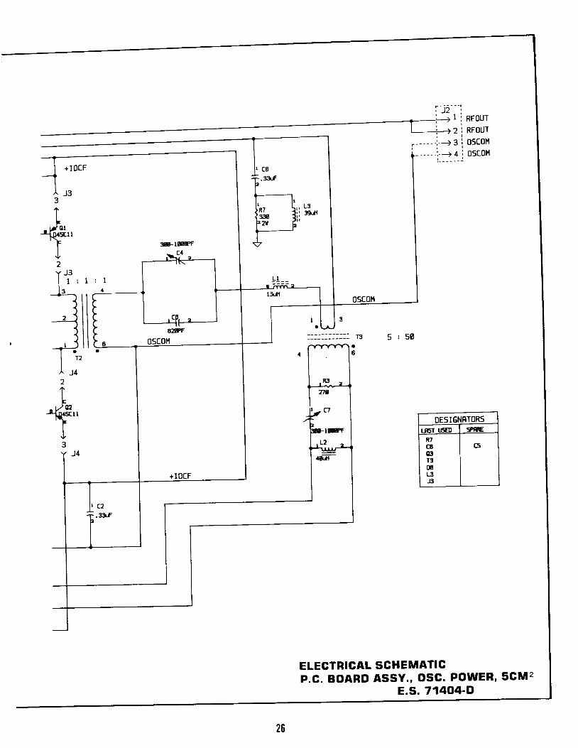
ELECTRICAL SCHEMATICP.C. BOARD ASSY. , OSC. pOWER' 5CM2
E.S. 71404-Il
OESIGNFTORsLnst lEE! sPffi
R7c6GIT3InL3.B
C5
tffi
05c0H
+IOCF
3
t-ft.81". F
I{/z
Y J 3l 1 r 1 :t ?
=i l t--{ lt F1 i l r
t , _ < l l fl 1 2I^ J 42
TF
-(.S,'
I3Y J 4
+IDCF
J3
It cai .sar
2
Ii-----r,f* iii g"f z r 6 "
_LL__
01.,|tad
I 3
T 3 $ : 5 0
1
t-,r^-l275
,, c7
,-lffi
L2
c2.xtf

+ I 2 V F I L. ; ,. \ ! t .
. i !-< (. \\
: ,,r\
21
| + IOCFtIA J 33
I
h')ascll
II2Y J 3
l - t ' t
*lwr- . c l
It ca
T''.'
f* l"*+-++
05c01{
i l
t \
q,LT
ltR
.8Z t
cP, "a
tldl
3
05c01{ T:' 3 : 5 0- T .
l "^ J 42+IF
- t ) t 2-fl-D6Cu''F
I3
a
+IOCF
1
RI
279
. c ,
F. twrL2
J4alrl
C2,:rlf
+'
OEsI6NRTOR5L6T UsE) s?ft
K'CBtrlT3ttL3-J:l
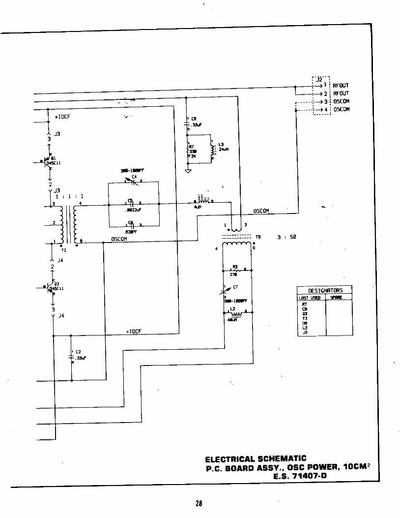
ELECTBIGAT SCHEIIATICP.C. BOARD ASSY., OSG POWER, 1OCM2
E.S. 71407-D
28

lrl ̂ A r ' t / t " r i ' l
i i ' , / '
r ( -
{ i i
' t / ) t l ' L ,
/ ! , :
: \ l r
- t 1
i"'l i'
"\ 1r.
/".
T-t R t6f.rxt '
v
5 t x
c5
T.E't, fv
T . l l t f | | . R 2 lg J ' a.t31", I h .-51s.r. il'* I l-s+ l l , K
A a )R I h' ,J 'a d.94x | 2'\'t ' E----{-- r. t -
f b I u *, \ c a i I
' s 1

eP-{.Alz LiNf' j , ' jG PE 'e t
Tl f l " { r q q '6 , 6 N *
IK
,8l t f
IrciilslcRt6
$.4r
R32lx
5
I l t.. l t l t
cnlt
ETECTRIGAL SGHEilATIGPWB SUPPLY.llur. sllP 50W scil
30
IN+ Cf,
lN- EF
cof Glo
RT CL-
cr CL.url52.
llGl59cR4
^r2!l
V E B+5Y CB
Ix+ Cn
IN- En
ct|? oo
RI CL-
cl cL+
s. 7382+C

IElr
CE
T..'.'v
traalatcrll
| "
fz,l*.' '"'i-
vf ' { i : i
t . r r r f l
l- ,r$ d*
^ - l { ( . I I
P l'r -3i
{ - ' " ' \ ' ;
I 1
[r.^P.- ,/)!-'\'y),.i
l i. r , l . . : \ \4 " - . { , ' ' < -!
3l
.-at -
| . L 2
\Ltf , . i ' '- ' f : '
- ' \ '\.
,)t
lx
v E l+5Y C!
ltl+ Cn
IlF EN
co" eoRT CL-
CT CL.
t*'*l]|unC'
_mll
Yo5Y
ItIFco?ircr
EI(l
CNEN
c3(L-
O.. rt.raCllt
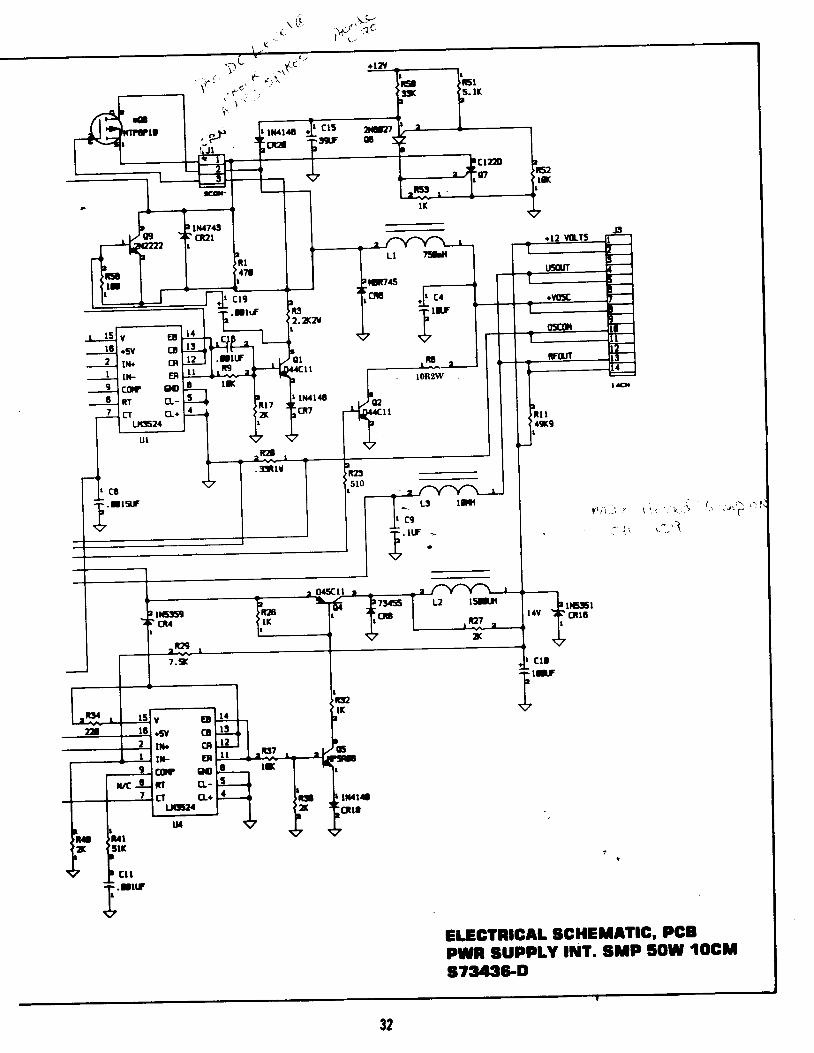
EI.EGTRIGAL SCHEIIAIIG' PGBPWR SUpPtY tilT. SllP 50W toctst34:t6-O
32
I ,\?r { I
( ' )
- { , , . , t -, t !
[ , , ' ' . ' '
V i "
* \u'({
. (. J
Y '
v\t .
t
- t , . t
: i * . t s o ( : l -a r - 5 - a f - - ? - - - i - {l s v r s a l l l
I 1'* it " l-l-I L ' " + . f l i u II F F- l lI + l rt - . * l l
__.i3'.,33(
rglal
IMI 'E
rtt
c F l
l ' . ui.ss6trrv
J ir fFr 1:-1H tMla6
* cni
;id
lN4 l4 l
r-L++I cnsI . R l 7 .
R l 5Its
1.lrur,,fu t@
l'rcm-r f rc-rl l n x l l l o t ll l r € p . l l -
l M l scffi
IBRr9
l lc
*R2l -
I+r.66 a
T 'v
It.f
l, ce f-^-L ) r .2T l r ? 6 . rr Ft l+ v
_[ crcf lq trv
t i
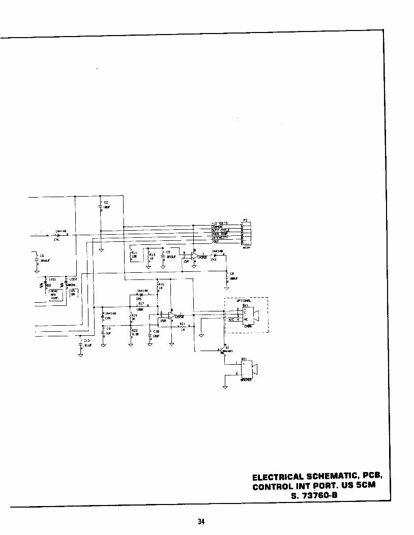
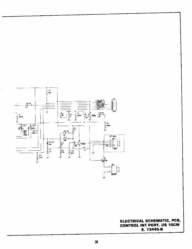
ELECTBIGAL SGHEIIATIC' PCB'coluTROL lNt PoRT. US scll
s. 7376G8
34

g
rs-il
TEE---]
35
L N a l 4 8
c2lff
c R l
-[ .uf .6Af
FI
v
J l M l a E
CR:'
II LEOI II LED2
lk" rfu^I ri6r I m=rl l n x I l l a t II l r r j f . r I
l M l 4 8
r4+!I cRs| . R l 7 "
R l 5l x
b ' -
v
i- -
I
rT I On-
l 1 6li4l48 l incR6 |lx I
P It(UsE
, R 2 l , f-t l 3. s l | f
L - -
r ltf?
tr I ' c l lo i , *r
v
I i
-}
ELECTRICAL SCHEMATIG' PCB'CONTROL INT PORT. US 1OGM
s. 73445-8

TO PA OF CONTROL BDARD
2.580 il FNT Ii225P ASSY
I
/'. t
./
3
Bx 16^l3 , ]
L-71915 tEil. tsrgN t/a reSD 22-ta
(71576 lEil fSloN',S mE USED tl{ [Llll€l cou|€crftns {! n f,L LlfFTLTER COllr€C1lltrs.)
r-*'-. - 735?8 HARN INT POR] I IT IR
D E T A I L ' A '
IFA{SFMXIR IS SHOVN ON IT 'S SIE IOSOV VIRING CONNICTION IFlxgTION
\L I -
\ s t t D I T ^ I . ' A '
LINE FTLTER O ;+ 1
iLr GN/YLle6^
//-60168 rul 6-34 CSs raen-62 PLAIID
,1
BX t8A2 t /2.
vH ISGA 3 '
w tSGl 7'
] . "-6-13
] ' o
oeb
TII,IER
l b
o
3t
--@60 rul 6-3a {x PTATED

ArlACt{s T0 ToP PI{L
-sEE D€lA!- . r .
60t05 I tR i . R lN6 r8 22 l8 SrD(a tu{fs)
60060 tUX t€AT S|aDa( 3/16r( Al(fal slnlf,( ls usE! ol aLL r)ltE rust
i'r:*'1.tro3lm"r'Hti,'''
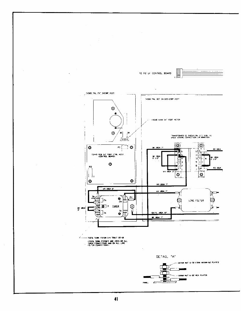
FTNAL ASSY. lN-225P 120v73775

a - -
II
I
IIIIII
iI
IIIIII
TESIIOII TTICRT n l - -
Pil 7458e PU- 80Tr(Il R55Y. USY
39
PN 745E8 Pft{- FR(I{T tN-25P f,55Y.
.l2tflL
(EOJT
.vc5(
Gtqrl
iI
I
I
.1-IIII
I9fFLY N55Y.PB IrI F(TT PO6
fll 7lt{!P(! Gr FO*R I-2G nssE O'.AnFi{ 7 t,La
IIII
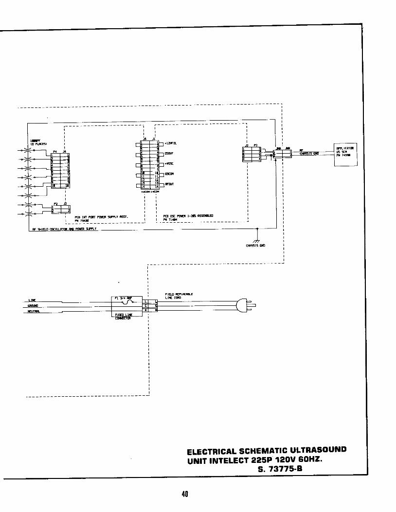
ELECTRICAL SCHEMATIG ULTRASOUilDUIUIT INTELECT 225P 120v 60H2.
s. 73775-8
7.5(l ro FNr UaS ASS!
TO P2 OF CON1ROL BOARD
D E ' I - A I L ' A '
TRANSrmif l ls srcYN u IT'5 slE rosmv vIRIrc coNucTlor l [ lmTIoN
, [ - - - \ |i I @ \ I
I e \-- |l ^ \ l i
I O) i iI \-./rr I It a li o,/"1I.,'lI r ,Iio'ol I
' ' F ro l l23..5 Pcr lrr Pqr crR! asY ll(mrEL InD
ll
,r l l
| . - , rraa halN lNr PoRr r t ' t l
l . /*'
Al l
fl, llo
-}t-
\LINE FTLT.R
Iri
. t l l { FrJ
Lrtt 3 lttr r3to| t/. ft.l, ?e-',(trlt6 lEit fslors E ust! (l{ ^LLrl|{r COl|{€CltttS s! lt{ A-L LtxE' rlr :Er cuf c llofs )
, -go16a rur 6-3a tsu .22F-e R t f D
4l
l a
l l
l 0
9
8
7vH 106^ 3'
w 186 7.
lao q) a o
-dl 3 Tll{[R
- l bl r o o
-ffi rut 6-? }{x [arED
aTTACHIS r0 rOP PANTL (741)
\ - - 6 0 1 0 5 l t R t . R | N G t a 2 2 l 8 s r D(8 PL{IS,
7311? CSVEP SHILLD ASSYIN ?25 l?TP
@r
i o
s E a 0 t r ^ l L ' A '
' ! -6om IUAI h f^ l S* lu 3 /1514 ' e? t
(xeal smlx ls ustD 0x atL lHtt tusfRicEPrELf COWCII(}.S, il rtrrlKs o,rl5 t 6 oil' rlasftnltR ND Pmrc J[x-)
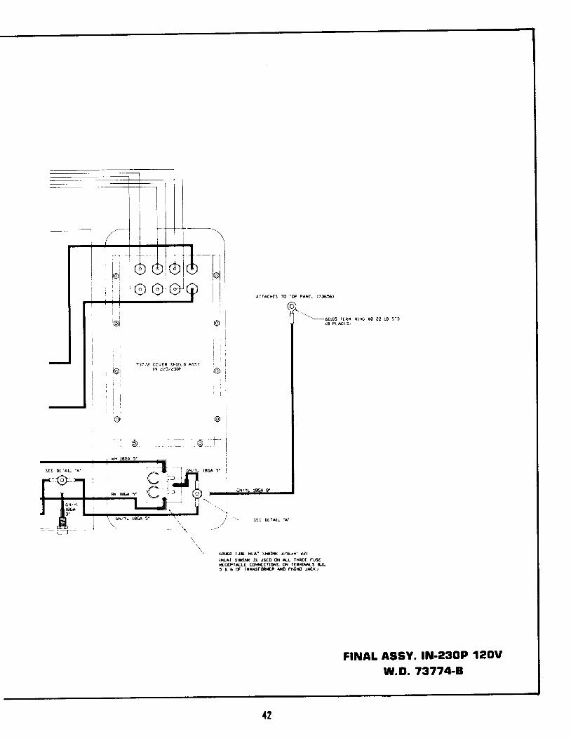
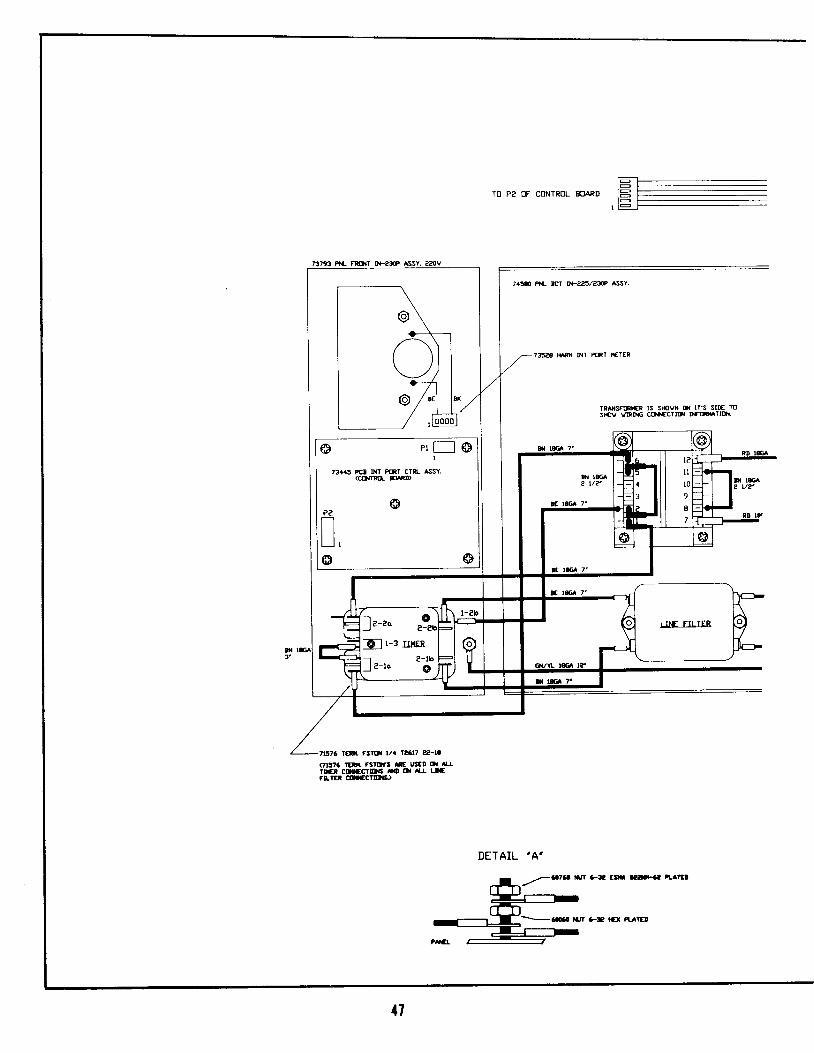
FINAL ASSY. lltl-230P 120V
w.D. 7377+8
12

IIIIIII
PC8 COflEt g! 6St. IF2fPi 73a,as
tltCR
PN 7/t580 PNL 80TT0lt R55Y. l l6vPN 74583 PNL FRONT IN-23tr R55Y.
13

G;qt
lfctr
I FCI II{T F(FT POE qI?LY 65Y.I Pi 73a:tr
l lr lr lr lr l| | P@ CsC Pog t-2lt CSEq..ql| | Fil 7t{'
ETEGTBIGAL SCHEMATIC ULTBASOU]UDu]$T IilTELEGT 230P '120U. 60H2.
s.7377i||8
11

F@ qtaTtu- n) EY. IF225PPil INN
PN 7376I PU- BOITO{ RSsY. 22gYPNL FRONT IN-225P AsSY. 22SVPN 73792I
{5

I
I F@ Ufr F(f,T nn gtf|-Y 6rI m 7:tL
ELECTRIGAT SCHEMATIC ULTRASOU]UDUNIT INTELECT 225PI22OU sOHZ.
s.737r7-C
46
t - -
ro Pa oF coNTRoL BoARD l= -t - -
TRilSnn€R lS St{rvi il lrs slE msf{!v vtRIrc c(}rfcTl('l lmTl('i.
O p r T - _ l @I
73a45 PCI l}{T Pml cTR- ASSY,GO{rnIL XnD
tt!t76 ruil. fsrol va la6l7 ae-ra(7l:''6 lIFt rsrars ff t s€D (la ll-LrDCr dt|cclloti xo o{ Lr urflLtEl c|Lecl[Ls)
41
DETAIL 'A '
N77A COVER SHIELD ASSY.t1 6/*
737?7 7x- RE* lFaf ASSY. ??0V
^TIACI{S l0 ltP P^r€L Orlb)
60105 rElf, RIK € a2-r8 SrD(8 PLACIS)
6EO IUE lCaT 93ll.( 3fr6r1' erOfar snDa( 13 rJsfa or u lrr€f n6atrcEPlrcLf cDacctrl6, o{ lt tms 1.:,5 t 6 tt TRrgancr xo Pffalo JACD
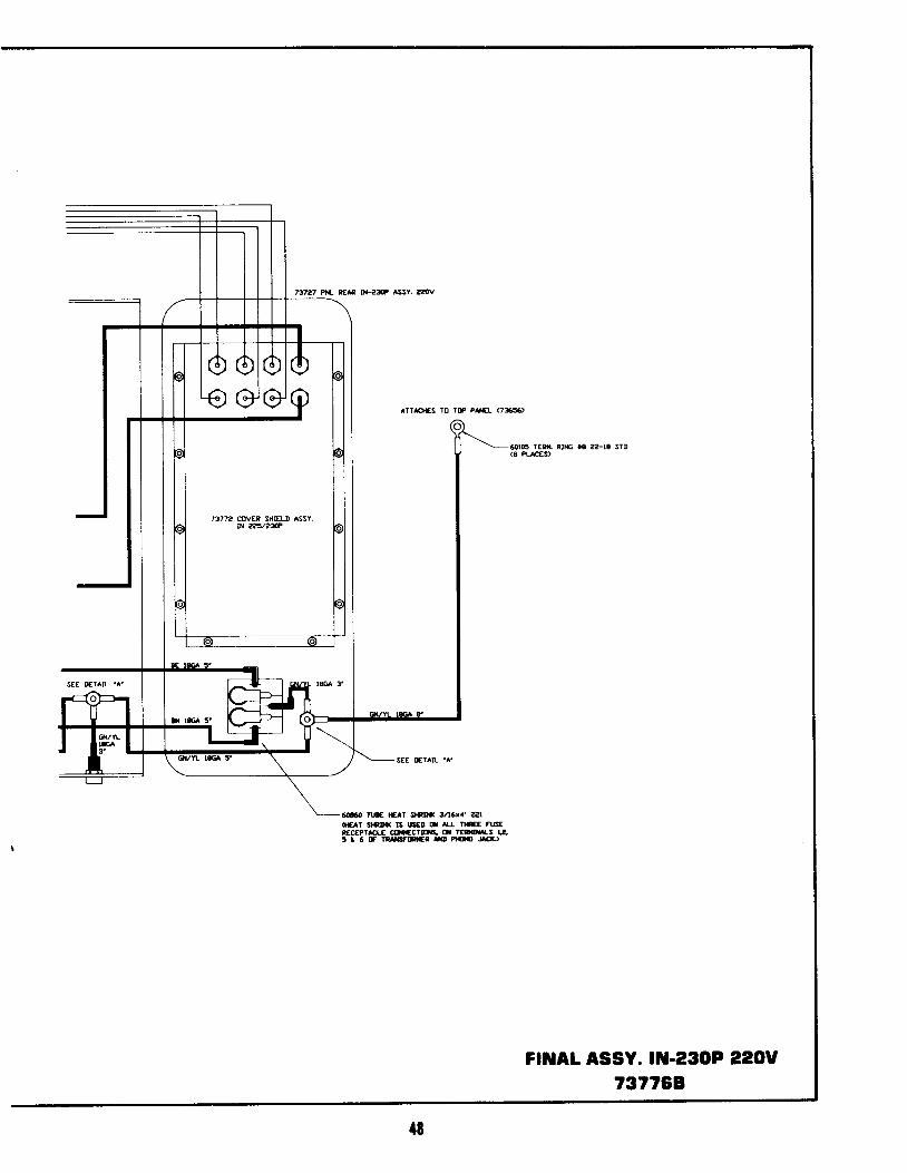
FrtAL ASSY. lIt-230P 220U7377E,8
{8
PCa CO{tEt m nsnPt{ 73445
lF2r
nf,nrrfxr il|fn
IIIII
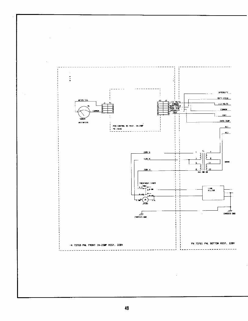
-N 73793 PNL FRONT tN-238P R55Y. 22EYPr{ 7376t Pr{L 8orr(tl nssY. 22rv
49
Irf(I PLGSI
F@ IX' P(NT POB Af'LY N55Y,Pta 73tr
I
IIIIIIIIIIIIII
_l
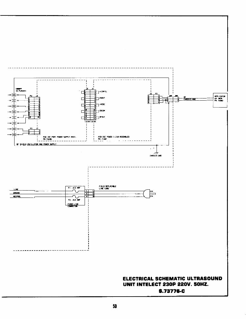
ETECTRIGAL SCHEIIATIG ULTRASOUTDururr TUTELEGT eSoP ?zou. sOHZ.
3.73t?6'G
50
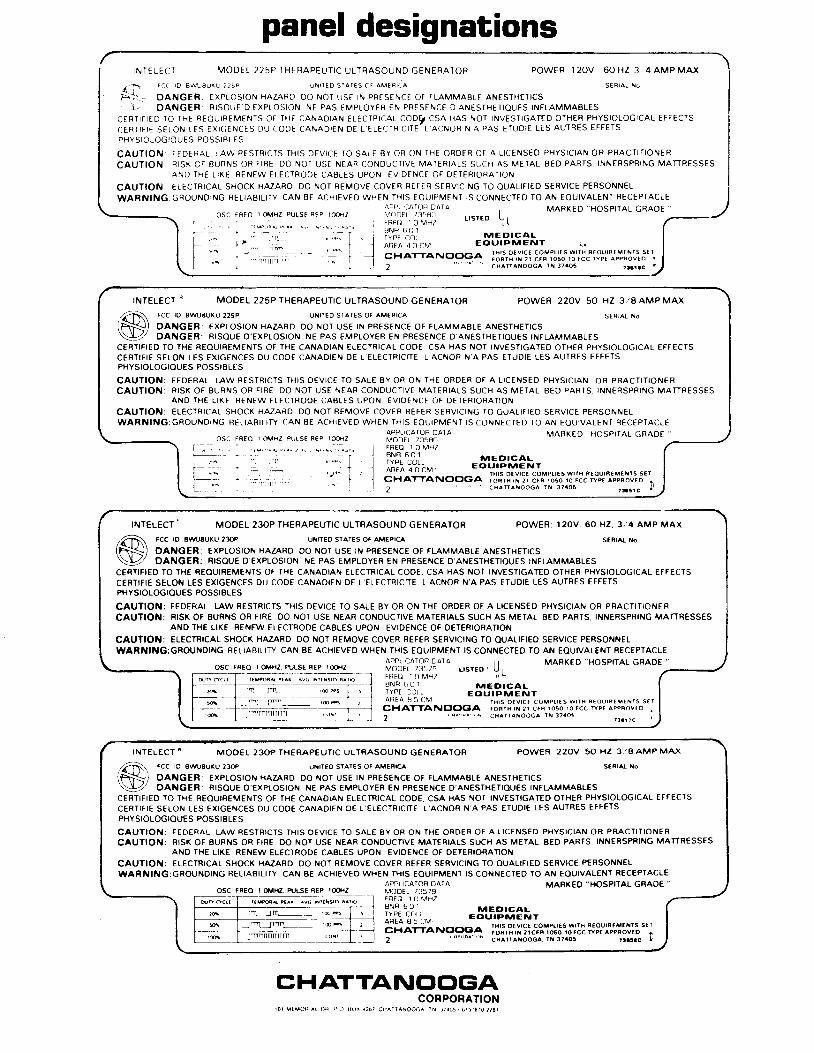
panel designations\
INTELEC] MODEL 225P IHERAPEUI IC UL IRASOUND GENERATOR POWER 1 2OV 60 I {Z 3 4 AMP MAX , !
, - FC( IO AWU8UKU 225P UN1IEO SIAIES OF AMERI IA S€RIAL Io4F*- : DANGER: EXPIOSION HAZARC OO NOT US€ lN PRESENCE OF FLAMMABLE ANESTHFTICS' r ' . D A N G E R . R I S O U E 0 E X P L O S I O N N E P A S E M P L O Y € R € N P R E S E N C E D ' A N € S I H E I I O U E S I N F L A I V I M A B L E S
c E R I | F t E D T O r H E R E O U T R E M E N I S O F T H E C A N A D T A N E L E C T R T C A L C O D ' C S A H A S N O T T N V E S T T G A T E O O T H € R P H Y S T O L O G I C A L E F F E C T S
C E R T I F I E S E L O N t E S E X I G € N C E S D U C O D E C A N A D I € N O E t E L E C T R I C T T E . L A C N O R N A P A S E T U D I € L E S A U T R E S E F F E T S
P H Y S I O L O G I O U E S P O S S I B L E S
C A U T I O N : F E D E R A T L A W R E S I R I C I S T H I S D € V I C E I O S A L F B Y O R O N I H E O R D E R O F A L I C € N S E O P H Y S T C I A N O R P R A C T I T I O N E R
C A U T I O N . R I S K C F E U R N S O R F I R E D O N O T U S E N E A B C O N D U C I I V E M A I E R I A L S S U C H A S M E T A L B E D P A R I S I N N E R S P R I N G M A T T R E S S E SA N D T H € L I K E R E N E W E L E C T R O D E C A S L E S U P O N E V I D € N C E O F D E I E R I O R A T I O N
CAUTION: ELECTRICAL SHOCK HAZARO DO NOT REMOVE COVER REFER SERVICING rO OUALTFI€O SERVICE PERSONNEL
W A R N I N G : G R O U N O I N G R E t l A B l L l r y C A N B € A C H I E V E D W H E N T H I S E O U I P M E N I l S C O N N E C T E D I O A N E O U I V A L E N T R E C E P T A C L Eappt CATOH OAIA , , MARKEO HOSP|TAL GRAOE . .
POWER 12OV 60 I {Z 3 4 AMP MAX is€RraL ro I
c s lINFLAIVIMABLES IATEO OTH€R PHYSIOLOGICAL EFFECTS ILES AUTRES EFFETS
I
:O PHYSIC IAN OR PRACTI ' IONER IAI BED PARIS INNERSPRING MATTRESSES
I
Eo sERVrcE PERS.NNEL Ir o AN Eou rvaLENT RE .EPTA.LE
IMARKEO 'HOSPITA I GRAOE "
, /
r lN T r . lcoMPLr t 5 wr la n tourAtMtNrs s t I Ic r n r o 5 o r o r c c n P t A P P F o v t D I I
f cA r t j7 .o5 ns tc
t )- /
o s c r R t o I o i H z P u t s t n t P 1 0 0 f i 2 ' \ i t \ t . " ( 4 .
- , lt r, t _ , r , r : , * . I i TypECor _ ! ! €_o_ l_93_LI i i r p r , n , . r \ r E E ' r c a l -
i I ac ra a l i , v Eou lPt r / |ENT. l
. . ] cxa'rraruoocA ]['f,?il':::||'fti'J,t';3.::,i1X'#l:L:i"| 2
" ' " ' c * r n a l o o c A r t i 7 a o 5 , r a r a c
CHATTAIVclclGiA,01 MrMon ^r oH p (, 0.r .*, .,^,,^"oos?:.l9il.Tlg,I
INTELECT * MODEL 225P IHERAP€UTIC ULTRASOUND GENERATOR POWER 22OV 50 HZ 3/8 AMP MAX
/:,-R Fcc ro BmBUxu 22sp uNrrEo sr arEs oF AM€flrcl sERtaL do(FSSJ Ol t lCER: EXPLOSION HAZARO OO NOT USE tN PRESENC€ OF FLAMMABLE ANESTHETICS\ lZ DANGER: RISOUE O'EXPLOSION NE PAS €MPLOYER EN PR€SENCE O ANESIHETIOU€S TNFLAMMABLES
C€RTIFIEO TO THE REOUIREMENTS OF THE CANAOIAN ELECTRICAL COOE CSA HAS NOT INVESTIGATEO OTH€R PHYSIOLOGICAL EFFECTSCERTIFIE SELON LES EXIGENCES DU COD€ (JANADIEN OE L '€L€CTRICTT€ t 'ACNOR N'A PAS ETUDIE LES AUTRES EFFETSPHYSIOLOGIOUES POSSIBLES
CAUTION: FEDERAL LAW RESIRICIS THIS D€VrC€ TO SALE BY OR ON IHE OROER OF A L ICENSED PHYSICIAN OR PRACTITION€RCAUTION: RISK OF EURNS OR FIRE DO NOT USE r , l€AR CONDUCTIVE MAIERIALS SUCH AS METAL 8ED PARTS INN€RSPRING MAITRESSES
AND THE L IKE RENEW ELECTRODE CABLES UPON EVIO€NCE OF OEIERIORATION
CAUTION: ELECTRICAL SHOCK HAZAf lD DO NOI R€MOVE COV€R REFER SERVICTNG TO OUALIFIEO S€RVIC€ PERSONN€LWARNING:GROUNOING RELIABIL ITY CAN 8E ACHIEVED WHEN THIS EOUIPMENT lS CONNECTED IO AN EOUIVALENT RECEPTACuE
A P P L I C A I O R O A T A M A R K E D , , H O S P I T A L
G R A o EMODEL 735AOFREO 1 O MHZ
9l: 1o^l ilrEDrcar-: : : ' - ' " "1 '^ . . Eot rPi tENr
ditHXru o o c a I 5i', ? i I' 9 i 3 ,f ft i'i,:' Ii Jf ,i? X'#::1,? 3 ".2
' : c x a n a N o o c a T N 3 7 4 0 5 , - a . " !
MODEL 23OP THERAPEUTIC ULTRASOUNO GENERATOR P O W E R I 2 O V 6 0 H Z , 3 / 4 A M P M A X
za\ FCC rO AWUEU(U 23OP UNr€O SIAT€S OF AMERTCI SERTA/. rc
[N! ) OITVCER: EXPLOSION HAZARO OO NOT USE IN Pf fESENCE OF FLAMMABLE ANESTHETICS\ ! / OANGER: RISOUE D 'EXPLOSION NE PAS EMPLOYER EN PRESENCE D 'ANESTHETIOUES TNFLAMMABLESCERTIFIEO TO THE REOUIREMENTS OF TH€ CANAOIAN ELECTRICAL COOE, CSA HAS NOT INVESI IGATEO OTHER PHYSIOLOGICAL EFFECTSCESTIFIE SELON LES EXIGENCES OU COOE CANAOIEN DE L '€LECTRICf fE L 'ACNOR N'A PAS ETUDI€ LES AUTRES EFFETSPHYSIOLOGIOUES POSSIELES
CAUTION: FEDERAL LAw RESTRICTS THIS oEVICE IO SAIE BY OR ON THE OROER OF A L ICENSEO PHYSICIAN OR PRACTITTONERCAUTION: RISK OF BURNS OR FIRE 0O NOI USE NEAR CONOUCTIVE MATERIALS SUCH AS METAL 8EO PARTS. INNERSPRING MAITR€SSES
ANO THE L IKE RENEW ELECTROOE CAELES UPON EVIOENCE OF OETERIORAI ION
CAUTION: ELECTFICAL SHOCK HAZ,ARO OO NOT REMOVE COVER REFER SERVICING TO OUALIFIEO SERVICE PERSONNEL
WARNING:GROUNDING RELIABIL ITY CAN 8E ACHIEVE0 WHEN THIS EOUIPMENT lS CONNECTEO TO AN EOUIVALENT RECEPTACLE
I crl|xz ruLsE R€P l@rizA P P | C A I O R D A I AM O O E r 7 : 1 5 / 9F R E O 1 O M H ZB N R 6 t J ]T Y P E C O I LA R E A 8 5 C M
r t@ea r t l r ^vG ' i r ( i s rn u r rc
| | MARKED "HOSPITAL GRAOE "r rs r ro lL /
M E D I C A LE O I J I P I T ' E N T
r H r s o f v r c t c o M P ! r f s w r T H R t o u t R E M E d r S S t rf o R I H t N 2 t C f n r o 5 o r o F c c R P t a p P n o v f o t( x A n a N o o c a r t l 7 a o 5
, t a r r c
I N T E L E C T A MOOEL 23OP TH€RAPEUTIC ULTRASOUNO GENERATOR POWER 22OV 50 HZ 3 /SAMPMAI
,A\ rcc ro gwlsuxu 23op utrr[o srarEs oF AMERrcl stRra k
lN^ l OAICER: EXPLOSION HAZARO OO NOT USE lN PRESENCE OF FIAMMA8LE ANESTHETICS\y OANGER: RISOUE O'EXPLOSION NE PAS EMPLOYER EN PR€SENCE O'aN€STHETIOU€S INFLAMMABLESCERTIFIEO TO IHE REOUTREMENTS OF THE CANAOIAN €LECTRICAL COOE, CSA HAS NOT INVESTIGAIEO OTHER PHYSIOLOGICAL EFFECTSCERTIFIE SELON LES EXIGENC€S OU COO€ CANAOIEN O€ L 'ELECTRICTTE L 'ACNOR N'A PAS ETUOIE LES AUTRES EFF€TS
PHYSIOTOGIOWS POSSIELES
CAUTION: FEO€RAL L , .w RESTRICTS THIS OEVICE rO SALE 8Y OR ON TH€ ORDER OF A L ICENSED PHYSICIAN OR PRACTITIONER
CAUTION: RISK OF BURNS OR FIRE OO NOI USE NEAR CONOUCTIVE MAT€RIALS SUCH AS MEIAL 8ED PARTS. INNERSPFING MATTF€SSESANO TH€ LIKE RENEW ELECTROOE CAELES UPON EVIOENCE OF OETERIORAIION
CAUTION: €LECTRICAI SHOCK HAZARD OO NOI REMOVE COVER R€F€R SERvlc lNG rO OUALIFIEO S€Rv lCE PERSONNEL
WARNING:GROUNOING RELIAAIL ITY CAN 8E ACHIEVED WHEN lH lS EOUIPM€NT lS CONNECT€O TO AN EOUIVALENT RECEPTACL€APPLICAIOR OAIA MAFKED
"HOSPITAL GRAOE
"
M O O € L 7 3 5 7 9F R E O ] O M B Z
9 ! : 90^ ' MGorcaL:Li . . 9Y.; . . Cot tnptrrENTsEA d I I rv,
rr ts oEvtct coMplt ts wtrH aEout8€Mtxls sf rCHATTANOCTGA ;; ; r ; rB 2lcFF ro5o ,ofcc wpf appFovEo *2
"qe' ia^r r)r cxanatoocA- TN 37ao5 rrotc I
osc f nEo r oltHz. ruLs€ REP tmHz
m _ lT I l ,m4