MODEL 1500 - Manual No. TI065
154
MODEL 1500 Manual No. TI065 MANUAL PART NO. 2022705 (Includes Revision 1) o
-
Upload
khangminh22 -
Category
Documents
-
view
0 -
download
0
Transcript of MODEL 1500 - Manual No. TI065

MODEL 1500 Manual No. TI065
MANUAL PART NO. 2022705 (Includes Revision 1)
o

I'!Y-N Construction Equipment October, 1975
PARTS MANUAL AND OPERATING INSTRUCTIONS
Machine Serial fIIo. ......................... ................. ................................ .
Engine Model .' ........ ............. Serial No ..
Transmission Part No. .. .................... Serial No ..
Front Axle Part No. .................... Serial No ..
Rear Axle Part No. ............................... Serial No. . ..
MODEL 1500 Manual No. T8065
MANUAL PART NO. 2022705 (Includes Revision 1)
TROJAN CIRCLE. BATAVIA, NEW YORK 14020

INTRODUCTION
fhis manual illustrates and identifies maintenance parts for the Model 1500 Loader, to enable to determine the part number and name assigned to the part you wish to order. O:dering by proper part number and name will help assure the receipt of the pro~er part the f~rst time without time consuming exchanges of correspondence or other annoy~ng delays.
An index is provided in the front of the manual to help you determine which ~llus~ration contains the part you wish to order. Determine the basic system or assembly ~n wh~ch the part is used, and find this system or assembly in the index. It will reference the page(s) which illustrate and list the part.
This manual contains the latest information available at the time of printing. However, at the discretion of the Construction Equipment Division, its contents are subject to change without notice. This reservation is in keeping with the division's policy of constant progressive improvement and refinement of all our products. As a result of such policy, certain changes may be made from time to time which will not be covered in this manual.
Because we are constantly upgrading our equipment, it is necessary that the SERIAL NUMBER of your machine accompany every repair parts order. To assure the receipt of the proper part, it is essential that the following information be included with your parts order.
MACHINE MODEL NUMBER MACHINE SERIAL NUMBER PART NUMBER OF THE DESIRED PART PART NAME OF THE DESIRED PART QUANTITY OF ITEM WANTED NAME AND ADDRESS TO WHICH PART SHOULD BE SENT
USE ONLY PARTS WHICH ARE AUTHORIZED BY EATON CONSTRUCTION EQUIPMENT DIVISION TO ASSURE THAT ORIGINAL DEPENDABILITY AND PERFORMANCE WILL BE MAINTAINED.
Certain abbreviations are used in the parts list to call your attention to specific situations. These abbreviations are explained as follows:
A.R.
N.S.S.
N.I.
-As Required: No specific quantity can be assigned to the part since the number used varies from machine to machine.
-Not Serviced Separately: This part is not serviced by itself but, for reasons of matching fit with another part or for other reasons, it is serviced only as part of another assembly.
-Not Illustrated: The part is used on the machine, but is not shown on the parts illustration.
WHEN YOU RECEIVE PARTS:
Check immediately to assure that you have received the correct parts, the correct quantity, and that they are in good condition.
Report any errors to your Eaton Distributor.
In case of shipment damage, make any claims to the carrier immediately.

(
INDEX
GENERAL INSTRUCTIONS
Page Page Adjustments ............................................................ 15 thru 20 Operating Instructions ......................................................... 14, Battery ................................................................................. 26 PreparationforOperation .................................................. 6,7 CapaCities, Pressures, Electrical System ............................ 12 Safety Precautions ................................................................. 4 Filters and Breathers ................................... .................. 20, 21 Start-Up Procedure ........................................................ 12, 13 Instrument Panel ....................................................... 7 thru 11 Tires ............................................................................... 26,27 Lubrication Charts ......................................................... 28, 29 Torque Chart ...................................................................... 148 Lubrication Instructions .......................................... 21 thru 25
PARTS LISTING A Engine Controls (HG) ..................................................•........ 71
Accelerator Pedal and Linkage(GM) ................................... 67 EtherStartingAid ................................................................ 63 Accelerator Pedal and Linkage (HD) .................................... 69 Exhaust System (GM) .......................................................... 73 Accelerator Pedal and Linkage (HG) .................................... 71 ExhaustSystem(HD) ........................................................... 74 Air Cleaner (GM) .................................................................. 73 Exhaust System (HG) ........................................................... 75
F Fender Installation ............................................................... 51 FilterElementAssembly, Hydraulic Oil ......................... 80,81 Filter Assembly. Steering HydraulicOil ......................... 80, 81 Filter Assembly, Transmission Oil .................................... 119 Floorboards .................................................................... 32, 33 Frame. Main ......................... .......................................... 40,41 FrpntAxleBrakeGroup ............................................. 142.143 Fuel Filter .......................... ; .................................................. 72 Fuel Tank and Lines (GM) ..................................................... 66 Fuel Tank and Lines(HD) ...................................................... 68
Air Cleaner (HD) ................................................................... 74 Air Cleaner (HG) ................................................................... 75 AirCompressor ......................................................... 130,131 Air Compressor Piping (GM) ...................................... 124. 125 Air Compressor Piping (HD) ....................................... 126. 127 Air Compressor Piping (HG) ...................................... 128,129 Air Shift Lever ....................................................................... 89 Air Shift, Reverse to Forward ............................................... 88 Automatic Bucket Leveler .................................................... 50 Axle Assembly. Front ......................................................... 138 Axle Assembly. Rear ....................................... : ........ ; ......... 139
B Battery and Wiring ......................................................... 76, 77
FueITankandLines(HG) ..................................................... 70
Brake Controls and Lines .......................................... 122, 123 G Brake. Front and Rear Axle ........................................ 142, 143 Gauges, Instrument Panel ................................................... 64 Brake, Parking ................................................................... 120 Grille .............................................................................. 30, 31 BucketAssembly ................................................................. 46 Bucket Cylinder .................................................................... 92 Bucket Indicator ................................................................... 47
H Head Lights .......................................................................... 78 Hood ............................................................................... 30,31
C Cab ................................................................................. 34,35
Hydraulic Control Valve Levers, Main ... ........................ 86. 87 Hydraulic Control Valve, Main (2 Spool) ........................ 82, 83
Clutch Group, Forward. Reverse, 2nd and 3rd .................. 114 HydrauliC Pump .............................................................. 90. 91 Clutch Group. Low ............................................................. 115 Clutch Cut-Out Switch ....................................................... 135 Clutch Cut-Out System ...................................................... 121 Compressor Piping. Air (GM) ..................................... 124, 125
Hydraulic System, Main ................................................. 80, 81 Hydraulic System, Steering ........................................... 96, 97 Hydraulic System, Transmission ....................................... 106
CompressorPiping.Air(HD) ...................................... 126, 127 I Compressor Piping. Air(HG) ..................................... 128.129 Instrument Panel .................... ............................................. 64 Control Valve Assembly
Main Hydraulic (2 spool) ............................................. 82, 83 Control Valve Assembly. Transmission .................... 116, 117 Converter Assembly. Torque ..................................... 108, 109 Cylinder, Bucket ................................................................... 92 Cylinder, Lift ......................................................................... 94 Cylinder, Steering ................................................................ 98
L Leveling Arm ................... ............................................... 44.45 Lift Arm .......................................................................... 44,45 LiftArm Linkage ............................................................. 44,45 Lift Cylinder .......................................................................... 94 Lights ................................................................................... 78
D Decals .................................................................................. 79 Detent. Bucket Leveler ................................................... 84. 85 Differential Group. Front and Rear Axle .................... 144. 145 DirectionalLevers ..................................................... 104, 105 Drive Shaft Assembly ........................................................ 136 Dual BrakeValve ........................................................ 132, 133
M Main Frame Components ..................................... ......... 40.41 Main Hydraulic System .................................................. 80.81 Main Hydraulic Pump ..................................................... 90.91 Motor Mounts (GM) ....................................................... 54, 55 Motor Mounts(HD) ........................................................ 56. 57 MotorMounts(HG) ................................ : ....................... 58,59 Muffler(GM) ........................................................................ 73
E Muffler(HD) ......................................................................... 74 Electrical System ........................................................... 76, 77 Muffler(HG) ......................................................................... 15 Engine and Related Parts (GM) ...................................... 54. 55 Engine and Related Parts (HD) ....................................... 56. 57 o Engine and Related Parts (HG) ....................................... 58.59 EngineControls(GM) .......................................................... 67 Engine Controls (HD) ........................................................... 69
Oil Filter Assembly, Steering . ...................... 80,81 Oil Filter Assembly. Transmission ................. ; .. 119 Oil Filter Element Assembly. Hydraulic .............. 80,81
18065 EATON YALE a TOWNE INC. . -. [3)

[4]
INDEX (Continued)
P Page T Pag" Parking Brake Lever Assembly ........................ 53 Parking Brake and Linkage ........................... 52
ThronleLinkage(GM) ................................ 67 ThronleLinkage(HO) ................................ 69
Pivot Group ...................................... 42,43 ThrottleLinkage(HG) ................................ 71 Planetary Hub, Front and Rear Axle .............. 140, 141 Tires and Wheels ................................... 146 Power Cluster ..................................... 134 Tools ............................................... 79 Propeller Shaft ..................................... 137 Torque Converter Assembly ..................... 108,109 Pressure Regulating Valve Assembly ................. 119 Transmission Assembly ........................ 110, 111 Pump, Main and Steering HydrauliC ................ 90,91 Transmission Case Assembly ................... 112, 113
Transmission Control Valve Assembly ........... 116, 117 R Transmission Controls ......................... 104,105
Radiator Assembly (GM) .......................... .. 60 RadiatorAssembly(HO) .............................. 61
Transmission Hydraulic System ...................... 106 Transmission Mounting Parts ....................... 107
Radiator Assembly (HG) .............................. 62 Radiator and Cooling System (GM) .................... 60 V
Radiator and Cooling System (HO) ..................... 61 Valve Controls, Main ............................. 86,87 Radiator and Cooling System (HG) ..................... 62 Valve, Dual Brake .............................. 132, 133 Range Selector Lever .......................... 104, 105 Valve, Main Hydraulic Control (2 Spool) ............. 82,83 Rear Axle ......................................... 139 Valve. Pressure Regulating .......................... 119
Valve, Cushion ..................................... 100 S
Seat ............................................ 32,33 W
Sheetmetal ..................................... 30,31 Wheels ........................................... 146 Steering Cylinder .................................... 98 WindshieldWiperKit ............................. 36,37 Steering Gear Installation ........................... 101 Winterization Kit(GM) ............................... 39 Steering Gear Assembly ........................ 102, 103 Winterization Kit(HO) ................................ 38 Steering Hydraulic Filter .......................... 80,81 Winterization Kit(HG) ................................ 38 Steering Hydraulic System ........................ 96,97 Wiring .......................................... 76,77 Steering Pump ................................... 90,91 Steering Valve Assembly (Cushion) ................... 100 Switch, Clutch Cut-Out ............................. 135
TROJAN STANDARD PARTS LISTING (See Index Rear of Manual)
SAFETY PRECAUTIONS
1. Never leave the operators seat with the arms raised.
2. Never leave the seat with the engine running.
3. Set the parking brake before leaving the seat. 4. Always look carefully before starting the machine in motion. Have some-
one on the ground give a hand signal that all is clear. 5. Never lift the bucket over a ground crew or truck cab.
6. Never carry a rider in the bucket. 7. Keep the brakes properly adjusted. 8. Always stop the engine to make -adjustments or lubricate the machine.
EATON YALE 8c TOWNE INC. TB065
)

[6]
GENERAL INSTRUCTIONS TROJAN TRACTOR SHOVEL - MODEL 1500
ORDERING PARTS
In order to avoid delay, unneccessary correspondence, and to have your orders filled correctly, promptly and at the least possible expense, the following is the recommended procedure to use when ordering replacement parts. Call, wire or write your authorized TROJAN distributor, giving him the following information.
1. Your purchase order numbers.
2. Complete invoicing and shipping address.
3. Specify method of shipment; otherwise, least expensive method will be used.
4. Give the correct part numbers and descriptions, using your parts manual as reference.
5. Provide the model and serial number of your tractor shovel and the model and serial number of the major components for which these parts are required.
WHEN PARTS ARE RECEIVED
1. Check immediately for quantity, correctness and condition.
2. Advise your TROJAN distributor of any error.
3. Claims for damages during shipping, should be made to the carrier immediately. Trojan assumes no responsibility for damage during shipment.
SERIAL NUMBER PLATES
The tractor shovel serial number plate is located in the operator's compartment to the right of the seat on the valve controls console. (See Fig. 1). Always give the serial number of the machine when ordering parts.
Fig. 1. Tractor Shovel Serial Number Plate
, The Hercules Diesel engine model and serial number plate is located on the left side of the engine block. Always provide the engine model and serial number when ordering parts from your Hercules Engine dealer.
The Hercules Ga:::oline engine model and serial number plate is located on the right side of the engine block. Always provide the engine model and serial number when ordering parts from your Hercules Engine dealer.
The General Motors engine serial number plate is located on the rocker arm cover on the right side of the machine.
The engine model, serial number and assembly group numbers are listed. Always provide engine model and serial numbers when ordering parts from your local GM Diesel dealer.
The transmission serial number plate is located on the right front of the transmission case. The part number and serial number of the transmission are stamped on the plate. (See Fig. 2)
The front axle serial number plate is located on the right rear side of the axle housing near the differential carrier. The rear axle serial number plate is located on the left front side of the axle housing and is also near the differential carrier.
The machine model and serial number, engine model and serial number, transmission part number and serial number, front axle part number and serial number and rear axle part number and serial number should be entered in the front of the parts and operator's manual for quick reference when ordering parts.
PREPARATION FOR OPERATION
Before starting your TROJAN Tractor Shovel, place it on level ground and make the following checks:
1. Look at the serial number plates and enter all model and serial numbers on the title page of this Parts Manual and Operating Instructions. A block on the title page is provided for this information.
2. Check the entire machine for damage in transit.
A. See that all bolts, nuts or other attaching parts are tight.
B. Pay particular attention to the axle, transmiSSion, engine mounting bolts and wheel mounting nuts. Refer to the torque chart at the end of this manual.
3. Check all of the drain plugs, drain cocks, filler opening plugs, fuel lines, coolant lines and air cleaner connections to see that they are tight and do not leak.
EATON YALE Be TOWNE INC. TB065

4. Fi II the fuel ta nk.
5. Check each battery cell. Make sure the plates are covered with fluid. Add clean, distilled water to cover plates if necessary.
6. Check to see that the cooling system is filled. Check for anti-freeze protection if freezing conditions are expected.
7. Grease all lubrication points, referring to the lubrication section of this manual for location and type of lubrication required.
8. Check the oil level of the following items, referring to the lubrication section of this manual for location, quantity and type of lubricant required:
A. Engine Crankcase
B. Front drive axle (outer hubs-planetaries and differential.
C.Rear drive axle (outer hubs-planetaries and differential.
D. Main hydraulic reservoir
E. Transmission
9. Check tire air pressure. Be sure valve caps are in place.
10. Refer to the list of capacities, electrical ratings and pressures, tabulated after the Instrument Panel and Operating Controls Section, for values for this machi ne.
TP2153
1. Plate 2. Transmission
Fig. 2. Transmission Serial Number Plate.
INSTRUMENT PANEL AND OPERATING CONTROLS
Before any operation is performed, study the start-up procedure, instrument panel and operating controls and shut-down procedure.
Before operating any machine, it is necessary for the operator to become thoroughly familiar with the location and function of the controls and instruments. Study the following paragraphs carefully to know the location and purpose of each item shown in Fig. 3.
The operator must work slowly and carefully until he becomes thoroughly familiar with the machine. Speed and skill will be attained more easily if the necessary time is spent acquiring complete familiarity with the machine and its operation.
The right side of the machine is to the right of the operator when he is sitting in the seat facing the bucket, the left side is to the left of the operator in this pOSition.
CLUTCH CUT-OUT SWITCH (1 Fig. 3)
1. Location: The clutch cut-out switch is located to the extreme left, on the instrument panel.
2. Purpose: Position the clutch cut-out switch to the ON position to automatically disconnect the transmission clutches each time the service brakes are applied. This allows full engine supplied hydraulic power to be used to operate the lift and bucket cylinders.
ENGINE OIL PRESSURE GAUGE (2 Fig. 3)
1. Location: The engine oil pressure gauge is the first gauge from the left side of the panel.
2. Purpose: The engine oil pressure gauge indicates pressure in the engine lubricating system. Refer to engine manufacturer's operation manual for correct operati ng pressure.
ENGINE WATER TEMPERATURE GAUGE (3 Fig. 3)
1. Location: The engine water temperature gauge is the second gauge from the left of the panel.
2. Purpose: The engine water temperature gauge indicates the temperature of the engine coolant. Refer to engine manufacturer's operation manual for correct operating temperatures.
DASH LAMPS (4 Fig. 3)
1. Location: Two dash lamps are mounted above the instrument panel, one for each side of the panel.
2. Purpose: The dash lamps illuminate the instrument panel during night operation; they are controlled by the main light switch.
TB065 EATON YALE & TOWNE INC.
,
[7]

[8]
1 2 3 4
27-----4~--------~
26
25
24
23--~4-+-------~~
22
21--+-------1
5 6 7 8 9 10 11 ,
<-·------'1;-.:;----12
13
liJI!P~I---->,---+-;--14
15
20 19 18 17 TP2218
1. Clutch Cut-Out Switch 15. Bucket Control Lever 2. Engine Oil Pressure Gauge 16. Lift Arm Control Lever 3. Water Temperature Gauge 17. Ether Start Switch (Optional) 4. Dash Lamp 18. Emergency Engine Shut Down (GM) 5. Ammeter 19. Engine Shut Down Control (GM) 6. Steering Wheel Spinner 20. Seat Tilt Adjustment Control 7. Plug Button 21. Parking Brake Lever 8. Hourmeter 22. Seat Adjustment Control 9. Air Pressure Gauge 23. Brake Pedal
10. Transmission Clutch Pressure Gauge 24. Horn Button 11. Torque Converter Temperature Gauge 25. Directional Control Lever 12. Light Switch 26. Plug Button 13. Ignition Switch 27. Speed Range Control Lever 14. Accelerator Pedal
Fig. 3 Operator's Compartment
EATON YALE & TOWNE INC. TB065

AMMETER (5 Fig. 3)
1. Location: The ammeter is the first gauge to the left of center on the instrument panel.
2. Purpose: The ammeter indicates the amount of curflow to and from the batteries. A reading in the minus (-) range indicates that the batteries are discharging; a reading in the plus (+) range indicates that the batteries are charging.
STEERING WHEEL SPINNER (6 Fig. 3)
1. Location: The steering wheel spinner is located on the steering wheel.
2. Purpose: The steering wheel spinner allows the operator to turn the wheel rapidly and easily in either direction.
PLUG BUTTON (7 Fig. 3)
1. Location: The plug button is located to the left of center on the instrument panel.
2. Purpose: The plug button is installed for optional accessory instal/ation. A special switch may be installed at this location.
ENGINE HOURMETER (8 Fig. 3)
1, Location: The engine hourmeter is mounted just to the right of the center of the panel.
2. Purpose: The engine hourmeter indicates the operating time of the machine. It registers the operating time in hours and tenths of an hour. The operating time, as indicated on the hourmeter, should be used as a basis for lubrication and maintenance schedules.
AIR PRESSURE GAUGE (9 Fig. 3)
1. Location: The air pressure gauge is mounted next to the hourmeter, just to the right of the steering wheel.
2. Purpose: This gauge indicates the air pressure in the air reservoir available for service brake power cluster operation. The gauge should read between 90 and 120 PSI. The machine must not be moved unless there is at least 60 pounds air pressure in the reservoir. If the air pressure falls below the specified range while operating, shut down immediately; refer to the brake section of this manual and correct the cause.
TRANSMISSION CLUTCH PRESSURE GAUGE (10 Fig. 3)
1. Location: The transmission clutch gauge is the third gauge to the operator's right on the panel.
2. Purpose: This gauge indicates the pressure of the transmission hydraulic system at the control valve that is available to actuate the transmission clutches. This pressure should read between 240 and 280 PSI engine idle. If clutch pressure falls below 240 PSI, investigate the cause immediately to prevent transmission clutch Slippage.
TORQUE CONVERTER TEMPERATURE GAUGE (11 Fig. 3)
1. Location: The torque converter temperature gauge is mounted to the extreme right of the instrument panel.
2. Purpose: This gauge indicates the temperature of the oil in the torque converter and transmission lubricating system as it leaves the torque converter. It will normally register between 210° and 230° F. If the temperature rises above 230°F., shift to a lower operating range. Should the temperature remain above normal investigate immediately and correct the cause. Refer to the torque converter section in this manual.
LIGHT SWITCH (12 Fig. 3)
1. Location: The light switch is located to the right of the steering wheel below the air pressure and transmission clutch pressure gauges on the instrumentpanel.
2. Purpose: Turn the switch clockwise to the first position to energize dash lights, headlights, floodlights and red tailights. Turn it clockwise to the second position to energize rear work lights in addition to the above.
IGNITION SWITCH (13 Fig. 3)
1. Location: The ignition switch is located on the lower edge of the instrument panel, to the right of the center of the panel.
2. Purpose: The ignition switch energizes the starting motor circuit. Turn key to right for ON position, further to right to energize the starting motor. Release when engine starts. Turn the key to the OFF position before leaving the operator's seat. Refer to shut-down procedure.
ACCELERATOR PEDAL (14 Fig. 3)
1. Location: The accelerator pedal is mounted on the front floorboard, to the right of the operator.
2. Purpose: Press the accelerator pedal to increase the speed of the machine. Release pressure to decrease speed.
BUCKET CONTROL LEVER (15 Fig. 3)
1. Location: The bucket control lever is the inside lever located to the operator's right.
2. Purpose: The bucket control lever has three positions for bucket control. Push the lever in the forward dump position to tilt the bucket to dump the contents; release the lever to the center hold position to hold the bucket in any given position; place the lever in the rear tip back pOSition to hold the bucket in an upright position for transporting loads. The lever operates at any bucket height.
TB065 EATON YALE & TOWNE INC.
,
[9J

[101
LIFT ARM CONTROL LEVER (16 Fig. 3)
1. Location: The lift arm control lever is the outer lever located to the right of the operator.
2. Purpose: The lift arm control lever has four positions. To raise the bucket, pull the lever back to the lift position. To hold the bucket at any height, move the lever forward one position to HOLD. To lower the bucket quickly and positively, move the lever forward one position to the DOWN position. Move the lever all the way forward to the FLOAT position to lower the bucket slowly, cushioned by hydraulic pressure, or to allow the bucket to move freely following the grade contour while backgrading.
OPTIONAL AIR SHIFT - REVERSE TO FORWARD
Shifting from reverse to forward can be accomplished easily by means of a special button built into the top of the lift arm control lever, second lever to the operator's right. Depress button with thumb of right hand to operate.
Completing unloading the contents of the bucket, the operator's left hand is positioned on the steering wheel spinner with his right hand controlling the movement of the lift arm and bucket linkage. The operator will then back his machine away from the unloading location lowering the lift arms as he travels backwards.
Reaching a suitable location from which he can proceed forward, the operator need not remove his left hand from the steering wheel to shift from reverse to forward. The service brakes should be applied with the operator's left foot, bringing the machine to a stop. Depress the shifting button on top of the lift arm control lever with thumb of right hand.
Depressing the shifting button actuates an air solenoid mounted on the transmission control linkage bracket. A plunger inside the air cylinder moves against a lug mounted on the transmission linkage bellcrank causing the FNR lever and spool in the transmission control valve to move to the forward position.
CAUTION: Under no circumstances should the shifting button be operated while transporting a load from one location to another, while the machine is in motion or around ground crews.
OPTIONAL ETHER START KIT CONTROL (17 Fig. 3)
1. Location: The optional ether start kit control is positioned to the right of the operator's seat on the valve controls console.
2. Purpose: The ether start kit supplies a charge of ether to the intake manifold for starting in cold weather. To use kit, pull the control once, them immediately engage the starting motor. Refer to start up procedure in cold weather (+40oF. and below).
ENGINE EMERGENCY STOP CONTROL (18 Fig. 3) (GM Diesel Only)
1. Location: The engine emergency stop control is located to the right of the operator's seat on the valve controls console.
2. Purpose: The engine emergency stop control is to be used only when normal engine stopping procedures fail. Pull the control to cut off all air flow to the engine and stop it immediately. When the engine is stopped by this method, it must not be restarted' until the cause of trouble is repaired. (REFER TO MACHINE SHUT-DOWN PROCEDURES).
ENGINE SHUT-DOWN CONTROL (19 Fig. 3) (GM Diesel Only)
1. Location: The engine shut-down control is located to the right of the operator's seat on the extreme left of the valve controls console.
2. Purpose: Pull the engine shut-down control to shut-off the flow of fuel to the engine, stopping the engine. Hold until engine stops, then return to original position. Turn ignition switch to "OFF POSITION." Refer to shut-down procedure.
CHOKE CONTROL CA8LE (19 Fig. 3) (HG only)
1. Location: The choke cable is located to the right of the operator's seat, on the valve controls console.
2. Purpose: Pull the choke control cable to completely close or choke the carburetor. Push in to release or open the carburetor. Refer to start up procedure in cold weather.
SEAT ADJUSTMENT CONTROL (20 Fig. 3)
1. Location: The control lever is located on the seat base, to the left of the operator.
2. Purpose: Pull the lever upwards to release the catch; this permits the operator to tilt the seat backward or forward.
PARKING 8RAKE LEVER (21 Fig. 3)
1. Location: The parking brake lever is located immediately to the left of the operator's seat.
2. Purpose: Pull the lever up to set the parking brake. Release the parking brake by moving the lever down before putting the machine in motion to prevent damage to drum and lining.
SEAT ADJUSTMENT CONTROL (22 Fig. 3)
1. Location: The seat adjustment control is located on the seat base, to the right and in front of the operator.
2. Purpose: Pull the seat adjustment control to the right to release the catch; this permits the operator to slide the seat backward or forward.
EATON YALE 8c TOWNE INC. TB065

SERVICE BRAKE PEDAL (23 Fig. 3)
1. Location: The service brake pedal is located on the floor in the front of and to the left of the operator.
2. Purpose: Press forward on the service brake pedal to actuate the brake power clusters, applying brakes to all four wheels. When the clutch cut out switch is in the ON position, this also disconnects the transmission clutches.
CAUTION: There must be at least 60 pounds of air pressure in the brake system before the machine is moved
HORN BUTTON (24 Fig. 3)
1. Location: The horn button is mounted in the center of the steeri ng wheel.
2. Purpose: The horn button operates the electric horn. Depress the button to sound the horn.
DIRECTIONAL CONTROL LEVER (25 Fig. 3)
1. Location: The directional control lever is located left and forward of the steering wheel and is the uppermost of the two levers.
2. Purpose: The directional control lever controls the forward or reverse movement of the machine. Move the lever forward so the pointer indicates F to put the transmission in forward range; move it to the rear so the pointer indicates R to put the transmission in reverse. The center position, with the indicator at N, puts the transmission in neutral.
PLUG BUTTON (26 Fig. 3)
1. Location: The plug button is located to the left of the center of the panel.
2. Purpose: The plug button is installed for optional accessory installation. A special switch may be installed at this location.
SPEED RANGE CONTROL LEVER (27 Fig. 3)
1. Location: The speed control lever is located left and forward of the steering wheel, and is the lower of the two levers.
2. Purpose: The speed range control lever controls the speed at which the machine moves. Move the lever forward so the indicator is at 1 for first speed. Pull the lever straight back to the indicator is at 2 for second speed. Pull the control lever back to it s final pOSition, so the indicator is at 3 for third speed. Avoid severe up and down shifts which could cause serious damage to the machine and shifting· of loads.
FUEL GAUGE
1. Location: The fuel gauge is mounted on the upper left side of the fuel supply tank, to the left of the operator.
2. Purpose: The fuel gauge indicates the amount of fuel in the tank at all times.
TB065 EATON YALE at TOWNE INC.
,
[11]

I
CAPACITIES APPROX. ELECTRICAL SYSTEM
Cooling System: System Voltage ........................................................ 12Volts GM .................................................................. 19 U.S. Ots. Ground .................................................................... Negative HD ................................................................... 22 U.S. Ots. Head Lamps ............................................................. 12 Volts' HG ................................................................... 22 U.S. Ots. Tail Lamps ................................................................ 12 Volts
Engine Oil (GM) .................................................. 12 U.S. Ots. Work Lights .............................................................. 12 Volts Engine Oil (HD) ..................................................... 6 U.S. Ots. Engine Oil (HG) ..................................................... 6 U.S. Ots.
Auxiliary Circuit Breaker: Poles ................................................................................ 4
Fuel Tank .......................................................... 38 U.S. Gals. Ratings ........................................ 3/15 Amp.; 1/30Amp. Hydraulic System, Main and Steering ............. 35 U.S. Gals. Battery: Transmission Hydraulic System ........................ 16 U.S. Ots. Voltage (2 Batteries in Series) ................................ 6 Volts Front Axle: Amp. Hour Cap ............................................................ 150
Differential ...................................................... 22 U.S. Pts. Hubs .................................................................. 7 U.S. Pts.
Rear Axle: PRESSURES
Differential ...................................................... 22 U.S. Pts. Main Hydraulic ....................................................... 2250PSI Hubs .................................................................. 7 U.S. Pts. Bucket Circuit ReliefValve* .................................... 1500 PSI
Steering Pressure: Cushion Relief 1 1200 R.P.M ............................. +1500 PSI Pump Relief /2500 R.P.M ................................... 2500 PSI
Transmission Clutch (Engine Idle) ................. 240 to 280 PSI Air Brake ...................................... 90PSI Min.; 120PSI Max.
*NotAdjustable+Maximum 1600PSI
START - UP - SHUT-DOWN PROCEDURE
START-UP PROCEDURE
Before attempting to start the engine, the operator must carefully read the engine starting instructions in the engine operator's manual. Attempting to start or run the engine before studying these instructions may result in permanent engine damage.
With the engine fully serviced in accordance with the applicable engine operator's manual and with the operator thoroughly familiar with the locations and functions of the Operating Controls, Instruments, and Switches, the tractor shovel is started according to the following instructions:
WARM WEATHER
1. Place directional control lever in neutral (N-Start) pOSition.
2. Depress accelerator pedal to full fuel position.
3. Turn ignition key to START position.
Do not crank for more than 30 seconds in anyone cranking period to avoid overheating the starting motor.
CAUTION: If the engine fails to start, do not energize the starting motor again until the the starting motor has stopped rotating. Engaging the starting motor while rotating may result in serious damage to the engine or starting motor.
4. Immediately after starting, observe the engine oil pressure gauge. If no pressure is shown within 10 to 15 seconds, stop the engine and check the engine lubrication system.
5. Run the engine at part throttle for 5 minutes for proper warm up.
6. Allow engine oil pressure, transmission clutch pressure, and brake air pressure to stabilize before moving machine.
COLD WEATHER (+40oF. and Below for GM Engines; +50oF. and Below for Hercules Engines)
1. Place directional control lever in neutral (N-Start) position.
2. Set accelerator pedal to full fuel position.
3. For Hercules Gasoline Engine, pull choke cable to close carburetor choke, turn switch key firmly to energize starter and keep engine turning over (for 30 sec. intervals) until it starts. When engine starts to fire, keep choke partially closed until engine warms up sufficiently to run normally.
For Hercules and GM Diesel Engines, pull the optional ether start kit control, release and immediately turn the ignition switch to start the engine. Crank in 30 second intervals until engine starts. Allow 1-to-2-minute intervals between cranking periods to prevent overheating the starting motor.
NOTE: The ether start kit control is connected to an ether start kit mounted on a plate in the engine compartment. The starting fluid used in this kit is contained in a disposable cylinder. For replacement, order Trojan Part No. 2036555. This is the safest and most modern way to handle this highly volatile fluid.
4. Check gauges and warm up engine as directed in "Warm Weather" procedures 4, 5, and 6 above.
[12] EATON YALE & TOWNE INC. TB065

The following steps will assure good starting in cold weather:
1. Keep the engine in good operating condition. The highest possible compression pressures and temperatures demand good valve and piston ring seating. Clean injector tips insure proper fuel atomizing and even combustion.
2. Low temperatures reduce battery output. Fully charged batteries deliver the greatest possible cranking power.
3. Use clean Diesel fuel, No. 1 or No. 2 for diesel engines. Use a good grade of gasoline for the gas engine. Drain condensed moisture from bottom of fuel tank periodically to prevent fuel line freeze-ups. Tighten all fuel connections to prevent air locks.
4. Be cautious when using ether start kit. An excess of starting fluid can cause extremely high cylinder pressures and could result in serious engine damage not covered by the warranty.
5. Make use of any available shelter for the machine, as any shelter will improve starting conditions to some degree.
6. Use the correct grade of engine oil recommended by the engine manufacturer for the temperature conditions expected. Thinner oils take less cranking power in severe cold.
WARM UP PERIOD
After the engine has started and is running smoothly, allow it to warm up to its most efficient operating temperature by operating through a complete work cycle at a moderate pace. While the engine is warming, check the following:
1. Engine oil pressure. Refer to engine manufacturer's manual for correct operating pressure.
2. Ammeter will show a high charge immediately after cranking, then gradually show decreasing charge as the batteries become more fully charged. A continuous high charge rate is an indication of an electrical malfunction. Determine the cause of the trouble and make necessary corrections.
3. Disengage parking brake and work at moderate pace until required temperature and pressures are stabilized.
4. Transmission clutch pressure should be 240 PSI minimum in all speeds forward and reverse.
5. When all systems have reached operating pressures and temperatures (approximately 30 minutes), stop the machine and visually check for external engine oil leaks, engine coolant leaks, fuel line leaks, transmission oil leaks, hydraulic oil leaks and axle lubricant leaks.
When the engine has fully warmed up, all operating pressures and temperatures are within requirements, and , above checks are made, the machine is ready for full operation.
SHUT DOWN PROCEDURE
When stopping the engine, speed must be reduced to idle for 5 minutes to allow the coolant and lubricating oil to carry accumulated heat away from bearings, combustion chambers and other moving parts. Stopping procedures differ for GM, and Hercules engines.
GM ENGINES
Pull the engine shut-down control (19 Fig. 3) located to the right of the operator's seat on the valve control console until the engine stops rotating; then return it to its normal position. Pulling this control shuts off fuel to the engine by moving the governor throttle lever to its no-fuel position. If the engine fails to stop when this control is pulled, pull the emergency stop control (18 Fig. 3) to the right of it to cut off the air flow to the engine. This control must be pushed in and the latch on the engine air intake must be manually reset before the engine can be started.
HERCULES DIESEL ENGINES
Turn the ignition switch to the OFF position. This actuates a solenoid fuel shut-off valve on the fuel pump, stopping the flow of fuel to the engine.
HERCULES GAS ENGINES
Turn the ignition switch to the OFF position.
TOWING
If for any reason the machine has to be moved from one location to another, it must be moved under its own power. Under no condition, should the machine be moved by towing.
WELDING PROCEDURES
CURRENT: Use the highest current possible consistent with good shape and quality. Alternating current reduces arc blow, while direct current gives best operation on critical applications.
GROUNDING: The location of the ground may affect arc blow. Ground as close to the weld area as possible.
EQUIPMENT: Equipment must be of the proper type, with capacity and controls that is best suited to the application.
TB065 EATON YALE & TOWNE INC. [13]

[14]
OPERATING THE TRACTOR SHOVEL
LOADING THE BUCKET
Place the speed range control lever in the first (1) gear position and the directional control lever in the forward (F) position. Lower the bucket with the lift arm control lever. Use the bucket control lever to position the cutting edge of the bucket parallel to the ground (bucket indicator marks coincide). Drive the machine slowly forward to push the cutting edge into the pile until the bucket is nearly full. Alternately pull the lift arm control lever and the bucket control lever back a little at a time so the lift arm raises and bucket tips back a little at a time. Continue until the bucket is full. Push the lift arm control lever to the HOLD position. Move the direction control lever to the reverse (R) position and back out of the pile. Keep the load low and bucket slightly tipped back and carry the load to the dumping area.
When grading or excavating, adjust the bucket so the bucket position indicator indicates the bucket is in a level position (marks coincide). Tip the bucket forward toward the DUMP position slightly to get penetration. When the cutting edge penetrates, use the bucket control lever to adjust the bucket to the desire cut, and to prevent excessive penetrating or digging in. Move bucket control lever slightly forward and back to obtain a smooth, even grade. To hold a proper grade, the foot throttle should be depressed to half throttle in first (1) or second (2) gear, low range. When the bucket is full, or the end of the cut has been reached, pull back on the bucket control lever, until it is in "TILT-BACK" position and the bucket rests against the stops. Raise the lift arms slightly off the ground for carrying the load.
TRANSPORTING THE LOAD
When transporting the load, travel speed of the machine will depend on the length of the haul and type of surface over which the machine must travel. Rough terrain and sharp turns require fairly slow speeds. Carry a loaded bucket approximately 14 inches above the ground. Never transport a load with the bucket raised more than half way. Hold the bucket as near to the ground as conditions permit to improve stability of the machine, especially on slopes or when turni ng.
DUMPING THE BUCKET
Raise the bucket with the lift control lever until it clears the top edge of the truck side or dumping bin. Keep the machine perpendicular to the truck side or bin so the load can be dumped evenly inside the dumping area. When the bucket has reached the proper height, place the lift arm control lever in the "HOLD" position and push the bucket control lever forward to the "DUMP" position slowly and gradually. Do not suddenly push the bucket control lever all the way forward - the load may dump too quickly and damage the truck body. After the bucket has emptied, pull the bucket control lever to the TIP BACK position and back the machine away from the truck or bin. Place the lift control lever in the FLOAT position to lower the bucket. Proceed back to the pile to get another load.
TRAVELING WITHOUT A LOAD IN THE BUCKET
When moving the machine to another job, the bucket should be carried approximately 14 inches off the ground. Drive in a high speed range to the new job site. Do not drive the machine in reverse as this puts the operator in an unnatural position to control the machine. The operator has relatively poor visibility over the rear hood of the machine. Fast, continuous rear travel may cause the engine to overheat. The impact air coming through the radiator from traveling backward reduces the air flow from the pusher fan.
SAFETY LINK
Location: The safety link, when not in use is bolted to the access ladder on the left side of the machine. (See Fig. 4).
Purpose: The safety link when installed (See Fig. 5) provides a means of locking both frame sections stationary to permit work to be performed between the frame sections without causing injury to personnel. The safety link must also be installed when the unit is to be transported by truck from one job site to another.
-EATON'YALE & TOWNE INC. T8065

Fig. 4. Safety Links - Carried Position
ADJUSTMENTS
Most equipment owners realize that their tractor shovel operator must take certain responsibilities for daily duties of lubrication and adjustment to keep the machine operating at its peak efficiency. Therefore, we are including certain routine adjustments in this book so that the operator can be properly informed as to what is required of him. Quick attention to certain indications of trouble or the proper adjustment can save expensive down time and serious machine failures.
ENGINE CONTROLS
From time to time it may be necessary to adjust the accelerator linkage that controls the speed of the engine. These adjustments may be made at the accelerator pedal below the floorplate and on the engine in the engine compartment. Refer to Fig. 6 for the accelerator pedal adjustments. Refer to Fig. 7 for the control linkage on the General Motors Engine, Fig. 8 for the control linkage on the Hercules Diesel Engine and Fig. 9 for the control linkage on the Hercules Gas Engine.
1. Loosen the jam nut at the clevis or balljoint.
2. Remove the cotter pin and clevis pin on clevises. Remove the mounting nut on balijoint.
3. Turn clevis or balljoint to lengthen or shorten rod.
4. Lock the clevis or balljoint with the jam nut to prevent loosening.
5. Reinstall the clevis pin and cotter pin on clevises.
6. Secure balljoints with the mounting nut.
Fig 5. Safety Links - Locked Position
2 3 4
1. Pedal 4. Clevis 2. Rod 5. Bolt&. Nuts 3. Nut
Fig. 6. Accelerator Pedal Adjustment
TB06S EATON YALE & TOWNE INC.
,
5 TP2034
[15]

[16]
TP241 0
1. Ball Joint 2. Nut 3. Clevis Fig. 7 Accelerator Rod Adjustment (GM)
1. Ba/lJoint 2. Nut 3. Clevis Fig. 8. Accelerator Rod Adjustment (HD)
TP2416
1. BaliJoint 2. Nut Fig. 9. Accelerator Rod Adjustment (HG)
ENGINE DRIVE BELTS
Each 250 hours of operation, all engine drive belts should be checked for proper tension. Approximately 3,," deflection is allowed under normal conditions. Check belts for wear and cracking. Replace if necessary.
LIGHTS
The front head lights may be adjusted to position the, lights to fit a particular job application. Loosen the mounting nut and focus the light beam either up or down. Tighten mounting nut.
The head lamps and rear work lamps are easily removed from the outside of the machine for replacement. Press rubber cover from inside to outside. Lift out lamp and replace. The tail and stop lamps are included in a single, double-filament bulb. For bulb replacement, press rubber cover from inside out. Remove bulb and replace.
MAIN HYDRAULIC CONTROL VALVE ADJUSTMENT
The main hydraulic control valve incorporates two relief valves. The main relief valve can be adjusted manually. The bucket circuit relief valve is pre-set and non-adjustable.
Refer to Fig. 10 for individual relief valve locations. The valve illustration is viewed positioning the person who will be adjusting the valve between the valve and the control cables facing the front of the machine.
The main relief valve is located to the right of the bucket control spool. The bucket circuit relief valve is located above the bucket control spool. The pressure gauge port is located on the bottom of the main valve housing.
NOTE: All control valve pressures should be set when the temperature of the hydraulic oil is at operating temperature. Pressures taken with cold oil will drop when the oil reaches operating temperature.
Place the machine on level terrain. Raise the lift arms and place the bucket in tip-back position to relieve system pressure. Apply the parking brake and place the directional control lever in UN" neutral position. Have a helper block the lift arms in the interest of safety. Shut the engine down.
Slowly loosen the fill cap on the main hydraulic tank to release all pressure from the system. Remove the cap from the gauge fitting. Connect a 0-3000 PSI pressure gauge to the fitting. Re-tighten fill cap.
Remove the acorn nut, washer and loosen the jam nut on the main relief valve.
Start the engine. Have a helper remove the lift arm blocking. When the area is clear, run the engine at maximum speed. Push the hoist control lever forward into DOWN position, forcing the lift arms on the ground thus applying down pressure to the circuit.
EATON YALE & TOWNE INC. TB065

HOIST
SPOOL
SERIAL NUMBER PLATE
BUCKET
SPOOL
MAIN PUMP io4--....-oo IN LET
~~~~ GAUGE PORT
MAIN RELIEF VALVE
TP2430
Fig. 10. Control Valve Adjustment Locations
With a screwdriver. adjust the main relief valve to 2250 PSI on the gauge. Turn adjusting screw in to increase pressure. out to decrease pressure. When pressure stabilizes. hold the adjusting screw and tighten the jam nut. Reinstall the washer and acorn nut.
Run engine at maximum speed. Raise bucket off the ground. Push the bucket control lever forward and hold bucket in the extreme DUMPED position.
Check the pressure gauge for the bucket circuit relief valve setting. This reading should be 1500 PSI plus or minus 100 PSI. If this pressure cannot be obtained a complete new pre-set bucket circuit relief valve must be ordered from the factory.
Raise the lift arms and place the bucket in tip-back position. Apply the parking brake and place the directional control lever in "N" neutral position. Have a helper block the lift arms.
Slowly loosen and remove fill cap on the main hydraulic tank. Remove the pressure gauge and gauge hose.
Install the cap. removed at the start of this procedure.
Check the oil level in the hydraulic tank. Refill if necessary. Reinstall fill cap.
In performing these pressure settings. it is assumed that the cylinder packings have been replaced or are in good condition.
TB065 EATON YALE Be TOWNE INC. [17]

[18]
;;;..----1
1. Parking Brake Lever Fig. 11. Parking Brake Lever
1. Cable 2. Nut 3. Clevis Fig. 12. Parking Brake Clevis
PARKING BRAKE
When the slack develops in the parking brake linkage, perform the following adjustments:
1. With the lever in the "RELEASE" position turn the acorn cap on the end of the handle clockwise. Test for good pull; the handle is pulled up over center to the applied position. See Fig. 11.
2. If adequate adjustment cannot be obtained at the parking brake lever, put brake lever in released position and back off acorn cap. Adjust the clevis of the parking brake cable at the parking brake arm at the front of the transmission; adjust the brake lever as describe in step 1. See Fig. 12.
PROPELLER SHAFTS
When installing propeller shafts, make sure the keyways are properly engaged in the mating yokes; install special heat-treated bolts, and torque to 95 Ibs. ft.
TRANSMISSION CONTROL LINKAGE
It is very important that the shift levers on the steering column are properly aligned so the position pointer indicates the correct position of the control lever.
The directional control lever pointer should always point to neutral (N) when the transmission is in neutral for safety reasons. The speed control lever must register either 1 , 2, or 3.
The speed range control lever is connected to the forward most spool on the transmission control valve. The directional control lever is connected to the rear valve spool on the transmission control valve.
To correctly position the directional control lever in neutral (N) position, shut the engine down as directed in the engine shut down procedure section. Apply parking brake. Disconnect the rod end from the shift lever at the steering column below the floorboard. Disconnect the rod end from the rear valve spool on top of the transmission control valve. Manually move the valve spool down until it stops. The valve is now in REVERSE range. Lift the spool one notch. The valve is now in NEUTRAL. Lifting the spool one more notch will place the valve in FORWARD. Position the valve spool in NEUTRAL pOSition. Connect the rod end to the small bellcrank. Position the shift lever so the pointer is on (N) and connect the rod end to the shift lever. Refer to Fig. 13 and Fig. 14 for rod end locations.
The speed range control lever is adjusted in the same basic manner as the directional control lever. The valve spool on the control valve is the forward spool and has three positions. Position the spool all the way down for third speed. Pull the spool up one notch for second speed, and two notches for first speed. The pointer on the steering column will have to be matched with the position of the valve spool before connecting the rod end at the bellcrank and shift lever.
EATON YALE Be TOWNE INC. TB065

TB065
TP2409
1. Rod End 2. Nut 3. Rod Fig. 13. Rod End Adjustment (Shift Levers)
TP2427
1. Rod End 2. Nut 3. Rod Fig. 14. Rod End Adjustment (Transmission Linkage)
WHEEL NUTS
Wheel nuts should be checked each 8 hours of operation and kept tight. Correct tightening of wheel nuts is the most important part of wheel maintenance. Loose wheel nuts can cause broken wheel studs, and affect steering and load distribution. Tighten to 500 Ibs. ft. torque, dry thread. This is equal to 150 pounds of force exerted at the. end of a 3% foot bar or 200 pounds of force exerted at the end of a 2% foot bar. (Fig. 15).
Fig. 15. Wheel Mounting Nuts
A BROKEN STUD IS A DIRECT RESULT OF OPERATION WITH LOOSE WHEEL NUTS. WHEN A BROKEN STUD IS REPLACED, THE STUD ON EACH SIDE OF IT MUST BE REPLACED ALSO.
Because wheel cap nuts tend to loosen when a machine is being transported, the following is recommended upon receipt of delivery.
Dismount wheels and check the wheel nut seats in the wheel ring for evidence of paint or other foreign material. Remove if any is found.
Check mounting face of wheels to see that there are no obstructions such as clotted paint, burrs, dirt, etc., that couldpreventgoodwheel-to-hub contact.
Check the threads of the studs at the hub face for evidence of damage, cross-threading or dirt.
EATON YALE 8c TOWNE INC. [19]

(20)
Remount wheel and tighten ball faces of wheel nuts into countersunk seats in wheel. Then tighten nuts to 500 lb. ft. torque (dry thread).
Recheck tightness of the cap nuts after initial run in of 1 or 2 hours, and each 8 hours thereafter. A check for rim damage, tire damage, and a check for broken studs should also be made at this time.
DO NOT MINIMIZE THE IMPORTANCE OF WHEEL MAINTENANCE. KEEP MOUNTING CLEAN AND TIGHT. THIS WILL INCREASE TIRE LIFE AND REDUCE OPERATING DOWNTIME.
In this adjustment section we have pointed out the various adjustments that can be made that will, in some cases, , prevent serious problems and costly downtime. Make it a practice to make periodic checks for the external leakage of engine oil, fuel. engine coolant, transmission oil, and axle lubricant. Also check to see that sheet metal hanger straps, mounting bolts, bellcranks, and clevises are all tight. Tighten hose clamps, fittings, filler plugs, drain plugs, loose bolts, nuts or screws, paying particular attention to the wheel nuts, axle, transmission engine mounting bolts, and hose connections. When tightening the various bolts, use the torque specified in the chart. (See Index).
Remember preventive maintenance cuts operation expense and often prevents expensive delays.
FILTERS AND BREATHERS
FILTERS
Various systems of your Trojan Tractor Shovel are protected by filters to prevent dirt from entering the system. In order to continue to get the best performance from your Trojan, these filters must be cleaned or replaced at regular intervals to insure a long component life. The change periods listed below are for average conditions.
REMEMBER
Oil filter elements, replaced or cleaned as directed, mean a long machine life, minimum down time, and a saving of repair expense.
NOTE: Before attempting to replace or clean any filters, breathers or drain plugs, the entire surrounding area must be wiped clean of grease or any foreign material In servicing these systems, cleanliness is of the utmost importance.
Because of fire hazards and insurance regulations, we do not recommend gasoline or any other volatile solvent such as naptha, benzene, etc., for cleaning. Less flammable fluids, such as kerosene or mineral spirits, must be used.
AIR CLEANER
Check every 8 hours or more often as required. This is very important. Excessive exhaust smoke and loss of power can be caused by a dirty air cleaner.
Squeeze bladder vacuator and hold until all dust drops out.
Remove rear cup, dump out dust. Reinstall rear cup.
Each 200 hours of operation, remove rear cup, dump out dust. Remove air cleaner element. Clean the element with compressed air (do not exceed 100 PSI) from inside to outside. The element may also be washed in a filter cleaner solution. After cleaning, inspect by holding a lighted light bulb on the inside diameter of the element. Air holes which do not let light pass through will indicate the element is still dirty.
Replace the element each 1000 hours of operation or after 10 cleanings. This period may be extended or shortened if necessary. Slightest element rupture requires replacement.
CAUTION: Always cover engine air intake pipe while air cleaner is being serviced. DO NOT USE OIL IN DUST CAP. Keep spare parts on hand to insure a minimum of downtime. (See Parts Listing.)
DIESEL FUEL FILTERS
The fuel filter and fuel strainer are mounted beneath the operator's compartment near the fuel tank. One-quarter pint of fuel should be drained daily from each to remove dirt and water accumulations. Drain cocks are provided at the base of each for this purpose. Replace the fuel filter elements after approximately 2000 to 4000 U.S. gallons of fuel consumption. This period may be shortened or extended depending on the condition of the filter element at replacement. See Parts Listing for element part number.
EATON YALE Be TOWNE INC. TB065

ENGINE LUBE OIL FILTER
Change the replaceable type filter element with each engine oil change. Detailed changing instructions are provided in the Engine Maintenance manual. See Parts Listing for element part number.
MAIN HYDRAULIC FILTER
This filter is located inside the main hydraulic reservoir. Access to the filter is provided by the cover plate on the FRONT side of the reservoir.
Every 500 hours of operation or when any major overhaul to cylinders, pump, or valve is performed, the element should be changed. Remove tee handle assembly, element hold-down spring and element cover. Lift out old filter element and replace with new. Reinstall element cover, spring and teehandle.
TRANSMISSION HYDRAULIC SYSTEM FILTER AND STRAINER
The system filter is mounted on tRe converter charging pump at the rear of the torque converter housing. Service from engine compartment. Remove and clean shell. Replace element and install new o'ring in filter adapter housing. Tighten filter housing to 20-25 ft. Ibs. torque. See parts listing for element and o'ring part numbers. Replace element every 200 hours of operation.
BREATHERS
Breathers are installed in various components to relieve any pressure that is built up by the heat generated in the lubricant through the operation of the machine.
Service on these breathers is necessary and should be adhered to strictly. Failure to do this can result in seal and bearing failures.
AXLE HOUSING BREATHERS
Breathers should be kept free of foreign material. For replacement, order Trojan Part No. 2016292, for both front axle and rear axle.
Magnetic drain plugs are installed in the planetary hubs of each axle. These plugs perform the vital functions of trapping small metallic particles the circulate in the lubricant through the gears and bearings, causing rapid wear and premature failure. Clean these plugs when changing lubricant. For replacement, order Trojan Part No. 2006506.
TORQUE CONVERTER BREATHER
Breather is located on the right side of the torque converter. Service after 8 hours of operation. Swish in clean non-inflammable solvent, shake off excess, and blow away from the inside out with compressed air. For replacement, order Trojan Part No. 2049101.
LUBRICATION AND SERVICE
Lubrication is the most essential part of preventive maintenance. Different lubricants are required for different purposes. Complete lubrication at recommended intervals is a good insurance against costly breakdowns.
Refer to the lubrication chart to locate the various points to be serviced. Before any servicing is performed, always wipe clean the grease fittings, plugs or covers to prevent dirt or foreign material from entering.
Be sure the machine is setting level with the complete cutting edge of the bucket resting flat on the ground andTHE ENGINE SHUTOFF.
SERVICE EVERY 8 HOURS OF OPERATION
ALL GREASE FITTINGS.
Refer to lube chart.
USE MULTIPURPOSE GREASE
AIR CLEANER
Check every 8 hours or more often as required. This is very important. Excessive exhaust smoke and loss of power can be caused by a dirty air cleaner. See 200-hour service. (See Filter Section.)
AIR RESERVOIR
Due to the accumulation of condensation, the reservoir should be drained after each completed work day. NOTE: Be sure drain valve is closed before engine is started and air gauge registers 60 PSI before machine is moved.
BATTERIES
The batteries are located behind the operator's seat. Inspect the batteries daily. Keep terminals and cables clean and tight, and be sure that distilled water is above the plates and separators in each cell.
TB065 EATON YALE & TOWNE INC. [21]

ENGINE
Check the engine oil level each 8 hours of operation. Under normal conditions this should be done prior to engine start-up. See Fig. 16, Fig. 17 and Fig. 18 for location of dipstick. Add make-up oil,through filler opening, See Fig. 19 for the General Motors engine, Fig. 20 for the Hercules Diesel Engine and Fig. 21 for the Hercules Gas Engine, Bring oil up to the full mark on the dipstick. Secure filler cap and replace dipstick.
Refer to engine manufacturer's operation and maintenance manual for additional instructions, and choice of engine oil.
Fig. 16. Oil Level Check (GM)
Fig. 17. Oil Level Check (HD)
Fig. 18. Oil Level Check (HG)
Fig. 19. Engine Oil Fill (GM)
FUEL
Fill the tank with clean fuel. Refer to engine manufacturer's maintenance manual for choice of fuel. See 50-Hour Service. See Capacity Section.
MAIN AND STEERING HYDRAULIC SYSTEM
Check level each 8 hours by looking at sight glass on side of reservoir. If level is low, bring up to full. Add only clean make-up oil through filler cap opening. For temperatures above OOF., use SAE-1 CNV oil with anti-foam characteristics, for operation in temperatures below OaF. to- 25°F., use type "A" suffix "A" automatic transmission fluid. DO NOT MIX OILS. The original oil must be drained at 500 hours.
[22] EATON YALE & TOWNE INC. TB065

Fig. 20. Engine Oil Fill (HD)
Fig. 21. EngineOil Fill (HG)
RADIATOR
Check coolant level each 8 hours; refill as required with clean water. Add a reliable brand of rust inhibitor when anti-freeze is not in use. Twice yearly, drain, flush, and refill system. Use a recommended automotive permanenttype anti-freeze. For temperatures below 32°F. get protection necessary by following the anti-freeze manufacturer's instructions. See capacity section.
TRANSMISSION HYDRAULIC SYSTEM
Check oil level each 8 hours. This check should be performed as soon as the transmission oil temperature levels off (approximately 180°F.) with the engine idling, and the transmission in neutral range.
Open bottom drain valve on lower right side of the transmission housing. (See Fig. 23). If oil does not run out, fill to level through the filler pipe located on the torque converter housing. (See Fig. 22).
Use Type "A" Suffi~ "A" AUTOMATIC Transmission Fluid or Dexron. The original oil must be drained at 400 hours.
~----------------------------------------I~
1. Filler Cap Fig. 22. Torque Converter 8t Transmission
WHEEL NUTS
Se Adjustment Section.
SERVICE EACH 50 HOURS OF OPERATION
AXLES
Check lubricant level each 50 hours and keep level up to bottom of level hole. To check the spiral and bevel differential and the planetary hubs, the machine should be run first, then allowed to stand on level ground.
After a 5-minute interval, which allows the lubricant to settle to its level, proceed as follows:
Remove oil filler plug in rear of housing bowl of each axle for inspection. If lubricant level is below bottom opening of the filler hole, add necessary lubricant. Reinstall plug. For planetary hubs (4 points) rotate wheel until oil level mark in wheel and thrust cap is parallel with ground. Remove level plug; if lubricant level is below opening, add necessary lubricant. Re-install plug.
DO NOT OVERFILL - SEE LUBE CHART FOR LEVEL PLUGS. Use mUlti-purpose gear lube (API service GL 4, CRS-10 level grade or better), SAE-90 or Rockwell Standard specification 0-64, grade 90 viscosity. DO NOT ADD DIFFERENT TYPE OF LUBRICANT. The original lubricant must be drained at 1000 hours of operation. See 1ooo-hour service.
FUEL TANK
Open drain plug to remove accumulated water and sediment.
TB065 EATON YALE Be TOWNE INC. [23]

POWER CLUSTER
Check level of brake fluid in each power cluster every 50 hours of operation. If necessary, add brake fluid to within Y2 to :va inch. Change fluid if it is materially darker in color than new fluid, if it is watery in consistency, if it is comparatively odorless, or if it fails to provide a thin lubricating film when rubbed between fingers. Use a super heavy brake fluid. SAE 70 R-3.
CAUTION: Never add mineral base oils to the brake hydraulic system. This will cause rapid deterioration of rubber parts in the system.
PROPELLER SHAFTS
There are two propeller shafts, located as follows: from transmission to rear axle and from transmission to forward drive shaft. Each shaft has 3 points of lubrication, one on each spider and bearing assembly and one on the slip yoke assembly (total 6 points).
USE A HAND GUN AND APPLY MULTI-PURPOSE GREASE SPARINGLY.
FORWARD DRIVE SHAFT
The forward drive shaft and support assembly is located between the center propeller shaft and the front axle. There are two points of lubrication, one at the spider and bearing assembly and one at the roller bearing support.
USE A HAND GUN AND APPLY MULTI-PURPOSE GREASE SPARINGLY.
SERVICE EACH 200 HOURS OF OPERATION
AIR CLEANER
(See Filter Section).
TRANSMISSION HYDRAULIC FILTER
Change the transmission oil filter each 200 hours of operation. (See Filter Section).
SERVICE EACH 400 HOURS OF OPERATION.
TRANSMISSION HYDRAULIC SYSTEM
The transmission hydraulic system oil must be changed each 400 hours.
Draining is best accomplished immediately after the machine has been operated. The oil temperature should be between 180° and 200°F.
Remove and drain transmission filter. Replace using new element and o'ring. See Parts Listing for element part number. See Filter Section.
Provide a suitable container and drain transmission sump. Remove sump screen. Clean thoroughly and replace using a new gasket.
Remove filler cap on converter and fill the transmission to the top drain valve. Start and run engine at idle speed with the transmission in the neutral range to charge the transmission clutches and torque converter. When the, transmission oil temperature reaches 180°F., re-check oil level at the top drain valve. Add new make-up oil until fluid overflows from upper drain valve. (See Fig. 23).
Use Type "A" Suffix "A" AUTOMATIC Transmission Fluid or Dexron.
Close drain valve, install filler cap and operate.
3 -...-.:
4 TP2151
1. Drain Valve "Top" 3. Sump Screen 2. Drain Valve "Bottom" 4. Drain Plug
Fig. 23. Transmission Assembly
SERVICE EACH 500 HOURS OF OPERATION
MAIN HYDRAULIC SYSTEM FILTER
(See Filter Section).
SERVICE EACH 1000 HOURS OF OPERATION
AXLES
Drain lubricant in each spiral and bevel differential (2 points) and planetary hubs (4 points) each 1000-hours.
Draining is best accomplished immediately after machine has been operated. The lubricant is then warm and will flow freely, allowing full drainage in minimum time. To drain differential, unscrew plug at bottom of housing bowl. To fill, reinstall bottom plug, remove rear filler plug, and fill until lubricant seeps out opening. Reinstall plug. To drain planetary hubs, rotate wheel until drain hole plug is at the bottom of axle.
Remove plug and allow ample time for the old oil to run out; reinstall plug. To fill, rotate wheel until embossed arrow on end cap is pointing up. Remove level plug and fill until lubricant seeps out opening. Reinstall plug. DO NOT OVERFILL - SEE LUBE CHART FOR LEVEL PLUGS.
UNDER NO CONDITIONS SHOULD MACHINE BE MOVED WITH NO LUBRICANT IN AXLES.
[24] EATON YALE & TOWNE INC. TB065

Use Multi-purpose Gear Lube (API Services GL-4, CRC-10 Level Grade or Better). SAE 90, or Rockwell-Standard Specification 0-64, Grade 90 Viscosity. See capacity section.
AIR CLEANER
Replace element after every 1000-hours of operation. Inspect tubes in bright light. Dust deposits may be removed with stiff fiber brush. Before reassembly, inspect outside case for cracks and see that all connections are tight. Inspect all gaskets for damage.
CAUTION: Always cover engine intake pipe while air cleaner is being serviced. Keep spare parts on hand to insure a minimum of downtime.
STEERING AND MAIN HYDRAULIC SYSTEM
Oil should be changed each 1000-hours, or when any major overhaul to the cylinders, pump or valve is performed. When operating under severe dusty or dirty conditions, this system should be cleaned and refilled more often to prevent excessive wear or premature failure of component parts.
Drain and refill as follows:
Draining should be accomplished after operating machine, while oil is still warm. Warm oil flows more freely and carries more dirt and sludge with it.
Raise lift arms fully and tip bucket all the way back. This must be done to relieve system pressure. Remove reser- , voir filler cap to allow rapid draining. Attach a 1-inch pipe thread hose from bottom of reservoir to suitable container to keep machine and work area free of spilled oil. When reservoir is nearly empty, place the bucket control lever in the "dump" position and the lift arm control lever in the "down" position. Do not start the engine at this time. Gravity will roll the bucket forward and allow the lift arms to drop slowly, thus forcing additional oil into the reservoir due to the retracting of bucket and hoist cylinders.
When oil has stopped draining, reinstall drain plug and fill reservoir with new oil. Check to see that controls, (lift arms and bucket) are in neutral position; then start engine. Idle for a few minutes. Operate the machine by raising. lowering, dumping, closing the bucket, and turning the steering wheel to its extreme left and right positions until oil ceases to foam. This will "bleed" system, forcing trapped air to escape through the filler opening.
After oil has ceased to aerate, raise lift arms, tip bucket back and add sufficient oil to bring reservoir level to full mark. Reinstall fill cap.
Check all connections for leaks. NEVER USE ANY FLUSHING OIL, COMPOUNDS, or SOLVENTS FOR CLEANING THIS SYSTEM.
For operation in temperatures above OOF., refill with SAE 10 oil with anti-foam characteristics. For operation in temperatures below OaF. to - 25°F., refill with TYPE "A" SUFFIX "A" AUTOMATIC TRANSMISSION FLUID. DO NOT MIX OILS. See Capacity Section.
TB065 EATON YALE & TOWNE INC. [25]
[26]
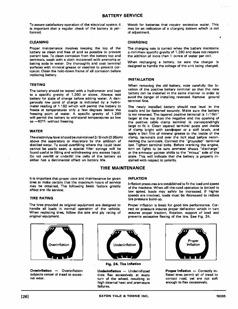
BATTERY SERVICE
To assure satisfactory operation of the electrical system it is important that a regular check of the battery is per- . formed.
CLEANING
Proper maintenance involves keeping the top of the battery as clean and free of acid as possible to prevent current loss. To clean corrosion from the battery top and terminals, wash with a cloth moistened with ammonia or baking soda in water. Dry thoroughly and coat terminal surfaces with mineral grease or vaseline to prevent corrosion. Clean the hold-down frame of all corrosion before replacing battery.
TESTING
The battery should be tested with a hydrometer and kept to a specific gravity of 1.260 or above. Always test battery for state of charge before adding water. A dangerously low point of charge is indicated by a hydrometer reading of 1.150 which will permit the battery to freeze at temperatures only a few degrees below the freezing point of water. A specific gravity of 1.260 will permit the battery to withstand temperatures as low as -60°F. without freezing.
WATER
The electrolyte level should be maintained 3/8 inch (0.95cm) above the separators or insulators by the addition of distilled water. To avoid overfilling where the liquid level cannot be easily seen, a special filler syringe will be found useful in filling and withdrawing any excess liquid. Do not overfill or underfill the cells of the battery as either has a detrimental effect on battery life.
Watch for batteries that require excessive water. This may be an indication of a charging system which is out of adjustment.
CHARGING
The charging rate is correct when the battery maintains a minimum specific gravity of 1.260 and does not require the addition of more than 1 ounce of water per cell.
When recharging a battery, be sure the charger is designed to handle the voltage of the unit being charged.
INSTALLATION
When removing the old battery, note carefully the location of the positive battery terminal so that the new battery can be installed in the same manner in order to avoid the danger of installing reversed. Remove ground terminal first.
The newly installed battery should rest level in the cradle and be fastened securely. Make sure the battery is not reversed. The tapered positive terminal is 1/16th" larger at the top than the negative and the opening of the positive cable clamp terminal is correspondingly large to fit it. Clean tapered terminal posts and inside of clamp bright with sandpaper or a stiff brush, and apply a thin film of mineral grease to the inside of the clamp, terminals and over the bolt stud before reconnecting the terminals. Connect the "grounded" terminal last. Tighten terminal bolts. Before cranking the engine, turn on lights to be sure ammeter shows "discharge" or the ammeter pointer shifts to the "minus" side of the scale. This will indicate that the battery is properly installed with respect to polarity.
TIRE MAINTENANCE
It is important that proper care and maintenance be given tires to make certain that the maximum hours of service may be obtained. The following basic factors greatly affect tire life service:
TIRE RATING
The tires provided as original equipment are designed to handle all loads in normal operation of the vehicle. When replacing tires, follow the size and ply rating of original equipment.
INFLATION
Inflation pressures are established to fit the load and speea of the machine. When off-the-road operation is limited to low speed, loads may safely be increased. If higher speeds are involved. loads must be decreased to reduce tire pressure build-up.
Proper inflation is basic for good tire performance. Correct air pressure insures proper deflection which in turn assures proper traction, flotation, support of load and prevents excessive flexing of the tire. See Fig. 24.
Overinflation - Overinflation subjects center of tread to excesive wear.
Fig. 24. Tire Inflation
Underinflation - Underinflated tires flex excessively at every turn of the wheel, resulting in high internal heat and premature failures.
Proper Inflation - Correctly inflated tires permit all of tread to contact road, yet are not soft enough to- flex excessively.
EATON YALE & TOWNE INC. TB065

CAUTION: Check and correct pressures only when tires are at normal temperatures.
For average operating conditions, inflate tires to the pressure shown in Tire Inflation Chart Fig. 25.
PRESSURE CHECKS
Continuous operation of equipment builds up heat in a tire. The hot air tries to expand and as a result, the temperature increases. Because only a small amount of expansion is possible, tire pressure increases. If "hot" pressure exceeds recommended "cold" pressure by
Inspect tires daily for cuts, breaks or sharp objects which might work into the casing. Remove all foreign material. It is important that even apparently minor damage be' repaired at once as water, dirt or other materials will enter cuts or other injuries causing tread or ply separation, possibly a blow-out.
more than 15 Ibs., speed, load or both must be decreased. TIRE STORAGE
CAUTION: Do not bleed tire to correct build-up of It is important to use the tires which have been in stock air pressure. the longest period of time.
INSPECTION AND MAINTENANCE
Regular tire inspection is important to the increased life of the tires. The following conditions must be observed and corrections made where necessary. Keep valve caps on to prevent dirt QettinQ in the valve. Replace the valve core when it first develops a leak.
Keep tires free from oil, grease and gasoline. Never clean tires with gasoline or other petroleum products or allow tires to stand in puddles of petroleum products. If a petroleum product does get on a tire, promptly flush off or wipe off with water.
Tire Size Ply Rating
13 x 24 8
17.5 x 25 12
For indoor storage, it is important that the location be cool. dry, dark and free from air currents. High temperatures (over 8()OF.) should be avoided. Keep the floor free of oil and grease. Store away from electrical devices such as motors or switches as they are an active source of ozone which causes rapid aging.
Outdoor storage is not recommended. If it is necessary, however, tires should be protected from the weather by a waterproof covering. Inspect tires before mounting to be sure they are clean, dry and free of foreign objects.
Unmounted tires should be stored in a vertical position. Do not lift tires by beads with hooks or forks.
Pressure
Operating Transporting Load Without Load
25 25
25 25
Fig. 25. Tire Inflation Chart
TB065 EATON YALE & TOWNE INC. [27]

g ~ .. Q,. I-,
CD
r-
OO
eft
c:t C"ooI
-C"ooI
C"ooI C"ooI
-C"ooI
-C"ooI
." C"ooI
CD C"ooI
r-C"ooI
-C"ooI
eft C"ooI
c:t ---C"ooI -
[28] EATON YALE & TOWNE INC. TB065

aI o C» U1
~ Z
~ !;; AI
~ Z /11
Z $"I
~ ......
Interval Hours Point
1 2 3 4 5
6 7 8
11 12
13 14
8 15
16
17
18
19 23 24 25
26 27 29 32
TROJAN TRACTOR SHOVEL
MODEL 1500
Indentification
Front Bucket Link Assembly Front Bucket Lever Assembly Bucket Link Assembly Bucket Cylinder Pivot Rear Bucket Lever Assembly
Bucket Cylinder Head Lift Arm Pivot Fuel Filter (GM & HD) Batteries Engine Controls (GM)
Air Cleaner Fuel Filter (GM) Radiator (Permanent Type Anti-Freeze Below 32° F) (Water with rust inhibitor above 32° F)
Air Reservoir
Engine Oil (Refer to Engine Manufacturers Maintenance Manual for type and change intervals)
Axle Cradle Pivot
Differential Drain & Fill Transmission Breather Main Pivots (Upper & Lower) Drive Shaft Assembly
Steering Cylinder Pivot & Head Lift Cylinder Pivot Lift Cylinder Head Bucket Pivot
No. of Type of Points Lubricant
2 MPG 1 MPG 4 MPG 1 MPG 1 MPG
1 MPG 2 MPG 2 Drain 6 Check 2 MPG
1 Check 2 Drain
1 Check 2 Drain
1 Check EO
2 MPG
2 MPL 1 Clean 2 MPG 2 MPG
4 MPG 2 MPG 2 MPG 2 MPG
LUBRICATION CHART
Interval Hours Point Identification
20 Power Cluster (Rear) 22 Propeller Shafts
50 28 Power Cluster (Front) 30 Planetary Oil Level
31 Differential Drain
200 9 Transmission Hydraulic System Filter
13 Air Cleaner (Element)
300 8 Fuel Filter (GM & HOI
400 9 Transmission Filter (Change when Changing Oil)
23 Transmission Hydraulic Oil
500 10 Filter Element, Main & Steering Hydraulic (In Reservoir)
10 Main & Steering Hydraulic System Oil
1000 13 Air Cleaner (Element) 19 Differential Drain & Fill 21 Planetary Drain & Fill
KEY TO SYMBOLS
No. of Type of Points Lubricant
1 BF 6 MPG 1 BF 4 Check
MPL 2 Check
1 Change 1 Clean
2 Change
1 Change 1 Change
TA
1 Change
1 Change SAE 10-W
1 Change 2 MPL 4 Change
EO - Engine Oil MPG - Multi-Purpose Type Grease SAE 10 - W Hydraulic Oil that is resistant to rust. oxidation and foaming. I
TA -Type A - Suffix A Automatic Transmission Fluid or Dexron. MPL - Multi-Purpose Type Gear Lubricant for Service API GL4 CRC - 10 Level
Grade or Better - SAE 90. BF - Brake Fluid (Conforms to SAE - Spec. 70R3).
I
'---~- ..

ow 3
~ a z
~ r 111 AI
a ~ z 111
Z fl
ill o m en
63
62
47
46 45 44 43 42 41
5 6 7 8 14 15 16 17
\1 ;, /". ~ ~
40 39 38 37 36 35 34 33
29
30
31
32
TP2398 .

Item
1 2
3 4 5 6 6A 6B 7 8 8A 9
10 lOA lOB 11 12 12A 12B 12C 13 14 14A 14B 14C 15 16 16A 17 17A 17B 17C 18 19 20 20A 20B
*21 22 22A 22B 22C 23
*24 *24A *24B *24C *25 *26 *27 *28 *29 *29A *29B *30
TB065
SHEET METAL SHROUDING
Part No.
2079440
2077098 2077101 2077111 2031477 2031391 2032960 2077567 2031615 2031389 2079951 2031427 2031389 2032958 2077751 2031477 2031391 2032960 2031617 2071340 2079237 2031769 2031391 2031617 2079040 2078568 2077987 2031519 2036818 2031393 2031619 2079041 2079039 2071029 2031391 2032960 2077884 2031473 2031391 2032960 '2031617 2079230 2079613 2036097 6950888 2031863 2062539 2031757 2064185 2036811 2036097 6950888 2031863 2079612
Description No. Req'd.
Tank Assy., Hydraulic ....... . Element, Filter (See Main Hydraulic System) .... .
Spring ..................... 1 HandleAssy., Tee........... 1 Cover, Filter Element ........ 1 Bolt ....................... , 4 Washer, Flat. . . . . . . . . . . . . . . . 4 Washer, Lock (N.I.) ... . ... . .. . 4 Clamp. ... .... ..... ..... .... 2 Nut................ ........ 4 Washer, Lock ............... 4 Cover, Console.. . . .. . . . . . . . . 1 Bolt.... ........ ......... ... 4 Washer, Lock ............... 4 Washer, Flat . . . . . . . . . . . . . . . . 4 Console, Valve Control .... . . . 1 Bolt........................ 6 Washer, Lock ............... 6 Washer, Flat . . . . . . . . . . . . . . . . 6 Nut........................ 6 Knob....................... 2 Rod .... ............ ..... ... 2 Pin, Cotter ................... 2 Washer, Lock (N.I.) . ... . . .. . .. 2 Nut(N.I.).................... 2 Cover, Battery Box. . . . . . . . . . . 1 Hold Down Assy., Battery. . . . . 1 Tray, Battery (N.I.) ........... 1 Bolt........................ 5 Washer, Flat(N.I.) ........... 5 Washer, Lock ............... 5 Nut........................ 5 Box, Battery ................ 1 Hood Assy., Rear............ 1 Bolt........ ................ 4 Washer, Lock ............... 4 Washer, Flat . . . . . . . . . . . . . . . . 4 Panel, Side ................. 2 Bolt....... ................. 4 Washer, Lock(N.I.) . . . . . . . . . . . 4 Washer, Flat .. .. . .. . . .. . . .. . 4 Nut(N.I.).................... 4 Plate, Side . . . . . . . . . . . . . . . . . . 2 Seat, Panel Catch ........... 4 Screw, Machine. . . . . . . . . . . . . 8 Washer, Lock ............... 8 Nut........................ 8 Pin........................ 4 Pin, Cotter . . . . . . . . . . . . . . . . . . 4 Latch...................... 4 Washer.................... 4 Screw, Machine. . . . . . . . . . . . . 8 Washer, Lock(N.I.)........... 8 Nut(N.I.).................... 8 Base, Panel Catch ........... 4
(N.I.) Not Illustrated
*Optional Equipment
Item
31 31A 31B 31C 32 33 33A 34 35 36 36A 36B 37 37A 38 39 39A 39B 40 41 42 42A 42B 43 44 45 46 47 48 49 50
50A 51 52 53 54 55 56
56A 57 58 59 60 61
61A 61B 62
62A 62B 63 63A 63B
Part No.
2031475 2031391 2032960 2031617 2079267 2077067 2077038 2079448 2033388 2031560 2032964 2031621 2031426 2031389 2077565 2071029 2031391 2032960 2078502 2077566 2071029 2031391 2032960 2038543 2077055 2077153 2077058 2031391 2067425 2077054 2077060
2077059 2077056 2077152 2031959 2008813 2069785 2069784
2069137 2005062 2069140 2069143 2031770 2072697
2072696 2039493 2077833
2077716 6750769 2031562 2032964 2031621
EATON YALE & TOWNE INC.
, Description No. Req'd.
Bolt.. ...... .... ......... ... 4 Washer, Lock. .. . . . . .. . . . . . . 4 Washer, Flat(N.I.) ........... 4 Nut........................ 4 Gauge, Fuel. . . . . . . . . . . . . . . . . 1 Cap Assy., Fuel.. . . . . . . . . .. . . 1 Gasket, Fuel Cap ............ 1 TankAssy., Fuel ............. 1 Plug, Drain ................. 1 Bolt........................ 6 Washer, Flat. . . . . . . . . . . . . . . . 6 Nut........................ 6 Bolt........................ 2 Washer, Lock ............... 2 Plate....................... 1 Bolt.... .................... 4 Washer, Lock ............... 4 Washer, Flat . . . . . . . . . . . . . . . . 4 Cowl, Front Deck Assy. ....... 1 ' Shroud Assy., Front. . . . . . . ... 1 Bolt........................ 5 Washer, Lock ............... 5 Washer, Flat ................ 5 Plug, Magnetic Drain ........ 1 Plate, Valve. . . . . . . . . . . . . . . . . 1 Ring, Retainer .............. 1 Spacer, Pipe ................ 2 Washer, Lock... . . . . . .. . . .. . 2 Nut,Lock ................... 2 Spring ..................... 1 Valve Assy., Pressure Relief (Incl. Items 44,45,49 & 50A thru 52)
Plate, Capture .............. . Rod,Valve ................. . Ring, Retainer ............. . "0" Ring .................. . Washer ................... . Bolt ....................... . Plate Assy., Cover (Incl. Items 53 thru 55 & 56A thru 60) ... .
Plate ...................... . "0" Ring .................. . Spacer .................... . Bar ....................... . Pin, Cotter ................. . Glass Assy., Sight(lncl. Items 61A& 61 B) .......... .
Glass, Sight ............... . "0" Ring .................. . Cap Assy. (lncl.ltems 62A&62B) ................ 1
Cap........................ 1 "0" Ring ................... 1 Bolt........................ 2 Washer,Flat(N.I.) ........... 2 Nut........................ 2
[31]

[32]
-------
CI -
CD
-
M -
-eN
u:t -
CD -en -
EATON YALE &~T~O~W~N:E:-;I;:;;;NC~. --------------~~ TB065

TB065
FLOORBOARDS AND SEAT
Item Part No. Description No. Req'd.
A
1 2 3 4 5 6 6A 6B 6C 7 7A 7B 8 9 9A 9B
10 10A 10B 11 12 13 14 15
16 17 18 19 20 21 22 23 24
2078444
2031472 6952843 6952844 6952845 2078433 2031519 2031393 2032962 2031619 2071029 2032960 2036816 2071719 2031454 2031390 2031616 2031485 2031617 2031391 2077651 2077652 2078424 2079156
2079227 2033517 2032962 2079429 2078395 2031370 2031390 2031475 2036816
Seat Assy. (Incl. Items 1 Thru4&21 thru24) ........ .
Bolt ....................... . Shell Assy ................. . Back Rest Assy ............. . Cushion, Seat .............. . Support Assy., Seat ......... . Bolt ....................... . Washer, Lock .............. . Washer, Flat(N.I.) .......... . Nut(N.I.) ................... . Bolt ....................... . Washer, Flat (Large) ........ . Washer Flat (Small) (N.I.) .... . Plate, Mounting ............ . Bolt ....................... . Washer, Lock .............. . Nut ....................... . Bolt ....................... . Nut ....................... . Washer, Lock .............. . Molding, Rubber ........... . Molding, Rubber ........... . Floorplate Assy., Front ...... . Floorplate Assy., Center ..... . Console, Valve Control (SeePage30&31) ......... . FloorplateAssy., Rear ....... . Nut ....................... . Washer, Flat ............... . Rod, Threaded ............. . Support Assy., Tipping Seat Nut(Furn. W/Seat) ......... . Washer, Lock (Furn. W/Seat) Bolt ....................... . Washer, Flat ............... .
(N.J.) Not Illustrated
THINK Avoid greasy hands and floor boards.
EATON YALE 8: TOWNE INC.
1 5 1 1 1 1 3 3 3 3 8 7 1 1 4 4 4 1 2 1 2 1 1 1
1 2 2 1 1 4 4 2 2
,
[33]

GO-______ _
,...
[34]
----~ --- -
\.--------
-~
-----------~~-------~ -1ft -UI -,... -GO -
~~;;-----~
EATON YALE & TOWNE INC. TB065

CAB ASSEMBLY (Optional)
Item Part No. Description No. Req'd. Item Part No. Description No. Req'd.
TB065
A
B
C
1 2 3 4 5 6 6A 6B 6C 7
7A 7B 7C 8 9
10 11 12
12
6952817
6952821
6952813 6952814 6952417 6952809 6952808 2031450 2032959 2031390 2031616 6952419
6952473 2032959 2031450 6950586 6952812 6952819 6952818 6951408
6952697
CabAssy., (Incl.ltems 1 thru21,23thru27)(See Note)
Door Assy., Right Hand (Incl.ltems 7 & 10 thru 18) .................. .
Door Assy., Left Hand (Incl. items 7 & 10 thru 18) ................... 1
Window, Quarter Panel ...... 2 Rubber, Quarter Panel ....... 2 Latch, Door ................. 2 Rubber, FrontWindow ....... 1 Window, Front .............. 1 Bolt........................ 4 Washer, Flat . . . . . . . . . . . . . . . . 8 Washer,Lock ............ ... 4 Nut........................ 4 Hanger Assy. (Incl. Items 7 A, 7B, & 7C) ......... 4
Hanger..................... 4 Washer, Flat(N.I.) ........... 8 Screw, Cap ................. 8 Rubber, Corner Window ...... 2 Window, Corner. . . . . . . . . . . . . 2 Rubber, Door Window ........ 2 G lass, Door . . . . . . . . . . . . . . . . . 2 Handle, Door (L.H.) (Incl. Items 12A& 12B) .......... .
Handle, Door (R.H.) (Incl. Items 12A& 12B) .......... .
(N.I.) Not Illustrated
12A 12B 13
13A 13B 13C 130 13E 14
14
14A 15 16 17 18 19 20 21 22 22A 22.B 22C 23 24 25 26 27
6952698 6951410 6952420
6952475 6952474 2032959 2031389 2031615 6952699
6952700
6952421 6951409 6952426 6952476 2033359 6952816 6952433 6950951 2031480 2032960 2031391 2031617 6952432 6952431 6952811 6952810 6952429
Handle .................... . Screw ..................... . GuideAssy., Door (lncl.
Items 13A thru 13E) ....... . Screw ..................... . Roller ..................... . Washer, Flat ............... . Washer, Lock .............. . Nut ....................... . Lock, Ooor(R.H.) (Incr. Items 14A & 1 8) ........... .
Lock, Ooor(L.H.) (Incl. Items 14A & 1 8) ........... .
Lock ...................... . Handle, Inside ............. . Seal ...................... . Screw, Set ................. . Screw ..................... . Seal,Ooor ................. . Track, Lower ............... . Screw ..................... . Bolt ....................... . Washer, Flat ............... . Washer, Lock .............. . Nut ....................... . Seal ...................... . Seal ...................... . Rubber, Rear ............... . Window, Rear .............. . Rubber, Mounting (N.I.) ...... .
1 4
4 4 4 4 4 4
1 2 2 2 2 8 4 2
14 4 8 4 4 1 2 1 1 1
Note: Consult Factory When Ordering Complete Cab Assembly
THINK Never leave operators seat with the arms raised.
[35] Revision 1 - October, 1975

[36]
1 2 3 4 5 6 7 8 9 10 11 12 13
33
32
31
29--"':
28 27 26 25 24
, :' ,
I' /
I
23
'1\\Q-----+--4-!--14
1_15
I,' I : : / . I I, I
/ll / If! I " , ., ,
" i,i
/ " / , , I ,
/ / 1,1 I I I
! , , , ,
, I I , I ! ! I , I I I I
. ! I
I II 16
II 17 18
@ \19
TP2379
TB065

TB065
WINDSHIELD WIPER KIT (ELECTRIC)
(optional)
Item Part No. Description
2080150 Arm, Pantograph
No. Req'd.
(lncl.ltems 30 & 30A) ....... 1 2 6952961 Nut. . . . . . . . . . . . . . . . . . . . . . . . 1 3 6952961 Nut.... .. . . ...... . . .. . .. .. . 1 3A 2049429 Washer.................... 1 4 6952962 Driver... . . . . . . . . . . . . . . . . . . . 1 5 2049429 Washer, Lock ............... 1 6 6952963 Cap, Rubber ................ 1 7 6952964 Nut.... .. .. .. .. .. .. .. .. .. .. 1 8 2030743 Bolt........................ 2 8A 2031389 Washer, Lock............... 2 8B 2032959 Washer, Flat .. .. .. .. .. .. .. .. 2 9 2080151 Kit, Adapter
(lncl.ltems 3, 3A & 10) ...... 1 10 6952973 Gasket.... .. .. .. .. .. .. .. .. . 1 11 6952965 Gasket.. .. .. .. .. .. .. .. .. .. . 1 12 6952966 Washer, Flat.. .. .. .. .. .. .. .. ·1 13 2080152 Switch (lncl.ltems 17 & 18) . . . 1 14 2080387 Kit, Wiper (lncLltems2,
4thru7, 11 & 12) ........... 1 15 2080196 Tube........ .. .. .. .. .. .. . .. 1 16 2031425 Bolt........................ 2 16A 2032958 Washer, Flat (N.I.) ........... 2 16B 2031389 Washer, Lock............... 2 16C 2031615 Nut........................ 2 17 6952969 Knob. . . . . . . . . . . . . . . . . . . . . . . 1 18 6952970 Nut.... .. .. .. .. .. .. .. .. .. .. 1 19 2079166 Clip........................ 4 20 2050575 Connector...... .. .. .. .. .. .. 1 21 2080202 Wire....................... 1 22 2079165 Grommet... . . . . . . . . . . . . . . . . 1 23 Switch, Ignition (See Page 64) 24 2049952 Wire ...................... . 25 Switch, Ignition (See Item 23) 26 Connector (See Item 20) 27 Motor, Wiper (See Item 14) 28 Switch (See Item 13) 29 2080149 Blade, Wiper .. .. .. .. .. .. .. .. 1 30 6952971 Bolt........................ 1 30A 6952972 Nut.. .. .. .. .. .. .. .. .. .. .. .. 1 31 2080167 Lug, Mount ................. 1 32 2051062 Ends, Terminal .... '" ....... 3 33 2046559 Sleeve.. .. .. .. .. .. .. .. .. .. . 3
(N.I.) Not Illustrated
THINK Set parking brake when leaving seat or shutting down for the day.
EATON YALE 8c TOWNE INC.
,
[37]

Item
1 2 3
4 4A 5 6
6A 68 6C 6D 7
[38]
Part No.
2049952 2080203
2050575 2051069 2079176 2033155
2021523 2022590 6950812 2020716 2033634
1 8 9 10
20 19 18 11 16
WINTERIZATION KIT (Optional) (HG&HD)
Description No. Req'd. Item
Wire, Ignition to Connector 8 Wire, Connector to Connector 9 Switch, Ignition (See 10 Page 64) ................... 11
Connector .................. 2 12 Terminal. Bullet ............. 1 13 Fan, Defroster ••• 0 •••••••••• 1 14 Heater (lncl. Items 15 6AThru6D) ................ 1 16
Motor, Heater(N.I.) •• ••••• 0 •• 1 Blade, Fan (N.I.) ............. 1 17 Switch, Motor (N.I.) .......... 1 18 Core, Heater (N.I.) •••••••• 0 •• 1 19 Nipple ...................... 1 20
Part No.
2032294 2033033 2032038 2044426 2055832 2035717 2033084 2033635
2035717 2032294 2039445 2080748
(N.I.) Not Illustrated
THINK Never carry a rider in the bucket.
EATON YALE 8: TOWNE INC.
11 17 ,
TP2422
Description No. Req'd.
Elbow,90o ••• 0 ••••••••••••• 2
Nipple ...................... 1 Clamp. Hose ................ 4 Grommet ................... 2 Hose ....................... 1 Valve, Drain •• 0 ••••••••••••• 1 Coupling ................... 1 Nipple ...................... 1 Engine(See Page 56 Thru 59) ••••••••• 0 •
Valve. Drain • ••••• 0 ••••••• 0.
Elbow, 900 ................. Hose ....................... Floormat ...................
TB065

Item , 2 3
4 4A 5 6
6A 6B 6C 60 7
TB065
19 18 17 16 15 14 TP2400
WINTERIZATION KIT (Optional)
(GM)
Part No. Description No. Req'd. Item Part No. Description No. Req'd.
2049952 Wire, Ignition to Connector ... 8 2033634 Nipple ...................... 1 2080203 Wire, Connector to Connector. 9 2032038 Clamp, Hose ................ 4
Switch, Ignition (See 10 2044426 Grommet ................... 2 Instrument Panel) .......... 11 2039445 Hose, Feed ................. 1
2050575 Connector .................. 2 12 2032829 Clamp ...................... 2 2051069 Terminal, Bullet (N.I.) •• 0 •• 0 •• 1 13 2031473 Bolt ........................ 2 2079176 Fan, Defroster •• •••••••• 0 ••• 1 14 2035717 Valve, Shut-Off •• 0.0 •••• 0 ••• 2 2033155 Heater (Incl. Item 15 2053266 Bushing, Reducer ........... 1
SA Thru 60) ................ 1 *16 2032303 Elbow, 45° ................. 1 2021523 Motor, Heater(N.I.) .......... , +16 2032294 Elbow, 90° ................. 1 2022590 Blade, Fan (N.I.) •••• 0 ••••••••
, +16A 2053268 Bushing, Reducer ........... , 6950812 Switch, Motor(N.I.) .......... 1 17 2039443 Hose, Return ................ 1 2020716 Core, Heater (N.I.) ........ ... , 18 2033033 Nipple ...................... , 2032294 Elbow, 90° .. , .. ·.·.0 ..... 0. 2 19 2080748 Floormat ................... 1
(N.I.) Not Illustrated
*For Machines having Serial NumberThru 15-' 049. +For Machines having Serial Number 15-1050 & Higher.
EATON YALE & TOWNE INC.
,
[39]

- 00 ,
-----CP,t -
\...---------~ -
- ----~ ~=-------
--o
--
[40] EATON YALE & TOWNE INC. TB065

,
FRAME GROUP
Item Part No. Description No. Req'd. Item Part No. Description No. Req'd.
1 2060723 Screw, Drive ................ 6 +13 2082467 Bar, Tie Down ............... 1 2 2058920 Plate, Trojan Name •• 0 ••••••• 1 +13A 2031586 Bolt, Bar to Front Section 1 3 2048096 Bolt ........................ 4 13B 2031622 Nut ........................ 1 3A 2032967 Washer, Flat ................ 8 14 2031580 Bolt ........................ 1 3B 2031378 Nut •• 0 ••••••••••••••••••••• 4 14A 2031622 Nut •••••••••••• D ••••••••••• 1 4 2033249 Fitting, Grease .............. 2 15 2031490 Bolt ........................ 2 5 2031561 Bolt ........................ 8 15A 2031391 Washer, Lock ............... 2 5A 2032964 Washer, Flat ................ 8 15B 2031617 Nut ........................ 2 5B 2041073 Nut ............ ............ 8 16 2080085 Pin ........................ 2 6 2079053 DeckAssy ................... 1 17 2077885 Bushing .................... 2 7 2077234 Frame Assy., Front .......... 1 18 2044117 Spacer(1/16"j .............. AR 8 2032415 Bolt ........................ 8 19 2044118 Spacer(Vs"j ................. AR 8A 2031376 Nut .·0 ..................... 16 20 2077892 Cradle Assy. • •• 0 •••••••••••• 1 9 2033250 Fitting, Grease .............. 2 21 2032415 Bolt ........................ 8
10 2077477 Spacer ..................... 2 21A 2031376 Nut ........................ 16 11 2077656 Plate, Capture ............... 2 22 2077888 TubeAssy ................... 2 12 2031557 Bolt ........................ 2 23 2031985 Adapter, Straight ............ 1
*13 2077341 Bar, Tie Down ............... 1 24 2032007 Elbow, 900 . ................ 3 *13A 2031582 Bolt, Bar to Front Section ..... 1 25 2081435 Plate, Counterweight ........ 3
26 2079158 Frame Assy., Rear ........... 1
AR As Required
* For Machines having serial number thru 15-1039. + For Machines having serial number 15-1040 & Higher.
THINK Stop machine to lubricate or adjust.
TB065 EATON YALE & TOWNE INC. [41]
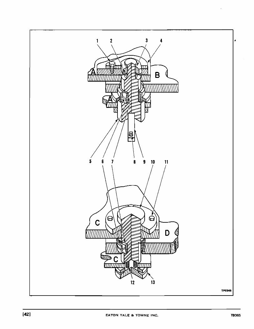
2 3 4
5 6 7 8 9 10 11
TP2345
[42] EATON YALE 8: TOWNE INC. TB065

,
PIVOT GROUP
Item Part No. Description No. Req'd.
A (Reference Pivot Crossmember, Upper Rear B (Reference) Pivot Crossmember, Upper Front C (Reference) Pivot Crossmember, lower Rear D (Reference) Pivot Crossmember, lower Front 1 2031559 Bolt........................ 1 2 2080648 Spacer..................... 1 3 2080249 Nut......... .. .. .. .. .. . .. .. 1 4 2077906 Plate, lock. . . . . . . . . . . . . . . . . . 1 5 2077898 Pin, Upper (Incl. Item 7) . . . . .. . 1 6 2066431 Race, Outer.......... . .. .... 2 7 2066432 Race, Inner ................. 2 8 2031519 Bolt........................ 2 9 2077341 lockbar. . .. .. .. . . .. . .. . .. . . 1
10 2077337 Pin,lower(lncl.ltem7) ....... 1 11 2031578 Bolt........................ 4 12 2031523 Bolt........................ 2 13 2077357 Plate, Capture. . . . . . . . . . . . . . . 1
THINK Keep the work area as smooth as possible.
TB065 EATON YALE Be TOWNE INC. [43]

--------------------~~.-
N-
-
[44] EATON YALE 8: TOWNE INC. TB065

Item
1 1A 1B 1C 2 3 4
5 5A 5B 5C 6
7
8 9
10 11 11A 12 13
14 15 15A 15B 15C 16
TB065
LIFT ARM AND LINKAGE
Part No.
2077132 2031516 2077182 2031557 2076005 2030225 2077377
2077139 2031557 2077182 2037659 2077025
2030225 2077536 2077538 2077143 2037659 2030225 2080581
2031557 2080612 2077182 2031492 2031617 2073398
Description No. Req'd.
Pin Assy. ................... 2 Bolt, Pin to Frame. . . . . . . . . . . . 2 Plate, Capture (N.I.) .......... 2 Bolt........................ 2 Bushing.................... 2 Fitting, Grease.. . . . . . .. . . .. . 2 Lift Arm Assy. (lncl. Items 2 & 24) .............. .
Pin Assy ................... . Bolt(N.I.) .................. . Plate, Capture(N.I.) ......... . Bolt, Pi n to Lever ........... . Bucket Lever Assy., Rear (lncl.ltem 10) ............. .
Cylinder, Bucket (See Sep. lIIus.) ..................... .
Fitting, Grease .............. 4 Bushing.................... 4 Bushing.................... 2 Pin Assy. ................... 1 Bolt(N.!.) ................... 1 Fitting, Grease .............. 1 Link Assy., Bucket Rear (lncl.ltem 9) ............... 2
Bolt........................ 4 Pin... ........... .......... 2 Plate, Capture. . . . . . . . . . . . . . . 4 Bolt (N.I.) ................... 2 Nut(N.I.) .................... 2 Pin........................ 1
(N.!.) Not Illustrated
THINK
Item
16A 16B 16C 17 18
19 20 21 22 22A 22B 22C 23 24 25 25A 25B 25C 26 26A 26B 27 27A 27B 27C 28
29 29A 29B
Know the work area.
Part No.
2031530 2031393 2031619 2077536 2077034
2030225 2030225 2077028 2077137 2031557 2077182 2037659 2030225 2077535 2073187 2031530 2031393 2031619 2077141 2031519 2031393 2077135 2077539 2031534 2031619
2077385 2031519 2031393
EATON YALE & TOWNE INC.
Description No. Req'd.
Bolt(N.I.) ................... 1 Washer, Lock(N.I,) . . . . . . . . ... 1 Nut(N.I.) . . .. .. .. . . . . ... . . .. . 1 Bushing.................... 4 Link Assy., Front Bucket (lncl,ltem 17) .............. 1
Fitting, Grease .............. 2 Fitting, Grease .............. 1 Lever,BucketFront .. ... ..... 1 Pin........................ 1 Bolt(N.I.) ................... 1 Plate, Capture (N.I.) .......... 1 Bolt, Pin to Front Lever ....... 1 Fitting, Grease .............. 2 Bushing.................... 2 Pin ..................... ... 2 Bolt(N.I.) ................... 2 Washer, Lock (N.I.) . . . . . . . . .. . 2 Nut(N.I.).................... 2 Pin Assy. ................... 1 Bolt(N.I.) ................... 1 Washer, Lock(N.I.) . . .. .. . . . . . 1 Pin Assy. ................... 1 Bushing(N.I.) ............... 2 Bolt(N.I.) ................... 1 Nut(N.I.)... ................. 1 Cyli nder, Lift (See Sep. lIIus.) ..................... .
Pin Assy. ................... 2 Bolt........................ 2 Washer, Lock ............... 2
[45]

1 2
3 TPt020
BUCKET ASSEMBLY
Item Part No. Description No. Req'd. Item Part No. Description No. Req'd.
2079981 BucketAssy., 1 % Cu. Yd. 2079982 BucketAssy., 1 % Cu. Yd. (Inclltems 2 thru 4) ......... (Incl.ltems 2 thru 4) .........
2 2077844 Edge, Cutting, L.H. Side ..... . 2 2077837 Edge, Cutting, L.H. Side ...... 3 2079062 Edge, Cutting .............. . 3 2070835 Edge, Cutting •• 0 ••••••••••••
4 2077843 Edge, Cutting, R.H. Side ...... 4 2077836 Edge, Cutting, R.H. Side ......
[46] EATON YALE & TOWNE INC. TB065

, 2 3 4 5 6 7
13 12 11 10 9 8 TP2336
BUCKET INDICATOR
Item Part No. Description No. Req'd. Item Part No. Description No. Req'd.
A 2077548 Bucket Indicator Assy. (lncl. 7 2031481 Bolt ........................ Items 2 thru 4 & 8 2077512 Housing Assy. (Incl. 8& 11 ..................... 1 Items 1 & 8A) .............. 1
1 2077440 Bushing,Oilite .............. 1 SA 2077437 Housing .................... 1 2 2077496 Indicator ................... 1 9 2031617 Nut . ....................... 1 3 2080844 Rod ........................ 1 10 2077501 Washer, Lock ............... 2 4 2077504 Nut, Jam ................... 2 11 2063052 Bearing, Rod End ............ 2 5 2077445 Boss, Tapped .............. . 1 12 2077500 Washer, Flat ................ 3 6 2031391 Washer, Lock . ........... ... 1 13 2077502 Bolt ........................ 2
TB065 EATON YALE & TOWNE INC. [47]

1 2 3 4 5 ,
6
7
8
9
18--------------~~~1
/:
r / '
17 16 15 14 13 12 11 TP2433
AUTOMATIC BUCKET LEVELER Item Part No. Description No. Req'd. Item Part No. Description No. Req'd.
A 2077688 Leveler Assy., Automatic Bucket 7A 2077684 Strain Relief, Metal (N.I.) 1 (Incl.ltems 2 thru 8 & 10) .... 8 2077683 Grommet ................... 1
1 Switch, Ignition (See Page 64) 9 2032854 Clamp ...................... 1 2 Spacer (N.S.S.)(Order Item 3) . 10 2077685 Wire Assy ................... 1 3 2077681 Switch Assy., Micro 1 1 2077527 Loom,Wire ................. 1
(Incl.ltem 2) ............... 12 Spool Assy., Bucket 4 Indicator, Bucket (See Page 47) (See Pages 84 & 85) ........ 5 2036081 Screw ...................... 2 13 2079410 Connector, Knife End ........ 1 5A 2031865 Washer, Lock ............... 2 14 2013250 Sleeve •••••••• 0 •••••••••••• 2 6 2046755 Screw ...................... 2 15 2013218 Terminal •••• 0 •••••••••••••• 1 6A 2031866 Washer, Lock ............... 2 16 2077689 WireAssy ................... 1 7 2077686 Cover ...................... 1 17 2055351 Sta-Strap ................... 4
(N.I.) Not Illustrated 18 2077690 Wire Assy ................... 1
(N.S.S.) Not Serviced Separately
[50] EATON YALE & TOWNE INC. TB065

,
1 2 3 4
TP2399
FENDER INSTALLATION
Item Part No. Description No. Req'd.
1 2080910 Fender Assy., R. H............ 1 2 2031521 Bolt.. .. .. . .. .... ........ ... 6 3 2031393 Washer, Lock ............... 6 4 2031619 Nut........................ 6 5 2080911 Fender Assy., L. H. . . . .. . . . . .. 1
THINK Use care on slopes.
TB065 EATON YALE Be TOWNE INC. [51]

, 14
13
12
3
10
9
8
1 ___ --=:::::~~~
6
5-____ _.1
4 TP2421
PARKING BRAKE & LINKAGE Item Part No. Description No. Req'd. Item Part No. Description No. Req'd.
Lever Assy., Parking 8A 2031396 Washer, Lock •••••••••• 0 •••• 6 Brake (See Page 53) .0 ••••.• 9 2081458 Bracket, Cable Mount ........ 1
2 Pin, Clevis (Furn. 10 2078325 Cable Assy .................. 1 W/ltem1) ................. 11 2033514 Nut,Jam .0 ••••••••••••••••• 1
3 Pin, Cotter (Furn. 12 2031675 Clevis ...................... 1 W/ltem 1) ................. 1 13 Washer(Furn.
4 2031662 Pi n, Clevis .................. 1 W/ltem 1) ................. 1 5 2031764 Pin, Cotter .................. 1 14 2031475 Bolt ........................ 2 6 2031676 Clevis ...................... 1 14A 2031391 Washer, Lock ............... 2 7 2033515 Nut, Jam • 0 •••••••••• 0 ••• 0 •• 1 14B 2031617 Nut ........................ 2 8 2031574 Bolt ........................ 2
THINK Never leave operators seat with the arms raised.
[52] EATON YALE & TOWNE INC. TB065

14-------..
TP2303
PARKING BRAKE LEVER ASSEMBLY
Item Part No. Description No. Req'd. Item Part No. Description No. Req'd.
A 2078324 Lever Assy. 9 6950684 Bracket Assy., Pivot .......... 2 (Incl.ltems 1 Thru 21) ....... 10 6950693 Spacer ..................... 2
B 6955461 Kit, Knob Repair 11 6950701 Rivet ....................... 1 (lncl.ltems 1 thru 3 & 19) . ... 1 12 2031764 Pin, Cotter .................. 1
1 6952950 Knob ....................... 1 13 6950690 Pin •••••••••• 0 ••••••••••••• 1 1A 6952952 Pin(N.I.) .................... 1 14 6952947 Bracket, Mounting ........... 1 2 6950692 Washer, Spring ............. 1 15 2036815 Washer, Flat ................ 1 3 6952951 "O"Ring ................... 1 16 6950682 Link ........................ 1 4 6952949 Handle Assy., Lever (Incl. Item B) 1 17 6950678 TubeAssY.,Adjusting ........ 1 5 6950700 Washer, Spring •••• 0 •••••••• 1 18 Screw, Adjusting (N.S.S.) 6 6950679 Pin ........................ 1 (Order Item 4) .............. 7 6950692 Washer, Spring ............. 2 19 6950692 Washer, Spring . ............ 8 6950688 Spacer ..................... 1 20 6950686 Ring, "E" ...................
(N.I.) Not Illustrated 21 2036815 Washer, Flat ................
(N.S.S.) Not Serviced Separately
TB065 EATON YALE & TOWNE INC. [53]

---~
----
en
CD
-- ..
[54]
en
EATON YA LE Be T OWNE INC.
--1ft -
TB065

,
ENGINE AND RELATED PARTS (GM)
Item Part No. Description No. Req'd. Item Part No. Description No. Req'd.
1 1A 2 3 4 5
6 7
8 9
10 10A 11
12 13 13A 13B 13C 14 14A 14B 15
16 17 17A 17B 18 18A 18B 19 19A
TB065
2035717 Valve, Shut-Off ............. 1 2032303 Elbow (N.I.) ................. 1 2035236 Elbow, 90° ................. 1 2073968 Connector, Female .......... 2 2081004 Hose....................... 1
Gauge, Engine Oil Pressure (See Instrument Panel) ..... .
2032310 Tee ....................... . Switch, Oil Pressure (See Battery and Wiring) ............... .
2031985 Elbow,45° ................ . 2039266 Adapter,Orive(lncl.ltem
22&22A) ................. 1 2031477 Bolt........................ 12 2031391 Washer, Lock ............... 12
Transmission & Converter Assy. (lncl.ltem 9) (See Sep. lIIus.) ..................... .
2073633 Pulley ..................... . 2081010 Strap,Adjustment .......... . 2031475 Bolt(N.I.) .................. . 2031391 Washer, Lock(N.I.) .......... . 2031617 Nut(N.I.) ................... . 2031452 Bolt ....................... . 2032959 Washer, Flat ............... . 2031390 Washer, Lock .............. .
Alternator (See Battery &Wiring) ................. .
2068569 Kit, Mounting Bracket. . . . . . . . 1 Bolt(Furn. W/ltem 16) ....... 2 Washer, Lock (Furn. W/ltem 16) 2 Washer, Flat(Furn. W/ltem 16) 2
2031522 Bolt.... . . . . . . . . . . . . . . . . . . . . 1 2031393 Washer, Lock............... 1 2032962 Washer, Flat .. . . . . . . . . . . . . . . 1 2031475 Bolt........................ 2 2032960 Washer, Flat. . . . . . . . . . . . . . . . 2
(N.I.) Not Illustrated
THINK
19B 19C 20
21
22 22A 23 24 25
25A 25B
25C
250 26 26A 26B 27 27A 27B 28 29 30 31 32 33 33A 34 35 35A 36 36A 37
2031391 Washer, Lock .............. . 2031617 Nut ...................... .. 2052051 Belt,Alternator(Matched
Set of 2) .................. . 2052051 Belt, Fan (Matched
Set of 2) .................. . 2077705 Bolt ....................... . 69501 68 Washer ................... . 2035717 Valve, Shut-Off ............ . 2053266 Bushing, Reducer .......... . 2082697 Engine Assy. (lncl. Items
25A Thru 250) ............ . 6952823 Fan ....................... . 2021737 Element, Primary Fuel,
Filter(N.I.) ................ . 2021736 Element, Secondary Fuel
Filter(N.I.) ................ . 6950967 Element, Luboil (N.I.) ........ . 2031522 Bolt ....................... . 2032962 Washer, Flat ............... . 2067435 Nut, Lock .................. . 2031 529 Bolt ...................... .. 2032962 Washer, Flat ............... . 2067435 Nut, Lock .................. . 2032962 Washer, Flat ............... . 2078517 Mount, Engine Front ........ . 2032969 Washer, Flat ............... . 2049889 Pad, Mounting ............. . 2073210 Spacer .................... . 2031498 Bolt ....................... . 2031392 Washer, Lock .............. . 2038792 Angle, Engine Support ...... . 2031488 Bolt ....................... . 2031391 Washer, Lock .............. . 2031462 Bolt ...................... .. 2031390 Washer, Lock(N.I.) .......... . 2077946 Spacer, Fan ................ .
Remove or fasten any loose items in the operators compartment.
EATON YALE & TOWNE INC.
2 2
1 8 8 1 1
1 1 4 4 4 2 2 2 2 1 2 2 2 2 2 1 2 2 4 4 1
[55]

&ft CD ..... _ en - - -
--.., --- --
c:t - &ft -CD -
:= ..... -----en -c:t ..,
-.., - -.., ---..,
&ft ..,
-~
[56] EATON YALE & TOWNE INC. TB065

,
ENGINE AND RELATED PARTS (HD)
Item Part No. Description No. Req'd. Item Part No. Description No. Req'd.
1 2032007 Elbow ...................... 1 20 2048449 Belt, V, Compressor Drive .... 1 2 2073968 Adapter, Push-Lok ........... 2 21 2073992 Belt, Fan (Matched Set of 2) ... 1 3 2077639 Hose ....................... 1 22 2077705 Bolt ........................ 8 4 2035717 Valve, Shut-Off ............ . 2 22A 6950168 Washer .................... 8 5 Gauge, Engine Oil Pressure 23 2073967 Adapter, Push-Lok ........... 1
(See Instrument Panel) ...... 24 2077637 Hose ....................... 1 6 2032310 Tee ........................ 25 2073970 Adapter, Push-Lok ........... 1 7 Switch, Oil Pressure (See 26 2073970 Adapter, Push-Lok ........... 1
Battery & Wiring ........... 27 2081040 Hose ....................... 1 8 2031985 Connector .................. 28 2031999 Elbow, 45° ................. 1 9 2039266 Adapter, Drive (Incl. 29 2032295 Elbow, 90° ••••••••••• 0 ••••• 1
Items 22 & 22A) ............ 1 30 2038647 Coupling •••••• 0 •••••••••••• 1 10 2031477 Bolt ........................ 12 31 2013670 Nipple ...................... 1 10A 2031391 Washer,Lock ............... 12 32 2053633 Coupling ................... 1 11 Converter Assy., Transmission (lncl. 33 2013670 Nipple ...................... 1
Item 9) (See Sep. lIIus.) ...... 34 2031522 Bolt ........................ 4 12 2073633 Pulley ...................... 1 34A 2032962 Washer, Flat ................ 4 13 Strap, Adjust. (Furn. W IEngine) 1 34B 2067435 Nut, Lock ................... 4 14 2031429 Bolt ........................ 1 35 2031527 Bolt ........................ 2 14A 2031389 Washer, Lock ............... 1 35A 2032962 Washer, Flat ................ 2 14B 2032958 Washer, Flat ................ 1 35B 2067435 Nut, Lock ................... 2 15 Alternator (See Battery & Wiring 36 2079252 Bracket .................... 1 16 2068569 Kit, Mounting Bracket ........ 1 37 2078517 Mount, Engine Front ......... 1 17 Bolt (Furn. W litem 16) ....... 1 38 2032969 Washer, Flat ................ 2 17A Washer, Lock (Furn. W/ltem 16) 1 39 2031522 Bolt ........................ 2 17B Washer, Flat(Furn. W/ltem 16) 1 39A 2067435 Nut, Lock .............. , .... 2 18 2031522 Bolt ........................ 1 40 2049889 Pad, Mounting ••••••••••• 0 •• 2 18A 2031393 Washer, Lock ............... 1 41 2041570 Washer, Flat ................ 4 18B 2032962 Washer, Flat ................ 1 42 2043276 Fan ........................ 1 19 2031475 Bolt ........................ 2 43 2073967 Adapter, Push-Lok ........... 1 19A 2032960 Washer, Flat ................ 2 44 2078264 EngineAssy. (lncl. Item 42, 19B 2031391 Washer, Lock ............... 2 44A&44B) ................ 1 19C 2031617 Nut ........................ 2 44A 2022817 Element, Luboil (N.I.) ......... 1
44B 2079431 Element, Fuel Filter(N.I.) ..... 2 (N.I.) Not Illustrated
THINK Use care on slopes.
TB065 EATON YALE Be TOWNE INC. [57)

--------"~
--
[58] EATON YAL
,.... -E 8c TOWNE INC. TB065

Item
1 2
2A
3 4 5 5A 6 6A 7
8
9 10 11 12 12A 13
14 15
16 16A 16B 17
18 19 19A
19B
TB065
Part No.
2073967 2054212
2022817
2032295 2077967 2079240 6952926 2035717 2032007
2032310 2031996 2073968 2031477 2031391
2073633
2031429 2031389 2032958
2068569
ENGINE AND RELATED PARTS
(HG)
Description No. Req'd.
Adapter, Push-Lok . . . . . . . . . . . 2 Filter, Oil (Furn. W/Engine) ............... .
Element Assy., Luboil (N.J.) ................ 1
Elbow, 90° ................. 2 Hose....................... 1 EngineAssy ... ,. .... .. .. .. . . 1 Filter, Fuel(N.J.) ............. 1 Valve, Shut-Off ............. 2 Elbow, 90° (N.L) . .. . . .. . . .. . . 1 Gauge, Engine Oil Pressure (See Page 64) ............. .
Switch, Oil Pressure (See Page 76 & 77) ........ .
Tee........................ 1 Elbow,45° ................. 2 Adapter, Push-Lok .. '" . . .. . . 2 Bolt........................ 12 Washer, Lock ............... 12 Transmission-Converter Assy (See Page 1 07) ...... ..
Pulley ..................... . Strap, Adjustment (Furn. W/Engine) .......... .
Bolt ....................... . Washer, Lock .............. . Washer, Flat ............... . Alternator (See Battery &Wiring) ................. .
Kit, Mounting Bracket. . . . . . . . 1 Bolt(Furn. Wlltem 18) ....... 2 Washer, Lock(Furn. Wlltem 18)................ 2
Washer, Flat (Furn. Wlltem 18) ................ 2
(N.J.) Not Illustrated
THINK
Item
20 20A 20B 21 21A 21B 21C 22 23 24 24A
25
26 27 28 29 30 30A 30B 31 31A 31B 32 33 34 35 36 36A 37 38 39 40 41
Part No. Description No. Req'd.
2031522 Bolt........................ 1 2031393 Washer, Lock............... 1 2032962 Washer, Flat . . . . . . . . . . . . . . . . 1 2031475 Bolt........................ 2 2032960 Washer, Flat . . . . . . . . . . . . . . . . 2 2031391 Washer, Lock ............... 2 2031617 Nut........................ 2 2069862 Belt, Fan (Matched Set of 2) 1 2048449 Belt, V, Compressor Drive 1 2077705 Bolt.. .. . . .. . . . .. . .. . . . . . .. . 8 6950168 Washer(Furn. WlTrans.
-Converter) .. , . . . . . . . . . . . . . 8 2039266 Adapter, Drive (Furn.
WIT orque Converter) . . . . . . . 1 2077936 Hose.. .. .. .. .. . . . .. .. . . . .. . 1 2033256 Valve, Drain ................ 1 2053633 Coupling................... 1 2013670 Nipple...................... 1 2031522 Bolt........................ 4 2032962 Washer, Flat. . . . . . . . . . . . . . . . 4 2067435 Nut, Lock ................... 4 2031527 Bolt.... .. .. . . .. . . .. .. . . . .. . 2 2032962 Washer, Flat. . . . . . . . . . . . . . . . 2 2067435 Nut, Lock ................... 2 2079252 Bracket .................... 1 2078517 Mount, Front Engine . . . . . . . . . 1 2032969 Washer, Flat . . . . . . . . . . . . . . . . 2 2049889 Pad, Mounting .............. 2 2031522 Bolt........................ 2 2067435 Nut, Lock ................... 2 2041570 Washer, Flat . .. . . . . . . . .. .. .. 4 2043276 Fan (Furn. W/Engine) ........ 1 2073970 Adapter, Push-Lok . . . . . . . . . . . 2 2031999 Elbow,45° ................. 2 2077966 Hose.... .. . .. .. .. . .. .. . . . .. 1
Set parking brake when leaving seat or shutting down for the day.
,
EATON YALE 6& TOWNE INC. [59]

1
l )
TP2323
RADIATOR AND COOLING SYSTEM (GM)
Item Part No. Description No. Req'd. Item Part No. Description No. Req'd.
1 2032993 Hose, Upper ............... . 1 12 2031525 Bolt ........................ 2 2 2077969 Rod, Radiator Brace .......... 2 13 2031561 Bolt ........................ 4 3 2031619 Nut .... .................... 8 13A 2031395 Washer, Lock ............... 4 4 2031393 Washer, Lock ............... 8 13B 2031621 Nut •••••••••• 0 ••••••••••••• 4 5 2077313 Cap ........................ 1 14 2077241 Shroud, Fan ................ 1 6 2077113 Radiator (lncl, Item 6) ........ 1 15 2031472 Bolt ........................ 6 7 2067435 Locknut • ••• •••• •••••••••• 0. 2 15A 2031391 Washer, Lock ............... 6 8 2033212 Valve, Drain •••••••••• 0 ••••• 1 15B 2032960 Washer, Flat ................ 6 9 2032962 Washer, Flat ................ 4 16 2001354 Hose, Lower ................ 1
10 2049889 Mount, Rubber .............. 2 17 2032041 Clamp, Hose ................ 4 11 2078547 Bar, Mount ................. 2
THINK Give the job your full attention.
[60] EATON YALE & TOWNE INC. TB065

2 3 4
r / 1,/
1 ....... --12
17 16 15 14 13 TP2355
RADIATOR AND COOLING SYSTEM (HD)
Item Part No. Description No. Req'd. Item Part No. Description No. Req'd.
1 2002872 Hose ....................... 1 11 2032962 Washer, Flat ................ 2 2 2077937 Rod, Brace .................. 2 12 2031525 Bolt ........................ 2 3 2033212 Valve, Drain •• 0 •••••••••• 0 •• 1 13 2031562 Bolt ........................ 4 4 2031619 Nut ••• 0 •••••••••••••••• 0 ••• 8 13A 2032964 Washer, Flat(N.I.) • ••••••• 0.0 4 5 2031393 Washer, Lock •••••• 0 ••••• 0 o. 8 13B 2031395 Washer, Lock • ••••••••• 0 •••• 4 6 2077313 Cap, Radiator ............... 1 13C 2031621 Nut .0 •••••• 0 ........... 0 •••• 4 7 2077112 Radiator (lncl.ltem 6) ........ 1 14 2077241 Shroud,Fan . ............... 1 8 2067435 Locknut •••••••••••••••• 0 ••• 2 15 2032040 Clamp, Hose ................ 4 9 2049889 Mount. Rubber .............. 2 16 2031473 Bolt ........................ 6
10 2078548 Bar, Mount ••••••••• 0 •••••• 0 2 16A 2031391 Washer, Lock ............... 6 16B 2032960 Washer, Flat ................ 6
(N.I.) Not Illustrated 17 2002872 Hose ....................... 1
TB065 EATON YALE & TOWNE INC. [61]

2 3 4
17 16 15 14 13 TP2355
RADIATOR AND COOLING SYSTEM (HG)
Item Part No. Description No. Req'd. Item Part No. Description No. Req'd.
1 2003766 Hose ....................... 1 12 2031525 Bolt ........................ 2 2 2077937 Rod, Brace .................. 2 13 2031562 Bolt ........................ 4 3 2033212 Valve, Drain ............... . 1 13A 2032964 Washer, Flat(N.I.) ........... 4 4 2031619 Nut ••• 0 •••••••••••••••••••• 8 13B 2031395 Washer, Lock ............... 4 5 2031393 Washer, Lock ............... 8 13C 2031621 Nut ••••••••••••• 0 •••••••••• 4 6 2077313 Cap, Radiator •••••• 0 ••••••• 0 1 14 2077241 Shroud, Fan •••••• 0 ••••••••• 1 7 2077112 Radiator(lncl.ltem 6) •••••• 0. 1 15 2032040 Clamp, Hose ................ 4 8 2067435 Locknut .0 ••••••••••••••• 0 •• 2 16 2031473 Bolt ........................ 6 9 2049889 Mount, Rubber .............. 2 16A 2031391 Washer, Lock ............... 6
10 2078548 Bar, Mount •••••••••• 0 •••••• 2 16B 2032960 Washer, Flat ................ 6 11 2032962 Washer, Flat ................ 2 17 2002872 Hose ....................... 1
(N.I.) Not Illustrated
[62] EATON YALE Be TOWNE INC. TB065

TP2320
ETHER STARTING AID
(Optional)
Item Part No. Description No. Req'd. Item Part No. Description No. Req'd.
A 2079583 Ether Kit, Quick Start (I ncl. 8 2079578 Bracket .................... 1 Items3thru6,9,12& 14) •• o' 9 2036099 Screw ...................... 2
1 2078764 Decal ••• 0 •••••••••••••••••• 9A 2031866 Washer, Lock ............... 2 2 Not Applicable 9B 2031863 Nut ........................ 2 3 2036558 Fitting ...................... 1 10 2036559 Valve & Bracket ............. 1 4 2036556 Tube ....................... 1 11 6952388 Stop •••• 0 •••••••••••••••••• 1 5 6952578 Clamp ...................... 1 12 2031816 Screw ...................... 1 6 2036555 Cylinder .................... 1 13 2036557 Coupler Assy. ............... 1 7 2031521 Bolt(GM Only) .............. 2 14 2005792 Cable, Control ............... 1 7A 2031393 Washer, Lock(GM Only) ...... 2 15 2033516 Nut ........................ 1 7B 2046888 Spacer(GMOnly) (N.I.) 2
(N.I.) Not Illustrated
TB065 EATON YALE & TOWNE INC. [63]

1
14 13 12 11 10 9
2
~~ ~
8 7 6 5
INSTRUMENT PANEL
4 3 TP2305
Item Part No. Description No. Req'd. Item Part No. Description No. Req'd.
1 2078314 Panel, Instrument .......... . 1 7 2078409 Gauge, Air Pressure ......... 1 2 2048705 Lamp, Dash (lncl.ltem 2A) .... 2 8 2062644 Switch,lgnition ............. 1 2A 6950502 Bulb ••••••••••••••••••• 0 ••• 2 9 2062888 Hourmeter .................. 1 3 2048525 Mount, Shock ............... 3 10 2078413 Ammeter ................... 1 3A 2031390 Washer, Lock ............... 6 11 2031413 Button, Plug • •••••• 0 •••••••• 2 3B 2031616 Nut ........................ 6 12 2078408 Gauge, Engine Temperature .. 1 4 2078412 Gauge, Torque Converter 13 2078411 Gauge, Engine Oil Pressure ... 1
Temperature ............... 1 14 Switch, Clutch Disconnect 5 2078410 Gauge, Clutch Pressure ...... 1 (See Sep.lllus.) 6 2078634 Switch, Light ............... 1
THINK A careful operator is a good man to work with.
[64] EATON YALE 8c TOWNE INC. TB065

2 3 5 6 7 8 9 10
~
~t1 18 17 16 15 14 13 12 11
TP2407
FUEL TANK AND LINES (GM)
Item Part No. Description No. Req'd. Item Part No. Description No. Req'd.
1 2032009 Elbow, 90° ••• 0 •••••••••• 0 •• 1 12 2073968 Connector, Swivel ........... 1 2 2073969 Connector, Swivel ........... 2 13 2081037 Elbow, 90° ................. 2 3 2076982 Hose ....................... 1 14 2031960 "0" Ring ................... 2 4 2079448 Tank, Fuel .................. 1 15 Filter, Fuel (See 5 2038544 Elbow,900 ................. 1 Page 72) ................... 6 2049101 Breather ••••••••••• 0 •••• 0 •• 1 16 2076963 Hose ....................... 7 2076976 Hose ....................... 1 17 2077022 Con!lector, Swivel ........... 8 2031475 Bolt ........................ 4 18 Elbow, 90° (Furn. 8A 2031391 Washer, Lock (N.I.) ........... 4 W/Engine) •• 0 •••• 0 ••••••••
9 2073969 Connector, Swivel ........... 2 19 Engine Assy. (See 10 2053263 Bushing, Reducer •••• 0 •••••• 1 Page 54 & 55) .............. 11 2034486 Elbow, 90° .0 ••••••••••••••• 1
(N.I.) Not Illustrated
THINK Give the job your full attention.
[66] EATON YALE & TOWNE INC. T8065

Item
TB065
1 2 2A 2B 2C 20 3 4 4A 5 6 7 7A 8 8A
Part No.
2040074 2032762 2031370 2031390 2033514 2050132 2077989 2031661 2031759 2031370 2007026 2031968 2031758 2032762 2031370
2 3 5 6
17 16 15 14 13 12 11 10 TP2405
ACCELERATOR LINKAGE
Description No. Req'd.
Pellet Assy., Cable . . . . . . . . . . . 1 Joint, Ball .................. 2 Nut........................ 2 Washer, Lock. . . . . . . . . . . . . . . 2 Nut,Jam ................... 2 Rod, Throttle . . . . . . . . . . . . . . . . 1 BelicrankAssy. ............. 1 Pin, Clevis .................. 1 Pin, Cotter. . . . . . . . . . . . . . . . . . 1 Nut, Lock................... 1 Cable...................... 2 Pin........................ 1 Pin, Cotter . . . . . . . . . . . . . . . . . . 2 Joint, Ball .................. 1 Nut........................ 1
(GM)
THINK
Item
8B 9
10 11 12 13 14 15 16 17
18 18A 18B
Use lights after dark.
Part No.
2033514 2049926 2077974 2077988 2031952 2049610 2031675 2032806 2039529
2031473 2031391 2031617
EATON YALE & TOWNE INC.
Description No. Req'd.
Nut,Jam ................... 1 Pedal Assy., Accelerator ..... 1 Bracket .................... 1 Rod, Accelerator ............ 1 Spring ..................... 1 Clip, Spring ................. 1 Clevis. . .. . .. . . . . . . . . . . . .. . . 1 Clip........................ 2 Pellet, Cable ................ 1 EngineAssy. (See Page 54 & 55) ............. .
Bolt ....................... . Washer, Lock .............. . Nut ....................... .
,
[67]

20 19 18 17 16 15 14 13 12 TP2356
FUEL TANK AND LINES (HD)
Item Part No. Description No. Req'd. Item Part No. Description No. Req'd.
1 2032009 Elbow, 900 .. '" ............ 1 13 2034486 Elbow, 900 •••••••••• 0 •••••• 1
2 2073969 Connector, Swivel Nut ..... .. 1 14 2049101 Breather •••••••••••••• 0 •••• 1 3 2034486 Elbow, 900
•••• •••• •••••••• 0 1 15 2073968 Connector, Swivel Nut ....... 1 4 2077634 Hose ....................... 1 16 2077640 Adapter, Straight 5 2073968 Connector, Swivel Nut •••• 0 •• 1 (Incl.ltem 16A) ............. 6 2076963 Hose ....................... 1 16A 2031960 "O"Ring ••• 0 •••••••••• 0 ••••
7 2038544 Elbow,900 • 0 •••••••••••• 0 •• 1 17 2033040 Bushing, Reducer ...........
8 2073969 Connector, Swivel Nut ...... . 1 18 2073969 Connector, Swivel Nut ....... 9 2076976 Hose ....................... 1 19 TankAssy., Fuel (See
10 2073969 Connector, Swivel Nut ....... 1 Sheet Metallllus.) .......... 11 2081037 Elbow, 900
•••••••••• 0 ••• 0 •• 1 20 Engine Assy. (See Engine & 12 Filter, Fuel (See Sep.lllus) .... Related Parts lIIus.) .........
THINK Never coast in neutral.
[68] EATON 'YALE Be TOWNE INC. TB065

15 14 13 12 11 10 9 8 TP2347
ACCELERATOR LINKAGE
(HD)
Item Part No. Description No. Req'd. Item Part No. Description No. Req'd.
1 2049610 Clip ........................ 1 10A 2031394 Washer, Lock ••• 0 ••••••••••• 2 2 2031952 Spring ••• 0 ••••••••••••••••• 1 10B 2032963 Washer, Flat ................ 2 3 2031370 Nut ••••••••••••••••• 0.0 •••• 1 11 2031370 Nut . ....................... 1 4 2031675 Clevis ...................... 1 12 2031675 Clevis ...................... 1 5 2031968 Pin ........................ 1 13 2031661 Pin, Clevis .................. 1 5A 2031758 Pin, Cotter .................. 2 13A 2031759 Pin, Cotter .................. 1 6 2049926 Pedal Assy., Accelerator ..... 1 14 2053083 BelicrankAssy. • ••••••••• 0 •• 1 7 2031661 Pin, Clevis .................. 1 15 2073660 Rod ........................ 1 7A 2031759 Pin, Cotter .................. 1 16 2006970 Joint, Ball .................. 2 8 2077974 Bracket ••• o ••••••••••••••• 0 1 16A 2031389 Washer, Lock ............... 2 9 2077973 Rod, Accelerator ............ 1 17 2031369 Nut • ••••• 0 ••••• 0".0 •••••• 00 4
10 2031536 Bolt ........................ 2
THINK Never engage in horseplay or practical jokes on the job.
TB065 EATON YALE & TOWNE INC. [69]

1 2 3
TP2413
FUEL TANK AND LINES (HG)
Item Part No. Description No. Req'd. Item Part No. Description No. Req'd.
1 2032007 Elbow, 900 ................. 5 2049101 Breather . .................. 2 2073968 Connector, Swivel Nut ....... 6 2053263 Bushing, Reducer . .......... 3 2073971 Hose ....................... 7 2034486 Elbow, 900 ................. 4 2033385 Plug ....................... 8 2073968 Connector, Swivel Nut . ......
THINK
Look carefully before starting machine in motion.
[70] EATON YALE Be TOWNE INC, TB065

1 2 3 4 6
11 10 9 8 1 TP2415
ACCELERATOR LINKAGE (HG)
Item Part No. Descril!tion No. Req'd. Item Part No. Descril!tion No. Reg'd.
1 2007026 Cable, Choke ................ 1 10 2031370 Nut,Lock .................•. 1 2 2031952 Spring ..................... 1 11 2049610 Clip, Tension ................ 1 3 2077974 Bracket ••• 0 ••••• • •••••• • ••• 1 12 2040988 Guide,Rod .................. 1 4 2031758 Pin, Cotter .................. 2 13 2031475 Bolt ........................ 1 5 2031968 Pin •••• 0 ••••••••••••••••••• 1 13A 2031391 Washer, Lock ............... 1 6 2049926 Pedal Assy., Accelerator ..... 1 13B 2031617 Nut . ....................... 1 7 2031661 Pin, Clevis .................. 1 14 2077983 Rod, Throttle ................ 1 8 2031759 Pin, Cotter .................. 1 15 2031370 Nut,Lock ................... 1 9 2031675 Clevis ...................... 1 16 2032762 Joint, Ball ••••• 0 ••• 0 ••• 0 •••• 1
THINK Know the work area.
TB06S EATON YALE & TOWNE INC. [71]

I
0-" -+--------7-4
FUEL FILTER (GM &. HD)
Item Part No. Description No. Req'd. Item Part No. Description No. Req'd.
[72]
A
1 2
2079431 Filter Assy., Fuel 3 6952880 Bolt ....................... . (lncl. Items 1 thru 5) ........ . 1 4 6952881 Ring ...................... .
2078834 Cartridge .................. . 2 5 6950956 Seal ...................... . 6952879 Head ...................... . 1
THINK Use lights after dark.
EATON YALE Be TOWNE INC.
2 2 2
TB065

23-----.-
22 ~
21-----~'
20 19 18 17 16 15
2 3
14 13 12
5
6
7
8
9
~~ ..... --10
~~-11
TP2420
AIR CLEANER AND EXHAUST SYSTEM (GM)
Item Part No. Description No. Req'd. Item Part No. Description No. Req'd.
A 2052546 Air Cleaner Assy. (Inc!. 12A Washer, Lock (N.S.S.) Items 1 & 14& 16Thru 23) ... 1 (Order Item 14) ............ 2
1 6952793 "0" Ring ••••••••••••••••• '0 1 12B Nut(N.S.S.) (Order 2 2031475 Bolt ........................ 4 Item 14) ................... 2 2A 2032960 Washer, Flat ................ 6 13 6950652 BodyAssy ................... 1 2B 2031391 Washer, Lock ............... 4 14 2036853 Band, Mount ................ 2 2C 2031617 Nut ........................ 4 15 6950090 Element Assy. • •••••••• 0 •••• 1 3 6952991 Clamp ...................... 1 16 2022515 Washer, Gasket ............. 1 4 2079524 Cap, Air Stack ............... 1 17 2022516 Screw, Thumb .............. 1 5 2035725 Elbow, 90° Rubber ........... 1 18 6950653 Baffle Assy .................. 1 6 2079523 Tube ....................... 1 19 6950086 ClampAssy. ................ 1 7 2032044 Clamp ...................... 4 20 2057939 Valve, Vacuator •••••••••• 0 •• 1 8 2035663 Elbow, 45° Rubber ........... 1 21 6752875 Spring •••• 0 •••••••••••••• • • 1 9 2031452 Bolt ........................ 4 22 6952791 CupAssy .................... 1 9A 2031390 Washer, Lock ............... 4 23 Gasket. Exhaust
10 2077975 Adapter Assy., Flange ........ 1 (Fum. W/Engine) ........... 1 11 2038266 Gasket ..................... 1 24 2077964 Flange Assy ................. 1 12 Bolt(N.S.S.) (Order 25 2046958 Clamp, Muffler .............. 1
Item 14) ................... 2 26 Bolt(Furn. W/Engine) ........ 4 26A Washer, Lock
(N.S.S.) Not Serviced Separately (Fum. W/Engine) ........... 4 27 2078650 Muffler Assy . ••••••••••••• '0 1
TB065 EATON YALE & TOWNE INC. [73]

[74]
20 ------t~~
19----
18----
17-----\\
2 3 4 5 6 7
I I J
!~- '-lU ~ ----.;? 1---
/~ 8
9
10
16 15 14 13 12 11 TP23S3
AIR CLEANER AND EXHAUST SYSTEM (HOI
Item Part No. Description No. Req'd. Item Part No. Description No. Req'd.
A 2079477 Air Cleaner Assy. (lncl. 8A Washer, Lock(N.S.S.) Items 9 & 11 Thru 17) ....... 1 (Orderltem 10) ............. 2
1 2057033 Gasket ..................... 1 88 Nut(N.S.S.) 2 2031519 80It ........................ 2 (Order Item 10) ............. 2 2A 2031393 Washer, Lock ............... 2 9 6952882 8odyAssy ................... 1 3 2079469 Flange Assy. . ............... 1 10 2002276 Band, Mount ................ 2 4 2031452 Bolt ... "_ .................... 4 1 1 6952885 Element Assy. ••••• 0.0 •••••• 1
4A 2032gs.s.. Washer, Flat ................ 6 12 6950220 Gasket ..................... 1
4B 2031390 Washer, Lock ............... 4 13 6952792 Nut Assy .................... 1
4C 2031616 Nut 4 14 6950222 Baffle ...................... 1 ••••••••• 0.0 ••••••••••••
15 6952887 Clamp Assy. 1 5 2048007 Cap, Air Stack ............... 1 . ...............
6 2032044 Clamp, Hose ................ 4 16 6952840 Valve, Vacuator ..0 .......... 1 17 2062454 CupAssy .................... 1
7 2067596 Elbow, 90° ................. 1 18 2046925 Nipple, Pipe ................. 1 8 Bolt(N.S.S.) 19 2034031 Clamp, Muffler .............. 1
(Order Item 10) ............. 2 20 2078565 Muffler Assy. 1 ••••••• '0' •••••
(N.S.S.) Not Serviced Separately
THINK TAKE time to be SAFE or you won't HAVE time to get old.
EATON YALE 8: TOWNE INC. TB065

3 4 5 6 7
,
21--:
8
20-9
19 ----l~1
18 .~ 10
~11>.:' ----~_~r"'" ~;::=~:::-... /.;.----~-- ~--"
//
17--'
16---.~
15 14 13 12 11 TP2417
AIR CLEANER AND EXHAUST SYSTEM (HG)
Item Part No. Description No. Req'd. Item Part No. Description No. Req'd.
A 2079477 AirCleaner Assy. (lncl. 8B Nut (N.S.S.) (Order Items 9 & 11 Thru 17) ....... 1 Item 10) ................... 2
1 2063801 Hose ....................... 1 9 6952882 BodyAssy ................... 1 2 2032041 Clamp ...................... 2 10 2002276 Band, Mount ................ 2 3 2079183 Manifold Assy., Air Intake .... 1 11 6952885 Element Assy. • ••• 0 ••••••••• 1 4 2031452 Bolt ........................ 4 12 6950220 Gasket ..................... 1 4A 2032959 Washer, Flat ................ 8 13 6952792 Nut Assy. (lncl. 4B 2031390 Washer, Lock ............... 4 Item 12) ................... 4C 2031616 Nut ••••••••••••• 0 •••••••••• 4 14 6950222 Baffle ...................... 5 2048007 Cap,AirStack ............... 1 15 6952887 Clamp Assy. ................ 6 2032042 Clamp ...................... 2 16 6952840 Valve, Vacuator •••••••• 0 ••••
7 2067597 Elbow,90o ................. 1 17 2062454 CupAssy .................... 8 Bolt(N.S.S.)(Order 18 2053298 Bushing, Reducer ...........
Item 10) ................... 2 19 2054961 Nipple, Pipe ................. 8A Washer, Lock(N.S.S.) 20 2034031 Clamp ......................
(Order Item 10) ............. 2 21 2078565 Muffler Assy. •••• 0 ••••••••••
(N.S.S.) Not Serviced Separately
THINK Keep the work area as smooth as possible.
TB065 EATON YALE Be TOWNE INC. [75]

':::J ~
III ~ -I 0 z -< ~ r III
AI -I 0 ~ z III
z. fI
~
m
II
II I
ICF I
11.1 37
rr1
36
2 3 4 5 6 7 8 9 10 11
12
~~~ \\\ \~\'I \ \ IIllIi I~ .... ,,~IIIII 14
III 'T11E:::7 _\~\~I J,.r-------®-£ ~!. !! !! ! 15
~II I 1\ \/llIli ~l r.;ou~ I 1111 ~. 16
Y II III~ I &ri1) /1111 i ~ "I" I. I I 17 . ,
( ~~~~ i ~@ '<
I' I I 18 rr II 19 PRES , : IJ~ , I _I 20
35 34 33 32 31 30 29 28 27 26 25 24 23 22 21 TP2301
..

BATTERY AND WIRING
Item Part No. Description No. Req'd. Item Part No. Description No. Req'd.
1 2079410 Connector ................. . 2 Starter (Furn. W/Engine) .... . 3 2077956 Cable, Starter .............. . 3A 2032834 Clip, Wire (Starter Cable
&Wire)(N.I.) .............. . 4 2046238 Switch, Stop light .......... . 5 6901391 Switch, Safety ............. . 6 2077960 Harness, MainWiring ....... . 7 6950156 Brush Assy., Horn .......... . 8 2050575 Connector ................. . 9 2058276 Wire, Instrument Panel
Ground ................... . 10 2078490 Wire, Circuit Breaker to
Pressure Switch ........... . 11 2079392 Wire, light Switch to
Terminal Block ............ . 12 2063741 Wire,Hourmeterto
Pressure Switch ........... . 13 2082253 Harness, Headlight ......... . 13A 2032859 Clip, Wire (Headlight Harness
to Headlight Mounting Bolt)(N.I.) ................. .
14 2078481 Wire, Circuit Breaker to Ammeter ................. .
15 2057049 Block, Circuit Breaker Gang .. . 15A 2038628 Bolt(N.J.) .................. . 15B 2031389 Washer, lock(N.J.) .......... . 15C 2031615 Nut(N.J.) ................... . 16 2078673 Block, Terminal ............ . 16A 2036101 Screw(N.J.) ................ . 16B 6950888 Washer, lock(N.J.) .......... . 16C 2031863 Nut/N.J.I .................. .. 17 2063741 Wire,HourmetertoGrol,Jnd .. . 18 2078482 Wire, Circuit Breaker to
Ignition Switch ............ . 19 2033439 Connector, line ............ .
(N.J.) Not Illustrated
3 1 1
1 1
2
1 1 2 2 2 1 2 2 2 1
1 2
THINK
20 21 22
23
24 25 26
27 28 28A 28B 28C
280 28E 29 30
31 32
32A
32B 32C 320 32E 32F 32G 33 34 35 36
37
2082253 Harness, Headlight ......... . 2079410 Connector ................. . 2078456 Wire, light Switch to
Panel light ............... . 2078483 Wire, Circuit Breaker to
light Switch .............. . 2078634 Switch, light .............. . 2062644 Switch, Ignition ............ . 2078488 Wire, Horn Relay to Steer
Column Horn Wire ......... . 2033377 Relay, Horn ................ . 2048655 Horn ...................... . 2048656 Bracket, Horn (N.J.) ......... . 2048657 Nut(N.J.) .................. .. 2031450 Bolt, Horn Bracket & Relay
toFrame(N.J.) ............. . 2031390 Washer, lock(N.I.) .......... . 2031616 Nut(N.I.) ................... . 2078489 Wire, Horn Relay to Horn .... . 2078485 Wire, Horn RelayWireto
Steer Column ............. . 2077957 Cable, Ground ............. .
Battery, 6 Volt, 150 Amp. Hr., Type4-H .............. .
2078568 Hold Down Assy., Battery (N.J.) ..................... .
2078504 Block, Pine Spacer (N.J.) ..... . 2079237 Rod (N.I.) .................. . 2031391 Washer, lock(N.J.) .......... . 2031617 Nut(N.J.) ................... . 2077987 Tray, Battery(N.I.) .......... . 2031769 Pin,Cotter(N.J.) ............ . 2033412 Cable,Jumper ............. . 2073556 Resistor ................... . 2078283 Alternator ................ ..
Shut Down, Fuel (Fum. W/Engine .......... .
2078311 Harness, Tailight ........... .
Give the job your full attention.
TB065 EATON YALE & TOWNE INC.
1 4
2
2
1 1 2 2 2 1 2 1 1 1
[77]

LIGHTS AND MOUNTING
Item Part No. Description No. Req'd.
A
B
1 1A 2 3 4 C
5 6
*7 *7A *7B
8 9
*10 11
12 13 13
2069852 Light, Stop & Tail (Incl. Items 1, 2 & 3) . . . . . . . . . . . . . . 2
2047997 Light, Rear Work (Incl. Items 1, 2 & 4) . . . . . . . . . . . . . . 2
6951120 Frame...................... 4 6951121 Screw. . ... . .... . . . . . . . . . . . . 12 6950508 Retainer.................... 4 2071090 Lamp (Red) ................. 2 2048398 Lamp(Clear)................ 2 2074850 LampAssy., Flood (Incl.
Items 5,6,8,9, 12& 13)(Top) .............. 2
6952380 Shell Assy. ................. 4 6950846 Bushing, Pivot .............. 4 2031517 Bolt........................ 4 2031393 Washer, Lock ............... 4 2031619 Nut........................ 4 6950847 Washer.................... 4 2032982 Nut....... ..... .. .. .. .. .. .. . 4 2081491 BracketAssy., Light.......... 2 2074849 Lamp Assy., Headlight
(Incl. Items 5,6,8,9, 12 & 13)(Bottom) .. .. .. .. .. . 2
6952579 Retainer...... .. . . . . . . . .. . . . 4 2074853 Lamp, Headlight (Bottom) .... 2 2036355 Lamp, Floodlight (Top) . . . . . .. . 2
*For Machines Having Serial Number 15-1 028 & Higher.
THINK TAKE time to be SAFE or you won't HAVE time to get old.
[78] EATON YALE Be TOWNE INC.
1
2
3
"----4
11 10 9 TP2388
TB065

Item
A
B
1 2 3 4 5 6 7 8
Item
TB06S
TOOLS
Part No. Description No. Req'd.
2030340 Wrench Assy., Wheel (Incl.ltems 2 & 7) ...........
2062739 Gun Assy., Grease (Incl.ltems 3, 4, & 5) ........ 1
2082071 Wrench, Main Pivot Pin ...... 1 2030341 Socket ..................... 1 2062207 Gun, Grease ................ 1 2062738 Hose ....................... 1 2062737 Coupler, Hydraulic ........... 1 2039106 Wrench, Wheel Bearing Nut .. 1 2030342 Handle ..................... 1 2072266 Wrench, Chain .............. 1
DECALS
(Not Illustrated)
Part No. Description No. Req'd.
2079495 Kit, Decal ...................
EATON YALE 8: TOWNE INC.
2
4
~5
TP2299
[79]

[80]
.... ca
U"J
-C¥:t -co-. -
c:t -
co-._-----
---------------
en :; ~ ...
C¥:t
~ ____ ---- co-.
-co-.
U"J co-.
en co-.
c:t C¥:t
-C¥:t
-~
@!i)~ ~~.---------------- .... C¥:t
EATON YALE Be TOWNE INC. TB065

Item
1 1A 2 3 3A 4
5 5A 6 7
7A
7B 7C 70 8 9
10 11 12 12A 13 14
14A 15
15A 15B 15C 150 16 16A 17
17A 18 18A
TB065
MAIN HYDRAULIC SYSTEM
Part No. Description No. Req'd.
2031477 Bolt........................ 4 2031391 Washer, Lock............... 4 2070814 FlangeHalf................. 2 2031521 Bolt........................ 4 2031393 Washer, Lock ............... 4
Sleeve Assy. (See Page 108 & 109) .......... .
2080183 Plate, Adapter .............. . 2077945 Gasket (N.I.) .............. .. 2073604 Gasket .................... .
Pump, Main(See Page 90 & 91)
2031519 Bolt, Pump to Adaptor (N.I.) ............... 2
2031393 Washer, Lock (N.I.) . . . . . . . . . . . 2 2032029 Adapter, Straight(N.I.) ....... 1 2075587 Cap(N.I.)................... 1 2032040 Clamp, Hose ................ 2 2058057 Hose.. . . . . . . . . . . . . . . . . . . . . . 1 2059343 Hose....................... 1 2080904 Elbow, 45° ................. 1 2077943 TubeAssy.,Suction.......... 1 2033309 "O"Ring................... 1 2080905 Hose.... .. .. .. .. .. .. .. .. .. . 1 2038737 Elbow, 90°
(I ncl.ltem 14A) ............ . 2031961 "O"Ring .................. .
Valve, Main(See Page 82 & 83) ............ ..
2033927 Adapter, Straight(N.I.) ....... 1 2075587 Cap(N.I.)................... 1 2053393 Bolt, Valve Mounting (N.I.) 4 2031391 Washer, Lock(N.I.)........... 4 2077351 Hose. .. . .. .. . .. .. .. .. . . . . . . 1 2072631 "O"Ring................... 1 2031916 Adapter, Straight
(lncl.ltem 17A) .. .... .. .. .. . 1 2031961 "O"Ring................... 1 2031929 Elbow, 90° (Incl. Item 18A) ... 1 2031963 "O"Ring................... 1
(N.I.) Not Illustrated
THINK
Item
19
20
21
21A 22 22A 23 23A 24 25
25A 26 27 28
28A 29 29A 30 31 31A 32 33 34 35 36 37 38
39 40 40A 41 42 43 43A
Part No.
2031916
2031961 2077258 2075274 2038058 2037840 2077671 2031938
2031961 2038058 2077148 2031916
2031961 2031521 2031393 2033319 2031477 2031391 2070814 2072742 2077603 2076846 2077605 2077094
2080379 2045180 2072631 2031540 2033319 2077943 2033309
Description No. Req'd.
Cylinder Assy., Bucket (See Page 92) ............. .
Cylinder Assy., lift (See Page 94) ............. .
Adapter, Straight (Incl.ltem 21A) . . . . . . . . . . .. . 4
"O"Ring ................... 4 Hose, Upper Right ........... 1 Hose, Upper Left (N.I.) . . . . . . . . 1 Hose, Lower Right . . . . . . . . . . . 1 Hose, Lower Left(N.I.) . . . . . . . . 1 Hose....................... 1 Elbow, 45° (Incl. Item 25A) .................. 1
"O"Ring ................... 1 Hose....................... 1 Tee .... .................... 2 Adapter, Straight (lncl.ltem 28A) . .. . . . . .. . . . . 4
"O"Ring ................... 4 Bolt........................ 4 Washer, Lock ............... 4 Flange Half ................. 2 Bolt.... .................... 4 Washer, Lock ............... 4 Flange Half ................. 2 Valve, Pressure Relief. . . . . . . . 1 SupportAssy., Angle. . . . . . . . . 1 Connector, Male ............ 2 Hose....................... 1 Element, Filter .............. 1 Reservoir, Main Hydraulic (SeePage30&31) ........ .
Manifold Assy. .............. 1 Hose....................... 1 "O"Ring ............... ..... 1 Bolt........................ 2 Flange Half ................. 2 Tube Assy., Suction. . . . . .. .. . 1 "O"Ring ................... 1
Never lift the bucket over ground crew or truck cab.
EATON YALE & TOWNE INC. [81]

~
111 ~
d z ~ r 111 AI
~ Z 111
Z P
iii o 8l
22 20 21 --- ~-23
19 -~O 18 .i\\j
16 11 - - -'Sl)~ 15, ~e24 "". ~~___ 25 ~ ~~~~~ 26
14 ~C\ \' """'" 28 21 13 ' ," 29
12 J / 3J 6l 69 I 1 \ . 30 \ ~~l 3! 3\ ~. r II 6 7 \ ~ ~($f;) \ ~ . 31 35
4 5 I ~~ . . (j) 1 J ~~. 2 ~ I /// . ~Q~~'i\\1 ~I[ij) ~(\ \ \
, ~ '¥U ~~ I 44 41 42 I ~I ~ ~~---- 62 ~ d I 45 l ~()~,""' 63 46 ~\J ~ \ '\. 64
47 0 '-... 6l$? 66 65
48 ~ ~\ \ '\ 51 j' 13 12 \ \ \ \a 61 49 t@~r\ 56 '69 ~ ~ \ 54 55 ~~J----=1 1 1,
10 ~ ~.tJ' 53 ~ 76 ()QlllJ'----..
1 \ 52 ~:=:.::;::: 1L 18 ~~, "" 94 51 O£- -19 ~ ~\ " 93
50 qfl)~ aL 80 <9(;)\ \ 92 .A IJj - 83 82 1 91 ~v- _ 90
(j))~~" _ 85 84 89 -- _ 81 86 88
61
TP2431 ..

Item
A
B
1 2 3 4 5 6 7 8 9
10 11 12 13 14 15
16 17 18 19 20 21 22 23 24 25 26 27 28 29 30 31 32 33 34 35 36 37 38 39 40 41 42 43 44 45 46 47
TB065
MAIN CONTROL VALVE ASSEMBLY
Part No.
2078135
6751355
6750960 6751342 6750957 6750955 6750956 6751341 6751340 6751338 6751339 6751337 6751336 2033948 6750336 6751335
6751334 6750346 6751318 6750336 6751316 6751317 2044992 6751315 6751362 2041342 6751363 6751364 6750674 6751354 2041355 6750936 2040259 6750936 6751351 6751352 6751353 6750288 6751366 6751274 6751353 6751352 6751351 6750936 2040259 6750936 2041355 6751354
Description No. Req'd.
Valve Assy., Control (Incl. Items 1 thru 91) ........... .
Valve Assy., Check & Overload Relief (lncl. Items 62&69thru71) ............ 1
Plug, Adjusting. . . . . . . . . . . . . . 1 Spring ..................... 1 Cam ............... ........ 1 Detent, Washer ............. 1 Ball.................... .... 8 CapAssy.................... 1 Stud....................... 1 Retainer.................... 1 Spring ..................... 1 Retainer.................... 1 Retainer.................... 1 "O"Ring ................... 1 "O"Ring ................... 1 Sleeve..................... 1 Spool, Hoist Control (N.S.S.)(Orderitem A) . . . . . . . 1
Sleeve..................... 1 "0" Ring................... 1 Retainer, Seal. . . . . . . . . . . . . . . 1 "0" Ring................... 1 Wiper...................... 1 Retainer.. . . .. .. . . .. . . .. . .. . 1 "0" Ring................... 1 Eye........................ 1 Cap, Check Seat . .. . . . . .. . .. . 2 "0" Ring. .. .. .. . . .. . . . .. . . . 2 Cap, Load Check. .. . . . . . . . .. . 2 Ball..... ................... 2 "0" Ring ................... 2 Ring, Back-Up. .. .. . . .. . .. . . . 2 "O"Ring ................... 2 Ring, Back-Up. .. .. . . .. . . . .. . 2 "0" Ring................... 2 Ring, Back-Up. .. . .. . . .. . . .. . 2 Spring ..................... 2 Poppet..................... 2 Sleeve..................... 2 Plug....................... 1 Adapter.................... 1 Plug....................... 1 Sleeve, Check Seat .......... 1 Poppet..................... 1 Spring ..................... 1 Ring, Back-Up. .. . . . .. . . . . .. . 1 "0" Ring................... 1 Ring, Back-Up. . . . . . . . . . . . . . . 1 "0" Ring ................... 1 Ring, Back-Up. .. . . .. . . . .. .. . 1
Item
48 49 50 51 52 53 54 55 56 57 58 59 60 61
62
63 64 65 66 67 68 69 70 71 72
73
74 75 76 77 78 79 80 81 82 83 84 85 86 87 88 89 90 91 92 93 94
Part No.
6750674 6751350 6751332 2033967 6751303 6751304 6751085 6751303 6751300 6750336 6750336 6751300 6751333
6751384
6750674 6751354 2041355 6750936 2040259 6750936 6751351 6751352 6751353
6751361
6751345 6751347 2039191 2039188 2039187 6750627 6750628 2041342 6751343 6751344 2039183 2033514 2039183 2039182 2041385 2041355 6750628 6751348 6751349 2041342 6751021
(N.S.S.) Not Serviced Separately
THINK Keep the brakes properly adjusted.
EATON YALE & TOWNE INC.
Description No. Req'd.
"0" Ring................... 1 Cap, Load Check. .. . . . . . .. .. . 1 Cap........................ 1 Ring, Snap. . . . . . . . . . . . . . . . . . 1 Spacer..................... 1 Spring ..................... 1 Washer.................... 1 Spacer..................... 1 Retainer.................... 1 "O"Ring ................... 1 "O"Ring ................... 1 Retainer.................... 1 Retainer & Wiper. . . . . . . . . . . . 1 Spool, Bucket Control (N.S.S.)(Order Item A) ...... .
Relief Assy., Overload (I ncl. Items 63 thru 68) ..... .
"O"Ring .................. . Ring, Back-Up .............. . "O"Ring .................. . Ring, Back-Up .............. . "O"Ring .................. . Ring, Back-Up .............. . Spring .................... . Poppet .................... . Sleeve, Check Seat ......... . Housing (N.S.S.) (Order Item A) ............. .
Poppet Load Check, Bucket Spool (lncl. 1 each of Items 24 Thru 36) ................ 2
Poppet Assy. ................ 1 Spring ..................... 1 Seat....................... 1 Plunger.................... 1 Spring ..................... 1 "O"Ring ................... 1 Ring, Back-Up............... 1 "0" Ring................... 1 Cap........................ 1 Screw, Set. . . . . . . . . . . . . . . . . . 1 Stat-O-Seal ................ 1 Nut,Jam ................... 1 Stat-O-Seal ................ 1 Nut, Acorn . . . . . . . . . . . . . . . . . . 1 Seat....................... 1 "O"Ring ................... 1 Ring, Back-Up.. . . .. . .. . . .. .. 1 Sleeve, Seat ................ 1 Sleeve, Drain ............... 1 "O"Ring ................... 1 Plug....................... 1
[83]

26--------~O 25---____ __
~O 1
,
24----------8
:::u 22--------~ I ~
I ~-o~~~------------------------
C)~~~-------------------------
~-~ -23
2
3
4
21------------------~~~l ~~ 5
-~-=~~~-------- 6
~.--... ----- 7
8
9
1-..... --~ u--~--__ _
20---___ .~
19----------+ •. ~~
18-_______ ~~
10
12
13
14
TP2432
[84] EATON YALE 8: TOWNE INC. TB065

BUCKET DETENT ASSEMBLY
Item Part No. Description No. Req'd.
A 6955517 Valve Assy., Main Control (lncl.ltemsB& 11) ..........
B 2082942 Detent Assy., Bucket Spool (lncl. Items 1 thru 9 & 12 Thru26) ................... 1
1 6750242 Retainer, Ball .. ~ ............ 1 2 2022271 Ball ........................ 6 3 2033964 "O"Ring •••••••••• D •••••••• 1 4 6751307 Cover •• 0 ••••••••••••••••••• 1 5 6751306 Detent, Barrel ............... 1 6 6750415 Pins ....................... 2 7 6751305 End,Spool .................. 1 8 6751304 Spring •••• 0 •••••••••••••• 0. 1 9 6751303 Retainer .................... 2
10 Spool, Bucket Control (N.S.S.) . 11 Valve, Main Control (See Pages
82&83) 12 6750336 "O"Ring ................... 2 13 6751300 Retainer .................... 2 14 6751333 Retainer .................... 1 15 6751309 Cam ....................... 1 16 6751108 Pin ••• 0 ••••••••• 0 •••••••••• 2 17 6750423 Link ........................ 2 18 6751310 Plunger .................... 1 19 6751308 Spring ..................... 1 20 6751311 Locknut .................... 1 21 Housing, Coil (N.S.S.)
(Order Item B) .............. 1 22 6751313 Grommet ................... 2 23 6751099 Coil ........................ 1 24 6751312 Stop, Plunger •••• 0 •••••••••• 1 25 2033306 "0" Ring ••••••••••••• 0 ••••• 1 26 6751100 Ring, Snap .................. 1
(N.S.S.) Not Serviced Separately
THINK Never engage in horseplay or practical jokes on the job.
TB065 EATON YALE & TOWNE INC. [85]

en ________________ ,
-
[861
en - CD -
EATON YALE &
=
r- co -
TOWNE INC. TB065

TBOS5
VALVE CONTROLS Item Part No. Description No. Req'd.
1 2 3 4 5
6 6 7 8
9 10 10A 10B 10C 11 12 13 14 15 16 17 17A 17B 18 19 19A 19B
2077719 2048821 6950131 2077717 2077767
2079927 2079928 2033537 2077762
2077759 2031533 2032962 2031393 2031619 2031675 2031764 2031661 2033514 2079955 2077720 2031475 2031391 2031617 2077760 2031454 2031390 2031616
Bearing, Thrust ............ . Spacer .................... . Seal,Oil ................... . Bearing, Needle ............ . Lever Assy., Control (lncl.ltems 3 & 4) .......... .
Knob, Ball, Bucket (Tilt) ...... . Knob, Ball (Hoist) ........... . Nut,Jam .................. . Lever Assy., Control (lncl.ltems 3 & 4) .......... .
Bar,Lock .................. . Bolt ....................... . Washer, Flat(N.I.) .......... . Washer,Lock .............. . Nut ....................... . Clevis ..................... . Pin, Cotter ................. . Pin, Clevis ................. . Nut ....................... . Cable, Control .............. . Bearing, Rod End ........... . Bolt ....................... . Washer, Lock .............. . Nut ........................ . Shaft ..................... . Bolt ....................... . Washer,Lock .............. . Nut ....................... .
(N.I.) Not Illustrated
THINK Look carefully before starting machine in motion.
EATON YALE 8: TOWNE INC.
4 1 4 4
1 1 1 2
1 1 4 4 4 4 2 2 2 2 2 2 2 2 2 1 2 2 2
,
[87]

TP2402
AIR SHIFT, REVERSE TO FORWARD (Optional)
Item Part No. Description No. Req'd. Item Part No. Descri~tion No. Req'd.
1 2034486 Elbow, Adapter, 900 ••••..• 0. 1 8 2073971 Hose ....................... 1 2 2073968 Adapter, Hose, Push-Lok ..... 4 9 Nut,Jam (Furn. W/ltem 12) 1 3 2032007 Adapter, Elbow, 900 ......... 3 10 2031477 Bolt ........................ 2 4 Lever, Shift (See Sep. lIIus) lOA 2031391 Washer, Lock(N.I.) ........... 2 5 2080599 Lever Assy., Control lOB 2031617 Nut(N.I.) .................... 2
(lncl./tems 5A Thru 7) ....... 1 11 2080990 Bracket, Mount .............. 1 5A 2080600 Lever, Control ............... 1 12 2046020 Cylinder, Air ................ 1 6 2077717 Bearing ••••••••••• 0 •••••••• 2 13 2076965 Hose ....................... 1 7 2077718 Seal •••••••••• 0 •••••••••••• 2 14 Reservoir, Air (See Air
Compressor Piping) ......... (N.I.) Not Illustrated
[88] EATON YALE Be TOWNE INC. TB065

:~ 18~ 17~ 16~S
Iiil
(
15
I \~ .' -~
/
~--: @----- 6 0-----1-----7
0----- 8 Q __ ---9
~-----10
~'4----11
~ __ 12
AIR SHIFT LEVER
TP2284
Item Part No. Description No. Req'd. Item Part No. Description No. Req'd.
A 2063317 Lever Assy., Air Shift 9 6952401 Poppet ..................... 1 (Incl. Items 1 thru 21) ........ 10 6952403 Spring ..................... 1
B 6955359 Kit, Service (Incl.ltems 1 thru 4, 11 6952734 Body, Valve ................. 1 6,8, thru 10,13,20& 21) ..... 1 12 6951930 Screen ..................... 1
1 6952404 Spring ..................... 1 13 6952406 Screw ...................... 6 2 6952407 Ring, Retainer .............. 1 14 6952735 Body, Handle . .............. 1 3 6952408 "0" Ring ................... 1 15 6952729 Rod, Push . ................. 1 4 6952402 Stem ....................... 1 16 6952730 Ring, Retainer •••••• 0 ••••••• 1 5 6952730 Ring, Retainer .............. 1 17 6952731 Spacer ..................... 1 6 6952409 "O"Ring ................... 1 18 6952728 Knob ....................... 1 7 6952736 Valve, Seat Spool ............ 1 19 6952732 Button ..................... 1 8 6952409 "O"Ring ................... 1 20 6952405 Screw ...................... 1
21 6952355 Boot •••••••.•••.•••.•. o. 0.' 1
THINK Never leave operators seat with the arms raised.
TB065 EATON YALE & TOWNE INC.
,
[89]

'8 .....
~ z ~ r PI
AI
a ~ z PI
Z P
~ 3l
14 15
13 I
19 16 17 18

MAIN AND STEERING HYDRAULIC PUMP
Item Part No. Description No. Req'd. Item Part No. Description No. Req'd.
A 2078120 Pump Assy., Main(lncl. 18 6800124 Bearing •• eo •••••••••••••••• 1 Items 1 thru 41 ) ....... ..... 19 6800127 Shaft ...................... 1
B 6955419 Kit. Cartridge (lncl. Items 20 6800257 Seal ....................... 1 5 thru 9 & 32 thru 38 ........ 21 6800490 Body ....................... 1
C 6955456 Kit, Cartridge (Incl. Items 22 6800258 Wiper ...................... 1 12 thru 16& 25 thru 31 ) ... .. 23 6800128 Washer .................... 1
D 6955051 Kit, Seal (Incl.ltems 5 thru 24 6800479 Ring, Snap .................. 1 8,15,16,20,22 25 6800256 Ring, Back-up ............... 1 25 thru 27 & 38) ............ 1 26 6800254 "O"Ring ................... 1
1 6800119 Bolt ........................ 4 27 6800252 "0" Ring ................... 1 2 6800121 Plug •••••••••••••••• 0: •••••• 1 28 6800108 Kit, Vane(lncl. 1 OVanes & 3 6800118 Ring,Snap .................. 1 10 Inserts) ................. 1 4 6800485 Cover ............... ....... 1 29 6800107 Rotor •••••••••••••••••• 0 ••• 1 5 6800247 Ring, Back-up ............... 1 30 6800305 Plate, Wear ................. 1 6 6800249 "O"Ring ................... 1 31 6800260 Screw ...................... 2 7 6800250 Ring, Back-up ............... 1 32 6800259 Screw ...................... 2 8 6800251 "0" Ring .................. . 1 33 6800115 Pin ........................ 2 9 6800484 Plate, Pressure .............. 1 34 6800493 Plate, Wear ................. 1
10 6800122 Bolt ........................ 4 35 6800494 Ring (See Note) .............. 1 11 6800123 Housing .................... 1 36 6800112 Kit, Vane (lncl. 10Vanes& 12 6800102 Pin ........................ 2 10 Inserts) ................. 1 13 6800550 Ring ....................... 1 37 6800495 Rotor (See Note) ............. 1 14 6800304 Plate, Pressure .............. 1 38 6800248 "0" Ring ................... 1 15 6800253 Ring, Back-up ............... 1 39 6800496 Valve, Relief ................ 1 16 6800255 "0" Ring .................. . 1 40 6800121 Plug ....................... 1 17 6800125 Ring, Lock ................. . 1 41 6800120 Spring ..................... 1
Note: Item 35 & 37 Must be Serviced Together.
THINK Use lights after dark.
TB06S EATON YALE & TOWNE INC. [91]

Item
A
B
1 2 3 4 5 6 7 8 9
[92]
1
1 ~
2 3
j
23 22 21 20· 19 18 17 16 15
4
14
5 6 7 8 9 10 11
13 12 TP2339
BUCKET CYLINDER ASSEMBLY
Part No. Description No. Req'd. Item Part No. Description No. Req'd.
2079145 Cylinder Assy., Bucket 10 2081136 Seal, Piston ................. 1 (IncL Item 1, 3 thru 12 11 2081132 Spacer ..................... 1 & 14thru 23) ............... 12 6700701 Screw,Set .................. 2
6955443 Kit, Service (Incl. Items 13 2030225 Fitting, Grl:!ase .............. 1 6 thru 8, 10, 16, 20, 14 2077537 Bushing .................... 1 22&23) ................... 1 15 6955437 Rod Assy. (IncLltem 14) ...... 1
2077537 Bushing .................... 1 16 2081131 Wiper ...................... 1 2030225 Fitting, Grease .............. 1 17 2081137 Nut, Cartridge ............... 1 6955436 Body Assy. (lncLltem 1) ..... . 1 18 6750221 Plug, Nylon ••••••••••••• 0 ••• 2 2075186 Nut,Lock ................... 1 19 2081128 Stuffing Box ••• 0 •••••••••••• 1 2081133 Piston, Rear Half .0 •••••••••• 1 20 2081130 Seal • ••••••••••• 0 •••••••••• 1 2081135 Bearing ••••••••••••••••• 0 •• 1 21 2081129 Bearing, Rod ................ 1 2081136 Seal, Piston ................. 1 22 6700741 Ring, Back-Up ............... 1 2072632 "0" Ring ................... 1 23 6700740 "O"Ring • ••••••••• 0 •••••••• 1 2081134 Piston, Front Half ............ 1
THINK Set parking brake when leaving seat or shutting down for the day.
EATON YALE Be TOWNE INC. TB065

[94]
Item
A
B
1 2 3 4 5 6 7 8 9
1 2 3 4 5 6 7 8 9 10 11
, ~
'Vo~~, rJ ~ IOi WO ~ ~ \lilV,.vn
~(~ '~CVOo~ ~@~" ~ fJJ@·
q~ '~ ~ \
23 22 21 20 19 18 17 16 15 14 13 12
,
TP2338
Part No.
2079144
6955444
2077091 2030225 6955438 2075186 2081150 2081151 2081152 2072632 2081149
LIFT CYLINDER ASSEMBLY Two Cylinders Used Per Machine; Quantity Shown is For One Cylinder
Description No. Req'd. Item
Cylinder Assy., Lift (Incl. Items 1, 3 thru 13 & 15 thru 23) .............. .
Kit. Service (lncl. Items 6 thru 8, 10, 16, 20, 22&23) .................. .
Bushing ................... . Fitting, Grease ............. . Body Assy. (Incl.ltem 1) ..... . Nut,Lock .................. . Piston Half, Rear ........... . Bearing, Piston ............. . Seal, Piston ................ . "O"Ring .................. . Piston Half, Front ........... .
10 11 12 13 14 15 16 17 18 19 20 21 22 23
THINK Use care on slopes.
Part No. Description No. Req'd.
2081152 Seal. Piston. . . . . . . . . . . . . . . . . 1 2081153 Spacer..................... 1 6700701 Screw. Set. . . . . . . . . . . . . . . . . . 1 6955439 Rod Assy. (Incl. Item 15) ...... 1 2030225 Fitting, Grease. . . . . . . . . . . . . . 1 2057986 Bushing... . . . . . . . . . . . . . . . . . 1 2081131 Wiper. . . . . . . . . . . . . . . . . . . . . . 1 2081154 Nut, Cartridge. .. . . . . . . . .. .. . 1 6750221 Plug, Nylon ................. 1 2081146 Stuffing Box ................ 1 2081130 Seal....................... 1 2081129 Bearing, Rod . . . . . . . . . . . . . . . . 1 2081148 Ring, Back-Up. . . . . . . . . . . . . . . 1 2081147 "0" Ring ................... 1
EATON YALE & TOWNE INC. TB065

1 2 3 4 5 6 7 8 9 10 11 12 13 14 15'
23 22 21 20 19 18 17 16 TP2418
[96] EATON YALE & TOWNE INC. TB065

,
STEERING HYDRAULIC SYSTEM
Item Part No. Description No. Req'd.
1 Pump, Main (See Page 90 & 91) 2 2049515 Hose....................... 2 3 2077672 Tee........................ 2 4 2069353 Spacer............... . . . . . . 2 5 Valve Assy., Cushion (See
Page 100) ................ . 6 2031468 Bolt........................ 2 6A 2032959 Washer, Flat................ 2 6B 2031390 Washer, Lock ............... 2 7 2077942 Hose........ . . . . . . . . . . . . . . . 2 8 2077151 Hose.. . . . .. .... . . . . . .. . . .. . 1 9 2031914 Adapter, Straight (Incl.ltem 9A) 2 9A 2031959 "0" Ring ................... 2
10 2073627 Adapter, Straight(lncl.ltem 10A) 2 10A 2031959 "O"Ring................... 2 11 Gear Assy., Steering (See
Page 102 & 103) .......... . 1 2 2077680 Hose. . . . . . . . . . . . . . . . . . . . . . . 2 13 2031925 Adapter, 90° (Incl.ltem 13A) .. 4 13A 2031959 "O"Ring................... 4 14 2078567 Plate, Retainer .............. 4 14A 2081079 Spacer(N.I.) ................ 4 15 2031555 Bolt........................ 4 15A 2031395 Washer, Lock............... 4 16 2031471 Bolt........................ 2 16A 2032960 Washer, Flat .. . . . . . . . . . . . . . . 2 16B 2031391 Washer, Lock ............... 2 16C 2031617 Nut........................ 2 17 2032869 Clamp... . . . . . . . . . . . . . . . . . . . 4 18 Reservoir, Main Hydraulic (See
Page30&31) ............. . 19 2077533 Tee (Incl. Item 19A) .......... 1 19A 2031960 "O"Ring................... 1 20 2080385 Hose........ . . . . . . . . . . . . . . . 1 21 2081006 Hose....................... 1 22 2073570 Adapter, 90° (Incl. Item 22A) . . 1 22A 2031959 "O"Ring................... 1 23 2031915 Adapter, Straight (Incl.ltem 23A) 1 23A 2031960 "O"Ring................... 1
(N.I. Not Illustrated
TB065 EATON YALE & TOWNE INC. [97]

3 4 5 6 . 7 8 9 ,
j
20 19 18 17 16 15 14 13 12 11 TP2335
STEER CYLINDER ASSEMBLY Two Cylinders Used Per Machine; Quantity Shown is For One Cylinder
Item Part No. Description No. Req'd. Item Part No. Description No. Req'd.
A 2078321 Cylinder Assy., Steer(lncl. 8 2081117 "O"Ring ................... Items 1,3 thru 8, & 9 2080784 Spacer, Cylinder ............ 10thru 19) ................. 10 2033250 Fitting, Grease ..............
B 6955440 Kit, Service (I ncl. 11 6955442 Rod Assy., (Incl. Items 5, 6, 8, 14, 15, 1 of Item 1) ................. 1 17& 18) ................... 1 12 2081119 Nut, Cartridge ............... 1
1 2057986 Bushing .................... 2 13 6750221 Plug, Nylon ................. 1 2 2033250 Fitting Grease ............... 1 14 6700701 Screw,Set .................. 1 3 6955441 Body Assy. (Incl. 1 of 15 2081113 Wiper ...................... 1
Item 1) .................... 1 16 2081112 Seal, Rod ................... 1 4 2081530 Nut,Lock ................... 1 17 2081110 Stuffing Box ................ 1 5 2081118 Seal, Piston ............ , .... 2 18 2081114 Ring, Back-Up ............... 1 6 2081116 Bearing, Piston ... , .......... 1 19 2072635 "O"Ring •• 0 ••• 0 _ ••••••••••• 1 7 2081115 Piston ...................... 1 20 2081111 Bearing, Rod ................ 1
THINK Never leave operators seat with the engine running.
[98] EATON YALE & TOWNE INC. T8065

[100]
2 3
CUSHION VALVE
Item Part No. Description No. Req'd.
A
1 2 3 4 5 6 7 8 9
2082473 Valve Assy., Cushion (Inc!. Items 1 thru 9) ............. .
6750304 Cap ....................... . 2082474 Spring .................... . 6750301 Guide, Ball & Spring ........ . 6750305 Housing .................. .. 6750295 "0" Ring ................. .. 6750296 Seat ...................... . 6750300 Ball ...................... .. 6750297 Shim. (.010) ............... . 6750303 "0" Ring .................. .
THINK Never coast in neutral.
EATON YALE & TOWNE INC.
1 2 2 2 1 2 2 2 4 2
,
TP2212
TB065

Item
A
1 2 3 4 5 6 7 8 8A
TB065
_ .. 1
2 0" ® .. 3
14 ~'4 ~ ... 4 .
5 -. -&
7
8
-----9
/
/
11------------~ \-.--------------10
TP2214
STEERING GEAR INSTALLATION
Part No. Description No. Req'd.
2046341 Button Assy., Horn (lncl. Items 1 thru 7 & 14) .........
6950159 Cover, Weather •••••••••• 0 ••
6950160 Button, Horn ................ 6950161 Cup, Contact ................ 6950162 Spring ..................... 6950163 Cap, Contact ................ 6950120 Base, Plate Assy. . ........... 2046342 Nut ••••••••••••••••••••••• 0
2046338 Wheel, Steering ............. 2034063 Spinner, Steering Wheel
(N.I.) ••••• ••••• ••••• •••• 0 ••
(N.I.) Not Illustrated (AR) As Required
1 1 1 1 1 1 1 1 1
Item Part No. Description No. Req'd.
9 2031479 Bolt, Steer Gear to DeckAssy .................. 2
9A 2031391 Washer, Lock ............... 2 9B 2032960 Washer, Flat ................ AR
10 Gear Assy., Steering (See Sep. lIIus.)
11 6950143 Bolt, Steer Unit to Column .... 2 11A 2031391 Washer,Lock ............... 2 12 2073861 Block ...................... 1 13 2031480 Bolt ........................ 2 13A 2031391 Washer, Lock ............... 2 14 6950121 Screw ...................... 3
,
EATON YALE & TOWNE INC. [101]

-
:~ .- /
[102]
-----------~TB065 ----
TOWNE INC. EATON YALE &

STEERING GEAR SHAFT COLUMN AND ORBITAL UNIT ASSEMBLY
Item Part No. Description No. Req'd. Item Part No. Description No. Req'd.
A
B
C
1 2 3 4 5 6 7 8 9
10 11 12 13
14
15 16
16
TB065
Shaft, Column & Orbitrol Unit Assy., Steering Gear(lncl. Item 1 thru 15 & 17 thru41) .................. .
2049562 Shaft & Column Assy., Steering (Incl. Items 1 thru 15) ................. .
2073256 Orbitrol UnitAssy. (Incl. Items 1 7 thru 41) .......... .
6950208 Terminal & VVireAssy ....... . 6950149 Contact,lnsulator .......... . 6950150 Spring, Contact ............ . 6950151 VVasher, Contact ........... . 6950144 Ring, Retaining ............ . 6950146 Ring, Retaining ............ . 6950145 Bearing Assy ............... . 6950147 ShaftAssy.,Steering ....... . 6950152 Ring, Contact ..... " ....... . 6950153 Insulator, Contact Ring ...... . 6950158 Connector, Two-VVire ....... . 6950157 VVire, Terminal ............. . 6950155 Screw, Horn Brush To
Tube ..................... . 6950156 Brush Assy., Horn (Incl.
Item 12 ................... . 6950205 Tube & Flange Assy. 6950143 Bolt, Column to Orbitrol
Unit ...................... . 2031474 Bolt,ColumntoOrbitrol
Unit ...................... .
(N.S.S.) Not Serviced Separately
1 1 1 1 1 1 2 1 1 1 1 1 1
2
2
2
THINK
16A 17 18 19 20 21 22 23 24 25
26
27 28 29 30 31 32 33 34 35
36 37 38 39 40 41
2031391 6952633 6952632 6952629 6952630 6952631 6952628 6950406 6950127 6952635
6950138 6950139 6950140 6950141 6950142 6950136 6952636 6950137
6950134 6950133 6950132 6952634 6950129 6950131
VVasher,Lock .............. . Bolt, End Cap .............. . Cap,End .................. . Gear, Set .................. . Spacer .................... . Spline ..................... . Plate, Spacer .............. . Spacer .................... . Control Drive .............. . Valve Assy., Control (Incl. Items26thru35) .......... .
Sleeve (N.S.S.)(Order Item25) .................. .
Spring .................... . Ball ....................... . Seat, Check ................ . Plug, Seal ................. . "O"Ring ................ : .. Pin, Centering ............. . Disc,Pin ................... . Spring, Centering .......... . Spool (N.S.S.) (Order Item25) .................. .
"O"Ring .................. . Bushing, Cap Locator ....... . Seal,QuadRing ............ . Plate Assy., Mounting ....... . Bolt. Mounting Plate ........ . Seal, Oil ................... .
Never lift the bucket over ground crew or truck cab.
EATON YALE & TOWNE INC.
2 7 1 2 1 1 1 1 1
1 1 1 1 1 1 1 2 6
1 1 1 1 1 4 1
[103]

1
~
~\M-\~--3
~ 4
25
5
19
18
17 16 15 14 13 12 11 10 9
TP2428
[104] EATON YALE & TOWNE INC. TB065

TB065
TRANSMISSION CONTROLS
Item Part No. Description No. Req'd.
1 2
3 4 4A 5 5A 5B 6 6A 6B 7 8 9
10 11 12 12A 12B 13 14 15 16 16A 17 18 18A 18B 19
19A 20 21 21A 22 22A 23 24 24A 24B 24C 25
2033542 2080916
2045717 2031475 2031391 2031522 2031393 2031619 2031480 2032960 2031617 2077291 2077071 2073756 2077261 2031373 2031475 2031391 2031617 2080937 2080936 2079419 2053393 2031391 2045563 2031522 2031393 2031619 2079565
2047781 2079418 2079413 2079412 2031661 2031760 2079414 2031526 2032962 2031393 2031619 2073747
Handle .................... . Shift Lever Assy., Transmission ............. .
Clamp ..................... . Bolt ....................... . VVasher,Lock .............. . Bolt ....................... . VVasher,Lock .............. . Nut ....................... . Bolt ....................... . VVasher, Flat ............... . Nut ....................... . Block, Guide ............... . Bearing, Flange ............ . SupportAssy ............... . Rod Ends .................. . Nut ....................... . Bolt ....................... . VVasher, Lock .............. . Nut ....................... . Rod, 1-2-3 ................. . Rod, F-N-R ................. . Plate, Support .............. . Bolt ....................... . VVasher,Lock .............. . Spacer .................... . Bolt ........ " ............. . VVasher,Lock .............. . Nut ....................... . BellcrankAssy. (lncl. Item 19A) ................. .
Bushing (N.l.) .............. . Spacer .................... . Link, 1-2-3 ................ . Link, F-N-R ................ . Pin, Clevis ................. . Pin, Cotter ................. . Screw, Shoulder ........... . Bolt ....................... . VVasher, Flat ............... . VVasher, Lock .............. . Nut ....................... . Spacer .................... .
(N.l.) Not l11ustrated
THINK
2
1 1 2 2 2 2 2 2 2 2 1 1 1 4 4 4 4 4 1 1 1 3 3 3 2 2 2
2 2 2 2 2 2 2 2 2 2 2 2 2
Remove or fasten any loose items in the operators compartment.
EATON YALE & TOWNE INC. [105]

2 3 4 5 6 1 8
TP2424
TRANSMISSION HYDRAULIC SYSTEM Item Part No. Description No. Req'd. Item Part No. Description No. Req'd.
1 2077953 Hose ....................... 11 2031985 Adapter, Straight ............ 1 2 2016842· Tee •••••••• ••••• • 0 ••••••••• 12 2073968 Connector, Swivel Nut ....... 1 3 2036602 Adapter, Straight ............ 13 2031916 Connector, Straight 4 Transmission (See (lncl. Item 13A) ............. 1
Page 107) ................. 13A 2031961 "0" Ring(N.I.) ............... 1 5 2080995 Plug ....................... 14 2077954 Hose ....................... 1 6 2032007 Elbow, 900
•••••••••• 0 •••••• 15 2077958 Clip ........................ 2 7 2073968 Connector, Swivel Nut ....... 16 2031559 Bolt ........................ 2 8 2077931 Hose ....................... 16A 2031621 Nut ........................ 2 9 Gauge, Transmission Pressure 17 2031990 Connector, Straight .......... 2
(See Page 64) .............. 18 2053273 Bushing, Reducer . .......... 2 10 2032274 Elbow, 900 ................. 19 Radiator(See Page 60-62) ...
(N.I.) Not Illustrated THINK
Keep the brakes properly adjusted.
[106] EATON YALE & TOWNE INC. TB065

9 B 7 6 TP2423
TRANSMISSION MOUNTING
Item Part No. Description No. Req'd.
1 2081002 Seal Plug, Adjustable ....... . 2 2077999 Pipe,Fill ................... . 3 2077995 Elbow, 90° Reducing ........ . 4 2033467 Nipple ..................... . 5 Transmission-Converter
Assy. (See Page 111) ..... . 6 2031580 Bolt........................ 4 7 2078229 Plate, Rear Mount ........... 2 8 2067438 Nut,Lock ................... 4 9 2031576 Bolt........................ 4 9A 2031396 Washer, Lock ............... 4
TB065 EATON YALE & TOWNE INC. [107]

[108]
45
\~ \
\
56
EATON YALE Be TOWNE INC. TB065

Item
1 2 3 4 5 6 7 8
8A
9 10 11 12 13 14
15 16 17 18 19 20 21 22 23 24 25 26 27 28 29 30 31 32
TB065
Part No.
2030814 2031392 6901727 2019228 6901726 6901728 6901749 6901747
6901750
2039312 6901739 6901742 6901741 6901743
2039278 6901729 2039290 2039292 6901720 6900781 6900786 6900785 6901711 6901719 2039293 2035686 2031519 2030811 2039277 6901760 6901757 6901758
TORQUE CONVERTER ASSEMBLY
Description No. Req'd.
Screw...................... 4 Washer, Lock ............... 4 Ring, Snap. . . . . . . . . . . . . . . . . . 2 Bearing.................... 2 Support, Bearing ............ 2 Gear....................... 2 Ring, Snap. . . . . . . . . . . . . . . . . . 1 Ring Assy., Sleeve & Snap (Incl. Items 7 & 9), Charging Pump.
Ring Assy., Sleeve & Snap (Incl. Item 9) Main Pump. . . . . . . . . . 1
Ring, Snap. . . . . . . . . . . . . . . . . . 2 Gasket. . . .. . . . . . . . . . . . . . .. . 1 "O"Ring ................... 1 "O"Ring ................... 1 "O"Ring ................... 1 Pump, Filter & Reg. Valve (SeeSep.lllus.)
Seal,Oil .................... 1 Gear,lmpeller Hub .......... 1 Ring, Snap. . . . . . . . . . . . . . . . . . 1 Ring, Seal .................. 1 Support, Stator. . . . . . . . . . . . . . 1 Shaft, Turbine. . . . . . . . . . . . . . . 1 Gear....................... 1 Ring, Retainer .............. 1 Housing & Tube Assy., Converter 1 Bearing.................... 1 Ring, Seal .................. 1 Washer, Lock. .. . . . . . . . . . .. . 6 Screw...................... 6 Screw...................... 8 Washer.................... 8 Bearing.................... 1 Hub,lmpeller ............... 1 "O"Ring ................... 1
Item
33 34 35 36 37 38 39 40
41 42 43 44 45 46 47
48 49 49A 50 51 52 53 54 55 56 57 58 59 60 61 62 63 64 64A
Part No.
6901756 6901725 6901789 6901724 6701365 2039490 6901679
2031391 2031481
2039267 6950168 2039266
2039325 2031475 2031391 2039265 2039261 2039324 6901794 2039262 6901762
2039262 2039263 6901763 6901396 6901761 6901807 6901808 2031473 2031391
Description No. Req'd.
Impeller.................... 1 Ring, Retainer .............. 1 Baffle, Oil (Incl.ltem 15) . . . . . . 1 Ring, Seal .................. 1 Spring, Detent .............. 2 Ball, Detent . . . . . . . . . . . . . . . . . 2 Gasket..................... 1 Valve Assy., Control (See Sep. lIIus.)
Washer, Lock ............... 9 Screw...................... 9 Not Applicable Not Applicable Screw...................... 8 Washer.................... 8 Kit, Ring Gear (I ncl.ltems 45 & 46 ......... 1
Sleeve..................... 1 Screw...................... 24 Washer,Lock ...... ......... 24 Cover...................... 1 Bearing.................... 1 Ring, Retainer .............. 1 "0" Ring................... 1 Ring, Retainer .............. 1 Turbine .................... 1 Not Applicable Ring, Retainer .............. 1 Ring, Retainer .............. 1 Member, Reaction. . . . . . . . .. . 1 Spacer..................... 1 Ring, Retainer .............. 1 Cover,PumpHole(N.I.) ....... 1 Gasket, Pump Hole Cover (N.I.) 1 Screw, Pump HoleCover(N.I.) . 2 Washer, Lock(N.I.) . . .. . . . .... 2
,
(N.I.) Not Illustrated
NOTE: For Complete Transmission-Converter Assy. Refer to Page 111.
EATON YALE & TOWNE INC. [109]
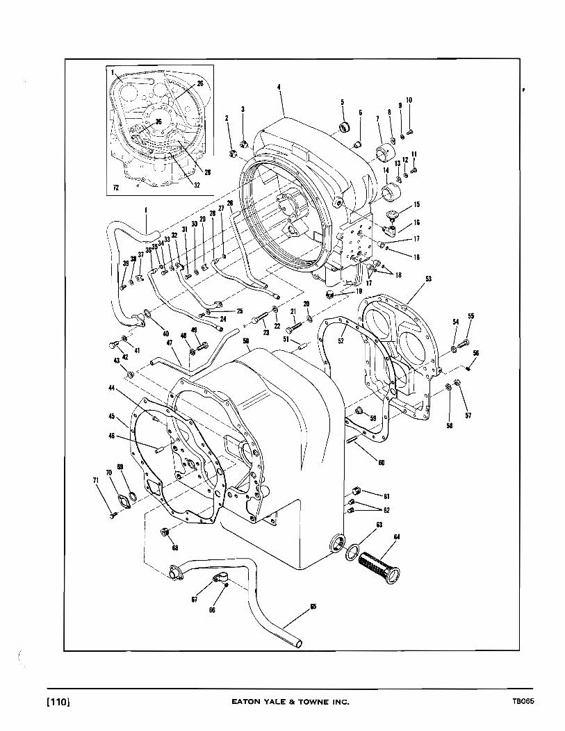
4
\ ,
44
58 46
/~--61 ~62
(
[110] EATON YALE & TOWNE INC. TB065

TRANSMISSION ASSEMBLY
Item Part No. Description No. Req'd. Item Part No. Description No. Req'd
1 6901713 Tube, Suction ............... 1 37 6901581 Clip ........................ 1 2 2033387 Plug, Pipe ................... 1 38 2031390 Washer, Lock ............... 1 3 Not Applicable 39 2031449 Screw ...................... 1 4 6901711 Housing & Tube Assy., Converter 1 40 6750089 "O"Ring ................... 1 5 6901715 Sleeve, Tube ................ 1 41 2031391 Washer, Lock ............... 1 6 6901068 Sleeve, Tube ................ 1 42 2031473 Screw ...................... 1 7 6901582 Sleeve .................... . 1 43 6901068 Sleeve, Tube ................ 1 8 6901583 Lock ....................... 1 43A 6901206 "0" Ring . ................ -. 1 9 2031390 Washer, Lock .............. . 1 44 6901590 Rivet ....................... 1
10 2031449 Screw ...................... 1 45 6901584 Gasket ..................... 1 11 2031449 Screw ...................... 1 46 2039343 Pin,Dowel .................. 2 12 2031390 Washer, Lock ............... 1 47 6901591 Tube, Low Speed Clutch ...... 1 13 6901583 Lock ...................... . 1 48 2031392 Washer, Lock ............... 10 14 6901582 Sleeve ..................... 1 49 2031498 Screw ...................... 10 15 2049101 Breather ................... 1 50 6901683 Case Assy., Transmission . ... 1 16 2032294 Ell, Street ................... 1 51 6901596 Pin, Dowel .................. 2 17 6901069 Sleeve, Tube ................ 3 52 6901598 Gasket ..................... 1 18 Not Applicable 53 6901595 Cover, Transmission Case Rear 1 19 Not Applicable 54 2031392 Washer, Lock ............... 13 20 2031392 Washer, Lock ............... 4 55 2031498 Screw ...................... 13 21 2031501 Screw ...................... 4 56 2035345 Plug, Pipe ................... 1 22 2031392 Washer, Lock .............. . 4 57 2031372 Nut ••••••••••••••••••• 0 •••• 2 23 2031505 Screw ...................... 4 58 2031392 Washer, Lock ............... 2 24 2031449 Screw ...................... 1 59 6901068 Sleeve, Tube ................ 1 25 2031390 Washer, Lock .............. . 1 59A 6901206 "O"Ring ................... 1 26 6901718 Tube, Oil Supply ............. 1 60 6901597 Stud ....................... 2 27 2003450 "O"Ring .................. . 1 61 6901211 Plug, Drain ................. 1 28 6901717 Tube, 3rd Speed ............. 1 62 2033384 Plug, Oil Level ............... 2 29 6901581 Clip ........................ 1 63 6950187 Gasket ..................... 1 30 2031390 Washer, Lock ............... 1 64 6901599 Screen Assy ................. 1 31 2031449 Screw ...................... 1 65 6901587 Tube Assy., Suction .......... 1 32 6901714 Tube, Lube .................. 1 66 6901066 Washer .................... 1 33 2031390 Washer, Lock ............... 1 67 6901589 Clip ........................ 1 34 2031449 Screw ...................... 1 68 6901566 Plug, Pipe ................... 2 35 2003450 "O"Ring ................... 1 69 2007972 "0" Ring . .................. 1 36 6901716 Tube, Reverse ............... 1 70 6901588 Washer .................... 1
71 2030767 Screw ...................... 2
Note: For Complete Transmission-Converter Assy. Order Trojan P IN2078292.
(
TB065 EATON YALE 8c TOWNE INC. [111 ]

20
19 \
n18
\
15 \\\ ~ \ ~p~ I
~ 31
I i --' --' ./ ./
./ ./
./ ./ ./
./ ./
./ /
1 6
l' \ \\ b ~ ~~~~ .,"\ \
lfjO " .. " ~~~ .. \ \ \ \~~~ /'
" /' ,
./ /
/
./ ./
./ ./
./ ./
./ ./
./
[112] EATON YALE & TOWNE INC. T8065

(
TRANSMISSION CASE ASSEMBLY Item Part No. Description No. Req'd. Item Part No. Description No. Req'd.'
1 2 3 4 5 6 7 8 9
10 11 12 13 14
15 16 17 18 19 20 21 22 23 24 25
26 27 28 29 30 31 32
33 34 35 36 37 38 39 40 41 42 43 44 45 46 47 48 49 50 51 52 53 54 55 56 57
TB065
2039354 Ring, Piston ................ . 6901573 Ring, Retainer ............. . 2047022 Bearing, Front ............. . 6901573 Ring, Retainer ............. . 6901608 Bearing ................... . 6901613 Ring, Snap ................. . 6901605 Gear ...................... . 6901607 Ring, Oil Baffle ............. . 6901613 Ring, Snap ................. . 6901608 Bearing ................... . 2039317 Ring,Snap ................. . 6901604 Retainer ................... . 6901603 Spring .................... . 6901600 ShaftandDrum, Reverse
and 3rd Clutch ............ . 6901603 Spring .................... . 6901604 Retainer ................... . 2039317 Ring, Snap ................. . 6901609 Bearing ................... . 6901612 Ring, Snap ................. . 6901607 Ring, Oil Baffle ............. . 6901685 Gear,3rd .................. . 6901610 Spacer .................... . 6901612 Ring, Snap ............... , .. 6901609 Bearing ................... . 6901611 Bearing, Rear, Reverse
and3rdShaft ............. . 6901687 Gear,2nd ................. . 6901607 Ring, Oil Baffle ............. . 2039317 Ring, Retainer ............. . 2039317 Ring,Snap ................. . 6901604 Retainer ................... . 6901603 Spring .................... . 6901616 Shaft & Drum, Forward
and2ndClutch ............ . 6901603 Spring .................... . 6901604 Retainer ................... . 2039317 Ring,Snap ................. . 6901608 Bearing ................... . 6901613 Ring, Snap ................. . 6901607 Ring, Oil Baffle ............. . 6901605 Gear ...................... . 6901613 Ring, Snap ................. . 6901608 Bearing ................... . 6901573 Ring, Retainer ............. . 6901619 Ring, Locating ............. . 6901618 Bearing, Front ............. . 6901573 Ring, Retainer ............. . 2039354 Ring, Piston ................ . 6901627 Bearing, Pilot .............. . 2039295 Bearing ................... . 6901646 Ring, Retainer ............. . 6901691 Bearing ................... . 6901692 Ring, Locating ............. . 6901690 Gear, Low ................. . 6901607 Ring,OiIBaffle ............. . 6901692 Ring, Locating ............. . 6901691 Bearing ................... . 6901646 Ring, Retaining ............ . 2039317 Ring, Snap ................. .
AR As Required
3 1 1 1 1 1 1 1 1 1 1 1 1
1 1 1 1 1 1 1 1 1 1 1 1 1 1 3 1 1 1 1 1 1 1 1 1 1 1
58 59 60 61
62 63 64 65 66 67 68 69 70 71 72 73 74 75 76 77 78 79 80 81 82 83 84 85 86 87 88 89 90 91 92 93
94 95 96 97 98 99 99A 99B 99C 100 101 102 103 104 105 106 107 108 109 110 111 112 113 114 115
6901604 6901603 6901622 6901689
2031476 2031391
6901615 6901686 6901695 6901628 6901629 6901626 6901626 6901631 2039492 6901630 2035345 2031538 2031394 6901641 6901639 6901640 6901649 6901651 6901650 6900808 2039190 2031541 2031394 6901659 2063920 6901657 6901658 6901695 6901683
6901652 6901655 6901654 2040747 2015816 6901664 6901665 6901666 6901667 6901660 2031394 2031538 6901663 6900812 6900811 6901698 6901661 6901573 2039344 6901694 6901642 6901663 6900812 6900811
EATON YALE & TOWNE INC.
Retainer ................... . Spring .................... . Retainer ................... . Shaft & Drum, Low Speed Clutch ............. .
Screw,Cap ................ . VVasher,Lock .............. . Not Applicable Ring, Retainer ............. . Gear ...................... . Gear, Idler Shaft ............ . Bearing ................... . Ring, Retainer ............. . Ring, Piston ................ . Ring, Piston ................ . Gasket .................... . "O'"Ring .................. . Cap, Bearing ............... . Plug ...................... . Screw,Cap ................ . VVasher,Lock .. , ........... . Ball ....................... . Bearing ................... . Ring, Locating ............. . Nut ....................... . Gasket .................... . Cap, Bearing ............... . Seal,Oil ................... . '"O'"Ring .................. . Screw,Cap ................ . VVasher,Lock .............. . Cap, Bearing ............... . '"O'"Ring .................. . Cup ....................... . Cone ...................... . Gear ...................... . Case & Tube Assy., Transimission ............ .
Shaft. Output .............. . Spacer .................... . Cone, Bearing .............. . Cup, Bearing ............... . "O'"Ring .................. . Shim(.004) ................ . Shim (.007) ................ . Shim (.01 0) ................ . Shim (.020) ................ . Cap, Bearing ............... . VVasher,Lock .............. . Screw,Cap ................ . Nut, Flange ................ . VVasher ................... . '"O'"Ring .................. . Flange,Output(5C) ......... . Seal,Oil ................... . Ring, Retaining ............ . Bearing, Front ............. . Shaft, Idler ................ . Ring, Locating ............. . Nut, Flange ................ . VVasher, Flange Nut ......... . '"O'"Ring .................. . Brake, Parking, (SeeSep.lllus.)
1 5 5
1 1 1 1 1 1 1 1 1 1 1 4 4 1 1 1 1 1 1 1 1 4 4 1 1 1 1 1
1 1 1 1 1 1
AR AR AR AR
1 4 4 1 1 1 1 1 1 1 1 1 1 1 1
[113]

0- -01 I I I I I
1234 567 8: ,-------------------------------------------------------------------~
[114]
CLUTCH GROUP FORWARD, REVERSE, 2ND 3RD
Item Part No. Description No. Req'd.
1 2039350 Ring, Retainer .............. 4 2 2039351 Plate, End .................. 4 3 6900790 Disc,lnner.................. 24 4 2039353 Disc, Outer ................. 24 5 6901602 Piston, Clutch. . . . . . . . . . .. . . . 4 6 2039339 Ring, Seal .................. 4 7 6901601 Ring, Seal .................. 4 8 6901600 Drum, & Shaft, 3rd & Reverse . 1 9 6901616 Drum & Shaft, 2nd & Forward. 1
EATON YALE Be TOWNE INC. TB065

1 2 3 4
TB065
Item
1 2 3 4 5 6 7 8
o I
6 7
LOW CLUTCH GROUP
Part No.
2039350 2039351 6901621 2039353 6901602 2039339 6901601 6901689
Description No. Req'd.
Ring,Retainer ......... , .... 1 Plate, End .................. 1 Disc, Inner . . . . . . . . . . . . . . . . . . 9 Disc, Outer ................. 9 Piston, Clutch ............... 1 Ring, Outer Piston ........... 1 Ring,lnner Piston ........... 1 Drum & Shaft, Low Speed Clutch 1
THINK Look carefully before starting machine in motion.
EATON YALE & TOWNE INC.
8
[115]

7
8
9
[116]
84 d:>4 ~.
11
12
13
14
15
16
17
18
19
20
10
EATON YALE & T:OW:N:-E= INC~. ----
31
----TB065

(
TB065
TRANSMISSION CONTROL VALVE ASSEMBLY
Item Part No. Description No. Req'd.
A
B
1 2 3 4 5 6 7 8 9
10 11 12 13 14 15 16 17 18 19 20 21 22 23 24 25 26 27 28 29 30 31
6901675
6955110
6901373 2061574 6901372 6901671 2039490 6901365 6901679 2039490 6901391 6950195 6950190 2022463 2039493 6950658
6950193 2039371 6900797 2039483 6901677 6901678 6901373 2061574 6901372 6901676 6901673 6901435
6901697 6750674 6901214
ValveAssy., Control (Incl. Items 1 thru 31) ........... .
Kit, Slave Piston (Incl. Items 13,14&15) .............. .
Seal, Oil ................... . Ring, Retainer ............. . Washer, Retainer .......... . Spool, Forward & Reverse ... . Ball, Detent ................ . Spring .................... . Gasket .................... . Ball, Detent ................ . Switch, Neutral ............ . Valve Assy., Clutch Cut - Out .. Cap ....................... . "O"Ring .................. . "O"Ring .................. . Ring,Glyd ................. . Piston (N.S.S.) (Order Item B) .. Housing ................... . Seal,Oil ................... . Seal, Band ................. . "O"Ring .................. . Spool ..................... . Spring .................... . Seal,Oil ................... . Ring, Retainer ............. . Washer, Retainer .......... . Spacer, Overshift ........... . Spool Assy., Speed Selector .. Plug ...................... . Housing (N.S.S.)(Order Item A) Spacer, Overshift ........... . "O"Ring .................. . Plug ...................... .
(N.S.S.) Not Serviced Separately
EATON YALE & TOWNE INC.
1 1 1 1 1 2 2 1 1 1 1 1 1 1 1 1 1 1 1 1 1 1 1 1 1 1 1 1 1 1 1 1
[117]
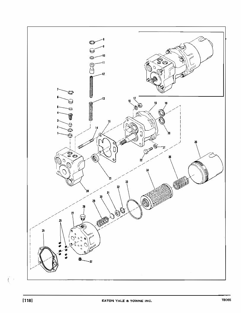
2&
\ -a --37
EATON YALE &~::~=------~ : TOWNE INC.
---~ TB065 [118]

CHARGING PUMP, FILTER AND PRESSURE REGULATOR VALVE
Item Part No. Description No. Req'd.
1 6901736 Seat, Valve ................. 1 2 6901737 Ring, Retainer .............. 1 3 2039281 Plunger. . . . . . . . . . . . . . . . . . . . 1 4 2039282 Spring...... . . . . . . . . . . . . . . . 1 5 2040735 "0" Ring ................... 1 6 2039327 Stop, Valve ................. 1 7 6901735 Ring, Retainer .............. 1 8 6901735 Ring, Retainer .............. 1 9 2039327 Stop, Valve ................. 1
10 2040735 "0" Ring ................... 1 11 Piston (N.S.S.) (Order Item 24) 1 12 6950226 Spring, Valve, Inner . . . . . . . . . . 1 13 6901734 Spring, Valve, Outer ......... 1 14 6901746 Stud....................... 4 15 6901740 Gasket..................... 1 16 2031392 Washer, Lock ............... 4 17 2031372 Nut........................ 4 18 6901764 Pump Assy., Charging ........ 1 19 6901765 Seal... . . .. . .. .. .. .. .. .. .. . 1 20 6901765 Seal....................... 1 21 2031392 Washer, Lock............... 4 22 2031500 Capscrew. . . . . . . . . . . . . . . . . . 4 23 6901738 Seal, Oil .................... 1 24 6901733 Valve Assy., Pressure Regulator
(Incl.ltems 1 thru 13 & 23) . . . 1 25 6901766 Gasket..................... 1 26 6901767 Spring ..................... 8 27 6901768 Adaptor, Filter .............. 1 28 6901769 Plug ....................... 1 29 6901770 Spring............. .. .. . . . . 1 30 6901771 Disc.. .. .. .. .. .. . .. .. . . .. .. 1 31 6901772 Seat.. .. . . .. .. .. .. .. . . . .. . . 1 32 6901773 Ring, Retainer .............. 1 33 6901774 "O"Ring................... 1 34 6901745 Element Assy., Oil Filter. . . . . . 1 35 6901775 Spring.. .. .. .. .. .. . . . .. . .. . 1 36 6901776 Housing, Filter .............. 1 37 2035345 Plug, Pipe.. .. . .. .. .. .. .. . .. . 1
(N.S.S.) Not Serviced Separately
THINK Keep the work area as smooth as possible.
TB065 EATON YALE 8: TOWNE INC. [119]
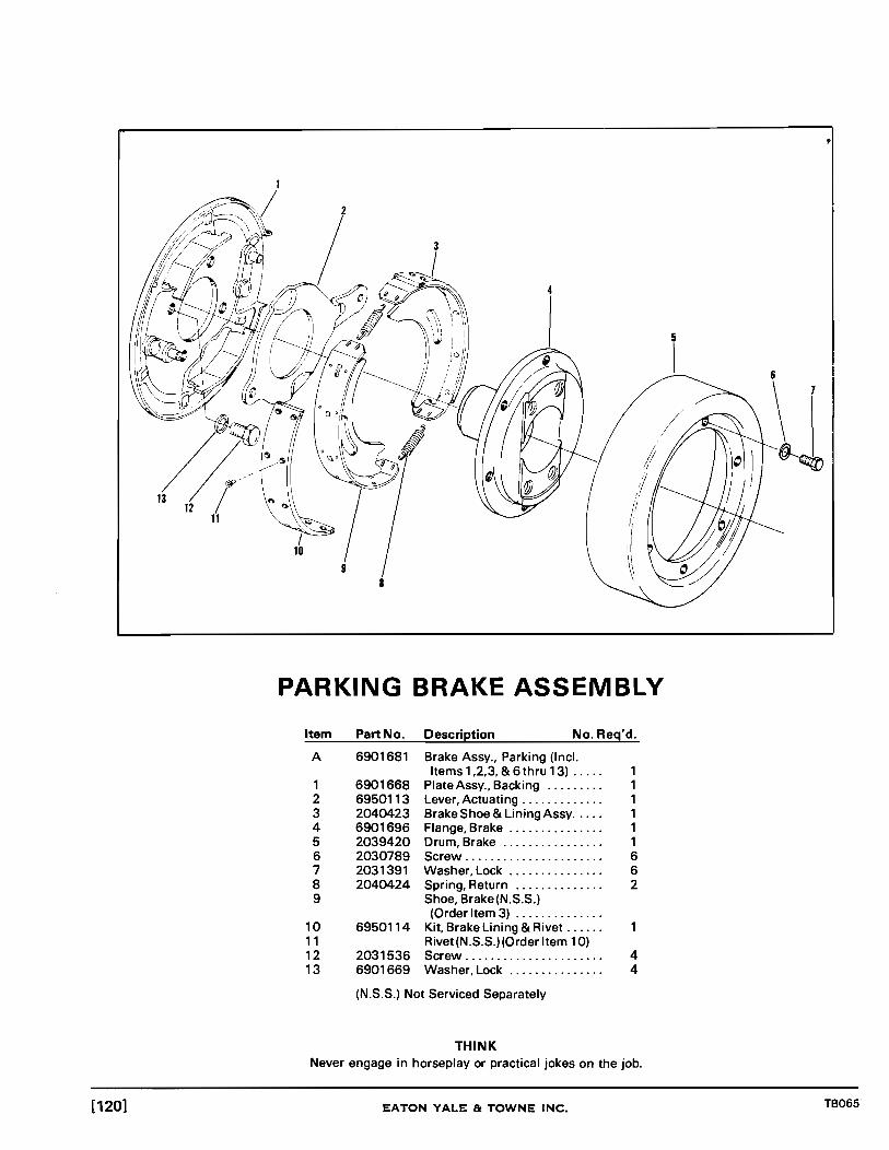
PARKING BRAKE ASSEMBLY
Item Part No. Description No. Req'd.
A 6901681 Brake Assy., Parking (lncl. Items 1 ,2,3, & 6 thru 13) ..... 1
1 6901668 Plate Assy., Backing ......... 1 2 6950113 Lever, Actuating ............. 1 3 2040423 Brake Shoe & Lining Assy ..... 1 4 6901696 Flange, Brake ............... 1 5 2039420 Drum, Brake ................ 1 6 2030789 Screw ...................... 6 7 2031391 VVasher,Lock ............... 6 8 2040424 Spring, Return .............. 2 9 Shoe, Brake(N.S.S.)
(Order Item 3) .............. 10 6950114 Kit, Brake Lining & Rivet ...... 11 Rivet(N.S.S.)(Order Item 10) 12 2031536 Screw ...................... 4 13 6901669 VVasher,Lock .. , ............ 4
(N.S.S.) Not Serviced Separately
THINK Never engage in horseplay or practical jokes on the job.
[120] EATON YALE & TOWNE INC. TB065

2 3 4
14 13 12 11 10 9 8 TP2328
CLUTCH CUT-OUT SYSTEM Item Part No. Description No. Req'd. Item Part No. Description No. Req'd.
1 2077933 Hose ....................... 9 Elbow, 90° (See 2 2073971 Hose ....................... Page 1 22 & 1 23) .......... . 3 2073968 Connector, Swivel Nut ....... 10 2031985 Adaptor, Straight ........... . 4 2032007 Elbow, 90° ................. 11 2073968 Connector, Swivel Nut ...... . 5 Switch, Clutch Cut-Out 12 2073968 Connector, Swivel Nut ...... .
(See Page 135) ............. 13 2031996 Elbow,45° ................ . 6 2032007 Elbow, 90° •••••••••• 0 •••••• 13A 2033844 Elbow, 45° 7 2073968 Connector, Swivel Nut •••• 0 •• (At Valve) (N.I.) ............ . 8 Valve, Brake 14 Valve, Control (See
(See Page 1 32 & 1 33) ....... Page 11 6 & 117) .......... .
(N.J.) Not Illustrated
TB065 EATON YALE & TOWNE INC. [121 ]

~ d z
~ r [II
IP
~ Z [II
Z P
-t III o 0) 01
42 41 40 39 38 37 36 29 28

BRAKE CONTROLS AND LINES
Item Part No. Description No. Req'd. Item Part No. Description No. Req'd.
1 2 3 4 5 6 7
8 9
10 11 12 13
14 15 16 17 18 19 20 21 22 23 24 25 26 27
TB065
2076989 2079162 2073969 2079161 2073969 2032313
2013670 2033383 2032310 2032007 2073968
2079281 2032007 2073968 2079162 2079302 2033395 2033397 2012046 2033398 2033395 2033379 2012046 2033394 2079304
Hose ...................... . Elbow,900
•••••••••.•••••••
Connector, Swivel Nut ...... . Elbow,900
•••••••••.•••••••
Connector, Swivel Nut ...... . Tee ....................... . Gauge, Air Pressure (See Page 64) ............. .
Nipple ..................... . Plug ...................... . Tee ....................... . Elbow,900 •••••••••••••••••
Connector, Swivel Nut ...... . Valve, Brake(See
Page 1 32 & 1 33) .......... . Hose ...................... . Elbow,900
•••••••••••••••••
Connector, Swivel Nut ...... . Elbow,900 •••••••••••••••••
Line Assy., Brake ........... . Gasket .................... . Fitting, Brake .............. . Gasket .................... . Bolt ....................... . Gasket .................... . Connector, Inlet ............ . Gasket .................... . Bolt ....................... . LineAssy., Brake ........... .
1 1 2 1 1 1
1 1 1 1 1 1 1 1 1 1 1 1 1 1
THINK
28 29 30 31 32 33 34 35
36 37 38 39 39A 39B 40 40A 40B 41 42 43 44 45 46 47
48 48A
Know the work area.
2079283 Hose ...................... . 2073969 Connector, Swivel Nut ...... . 2079260 Fitting, Bulkhead ........... . 2079284 Connector, Swivel Nut ...... . 2073969 Connector, Swivel Nut ...... . 2032009 Elbow, 900
•••••••..••••••••
2033042 Bushing, Reducer .......... . Switch, Stop Light (See Page 76 & 77) ........ .
2079284 Hose ...................... . 2079113 Hose ...................... . 2033398 Bolt, Connector ............ . 2012038 Fitting, Brake .............. . 2033395 Gasket, Power Cluster ...... . 2012046 Gasket, Bolt ............... . 2031477 Bolt ....................... . 2031400 Washer,Lock ............. .. 2031617 Nut ...................... .. 2079306 LineAssy., Brake ........... . 2040438 Bar, Mount ................ . 2079308 line Assy., Brake ........... . 2032764 Tee ....................... . 2032009 Elbow,900 .•.••••••.•.••••.
2073969 Connector, Swivel Nut ...... . Cluster, Power (See Page 134) ................ .
2031450 Bolt ...................... .. 2031391 Washer, Lock .............. .
EATON YALE & TOWNE INC.
8 8
[123]

...... .... ~
111 » -t 0 Z
-< » r 111 AI
d ~ z 111
Z P
iil o Ol CJ1
1 4
44
41
40 39 38 37 36 35 34 33 32 31 26 25 24
11 18)9 20 ro,/ ' ) , ,1
/ /j , , 1
, , 1 , , 1 "i, ,
~~~n ~V""lJ1 ::;}..;~
RI\II~ ~ ~ y v __ ~
, 1"1\
22
23 TP2414

Item
1 1A 2 3 3A 3B 4
4A 5
6 7 8 9
10 11 12 12A 13 14 15 16 17 18 19
20 21 22
T8065
AIR COMPRESSOR PIPING
Part No.
2031477 2031391 2077882 2031479 2031391 2031617
2044107
2035236 2073968 2031996 2073968 2053266 2076961 2079292 2032813 2012082 2073968 2035236 2054765 2073969 2079162
2079161 2073969 2077934
Description No. Req'd.
Bolt........................ 4 VVasher,Lock .. ..... ........ 4 Adapter, Straight. . . . . . . . . . . . 1 Bolt........................ 4 VVasher,Lock ............... 4 Nut........................ 4 Compressor, Air (See Page 130 & 131) .......... .
Gasket .................... . Governor (Furn.
VV ICompressor) ........... . Elbow, 90° ................. 1 Connector, Swivel Nut ....... 1 Elbow,900 ................. 1 Connector, Swivel Nut ....... 1 Bushing, Reducer ........... 1 Hose....................... 1 Hose....................... 1 Clamp, HoseSupport(N.J.) 1 Nipple,45° ................. 1 Connector, Swivel Nut ....... 1 Elbow,900 ................. 1 Clamp, Hose ................ 2 Connector, Swivel Nut. .. .. . . 1 Elbow, 90° ................. 1 Valve, Brake(See Page 132 & 133) .......... .
Elbow,900 ................ . Connector, Swivel Nut ...... . Hose ...................... .
(GM)
Item
23 24 25 26 27 28 29 30 31 32 33 34 35 35A 35B 35C 36 37 38 39 40 41 42 43 44 45 46 47 48 49
Part No.
2076993 2063821 2079282 2073970 2038470 2076843 2077935 2076848 2032295 2073969 2054598 2079161 2031479 2032960 2031391 2031617 2034221 2033212 2059175 2032293 2054598 2033384 2079161 2073969 2078840 2031996 2073968 2077950 2073967 2049350
(N.J.) Not Illustrated
THINK A careful operator is a good man to work with.
EATON YALE & TOWNE INC.
Description No. Req'd.
Hose....................... 1 Hose....................... 1 Hose....................... 1 Connector, Swivel Nut ....... 1 Elbow,900 ................. 1 Connector, Swivel Nut ....... 1 Hose....................... 1 Connector, Male ............ 1 Elbow,90 .................. 1 Connector, Swivel Nut. . . . . . . 1 Valve, Check. . . . . . . . . . . . . . . . 1 Elbow,900 ................. 1 Bolt........................ 4 VVasher, Flat . . . . . . . . . . . . . . . . 4 VVasher,Lock ... .... .... .... 4 Nut........................ 4 Valve, Blow-Off ............. 1 Valve, Drain ................ 2 Reservoir, Air ............... 1 Elbow,900 ................. 1 Valve, Check. . . . . . . . . . . . . . . . 1 Plug....................... 1 Elbow, 90° ................. 1 Connector, Swivel Nut ....... 1 Tee........................ 1 Elbow, 90° ................. 1 Connector, Swivel Nut ....... 1 Hose....................... 1 Connector, Male ............ 1 Bracket .................... 1
[125]

~ ... I\)
!!!!.
f11 » -I o Z -< » r f11
AI
a ~ z f11
Z fl
-I CD o 0> 01
1 2 4
26 25 24 23
18 19 20
'I /'-- J ! 21
~~,Jf i '-. / /, '-./ /' ...i.?I ~" /,' ....... .,.. ~~~!/-. I '---..}f '- ~ C-,- :.( ,,"v ,,/---.:; ,
.... _.-J A
~#' I
I ~\ 22

Item
1 1A 1B 1C 2 3 3A 3B 4
4A 5
6 7 8 9
10 11 12 13 14 15 16 17 18 19
20 21 22 23 24 25 26
TB065
AIR COMPRESSOR PIPING
(HD)
Part No. Description No. Req'd.
2031479 2032960 2031391 2031617 2077882 2031475 2031391 2032960
2044107
2079313 2032007 2073968 2032007 2073968 2053266 2012082 2077000 2073968 2032007 2054765 2077934 2073969
2079162 2079161 2073969 2076993 2047337 2073993 2073970
Bolt ....................... . Washer, Flat ............... . Washer, Lock .............. . Nut ....................... . Adapter, Straight ........... . Bolt ....................... . Washer, Lock .............. . Washer, Flat ............... . Compressor, Air (See Page 130 & 1 31) .......... .
Gasket .................... . Governor (Furn. W/Compressor) ........... .
Plate, Mount ............... . Elbow,900 ................ . Connector, Swivel Nut ...... . Elbow,900 ................ . Connector, Swivel Nut ...... . Bushing, Reducer .......... . Nipple,45° ................ . Hose ...................... . Connector, Swivel Nut ...... . Elbow,900 ................ . Clamp ..................... . Hose ...................... . Connector, Swivel Nut ...... . Valve, Brake (See Page132& 133) ......... ..
Elbow,900 ................ . Elbow,900 ................ . Connector, Swivel Nut ...... . Hose ...................... . Hose ...................... . Hose ...................... . Connector, Swivel Nut
(N.I.) Not Illustrated
4 8 4 4 1 4 4 4
1 1 1 1 1 1 1 1 1 1 2 1 1
THINK
Item
27 28 29 30 30A 30B 30C 31 32 33 34 35 36 37 38 39 40 41 42 43 44 45 46 47 48 49 50
51 52
53 54
54A 54B
Part No.
2031999 2073969 2079161 2031479 2032960 2031391 2031617 2033212 2032295 2076848 2054598 2077935 2033384 2076843 2054598 2032007 2078840 2073968 2070524 2077932 2079161 2059175 2073969 2032293 2034221 2073966 2079314
2079329 2031482
2031477 2031477
2031391 2031617
Description No. Req'd.
Elbow, 90° ................. 1 Connector, Swivel Nut ....... 1 Elbow, 90° ................. 1 Bolt........................ 4 Washer, Flat . . . . . . . . . . . . . . . . 4 Washer, Lock ............... 4 Nut........................ 4 Valve, Drain ................ 2 Elbow, 90° ................. 1 Connector, Male ............ 1 Valve, Check. . . . . . . . . . . . . . . . 1 Hose....................... 1 Plug....................... 1 Connector, Swivel Nut ....... 1 Valve, Check. . . . . . . . . . . . . . . . 1 Elbow, 90° ................. 1 Tee........................ 1 Connector, Swivel Nut ....... 1 Hose....................... 1 Hose....................... 1 Elbow,900 ................. 1 Reservoir,Air ............... 1 Connector, Swivel Nut ....... 1 Elbow,900 ................. 1 Valve, Blow-Off ............. 1 Connector, Male ............ 1 Mount Assy., Compressor(N.I.) .......... .
Strap, Support(N.I.) ......... . Bolt, Mount Assy. toEngine (N.I.) ............ .
Bolt, Strap to Engine (N.I.) ... . Bolt, Compressor Strap to Mount Assy. (N.I.) ....... .
Washer, Lock(N.I.) .......... . Nut(N.I.) ................... .
Never leave operators seat with the engine running.
EATON YALE 8c TOWNE INC. [127]

[128] LC:: & TOW EATON VA NE INC. -~-------~TB065
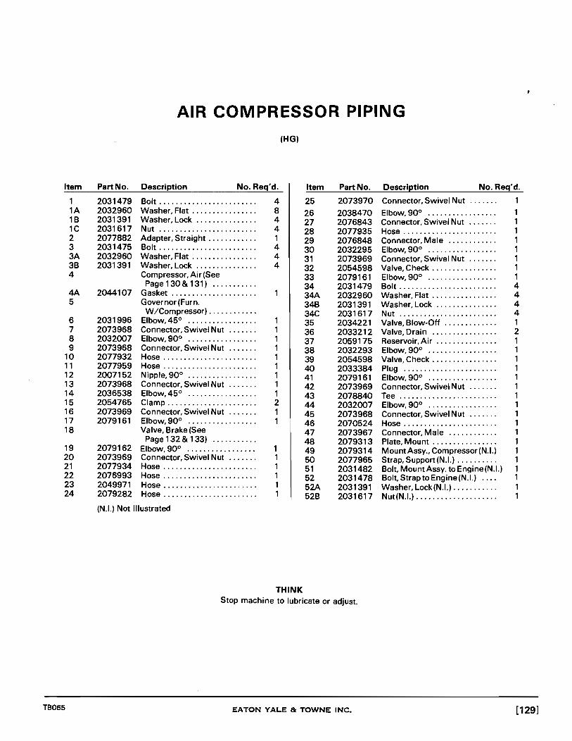
Item
1 1A 1B 1C 2 3 3A 3B 4
4A 5
6 7 8 9
10 11 12 13 14 15 16 17 18
19 20 21 22 23 24
TB065
AIR COMPRESSOR PIPING
Part No.
2031479 2032960 2031391 2031617 2077882 2031475 2032960 2031391
2044107
2031996 2073968 2032007 2073968 2077932 2077959 2007152 2073968 2036538 2054765 2073969 2079161
2079162 2073969 2077934 2076993 2049971 2079282
Description No. Req'd.
Bolt........................ 4 Washer, Flat . . . . . . . . . . . . . . . . 8 Washer,Lock ............... 4 Nut........................ 4 Adapter, Straight. . . . . . . . . . . . 1 Bolt........................ 4 Washer, Flat . . . . . . . . . . . . . . . . 4 Washer, Lock ............... 4 Compressor, Air (See Page 1 30 & 1 31) .......... .
Gasket .................... . Governor (Furn. W /Compressor) ........... .
Elbow,45° ................. 1 Connector, Swivel Nut ....... 1 Elbow,900 ................. 1 Connector, Swivel Nut ....... 1 Hose....................... 1 Hose....................... 1 Nipple,900 ................. 1 Connector, Swivel Nut. .. .. . . 1 Elbow,45° ................. 1 Clamp...................... 2 Connector, Swivel Nut ....... 1 Elbow, 90° ................. 1 Valve, Brake (See Page132& 133) .......... .
Elbow,900 ................. 1 Connector, Swivel Nut ....... 1 Hose....................... 1 Hose....................... 1 Hose....................... 1 Hose....................... 1
(HG)
Item
25
26 27 28 29 30 31 32 33 34 34A 34B 34C 35 36 37 38 39 40 41 42 43 44 45 46 47 48 49 50 51 52 52A 52B
Part No.
2073970
2038470 2076843 2077935 2076848 2032295 2073969 2054598 2079161 2031479 2032960 2031391 2031617 2034221 2033212 2059175 2032293 2054598 2033384 2079161 2073969 2078840 2032007 2073968 2070524 2073967 2079313 2079314 2077965 2031482 2031478 2031391 2031617
(N.L) Not Illustrated
THINK Stop machine to lubricate or adjust.
EATON YALE & TOWNE INC.
Description No. Req'd.
Connector, Swivel Nut
Elbow,900 ................ . Connector, Swivel Nut ...... . Hose ...................... . Connector, Male ........... . Elbow,900 ................ . Connector, Swivel Nut ...... . Valve, Check ............... . Elbow,900 ................ . Bolt ....................... . Washer, Flat ............... . Washer,Lock .............. . Nut ....................... . Valve, Blow-Off ............ . Valve, Drain ............... . Reservoir,Air .............. . Elbow,900 ................ . Valve, Check ............... . Plug ...................... . Elbow,900 ................ . Connector, Swivel Nut ...... . Tee ....................... . Elbow,900 ................ . Connector, Swivel Nut ...... . Hose ...................... . Connector, Male ........... . Plate, Mount ............... . MountAssy., Compressor (N.L) Strap, Support (N.I.) ......... . Bolt, MountAssy. to Engine (N.L) Bolt, Strap to Engine(N.I.) ... . Washer, Lock(N.I.) .......... . Nut(N.I.) ................... .
1
1 1 1 1 1 1 1 1 4 4 4 4 1 2 1 1 1 1 1 1 1 1 1 1 1 1 1 1 1 1 1 1
[129]

.-... ..... ~
111
~ z -< :r> r 111 AI
d :E z 111
Z P
01 o CJl C1I
AIR STRAINER ASSEMBLY
40
SCREW
2

Item
A 1
2 3 4
5 6 7 8 9
10 11 12 13 14 15 16
*17 *18 *19 *20 *21 *22
*23 *23A 24
25 26 27 28 29 30 30A 31 31A
32 33 34 35
TB065
AIR COMPRESSOR ASSEMBLY
Part No. Description No. Req'd.
2041163 Compressor, Air. . . . . . . . . . . . . 1 6950877 HeadAssy., Cylinder (lncl.
Item 2 thru 10) ............ . 6950884 Cover, Head ............... . 6950878 Head Assy. (Incl.ltems 4 & 5) ..
Head, Body (N.S.S.) (Order Item 3) .............. 1
6950879 Seat, Discharge Valve. . . . . . . . 2 6950880 Guide...................... 2 6950882 Spring..................... 2 6950881 Valve...................... 2 2031426 Screw, Cap ................. 4 6950883 Gasket..................... 1 6950873 Guide...................... 2 6950875 Spring..................... 2 6950874 Valve ...................... 2
Element (Not Applicable) 2038757 Gasket (Not as Illustrated) .... 1 2038744 Cover, Inlet. .. . . . . . . . .. . . . . . 1 6950858 Seat....... . . . . . . . . . . . . . . . . 1 6950859 Spring ..................... 1 6950855 Plunger.................. . . 2 6950857 Saddle...... . . . . . . . . . . . . . . . 1 6950856 Guide...................... 2 6950852 Piston Assy. (Incl. Items
23, 23A, & 24) ............. 2 6950853 Ring, Back-up. .. . . . . . . . . . .. . 2 6950854 Grommet................... 2
Piston (N.S.S.) (Order Item 22) . . . . . . . . . . . . . 2
2031390 Washer, Lock............... 4 2031452 Screw, Cap ................. 4 2031426 Screw, Cap................. 5 2031433 Screw, Cap................. 1 6950876 Gasket, Head ............... 1 6950888 Washer, Lock ............... 2 6952679 Capscrew... . . . . . . . . . . . . . . . 2 6950849 Gasket. Cylinder Block ....... 1 6950850 Block Assy. (lncl. Items
17thru23A) ............... 1 6950866 Gasket. Rear Cover .......... 1 6950889 Screw, Cap ................. 4 6950888 Washer, Lock ............... 4 6950867 Cover, Rear . . . . . . . . . . . . . . . . . 1
(N.I.) Not Illustrated (N.S.S.) Not Sold Separately
Item Part No.
36 6950858
37
38
39 6950868
40 6950872 41 6950863 42 6950861 43 6950862 44 6950865 45 6950860 46 2050231 47 6950890 48 '6950864 49 2031426 50 2031389 51 6950870 52 6950871
53
54
55
56 6950869
57
58
59 2046601 60 6950885 61 2031462
62 2031616 63 2033006 64 2033005 65 6950891
66 2044107
*Indicates Parts Included in Repair Kit; order Trojan Part No. 6955177.
THINK Stop machine to lubricate or adjust.
EATON YALE & TOWNE INC.
Description No. Req'd.
Crankcase Assy. (lncl. Items 37 & 39) ............ .
Bearing, Crank Shaft (N .S.S.) (Order Item 36) ............ .
Body, Crankcase (N.S.S.) (Order Item 36) ............ .
Rod, Connecting (lncl. Item40) ................... 2
Strip, Locking ............... 2 Gasket, Front ............... 1 Bearing.................... 1 Ring, Retaining ............. 1 Seal....................... 1 Crankshaft ................. 1 Nut........................ 1 Key........................ 1 Cover, Front ................ 1 Screw, Cap ................. 4 Washer,Lock ..... ..... ..... 4 Wire, Lock . . . . . . . . . . . . . . . . . . 2 Ring Set, Piston (Incl. Items 53 thry 5g) .......... .
Ring, Piston(N.S.S.)(lncl. in Item 52) . . . .. . . . . . . . . . . . . 2
Ring, Piston (N.S.S.) (lncl. in Item 52) ............ 2
Ring, Piston(N.S.S.) (Incl. in Item 52) ............ 2
Piston & Wrist Pin Set (lncl. Items 57 & 58) ............. 2
Pin, Wrist(N.S.S.) (Order Item 56) . . . . . . . . . . . . . 2
Piston (N.S.S.) (Order Item 56) . . . . . . . . . . . . . 2
Governor Assy. (N.I.) . . . . . . . . . 1 Bracket. Governor Mount(N.I.) 1 Screw, Cap, Bracket to Compressor(N.I.) . . . . .. . . .. . 2
Nut(N.I.).................... 2 Elbow, at Compressor (N.I.) ... 1 Elbow, at Governor (N.I.) . . . . . . 1 Tube, Governor to Compressor(N.I.) .......... .
Gasket, Compressor to Plate (N.I.) ............... .
[131]

49
~ _______ ---:1 I
- ~4 I 1 2 I cgy( 3 0---1 48 4 0"1
~ .. I S 0" , 6
47 0--. 7 46
~. 8 4S
44
C~~· 9
43 10 42
~ .. 41 11 40 39 0 .. 12
38
~. 13
37 36 14
3S 34
lS
33
32 • '. 8"~~
31 ~@1 J 30 ;t::i . 29 1---0 _--------28~' ~
TP1151
[132] EATON YALE & TOWNE INC. TB065

DUAL BRAKE VALVE ASSEMBLY
Item Part No. Description No. Req'd. Item Part No. Description No. Req'd.
A
1 2 3 4 5 6 7 8 9
10
11 12 13 14 15 15A 15B 16 17 18 19 20 21 22 23 24 25 26
TB065
2070505
6952174 6952175 6952176 6952197 6952117 6952178 6952033 6952179 6952183
6952180
6952181 6952182 6952184 6952186 6952185 6952188 2031390 6952191 6952190 6952192 6952189 6952193 6952194 6952197 6952195 6952196 6952198 6952199
Valve Assy., Dual Brake (IncLltem 1 thru 51) ........ .
Spring, UpperValve ........ . Washer, Special ............ . "0" Ring, Upper Valve ...... . "O"Ring .................. . Retainer, "0" Ring ......... . Ring, Retaining ............ . Ring, Retaining ............ . Piston, Outer Relay ......... . "0" Ring,lnner Relay Piston .................... .
"0" Ring, Outer Relay Piston .................... .
Piston,lnnerRelay ......... . "0" Ring, Piston ........... . Spring, Return ............. . "0" Ring, Cover ............ . Cover ..................... . Screw ..................... . Washer,Lock .............. . Valve ..................... . Body ...................... . Retainer ................... . Valve Assy.,lnlet & Exhaust .. Spring .................... . "0" Ring, Lower Valve ...... . "0" Ring, LowerValve Guide Guide ..................... . Ring, Retaining ............ . Seat, Valve ................ . Diaphragm ................ .
(N.I.) Not Illustrated
1 1 1 1 1 4 4 1 1 1 1 1 1 1 1 1 1 1
THINK
27 28 29 30 31 32 33 34 35 36 37 38 39 40 41 42 42A 42B 42C 420 42E 43 43A 44 45 46 47 48 49 49A 50 51
6952200 6952173 6952171 6952172 6952170 6952169 6952201 6952182 6952203 6952204 6952202 6952205 6952206 6952207 6952208 2054808 2031449 2031390 6952188 2031390 2031616 2054810 2054809 2054811 2054806 2054807 2054804 2020635 2054805 2031764 6952209 6952187
Ring, Retaining ............ . Retainer, Valve ............. . Body ...................... . Valve ..................... . ValveAssy.,lnlet& Exhaust .. Body, Valve ................ . Spring, Piston Return ....... . "O"Ring .................. . Piston ..................... . Spring, Rubber ............. . Piston Assy. . .............. . Seat, Spring ............... . Washer ................... . Screw ..................... . Retainer ................... . Plate, Mounting ............ . Screw ..................... . Washer,Lock .............. . Bolt(N.I.) .................. . Washer, Lock(N.I.) .......... . Nut(N.I.) ................... . Pin, Fulcrum ............... . Pin,Roll ................... . Button, Stop ............... . Plunger ................... . Boot ...................... . Roller ..................... . Treadle .................... . Pin,Rolier ................. . Pin, Cotter ................. . Washer, Diaphragm (N.I.) .... . Screw, Pan Head Rolling (N.I.) .
Carry the bucket close to the ground when travelling.
EATON YALE & TOWNE INC.
1 1 1 1 1 1 1 1 1 1 1 1 1 1 1 1 3 3 3 3 3 1 1 1 1 1 1 1 1 1 1 1
[133]

2
22 21 20 19 18 17 16 15 14 TP2358
POWER CLUSTER ASSEMBLY Two Power Clusters Used Per Machine; Quantity Shown is for one
Item Part No. Description No. Req'd. Item Part No. Description No. Req'd.
A 2078282 PowerCluster(lncLltems 9 6952914 Bracket, Mounting .......... . B, 1 thru 9, 13, thru 10 6952913 CapAssy., Filter ............ . 13B&22) ................ . 11 6952912 Gasket .................... .
B 6952911 Cylinder, Master (lncL Items 12 6952936 Housing ................... . 10 thru12 & 13 Stud (N.S.S.)(Order Item 8) .. . 14thru21) ................. 1 13A 2031391 Washer,Lock .............. .
1 2032109 Bolt........................ 16 13B 2031617 Nut ....................... . 1A 2031390 Washer, Lock............... 16 14 6952941 Seat, Valve ................ . 1B 2031370 Nut........................ 16 156952937 Valve Assy ................. . 2 6752904 Plate, Pressure. . . . . . . . . . . . . . 1 16 6952938 Spring & Retainer Assy ...... . 3 6952905 Diaphragm................. 1 17 6952942 Cup, Primary ............... . 4 6952906 Plate, Push ................. 1 1 8 6952939 Piston Assy. 5 '6952907 Guide, Spring. .. . . . . . . . .. .. . 1 (IncLltem 18A) ............ . 6 6951251 'Grommet................... 1 18A 6952940 Cup, Secondary(N.L) ........ . 76952908 Spring ..................... 1 1 9 6952943 Plate, Stop ................. . 8 6952909 Plate, Non-Pressure 20 '6952944 Lockwire .................. .
(IncLltem 13) ............. . 21 6952945 Boot ...................... . (N.L) Not Illustrated 22 6952910 Collar, Stop ................ . (N.S.S.) Not Serviced Separately
[134] EATON YALE Be TOWNE INC.
1 1 1 1 3 3 3 1 1 1 1
1 1 1 1 1 1
TB065

1-10
CTl-------2
9~
\-,_-----4
TP796
CLUTCH CUT-OUT SWITCH
Item Part No. Description No. Req'd. Item Part No. Description No. Req'd.
A
TB065
1 2 3 4 5
2048300 Switch, Clutch Cut-Out (Incl. Items 1 thru 10) ...... .
6951104 Lever ..................... . 6951100 Grommet .................. . 6951105 Pin ....................... . 6951101 Valve ..................... . 6951102 "O"Ring .................. .
(N.S.S.) Not Serviced Separately (N.I.) Not Illustrated
THINK
6 7 8 9
10 11 11A
6951103 Nut, Cap ................... . 6951097 Spring, Valve .............. .
Body(N.S.S.)(Order Item A) .. . 6951098 Spring, Plunger Return ...... . 6951099 Plunger ................... . 2078763 Dial (N.I.) .................. . 2036099 Screw(N.I.) ................ .
Never lift the bucket over ground crew or truck cab.
EATON YALE & TOWNE INC.
1 1 1 1 1 1 2
[135]

13 12 11 10 9 8 7 6
TP2364
DRIVE SHAFT ASSEMBLY
Item Part No. Description No. Req'd. Item Part No. Description No. Req'd.
A 2077077 Drive Shaft Assy. (IncL 7 2077082 Bearing Assy., Roller ......... 1 Items 2, 6 thru 8B, 10, 8 2031482 Bolt ........................ 4 12& 13 ................... . 1 8A 2031391 Washer, Lock ............... 4
1 2031579 Bolt ........................ 2 8B 2031617 Nut ........................ 4 lA 2032965 Washer, Flat ................ 2 9 2032140 Bolt ........................ 4 2 2077078 Sub-Assy, Drive Shaft ........ 1 9A 2031371 Nut ........................ 4 3 2034881 Spider & Bearing Assy ........ 1 9B 2033515 Nut,Jam ................... 4 3A 2030224 Fitting, Grease(N.L) ........ . 1 10 2081365 Yoke ....................... 1 4 2032138 Bolt ........................ 4 11 2032965 Washer, Flat ................ 1 4A 2033515 Nut ....................... . 4 12 2032921 Nut ........................ 1 5 2032138 Bolt ........................ 4 13 2031776 Pin, Cotter .................. 1 5A 2033515 Nut ........................ 4 6 2077083 Angle, Bearing Mount ........ 1
(N.L) Not Illustrated
THINK Avoid greasy hands and floor boards.
[136] EATON YALE & TOWNE INC. TB065

2 3 4
<~ ~ ~() .AY" a _ "
~9~8 7 6 TP713
PROPELLER SHAFT ASSEMBLIES
From Transmission to Front Axle From Transmission to Rear Axle
Item Part No. Description No. Req'd. Item Part No. Description No. Req'd.
A
1 2 3 4 5 6 7 8
TB065
8A 9
2042734 Shaft Assyo, Propo (6C) (Incl. Items 1 Thru 9) 0 0 0 0 0 0 0 0 0 0 0 0 •• 0.0.. 1
2034875 Yoke Assyo, Slip ... 00.00 •••• 0 1 2034879 Washer, Felt 0 0 0 0 • 0 0 0 •• 0 0 • • • • 1 2034878 Retainer, Felt . o. 0 •••• 0 0 •• 0 0 0 1 6950016 Tube Assyo .. 0 •• 0 ••• 0 0 0 0 0 0 0.. 1 2030224 Fitting, Grease 0 ••• 00.00.0. 0 0 3 2034877 Washer, Retainer 000 •• 00 0 • • • 2 2033515 Nut, Jam 0 0 0 0 • 0 0 0 • 0 •• 0 0 •••• 0 16 2034881 Spider & Bearing
Assyo (Incl. Item 5) 0.00 ••• 0 0 2 2034887 Washer, Cork(Nol.) .... o. 0 0000 8 2034888 Capscrew .. 0 0 •••• 0 0 • 0 0 0 0 • 0 0 16
(Nolo) Not Illustrated
THINK
B
1 2 3 4 5 6 7 8
8A 9
2057952 ShaftAssyo, Propeller (6CL) (Incl.ltems 1 Thru 9) 0 0 0 0 00000000 •• 0.000 1
6950018 Yoke Assyo, Slip 0.00.0000.0.. 1 6950021 Washer, Felt 00 •• 0.00000. 0 0 0 0 1 6950020 Retainer, Felt 0 •••••• 00000. 0 0 1 6951317 Tube Assy. 0 0 0 0 • 0 • 0 • 0 0 0 0 0 •• 0 • 1 2050894 Fitting, Grease . 0 0 0 0 0 0 0 0 •• 0 • • 3 6950019 Washer, Retainer 0 0 0 0 ••• 0 0 0 0 2 2033515 Nut 00 •• 0 •••• 0000. 0 0 0 •• 0 0 • 0 • 16 6950025 Spider & Bearing Assyo (Incl.
Item8A). 0 0 ••• 00000.0.00 •• 0 2 6950022 Washer, Cork 0" 0 • 0 0 0 0 0 0 0 0 0 • 8 2034888 Capscrew ... 0 0 0 • 0 •• 0 •• 0 0 • 0 • 16
Never carry a rider in the bucketo
EATON YALE & TOWNE INC. [137]

[138)
FRONT AXLE ASSEMBLY
Item Part No. Description No. Req'd.
*A 2078208 Axle Assy., Front ............ 1 +A 2082643 Axle Assy., Front .0 •••••••••• 1
1 2006506 Plug, Planetary Drain ........ 2 2 6600865 Plug, Differential Level
&Fill ...................... 1 3 6601051 Stud, Carrier to Housing ...... 6 4 6601048 Housing, Axle (Incl.
Items 2,3,5, & 9) ........... 1 5 6601050 Stud, Carrier to Housing ...... 2 5A 6601051 Stud, Carrierto Housing ...... 2 6 2040532 Gasket ..................... 1 7 2006298 Plug, Differential Fill ......... 1 8 2040814 Nut, Carrierto Housing ....... 10 SA 6600861 Washer .................... 10 9 2006298 Plug, Differential Drain ....... 1
10 2016292 Breather ................... 3 11 2017688 Stud, Wheel ................ 24 12 2017694 Nut, Wheel ••••••••••• 0 ••••• 24 13 2034287 Plug, Planetary Level ......... 2
* For Machines having sin 15-1011 thru 15-1013, 15-1022 thru 15-1027 & 15-1034 thru 15-1039. + For Machines having sin 15-1014thru 15-1021, 15-1 028thru 15-1033, 15-1040 & higher.
EATON YALE & TOWNE INC.
TP780
TB065

TB065
REAR AXLE ASSEMBLY
Item Part No. Description No. Req'd.
*A 2078209 Axle Assy., Rear ............. 1 +A 2082644 Axle Assy., Rear ............. 1
1 2006506 Plug, Planetary Drain& Fill ................ 2
2 6600865 Plug, Differential Level ....... 1 3 6601051 Stud, Carrier to Housi ng ...... 6 4 6601048 Housing, Axle (lncl.
Items 2,3,5, & 9) ............ 1 5 6601050 Stud, Carrier to Housing ., .... 2 6 2040532 Gasket ..................... 1 7 2006298 Plug, Differential Fill ......... 1 8 2040814 Nut, Carrierto Housing ....... 10 8A 6600861 Washer .................... 10 9 2006298 Plug, Differential Drain ....... 1
10 2016292 Breather ................... 3 11 2017688 Stud, Wheel ................ 24 12 2017694 Nut, Wheel ................. 24 13 2034287 Plug, Planetary Level ......... 2
* For Machines having sin 15-1011 thru 15-1013, 15-1022 thru 15-1027 & 15-1034 thru 15-1039. + For Machines having sin 15-1014thru 15-1021, 15-1 028thru 15-1033,15-1040& Higher.
THINK Never coast in neutral.
EATON YALE & TOWNE INC.
TP760
[139}

,... ------+-i.
[140]
/ /
\ \ \
EATON YALE & TOWNE INC.
p"'~a:
== -
,... .-
co .-
.-c.....
c..... ---c.....
CO') CO')
LI....tt----~
\.------~ ~---__ u:»
CO')
co CO')
TB065

Item
2 3 4
5 6 6A 6B 7 8 9
10 11 12 13 14 15 16
17 18 19 20
TB065
PLANETARY HUB
(Four Groups Used Per Machine; Quantity Shown is for One)
Part No. Description No. Req'd.
2016934 Oil Seal and Retainer Assy. (lncl. Item 2) .............. .
2016938 Seal, Oil ................... . 2034693 Seal, Brake Drum ........... .
Spider & Cam Assy. (See Brake Group. . . .. . . .. .. . . . . . . . . . . 1
2032879 Spindle, Wheel Bearing ...... 1 2032224 Bolt, Spindle to Housing. . . . . . 12 2032877 Washer(N.I.)................ 12 2034836 Nut........................ 12 2016906 Seal ....................... 1 6601058 Shaft ...................... 1 2016930 Cone, Inner Bearing ......... 1 2016914 Cup, Inner Bearing. . . . . . . . . . . 1 2032876 Bolt, Brake Drum to Hub ...... 10 2032878 Drum, Brake ................ 1 6600835 Slinger, Oil ................. 1 2017688 Stud, Wheel ................ 12 2006506 Plug, Oil Drain .............. 1 6601056 Hub & Cup Assy. (Incl.
Items 10, 17 & 19) .......... 1 6600860 Stud, Spiderto Hub .......... 12 2017694 Nut, Wheel ................. 12 2016910 Cup, Outer Bearing .......... 1 2018184 Cone, Outer. . .. . . .. . . . .. . . . . 1
(N.I.) Not Illustrated
THINK
Item
21 22 23
24 25 26 27 28 29 30 31 32 33 34 35 36 37 37A 38 39
40 41 41A
Part No.
2016974 2044164 2016956
2016972 2016968 2016970 2017602 2017534 2017608 6600249 2017614 2044167 2040505 2017628 6600250 2017646 2019076 2031393 2019046 2034308
2034287 2037635 6600861
Avoid greasy hands and floor boards.
EATON YALE & TOWNE INC.
Description No. Req'd.
Capscrew, Ring Gear Lock. . . . 8 Lock....................... 4 Hub & Sleeve Assy., Ring Gear...................... 1
Gear, Planetary Ring ......... 1 Nut,HubBearing ............ 1 Lock, Bearing, Nut ........... 2 Washer&PinAssy........... 1 Gear, Planetary Sun ......... 1 Ring, Retainer Snap ......... 1 Washer,lnnerThrust ........ 3 Pinion, Planetary. . . . . . . . . . . . 3 Washer, Outer Thrust . . . . .. . . 3 Gasket, Spiderto Hub. . . . . . . . 1 Spider, Planetary Gear. . . . . . . 1 Shaft, Planetary Pinion . . . .. . . 3 Button, Thrust. . . . . . . . . . . . . . . 1 Nut, Spider to Hub ........... 12 Washer, Lock(N.I.) . . . . . .. . . . . 12 Gasket, Spider Cover ........ 1 Cover & Thrust Button Assy. (Incl. Item 36) .............. 1
Plug, Oil Filler. . . . . . . . . . . . . . . 1 Capscrew, Spider Cover. . . . . . 8 Washer, Spider Cover. . . . . . . . 8
[141]

[142]
C'? _____ .... N ____ --t
,...------t~
.----~
C'?_fj N __ •
--[J
- -
, __ --------------cn
= N
J..------c:::i
'-------~
------~
,... N
~~~~------------------------------------N
EATON YALE Be TOWNE INC.
III ;:; ~ t-
TB065

BRAKE GROUP
(Four Groups Used Per Machine, Quantity Shown is for One)
Item Part No. Description No. Req'd. Item Part No. Description No. Req'd.
1 2018446 Yoke Assy., ................. 2 15A 2034698 Washer, Guide Pin ........... 2 2 2018430 Boot •••••••••••••• 0 •••••••• 2 16 6600880 Spider, Brake (Incl. Items 3 2018426 Piston ...................... 2 11, 12, 14, 15, 17) 4 2018420 Cup ........................ 2 18& 19) ................... 1 5 2018414 Spring • 0 ••••••••••••••••••• 1 17 6600154 Pin, Brake Anchor ........... 2 6 2034810 Cylinder Assy., Wheel (Incl. 17A 6600879 Snap Ring, Brake
Items 2 thru 5) .............. 1 AnchorPin(N.I.) ............ 2 7 2018566 Screw, Bleeder .............. 1 18 2018338 Spring, BrakeAdjusting 8 2033379 Connection, Inlet ............ 1 Cam ...................... 2 9 2012046 Gasket, Outside ............. 1 19 2018316 Adjusting Cam, BrakeShoe ... 2 9A 2033395 Gasket, Inside ............... 1 20 2018374 Spring, Brake Shoe Return ... 1
10 2033394 Bolt ........................ 1 21 2032873 ShoeAssy., Brake (Incl. 11 2018330 Washer .................... 2 Items 24,27 & 28) .......... 2 12 2040533 Pin, Brake Shoe Adjusting 22 2034696 Link, Anchor Pin ............. 1
Cam ...................... 2 23 2018354 "c" Washer,Anchor Pin . .... 2 13 2037613 Capscrew, Cylinder to 24 Shoe, Brake(N.S.S.) (Order
Spider ................... . 2 Item 21) ................... 2 13A 2031391 Washer, Lock ............... 2 25 2018468 Washer, Guide Pin ........... 6 14 2034693 Seal, Brake Drum ............ 1 26 2018486 "C"Washer, GuidePin ....... 2 15 2034699 Pin, Brake Shoe Guide 2 27 2034691 Lining, Brake Shoe .......... 2
28 2034547 Rivet ....................... 28 (N.I.) Not Illustrated
(N.S.S.) Not Serviced Separately
THINK TAKE time to be SAFE or you won't HAVE time to get old.
TB065 EATON YALE Be TOWNE INC. [143]

........ ... ~
III » -i o Z
~ r III
IP
a ~ z III
Z P
til o en 01
46
3 4 5 6 7 8 9 to 11 12 13 14
~
36 35 34 33 32 31 30 29 28
15 16 17 18 19 20 21
©){f\@0)~Ql)~.~~©~ ~ ~~ +~ ~ 1
27 26 25 24 23 22
TP900

AXLE DIFFERENTIAL GROUP
Item Part No. Description No. Req'd. Item Part No. Description No. Req'd.
*A
+A
B
C
*0
+0
E
1 2 3
*4
+4 +4A +4B
5
6
7 8 9
10 10 10 11 12 13
14
TB065
6601109 Carrier Assy .• Differential (5.29 to 1 )(Incl.ltems 1 Thru 19 & 24 Thru47) ............... .
6601108 Carrier Assy .• Differential (6.20to 1 )(Incl.ltems 1 Thru 19 & 24Thru47) ............... .
6601061 Carrier & CapAssy .• Differential (Incl.ltems 9&43Thru46) ............ .
6601070 Case Assy .• Differential (Incl.ltems 5,41. & 47) ..... .
6601069 Gear & Pinion Assy .• Drive (Incl. Items 28&42) .................. .
6601094 Gear&PinionAssy .• Drive (Incl. Items 28&42) .................. .
6601063 Cage Assy .• Pinion Forward Bearing (Incl. Items 13. 14. 15. 25.26&27) .............. .
2040742 Ring. Adjusting ............. . 2040745 Cup. Bearing ............... . 2040744 Cone. Bearing .............. .
Rivet (For Replacement. Order +4 Thru +4B) . . . . . . . . . . 12
6601095 Bolt(N.I.)................... 12 2016838 Nut(N.I.).................... 12 2031769 Pin. Cotter (N.I.) ............. 12
Flange Half. Differential Case (N.S.S.) (Order ItemC) ................... .
Block. Thrust (Not Applicable) ........... .
Not Applicable ............. . Not Applicable ............. . Carrier. Differential (N.S.S.) (Order Item B) ...... .
6601073 Shim(.010)................. AR 6601072 Shim(.OO5)................. AR 6601074 Shim(.003)................. AR 6601077 Washer. Thrust ............. 1 2041742 Bearing. Rear. . . . . . . . . . . . . . . 1
Cone. Bearing (N.S.S.) (Order Item E) .............•
Spacer (N.S.S.) (Order Item E) ............. .
(N.S.S.) Not Serviced Separately (N.I.) Not Illustrated AR As Required
15
16 17 18 19 20 21 22 23
23
24 25
26
27
28
29 30 31
32 33 34 35 36 37 38 39 40 40A 41
42
43
44 45 46
47
Cup, Bearing (N.S.S.) (Order Item E) ............. .
6601068 Gasket .................... . 6601066 Cover & Oil Seal Assy. . ..... .
Not Applicable ............. . 2031499 Bolt ...................... .. 2016674 Washer ................... . 6600809 Nut ....................... . 2035849 Pin. Cotter ................. . 6601079 Companion Yoke & Slinger
Assy. (Rear Axle) .......... . 6601075 Companion Yoke & Slinger
Assy. (Front Axle) .......... . 6601067 Seal. Oil ................... .
Cone. Bearing (N.S.S.) (Order Item E) ............. .
Cage(N.S.S.) (Order Item E) ............. .
CuP. Bearing(N.S.S.) (Order Item E) ............. .
Pinion. Drive(N.S.S.) (Order Item D) ............ ..
6601071 Ring. Lock ................. . 2040752 Washer. Thrust ............ .
Bushing (N.S.S.) (Order Item 32) ............ .
2040743 Gear ...................... . 2040740 Spider .................... . 2040750 Gear. Side ................. . 2040741 Washer. Thrust ............ . 2040744 Cone. Bearing .............. . 2040742 Ring. Adjusting ............. . 2044169 Pin. Cotter ................. . 2040745 CuP. Bearing ............... .
Nut(NotApplicable) ......... . Washer(NotApplicable) ..... . Plain Half. Differential Case (N.S.S.) (Order Item C) ..
Gear. Drive(N.S.S.) (Order Item D) ............. .
Cap. Bearing(N.S.S.) (Order Item B) .............. .
6600032 Washer ................... . 6601062 Bolt ....................... .
Cap. Bearing (N.S.S.) (Order Item B) ............. .
6600814 Bolt. Long (Incl. inltemC) ................. .
*For Machines Having Serial Number 15-1 011 Thru 15-1013.15-1022 Thru 15-1027 & 15-1034 Thru 15-1039.
+For Machines Having Serial Number 15-1014 Thru 15-1021.15-1 028Thru 15-1033. 15-1040 & Higher.
THINK A careful operator is a good man to work with.
EATON YALE & TOWNE INC.
8 1 1 1
1 1 4
4 4 1 2 2 1 1 2 1
1 4 4
8
[145J

2 3 4 5 6
TP2213
TIRES AND WHEELS
Item Part No. Description No. Req'd.
A 2059831 Wheel Assy. (Inc!. Items 1.4,5, &6) ................. 4
1 2034826 Base, Rim .................. 4 2 2034899 Valve Assy . ................ . 4 2A 2056824 Cap, Valve .................. 4
*3 Tire, 14:00 X 24" Tubeless, Grader,8PR ............... 4
4 2034824 Ring, Side •••• ·0 ••••••••• • •• 4 5 2034823 "0" Ring ................... 4 6 2034825 Ring, Lock .................. 4
*Not Sold For Replacement
THINK Remove or fasten any loose items in the operators compartment.
[146] EATON YALE & TOWNE INC. TB065

Notes-
TB065 EATON YALE & TOWNE INC. [147]

[148]
Grade 5 and Grade 8 bolts can be distinguished by the markings on their heads.
GRADE 5 BOLT CARBON STEEL HEAT TREATED
GRADE 8 BOLT ALLOY STEEL HEAT TREATED---d..1
BOLT TORQUE
THREAD HEX TORQUE (Lbs.-Ft.) TORQUE (Lbs.-Ft.) SIZE SIZE SAE GRADE 5 SAE GRADE 8
Bolt & Nut Dry Oiled Dry Oiled
1/4-20 7/16 5 4 9 7 1/4-28 7/16 6 5 12 9 5/16-18 1/2 10 7 20 15 5/16-24 1/2 13 10 25 19 3/8-16 9/16 18 13 36 27 3/8-24 9/16 24 18 47 35 7/16-14 5/8 Be 11/16 33 25 59 44 7/16-20 5/8 Be 11/16 37 28 74 55 1/2-13 3/4 47 35 91 68 1/2-20 3/4 60 45 117 88 9/16-12 13/16 Be 7/8 68 51 132 100 9/16-8 13/16 Be 7/8 86 65 166 125 5/8-11 15/16 95 71 181 136 5/8-18 15/16 124 93 240 180 3/4-10 1-1/8 175 131 340 255 3/4-16 1-1/8 218 163 424 318 3/4-16 WHEEL MOUNTING TORQUE .... 500 7/8-9 1-5/16 286 214 555 415 7/8-14 1-5/16 344 258 679 510 1"-8 1-1/2 428 320 836 626 1"-14 1-1/2 545 410 1058 790 1-1/8-7 1-11/16 605 455 1175 880 1-1/8-12 1-11/16 768 575 1494 1120 1-1/4-7 1-7/8 878 660 1705 1280 1-1/4-12 1-7/8 1080 810 2115 1580 1-3/8-6 2-1/16 1265 950 2455 1840 1-3/8-12 2-1/16 1635 1230 3180 2380 1-1/2-6 2-1/4 1551 1130 3011 2260 1-1/2-12 2-114 1972 1480 3830 2870
Use Grade 5 Torques on ordinary fasteners. Use oUed column when white lead is used. Use Grade 8 Torques for propeller shaft bolts.
EATON YALE & TOWNE INC. T8065
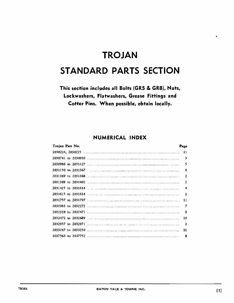
TB065
TROJAN
STANDARD PARTS SECTION
This section includes all Bolts (GRS & GRa), Nuts,
Lockwashers, Flatwashers, Grease Fittings and
Cotter Pins. When possible, obtain locally.
NUMERICAL INDEX
Trojan Part No. Page
2030224, 2030225 .. ........... ..... ..... ... .... ........... .... ............... ... ........ .... ...... ..... ... ....... 11
2030741 to 2030930 ........................................................... ..................................... 3
2030986 to 2031127 ............................................................................................... .
2031150 to 2031367 .............................................................................................. .
2031369 to 2031388 .................................................................................................. .
2031389 to 2031402 ................................................................................................. .
2031425 to 2031614 .................................................................................................. .
2031615 to 2031634 .................................................................................................. .
5
6
2
2
4
2
2031757 to 2031797 ........................................................ ........................................ 11
2032083 to 2032272 ........... ... .... ............................. ........... ... ..... ............................. ... 7
2032328 to 2032471 ..................................... ................ ............................ ............ 9
2032472 to 2032689 .......................................................... ........................................ 10
2032957 to 2032971 .......................................................... ........................................ 2
2033247 to 2033250 ........ ..................... .............................. . ........ .......... ..... ............ .... 11
2037563 to 2037752 ........................................................... .................................... 8
EATON YALE & TOWNE INC. [1]
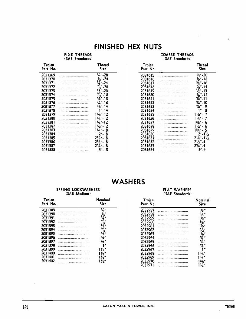
[2]
Trojan Part No.
2031369 2031370 2031371 2031372 2031373 2031374 2031375 2031376 2031377 2031378 2031379 2031380 2031381 2031382 2031383 2031384 2031385 2031386 2031387 2031388
Trojan Part No.
2031389 2031390 2031391 2031392 2031393 2031394 2031395 2031396 2031397 2031398 2031399 2031400 2031401 2031402
FINISHED HEX NUTS FINE THREADS (SAE Standards)
Thread Size
W'-28 ~6"-24 %"-24 Kt-20 W'-20 Kt-18 %"-18 %"-16 %"-14 1 "-14
1 Va"-12 1 W'-12 13/8"-12 lW'-12 1%"- 8
2"- 8 2W'- 8 2W'- 8 2%"- 8
3"- 8
SPRING LOCKWASHERS (SAE Medium)
...............................
...................... ..
................... ..
...................... ..
...............................
...........................
.......................
...................... ......
...............................
...................... ..
. . . . . . . . . . . . . . . . . . . . . . . . . . . . . . .
...............................
...............................
........................... ...
Nominal Size
1,4" ~t %" Kt V2" ~6" !V8" 3,4" %" 1"
1 Va" 11,4" 1%" lV2"
Trojan Part No.
2031615 2031616 2031617 2031618 2031619 2031620 2031621 2031622 2031623 2031624 2031625 2031626 2031627 2031628 2031629 2031630 2031631 2031632 2031633 2031634
WASHERS
Trojan Part No.
2032957 2032958 2032959 2032960 2032961 2032962 2032963 2032964 2032965 2032966 2032967 2032968 2032969 2032970 2032971
EATON YALE & TOWNE INC.
COARSE THREADS (SAE Standards)
FLAT WASH ERS (SAE Standards)
Thread Size
V4"-20 ~t-18 %"-16 K6"-14 W'-13 Kt-12 %"-11 3,4"-10 %"- 9
1"- 8 1 Va"- 7 lW'- 7 13h"- 6 Ph"- 6 13,4"- 5
2"-4V2 2W'-4V2 2W'-4 23,4"-4
3"-4
Nominal Size
TB065

FINISHED HEXAGON BOLTS, FINE THREADS SAE GRADE 5 STEEL
Part Nos. 2030741 thru 2030930
Thread 1/4"-28 5/16"-24 3/8"-24 7/16"-20 1/2"-20 9/16"-18 5/8"-18 3/4"-16 7/8"-14 1"-14 Hex. 7/16" 1/2" 9/16" 5/8" 3/4" 13/16" 15/16" 1-1/8" 1-5/16" 1-1/2" Lgt. Trojan Part Numbers
Yz" 2030741 2030764 2030787 o/a" 2030742 2030765 2030788 3,4" 2030743 2030766 2030789 2030810 2030831 'fa" 2030744 2030767 2030790 2030811 2030832
1" 2030745 2030768 2030791 2030812 2030833 2030852 2030871 1 Ya" 2030746 2030769 2030792 2030813 2030834 2030853 2030872 1~" 2030747 2030770 2030793 2030814 2030835 2030854 2030873 2030890 1%" 2030748 2030771 2030794 2030815 2030836 2030855 2030874 2030891 1 Yz" 2030749 2030772 2030795 2030816 2030837 2030856 2030875 2030892 2030907 2030920
203. 13,4" 2030750 2030773 2030796 2030817 2030838 2030857 2030876 2030893 2030908 2030921 203· 2" 2030751 2030774 2030797 2030818 2030839 2030858 2030877 2030894 2030909 2030922
2~" 2030752 2030775 2030798 2030819 2030840 2030859 2030878 2030895 2030910 2030923 2Yz" 2030753 2030776 2030799 2030820 2030841 2030860 2030879 2030896 2030911 2030924 23,4" 2030754 2030777 2030800 2030821 2030842 2030861 2030880 2030897 203091Z 2030925
3" 2030755 2030778 2030801 2030822 2030843 2030862 2030881 2030898 2030913 2030926 3~" 2030756 2030779 2030802 2030823 2030844 2030863 2030882 2030899 2030914 2030927 3Yz" 2030757 2030780 2030803 2030824 2030845 2030864 2030883 2030900 2030915 2030928 33,4" 2030758 2030781 2030804 2030825 2030846 2030865 2030884 2030901 2030916 2030929
4" 2030759 2030782 2030805 2030826 2030847 2030866 2030885 2030902 2030917 2030930 4Yz" 2030760 2030783 2030806 2030827 2030848 2030867 2030886 2030903 2030918
5" 2030761 2030784 2030807 2030828 2030849 2030868 2030887 2030904 2030919 5Yz" 2030762 2030785 2030808 2030829 2030850 2030869 2030888 2030905
6" 2030763 2030786 2030809 2030830 2030851 2030870 2030889 2030906
TB065 EATON YALE & TOWNE INC. [3]

FINISHED HEXAGON BOLTS, COARSE THREADS SAE GRADE 5 STEEL
Part Nos. 2031425 thru 2031614
Thread 1/4"-20 5/16"-18 3/8"-16 7/16"-14 1/2"-13 9/16"-12 5/8"-11 3/4"-10 7/8"-9 1"-8 Hex. 7/16" 1/2" 9/16" 5/8" 3/4" 13/16" 15/16" 1-1/8" 1-5/16" 1-1/2" Lgt. Trojan Part Numbers
V2" 2031425 2031448 2031471 o/s" 2031426 2031449 2031472 3A" 2031427 2031450 2031473 2031494 2031515 ~" 2031428 2031451 2031474 2031495 2031516
1" 2031429 2031452 2031475 2031496 2031517 2031536 2031555 1 Vs" 2031430 2031453 2031476 2031497 2031518 2031537 2031556 1W' 2031431 2031454 2031477 2031498 2031519 2031538 2031557 2031574 1318" 2031432 2031455 2031478 2031499 2031520 2031539 2031558 2031575 1V2" 2031433 2031456 2031479 2031500 2031521 2031540 2031559 2031576 2031591 2031604 1%" 2031434 2031457 2031480 2031501 2031522 2031541 2031560 2031577 2031592 2031605
2" 2031435 2031458 2031481 2031502 2031523 2031542 2031561 2031578 2031593 2031606 2W' 2031436 2031459 2031482 2031503 2031524 2031543 2031562 2031579 2031594 2031607 2V2" 2031437 2031460 2031483 2031504 2031525 2031544 2031563 2031580 2031595 2031608 2%" 2031438 2031461 2031484 2031505 2031526 2031545 2031564 2031581 2031596 2031609
3" 2031439 2031462 2031485 2031506 2031527 2031546 2031565 2031582 2031597 2031610 3V4" 2031440 2031463 2031486 2031507 2031528 2013547 2031566 2031583 2031598 2031611 3Y.2" 2031441 2031464 2031487 2031508 2031529 2031548 2031567 2031584 2031599 2031612 3%" 2031442 2031465 2031488 2031509 2031530 2031549 2031568 2031585 2031600 2031613
4" 2031443 2031466 2031489 2031510 2031531 2031550 2031569 2031586 2031601 2031614 4V2" 2031444 2031467 2031490 2031511 2031532 2031551 2031570 2031587 2031602
5" 2031445 2031468 2031491 2031512 2031533 2031552 2031571 2031588 2031603 5V2" 2031446 2031469 2031492 2031513 2031534 2031553 2031572 2031589
6" 2031447 2031470 2031493 2031514 2031535 2031554 2031573 2031590
[4] EATON YALE & TOWNE INC. TB065
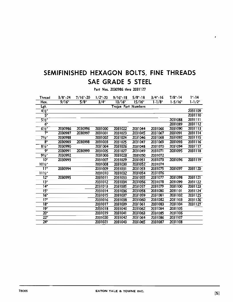
SEMIFINISHED HEXAGON BOLTS, FINE THREADS SAE GRADE 5 STEEL
Part Nos. 2030986 thru 2031127
Thread 3/8"-24 7/16"-20 1/2"-20 9/16"-18 5/8"-18 3/4"-16 7/8"-14 1" -14 Hex. 9/16" 5/8" 3/4" 13/16" 15/16" 1-118" 1-5/16" 1-1/2" Lgt. Trojan Part Numbers 4W' 2031109
5" 2031110 5V2" 2031088 2031111
6" 2031089 2031112 6V2" 2030986 2030996 2031000 2031022 2031044 2031066 2031090 2031113
7" 2030987 2030997 2031001 2031023 2031045 2031067 2031091 2031114 7V2" 2030988 2031002 2031024 2031046 2031068 2031092 2031115
8" 2030989 2030998 2031003 2031025 2031047 2031069 2031093 2031116 8Vz" 2030990 2031004 2031026 2031048 2031070 2031094 2031117
9" 2030991 2030999 2031005 2031027 2031049 2031071 2031095 2031118 9V2" 2030992 2031006 2031028 2031050 2031072
10" 2030993 2031007 2031029 2031051 2031073 2031096 2031119 lOW' 2031008 2031030 2031052 2031074
11" 2030994 2031009 2031031 2031053 2031075 2031097 2031120 11 V2" 2031010 2031032 2031054 2031076
12" 2030995 2031011 2031033 2031055 2031077 2031098 2031121 13" 2031012 2031034 2031056 2031078 2031099 2031122 14" 2031013 2031035 2031057 2031079 2031100 2031123 15" 2031014 2031036 2031058 2031080 2031101 2031124 16" 2031015 2031037 2031059 2031081 2031102 2031125 17" 2031016 2031038 2031060 2031082 2031103 2031126 18" 2031017 2031039 2031061 2031083 2031104 2031127 19" 2031018 2031040 2031062 2031084 2031105 20" 2031019 2031041 2031063 2031085 2031106 22" 2031020 2031042 2031064 2031086 2031107 24" 2031021 2031043 2031065 2031087 2031108
TB065 EATON YALE 8: TOWNE INC. [5]

REGULAR HEXAGON BOLTS, FINE THREADS SAE GRADE 5 STEEL
Part Nos. 2031150 thru 2031367
Thread 1-1/8"-12 1-1/4"-12 1-3/8"-12 1-1/2"-12 1-5/8"-8 1-3/4"-8 1-118"-8 2"-8 Hex. 1-11/16" 1-118" 2-1/16" 2-1/4" 2-7/16" 2-5/8" 2-13/16" 3" Lgt. Trojan Part Numbers
4" 2031150 2031167 2031183 2031216 2031249 4Y2" 2031151 2031168 2031184 2031217 2031250
5" 2031152 2031169 2031185 2031218 2031251 2031282 5Y2" 2031153 2031170 2031186 2031219 2031252 2031283
6" 2031154 2031171 2031187 2031220 2031253 2031284 2031313 6Y2" 2031188 2031221 2031254 2031285 2031314
7" 2031155 2031172 2031189 2031222 2031255 2031286 2031315 7Y2" 2031190 2031223 2031256 2031287 2031316 2031342
8" 2031156 2031173 2031191 2031224 2031257 2031288 2031317 2031343 8Y2" 2031192 2031225 2031258 2031289 2031318 2031344
9" 2031157 2031174 2031193 2031226 2031259 2031290 2031319 2031345 9Y2" 2031194 2031227 2031260 2031291 2031320 2031346
10" 2031158 2031175 2031195 2031228 2031261 2031292 2031321 2031347 11" 2031159 2031176 2031196 2031229 2031262 2031293 2031322 2031348 12" 2031160 2031177 2031197 2031230 2031263 2031294 2031323 2031349 13" 2031161 2031198 2031231 2031264 2031295 2031324 2031350 14" 2031162 2031178 2031199 2031232 2031265 2031296 2031325 2031351 15" 2031163 2031179 2031200 2031233 2031266 2031297 2031326 2031352 16" 2031164 2031180 2031201 2031234 2031267 2031298 2031327 2031353 17" 2031165 2031181 2031202 2031235 2031268 2031299 2031328 2031354 18" 2031166 2031182 2031203 2031236 2031269 2031300 2031329 2031355 19" 2031204 2031237 2031270 2031301 2031330 2031356 20" 2031205 2031238 2031271 2031302 2031331 2031357 21" 2031206 2031239 2031272 2031303 2031332 2031358 22" 2031207 2031240 2031273 2031304 2031333 2031359 23" 2031208 2031241 2031274 2031305 2031334 2031360 24" 2031209 2031242 2031275 2031306 2031335 2031361 25" 2031210 2031243 2031276 2031307 2031336 2031362 26" 2031211 2031244 2031277 2031308 2031337 2031363 27" 2031212 2031245 2031278 2031309 2031338 2031364 28" 2031213 2031246 2031279 2031310 2031339 2031365 29" 2031214 2031247 2031280 2031311 2031340 2031366 30" 2031215 2031248 2031281 2031312 2031341 2031367
[6] EATON YALE & TOWNE INC. TB065

FINISHED HEXAGON BOLTS, FINE THREADS SAE GRADE 8 STEEL
Part Nos. 2032083 thru 2032272
Thread 1/4"-28 5/16"-24 3/8"-24 7/16"-20 1/2"-20 9/16"-18 5/8"-18 3/4"-16 7/8"-14 1"-14 Hex. 7/16" 1/2" 9/16" 5/8" 3/4" 13/16" 15/16" 1-1/8" 1-5/16" 1-1/2" Lgt. Trojan Part Numbers
V2" 2032083 2032106 2032129 0/8" 2032084 2032107 2032130 3,4" 2032085 2032108 2032131 2032152 2032173 ~" 2032086 2032109 2032132 2032153 2032174
1" 2032087 2032110 2032133 2032154 2032175 2032194 2032213 1 Va" 2032088 2032111 2032134 2032155 2032176 2032195 2032214 1 v,." 2032089 2032112 2032135 2032156 2032177 2032196 2032215 2032232 i%" 2032090 2032113 2032136 2032157 2032178 2032197 2032216 2032233 1V2" 2032091 2032114 2032137 2032158 2032179 2032198 2032217 2032234 2032249 2032262 1%" 2032092 2032115 2032138 2032159 2032180 2032199 2032218 2032235 2032250 2032263
2" 2032093 2032116 2032139 2032160 2032181 2032200 2032219 2032236 2032251 2032264 2v,." 2032094 2032117 2032140 2032161 2032182 2032201 2032220 2032237 2032252 2032265 2V2" 2032095 2032118 2032141 2032162 2032183 2032202 2032221 2032238 2032253 2032266 2%" 2032096 2032119 2032142 2032163 2032184 2032203 2032222 2032239 _2032254 2032267
3" 2032097 2032120 2032143 2032164 2032185 2032204 2032223 2032240 2032255 2032268 3v,." 2032098 2032121 2032144 2032165 2032186 2032205 2032224 2032241 2032256 2032269 3V2" 2032099 2032122 2032145 2032166 2032187 2032206 2032225 2032242 2032257 2032270 3%" 2032100 2032123 2032146 2032167 2032188 2032207 2032226 2032243 2032258 2032271
4" 2032101 2032124 2032147 2032168 2032189 2032208 2032227 2032244 2032259 2032272 4~" 2032102 2032125 2032148 2032169 2032190 2032209 2032228 2032245 2032260
5" 2032103 2032126 2032149 2032170 2032191 2032210 2032229 2032246 2032261 5V2" 2032104 2032127 2032150 2032171 2032192 2032211 2032230 2032247
6" 2032105 2032128 2032151 2032172 2032193 2032212 2032231 2032248
TB065 EATON YALE & TOWNE INC. [7]

FINISHED HEXAGON BOLTS, COARSE THREADS SAE GRADE 8 STEEL
Part Nos. 2037563 thru 2037752
Thread 1/4"-20 5/16"-18 3/8" -16 7/16"-14 1/2"-13 9/16"-12 5/8"-11 3/4"-10 7 /8"-9 1"-8 Hex. 7/16" 1/2" 9/16" 5/8" 3/4" 13/16" 15/16" 1-1/8" 1-5/16" 1-1/2" Lgt. Trojan Part Numbers
V2" 2037563 2037586 2037609 %" 2037564 2037587 2037610 %" 2037565 2037588 2037611 2037632 2037653 'Va" 2037566 2037589 2037612 2037633 2037654
1" 2037567 2037590 2037613 2037634 2037655 2037674 2037693 1 Va" 2037568 2037591 2037614 2037635 2037656 2037675 2037694 1W' 2037569 2037592 2037615 2037636 2037657 2037676 2037695 2037712 13;8" 2037570 2037593 2037616 2037637 2037658 2037677 2037696 2037713 1W' 2037571 2037594 2037617 2037638 2037659 2037678 2037697 2037714 2037729 2037742 1%" 2037572 2037595 2037618 2037639 2037660 2037679 2037698 2037715 2037730 2037743
2" 2037573 2037596 2037619 2037640 2037661 2037680 2037699 2037716 2037731 2037744 2W' 2037574 2037597 2037620 2037641 2037662 2037681 2037700 2037717 2037732 2037745 2V2" 2037575 2037598 2037621 2037642 2037663 2037682 2037701 2037718 2037733 2037746 2%" 2037576 2037599 2037622 2037643 2037664 2037683 2037702 2037719 2037734 2037747
3" 2037577 2037600 2037623 2037644 2037665 2037684 2037703 2037720 2037735 2037748 3W' 2037578 2037601 2037624 2037645 2037666 2037685 2037704 2037721 2037736 2037749 3W' 2037579 2037602 2037625 2037646 2037667 2037686 2037705 2037722 2037737 2037750 33,4" 2037580 2037603 2037626 2037647 2037668 2037687 2037706 2037723 2037738 2037751
4" 2037581 2037604 2037627 2037648 2037669 2037688 2037707 2037724 2037739 2037752 4V2" 2037582 2037605 2037628 2037649 2037670 2037689 2037708 2037725 2037740
5" 2037583 2037606 2037629 2037650 2037671 2037690 2037709 2037726 2037741 5V2" 2037584 2037607 2037630 2037651 2037672 2037691 2037710 2037727
6" 2037585 2037608 2037631 2037652 2037673 2037692 2037711 2037728
[8] EATON YALE 8c TOWNE INC. TB065

SEMIFINISHED HEXAGON BOLTS, FINE THREADS SAE GRADE 8 STEEL
Part Nos. 2032328 thru 2032471
Thread 3/8"-24 7/16"-20 1/2"-20 9/16"-18 5/8"-18 3/4"-16 7/8"-14 1"-14 Hex. 9/16" 5/8" 3/4" 13/16" 15/16" 1-1/8" 1-5/16 1-1/2" Lgt. Trojan Part Numbers 4W' 2032453
5" 2032454 5W' 2032432 2032455
6" 2032433 2032456 6W' 2032328 2032340 2032344 2032366 2032388 2032410 2032434 2032457
7" 2032329 2032341 2032345 2032367 2032389 2032411 2032435 2032458 7W' 2032330 2032346 2032368 2032390 2032412 2032436 2032459
8" 2032331 2032342 2032347 2032369 2032391 2032413 2032437 2032460 8W' 2032332 2032348 2032370 2032392 2032414 2032438 2032461
9" 2032333 2032343 2032349 2032371 2032393 2032415 2032439 2032462 9W' 2032334 2032350 2032372 2032394 2032416
10" 2032335 2032351 2032373 2032395 2032417 2032440 2032463 lOW' 2032336 2032352 2032374 2032396 2032418
11" 2032337 2032353 2032375 2032397 2032419 2032441 2032464 11 W' 2032338 2032354 2032376 2032398 2032420
12" 2032339 2032355 2032377 2032399 2032421 2032442 2032465 13" 2032356 2032378 2032400 2032422 2032443 2032466 14" 2032357 2032379 2032401 2032423 2032444 2032467 15" 2032358 2032380 2032402 2032424 2032445 2032468 16" 2032359 2032381 2032403 2032425 2032446 2032469 17" 2032360 2032382 2032404 2032426 2032447 2032470 18" 2032361 2032383 2032405 2032427 2032448 2032471 19" 2032362 2032384 2032406 2032428 2032449 20" 2032363 2032385 2032407 2032429 2032450 22" 2032364 2032386 2032408 2032430 2032451 24" 2032365 2032387 2032409 2032431 2032452
TB065 EATON YALE & TOWNE INC. [9]

REGULAR HEXAGON BOLTS, FINE THREADS SAE GRADE 8 STEEL
Part Nos. 2032472 thru 2032689
Thread 1-1/8" -12 1-1/4"-12 1-3/8"-12 1-1/2"-12 1-5/8"-8 1-3/4"-8 1-7/8"-8 2"-8 Hex. 1-11/16" 1-7/8" 2-1/16" 2-1/4" 2-7/16" 2-5/8" 2-13/16" 3" Lgt. Trojan Part Num.bers
4" 2032472 2032489 2032505 2032538 2032571 4Vz" 2032473 2032490 2032506 2032539 2032572
5" 2032474 2032491 2032507 2032540 2032573 2032604 5Vz" 2032475 2032492 2032508 2032541 2032574 2032605
6" 2032576 2032493 2032509 2032542 2032575 2032606 2032635 6Vz" 2032510 2032543 2032576 2032607 2032636
7" 2032477 2032494 2032511 2032544 2032577 2032608 2032637 7Vz" 2032512 2032545 2032578 2032609 2032638 2032664
8" 2032478 2032495 2032513 2032546 2032579 2032610 2032639 2032665 81h" 2032514 2032547 2032580 2032611 2032640 2032666
9" 2032479 2032496 2032515 2032548 2032581 2032612 2032641 2032667 9Vz" 2032516 2032549 2032582 2032613 2032642 2032668
10" 2032480 2032497 2032517 2032550 2032583 2032614 2032643 2032669 11" 2032481 2032498 2032518 2032551 2032584 2032615 2032644 2032670 12" 2032482 2032499 2032519 2032552 2032585 2032616 2032645 2032671 13" 2032483 2032520 2032553 2032586 2032617 2032646 2032672 14" 2032484 2032500 2032521 2032554 2032587 2032618 2032647 2032673 15" 2032485 2032501 2032522 2032555 2032588 2032619 2032648 2032674 16" 2032486 2032502 2032523 2032556 2032589 2032620 2032649 2032675 17" 2032487 2032503 2032524 2032557 2032590 2032621 2032650 2032676 18" 2032488 2032504 2032525 2032558 2032591 2032622 2032651 2032677 19" 2032526 2032559 2032592 2032623 2032652 2032678 20" 2032527 2032560 2032593 2032624 2032653 2032679 21" 2032528 2032561 2032594 2032625 2032654 2032680 '22" 2032529 2032562 2032595 2032626 2032655 2032681 23" 2032530 2032563 2032596 2032627 2032656 2032682 24" 2032531 2032564 2032597 2032628 2032657 2032683 25" 2032532 2032565 2032598 2032629 2032658 2032684 26" 2032533 2032566 2032599 2032630 2032659 2032685 27" 2032534 2032567 2032600 2032631 2032660 2032686 28" 2032535 2032568 2032601 2032632 2032661 2032687 29" 2032536 2032569 2032602 2032633 2032662 2032688 30" 2032537 2032570 2032603 2032634 2032663 2032689
[10] EATON YALE & TOWNE INC. TB065

TB065
Dia.
Length 3/s" ~"
0/8" 3,4"
1" 11,4" 1 Y2" 1%"
2" 21,4" 2Y2" 2%"
3"
Trojan Part No.
2030224 2033247 2033248 2030225 2033249 2033250
1/16"
2031757 2031758 2031759 2031760 2031761
COTTER PINS 3/32" 1/8" 5/32" 3/16"
Trojan Part Numbers
2031762 2031763 2031767 2031764 2031768 2031773 2031765 2031769 2031774 2031779 2031766 2031770 2031775 2031780
2031771 2031776 2031781 2031772 2031777 2031782
2031778 2031783 2031784
GREASE FITTINGS Thread
Size
1,4"-28 1,4"-28 1,4"-28 Va" NPTF Va" NPTF Va" NPTF
EATON YALE & TOWNE INC.
7/32"
2031785 2031786 2031787 2031788 2031789 2031790
1/4"
2031791 2031792 2031793 2031794 2031795 2031796 2031797
Angle
Straight 45° 90°
Straight 45° 90°
[11 ]

Notes-
[12] EATON YALE & TOWNE INC. TB065