
CNT/Graphite/SBS Conductive Fibers for Strain Sensing in ...
Upload
independentCategory
view
3download
0
This journal is© the Owner Societies 2014 Phys. Chem. Chem. Phys., 2014, 16, 8521--8528 | 8521
Cite this:Phys.Chem.Chem.Phys.,
2014, 16, 8521
MnO2 nanolayers on highly conductiveTiO0.54N0.46 nanotubes for supercapacitorelectrodes with high power density andcyclic stability†
Zhiqiang Wang, Zhaosheng Li,* Jianyong Feng, Shicheng Yan, Wenjun Luo,Jianguo Liu, Tao Yu and Zhigang Zou*
Pseudo-capacitive MnO2 supercapacitors are attracting intense interest because of the theoretically high
specific capacitance (1370 F g�1) and low cost of MnO2. For the practical application, the power density
and the cyclic stability of MnO2-based supercapacitors are expected to be improved. Increasing the
efficiency of the current collection is an effective method to improve the power density for a given
supercapacitor. Here, the highly conductive and electrochemically stable material, titanium oxynitride
(TiO0.54N0.46), is used as the current collector. Uniform amorphous MnO2 nanolayers were deposited on
metal-phase TiO0.54N0.46 nanotube arrays using a modified electrochemical deposition method. The
resulting MnO2 supercapacitors exhibited a high power density of 620 kW kg�1 at an energy density of
9.8 W h kg�1. This is comparable to high-performance carbon-based electrochemical double layer
capacitors in aqueous electrolytes. The high electron transport was enhanced with a highly conductive
TiO0.54N0.46 scaffold. Ion transport was promoted in the nanotube structures that had porous walls. In
addition, the close interfacial connection between MnO2 and TiO0.54N0.46 contributed to the excellent
cyclic stability (ca. 92.0% capacitance retention after 100 000 cycles). These results indicated that the
highly conductive and electrochemically stable titanium oxynitride is an excellent candidate for use as
an electrode material in high performance supercapacitors.
Introduction
High performance electric energy storage systems as well assustainable and renewable energy have drawn worldwide scientificand industrial interest.1–9 Electrochemical capacitors (ECs orsupercapacitors) and batteries are opposite types of electricenergy storage systems in terms of their power and energydensities.10,11 In the future, hybrid energy systems will combinethe high energy density of batteries with the rapid charge–discharge and power capabilities of ECs.6 ECs can be completelycharged or discharged within seconds and exhibit a much higherpower density (ca. 10 kW kg�1) than batteries.12,13 ECs cancompensate for the shortage of the lower power uptake or thedelivery rate and the short charge–discharge cycle life of thebatteries in battery–supercapacitor hybrid power supply systems.6,13
ECs can be classified into two categories based on the chargestorage mechanisms. The first is electrochemical double layercapacitors (EDLCs), and are based on the pure electrostaticattraction between ions in the electrolyte and the chargedsurface of the active materials. The second is pseudo-capacitors,which are associated with the surface reversible redox reactions orthe faradaic charge transfer reactions with the active materials.12
Because of the high mobility of the ions, especially in the aqueouselectrolytes that always have a relatively high ionic conductivityand low viscosity,6 the former type of ECs (EDLCs) can be chargedor discharged with a high power density and operate for a longcycle life (4105 cycles). However, the latter ECs can store morecharge and exhibit a higher energy storage density.12
Among the active materials in pseudo-capacitors (transitionmetal oxides and conductive polymers),14–21 MnO2 has drawn asignificant and growing interest because of its high theoreticalspecific capacitance (1370 F g�1), cost effectiveness, abundanceand environmental friendliness.22 However, the low electricalconductivity of MnO2 (10�5–10�6 S cm�1) limits the charge–discharge rate for high power applications. Also, MnO2-basedECs often suffer from a short cycle life.11,22 Practical applicationsfor electrochemical capacitors demand a much higher power
National Laboratory of Solid State Microstructures, Ecomaterials and Renewable
Energy Research Center (ERERC), Department of Physics, Nanjing University,
22 Hankou Road, Nanjing 210093, People’s Republic of China.
E-mail: [email protected], [email protected]
† Electronic supplementary information (ESI) is available: Details of the anodiza-tion process, XRD, SEM, TEM and other additional electrochemical measure-ments and analysis. See DOI: 10.1039/c3cp55456b
Received 26th December 2013,Accepted 4th March 2014
DOI: 10.1039/c3cp55456b
www.rsc.org/pccp
PCCP
PAPER
Publ
ishe
d on
10
Mar
ch 2
014.
Dow
nloa
ded
by N
AN
JIN
G U
NIV
ER
SIT
Y o
n 08
/10/
2014
10:
29:2
1.
View Article OnlineView Journal | View Issue
8522 | Phys. Chem. Chem. Phys., 2014, 16, 8521--8528 This journal is© the Owner Societies 2014
output and a longer cycle life. Improving the power density andcyclic stability of pseudo-capacitors to the magnitude of EDLCs,and maintaining the high energy density of the former at thesame time, remain a scientific and technical challenge.
To improve the power density and cyclic stability of pseudo-capacitors, designing a nanostructured current collector withhigh conductance and a linear channel for fast electron and iontransport is required.23 It has been demonstrated that tubularstructured nano-scaffolds can be used to improve the ion transportthrough the electrolyte to the active site while maximizing the activearea of the electrode materials. The three dimensional nanotubenetwork of titanium oxide offers a solid support structure for theactive materials RuO2 and NiO, allowing the active material tobe readily accessible for electrochemical reactions, improving theefficiency of the active materials.24,25 In addition, taking advantage ofthe shortened electrolyte penetration depth and the ion diffusiondistance in the aligned titania nanotubes, superior performance ofthe electrochemical energy storage was achieved.26 More recently,NiO or Fe2O3 hybrid TiO2 nanotube electrodes displayed a high ratecapability, which was attributed to the ordered architecture thatinduced an efficient ion transport.27,28 However, the conductivity oftitanium oxide is relatively low. For example, the conductivity ofanatase was reported to be 2.2� 10�7 S cm�1.29 The low conductivityof the nanotubes limits the electron transport along the tubes.
Deposition of pseudo-capacitive transitional metal oxides onhighly conductive tubular current collectors is an efficient routeto enhance the flow of electrons to and from the substrate.20–32
Titanium oxynitride is a metallic material with a conductivity of30 000–35 000 S cm�1.33,34 This is higher than chemically-converted graphene (210–1000 S cm�1)35 and carbon nanotubes(60–170 S cm�1).36 Here, it is shown that titanium oxynitride (cubic)is stable in a neutral electrolyte with a 1 mol L�1 aqueous KClsolution or a 1 mol L�1 TEA-BF4 (tetraethylammonium tetrafluoro-borate) acetonitrile electrolyte. This indicated that titaniumoxynitride (cubic) is a current collecting material. A near uniformMnO2 layer was deposited on TiO1�xNx nanotube arrays. Takingadvantage of the high conductivity and the linear ion channel oftitanium oxynitride nanotube arrays, the deposited MnO2 hadexcellent cyclic stability (ca. 92.0% capacitance retention after100 000 cycles) and a high power density of 620 kW kg�1 at a highenergy density of 9.8 W h kg�1. This is comparable to the powerdensity and cycle life of active materials used in the recentlyreported high-performance aqueous electrolyte EDLCs.37–40
Experimental sectionSample preparation
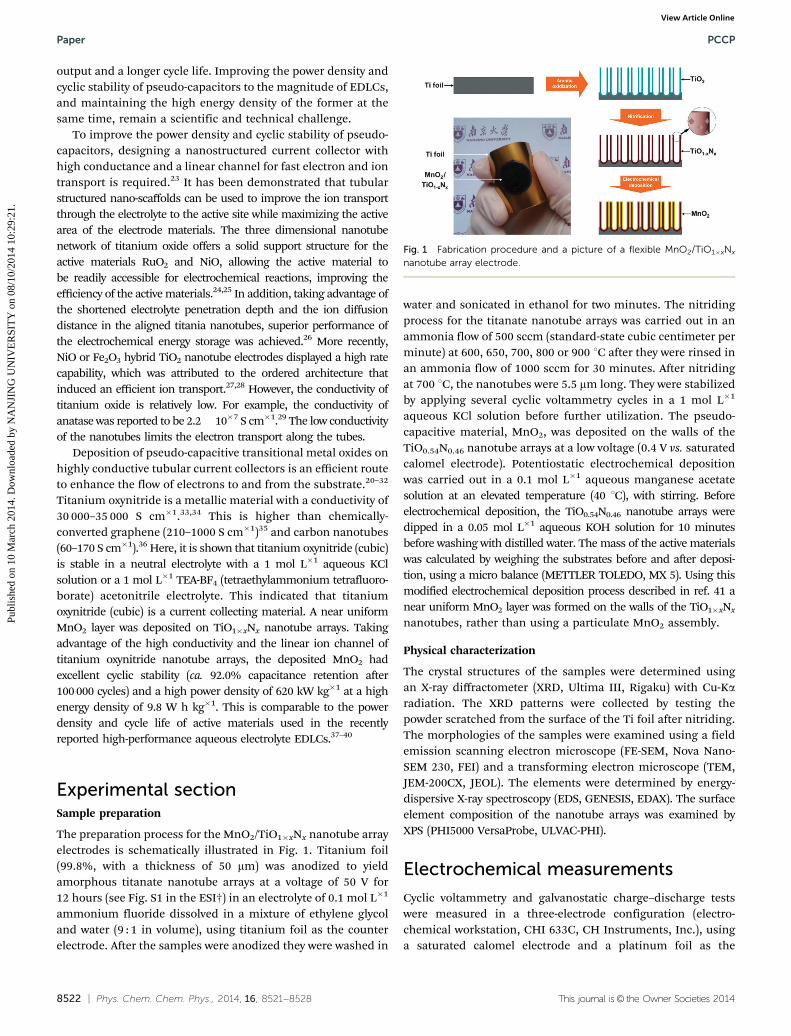
The preparation process for the MnO2/TiO1�xNx nanotube arrayelectrodes is schematically illustrated in Fig. 1. Titanium foil(99.8%, with a thickness of 50 mm) was anodized to yieldamorphous titanate nanotube arrays at a voltage of 50 V for12 hours (see Fig. S1 in the ESI†) in an electrolyte of 0.1 mol L�1
ammonium fluoride dissolved in a mixture of ethylene glycoland water (9 : 1 in volume), using titanium foil as the counterelectrode. After the samples were anodized they were washed in
water and sonicated in ethanol for two minutes. The nitridingprocess for the titanate nanotube arrays was carried out in anammonia flow of 500 sccm (standard-state cubic centimeter perminute) at 600, 650, 700, 800 or 900 1C after they were rinsed inan ammonia flow of 1000 sccm for 30 minutes. After nitridingat 700 1C, the nanotubes were 5.5 mm long. They were stabilizedby applying several cyclic voltammetry cycles in a 1 mol L�1
aqueous KCl solution before further utilization. The pseudo-capacitive material, MnO2, was deposited on the walls of theTiO0.54N0.46 nanotube arrays at a low voltage (0.4 V vs. saturatedcalomel electrode). Potentiostatic electrochemical depositionwas carried out in a 0.1 mol L�1 aqueous manganese acetatesolution at an elevated temperature (40 1C), with stirring. Beforeelectrochemical deposition, the TiO0.54N0.46 nanotube arrays weredipped in a 0.05 mol L�1 aqueous KOH solution for 10 minutesbefore washing with distilled water. The mass of the active materialswas calculated by weighing the substrates before and after deposi-tion, using a micro balance (METTLER TOLEDO, MX 5). Using thismodified electrochemical deposition process described in ref. 41 anear uniform MnO2 layer was formed on the walls of the TiO1�xNx
nanotubes, rather than using a particulate MnO2 assembly.
Physical characterization
The crystal structures of the samples were determined usingan X-ray diffractometer (XRD, Ultima III, Rigaku) with Cu-Karadiation. The XRD patterns were collected by testing thepowder scratched from the surface of the Ti foil after nitriding.The morphologies of the samples were examined using a fieldemission scanning electron microscope (FE-SEM, Nova Nano-SEM 230, FEI) and a transforming electron microscope (TEM,JEM-200CX, JEOL). The elements were determined by energy-dispersive X-ray spectroscopy (EDS, GENESIS, EDAX). The surfaceelement composition of the nanotube arrays was examined byXPS (PHI5000 VersaProbe, ULVAC-PHI).
Electrochemical measurements
Cyclic voltammetry and galvanostatic charge–discharge testswere measured in a three-electrode configuration (electro-chemical workstation, CHI 633C, CH Instruments, Inc.), usinga saturated calomel electrode and a platinum foil as the
Fig. 1 Fabrication procedure and a picture of a flexible MnO2/TiO1�xNx
nanotube array electrode.
Paper PCCP
Publ
ishe
d on
10
Mar
ch 2
014.
Dow
nloa
ded
by N
AN
JIN
G U
NIV
ER
SIT
Y o
n 08
/10/
2014
10:
29:2
1.
View Article Online

This journal is© the Owner Societies 2014 Phys. Chem. Chem. Phys., 2014, 16, 8521--8528 | 8523
reference and counter electrodes respectively. The galvanostaticcharge–discharge cycle life tests for the TiO1�xNx nanotubearrays (after nitriding at 700 1C) and MnO2/TiO0.54N0.46 nano-tube array electrodes (where MnO2 was loaded for 100 s) weremeasured using a two symmetric electrode configuration(programmable digital source meter, Keithley 2400, KeithleyInstruments, Inc.) from 0 to 0.8 V at current densities of5 mA cm�2 and 50 A g�1, respectively. Electrochemical charac-terizations were conducted at 20 1C in a 1.0 mol L�1 aqueous KClsolution and in a 1.0 mol L�1 TEA-BF4 acetonitrile electrolyte.
Results and discussion
By anodizing the titanium foil, well-defined titanate nanotubearrays with a diameter of B150 nm were obtained, as shown inFig. 2a. The morphology of the nanotube arrays remained afternitriding at 700 1C. However, there were some holes, 10–20 nmin size, in the nanotube walls (Fig. 2b). All of the peaks inthe XRD pattern (Fig. 2c) for the nanotubes that underwentnitriding at 700 1C appeared between the correspondingstandard peaks of the cubic TiN and cubic TiO, which weresimilar to the theoretically calculated peak positions for cubicTiO0.5N0.5. This suggested that the titanate was transformed into asolid solution of cubic TiN and TiO (cubic TiO1�xNx) at a nitridingtemperature of 700 1C. A mixture containing only rutile andanatase titania was obtained at 600 1C (see Fig. S2 in the ESI†).
When the nitriding temperature was Z650 1C, cubic TiO1�xNx
was formed. The dominant XRD peaks of cubic TiO1�xNx
became sharper and gradually shifted to lower angles asthe nitriding temperature was increased from 650 to 900 1C(see Fig. S3 in the ESI†). This indicated that N atoms wereincorporated into the crystal lattice of cubic TiO. Because theX-ray photoelectron spectroscopy (XPS) method is restricted tothe surface and energy dispersive X-ray spectroscopy (EDS)is usually influenced by the substrate, the N/O ratio wascalculated from the XRD data to eliminate deviations fromthe actual elemental composition. According to Vegard’s law,which describes a linear relationship between the crystal latticeparameter in the solid solution and the concentration ofthe constituent elements, the concentration of nitrogen (x) inTiO1�xNx was calculated to be 0.09, 0.46, 0.50 and 0.55 atnitriding temperatures of 650, 700, 800, and 900 1C, respectively(see Fig. S4 in the ESI†).
The cyclic voltammograms of the nanotube arrays (excludingthose at a nitriding temperature of 600 1C) retained their rectan-gular shape, which is a characteristic of the ideal electrochemicaldouble layer capacitive behavior (Fig. 2d). The specific capaci-tances of the samples were 0.2, 19.5, 22.3, 9.1 and 3.5 mF cm�2
(Fig. 2d) as the nitriding temperature was increased from 600 to900 1C (details of the calculation methods are described in theESI†). The cyclic voltammograms of all samples obtained atdifferent temperatures had an ideal rectangular shape. Therectangular shape of the TiO0.54N0.46 samples were maintained
Fig. 2 (a) SEM image of an as-anodized TiO2 nanotube array. (b) SEM image of a 700 1C nitrificated TiO1�xNx nanotube array. (c) XRD pattern of a 700 1Cnitrificated TiO1�xNx nanotube array and the simulated powder XRD pattern of TiO0.5N0.5, compared with the standard JCPDS (Joint Committeeon Powder Diffraction Standards) patterns. (d) Cyclic voltammetry of TiO1�xNx nanotube arrays that were nitrificated at different temperatures ata scan rate of 0.1 V s�1 in a 1.0 mol L�1 aqueous KCl solution with a three-electrode configuration. (e) Cyclic voltammetry scan of a TiO1�xNx filmprepared at a nitriding temperature of 700 1C at various scan rates (in a 1.0 mol L�1 aqueous KCl solution, three-electrode configuration). (f) Galvanostaticcharge–discharge capacity retention (in a 1.0 mol L�1 aqueous KCl solution, two-electrode configuration) and the XPS spectra (inset) of a TiO0.54N0.46
nanotube array.
PCCP Paper
Publ
ishe
d on
10
Mar
ch 2
014.
Dow
nloa
ded
by N
AN
JIN
G U
NIV
ER
SIT
Y o
n 08
/10/
2014
10:
29:2
1.
View Article Online

8524 | Phys. Chem. Chem. Phys., 2014, 16, 8521--8528 This journal is© the Owner Societies 2014
at a higher scan rate of 1 V s�1 (Fig. 2e). The TiO0.54N0.46 sampleexhibited the highest specific capacitance of 22.3 mF cm�2 at ascan rate of 0.1 V s�1. Cyclic voltammograms of the 700 1Cnitrificated electrodes were also tested in other alkali metalchloride aqueous electrolytes, such as LiCl, NaCl, RbCl andCsCl. They all showed a similar rectangular shape (Fig. S5 inthe ESI†). The high quality capacitance behavior in cyclicvoltammograms indicated that there was fast electron andion transport. For comparison, the same precursor nanotubearrays were annealed in other atmospheres such as air, oxygen,a hydrogen–nitrogen (1 : 9) gas mixture or argon at 700 1C.These as-prepared samples exhibited cyclic voltammogramsthat drastically deviated from the rectangular shape and hadnegligible capacitance (Fig. S8a in the ESI†). These results wereattributed to the high resistances of the titania nanotubes, asdemonstrated in the electrochemical impedance spectroscopy(EIS) (Fig. S8b in the ESI†). Density functional theory calcula-tions indicated that cubic TiOxN1�x behaved as a metal ratherthan a semiconductor, thus displaying a high conductivity.34
The TiOxN1�x nanotubes had high quality crystallinity forTiO0.54N0.46. This was proved by both XRD analysis (Fig. 2c)and selected area electron diffraction (see the inset in Fig. S9cin the ESI†) and was helpful in achieving a high conductivity.
Cycle life is one of the vital parameters used to evaluate theelectrochemical stability of electrode materials. The TiO0.54N0.46
nanotube array electrodes showed an excellent cyclic stability bothin a 1.0 mol L�1 aqueous KCl solution and in a 1 mol L�1 TEA-BF4
acetonitrile electrolyte. As depicted in Fig. 2f, the TiO0.54N0.46
nanotube array electrodes in 1.0 mol L�1 aqueous KCl solutionretained B100% of their initial response after 100 000 galvano-static charge–discharge cycles at a current density of 5 mA cm�2.The capacity retentions of the electrodes tested in 1 mol L�1
TEA-BF4 acetonitrile electrolyte in the voltage windows of0–0.8 V, 0–1.5 V and 0–2.5 V were 95.9%, 86.0%, and 74.3%,respectively, after 100 000 galvanostatic charge–discharge cycles(Fig. 3). Ti 2p XPS analysis (see inset in Fig. 2f) did not show anyobvious changes in the chemical states of Ti before and afterthe 100 000 charge–discharge cycles. Simultaneously, the N 1sXPS (see the inset in Fig. 2f) showed only a slight decrease inthe peak intensity, proving that TiO0.54N0.46 was stable duringthe charge–discharge process. These results support theargument that TiO0.54N0.46 is an excellent current collectorbecause of its high chemical stability. It is believed thatTiO0.54N0.46 is the first oxynitride electrode material to exhibitextreme cyclic stability without any significant degradation over100 000 charge–discharge cycles (Fig. 2f), which is comparableto carbon-based materials.12
Fig. 4a shows the effects of the MnO2 loading time on thecurrent–capacitance relationship of MnO2/TiO0.54N0.46 electro-des. As the loading time was increased, the specific capacitanceof MnO2 decreased, owing to the enhancement in the amountof MnO2. At loading times of 50, 100, 200, and 400 s the loadedmasses of the MnO2 samples were 0.074, 0.131, 0.250 and0.521 mg cm�2, respectively. Among the samples, a loadingtime of 50 s had the highest specific capacitance for MnO2
(against the mass of MnO2), while MnO2/TiO0.54N0.46 had the
best specific capacitance against area at a loading time of 400 s(Fig. 4a and Fig. S11 in the ESI†). The masses of the materialsdeposited were comparable to or exceeded most of the MnO2
loaded films reported thus far.22,29–31,41,43
All of the MnO2/TiO0.54N0.46 nanotube array electrodes,regardless of the deposition time, showed near ideal triangularcharge–discharge curves, which were obtained at a high currentdensity of 100 A g�1 (Fig. 4b). The 50 s deposited electrodes hadthe best charge–discharge behaviour with a very small IR drop(voltage drop) of 0.02 V, even at a current of 100 A g�1 (Fig. 4band Fig. S6b in the ESI†). This worked well when the IR dropreached 0.20 V and 0.39 V at ultrahigh current densities of 1000and 2000 A g�1, respectively (Fig. S12 in the ESI†). A capacitanceof B220 F g�1 was obtained, even when the capacitor (MnO2
loading time of 50 s) was operated at an ultrafast charge–discharge rate of 2000 A g�1. For the MnO2 samples with aloading time of 100 s, a capacitance of B152 F g�1 was achievedat an ultrafast charge–discharge rate of 1000 A g�1. This suggestedthat supercapacitors could be charged and discharged at a milli-second rate, indicating that they can bear high power outputapplications. Under the same area current density, the TiO0.54N0.46
nanotube substrates had capacitances of o25% and o11% ofMnO2 deposited TiO0.54N0.46 nanotubes, indicating that thecontribution of the TiO0.54N0.46 nanoarray substrates can beomitted (Fig. S13 in the ESI†).
The cyclic stability of the MnO2/TiO0.54N0.46 nanotube arrayelectrodes was studied using the galvanostatic charge–dischargemethod for a two-electrode system. The MnO2/TiO0.54N0.46 nano-tube array electrodes exhibited excellent cyclic stability andretained B92% of their initial response, even after 100 000 cycles,as shown in Fig. 4c. TEM observations (Fig. 4d) and EDS linescanning analysis along the cross section of the nanotubes(Fig. 4e) indicated that MnO2 was uniformly coated on thesurface of the TiO0.54N0.46 nanotubes with a thickness of5–10 nm (Fig. S9e and f, ESI†).
Fig. 3 Galvanostatic charge–discharge capacity retention of a TiO0.54N0.46
nanotube array in a 1 mol L�1 TEA-BF4 acetonitrile electrolyte (tested in thetwo symmetric electrode mode). The voltage windows of 0–0.8 V, 0–1.5 V,and 0–2.5 V correspond to capacity retentions of 95.9%, 86.0%, and74.3%, respectively.
Paper PCCP
Publ
ishe
d on
10
Mar
ch 2
014.
Dow
nloa
ded
by N
AN
JIN
G U
NIV
ER
SIT
Y o
n 08
/10/
2014
10:
29:2
1.
View Article Online

This journal is© the Owner Societies 2014 Phys. Chem. Chem. Phys., 2014, 16, 8521--8528 | 8525
Electrochemical impedance spectroscopy (EIS) was usedto further understand the original nature of these high-performance supercapacitor electrodes. Fig. 4f shows the EISspectra of a sample, obtained for different deposition times.The impedance spectra were similar to each other and werecomposed of one semicircle at the high-frequency end of thespectrum, followed by a linear section at the low-frequency endof the spectrum. The first semicircle in the spectra corre-sponded to the resistance of the MnO2 layers. As the loadingtime was increased, the thickness of the MnO2 layer grew,resulting in a larger semicircle in the corresponding spectra.An equivalent circuit was used to fit the Nyquist spectra usingthe software ZVIEW (see the inset in Fig. 4f). The equivalentcircuit in Fig. 4f is the Randles circuit used to model theinterfacial electrochemical reactions of the TiO0.54N0.46 andMnO2-loaded TiO0.54N0.46 nanotube arrays. In this model, R1represents the series resistance and accounts for the solutionresistance between the reference electrode and the workingelectrode. C1 represents the double-layered capacitor wherethe double layers were formed on the surface of the electrodesthat were in contact with the electrolyte, which was in parallelwith the electrochemical reaction. The impedance of an electro-chemical reaction consists of the active charge transfer resis-tance (R2) and the specific electrochemical element of diffusion(W1). This is called a generalized finite length Warburgdiffusion element (GFW) and includes the impedances encoun-tered when the electrolyte ions diffuse from the bulk to the
electrode–electrolyte interface. Here, this is a GFW open circuitterminus. As the loading time for MnO2 increased, the resis-tances (R1 and R2) slightly increased (see Table S1 in the ESI†)(o3.5 O for R1 and o1.8 O for R2). This guaranteed a highcharge–discharge rate. All of the spectra had a B901 capacitivespike starting from the mid-high frequency region, demonstratingthe high quality capacitive behavior of the MnO2/TiO0.54N0.46
electrodes.A high-resolution TEM (HRTEM) image of the MnO2/
TiO0.54N0.46 surface layer did not show the presence of a crystallattice (Fig. 5a). This implied that the MnO2 coating layerwas amorphous. However, HRTEM analysis of the MnO2/TiO0.54N0.46 scaffold showed that the lattice spacing was0.21 nm along the (200) plane, which provided direct evidencethat the scaffold was crystalline TiO0.54N0.46. After 100 000galvanostatic cycles of charging and discharging, there wereno obvious changes in the morphology of MnO2/TiO0.54N0.46
(Fig. 5b), indicating that the MnO2/TiO0.54N0.46 electrode waselectrochemically stable. This is likely a result of the closelyconnected interface formed between MnO2 and TiO0.54N0.46, asobserved by the HRTEM measurements (Fig. 5). Therefore,it is concluded that the excellent cyclic stability of the MnO2/TiO0.54N0.46 supercapacitor resulted from the highly dispersedstate of MnO2 on the TiO0.54N0.46 surface and the close connec-tion of the MnO2/TiO0.54N0.46 interface.
The effect of the folding angle and time on the capacitanceof the electrodes was studied to evaluate the potential of the
Fig. 4 (a) Effect of the loading time on the current density–specific capacitance relationship of MnO2 on TiO0.54N0.46 nanotube arrays (the three-electrode configuration, a galvanostatic discharge of 0–0.8 V in a 1.0 mol L�1 aqueous KCl solution). (b) Galvanostatic charge–discharge curves of MnO2/TiO0.54N0.46 nanotube array electrodes (with various MnO2 loading times) at a current density of 100 A g�1 (in a 1.0 mol L�1 aqueous KCl solution with athree-electrode configuration). (c) Galvanostatic charge–discharge cyclic stability of a MnO2/TiO0.54N0.46 nanotube array electrochemical capacitor (in a1.0 mol L�1 aqueous KCl solution with a two-electrode configuration). The inset displayed that the MnO2/TiO0.54N0.46 nanotube array electrochemicalcapacitors retained ca. 98% of their initial response after 10 000 cycles. (d) TEM image of a MnO2/TiO0.54N0.46 interface. (e) EDS scanning of N, O, Ti andMn elements over a MnO2/TiO0.54N0.46 nanotube array. (f) Nyquist spectra of the MnO2/TiO0.54N0.46 nanotube array electrodes (0.1–10 000 Hz),magnified in the high-frequency region in the inset (in a 1.0 mol L�1 aqueous KCl solution), and the equivalent circuit (below).
PCCP Paper
Publ
ishe
d on
10
Mar
ch 2
014.
Dow
nloa
ded
by N
AN
JIN
G U
NIV
ER
SIT
Y o
n 08
/10/
2014
10:
29:2
1.
View Article Online

8526 | Phys. Chem. Chem. Phys., 2014, 16, 8521--8528 This journal is© the Owner Societies 2014
MnO2/TiO0.54N0.46 electrodes for use in flexible energy storageunder practical conditions. The folding angle had no influenceon the capacitance of MnO2/TiO0.54N0.46 (see Fig. S14 in theESI†). After they were folded various times, the cyclic voltam-metric performance of the MnO2/TiO0.54N0.46 nanotube arrayelectrodes exhibited no obvious changes (Fig. S15 in the ESI†).The excellent durability was attributed to the high mechanicalflexibility of the MnO2/TiO0.54N0.46 electrodes.
To demonstrate the overall performance of the MnO2/TiO0.54N0.46 nanotube array supercapacitor electrodes, aRagone plot is shown in Fig. 6 to compare the performanceof the supercapacitor electrodes in this study with the existingtypical EDLCs. The power density of the MnO2 films onTiO0.54N0.46 was comparable to that of the most recentlyreported high performance aqueous electrolyte EDLCs basedon carbon materials. The MnO2 electrodes with a depositiontime of 100 s exhibited an energy density of 5.1 W h kg�1 and apower density of 632 kW kg�1 (at a discharge current density of1000 A g�1). They exhibited a power density of 620 kW kg�1 at ahigh energy density of 9.8 W h kg�1 at a discharge currentdensity of 100 A g�1. Such a high power density can beattributed to the high current collection efficiency of the highlyconductive TiO0.54N0.46 nanotubes and the fast ion transport inthe nanotubes with porous walls. A porous network in the bulkof the electrode materials influenced the transport rate of theions in the electrolyte. This determined the charge–dischargerate of the working electrodes.42 As the crystal volume shrankduring the nitriding process, nanopores appeared in the nano-tubes. Regular and linear porous networks displayed in Fig. 2bare much more favorable to electrolyte diffusion than desultorypores, which may improve the charge–discharge rate. Although
the energy density of MnO2/TiO0.54N0.46 was not very highbecause of the low test voltage used here (0–0.8 V), it surpassedthe power density of most of the existing MnO2-based super-capacitors.44–46 The energy density can be approximatelyexpressed as E = 1/2(CV2), where V is the voltage window.Compared with the voltage window (0.8 V) in 1 mol L�1
aqueous KCl solution, a higher voltage window of 2.5 V wasachieved in the organic electrolyte (1 mol L�1 TEA-BF4 inacetonitrile), thus obtaining a much higher energy density of57.2 W h kg�1 (discharge rate = 100 A g�1).
To check their practical application potential, the super-capacitor devices were prepared by a simple sealing technique(details in ESI†). Supercapacitor devices were constructed bysealing two 100-s deposited MnO2/TiO0.54N0.46 electrodes withan electrolyte and a separating membrane in a plastic bag. Thecapacity retention (97.5% after 10 000 galvanostatic cycles,Fig. S16 in the ESI†), power density and energy density (theRagone plot based on the mass of MnO2, Fig. S17 in the ESI†)for the sealed devices were close to those with MnO2/TiO0.54N0.46 electrodes tested in an open electrolyte system.After charging for only 1 s, two MnO2/TiO0.54N0.46 devices wereconnected in series and efficiently powered a red round lightemitting diode (LED) for 60 s (Fig. S18 in the ESI†). The highperformance of MnO2 nanolayers on TiO0.54N0.46 nanotubearrays may have originated from: (1) the highly conductiveand electrochemically stable current collecting material,titanium oxynitride, which backs up the high stability and thehigh power delivery capability of the pseudo-capacitive MnO2
in the supercapacitor electrodes; (2) the linear ion diffusionpathways in the hollow nanotube arrays, which improved thecharge–discharge rate. The ions in the electrolyte could directlypenetrate the nanotubes and move to the active MnO2 nano-layers on the surface of the nanotube walls under the highpower operating conditions; and (3) the intimate interfaceconnection between MnO2 and TiO0.54N0.46 and the uniform
Fig. 5 HRTEM images of the 100-s deposited MnO2/TiO0.54N0.46
interface. (a) The as-synthesized sample. (b) The sample after 100 000galvanostatic cycles. The blue lines indicate the interface between MnO2
and TiO0.54N0.46.
Fig. 6 Energy and power densities of MnO2 nanolayers on TiO0.54N0.46
nanotube arrays (Ragone plot) compared with aqueous electrolyte EDLCdata from ref. 37–40 (measured in a two-electrode configuration, basedon the mass of MnO2).
Paper PCCP
Publ
ishe
d on
10
Mar
ch 2
014.
Dow
nloa
ded
by N
AN
JIN
G U
NIV
ER
SIT
Y o
n 08
/10/
2014
10:
29:2
1.
View Article Online

This journal is© the Owner Societies 2014 Phys. Chem. Chem. Phys., 2014, 16, 8521--8528 | 8527
distribution of MnO2 on TiO0.54N0.46 which minimized theresistance between the MnO2 nanolayers and the TiO0.54N0.46
nanotubes, which may contribute to the high power density.
Conclusions
In summary, the TiO0.54N0.46 nanotube arrays exhibited highquality electrochemical characteristics and stability in a 1 mol L�1
aqueous KCl solution and a 1 mol L�1 TEA-BF4 acetonitrileelectrolyte. The uniform MnO2 layer deposited on the walls ofTiO0.54N0.46 nanotube arrays exhibited a high power densityand a high quality cyclic stability comparable to the EDLCs. Atthe same time, the energy density of the pseudo-capacitivematerial was maintained and was several times higher thanthe aqueous electrolyte EDLCs with carbon based materials.These results weakened the concept that pseudo-capacitivematerials are inferior in cyclic stability and power density totheir EDLC counterparts. This demonstrated the possibility oftitanium oxynitride nanotube arrays as nanostructured currentcollectors to improve the power density and cyclic stability ofpseudo-capacitive materials.
Acknowledgements
This work was financially supported by the National BasicResearch Program of China (973 Program, 2013CB632404), aProject Funded by the Priority Academic Program Developmentof Jiangsu Higher Education Institutions, the Program for NewCentury Excellent Talent in University (NCET-12-0268), and theNational Natural Science Foundation of China (no. 51272102,21073090 and 51272101).
Notes and references
1 J. Chmiola, C. Largeot, P. L. Taberna, P. Simon andY. Gogotsi, Science, 2010, 328, 480–483.
2 Y. Zhu, S. Murali, M. D. Stoller, K. J. Ganesh, W. Cai,P. J. Ferreira, A. Pirkle, R. M. Wallace, K. A. Cychosz,M. Thommes, D. Su, E. A. Stach and R. S. Ruoff, Science,2011, 332, 1537–1541.
3 A. S. Arico, P. Bruce, B. Scrosati, J.-M. Tarascon and W. vanSchalkwijk, Nat. Mater., 2005, 4, 366–377.
4 M. Winter and R. J. Brodd, Chem. Rev., 2004, 104,4245–4270.
5 X. Lu, G. Wang, T. Zhai, M. Yu, S. Xie, Y. Ling, C. Liang,Y. Tong and Y. Li, Nano Lett., 2012, 12, 5376–5381.
6 P. J. Hall, M. Mirzaeian, S. I. Fletcher, F. B. Sillars,A. J. R. Rennie, G. O. Shitta-Bey, G. Wilson, A. Cruden andR. Carter, Energy Environ. Sci., 2010, 3, 1238–1251.
7 G. Zhang and X. W. Lou, Adv. Mater., 2013, 25, 976–979.8 G. Q. Zhang, H. B. Wu, H. E. Hoster, M. B. Chan-Park and
X. W. Lou, Energy Environ. Sci., 2012, 5, 9453.9 C. Yuan, J. Li, L. Hou, X. Zhang, L. Shen and X. W. D. Lou,
Adv. Funct. Mater., 2012, 22, 4592–4597.
10 M. F. El-Kady, V. Strong, S. Dubin and R. B. Kaner, Science,2012, 335, 1326–1330.
11 P. Simon and Y. Gogotsi, Nat. Mater., 2008, 7, 845–854.12 Y. Zhai, Y. Dou, D. Zhao, P. F. Fulvio, R. T. Mayes and S. Dai,
Adv. Mater., 2011, 23, 4828–4850.13 Y. Zhang, H. Feng, X. Wu, L. Wang, A. Zhang, T. Xia,
H. Dong, X. Li and L. Zhang, Int. J. Hydrogen Energy, 2009,34, 4889–4899.
14 M. D. Levi, G. Salitra, N. Levy, D. Aurbach and J. Maier, Nat.Mater., 2009, 8, 872–875.
15 D. Pech, M. Brunet, H. Durou, P. Huang, V. Mochalin,Y. Gogotsi, P. L. Taberna and P. Simon, Nat. Nanotechnol.,2010, 5, 651–654.
16 J. Zhang, J. Jiang, H. Li and X. S. Zhao, Energy Environ. Sci.,2011, 4, 4009–4015.
17 K. Naoi, S. Ishimoto, J.-i. Miyamoto and W. Naoi, EnergyEnviron. Sci., 2012, 5, 9363–9373.
18 G. Wang, L. Zhang and J. Zhang, Chem. Soc. Rev., 2012, 41,797–828.
19 G. A. Snook, P. Kao and A. S. Best, J. Power Sources, 2011,196, 1–12.
20 H. Xia, J. Feng, H. Wang, M. O. Lai and L. Lu, J. PowerSources, 2010, 195, 4410–4413.
21 G. W. Yang, C. L. Xu and H. L. Li, Chem. Commun., 2008,6537–6539.
22 W. Wei, X. Cui, W. Chen and D. G. Ivey, Chem. Soc. Rev.,2011, 40, 1697–1721.
23 J. Jiang, Y. Li, J. Liu, X. Huang, C. Yuan and X. W. Lou, Adv.Mater., 2012, 24, 5166–5180.
24 W. Yong-gang and Z. Xiao-gang, Electrochim. Acta, 2004, 49,1957–1962.
25 Y.-g. Wang and X.-g. Zhang, J. Electrochem. Soc., 2005,152, A671.
26 D.-W. Wang, H.-T. Fang, F. Li, Z.-G. Chen, Q.-S. Zhong,G. Q. Lu and H.-M. Cheng, Adv. Funct. Mater., 2008, 18,3787–3793.
27 J. H. Kim, K. Zhu, Y. Yan, C. L. Perkins and A. J. Frank, NanoLett., 2010, 10, 4099–4104.
28 L. Yu, Z. Wang, L. Zhang, H. B. Wu and X. W. Lou, J. Mater.Chem. A, 2013, 1, 122.
29 S.-T. Myung, M. Kikuchi, C. S. Yoon, H. Yashiro, S.-J. Kim,Y.-K. Sun and B. Scrosati, Energy Environ. Sci., 2013,6, 2609.
30 S. Dong, X. Chen, L. Gu, X. Zhou, L. Li, Z. Liu, P. Han, H. Xu,J. Yao, H. Wang, X. Zhang, C. Shang, G. Cui and L. Chen,Energy Environ. Sci., 2011, 4, 3502–3508.
31 S. A. Sherrill, J. Duay, Z. Gui, P. Banerjee, G. W.Rubloff and S. B. Lee, Phys. Chem. Chem. Phys., 2011, 13,15221–15226.
32 C. Shang, S. Dong, S. Wang, D. Xiao, P. Han, X. Wang, L. Guand G. Cui, ACS Nano, 2013, 7, 5430–5436.
33 H. Do, Y.-H. Wu, V.-T. Dai, C.-Y. Peng, T.-C. Yen andL. Chang, Surf. Coat. Technol., 2013, 214, 91–96.
34 J. Graciani, S. Hamad and J. F. Sanz, Phys. Rev. B: Condens.Matter Mater. Phys., 2009, 80.
35 H. Bai, C. Li and G. Shi, Adv. Mater., 2011, 23, 1089–1115.
PCCP Paper
Publ
ishe
d on
10
Mar
ch 2
014.
Dow
nloa
ded
by N
AN
JIN
G U
NIV
ER
SIT
Y o
n 08
/10/
2014
10:
29:2
1.
View Article Online

8528 | Phys. Chem. Chem. Phys., 2014, 16, 8521--8528 This journal is© the Owner Societies 2014
36 B. Ruzicka, L. Degiorgi, R. Gaal, L. Thien-Nga, R. Bacsa,J. P. Salvetat and L. Forro, Phys. Rev. B: Condens. MatterMater. Phys., 2000, 61, R2468–R2471.
37 X. Yang, J. Zhu, L. Qiu and D. Li, Adv. Mater., 2011, 23,2833–2838.
38 L. L. Zhang, X. Zhao, M. D. Stoller, Y. Zhu, H. Ji, S. Murali,Y. Wu, S. Perales, B. Clevenger and R. S. Ruoff, Nano Lett.,2012, 12, 1806–1812.
39 Z. Xu, Z. Li, C. M. B. Holt, X. Tan, H. Wang, B. S. Amirkhiz,T. Stephenson and D. Mitlin, J. Phys. Chem. Lett., 2012, 3,2928–2933.
40 B. G. Choi, M. Yang, W. H. Hong, J. W. Choi and Y. S. Huh,ACS Nano, 2012, 6, 4020–4028.
41 W. Chen, R. B. Rakhi, L. Hu, X. Xie, Y. Cui andH. N. Alshareef, Nano Lett., 2011, 11, 5165–5172.
42 A. B. Fuertes, G. Lota, T. A. Centeno and E. Frackowiak,Electrochim. Acta, 2005, 50, 2799–2805.
43 C. D. Lokhande, D. P. Dubal and O.-S. Joo, Curr. Appl. Phys.,2011, 11, 255–270.
44 X. Lu, T. Zhai, X. Zhang, Y. Shen, L. Yuan, B. Hu, L. Gong,J. Chen, Y. Gao, J. Zhou, Y. Tong and Z. L. Wang, Adv. Mater.,2012, 24, 938–944.
45 Y.-H. Lin, T.-Y. Wei, H.-C. Chien and S.-Y. Lu, Adv. EnergyMater., 2011, 1, 901–907.
46 S. Santhanagopalan, A. Balram and D. D. Meng, ACS Nano,2013, 7, 2114–2125.
Paper PCCP
Publ
ishe
d on
10
Mar
ch 2
014.
Dow
nloa
ded
by N
AN
JIN
G U
NIV
ER
SIT
Y o
n 08
/10/
2014
10:
29:2
1.
View Article Online
Copyright © 2022 FDOKUMEN