Mix-and-match modules create - World Radio History
182
VOL. 14, NO. THE MAGAZINE OF ESSENTIAL NEWS, PRODUCTS AND TECHNOLOGY JULY 19, 1966 Mix-and-match modules create function generators. Start with the basic square-triangle module and power pack and build only as much generator as you need. Three or four independent units for systems applications are no longer required. Specs are not sacrificed but costs are cut with this versatile system (page 104).
-
Upload
khangminh22 -
Category
Documents
-
view
1 -
download
0
Transcript of Mix-and-match modules create - World Radio History

VOL. 14, NO.
THE MAGAZINE OF ESSENTIAL NEWS, PRODUCTS AND TECHNOLOGY JULY 19, 1966
Mix-and-match modules create function generators. Start with the basic square-triangle module and power pack and build only as much generator as you need.
Three or four independent units for systems applications are no longer required. Specs are not sacrificed but costs are cut with this versatile system (page 104).

Gold-plated components conduct better, solder easier, reflect heat, and resist wear, corrosion, oxidation, galling.
Now let us give you the details.
The details are in our comprehensive reference guide—a voluminous encyclopedia of precious metal electroplating processes. Here you'll find charts, graphs, technical papers, magazine articles. A compendium of today's most advanced knowledge of gold-plating—the facts that have put gold into computers, communications equipment, jet aircraft, missiles, space probes. Write for your copy of . _ "Gold Electroplating Processes." Z>el“KCX
Sel-Rex Corporation, Dept. A-7, 75 River Road, Nutley, N. J., 07110.ON READER-SERVICE CARD CIRCLE 122

A 10 Hz
to10 MHz
AC Voltmeter with
DC Output
With ImV
to 300 V
Linear/Log Ranges
for $285
THAT'S WHAT HAPPENS WHEN THE HEWLETT-PACKARD 400 SERIES GOES SOLID-STATE! Here’s the world’s first averaging ac voltmeter with a 0.5% of reading de output... something you’ve never been able to get before. Offers a broad ac range, 10 Hz (cps) to 10 MHz (me), 1 mV to 300 V, plus a log model, —72 to + 52 dBm.
Highest available input impedance, too, (10 Mil) with shunt capacity at a low value (8pf) unequalled by other instruments.WHAT'S EVEN BETTER: Price...only $285 for the 400E, only $295 for the 400EL log model!
If you have any of the following responsibilities, you should consider these points:Design and production: 1 mV-300 V range, adjustable meter setting
Systems: 0.5% of reading de out (1 V) for ac/dc conversion
Communications: 10 Hz-10 MHz, dB scales, external battery operation
Sciences: ac amplifier output (150 mV), long-term stability
Military: More rugged than the reliability-proven tube versions
University: budget price
The brief specs here tell the story. Compare them with any others...and then call your Hewlett-Packard field engineer (you probably won’t even need a demonstration). Or write for complete specs to Hewlett-Packard, Palo Alto, Calif. 94304, Tel. (415) 326-7000; Europe: 54 Route des Acacias, Geneva.
SPECIFICATIONSVoltage range: 1 mV to 300 V full scale, 12 rangesFrequency range: 10 Hz to 10 MHz *
Frequency 10 Hz 20 Hz 40 Hz 2 MHz 4 MHz 10 MHz
hp 400E/EL Accuracy % of reading, 3 mV to 300 V ranges
At full scale | ±4 | ±2 1¡ “ 1 ±2 j ±4
Accuracy % of reading, 1 mV range
Frequency 10 Hz 20 Hz 40 Hz 500 kHz 1 MHz 4 MHz 6 MHzAt full scale +4
-10±2 ±1 ±2 ±4 +4
-10
hp 400E/EL AC-to-DC Converter Output
Accuracy % of reading, 3 mV to 300 V ranges
Frenuenev 10 20 40 100 500 2 4 10frequency Hz Hz Hz Hz kHz MHz MHz MHz
At full scale j ±4 j ±2 I ±1 I ±0.5* | ±1 | ±2 | ±4
‘For 15°C-40°C on 1 mV-1 V ranges only.
Input impedance: 10 megohms shunted by 21 pf on the 1 mV-1 V ranges, 10 megohms shunted by 8 pf on the 3 V-300 V rangesAmplifier ac output: 150 mV rms for full-scale meter indication; output impedance 50 ohms, 10 Hz to 10 MHz (105 mV on the 1 mV range)AC-DC converter output: 1 V de output for full-scale meter deflection; output is linear for both 400E and 400ELExternal battery operation: terminals provided on rear panelPrice: 400E, $285 (replaces 400H-$325)
400 EL, $295 (replaces 400L-$325)Data subject to change without notice. Prices f.o.b. factory.
HEWLETT lip862
PACKARDAn extra measure of quality
ON READER-SERVICE CARD CIRCLE 2
Electronic Design. July 19, 1966 1

Our new Mother... all-silicon solid state
We're normally a hard-nosed, unsentimental bunch at CMC, dedicated to giving the other two major makers of electronic counters (Hewlett-Packard and Beckman) a run for their money. So you wouldn’t think we'd have time for motherhood or advancing the counter art. But, we’ve scored on all three with our new 600-Series. (1) It's the first all-silicon solid state counter. (2) We’re the first of the big three to use the advanced "Mother-Board” technique. So we've cut size, weight, and components while increasing reliability and ease-of-maintenance. (3) Operating temperatures from —30° to +75°C are available. (Other folks we know strain to claim —25° to +65°C). Model 607 provides a frequency range of 0 to 5 Me and period measurement of 0 to 1 Me. Other models have readout from 2 cps to 2.5 Me. That’s eight times faster than any competitive counter at the price. All this, and a price that's competitive with ordinary germanium counters. Something free! We give a glorious Crusading Engineers’medal to engineers who have the courage to compare everyone's performance specs before buying a counter. Get yours by writing today for our new stimulating technical catalog. It's free, too. And your Mother will be so proud of your shiny medal.
12973 Bradley • San Fernando, California • Phone (213) 367-2161 • TWX 213-764-5993
Electronic Design, July 19, 1966
COMPUTER MEASUREMENTS COMPANY IS A LEADING DESIGNER AND MANUFACTURER OF ELECTRONIC INSTRUMENTATION TO COUNT. MEASURE. AND CONTROL.
Speed Inquiry to Advertiser via Collect Night LetterON READER-SERVICE CARD CIRCLE 3
2

NEWS
13 News Scope17 Mount transistors in topsy-turvy holders
Small and simple, new inverted ceramic holders connect semiconductor chips to substrate.
18 Advances sought for deep submersiblesAccurate navigation systems and improved power sources are needed for improved mission capability.
24 Supersensitive radars spot clear air turbulence.26 Most powerful atom smasher to make debut.29 Washington Report33 ‘Resonistor’may tune ICs.35 Sensitive SQUID measures minute magnetism.38 Letters41 Semiconductor Directory Reference Issue Errata43 Editorial: The quest is on for the perfect micronym.
TECHNOLOGY46 Tunnel diodes trigger thyristors for a complementary, compatible design. Stabil
ity, accuracy, versatility and simplicity are the ancillary benefits.56 Log IF strips use cascaded ICs in successive-detection-type amplifier to cut
packaging time and costs.61 Perform binary division fast. Here are some techniques for handling division that
can improve computer operation.68 Neons control VOX circuits, suppress transients in transceiver. Complete in
dependence of VOX sensitivity and delay-time adjustment highlight the design.72 Consider double-loop regulation: hybrid megamp-SCR circuit combines benefits
of reactive and dissipative techniques in a five-pound unit.78 Measure potentiometer noise correctly and you may find that your noise problem
has disappeared—or at least eased.83 Semiannual Index of Articles for January to June, 196688 Ideas for Design
PRODUCTS104114136140144148
Cover Feature: Mix-and-match modules create function generators.Components: Back-panel wiring harness supersedes connector blocks.;Materials 150 SemiconductorsProduction Equipment' 154 MicrowavesMicroelectronics 160 SystemsPower Equipment
Departments96 Book Reviews162 New Literature170 Reprints
172 Application Notes174 Advertisers’ Index176 Designer's Datebook
ELECTRONIC DESIGN is published biweekly by Hayden Publishing Company, Inc., 850 Third Avenue, New York, N. Y. 10022. James S. Mulholland, Jr., President. Printed at Poole Bros., Inc., Chicago, III. Controlled-circulation postage paid at Chicago, III., and New York, N. Y. Copyright© 1966, Hayden Publishing Company, Inc., 61,194 copies this issue.
Electronic Design, July 19, 1966 3

Take your pick1 Solderless Wrap Terminals eliminate the hazards of soldering. No splashes, heat or clippings. Faster, easier connections. And the technique is easy to learn.
3 Solder Terminals—
2 Taper Tab Termi-
\ \ slip-on connections 3 which are crimped to
each wire lead. Easy to connect or discon-nect. Simplify circuit
' ; changes and relay I substitutions.
the conventional way. For chassis and rack mounting where quick-connect methods aren’t needed.
4 Printed Circuit Terminals can be inserted directly
i into PC cards or boards.All terminals are soldered at one time by
“flowing. ” This process can be automated.You can get AE Class E relay with several types of plug-in sockets, too—that further in-
Nobody but AE makes a Class E relay with all these terminals.
crease the number of mounting options.But don’t select the Class E relay because of wiring convenience alone. This is a miniaturized version of the premium-quality Class B—with most of its best features. Perfect contact reliability exceeding 200 million operations is common. That’s why, even with ordinary solder terminals, the Class E is the most popular quality relay of its size I For helpful information on the full line, ask for Circular 1942. Just write the Director, Relay Control Equipment Sales, Automatic Electric Company, Northlake, Illinois 60164.
k J
AUTOMATIC ELECTRICSUBSIDIARY OF
GENERALTELEPHONE & ELECTRONICS Lj i&L>
ON READER-SERVICE CARD CIRCLE 211 >
ON READER-SERVICE CARD CIRCLE 4

Schjel-Flex Kaptonf circuit for Astronautics Corp, of America, Milwaukee. Wisconsin
New Schjel-Flex* Kapton circuit beats heat
Of course you wouldn’t lay a hot soldering iron on a flexible printed circuit. But if someone should, this one wouldn't be a production reject. It takes the heat because the base is Kapton, laminated to copper with a proprietary Schjeldahl adhesive system that approximates the characteristics of the polyimide film.
We've made hundreds of thousands of Schjel-Flex circuits. Most often, we use our polyester laminate, GT-55OO Schjel-Clad.* With polyester’s excellent physical, electrical and chemical properties, the circuits are right for most applications. But sometimes extreme processes or service temperature requirements exceed polyester’s limits. That’s why we’ve developed the Kapton laminate. It retains poly
ester properties at much greater temperature extremes.
For example, at room temperature, a Schjel-Flex Kapton circuit has tensile strength of about 25,000 psi. At 260°C, it’s 14,000 to 15,000 psi. Typical cut-through temperature, using a weighted probe on heated film, is 435°C. Room temperature dielectric strength is 7,000 volts/mil; 4,000 volts/mil at 260°C. The Kapton base is non-flammable, infusible and unaffected by known organic solvents.
There are other high temperature circuits. But ours is the first to use an adhesive system — instead of fusionbonding copper to Teflonf or a Teflon- Kapton combination. The adhesive doesn't permit conductor “swimming”
during processing. Tolerances of ± 0.1% can be achieved.
Schjel-Flex circuits offer the design freedom of materials you can bend, twist and flex. At the same time, they give you the precision and assembly ease of printed circuit boards. Yet with all their desirable qualities, our continuous roll production keeps unit costs low.
We’d like to help find a Schjel-Flex answer to your circuit problem — whether you want to make or buy. Our list of standard Schjel-Clad laminates will soon include the Kapton-base material (designated GT-7500). We’re already making circuits of it. Don’t let pronunciation stop you. Say “ShellDoll.”
♦Trademark, G. T. Schjeldahl Company +Du Pont trademark
Schjeldahl /ELECTRICAL PRODUCTS DIVISION
G.T. SCHJELDAHL COMPANY- NORTHFIELD, MINNESOTA 55057 - PHONE 507-645-5633

Space capsule. (Actual size)Meet Hermet. It takes up less space than any other hermetically sealed transistor capsule. Hermet is ceramic, hermetic, and measures only 80 x 80 x 50 mils. It passes all military environmental tests including hermeticity.It holds almost any of our standard transistors, except for power devices. It’s readily aaHavailable. You can get Hermet through Fairchild Distributors or from Fairchild. Use FAIRCHILD it wherever you need hermetic sealing and are cramped for space. Like in space, semiconductor
FAIRCHILD SEMICONDUCTOR/A Divisio'n-of Fairchild Camera and Instrument Corporation ■ 313 Fairchild Drive, Mountain View, California (415) 962-5011 ■ TWX: 910-379 6435
ON READER-SERVICE CARD CIRCLE 6
6 Electronic Design, July 19, 1966

Be a hero Ore*-design something
with our new conductive-film pendulum pot-
(and win your very own certificate of heroism).
Strong point of our new transducer is infinite resolution in both linear and nonlinear functions. Trigonometric, logarithmic, or any empirical functions can be generated to provide a smooth transition of a mathematical characteristic. This unique versatility makes it easy to win your certificate of heroism. Here are a few more specs to help you along.
The transducer consists of a pendulous high- density mass vertically suspended from an ultralow-torque bearing system. Hermetically sealed silicone fluids of varied viscosities mean you can use practically any damping ratio you like. What’s more, your design element can be of deposited conductive material or of wire, wound in sizes down to .0003 inches.
Our ability to trim the resistive element down after manufacturing means, too, that your design can include a high order of accuracy conformity—up to .05%! And you needn’t worry about striction because it’s kept at a minimum with Litton’s smooth track and light wiper pressure.
We’ve already thought of a few of the more obvious applications, but let’s see what you can come up with. We'll send your certificate by return mail, and if yours is one of the 50 best ideas we’ll publish it in our next IDEA BOOK.
LITTON INDUSTRIES FM POTENTIOMETER DIVISION LlJ
If your present supplier can’t solve your potentiometer problem, try us. For single-turn and multiturn, linear and functional, wirewound and conductive film, ganged or unitized with servo modules—Litton begins where others leave off.
Litton Industries, Potentiometer Division226 East Third Street, Mt. Vernon, New York 10550□ My idea for an application is attached. Send my hero
certificate.□ I have an idea, but need more data first. Send specs.
Name Title
Company________________________________________
Address_________________________________________
City State Zip
Electronic Design, July 19, 1966 7

half the picti
When you look at electronic components are you seeing only half the picture?
We’re the last people to argue with component purchasers who put performance, price and delivery first — meeting these three basic requirements is what keeps us in business. But most engineers are also on the lookout for something more, and many of them find it at Mullard.Take research and development for instance. Out of Mullard R&D have come outstanding devices such as the travelling wave tubes for the New York — San Francisco and Montreal — Vancouver microwave links. Production resources? Mullard
DIODES • TRANSISTORS • PHOTO-DEVICES AND RADIATION DETECTORS •
RECTIFIER DIODES AND STACKS • THYRISTORS AND STACKS • INTEGRATED
CIRCUITS ■ CATHODE RAY TUBES ■ RECEIVING TUBES • ELECTRON OPTICAL
DEVICES ■ PHOTOSENSITIVE DEVICES • COLD CATHODE DEVICES ■ POWER
DEVICES ■ TRANSMITTING TUBES • MICROWAVE DEVICES ■ CAPACITORS •
FERRITE MATERIALS AND ASSEMBLIES • COMPUTER COMPONENTS AND
ASSEMBLIES • MAGNETIC MATERIALS ■ SPECIAL PURPOSE MAGNETS • VACUUM
DEVICES ■ WOUND COMPONENTS.
plants are among the most efficient anywhere, with a reputation for the production of tight-tolerance devices to proved standards of reliability. As for circuit know-how, Mullard has the best equipped applications laboratories in Britain. And when it comes to technical services, you will find that Mullard provides the kind of comprehensive performance specs, survey documents and application reports that are just that much more useful.If you want to get the whole picture, why not ask us to help you with some of your component problems ?
ON READER-SERVICE CARD CIRCLE 225
Mullardwhere the product is only part of the deal MULLARD LIMITED • TORRINGTON PLACE ■ LONDON WCI ■ ENGLAND

ERIE, PENNSYLVANIA • OFFICES IN MOST PRINCIPAL CITIES •
A Growing Force in the World of Electronic Components
SUBMINIATURE CAPACITORS • EMI FILTERS • SEMICONDUCTORS • THICK FILM INTEGRATED CIRCUITS •
ON READER-SERVICE CARD CIRCLE 8
Electronic Design, July 19, 1966 9

All from Sprague!
TWELVE OF OUR MOST POPULAR METALLIZED CAPACITOR TYPESSPRAGUE TYPE Case And
Configuration DielectricTemperature
RangeMilitary
EquivalentEngineering
Bulletin
"***^*^^^^^ 680P hermetically-sealed metal-clad tubular
metallized Metfilm*'A' —55 C, + 85 C no specification 2650
***^*^^^^****^ 431P film-wrapped axial-lead tubular
metallized Metfilm* ‘E' (polyester film)
—55C.+85C no specification 2445
155P,156P molded phenolic axial-lead tubular metallized paper -40 C, +85 C no
specification 2030
218P hermetically-sealed metal-clad tubular
metallized Metfilm* ‘E’ (polyester film) —55 C, +105 C CH08, CH09
Characteristic R 2450A
260P hermetically-sealed metal-clad tubular
metallized Metfilm* ‘K’ (polycarbonate film)
-55 C, +105 C no specification 2705
121P hermetically-sealed metal-clad tubular
metallized paper -55 C, +125 C no specification 2210C
118P hermetically-sealed metal-clad tubular
metallized Difilm® (polyester film
and paper)-55 C, +125 C CHO8, CHO9
Characteristic N 2211D
143Phermetically-sealed
metal-clad "bathtub” case
metallized paper -55 C, +125 C no specification 2220A
144Phermetically-sealed
metal-clad "bathtub" case
metallized Difilm® (polyester film
and paper)-55 C, +125 C CH53, CH54, CH55
Characteristic N 2221A
284Phermetically-sealed
metal-clad rectangular case
metallized paper -55 C, +105 Cno
specification 2222
Hi 283Phermetically-sealed
metal-clad rectangular case
metallized Difilm® (polyester film
and paper)—55 C, +125 C CH72
Characteristic N 2223
282P (energy storage)
drawn metal case, ceramic
pillar terminalsmetallized paper OC, +40 C
no specification 2148A
For additional information, write Technical Literature Service, Sprague Electric Company, 347 Marshall St., North Adams, Massachusetts 01247, indicating the engineering bulletins in which you are interested.
★Trademark
SPRAGUE COMPONENTS
CAPACITORS
TRANSISTORS
RESISTORS
INTEGRATED CIRCUITS
THIN-FILM MICROCIRCUITS
PULSE TRANSFORMERS
INTERFERENCE FILTERS
PULSE-FORMING NETWORKS
TOROIDAL INDUCTORS
ELECTRIC WAVE FILTERS
CERAMIC-BASE PRINTED NETWORKS
PACKAGED COMPONENT ASSEMBLIES
BOBBIN and TAPE WOUND MAGNETIC CORES
SILICON RECTIFIER GATE CONTROLS
FUNCTIONAL DIGITAL CIRCUITS
SPRAGUETHE MARK OF RELIABILITY
Sprague' and are registered trademarks of the Sprague Electric Co
10 Electronic Design, July 19, 1966

News
Deep submersibles are expected to play an important role in future exploitation of the
ocean. But improved power sources and navigation methods are needed. Page 18
Ultra-sensitive radars effectively detect clearair turbulence. Page 24
Silicon attenuators provide stable means for measuring laser power. Page 23
Also in this section:
Transistors fit onto hybrid substrates in leadless ceramic packs. . Page 17
New undersea cable system has 720 channels. . . Page 22
Most powerful accelerator to make debut. . . Page 26
Resonistor may provide new method for tuning integrated circuits . . . Page 33
Electronic Design, July 19, 1966 11

Advertisement
New Bridge Design For Safe, Accurate, Easy Measurement of ’Lytic Capacitors
The Sprague Model 1W2A Capacitance Bridge introduces new, improved technical refinements as well as restyling for added attractiveness and ease of operation. Built by capacitor engineers for capacitor users, it incorporates the best features of bridges used for many years in Sprague laboratories and production facilities.Precision Measurements over Entire Range from 0 to 120,000 pFThe internal generator of the 1W2A Bridge is a line-driven frequency converter, and detection is obtained from an internal tuned transistor amplifiernull detector, whose sensitivity increases as the balance point is approached. It has provision for 2-terminal, 3-terminal, and 4-termi- nal capacitance measurements, which are essential for accurate measurement ... ± 1% of reading + lOggF ... of medium, low, and high capacitance values, respectively.No Damage to CapacitorsThe model 1W2A Capacitance Bridge will not cause degradation or failure in electrolytic or low-voltage ceramic capacitors during test, as is the case in many conventional bridges and test circuits. The 120 cycle A-C voltage, applied to capacitors under test from a built-in source, never exceeds 0.5 volt! It is usually unnecessary to apply d-c polarizing voltage to electrolytic capacitors because of this safe, low voltage.Complete Specifications AvailableFor complete technical data on this precision instrument, write for Engineering Bulletin 90.010A to Technical Literature Service, Sprague Electric Company, 347 Marshall Street, North Adams, Massachusetts.4883-1 88-83
ON READER-SERVICE CARD CIRCLE 912
Did You KnowSprague Makes 32 Types of Foil Tantalum Capacitors?
125C TUBULAR TANTALEX®CAPACITORS
Type 120D polarized plain-foil
Type 121D non-polarized plain-foil
Type 122D polarized etched-foil
Type 123D non-polarized etched-foil
ASK FOR BULLETIN 3602C
Type HOD polarized plain-foil
Type 111D non-polarized plain-foil
Type 112D polarized etched-foil
Type 113D non-polarized etched-foil
ASK FOR BULLETIN 3601C
ON READER-SERVICE CIRCLE 821
RECTANGULAR TANTALEX$CAPACITORS
Type 300D polarized plain-foil
Type 301D non-polarized plain-foil
Type 302D polarized etched-foil
Type 303D non-polarized etched-foil
ASK FOR BULLETIN 3650
ON READER-SERVICE CIRCLE 823
RECTANGULAR TANTALUM CAPACITORS TO MIL-C-3965C
CL51 polarized plain-foilCL52 non-polarized plain-foilCL53 polarized etched-foilCL54 non-polarized etched-foil
85 C TUBULAR TANTALEX® CAPACITORS
ON READER-SERVICE CIRCLE 822
TUBULAR TANTALUM CAPACITORS TO MIL-C-3965C
---------
CL20, CL21 125 C polarized etched-foil CL22, CL23 125 C non-polarized etched-foil CL24, CL25 85 C polarized etched-foil CL26, CL27 85 C non polarized etched-foil CL30, CL31 125 C polarized plain-foil CL32, CL33 125 C non-polarized plain-foilCL34, CL35 85 C polarized plain-foilCL36, CL37 85 C non-polarized plain-foil
ON READER-SERVICE CIRCLE 824
For comprehensive engineering bulletins on the capacitor types in which you are interested, write to:
Technical Literature Service Sprague Electric Company 347 Marshall StreetNorth Adams, Mass. 01248
SPRAGUETHE MARK OF RELIABILITY
'Sprague' and (2)' are registered trademarks ot the Sprague Electric Co.
Electronic Design, July 19, 1966
ON READER-SERVICE CIRCLE 825

Television programsrediffuse through England
News scope
Several English firms are taking the CATV (community antenna television) principle one step further. They manufacture centralized receiver circuitry that supplies several channels (both video and audio) to a compact remote unit that contains only deflection circuits, a picture tube and a speaker. The viewer can then select any channel by simply turning a switch on the set.
The National Community Television Association (NCTA) convention in Miami, Fla., discussed several such systems—all English. Although color television is not yet available to the public in England, at least one of these systems can be used to centralize color receivers.
Though rediffusion, as these systems are called, has only been used in large hotels so far, the city of Leicester, England, is examining the possibilities of offering it to local residents. The sets would be rented to the user and the signals would come from the central circuitry to the remote sets on either coaxial or multiconductor cables. Which kind of cable will depend on whether the Leicester City council decides to use
Adjustments at central control . . .
the vhf system (40-to-800-MHz signals traveling on two coaxial conductors) proposed by Multisignals, Ltd., or the hf system (2-to-10-MHz signals traveling on a pair of twisted, unshielded conductors for each channel) proposed by Rediffusion, Ltd., and British Relay Wireless and Television, Ltd.
There are many advantages to a community rediffusion system. The remote sets can be made cheaply. They require practically no maintenance. All fine tuning is done at the central control, a particularly important consideration for color reception. Interference due to electrical disturbance and aircraft is reduced to a minimum.
Most observers feel that the hf transmissions are more suitable for rediffusion than the vhf. The lower- frequency signals are attenuated less by the conductor and are more immune to interference. The sets, too, require less circuitry to receive the hf signals and convert them into audio and video.
A British official remarked that England was the logical place for rediffusion to gain a foothold be
cause already 70% of all, television sets in use are rented, not bought. The rediffusion system will offer the viewer a better-quality image at a lower rental than if he rented a regular unit and the services of a community antenna.
The United States has never been receptive to such proposals. But, according to R. P. Gabriel, chief engineer of Rediffusion, Ltd., “it is increasingly recognized that in the major cities of North America the ordinary means of television reception is becoming unsatisfactory, and every time a new skyscraper is built the pattern of ghosts and interference is altered in the locality. Furthermore, it is necessary for all the apartment blocks to have some kind of distribution system and it might make a lot of sense to connect them up and to have a single system serve the whole city.”
Surveyor chalks up A+ for endurance
The remarkable endurance of the Surveyor I spacecraft has both surprised and impressed project officials. After landing on the Ocean of Storms last June 2, it sent over 10,000 photographs back to Earth. It then “slept” through a two-week lunar night, during which the Moon’s surface temperature dropped as low as —260°F. And after a week of warming in the lunar morning, Surveyor successfully transmitted more pictures.
Shortly after this reawakening, it became evident that there was trouble in the spacecraft’s battery, when the battery temperature rose to almost 140° F. But even this crisis passed, when all equipment except one receiver was turned off and the battery temperature dropped closer to normal.
When Surveyor I finally does succumb to what is tentatively diagnosed as a cracked battery, it will have provided significant information on equipment survival in the lunar environment.
ICs make new inroads in consumer field
Breaking new ground in consumer electronics, the General Electric Co. earlier this month make public a tiny clock-radio that uses a single integrated circuit (IC).
Electronic Design, July 19, 1966 13

NewsScope CONTINUED
Consumer market waking up to ICs.
The whole radio, except for speaker, battery, antenna, and tuning adjustments, is built right on a monolithic silicon chip. The chip is then encapsulated in an “economy,” 14- lead, dual-in-line package. The consumer, besides getting a smaller clock-radio at lower cost, has the benefit of greatly improved reliability. GE has backed this by offering a three-year warranty on parts and labor. The warranty includes, to boot, the rechargeable nickel-cadmium battery that powers the set.
The radio is completely self-contained. When plugged into the combination clock-charger unit, it becomes a clock-radio complete with snooz-Alarm and extra speaker, while the radio’s batteries are simultaneously recharged. Cost of the clock-radio, which will be available in October, is $39.95.
George Farnsworth, marketing manager, GE Semiconductor Products Dept., pointed out that the “economy” ICs are presently only produced on an in-house basis.
He added, however, that by the spring of 1967 he expected a number of linear circuits to be available in this new package on an off-the-shelf basis. Farnsworth pointed out that the price could be as low as 80 cents in quantities of 100,000. First units to be offered will be the GE operational amplifiers now made in TO-5 cans.
NASA looking into home-broadcast satellite
Televesion broadcasts relayed by Early Bird satellite are now commonplace to anyone who spends even a modest amount of time in front of
a TV set. But these relays must be received by special ground stations before being retransmitted commercially. A small first step toward the eventual elimination of this intermediary has recently been taken by NASA.
NASA is negotiating a contract with the Missile and Space Division of General Electric Co. and the Astro-Electronics Division of RCA for a study of the feasibility of a satellite capable of broadcasting directly to conventional home FM radios and/or short-wave radios. Each company will conduct a detailed mission study of two alternative spacecraft configurations: one for a satellite capable of transmitting in the hf (short-wave) band, and the other for a satellite transmitting in the commerical FM band.
According to NASA, the results of the two studies will be used to help direct its future research and development program.
New NBS group to help standards-makers
The National Bureau of Standards has established a new office as a focal point for NBS assistance to engineering-standards-making bodies throughout the nation.
Called the Office of Engineering Standards Liaison and Analysis, the new Office will investigate new ways both to increase the effectiveness of NBS technical assistance in the development of engineering standards, and to match NBS technical resources to the needs of outside organizations. It will also, according to NBS, make a continuous effort to extend and improve communication between the bureau and other engineering-standards bodies.
Two old satellites celebrate birthdays
Birthday greetings are in order for two satellites, both of which represent milestones in the U.S. space program.
The Tiros VII, launched with a mission goal of three months, has just passed its three-years-in-space mark with its cameras still fully operational and sending back pictures of the Earth’s cloud cover. Even older is the Navy’s experimental navigation satellite 4-A, which has clocked its fifth annivers
ary in space still signaling to Navytracking stations around the world.
The 4-A became the oldest operating satellite in May, 1964, when the signals of Vanguard I, launched on March 17, 1958, were heard by NASA stations for the last time. The drum-shaped 4-A has traveled more than 724,000,000 miles and was the forerunner of the now operational Navy navigation system. It was also the first satellite to carry a nuclear battery.
Despite their operational longevity, both the Tiros VII and the 4-A are relatively crude compared with their sophisticated successors being launched today. As a result, many of the newer satellites are being provided with disabling circuitry that will shut the satellite down when its mission goals have been achieved.
Another Japanese manufacturer has entered the U.S. electronic home entertainment products market. Toshiba, the giant international electrical and electronics firm, now offers a full line of “popular-price” items in the U.S., including both color and black-and-white television receivers, transistor radios, tape recorders and related products.
A three-axis laser gyroscope is to be developed by Honeywell’s Aeronautical division for the Army Missile Command. Three helium-neon gas lasers will form the heart of the unit, to be developed under the 24- month, $500,00 contract.
RCA sales topped $1 billion for the first half of 1966—the top figure ever achieved at mid-year in the company’s history. Color television, which accounted for a significant portion of the total sales, reached a milestone during the same period, when RCA produced more color sets than it did black-and-white units.
Artificial hearts of the type used by heart surgeon Michael DeBakey at Methodist Hospital in Houston will be produced by Statham Instruments, Inc. under a production-engineering contract with the National Heart Institute. Under this historic contract, 62 artificial hearts and 12 control consoles will be delivered.
14 Electronic Design, July 19, 1966

Challenge from Westinghouse:WC115T Typical Electrical CharacteristicsInput impedance 500 KO
Output impedance 8 KO
Output voltage swing 14 volts P/P
Differential gain 50 V/V
Frequency response 150 KHz
Common mode rejection ratio 80 db
Drift 10 uV/°C
Supply voltage + 12 V, - 9 Vtry to find another IC differential amplifier like this for $7.50WC 115 T directly replaces IC’s costing much more
This universal differential amplifier gives you two Darlington pairs in a differential connection with a constant-current source. Manufacturer’s price in 50-499 quantities: $7.50. For smaller orders: $10.50.How does Westinghouse do it? Having the most modern IC plant in the industry helps. But mostly, it's a product of Westinghouse research leadership in linear IC’s.This differential amplifier design gives you top performance in these parameters: input impedance, input current, source to load isolation, temperature stability, and DC drift. You can use it as either a differential or single-ended input and output amplifier. It gives both inverting and non-inverting operation. Frequency response exceeds 150 KHz.For immediate delivery, call your Westinghouse electronic distributor*. Or for complete specs, write Westinghouse Molecular Electronics Division, Box 7377, Elkridge, Maryland 21227.♦Distributors determine resale prices You can be sure if it’s Westinghouse
J-09131
ON READER-SERVICE CARD CIRCLE 10Electronic Design, July 19, 1966 15

Now: A Fast Signal Averager
Photo #1—Input to Model TDH-9 SENSITIVITY: 5 V/cmTIME: 10 /¿sec/cmNOISE-TO-SIGNAL RATIO: 10:1
Photo #2—Output of Model TDH-9 SENSITIVITY: 5 V/cmTIME: 10 /¿sec/cm
PAR Model TDH-9 Waveform EductorPhoto #1 is an actual oscillogram of a signal obscured by noise — a situation unfortunately prevalent in many research areas; such as, studies of biomedical evoked potentials, seismology, spectroscopy, fluorescent lifetime studies, and vibration analysis. Photo #2 shows the dramatic improvement in signal-to-noise ratio when the noisy signal was processed
by the PAR Model TDH-9 Waveform Eductor.
This new instrument employs a highly efficient waveform - averaging technique, and at the same time offers the fastest sweep rates obtainable in signal processing equipment of the signalaveraging type. Sweep durations as short as 100 microseconds, with dwell times per channel of 1 microsecond, are obtainable. The high resolution capability of the Model TDH-9 allows observation of waveforms or transients which have heretofore been un- resolvable by averaging instruments employing a greater number of channels.
Although the Model TDH-9 Waveform Eductor sells for only $4,200,
ON READER-SERVICE CARD CIRCLE 11
we invite functional comparison with the higher-priced digital averagers. We believe you will be pleasantly surprised. For more information about the PAR Model TDH-9, ask for Bulletin No. T-126.Have a noise problem?PAR’s technical staff, unusually knowledgeable in signal processing problems and techniques as a result of its experience in the development and application of Lock-In Amplifiers, welcomes your specific inquiries. Please call or write.
^PRINCETON\\ A APPLIED RESEARCH CORP.\\ Q\Dept. E
\\H \ Box 565, Princeton, N. J.,Tel, (609) 924-6835
16 Electronic Design, July 19, 1966

NEWS
Mount transistors in topsy-turvy holdersSmall and simple, new inverted ceramic holders connect semiconductor chips to substrateRoger Kenneth FieldNews Editor
Within a few weeks, Texas Instruments, Inc., will make available transistors mounted in an unusual, recently developed ceramic holder. The three-legged holder can be turned upside down and ultrasonically bonded to metal conductors on a substrate with passive thick- and thin-film components. It is to be called the “Flip Chip-Pak” (Fig. 1).
This innovation follows announcement by Amperex Electronics Corp, that it could supply transistors in a similar package that is called a Leadless Inverted Device (LID).
The new packages are considered a good compromise between selling semiconductor chips bare (unpackaged and without leads) and selling them in standard, hermetically sealed cans with leads.
The Flip Chip-Paks measure 75 x 75 x 30 mils. The Amperex LID is smaller. The chip is set in a major channel in the ceramic and either ultrasonically bonded or thermocompressionally welded to it. Leads from the chip are attached to thick gold-plated pads on the holder legs. To protect chip and leads, the
channel can be filled with epoxy. In the past this tended to “creep” over the gold interfering with the electrical contact. Also, since many epoxy resins have a different thermal coefficient of expansion than the gold leads, large temperature changes severed the connection. But Amperex reports that these problems have been overcome.
The first of these inverted, leadless micropackages, called Flip Chip Versa Pak, was made by Ceramics for Industry, now Frenchtown/ CFI, Inc. Sales Manager Charles Eliot says the package was designed to help the manufacturer of hybrid circuits attach active components directly to substrates containing passive components and metal-film interconnections. His firm has designed a 12-Iead IC version and a holder for beam-lead diodes. Compared with unpackaged raw chips, the ceramic flip holders:
■ Protect the chip from damage during handling in production.
■ Can be ultrasonically bonded, rather than thermocompressionally welded, to the substrate. This eliminates heat deterioration of the chip.
■ Allow chips to be tested easily before installation.
■ Permit the chip’s maker to at
tach its leads, not the customer.■ With their large metal sur
faces, provide a fairly good heatsink for the chip,
Compared to chips mounted in standard cans, the flip holders:
■ Take far less room on the hybrid substrate.
■ Have no leads.■ Could ultimately cost less, par
ticularly in high quantities.■ Allows the designer to put any
Combination of active and passive devices on a substrate, even to mix discrete components with integrated circuits (see Fig. 2).
Though it is not seriously contended that these packages will supersede metal cans with leads, they certainly offer a highly useful alternative to the purchase of raw chips. The holders give every indication of being very useful for high-production commercial products. The Delco Division of General Motors is examining flip ceramics for possible use in car radios. Collins Radio, Cedar Rapids, Iowa, has been trying the devices in digital frequency synthesizers. Sprague Electric Co., North Adams, Mass., is using a related device, called Cer-Chip, for inhouse applications.
Other semiconductor makers are watching the marketplace for signs of flip-ceramic activity. ■ ■
1. Flip Chip-Pak, by Texas Instruments Inc., has three legs. Its makers say the tripodal configuration assures good contact when the unit is bonded to a substrate.
2. Integrated circuit Versa-Pak, made by Frenchtown/CFI, Frenchtown, N. J., allows the designer of hybrid circuits to include both discrete devices and ICs on one substrate.
Electronic Design, July 19, 1966 17

NEWS
Deep-diving designers hunt two improvementsBetter power and navigation systems are musts before the world’s oceans can be fully exploited
Frank EganNews Editor
WASHINGTON, D. C.Designers and users of manned
deep-diving vessels gathered here recently to analyze two crucial problems: how to improve power sources in order to prolong missions, and how to improve navigation methods.
Both problems, observers noted, were brought home forcefully in the undersea searches for the submarine “Thresher” and the H- bomb missing off Spain. Deep-diving methods would also have to be refined before such diverse industries as mining, petroleum, fishing and canning can exploit the oceans fully.
Representatives of these industries were among the more than 1000 persons who attended the Second Annual Conference on Exploiting the Ocean. At meetings on problems of the deep sea, results of power and navigation studies were revealed. They covered both the present state-of-the-art and the directions which new developments are taking.
The results of a power study by the Lockheed Missile and Space Co. were presented in a paper by J. C. Louzader and G. F. Turner. The power requirements for five
types of missions were considered (see Table 1). Batteries, fuel cells and radioisotope systems were all investigated from the following standpoints:
■ Weight.■ Volume.■ Operational handling.■ Packaging and adaptability.■ Maintainability.■ Reliability.■ Cost.According to the study, fuel
cells offer the most reasonable advanced-system choice from the standpoint of weight, volume and packaging. However, because of their cost and availability, batteries will continue to play an important role. The present dominance of battery power sources can be seen in Table 2, which lists submersibles capable of operating at depths of 1000 feet and more.
Batteries are least costlyThe development costs for sub
mersible battery systems, even for highly specialized applications, are expected to be considerably less than for either radioisotope or fuel-cell systems, the study indicated. In addition, say the authors, batteries have the advantage that they can be packaged compactly. And with pressure-balancing provisions, they can also be mounted
outside the submersible’s pressure hull. This leads to a major saving in vehicle cost, since pressure hulls are expensive, and their cost increases rapidly with size.
A serious drawback with batteries, however, is the relatively long time it takes to recharge them. This can set a limit on their usefulness for certain missions, such as rescue operations.
Rechargeable lead-acid batteries are widely used, for they give highly reliable performance over several thousand recharge cycles. Recently, however, rechargeable sil- ver-zinc batteries, with their high watt-hours/pound ratio, have been adopted to some extent for undersea use.
Fuel cells cut weightIn the Lockheed study both hy
drogen-oxygen and hydrazine-hy- drogen peroxide fuel cells were considered applicable for deepsubmersible use.
Weight and volume calculations for the two types of cells show them to offer the lowest powersource weight and volume for most missions considered. This can be seen from the figure (next page), which compares the specific weights of various power systems for a 10- hour mission.
From the standpoint of refueling or turn-around time, the two fuel cells differ considerably. The hydrogen-oxygen system, because of its cryogenic fuels, would re-
Table 1. Deep submersible missions and power requirements.
MissionPower
requirements
Maximum duration between
power recharge
Ocean survey/bottom mapping
20 kW avg—40 kW max 12 hr
Salvage/recovery 30 kW avg—60 kW max 8 hr
Rescue of personnel 20 kW avg—40 kW max 2 hr*
Search 10 kW avg—40 kW max 12 hr
Bottom base support 20 kW avg—40 kW max 8 hr
•Very short recharge time is required (about 10 min); otherwise the operational duration must be extended: 30 hours would be optimum.
Both Star I and Star II, built by General Dynamics, completed their sea trials last month.
18 Electronic Design, July 19, 1966

TAPE WOUND BOBBIN CONESStandard Cores of 4-79 Mo-Permalloy and Deltamax on Ceramic or Stainless Steel Bobbins .. .
engineered for use in sophisticated data processing systems, high frequency magnetic amplifiers, static inverters, timing circuits, shift registers, ring counters, pulse transformers and as static magnetic memory elements. All tapes are rolled on a beta-ray controlled Sendzimir mill in standard gages of 1, Vz, % and % mil and slit to standard widths of 0.031, 0.0625, 0.125 and 0.250. Cores are wound on semi-automatic machines, then annealed at extremely high temperatures in specially designed dry hydrogen atmosphere furnaces to obtain the final magnetic properties. Arnold maintains complete control overall phases of fabrication. Melting, processing, rolling and slitting of raw materials (nickel iron) to winding annealing and final test are all “in-plant” functions.Write for Catalog TC-108B.
^ARNOLDSPECIALISTS In MAGNETIC MATERIALS
Speed Inquiry to Advertiser via Collect Night Letter ON READER-SERVICE CARD CIRCLE 12
THE ARNOLD ENGINEERING COMPANY. Ma.n Office MARENGO, III BRANCH OFFICES and REPRESENTATIVES >n PRINCIPAL CITIES
Electronic Design, July 19, 1966 19

New from Sprague! NEWS(submersibles, continued)
TW-3000TO-181 CASE
MICROPOWER PNP SILICON HIGH-SPEED |
SWITCHING TRANSISTORS
900 | 800 A - 700 »5 600 Q £ 500UJ o 400
8 300
x 200
o 100
0 2 4 6 8 10 12 14 16 18 20DEPTH (1000 FT.)
Fuel cells would offer lowest specific weight for 10-hour mission.
Sprague Electric also makes more than 200 standard SEPT (Silicon
Epitaxial Planar Transistor) Types, including 2N2218A-2N2222A,
2N29O4A-2N29O7A, 2N2369A-2N32O9.
For complete information, write to Technical Literature Service, Sprague Electric Co., 347 Marshall St., North Adams, Mass. 01247
SPRAGUE COMPONENTS
TRANSISTORS
CAPACITORS
RESISTORS
INTEGRATED CIRCUITS
THIN-FILM MICROCIRCUITS
INTERFERENCE FILTERS 4SS-6137
PACKAGED COMPONENT ASSEMBLIES
FUNCTIONAL DIGITAL CIRCUITS
MAGNETIC COMPONENTS
PULSE TRANSFORMERS
CERAMIC-BASE PRINTED NETWORKS
PULSE-FORMING NETWORKS
SPRAGUETHE MARK OF RELIABILITY
quire some five to eight hours for complete refueling, according to the Lockheed study. Refueling a hydrazine-hydrogen peroxide system, on the other hand, would be short, since it operates at ambient sea pressure with minimum complexity.
Radioisotope sources consideredPower sources consisting of a
radioisotope heat source, coupled with a Brayton, Rankine or Sterling cycle heat engine, were also evaluated in the Lockheed study. They have the advantages of no exhaust products and long periods between refueling.
Because of its relatively low cost, cerium 144 was considered as the fuel, although polonium 210 or strontium 90 might also be used, but at much greater cost. In spite of certain advantages, the radioisotope system was the least attractive power source considered. Not only must all parts of the system be pressurized, but precautions must also be taken during refueling against radioactivity hazards. Furthermore, the heat source must be cooled continuously, whether in service, transit or storage.
Based on these investigations, Lockheed has provided for future incorporation of a fuel-cell system in its deep submersible, “Deep Quest,” now under construction. This system would provide all or part of the primary power for missions of up to 24 hours.
Navigational improvements soughtThe problem of navigation in
deep submersibles was dealt with' Sprague' and ' (2)' are registered trademarks of the Sprague Electric Co.
ON READER-SERVICE CARD CIRCLE 13
20 Electronic Design, July 19, 1966

Table 2. Deep-submersible vehicles
Name Operator CrewPayload
(lb)
Maximum operating depth (ft) Status
Power source (batteries)
Aluminaut Reynolds International, Inc.
3 + 3 observers
6000 15,000 Undergoing sea trials
silver-zinc
Alvin 1 Woods Hole Oceanographic Institute
1 + 1 observer
— 6000 Operational lead-acid
CubmarinePLC4
Ocean Systems, Inc. 2 + 2 divers
1500 1500 Under construction
lead-acid
Deep Jeep NOTS, China Lake 1 + 1 observer
— 2000 Operational lead-acid
Deep Quest Lockheed Missiles & Space Co.
2 + 2 observers
7000 6000 Under construction
lead-acid
Deep Star 2000
Westinghouse Electric Corp.
2 + 1 observer
100 2000 Under construction
lead-acid
Deep Star 4000
Westinghouse Electric Corp.
2+1 observer
100 4000 Undergoing test
lead-acid
Diving Saucer
Westinghouse Electric Corp.
1+1 observer
100 1000 Operational lead-acid
Moray NOTS, China Lake 1 + 1 observer
150 6000 Operational silver-zinc
Star II General Dynamics Electric Boat
2 250 2000 Under construction
lead-acid
Star III General Dynamics Electric Boat
2 1000 2000 Under construction
lead-acid
in a paper by Kenneth V. Mackenzie, Chief Scientist of the Deep Submergence Program at the Navy Electronics Laboratory.
According to Mackenzie, dead reckoning was tried by the undersea vehicle “Trieste” in the search for the “Thresher,” but was insufficiently exact. What was needed was navigational accuracy that would yield no more than 20 feet of accumulated error over eight hours of operation. An aircraft type of gyro gave headings to one degree, but measurements of the actual motion over the bottom were less accurate, because they were made relative to highly unpredictable prevailing currents.
Dead-reckoning navigation, Mackenzie says, requires some device to measure accurately actual motion over the bottom independent of the current. Some work has been done along these lines using a trailing wheel on the end of a trolley, attached to the underside of the submersible. Distance read-out is by means of an odometer.
Acoustic methods now bestAcoustic methods, according to
Mackenzie, offer the best hope for good navigation at present. These employ transponders that, when queried by a signal, produce acoustic responses which provide position data.
One method developed by the University of Washington Applied Physics Laboratory and called the 3-D acoustic tracking system, involves a surface vessel tracking the submersible. The surface ship queries and receives replies from a transponder mounted on the submersible. The difference in signal travel time from the transponder to three receiving hydrophones on the surface ship is used to compute the relative co-ordinates of the two vessels.
A variation of the 3-D system uses fixed transponders moored to the bottom and a submersiblemounted transponder. This allows the surface ship to determine the co-ordinates of the submersible relative to the moored transponders. The position information can then be relayed to the submersible by an underwater sound telephone system.
Another possible adaptation of
the 3-D system is to have the submersible query two or more moored transponders simultaneously and then compute its relative position by signal travel-time differences. This would require a small on-board computer.
Other methods under studyOther methods of navigation for
deep submersibles are being studied. One promising method is inertial navigation. Although to date no system combining the required small size and high accuracy has been announced, a practical inertial system may be available in the near future.
Research is also under way on optical navigation by means of strobe-light flashes.
Conference dataThe Second Annual Conference
and Exhibit on Exploiting the Ocean was held June 27-29, 1966. It was sponsored by the Marine Technology Society. Copies of the conference proceedings may be obtained for $6 each from the Marine Technology Society, Executive Building, 1030 15th Street N.W., Washington, D. C. 20005. ■ ■
Electronic Design, July 19, 1966 21

NEWS
Contiguous Comb Crystal Filters
Multi-Channel Real-Time Signal Detection with Single Channel Driving Power
Contiguous Comb Crystal Filters (Damon's name for a unique new design) permit direct operation of large numbers of adjacent frequency channels from a single low power driver. As there are no padding or isolation losses, drive power requirements are no greater for multi-channel operation than for single channel. Miniaturized Contiguous Comb Crystal Filters with reduced active driving circuitry are now being used in airborne and groundbased Doppler radar systems where small size and high reliability are essential. A wide range of filters is available with Chebyshev, Butterworth or Gaussian characteristics for CW Doppler, FM Doppler, or Pulse Doppler Systems.
Write for Data on Contiguous Comb Crystal Filters
Silicon attenuators used with lasers
Attenuators made of elemental silicon have been used at the NBS Institute for Applied Technology to measure accurately the outputs of ruby and gallium arsenide lasers.
Unlike conventional glass attenuation filters, the pure silicon disks are relatively cheap and do not change their attenuation factor with use. The silicon attenuates the laser beam by means of a reradiation process, reducing the beam intensity sufficiently for the output pulse shape to be measured by calibrated photomultipliers.
The NBS work, performed by Dr. N. N. Winogradoff and H. K. Kessler, formed part of research into the major problems of characterizing and standardizing lasers —namely measuring the output energy.
The silicon absorbs the radiant energy, is excited and subsequently reradiates at a longer wavelength. The low efficiency of the wavelength-conversion process permits the intensity of the resulting radiation to be measured by direct radiometric techniques. The efficiency of conversion is nonlinear, and yields a response curve characteristic of silicon.
Further fundamental studies of properties of the radiative recombination processes are expected to result in accurate power and pulse-shape measurements using this technique. ■ ■
DAMON ENGINEERING, INC.240 HIGHLAND AVENUE, NEEDHAM HEIGHTS 94, MASS.
(617) 449-0800Speed Inquiry to Advertiser via Collect Night Letter
ON READER-SERVICE CARD CIRCLE 14
22
Silicon disk is placed over the aperture of a photodetector housing as an attenuator for laser measurements.
Electronic Design, July 19, 1966

New undersea cable uses transistors
The first undersea cable system to use transistor amplifiers instead of vacuum-tube amplifiers has been developed by Bell Telephone Laboratories. Increased reliability and broadened bandwidth are two advantages afforded by the use of transistors.
The new cable system, known as the SF system, provides for 720 two-way voice channels, compared with only 128 two-way circuits in the previous SD system. Transmission is divided into two major frequency bands of 2224 kHz each, one for each direction of transmission. One band extends from 564 kHz to 2788 kHz, while the other goes from 3660 kHz to 5884 kHz. The earlier SD system, by comparison, operates at a top frequency of 1052 kHz, with a bandwidth of 422 kHz each way.
The SF system can operate over distances as long as 4000 nautical miles and at depths down to four nautical miles. Amplifying repeaters are spaced at 10-mile intervals.
Each repeater contains one amplifier, a tone oscillator, high- and low-pass filters and diodes to protect components against accidental voltage surges. The high- and low-pass filters separate directions of transmission, permitting the single amplifier to serve both directions. The de power required in each repeater is isolated from the transmission path by power-separation filters. Terminal de voltage of the SF system is 3250 volts, compared with 5500 volts for the SD system. This low’er voltage, too, was made possible by the use of transistors in the new repeaters. The system operates on 160 milliamperes of current.
Each transistorized repeater contains four pnp germanium diffused- mesa transistors specially developed by Bell Laboratories and manufactured by the Western Electric Co. The transistors have high, stable gain, high-frequency response, low noise over the cable bandwidth and low compression and distortion.
AT&T has asked the FCC forpermission to lay the first SF cable 1250 nautical miles betweenFlorida and St. Thomas in the Virgin Islands. ■ ■
basic measuring tools from
HEWLETTPACKARD MB + i
hp 333A, 334A AutonullingDistortion Analyzersautomatic fundamental nulling for ease of operation harmonic distortion measurement 5 Hz-600 kHz 0.1% full-scale distortion sensitivityinput sensitivity 0.3 v rms for 100% set level referencemaximum full-scale voltmeter sensitivity 300 u\i rms
(residual noise <25 nv)
Use it to:measure total broadband distortionmeasure noise and hum levelmeasure envelope distortion of AM rf carriersmeasure voltage and amplifier gainamplify signals with high gain over a wide frequency range
The automatic fundamental nulling offered by the solid-state 333A and 334A Distortion Analyzers provides simple, fast measurements. Manually null to less than 10% of set level reference, flip a switch, and nulling is completed automatically. No tedious tuning on the more sensitive ranges. Greater than 80 db rejection with automatic nulling.
The switchable filter, which attenuates frequencies below 400 Hz on signals greater than 1 kHz, removes hum and provides pure distortion measurements. The two models differ only in that the
HEWLETT fp, PACKARDAn extra measure of quality
1227
ON READER-SERVICE CARD CIRCLE 15
334A incorporates an amplitude modulation detector, 500 kHz to greater than 65 MHz, which measures distortion at carrier levels as low as 1 v. Prices: 333A. $760; 334A, $790.
Ask your Hewlett-Packard field engineer for a demonstration or for full specifications. Or write for information: Hewlett-Packard, Palo Alto, Calif. 94304, Tel. (415) 326-7000; Europe: 54 Route des Acacias, Geneva.
Data subject to change without notice.Prices f.o.b. factory.
Electronic Design, July 19, 1966 23

NEWS
Supersensitive radars spot perilous CATStudy of mysterious clear air turbulence may lead to forward-scatter warning network for aircraft.
Neil SclaterEast Coast Editor
Radars so sensitive that they have observed a bee leaving an aircraft 10 miles away are being used to investigate a mysterious phenomenon in aviation: a high-altitude layer of disturbed air known as clear air turbulence (CAT).
Potentially dangerous to aircraft because of its roughness, CAT has long remained invisible and eluded advance detection by aviation traffic controllers. But an international group of scientists, working at the Air Force-NASA radar facility on Wallops Island, Va., has succeeded in capturing images of the potentially dangerous rough air on radar scopes. The feat is comparable to observing ghosts six or seven miles aloft and the research holds promise that an effective network of ground-based radars could be developed to warn aircraft of the hazardous turbulence.
Identification of possible clear air turbulence was made by simultaneous use of radars operating at three different frequencies. Large, high-gain antennas, with sensitivities 30 dB greater than conventional antennas, enabled the radars to distinguish CAT from other atmospheric phenomena.
In their continuing project the scientists will send instrumented aircraft aloft to establish positive correlations between suspected
CAT and the turbulence shown on the scopes.
The importance attached to the study is indicated by the list of organizations co-operating in the joint effort. Scientists came from the Air Force Cambridge Research Laboratories, the Applied Physics Laboratory of Johns Hopkins University, the Mitre Corp., the Naval Research Laboratories and Britain’s Radio and Space Research Station.
Project Director Dr. Kenneth Hardy of the Air Force says that clear air turbulence is most likely to occur in the winter in the vicinity of jet streams at 20,000 to 50,000
. feet. Without advance warning and a chance to bypass the area of turbulence, high-speed aircraft may be subjected to perilous stresses, aviation officials fear. Investigators are looking into the possibility, for example, that CAT contributed to the crash of the XB-70 in the West last month.
The Wallops Island studies grew out of earlier work on the detection of the tropopause by the Air Force under Drs. Hardy and David Atlas and by Johns Hopkins University under Isadore Katz and Thomas Konrad. The tropopause—the bondary layer between the troposphere and the stratosphere—was suspected to be the zone where clear air turbulence formed.
The radars on Wallops Island
have such high resolving power, according to Dr. Hardy, that they have distinguished bees from moths at 10 miles. The equipment includes two 60-foot-diameter antennas operating at 71.5 and 10.71 cm and a 34-foot dish at 3.2 cm. By applying radar data to formulas relating reflectivity of the atmosphere, range and received power, the scientists obtained a profile to the tropopause and its associated turbulence.
After eliminating the effects of clouds and ground return, the scientists isolate probable clear air turbulence. The variations in refractive index make CAT visible at certain microwave frequencies, Dr. Hardy reports.
CAT shows no day-night variations, according to the scientist, and it is “typically more than 500 feet thick, 30 miles across and hundreds of miles long in the direction of the wind.”
One important conclusion of the research is that ground-based radar that uses forward-scattering techniques may be the best method for monitoring CAT. In a scheme suggested by the scientists, transmitters and receivers 100 miles apart could detect the air turbulence with an increase in sensitivity of 20 to 30 dB over experimental back-scatter techniques. Such a system, set up along the principal airways, would give sufficient warning to pilots to alter their flight plans, and the networks might even be automated by tie-ins with computers, Dr. Hardy says. ■ ■
Mysterious CAT (clear air turbulence) suspect as it appears on radar. The left frame is at X-band, the middle at S-band and the right at uhf. All photos were taken at the same time and place. CAT appears only in the S-band and UHF views. Strong echoes four to seven miles up (S and X) are due to clouds.
24 Electronic Design, July 19, 1966

7^'
”1
frB '
Typical Philbrick solid state operational amplifiers. The Model P65A differential operational amplifier with cover removed shows the use of Allen-Bradley hot molded fixed resistors and an Allen-Bradley Type N adjustable fixed resistor for zero balance adjustment
“ We have I bitter experAllen-Bradley resistors ar unmatched for reliability '
.Philbrick Researche,
MIL TYPE RC 05Type BB i/b Watt
MILType RC 07
MIL Type RC 20
Type GB 1 Watt
I
Type HB 2 Watts
MILTYPE RC 32
MIL Type RC 42
HOT MOLDED FIXED RESISTORS are available in all standard EIA and MIL-R-11 resistance values and tolerances, plus values above and below standard limits. Shown actual size.
The need for a yearly production capacity of well over a billion units is a testimonial to the uniformity and reliability of all Allen-Bradley hot molded resistors. Type N hot molded adjustable fixed
resistor rated V3 watt at 50°C ambient. Available with nominal resistance values from 100 ohms to 2.5 megohms with tolerances of ±10% and +20%.
■ “Why have Allen-Bradley hot molded resistors been our first choice since the late 1940’s? In a word: Reliability!” states Philbrick—the leading manufacturer of operational amplifiers. There’s nothing accidental about this superiority of A-B resistors. A unique hot molding process using completely automatic machines, eliminates the “human element” and produces such uniformity from one resistor to the next—year in and year out— that long resistor performance can be accurately predicted. No instance of “catastrophic failures” has ever come to our attention.
Allen-Bradley Type N adjustable fixed resistors likewise use a solid hot molded resistance track. Adjustment is so smooth, it approaches infinite resolution—and settings remain fixed. Being noninductive, Type N controls can be used at high frequency, where wire-wound units would be completely unsatisfactory.
For more details on the full line of Allen-Bradley quality electronic components, please write for Publication 6024: Allen-Bradley Co., 1344 S. Second Street, Milwaukee, Wis. 53204. Export Office: 630 Third Ave., New York, N.Y., U.S.A. 10017.
ALLEN-BRADLEYQUALITY ELECTRONIC COMPONENTS
ON READER-SERVICE CARD CIRCLE 16
Electronic Design, July 19, 1966 25

NEWS
Most powerful accelerator to make debutStanford University’s 20-billioii--
electron-volt linear accelerator, the most powerful of its type ever built in the United States, is scheduled to become operational sometime this summer. The new accelerator will enable scientists to conduct hitherto impossible investigations of subatomic particles.
SLAC (Stanford Linear Accelerator Center), as the facility will be called, is being built by Stanford University under contract to the U. S. Atomic Energy Commission at a cost of $114 million. When operational, it will function 24 hours a day, seven days a week with a staff of about 1000. Annual operating costs will be about $20 million. ■ ■
Aerial view of SLAC shows the above-ground portion of the 2-mile-long linear accelerator. The buildings at the left will contain experiments to be bombarded by the 20-GeV (Bev) electrons, which will begin their 2-mile race from the distant end.
SLAC comprises two main elements, both extending over the 2-mile length. The accelerator housing (left) is an 11-foot-wide by 10-foot-high underground tunnel that contains the accelerator proper and related systems. The klystron gallery (right) is a 29-foot-wide byl3-foot-high above-ground installation containing the klystrons, modulators, vacuum pumps and other auxiliary equipment.
Each of the 240 klystrons that provide power for the accelerator can produce at least 21 MW peak power at 360 pulses per second. The power is supplied at a frequency of 2856 MHz. Barrel-shaped permanent magnets made by Arnold Engineering Co. are used for klystron focusing. Each barrel magnet is 27-1/2 inches high and weighs slightly over 1000 pounds. The crosscomponent of the magnetic field is less than 5 gauss average, which is only 1/2 of 1 per cent of the total main field. Interchangeability of the klystrons from any one barrel magnet to another is possible.
26 Electronic Design, July 19, 1966
A/D system has 100kHz sampling rate
An analog-to-digital system with a 100-kHz sampling rate—said to be the highest speed yet achieved —w’ill be delivered to the Air Force in August.
Called a Programed Data Acquisition Station (PDAS), the unit was developed by Stellarmetrics, Inc., Santa Barbara, Calif., and is designed as a general-purpose, online peripheral for a digital computer. The station allows real-time acquisition and processing of simultaneously applied analog, digital and PAM (pulse amplitude modulation) telemetry inputs.
In operation, incoming digital data from telemetry or other data acquisition systems are fed directly to the computer, while incoming analog data are first digitized and then presented to it. In the other direction, the computer controls the PDAS, instructing it what data are wanted for computation and at what rate.
The 100-kHz sampling rate— compared to a typical 25- to 40-kHz rate for current A/D systems— could be increased to 250 kHz with some redesign, according to Tom Norton, Stellarmetrics engineer.
He cited other “unusual” features of the PDAS:
■ Ten channels of simultaneous sample and hold. For example, the computer may advise that it wants to compare 10 channels of data at an identical point in time. The system simultaneously samples the 10 channels, holding the information for sequential digitization and presentation to the computer at a 100kHz rate.
■ Data holding accuracy of ±0.02% of full scale for 120 ps (i.e., 10 channels at 100-kHz rate, including sample and settling times), with a decay rate of 0.001% of full scale per ps thereafter.
A manual control panel permits override of computer signals. It can be used to exercise PDAS functions for diagnostic, checkout, trouble-shooting or preprograming purposes.
The PDAS can also recognize interrupt signals received from outside the system and pass these on to the computer. ■ ■
QUALITY ASSURED ACHIEVEMENT THROUGH RESEARCH
it is sure about
time that someone put the proper technology and
effort into a tunnel diode to insure unprecedented stability
and uniformity. no longer is it necessary to depend upon the dubious impurity percentages encountered with the
dot-alloy method of manufacturing - the "boulder on a pinnacle" concept is gone forever, here
to replace the veritable antique is our FILMBLOC process* of construction, which
rarely allows the alloy region to exceed0.00025. new concepts in reliability insure
that ALL tunnel diodes will handily exceed 25,000 G shock and vibration,
present materials of manufacture include germanium, gallium arsenide, gallium antimonide
and silicon, but we would welcome the challenge of other materials if someone declares the need
for them. WE ARE ABLE TO DUPLICATE ANY TUNNEL DIODE IN THE WORLD, REGARDLESS OF SPECIFICATIONS, and even sell it without a package, (that is if you can handle a chip
measuring .010" x .006".) while you’re using your imagination, perhaps you can dream up a use for our forthcoming 3-terminal tunnel
diode* essentially, it looks like this:SPECIFICATION SHEETS AVAILABLE FOR ALL BACK DIODES, DETECTORS, SWITCHES AND MICROWAVE
COMMUNICATION DIODES. Watch for specifications of our: “SUPER” STEP RECOVERY DIODE & SILICION PIN DIODES WITH
WITH BV R @ 1500V Rs @ 1.0^
‘patent applied for
Gemini semiconductors, ¡no.482 RIDGEDALE AVENUE HANOVER. N J. 07936. TELEPHONE «201 887-8181
ON READER-SERVICE CARD CIRCLE 17
Electronic Design, July 19, 1966 27

IN SEMICONDUCTOR PRODUCTS
■ NEWEST SHAPE IN LOW-COST SIGNAL TRANSISTORS . . .
STICKY APPLICATION PROBLEM?PERHAPS ONE OF THESE NEW BULLETINS CAN HELP YOU
Actual size new G-E D24 Transistors
500-Watt AC Line Voltage and Power Regulator (Application Note 201.12— Serge Zimmer). Easy to build at a relatively low components cost. Suitable for many applications in consumer, military and industrial equip
ments. Circle Number 813.
Universal Motor Control with Built-in Self-Timer (Application Note 201.13 —Denis Grafham). Particularly suitable for blenders and larger pedestal type food mixers. Shuts off motor at the end of a predetermined time
cycle. Circle Number 814.
Automatic Liquid Level Control (Application Note 201.14 —Denis Grafham). Lew cost, hybrid level control designed to maintain the liquid content of any well-grounded container
between two previously established limits. Circle Number 815.Fan Motor Speed Control or “High Intensity” Lamp Dimmer (Application Note 201.16—Denis Grafham). Low cost variable voltage control that can either adjust the speed of a small, 120-v AC shaded pole fan motor or dim “high intensity", low voltage
table-top lamps. Circle Number 816.High Voltage Power Supply for Low Current Applications (Application Note 201.18—-Andy Adem). Used in powering AC or DC for neon signs, electrostatic precipitators, copying
machines, etc. Circle Number 817.Any or all of these are yours for the asking. Just circle the Reader’s Service Card indicated or contact General Electric direct.
... is this new, compact silicone case and lead configuration. The case measures just 0.170 by 0.135 by 0.060 inch.
What an excellent device when you need low height or high density packaging! Already, seven distinct amplifier types of G-E D24 transistors are available for computers, electronic calculators, and many other industrial and consumer applications. And their electrical characteristics are the same as their “2N counterparts”—the 2N- 3900 and 3900A, 2N3391 and 3391A, and 2N3392 through 3394 transistors.
Prices range from 25 to 35 cents in lots of 10,000 and up.
Thanks to transfer molded silicone encapsulation, each of these new amplifiers features excellent humidity resistance. Heat dissipation is over 300 milliwatts at 25°C. Each features low package capacitance and leakage current of 100 nanoamps maximum.
Try them out for flexibility. You can adapt them to thick and thin film microelectronics for hybrid circuits. And you can bend their leads so they’ll fit conventional TO-5 hole patterns. Circle Number 811 on the Reader’s Service Card. (And if these transistors still aren’t small enough for you, try the new G-E microtab transistors.)
■ AND HOW ABOUT THISNEW, ECONOMY LINE SWITCHING TRANSISTOR?
It’s the 2N4256—a new device you should consider for all your medium speed, low level switching applications. Why? Because it features high gain and low saturation voltages. This new, low-cost transistor has outstanding performance characteristics and very thorough specifications.
Among its more outstanding features are those listed at right.
These features can greatly aid to simplify certain design problems. You can have the transistor’s VCE(SATI specified over a wide range of current and at a very high circuit 8- And its stored charge capability simplifies your selection of trigger capacitors for flip-flops and one shots.
GENERAL® ELECTRIC
Max. Vce(sat) for any Ic between0.1 and 10mA and a circuit ß of 50..............................0.2 volts
Minimum hFE at lc=2mA...................100Maximum stored charge
at lc=10mA..................................600 pcMaximum turn-on time
at lc=10mA, ß—3Q......................180 ns
Circle Number 812 on the Reader's Service Card if you're interested in more details. This is one more example of General Electric's total electronic capability. Or ask your G-E
engineer/salesman or distributor for more information or write to Section 220-38, General Electric Company, Schenectady, New York. In Canada: Canadian General Electric, 189 Dufferin St., Toronto, Ontario. Export: Electronic Components Sales, IGE Export Division, 1*59 Madison Avenue, New York, N.Y. 10016.
28 Electronic Design, July 19, 1966

Playing back a tax return WashingtonReport S. DAVID PURSGLOVE,
WASHINGTON EDITOR
IRS boosts ADP bookkeepingComputer manufacturers and developers of automatic-data-processing software received heartening encouragement at a recent Computer and Tax Conference here. The conference was sponsored by the American and Federal Bar Associations and George Washington University’s National Law Center under the auspices of the Internal Revenue Service.
The IRS interprets liberally the words “books” and “records” as they appear in laws and regulations. It now treats ADP-maintained or -produced data the same as manual, pen-andink bookkeeping systems. The tax men have now specifically invited a number of firms to submit their tax returns next year on magnetic tape.
An engineer at the conference commented on the significance of the new approach: “Some companies may be considering buying a computer to speed up billings, aid in the design of bridges, control chemical processes or improve a personnel department. But they know they would be using only part of the system’s potential. If they know that they can also use that same system to keep their books and prepare their tax returns, then they’ll likely be favorably persuaded.” Many participants in the conference saw the IRS attitude as a boon to computer sales.
Though the IRS may seem optimistic, however, there are still some knotty problems to be solved. One speaker pointed out: “The whole nature of the audit trail has changed; now it’s computer tapes, disks and print-outs instead of ledgers and vouchers. There has never been the widely publicized moan over any shortage of bookkeepers the way there is now deep concern over the shortage of programers.”
The most difficult adjustment for auditors, lawyers and the IRS will be to accustom themselves to not seeing actual figures but taking someone’s word that they are there. Traditional records will be virtually eliminated and accountants will be performing “no pens, no paper” operations. Most participants agreed that somebody will have to set standards of acceptability for computer-produced audits.
Another moot point is the ultimate responsibility for an error. Even lawyers do not know whose it is. In manual bookkeeping, the bookkeeper or the person who supplied him with the information is responsible for false or misleading entries. Most lawyers believe that the same holds true for ADP, but the defendant in an IRS suit may have had recourse to an outside programing firm or computer operatortime seller under certain circumstances. And in some cases, he may even have contacted the manufacturers.Happily, the IRS has not simply shrugged off the problems. Its spokesmen made it clear that the IRS was aware of them and had instituted programs ranging from general surveys and literature searches to hardware research and engineering to solve them. They even pointed out some of the less evident potential problems, such as whether all businesses will have to use the same ADP system and whether advances in technology would be frozen out.
The IRS position is that, just as in manual bookkeeping, almost any system that works and accurately reflects business flow will be acceptable provided it is used consistently. The system must ultimately produce a print-out that is legible and suitable for audit.
The IRS itself had its own pat on the back for the industry in an official statement that it recognizes that “ADP systems are capable of recording business transactions with greater efficiency and accuracy than manual accounting systems.”
IRS funded for its own ADP systemThe Internal Revenue Service already has wide insight into the use of ADP and has become one of the world’s largest users. Now Congress has appropriated the money for it to become yet larger and to complete installation of its nationwide ADP system.
The big, master-file ADP system inMartinsburg, W.Va., is to be modified andexpanded and several regional preliminaryprocessing centers are to be operating fullybefore next January. The “MartinsburgMonster” is an IBM System/360, Model 62,which will be modified into a Model 65. A
Electronic Design, July 19, 1966 29

WashingtonReport CONTINUED
second Model 65 is on order. The Martinsburg center uses IBM Hypertape and high-speed 7340 Hypertape drives. The instruments in the regional preliminary processing centers will be key punches and standard verification machines.
Five regions were considered operational by last January: Southeast, Mid-Atlantic, Central, Southwest and Western. Two states in those regions were not operational but will be by next January: California in the Western and Michigan in the Central. In addition, year’s end will see the Midwest region, with headquarters at Kansas City, Mo., and the North Atlantic region, based at Lawrence, Mass., fully equipped and operating.
Coal men call on electronicsThe competition between coal and atomic power may be involving electronic firms more and more, an Interior Department spokesman believes.
The coal men will be offering increasingly valuable and challenging contracts to R&D firms. And the Department of the Interior’s Office of Coal Research has already turned to them. It has contracts with universities and such companies as Gourdine Systems, Melpar and Foster Wheeler, and recently announced a $1.8 million, 3-1/2-year contract with Avco Corp.’s Space Systems Research Division to develop a method of converting coal into a higher value gas or liquid product.
A leading coal-mining-equipment manufacturer, Bucyrus-Erie president E. P. Berg, recently told the National Coal Association: “Advanced techniques, proven concepts and new hardware from any technological field are considered almost immediately for any possible application to our mining techniques.”
Berg’s competitor, Joy Manufacturing president James A. Drain, stated that “interesting results” had been obtained from “push-button mining,” which operates without a man at the working face and without roof support and is already in use in the high walls of opencast mines. The next step, he said, would bring R&D firms underground to evolve a below- the-surface model.
Navy seeks new-generation simulatorsThe Navy has spelled out its ideas on new generations of computer-based training
simulators that it will seek from the electronics industry. At the top of the list are simulators for training crews of the future deepsubmergence fleet.
The Navy’s Bureau of Personnel wants equipment to simulate undersea rescue work, navigation at great depths, and the search, recovery and communications procedures being elaborated for the new fleet of small, deepdiving rescue, salvage and research vessels, which are being produced largely as a result of the “Thresher” tragedy.
Second in order of priority is greater realism in advanced submarine-control trainers. They must be able to simulate accurately and realistically such accidents as flooding, providing the crews with correct procedural and decision-making training. In this area, too, the Navy will look for improved simulation techniques for sonar classification training.
Finally, but still very high on the list, the Navy wants a line of hardware that will change the old adage to “A sailor has a computer in every port.” Specifically, the bureau wants a generation of mobile, dockside computers. Then, whenever a ship ties up after sea duty, a simulator will be rolled out on the pier and plugged into the ship’s Combat Information Center and other electronic gear and will simulate patrols, battles, or accidents.
Police need more electronic helpThe Man from Interpol recently spelled out in detail some of the hardware that working policemen would like to see developed. Arnold Sagalyn, director of the Treasury Department’s Office of Law Enforcement and U.S. representative to the International Criminal Police Organization (Interpol), said that cars should be made not merely safer but also theftproof.
Laws should be passed, he suggested, to make it an offense for drivers to leave their keys in their cars. But in addition, he said, “we look to science and technology for a technical solution which will lock the ignition and secure the car without regard to security habits of the driver.” He proposed such gadgets as jump-proof ignition systems, audio and visual alarms that go off when an unauthorized person tries to drive a car, and spring locks that forcefully eject keys from the ignition.
Without turning homes into fortresses, he said, they could be protected at low cost if industry would develop new concepts of interior and exterior lighting and simple contact mats that would trigger alarms. Automatic elevators without operators that attract undesirables could be equipped with devices that would detect untoward activities and prevent their being stopped between floors.
Speed Inquiry to Advertiser via Collect Night Letter ►ON READER-SERVICE CARD CIRCLE 212 >
30

Now! All the Features of Larger SizePotentiometers—Except Larger Size!(1) Dimensions: %'x !4'x 0.17(2) Multi-turn adjustment(3) Damage-proof clutch action(4) Indestructible SILVERWELD® termination(5) Standard resistances from 10q to 20K(6) 20 ppm wire
New TRIMPOT® Potentiometer Model 3260 ACTUAL SIZE
Write today for complete technical data
If it’s TRIMPOT®, it’s BOURNS
TRIMPOT is a registered trademark of Bourns, Inc.
MANUFACTURER: TRIMPOT® & PRECISION POTENTIOMETERS, RELAYS: TRANSDUCERS FOR PRESSURE, POSITION, ACCELERATION. PLANTS: RIVERSIDE, CALIFORNIA; AMES, IOWA; TORONTO, CANADA

Take a look at our family...
your specifications . . . quickly and with only a small dowry on your part. If you see a member of our family you’d like to know better . . .
call one of our “kinfolk” in your neighborhood (see column at right) or get in touch with our “home” in Wheeling (Ill.).
‘Registered trademark—DuPont Co.•‘Registered trademark—Precision Paper Tube Co.
..fPaper Tube Company
Divisions: Resinite • Buckeye Bobbin • Automation Devices1033 S. Noel Ave., Wheeling, III. Phones: Chicago: 631-1445 • Long Distance: 312-537-4250, TWX: 312-537-5202
ON READER-SERVICE CARD CIRCLE 18Electronic Design, July 19, 1966

NEWSour “kinfolk" are spread far and wide to serve you . . . ‘Resonistor’ may tune ICs
EASTERN STATES(N.Y. City—South)H. Wm. Bauer, 234 Terrace Ave., Jersey City, N.J. 07307 201-795-2480
E. MICHIGAN, OHIO, W, NEW YORK
John F. Kirby, Jr., 11120 Riveredge Dr., Parma, Ohio 44080 216-886-1221
Bino
MEXICOIndustrias Comerciales,
S.A.,Medellin No. 184,México 7, D.F., 14-65-58, 14-65-66
S. ILLINOIS, MISSOURI
Tanler and Company 7720 E. Big Bend Blvd., St. Louis, Mo. 63119 314-645-0590
KENTUCKYPackaging Service Corp., 3001 W. Madison St., Louisville, Ky. 502-778-5565
NEW ENGLANDN.E. NEW YORK
Walter S. Peterson, Box 17, Station 1, E. Natick, Mass. 01760 617-653-3855
ENGLANDLangley London Ltd., Kelvin Way Crawley, Sussex Crawley 25955
CANADAThe Glendon Company Ltd.—Suite No. 4—603 Evans Ave., Toronto 14, Ontario, Canada, 416-255-5001—P.O. Box 101He Perrot Sud, Quebec 514-453-6375
MOUNTAIN & WEST COASTElectrical Specialty Co. with offices in: Denver, Phoenix, Los Angeles, San Francisco, Portland, Seattle.
No. ILL., WISC., IOWA, MINN., W. MICH., INDIANA(AND BALANCE OF U.S.)PRECISION PAPER TUBE CO.1033 S. Noel Ave., Wheeling, Illinois 60090 Chicago: 631-1445, Long Dist.: 312-537-4250, TWX: 312-537-5202
An experimental resonating device that may lead to a new way of tuning integrated circuits has been developed by IBM. Called a resonistor, the new device is essentially a cantilevered chip of silicon mounted, like a tiny diving board, on a substrate. It measures 0.0350 inch long, 0.090 inch wide and 0.008 inch thick, and contains two special diffused resistors.
When an input signal is applied to the resonistor, it causes the silicon chip to vibrate. The resonistor then delivers an output voltage with a specific, stable frequency. Not only is the resonistor compatible with integrated circuit technology from a fabrication and interconnection standpoint, but it is suited for relatively low operating frequencies—something difficult to achieve in monolithic integrated circuits.
In operation (Fig. 1), heat is
1. Heat makes silicon chip vibrate and produce an output voltage of a frequency proportional to its vibration.
2. Resonistor is essentially a cantilevered chip of silicon mounted on a substrate.
generated when an electrical input signal is applied to the diffused resistor located at the supported end of the cantilevered chip. Strains set up in the silicon by the heat cause the chip to vibrate at its resonant frequency. The unsupported end of the chip moves up and down approximately 50-millionths of an inch while vibrating.
The second diffused resistor is a piezoelectric type. As it senses the physical strain within the vibrating silicon chip, proportional changes in its electrical resistance take place. The frequency of the output voltage is therefore proportional to the chip’s vibration. The resonant frequency of the resonistor can be controlled by weighting the unsupported end of the chip.
Several resonistors, designed to operate at different frequencies, have been built at IBM’s Components Division. ■ ■
eout
3. Frequency response of the resonistor is shown by this typical transfer characteristic.
Electronic Design, July 19, 1966 33

Motorola’s New MRTL Plastic Integrated Circuits Shatter IC Price Barriers
As low as 564 per 2-input gate function,
and $1.78 per J-K Flip-Flop function -(100-up)!
These typical economies result from the multiplecircuit functions of these integrated circuits ... For example, at a cost of $2.25 each, the MC724P quad contains the functions of four 2-input gates, which lowers the cost to 56<P per function. But, price is only one reason why you’ll want to investigate this newest Motorola integrated circuit series.
The MC700P series is an expanded MRTL* complement that offers a new level of system design flexibility with a multitude of circuit functions — including 10 entirely new multi-function devices not previously available in integrated RTL logic!
Multi function capability in one small, low-cost package...The MC700P series offers low-power milliwatt MRTL
and medium-power MRTL in the 14-Pin dual in-line plastic package for such functions as:
Milliwatt MRTL Price (100 up)Quad 2-lnput Gate (MC717P) $2.25Dual 3-lnput Gate (MC718P) 1.90Duel 4-lnput Gate (MC719P) 2.25Triple 3-lnput Gate (MC793P) 2.50Dual Buffer (MC798P) 2.70
Medium-Power MRTL
Dual 3-lnput Gate (MC715P) $1.90Quad 2-lnput Gate (MC724P) 2.25Dual 4-lnput Gate (MC725P) 2.25Triple 3-lnput Gate (MC792P) 2.50Hex Inverter (MC789P) 2.25Dual Buffer (MC799P) 2.70Dual Buffer (Non/inverting) (MC788P) 2.70J-K Flip-Flop (MC723P) 2.70Dual J-K Flip-Flop (MC790P) 3.55
One more point: You get the added assurance of rugged construction of the Motorola Unibloc*package — the solid, single-piece, pressure-molded package that offers unusual physical strength for internal leads and connections, plus improved heat transfer characteristics. Write for complete data to: Motorola Semiconductor Products Inc., Dept. TIC, Box 955, Phoenix, Arizona 85001.■^Trademark of Motorola Inc.
MOTOROLA Semiconductors
Speed Inquiry to Advertiser via Collect Night Letter ON READER-SERVICE CARD CIRCLE 20
34 Electronic Design, July 19, 1966

NEWS
Sensitive SQUID measures minute magnetismMagnetometer uses quantum interference and flux-nulling to gauge tiny magnetic variations.
Roger Kenneth FieldNews Editor
A new device—called a SQUID magnetometer—can very accurately measure feeble magnetic fields with a sensitivity that is an order of magnitude greater than that of previous devices. Developed by Ford Motor Co. physicists, the SQUID (Superconducting Quantum Interference Device) is so sensitive that even tiny fluctuations in the earth’s magnetic field are enough to drive it off its lowest scale.
This supersensitivity is achieved by a combination of a flux-nulling technique with the operation of two point contacts at the threshold between superconductivity and resistivity.
Sensitivity of the SQUID is at least 10 s gauss compared with 10*’ gauss for the rubidium-vapor magnetometer. The new magnetometer can also measure flux densities in the range of zero to 50 microgauss; the rubidium-vapor device cannot do this.
This could be significant in certain areas of space, for instance, near Mars, where present magnetometers have yet to detect flux.
The SQUID magnetometer was designed at Ford’s Scientific Laboratory in Dearborn, Michigan.
Ford’s Western Development
1. Block diagram of the SQUID magnetometer shows path of signal from SQUID to output meter. Voltage, V, appears when bias current and flux in the SQUID’s aperture cause the “weak links” to go resistive.
Laboratories in Palo Alto, Calif., have used a version of the SQUID to check conventional magnetometers used aboard the Pioneer spacecraft
SQUID uses flux-nulling methodThe SQUID’s flux-nulling tech
nique is not unlike everyday voltage-nulling methods. It neutralizes a flux with an equal and opposite flux.
The magnetometer’s circuitry provides the field coil with a current and, hence, a magnetic field, which precisely counteracts the minutest changes in the magnetic field of the SQUID’s sensitive aperture. Since this current is directly proportional to these tiny changes, an ammeter that measures this current is the register of the information that the SQUID garners.
Step by step through the circuitA cell provides direct current for
the SQUID (see Fig. 1). Since the SQUID is supercooled by liquid helium, it should offer no resistance to this current, and voltage, V, across the “weak link” should equal zero. This “weak link” is a mechanical point of contact of extremely small contact area. It will offer no resistance to small currents, but a minimal increase in either flux or
current will convert the contact from superconductive to resistive; then a voltage will appear. The variable resistor in the bias loop is adjusted to bring the current just above the threshold. Thus a slight increase in flux through the sensitive aperture causes the “weak link” to go more resistive and a greater voltage appears across it. A 10-kHz oscillator drives a field coil in the proximity of the SQUID. The voltage thus induced passes through a transformer, is amplified by an ac amplifier and sent into a synchronous detector.
The function of the detector is to home in continuously on a 20-kHz output from the SQUID. It compares the signal with that of the 10kHz oscillator. If the two signals are in phase, the detector directs the operational amplifier to increase the current through the field coil; if they are out of phase, it decreases
The probe is housed in its Dewar mount for measurements of the earth’s magnetic field.
Electronic Design, July 19, 1966 35

NEWSKLixOtfPRECISION CONTROLS (SQUID, continued)'
the field-coil current. This fluctuating current continually neutralizes the tiny but significant changes in the density of the magnetic field in the SQUID’s aperture.
It is evident that this magnetometer measures relative changes in flux, not the absolute amount of flux. But it is the physics of the SQUID that explains why the phase of V reverses for flux densities higher than a certain value and remains unreversed for all lower densities.
New Tl cooling effect detector revolutionizesoverheat protection of forced-air-cooledequipment!KLIXON® 2ST Cooling Effect Detectors combine unprecedented
sensitivity, reliability, simplicity and economy to prevent harmful
overheating in computers, radar and microwave systems,
copying machines, film projectors and other fan-cooled equipment.
They completely eliminate the need for vane switches and thermostats.
Reliable solid-state sensing makes the difference! The sensor is a
self-heated NTC (negative temperature coefficient) resistor.
Mounted in the air stream and connected in series with a special
rating of the KLIXON 4MC magnetic circuit breaker, it monitors
the cooling capacity of the air stream. Loss of cooling effect
as a result of clogged inlets, fan failure, air conditioner loss, or any
combination of these causes a sharp drop in sensor resistance.
The resultant increased current will trip the circuit breaker.
Unlike conventional thermistors, KLIXON 2ST Detectors sense over their entire
surface, instead of only one point. This simplifies installation and mounting. Moreover,
they can handle directly a current large enough to actuate a circuit breaker
without intermediate amplification. They can be designed to operate
at any voltage between 3 and 24 v-dc/60 cycle ac.
Bulletin PRET-16 gives you all the facts you need to evaluate these exclusive
Tl developments. Write for your copy today.
SQUID uses quantum interferenceIn any superconducting closed
loop like the SQUID, circulating electron currents arrange themselves into a standing wave in the presence of magnetic flux. In an ordinary conductor the temperature (and therefore the average kinetic energy of its electrons) is too high to allow this to happen. The wave forms to neutralize a magnetic field in a superconductor just as electric charge redistributes itself along the surface of a metal to neutralize any electric field. Since the wave closes on itself, it must contain an integral number, n, of cycles.
The wave resists any increase in flux until the additional flux reaches a value corresponding to half a cycle. The wave then promotes the addition of flux up to the value of one full cycle. Thereafter it resists the addition of flux, and the cycle repeats itself. The alternating nature of the wave’s resistance to flux is seen at the “weak link” as a periodic variation in voltage against a steady increase in flux (see Fig. 2). The period of this variation is h/2e, where h is the Planck constant and e the charge on an electron.
If the amount of flux in the aperture exactly equals ±nh/2e (where
METALS & CONTROLS INC.5 10 7 FOREST ST . ATTLEBORO MASS
A CORPORATE DIVISION OF
Texas InstrumentsINCORPORATED
Speed Inquiry to Advertiser via Collect Night Letter
2. SQUID voltages take three forms depending on the level of ambient flux and the flux emanating from the field coil.
ON READER-SERVICE CARD CIRCLE 21
36 Electronic Design, July 19, 1966

n is any integer), then the small 10- kHz flux variations impressed on the aperture by the field coil result in a 20-kHz voltage across the “weak link” (see Fig. 2, signal B„). The synchronous detector orders no change in the field-coil current, as it responds only to 10-kHz signals. If the flux rises or falls slightly, the impressed signals from the oscillator behave like signals B., or B, respectively. Either an ac voltage or its reciprocal prompt the operational amplifier to alter its de output, and the level of flux returns to an integral number of energy units— ±nh/2e.
SQUID has limitationsObviously, an absolute magneto
meter such as the rubidium-vapor unit can give relative measurements. A relative instrument like the SQUID, on the other hand, must be calibrated before it can be made to show absolute readings. Since the supercooled SQUID, as well as current in the probe, distorts a magnetic field, the calibration must take place in a field that has the same configuration as the field to be measured. To measure a uniform field, the SQUID can be calibrated with large Helmholtz coils which simulate such a field. But if a non- uniform field is to be measured, the nature of these non-uniformi- ties must be known and must lend themselves to simulation in a calibration rig.
The SQUID must be cooled to cryogenic temperatures with liquid helium and liquid nitrogen. Though this limits the length of time it can be operated remotely, it does not preclude its use in space. Cryogenic fuel cells have been used in the Gemini Program, for example. And even on earth, a filling will last more than a day. One drawback of the SQUID is that it drifts.
SQUIDS in the futureThe Ford Scientific Laboratory is
experimenting with thin-film versions of the SQUID. A thin film “weak link” should be completely free of drift.
The lab is also designing a digital read-out to register the number of flux cycles. An analog meter will show the fraction of the last cycle. This will provide a clearer and even more accurate reading than the present all-analog display. ■ ■
black box BB Handsome? You should see it in color! Black is only one of eight colors available at no extra cost. Use them singly or in two-tone combination. Here is instant distinction for your quality instruments.
Cases are made for 19" panels, 3%" to 28" high. All-aluminum/ recessed handles/choice of panel patterns/color-matched front and rear panels/chassis slides and other accessories.... from stock.
Matching consoles and racks offer you coordinated and outstanding style for equipments of virtually all sizes and arrangements. Ask for detailed catalog.
made by Scientific-Atlanta, Inc., Box 13654, Atlanta, Ga. 30324, Tel. 404-938-2930, TWX 810-766-4912.
ON READER-SERVICE CARD CIRCLE 22
Electronic Design, July 19, 1966 37

Letters
Engineer qualifications need tighteningSir:
Your report on the IEEE panel on the qualification for a professional engineer [ED 8, Apr. 12, 1966, p. 23] was of more than “academic interest.” In the electronic industry, we have been neglected by the engineering schools and the professional registration system. Neither has been able to keep up with the industry. Until recently a BS in physics was the better preparation for electronic engineering. It has always been necessary for the electronic engineer to continue to pursue specific studies of immediate importance in his work. This is accomplished by graduate courses, self-teaching and by interacting with associates on the job or in professional societies like the IEEE. However, even the formal university graduate courses seldom fit into a master’s program. The registration examination neglects electronics also. Only 10 years ago our “practical examination” was almost entirely power engineering. Now you report that ASEE advocates adding insult to injury.
In my opinion, the answer lies in improving the practical examination. This examination may be updated twice a year in order to measure the engineer’s proficiency in the current state of the electronic art. An additional requirement might be added in the form of a paper or article equivalent to a master’s thesis. This paper should be acceptable for publication in a recognized technical journal and concerned with design or research and development. It may be practical to use the master’s degree as qualification for branches of engineering that do not change as rapidly as electronics. My personal concern is that we do not repeat the history of electronic engineering with biomedical engineering. We are just beginning to define this new area of engineering.
D. G. Kilpatrick Project Engineer American Electronic Labs., Inc. Colmar, Pa.
Black and white film gives color pictures?Sir:
In reference to your article on photomicrography [ED 7, Mar. 29, 1966, p. 59 ff.], I should like to point out that Polaroid P/N 55 is a black and white film; yet the article said it was used for the color illustrations. Could you then advise me what film was in fact used and whether the exposure data are available ?
D. Thomas Beach Tektronix, Inc. Beaverton, Ore.
Author's reply:Mr. Beach is entirely correct. The
P/N 55 film was used only to obtain exposure information. The color shots were then made with Kodak Type-L negative color film.
As explained in the text, these consisted of multiple exposures: Chip exposure time was 1/10 second under 50 x magnification using the internal light system of the microscope; the package exposure time
Editorgram comments: Keep them comingHundreds of Editorgrams are
still pouring into us, bringing us your comments and criticisms. All of Electronic Design’s editors read your comments; every reader’s suggestion is considered carefully.
Here is a sampling of some recent cards. Notice that we still do not identify the writers so that your comments can remain candid and uninhibited. Take out a minute yourself after you have finished reading this issue to let us know what you thought of it. Use the Editorgram inside the back cover. It’s free.
First, here are some comments that have led to changes in our editorial practices:
“I dislike use of the following symbol:
o------------ II------------o
for a capacitor. It is the standard
using the tenting technique was four seconds.
Bernard W. White Texas Instruments, Inc.Dallas, Tex.
ED criticized for frivolitySir:
Reference is made to your cover feature on electric cars in ED 13, May 24, 1966. The photo on p. 17 shows Mr. Yardney about to plug the cord into the tree receptacle. The caption states that “it may be some while before a driver can recharge the batteries of his electric auto by plugging into any wayside tree.”
While this may be a petty detail, Electronic Design is a technical magazine, and as such it is my contention that phony setups and other Madison Avenue hocus pocus should not be used in the magazine.
Charles A. Klimko Sr. Elect. Engr.Marietta, Ga.
symbol for a switch. This is the proper symbol:
o------------If------------o
(Note: You’ll find the correct symbol in use in this issue.)
* * *“The dark overlay on circuitry
schematics does not reproduce on the 914 copier.”
(Note: Dark overlays also make circuits hard to read. This problem has been corrected: Overlays will be light or absent altogether.)
* * *“Corrections should mention the
subject of the article. I file by subject, after clipping. Hence, such a reference as ‘Idea #115’ is completely unusable by me.”
(Note: Corrections, appearing at the end of the Letters column, now always refer to the subject.)
38 Electronic Design, July 19, 1966

For those who think big—about availability, that is. Babcock’s 1/6- size Model BRIO with unique universal contacts gives you “nonstop”
load 'performance dry circuit to 1 amp. in the same unit. Now, you can order one relay to meet all your high-density circuit-board requirements —at no cost premium. And you’ll find that this subminiature unit has everything... MIL-R- 5757 conformance, unitized construction, solder- sealed or welded versions, standard circuit board grid pattern, and a wide choice of terminal and mounting styles. Get more information about
the BRIO, and the complete Babcock line of relays, all with universal contacts. Write Babcock Relays, Division of Babcock Electronics Corp., 3501 Harbor Blvd., Costa Mesa, Calif.; (714) 540-1234.
SPECIFICATIONSsize:.405" h. x .500" 1. x .230"weight:Approx. 0.15 oz.CONTACT arrangement:DPDT
PULL-IN power Low as 80 mw life:To 150,000 operations temp, range:
Babcock model BRIO
ON READER-SERVICE CARD CIRCLE 23Electronic Design, July 19, 1966 39

MULTI-CAP CAPACITORS
for high
capocitonce-to-volume
ratio in micro-circuits and in equipment miniaturization
An exclusive manufacturing process insures a strong lamination of the high quality AISiMag thin strong ceramic dielectric and the electrode layers and virtually eliminates any tendency to delaminate. The edge termination is readily solderable for quick, reliable assembly.These unencapsulated capacitors range from .152 x .052 x .055 inches to .375 x .155 x .065 inches with capacitance from 330 pf to .5 mfd, at voltages of 25-50, 100-200 D.C. Production quantities in this range are promptly available.
NEW NPO CERAMICA K46 material with lower losses and better dielectric properties than conventional mica or glass capacitors.
CUSTOM PROTOTYPESThe laminated thin ceramic-electrode principle can be applied in a great variety of electronic uses. Prototypes can be made to your specifications for your evaluation over a wide range of sizes and capabilities and at reasonable cost.
Write for Data Sheet CM
American Lava Corporationa subsidiahv o • !■ comPAxy
Titania Division Chattanooga, Tennessee 37405
Sixty-Fifth Year of Ceramic Leadership
LETTERS
“Why not reprint the issues on microfilm cards? We have a problem filing back issues. These could be offered on a special subscription basis.”
(Note: ED is available on microfilm. Copies of complete issues for the years 1961 through 1965, or selected articles, can be obtained from University Microfilms, Inc., 313 N. First St., Ann Arbor, Mich. 48103. Interested readers should correspond directly with University Microfilms for further information.)
Some notes to manufacturers . . .“Your advertising should always
include price information. I read ED for two reasons: (1) because I need to know who is producing what; and (2) because you offer useful tips on most engineering problems.”
* * *“Please ask manufacturers to
give a number and a letter to all catalogs; for instance, 50B or 50C. This would help prevent duplicate catalog requests and would allow readers to check if they had the latest catalog.”
* * *“Try to have every manufacturer
state his prices. An open price in an ad helps me to an immediate decision on whether the product is of any use. This would save some manufacturers from sending out a lot of literature in vain.”
Linvill article a hit . . .Several articles have drawn high
praise from readers, but the recordbreaker so far is “Design high-frequency amplifiers graphically, relating stability, gain, bandwidth and sensitivity with easy-to-construct Linvill-Smith charts” (Ed 8, Apr. 12, 1966, pp. 48-54). Many readers indicated that they had an immediate application for the method; several said it was the clearest explanation of the technique that they had yet seen.
Here are some more, specific article comments:
“ ‘Committee meetings waste time’ (ED 5, Mar. 1, 1966, pp. 66- 68) describes our meetings to a T.”
* * *
“I like articles that include truecomponent values, such as ‘Devicehunting for motor speed control?’(Ed 11, May 10, 1966, pp. 38-45).”
* * *“I especially liked ‘Swamp out
distortion in wide-range age systems’ (ED 8, Apr. 12, 1966, pp. 72- 74), because 1 have an immediate use for such a circuit.”
* * *Another reader asked a couple of
questions that others may also be curious about:
“What is the night letter program?”
(Those who have design problems may send a free telegram of up to 50 words asking for information to any participating manufacturer. Just call Western Union and send a collect night letter telegram. The manufacturers taking part in the program are marked with an asterisk in the Advertisers’ Index in ED; their advertisements carry the line: “Speed Inquiry to Advertiser via Collect Night Letter.”)
* * *Second question:
Where were pages 144A-D in ED 8, Apr. 12, 1966?”
(Certain advertisements appear only in those issues of ED that circulate in specified areas of the country. In the Advertisers’ Index these are listed as “Regional Advertising.”)
* * *One final Editorgram simply told
us:“I especially liked the Editorgram
because closed loops are nicer!”We look forward to hearing from
more of you.
Accuracy is our policyElectronic Devices, Inc., points
out that in the New Products section of ED 11, May 10, 1966, the item “SCRs” on p. 117 should refer throughout to silicon rectifiers, not to silicon-controlled rectifiers.
In “Microwave parley sees room for IC growth” in ED 15, June 21, 1966, the figure on p. 22 should be above the caption for Fig. 2 on p. 21, and vice versa.
ON READER-SERVICE CARD CIRCLE 24
40 Electronic Design, July 19, 1966

ED SemiconductorDirectory Errata
Put your copy of Electronic Design’s 1966 Semiconductor Directory (ED 12, May 17, 1966) in order by taking note of the omissions and incorrect listings pointed out below. Take advantage of the Reader-Service-Card system to obtain more detailed information directly from the semiconductor manufacturer involved.
Crystalonics Inc.’s analogswitching FETs were given the wrong figures for their ID(of!) parameters on pp. 104-105. These values should have been in nanoamps, not microamps as given. The correct parameters are :
Type No. lofofl)
C6690 1.0 nAC6691 1.0 nAC6692 1.0 nACM600 3.0 nACM601 3.0 nACM602 3.0 nACM603 3.0 nA
Hoffman Electronics Corp, is not at present a manufacturer of transistors or integrated circuits. Delete from the Manufacturers’ List (p. 5) RSC numbers 254 and 256.
ITT Semiconductors produces nine DTL logic circuits that should have appeared in the Microelectronics Section of the directory (pp. 174-179). Add ITT to the “Who makes what in DTL” chart on page 179. The ITT circuits that should appear in the DTL lists are:
Binary - MIC 950 (RS flipelements flop), MIC 948
(RS/JK), MIC 945 (RS/JK).
Drivers/ -MIC 932 (Dual 4-Buffers input).
Gates - MIC 930 (Dual 4-(NAND/ input), MIC 946NOR) (Quad), MIC 962
(Triple).
Gate - MIC 933 (Dual 4-Expanders input).
Multivibrators - MIC 951 (2-input).Additional data on these devices
will be sent if you circle Reader Service Card number 600.
Kemtron Electron Products, Inc., 14 Prince St., Newburyport, Mass. 01950 (617-462-4464), should be included in the List of Manufacturers (p. 6) and on the Diode Manufacturers’ List (p. 165). Kemtron manufactures microwave, RF and general-purpose diodes.
KMC Semiconductor Corp, manufactures a number of bipolar and field-effect transistors that were omitted from the Directory listings. Here are the type numbers, according to their similarity to other devices, as listed in the cross-index key.
FET 1 (p. 104) - K1501, K1502FET 58 (p. 112)- K1202.HF 85 (p. 50) - K3683C.HF 91 (p. 50) - 2N2857, 2N3572,
K2523-K2526, K2857C.
HF 92 (p. 52) - 2N3571, K3880C.HF 93 (p. 52) - 2N3570, K2101-
K2127, K2601- K2604, K2607- K2616, K2601C- K2604C.
HF 94 (p. 52) - K5001-K5003,K5010-K5012.
HF 106 (p. 53) - K2501-K2503, K2507, K2509.
Circle Reader Service Card number 601 for data.
M. S. Transistor Corp., 87-31 Britton Ave., Elmhurst, N.Y. 11373, (212) 478-3134, manufacturer of high-voltage, medium-power, silicon npn transistors (100-1000 volt units) was omitted from the listings. Circle RSC number 602 for data on their devices.
Radio Corporation of America
produces 13 linear integrated circuits that should be included onthe chart on p. 196. These are:Audio Amp. - CA3007Broadband
Amp. - CA3011, CA3012.Gen. Pur
pose Amp. - CA3000.Operational - CA3008, CA3010.
Amp.RF/IF Amp. - CA3002, CA3004,
CA3005, CA3006, CA3013, CA3014.
Video Amp. - CA3001.
The following RCA digital integrated circuits should also be included:
In the DTL section (p. 174):Binary - CD2203 (J-K flip
elements flop).
Gates - CD2200 (Dual 4-(NAND) input), CD2201
(Quad 2-input).In the ECL section (p. 190):
Gates - CD2100, CD2150, (OR/NOR) CD2151 (Dual 4-in-
put) ; CD2101 (Quad 2-input), CD2152 (8-input).
For additional information on these devices, circle Reader Service Card number 603.
RCA, not Motorola, is the original registrant of the 2N3866 high- frequency transistor (p. 50, HF 88). The credits for registrant and second-source were inadvertently interchanged.
Westinghouse Electric Corp., Semiconductor Div., was incorrectly listed in the Diode Manufacturers’ List (p. 168) as a manufacturer of zener and reference diodes. The dot listing should have been in the SCR and SCS columns. Westinghouse also manufactures diode bridges and high-voltage diode elements. Additional data on all these devices may be obtained by circling number 604.
Electronic Design, July 19, 1966 41

... up to 20% greater Ac!You have a lot of things working for you when you design your tuning system around TRW Varicap diodes. First of all, your circuit will provide controlled tuning range to spare—in many cases you can eliminate additional band switching.
Circuitry is simplified and fewer components are required. Varicap-controlled tuning systems assure the performance characteristics required in the most sensitive communications and monitoring networks.
TRW Varicap diodes are true abrupt junction devices, pro
duced by proprietary processes. This construction gives the designer maximum capacitance change with voltage; optimum uniformity and tracking and superior performance under all operating conditions.
Varicap Bulletin No. 101 discusses wide-range theory in detail. Get a copy from your authorized distributor or write TRW Semiconductors Inc., 14520 Aviation Boulevard, Lawndale, California (213) 679-4561.
Varicap is the trademark of silicon voltage-variable capacitors manufactured by TRW Semiconductors Inc.
TR MrSEMICONDUCTORSON READER-SERVICE CARD CIRCLE 25
42 Electronic Design, July 19, 1966

EDITORIALCo-PublishersJames S. Mulholland, Jr.Robert E. Ahrensdorf
Editorial DirectorEdward E. Grazda
EditorHoward Bierman
Managing EditorRobert C. Haavind
Technical EditorsJoseph J. CasazzaRene ColenMaria DekanyMark B. Leeds
News EditorsFrank EganRoger K. Field
East Coast EditorNeil Sclater
West Coast EditorsRalph DobrinerPeer Fossen
Copy EditorPeter Beales
New Products EditorsDavid SurganGenevieve Adee
Washington EditorS. David Pursglove
Editorial ProductionDollie S. ViebigAnne T. Lombardi
Art DirectorClifford M. Gardiner
Art AssistantWilliam Kelly
Technical IllustratorsLewis D. HillCheh Nam LowDouglas LunaRobert Ranta
Production ManagerThomas V. Sedita
Asst. Production ManagerHelen De Polo
Production AssistantsCarl MerkinBernard Wolinsky
Circulation ManagerNancy L. Merritt
Reader ServiceDiane Pellechi
Electronic Design, July 19, 1966
The quest is on for the perfect micronym
On one candy bar we recently consumed, we noticed that the confectioner had written his name hundreds of times all over the wrapper. It made us shed a tear for our semiconductor friends who can’t even fit one name on their products.
Most manufacturers of tiny devices and circuits have long abandoned any attempt to print their names on these diminutive wonders. Texas Instruments, Incorporated, for example, finds it easier to produce a map of the largest state in the U.S. (save Alaska, naturally) on its transistors than to imprint its long moniker.
The problem sears the professional pride of manufacturers. And it is bound to get worse as microminiaturization advances to picominiaturization. Innovations in packaging are sorely needed. But thus far the matter has been treated more with humorous conjecture than serious consideration.
One suggestion has been that the miniature component companies follow the footsteps of pharmaceutical houses of the 19th Century.
Early in the internal medicine game, pill makers, realizing that the alphabet had no place in a patient’s stomach, devised a simple code. They put the remedy for yellow jaundice in a green pill. They saw to it that the gangrene antidote was transported to the patient’s spleen in a lovely yellow tablet. Orange pills countered violet pills, and indigo neutralized beige.
Contemplate the impact of this thinking on the electronics industry. All 2N-6034’s could be one color; all 2N-4028’s another. The plaids and tweeds might be reserved for the large-scale integrated circuits. Companies, no longer needing names, could identify themselves with hues, and all new equipment would be designed by interior decorators.
Don’t laugh. Some manufacturers have already gone to distinctive colors for some of their smaller units. But to what method will the industry turn when device dimensions dwindle yet another order of magnitude ?
With each “fleck” containing thousands of circuits and millions of devices, a few circuits easily could be reserved to identify the unit. Plugged into an oscilloscope, the grit-sized picomodule would proudly write its company’s name across the tube face in a bold, green script.
Or perhaps the information would be borne in an audible form. When inserted into a small scan-feedback negative decay push-pull input-output loop sensor, a soft, female voice would purr: “I am a semiphased widget. I will deliver 69 sinusoidal ergs at a temperature of 1010"°C. I will turn any signal around, flip it on to its reciprocal and spit it through the output leads. I cost $100 in quantities of two handfuls and I have been made by Formile Semiconductors on the beach of Alo Palto.”
Too bizarre? Well, then let’s see the package designers come up with better ideas.
Roger Kenneth Field43

Specify Union Carbide Duals
Better Specs — Lower Cost
CHECK THESE SPECS & PRICES ... AGAINST THESE!/ ■ s
UCE's 2N40432N4045
UCE’s2N40992N4100
UCE's 2N40422N4044
ANYBODY'S 2N2920 2N2979
ANYBODY’S 2N2060
hFE 80 150 200 150 20
hFE (-55° 0 30 50 80 40 —
Cob 0.8 pf 0.8 pf 0.8 pf 6.0 pf 15 pf
Noise 2.0 db 2.0 db 2.0 db 4.0 db 8.0 db
VcE(SUST) 45 55 60 60 60
VbEi-VbE2 5.0 mV 5.0 mV 3.0 mV 5.0 mV 5.0 mV
Hfe Ratio 0.8 0.85 0.9 0.9 0.9
a(VbE —Vbez) 10 aV/°C 5.0 aV/°C 3.0 aV/ °C 10aV/°C 10 aV/ °C
A ( Ibi Ib2 ) 1.0 nA/°C 0.5 nA/°C 0.3 nA/° C
1-99Price $9.50 $15.25 $19.90 $32.25 $27.00
Also these UCE duals are suggested replacements for 2N2453A; 2N2639; 2N2640, 41, 42, 43, 44; 2N3680; 2N2903, 03A; 2N2913-19; 2N2972, 73, 74, 75, 76, 77, 78, 79.
Comparative thermal transient response of standard prime duals and UCE Monolithic Dual Transistors.
Union Carbide Electronics duals are available off the shelf from distributors. Contact one of the UCE regional sales offices listed below for more information.CALIFORNIA: Mountain View (415) 961-3300; Los Angeles (714) 871-5073; ILLINOIS: Park Ridge (312) 825-7181; MASSACHUSETTS: Needham (617) 444-5400; NEW YORK: Great Neck, L.l. (516) 466-8244; TEXAS, Dallas (214) 239-0221.Also, distributors and representatives in key areas of U.S. and Canada. In ENGLAND: Union Carbide Ltd., London; FRANCE: Mesure et Contrôle Electroniques, Paris; Tranchant Electronique, Seine; GERMANY: Neumuller and Co., GMBH, Munich.
UNION CARBIDE
ELECTRONICS
UNION CARBIDE CORPORATION 365 Middlefield Road, Mountain View, California 94041 TWX: 415-969-9166; Telephone: (415) 961-3300
DISTRIBUTORS ALABAMA, Hall-Mark Electronics (205) 536-9627/ARIZONA, Avnet Electronics (602) 272-6821/CALIFORNIA-NORTHERN, Avnet Electronics (415) 961-7700 CALIFORNIA-SOUTHERN, Avnet Electronics (714) 279-1550/Kierulff Electronics (714) 278-2112/K-Tronics (213) 685-5888/Western Electronic Components (714) 540-1322 COLORADO, Newark-Denver Electronics (303) 757-3351/FLORIDA, Hall-Mark Electronics (305) 855-4020/ILLINOIS, Avnet Electronics (312) 678-8160/MARYLAND Radio Electric Service Co. (301) 539-3835/MASSACHUSETTS, Avnet Electronics (617) 272-3060/KANSAS, Precision Electronic Devices, Inc. (913) 236-4343/NEW JERSEY, Eastern Radio (201) 471-6600/NEW YORK, Summit Electronics (716) 884-3450/OKLAHOMA, Hall-Mark Electronics (918) 835-8458/PENNSYLVANIA, Buyer’s Electronic Distributors, Inc. (215) 744-3242/TEXAS, Hall-Mark Electronics (214) 276-8531 /Sterling Electronics (713) 225-1321/WASHINGTON, Garretson Radio Supply, Inc. (206) 682-4380.
Speed Inquiry to Advertiser via Collect Night LetterON READER-SERVICE CARD CIRCLE 26
44 Electronic Design, July 19, 1966

Technology
A wisp of lint can produce pot noise; exact measurement may help cure it. Page 78
Printed circuit board holds all IC devices used to fabricate logarithmic IF amplifier. Page 56
Keep your eye on tunnel diodes. These minute devices excel at thyristor triggering. Page 46
Also in this section:
Different binary-division techniques affect computers’ speed, cost and accuracy. Page 61
Neons are used to control VOX circuits and suppress transients in the transceiver. Page 68
Double-loop regulation combines the benefits of reactive and dissipative techniques. Page 72
Semiannual index of articles for January to June, 1966. Page 83
Electronic Design, July 19, 1966 45

Tunnel diodes trigger thyristors in a complementary, compatible design. Stability, accuracy, versatility and simplicity are the ancillary benefits.
Searching for a trigger device for your thyristor power control system? Don’t overlook the silicon tunnel diode—it’s especially well-suited for the more sensitive types (low-power SCRs).
These diodes are fast-switching, relatively insensitive to temperature variations, require little power and are accurate sensors of current levels. Their output, typically 0.8 V at a few milliamperes, is suitable for directly driving a number of these low-current thyristors.
Their advantages in this application are:■ They have complementary and compatible
properties.■ Their firing function is stable and accurate.■ They provide improved SCR performance
with inductive loads.■ They have a built-in low-voltage sensing
property.■ They generate a high-speed trigger wave
form.■ The trigger circuit is particularly simple.
Diode characteristics meet drive needs
The important parameters of a silicon tunnel diode current-sensor are illustrated in Fig. 1. The tunnel diode, whatever the value of series load resistance Rs, switches to its high-voltage state when the current through it is essentially equal to Ip. Note that output voltage, V„, of the tunnel diode is dependent on Rs and on the load in parallel with the diode. Figure lb shows how to make voltage-current plots of the current available to the load across the tunnel diode for various values of Rs. After the curves (Fig. lc) are determined, the voltage-current characteristic of the load will give the minimum value of Ra (called R„ nmit) that will enable the tunnel diode to drive this load.
The reason why a silicon tunnel diode, which exhibits the characteristic of a silicon diode in the high-voltage state, can easily drive the input of a controlled rectifier (also a silicon diode device), lies in the construction of the tunnel diode itself. The
Jacques A. Tazartes, Engineering Manager, Diodes and Assemblies, TRW Semiconductor, Inc., Lawndale, Calif. [This article was generated during the author’s tenure as an employee of Hoffman Electronics, El Monte, Calif.]
device operates at current densities (I) which are several orders of magnitude higher than the current densities of regular diodes. Thus, its forward voltage (Vf) is somewhat higher than that of normal rectifiers. This enables it to be used directly for SCR triggering.
The thyristor-gate characteristic is that of a diode when the SCR is not in the conducting state. When the SCR is turned ON, the gate region is saturated and behaves like a positive voltage generator of about 0.7 V in magnitude, in series with an internal resistance. The current at which the SCR fires, dependent on the anode voltage, is lgt. The corresponding firing voltage is Vgt. Both parameters are very sensitive to temperature (Fig. 2).
The low- and high-conductance limits are specified in conjunction with three basic areas—no firing, possible firing and certain firing—and the boundaries of each area vary with temperature.
Meeting the compatibility criterionThe maximum loading effect that the SCR gate
has on the tunnel diode is represented by point A of Fig. 2. With sensitive SCR units, the coordinates of point A are typically 20 to 200 ju-A and 0.5 to 0.8 volts. For the SCR to fire, point A in Fig. lc must be within the available output curves of the tunnel diode. For example, it can be seen (Fig. lc) that curves corresponding to Rs = oo and Rs = RS1 fulfill the above condition; for R, = Ra2, the SCR may not trigger.
A simplified method for establishing the tunnel diode-SCR compatibility is as follows. The SCR firing characteristic can be divided into three voltage bands (Fig. 3). Below Vg0 (usually 0.2 V), no SCR fires; above Vgt all SCRs fire. The tunnel diode also has three voltage bands: below Vp (70 mV approximately), all tunnel diodes are in the low-voltage state. In the high-voltage state firing is assured since the diode output is VE, which is usually greater than Vgt for most sensitive SCRs. In the low-voltage state VP is always much smaller than Vg0, which ensures a very effective clamping of the gate and thus a reliable no-firing condition.
If the characteristics of the tunnel diode and of
46 Electronic Design, July 19, 1966

the SCR gate are known, a composite curve can be generated for different values of V„ (Fig. 4a). Then, a plot can be constructed of Io vs input current I, as shown in Fig. 4b. This plot may also be developed by analytical means.
The SCR gate, when the device is in the blocking state, is similar to an ideal diode in series with an internal resistance RD. Note that RD includes the ohmic drops in the bulk of the semiconductor material. The equation of an ideal diode in the forward direction is:
IVID^ -lood-e^). (1)
In the forward direction, e“v/kT is much great
er than unity for voltages in excess of several tens of millivolts. Thus:
QV r — t , st ~ ¿OD € , (2)
(3)
If the resistor RD is now introduced :
V RdId T-----hi (4)q
The silicon tunnel diode has a remarkably consistent characteristic when currents are normalized to the peak current. Therefore, to find the
2. SCR gate characteristics are temperature-sensitive. The shaded area at the right is used to compare the tunnel diode output and SCR gate input.
1. Tunnel diode sensors are fast switching, simple circuits capable of driving low voltage loads (a). Peak current lP is the key sensing parameter. Forward current I,. as a function of forward voltage is plotted for various values of Rs (b). The firing requirements of a low-current SCR show how that kind of load may be driven by the diode. A graph of the load current available vs the loaded diode output voltage (c) shows that the R„ value must pass through or above point A.
3. Voltage band characteristics of tunnel diode depict the needs of SCR firing and how they are met.
Electronic Design, July 19, 1966 47

tunnel-diode equation, a one-milliampere-peak- current device is considered in the region of voltages greater than Vr. The quantity (VT — Vy) (It — Iv) is plotted first (Fig. 5). Note that a straight line with a slope of two is obtained for the lower values of IT — Iv Thus, in the low- current region, the tunnel-diode characteristic is a parabola expressed by:
IT - Iv = m(VT - Vv)2, (5)where m is a constant determined by IP. But as IT approaches IP, another current component appears. Its algebraic form is determined by the facts that the forward characteristic is that of a normal diode and the valley current is an “excess current.” The tunnel-diode equation should then asymptotically tend toward that of a diode, as given by:
It - Iv = m (VT - Vv)2 + Iot (6)The series resistance of the tunnel diode is ignored, as it is too small to affect Eq. 6. For exam
ple, a one-milliampere-peak-current tunnel diode has a series resistance of less than 2 Q—this makes an additional drop of 2 mV, which is negligible here.
Matching the tunnel and gate currents
Since the tunnel diode and the SCR gate are in parallel, voltage V is common to both. Thus, combining Eqs. 4 and 6 produces:
IT - Iv = mr kT---- In
L <i (7)(Q/kT) [ (kT/q) in (1„/IOD) *«/»].
+ 1OT e
Rewriting the second term in Eq. 7 as the product of two exponentials yields:
4. Composite of SCR-tunnel diode combination (a) is used to establish the gate current-transfer current character-
TOTAL CURRENT I (MA) 0¡sties (b). Here I = lT + lG, where lT is the tunnel diode current and lG the SCR gate current.
TUNNEL DIODE FORWARD CURRENT, IT-IV (M*l
5. Forward characteristic of tunnel diode shows (V — Vv) vs (lT — lv) relationship. The evident linearity over most of this log plot indicates a parabolic relationship (this is a 1 mA peak-current device).
VOLTAGE (mV)
6. SCR gate diode is a factor in the tunnel diode-SCR gate parallel circuit. As can be seen, the composite V-l characteristics for a low Rs type differ markedly from those of the high Rs unit.
48 Electronic Design, July 19, 1966

The total current (I) is now:
I — It Y Id — I a + ly + m[ kT-----In
L q(9)
/j \ q &D+ RdId-Vv +(-f-\lDe—.
J \ 1 OD '
Reference to Fig. 4b, curve 1, and using Fig. 6, curve 1, show that, in the case of an ideal gate diode, Rd is equal to zero. Then, Eq. 9 becomes:
' kT I I \ "I21 = ID + Iv + m ----- In ly5-) - Vv
L 9 ' od/ J (10), Ur+ ~I----- ‘
1OD
To determine the form of I as a function of ID, the derivative of I with respect to In is calculated :
di InT 2mkT [kT / In \ ^7-= 1 + -/^ +---- =------------In (vMal n on L 9 \ I on ' ~Vy
(IDValues of coefficients m and IOt are calculated by fitting the numerical data in Fig. 5 into Eq. 6 and the value of coefficient IOd is calculated by using the data in Fig. 2 in Eq. 2.
To illustrate all this, with a 1-mA tunnel diode the typical parameters would be:■ m = 5.7 X 10-3 = 5.92 I,. (A/V2).■ I0T = 1.49 X 10 18 = 1.55 X 10⁻¹⁵ ZP (A).■ IOD = 4.63 X 10” (A).The value of Eq. 11 is then:
|| Introducing the perfected line
of integrated circuit modules
d ‘n M220 10^^+^^
Equation 12 shows that as In increases, its third term approaches zero. For ID values above 100 /xA dI/dID is approximately unity. As a consequence, any increase in total current, △/, results in an equal increase in gate current, Alg, as illustrated in Fig. 4a, curve 1.
For a gate diode with high series resistance we use Fig. 6, curve 2, and Fig. 4b, curve 2. We again derive dI/dID, but this time we use Eq. 9. Thus:
" I / kT \+ RnID-Vv + -^ 1 + ÄD7D —
J 1OD ' V '
d1 rJ{ n'n/kT.
In Eq. 13, observe that the second term increases almost linearly with ID for values of In much greater than kT/qRD, and the third term increases much faster. Thus dl/dln will increase to infinity as ID increases, which means that the
Micro VersaLOGIC is a complete new line of 5 M.C. general purpose integrated circuit modules incorporating many of the features of the proven VersaLOGIC line, such as NAND, NOR logic with wired OR capability at the collector.
Perfected for system use, and based on proven DTL circuits, Micro VersaLOGIC operates to 5v. logic levels, and has excellent noise rejection of over Iv. Micro VersaLOGIC modules are capable of driving high systems capacitances. The modules operate from 0°C. to plus 70°C. and require a single 5v. power supply.
Over twenty types of /iVL modules are available, as well as interfacing and power driving modules. Mounting hardware, including card files and card drawers, is also available.
Plan Micro VersaLOGIC into your next system — we ll be happy to show you how easy and economical it is. In the meantime, write for our new Micro VersaLOGIC brochure.
dd| DECISION CONTROL, INC.
1590 Monrovia Avenue, Newport Beach, Calif. Tel. (714) 646-9371 • TWX (714) 642-1364
ON READER-SERVICE CARD CIRCLE 27
Electronic Design, July 19, 1966 49

ot2 (Ms> ®
9. SCRs may be inadvertently triggered by too high a value of dv/dt (rate of anode voltage change). The inclusion of an impedance between gate and cathode helps to offset this (a). Also shown is how the rate of rise is measured, and the critical value t2. A plot of VA vs t2 (b) is then used to ensure that dv/dt breakdown does not occur.
7. Transient behavior of the SCR is modified by the tunnel diode trigger. Delay time and rise time are both increased. Plot of trtl tr and turn-on delay charge (igtd) as functions of gate current must be altered accordingly (see Fig- 8).
8. SCR trigger needs are set by the minimum pulse width vs firing current (lG) relationship (a). Alternatively, the charge (lQXt) may be used. In either case, the effect of the tunnel diode lP must be included (b). Here the straightline segment (t,) represents the minimum pulse width (to fire) for the lP values indicated.
tunnel diode will take most of the current away from the gate for ID << kT/qRD, as illustrated in the Fig. 4b, curve 2.
Diode modifies turn-on delay time
It is important to examine how the tunnel-diode drive modifies the transient characteristic of the SCR. To fire an SCR, the gate current should supply enough charge to bring the gate and anode terminals to the proper potentials at the edge of conduction. The gate-to-cathode diode capacitance should be charged to its conduction potential. And, since delay time is measured at the point where the anode voltage drops 10% below its OFF value, the anode-to-gate capacitance should discharge approximately 10%. Since the SCR gate and anode electrodes are high impedances when in the OFF state, the charge to be supplied is essentially dependent on the initial gate and anode voltages, and not on the value of the gate current when the latter is well over ZGT (Fig. 7).
When a constant current is applied to the tunnel diode-SCR combination, the diode will switch to its high-voltage state and act as a generator to trigger the SCR. The de value of the gate current can be calculated from Fig. 4b. The expected value of the delay time can then be obtained from Fig. 7. However, the actual measured value of the delay
50 Electronic Design, July 19, 1966

TUNNEL DIODE lp (mA)
10. Plots of maximum applied anode voltage (VAM) vs tunnel diode lP for two different SCRs demonstrate that VAM lowers as lP values decrease. This implies an increase in ZGK, which is inadvisable for transient protection.
time proves to be larger. Thus, the average gate current supplied by the tunnel diode to the SCR gate is only a fraction of the current calculated from Fig. 4b. This is because, with submicrosecond pulses, the injected gate current flows only in the immediate vicinity of the gate and cathode electrodes, as it did not have enough time to spread. The voltage drop is consequently larger than that corresponding to the de condition.
The anode current also produces an ohmic drop in the cathode region. This contributes to the increase in gate-voltage drop and acts as negative feedback. If the gate voltage becomes greater than the tunnel-diode output voltage when the SCR is completely ON, the tunnel-diode function will rapidly change from that of a voltage generator to that of a load, thereby increasing the SCR delay and rise times.
Experiments revealed that the effective gate current is usually 25 to 40 per cent of the gate current which would have flown under de conditions. For pulses of the order of several microseconds, the ratio reaches 100%.
SCR rise time modified by diodeTurning to SCR rise times, the tunnel-diode
trigger has some effect here. For low rise-time units (high-gain-bandwidth transistors in the thyristors), tunnel diodes with 0.47 to 2.2 mA peak currents do not cause any change. But for relatively slow SCR units (low-gain-bandwidth), the tunnel-diode loading of the gate increases '.the rise time. The effect is slight with the 0.47-mA diodes; but with 2.2-mA units, the SCR rise time is doubled.
Figure 8a shows the minimum gate current needed to fire a thyristor, versus the length of
time the firing current is maintained. In line with this, the charge introduced into the gate was also plotted in Fig. 7. The latter curve shows that the optimum firing pulse for the particular SCR under study has a duration of 0.2 to 0.5 /xs. The curves corresponding to the tunnel diode-SCR pair are shown in Fig. 8b. The curves demonstrate that for very long pulse durations the use of de parameters will yield accurate designs. Under these conditions, when a current equal to IP flows at the input, the tunnel diode switches to its high- voltage state. Its switching time is negligible in comparison with that of the thyristor’s.
The tunnel diode applies a gate voltage and a gate current to the SCR which then turns on after a time, tit has elapsed. Obviously, no advantage accrues if the input-current pulse width is made much larger than h. Thus tj represents the minimum pulse width at which the input sensitivity of the pair remains constant and equal to its de value. A curve (a straight line in logarithmic coordinates) of ti as a function of the tunnel-diode peak current appears in Fig. 8b. Its shape is predicted by Eq. 10. Also note that Ia/IP is shown to be essentially constant.
Gate-cathode impedance critical to dv/dt
When an anode voltage is applied across the SCR in a very short time, the device may inadvertently turn ON. The critical rate-of-rise of anode voltage, known as the dv/dt effect, may be defined by using Fig. 9a. When anode voltage V A is applied, the SCR will turn ON if time f2 is so small that it reaches a critical value. Critical t2, plotted as a function of VA, appears in Fig. 9b. Here, V AM is the highest anode voltage which can be abruptly applied without causing the SCR to fire. Knowing the value of VA enables us to find t2 from Fig. 9b. If i2 = 1-39 te (Fig. 9a), the dv/dt effect will not be a problem.
For any thyristor, the values of VAM are dependent on the impedance placed between gate and cathode, Z0K—VAU decreases with increasing values of impedance. With tunnel-diode triggers, this increase of Z0K corresponds to a decrease in IP (Fig. 10).
A concept can be developed, based upon the total charge introduced into the gate, that will tie together the voltage and current relationships associated with SCR firing. The anode-to-gate capacitance here is C = C0(V0/VA)'/3. The total charge, Q, is then approximated by:
(Q \ 12-)C0V0^VA\ (14)
where Co is the anode-to-gate capacitance of the SCR (at Vo), Vo the gate reference voltage and VA the anode voltage. Equation 14 is used to generate a plot of the composite dv/dt characteristic (Fig. 11)—△ Q vs t2. Here, A Q = Q — QM, where Qu is the charge corresponding to VAU. The linear
Electronic Design, July 19, 1966 51

11. Composite dv/dt characteristic for a tunnel diode- SCR combination is a plot of minimum triggering charge (AQ) vs pulse width (t2). Note that the higher the lP, the sooner the curves level off.
12. A low-voltage sensor is made with the tunnel diode- SCR combination (a). In essence, this circuit is a one- shot multivibrator, as indicated by the wave shape at the anode of the diode (b).
portion of the A Q vs t2 curve can be explained as follows :
For the SCR to fire, the tunnel diode should be maintained in its high-voltage state. This requires that the current supplied to the tunnel diode be equal to 0.7 IP (approximately).
Tunnel diode helps SCR drive inductive loadsThe holding current of an SCR is the minimum
anode current which can maintain the SCR in the high-conductance state. It is dependent upon the amount of current drawn out of the gate. The lower the impedance from gate to cathode, the higher the holding current (see Table).
When the SCR is used with an inductive load, the device’s anode current may have a substantial build-up time, as dl/dt = E/L, where E is the instantaneous supply voltage and L the load inductance.
Many of the thyristor-triggering systems use a capacitive discharge instead of a tunnel diode to
Table—SCR Holding correct vs Zgk
Zgk Holding current SCR, (mA)
Holding current SCR.. (mA)
R = oo 0.305 0.083
R = 40 kQ 0.349 0.153
R = 1 kQ 1.72 0.626
Tunnel Diode (lP = 0.47 mA) 1.39 0.748
Tunnel Diode (Ip = 2.2 mA) 2.89 0.751
fire the SCR. With inductive loads, however, the discharge time may be too short to allow the SCR to latch on, and the device may then revert to its high-impedance state. With the tunnel-diode triggering system, the firing is dc-coupled to the gate. This will maintain the SCR in its low-impedance state, whatever the anode current or the nature of the load. This is an important advantage of the tunnel-diode trigger.
The tunnel-diode drive bestows still another benefit on SCR performance—it permits SCRs to be used as accurate low-voltage sensors.
When a very low voltage of the order of 100 millivolts is to be accurately sensed, conventional methods dictate the use of a low-drift de amplifier or a chopper amplifier. Then, when enough amplitude is obtained, the actual sensing is performed.
By contrast, the tunnel diode-SCR pair (Fig. 12) presents a unique advantage here because:
■ The SCR needs only one pulse with enough energy to trigger it.
■ The tunnel diode is a very low-voltage, negative-resistance element, well adapted to make a one-shot multivibrator (voltage sensor).
In the one-shot multivibrator circuit of Fig. 12, when Ein reaches the firing value, the tunnel diode generates one pulse to fire the SCR. The conditions for such operation are that: (1) t, be large enough to fire the SCR-this requires that tp be several microseconds; and (2) R be smaller than the negative resistance of the tunnel diode. Experimental results show that the triggering of such a circuit is repeatable to within 0.5%, and that it is quite insensitive to temperature. ■ ■Bibliography:McKintosh, I. M. “The Electrical Characteristics of Sili
con pnpn Triodes,” Proc, of the IRE, June, 1958.SCR Manual. Third ed.; Auburn, N. Y.: General Electric
Co., 1964.Somos, I. “Switching Characteristics of Silicon Power-
controlled Rectifiers—Part 1: Turn-on Action,” Proc, of the IRE, July, 1961.
Tazartes, J. A. “Silicon Tunnel Diodes & Controlled Rectifiers for Power Control,” Span, WESCON ’63 issue (Los Angeles, Calif.: Hoffman Electronics).
Tunnel Diode Manual. First ed.; Liverpool, N. Y.: General Electric Co., 1961.
52 Electronic Design, July 19, 1966

OUTSTANDING PERFORMANCE...AT REASONABLE COST HIGHEST ACROSS-THE- BOARDPERFORMANCE AVAILABLE FROM A WIDEBAND DIFFERENTIAL DATA AMPLIFIER
New Hewlett-Packard 2470A Differential Data Amplifier...$585
Top electrical performance:Com pare, spec to spec—DC gain X10 to X1OOO (optional precision vernier, XI gain), output ±10 v, 0-100 ma. Gain accuracy ±0.02% range; constant 50 kHz bandwidth. Differential input for low drift, high cmr (120 db at 60 kHz on gains down to x30, 90 db at xl). Full output across full bandwidth (107 v/sec RTO). High 1000-meg input impedance all gain settings, output impedance 0.1 ohm + 10 /jh. DC linearity of 0.002% on both polarities; de gain stability of 0.005% per month achieved without chopper stabilization, low drift and noise. Fast 100 microsecond settling, 100 microsecond overload recovery, excellent overload protection, optional overload indicator. Input and output isolated by internally driven guard shields; dual output available with fixed 2-pole filter.
Price f.o.b. factory.Data subject to Change without notice.
HEWLETTPACKARD
Built-in reliability: The predicted MTBF of the 2470A is in excess of 20,000 hours. Silicon transistors are used throughout, and passive and active components are selected for dependability, as well as performance. Amplifier meets spec at 95% humidity at 40°C. Critical parameters (zero drift, full-scale accuracy, common mode rejection) are verified after 100 hours of "run-in” at elevated temperature.
Packaging for value, compactness: Amplifier and self-contained power supply are enclosed in a unique, rugged molded dielectric case. Combining case, bench stand, power and signal cables, plus many other accessories, are available.
1306
Use if for: Amplifying signals from low-level resistive transducers, such as thermocouples, strain gages. High input and low output impedance make it ideal for amplification over long transmission lines; use it, with resistive or reactive loads, such as x-y, strip-chart or oscillographic recorders, digital voltmeters, null detectors and servo systems, telemetry systems ... or use it as a highperformance bench amplifier.
Call your Hewlett-Packard field engineer for complete information or write the Dymec Division of Hewlett-Packard, 395 Page Mill Road, Palo Alto, California 94306, Tel. (415) 326-1755; Europe: 54 Route des Acacias, Geneva.
ON READER-SERVICE CARD CIRCLE 28Electronic Design, July 19, 1966 53

Six more semiconductor
COMPARE
TIXM103 Vs TYPICAL TRAVELING WAVE TUBE AMPLIFIERS
CHARACTERISTIC TIXM1031-2 GHz TWT 2-4 GHz TWT
L0 NOISE TWT HI GAIN TWT L0 NOISE TWT HI GAIN TWT
1.5 GHz NF 3.8 dB 4.5 dB 20 dB1.5 GHz Gain3 GHz NF
8.5 dB5.5 dB
25 dB 40 dB5 - 6 dB 25 dB
3 GHz Gain 6.5 dB . -____ ...— 25 dB 40 dBUnsaturated
Output Power *0 ■ 6 dBm 0 - 6 dBm 0 - 6 dBm 0 • 6 dBm 0 - 6 dBmPower Consumption <25 mW 1 ■ 10 Watts 1 -10 Watts 1 ■ 10 Watts 1 ■ 10 Watts
Size 0.25" X 0.10" 5" X 14" 5" X 14" 1%" X 12" 1%" X 12"
Weight 0.3 gram 1 ■ 10 lb. 1 -10 lb. 1 - 5 lb. 1 - 5 lb.
Warm-up Time NONE 1 hour 5 minutes 1 hour 5 minutesMagnetic Field NO YES YES YES YESSolid State Reliability YES NO NO NO NO
•Circuit Dependent
1 Comparison shows performance, size, weight, power consumption, and reliability advantages of TIXM103 over typical traveling wave tube amplifiers for two frequency ranges.
Ic-COLLECTOR CURRENT-mA f-FREQUENCY-Mc/s“Data courtesy of AMECO
Data supplied by AMECO show how TIXS39 transistors reduced intermodulation and improved gain-frequency characteristics of ATM-70 CATV all-band trunkline amplifier.
Tl cannot assume any responsibility for any circuits shown or represent that they are free from patent infringement.
INew microwave transistors replace TWTs, tunnel diode amplifiers and parametric amplifiers
Low-noise, high gain TIXM103-104 germanium planar transistors offer cost, size, weight, performance, and reliability advantages over other amplifiers in the 1 to 4 GHz frequency range.
The table at left, for example, compares performance of TIXM 103s with top-of-the-line TWTs. Three TIXM 103s in a strip-line circuit will replace a TWT. Notice that noise figure and gain compare favorably, while power consumption, size, weight, reliability and cost are far superior to TWT performance.
When compared with tunnel diode amplifiers, the TIXM 103-104 offers long-term noise and gain stability. Dynamic range is typically 20 dB better, while the elimination of circulators lowers cost, reduces size and weight, and improves reliability.
A Tl-Line^ package, designed for stripline circuitry, is used. 50 il input and output impedances facilitate matching. Circle 140 for data sheet.
2 900 MHz fT, minus-70 dB 3rd order IM from new Tl silicon transistor
The T1XS39 RF-VHF-UHF NPN epitaxial planar silicon transistor is ideal for such applications as the AMECO CATV all-band trunk line amplifier. Notice, from the curves at the left, that both gain and intermodulation is far better with TIXS39s than with the best competitive units tested.
Other suggested applications include sono- bouy transmitters and multicoupler amplifiers.
High fx (900 MHz typ) and low intermodulation distortion (see curves) are combined with such other operating features as 13 dB power gain at 200 MHz, 4 dB noise figure at 200 MHz, and 5 W power dissipation at 25°C case temperature. Circle 141 for data sheet.
3 New germanium FET features 12,000 to 14,000 /¿mhos, 1.8 dB noise figure and useful amplification to 500 MHz
The TIXM301 is industry’s first high frequency epitaxial planar P-channel germanium fieldeffect transistor. The inherently high mobility of germanium gives this device a higher figure- of-merit and higher transconductance than presently available FETs.
The TIXM301 is ideal for VHF amplifiers. Typically, transconductance remains above 12,000 «mhos to beyond 300 MHz and typical noise figure is 1.8 dB at 100 MHz. Circle 142 for data sheet.
54 Electronic Design, July 19, 1966

advances from 77
4 17 ohms "on” resistance ofnew Tl FET chopper permits high-accuracy analog switching
Low “on” resistance (17 fl typ, 25 fl max) and low drain-gate leakage current (less than 0.1 nA typ) make the TIXS41 exceptionally well-suited for use as a series-type or shunttype switching element. This new N-channel epitaxial-planar silicon field-effect transistor is ideal for such applications as commutators, relay-contact replacements, and high-accuracy analog-digital converters.
Two applications of the TIXS41 are shown at the right: a series connection, as in the analog gate, and a shunt connection, as in the shunt chopper. In both instances, the excellent measured performance results from low leakage and “on” resistance.
Circle 143 for data sheet.
5 New Tl Schottky-barrier UHF mixer diode features 6.5 dB typical noise figure, at 900 MHz
This planar silicon diode offers a noise figure approximately 5 dB lower than popular pointcontact diodes used in UHF TV tuners, resulting in greatly improved picture fidelity. Low noise and low conversion loss permit use in fringe areas where other tuners will not work. Designated TIV305, the new device is also well- suited for use in video detectors, microwave mixers and high-speed switching applications.
Low total capacitance (CT = 0.75 pF typ) reduces possibility of violating FCC radiation rules.
For switching applications, the TIV305 offers a fast recovery time of 50 picoseconds typical.
Rugged Schottky-barrier construction eliminates fragile point contacts. The TIV305 withstands 20,000 G constant acceleration and 1000 G drop shock.
Circle 144 for data sheet.
ANALOG GATE
Qz on : Your > 0.9987 V NQz off : VOUT - 0 v
SHUNT CHOPPER
Qion^Vout- 0.0025 V,nQl OFF : VoUT “ V|N
Two circuit applications demonstrate performance advantages of TIXS41 silicon FET.
5TIV305 diode delivers lower noise figure than conventional point contact diodes. 6TIXL101 optoelectronic isolator combines
two proven Tl units in single package.
6 New optoelectronic coupling device isolates 5000 volts
The T1XL101 optoelectronic isolator combines an LS600 planar silicon light sensor and a TIXL01 gallium arsenide light source in the single opaque epoxy package shown at the right. As a replacement for electro-mechanical relays, the new device offers faster switching times (typically 1.5 psec reverse, and 15 /¿sec forward). It also offers great mechanical ruggedness, small size and reasonable cost.
Input current rating is 50 mA, and output is 250 pA min — sufficient to drive simple amplifier circuits.
Circle 145 for data sheet.
Texas Instruments INCORPORATED 13500 N. CENTRAL EXPRESSWAY P O. BOX 5012 • DALLAS 2 2. TEXAS
SEMICONDUCTOR PLANTS IN BEDFORD, ENGLAND • NICE, FRANCE • FREISING, GERMANY • DALLAS, TEXAS
Electronic Design, July 19, 1966 55

Log IF strips use cascaded ICs in successive-detection-type amplifier to cut down on packaging time and costs.
Logarithmic IF amplifiers, often considered a difficult design problem, can now be developed in almost routine fashion. The simplifying ingredient is a monolithic integrated circuit (IC) specially designed for this application.
An integrated circuit has been developed that includes amplifier, limiter and detector—all in a single package. Now in production, this unit is intended for use in a successive-detection type of log amplifier. The system, shown in Fig. 1, was chosen because the output signal is supplied by having all the stages work in parallel. This provides lower power consumption per stage than would be required if all the stages had to handle the full output signal.
Decoupling capacitor on IC chip
The integrated circuit, shown in Fig. 2, includes an emitter-coupled-pair amplifier limiter with an emitter follower completing the amplifier section. The gain and frequency response are controlled by series voltage feedback and a second emittercoupled pair serves as a low-level detector with a current output. At 60 MHz, the maximum rectified output current is 1.05 mA (see Fig. 3). The unit operates from a single 6-volt supply, has supplyline decoupling and can be directly coupled to the following stages. Decoupling of the input bias network in the first stage of a chain (done to obtain an optimum noise figure) is simply accomplished by use of the separate bias connecting pin that is available. Two grounds are provided to avoid the problems of common-ground coupling.
The complete amplifier is built on a 50-mil- square chip, as shown in Fig. 2b. The large areas represent the junction-type decoupling capacitors1. The circuit is suitable for use at center frequencies between 10 and 100 MHz and can be cascaded to provide dynamic ranges of greater than 100 dB. Though the accompanying table provides some of the typical performance data, more complete design information is available in the amplifier data sheets.
Broadband amplifier had 90-dB range
The units may be cascaded, as shown in Fig. 4a, to obtain IF strips with over-all bandwidths in excess of 100 MHz. The maximum useful number of stages in such chains is 6, since additional
M. J. Gay, Asst. Group Leader, The Allen Clark Research Centre, The Plessey Co., Ltd., Caswell, Towcester, Northants., England.
stages would become noise-limited. The attainable dynamic range with this circuit is around 70 dB; the lower limit is set by noise and the upper limit by the voltage level that will cause the first stage to limit.
The upper end of the range may be extended, however, since the units will tolerate input levels as high as 2 V rms. The technique is to feed an attenuated fraction of the input voltage (1/4 or 1/16) to a separate stage or pair of stages, as in Fig. 5. The upper limit is thus raised to around 1.5 V rms and the dynamic range increased to around 90 dB. Fig. 6 shows the transfer characteristic of an eight-stage IF strip connected in this manner.
The supply line may be decoupled by a single low-inductance capacitor, a disc ceramic type, with a value chosen from the following:Number of stages in chain
Capacitor value (nF)
^6 51Ô ÏÔ
4
3
3
1
Narrow-band amplifier uses interstage filtersFor applications in which the noise associated
with bandwidths in excess of 100 MHz is unacceptable, one or more filters may be inserted in the amplifier chain. The filter network must be compatible with the amplifier’s low output impedance and high input impedance. Also, unless inserted
1. Successive-detection technique leads to lower power dissipation per stage. The logarithmic-amplifier (a) output is equal to the sum of the paralleled outputs of each stage (b).
56 Electronic Design, July 19, 1966
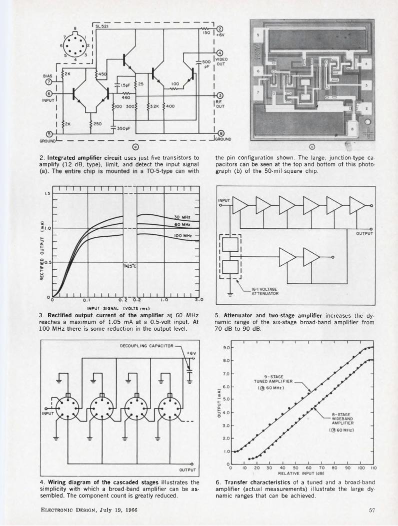
2. Integrated amplifier circuit uses just five transistors to amplify (12 dB, type), limit, and detect the input signal
INPUT SIGNAL (VOLTS rm»)
3. Rectified output current of the amplifier at 60 MHz reaches a maximum of 1.05 mA at a 0.5-volt input. At 100 MHz there is some reduction in the output level.
the pin configuration shown. The large, junction-type capacitors can be seen at the top and bottom of this photograph (b) of the 50-mil-square chip.
5. Attenuator and two-stage amplifier increases the dynamic range of the six-stage broad-band amplifier from 70 dB to 90 dB.
4. Wiring diagram of the cascaded stages illustrates the simplicity with which a broad-band amplifier can be assembled. The component count is greatly reduced.
6. Transfer characteristics of a tuned and a broad-band amplifier (actual measurements) illustrate the large dynamic ranges that can be achieved.
Electronic Design, July 19, 1966 57

between each pair of stages, these filters must provide a unity voltage transfer at resonance to avoid distorting the logarithmic law. Suitable networks are shown in Fig. 7. Unity voltage transfer at resonance is obtained if the susceptance of Ci at resonance equals the total effective shunt conductance across the tuned circuit. The effects of the amplifier input and output impedances are normally very small but can be readily calculated with the information given on the data sheets.
The filter bandwidth can be calculated from the relationship:
_ Total capacitive susceptance Total shunt conductance ’
.. Ct + C2 + ctn
where Cin is the amplifier input capacitance. The signal delay introduced by a filter of bandwidth B at a center frequency f0 is given by:
1 _ Q 4/fl *
The insertion of filters will often reduce the value of the supply-line decoupling capacitor that is required. For example, a 60-MHz tuned IF strip will normally require only a 1-nF decoupling capacitor.
Delay lines are not neededThe rectified current outputs from a chain of
SL521s can be added in a simple parallel connection (as in Fig. 4a). The total output current is then either fed to a video amplifier or passed through a resistive load to the positive supply line. To avoid ringing due to stray capacitances, the video amplifier must have a capacitive input impedance. Whatever the load, a certain voltage swing will be required, and this will set the limit on the attainable rise time of the output pulse.
On the assumption that all currents arrive simultaneously at the output point, the rate of rise of voltage across the total load capacitance CL is given by:
dV Total current~dt ~ C~L ’
Since each stage has an output stray capacitance of approximately 5 pF and provides an output current that rises to 2.8 mA during the conduction periods, the maximum value of voltage rate of rise, for any number of stages, is approximately 0.5 V/ns. With this rating it is possible to have the output pulse reach the full output level within one cycle of the RF signal.
To obtain this performance, however, it would normally be necessary to feed the output currents into a delay line to match the delay through the amplifiers and the interstage filters used. The advantage of the IC amplifier is that most, if not all, of the interstage filters are eliminated, and thus the total propagation delay down the am-
FROMn STAGE
C
th
FROM n STAGE
TO(n+l) STAGE (PINS 6&7LINKED)
TO . , .th(n + l)STAGE
7. Interstage filters are used for narrow-band applications. R; acts as a damping resistor and C3 is a de blocking capacitor (about 1 nF).
Table. Typical performance data (SL521)
Voltage gain 12 dB
Lower cutoff frequency 5 MHz
Upper cutoff frequency 170 MHz
Noise figure (@ 60 MHz) 4 dB (450q source)
Power supply requirement 15 mA @ 6 V
Operating temperature range -55 to + 125°C
plifier chain is small enough for delay lines to be rarely necessary.
Another problem that has to be taken into account concerns the parasitic feedback path in the output line. Precautions must be taken if more than four stages are used in an untuned cascade, or more than five stages are used in a cascade tuned to 30 MHz or higher. The simplest precaution is the addition of an output smoothing capacitor. This will often be satisfactory in tuned systems in which fast rise time is not required; for example, a seven-stage amplifier tuned to 60 MHz requires a 500-pF smoothing capacitor for a stability factor of 5 and will give an output rise time (to 90% of full output) of 150 ns. If the fast response characteristics are to be preserved, a simple method of reducing the parasitic feedback is to use a transistor buffer stage in the output line, as in Fig. 8.
The total current output of the amplifier, approximately 1 mA/stage (averaged), must be fed to a suitable video amplifier or returned to a positive supply line via a resistor. To prevent the output transistors from going into saturation, the voltage level at the rectified output terminals of each amplifier must not drop below 1.8 volts at any time. Consequently, if the outputs are returned to the 6-volt line, the maximum output voltage swing is 4.2 volts. Larger swings can be obtained by returning the outputs to a higher- voltage line (12 volts maximum).
Design example operates at 60 mHzThe amplifier circuit shown in Fig. 8 was built
to demonstrate the capabilities of these integrated circuits. It operates at 60 MHz with a 10-MHz
58 Electronic Design, July 19, 1966

8. Narrow-band log amplifier operates at 60 MHz with a 10-MHz bandwidth. A transistor buffer amplifier is in
serted in the output line to reduce the spurious feedback, while maintaining a fast response characteristic.
9. Double-sided printed circuit board (about 2.8 by-1.6 inches) is used to hold and interconnect all the com-
ponents used in the 60-MHz amplifier. Note the use of printed inductors (spirals) in the filters.
bandwidth that is defined by the input and interstage filters. The main chain provides a dynamic range at 80 dB, which is raised to 104 dB by the addition of the second untuned two-stage chain. A transistor buffer stage was used in the output summing line to reduce spurious feedback without seriously degrading the output rise time. The unit was built on a double-sided printed-circuit board measuring about 2.8-by-1.6 in., and it used printed inductors (Fig. 8). The noise figure of the complete amplifier was 4 dB with a 50-Q source, and the transfer characteristic, shown in Fig. 6, was accurate to ± 0.5 dB over a 100-dB range.
With respect to noise figure, this amplifier compares unfavorably with the best conventional circuits on the market. This is a serious problem, but it appears to be surmountable. Studies indicate that noise figures of better than 2 dB at 60 MHz can be obtained, and future work will be
aimed at achieving this.Since each stage can be directly coupled, it
becomes practical to build cascades of amplifier stages on single silicon chips. Though the yields on such multistage chips will be lower, the resulting increase in costs should be more than offset by savings in testing and encapsulating the units and by an anticipated increase in reliability. A four-stage chip is now under development. The ultimate aim is to go into production on one-, two- and four-stage chips. ■ ■
Acknowledgement:The author is indebted to the British Ministry of De
fence (Naval) and the directors of the Plessey Co., Ltd., for permission to publish this article.
Reference:1. J. S. Brothers and M. J. Gay, “Monolithic Integrated
Circuit Capacitors,” Proc, of the IEEE, LIII, No. 6 (June, 1965), 644.
Electronic Design, July 19, 1966 59

INKLESS
NEW STRIP-CHART WRITING TECHNIQUE:Ends pen clogging, ink dryingGives clear, clean tracesProvides new economyNew Hewlett-Packard electrosensitive paper, available as a standard option on Moseley 680 and 7100 Series Strip-Chart Recorders, ends the problems associated with pen-and-ink writing techniques.. .at an economical price and without the disadvantages inherent in other available electric writing methods.
The Hewlett-Packard electrosensitive paper is a special electro-chemical coated chart paper. The coating is current sensitive, changing to a dark brown trace with application of voltage from the recorder stylus. The new technique eliminates the familiar arc method of electric writing on carbon-backed paper.
With Hewlett-Packard electric writing, you can use your strip-chart recorders for long-term, unattended monitoring, with increased performance at slow writing speeds, as well as at high writing speed. It is non
pressure sensitive, so that you can’t damage or obscure your recordings.
Here’s another advance in recording capability from Hewlett-Packard. Call your Hewlett-Packard field engineer for information on converting your strip-chart recorder to maintenance-free electric writing. Or write for information: Hewlett-Packard, Palo Alto, California 94304, Tel. (415) 326-7000; Europe: 54 Route des Acacias, Geneva.
Data subject to change without notice.
HEWLETTPACKARD MOSELEY
Hi DIVISION
ON READER-SERVICE CARD CIRCLE 2960 Electronic Design, July 19, 1966

Perform binary division fast. Here aresome techniques for handling binary divisionthat can improve computer operation.
Part 2 of a two-part article*Like a student involved in the “new math,” a
computer can do high-speed division in several ways. Which algorithm the engineer uses depends on such needs as speed, cost and accuracy.
In order of increasing speed, the leading methods for computer division are these:
• Restoring division. This technique, the slowest, is basically the same as manual binary division and relies on repeated subtraction. Some improvement results from “skipping zeroes” to simplify quotient-bit selection.
• Nonrestoring division. With this method, the digital computer combines both binary addition and subtraction. Further improvement is possible here by “skipping zeroes” and also by “skipping ones.”
• Use of divisor multiples. With the use of multiples of the divisor, the computer can be made to produce two or more quotient bits simultaneously.
• Division by repeated multiplication. Here is an algorithm especially suited to the use of integrated circuitry. Most useful for precise floatingpoint arithmetic, this method is essentially an approximation technique that uses a converging series. A large multiply unit is required.
The repeated-multiplication method is the most costly and is used mainly in scientific applications. But each of the other methods finds widespread use in less demanding applications.
What is restoring division?
The basic approach to binary division, also called restoring division, may be performed by repeated subtraction as shown in the following example.
100111 quotientdivisor 1011 | 110110010 (a) dividend
-1011 (b)partial dividend xxlOlOO (c)
-1011 (d)10011
-101110000-1011
101
* Part I of this article (ED 16, July 5, 1966, pp. 52-57) discussed algorithms for high-speed addition and multiplication in digital computers.
Martin S. Schmookler, Project Engineer, IBM, Poughkeepsie, N. Y.
The similarity to longhand decimal division is apparent. Binary division, however, possesses an inherent simplicity not present in decimal division; i.e., in binary division, after each trial subtraction of divisor from partial dividend there are only two choices (0 or 1) for the quotient bit. If the divisor can be subtracted from the partial dividend, the quotient bit is 7; if not, then the quotient bit is 0. Contrast this with the ten possible choices (0 through 9) in the decimal case.
A computer can exploit this simplicity of quotient-bit choice by comparing the divisor with the partial dividend. When the divisor is smaller than, or equal to, the partial dividend, subtraction takes place and the difference becomes the new partial dividend. When the divisor is greater than the partial dividend, the partial dividend is shifted without being modified and a 0 is placed in the quotient. That is, a trial subtraction has taken place, but the result is not used; in other words, the previous dividend is restored. This method is therefore called restoring division. (Ordinary decimal division which we do by hand is restoring.) Allowing one cycle time for each trial subtraction, this method requires one cycle for each quotient bit developed.
Note that while the leftmost bit of the dividend in the above example is assumed to line up with the leftmost bit of the divisor [ (a) and (b) in the example] when attempting subtraction, the leftmost 1 in the partial dividend could extend one position farther to the left [(c) and (d) in the example]. This additional bit position (underlined) will be considered to be the high-order bit position of the partial dividend in the following discussion.
In each of the following methods of accelerated division, it is assumed that the divisor is normalized. This means that the divisor has been shifted left until a 1 appears at the high-order position, e.g., 1XXXX. This is similar to decimal division. In decimal division, we usually guess what quotient digit to try by looking at the leftmost significant digit. If there are any zeros to the left, we ignore them. Analogously, in binary division, a trial quotient bit is selected according to some rule which must consider the most significant bits of the divisor.
If the leftmost bits are all O’s they are not significant. The hardware is designed to look at the leftmost bits. Shifting an unnormalized number left can place its most significant 1 in the leftmost position.
Since normalized fractions usually appear in floating-point arithmetic, these improved algo-
Electronic Design, July 19, 1966 61

Table 1. Multiples used when dividend is true
Normalized divisor
(hi-order bits)*High order 3 bits of dividend
000 001 010 Oil 100 101 110 111
10 0 1 2 3 3 3 — —
11 0 1 2 2 3 3 3 3
The following list indicates the corresponding quotient bits for each iteration, which depends on the multiple chosen and whether the remainder is positive or negative.
Multiple subtracted Remainder Quotient bits
0 true 00
1 compì. 00
1 true 01
2 compì. 01
2 true 10
3 compì. 10
3 true 11
♦The entries are divisor multiples which must be subtracted.
»IIIIIIIIIIIIIIIIIIIIIIIIIIIIIIIIIIIIIIIUIIIIIIIUIIIIIIIIIIN
Table 2. Multiples used when dividend is complemented
Normalized divisor
(hi-order bits)
**High order 3 bits of dividend
111 110 101 100 Oil 010 001 000
10 1 1 2 3 3 3 — —
11 1 1 2 2 3 3 3 3
rithms are often restricted to floating-point division, where it is necessary to retain as many significant bits as possible to achieve maximum precision. For instance, in decimal floating point, 0.473256 X 10’ is in normalized form, and is more precise than 0.004732 X 10~2. However, these algorithms may be applied to unnormalized quantities in fixed-point division also by shifting both the divisor and dividend an equal number of positions until a high-order 1 appears in the divisor.
If the divisor is normalized and the partial dividend has two or more high-order O’s [see x’s in (c) in the example], then the divisor must be greater than the partial dividend, and no trial subtraction is needed. Shifting can take place without modifying the partial dividend, and the quotient bits must be 0. One obvious means, then, of speeding up restoring division when the divisor is normalized, is to skip across O’s in the partial dividend by shifting. In the example, two shifts occurred because of the two leading O’s in (c). Then, a trial subtraction showed one more shift was needed. If the partial dividend has n highorder O’s, we would shift across n O’s and enter n-1 O’s in the quotient. Although the average division would be improved, a worst case (e.g., all 1’s in the partial dividend) would still require one cycle for each quotient bit.
Nonrestoring division improves on the basic method
A nonrestoring division algorithm is one which always uses the difference between divisor and partial dividend regardless of the sign of the difference. Thus, the new partial dividend may be either positive or negative. Assume initially that the divisor is subtracted from the dividend. If the result is positive, then the quotient bit is 1. If the result is negative, the quotient bit is 0. In either case, the difference is the new partial dividend.
When the partial dividend is negative, the procedure is slightly altered. The divisor must now be added to the partial dividend to obtain their difference. As before, the quotient bit is 1 for a positive result, and 0 for a negative result.
The two methods of division may be compared using the same example as before:
The following list indicates the corresponding quotient bits for each iteration, which depends on the multiple chosen and whether the remainder is positive or negative.
Multiple added Remainder Quotient bits
1 true 11
1 compì. 10
2 true 10
2 compì. 01
3 true 01
3 compì. 00
♦♦The entries are divisor multiples which must be added.
Restoring Division100111
1011 \ 110110010-1011
10100-1011
10011-1011
10000-1011
101
Nonrestoring Division 100111
1011 I 110110010 -1011+ 001010010 -1011 -01011110 (e) + 1011
(f)-0000110+ 1011+ 100110-1011+ 10000-1011+ 101
62 Electronic Design, July 19, 1966

Since a computer normally performs subtraction by complementing the divisor and adding this complement to the dividend or partial dividend, the remainder produced when the divisor is greater than the dividend will be in 2’s complement form as in (e) and (f) above, i.e., all l’s changed to O’s and all O’s changed to l’s with a 1 added to the result. As an example, consider the binary number 11010. To change this to 2’s complement form, we first change l’s to O’s and O’s to l’s: The result is 00101. Adding a 1 we get:
00101 + 00001
00110
Therefore 00110 is the 2’s complement form of 11010.
When the divisor is less than the dividend, the remainder will be in true (i.e., noncomplemented) form.
With negative partial dividends in this complemented form (see two lines marked “neg.” in following example), we can simply add these to the divisor and save the complementing step. The partial dividend would then actually appear after each cycle as shown in the following example. (Compare the partial dividends marked “neg.” with (e) and (f) in the preceding nonrestoringdivision example.)
1001111011 | 110110010
-101100101 -1011
neg. 10100+ 1011
neg. 11110+ 1011
10011 — 1011
10000 — 1011
0101Again, if the partial dividend is true (i.e., not
complemented) and has n leading O’s, we know that subtraction of the divisor would leave a negative result (in 2’s complement form). We can therefore skip across n O’s and enter n O’s in the quotient. Similarly, if the partial dividend is negative, and has n leading l’s in complement form, then addition of the divisor would surely leave a positive result. We may therefore skip across n l’s and enter n-1 l’s in the quotient. Note that a quantity whose magnitude is small has leading O’s in true form, but leading 1 ’s in complement form.
Use divisor multiples to increase speedDivision may also be accelerated by a method
which produces two quotient bits each cycle. This method requires that the computer be capable of adding or subtracting multiples of the divisor, rather than just the divisor itself. This concept can be illustrated by considering a simple decimal
division: 2 into 145. In this case a step-by-step division would take three operations (i.e. one operation per quotient digit). However if we used divisor multiples we would recognize immediately that the seventy-second multiple of 2 (i.e.144) would give us the first two quotient digits, 72.
To use divisor multiples in binary the three- times multiple of the divisor is developed and placed in a register. The two-times multiple of the divisor is the divisor itself, shifted left one position on entering the adder. Other divisor multiples can be formed with combinations of these. These multiples may now be used as follows:
The computer examines the leading digits of the divisor multiples and partial dividend to determine which multiples will guarantee a remainder whose magnitude is less than the divisor.
For a positive dividend, subtracting the smaller multiple produces a positive remainder, while subtracting the larger multiple produces a negative remainder. The quotient digit corresponds to the smaller divisor multiple. If the examined leading digits of one of the multiples are identical to the corresponding digits of the dividend, then that multiple must be chosen, and the quotient is determined after the sign of the remainder is known. The quotient digit corresponds to the divisor multiple if the remainder is positive, and is one less if the remainder is negative. The ability to proceed two bits at a time in these cases is made possible by use of nonrestoring division. Tables 1 and 2 show the action taken for each combination of leading bits of the partial dividend, and an example is shown below. Note that the remainder is shifted two positions left each cycle to form the new partial dividend. The leading bits of the partial dividend then extend two positions to the left of the divisor.
1st quotient digit £ Loom
1011 I 0.110110010— 3x -100001neg. 101000+ 2x +10110neg. 111010+ lx +1011
000101
For illustration, the same example previously used is shown above using divisor multiples. Since the divisor is 1011, entries from Table 1 will always be chosen corresponding to the high order bits of the divisor 10. Initially, the dividend must be regarded as having a 0 in the most significant position, so the first multiple is chosen from Table 1 corresponding to a dividend of Oil (i.e. the — 3x multiple). Since the result of the first subtraction is negative, the first quotient digit is two (i.e. 10). The lower part of Table 1 shows the quotient bits obtained for each multiple.
Upon shifting the partial dividend left two positions, the high order l’s are dropped. Since it is in complement form, these l’s correspond to O’s
Electronic Design, July 19, 1966 63
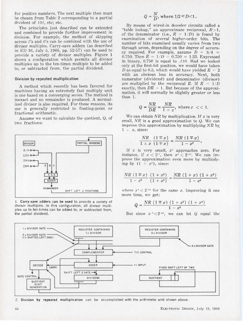
for positive numbers. The next multiple then must be chosen from Table 2 corresponding to a partial divident of 101, etc; etc.
The principles just described can be extended and combined to provide further improvement in division. For example, the method of skipping across l’s and O’s can be combined with the use of divisor multiples. Carry-save adders (as described in ED 16, July 5, 1966, pp. 52-57) can be used to provide a variety of divisor multiples. Figure 1 shows a configuration which permits all divisor multiples up to the ten-times multiple to be added to, or subtracted from, the partial dividend.
Division by repeated multiplication
A method which recently has been favored for machines having an extremely fast multiply unit is one based on a converging series. The method is inexact and no remainder is produced. A normalized divisor is also required. For these reasons, its use is generally restricted to floating-point or fractional arithmetic.
Assume we want to calculate the quotient, Q, of two fractions:
Q = , where 1/2 ^D<1.
By means of wired-in decoder circuits called a “table lookup,” an approximate reciprocal, 7?>1, of the denominator (i.e., R = 1/D) is found by examination of several higher-order bits. The number of bits examined usually varies from two through seven, depending on the degree of accuracy required. For example, assume D = 3/4 = 0.750. Then R — 1/D = 0.750 = 1.33. Expressed in binary, 0.750 is equal to .110. Had we looked only at the first-bit position, we would have taken D as equal to 0.5, which would have yielded R = 2 with an obvious loss in accuracy. Next, both numerator (dividend) and denominator (divisor) are multiplied by the reciprocal R. If R = 1/D exactly, then DR = 1. But because of the approximation, it will normally be slightly greater or less than 1.
_ NR NRQ DR l±x’ where a: << 1.
We can obtain NR by multiplication. If x is very small, NR is a good approximation to Q. We can improve this approximation by multiplying NR by 1 q: x, since:
SHIFT LEFT 2 POSITIONS
NR (1 + a;) NR (l + x)1 ± x (1 + x) 1 — X2 ’
If x is very small, x2 approaches zero. For instance, if x < 2‘®, then x2 < 2'12. We can improve the approximation even more by multiplying by (1 + x2), since:
NT? (1 + a;) (1 + x2) NR (1 + x) (1 + x2)1 — X2 ( 1 + X2 ) 1 — X4
where x' < 2’24 for the same x. Improving it one more time, we get:
1. Carry-save adders can be used to provide a variety of divisor multiples. In this configuration, all divisor multiples up to ten-times can be added to, or subtracted from, the partial dividend.
NR (l + æ) (1 + x2} (1 + x4} 1 - Xs
But since ars<2 '’8, we can let Q equal the
2. Division by repeated multiplication can be accomplished with the arithmetic unit shown above.
64 Electronic Design, July 19, 1966

High QwithAssuredReliability!
numerator only, which is accurate to 48 bits (that is, it has an error less than 2 48). This completes calculations of the quotient Q.
We obtained 1± x by multiplication of DR, where R is obtained by wired-in circuits from the high-order bits of D. From l±x, the factors (1 + x), (1 + a;2), and (1 + a;4) can be obtained as follows:
Starting with 1 + a;, we complement it. This is approximately equivalent to subtracting it from 2. That is:
complement of l±x — 2— (l±x) = 1 T x, which is the first factor. Complementing it only requires changing 1’s to O’s and O’s to 1’s, and is therefore considerably faster than subtracting from 2. Now that we have (1 ± x) and (1 + x), multiplying them gives (1—a:2). Complementing again, we get 2— (1 — x2) = (1+a;2), which is the second factor.
Then (1 —a;2) (1+a;2) gives (1 — a;4). This may be complemented and the process taken as far as is required.
The actual number of multiplications performed will depend on the degree of accuracy required in the quotient. For example, if the precision required of the quotient is 48 bits or less, and x is smaller than 2 “, then x" is smaller than 2-48 which indicates that multiplication by (l+a;s) would produce more lower-order bits than are required. Therefore (1 + a;4) is the last factor needed. A total of seven multiplications are needed to obtain the quotient. The sequence of steps to be followed is:
1) Obtain = NR. (1st multiplication)2) Obtain 1 ± x = DR. (2nd multiplication)3) Complement (1 ± a;) to obtain (1 + x).4) Obtain Q. — Qt (1 + x). (3rd multiplication)5) Multiply (1 + x) by its complement to obtain
(1 —a;2). (4th multiplication)6) Complement (1 — x2) to obtain (1 + a;2).7) Obtain Q3 = Q2 (1+a;2). (5th multiplica
tion)8) Multiply (1 + a;2) by its complement to obtain
(1 —a;4). (6th multiplication)9) Complement (1—a;4) to obtain (1 + a;4).10) Obtain Q4 = Q3 (1 + a:4).Qt is the final quotient. Figure 2 shows how a
computer’s arithmetic unit could be organized to implement this algorithm.
Several of the multiplications need not involve the full 48 bits. For instance, a;4 is less than 2"24. Therefore, the high-order 24 bits of the fractional part of (1+a;4) must all be 0, and may therefore be skipped when (1+a;4) is used as a multiplier in the last step. The precision required in the other multiplications is 24 bits or less permitting early termination. Taking full advantage of these techniques, the time required for division is three to four times as long as multiplication for 48 or less bits of precision.
This method can be further improved if two multiply units are available. The first two multiplications can be performed concurrently; similarly the third and fourth and also the fifth and sixth multiplications. An execution time only twice as long as multiplication could be achieved. ■ ■
The Johanson 3955 Series Variable Air Capacitors
are backed by these special
RELIABILITY ASSURANCE PROVISIONS
1. Parts examined and assembled in accordance with special Johanson high reliability inspection and assembly procedures.
2. All sub-assemblies inspected under magnification to assure highest quality components prior to final assembly.
3. Final assemblies subjected to 100% burn-in and screening tests.
4. Samples taken from each lot and subjected to life tests.
5. Test data supplied on request.
SPECIFICATIONSCapacity Range: 0-8 - 10 pfWorking Voltage: 250 VDCQ >2000 @ 100 MCTemperature Coefficient: 0±20.0 ppm/°C
Write Today for Full Data
MANUFACTURING CORPORATION
400 Rockaway Valley Road.
Boonton, N. J. 07005 (201) 334-2676
ELECTRONIC ACCURACY THROUGH MECHANICAL PRECISION
ON READER-SERVICE CARD CIRCLE 30
Electronic Design, July 19, 1966 65

66 Electronic Design, July 19, 1966

The 777comes complete with four cavities.There are 19 modules you can plug into any one of them. In any combination. We have a booklet that takes 16 pages just to describe the scope, the modules, and the wave forms they produce. Get one.
FINSTRUMENTATION
Electronic Design, July 19, 1966 67
FAIRCHILD INSTRUMENTATION IA Division of Fairchild Camera and Instrument Corporation ■ 475 Ellis Street, Mountain View,California, (415) 962-2011 ■ TWX: 910-379-6944
ON READER-SERVICE CARD CIRCLE 31

DESIGN DECISION
Neons control VOX circuits, suppress transientsin transceiver. Complete independence of VOX sensitivityand delay-time adjustment highlight the design.
The use of neon lamps in EICO’s 753 transceiver has made possible a design of outstanding simplicity that combines low cost with complete independence of sensitivity and delay-time adjustment.
The function of VOX (voice-operated) circuits in transceivers is relatively simple—to switch automatically from “receive” to “transmit” on receipt of a signal from the microphone. A number of conflicting operational considerations, however, has led to circuits that are elaborate for what is basically a voice-operated relay. The need for a simplified approach induced EICO to make an early decision to use neon lamps.
VOX design considerations
A prime consideration is that the VOX circuit must provide a controlled delay to prevent the relay from returning the transceiver to the “receive” condition between words or during short pauses in the operator’s speech. This delay must be adjustable to allow each operator to set it to his own preferences. At the same time, the VOX must switch from “receive” to “transmit” as rapidly as possible, so that the first portion of the spoken message is not lost.
Secondly, since many station operators employ a speaker instead of headphones, there exists the possibility that the speaker output will be picked up by the microphone and cause the transceiver to switch to the “transmit” mode. This tendency is overcome by introduction of an ANTI-VOX feature to reduce the VOX circuit’s sensitivity to signals received from the speaker. The level of ANTI-VOX control should be adjustable, just like the basic sensitivity of the VOX circuit itself.
Although there are many designs for such control circuits, few, if any, provide complete independence of the sensitivity, ANTI-VOX, and delay-time adjustments; the alteration of one parameter usually requires a change of the others. Use of neon lamps, however, solves these problems.
One neon for VOX switching
In the circuit shown in Fig. 1, the speech am-
T. Bially, Chief Engineer, Eico Electronic Instrument Co., Inc., Flushing, N. Y.
plifier in the transmitter employs two stages. The output of the first stage is applied to the input of the VOX amplifier tube, V2A, through the VOX sensitivity control, R,. Since the transmitter speech gain control is in the following stage, the operation of the VOX will be independent of the level at which the transmitter is driven. Assume for the moment that the “cold” end of R, is grounded, and that points A and B are connected together. Under these conditions the grid of V2A is at zero potential, the tube conducts heavily, and neon bulb PL, is extinguished.
When PL, is extinguished, a negative bias of 25 volts is applied to the grid of V2B, causing the tube to be cut off, and leaving the relay in its normal, or “receive,” position. On receipt of a negative pulse from the speech amplifier, V2a will momentarily cut off, and PL, will ignite. The transmission of a positive voltage through PL, to the grid of V2B will cause this tube to conduct heavily, thus closing the relay, and changing the equipment function to “transmit”.
Diodes CR, and CR, detect the signal in the speaker and produce a de voltage across R, which is proportional to this signal. Thus, anti-VOX control R, may be adjusted so that the positive voltage developed by the detector is applied to the grid of V,A in any desired amount. This voltage tends to keep V2A conducting, and reduces the VOX sensitivity during those times when a signal is present in the speaker.
To provide extreme VOX sensitivity, a threshold control, R,3, is included. This control places a small negative voltage on the grid of V2A, and is adjusted so that PL, is just on the verge of igniting when no input is applied.
To analyze the delay mechanism, assume PL, has just extinguished. The grid of V2b begins to decay from zero volts to —25 volts with a time constant which is determined by Rs and C7. If C7 were returned to ground instead of to point C, this indeed would be the case. If R9 is temporarily ignored, C7 is effectively connected to the variable arm on potentiometer R,o. When the arm is at the ground end of R,o, the decay time constant in the grid circuit of V2B is simply (Ra) (C7). On the other hand, when the arm of R,n is moved up to the plate, the decay time constant will be increased, by Miller effect. (7?8) (C7) (A), where A represents the gain of V2b- Thus, by varying the
68 Electronic Design, July 19, 1966

Neon bulb PL, controls relay amplifier V2B. In “receive" function (no signal through microphone or speech amplifier V1A), V2A conducts, neon PL, is extinguished, and relay amplifier V2B is cut off by —25 V applied to its grid; the relay remains in its open or “receive” position. Dur
ing "transmit," the microphone signal is amplified by V1A and V1B. The negative peaks from V1B cause V2B to cut off, igniting PL,, and thus applying a positive voltage to V2B that causes the relay contacts to close. Up to 3 seconds delay is provided by R10.
arm position of Ri0, the VOX delay may be adjusted over the unusually wide range of 0.2 to 3 seconds. Since no de components are controlled by this setting, the VOX delay control in no way affects other parts of the circuit.
If it is desired to control the operation of the transceiver manually, point C is grounded and the push-to-talk switch is connected between point D and ground. Point C is grounded to make the transceiver switch back to “receive” in the shortest possible time (regardless of the setting of the delay control) when the push-to-talk switch is released.
Another neon for transient immunity
In changing the function of the transceiver, several high-voltage points are switched by the relay. The transients thus produced may, in some cases, be picked up by the microphone amplifier circuits and be transmitted to the VOX circuit. The circuit might then return to “transmit” immediately after switching to “receive”.
To prevent this action, capacitor Cs is connected to a point in the transceiver circuit that drops to ground from a potential of +250 volts as soon as the transceiver is switched to “receiver.” A 250- volt negative impulse is thus developed across resistor Ri4, and is transmitted by neon PL, to the grid of V2B. This pulse tends to keep V2B cut off for a short period of time following the change-over, and makes the relay immune to transients received by the VOX circuit during this time. These transients will have disappeared before PL, extinguishes, so that the circuit remains stable in the “receive” position.
An additional function of the VOX is to provide automatic change-over from “receive” to “trans-
+ 250 ♦
TO POINT "B"IN 4
VOX CIRCUIT
Automatic switching during cw operation is accomplished by connection of junction R2 and R3 to the grid of the VOX amplifier tube (V2A in Fig. 1). When the key is up, transmitter mixer V3 is cut off by —100 V, and a positive voltage will appear at junction R2 and R3; relay tube V2B (Fig. 1) will be cut off, placing the contacts in "receive” position. When the key is depressed, V, conducts, its plate voltage drops and junction R„ and R3 becomes negative; relay tube V2B conducts, placing the contacts in “transmit" position.
mit” when the transceiver is used in a Morse Code or cw mode. In this case, the closure of the telegraph key provides the VOX triggering signal. Fig. 2, the keyed stage in the transmitter obtains its plate voltage through resistor R,. When the key is up, the stage is cut off, and the voltage at the plate end of R, is the same as that of the supply. When the key is closed, this voltage will drop appreciably. The voltage at the junction of R, and R3 will be positive when the key is up, and negative when the key is down. For cw operation, points A and B in the VOX circuit of Fig. 1 are disconnected, and point B is connected to the junction of R, and R3 in Fig. 2. This voltage then controls the operation of the VOX, and the telegraph key simply replaces the microphone in its effect upon the circuit. ■ ■
Electronic Design, July 19, 1966 69

Reliable electrical connections

Your choice of power for hand “WireWrap" tools ... electricity, compressed air, or rechargeable battery. We also make manual tools for field servicing. Bulletins 14-1, 14-3 and 14-7.
Solderless electrical connections are wrapped to stay . . . wrapping time is less than one second each .. . Using Gardner-Denver “WireWrap”® tools. You save hours of handwork. You save inspection and rework time as well, because “Wire-Wrap” tools make reliable connections, even in inexperienced hands. Widely used for wiring television, instruments, communications equipment, computer panels and missile guidance systems.
in less than one second eachModular panels are quickly and securely wired on Gardner-Denver automatic “Wire-Wrap” machines, which are programmed with punched cards for maximum flexibility. Bulletin 14-121.
Reliable! More than 40 billion solderless wrapped connections have been made with “Wire-Wrap” equipment without a single reported electrical failure.
Film is scraped from wire and terminal at contact points. High pressure metal-to-metal contact invites solid state diffusion, maintaining low connection resistance.
Solderless wrapped connections remain gastight even when exposed to severe changes of temperature and humidity ... so they're not affected by atmospheric corrosion.
Initial pressure may go as high as 100,000 psi. Pressure drops as wire relaxes, but stabilizes at a value greater than 29,000 psi.
Flexible lead-off absorbs vibration and handling shocks . . . permits wrapped connection to stay tight and mechanically stable.
SEE WHAT AIR IS DOING NOW...SEE
GARDNER - DENVERGardner-Denver Company, Quincy, Illinois
ON READER-SERVICE CARD CIRCLE 213

Consider double-loop regulation: hybridmagamp-SCR circuit combines benefits of reactiveand dissipative techniques in a five-pound unit.
A hybrid regulator scheme for general-purpose power supplies combines in a five-pound, 80-watt unit the high efficiency of a reactive regulator and the precision and fast response of a dissipative regulator.
This is accomplished by use of a magnetic amplifier as the control element and feedback path. Further advantage is gained from use of SCRs in the coarse-regulator stage, necessary for low- voltage, high-current applications. Here the magamp acts as the SCR trigger—much simpler and offering higher gain than transistor trigger circuits.
The Table lists the performance of a power supply of this type with self-resetting shortcircuit protection.
Typically, dissipative regulators employ transistors as series-gating elements that act as variable “self-adjusting” resistors to compensate for line and load changes. Reactive regulators, on the other hand, employ switching devices that deliver gated bursts of constant average power to the load, independent of line changes. SCRs, magnetic amplifiers or series-switching transistors are among the control elements used in this mode.
The dissipative approach features precise regulation, low ripple, low output impedance and fast transient response. This type of circuit is a good choice for narrow input-voltage swing or low-load-current applications. However, if the dissipative regulator is used in applications involving wide input-voltage regulation or wide output adjustments and/or high load currents, the penalty is high gate dissipation with resulting low efficiency. As a direct consequence of these considerations, the regulator package size is now dictated by thermal considerations rather than by component accommodation.
The reactive regulator is a good choice for higher load-current applications where considerable power must be absorbed to compensate for a wide range of input and/or load variations and where close control of the output and fast transient response is not essential.
Anthony A. Annunziato, Sperry Gyroscope Co., Great Neck, N. Y.
An efficiency and volume comparison of doubleloop versus dissipative regulators with the same specs, (Fig. 2) shows that the latter would have to be nearly twice the volume of the former and would have an efficiency of only 54%. The graph shows further that double-loop regulator efficiencies are very flat, from 85% for low-power outputs to approximately 80% for higher outputs. The corresponding efficiencies for dissipative regulators run from 63% to 40%.
How the circuit operates
In general terms, the double-loop regulator consists of a reactive coarse preregulator in cas-
Double-loop regulator supply characteristics
singlephase
three- phase
Input voltage 90-127 Vac 135 Vac
(square) (sine)
Frequency 2000 Hz 400 Hz
Output voltage 65 V 100 V
Output current 40 mA-1.2 A
1.0 A
Output power 80 W 100 W
Regulation (max) ±1% ±1%Ripple (max) 25 mV p-p 5 mV p-p
Output impedance (max) 0.25 Q (0.5 kHz)-1.0 Q (5-50 kHz)
Line transient response 3 mV max amplitude; 4
(10% step change) ms max recovery time
Load transient response 3 mV max amplitude; 4
(25% step, 25-75% load) ms max recovery time
Size 6.5x6.5 xl.75 in.
7x7x2 in.
Weight 5 lb 6 lbTemperature range -32 to -40 to
+ 65°C + 60°C
72 Electronic Design, July 19, 1966

fluctuations and adjusts the magamp firing angle to raise or lower coarse-regulator output. The fine regulator then provides the required precise regulation.
1. Magnetic-amplifier feedback loop in five-pound power supply allows 80% efficiency at 80 watts. Control winding (MAj-C) of magamp in fine regulator gate senses VGF
cade with a dissipative fine regulator. The magamp provides the feedback or control path. Refer to Fig. 1 for the basic circuitry of a regulator of this type employing a full-wave, center-tap magamp as the coarse regulating element.
MAt-GX and MA}-GY are the gate windings of the magamp, which uses 1DU laminations, 6 mil Orthonol, and is wound as indicated in Fig. 1. CR3 is a free-wheeling diode that provides a discharge path for the current in filter choke Lt during the exciting interval of the magamp. The Lt-Ct filter serves to smooth out the voltage pulsations caused by the magamp operation.
MAt-C and MAt-B are the control and bias windings of the coarse-regulator magamp. Qi is the gate transistor of the fine regulator. CR*, R10, R,., R1S, and R}i form the output error-sensing network with Ri3 serving as the output adjustment. Ct aids in reducing the remaining ripple and provides for low output impedance in those frequency ranges where the gate transistor gain falls off. CR, provides a positive voltage for the base drive of gate transistors Q3, Q2 and Qu Rt9,
3s 100• 90
o 80y 70E 60uj 50
40302010
VOLUME OF EQUIVALENT DISSIPATIVE REGULATOR
EFFICIENCY RANGE OFDOUBLE-LOOP REGULATOR 7
EFFICIENCY RANGE OF EQUIVALENT DISSIPATIVE REGULATOR
VOLUME OF DOUBLE-LOOP REGULATORJ____________L_
2600 2400 22002000 180016001400 12001000 800600400200 0
200 300 400 500OUTPUT POWER - WATTS
2. Efficiency-volume comparison of double-loop regulator with dissipative type reveals a figure of merit of 1/3 to 1 watt/in.3, and 1/5 to 1/2 watt/in.3 respectively.
a one-time adjustment, sets the level of the magamp’s bias winding.
The regulators, both coarse and fine, act like any degenerative feedback device, sensing the output and controlling the gating element to cancel, or act in opposition to, any fluctuation resulting from line or load changes. If the line voltage rises above, or falls below, nominal while the load remains unchanged, the fine-regulator gate, VGF, instantaneously absorbs more or less voltage, respectively, to maintain a constant output voltage.
This change in gate voltage (from nominal of about five volts in this case) is sensed by the magamp control winding MAX-C. This causes the magamp to adjust its firing angle for a lower or higher (for line-voltage rise or fall, respectively) average coarse output voltage. Thus, the output voltage of the coarse regulator is automatically adjusted to maintain the minimum voltage required at the collector of the fine regulator passtransistor. The coarse regulator essentially attends to the “long-term” regulation needs of the fine regulator.
The fine regulator, in turn, takes care of the instantaneous tasks of the power supply, thereby providing precise regulation, fast transient response and low output impedance. A similar regulating action takes place if the load is changed, while the line voltage is held constant.
SCRs improve output capability
A further advantage of the double-loop regulator is that the size of its coarse-regulator portion need not increase in proportion to power output. Figure 3 illustrates how the output capability (e.g., low-voltage, high-current) of the coarse regulator may be extended by replacing the magamp with SCRs as coarse-gating elements. At the expense of only a minor increase in circuit com-
Electronic Design, July 19, 1966 73

3. Magamp triggers SCR coarse-control in this hybrid variation. Smaller size, faster response, and increased gain are among the resultant benefits.
4. Self-resetting short-circuit protection is easily added to double-loop regulator. Q6 saturates when R2 and CR, sense a short circuit, causing current to flow in MA,-SC in a direction to drive magamp to cut off. Circuit resets upon removal of short circuit.
plexity, the magamp is now used merely as a low- level trigger for the SCRs. The speed and gain are thereby improved significantly and the magamp’s postsaturation inductive drop is not a problem. (Care should be taken, however, in stabilizing the loop.) The magamp can also be smaller; as a result, the volume of the coarse-regulator portion, instead of being determined mainly by the size of the magamp and only to some extent by that of the LC-filter combination, now depends mainly on the size requirements of the filter alone.
Because of the inherently low long-term power dissipation of the fine regulator’s gate, the fineregulator output capability may easily be extended by merely adding gate transistors in parallel. Except for higher base-drive requirements, the fine-regulator circuitry is not affected by the addition of parallel gates.
Add self-reset short-circuit protection
Because of its ability to gate from full-ON to full-OFF in a lossless manner, the double-loop regulator lends itself particularly well to selfresetting short-circuit protection. In Fig. 4, rectifiers CRa and CRW act as auxiliary power supplies for the protective circuit. R1X and C9 serve as an RC filter. An additional magamp winding, MAX-SC, is the short-circuit control winding of the coarse-regulator magamp. QR acts as a normally open switch, closed during shortcircuit conditions. R2 and zener CR, function as short-circuit sensing elements. The L2-Rt parallel combination serves to prevent C, from dumping current through the fine-regulator gate until the magamp responds to the short-circuit cut-off signal.
Under normal operating conditions, the voltage developed across R2 by the load current is insufficient to break down zener CRit thereby
holding Q6 in cut-off and preventing current flow in the magamp winding, MAr-SC. Upon application of a short circuit to the output terminals, the following sequence of events takes place: The build-up of short-circuit current causes a voltage drop to build up across R2. When this drop exceeds the zener CR, breakdown voltage, it conducts, driving Qe into saturation. This causes current to flow in the magamp short-circuit winding MA,-SC in a direction to drive the magamp to cut off, thereby effecting a reduction in the coarse- regulator output voltage.
The circuit will then settle at some equilibrium point at which the magnitude of the short-circuit current will be no more than required to cause the magamp to supply a reduced magnitude of VCOARSE) just sufficient to drive this short-circuit current through the various short-circuit impedances. Upon removal of the short, the protective circuit resets and the regulator reverts to its normal operating mode.
For the sake of comparison it is interesting to note that additional gate capacity and heat dissipation capability would be required if this shortcircuit protection was to be accomplished with an ordinary dissipative regulator. Furthermore, the ability of the magamp to accept isolated inputs makes the double-servo-loop regulator suitable for a variety of auxiliary control functions.
The double-loop technique is not limited exclusively to regulators with single-phase inputs. For three-phase inputs, the circuit is essentially the same as that shown in Fig. 1, except that the magamp is replaced by a three-phase, full-wave bridge magamp having its three control windings series-connected across the fine-regulator gate. Operating characteristics of the three-phase unit are also shown in the Table.
The double-servo-loop regulator technique can also be applied to current regulators. ■ ■
74 Electronic Design, July 19, 1966

Introducing:The Fabri-Tek Line concept
microsecond
—a unique solution to COMPUTER MEMORY requirements in the sub-microsecond speed range!
The Fabri-Tek FAST Line concept represents a significant departure from the discrete memory speeds of equipment currently available. FAST Line provides a free selection of any memory speed between 1 usee and 150 nsec without specific incremental restrictions.
Now, you can select an optimized memory stack or system from the FAST Line spectrum which matches exactly the logical organization and internal circuit speeds of your computer design.Here's what the Fabri-Tek FAST Line concept means to you:1. Exact match of speed and capacity to your next
computer design.2. Value-engineered memories. You pay for only
the speed required.3. Speed-cost evaluation resulting in lowest ulti
mate cost to you.4. Standardized designs and organizational tech
niques for reduced manufacturing costs and improved reliability.
5. All organizational modes available to match your needs (3D, 2'/2D and linear select).
6. . . . and a serious commitment in depth of our entire company to helping you fill your computer memory requirements.
The FAST Line memory includes core memories from 1 usee to the 375 nsec range and film memories from 500 to 1 50 nsec. If your present or future computer design calls for memory stack or system speeds in this spectrum, the FAST Line concept is worth your time to check out. Call: 61 2-935-8811, TWX: 910-576-2913 or Write: Fabri-Tek Incorporated, 5901 South County Road 18, Minneapolis, Minnesota 55436.
The Leader in Memory TechnologyON READER-SERVICE CARD CIRCLE 32
Electronic Design, July 19, 1966 75

Alcoa Aluminum makes your choice easier when you must meet all 5 productpersonality requirements.
EnvironmentAlcoa® Aluminum is durable. In the lab or in the field, lightweight, corrosion-resistant Alcoa Aluminum will stand up against everyday wear and tear. Pound for pound, it’s stronger than steel. And Alcoa has the alloys that can meet your most exacting requirements.
ft
ApplicationAlcoa Aluminum is versatile. It’s nonmagnetic, nonsparking, dampens vibration and, since it is an excellent conductor of both heat and electricity, it’s suitable for a wide variety of enclosed applications.

$Aesthetics Production Customer SatisfactionAlcoa Aluminum is easy to finish. Either alone or in combination with many other materials, natural aluminum has a pleasing appearance that can be enriched by embossing the surface or by the addition of color —in a broad spectrum.
Alcoa Aluminum is easy to fabricate. It can be cast, forged, extruded, machined or drawn . . . formed or fastened by practically any method, often at cost savings.
Alcoa Aluminum is oriented to your customer’s needs. A wide variety of shapes and sizes, alloys and finishes, properly applied, assure the best performance of your product.For complete information on how to put aluminum’s five-point
personality into your product, contact your nearest Alcoa sales office. Or write: Aluminum Company of America, 1780-G Alcoa Building, Pitts- r burgh, Pa. 15219. ES
ON READER-SERVICE CARD CIRCLE 222 Change for the better with Alcoa Aluminum ALCOA

Measure potentiometer noise correctlyand you may find that your noise problemhas disappeared-or at least eased.
Just as gardeners have to “live with” some weeds, so must you, as an engineer, put up with a certain degree of noise in potentiometers. But if you are overly concerned with that degree, perhaps you are not taking into account all the necessary factors when measuring noise.
Better materials and manufacturing techniques have improved inherent noise figures to the point where they may no longer be significant in your design. With correct noise measurement, you may find that what you thought was a problem no longer exists, or that you have overdesigned.
In any analysis of the problem, it may help to consider first the sources of noise in precision and adjustment potentiometers, some of which are shown in the accompanying photographs.
It is interesting to observe that most potentiometers that are discarded are rejected because of noise at incoming inspection. Few rejects actually occur during use. One reason is that many users specify noise levels well above available minimums. These minimums have been accepted by many other users as standard. Cognizant of this problem, most manufacturers strive to reduce the noise level of all potentiometer types below the generally established standard for precision types. The result actually is some degree of overdesign.
Under definitions of the Military and the Precision Potentiometers Manufacturers Association, the two most common ingredients of noise are its apparent random nature and the fact that it is a distortion of the desired voltage.
Where does noise originate?Two types of noise usually occur from several
sources in a wirewound potentiometer: mechanical and residual.
Mechanical noise is produced under dynamic conditions when excessive resistance is introduced between wiper and element. It can vary from a few ohms to an open circuit. Causes can be excessive vibration, acceleration, cycling rate, shock, etc. To prepare for it, the unit should have a properly designed wiper to minimize bounce on lift-off. Wiper pressures must be controlled and minimum relaxation of the spring contact allowed during use. Coarse windings are undesirable; but with present day equipment are usually not a problem. Lubricants must not be too viscous lest
Robert Jabs & Richard Boman, Bourns, Inc., Trimpot Div., Riverside, Calif.
they impede the wiper-to-element contact. Resolution noise is a sawtooth voltage variation introduced when the wiper contact moves across discrete turns of a resistance wire, and it is inversely proportional to the resolution figure of the potentiometer.
Residual-noise effects can show up as sharp random voltage peaks generated between the moving contact surface and winding. The principal cause is foreign material—dirty windings, oxide films, wear products, etc., which introduce extra resistance between the contact surface and turns of resistance wire. Contact-resistance fluctuations arising from such contamination are characteristically large, usually stationary with respect to time, and independent of slider velocities. This noise effect may properly be called “passive.” It is precluded by careful design, clean manufacturing conditions and wise use of long- wearing, stable wire and contact materials, as well as by periodic cleaning after use.
Sources of “active” residual noise are not so easily analyzed. Fortunately these disturbances in wirewound potentiometers rarely exceed a small fraction of a millivolt. Active noise is a self-generated voltage, found under three principal sets of conditions: galvanic or chemical action at the point of contact between slider and wire; thermojunction effects, which depend on frictional or external heat, and triboelectrical phenomena, which are small voltages generated by abrasion of the contact upon the wire. Here again, noise is minimized by use of compatible materials, proved welding techniques and optimum contact pressures.
The correct way to measureLet’s examine now both the correct way to
measure noise and some pitfalls that can affect those measurements. The total noise figure is most commonly expressed as an equivalent resistance. Some users define noise by voltage. In either case, evaluations of noise are generally made with a constant current of one milliampere. The noise figure is, in brief, a quantitative measurement of the total noise, and it is defined as the total residual noise peak voltage divided by the source current, with the source current and shaft velocity usually specified.
The most common specifications used for noise measurements are MIL-R-12934C, MIL-R- 27208A, MIL-R-22097B. These military docu-
78 Electronic Design, July 19, 1966

The effects of a chemically active cleaning solvent can be seen inside an adjustment potentiometer. Organic materials reacted with the solvent and caused the debris and noise.
Intermittent noise was created when a terminal on a potentiometer element was structurally damaged by an attempted forced installation.
Ordinary lint on a wirewound potentiometer was sufficient to produce noise spikes, illustrating that even the smallest particle can cause trouble.
The entry of chemical agents caused a small section of the element to deteriorate. The resultant chemical action caused noisy performance.
Electronic Design, July 19, 1966 79

ments specify the test circuit, frequency response, input impedance and test current for both precision and adjustment potentiometers.
In an effective noise-measurement circuit, a source of constant current is placed across one end of the potentiometer and the wiper (see Fig. 1). The wiper and the other end of the potentiometer are then connected to a voltage-measuring circuit with a high input impedance (audio amplifier, scope, etc.). When the constant-current source is applied, a voltage drop occurs across any resistance that may exist between the wiper and the resistance element. This voltage output is equivalent to noise resistance.
To standardize these equivalent noise-resistance measurements, the source current has been arbitrarily set at one milliampere flowing from the contact to the winding. For calibration, it is necessary to insert rapidly the calibrating resistance (50 Q, 100 Q, 500 Q, etc.) in series with the wiper, as shown in Fig. 1.
When an oscilloscope is used for detection, the signal should be fed to the vertical amplifier input. When the circuit is functioning properly, there will be a single line across the face of the scope. With an open circuit, an ac signal will be imposed on the screen. The calibration will appear as a definite deflection, which will be equivalent to the calibration resistance.
If an audio amplifier is used for detection, the method is the same as that for the scope—that is, the calibrating resistance must be inserted rapidly in series with the wiper of the potentiometer. The output from the speaker should be barely audible with proper calibration resistance, and it will not be audible at all if the calibration resistance is about 10% below the required value.
Consider these points, tooIn the measurement of noise, several other
factors should be taken into consideration, depending on the type of potentiometer being evaluated. These factors are:■ Product type.■ Contact-resistance variation.■ Application.■ Wiper position.■ System bandwidth.■ Input impedance of test circuit.
Product type—A distinction must be made between adjustment potentiometers and precision potentiometers. The latter are typically rotary types, although applications do exist for linearmotion types. The user is concerned primarily with noise under dynamic conditions. Therefore noise performance after use is of considerable importance. Such things as cycling rate and noise appearance and disappearance must be checked.
With the adjustment potentiometer, on the other hand, the user faces a different problem. Stability under static conditions becomes the prevailing concern. Once an adjustment is made, the user would like to be assured that there will
80
1. The total noise figure is determined with this setup. With constant current applied on wiper and one end, any noise will appear as a voltage at the other end.
not be any change in the selected setting. Contamination or oxidation will cause a change.
Contact-resistance variation—The designer should determine whether the potentiometer is made of a wirewound or non-wirewound element. In a wirewound type, this resistance variation doesn’t occur, because of the uniformity of the resistance winding.
In non-wirewound units, however, contactresistance variation is of utmost importance. There are several theories, but perhaps the most easily understood is the one that assumes a mean current path through a composition resistance element.
If resistance is to be measured through the wiper, an additional resistance is introduced into the circuit. This resistance exists between the mean current path through the element and the contact point on the surface of the element. An additional variable is the resistance introduced at the surface of the element between the surface and the wiper-contact material. Since the resistance path in a non-wirewound element does not follow a straight course and is not always at a fixed distance below the surface of the element, different levels of contact resistance will be noted at different points on the element. Under dynamic conditions, such as when the adjustment screw is being turned, these changes in static contactresistance level appear as contact-resistance variation. If these variations are large or rapid, erratic linearity can result.
However, all problems with contact resistance and contact-resistance variation are of little consequence if the non-wirewound potentiometer is used as a pure potentiometer—that is, with no wiper current being drawn. If no wiper current exists, no voltage drop occurs across the resistance between the resistance path and the wiper; therefore, contact resistance is not present.
Unfortunately, few applications use potentiometers as pure potentiometers. Oftentimes wiper current is drawn, and in many other cases the unit is used as a variable resistor. In both instances contact-resistance variation becomes a factor.
Fortunately the contact-resistance variation does not usually change over a period of life but
Electronic Design, July 19, 1966

+v
NOISELIGHT
HIGH-PASS FILTER
LOW- PASSFILTER
2. SCR go-no-go potentiometer tester rejects units with noise above a level selected by gain control. High-pass
filter is switched out to ignore high-frequency noise. Desired noise cutoff level is selected by gain pot.
Table. Major sources of noise
Types Origin Expression (noise figure)
Loading noise Load current flowing through fluctuating contact resistance.
Ohms (peak-to-peak variations in contact resistance).
Shorting noise Winding current flowing through fluctuating contact resistance.
Equivalent ohms peak-to- peak (calculated from an observed winding current and noise voltage).
Resolution noise (due to winding current)
Stepped nature to wirewound resistance element. Percent (reciprocal of number of turns of resistance wire).
(due to load current) Same. Ohms (resistance per turn of resistance wire).
Generated noise Tribo effect. Millivolts or microvolts.
High velocity noise Brush leaving winding above critical velocity. In terms of pulse width and artificial velocity.
Active residual noise Self-generated voltages such as tribo effect, thermo-electric effect, or electro-chemical effects.
Millivolts or microvolts.
Passive residual noise Occurs when excitation current flows in winding. Principal cause is fluctuating contact resistance between moving slide and resistance element.
In ohms.
Contact resistance variation
Variations in resistance due to non-homogenous nature of resistive path, (non-wirewounds)
Percentage of total resistance.
remains fairly consistant.The requirements and specifications for meas
uring contact-resistance variation are given in MIL-R-22097B, Par. 4.6.4. The circuit requirements described there are very similar to those for measuring total noise. .
At present, contact-resistance variation specifications exist only for non-wirewound adjustment potentiometers. The typical specification is 2% or 3% of the total resistance value. Under evaluation is a non-wirewound precision potentiometer specification for contact-resistance
variation measurement.Several new methods of determining the rela
tionship of output, accuracy and the contact resistance factor are also under consideration. Output smoothness and window-resolution tests have been recommended as more indicative of actual circuit noise for these units. In an outputsmoothness test, changes to the output slope, noise and discontinuity will appear as spikes on a filtered output. The range of noise may be evaluated by the use of suitably designed electronic filters and specified wiper load in conjunction with a
Electronic Design, July 19, 1966 81

DCS 6-66
strip-chart recorder. In the window method, the slope of the output characteristic is analyzed by observing the voltage difference at the beginning and the end of a very small shaft movement.
Application intended—For wirewound potentiometers the most common total noise level is 100 Q. If commercial applications or products are under consideration, the noise level is typically relaxed to values such as 200 or 500 Q. For adjustment potentiometers, 500 12 is considered a typical specification, and for precision potentiometers 200 Q is more common.
Wiper position—It is sometimes important to determine the wiper position at the time of calibration. If the total potentiometer resistance is included in the calibration, a difference in the final accurate measurement can result. For example, if the resistance is one megohm and the input impedance 10 Mq, 10:1, or 10%, error is introduced into the final measurement. To insure proper detection of noise the system should be calibrated with the wiper at the point of maximum noise. The important idea is to realize that a basic calibration error does exist and take it into account.
System bandwidth—The frequency response for wirewound potentiometers is de to 50 kHz and 100 Hz to 50 kHz for non-wirewound units. The oscilloscope is useful in diagnosing noise causes and in determining the total noise level, but high- frequency noise may not be detected. A better method in this case would be a go-no-go arrangement. Here, a thyratron or SCR is triggered to detect a specified level of noise, regardless of frequency (see Fig. 2.). This approach is also used in testing of large quantities of units.
Input impedance of test circuit—The input impedance of the measuring equipment should be at least 10 times the total resistance of the potentiometer under test. The obvious reason for this condition is to prevent loading the noise signal, which would result in errors of measurement.
To give a true picture of noise performance over the frequency range, the input impedance must also be maintained constant throughout the frequency band. Therefore careful design or selection of test equipment is necessary. The wiring and interconnections must not influence the input impedance and subsequently change the frequency response characteristics. This problem is especially critical with high-resistance potentiometers.
Cycle rate—The established cycling rate for adjustment potentiometers is typically between one cycle every five seconds and one cycle every two minutes. For precision potentiometers, the rate is 4±1 rpm. These rates fulfill most application requirements.
In properly designed potentiometers noise should not increase appreciably with cycling rates until a critical speed is attained in wiper bounce or until the inertia of cycling reversal causes the wiper to leave the element. With the increase of noise frequency at faster cycling rates, a potentiometer may appear to perform better, because higher-frequency noise is not as easy to see. ■ ■
ON READER-SERVICE CARD CIRCLE 34
82 Electronic Design, July 19, 1966

Electronic Designsemiannual index of articles
January-June, 1966
Careers and ManagementCommittee meetings waste time
............................C&M p. 66 ED 5 EE societies: Are they doing enough?
............................... SR p. U86 ED 6 How does your company rate?
.............................C&M p. 68 ED 2 Tackle those tough decisions
................................. C&M p. 76 ED 10Try designing your career
..............................C&M p. 70 ED 3Work hard to get less done!
.................................C&M p. 70 ED 13
Circuits and Mathematical AnalysisAlarm circuit replaces large nonpolar tantalum capacitor IFD p. 86 ED 2
Amplifier has 85% efficiency .......................................ART p. 38 ED 5
Avalanche circuit produces ultra fast light pulses ...... IFD p. 102 ED 15
Bipolar current source simplifies triangle generator..............................
............................IFD p. 130 ED 1 Blueprint for rapid design of high- voltage vhf stages IFD p. 134 ED 1
Bootstrap action yields high Zi„ wide
band amplifier . . . IFD p. 93 ED 10 Carpet plotting is easy...................
.......................ART p. 226 ED 6 Cascade circuit arrangement generates sequential pulses.......................
IFD p. 82 ED 2 Cell and LC network form frequency selective photo relay..........................
..............................IFD p. 84 ED 13 Circuit converts generator into mon
opulser unit.........IFD p. 92 ED 10 Circuit provides constant gain and variable de offset . . IFD p. 80 ED 5
Circuit uses few components for sinewave frequency doubling .............
................................IFD p. 86 ED 7 Combine reverse age and diodes
............................ DD p. 72 ED 10 Complementary monostable circuit has low-standby current drain ....
.............................IFD p. 88 ED 4 Current-mode detector is inexpensive
and precise ...........IFD p. 89 ED 4 Dc-coupled flip-flop acts as Schmitt trigger .................. IFD..p. 244 ED 6
Design high-frequency amplifiers graphically ...........ART p. 48 ED 8
Difference amplifier forms short-cir-
cuit detector ...........IFD p. 84 ED 3Diode-resistor network simplifieslinear triangle wave generator
IFD p. 84 ED 7 Diodes ensure start of astable multivibrator ................IFD..p. 60 ED 14
Dual 2-input gate forms free-running clock ........................ IFD p. 90 ED 4
Fast, free-running pulses generated by tunnel diode .... IFD p. 88 ED 2
FET audio signal mixer exhibits linearity, isolation . . .IFD p. 242 ED 6
FET-bipolar oscillator features notch network................IFD p. 102 ED 15
FET circuit measures low-level, subaudio signals........ IFD p. 82 ED 7
FET for ac amplifiers.......................................................NASA p. 79 ED 13
FET impedance converter used in sample-and-hold circuits ..................
.............................IFD p. 86 ED 7 FET replaces vacuum tube in 1.0-MHz Miller oscillator . .. IFD p. 81 ED 5
FET to replace bulky transformer ...................NASA p. 116 ED 15
Flip-flop reset circuit requires no diodes .................... IFD..p. 66 ED 11
Four-layer diodes form ‘first one
Subject listingCareers and ManagementCircuitsand Mathematical
AnalysisCommunicationsComponentsComputers, Data Processing
and Auxiliary DevicesConsumer Electronics Controls, Automatic EditorialsMeasurements, Instruments
and Test Equipment
Medical Electronics MicroelectronicsMicrowavesMissiles and SpacePackagingPower SourcesProduction Processes
and CoolingReliabilityResearch and DevelopmentSemiconductors and
Solid-State DevicesTelemetering
Department keysAN Application NoteART ArticleC&M Careers and
ManagementDD Design DecisionEDIT EditorialENG DATA Engineering DataIFD Ideas for DesignNASA NASA Tech BriefPF Product FeatureSR Special Report
Electronic Design, July 19, 1966 83

there’ circuit .........IFD p. 80 ED 5 Gain insight into FET amplifiers
...........................ART p. 40 ED 14 High-speed limiter is efficient.............
............................NASA p. 94 ED 7 Independent astable multi uses adjustable current sources..........................
.......................... IFD p. 100 ED 4 Inexpensive null detector is sensitive and accurate .........IFD p. 86 ED 8
Logic-circuit multi yields precise pulse-delay periods IFD p. 98 ED 4
Low-frequency astable circuit uses three inexpensive relays..................
.......................... IFD p. 66 ED 11 Modified monostable flip-flop has improved duty cycle .. IFD p. 81 ED 3
MOS-FET circuit stores input voltage peaks as de ........... IFD p. 76 ED 3
NAND gates form tri-stable flip-flop........................... IFD p. 64 ED 11
Need a pedestal-free gate? ............. ART p. 58 ED 8
Neon lamp arrangement forms 60-Hz divider .................... HD p. 76 ED 3
New time-voltage integrator has infinite recall ...... PF p. U132 ED 6
Nonlinear design yields linearity.................................... DD p. 76 ED 15
Nuvistor and bipolars form low-noise preamplifier .... IFD p. 108 ED 15
OR gates and RC timing control UJT pulse rate ............. IFD p. 84 ED 8
Oscillator-multivibrator combo forms super-regenerative detector ...........
.......................... IFD p. 87 ED 10 Peak-following amplifier provides two outputs ........ .....IFD p. 102 ED 4
Predict common-emitter performance........................... ART p. 52 ED 10
Push-button monopulse unit shows clean, ring-free output
.................. ........ IFD p. 88 ED 8 Remote-control time delay needs no turn-off signal . . .IFD p. 108 ED 15
Sample-hold amplifier recalls analog input for hours.......PF p. 98 ED 5
Sawtooth frequency range extended by extra transistor IFD p. 83 ED 7
SCR plus zener extend one-shot’s time delay ...................... IFD p. 242 ED 6
SCR-UJT circuit gives economical time delay ............. IFD p. 90 ED 8
SCS and UJT form count generator......................... IFD p. 82 ED 13
Simple oscillator for high power........................................NASA p. 70 ED 5
Department keysAN Application NoteART ArticleC&M Careers and
ManagementDD Design Decision
EDIT EditorialENG DATA Engineering DataIFD Ideas for DesignNASA NASA Tech BriefPF Product FeatureSR Special Report
Simple transition detector has unipolar outputs .........IFD p. 88 ED 10
Simplify de amplifier design ........... ............................... AN p. 64 ED 3
Slide-rule procedure directly yields equivalent resistances ......................
.............................IFD p. 98 ED 4 Small-signal amplifier performance
........................ ART p. Ill ED 1 Swamp out distortion in wide-range age systems .........DD p. 72 ED 8
Switch-bridge provides versatile loadcontrol ....................IFD p. 90 ED 10
System conditions cells selectively .............................NEWS p. 24 ED 15
Take the fog out of field-effect design........................ ART p. 38 ED 13
TD improves monostable circuit ................................NASA p. 72 ED 5
Three-stage pulse limiter has shortrecovery time ....IFD p. 86 ED 13
Time-shared readout uses standard logic blocks ...........IFD p. 82 ED 7
Transistor bridge circuit monitors twovoltage sources ..IFD p. 78 ED 3
Transmission-gate circuit processes video signals ...... IFD p. 128 ED 1
Treat the flip-flop logically ................................................. ART p. 48 ED 2
Tristable multivibrator forms 3-phase generator ................IFD p. 84 ED 2
Tunnel diode and transistor form linear monopolar gate .IFD p. 86 ED 8
Tunnel-diode generator calibrates frequency counter ... IFD p. 63 ED 14
UJT, flip-flop form stable, 20-second one-shot ..................IFD p. 86 ED 3
UJT pulse generator makes bistable multi more versatile IFD p. 246 ED 6
Vacuum photo-diode constitutes simple, accurate current source
................................ IFD p. 60 ED 14Variable pulse limiter uses few components ...............IFD p. 94 ED 10
Variable-speed photochopper generates teletype signals IFD p. 246 ED 6
Voltage comparator is also sensor ..........................NASA p. 241 ED 6
Voltage, current transients suppressed by relay ................IFD p. 88 ED 13
Widen multivibrator ranges ................................................ART p. 66 ED 10
CommunicationsDual MOS-FET simplifies FM multiplex decoder .........IFD p. 78 ED 5
Estimate the solar noise.................................................... ART p. 56 ED 7
Find the received signal level...................................ART p. 84 ED 4
New system transmits documents by telephone ...... NEWS p. 32 ED 13
Pick a delay equalizer............................ ..................... ART p. 62 ED 13
Receiving unwanted signals ? ............................................... ART p. 50 ED 4
Replace expensive coils with pulse transformers in phase-lock detectors
...................................ART p. 82 ED 15Showdown near on airborne phone system ............... NEWS p. 17 ED 3
Telephone system uses time-sharing....................... NEWS..p. 22 ED 14
Two-stage network provides 60-dB age .......................... IFD p. 84 ED 7
ComponentsChopper-stabilized amp has superior price/specs ratio ..PF p. 84 ED 5
Cryogenic de transformer ..................................................NEWS p. 24 ED 4
Differential op-amp has Schmitt trigger applications .. . PF- p. 124 ED 4
Guide to crystal selection............... ART p. 48 ED 11
New panel-meter mounts with nothing behind the panel but terminals
.............................PF..p. 108 ED 7 Paris electronics show dominated by ICs .......................NEWS p. 17 ED 5
Silent stepping relay? ........................................................ ART p. 60 ED 11
Solar cells charge operational amplifier ...................... PF p. 88 ED 11
Stepless control with a $1 Triac ............................PF p. 116 ED 8
Testing coaxial cables....................................................... ART p. 62 ED 4
Try capacitance transducers...........................................ART p. 188 ED 6
Varactor bridge op-amp provides picolevel performance PF p. 140 ED 15
Will a switch fail? ART p. 58 ED 10
Computers, Data Processing and Auxiliary DevicesA/D converter goes adaptive ...........
ART p. 78 ED 4 Analog desk-top computer designed for economy ......... PF p. 106 ED 2
Cascade circuit arrangement generates sequential pulses......................
............................. IFD p. 82 ED 2 Circuit protects memory against pow
er interruptions ..IFD p. 84 ED 13 Complement of exclusive-OR ...........
ART p. 48 ED 3 Computers aid........circuit design
................................... SR p. 96 ED 1 Computers control Sky Bus
NEWS p. 40 ED 6 Computer speaks.with “optical voice”
......................... NEWS p. 47 ED 15 Computer wires chip with discretion
.... ....................... NEWS p. 32 ED 6 Data system has automatic error detection'.:..............NEWS p. 32 ED 6
Dial a computer for design information at NAA ... .NEWS p. 26 ED 2
Fast, free-running pulses generated by tunnel diode .... IFD p. 88 ED 2
Forty-eight ..column high-speed alphanumeric'printer PF p. 122 ED 3
Miniature 14-bit A/D converter gives 2 microseconds per bit ..................
............................PF p. 110 ED 4 Modified monostable flip-flop has improved duty cycle . . IFD p. 81 ED 3
Neurons generate parity..................................................ART p. 70 ED 15
One-bit comparator uses FETs ART p. 58 ED 13
Simplify NAND-circuit synthesis ............................ART..p. 203 ED 6
Tristable multivibrator forms 3-phase generator ................ IFD p. 84 ED 2
UJT, flip-flop form stable, 20-second one-shot .................. IFD p. 86 ED 3
Unique laboratory customizes computer systems ....NEWS p. 26 ED 11
Consumer ElectronicsBat-like detectors to direct traffic
NEWS p. 32 ED 15 CdS photocells smooth electronic-organ transients ... IFD p. 84 ED 13
Coin operates SCR-type electronic dispenser .....................IFD p. 90 ED 2
Computer speaks with “optical voice” ......................... NEWS p. 47 ED 15
Deflection amplier shows high
84 Electronic Design, July 19, 1966

efficiency, linearity IFD p. 88 ED 10 Elective cars.................. SR p. 17 ED 13Electronic eavesdropping devices . . .
.................................. SR p. 34 ED 15Electronic pop-op art pops on the scene
........................... NEWS p. 42 ED 1 Electronics at the Boat Show
...................... NEWS, p. 34 ED 4 Electronic typesetting combines computer and TV techniques .................
.......................... NEWS p. 24 ED 15 Focus ’66: $18 billion for electronics
........................... NEWS p. 17 ED 1 New FETs replace tubes ...................
................................ ART p. 196 ED 6Phono cartridge uses strain gauge . .
.NEWS p. 26 ED 113-D television is still a long way off
.NEWS p. 28 ED 11 Transmission-gate circuit processes video signals .......IFD p. 128 ED 1
Controls, AutomaticAlarm circuit replaces large nonpolar tantalum capacitor IFD p. 86 ED 2
Coin operates SCR-type electronic dispenser .................... IFD p. 90 ED 2
Cure force-transducer inaccuracies .................................DD p. 98 ED 15
Device-hunting for motor speed control? .................. ART p. 38 ED 11
Difference amplifier forms short-circuit detector .........IFD p. 84 ED 3
Differentiator noise is no problem ............................ART p. 92 ED 15
Full speed ahead for high-speed trains . NEWS p. 22 ED 6
Heat detector uses fiber optics .... ....... DD p. 66 ED 2
Keep sampled-data systems accurate ............................ART p. 54 ED 13
Neon lamp arrangement forms 60-Hz divider .....................IFD p. 76 ED 3
SCRs control truck motors ................ NEWS p. 26 ED 1
Shunt-motor speed control .......................ART p. 56 ED 2
Simplify de amplifier design ..................AN p. 64 ED 3
Speed control-system response ......................ART p. 68 ED 8
EditorialsCraftsmanship is the mark of the professional engineer..........................
............................... EDIT p. 41 ED 10Dispersal—one answer to civil defense
........ ...............EDIT p. 47 ED 4Engineers are too often silent on major social issues . .EDIT p. 43 ED 8
Here are some winners . . . And here are some losers . .EDIT p. 29 ED 7
Is electronics doing enough for puzzled astronomers..................................
............................EDIT p. 35 ED 5 It’s the engineer’s job to bring order out of chaos .......EDIT p. 63 ED 6
Making the proper first impression......................... EDIT p. 35 ED 11
Need better calibrations ? Then, speak out! .................... EDIT p. 35 ED 13
The year to do yourself a favor EDIT p. 39 ED 2
Training for tomorrow’s jobs must begin today...........EDIT p. 67 ED 15
“ ‘True democracy’ will be based on electronic voting” EDIT p. 63 ED 1
We’re indebted to you.................................................. EDIT p. 41 ED 3
What’s happening in computer-aided
design? ...........EDIT p. 31 ED 14
Measurements, Instruments and Test EquipmentBuild a tone-burst generator ...........
.............................DD p. 104 ED 4Buying a spectrum analyzer? ...........
.................................ART p. 218 ED 6Crystal and recovery diode used in RF calibration............. IFD p. 104 ED 15
Curve-tracer test jig matches diodes quickly.................. IFD p. 252 ED 6
Difference amplifier forms short-circuit detector...... IFD p. 84 ED 3
Equipment for blind engineers■..............................NEWS p. 52 ED 6
Heat-aging detects transistor failure ..........................NEWS p. 20 ED 15
Industry standards picture confused .....................NEWS p. 17 ED 11
Iron mightier than pen for polaroid data marking . . . .IFD p. 78 ED 3
Low-power precision calibrator gives rms, peak and de . PF p. 101 ED 7
Memory tester uses 5-MHz IC logic................................. PF p. 98 ED 10
Null-detector digital voltmeter adjusts itself.......................PF p. 92 ED 5
Phase-shift oscillator measures inductance precisely . .. .IFD p. 106 ED 15
Photomicrography is a powerful tool.................................ART p. 59 ED 7
Preprogramed transistor classification system .............. PF p. 112 ED 13
Show off your display system ........................... ART p. 46 ED 5
Small-capacitor measurements ..........................................ART p. 52 ED 3
Testing coaxial cables ......................................................... ART p. 62 ED 4
Transistor bridge circuit monitors two voltage sources . . .IFD p. 78 ED 3
True rms differential voltmeter gives 0.05% accuracy, digital read-out ................................ PF p. 98 ED 7
Twenty-five-MHz oscilloscope with zero de drift.......PF p. 90 ED 3
Two-channel function generator gives sines and cosines . .PF p. U168 ED 6
Use magnetic deflection to iron out problems in display systems
................................ART p. 210 ED 6Variable resistor for precision uses
............................ PF p. 104 ED 8Voltage and phase-angle measurements, 1 MHz-1 GHz ......................
...................................PF p. 120 ED 4Volt/ratiometer features accuracy
and stability .........PF p. 78 ED 11Wideband true rms/dc converter covers
20 Hz-100 kHz ... .PF p. U142 ED 6
Medical ElectronicsBraille devices aid blind engineers
......................... NEWS p. 52 ED 6Design deficiencies cited in medical electronics ....NEWS p. 17 ED 14
Electronics in medecine still challenges engineers NEWS p. 48 ED 6
Medical electronics fights heart disease...............................NEWS p. 21 ED 10
Sensor detects eyeball movements .....................................NASA p. 77 ED 5
Speech compressor adapted to “speedhearing” for the blind........................
.................................NEWS p. 27 ED 2
MicroelectronicsAvoid over-integration ........................
...................................ART p. 56 ED 3Chips falling the right way
..................................... SR p. 85 ED 1Crowbar circuit protects expensive IC components .........IFD p. 89 ED 10
D/A converter uses thin-films ..................................ART p. 48 ED 14
Design a transformerless chopper............................ART p. 54 ED 11
Dual MOSs handle microvolt sampling.................................PF p. 146 ED 1
Flat-pack carrier speeds production.............................PF p. 114 ED 3
Half-a-meg resistance on a chip..............................PF p. 96 ED 5
IC breadboard allows bench assembly with the drop of a dot..........................
PF p. 66 ED 14 ICs for....... bounceless push-buttonswitching .............IFD p. 62 ED 14
It’s what’s....up front that counts........................... .ART p. 40 ED 7
Lack of inductors blocks microwave ICs .................... NEWS p. 21 ED 15
Logic family features very low power dissipation ............. PF p. 104 ED 7
LSI highlighted at solid-state conference .................... NEWS p. 17 ED 6
Microwave ICs are on the horizon......................... NEWS p. 34 ED 1
More and more on a chip........................... NEWS p. 4 ED 7
MOS arrays diffuse into commercial market .............NEWS p. 22 ED 2
Need a small power inverter? .....................................ART p. 62 ED 10
Output circuit increases noise immunity of ICs .............IFD p. 66 ED 11
Paris electronics show dominated by ICs ...................... NEWS p. 17 ED 5
Photomicrography is a powerful tool ..............................ART p. 59 ED 7
Planning to use MOS arrays? ......................................... ART p. 42 ED 2
Put a computer on a chip? .................................................... SR p. 90 ED 1
Saw cuts IC wafers without touching .......................NEWS p. 26 ED 11
Thick or thin films: panel debates pros and cons ........ NEWS p. 24 ED 13
Try IC gate-ring counters!..................................................ART p. 56 ED 4
Use an IC counter next time!..............................ART p. 62 ED 8
Why use IC gate ring counters? . .............................. ART p. 52 ED 5
Wire modules fast with sticks and stacks ............... NEWS p. 21 ED 8
MicrowavesABC of dummy loads....................
............................. ART p. 60 ED 5Antenna-beam offset improves radar resolution .........IFD p. 92 ED 10
Coupling-irises arrangement solves microwave filter need IFD p. 84 ED 8
Cut radar hardware needs and costs............................... DD p. 76 ED 8
Design efficient multipliers .............................................ART p. 44 ED 3
Diamond dies are cut by ruby laser......................... NEWS p. 21 ED 2
Fewer dramatics, more uses for lasers....................... NEWS..p. 21 ED 11
Germanium planar transistor outdoes TWTs .........................PF p. 88 ED 5
Good diode phase-shifter ................................................ART..p. 46 ED 13
Gunn-effect devices invade millimeter bands .................. NEWS p. 28 ED 8
Lack of inductors blocks microwave ICs ......................NEWS p. 21 ED 15
Electronic Design, July 19, 1966 85

Microwave ICs are on the horizon .........................NEWS p. 34 ED 1
Microwave parley sees room for IC growth .............NEWS p. 21 ED 15
Microwave power race subsiding.NEWS p. 23 ED 10
Microwaves study rocket plumes.NEWS p. 24 ED 14
Millimeter wave switch operates in 2.5 ms ...............................PF p. 96 ED 2
Modular microwave source covers 0.25 to 40 GHz............. PF p. 106 ED 10
Pace of Gunn-effect research quickens .NEWS p. 17 ED 2
Parametric amplifier...............................NEWS p. 28 ED 4
Simple optical radar fires like a spark plug .................. NEWS p. 26 ED 13
Solid-state invades microwaves...............................SR p. 67 ED 1
Switch high power with diodes.................................ART p. 118 ED 1
Transmission losses............................................ ENG DATA p. 124 ED 1
Use ferrite phase-shifters ................................................ART p. 34 ED 14
Missiles and SpaceACME flaw spotter to check big radio dishes .................NEWS p. 35 ED 6
ESSA: technical and meteorological success ...........NEWS p. 17 ED 10
First the Moon, then Mars ............................................. SR p. 72 ED 1
Jet engines power satellite ground station .............NEWS p. 28 ED 11
Navy elevates deep-submergence program ..................NEWS..p. 21 ED 3
Plotting the ocean’s profile......................................................SR p. 80 ED 1
Radio controlled parachutes ........................................ NEWS p. 46 ED 6
Reaching for the Moon . . . and beyond .......................... SR p. 30 ED 7
Solutions sought for deep-space link problems ...........NEWS p. 21 ED 5
Spacecraft designers plan for unmanned exploration of Mars ...........
........................NEWS.. p. 26 ED 15 Undersea atom power: wave of the future .................... NEWS p. 20 ED 7
PackagingMolded spacer- protects transistors
..........................NASA p. 100 ED 8 Mount improves transducer accuracy
NASA p. 58 ED 14 Package electronic modules with shrinkable tubing .IFD p. 68 ED 11
Simple splash-proof guard protects printed circuits .... IFD p. 94 ED 4
Sleeve for RF cables bridges shielding gap...................... NASA p. 74 ED 11
Power sourcesAre you up on power supplies? ....
.........................NEWS p. 26 ED 8 Current transformer protects regulator against overloads . .IFD p. 104 ED 15
Do you know when to consider a custom power supply? ART p. 20 ED 9
Heat-pipes to convert thermal energy into electricity . .NEWS p. 18 ED 15
Lithium batteries promise high yields ................... NEWS... p. 28 ED 3
Low-voltage supply replaces small batteries ............ IFD p. 64 ED 11
New trends are emerging in powersupply design ....ART p. 24 ED 9
Programable power supply regulates 1 UA ......................PF p. U158 ED 6
Seventy watthours per pound from
regenerative fuel cell.........................................................NASA p. 73 ED 11
Thermocouple power source guarantees safe control device ...................
............................IFD p. 88 ED 7 Use a systematic approach to buying a power supply . . . ART p. 14 ED 9
Production Processes and CoolingACME flaw spotter to check big radio dishes ................. NEWS p. 35 ED 6
Computer wires chip with discretion........................... NEWS p. 32 ED 6
Laser holography may bring majorwafer-making breakthrough ..........
............................NEWS p. 17 ED 15
ReliabilityGuarantee circuit performance! ....
.............................ART p. 70 ED 4 National role for reliability
............................ NEWS p. 22 ED 4
Research and DevelopmentCeramic laser tube .NEWS p. 38 ED 1 Cheap tools for budding physicists
........................NEWS p. 26 ED 5 Electro-optical reader automatically
sorts P.O. letters . .NEWS p. 30 ED 1 Flame amplifies sonic energy .............
...........................NEWS p. 50 ED 1 Giant pulse lasers emit high-intensity beams ................. NEWS p. 20 ED 8
Infrared aimed laser radar prototyped for Army.............NEWS p. 50 ED 1
Plastic fiber optics NEWS p. 23 ED 15 Plotting the ocean’s profile...................
.....................................SR p. 80 ED 1 Sensor detects eyeball movements
........................... NASA p. 77 ED 5 Spacecraft designers look ahead to Mars................... NEWS p. 26 ED 15
Speech compressor adapted to “speedhearing” for the blind .....................
...........................NEWS p. 27 ED 2 Superconductive atom smasher at SRI
................................NEWS p. 38 ED 1
Semiconductors and Solid-State DevicesAmplifier has 85% efficiency ...........
......ART p. 38 ED 5 Batch diodes apply beam-lead method
........................ NEWS p. 26 ED 3 Chips falling the right way
.......SR p. 85 ED 1 Choosing ICs needn’t be a chore
.........................ART p. 170 ED 12 Combine reverse age with diodes
............................ DD p. 72 ED 10 Design efficient multipliers ...............
.............................ART p. 44 ED 3 Device-hunting for motor speed control? ................. ART p. 38 ED 11
Electroacoustic amplifiers about to leave laboratory? NEWS p. 17 ED 8
FET operating at uhf? .....................................................ART p. 48 ED 7
For the how, why and where of FET usage, consult parameters .............
.......................... ART p. 94 ED 12 Forward with backward diodes
...........................ART p. 44 ED 10 Germanium FET goes plastic, bears
$1 price tag.........PF p. 120 ED 15 Germanium planar transistor outdoes TWTs ........................ PF p. 88 ED 5
Guarantee circuit performance! ..................................ART p. 70 ED 4
Gunn-effect devices invade millimeter
Department keysAN Application NoteART ArticleC&M Careers and
ManagementDD Design DecisionEDIT EditorialENG DATA Engineering DataIFD Ideas for DesignNASA NASA Tech BriefPF Product FeatureSR Special Report
bands ....................NEWS p. 28 ED 8Hot-carrier diode opens new vistas
........................... ART p. 178 ED 6 In choosing diodes, don’t settle for second-best ....ART p. 156 ED 12
Inexpensive transistor functions as low-TC reference diode ..................
..........................IFD p. 100 ED 4 Junction-switching FET has 30-ohm on-resistance .........PF p. 144 ED 1
Large-signal FET amplifiers? ...................................... ART p. 102 ED 1
Low-cost 5-watt laser diode.......................................... PF p. 94 ED 13
LSI highlighted at solid-state conference ....................NEWS p. 17 ED 6
New FETs replace tubes................................................ ART p. 196 ED 6
New process boosts gallium arsenide devices ...........NEWS p. 21 ED 14
Novelty abounds at solid-state conference ....................NEWS p. 17 ED 4
Parameters key application^, govern transistor selection..............................
........................... ART p. 10 ED 12 Photodiode and transistor read cards and tape ..................PF p. 114 ED 2
Plastic UJT in planar form has low leakage................. PF p. UI 10 ED 6
Power FETs headed for wide expansion ....................NEWS p. 17 ED 7
Predict common-emitter performance............................ART p. 52 ED 10
SCRs control ac truck motors ......................... NEWS p. 26 ED 1
Selecting thyristors to fill a control need ....................ART p. 144 ED 12
Shunt-motor speed control ............................................... ART p. 56 ED 2
Simplify de amplifier design ...........................................AN p. 64 ED 3
Simplify low-frequency FET designs........................... ART p. 86 ED 15
Stepless conti-ol with a $1 Triac ............................ PF p. 116 ED 8
Treat the flip-flop logically ..............................ART p. 48 ED 2
Two-hundred MW at 2 GHz from this microwave oscillator............................
............................ PF p. 114 ED 4 Use the UJT that does the job best
......................... ART p. 114 ED 12
TelemeteringAnalog-to-frequency converter has improved linearity, range ...............
.................................IFD p. 248 ED 6Test system uses telemetry data
...............................DD p. 80 ED 8
86 Electronic Design, July 19, 1966

AUTOMATIC OPERATION for your Tektronix Type 561A or 564 oscilloscope - with Type 3A5/3B5 plug-ins
Now, with two Tektronix automatic/programmable plug-ins—a Type 3A5, with included P6030 Probe, and a Type 3B5—you can make DC-to-15 MHz measurements with new ease, and in any of these modes of operation:
AUTOMATIC SEEKINGIn this mode, upon SEEK command from the probe or the plugins, the oscilloscope automatically presents an optimum display. The SEEK command to the plug-in units automatically controls the triggering settings and the time and amplitude settings, eliminating the need for continuous front-panel adjustments. Indicators on the plug-ins light automatically to show the time and amplitude settings. Measurements canthen be madequickly and accurately from the CRT display. In AUTOMATIC SEEKING mode, the deflection factor is 10 mV/div to 50 V/div and sweep range is 5 s/div to 0.1 /xs/div.
when plug-ins receive SEEK command Type 3A5 automatically establishes the optimum deflection factor. Indicators light to show readout with input coupling, such as .5 V/DIV, DC (coupled) WITH PROBE. (Coupling can also be DC or AC Trace Stabilized.) Type 3B5 automatically establishes optimum trigger settings and automatically selects time per division setting. Indicators light to show readout, such as .2 jxs/DIV, and to show NOT TRIG’D condition. (IF X10 or X100 Magnifier operative, readout is automatically corrected and indicates SWP MAG’D condition.)
REMOTE PROGRAMMINGoverrides the SEEK command and Manual Operation. In this mode, both plug-ins can be programmed using the Type 263 Programmer, which accepts up to 6 plug-in type program cards. Each program card, after initial set-up, establishes the plug-in control functions required for a particular test or measurement . . . with actual measurements made conveniently from the CRT display, as usual. Automatic/Programmable Plug-Ins provide selection of eleven different programmable functions. Any number of programmers can be cascaded for applications requiring pushbutton control of more than six measurement set-ups. In REMOTE PROGRAMMING mode, the deflection factor is 10 mV/div to 50 V/div and sweep range is 5 s/div to 10 ns/div.
MANUAL OPERATIONIn this mode, both plug-ins are controlled conventionally. Indicators on the plug-ins show the time and amplitude settings. In MANUAL OPERATION mode, deflection factor is 1 mV/div to 50 V/div (5 MHz bandwidth at 1, 2 or 5 mV/div and 15 MHz at 10 mV/div to 50Vdiv) and sweep range is 5 s/div to 10 ns/div.
Type 3A5 Automatic/Programmable Amplifier Unit...........................$760Type 3B5 Automatic/Programmable Time-Base Unit....................... $890Type 263 Programmer (complete with 6 program cards) .... $325
Oscilloscopes which accept both Automatic/Programmable Plug-Ins:Type 561A Oscilloscope ....................................................................... $500Type RM561A Oscilloscope................................................................... $550Type 564 Storage Oscilloscope....................................................... $875Type RM564 Storage Oscilloscope........................................................ $960
U.S. Sales Pricesf.o.b. Beaverton. Oregon
Tektronix, ine. For complete information, contact your nearby Tektronix field engineer or write:
Tektronix, Inc., P.O. Box 500, Beaverton, Oregon 97005
ON READER-SERVICE CARD CIRCLE 35Electronic Design, July 19, 1966 87

IDEAS FOR DESIGN
Infinite heat control uses Triac and contacts
The power in a resistive heater load may be controlled by ON-OFF switching at a relatively slow rate. Since the Triac device is immune to the wear, arcing and pitting of ordinary contacts, it is very well suited for this type of control. The use of mechanical contacts to control the gate of the Triac further increases over-all system simplicity and economy.
These control contacts are very small and have extremely long life because of the Triac’s high sensitivity. The circuits (see schematics) are arranged so that current through the control contacts drops virtually to zero when the Triac turns ON. If the contacts are closed at the beginning of a half cycle of the supply voltage, current will build up through the contacts, following the sine wave, until the Triac turns ON. The maximum current that can occur under this condition is 50 mA and the maximum time needed to reach this level from the start of each half cycle is 75 ys.
Infinite heat control is provided by a semiconductor (Triac) -mechanical (wire contact) combination. Shown are the series type (a) for controlling average load (heater) power and the shunt type (b) for phase-control functions.
VOTE! Circle the Reader-Service-Card number corresponding to what you think is the best Idea-for-Design In this issue.
SEND US YOUR IDEAS FOR DESIGN. Submit your IFD describing a new or important circuit or design technique, the clever use of a new component, or a cost-saving design tip to our Ideas-for-Design editor. If your idea is published, you will receive $20 and become eligible for an additional $30 (awarded for the best-of-issue Idea) and the grand prize of $1000 for the Idea of the Year.
These values are based on a 120-volt ac supply and a 100-Q current-limiting resistor in the gate.
If the contacts close some time during the cycle, the peak current will be higher than this value (50 mA) and its duration will be less than 20 ys, depending on the magnitude of the current. Since the Triac is triggered by a specific amount of charge, the time will be inversely proportional to current in this range. Because the contacts cannot interrupt a current higher than 50 mA and since the line voltage under this condition is invariably low, arcing cannot exist between these contacts.
Figure la shows an infinite heat control of the series type. Load current flows through a taut nichrome wire, causing it to expand and open contacts controlling the gate of the Triac. This stops load current and allows the wire to cool, contract, and reclose the contacts. As long as the contacts are closed, the Triac will conduct. When the contacts open, the Triac turns OFF at the next successive current zero. The control of average power applied to the load is mechanically accomplished by adjustment of the fixed contact relative to the movable contact. The thermal characteristics of the hot wire and the relative setting of the two contacts determine the time required to open and close the contacts during the ON and OFF portions of the cycle.
With a shunt-type infinite heat control (Fig. lb), operation is by voltage appearing across the Triac in the OFF state, rather than by current through the load. Thus, the circuit is not sensitive to the size of the connected load. However, the operation of this control is similar to the series type in that it involves the expansion and contraction of a wire to operate a pair of contacts.
Regulation of load power is accomplished by a variable resistor, R2, which controls the rate at which the hot-wire element can be heated during the time the Triac is nonconducting. If R2 is made very small, or zero, the hot wire will heat very rapidly at the beginning of each half cycle, causing the Triac to turn ON early in each half cycle. If R2 is made very large, a considerable length of time will be required to heat the wire sufficiently to close the contacts in the gate circuit.
With the shunt-type control, it is desirable to have the power dissipation in R2 rather low. This requires that the hot-wire element be small and responsive to a relatively low current. The result can be very fast response characteristics, which produce the equivalent of a phase-control func-
88 Electronic Design, July 19, 1966

tion, particularly at the lower resistance settings of R2.
Since both these circuits depend on the temperature of a hot wire, they will also respond to any cooling effects upon this wire, such as the flow of air across it. Air flow across the wire in the seriestype unit (Fig. la) will increase power applied to the load. Conversely, air flow across the wire in the shunt-type control of Fig. lb will decrease power to the load. This effect can be quite useful in certain applications, such as a forced-air heating element. There, the use of the series-type control can provide a large reduction in heater power in the event of failure of the fan to deliver the proper amount of air. The shunt-type operation may regulate the flow of air if it is made to control a series motor instead of a heater load.
These hybrid types of controls which use mechanical contacts to actuate semiconductor power switches provide simple, effective, and economical solutions to many control problems.
E. K. Howell, Applications Engineer, General Electric Co., Auburn, N. Y.
Vote for 110
BCD counter uses ICs to minimize component count
Binary-coded-decimal counting with a resultant 8-4-2-1 signal output can be performed using DTL integrated circuits. Just two flip-flop IC packages, one resistor and one capacitor are needed in this minimum-component subsystem.
The circuit (see schematic) uses two dual flipflops. Flip-flops 1, 2 and 3 act like straight binary counters. Flip-flop J is effectively reset for the first 8 counts by the input from flip-flop (FF) 1. On count 8, FF 4 is set by the pulse from FF 3, through Ci. The pulse at the preset input overrides the reset pulse at the clock input. When FF 4 is set, its Q output inhibits FF 2 from changing state. On count 10, the output from FF 1 resets FF 4 again; FF 2 is enabled, and the circuit is ready for a new count.
BCD counter uses just two ICs and two discrete components to produce an 8-4-2-1 coded output. The RC network provides a set pulse to the last flip-flop, overriding the reset pulse present at the clock input.
The 8-4-2-1 outputs are obtained from Q of FF 1 , 2 and 3, and Q of FF 4. With Ci = 100 pF and Ri = 1 kQ, the pulse at FF 4 is less than 1 microsecond, but sufficient to set the flip-flop.
Hans H. Nord, Consultant, Little Falls, N. J.Vote for 111
Curve tracer adapter unit shows FET 'zero-tc point’
A simple resistance chain and switches forming a circuit to be used with a Transistor Curve Tracer* will produce smooth-line tracings of a FET’s drain current vs gate-to-source voltage. The super-imposed photograph of these characteristics at different temperatures enables the user to determine the exact bias point at which the zero temperature coefficient of the FET (junctiontype) occurs.
The circuit (Fig. 1) uses the external input to the vertical amplifier of the 575 for a vertical deflection that indicates drain current. The external input is made through pins J and H of the type-175 adapter socket on the rear of the curve tracer. The current-viewing resistors in the source leg of the FET give the required 0.1 V/div input to the vertical amplifier and produce the current calibration indicated parenthetically.
Gate drive and horizontal deflection are obtained by use of the collector sweep voltage of the 575; positive for p-channel devices and negative for n-channel units. If the scope ground is placed at the source lead of the FET, the horizontal deflection drive becomes the gate-to-source voltage.♦Tektronix 575 unit
1. Curve-Tracer adapter circuit consisting of resistors and switches enables lD vs VGS characteristic of junction-FETs to be easily displayed.
Electronic Design, July 19, 1966 89

IDEAS FOR DESIGN
2. Cross over of FET l„ vs VGS curves indicates zero-temperature coefficient point of junction-FETs. N-channel de vice is shown in (a); p-channel unit in (b). Vertical scale in both traces is 0.1 mA/div; horizontal in (a) is 0.2 V/div, in (b) 0.1 V/div.
The drain supply, Vm,, should be adjusted to ã value above the FET’s pinch-off voltage. The supply should also be well isolated from ground to prevent phase interference on the scope trace. The zero temperature coefficient point is indicated by the crossover of the superimposed ID vs Vos curves (Fig. 2).
Ross B. Yingst, Design Engineer, Sandia, Corp., Albuquerque, N. M.
Vote for 112
Thermoelectric module senses its own temperature
Monitoring the temperature of a cold chamber normally requires a thermistor or thermocouple in a bridge circuit. But if thermoelectric cooling is
SZOOul IOV
N.C.
Thermoelectric heat pump senses its own temperature. Module current interruptions generate a voltage proportional to the temperature differential.
used, the thermoelectric heat pump can serve as its own sensor to economical advantage.
The voltage across a thermoelectric module varies fairly linearly with current and temperature differentials. If the current is interrupted, the module will generate a voltage proportional to temperature differential.
In a cold-chamber application, the module is connected between a cold chamber and a heat sink at ambient temperature. In steady-state these act as a cold sink and a heat sink, respectively, preventing a sudden change in temperature differential if the current is interrupted. The initial open-circuit output depends only on temperature.
In the illustrated circuit the relay disconnects the module from the current supply and connects it across a large capacitor, Ct. Then Ct charges up to Vernai in a few milliseconds because of the module’s small internal resistance. When the relay opens, Cx slowly discharges through the high impedance voltmeter, which reads Vthermai-
For the Frigistor I-FB-32-15, Vthermai is approximately 12 mV/ °C. After subtracting a constant number of degrees for thermal drops between the module and the sinks, the temperature difference between the cold chamber and the ambient is readily obtained. Because the module generates such a high voltage compared with normal thermocouple voltages, a simple meter can measure Vthermai- Note that the relay should only be actuated for a few seconds, to increase over-all system accuracy.
S. E. Summer, Consultant, Bellrose, N. Y.Vote for 113
Frequency doubler yields rectangular pulse outputs
Four transistors are all that are needed to form a frequency doubler. The circuit yields two rectangular pulse outputs for each input sine wave and operates from audio to beyond 200 kHz.
Its operation (see schematic) is straightforward. Qt functions as a noninverting follower and responds to the positive sine-wave input. The signal is coupled to the emitter of Q. which serves as a grounded-base amplifier (noninverting) and the amplified pulse appears at the common 2.2-kn
90 Electronic Design, July 19, 1966

for the first time in a silicon power transistor...
HIGH BREAKDOWN VOLTAGE (BVceo(-s)=35O V)
HIGH GAIN BAND WITHLOW CAPACITANCE PF)AND
The RCA 2N4296 family is designed for high voltage, wide-band amplifiers and other military and critical industrial applications.Use it for: high-voltage switches • relay drivers • switching and series regulators • waveform amplifiers • converters (low-voltage DC to high-voltage DC or AC) • high-voltage inverters • differential and operational amplifiers in analog computers • video amplifiers in camera chains, TV monitors, color-difference amplifiers.
Packaged in a TO-66 case, the RCA 2N4296, 2N4297, 2N4298 and 2N4299 are triple-diffused silicon NPN high-voltage power transistors, with exceptionally*Prices indicated are for quantities of 1,000 and
high-frequency response and fast switching speeds. And they are priced below virtually every other transistor on the market with similar characteristics.
For delivery information, and for your copy of a technical bulletin which has all pertinent performance curves, applications data and electrical and mechanical specifications, call your local RCA Field Office; or write: RCA Electronic Components and Devices, Commercial Engineering, Section EG7-3 , Harrison, N.J.
Available Through Your RCA Distributor
RCA 2N4296 SILICON POWER TRANSISTOR FAMILY CHARACTERISTICS
2N4296 2N4297 2N4298 2N4299
Collector-to-BaseVoltage, BV^gg 350 350 500 500 max volts
Col lector-to-EmitterVoltage, BVqE0 (sus) 250 250 350 350 max volts
Emitter-to-BaseVoltage, BVEß0 4 4 4 4 mox volts
Collector Current, Ig 1 1 1 1 max amps
Col lector-to-Emitter Saturation Voltage VgE (sat) Ig 50 mA, Ig 5 mA
0.9 0.75 0.9 0.75 max volts
Bose Current, Ig 0.25 0.25 0.25 0.25 max amps
DC Forward CurrentTransfer Ratio, hEE(at VCE 10 V, lc = 50 mA)
50-150 75-300 25-75 50-150
Transistor Dissipation Tg up to 25 ° C Ta up to 55°C
202.0
202.0
202.0
202.0
max watts max watts
SI.50* $1.75* $2.25* $2.50*
The Most Trusted Name in Electronics
am DCAncDxrDVirr rAon fiori e oh

IDEAS FOR DESIGN
+ (9-l2Vdc)
— (9-l2Vdc)
Frequency doubler uses only four transistors. Two rec-tangular pulse outputs are produced for each input sine wave.
collector load. During the negative sine-wave input, Q> functions as a grounded-emitter amplifier (i.e., it inverts) and again the amplified pulse appears at the common 2.2-kQ collector load. Transistors Q2 and Q, function as a limiter amplifier and follower, respectively.
Output pulses are clipped and of uniform height. The follower output is sufficiently stiff to work into a 50-Q resistive load. Note that the output may be direct-coupled. In the absence of an input signal the de output rests at approximately — 1.2 V. If this bias is objectionable, the output may be capacitively coupled to its working load.
Robert S. Selleck, Consultant, Edac Assoc., Los Angeles, Calif. VOTE FOR 114
Transformer in delay circuit compensates for attenuation
A phase-shift and group-delay adjusting network uses a step-up autotransformer coil to obtain a 74-ns adjustment range and to compensate signal losses up to 10 dB.
The autotransformer is strictly bifilar-wound and can be tuned by its parallel capacitor, C2, to the center frequency of the line bandpass. If a sine-wave signal is fed into the input, the phase of the voltages at the two transformer tops is 0° (at A) and 180° (at B) with respect to the input (Fig. 1).
Let us consider now the phase of the voltage appearing at the junction P, between L, and Cu for an infinite value of R3. Since L, and C, resonate at the mid-band frequency of the input, ideally the phase of the voltage at point P lags by 90° behind the voltage phase at A, because R, is negligible in comparison with wL,. In reality, Ri must be large enough for the Q of the series resonating circuit, R, and u>Llt to be relatively low. A low Q is needed to preserve the fixed phase relation between the voltages at points A and P over the whole-pass-band of the delay line.
The adjustable phase-shift effect of the entire
B
1. Step-up transformer coil in time-delay trimmer compensates for losses up to 10 dB and provides impedance matching between a conventional delay line and the circuit following it. P (R, a CD)
A A* 0 B
2. Vector relationship of voltages appearing at points A, B, A' and P, shown in Fig. 1, does not take into account the mutual effects of the various branches.
3. Phase delay vs frequency curves are almost straight lines for the two end positions of the potentiometer, R2 (left curves). The amplitude of the output (right curves) remains fairly constant through the band, maintaining a voltage gain of 10 dB.
circuit is due to the addition of the two voltages, one of which depends on the position of the slider of R2.
The voltage at the slider of potentiometer R, can be varied continuously from a full-amplitude inphase to a full-amplitude phase-opposition with respect to the input voltage.
The vector relationships of the voltages at the points indicated in Fig. 1 are plotted in the vector diagram of Fig. 2. V„ and Vb represent the output voltages of the circuit, if R3 has the indicated value, when the slider of R2 is at a and b, respectively. This diagram can only be taken as a rough explanation of the principle of operation. The mutual loading of the various arms of the circuit influences the actual vector relationship. Resistor
92 ON READER-SERVICE CARD CIRCLE 215 >

Hydro-Aire engineers turned to FLEXPRINT Circuitry instead of conventional wire for two reasons — reliability — economy.Normally it takes at least 80 separate wires to interconnect three MS connectors and 5 printed circuit card connectors that go into a Hytrol aircraft anti-skid brake system. Now Sanders FLEXPRINT Circuitry replaces all this bulky hook-up harness, saves space and lowers the installed wiring cost of every unit by 30%.Because FLEXPRINT Circuitry comes made to order, it assembles faster, eliminates rework time and increases reliability. There are no wires to cut, strip, tin, solder, color code or lace.Whether your needs demand a simple circuit or sophisticated system incorporating many different components, Sanders can produce a FLEXPRINT Circuit that will make the whole package more economical. We’ve got the experience . . . we've produced more flexible printed circuits than anyone else in the business.For detailed information on Sanders FLEXPRINT Circuitry, FLEXMAX flexible multilayer circuitry and INTRAMAX* multilayer hardboard, call your local Sanders representative or writeSanders Associates, Inc., FLEXPRINT Products Division, Nashua, New Hampshire 03060.Phone:603-883-3321.*T. M., Sanders Associates, Inc. ~ x *
Sanders Associates, Inc. /SFLEXPRINT PRODUCTS DIVISION WWT
Creating New Directions in Electronics
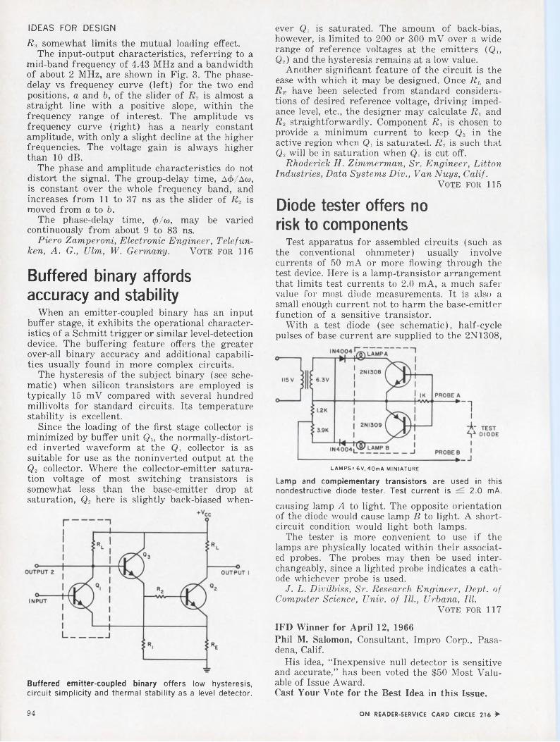
IDEAS FOR DESIGNR3 somewhat limits the mutual loading effect.
The input-output characteristics, referring to a mid-band frequency of 4.43 MHz and a bandwidth of about 2 MHz, are shown in Fig. 3. The phasedelay vs frequency curve (left) for the two end positions, a and b, of the slider of R2 is almost a straight line with a positive slope, within the frequency range of interest. The amplitude vs frequency curve (right) has a nearly constant amplitude, with only a slight decline at the higher frequencies. The voltage gain is always higher than 10 dB.
The phase and amplitude characteristics do not distort the signal. The group-delay time, A</>/Aw, is constant over the whole frequency band, and increases from 11 to 37 ns as the slider of R, is moved from a to b.
The phase-delay time, </>/&>, may be varied continuously from about 9 to 83 ns.
Piero Zamperoni, Electronic Engineer, Telefunken, A. G., Ulm, W. Germany. Vote for 116
Buffered binary affords accuracy and stability
When an emitter-coupled binary has an input buffer stage, it exhibits the operational characteristics of a Schmitt trigger or similar level-detection device. The buffering feature offers the greater over-all binary accuracy and additional capabilities usually found in more complex circuits.
The hysteresis of the subject binary (see schematic) when silicon transistors are employed is typically 15 mV compared with several hundred millivolts for standard circuits. Its temperature stability is excellent.
Since the loading of the first stage collector is minimized by buffer unit Q3, the normally-distorted inverted waveform at the Q, collector is as suitable for use as the noninverted output at the Q2 collector. Where the collector-emitter saturation voltage of most switching transistors is somewhat less than the base-emitter drop at saturation, Q2 here is slightly back-biased when-
Buffered emitter-coupled binary offers low hysteresis, circuit simplicity and thermal stability as a level detector.
ever Q, is saturated. The amount of back-bias, however, is limited to 200 or 300 mV over a wide range of reference voltages at the emitters (Qx, Q2) and the hysteresis remains at a low value.
Another significant feature of the circuit is the ease with which it may be designed. Once RL and Re have been selected from standard considerations of desired reference voltage, driving impedance level, etc., the designer may calculate R, and R2 straightforwardly. Component R, is chosen to provide a minimum current to keep Q3 in the active region when Qx is saturated. R2 is such that Q2 will be in saturation when Q, is cut off.
Rhoderick H. Zimmerman, Sr. Engineer, Litton Industries, Data Systems Div., Van Nuys, Calif.
Vote for 115
Diode tester offers no risk to components
Test apparatus for assembled circuits (such as the conventional ohmmeter) usually involve currents of 50 mA or more flowing through the test device. Here is a lamp-transistor arrangement that limits test currents to 2.0 mA, a much safer value for most diode measurements. It is also a small enough current not to harm the base-emitter function of a sensitive transistor.
With a test diode (see schematic), half-cycle pulses of base current are supplied to the 2N1308,
LAMPS=6V, 40mA MINIATURE
Lamp and complementary transistors are used in this nondestructive diode tester. Test current is 2.0 mA.
causing lamp A to light. The opposite orientation of the diode would cause lamp B to light. A shortcircuit condition would light both lamps.
The tester is more convenient to use if the lamps are physically located within their associated probes. The probes may then be used interchangeably, since a lighted probe indicates a cathode whichever probe is used.
J. L. Divilbiss, Sr. Research Engineer, Dept, of Computer Science, Univ, of III., Urbana, III.
Vote for 117
IFD Winner for April 12, 1966Phil M. Salomon, Consultant, Impro Corp., Pasadena, Calif.
His idea, “Inexpensive null detector is sensitive and accurate,” has been voted the $50 Most Valuable of Issue Award.Cast Your Vote for the Best Idea in this Issue.
94 ON READER-SERVICE CARD CIRCLE 216 >

¿Rub-a-dub-dubIf you’re going to guarantee every digital Flip Chip™ module for ten years, you worry about reliability.This particular module was routinely run through 120 standard tests, component by component, spec by spec. (The tests took 25 seconds on one of our PDP general purpose computers, a machine mostly made of modules just like this.)Then, we duplicated the laboratory environment. We dropped the module from a table, blew smoke at it,
spilled coffee over the components. We left the module on a radiator overnight.
All components still okay.
Somehow the module got left in a shirt pocket and subjected to a further unplanned test — wash, rinse, wash, rinse, spin dry.
Know what happened ? The coffee stains washed off.
Write for a catalog.nasoMODULES • COMPUTERS
DIGITAL EQUIPMENT CORPORATION, Maynard, Massachusetts 01754. Telephone: (617) 897-8821 . Cambridge, Mass. • Washington, D. C. • Parsippany, N. J. .Rochester, N.Y. • Philadelphia • Huntsville • Orlando • Pittsburgh • Chicago • Denver • Ann Arbor • Los Angeles • Palo Alto • Seattle • Carleton Place and Toronto,Ont. • Reading, England • Paris, France • Munich and Cologne, Germany • Sydney and West Perth, Australia • Modules distributed also through Allied Radio

Above all...the creative IDEAFrom the very beginning, Motorola has been an “engineer’s company”—an organization where every consideration was secondary to the newest technological development. As a result, Motorola has attracted the type of engineer and scientist who is noted, not for his ability to conform—but to create.
In this intellectually rarified atmosphere, the challenges to an engineer are great—but, of course, the rewards are commensurate.
Motorola does not need “engineers” per se, but there is always an urgent need for really good engineers and scientists—men who are inspired by this dynamic environment rather than afraid of it— men who shun monotony and search for diversified projects. If you are such a man, we would like very much to talk with you.SYSTEMS ENGINEERS advanced R & D in radio communications systems related to Two-way, portable, mobile and radio-telephone equipment
EQUIPMENT DESIGN high performance solid state receivers, transmitters, and data processing equipment for radar, communications, command and control, tracking and telemetry.
FAMILIARITY WITH STATE-OF-THE-ART statistical communications theory, advanced signal processing techniques, solid state r.f. techniques, ultra-reliability, antenna systems, advanced structural and thermal designs.
Excellent opportunities also available in Phoenix, Ariz.
Mr. W. H. HAUSMANN, Engineering Personnel Mgr., Dept. B 4545 Augusta Blvd., Chicago 51, Illinois
An equal opportunity employer.
MOTOROLA Inc.
SECTION MANAGER direct engineers and support personnel in state-of-the-art communications, including r.f. systems and input-output devices.CHIEF ENGINEER technical management of R & D group in advanced technology related to solid state r.f. communications.CIRCUIT DESIGN ENGINEERS advanced R & D in receivers, transmitters, RF, digital, Color TV and automotive electronics.DEVELOPMENT ENGINEERS advanced communications products in consumer, industrial and military electronics.
BookReviews
e. j. mcduskeyP:at««ir at EkKO&A* Venetian Go:»«
: K
Hi spates*»®Switching circuits
The words “introduction to” in the title of a book often give the author free reign in the pursuit of his subject. Depending on his bent, he may present an exhaustive exposition of the major principles, or he may instead provide cursory treatment of every topic remotely related to the subject. Professor McCluskey has done an excellent job of avoiding both extremes. He has selected from the vast body of switching circuit theory those topics which, because of their fundamental nature, should be of lasting importance to anyone engaged in switching circuit design. The selected topics are covered in comfortable depth, without delving into the highly detailed subject matter of more advanced texts.
In addition to covering number systems, switching algebra and function simplification, the author devotes a considerable amount of attention to the analysis and synthesis of sequential circuits, covering each separately.
An especially noteworthy contribution of the text is its inclusion of a separate chapter on the transient behavior of switching circuits. Although introductory works tend to overlook or minimize the effects of spurious delays and their effects on switching networks, Professor McCluskey has insured that readers of his book will be aware
(continued on p. 100)ON CAREER-INQUIRY FORM CIRCLE 901
96 Electronic Design, July 19, 1966

CAREER INQUIRY-confidential 17Respond to the career opportunities advertised in this issue. Fill out and send us this handy resume. Electronic Design will do the rest - neat copies of this form will be mailed to the companies of your choice, indicated by the circled Career Inquiry Numbers at the bottom of this page.
Name Home Phone
Home Address (Street) City State [ZIP Code
Age U.S. CitizenH Yes n no
Security Clearance1
Prime Experience Secondary Experience
Employment History - present and previous employers
Desired Salary Availability Date
Education - indicate major if degree is not self-explanatory
Company
City, State
Dates to to to
Title
Specialty
Additional Training -non-degree, industry, military, etc.
Degree
College
City, State
Dates to to to
Professional Societies
Published Articles
Career Inquiry Numbers:
900 901 902 903 904 905 906 907 908 909 ELECTRONIC DESIGN850 Third Avenue
910 911 912 913 914 915 916 917 918 919 New York, New York 10022

Reliability EngineersLockheed engineers are developing some of the most important vehicle systems in the country. There are major modifications underway on Polaris. And, the new fleet ballistic missile, Poseidon, is now in its early stages. Other systems include unique land vehicles and deep submersibles. Reii ability engineers are needed in these areas and many more. We invite you to investigate the following:
BSEE or BSME—Reliability design review: Experienced with small electrical components and semiconductors. Prepare procurement, test and design specifications.
BSEE—Reliability analysis:Experienced in circuit design and analysis. Perform detailed reliability analyses of complex electronic parts and circuits and recommend improvements in design reliability.
BSEE—Reliability test engineering:Prepare test procedures for electrical and electronic packages and coordinate procedures with test laboratories, conduct proofing of test procedures & equipment.
BSME—Reliability and inspection:Perform mechanical and structural reliability analyses. Provide for inspection planning and review prints to determine inspection attributes. Experience in metallurgy and NDT helpful.
Non destructive testing:Background in electronics and applied physics plus knowledge of instrumentation related to the use of X-rays, sound waves, electrical fields and optics.Write Mr. K. R. Kiddoo, Professional Placement Manager, Lockheed Missiles & Space Company, P.O. Box 504, Sunnyvale, California. An equal opportunity employer.
LOCKHEEDMISSILES & SPACE COMPANYA GROUP DIVISION OF LOCKHEED AIRCRAFT CORPORATION
ON CAREER-INQUIRY FORM CIRCLE 902
Fold twice, staple, and mail. Or, for absolute privacy, enclose in an envelope and mail to address given below.
FIRST CLASS Permit No. 725 New York, N.Y.
BUSINESS MAIL REPLYNo Postage Stamp Necessary if Mailed in the United States
POSTAGE WILL BE PAID BY
ELECTRONIC DESIGNREADER SERVICE850 THIRD AVENUENEW YORK, NEW YORK 10022

Share in the excitement at Delco Radio!Pick your opportunity from these openings in:
PRODUCT or PROCESS
DESIGN ENGINEERINGDelco Radio Division of General Motors is on the move! Growing demand for Delco solid state products requires more expansion . . . new buildings (411,000 sq. ft. addition underway) . . . new equipment . . . new projects . . . and most importantly, new people.
The pace is dynamic. Challenging. Advancement opportunity is ripe— for those who choose to capitalize on it. Make your choice from the following openings—now!
PRODUCTDESIGNSUBMINIATURE MILITARY COMMUNICATIONS EQUIPMENT
EE or ME—for assignment to development group designing all-transistor portable transmitters and receivers, operating in 2-100 me range. FM, AM, FSK, CW, SSB modulation.
HEATER, AIR CONDITIONER, AND VENTILATION CONTROL
ME’s—with 3-5 years experience, for development, engineering production liaison, and re-designing of comfort control systems including vacuum valves and mechanical controls.
AUTOMOTIVE RADIO DESIGNAND DEVELOPMENT
EE—to work with Senior Engineer on advanced development of auto radios and other entertainment devices, including FM-AM, miniaturized circuitry and components.
ME—for design of small electronic mechanisms, including FM-AM, Signal Seeking and push-button tuners, and components modules. EE or ME—for packaging of auto radios and associated tuners, solenoids, etc. Required to make some engineering contacts with automobile manufacturers.
PROCESSENGINEERINGSEMICONDUCTOR PROCESS ENGINEERSME’s or EE’s—BS or MS, to develop and create new processes for manufacturing germanium and silicon semiconductor devices. Includes development of automatic and semiautomatic fabrication equipment, pilot line operation and general cost savings investigations pertinent to semiconductor manufacturing.
RELIABILITY ASSURANCEME—project engineer, for design and development work on test equipment for semiconductors and special products. Will handle tests and evaluations of transistorized systems and components, both power and small signal type. Must evaluate results and associated statistical data. Also includes failure analysis work with suppliers and production.
Interested? Don't waste time—call us collect! Area Code 317/459-2808. Ask for C. D. Longshore. Or, send your resume to Mr. Longshore, Salaried Employment, Dept. 204, Delco Radio Division, General Motors Corporation, Kokomo, Indiana.
An equal opportunity employer
ON CAREER-INQUIRY FORM CIRCLE 903Electronic Design, July 19, 1966 99

BOOK REVIEWS(continned f rom - p. 96) that there is more to the theory than just building a circuit to implement some Boolean equation.
Introduction to the Theory of Switching Circuits. E. J. McCluskey (McGraw-Hill Book Co.: New York). 318 pp, $12.50.
Computer designThis discussion of the addition of
redundancy to computers to increase reliability is primarily theoretical in approach, with problems included at chapter endings and in appendices. Limit theorems for vote-taking, multiple-relay and generalized quadding types of error-correction circuits are covered. A conceptual foundation is provided for the theory of correcting errors in the same circuits that perform logic, and a systematic theory for structuring the interconnections in redundant logic is given.
Failure-tolerant Computer Design. William H. Pierce (Academic Press, Inc.: New York). 242 pp, $8.50.
Semiconductor surfacesTheories, techniques and experi
mental data on the electrical behavior of semiconductor surfaces are found in an illustrated volume containing several reference lists. Emphasis is on electrical aspects, but lattice structure and chemical reactivity of the surface are also described. Experimental methods relating to field effect, optical and magnetic measurements and noise are critically reviewed.
Semiconductor Surfaces. A.. Many, Y. Goldstein and N. B. Grover (John Wiley & Sons, Inc.: New York). 496 pp., $17.50.
Electronics dictionaryDefinitions of electronics terms
and fundamental facts are listed. Supplementary material includes an appendix of circuit symbols, abbreviations, color codes, conversion tables and value bases.
Dictionary of Electronics. Harley Carter (Hart Publishing Company, Inc.: New York). 410 pp. $6.95 (cloth edition) and $2.65 (paperback).
Optical toolingThis text explains and illustrates
the applications and mechanics of optical tooling in industrial use. The potentialities of the field of optical measurement, alignment and collimation are described and the advantages of optical tooling are pointed out.
Included in the book is a glossary of terms which apply specifically to this field.
Optical Tooling in Industry. John D. McGrae (Hayden Book Company, Inc.: New York). 122 pp. $7.
Matrix algebraA basic course in matrix alge
bra is divided into two sections. Part I covers the essentials of matrix methods and their applications and requires background in basic algebra only.
Part II treats the development of matrix algebra up to the eigenvalue problem and an introduction of functional concepts relevant to matrices.
Matrix Algebra for Electronic Engineers. Paul Hlawiczka (Hayden Book Company, Inc.: New York). 216 pp., $8.75.
DESIGN and
DEVELOP
POWER SUPPLIESAt the Research and Engineering Division of
Honeywell EDP we have developed many new techniques in computer design and capabilities. An integral function of these advances are the design and development of power supplies utilizing passive regulating, switching type regulating or C.V.T. techniques. Another activity would be the design of electronic power control, sensing and interlocking circuits for computer systems.If you are currently a power supply designer familiar with magnetic circuit as well as electronic circuit design OR if you have three to four years’ electronic circuit design and a hankering to design power circuits ,call or write Mr. Edwin Barr, Employment Supervisor,
Dept.ED -7 200 Smith Street, Waltham, Massachusetts.
(617) 891-8400
HoneywellELECTRONIC DATA PROCESSING
An Equal .Opportunity Employer
ON CAREER-INQUIRY FORM CIRCLE 904
To ELECTRONIC ENGINEERS with a sense of timing ...
BENDIX^^Ff/This is the opportune moment to investigate your career potential at Bendix, Kansas City Division. As prime contractor for the AEC, we have enjoyed an enviable, orderly 16-year growth. Now we are entering a unique developmental phase, opening new fields of activity in microminiaturization, microwave and logic circuitry. This situation adds up to a ground-floor opportunity in a well-established corporation noted for advanced engineering. Cooperative, professional atmosphere, plus excellent living conditions. Let us hear from you promptly so we may detail more clearly the many advantages we can offer you.
CORPORATION
Please mail résumé at once to:Mr. E. C. McGurren. Tech. Personnel Repr.
THE BENDIX CORPORATION. Box 303-HE
Kansas City. Missouri 64141
AN EQUAl OPPORTUNITY FMPIOYERON CAREER-INQUIRY FORM CIRCLE 905
Electronic Design. July 19, 1966100

I Top—For quick reaction in airborne and | I ground based electronic systems, LTV I I Electrosystems' Greenville Division is the I I experienced leader. Range instrumentation I I and tracking, ground-based satellite track- I I ing stations, command and control systems I I — all are in production or in use.
Right—Designer and builder of the world's 1 most powerful transmitting equipment, Con
tinental Electronics, an LTV Electrosystems subsidiary, was the prime contractor for the NATO VLF installation at Anthorn, England. Continental is the Free World's most experienced organization specializing in super power electronics.
Left — Powerful, compact units such as the ESC-1000 Long Range Ground/Air/Ground Secure Digital Communications System demonstrate only one phase of LTV Electrosystems' Garland Division's experience and capability in systems design. The ESC-1000 system will communicate up to 6000 miles in conventional applications and up to 12,000 miles in conjunction with a satellite.
complete spectrum of opportunity for creative challengeAt LTV Electrosystems, Inc., talented electronic systems oriented engineers know the excitement of creativity, the satisfaction of personal and professional advancement and contribution in an expanding organization, the flexibility and creative freedom of small product groups. Still they enjoy big company growth and opportunity.
LTV Electrosystems is an organization delivering highly complex new electronic systems to meet defense and space
demands of today and the future. Major fields of capability include: space/air/ground electromagnetic reconnaissance and surveillance systems; command and control systems; high-power radar and radio; nuclear detection and surveillance equipment; information processing and display systems; super power equipment; VLF transmitters; commercial radio transmitters; guidance systems; antennas; electronic warfare systems; satellite tracking systems ... and more.
These vital programs offer exceptional career positions to engineers in the following disciplines: RF SYSTEMS ANALYSIS / RF CIRCUIT DESIGN / DIGITAL CIRCUITS DESIGN / DIGITAL SYSTEMS ANALYSIS / WEAPONS SYSTEMS ANALYSIS / GUIDANCE SYSTEMS / RADAR SYSTEMS / ANTENNA SYSTEMS DESIGN / ELECTRO MECHANICAL PACKAGING / AIRCRAFT ELECTRICAL INSTALLATION DESIGN / AIRCRAFT STRUCTURES DESIGN / MECHANICAL SYSTEMS / ELECTROOPTICS / STRESS ANALYSIS / SCIENTIFIC PROGRAMMING . .. plus others.
For complete information about a career with LTV Electrosystems, Inc., write: Professional Placement, Dept. 176A, P. O. Box 6118, Dallas, Texas 75222. LTV is an equal opportunity employer.
EL-EC-moEy^^TEME, incXX SUBSIDIARY OF LirMQ-TEMCO-VOOGIHT, INC
---------------------------------- GREENVILLE AND DALLAS, TEXAS ----------------------------------ON CAREER-INQUIRY FORM CIRCLE 906
Electronic Design, July 19, 1966 101

you can’t make a commercial stack work in a military memory system.
that’s why we make both.When you build a military stack you're dealing with severe environment reliability problems, low weight and volume, wide operating margins and high speed. That's why we have a complete engineering group at Electronic Memories devoted exclusively to the design of stacks and systems for military environments. Now all this may not be particularly exotic — but it's not easy — and let's face it, these qualities have to be designed in from the ground up —not adapted from commercial stacks.
We've cut our teeth on military memory systems for fire control systems, asw, ecm, navigation and display systems and we've successfully met applicable portions of the following Mil specs: Mil-E-16400, Mil-E-4158, Mil-E-54oo and Mil-Q-9858.
In effect, no one else has Electronic Memories' experience or track record. But don't believe us — we'll send you the names of our customers and you
’ can ask them. They know commercial stacks won't do. If they did, we'd sell them. We make them too.
Ell! electronic memoriesMemory systems, stacks and cores for commercial, military and space applications12621 Chadron Avenue, Hawthorne, California

Products
Function generator modules afford versatility but cost less. With this system, all signals are go! Page 104
Semiconductor dicer uses abrasive slurry on 0.015-in.2 silicon, ferrite or ceramic wafers for 95% yield. Page 140
Wire harness ousts connector blocks. Page 114
Also in this section:____________________________________________
De op-amp neutralizes summing-node capacitance to cut ac error. Page 116
Carbon-14 battery is ultra-stable current standard. Page 120
Component spacers dissolve in water after use. Page 134
PC board translates decimal code to energize 7-bar display. Page 144
« ON READER-SERVICE CARD CIRCLE 217 103

COVER FEATURE READER SERVICE NO. 250
Multi-function modular series eliminates purchaseof several units for function generator applications
Different function generator applications normally each require individual fixed-package purchases. In contrast, this modular series offers the designer at-the-bench flexibility. With 15 initial modules already available and five others currently in the engineering stage, you can specify and buy no more or no less generator than you need. Off- the-shelf plug-ins add features or functions as needed.
In many systems applications three or four individual signal sources are required. This involves the purchase of three or four complete generators. With system 1000 the same thing can be accomplished with one modular unit. All that is necessary is a single power-pack and a series of waveform modules—sines, cosines, diode-shaper units or whatever the job calls for. Cost will be cut by two-thirds.
A typical workhorse generator application requires only a pulse or square wave. Sophisticated rise time is not the objective; yet where today can a unit that does not have a relatively fast rise time be found? Normally the buyer would have to outlay $700. But system 1000 provides an “unsophisticated” pulse or square-wave generator for under $300.
Checking computer cores normally takes a variable-power multiple-driving source to check
several cores simultaneously. But one of the new high-current output modules, coupled with a series of waveform modules, will handle the job inexpensively.
Tentative specifications of system 1000 modules are as follows:
■ Power supplies: Types 1001, 1002, 1003 and 1004 may be used independently or in conjunction with any of the modules. Type 1004 Ni/Cd battery pack will power 5 modules for 6 hours. Output is ±15 V at 500 mA (1001), 250 mA (1004), 1.5 A (1003) or 1 A (1002). Regulation is 0.05% (1001) and 0.1% (1002 and 1003). The supplies are rated at 50 W (1001 and 1002) and 75 W (1003) full load. Price: $100, $125, $150, $65 respectively.
■ Square-triangle generator: Types 1101 and 1102 may be termed “basic” to any system. Decade-multiplier controls, digital frequency dials and a ±2% vernier give 1% accuracy over the 109 frequency range. Voltage-controlled frequency (VCF) over a two-decade range is featured in the 1102. The applied VCF voltage will always sweep the generator at a lower frequency than the calibrated dial position. VCF range is 100:1, corresponding to 5 V, and linearity is 1%. Amplitude is an adjustable 10-V and source impedance
104 Electronic Design, July 19, 1966

New JFD Air Variable Capacitors offer higher frequencies with negligible loss of Q
Plus
• Ultra Stability• Highest Q•Small Size• Rugged
Construction
Now JFD air variable capacitors offer circuit designers the advantages of extremely high “Q” and greater capacitance values in a rugged miniature size unit. Offered in both a printed circuit (VAM 010W) and a panel mounting model (VAM 010), the new units operate at far higher frequencies with negligible loss of "Q” in comparison to other types.
Internal air meshing shells are silver plated to provide good surface conductivity and to prevent corrosive effects. Three internal contact springs assure positive electrical contact of rotor at all times. Leads on printed circuit model are tinned for ease in soldering.
The high density insulator between stator and rotor has excellent electrical properties and contributes to overall structural strength. Rubber gasketed threaded end caps effectively seal the units against dirt entrance or atmospheric contamination after tuning.
WRITE FOR JFD BULLETIN VAM-65JFD 120-A
Components DivisionJFD ELECTRONICS CORPORATION, 15th Ave. at 62nd St.. Brooklyn, N. Y. 11219
Tel: 212 DE 11000JFD NORTHEASTERN, Ruth Drive, P. O. Box 228, Marlboro, Mass. 07152JFD NEW YORK-NORTHERN, Damiano PL. P. O. Box 96, New Hartford, N. Y. 13503JFD MID ATLANTIC. P. O. Box 5055, Philadelphia. Pa. 19111JFD MID ATLANTIC-MARYLAND, P. O. Box 7676. Baltimore, Md. 21207JFD MIDWESTERN, 6330 W. Hermione St.. Chicago, III. 60646JFD MIDWESTERN-OHIO. P. O. Box 8086, Cincinnati. Ohio 45208JFD WESTERN, 9 Morían Place, Arcadia, California 91006JFD ISRAEL LTD.. Industrial Area B, Bldg. 23, Azor. IsraelJFD ELECTRONICS, EUROPE S A. 7 Rue de Rocroy, Paris. 10, France
Precision Piston Trimmer Capacitors ■ Metalized Inductors • LC Tuners « Ceramic Fixed and Variable Capacitors ■ Fixed and Variable Distributed and lumped Constant Delay Unes
Speed Inquiry to Advertiser via Collect Night Letter
ON READER-SERVICE CARD CIRCLE 36
I TH ELECTRONICS urUCORPORATION
THE ^AMERICA KNOWS BEST!
Electronic Design, July 19, 1966 105

COVER FEATURE
is 50 Q. Frequency range is 0.001 Hz to 1 MHz in 900 discrete steps. Square-wave rise and fall times are 40 ns, with symmetry exceeding 99 %. Triangle deviation from linearity is 0.3% max to 100 kHz (1101) and 1% max to 1 MHz (1102). Both modules will “free-run” with proper supply voltage, and the addition of a gate-trigger module will control operating modes. Trigger output is 100 ns at 5 V and 50 Q. Price: $155, $190, respectively.
■ Sine shaper: Type 1301 (see photo below) shapes the 10-V triangle from a system 1000 module; however, its 14 diode transfer points will shape any comparable input. The 10- Q input impedance allows several of these modules to be driven by one modular generator. The 10-V p-p sinusoidal output can also drive several other modules without degradation. De reference level is center 0, adjustable ±100 mV. Sinusodial distortion is ±0.5% max to 10 kHz, 1% max to 100 kHz and 2% max to 1 MHz. Price: $65.
■ Ramp generator: Type 1103 generates a ramp or sawtooth and a 50-ns rise-time gate over a 108 frequency range (1000 s to 10 ^s in 800 discrete steps). Two-significant-figure and decade-multi-
plier digital dials and a ±2% vernier give 1% over-all accuracy. In conjunction with the VCF square-triangle module, the,ramp generator forms a sweep-voltage source. Amplitude is an adjustable 10 V, and source impedance is 50 Q. Deviation from linearity is 0.5% max. Fall time is less than 0.1% of period (ramp) or 50 ns (gate). Price: $165.
■ Delay logic module: Type 1011 provides the logic to control delay time between two or more modules for double pulse generation, delay triggering and notch or delay burst generation. Delays range from 0.1 s to 100 ns with a 50-ns rise time and 1 % accuracy. Delay trigger output is 5 V into 50 Q, with a 3-V input needed to start the delay. Module delayed and delay source are switch-selected. Price: $145.
■ Gate/trigger module: One or more Type 1010 gate/trigger modules can control any one or more generator modules. The units furnish gating and triggering pulses (10 V/100 ns) either manually or upon receipt of an external signal. Since the module has its own high-speed flip-flop and is decoupled, the slowest waveform will produce a sharp triggering pulse. Input (manual) is 5 V (gate or trigger on) or 2 V (gate or trigger off). Price: $50.
■ Output amplifiers: The 20- Q input impedance of Type 1201, 1202, 1203 (see photo p. 104), 1204, and 1205 output amplifier modules allows one modular generator to drive several amplifiers. A maximum choice of 11 output waveforms is offered to the customer. Outputs are a variable 10 V into 50 Q (1201 and 1202), 5 V into 5 a (1205) and 30 V into 600 Q (1203 and 1204). Rise and fall times are 10, 12, 100, 100 and 10 ns respectively. The de reference level is center 0 (1201, 1202, 1204 and 1205) or a variable +4 to —4 V offset (1203). The balanced push-pull output of type 1204 has amplitude symmetry within 0.5% with respect to ground. The high-current type 1205 (1 A) requires the 1003 power supply. Price: $95, $145, $95, $135, $175, respectively.
In the engineering stage are cosine/phase shift, phase lock control, tone burst control, diode shaper and programable modules. All modules are of PC board construction with 22-pin ribbon connectors. Packaging is 5-1/4 in. high for rack mounting. The smallest width bench box is 9 in., which holds 5 modules 1-5/8-in. high.
The manufacturer will provide “specials” to order and expects to supply its representatives with replacement modules. Thus the concept of the modular instrument will allow the rep to serve in a factory-supply role.
Availability: August. Exact Electronics Inc., 455 S.E. Second Ave., Hillsboro, Ore. Phone: (503) 648-6661.
Circle No. 250
106 Electronic Design, July 19, 1966

Semiconductor Report MNEW PRODUCTS. DESIGNS AND APPLICATIONS FROM MOTOROLA
FET’s OFFER ANSWERTO RF/AUDIO AMPLIFIER DESIGN PROBLEMS
If you’ve had trouble finding the right answer for solid-state design of audio and RF amplifier circuits, two new series of Motorola Field Effect Transistors could be the solution.
For example, in Tone Control for high fidelity audio amplifiers, (see circuit above) the high input impedance of Motorola’s new audio amplifier FET’s (types 2N4220-22) allows for “vacuum-tube” design principles in the selection of tone control elements — thus permitting the use of high resistance values and small, low-cost, reliable capacitors. In addition, low “1/F noise” provides a definite advantage over “bipolar” transistors. The noise figure of the 2N4220-22 types is just 2 db (typ.) at 100 cycles, while their very high input impedance is indicated by the 0.1 nanoamp Ig88 value at 15 volts (greater than 10“ ohms) and the Ci88 value of less than 6 pF.ON READER-SERVICE CARD CIRCLE 146
FIGURE 1 - TONE CONTROL FOR THE HIGH FIDELITY AUDIO AMPLIFIERS
FIGURE 2 - 200 MHz RF AMPLIFIER TEST CIRCUIT
FOR LOW-NOISE, HIGH-GAIN RF DESIGNS
For application in low-noise RF amplifiers, as shown in the 200 MHz Amplifier Test Circuit (above), Motorola’s FET series types 2N4223- 24 offer a low 200 MHz noise figure of 5 db (max), a minimum gain of 10 db at 200 MHz (measured “in circuit”), and low cross-modulation and intermodulation distortion. As a result, you can design RF Amplifier circuits with good gain and the assurance of minimum distortion and device noise, plus the expected solid-state advantages of small size and reliability.ON READER-SERVICE CARD CIRCLE 147
2N4220-22 & 2N4223-24Electrical CharacteristicsCHARACTERISTICS SYMBOL MIN MAX UNITForward Transfer Admittance
(Vds = 15 Vdc,Vgs = 0» f=l kHz) 2N4220 [Yfs] 1000 4000 /imhos
2N4221 2000 50002N4222 2500 60002N4223 3000 70002N4224 2000 7500
Zero-Gate-Voltage Drain Current 2N4220 Idss 0.5 3.0 mAdc(Vds = 15 Vdc, Vgs = 0) 2N4221 2.0 6.0
2N4222 5.0 152N4223 3.0 182N4224 2.0 20
Input Capacitance 2N4220-22 Ciss — 6.0 PF(Vds = 15 Vdc, 2N4223-24 — 6.0Vgs = 0. f= 1MHz)
Noise Figure 2N4223 NF 5.0 dB(Vds =15 Vdc, Vgs = 0,Rs = 1 kohm, f = 200 MHz)
Small-Signal Power Gain 2N4223 Gps 10 — dB(Vos = 15 Vdc, Vgs = 0,f = 200 MHz)
MOTOROLA Semiconductors - iv/m fkapAiodk/A a
WHAT & WHY OF FET’s EXPLAINED IN NEW APPLICATION NOTE
Motorola Application Note -211 — “Field Effect Transistors in Theory and Practice” — has been prepared to help circuit designers to better understand how FET’s operate and how they are specified. This report is designed to provide an insight into the physics of the device which will permit its use with maximum effectiveness. You’re sure to find it a valuable addition to your semiconductor library. Write for it today, to Technical Information Center, Motorola Semiconductor Products Inc., P. O. Box, 955, Phoenix, Arizona 85001.ON READER-SEI.VICE CARD CIRCLE 148
Electronic Design, July 19, 1966 107

Shake, TEST EQUIPMENTHigh speed scaler
Digital indicator
rattle and roll...
When they made the 1912 Simplex, the art of vibration control was virtually unexplored — if you go by the theory of what you don’t know can’t hurt you, fine! Today's engineers are a little different (thank heavens) they design every shock and vibration problem possible out of a product. A good example is Rolls-Royce, they just installed 16 of our all-metal Met-L-Flex mounts. They will now become a production standard.
Rolls-Royce chose Met-L-Flex because it’s the only mount that completely resists all elements —extreme high or low temperatures, oils, chemicals, fuels, etc. You see Met-L-Flex mounts are all-metal — they incorporate a resilient cushioning material of fabricated, knitted stainless steel wire. It isolates your product from vibration and shock and we’re the only ones that make it!
We also have a complete line of elastomeric mounts to meet vibration and shock problems — so whether you’re mounting engine and exhaust systems, electronic gear, industrial equipment, or computer systems, we have the mountto solve the problem.
Met-L-Flex unit isolator for Airborne, Vehicular and Industrial applications.
High Frequency engineered mounting systems for missile applications.
VibraShock
Selective voltmeter
ROBINSON TECHNICAL PRODUCTS. INC. 3310 Vanowen Street, Burbank, California 91504
Teterboro, New Jersey(213) 849-7181 TWX 910-498-2217
ON READER-SERVICE CARD CIRCLE 37
A scaler and timer/scaler are of 6-decade capacity with built-in printer output. Both incorporate a direct-coupled internal discriminator. Input signals to the scaler range from ±0.1 to ±11 V. The timer/scaler accepts from de to 10 MHz with a pulse-pair resolution of 66 ns. Scaling rate of the timerscaler is 2 MHz min. Minimum gate signal is 100 ns.
P&A: $835 (model 430), $780 (model 431A); 90-120 days. Ortec Corp., P.O. Box C, Oak Ridge, Tenn. Phone: (615) 483-8451.
Circle No. 251
Transducer-measured forces are read by the digital indicator. The manual null-balance instrument has a 4-position bridge resistance selector switch with a 6-position mV/V range selector switch. Model 350 has a ±0.1% accuracy full scale and a system accuracy of ±0.25%. Repeatability is ±0.05% min full scale and resolution is 0.025%.
Baldwin-Lima-Hamilton Corp., Waltham, Mass. Phone: (617) 894-6700.
Circle No. 252
Frequency changers Produced in 8 sizes from 0.1 to 15.0 kVA, frequency changers have input frequencies of 47 to 73 Hz, 350 to 450 Hz and output frequencies of 50 to 60 Hz and 350 to 450 Hz. Output frequencies are continuously variable and/or fixed with 0.1% standard stability. The units have an efficiency of better than 80% and meet MIL-1-26600. The sinewave output has 5% max third harmonic distortion.
Avtel Corp., 1130 E. Cypress St., Covina, Cal. Phone: (213) 3310661.
Circle No. 253
A 10-kHz to 36-MHz selective and wideband voltmeter combines a generator and frequency selective receiver with a frequency locking oscillator for common tuning. The PSM-5 can be tuned over a 36-MHz range or internally swept about a center frequency from ±17.5 Hz to ±17.5 MHz. Reading sensitivity is — 120 dBm max. Frequency stability is 2 x 10-B ±100 Hz.
Tel-Com Instruments, Inc., 17715 Chatsworth St., Granada Hills, Calif. Phone: (213) 360-2278.
Circle No. 254
108 Electronic Design, July 19, 1966

then add this complete, low cost data system!(only $4,300, including DVM!)
Start with the EI-62ODVM with autoject...
Whether your signal levels are single ended or floating above ground, fool proof operation is provided by the 620's isolated-guarded differential input (140 db of CMR). Ground loops, offset or error due to noise arc eliminated. The 620’s constant high input impedance of greater than 1000 megohms eliminates errors due to source of loading. Fluctuating DC signals are accurately measured with the 620’s integrating logic, the value being integrated over the sampling time base of 100 msec.
The exclusive autoject circuitry provides greater than 60 db of normal mode rejection to superimposed noise of any frequency above 30 Hz, without the delay required by filters. (See graph.) All this at ^.01% accuracy!
620 features — • ±.01% accuracy • 4 full digits plus 5th for 20% overrangc • Automatic ranging and polarity • 4 readings per second • DC and Ratio • Differential inputs • Isolated electrical outputs • Remote control • Completely solid state circuitry including logic • From $995.00
* 620 Data System — Now, a low cost portable measuring and recording system utilizing as its heart, the EI-620DVM with autoject. Plug in your El- 620 and the system is complete.
Whether your application is for in house or field use, the 620 system provides a portable package everyone can use, anywhere!
System features — *40 points of guarded scanning • High-Low limit channel selection • Automatic or manual channel selection • Single or continuous cycle operation • Printed record on
DATA HANDLING SYSTEMS
HoneywellB □ DIGITAL VOLTMETERS
4 inch wide paper tape • Printed record includes channel ID, polarity, 5 digits of measured value and range • New, bold printed numerals • Automatic or single print operation • From $4300.00 (including DVM)
Additional systems extensions—are also available to provide additional signal conditioning and printout capability. Write forsystems brochure No. S25.512.
Your choice of system or portable DVMuse. When systems operation is not required, the EI-620 is unplugged and used with its portable case, carrying handle, and bench stand. All features and specifications are identical in both.
Contact your Honeywell Sales Office or write: Honeywell, Test Instruments Division, San DiegoOperation, 8611 Balboa Ave., San Diego, Calif. 92112.
Electronic Design, July 19, 1966 109
HONEYWELL IS WORLDWIDE • Sales and service offices in all nrincioa! cities of the world. Manufacturing in Brazil. Canode, France. Germeny, Japan, Mexico. Netherlands, United Kingdom, United States.
ON READER-SERVICE CARD CIRCLE 38

SEQUENTIAL SWITCHINGCompact, Efficient, Low Cost with
CLARE STEPPING SWITCHESCounting • Totalizing • Sequence Control • Monitoring■ Where circuit requirements call for selecting, interrupting, or changing connections in response to momentary impulses of current, Clare’s full line of rotary stepping switches provides exactly the device you need.
Compact and ruggedly built, Clare Stepping Switches have many new, improved features which contribute to longer service life, greater capacity and unusual freedom from maintenance. Contacts are bifurcated for maximum operating reliability. They may be gold plated for low-level switching, with consistently low contact resistance. Your choice of terminals: taper tabs, solder, or plug-in. Special units available to meet airborne shock and vibration requirements.
ONLY CLARE GIVES YOU ALL THIS:
1 Special Purpose Shorting Switches... for Test and Encoding Circuits
"All but one"Ideal for the classic “multiconductor cable” test for leaks, shorts, continuity, etc. Shorts all circuits except one together, making possible sequential testing of each circuit individually.
"Progressive"Useful for location of trouble sources in test circuits. Provides incremental increases and decreases in power as required by some control systems.
"Alternate"An excellent device for process control functions, generating a wide variety of coded control outputs. Useful in transmitting special coding in sequential repetition. Readily adaptable to binary coded decimal encoding.
2 High Voltage Sequential Control CapacityClare will provide special stepping switches to stand off voltages up to 2500 volts. Number of switch levels available depends upon voltage.
3 Special Enclosures for Adverse Environments
Clare Stepping Switches may be enclosed in removable covers, or hermetically-sealed (with either nitrogen or fluid)
to minimize undesirable effects of tampering, shock, or vibration, as well as salt air, humidity, fungus, corrosive atmosphere, sand and dust.
no Electronic Design, July 19, 1966

4 Custom-Designed Functional Sequence Control Units..,
5
Clare engineering can provide functional assemblies incorporating such features as variable time delay pulse generators. Combining stepping switches with solid state (for time delay and pulse generation) and relays (for switch-over between stepper levels), these assemblies expand the capabilities of Clare Stepping Switches.
Easy Installation withNew Plug-in Connector for Type 211 Stepping Switches
Faster, easier assembly and replacement. Connector contacts, crimped to lead wires, snap into connector frame. Plated contact areas (tin or gold over nickel) for contact reliability.
Typical Clare-designed sequential switching unit: 104 point sequence scanner. Solid State pulse generator, driving 10-level, 52-point stepping switch, provides predetermined time interval of 160 ms to 10 seconds at each position.
For information write:
C. P. CLARE & CO.Group 07A6,
3101 Pratt Boulevard, Chicago, Illinois
60645
Speed Inquiry to Advertiser via Collect Night LetterON READER-SERVICE CARD CIRCLE 39
Electronic Design, July 19, 1966 111

TEST EQUIPMENTNEW MAGNETIC RELAY plugs into your PC board!
NO Springs, NO Wiring, NO Sockets, NO Soldering,
NO Mechanical Linkage
Standard Series G Latching Series LS/LD Field vibration meter Milliwatt test set
(actual size)
Plated Conductors on Your PC Board are the Fixed Contacts
Save space, money and manhours with these new small, lightweight, highly reliable Standard and Latching PRINTACT Relays.Available with Bifurcated Palladium or Gold Alloy contacts for more than 10 million cycle 2 or 3 pole switching. Handles up to 3 amp. res. loads. Coils for 6, 12, 24 and 48 vdc at 500 mw. Operating temperature —30°C to +95°C. Operate time 7 ms. The little gem is an 0.8 oz. %" cube.Quality features include: double-break contacts; balanced armature, enclosed housing, plug-in application; encapsulated coil; self-wiping contacts and inherent snap-action — and the cost is lower than you think!
---------------- mail coupon today--------------PRINTACT RELAY DIVISION47-37 Austell PlaceLong Island City, N.Y. 11101
□ Send Printact data and prices.□ Have your local rep. call.
Name-------------------------------------------Title----------------------
Fi rm------------------------------------------- Te I. #
A d d re s s__________________________________________
City_______________________________________________
Available in ac or de, model 1-157 vibration meter indicates p-p displacement and average velocity. The input signal is averaged and displayed on a meter to peak or average values based upon equivalent sinusoidal input. Frequency range is 5 to 2000 Hz (displacement), 5 to 20,000 Hz (velocity) and frequency response is ±2%.
P&A: $1195 (ac), $1135 (de); 90 days. Consolidated Electrodynamics Corp., 360 Sierra Madre Villa, Pasadena, Calif. Phone: (213) 796- 9381.
Circle No. 255
High-gain pulse amplifierCompletely shielded and decou
pled to operate at input levels of 300 mV max, this 2-transistor multiple feedback amplifier has a 20-dB ±3% gain. Model 281 has a 50-Q input and output impedance. Rise time is 2 ns max and pulse distortion is 15 mV p-p max with a 300 mV output. Undistorted output is 600 mV max and droop time constant is 1/2 ps. Noise referred to input is 50 pX.
Nanosecond Systems, Inc., 176 Linwood Avenue, Fairfield, Conn. Phone: (203) 255-1008.
Circle No. 256
Fitted with BNC connectors, this mW test set measures 1 to — 1 dB referred to 1 mW on 75-Q unbalanced circuits at frequencies up to 30 MHz. It measures heater voltages of 5.6 to 7 V. A wired-in thermocouple is used with heater impedance of 75 Q. The standardizing circuit can send 1 mW de into external 75-Q circuits for calibrating other apparatus. The device operates from three integral 1.5-V dry cells.
ITT Corp., 320 Park Ave., New York. Phone: (212) 752-6000.
Circle No. 257
Spectrum stabilizerTwo independent sections of this
digital spectrum stabilizer correct for gain and baseline drift effects. The gain section corrects for changes in steps of one part in 64,- 000 to one part in 1000. Stabilization is unaffected by variations in input counting rate up to 50 kHz. Gain and/or zero stabilization may be based on a prominent peak in the input spectrum or an externally generated reference signal. The gain stabilization channel can be incremented from 0 to 9999 and the zero peak channel is switch-selectable from 0 to 99.
Technical Measurement Corp., 441 Washington Ave., North Haven, Conn. Phone: (203) 239- 2501.
Circle No. 258ON READER-SERVICE CARD CIRCLE 40
112 Electronic Design, July 19, 1966

After 130,000,000 diodes
1-amp glass rectifiers come easy
The basic technology required for making silicon glass rectifiers has long since been proved out in ITT’s diode operation. More than 130,000,000 diodes last year paved the way for 1966 l-amp glass rectifier capability that’s already operating at better than a 1.2 million annual rate.
If you’re using old-fashioned top-hats because delivery is slow on DO-29 glass rectifiers, make the switch now.
ITT offers immediate shipment of 200 to 1000 V, 1-amp glass rectifiers from factory stock or from ITT distributors’ shelves. See how fast silicon glass rectifier delivery can be — call your ITT factory representative or any of ITT’s semiconductor distributors throughout the United States today. ITT Semiconductors, a division of International Telephone and Telegraph Corporation, 3301 Electronics Way, West Palm Beach, Florida.
ITTSEMICONDUCTORS
FACTORIES IN PALO ALTO, CALIFORNIA; LAWRENCE. MASSACHUSETTS; WEST PALM BEACH. FLORIDA; HARLOW AND FOOTSCRAV. ENGLAND. FREIBURG AND NURENBERG, GERMANY.
ON READER-SERVICE CARD CIRCLE 41Electronic Design, July 19, 1966 113

COMPONENTS
Back-panel wiring harness ousts connector blocks
A back-panel interconnection system completely supplants more expensive connector blocks. The wiring harness is an independent unit that is plugged on to the array of PC boards. The male pins are supplied on strips wound on reels. Wiring logic and gauge are customer- specified.
The connecting hardware is the combination of 0.025-in.2 male pins staked in rows on the edge of the PC boards and a female connector crimped to the harness wires. These wires are insulated and ganged together by sandwiching them between layers of PVC. The layers are sealed by an RF dielectric heatsealer to form the female connector.
The harness itself is produced on a tape-programed machine, which eliminates bugs associated with hand-wiring. Two wires can be crimped into one terminal allowing
the jumpering or commoning of any number of pins in the array. The male pins are automatically staked on a machine supplied by the manufacturer located in the customer’s plant. The machine stakes 4000 ter- minals/hour.
Two heights of male pins are available. Using one type of pin permits a minimum spacing of 0.125in. centers. By alternating the two heights, a density of 0.0625-in. center-to-center can be achieved. In a typical harness of over 800 wires on 0.0625-in. centers, the harness projection beyond the board is limited to 1.25 in. with slight compression. Eliminating custom wiring and debugging each back panel saves production line time and money. The cost of fabricating a connectorblock array is completely eliminated.
The resistance of the mated connection is 5 mil max at 2 A after 100 cycles of the connection. A minimum tensile strength of three pounds for #28 AWG and 4.5 pounds for #26 AWG is maintained between the wire and the terminals.
P&A: $4 to $7/M; stock to 2 wks (male pins). $0.05 to $0.10/connec- tion; 3 to 4 months (initial order), 3 to 4 wks (subsequent orders); (harness). Berg Electronics' Inc., New Cumberland, Pa. Phone: (717) 938-6711.
Circle No. 259
Gangable plastic potServo-mounted, 2-in. diameter
pots offer ±0.5% linearity, a 4-W power rating at 85°C and resistance tolerance of ±3%. Model 2580 withstands temperatures of 150°C. Resistances are available from 20 to 125,000 il. The rotor, insulator ring and element mount are of diallyl phthalate. The resistance element is epoxyed to the diallyl mount. The pots are gangable up to 8 units and available with up to 9 additional taps.
P&A: $25 (1 to 9); stock to 6 wks. Amphenol, 120 S. Main St., Janesville, Wis. Phone: (608) 7542211.
Circle No. 260
Isolated converterAn isolated converter provides
high isolation and minimum conversion loss from de to 400 MHz with a noise figure of 7.5 dB. RF range is 500 kHz to 400 MHz. Conversion loss is 7 dB. The unit weighs 4 oz and has BNC connectors.
P&A: $268; stock. Adams-Russell Co. Inc., 280 Bear Hill Rd., Waltham, Mass. Phone: (617) 8993145.
Circle No. 261
114 Electronic Design, July 19, 1966

Evaluate ITT
ITTSEMICONDUCTORS
ITT SEMICONDUCTORS IS A DIVISION OF THE INTERNATIONAL TELEPHONE AND TELEGRAPH CORPORATION
FACTORIES IN WEST PALM BEACH FLORIDA. PALO ALTO. CALIFORNIA. LAWRENCE. MASSACHUSETTS; HARLOW AND FOOTSCRAY. ENGLAND. FREIBURG AND NURENBERG. GERMANY
ON READER-SERVICE CARD CIRCLE 42Electronic Design, July 19, 1966 115

COMPONENTS
De op-amp cuts ac errorA 100-Vdc operational amplifier
reduces ac error by neutralizing summing-node capacitance. In systems requiring physical separation of the gain-determining network from the amplifier, the summing node is loaded by cable capacitance which impairs ac system performance. A “guard driver” reduces the effective magnitude of such capacitance by a factor of 10. The openloop single-ended amplifier has an output capability of 30 mA at 110 V. Input impedance is 1011 Q shunted by 3 pF. Gain is 10s at de. Small-signal gain rolls off at 6 dB/- octave to unity at 5 MHz. Output slewing limit is 20 V/^s. Input offsets are 1 ¿iV/°C and 2 pA.
P&A: $180; stock to 40 days. Newport Labs., P. O. Box 2087, Newport Beach, Calif. Phone: (714) 646-9295.
Circle No. 262
The big difference is beam control. This General Electric TL 1% lens-end lamp puts 750 footcandles
on a %" spot. From %'' away, this type puts no light at all outside an area %" by %".
For the electronic eyes of reader-sorters, computers, scanners — anywhere errant light can mean error -
G-E TL 1% lamps keep a tight squeeze on light.Choose from seven with five different beam patterns.
Available with midget flange, midget groove or wire terminal. All with low color temperature (2225K±175)
and average life of 10,000 hours or more.For detailed specifications on all G-E TL 1% lens-end
lamps, write: General Electric Company, Miniature Lamp Department, M 6-2, Nela Park, Cleveland, Ohio 44112.
Progress Is Our Most Important Produci
GENERAL @ ELECTRIC
Micromin mW preampEmploying silicon semiconduc
tors and FETs, these preamplifiers may be cascaded to obtain a gain of 40 to 70 dB. All units have a per cycle noise figure of —168 dB at 1 KHz. Frequency response is 3 Hz to 100 kHz ±3 dB. Input impedance is 1 Mil and output impedance is 30 Q. The broadband minimum detectable signal is 1.25-pV for 100 kHz bandwidth. Power consumption is 12 mV, output signal is 2.5 V rms min and dynamic range is 70 dB.
Applied Cybernetics Systems, 880 Bonifant St., Silver Spring, Md. Phone: (301) 588-4873.
Circle No. 263ON READER-SERVICE CARD CIRCLE 43
116 Electronic Design, July 19, 1966

MarkH Series 300 and Series 350
Shock: 100G — 11 ±1 ms
■U.S. Potent No. 2,86b.O46 and others pending.
CHARACTERISTIC PERFORMANCE DATA
Operate and Release Time: 10 ms max. @ 26.5 VDC and 25°CContact Bounce: 1 ms max. even at low-level loads
PC plug-in cansTwo epoxy-glass, single-sided
printed circuit boards (2-1/2 x 21/4 x 1/16-in.) with 312 soldering pads each mount in 3 x 2 x 2 in. cans. Prototype circuits may be quickly built by mounting transistors or other components, wiring and soldering.
Plug-In Instruments Inc., 1416 Lebanon Rd., Nashville, Tenn. Phone: (615) 244-1330.
Circle No. 264
100-Meg decade boxTwo resistance decade boxes have
a 100-0 to 111.Ill-Mil range with positive in-line read-out. Models RUS 67A and 67B have accuracies of 0.01% and 0.025%. Resistance settings are accurate to 0.01%. Stability is 25 ppm/year and switch life is 10s operations. Temperature coefficient is 5 ppm/°C.
P&A: $575 (67B), $695 (67A) ; stock to 30 days. General Resistance Inc., 430 Southern Blvd., Bronx, N. Y. Phone: (212) 292-1500.
Circle No. 265
Micromin reed relayIncluding epoxy resin encapsula
tion, this spst-NO reed relay is 7/16-in. long by 14-in. diameter. Operate time is 0 25 ms and release time is 0.5 ms. Contacts are rated 0.1 VA max at 10 mA max or 12 V max, non-inductive.
Magnecraft Electric Co., 5575 N. Lynch, Chicago. Phone: (312) 2825500.
SIZE DOWN. PERFORMANCE UP!Our new one-inch 6PDT and 4PDT relays give you
established dry-circuit reliabilityElectro-Tec s wedge-action contact mechanism* has been proving itself in conventional 6PDT operations for 9 years. It's established anoutstanding dry-circuit confidence level of 90% based on a failurerate ot .001% per 10.000 operations. Now we’ve put wedge-actionto work in two 1 ' x 1 miniature relays, the Series 300 (6PDT) and Series 350 (4PD I). The Series 300 will replace three half-size crystalcan relays in approximately the same space while giving you theadvantage ot a proven reliability factor. Wedge-action, precious metalcontacts combine long contact wipe area with high contact force. Results? Low, low contact resistance, stable over operating life. Extreme shock, vibration, and acceleration immunity. Performance exceeds all MIL-H-5757/1 and /7 requirements. Competitively priced, with in-house testing to your high-rel specifications.
contact Rating. Low-level to 2 amps
vibration: 30G up to 3000 cps
EleciPoTec corpSLIP RINGS • RELAYS • SWITCHES • OPTICS
P. O Box 667 • Ormond Beach, Florida (904) 677 1771 • TWX 810-857-0305
Manufacturing facilities: Ormond Beach, Fla. • Blacksburg, Va.
ON READER-SERVICE CARD CIRCLE 44
Circle No. 266
Electronic Design, July 19, 1966 117

Think of a number between
1 and 6,000.
That’s how many lines per minute the MC4000 can print.Monroe Datalog®’s MC 4000 ultra high speed optical printer records 6000 lines per minute, or any speed less that your application requires. Truly synchronous or asynchronous. Completely silent. Absolutely reliable—only two moving parts. Available in numeric or alphanumeric models—both 32 columns wide. Any 4 or 6 line code with any logic level.
Features: character serial input, bit parallel. 6 microseconds per character data transfer time. Exceptional compactness— lOyi" x 10X" x 21%*. All
ON READER-SERVICE CARD CIRCLE 45
solid state. Cathode ray tube with fiber optics.
Permanent copy option available.And a full year’s warranty. Price:
$5650 for numeric model; $5850 for alphanumeric model.
For information, contact Monroe Datalog Division of Litton Industries, 343 Sansome St., San Francisco 94104. (415) 397-2813.
MONROE DATALOG mDIVISION OF LITTON INDUSTRIES L-LJ
118 Electronic Design, July 19, 1966

COMPONENTS
Logic sensing module
Militarized versions
of MC 4000
also available.
Crystal oscillator
A solid-state sensing module performs AND, OR, NOT, NOR, NAND and memory logic functions. The module has plug-in PC board design. Up to 4 isolated pA control signals may be algebraically mixed to yield an on/off mA output capable of driving a small de relay, indicating lamp or power thyristor.
Norbatrol Electronics Corp., 356 Collins Ave., Pittsburgh. Phone: (412) 362-2020.
Circle No. 267
Frequency tolerances of ±0.001% can be met over the 5- to 100-MHz range of this crystal oscillator. Available supply voltages of 5 to 28 Vdc suggest uses as an IC frequency source. Output voltages of 3 V p-p square wave with 20-ns rise time and 2 V rms sine wave with 10% distortion into a 1- kQ load are typical.
Price: $71.50 to $169.75. Accu- tronics Inc., 12 S. Island Ave., Batavia, Ill. Phone: (312) 879-1000.
Circle No. 268
A plug-in de to de converter reduces the output voltage of a 130 Vdc power supply to lower regulated voltage levels. It eliminates large voltage-dropping resistors and provides transformer isolation from the battery. Regulating circuits function over an input range of 104 to 140 Vdc. Maximum total output is 6 W.
Radio Frequency Labs. Inc., Boonton, N. J. Phone: (201) 3343100.
Circle No. 269
Strain gage transmitter
The Monroe DATALOG MC 4000 is available in any configuration or to any military specifications that your application requires.
For further information, call the Monroe DATALOG Division of Litton Industries, 343 Sansome St., San Francisco 94104. (415) 397-2813.
MONROE DATALOG mDIVISION OF LITTON INDUSTRIES LO
ON READER-SERVICE CARD CIRCLE 46Electronic Design, July 19, 1966
A transistorized strain gage transmitter for transducer forcemeasuring systems connects a strain gage transducer output directly to all three of the standard control current signals. The unit has linearity of ±0.20%, repeatability of ±0.05% and sensitivity of 0.05% over an operating range of -20 to 140° F.
Baldwin-Lima-Hamilton Corp., 42 Fourth Ave., Waltham, Mass. Phone: (617) 894-6700.
Circle No. 270
119

COMPONENTSELIMINATE COSTLY DATA REOUCÏION!
Carbon-14 battery is stable current standard
HEAD TEMPER ATURE DIRECTLY. ■ ■■■■■ I
WITH REC'S NEW MODEL 414 LINEAR BRIDGENow you can read temperature directly and accurately to 0.03 per cent, in a range of—100° to 4-5OO°F! Simply combine REC’s Model 414 Bridge with platinum resistance temperature sensor* and any digital voltmeter.
REC’s Model 414 linear bridge provides 1 millivolt per °C or °F suitable for direct presentation on digital voltmeters, printers, etc. Or use it as an input for recorders, computers and control systems. No further signal conditioning is required. Ideal for differential measurements (2 units required).
The cost? Approximately $155.00 complete for bridge and integral power supply. Write today for full details.
*REC also manufactures a complete line of Surface and Immersion Temperature Sensors, Air Data Sensors, Pressure Calibration equipment, Mass Flow and Pressure Sensors and related accessory equipment.
we invite inquiries regarding your particular requirements...
ROSEMOUNTENGINEERINGCOMPANY
4900 WEST 78th STREET • MINNEAPOLIS, MINNESOTA 55435 ON READER-SERVICE CARD CIRCLE 47
“Perma-Nuclear” batteries produce a 5 x 10’13-A current by collecting beta particles from the decay of Carbon-14. Since the half-life of Carbon-14 is 5,570 years, current decreases less than 0.1%/year. The battery produces the same current whether connected to a short or to up to 1015 Q. The source is permanently shielded and license-exempt.
General Radioisotope Processing Corp., 3000 San Ramon Valley Rd., San. Ramon, Calif. Phone: (415) 837-5424.
Circle No. 271
Single-digit read-outsSingle-digit read-outs are each
capable of representing 21 standard alphanumeric characters in a 7-segmented bar configuration. They use miniature 0.7-A incandescent lamps and silvered light pipe segments to achieve a brilliance of 500 foot-lamberts. The units meet MIL-E-5400.
Tung-Sol Electric Inc., One Summer Ave., Newark, N. J. Phone: (201) 484-8500.
Circle No. 272
120 Electronic Design, July 19, 1966

Ceramic planar triodesTwo ceramic planar triodes are
designed for the telemetry frequencies of 2.2 to 2.3 GHz. The Y-1266 weighs 2-oz and is designed for applications requiring power outputs up to 3 W. It has a power gain of 9 to 12 dB. Plate voltage is 200 V and current is 30 mA. The Y-1223 has a high-dissipation anode designed to increase plate dissipation to achieve a 10-W output at 2.3 GHz. Power gain is 7 to 9 dB.
General Electric Co., 1 River Rd., Schenectady, N. Y. Phone: (518) 374-2211.
Circle No. 273
Dual-dielectric capacitors using paper and polyester-film are rated at 1600 Vdc in capacitance values of 0.001 to 0.1 p.F. Type 160P capacitors are fully molded while type 161P capacitors utilize premolded cases. Both use a synthetic hydrocarbon solid imprégnant which is polymerized in situ. The capacitors have standard working voltages of 200, 400, 600, 1000 and 1600 Vdc with operating temperatures of 85°C max.
Sprague Electric, 347 Marshall St., North Adams, Mass.
Circle No. 274
BIG POWERSMALL PACKAGECERMET STABILITYUNDER $2.00 each—
(in production quan.)
GOLD TERMINATION PAD
CERMET RESISTANCE ELEMENT
TERMINALS ELECTRICALLY BONDED TO TERMINATION PAD
MOLDED DIALLYL PHTHALATE BASE
RING AND HEAT SINK
Series 550 has long life- no catastrophic failures
New 2-watt, 3/4" diameterCERMET Variable Resistor
TERMINAL INSERT MOLDED INTO BASE
Applications: computers, instruments, medical electronics, communications equipment, electronic machine controls, electronic processing equipment, aerospace electronics, microwave transmission, etc.
Outstanding features:Closed construction—Cover entirely protects against dust and dirt.Exceeds MIL-R-23285 (Navy) metal film, Cermet; also far exceeds MIL-R-94B.Extreme stability under severe environmental conditions.Resistance range—50 ohms through 1 Megohm.Infinite resolution.Low noise and long life.Excellent high frequency characteristics.
Request data sheet 3550.Founded 1896
a subsidiary of CTS Corporation, Elkhart, Indiana
ON READER-SERVICE CARD CIRCLE 48
Electronic Design, July 19, 1966 121

COMPONENTS
OFF-THE-SHELFMAGNETIC SHIELDSAbout 80% of all magnetic shield designsnow in use originated here.Maybe it’s because our designs work. Maybe our designs work because we’ve had the most experience. All are good reasons to contact us.
Netic and Co-Netic magnetic shields are the recognized standard all over the world for military, laboratory, industrial and commercial applications. They are insensitive to ordinary shock, do not require periodic annealing, and have minimal retentivity. A few typical applications are illustrated. Our design deDartment is yours. Magnetically Shielded Room
CRT Shield Complex Sectionallzed P.M. Shield Nesting Cans
MAGNETIC SHIELD DIVISIONPerfection Mica Company
1322 N. ELSTON AVENUE, CHICAGO, ILLINOIS 60622ORIGINATORS OF PERMANENTLY EFFECTIVE NETIC CO-NETIC MAGNETIC SHIELDING
ON READER-SERVICE CARD CIRCLE 49
Phase-locked oscillatorAutomatic phase control com
bined with automatic frequency control gives this oscillator the crystal stability of the APC circuit with the wide capture range of AFC. A stabilization indicator lamp is incorporated. Frequency range is 1850 to 2050 MHz and output power is 25 mW. Long-term stability is 1 ppm and short-term stability is 0.3 ppm min. An integral proportional controlled crystal oven requires 28 Vdc, 15 W. The oscillator requires 10 W max.
Litton Industries, 200 E. Hanover Ave., Morris Plains, N. J. Phone: (201) 539-5500.
Circle No. 275
NEWCold-Weld Crystals withstand 20g vibration at 10-2,000 Hz Actual Size
“Slim” totalizer
TYPICAL SPECIFICATIONS
Frequency Range... 300 to 700 KHZ Shock.......................................... 100gHolder............................ HC-6 type Vibration... .20g at 10-2,000 Hz
After 5,000-hour life test at 65°C, less than 2 x IO"8 per day.
Reeves-Hoffman’s high reliability cold-welded crystals meet all requirements for space programs such as Apollo and Ranger. Cold welding solves problems of damping and corrosion, permits minaturization, pro-vides typical specifications as shown above. We invite your inquiry for complete information.
REEVES- 2Z2ZZ2Z22Z22- HOFFMAN ^1" DIVISION OF DCA
400 WEST NORTH STREET, CARLISLE, PENNSYLVANIA 17013
The 1-3/4-in. high front panel of this 3- to 6-decade totalizer contains the reset push-button, power on-off controls and input terminal. Input is square wave or positive pulse with amplitude 6 V p-p. Rise time is 1 ps max and duration is 4 p.s min. Frequency range is de to 200 kHz. Options include digital printer output, 6-digit mechanical totalizer, pre-amp for 10 mV sensitivity and + 12 Vdc level gating and pre-amp to provide 10 mV sensitivity and 2- line pulse gating.
P&A: $445; stock to 4 wks. Ana- dex Instruments Inc., 7833 Haskell Ave., Van Nuys, Calif. Phone: (213) 782-9527.
Circle No. 276
Electronic Design, July 19, 1966ON READER-SERVICE CARD CIRCLE 50
122

Now! Transistor chips for hybrid circuits!
These are standard PNP and NPN silicon PLANEX* chip transistors, supplied in gold- backed form or as chips pre-attached to gold- plated Kovar Tabs. They are available for your hybrid circuits now.
These chips are 100% tested to all low level DC parameters. Sample lots are tested for all
AC and DC data sheet parameters to assure full specification compliance.
For specifications, price and delivery information, call your nearest Raytheon regional sales office. Or write: Raytheon Company, Components Division, 141 Spring Street, Lexington, Mass. 02173.
♦PLANEX—Raytheon’s designation for Planar Epitaxial
1
TYPES DESCRIPTIONABSOLUTE
MAXIMUM RATINGS
VCBO vceo Vebo ic
TA4980 (2N918) NPN chip transistor for low-level high- frequency amplifiers. Dice size.017x.017"
30V 15V 3V 100mA 1
1 TA4981 (2N2369A) NPN chip transistor for high-speed 40V 15V 45V 200mA iI TA4982 (2N3011) saturated switching. Dice size .O17x.O17" 30V 12V 5V 200mA .
TA4972 (2N2904A) 1 TA4973 (2N2905A)
PNP chip transistors for general purpose usage. Dice size .020 x .027"
60V 60V 5V 1000mA 1
1 TA4984 (2N2218A) i TA4985 (2N2219A)
NPN chip transistors for general purpose usage. Dice size .020 x .027"
75V 40V 6V 1000mA I
i TA4974 (2N1890) NPN chip transistors for general pur- 120 V 80V 7V 1000mA 1• TA4975 (2N1893) pose usage. Dice size .036 x .036" 100V 60V 7V 1000mA 11 TA4976 (2N3250) PNP chip transistors for low-level and 50V 40V 5V 100mA II TA4977 (2N3251) preamplifier usage. Dice size .017 x .017" 50V 40V 5V 100mAi TA4991 (2N2483) NPN chip transistors for high-gain pre- 60V 60V 6V 100mA ‘1 TA4992 (2N2484) amplifier usage. Dice size .019 x .019" 60V 60V 6V 100mA 11 TA4978 (2N3244) PNP chip transistors for high current
saturated switching. Dicesize .036x.036"40V 40V 5V 1000mA j
i TA4983 (2N3252) NPN chip transistor for high current 60V 30V 5V 1000mA 1
1____________________saturatedswitching. Dice size.036 x.036' '
1
Raytheon Components Division—A single source for Transistors/Diodes/Integrated Circuits/ Industrial Tubes/Control Knobs/Panel Hardware/Raysistors/Circuit Modules/Display Devices
RAYTHEONON READER-SERVICE CARD CIRCLE 51
Electronic Design, July 19, 1966 123

COMPONENTS
Thermocouple referenceA self-powered thermocouple
and reference temperature compensator simulates any hot or cold reference temperature. It features a replaceable energy cell. Units are supplied with mounting straps and mating connectors. Maximum error is ±1/2°F and continuous duty life is 10,000 hours. The unit is manufactured to NASA specs with all solid-state passive elements in any of the common thermocouple materials.
General Resistance Inc., 430 Southern Blvd., Bronx, N. Y. Phone: (212) 292-1500.
Circle No. 277
Maybe the Parsons DR 1200 is what you’ve been looking for. This new digital recorder is compact, weighs only 45 pounds, operates with only 100 watts of power and reads and writes IBM computer compatible tapes with tape speeds up to 120 inches persecond. Recording format is 7 or 9 track data on IBM reels. Overall dimensions: 19 in. x 14 in. x 7.5 in.
Its rugged construction, precision performance and fail-safe features make the DR 1200 an ideal instrument for field or fixed installations in virtually any kind of environment. Best of all, it is priced considerably lower than you would expect to pay for a comparable unit. It is now in production and deliveries can be made within six weeks.
Dial 213-681-0461 (or drop us a line) and tell us what you need. Chances are the DR 1200 can be adapted to meet your optional requirements at a price you are ready to pay. For the white glove treatment, contact Jim Vallely, Sales Manager, at
LOS ANGELES NEW YORK WASHINGTON
THE RALPH M. PARSONS ELECTRONICS COMPANY
151 S. DE LACEY AVE., PASADENA, CALIF.
A subsidiary of The Ralph M. Parsons Company
OFFICES IN OTHER PRINCIPAL CITIES THROUGHOUT THE WORLD
Pulse generatorsTemperature stability without
the use of an oven is provided by a MIL-E-5272 crystal-controlled pulse generator. Frequency range is 2 to 499 kHz for model PG-111 and 500 kHz to 20 MHz for model PG-112. Frequency stability is ±0.005% for the PG-111 and ±0.01% for the PG-112 at a load of 600 Q. Standard output is ±10 V ±10%. At a 600-Q load, rise time is 300 ns and fall time is 200 ns.
Solid State Electronic Corp., 15321 Rayen St., Sepulveda, Calif. Phone: (213) 894-2271.
Circle No. 278ON READER-SERVICE CARD CIRCLE 52
124 Electronic Design, July 19, 1966

what’s so great about Hoffman’s
controlled avalanche rectifier? it’s what we’ve
got up our sleeve.ELECTRICAL EXCELLENCE — PRV’s for our series HAR-10, 15, and 20 are 100, 150, and 200 respectively. Minimum avalanche voltage @ SO^A is 125 for HAR-10, 175 for HAR-15, and 250 for HAR-20. Maximum avalanche voltage @ 500pA is 250, 350, and 500. And the maximum reverse current for all three rectifiers is 0.1/iA @ 25°C,
l and 1.5/zA @ 100°C.
BUTTED SLUGS — Construction is as simple as it could possibly be.
In a body only 0.160” long, the slugs butt right up against the wafer.
Reliability couldn’t be higher.
PASSIVATED WAFER — Our passivating technique forms
an impenetrable shield wrapped around the silicon
wafer creating a lifetime barrier against electrical enemies.
COMPRESSION GLASS SEAL— No fusion of the metal-glass interface takes place. All contaminants are sealed out. No trapped impurities are sealed in. And the sleeve doesn’t touch the wafer anywhere.
MATCHED COEFFICIENTS OF EXPANSION — The contraction and expansion properties of the glass, the slugs, and the wafer are matched to less than 5%.
BRAZED LEADS —Each W terminating wire can take a pull of
12 lbs. This is more than 10 times 1 the strength of a soldered or welded lead.
Ask us for complete specs on these devices; also on our 1 amp HFR series
fast recovery rectifiers, and on our 1 amp HGR series general purpose rectifiers.
-J i Huffman Semiconductor
Hoffman Electronic Park, El Monte, California 91734 • 686-0123
ON READER-SERVICE CARD CIRCLE 53Electronic Design, July 19, 1966 125

READ, PLOT, OR SCALE CURVES WITHOUT CALCULATIONThe Gerber Variable Scale is based on a precision extensible spring, calibrated in hundredths. It allows you to read curve amplitudes directly, read frequencies directly, multiply by scale factors, plot with correction factors or other constants included, interpolate, normalize, etc. It eliminates routine calculations. Accurate to 0.05% in full scale of ten inches. ■ Partially shown below (actual size) plotting curve from original. ■ Send for literature: THE GERBER SCIENTIFIC INSTRUMENT CO., P.O. Box 305, Hartford 1, Connecticut.
COMPONENTS
Ultra-stable resistors Guaranteed max shelf life drift of 25 ppm/year is offered in a line of 10-0 to 30-0 resistors. Absolute tolerance is 0.01% and temperature coefficient is ±1 ppm/°C from O to 60°C. Noise and inductance are non-measurable. Standard resistance values in the S-102 case range from 10 O to 30 kO with values to 120 k available in other cases.
P&A: $1.55 to $3; stock to 4 wks. Vishay Resistor Products, 63 Lincoln Highway, Malvern, Pa. Phone: (215) 644-1300. Circle No. 279
Operational amplifier Offset current of typically 5 nA (10 nA max), voltage drift of typically 5 pN/°C (15 pN/°C max) and an output of ±10 V at 20 mA are features of this all-silicon operational amplifier. The D-22 will drive loads up to 10 JU.F without stability loss. Minimum gain is 100 dB, current drift is 0.5 nA/°C and noise is 8 pN max.
P&A: $75 (10 to 24); stock. Data Device Corp., 240 Old Country Rd., Hicksville, N. Y. Phone: (516) 433- 5330.
Circle No. 280A low torque circulator potentio
meter may be used as a sensing element in instrumentation systems, or as a pickoff device for oceanographic current direction sensors and magnetic compass devices. The standard model CP39 has a 10 Mo resistance element with continuous mechanical rotation and 355° minimum electrical travel. Starting and running torque is 1 gm-cm max. Independent linearity is ±0.5%.
Humphrey Inc., 2805 Canon St., San Diego, Calif. Phone: (714) 223- 1654.
Circle No. 281
Strain gage transducerA semiconductor strain gage
transducer measures pressure of 0-100 through 0-5000 psia. The unit operates from a constant 30-Vdc max and provides a 15-mV/V min output. Combined accuracy is ±0.25%. Natural frequency is 35 kHz min in the 100 psi range. Response is 0.5 ms max to achieve 63% rise time. Model 1029 has an MTBF of 5 x 10⁶ hours.
Micro-Systems Inc., 255 N. Halstead St., Pasadena, Calif. Phone: (213) 355-7111.
Circle No. 282ON READER-SERVICE CARD CIRCLE 54
126 Electronic Design, July 19, 1966

Hire Helipot’s 3/s cermet trimmer for the jobs too tough for wirewounds
Got a big job for a small, square trimmer? Sign up the new Helitrim® Model 63P trimming potentiometer. Smallest of its class in size and price, the tough little 63P offers essentially infinite resolution, with ruggedness and reliability twice as high as you’d expect.
No wonder. Beneath its sealed %" x %" x yl4" molded plastic housing, the 63P has a heart of cermet. No other resistance element can match its combination of high power rating, essentially infinite resolution, freedom from sudden failure, resistance stability, and wide 10 ohm to 2 megohm resistance range. Wirewounds or carbon won’t even come close.
References? This new trimmer just graduated from Helipot. It’s been thoroughly checked out and tested again and again.
It meets or exceeds requirements of MIL- R-22097B. We’ll vouch for it. .. and so will you, once you’ve tried it. Send now for full details, or ask a Helipot sales rep to introduce you.
RESUMEGENERALAmbient temp....................—65 to + 150°CPower rating, watts... .0.5 at 85°C, derating
to Oat 150°C Adjustment turns, nominal........................ 20ELECTRICALStandard res. range, ohms.........10 to 2 meg. Resistance tolerance.......................... ±20%Resolution........................essentially infiniteMECHANICALStop..........................clutch action, both endsStarting torque, max......................5.0 oz -in.Weight, approx.................................... 1 gm.
INSTRUMENTS, INC.
HELIPOT DIVISION
FULLERTON. CALIFORNIA • 92634
INTERNATIONAL SUBSIDIARIES: GENEVA; MUNICH; GLENROTHES, SCOTLAND; TOKYO; PARIS; CAPETOWN; LONDON; MEXICO CITY
Speed Inquiry to Advertiser via Collect Night Letter
ON READER-SERVICE CARD CIRCLE 55
Electronic Design, July 19, 1966 127

COMPONENTS
De transducers
IF THIS HIGH VALUE METAL
FILM RESISTOR DOESN’T CHANGE YOUR
design ideas
.. .hy one thene,VI.VMIUUHIIII III' I I " » «U— —
......... —'— ;____________________
............................................. ----------—»
De transducers enable de measurement with the instrumental isolation standard in measuring ac.. Standard units have full-scale input sensitivities as low as 1 mA. In operation, the de cable passes through a hole in the transducer with no connection or break in insulation. This input signal, in standard ranges from 0 to 1 mA to 0 to 3 A, is converted by the transducer into an output of 0 to 200 /*A which is directly proportional to the input signal current.
Airpax Electronics Inc., P. O. Box 8488, Ft. Lauderdale, Fla. Phone: (305) 587-1100.
Circle No. 283
.... .......... ................i FME70 I___________________________ tan —rj
Part No. Power Ohms Tol. Temp. Coef.
PME 50 1/20 W 10« to IM ±1% to .1% T-0, T-2, T-9
PME 55 1/10 W 100 to 3M ±1% to .1% T-0, T-2, T-9
PME 60 1/8 W 49« to 7.5M ±1% to .1% T-0, T-2, T-9
PME 65 1/4 W 49« to 20M ±1% to .1% T-0, T-2, T-9
PME 70 1/2 W 24« to 30 M ±1% to .1% T-0, T-2, T-9
PME 75 1 W 49« to 50 M ±1% to .1% T-0, T-2, T-9
The stability and accuracy of Pyrofilm's PME metal film resistors makes their use ideal in applications where before only wire wound resistors could be used. These resistors are virtually unaffected by environme'ntal conditions and withstand constant exposure to high moisture conditions without change in specifications. PME resistors meet or surpass all requirements of MIL-R-10509F.
Send for fact-filled literature sheet!
Solid-state relay
PYROFILM RESISTOR COMPANY, INC.
3 SADDLE ROAD • CEDAR KNOLLS, NEW JERSEY • 201-539-7110
With a sensing accuracy of 0.1%, this all solid-state relay has an output rating of 2 A continuous. The relay can be used with any sensor that changes resistance or makes and breaks a contact. It can be mounted on standard 300-V relay mounting strips. Four sensor terminals permit a connection providing a NO or NC contact with any sensor. They also permit sensors of inverse characteristics to perform the same control function.
Westinghouse, Beaver, Pa.Phone: (412) 775-2000.
Circle No. 284ON READER-SERVICE CARD CIRCLE 56
128 Electronic Design, July 19, 1966

j labo Wrong! Its got GVB*. Even at more than 1500 volts, tests show no breakdown on M.A. bobbin cores with GVB. In addition to guaranteeing the core’s ability to withstand at least 500 volts between bare winding and bobbin, GVB finish also seals the bobbin to withstand a ten-inch mercury vacuum.
It seals against potting material, provides a resilient, non-slip base for winding, and its epoxy skin protects the core against wire cuts. Abraded wire problems are eliminated and no prior taping is required.
GVB has proven itself on thousands of cores. . . and now Magnetics has applied it to the bobbin core, the
-SERVK
miniature workhorse of computers, high frequency counters, timers, oscillators, inverters and magnetic amplifiers.
Made from ultra-thin permalloy 80 and Orthonol® (0.001" to 0.000125"), Magnetics’ bobbin cores are available in tape widths from 0.023" to 0.250" or wider on request. Core diameters range down to less than 0.100" with flux capacities down to several maxwells.
For more information onGVB Bobbin Cores, writeMagnetics Inc., Dept. ED-42,Butler, Pa. 16001.
mHCnETICS inc. meb e^ ®
• Guaranteed voltage breakdownON READER-SERVICE CARD CIRCLE 240

Automatic crossover between constant
Soiensc
4«BONUS FEATU resistors offer i than any other i
1. MORE POWER in MIL SPEC SIG SERIES
DALE TYPE
MIL-R-26C TYPE
MIL R 23379 TYPE
POWER RATING (WATTS)
RESISTANCE RANGE (OHMS)
Dale Mil. .05%,.!%, .25% .5%, 1%. 3%
G-l - - 1.0 - 10 to 950 1 to 3.4K
G-3 RW-70 RWP-18 2.25 1 1 to 2.7K .1 to 10.4K
G-5C RW-69 RWP-20 5 3 1 to 8.6K .1 to 32.3K
G-15 RW-68 RWP 23 15 10 .5 to 73.4K .1 to 273K
Major Environmental Specifications: LOAD LIFE: 1% Max.AR in 1000 hours at fu 3, 5, or 10 times momentary overload per applicable Mil. Spec. OPERATING TEMPEI*G Series models are typical: 10 resistors in complete line.
Power S offer ±005^
2. THE SAME POWER in LESS SP1 Watt Silicone Coated ResistorConventional MIL-R-26C and MIL-R-23379
15 IA HousConv
DALE G-1
MIL-E
3. EXCEPTIONAL STABILITY at C(
The Sorensen QRC series — wide range, transistorized power supplies—provide constant voltage/constant current regulation so sharp the units operate without ever leaving the specified regulation band. Voltage regulation is ± .005% for line and load combined. The QRC's are provided with front panel dial set adjustment of voltage and current limits, as well as voltage/current mode indicator lights. Other design features include: Low ripple ... 1 mV rms • No turn-on/turn-off overshoots • Remote sensing and
Two RW-69, MIL-R-26C resistors (Dale G-5C and conventional Two silicone-coated wirewound) operated at Mil power levels. hous
280240
S 200 2 160 £ 120 Z 80
ELECTRICAL & MECHANIC.
MODEL NUMBER
OUTPUT VOLTAGE
RANGE (Vdc)
CURRENT OUTPUT RANGE (Ade)
VOLTAGE REGULATION (LINE & LOAD COMBINED)
RIPF VOLT
(rm
QRC20-08A 0-20 0-8 — .005% or — 1 mv 1 mQRC20-15A 0-20 0-15 — .005% or — 1 mv 1 rrQRC20-30A 0-20 0-30 — .005% or - 1 mv 1 rrQRC40-4A 0-40 0-4 — .005% or — 1 mv 1 rr
QRC40-8A 0-40 0-8 — .005% or — 1 mv 1 mQRC40-15A 0-40 0-15 — .005% or — 1 mv 1 rrQRC40-30A 0-40 0-30 — .005% or — 1 mv 1 mtHalf rack
4. IMPROVED THERMAL EFFICIERThe chart at right shows the outstanding heat dissipation advantage: which the beryllium oxide cores used in Dale G and HG resistors haveovei conventional core materials. To complement this advantage, Dale usese special high temperature silicone coating on the G Series and a new extruded aluminum housing for the HG Series.
FOR FOREIGN SALES ANO PRICES consult nearest facility. CONTINENTAL EUROPE: Sorens 25 A Rue du Chablais, 74 Annemasse; GERMANY: Sorensen G.m.b.H, 6 Frankfurt am Main nacles, Elizabeth Way, Harlow Essex, England. ALL OTHER FOREIGN SALES: Raytheon I
FOR COMPLETE INFORMATION WRITE FOR CATALOG A
DALE ELI1328 28th A1
Also Sold by Oale Electro
128DON READER-SERVICE CARD (

COMPONENTS
Vacuum relayThis vacuum relay is capable of
switching up to 50 kVac at 60 Hz and carrying up to 15 A. The spdt model H-25 has an operating time of 20 ms max. Standard coil resistance is 120 Q, and coil voltage is 26.5 Vdc. The unit will withstand vibration to 5 G from 55 to 500 Hz and shock to 15 G for 11 ms.
Availability: 20 to 30 days. High Vacuum Electronics Inc., 538 Mission St., South Pasadena, Calif. Phone: (213) 682-3661.
Circle No. 301
35-turn trimming potA ring of multiple contacts
around the resistance element of this 1-W trimming pot provides uniform contact pressure. During adjustment the spring ring makes many sequential contacts on each turn of resistance wire. Resolution is 0.2% min and wiper contact noise is less than 20 Q at vibration levels of 20 G. Resistance ranges are available from 10 n to 100 Mil with a 50-ppm/°C temperature coefficient.
Price: $1.96 to $6.65. Newport Instrument Corp., 893 W. 16th St., Newport Beach, Calif. Phone: (714) 646-1994.
Circle No. 302
FOR COMPLETE DESIGN FREEDOM IN CONTROL PANELS
SPECIFY
SWITCHCRAFT SWITCHESPUSHBUTTON ACTIONILLUMINATED LITTEL “MULTISWITCH Virtually unlimited lighting effects and switching functions in one ultra-compact unit. .. enables you to design a cybernetically correct, error-reducing panel for your special applications. Single color or split-face lighting. Up to 6PDT in only .6 sq. in. panel space! 1 to 18 stations per row . . . can be ganged and coupled.
SLIDE ACTION“MULTI-SLIDE" SWITCHES. New! A slide switch offering all 3 types of actuation: interlock, all-lock, non-lock. Speeds operator reaction while minimizing errors through slide-switch variety and visibility! 1 to 18 stations.
LEVER ACTIONSwitchcraft offers the largest selection of illuminated and non-illuminated lever-type switches in the industry. Wide variety of sizes from miniaturized “Feather Lever” (featuring changeable push-on color knobs) to the industry standard“Telever”* telephone-type switches with field changeable functions. Specialized types to solve such problems as capacitance build up, need for switches with Vz lock and Vs non-lock functions, extra length bushings, etc.
WRITE FOR COMPLETE LEVER, SLIDE AND PUSHBUTTON SWITCH CATALOGS or see your Switchcraft Authorized Industrial Distributor for immediate delivery at factory prices.
5529 North Elston Avenue Chicago, Illinois 60630 /S46-I9BB
ON READER-SERVICE CARD CIRCLE 57
SEE IT AT BOOTH 1645 AT WESCON
Electronic Design, July 19, 1966 129

COMPONENTSHAROWE INTEGRAL GEARED
SERVO MOTORS
Built together, Housed together, To work togetherHarowe builds servo motors and precision gearheads (AGMA class II or better) in the same facility ... then houses them in one-piece stainless steel cases.
One-piece case eliminates up to 14 coupling parts; guarantees accurate alignment; conducts heat better for cooler operation. And one-source responsibility gives you industry’s shortest lead time on geared servo motors.
New catalog lists 61 standard ratios for sizes 8, 10, 11, 15, and 18 motors and motorgenerators. (Any other ratio readily available.) Request your copy from—
Ceramic capacitorsThese MIL-C-11015C molded
miniature ceramic capacitors have PC by-pass and coupling applications. Leads are available in tinned copper and gold-flashed dumet, weldable or solderable. Capacitance range is 1200 to 10,000 and 12,000 to 100,000 pF at 200 and 100 Vdc. Operating temperature ranges from —55 to 125°C.
P&A: $1.08 to $2.84; stock. American Components Inc., 8th Ave. at Harry St., Conshohocken, Pa. Phone: (215) 828-6240.
Circle No. 303
1/2-W amplifier
4
10-kV rms transformerPhase and amplitude measure
ments for power amplifiers, transformers, transmission systems and electro-acoustical transducers may be made to 10 kV rms. With a 1000:1 turns ratio, this high voltage attenuation transformer converts standard lab instruments for these measurements. Frequency range is 20 Hz to 30 kHz.
Dranetz Engineering Labs. Inc., 1233 North Ave., Plainfield, N. J. Phone: (201) 755-7080.
Circle No. 305
5-k relay
HAROWE SERVO CONTROLS, INC.20 Westtown Road
West Chester, Pa. 19380 (215) 692-2700
ON READER-SERVICE CARD CIRCLE 58
Covering a frequency range of 100 to 200 MHz, model BH604 has a 1/2-W output. Power output capability is 27 dBm at 1 dB compression with third order intermodulation products down 30 dB at 1/2 W. Input and output impedance is 50 Q with vswr of 2 max. Noise figure is 10 dB max and gain is 30 dB.
Price: $450. RHG Electronics Laboratory Inc., 94 Milbar Blvd., Farmingdale, N. Y. Phone: (516) 694-3100.
Circle No. 304
An epoxy-potted SCR, triggered by external switch actuation is the heart of this 5-A relay. Response time is 1 ms min. Maximum inrush current is 11 A and max supply frequency is 500 Hz. Controlling contacts need 100 mA min at 120 Vac. Leakage current is 3 mA at standby conditions. Operating temperature range is —40 to +190°F.
Price: $33.30. Honeywell, Micro Switch Div., 11 W. Spring St., Freeport, Ill. Phone: (815) 2321122.
Circle No. 306
130 Electronic Design, July 19, 1966

Want a new slant on how muchcapacitor performance you can getin a low cost molded plastic case ?
Test our MTA molded electrolytic !
Here’s how it stacks up for performance:
Life at High Temperature—zero failures in one million piece-hours at 85°C. Only one failure in 2^2 million piecehours at 65°C.
Stability at Low Temperature —equal to or better than most metal-case miniatures down to — 30°C.
Maximum Values—800 mfd, 3 VDC, to 85 mfd, 50 VDC.
For sample order, call Jim Shaffer, collect, at 317-636-5353, Extension 403.
Available from stock at factory prices in quantities to 2499 from franchised Mallory distributors
50ANNIVERSARY
MallorYMALLORY CAPACITOR COMPANYa division of P. R. MALLORY & CO. INC.
3029 E. Washington St., Indianapolis, Indiana 46206
ON READER-SERVICE CARD CIRCLE 59Electronic Design, July 19, 1966 131

COMPONENTS
PC board guidesAll-steel PC board guides are
available in variable lengths. They can be applied for horizontal or vertical mounting with an effective grip of 2 or 3 in./wire. Series 90 is available with 1, 2 or 3 wires. The finish is cadmium plate.
Taurus Corp., Academy Hill, Lambertville, N. J. Phone: (609) 397-2390.
Circle No. 307
cXwonncingMIL-C-39104
Flangeless PC coil formsFor use with pi-wound coils, two
new coil forms have a molded diallyl phthalate base and polypropylene liner. Both have flangeless construction. Engineered for vertical mounting on 0.2-in. centers in PC applications, the coil forms can be used wherever an RF coil is required. Type 3618 measures 0.325in. above board while the 3619 measures 0.480-in. Both have a 0.375-in.2 base with solid brass pins.
P&A: $0.88 to $1 (1 to 9); stock. Cambridge Thermionic Co., 445 Concord Ave., Cambridge, Mass. Phone: (617) 876-2800.
Circle No. 308
POTTER P/NCHR05
CHR06
CHR1 2
CHR1 9
MIL. EQUIVCKR05
CKR06
CKR1 2
CKR1 9 Micromin low pass filterDELIVERY: FROM STOCK TO 6 WEEKS (Other styles, configurations and characteristics available from 0.5 PFD to 20 MFD.)
THE POTTER COMPANY Chem Electro-Research Div. 11144 Penrose Street Sun Valley, Calif. 91351 Tel: 213-875-1090 TWX 910-498-2248
A diameter of 11/32 in. with a height of 5/8 in. suit this 0.2-oz filter for printed-circuit applications. Source and load are 10 kQ. Response from de to 22 kHz is within 3 dB. At 36 kHz response measures 20 dB min, at 44 kHz it is 30 dB and above 48 kHz the response is 35 dB min.
United Transformer Corp., 150 Varick St., New York. Phone: (212) 255-3500.
Circle No. 309ON READER-SERVICE CARD CIRCLE 60
132 Electronic Design, July 19, 1966
JOIN THE DEUTSCH REBELLION
DEUTSCH |
Declare Your Independence. The revolutionary Deutsch Terminal Junction is here to lead you to freedom from the restrictions of the terminal strip. Your wires no longer must follow the dictates of the old system which leaves them frayed and defenseless against the hazards of environment. ■ To bring you more perfect junctions, Deutsch has combined the protection of silicone seals and the freedom of rear release contacts so that you may terminate, bus, and feed through in tranquility. ■ Secure the blessings of modular design, high density and light weight; promote the general welfare of all your wires from AWG 22 through AWG 4. ■ Each TJ module accommodates
eight leads in a package slimmer than a Yankee’s budget and with enough combinations to challenge his ingenuity. ■TJ contacts are crimped with standard tooling, and are inserted and removed from the Terminal Junction, individually, without grievances. Preserve your basic rights of design, get rid of the posts that bind. Phone, wire or write yourDeutschman for the complete declaration about TJ's in Data File T-l.
mmhoshhELECTRONIC COMPONENTS DIVISION • Municipal Airport • Banning. California
ADVANCED SPECIFICATION REAR RELEASE ELECTRICAL CONNECTORS
ON READER-SERVICE CARD CIRCLE 61
Electronic Design, July 19, 1966 133

COMPONENTSThese choppers work in any position
If you're looking for exceptional reliability, look at the life ratings of these two photo-choppers from L&N— 25,000 to 50,000 hours.
They're designed to operate with good efficiency into a wide range of circuit impedances, especially at high impedances. Efficiency goes beyond 95% when load is in the megohm range. And they're not as sensitive to shock and vibration as mechanical choppers.
For SPST application, we provide a tubular chopper with CdSe cell. For SPDT application, the chopper is in a flat package, plug-in configuration with two lamps and two CdS cells. A unique electrostatic shield is used between lamp and cell, reducing interaction and giving better noise characteristics.
Features include low d-c voltage offset-less than 1 gv and low microvolt noise levels.
Applications? The SPST chopper can be used to stabilize high-gain amplifiers, cutting drift to negligible levels. The SPDT design can profitably replace an electromechanical chopper in a low- level, d-c servo amplifier circuit. Both have excellent capability for handling low-level signals.
They're so good, we use them in our latest Speedomax recorders and other L&N instruments.
They're the newest in our family of choppers, which includes mechanical, photo-conductive and — soon — solidstate types.
To learn more about these choppers and how to order, write or call Components Division, Leeds & Northrup, North Wales, Pa. 19454. (212) 699-5353.
LEEDS & NORTHRUPPhiladelphia 44 • Pioneers in Precision
ON READER-SERVICE CARD CIRCLE 62
Component spacers dissolve after use
TO-5, -18, -65, -19, -20 and -21 component mounting pads space semiconductors 0.075-in. above board. After mounting and soldering, running water of 125°F completely dissolves the pad in 1 minute. “Dissopads” withstand the high temperature met in preheating and wave-soldering and leave no residue when washed away. The pads are non-conductive and non-corrosive.
P&A: $9/M to $12.50/M; stock.Bivar Co. Inc., 725 Loma Verde Ave., Palo Alto, Calif. Phone: (415) 327-1202. Circle No. 310
DC torque motorsBrushless wide-angle de torque
motors with a 400-ms response can replace servo motors and gear trains. The standard series covers the torque range of 6.5 to 750 oz-in. max and response of 0.0004 to 0.02 s. Torque is approximately sinusoidal. A typical model size 27 has an OD of 2.6093, is rated at 71 W at peak torque, and comes in two-pole (180°), four-pole (90°), and six- pole (60°) designs.
Sperry Rand Corp., Durham, N. C. Phone: (919) 682-8161.
Circle No. 311
Wideband amplifierBy using feedback, model 1202-3
achieves fast response and gain stability of 0.05/°C min with the gain adjustable from 10 to 100. The frequency response is 5 Hz to 10 MHz at 20 dB and 10 Hz to 1 MHz at 40 dB. Output voltage is 6 V p-p across 1000 Q. Pulse rise time is 60 ns at 20 dB. Input impedance is 100 kQ min shunted by 25 pF. Noise is 15 gV rms max referred to the input with the input shorted.
P&A: $135; 3 wks. California Electronic Mfg. Co. Inc., P.O. Box 555, Alamo, Calif. Phone: (415) 932-3911.
Circle No. 312
Potentiometer servosMIL-E-6400 pot repeaters are un
itized servo assemblies which convert an input command voltage into a shaft rotation. They incorporate servo motor, gear train, feedback pot, servo amplifier and power supply. The line includes 48 standard models, with customer options on 60- or 400-Hz line power, de, 60- or 400-Hz command voltage and single, 3- or 10-turn feedback pot.
P&A: about $920, 6 wks. Industrial Control Co., Central Ave. at Pinelawn, Farmingdale, N. Y. Phone: (516) 694-3000.
Circle No. 313
134 Electronic Design, July 19, 1966

NEW contactless meter relays (41/2")Utter reliability . . . utter simplicity. Completely fail-safe circuitry insures 100% reliability. No limitation on pointer travel due to mechanical contacts. Model 3324XA meter relays are CONTACTLESS. An infinite life lamp and solid state photo-conductors do the sensing. Solid state switching circuit and relay (10 amp, DPDT, 115VAC) are contained internally on single and double control point units. Set point accuracy rate + 1% of full scale. Available through distributors in ranges shown. For specials in 3%" and 4x6" models and other ranges contact factory.
RANGE Approx. Ohms
Single Control Double ControlCat. No. Price Cat. No. Price
DC Microammeters0-50 3000 16451 $99.00 16470 $136.350-100 1300 16452 96.15 16471 133.650-200 570 16453 96.15 16472 133.500-500 220 16454 96.15 16473 133.50DC Milliammeter0-1 80 16455 95.10 16474 132.45DC Millivoltmeter0-50 10 16460 95.40 16480 137.25
NEW miniature edgewise meters (lió")Takes only half the space of a 2^" Edgewise meter with little sacrifice in scale length. Movement is self-shielded. DC accuracy is ± 2% (F.S.); AC (rectifier type), ± 3% (F.S.) at 25°, 60 cycíe sine wave. Dustproof case. Meter comes complete with bezel and mounting hardware. 20 Ranges are STOCKED (see sampling below). Contact your ELECTRONIC DISTRIBUTOR about Model 1521.
RANGE Approx.Ohms
Cat.No. Price
DC Voltmeters 0-150 1000 o/v 10358 $15.45DC Milliammeters 0-100 1.35 6817 15.90DC Millivoltmeters 0-50 10 7013 16.20DC Microammeters 0-25 3150 4552 23.40AC Voltmeters 0-150 1000 o/v 10415 20.10
For Complete Details, Request Bulletin 2073 and Meter Relay Reprint Article.
SIMPSON ELECTRIC COMPANY 5202W. Kinzie Street,Chicago, III. 60644 • Phone: 312-379-1121Export Dept.: 400 W. Madison Street, Chicago, III. 60606 • Cable, AmergacoIn Canada: Bach-Simpson Ltd., London, OntarioIn India: Ruttonsha-Simpson Private Ltd., International House,
Bombay-Agra Road, Vikhroli, Bombay
ON READER-SERVICE CARD CIRCLE 106Electronic Design, July 19, 1966 135

MATERIALS
PC board spray coatingMeeting the fungus and moisture
resistance requirements of MIL-V- 173B, this aerosol coating is colorless, odorless, non-toxic and non-hy- groscopic. By forming tough fillets at the junction of components, the coating adds to the mechanical strength. The coating dries in 15 minutes and cures completely in 3 hours. Coated parts have an insulation resistance 10 times that of uncoated parts. Dielectric strength is 850 V/mil and de resistivity is 5 x 10¹⁴ n/cm.
Price: $1.95/can. Product Techniques Inc., 12049 Regentview Rd., Downey, Calif. Phone: (213) 9239271.
Circle No. 314
Alnico 8Alnico 8 permanent magnet has a
useful recoil energy product of 2.1 x 10⁶ gauss-Oersteds. The cast material offers a nominal coercive force of 1850 Oe. Both coercive force and operating flux density remain stable over a wide temperature range.
General Electric Co., P.O. Box 72, Edmore, Mich. Phone: (517) 4275151.
Circle No. 315
Epoxy/silver solderTwo solders combine the adhesive
properties of epoxies with the electrical conductivity (0.01 Q-cm max) of silver. Type 320 features fast set and type 325 offers an effective working time of 3 to 4 hours. Both solders have a 1:1 mix ratio and cure to form a tough bond. Tensile shear strength at 25°C is 1200 to 2500 psi. Both set at room temperature.
Price: $10/2-oz kit. Dynaloy Inc., 408 Adams St., Newark, N. J. Phone: (201) 622-3228.
Circle No. 316
Epoxy coatingA clear epoxy coating material,
“Eccocoat C-26,” can be used continuously at 500°F and for short periods at 600°F max. The material is supplied as a two-part system containing a solvent. After mixing, the coating is applied by brush, dip or spray. Pot life at room temperature is 24 to 48 hours. Multiple coats may be applied. An elevated temperature cure is required with a post-cure at 350°F.
Price: $2 to $3/lb. Emerson & Cuming Inc., Canton, Mass. Phone: (617) 828-3300.
Circle No. 317
Fluorocarbon bondingUnder normal circumstances,
there is no adequate adhesion of any material to such fluorocarbons as “Teflon-TFE” and “-FEP,” “Fluon,” “Kel-F,” “Halon” or “Kynar.” This etchant kit is offered as a do-it-yourself method of bonding most materials to fluorocarbons. The etchant is a stabilized dispersion of metallic sodium which modifies the surface of the polymers so that the adhesive, which is contained in the kit, can be used.
Price: $7.50. Seezak Products Inc., 5057 W. Washington Blvd., Los Angeles. Phone: (213) 9393129.
Circle No. 318
Epoxy evaluation kitCured epoxy resins range from a
hard, brittle material to a rubberlike compound. Adhesion between a cured epoxy and a given material may range from poor to superior. To select the desired epoxy-curing agent/filler combination, an epoxy kit has 4 different types of epoxy resin, 6 curing agents, 5 fillers, together with instructions, properties tables and mixing and curing data.
Price: $37.50. Ring Chemical Co., 1112 Rosine St., Houston, Tex. Phone: (713) 526-2091.
Circle No. 319
136 ON READER-SERVICE CARD CIRCLE 218 >

even at 5 KC
SANBQrn
Get a record you can clearly read-
... from the one system supplied complete with your choice of amplifier
Now you can have all the Sanborn advantages of a DC—5KC optical oscillograph supplied as a complete, integrated package ready to record — plus clearer, higher resolution recordings made possible by improvements in optical system design and chart papers. Put one to 8 traces on the 8" ultraviolet-sensitive chart of a standard 4508B system — with p-p amplitudes up to 4" at DC— 5kHz, to 8" at DC—3kHz. Or record up to 25 channels of high frequency information with a 4524B system. Save valuable time by recording all frequencies up to 5 kc with a single set of galvanometers driven by amplifiers incorporating frequency boost and compensating circuits, thus eliminating an “inventory” of different galvanometers and the time required to install and align a new set for each recording requirement. Make signal connections quickly and conveniently to front-panel or rear input connectors, and have complete operational control with amplifier front panel basic controls for each signal. Change system sensitivity from 2.5 mv/inch to 625 mv/inch by easily changing 8-channel amplifier modules (choice of three). Load paper in daylight... select any of 9 chart speeds by pushbutton or control them remotely ... see fully developed traces a few seconds after recording . . . use system in mobile console, rack mount or portable cases.Ask your local Sanborn Division/Hewlett-Packard sales office for technical data and expert application assistance. Offices in 47 U.S. and Canadian cities, and major areas overseas. Hewlett-Packard Company, Sanborn Division, Waltham, Massachusetts 02154. Specifications — 4500 Series Optical Oscillographs
Sensitivity 625 mv/1", 50 mv/1", or 2.5 mv/1", depending on amplifier chosen.
Frequency Response DC to 5 KC (—3db) at 4" p-p
Common Mode Performance
Linearity
Gain Stability
NoiseChart Speeds
Prices
Rejec. ratio at least 140 db at DC, max. c.m. voltage ±500 v (with Medium Gain Amplifier)
1%% of full scale (8 inches)
Better than 1%, 0“ to 50”C, 103 to 127 (line) volts
0.02" p-p, max.
Nine, 0.25 to 100"/sec.
Complete 8-channel system in cabinet, with galvanometer driver amplifiers, $7400; with medium gain amplifiers, $8980 (F.O.B. Waltham, Mass.)
EjmAJT TTTT ¿fig
PACKARD Jipi SANBORN Hi DIVISION

ÃmThermostatic
DELAY RELAYS
Only a glass seal offers true hermetic sealing ...assuring maximum stability and life!
Delays: 2 to 180 seconds . . Actuated by a heater, they operate on A.C., D C., or Pulsating Current . . . Being hermetically sealed, they are not affected by altitude, moisture, or climate changes . . . SPST only-normally open or normally closed . . . Compensated for ambient temperature changes from —55° to -|-80° C. . . . Heaters consume approximately 2 W. and may be operated continuously ... The units are rugged, explosion-proof, long-lived, and—inexpensive!TYPES: Standard Radio Octal, and 9-Pin Miniature.
List Price, $4.00
PROBLEM? Send for Bulletin No. TR-8IimirtBALLAST
DflHermetically sealed, they are not affected by changes in altitude, ambient temperature (—50° to +70° C.), or humidity . . . Rugged, light, compact, most inexpensive... List Price, $3.00.
Write for 4-page Technical Bulletin No. AB-51
amperiteREGULATOR.
AM PE RITE600 PALISADE AVE., UNION CITY, N.J.
Telephone: 201 UNion 4-9503In Canada: Atlas Radio Corp., Ltd.,
50 Wingold Ave., Toronto 10_________
MATERIALS
High purity crystalsRandomly and specifically oriented
single crystals of tungsten to 3/8-in. diameter and tantalum to 1/2-in. diameter, in lengths up to 3-in., are offered. Electron beam refining techniques yield purities of up to 99.999% including gases. Purities have been confirmed by mass spectrographic analysis.
P&A: $100/in. (tungsten), $200/ in. (tantalum); stock to 2 wks. Materials Research Corp., Orangeburg, N. Y. Phone: (914) 359-4200.
Circle No. 320
Thermocouple alloysTwo thermocouple alloys have
improved emf stability and oxidation resistance. Tophel II (91% nickel, 9% chromium) is used for positive thermoelements and Nial II (95% nickel, 5% silicon) for negative thermoelements. The materials eliminate positive leg failure in a protective atmosphere caused by drifting from the original emf. Lack of oxidation resistance of the negative leg is also eliminated.
Wilbur B. Driver Co., 1875 McCarter Hwy., Newark, N. J. Phone: (201) 482-5550.
Circle No. 321
Pt thermocouple wireThis thermocouple grade plati
num is used with conventional platinum rhodium wires to form R & S thermocouples conforming to NBS emf values. Because of its grain structure, “Thermoplatinum FG” retains high ductility and tensile strength after long exposures to temperatures over 1200°C.
Electric Thermometers Inc., 615 Schuyler Ave., Kearney, N. J. Phone: (201) 998-8005.
Circle No. 322
Niobates/tantalatesNiobates and tan tala tes of lithi
um, potassium and sodium are supplied in powder form. They are used as transducer elements, ferroelec- trica and laser elements. Aggregate impurities are less than 150 ppm. All impurities are below the detection limits of emission spectroscopy.
CIBA Corp., Summit, N. J.Phone: (201) 273-3500.
Circle No. 323
Ceramic absorbersBroadband absorbing materials
for 50 MIIz to 15 GHz use are composed of a sintered ceramic of dielectric and magnetic materials unaffected by high vacuum. They are resistant to high energy radiation and have excellent thermal conductivity. NZ-1 tiles are 4 in.2 with 4 pyramids with 1-in. over-all thickness. NZ-2 tiles are 1 X 1 X 1/4 in. They are available with a threaded metal projection from the back surface.
Price: $100/sq ft, $60/sq ft Emerson & Cuming Inc., Canton, Mass. Phone: (617) 828-3300.
Circle No. 324
Solder powderSolder powder with an extremely
low metal-to-oxide ratio meets Federal Spec QQ-S-571d and ASTM standards. “Vaculoy” solder powders absorb IR heat. Fluxed remelting of this material indicates there is no appreciable amount of oxide, permitting rapid heat transfer. Soldering requires less active fluxes and metallic salts do not form readily. Powders are available in any alloy with a melting range of 200 to 625 °F.
Alpha Metals Inc., 56 Water St., Jersey City, N. J. Phone: (201) 434-6778.
Circle No. 325
Eutectic solderThis solder, a high-purity 63%
tin/37% lead eutectic, has a melt and solidus point at 360°F. The solder softens and hardens at a much faster rate than non-eutectics, thus limiting oxide build-up within the solder joint. Uses are in wave solder machines.
Semi-Alloys Inc., 20 N. MacQues- ten Pkwy., Mt. Vernon, N. Y. Phone: (914) 664-2800.
Circle No. 326
ON READER-SERVICE CARD CIRCLE 219 >ON READER-SERVICE CARD CIRCLE 63
138
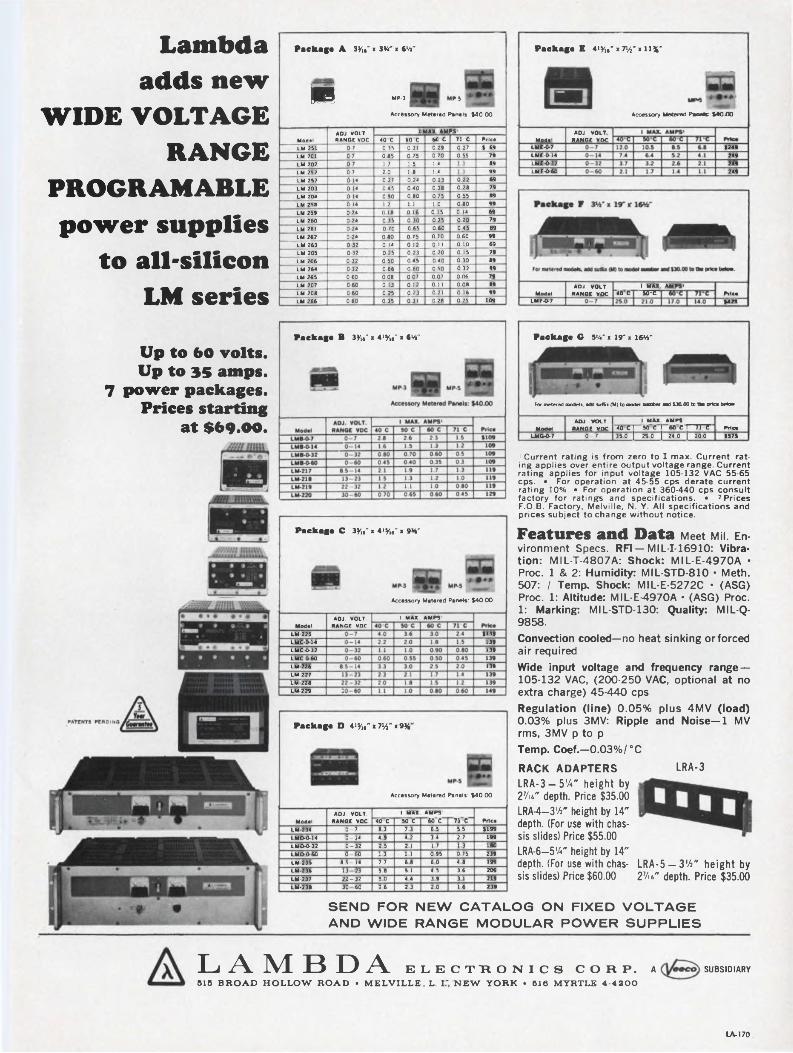
Lambda adds new
WIDE VOLTAGE RANGE
PROGRAMABLE power supplies
to all-silicon LM series
Package A 3y„- > 3W > 6W"
P-5■ MP
Acc
-3
essory Metered Penels: $40.00
ModelADJ. VOLT. RANGE VDC
XMAX. AMPS40 C 60 C 60 C 71 C Price
LM 251 0 7 0 35 0 31 0 29 0 27 $ 69LM 201 0 7 0 85 0 75 0 70 0 55 79LM 202 0 7 1 7 1 5 1 4 1 1 89LM 252 0 7 20 1 8 1 4 1 1 99LM 257 0 14 0 27 0 24 0 23 0 22 69LM 203 0 14 0 45 0 40 0 38 0 28 79LM 204 0 14 0 90 0 80 075 0 55 89LM 258 0 14 1 2 1 1 1 0 080 99LM 259 0 24 0 18 0 16 0 15 0 14 69LM 260 0 24 0 35 0 30 0 25 0 20 79LM 261 0 24 0 70 0 65 0 60 045 89LM 262 0 24 0 80 0 75 0 70 0 60 99LM 263 0-32 0 14 0 12 0 11 0 10 69LM 205 0 32 0 25 0 23 0 20 0 15 79LM 206 0 32 0 50 0 45 0 40 0 30 89LM 264 0 32 0 66 0 60 0 50 0 32 99LM 265 0 60 0 08 0 07 0 07 0 06 79LM 207 060 0 13 0 12 0 11 0 08 89LM 208 0 60 025 0 23 0 21 0 16 99LM 266 060 0 35 0 31 0 28 0 25 109
Package E W x 7»/f x 11%“
ModalLME-0-7LME-0-14LME-O-32LME-0-60
Package B 3yw“ x 4»%.“ x 6tt"
Accessory Metered Peneis: $40.00
ADJ. VOLT RANGE VDC
$249249249249
ModelLMF-0-7
ADJ. VOLT. RANGE VDC 40°C
I MAX. AMPS' "35^ Price
$425
Package G 5%' i ir > 16*4'
Up to 60 volts.Up to 35 amps.
7 power packages. Prices starting
at $69.00.For metered models, add suffix (M) to model enmOer and $30.00 to tke price betcer
ADJ. VOLT. _________ I MAX. AMPS'_________Model RANGE VDC 40 C I 50 C I 60 C I 7Í C
LMG-O-7 0-7 35 0 | 29.0 | 24.0 | 20.0Price $575
1 Current rating is from zero to I max. Current rating applies over entire output voltage range. Current rating applies for input voltage 105-132 VAC 55-65 cps. • For operation at 45-55 cps derate current rating 10%. • For operation at 360-440 cps consult factory for ratings and specifications. • 2 Prices F.O.B. Factory, Melville, N. Y. All specifications and prices subject to change without notice.
Package C 3^" x 4iy16" x w
ModelLM-225LMC-0-14LMC-O-32LMC-0-60LM-226LM-227LM-228LM-229
Accessory Metered Panels: $40.00
I MAX. AMPS'ADJ. VOLT. RANGE VDC
139
Features and Data Meet Mil. Environment Specs. RFI —MIL-I-16910: Vibration: MIL-T-4807A: Shock: MIL-E-4970A • Proc. 1 & 2: Humidity: MIL-STD-810 • Meth. 507: I Temp. Shock: MIL-E-5272C • (ASG) Proc. 1: Altitude: MIL-E^970A • (ASG) Proc. 1: Marking: MIL-STD-130: Quality: MIL-Q- 9858.
Package D 4>yw* x7%* x9H
$139139139
Accessory Metered Panels: $40.00
ModelADJ. VOLT.
RANGE VDC1 MAX. AMPS'
Price40 C 50 C 60 C n cLM-234 0-7 8 3 7.3 6 5 5.5 $199LMD-0-14 0-14 4.9 4.2 3.4 2.7 199LMD-O-32 0-32 2.5 2.1 1.7 1.3 180LMD-0-60 0-60 1.3 1.1 095 0 75 239LM-235 8.5-14 7.7 6 8 6.0 4 8 199LM-236 13-23 5.8 5.1 4.5 3.6 209LM-237 22-32 5.0 4.4 3.9 3.1 219LM-238 30-60 2.6 2.3 2.0 1.6 239
Convection cooled—no heat sinking orforced air requiredWide input voltage and frequency range — 105-132 VAC, (200-250 VAC, optional at no extra charge) 45-440 cpsRegulation (line) 0.05% plus 4MV (load) 0.03% plus 3MV: Ripple and Noise—1 MV rms, 3MV p to pTemp. Coef.—0.03%/°CRACK ADAPTERSLRA-3 — 5%" height by
27u" depth. Price $35.00
LRA-4—3'A" height by 14" depth. (For use with chassis slides) Price $55.00
LRA-6—574" height by 14" depth. (For use with chassis slides) Price $60.00
LRA-3
LRA-5 — 3'A" height by 27>i" depth. Price $35.00
SEND FOR NEW CATALOG ON FIXED VOLTAGE AND WIDE RANGE MODULAR POWER SUPPLIES
LAMBDA ELECTRONICS CORP. A SUBSIDIARY
B16 BROAD HOLLOW ROAD • MELVILLE. L. I* NEW YORK • 516 MYRTLE 4-4300
LA-170
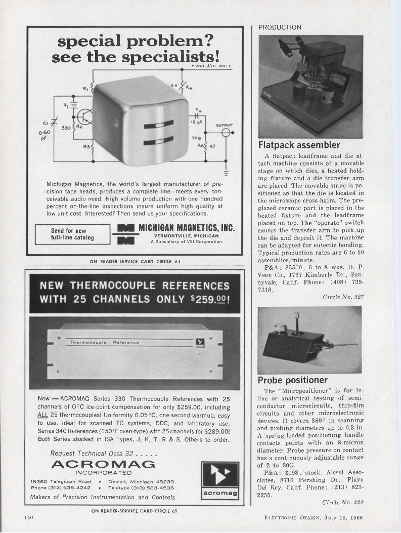
PRODUCTION
special problem? see the specialists!
■r ZOO-3SO VOLT3
Michigan Magnetics, the world’s largest manufacturer of precision tape heads, produces a complete line—meets every conceivable audio need. High volume production with one hundred percent on-the-line inspections insure uniform high quality at low unit cost. Interested? Then send us your specifications.
Send for new full-line catalog
M MICHIGAN MAGNETICS, INC.VERMONTVILLE, MICHIGAN
A Subsidiary of VSI Corporation
Flatpack assembler
ON READER-SERVICE CARD CIRCLE 64
Now — ACROMAG Series 330 Thermocouple References with 25 channels of O°C ice-point compensation for only $259.00, including ALL 25 thermocouples! Uniformity 0.05°C, one-second warmup, easy to use. Ideal for scanned TC systems, DDC, and laboratory use. Series 340 References (150’F oven-type) with 25 channels for $289.00! Both Series stocked in ISA Types, J, K, T, R & S. Others to order.
Request Technical Data 32............
ACROMAGINCORPORATED
15360 Telegraph Road • Detroit, Michigan 48239 Phone (313) 538-4242 • Teletype (313) 583-4536
Makers of Precision Instrumentation and Controlsacromag
A flatpack leadframe and die attach machine consists of a movable stage on which dies, a heated holding fixture and a die transfer arm are placed. The movable stage is positioned so that the die is located in the microscope cross-hairs. The preglazed ceramic part is placed in the heated fixture and the leadframe placed on top. The “operate” switch causes the transfer arm to pick up the die and deposit it. The machine can be adapted for eutectic bonding. Typical production rates are 6 to 10. assemblies/minute.
P&A: $3500; 6 to 8 wks. D. P. Veen Co., 1737 Kimberly Dr., Sunnyvale, Calif. Phone: (408) 7397318.
Circle No. 327
Probe positionerThe “Micropositioner” is for in
line or analytical testing of semiconductor microcircuits, thin-film circuits and other microelectronic devices. It covers 360° in scanning and probing diameters up to 0.3-in. A spring-loaded positioning handle contacts points with an 8-micron diameter. Probe pressure on contact has a continuously adjustable range of 2 to 20G.
P&A: $198; stock. Alessi Associates, 8710 Pershing Dr., Playa Del Rey, Calif. Phone: (213) 8232255.
Circle No. 328ON READER-SERVICE CARD CIRCLE 65
140 Electronic Design, July 19, 1966

You can save a lot of troublesome circuit engineering with the AE Series OCS Relay. We’ve “packaged” most of the programming!AE’s Series OCS Relay is low in cost and no bigger than a pack of king-size cigarettes. But it can save you a lot of engineering time.
This little- relay can do the work of a whole battery of solid-state devices. And it won’t lose its memory in a power failure or a circuit interruption.
“Packaged” programming. The AE Series OCS will follow or initiate a prescribed series of events or cycles at 30 steps per second impulse-controlled—or 65 per second self-interrupted. You can set up any programming sequence on one to eight cams, with as many as 36 on- and-off steps per cam. And each cam, tailored to your specifications, will actuate as many as six contact springs.
Can AE help take the “snags” out of your job? Our engineers are ready to work with you, to find the most practical and economical solution to any circuit-transfer problem.
There’s a lot of helpful application information in the 160-page book, “How to Use Rotary Stepping Switches.” Just ask your AE representative. Or write Director, Relay Control Equipment Sales, Automatic Electric, Northlake, Illinois 60164.
AUTOMATIC ELECTRICSUBSIDIARY OF
GENERALTELEPHONE & ELECTRONICS VJ
ON READER-SERVICE CARD CIRCLE 66Electronic Design, July 19, 1966 141

PRODUCTION
Semiconductor dicer cuts 0.015 in.2 wafers
Ganged steel blades and an abrasive slurry are used in the model 311 dicer to cut semiconductor materials such as silicon, ferrites and ceramics. Spaced straight steel blades reciprocate over the work. Dice as small as 0.015-in.2 may be cut. The machine has a capacity for up to six 1-1/4-in. diameter wafers and cuts at rates to 0.001- in./minute. Reduced chipping and cracking are claimed to raise yields to 95%. Wafers with metallic or oxide layers can be successfully diced. Grooves can be cut to any thickness down to 0.0025-in.
P&A: $12,000; 12 wks. Norton Co., Worcester, Mass. Phone: (617) 853-1000.
Circle No. 329
IC lead formerThis hand-operated device is de
signed to produce bends in multiple- lead components. The model 100B “Leadbender” handles up to 600 components/hour including flat packs, reed relays, diodes and miniature electrolytic capacitors. Components 1-in. long, with any number of leads and any center-to-center spacing can be accommodated. Dies are interchangeable.
D. Vel Research Labs. Inc., 555 Bedford Rd., Bedford Hills, N. Y. Phone: (914) 665-3455.
Circle No. 330
PC roller coaterCoatings can be applied to print
ed-circuit blanks, with or without filling small holes or depressions. The roller coater has a 4-in.-diame- ter chrome-plated roller, with a 2- 3/4-in. spring-loaded doctor roll, both mounted in self-aligning ball bearings. Series 5 coaters can be furnished with rolls from 14 to 50 in. wide, single or double coating with variable speed drives. The machine can be adjusted to accept material up to 4-in. thick.
Union Tool Corp., Warsaw, Ind. Phone: (219) 267-3211.
Circle No. 331
Electric glue gunPolyethylene-based glue for insu
lation and waterproofing is heated to 400°F in 3 minutes in a thermostatically controlled aluminum chamber. When glue cartridges are forced through the chamber, the glue is liquified and emitted from the 1/16-in. diameter nozzle. Approximately 90% of the moderately flexible bond strength is reached through cooling within 60 s, and the remainder in 24 hours. High temperature limitation of the glue is 130 to 150°F.
P&A : $7.95 ; stock. United Shoe Machinery Corp., 784 Memorial Dr., Cambridge, Mass. Phone: (617) 542-9100.
Circle No. 332
PC board probeA portable constant-pressure
probe is designed for measurements of coating thicknesses on pad areas, tracer lines or contact fingers of PC boards. Use of lights, mirrors and weights for alignment
■ is eliminated. A locating ring with a translucent guide is placed on the circuit board surrounding the general area of measurement. The translucent disc is removed and replaced by the probe.
Twin City Testing Corp., 533 Niagara St., Tonawanda, N. Y. Phone: (716) 693-6303.
Circle No. 333
4-point crystal probeFour-point probes for measure
ment of thin semiconductor slices or raw crystals have adjustable probe point pressures of 70 to 180 grams. Point spacing ranges from 0.025 to 0.0625 in. Coil springs coupled to an adjustment screw make each probe adaptable to the measurement of thin slices or raw crystals as opposed to fixed or pre-set pressures. Units are equipped with 12-in. color-coded leads.
P&A: from $45; stock to 5 days. Alessi Associates, 8710 Pershing Dr., Playa Del Rey, Calif. Phone: (213) 823-2255.
Circle No. 334
142 Electronic Design, July 19, 1966
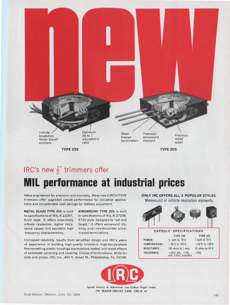
Infinite resolutionMetal Glaze® element
Optimum 28 to 1 adjustment ratio
Silver brazed termination
Precision wirewound element
Precious metal wiper
TYPE 255 TYPE 205
IRC’s new j" trimmers offer
MIL performance at industrial pricesValue engineered for precision and economy, these new CIRCUITRIM trimmers offer upgraded circuit performance for industrial applications and considerable cost savings for military equipment.
ONLY IRC OFFERS ALL 4 POPULAR STYLESWirewound or infinite resolution elements
METAL GLAZE TYPE 255 is built to specifications of MIL-R-22097, RJ22 style. It offers essentially infinite resolution, higher resistance values and excellent high frequency characteristics.
WIREWOUND TYPE 205 is built to specifications of MIL-R-27208, RT22 style. Designed to "set and forget,” it offers wirewound stability and indestructible silver brazed terminations. CAPSULE SPECIFICATIONS
Increased reliability results from simplified design and IRC's years of experience in building high-quality trimmers. High-temperature thermosetting plastic housings are moisture sealed, and resist effects of automatic soldering and cleaning. Choice of terminations. Write for data and prices. IRC, Inc., 401 N. Broad St., Philadelphia, Pa. 19108
POWER: TEMPERATURE: RESISTANCE: TOLERANCE:
TYPE 255% watt @ 70°C—55°C to 150°C100 ohms to 1 meg.±10% std., ±5% and ±20% available
TYPE 2051 watt @ 70°C —55°C to 150°C10 ohms to 50 K
±5%
Speed Inquiry to Advertiser via Collect Night LetterON READER-SERVICE CARD CIRCLE 67
Electronic Design, July 19, 1966 143

MICROELECTRONICS
CATALOG SERIES —BOS
MICA INSULATORS
.00). i 9 n $,ihapes, thicknesses or tol-
special order.
CATALOG SERIES — Ml
Made of high purity (99 4%) sintered BeO, these sinks provide a satisfactory solution to the design engineer where electronic applications require both dielectric insulation and high heat transfer.
BERYLLIUM OXIDE TRANSISTOR HEAT
SINKS
NYLONTRANSISTOR PADS
CATALOG SERIES — TPN
Many other heat sink, transistor pad and specialty items not shown are available.
Delbert Blinn mica insulators are precision stamped from quality controlled stock and will withstand temperatures to 1000 F. with negligible dehydration. Standard thickness is .002 ±
Precision molded from Zytel
101 (MIL-P-20693), these
pads provide an economical
insulator and thermal bar-
When custom designs or modifications of standard electronic hardware parts are needed, our years of experience in the molding, extruding, stamping and fabrication of metal and plastic parts enables us to supply you with parts unsurpassable in quality.
We can help you successfully meet competition in today's highly competitive market.
strength. Resist contini
exposure to 135 C.
Write for additional information.
HEAT SINK DISSIPATORS
Efficiency, light weight and economy are incorporated in a complete line of professionally engineered heat sinks available in a variety of sizes and shapes. Material: Aluminum 6063-T5 alloy, mill finish. Lengths to 5 ft. available (Serrations— U.S. Pat. No. 3163207). Can be cut, drilled, anodized or painted to your specifications.
CATALOG SERIES —AHS
PC board energizes segmented displays
elbertmn THE DELBERT BLINN CO.
¡I P. O. BOX 2007 • POMONA, CALIFORNIA • PHONE (714) 623-1257 (213) 628-8794
ON READER-SERVICE CARD CIRCLE 68
Decimal code is translated by this PC board to energize various segment combinations of 7-bar segmented display read-outs. The “Decimal to Visual Translator” can be used with all 7-bar segmented displays now available. It is rated at 6 Vdc and 0.5 A max input. Measuring 1-7/8- x 2-3/8-in., the translator consists of silicon planar semiconductors wave-soldered to a PC board. Operating temperature range is —20 to 100°C.
P&A: $12.50; stock. Shelly Associates, 111 Eucalyptus Dr., El Segundo, Calif. Phone: (213) 3222374. Circle No. 335
US 111 IB VHF UHF HeceMng System
(30-1000 MHz, no “oluo-ins" reauired)Sales continue to climb for this CEI solid state receiving system, attesting to both its performance and its feature-packed design concept.
No plug-in modules are required. The RS-111-1 B spans 30-1000 MHz in four bands—all built in. A sensitive, high-resolution signal monitor is also built in. Thiscomplete frequency coverage and visual display are combined in a compact unitjust 5%" high.
AM, FM and CW reception are provided, with audio and video outputs available simultaneously from a 2-MHz IF strip and a selectable 20-kHz/75-kHz/300-kHz IF strip. For full details and specifications of the RS-111-1 B, please write:
COMMUNICATION ELECTRONICS INCORPORATED6006 Executive Boulevard, Rockville, Md. 20852-Phone: (301) 933-2800. TWX: 710-824-9603
One-shot pulse circuitAn encapsulated pulse circuit for
PC board mounting gives a single pulse whose duration is inversely proportional to the output voltage. Pulse duration varies from 0.1 to 2.5 pS. The circuits are suitable for any unitary-bit inputs. They are available for inputs ranging from 6 to 35 Vdc and impedances from 47 to 2200 D. Output pulses can be either polarity.
Honeywell, Micro Switch Div., 11 W. Spring St., Freeport, Ill. Phone: (815) 232-2730.
Circle No. 336ON READER-SERVICE CARD CIRCLE 69
144 Electronic Design, July 19, 1966
IC carrierFlat packs are held for testing
and shipping without any stress being applied to the leads by this IC carrier. The “Auto-Pak” is a 2- piece device which positions the flat pack within a boss molded into the base. A snap-in cover locks the flat pack in place. The leads are neither twisted around supports nor clamped. The polysulfone carriers have an operating range of —100 to +150°C. They are produced in four designs to accept a variety of EIA-registered flat packs.
Westinghouse, Molecular Electronics Div., Elkridge, Md. Phone: (301) 796-3666.
Circle No. 341
J-K flip-flopA new J-K flip-flop provides the
OR function on both J and K sides. The SF-60 operates at clock speeds up to 20 MHz and triggers on clock edges as long as 200 ns. Data inputs are 1.0 gate load and clock is 2.0 gate loads. The circuit is available in a hard glass flat-pack or a dual in-line plug-in. Both are hermetically sealed.
Sylvania Electric Products Inc., Electronic Components Group, Seneca Falls, N. Y. Phone: (315) 5685881.
Circle No. 342
TTL ICsA family of TTL monolithic inte
grated circuits in TO-5 or flat packs dissipates 1.3 mW/node. Propagation delay is 50 ns/node, noise immunity is 800 mV and 2.5 V with interface circuits, fan-out is 9 and single power supply is 4 V. Initially, eight elements are offered: Five/three-input NAND/NOR gate, dual-three input gate, RST flip-flop, dual-shift register, gated buffer, flip-flop driving buffer, and input and output interface circuits.
P&A : $23.10 to $28.50 (1 to 24) ; stock. Amelco Semiconductor, 1300 Terra Bella Ave., Mountain View, Calif. Phone: (415) 968-9241.
Circle No. 343
USECO introduces ORCQN*
The FirstW Lighted Pushbutton Switch
With 6 Pole Double Throw Capacity and Plug-In Convenience
New Breakthrough in Switch Design. ORCON is the first lighted pushbutton switch that matches the needs of today's technology in design versatility, operational flexibility and ease of maintenance. Here's why:
■ 25% Smaller — only %" Diameter.■ Multicircuit capacity — 2 pole double throw through 6 pole double throw
— other variations available.■ Plug-in convenience — optional connector simplifies installation and
maintenance.■ Isolated self-aligning contacts — for increased reliability.■ Independent light circuit — accepts incandescent or neon without lens modification.■ Operating action versatility — choice of four actions.■ “Customized” to your exact requirements from standard options.
Developed by USECO engineers for Computer and Data processing equipment, Tape Recorders, Telemetering Devices, Control Panels, Broadcasting Consoles and Business Machines, ORCON's advanced features are adaptable to an expanding variety of new applications, and are available for immediate delivery. Please contact us with your specific needs.
For complete information send for the illustrated technical brochure today. USECO DIVISION, 13536 Saticoy Street, Van Nuys, California. Phone (213) 786 9381.
DIVISION
* USECO TRADEMARK, PATENT PENDING
OF LITTON INDUSTRIES
ON READER-SERVICE CARD CIRCLE 70
Electronic Design, July 19, 1966 145

MICROELECTRONICS
ot
Columbia has the facilities to manufacture cables up to one inch in diameter with almost any number of conductors of various gauges, solid and stranded, bare or tinned copper. Wire and cable can be made from single conductors to pairs, triplets, quads, etc. Shielding where required can be braided, spiral wrapped, aluminum mylar or the new conductive vinyls and polyethylenes. Outer coverings are available in a broad temperature range. Also included are extremely flexible and weatherproof compounds. Steel support wires with tensile strengths of from 900 lbs. to 5,000 lbs. can also be furnished as part of the cable.Fora prompt quotation on your special cable write us giving full information regarding your requirements.
Send for our Catalog No. Ill describing “America's Most Complete ]
WIRE & SUPPLY CO.2850 Irving Park Road • Chicago 18, III.
Cermet resistor networksCermet resistor networks in
standard 2-, 4-, 6- and 8-lead configurations can be adjusted to 0.25% tolerance after firing and retain better than a 1% load life when subjected to rated power and 70°C ambient. The passive networks feature a constant positive temperature co-efficient of 200 ±50 ppm/°C. Resistance range is from 10 Q to 500 kQ and dissipation is 0.16 W/in.2. The devices maintain temperature coefficient tracking from resistor path to path within 25 ppm/°C linearly over a —55 to 150°C range. They are available in tolerances from 0.25 to 5% with a conformal coating over the ceramic substrate or in a transfer-molded epoxy package.
Electra Mfg. Co., 800 N. 21st St., Independence, Kans. Phone: (316) 331-3400.
Circle No. 337
High-gain op-ampWith an open loop gain of 50,000
and a 750-kQ input impedance at 25°C, the WM 174Q IC op-amp has a unity gain bandwidth of 10 MHz. Input offset current is 100 nA and output current is 20 mA. Output impedance is 75 Q and output swing is ±12 V. The unit has 83-dB common mode rejection and common mode voltage range of ±4 V. Zero voltage offset is obtainable by connecting a 5-kQ pot between 2 leads. Packaging is in a 14-lead TO-86 flat pack.
P&A: $39.50 (1 to 49), $29 (50 to 499); stock. Westinghouse, Molecular Electronics Div., Box 7377, Elkridge, Md. Phone: (301) 7963666.
Circle No. 338
Cermet resistor networkEncapsulated cermet resistance
networks are available in configurations including binary and BCD-related resistance ratios for use in D/A interface converters. Standard resistance tolerances are 1 and 0.5% and special order tolerances are 0.25% and 0.1%. Thermal tracking ratio between units on common substrate is ±20 ppm/°C and power dissipation per substrate is 0.5 W.
Price: about $10. Nexus Research Lab. Inc., 480 Neponset St., Canton, Mass. Phone: (617) 8289000.
Circle No. 339
Plug-in connectorThe “Universal Pin Pack Connec
tor” allows interconnection of all popular in-line or plug-in flat-pack types of ICs with flat or round leads. The device permits plug-in and operation of up to 16-position devices for testing, prototype design and packaging. The connector is available with 0.025-in.2 wire wrap terminals or solder tails. Models are available for 14- or 16-lead devices.
Texas Instruments Inc., 34 Forest St., Attleboro, Mass. Phone: (617) 222-2800.
Circle No. 340ON READER-SERVICE CARD CIRCLE 71
146 Electronic Design, July 19, 1966

M
A: Circuit packages for printed circuit or conventional mounting. B, C and D: typical switch-circuit assemblies for panel mounting.
£2MILLISECONDPULSE ONE-SHOT CIRCUITS
MICROSECONDPULSE ONE-SHOT CIRCUITS
UNTIMED PULSE CONTACT BUFFER
OUTPUT VOLTAGE
SIMPLIFIED GRAPH SHOWING TYPICAL PULSE CHARACTERISTICS OF EACH PACKAGE. BULLETIN ED CONTAINS COMPLETE INFORMATION.
Need a pulse input, but don't have the engineering time?
A full line of electronic pulse circuit packages is now available from MICRO SWITCH.
These compact packages provide a single output pulse for each actuation of the controlling switch. They provide versatility in packaging and mounting—save engineering time, assembly costs and space.
Microsecond, millisecond and untimed pulse circuits are available pre-assembled to a variety of pushbutton switches, or as separate packages.
Send for this new design guide and application manual. Keep it handy for quick ref- g<erence. Save time and money the next time "you need an electronic pulse circuit.
Or call a Branch Office or Authorized Dis- , tributor (Yellow Pages, "Switches, Electric") bulletin ed
MICRO SWITCHFREEPORT, ILLINOIS 61032
A DIVISION OF HONEYWELL
Electronic Design, July 19, 1966 147
HONEYWELL INTERNATIONAL-Sales and service offices in all principal cities of the world. Manufacturing in United States, United Kingdom, Canada, Netherlands, Germany. France, Japan.
Speed Inquiry to Advertiser via Collect Night LetterON READER-SERVICE CARD CIRCLE 72

POWER EQUIPMENT-PACKAGING PANELS-iCUSTOM DESIGNED * FAST DELIVERY • MINIMUM COST
WESCONBOOTH 1643
is fast and at lowestties, our delivery possible cost.Wide selection of brass sleeves and
This packaging application with Wire-Wrap terminals Is typical of how Augat custom designs to fit any component requirement. Because we work in a wide range of applications every day, our designing ability is uninhibited. Due to complete in-house facili-
DUAL-IN-LINEWIRE-WRAP®SOCKET/PANEL for high density packaging
Socket/Terminals with beryllium copper, gold
plated contacts available. May be purchased separately.Write for data sheet 266.
AUGATinc. 31 PERRY AVE., ATTLEBORO,
ON READER-SERVICE CARD CIRCLE 73
Quick Adjusting . . COMPONENT LEADS BENDING BLOCK
with gauge plate
CUTS COMPO LOSSES TO A MINIMUM AND ELIMINATES PLIER DAMAGE
Quickly adjustable to any component body length from 0" to 1 Leads can be bent within .070 of end of component and up to 3" centers. Handles any diameter lead up to .045".
Dimensions: 1 "x33/s"x57a"
Weight: 10 oz.
MANUFACTURED BY
BY-BUK COMPANY4326 West Pico Boulevard • Los Angeles, California 90019
Phone: 937-3511 • Long Distance Area Code 213
Speed Inquiry to Advertiser via Collect Night Letter
ON READER-SERVICE CARD CIRCLE 75
MASS. 02703 ©Trademark Gardner-Denver Co.
6-Vdc IC supplyWith remote programing and
sensing capability and convection cooling, models 505 and 507 are designed to power ICs. Both supplies operate from a 45- to 440-Hz, 105- to 130-Vac input, over a —20 to 70°C range. Ripple is 0.005% max and output is adjustable from 3 to 6 Vdc. The model 505 has 0.02% regulation with line or load and an 8-A output. Model 507 has 0.015% regulation with line or load and a 5-A output.
P&A: $190 (507), $199 (505); stock to 2 wks. RO Associates, 917 Terminal Way, San Carlos, Calif. Phone: (415) 591-9443.
Circle No. 366
A hand tool for bending leads on resistors, diodes, capacitors, etc., to accurately register with their holes in printed circuit panels.
Only $ 1 9.80 eachIMMEDIATE DELIVERY
Programable powerDigitally programed supplies are
programed by BCD logic levels (0 and +12 V) and can deliver either voltage or current on command. Programing time with a resistive load is 1 ms max with no overshoot. Ranges are 0 to 0.999, 9.99 V and 0 to 9.99, 99.9, 999 pA, 9.99 and 99.9 mA. Accuracy is ±0.1% ±1 digit.
Optimized Devices Inc., Pleasantville, N. Y. Phone: (914) 768-6100.
Circle No. 367
148 Electronic Design, July 19, 1966

courting capacitor disaster?
ONLY Hi-Q CERALAM CAPACITORS OFFER YOU PROVEN HIGH PERFORMANCE & ESTABLISHED HIGH RELIABILITY
»TIM« HMNVKNIM MISUKS IIRO MHCIS mCUM
With so much current talk about jamming more and more performance into smaller and smaller packages, we think it’s about time attention was called to this kind of “brinkmanship.” These
claims are okay—usually—as far as they go. But how often do you see them underscored with a promise of tops in reliability? Not often? Never! (Unless the reference is to a CERALAM capacitor.) It's simply a fact that you can't jam a conventional capacitor construction into a smaller package without sacrificing reliability. And you can’t put one of these “wonder” capacitors into your equipment without risking its reliability.
There’s just one way to cram more performance into a smaller package and still provide the kind of reliability that’s demanded in a probe going millions of miles into space. That’s with CERALAM construction... a lamination so dense it becomes a rugged monolithic block. Hi-Q developed the technique, and proved it in performance so we could guarantee reliability. That's something you can’t buy anywhere else. So don’t mess around, call us and be sure.
AEROVOXCORPORATIONOLEAN, NEW YORK MYRTLE BEACH, SOUTH CAROLINA
SELECTED COMMERCIAL and MILITARY HI-Q PRODUCTS ARE AVAILABLE OFF-THE-SHELF FROM AUTHORIZED AEROVOX DISTRIBUTORS ON READER-SERVICE CARD CIRCLE 74
Electronic Design, July 19, 1966 149

SEMICONDUCTORSCUT BREADBOARDINGTIME.... 4 WAYS
New MICRO PLUGBORDS with subminiature connectors. The .042” or .025" dia. holes on .1" or .05” centers allow greater packaging density than possible before with prepunched boards. Available also without connectors and in copper clad epoxy glass.
Pre punched PLUGBORDS with Varicon* or Vector Edge-Pin contacts ready for your components. Insert Mini-Klip Push-In terminals where needed. JEDEC hole spacing matches transistor leads. ’Elco Trademark.
ETCHED CIRCUIT KITS 27X and 27XA provide all materials for making quick, inexpensive etched circuits. New 27XA has timesaving Vectoresist, the "rub-on” transfer resist sheet with lines, circles, ellipses, pads and standard .156" contacts, plus Vector- bord and unpunched copper clad cards and ready-to-use etch bags.
Large and small BREADBOARD KITS with complete hardware systems for faster breadboarding in Lab. or school experiments. Complete with solderless Springclip, solderable push-in terminals, transistor and tube sockets. New Hi Frequency breadboard kit now available.
May we send you literature and prices?
VECTOR ELECTRONIC CO. INC.1100 Flower St., Glendale, Calif. 91201 Phone (213) 245-8971 • TWX (213) 240-2162
ON READER-SERVICE CARD CIRCLE 76150
100-MHz photodiodeDiffused guard-ring construction
gives this silicon photodiode a spectral range of 0.35 to 1.13 microns and a high response in the “blue” region. Sensitivity is 0.5 p.A/gW at 0.9 microns (70% quantum efficiency). Leakage currents at 90-V bias are less than 0.1 /¿A. The photodiode has a rise time of 4 ns and will operate up to 100 MHz. Linearity of response has been demonstrated over a seven-decade range of incident power levels.
EG&G Inc., 160 Brookline Ave., Boston, Mass. Phone: (617) 2679700.
Circle No. 344
Pin photodiodeThe silicon planar pin photodiode
has a dark current of 150 pA max. Speed of response is 1 ns max and frequency response extends from de to 1 GHz. Laser pulses of less than 0.1 ns can be detected. Quantum detection response is constant over six decades of light intensity. The 4205 is packaged in kovar-ceramic with a glass lens.
P&A: $19.15, (10 to 99); stock, hp associates, 620 Page Mill Rd., Palo Alto, Calif. Phone: (415) 3218510. Circle No. 345
Potted power transistorA 2-A epitaxial planar silicon
power transistor is characterized for Class B operation up to 20 W rms/channel. De beta brackets provide pairs matched within 20% (Ic = 1.5 A). HF£. is typically 50 at 50 mA and 1.5 A and 66 at 300 mA. Vce(sat) is 0.3 V at 1.5 A. Power capability is 10 W at 70 V and 75°C case temperature.
Price: $0.55. Texas Instruments, 13500 N. Central Expwy., Dallas. Phone: (214) 235-3111.
Circle No. 346
Npn power transistorsHigh voltage silicon npn planar
power transistors in a TO-63 can are capable of collector-to-emitter sustaining voltages of 300 V max. Beta is 50 at 5 A and ranges from 15 to 45 at 10 A. The gain curve is virtually flat from 10 mA to 2 A. Vce(sat) is typically 0.6 V at 10 A with f( of 40 MHz. Switching times are in the ¿us range. The devices dissipate 100 W at 100°C case temperature.
Solitron Devices Inc., 1177 Blue Heron Blvd., Riviera Beach, Fla. Phone: (305) 848-4311.
Circle No. 347
ON READER-SERVICE CARD CIRCLE 223 ►

If you felt like this the last time your subminiature relay order was rescheduled, next time call Leach
We've got over 7,000 subminiature relays in stock at key locations throughout the country. Ready for immediate delivery. Relays like our series e., a half-size unit rated for top performance in dry circuit to 2 amp switching.
Designed for printed circuit and high environmental applications, this subminiature relay offers you space and weight economies of better than 50% over full size crystal can types. Available in voltages from 6 to 26.5 vdc, the series e has an operate and release time
LEACH"’ sr®“con 2 6 5 VDC ?ogo
of less than 4 milliseconds maximum, including bounce. It will withstand 100g shock, 30g vibration and operating temperatures from —65 to +125 c. Life is 1,000,000 cycles, dry circuit. Need one tomorrow? A dozen, a hundred?Then call us today. You'll have them right on time.Leach Corporation, Relay Division, 5915 Avalon Blvd.,
LEACHLos Angeles, California; 90003Phone (Area code 213) 232-8221Export: LEACH INTERNATIONAL S. A.
SEMICONDUCTORS
152
If you thought our "Compact” was
great @ $17.50...
look what we have for $9*
It's our new TCD filter. And for the money, it's the finest filter around. Bandwidth @ 6 db is 8 kc (minimum); at 60 db—20 kc (maximum). Transformer input provides a DC path and an input impedance of 40 K ohms, suitable for transistor and vacuum tube circuits. We designed it specifically for CB, mobile, aircraft and marine radios . . . put it in a package that's less than .6 cu. in. The following specs are for our standard model (but say the word and we'll custom design to your special requirements):
0TCD-4-8D2OA B/W @ 27’C Impedance
Insertion Loss: 5db max. Temp. Stability: less than 800 cps variation -20 to +60°C.
Center Freq @ 6db 455 1kc 8kc min.
max. @ 60db 20 kc max.
In 40
K ohms
Out1.5
K ohms
'For orders of 100 to 499. Complete TCD Prices : 1 -24 — $15 ea; 25-99 —$12 ea.; 100-499 -$9 ea.; 500-1999 — $7.50 ea.; 2000-4999 — $6.50 ea. (Prices subject to change without notice.)
Send order or request for free Technical Brochure to: Piezoelectric Division, Clevite Corporation, 232 Forbes Road,Bedford, Ohio 44014.See it at WESCON
Booth 420 CLEVITE
2-A npn transistorAvailable in a TO-46 can, this
npn dissipates 4 W at 100°C case temperature. The MHT 5051 through MHT 5056 are characterized at Ic = 0.5 A with VCe(sat) of 0.35 V max. The two gain (hte) families, 30 to 90 and 50 to 150, are available with unity gain voltages of 150, 175 or 200 V collector to emitter.
Availability: stock. Solitron Devices Inc., 1177 Blue Heron Blvd., Riviera Beach, Fla. Phone: (305) 848-4311.
Circle No. 348
HHK......... ..GaAs light source
This high-intensity IR source, when forward biased, emits 0.2 mW at a wavelength of 9000 A. Type 4106 GaAs electroluminescent diode is packaged on a TO-46 header with a plane glass window with the anode connected to the case. Minimum power output is 0.15 mW when the diode is forward biased with 100 mA at 1.25 V.
P&A: $21.25 (1 to 99); stock, hpassociates, 620 Page Mill Rd., PaloAlto, Calif. Phone: (415) 321-8510.
Circle No. 349
Electronic Design, July 19, 1966ON READER-SERVICE CARD CIRCLE 78

these terminalsare engineered
P&B dry reed relays extra stability
Now you can have the assurance of P&B quality in a complete new line of dry reed relays.
JR standard size reed relays are available in assemblies of 1 to 5 switches. In the JRM miniature series up to 6 reeds are available in one assembly. Both sizes come in a standard range of coil voltages and various combinations of Form A and Form C contact arrangements.
BOBBIN FLANGESUPPORTS TERMINALSFOR STRESS PROTECTION
P&B reed relays employ an unusually sturdy terminal configuration. Extensions of the molded coil bobbin
support the cross-shaped terminal pins. Stresses that otherwise would be transmitted to the reed extensions are confined, instead, to the bobbin thus protecting the glass-to-metal seal of the capsule.
METAL HOUSING PROVIDES MAGNETIC SHIELDING, INCREASES SENSITIVITYMetal housings for the various assemblies provide magnetic shielding, eliminate stray magnetic fields and protect the relays from mechanical damage. JRM miniature relays are
potted in a high melting point compound to insure mechanical stability. Speeds of less than 1 millisecond are attainable.
MAY REPLACE EXPENSIVE SOLID STATE DEVICESIn many applications JR and JRM reed relays may be used in place of more expensive solid state devices over which they have one basic advantage . . . they are not subject to inadvertent switching by ambient or line transients.
IDEAL FOR LOW POWERLONG LIFE LOGIC SWITCHINGJR and JRM are especially suited for applications where fast operating time, low power and long life are required. Their high sensitivity and compact size recommend them for data processing, computer equipment, logic circuitry, for voltage or current sensing and various other types of sophisticated control circuits.
Send for data sheets giving complete specifications. Contact your local P&B representative or the factory direct for complete information.
P&B Dry Reed Relays are now available from authorized
Electronic Parts Distributors
POTTER & BRUMFIELDDivision of American Machine & Foundry Co., Princeton, ind.Export: AMF International, 261 Madison Ave., New York, N.Y.
Electronic Design, July 19, 1966
Speed Inquiry to Advertiser vic Collect Night LetterON READER-SERVICE CARD CIRCLE 79
153

MICROWAVES
ADJUSTABLE iWBUfrTORS
Frequency multiplier
If your problem is one of packaging inductive components, then the answer can probably be found in one of the Aladdin Electronics configurations shown above. As specialists in inductive components for frequency generation or selectivity, we can confidently recommend our products for your exacting applications. The units shown above may be used as fixed and adjustable inductors, fixed and adjustable transformers (either tuned or untuned), and as filter elements. They have been designed to help you solve both the problem of making your equipment more compact and also the problem of improving performance through the use of more stable inductive components.
For help concerning component selection for FREQUENCY SELECTIVE NETWORKS or for free literature on Aladdin inductive components write to:
The usable frequency range of signal generators and frequency synthesizers is extended with a minimum conversion loss by this frequency multiplier. Input power of 400 mW max from 50 MHz to 4 GHz produces harmonic energy of 100 MHz to 12 GHz at efficiencies of 200% max divided by harmonic number. The N807 can generate a comb of harmonics from a crystal- controlled 100-MHz source. A 100- ps step recovery diode is the harmonic generating device.
P&A: $110; 10 days. Somerset Radiation Lab. Inc., P.O. Box 201, Edison, Pa. Phone: (215) 348-8883.
Circle No. 350
Forward wave amplifier
electronicswhere the magic of magnetics is a science'
Nashville, Tennessee 37210 615-242-3411 TWX: NV252Speed Inquiry to Advertiser
via Collect Night Letter
ON READER-SERVICE CARD CIRCLE 80
A 100-kw peak power L-band forward wave amplifier weighs 35 lbs. The QKS-1319 has a 15% bandwidth and features constant voltage operation without a heater. Average power is 3 kw and peak anode current is 20 A. Pulse width is 300 p.s. Gain is 15 dB over the 1.2- to 1.4-GHz band.
Raytheon Co., Waltham, Mass. Phone: (617) 899-8400.
Circle No. 351
Varactor multipliersStripline varactor multipliers
have a 3 to 15% bandwidth over the 0.3- to 6-GHz range. Conversion loss is 2.8 dB at 5%, 3.5 dB at 10% and 7 dB at 15% bandwidth. With a clean input signal within the multiplication band, spurious signals are — 27 to —30 dB. The multiplier is internally biased and fixed tuned, so that installation consists of inserting the RF input and obtaining 2f at the output.
Elpac Inc., 3760 Campus Dr., Newport Beach, Calif. Phone: (714) 546-8640.
Circle No. 352
Wide-range receiverWith appropriate local oscillator
and mixer, this receiver measures attenuation over a 10-MHz to 40 GHz range. Single-step attenuation measurements of 100 dB and relative power measurements at a level of —120 dBm can be made. The parallel IF substitution receiver can be used for signal generator attenuation calibration, vswr measurements or as a detector in RF and microwave systems.
P&A: $2800; stock. PRD Electronics Inc., 1200 Prospect Ave., Westbury, N. Y. Phone: (516) 334- 7810.
Circle No. 353
154 Electronic Design, July 19, 1966

SELECTED FOR THE MINUTEMy PROJECTMore than 6 million LI'HIeHCD Dipped Mica Capacitors have been used in the Minuteman ground support and control equipment.
After 64,000,000 ACTUM. TEST unit-hours at 85°C with f25% of the rated DC voltage applied, no failures of any type octejrapd.The accumulated 64 x 104 test unit-hours without any failures can be used to calculate many different failure rates depending upon the confidence level desired. However, we shall explore the meaning of the results at a 90% confidence lewl.
Assuming no acceleration factor for either temperature or voltage, we have verified a failure rate of less than 0.004% per 1000 hours. (Actually, there is a temperature effect and it has been found that, with the DC voltage stress regaining constant, the life decreases approximately 50% for every 10°C rise in temperature. There is also a voltage effect such that, with the temperature stress remaining constant, the life is inversely proportional to the 8th power of the applied DC voltag«.) -
Assuming no temperature acceleration factor and assuming the voltage acceleration exponent is such as to yield an acceleration factor as low as 1 00, we have nevertheless verified a failure rate of less than 0.00004% per 1 000 hours.
Assuming no temperature acceleration factor and assuming the voltage acceleration factor is on the order of 250 (test results are available to confirm this) we have accumulated sufficient unit-hours to verify a failure rate of less than 0.000015% per 1000 hours !All above failure rates are calculated at a 90% confidence level!
DIPPED MICA CAPACITORS
TYPE M2DMWrite for a complete reliability study on your company letterhead.
the ELECTRO MOTIVE MFG. CO INC.WILLIMANTIC, CONNECTICUTMANUFACTURERS OFDipped Mica • Molded Mica • Silvered Mica Films • Mica Trimmers & Padders Mylar-Paper Dipped • Paper Dipped • Mylar Dipped • Tubular Paper
ARCO ELECTRONICS, INC., Community Drive, West Coast Manufacturers Contact:Great Neck, L. I., New York COLLINS & HYDE CO., 1020 Corporation Way
Exclusive Supplier lo Jobbers and Distributors Palo Alto, Californiain the U. S. and Canada 5380 Whittier Boulevard, Los Angeles, California
ON READER-SERVICE CARD CIRCLE 81
Electronic Design, July 19, 1966 155

KILLS SNIVELS INSTANTLY
How would you like an anti-snivet tube for your color TV horizon
tal deflection circuits'? That’s right—an anti-snivet tube would eliminate the need for snivet-suppression circuitry with its extra components and extra costs.
The new Amperex 6KG6 output pentode is your tube! It was specifically developed to eliminate Barkhausen oscillations and achieves its snivet-free performance through the use of a Cavitrap anode and other unique design characteristics. The 6KG6 can be operated with grounded suppressor at B+ supply voltages from 240 to 400 volts and still remain snivet-free.
Life-expectancy and reliability of the 6KG6 is far above that of ordinary output pentodes in similar service due to its lower bulb temperature at maximum operating conditions; it operates about 50°C. cooler
than comparable tubes in similar service. But in spite of its low operating temperature, the 6KG6 packs plenty of reserve power and added safety factors. It has a max. 7,000 V peak plate voltage, 34 watts max. plate dissipation and 1.4 amps peak
anode current.The 6KG6 is but one of the
growing family of new Amperex tubes for color TV
that make possible lower costs, higher quality and more reliable performance. Other new tubes in this family include the 6EC4 damper diode, a matching com
panion to the 6KG6 for horizontal deflection circuits, the 3BH2 high voltage rectifier diode and the ED500 shunt stabilizer.
For data and applications information, write to the company still doing
new things with receiving tubes: AmperexElectronic Corporation, Semiconductorand Receiving Tube Division, Dept. 371,Slatersville, Rhode Island, 02876.
AmperexSpeed Inquiry to Advertiser via Collect Night Letter
ON READER-SERVICE CARD CIRCLE 220

MICROWAVES
2.69-GHz antennasDirective parabolic receiving an
tennas cover the 2.5 to 2.69-GHz range and are available in 1, 2, 4 and 6-ft. diameters. Reflectors are aluminum and meet all EIA windload specs. Adjustment is provided through 360° of horizontal rotation and 0 to ±7° of vertical tilt. Installed from the rear of the reflector, the slot-dipole feed is radome protected.
Jerrold Electronics Corp., 15th & Lehigh, Philadelphia. Phone: (215) 226-3456.
Circle No. 354
Power metersRF power is measured at 3 loca
tions with a switch-selected choice of mounts. Full scale is 10 mW of RF (model A610) and 30 mW (A630). Mounts in 3 waveguide sizes cover the 7- to 12.4-GHz band. Max error is 5% up to 1000 ft from the meter. The meters are rated at 117 V ±10%, 50 to 1000 Hz.
P&A: $265; 30 days. MSI Electronics Inc., 116-06 Myrtle Ave., Richmond Hill, N. Y. Phone: (212) 441-6420.
Circle No. 355
WE’VE GOT A BABY FIREFLY THAT REALLY PERFORMS!
G y NO FOOLING ! ONE OF OUR ff 1 competitors is telling about a lamp ; i that is as big as a firefly — claims
' it flies, too! Says it’s dependable and if you want a smaller lamp
than theirs you’ll have to consider baby fireflies. How droll!
LOOK NO FARTHER!We’ve got baby fireflies and the mother too! Our babies are every bit as dependable as the parent — real performers. Hudson’s T-3/4 lamps actually have the same electrical ratings as our famous, but bigger, T-l lamps. They’re just as bright and also have design lives exceeding 100,000 plus hours.Where you have the space, Hudson’s T-l lamp will do a great job. If your space is limited, the Hudson T-3/4 lamp will do the job equally well. Regardless of which size you need, why not get them from Hudson the next time?
UAúíe for new catalog.
We make no
claim that our
fireflies fly. Un
less, of course,
they get an assist
from an airplane.
And many of them do.
Hudson. LAMP COMPANYMiniature Lamp Specialists
ON READER-SERVICE CARD CIRCLE 82
518 ELM STREET, KEARNY, NEW JERSEY 07032
Electronic Design, July 19, 1966 157

MICROWAVESwho said you can’t design a plugboard programming system to withstand severe shock?
MAC Panel has done it!
Diode switchModel 420263 C-band diode switch
has a power capability of 200 W peak and 100 W cw. Switching time is 1 gs max and pulsewidth is 50 gs. Insertion loss is 0.6 dB max, isolation is 40 dB min and vswr is 1.25 max. The switch exceeds MIL-E- 5400. The 2-in.3 unit weighs 4 oz.
Litton Industries, 200 E. Hanover Ave., Morris Plains, N. J. Phone: (201) 539-5500.
Circle No. 356
NEW SERIES 140
MAC Panel's Series 140 Plugboard Programming Systems are available in a wide range of sizes... each designed and engineered to withstand the severest shock and vibration under operating conditions. Tested to 50G without self-generated contact noise. And life tested to 10,000 cycles with only random variation in contact voltage drop.Not enough facts? Here are more; You can only insert pl ug boards one way. Receptacles are available for standard taper pins or series 53 pins. Contacts are spaced on X" x X" 9rid to allow more positions in a minimum of space.How about plugwires? The new Series 140 Plugwires are interchangeable with most existing systems. Ball-D-Tent design prevents accidental dislodging, won't mar the surface.Want more facts? Write today . . . outline your specific needs and let MAC engineers come up with the answers. They usually do.
Tunnel diode amplifiersDesigned as IF amplifiers in ra
diometry applications, these tunnel diode amplifiers provide a 50- dB min gain with a 500-MHz min bandwidth from 4.4 to 6.8 GHz. Noise figure is 5.5 dB. Units operate from 12 to 28 Vdc at 50 mA.
P&A: $4000; 45 days. International Microwave Corp., River Rd., Cos Cob, Conn. Phone: (203) 661- 6277.
Circle No. 357
Grid pulsed oscillator
MRCO.E.M. DIVISION
MAC PANEL CO. High Point, N. C.ON READER-SERVICE CARD CIRCLE 84
A high-power S-band grid pulsed strip transmission line oscillator provides 2 kW at 2 GHz. Tuning range is 10 MHz. Test pulse width is 0.5 ms and rep rate is 1 kHz. Rise time of RF pulses is 25 ns. Similar models are available in L- and S- bands.
Terra Corp., Albuquerque, N. M. Phone: (505) 255-0157.
Circle No. 358
158 Electronic Design, July 19, 1966

“orders zoomed 250%”Computer Control Division of Honeywell builds amazing sales with unique catalog insert program
William F. TaylorDirector of Advertising
Honeywell, Computer Control Division
William F. Taylor, Director of Advertising, Honeywell, Computer Control Division, reports that Electronic Design has helped achieve record sales goals for his company. Mr. Taylor writes:
“Our 44-page catalog insert inthe January 18 issue of Electronic Design is judged a complete success . . . every objective was met.
“Although we could have communicated our digital logic module product story to customers and potentials in an “ad’’ of less magnitude, we would not have achieved a particularly strong impression per reader. Since the easy-to-detach catalog insert contained complete specifications on 128 logic modules, potential customers were able to make detailed product comparisons. Result
ing inquiries, therefore, were of a qualified nature and dealt primarily with delivery time and in some cases quantity pricing — product suitability was already a fait accompli and the cost per sale was automatically reduced.
“Because of the recognized correlation between advertising and sales, (I consider communication, not sales, to be the primary function of industrial advertising), it is interesting to note that our order entries zoomed 250% since the insert appeared."
No wonder the Computer Control Division ofHoneywell gets these remarkable results . . . Electronic Design is the best read publication in thisindustry. If you have a case history of interest toour management readers, please let us know. We’llpass it along in this series.
Electronic DesignSERVES BY COMMUNICATING

SYSTEMSnewop amp measures 1013 amps handles 1010 ohmsourcesModel 301 ’s varactor input circuit virtually eliminates 1 /f noise, provides 100-fold better offsetcurrent drift than FET amplifiers. Encapsulated, 3 cu-inch unit costs $198, works from —25°C to +85°C, is P-C mounting.
Electrometer’s 10” ohms ZCM,0.06 pa/°C drift at 25°C, develops low offsets from high impedance sources. Unit has only 1 pV p-p noise, 30 /¿V max drift, plus 10s CMRR.
Frequency standard consumes 7 watts
-WV-
Current amplifier's 1 pa offset at 25°C, 0.01 pa p-p noise, 10” ohms differential impedance, and 30 pa offset change from -25”C to +75°C, permits 10-” amp resolution, builds 9-decade log amplifiers.
A new frequency standard and time code generator offers frequency stabilities to 1 part in 109 per day and uses 7 W. The system can also provide 115-V 60-Hz frequency-regulated power at levels of 10, 100, or 100 VA.
Time code and calibration programs required by short and longperiod seismographs, and the Vela Uniform code for magnetic tape recording are generated. Modifications yield IRIG and NASA time programs. Readout is BCD or deci- minal in-line. Other outputs are frequency-regulated square wave trains at 100 kHz, 10 kHz, 100 Hz, 50 Hz and 1 Hz.
P&A: $4250 to 6500; stock to 90 days. Teledyne Industries Inc., 3401 Shiloh Rd., Garland, Tex. Phone: (214) 278-8102. Circle No. 359
Í300V
Differential amplifier’s ± 300 Volts CM and 10” ohms ZDtrF, permits use of 10“ ohm input resistors, resolves millivolt signals on ± 300 volt inputs.
ANALOG221 FIFTH STREET CAMBRIDGE, MASS. 02142
617/491-1650
DEVICES
Graphic recorderThe low cost graphic recorder has
a flip-fold chart width of 4 in. Accuracy is better than 1% at 1 V span setting. The recorder will follow 1 Hz full scale and 5 Hz at 1/2-in. deflection. Chart speeds are available from 1 in./hour to 4 in./minute.
Price: $150. Yeiser Laboratories, 881 W. 18th St., Costa Mesa, Calif. Phone: (714) 548-2458.
Circle No. 360
i I *■' ------------------- —-----
**~~.. - s —
• • • •
. ■■ - .. 1
■ oooooo o
X
Digital spectral analyzerWith correlation and spectral
analysis techniques, model 2632 performs on-line analysis and offline data reduction. Power spectral density of digitized analog data of 2.5-kHz max bandwidth, performed with 10-Hz resolution, can be determined on-line and displayed in 1.5 s max. The resolution bandwidth of the spectral analysis may be changed by program.
Astrodata Inc., 240 E. Palais Rd., Anaheim, Calif. Phone: (714) 7721000.
Circle No. 361
PCM signal conditionerA PCM telemetry signal condi
tioner and bit synchronizer features both computer and manual control. Model 2720 provides a synchronized PCM output from a PCM telemetry input. It reconstitutes noisy PCM signals over a 60:1 dynamic input range at rates up to 1 Mbit. Bitrate tracking ranges of 1, 3 and 10% are selectable. A digital restorer establishes the median of the PCM signal at ground potential.
Electro-Mechanical Research Inc., Box 3041, Sarasota, Fla. Phone: (813) 958-0811.
Circle No. 362ON READER-SERVICE CARD CIRCLE 86
160 Electronic Design, July 19, 1966

Signal averaging system Tape recorder keyboard 60-dB discriminatorTo average on-line signals con
taining frequency components up to 200 kHz this system has a 1024-ad- dress computer of average transients, and a sweep expander. Effective dwell time is reduced to 1 jus/data point by sampling the input waveform at different points during successive analysis sweeps. Each input waveform sample is digitized with 1% accuracy.
Technical Measurement Corp., 441 Washington Ave., North Haven, Conn. Phone: (203) 239-2501.
Circle No. 363
Data are entered manually on a 12-key numeric keyboard on this digital magnetic tape recorder. Keyboard includes a “space” and “error” key. When two or more keys are depressed simultaneously, the R41 activates an error light. The unit records 20,000 characters max on a re-usable cartridge of 1/2- in. 5-track tape. Three cartridges can be recorded before recharging.
Price: $1900. Hersey-Sparling Meter Co., 210 W. 131 St., Los Angeles. Phone: (213) 321-6283.
Circle No. 364
Employing solid-state circuitry, this bandswitching discriminator has 23 channels and constant amplitude or zero overshoot low-pass filters.
The unit has 0.1% linearity and a 60-dB dynamic range without adjustment. Output is adjustable from ±1 to ±10 V and 0 to ±100 mA.
Price : about $7000. Airpax Electronics Inc., P. O. Box 8488, Fort Lauderdale, Fla. Phone: (305) 587- 1100.
Circle No. 365
Need a frequency? Make Allen your source.Allen ComponentsPrompt Delivery • Low Cost • High Quality — used by leading electronic manufacturers, laboratories, designers, government agencies
Allen Frequency Sources Types C and P (plug-in type)Low-priced compact audio oscillators designed forapplications that have moderate requirements for stabilityin respect to temperature and frequency drift.
Allen ToroidsOver 150 sizes available from stock include Permalloy, Ferrite and Powdered Iron types. Inductance ranges from 50 henries to 6 millihenries.
Allen 20-Watt and 50-Watt Transistorized Amplifiers Utilize latest developments in solid-state technology. They demonstrate characteristics normally associated with such circuitry (compact design, low heat dissipation).High sensitivity, conservatively rated.
Write for our free catalog!
Components Division
Allen Organ Co., Dept. ED766,Macungie, Pa. 18062. Phone 215-965-9801Please send me your components catalogI am interested in: □ Oscillators □ Toroidal coils □ Amplifiers
Name_________________________________ —
Firm____________________________________
St reet-----------------------------------------------------------
City_______ ____________________________ _
State-------------------------------Zip Code----------------© A. O. Co.
ON READER-SERVICE CARD CIRCLE 87
Electronic Design, July 19, 1966 161

New Literature
Instruments catalogA 48-page brochure on industrial
instrumentation is offered. Units with direct digital readout for measurement, recording and control of temperature, speed or rate, pressure or load, flow and voltage are covered. Howell Instruments Inc.
Circle No. 368
Hall devicesA short-form illustrated catalog
covers the manufacturer’s line of Hall-effect instrumentation and components. F. W. Bell Inc.
Circle No. 369
Trimmer capacitorsCatalog C-66 of precision piston
trimming and tuning capacitors presents over 500 models. The 24- page brochure contains dimensioned outline drawings, tabular listings of electrical and physical characteristics and an illustrated description of the adjustment mechanisms for each series. It includes information on tuning tools and kits and test fixtures. JFD Electronics Corp.
Circle No. 370
Planar power transistorsPlanar power transistors and
SCRs are cataloged and described and power packages are illustrated in this 8-page brochure. A complete discussion of planar power advantages is included. Fairchild Semiconductor.
Circle No. 371
Copper-clad laminatesGlass-base, epoxy resin, copper-
clad laminates for printed circuits are described in this illustrated data sheet. A table lists the properties of four grades, including two that are flame retardant. Thickness tolerances and NEMA and MIL specs are also given. Taylor Corp.
Circle No. 372
Power convertersAn 8-page color brochure illus
trates a line of solid-state power converters. Product categories include de to de converters, de to ac static inverters, ac to ac frequency changers and ac to de converters. TRW, Equipment Operations.
Circle No. 373
Switch selectorA pocket-sized “Switch Selector
Guide” contains switch sizes and ratings, along with illustrations of the most widely used precision snap action switches. Cherry Electrical Products Corp.
Circle No. 374
Conversion factorsA reference table for engineers in
wall chart form is offered. Included are many common conversions as well as those difficult to locate in reference manuals. Precision Equipment Co.
Circle No. 375
Sample/hold amplifierThis bulletin describes a sample-
and-hold amplifier with built-in floating power supply used to prevent loss of information in data transmission links and control systems. It shows how to replace a slide-wire and recorder system with the all-electronic holding circuit, including bumpless switchover to manual control. Pacific Data & Controls.
Circle No. 376
Test equipmentEquipment for the scientific and
laboratory field is described and pictured in the 224-page catalog. Specifications and prices on ovens, water, oil and refrigerated baths, furnaces and temperature/humidi- ty-environmental chambers are given. Subjects related to temperature and temperature control are covered with the aid of temperature, measurement and relative humidity conversion tables. Blue M Electric Co.
Circle No. 377
Solderless terminalsNoninsulated and pre-insulated
solderless terminals are fully described in a new 28-page illustrated catalog. Specifications for flanged and square spade, ring and quickconnect types are given. Aerovox Corp.
Circle No. 378
Electronic Design, July 19, 1966162

Only Litton offers coaxial magnetrons covering the
full power range at KU-Band. Lightweight for their power output, these rugged coax magnetrons offer: higher efficiency; greater frequency stability under changes in operating conditions and load; low starting and frequency jitter. In addition to standard models, computer techniques permit us to custom design tubes to match your special requirements with shorter lead time. For details, please contact Electron Tube Division, 960 Industrial Road, San Carlos, California 94070. (415) 591-8411. Williamsport, Pennsylvania. Canada: 25 Cityview. Drive, Rexdale, Ontario. Europe: Box 110, Zurich 50, Switz.
LITTON INDUSTRIESELECTRON TUBE DIVISION
In addition to those shown, other coaxial magnetrons are available at KU-Band and X-Band
Tube Type
Frequency Range (Megacycles)
Minimum Power (Kw) Tuning
L-5048 16,000 - 16,500 9 Mechanical
L-5013 15,500 - 16,500 4 MechanicalL-5035 15,900- 16,400 8 Mechanical
L-3958 15,500 ± 85 9 Fixed Frequency
L-5029 16,500 - 17,500 35 MechanicalL-4451 16,600 - 17,100 35 MechanicalL-5049 16,000 - 17,000 65 MechanicalL-3950 16,500 ± 100 65 Fixed Frequency
L-4419 16,500 ± 25 65 Fixed Frequency
L-5042 16,000 - 16,500 80 MechanicalL-4500 15,500 - 17,500 90 ElectromagneticL-3976 16,500 ± 150 100 Fixed Frequency7208B 15,500 - 17,500 125 Mechanical
Speed Inquiry to Advertiser via Collect Night Letter
ON READER-SERVICE CARD CIRCLE 104
Electronic Design, July 19, 1966 163

NEW LITERATURE-------------------------------------
Need a small 1, 5 or 10 me crystal oscillator for use in synthesizers, timing systems, counters, communication systems, time-code generators, tape systems, or some other small black box?
Think TRACOR
Shown half actual size
TFA 766
Volume 19.1 in.3That's about the size of it.For further information: TRACOR, Inc.General Sales Office 6500 Tracor Lane Austin, Texas 78721 Phone: 512-926-2800
SULZER DIVISION
Components catalogThis 40-page catalog describes
more than 96 different components. Drawings, curves, schematics, photographs and descriptions are included. Transistorized servo amplifiers, choppers, de supplies, isolation amplifiers, signal sensors, magamps, driver and logic packages are among the devices covered. Application data and hook-up information is included. General Precision Inc.
Circle No. 379
KfOtntm thH
a» AtUfD
Allied
ELECTRONICS DATA
HANDBOOK/ V 1
FORMULAS AND DATA
COMMONLY USED
IN ELECTRONICS
Switch catalogPrecision switches including sub
miniature, miniature, general purpose, metal enclosed, appliance and open blade models are fully described in this 120-page catalog. Schematics and tabular data are included. Robertshaw Controls Co.
Circle No. 380
Power suppliesIn addition to complete specs for
voltage and current regulated supplies, this 52-page catalog contains a glossary of terms. Specifications are accompanied by explanations of regulated supply capabilities. Kepco, Inc.
Circle No. 381
Linear programingApplications of linear program
ing for computers are given in this 16-page illustrated brochure. Specific experiences with linear programing within several industries are cited and available programing packages are described in detail. General Electric, Information Systems.
Circle No, 382
REPRESENTATIVES IN PRINCIPAL CITIES
We are looking for EE’s, ME’s and Physicists for design consultation
or systems development in ASW and undersea problems—experi
ence in penetrations aids—design studies, tests, analysis and reports on electronic and mechanical systems. Your reply strictly confi
dential.K J
Electronic data handbookThis reference book includes
math constants and symbols, algebraic formulas and mathematical tables. The 112-page handbook also contains basic radio and electronic formulas and engineering and servicing data.
Available for $0.75 from Allied Radio Corp., 100 N. Western, Chicago.
Digital logic plug-insA 40-page catalog describes a line
of digital plug-in modules. The brochure contains circuit diagrams of the modules and detailed engineering data. Included are flip-flops, gates, clock and timing modules, system interface modules, drivers and A/D modules. Decision Control Inc.
Circle No. 383
164 Electronic Design, July 19, 1966ON READER-SERVICE CARD CIRCLE 88

GLOBE Globe A. C. Centrifugals WM with slingshot force
For economical cooling and pressurization, obtain a Globe proposal the next time you need standard or special centrifugal blowers. Globe makes single and double styles, for military or commercial applications. We also make a.c. and d.c. vaneaxial, tubeaxial, and multistage blowers and fans. Request Bulletin CB.
Globe Industries, Inc., 2275 Stanley Ave., Dayton, Ohio, 45404, U.S.A., Tel.: 513 222-3741.
PERFORMANCE1 1" wheel. 115 v.a.c., 400 cps. Overall length 2.48". Weight 4 oz.
Part Number 19A565.2 1%" wheel. 115 v.a.c., 400 cps. Overall length 3.30". Weight 16%
oz. Part Number 19A690.3 2" wheel. 115 v.a.c., 400 cps. Overall length 3.77". Weight 18%
oz. Part Number 19A694.4 3" wheel. 115 or 208 v.a.c., 50 or 60 «ps. Overall length 6" max.
Weight 3% lb. Part No. 19A1540.5 5" wheel. 115 v.a.c., 50 or 60 cps. Overall length 5%®". Weight
7.5 lb. Part No. 19A1670.
ON READER-SERVICE CARD CIRCLE 89
The Choice of the Discriminating Communication Engineer . . . the Man who Never Settles for Anything Less than THE-VERY-BEST!
tel/lOK “BEAMED-POWER”ANTENNAS and ANTENNA SYSTEMS
Provide optimum performance and reliability per element, per dollar. Antennas from 500 Kc to 1500 Me. Free PL88 condensed data and pricing catalog, describes military and commercial antennas, systems, accessories, Towers, Masts, Rotators, “Baluns“ ______ and transmission line data.
\ — Communication/ A^EhhNAS^^^ U and TV Antennas
voe/rex_ LABORATORIES
Asbury Park 41, New Jersey, U.S.A.ON READER-SERVICE CARD CIRCLE 91
Electronic Design, July 19, 1966
New DC Scope! . ..the Heathkit’ 10-14
• Sets New Standard for Per-formance & Value . . . $299.00 Kit . . . $399.00 Assembled • DC to 8 me Bandwidth—0.04 usee, rise time • Calibrated Vertical Attenuator — .05 v/cm to 600 v. (max.) Input • Triggered Sweep — 18 calibrated rates • Delay-Line Vertical Amplifiers for Fast Rise Signal Analysis • Electronically Regulated Power Supplies — Forced Air Cooling • Built for Continuous-Duty Industrial & Lab Use
A 5" DC scope with calibrated time base & 5X sweep magnifier. For 115/230 volt, 50-60 cycle operation.Kit 10-14, 45 lbs........ $299.00Assembled IOW-14,45 lbs. $399.00
r FREE CATALOG!
HEATHKIT I960 Fully Describes Over 250 Heathkit Electronic Products
Heath Company, Dept. 60-7 Benton Harbor, Michigan 49022□□
Please send FREE Heathkit Catalog & Information describing the New | Heathkit 10-14 OscilloscopeEnclosed Is $, plus shipping, jPlease send model I
Name__Address.City___
| Prices 4 specifications subject to change without notice.State.
Zip._____ I
TE-141 J
ON READER-SERVICE CARD CIRCLE 90
165

NEW LITERATURE
How do you evaluate audio oscillators?
How can you be sure of the right selection for your particular application?
TRACOR® has an answer
“Selection and Application of
Stable, Packaged Oscillators”
is a comprehensive two-part report. Section I outlines the
availability of standard oscillators in the 0.5% to 0.0001%
accuracy range. Section II offers
guidelines for choosing a
specific oscillator.
The report is free from TRACOR.
Whether or not you want a copy, may we help you evaluate
oscillators in your next
application?
TRACOR, Inc.General Sales Offices 6500 Tracor Lane Austin, Texas 78721
COMPONENTS
REPRESENTATIVES IN PRINCIPAL CITIES
PC materialsA selection guide for designers of
flexible printed circuits is offered. Copper-clad materials, flexible insulating materials and coatings are included. Tables of electrical and mechanical data on unclad adhesive- coated insulating materials and copper-clad flexible laminates aid in selection. Westinghouse Electric Corp.
Circle No. 384
Telemetry modulesA 40-page catalog describes a line
of FM-FM telemetering modules. Included are VCOs, de amplifiers, de signal isolators, frequency-to-dc converters, tone oscillators, pressure transducers and laboratory telemetering systems. Solid State Electronics Corp.
Circle No. 385
Turbulence amplifiersTheory and applications of turbu
lence amplifiers are described in this 6-page catalog of fluidic components for logic and control systems. Aspects of fluidics and specifications of the units with tables, charts and graphs are given. Howie Corp.
Circle No. 386
Power suppliesA listing of the MTBF among the
specs for each line of power supplies is given in this 20-page catalog. A nomograph on determining heat sinking requirements, drawings of the power supplies, rack mount adapters and heat sinks are included. Prices and options are listed for each supply. Stanley Schwartz Co.
Circle No. 387
Solder alloysThis illustrated technical catalog
describes solder alloys, wire sizes and flux core percentages. A line of liquid fluxes for applications from PC boards to sheet metal are also given. Gardiner Solder Co.
Circle No. 388
A 32-page crystal cross reference booklet lists numbers for every known CB transceiver by manufacturer. Cross reference is also made by listing CB models under the available crystal numbers. Six pages are devoted to a classification of crystal frequencies by channel number for all 23 CB channels. Classifications are made for both transmit and receive functions. Shepherd Industries. Circle No. 389
ON READER-SERVICE CARD CIRCLE 92
166 Electronic Design, July 19, 1966

New total protection ♦♦ ♦against all hostile environments
Completely sealed switching area for positive switching and long, trouble-free life
Wheel totally panel sealed against all hostile environments
Machine-engraved numerals or legends white paint filled for maximum readability & life
Most switch manufacturers seal just the switching area. But Only CDI Seals both The Switching Area and the panel, Pat. Pending.
Exclusive CDI total switch sealing benefits you by protecting all other components in your system against dust, dirt, salt spray and other foreign elements which reduce performance. Switching area and panel are independently sealed for full protection and reliability.
Clean room assembled. Decimal or coded models. For R.F.I. applications. Series PS tab type Thumbwheel Switch mounts on %" centers and retrofits Series TTS. Switch life exceeds 100,000 operations. Send for data sheet.
NO SCREWS VISIBLE, new aluminum bezel permits rear mounting of miniature and standard type switches with no screws visible. Accommodates to 20 switch modules. Miniature model fits CDI Series TTD and TTB standard type switches. Available in colors to match any instrument panel. Send for data sheet.
CHICAGO DYNAMIC INDUSTRIES, INC.PRECISION PRODUCTS DIVISION 1725 Diversey Blvd.. Chicago. Illinois 60614 Phone: (312), 935-4600
ON READER-SERVICE CARD CIRCLE 93
Electronic Design, July 19, 1966 167

NEW LITERATURE
Cramped for space?Use Couch 1/7-size RelaysSpace/weight problem? The new Couch 2X 1 /7-size crystal can relay gives you tremendous savings in space and weight. 0.1" grid — plus many outstandingspecs —all in microminiature. Thoroughly field-proven in electronics Tl and space applications. ,XSB[
SizeContactsCoil Operating PowerCoil Resistance Temperature VibrationShock
2X(DPDT) 1X(SPDT)0.2" x 0.4" x 0.5" same
0.5 amp @ 30 VDC same100 mw 150 mw 70 mw 100 mw60 to 4000 ohms 125 to 4000 ohms—65°C to 125°C same
20 G same75 G same
Broad choice of terminals, coil resistances, mounting styles. Write for detailed data sheets.
HUGGED ROTARY RELAYS Dynamically and Statically Balanced
COUCH ORDNANCE INC.3 Arlington St.. North Quincy, Mass. 02171, Area Code 617.CYpress 8-4147 * A subsidiary of S. H. COUCH COMPANY. INC.
ON READER-SERVICE CARD CIRCLE 94
168
Logic symbolsA fold-out chart contains graphic
symbols used in logic diagrams, with explanations. Integrated circuits and semiconductor symbols are also included. Schweber Electronics.
Circle No. 390
Capacitor specsA line of capacitors for oscillato
ry and nonoscillatory duty is featured in the 8-page illustrated application and specification guide. The effect of duty requirements on energy storage life is detailed along with ratings and dimensions of standard castor oil impregnated capacitors. General Electric.
Circle No. 391
Proximity switchesA 75-page illustrated proximity
switch manual gives a detailed description of all-metals sensitive and ferromagnetic sensitive systems. The theory of operation, installation, maintenance and trouble shooting is described. Charts, graphs, wiring diagrams and dimensional data are included. Micro Switch.
Circle No. 392
Pulsating batteryApplications of a battery that
gives pulsating current are given in this report. It describes research of Army engineers on this de battery that delivers a current in oscillations characterized by amplitude, wave form and frequency.
Available for $1 from Clearinghouse, U.S. Dept, of Commerce, Spring field, Va.
Thermocouple connectorsA 12-page comprehensive catalog
of connectors and connector systems for thermocouples is offered. Illustrations and technical information from single plugs and jacks to mass panels accommodating virtually unlimited thermocouple circuits are included. Marlin Mfg. Corp.
Circle No. 393
RF preamplifierA short form catalog covers a
complete line of standard, solid- state, low noise preamplifiers. Power requirements, mounting provisions and RF connectors are listed for every model. A nomograph which predicts intermodulation values on a relative and absolute level with specified input signal conditions forms the latter section of the catalog. Avantek, Inc.
Circle No. 394
Test equipmentComplete technical data, photos,
prices and delivery information for high-voltage test equipment are contained in an 8-page catalog. Included are 1 to 300 kV ac and de power packs, power supplies and test sets for dielectric strength, breakdown, leakage, corona and continuity tests. Peschel Instruments Inc.
Circle No. 395
Microwave diodesThis 24-page catalog contains com
plete specifications for mixer and detector diodes, power varactors, switching diodes, tuning varactors, harmonic generator circuit characterized varactors, tunnel diodes and Schottky-barrier diodes. Photographs and outline drawings are included. Microwave Associates Inc.
Circle No. 396
Electronic Design, July 19, 1966
Hold the winning hand.
ON READER-SERVICE CARD CIRCLE 95
Triad deals out two new integrated circuit cards for breadboarding with TO-5's and flat packs—the 13540 and 13541. They give the engineer new flexibility in pre-design testing of discrete components.
Both cards are two-sided, 1/16" G-10 glass epoxy, gold plated, with flat pack mounting tabs on one side and TO-5 pads on the other. You can mount six TO-5’s or six flat packs or a mixture of both. The only difference between the 13540 and 13541 is the connector pattern. Both are in stock now!
We're also offering the CE-5 card extractor to go with them, an unbeatable combination for devel
opment and prototype breadboarding ofintegrated circuitry.
Stock Triad, and come up winners every time. One way to make sure you have all the Triad transformers your customers need is to keep a copy of our catalog handy...over 1700 items immediately available, more added each month. Get it from your distributor or write us direct. Triad Distributor Division, 305 North Briant Street, Huntington, Indiana.
T Triad Distributor DivisionLITTON INDUSTRIES ES
IS AIR MOVE R PROBLEM?
WANT GU ANTEED
TROUBLE-FREE PERFORMANCE?
Over 5 million successful installations! That’s the record of the Howard Unit Bearing Motor, available only in HOWARD CYCLOHM Fans and Blowers. A complete line engineered to provide greater output at less cost, and guaranteed for 5 years to require no maintenance or re-lubrication. For rating tables, prices and full information, ask for the Howard Fan and Blower bulletins.
The world’s smallest fuse—PicoSuse. 1/8 thru 5 amps... 1/6 gram... 125 v.
AmHOWARD INDUSTRIES (cSEED/ division of MSL INDUSTRIES, INC.
¿X 1760 STATE STREET, RACINE, WIS. 53404
ON READER-SERVICE CARD CIRCLE 96
Electronic Design, July 19, 1966
LITTELFUSEDES PLAINES, ILLINOIS
ON READER-SERVICE CARD CIRCLE 97
169

Design Data fromNEW LITERATURE
Resisitor designResistor design and manufacture
are explained in this 8-page brochure. Physical aspects such as new construction and packaging techniques are described with listings of basic styles and specs. Vishay Intertechnology Inc.
Circle No. 397
IC package guideThis brochure gives 13 worst
case guidelines for comparison between IC packaging techniques based on the time required to replace the component.
Available for $2 from Electronic Industries Assoc., 2001 Eye St., N. W., Washington, D. C.
Complete Line of Non-Linear ResistorsThis 110-page engineering guide covers the most complete line of heat-, light-, and voltage-sensitive resistors available today. Prepared by the Components Division of Amperex, the book describes physical principles, measurement techniques and the electrical and mechanical properties of the non-linear resistors in the Amperex line. These fall into four broad categories: negative temperature-coefficient thermistors, positive temperature-coefficient thermistors, voltage-dependent resistors, and light-dependent resistors. Applications data, including circuits and selection criteria, are given for each type.
Amperex Electronic Corporation Components Division
Hicksville, Long Island, N. Y. 11802 171Reprints Available
The following reprints arc available free and in limited quantities. To obtain single copies, circle the number of the article you want on the Reader-Service Card.
High Volume—Low Cost: Designers’ Challenge (No. 740)
Improve Device Reliability with Physics of Failure Techniques (No. 741)
Guidelines for Selecting Laser Materials (No. 742)
Subscription PolicyElectronic Design is circulated
free of charge to qualified design engineers in the U.S., Western European Continent and Britain. To establish your qualifications, send Electronic Design the following information on your company’s letternead: Your name, engineering title, description of your design duties and a list of your company’s major products. The letter must be signed by you personally.
Subscription rates for nonqualified subscribers—$25 a year in the U.S., $35 in all other countries. Single copy, $1.50.
Change of AddressA subscriber’s change of address
requires a restatement of his qualifications. To expedite the change, and to avoid missing any issues, send along a label from a back copy.
Microfilm CopiesMicrofilm copies of all 1961, 1962,
1963, 1964 and 1965 issues of Electronic Design are available through University Microfilms, Inc., 313 N. First Street, Ann Arbor, Mich.
Piezotron® Quartz AccelerometerFour-page illustrated Bulletin 321466 on Model 818 quartz accelerometer describes Piezotron principle which eliminates need for costly amplifiers and permits use of just one sinqle-wire shielded cable for both power and signal. Bulletin also describes how base strain sensitivity, ground loop, cable noise and insulation resistance problems are prevented. Diagrams of the basic circuit and a typical system show operation. Performance data is graphically displayed. Complete specs and ordering information are included.
piezotronV
accelerometer
Kistler Instrument Corporation8969 Sheridan DriveClarence, N. Y. 14031 173
Integrated Circuit Logic ModulesGENERALSMCIFK ATIONS
General specifications bulletin and price list for over 20 in-stock integrated circuit logic cards. Electrical and mechanical specifications given for product line plus description of each model. Line offers comprehensive selection of modules, including flip-flops, counters, AND and NAND gates, buffer amplifiers, lamp and relay drivers, decoders, one-shot and free-running multivibrators, crystal oscillators, and Schmitt triggers. Card mounting hardware, power supplies, and other accessory parts are available. Special cards designed, built to customer specifications.
Wyle Laboratories, Products Division 133 Center Street
El Segundo, California 90245 175170 Electronic Design, July 19, 1966

Manufacturers Electronic DesignAdvertisements of booklets, brochures, catalogs and data sheets. To order use Reader-ServiceCard.
Miniature Film ResistorsCADDOCK ADVANCED STATE DF THE ART MICROMINIATURE FILM RESISTORS
Ui
A new catalog describing miniature film resistors produced with proprietary Micronox* films is now available. Design data for three basic types is included:1—Miniature Megohm resistors, one-fifth conven
tional size in 1 to 20 megohm range.2—Miniature Precision Film resistors, 10 ohms to
5 megohms, 1/2 conventional size.3—Miniature Power Film Resistors operating to
—275 °C.‘MICRONOX—Trade Mark.
AdvertisingRepresentatives
CADDOCK ELECTRONICS6151 Columbus Ave.
Riverside, California 91769 Í72
Bus Bars For Noise ReductionA 10 page Technical Bulletin is now available, describing a new concept in power or signal distribution. Basic mechanical and electrical design principles, along with descriptive pictures and diagrams, are included in this bulletin. These compact buses can replace bulky cable harnesses and repetitive wiring for computer or modular application. This method of construction satisfies the demanding requirements of low inductance and resistance of high speed, solid state systems, while controlling electrical noises.
Eldre Components, Inc.1239 University Avenue
Rochester, New York 14607 174
Catalog Of G. E. Semiconductors
New York 10022Robert W. Gascoigne Thomas P. Barth Samuel M. Deitch Richard W. Nielson 850 Third Avenue (212) PLaza 1-5530 TWX: 867-7866
Philadelphia 19066Fred L. Mowlds, Jr.P. O. Box 206Meriov Station, Pa.(215) MO 4-1073
Marblehead 01945Richard Parker 7 Redstone Lane (617) 742-0252
Chicago 60611Thomas P. Kavooras Berry Conner, Jr.720 N. Michigan (312) 337-0588
Cleveland 44107Rohei t W. Patrick 8410 Treetower Drive Chagrin Falls, Ohio (216) 247-7670
Los Angeles 90303Stanley I. Ehrenclou Terrence D. Buckley W. James Bischof 2930 W. Imperial Highway Inglewood, Calif. (213) 757-0183
San FranciscoAshlev P. Hartman P. O. Box 1106 Los Altos, Calif. 94022 (415) 327-6536
Southwestern 75206 Tommy L. Wilson 6200 North Central Express
wayDallas, Tex.(214) EM er son 1-2311
Schweber catalog of General Electric
semiconductors
The Schweber Catalog of General Electric Semiconductors lists the major specifications of a broad product range from signal to power devices, in silicon, germanium, and selenium. Special products to meet individual needs include tunnel diodes, light emitting diodes, light activated SCR's, rectifier stacks, strain sensors, uni- juction transistors, stabistors, reference amplifiers. Fifty-five pages of General Electric product innovation.
Schweber ElectronicsWestbury, N. Y. 11591
(516) ED 4-7474 176
London W. 1Brayton C. Nichols44 Conduit Street
TokyoYoshihiro TakemuraInternational Planning
Service, Inc.Room No. 512 Nikkoh
Mita Building1, Nishidaimachi, Shiba-
TakanawaMinato-ku, Tokyo
BPA
AMERICAN BUSINESS PRESS, INC.
Electronic Design, July 19, 1966 171

printed circuitCONNECTIONS SIMPLIFIED SIMPLE AS 1-2-3
LOW COST Nylon Plug & ReceptaclesPlug connector with protected male crimped terminals. Receptacle soldered to circuit board.
Plug or receptacle with snap-in pin terminals for dip soldering to printed circuit board.
Receptacle with encased crimped snap-in female terminals. Male plug with snap-in terminals dip soldered to board.
• Positive polarity • Extremely low resistance• High contact pressure without injury to printed
I circuit • Other units for up to 60 circuits available.
| 1 MOLEX PRODUCTS CO.MBHF5235 Katrine Ave. (312) 969-4550
Downers Grove, III. 60515 TWX 910-695-3533
ON READER-SERVICE CARD CIRCLE 98
The most excellent characteristics of Mitsumi micro-motor is in its extremely high efficiency. Formerly it has been considered impossible to attain an efficiency of more than 50% for micro-motors with a diameter of 20mm or less. We have, however, succeeded in breaking through this common concept through the adoption of a new system in the magnetic circuit. We serves many types of micro-motors to our customers with automated and quality-controlled mass production.
NEW MICRO-MOTOR
MITSUMI COMPONENTS
3
Main ProductsPolyvaricon • I FT • Oscillator coil • Antenna coil* Composite coil • Special coil • Micro motor • Synchronous motor • Variable resistor-Trimming potentiometer • FM tuner TV tuner • Various sockets-CdS photoconductive cell.
Application Notes
RF shieldingA 4-page pamphlet describes how
to build a high-performance RF shielded room using the manufacturer’s metal-clad panels and jointsealing components. The pamphlet discusses design considerations, installation techniques and gives a quick method for calculating material requirements. Emerson & Cuming Inc. Circle No. 398
Bridge measurementMethods for making resistance
bridge measurements in rotating systems are covered in a 2-page application note. A multichannel rotary transformer is used to transfer signals between rotating and stationary members. The note includes a discussion of de and ac bridge excitation systems, general methods of employing the transformer in lieu of slip rings, a typical schematic and a step-by-step procedure describing the selection of optimum transformer windings. S. Himmelstein & Co. Circle No. 399
Safe operating areaThis application note is a handy
discussion of the concept of SOAR (Safe Operation ARea) and its ramifications. It covers definition, circuit applications, inductive spikes, safe operating area for switching, base current, driving circuit output resistance, switching time, average power dissipation and junction temperature. A reference table for germanium alloy and power transistor safe operating area and a section on safe operating area for de operation are also included. Milgray Electronics Inc.
Circle No. 500
MITSUMI ELECTRIC CO.,LTD.New York office: 11 Broadway, New York, N.Y. 10004,
U.S.A. Phone: HA-5-3085.3086Main office: 1056, Koadachi, Komae-machi, Kitatama-gun,
Tokyo, Japan. Phone: Tokyo 415-6211/23
ON READER-SERVICE CARD CIRCLE 99
172 Electronic Design, July 19, 1966

Timely, Thorough, To-The-PointThree new books to keep you abreast of modern electronic theory and practice
MATRIX ALGEBRA FOR ELECTRONIC ENGINEERS
— _
MATRIX ALGEBRA Mill HLAWICZKA
FOR ELECTRONIC ENGINEERS
w —
■ ■■ ■
■ ■ ■ ■■ ■ ■ ■■ ■ ■ ■ ■ ■ ■
■ ■ ■ ■ ■ ■ ■■ ■ ■■ ■ ■
■ ■ ■ ■ ■ ■■ ■ ■ 1 HAYDEN 1
PAUL HLAWICZKA. A working knowledge of matrix algebra has become a useful and often indispensable tool for solving many problems in electronics. This introductory book gives a general orientation and shows the solution of numerous simple problems. Part I covers the essentials of matrix methods and their applications to various networks — requiring only a basic algebra background. Part II treats more complex methods, applying them to the differential equations of linear networks. 224 pages, illustrated, clothbound, $8.75.
principles of
transistor circuits
PRINCIPLES OF TRANSISTOR CIRCUITS 3rd Ed.S. W. AMOS. Keeping up with the rapid advance in transistor technology, this updated revision contains fifty per cent more information than the second edition. Includes new material on de stabilization of amplifiers by direct-coupled feedback, phase shift and Weinbridge oscillators, blocking oscillators and transistor sawtooth generators. New appendices of transistor parameters and transistor manufacture add to the completeness of this definitive work. 293 pages, illustrated, clothbound, $7.95.
THE ELECTRON IN ELECTRONICS
M. G. SCROGGIE. An engineer's introduction to the modern physical concepts such as wave mechanics, quantum theory and relativity. These give an entirely new view of the electron, the structure of atoms, and the radiation of energy — all insights of particular importance to the understanding of solid state electronics. This descriptive treatment is expressed in terms and symbols used by the practicing engineer rather than the mathematical physicist. 275 pages, illus., clothbound $9.95.
10-DAY FREE EXAMINATION - SEND NO MONEY!Hayden Book Co., Inc., Dept. ED-72, 116W. 14th St., N. Y., N.Y. 10011Gentlemen:Send me the book(s) checked below. At the end of ten days, I will remit payment (plus a few cents postage) or return the books with no further obligation.□ Matrix Algebra for Electronic Engineers, $8.75 □ Principles of Transistor Circuits (3rd Ed.), $7.95
□ The Electron in Electronics, $9.95
Name TitleCompany______________________________________________________________________________________Ad d ress_______________________________________________________________________________________City State_______________ Zip□ Check here if payment is enclosed. Publisher will pay postage with same return guarantee.
Electronic Design, July 19, 1966 173

1. AMPLIFIER HANDBOOK. Edited by R. F.SHEA.
Just out. This all-inclusive handbook fully describes and explains all types of amplifiers covering the entire frequency and power spectrums. The book is divided into three parts: Amplifier Fundamentals; Amplifying Devices; and Amplifier Circuits. The approach is practical. Applications are stressed. Valuable data has been consolidated from many scattered sources. 1,280 pp., $37.50.
2. SOLID - STATE COMMUNICA- TIONS. By the Engineering Staff, Texas Instruments, Inc.
From RF to VHF, this book brings you an up-to-the-minute examination of a wide range of the most significant new communications components now applicable in industry, the military, and consumer products. The book is of inestimable value to all concerned with contemporary electronics design. 365 pp., $12.50.
3. PULSE, DIGITAL, AND SWITCHING WAVEFORMS. By Jacob Mill- man and Herbert Taub.
This comprehensive book provides a wealth of fully detailed information for all who work in electronics. New J developments—such as transistors and other semiconductor devices—are carefully explained and illustrated.
958 pp., $18.00
4. WAVE AND DIFFUSION AN- ALOGIES. By Richard K. Moore.
This detailed treatment of the relations between electric transmission waves and others shows how to solve a wide range of problems by use of analogies. 139 pp., $4.95
- - -10 DAYS FREE EXAMINATION - - -I McGRAW-HILL BOOK CO
Dept. 23-ED-76, 330 West 42 StreetI New York, N. Y. 10036
Send me the book(s) encircled below for 10 days on approval. In 10 days I will
| remit for book(s) I keep plus a few cents for delivery costs, and return unwanted B book(s) postpaid.
1 1 2 3 4 I। Name (print) ..................... ...................... ।
Address .......................................................................... ..I City...»..................... State.................... Zip.............. ।
For prices and terms outside U.S. ■write McGraw-Hill Book Int'l., N.Y.C.
23-ED 76 |
Advertisers’ index
* PARTICI PANTS INNIGHT LETTER PROGRAM
Advertiser PageAcromag, Inc............................................................140Aerovox Corporation Hi Q Division ........149
*Agastat Timing Instruments, Elastic Stop Nut Corporation of America ............. . ..176
Aladdin Electronics, A Division of AladdinIndustries, Inc........................................................154
Allen-Bradley Co..................................................... 25Allen Organ Company, Inc................................161Aluminum Company of America.............76, 77American Airlines .................................................175American Lava Corporation ........................... 40
♦Amperex Electronic Corporation ......... 156, 170Amperite ...................................................................138Analog Devices, Inc.............................................. 160
♦Arnold Engineering Company, The............. 19Augat, Inc..................................................................148Automatic Electric, A Subsidiary ofGeneral Telephone & Electronics ......... 4, 141
Babcock Relays, A Division of Babcock Electronics Corp................................................. 39
♦Beckman Instruments, Inc., Helipot Division ..............................................................127
♦Bourns, Inc............................................................... 31By-Buk Company .................................................148
CTS of Berne. Inc.................................................. 121Caddock Electronics ...........................................171Chicago Dynamics Industries, Inc................ 167
♦Clare & Co., C. P..........................................110, 111Clevite Corporation, Piezoelectric Division ................................................................152
Columbia Wire & Supply Co............................146Communication Electronics, Incorporated 144
♦Computer Measurements Company ............. 2Couch Ordnance, Inc............................................ 168
♦ Damon Engineering, Inc................................ 22Data Control Systems, Inc................................ 82Decision Control, Inc........................................... 49Delbert Blinn Co., The .......................................144Deutsch Electronic Components Division .133Digital Equipment Corporation ................ 95
Eldre Components, Inc........................................ 171Electro-Motive Mfg. Co........................................155Electro Tec Corp.....................................................117Electronic Design .................................................159Electronic Memories ...........................................102Erie Technological Products, Inc.................... 9Executone, Inc..........................................................112
Fabri-Tek, Incorporated .................................. 75Fairchild Instrumentation,A Division of Fairchild Camera and Instrument Corporation ............................66, 67
Fairchild Semiconductor,A Division Fairchild Camera and Instrument Corporation .................................. 6
Gardner-Denver Company ..........................70, 71Gemini Semiconductors, Inc............................. 27General Electric Company, Electronic Components Division .................................... 28
General Electric Company Miniature Lamp Dept .......................................................... 116
Gerber Scientific Instrument Co., The ....126Globe Industries, Inc............................................ 165Gudebrod Bros Silk Co., Inc.............. Cover III
Harowe Servo Controls, Inc..............................130Hayden Book Company, Inc............................ 173Heath Company ...................................................165Hewlett-Packard ...............................................1. 23Hewlett-Packard, Dymec Division ............... 53Hewlett-Packard, Moseley Division ........... 60Hewlett-Packard, Sanborn Division ........... 137Hoffman Semiconductor Division ..................125Honeywell Test Instrument Division........... 109Howard Industries, Inc........................................ 169Hudson Lamp Company .....................................157
♦ IRC, Inc.................................................................143ITT Semiconductors .................................. 113, 115
Advertiser Page♦ JFD Electronics Corporation ......................105Johanson Manufacturing Corp......................... 65
Kistler Instrument Corporation ...................... 170Lambda Electronics Corp ................................. 139
♦ Leach Corporation ........................................... 151Leeds & Northrup, Components Division ..134Littelfuse ................................................................... 169Litton Industries, Electron Tube Division
..................................................................................163Litton Industries, Triad Distributor Division ....................................................................169
Litton Industries, Potentiometer Division . 7McGraw-Hill Book Co.......................................... 174Mac Panel Company ............................................158Mallory Capacitor Company .............................131
♦ Metals & Controls, Inc.................................... 36Michigan Magnetics, Inc......................................140
♦MicroSwitch, A Division of Honeywell ...147Mitsumi Electric Co., Inc.....................................172Molex Products Co.................................................. 172Monroe/Data Log, Division of LittonIndustries ...................................................... 118, 119
♦Motorola Semiconductor Products, Inc...................................................................... 34, 107
Mullard Limited ................................................. 8
Parsons Electronics Company, The Ralph .124Perfection Mica Company ................................ 122Potter Company, The .........................................132
♦Potter & Brumfield Division of AmericanMachine & Foundry Company .................... 153
Precision Paper Tube Company...............32, 33Princeton Applied Research Corp................... 16Pyrofilm Resistor Co., Inc...................................128RCA Electronic Components and Devices
................................................................ 91. Cover IVRaytheon Company, Components Division 123Reeves Hoffman Division of DCA ................ 122Robinson Technical Products Inc....................108Rosemount Engineering Company ................ 120.
Sanders Associates, Inc........................................ 93Schjeldahl Company, G. T.................................. 5Schweber Electronics ..........................................171Scientific Atlanta, Inc........................................... 37Sei-Rex Corporation ................................. Cover IISimpson Electric Company .............................135Sprague Electric Company ..................10, 12, 20Switchcraft. Inc.........................................................129
TRW Semiconductors ......................................... 42Tektronix, Inc., Oscilloscopes ........................ 87Telrex Laboratories ............................................165
♦Texas Instruments Incorporated, Metals &Controls Inc., a corporate division ............. 36
Texas Instruments Incorporated, Semiconductors-Components Division 54, 55
Tracor, Inc.........................................................164, 166
♦Union Carbide Corporation.............................. 44Useco Division of Litton Industries ..............145
Vector Electronic Co. Inc.....................................150Westinghouse Molecular Electronics Division ................................................................. 15
Wyle Laboratories ................................................ 170Regional Advertising
Burndy Corporation ..........................................128C♦Dale Electronics, Inc..........................................128D♦Magnetics, Inc........................................................ 128ASorensen Operation, Raytheon Company 128B
Career Advertising
Bendix Corporation. The ................................... 100Delco Radio Division, General Motors .... 99Honeywell, Electronic Data Processing ...100LTV Electrosystems. Inc................................... 101Lockheed Missiles & Space Company ......... 98Motorola, Inc................................................................ 96
174 Electronic Design, July 19, 1966

We prepared a steak dinner
for Henry Fonda and this kid
ate it.
We weren’t thinking of the kid when we set up the menu.
(We loved having him aboard. We just weren’t thinking of him to start with.)
We were thinking of people like Fonda.
A Henry Fonda buys up to 50 tickets a year.
And setting up an airline to get customers like this takes a “tight ship.”
Sidewalk check-in service. Quick baggage delivery. Fan-jets. (Seasoned fliers want the shortest take-offs they can get.)
And steaks that are steaks. Serve these people a piece of gristle and you lose more business than we like to think about.
Anyhow, the kid turned up for a flight to his grandmother’s and stuffed himself. (A travel agent put him on the airline we built for
Henry Fonda. He got the service Fonda gets.)
This is one of those little discoveries that a lot of vacationists have made lately.
But in case you didn't know there was an airline like this, we thought we’d run some ads.
American built an airline for professional travellers.
American AirlinesElectronic Design, July 19, 1966 175

COIL
Deenergized । ______________where -|-e _ je|ay on energization (before switch transfer)
Td = delay on deenergization (before switch reset)
You get "on-delay” and "off-delay” operation in sequence in the same unit with
the new agastat® Double Head time/delay/relay. Each delay can be independently set on the unit’s time-calibrated dials, in any of eight ranges covering a total span from .01 second to a full thirty minutes. Thus, the unit can take the place of two conventional timers, with substantial savings in panel space and installation time.
HP AOTAT TIM,NG instruments Il I ■ 11^ I 11 I ELASTIC STOP NUT CORPORATION OF AMERICAnUflV I ■■ ■ ELIZABETH DIVISION • ELIZABETH, NEW JERSEYIN CANADA: ESNA LIMITED, 271 PROGRESS AVENUE, SCARBOROUGH, ONTARIO
Speed Inquiry to Advertiser via Collect Night LetterON READER-SERVICE CARD CIRCLE 101
This new model of the 2400 Series is supplied for operation on all standard ac and de voltages. Pneumatic timing offers high repeat accuracy, not affected by normal voltage and temperature fluctuations. DPDT switches handle loads up to 20 amps.
Want more complete data? Write the leader in time/delay instrumentation since 1931. Department A33
Designer’s Datebook
JULYS M T W T F J
1 23 4 5 6 7 8 9
10 11 12 13 14 15 1617 18 19 20 21 22 2324 25 26 27 28 29 30il________________
AU6USTS M T W T F S
1 2 3 4 5 67 8 9 10 11 12 13
14 15 16 17 18 19 2021 22 23 24 25 26 2728 29 30 31
July 18-20Fifth Annual Reliability and Maintainability Conference (New York) Sponsor: AIAA, SAE, ASME, EIA, ASTM, AICHE & ASTME; Stanley A. Rosenthal, Kollsman Instruments Corp., Syosset, N. Y.
July 18-20Microelectronics Symposium (St. Louis, Mo.) Sponsor: IEEE; Dr. John W. Buttrey, McDonnell Aircraft Corp., P. O. Box 516, St. Louis, Mo.
July 22-26Photo-optical Instrumentation Engineers Annual Symposium and Exhibit (St. Louis, Mo.) Sponsor: SPIE; J. Friedman, SPIE, P.O. Box 288, Redondo Beach, Calif., 90277.
August 17-19Joint Automatic Control Conference (Seattle, Wash.) Sponsor: AACC; Prof. Arthur Bryson, Dept, of A&A, MIT, Cambridge, Mass.
August 23-26WESCON (Western Electronic Show & Convention) (Los Angeles, Calif.) Sponsor: IEEE: Don Larson, WESCON, 3600 Wilshire Blvd., Los Angeles, Calif.
August 29-31International Congress on Instrumentation in Aerospace Simulation Facilities (Stanford University) Sponsor: IEEE, G-AES: R. K. Hallett, Jr., NASA, Ames Research Center, Moffett Field, Calif.
August 29-31Annual Conference on Electronic Materials (Boston, Mass.) Sponsor: AIME; Leonard R. Weisberg, the Metallurgical Society of AIME, 345 East 47th St., New York, N.Y. 10017.
176 Electronic Design, July 19, 1966

WANT TO SAVE MONEY BYUSING GUDEBROD
LACING TAPE?... ._ _ _
YOU DO IT HERE!
Harness tying may be a relatively minor operation. But it also can be a major cost drain. Lacing tape is one of the smallest costs in the harnessing operation but with Gudebrod Tape you can save dollars in making harnesses. Knots tie easier, workers say they almost tie themselves, knots stay tied, the harness workers can go right on with the harnessing without having to go back for re-tightening. Workers like to use Gudebrod Tape. You cut harnessing time—you have fewer rejects. All of this works for you in saving money on cable harnesses—that’s why it pays to specify Gudebrod Lacing Tape, the original flat braided tape. Prove these statements in your own harnessing department—give Gudebrod Tape a comparative test.
CABLE LACING INFORMATION:When you need help on knots, on spacing, on the type of tape to use—Gudebrod is your one best source for information. We have over 200 different lacing tapes in stock, for temperatures up to 1500° F. or down to -100° F., burn proof
-ANOTHER MONEY SAVERThe first hand tool specifically engineered for continuous wire harnessing. Handle holds bobbin, feeds tape as needed, grips tape for knotting. Speeds, eases harnessing. Has paid for itself in a day in many plants.
tapes, tapes that do not outgas in vacuum, color coded tapes, cut lengths, tapes of nylon, Dacron*, Teflon*, spun glass, silica fiber. Ask for a copy of our Product Data Book.
*Du Pont Registered Trade Mark
GUDEBCA
Area Code 215, WA 2-1122
UDEBROD BROS. SILK CO., INC.----------------------------------------------------------------------- FOUNDED IN 18 7 0 ---------------------------------------------------------------------------
See us at WESCON Show, Booth 707, Hollywood ParkON READER-SERVICE CARD CIRCLE 123

The world's smallest scan-conversion tubedesigned for multi-sensor display capability
RCA-C22007Actual Size
RCA C22007 PERMITS DESIGN OF ULTRA-COMPACT SYSTEMS FOR TV AND RADAR READOUT ON A SINGLE MONITORING DEVICE
RCA-C22007 is the smallest Scan-Converter ever built for multisensor displays. Designed especially for use in combination with a TV monitor for ultra-compact, airborne detection and surveillance systems, this tube can revolutionize your design thinking regarding radar and TV input capability for readout on a single monitoring device.
Type C22007 is the ideal answer for multi-sensor display where critical space requirements make larger scan-converter systems impractical. This 10” tube uses a magnetic-focus, magnetic-deflection type reading gun and an electrostatic-focus writing gun.
RESOLUTION: Intended primarily for use in systems employing TV monitors utilizing 500-1000 scanning lines.
SIZE: 10" long. (Longer variants are also available, such as RCA- C22001, 16" long, for applications requiring higher resolution.)
STORAGE TIME: Adjustable over a wide range to provide signal persistence times of from 0.5 to 20 seconds.
RCA-C22007 and other RCA Scan-Converter Tubes may be customized for size, resolution, and other characteristics to optimum performance for a specific system. Your RCA Representative has complete information on prices and delivery. For technical data, write: Manager, Marketing, Display Tubes, RCA, Lancaster, Pa.
RCA Electronic Components and Devices, Harrison, N.J.
e Most Trusted Name in Electronics