
FP2 EzSPRED - Roto-Mix
31
FP2 EzSPRED TRUCK SPREADER SAFETY, OPERATIONAL & PARTS MANUAL FSI Fabrication, LLC A wholly owned subsidiary of Roto-Mix, LLC P.O. BOX 1724 2205 E. Wyatt Earp Blvd. Dodge City, Kansas 67801 (620) 225-1142 ©ROTO-MIX 2006 SERIAL NUMBER_________________ 441986 07/2021 Printed in U.S.A.
-
Upload
khangminh22 -
Category
Documents
-
view
0 -
download
0
Transcript of FP2 EzSPRED - Roto-Mix

Page 1
FP2 EzSPRED TRUCK SPREADER
SAFETY, OPERATIONAL & PARTS MANUAL
FSI Fabrication, LLC A wholly owned subsidiary of Roto-Mix, LLC
P.O. BOX 1724 2205 E. Wyatt Earp Blvd.
Dodge City, Kansas 67801 (620) 225-1142
©ROTO-MIX 2006
SERIAL NUMBER_________________
441986 07/2021 Printed in U.S.A.

Page 2
TABLE OF CONTENTS
PAGE NO. WARRANTY .................................................................................................................. 3 SCALES WARRANTY & SERVICE POLICY ................................................................ 4 OPERATOR QUALIFICATIONS ................................................................................... 5 SAFETY ...................................................................................................................... 6-16 PREOPERATION, OPERATING AND LOADING INSTRUCTIONS ............................ 17 MAINTANENCE ........................................................................................................... 18 LUBRICATION ............................................................................................................. 19 SPECIFICATIONS ........................................................................................................ 20 REPAIR PARTS TABLE OF CONTENT ...................................................................... 21

Page 3
Limited Warranty Statement ROTO-MIX LLC warrants to the original purchaser all products manufactured by it to be free from defects in material and workmanship under normal use and service.
ROTO-MIX’s obligation under this warranty is limited to repairing or replacing, as the company may elect, free of charge and without charge for installation, at the place of business of a dealer or distributor authorized to handle the equipment covered by this warranty or at a ROTO-MIX plant, any parts that prove, in the company’s judgment, to be defective in material or workmanship within one (1) year after delivery to the original purchaser, and still owned by the original purchaser. This warranty shall in no way make ROTO-MIX liable to anyone for personal injuries or damages, loss of time, or expense of any kind either direct or indirect resulting from part failure or defect. This warranty is subject to acts of God, fire and existing conditions of supply and demand, or production, or ability or inability to deliver, or for any other valid reason beyond the reasonable control of ROTO-MIX, to obtain materials, manufactured replacement parts, or make delivery thereof. No distributor, dealer, agent, or ROTO-MIX employee (other than the CEO or President in writing) is authorized to extend any other or further express or implied warranty or incur any additional obligation on ROTO-MIX’s behalf in connection with the sale of this product.
Customer Responsibility
Product Registration - It is a condition of this warranty that the original purchaser must fill out the warranty card furnished by ROTO-MIX and that it be returned to ROTO-MIX and be recorded in ROTO-MIX’s owner file for this warranty to be valid. In the event an owner’s card is not on file at the ROTO-MIX office, the warranty period will extend only from date equipment was picked up or shipped from the ROTO-MIX plant.
Maintenance - It is the customer’s responsibility to maintain their equipment in accordance with the instructions provided in the Operator’s Manual. ROTO-MIX recommends that you keep records and receipts; you may be asked to prove that maintenance instructions have been followed.
Operation - It is the customer’s responsibility to operate the equipment only for the purpose for which it was designed and in accordance with all safety and operational recommendations contained in the Operators Manual. If a defect in materials or workmanship occurs, it is the customer’s responsibility to cease operating the equipment until authorized
repairs are made. Damage, which occurs from continued operation, may not be covered by this warranty.
What this Warranty Covers
This warranty covers failures caused by defects in materials or workmanship only.
This Warranty does not cover failures caused by:
-Improper operation
- Natural calamities
- Unauthorized modifications
- Unauthorized repairs
- Use of Non ROTO-MIX parts
- Neglected maintenance
- Usage contrary to the intended purpose of the product
This Warranty does not cover replacement of Wear or Maintenance Items (unless defective) including, but not limited to.
- Lubricants - Filters
- Hoses - Tires
- Augers - Wipers
- Chains - Idlers
- Blades - Belts
This Warranty does not cover:
- Pickup and delivery of the equipment
- Service Calls or Travel Time to and from sites
- Rental of replacement equipment during repair period
- Products that have been declared a total loss and subsequently salvaged
- Overtime labor charges
Right to Make Changes
ROTO-MIX reserves the right to make any changes to a ROTO-MIX product at any time without incurring any obligation with respect to any product previously ordered, sold or shipped, with or without notice.
Parts Warranty
ROTO-MIX warranties replacement parts against defects in materials or workmanship for a period of 90 days or the remainder of the product warranty, whichever is longer. Remedy for defective replacement parts for units that are beyond the original product warranty, will be limited to replacement of the failed part. Failures that are due to damage, improper installation, lack of maintenance or improper operation will not be covered.
ROTO-MIX 2205 East Wyatt Earp Blvd., Dodge City, KS 67801 (620) 225-1142 Fax: (620) 225-6370

Page 4
SCALES WARRANTY & SERVICE POLICY
TOPCON/DIGI-STAR SCALE SYSTEMS
Digi-Star, LLC warrants for a period of one year from date of installation, to
correct by repair or replacement, at Digi-Star’s option, any defect in material or
workmanship in any part of this product. In the event of replacement, Digi-Star’s
sole obligation shall be to provide replacement products or parts. F.O.B. Topcon/
Digi-Star, LLC, W5527 Hwy 106, Fort Atkinson, WI 53538 USA.

Page 5
Operation of this feeder box shall be limited to competent and experienced persons. In addition, anyone who will operate or work around a feeder box must use good common sense. In order to be qualified, he or she must also know and meet all other qualifications, such as:
1. Some regulations specify that no one under the age of sixteen (16) may operate
power machinery. It is your responsibility to know what these regulations are in your area and/or situation.
2. Current OSHA regulations state in part: At the time of initial assignment and at
least annually thereafter, the employer shall instruct EVERY employee in the safe operation and servicing of all equipment with which the employee is, or will be involved.
3. Unqualified persons are to STAY OUT OF THE WORK AREA. 4. A person who has not read and understood all operating and safety instructions
is not qualified to operate the machinery.
FAILURE TO READ THIS FEEDER BOX MANUAL AND ITS SAFETY INSTRUCTIONS IS A MISUSE OF THE EQUIPMENT.
OPERATOR QUALIFICATIONS
SA FETY
R EAD BEFO R E
YO U FEED
SA FETY
R EAD BEFO R E
YO U FEED
SA FETY
R EAD BEFO R E
YO U FEED
Page 6
SAFETY
TAKE NOTE! THIS SAFETY ALERT SYMBOL FOUND THROUGHOUT THIS MANUAL IS USED TO CALL YOUR ATTENTION TO INSTRUCTIONS INVOLVING YOUR PERSONAL SAFETY AND THE SAFETY OF OTHERS. FAILURE TO FOLLOW THESE INSTRUCTIONS CAN RESULT IN INJURY OR DEATH.
THIS SYMBOL MEANS
-ATTENTION!
-BECOME ALERT!
-YOUR SAFETY IS INVOLVED!
SIGNAL WORDS: Note the use of the signal words DANGER, WARNING, and CAUTION with the safety messages. The appropriate signal word for each has been selected using the following guidelines:
DANGER: Indicates an imminently hazardous situation that, if not avoided, will result in serious injury or death. This signal word is to be limited to the most extreme situations typically for machine components which, for functional purposes, cannot be guarded. WARNING: Indicates a potentially hazardous situation that, if not avoided, will result in serious injury or death, and includes hazards that are exposed when guards are removed. It may also be used to alert against unsafe practices. CAUTION: Indicates a potentially hazardous situation that, if not avoided, may result in minor or moderate injury. It may also be used to alert against unsafe practices.
If you have questions not answered in this manual or require additional copies or the manual is damaged, please contact your dealer or ROTO-MIX, 2205 E. Wyatt Earp, Dodge City, Kansas, 67801. (Telephone) 620-225-1142 (Fax) 620-225-6370

Page 7
OPERATING PRECAUTIONS & INSTRUCTIONS: A. Check to see that no obstructions are present in the feeder box prior to start up. B. Before loading, run the feeder box empty and check all operations. C. Do not overload the feeder box, unit damage may occur. (See loading
instructions). D. Be sure all shields are in place before operation. F. Use common sense when operating.
SAFETY FIRST
REMEMBER: The careful operator is the best operator. Most accidents are caused by human error. Certain precautions must be observed to prevent the possibility of injury or death.
DO NOT ALLOW PERSONNEL OTHER THAN THE QUALIFIED
OPERATOR NEAR THE MACHINE.
NEVER START MACHINE UNTIL ALL GUARDS AND SAFETY
SHIELDS ARE IN PLACE.
DO NOT CLEAN, ADJUST OR LUBRICATE THE MACHINE WHILE
IT IS IN MOTION.
LOOSE OR FLOPPY CLOTHING SHOULD NOT BE WORN BY THE OPERATOR.

Page 8
EQUIPMENT SAFETY GUIDELINES
Safety of the operator is one of the main concerns in designing and developing a new piece of equipment. Designers and manufactures build in as many safety features as possible. However, every year many accidents occur which could have been avoided by a few seconds of thought and a more careful approach to handling equipment. You, the operator, can avoid many accidents by observing the following precautions in this section. To avoid personal injury, study the following precautions and insist those working with you, or for you, follow them. In order to provide a better view, certain photographs or illustrations in this manual may show an assembly with a safety shield removed. However, equipment should never be operated in this condition. Keep all shields in place. If shield removal becomes necessary for repairs, replace the shield prior to use. Replace any CAUTION, WARNING, DANGER or instruction safety decal that is not readable or is missing. Location of such decals are indicated in this manual. Do not attempt to operate this equipment under the influence of drugs or alcohol. Review the safety instructions with all users annually. This equipment is dangerous to children and persons unfamiliar with its operation. The operator should be a responsible adult familiar with farm machinery and trained in this equipment’s operations. Do not allow persons to operate or work on this unit until they have read this manual and have developed a thorough understanding of the safety precautions and of how it works. To prevent injury or death, do not paint over, remove or deface any safety signs or warning decals on your equipment. Observe all safety signs and practice the instructions on them. Never exceed the limits of a piece of machinery, in its ability to do a job, or to do so safely, if in question - DON’T TRY IT.
LIGHTING AND MARKING It is the responsibility of the customer to know the lighting and marking requirements of the local highway authorities and to install and maintain the equipment to provide compliance with the regulations. Add extra lights when transporting at night or during periods of limited visibility.
SA FETY
R EAD BEFO R E
YO U FEED

Page 9
KEEP ALL SHIELDS IN PLACE
Do not operate feeder box without safety shields in place. Rotating parts can crush or dismember causing personal injury or death. Disengage power supply and turn off engine before removing shields for adjustment or service.
SA FETY
R EAD BEFO R E
YO U FEED
OPERATE FEEDER BOX SAFELY Rotating parts can entangle or strike people, resulting in personal injury or death. Never enter a feeder box while in operation. Operate the feeder box from the operator’s seat only. Do not exceed load capacity of the feeder box. (See loading instructions). Reduce speed when turning or traveling on rough terrain. Avoid traveling over loose fill, rocks, ditches or holes. Keep transmissions in gear when traveling downhill.
KEEP RIDERS OFF FEEDER BOX
Keep riders off. Riders are subject to injury such as being struck by foreign objects and being thrown off. Riders also obstruct the operator’s view resulting in the machine being operated in an unsafe manner.

Page 10
SA FETY
R EAD BEFO R E
YO U FEED
PREVENT BATTERY EXPLOSIONS Keep sparks, lighted matches, and open flame away from the top of battery. Battery gas can explode. Never check battery charge by placing a metal object across the posts. Use a volt-meter or hydrometer. Do not charge a frozen battery; it may explode. Warm battery to 16C (60F)
AVOID HIGH-PRESSURE FLUIDS Escaping fluid under pressure can penetrate the skin causing serious injury or death. Avoid the hazard relieving pressure before disconnecting hydraulic or other lines. Tighten all connections before applying pressure. Search for leaks with a piece of cardboard. Protect hands and body from high pressure fluids. If an accident occurs, see a doctor immediately. Any fluid injected into the skin must be surgically removed within a few hours or gangrene may result. Doctors unfamiliar with this type of injury should reference a knowledgeable medical source.

Page 11
SA FETY
R EAD BEFO R E
YO U FEED
SAFETY DECAL CARE Keep safety decals and signs clean and legible at all times. Replace safety decals and signs that are missing or have become illegible. Replaced parts that displayed a safety sign should also display the current sign. Safety decals or signs are available from your dealer or the ROTO-MIX manufacturing plant.
How to Install Safety Decals: Be sure that the installation area is clean and dry. Decide on the exact position before you remove the backing paper. Remove the smallest portion of the split backing paper. Align the decal over the specified area and carefully press the small portion with the exposed sticky backing in place. Slowly peel back the remaining paper and carefully smooth the remaining portion of the decal in place. Small air pockets can be pierced with a pin and smoothed out using the piece of decal backing paper.
PRACTICE FIRE PREVENTION Keep fire extinguishers accessible at all times. Use the extinguisher recommended for the material being processed. It should be rated safe for use on electrical fires. Never smoke close to combustible material. Clean the area before welding or other activities which may make sparks. Keep all components that generate excessive heat clear of oil and other combustible materials.

Page 12
REMEMBER Your best assurance against accidents is a careful and responsible operator. If there is any portion of this manual or function you do not understand, contact your dealer or the ROTO-MIX plant.
BEFORE OPERATION:
Carefully study and understand this manual.
Do not wear loose-fitting clothing which may catch in moving parts.
Always wear protective clothing and substantial shoes.
Keep wheel lug nuts or bolts tightened to specified torque.
Assure that all tires are inflated to the tire manufactures specifications.
Give the unit a visual inspection for any loose bolts, worn parts or cracked welds, and make necessary repairs. Follow the maintenance safety instructions included in this manual.
Be sure that there are no tools lying on or in the feeder box.
Do not use the unit until you are sure that the area is clear, especially children and animals.
Because it is possible that this feeder box may be used in dry areas or the presence of combustibles, special precautions should be taken to prevent fires and fire fighting equipment should be readily available.
Don’t hurry the learning process or take the unit for granted. Ease into it and become familiar with your new feeder box.
Practice operation of your feeder box and its attachments. Completely familiarize yourself and other operators with its operation before using.
SA FETY
R EAD BEFO R E
YO U FEED

Page 13
DURING OPERATION: Beware of bystanders, particularly children! Always look around to make sure that it is safe to start the engine of the vehicle or move the unit. This is particularly important with higher noise levels and quiet cabs, as you may not hear people shouting.
NO PASSENGERS ALLOWED - Do not carry passengers anywhere on, or in, the truck or equipment, except as required for operation.
Keep hands and clothing clear of moving parts.
Do not clean, lubricate or adjust your feeder box while it is moving.
Be especially observant of the operating area and terrain - watch for holes, rocks or other hidden hazards. Always inspect the area prior to operation.
Do not operate near the edge of drop-offs or banks.
Do not operate on steep slopes as overturn may result.
Operate up and down (not across) intermediate slopes. Avoid sudden starts and stops.
Pick the levelest possible route when transporting across fields. Avoid the edges of ditches or gullies and steep hillsides.
Be extra careful when working on inclines.
Periodically clear the equipment of brush, twigs or other materials to prevent buildup of dry combustible materials.
Maneuver the equipment at safe speeds.
Avoid overhead wires or other obstacles. Contact with overhead lines could cause serious injury or death.
Avoid loose fill, rocks and holes; they can be dangerous for equipment operation or movement. Allow for unit length when making turns.
Do not walk or work under raised components or attachments unless securely positioned and blocked.
Keep all bystanders, pets and livestock clear of the work area.
Operate the equipment from the operator’s seat only.
Never stand alongside of the unit with engine running. Never attempt to start engine and/or operate machine while standing alongside of unit.
SA FETY
R EAD BEFO R E
YO U FEED

Page 14
Never leave running feeder box unattended.
As a precaution, always recheck the hardware on feeder following every 100 hours of operation. Correct all problems. Follow the maintenance safety procedures.
FOLLOWING OPERATION:
Following operation, stop the equipment, set the brakes, disengage all power drives, shut off the engine and remove the ignition keys.
Store the unit in an area away from human activity.
Do not park equipment where it will be exposed to livestock for long periods of time. Damage and livestock injury could result.
Do not permit children to play on or around the stored unit.
Make sure parked machine is on a hard, level surface and engage all safety devices.
HIGHWAY AND TRANSPORT OPERATIONS:
Adopt safe driving practices:
Always drive at a safe speed relative to local conditions and ensure that your speed is low enough for an emergency stop to be safe and secure. Keep speed to a minimum.
Reduce speed prior to turns to avoid the risk of overturning.
Avoid sudden uphill turns on steep slopes.
Do not coast with truck in neutral position.
Do not drink and drive.
Comply with state and local laws governing highway safety and movement of farm machinery on public roads.
Use approved accessory lighting, flags and necessary warning devices to protect operators of other vehicles on the highway during daylight and nighttime transport.
The use of flashing amber lights is acceptable in most localities. However, some localities prohibit their use. Local laws should be checked for all highway lighting and marking requirements.
SA FETY
R EAD BEFO R E
YO U FEED
DURING OPERATION (CONT.):

Page 15
SA FETY
R EAD BEFO R E
YO U FEED
When driving the feeder box on the road or highway under 20 MPH (40 KPH) at night or during the day, use flashing amber warning lights and a slow moving vehicle (SMV) identification emblem.
Plan your route to avoid heavy traffic.
Be a safe courteous driver. Always yield to oncoming traffic in all situations, including narrow bridges, intersections, etc.
Be observant of bridge loading ratings. Do not cross bridges rated lower than the gross weight at which you are operating.
Watch for obstructions overhead and to the side while transporting.
Always operate feeder box in a position to provide maximum visibility at all times. Make allowances for increased length and weight of the feeder box when making turns, stopping the unit, etc.
PERFORMING MAINTENANCE:
Good maintenance is your responsibility. Poor maintenance is an invitation to trouble.
Make sure there is plenty of ventilation. Never operate the engine of the vehicle in a closed building. The exhaust fumes may cause asphyxiation.
Before working on the feeder box, stop the vehicle, set the brakes, disengage all power drives, shut off the engine and remove the ignition keys.
Be certain all moving parts on attachments have come to a complete stop before attempting to perform maintenance.
Always use a safety support and block the wheels. Never use a jack to support the machine.
Always use the proper tools or equipment for the job at hand.
Use extreme caution when making adjustments.
Never use your hands to locate hydraulic leaks on attachments. Use a small piece of cardboard or wood. Hydraulic fluid escaping under pressure can penetrate the skin.
When disconnecting hydraulic lines, shut off hydraulic supply and relieve all hydraulic pressure.
Openings in the skin and minor cuts are susceptible to infection from hydraulic fluid. If injured by escaping hydraulic fluid, see a doctor at once.
HIGHWAY AND TRANSPORTIONS (CONT.):

Page 16
SA FETY
R EAD BEFO R E
YO U FEED
Gangrene can result. Without immediate treatment, serious infection and reactions can occur.
Replace all shields and guards after servicing and before moving.
After servicing, be sure all tools, parts and service equipment are removed.
Do not allow grease or oil to build up on any step or platform.
Never replace hex bolts with less than grade five (5) bolts unless otherwise specified.
Where replacement parts are necessary for periodic maintenance and servicing, genuine factory replacement parts must be used to restore your equipment to original specifications. ROTO-MIX will not claim responsibility for use of unapproved parts and/or accessories and other damages as a result of their use.
If equipment has been altered in any way from original design, ROTO-MIX does not accept any liability for injury or warranty.
A fire extinguisher and first aid kit should be kept readily accessible while performing maintenance on this feeder box.
PERFORMING MAINTENANCE(CONT.):
READ THE FOLLOWING BEFORE WELDING ON THIS
FEEDER BOX
When welding on your feeder box, do not allow the current to flow through the ball bearings or the conveyor chains. Ground directly to the item being welded.
Always disconnect the scale instrumentation from the weigh bars or load cells and the power source. Be sure the current does not pass through weigh bars or load cells or scale indicator. The alternator should always be disconnected.
APPLY THE PARKING BRAKE, TURN OFF ENGINE AND REMOVE IGNITION KEY BEFORE CLEANING, ADJUSTING, LUBRICATING OR SERVICING THIS MACHINE.

Page 17
PRE-OPERATION INSTRUCTIONS
PREOPERATION CHECK LIST:
Check all bearings for alignment and tightness of locking collars.
Check all guards for proper fit and latch tension.
Check gearbox for proper oil level.
Grease all bearings.
Check floor chain and floor chain take-up assemblies for proper tension and alignment.
Check for proper installation of rear floor chain guards.
Review proper machine operation and maintenance.
RUN UNIT AND CHECK THE FOLLOWING;
Check for vibration in beater assemblies.
Check for proper floor chain adjustment and alignment.
LOADING INSTRUCTIONS & PRECAUTIONS
Loading the material height evenly from the front to the rear of the box will result in a smoother and steadier flow of material when spreading.
OPERATING & MAINTENANCE AWARENESS
Anyone who will be operating and/or maintaining FSI Fabrication, Inc. machinery must read and clearly understand ALL Safety, Operating and Maintenance information presented in this manual.
Do not operate or allow anyone else to operate this equipment until such information has been reviewed. In addition, once a year review this information.
Make these periodic reviews of SAFETY and OPERATION a standard practice of all of your equipment , we feel that an untrained operator is unqualified to operate this machine.
All personnel who operate this equipment must read and understand the information in the Operator’s Manual and must be instructed in the operation of the equipment.

Page 18
MAINTANENCE
DISENGAGE PTO & SHUT OFF POWER BEFORE SERVICING OR LUBRICATING THE
MACHINE.
DO NOT WEAR LOOSE FITTING CLOTHING THAT MAY CATCH IN MOVING PARTS.
Oil Specification: (CITGO TRANSGARD TRACTOR HYDRAULIC FLUID - Material
Code 633310001) or equivalent.
Maximum allowable operating temperature 240°F.
Check the oil level in the reservoir daily. It should be maintained 1” from the top of the sight gauge.
Oil is added through a filter screen inside the filler neck. Before filling, remove the screen, inspect, clean and replace if required. After replacing screen add oil to proper level.
All filters should be changed the first 24 hours after start up of the system, then after the running-in period (50-100 hours of service) and during normal maintenance every 300 - 500 hours of service. Carefully clean dirt from the return filter head and replace the filter element with.
Drain reservoir and refill with new oil every 2000 hrs or annually, whichever occurs first. If the oil becomes contaminated and appears milky colored, replace immediately.
Every 100 hrs of operation, inspect all hydraulic hoses, hose connections, pump seals and motor seals for leakage. Tighten loose connections and replace damaged components.
A valve is provided at the bottom of the reservoir where the suction hose is connected. Turn this valve off to service hydraulic components. This prevents draining of the reservoir, however it is necessary to catch the oil that drains from disconnected hoses into a suitable container for proper disposal. Always check and refill the reservoir as required when servicing is completed.
Always clean around hydraulic components, hose fittings and filters before removal and cap any open ports and hose ends to insure no contamination can infiltrate the system.

Page 19
All Dimensions & Specifications are Approximate and Subject to Change Without Notice.
ITEM LUBRICATION INTERVAL
Conveyor Chain Light Weight Oil Brush or spray on lightly every 40 hours of operation
Conveyor Bearings Good Quality Grease One pump every 10 hours of operation
Truck Hydrostat Reservoir
CITGO TRANSGARD TRACTOR HYDRAULIC FLUID - Material Code 633310001 or equivalent
2000 hours or every 12 months, whichever comes first
Oil Filters 1. 24 hours after start up of the system. 2. After the running-in period (50-100
hours of service). 3. Normal maintenance every 300-500
hours of service.
LUBRICATION

Page 20
All Dimensions & Specifications are Approximate and Subject to Change Without Notice.
SPECIFICATIONS
Specifications and Dimensions
Overall On Truck
Length Width Height With 40”
Frame Ht
20' FP2 Ez Spread Spreader - Vertical, Super 289" 107" 96" 136"
22' FP2 Ez Spread Spreader - Vertical, Super 304" 107" 96" 136"
24' FP2 Ez Spread Spreader - Vertical, Super 328" 107" 96" 136"
Capacity - Struck Level - Cu. Ft.
No Ext. Silage Kit
20' FP2 Ez Spread Spreader - Vertical, Super 580 834
22' FP2 Ez Spread Spreader - Vertical, Super 639 921
24' FP2 Ez Spread Spreader - Vertical, Super 697 1005
Minimum Truck Specifications - Tandem Axle Truck Required
Suspension Cab to Box
Cab to Trunnion
Total Frame
Minimum H.P.
Front Rear
20' FP2 Ez Spread Spreader - Vertical
12,000 40,000 30" 194" 254" 350 H.P.
22' FP2 Ez Spread Spreader - Vertical
12,000 46,000 30" 210 270" 350 H.P.
24' FP2 Ez Spread Spreader - Vertical
14,600 46,000 30" 230" 290" 350 H.P.

21
REPAIR PARTS TABLE OF CONTENTS
DESCRIPTION PAGE NO.
FP2 SPREADER ASSEMBLY .................................................................................... 22
FP2 SUPER FLOOR DRIVE ASSEMBLY .................................................................. 23
FP2 TRIPLE FLOOR CHAIN & TAKE-UP ASSEMBLY .............................................. 24
FP2 DOUBLE FLOOR CHAIN & TAKE-UP ASSEMBLY............................................ 25
FP2 VERICAL BEATER ASSEMBLY ...................................................................... 26-27
PF2 7.5' HORIZONTAL BEATER ASSEMBLY .......................................................... 28
6 POINT WEIGHBAR MOUNT KIT ............................................................................ 29
SPREADER REAR LIGHT BAR BUMPER ASSEMBLY ............................................ 30
SPREADER TRUCK FENDERS, BRACKETS & MUD FLAPS .................................. 31

14
613
8
2019
18
17 1516
12
2
39
41 5
7
1
11
10
ITEM # PART # DESCRIPTION QTY.1 120227 PIN, GATE HINGE, GREASED FP2 42 120233 PIN, SLURRY GATE GUIDE FP2 23 161192 CYLINDER PIN 1" x 3-1/4" 24 2.5X20 CYLINDER, 2.5 x 20 45 2550-0-062 PLATE, SLURRY BUSHING MOUNT 126 2650-U-055 HEAD BOARD 7.5' 17 2850-DS-3C DRAPER DRIVE ASSY 18 3010-U-001 UNIVERSAL TAKE-UP 39 402416 FLAT WASHER MED PLTD 1 4
10 820007 FP2 Body Assembly 20' 126502202 FP2 Body Assembly 22' 126502402 FP2 Body Assembly 24' 1
11 820033 FP2 SUPER 88C 3 CHAIN WA 3820035 FP2 SUPER 88C 2 CHIAN WA 2
12 820054 GUIDE, SLURY GATE FP2 213 820055 SLURRY GATE FP2 SUPER 114 820056 SLURRY GATE 115 820064 GUARD, DRIVE CHAIN LH BACK FP2 116 820065 COVER, DRIVE CHAIN LH RR FP2 117 820066 COVER, DRIVE CHAIN LH FRT FP2 118 820067 GUARD, DRIVE CHAIN RH BACK FP2 119 820068 COVER, DRIVE CHAIN RH RR FP2 120 820069 COVER, DRIVE CHAIN RH FRT FP2 1
FP2 SPREADER ASSEMBLY
21

2
18
36
63
2
18
27
7
74
72
5
2 CHAIN FLOOR DRIVE ASSEMBLY
88
48
4
6
1
29
37
73
12
9
3 CHAIN FLOOR DRIVE ASSEMBLY
ITEM # PART # DESCRIPTION QTY.1 100B45 SPROCKET, 100B45F, 2-3/16" BORE 22 100B20 SPROCKET, 100B20F, 2-1/4" BORE 23 16FF1458 Gearbox 5:1 Planetary 24 21235 2-3/16" SPLIT BEARING EAR REMOVED 46 2650-DS-3C Draper Shaft 17 350400 FC Motor for 5:1 Heco 28 78BC7X35 Draper Sprocket 69 RC100RIV #100 Roller Chain 85in 2
ITEM # PART # DESCRIPTION QTY.1 100B45 SPROCKET, 100B45F, 2-3/16" BORE 22 100B20 SPROCKET, 100B20F, 2-1/4" BORE 23 16FF1458 Gearbox 5:1 Planetary 24 21235 2-3/16" Split Bearing 35 2650-DS-2C Draper Shaft 16 350400 FC Motor for 5:1 Heco 27 78BC7X35 Draper Sprocket 48 RC100RIV #100 Roller Chain 85in 2
FP2 SUPER FLOOR DRIVE ASSEMBLY
23

9
2
2
16
313 10 12
4 6 7
51410 12
11
11
13
8
26"(APPROX)
10' (APPROX)
15
AN = AS NEEDED
ITEM # PART # DESCRIPTION QTY.1 21227 Babbit Bearing 1-11/16 22 2550-U-015 Take Up Arm 23 823073 TENSIONER CYLINDER WA 14 5602-02-02-02 STREET TEE 1/8-27 5602-02-02-02 15 BBS02MP Brake Bleeder Assembly -02 16 563200 Check Valve, Inlet, 02MP-02FP 17 1404-02-02 Straight 1/8"MP x 1/8"FP Swivel 18 2550-U-025 PLATE, TAKE UP COVER 29 123182 SHAFT, CFB TAKE UP 1
10 400208 HEX NUT 1/2"-13 #5 PLTD 411 400913 HEX CROWN LOCKNUT 1/2"-13 #5 412 402008 SPRING LOCK WASHER 1/2" PLTD 413 405711 HHCS 1/2"-13 x 3-1/2" #5 PLTD 614 407101 CHCS 1/2"-13 x 1-1/4" #5 PLTD 215 820033 FP2 SUPER 88C 3 CHAIN WA 10' AN16 823053 CFB TAKE UP CROSS BAR WA 1
FP2 TRIPLE FLOOR CHAIN & TAKE-UP ASSEMBLY
24

11
11
3 46
7
14
8
2
29
5
13
13
10
10 12
41 3/8" REF
10' (APPROX)
15
AN = AS NEEDED
12
ITEM # PART # DESCRIPTION QTY.1 21227 Babbit Bearing 1-11/16 22 2550-U-015 Take Up Arm 23 823073 TENSIONER CYLINDER WA 14 5602-02-02-02 STREET TEE 1/8-27 5602-02-02-02 15 BBS02MP Brake Bleeder Assembly -02 16 563200 Check Valve, Inlet, 02MP-02FP 17 1404-02-02 Straight 1/8"MP x 1/8"FP Swivel 18 2650-U-016 Take Up Sprocket 19 2650-U-017 FP2 SUPER TAKE UP BRACE 1
10 400208 HEX NUT 1/2"-13 #5 PLTD 411 400913 HEX CROWN LOCKNUT 1/2"-13 #5 412 402008 SPRING LOCK WASHER 1/2" PLTD 413 405711 HHCS 1/2"-13 x 3-1/2" #5 PLTD 614 407101 CHCS 1/2"-13 x 1-1/4" #5 PLTD 215 820035 FP2 SUPER 88C 2 CHAIN WA AN
FP2 DOUBLE FLOOR CHAIN & TAKE-UP ASSEMBLY
25
A
B
C
27
26
6
14
15
9
5
319
10
7
218
1116
12
29
28
34321119DETAIL A
25
11
18
2
19
33
1023
17
11
32
24
22
DETAIL B
4
31
13
9
20
10
1
DETAIL C
30
9
13
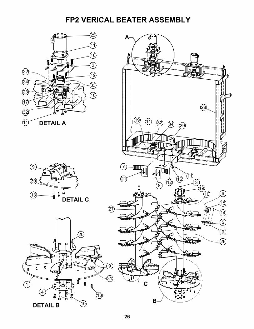
FP2 VERICAL BEATER ASSEMBLY
26

ITEM# PART # DESCRIPTION QTY.1 2550-0-176 PLATE, 38" SPINNER 22 2550-0-295 PLATE, FP2 MTR MOUNT 23 2550-U-031 Vertical Beater Stub Shaft 24 2550-U-034 Vertical Auger Stub Shaft Idler 25 2650-0-111 Vertical Flight Cutter Point 486 2650-0-112 Vertical Flight Kicker 487 2650-0-292 Choke Slides 18 2650-0-292-LH Choke Blade 19 400908 HEX CROWN LOCNUT 1/2"-13 #9 228
10 400910 HEX CROWN LOCNUT, 5/8"-11 #9 PLT 4011 400911 HEX CROWN LOCNUT, 5/8"-11 #5 PLT 2812 402010 SPRING LOCK WASHER MED 5/8" 313 405703 HHCS 1/2"-13 x 1-1/2" #5 PLTD 3614 405703 HHCS 1/2"-13 x 1-1/2" #5 PLTD 14415 405704 HHCS 1/2"-13 x 1-3/4" #5 PLTD 4816 405752 HHCS 5/8"-11 x 1 1/2" #5 PLTD 317 405753 .HHCS #5 PLTD 5/8"-11 x 1 3/4" 818 405754 HHCS 5/8"-11 x 2" #5 Pltd 819 405755 HHCS 5/8"-11 x 2-1/4" #5 PLTD 3220 405758 5/8"-11 x 3" HEX BOLT #5 PLTD 1621 407923 HHCS 5/8"-11 x 2" WHIZ BOLT 422 5415K370 Hose Clamp Worm Drive 123 7674K35 DC Metallic-Object Proximity Switch 124 7674K350_target Magentic Proximity Switch Target 125 801450C8930 Fp2 Beater Motor 226 820023 2650- Beater Tube Right 127 820024 2650- Beater Tube Left 128 820029 2650-Beater Frame 129 820030 2650- Spinner Dam 130 820042 2650-WELDMENT, HEAVY VANE 631 820043 2650-WELDMENT, HEAVY VANE LH 632 QMFL10J200SEM QM 2" BEARING 433 QMFLEX Flex Coupler Assembly 234 STD32 Schedule 40 Pipe 2
27
FP2 VERICAL BEATER ASSEMBLY

70 1/2"
85"
7
63
5
34
21
8
All Dimensions & Specifications are Approximate and Subject to Change Without Notice
ITEM # PART # DESCRIPTION QTY.1 2650-U-011 7.5' Beaters 32 25070105 Bolt on Point 103 400208 HEX NUT 1/2"-13 #5 PLTD 644 405703 HHCS 1/2"-13 x 1-1/2" #5 PLTD 405 407103 CHCS 1/2"-13 x 1-3/4" #5 PLTD 246 402008 SPRING LOCK WASHER 1/2" PLTD 247 QMF09J111SM 1 11/16 FLANGE BEARING 68 2550-B-075 Fp2 Beater 3
PF2 7.5' HORIZONTAL BEATER ASSEMBLY
28

74
2
6
3
1
5
ITEM # PART # DESCRIPTION QTY.1 3010-0-921 DESB SCALE WASHER 122 3010-0-935 DESB Scale Spacer Shim 63 409995 WEIGHBAR DESB 2.875 14T 21' EZMATE 64 823077 SADDLE MOUNT WA 35 M24 24MM X 3.0 NUT 246 M24XM130 M24-3.0X130MM HEX CAP BOLT 10.9 127 M24XM90 M24-3.0X90MM HEX CAP BOLT 10.9 12
6 POINT WEIGHBAR MOUNT KIT
29

2
3
1
ITEM # PART # DESCRIPTION QTY.1 820045 REAR BUMPER W/ LIGHT BAR WA 12 94993 RIGHT ANGLE STOP/TAIL LIGHT 43 10503 2-1/2" RED CLEARANCE LIGHT 3
SPREADER REAR LIGHT BAR BUMPER ASSEMBLY
30
2
1
3
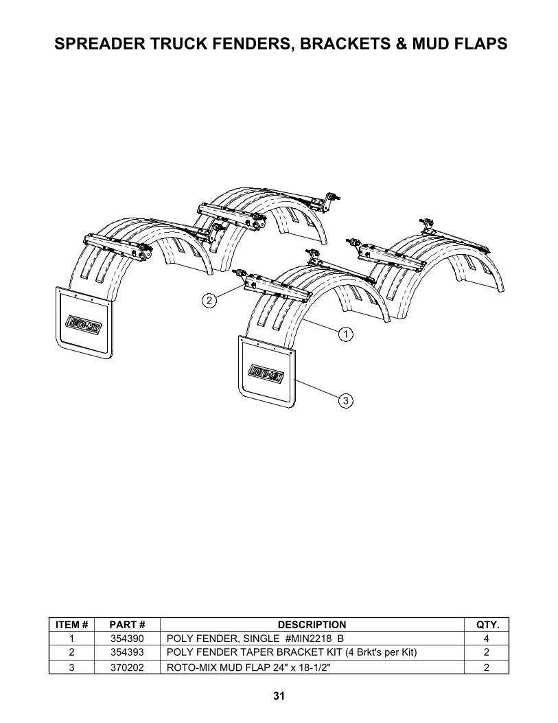
ITEM # PART # DESCRIPTION QTY.1 354390 POLY FENDER, SINGLE #MIN2218 B 42 354393 POLY FENDER TAPER BRACKET KIT (4 Brkt's per Kit) 23 370202 ROTO-MIX MUD FLAP 24" x 18-1/2" 2
SPREADER TRUCK FENDERS, BRACKETS & MUD FLAPS
31