MISSILE LAB USER 'S GUIDE - DTIC
84
TECHNICAL REPORT AMR-SS-06-12 Lamar M. Auman System Simulation and Development Directorate Aviation and Missile Research, Development, and Engineering Center February 2006 Approved for public release; distribution is unlimited.. MISSILELAB USER’S GUIDE
-
Upload
khangminh22 -
Category
Documents
-
view
1 -
download
0
Transcript of MISSILE LAB USER 'S GUIDE - DTIC

TECHNICAL REPORT AMR-SS-06-12
Lamar M. Auman
System Simulation and Development Directorate Aviation and Missile Research, Development, and
Engineering Center
February 2006
Approved for public release; distribution is unlimited..
MMIISSSSIILLEELLAABB UUSSEERR’’SS GGUUIIDDEE

DESTRUCTION NOTICE
FOR CLASSIFIED DOCUMENTS, FOLLOW THE PROCEDURES IN DoD 5200.22-M, INDUSTRIAL SECURITY MANUAL, SECTION II-19 OR DoD 5200.1-R, INFORMATION SECURITY PROGRAM REGULATION, CHAPTER IX. FOR UNCLASSIFIED, LIMITED DOCUMENTS, DESTROY BY ANY METHOD THAT WILL PREVENT DISCLOSURE OF CONTENTS OR RECONSTRUCTION OF THE DOCUMENT.
DISCLAIMER
THE FINDINGS IN THIS REPORT ARE NOT TO BE CONSTRUED AS AN OFFICIAL DEPARTMENT OF THE ARMY POSITION UNLESS SO DESIGNATED BY OTHER AUTHORIZED DOCUMENTS.
TRADE NAMES
USE OF TRADE NAMES OR MANUFACTURERS IN THIS REPORT DOES NOT CONSTITUTE AN OFFICIAL ENDORSEMENT OR APPROVAL OF THE USE OF SUCH COMMERCIAL HARDWARE OR SOFTWARE.

i/(ii Blank)
REPORT DOCUMENTATION PAGE Form Approved OMB No. 074-0188
Public reporting burden for this collection of information is estimated to average 1 hour per response, including the time for reviewing instructions, searching existing data sources, gathering and maintaining the data needed, and completing and reviewing this collection of information. Send comments regarding this burden estimate or any other aspect of this collection of information, including suggestions for reducing this burden to Washington Headquarters Services, Directorate for Information Operations and Reports, 1215 Jefferson Davis Highway, Suite 1204, Arlington, VA 22202-4302, and to the Office of Management and Budget, Paperwork Reduction Project (0704-0188), Washington, DC 20503
1.AGENCY USE ONLY
2. REPORT DATE February 2006
3. REPORT TYPE AND DATES COVERED Final
4. TITLE AND SUBTITLE
MissileLab User’s Guide
5. FUNDING NUMBERS
6. AUTHOR(S)
Lamar M. Auman
7. PERFORMING ORGANIZATION NAME(S) AND ADDRESS(ES) 8. PERFORMING ORGANIZATION REPORT NUMBER
TR-AMR-SS-06-12
9. SPONSORING / MONITORING AGENCY NAME(S) AND ADDRESS(ES) 10. SPONSORING / MONITORING AGENCY REPORT NUMBER
11. SUPPLEMENTARY NOTES 12a. DISTRIBUTION / AVAILABILITY STATEMENT
Approved for public release; distribution is unlimited. 12b. DISTRIBUTION CODE A
13. ABSTRACT (Maximum 200 Words) A tool has been developed to assist the applied aerodynamicist in the generation of the aerodynamic characteristics of missile configurations. MissileLab provides the ability to enter a single set of vehicle geometry and flight conditions, and then execute as many as six engineering-level aerodynamic prediction engines (APE). The user must have licensed copies of the various aero-prediction engines, as MissileLab simply provides a common geometry front-end to the respective codes. Currently, MissileLab supports input to the Air Force Missile DATCOM, Naval Surface Weapon Center (NSWC) AP98, Aero-Prediction AP02, AP05, and Nielsen Engineering and Research (NEAR) MISL3-March 2004. The features and capabilities of MissileLab are presented.
14. SUBJECT TERMS
15. NUMBER OF PAGES 87
16. PRICE CODE
17. SECURITY CLASSIFICATION OF REPORT
UNCLASSIFIED
18. SECURITY CLASSIFICATION OF THIS PAGE
UNCLASSIFIED
19. SECURITY CLASSIFICATION OF ABSTRACT
UNCLASSIFIED
20. LIMITATION OF ABSTRACT
SAR NSN 7540-01-280-5500 Standard Form 298 (Rev. 2-89)
Prescribed by ANSI Std. Z39-18 298-102
Commander, U.S. Army Research, Development, and Engineering Command ATTN: AMSRD-AMR-SS-AT Redstone Arsenal, AL 35898
Aerodynamic Analysis, Aerodynamic Prediction Codes, Missile DATCOM, NSWC AP98, AP02, AP05, Nielsen Engineering and Research (NEAR) MISL3

iii
TABLE OF CONTENTS
Page
I. INTRODUCTION ................................................................................................... 1
A. Guiding Philosophy Behind the Creation of MissileLab................................ 1 B. MissileLab Configuration Management Philosophy ...................................... 1 C. Background ........................................................................................................ 1
II. INSTALLING MISSILELAB INTERFACE........................................................ 3
A. MissileLab Installation File .............................................................................. 3 B. Manual Installation of MissileLab ................................................................... 3 C. Copying the AeroEngine Files .......................................................................... 4
III. THE MISSILELAB INTERFACE ........................................................................ 6
A. Initial MissileLab Setup .................................................................................... 6 B. Creating and Opening MissileLab Geometry Files ........................................ 15 C. Sketching Geometry .......................................................................................... 21 D. Entering MissileLab Geometry in the GUI ..................................................... 24
IV. MISSILELAB TOOL SUITE................................................................................. 59
A. APparser - Post-Processing the APxx Files .................................................... 59 B. MISL3parser - Post-Processing the MISL3 Files .......................................... 59 C. QPlot - Quick Plot Capability.......................................................................... 59 D. BLDAuto - Building an AeroLab Database ................................................... 59 E. AeroLab - Plotting and Analysis Tool............................................................. 59 F. Mini-Rocket (5-DOF)......................................................................................... 59
V. EXAMPLE CASES ................................................................................................. 60
A. Project_101......................................................................................................... 60 B. Project_102 ......................................................................................................... 65 C. Project_103......................................................................................................... 68
VI. FREQUENTLY ASKED QUESTIONS (FAQ) .................................................... 72
REFERENCES ........................................................................................................ 75

iv
LIST OF ILLUSTRATIONS
Figure Title Page
1. Installation Screens.................................................................................................. 5
2. File Locations for the Aerodynamic Prediction Engines ..................................... 6
3. Recommended Directory Structure for the APEs ................................................ 7
4. Recommended Directory Structure for the APEs ................................................ 8
5. Locate Prediction Codes Setup Screen .................................................................. 13
6. Locate Manuals Setup Screen ................................................................................ 14
7. Project File Screen................................................................................................... 15
8. New Project Screen.................................................................................................. 16
9. DATCOM Import Screen ....................................................................................... 17
10. DATCOM Axibod Option 2 Import Screen.......................................................... 19
11. Open Recent Files Screen........................................................................................ 20
12. Recent Files Windows Registry Location.............................................................. 20
13. Sample MissileLab 3-D Sketch............................................................................... 21
14. Sample MissileLab Sketch ...................................................................................... 22
15. Sample MissileLab Sketch via Meta File............................................................... 22
16. Sample MissileLab Fin Sketch ............................................................................... 23
17. Units and Case ID Screen ....................................................................................... 24
18. Reference Screen...................................................................................................... 27
19. Roughness Height Selection Screen ....................................................................... 28
20. Roughness Height Ratio Selection Screen ............................................................. 28
21. Body Geometry Screen............................................................................................ 29
22. User-Defined Body Input Screen............................................................................ 32

v
LIST OF ILLUSTRATIONS (CONT)
Figure Title Page
23. User-Defined Body Points Screen .......................................................................... 33
24. Fin Geometry Screen............................................................................................... 34
25. AP Panel Geometry Screen..................................................................................... 35
26. Protuberance Geometry Input Screen................................................................... 36
27. Protuberance Type Selection Screen ..................................................................... 37
28. Inlet Geometry Input Screen .................................................................................. 38
29. Geometry Parametrics Screen................................................................................ 39
30. Flight Conditions Input Screen .............................................................................. 40
31. Control Deflections Input Screen........................................................................... 41
32. Power-on/Power-off Base Drag Input Screen ....................................................... 42
33. Inlet Additive Drag Input Screen........................................................................... 43
34. DATCOM Prediction Methods Screen.................................................................. 44
35. DATCOM Output Options Screen ........................................................................ 45
36. DATCOM Common Block Output Screen ........................................................... 45
37. APxx Specific Run-Time Conditions Screen......................................................... 46
38. AP05 Specific Protuberance Input Screen ............................................................ 47
39. NEAR MISL3 Specific Run-Time Input Screen................................................... 48
40. NEAR MISL3 Body Loads Input Screen .............................................................. 49
41. Multiple Run Case Manager Screen...................................................................... 50
42. AeroLab Database Management Screen ............................................................... 51
43. DATCOM Warning Screen .................................................................................... 52
44. AP Warning Screen ................................................................................................. 53

vi
LIST OF ILLUSTRATIONS (CONCLD)
Figure Title Page
45. NEAR Warning Screen ........................................................................................... 53
46. Export Data Screen ................................................................................................. 56
47. View Data Screen..................................................................................................... 58
48. Project 101 Configuration....................................................................................... 60
49. Project 101 Normal Force Coefficient Versus AoA.............................................. 62
50. Project 101 Pitching Moment Coefficient Versus AoA........................................ 63
51. Project 101 Axial Force Coefficient Versus AoA.................................................. 64
52. Project 102 Configuration....................................................................................... 65
53. Project 102 Alternate Wing+Tail Modeling Approach........................................ 65
54. Project 103 Configuration Line Sketch ................................................................. 69
55. Project 103 Configuration 3-D Sketch................................................................... 69
56. Project 103 Equivalent Wing Sketch ..................................................................... 71
57. Project 103 Equivalent Wing Sketch ..................................................................... 72

vii
LIST OF TABLES
Table Title Page
1. Required MissileLab Files for Manual Installation ............................................. 4
2. Recommended Directory Structure for the APEs ................................................ 9
3. MissileLab Project Files and Locations................................................................. 10
4. Menu Options Panel ................................................................................................ 25
5. Body Screen Pull-Down Fields ............................................................................... 30
6. Body Screen Pull-Down Fields ............................................................................... 40
7. MissileLab Warning and Error List ...................................................................... 54
8. MISL3 Command Prompt Inputs via the Temp.txt File ..................................... 57
9. Project 101 Reference Geometry.......................................................................... 60
10. Project 101 Body Geometry.................................................................................... 61
11. Project 101 Canard Geometry................................................................................ 61
12. Project 101 Fin Geometry....................................................................................... 61
13. Project 102 Reference Geometry............................................................................ 66
14. Project 102 Body Geometry.................................................................................... 66
15. Project 102 Canard Geometry................................................................................ 66
16. Project 102 Wing Geometry ................................................................................... 67
17. Project 102 Tail Geometry...................................................................................... 67
18. Project 102 Alternate Wing+Tail Geometry Modeling Approach...................... 68
19. Project 103 Reference Geometry............................................................................ 70
20. Project 103 Body Geometry.................................................................................... 70
21. Project 103 Wing Geometry ................................................................................... 70
22. Project 103 Tail Geometry...................................................................................... 71

1
I. INTRODUCTION
A. Guiding Philosophy Behind the Creation of MissileLab
Fast, engineering-level, aerodynamic design codes are required in the early stages of missile design projects to perform numerous aerodynamic trade studies. It is highly desirable to use several techniques to predict the external aerodynamics, as this gives higher confidence in the results (or points to weaknesses in the various methods). The MissileLab interface will map all common airframe geometry inputs to the respective Aerodynamic Prediction Engines (APEs). APE specific inputs will be called out for the given code.
MissileLab will attempt to identify and warn the user of common input errors. MissileLab will communicate with the various APEs via their standard, documented input and output files, and will read pre-existing DATCOM namelist input files. MissileLab will feature various graphic displays of the missile geometry to aid the user in verifying configuration input geometry data.
The user is responsible for obtaining licensed copies of the various APEs that one wishes to use. Tools are needed to assist the engineer in analyzing the data in a timely fashion.
B. MissileLab Configuration Management Philosophy
A given MissileLab Project will consist of multiple configuration files (*.MLN) that contain the airframe geometry specific to a single configuration. Results from a MissileLab run will be stored in a directory corresponding to the configuration file name. This directory may be deleted with no impact to MissileLab. When MissileLab is run, the results directory will be (re)created and contain all APE results and associated input files.
C. Background
In the early stages of missile system design, it is necessary to have the means to quickly and accurately estimate the aerodynamics of a wide variety of missile configuration designs operating over many different flight regimes. The ultimate shape and aerodynamic performance of a missile are highly dependent on mission requirements (range, maneuverability, weight, radar cross-section) and subsystems (payload, propulsion, control actuation system, launch mechanism). Therefore, the applied aerodynamicist must be capable of reliably predicting aerodynamic trends on a wide variety of configurations in a timely manner.
Engineering-level codes provide an immediate means to determine the aerodynamic characteristics of a flight vehicle configuration. The foundations of these codes are extensive databases of experimental tests performed by National Aeronautics and Space Administration (NASA), Army, Air Force, and Navy. A combination of mathematical expressions and table lookups define the semi-empirical nature of these APE.

2
For missile applications, the three most frequently used semi-empirical codes are Missile DATCOM [1], AeroPrediction code (version AP98 [2, 3], AP02 [4, 5], and the recently released AP05 [6, 7]), and NEAR MISL3 [8]. Unfortunately, these codes require significantly different input decks; therefore, the applied aerodynamicist must work through the tedious process of setting up input files for the different codes. This process also introduces the potential for error, thereby slowing the aerodynamicist’s ability to quickly and reliably provide results to the design team.
It is advisable to run multiple APEs during the design trade process to increase the confidence level associated with the results. However, with ever increasing demands to shorten program development timelines, the aerodynamicist must sometimes choose between conducting additional analysis and meeting schedule demands. The entire design team must find ways to increase the efficiency and accuracy of the initial configuration trade study phase.
To meet the aerodynamicist’s needs, a tool dubbed MissileLab has been developed to allow the aerodynamicist to input one set of geometry and atmospheric conditions, and then run several missile APEs with the click of a button. Additional features include a user-friendly Graphical User Interface (GUI), Two-Dimensional (2-D) line sketch and Three-Dimensional (3-D) solid model display of the missile geometry, customizable help information, and display of the output files from the prediction codes.
In addition to its use as a tool to conduct design trade analyses, MissileLab will serve as an interface between the Subject Matter Expert (SME) and the U.S. Army’s Multidisciplinary Design Code (AMCODE GA). The SME may use MissileLab by itself to generate aerodynamic predictions using a variety of prediction codes (Missile DATCOM, AP98, AP02, AP05, NEAR MISL3). Alternatively, the SME will be able to use MissileLab in conjunction with the AMCODE and/or AeroLab [9, 10]. Together, this suite of codes provides a powerful analysis tool set for the applied aerodynamicist.

3
II. INSTALLING MISSILELAB INTERFACE
MissileLab is a MicroSoft Windows-based, GUI written in Visual Basic, that assists the user in running several Missile Aerodynamic Prediction codes. As such, in addition to the executables, Windows requires that several “OCX” and “DLL” files be registered on your computer. The MissileLab installation file automatically registers the files; however, if you prefer to install MissileLab manually, you may do this as well.
A. MissileLab Installation File
To install the MissileLab GUI, locate and run the setup file named “Setup_MissileLab_x_yy.exe” (note “x_yy” indicates the MissileLab version that will be installed). Figure 1 presents the various set-up screens that you will encounter.
As MissileLab stores all project files below the point where it is installed, it is RECOMMENDED, that MissileLab be installed at the root directory. This is not required, and as seen in Figure 1 it is not the default location. More on file locations will be discussed later.
Once MissileLab is installed, the user must copy the “AeroEngines” files that are discussed in Section II.C.
B. Manual Installation of MissileLab
Table 1 lists the files needed for a manual installation. While it is not required, it is recommended that the files listed in this table be placed in a directory named “/MissileLab”. If the OCX and “DLL” files have not been previously registered with Windows, then MissileLab will not run. The OCX files are Windows ActiveX controls and may have been previously registered if you have already installed a previous version of MissileLab, Visual Basic, or some other Visual Basic program. The DLL files listed in Table 1 are part of the 3-D sketcher functionality and make use of 3DLINX [11] software.
The simplest way to manually register the OCX and DLL files is listed below.
1. Locate the REGSVR32.EXE program (typically found in your “Windows\system32” directory).
2. Make a short-cut to the REGSVR32 program on your desktop.
3. Drag-and-drop the OCX and DLL files listed in Table 1 onto the REGSVR32.EXE shortcut.
Once the OCX files are registered, you can start MissileLab by double-clicking on the MissileLab Executable, however for full functionality the user must copy over the “AeroEngines” files that are discussed in Section II.C, and arrange for APE licenses from the various code vendors.

4
Table 1. Required MissileLab Files for Manual Installation
MissileLabX_YY.exe MissileLab Executable X_YY indicates the version number
3DLinx.dll NavAddons.dll
DLL files that must be registered in Windows. Use the REGSVR32.EXE to register the files.
COMDLG32.OCX MSCOMCTL.OCX MSHFLXGD.OCX RICHTX32.OCX TABCTL32.OCX
OCX files that must be registered in Windows. Use the REGSVR32.EXE (this should be in your Windows\system32 directory) to register the OCX files.
C. Copying the AeroEngine Files
After the MissileLab installation program has finished, the user must copy the “AeroEngines” directory. Initially, this directory contains contact information on how to obtain valid licenses for the various APEs, and other standalone executables that MissileLab will need to have full functionality. Figure 2 presents an example of what the AeroEngines directory might look like.
While the various APEs may be located anywhere on the user’s computer, it is RECOMMENDED that the APEs that MissileLab will utilize be located in a directory under the AeroEngines directory. The rational for this is that when the user “exports” the geometry,
1. MissileLab deletes previous APE specific input and output files,
2. MissileLab then creates the APE specific input files in the directory where the user has indicated the APE exists,
3. MissileLab then runs the APE,
4. MissileLab then copies and renames the output files into the appropriate MissileLab directory.

5
(a)
(b)
(c)
(d)
(e)
(f)
Figure 1. Installation Screens

6
Figure 2. File Locations for the Aerodynamic Prediction Engines
III. THE MISSILELAB INTERFACE
MissileLab is a Windows-based Visual Basic GUI. A series of screens, loosely based on the Missile DATCOM input format, provide the user the ability to define the missile geometry, flight conditions, and reference conditions in a straightforward manner. MissileLab will process these inputs to create the input decks for Missile DATCOM, any of the APxx codes, and/or MISL3. If the user has licensed copies of DATCOM, APxx, and/or NEAR MISL3, and has defined the paths to these APEs in MissileLab, then MissileLab will execute the available APEs. It is noted, however, that it is up to the user to acquire the APE licenses from the appropriate vendor, and use of MissileLab does not constitute an agreement with the APE vendors.
A. Initial MissileLab Setup
When MissileLab is started for the first time following installation, the user must tell MissileLab where the aerodynamic prediction engines reside on the computer. Before we describe this process, let’s first discuss the MissileLab Directory Structure.
1. MissileLab Recommended Directory Structure
While the APE and other standalone programs that MissileLab supports may be located anywhere on your computer, it is RECOMMENDED that they be located together as shown in Figure 3. Each of the subdirectories under \AeroEngines contains the respective executables. Table 2 lists the recommended directory structure and required executable that MissileLab will need.

7
Figure 3. Recommended Directory Structure for the APEs

8
The MissileLab project files and associated predicted results are organized according to the “Project” and the “configuration” as illustrated in Figure 4 and Table 3.
Figure 4. Recommended Directory Structure for the APEs

9
Table 2. . Recommended Directory Structure for the APEs
Directory Executable Description Contact /AeroEngines/MD
MDATCOM.EXE
Missile DATCOM APE
Mr. William Blake AFRL/VACA 2210 Eighth St. Suite 21 Bldg 146, Area B Wright-Patterson AFB, OH 45433-7531 [email protected]
/AeroEngines/AP05 /AeroEngines/AP02 /AeroEngines/AP98
AP05FOR.EXE AP02FOR.EXE AP98FOR.EXE
AP05 APE (Latest Version) AP02 APE (no longer supported by Dr. Moore) AP98 APE (no longer supported by Dr. Moore)
Dr. Frank Moore 9449 Grover Drive, Suite 201 King George, VA 22485 [email protected]
/AeroEngines/NEAR /AeroEngines/NEAR
MISL3.EXE M3FLR.EXE
MISL3 APE (Latest Version) M3FLR APE (no longer supported by NEAR)
NEAR Attn: Dr. Marnix Dillenius 526 Clyde Avenue Mountain View, CA 94043-2212 [email protected]
/AeroEngines/APparse /AeroEngines/BldAuto
APPARSE.EXE BLDAUTO.EXE
Pytheon script that reads the APxx generated ‘TAPE6’ output file, and writes a new file that may be easily used by other codes and plotting packages. Program to build an AMRDEC AeroLab Aerodynamic database from the output various APEs.
US Army AMRDEC Attn: Mr. Lamar M. Auman AMSRD-AMR-SS-AT Bldg 5400, E339 Redstone Arsenal, AL 35898-5252 [email protected]

10
Table 3. MissileLab Project Files and Locations
Directory Files Description /MissileLab MissileLab_Vxxx.EXE
*.OCX MissileLab.INI
MissileLab Executable MissileLab ActiveX Control Libraries MissileLab Initialization File
/MissileLab/Project_A Config_001.MLN Config_002.MLN Config_003.MLN
: Config_xxx.MLN
MissileLab Geometry files for “Project_A”
(Where “Project_A” and “Config_xxx” are defined by the user.)
MissileLab/Project_A/Config_001
Generated by MissileLab Config_001.Run0001.MDC Config_001.Run0001.AP05.AIR Config_001.Run0001.AP05.GEOM Config_001.Run0001.AP02.AIR Config_001.Run0001.AP02.GEOM Config_001.Run0001.AP98.INP Config_001.Run0001.MISL3.INP
Missile DATCOM input file AP05 “AIR” Input file AP05 “GEOM” Input file AP02 “AIR” Input file AP02 “GEOM” Input file AP98 input file MISL3 input file

11
Table 3. MissileLab Project Files and Locations (Concluded)
Directory Files Description
MissileLab/Project_A/Config_001
Generated by APE and renamed by MissileLab
Config_001.Run0001.MDC.FOR006.OUT Config_001.Run0001.MDC.FOR042.OUT Config_001.Run0001.AP05.TAPE6.OUT Config_001.Run0001.AP05.TAPE6out.OUT Config_001.Run0001.AP05.TAPE6ou2.OUT Config_001.Run0001.AP02.TAPE6.OUT Config_001.Run0001.AP02.TAPE6out.OUT Config_001.Run0001.AP02.TAPE6ou2.OUT Config_001.Run0001.AP98.TAPE6.OUT Config_001.Run0001.AP98.TAPE6out.OUT Config_001.Run0001.AP98.TAPE6ou2.OUT Config_001.Run0001.MISL3.OUT
Standard DATCOM output file New DATCOM output file Standard AP05 output file APparser “re-formatted” AP05 output file 1 APparser “re-formatted” AP05 output file 2 Standard AP02 output file APparser “re-formatted” AP02 output file 1 APparser “re-formatted” AP02 output file 2 Standard AP98 output file APparser “re-formatted” AP98 output file 1 APparser “re-formatted” AP98 output file 2 Standard NEAR MISL3 output file
12
2. Locating Executables and Manuals
When MissileLab is run for the first time, the “Locate Prediction codes” window will appear automatically. The user can also open this window at any time by selecting “Locate Prediction Codes” under the “Setup” menu bar. By clicking in the “Browse” button on this screen, illustrated in Figure 5, the user can navigate through the computer directory structure to locate the respective aerodynamic prediction engines. After the APE is located, the user then defines which APE he has selected in step 2 and assigns a version number. Because all supported versions of DATCOM currently have identical input files, the Version Number is a separate input for DATCOM. It is merely descriptive and will be used to name the output files. For APxx and MISL3, the version number is part of the “Define Program Type” pull-down, and will determine what type of input file is written, as well as being used to name the output files. For compatibility with AMRDEC’s AeroLab program, the user may define a database Identification (ID) which will correspond to the results from a specific APE. Finally, the user must click the “Add” button in step 4.
If the various APE executables are NOT located, MissileLab can still create the input files for all codes; it just will not be able to run the codes.
After all APEs are defined, the user may also locate the standalone programs APPARSE, BLDAUTO, and AeroLab.

13
Figure 5. Locate Prediction Codes Setup Screen
Figure 6 presents the “Locate Manuals” setup screen, and may be used to locate
any number of Adobe PDF manuals (or any text document) that the user may want to easily access while using MissileLab. Once all desired APEs and Adobe PDF manuals are located, the APE executables will appear on the “Export Data” screen, and the manuals will appear under “Help” in the MissileLab menu bar.
Manuals defined on this screen are available whenever MissileLab is open. As will be discussed later, the user may also locate manuals that are available for the specific configuration file that is currently loaded. These Adobe PDF manuals/documents are defined under the “Input Units” screen discussed in Section III.C.1.

14
Figure 6. Locate Manuals Setup Screen
When the user clicks on the “OK” button on either screen, MissileLab will query
whether or not to store the setup information in the file named “MissileLab.ini.” This is the MissileLab initialization file, and is located in the same directory as the MissileLab executable. After this file is created, it will be loaded when MissileLab is started, and the “Locate Prediction Codes” window will no longer automatically appear. The initialization file is an American Standard Code for Information Interchange (ASCII) text file and while not recommended, the file may be edited by the user with an ASCII text editor.

15
B. Creating and Opening MissileLab Geometry Files
Figure 7 presents the initial project definition screen. As seen in this figure, there are four tabs (or options) for the user to choose. These options are: start a “New Project,” open an “Existing Project,” “Import (an existing) DATCOM File,” or open a “Recent(ly)” used MissileLab file. As discussed in Section III.A.1, MissileLab will create a project directory under the MissileLab home directory, and then a configuration results directory under the project directory. As seen in Figure 7, the project directory may have several configuration files (*.MLN) and their corresponding configuration results directories.
Figure 7. Project File Screen

16
1. Creating a New Project
The “New Project” screen shown in Figure 8 creates a new blank project for the user.
Figure 8. New Project Screen
2. Opening an Existing Project
The “Existing Project” screen shown previously in Figure 7 opens an existing MissileLab file. The user may also open an existing project file and rename it by entering a new configuration name in the “Configuration Name” text box or a new project name in the “Project Name” text box.

17
3. Importing a Missile DATCOM File
MissileLab can read (import) existing Missile DATCOM namelist files. With that said, the Missile DATCOM namelist parser is much more forgiving than the MissileLab parser, and if there is an error in the DATCOM file (such as a missing or misplaced comma), MissileLab will not open the file until the user has found and corrected the problem.
MissileLab also attempts to identify, correct, and warn the user if it detects typical geometry input errors. Any changes that are made by MissileLab when reading in an existing DATCOM file will be followed with a “confirmation” warning message.
Figure 9 presents the DATCOM import screen. As with the open existing projects option, the user may rename the configuration and/or project name by entering a new name in the appropriate text box.
Figure 9. DATCOM Import Screen

18
If the user imports an existing DATCOM file where the body has been defined using the DATCOM “Axibod Option 2” method, then an additional screen appears. This screen, shown in Figure 10, is used to associate the input points with their respective body segment, as required for compatibility with the AP codes. In the example shown in the figure, the first three points were “assigned” to the nose by selecting the points (“left clicking” on point 1, holding down the <SHIFT> key and “left clicking” on point 3), then “right clicking.” The “right click” of the mouse popsup a “copy to” menu that allows the user to select the nose, midbody section 1 through 4, or the aft body (boattail) section. After points have been copied to body segments, they can then be deleted from the segment or moved to a different segment by selecting them and “right clicking” the mouse and choosing the appropriate pop-up menu option. Once all points have been assigned to a section, the user clicks on the “OK” button.
APxx’s requirements for certain number of points, in certain segments can be a little tricky, and so the user is referred to the AP05 User’s Guide for additional information as to AP’s requirements for points per segment.
As far as DATCOM is concerned, these points are handled in the standard way for Axibod Option 2. As seen in Figure 10, certain cells are colored yellow. These yellow cells correspond to points where the DATCOM “DISCON” flag is set to 1 indicating that the slopes at those points are not continuous. Neither the body geometry nor the DISCON flags can be changed on this screen, but they can be changed on the MissileLab “Body Geometry” screen that will be discussed in Section III.C.3.

19
Figure 10. DATCOM Axibod Option 2 Import Screen

20
4. Opening Recent MissileLab Files
Figure 11 presents the recent files screen. As with the open existing projects option and the Import DATCOM option, the user may rename the configuration by entering a new name in the “Configuration Name” and/or “Project Name” text box.
The list of recently used files is stored in the Windows registry as shown in Figure 12.
Figure 11. Open Recent Files Screen
Figure 12. Recent Files Windows Registry Location

21
C. Sketching Geometry
Any time after geometry has been defined, the missile can be viewed graphically using the “Sketch” menu option. Under this menu, there is a “Sketch 3-D Missile” option. This will only be enabled when the appropriate libraries can be found, and the option is selected on the “Locate Manuals” screen. The 3-D solid model sketcher is shown in Figure 13. Here functionality is provided to zoom in and out (right mouse button), rotate the camera around the fixed body (left mouse button), and pan (<SHFT> plus left mouse button). Detailed instructions for controlling the 3-D view can be found in the “Help” section on the screen.
Figure 13. Sample MissileLab 3-D Sketch
MissileLab contains a simple 2-D sketch feature that is accessed via the “Sketch” menu. The user can sketch the missile, an individual fin, or both, by using the appropriate menu option. A sample sketch of both missile and fins is presented in Figure 14. For each finset (when finsets are displayed), a box is displayed that shows the panel orientation and/or dihedral (looking from the rear of the missile). As seen in Figure 14, various user controls are provided. There is a button at the bottom of the screen that allows the user to copy the sketch to the clip-board so that it may be pasted into any Windows application that supports Windows Meta Files. A sample of the pasted Windows Meta File is presented in Figure 15. Also, check-box controls allow the user to turn on and off the panel displays and the body station information on the sketch, as well as allow the user to highlight body discontinuities and/or the Moment Reference Point (MRP). Another control enables a text screen to display body geometry data. When finsets are displayed, a control enables the leading edge locations to be shown.

22
Figure 14. Sample MissileLab Sketch
Figure 15. Sample MissileLab Sketch via Meta File

23
An individual finset can be displayed by using the “Sketch Fin” menu option. An example of this sketch is shown in Figure 16. The controls described above that are appropriate are also present on this screen. An additional check-box control is provided to set the leading edge location to 0.0.
Figure 16. Sample MissileLab Fin Sketch

24
D. Entering MissileLab Geometry in the GUI
Figure 17 presents MissileLab’s main interface screen with focus on the “Input Units” screen. As seen in this figure, the screen is divided into three panels: the Menu Options Panel (upper-left), the Help Topics Panel (lower-left), and the Work Area Panel (right; in this case displaying the Input Units panel).
Figure 17. Units and Case ID Screen

25
Notice that the menu options panel, located in the upper-left of the screen, is an expandable list that guides the user through the steps required to generate a valid input deck. Table 4 lists the contents of the menu options panel. While this is a numbered list of the recommended data entry steps, the user may enter the data in any order, may return to any screen at any time during the input definition process, and may save the project configuration file at any point in the process. When a menu option is selected, the appropriate panel will be displayed in the “Work Area” that forms the right-hand side of the screen.
Table 4. Menu Options Panel (1) Setup MissileLab Project Define Input Units / Case ID (2) Define Reference Values Body References (3) Define Geometry Body Finsets Protuberances Inlets (4) Define Run Conditions Geometry Parametrics Flight Conditions Deflection / Trim Base Effects Inlet Additive Drag (5) Define DATCOM Specific Inputs Prediction Method/Case Computations Output Options Common Block Output (6) Define APxx Specific Inputs Run-Time Conditions AP05 Protuberance Inputs (7) Define NEAR MISL3 Specific Inputs Run-Time Conditions Body Loads / Rotation Rates (8) Define Multiple Runs Run Manager (9) Define AeroLab Database Configure AeroLab Database Parameters (10) View Warnings DATCOM Warnings AP Warnings MISL3 Warnings (11) Export Data / Run Predictions (12) View Predicted Data

26
The help topics panel, located directly below the menu options panel, displays information the user may need while entering data on the given screen. Note: Additional help information may be accessed via the pull-down “Help” menu item located in the menu bar at the top of the screen. From that menu, the user can access any number of previously user-defined text documents to aid in understanding the required input fields.
The work area panel displays the fields to be completed by the user. Once the user leaves the current work area panel, a check-mark appears by the associated panel name in the menu options panel, indicating that the user has visited the given panel during the current session. If the current configuration is closed and then re-opened, all check-marks are reset.
1. Input Units Screen
The user defines the input units (default = inches), configuration case ID (required input for the AP codes), comments regarding the configuration (optional), and project-specific text reference files (optional) on the “Input Units” screen shown in Figure 17. As previously discussed in Section III.A.2, text files defined on the “Setup” screen are always available via the “Help” menu, where as the text files that are defined on the “Input Units” screen shown in Figure 17 are only available for the specific project where they were defined. Additionally, whereas the text files that are defined on the initial setup screen are stored in the MissileLab initialization file, the PDF files defined on the project screen shown in Figure 17 are stored in the respective MissileLab project file (*.MLN).
Helpful Hint: To increase the font size in the Help Topics panel, click in the panel, hold down the <CTRL> key, and rotate your mouse wheel.
This is a MS Windows feature and may be useful in other applications such as MS Windows WordPad.

27
2. Reference Input Screen
Figure 18 presents the Body Reference screen. Here the user is queried to enter the characteristic reference length, area, moment reference point, and boundary-layer transition information. For user convenience, a calculator command button is provided adjacent to the reference area field which automatically calculates the reference area based on a circular cross-section using the characteristic reference length as the diameter of the circle. If the user wants to use some other reference area (e.g. wing area, area of a non-cylindrical body cross-section, and so on), then the user simply enters the desired value in the Reference Area text box field.
Figure 18. Reference Screen
The majority of the MissileLab input fields are automatically mapped to the respective locations for the various aerodynamic prediction engines. However, as each APE has its own unique capabilities and input requirements, MissileLab lists APE code-specific variables separately for the user. One such example of this is shown at the bottom of Figure 18. Here, the user must define the DATCOM boundary layer option and the APxx boundary layer transition characteristics. In this example, the user has the option of allowing MissileLab to derive the APxx boundary layer transition based on the specified DATCOM inputs, or alternatively the user may select the desired AP boundary layer transition value via the pull-down selection box.

28
Notice that there is a “Look-up Value” button to the right of the roughness value entry field. Selecting this button opens the screen shown in Figure 19. Here, the user may select the surface that he or she desires and click “OK.” When the screen closes, the selected value is automatically entered into the roughness value field. Similarly, if the user had selected the roughness height ratio option, and then selected the look-up value button, the screen shown in Figure 20 would have appeared.
Figure 19. Roughness Height Selection Screen
Figure 20. Roughness Height Ratio Selection Screen
29
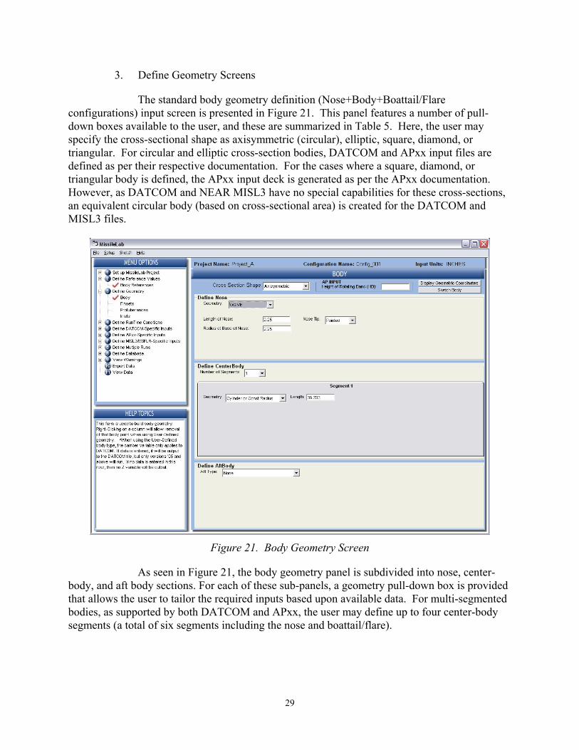
3. Define Geometry Screens
The standard body geometry definition (Nose+Body+Boattail/Flare configurations) input screen is presented in Figure 21. This panel features a number of pull-down boxes available to the user, and these are summarized in Table 5. Here, the user may specify the cross-sectional shape as axisymmetric (circular), elliptic, square, diamond, or triangular. For circular and elliptic cross-section bodies, DATCOM and APxx input files are defined as per their respective documentation. For the cases where a square, diamond, or triangular body is defined, the APxx input deck is generated as per the APxx documentation. However, as DATCOM and NEAR MISL3 have no special capabilities for these cross-sections, an equivalent circular body (based on cross-sectional area) is created for the DATCOM and MISL3 files.
Figure 21. Body Geometry Screen
As seen in Figure 21, the body geometry panel is subdivided into nose, center-body, and aft body sections. For each of these sub-panels, a geometry pull-down box is provided that allows the user to tailor the required inputs based upon available data. For multi-segmented bodies, as supported by both DATCOM and APxx, the user may define up to four center-body segments (a total of six segments including the nose and boattail/flare).

30
Table 5. Body Screen Pull-Down Fields
Field Choices Comments Cross-Sectional Shape Axisymmetric …………….
Elliptical …………………..
Square ……………………
Diamond …………………
Triangle ………………….
Inverted Triangle ……….
All APEs
Specific to DATCOM and APxx
Specific to APxx
Specific to APxx
Specific to APxx
Specific to APxx
Nose Geometry Ogive
Conical
Power
Haack
Karman
Hemisphere
Secant Ogive
User Defined
A hemisphere can be modeled as a Tangent Ogive, however as APxx input files are slightly different for the hemispherical case it is recommended that the HEMISPHERE option be used when modeling a hemispherical nose.
Secant Ogive and User Defined options force DATCOM into Axibod Option 2 mode.
Nose Tip Geometry Pointed
Blunted
Truncated
The corresponding length for all nose tip geometries is the physical length of the nose (after blunting or truncating).
Number of Body Segments 1 to 4 Any value other than 1 forces DATCOM into Axibod Option 2 mode.
Center Body Geometry Cylinder
Cone – known radius
Cone – known half-angle
User Defined
User Defined options force DATCOM into Axibod Option 2 mode.
Aft Body Geometry None
Tangent Ogive
Cone – known radius
Cone – known half-angle
User Defined
User Defined options force DATCOM into Axibod Option 2 mode.

31
For cases where the body cannot be modeled by a simple nose+body+aft section, MissileLab allows the user to enter body point pairs, X & R (longitudinal ‘X’ station and radial ‘R’ station). For those familiar with Missile DATCOM this would be the “Axibod Option 2” input method, and for those familiar with AP this corresponds to the “Other” nose and body input method. Figure 22 presents two examples of this screen.
The 2006 version of Missile DATCOM includes the capability to predict aerodynamic trends of a cambered (or bent) body at zero roll angle. This new DATCOM capability introduced a new “Z” input variable as part of the Axibod Option 2 “X” and “R” variables. MissileLab allows for this variable using the “Camber” field shown in Figure 22.
From this screen it is seen that some of the user-defined body point cells are colored yellow, while one is colored white. Yellow-shaded cells indicate points that do not have a continuous slope. In Missile DATCOM, these points would have the DISCON namelist variable set to a value of 1. The discontinuity slope flag may be toggled on and off by “left-clicking” on the point number, then “right-clicking.” When this is done, a “pop-up” screen will appear that will allow the user to (1) remove the current point, (2) insert a point before the current point, or (3) toggle the discontinuity flag of the current point
Each section may have up to 10 pairs of points. This limitation is imposed for compatibility with the AP prediction codes. Up to six sections (one nose, four centerbody, and one aft body) may be entered. As this can lead to 60 discrete body points, and as DATCOM allows for a maximum of 50 body points, points over 50 will disable Missile DATCOM from running. It is also noted that the distribution of points in the various sections effects only the AP input files. It is also noted that discrete “steps” are NOT allowed by MissileLab as none of the APE are designed to account for forward/rearward facing steps along the body. Additionally, the user should avoid entering points that will produce “very steep slopes” along the body.
Figure 23 presents the body points display window. This screen is for point “inspection” alone and has no functionality other than allowing the user to view all the points in all the sections “in order.” This screen will open automatically when more complex or user-defined geometry is defined. It can also be displayed using the “Display Geometric Coordinates” button near the top right of the panel.

32
(a)
(b)
Figure 22. User-Defined Body Input Screen

33
Figure 23. User-Defined Body Points Screen
Below the “Display Geometric Coordinates” button, there is a “Sketch Body” button. This will display the same sketch as the “Sketch Missile Only” menu option described in Section C.
Figure 24 presents the fin geometry input screen. Up to four fin sets may be specified using the pull-down box at the top of the screen. If more than two fin sets are specified, the user must specify on the Geometry Parametrics Screen which TWO fin sets are to be run for the APxx APEs. If more than three fins are specified, the user must specify on the Geometry Parametrics Screen which THREE fin sets are to be run NEAR MISL3 APE. The user can “turn off” any combination of fins on the Geometry Parametrics screen. This capability will be discussed in greater detail in Section III.D.4. The current fin set can be sketched using the “Sketch Fin” button at the top right corner of the panel. This displays the same sketch as the “Sketch Fin” menu option described in Section C.
As seen in Figure 24, the fin geometry variables follow the DATCOM namelist inputs and allow for multi-segmented lifting surfaces. As this feature is not supported by APxx, routines have been added to MissileLab that create an equivalent single-segment wing panel [12]. Regardless of the number of segments in the wing panel, a command button is provided that allows the user to view the wing geometry as it would be entered from the APxx GUI, as shown in Figure 25. The user cannot change the values shown on this page. If the user feels these values are incorrect, then the values must be changed on the main fin set page. The “Sketch Fin Planform” button will show the defined fin (denoted as DATCOM Fin) beside the equivalent APxx fin in a window that is similar to the sketch windows described in Section C.
.

34
Figure 24. Fin Geometry Screen

35
Figure 25. AP Panel Geometry Screen
36
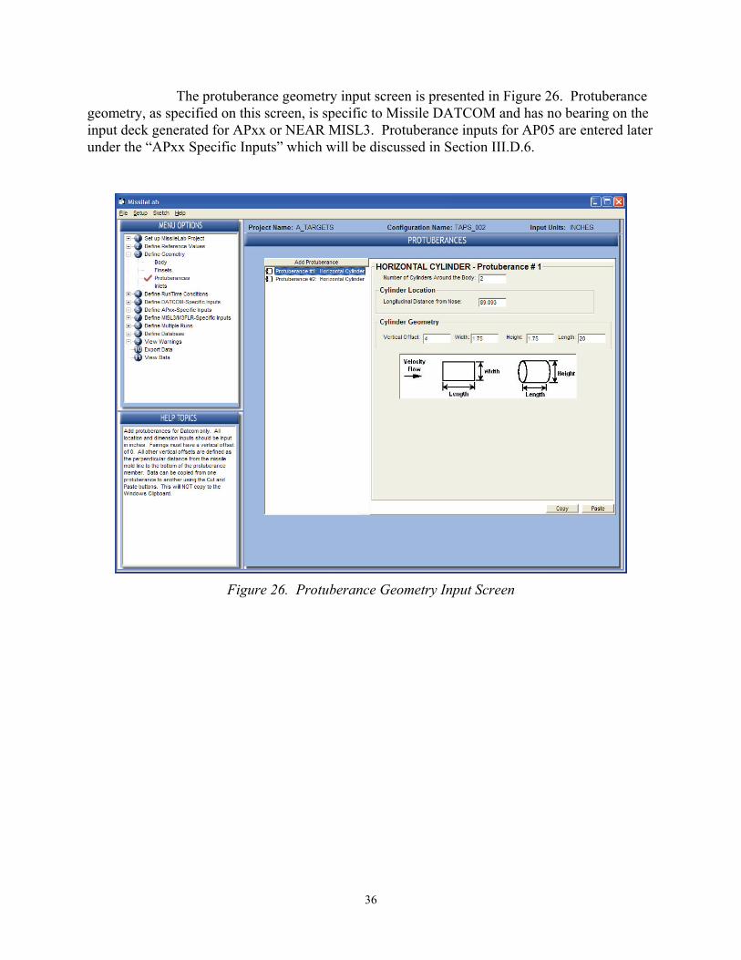
The protuberance geometry input screen is presented in Figure 26. Protuberance geometry, as specified on this screen, is specific to Missile DATCOM and has no bearing on the input deck generated for APxx or NEAR MISL3. Protuberance inputs for AP05 are entered later under the “APxx Specific Inputs” which will be discussed in Section III.D.6.
Figure 26. Protuberance Geometry Input Screen

37
When the user clicks on the “Add Protuberance” button, the screen shown in Figure 27 appears. The user then selects the type of protuberance that most closely matches the actual geometry and clicks on “OK.” This adds the protuberance type to the protuberance screen, and the actual geometry is then entered. Currently, the MissileLab sketcher does not support sketching protuberances.
Figure 27. Protuberance Type Selection Screen
All or specific protuberance geometry can be turned on and off under the “Geometry Parametrics” screen which will be discussed further in Section III.D.4.

38
The inlet geometry input screen is presented in Figure 28. Inlet geometry as specified on this screen is specific to Missile DATCOM and has no bearing on the input deck generated for APxx or NEAR MISL3. Currently, the MissileLab sketcher does not support sketching inlets.
Inlet geometry can be turned on and off under the “Geometry Parametrics” screen which will be discussed further in Section III.D.4.
Figure 28. Inlet Geometry Input Screen

39
4. Define Run-Time Conditions Screens
The “Run-Time Conditions” screens control body-build-up runs, flight conditions such as Mach number, Angle-of-Attack (AoA), fin deflections, power-on/power-off base drag affects, and inlet-drag affects.
Control over APE geometry files is provided via the Geometry Parametrics screen shown in Figure 29. This screen allows the user to turn on/off fins to conduct body build-up analysis; in the case of Missile DATCOM inlets and protuberances may be turned on or off; and in the case of APxx the body may be turned off to allow for wing-alone calculations.
Figure 29. Geometry Parametrics Screen
In addition to turning specific fin sets on and off, the user should specify if the given fin set is to be used for control. As both Missile DATCOM and NEAR MISL3 allow for dual control, all fins sets may be specified as “Used for Control” for these codes. However, as APxx does not allow for dual control, selecting a given fin set for control automatically sets the other fin set for “Used for Stability.”
If fin deflections are to be entered in the “Deflections/Trim” screen that will be discussed later in this section, then one of the fin sets must be selected for control.

40
Flight conditions, such as Mach number, altitude, AoA, and roll angle are entered into MissileLab using the flight conditions input screen shown in Figure 30. The user has several ways to enter the desired velocity conditions as shown in Table 6. As APxx and NEAR MISL3 require Mach number and Reynolds number as the input, these values are calculated by MissileLab using an atmosphere model if anything other than Mach and Reynolds number are entered.
Figure 30. Flight Conditions Input Screen
Table 6. Body Screen Pull-Down Fields
MissileLab DATCOM APxx NEAR MISL3 Mach & Altitude
As entered Mach & Rn calculated using a standard Atmosphere model
Mach & Rn calculated using a standard Atmosphere model
Mach & Rn As entered As entered As entered
Mach, Pressure & Temperature
As entered Mach & Rn calculated using a standard Atmosphere model
Mach & Rn calculated using a standard Atmosphere model
Velocity, Altitude
As entered Mach & Rn calculated using a standard Atmosphere model
Mach & Rn calculated using a standard Atmosphere model
Velocity, Pressure & Temperature
As entered Mach & Rn calculated using a standard Atmosphere model
Mach & Rn calculated using a standard Atmosphere model
41
Up to 20 Mach numbers and up to 20 AoAs may be entered for a given case. Also, the user may specify a Side-slip angle or an Aerodynamic roll angle, which are exported to DATCOM and MISL3 but are not exported to APxx as AP only supports roll angles of 0 and 45 degrees. If the user wishes to export φ=45 data from APxx, then this is specified under the “APxx Specific Inputs” discussed in Section III.D.6.
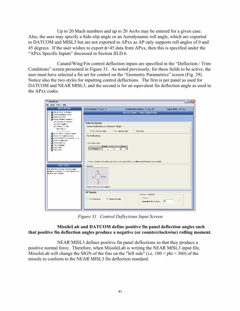
Canard/Wing/Fin control deflection inputs are specified in the “Deflection / Trim Conditions” screen presented in Figure 31. As noted previously, for these fields to be active, the user must have selected a fin set for control on the “Geometry Parametrics” screen (Fig. 29). Notice also the two styles for inputting control deflections. The first is per panel as used for DATCOM and NEAR MISL3, and the second is for an equivalent fin deflection angle as used in the APxx codes.
Figure 31. Control Deflections Input Screen
MissileLab and DATCOM define positive fin panel deflection angles such that positive fin deflection angles produce a negative (or counterclockwise) rolling moment.
NEAR MISL3 defines positive fin panel deflections so that they produce a positive normal force. Therefore, when MissileLab is writing the NEAR MISL3 input file, MissileLab will change the SIGN of the fins on the "left side" (i.e. 180 < phi < 360) of the missile to conform to the NEAR MISL3 fin deflection standard.

42
APxx expects an equivalent fin deflection angle that will produce an in-plane pitch maneuver. Positive equivalent fin deflection angles in AP produce a positive normal force increment at zero AoA for both canard controlled and tail controlled configurations. Therefore, assuming that canards are forward of the MRP and the tails are aft of the MRP, then positive canard deflections in AP produce positive (nose up) pitching moments, and positive tail deflections in AP produce negative (nose down) pitching moments.
Base drag effect information is entered via the panel presented in Figure 32, and Inlet Additive Drag information is entered via the panel presented in Figure 33.
Figure 32. Power-on/Power-off Base Drag Input Screen

43
Figure 33. Inlet Additive Drag Input Screen

44
5. Define DATCOM Specific Inputs Screens
The “DATCOM Specific Inputs” screens control various DATCOM cards such as SOSE, HYPERS, PART, BUILD, DAMP, SPIN, and so on. As these control cards should be familiar to any experienced DATCOM user, nothing else will be said about them here other than to show the various screens (Figs. 34 and 35). If additional information is required, please refer to the DATCOM user’s manual.
The screen shown in Figure 36 provides controls for “WRITING” and “DUMPING” array data from older versions of Missile DATCOM (version 9/02 and earlier). This functionality has been deleted from DATCOM 1/06 and later versions of the code.
Figure 34. DATCOM Prediction Methods Screen

45
Figure 35. DATCOM Output Options Screen
Figure 36. DATCOM Common Block Output Screen

46
6. Define AP-xx Specific Inputs Screens
The “AP-xx Specific Inputs” screens control various AP-xx control cards such as ISPIN, IPRINT, ALIMIT, ALIMS, smoothing, and so on. As these control cards should be familiar to any experienced AP user, nothing else will be said about them here other than to show the screen in Figure 37. If additional information is required, please refer to the AP user’s manual.
Figure 37. APxx Specific Run-Time Conditions Screen

47
The AP05 protuberance screen is presented in Figure 38. Again, the user is referred to the AP05 manual for more information. However, there is one subtle point that is not covered in the AP05 manual that will be briefly discussed below.
Figure 38. AP05 Specific Protuberance Input Screen
MissileLab does NOT automatically populate the Mach array for the AP05 protuberance screen, as the inputs do not have to correspond to the Mach numbers input under the flight conditions input screen.
AP05 allows the user to input in any number of Mach numbers and corresponding protuberance data. AP05 (i.e. AP05FOR.EXE) then interpolates the protuberance data given the input flight condition Mach number. For flight condition Mach numbers that are outside the input protuberance Mach numbers, AP uses the nearest set of protuberance data. For example, suppose you put in perturbation inputs at Mach 2.3 and 4.6 as was done in the AP05 User’s Guide. You then ran Mach numbers of 1.0, 2.3, 3.5, 4.6, and 7.0. AP05 would use the protuberance data defined for Mach 2.3 for flight conditions of Mach 1.0 and 2.3. For the flight condition of 3.5, AP05 would interpolate between the 2.3 and 4.6 protuberance data, and for the flight conditions of 4.6 and 7.0, AP05 would use the protuberance data defined at Mach 4.6.

48
7. Define MISL3 Specific Inputs Screens
The “MISL3/M3FLR Specific Inputs” screens presented in Figure 39 and Figure 40 control various NEAR MISL3 control cards such as body rotation rates, body loads, various output options and so on. These control cards should be familiar to any experienced NEAR MISL3 user. If additional information is required, please refer to the NEAR MISL3 user’s manual.
Figure 39. NEAR MISL3 Specific Run-Time Input Screen

49
Figure 40. NEAR MISL3 Body Loads Input Screen

50
8. Define Multiple Runs Screen
The “Multiple Runs” case manager screen is presented in Figure 41. In designing this screen and functionality, the question that must be addressed is: “what do we allow the user to change for a specific project configuration file”? Using the guidelines set out in Section I, it was decided that for a given configuration, the user should have control over (1) body build-up, (2) flight conditions, (3) control deflections, (4) power-on/power-off base drag, and (5) inlet drag. If, for example, the MissileLab user needs to change the wing geometry, this should be done by making a copy of the MissileLab geometry file (*.MNL) and then modifying the wing in that file. If, however, the MissileLab user wants to make various control deflection runs (for the given airframe geometry), then that will be handled by the case manager as shown in Figure 41.
Figure 41. Multiple Run Case Manager Screen
Once the baseline geometry is defined, the user may add multiple cases, select what will change for that case, and then enter the new data. When additional cases are defined, MissileLab LOCKS the baseline geometry to prevent the user from inadvertently modifying the baseline data. When this occurs a red “KEY” command button appears in the upper left of each screen. Clicking on this button will unlock the screen and allow the user to modify the baseline configuration data.

51
9. Define AeroLab Database Parameters Screen
To facilitate comparison of predicted data to wind tunnel test results, functionality has been incorporated to have MissileLab automatically generate an AeroLab database. The AeroLab database interface screen is presented in Figure 42. On this screen, the user must specify the 6-character alphanumeric database name, a configuration name, and “database run numbers.”
Additional information on AeroLab may be found in Reference [9].
Figure 42. AeroLab Database Management Screen

52
10. View Warnings Screens
An attempt has been made to identify as many “problems” as possible before the specific APE input files are generated. MissileLab generates two types of warnings: CRITICAL ERROR and NONCRITICAL WARNING. If MissileLab identifies a critical error for a given APE, that code is disabled and can not be selected on the “Export Data” screen. MissileLab will allow the user to run APEs with noncritical warnings, but the user should review all warnings.
For example, some APEs allow for eight fins, while others do not. So if the airframe geometry is defined with eight wings/fins, then MissileLab identifies this as a CRITICAL ERROR for the codes that will not run eight-fin panels. An example of a noncritical warning would be if the user defined an airfoil section with a NACA airfoil. APxx does not have NACA airfoil capability, so MissileLab substitutes a bi-convex fin section when it writes the APxx input file.
Figures 43 through 45 present sample warning pages for a given airframe geometry. Table 7 presents a list of the major warnings and errors as currently defined in MissileLab Version 5_3.
Figure 43. DATCOM Warning Screen

53
Figure 44. AP Warning Screen
Figure 45. NEAR Warning Screen

54
Table 7. MissileLab Warning and Error List
APE Level Message
All Critical
Invalid Mach number
Reynolds number too small or zero
Temperature/Pressure values have not been set
(and various other house-keeping checks to make sure that what the user indicated he was going to enter is in a valid range of what is expected)
All Critical The power series nose exponent value is too low. A solution can't be determined. (Applies to TRUNCATED Power Nose)
All Critical The power series nose solution can not be obtained (tangency point is < 0). (Applies to BLUNTED Power Nose)
All Critical There is a vertical step in the body coordinates.. (Applies to DATCOM AXIBOD Option 2 input)
All Critical There is an invalid AoA. If the value is at the end, it will be dropped and raise a warning. Otherwise, it is a Critical Error.
All Critical There is an AoA that is repeated. DATCOM Warning There are no discontinuities defined.
DATCOM Warning Z points (cambered body) have been defined. Versions of DATCOM prior to March 2005 will not run.
DATCOM Critical There are too many body points defined (maximum = 50) DATCOM Critical Not Enough AoAs Error DATCOM Critical Invalid NACA Number (could signify user-error).
APxx Warning There are not enough nose, midbody, or aft segment points to export to APxx.
APxx Warning Z points (cambered body) have been defined. These values will not be exported in any way to AP codes.
APxx Warning A NACA or USER type airfoil has been defined for finset n. This will be converted to a biconvex airfoil with a 0.025 thickness to chord ratio.
APxx Warning Too many finsets have been defined. Apxx only allows two sets. The two that are selected on the Geometry Parametrics page will be exported.
APxx Warning Panels were defined for finset n are not evenly distributed around the body.
APxx Warning Finset has more than 4 Panels and is being used for control. (according to the AP05 GUI this is not allowed, but the AP05 GUI does allow this case to run as does MissileLab.)
APxx Warning Finset n has dihedral associated with it. This dihedral will not be used in APxx.
APxx Critical The body has been defined as non-circular and there are more than 1 Midbody segments. This is not allowed in AP.
APxx Critical The body has been defined as non-circular and the Midbody segment is not a constant-radius segment. This is not allowed in AP.
APxx Critical Finsets are not oriented as designated by IPHIRD.
NEAR Warning There are more than 10 mach numbers defined. M3FLR and MISL3 will use the first 10.
NEAR Warning There is an Ogive defined for the Aft body segment. This is not allowed in MISL3 and M3FLR. It will be converted to a conic segment.

55
Table 7. MissileLab Warning and Error List (Cont.)
NEAR Warning Too many finsets have been defined. MISL3/M3FLR only allow three sets. The three that are selected on the Geometry Parametrics page will be exported.
NEAR Warning Finset n has dihedral associated with it. This dihedral will not be used in MISL3 or M3FLR.
NEAR Warning Too many points aft of nose. MissileLab will use the end points of each segment.
NEAR Warning User or NACA airfoil defined. This will be converted to a double-wedge airfoil.
NEAR Critical No body defined. MISL3 and M3FLR must have a body. NEAR Critical No AoAs defined. MISL3 and M3FLR must have at least 1 AoA.
NEAR Critical Blunted/Truncated nose for HAACK or Karman nose. This is not allowed in MISL3 and M3FLR.
NEAR Critical First body segment aft of the nose is not a cylinder. NEAR Critical No discontinuities on the nose.
NEAR Critical Nonuniform Flow Field Flag was set, but the additional files needed were not designated.
NEAR Critical Too many finset panels or invalid orientations NEAR Critical Flap to Fin chord ratio defined for finset.
NEAR Critical Finset n is a forward-swept fin. This is not allowed in MISL3 and M3FLR.

56
11. Export Data Screen
Figure 46 presents the “Export Data” screen. Here, the user selects the desired prediction code(s) to be executed. As shown in the figure, if MissileLab identifies a critical error in the geometry input for a specific APE, then that code is disabled for the current case. The warnings page discussed previously lists the critical errors and warning messages. The user should always view the warnings page, even if no critical errors are noted.
Figure 46. Export Data Screen
The APEs may only be selected if no critical errors were found. If a critical error
was found, MissileLab disables the specific APE. When a prediction code is selected, the associated input file is also selected for generation. Alternatively, the user may request that MissileLab produce a given input file without running the prediction program.
Once the desired APEs have been selected, the user clicks on the “Export Data / Run Codes” command button. This initiates generation of the APE input files and execution of the selected engines. As each engine terminates, its respective output file is saved to the hard disk, and if the “View Output Files” checkbox is checked, the results are then displayed in Windows NotePad text viewer.

57
When the “Export Data/Run Codes” command button is selected, MissileLab creates the APE input files in the directory where the specific APE executable is located (as specified by the user under the “locate prediction codes” screen discussed previously in Section III.A.2). Before these files are written, however, MissileLab DELETES any pre-existing native input/output files for the specific APE. This is why it is recommended that the user place the APEs in a separate directory that only MissileLab will access. After the specific APE terminates, MissileLab copies the native output files into the standard MissileLab directory structure.
Missile DATCOM and APxx codes do not require any extra input from the user apart from the input files. NEAR MISL3, however, requires “command prompt input” from the user in addition to the standard MISL3 input file. As this is not desirable from MissileLab’s perspective, the following additional files are created for NEAR MISL3 operation.
First, MissileLab creates a text file named “temp.txt” that is written to the directory where the MISL3 executable resides. This file contains the “command prompt” inputs that the user would normally have to enter, and the contents of this file are listed in Table 8. The values that are defined in this file are set on the MISL3 Specific Input screen discussed in Section III.D.7. MissileLab also creates a DOS batch file named “RunMISL3.exe.bat” that is also written to the directory where the MISL3 executable resides. This file contains one line, which is:
“MISL3.exe < temp.txt”.
To run MISL3, MissileLab executes the “RunMISL3.exe.bat” batch file.
Table 8. MISL3 Command Prompt Inputs via the Temp.txt File
Line Value Description
1 Input.inp Input file name
2 Output Output file name
3 “Y” or “N” “Y” – Create NEAR MG3 output files (Units 1, 2, & 3)
4 “Y” or “N” “Y” – Create Control Points output files (Units 16 & 17)
5 “Y” or “N” “Y” – Create comma delimited output files (Units 60 & 61)
6 “Y” or “N” “Y” – Create TechPlot output files (Units 62 and 63)

58
12. View Data Screen
If the configuration has ever been run in MissileLab, regardless if it was run in the current session or not, the results may be viewed by using the “View Data” screen shown in Figure 47. The latest version of Missile DATCOM (January 2006) outputs a new file referred to as the ‘042’ file. Similarly, the Pytheon script tool, APparse, discussed in this report was written to post-process the APxx files and produce an AP results file that has a format very similar to the DATCOM 042 file.
This screen also contains the controls for building an AeroLab database once all cases have been run.
Figure 47. View Data Screen

59
IV. MISSILELAB TOOL SUITE
Several stand-alone codes have been written to aid in the analysis of data produced by the APEs. This section discusses these codes.
A. APparser - Post-Processing the APxx Files
The APparser is a Pytheon script that was written to reformat the standard APxx output file (i.e. the “TAPE6” file) into a format that is similar to the new DATCOM “042” file. The advantages of this format is that the file can be read with a free-format FORTRAN read statement, and can be easily loaded into a number of other post-processing packages such as MS Excel and so on.
B. MISL3parser - Post-Processing the MISL3 Files
Future Development – a tool similar to APparser that takes the native MISL3 output data and re-formats the results into a format similar to the new DATCOM “042” file.
C. QPlot - Quick Plot Capability
Future Development – a Python script tool used to quickly plot and compare the results of the various APEs.
D. BLDAuto - Building an AeroLab Database
BldAuto is a FORTRAN code that reads the “042” files, then automatically generates an AMRDEC Aerodynamic database file that can be read by AMRDEC’s AeroLab program.
E. AeroLab - Plotting and Analysis Tool
AeroLab is AMRDEC’s aerodynamic database program use for archiving, analyzing, and plotting wind tunnel test data.
F. Mini-Rocket (5-DOF)
Future Development – a C++ and/or Python script tool fly simple trajectories based on the APE results.

60
V. EXAMPLE CASES
A. Project_101
This sample case is the canard-controlled missile illustrated in Figure 48. and summarized in Tables 9 through 12.
As none of the canard or fin thickness or breaklines are specified in the tables listed above, the DATCOM defaults are assumed and used to generate the APxx and NEAR MISL3 input decks.
Figures 49 and 50 present the results from Missile DATCOM, AP05, and NEAR MISL3 as run using MissileLab as a COMMON geometry input deck!
Figure 48. Project 101 Configuration
Table 9. Project 101 Reference Geometry
Reference Length 22.7000 cm
Reference Area 404.7079 cm2
Moment Reference Point (from Nose tip) 180.4400 cm

61
Table 10. Project 101 Body Geometry
Type of Nose Pointed Tangent Ogive Length of the Nose 90.80 cm Diameter at the base of the Nose1 22.70 cm Length of the Center-body Section 310.30 cm Diameter at the base of the Center-body Section1 22.70 cm
Notes: MissileLab requires the RADIUS be entered.
Table 11. Project 101 Canard Geometry
Airfoil Section Type Hex Distance from nose tip to LE of Root chord 25.01 cm Distance from nose tip to LE of Tip chord 31.70 cm Radial distance from centerline to root chord 6.17 cm Radial distance from centerline to tip chord 13.17 cm Root chord 9.19 cm Tip chord 2.50 cm Leading Edge Radius 0.02 cm Number of Panels 4 Location of Panels 0, 90, 180, 270-deg
Table 12. Project 101 Fin Geometry
Airfoil Section Type Hex Distance from nose tip to LE of Root chord 347.80 cm Distance from nose tip to LE of Tip chord 347.80 cm Radial distance from centerline to root chord 11.35 cm Radial distance from centerline to tip chord 28.16 cm Root chord 21.50 cm Tip chord 21.50 cm Leading Edge Radius 0.052 cm Number of Panels 4 Location of Panels 0, 90, 180, 270-deg

62
0.0
1.0
2.0
3.0
4.0
5.0
6.0
0 2 4 6 8 10 12 14 16 18 20
Angle of Attack
CN
NEAR MISL3MDC 0106AP05
Mach 0.60
(a)
0.0
1.0
2.0
3.0
4.0
5.0
6.0
0 2 4 6 8 10 12 14 16 18 20
Angle of Attack
CN
NEAR MISL3MDC 0106AP05
Mach 0.80
(b)
0.0
1.0
2.0
3.0
4.0
5.0
6.0
0 2 4 6 8 10 12 14 16 18 20
Angle of Attack
CN
NEAR MISL3MDC 0106AP05
Mach 1.10
(c)
0.0
1.0
2.0
3.0
4.0
5.0
6.0
0 2 4 6 8 10 12 14 16 18 20
Angle of Attack
CN
NEAR MISL3MDC 0106AP05
Mach 1.60
(d)
0.0
1.0
2.0
3.0
4.0
5.0
6.0
0 2 4 6 8 10 12 14 16 18 20
Angle of Attack
CN
NEAR MISL3MDC 0106AP05
Mach 2.20
(e)
0.0
1.0
2.0
3.0
4.0
5.0
6.0
0 2 4 6 8 10 12 14 16 18 20
Angle of Attack
CN
NEAR MISL3MDC 0106AP05
Mach 3.0
(f)
0.0
1.0
2.0
3.0
4.0
5.0
6.0
0 2 4 6 8 10 12 14 16 18 20Angle of Attack
CN
NEAR MISL3MDC 0106AP05
Mach 4.8
(g)
Figure 49. Project 101 Normal Force Coefficient Versus AoA

63
-20.0
-18.0
-16.0
-14.0
-12.0
-10.0
-8.0
-6.0
-4.0
-2.0
0.0
0 2 4 6 8 10 12 14 16 18 20
Angle of Attack
Cm
NEAR MISL3MDC 0106AP05
Mach 0.60
(a)
-20.0
-18.0
-16.0
-14.0
-12.0
-10.0
-8.0
-6.0
-4.0
-2.0
0.0
0 2 4 6 8 10 12 14 16 18 20
Angle of Attack
Cm
NEAR MISL3MDC 0106AP05
Mach 0.80
(b)
-20.0
-18.0
-16.0
-14.0
-12.0
-10.0
-8.0
-6.0
-4.0
-2.0
0.0
0 2 4 6 8 10 12 14 16 18 20
Angle of Attack
Cm
NEAR MISL3MDC 0106AP05
Mach 1.10
(c)
-20.0
-18.0
-16.0
-14.0
-12.0
-10.0
-8.0
-6.0
-4.0
-2.0
0.0
0 2 4 6 8 10 12 14 16 18 20
Angle of Attack
Cm
NEAR MISL3MDC 0106AP05
Mach 1.60
(d)
-20.0
-18.0
-16.0
-14.0
-12.0
-10.0
-8.0
-6.0
-4.0
-2.0
0.0
0 2 4 6 8 10 12 14 16 18 20
Angle of Attack
Cm
NEAR MISL3MDC 0106AP05
Mach 2.20
(e)
-20.0
-18.0
-16.0
-14.0
-12.0
-10.0
-8.0
-6.0
-4.0
-2.0
0.0
0 2 4 6 8 10 12 14 16 18 20
Angle of Attack
Cm
NEAR MISL3MDC 0106AP05
Mach 3.0
(f)
-20.0
-18.0
-16.0
-14.0
-12.0
-10.0
-8.0
-6.0
-4.0
-2.0
0.0
0 2 4 6 8 10 12 14 16 18 20
Angle of Attack
Cm
NEAR MISL3MDC 0106AP05
Mach 4.8
(g)
Figure 50. Project 101 Pitching Moment Coefficient Versus AoA

64
0.00
0.10
0.20
0.30
0.40
0.50
0.60
0 2 4 6 8 10 12 14 16 18 20
Angle of Attack
CA
NEAR MISL3MDC 0106AP05
Mach
(a)
0.00
0.10
0.20
0.30
0.40
0.50
0.60
0 2 4 6 8 10 12 14 16 18 20
Angle of Attack
CA
NEAR MISL3MDC 0106AP05
Mach 0.80
(b)
0.00
0.10
0.20
0.30
0.40
0.50
0.60
0 2 4 6 8 10 12 14 16 18 20
Angle of Attack
CA
NEAR MISL3MDC 0106AP05
Mach 1.10
(c)
0.00
0.10
0.20
0.30
0.40
0.50
0.60
0 2 4 6 8 10 12 14 16 18 20
Angle of Attack
CA
NEAR MISL3MDC 0106AP05
Mach 1.60
(d)
0.00
0.10
0.20
0.30
0.40
0.50
0.60
0 2 4 6 8 10 12 14 16 18 20
Angle of Attack
CA
NEAR MISL3MDC 0106AP05
Mach 2.20
(e)
0.00
0.10
0.20
0.30
0.40
0.50
0.60
0 2 4 6 8 10 12 14 16 18 20
Angle of Attack
CA
NEAR MISL3MDC 0106AP05
Mach 3.0
(f)
0.00
0.10
0.20
0.30
0.40
0.50
0.60
0 2 4 6 8 10 12 14 16 18 20
Angle of Attack
CA
NEAR MISL3MDC 0106AP05
Mach 4.8
(g)
Figure 51. Project 101 Axial Force Coefficient Versus AoA

65
B. Project_102
This sample case is the tail-controlled missile illustrated in Figures 52 and 53. As seen from the figures, the third fin set is closely coupled with the second fin set. As such, there are two possible ways to model this configuration. The first method is to model all three fin sets as shown in the figure and summarized in Tables 13 through 17. The second method is to model the body and first fin set normally (as summarized in Tables 13 through 15), and then to treat the “wing+tail” as one fin set but set the “flap to fin chord ratio” flag as summarized in Table 18. As seen in this table the chord of the wing and the chord of the tail were added together (and entered) and the ratio of the flap chord to the fin chord was included.
Figure 52. Project 102 Configuration
Figure 53. Project 102 Alternate Wing+Tail Modeling Approach

66
Table 13. Project 102 Reference Geometry
Reference Length 7.00 in
Reference Area 38.48451 in2
Moment Reference Point (from Nose tip) 36.32 in
Table 14. Project 102 Body Geometry
Type of Nose Pointed Tangent Ogive (Hemisphere)
Length of the Nose 3.500 in
Diameter at the base of the Nose1 7.000 in
Length of the Center-body Section 63.575 in
Diameter at the base of the Center-body Section1 7.000 in
Type of After-body Conical
Length of the After-body Section 2.125 in
Diameter at the base of the After-body Section1 6.200 in Notes: MissileLab requires the RADIUS be entered.
Table 15. Project 102 Canard Geometry
Airfoil Section Type HEX
Distance from nose tip to LE of Root chord 15.79 in
Distance from nose tip to LE of Tip chord 16.37 in
Radial distance from outer mold line to root chord 0.000 in
Radial distance from outer mold line to tip chord 1.625 in
Root chord 4.000 in
Tip chord 3.420 in
Leading Edge Radius 0.000 in
Thickness-to-chord ratio of UPPER HALF of airfoil Root 0.02; Tip 0.0092
Fraction of chord from LE to Max thickness Root 0.05; Tip 0.05
Fraction of chord of constant thickness Root 0.90; Tip 0.90
Number of Panels 4
Location of Panels 45, 135, 225, 315

67
Table 16. Project 102 Wing Geometry
Airfoil Section Type HEX
Distance from nose tip to LE of Root chord 46.23 in
Distance from nose tip to LE of Tip chord 50.95 in
Radial distance from outer mold line to root chord 0.000 in
Radial distance from outer mold line to tip chord 2.320 in
Root chord 18.340 in
Tip chord 13.620 in
Leading Edge Radius 0.000 in
Thickness-to-chord ratio of UPPER HALF of airfoil Root 0.01; Tip 0.01
Fraction of chord from LE to Max thickness Root 0.05; Tip 0.05
Fraction of chord of constant thickness Root 0.90; Tip 0.90
Number of Panels 4
Location of Panels 45, 135, 225, 315
Table 17. Project 102 Tail Geometry
Airfoil Section Type HEX
Distance from nose tip to LE of Root chord 64.57 in
Distance from nose tip to LE of Tip chord 64.57 in
Radial distance from outer mold line to root chord 0.000 in
Radial distance from outer mold line to tip chord 2.320 in
Root chord 3.500 in
Tip chord 3.500 in
Leading Edge Radius 0.000 in
Thickness-to-chord ratio of UPPER HALF of airfoil Root 0.05; Tip 0.02
Fraction of chord from LE to Max thickness Root 0.05; Tip 0.05
Fraction of chord of constant thickness Root 0.90; Tip 0.90
Number of Panels 4
Location of Panels 45, 135, 225, 315

68
Table 18. Project 102 Alternate Wing+Tail Geometry Modeling Approach
Airfoil Section Type HEX
Distance from nose tip to LE of Root chord 46.23 in
Distance from nose tip to LE of Tip chord 50.95 in
Radial distance from outer mold line to root chord 0.000 in
Radial distance from outer mold line to tip chord 2.320 in
Root chord 21.840 in
Tip chord 17.120 in
Ratio of Flap Chord to Fin Chord Root 0.160; Tip 0.204
Leading Edge Radius 0.000 in
Thickness-to-chord ratio of UPPER HALF of airfoil Root 0.01; Tip 0.01
Fraction of chord from LE to Max thickness Root 0.05; Tip 0.05
Fraction of chord of constant thickness Root 0.90; Tip 0.90
Number of Panels 4
Location of Panels 45, 135, 225, 315
C. Project_103
This sample case is the tail-controlled missile illustrated in Figures 54 and 55, and is summarized in Tables 19 through 22. As seen from the figure, the wing and the tail are made up of multiple sections.
As APxx and NEAR MISL3 require “simple” fin geometry, MissileLab takes the input geometry for a multi-section wing/fin panel and attempts to calculate an equivalent fin planform. When entering multi-section fin panels, it is always recommended that the user examine the equivalent wing/fin geometry with a critical eye.

69
Figure 54. Project 103 Configuration Line Sketch
Figure 55. Project 103 Configuration 3-D Sketch
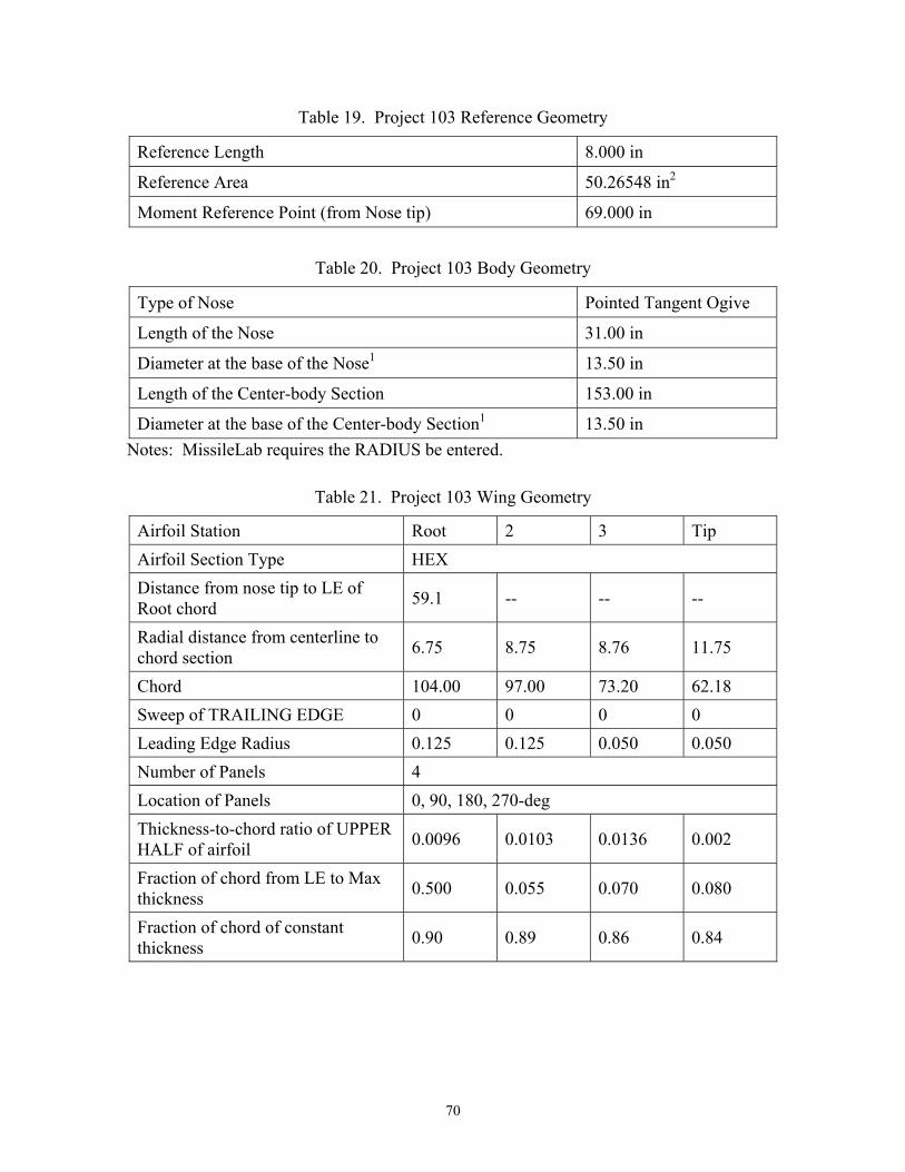
70
Table 19. Project 103 Reference Geometry
Reference Length 8.000 in
Reference Area 50.26548 in2
Moment Reference Point (from Nose tip) 69.000 in
Table 20. Project 103 Body Geometry
Type of Nose Pointed Tangent Ogive
Length of the Nose 31.00 in
Diameter at the base of the Nose1 13.50 in
Length of the Center-body Section 153.00 in
Diameter at the base of the Center-body Section1 13.50 in Notes: MissileLab requires the RADIUS be entered.
Table 21. Project 103 Wing Geometry
Airfoil Station Root 2 3 Tip Airfoil Section Type HEX Distance from nose tip to LE of Root chord 59.1 -- -- --
Radial distance from centerline to chord section 6.75 8.75 8.76 11.75
Chord 104.00 97.00 73.20 62.18 Sweep of TRAILING EDGE 0 0 0 0 Leading Edge Radius 0.125 0.125 0.050 0.050 Number of Panels 4 Location of Panels 0, 90, 180, 270-deg Thickness-to-chord ratio of UPPER HALF of airfoil 0.0096 0.0103 0.0136 0.002
Fraction of chord from LE to Max thickness 0.500 0.055 0.070 0.080
Fraction of chord of constant thickness 0.90 0.89 0.86 0.84
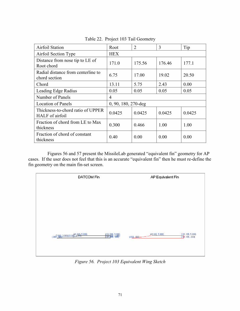
71
Table 22. Project 103 Tail Geometry
Airfoil Station Root 2 3 Tip Airfoil Section Type HEX Distance from nose tip to LE of Root chord 171.0 175.56 176.46 177.1
Radial distance from centerline to chord section 6.75 17.00 19.02 20.50
Chord 13.11 5.75 2.43 0.00 Leading Edge Radius 0.05 0.05 0.05 0.05 Number of Panels 4 Location of Panels 0, 90, 180, 270-deg Thickness-to-chord ratio of UPPER HALF of airfoil 0.0425 0.0425 0.0425 0.0425
Fraction of chord from LE to Max thickness 0.300 0.466 1.00 1.00
Fraction of chord of constant thickness 0.40 0.00 0.00 0.00
Figures 56 and 57 present the MissileLab generated “equivalent fin” geometry for AP cases. If the user does not feel that this is an accurate “equivalent fin” then he must re-define the fin geometry on the main fin-set screen.
Figure 56. Project 103 Equivalent Wing Sketch

72
Figure 57. Project 103 Equivalent Wing Sketch
VI. FREQUENTLY ASKED QUESTIONS (FAQ)
(Q) I am trying to load an existing DATCOM file, and MissileLab seems to “hang-up” when reading the file. What is the problem?
(A) It is most likely that the existing DATCOM file is missing or has a mis-placed comma. You should carefully inspect the DATCOM input file, then try and re-load the file after correcting any comma errors.
(Q) I am trying to read an existing DATCOM file, and a variable is not being interpreted correctly.
(A) The DATCOM reader was developed based on existing DATCOM documentation. Sometimes DATCOM allows things that the manual does not address. Check the manual, and try changing the input to conform to what the manual states.
(Q) How does the reference area calculator button (on the Body Reference screen) work with non-circular body cross-sections (on the Body Geometry screen)?
(A) The reference area calculator button calculates the area of a circle using the characteristic reference length as the diameter of the circle regardless of what body cross-section is specified. If the user, wishes to use any other value for reference area, simply enter that value if the reference area text box.

73
(Q) I entered the number of fin panels, but not the orientation. The AP codes will not run. Why?
(A) If the fin panel orientations are not entered, then the DATCOM defaults are used. These may not be valid orientations for the other codes.
(Q) I opened an existing project, and I can’t modify anything now. Why?
(A) If a project is opened with multiple cases, then the baseline case is automatically locked. This should be denoted by a “padlock” button at the top left corner of the form. To unlock the baseline case, simply click that button. However, BE CAREFUL. Changes to the baseline case might have an effect on other cases!
(Q) I added a case on the Case Manager page, and now I can’t modify my baseline case. Why?
(A) If any additional cases were added, then the baseline case is automatically locked. This should be denoted by a “padlock” button at the top left corner of the form. To unlock the baseline case, simply click that button. However, BE CAREFUL. Changes to the baseline case might have an effect on other cases!
(Q) On the body page, how do I designate body option 1 or 2 (AXIBOD or ELLBOD) for DATCOM?
(A) From MissileLab, this is not necessary. You can input the body in a way that makes sense. MissileLab will determine which option to send to DATCOM. If “User-Defined” is selected for the nose, a Midbody segment, or the Aft segment, then Option 2 is automatically used. Also, if multiple midbody segments are selected, Option 2 is used.
(Q) On the Base Effects page, I tried to enter Base Plume Interaction data, but the grid was not large enough. Why?
(A) The Base Plume Interaction (as well as numerous other inputs) are Mach number dependent. Check to make sure that you have correctly input the Mach numbers on the Flight Conditions page.
(Q) I have entered a fin set on the Finsets page but it does not get exported to the output files nor do they show up on the geometry sketcher.
(A) To allow easy changing of the body geometry, The Geometry Parametrics page allows the user to turn on/off fins and other geometric parameters. Check to make sure that the finsets are turned on on the Geometry Parametrics page.

74
(Q) When I go to the Deflections/Trim page, the finset I want to deflect/trim doesn’t show as an option.
(A) Check the Geometry Parametrics page to make sure that the Finset is designated for Control.
(Q) How do I clear my “Recently Used Files” list?
(A) Locate the “REGEDT32.EXE” program which is typically located in your “\Windows\System32” directory. BE VERY CAREFUL what you do here! Locate the “MissileLab” entry, and under that you should find a “Files” entry. This is where the “recently used files” are stored. Locate the files you wish to delete – and be VERY CAREFUL!
(Q) Why does my computer seem to run slow after using the 3-D sketch feature in MissileLab?
(A) On some graphics card, the 3-D graphics will run slowly. To disable the 3-D graphics, go to the “Locate Manuals / Set Options”. Allow MissileLab to write a new Initialization file to disable the 3-D graphics every time MissileLab is run.
In extremely rare cases, the 3-D graphics can cause an unexplained memory leak. In this case, disable the 3-D graphics as explained above. This last problem has occurred only once, was in a different application, and was not repeatable.
(Q) Why does MissileLab keep asking me to locate either 3-DLinx.dll or NavAddons.dll?
(A) At runtime, MissileLab looks for these components in the executable directory and the System32 directory. These dll’s should be placed into one of these directories if 3-D graphics are desired. If 3-D graphics are not desired, the Include3d flag in the INI file should be set to 0. This can also be done from the Locate Manuals / Set Options menu under Options.

75/(76 Blank)
REFERENCES
1. Blake, Missile DATCOM: Users’ Manual – 1997 FORTRAN 90 Version, Air Force Research Laboratory, AFRL-VA-WP-TR-1998-3009, Feb 1998.
2. Moore, McInville, Hymer, The 1998 Version of the NSWC Aeroprediction Code – Part 1: Summary of New Theoretical Methodology, Naval Surface Warfare Center, Dahlgren Division, NSWCDD/TR-98/1, April 1998.
3. Moore, Hymer, Downs, Users’ Guide for an Interactive Personal Computer interface for the 1998 Aeroprediction Code (AP98), Naval Surface Warfare Center, Dahlgren Division, NSWCDD/TR-98/7, June 1998.
4. Moore, Hymer, The 2002 Version of the Aeroprediction Code – Part 1: Summary of New Theoretical Methodology, Naval Surface Warfare Center, Dahlgren Division, NSWCDD/TR-01/108-PT-1, March 2001.
5. Moore, Hymer, The 2002 Version of the Aeroprediction Code – Part 2: Users’ Guide, Naval Surface Warfare Center, Dahlgren Division, NSWCDD/TR-02/34, May 2002.
6. Moore, Hymer, The 2005 Version of the Aeroprediction Code – Part 1: Summary of New Theoretical Methodology, Aeroprediction INC, King George, VA.
7. Moore, Hymer, The 2005 Version of the Aeroprediction Code – Part 2: Users’ Guide, Aeroprediction INC, King George, VA.
8. Lesieutre, Love, Dillenius, “MISL3 – Aerodynamic Analysis for Finned Vehicles with Axisymmetric Bodies,” Nielsen Engineering and Research INC, NEAR TR-561, May 2001.
9. Auman Tauchen, “AeroLab Users’ Guide,” U.S. Army Aviation and Missile Command, TR-RD-SS-03-09, Redstone Arsenal, AL, April 2003.
10. Auman, “Users’ Guide to the Aerodynamic Database,” U.S. Army Missile Command, TR-RD-SS-92-7, Redstone Arsenal, AL, April 1992.
11. 3DLinx - a 3D ActiveX Control developed by GlobalMajic Software, Huntsville AL.
12. Blackmar, Miller, Blake, “Approximate Methods for Center of Pressure Prediction of Multi-Segment Wings,” AIAA paper 2003-3934, Presented at the 21st Applied Aerodynamics Conference, Orlando, FL, June 2003.

Dist-1/(Dist-2 Blank)
INITIAL DISTRIBUTION LIST
Copies Weapon Systems Technology Information Analysis Center 1 ATTN: Ms. Vakare Valaitis 1901 N. Beauregard Street, Suite 400 Alexandria, VA 22311-1720
Defense Technical Information Center 1 8725 John J. Kingman Rd., Suite 0944 Fort Belvoir, VA 22060-6218
AMSRD-AMR (Electronic)
AMSRD-AMR-IN-IC 2
AMSRD-AMR-SS, Mr. George Landingham 1 Mr. Gregg Tackett 1
AMSRD-AMR-SS-AT, Mr. Lamar Auman 1 Mr. Richard Kretzschmar 1
AMSRD-L-G-I, Mr. Dayn Beam 1


![Navy Ohio Replacement (SSBN[X]) Ballistic Missile ...](https://static.fdokumen.com/doc/165x107/6322a5b0887d24588e045283/navy-ohio-replacement-ssbnx-ballistic-missile-.jpg)