MIL-DTL-5015 Solder - MILNEC
34
MILITARY & DEFENSE EDITION • IP67 Rated Waterproof Connectors • Covers, Gaskets, Bushings • Mounting Hardware, Tooling CONNECTING YOUR ENGINEERING PASSION PM Series MIL-DTL-5015 Solder MILITARY STYLE CONNECTORS
-
Upload
khangminh22 -
Category
Documents
-
view
0 -
download
0
Transcript of MIL-DTL-5015 Solder - MILNEC

M I L I TA RY & D E F E N S E E D I T I O N
• IP 67 Rated Wate rp roof Connecto rs• Covers , Gaskets , Bush ings• Mount ing Hardware , Too l ing
C O N N E C T I N G Y O U R
E N G I N E E R I N G P A S S I O N
PM Series
MIL-DTL-5015 SolderM I L I T A R Y S T Y L E C O N N E C T O R S

Rev. 2208
G-1M I L N E C . C O M
PM
PM Series • MIL-DTL-5015 Solder Type Connectors
Milnec Interconnect Systems High-Performance Cylindrical Connectors
High Reliability—SimplifiedJust because your interconnect
problem is complicated does
not mean acquiring the
solution has to be. Milnec
connector systems and our
“all-in-one” kits provide
engineers the most complete
and professional connector
solutions with ease and technical clarity.
• Complete, high-reliability solutions
• Simple to understand technical data & configurations
• Online part builder tools, drawings, & documentation
• Field installable & serviceable
Highest Manufacturing QualityWe invest in the finest equipment and
modern production processes
to ensure that our connectors
will exceed your quality and
performance expectations.
Our production processes
include advanced computer
numerical control machining,
cosmetic and metal finishing,
heat treatment, and stainless
steel passivation.
• Traceability on 100% of the parts
• Quick production lead times
• Quantity support from R&D to production
• “Just-in-time” delivery, kitting, & special packaging
• Rapid tooling & prototyping for custom designs
About Usilnec interconnect systems is a leader in the design,
manufacture, and supply of high-performance
cylindrical interconnect systems. From research
stations in the Antarctic to spacecraft on
the plains of Mars, our high-reliability
connector systems conquer the
most demanding environments.
Milnec is a supplier to leading
companies in 24 countries in
the following industries:
• Military & Defense
• Aerospace & Space
• Railway & Mass Transit
• Industrial & Heavy Equipment
• Alternative Energy, Nuclear, Oil & Gas
Logistics Solutions for Global ApplicationsGlobal logistics and support means we deliver products on
time every time to any destination. To support your immediate
requirements, we have extensive inventories, making most
systems readily available for today’s compressed design and
production schedules. On average, custom connector solutions
made to your exact configuration ship within seven days from
the time of order placement.
• Worldwide shipping (restricted to NATO countries only)
• Web access to inventory, prices, & delivery information
• A large stock of popular parts for greater availability
• Competitive pricing and short lead times
• Impeccable customer service & technical support
Performance With Environmental ResponsibilityRoHS compliant products are available to
support environmental responsibility and
legislative conformity. Through simple
modification codes, Milnec provides a
wide variety of material options to easily
provide customers with fully compliant
and eco-friendly connector components.
• RoHS compliant materials & finishes
• Simple material modification codes
• Lead-free solder contacts
Milnec Interconnect Systems3947 West Lincoln Highway #192
Downingtown, PA 19335
1-855-4MILNEC Toll Free
(1-855-464-5632)--------------
U.S. Military Cage Code: 6STX5
NAICS Code: 423690

Rev. 2208
G-2 M I L N E C . C O M
PM
PM Series • MIL-DTL-5015 Solder Type Connectors
Features & Benefits
MIL-DTL-5015 Compliant Connectors
The PM Series offers a complete line of MIL-DTL-5015
type connectors. PM connectors are built to meet and
exceed all performance specifications for the military
MIL-DTL-5015 standard. In addition, the series provides a
complete offering of accessories to ensure full IP67 protection
and reliability. These heavy duty, environmentally resistant
connectors offer the protection required for signal and power
applications in harsh environments. The PM Series provides a
versatile and high-performance, yet economical, solder termi-
nated metal connector solution designed for mission success.
• Compatible with all MIL-DTL-5015 style connectors
• Rated for up to 150 amps
• Wide range of insert arrangements
• Full array of sealing accessory kits for
complete IP67 environmental installations
100% MIL-DTL-5015 CompatibilityPM Series connectors provide
complete compatibility with all existing military and commercial5015 style plugs and receptacles.
About Us . . . . . . . . . . . . . . . . . . . . . . . . . . . . . . . . . . . . . . G-1
Features & Benefits . . . . . . . . . . . . . . . . . . . . . . . . . . . . . G-2
Component Overview . . . . . . . . . . . . . . . . . . . . . . . . . . . G-3
Series Specifications . . . . . . . . . . . . . . . . . . . . . . . . . . . . G-4
Contact Specifications . . . . . . . . . . . . . . . . . . . . . . . . . . . G-6
Materials & Finishes. . . . . . . . . . . . . . . . . . . . . . . . . . . . . G-8
Part Builder . . . . . . . . . . . . . . . . . . . . . . . . . . . . . . . . . . . . G-10
Insert Arrangements & Rotations . . . . . . . . . . . . . . . . . . G-11
Insert Arrangement Drawings . . . . . . . . . . . . . . . . . . . . . G-14
(PM06) Straight Plug . . . . . . . . . . . . . . . . . . . . . . . . . . . . G-20
(PM08) 90° Plug . . . . . . . . . . . . . . . . . . . . . . . . . . . . . . . . G-21
(PM00) Wall Mount Receptacle . . . . . . . . . . . . . . . . . . . . G-22
(PM02) Box Mount Receptacle . . . . . . . . . . . . . . . . . . . . G-23
(PM01) Cable Mount Receptacle. . . . . . . . . . . . . . . . . . . G-24
(PM22) Thru-Bulkhead Receptacle . . . . . . . . . . . . . . . . . G-25
(PMCP) Protective Covers . . . . . . . . . . . . . . . . . . . . . . . . G-26
(PMCD) Stowage Receptacle . . . . . . . . . . . . . . . . . . . . . . G-27
(PMGE) Mounting Gasket. . . . . . . . . . . . . . . . . . . . . . . . . G-28
(PMMB)Mounting Bracket & Screws. . . . . . . . . . . . . . . . G-29
(PMRB) Cable Bushing . . . . . . . . . . . . . . . . . . . . . . . . . . . G-30
Soldering Station . . . . . . . . . . . . . . . . . . . . . . . . . . . . . . . G-31
Table of Contents
Complete IP67 Rated Waterproof Connector KitsPM Series connectors can be easily configured as complete
kits that include everything you need for a reliable, IP67 rated
environmental interconnect solution. Simply select the desired
kit option on the part builder and your connector will come
with all the matching accessories you need right out of the box.
• Integrated environmental backshells
• Protective covers
• Sealing gaskets
• Mounting brackets with locking nuts
• Sealing screws
Signal & Power in One ConnectorWith five contact sizes ranging from #0 to #16, engineers have the option of running signal and high power (up to 150A) through the same PM Series connector.
More Options for Complete Design FlexibilityWith today’s advanced electronic designs, engineers demand
more options. PM Series connectors provide you with the
most complete offering of shell options, materials, finishes,
and accessories currently unavailable in the mil-spec.
• More shell options, including thru-bulkheads
• Alternate material & RoHS compliant platings
• Complete set of sealing accessories
MILNEC.COM
MILNEC.COM
MILNEC.COM
MILNEC.COM MILNEC.COM

Rev. 2208
G-3M I L N E C . C O M
PM
7
Plugs
Mounting
Covers
Receptacles
ToolsAccessories
Cable Mount
p. G-24
Thru-Bulkhead
p. G-25
Plug Cover
p. G-26
Recept. Cover
p. G-26
Stowage Receptacle
p. G-27
Box Mount
p. G-23
Wall Mount
p. G-22
Soldering Station
p. G-31
Straight Plug
p. G-20
90° Plug
p. G-21
Mounting Gasket
p. G-28
Mounting Bracket & Screws
p. G-29
Cable Bushing
p. G-30
PM Series • MIL-DTL-5015 Solder Type Connectors
Component Overview

Rev. 2208
G-4 M I L N E C . C O M
PM
PM Series • MIL-DTL-5015 Solder Type Connectors
Protective Cover
CableBushing
Compression Cup
Mounting Bracket
Mounting Gasket
Receptacle Shell
Sealing Screws
Backshell with Strain Relief Clamp
Sealing Grommet
SashChain
Series Specifications
Performance Specifications Built to meet or exceed MIL-DTL-5015 specifications
Guaranteed fully compatible and interchangeable with
respect to physical and performance characteristics with
all existing 5015 style military and commercial derivatives
Environmental Characteristics Temperature Range
-67° to +257°F (-55° to +125°C)
Service life varies with the maximum internal hot
spot temperature resulting from any combination
of electrical load or ambient temperature:
77°F (25°C): Continuous
221°F (105°C): 1,000 hours
257°F (125°C): 250 hours
Water Pressure
IP67 rating (environmental sealing)
Fully submersible to 3.3 ft (1m) for minimum of 30 min
Air Leakage Rate
Environmental connector air leakage rate shall not
exceed 1 inch3/hr (4.55 x10⁻³ cm3/sec) at 30 psi
(2.11 kg/cm2) pressure differential
Salt Spray Rating
See Materials & Finishes, p. G-8
Humidity
Mated connectors shall maintain an insulation
resistance of 100 megohms or greater at 77°F (25°C)
with 95% humidity for duration of 20 days
Chemical Resistance to Fluids
20 hour full immersion (unmated) in hydraulic fluid and
lubricating oil without damage or material degradation
Physical Characteristics Coupling
Threaded (A-Threads), single-start, 4 turns to couple
Coupling Torque
Engagement & Disengagement Force (max / min)
Shell Size 10: 2.21 ft-lbf (3.0 N-m) / .11 ft-lb
f (.15 N-m)
Shell Size 12: 2.07 ft-lbf (2.8 N-m) / .17 ft-lb
f (.23 N-m)
Shell Size 14: 4.35 ft-lbf (5.9 N-m) / .26 ft-lb
f (.35 N-m)
Shell Size 16: 5.16 ft-lbf (7.0 N-m) / .34 ft-lb
f (.46 N-m)
Shell Size 18: 5.90 ft-lbf (8.0 N-m) / .43 ft-lb
f (.58 N-m)
Shell Size 20: 6.64 ft-lbf (9.0 N-m) / .52 ft-lb
f (.70 N-m)
Shell Size 22: 7.82 ft-lbf (10.6 N-m) / .59 ft-lb
f (.80 N-m)
Shell Size 24: 9.51 ft-lbf (12.9 N-m) / .59 ft-lb
f (.80 N-m)
Shell Size 28: 12.32 ft-lbf (16.7 N-m) / .68 ft-lb
f (.92 N-m)
Shell Size 32: 13.35 ft-lbf (18.1 N-m) / .75 ft-lb
f (1.02 N-m)
Shell Size 36: 17.63 ft-lbf (23.9 N-m) / .77 ft-lb
f (1.05 N-m)
Polarization
Single master key and keyway on top position of shell
Insert Arrangements
126 standard, custom inserts available
Insert Rotations
Normal polarization (N), plus 4 alternate insert
rotational polarizations (W, X, Y, Z)
Endurance Characteristics Coupling Cycles
250 coupling cycles (minimum)
Shock
50g’s, 11ms duration, three major axes,
10 microseconds maximum discontinuity
Vibration
Random vibration at 10 to 2,000Hz (15g’s),
10 microseconds maximum discontinuity
MILNEC.COMMILNEC.COM

Rev. 2208
G-5M I L N E C . C O M
PM
PM Series • MIL-DTL-5015 Solder Type Connectors
Sash Chain
Cable Bushing
Protective Cover
PlugShell
Sealing Grommet
Compression Cup
Coupling Ring
Backshell with Strain Relief Clamp
Series Specifications
Material Characteristics Shell
Aluminum, solid, one piece, seamless construction
Shell Plating
Standard (F) finish is electrically conductive cadmium
plate finish with an olive drab chromate after-treat
for additional corrosion resistance
(See p. G-8 for all available finishes)
Shell Conductivity
Maximum shell-to-shell conductivity potential drop
shall not exceed 200 millivolts across assembly
Insert
Resilient polychlorophrene (neoprene)
Non-removable and mechanically bonded to shell
Protective Cover Chain
Passivated stainless steel, sash chain able to
withstand a 25 lb (11.3 kg) tensile force without damage
Compression Cup
Plastic
Sealing Grommet
Neoprene
O-Ring Seal
Neoprene or silicone
Mounting Gasket
Neoprene or silicone
Mounting Bracket
Aluminum alloy with SST locking nuts
Sealing Screws
SST steel with silicone O-rings
Cable Bushing
Neoprene
Contact Characteristics Contact Design
Solder style, permanently bonded to insert
Pre-tinned solder cups and solder wells standard
Contact Sizes
#0, #4, #8, #12, #16
Contacts
Copper alloy
Contact Plating
Silver alloy plate, 100 µinches (2.54 µm) minimum
Max Number of Contacts
1 to 52 standard, custom inserts available
Max Contact Resistance
6 milliohm maximum resistance
Potential Voltage Drop
<50 millivolt maximum drop (initial)
Contact Retention
Pin and socket contacts are designed to resist severe
vibration and repeated connection and disconnection
Electrical Characteristics Current Rating
150 amps (test current) at 68°F (20°C)
Max Operating Voltage
3,000 VAC (RMS) at sea level
Insulation Resistance
>5,000 megohms at 77°F (25°C)
Wire Size
0 to 22 (AWG)
Wire Sealing Range
Designed for individual wire sealing
Sealing is only guaranteed if wires meet
MIL-W-5086 or within permitted ranges
MILNEC.COM MILNEC.COM

Rev. 2208
G-6 M I L N E C . C O M
PM
AStrip Length
(A + B)
B
B
B
Dimensions are in inches (mm).
Wire Size (AWG)
Contact Size
#16 #12 #8 #4 #0
22 5A
20 7.5A
18 10A
16 13A
14 17A
12 23A
10 33A
8 46A
6 60A
4 80A
2 100A
1 125A
0 150A
Current Rating By Contact Size & Wire Size
Wire & Solder Dimensions
ContactSize
Wire RangePotential Drop
(Millivolts)
Max Contact Resistance(Milliohm)
Solder Well Depth
Solder Well Inside
Diameter
Solder Well Outside
Diameter
Contact RetentionAxial Load
Pounds (Newtons)
Separation Force Min
Pounds (Newtons)
AWG Dia
#16 16, 18, 20, 22 .025–.050 (.64–1.29) <50 6 .250 (6.4) .078 (2.0) .103 (2.6) 10 (44) .25 (1)
#12 12, 14 .064–.080 (1.62–2.05) <42 3 .375 (9.5) .116 (2.9) .146 (3.7) 15 (67) .50 (2)
#8 8, 10 .10–.12 (2.58–3.26) <26 1 .500 (12.7) .209 (5.3) .256 (6.5) 20 (89) .75 (3)
#4 4, 6 .16–.20 (4.11–5.18) <23 .5 .625 (15.9) .332 (8.4) .394 (10.0) 20 (89) 1.00 (4)
#0 0, 1, 2 .25–.32 (6.54–8.25) <21 .2 .625 (15.9) .469 (11.9) .547 (13.9) 25 (111) 2.00 (9)
Test ratings only. A connector cannot withstand maximum current through all contacts continuously. Please notethat the establishment of electrical safety factors is left entirely in the designer’s hands, since he or she is inthe best position to know what peak voltage, switching surges, transients, etc. can be expected in a particularcircuit.
Contact Size (A) Well Depth Recommended
Strip Length
#16 .200 (5.1) .250 (6.4)
#12 .245 (6.2) .375 (9.5)
#8 .350 (8.9) .500 (12.7)
#4 .500 (12.7) .625 (15.9)
#0 .575 (14.6) .625 (15.9)
Strip Length
Test ratings only. A connector cannot withstand maximum current through all contacts continuously. Please note that the establishment of electrical safety factors is left entirely in the designer’s hands, since he or she is in the bestposition to know what peak voltage, switching surges, transients, etc. can be expected in a particular circuit. Dimensions are in inches (mm) unless otherwise noted.
PM Series • MIL-DTL-5015 Solder Type Connectors
Contact Specifications
The recommended insulation strip length found in the table
below can be used for standard insulated wire. For heavy
jacketed wire, insulation strip length can be quickly and easily
calculated by adding the contact solder well depth (A) to the
wire’s outside insulation diameter (B). The conductor should
be exposed to a length that will bring the insulation clearance
above the solder cup equal to the outside diameter of the
insulation (B) when the wire is inserted in the solder cup to its
full depth.
When removing the insulation from conductors always use a
thermal precision cutter or jacket stripping device. Care must
be exercised to prevent damage to the individual wire strands
or conductor when cutting the jacket insulation.
Recommended Insulation Strip Length
PM Series ContactsBelow are the PM Series solder contacts shown in actual size.
This illustration can help determine which size contact will
best fit a wire if you do not know the wire gauge being used.
Size #12
Size #8
Size #4
Size #0
Size #16
MILNEC.COM MILNEC.COM
MILNEC.COM
MILNEC.COM
MILNEC.COM
MILNEC.COM
MILNEC.COM
MILNEC.COM

Rev. 2208
G-7M I L N E C . C O M
PM
We know your project can’t wait, so we provide tailor-made
flexibility with off-the-shelf lead times. We employ the lat-
est assembly and quality-control processes to build and
test every connector we ship.
World Class Service, Worldwide
MILNEC SHIPS CONNECTORS
WORLDWIDE IN ONE WEEK
• Standard connector kits ship in just one week
• No order minimums, credit cards accepted
• Average ship time is 7 days
• Expedited builds available for critical requirements
Contact Derating Specifications
Service Rating
Max Operating Voltage
at Sea Level
Nominal Distance in Inches (mm) Mechanical
Spacing Nominal
Standard Sea Level Conditions
Pressure Altitude 50,000 ft
Pressure Altitude 70,000 ft
AC (RMS) DC Airspace Creepage
Min Flashover Voltage
AC (RMS)
Test Voltage AC (RMS)
Min Flashover Voltage
AC (RMS)
Test Voltage AC (RMS)
Min Flashover Voltage
AC (RMS)
Test Voltage AC (RMS)
Inst. 200 250 .0312 (.8) .063 (1.6) — 1,400 1,000 500 400 325 260
A 500 700 .063 (1.6) .125 (3.2) .063 (1.6) 2,800 2,000 800 600 450 360
D 900 1,250 .125 (3.2) .188 (4.8) .125 (3.2) 3,600 2,800 900 675 500 400
E 1,250 1,750 .188 (4.8) .250 (6.4) .188 (4.8) 4,500 3,500 1,000 750 550 440
B 1,750 2,450 .250 (6.4) .313 (8.0) .250 (6.4) 5,700 4,500 1,100 825 600 480
C 3,000 4,200 .313 (8.0) 1.000 (25.4) .313 (8.0) 8,500 7,000 1,300 975 700 560
Wire Sealing RangeContact
SizeWire Size
(AWG)
Insulation Outside Diameter Range
Min Max
#16 16, 18, 20, 22 .064 (1.63) .130 (3.30)
#12 12, 14 .114 (2.90) .170 (4.32)
#8 8,10 .164 (4.17) .255 (6.48)
#4 4, 6 .275 (6.98) .370 (9.40)
#0 0, 1, 2 .415 (10.54) .550 (13.97)
Test ratings only. A connector cannot withstand maximum current through all contacts continuously. Please note that the establishment of electrical safety factors is left entirely in the designer’s hands, since he or she is in the bestposition to know what peak voltage, switching surges, transients, etc. can be expected in a particular circuit.
Units are in inch pounds (Newton meters).
ScrewSize
Recommended Torque
Min Max
#2-56 1.5 (.2) 2.5 (.3)
#4-40 3.5 (.4) 4.5 (.5)
#6-32 5 (.6) 7 (.8)
#8-32 7 (.8) 9 (1.0)
#10-32 9 (1.0) 11 (1.2)
#.250-20 11 (1.2) 13 (1.5)
Torque Values For Cable Clamp Screws
Dimensions are in inches (mm) unless otherwise noted.
PM Series • MIL-DTL-5015 Solder Type Connectors
Contact Specifications

Rev. 2208
G-8 M I L N E C . C O M
PM
A
B
CD
E
F
G
MIL
NE
C
FinishCode Finish Electrically
ConductivePre-TinnedSolder Cups
RoHS Compliant Appearance Shell
MaterialSalt Spray
RatingRecommended Operating
Temperature Range
F Olive Drab Cadmium Drab Olive Green Aluminum 500 hrs -67° to +257°F (-55° to +125°C)
Finish Code Finish Electrically
ConductivePre-TinnedSolder Cups
RoHS Compliant Appearance Shell
MaterialSalt Spray
RatingRecommended Operating
Temperature Range
BHardcoat Anodize
Grey to Black Aluminum 336 hrs -67° to +257°F (-55° to +125°C)
BA N
Electroless Nickel
Bright Metal Aluminum 48 hrs -67° to +257°F (-55° to +125°C)NA C
Zinc Cobalt
Black Aluminum 125 hrs -67° to +257° (-55° to +125°C)CA CB
CC T
Hard Anodic
Grey Aluminum 500 hrs -67° to +257°F (-55° to +125°C)TA
Special PM Series Materials & Finishes*
Standard PM Series Materials & Finishes
* Pleaseconsultanauthorizeddistributorforleadtimeinformationandminimumquantityrequirementsforspecialorderfinishes.
PM Series • MIL-DTL-5015 Solder Type Connectors
Aconnector's finish does more than simply provide
good looks. The finish is the first line of defense for a
connector. It provides enhanced corrosion resistance
and can be made conductive to provide electrical continuity
across connector shells for EMI/RFI shielding applications.
Olive drab cadmium is the standard finish for the PM Series.
It offers excellent corrosion resistance and will match the
aesthetic design of most applications. In addition, a number
of specialty finishes are available, including RoHS compliant
finishes for environmentally friendly designs. n
PM Series Finishes
Milnec provides a full
offering of RoHS compliant
finishes in conductive and
non-conductive versions to
best suit your application requirements.
Please consult the latest European Union general and
regional regulations to ensure materials are appropriate
for your application and compliance requirements.
RoHS Compliant Parts
Materials & Finishes
Olive Drab Cadmium—Durable & EconomicalOlive drab cadmium (F) plating is the standard finish for PM
Series connectors due to its high corrosion resistance. This fin-
ish is conductive, making it suitable for shielding or ground-
ing applications, and is resistive to galling. Its olive drab
appearance matches most equipment. Olive drab cadmium
is suitable for all general duty, industrial, military, and marine
applications.
• Finish Specification: SAE-AMS-QQ-P-416 II Class 2
• Appearance: Military Olive Drab Green
• Sheen: Flat, Low Gloss
• Max Temp. Rating: 347°F (175°C)
• Salt Spray Rating: 500 hours
• Lubricity: Good
• Galling Resistance: High
• Conductive: Yes
• RoHS Compliant: No

Rev. 2208
G-9M I L N E C . C O M
PM
PROTECTIVE ACCESSORIES
FOR HARSH ENVIRONMENTS
Maintain System Integrity — AnywhereKeep equipment running by using perfectly matched accessories
to protect your connectors. Our full line of protective accessories is
designed for MIL-DTL-5015 plugs and receptacles to ensure a reliable
installation. Don’t let your connectors go into battle alone. Protect
them with covers, gaskets, mounting brackets, and sealing screws.
PM Series • MIL-DTL-5015 Solder Type Connectors

Rev. 2208
G-10 M I L N E C . C O M
PM
PM Series • MIL-DTL-5015 Solder Type Connectors
Series Shell Style Environmental Shells
PM06 Straight plug w/ backshell, p. G-20
PM08 90° plug w/ backshell, p. G-21
PM00 Wall mount recept. w/ backshell, p. G-22
PM01 Cable mount recept. w/ backshell, p. G-24
PM02 Box mount receptacle, p. G-23 For non-standard shell styles, including thru-bulkhead receptacles, pleaseseespecificdatasheetforpartnumberingandkittingoptions.
Material & Finish F Olive drab cadmium (aluminum)
500 hr. dynamic salt spray rating Forcompletematerialsandfinishesoptions,includingRoHS,seep.G-8.
Shell Size & Insert Arrangement See Insert Arrangement Selection table on p. G-11.
Contact Style Standard Solder Contacts
P Pin
S Socket
Thermocouple Solder Contacts*
Connectors may be ordered with the following
size #16 and #12 thermocouple contact options:
alumel, chromel, iron, and constantan. * Please consult authorized distributor for lead time and minimum quantity requirements.
Part Builder
PM00 F 16S-1 S N - 02
How to Build Your PM Connector Part Number
Insert Rotations Normal Rotation
N Normal rotation
Alternate Rotations
W, X, Y, Z Alternate rotation SeeInsertArrangementSelectiontableonp.G-11. (Not all rotations are available for every arrangement.)
Optional Accessory Kit (Omit for None) 01 For Plugs:
Protective cover, p. G-26 +
Cable bushing, p. G-30
02 For Receptacles:
Protective cover, p. G-26 +
Mounting gasket, p. G-28 +
Cable bushing, p. G-30
03 For Receptacles:
Protective cover, p. G-26 +
Mounting gasket, p. G-28 +
Cable bushing, p. G-30 +
Mounting bracket, p. G-29
with (4x) sealing screws
A part number is comprised of a string of characters
that represent the different elements of a connector.
High-performance connectors are built to order from
component form using a unique part number as a blueprint
to specify particular characteristics. Each modifier of the part
number represents a particular configuration.
Below is an example part number for a PM Series connector
that designates, 1) Milnec PM Series wall mount receptacle,
2) olive drab cadmium finish over aluminum, 3) 16S-1 insert
arrangement, 4) socket contacts, 5) normal rotation, and 6)
integrated kit including protective cover, mounting gasket,
and cable bushing. n

Rev. 2208
G-11M I L N E C . C O M
PM
Position Z
AB
AB
AB
AB
Position Y
AB
AB
AB
AB
Position X
AB
AB
AB
AB
Position W
AB
AB
AB
AB
Insert Arrangement Selection
* Option is unavailable if left blank. (Continued on next page)
InsertArrangement
TotalContacts
Contact Size ServiceRating
Alternate Insert Rotation
#16 #12 #8 #4 #0 W X Y Z
10SL-3 3 3 A
10SL-4 2 2 A 63°
12-5 1 1 A
12S-3 2 2 A 70° 145° 215° 290°
14S-1 3 3 A
14S-2 4 4 Inst. 120° 240°
14S-4 1 1 D
14S-5 5 5 Inst. 110°
14S-6 6 6 Inst.
14S-7 3 3 A 90° 180° 270°
14S-9 2 2 A 70° 145° 215° 290°
16-7 3 2 1 A 80° 110° 250° 280°
16-9 4 2 2 A 35° 110° 250° 325°
16-10 3 3 A 90° 180° 270°
16-11 2 2 A 35° 110° 250° 325°
16-12 1 1 A
16S-1 7 7 A 80° 280°
16S-4 2 2 D 35° 110° 250° 325°
16S-5 3 3 A 70° 145° 215° 290°
16S-6 3 3 A 90° 180° 270°
16S-8 5 5 A 170° 265°
18-1 10 10 A/Inst. 70° 145° 215° 290°
18-3 2 2 D 35° 110° 250° 325°
18-4 4 4 D 35° 110° 250° 325°
18-5 3 1 2 D 80° 110° 250° 280°
18-8 8 7 1 A 70° 290°
18-9 7 5 2 Inst. 80° 110° 250° 280°
18-10 4 4 A 120° 240°
18-11 5 5 A 170° 265°
18-12 6 6 A 80° 280°
18-13 4 3 1 A 80° 110° 250° 280°
18-16 1 1 C
PM Series • MIL-DTL-5015 Solder Type Connectors
Below is a chart that represents every available shell
and insert arrangement within the series. To choose the
proper insert arrangement, you must first distinguish
your application requirements for contact size and amount.
Rotations are designated at the time of ordering using rotation
labels N (normal), W, X, Y, and Z. Some insert arrangements
have limited or no alternate rotation options. Refer to the
chart below for possible rotations for specific arrangements. n
Selecting Your Insert Arrangement & Rotation
Insert Arrangements & Rotations
Looking into front face of pin
insert or rear of socket insert.

Rev. 2208
G-12 M I L N E C . C O M
PM
Insert Arrangement Selection (Continued from previous page)
InsertArrangement
TotalContacts
Contact Size ServiceRating
Insert Rotation
#16 #12 #8 #4 #0 W X Y Z
18-19 10 10 A
18-22 3 3 0 70° 145° 215° 290°
20-2 1 1 D
20-3 3 3 D 70° 145° 215° 290°
20-4 4 4 D 45° 110° 250°
20-7 8 8 D/A 80° 110° 250° 280°
20-8 6 4 2 Inst. 80° 110° 250° 280°
20-11 13 13 Inst.
20-14 5 3 2 A 80° 110° 250° 280°
20-15 7 7 A 80° 280°
20-16 9 7 2 A 80° 110° 250° 280°
20-17 6 1 5 A 90° 180° 270°
20-18 9 6 3 A 35° 110° 250° 325°
20-19 3 3 A 90° 180° 270°
20-22 6 3 3 A 80° 110° 250° 280°
20-23 2 2 A 35° 110° 250° 325°
20-24 4 2 2 A 35° 110° 250° 325°
20-27 14 14 A 35° 110° 250° 325°
20-29 17 17 A 80° 280°
20-33 11 11 A
22-1 2 2 D 35° 110° 250° 325°
22-2 3 3 D 70° 145° 215° 290°
22-5 6 4 2 D 35° 110° 250° 325°
22-6 3 1 2 D 80° 110° 250° 280°
22-7 1 1 E
22-8 2 2 E 35° 110° 215° 325°
22-9 3 3 E 70° 145° 250° 290°
22-11 2 2 B 35° 110° 250° 325°
22-12 5 3 2 D 80° 110° 250° 280°
22-13 5 1 4 D/A 35° 110° 250° 325°
22-14 19 19 A 80° 110° 250° 280°
22-15 6 1 5 E/A 80° 110° 250° 280°
22-18 8 8 D/A 80° 110° 250° 280°
22-19 14 14 A 80° 110° 250° 280°
22-20 9 9 A 35° 110° 250° 325°
22-21 3 2 1 A 80° 110° 250° 280°
22-22 4 4 A 110° 250°
22-23 8 8 D/A 35° 250°
22-28 7 7 A 80° 280°
22-33 7 7 D/A 80° 110° 250° 280°
24-2 7 7 D 80° 280°
24-5 16 16 A 80° 110° 250° 280°
24-6 8 8 D/A 80° 110° 250° 280°
24-7 16 14 2 A 80° 110° 250° 280°
24-9 2 2 A 35° 110° 250° 325°
24-10 7 7 A 80° 280°
24-11 9 6 3 A 35° 110° 250° 325°
* Option is unavailable if left blank. (Continued on next page)
PM Series • MIL-DTL-5015 Solder Type Connectors
Insert Arrangements & Rotations

Rev. 2208
G-13M I L N E C . C O M
PM
Insert Arrangement Selection (Continued from previous page)
InsertArrangement
TotalContacts
Contact Size ServiceRating
Insert Rotation
#16 #12 #8 #4 #0 W X Y Z
24-12 5 3 2 A 80° 110° 250° 280°
24-20 11 9 2 D 80° 110° 250° 280°
24-21 10 9 1 D 80° 110° 250° 280°
24-22 4 4 D 45° 110° 250°
24-27 7 7 E 80° 280°
24-28 24 24 Inst. 80° 110° 250° 280°
28-1 9 6 3 D/A 80° 110° 250° 280°
28-2 14 12 2 D 35° 110° 250° 325°
28-3 3 3 E 70° 145° 215° 290°
28-5 5 2 1 2 D 35° 110° 250° 325°
28-6 3 3 D 70° 145° 215° 290°
28-7 2 2 D 35° 110° 250° 325°
28-8 12 10 2 E/D/A 80° 110° 250° 280°
28-9 12 6 6 D 80° 110° 250° 280°
28-10 7 3 2 2 D/A 80° 110° 250° 280°
28-11 22 18 4 A 80° 110° 250° 280°
28-12 26 26 A 90° 180° 270°
28-15 35 35 A 80° 110° 250° 280°
28-16 20 20 A 80° 110° 250° 280°
28-17 15 15 B/D/A 80° 110° 250° 280°
28-18 12 12 C/D/A/Inst. 70° 145° 215° 290°
28-19 10 6 4 B/D/A 80° 110° 250° 280°
28-20 14 4 10 A 80° 110° 250° 280°
28-21 37 37 A 80° 110° 250° 280°
28-22 6 3 3 D 70° 145° 250° 290°
32-1 5 3 2 E/D 80° 110° 250° 280°
32-2 5 2 3 E 70° 145° 215° 290°
32-3 9 4 2 2 1 D 80° 110° 250° 280°
32-5 2 2 D 35° 110° 250° 325°
32-6 23 16 2 3 2 A 80° 110° 250° 280°
32-7 35 28 7 Inst./A 80° 125° 235° 280°
32-8 30 24 6 A 80° 125° 235° 280°
32-9 14 12 2 D 80° 110° 250° 280°
32-13 23 18 5 D 80° 110° 250° 280°
32-15 8 6 2 D 35° 110° 250° 280°
32-17 4 4 D 45° 110° 250°
36-3 6 3 3 D 70° 145° 215° 290°
36-4 3 3 D/A 70° 145° 215° 290°
36-5 4 4 A 120° 240°
36-6 6 4 2 A 35° 110° 250° 325°
36-7 47 40 7 A 80° 110° 250° 280°
36-8 47 46 1 A 80° 110° 250° 280°
36-9 31 14 14 2 1 A 80° 125° 235° 280°
36-10 48 48 A 80° 125° 235° 280°
36-14 16 6 5 5 D 90° 180° 270°
36-15 35 35 D/A 60° 125° 245° 305°
36-52 52 52 A
* Option is unavailable if left blank.
PM Series • MIL-DTL-5015 Solder Type Connectors
Insert Arrangements & Rotations

Rev. 2208
G-14 M I L N E C . C O M
PM
#0 #4 #8 #10 #12 #16Contact Legend
PM Series • MIL-DTL-5015 Solder Type Connectors
A
B
CD
E
F
G
H
BC
AD
A
C
D
E
F
G
BA
B
C
D
E
F
A
BC
D
E
A
B
C
D
A
B
CA
BC
D
EA
BC
D
A B
A
BC
AB
A
BC
A
B
CD
E
F
G
B
C AA
B
A
B
CD
E
C
A BF
AB
CD
E
A
B
CAB
A
B
C
D
A
B
C ABB A A
B
C
AD
BC
AH
GBI
CF
DE
12-5
A
1 x #12
Arrangement
Service Rating
Number of Contacts
Arrangement
Service Rating
Number of Contacts
Arrangement
Service Rating
Number of Contacts
Arrangement
Service Rating
Number of Contacts
Arrangement
Service Rating
Number of Contacts
10SL-3
A
3 x #16
10SL-4
A
2 x #16
12S-3
A
2 x #16
14S-1
A
3 x #16
14S-2
Inst.
4 x #16
14S-4
D
1 x #16
14S-5
Inst.
5 x #16
16S-4
D
2 x #16
16S-5
A
3 x #16
16S-6
A
3 x #16
16S-8
A
5 x #16
16-7
A
1 x #8
2 x #16
14S-6
Inst.
6 x #16
14S-7
A
3 x #16
14S-9
A
2 x #16
16S-1
A
7 x #16
16-10
A
3 x #12
16-11
A
2 x #12
16-12
A
1 x #4
16-9
A
2 x #12
2 x #16
18-1
B,C,F,G=A; Bal.=Inst.
10 x #16
18-4
D
4 x #16
18-3
D
2 x #12
18-5
D
2 x #12
1 x #16
18-8
A
1 x #12
7 x #16
18-10
A
4 x #12
18-9
Inst.
2 x #12
5 x #16
18-12
A
6 x #16
18-11
A
5 x #12
18-13
A
1 x #8
3 x #12
Insert Arrangement Drawings
(Continued on next page)

Rev. 2208
G-15M I L N E C . C O M
PM
PM Series • MIL-DTL-5015 Solder Type Connectors
A
B C
GD
EF
H
K
J A B
GA
BC
A
B
D
C
A
B
C
DE
F
GH
B
C
AD
E F
A
B C
D
EF
G H
J
K
L
M
N
A
B
C
D
E
B
CD
E G
F A
A
BC
D
E
F
A
B
C
D
E
F
GH
I
A
BC
I H
F
GE
D
C
B
A
A
B
C
D
E
F A
B
A
B
C
D
D
A
C
EF
G
H
I
J
KB
L
M
N
A B
C
D
E
FGH
J
K
L
M
N
PT
S R
A
B
C
D
EF
K
H
J M
LAB
A
BC
A
B
CD
E
F
Arrangement
Service Rating
Number of Contacts
Arrangement
Service Rating
Number of Contacts
Arrangement
Service Rating
Number of Contacts
Arrangement
Service Rating
Number of Contacts
18-16
C
1 x #12
18-19
A
10 x #16
18-22
D
3 x #16
20-2
D
1 x #0
20-3
D
3 x #12
20-4
D
4 x #12
20-7
A,B,H,G=D; C,D,E,F=A
8 x #16
20-8
Inst.
2 x #8; 4 x #16
20-11
Inst.
13 x #16
20-14
A
2 x #8
3 x #12
20-15
A
7 x #12
20-17
A
5 x #12
1 x #16
20-18
A
3 x #12
6 x #16
20-19
A
3 x #8
20-16
A
2 x #12
7 x #16
20-22
A
3 x #8
3x #16
20-23
A
2 x #8
20-24
A
2 x #8
2 x #16
20-27
A
14 x #16
Insert Arrangement Drawings
20-29
A
17 x #16
20-33
A
11 x #16
22-1
D
2 x #8
22-2
D
3 x #8
22-5
D
2 x #12
4 x #16
(Continued on next page)
(Continued from previous page)

Rev. 2208
G-16 M I L N E C . C O M
PM
PM Series • MIL-DTL-5015 Solder Type Connectors
A
B
C
AB
A
BC
AB
A
B
CD
E
A
BC
D
E
A
B
C
D
EFG
H
J
K
L M
V
RS
T P
NU
B
A
E
F
C
D
A
B
C
D
E
F
G
H
A
B
CDE
F
G H
J
AB
C
D
EF
G
H
J
KL
M
N
P
A
B
C A
BC
DA
B
CD
E
F
G
H
A
B
C
E
F
G
D
A
BC
E
FG
DA
CD
E
F
G
A BC
D EF G H
J KL M N
P
S
R
B
A
C
D
E
F
G
H
AB
C
D
E
FG
H
J
K
L
M
NP
I O
AB
A
B
CD
E
F
G
Insert Arrangement Drawings
Arrangement
Service Rating
Number of Contacts
Arrangement
Service Rating
Number of Contacts
Arrangement
Service Rating
Number of Contacts
22-6
D
2 x #8
1 x #16
22-7
E
1 x #0
22-8
E
2 x #12
22-9
E
3 x #12
22-11
B
2 x #16
22-12
D
2 x #8
3 x #16
22-13
E=D; A,B,C,D=A
4 x #12
1 x #16
22-14
A
19 x #16
22-15
D=E; A,B,C,E,F=A
5 x #12
1 x #16
22-18
A,B,F,G,H=D; C,D,E=A
8 x #16
22-20
A
9 x #16
22-21
A
1 x #0
2 x #16
22-22
A
4 x #8
22-19
A
14 x #16
22-23
H=D; Bal.=A
8 x #12
22-28
A
7 x #12
22-33
A,B,C,D=D; E,F,G=A
7 x #16
Arrangement
Service Rating
Number of Contacts
24-2
D
7 x #12
24-5
A
16 x #16
24-6
A,G,H=D; Bal.= A
8 x #12
24-7
A
2 x #12
14 x #16
24-9
A
2 x #4
24-10
A
7 x #8
(Continued from previous page)
(Continued on next page)

Rev. 2208
G-17M I L N E C . C O M
PM
(Continued on next page)
PM Series • MIL-DTL-5015 Solder Type Connectors
A B C
D E F
G
H
I
A
B
C
D
E
AB
C
D
EF
G
H
J
K L
AB
C
D
E
F
G
H
J K
AD
BC
A
B
C
D
E
F
G
A B C D
E F G H J
K L M N P Q
R S T U V
W X Y Z
A B
C
DEF
G
H
J
A
B
C
D
EF
G
H
J
K
L
N
MP
A
BC
A
B
CD
E
A
BC
AB
A
B
C
DE
F
G
H J
K
LM
A
B
CD
E
F
GA
B
C
D
E
F
G
H
J
K
L
MI
N
P
R
S
T
U
V
W
X
H
AB
C
D
E
F
GJ
K
L
M
P R
N
S
T
U
V
WX
Y
Z
ab
d
B
C
D
EFG
H
J
K
L
S
T
A
UV
R Q P
N
M
A BC D E F G
H J K L M
P R S T
N
W
X Y Z
U V
a b c
de
f
gh
j
ml
k
A
B
C
D
E
F
G
H
J
K
L
M
Insert Arrangement Drawings
24-11
A
3 x #8
6 x #12
24-12
A
2 x #4
3 x #12
24-20
D
2 x #12
9 x #16
24-21
D
1 x #8
9 x #16
24-22
D
4 x #8
24-27
E
7 x #16
24-28
Inst.
24 x #16
28-1
A,J,E=D; Bal.=A
3 x #8
6 x #12
28-2
D
2 x #12
12 x #16
28-3
E
3 x #8
28-5
D
2 x #4
1 x #12
2 x #16
28-6
D
3 x #4
28-7
D
2 x #4
28-8
L,M=E; B=D; Bal.=A
2 x #12
10 x #16
28-9
D
6 x #12
6 x #16
Arrangement
Service Rating
Number of Contacts
Arrangement
Service Rating
Number of Contacts
Arrangement
Service Rating
Number of Contacts
Arrangement
Service Rating
Number of Contacts
28-10
G=D; Bal.= A
2 x #4
2 x #8
3 x #12
28-11
A
4 x #12
18 x #16
28-12
A
26 x #16
28-16
A
20 x #16
28-15
A
35 x #16
(Continued from previous page)

Rev. 2208
G-18 M I L N E C . C O M
PM
PM Series • MIL-DTL-5015 Solder Type Connectors
A
B
C D
E
FGH
JK
L
M
N
P
R
A
B
C
D
E
FGH
J
K
L
M
A B
C
E
GH
J
K
L
M B
A
C
D
EF
G
H
J
K
LM
N
P
B C
E F G H JK M N R
S T U V W X Z
a b c d e f
g jH Mk
n p r s
D
P
F A
B
C
DE
B
CD
E
A
B
C
D
E
A AB
C
D E F
G
H
J
A
B
A BC D
E FG HJ
K L M N
OP R
S
TU V
W
I
X
A
B
C
D
E
F
G
H
I
J
K
L
M
N
O
P
R
S
T
U
V
X
Y
Z
a
b
d
e
f
g
h
j
k
W
A
B
C
D
E
F
G
H
I
J
K
L
M
N
O
P
R
S
T
U
V
W
X
Y
Z
a
b
c
d
e
A B
C D E F G
H I J K
L M N
B
C
D
E
F
G
H
J
K
L
M
N
PR
S
T
U
V
W
XY
Z
A
A
B C
D E
F
G
H
A
BC
D
A
B
CD
E
F A
BC
A
B
C
D
Arrangement
Service Rating
Number of Contacts
Arrangement
Service Rating
Number of Contacts
Insert Arrangement Drawings
28-17
R=B; M,N,P=D; A to L =A
15 x #16
28-18
M=C; G,H,J,K,L= D;
A,B=A; Bal.=Inst.
12 x #16
28-19
H,M=B; A,B=D; Bal.=A.
4 x #12
6 x #16
28-20
A
10 x #12
4 x #16
28-21
A
37 x #16
28-22
D
3 x #4
3 x #16
32-1
A=E; B,C,D,E=D
2 x #0
3 x #12
32-2
E
3 x #4
2 x #16
32-3
D
1 x #0; 2 x #4
2 x #12; 4 x #16
Arrangement
Service Rating
Number of Contacts
32-5
D
2 x #0
32-6
A
2 x #4; 3 x #8
2 x #12; 16 x #16
32-7
A,B,H,J=Inst.; Bal.=A
7 x #12
28 x #16
32-8
A
6 x #12
24 x #16
32-9
D
2 x #4
12 x #16
32-13
D
5 x #12
18 x #16
Arrangement
Service Rating
Number of Contacts
32-15
D
2 x #0
6 x #12
32-17
D
4 x #4
36-3
D
3 x #0
3 x #12
36-4
A=D; B,C=A
3 x #0
36-5
A
4 x #0
(Continued from previous page)
(Continued on next page)
Rev. 2208
G-19M I L N E C . C O M
PM
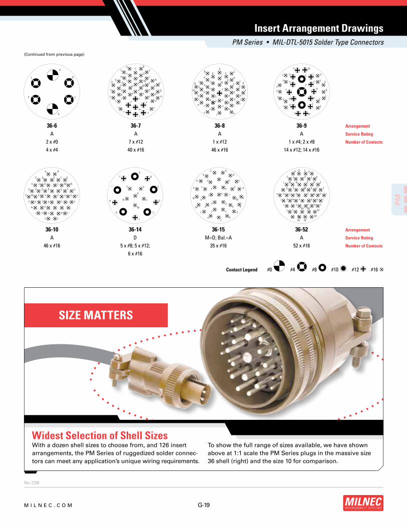
SIZE MATTERS
Widest Selection of Shell SizesTo show the full range of sizes available, we have shown
above at 1:1 scale the PM Series plugs in the massive size
36 shell (right) and the size 10 for comparison.
With a dozen shell sizes to choose from, and 126 insert
arrangements, the PM Series of ruggedized solder connec-
tors can meet any application’s unique wiring requirements.
#0 #4 #8 #10 #12 #16Contact Legend
PM Series • MIL-DTL-5015 Solder Type Connectors
A
B
C
D
E
F
AB C
D EFG H
I J LMN O P RS
T UV
WX
YZ
a
b c d ef g h jk
mn p r
tuv w
s
x yz
K
DA B
C EF G
H I JK L M N
O P S TU V
RW X
Y Z a b c
d e f gh j k m
n p
r
t
s
u v
x yz
w
H
N
O
PA
B
C
D
E
F
G
I
J
K
L
MS
T
U
V
W
X
Y
Z
a
b
c
d
e
f
A B
C D E F G
H J K L M N
O P Q R S T U
V W X Y Z a b c
d e f g h j k
m p
t u v w x
y z
A
B
C
D
E
F
G
H
J
K
L
M
N
I P
Q
A
B
C
D
E
F
G
HJ
K
L
M
N
P
Q
R
S
U
V
W
X
YZ
a
b
c
d
e
f
gh
j
k
m
A B C D
E F H J K
L M N P R S
U V W X Y Z
a b c d f g h i
j k m n p r
u v ws x
y z
q
AC
AE AF
AH
AA AB
Insert Arrangement Drawings
Arrangement
Service Rating
Number of Contacts
36-6
A
2 x #0
4 x #4
36-8
A
1 x #12
46 x #16
36-7
A
7 x #12
40 x #16
36-9
A
1 x #4; 2 x #8
14 x #12; 14 x #16
36-10
A
46 x #16
36-14
D
5 x #8; 5 x #12;
6 x #16
36-15
M=D; Bal.=A
35 x #16
36-52
A
52 x #16
Arrangement
Service Rating
Number of Contacts
(Continued from previous page)

Rev. 2208
G-20 M I L N E C . C O M
PM
D L
CC B
C ThreadClass 2A
N
MIL
NE
C
Shell Size D C Thread
Class 2A L N B CC
CableClearance
10SL .946 (24.0) .6250-24 UNEF 2.129 (54.1) .531 (13.5) .896 (22.8) .281 (7.1)
12S .995 (25.3) .7500-20 UNEF 2.129 (54.1) .531 (13.5) .896 (22.8) .281 (7.1)
14S 1.123 (28.5) .8750-20 UNEF 2.201 (55.9) .531 (13.5) 1.021 (25.9) .406 (10.3)
16S 1.250 (31.8) 1.0000-20 UNEF 2.201 (55.9) .531 (13.5) 1.151 (29.2) .500 (12.7)
16 1.250 (31.8) 1.0000-20 UNEF 2.524 (64.1) .719 (18.3) 1.151 (29.2) .500 (12.7)
18 1.333 (33.9) 1.1250-18 UNEF 2.596 (65.9) .719 (18.3) 1.242 (31.5) .531 (13.5)
20 1.461 (37.1) 1.2500-18 UNEF 2.654 (67.4) .719 (18.3) 1.499 (38.1) .656 (16.7)
22 1.588 (40.3) 1.3750-18 UNEF 2.654 (67.4) .719 (18.3) 1.499 (38.1) .740 (18.8)
24 1.715 (43.6) 1.5000-18 UNEF 2.885 (73.3) .719 (18.3) 1.781 (45.2) .781 (19.8)
28 1.968 (50.0) 1.7500-18 UNS 2.885 (73.3) .719 (18.3) 1.781 (45.2) .922 (23.4)
32 2.209 (56.1) 2.0000-18 UNS 2.943 (74.8) .719 (18.3) 2.087 (53.0) 1.156 (29.4)
36 2.463 (62.6) 2.2500-16 UN 2.943 (74.8) .719 (18.3) 2.281 (57.9) 1.250 (31.8)
Plug Dimensions
Dimensions are in inches (mm).
Compatible Brands Equivalent Mates
MIL-DTL-5015 MS3106 MS3100, MS3101, MS3102
Amphenol 97-3106 97-3100, 97-3101, 97-3102
Array AC3106 AC3100, AC3101, AC3102
DDK DMS3106 DMS3100, DMS3101, DMS3102
ITT Cannon CA3106 CA3100, CA3101, CA3102
PM Series • MIL-DTL-5015 Solder Type Connectors
BASIC PART NUMBER
PM06 Straight plug w/ integrated backshell
MATERIAL & FINISH
F Aluminum, olive drab cadmium
SHELL SIZE & INSERT ARRANGEMENT
See Insert Arrangement Selection table, p. G-11
CONTACT STYLE
P Pin
S Socket
INSERT ROTATION
N Normal or W, X, Y, Z, see p. G-11 for availability
OPTIONAL ACCESSORY KIT (OMIT FOR NONE)
01 Protective cover + cable bushing
Note: See part builder (p. G-10) for additional kit options.
PM06 F 16S-1 P N - 01
PM06 Cross Reference & Compatibility
MS3106 Connector Type Datasheet
MILNEC.COM
MILNEC.COM

Rev. 2208
G-21M I L N E C . C O M
PM
D L1
B
L2
CC
N
C ThreadClass 2B
MIL
NE
C
Shell Size D C Thread
Class 2B L1 L2 N B CC
CableClearance
10SL .946 (24.0) .6250-24 NEF 1.482 (37.6) 1.508 (38.3) .531 (13.5) .901 (22.9) .311 (7.9)
12S .995 (25.3) .7500-20 UNEF 1.487 (37.8) 1.508 (38.3) .531 (13.5) .901 (22.9) .311 (7.9)
14S 1.123 (28.5) .8750-20 UNEF 1.551 (39.4) 1.570 (39.9) .531 (13.5) 1.026 (26.1) .437 (11.1)
16S 1.250 (31.8) 1.0000-20 UNEF 1.677 (42.6) 1.633 (41.5) .531 (13.5) 1.119 (28.4) .559 (14.2)
16 1.250 (31.8) 1.1000-20 UNEF 2.052 (52.1) 1.633 (41.5) .719 (18.3) 1.119 (28.4) .559 (14.2)
18 1.333 (33.9) 1.1250-18 UNEF 2.114 (53.7) 1.759 (44.7) .719 (18.3) 1.229 (31.2) .622 (15.8)
20 1.461 (37.1) 1.2500-18 UNEF 2.317 (58.9) 1.931 (49.0) .719 (18.3) 1.479 (37.6) .748 (19.0)
22 1.588 (40.3) 1.3750-18 UNEF 2.317 (58.9) 1.993 (50.6) .719 (18.3) 1.479 (37.6) .748 (19.0)
24 1.729 (43.9) 1.5000-18 UNEF 2.505 (63.6) 2.119 (53.8) .719 (18.3) 1.666 (42.3) .933 (23.7)
28 1.968 (50.0) 1.7500-18 UNS 2.505 (63.6) 2.181 (55.4) .719 (18.3) 1.666 (42.3) .933 (23.7)
32 2.0000-18NS 2.209 (56.1) UNS 2.739 (69.6) 2.570 (65.3) .719 (18.3) 2.135 (54.2) 1.252 (31.8)
36 2.2500-16UN 2.463 (62.6) UN 2.864 (72.7) 2.695 (68.5) .719 (18.3) 2.260 (57.4) 1.362 (34.6)
Dimensions are in inches (mm).
Plug Dimensions
Compatible Brands Equivalent Mates
MIL-DTL-5015 MS3108 MS3100, MS3101, MS3102
Amphenol 97-3108 97-3100, 97-3101, 97-3102
Array AC3108 AC3100, AC3101, AC3102
DDK DMS3108 DMS3100, DMS3101, DMS3102
ITT Cannon CA3108 CA3100, CA3101, CA3102
PM08 Cross Reference & Compatibility
PM Series • MIL-DTL-5015 Solder Type Connectors
BASIC PART NUMBER
PM08 90° plug w/ integrated backshell
MATERIAL & FINISH
F Aluminum, olive drab cadmium
SHELL SIZE & INSERT ARRANGEMENT
See Insert Arrangement Selection table, p. G-11
CONTACT STYLE
P Pin
S Socket
INSERT ROTATION
N Normal or W, X, Y, Z, see p. G-11 for availability
OPTIONAL ACCESSORY KIT (OMIT FOR NONE)
01 Protective cover + cable bushing
Note: See part builder (p. G-10) for additional kit options.
PM08 F 20-29 S N - 01
MS3108 Connector Type Datasheet
MILNEC.COM
MILNEC.COM

Rev. 2208
G-22 M I L N E C . C O M
PM
Panel Cutout
X
EH
S
S
P
L
CC B
C Thread Class 2A
D
R
S
W
Z
MIL
NE
C
Size Shell W Z C Thread
Class 2A L R D B CC
Cable Clearance
P
Max RearPanel‡
S X H
Front Mount
ERear
Mount
10SL 1.000 (25.4) .120 (3.0) .6250-24 UNEF 2.129 (54.1) .672 (17.1) .625 (15.9) .896 (22.8) .281 (7.1) .187 (4.8) .719 (18.3) .134 (3.4) .646 (16.4) .728 (18.5)
12S 1.094 (27.8) .120 (3.0) .7500-20UNEF 2.129 (54.1) .672 (17.1) .750 (19.1) .896 (22.8) .281 (7.1) .187 (4.8) .812 (20.6) .134 (3.4) .646 (16.4) .854 (21.7)
14S 1.188 (30.2) .120 (3.0) .8750-20 UNEF 2.201 (55.9) .672 (17.1) .875 (22.2) 1.021 (25.9) .406 (10.3) .187 (4.8) .906 (23.0) .134 (3.4) .776 (19.7) .980 (24.9)
16S 1.281 (32.5) .120 (3.0) 1.0000-20 UNEF 2.201 (55.9) .672 (17.1) 1.000 (25.4) 1.151 (29.2) .500 (12.7) .187 (4.8) .969 (24.6) .134 (3.4) .902 (22.9) 1.091 (27.7)
16 1.281 (32.5) .120 (3.0) 1.0000-20 UNEF 2.524 (64.1) .860 (21.8) 1.000 (25.4) 1.151 (29.2) .500 (12.7) .125 (3.2) .969 (24.6) .134 (3.4) .902 (22.9) 1.091 (27.7)
18 1.375 (34.9) .120 (3.0) 1.1250-18 UNEF 2.596 (65.9) .891 (22.6) 1.125 (28.6) 1.242 (31.5) .531 (13.5) .125 (3.2) 1.063 (27.0) .134 (3.4) 1.028 (26.1) 1.224 (31.1)
20 1.500 (38.1) .120 (3.0) 1.2500-18 UNEF 2.654 (67.4) .891 (22.6) 1.250 (31.8) 1.499 (38.1) .656 (16.7) .125 (3.2) 1.156 (29.4) .134 (3.4) 1.161 (29.5) 1.358 (34.5)
22 1.625 (41.3) .120 (3.0) 1.3750-18 UNEF 2.654 (67.4) .891 (22.6) 1.375 (34.9) 1.499 (38.1) .740 (18.8) .125 (3.2) 1.250 (31.8) .134 (3.4) 1.287 (32.7) 1.488 (37.8)
24 1.750 (44.5) .147 (3.7) 1.5000-18 UNEF 2.885 (73.2) .953 (24.2) 1.500 (38.1) 1.781 (45.2) .781 (19.8) .187 (4.8) 1.375 (34.9) .154 (3.9) 1.417 (36.0) 1.626 (41.3)
28 2.000 (50.8) .147 (3.7) 1.7500-18 UNS 2.885 (73.2) .953 (24.2) 1.750 (44.5) 1.781 (45.2) .922 (23.4) .187 (4.8) 1.562 (39.7) .154 (3.9) 1.654 (42.0) 1.854 (47.1)
32 2.250 (57.2) .173 (4.4) 2.0000-18 UNS 2.943 (74.8) 1.031 (26.2) 2.000 (50.8) 2.087 (53.0) 1.156 (29.4) .250 (6.4) 1.750 (44.5) .177 (4.5) 1.902 (48.3) 2.118 (53.8)
36 2.500 (63.5) .173 (4.4) 2.2500-16 UN 2.943 (74.8) 1.031 (26.2) 2.250 (57.2) 2.281 (57.9) 1.250 (31.8) .250 (6.4) 1.938 (49.2) .177 (4.5) 2.150 (54.6) 2.362 (60.0)
Dimensions are in inches (mm). ‡ Max panel thickness applies only to rear mount applications to ensure proper coupling clearance.
Receptacle Dimensions
Compatible Brands Equivalent Mates
MIL-DTL-5015 MS3100 MS3106, MS3108
Amphenol 97-3100 97-3106, 97-3108
Array AC3100 AC3106, AC3108
DDK DMS3100 DMS3106, DMS3108
ITT Cannon CA3100 CA3106, CA3108
PM Series • MIL-DTL-5015 Solder Type Connectors
BASIC PART NUMBER
PM00 Wall mount recept. w/ integrated backshell
MATERIAL & FINISH
F Aluminum, olive drab cadmium
SHELL SIZE & INSERT ARRANGEMENT
See Insert Arrangement Selection table, p. G-11
CONTACT STYLE
P Pin
S Socket
INSERT ROTATION
N Normal or W, X, Y, Z, see p. G-11 for availability
OPTIONAL ACCESSORY KIT (OMIT FOR NONE)
02 Protective cover + mounting gasket
+ cable bushing
03 02 kit + mounting bracket + sealing screws
Note: See part builder (p. G-10) for additional kit options.
PM00 F 16S-1 S N - 02
PM00 Cross Reference & Compatibility
MS3100 Connector Type Datasheet
MILNEC.COM
MILNEC.COM

Rev. 2208
G-23M I L N E C . C O M
PM
P
C ThreadClass 2A
R
L
UDW
S
Z
X
EH
S
S
Panel Cutout
MIL
NE
C
Shell Size W Z C Thread
Class 2A L R D UP
Max RearPanel‡
S X H
Front Mount
ERear
Mount
10SL 1.000 (25.4) .120 (3.0) .6250-24 UNEF 1.094 (27.8) .562 (14.3) .625 (15.9) .625 (15.9) .187 (4.8) .719 (18.3) .134 (3.4) .646 (16.4) .728 (18.5)
12S 1.094 (27.8) .120 (3.0) .7500-20 UNEF 1.094 (27.8) .562 (14.3) .750 (19.1) .625 (15.9) .187 (4.8) .812 (20.6) .134 (3.4) .646 (16.4) .854 (21.7)
14S 1.188 (30.2) .120 (3.0) .8750-20 UNEF 1.094 (27.8) .562 (14.3) .875 (22.2) .750 (19.1) .187 (4.8) .906 (23.0) .134 (3.4) .776 (19.7) .980 (24.9)
16S 1.281 (32.5) .120 (3.0) 1.0000-20 UNEF 1.094 (27.8) .562 (14.3) 1.000 (25.4) .875 (22.2) .187 (4.8) .969 (24.6) .134 (3.4) .902 (22.9) 1.091 (27.7)
16 1.281 (32.5) .120 (3.0) 1.0000-20 UNEF 1.532 (38.9) .750 (19.1) 1.000 (25.4) .875 (22.2) .125 (3.2) .969 (24.6) .134 (3.4) .902 (22.9) 1.091 (27.7)
18 1.375 (34.9) .120 (3.0) 1.1250-18 UNEF 1.532 (38.9) .750 (19.1) 1.125 (28.6) 1.000 (25.4) .125 (3.2) 1.062 (27.0) .134 (3.4) 1.028 (26.1) 1.224 (31.1)
20 1.500 (38.1) .120 (3.0) 1.2500-18 UNEF 1.532 (38.9) .750 (19.1) 1.250 (31.8) 1.125 (28.6) .125 (3.2) 1.156 (29.4) .134 (3.4) 1.161 (29.5) 1.358 (34.5)
22 1.625 (41.3) .120 (3.0) 1.3750-18 UNEF 1.532 (38.9) .750 (19.1) 1.375 (34.9) 1.250 (31.8) .125 (3.2) 1.250 (31.8) .134 (3.4) 1.287 (32.7) 1.488 (37.8)
24 1.750 (44.5) .147 (3.7) 1.5000-18 UNEF 1.531 (39.0) .812 (20.6) 1.500 (38.1) 1.375 (34.9) .187 (4.8) 1.375 (34.9) .154 (3.9) 1.417 (36.0) 1.626 (41.3)
28 2.000 (50.8) .147 (3.7) 1.7500-18 UNS 1.531 (39.0) .812 (20.6) 1.750 (44.5) 1.625 (41.3) .187 (4.8) 1.562 (39.7) .154 (3.9) 1.654 (42.0) 1.854 (47.1)
32 2.250 (57.2) .173 (4.4) 2.0000-18 UNS 1.531 (39.0) .875 (22.2) 2.000 (50.8) 1.875 (47.6) .250 (6.4) 1.750 (44.5) .177 (4.5) 1.902 (48.3) 2.118 (53.8)
36 2.500 (63.5) .173 (4.4) 2.2500-16 UN 1.531 (39.0) .875 (22.2) 2.250 (57.2) 2.062 (52.4) .250 (6.4) 1.938 (49.2) .177 (4.5) 2.150 (54.6) 2.362 (60.0)
Receptacle Dimensions
Dimensions are in inches (mm). ‡ Max panel thickness applies only to rear mount applications to ensure proper coupling clearance.
PM02 Cross Reference & Compatibility Compatible Brands Equivalent Mates
MIL-DTL-5015 MS3102 MS3106, MS3108
Amphenol 97-3102 97-3106, 97-3108
Array AC3102 AC3106, AC3108
DDK DMS3102 DMS3106, DMS3108
ITT Cannon CA3102 CA3106, CA3108
PM Series • MIL-DTL-5015 Solder Type Connectors
BASIC PART NUMBER
PM02 Box mount receptacle
MATERIAL & FINISH
F Aluminum, olive drab cadmium
SHELL SIZE & INSERT ARRANGEMENT
See Insert Arrangement Selection table, p. G-11
CONTACT STYLE
P Pin
S Socket
INSERT ROTATION
N Normal or W, X, Y, Z, see p. G-11 for availability
OPTIONAL ACCESSORY KIT (OMIT FOR NONE)
02 Protective cover + mounting gasket
03 02 kit + mounting bracket + sealing screws
Note: See part builder (p. G-10) for additional kit options.
PM02 F 16S-1 S N - 02
MS3102 Connector Type Datasheet
MILNEC.COM
MILNEC.COM

Rev. 2208
G-24 M I L N E C . C O M
PM
D
C Thread Class 2A
L
BCCD
MIL
NE
C
Shell Size D C Thread
Class 2A L B CC Cable Clearance
10SL .625 (15.9) .6250-24 UNEF 2.129 (54.1) .896 (22.8) .281 (7.1)
12S .750 (19.1) .7500-20 UNEF 2.129 (54.1) .896 (22.8) .281 (7.1)
14S .875 (22.2) .8750-20 UNEF 2.201 (55.9) 1.021 (25.9) .406 (10.3)
16S 1.000 (25.4) 1.0000-20 UNEF 2.201 (55.9) 1.151 (29.2) .500 (12.7)
16 1.000 (25.4) 1.0000-20 UNEF 2.524 (64.1) 1.151 (29.2) .500 (12.7)
18 1.125 (28.6) 1.1250-18 UNEF 2.596 (65.9) 1.242 (31.5) .531 (13.5)
20 1.375 (34.9) 1.2500-18 UNEF 2.654 (67.4) 1.499 (38.1) .656 (16.7)
22 1.500 (38.1) 1.3750-18 UNEF 2.654 (67.4) 1.499 (38.1) .740 (18.8)
24 1.750 (44.5) 1.5000-18 UNEF 2.885 (73.3) 1.781 (45.2) .781 (19.8)
28 2.000 (50.8) 1.7500-18 UNS 2.885 (73.3) 1.781 (45.2) .922 (23.4)
32 2.250 (57.2) 2.0000-18 UNS 2.943 (74.8) 2.087 (53.0) 1.156 (29.4)
36 2.500 (63.5) 2.2500-16 UN 2.943 (74.8) 2.281 (57.9) 1.250 (31.8)
Dimensions are in inches (mm).
Receptacle Dimensions
Compatible Brands Equivalent Mates
MIL-DTL-5015 MS3101 MS3106, MS3108
Amphenol 97-3101 97-3106, 97-3108
Array AC3101 AC3106, AC3108
DDK DMS3101 DMS3106, DMS3108
ITT Cannon CA3101 CA3106, CA3108
PM Series • MIL-DTL-5015 Solder Type Connectors
BASIC PART NUMBER
PM01 Cable mount recept. w/ integrated backshell
MATERIAL & FINISH
F Aluminum, olive drab cadmium
SHELL SIZE & INSERT ARRANGEMENT
See Insert Arrangement Selection table, p. G-11
CONTACT STYLE
P Pin
S Socket
INSERT ROTATION
N Normal or W, X, Y, Z, see p. G-11 for availability
OPTIONAL ACCESSORY KIT (OMIT FOR NONE)
02 Protective cover + cable bushing
Note: See part builder (p. G-10) for additional kit options.
PM01 F 16S-1 S N - 02
PM01 Cross Reference & Compatibility
MS3101 Connector Type Datasheet
MILNEC.COM
MILNEC.COM

Rev. 2208
G-25M I L N E C . C O M
PM
S
W
Z
S
X
SH
Panel Cutout
P
F
R R
L
C ThreadClass 2A
C ThreadClass 2A
MIL
NE
C
Receptacle Dimensions
Dimensions are in inches (mm)
ShellSize W Z L R F C Thread
Class 2A
MinThreadLength
P
Max RearPanel‡
S X H
10SL 1.000 (25.4) .120 (3.1) 1.563 (39.7) .711 (18.1) .141 (3.6) .6250-24 UNEF .406 (10.3) .215 (5.5) .719 (18.3) .120 (3.1) .688 (17.5)
12S 1.094 (27.8) .120 (3.1) 1.563 (39.7) .711 (18.1) .141 (3.6) .7500-20 UNEF .406 (10.3) .215 (5.5) .812 (20.6) .120 (3.1) .812 (20.6)
14S 1.188 (30.2) .120 (3.1) 1.563 (39.7) .711 (18.1) .141 (3.6) .8750-20 UNEF .406 (10.3) .215 (5.5) .906 (23.0) .120 (3.1) .938 (23.8)
16S 1.281 (32.5) .120 (3.1) 1.563 (39.7) .711 (18.1) .141 (3.6) 1.0000-20 UNEF .406 (10.3) .215 (5.5) .969 (24.6) .120 (3.1) 1.062 (27.0)
18 1.375 (34.9) .120 (3.1) 2.125 (54.0) .985 (25.0) .155 (4.0) 1.1250-18 UNEF .625 (15.9) .250 (6.4) 1.062 (27.0) .120 (3.1) 1.188 (30.2)
20 1.500 (38.1) .120 (3.1) 2.125 (54.0) .985 (25.0) .155 (4.0) 1.2500-18 UNEF .625 (15.9) .250 (6.4) 1.156 (29.4) .120 (3.1) 1.312 (33.3)
22 1.625 (41.3) .120 (3.1) 2.125 (54.0) .985 (25.0) .155 (4.0) 1.3750-18 UNEF .625 (15.9) .250 (6.4) 1.250 (31.8) .120 (3.1) 1.438 (36.5)
24 1.750 (44.5) .147 (3.7) 2.125 (54.0) .985 (25.0) .155 (4.0) 1.5000-18 UNEF .625 (15.9) .250 (6.4) 1.375 (34.9) .147 (3.7) 1.562 (39.7)
28 2.000 (50.8) .147 (3.7) 2.125 (54.0) .985 (25.0) .155 (4.0) 1.7500-18 UNS .625 (15.9) .250 (6.4) 1.562 (39.7) .147 (3.7) 1.812 (46.0)
32 2.250 (57.2) .173 (4.4) 2.125 (54.0) .985 (25.0) .155 (4.0) 2.0000-18 UNS .625 (15.9) .250 (6.4) 1.750 (44.5) .173 (4.4) 2.062 (52.4)
36 2.500 (63.5) .173 (4.4) 2.125 (54.0) .985 (25.0) .155 (4.0) 2.2500-16 UN .625 (15.9) .250 (6.4) 1.938 (49.2) .173 (4.4) 2.312 (58.7)
PM22 Compatibility Compatible Brands Mates
MIL-DTL-5015 MS3106, MS3108
Amphenol 97-3106, 97-3108
Array AC3106, AC3108
DDK DMS3106, DMS3108
ITT Cannon CA3106, CA3108
PM Series • MIL-DTL-5015 Solder Type Connectors
BASIC PART NUMBER
PM22 Thru-bulkhead receptacle
MATERIAL & FINISH
F Aluminum, olive drab cadmium
SHELL SIZE & INSERT ARRANGEMENT
See Insert Arrangement Selection table, p. G-11
CONTACT STYLE
PS Pin / socket (non-configurable)
INSERT ROTATION
N Normal or W, X, Y, Z, see p. G-11 for availability
OPTIONAL ACCESSORY KIT (OMIT FOR NONE)
02 Protective covers (2x) + mounting gasket
03 02 kit + mounting bracket + sealing screws
PM22 F 18-11 PS N - 02
Note: See part builder (p. G-10) for additional kit options.
Thru-Bulkhead Receptacle
MILNEC.COM
MILNEC.COM

Rev. 2208
G-26 M I L N E C . C O M
PM
E1
L1
JD1
Plug Cover
Gasket(Inside)
Receptacle Cover
L2
JD2
E2
C ThreadClass 2B
C Thread Class 2A
MIL
NE
C
MIL
NE
C
ShellSize
C ThreadClass 2A L1 D1 E1 J
Chain LengthC ThreadClass 2B L2 D2 E2
10 .625-24 UNEF .656 (16.7) .687 (17.4) .151 (3.8) 4.00 (101.6) .625-24 UNEF .469 (11.9) .815 (20.7) .135 (3.4)
12 .750-20 UNEF .844 (21.4) .812 (20.6) .151 (3.8) 4.50 (114.3) .750-20 UNEF .469 (11.9) 1.000 (25.4) .135 (3.4)
14 .875-20 UNEF .844 (21.4) .937 (23.8) .151 (3.8) 4.50 (114.3) .875-20 UNEF .469 (11.9) 1.125 (28.6) .135 (3.4)
16 1.000-20 UNEF .844 (21.4) 1.062 (27.0) .151 (3.8) 4.50 (114.3) 1.000-20 UNEF .469 (11.9) 1.188 (30.2) .135 (3.4)
18 1.125-18 UNEF .844 (21.4) 1.187 (30.1) .151 (3.8) 5.00 (127.0) 1.125-18 UNEF .469 (11.9) 1.344 (34.1) .135 (3.4)
20 1.250-18 UNEF .844 (21.4) 1.312 (33.3) .182 (4.6) 5.00 (127.0) 1.250-18 UNEF .469 (11.9) 1.469 (37.3) .135 (3.4)
22 1.375-18 UNEF .844 (21.4) 1.437 (36.5) .182 (4.6) 5.50 (139.7) 1.375-18 UNEF .469 (11.9) 1.594 (40.5) .135 (3.4)
24 1.500-18 UNEF .844 (21.4) 1.562 (39.7) .182 (4.6) 7.75 (196.9) 1.500-18 UNEF .469 (11.9) 1.719 (43.7) .166 (4.2)
28 1.750-18 UNS .844 (21.4) 1.812 (46.0) .182 (4.6) 7.75 (196.9) 1.750-18 UNS .531 (13.5) 1.969 (50.0) .166 (4.2)
32 2.000-18 UNS .844 (21.4) 2.062 (52.4) .213 (5.4) 7.75 (196.9) 2.000-18 UNS .531 (13.5) 2.219 (56.4) .182 (4.6)
36 2.250-16 UN .844 (21.4) 2.312 (58.7) .213 (5.4) 7.75 (196.9) 2.250-16 UN .531 (13.5) 2.469 (62.7) .182 (4.6)
Dimensions are in inches (mm).
Protective Cover Dimensions
Compatible Brands Plugs Receptacles
MIL-DTL-5015 MS3106, MS3108 MS3100, MS3101, MS3102
Amphenol 97-3106, 97-3108 97-3100, 97-3101, 97-3102
Array AC3106, AC3108 AC3100, AC3101, AC3102
DDK DMS3106, DMS3108 DMS3100, DMS3101, DMS3102
ITT Cannon CA3106, CA3108 CA3100, CA3101, CA3102
PM Series • MIL-DTL-5015 Solder Type Connectors
PMCP - 16 B
BASIC PART NUMBER
PMCP Plug cover w/ sash chain
PMCR Receptacle cover w/ sash chain
SHELL SIZE
See Protective Cover Dimensions table below
MATERIAL & FINISH
B Aluminum, anodize hardcoat
Note: See part builder (p. G-10) for additional kit options.
Protective Covers
PMCP & PMCR Compatibility
MILNEC.COM
MILNEC.COM

Rev. 2208
G-27M I L N E C . C O M
PM
Z
S
W
X
S
SH
Panel Cutout
FR
P
C ThreadClass 2B
MIL
NE
C
ShellSize W S Z C Thread
Class 2B R FP
Max RearPanel‡
S X H
10S 1.031 (26.2) .719 (18.3) .130 (3.3) .625-24 UNEF .593 (15.1) .156 (4.0) .125 (3.2) .719 (18.3) .120 (3.1) .688 (17.5)
12S 1.125 (28.6) .812 (20.6) .130 (3.3) .750-20 UNEF .593 (15.1) .156 (4.0) .125 (3.2) .812 (20.6) .120 (3.1) .812 (20.6)
14S 1.219 (31.0) .906 (23.0) .130 (3.3) .875-20 UNEF .593 (15.1) .156 (4.0) .125 (3.2) .906 (23.0) .120 (3.1) .938 (23.8)
16S 1.312 (33.3) .969 (24.6) .130 (3.3) 1.000-20 UNEF .593 (15.1) .156 (4.0) .125 (3.2) .969 (24.6) .120 (3.1) 1.062 (27.0)
18 1.406 (35.7) 1.062 (27.0) .130 (3.3) 1.125-18 UNEF .781 (19.8) .203 (5.2) .125 (3.2) 1.062 (27.0) .120 (3.1) 1.188 (30.2)
20 1.531 (38.9) 1.156 (29.4) .130 (3.3) 1.250-18 UNEF .781 (19.8) .203 (5.2) .125 (3.2) 1.156 (29.4) .120 (3.1) 1.312 (33.3)
22 1.656 (42.1) 1.250 (31.8) .130 (3.3) 1.375-18 UNEF .781 (19.8) .203 (5.2) .125 (3.2) 1.250 (31.8) .120 (3.1) 1.438 (36.5)
24 1.781 (45.2) 1.375 (34.9) .157 (4.0) 1.500-18 UNEF .843 (21.4) .203 (5.2) .125 (3.2) 1.375 (34.9) .147 (3.7) 1.562 (39.7)
28 2.031 (51.6) 1.562 (39.7) .157 (4.0) 1.750-18 UNS .843 (21.4) .203 (5.2) .125 (3.2) 1.562 (39.7) .147 (3.7) 1.812 (46.0)
32 2.281 (57.9) 1.750 (44.5) .183 (4.6) 2.000-18 UNS .906 (23.0) .359 (9.1) .125 (3.2) 1.750 (44.5) .173 (4.4) 2.062 (52.4)
36 2.531 (64.3) 1.938 (49.2) .183 (4.6) 2.250-16 UN .906 (23.0) .359 (9.1) .125 (3.2) 1.938 (49.2) .173 (4.4) 2.312 (58.7)
Stowage Receptacle Dimensions
Dimensions are in inches (mm). ‡ Max panel thickness applies only to rear mount applications to ensure proper coupling clearance.
Compatible Brands Plugs
MIL-DTL-5015 MS3106, MS3108
Amphenol 97-3106, 97-3108
Array AC3106, AC3108
DDK DMS3106, DMS3108
ITT Cannon CA3106, CA3108
PMCD & PMCC Compatibility
PM Series • MIL-DTL-5015 Solder Type Connectors
PMCD - 16 F - 02
BASIC PART NUMBER
PMCD Stowage receptacle (thru-hole flange)
PMCC Stowage receptacle (solid flange)
SHELL SI ZE
See Stowage Receptacle Dimensions table below
MATERIAL & FINISH
F Aluminum, olive drab cadmium
OPTIONAL ACCESSORY KIT (OMIT FOR NONE)
02 Protective cover + mounting gasket
03 02 kit + mounting bracket + sealing screws
Note: See part builder (p. G-10) for additional kit options.
Solid flange (Environmental)
Thru-hole flange(Economical)
Stowage Receptacle
MILNEC.COM
MILNEC.COM

Rev. 2208
G-28 M I L N E C . C O M
PM
W H
Z
S
MIL
NE
C
.031 (.8)± .012 (.3)
Shell Size W S Z H
10 1.000 (25.4) .719 (18.3) .172 (4.4) .625 (15.9)
12 1.094 (27.8) .813 (20.7) .172 (4.4) .750 (19.1)
14 1.188 (30.2) .906 (23.0) .172 (4.4) .875 (22.2)
16 1.281 (32.5) .969 (24.6) .172 (4.4) 1.000 (25.4)
18 1.375 (34.9) 1.063 (27.0) .203 (5.2) 1.125 (28.6)
20 1.500 (38.1) 1.156 (29.4) .203 (5.2) 1.250 (31.8)
22 1.625 (41.3) 1.250 (31.8) .203 (5.2) 1.375 (34.9)
24 1.750 (44.5) 1.375 (34.9) .203 (5.2) 1.500 (38.1)
28 2.000 (50.8) 1.563 (39.7) .203 (5.2) 1.750 (44.5)
32 2.250 (57.2) 1.750 (44.5) .219 (5.6) 2.000 (50.8)
36 2.500 (63.5) 1.938 (49.2) .219 (5.6) 2.188 (55.6)
Dimensions are in inches (mm).
Gasket Dimensions
Compatible Brands Receptacles
MIL-DTL-5015 MS3100, MS3102
Amphenol 97-3100, 97-3102
Array AC3100, AC3102
DDK DMS3100, DMS3102
ITT Cannon CA3100, CA3102
PM Series • MIL-DTL-5015 Solder Type Connectors
PMGE - 16
Note: See part builder (p. G-10) for additional kit options.
BASIC PART NUMBER
PMGE Neoprene environmental (weather resistant)
Temp. range -40˚F to +230˚F (-40˚C to +110˚C)
PMGS Conductive EMI-RFI neoprene, Ni-Cu alloy mesh
Temp. range -40˚F to +230˚F (-40˚C to +110˚C)
PMGL Fluorosilicone ( jet fuel & oil resistant)
Temp. range -70˚F to +392˚F (-56˚C to +200˚C)
Per MIL-DTL-25988, Class 1, Grade 6
PMGD Conductive EMI-RFI fluorosilicone, Al-Ag filled
Temp. range -70˚F to +392˚F (-56˚C to +200˚C)
Shielding effectiveness at 90 dB @ 10 GHz
Per MIL-DTL-83528, Type D
SHELL SIZE
See Gasket Dimensions table below
RFI Gasket’s Conductive Weave
Mounting Gasket
PMGE Compatibility
MILNEC.COM

Rev. 2208
G-29M I L N E C . C O M
PM
F
N
W
S
TH
Y Thread
.210 (5.3)
.550 (14.0) Approx.
O-Ring
.077 (2.0)
ShellSize W S H T N F Screw
SizeY
Thread
10 1.019 (25.9) .719 (18.3) .720 (18.3) .433 (11.0) .136 (3.5) .040 (1.0) #4 4-40 UNJC-3B
12 1.104 (28.0) .812 (20.6) .855 (21.7) .530 (13.5) .136 (3.5) .040 (1.0) #4 4-40 UNJC-3B
14 1.198 (30.4) .906 (23.0) .984 (25.0) .624 (15.8) .136 (3.5) .040 (1.0) #4 4-40 UNJC-3B
16 1.280 (32.5) .969 (24.6) 1.094 (27.8) .687 (17.4) .136 (3.5) .040 (1.0) #4 4-40 UNJC-3B
18 1.406 (35.7) 1.062 (27.0) 1.220 (31.0) .780 (19.8) .136 (3.5) .040 (1.0) #4 4-40 UNJC-3B
20 1.535 (39.0) 1.156 (29.4) 1.345 (34.2) .874 (22.2) .136 (3.5) .040 (1.0) #4 4-40 UNJC-3B
22 1.665 (42.3) 1.250 (31.8) 1.478 (37.5) .968 (24.6) .136 (3.5) .040 (1.0) #4 4-40 UNJC-3B
24 1.738 (44.1) 1.375 (34.9) 1.483 (37.7) .907 (23.0) .153 (3.9) .040 (1.0) #6 6-32 UNJC-3B
28 2.000 (50.8) 1.562 (39.7) 1.820 (46.2) 1.125 (28.6) .153 (3.9) .040 (1.0) #6 6-32 UNJC-3B
32 2.312 (58.7) 1.750 (44.5) 2.062 (52.4) 1.188 (30.2) .153 (3.9) .040 (1.0) #6 6-32 UNJC-3B
36 2.500 (63.5) 1.938 (49.2) 2.312 (58.7) 1.375 (34.9) .153 (3.9) .040 (1.0) #6 6-32 UNJC-3B
Dimensions are in inches (mm).
Bracket Dimensions
PMMB Compatibility Compatible Brands Receptacles
MIL-DTL-5015 MS3100, MS3102
Amphenol 97-3100, 97-3102
Array AC3100, AC3102
DDK DMS3100, DMS3102
ITT Cannon CA3100, CA3102
PM Series • MIL-DTL-5015 Solder Type Connectors
BASIC PART NUMBER
PMMB Mounting bracket, aluminium alloy
with SST locking nuts
SHELL SIZE
See Bracket Dimensions table below
OPTIONAL ACCESSORY KIT (OMIT FOR NONE)
A Self-sealing SST fillister head screws (4x)
B A kit + environmental gasket
D A kit + fluorosilicone EMI/RFI gasket
PMMB - 16 - A
Note: See part builder (p. G-10) for additional kit options.
Mounting Bracket & Screws
MILNEC.COM
MILNEC.COM

Rev. 2208
G-30 M I L N E C . C O M
PM
M
G
L2
D
MIL
NE
C
Shell Size Bushing Included
10 PSRB34-4
12 PSRB34-4
14 PSRB34-6
16 PSRB34-8
18 PSRB34-10
20 PSRB34-12
22 PSRB34-12
24 PSRB34-12, PSRB34-16
28 PSRB34-12, PSRB34-16
32 PSRB34-16, PSRB34-20
36 PSRB34-20, PSRB34-24
Bushing Part Numbers M L2 D G
PSRB34-3 .130 (3.3) 2.875 (73.0) .374 (9.5) .210 (5.3)
PSRB34-4 .220 (5.6) 2.750 (69.9) .500 (12.7) .302 (7.7)
PSRB34-6 .312 (7.9) 2.625 (66.7) .614 (15.6) .427 (10.9)
PSRB34-8 .437 (11.1) 2.500 (63.5) .739 (18.8) .552 (14.0)
PSRB34-10 .562 (14.3) 2.375 (60.3) .889 (22.6) .615 (15.6)
PSRB34-12 .625 (15.9) 2.250 (57.2) 1.084 (27.5) .740 (18.8)
PSRB34-16 .750 (19.1) 2.125 (54.0) 1.309 (33.3) .927 (23.6)
PSRB34-20 .937 (23.8) 2.000 (50.8) 1.592 (40.4) 1.240 (31.5)
PSRB34-24 1.250 (31.8) 1.875 (47.6) 1.842 (46.8) 1.365 (34.7)
Bushing DimensionsBushing Shell Size Selector
Dimensions are in inches (mm).
Two bushings, designed to nest inside one another, are supplied with shell sizes 24 and larger.
Compatible Brands Connectors
MIL-DTL-5015 MS3100E/F/R, MS3101E/F/R, MS3106E/F/R, MS3108E/F/R
Amphenol 97-3100, 97-3101, 97-3106, 97-3108
Array AC3100F/R, AC3101F/R, AC3106F/R, AC3108F/R
DDK DMS3100E/F/R, DMS3101E/F/R, DMS3106E/F/R, DMS3108E/F/R
ITT Cannon CA3100E, CA3101E, CA3106E, CA3108E
PM Series • MIL-DTL-5015 Solder Type Connectors
BASIC PART NUMBER
PMRB Cable bushing
SHELL SIZE
See Bushing Shell Size Selector table below
Note: Individual bushings can be ordered for wire bundles too small to seal properly within a single sleeve. Additional bushings should be ordered one size smaller or bigger to nest inside one another.
PMRB - 16
Cable Bushing
PMRB Compatibility
MILNEC.COM
MILNEC.COM

Rev. 2208
G-31M I L N E C . C O M
PM
MILNEC.COM
MILNEC.COM
Replacement Tips
Soldering Station Kit
MILNEC.COM
MILNEC.COM
Part Number Kit Includes The Following Items
H900120V / 60W soldering station, iron holder, cleaning sponge,
5 interchangeable tips, rosin-core lead solder, instructions
Part Number For ContactSize Description Image
H900-6D#16, #20,
#22DChisel (1.6mm Tip)
H900-B #16, #20 Conical (0.5mm Tip)
H900-2C #16 45° Beveled (2mm Tip)
H900-4C #8, #12 45° Beveled (4mm Tip)
H900-S3 #0, #4 Chisel (5.2mm Tip)
MILNEC.COM
MILNEC.COM
MILNEC.COM
MILNEC.COM
Note: The above lists standard options readily available in stock. Please consult an authorized distributor for full range of solder stations, re-work stations, specialty tips, and accessories.
Our soldering station kit provides a complete solution for pro-
fessionally terminating solder contacts to stranded or solid
core wire.
Features & Benefits
• Temperature range 392° to 896°F (200° to 480°C)
• Adjustable temperature control dial with lock/set screw
• Idle temperature stability of ±1.8°F (1.0°C)
• Ceramic heating element and senor ensure rapid heat-
up temperature (30 seconds) and fast thermal recovery
• Celsius or Fahrenheit temperature setting
• Slender iron handles are insulated and
ergonomically designed for ease and comfort
• ESD-safe design suitable for controlled environments
• 5 interchangeable tips suitable for connector
solder contacts ranging from #0 to #22D
H900 Soldering Station Kit
Soldering StationPM Series • MIL-DTL-5015 Solder Type Connectors

Project:
Engineer:
Date:
WarrantyIfanyof theproducts in this catalogareelectrical components, components thereof,orelectrical connectorsaccessories, then the following warranty terms set forth in this subparagraph (a) shall be applicable to such process.MilnecInterconnectSystems,LLC(“Milnec”)andMilnecInterconnectSystemsAuthorizedDistributors(“AuthorizedDistributors”)warrantseachnewproductsoldbyMilnecoranAuthorizedDistributortobefreefromdefects in material and workmanship under normal use and service. The obligation and liability of Milnec and its Authorized Distributors under this warranty is limited to the repair or replacement at its factory, at the option of Milnec or the Authorized Distributor, of any such product which proves defective within ninety (90) days after deliverytothefirstenduser,andisfoundtobedefectiveinmaterialandworkmanshipunderMilnec’sinspection.Neither Milnec nor its Authorized Distributors shall be obligated or liable under this warranty for apparent defects which examination discloses are due to tampering, misuse, neglect, improper storage, normal wear and all cases where the products are disassembled by other than authorized Milnec or Authorized Distributor representatives. Inaddition,neitherMilnecnoritsAuthorizedDistributorsshallbeobligatedorliableunderthiswarrantyunlessthedateofdeliverytothefirstendusershallbewithinsix(6)monthsfromthedateofdeliverytotheoriginalpurchaser,ifdifferentfromthefirstenduser,andfurtherprovidedthatwrittennoticeofanydefectshallbegiventoMilnecoritsAuthorizedDistributorswithinthirty(30)daysfromthedatesuchdefectisfirstdiscovered.
Product Safety InformationProductsofwarrantyconsiderationshallbereturnedwithalltransportationchargesprepaidtoMilnecInterconnectSystemsorAuthorizedDistributorinshippingcontainersthatareadequatetopreventlossordamageinshipment.Products repaired or replaced under this warranty are warranted for the unexpired portion of the original warranty. Other than the liability set forth in any expressed warranty applicable to the products sold to the purchaser, seller shall not be liable for consequential, incidental or other type of damages and expressly excludes and disclaims such damages resulting from or caused by the use, operation, failure, malfunction or defects of any products sold to the purchaser, it being understood that the products sold to the purchaser are not consumer products. Milnec and its Authorized Distributors disclaim any liability whether under this warranty or otherwise for any failure of its product which is caused by, in whole or in part, the use in, or with that product of component parts not manufactured or sub-contracted by Milnec. The terms of the applicable warranty or warranties, as the cause may be, as set forth above, are the sole and exclusive warranty terms that shall have any force and effect in this catalog, and such terms and in lieu of all other warranties, expressed or implied including the implied warranties ofmerchantabilityandfitnessforaparticularpurposewhichareherewithexpresslyexcluded.
Limited WarrantyMilnecagreestotransfertoCustomerwhatevertransferablewarranties,MilnecreceivesfromthemanufacturerofproductssoldtoCustomer.Milnecmakesnootherwarranty,expressorimplied,withrespecttotheProducts.INPARTICULAR,MilnecMAKESNOWARRANTYRESPECTINGTHEMERCHANTABILITYOFTHEPRODUCTSORTHEIR SUITABILITY OR FITNESS FOR ANY PARTICULAR PURPOSE OR USE OR RESPECTING INFRINGEMENT.Milnec’sliabilityarisingoutofanysaleofproductstoCustomerisexpresslylimitedtoeither(1)RefundofthepurchasepricepaidbyCustomerforsuchproducts(withoutinterest),or(2)Repairand/orreplacementofsuchproducts,atMilnec’selection,andsuchremediesshallbeexclusiveandinlieuofallothers.CustomermustnotifyMilnec within 90 days from date of shipment of any defective product. This warranty is in lieu of any and all other warranties,whetheroral,written,expressed,impliedorstatutory.Impliedwarrantiesoffitnessforaparticularpurposeandmerchantabilityarespecificallyexcludedandshallnotapply.Customer’sobligationsandMilnec’sremedies, with respect to defective or nonconforming products, are solely and exclusively as stated herein. Further, no warranty will apply if the Product has been subject to misuse, static discharge, neglect, accident or modification,orhasbeensolderedoralteredinanyway.
Use of Products in Life Support, Nuclear, and Certain Other ApplicationsProducts are traceable at the manufacturer’s level only. There is no lot level traceability. Products sold by Milnec are not designed, intended or authorized for use in life support, life sustaining, human implantable, nuclear facilities, or other applications in which the failure of such Products could result in personal injury, loss of life or catastrophic property damage. If Customer usesor sells theProducts for use in any suchapplications: (1)CustomeracknowledgesthatsuchuseorsaleisatCustomer’ssolerisk;(2)CustomeragreesthatMilnecandthemanufactureroftheProductsarenotliable,inwholeorinpart,foranyclaimordamagearisingfromsuchuse;and(3)Customeragreestoindemnify,defendandholdMilnecandthemanufactureroftheProductsharmlessfromand against any and all claims, damages, losses, costs, expenses and liabilities arising out of or in connection with such use or sale.
Specifications Are Subject to Change Without Notice. ContactyournearestAuthorizedDealerforthelatestspecifications.Allstatements,informationanddatagivenherein are believed to be accurate and reliable but are presented without guarantee, warranty, or responsibility ofanykind,expressedorimplied.Statementsorsuggestionsconcerningpossibleuseofourproductsaremadewithout representation or warranty that any such use is free of patent infringement and are not recommendations to infringe any patent. The user should assume that all safety measures are indicated or that other measures may notberequired.Specificationsaretypicalandmaynotapplytoallconnectors.
MilnecandtheMilnecLogoisaregisteredtrademarkofMilnecInterconnectSystems,LLC. © 2013
SetinUnivers,arealistsans-seriftypefacedesignedbyAdrianFrutigerin1954.
Revision:01/13
ComputerDesign: SeanFlynnIVSeniorEditor: JamesHendersonTechnicalWriters: AllisonBrubaker,GabrielleProtzTechnicalSupport: ConnerMathewsResearchAssistants: DejaCromartie,BrynnJones,SharleneQuiñones,SchuylerWeest
Application:

FOR SALES & TECHNICAL SUPPORT
CONTACT YOUR AUTHORIZED DISTRIBUTOR
Milnec Interconnect Systems 3947 West Lincoln Highway #192Downingtown, PA 19335
1-855-4MILNEC Toll Free(1-855-464-5632)
www.milnec.com
Alvatek Electronics, LLC1200 Pennsylvania Avenue Wilmington, DE 19806
alvatek.com
1-888-965-7278 Toll Free1-888-487-8859 Toll Free Fax
Business Hours9 –5pm EST (-5 GMT), Mon—Fri
U.S. Military Cage Code49X37
NAICS Code423690
Regions ServedAmericas, Europe, Asia