MIL-M-63356A(AR) - EverySpec
29
MIL-M-63356A(AR) 21 April 1981 MILITARY SPECIFICATION MACHINE GUN, 7.62MM: M240C This specification is approved for use by the U.S. Army Armament Research and Developent Command, and is available for use by all departments and Agencies of the Department of Defense. 1. SCOPE 1.1 Scope. This specification establishes the performance, design, developement, foromg. packaging and quality assurance requirements for one tVPe of 7.62 millimeter (MM) gas operated, air cooled, link belt fed, light weight, machine qun furnished with one spare interchangeable barrel assembly in carrying case and one ruptured cartridge case extractor. This machine gum is for use as a coaxial weapon in - tank application or other vehicle. 2. APPLICABLE DOCUMENTS 2.1 Issue of documents. The followina documents of issue in effect on rate of invitation for bids or request for proposals, form a part of this specification to the extent specified herein. SPECIFICATION MILITARY MIL-P-116 - Preservation-Packing, Methods of MIL-D-1OOO - Drawings, Engineering and Associated Lists MIL-W-13855 - weapon, Small Arms and Aircraft Armament Subsystems, General Specification For FSC: 1005 Downloaded from http://www.everyspec.com
-
Upload
khangminh22 -
Category
Documents
-
view
2 -
download
0
Transcript of MIL-M-63356A(AR) - EverySpec

MIL-M-63356A(AR)21 April 1981
MILITARY SPECIFICATION
MACHINE GUN, 7.62MM: M240C
This specification is approved for use by the U.S. Army Armament Researchand Developent Command, and is available for use by all departments andAgencies of the Department of Defense.
1. SCOPE
1.1 Scope. This specification establishes the performance, design,developement, foromg. packaging and quality assurance requirements for onetVPe of 7.62 millimeter (MM) gas operated, air cooled, link belt fed,light weight, machine qun furnished with one spare interchangeable barrelassembly in carrying case and one ruptured cartridge case extractor.This machine gum is for use as a coaxial weapon in-tank application or other vehicle.
2. APPLICABLE DOCUMENTS
2.1 Issue of documents. The followina documents of issue in effecton rate of invitation for bids or request for proposals, form a part of
this specification to the extent specified herein.
SPECIFICATION
MILITARY
MIL-P-116 - Preservation-Packing, Methods ofMIL-D-1OOO - Drawings, Engineering and Associated
ListsMIL-W-13855 - weapon, Small Arms and Aircraft
Armament Subsystems, GeneralSpecification For
FSC: 1005
Downloaded from http://www.everyspec.com

MIL-M-63356A(AR)
MIL-W-63150 -
MIL-I-45607 -
MIL-L-46000 -
STANDARDS
MILITARY
MIL-STD-1188 -
MIL-STD-105 -
MIL-STD-109 -
DRAWINGS
Weapons and Support Material StandardQuality Assurance Provisions ForInspection Equipment, AcqulsItionsMaintenance and Disposition ofLubricant, Semi-fluid [AutomaticWeapons)
Commerical Packaging of Supplies andEquipment
Sampling Procedures and Tables forInspection by Attributes
Quality Assurance Terms and Definitions
U.S. ARMY ARMAMENT RESEARCH & DEVELOPMENT COMMAND
J11826004 - Machine Gun 7.62mm, M240CP11826175 - packaging Data Sheet, Machine Gun, 7.62mm
M240C (R.H.)
INSPECTION EQUIPMENT DRAWINGS
11826302 - Gage, Headspace, Minimum11826303 - Gage, Headspace, Maximum11826304 - Gage, Flush Pin, Firing Pin Protrusion11826305 - Gage, Plug, Extractor Engagement11826306 - Gage, Plug, Extractor Clearance11826373 - Gage, Functional (max. Operating Rod)11826322 - Gage, Functional (max. Breech Bolt)
2.2 Other publications.
ANSI Y14.36 - Surface Texture SymbolsANSI/ASTM E380-76 - Standard for Metric Practice
Department of Defense
DOD-STD-1476 - International System of Units (SE)
2
Downloaded from http://www.everyspec.com

MIL-M-63356A(AR)
(Copies of specifications, standards, drawings, and publications requiredby suppliers in connection with specific procurement functions should beobtained from the procuring activity or as directed by the contractingofficer.)
3. REQUIREMENTS
3.1 First article. Requirements for submission of the first articleshall be specified in the contract. Unless otherwise specified, thefirst article shall include the pilot pack.
3.2 Materials and construction. Machine guns and parts shallconform materlals, dimensions. conditions and constructionrequirements specified herein and on Drawing .11826004 and drawlngsapplicable thereto and shall be in accordance with the applicablematerial and constructon previsions of MIL-W-13855.
3.2.1 Packaging. Packaging Data Sheet Pl1826175 (see 5.0 dimensionsare in the inch-pound unit system).
3.2.1.1 Drawings. Dimensions of Drawing 11826004 and drawingsapplicable thereto arein the metric unit system.
3.2.1.1.1 Surface roughness. Surface roughness (ANSI Y14.36) isstated in micro-inch units on drawings in accordance with ANSI/ASTM
E380-76.
3.2.2 Manufacturing. Unless otherwise specified, manufacturingprocedures stated on drawings are for guidance only.
3.2.2.1 Heat treatment. Hardness shall be as specified on thedrawings. Dimensions on drawings prior to heat treatment are for guidanceonly.
3.3 Design. All drawings are presented in first angle projection.
3.3.1 Barrel assembly (dwg 11825985). The barrel assembly with gasregulator shall be so manufactured that when the machine gun iscompletely assembled, the requirements for targeting and accuracy shallbe met (see para 3.4.3.2).
3
Downloaded from http://www.everyspec.com

MIL-M-63356A(AR)
3.3.1.1 Condition. The barrel assembly shall be free of cracks andseams. The bore and chamber shall be free of pits. The chromium platingshall be free of nodules, flaking, stripping, anode burns and evidence ofetched steel. Mechanical methods for removal of chromium plating in thebarrel (dwg 11825987) bore shall not be permitted. Burrs and sharp edgesshall be removed from chamber edges prior to chrome plating. Scratchesand marks occuring in a chamber which otherwise meets the surface texturerequirements.shall be permitted providing those scratches and marks donot cause marks on the case of a high pressure test cartridge fired Inthe chamber (See 3.4.2).Every accepted barrel assembly shall be markedin accordance with Drawing 11825985 after proof firing and magneticparticle inspection.
3.3.1.1.1 Plug, gas regulator (dwg 1826003) and collar asregulator (dwg 1186992). The plug gas regulator and the co llar, gasregulator shall be assembled to the barrel. Gas position #1 on the plug.gas regulator shall produce a machine gun firing rate of 700 to 850 -
rounds per minute. Position #3 shall produce a firing rate of 800 roundsper minute or greater.
3.3.1.1.2 Barrel qun (dwg 11825986) and adapter, barrel (dwg1186001). The release, barrel (dwg 11825997) and latch, barrel (dwg11825999) shall be assembled to the barrel with free movement between allthree parts which shall be held in place by the adapter, barrel. Theadapter, barrel shall be tightened against the barrel and then looseneduntil the latch barrel fits into its notch. The adapter, barrel, latch,barrel and release, barrel shall be held in place by a pin (MS 16562-122).
3.3.2 Receiver assembly (R.H.) (dwg 11825984). Every receiverassembly shall operate smoothly and accept a maximum sized bolt andoperating rod assembly (dwg 11826070) following the firing of aGovernment Standard 7.62mm M60 high pressure test cartridge and theapplication of a protective finish. The rod assembly, driving spring(dwg 11826024) shall fit into the extension, piston rod (dwg 11826074)and shall be locked in place in the rear end of the receiver assembly.The latch, barrel locking (dug 11826124) shall function without binding.The barrel is locked in position when the assembly of the release,barrel; latch barrel; adapter barrel and pin are engaged with the latch,barrel locking with 2 to 5 clicks. The buffer assembly (dwg 11826211)shall be locked and unlocked without the use of tools. The trigger andframe assembly (dwg 11826230) shall be assembled to the rear part of thereceiver assembly and locked in position with the pin, trigger mechanism(dwg 11826160), assembly and disassembly being accomplished without theuse of tools. The cover assembly (R.H.) (dwg 11826038) with the trayfeed, (right hand feed) (dwg 11826020) shall be assembled anddisassembled without the use of tools by manually placing and removingthe pin, axis, tray and cover (dwg 11826037). The slide charger (dwgli826135) with the cable, charger (dwg 11826145) shall be assembled tothe receiver assembly and shall function freely.
4
Downloaded from http://www.everyspec.com

MIL-M-63356A(AR)
3.3.2.1 Bolt and operating rod assembly (dwg 11826070). The boltand operating rod assembly shall be assembly manually to the rear end ofthe receiver assembly prior to the assembly of the buffer assembly (dwg11826211). The bolt and operating rod assembly must readily move forwardand backward in the guides in the receiver assembly. The bolt assemblyand operating rod assembly shall consist of the rod assembly, operating(dwg 11826072), pin, firing (dwg 11826065), bolt, -assembly (11826057) andpin, spring loaded (dwg 11826054) and pin, spring’(F?S 16562-129). Thefiring pin shall move freely when assembled to the rod assembly,operating. All surfaces which contact guide ways to shoulders shall bepolished to 32 micro inches.
3.3.2.2 Extractor, cartridge (dwg 11826060). The extractor,cartridge shall be assembled into the bolt, breech (dwg 11826041). Thespring, extractor assembly (dwg 11826062) and the exterior of theplunger, extractor (dwg 11826061) shall be lubricated with grease(MIL-L-46000) prior to being assembled into the bolt, breech body (dwg11826040). A clearance (1.68 ± 0.18 mm) between the cartridge case seatand the inner face of the extractor, cartridge shall be verified aftermovement of the extractor, cartridge has been verified. The extractor,cartridge engagement (10.9 ± 0.25 mm) shall be verified.
3.3.2.3 Ejector, cartridge (dwg 11826067). The ejector, cartridgeand spring. heical compression, ejector (dwg 11826069) shall be greasedand then assembled into the bolt, breech. The ejector, cartridge-shallbe oriented and compressed using the tool, removed ejector and shall besecured with a pin, spring.
3.3.2.4 Rod assembly, operating (dwg 11826072). The piston rod dwg11826073) shallbe assembled to the extension, piston rod (dwg 11826074)and secured with a pin, straight-headless (dwg 11826075) and permanentlyriveted together per dwg 11826072, Note 4.
3.3.2.5 Pin, firing (dwg 11826065). The pin, firing when assembledinto the bolt and operating rod assembly. shall function freely in thebolt, breech assembly.
3.3.2.6 Rod assembly, driving spring (dwg 11826024). The rodassembly, driving spring shall be assembled manually into the bolt andoperating rod assembly in the receiver assembly and locked into positionby inserting a pin into the key hole slot in the rear end of the bottomof the receiver assembly. The rod assembly, driving spring shall bedisassembled from the bolt and operating rod assembly by manuallydisengaging the pin of the rod assembly, driving spring from the rear ofthe receiver assembly.
5
Downloaded from http://www.everyspec.com

MIL-M-63356A(AR)
3.3.3 Cover assembly (R.H.) (dwg 11826038). The cover assemblycontains the mechanism to feed cartridges linked with m13 links(MIL-L-45403) through the firlng cycle, All rollers, links, pawls andcams shall operate smoothly and freely. When in the operating positionthe cover assembly shall be latched securely to the receiver assembly tohold both the cover assembly and the tray, feed in operating position.There shall be a maximum clearance between the feed pawl, Inner (dug11826188) and the tray, feed per dwg 11826004, sheet 1. The coverassembly shall be assembled to the tray, feed and the receiver assemblywith pin, axis tray and cover (R.H.) (dwg 11826037).
3.3.4 Tray, feed (riqht hand feed) (dwg 11826020). The tray, feedand the cover assembly together shall be assembled to the receiverassembly. The tray, feed-shall move easily both with and independentlyof the cover assembly.
3.3.5 Cable, charger (dwq 11826145). The cable, charger shall beassembly to the slide, charger (dwg 11826135) and pass through thesupport, cocking cable, guide (dwg 11826236). The cable, charger shallbe flexible and return to normal position rapidly through the guide,charger cable without snagging, seizing or otherwise fouling whenreleased. The handle (dwg 11826148) shall remain pliable.
3.3.5.1 Slide, charge (dwg 11826135). The slide, charger when assembled to the receiver assembly with the spring, extension, helical(dwg 11826155), plate spring, mounting (dwg 11826153) and the cable,charger shall operate freely and allow the bolt and operating rodassembly (dwg 11826070) to move forward and backward as required.
3.3.6 Trigger and frame assembly ( dwg 11826230). The trigger andframe assembly shall be held in position by the pin, spring, trigger (dwg11826160). The trigger and frame assembly component parts shall includethe guide, charger cable (dwg 11826234), trigger assembly (dug 11826240),safety, small arms (dwg 11826258) and sear (dwg 11826253).
3.3.6.1 Guide, charger cable (dwq 11826234). The guide, chargercable shall be assembled to the trigger and frame assembly and held inposition by a bolt (MS 9286-26) which clamps the entire trigger and frameassembly together.
3.3.7 Buffer assembly (dwg 11826211). The buffer assembly shall beassembled and disassembled, without the use of tools, in the grooves atthe rear of the receiver assembly. The buffer assembly shall-be securedin position by the latch, buffer block (dwg 11826213) at the bottom ofthe plate, back buffer (dwg 11826212).
6
Downloaded from http://www.everyspec.com

3.4.1 Trigger pull (dwg 11826241). The trigger pull shall not be
less than 4 and at the most 7 kilograms.
3.4.2 High pressure resistance. The machine gun and all of its
MIL-M-63356A(AR)
3.3.8 Headspace. The headspace shall be as specified-on dug.11826004.
3.3.9 Firing pin protrusion. The firing pin protrusion shall be asspecified on dwg. 11826004.
3.4 Performance characteristics.
component parts shall be capable of withstanding the firing of onestandard 7.62mm M60 high pressure test cartridge (MIL-C-46477). Thecomponent parts shall be subjected to the firing as integral parts of themachine gun. Replacement component parts, (barrel assembly, 11825985;bolt, breech body, 11826040), shall also be subjected to the highpressure test. The receiver assembly shall be tested in the “whitecondition", i.e.,prior to phosphate coating. After firing, allcoponent parts shall be free of cracks, seams, and other defects.Testing shall be as specified in 4.4.3.4.
3.4.3 Functioning. The machine gun shall operate with standard7.62mm M80 MIL-C-46931) cartridges and 7.62mm M13 links withoutmalfunctions or unserviceable parts. The cyclic rate of fire shall be700 to 850 rounds per minute with the plug, gas regulator in the position#1. The rate of fire shall not be less than 800 rounds per minute withthe plug, gas regulator set at position #3. Testing shall be as specifiedin 4.4.3.5.
3.4.3.1 Belt pull. The machine gun, under normal operatingconditions, shall be capable of pulling a belt weighing 4.5 Kg withoutmalfunction. This shall be demonstrated in accordance with 4.4.3.5.
3.4.3.2 Accuracy. Accuracy shall be measured at a firing distance of 100 meters. Testing. shall be in accordance with 4.4.3.6.
3.4.3.2.1 The machlne gun shall be capable of placing nine out often shots fired single shot within a rectangle, half the perimeter(height + width) of which shall not exceed 25 cm. This is required forboth the assigned and spare barrel.
3.4.3.2.2 The mean points of impact of both barrels shall be locatedin a square 20 X 20 cm.
7
Downloaded from http://www.everyspec.com

MIL-M-63356A(AR)
3.4.3.3 Endurance. The machine gun with assigned barrel shall becapable of firing a 10,000 round endurance test without incurring morethan three immediately clearable stoppages. No unserviceable parts orstoppages which require disassembly of the machine gun and/or in excessof one minute to correct are allowed. A stoppage is defined as anyunplanned cessation in firing or the inability to commence firing.Testing shall be in accordance with 4.4.3.7.
3.4.3.4 Reliability. The machine gun shall demonstrate a Mean RoundBetween Stoppage (MRBS) of 4,500 rounds and a Mean Round Between Failure(MRBF) of 10,O00 rounds over minlnum receiver service life of 50,000rounds. Barrel life shall be 15,000 rounds minimum. Testing shall be inaccordance with 4.4.3.9.
3.4.3.4.1 MRBS is determined by dlviding the total numberof roundsfired by the total number of stoppages. A stoppage is defined as anyunplanned cessation in firing or the inability- to comence firingattributable to the gun. All incidents shall be recorded and anyconsidered as not chargeable to the machine gun shall be substantiated bythe contractor.
3.4.3.4.2 MRBF is determined by dividing the total number of roundsfired by the total number of failures. A failure is defined as anystoppage (as described above) which involves part replacement and/orrequires in excess of one minute to correct; and/or involve any failed ordamaged part detected during scheduled preventive maintenance, thereplacement of which is not authorized at the crew or organizationallevel of maintenance as prescribed by Source Maintenance RecoverabilityCode and TM (Note: MRBF is a subset of MRBS). Only parts determinedunserveable may be replaced. Simultaneous replacement of unserviceableparts is treated as one chargeable failure. Incidents attributable topersonnel, test equipment, and/or parts found broken at the conclusion oftesting are not chargeable; however, they shall be recorded.
3.4.3.5 Interchangeability. Unless otherwise specified on thedrawings, all parts are interchangeable. Testing shall be as specifiedin 4.4.3.8.
3.4.4 Marking. Marking shall be in accordance with the applicabledrawing and :MIL-W-13855.
3.4.5 Workmanship. Workmanship shall be in accordance with theworkmanship requirements of MIL-W-63150. In addition, the machine gunshall be free of dust, grease, rust, corrosion products, and otherforeign matter. The cleaning method used shall not be injurious to anyparts nor shall the parts be contaminated by the cleaning agent. Allmarkings and stampings shall be neat and clearly defined.
8
Downloaded from http://www.everyspec.com

MIL-M-63356A(AR)
4. QUALITY ASSURANCE PROVISIONS
4.1 Responsibity for impection. Unless otherwise specified in thecontract or purchase order, the supplier is responsible for theperformance of all inspection requirements as specified herein Exceptas otherwise specified in the contract or order, the suppller may use hisown or any facilities suitable for the performance of the inspectionrequirements specified herein, unless disapproved by the Government. Inaddition, the Government reserves the right to perform any of theinspections set forth in the specification where such-inspections aredeemed necessary to assure that supplies and services conform toprescribed requirements. Reference shall be made to MIL-STD-109 todefine terms used herein. The provisions of MIL-M-13855 shall apply.
4.2 Classification of Inspections. Unless otherwise specified inthe specification, or contract, the following types of inspection shallbe conducted on the unit of product:
a. First Article Inspection
b. Quality Conformance Inspection
4.3 First article inspection. The first article shall be subjectedto quality conformance inspection scecified herein and SQAP’S and suchother inspection as necessary to determine compliance with contractrequirements. The first article shall be representative of themanufacturing methods and processes to be used for quantity production.The first article or articles shall deselected, as specified in thecontract, from articles produced prior to the beginning of quantityproduction.
4.3.1 First article submission. The first article shall consist ofthe following items in sample quantities as indicated:
Part Description Drawing Quantity
Combination of 11826175 10Adopted Item forMachine gun, 7.62mmM240C (R.H.) withBasic Itemsof Issue
9
Downloaded from http://www.everyspec.com

MIL-M-63356A(AR)
4.3.2 Rejection. any assembly, component, or test specimen failsto comply with any of the applicable requirements, the first articlesample shall be rejected. The Government reserves the right to terminateits inspection upon any failure of an assembly, component, or testspecimen in the sample to comply with any of the stated requirements.
4.4 Quality conformance Inspection
4.4.1 Inspection lot.
4.4.1.1 Machine guns. The number of machine guns in an Inspectionlot shall be 200 or one months production, whichever is smaller.
4.4.1.2 Parts. The number of parts in an inspection lot shall bedetermined in accordance with MIL-STD-105 and MIL-W-13855.
4.4.2 Examination. The examinations Iisted in the specification andSQAP’S shall be performed on inspection lots as defined in 4.4.1 of thisspecification.
a. Sampling plans. Sampling plans are incorporated in thisspecification either by reference to appropriate military standardsor by stipulating other specific acceptance criteria. In cases wheresampling is specified in accordance with MIL-STD-105, the contractormay request permission from the procuring activity to use anequivalent continuous sampling plan from MIL-STD-1235.
4.4.2.1 Component parts and concurrent repair parts. Examination ofcomponent parts and concurrent repair parts shall be performed inaccordance-with criteria specified in the contract. Machine gun andconcurrent repair parts consisting of more than one part shall beassembled with accepted parts.
4.4.2.2 Machine guns. Examination of each machine gun shall beperformed after completion of all testing and immediately prior topreservation and packaging. A visual inspection in accordance withMIL-W-13855 shall be performed on the machine gun and on component partsat each examination step below for the following characteristics:
a. Cleaning improper
b. Specified protective-coating missing
c. Evidence of poor general quality
10
Downloaded from http://www.everyspec.com

MIL-M-63356A(AR)
d. Manufacturing operations inccomplete.
e. Assembly improper
f. Evidence of poor workmanship.
g. Parts damaged
h. Finish Incorrect
i. Marking incorrect or illegible
Machine guns and component parts failing to meet the requirements shall be rejected.
4.4.2.2.1 Assembly characteristics. Each machine gun shall beexamined as specified below.
4.4.2.2.1.1 Barrel assembly.
a. Manually disassemble the barrel assembly from the receiverassembly. Manually assemble to and manually disassemble the spare barrelassembly from the receiver assembly. Determine compliance with 3.3.1.1.2by examining the operation of the release, barrel. -
b. Visually examine both barrel assemblies to determinecompliance with 3.3.1.1.
c. Examination of the high pressure test cartridge case todetermine whether or not specified scratches and marks occuring in thechamber are permitted, shall be performed immediately following thefiring of the designated test cartridge. Visually examine every barrelassembly for proof marking and magnetic particle inspection.
4.4.2.2.1.1.1- Plug; gas regulator and collar, gas regulator.
a. Visually examine the barrel and the gas-hole bushing forcompliance with 3.3.1.1.1.
4.4.2.2.1.1.2 Barrel and adapter, barrel.
a. Visually and manually examine the assembly of the parts tothe barrel to determine compliance with 3.3.1.1.2.
b. Manually examine the assembly for free movement between allparts.
11
Downloaded from http://www.everyspec.com

MIL-M-63356A(AR)
4.4.2.2.1.2 Receiver assembly. Visually and manually examine the following characteristics to determine compliance with 3.3.2.
a. The receiver assembly operates smoothly and accepts Gage,Functional (max operating rod) 11826373 and Gage, Functional (max breechbolt) 11826322 after firing a high pressure test cartridge and theapplication of a protective finish.
b. The rod assembly, driving spring fits into the extensionpiston rod and is locked In place In the rear end of the receiverassembly.
c. The latch, barrel functions without blndlng and securelylocks the barrel in position.
d. The buffer assembly locks to and unlocks from the.receiverassembly without the use of tools.
e. The trigger and frame assembly assembles to and disassemblesfrom, without the use of tools, the rear part of the receiver assemblyand locks In position with the pin, trigger mechanism.
f. The cover assembly with the tray, feed assembles to anddisassembles from, wtthout the use of tools, the receiver assembly byplacing and removing the pin, axis, tray and cover.
g. The cable, charger assembles to the receiver assembly andfunctions freely.
4.4.2.2.1.2.1 Bolt and operating rod assembly. Visually andmanually examine the following characteristics to determine compliancewith 3.3.2.1.
a. The component parts of the assembly are the rod assemblyoperating, the pin, firing, the bolt, assembly and the pin, securing,link assembly.
b. All surfaces contacting the guide ways or shoulders arepolished to 32 micro inches.
c. The assembly readily moves forward and backward in the guideof the receiver assembly.
d. The assembly manually assembles to and disassembles from therear end of the receiver assembly.
12
Downloaded from http://www.everyspec.com

MIL-M-63356A(AR)
4.4.2.2.1.2.2 Extractor, cartridge.
a. Visually examine the springs and exterior of the plunger,extractor for the presence of lubrication.
b. Measure the clearance, using gage number 11826306, betweenthe cartridge case seat and the inner face of the extractor, cartridge.
C. Measure the engagement, using gage number 11826305, of the extractor, cartridge.
4.4.2.2.1.2.3 Ejector, cartridge.
a. Visually examine the ejector, cartridge for the presence oflubrication.
b. Visually and manually examine the ejector, cartridge forproper orientation and the correct fastening with a roll pin.
4.4.2.2.1.2.4 Rod assembly, operating. Visually and manuallyexamine the following characterstics to determine compliance with3.3.2.4.
a. The pin, firing is fastened to the assembly with a roll pinand moves freely.
b. The piston, rod and extension, piston rod are permanentlyriveted together.
c. Pleasure the clearance described by the axis of the piston,rod for conformance.
4.4.2.2.1.2.5 Pin firing. Using gage number 11826304, determinecompliance of the pin, firing protusion.
4.4.2.2.1.2.6 Rod assembly, driving spring. Manually disassembleand assemble the rod assembly, driving spring into the bolt and operatingrod assembly in the receiver assembly to determine compliance with3.3.2.6. Unlock and lock the rod assembly, driving spring from and intoposition by disengaging and engaging a pin out of and into the key holeslot in the rear end of the bottom of the-receiver assembly.
13
Downloaded from http://www.everyspec.com

MIL-M-63356A(AR)
4.4.2.2.1.3 Cover assembly (R.H.). Visually and manually examinethe following characteristics to determine compliance with 3.3.3.
a. Rollers, links, pawls and cams operate smoothly and freely.
b. The cover assembly is latched securely to the receiverassembly and holds both the cover assembly and the tray, feed in .operating position.
c. Assure that the clearance between the pawl, inner and thetray, feed is not more than maximum in accordance with drawing No.11826004.
4.4.2.2.1.4 Tray, feed, visually and manually examine the coverassembly and tray, feed for compliance with 3.3.4.
4.2.2.1.5 Cable charger. Visually and manually examine thecable, charger for compliance with 3.3,5.1.
4.4.2.2.1.6 Slide charger assembly Visually and manually examinethe folling characteristics to determine compliance with 3.3.5.2.
a. Free movement of the bolt and operating rod assembly bothforward and backward.
4.4.2.2.1.7 Trigqer and frame assembly. Visually and manuallyexamine the trigger and frame assembly for compliance with 3.3.6 and3.3.6.1.
4.4.2.2.1.8 Buffer assembly.
a. Manually examine for secure fastening of buffer assembly tothe receiver assembly by the latch, buffer block.
b. Disassemble and assemble, without the use of tools, thebuffer assembly from and to the grooves at the rear of the receiverassembly.
4.4.3 Testing. The conformance tests listed in this specificationshall be performed on inspection lots as defined in 4.4.1. The samplingplans shall conform to the provisions of 4.4.2a above..
4.4.3.1 Headspace testing. Every machine gun shall be tested forminimum and maximum headspace using the method specified in 4.5.1.Machine guns which fail to meet the requirements per dwg 11826004 shallbe rejected.
14
Downloaded from http://www.everyspec.com

MIL-M-63356A(AR)
4.4.3.2 Trigger pull testing. A sample of 10 machine guns selectedby the Government representative from each inspection lot shall be testedfor trigger pull using the test methods specified in 4.5.2. Failure ofany machine gun in the sample to meet requirements shall cause-rejectionof the represented lot subject to retest.
4.4.3.2.1 The sample for a retest shall consist of 20 machine guns.If the retest is successful, the nonconforming machine gun in the firstsample shall be corrected and verified and the lot accepted.
4.4.3.2.2 If any of the machine guns fail the retest, the inspectionlot shall be rejected and the contractor shall inspect and correct allmachine guns in the lot to insure that the defect(s) revealed duringtesting are purged from the represented lot and not presented to theGovernment for acceptance. The contractor shall also correct theappliable production and inspection processes to prevent the recurrenceof the defects revealed during the test.
4.4.3.3 Pin, firing protrusion. A sample of 10 machine gunsselected by the Government representative from each inspection lot shallbe tested for pin, firing protrusion using the test methods specified in4.5.3. Failure of any machine gun in the sample to meet requirements perdwg 11826004 shall cause rejection of the represented lot subject toretest as described in paragraphs 4.4.3.2.1 and 4.4.3.2.2.
4.4.3.4 High pressure resistance. Every machine gun shall be testedfor high pressure resistance using the method in 4.5.4. Every barrelassembly and bolt, breech body to-be used as a repair or spare part shallbe tested for high pressure resistance. Failure to meet the requirementsshall cause rejection of the machine gun and the part.
4.4.3.5 Functioning. Every machine gun shall be tested for functionfiring using the test method specified in 4.5.5. The cyclic firing ratefor two positions of the plug, gas regulator setting shall be measuredfor both the assigned and spare barrel. A machine gun shall be rejectedif it does not achieve the cyclic rate requirements and/or has amalfunction. The belt pull requirement shall be demonstrated concurrentlywith the function firing.
4.4.3.5.1 Rejected machine guns. Machine guns rejected because ofmalfunction or failure to meet cyclic rate during the test shall becorrected by the contractor and the corrective action recorded. Themachine guns shall be retested by repeating the firing procedures andparagraph 4.5.5. The machine guns shall operate without malfunction andshall meet the cyclic rate requirements.
15
Downloaded from http://www.everyspec.com

MIL-M-63356A(AR)
4.4.3.6 Accuracy. Every machine gun with Its assigned and spare barrel shall tested or the accuracy requirement of 3.4.3.5 using thetest method specified in 4.5.8. Failure to meet the requirements shallbe cause to reject the machine gun.
4.4.3.6.1 Machine guns rejected because of failure to meet theaccuracy requirements shall be corrected by the contractor and thecorrective action recorded. Corrected machine guns shall be retested byrepeating the accuracy test twice. Each target shall be checked todetermine that the accuracy requirements are met for both tests. Machineguns failing the retest shall be rejected.
4.4.3.7 Endurance. One machine gun randomly selected by theGovernment from each inspection lot shall be tested for endurance. Thefirst five endurance test lots shall each consist of 200 machine guns ora month’s production, whichever is smaller. When five successive-lotsmeet the endurance requirements, as prescribed in 4.5.9, the lot sizeshall be increased to 500 machine guns or a month’s production, whicheveris smaller. When five successive lots of the increasecl size have met theendurance requirements, the lot size shall be further increased to 1,000machine guns or a month’s production, whichever is smaller. If rejectionof a lot occurs at any time, the next smaller test lot size critieriashall be reinstated and the above procedure repeated in returning to thelarger lot size.
4.4.3.8 Interchangeability testing.
4.4.3.8.1 In plant.
4.4.3.8.1.1 Machine guns. Ten machine guns, selected at random bythe Government from each inspection lot, shall be tested forinterchangeability (see 3.4.3.5) using the test method specified in4.5.10. Machine guns taken for interchangeability testing shall havebeen found satisfactory in all other examinations and tests. Testfrequency may be reduced to not less than 1 test of 10 machine guns eachmonth after three consecutive inspection lots have been accepted. Ifrejection of a lot occurs, reinstate above procedure. After interchangeof parts, the 10 machine guns shall be tested for the following:
a. Pin, Firing Protrusion per Para 3.3.9
b. Headspace per Para 3.3.8
c. Functioning per Para 3.4.3
16
Downloaded from http://www.everyspec.com

MIL-M-63356A(AR)
d. Belt Pull per Para 3.4.3.l
e. Rate of Fire Position #l per Para .3.4.3
f. Rate of Fire PositIon #3 per Para 3.4.3
g. Accuracy per Para 3.4.3.2
h. Trigger Pull per Para 3.4.1
i. Extractor clearance and engagement per Para 3.3.2.2
No failures shall be allowed.
Failure of the interchangeability test shall be cause retest orrejection of the represented lot. At the discretion of the Government,an interchangeability retest may be allowed without reconditioning thelot of machine guns. Failure in the retest shall cause rejection of therepresented lot subject to reconditioning and further test as areconditioned lot. A sample of 20 machine guns from each retest orreconditioned lot shall be tested using the same procedure describedabove.
4.4.3.8.1.2 Concurrent repair parts. At least two parts from eachInspection lot of concurrent repair parts shall be subjected to theinterchangeability test specified in 4.5.8. Failure of any part to meetthe requirements shall be cause for rejection of the represented lot ofparts subject to reconditionlng and further test as a reconditioned lot.A sample of double the nunber of parts used in the original test shall betested from each reconditioned lot using the test method specified in4.5.10.
4.4.3.8.2 Interplant. When machine guns are manufacturedconcurrently by more than one contractor, each contractor shall forwardmonthly five machine guns, for the interplant interchangeability testspecified in 4.5.8.2 See 6.1). The contractor will be informed of anyfailure of the machine guns to meet prescribed requirements.
4.4.3.9 Reliability As specified in the contract (See 6.1), threemachine guns randomly selected by the. Government shall be each tested to50,000 rounds using the test method specified in 4.5.9. Failure of themachine guns to meet, collectively, the MRBS and MRBF requirements shallbe cause for deferment of acceptance of product and shall cause thecontractor to determine the cause(s) of test failure and to perform thenecessary corrective action on all products in house, both finished itemsand items in process. If test failure occurs and is believed to beattributed to causes other than machine guns, the contractor shall submitan analysis report supporting his contention to the contracting officerfor review and final resolution.
17
Downloaded from http://www.everyspec.com

MIL-M-63356A(AR)
4.4.4 Inspection equipment. The inspection equipment required toperform the examinations and tests prescribed herein is described in theapplicable paragraphs. The contractor shall submit for approvalinspection equipment designs in accordance with the terms of thecontract. See section 6.2.
4.5 Test methods and procedures.
4.5.1 Headspace test. Every machine gun with both its component barrel assembly and spare barrel assembly shall be gaged for minimumheadspace and maximum headspace requirements after proof firing, prlor toacceptance, using gage number 11826302 for minimum and gage number11826303 for maximum measurements.
4.5.2 Trigger pull test. Place the machine gun in an unloadedfiring mode. Apply masses gradually to the center of the trigger bow ina rearward direction parallel to the barrel. For acceptance, a 4kilogram mass will not fire the machine gun and a7 kilogram mass willfire the machine gun.
4.5.3 Pin, firing protrusion test. The pin, firing protrusion shallbe gaged for compliance using gage number 11826304.
4.5.4 High pressure resistance test. Fire one high pressure testcartridge in every machine gun. Fire one high pressure test cartridge inevery barrel assembly and with every bolt, breech body to be used as arepair or spare part. Machine gun testing and repair part testing areindependent. After firing, apply magnetic particle inspection to thebarrel assembly to be used as a repair or spare part. After firing,examine the machine gun for cracks, deformations and other evidence ofdamage. After firing, examine the cartridge case for bulges, splits,rings and other indications of defective barrels. Determine thatspecific scratches and marks, if present in the chamber which meetssurface texture requirements, have not caused marks on the cartridge case.
4.5.5 Functioning test. Testing for the functioning and belt pullrequirements of 3.4.33 and .4.3.1 shall be accomplished using a 100 roundlink belt. The belt is separated into five 20 round belts. Ten linkeddummy rounds are attached to the end of one of the 20 round belts forminga 30 round belt. Mounted in a Government approved firing fixture, theweapon is first loaded with a 30 round link belt. A 3.7 Kg weight(minimum) shall be attached to the end of the belt. The belt with weightattached shall hang unsupported vertically from the feed tray. The plug,gas regulator is set at position #1 and the first 20 rounds (with 10dummy rounds and weight attached) are fired in interrupted bursts with at
18
Downloaded from http://www.everyspec.com
MIL-M-63356A(AR)
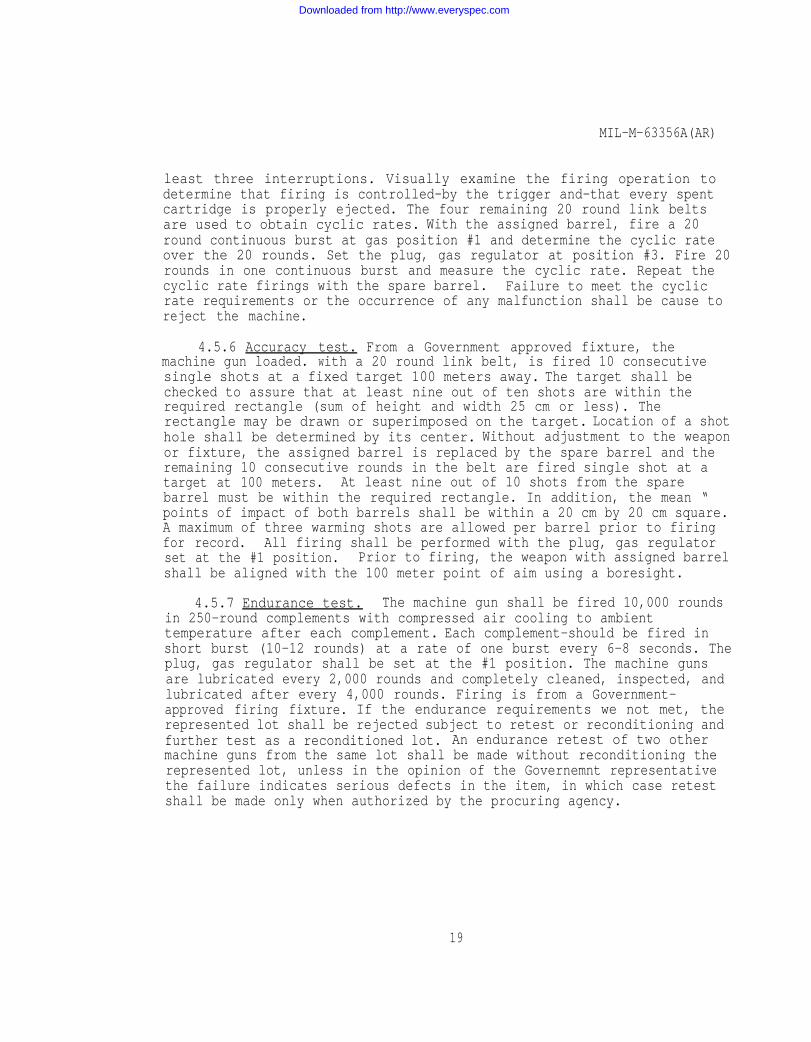
least three interruptions. Visually examine the firing operation todetermine that firing is controlled-by the trigger and-that every spentcartridge is properly ejected. The four remaining 20 round link beltsare used to obtain cyclic rates. With the assigned barrel, fire a 20round continuous burst at gas position #1 and determine the cyclic rateover the 20 rounds. Set the plug, gas regulator at position #3. Fire 20rounds in one continuous burst and measure the cyclic rate. Repeat thecyclic rate firings with the spare barrel. Failure to meet the cyclicrate requirements or the occurrence of any malfunction shall be cause toreject the machine.
4.5.6 Accuracy test. From a Government approved fixture, themachine gun loaded. With a 20 round link belt, is fired 10 consecutivesingle shots at a fixed target 100 meters away. The target shall bechecked to assure that at least nine out of ten shots are within therequired rectangle (sum of height and width 25 cm or less). Therectangle may be drawn or superimposed on the target. Location of a shothole shall be determined by its center. Without adjustment to the weaponor fixture, the assigned barrel is replaced by the spare barrel and theremaining 10 consecutive rounds in the belt are fired single shot at atarget at 100 meters. At least nine out of 10 shots from the sparebarrel must be within the required rectangle. In addition, the mean “points of impact of both barrels shall be within a 20 cm by 20 cm square.A maximum of three warming shots are allowed per barrel prior to firingfor record. All firing shall be performed with the plug, gas regulatorset at the #1 position. Prior to firing, the weapon with assigned barrelshall be aligned with the 100 meter point of aim using a boresight.
4.5.7 Endurance test. The machine gun shall be fired 10,000 roundsin 250-round complements with compressed air cooling to ambienttemperature after each complement. Each complement-should be fired inshort burst (10-12 rounds) at a rate of one burst every 6-8 seconds. Theplug, gas regulator shall be set at the #1 position. The machine gunsare lubricated every 2,000 rounds and completely cleaned, inspected, andlubricated after every 4,000 rounds. Firing is from a Government-approved firing fixture. If the endurance requirements we not met, therepresented lot shall be rejected subject to retest or reconditioning andfurther test as a reconditioned lot. An endurance retest of two othermachine guns from the same lot shall be made without reconditioning therepresented lot, unless in the opinion of the Governemnt representativethe failure indicates serious defects in the item, in which case retestshall be made only when authorized by the procuring agency.
19
Downloaded from http://www.everyspec.com

MIL-M-63356A(AR)
Failure of either machine gun in the retest to meet the requirements shall cause rejection of the represented lot subject to reconditioningand further testing as a reconditioned lot, Prior to submission of a lotof machine guns as a reconditioned lot, the cause of failure shall bedetermined and contractor correction shall be effected on all machineguns in the lot. Sample size and test methods for reconditioned lotsshall be the same as for retest.
4.5.8 Interchange of parts.
4.5.8.1 In plant.
4.5.8.1.1 Machine guns. Machine guns shall be tested bydisassembling and then reassembling parts using the parts and prearrangedsystem prescribed below. Interchange of parts shall be accomplished bydividing the parts of each machine gun into 10 gross of nonmating partsas shown below and distributing the-groups into 10 different trays untileach tray contains a complete machine gun. Groups of parts from machinegun number 1 shall be taken in order and placed in trays 1 through 10;groups of parts from machine gun number 2 shall be taken in order andplaced in trays 2 through 10 to 1; groups of parts from machine gunnumber 3 shall be taken in order and placed in trays 3 through 10 to 2,etc. Commerical parts such as screws, nuts, washers, and pins shall beplaced in the same tray as their mating or associated part. Anycommerical part rendered unserviceable by disassembly shall be replacedwithout penalty to the interchangeability test. The machine guns Shallbe reassembled using only those parts which are in the same tray.
Groups of nonmating parts
GROUP I
1. Barrel, Gun With Flash Hider Mounted ( 11825986)( 11826002)
2. Pin, Spring Release (MS 16562-122)3. Cover, Frame with rollers (11826022)4. Pin, Spring (MS 16562-105)5. Plate, Spring Mounting (11826153)6. Pin, Straight Headless (11826250)7. Rod Assembly, Driving Spring (11826024)
20
Downloaded from http://www.everyspec.com

MIL-M-63356A(AR)
GROUP II
(11826216)
(1182677)
1.2.3.4.5.6.7.8.9.
Latch, BarrelPin, Straight Headed“Pin, Straight Catch StopPlunger, Detent Buffer CatchCone, Buffer BrakingWasher, Spring Tension .Plug, Machine, ThreadTray, Feed (R.H.)Pin, Straight, Headed
GROUP III
11825999
(MS 9047-016) (11826215)
(11826219)(11826221-)(11826223(11826019)( 11826137)
1. Release, Barrel (11825997)2. Plate, Back Buffer (11826212)3. Pin, Axis, Tray& Cover4. Pin, Spring Trigger5.
(11826277Rod, Assembly Operating (11826072)
6. Guide, Cartridge Rear (R.H.) ( 11826035)7. Plunger, Detent (11826156)
GROUP IV
1.2.3.4.5.6.7.
GROUP V
1.2.3.4.5.6.7.8.9.
Spring, Helical CompressionPlug, BufferGuide, Charger CableGrip, Machine Gun LeftSearSlide, ChargerAdapter, Barrel
Ring, Extension BrakingPin, Spring LoadedPin, FiringPin, Pawl Retaining (R.H.)Guide, Cartridge Front (R.H.)Clip, RetainingGrip, Machine gun, RightSpring, Helical Torsion SearLatch, Barrel Locking
(11826214)(11826218)(11826234)(11826232-1) (11826253)( 11826135)(11826001)
(11826220)( 11826054)(11826065)(11826205)(11826023)(11826204)
(11826232-2)11826254)
(11826124)
21
Downloaded from http://www.everyspec.com

MIL-M-63356A(AR)
GROUP VI
1. Spacer, Sleeve Masher, Support (11826222) 2. Pin, Spring (11826068-1)3. Bolt, Breech Body (118260404. Trigger, Assembly )5.
(11826240 Pawl, Feed Assembly (RH). (11826017)
6. Clip, Spring Tension Feed Lever (11826202) 7. Clip, Retaining Catch (11826203)8. Latch, Back Plate (11826213)
GROUP VII
1.2.3.4.5.6.
7.
8.9.
Housing, TriggerNut, Plain, HexagonRing, RetainingLatch, CoverLever, Feed (R.H.)Screw, Cap, Hexagon Head Flat
Metal, RoundSpring, Helical, Compression,
Detent PlungerEjector, CartridgeSpring, Helical Compression
(11826231)(MS 35650-3384B){11826200)
(11826206)(11826209)
(MS 9286-26)
(11826158)( 11826067)(11826201)
GROUP VIII
1.2.3.4.5.6.7.8.9.
Cover, Access FrontPin, Grooved HeadPin, Spring PlungerPin, CotterPin, CotterPlunger, ExtractorScrew, Pan HeadExtractor, CartridgePlug, Gas Regulator
GROUP IX
1.2.
3.4.5.6.
7.
Washer, Flat (11826121)Spring, Helical Compression,
Barrel Latch (11826131)Spring, Extension (11826155)Cable, Charger (11826145)Spring, Extractor Assembly (11826062)Washer, Lock, Flat Internal
Tooth (MS 35333-42)Spring, Helical Compression,
Ejector (11826069)
(11826122)(11826130)(1182068-2)( AS3259-67)(AS3259-53)( 11826061)(11826120)(11826060)(11826003 )
22
Downloaded from http://www.everyspec.com

MIL-M-63356A(AR)
GROUP X
1.2.3.4.
5.
6.
Receiver Assembly (11825984)Safety, Small Arms ( 11826258)Collar, Gas Regulator (11825992)Washer, Flat Metal, Round,General Purpose (MS 15795-814B)
Pin, Spring, Steel, PhosphateFinish MS 9047-016)
Pin, Straight, Headless (11826255)
4.5.8.1.2 Concurrent repair parts. Concurrent repair-parts shall betested by disassembling two machine guns, previously tested in 4.4.3.8,as necessary and then reassembling them using the concurrent repairparts. The machine guns shall operate and function properly, This testmay be performed independently of the machine gun interchangeability testspecified in 4.4.3.8, and at more frequent intervals using acceptedmachine guns taken from current production. .
4.5.8.2 Interplant. Machine guns which are to be subjected to theinterplant interchangeability test shall be given preliminary handfunctioning to assure proper operation before parts are disassembled formthe gun. Machine guns shall be Interchanged in a manner similar to thedetalled plan in 4.5.8.1.1. When disassembling, every other gun usedshall be one produced by a different manufacturer. The machine gunsshall be tested for and shall comply with the requirements of para.4.4.3.8.1.1. Parts shall be identified with their manufacturerthroughout the test. Before guns are returned to the contractors, theoriginal parts shall be reassembled to their respective guns and the gunsgiven a hand functioning test to assure proper operation.
4.5.9 Reliability test. The three machine guns are each fired50,000 rounds in 10,000-round cycles from a Government-approved firingfixture simulating tank mounting. Unless otherwise specified, the firingis conducted in 250-round complements, alternating between firingschedules No. 1 and No. 2 (below), using gas port setting #1. Two barrelassemblies are to be used alternately (change after 250 rounds) with eachweapon and are air cooled to ambient temperature after each 250 rounds.
4.5.9.1 Firing schedulesm.
4.5.9.1.1 Schedule No. 1: 10-round burst at a rate of one burstevery 6 seconds; use for complete complement of 250 rounds.
23
Downloaded from http://www.everyspec.com

MIL-M-63356A(AR)
4.5.9.1.2 Schedule No. 2: 25-round burst at a rate of one burstevery 15 seconds; use for complete complement of 250 rounds,
4.5.9.2 The weapons shall be cleaned, inspected, and lubricatedafter each 4,000 rounds and re-lubricated after each 2,000 rounds.Semi-fluid lubricant conforming to MIL-L-46000A is to be used.
4.5.9.3 Barrel life.
4.5.9.3.1 At the start of test and during the last 50 rounds of eachof the final 250-round complements for each barrel in each 10,000 roundcycle, velocities shall be measured and evidence of yaw of keyholingdetermined.
4.5.9.3.2 Targets shall be placed at a range of 100 meters.Projectile velocities shall measured and recorded instrumentally at apoint 9 meters forward of the muzzle. Results shall be compared to thecriteria in 3.4.3.4. When a barrel is suspected of being unserviceableduring cycles, a check of barrel velocities and yaw shall be made. Abarrel is considered unserviceable when (a) 20 percent of any burstexhibits yaw of 15 degrees or more, or (b) a mean velocity of a burstdrops 200 feet per second below the mean of the velocity initiallyrecorded at the start of the test. If declared unserviceable, the roundsfired on the barrel shall be recorded and the barrel replaced with a newbarrel.
4.6 Testing stipulations.
4.6.1 Mounts. All firing tests shall be accomplished with themachine guns affixed to a Government approved mount.
4.6.2 Ammunition. All firing tests shall use cartridges perMIL-C-46931 except the high pressure test which shall use cartridges perMIL-C-46477. Defective ammunition shall void the test. Links shall beper MIL-L-45403.
5. PACKAGING
5.1 Preservation, Packaging. The requirements for packaging ofmachine guns shall be in accordance with Packaging Data Sheet P11826175.
5.2 Packing and Marking Packing and marking shall be as specifiedon Packaging Data Sheet P11826289)
24
Downloaded from http://www.everyspec.com

MIL-M-63356A(AR)
6. NOTES
6.1 Ordering data. Procurement documents shall specify thefollowing:
6.1.1 Procurement requirements.
a. Title, number and date of this specification and allapplicable Supplementary Quality Assurance Provisions (SQAP’s).
b. Quantity required and delivery schedules
c. Serialization requirements, if applicable.
d. Quality Conformance Inspection, if other than specified inSection 4 of specificationo
e. Packaging requirements. if other than specified in Section 5of specification.
f. Certificates of conformance for each lot or shipment ofproduct.
g. Responsibilities for furnishing ammunition and links.
h. Shipping instructions for machine guns when an interplantinterchangeability test is required.
i. The packages opened for examination shall be repackaged bythe contractor at the contractor’s expense.
j. Disposition of tested machine guns.
k. Requirement to conduct reliability test.
l. Responsibility for test firing facilities and operatingprocedures.
6.1.2 Contract data requirements.
a. Contract data requirements for inspection equipment designs(conforming to Data Item Description DI-E-7031 or DI-R-1714 withappropriate addendum to each). see 6.2.
25
Downloaded from http://www.everyspec.com

MIL-M-63356A(AR)
6.2 Insection Equipment Designs.Inspection equipment designs areof two types- Government Special Inspection Equipment (SIE) designs andcontractor designs. SIE designs are designated by drawing numbers underthe “Method of Inspectionn heading in Section 4. Design responsibility forall other inspection equipment is assigned-to the contractor. However,the contractor need not furnish any design when a-complete Government SIEis part of the Technical Data Package (TDP). Unless otherwise specified,the contractor may submit alternate or modified contractor designs of SIEin accordance with 6.2.2 and 6.2.3 should he elect tQ do Son
6.2.1 SIE designs. SIE designs may consist of any of the following:
a. Detailed drawings which completely depict all informationnecessary for the fabrication and use of the item of inspection. equipment.
b. A source control drawing or a specification control drawingas defined in MIL-STD-1OO.
c. An envelope drawing, as defined in MIL-STD-KIO, whichestablished the criteria which a detailed design shall meet. -Whenenvelope drawings are specified, the contractor shall prepare designswhich comply with the criteria therein. .
6.2.2 Contractor designs. Contractor designs are required for allinspection equipment for which SIE designs are not specified and mayinclude commercial equipment which the contractor proposes to use. -
(Commercial equipment is defined as unmodified equipment which iscataloged and available for purchase by the general public). Contractordesigns shall include appropriate operating instructions, calibrationprocedures and maintenance procedures. Commerical equipment shall befully described by catalog listings or other means which providesufficient information to permit identification and evaluation by theGovernment and may include illustrations and engineering data. Designsshall be prepared for any special fixture(s) required to be used withcommerical equipment. or with SIE designs if not otherwise coveredthereby (see 6.3.1c). Designs shall be of the category and form (perMIL-D-1000) specified in the Contract Data Requirements Lists (DD Form1423).
The specification number, paragraph number, and defect number fromSection 4 shall be referenced on each contractor design together with thecomponent or assembly drawing number, revision letter and date to whichthe specific design applies.
26
Downloaded from http://www.everyspec.com

MIL-M-63356A(AR)
6.2.3 Submission of designs for approval. Contractor designs shallbe approved by the Government prior to fabricating or procuring theequipment. Designs shall be submitted for-approval In accordance withthe stipulations, time frame and distribution specified in the ContractData Requirements Lists (DD Form 1423) or in the contract. Partialsubmission of Inspection equipment designs is permissible andencouraged. However, the completion data for design review will be basedon the date of the final submission of designs and the required deliveryschedule as stipulated In the contracct. The specific segment of ARRADCOMto which the Contractor designs shall be sent will be DRDAR-QAA-I.
When the contractor submits Inspection equipmentdesigns to the Government for approval he shall givethe following information in his letter of transmittal:
The contract numberThe contract item (name, model number, etc.)
c. The designs remaining to be submitted and theexpected date of submittal.
6.3 Definitions.
6.3.1 Contractor. Unless otherwise specified, the word Contractorused throughout this or the item detail specification shall mean anysupplier or producer of items or material to the Government. this shallinclude commerical contractors, sub-contractors, Government Owned,Contractor Operated (GOCO) and Government Owned, Government Operated(GOGO) plants.
6.3.2 Technical data package (TDP). A technical description of anitem adequate for use in proccurement. The description defines therequired design configuration and assures adequacey of item performance.It consists of all applicable technical data such as plans, drawings, andassocited lists specifications, standards, models, performancerequirements, quality assurance provisions, and packaging data.
6.3.3 Critical defect. A defect that judgement and experienceindicate is likely to result in hazardous or unsafe conditions forindividuals using, maintaining, or depending upon the product; or adefect that judgement and experience indicate is likely to preventperformance of the tactical function of a major end item such as anaircraft, tank, land vehicle, missle, artillery, or other major weaponsystem.
27
Downloaded from http://www.everyspec.com
MIL-M-63356A(AR)
6.3.4 Special defect. A defect, other Critical, that judgement and experience indidiate may, depending upon the degree of variance fromthe design, requirement:
a. Result in hazardous or unsafe, conditions for individualsusing, maintaining or depending upon the product or
b. Prevent performance of the tactical function of a major enditem.
6.4 To avoid delay in test firing the contractor should maintain aminimum of 2 mounts supply of ammunition as determined by anticipatedfiring requirements.
6.5 Test firing facilities and operating procedures should bedesignated by the contractor in conformance with local, state, andfederal regulations. They should be suitable for carrying out prescribedfiring tests and insure the safety of operation and personnel. Copies ofthese contractor designs should be forwarded to the contracting officer.Government facilities may be viewed upon application to the contractingofficer.
6.6 When action by a testing agency is required, work programingwill be effected with the testing agency at the earliest practical date.
6.7 Chanqes from previous issue. Asterisks are not used in thisrevision to identify changes with respect to the previous issue, due tothe extensiveness of the changes.
Custodian: Preparing Activity:Army-AR Army-AR
Project No: 1OO5-A6O8
28
Downloaded from http://www.everyspec.com

Downloaded from http://www.everyspec.com