Effects of sintering temperatures on microstructures and ...

Microstructures of sediment ow deposits and subglacial sedimentsa comparison
MATTHEW S LACHNIET GRAHAME J LARSON DANIEL E LAWSON EDWARD B EVENSON AND RICHARD B ALLEY
Lachniet M S Larson G J Lawson D E Evenson E B amp Alley R B 2001 (September) Microstruc-tures of sediment ow deposits and subglacia l sediments a comparison Boreas Vol 30 pp 254ndash262 OsloISSN 0300-9483
Microstructura l analysis of glacial deposits has recently been used as a research tool to determine sedimentgenesis However the occurrence of microstructure s in deposits of known origin has not been suf cientlydocumented hindering our ability to con dently interpret microstructure s in sediments of unknown originOur objective is to present a calibration study of microstructure s of recent sediment ow deposits and asso-ciated sediments from the Matanuska Glacier Alaska and to evaluate the degree of commonality with micro-structures found in subglaciall y deformed sediments Microstructure s in sediment ow deposits can be formedas a result of sediment transport deposition andor post-depositiona l processes and are related to the viscosityregime of the source ow Characteristi c microstructures formed during brittle deformation include shearsfaults and brecciation microstructure s formed during ductile deformation include folds pressure shadows re-orientation of clasts around a lsquocorersquo stone ne laminations basal shear zones imbrication and ow fabricsOther microstructures include uid escape and injection structures clast haloes and ssility The results ofour comparison suggest that sediment ow deposits share many microstructure s in common with subglaciall ydeformed sediments
Matthew S Lachniet (e-mail mlachniesyredu) Department of Earth Sciences Syracuse UniversitySyracuse NY 13244 USA Grahame J Larson (e-mail larsongpilotmsuedu) Department of GeologicalSciences Michigan State University East Lansing MI 48824 USA Daniel E Lawson (e-maildlawsoncrrelusacearmymil) US Army Cold Regions Research and Engineering Laboratory AnchorageAK 99505 USA Edward B Evenson (e-mail ebe0lehighedu) Department of Earth and EnvironmentalSciences Lehigh University Bethlehem PA 18015 USA Richard B Alley (e-mail ralleyesscpsuedu) Earth System Science Center and Department of Geosciences The Pennsylvania State University UniversityPark Pennsylvania 16802 USA received 11th December 2000 accepted 21st February 2001
Microstructural analysis has emerged as a useful tech-nique in the study of glacial deposits For examplemicrostructures observed in thin section have been usedto determine sediment genesis (van der Meer 1987 vander Meer amp Laban 1990 Harris 1998) and to elucidatesubglacial processes (Menzies amp Maltman 1992 vander Meer 1993 Menzies et al 1997) These studies haveresulted in a preliminary classi cation of microstruc-tures within subglacial diamictons (Menzies 1998)More recently microstructures have been used todifferentiate types of sediment ow deposits in an ice-proximal environment (Lachniet et al 1999) wheresediment released from ablating debris-bearing ice isremobilized and deposited under the in uence ofgravity sometimes several times (Lawson 19791982) During remobilization and consequent deposi-tion of sediment ows primary structures may bedestroyed while ow structures are created andpreserved In addition deformation of underlyingsediment may occur during ow and deposition
Microstructural studies of modern sediments ofknown origin are few so the process-microstructurelink has not been clearly established for many types ofglacial deposits To be successfully applied to ancientsediments calibration studies are needed in order todetermine which structures may be indicative ofparticular sedimentary environments The objective of
this study is (1) to present various microstructuresformed in modern sediment ow deposits and inunconsolidated sediments overridden by ows at theMatanuska Glacier Alaska as a calibration studyand (2) to compare our results with microstructuresdescribed for subglacially deformed sediments
Types of sediment ows
Sediment ow deposits have been referred to previouslyas lsquo ow tillsrsquo (Boulton 1968 Marcussen 1973 1975Kruger amp Marcussen 1976 Evenson et al 1977 van derMeer 1987) At the Matanuska Glacier (Fig 1) themajority of deposits present at the surface formed fromsubaerial sediment ows with only a minor percentageof tills (Lawson 1979 1982) Sediment ows originatefrom water and sediment released by the ablation ofdebris-rich basal ice and owage initiated fromsaturation of sediment on ice or ice-cored moraine
Subaerial sediment ows have been classi ed intofour types at the Matanuska Glacier based primarily onwater content (Lawson 1979 1982) Type I ows have awater content ranging from 8 to 14 by weight arelobate in shape and composed of a cohesive plug owing over a thin (a few cm) basal shear zone Type II ows have a water content of 14ndash19 by weight are
commonly channelized and move as a cohesive plugover basal and lateral shear zones Laminar owdominates in the basal shear zone of Type I and II ows Type III ows have a water content of 18ndash25are channelized and ow by differential shear through-out Type IV ows contain more than 25 water by dryweight may be lique ed and transport occurs bylaminar ow with shear throughout The transportmechanism in ows is actually a continuum betweenthe thin basal shear zone supporting a cohesive plug ofdry ows and laminar ow with differential shearthroughout the ow body in wet sediment ows(Lawson 1979 1982)
Sediment ow deposits contain structures related tothe water content of the ow inherited structures fromthe source material and structures formed duringsediment owage and deposition Type I ow depositscommonly exhibit cobbles in a matrix of pebbly sandysilt are poorly sorted and may retain characteristics ofthe source material Type II ow deposits may betexturally similar to Type I deposits and commonlyappear structurally heterogeneous in the eld They maypresent intact blocks of source sediment that retainprimary structures and uid escape structures due topartial or complete liquefaction of ow sediment arealso common Type I and II deposits may inducedeformation of underlying sediments Type III owdeposits commonly are gravelly sands to sandy siltsmay be strati ed and may form fans with clastsimbricated upslope Type IV ow deposits are generallywell sorted and lack de nite structure in the eldFurther eld characteristics and fabric analyses arepresented in Lawson (1979 1982)
Flows with higher water content are generally thinner
than those with lower water content The ow velocityis determined primarily by the surface slope and watercontent both of which vary proportionally Grain sizefor the different types is presented in Fig 2 and isdominated by the silt-sized fraction with a conspicuouspaucity of clay-sized particles (Lawson 1979 1982) Animplication of the lack of clay is the absence ofbirefringence in polarized light which is induced byplasma fabric development Therefore the terminologyof Brewer (1976) utilized in other microstructuralstudies (cf van der Meer 1993 Menzies et al 1997)has little application in our study
Sediment ows at the Matanuska Glacier commonlyhave traction gravels at their base and hold surfaceslopes up to 30deg depending on the cohesion of sedimentjust prior to deposition They also form under acontinuum of water contents and internal shear in theplug is both a function of water content and slopeTypes I and II ow plugs may undergo internal shear ifsurface slope is high In this study Types I and II areconsidered lsquodry-typersquo ows while Types III and IV areconsidered lsquowet-typersquo ows In addition to subaerialsediment ows subaquatic sediment ows occur inareas of standing or moving water and generally formas a result of sediment failure under saturated condi-tions
Methods
Sediment ow deposits and underlying sedimentswere sampled using metal tins (10 pound 55 pound 75 cm)inserted over a carved-out sediment block The sedi-ment- lled tin was carefully removed from the out-
Fig 1 Location of the study area and the MatanuskaGlacier Alaska USA
BOREAS 30 (2001) Micromorphology of glacial sediments 255
crop face and excess sediment trimmed until two lidscould be put on Care was taken not to disturb thestructural integrity of the sediment block duringsampling The sample number and orientation werenoted and the samples were stored in air-tight plasticbags until ready for preparation Samples were air-dried in the laboratory impregnated with a polyesterresin and thin sections prepared from the hardenedblocks according to a procedure developed by JohnMenzies (pers comm 1996) The thin sections wereanalyzed under various magni cations and lters witha PetroScope photographed and described Severalthin sections from a total of 13 samples are analyzedhere
Results
We investigated the microstructures present in sediment ow deposits at the terminus of the Matanuska Glacier
formed from wet-type and dry-type ows Fieldidenti cation of ow deposit type was based on thecharacteristics presented above (from Lawson 19791982) We present results from wet-type then dry-type ow deposits and then other structures that may not beexplicitly related to water content of the source ow
Sample 50 was taken from a wet-type deposit on themoraine that appeared massive in the eld The depositis well sorted and the silt matrix supports coarse and ne sands Thin sections of this deposit reveal near-horizontal laminations that are characterized by undu-lating sand layers a few grains thick that alternate withsilt layers (Fig 3A) Numerous rounded coarse sandsand ne gravels are distributed with long axes pref-erentially aligned along laminations or imbricatedupslope At the base of the deposit a gravel layer isoverlain by the sediment ow body The contactbetween the gravel and overlaying body is characterizedby linear silt layers that concentrate in the lee of gravelsand in the interstices between grains (Fig 3B) Thesesilt layers commonly surround grains and pinch out intothe ow body (Fig 3C)
Sample 45 was taken from a texturally heterogeneousdry-type deposit resting on glacier ice with a silt matrixthat supported numerous clasts In the eld the depositappeared massive with the exception of a few well-sorted sand and silt layers In thin section two texturallyde ned units are apparent A lower silt unit is separatedfrom a higher silt unit by a layer of coarse sands and negravels Immediately above this layer the depositpresents a conspicuous folded sand layer associatedwith a rounded clast (Fig 3D) The folded sand layer isdifferentiated from the remainder of the deposit by alack of silt-sized material The rounded clast visiblebeneath the fold is surrounded by silt material called alsquohalorsquo These features have been observed elsewhere(van der Meer 1993)
Sediment ows may also deform underlying sedi-ments during transport Sample 42 was collected fromsuch a deformed unit This deposit is composed ofalternating laminations of silt and sand and appearstexturally similar to sample 50 described above Thedeposit is overlain by a sediment ow deposit and waspresumably deformed by it In thin section a recumbentfold is visible (Fig 3E) which has been faulted Thefault zone is characterized by a linear high-angle planethat visibly offsets the laminations on either side
Sample 31 was taken from a texturally heterogeneousand poorly sorted dry-type deposit composed ofrounded to sub-rounded pebbles and cobbles in a siltmatrix The base of the deposit contains ne lamina-tions and appears to truncate the underlying strati edsilts In thin section this basal zone is characterized byrounded clasts and alternating layers of sand and siltWithin this zone a rounded metamorphic clast iscapped by silt layers that dip downward on either side(Fig 3F) A wedge-shaped sand lens occurs on the rightside of the clast and is bounded by these silt layers This
Fig 2 Grain-size distribution for sediment ow deposits in thebody of Types I (a) II (b1) III (c1) and IV (d) ows b2 and c2 aresamples from the basal zones of Types II and III ows (from Law-son 1982)
256 Matthew S Lachniet et al BOREAS 30 (2001)
BOREAS 30 (2001) Micromorphology of glacial sediments 257
258 Matthew S Lachniet et al BOREAS 30 (2001)
feature has been described in glacial sediments else-where and is called a pressure shadow (van der Meer1987)
Sample 53 was taken from a texturally heterogeneousdry-type deposit composed of a silt with sand matrixthat supported cobbles up to 20 cm in diameter Itappeared structureless in the eld In thin section a 4-cm long diameter rounded phyllite clast is surroundedby smaller clasts within the silt and sand matrix Thelong axes of the smaller clasts are arranged tangentiallyto the surface of the phyllite clast along its entirety in acircular alignment (detail in Fig 3G) This microstruc-ture has also been observed in tills and has been called alsquoturbatersquo or lsquogalaxyrsquo structure (van der Meer 1993)
In some locations at the Matanuska Glacierrsquosterminus sediment ows were deposited in basins thathave been inundated by water Sample 60 comes fromsuch a location where it overlies a clay-sized homo-genous horizontal layer 2 cm thick at an elevation belowterraces formed at old water level Based on this its lowsurface slope smooth upper surface and a predomi-nantly silt texture it was interpreted to be subaquaticsediment ow deposit In thin section the deposit showsnumerous discontinuous and jagged silt concentrationssurrounded by sands (Fig 3H) Horizontal lineations ofdarker-colored ne silt are evident within the lighter-colored coarser silt matrix and pinch-out a shortdistance from their thickest portion in a mannerconsistent with the appearance of boudins
A thin section prepared from sample 69 taken fromthe same deposit as sample 60 described above is
shown in Fig 3I The deposit consists of near horizontalalternating layers of silt-rich and sand material that arebounded and cross-cut by high-angle fault planes Fig3J shows a thin section prepared from a dry-typesediment ow deposit which is characterized bynumerous horizontal shear planes de ned either bysilt-rich or silt-poor layers These shear planes arejoined by another set of discreet shears oriented at anangle to them in a manner similar to Riedel shears(Hatcher 1990) In a meltwater silt deposit overriddenby a sediment ow brecciation is evident in thin section(Fig 3K) The lower section of the photograph showslayered silts and sands that have been brecciated andthat retain angular edges The overlying sand shows noapparent structure Also visible in Fig 3K is theconcentration of nes around the large near-verticalclast
A sequence consisting of two sediment ow deposits(sample 28) resting on glacier ice 3 m from the activeterminus was sampled The upper deposit showedvertical air- lled tubes on its surface which havebeen observed to form by uid expulsion duringsediment ow deposition (Lawson 1979) In thinsection the upper deposit showed laminations of siltalternating with sand that are in discordant contact at a45deg angle with a zone of sands (Fig 3L the lowerdeposit is described below) The laminations of thedeposit are upwarped and truncated along the contactwith the sand zone Similarly a thin section preparedfrom another sediment ow deposit (sample 13) shows asilt lineation that is discordant with the weak lamina-
Fig 3 A Fine laminations and laminar ow fabric in a wet-type sediment ow deposit Note undulations in the laminations and upslopeimbrication of some clasts Flow direction was from right to left Width of view is 27 mm Plane light (Sample 50) B Basal shear zone(dashed black line) over a traction gravel characterized by silt wisps in the lee of gravels (arrow) Width of view is 27 mm Plane light(Sample 50) C Silt wisp (arrows) around a small clast Width of view is 8 mm Plane light (Sample 50) D Fold in a sand layer atthe base of a dry-type sediment ow deposit Note the conspicuous halo around the large clast The underlying deposit was slightly foldedduring deposition of upper deposit Width of view is 27 mm Plane light (Sample 45) E Recumbent fold with faulting along axial plane(dashed black line) in meltwater silts formed as a result of overriding by a sediment ow Irregular white areas are porosity gained duringsample preparation Width of view is 27 mm Plane light (Sample 42) F A pressure shadow (arrows) around a small metamorphic clastlocated in the basal shear zone of a dry-type sediment ow deposit Width of view is 8 mm Plane light (Sample 31) G Reorientationof clasts around a lsquocore clastrsquo in a dry-type sediment ow deposit Clasts were reoriented around the entirety of the large phyllite clastOne clast is outlined with dotted white line long axes of reoriented clasts are shown with black lines Width of view is 27 mm Plane light(Sample 53) H Boudins in a subaquatic sediment ow deposit This deposit had a smooth lobate surface and had not been overriddenby other sediment ows or ice therefore the boudinage probably occurred during sediment transport Width of view is 27 mm Plane light(Sample 60) I Faulting in subaquatic sediment ow deposit Fault planes denoted by dashed black line showing arrows of relativemovement Width of view is 27 mm Plane light (Sample 69) J Riedel shears in a dry-type sediment ow deposit in middle of photo-graph from right down to the left denoted by black dashed lines Shear zones are characterize d by ne silt concentrations evidence thatshears are lubricated with water The shear zone overlies a tractional gravel Width of view is 17 mm Plane light (Sample 45) K Brec-ciation in meltwater silts from being overridden by a sediment ow Note also halo of silt (arrows) around near-vertica l clast Width ofview is 17 mm Plane light (Sample 55L) L Fluid escapeinjection structure (black dotted lines denote borders) starting from lowerright to top left cross-cutting laminations in a sediment ow deposit The structure is characterize d by sand and ne gravel that was in-jected from beneath Upwarping of laminations (arrows and one lamina denoted by dotted white line) in the sediment ow deposit oc-curred during uid expulsion Width of view is 27 mm Plane light (Sample 28) M Fluid injection structure (arrows) discordant withweakly de ned laminations and ssility planes (which were visible in the eld) Width of view is 27 mm Plane light (Sample 13) NFissility planes developed in a dry-type sediment ow deposit A silt intraclast is outlined with a dotted black line Width of view is27 mm Plane light (Sample 14) O Incomplete mixing of source sediment and small dark-colored silt intraclasts (lsquopebblesrsquo) in a sedi-ment ow derived from laminated silts The original laminations are stretched and elongated into boudin-like forms Deposition occurredwithin 10 m from source deposit Width of view is 22 mm Plane light (Sample 38) P Sand intraclast (lsquopebblersquo) surrounded by silt and ne sand laminations in a wet-type sediment ow deposit This deposit was sup13 m from the terminus of the glacier and the intraclast mayhave been frozen during incorporation Width of view is 27 mm Plane light (Sample 28)
BOREAS 30 (2001) Micromorphology of glacial sediments 259
tions and ssility present in the ow deposit body (Fig3M)
Fig 3M also presents ssility planes characterizedwith an orientation parallel to the upper surface of the ow deposit These ssility planes are more evident inthin sections made from sample 14 (Fig 3N) Sample 14is a texturally homogenous dry-type deposit that formedfrom mobilization of sediments on the moraine The ow deposit body has a surface slope of sup110deg and held asteep face attesting to its low water content The surfaceof the ow deposit contains uid escape tubes The ssility planes do not appear to coincide with texturalboundaries
Two deposits of sediment ows that solidi ed withina few meters of their source sediment were sampledSample 18 is a sediment ow deposit that was formedfrom mobilization of silts and had a smooth uppersurface and low surface slope This deposit wasinterpreted to be a wet-type deposit Numerous wavysilt lineations were evident in the eld and in thinsection (Fig 3O) Included within these silt lineationsare round silt lsquopebblesrsquo that are characterized by adarker color The silt lineations also demonstrateborders reminiscent of boudinage describe above Athin section from the lower sediment ow deposit ofsample 28 (described above) was also prepared and isshown in Fig 3P In this section laminations of sandand silt surround a sub-rounded sand lsquopebblersquo orintraclast
Interpretations
We interpret the laminations in Fig 3A as havingformed under ductile deformation during sediment owThis arrangement has been called a lsquolaminar owfabricrsquo (Lachniet et al 1999) The concentrations of nes in the interstices of the basal gravel and at thecontact between the basal gravels and overlyingsediment suggests formation in a silt-rich uidizedshear zone (Fig 3B) This interpretation is consistentwith observations that laminar ow occurs over basaltraction gravels in sediment ows (Lawson 1979 1982)The silt layers in Fig 3C are called lsquosilt wispsrsquo orlsquowinged inclusionsrsquo and are attributed to form underrotation of the clast under ductile conditions (van derMeer 1993)
The structures described above in Fig 3DndashH areinterpreted to form by ductile deformation similar toprevious interpretations For example folds (Fig 3D E)are commonly formed during ductile deformation(Hatcher 1990) Additionally pressure shadows andcircular alignment of clasts around a lsquocore stonersquo alsocalled a lsquoturbate structurersquo (Fig 3F G) and boudins(Fig 3H) have been attributed to form under rotationalshear during ductile deformation (Hatcher 1990 van derMeer 1993 Menzies et al 1997)
The features described in Fig 3IndashK are interpreted to
form by brittle deformation probably associated withlow pore-water pressures These brittle structures mayform after deposition and may be tectonic rather thansedimentary in origin
Given the discordant contact upwarped laminationsand disparate grain sizes of the two zones in Fig 3Lalong with the presence of sur cial water escape tubeswe interpret this structure to have been formed by uidexpulsion The discordant contact between the siltlineation and the weak laminations and ssility evidentin Fig 3M also suggest an origin related to uid escapeThese interpretations are consistent with those of vander Meer (1993) who noted that movement of uids hasthe ability to wash away nes leaving zones of sand-sized or larger particles In the sediment ow depositsthe structures formed may bifurcate and are vertical tosub-vertical except where uid escape has beendiverted by a more impermeable layer or clast as seenin other thin sections not presented here Where nes-rich uid ceases movement in fractures fault planesplanes of weakness or pores it can also produce nes-rich uid injection structures (Fig 3M) These struc-tures can have a similar appearance to silt wisps butmay be discordant with laminations or ow direction (asin Fig 3M) while wisps are concordant
The lsquopebblersquo features evident in Fig 3O P are similarto those described by van der Meer (1993) that areattributed to form due to rotational movement in adeforming till Similarly we interpret the lsquopebblesrsquo inthe sediment ow deposits as having formed during theincomplete mixing of the source sediments underrotational movement Additionally the sand lsquopebblersquoin Fig 3P may have been frozen during incorporationinto the ow body considering its close proximity to theactive terminus
The origin of the ssility planes (Fig 3M N) insediment ow deposits is less clear but they may formduring desiccation upon deposition or during thesampling process The ssility planes generally do notappear to coincide with textural boundaries
Discussion a comparison with subglacial tillmicrostructureNumerous microstructures have been reported in theliterature from subglacially deformed sediments (cf vander Meer 1987 1993 1997 Menzies amp Maltman 1992Menzies et al 1997 Menzies 1998) These micro-structures include discrete shears kink bands till (orother material) lsquopebblesrsquo brecciation galaxy or turbatestructures (orientation of clasts around a lsquocorersquo stone)casing of ne-grained material around a clast (halo)pressure shadows crushed quartz grains ssilityboudins water escape structures plasma fabricsdeformation of laminations and faults and folds Thesestructures are attributed to form under either planar or
260 Matthew S Lachniet et al BOREAS 30 (2001)
rotational movement within subglacial sediments thathave a downward decreasing strain pro le (van derMeer 1993) Although not observed in lsquo ow tillsrsquo fromVestspitsbergen van der Meer (1993) recognized thatdeformation microstructures may also form in sur cialprocesses such as sediment ow Our results con rmand document this contention and demonstrate thatsimilar microstructures may originate in disparateglacial environments Microstructures of sediment ow deposits are presented diagrammatically in Fig4 and compared with those found in subglacial tills inTable 1
An important distinction must be made however as
to the mode of formation of these microstructuresWhile deformation microstructures in subglacial sedi-ments should be described in tectonic terms (iesecondary structures overprinted upon primary struc-tures) some of these structures in sediment owdeposits are clearly primary and a result of sedimentaryprocesses operating during ow and deposition unaf-fected by overriding ice A good example is theboudinage observed in Fig 3H which most likelyoriginated during owage of a sediment mass under thein uence of gravity Microstructures formed duringductile deformation such as galaxy structures pressureshadows folds and clast haloes can form both primarily
Fig 4 Microstructura l types of glacigenic sediment ow deposits After van der Meer (1993) and Menzies (1998) with results from thisstudy and Lachniet et al (1999)
Table 1 Comparison of microstructure s formed during sediment ow and subglacial deformation The mutual occurrence of many micro-structures suggests formation in disparate environments
MicrostructureSediment ow deposits (this study Lachniet etal 1999
Subglacial sediments (van der Meer 1993Menzies amp Maltman 1992)
Incomplete mixingboudinage pound poundTurbate structures pound poundFluid escape and injection structures pound poundPressure shadows pound poundShears pound poundFolds pound poundHaloes pound poundBasal shear zones poundSilt wisps (winged inclusions ) pound poundLaminar ow fabric pound
BOREAS 30 (2001) Micromorphology of glacial sediments 261
during sediment ow and by secondary deformation insubglacial sediments Other structures such as uidescape and injection structures may also form bothprimarily and secondarily Microstructures in sediment ow deposits that formed during brittle deformationare generally found in dry-type ow deposits whereinternal stress resulting from transport is released byshearing in the cohesive plug (as in Fig 3J) Howeverthese shears can also be induced during overriding byanother sediment ow so knowledge of stratigraphicrelations is important to interpret correctly betweenprimary and secondary shearing
From this comparison we can conclude that bothsediment ow deposits and subglacially deformedsediments share common microstructures Howeverthe relative abundance of certain microstructures mayvary between sediment types For example sedimentlsquointraclastsrsquo or lsquopebblesrsquo appear to be more common insubglacially deformed sediments than in sediment owdeposits (van der Meer 1993 Menzies et al 1997this study) Considering this and the commonality ofmicrostructures between disparate deposits in theglacial environment the use of microstructural analysisof glacial sediments is most useful when undertakenalong with traditional sedimentological analysis suchas macroscopic descriptions of the exposure clastfabrics and stratigraphic context (van der Meer 1993van der Wateren 1997) Further research should focuson the characterization of microstructures in sedimentsof known origin to further establish the link betweenprocess and microstructure
Acknowledgement ndash The authors thank J J M van der Meer CHarris Kurt Kjaeligr John Menzies and an anonymous reviewer forhelpful comments on various drafts of this manuscript Additionalthanks to Neil Glasser Tavi Murray and others involved in orga-nizing the conference lsquoGlacial Debris Transport and DepositionProcesses and Productsrsquo held at the University of Leeds in January1998 which provided the impetus to produce this manuscript The rst author would like to thank the Department of Earth Sciencesat Syracuse University for providing funds to attend the confer-ence
ReferencesBoulton G S 1968 Flow tills and related deposits on some Vest-
spitsbergen glaciers Journal of Glaciology 7 391ndash412Brewer R 1976 Fabric and Mineral Analyses of Soils 482 pp
Krieger Huntingdon NY
Evenson E B Dreimanis A amp Newsome J W 1977 Subaqua-tic ow tills a new interpretation for the genesis of some lami-nated till deposits Boreas 6 115ndash133
Harris C 1998 The micromorphology of paraglacia l and peri-glacial slope deposits a case study from Morfa Bychan westWales UK Journal of Quaternary Science 13 73ndash84
Hatcher R D Jr 1990 Structural Geology Principles Conceptsand Problems 531 pp Macmillan New York
Kruger J amp Macrussen I 1976 Lodgement and ow till a dis-cussion Boreas 5 61ndash64
Lachniet M S Larson G J Strasser J C Lawson D E ampEvenson E B 1999 Microstructure s of glacigenic sediment ow deposits Matanuska Glacier Alaska In Mickelson D Mamp Attig J W (eds) Glacial Processes Past and Present 45ndash57 Geological Society of America Special Paper 337 BoulderCO
Lawson D E 1979 Sedimentologica l Analysis of the Western Ter-minus Region of the Matanuska Glacier Alaska 112 pp USArmy Cold Regions Research and Engineering Laboratory Han-over NH Report 79ndash9
Lawson D E 1982 Mobilization movement and deposition ofactive subaerial sediment ows Matanuska Glacier AlaskaJournal of Geology 87 629ndash645
Marcussen I 1973 Studies on ow till in Denmark Boreas 2213ndash231
Marcussen I 1975 Distinguishing between lodgement till and ow till in Weichselian deposits Boreas 4 113ndash123
Menzies J 1998 Microstructure s within subglacia l diamictons InKostrzewski A (ed) Relief and Deposits of Present-day andPleistocene Glaciation of the Northern Hemisphere ndash SelectedProblems 153ndash166 Adam Mickiewicz University Press Ge-ography Series no 58 Poznan Poland
Menzies J amp Maltman A J 1992 Microstructures in diamictonsndash evidence of subglacia l bed conditions Geomorphology 6 27ndash40
Menzies J Zaniewski K amp Dreger D 1997 Evidence frommicrostructures of deformable bed conditions within drumlinsChimney Bluffs New York State Sedimentary Geology 111161ndash175
van der Meer J J M 1997 Particle and aggregate mobility in tillmicroscopic evidence of subglacial processes QuaternaryScience Reviews 16 827ndash831
van der Meer J J M 1987 Micromorphology of glacial sedi-ments as a tool in distinguishing genetic varieties of till Geo-logical Survey of Finland Special Paper 3 77ndash89
van der Meer J J M 1993 Microscopic evidence of subglacia ldeformation Quaternary Science Reviews 12 553ndash587
van der Meer J J M amp Laban C 1990 Micromorphology ofsome North Sea till samples a pilot study Journal of Quater-nary Science 5 95ndash101
van der Wateren F M 1997 Structural analysis of micro- andmacro-fabrics in tills ndash kinematic indicators of subglacia l shear-ing Workshop notes for glacial debris transport and depositionprocesses and products Joint IGS British Branch QRA BGRGand BSRG meeting University of Leeds 9ndash11 January 199842 pp
262 Matthew S Lachniet et al BOREAS 30 (2001)
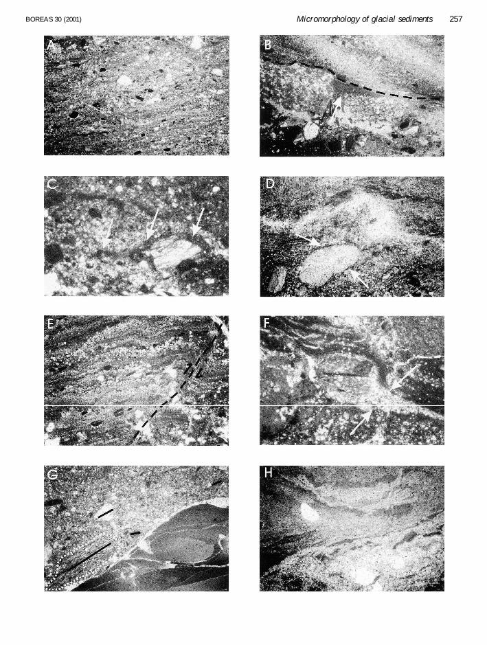
Copyright © 2022 FDOKUMEN