Microstructural and magnetic properties of L1 0 FePt–C (0 0 1) textured nanocomposite films grown...
6
IOP PUBLISHING JOURNAL OF PHYSICS D: APPLIED PHYSICS J. Phys. D: Appl. Phys. 41 (2008) 205001 (6pp) doi:10.1088/0022-3727/41/20/205001 Microstructural and magnetic properties of L1 0 FePt–C (0 0 1) textured nanocomposite films grown on different intermediate layers J S Chen 1,4 , B C Lim 2 , J F Hu 2 , Y F Ding 2 , G M Chow 1 and G Ju 3 1 Department of Materials Science and Engineering, National University of Singapore, 7, Engineering Drive 1, Singapore 117574, Singapore 2 Data Storage Institute, 5 Engineering Drive 1, Singapore 117608, Singapore 3 Seagate Technology, Pittsburgh, PA 15222-4215, USA E-mail: [email protected] Received 23 July 2008, in final form 19 August 2008 Published 22 September 2008 Online at stacks.iop.org/JPhysD/41/205001 Abstract The FePt : C films with different volume fractions of carbon and different thicknesses were epitaxially grown on a CrRu(2 0 0) underlayer with Pt and MgO intermediate layers. The magnetic properties and microstructure of these FePt : C films were investigated. The FePt : C films grown on the Pt intermediate layer consisted of a continuous layer of FePt, with overlying granular FePt grains, while the FePt : C films grown on the MgO intermediate layer consisted of granular FePt : C layers with overlying granular grains. The formation of the overlying granular FePt grains was attributed to carbon diffusion to the surface which resulted in the second nucleation of FePt. The different interface energies and surface energies of FePt on Pt and MgO intermediate layers caused the formation of an initial continuous FePt layer on the Pt intermediate layer and initial granular FePt layers on the MgO intermediate layer. The coupling between the continuous FePt layer or the granular FePt layer and the overlying granular FePt grains resulted in simultaneous magnetization reversal and thus strong exchange coupling in FePt : C films. (Some figures in this article are in colour only in the electronic version) 1. Introduction L1 0 ordered FePt films with large magnetocrystalline anisotropy (7 × 10 7 erg cm −3 ) have attracted much attention in recent years due to their potential application for ultrahigh density recording media [1, 2]. The large noise of FePt media has however became the main obstacle to its application for ultrahigh density media. In order to reduce the noise, a pinned FePt medium was proposed to trap the domain wall and decrease the domain size [3, 4]. Using this method, the noise was indeed decreased and the signal-to noise ratio (SNR) was increased. It remains very difficult to control the density and uniformity of the pinning sites. The conventional approach 4 Author to whom any correspondence should be addressed. to noise reduction and increase in SNR involves reducing the grain size and narrowing the grain size distribution. L1 0 FePt (0 0 1) textured films with small grain size have been obtained by post-annealing FePt/SiO 2 [5], FePt/C [6, 7] and FePt/MgO [8] multilayers at high temperature (above 550 ◦ C), but the long time and high temperature process were not favoured for practical applications. Significant progress has been made in fabricating L1 0 FePt (0 0 1) textured films with continuous film structure at temperatures lower than 400 ◦ C by epitaxial growth on Ag, Cr/MgO, CrRu/Pt and CrRu/MgO underlayers [9–13]. It is desirable to epitaxially grow granular L1 0 FePt (0 0 1) textured film with small grain size on the underlayers at low temperature by doping. In this work, the investigation on the microstructure and magnetic properties of FePt–C (0 0 1) 0022-3727/08/205001+06$30.00 1 © 2008 IOP Publishing Ltd Printed in the UK
-
Upload
independent -
Category
Documents
-
view
0 -
download
0
Transcript of Microstructural and magnetic properties of L1 0 FePt–C (0 0 1) textured nanocomposite films grown...

IOP PUBLISHING JOURNAL OF PHYSICS D: APPLIED PHYSICS
J. Phys. D: Appl. Phys. 41 (2008) 205001 (6pp) doi:10.1088/0022-3727/41/20/205001
Microstructural and magnetic propertiesof L10 FePt–C (0 0 1) texturednanocomposite films grown ondifferent intermediate layersJ S Chen1,4, B C Lim2, J F Hu2, Y F Ding2, G M Chow1 and G Ju3
1 Department of Materials Science and Engineering, National University of Singapore, 7,Engineering Drive 1, Singapore 117574, Singapore2 Data Storage Institute, 5 Engineering Drive 1, Singapore 117608, Singapore3 Seagate Technology, Pittsburgh, PA 15222-4215, USA
E-mail: [email protected]
Received 23 July 2008, in final form 19 August 2008Published 22 September 2008Online at stacks.iop.org/JPhysD/41/205001
AbstractThe FePt : C films with different volume fractions of carbon and different thicknesses wereepitaxially grown on a CrRu(2 0 0) underlayer with Pt and MgO intermediate layers. Themagnetic properties and microstructure of these FePt : C films were investigated. The FePt : Cfilms grown on the Pt intermediate layer consisted of a continuous layer of FePt, withoverlying granular FePt grains, while the FePt : C films grown on the MgO intermediate layerconsisted of granular FePt : C layers with overlying granular grains. The formation of theoverlying granular FePt grains was attributed to carbon diffusion to the surface which resultedin the second nucleation of FePt. The different interface energies and surface energies of FePton Pt and MgO intermediate layers caused the formation of an initial continuous FePt layer onthe Pt intermediate layer and initial granular FePt layers on the MgO intermediate layer. Thecoupling between the continuous FePt layer or the granular FePt layer and the overlyinggranular FePt grains resulted in simultaneous magnetization reversal and thus strong exchangecoupling in FePt : C films.
(Some figures in this article are in colour only in the electronic version)
1. Introduction
L10 ordered FePt films with large magnetocrystallineanisotropy (7 × 10⁷ erg cm−3) have attracted much attentionin recent years due to their potential application for ultrahighdensity recording media [1, 2]. The large noise of FePt mediahas however became the main obstacle to its application forultrahigh density media. In order to reduce the noise, apinned FePt medium was proposed to trap the domain wall anddecrease the domain size [3, 4]. Using this method, the noisewas indeed decreased and the signal-to noise ratio (SNR) wasincreased. It remains very difficult to control the density anduniformity of the pinning sites. The conventional approach
4 Author to whom any correspondence should be addressed.
to noise reduction and increase in SNR involves reducing thegrain size and narrowing the grain size distribution. L10 FePt(0 0 1) textured films with small grain size have been obtainedby post-annealing FePt/SiO2 [5], FePt/C [6, 7] and FePt/MgO[8] multilayers at high temperature (above 550 ◦C), but thelong time and high temperature process were not favouredfor practical applications. Significant progress has been madein fabricating L10 FePt (0 0 1) textured films with continuousfilm structure at temperatures lower than 400 ◦C by epitaxialgrowth on Ag, Cr/MgO, CrRu/Pt and CrRu/MgO underlayers[9–13]. It is desirable to epitaxially grow granular L10 FePt(0 0 1) textured film with small grain size on the underlayers atlow temperature by doping. In this work, the investigation onthe microstructure and magnetic properties of FePt–C (0 0 1)
0022-3727/08/205001+06$30.00 1 © 2008 IOP Publishing Ltd Printed in the UK

J. Phys. D: Appl. Phys. 41 (2008) 205001 J S Chen et al
Figure 1. Plan-view TEM images of FePt : C films on Pt intermediate layer with (a) 10 vol% and (b) 20 vol% C doping.
Figure 2. Cross-section TEM images of FePt : C films on Pt intermediate layer with 20 vol% C doping (a) low magnification and (b) highermagnification.
textured composite films grown on the CrRu underlayer with Ptand MgO intermediate layers was carried out by co-sputteringFePt alloy and C targets.
2. Experimental details
FePt and FePt : C films with structure of glass/Cr90Ru10
(30 nm)/Pt or MgO(2 nm)/FePt–C (4–12 nm) were preparedby a DSI home-built magnetron sputtering system with a basepressure of less than 3 × 10⁻⁸ Torr. The FePt : C films wereco-sputtered using FePt alloy and C targets. The volume percent of C varied up to 20% by adjusting the sputtering power ofC and keeping the sputtering power of the FePt target as 15 W.The FePt : C, Pt and CrRu layers were deposited at 350 ◦C andMgO layers at 90 ◦C, using Ar pressures of 2 mTorr for bothCr90Ru10 and Pt and 10 mTorr for MgO and FePt : C layers.The films were characterized using x-ray diffraction (XRD)and transmission electron microscopy (TEM). The magneticproperties were measured by the polar magneto-optical Kerreffect (PMOKE) at the maximum applied field of 20 kOe atroom temperature.
3. Results and discussions
The θ–2θ XRD scan of the samples with FePt : C layersdeposited on the Pt intermediate layer confirmed that FePt(0 0 1) texture persisted without detection of FePt (1 1 1), withcarbon up to 20% [14]. The long range ordering parameterindicated by (I0 0 1/I0 0 2)
1/2 (I0 0 1 and I0 0 2 are integrated
intensities of the FePt (0 0 1) and (0 0 2) peaks, respectively)remained the same, indicating C doping had little effect onthe formation of the L10 FePt phase. The variation of theFePt (0 0 1) texture with C concentration was studied usingthe rocking curves of the FePt (0 0 1) peak. The full-width-at-half maximum (FWHM) of the curves increased slightlyfrom ∼7.2◦ to 8.5◦, when C increased from 0% to 20%,confirming the retention of the (0 0 1) texture within this rangeof C concentrations.
In our previous work, pure FePt films grown on a Ptintermediate layer showed a continuous microstructure [15].Figures 1(a) and (b) show the plan-view TEM images ofFePt : C film with 10 vol% and 20 vol% C grown on the Ptintermediate layer, respectively. For 10 vol% C, a granularfilm was formed with some grain aggregation. The grain sizeroughly followed a Gaussian distribution with a mean diameterof ∼9.9 nm and a standard deviation of ∼2.3 nm. When Cincreased to 20 vol%, well-separated grains with relativelyuniform grain size were deposited. The average grain size andstandard deviation were ∼5.6 nm and ∼1.6 nm, respectively.The well-separated FePt grains and uniform size were alsoconfirmed from the cross-section TEM image as shown infigure 2(a). Note that the FePt grains appeared to be spherical(from the 2D projection). The layer with a dark contrastbetween the granular layer and the CrRu underlayer was around7–8 nm and thicker than 2 nm (as-deposited Pt layer). It hasbeen reported that the Cr diffusion could be effectively blockedby a thin Pt buffer layer [16, 17]. This layer with dark contrastshould consist of the Pt buffer layer and FePt continuous layer,which was also confirmed by subsequent experiments. The
2
J. Phys. D: Appl. Phys. 41 (2008) 205001 J S Chen et al
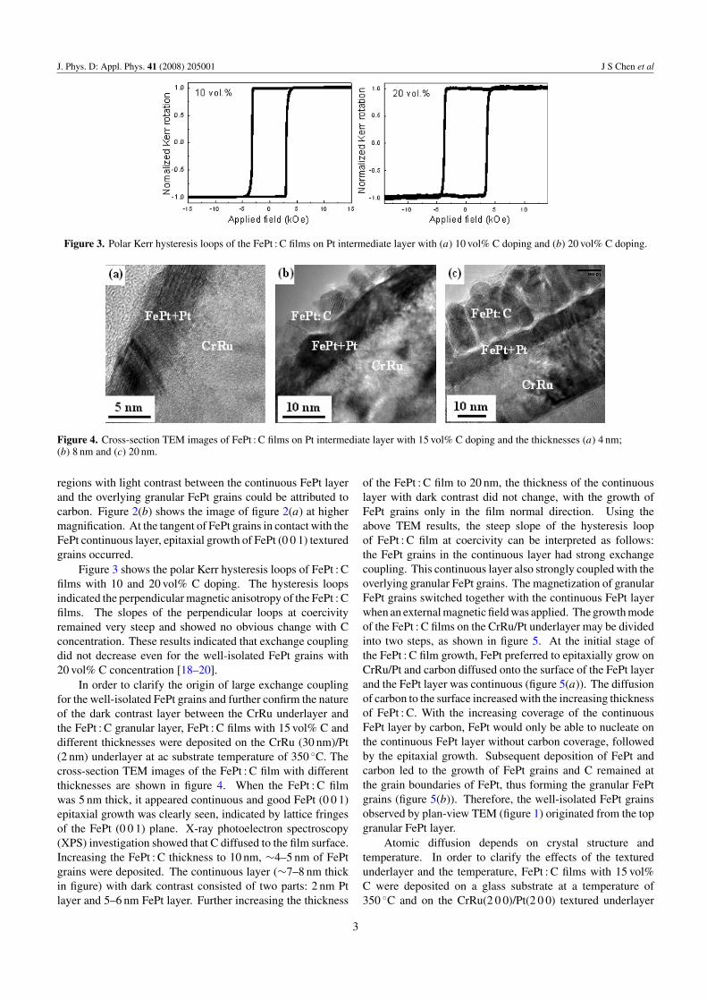
Figure 3. Polar Kerr hysteresis loops of the FePt : C films on Pt intermediate layer with (a) 10 vol% C doping and (b) 20 vol% C doping.
Figure 4. Cross-section TEM images of FePt : C films on Pt intermediate layer with 15 vol% C doping and the thicknesses (a) 4 nm;(b) 8 nm and (c) 20 nm.
regions with light contrast between the continuous FePt layerand the overlying granular FePt grains could be attributed tocarbon. Figure 2(b) shows the image of figure 2(a) at highermagnification. At the tangent of FePt grains in contact with theFePt continuous layer, epitaxial growth of FePt (0 0 1) texturedgrains occurred.
Figure 3 shows the polar Kerr hysteresis loops of FePt : Cfilms with 10 and 20 vol% C doping. The hysteresis loopsindicated the perpendicular magnetic anisotropy of the FePt : Cfilms. The slopes of the perpendicular loops at coercivityremained very steep and showed no obvious change with Cconcentration. These results indicated that exchange couplingdid not decrease even for the well-isolated FePt grains with20 vol% C concentration [18–20].
In order to clarify the origin of large exchange couplingfor the well-isolated FePt grains and further confirm the natureof the dark contrast layer between the CrRu underlayer andthe FePt : C granular layer, FePt : C films with 15 vol% C anddifferent thicknesses were deposited on the CrRu (30 nm)/Pt(2 nm) underlayer at ac substrate temperature of 350 ◦C. Thecross-section TEM images of the FePt : C film with differentthicknesses are shown in figure 4. When the FePt : C filmwas 5 nm thick, it appeared continuous and good FePt (0 0 1)epitaxial growth was clearly seen, indicated by lattice fringesof the FePt (0 0 1) plane. X-ray photoelectron spectroscopy(XPS) investigation showed that C diffused to the film surface.Increasing the FePt : C thickness to 10 nm, ∼4–5 nm of FePtgrains were deposited. The continuous layer (∼7–8 nm thickin figure) with dark contrast consisted of two parts: 2 nm Ptlayer and 5–6 nm FePt layer. Further increasing the thickness
of the FePt : C film to 20 nm, the thickness of the continuouslayer with dark contrast did not change, with the growth ofFePt grains only in the film normal direction. Using theabove TEM results, the steep slope of the hysteresis loopof FePt : C film at coercivity can be interpreted as follows:the FePt grains in the continuous layer had strong exchangecoupling. This continuous layer also strongly coupled with theoverlying granular FePt grains. The magnetization of granularFePt grains switched together with the continuous FePt layerwhen an external magnetic field was applied. The growth modeof the FePt : C films on the CrRu/Pt underlayer may be dividedinto two steps, as shown in figure 5. At the initial stage ofthe FePt : C film growth, FePt preferred to epitaxially grow onCrRu/Pt and carbon diffused onto the surface of the FePt layerand the FePt layer was continuous (figure 5(a)). The diffusionof carbon to the surface increased with the increasing thicknessof FePt : C. With the increasing coverage of the continuousFePt layer by carbon, FePt would only be able to nucleate onthe continuous FePt layer without carbon coverage, followedby the epitaxial growth. Subsequent deposition of FePt andcarbon led to the growth of FePt grains and C remained atthe grain boundaries of FePt, thus forming the granular FePtgrains (figure 5(b)). Therefore, the well-isolated FePt grainsobserved by plan-view TEM (figure 1) originated from the topgranular FePt layer.
Atomic diffusion depends on crystal structure andtemperature. In order to clarify the effects of the texturedunderlayer and the temperature, FePt : C films with 15 vol%C were deposited on a glass substrate at a temperature of350 ◦C and on the CrRu(2 0 0)/Pt(2 0 0) textured underlayer
3

J. Phys. D: Appl. Phys. 41 (2008) 205001 J S Chen et al
Figure 5. Schematic drawing of the growth mode of FePt : C filmson CrRu/Pt (2 0 0) textured underlayer.
at the temperature of 200 ◦C. The cross-section TEM imagesof the two samples are shown in figure 6. The FePt : C film onthe glass substrate showed a columnar, non-continuous film(figure 6(a)). The FePt : C film deposited on the CrRu/Pttextured underlayer at low temperature however showed asimilar structure to that grown at a higher temperature, i.e.continuous layer and granular layer. The formation of the two-layer structure may be due to the layer-by-layer growth on thetextured underlayer and the granular structure on glass wasdue to three-dimensional island growth. The enhancement ofdiffusion at higher temperature had little effect on the formationof the two-layer structure.
For the practical application of the L10 FePt film asrecording media, it is necessary to modify the properties ofthe interface, on which the FePt film epitaxially grows inthree-dimensional island mode instead of the layer-by-layermode, with carbon segregating to the boundaries of the FePtgrains. It is known that island growth (Vomer–Weber growth)is preferred when the sum of the surface energy of filmmaterials and interface energy is larger than the surface energyof the substrate. The surface energy of MgO is 1.1 J m−2 andFePt and Pt are ∼2.9 J m−2. Furthermore, the interface energybetween FePt and MgO should be larger than that betweenFePt and Pt since there are some dangling bonds of the surfaceof sputter-deposited MgO layer which will react with Fe or Ptatoms and the reaction (ionic bond) is stronger than the bondsbetween the Pt layer and the FePt layer (metal bond). It is,therefore, expected that the granular FePt : C nanocompositefilm can be obtained when using the MgO intermediate layer.FePt : C films with varying thicknesses from 4 nm to 12 nmwere deposited on the CrRu underlayer with a 2 nm MgOintermediate layer. The cross-section TEM images of theFePt : C films (15% C concentration) with the thickness of 4 nmand 12 nm are illustrated in figure 7. It was clearly shown thatthe FePt : C layer was a well-isolated granular structure and the
Figure 6. Cross-section TEM images of FePt : C films (12 nm) with15 vol% C doping deposited on (a) glass substrate at temperature of350 ◦C and (b) CrRu/Pt (2 0 0) textured underlayer at thetemperature of 200 ◦C.
grain size was around 8 nm when the FePt : C layer was 4 nm.For the sample with the FePt : C layer thickness of 12 nm, theFePt : C layer was still a granular structure and the grain sizeincreased to around 16 nm. It is worth noting that the smallspherical FePt grains were observed over the larger FePt grainswhich epitaxially grow on the MgO intermediate layer. Thisindicated that the second nucleation of FePt grain occurredwith the thickness increasing to a critical value, suggesting thecarbon was still diffused onto the surface during the depositionof the FePt : C layer. It was reported that by increasing thesputtering rate of the FePt : C layer the second nucleation ofthe FePt grains can be suppressed and led to the desired columngrowth of FePt grain [21].
The polar Kerr hysteresis loops of the samples with variousthicknesses FePt : C (15% C concentration) layers grown onMgO intermediate layer are shown in figure 8. The slope ofthe hysteresis loop at coercivity (α) was 1 when the thicknessof the FePt : C film was 4 nm, suggesting the grains werefully exchange-decoupled. With an increase in the thicknessof FePt : C films α increased, suggesting an increase in theexchange coupling. According to the TEM results, small FePtgrains were formed on the FePt grains which epitaxially growon MgO intermediate layer due to the diffusion of carbononto the surface and thus second nucleation of FePt. It wasbelieved that the FePt particles formed by second nucleationwere magnetically soft due to the diffusion of carbon to thesurface and loss of epitaxial growth. The increase in the
4

J. Phys. D: Appl. Phys. 41 (2008) 205001 J S Chen et al
Figure 7. Cross-section TEM images of the FePt : C films (15% C concentration) on MgO intermediate layer with the thicknesses ofFePt : C (a) 4 nm; (b) 12 nm.
Figure 8. Polar Kerr hysteresis loops of the FePt : C films (15% Cconcentration) with various thicknesses on MgO intermediate layer.
exchange coupling with the thickness was, therefore, ascribedto the exchange coupling of these soft magnetic grains with themagnetically hard FePt grains epitaxially grown on the MgOintermediate layer. The out-of-plane coercivity increased from7.7 kOe to 12 kOe and 16 kOe when the thickness increasedfrom 4 nm to 8 nm and 12 nm, respectively. The increase inthe coercivity may be due to the increase in the grain volumewith the thickness.
4. Conclusions
In summary, FePt : C films with different volume fractionsof carbon and different thicknesses were epitaxially grownon the CrRu(2 0 0) underlayer with Pt and MgO intermediate
layers. The FePt : C films grown on the Pt intermediatelayer consisted of a continuous layer of FePt, with overlyinggranular FePt grains, while the FePt : C films grown on theMgO intermediate layer consisted of granular FePt : C layerswith overlying granular grains. The formation of the overlyinggranular FePt grains was attributed to carbon diffusion to thesurface which resulted in the second nucleation of FePt. Thedifferent interface energies and surface energies of FePt onthe Pt and the MgO intermediate layers caused the formationof an initial continuous FePt layer on the Pt intermediate layerand initial granular FePt layers on the MgO intermediate layer.The coupling between the continuous FePt layer or granularFePt layer and overlying granular FePt grains resulted insimultaneous magnetization reversal and thus strong exchangecoupling in the FePt : C films. FePt films with fully exchange-decoupled small grains and columnar structure are expectedto be achieved by using MgO intermediate layer, optimizeddeposition conditions and suitable doping.
Acknowledgment
The authors (JS and GMC) acknowledge the support of theNUS academic research fund. The work is also partiallysupported by the Agency for Science, Technology andResearch (A∗STAR) (062 101 0021), Ministry of Education(MOE) Fund (T207B1104-RS) and Seagate Research,Pittsburgh.
References
[1] Lairson B M and Clemens B M 1993 Appl. Phys. Lett. 63 1438[2] Visokay M R and Sinclair R 1995 Appl. Phys. Lett. 66 1692[3] Suzuki T, Muraoka H, Nakamura Y and Ouchi K 2003
IEEE Trans. Magn. 39 691
5
J. Phys. D: Appl. Phys. 41 (2008) 205001 J S Chen et al
[4] Chen J S, Zhou Y Z, Lim B C, Zhou T J, Zhang J andChow G M 2005 IEEE Trans. Magn. 41 3196
[5] Luo C P, Liou S H, Gao L, Liu Y and Sellmyer D J 2000Appl. Phys. Lett. 77 2225
[6] Yan M L, Sabirianov R F, Xu Y F, Li X Z and Sellmyer D J2004 IEEE Trans. Magn. 40 2470
[7] Yan M L, Powers N and Sellmyer D J 2003 J. Appl. Phys.93 8292
[8] Kang K, Zhang Z G, Papusoi C and Suzuki T 2004 Appl. Phys.Lett. 84 404
[9] Hsu Y-N, Jeong S, Laughlin D and Lambeth D N 2001 J. Appl.Phys. 89 7068
[10] Suzuki T, Kiya T, Honda N and Ouchi K 2001 J. Magn. Magn.Mater. 235 312
[11] Xu Y, Chen J S and Wang J P 2002 Appl. Phys. Lett. 80 3325[12] Chen J S, Lim B C and Zhou T J 2005 J. Vac. Sci. Technol. A
23 184
[13] Chen J S, Lim B C, Hu J F, Lim Y K, Liu B and Chow G M2007 Appl. Phys. Lett. 90 042508
[14] Chen J S, Ding Y F, Lim B C and Liu E 2006 IEEE Trans.Magn. 42 2363
[15] Ding Y F, Chen J S, Liu E J and Wang J P 2005 J. Magn.Magn. Mater. 285 443
[16] Chen J S, Xu Y F and Wang J P 2003 J. Appl. Phys. 93 1661[17] Chen J S and Wang J P 2004 J. Magn. Magn. Mater. 284 423[18] Honda N, Ouchi K and Iwasaki S 2002 IEEE Trans. Magn.
38 1615[19] Miyashita E, Funabasgi N, Taguchi E R, Tamaki T and
Nakamura S 2005 J. Magn. Magn. Mater. 287 96–101[20] Choe G, Zheng M, Abarra E N, Demczyk B G, Zhou J N,
Acharya B R and Johnson K E 2005 J. Magn. Magn. Mater.287 160
[21] Chen J S, Lim B C, Hu J F, Liu B, Chow G M and Ju G 2007Appl. Phys. Lett. 91 132506
6


![(2Z,N 0 0 0 E)-N 0 0 0 -[(2-Hydroxy-1-naphthyl)- methylidene]furan-2-carbohydrazonic acid](https://static.fdokumen.com/doc/165x107/631360d4b033aaa8b2100e91/2zn-0-0-0-e-n-0-0-0-2-hydroxy-1-naphthyl-methylidenefuran-2-carbohydrazonic.jpg)