Microlab® 700 - Liquid Handling - Duratec
116
Microlab ® 700 Advanced and Premium Manual Wizards and Custom Method Operation
-
Upload
khangminh22 -
Category
Documents
-
view
0 -
download
0
Transcript of Microlab® 700 - Liquid Handling - Duratec
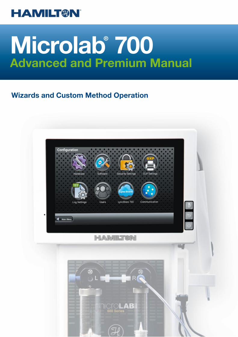
Microlab® 700Advanced and Premium Manual
Wizards and Custom Method Operation

Instruction to the User
This equipment has been tested and found to comply with the limits for a class B digital device, pur-suant to Part 15, Federal Communication Commission (FCC) Rules. These limits are designed to provide reasonable protection against harmful interference in an installation. This equipment generates, uses and can radiate radio frequency energy, and if not installed and used in accordance with the instructions, may cause harmful interference to radio communications. However, there is no guarantee that interference will not occur in a particular installation. If this equipment does cause harmful interference to radio or televi-sion reception, which can be determined by turning the equipment off and on, the user is encouraged to try to correct the interference by one or more of the following measures:
• Turn the Microlab® 700 Off and On to determine whether it is generating interference.• Reorient or relocate the receiving antenna.• Increase the separation between the equipment and receiver.• Connect the equipment into an outlet on a circuit different from that to which the receiver is connected.• Consult the dealer or an experienced radio/TV technician for help. This equipment has been verified to comply with the limits for a class B computing device, pursuant to FCC Rules. In order to maintain compliance with the FCC regulations, shielded cables must be used with this equipment. Operation with non-approved equipment or unshielded cables is likely to result in interference to radio and TV reception. The user is cautioned that changes and modifications made to the equipment without the approval of the manufacturer could void the user’s authority to operate this equipment.
Warranty Information For the User
Hamilton Company warrants this equipment1 to be free of defects in material and workmanship for 12 months from the date of receipt. The warranty does not cover normal wear and tear of the syringes, valves or equipment. The warranty is extended to the buyer of record on the original purchase order to Hamilton Company. Hamilton Company or an authorized Hamilton representative agrees to repair or replace, at its option and free of charge to the buyer at a normal place of business or at a Hamilton repair facility, any part or parts that under proper and normal use prove to be defective during the warranty period.2 Abuse, unauthorized replacement of parts, modifications or adjustments made by other than Hamilton Company or its assigned representative voids this warranty.
This warranty gives the user specific rights. No other warranties, expressed or implied, including implications of warranties of merchantability and fitness for a particular product, are made. Hamilton Company’s liability on the sale of all products shall be limited to repair, replacement or refund of price of any defective product.2
Hamilton Company endeavors to provide prompt and satisfactory service.
1. All Hamilton Company valves are warranted to be free of defects in material and workmanship at the time of delivery.
2. Hamilton Company reserves the right to refuse to accept the return of any instrument or valve that has been used with radioactive, microbiological substances or any other material that may be deemed hazardous to employees of Hamilton Company.
1 Welcome ............................................................................................................... 8
2 Intended Use ........................................................................................................ 8
3 About the Microlab® 700 Manuals ..................................................................... 83.1 Microlab 700 Manual ............................................................................................................. 83.2 LyncStore 700 Manual ........................................................................................................... 8
4 Conventions Used in this Manual ..................................................................... 8
5 Introduction ......................................................................................................... 95.1 Introduction of the Microlab 700 ............................................................................................ 95.2 Microlab 700 Part Number Nomenclature ............................................................................. 95.3 Microlab 700 Hardware Setups ........................................................................................... 10
5.3.1 Single Syringe Dispenser Setup .............................................................................. 105.3.2 Dual Syringe Diluter Setup ....................................................................................... 105.3.3 Dual Syringe Dispenser Setup ..................................................................................115.3.4 Continuous Dispenser Setup....................................................................................11
5.4 Safety Precautions ................................................................................................................115.4.1 General Safety Information .......................................................................................115.4.2 Operating the Microlab 700 ..................................................................................... 125.4.3 Electrical .................................................................................................................. 125.4.4 Radioactive, Biohazardous, or Harsh Chemicals .................................................... 12
6 Hardware Setup ................................................................................................. 126.1 Overview of Microlab 700 Parts List ..................................................................................... 126.2 Selecting the Proper Location .............................................................................................. 136.3 Description of Drive Unit Components ..................................................................................14
6.3.1 Description of the Front View of the Drive Units ........................................................146.3.2 Valve Actuator ..........................................................................................................146.3.3 Probe Receptacle .....................................................................................................146.3.4 Syringe Drive ........................................................................................................... 156.3.5 Description of the Rear View of the Drive Units ....................................................... 16
6.4 Installation of Drive Unit Parts ................................................................................................176.4.1 Installation of the Valve Assembly .............................................................................17
6.4.1.1 Mounting a Valve on the Microlab 700 ................................................... 186.4.1.2 Mounting Two Valves with Cross Tube on the Microlab 700................... 19
6.4.2 Installation of Syringe(s) ........................................................................................... 196.4.2.1 Preparing Syringe(s) for Installation ......................................................... 206.4.2.2 Installing the Syringe(s) ........................................................................... 20
6.4.3 Installation of the Tubing .......................................................................................... 226.4.3.1 Selecting the Proper Tubing ................................................................... 226.4.3.2 Installing the Tubing ................................................................................ 23
6.4.4 Installation of the Accessory Holder ........................................................................ 256.4.5 Tubing Management with the Accessory Holder ..................................................... 256.4.6 Installation of the Hand Probe ................................................................................. 26
Table of Contents
Microlab® 700 Advanced Manual 3
TABLE OF CONTENTS

6.5 Installation of Accessories .................................................................................................... 266.5.1 Installation of Precision Balances ............................................................................ 266.5.2 Installation of Office Network Printers ...................................................................... 276.5.3 Installation of the RFID Card Scanner ...................................................................... 276.5.4 Installation of the QR Code Scanner ....................................................................... 286.5.5 Installation of the Label Printer ................................................................................. 28
6.6 Controller Unit ...................................................................................................................... 286.6.1 Controller Unit Vesa Holder ..................................................................................... 286.6.2 Controller Unit Touch Screen .................................................................................. 29
6.7 Controller and Base unit connectivity ................................................................................... 306.7.1 Wireless Setup ........................................................................................................ 306.7.2 Dual LAN Setup ...................................................................................................... 316.7.3 Single LAN Setup .................................................................................................... 316.7.4 LyncStore 700 Offline Setup .................................................................................... 326.7.5 LyncStore 700 Online Setup .................................................................................... 32
7 Overview of Screens and Buttons .................................................................. 327.1 Splash Screen ...................................................................................................................... 327.2 Icon Screens ........................................................................................................................ 337.3 Run Screens ........................................................................................................................ 33
7.3.1 Valve Position Indicator ............................................................................................ 347.3.2 Parameter Adjustment Button ................................................................................. 347.3.3 Syringe Position Indicator ........................................................................................ 347.3.4 Back Button ............................................................................................................ 347.3.5 Small Icon Buttons .................................................................................................. 347.3.6 Auto Refill Icon ......................................................................................................... 347.3.7 Syringe Direction Indicator....................................................................................... 347.3.8 Valve Move Indicator................................................................................................ 347.3.9 Valve Position Indicator Drawings ............................................................................ 34
7.4 Data Entry Screens .............................................................................................................. 367.5 Pop-up Control .................................................................................................................... 367.6 Numeric Keypad .................................................................................................................. 37
8 User Interface Flow Chart ................................................................................ 38
9 Configuration Settings ..................................................................................... 389.1 Hardware Configuration ....................................................................................................... 39
9.1.1 Syringe Setup .......................................................................................................... 399.1.1.1 Syringe Size ............................................................................................ 399.1.1.2 Syringe Speed ........................................................................................ 399.1.1.3 Initialize Flow Rate .................................................................................. 399.1.1.4 Return Steps .......................................................................................... 399.1.1.5 Back-off Steps ........................................................................................ 39
9.1.2 Valve Setup ............................................................................................................. 409.1.2.1 Valve Type .............................................................................................. 40
9.1.3 Trigger Setup ........................................................................................................... 409.1.3.1 Trigger Side ............................................................................................ 40
9.1.4 Button Mapping Setup ............................................................................................ 409.1.4.1 Probe Hand Use ..................................................................................... 40
9.2 Software Configuration ........................................................................................................ 409.2.1 Premium Activation.................................................................................................. 409.2.2 Controller ..................................................................................................................41
9.2.2.1 Language ................................................................................................41
TABLE OF CONTENTS
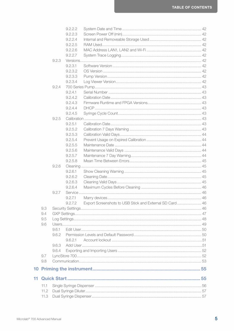
TABLE OF CONTENTS
9.2.2.2 System Date and Time ........................................................................... 429.2.2.3 Screen Power Off (min) ........................................................................... 429.2.2.4 Internal and Removeable Storage Used ................................................. 429.2.2.5 RAM Used .............................................................................................. 429.2.2.6 MAC Address LAN1, LAN2 and Wi-Fi .................................................... 429.2.2.7 System Trace Logging ............................................................................ 42
9.2.3 Versions ................................................................................................................... 429.2.3.1 Software Version .................................................................................... 429.2.3.2 OS Version ............................................................................................. 429.2.3.3 Pump Version ......................................................................................... 429.2.3.4 Log Viewer Version ................................................................................. 42
9.2.4 700 Series Pump ..................................................................................................... 439.2.4.1 Serial Number ........................................................................................ 439.2.4.2 Calibration Date ...................................................................................... 439.2.4.3 Firmware Runtime and FPGA Versions ................................................... 439.2.4.4 DHCP ..................................................................................................... 439.2.4.5 Syringe Cycle Count ............................................................................... 43
9.2.5 Calibration ............................................................................................................... 439.2.5.1 Calibration Date ...................................................................................... 439.2.5.2 Calibration 7 Days Warning .................................................................... 439.2.5.3 Calibration Valid Days ............................................................................. 449.2.5.4 Prevent Usage on Expired Calibration .................................................... 449.2.5.5 Maintenance Date .................................................................................. 449.2.5.6 Maintenance Valid Days ......................................................................... 449.2.5.7 Maintenance 7 Day Warning................................................................... 449.2.5.8 Mean Time Between Errors .................................................................... 45
9.2.6 Cleaning .................................................................................................................. 459.2.6.1 Show Cleaning Warning ......................................................................... 459.2.6.2 Cleaning Date ......................................................................................... 459.2.6.3 Cleaning Valid Days ................................................................................ 459.2.6.4 Maximum Cycles Before Cleaning ......................................................... 46
9.2.7 Service .................................................................................................................... 469.2.7.1 Marry devices ......................................................................................... 469.2.7.2 Export Screenshots to USB Stick and External SD Card ....................... 46
9.3 Security Settings .................................................................................................................. 469.4 GXP Settings........................................................................................................................ 479.5 Log Settings ......................................................................................................................... 489.6 Users.................................................................................................................................... 49
9.6.1 Edit User .................................................................................................................. 509.6.2 Permission Levels and Default Password ................................................................ 50
9.6.2.1 Account lockout ......................................................................................519.6.3 Add User ..................................................................................................................519.6.4 Exporting and Importing Users ............................................................................... 52
9.7 LyncStore 700 ...................................................................................................................... 529.8 Communication .................................................................................................................... 53
10 Priming the instrument ..................................................................................... 55
11 Quick Start ......................................................................................................... 5511.1 Single Syringe Dispenser ..................................................................................................... 5611.2 Dual Syringe Diluter .............................................................................................................. 5711.3 Dual Syringe Dispenser ........................................................................................................ 57
Microlab® 700 Advanced Manual 5
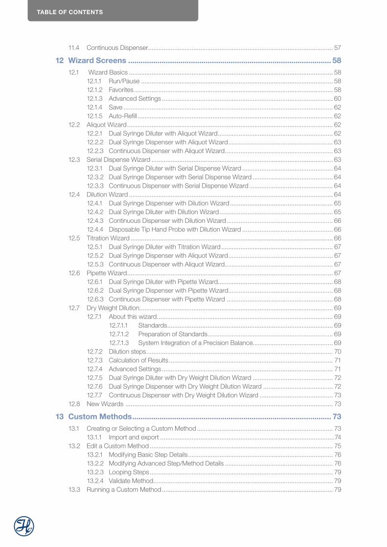
TABLE OF CONTENTS
11.4 Continuous Dispenser .......................................................................................................... 57
12 Wizard Screens ................................................................................................. 5812.1 Wizard Basics ..................................................................................................................... 58
12.1.1 Run/Pause .............................................................................................................. 5812.1.2 Favorites .................................................................................................................. 5812.1.3 Advanced Settings .................................................................................................. 6012.1.4 Save ........................................................................................................................ 6212.1.5 Auto-Refill ................................................................................................................ 62
12.2 Aliquot Wizard ...................................................................................................................... 6212.2.1 Dual Syringe Diluter with Aliquot Wizard .................................................................. 6212.2.2 Dual Syringe Dispenser with Aliquot Wizard ............................................................ 6312.2.3 Continuous Dispenser with Aliquot Wizard .............................................................. 63
12.3 Serial Dispense Wizard ........................................................................................................ 6312.3.1 Dual Syringe Diluter with Serial Dispense Wizard .................................................... 6412.3.2 Dual Syringe Dispenser with Serial Dispense Wizard .............................................. 6412.3.3 Continuous Dispenser with Serial Dispense Wizard ................................................ 64
12.4 Dilution Wizard ..................................................................................................................... 6412.4.1 Dual Syringe Dispenser with Dilution Wizard ........................................................... 6512.4.2 Dual Syringe Diluter with Dilution Wizard ................................................................. 6512.4.3 Continuous Dispenser with Dilution Wizard ............................................................. 6612.4.4 Disposable Tip Hand Probe with Dilution Wizard .................................................... 66
12.5 Titration Wizard .................................................................................................................... 6612.5.1 Dual Syringe Diluter with Titration Wizard ................................................................ 6712.5.2 Dual Syringe Dispenser with Aliquot Wizard ............................................................ 6712.5.3 Continuous Dispenser with Aliquot Wizard .............................................................. 67
12.6 Pipette Wizard ...................................................................................................................... 6712.6.1 Dual Syringe Diluter with Pipette Wizard .................................................................. 6812.6.2 Dual Syringe Dispenser with Pipette Wizard ............................................................ 6812.6.3 Continuous Dispenser with Pipette Wizard ............................................................. 68
12.7 Dry Weight Dilution............................................................................................................... 6912.7.1 About this wizard ..................................................................................................... 69
12.7.1.1 Standards ............................................................................................... 6912.7.1.2 Preparation of Standards........................................................................ 6912.7.1.3 System Integration of a Precision Balance .............................................. 69
12.7.2 Dilution steps ........................................................................................................... 7012.7.3 Calculation of Results .............................................................................................. 7112.7.4 Advanced Settings .................................................................................................. 7112.7.5 Dual Syringe Diluter with Dry Weight Dilution Wizard .............................................. 7212.7.6 Dual Syringe Dispenser with Dry Weight Dilution Wizard ........................................ 7212.7.7 Continuous Dispenser with Dry Weight Dilution Wizard .......................................... 73
12.8 New Wizards ....................................................................................................................... 73
13 Custom Methods ............................................................................................... 7313.1 Creating or Selecting a Custom Method .............................................................................. 73
13.1.1 Import and export ....................................................................................................7413.2 Edit a Custom Method ......................................................................................................... 75
13.2.1 Modifying Basic Step Details ................................................................................... 7613.2.2 Modifying Advanced Step/Method Details .............................................................. 7613.2.3 Looping Steps ......................................................................................................... 7913.2.4 Validate Method ....................................................................................................... 79
13.3 Running a Custom Method .................................................................................................. 79
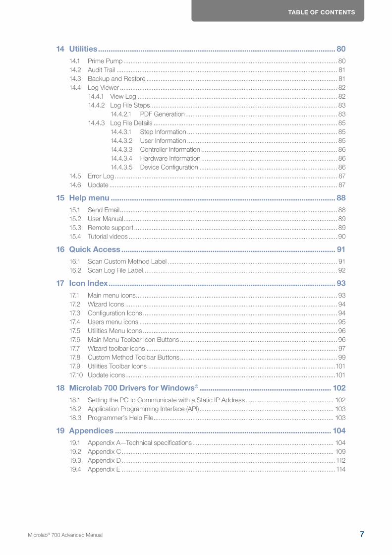
TABLE OF CONTENTS
14 Utilities ................................................................................................................ 8014.1 Prime Pump ......................................................................................................................... 8014.2 Audit Trail ............................................................................................................................. 8114.3 Backup and Restore ............................................................................................................ 8114.4 Log Viewer ........................................................................................................................... 82
14.4.1 View Log ................................................................................................................. 8214.4.2 Log File Steps .......................................................................................................... 83
14.4.2.1 PDF Generation ...................................................................................... 8314.4.3 Log File Details ........................................................................................................ 85
14.4.3.1 Step Information ..................................................................................... 8514.4.3.2 User Information ..................................................................................... 8514.4.3.3 Controller Information ............................................................................. 8614.4.3.4 Hardware Information ............................................................................. 8614.4.3.5 Device Configuration .............................................................................. 86
14.5 Error Log .............................................................................................................................. 8714.6 Update ................................................................................................................................. 87
15 Help menu .......................................................................................................... 8815.1 Send Email ........................................................................................................................... 8815.2 User Manual ......................................................................................................................... 8915.3 Remote support ................................................................................................................... 8915.4 Tutorial videos ...................................................................................................................... 90
16 Quick Access ..................................................................................................... 9116.1 Scan Custom Method Label ................................................................................................ 9116.2 Scan Log File Label.............................................................................................................. 92
17 Icon Index ........................................................................................................... 9317.1 Main menu icons .................................................................................................................. 9317.2 Wizard Icons ........................................................................................................................ 9417.3 Configuration Icons .............................................................................................................. 9417.4 Users menu icons ................................................................................................................ 9517.5 Utilities Menu Icons .............................................................................................................. 9617.6 Main Menu Toolbar Icon Buttons ......................................................................................... 9617.7 Wizard toolbar icons ............................................................................................................ 9717.8 Custom Method Toolbar Buttons ......................................................................................... 9917.9 Utilities Toolbar Icons ..........................................................................................................10117.10 Update icons .......................................................................................................................101
18 Microlab 700 Drivers for Windows® .............................................................. 10218.1 Setting the PC to Communicate with a Static IP Address .................................................. 10218.2 Application Programming Interface (API) ............................................................................ 10318.3 Programmer’s Help File ...................................................................................................... 103
19 Appendices ...................................................................................................... 10419.1 Appendix A—Technical specifications ................................................................................ 10419.2 Appendix C ........................................................................................................................ 10919.3 Appendix D .........................................................................................................................11219.4 Appendix E .........................................................................................................................114
Microlab® 700 Advanced Manual 7
WELCOME
1 Welcome
Welcome to the World of Hamilton Precision Instruments
Congratulations on user’s purchase of a Hamilton Microlab 700 instrument. Hamilton Microlab 700 is a versa-tile, semi-automatic, precision liquid handler. This family of instruments offers single or dual syringe units that function as dispensers, diluters and continuous dispensers.
The Microlab 700 functions on the principle of liquid/liquid displacement. At the heart of each Microlab 700 is a precise stepper drive motor combined with our uniquely designed Gastight® syringes. The result is a precise and accurate instrument that is very easy to set up and operate.
Proper handling and maintenance of user’s new Microlab 700 will increase the lifespan of user’s instrument. To learn about proper care and maintenance of user’s investment, please take the time to read this manual, including the warranty information.
Hamilton Company would like to thank you for purchase of the Microlab 700.
2 Intended UseThe Microlab 700 family of instruments are bench top devices designed for precision liquid handling. These units are intended for indoor laboratory use by technician grade personnel. These units are also designed for industrial purposes with an emphasis on continuous dispensing in an unattended mode.
3 About the Microlab® 700 Manuals
3.1 Microlab 700 Manual
This manual contains information on operating the Advanced and Premium controller software.
3.2 LyncStore 700 Manual
This manual contains information about LyncStore 700 software. LyncStore 700 is a software for data collec-tion, visualization, and management of the Microlab 700 Premium instrument. It enables device connectivity via HTTP and LIMS connection. LyncStore meets 21 CFR Part 11 and FDA GMP/GLP requirements making it a valuable addition to regulated labs or labs with increased security protocols. For LIMS integration, this manual contains information on communicating with the instrument through REST-API.
After reading these manuals user should be able to properly operate Microlab 700.
4 Conventions Used in this ManualThroughout this manual symbols are used to call attention to various kinds of information.
WARNING! Information that is essential for avoiding personal injury is flagged with the International Warning Symbol.
INTRODUCTION
BIOHAZARD: Information that is relating to interactions with biohazards.
IMPORTANT! Information that is essential for avoiding damage to equipment.
NOTE: Interesting information or information that can help improve system performance.
5 IntroductionThis chapter provides a brief overview of the Microlab 700 instrument. The Advanced Microlab 700 Controller features a touchscreen with a custom designed user interface (UI). The UI will enable a variety of advanced applications and Custom Method programs.
5.1 Introduction of the Microlab 700
The Microlab 700 Series is a family of high precision syringe pumps designed to simplify common dispens-ing and diluting tasks in a variety of research environments. Common components of a Microlab 700 pump include a controller, a syringe pump base unit, and an application-specific fluid path.
5.2 Microlab 700 Part Number Nomenclature
Each Microlab 700 Series part number describes the type of controller, type of syringe pump base unit, and type of application specific fluid path. Below is a discussion of how a Microlab 700 part number is created.
Microlab 700 Series Part Number: ML7X1X2-XXX3
X1 This digit defines the controller type. There are three standard controller types.
This system includes a Basic controller.
This system includes a Basic controller plus the Advanced upgrade kit. The upgrade kit comes with a proprietary SD card that adds memory to the controller and unlocks the Wizard and Custom Method functionality.
This system does not include a controller. This system must be connected to a PC running custom developed software. A CD containing the Application Programming Interface (API) is provided along with a programming manual and example programs in LabVIEW™, Visual Basic®, and Visual C#®.
X2 This digit defines the syringe pump base unit. There are two pump types.
Each pump comes with the appropriate valves pre-installed.
This system includes a single syringe base unit with a standard input and output valve.
This system includes a dual syringe base unit with Universal Valves installed.
XXX3 These letters define the tubing and hand probes that are shipped with the system to accomplish a defined application.
Microlab® 700 Advanced Manual 9
INTRODUCTION
XXX3 Application
DIS Single or Dual Syringe Dispenser package
DIL Dual Syringe Diluter package
DTHP1) Disposable Tip Hand Probe Diluter package2)
CNT Continuous Dispensing package
New Application Packages New packages will be created on occasion. Details about these packages can be found at www.hamiltoncompany.com/microlab700
1) only available with the Advanced Controller
2) This package will come with the Disposable Tip Hand Probe and the Cable Management System.
5.3 Microlab 700 Hardware Setups
There are four major hardware setups possible with the Microlab 700. Below is a brief description of each setup describing the intended use for each configuration.
NOTE: The Microlab 700 is compatible with syringes from 10 μL to 50 mL. To achieve the highest level of accuracy, the proper syringe should be selected for the range of dispense volumes to be performed (see Section 9.4.2). For example, the proper syringe size to use for dispensing 250 μL, 500 μL, 750 μL and 1 mL from a single instrument setup would be a 1 mL syringe. This is the smallest syringe that can be programmed to accomplish all four desired dispense volumes. When selecting a syringe, the volumes to be dispensed should fall between 10% and 100% of the nominal syringe volume for a 1 mL syringe that would be between 100 μL and 1 mL. Smaller volumes are possible with a slight loss in accuracy and precision (see Section 6.4.2).
5.3.1 Single Syringe Dispenser Setup
The Single Syringe Dispenser setup is designed to dispense precise volumes of liquid from a reservoir out through a hand probe. There is a single valve that connects the syringe to tubing. When the valve rotates it connects the syringe to the input or the output tubing. The input tubing connects the syringe to a reservoir of liquid. The output tubing connects the syringe to a hand probe. At the press of a button, the valve will position to the input so the syringe can fill with a user defined volume of liquid from the reservoir. A second push of a button will dispense the user defined volume from the tip of the hand probe.
A brief animation of «How a Microlab 700 Dispenser Works» can be found at www.hamiltoncompany.com/microlab700
5.3.2 Dual Syringe Diluter Setup
The Dual Syringe Diluter setup is ideally designed to perform dilutions. The two syringes operate as one to accurately draw the sample (right syringe) and diluent (left syringe) into the system before dispensing the two liquids into a final container where they mix to complete the dilution. This application could be accomplished with a single syringe system, but the dilution range would be limited to the volume range of a single syringe. With two syringes it is possible to use a 50 mL and a 10 µL syringe to draw up the sample. With this setup it is possible to perform a 50,000-fold dilution in a single step. When compared to Class A glassware, this is an incredible savings in buffers and time.
The basic dilution method involves priming the entire system with diluent. Next, the right syringe draws sample into the hand probe. The sample is completely contained in the dispense tubing and never comes into contact with the right syringe. At the same time the sample is drawn, the left syringe fills with diluent from the reservoir.
INTRODUCTION
Next, the two syringes dispense their entire volume out through the hand probe. The sample is dispensed from the tubing followed by the diluent which washes out the tubing and prepares the system for the next dilution.
A brief animation of «How a Microlab 700 Diluter Works» can be found in the video section of the Microlab 700 controller.
5.3.3 Dual Syringe Dispenser Setup
The Dual Syringe Dispenser setup has the same capabilities as two Single Syringe Dispensers that receive commands from a single controller. Instead of one valve and one syringe like the Single Syringe Dispenser there are two pairs of syringes and valves. Each pair works independently of the other, meaning that each can be setup with a different volume syringe and can be programmed to dispense a different volume of liquid. The fluid paths are maintained completely separate so liquid in the left syringe will not mix with liquid in the right syringe until the two liquids are dispensed out the end of the hand probe. This setup is ideal for applica-tions like epoxy dispensing where no mixing should occur until the proper quantities of each liquid have been dispensed.
A brief animation of «How a Microlab 700 Dispenser Works» can be found in the video section of the Microlab 700 controller.
5.3.4 Continuous Dispenser Setup
The Continuous Dispenser setup is designed to eliminate the time wasted waiting for the syringe to refill be-tween dispenses. This dual syringe system automatically fills one syringe while the other syringe is dispensing. Since there is always one full syringe the wait time is eliminated. This setup effectively cuts the work time of the Syringe Dispenser setup in half without sacrificing accuracy and precision by increasing the syringe speed. This setup requires that both the left and the right syringes are the same volume.
A brief animation of «How a Microlab 700 Dispenser Works» can be found in the video section of the Microlab 700 controller.
5.4 Safety Precautions
For proper handling and care of the Microlab 700 it is essential that operating and service personnel follow general safety procedures and safety instructions described in this manual. Service maintenance must only be performed by an authorized service technician.
5.4.1 General Safety Information
The Microlab 700 should be placed in a location where personnel have easy access to the front, back, and sides for ease of operation and maintenance. Before operating the instrument, determine the amount of space user will need for their Microlab 700. Cleaning, dismantling, and/or performing maintenance on the Microlab 700 should only be performed by properly trained personnel who are aware of possible dangers. Only certified repair technicians are authorized to perform mechanical maintenance on the Microlab 700. When transporting the Microlab 700 for repair or shipment it should be properly packaged inside the original shipping container. All Microlab 700 instruments that are sent back to Hamilton Company for repair must be decontaminated before they are shipped. Only the original approved parts and accessories may be used with the Microlab 700. Any alterations or modifications to the instrument may be dangerous and will void the warranty.
Microlab® 700 Advanced Manual 11
HARDWARE SETUP
5.4.2 Operating the Microlab 700
When using the Microlab 700, Good Laboratory Practices (GLP) should be observed. Users should wear protective clothing, safety glasses, and protective gloves, especially if working with radioactive, biohazardous, or harsh chemicals. During the operation of a Microlab 700, stand clear of moving parts. Never try to remove valves, syringes, or tubing when the Microlab 700 syringe drive mechanism is moving. Never move the Micro-lab 700 while it is in operation. If an accidental spill occurs, turn the instrument Off and wipe it down with the appropriate disinfectant or chemical. Remember to take into account the nature of the spill and the necessary safety precautions.
5.4.3 Electrical
The Microlab 700 must be turned Off and disconnected from the power source when removing any me-chanical or electrical components. Do not connect the unit to a power source of any other voltage (see Appendix B for appropriatepower cords) or frequency beyond the range stated on the power rating. Check to make sure theappropriate power cord for user’s country was received. Avoid damaging the power cord while operating the instrument. Do not bend excessively, step on,or place heavy objects on the power cord. A damaged power cord may easily become a shock or fire hazard. Never use a damaged power cord. Only connect the Microlab 700 to a grounded outlet.
5.4.4 Radioactive, Biohazardous, or Harsh Chemicals
BIOHAZARD: The Microlab 700 does not provide any user protection against radioactivity, biohazardous, or harsh chemicals.
When operating the Microlab 700 wear the appropriate laboratory clothing. Operators must be trained to handle hazardous materials before working with them in conjunction with the Microlab 700 pump. If the Microlab 700 becomes contaminated with radioactive, biohazardous, or harsh chemicals, it should be cleaned immediately, see Chapter 5 for maintenance procedures. Failure to observe and carry out the procedures may impair or damage the Microlab 700. Materials consumed or produced during use of this device should be disposed of in accordance with local, state, and federal laws.
6 Hardware SetupThis chapter provides detailed information on the features andinstallation of the Microlab 700 hardware.
6.1 Overview of Microlab 700 Parts List
The Microlab 700 instruments come complete with everything needed to get started. For replacement parts, please refer to Appendix B Replacement Parts and Accessories. Optional hand probes are also available and can be found in Appendix C. Unpack the Microlab 700 and verify that all parts have been received. The parts list for each family of instruments is displayed in the tables below.
HARDWARE SETUP
Instrument Part Number
Drive Unit Part Number
Controller Part Number
Controller Upgrade Kit Part Number
Probe and Tubing Kit Description
ML710-DIS Single Syringe 71501-01 71500-05 N/A Single Dispense Kit
ML715-DIL Dual Syringe 71502-01 71500-05 N/A Diluter Kit
ML715-DIS Dual Syringe 71502-01 71500-05 N/A Dual Dispense Kit
ML715-CNT Dual Syringe 71502-01 71500-05 N/A Continuous Dispense Kit
ML720-DIS Single Syringe 71501-01 71500-05 71500-02 Single Dispense Kit
ML725-DIL Dual Syringe 71502-01 71500-05 71500-02 Diluter Kit
ML725-DTHP Dual Syringe 71502-01 71500-05 71500-02 DTHP Diluter Kit
ML725-DIS Dual Syringe 71502-01 71500-05 71500-02 Dual Dispense Kit
ML725-CNT Dual Syringe 71502-01 71500-05 71500-02 Continuous Dispense Kit
ML730 Single Syringe 71501-01 N/A 71500-03 N/A
ML735 Dual Syringe 71502-01 N/A 71500-03 N/A
NOTE: Each unit will come with the power supply (P/N 61092-01) and user selected power cord (see Appendix B). The system will also ship with one syringe per syringe drive which can be user selected at the time the instrument is purchased.
Probe and Tubing Kit Description
Hand Probe Part Number
FIII Tublng 12 gauge 61614-01 18 gauge 61615-01
Dispense Tubing 12 gauge 240133 18 gauge 240134
Contlnuous FIII Tubing 12 gauge 61491-01 18 gauge 61491-02
Single Dispense Kit Concorde CTProbe 61401-01
User Defined 12 or 18 gauge 1 piece
User Defined 12 or 18 gauge 1 piece
N/A
Dlluter Kit Concorde CTProbe 61401-01
User Defined 12 or 18 gauge 1 piece
User Defined 12 or 18 gauge 1 piece
N/A
DTHP Dllutcr Kit1 Dlsposable Tip Probe 63960-02
User Defined 12 or 18 gauge 1 piece
User Defined 12 or 18 gauge 1 piece2
N/A
Dual Dispense Kit Dual Push Button Probe 62541-01
User Defined 12 or 18 gauge 2 pieces
User Defined 12 or 18 gauge 2 pieces
N/A
Cootlnuous Dispense Kit
Concorde CTProbe 61401-01
N/A User Defined 12 or 18 gauge 1 piece
User Defined 12 or 18 gauge 1 piece
If components are missing please contact Hamilton Costumer Service at (888) 525-2123.
1 This unit will also come with the Cable Management System. 2 This tubing assembly is included with the DHTP.
NOTE: The shipping container should be saved in case the Microlab 700 needs to be returned to Hamilton Company for service.
6.2 Selecting the Proper Location
When selecting a location for Microlab 700, choose an area that is clean, dry, level, and away from hazardous chemicals, radiation, and/or hazardous biological substances. Leave enough space around the unit for ventila-tion. Make sure there is a power source nearby to connect the power cord.
Microlab® 700 Advanced Manual 13

HARDWARE SETUP
6.3 Description of Drive Unit Components
The drive unit is the heart of the Microlab 700. The drive unit contains a precision drive motor, the syringe drive mechanism, the valve assembly, syringe selection button, prime button, power button, and hand probe receptacles.
This section will show a detailed diagram of the front and back of the Microlab 700 single and dual syringe drive units and provide a description of the buttons and port receptacles required to operate the Microlab 700.
6.3.1 Description of the Front View of the Drive Units
Left Valve Actuator
Left Probe Receptacle
Left Syringe Drive
Right Probe Receptacle
Right Valve Actuator
Ready Status LED
Alarm Status LED
Prime Button
Syringe Selector Button
Power On/Off Button
Right Syringe Drive
6.3.2 Valve Actuator
The valve actuator turns the valve at the appropriate time to fill and dispense solutions. A variety of valves can be mounted to the valve actuator. See Section 6.4.1 for valve installation instructions.
6.3.3 Probe Receptacle
There are two probe receptacles for this unit and they are located on the upper left and upper right side of the instrument. User may insert a hand probe or foot switch to either probe receptacle. When a signal is received by the pump through the probe receptacle it is triggered to perform the next action in the current method.
HARDWARE SETUP
6.3.4 Syringe Drive
The syringe drive mechanism positions Hamilton precision syringes with high-resolution stepper motors. The syringes are threaded into the valve and the plunger is attached to the syringe drive with a thumbscrew. See Section 6.4.2 for installing the syringes.
Ready LED
The Ready LED is used to indicate the status of the pump. Below are the different types of indication:
Rapid Blinking — This indicates the pump is in DHCP mode. It is requesting an IP address from the network server. Newer Software version will also have the power LED flash while in the DHCP mode until connected or after 1 minute 15 seconds it will stay steady, while the ready LED will blink slowly until connected or initialized.
Slow Blinking — Blinking about once per second indicates the pump is ready but not initialized. When a con-troller is connected to the pump, the ready indicator will blink until the controller is connected. If another device is connected, the ready indicator will continue to flash until the pump has initialized.
Solid Green — This indicates the pump is initialized and ready. Once the controller connects to the pump, the LED will be solid green. If connected to another device once the instrument is initialized, then the Ready LED will be solid green.
Alarm LED
If a problem arises, for example a syringe stall, the red LED light will be turned on behind the Alarm symbol to let the user know that there is a problem.
Syringe Selector Button
This button is only found on dual syringe systems and allows the user to select which side of the pump to prime. There is a setting for the left side only, right side only or both. The setting is indicated by a blue LED light above each syringe. When a syringe is selected, the blue LED will turn on. When the instrument is first turned on, both syringes will be selected by default.
Prime Button
This button is used to lower the syringe drive allowing replacement of the syringes or to prime the instrument prior to use. To lower the syringe drives, press and hold the Prime button. After three seconds the drive will begin to lower. Continue to press the button until the drives are halfway down. To prime the instrument, see Section 10 for details.
Power On/Off Button
The Power On/Off button is located on the front center of the drive unit. When the Microlab 700 is turned on a blue LED light will illuminate the Power button.
Microlab® 700 Advanced Manual 15
HARDWARE SETUP
NOTE: To reset the pump back to factory settings the pump must be turned Off. Press and hold the Prime button and power the instrument On; continue to hold the Prime button for three seconds. The power LED light will flash five times to indicate that you have correctly reset the pump to factory default settings.
6.3.5 Description of the Rear View of the Drive Units
Accessory Holder Anchor
CAN OUT (RJ-12)
CAN IN (RJ-12)
Power Cord Jack
Accessory Holder Anchor
TTL IN/OUT Ports (DB9 male)Ethernet (RJ-45a)
Serial RS-232 (DB9 female)
a-Please read the WARNING before connecting anything but the controller to this receptacle.
Ehternet (RJ-45)
The Ethernet receptacle is located on the back of the drive unit. This port is used to connect to the control-ler or a network.
WARNING! The Ethernet port is Power Over Ethernet (POE) supplied. When connecting the Microlab 700 pump to a computer or Microlab 700 controller, the POE MUST be turned Off to avoid damage to the computer. To turn the POE Off or On the Microlab 700 must first be turned Off. Next toggle the POE setting by pressing and holding the Power button for five seconds during power up. The green Ready light will flicker when POE has been turned On or will illuminate solid when POE is turned Off. The ready light will then blink slowly until it connects to a controller or is initialized. The POE state will be stored in memory so the setting will remain when the instrument is turned Off and back On.

HARDWARE SETUP
Accessory Holder Anchor
The Accessory Holder Anchors are located on the upper left and right sides of the instrument. This is the location where the Accessory Holder is to be installed. For detailed installation instructions, please see Section 6.4.4.
Power Cord Jack
The Power Cord jack is located on the back of the drive unit and accepts the output of a 24 VDC power supply. The universal power supply accepts power from 110–240V and connects to a power outlet using a standard computer power cable.
CAN IN and OUT (RJ-12)
The CAN IN and OUT receptacles are located on the back of the drive unit. These two ports are used for daisy chaining instruments together. Daisy chaining functionality is not supported by the basic controller.
TTL IN/OUT (DB9 male)
The TTL IN/OUT is located on the back of the drive unit. This port is designed to allow the user to wire other devices to the Microlab 700. TTL communication is not supported by the basic controller.
TTL Pin Configuration
Pin Function
1 Output 1 (O0)
2 Output 2 (O1)
3 Output 3 (O2)
4 Output 4 (O3)
5 Input 1 (O0)
6 Input 2 (O1)
7 Input 3 (O2)
8 Input 4 (O3)
9 Ground
Output Pins(O0O1O2O3)
Input Pin I0
Grounding PinInput Pins(I1 I2 I3)
Serial RS-232 (DB9 female)
The RS-232 COM port is located on the back of the drive unit. This port is used to connect and control the Microlab 700. A manual describing the RS-232 protocol can be downloaded at
www.hamiltoncompany.com/microlab700
6.4 Installation of Drive Unit Parts
In this section the user will learn how to properly install the valve assembly, syringes, tubing, Accessory Holder, and the hand probe.
6.4.1 Installation of the Valve Assembly
The Microlab 700 uses a universal valve that can support single dispensing, dual dispensing, diluting, and continuous dispensing. Each configuration requires unique plumbing, as described in Section 6.4.3.
Microlab® 700 Advanced Manual 17
HARDWARE SETUP
6.4.1.1 Mounting a Valve on the Microlab 700
Pin
Screw Hole
Valve Stem
REAR VIEWSIDE VIEW
Valve Stem
(Insert)
(Side of Pump)
Alignment Pins
Valve Actuator
Threaded Syringe Port
(inside)
Valve Shaft
NOTE: The valve assembly will be installed on the Microlab 700 before it leaves Hamilton Company. For single syringe dispensers, the plug configuration will be as depicted in chapter 9.4.3. For dual syringe units, the valve assembly will be set as a diluter configuration.
1. Insert the valve shaft into the valve actuator and rotate the valve until the valve stem engages with the valve drive. See figure bellow.
2. With the valve stem and valve drive engaged, rotate the valve until the alignment pins slip into the front of the instrument. The threaded syringe port should point down toward the syringe drive mechanism. See figure bellow.
3. Install the valve screws to complete the valve mounting. The final assembly of the valve is depicted in figure bellow.
Valve Stem
Valve Drive Stem
A.
Screws
C. B.
Figure 1: Valve Assembly Diagram
HARDWARE SETUP
6.4.1.2 Mounting Two Valves with Cross Tube on the Microlab 700
1. Take the left valve and engage the valve stem with the valve actuator and then rotate to engage the alignment pins as described in Steps 1 and 2 of Section 6.4.1.1.
2. Repeat step 1 with the right valve.3. Remove both valves from the instrument.4. Screw the cross tube into the port on the left valve that is marked with an «L». Do not completely tighten.5. Screw the cross tube into the valve port on the right valve marked by an «R». The valve shafts for the left
and right valve should both point in the same direction so they can be slipped into the valve actuator. Do not completely tighten the tubing.
6. Place the valve assembly onto the instrument as one assembled unit.7. Install two screws into each valve to secure the assembly to the instrument.8. Completely tighten the cross tube on both valves
6.4.2 Installation of Syringe(s)
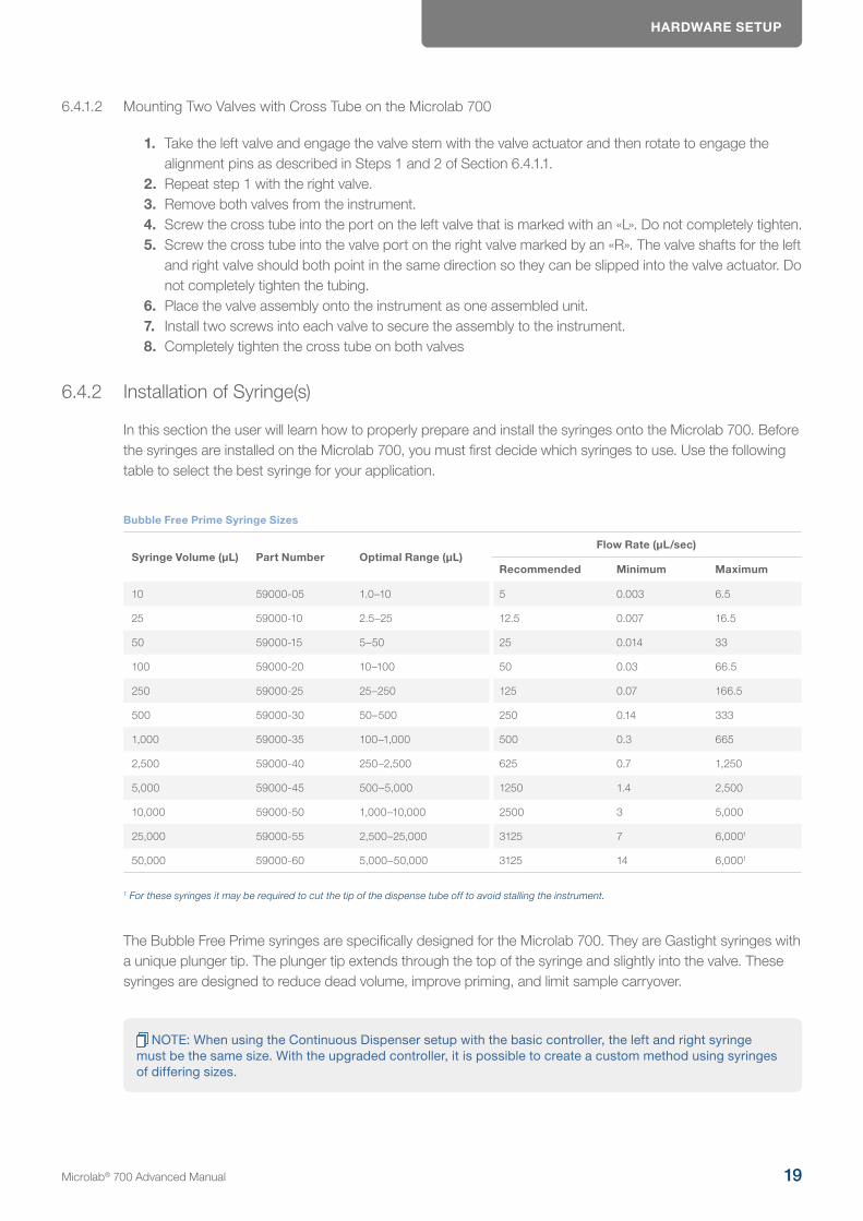
In this section the user will learn how to properly prepare and install the syringes onto the Microlab 700. Before the syringes are installed on the Microlab 700, you must first decide which syringes to use. Use the following table to select the best syringe for your application.
Bubble Free Prime Syringe Sizes
Syringe Volume (μL) Part Number Optimal Range (μL)Flow Rate (μL/sec)
Recommended Minimum Maximum
10 59000-05 1.0–10 5 0.003 6.5
25 59000-10 2.5–25 12.5 0.007 16.5
50 59000-15 5–50 25 0.014 33
100 59000-20 10–100 50 0.03 66.5
250 59000-25 25–250 125 0.07 166.5
500 59000-30 50–500 250 0.14 333
1,000 59000-35 100–1,000 500 0.3 665
2,500 59000-40 250–2,500 625 0.7 1,250
5,000 59000-45 500–5,000 1250 1.4 2,500
10,000 59000-50 1,000–10,000 2500 3 5,000
25,000 59000-55 2,500–25,000 3125 7 6,0001
50,000 59000-60 5,000–50,000 3125 14 6,0001
1 For these syringes it may be required to cut the tip of the dispense tube off to avoid stalling the instrument.
The Bubble Free Prime syringes are specifically designed for the Microlab 700. They are Gastight syringes with a unique plunger tip. The plunger tip extends through the top of the syringe and slightly into the valve. These syringes are designed to reduce dead volume, improve priming, and limit sample carryover.
NOTE: When using the Continuous Dispenser setup with the basic controller, the left and right syringe must be the same size. With the upgraded controller, it is possible to create a custom method using syringes of differing sizes.
Microlab® 700 Advanced Manual 19
HARDWARE SETUP
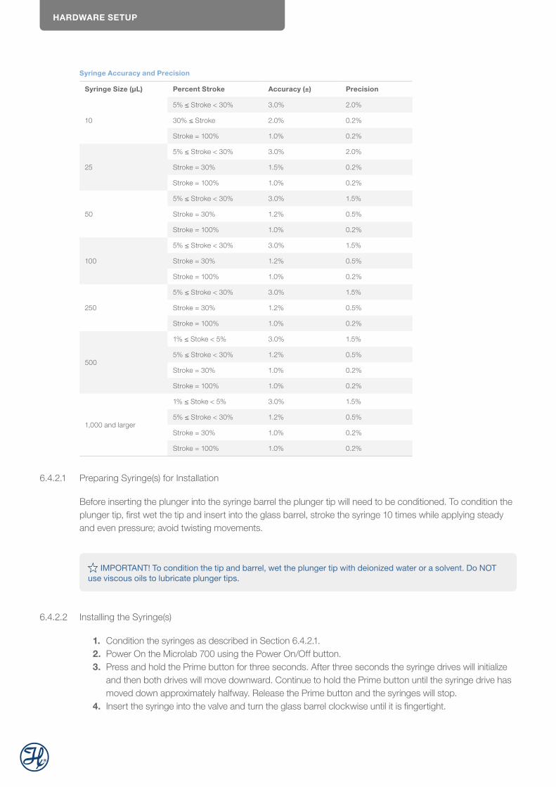
Syringe Accuracy and Precision
Syringe Size (μL) Percent Stroke Accuracy (±) Precision
10
5% ≤ Stroke < 30% 3.0% 2.0%
30% ≤ Stroke 2.0% 0.2%
Stroke = 100% 1.0% 0.2%
25
5% ≤ Stroke < 30% 3.0% 2.0%
Stroke = 30% 1.5% 0.2%
Stroke = 100% 1.0% 0.2%
50
5% ≤ Stroke < 30% 3.0% 1.5%
Stroke = 30% 1.2% 0.5%
Stroke = 100% 1.0% 0.2%
100
5% ≤ Stroke < 30% 3.0% 1.5%
Stroke = 30% 1.2% 0.5%
Stroke = 100% 1.0% 0.2%
250
5% ≤ Stroke < 30% 3.0% 1.5%
Stroke = 30% 1.2% 0.5%
Stroke = 100% 1.0% 0.2%
500
1% ≤ Stoke < 5% 3.0% 1.5%
5% ≤ Stroke < 30% 1.2% 0.5%
Stroke = 30% 1.0% 0.2%
Stroke = 100% 1.0% 0.2%
1,000 and larger
1% ≤ Stoke < 5% 3.0% 1.5%
5% ≤ Stroke < 30% 1.2% 0.5%
Stroke = 30% 1.0% 0.2%
Stroke = 100% 1.0% 0.2%
6.4.2.1 Preparing Syringe(s) for Installation
Before inserting the plunger into the syringe barrel the plunger tip will need to be conditioned. To condition the plunger tip, first wet the tip and insert into the glass barrel, stroke the syringe 10 times while applying steady and even pressure; avoid twisting movements.
IMPORTANT! To condition the tip and barrel, wet the plunger tip with deionized water or a solvent. Do NOT use viscous oils to lubricate plunger tips.
6.4.2.2 Installing the Syringe(s)
1. Condition the syringes as described in Section 6.4.2.1.2. Power On the Microlab 700 using the Power On/Off button.3. Press and hold the Prime button for three seconds. After three seconds the syringe drives will initialize
and then both drives will move downward. Continue to hold the Prime button until the syringe drive has moved down approximately halfway. Release the Prime button and the syringes will stop.
4. Insert the syringe into the valve and turn the glass barrel clockwise until it is fingertight.
HARDWARE SETUP
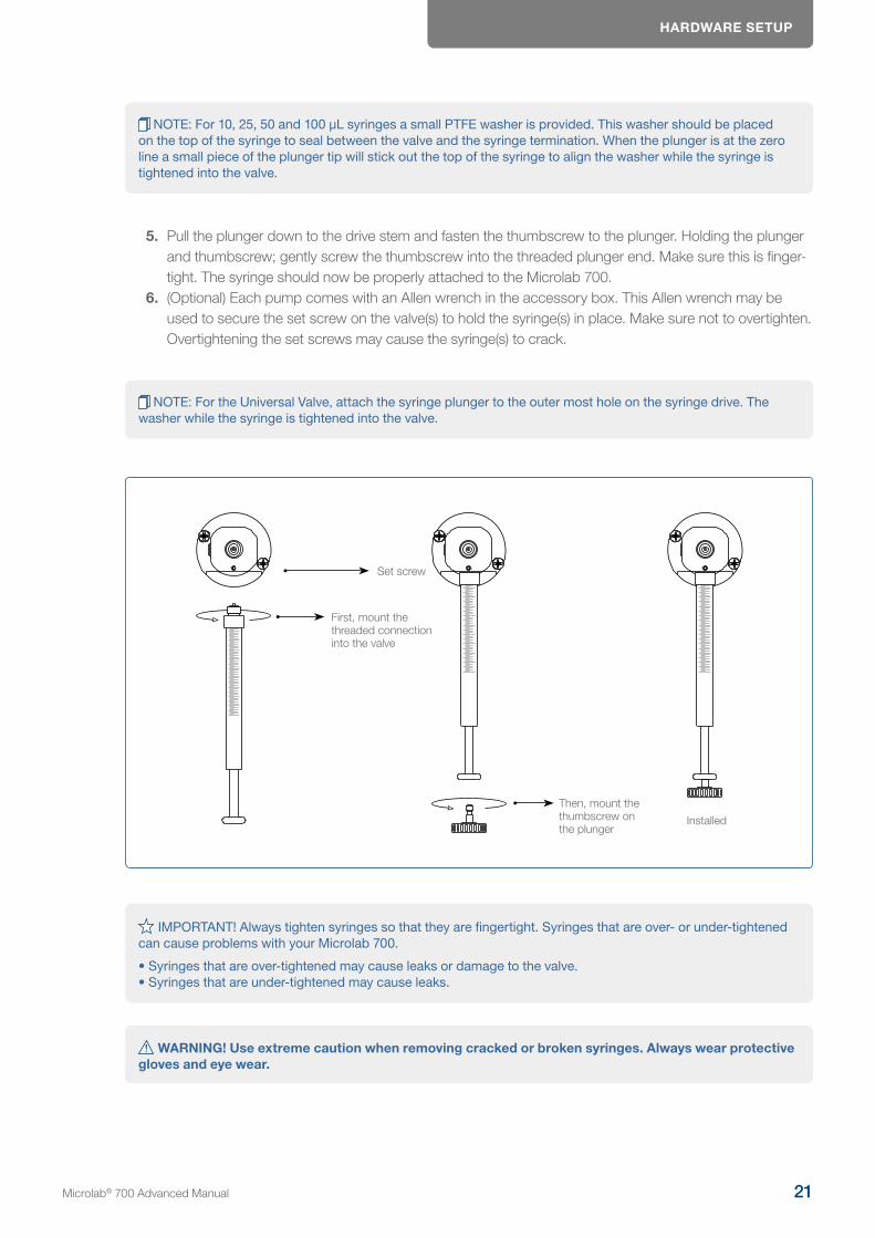
NOTE: For 10, 25, 50 and 100 µL syringes a small PTFE washer is provided. This washer should be placed on the top of the syringe to seal between the valve and the syringe termination. When the plunger is at the zero line a small piece of the plunger tip will stick out the top of the syringe to align the washer while the syringe is tightened into the valve.
5. Pull the plunger down to the drive stem and fasten the thumbscrew to the plunger. Holding the plunger and thumbscrew; gently screw the thumbscrew into the threaded plunger end. Make sure this is finger-tight. The syringe should now be properly attached to the Microlab 700.
6. (Optional) Each pump comes with an Allen wrench in the accessory box. This Allen wrench may be used to secure the set screw on the valve(s) to hold the syringe(s) in place. Make sure not to overtighten. Overtightening the set screws may cause the syringe(s) to crack.
NOTE: For the Universal Valve, attach the syringe plunger to the outer most hole on the syringe drive. The washer while the syringe is tightened into the valve.
Then, mount the thumbscrew on the plunger
First, mount the threaded connection into the valve
Installed
Set screw
IMPORTANT! Always tighten syringes so that they are fingertight. Syringes that are over- or under-tightened can cause problems with your Microlab 700.
• Syringes that are over-tightened may cause leaks or damage to the valve. • Syringes that are under-tightened may cause leaks.
WARNING! Use extreme caution when removing cracked or broken syringes. Always wear protective gloves and eye wear.
Microlab® 700 Advanced Manual 21
HARDWARE SETUP
NOTE: When installing syringes for a dilution application the diluent syringe should be placed on the left side of the instrument, while the sample syringe should be placed on the right side of the instrument.
6.4.3 Installation of the Tubing
The Microlab 700 instrument uses 12 and 18 gauge tubing for dispensing applications. The tubing comes in two different types, fill and dispense. The fill tubing has a blunt end and is designed to go into a reservoir of liquid. The dispense tubing has a tapered tip and is designed to minimize droplet formation.
6.4.3.1 Selecting the Proper Tubing
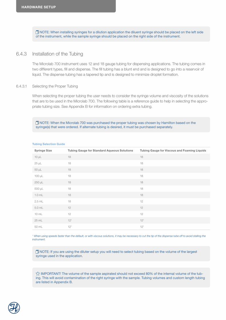
When selecting the proper tubing the user needs to consider the syringe volume and viscosity of the solutions that are to be used in the Microlab 700. The following table is a reference guide to help in selecting the appro-priate tubing size. See Appendix B for information on ordering extra tubing.
NOTE: When the Microlab 700 was purchased the proper tubing was chosen by Hamilton based on the syringe(s) that were ordered. If alternate tubing is desired, it must be purchased separately.
Tubing Selection Guide
Syringe Size Tubing Gauge for Standard Aqueous Solutions Tubing Gauge for Viscous and Foaming Liquids
10 μL 18 18
25 μL 18 18
50 μL 18 18
100 μL 18 18
250 μL 18 18
500 μL 18 18
1.0 mL 18 18
2.5 mL 18 12
5.0 mL 12 12
10 mL 12 12
25 mL 121 121
50 mL 121 121
1 When using speeds faster than the default, or with viscous solutions, it may be necessary to cut the tip of the dispense tube off to avoid stalling the instrument.
NOTE: If you are using the diluter setup you will need to select tubing based on the volume of the largest syringe used in the application.
IMPORTANT! The volume of the sample aspirated should not exceed 80% of the internal volume of the tub-ing. This will avoid contamination of the right syringe with the sample. Tubing volumes and custom length tubing are listed in Appendix B.
HARDWARE SETUP
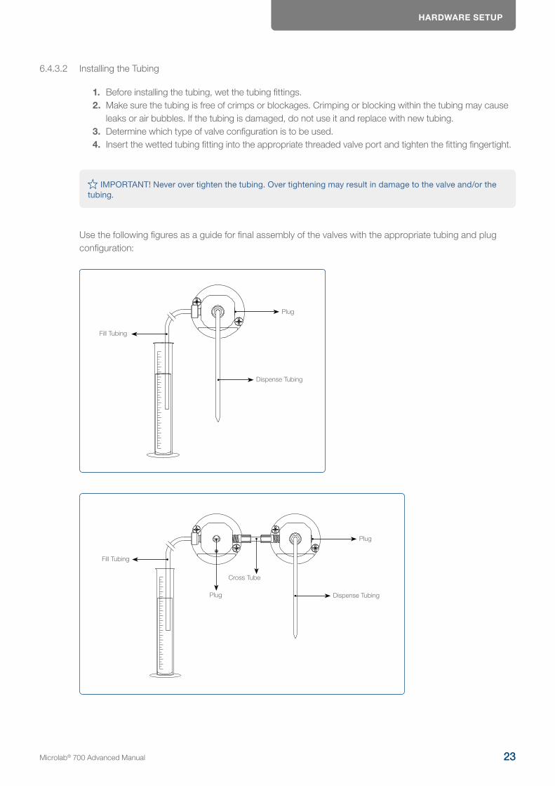
6.4.3.2 Installing the Tubing
1. Before installing the tubing, wet the tubing fittings.2. Make sure the tubing is free of crimps or blockages. Crimping or blocking within the tubing may cause
leaks or air bubbles. If the tubing is damaged, do not use it and replace with new tubing.3. Determine which type of valve configuration is to be used. 4. Insert the wetted tubing fitting into the appropriate threaded valve port and tighten the fitting fingertight.
IMPORTANT! Never over tighten the tubing. Over tightening may result in damage to the valve and/or the tubing.
Use the following figures as a guide for final assembly of the valves with the appropriate tubing and plug configuration:
Plug
Dispense Tubing
Fill Tubing
Dispense Tubing
Plug
Fill Tubing
Plug
Cross Tube
Microlab® 700 Advanced Manual 23
HARDWARE SETUP
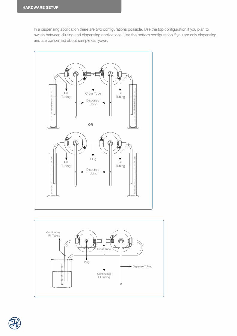
In a dispensing application there are two configurations possible. Use the top configuration if you plan to switch between diluting and dispensing applications. Use the bottom configuration if you are only dispensing and are concerned about sample carryover.
Dispense Tubing
Dispense Tubing
Plug
Fill Tubing
Fill Tubing
Fill Tubing
Fill Tubing
OR
Cross Tube
Plug
Dispense Tubing
Continuous Fill Tubing
Continuous Fill Tubing
Cross Tube
HARDWARE SETUP
NOTE: All dual syringe pumps will come from the factory set in the diluter configuration. If this is not the desired application, refer to the appropriate configuration and change the pump accordingly.
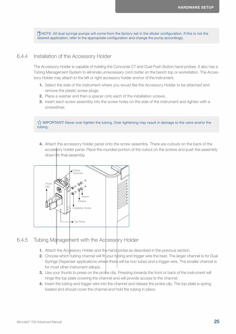
6.4.4 Installation of the Accessory Holder
The Accessory Holder is capable of holding the Concorde CT and Dual Push Button hand probes. It also has a Tubing Management System to eliminate unnecessary cord clutter on the bench top or workstation. The Acces-sory Holder may attach to the left or right accessory holder anchor of the instrument.
1. Select the side of the instrument where you would like the Accessory Holder to be attached and remove the plastic screw plugs.
2. Place a washer and then a spacer onto each of the installation screws.3. Insert each screw assembly into the screw holes on the side of the instrument and tighten with a
screwdriver.
IMPORTANT! Never over tighten the tubing. Over tightening may result in damage to the valve and/or the tubing.
4. Attach the accessory holder panel onto the screw assembly. There are cutouts on the back of the accessory holder panel. Place the rounded portion of the cutout on the screws and push the assembly down for final assembly.
Installation Screw
Top Panel
Washer
Spacer
ProbeClip
Tubing Channels
6.4.5 Tubing Management with the Accessory Holder
1. Attach the Accessory Holder and the hand probe as described in the previous section.2. Choose which tubing channel will fit your tubing and trigger wire the best. The larger channel is for Dual
Syringe Dispenser applications where there will be two tubes and a trigger wire. The smaller channel is for most other instrument setups.
3. Use your thumb to press on the probe clip. Pressing towards the front or back of the instrument will hinge the top plate covering the channel and will provide access to the channel.
4. Insert the tubing and trigger wire into the channel and release the probe clip. The top plate is spring loaded and should cover the channel and hold the tubing in place.
Microlab® 700 Advanced Manual 25

HARDWARE SETUP
NOTE: There is a wire stand that can be mounted to the Accessory Holder to keep the tubing completely off the workstation.
Tubing Wire Stand
Accessory Holder
6.4.6 Installation of the Hand Probe
Hand probe receptacles are located on the left and right side of the drive unit. The trigger wire for the hand probe or foot switch may be inserted into either of these receptacles. The dispense tubing (12 or 18 gauge) may be threaded through the hand probe. See Appendix C for optional hand probes and foot switch.
NOTE: When installing the probe on the Microlab 700, thread the tubing from the hand probe through the clips that hold the trigger wire and the dispense tubing together.
6.5 Installation of Accessories
6.5.1 Installation of Precision Balances
Analytical and precision balances from manufacturers KERN, Mettler Toledo, Ohaus and Sartorius can be connected the the Microlab 700 instrument.
HARDWARE SETUP
Kern ADJ Series
Kern ABP Series
Ohaus AX-Series
Ohaus Advanturer Series
Mettler Toledo ME-Series
Mettler Toledo ME-T-Series
Mettler Toledo PL-E-Series
Mettler Toledo XP-Series
Sartorius Practum-Series
Sartorius Cubis-Series
Sartorius Quintix-Series
To connect the balance to the Microlab 700 instrument, plug in the balance RS232C serial cable into the IOIO Port 1 of the controller.
6.5.2 Installation of Office Network Printers
Smart office printers from HB and Epson are compatible with the Microlab 700 instrument. The network printer must be connected via WLAN or LAN in the same network. PDF log files can be printed directly from the Microlab 700 Instrument.
HP DeskJet 26x Series
HP DeskJet 37x Series
Epson Expression Home
Epson WorkForce Pro
Printouts are available in Letter or A4 format
6.5.3 Installation of the RFID Card Scanner
The Hamilton RFID scanner can be connected to the Microlab 700 instrument. With the RFID scanner, a authentication with RFID card is possible.
Connect the RFID scanner USB cable with one of the USB ports of the Microlab 700 controller. If no USB port is available, a USB hub can be used.
Frequency 125 kHz/134.2 kHz (LF) / 13.56 MHz (HF)
Dimensions (L x W x H) 88 mm x 56 mm x 18 mm / 3.5 inch x 2.2 inch x 0.7 inch
Power Supply 4.3 V - 5.5 V via USB; via generic interface (X2) 3.3 V +/- 5%; RS232 requires 5 V external power supply
Current Consumption RF field on: 120 mA typically / Sleep: 500 µA typ. / Cyclic Operation: TBD
Temperature Range Operating: -25 °C up to +70 °C (-13 °F up to +158 °F) Storage: -45 °C up to +75 °C (-49 °F up to +167 °F)
Relative Humidity 5% to 95% non-condensing
Read- / Write Distance LF and HF: Up to 100 mm / 4 inch, depending on environment and transponder
Weight 117 g / 4.13 oz (with cable)
Microlab® 700 Advanced Manual 27
HARDWARE SETUP
6.5.4 Installation of the QR Code Scanner
The ZEBRA DS9208 2D QR and 1D barcode reader can be connected to the Microlab 700 instrument. With the QR code reader, tracing, custom method and favorite labels from Microlab 700 instrument can be scanned. This system can be used to meet SOP requirements and system integration.
Connect the QR code scanner USB cable with one of the USB ports of the Microlab 700 controller. If no USB port is available, a USB hub can be used.
6.5.5 Installation of the Label Printer
The label printer is used to print custom method and favorite identification labels for the Microlab 700 Instrument.
Connect the label printer to the IOIO2 port of the Microlab 700 instrument.
6.6 Controller Unit
The controller unit is the final piece that is connected to the drive unit. It will connect from the Ethernet port on the controller via the controller cord into the Ethernet port on the pump. The controller unit will send instructions to the drive unit via a touchscreen interface.
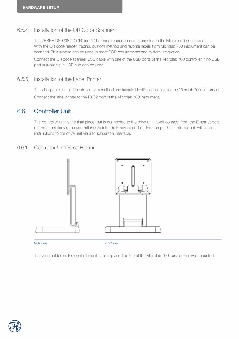
6.6.1 Controller Unit Vesa Holder
Right view Front view
The vesa holder for the controller unit can be placed on top of the Microlab 700 base unit or wall mounted.
HARDWARE SETUP
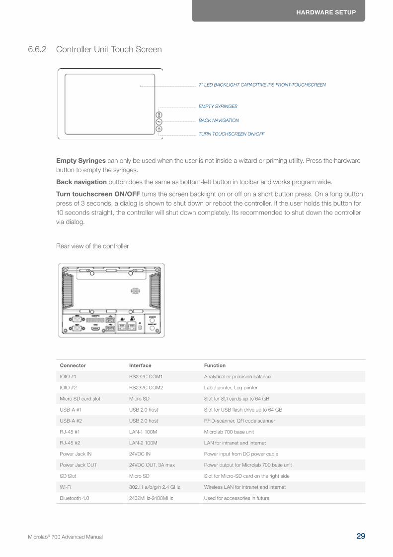
6.6.2 Controller Unit Touch Screen
7" LED BACKLIGHT CAPACITIVE IPS FRONT-TOUCHSCREEN
BACK NAVIGATION
EMPTY SYRINGES
TURN TOUCHSCREEN ON/OFF
Empty Syringes can only be used when the user is not inside a wizard or priming utility. Press the hardware button to empty the syringes.
Back navigation button does the same as bottom-left button in toolbar and works program wide.
Turn touchscreen ON/OFF turns the screen backlight on or off on a short button press. On a long button press of 3 seconds, a dialog is shown to shut down or reboot the controller. If the user holds this button for 10 seconds straight, the controller will shut down completely. Its recommended to shut down the controller via dialog.
Rear view of the controller
Connector Interface Function
IOIO #1 RS232C COM1 Analytical or precision balance
IOIO #2 RS232C COM2 Label printer, Log printer
Micro SD card slot Micro SD Slot for SD cards up to 64 GB
USB-A #1 USB 2.0 host Slot for USB flash drive up to 64 GB
USB-A #2 USB 2.0 host RFID-scanner, QR code scanner
RJ-45 #1 LAN-1 100M Microlab 700 base unit
RJ-45 #2 LAN-2 100M LAN for intranet and internet
Power Jack IN 24VDC IN Power input from DC power cable
Power Jack OUT 24VDC OUT, 3A max Power output for Microlab 700 base unit
SD Slot Micro SD Slot for Micro-SD card on the right side
Wi-Fi 802.11 a/b/g/n 2.4 GHz Wireless LAN for intranet and internet
Bluetooth 4.0 2402MHz-2480MHz Used for accessories in future
Microlab® 700 Advanced Manual 29
HARDWARE SETUP
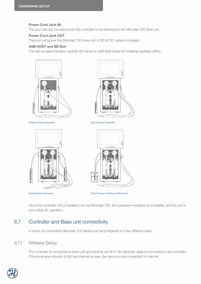
Power Cord Jack IN This port will only be used when the controller is not attached to the Microlab 700 drive unit.
Power Cord Jack OUT This port will power the Microlab 700 drive unit. A DC to DC cable is included.
USB HOST and SD Slot This slot accepts Hamilton specific SD cards or USB flash drives for installing updates offline.
Single Syringe Dispenser Dual Syringe Dispenser
Dual Syringe Dispenser Dual Syringe Continuous Dispenser
Once the controller unit is installed onto the Microlab 700, the hardware installation is complete, and the unit is now ready for operation.
6.7 Controller and Base unit connectivity
In terms of Connectivity Microlab 700 device can be configured in a few different ways.
6.7.1 Wireless Setup
The controller is connected to base unit and intranet via Wi-Fi. No ethernet cable is connected to the controller. If the local area network (LAN) has internet access, the device is also connected to internet.
HARDWARE SETUP
Intranet
LANWiFi
Microlab 700Controller
Base UnitEthernet
Base Unit
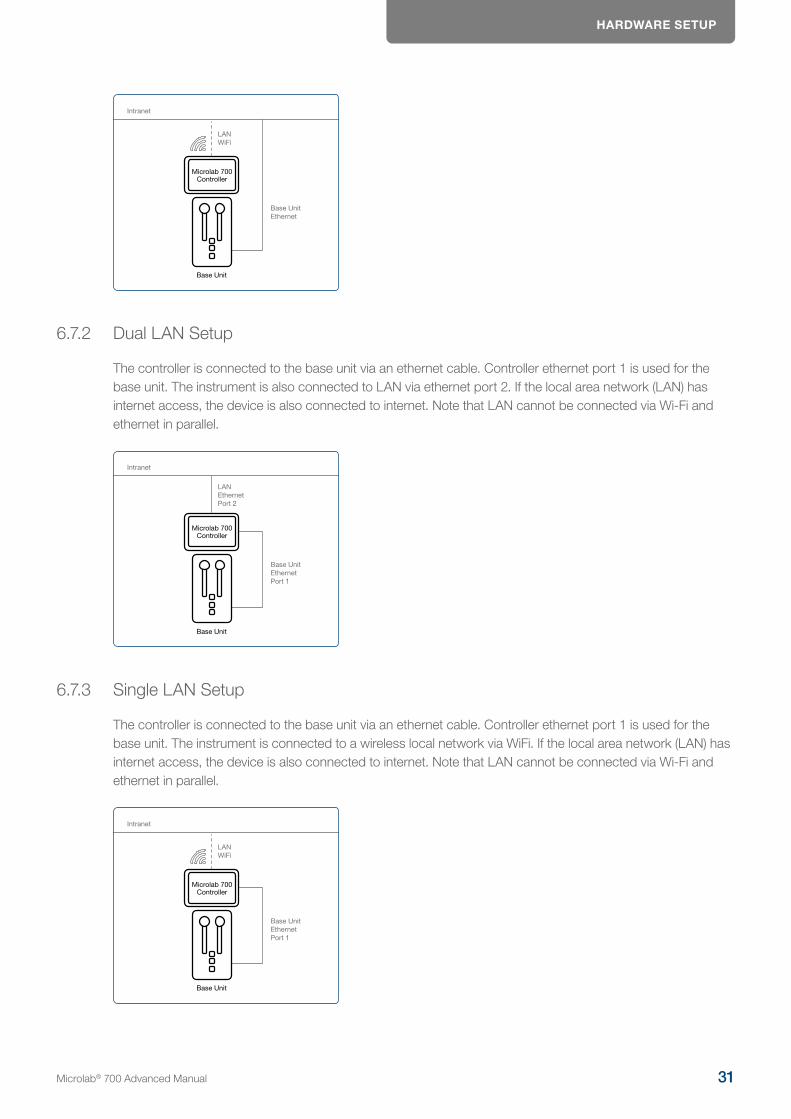
6.7.2 Dual LAN Setup
The controller is connected to the base unit via an ethernet cable. Controller ethernet port 1 is used for the base unit. The instrument is also connected to LAN via ethernet port 2. If the local area network (LAN) has internet access, the device is also connected to internet. Note that LAN cannot be connected via Wi-Fi and ethernet in parallel.
Intranet
LANEthernetPort 2
Microlab 700Controller
Base UnitEthernetPort 1
Base Unit
6.7.3 Single LAN Setup
The controller is connected to the base unit via an ethernet cable. Controller ethernet port 1 is used for the base unit. The instrument is connected to a wireless local network via WiFi. If the local area network (LAN) has internet access, the device is also connected to internet. Note that LAN cannot be connected via Wi-Fi and ethernet in parallel.
Intranet
Microlab 700Controller
Base UnitEthernetPort 1
Base Unit
LANWiFi
Microlab® 700 Advanced Manual 31

OVERVIEW OF SCREENS AND BUTTONS
6.7.4 LyncStore 700 Offline Setup
Details about how to connect LyncStore 700 with the Microlab 700 instrument are available in the LyncStore 700 user manual.
Intranet
LAN
or
WiF
i
Microlab700
Controller
Base UnitEthernet Port 1
Base Unit
Laptop / PC
LyncStore 700 Server
Tablet SmartphoneE
ther
net o
r W
iFi
WiF
i
WiF
i
6.7.5 LyncStore 700 Online Setup
Details about how to connect LyncStore 700 with the Microlab 700 instrument are available in the LyncStore 700 user manual.
Internet
LAN
or
WiF
i
Microlab700
Controller
Base UnitEthernet Port 1
Base Unit Laptop / PC
Tablet Smartphone
LyncStore 700 Cloud
7 Overview of Screens and ButtonsThis chapter will describe the features of the seven major screen types that are used throughout the user interface.
7.1 Splash Screen
This is the boot up screen that will appear when the pump is powered On. The boot up will take approximately 30 seconds. Activity will be indicated by green lights that move across the bottom of the screen. During the boot up the screen will go black for a few seconds. Once the system finishes loading, it will start on the Main Menu screen.
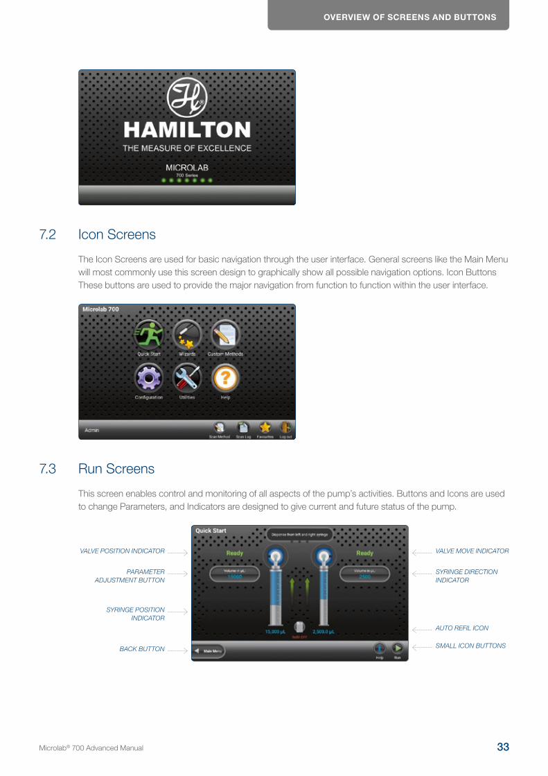
OVERVIEW OF SCREENS AND BUTTONS
7.2 Icon Screens
The Icon Screens are used for basic navigation through the user interface. General screens like the Main Menu will most commonly use this screen design to graphically show all possible navigation options. Icon Buttons These buttons are used to provide the major navigation from function to function within the user interface.
7.3 Run Screens
This screen enables control and monitoring of all aspects of the pump’s activities. Buttons and Icons are used to change Parameters, and Indicators are designed to give current and future status of the pump.
VALVE MOVE INDICATOR
AUTO REFIL ICON
SYRINGE DIRECTION INDICATOR
SMALL ICON BUTTONSBACK BUTTON
SYRINGE POSITION INDICATOR
PARAMETER ADJUSTMENT BUTTON
VALVE POSITION INDICATOR
Microlab® 700 Advanced Manual 33
OVERVIEW OF SCREENS AND BUTTONS
7.3.1 Valve Position Indicator
This indicator shows the current valve position and the fluid path.
7.3.2 Parameter Adjustment Button
This button shows the current dispense setting. The exact function for these buttons will be defined in greater detail in the Quick Start section of this manual.
7.3.3 Syringe Position Indicator
This indicator shows the current syringe position graphically and in a numeric volume.
7.3.4 Back Button
This button takes the user back to the previous screen.
7.3.5 Small Icon Buttons
These buttons provide additional functionality to the Run screen. The exact function for these buttons will be defined in greater detail in the Quick Start section of this manual.
7.3.6 Auto Refill Icon
This icon can be toggled «ON» and «OFF». When the icon is labeled «ON» the syringes automatically refill when they are empty. When the icon is labeled «OFF» the syringes will not refill until they are triggered by the hand probe or the «Run» icon.
7.3.7 Syringe Direction Indicator
This indicator shows the direction the syringe will move in the next step. If there is not an arrow, the syringe will not be moving in the next step.
7.3.8 Valve Move Indicator
This indicator shows the current valve position and the position where the valve will move in the next step. If the indictor says «Ready» the valve will not move in the next step.
7.3.9 Valve Position Indicator Drawings
The Valve Position Indicator will display drawings intended to illustrate the current open fluid path for the universal valve. The gray path with double headed arrows indicates the fluid path that is currently connected to the syringe. The direction the liquid flows through the open fluid path is determined by the direction the syringe is moving. Descriptions and images of the drawings displayed by the Valve Position Indicator are shown for the four pump configurations.
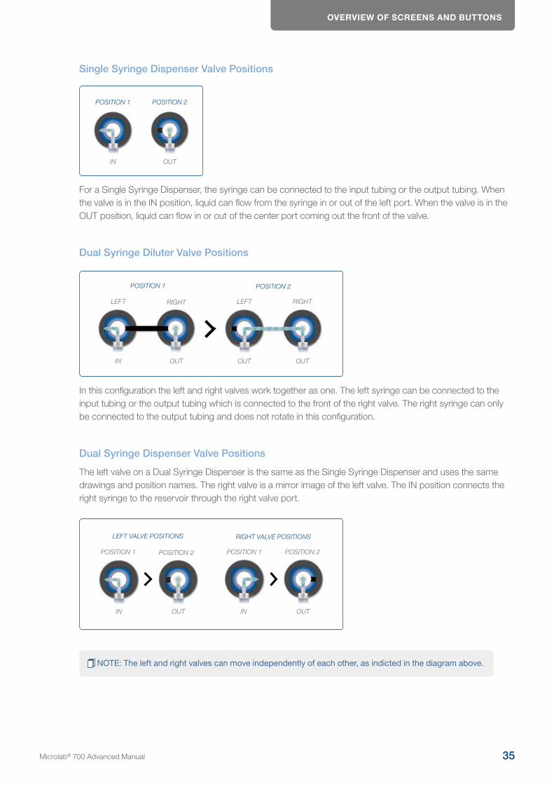
OVERVIEW OF SCREENS AND BUTTONS
Single Syringe Dispenser Valve Positions
POSITION 1 POSITION 2
IN OUT
For a Single Syringe Dispenser, the syringe can be connected to the input tubing or the output tubing. When the valve is in the IN position, liquid can flow from the syringe in or out of the left port. When the valve is in the OUT position, liquid can flow in or out of the center port coming out the front of the valve.
Dual Syringe Diluter Valve Positions
POSITION 1 POSITION 2
IN OUT OUT OUT
LEFT RIGHT LEFT RIGHT
In this configuration the left and right valves work together as one. The left syringe can be connected to the input tubing or the output tubing which is connected to the front of the right valve. The right syringe can only be connected to the output tubing and does not rotate in this configuration.
Dual Syringe Dispenser Valve Positions
The left valve on a Dual Syringe Dispenser is the same as the Single Syringe Dispenser and uses the same drawings and position names. The right valve is a mirror image of the left valve. The IN position connects the right syringe to the reservoir through the right valve port.
LEFT VALVE POSITIONS RIGHT VALVE POSITIONS
IN OUT IN OUT
POSITION 1 POSITION 2 POSITION 1 POSITION 2
NOTE: The left and right valves can move independently of each other, as indicted in the diagram above.
Microlab® 700 Advanced Manual 35
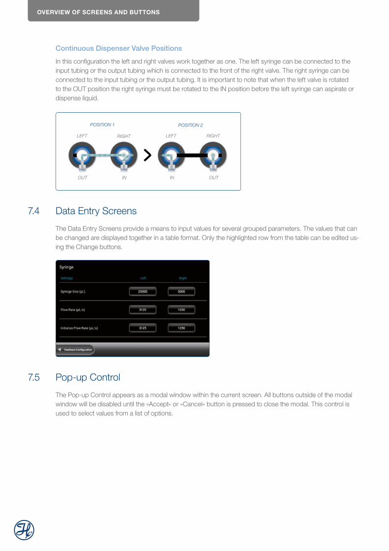
OVERVIEW OF SCREENS AND BUTTONS
Continuous Dispenser Valve Positions
In this configuration the left and right valves work together as one. The left syringe can be connected to the input tubing or the output tubing which is connected to the front of the right valve. The right syringe can be connected to the input tubing or the output tubing. It is important to note that when the left valve is rotated to the OUT position the right syringe must be rotated to the IN position before the left syringe can aspirate or dispense liquid.
POSITION 1 POSITION 2
OUT IN IN OUT
LEFT RIGHT LEFT RIGHT
7.4 Data Entry Screens
The Data Entry Screens provide a means to input values for several grouped parameters. The values that can be changed are displayed together in a table format. Only the highlighted row from the table can be edited us-ing the Change buttons.
7.5 Pop-up Control
The Pop-up Control appears as a modal window within the current screen. All buttons outside of the modal window will be disabled until the «Accept» or «Cancel» button is pressed to close the modal. This control is used to select values from a list of options.
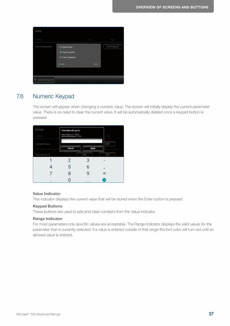
OVERVIEW OF SCREENS AND BUTTONS
7.6 Numeric Keypad
The screen will appear when changing a numeric value. The screen will initially display the current parameter value. There is no need to clear the current value. It will be automatically deleted once a keypad button is pressed.
Value Indicator This indicator displays the current value that will be stored when the Enter button is pressed.
Keypad Buttons These buttons are used to add and clear numbers from the Value Indicator.
Range Indicator For most parameters only specific values are acceptable. The Range Indicator displays the valid values for the parameter that is currently selected. If a value is entered outside of that range the font color will turn red until an allowed value is entered.
Microlab® 700 Advanced Manual 37
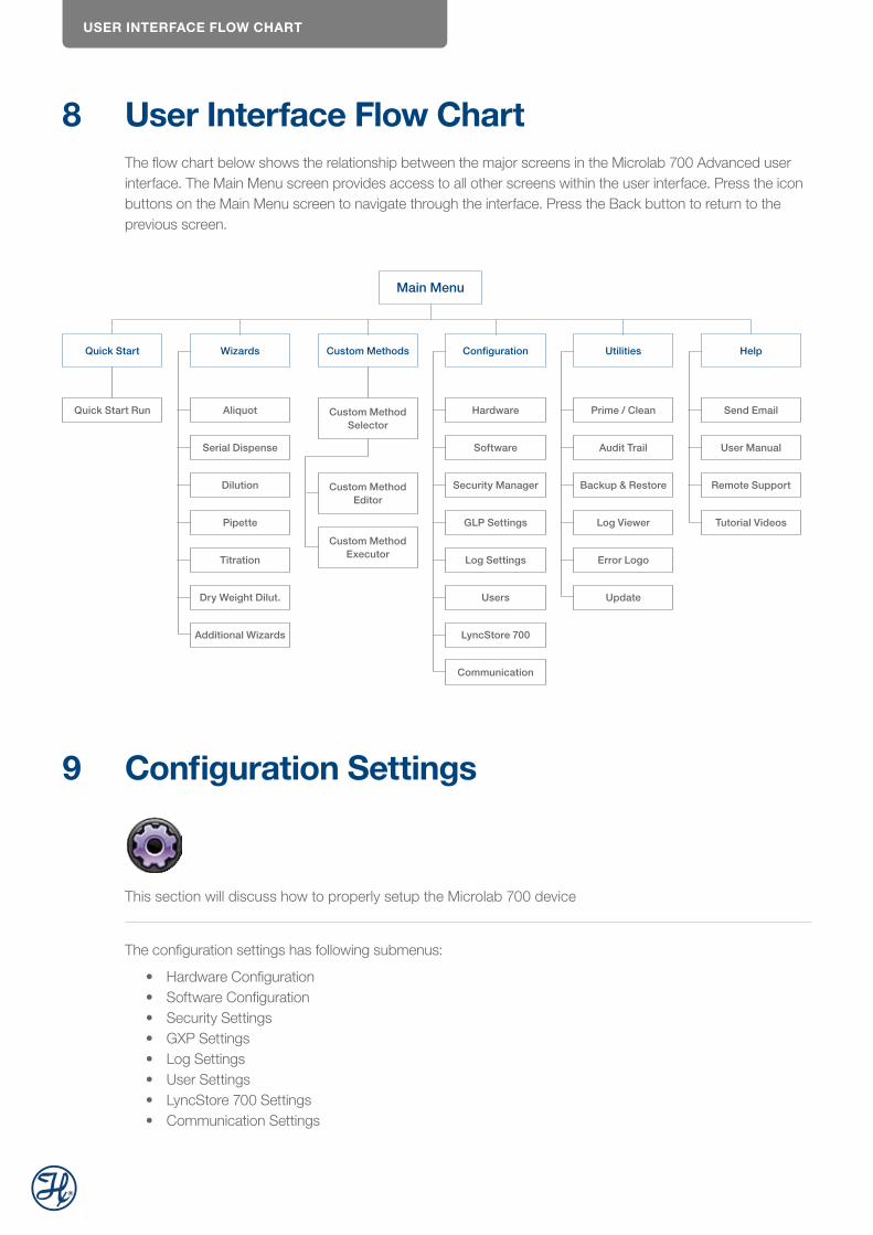
USER INTERFACE FLOW CHART
8 User Interface Flow ChartThe flow chart below shows the relationship between the major screens in the Microlab 700 Advanced user interface. The Main Menu screen provides access to all other screens within the user interface. Press the icon buttons on the Main Menu screen to navigate through the interface. Press the Back button to return to the previous screen.
Quick Start Wizards Custom Methods Configuration Utilities Help
Main Menu
Quick Start Run Aliquot
Serial Dispense
Dilution
Pipette
Titration
Dry Weight Dilut.
Additional Wizards
Custom Method Selector
Custom Method Editor
Custom Method Executor
Hardware
Software
Security Manager
GLP Settings
Log Settings
Users
LyncStore 700
Communication
Prime / Clean
Audit Trail
Backup & Restore
Log Viewer
Error Logo
Update
Send Email
User Manual
Remote Support
Tutorial Videos
9 Configuration Settings
This section will discuss how to properly setup the Microlab 700 device
The configuration settings has following submenus:
• Hardware Configuration• Software Configuration• Security Settings• GXP Settings• Log Settings• User Settings• LyncStore 700 Settings• Communication Settings
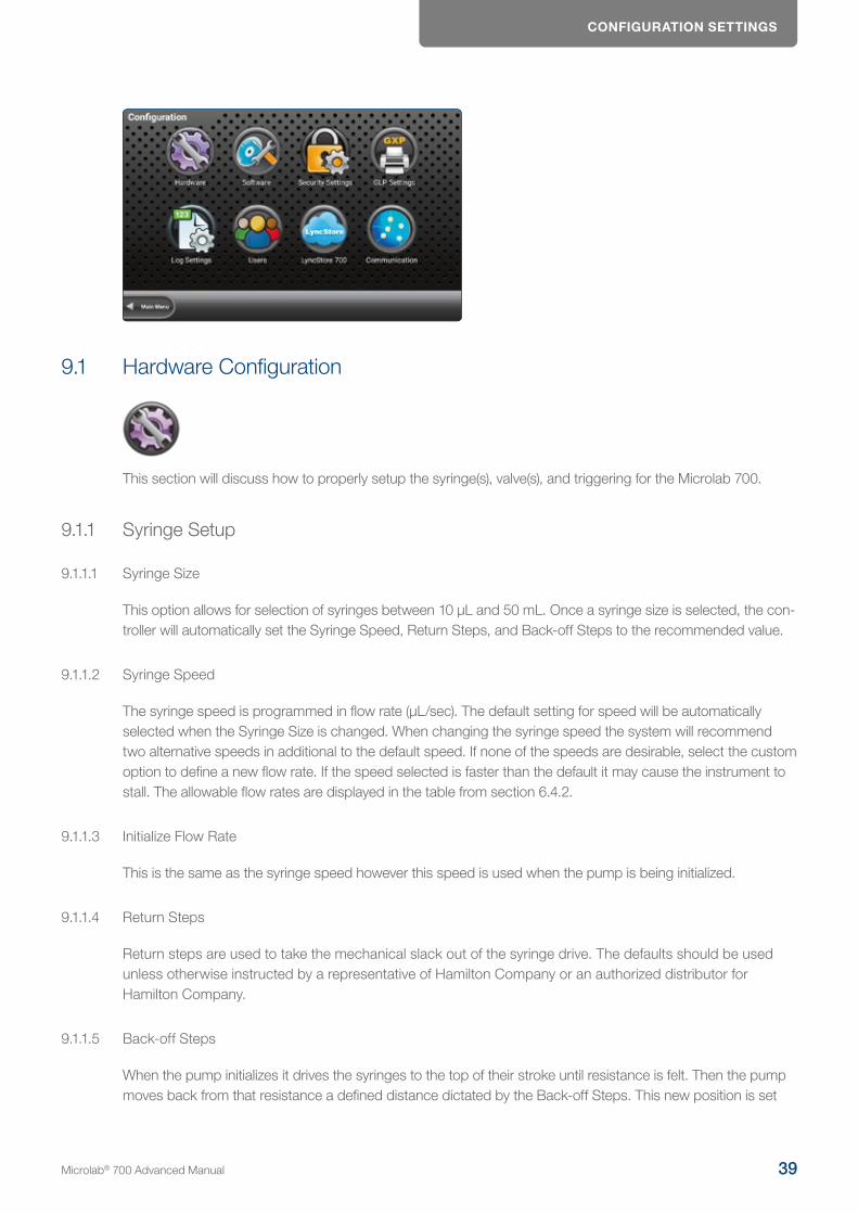
CONFIGURATION SETTINGS
9.1 Hardware Configuration
This section will discuss how to properly setup the syringe(s), valve(s), and triggering for the Microlab 700.
9.1.1 Syringe Setup
9.1.1.1 Syringe Size
This option allows for selection of syringes between 10 μL and 50 mL. Once a syringe size is selected, the con-troller will automatically set the Syringe Speed, Return Steps, and Back-off Steps to the recommended value.
9.1.1.2 Syringe Speed
The syringe speed is programmed in flow rate (μL/sec). The default setting for speed will be automatically selected when the Syringe Size is changed. When changing the syringe speed the system will recommend two alternative speeds in additional to the default speed. If none of the speeds are desirable, select the custom option to define a new flow rate. If the speed selected is faster than the default it may cause the instrument to stall. The allowable flow rates are displayed in the table from section 6.4.2.
9.1.1.3 Initialize Flow Rate
This is the same as the syringe speed however this speed is used when the pump is being initialized.
9.1.1.4 Return Steps
Return steps are used to take the mechanical slack out of the syringe drive. The defaults should be used unless otherwise instructed by a representative of Hamilton Company or an authorized distributor for Hamilton Company.
9.1.1.5 Back-off Steps
When the pump initializes it drives the syringes to the top of their stroke until resistance is felt. Then the pump moves back from that resistance a defined distance dictated by the Back-off Steps. This new position is set
Microlab® 700 Advanced Manual 39
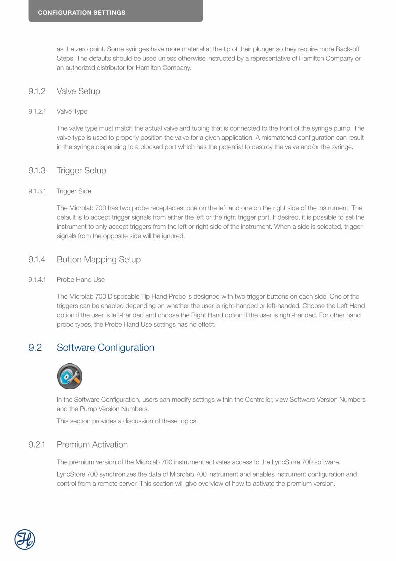
CONFIGURATION SETTINGS
as the zero point. Some syringes have more material at the tip of their plunger so they require more Back-off Steps. The defaults should be used unless otherwise instructed by a representative of Hamilton Company or an authorized distributor for Hamilton Company.
9.1.2 Valve Setup
9.1.2.1 Valve Type
The valve type must match the actual valve and tubing that is connected to the front of the syringe pump. The valve type is used to properly position the valve for a given application. A mismatched configuration can result in the syringe dispensing to a blocked port which has the potential to destroy the valve and/or the syringe.
9.1.3 Trigger Setup
9.1.3.1 Trigger Side
The Microlab 700 has two probe receptacles, one on the left and one on the right side of the instrument. The default is to accept trigger signals from either the left or the right trigger port. If desired, it is possible to set the instrument to only accept triggers from the left or right side of the instrument. When a side is selected, trigger signals from the opposite side will be ignored.
9.1.4 Button Mapping Setup
9.1.4.1 Probe Hand Use
The Microlab 700 Disposable Tip Hand Probe is designed with two trigger buttons on each side. One of the triggers can be enabled depending on whether the user is right-handed or left-handed. Choose the Left Hand option if the user is left-handed and choose the Right Hand option if the user is right-handed. For other hand probe types, the Probe Hand Use settings has no effect.
9.2 Software Configuration
In the Software Configuration, users can modify settings within the Controller, view Software Version Numbers and the Pump Version Numbers.
This section provides a discussion of these topics.
9.2.1 Premium Activation
The premium version of the Microlab 700 instrument activates access to the LyncStore 700 software.
LyncStore 700 synchronizes the data of Microlab 700 instrument and enables instrument configuration and control from a remote server. This section will give overview of how to activate the premium version.

CONFIGURATION SETTINGS
To activate the premium software version, navigate to the software configuration screen. Following settings screen appears.
Press the Activate premium version list entry. An activation input dialog will be shown.
To purchase an activation key, contact and send the displayed hardware key to your supplier. Enter the acti-vation key into the text field and press the Activate button.
9.2.2 Controller
9.2.2.1 Language
This is used to select the appropriate language. When this button is pressed the user will be directed to a screen that has the different languages represented by flags. The user may use the toggle to see all languag-es. Available languages include English, French, Italian, Portuguese, Spanish, German, Chinese, Japanese, Korean, and simplified Chinese. The default setting will be English. The button in the lower right corner of the screen toggles Hide on and off. When Hide is turned off the language screen will show up every time the instrument is turned on. This allows for multiple users that speak different languages to all use the same instru-ment in their native language. If Hide is turned on the language screen is only accessed through the Configura-tion menu.
Microlab® 700 Advanced Manual 41
CONFIGURATION SETTINGS
9.2.2.2 System Date and Time
Using the toggle buttons the user can highlight and select the System Date and then use the change buttons to set the appropriate date. Likewise the user can repeat this process for the System Time.
9.2.2.3 Screen Power Off (min)
The Microlab 700 touchscreen is designed to turn off after an extended period of inactivity. The default setting for the power off is ten minutes. If desired, the power off time can be increased through this selection.
9.2.2.4 Internal and Removeable Storage Used
These are indicators for the percent memory used for the system memory and the SD card or USB flash drive.
9.2.2.5 RAM Used
This is an indicator of how much RAM is used on the controller.
9.2.2.6 MAC Address LAN1, LAN2 and Wi-Fi
This is the unique identifier assigned to the instrument for connecting to a network.
9.2.2.7 System Trace Logging
The default system trace logging configuration is off. If system trace logging is on, the error log viewer in the utilities menu will be enabled for all users.
9.2.3 Versions
This option displays the software version for the Microlab 700 controller and all software modules that are installed on the controller.
9.2.3.1 Software Version
Software version of the Microlab 700 controller.
9.2.3.2 OS Version
Software version of the Microlab 700 controller operating system.
9.2.3.3 Pump Version
Type of the Microlab 700 base unit. Valid types are INSTRUMENT_TYPE_BOTH for a dual syringe base unit and INSTRUMENT_TYPE_SINGLE for a single syringe base unit.
9.2.3.4 Log Viewer Version
Software version of the log viewer utility.
CONFIGURATION SETTINGS
9.2.4 700 Series Pump
This option shows the pump details. This is information stored in the pump and is independent of swapping out the controller.
9.2.4.1 Serial Number
Optional information that can be entered by a Microlab 700 service engineer only. The field shows the serial number of the connected Microlab 700 series pump.
9.2.4.2 Calibration Date
This date is manually adjusted by the user each time the instrument calibration occurs.
9.2.4.3 Firmware Runtime and FPGA Versions
These are the version numbers for the firmware that runs on the pump.
9.2.4.4 DHCP
This Microlab 700 controller communicates with the pump using a static IP address. Valid IP address range in DHCP mode is 192.168.100.[1 – 150]. A static IP address is also used when connecting the Microlab 700 to a PC. To connect the Microlab 700 to most corporate networks it is required to change the Microlab 700 to a Dynamic Host Configuration Protocol (DHCP). When in DHCP mode the Microlab 700 will obtain a dynamic IP address for the corporate server. During this time, it will not be able to connect to the Microlab 700 controller. If the corporate server does not return a valid IP address after 60 seconds, the Microlab 700 will automatically switch back to a static IP address until the power is cycled again. The default DHCP setting is Off.
9.2.4.5 Syringe Cycle Count
This option displays a running total of the number of syringe-strokes the pump has accumulated over its entire life. A complete stroke is recorded when the syringe drive has traveled 60 mm or the equivalent of completely filling or emptying a syringe. This is done so that a series of small movements do not artificially increase the cycle count. For a dual syringe system, the cycle count is displayed as two numbers separated by a colon. The number on the left corresponds to the left syringe and the number on the right corresponds to the right syringe
9.2.5 Calibration
9.2.5.1 Calibration Date
This setting allows user to edit the date of last performed calibration of the device manually. Only administrator users can change the calibration date.
9.2.5.2 Calibration 7 Days Warning
7 days before calibration expiration the user will receive a reminder that calibration is due if this setting is enabled.
Microlab® 700 Advanced Manual 43
CONFIGURATION SETTINGS
If confirm is pressed, the dialog will dismiss, and calibration date will set to today. Otherwise, the dialog will just dismiss and will show when the user leaves or enters any wizard.
9.2.5.3 Calibration Valid Days
Days before the calibration expires. If between user’s calibration date and today is more than calibration valid days, the calibration is considered expired.
9.2.5.4 Prevent Usage on Expired Calibration
If this setting is enabled, users will not be able to operate the pump until the instrument is calibrated again.
9.2.5.5 Maintenance Date
This setting allows user to change latest performed maintenance of the device. Only admin can change this setting.
9.2.5.6 Maintenance Valid Days
Days before maintenance expires. If between maintenance date and today is more than Maintenance valid days, the maintenance is considered expired.
9.2.5.7 Maintenance 7 Day Warning
If between maintenance date and today is more than Maintenance valid days, the maintenance is considered expired. If this setting is enabled, 7 days before the expiration user will start receiving reminders like screen-shot below:
CONFIGURATION SETTINGS
If confirm is pressed, the dialog will dismiss, and maintenance date will set to today. Otherwise, the dialog will just dismiss and will show when the user leaves or enters any wizard.
9.2.5.8 Mean Time Between Errors
Mean time between errors is calculated with the formula
Øerrors = Tfirst error – Tlatest Error
∑errors
where,
Øerrors is the mean time between errors
Tfirst error – Tlatest Error is the time difference between the first and latest error
∑errors is the number of errors in total
The mean time between errors is shown in the format dd:hh:mm (days: hours: minutes).
9.2.6 Cleaning
Cleaning is a procedure of fully dispensing and aspirating syringes 5 times. It can be performed via «Priming/Cleaning» menu.
9.2.6.1 Show Cleaning Warning
If this setting is on, user will get notification reminders about cleaning, if cleaning is expired.
Notification like above will appear each time user tries to enter any wizard or custom method.
9.2.6.2 Cleaning Date
This setting allows user to change their latest performed cleaning of the device. Only admin can change this setting. If the user changes it, cycle counter will reset like cleaning was performed.
9.2.6.3 Cleaning Valid Days
Days before cleaning expires. If between the user’s cleaning date and today is more than Calibration valid days, the cleaning is considered expired. If cleaning expires, user will start receiving notifications (in case Show Cleaning Warning is enabled).
Microlab® 700 Advanced Manual 45
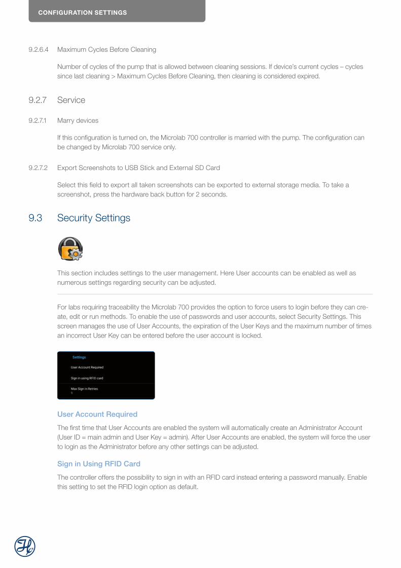
CONFIGURATION SETTINGS
9.2.6.4 Maximum Cycles Before Cleaning
Number of cycles of the pump that is allowed between cleaning sessions. If device’s current cycles – cycles since last cleaning > Maximum Cycles Before Cleaning, then cleaning is considered expired.
9.2.7 Service
9.2.7.1 Marry devices
If this configuration is turned on, the Microlab 700 controller is married with the pump. The configuration can be changed by Microlab 700 service only.
9.2.7.2 Export Screenshots to USB Stick and External SD Card
Select this field to export all taken screenshots can be exported to external storage media. To take a screenshot, press the hardware back button for 2 seconds.
9.3 Security Settings
This section includes settings to the user management. Here User accounts can be enabled as well as numerous settings regarding security can be adjusted.
For labs requiring traceability the Microlab 700 provides the option to force users to login before they can cre-ate, edit or run methods. To enable the use of passwords and user accounts, select Security Settings. This screen manages the use of User Accounts, the expiration of the User Keys and the maximum number of times an incorrect User Key can be entered before the user account is locked.
User Account Required
The first time that User Accounts are enabled the system will automatically create an Administrator Account (User ID = main admin and User Key = admin). After User Accounts are enabled, the system will force the user to login as the Administrator before any other settings can be adjusted.
Sign in Using RFID Card
The controller offers the possibility to sign in with an RFID card instead entering a password manually. Enable this setting to set the RFID login option as default.
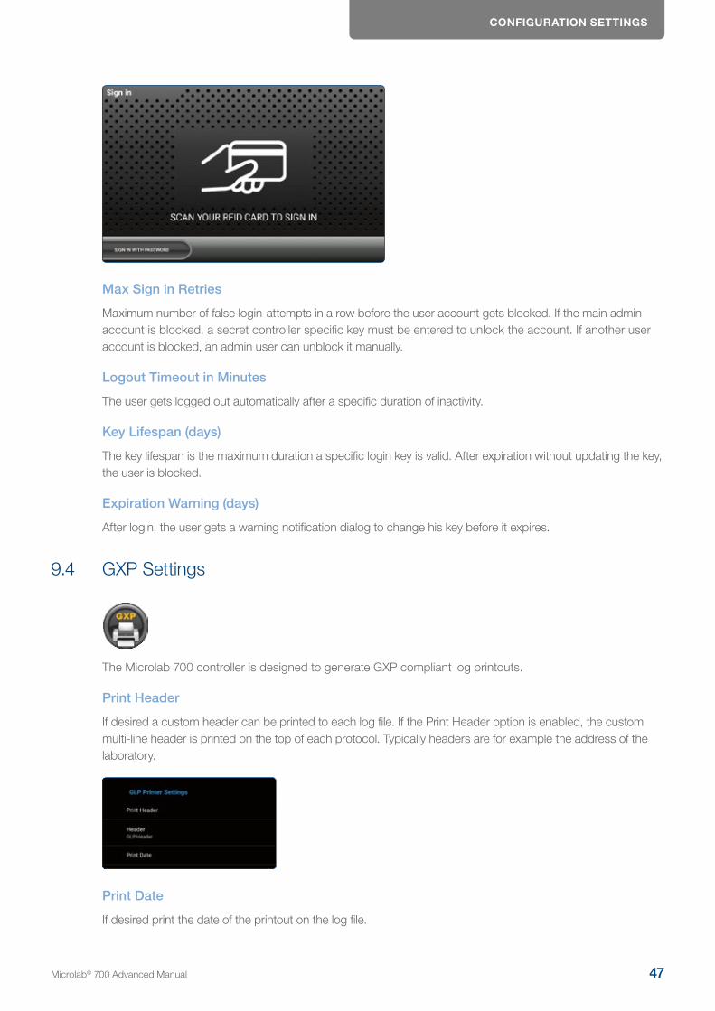
CONFIGURATION SETTINGS
Max Sign in Retries
Maximum number of false login-attempts in a row before the user account gets blocked. If the main admin account is blocked, a secret controller specific key must be entered to unlock the account. If another user account is blocked, an admin user can unblock it manually.
Logout Timeout in Minutes
The user gets logged out automatically after a specific duration of inactivity.
Key Lifespan (days)
The key lifespan is the maximum duration a specific login key is valid. After expiration without updating the key, the user is blocked.
Expiration Warning (days)
After login, the user gets a warning notification dialog to change his key before it expires.
9.4 GXP Settings
The Microlab 700 controller is designed to generate GXP compliant log printouts.
Print Header
If desired a custom header can be printed to each log file. If the Print Header option is enabled, the custom multi-line header is printed on the top of each protocol. Typically headers are for example the address of the laboratory.
Print Date
If desired print the date of the printout on the log file.
Microlab® 700 Advanced Manual 47
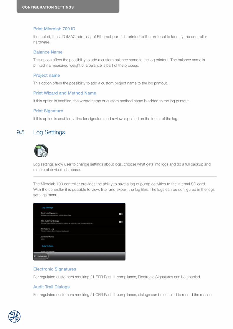
CONFIGURATION SETTINGS
Print Microlab 700 ID
If enabled, the UID (MAC address) of Ethernet port 1 is printed to the protocol to identify the controller hardware.
Balance Name
This option offers the possibility to add a custom balance name to the log printout. The balance name is printed if a measured weight of a balance is part of the process.
Project name
This option offers the possibility to add a custom project name to the log printout.
Print Wizard and Method Name
If this option is enabled, the wizard name or custom method name is added to the log printout.
Print Signature
If this option is enabled, a line for signature and review is printed on the footer of the log.
9.5 Log Settings
Log settings allow user to change settings about logs, choose what gets into logs and do a full backup and restore of device’s database.
The Microlab 700 controller provides the ability to save a log of pump activities to the internal SD card. With the controller it is possible to view, filter and export the log files. The logs can be configured in the logs settings menu.
Electronic Signatures
For regulated customers requiring 21 CFR Part 11 compliance, Electronic Signatures can be enabled.
Audit Trail Dialogs
For regulated customers requiring 21 CFR Part 11 compliance, dialogs can be enabled to record the reason
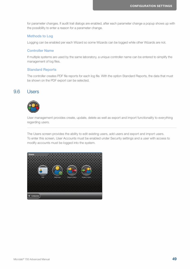
CONFIGURATION SETTINGS
for parameter changes. If audit trail dialogs are enabled, after each parameter change a popup shows up with the possibility to enter a reason for a parameter change.
Methods to Log
Logging can be enabled per each Wizard so some Wizards can be logged while other Wizards are not.
Controller Name
If multiple systems are used by the same laboratory, a unique controller name can be entered to simplify the management of log files.
Standard Reports
The controller creates PDF file reports for each log file. With the option Standard Reports, the data that must be shown on the PDF export can be selected.
9.6 Users
User management provides create, update, delete as well as export and import functionality to everything regarding users.
The Users screen provides the ability to edit existing users, add users and export and import users. To enter this screen, User Accounts must be enabled under Security settings and a user with access to modify accounts must be logged into the system.
Microlab® 700 Advanced Manual 49
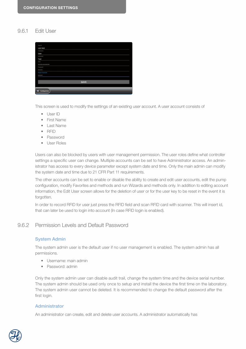
CONFIGURATION SETTINGS
9.6.1 Edit User
This screen is used to modify the settings of an existing user account. A user account consists of
• User ID• First Name• Last Name• RFID• Password• User Roles
Users can also be blocked by users with user management permission. The user roles define what controller settings a specific user can change. Multiple accounts can be set to have Administrator access. An admin-istrator has access to every device parameter except system date and time. Only the main admin can modify the system date and time due to 21 CFR Part 11 requirements.
The other accounts can be set to enable or disable the ability to create and edit user accounts, edit the pump configuration, modify Favorites and methods and run Wizards and methods only. In addition to editing account information, the Edit User screen allows for the deletion of user or for the user key to be reset in the event it is forgotten.
In order to record RFID for user just press the RFID field and scan RFID card with scanner. This will insert id, that can later be used to login into account (In case RFID login is enabled).
9.6.2 Permission Levels and Default Password
System Admin
The system admin user is the default user if no user management is enabled. The system admin has all permissions.
• Username: main admin• Password: admin
Only the system admin user can disable audit trail, change the system time and the device serial number. The system admin should be used only once to setup and install the device the first time on the laboratory. The system admin user cannot be deleted. It is recommended to change the default password after the first login.
Administrator
An administrator can create, edit and delete user accounts. A administrator automatically has
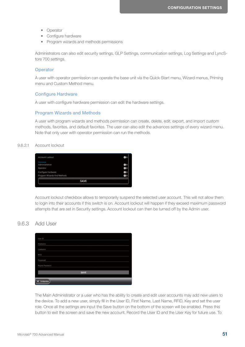
CONFIGURATION SETTINGS
• Operator• Configure hardware• Program wizards and methods permissions
Administrators can also edit security settings, GLP Settings, communication settings, Log Settings and LyncS-tore 700 settings.
Operator
A user with operator permission can operate the base unit via the Quick Start menu, Wizard menus, Priming menu and Custom Method menu.
Configure Hardware
A user with configure hardware permission can edit the hardware settings.
Program Wizards and Methods
A user with program wizards and methods permission can create, delete, edit, export, and import custom methods, favorites, and default favorites. The user can also edit the advances settings of every wizard menu. Note that only user with operator permission can run the methods.
9.6.2.1 Account lockout
Account lockout checkbox allows to temporarily suspend the selected user account. This will not allow them to login into their accounts if this switch is on. Account lockout will happen if they exceed maximum password attempts that are set in Security settings. Account lockout can then be turned off by the Admin user.
9.6.3 Add User
The Main Administrator or a user who has the ability to create and edit user accounts may add new users to the device. To add a new user, simply fill in the User ID, First Name, Last Name, RFID, Key and set the user role. Once all the settings are input the Save button on the bottom of the screen will be enabled. Press this button to exit the screen and save the new account. Record the User ID and the User Key for future use. To
Microlab® 700 Advanced Manual 51

CONFIGURATION SETTINGS
record RFID, click the RFID field and scan card of choice. Every field except RFID must be filled before the account can be saved.
9.6.4 Exporting and Importing Users
To export users, press the Export Users button and the data will be saved to the SD card. To import user accounts, insert the SD card or USB flash drive with the exported user files into a new controller and press the Import Users button and the users will be uploaded to the pump. Only administrator can import and export users.
9.7 LyncStore 700
LyncStore settings allow users log in into their LyncStore 700 accounts as well as change settings regarding synchronization and remote configuration.
LyncStore 700 Microlab 700 Premium Controller
Add LyncStore 700 Account
Add an existing LyncStore 700 user account by entering username and password.
Remove LyncStore 700 Account
Press the Remove LyncStore 700 Account list entry to remove an connected account from the Microlab 700 Premium instrument.

CONFIGURATION SETTINGS
Upload Wizard Logs and Audit Logs
The Microlab 700 Premium instrument allows fully automatic data backups. To allow automatic backup of log files and audit logs enable the Upload settings.
Allow Remote Configuration
The Microlab 700 Premium instrument can be configured remotely. To enable the remote configuration from the added LyncStore 700 account check the setting. If remote configuration is not allowed, the remote access from LyncStore 700 software is blocked.
Base Server Address
The default LyncStore 700 server address is the online deployed LyncStore 700 software by Hamilton. For offline LyncStore 700 installations in the company intranet, the IP address or computer name of the offline server must be entered.
Test Connection
Press the Test Connection list entry to query the LyncStore 700 software version. If the software version is shown, the LyncStore 700 software is setup and installed correctly.
Download LyncStore Offline Server
The LyncStore 700 software can be installed on a local PC or server within the laboratory. In this case the data of the Microlab 700 instrument will stay within the private network. To download the latest offline installer of LyncStore 700, press the Download LyncStore Offline Server button. The Microlab 700 instrument must be connected to internet to download the installer zip archive. The installer will be downloaded to an inserted USB stick. Ensure that a USB stick is inserted to the controller before downloading the zip archive.
9.8 Communication
Communication settings allow user to change numerous settings regrading external devices, base unit con-nectivity as well as connect to the WIFI network.
WLAN
The Microlab 700 Premium instrument can be connected to internet, local network and to the base unit via wireless LAN. To connect to a wireless LAN, press the WLAN list setting. Note: LAN-2 and wireless LAN cannot be used in parallel.
Microlab® 700 Advanced Manual 53
CONFIGURATION SETTINGS
WLAN Network Selection
In order to connect to WIFI network move the switch to the right After that pick desired wifi-network and enter password, if hotspot is secured. After that user can get back to the settings menu by pressing back button.
Microlab Base Unit
If the base unit is connected via ethernet cable, ethernet port 1 (LAN-1) must be used.
LAN
The Microlab 700 Premium instrument can be connected to internet and local network via ethernet cable. For internet or intranet connection, ethernet port 2 (LAN-2) must be used. Note: LAN-2 and wireless LAN cannot be used in parallel.
Label Printer
Default hardware interface for the label printer is IOIO port 2, a RS232C COM 2 serial interface.
Protocol Printer
Default hardware interface for the protocol printer is available via RS232C splitter cable. The splitter cable extends IOIO port 1 with 3x RS232C serial ports. The protocol printer must be connected to COM-5 serial interface.
Barcode, RFID and QR-Code Scanner
Default hardware interface IO devices is USB host.
Balance
Default hardware interface for analytical or precision balances is IOIO port 1.
Balance Model
Select the balance model that is connected to the IOIO port 1. Balances from brand Kern, Mettler Toledo, Ohaus and Sartorius with a serial port are supported.
LAN Ports Configuration
The default LAN port configuration of the Microlab 700 instrument is
• Dual LAN : enabled• Priority LAN: LAN 2
This setting should be changed by Microlab 700 service engineers only.
PRIMING THE INSTRUMENT
Open Browser
Press this entry to open a default internet browser. This functionality is available for the main administrator only. WLAN hotspots may require a specific IP address to open with a web browser to activate Internet access. This functionality is available for the installation and configuration of the Microlab 700 instrument only.
10 Priming the instrumentThis section will describe how to properly prime the Microlab 700 before running a method.
1. Decide which side or sides of the instrument are to be primed. Use the Syringe Selector button to select the syringes to prime as described in 6.4.2.2. The selected syringes will have a blue LED illuminated above them. The Syringe Selector button is not present on single syringe instruments.
2. Make sure your fill tubing is in the reservoir and dispense tubing is directed towards a waste container. Tubing clips may be required to secure the tubing to the vessel.
3. Press and release the Prime button. The syringes that were selected using the Syringe Selector button should move to the top of their stroke and then continuously prime until the Prime button is pressed again.
NOTE: If the valves were not already initialized, they will initialize before the syringe(s) move which could result in a slight delay before the syringe(s) begin moving.
NOTE: Each dual syringe setup will prime differently to optimize the priming and minimize waste.
• Each Dual Syringe Diluter setup will prime both left and right syringes. Make sure the dispense tubing from the hand probe is submersed in the diluent reservoir to prime the right syringe.
• The Continuous Dispenser will oscillate syringes so one syringe will fill while the other is dispensing.
4. Once all the air is flushed from the system it is fully primed. Press the Prime button when the syringes are near the top of their stroke to stop the priming.
11 Quick Start
QuickStart provides basic functionality of aspirating and dispensing liquids with limited number of settings allows user to jump into the process.
When the Quick Start button is selected from the Main Menu the user will be taken directly to the Run screen. From this screen the user can enter a dispense volume for the left and right syringe, using the Parameter Adjustment button.
Microlab® 700 Advanced Manual 55
QUICK START
With the info button at the toolbar the user can open a video that shows how to use the Microlab 700 in the specific valve mode.
Depending on the entered volume, the syringe(s) will fill and dispense the selected volume when the hand probe is triggered. Prior to running a method, the instrument must be properly configured and primed. For information on how to do this, review Sections 12.1–12.2. There are four basic instrument configurations including Single Syringe Dispenser, Dual Syringe Diluter, Dual Syringe Dispenser, and Continuous Dispenser. Below is a discussion of the steps each of the configurations will perform.
11.1 Single Syringe Dispenser
1. The syringe will fill from the input reservoir to the volume specified by the Parameter Adjustment button, see Section 7.3. This step will execute when the Run icon is pressed on the controller or the trigger is pressed on the hand probe.
2. Position the dispense tubing over the destination container. Trigger the next step with the Run icon or the trigger on the hand probe.
3. The syringe will dispense the volume specified by the Parameter Adjustment button, see Section 7.3 to the output tubing through the hand probe.
4. Step 1 will be repeated. If the Auto Refill icon, see Section 7.3, is set to ON this step will execute auto-matically. If the icon is set to OFF then the Microlab 700 will wait for a trigger.
IMPORTANT! The dispense volume can be changed at any time. The pump will automatically recalculate to bring in more liquid if needed.
QUICK START
11.2 Dual Syringe Diluter
1. Place the tip of the hand probe into the sample and press the trigger.2. The left syringe will fill with diluent from the input reservoir to the volume specified by the left Param-
eter Adjustment button see Section 7.3. The right syringe will aspirate sample into the hand probe according to the right Parameter Adjustment button.
IMPORTANT! The volume of the sample aspirated should not exceed the 80% of the internal volume of the dispense tubing. This will avoid contamination of the right syringe with the sample. Tubing volumes and custom length tubing is listed in Appendix B.
3. The hand probe should be positioned over the destination container. Trigger the next step with the Run icon or the trigger on the hand probe.
4. The left and right syringe will dispense their entire volume through the dispense tubing and out the hand probe. The sample will be dispensed followed by the diluent which washes out the tubing for the next sample.
5. If the Auto Refill icon is set to ON the left syringe will automatically refill with diluent. If the icon is set to OFF then the Microlab 700 will wait for a trigger at which time Step 1 will be repeated.
11.3 Dual Syringe Dispenser
The steps described in Section 4.5.1 will be the same with this configuration. The only difference is that both the left and right syringes will fill and dispense according to the values entered for the Parameter Adjustment buttons.
11.4 Continuous Dispenser
The steps described in Section 14.1.1 will be the same with this configuration. The only difference is that the left syringe will fill while the right syringe is dispensing, or the right syringe will fill while the left syringe is dispensing. This setup will ensure that one syringe is always filled with reagent, resulting in decreased time between dispenses.
Microlab® 700 Advanced Manual 57
WIzARD SCREENS
12 Wizard ScreensThis section discusses the Advanced Wizards for the Microlab 700. It is possible that new Wizards have been created that are not described in this document. To request a Wizard, perform a software update.
IMPORTANT! Before operating these Wizards make sure pump is configured correctly and is well primed.
12.1 Wizard Basics
To simplify the programming of the Microlab 700, Wizards were created for common dispensing and diluting applications. These Wizards are designed to enable the user to quickly change from one dispense volume or dilution to the next with minimal time and hassle. This section of the manual will describe the features that are common to most Wizards.
• 12.1.1 Run/Pause • 12.1.2 Favorites • 12.1.3 Advanced Settings • 12.1.4 Save• 12.1.5 Auto-Refill
12.1.1 Run/Pause
Run/Pause is a small icon button present on every Run screen. This button serves a similar purpose to the trigger button on a hand probe. When the Run button is pressed the pump will begin to perform the pro-grammed action. The Run button will convert to a Pause button until the action is completed and then will turn back into a Run button. If the Pause button is pressed in the middle of an action, the pump will stop after the current action is completed. To stop the pump immediately, press the Back button on the bottom left of the screen.
NOTE: The Pause feature is only available in the Custom Method Run screen.
12.1.2 Favorites
Operations that are performed frequently can be stored as Favorites and then recalled for use later. Press the Favorites button to store the current Wizard setup as a Favorite or to change the current Wizard setup to a previously stored Favorite setting. When selecting a previously stored Favorite, the menu will display only the Favorites that were stored with the same valve and syringe setup that is currently configured.
Favorites screen can be wizard-specific or general. Wizard-specific favorites will only show favorites for a specific wizard. General will show all the wizards and will open a specific wizard accordingly.
WIzARD SCREENS
To select favorite just press on it. Selected favorite will turn blue.
Save custom method to LyncStore account or to any removable storage. Reference 16.1.1 for more info on import/export.
Set a currently selected favorite to a default favorite. This means it will be loaded during each start of the application as the default wizard configuration. User can have only one default favorite per wizard and hard-ware configuration. During startup only default favorites that matches the current hardware configuration will be loaded.
Import favorites from LyncStore or SD card. This will create a new favorite either from SD or internet.
User will be presented with dialog like this where user can do the import. User may check 16.1.1 for more info on import/export.
Load button opens selected favorite in according wizard
Microlab® 700 Advanced Manual 59
WIzARD SCREENS
Rename button opens dialog where user can change name of the favorite
Remove button deletes favorite
12.1.3 Advanced Settings
For most Wizards the default settings for the Microlab 700 will provide the best results. For applications that require greater control over the pump settings the Advanced menu provides an interface to adjust the following settings:
Speed for Syringe Fill, Dispense, Aspirate, Wash Fill, Wash, Initial and Step Dispense
This option will be automatically set to the syringe speed defined by the Syringe Setup in the Hardware Configuration Menu. The user may change the speed to any desired speed. The UI will suggest three dispense speeds for the current syringe size, but a custom option is always available. Syringe speed is defined in µL/sec. Speeds faster than the default may result in a syringe stall.
Red/Green Probe Light
This option will allow the user to control when the indicator light on some hand probes will be On and Off. Valid selections for Wizards are to turn the light to Busy, Trigger or Never. Both lights cannot be the same setting.
Aliquots to Dispense (Aliquot Wizard Only)
This is the number of aliquots to dispense before refilling the syringe. This will be automatically set to the maximum number of aliquots that will fit within the configured syringe. For a Dual Syringe Dispenser, the default will be the maximum number of aliquots that can be achieved by both syringes.
Program Mode (Dilution Wizard Only)
There are four parameters that can be used to program a dilution. These parameters are sample volume, diluent volume, factor and total volume. Entering any two of these parameters is enough to calculate the remaining two parameters so the Dilution Wizard only allows for the adjustment of two at the same time. The default active parameters are Diluent Volume and Sample Volume. This advanced setting allows for the selection between:
• a. Adjust Diluent Volume and Sample Volume • b. Adjust Diluent Volume and Factor • c. Adjust Diluent Volume and Total Volume • d. Adjust Sample Volume and Factor • e. Adjust Sample Volume and Total Volume • f. Adjust Factor and Total Volume
Factor Type (Dilution Wizard Only)
This allows the user to toggle between a dilution factor or a ratio when preparing dilutions.
WIzARD SCREENS
Air Gap Mode (Dilution and Pipette Wizards Only)
Some pipette applications require the sample and the system fluid to be separated in the tubing by an air gap. This minimizes the mixing in the tubing and reduces the possibility for carryover. The default for this mode is Off. There are two On modes: Automatic and Trigger.
Automatic means that prior to aspirating a sample the pump will automatically pull in an air gap when the previous sample has been dispensed. To provide sufficient time to remove the tip from the recently dispensed sample an Air Gap Delay can be set between the dispense and the air gap aspiration. Trigger means that the pump will wait for the user to press the trigger button when the air gap should be aspirated.
Post Sample Air Gap Mode (Dilution and Pipette Wizards Only)
Some dilutions call for small sample volumes (100 µL and less). The act of inserting the probe into the sample and removing it can result in excess sample stuck to the outside of the tip. For these small sample volumes this excess could be enough to impact results. To achieve the highest accuracy and precision possible it may be necessary to wipe excess sample from the outside of the tip. To eliminate wicking the sample out of the tubing during wiping, the user may add a Post Sample Air Gap to create an air pocket between the sample and the end of the tubing. The volume of the Post Sample Air Gap may be set by pressing the Post Sample Air Gap button and inputting a volume in microliters (µL).
Air Gap Delay and Post Air Gap Delay (Dilution and Pipette Wizards Only)
When the Air Gap Mode or Post Sample Air Gap Mode is set to Auto it is possible to specify a delay between the completion of the previous step and the triggering of the air gap. This delay specifies the number of seconds the pump will wait before triggering the air gap.
Wash Mode (Dilution and Pipette Wizards Only)
The Wash Mode provides the option to push a wash volume through the system to clean out the tubing. When Wash Mode is turned On the wash will occur after a dilution or pipette operation has completed and before the next dilution or pipette operation is started. The default for this mode will be Off. If turned On a new Parameter Adjustment button will appear on the run screen. This button will provide the means to enter the desired wash volume.
Syringe Selection (Dilution and Pipette Wizard with Dual Syringe Dispenser Configuration Only)
The Pipette Wizard only requires a single syringe. For the Single Syringe Dispenser, Dual Syringe Diluter and Continuous Dispenser Configurations, the left syringe is automatically chosen. For the Dual Syringe Dispenser, it is possible to use the left or right syringe. The user must decide which syringe to use when entering the Wizard. This setting allows the user to select the left or right syringe.
Step Auto-Repeat Delay (Titration Wizard Only)
The process of titration requires the repetitive dispensing of small volumes. As the user approaches the endpoint of a titration there is a need to dispense the Step Volume one at a time, with each press of the trigger. When the user is further away from the endpoint, holding the trigger for a time dictated by the Step Auto-Repeat Delay will result in repetitive dispensing of the Step Volume until the button is released.
Number of Steps (Titration Wizard Only)
This number is set based on the volume of the syringe used for the titration. If the syringe used is a 2.5 mL and the Step Volume is 250 µL, then the number of Steps is 10.
Microlab® 700 Advanced Manual 61
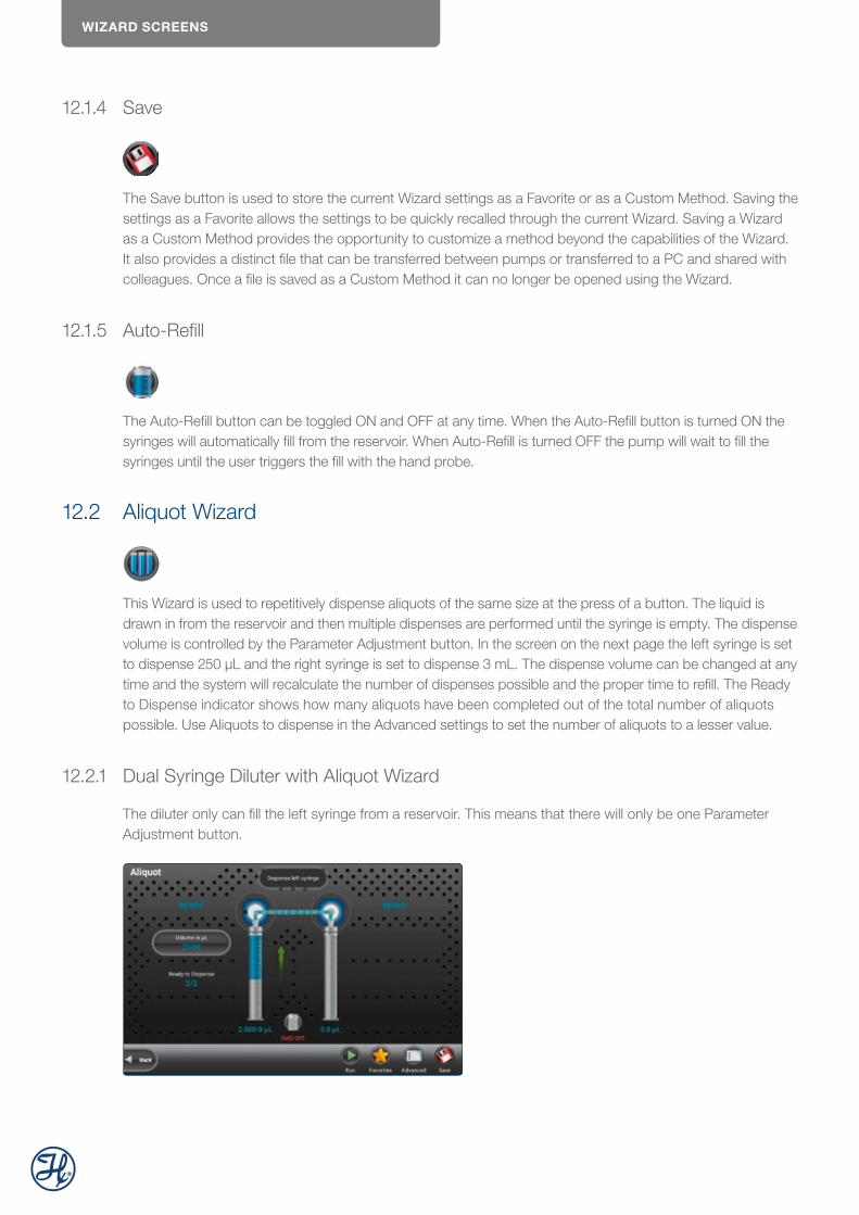
WIzARD SCREENS
12.1.4 Save
The Save button is used to store the current Wizard settings as a Favorite or as a Custom Method. Saving the settings as a Favorite allows the settings to be quickly recalled through the current Wizard. Saving a Wizard as a Custom Method provides the opportunity to customize a method beyond the capabilities of the Wizard. It also provides a distinct file that can be transferred between pumps or transferred to a PC and shared with colleagues. Once a file is saved as a Custom Method it can no longer be opened using the Wizard.
12.1.5 Auto-Refill
The Auto-Refill button can be toggled ON and OFF at any time. When the Auto-Refill button is turned ON the syringes will automatically fill from the reservoir. When Auto-Refill is turned OFF the pump will wait to fill the syringes until the user triggers the fill with the hand probe.
12.2 Aliquot Wizard
This Wizard is used to repetitively dispense aliquots of the same size at the press of a button. The liquid is drawn in from the reservoir and then multiple dispenses are performed until the syringe is empty. The dispense volume is controlled by the Parameter Adjustment button. In the screen on the next page the left syringe is set to dispense 250 µL and the right syringe is set to dispense 3 mL. The dispense volume can be changed at any time and the system will recalculate the number of dispenses possible and the proper time to refill. The Ready to Dispense indicator shows how many aliquots have been completed out of the total number of aliquots possible. Use Aliquots to dispense in the Advanced settings to set the number of aliquots to a lesser value.
12.2.1 Dual Syringe Diluter with Aliquot Wizard
The diluter only can fill the left syringe from a reservoir. This means that there will only be one Parameter Adjustment button.
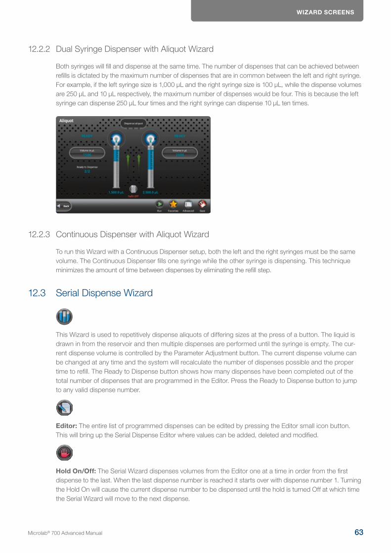
WIzARD SCREENS
12.2.2 Dual Syringe Dispenser with Aliquot Wizard
Both syringes will fill and dispense at the same time. The number of dispenses that can be achieved between refills is dictated by the maximum number of dispenses that are in common between the left and right syringe. For example, if the left syringe size is 1,000 µL and the right syringe size is 100 µL, while the dispense volumes are 250 µL and 10 µL respectively, the maximum number of dispenses would be four. This is because the left syringe can dispense 250 µL four times and the right syringe can dispense 10 µL ten times.
12.2.3 Continuous Dispenser with Aliquot Wizard
To run this Wizard with a Continuous Dispenser setup, both the left and the right syringes must be the same volume. The Continuous Dispenser fills one syringe while the other syringe is dispensing. This technique minimizes the amount of time between dispenses by eliminating the refill step.
12.3 Serial Dispense Wizard
This Wizard is used to repetitively dispense aliquots of differing sizes at the press of a button. The liquid is drawn in from the reservoir and then multiple dispenses are performed until the syringe is empty. The cur-rent dispense volume is controlled by the Parameter Adjustment button. The current dispense volume can be changed at any time and the system will recalculate the number of dispenses possible and the proper time to refill. The Ready to Dispense button shows how many dispenses have been completed out of the total number of dispenses that are programmed in the Editor. Press the Ready to Dispense button to jump to any valid dispense number.
Editor: The entire list of programmed dispenses can be edited by pressing the Editor small icon button. This will bring up the Serial Dispense Editor where values can be added, deleted and modified.
Hold On/Off: The Serial Wizard dispenses volumes from the Editor one at a time in order from the first dispense to the last. When the last dispense number is reached it starts over with dispense number 1. Turning the Hold On will cause the current dispense number to be dispensed until the hold is turned Off at which time the Serial Wizard will move to the next dispense.
Microlab® 700 Advanced Manual 63
WIzARD SCREENS
12.3.1 Dual Syringe Diluter with Serial Dispense Wizard
The diluter only can fill the left syringe from a reservoir. This means that there will only be one Parameter Adjustment button next to the left syringe for the Serial Wizard.
12.3.2 Dual Syringe Dispenser with Serial Dispense Wizard
Both syringes will fill and dispense at the same time.
12.3.3 Continuous Dispenser with Serial Dispense Wizard
To run this Wizard with a Continuous Dispenser setup both the left and the right syringes must be the same size. The Continuous Dispenser fills one syringe while the other syringe is dispensing. This technique minimizes the amount of time between dispenses by eliminating the refill step.
12.4 Dilution Wizard
This Wizard is used to dilute sample with diluent. The diluent is drawn in from the reservoir into the left syringe. The sample is aspirated into the hand probe by the left or right syringe depending on the programmed volume. Next, the sample and the diluent are dispensed out the hand probe into the destination vessel where the solu-tions are mixed. Since the sample was drawn into the hand probe last, it is dispensed first. The sample is then trailed by the diluent which washes out the hand probe tubing minimizing carryover for the next sample.

WIzARD SCREENS
A brief animation of «How a Microlab 700 Diluter Works» can be found at www.hamiltoncompany.com/microlab700
A dilution can be programmed using any two of the following parameters: sample volume, diluent volume, factor and total volume. These parameters are controlled by the Parameter Adjustment buttons. The current dilution can only be changed prior to aspirating sample.
Reset: Since the allowable sample volume and diluent volume are dependent on each other it may be neces-sary to reset all values to achieve the desired dilution. Pressing the Reset button will set all volumes to zero.
NOTE: To reduce carryover between samples, use an air gap to minimize mixing in the tubing. Additionally, ensure that the volume of the air gap and the sample does not exceed 80% of the volume in the dispense tubing so the sample does not get pulled into the syringes. Custom length tubing is available to increase the volume of the dispense tubing.
12.4.1 Dual Syringe Dispenser with Dilution Wizard
The syringes for this hardware setup behave independently. This means that only one syringe can be used with the Dilution Wizard. The syringe that is active can be selected in the Advanced menu.
12.4.2 Dual Syringe Diluter with Dilution Wizard
The Dilution Wizard was designed to enable large dilutions in a single step. Using a 50 mL syringe on the left it can fill with large volumes of diluent while a syringe as small as 10 µL on the right can accurately aspirate extremely small volumes of sample. Large dilutions in a single step will result in a savings of time and materials.
Microlab® 700 Advanced Manual 65

WIzARD SCREENS
12.4.3 Continuous Dispenser with Dilution Wizard
The Continuous Dispenser setup is not supported by the Dilution Wizard. The instrument can be reconfigured to a Dual Syringe Diluter setup in the software to run this Wizard without changing the hardware.
12.4.4 Disposable Tip Hand Probe with Dilution Wizard
The Disposable Tip Hand Probe (DTHP) is used when there are concerns of cross-contamination. The DTHP is designed to allow the user to aspirate samples into a tip that can be disposed, thus eliminating any potential cross-contamination. The tips that are used with this probe are the ClickSure® tips, for ordering information reference Appendix B in the Microlab 700 Basic User Manual (p/n 61440-01). When the DTHP is attached to the Microlab 700 instrument, the instrument will recognize that the probe is attached to the pump. This probe can then be configured to right or left-handedness by pressing Configuration from the Main Menu and then editing the setting within the hardware menu. Once the probe is configured the user may use the DTHP as described below.
When the DTHP is plugged into the Microlab 700 the Dilution Wizard will automatically pause between dispensing the sample and the diluent to allow for the tip to be ejected. The sample is aspirated into the ClickSure tip by the right syringe while the diluent is filled into the left syringe. Then the probe is triggered to dispense the sample. After the sample is dispensed the instrument will pause for tip ejection. Then the dilu-ent will be dispensed through the probe to complete the dilution.
NOTE: The sample is being aspirated by air displacement. The syringe will move the requested volume but the amount of liquid drawn into the tip depends on many factors like surface tension, viscosity, atmospheric pressure, humidity, density, etc. To achieve the highest possible accuracy it is recommended to check pipet-ted volume using a balance. If the accuracy is low or high adjust the requested sample volume to compensate for this expected variance.
12.5 Titration Wizard
This Wizard is used to slowly add liquid to another liquid until an endpoint is reached. An example of this application is an adding acid or base to change the pH of a buffer. This Wizard fills with liquid from a reservoir and then performs an initial dispense. This dispense is often larger than the step dispenses and is designed to get the user close to the endpoint without going over. Next, the step volume is added one at a time until the endpoint is reached. The Wizard will continually dispense the step volume and will refill the syringes if neces-sary. The total volume dispensed is tracked by the Total Volume Indicator.
Restart: Once the endpoint is reached the instrument can be reset for the next titration by pressing the Restart button to start the Wizard over.
WIzARD SCREENS
12.5.1 Dual Syringe Diluter with Titration Wizard
The diluter only has the ability to fill the left syringe from a reservoir.
12.5.2 Dual Syringe Dispenser with Aliquot Wizard
Both syringes will fill and dispense at the same time. If it is desired to turn one syringe Off it is possible to set the dispense volumes to zero.
12.5.3 Continuous Dispenser with Aliquot Wizard
The Continuous Dispenser setup will behave like a single syringe system except that one syringe will be filling while the other syringe is dispensing to minimize the time wasted during filling.
12.6 Pipette Wizard
This Wizard is used to transfer liquid from one vessel to the next. First the system must be primed with a system fluid. This is usually a liquid that is compatible with the liquid to be transferred like water or buffer. Next the liquid is aspirated into the hand probe by the left or right syringe depending on the instrument setup. The liquid is then dispensed from the hand probe into the destination vessel. If desired, an additional wash can be preformed between samples to ensure the fluid path is clean.
Microlab® 700 Advanced Manual 67
WIzARD SCREENS
NOTE: To reduce carryover between samples use an air gap to minimize mixing in the tubing. Additionally ensure that the volume of the air gap and the sample does not exceed 80% of the volume in the dispense tubing so the sample does not get pulled into the syringes. Custom length tubing is available to increase the volume of the dispense tubing.
12.6.1 Dual Syringe Diluter with Pipette Wizard
The Dual Syringe Diluter system can aspirate and dispense volume from the left or right syringe. This is set in the Advanced menu. If a wash is required, this must be programmed using the left syringe since the right syringe does not have the ability to draw liquid in from the reservoir.
12.6.2 Dual Syringe Dispenser with Pipette Wizard
This hardware setup is pictured above. The syringes for this hardware setup behave independently meaning that only one syringe can be used with the Pipette Wizard. The syringe that is active can be selected in the Advanced menu.
12.6.3 Continuous Dispenser with Pipette Wizard
The Continuous Dispenser setup is not supported by the Pipette Wizard. The instrument can be reconfigured to a Dual Syringe Diluter setup in the software to run this Wizard without changing the hardware.
WIzARD SCREENS
12.7 Dry Weight Dilution
This chapter provides description of Dry Weight Dilution wizard. The Dry Weight Dilution Wizard simplifies workflows in the preparation of analytical standards.
12.7.1 About this wizard
12.7.1.1 Standards
Reference samples, called standards, are required to determine the concentration of chemical compounds using highly sensitive quantitative analytical procedures. These standards have a defined concentration of one or several known compounds. It goes without saying that the concentration of these standards must be as accurate as possible to prevent subsequent errors in determining unknown concentrations in samples.
12.7.1.2 Preparation of Standards
The Dry Weight Dilution Wizard simplifies workflows in the preparation of analytical standards. Once the desired concentration of the components and the volume of the standard solution have been entered, the required amount of sample to be weighed is automatically calculated and the target weight is shown on the wizard main page. If the desired target weight is not achieved, the Dry Weight Dilution software will recalculate the required volume of solvent based on the actual weight determined. After the solvent has been added, the weight of sample is again measured gravimetrically. At the end of this procedure, the application software calculates the exact concentration of standard solution from the weights of component and the volume of solvent. A final report according to GxP is generated for every dilution process.
12.7.1.3 System Integration of a Precision Balance
The Dry Weight Dilution process requires to work with the Microlab 700 pump together with a precision balance. The Dry Weight Dilution wizard allows manual and automatic input of weights. The user can connect a balance to the Microlab 700 Premium controller via COM1 interface. The supported balance models can be browsed and selected in the Communication settings of Microlab 700 controller.
Microlab® 700 Advanced Manual 69
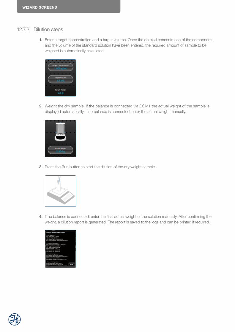
WIzARD SCREENS
12.7.2 Dilution steps
1. Enter a target concentration and a target volume. Once the desired concentration of the components and the volume of the standard solution have been entered, the required amount of sample to be weighed is automatically calculated.
2. Weight the dry sample. If the balance is connected via COM1 the actual weight of the sample is displayed automatically. If no balance is connected, enter the actual weight manually.
3. Press the Run button to start the dilution of the dry weight sample.
4. If no balance is connected, enter the final actual weight of the solution manually. After confirming the weight, a dilution report is generated. The report is saved to the logs and can be printed if required.
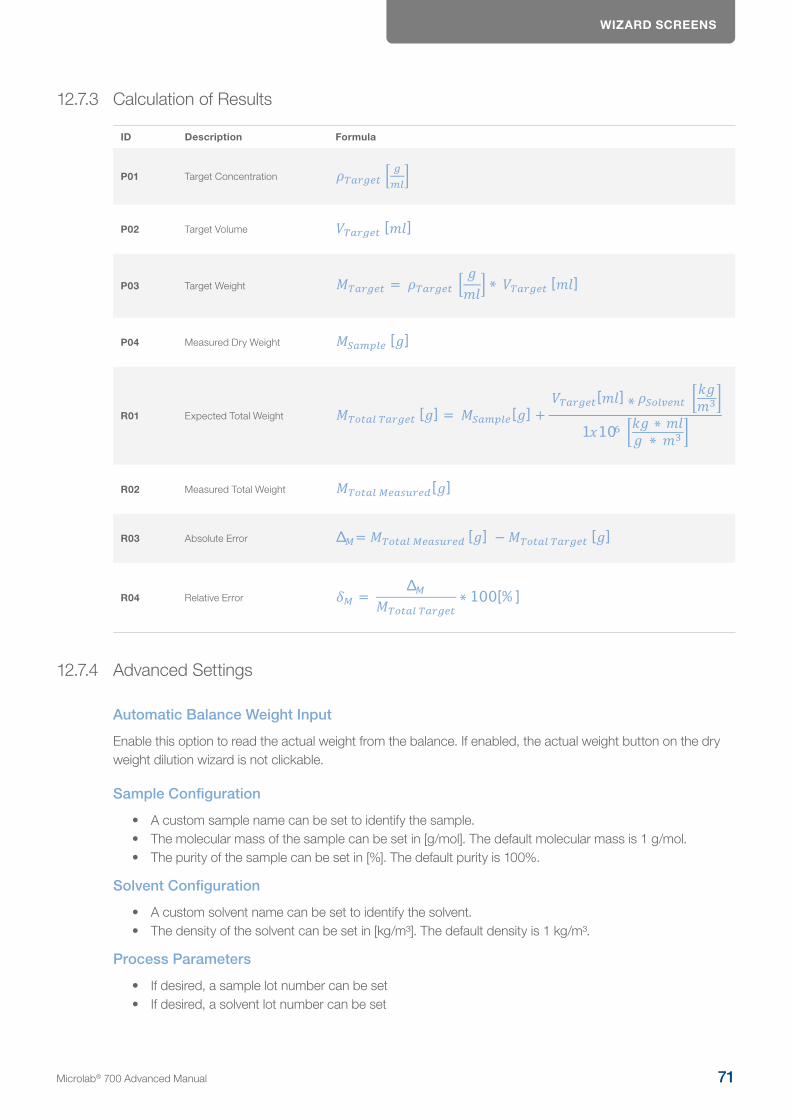
WIzARD SCREENS
12.7.3 Calculation of Results
ID Description Formula
P01 Target Concentration
P02 Target Volume
P03 Target Weight
P04 Measured Dry Weight
R01 Expected Total Weight
R02 Measured Total Weight
R03 Absolute Error
R04 Relative Error
12.7.4 Advanced Settings
Automatic Balance Weight Input
Enable this option to read the actual weight from the balance. If enabled, the actual weight button on the dry weight dilution wizard is not clickable.
Sample Configuration
• A custom sample name can be set to identify the sample. • The molecular mass of the sample can be set in [g/mol]. The default molecular mass is 1 g/mol. • The purity of the sample can be set in [%]. The default purity is 100%.
Solvent Configuration
• A custom solvent name can be set to identify the solvent.• The density of the solvent can be set in [kg/m³]. The default density is 1 kg/m³.
Process Parameters
• If desired, a sample lot number can be set• If desired, a solvent lot number can be set
Microlab® 700 Advanced Manual 71
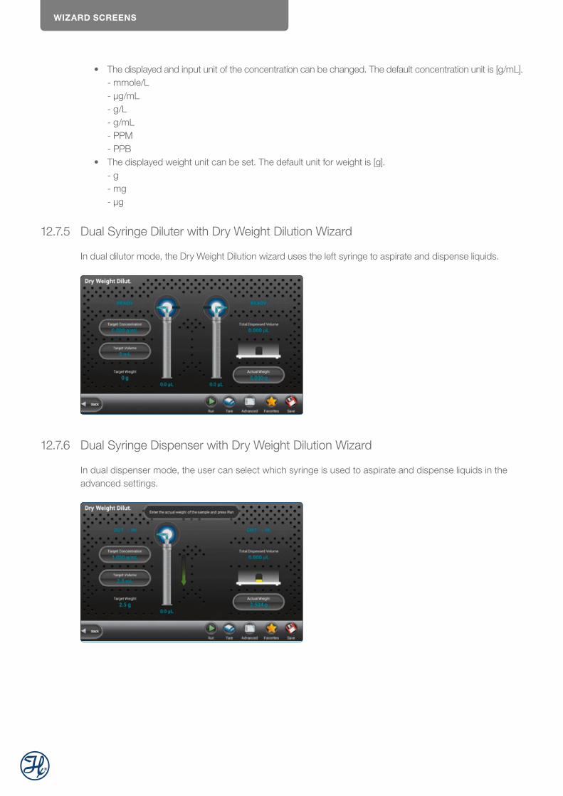
WIzARD SCREENS
• The displayed and input unit of the concentration can be changed. The default concentration unit is [g/mL]. - mmole/L - µg/mL - g/L - g/mL - PPM - PPB
• The displayed weight unit can be set. The default unit for weight is [g]. - g - mg - µg
12.7.5 Dual Syringe Diluter with Dry Weight Dilution Wizard
In dual dilutor mode, the Dry Weight Dilution wizard uses the left syringe to aspirate and dispense liquids.
12.7.6 Dual Syringe Dispenser with Dry Weight Dilution Wizard
In dual dispenser mode, the user can select which syringe is used to aspirate and dispense liquids in the advanced settings.

CUSTOM METHODS
12.7.7 Continuous Dispenser with Dry Weight Dilution Wizard
In continuous dispenser mode, both syringes are used to dilute the dry weight.
12.8 New Wizards
The Microlab 700 instrument comes with a set of standard Wizards which include Aliquot, Serial Dispense, Dilution, Titration, Pipette, Dry Weight Dilution. As new Wizards are developed, they will be available after performing a software update in Utilities section and installed after download.
13 Custom Methods
This chapter will enable users to create, run and edit Custom Methods. This chapter includes a discussion of the following topics:
13.1 Creating or Selecting a Custom Method
From the Main Menu screen, press the Custom Methods button. This will open the method selector screen. This screen displays all the Custom Methods that are stored on the local memory. To Run or Edit a method simply click on the corresponding button in the same row. If the user choses to create a new method or folder then they may press the New button and select the option that is applicable.
Microlab® 700 Advanced Manual 73

CUSTOM METHODS
Run
Press this button to trigger the steps in the Custom Method.
Edit
Press this button to edit an existing Custom Method.
New
Press this button to create a new Custom Method or Folder.
Duplicate
Press this button to duplicate a Custom Method.
Delete
Press this button to delete a Custom Method.
Print label
Press this button to print label on label printer that can be later scanned to open method immediately.
Save custom method
This option allows user to save custom method to LyncStore account or to any external storage that can later be moved to different device or same device in case of unintended deletion.
Import
This option allows users to import custom method either from cloud or from external removable storage.
13.1.1 Import and export
Custom methods are an essential part of the workflow with Microlab 700 device and therefore we understand that users require a way to backup and share their custom methods. We provide two options for storage of custom methods:
1. LyncStore 2. Local Backup
LyncStore requires to login into LyncStore account from the device (this is described in more detail in chapter 12.7). After that, user can upload custom method and link it to account.

CUSTOM METHODS
Just press the button and user will be presented with dialog like this:
If LyncStore is picker, device should be connected to the internet. If it is, the app will upload custom method with all steps and settings to the cloud.
After this, click icon and select the «LyncStore 700» option. User will be presented with a popup like this:
Where user can select one of exported custom methods and download them directly to list. From this screen user can also remove exported custom method (WARNING: this action is destructive and irreversible).
Local backup and restore works similarly, just insert SD Card or USB stick and user can export data for sharing or later restore.
13.2 Edit a Custom Method
This section describes how to edit a Custom Method. First navigate to an existing method or create a new method as described in Section 13.1. Press on the Edit button that is in the same row with the Custom Method wished to edit. The method editor will display all the steps that have been added to the method. Each row in the table represents a unique step in the method. The details of these steps dictate how the syringes, valves,
Microlab® 700 Advanced Manual 75
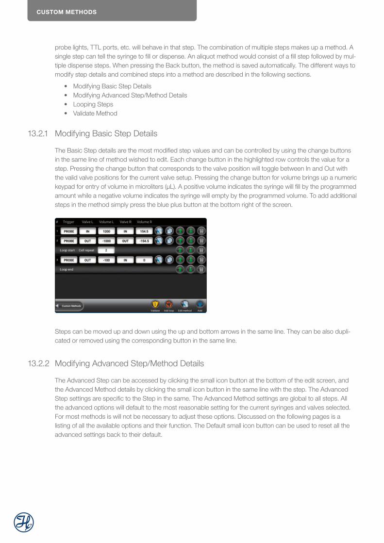
CUSTOM METHODS
probe lights, TTL ports, etc. will behave in that step. The combination of multiple steps makes up a method. A single step can tell the syringe to fill or dispense. An aliquot method would consist of a fill step followed by mul-tiple dispense steps. When pressing the Back button, the method is saved automatically. The different ways to modify step details and combined steps into a method are described in the following sections.
• Modifying Basic Step Details • Modifying Advanced Step/Method Details • Looping Steps • Validate Method
13.2.1 Modifying Basic Step Details
The Basic Step details are the most modified step values and can be controlled by using the change buttons in the same line of method wished to edit. Each change button in the highlighted row controls the value for a step. Pressing the change button that corresponds to the valve position will toggle between In and Out with the valid valve positions for the current valve setup. Pressing the change button for volume brings up a numeric keypad for entry of volume in microliters (µL). A positive volume indicates the syringe will fill by the programmed amount while a negative volume indicates the syringe will empty by the programmed volume. To add additional steps in the method simply press the blue plus button at the bottom right of the screen.
Steps can be moved up and down using the up and bottom arrows in the same line. They can be also dupli-cated or removed using the corresponding button in the same line.
13.2.2 Modifying Advanced Step/Method Details
The Advanced Step can be accessed by clicking the small icon button at the bottom of the edit screen, and the Advanced Method details by clicking the small icon button in the same line with the step. The Advanced Step settings are specific to the Step in the same. The Advanced Method settings are global to all steps. All the advanced options will default to the most reasonable setting for the current syringes and valves selected. For most methods is will not be necessary to adjust these options. Discussed on the following pages is a listing of all the available options and their function. The Default small icon button can be used to reset all the advanced settings back to their default.

CUSTOM METHODS
Syringe Speeds
This will be set to the speed saved in the instrument configuration. If the speed is to be changed, only valid speed values will be allowed. Three suggested speed options will be proposed along with the option to choose a custom speed. If the liquid is viscous or a custom speed is chosen that is faster than the default, there is a risk of the syringe stalling. All speeds are measured in µL/sec.
Command Delay
his is the delay between the completion of one step and the start of the next step. Optional values are between 1 and 3, 700 seconds. The default will be to have no delay, so the commands execute as quickly as possible.
Syringe Delay
For some applications it is required to start moving one syringe while the other syringe is still moving. Since the pump ignores all new commands until the previous command is completed it is necessary to use the Syringe Delay for this purpose. Optional values are between 1 and 3, 700 seconds. The default will be to have no delay so that both syringes start moving at the same time.
Run Once
This may be toggled to either On or Off. A setting On means that the step will only be executed the first time through the method. The next time through the method this step will be skipped. Steps with an On setting cannot follow an Off setting, which means that the On steps must be grouped together at the beginning of a method. The default for this setting will be Off.
Counters
The Counter will increment for the selected step each time it is executed in the method. There are six unique counters, so it is possible to keep track of up to six different metrics. The valid options are 1 through 6 but the default for the Counter is Off.
Trigger Side
This will allow the user to select which side of the instrument the pump may be triggered from in each step. The options are Either, Left or Right. The pump default setting will be Either.
Valve Rotation
This allows the user to set the rotation to Shortest, clockwise (CW) or counterclockwise (CCW). The default setting will be Shortest.
Microlab® 700 Advanced Manual 77
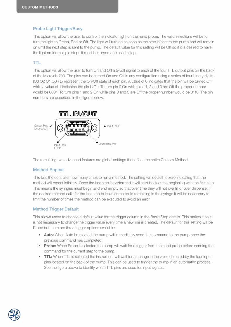
CUSTOM METHODS
Probe Light Trigger/Busy
This option will allow the user to control the indicator light on the hand probe. The valid selections will be to turn the light to Green, Red or Off. The light will turn on as soon as the step is sent to the pump and will remain on until the next step is sent to the pump. The default value for this setting will be Off so if it is desired to have the light on for multiple steps it must be turned on in each step.
TTL
This option will allow the user to turn On and Off a 5-volt signal to each of the four TTL output pins on the back of the Microlab 700. The pins can be turned On and Off in any configuration using a series of four binary digits (O3 O2 O1 O0 ) to represent the On/Off state of each pin. A value of 0 indicates that the pin will be turned Off while a value of 1 indicates the pin is On. To turn pin 0 On while pins 1, 2 and 3 are Off the proper number would be 0001. To turn pins 1 and 2 On while pins 0 and 3 are Off the proper number would be 0110. The pin numbers are described in the figure bellow.
Output Pins(O0O1O2O3)
Input Pin I0
Grounding PinInput Pins(I1 I2 I3)
The remaining two advanced features are global settings that affect the entire Custom Method.
Method Repeat
This tells the controller how many times to run a method. The setting will default to zero indicating that the method will repeat infinitely. Once the last step is performed it will start back at the beginning with the first step. This means the syringes must begin and end empty so that over time they will not overfill or over dispense. If the desired method calls for the last step to leave some liquid remaining in the syringe it will be necessary to limit the number of times the method can be executed to avoid an error.
Method Trigger Default
This allows users to choose a default value for the trigger column in the Basic Step details. This makes it so it is not necessary to change the trigger value every time a new line is created. The default for this setting will be Probe but there are three trigger options available:
• Auto: When Auto is selected the pump will immediately send the command to the pump once the previous command has completed.
• Probe: When Probe is selected the pump will wait for a trigger from the hand probe before sending the command for the current step to the pump.
• TTL: When TTL is selected the instrument will wait for a change in the value detected by the four input pins located on the back of the pump. This can be used to trigger the pump in an automated process. See the figure above to identify which TTL pins are used for input signals.
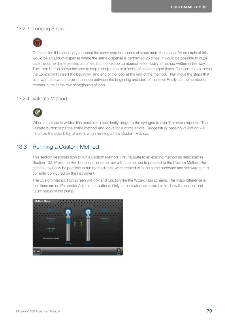
CUSTOM METHODS
13.2.3 Looping Steps
On occasion it is necessary to repeat the same step or a series of steps more than once. An example of this would be an aliquot dispense where the same dispense is performed 25 times. It would be possible to dupli-cate the same dispense step 25 times, but it could be cumbersome to modify a method written in this way. The Loop button allows the user to loop a single step or a series of steps multiple times. To insert a loop, press the Loop icon to insert the beginning and end of the loop at the end of the method. Then move the steps that user wants between to be in the loop between the beginning and start of the loop. Finally set the number of repeats in the same row of beginning of loop.
13.2.4 Validate Method
When a method is written it is possible to accidently program the syringes to overfill or over dispense. The validate button tests the entire method and looks for runtime errors. Successfully passing validation will minimize the possibility of errors when running a new Custom Method.
13.3 Running a Custom Method
This section describes how to run a Custom Method. First navigate to an existing method as described in Section 13.1. Press the Run button in the same row with the method to proceed to the Custom Method Run screen. It will only be possible to run methods that were created with the same hardware and software that is currently configured on the instrument.
The Custom Method Run screen will look and function like the Wizard Run screens. The major difference is that there are no Parameter Adjustment buttons. Only the indicators are available to show the current and future status of the pump.
Microlab® 700 Advanced Manual 79
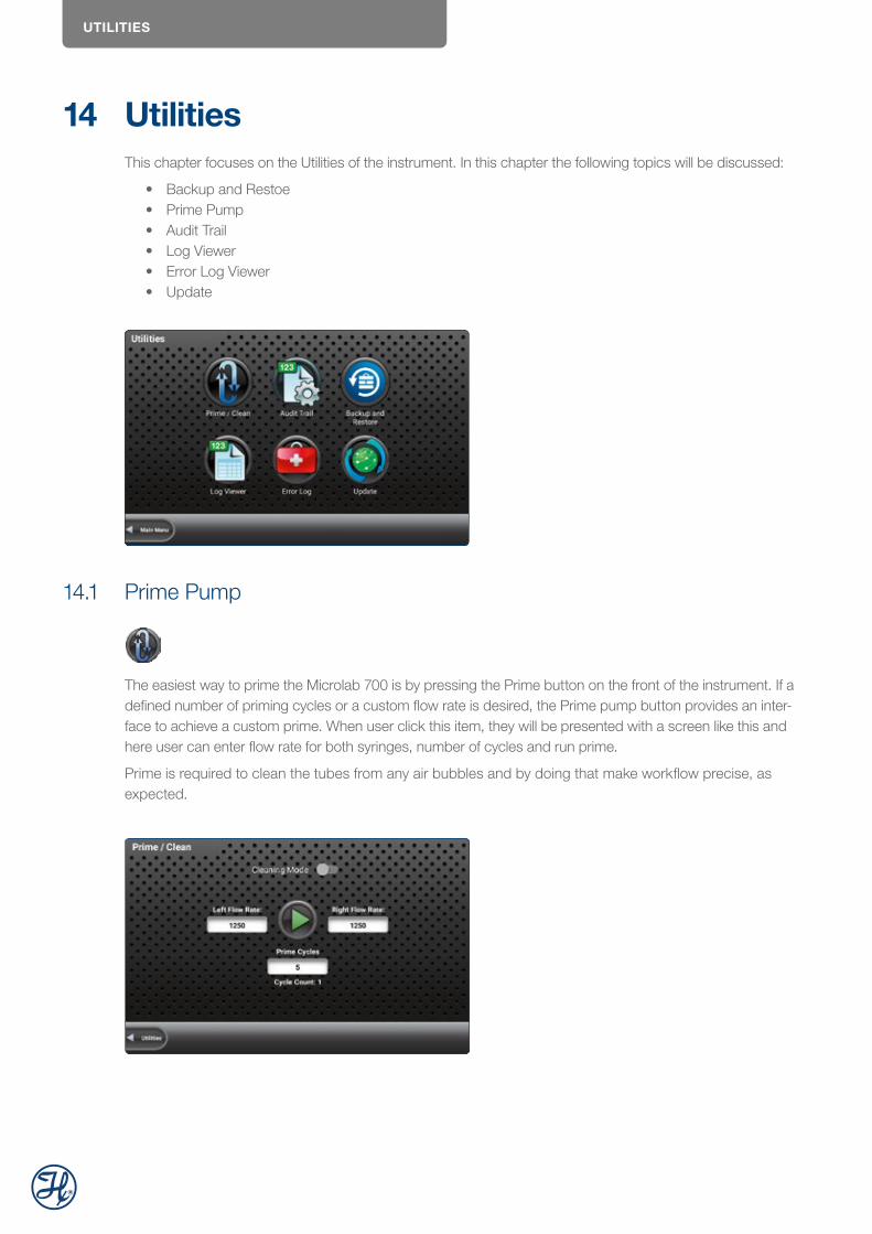
UTILITIES
14 UtilitiesThis chapter focuses on the Utilities of the instrument. In this chapter the following topics will be discussed:
• Backup and Restoe• Prime Pump • Audit Trail • Log Viewer • Error Log Viewer• Update
14.1 Prime Pump
The easiest way to prime the Microlab 700 is by pressing the Prime button on the front of the instrument. If a defined number of priming cycles or a custom flow rate is desired, the Prime pump button provides an inter-face to achieve a custom prime. When user click this item, they will be presented with a screen like this and here user can enter flow rate for both syringes, number of cycles and run prime.
Prime is required to clean the tubes from any air bubbles and by doing that make workflow precise, as expected.

UTILITIES
14.2 Audit Trail
In audit trail, it is possible to see the history of critical changes. It shows events and their time stamps. More details are shown, once clicked on one of the events in the list: Event ID, Device ID, Original Value, New Value, Comment. Audit trail event is created whenever user changes any setting in the app or do any creative or destructive action.
It is possible to export audit trail. The app will create files on every external storage device, and user can transfer data.
14.3 Backup and Restore
Backup Database to External Storage
To perform a complete backup of the internal database of the controller press the backup to removable storage icon. Insert a USB stick or micro SD card into the controller before performing a backup. For regulated customers requiring 21 CFR Part 11 compliance, the backup is encrypted and can only be decrypted by the same controller that generated the backup file. For data protection reasons, the backup cannot be edited or used for other controllers.
Restore Database from External Storage
The controller can perform a restore of a previous database backup. This function is useful after an update failed for any reason. For regulated customers requiring 21 CFR Part 11 compliance, only backups that are generated by the same controller can be restored. Only the main administrator can perform a restore.
Microlab® 700 Advanced Manual 81
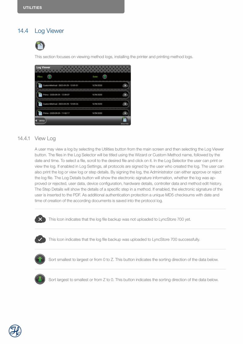
UTILITIES
14.4 Log Viewer
This section focuses on viewing method logs, installing the printer and printing method logs.
14.4.1 View Log
A user may view a log by selecting the Utilities button from the main screen and then selecting the Log Viewer button. The files in the Log Selector will be titled using the Wizard or Custom Method name, followed by the date and time. To select a file, scroll to the desired file and click on it. In the Log Selector the user can print or view the log. If enabled in Log Settings, all protocols are signed by the user who created the log. The user can also print the log or view log or step details. By signing the log, the Administrator can either approve or reject the log file. The Log Details button will show the electronic signature information, whether the log was ap-proved or rejected, user data, device configuration, hardware details, controller data and method edit history. The Step Details will show the details of a specific step in a method. If enabled, the electronic signature of the user is inserted to the PDF. As additional authentication protection a unique MD5 checksums with date and time of creation of the according documents is saved into the protocol log.
This Icon indicates that the log file backup was not uploaded to LyncStore 700 yet.
This Icon indicates that the log file backup was uploaded to LyncStore 700 successfully.
Sort smallest to largest or from 0 to Z. This button indicates the sorting direction of the data below.
Sort largest to smallest or from Z to 0. This button indicates the sorting direction of the data below.
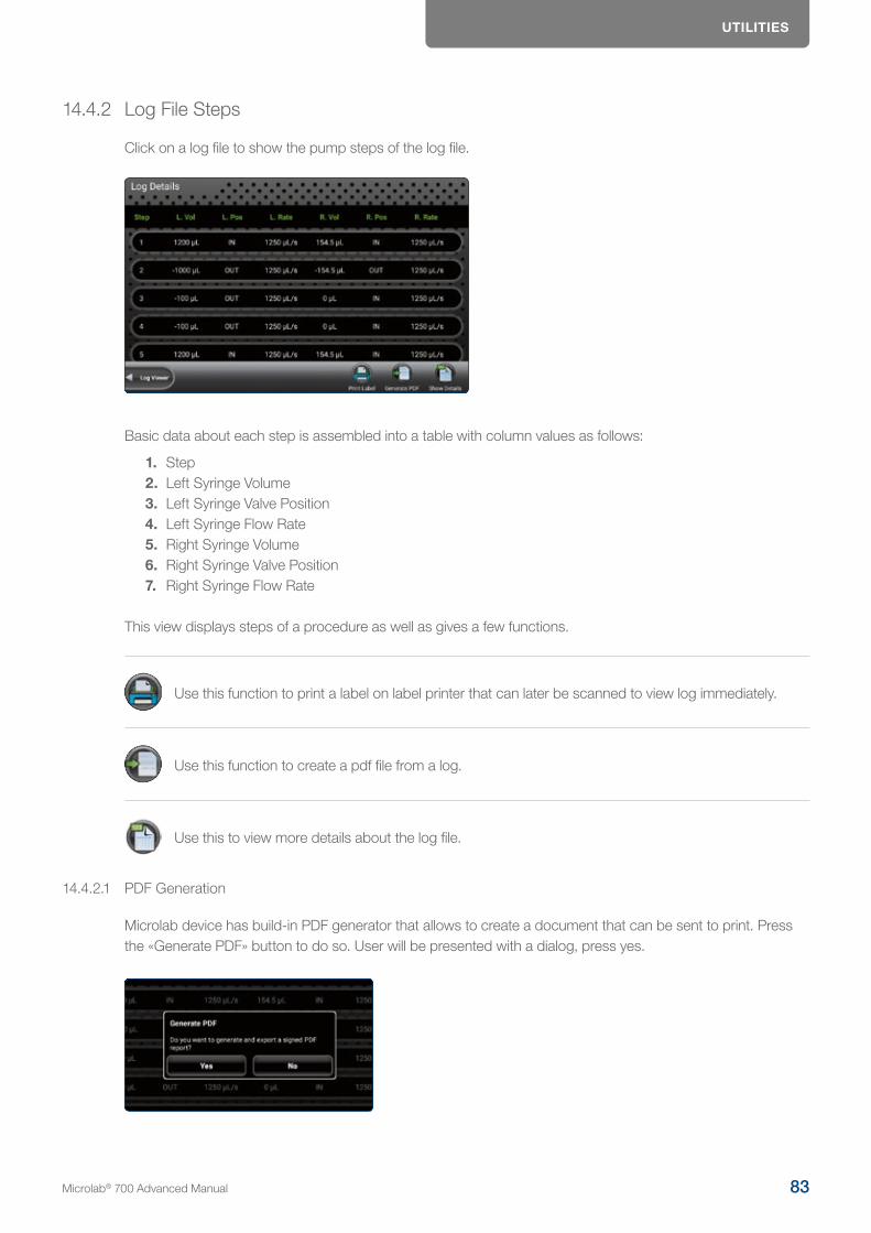
UTILITIES
14.4.2 Log File Steps
Click on a log file to show the pump steps of the log file.
Basic data about each step is assembled into a table with column values as follows:
1. Step2. Left Syringe Volume3. Left Syringe Valve Position4. Left Syringe Flow Rate5. Right Syringe Volume6. Right Syringe Valve Position7. Right Syringe Flow Rate
This view displays steps of a procedure as well as gives a few functions.
Use this function to print a label on label printer that can later be scanned to view log immediately.
Use this function to create a pdf file from a log.
Use this to view more details about the log file.
14.4.2.1 PDF Generation
Microlab device has build-in PDF generator that allows to create a document that can be sent to print. Press the «Generate PDF» button to do so. User will be presented with a dialog, press yes.
Microlab® 700 Advanced Manual 83
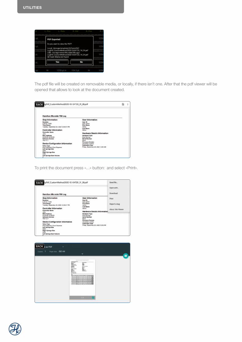
UTILITIES
The pdf file will be created on removable media, or locally, if there isn’t one. After that the pdf viewer will be opened that allows to look at the document created.
To print the document press «…» button: and select «Print».
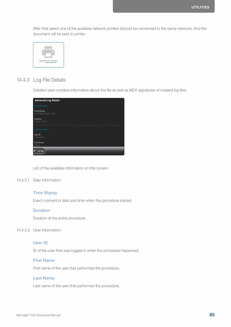
UTILITIES
After that select one of the available network printers (should be connected to the same network). And the document will be sent to printer.
14.4.3 Log File Details
Detailed view contains information about the file as well as MD5 signatures of created log files.
List of the available information on this screen:
14.4.3.1 Step Information
Time Stamp
Exact moment in date and time when the procedure started
Duration
Duration of the entire procedure.
14.4.3.2 User Information
User ID
ID of the user that was logged in when the procedure happened.
First Name
First name of the user that performed the procedure.
Last Name
Last name of the user that performed the procedure.
Microlab® 700 Advanced Manual 85

UTILITIES
14.4.3.3 Controller Information
Name
Name of the user at the time of the procedure. Can be changed in Configuration-Log Settings.
MAC Address
LAN1 MAC address of the device.
Software Version
Version of the Microlab 700 controller.
14.4.3.4 Hardware Information
Type
Indicates type of the hardware: either single or dual syringe configuration.
Serial Number
Serial Number of the device.
Pump ID
ID number of the base unit.
Firmware Version
Firmware version of the Base unit.
Calibration Date
Latest calibration date.
14.4.3.5 Device Configuration
Valve Type
Valve type of the device.
Left Syringe Size
Left syringe size configuration.
Right Syringe Size
Right syringe size configuration.
Left Syringe Start Volume
Volume inside left syringe at the start of the procedure.
Right Syringe Start Volume
Volume inside right syringe at the start of the procedure.
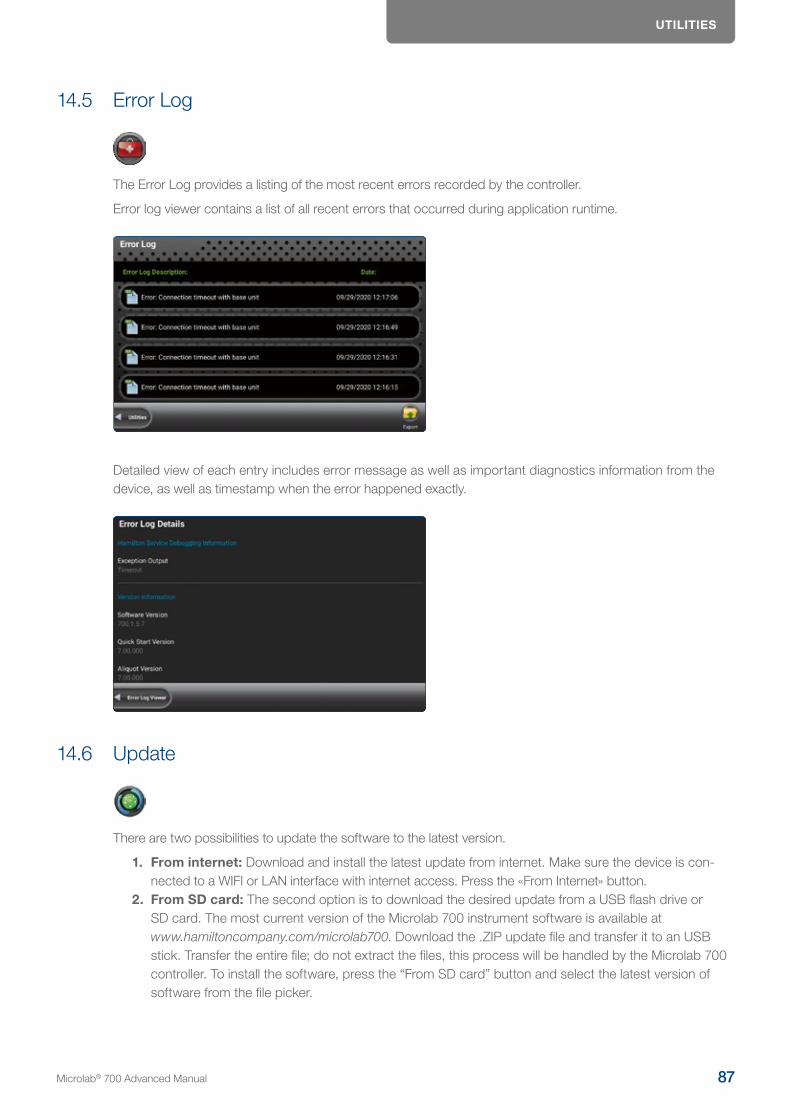
UTILITIES
14.5 Error Log
The Error Log provides a listing of the most recent errors recorded by the controller.
Error log viewer contains a list of all recent errors that occurred during application runtime.
Detailed view of each entry includes error message as well as important diagnostics information from the device, as well as timestamp when the error happened exactly.
14.6 Update
There are two possibilities to update the software to the latest version.
1. From internet: Download and install the latest update from internet. Make sure the device is con-nected to a WIFI or LAN interface with internet access. Press the «From Internet» button.
2. From SD card: The second option is to download the desired update from a USB flash drive or SD card. The most current version of the Microlab 700 instrument software is available at www.hamiltoncompany.com/microlab700. Download the .ZIP update file and transfer it to an USB stick. Transfer the entire file; do not extract the files, this process will be handled by the Microlab 700 controller. To install the software, press the “From SD card” button and select the latest version of software from the file picker.
Microlab® 700 Advanced Manual 87

HELP MENU
If the Microlab 700 instrument is connected to internet, and update notifications are enabled, the instrument will notify the user about new updates.
NOTE: It is recommended to perform a manual full encrypted data backup of the Microlab 700 instrument. To create a backup file, insert a USB flash drive or SD card and select the backup option in Log Settings.
15 Help menuThe help menu contains following options:
1. Send email to Hamilton service2. Read and browse the user manual3. Start a remote support session4. Watch tutorial videos
15.1 Send Email
Send email feature allows users to ask device related questions via email and get a reponse to LyncStore linked email.
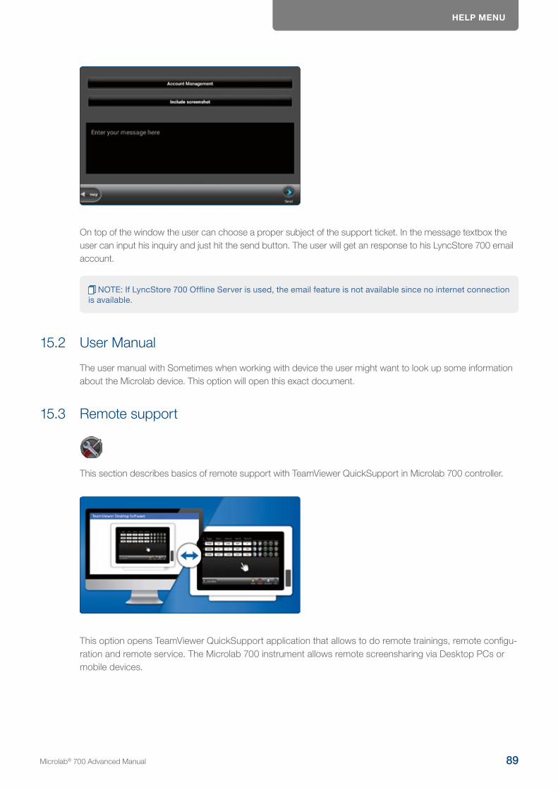
HELP MENU
On top of the window the user can choose a proper subject of the support ticket. In the message textbox the user can input his inquiry and just hit the send button. The user will get an response to his LyncStore 700 email account.
NOTE: If LyncStore 700 Offline Server is used, the email feature is not available since no internet connection is available.
15.2 User Manual
The user manual with Sometimes when working with device the user might want to look up some information about the Microlab device. This option will open this exact document.
15.3 Remote support
This section describes basics of remote support with TeamViewer QuickSupport in Microlab 700 controller.
This option opens TeamViewer QuickSupport application that allows to do remote trainings, remote configu-ration and remote service. The Microlab 700 instrument allows remote screensharing via Desktop PCs or mobile devices.
Microlab® 700 Advanced Manual 89
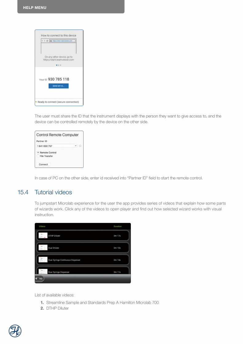
HELP MENU
The user must share the ID that the instrument displays with the person they want to give access to, and the device can be controlled remotely by the device on the other side.
In case of PC on the other side, enter id received into “Partner ID” field to start the remote control.
15.4 Tutorial videos
To jumpstart Microlab experience for the user the app provides series of videos that explain how some parts of wizards work. Click any of the videos to open player and find out how selected wizard works with visual instruction.
List of available videos:
1. Streamline Sample and Standards Prep A Hamilton Microlab 7002. DTHP Diluter

QUICK ACCESS
3. Dual Diluter4. Dual Dispenser5. Dual Syringe Continuous Dispenser6. Dual Syringe Dispenser7. Single Dispenser
Video 1 explains benefits of Microlab device. Videos 2-7 visualize wizards.
16 Quick AccessDirectly in the toolbar of the main menu the user has three quick access options:
1. Scan custom method label2. Scan log file label3. Load favorite
16.1 Scan Custom Method Label
Every custom method has a unique database identifier. A tracing label with this identifier can be printed in the custom method menu. A label printer and barcode scanner is required to print and scan tracing labels.
Microlab® 700 Advanced Manual 91
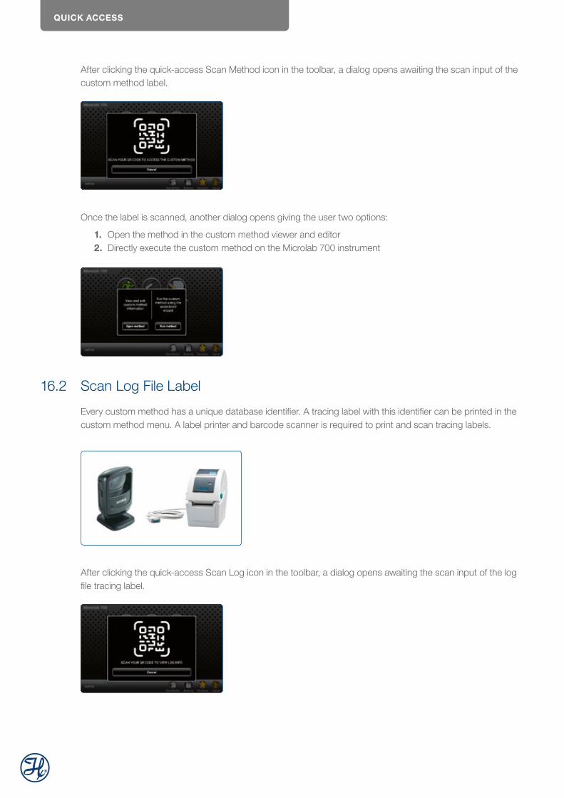
QUICK ACCESS
After clicking the quick-access Scan Method icon in the toolbar, a dialog opens awaiting the scan input of the custom method label.
Once the label is scanned, another dialog opens giving the user two options:
1. Open the method in the custom method viewer and editor2. Directly execute the custom method on the Microlab 700 instrument
16.2 Scan Log File Label
Every custom method has a unique database identifier. A tracing label with this identifier can be printed in the custom method menu. A label printer and barcode scanner is required to print and scan tracing labels.
After clicking the quick-access Scan Log icon in the toolbar, a dialog opens awaiting the scan input of the log file tracing label.
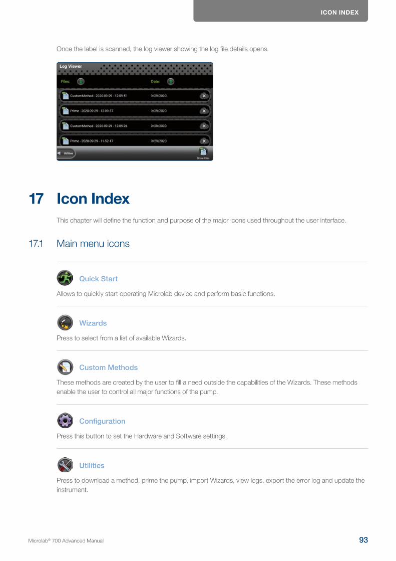
ICON INDEX
Once the label is scanned, the log viewer showing the log file details opens.
17 Icon IndexThis chapter will define the function and purpose of the major icons used throughout the user interface.
17.1 Main menu icons
Quick Start
Allows to quickly start operating Microlab device and perform basic functions.
Wizards
Press to select from a list of available Wizards.
Custom Methods
These methods are created by the user to fill a need outside the capabilities of the Wizards. These methods enable the user to control all major functions of the pump.
Configuration
Press this button to set the Hardware and Software settings.
Utilities
Press to download a method, prime the pump, import Wizards, view logs, export the error log and update the instrument.
Microlab® 700 Advanced Manual 93
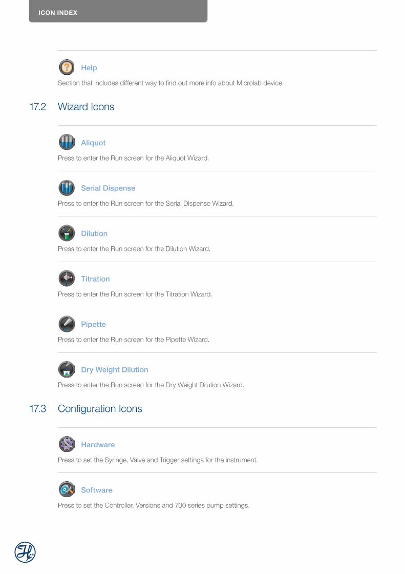
ICON INDEX
Help
Section that includes different way to find out more info about Microlab device.
17.2 Wizard Icons
Aliquot
Press to enter the Run screen for the Aliquot Wizard.
Serial Dispense
Press to enter the Run screen for the Serial Dispense Wizard.
Dilution
Press to enter the Run screen for the Dilution Wizard.
Titration
Press to enter the Run screen for the Titration Wizard.
Pipette
Press to enter the Run screen for the Pipette Wizard.
Dry Weight Dilution
Press to enter the Run screen for the Dry Weight Dilution Wizard.
17.3 Configuration Icons
Hardware
Press to set the Syringe, Valve and Trigger settings for the instrument.
Software
Press to set the Controller, Versions and 700 series pump settings.
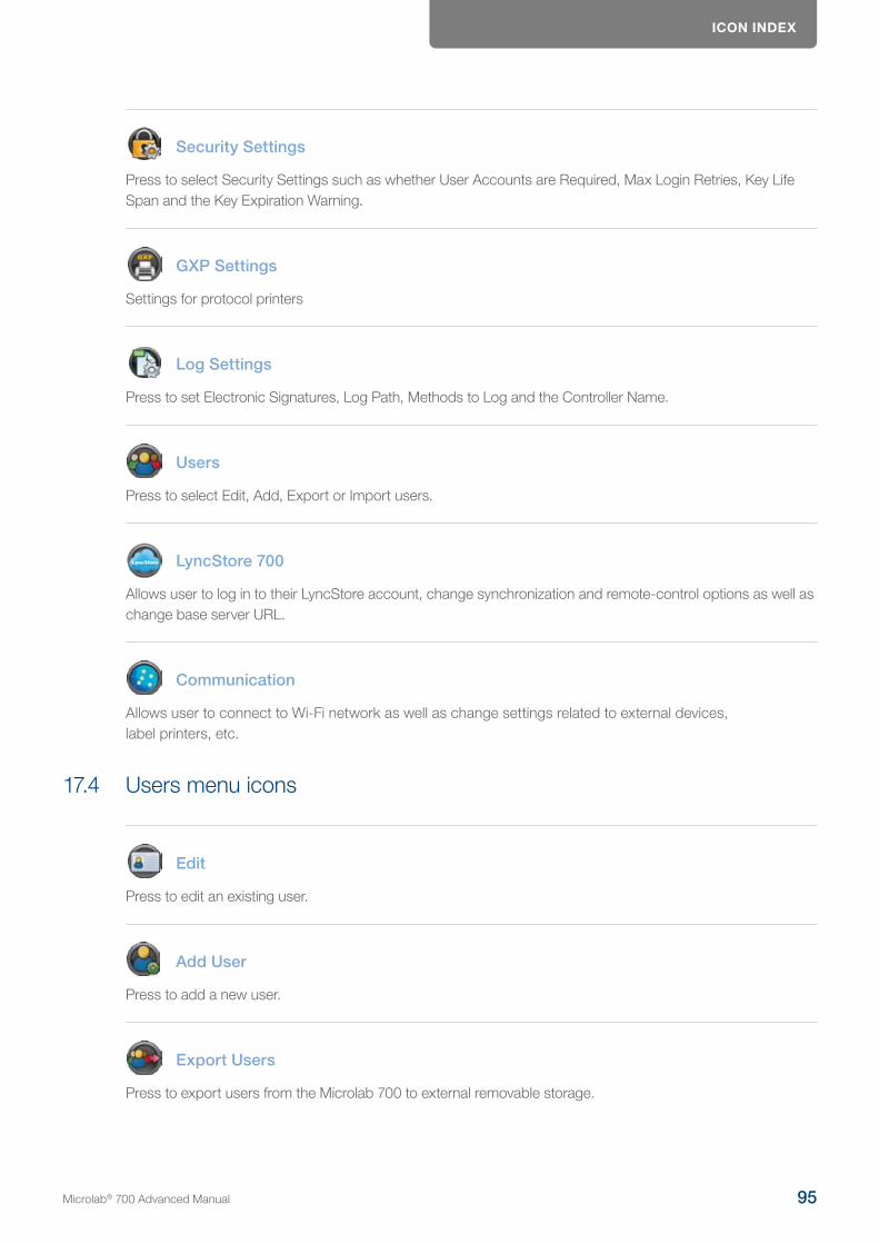
ICON INDEX
Security Settings
Press to select Security Settings such as whether User Accounts are Required, Max Login Retries, Key Life Span and the Key Expiration Warning.
GXP Settings
Settings for protocol printers
Log Settings
Press to set Electronic Signatures, Log Path, Methods to Log and the Controller Name.
Users
Press to select Edit, Add, Export or Import users.
LyncStore 700
Allows user to log in to their LyncStore account, change synchronization and remote-control options as well as change base server URL.
Communication
Allows user to connect to Wi-Fi network as well as change settings related to external devices, label printers, etc.
17.4 Users menu icons
Edit
Press to edit an existing user.
Add User
Press to add a new user.
Export Users
Press to export users from the Microlab 700 to external removable storage.
Microlab® 700 Advanced Manual 95

ICON INDEX
Import Users
Press to import users from a different Microlab 700 by using external removable storage.
17.5 Utilities Menu Icons
Prime
Press to set the number of prime cycles as well as the flow rate of the prime.
Audit trail
Allows user to view all the constructive and destructive events as well as changes in settings in Microlab Device.
Log Viewer
Press to view and print logged methods.
Error Log
Press to download the Error Log from the pump onto the SD card or USB flash drive.
Update
Press this button to update the current Microlab 700 software to the version that is present on the SD card or USB flash drive.
17.6 Main Menu Toolbar Icon Buttons
Logout
Logout from current account (only if user management is enabled).
Scan method
Use this to scan label printed for specific custom method to open it.
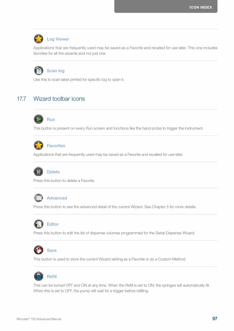
ICON INDEX
Log Viewer
Applications that are frequently used may be saved as a Favorite and recalled for use later. This one includes favorites for all the wizards and not just one.
Scan log
Use this to scan label printed for specific log to open it.
17.7 Wizard toolbar icons
Run
This button is present on every Run screen and functions like the hand probe to trigger the instrument.
Favorites
Applications that are frequently used may be saved as a Favorite and recalled for use later.
Delete
Press this button to delete a Favorite.
Advanced
Press this button to see the advanced detail of the current Wizard. See Chapter 5 for more details.
Editor
Press this button to edit the list of dispense volumes programmed for the Serial Dispense Wizard.
Save
This button is used to store the current Wizard setting as a Favorite or as a Custom Method.
Refill
This can be turned OFF and ON at any time. When the Refill is set to ON; the syringes will automatically fill. When this is set to OFF, the pump will wait for a trigger before refilling.
Microlab® 700 Advanced Manual 97
ICON INDEX
Hold
Press the Hold button in the Serial Dispense Wizard to repeat the current dispense. After the Hold button is turned Off the Serial Dispense Wizard will continue to the next dispense.
Used to print label for custom method or log that can be later used to quickly go to this entry.
Hold
Hold is ON
Up
Press this button to move a line up in the Serial Dispense Wizard Editor.
Down
Press this button to move a line down in the Serial Dispense Wizard Editor.
Duplicate
Press this button to duplicate a line in the Serial Dispense Wizard Editor.
Remove
Press this button to delete a line in the Serial Dispense Wizard Editor.
Add Step
Press this button to add a line in the Serial Dispense Wizard Editor.
Reset
Press to set all volumes in the Dilution Wizard to zero. Since the valid values for some dilutions settings are related, a reset may be required to program the desired dilution.
Restart
Press this button in the Titration Wizard once the endpoint is reached to start the next titration. The volume counter will reset to zero and the Wizard will start again with the initial dispense.
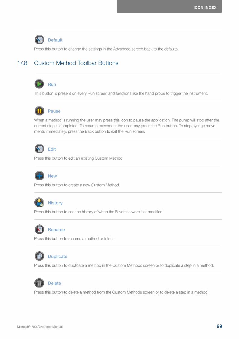
ICON INDEX
Default
Press this button to change the settings in the Advanced screen back to the defaults.
17.8 Custom Method Toolbar Buttons
Run
This button is present on every Run screen and functions like the hand probe to trigger the instrument.
Pause
When a method is running the user may press this icon to pause the application. The pump will stop after the current step is completed. To resume movement the user may press the Run button. To stop syringe move-ments immediately, press the Back button to exit the Run screen.
Edit
Press this button to edit an existing Custom Method.
New
Press this button to create a new Custom Method.
History
Press this button to see the history of when the Favorites were last modified.
Rename
Press this button to rename a method or folder.
Duplicate
Press this button to duplicate a method in the Custom Methods screen or to duplicate a step in a method.
Delete
Press this button to delete a method from the Custom Methods screen or to delete a step in a method.
Microlab® 700 Advanced Manual 99

ICON INDEX
Validate (not validated)
Press this button to validate that the Custom Method that is currently being edited can run without overfilling or over dispensing.
Validate (validated)
When this icon is displayed the Custom Method that is currently being edited passed validation.
Loop
Press to loop a single step or a series of steps multiple times. See Chapter 6 for more details.
Up
Press this button to move a line up in a Custom Method.
Down
Press this button to move a line down in a Custom Method.
Method
Press this button to adjust advanced settings that pertain to the entire Custom Method.
Use this to print a label for custom method on label printer.
Import
Use this button to import custom method from LyncStore or removable storage.
Backup
Backup custom method to LyncStore 700 or local storage.
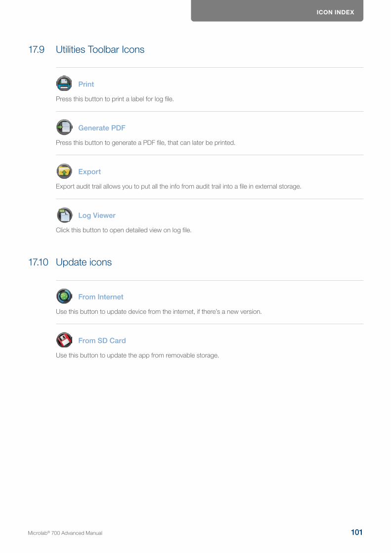
ICON INDEX
17.9 Utilities Toolbar Icons
Press this button to print a label for log file.
Generate PDF
Press this button to generate a PDF file, that can later be printed.
Export
Export audit trail allows you to put all the info from audit trail into a file in external storage.
Log Viewer
Click this button to open detailed view on log file.
17.10 Update icons
From Internet
Use this button to update device from the internet, if there’s a new version.
From SD Card
Use this button to update the app from removable storage.
Microlab® 700 Advanced Manual 101
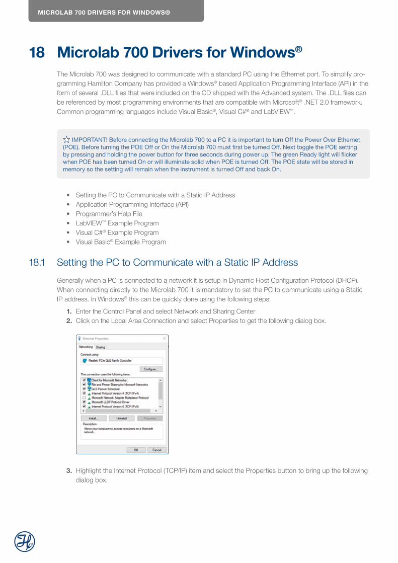
MICROLAB 700 DRIVERS FOR WINDOWS®
18 Microlab 700 Drivers for Windows®
The Microlab 700 was designed to communicate with a standard PC using the Ethernet port. To simplify pro-gramming Hamilton Company has provided a Windows® based Application Programming Interface (API) in the form of several .DLL files that were included on the CD shipped with the Advanced system. The .DLL files can be referenced by most programming environments that are compatible with Microsoft® .NET 2.0 framework. Common programming languages include Visual Basic®, Visual C#® and LabVIEW™.
IMPORTANT! Before connecting the Microlab 700 to a PC it is important to turn Off the Power Over Ethernet
(POE). Before turning the POE Off or On the Microlab 700 must first be turned Off. Next toggle the POE setting by pressing and holding the power button for three seconds during power up. The green Ready light will flicker when POE has been turned On or will illuminate solid when POE is turned Off. The POE state will be stored in memory so the setting will remain when the instrument is turned Off and back On.
• Setting the PC to Communicate with a Static IP Address • Application Programming Interface (API) • Programmer’s Help File • LabVIEW™ Example Program • Visual C#® Example Program • Visual Basic® Example Program
18.1 Setting the PC to Communicate with a Static IP Address
Generally when a PC is connected to a network it is setup in Dynamic Host Configuration Protocol (DHCP). When connecting directly to the Microlab 700 it is mandatory to set the PC to communicate using a Static IP address. In Windows® this can be quickly done using the following steps:
1. Enter the Control Panel and select Network and Sharing Center2. Click on the Local Area Connection and select Properties to get the following dialog box.
3. Highlight the Internet Protocol (TCP/IP) item and select the Properties button to bring up the following dialog box.

MICROLAB 700 DRIVERS FOR WINDOWS®
4. Select «Use the following IP address» and enter 192.168.100.50 for the IP address and 255.255.255.0 for the Subnet mask. Press the OK button and close all open dialog boxes so the settings take effect.
NOTE: The default IP Address for the Microlab 700 is 192.168.100.100. If the decision is made to change the settings and subsequently the new settings are lost it is possible to revert the pump back to the factory settings. Start with the pump turned Off. Next press and hold the Prime button and power the instrument On, continue to hold the Prime button for three seconds. The power LED light will flash five times to indicate the pump is reset to the factory default settings.
18.2 Application Programming Interface (API)
On the CD that was provided with the Microlab 700 there is a folder named ML700 API. In this folder there are several .DLL files that can be referenced in the desired programming environment. Referencing .DLL files can vary depending on the programming environment. Refer to development environment’s documentation to properly reference the .DLL.
18.3 Programmer’s Help File
On the CD that was provided with the Microlab 700 there is a file named ML700API.CHM. This is a complied help file that can be opened by Windows® and provides detailed instructions on the functions included in the API. Contained in the file are instructions describing the purpose of a function, proper values to pass to the function and expected return values from the function.
Microlab® 700 Advanced Manual 103
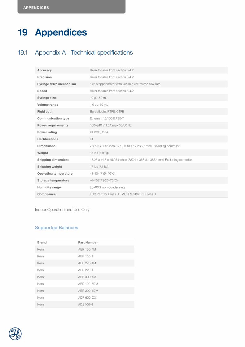
APPENDICES
19 Appendices
19.1 Appendix A—Technical specifications
Accuracy Refer to table from section 6.4.2
Precision Refer to table from section 6.4.2
Syringe drive mechanism 1.8° stepper motor with variable volumetric flow rate
Speed Refer to table from section 6.4.2
Syringe size 10 µL–50 mL
Volume range 1.0 µL–50 mL
Fluid path Borosilicate, PTFE, CTFE
Communication type Ethernet, 10/100 BASE-T
Power requirements 100–240 V 1.5A max 50/60 Hz
Power rating 24 VDC, 2.5A
Certifications CE
Dimensions 7 x 5.5 x 10.5 inch (177.8 x 139.7 x 266.7 mm) Excluding controller
Weight 13 lbs (5.9 kg)
Shipping dimensions 15.25 x 14.5 x 15.25 inches (387.4 x 368.3 x 387.4 mm) Excluding controller
Shipping weight 17 lbs (7.7 kg)
Operating temperature 41–104°F (5–40°C)
Storage temperature -4–158°F (-20–70°C)
Humidity range 20–90% non-condensing
Compliance FCC Part 15, Class B EMC: EN 61326-1, Class B
Indoor Operation and Use Only
Supported Balances
Brand Part Number
Kern ABP 100-4M
Kern ABP 100-4
Kern ABP 220-4M
Kern ABP 220-4
Kern ABP 300-4M
Kern ABP 100-5DM
Kern ABP 200-5DM
Kern ADP 600-C3
Kern ADJ 100-4
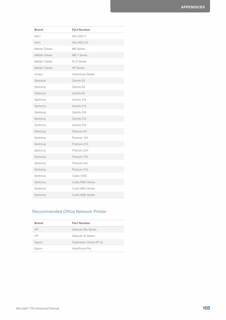
APPENDICES
Brand Part Number
Kern ADJ 200-4
Kern ADJ 600-C3
Mettler Toledo ME Series
Mettler Toledo ME-T Series
Mettler Toledo PL-E Series
Mettler Toledo XP Series
Ohaus Adventurer Series
Sartorius Quintix 35
Sartorius Quintix 64
Sartorius Quintix 65
Sartorius Quintix 124
Sartorius Quintix 213
Sartorius Quintix 224
Sartorius Quintix 313
Sartorius Quintix 513
Sartorius Practum 64
Sartorius Practum 124
Sartorius Practum 213
Sartorius Practum 224
Sartorius Practum 313
Sartorius Practum 412
Sartorius Practum 513
Sartorius Cubis 124S
Sartorius Cubis MSA Series
Sartorius Cubis MSU Series
Sartorius Cubis MSE Series
Recommended Office Network Printer
Brand Part Number
HP DeskJet 26x Series
HP DeskJet 3x Series
Epson Expression Home XP-3x
Epson WorkForce Pro
Microlab® 700 Advanced Manual 105
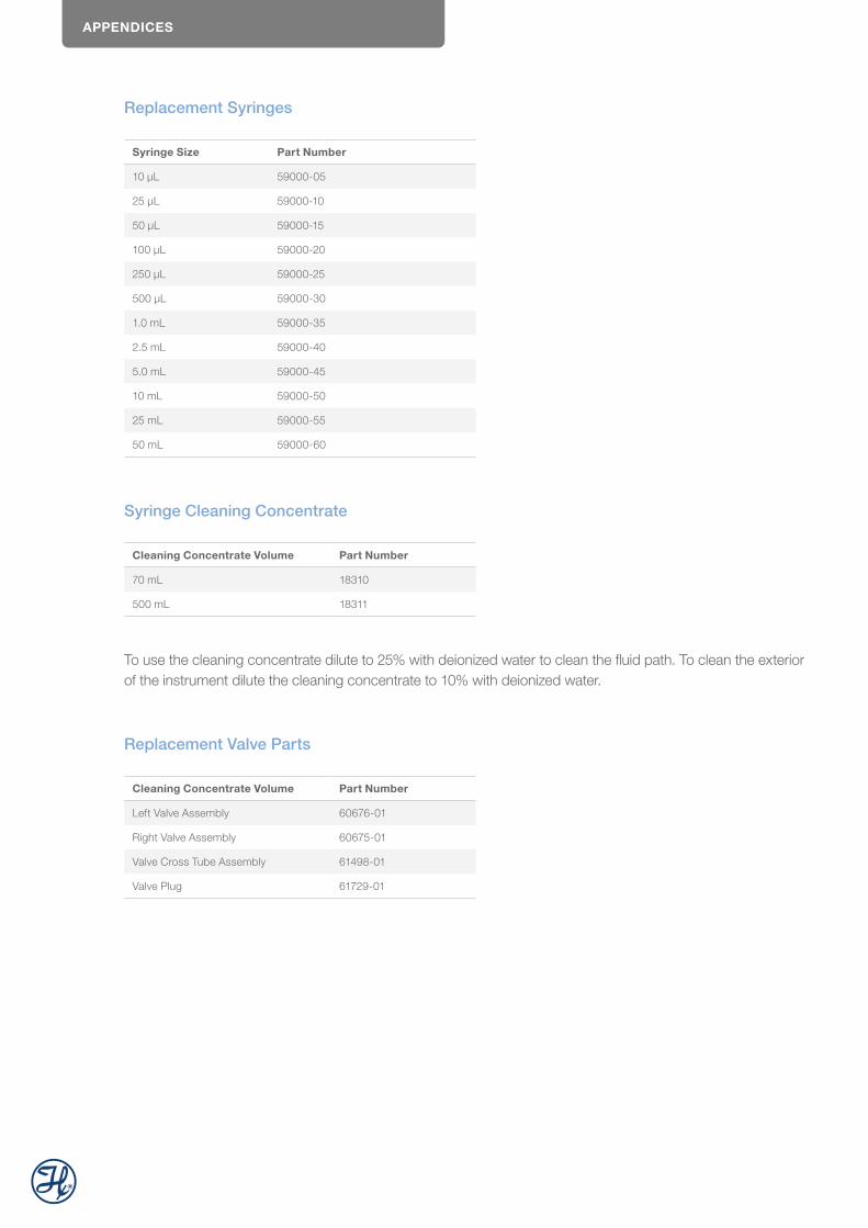
APPENDICES
Replacement Syringes
Syringe Size Part Number
10 μL 59000-05
25 μL 59000-10
50 μL 59000-15
100 μL 59000-20
250 μL 59000-25
500 μL 59000-30
1.0 mL 59000-35
2.5 mL 59000-40
5.0 mL 59000-45
10 mL 59000-50
25 mL 59000-55
50 mL 59000-60
Syringe Cleaning Concentrate
Cleaning Concentrate Volume Part Number
70 mL 18310
500 mL 18311
To use the cleaning concentrate dilute to 25% with deionized water to clean the fluid path. To clean the exterior of the instrument dilute the cleaning concentrate to 10% with deionized water.
Replacement Valve Parts
Cleaning Concentrate Volume Part Number
Left Valve Assembly 60676-01
Right Valve Assembly 60675-01
Valve Cross Tube Assembly 61498-01
Valve Plug 61729-01
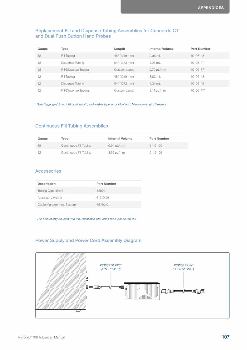
APPENDICES
Replacement Fill and Dispense Tubing Assemblies for Concorde CT and Dual Push Button Hand Probes
Gauge Type Length Internal Volume Part Number
18 Fill Tubing 48" (1219 mm) 0.96 mL 10106145
18 Dispense Tubing 54" (1372 mm) 1.08 mL 10106147
18 Fill/Dispense Tubing Custom Length 0.79 µL/mm 10106177*
12 Fill Tubing 48" (1219 mm) 3.83 mL 10106148
12 Dispense Tubing 54" (1372 mm) 4.31 mL 10106149
12 Fill/Dispense Tubing Custom Length 3.14 µL/mm 10106177*
* Specify gauge (12 red / 18 blue), length, and wether tapered or blunt end. Maximum length: 5 meters
Continuous Fill Tubing Assemblies
Gauge Type Internal Volume Part Number
18 Continuous Fill Tubing 0.94 µL/mm 61491-02
12 Continuous Fill Tubing 3.75 µL/mm 61491-01
Accessories
Description Part Number
Tubing Clips (5/pk) 88990
Accessory Holder 61710-01
Cable Management System1 65160-01
1 This should only be used with the Disposable Tip Hand Probe (p/n 63960-02)
Power Supply and Power Cord Assembly Diagram
POWER SUPPLY (P/N 61092-01)
POWER CORD (USER DEFINED)
Microlab® 700 Advanced Manual 107
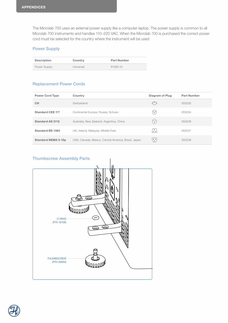
APPENDICES
The Microlab 700 uses an external power supply like a computer laptop. The power supply is common to all Microlab 700 instruments and handles 110–220 VAC. When the Microlab 700 is purchased the correct power cord must be selected for the country where the instrument will be used
Power Supply
Description Country Part Number
Power Supply Universal 61092-01
Replacement Power Cords
Power Cord Type Country Diagram of Plug Part Number
CH Switzerland 355235
Standard CEE 7/7 Continental Europe, Russia, Schuko 355234
Standard AS 3112 Australia, New Zealand, Argentina, China 355238
Standard BS 1363 UK, Ireland, Malaysia, Middle East 355237
Standard NEMA 5-15p USA, Canada, Mexico, Central America, Brazil, Japan 355236
Thumbscrew Assembly Parts
O-RING (P/N 16108)
THUMBSCREW (P/N 35684)

APPENDICES
19.2 Appendix C
Hand Probes and Foot Switch Parts
Description Part Number
Concorde CT Hand Probe 61401-01
Dual Push Button Hand Probe 62541-01
Disposable Tip Hand Probe 63960-01
50 µL, non-sterile ClickSure tips, 960 tips racked 235537
50 µL, non-sterile ClickSure tips, 960 bulk 235543
1 mL, non-sterile ClickSure tips, 960 tips racked 235539
1 mL, non-sterile ClickSure tips, 960 bulk 235545
Large Volume Disposable Tip Hand Probe (5 mL) 62575-01
5 mL Disposable Tips (250/pk) 75702
Foot Switch 62576-01
Probe Extension Cable 3 Feet 63397-01
Concorde CT Hand Probe
The Concorde CT Hand Probe is a single dispense tube pipette probe that features a slim, comfortable design. This probe is used with single syringe dispensers, dual syringe diluters and continuous dispensers. Dispense tubing will connect to the pump and run through the Concorde CT Hand Probe. The probe jack will fit into the probe receptacle on the drive unit. This probe accommodates either 12 or 18 gauge dispense tub-ing. See Table B-5 in Appendix B for dispense tubing part numbers.
If there are applications where needles are required for use with the Microlab 700 the tip of the Concorde CT Hand Probe may be converted to a luer lock termination using the Luer Lock Conversion Kit (p/n 58381-01).
TUBING CLAMP NUTTUBING
1/4-28 THROUGH TUBE ADAPTER
Dual Push-Button Hand Probe
The Dual Push-Button Hand Probe holds two dispense tubes and features a pistol grip design with a push-button actuator. This probe is used with the Dual Syringe Dispenser configuration. It will accommodate either 12 or 18 gauge dispense tubing assemblies. It can independently extend each dispense tube into the dispense vessel. See the table titled «Replacement Fill and Dispense Tubing Assemblies for Concorde CT and Dual
Microlab® 700 Advanced Manual 109

APPENDICES
Push Button Hand Probes» in Appendix B in Appendix B for dispense tubing part numbers.
COLLETS
NOTE: The 18 gauge tubing requires the use of a tubing collet to hold the smaller tubing firmly. The tubing should be threaded through the probe to the desired length. Then the tubing collet should slide over the tubing and be slipped into the metal tip of the hand probe. As the collet is pressed into the metal tube it will grab on the tube to hold it firmly in place.
Disposable Tip Hand Probe
The Disposable Tip Hand Probe is a single dispense tube pipette that features ClickSure® tips and a tip ejector. This is an optional hand probe for use with the Dilution and Pipette Wizards.

APPENDICES
Large Volume Disposable Tip Hand Probe
This is an optional hand probe with a single dispense tube designed to accommodate highly viscous samples, such as motor oil and also large volume samples from 1–5 mL. This probe features a 5 mL disposable tip that will minimize sample carryover.
Foot Switch
The Foot Switch allows you to operate the Microlab 700 via a foot-activated control pedal. This is useful when you need to keep both hands free, in applications such as hand sampling or animal dosing.
Microlab® 700 Advanced Manual 111
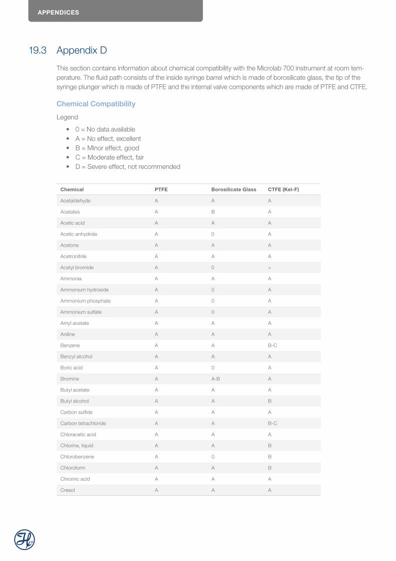
APPENDICES
19.3 Appendix D
This section contains information about chemical compatibility with the Microlab 700 instrument at room tem-perature. The fluid path consists of the inside syringe barrel which is made of borosilicate glass, the tip of the syringe plunger which is made of PTFE and the internal valve components which are made of PTFE and CTFE.
Chemical Compatibility
Legend
• 0 = No data available• A = No effect, excellent• B = Minor effect, good• C = Moderate effect, fair• D = Severe effect, not recommended
Chemical PTFE Borosilicate Glass CTFE (Kel-F)
Acetaldehyde A A A
Acetates A B A
Acetic acid A A A
Acetic anhydride A 0 A
Acetone A A A
Acetronitrile A A A
Acetyl bromide A 0 =
Ammonia A A A
Ammonium hydroxide A 0 A
Ammonium phosphate A 0 A
Ammonium sulfate A 0 A
Amyl acetate A A A
Aniline A A A
Benzene A A B-C
Benzyl alcohol A A A
Boric acid A 0 A
Bromine A A-B A
Butyl acetate A A A
Butyl alcohol A A B
Carbon sulfide A A A
Carbon tetrachloride A A B-C
Chloracetic acid A A A
Chlorine, liquid A A B
Chlorobenzene A 0 B
Chloroform A A B
Chromic acid A A A
Cresol A A A
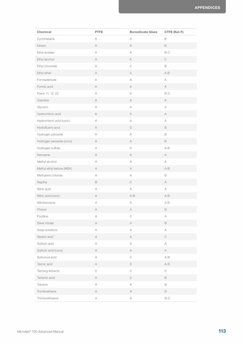
APPENDICES
Chemical PTFE Borosilicate Glass CTFE (Kel-F)
Cyclohexane A A B
Ethers A A B
Ethyl acetate A A B-C
Ethyl alcohol A A 0
Ethyl chromide A 0 B
Ethyl ether A 0 A-B
Formaldehyde A A A
Formic acid A A A
Freon 11, 12, 22 A A B-C
Gasoline A A A
Glycerin A A A
Hydrochloric acid A A A
Hydrochloric acid (conc) A A A
Hydrofluoric acid A D B
Hydrogen peroxide A A B
Hydrogen peroxide (conc) A A B
Hydrogen sulfide A 0 A-B
Kerosene A A A
Methyl alcohol A A A
Methyl ethyl ketone (MEK) A A A-B
Methylene chloride A A B
Naptha B 0 A
Nitric acid A A A
Nitric acid (conc) A A-B A-B
Nitrobenzene A A A-B
Phenol A A B
Pyridine A 0 A
Silver nitrate A A B
Soap solutions A A A
Stearic acid A A 0
Sulfuric acid A A A
Sulfuric acid (conc) A A A
Sulturous acid A 0 A-B
Tannic acid A 0 A-B
Tanning extracts 0 0 0
Tartartic acid A 0 B
Toluene A A B
Trichlorethane A A B
Trichlorethylene A A B-C
Microlab® 700 Advanced Manual 113
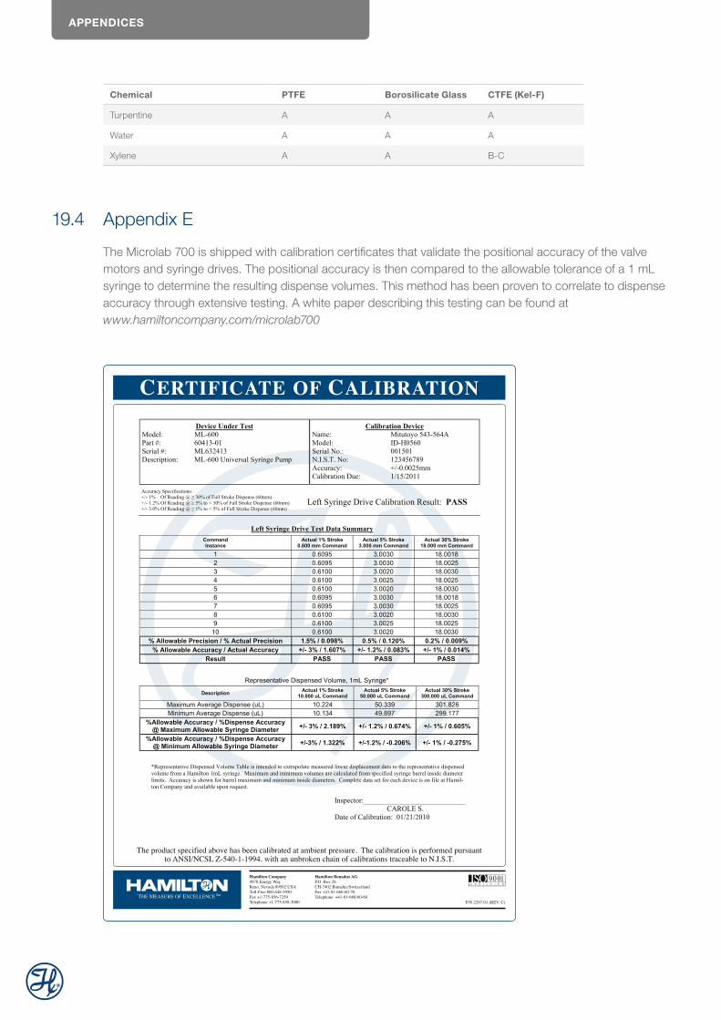
APPENDICES
Chemical PTFE Borosilicate Glass CTFE (Kel-F)
Turpentine A A A
Water A A A
Xylene A A B-C
19.4 Appendix E
The Microlab 700 is shipped with calibration certificates that validate the positional accuracy of the valve motors and syringe drives. The positional accuracy is then compared to the allowable tolerance of a 1 mL syringe to determine the resulting dispense volumes. This method has been proven to correlate to dispense accuracy through extensive testing. A white paper describing this testing can be found at www.hamiltoncompany.com/microlab700

NOTES
Microlab® 700 Advanced Manual 115
© 2021 Hamilton Bonaduz AG. All rights reserved.
Microsoft, Windows, Visual Studio, Visual C# and Visual Basic are registered trademarks of Microsoft Corporation in the United States and other countries. LabVIEW is a trademark of National Instruments. Neither Hamilton Company, nor any software programs or other goods or services offered by Hamilton Company, are affiliated with, endorsed by or sponsored by National Instruments.
All other trademarks are owned and/or registered by Hamilton Company in the U.S. and/or other countries.
10100186/00 — 01/2021
Hamilton Europe, Asia & AfricaHamilton Central Europe S.R.L.Str. Hamilton nr. 2-4307210 Giarmata, RomaniaTel: +40-356-635-055Fax: [email protected]
Web: www.hamiltoncompany.comEurope: +40-356-635-055
To find a representative in your area, please visit www.hamiltoncompany.com.