Micro-kinetic generator: Modeling, energy conversion optimization and design considerations
6
Proceeding of the 15 th IEEE Mediterranean Electrotechnical Conference, 25-28 April 2010, Malta 978-1-4244-5794-6/10/$26.00 ©2010 IEEE 1516 Micro-kinetic Generator: Modeling, Energy Conversion Optimization and Design Considerations Marianne Lossec #1 , Bernard Multon #2 , Hamid Ben Ahmed #3 # SATIE, ENS CACHAN Bretagne, CNRS, UEB, Avenue Robert Schuman, F-35170 BRUZ [email protected] [email protected] [email protected] Abstract— This article focuses on a micro-kinetic generator, which is used in Autoquartz watches designed by the Swiss manufacturer ETA (part of the Swatch Group). This original electromechanical system, incorporating an intermediate energy storage located in a spring, is based on harnessing the energy from movement. We have built an electromechanical model using the Matlab Simulink application and proceeded with its experimental validation on various movement profiles. Our research has highlighted the existence of an optimal transfer of energy (obtained by either influencing generator design or regulating output voltage of the active rectifier connected to the generator) that helps maximize energy recovery. Finally, this paper presents the results of a system resizing study for the purpose of studying potential system productivity at other scales, and highlights the existence of an optimal set of parameters maximizing energy recovery. I. INTRODUCTION Many portable, low-consumption electronic systems now make it possible to envisage self-supply from resources available in the environment. In this context, our laboratory has been working for several years on multi-source recovery energy systems, their energy potential and strategies for managing this energy [1,2]. Concerning mechanical energy recovery, a wide range of devices that convert this energy resulting from vibrations and motion into electrical energy have already been identified and studied [3-5]. Such a conversion step can be performed by means of piezoelectric generators or a linear or rotating electromagnetic generator. This research is devoted to investigating a system that incorporates a rotating electromagnetic generator with intermediate energy storage in a spring, thus enabling energy recovery from very slow movements. The Autoquartz watch works like a traditional quartz watch, with the particularity that it utilizes the movement of the watch wearer as an energy source. An oscillating weight transmits mechanical energy to a micro-generator and subsequently to an electrical accumulator via a spiral spring positioned within a micro barrel (Figs. 1 and 2). Fig. 1. 3D view [6] of the Autoquartz system Fig. 2. Sectional view [7] of the Autoquartz system The mechanical power supplied by the oscillating weight is distributed to two ratchet wheels, one of which has been fastened to the lower extremity of a spiral spring. The weight oscillation action is able to wind the spring (with a multiplication ratio m 1 equal to 1.6) regardless of movement direction or range. Once the spring torque exceeds the detent torque amplitude of the generator transmitted through a multiplier gear with a ratio m 2 equal to 5, the spring unwinds suddenly, resulting in a single-phase permanent magnet generator rotation (claw pole stator structure). Fig. 7 shows the electromotive force variation cycle, which highlights the change in speed during this cycle. A high efficiency full-wave active synchronous rectifier (with MOSFET) convert the energy in order to charge an accumulator buffer (a supercapacitor or lithium element, depending on the watch model); like in traditional quartz watches, this step serves to redistribute energy to the electronic counting and stepper motor control electronics to ensure the watch hands are running smoothly.
-
Upload
independent -
Category
Documents
-
view
3 -
download
0
Transcript of Micro-kinetic generator: Modeling, energy conversion optimization and design considerations
Proceeding of the 15th
IEEE Mediterranean Electrotechnical Conference, 25-28 April 2010, Malta
978-1-4244-5794-6/10/$26.00 ©2010 IEEE 1516
Micro-kinetic Generator: Modeling, Energy
Conversion Optimization and Design Considerations Marianne Lossec
#1, Bernard Multon
#2, Hamid Ben Ahmed
#3
# SATIE, ENS CACHAN Bretagne, CNRS, UEB,
Avenue Robert Schuman, F-35170 BRUZ
Abstract— This article focuses on a micro-kinetic generator,
which is used in Autoquartz watches designed by the Swiss
manufacturer ETA (part of the Swatch Group). This original
electromechanical system, incorporating an intermediate energy
storage located in a spring, is based on harnessing the energy
from movement. We have built an electromechanical model
using the Matlab Simulink application and proceeded with its
experimental validation on various movement profiles. Our
research has highlighted the existence of an optimal transfer of
energy (obtained by either influencing generator design or
regulating output voltage of the active rectifier connected to the
generator) that helps maximize energy recovery. Finally, this
paper presents the results of a system resizing study for the
purpose of studying potential system productivity at other scales,
and highlights the existence of an optimal set of parameters
maximizing energy recovery.
I. INTRODUCTION
Many portable, low-consumption electronic systems now
make it possible to envisage self-supply from resources
available in the environment. In this context, our laboratory
has been working for several years on multi-source recovery
energy systems, their energy potential and strategies for
managing this energy [1,2].
Concerning mechanical energy recovery, a wide range of
devices that convert this energy resulting from vibrations and
motion into electrical energy have already been identified and
studied [3-5]. Such a conversion step can be performed by
means of piezoelectric generators or a linear or rotating
electromagnetic generator. This research is devoted to
investigating a system that incorporates a rotating
electromagnetic generator with intermediate energy storage in
a spring, thus enabling energy recovery from very slow
movements.
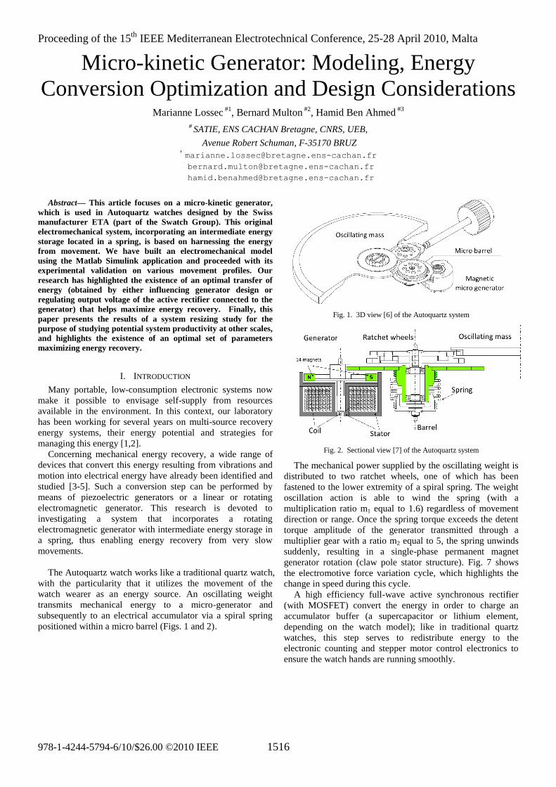
The Autoquartz watch works like a traditional quartz watch,
with the particularity that it utilizes the movement of the
watch wearer as an energy source. An oscillating weight
transmits mechanical energy to a micro-generator and
subsequently to an electrical accumulator via a spiral spring
positioned within a micro barrel (Figs. 1 and 2).
Fig. 1. 3D view [6] of the Autoquartz system
Fig. 2. Sectional view [7] of the Autoquartz system
The mechanical power supplied by the oscillating weight is
distributed to two ratchet wheels, one of which has been
fastened to the lower extremity of a spiral spring. The weight
oscillation action is able to wind the spring (with a
multiplication ratio m1 equal to 1.6) regardless of movement
direction or range. Once the spring torque exceeds the detent
torque amplitude of the generator transmitted through a
multiplier gear with a ratio m2 equal to 5, the spring unwinds
suddenly, resulting in a single-phase permanent magnet
generator rotation (claw pole stator structure). Fig. 7 shows
the electromotive force variation cycle, which highlights the
change in speed during this cycle.
A high efficiency full-wave active synchronous rectifier
(with MOSFET) convert the energy in order to charge an
accumulator buffer (a supercapacitor or lithium element,
depending on the watch model); like in traditional quartz
watches, this step serves to redistribute energy to the
electronic counting and stepper motor control electronics to
ensure the watch hands are running smoothly.
1517
Some specifications of the Autoquartz system, useful for
modeling purposes, are listed in the following table [8,9]. It
will be seen further below that the identifications actually
carried out lead to slightly different values:
TABLE I
INITIAL SPECIFICATIONS OF THE AUTOQUARTZ SYSTEM [8,9]
Autoquartz system parameter Numerical
value
External diameter of the system (dosc) 26.6 mm
Total system thickness (thosc) 3.95 mm
Moment of inertia of the weight (Josc) 220 g.mm²
Weight/spring multiplication ratio (m1) 45:28 = 1.6
Spring stiffness (ksp) 12.5 μNm/rad
Spring/generator multiplication ratio (m2) 60:12 = 5
Amplitude of the generator detent torque (TdMax) 8 to 15 μNm
Amplitude of the excitation flux (ΦfMax) 0.6 mVs
Number of pole pairs (generator) (p) 7
Moment of inertia of the rotor (JG) 0.03 g.mm²
Internal resistance of the armature (RG) 320 Ω
ON resistance of the MOSFETs (RMOS) 30 Ω
II. ELECTROMECHANICAL MODELING
To establish a design and optimization tool for harnessing
the energy from movement through the device Autoquartz, we
have developed an energy productivity model that runs on
Matlab-Simulink.
Fig. 3. Synoptic diagram of the micro-kinetic production model based on
motion profiles
This model is based on the fundamental principle of
dynamics applied to a solid rotation, which in our case is the
generator rotor. Let's consider TG as the restoring torque
transmitted by the spring through the speed multiplier, Td as
the generator detent torque, Tem the electromagnetic torque
(proportional to discharge current IG, and sinusoidal), and Tf a
viscous friction torque (intended to represent all types of
friction and identified indirectly from experiment).
The angular difference between the two spring extremities,
relative to spring stiffness ksp, defines the restoring torque Tsp.
Now, let's assume αosc and αG to be the angular positions of
low and high spring extremities respectively; this torque can
then be expressed by Tsp = ksp(αosc-αG) and transmitted onto
the rotor shaft through a gear train with a ratio equal to m2, as
indicated above (the notation used here is TG).
The electromagnetic micro-generator structure is non-
conventional (Fig. 4): it consists of a claw pole stator structure
of the kind found in magnet stepper motors. Also, it is single-
phase with 7 pole pairs. The inductive effects are insignificant
due to scale effects and will be neglected hereafter.
Fig. 4. Photography and 3D view of the micro-generator [9]
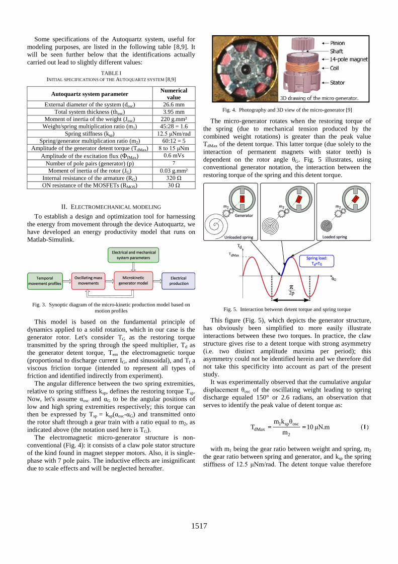
The micro-generator rotates when the restoring torque of
the spring (due to mechanical tension produced by the
combined weight rotations) is greater than the peak value
TdMax of the detent torque. This latter torque (due solely to the
interaction of permanent magnets with stator teeth) is
dependent on the rotor angle θG. Fig. 5 illustrates, using
conventional generator notation, the interaction between the
restoring torque of the spring and this detent torque.
Fig. 5. Interaction betwenn detent torque and spring torque
This figure (Fig. 5), which depicts the generator structure,
has obviously been simplified to more easily illustrate
interactions between these two torques. In practice, the claw
structure gives rise to a detent torque with strong asymmetry
(i.e. two distinct amplitude maxima per period); this
asymmetry could not be identified herein and we therefore did
not take this specificity into account as part of the present
study.
It was experimentally observed that the cumulative angular
displacement θosc of the oscillating weight leading to spring
discharge equaled 150° or 2.6 radians, an observation that
serves to identify the peak value of detent torque as:
1 sp osc
dMax2
m k θT 10 μN.m
m
with m1 being the gear ratio between weight and spring, m2
the gear ratio between spring and generator, and ksp the spring
stiffness of 12.5 μNm/rad. The detent torque value therefore
1518
determines the maximum energy stored in the spring for
transmission to the generator during the discharge cycle, i.e.:
22 dMax
spring 2sp
T1W m 100 μJ
2 k
The instantaneous electromagnetic torque is proportional to
both the output current and permanent magnet flux f
derivative with respect to the rotor position G:
fem G G
G
dΦT (θ ) I
dθ
Furthermore, the torque due to friction originates from
various sources: different types of mechanical friction, and
magnetic losses due to eddy currents. For this research, the
effects of dry friction due to mechanical friction and magnetic
hysteresis losses could not be directly identified and have
been neglected. A single component of equivalent viscous
friction has been retained, denoted Tf and identified from the
following basic energy assessment. Since the maximum power
potentially output by the generator is 10 mW at 5,000 rpm [8],
i.e. a value corresponding to impedance matching (given that
the limitations of this machine are not thermal), we have
somewhat arbitrarily in a first time assumed a power loss due
to viscous friction of approx. 30%, which corresponds to a
loss of Pf = fGΩG2 = 3 mW at the same speed. This assumption
leads to a value of the viscous friction coefficient equal to
fG = 3·10-9
Nm/rad/s.
The fundamental principle of dynamics applied to the
generator rotor is thus expressed by:
GG G d em f
dΩJ . T - T - T - T
dt
To better illustrate how this Autoquartz system operates
during unwinding of the spring, Fig. 6 shows the block
diagram of the entire system, where the active rectifier is
loaded by a constant voltage source Vbus, with R being the
global resistance, i.e. the sum of the resistance of the
generator armature and the resistances of semiconductor
rectifiers.
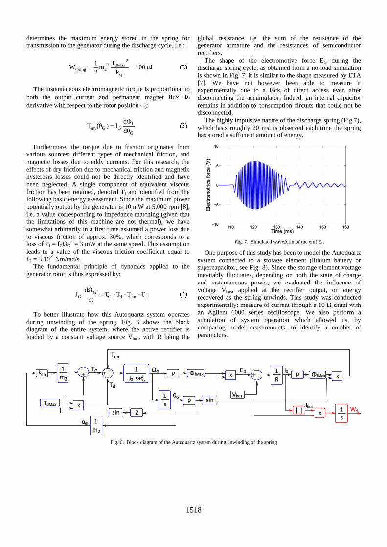
The shape of the electromotive force EG during the
discharge spring cycle, as obtained from a no-load simulation
is shown in Fig. 7; it is similar to the shape measured by ETA
[7]. We have not however been able to measure it
experimentally due to a lack of direct access even after
disconnecting the accumulator. Indeed, an internal capacitor
remains in addition to consumption circuits that could not be
disconnected.
The highly impulsive nature of the discharge spring (Fig.7),
which lasts roughly 20 ms, is observed each time the spring
has stored a sufficient amount of energy.
Fig. 7. Simulated waveform of the emf EG
One purpose of this study has been to model the Autoquartz
system connected to a storage element (lithium battery or
supercapacitor, see Fig. 8). Since the storage element voltage
inevitably fluctuates, depending on both the state of charge
and instantaneous power, we evaluated the influence of
voltage Vbus, applied at the rectifier output, on energy
recovered as the spring unwinds. This study was conducted
experimentally: measure of current through a 10 Ω shunt with
an Agilent 6000 series oscilloscope. We also perform a
simulation of system operation which allowed us, by
comparing model-measurements, to identify a number of
parameters.
Fig. 6. Block diagram of the Autoquartz system during unwinding of the spring
1519
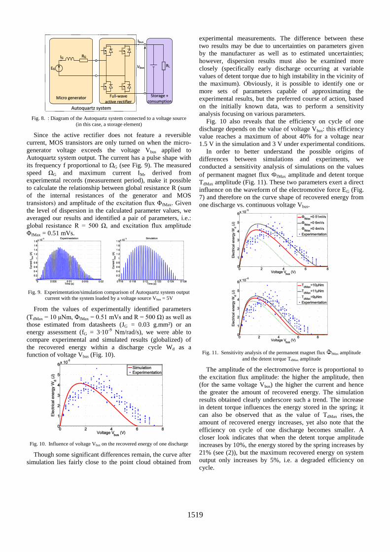
Fig. 8. : Diagram of the Autoquartz system connected to a voltage source
(in this case, a storage element)
Since the active rectifier does not feature a reversible
current, MOS transistors are only turned on when the micro-
generator voltage exceeds the voltage Vbus applied to
Autoquartz system output. The current has a pulse shape with
its frequency f proportional to ΩG (see Fig. 9). The measured
speed ΩG and maximum current IM, derived from
experimental records (measurement period), make it possible
to calculate the relationship between global resistance R (sum
of the internal resistances of the generator and MOS
transistors) and amplitude of the excitation flux ΦfMax. Given
the level of dispersion in the calculated parameter values, we
averaged our results and identified a pair of parameters, i.e.:
global resistance R = 500 Ω, and excitation flux amplitude
ΦfMax = 0.51 mVs.
Fig. 9. Experimentation/simulation comparison of Autoquartz system output current with the system loaded by a voltage source Vbus = 5V
From the values of experimentally identified parameters
(TdMax = 10 μNm, fMax = 0.51 mVs and R = 500 Ω) as well as
those estimated from datasheets (JG = 0.03 g.mm²) or an
energy assessment (fG = 3·10-9
Nm/rad/s), we were able to
compare experimental and simulated results (globalized) of
the recovered energy within a discharge cycle Wd as a
function of voltage Vbus (Fig. 10).
Fig. 10. Influence of voltage Vbus on the recovered energy of one discharge
Though some significant differences remain, the curve after
simulation lies fairly close to the point cloud obtained from
experimental measurements. The difference between these
two results may be due to uncertainties on parameters given
by the manufacturer as well as to estimated uncertainties;
however, dispersion results must also be examined more
closely (specifically early discharge occurring at variable
values of detent torque due to high instability in the vicinity of
the maximum). Obviously, it is possible to identify one or
more sets of parameters capable of approximating the
experimental results, but the preferred course of action, based
on the initially known data, was to perform a sensitivity
analysis focusing on various parameters.
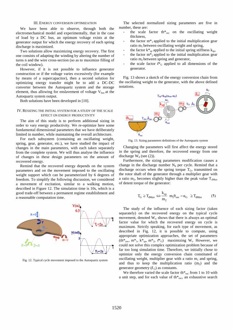
Fig. 10 also reveals that the efficiency on cycle of one
discharge depends on the value of voltage Vbus: this efficiency
value reaches a maximum of about 40% for a voltage near
1.5 V in the simulation and 3 V under experimental conditions.
In order to better understand the possible origins of
differences between simulations and experiments, we
conducted a sensitivity analysis of simulations on the values
of permanent magnet flux fMax amplitude and detent torque
TdMax amplitude (Fig. 11). These two parameters exert a direct
influence on the waveform of the electromotive force EG (Fig.
7) and therefore on the curve shape of recovered energy from
one discharge vs. continuous voltage Vbus.
Fig. 11. Sensitivity analysis of the permanent magnet flux fMax amplitude
and the detent torque TdMax amplitude
The amplitude of the electromotive force is proportional to
the excitation flux amplitude: the higher the amplitude, then
(for the same voltage Vbus) the higher the current and hence
the greater the amount of recovered energy. The simulation
results obtained clearly underscore such a trend. The increase
in detent torque influences the energy stored in the spring; it
can also be observed that as the value of TdMax rises, the
amount of recovered energy increases, yet also note that the
efficiency on cycle of one discharge becomes smaller. A
closer look indicates that when the detent torque amplitude
increases by 10%, the energy stored by the spring increases by
21% (see (2)), but the maximum recovered energy on system
output only increases by 5%, i.e. a degraded efficiency on
cycle.
1520
III. ENERGY CONVERSION OPTIMIZATION
We have been able to observe, through both the
electromechanical model and experimentally, that in the case
of load by a DC bus, an optimum voltage exists at the
generator output for which the energy recovery of each spring
discharge is maximized.
Two solutions allow maximizing energy recovery. The first
one consists of adapting the winding by altering the number of
turns n and the wire cross-section (so as to maximize filling of
the coil window).
However, if it is not possible to influence generator
construction or if the voltage varies excessively (for example
by means of a supercapacitor), then a second solution for
optimizing energy transfer might be to add a DC-DC
converter between the Autoquartz system and the storage
element, thus allowing for enslavement of voltage Vbus at the
Autoquartz system output.
Both solutions have been developed in [10].
IV. RESIZING THE INITIAL SYSTEM FOR A STUDY OF THE SCALE
EFFECT ON ENERGY PRODUCTIVITY
The aim of this study is to perform additional sizing in
order to vary energy productivity. We re-optimize here some
fundamental dimensional parameters that we have deliberately
limited in number, while maintaining the overall architecture.
For each subsystem (containing an oscillating weight,
spring, gear, generator, etc.), we have studied the impact of
changes in the main parameters, with each taken separately
from the complete system. We will thus analyse the influence
of changes in these design parameters on the amount of
recovered energy.
Remind that the recovered energy depends on the system
parameters and on the movement imposed to the oscillating
weight support which can be parameterized by 6 degrees of
freedom. To simplify the following discussion, we considered
a movement of excitation, similar to a walking motion,
described in Figure 12. The simulation time is 10s, which is a
good trade-off between a permanent regime establishment and
a reasonable computation time.
Fig. 12. Typical cycle movement imposed to the Autoquartz system
The selected normalized sizing parameters are five in
number, these are:
- the scale factor th*osc on the oscillating weight
thickness,
- the factor m*1 applied to the initial multiplication gear
ratio m1 between oscillating weight and spring,
- the factor k*sp applied to the initial spring stiffness ksp,
- the factor m*2 applied to the initial multiplication gear
ratio m2 between spring and generator,
- the scale factor l*G applied to all dimensions of the
generator.
Fig. 13 shows a sketch of the energy conversion chain from
the oscillating weight to the generator, with the above defined
notations.
Fig. 13. Sizing parameters definitions of the Autoquartz system
Changing the parameters will first affect the energy stored
in the spring and therefore, the recovered energy from one
discharge Wd (see (2)).
Furthermore, the sizing parameters modification causes a
change in the discharge number Nd per cycle. Remind that a
discharge occurs when the spring torque TG, transmitted on
the rotor shaft of the generator through a multiplier gear with
a ratio m2, becomes slightly higher than the peak value TdMax
of detent torque of the generator:
sp
G dMax 1 osc G dMax2
kT T m θ α T
m
The study of the influence of each sizing factor (taken
separately) on the recovered energy on the typical cycle
movement, denoted Wt, shows that there is always an optimal
factor value for which the recovered energy on cycle is
maximum. Strictly speaking, for each type of movement, as
described in Fig. 12, it is possible to compute, using
appropriate optimization approaches, the set of parameters
(th*osc, m*1, k*sp, m*2, l*G) maximizing Wt. However, we
could not solve this complex optimization problem because of
far too long simulation time. Therefore, we initially chose to
optimize only the energy conversion chain constituted of
oscillating weight, multiplier gear with a ratio m1 and spring,
and thus to keep the multiplication ratio (m2) and the
generator geometry (l G) as constants.
We therefore varied the scale factor th*osc from 1 to 10 with
a unit step, and for each value of th*osc, an exhaustive search
1521
is performed to find the couple of parameters (m*1, k*sp)
maximizing the electrical energy on cycle Wt. For each (m*1,
k*sp), a first simulation is run to find the DC bus voltage Vbus
that maximizes Wd (see Fig.6), and then, a second simulation
provide us Wt (see Fig.3). Results are presented in Fig.14.
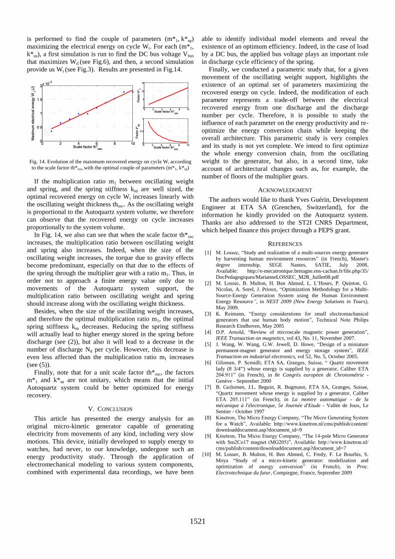
Fig. 14. Evolution of the maximum recovered energy on cycle Wt according
to the scale factor th*osc, with the optimal couple of parameters (m*1, k*sp)
If the multiplication ratio m1 between oscillating weight
and spring, and the spring stiffness ksp are well sized, the
optimal recovered energy on cycle Wt increases linearly with
the oscillating weight thickness thosc. As the oscillating weight
is proportional to the Autoquartz system volume, we therefore
can observe that the recovered energy on cycle increases
proportionally to the system volume.
In Fig. 14, we also can see that when the scale factor th*osc
increases, the multiplication ratio between oscillating weight
and spring also increases. Indeed, when the size of the
oscillating weight increases, the torque due to gravity effects
become predominant, especially on that due to the effects of
the spring through the multiplier gear with a ratio m1. Thus, in
order not to approach a finite energy value only due to
movements of the Autoquartz system support, the
multiplication ratio between oscillating weight and spring
should increase along with the oscillating weight thickness.
Besides, when the size of the oscillating weight increases,
and therefore the optimal multiplication ratio m1, the optimal
spring stiffness ksp decreases. Reducing the spring stiffness
will actually lead to higher energy stored in the spring before
discharge (see (2)), but also it will lead to a decrease in the
number of discharge Nd per cycle. However, this decrease is
even less affected than the multiplication ratio m1 increases
(see (5)).
Finally, note that for a unit scale factor th*osc, the factors
m*1 and k*sp are not unitary, which means that the initial
Autoquartz system could be better optimized for energy
recovery.
V. CONCLUSION
This article has presented the energy analysis for an
original micro-kinetic generator capable of generating
electricity from movements of any kind, including very slow
motions. This device, initially developed to supply energy to
watches, had never, to our knowledge, undergone such an
energy productivity study. Through the application of
electromechanical modeling to various system components,
combined with experimental data recordings, we have been
able to identify individual model elements and reveal the
existence of an optimum efficiency. Indeed, in the case of load
by a DC bus, the applied bus voltage plays an important role
in discharge cycle efficiency of the spring.
Finally, we conducted a parametric study that, for a given
movement of the oscillating weight support, highlights the
existence of an optimal set of parameters maximizing the
recovered energy on cycle. Indeed, the modification of each
parameter represents a trade-off between the electrical
recovered energy from one discharge and the discharge
number per cycle. Therefore, it is possible to study the
influence of each parameter on the energy productivity and re-
optimize the energy conversion chain while keeping the
overall architecture. This parametric study is very complex
and its study is not yet complete. We intend to first optimize
the whole energy conversion chain, from the oscillating
weight to the generator, but also, in a second time, take
account of architectural changes such as, for example, the
number of floors of the multiplier gears.
ACKNOWLEDGMENT
The authors would like to thank Yves Guérin, Development
Engineer at ETA SA (Grenchen, Switzerland), for the
information he kindly provided on the Autoquartz system.
Thanks are also addressed to the ST2I CNRS Department,
which helped finance this project through a PEPS grant.
REFERENCES
[1] M. Lossec, “Study and realization of a multi-sources energy generator
by harvesting human environment resources” (in French), Master's
degree internship, SEGE Nantes, SATIE, July 2008, Available: http://e-mecatronique.bretagne.ens-cachan.fr/file.php/35/
DocPedagogiques/MarianneLOSSEC_M2R_Juillet08.pdf
[2] M. Lossec, B. Multon, H. Ben Ahmed, L. L’Hours, P. Quinton, G. Nicolas, A. Sorel, J. Prioux, “Optimization Methodology for a Multi-
Source-Energy Generation System using the Human Environment Energy Resource”, in NEST 2009 (New Energy Solutions in Tours),
May 2009.
[3] K. Reimann, “Energy considerations for small electromachanical generators that use human body motion”, Technical Note Philips
Research Eindhoven, May 2005
[4] D.P. Arnold, “Review of microscale magnetic power generation”, IEEE Transaction on magnetics, vol 43, No. 11, November 2007.
[5] J. Wang, W. Wang, G.W. Jewell, D. Howe, “Design of a miniature
permanent-magnet generator and energy storage system”, IEEE Transaction on industrial electronics, vol 52, No. 5, October 2005.
[6] Gilomen, P. Scmidli, ETA SA, Granges, Suisse, “ Quartz movement
lady (8 3/4''') whose energy is supplied by a generator, Caliber ETA 204.911” (in French), in 8e Congrès européen de Chronométrie -
Genève - September 2000
[7] B. Guilomen, J.L. Beguin, R. Bugmann, ETA SA, Granges, Suisse, “Quartz movement whose energy is supplied by a generator, Caliber
ETA 205.111” (in French), in La montre automatique - de la
mécanique à l'électronique, 5e Journée d'Etude - Vallée de Joux, Le Sentier - October 1997
[8] Kinetron, The Micro Energy Company, “The Micro Generating System
for a Watch”, Available: http://www.kinetron.nl/cms/publish/content/
downloaddocument.asp?document_id=9
[9] Kinetron, The Micro Energy Company, “The 14-pole Micro Generator
with Sm2Co17 magnet (MG205)”, Available: http://www.kinetron.nl/ cms/publish/content/downloaddocument.asp?document_id=7
[10] M. Lossec, B. Multon, H. Ben Ahmed, C. Fredy, F. Le Bourhis, S.
Moya “Study of a micro-kinetic generator: modelization and optimization of energy conversion” (in French), in Proc.
Electrotechnique du futur, Compiegne, France, September 2009