Methods and systems for designing and/or selecting drilling ...
56
Printed by Jouve, 75001 PARIS (FR) (19) EP 2 258 918 A2 & (11) EP 2 258 918 A2 (12) EUROPEAN PATENT APPLICATION (43) Date of publication: 08.12.2010 Bulletin 2010/49 (21) Application number: 10163457.4 (22) Date of filing: 20.05.2010 (51) Int Cl.: E21B 10/00 (2006.01) (84) Designated Contracting States: AL AT BE BG CH CY CZ DE DK EE ES FI FR GB GR HR HU IE IS IT LI LT LU LV MC MK MT NL NO PL PT RO SE SI SK SM TR Designated Extension States: BA ME RS (30) Priority: 20.05.2009 US 469452 (71) Applicant: HALLIBURTON ENERGY SERVICES, INC. Houston, TX 77072-5299 (US) (72) Inventor: Chen, Shilin The Woodlands, TX 77385 (US) (74) Representative: HOFFMANN EITLE Patent- und Rechtsanwälte Arabellastraße 4 81925 München (DE) (54) Methods and systems for designing and/or selecting drilling equipment using predictions of rotary drill bit walk (57) Methods and systems are disclosed which pro- vide simulating forming a wide variety of directional well- bores including wellbores with variable tilt rates and/or relatively constant tilt rates. The methods and systems may also be used to simulate forming a wellbore in sub- terranean formations having a combination of soft, me- dium and hard formation materials, multiple layers of for- mation materials and relatively hard stringers disposed throughout one or more layers of formation material. Val- ues of steer force, bit walk rate and average walk rate from such simulations may be used to design and/or se- lect drilling equipment for use in forming a directional wellbore.
-
Upload
khangminh22 -
Category
Documents
-
view
0 -
download
0
Transcript of Methods and systems for designing and/or selecting drilling ...

Printed by Jouve, 75001 PARIS (FR)
(19)E
P2
258
918
A2
��&�� ������ �(11) EP 2 258 918 A2
(12) EUROPEAN PATENT APPLICATION
(43) Date of publication: 08.12.2010 Bulletin 2010/49
(21) Application number: 10163457.4
(22) Date of filing: 20.05.2010
(51) Int Cl.:E21B 10/00 (2006.01)
(84) Designated Contracting States: AL AT BE BG CH CY CZ DE DK EE ES FI FR GB GR HR HU IE IS IT LI LT LU LV MC MK MT NL NO PL PT RO SE SI SK SM TRDesignated Extension States: BA ME RS
(30) Priority: 20.05.2009 US 469452
(71) Applicant: HALLIBURTON ENERGY SERVICES, INC.Houston, TX 77072-5299 (US)
(72) Inventor: Chen, ShilinThe Woodlands, TX 77385 (US)
(74) Representative: HOFFMANN EITLEPatent- und Rechtsanwälte Arabellastraße 481925 München (DE)
(54) Methods and systems for designing and/or selecting drilling equipment using predictions of rotary drill bit walk
(57) Methods and systems are disclosed which pro-vide simulating forming a wide variety of directional well-bores including wellbores with variable tilt rates and/orrelatively constant tilt rates. The methods and systemsmay also be used to simulate forming a wellbore in sub-terranean formations having a combination of soft, me-
dium and hard formation materials, multiple layers of for-mation materials and relatively hard stringers disposedthroughout one or more layers of formation material. Val-ues of steer force, bit walk rate and average walk ratefrom such simulations may be used to design and/or se-lect drilling equipment for use in forming a directionalwellbore.
EP 2 258 918 A2
2
5
10
15
20
25
30
35
40
45
50
55
Description
RELATED APPLICATIONS
[0001] This application is a U.S. Continuation-In-Part of U.S. Patent Application Serial Number 11/462,898 filed August7, 2006, and entitled "Methods and Systems for Designing and/or Selecting Drilling Equipment Using Predictions ofRotary Drill Bit Walk," which claims the benefit of U.S. provisional patent Application entitled "Methods and Systems ofRotary Drill Bit Steerability Prediction, Rotary Drill Bit Design and Operation," Application Serial Number 60/706,321filed August 8, 2005.[0002] This application claims the benefit of provisional patent application entitled "Methods and Systems of RotaryDrill Bit Walk Prediction, Rotary Drill Bit Design and Operation," Application Serial Number 60/738,431 filed November21, 2005.[0003] This application claims the benefit of provisional patent application entitled "Methods and Systems of RotaryDrill Bit Walk Prediction, Rotary Drill Bit Design and Operation," Application Serial Number 60/706,323 filed August 8,2005.[0004] This application claims the benefit of provisional patent application entitled "Methods and Systems of RotaryDrill Bit Steerability Prediction, Rotary Drill Bit Design and Operation," Application Serial Number 60/738,453 filed No-vember 21, 2005.
TECHNICAL FIELD
[0005] The present disclosure is related to wellbore drilling equipment and more particularly to designing rotary drillbits and/or bottom hole assemblies with desired bit walk characteristics or selecting a rotary drill bit and/or componentsfor an associated bottom hole assembly with desired bit walk characteristics from existing designs.
BACKGROUND
[0006] Various types of rotary drill bits have been used to form wellbores or boreholes in downhole formations. Suchwellbores are often formed using a rotary drill bit attached to the end of a generally hollow, tubular drill string extendingfrom an associated well surface. Rotation of a rotary drill bit progressively cuts away adjacent portions of a downholeformation by contact between cutting elements and cutting structures disposed on exterior portions of the rotary drill bit.Examples of rotary drill bits include fixed cutter drill bits or drag drill bits and impregnated diamond bits. Various typesof drilling fluids are often used in conjunction with rotary drill bits to form wellbores or boreholes extending from a wellsurface through one or more downhole formations.[0007] Various types of computer based systems, software applications and/or computer programs have previouslybeen used to simulate forming wellbores including, but not limited to, directional wellbores and to simulate the performanceof a wide variety of drilling equipment including, but not limited to, rotary drill bits which may be used to form suchwellbores. Some examples of such computer based systems, software applications and/or computer programs arediscussed in various patents and other references listed on Information Disclosure Statements filed during prosecutionof this patent application.
SUMMARY
[0008] In accordance with teachings of the present disclosure, rotary drill bits including fixed cutter drill bits may bedesigned with bit walk characteristics and/or controllability optimized for a desired wellbore profile and/or anticipateddownhole drilling conditions. Alternatively, a rotary drill bit including a fixed cutter drill bit with desired bit walk and/orcontrollability may be selected from existing drill bit designs.[0009] Rotary drill bits designed or selected to form a straight hole or vertical wellbore may require approximately zeroor neutral bit walk. Rotary drill bits designed or selected for use with a directional drilling system may have an optimumbit walk rate for a desired wellbore profile and/or anticipated downhole drilling conditions.[0010] One aspect of the present disclosure may include procedures to evaluate walk tendency of a rotary drill bitunder a combination of bit motions including, but not limited to, rotation, axial penetration, side penetration, tilt rate and/ortransition drilling. For example, methods and systems incorporating teachings of the present disclosure may be used tosimulate drilling through inclined formation interfaces and complex formations with hard stringers disposed in softerformation materials and/or alternating layers of hard and soft formation materials.[0011] Drilling a wellbore profile, trajectory, or path using a wide variety of rotary drill bits and bottom hole assembliesmay be simulated in three dimensions (3D) using methods and systems incorporating teachings of the present disclosure.Such simulations may be used to design rotary drill bits and/or bottom hole assemblies with optimum bit walk charac-
EP 2 258 918 A2
3
5
10
15
20
25
30
35
40
45
50
55
teristics for drilling a wellbore profile. Such simulation may also be used to select a rotary drill bit and/or components foran associated bottom hole assembly from existing designs with optimum bit walk characteristics for drilling a wellboreprofile.[0012] Systems and methods incorporating teachings of the present disclosure may be used to simulate drilling varioustypes of wellbores and segments of wellbores using both push-the-bit directional drilling systems and point-the-bitdirectional drilling systems.
BRIEF DESCRIPTION OF THE DRAWINGS
[0013] A more complete and thorough understanding of the present disclosure and advantages thereof may be acquiredby referring to the following description taken in conjunction with the accompanying drawings, in which like referencenumbers indicate like features, and wherein:
FIGURE 1A is a schematic drawing in section and in elevation with portions broken away showing one example ofa directional wellbore which may be formed by a drill bit designed in accordance with teachings of the presentdisclosure or selected from existing drill bit designs in accordance with teachings of the present disclosure;FIGURE 1B is a schematic drawing showing a graphical representation of a directional wellbore having a constantbend radius between a generally vertical section and a generally horizontal section which may be formed by a drillbit designed in accordance with teachings of the present disclosure or selected from existing drill bit designs inaccordance with teachings of the present disclosure;FIGURE 1C is a schematic drawing showing one example of a system and associate apparatus operable to simulatedrilling a complex, directional wellbore in accordance with teachings of the present disclosure;FIGURE 2A is a schematic drawing showing an isometric view with portions broken away of a rotary drill bit withsix (6) degrees of freedom which may be used to describe motion of the rotary drill bit in three dimensions in a bitcoordinate system;FIGURE 2B is a schematic drawing showing forces applied to a rotary drill bit while forming a substantially verticalwellbore;FIGURE 3A is a schematic representation showing a side force applied to a rotary drill bit at an instant in time in atwo dimensional Cartesian bit coordinate system.FIGURE 3B is a schematic representation showing a trajectory of a directional wellbore and a rotary drill bit disposedin a tilt plane at an instant of time in a three dimensional Cartesian hole coordinate system;FIGURE 3C is a schematic representation showing the rotary drill bit in FIGURE 3B at the same instant of time ina two dimensional Cartesian hole coordinate system;FIGURE 4A is a schematic drawing in section and in elevation with portions broken away showing one example ofa push-the-bit directional drilling system adjacent to the end of a wellbore;FIGURE 4B is a graphical representation showing portions of a push-the-bit directional drilling system forming adirectional wellbore;FIGURE 4C is a schematic drawing showing an isometric view of a rotary drill bit having various design featureswhich may be optimized for use with a push-the-bit directional drilling system in accordance with teachings of thepresent disclosure;FIGURE 5A is a schematic drawing in section and in elevation with portions broken away showing one example ofa point-the-bit directional drilling system adjacent to the end of a wellbore;FIGURE 5B is a graphical representation showing portions of a point-the-bit directional drilling system forming adirectional wellbore;FIGURE 5C is a schematic drawing showing an isometric view of a rotary drill bit having various design featureswhich may be optimized for use with a point-the-bit directional drilling system in accordance with teachings of thepresent disclosure;FIGURE 5D is a schematic drawing showing an isometric view of a rotary drill bit having various design featureswhich may be optimized for use with a point-the-bit directional drilling system in accordance with teachings of thepresent disclosure;FIGURE 6A is a schematic drawing in section with portions broken away showing one simulation of forming adirectional wellbore using a simulation model incorporating teachings of the present disclosure;FIGURE 6B is a schematic drawing in section with portions broken away showing one example of parameters usedto simulate drilling a direction wellbore in accordance with teachings of the present disclosure;FIGURE 6C is a schematic drawing in section with portions broken away showing one simulation of forming adirection wellbore using a prior simulation model;FIGURE 6D is a schematic drawing in section with portions broken away showing one example of forces used tosimulate drilling a directional wellbore with a rotary drill bit in accordance with the prior simulation model;
EP 2 258 918 A2
4
5
10
15
20
25
30
35
40
45
50
55
FIGURE 7A is a schematic drawing in section with portions broken away showing another example of a rotary drillbit disposed within a wellbore;FIGURE 7B is a schematic drawing showing various features of an active gage and a passive gage disposed onexterior portions of the rotary drill bit of FIGURE 7A;FIGURE 8A is a schematic drawing in elevation with portions broken away showing one example of interactionbetween an active gage element and adjacent portions of a wellbore;FIGURE 8B is a schematic drawing taken along lines 8B-8B of FIGURE 8A;FIGURE 8C is a schematic drawing in elevation with portions broken away showing one example of interactionbetween a passive gage element and adjacent portions of a wellbore;FIGURE 8D is a schematic drawing taken along lines 8D-8D of FIGURE 8C;FIGURE 9 is a graphical representation of forces used to calculate a walk angle of a rotary drill bit at a downholelocation within a wellbore;FIGURE 10 is a graphical representation of forces used to calculate a walk angle of a rotary drill bit at a respectivedownhole location in a wellbore;FIGURE 11 is a schematic drawing in section with portions broken away of a rotary drill bit showing changes indogleg severity with respect to side forces applied to a rotary drill bit during drilling of a directional wellbore;FIGURE 12 is a schematic drawing in section with portions broken away of a rotary drill bit showing changes intorque on bit (TOB) with respect to revolutions of a rotary drill bit during drilling of a directional wellbore;FIGURE 13A is a graphical representation of various dimensions associated with a push-the-bit directional drillingsystem;FIGURE 13B is a graphical representation of various dimensions associated with a point-the-bit directional drillingsystem;FIGURE 14A is a schematic drawing in section with portions broken away showing interaction between a rotary drillbit and two inclined formations during generally vertical drilling relative to the formation;FIGURE 14B is a schematic drawing in section with portions broken away showing a graphical representation of arotary drill bit interacting with two inclined formations during directional drilling relative to the formations;FIGURE 14C is a schematic drawing in section with portions broken away showing a graphical representation of arotary drill bit interacting with two inclined formations during directional drilling of the formations;FIGURE 14D shows one example of a three dimensional graphical simulation incorporating teachings of the presentdisclosure of a rotary drill bit penetrating a first rock layer and a second rock layer;FIGURE 15A is a schematic drawing showing a graphical representation of a spherical coordinate system whichmay be used to describe motion of a rotary drill bit and also describe the bottom of a wellbore in accordance withteachings of the present disclosure;FIGURE 15B is a schematic drawing showing forces operating on a rotary drill bit against the bottom and/or thesidewall of a bore hole in a spherical coordinate system;FIGURE 15C is a schematic drawing showing forces acting on a cutter of a rotary drill bit in a cutter local coordinatesystem;FIGURES 16 is a graphical representation of one example of calculations used to estimate cutting depth of a cutterdisposed on a rotary drill bit in accordance with teachings of the present disclosure;FIGURES 17A-17G is a block diagram showing one example of a method for simulating or modeling drilling of adirectional wellbore using a rotary drill bit in accordance with teachings of the present disclosure; andFIGURE 18 is a graphical representation showing examples of the results of multiple simulations incorporatingteachings of the present disclosure of using a rotary drill bit and associated downhole equipment to form a wellbore.
DETAILED DESCRIPTION OF THE DISCLOSURE
[0014] Preferred embodiments of the present disclosure and their advantages may be understood by referring toFIGURES 1A-17G of the drawings, like numerals may be used for like and corresponding parts of the various drawings.[0015] The term "bottom hole assembly" or "BHA" may be used in this application to describe various componentsand assemblies disposed proximate to a rotary drill bit at the downhole end of a drill string. Examples of componentsand assemblies (not expressly shown) which may be included in a bottom hole assembly or BHA include, but are notlimited to, a bent sub, a downhole drilling motor, a near bit reamer, stabilizers and down hole instruments. A bottom holeassembly may also include various types of well logging tools (not expressly shown) and other downhole instrumentsassociated with directional drilling of a wellbore. Examples of such logging tools and/or directional drilling equipmentmay include, but are not limited to, acoustic, neutron, gamma ray, density, photoelectric, nuclear magnetic resonanceand/or any other commercially available logging instruments.[0016] The term "cutter" may be used in this application to include various types of compacts, inserts, milled teeth,welded compacts and gage cutters satisfactory for use with a wide variety of rotary drill bits. Impact arrestors, which
EP 2 258 918 A2
5
5
10
15
20
25
30
35
40
45
50
55
may be included as part of the cutting structure on some types of rotary drill bits, sometimes function as cutters to removeformation materials from adjacent portions of a wellbore. Impact arrestors or any other portion of the cutting structureof a rotary drill bit may be analyzed and evaluated using various techniques and procedures as discussed herein withrespect to cutters. Polycrystalline diamond compacts (PDC) and tungsten carbide inserts are often used to form cuttersfor rotary drill bits. A wide variety of other types of hard, abrasive materials may also be satisfactorily used to form suchcutters.[0017] The terms "cutting element" and "cutlet" may be used to describe a small portion or segment of an associatedcutter which interacts with adjacent portions of a wellbore and may be used to simulate interaction between the cutterand adjacent portions of a wellbore. As discussed later in more detail, cutters and other portions of a rotary drill bit mayalso be meshed into small segments or portions sometimes referred to as "mesh units" for purposes of analyzinginteraction between each small portion or segment and adjacent portions of a wellbore.[0018] The term "cutting structure" may be used in this application to include various combinations and arrangementsof cutters, face cutters, impact arrestors and/or gage cutters formed on exterior portions of a rotary drill bit. Some fixedcutter drill bits may include one or more blades extending from an associated bit body with cutters disposed of the blades.Various configurations of blades and cutters may be used to form cutting structures for a fixed cutter drill bit.[0019] The term "rotary drill bit" may be used in this application to include various types of fixed cutter drill bits, dragbits and matrix drill bits operable to form a wellbore extending through one or more downhole formations. Rotary drillbits and associated components formed in accordance with teachings of the present disclosure may have many differentdesigns and configurations.[0020] Simulating drilling a wellbore in accordance with teachings of the present disclosure may be used to optimizethe design of various features of a rotary drill bit including, but not limited to, the number of blades or cutter blades,dimensions and configurations of each cutter blade, configuration and dimensions of junk slots disposed between adjacentcutter blades, the number, location, orientation and type of cutters and gages (active or passive) and length of associatedgages. The location of nozzles and associated nozzle outlets may also be optimized.[0021] Various teachings of the present disclosure may also be used with other types of rotary drill bits having activeor passive gages similar to active or passive gages associated with fixed cutter drill bits. For example, a stabilizer (notexpressly shown) located relatively close to a roller cone drill bit (not expressly shown) may function similar to a passivegage portion of a fixed cutter drill bit. A near bit reamer (not expressly shown) located relatively close to a roller conedrill bit may function similar to an active gage portion of a fixed cutter drill bit.[0022] For fixed cutter drill bits one of the differences between a "passive gage" and an "active gage" is that a passivegage will generally not remove formation materials from the sidewall of a wellbore or borehole while an active gage mayat least partially cut into the sidewall of a wellbore or borehole during directional drilling. A passive gage may deform asidewall plastically or elastically during directional drilling. Mathematically, if we define aggressiveness of a typical facecutter as one (1.0), then aggressiveness of a passive gage is nearly zero (0) and aggressiveness of an active gage maybe between 0 and 1.0, depending on the configuration of respective active gage elements.[0023] Aggressiveness of various types of active gage elements may be determined by testing and may be inputtedinto a simulation program such as represented by FIGURES 17A-17G. Similar comments apply with respect to near bitstabilizers and near bit reamers contacting adjacent portions of a wellbore. Various characteristics of active and passivegages will be discussed in more detail with respect to FIGURES 7A-8D.[0024] The term "straight hole" may be used in this application to describe a wellbore or portions of a wellbore thatextends at generally a constant angle relative to vertical. Vertical wellbores and horizontal wellbores are examples ofstraight holes.[0025] The terms "slant hole" and "slant hole segment" may be used in this application to describe a straight holeformed at a substantially constant angle relative to vertical. The constant angle of a slant hole is typically less than ninety(90) degrees and greater than zero (0) degrees.[0026] Most straight holes such as vertical wellbores and horizontal wellbores with any significant length will havesome variation from vertical or horizontal based in part on characteristics of associated drilling equipment used to formsuch wellbores. A slant hole may have similar variations depending upon the length and associated drilling equipmentused to form the slant hole.[0027] The term "directional wellbore" may be used in this application to describe a wellbore or portions of a wellborethat extend at a desired angle or angles relative to vertical. Such angles are greater than normal variations associatedwith straight holes. A directional wellbore sometimes may be described as a wellbore deviated from vertical.[0028] Sections, segments and/or portions of a directional wellbore may include, but are not limited to, a verticalsection, a kick off section, a building section, a holding section and/or a dropping section. A vertical section may havesubstantially no change in degrees from vertical. Holding sections such as slant hole segments and horizontal segmentsmay extend at respective fixed angles relative to vertical and may have substantially zero rate of change in degreesfrom vertical. Transition sections formed between straight hole portions of a wellbore may include, but are not limitedto, kick off segments, building segments and dropping segments. Such transition sections generally have a rate of
EP 2 258 918 A2
6
5
10
15
20
25
30
35
40
45
50
55
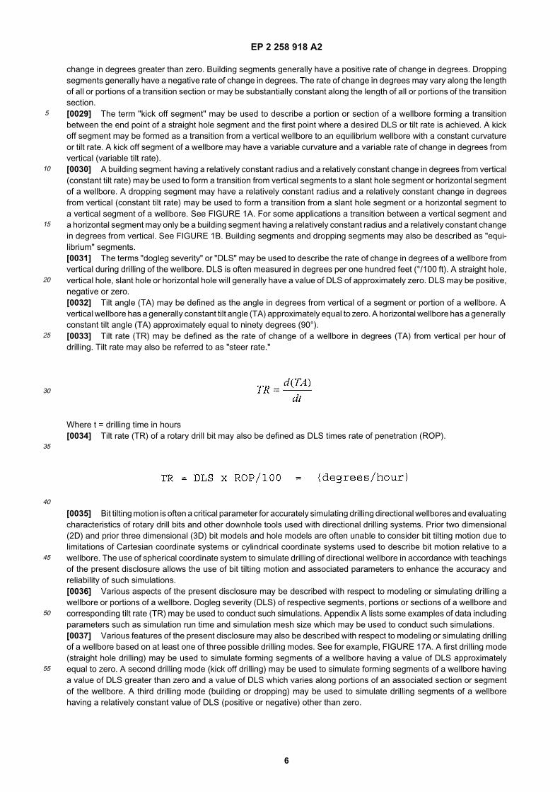
change in degrees greater than zero. Building segments generally have a positive rate of change in degrees. Droppingsegments generally have a negative rate of change in degrees. The rate of change in degrees may vary along the lengthof all or portions of a transition section or may be substantially constant along the length of all or portions of the transitionsection.[0029] The term "kick off segment" may be used to describe a portion or section of a wellbore forming a transitionbetween the end point of a straight hole segment and the first point where a desired DLS or tilt rate is achieved. A kickoff segment may be formed as a transition from a vertical wellbore to an equilibrium wellbore with a constant curvatureor tilt rate. A kick off segment of a wellbore may have a variable curvature and a variable rate of change in degrees fromvertical (variable tilt rate).[0030] A building segment having a relatively constant radius and a relatively constant change in degrees from vertical(constant tilt rate) may be used to form a transition from vertical segments to a slant hole segment or horizontal segmentof a wellbore. A dropping segment may have a relatively constant radius and a relatively constant change in degreesfrom vertical (constant tilt rate) may be used to form a transition from a slant hole segment or a horizontal segment toa vertical segment of a wellbore. See FIGURE 1A. For some applications a transition between a vertical segment anda horizontal segment may only be a building segment having a relatively constant radius and a relatively constant changein degrees from vertical. See FIGURE 1B. Building segments and dropping segments may also be described as "equi-librium" segments.[0031] The terms "dogleg severity" or "DLS" may be used to describe the rate of change in degrees of a wellbore fromvertical during drilling of the wellbore. DLS is often measured in degrees per one hundred feet (°/100 ft). A straight hole,vertical hole, slant hole or horizontal hole will generally have a value of DLS of approximately zero. DLS may be positive,negative or zero.[0032] Tilt angle (TA) may be defined as the angle in degrees from vertical of a segment or portion of a wellbore. Avertical wellbore has a generally constant tilt angle (TA) approximately equal to zero. A horizontal wellbore has a generallyconstant tilt angle (TA) approximately equal to ninety degrees (90°).[0033] Tilt rate (TR) may be defined as the rate of change of a wellbore in degrees (TA) from vertical per hour ofdrilling. Tilt rate may also be referred to as "steer rate."
Where t = drilling time in hours[0034] Tilt rate (TR) of a rotary drill bit may also be defined as DLS times rate of penetration (ROP).
[0035] Bit tilting motion is often a critical parameter for accurately simulating drilling directional wellbores and evaluatingcharacteristics of rotary drill bits and other downhole tools used with directional drilling systems. Prior two dimensional(2D) and prior three dimensional (3D) bit models and hole models are often unable to consider bit tilting motion due tolimitations of Cartesian coordinate systems or cylindrical coordinate systems used to describe bit motion relative to awellbore. The use of spherical coordinate system to simulate drilling of directional wellbore in accordance with teachingsof the present disclosure allows the use of bit tilting motion and associated parameters to enhance the accuracy andreliability of such simulations.[0036] Various aspects of the present disclosure may be described with respect to modeling or simulating drilling awellbore or portions of a wellbore. Dogleg severity (DLS) of respective segments, portions or sections of a wellbore andcorresponding tilt rate (TR) may be used to conduct such simulations. Appendix A lists some examples of data includingparameters such as simulation run time and simulation mesh size which may be used to conduct such simulations.[0037] Various features of the present disclosure may also be described with respect to modeling or simulating drillingof a wellbore based on at least one of three possible drilling modes. See for example, FIGURE 17A. A first drilling mode(straight hole drilling) may be used to simulate forming segments of a wellbore having a value of DLS approximatelyequal to zero. A second drilling mode (kick off drilling) may be used to simulate forming segments of a wellbore havinga value of DLS greater than zero and a value of DLS which varies along portions of an associated section or segmentof the wellbore. A third drilling mode (building or dropping) may be used to simulate drilling segments of a wellborehaving a relatively constant value of DLS (positive or negative) other than zero.
EP 2 258 918 A2
7
5
10
15
20
25
30
35
40
45
50
55
[0038] The terms "downhole data" and "downhole drilling conditions" may include, but are not limited to, wellbore dataand formation data such as listed on Appendix A. The terms "downhole data" and "downhole drilling conditions" mayalso include, but are not limited to, drilling equipment operating data such as listed on Appendix A.[0039] The terms "design parameters," "operating parameters," "wellbore parameters" and "formation parameters"may sometimes be used to refer to respective types of data such as listed on Appendix A. The terms "parameter" and"parameters" may be used to describe a range of data or multiple ranges of data. The terms "operating" and "operational"may sometimes be used interchangeably.[0040] Directional drilling equipment may be used to form wellbores having a wide variety of profiles or trajectories.Directional drilling system 20 and wellbore 60 as shown in FIGURE 1A may be used to describe various features of thepresent disclosure with respect to simulating drilling all or portions of a wellbore and designing or selecting drillingequipment such as a rotary drill bit based at least in part on such simulations.[0041] Directional drilling system 20 may include land drilling rig 22. However, teachings of the present disclosuremay be satisfactorily used to simulate drilling wellbores using drilling systems associated with offshore platforms, semi-submersible, drill ships and any other drilling system satisfactory for forming a wellbore extending through one or moredownhole formations. The present disclosure is not limited to directional drilling systems or land drilling rigs.[0042] Drilling rig 22 and associated directional drilling equipment 50 may be located proximate well head 24. Drillingrig 22 also includes rotary table 38, rotary drive motor 40 and other equipment associated with rotation of drill string 32within wellbore 60. Annulus 66 may be formed between the exterior of drill string 32 and the inside diameter of wellbore 60.[0043] For some applications drilling rig 22 may also include top drive motor or top drive unit 42. Blow out preventors(not expressly shown) and other equipment associated with drilling a wellbore may also be provided at well head 24.One or more pumps 26 may be used to pump drilling fluid 28 from fluid reservoir or pit 30 to one end of drill string 32extending from well head 24. Conduit 34 may be used to supply drilling mud from pump 26 to the one end of drillingstring 32 extending from well head 24. Conduit 36 may be used to return drilling fluid, formation cuttings and/or downholedebris from the bottom or end 62 of wellbore 60 to fluid reservoir or pit 30. Various types of pipes, tube and/or conduitsmay be used to form conduits 34 and 36.[0044] Drill string 32 may extend from well head 24 and may be coupled with a supply of drilling fluid such as pit orreservoir 30. Opposite end of drill string 32 may include bottom hole assembly 90 and rotary drill bit 100 disposedadjacent to end 62 of wellbore 60. As discussed later in more detail, rotary drill bit 100 may include one or more fluidflow passageways with respective nozzles disposed therein. Various types of drilling fluids may be pumped from reservoir30 through pump 26 and conduit 34 to the end of drill string 32 extending from well head 24. The drilling fluid may flowthrough a longitudinal bore (not expressly shown) of drill string 32 and exit from nozzles formed in rotary drill bit 100.[0045] At end 62 of wellbore 60 drilling fluid may mix with formation cuttings and other downhole debris proximate drillbit 100. The drilling fluid will then flow upwardly through annulus 66 to return formation cuttings and other downholedebris to well head 24. Conduit 36 may return the drilling fluid to reservoir 30. Various types of screens, filters and/orcentrifuges (not expressly shown) may be provided to remove formation cuttings and other downhole debris prior toreturning drilling fluid to pit 30.[0046] Bottom hole assembly 90 may include various components associated with a measurement while drilling (MWD)system that provides logging data and other information from the bottom of wellbore 60 to directional drilling equipment50. Logging data and other information may be communicated from end 62 of wellbore 60 through drill string 32 usingMWD techniques and converted to electrical signals at well surface 24. Electrical conduit or wires 52 may communicatethe electrical signals to input device 54. The logging data provided from input device 54 may then be directed to a dataprocessing system 56. Various displays 58 may be provided as part of directional drilling equipment 50.[0047] For some applications printer 59 and associated printouts 59a may also be used to monitor the performanceof drilling string 32, bottom hole assembly 90 and associated rotary drill bit 100. Outputs 57 may be communicated tovarious components associated with operating drilling rig 22 and may also be communicated to various remote locationsto monitor the performance of directional drilling system 20.[0048] Wellbore 60 may be generally described as a directional wellbore or a deviated wellbore having multiple seg-ments or sections. Section 60a of wellbore 60 may be defined by casing 64 extending from well head 24 to a selecteddownhole location. Remaining portions of wellbore 60 as shown in FIGURE 1A may be generally described as "openhole" or "uncased."[0049] Teachings of the present disclosure may be used to simulate drilling a wide variety of vertical, directional,deviated, slanted and/or horizontal wellbores. Teachings of the present disclosure are not limited to simulating drillingwellbore 60, designing drill bits for use in drilling wellbore 60 or selecting drill bits from existing designs for use in drillingwellbore 60.[0050] Wellbore 60 as shown in FIGURE 1A may be generally described as having multiple sections, segments orportions with respective values of DLS. The tilt rate for rotary drill bit 100 during formation of wellbore 60 will be a functionof DLS for each segment, section or portion of wellbore 60 times the rate of penetration for rotary drill bit 100 duringformation of the respective segment, section or portion thereof. The tilt rate of rotary drill bit 100 during formation of
EP 2 258 918 A2
8
5
10
15
20
25
30
35
40
45
50
55
straight hole sections or vertical section 80a and horizontal section 80c will be approximately equal to zero.[0051] Section 60a extending from well head 24 may be generally described as a vertical, straight hole section witha value of DLS approximately equal to zero. When the value of DLS is zero, rotary drill bit 100 will have a tile rate ofapproximately zero during formation of the corresponding section of wellbore 60.[0052] A first transition from vertical section 60a may be described as kick off section 60b. For some applications thevalue of DLS for kick off section 60b may be greater than zero and may vary from the end of vertical section 60a to thebeginning of a second transition segment or building section 60c. Building section 60c may be formed with relativelyconstant radius 70c and a substantially constant value of DLS. Building section 60c may also be referred to as thirdsection 60c of wellbore 60.[0053] Fourth section 60d may extend from build section 60c opposite from second section 60b. Fourth section 60dmay be described as a slant hole portion of wellbore 60. Section 60d may have a DLS of approximately zero. Fourthsection 60d may also be referred to as a "holding" section.[0054] Fifth section 60e may start at the end of holding section 60d. Fifth section 60e may be described as a "drop"section having a generally downward looking profile. Drop section 60e may have relatively constant radius 70e.[0055] Sixth section 60f may also be described as a holding section or slant hole section with a DLS of approximatelyzero. Section 60f as shown in FIGURE 1A is being formed by rotary drill bit 100, drill string 32 and associated componentsof drilling system 20.[0056] FIGURE 1B is a graphical representation of a specific type of directional wellbore represented by wellbore 80.For this example wellbore 80 may include three segments or three sections - vertical section 80a, building section 80band horizontal section 80c. Vertical section 80a and horizontal section 80c may be straight holes with a value of DLSapproximately equal to zero. Building section 80b may have a constant radius corresponding with a constant rate ofchange in degrees from vertical and a constant value of DLS. Tilt rate during formation building section 80b may beconstant if ROP of a drill bit forming build section 80b remains constant.[0057] Movement or motion of a rotary drill bit and associated drilling equipment in three dimensions (3D) duringformation of a segment, section or portion of a wellbore may be defined by a Cartesian coordinate system (X, Y, and Zaxes) and/or a spherical coordinate system (two angles ϕ and θ and a single radius p) in accordance with teachings ofthe present disclosure. Examples of Cartesian coordinate systems are shown in FIGURES 2A and 3A-3C. Examples ofspherical coordinate systems are shown in FIGURES 15A and 16. Various aspects of the present disclosure may includetranslating the location of downhole drilling equipment and adjacent portions of a wellbore between a Cartesian coordinatesystem and a spherical coordinate system. FIGURE 15A shows one example of translating the location of a single pointbetween a Cartesian coordinate system and a spherical coordinate system.[0058] Figure 1C shows one example of a system operable to simulate drilling a complex, directional wellbore inaccordance with teachings of this present disclosure. System 300 may include one or more processing resources 310operable to run software and computer programs incorporating teaching of the present disclosure. A general purposecomputer may be used as a processing resource. All or portions of software and computer programs used by processingresource 310 may be stored one or more memory resources 320. One or more input devices 330 may be operate tosupply data and other information to processing resources 310 and/or memory resources 320, A keyboard, keypad,touch screen and other digital input mechanisms may be used as an input device. Examples of such data are shownon Appendix A.[0059] Processing resources 310 may be operable to simulate drilling a directional wellbore in accordance with teach-ings of the present disclosure. Processing resources 310 may be operate to use various algorithms to make calculationsor estimates based on such simulations.[0060] Display resources 340 may be operable to display both data input into processing resources 310 and the resultsof simulations and/or calculations performed in accordance with teachings of the present disclosure. A copy of inputdata and results of such simulations and calculations may also be provided at printer 350.[0061] For some applications, processing resource 310 may be operably connected with communication network 360to accept inputs from remote locations and to provide the results of simulation and associated calculations to remotelocations and/or facilities such as directional drilling equipment 50 shown in FIGURE 1A.[0062] A Cartesian coordinate system generally includes a Z axis and an X axis and a Y axis which extend normal toeach other and normal to the Z axis. See for example FIGURE 2A. A Cartesian bit coordinate system may be definedby a Z axis extending along a rotational axis or bit rotational axis of the rotary drill bit. See FIGURE 2A. A Cartesian holecoordinate system (sometimes referred to as a "downhole coordinate system" or a "wellbore coordinate system") maybe defined by a Z axis extending along a rotational axis of the wellbore. See FIGURE 3B. In FIGURE 2A the X, Y andZ axes include subscript (b) to indicate a "bit coordinate system". In FIGURES 3A, 3B and 3C the X, Y and Z axes includesubscript (h) to indicate a "hole coordinate system".[0063] FIGURE 2A is a schematic drawing showing rotary drill bit 100. Rotary drill bit 100 may include bit body 120having a plurality of blades 128 with respective junk slots or fluid flow paths 140 formed therebetween. A plurality ofcutting elements 130 may be disposed on the exterior portions of each blade 128. Various parameters associated with
EP 2 258 918 A2
9
5
10
15
20
25
30
35
40
45
50
55
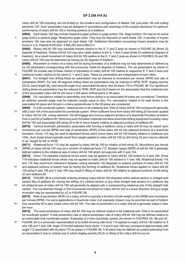
rotary drill bit 100 including, but not limited to, the location and configuration of blades 128, junk slots 140 and cuttingelements 130. Such parameters may be designed in accordance with teachings of the present disclosure for optimumperformance of rotary drill bit 100 in forming portions of a wellbore.[0064] Each blade 128 may include respective gage surface or gage portion 154. Gage surface 154 may be an activegage and/or a passive gage. Respective gage cutter 130g may be disposed on each blade 128. A plurality of impactarrestors 142 may also be disposed on each blade 128. Additional information concerning impact arrestors may befound in U.S. Patents 6,003,623, 5,595,252 and 4,889,017.[0065] Rotary drill bit 100 may translate linearly relative to the X, Y and Z axes as shown in FIGURE 2A (three (3)degrees of freedom). Rotary drill bit 100 may also rotate relative to the X, Y and Z axes (three (3) additional degrees offreedom). As a result movement of rotary drill bit 100 relative to the X, Y and Z axes as shown in FIGURES 2A and 2B,rotary drill bit 100 may be described as having six (6) degrees of freedom.[0066] Movement or motion of a rotary drill bit during formation of a wellbore may be fully determined or defined bysix (6) parameters corresponding with the previously noted six degrees of freedom. The six parameters as shown inFIGURE 2A include rate of linear motion or translation of rotary drill bit 100 relative to respective X, Y and Z axes androtational motion relative to the same X, Y and Z axes. These six parameters are independent of each other.[0067] For straight hole drilling these six parameters may be reduced to revolutions per minute (RPM) and rate ofpenetration (ROP). For kick off segment drilling these six parameters may be reduced to RPM, ROP, dogleg severity(DLS), bend length (BL) and azimuth angle of an associated tilt plane. See tilt plane 170 in FIGURE 3B. For equilibriumdrilling these six parameters may be reduced to RPM, ROP and DLS based on the assumption that the rotational axisof the associated rotary drill bit will move in the same vertical plane or tilt plane.[0068] For calculations related to steerability only forces acting in an associated tilt plane are considered. Thereforean arbitrary azimuth angle may be selected usually equal to zero. For calculations related to bit walk forces in theassociated tilt plane and forces in a plane perpendicular to the tilt plane are considered.[0069] In a bit coordinate system, rotational axis or bit rotational axis 104a of rotary drill bit 100 corresponds generallywith Z axis 104 of the associated bit coordinate system. When sufficient force from rotary drill string 32 has been appliedto rotary drill bit 100, cutting elements 130 will engage and remove adjacent portions of a downhole formation at bottomhole or end 62 of wellbore 60. Removing such formation materials will allow downhole drilling equipment including rotarydrill bit 100 and associated drill string 32 to tilt or move linearly relative to adjacent portions of wellbore 60.[0070] Various kinematic parameters associated with forming a wellbore using a rotary drill bit may be based uponrevolutions per minute (RPM) and rate of penetration (ROP) of the rotary drill bit into adjacent portions of a downholeformation. Arrow 110 may be used to represent forces which move rotary drill bit 100 linearly relative to rotational axis104a. Such linear forces typically result from weight applied to rotary drill bit 100 by drill string 32 and may be referredto as "weight on bit" or WOB.[0071] Rotational force 112 may be applied to rotary drill bit 100 by rotation of drill string 32. Revolutions per minute(RPM) of rotary drill bit 100 may be a function of rotational force 112. Rotation speed (RPM) of drill bit 100 is generallydefined relative to the rotational axis of rotary drill bit 100 which corresponds with Z axis 104.[0072] Arrow 116 indicates rotational forces which may be applied to rotary drill bit 100 relative to X axis 106. Arrow118 indicates rotational forces which may be applied to rotary drill bit 100 relative to Y axis 108. Rotational forces 116and 118 may result from interaction between cutting elements 130 disposed on exterior portions of rotary drill bit 100and adjacent portions of bottom hole 62 during the forming of wellbore 60. Rotational forces applied to rotary drill bit100 along X axis 106 and Y axis 108 may result in tilting of rotary drill bit 100 relative to adjacent portions of drill string32 and wellbore 60.[0073] FIGURE 2B is a schematic drawing showing rotary drill bit 100 disposed within vertical section or straight holesection 60a of wellbore 60. During the drilling of a vertical section or any other straight hole section of a wellbore, thebit rotational axis of rotary drill bit 100 will generally be aligned with a corresponding rotational axis of the straight holesection. The incremental change or the incremental movement of rotary drill bit 100 in a linear direction during a singlerevolution may be represented by ∆Z in FIGURE 2B.[0074] Rate of penetration (ROP) of a rotary drill bit is typically a function of both weight on bit (WOB) and revolutionsper minute (RPM). For some applications a downhole motor (not expressly shown) may be provided as part of bottomhole assembly 90 to also rotate rotary drill bit 100. The rate of penetration of a rotary drill bit is generally stated in feetper hour.[0075] The axial penetration of rotary drill bit 100 may be defined relative to bit rotational axis 104a in an associatedbit coordinate system. A side penetration rate or lateral penetration rate of rotary drill bit 100 may be defined relative toan associated hole coordinate system. Examples of a hole coordinate system are shown in FIGURES 3A, 3B and 3C.FIGURE 3A is a schematic representation of a model showing side force 114 applied to rotary drill bit 100 relative to Xaxis 106 and Y axis 108. Angle 72 formed between force vector 114 and X axis 106 may correspond approximately withangle 172 associated with tilt plane 170 as shown in FIGURE 3B. A tilt plane may be defined as a plane extending froman associated Z axis or vertical axis in which dogleg severity (DLS) or tilting of the rotary drill bit occurs.
EP 2 258 918 A2
10
5
10
15
20
25
30
35
40
45
50
55
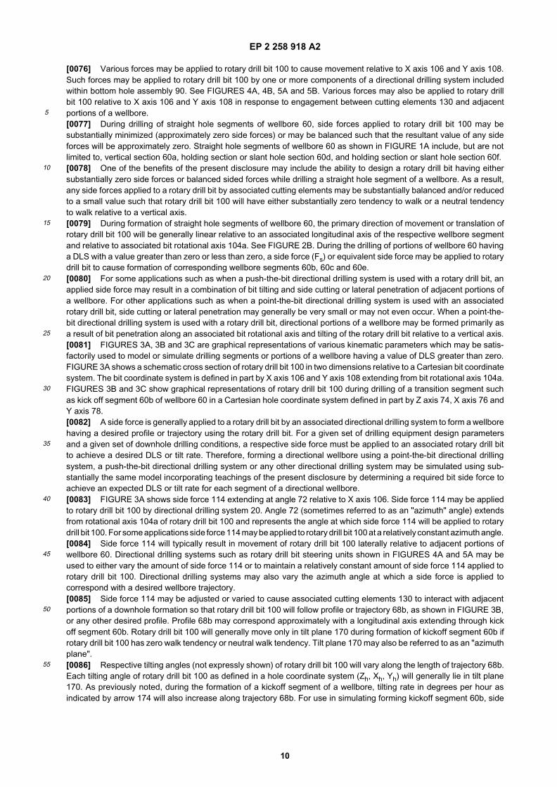
[0076] Various forces may be applied to rotary drill bit 100 to cause movement relative to X axis 106 and Y axis 108.Such forces may be applied to rotary drill bit 100 by one or more components of a directional drilling system includedwithin bottom hole assembly 90. See FIGURES 4A, 4B, 5A and 5B. Various forces may also be applied to rotary drillbit 100 relative to X axis 106 and Y axis 108 in response to engagement between cutting elements 130 and adjacentportions of a wellbore.[0077] During drilling of straight hole segments of wellbore 60, side forces applied to rotary drill bit 100 may besubstantially minimized (approximately zero side forces) or may be balanced such that the resultant value of any sideforces will be approximately zero. Straight hole segments of wellbore 60 as shown in FIGURE 1A include, but are notlimited to, vertical section 60a, holding section or slant hole section 60d, and holding section or slant hole section 60f.[0078] One of the benefits of the present disclosure may include the ability to design a rotary drill bit having eithersubstantially zero side forces or balanced sided forces while drilling a straight hole segment of a wellbore. As a result,any side forces applied to a rotary drill bit by associated cutting elements may be substantially balanced and/or reducedto a small value such that rotary drill bit 100 will have either substantially zero tendency to walk or a neutral tendencyto walk relative to a vertical axis.[0079] During formation of straight hole segments of wellbore 60, the primary direction of movement or translation ofrotary drill bit 100 will be generally linear relative to an associated longitudinal axis of the respective wellbore segmentand relative to associated bit rotational axis 104a. See FIGURE 2B. During the drilling of portions of wellbore 60 havinga DLS with a value greater than zero or less than zero, a side force (Fs) or equivalent side force may be applied to rotarydrill bit to cause formation of corresponding wellbore segments 60b, 60c and 60e.[0080] For some applications such as when a push-the-bit directional drilling system is used with a rotary drill bit, anapplied side force may result in a combination of bit tilting and side cutting or lateral penetration of adjacent portions ofa wellbore. For other applications such as when a point-the-bit directional drilling system is used with an associatedrotary drill bit, side cutting or lateral penetration may generally be very small or may not even occur. When a point-the-bit directional drilling system is used with a rotary drill bit, directional portions of a wellbore may be formed primarily asa result of bit penetration along an associated bit rotational axis and tilting of the rotary drill bit relative to a vertical axis.[0081] FIGURES 3A, 3B and 3C are graphical representations of various kinematic parameters which may be satis-factorily used to model or simulate drilling segments or portions of a wellbore having a value of DLS greater than zero.FIGURE 3A shows a schematic cross section of rotary drill bit 100 in two dimensions relative to a Cartesian bit coordinatesystem. The bit coordinate system is defined in part by X axis 106 and Y axis 108 extending from bit rotational axis 104a.FIGURES 3B and 3C show graphical representations of rotary drill bit 100 during drilling of a transition segment suchas kick off segment 60b of wellbore 60 in a Cartesian hole coordinate system defined in part by Z axis 74, X axis 76 andY axis 78.[0082] A side force is generally applied to a rotary drill bit by an associated directional drilling system to form a wellborehaving a desired profile or trajectory using the rotary drill bit. For a given set of drilling equipment design parametersand a given set of downhole drilling conditions, a respective side force must be applied to an associated rotary drill bitto achieve a desired DLS or tilt rate. Therefore, forming a directional wellbore using a point-the-bit directional drillingsystem, a push-the-bit directional drilling system or any other directional drilling system may be simulated using sub-stantially the same model incorporating teachings of the present disclosure by determining a required bit side force toachieve an expected DLS or tilt rate for each segment of a directional wellbore.[0083] FIGURE 3A shows side force 114 extending at angle 72 relative to X axis 106. Side force 114 may be appliedto rotary drill bit 100 by directional drilling system 20. Angle 72 (sometimes referred to as an "azimuth" angle) extendsfrom rotational axis 104a of rotary drill bit 100 and represents the angle at which side force 114 will be applied to rotarydrill bit 100. For some applications side force 114 may be applied to rotary drill bit 100 at a relatively constant azimuth angle.[0084] Side force 114 will typically result in movement of rotary drill bit 100 laterally relative to adjacent portions ofwellbore 60. Directional drilling systems such as rotary drill bit steering units shown in FIGURES 4A and 5A may beused to either vary the amount of side force 114 or to maintain a relatively constant amount of side force 114 applied torotary drill bit 100. Directional drilling systems may also vary the azimuth angle at which a side force is applied tocorrespond with a desired wellbore trajectory.[0085] Side force 114 may be adjusted or varied to cause associated cutting elements 130 to interact with adjacentportions of a downhole formation so that rotary drill bit 100 will follow profile or trajectory 68b, as shown in FIGURE 3B,or any other desired profile. Profile 68b may correspond approximately with a longitudinal axis extending through kickoff segment 60b. Rotary drill bit 100 will generally move only in tilt plane 170 during formation of kickoff segment 60b ifrotary drill bit 100 has zero walk tendency or neutral walk tendency. Tilt plane 170 may also be referred to as an "azimuthplane".[0086] Respective tilting angles (not expressly shown) of rotary drill bit 100 will vary along the length of trajectory 68b.Each tilting angle of rotary drill bit 100 as defined in a hole coordinate system (Zh, Xh, Yh) will generally lie in tilt plane170. As previously noted, during the formation of a kickoff segment of a wellbore, tilting rate in degrees per hour asindicated by arrow 174 will also increase along trajectory 68b. For use in simulating forming kickoff segment 60b, side
EP 2 258 918 A2
11
5
10
15
20
25
30
35
40
45
50
55
penetration rate, side penetration azimuth angle, tilting rate and tilt plane azimuth angle may be defined in a holecoordinate system which includes Z axis 74, X axis 76 and Y axis 78.[0087] Arrow 174 corresponds with the variable tilt rate of rotary drill bit 100 relative to vertical at any one locationalong trajectory 68b. During movement of rotary drill bit 100 along profile or trajectory 68a, the respective tilt angle ateach location on trajectory 68a will generally increase relative to Z axis 74 of the hole coordinate system shown inFIGURE 3B. For embodiments such as shown in FIGURE 3B, the tilt angle at each point on trajectory 68b will beapproximately equal to an angle formed by a respective tangent extending from the point in question and intersectingZ axis 74. Therefore, the tilt rate will also vary along the length of trajectory 168.[0088] During the formation of kick off segment 60b and any other portions of a wellbore in which the value of DLS iseither greater than or less than zero and is not constant, rotary drill bit 100 may experience side cutting motion, bit tiltingmotion and axial penetration in a direction associated with cutting or removing of formation materials from the end orbottom of a wellbore.[0089] For embodiments such as shown in FIGURES 3A, 3B and 3C directional drilling system 20 may cause rotarydrill bit 100 to move in the same azimuth plane 170 during formation of kick off segment 60b. FIGURES 3B and 3C showrelatively constant azimuth plane angle 172 relative to the X axis 76 and Y axis 78. Arrow 114 as shown in FIGURE 3Brepresents a side force applied to rotary drill bit 100 by directional drilling system 20. Arrow 114 will generally extendnormal to rotational axis 104a of rotary drill bit 100. Arrow 114 will also be disposed in tilt plane 170. A side force appliedto a rotary drill bit in a tilt plane by an associate rotary drill bit steering unit or directional drilling system may also bereferred to as a "steer force."[0090] During the formation of a directional wellbore such as shown in FIGURE 3B, without consideration of bit walk,rotational axis 104a of rotary drill bit 100 and a longitudinal axis of bottom hole assembly 90 may generally lie in tilt plane170. Rotary drill bit 100 will experience tilting motion in tilt plane 170 while rotating relative to rotational axis 104a. Thetilting motion may result from a side force or steer force applied to rotary drill bit 100 by a directional steering unit suchas shown in FIGURES 4A AND 4B or 5A and 5B of an associated directional drilling system. The tilting motion resultsfrom a combination of side forces and/or axial forces applied to rotary drill bit 100 by directional drilling system 20.[0091] If rotary drill bit 100 walks, either left or right, bit 100 will generally not move in the same azimuth plane or tiltplane 170 during formation of kickoff segment 60b. As discussed later in more detail with respect to FIGURES 9 and10 rotary drill bit 100 may also experience a walk force (FW) as indicated by arrow 177. Arrow 177 as shown in FIGURES3B and 3C represents a walk force which will cause rotary drill bit 100 to "walk" left relative to tilt plane 170. Simulationsof forming a wellbore in accordance with teachings of the present disclosure may be used to modify cutting elements,bit face profiles, gages and other characteristics of a rotary drill bit to substantially reduce or minimize the walk forcerepresented by arrow 177 or to provide a desired right walk rate or left walk rate.[0092] Various features of the present disclosure will be discussed with respect to directional drilling equipment in-cluding rotary drills such as shown in FIGURES 4A, 4B, 51 and 5B. These features may be described with respect tovertical axis 74 or Z axis 74 of a Cartesian hole coordinate system such as shown in FIGURE 3B. During drilling of avertical segment or other types of straight hole segments, vertical axis 74 will generally be aligned with and correspondto an associate longitudinal axis of the vertical segment or straight hole segment. Vertical axis 74 will also generally bealigned with and correspond to an associate bit rotational axis during such straight hole drilling.[0093] FIGURE 4A shows portions of bottom hole assembly 90a disposed in a generally vertical portion 60a of wellbore60 as rotary drill bit 100a begins to form kick off segment 60b. Bottom hole assembly 90a may include rotary drill bitsteering unit 92a operable to apply side force 114 to rotary drill bit 100a. Steering unit 92a may be one portion of a push-the-bit directional drilling system.[0094] Push-the-bit directional drilling systems generally require simultaneous axial penetration and side penetrationin order to drill directionally. Bit motion associated with push-the-bit directional drilling systems is often a combinationof axial bit penetration, bit rotation, bit side cutting and bit tilting. Simulation of forming a wellbore using a push-the-bitdirectional drilling system based on a 3D model operable to consider bit tilting motion may result in a more accuratesimulation. Some of the benefits of using a 3D model operable to consider bit tilting motion in accordance with teachingsof the present disclosure will be discussed with respect to FIGURES 6A-6D.[0095] Steering unit 92a may extend arm 94a to apply force 114a to adjacent portions of wellbore 60 and maintaindesired contact between steering unit 92a and adjacent portions of wellbore 60. Side forces 114 and 114a may beapproximately equal to each other. If there is no weight on rotary drill bit 100a, no axial penetration will occur at end orbottom hole 62 of wellbore 60. Side cutting will generally occur as portions of rotary drill bit 100a engage and removeadjacent portions of wellbore 60a.[0096] Figure 4B shows various parameters associated with a push-the-bit directional drilling system. Steering unit92a will generally include bent subassembly 96a. A wide variety of bent subassemblies (sometimes referred to as "bentsubs") may be satisfactorily used to allow drill string 32 to rotate drill bit 100a while steering unit 92a pushes or appliesrequired force to move rotary drill bit 100a at a desired tilt rate relative to vertical axis 74. Arrow 200 represents the rateof penetration relative to the rotational axis of rotary drill bit 100a (ROPa). Arrow 202 represents the rate of side penetration
EP 2 258 918 A2
12
5
10
15
20
25
30
35
40
45
50
55
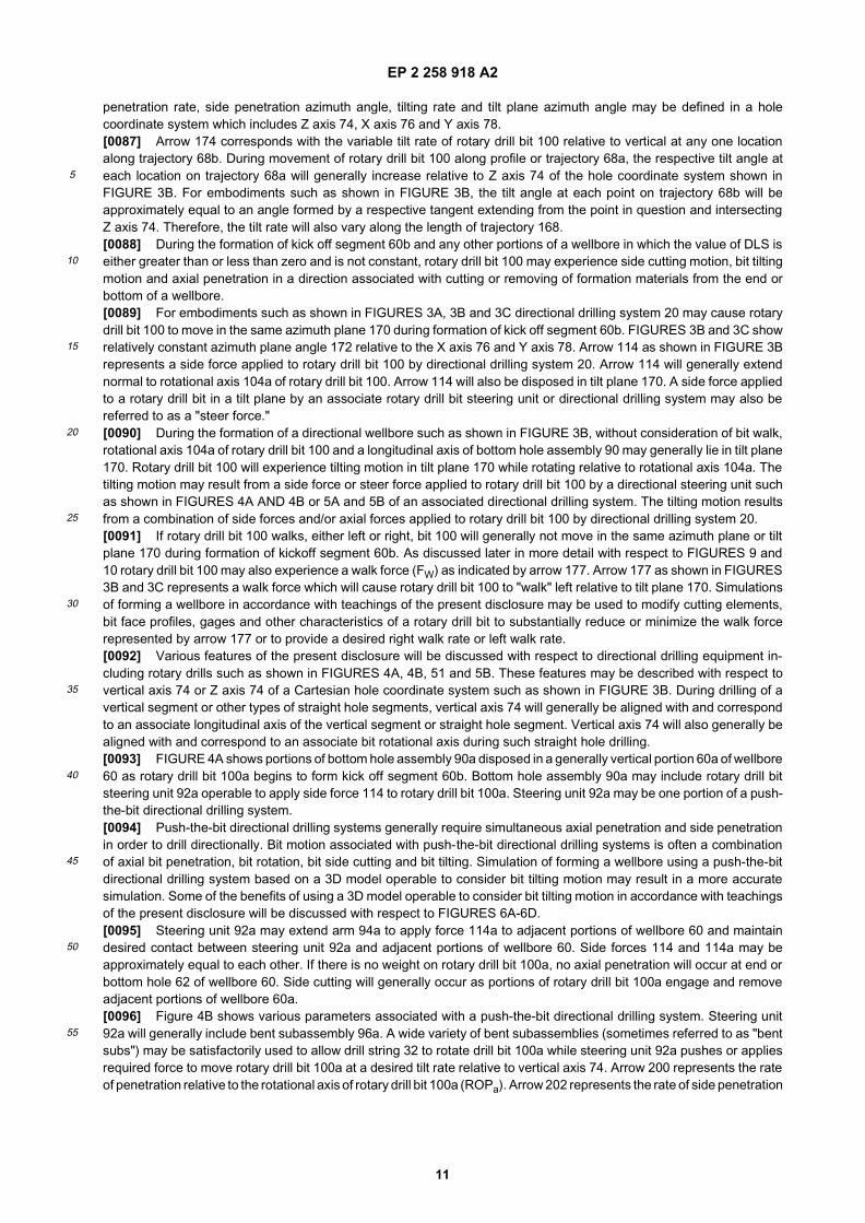
of rotary drill bit 200 (ROPs) as steering unit 92a pushes or directs rotary drill bit 100a along a desired trajectory or path.[0097] Tilt rate 174 and associated tilt angle may remain relatively constant for some portions of a directional wellboresuch as a slant hole segment or a horizontal hole segment. For other portions of a directional wellbore tilt rate 174 mayincrease during formation of respective portions of the wellbore such as a kick off segment. Bend length 204a may bea function of the distance between arm 94a contacting adjacent portions of wellbore 60 and the end of rotary drill bit 100a.[0098] Bend length (LBend) may be used as one of the inputs to simulate forming portions of a wellbore in accordancewith teachings of the present disclosure. Bend length or tilt length may be generally described as the distance from afulcrum point of an associated bent subassembly to a furthest location on a "bit face" or "bit face profile" of an associatedrotary drill bit. The furthest location may also be referred to as the extreme end of the associated rotary drill bit.[0099] Some directional drilling techniques and systems may not include a bent subassembly. For such applicationsbend length may be taken as the distance from a first contact point between an associated bottom hole assembly withadjacent portions of the wellbore to an extreme end of a bit face on an associated rotary drill bit.[0100] During formation of a kick off section or any other portion of a deviated wellbore, axial penetration of anassociated drill bit will occur in response to weight on bit (WOB) and/or axial forces applied to the drill bit by a downholedrilling motor. Also, bit tilting motion relative to a bent sub, not side cutting or lateral penetration, will typically result froma side force or lateral force applied to the drill bit as a component of WOB and/or axial forces applied by a downholedrilling motor. A model such as shown in FIGURES 17A-17G may then be used to obtain the total bit lateral force (Flat)as a function of time. Bit motion is often a combination of bit axial penetration and bit tilting while drilling a directionalwellbore.[0101] When bit axial penetration rate is very small (close to zero) and the distance from the bit to the bent sub orbend length is very large, side penetration or side cutting may be a dominated motion of the drill bit. The resulting bitmotion may or may not be continuous when using a push-the-bit directional drilling system depending upon the weighton bit, revolutions per minute, applied side force and other parameters associated with rotary drill bit 100a.[0102] FIGURE 4C is a schematic drawing showing one example of a rotary drill bit which may be designed in ac-cordance with teachings of the present disclosure for optimum performance in a push-the-bit directional drilling system.For example, a three dimensional model such as shown in FIGURES 17A-17G may be used to design a rotary drill bitwith optimum active and/or passive gage length for use with a push-the-bit directional drilling system. Rotary drill bit100a may be generally described as a fixed cutter drill bit. For some applications rotary drill bit 100a may also bedescribed as a matrix drill bit, steel body drill bit and/or a PDC drill bit.[0103] Rotary drill bit 100a may include bit body 120a with shank 122a. The dimensions and configuration of bit body120a and shank 122a may be substantially modified as appropriate for each rotary drill bit. See FIGURES 5C and 5D.[0104] Shank 122a may include bit breaker slots 124a formed on the exterior thereof. Pin 126a may be formed as anintegral part of shank 122a extending from bit body 120a. Various types of threaded connections, including but not limitedto, API connections and premium threaded connections may be formed on the exterior of pin 126a.[0105] A longitudinal bore (not expressly shown) may extend from end 121a of pin 126a through shank 122a and intobit body 120a. The longitudinal bore may be used to communicate drilling fluids from drilling string 32 to one or morenozzles (not expressly shown) disposed in bit body 120a. Nozzle outlet 150a is shown in FIGURE 4C.[0106] A plurality of cutter blades 128a may be disposed on the exterior of bit body 120a. Respective junk slots orfluid flow slots 148a may be formed between adjacent blades 128a. Each blade 128 may include a plurality of cuttingelements 130 formed from very hard materials associated with forming a wellbore in a downhole formation. For someapplications cutting elements 130 may also be described as "face cutters".[0107] Respective gage cutter 130g may be disposed on each blade 128a. For embodiments such as shown in FIGURE4C rotary drill bit 100a may be described as having an active gage or active gage elements disposed on exterior portionof each blade 128a. Gage surface 154 of each blade 128a may also include a plurality of active gage elements 156.Active gage elements 156 may be formed from various types of hard abrasive materials sometimes referred to as"hardfacing". Active elements 156 may also be described as "buttons" or "gage inserts". As discussed later in more detailwith respect to FIGURES 7B, 8A and 8B active gage elements may contact adjacent portions of a wellbore and removesome formation materials as a result of such contact.[0108] Exterior portions of bit body 120a opposite from shank 122a may be generally described as a "bit face" or "bitface profile." As discussed later in more detail with respect to rotary drill bit 100e as shown in FIGURE 7A, a bit faceprofile may include a generally cone-shaped recess or indentation having a plurality of inner cutters and a plurality ofshoulder cutters disposed on exterior portions of each blade 128a. One of the benefits of the present disclosure includesthe ability to design a rotary drill bit having an optimum number of inner cutters, shoulder cutters and gage cutters toprovide desired walk rate, bit steerability, and bit controllability.[0109] FIGURE 5A shows portions of bottom hole assembly 90b disposed in a generally vertical section of wellbore60a as rotary drill bit 100b begins to form kick off segment 60b. Bottom hole assembly 90b includes rotary drill bit steeringunit 92b which may provide one portion of a point-the-bit directional drilling system.[0110] Point-the-bit directional drilling systems typically form a directional wellbore using a combination of axial bit
EP 2 258 918 A2
13
5
10
15
20
25
30
35
40
45
50
55
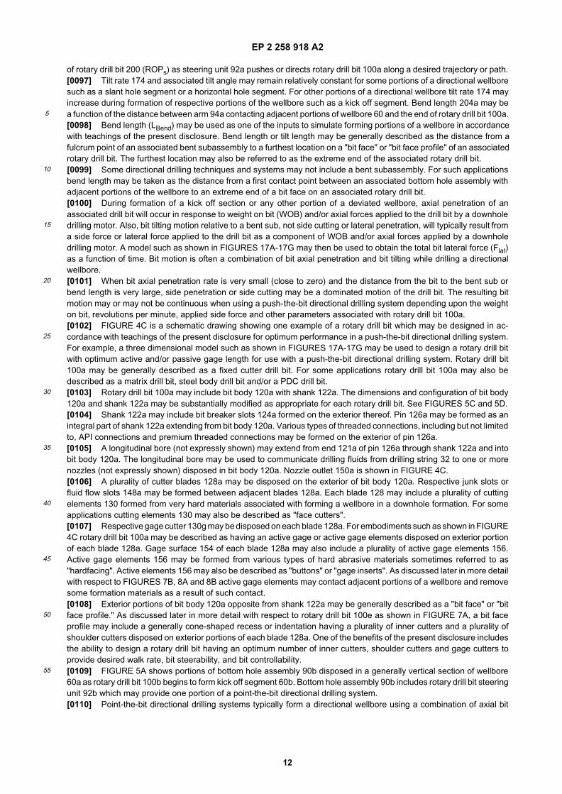
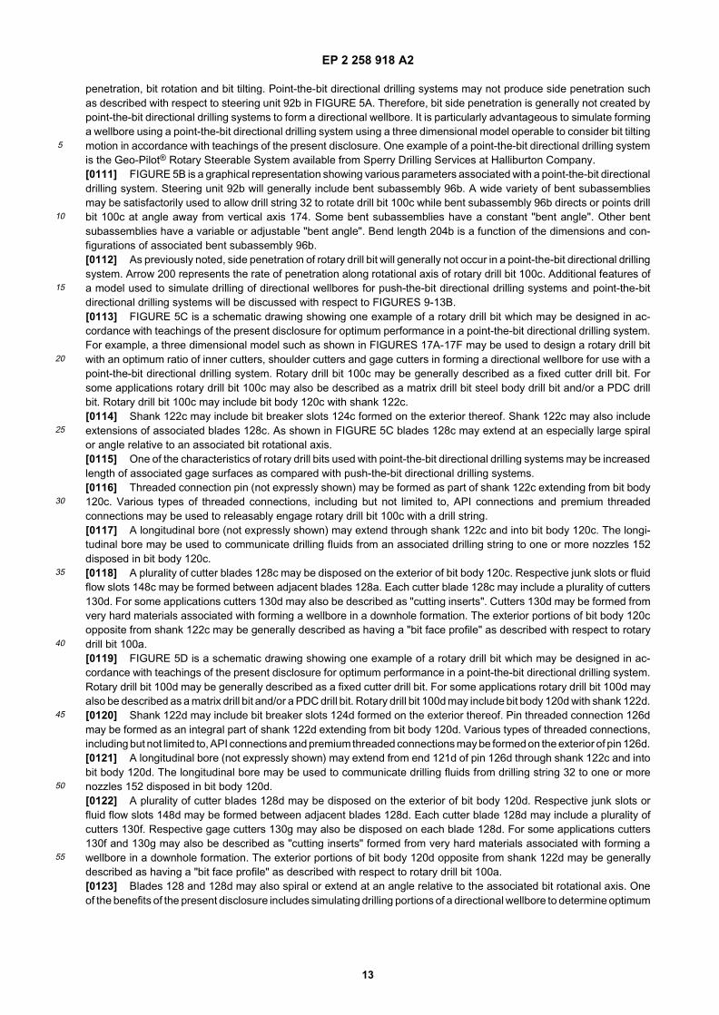
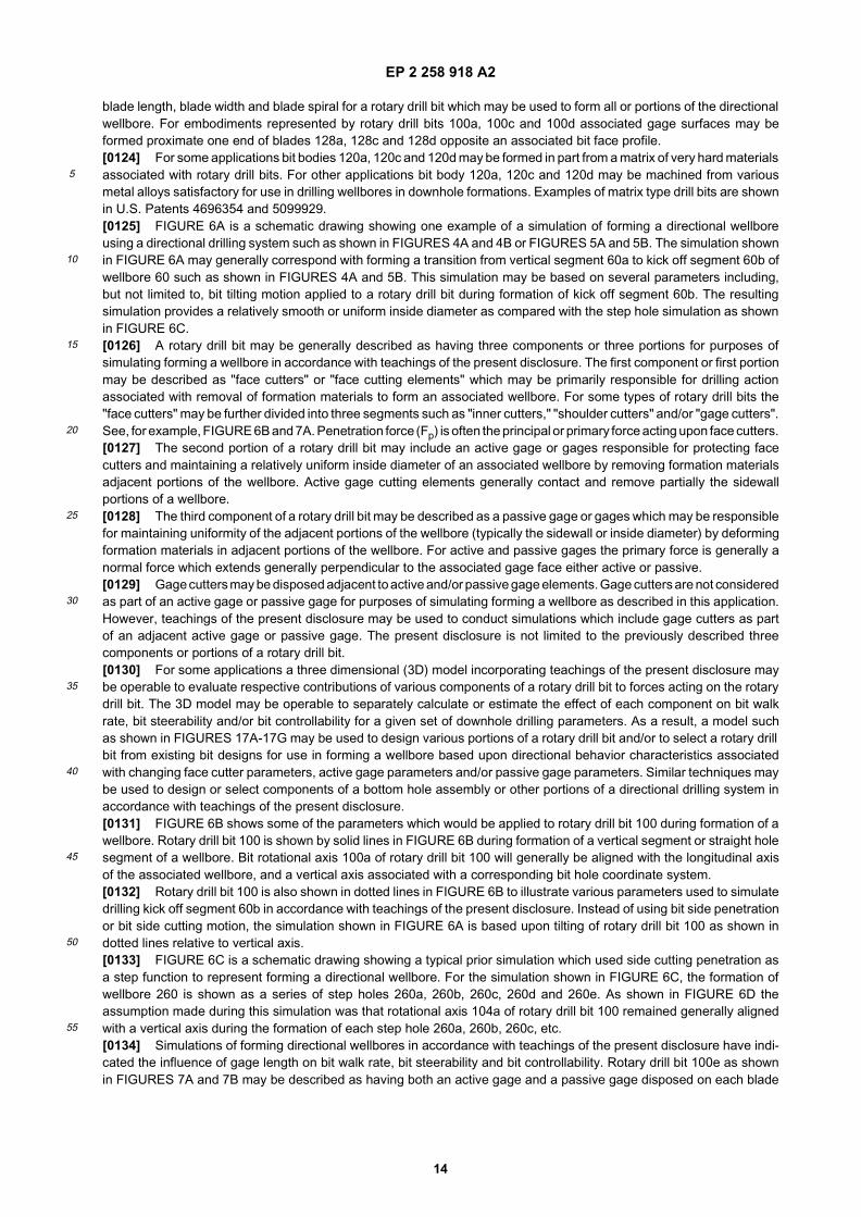
penetration, bit rotation and bit tilting. Point-the-bit directional drilling systems may not produce side penetration suchas described with respect to steering unit 92b in FIGURE 5A. Therefore, bit side penetration is generally not created bypoint-the-bit directional drilling systems to form a directional wellbore. It is particularly advantageous to simulate forminga wellbore using a point-the-bit directional drilling system using a three dimensional model operable to consider bit tiltingmotion in accordance with teachings of the present disclosure. One example of a point-the-bit directional drilling systemis the Geo-Pilot® Rotary Steerable System available from Sperry Drilling Services at Halliburton Company.[0111] FIGURE 5B is a graphical representation showing various parameters associated with a point-the-bit directionaldrilling system. Steering unit 92b will generally include bent subassembly 96b. A wide variety of bent subassembliesmay be satisfactorily used to allow drill string 32 to rotate drill bit 100c while bent subassembly 96b directs or points drillbit 100c at angle away from vertical axis 174. Some bent subassemblies have a constant "bent angle". Other bentsubassemblies have a variable or adjustable "bent angle". Bend length 204b is a function of the dimensions and con-figurations of associated bent subassembly 96b.[0112] As previously noted, side penetration of rotary drill bit will generally not occur in a point-the-bit directional drillingsystem. Arrow 200 represents the rate of penetration along rotational axis of rotary drill bit 100c. Additional features ofa model used to simulate drilling of directional wellbores for push-the-bit directional drilling systems and point-the-bitdirectional drilling systems will be discussed with respect to FIGURES 9-13B.[0113] FIGURE 5C is a schematic drawing showing one example of a rotary drill bit which may be designed in ac-cordance with teachings of the present disclosure for optimum performance in a point-the-bit directional drilling system.For example, a three dimensional model such as shown in FIGURES 17A-17F may be used to design a rotary drill bitwith an optimum ratio of inner cutters, shoulder cutters and gage cutters in forming a directional wellbore for use with apoint-the-bit directional drilling system. Rotary drill bit 100c may be generally described as a fixed cutter drill bit. Forsome applications rotary drill bit 100c may also be described as a matrix drill bit steel body drill bit and/or a PDC drillbit. Rotary drill bit 100c may include bit body 120c with shank 122c.[0114] Shank 122c may include bit breaker slots 124c formed on the exterior thereof. Shank 122c may also includeextensions of associated blades 128c. As shown in FIGURE 5C blades 128c may extend at an especially large spiralor angle relative to an associated bit rotational axis.[0115] One of the characteristics of rotary drill bits used with point-the-bit directional drilling systems may be increasedlength of associated gage surfaces as compared with push-the-bit directional drilling systems.[0116] Threaded connection pin (not expressly shown) may be formed as part of shank 122c extending from bit body120c. Various types of threaded connections, including but not limited to, API connections and premium threadedconnections may be used to releasably engage rotary drill bit 100c with a drill string.[0117] A longitudinal bore (not expressly shown) may extend through shank 122c and into bit body 120c. The longi-tudinal bore may be used to communicate drilling fluids from an associated drilling string to one or more nozzles 152disposed in bit body 120c.[0118] A plurality of cutter blades 128c may be disposed on the exterior of bit body 120c. Respective junk slots or fluidflow slots 148c may be formed between adjacent blades 128a. Each cutter blade 128c may include a plurality of cutters130d. For some applications cutters 130d may also be described as "cutting inserts". Cutters 130d may be formed fromvery hard materials associated with forming a wellbore in a downhole formation. The exterior portions of bit body 120copposite from shank 122c may be generally described as having a "bit face profile" as described with respect to rotarydrill bit 100a.[0119] FIGURE 5D is a schematic drawing showing one example of a rotary drill bit which may be designed in ac-cordance with teachings of the present disclosure for optimum performance in a point-the-bit directional drilling system.Rotary drill bit 100d may be generally described as a fixed cutter drill bit. For some applications rotary drill bit 100d mayalso be described as a matrix drill bit and/or a PDC drill bit. Rotary drill bit 100d may include bit body 120d with shank 122d.[0120] Shank 122d may include bit breaker slots 124d formed on the exterior thereof. Pin threaded connection 126dmay be formed as an integral part of shank 122d extending from bit body 120d. Various types of threaded connections,including but not limited to, API connections and premium threaded connections may be formed on the exterior of pin 126d.[0121] A longitudinal bore (not expressly shown) may extend from end 121d of pin 126d through shank 122c and intobit body 120d. The longitudinal bore may be used to communicate drilling fluids from drilling string 32 to one or morenozzles 152 disposed in bit body 120d.[0122] A plurality of cutter blades 128d may be disposed on the exterior of bit body 120d. Respective junk slots orfluid flow slots 148d may be formed between adjacent blades 128d. Each cutter blade 128d may include a plurality ofcutters 130f. Respective gage cutters 130g may also be disposed on each blade 128d. For some applications cutters130f and 130g may also be described as "cutting inserts" formed from very hard materials associated with forming awellbore in a downhole formation. The exterior portions of bit body 120d opposite from shank 122d may be generallydescribed as having a "bit face profile" as described with respect to rotary drill bit 100a.[0123] Blades 128 and 128d may also spiral or extend at an angle relative to the associated bit rotational axis. Oneof the benefits of the present disclosure includes simulating drilling portions of a directional wellbore to determine optimum
EP 2 258 918 A2
14
5
10
15
20
25
30
35
40
45
50
55
blade length, blade width and blade spiral for a rotary drill bit which may be used to form all or portions of the directionalwellbore. For embodiments represented by rotary drill bits 100a, 100c and 100d associated gage surfaces may beformed proximate one end of blades 128a, 128c and 128d opposite an associated bit face profile.[0124] For some applications bit bodies 120a, 120c and 120d may be formed in part from a matrix of very hard materialsassociated with rotary drill bits. For other applications bit body 120a, 120c and 120d may be machined from variousmetal alloys satisfactory for use in drilling wellbores in downhole formations. Examples of matrix type drill bits are shownin U.S. Patents 4696354 and 5099929.[0125] FIGURE 6A is a schematic drawing showing one example of a simulation of forming a directional wellboreusing a directional drilling system such as shown in FIGURES 4A and 4B or FIGURES 5A and 5B. The simulation shownin FIGURE 6A may generally correspond with forming a transition from vertical segment 60a to kick off segment 60b ofwellbore 60 such as shown in FIGURES 4A and 5B. This simulation may be based on several parameters including,but not limited to, bit tilting motion applied to a rotary drill bit during formation of kick off segment 60b. The resultingsimulation provides a relatively smooth or uniform inside diameter as compared with the step hole simulation as shownin FIGURE 6C.[0126] A rotary drill bit may be generally described as having three components or three portions for purposes ofsimulating forming a wellbore in accordance with teachings of the present disclosure. The first component or first portionmay be described as "face cutters" or "face cutting elements" which may be primarily responsible for drilling actionassociated with removal of formation materials to form an associated wellbore. For some types of rotary drill bits the"face cutters" may be further divided into three segments such as "inner cutters," "shoulder cutters" and/or "gage cutters".See, for example, FIGURE 6B and 7A. Penetration force (Fp) is often the principal or primary force acting upon face cutters.[0127] The second portion of a rotary drill bit may include an active gage or gages responsible for protecting facecutters and maintaining a relatively uniform inside diameter of an associated wellbore by removing formation materialsadjacent portions of the wellbore. Active gage cutting elements generally contact and remove partially the sidewallportions of a wellbore.[0128] The third component of a rotary drill bit may be described as a passive gage or gages which may be responsiblefor maintaining uniformity of the adjacent portions of the wellbore (typically the sidewall or inside diameter) by deformingformation materials in adjacent portions of the wellbore. For active and passive gages the primary force is generally anormal force which extends generally perpendicular to the associated gage face either active or passive.[0129] Gage cutters may be disposed adjacent to active and/or passive gage elements. Gage cutters are not consideredas part of an active gage or passive gage for purposes of simulating forming a wellbore as described in this application.However, teachings of the present disclosure may be used to conduct simulations which include gage cutters as partof an adjacent active gage or passive gage. The present disclosure is not limited to the previously described threecomponents or portions of a rotary drill bit.[0130] For some applications a three dimensional (3D) model incorporating teachings of the present disclosure maybe operable to evaluate respective contributions of various components of a rotary drill bit to forces acting on the rotarydrill bit. The 3D model may be operable to separately calculate or estimate the effect of each component on bit walkrate, bit steerability and/or bit controllability for a given set of downhole drilling parameters. As a result, a model suchas shown in FIGURES 17A-17G may be used to design various portions of a rotary drill bit and/or to select a rotary drillbit from existing bit designs for use in forming a wellbore based upon directional behavior characteristics associatedwith changing face cutter parameters, active gage parameters and/or passive gage parameters. Similar techniques maybe used to design or select components of a bottom hole assembly or other portions of a directional drilling system inaccordance with teachings of the present disclosure.[0131] FIGURE 6B shows some of the parameters which would be applied to rotary drill bit 100 during formation of awellbore. Rotary drill bit 100 is shown by solid lines in FIGURE 6B during formation of a vertical segment or straight holesegment of a wellbore. Bit rotational axis 100a of rotary drill bit 100 will generally be aligned with the longitudinal axisof the associated wellbore, and a vertical axis associated with a corresponding bit hole coordinate system.[0132] Rotary drill bit 100 is also shown in dotted lines in FIGURE 6B to illustrate various parameters used to simulatedrilling kick off segment 60b in accordance with teachings of the present disclosure. Instead of using bit side penetrationor bit side cutting motion, the simulation shown in FIGURE 6A is based upon tilting of rotary drill bit 100 as shown indotted lines relative to vertical axis.[0133] FIGURE 6C is a schematic drawing showing a typical prior simulation which used side cutting penetration asa step function to represent forming a directional wellbore. For the simulation shown in FIGURE 6C, the formation ofwellbore 260 is shown as a series of step holes 260a, 260b, 260c, 260d and 260e. As shown in FIGURE 6D theassumption made during this simulation was that rotational axis 104a of rotary drill bit 100 remained generally alignedwith a vertical axis during the formation of each step hole 260a, 260b, 260c, etc.[0134] Simulations of forming directional wellbores in accordance with teachings of the present disclosure have indi-cated the influence of gage length on bit walk rate, bit steerability and bit controllability. Rotary drill bit 100e as shownin FIGURES 7A and 7B may be described as having both an active gage and a passive gage disposed on each blade
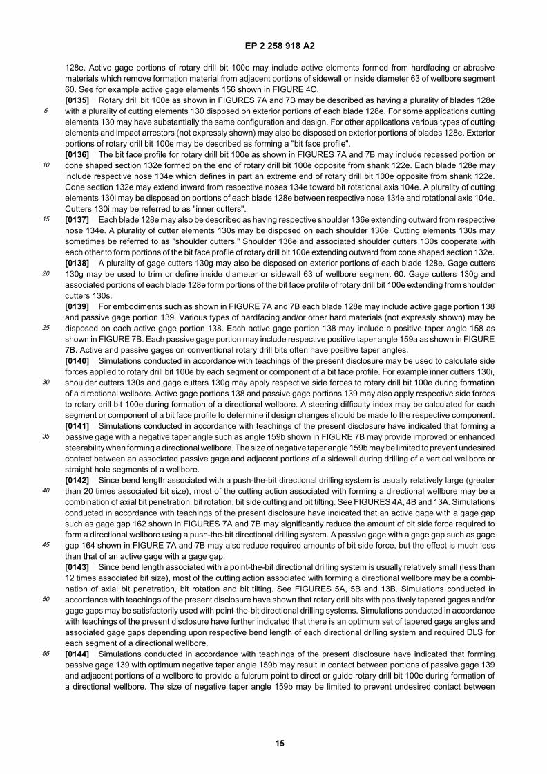
EP 2 258 918 A2
15
5
10
15
20
25
30
35
40
45
50
55
128e. Active gage portions of rotary drill bit 100e may include active elements formed from hardfacing or abrasivematerials which remove formation material from adjacent portions of sidewall or inside diameter 63 of wellbore segment60. See for example active gage elements 156 shown in FIGURE 4C.[0135] Rotary drill bit 100e as shown in FIGURES 7A and 7B may be described as having a plurality of blades 128ewith a plurality of cutting elements 130 disposed on exterior portions of each blade 128e. For some applications cuttingelements 130 may have substantially the same configuration and design. For other applications various types of cuttingelements and impact arrestors (not expressly shown) may also be disposed on exterior portions of blades 128e. Exteriorportions of rotary drill bit 100e may be described as forming a "bit face profile".[0136] The bit face profile for rotary drill bit 100e as shown in FIGURES 7A and 7B may include recessed portion orcone shaped section 132e formed on the end of rotary drill bit 100e opposite from shank 122e. Each blade 128e mayinclude respective nose 134e which defines in part an extreme end of rotary drill bit 100e opposite from shank 122e.Cone section 132e may extend inward from respective noses 134e toward bit rotational axis 104e. A plurality of cuttingelements 130i may be disposed on portions of each blade 128e between respective nose 134e and rotational axis 104e.Cutters 130i may be referred to as "inner cutters".[0137] Each blade 128e may also be described as having respective shoulder 136e extending outward from respectivenose 134e. A plurality of cutter elements 130s may be disposed on each shoulder 136e. Cutting elements 130s maysometimes be referred to as "shoulder cutters." Shoulder 136e and associated shoulder cutters 130s cooperate witheach other to form portions of the bit face profile of rotary drill bit 100e extending outward from cone shaped section 132e.[0138] A plurality of gage cutters 130g may also be disposed on exterior portions of each blade 128e. Gage cutters130g may be used to trim or define inside diameter or sidewall 63 of wellbore segment 60. Gage cutters 130g andassociated portions of each blade 128e form portions of the bit face profile of rotary drill bit 100e extending from shouldercutters 130s.[0139] For embodiments such as shown in FIGURE 7A and 7B each blade 128e may include active gage portion 138and passive gage portion 139. Various types of hardfacing and/or other hard materials (not expressly shown) may bedisposed on each active gage portion 138. Each active gage portion 138 may include a positive taper angle 158 asshown in FIGURE 7B. Each passive gage portion may include respective positive taper angle 159a as shown in FIGURE7B. Active and passive gages on conventional rotary drill bits often have positive taper angles.[0140] Simulations conducted in accordance with teachings of the present disclosure may be used to calculate sideforces applied to rotary drill bit 100e by each segment or component of a bit face profile. For example inner cutters 130i,shoulder cutters 130s and gage cutters 130g may apply respective side forces to rotary drill bit 100e during formationof a directional wellbore. Active gage portions 138 and passive gage portions 139 may also apply respective side forcesto rotary drill bit 100e during formation of a directional wellbore. A steering difficulty index may be calculated for eachsegment or component of a bit face profile to determine if design changes should be made to the respective component.[0141] Simulations conducted in accordance with teachings of the present disclosure have indicated that forming apassive gage with a negative taper angle such as angle 159b shown in FIGURE 7B may provide improved or enhancedsteerability when forming a directional wellbore. The size of negative taper angle 159b may be limited to prevent undesiredcontact between an associated passive gage and adjacent portions of a sidewall during drilling of a vertical wellbore orstraight hole segments of a wellbore.[0142] Since bend length associated with a push-the-bit directional drilling system is usually relatively large (greaterthan 20 times associated bit size), most of the cutting action associated with forming a directional wellbore may be acombination of axial bit penetration, bit rotation, bit side cutting and bit tilting. See FIGURES 4A, 4B and 13A. Simulationsconducted in accordance with teachings of the present disclosure have indicated that an active gage with a gage gapsuch as gage gap 162 shown in FIGURES 7A and 7B may significantly reduce the amount of bit side force required toform a directional wellbore using a push-the-bit directional drilling system. A passive gage with a gage gap such as gagegap 164 shown in FIGURE 7A and 7B may also reduce required amounts of bit side force, but the effect is much lessthan that of an active gage with a gage gap.[0143] Since bend length associated with a point-the-bit directional drilling system is usually relatively small (less than12 times associated bit size), most of the cutting action associated with forming a directional wellbore may be a combi-nation of axial bit penetration, bit rotation and bit tilting. See FIGURES 5A, 5B and 13B. Simulations conducted inaccordance with teachings of the present disclosure have shown that rotary drill bits with positively tapered gages and/orgage gaps may be satisfactorily used with point-the-bit directional drilling systems. Simulations conducted in accordancewith teachings of the present disclosure have further indicated that there is an optimum set of tapered gage angles andassociated gage gaps depending upon respective bend length of each directional drilling system and required DLS foreach segment of a directional wellbore.[0144] Simulations conducted in accordance with teachings of the present disclosure have indicated that formingpassive gage 139 with optimum negative taper angle 159b may result in contact between portions of passive gage 139and adjacent portions of a wellbore to provide a fulcrum point to direct or guide rotary drill bit 100e during formation ofa directional wellbore. The size of negative taper angle 159b may be limited to prevent undesired contact between
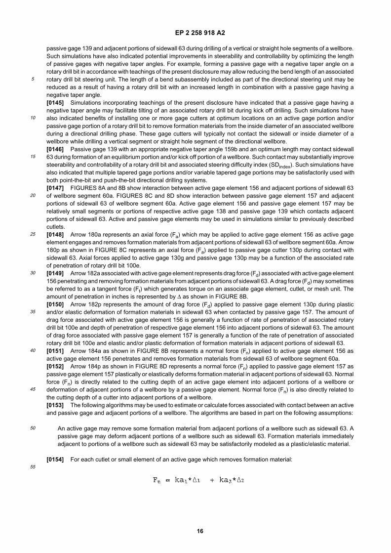
EP 2 258 918 A2
16
5
10
15
20
25
30
35
40
45
50
55
passive gage 139 and adjacent portions of sidewall 63 during drilling of a vertical or straight hole segments of a wellbore.Such simulations have also indicated potential improvements in steerability and controllability by optimizing the lengthof passive gages with negative taper angles. For example, forming a passive gage with a negative taper angle on arotary drill bit in accordance with teachings of the present disclosure may allow reducing the bend length of an associatedrotary drill bit steering unit. The length of a bend subassembly included as part of the directional steering unit may bereduced as a result of having a rotary drill bit with an increased length in combination with a passive gage having anegative taper angle.[0145] Simulations incorporating teachings of the present disclosure have indicated that a passive gage having anegative taper angle may facilitate tilting of an associated rotary drill bit during kick off drilling. Such simulations havealso indicated benefits of installing one or more gage cutters at optimum locations on an active gage portion and/orpassive gage portion of a rotary drill bit to remove formation materials from the inside diameter of an associated wellboreduring a directional drilling phase. These gage cutters will typically not contact the sidewall or inside diameter of awellbore while drilling a vertical segment or straight hole segment of the directional wellbore.[0146] Passive gage 139 with an appropriate negative taper angle 159b and an optimum length may contact sidewall63 during formation of an equilibrium portion and/or kick off portion of a wellbore. Such contact may substantially improvesteerability and controllability of a rotary drill bit and associated steering difficulty index (SDindex). Such simulations havealso indicated that multiple tapered gage portions and/or variable tapered gage portions may be satisfactorily used withboth point-the-bit and push-the-bit directional drilling systems.[0147] FIGURES 8A and 8B show interaction between active gage element 156 and adjacent portions of sidewall 63of wellbore segment 60a. FIGURES 8C and 8D show interaction between passive gage element 157 and adjacentportions of sidewall 63 of wellbore segment 60a. Active gage element 156 and passive gage element 157 may berelatively small segments or portions of respective active gage 138 and passive gage 139 which contacts adjacentportions of sidewall 63. Active and passive gage elements may be used in simulations similar to previously describedcutlets.[0148] Arrow 180a represents an axial force (Fa) which may be applied to active gage element 156 as active gageelement engages and removes formation materials from adjacent portions of sidewall 63 of wellbore segment 60a. Arrow180p as shown in FIGURE 8C represents an axial force (Fa) applied to passive gage cutter 130p during contact withsidewall 63. Axial forces applied to active gage 130g and passive gage 130p may be a function of the associated rateof penetration of rotary drill bit 100e.[0149] Arrow 182a associated with active gage element represents drag force (Fd) associated with active gage element156 penetrating and removing formation materials from adjacent portions of sidewall 63. A drag force (Fd) may sometimesbe referred to as a tangent force (Ft) which generates torque on an associate gage element, cutlet, or mesh unit. Theamount of penetration in inches is represented by ∆ as shown in FIGURE 8B.[0150] Arrow 182p represents the amount of drag force (Fd) applied to passive gage element 130p during plasticand/or elastic deformation of formation materials in sidewall 63 when contacted by passive gage 157. The amount ofdrag force associated with active gage element 156 is generally a function of rate of penetration of associated rotarydrill bit 100e and depth of penetration of respective gage element 156 into adjacent portions of sidewall 63. The amountof drag force associated with passive gage element 157 is generally a function of the rate of penetration of associatedrotary drill bit 100e and elastic and/or plastic deformation of formation materials in adjacent portions of sidewall 63.[0151] Arrow 184a as shown in FIGURE 8B represents a normal force (Fn) applied to active gage element 156 asactive gage element 156 penetrates and removes formation materials from sidewall 63 of wellbore segment 60a.[0152] Arrow 184p as shown in FIGURE 8D represents a normal force (Fn) applied to passive gage element 157 aspassive gage element 157 plastically or elastically deforms formation material in adjacent portions of sidewall 63. Normalforce (Fn) is directly related to the cutting depth of an active gage element into adjacent portions of a wellbore ordeformation of adjacent portions of a wellbore by a passive gage element. Normal force (Fn) is also directly related tothe cutting depth of a cutter into adjacent portions of a wellbore.[0153] The following algorithms may be used to estimate or calculate forces associated with contact between an activeand passive gage and adjacent portions of a wellbore. The algorithms are based in part on the following assumptions:
An active gage may remove some formation material from adjacent portions of a wellbore such as sidewall 63. Apassive gage may deform adjacent portions of a wellbore such as sidewall 63. Formation materials immediatelyadjacent to portions of a wellbore such as sidewall 63 may be satisfactorily modeled as a plastic/elastic material.
[0154] For each cutlet or small element of an active gage which removes formation material:
EP 2 258 918 A2
17
5
10
15
20
25
30
35
40
45
50
55
[0155] Where ∆1 is the cutting depth of a respective cutlet (gage element) extending into adjacent portions of a wellbore,and ∆2 is the deformation depth of hole wall by a respective cutlet.[0156] ka1, ka2, ka3 and ka4 are coefficients related to rock properties and fluid properties often determined by testingof anticipated downhole formation material.[0157] For each cutlet or small element of a passive gage which deforms formation material:
Where ∆p is depth of deformation of formation material by a respective cutlet of adjacent portions of the wellbore.[0158] kp1, kp2, kp3 are coefficients related to rock properties and fluid properties and may be determined by testingof anticipated downhole formation material.[0159] Many rotary drill bits have a tendency to "walk" or move laterally relative to a longitudinal axis of a wellborewhile forming the wellbore. The tendency of a rotary drill bit to walk or move laterally may be particularly noticeable whenforming directional wellbores and/or when the rotary drill bit penetrates adjacent layers of different formation materialand/or inclined formation layers. An evaluation of bit walk rates requires consideration of all forces acting on rotary drillbit 100 which extend at an angle relative to tilt plane 170. Such forces include interactions between bit face profile activeand/or passive gages associated with rotary drill bit 100 and adjacent portions of the bottom hole may be evaluated.[0160] FIGURE 9 is a schematic drawing showing portions of rotary drill bit 100 in section in a two dimensional holecoordinate system represented by X axis 76 and Y axis 78. Arrow 114 represents a side force applied to rotary drill bit100 from directional drilling system 20 in tilt plane 170. This side force generally acts normal to bit rotational axis 104aof rotary drill bit 100. Arrow 176 represents side cutting or side displacement (Ds) of rotary drill bit 100 projected in thehole coordinate system in response to interactions between exterior portions of rotary drill bit 100 and adjacent portionsof a downhole formation. Bit walk angle 186 is measured from Fs to Ds.[0161] When angle 186 is less than zero (opposite to bit rotation direction represented by arrow 178) rotary drill bit100 will have a tendency to walk to the left of applied side force 114 and titling plane 170. When angle 186 is greaterthan zero (the same as bit rotation direction represented by arrow 178) rotary drill bit 100 will have a tendency to walkright relative to applied side force 114 and tilt plane 170. When bit walk angle 186 is approximately equal to zero (0),rotary drill bit 100 will have approximately a zero (0) walk rate or neutral walk tendency.[0162] FIGURE 10 is a schematic drawing showing an alternative definition of bit walk angle when a side displacement(Ds) or side cutting motion represented by arrow 176a is applied to bit 100 during simulation of forming a directionalwellbore. An associated force represented by arrow 114c required to act on rotary drill bit 100 to produce the appliedside displacement (Ds) may be calculated and projected in the same hole coordinate system. Applied side displacement(Ds) represented by arrow 176a and calculated force (Fc) represented by arrow 114c form bit walk angle 186. Bit walkangle 186 is measured from Fc to Ds.[0163] When angle 186 is less than zero (opposite to bit rotation direction represented by arrow 178), rotary drill bit100 will have a tendency to walk to the left of calculated side force 176 and titling plane 170. When angle 186 is greaterthan zero (the same as bit rotation direction represented by arrow 178) rotary drill bit 100 will have a tendency to walkright relative to calculated side force 176 and tilt plane 170. When bit walk angle 186 is approximately equal to zero (0),rotary drill bit 100 will have approximately a zero (0) walk rate or neutral walk tendency.[0164] As discussed later in this application both walk force (Fw) and walk moment or bending moment (Mw) alongwith an associated bit steer rate and steer force may be used to calculate a resulting bit walk rate. However, the valueof walk force and walk moment are generally small compared to an associated steer force and therefore need to be
EP 2 258 918 A2
18
5
10
15
20
25
30
35
40
45
50
55
calculated accurately. Bit walk rate may be a function of bit geometry and downhole drilling conditions such as rate ofpenetration, revolutions per minute, lateral penetration rate, bit tilting rate or steer rate and downhole formation charac-teristics.[0165] Simulations of forming a directional wellbore based on a 3D model incorporating teachings of the presentdisclosure indicate that for a given axial penetration rate and a given revolutions per minute and a given bottom holeassembly configuration that there is a critical tilt rate. When the tilt rate is greater than the critical tilt rate, the associateddrill bit may begin to walk either right or left relative to the associated wellbore. Simulations incorporating teachings ofthe present disclosure indicate that transition drilling through an inclined formation such as shown in FIGURES 14A,14B and 14C may change a bit walk tendencies from bit walk right to bit walk left.[0166] For some applications the magnitude of bit side forces required to achieve desired DLS or tilt rates for a givenset of drilling equipment parameters and downhole drilling conditions may be used as an indication of associated bitsteerability or controllability. See FIGURE 11 for one example. Fluctuations in the amount of bit side force, torque on bit(TOB) and/or bit bending moment may also be used to provide an evaluation of bit controllability or bit stability duringthe formation of various portions of a directional wellbore. See FIGURE 12 for one example.[0167] FIGURE 11 is a schematic drawing showing rotary drill bit 100 in solid lines in a first position associated withforming a generally vertical section of a wellbore. Rotary drill bit 100 is also shown in dotted lines in FIGURE 11 showinga directional portion of a wellbore such as kick off segment 60a. The graph shown in FIGURE 11 indicates that theamount of bit side force required to produce a tilt rate corresponding with the associated dogleg severity (DLS) willgenerally increase as the dogleg severity of the deviated wellbore increases. The shape of curve 194 as shown inFIGURE 11 may be a function of both rotary drill bit design parameters and associated downhole drilling conditions.[0168] As previously noted fluctuations in drilling parameters such as bit side force, torque on bit and/or bit bendingmoment may also be used to provide an evaluation of bit controllability or bit stability.[0169] FIGURE 12 is a graphical representation showing variations in torque on bit with respect to revolutions perminute during the tilting of rotary drill bit 100 as shown in FIGURE 12. The amount of variation or the ∆TOB as shownin FIGURE 12 may be used to evaluate the stability of various rotary drill bit designs for the same given set of downholedrilling conditions. The graph shown in FIGURE 11 is based on a given rate of penetration, a given RPM and a givenset of downhole formation data.[0170] For some applications steerability of a rotary drill bit may be evaluated using the following steps. Design datafor the associated drilling equipment may be inputted into a three dimensional model incorporating teachings of thepresent disclosure. For example design parameters associated with a drill bit may be inputted into a computer system(see for example FIGURE 1C) having a software application such as shown and described in FIGURES 17A-17G.Alternatively, rotary drill bit design parameters may be read into a computer program from a bit design file or drill bitdesign parameters such as International Association of Drilling Contractors (IADC) data may be read into the computerprogram.[0171] Drilling equipment operating data such as RPM, ROP, and tilt rate for an associated rotary drill bit may beselected or defined for each simulation. A tilt rate or DLS may be defined for one or more formation layers and anassociated inclination angle for adjacent formation layers. Formation data such as rock compressive strength, transitionlayers and inclination angle of each transition layer may also be defined or selected.[0172] Total run time, total number of bit rotations and/or respective time intervals per the simulation may also bedefined or selected for each simulation. 3D simulations or modeling using a system such as shown in FIGURE 1C andsoftware or computer programs as outlined in FIGURES 17A-17G may then be conducted to calculate or estimatevarious forces including side forces acting on an associated rotary drill bit or other associated downhole drilling equipment.Average walk rate of an associated rotary drill bit may also be calculated over the simulated time interval.[0173] The preceding steps may be conducted by changing DLS or tilt rate and repeated to develop a curve of bit sideforces corresponding with each value of DLS. A curve of side force versus DLS may then be plotted (See FIGURE 11)and bit steerability calculated. Another set of rotary drill bit operating parameters may then be inputted into the computerand steps 3 through 7 repeated to provide additional curves of side force (Fs) versus dogleg severity (DLS). Bit steerabilitymay then be defined by the set of curves showing side force versus DLS.[0174] FIGURE 13A may be described as a graphical representation showing portions of a bottom hole assembly androtary drill bit 100a associated with a push-the-bit directional drilling system. A push-the-bit directional drilling systemmay be sometimes have a bend length greater than 20 to 35 times an associated bit size or corresponding bit diameterin inches. Bend length 204a associated with a push-the-bit directional drilling system is generally much greater thanlength 206a of rotary drill bit 100a. Bend length 204a may also be much greater than or equal to the diameter DB1 ofrotary drill bit 100a.[0175] FIGURE 13B may be generally described as a graphical representation showing portions of a bottom holeassemble and rotary drill bit 100c associated with a point-the-bit directional drilling system. A point-the-bit directionaldrilling system may sometimes have a bend length less than or equal to 12 times the bit size. For the example shownin FIGURE 13B, bend length 204c associated with a point-the-bit directional drilling system may be approximately two
EP 2 258 918 A2
19
5
10
15
20
25
30
35
40
45
50
55
or three times greater than length 206c of rotary drill bit 100c. Length 206c of rotary drill bit 100c may be significantlygreater than diameter DB2 of rotary drill bit 100c. The length of a rotary drill bit used with a push-the-bit drilling systemwill generally be less than the length of a rotary drill bit used with a point-the-bit directional drilling system.[0176] Due to the combination of tilting and axial penetration, rotary drill bits may have side cutting motion. This isparticularly true during kick off drilling. However, the rate of side cutting is generally not a constant for a drill bit and ischanged along drill bit axis. The rate of side penetration of rotary drill bits 100a and 100c is represented by arrow 202.The rate of side penetration is generally a function of tilting rate and associated bend length 204a and 204d. For rotarydrill bits having a relatively long bit length and particularly a relatively long gage length such as shown in FIGURE 5C,the rate of side penetration at point 208 may be much less than the rate of side penetration at point 210. As the lengthof a rotary drill bit increases the side penetration rate decreases from the shank as compared with the extreme end ofthe rotary drill bit. The difference in rate of side penetration between point 208 and 210 may be small, but the effects onbit steerability may be very large.[0177] Simulations conducted in accordance with teachings of the present disclosure may be used to calculate bitwalk rate for a given set of data (See for example Appendix A) Average walk force and/or average walk rate may alsobe calculated for one or more simulated time intervals.[0178] Walk force (FW) may be obtained by simulating forming a directional wellbore as a function of drilling time.Walk force (FW) corresponds with the amount of force which is applied to a rotary drill bit in a plane extending generallyperpendicular to an associated azimuth plane or tilt plane.[0179] FIGURES 14A, 14B and 14C are schematic drawings showing representations of various interactions betweenrotary drill bit 100 and adjacent portions of first formation 221 and second formation layer 222. Software or computerprograms such as outlined in FIGURES 17A-17G may be used to simulate or model interactions with multiple or laminatedrock layers forming a wellbore.[0180] For some applications first formation layer may have a rock compressibility strength which is substantially largerthan the rock compressibility strength of second layer 222. For embodiments such as shown in FIGURES 14A, 14B and14C first layer 221 and second layer 222 may be inclined or disposed at inclination angle 224 (sometimes referred toas a "transition angle") relative to each other and relative to vertical. Inclination angle 224 may be generally describedas a positive angle relative associated vertical axis 74.[0181] Three dimensional simulations may be performed to evaluate forces required for rotary drilling bit 100 to forma substantially vertical wellbore extending through first layer 221 and second layer 222. See FIGURE 14A. Three di-mensional simulations may also be performed to evaluate forces which must be applied to rotary drill bit 100 to form adirectional wellbore extending through first layer 221 and second layer 222 at various angles such as shown in FIGURES14B and 14C. A simulation using software or a computer program such as outlined in FIGURE 17A-17G may be usedcalculate the side forces which must be applied to rotary drill bit 100 to form a wellbore to tilt rotary drill bit 100 at anangle relative to vertical axis 74.[0182] FIGURE 14D is a schematic drawing showing a three dimensional meshed representation of the bottom holeor end of wellbore segment 60a corresponding with rotary drill bit 100 forming a generally vertical or horizontal wellboreextending therethrough as shown in FIGURE 14A. Transition plane 226 as shown in FIGURE 14D represents a dividingline or boundary between rock formation layer and rock formation layer 222. Transition plane 226 may extend alonginclination angle 224 relative to vertical.[0183] The terms "meshed" and "mesh analysis" may describe analytical procedures used to evaluate and studycomplex structures such as cutters, active and passive gages, other portions of a rotary drill bit, other downhole toolsassociated with drilling a wellbore, bottom hole configurations of a wellbore and/or other portions of a wellbore. Theinterior surface of end 62 of wellbore 60a may be finely meshed into many small segments or "mesh units" to assist withdetermining interactions between cutters and other portions of a rotary drill bit and adjacent formation materials as therotary drill bit removes formation materials from end 62 to form wellbore 60. See FIGURE 14D. The use of mesh unitsmay be particularly helpful to analyze distributed forces and variations in cutting depth of respective mesh units or cutletsas an associated cutter interacts with adjacent formation materials.[0184] Three dimensional mesh representations of the bottom of a wellbore and/or various portions of a rotary drill bitand/or other downhole tools may be used to simulate interactions between the rotary drill bit and adjacent portions ofthe wellbore. For example cutting depth and cutting area of each cutting element or cutlet during one revolution of theassociated rotary drill bit may be used to calculate forces acting on each cutting element. Simulation may then updatethe configuration or pattern of the associated bottom hole and forces acting on each cutter. For some applications thenominal configuration and size of a unit such as shown in FIGURE 14D may be approximately 0.5 mm per side. However,the actual configuration size of each mesh unit may vary substantially due to complexities of associated bottom holegeometry and respective cutters used to remove formation materials.[0185] Systems and methods incorporating teachings of the present disclosure may also be used to simulate or modelforming a directional wellbore extending through various combinations of soft and medium strength formation with multiplehard stringers disposed within both soft and/or medium strength formations. Such formations may sometimes be referred
EP 2 258 918 A2
20
5
10
15
20
25
30
35
40
45
50
55
to as "interbedded" formations. Simulations and associated calculations may be similar to simulations and calculationsas described with respect to FIGURES 14A-14D.[0186] Spherical coordinate systems such as shown in FIGURES 15A-15C may be used to define the location ofrespective cutlets, gage elements and/or mesh units of a rotary drill bit and adjacent portions of a wellbore. The locationof each mesh unit of a rotary drill bit and associated wellbore may be represented by a single valued function of anglephi (ϕ), angle theta (θ) and radius rho (ρ) in three dimensions (3D) relative to Z axis 74. The same Z axis 74 may beused in a three dimensional Cartesian coordinate system or a three dimensional spherical coordinate system.[0187] The location of a single point such as center 198 of cutter 130 may be defined in the three dimensional sphericalcoordinate system of FIGURE 15A by angle ϕ and radius ρ. This same location may be converted to a Cartesian holecoordinate system of Xh, Yh, Zh using radius r and angle theta (θ) which corresponds with the angular orientation ofradius r relative to X axis 76. Radius r intersects Z axis 74 at the same point radius ρ intersects Z axis 74. Radius r isdisposed in the same plane as Z axis 74 and radius ρ. Various examples of algorithms and/or matrices which may beused to transform data in a Cartesian coordinate system to a spherical coordinate system and to transform data in aspherical coordinate system to a Cartesian coordinate system are discussed later in this application.[0188] As previously noted, a rotary drill bit may generally be described as having a "bit face profile" which includesa plurality of cutters operable to interact with adjacent portions of a wellbore to remove formation materials therefrom.Examples of a bit face profile and associated cutters are shown in FIGURES 2A, 2B, 4C, 5C, 5D, 7A and 7B. The cuttingedge of each cutter on a rotary drill bit may be represented in three dimensions using either a Cartesian coordinatesystem or a spherical coordinate system.[0189] FIGURES 15B and 15C show graphical representations of various forces associated with portions of cutter130 interacting with adjacent portions of bottom hole 62 of wellbore 60. For examples such as shown in FIGURE 15Bcutter 130 may be located on the shoulder of an associated rotary drill bit.[0190] FIGURE 15B and 15C also show one example of a local cutter coordinate system used at a respective timestep or interval to evaluate or interpolate interaction between one cutter and adjacent portions of a wellbore. A localcutter coordinate system may more accurately interpolate complex bottom hole geometry and bit motion used to updatea 3D simulation of a bottom hole geometry such as shown in FIGURE 14D based on simulated interactions between arotary drill bit and adjacent formation materials. Numerical algorithms and interpolations incorporating teachings of thepresent disclosure may more accurately calculate estimated cutting depth and cutting area of each cutter.[0191] In a local cutter coordinate system there are two forces, drag force (Fd) and penetration force (Fp), acting oncutter 130 during interaction with adjacent portions of wellbore 60. When forces acting on each cutter 130 are projectedinto a bit coordinate system there will be three forces, axial force (Fa), drag force (Fd) and penetration force (Fp). Thepreviously described forces may also act upon impact arrestors and gage cutters.[0192] For purposes of simulating cutting or removing formation materials adjacent to end 62 of wellbore 60 as shownin FIGURE 15B, cutter 130 may be divided into small elements or cutlets 131a, 131b, 131c and 131d. Forces representedby arrows Fe may be simulated as acting on cutlet 131a-131d at respective points such as 191 and 200. For example,respective drag forces may be calculated for each cutlet 131a-131d acting at respective points such as 191 and 200.The respective drag forces may be summed or totaled to determine total drag force (Fd) acting on cutter 130. In a similarmanner, respective penetration forces may also be calculated for each cutlet 131a-131d acting at respective points suchas 191 and 200. The respective penetration forces may be summed or totaled to determine total penetration force (Fp)acting on cutter 130.[0193] FIGURE 15C shows cutter 130 in a local cutter coordinate system defined in part by cutter axis 198. Drag force(Fd) represented by arrow 196 corresponds with the summation of respective drag forces calculated for each cutlet 131a-131d. Penetration force (Fp) represented by arrow 192 corresponds with the summation of respective penetration forcescalculated for each cutlet 131a-131d.[0194] FIGURE 16 shows portions of bottom hole 62 in a spherical hole coordinate system defined in part by Z axis74 and radius Rh. The configuration of a bottom hole generally corresponds with the configuration of an associated bitface profile used to form the bottom hole. For example, portion 62i of bottom hole 62 may be formed by inner cutters130i. Portion 62s of bottom hole 62 may be formed by shoulder cutters 130s. Side wall 63 may be formed by gage cutters130g.[0195] Single point 200 as shown in FIGURE 16 is located on the exterior of cutter 130s. In the hole coordinate system,the location of point 200 is a function of angle ϕh and radius ρh · FIGURE 16 also shows the same single point 200 onthe exterior of cutter 130s in a local cutter coordinate system defined by vertical axis Zc and radius Rc. In the local cuttercoordinate system, the location of point 200 is a function of angle ϕc and radius ρc. Cutting depth 212 associated withsingle point 200 and associated removal of formation material from bottom hole 62 corresponds with the shortest distancebetween point 200 and portion 62s of bottom hole 62.
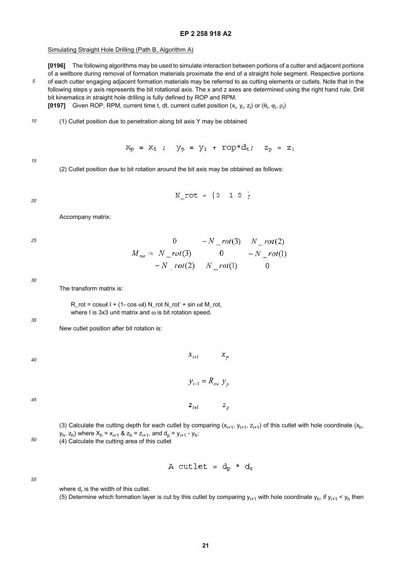
EP 2 258 918 A2
21
5
10
15
20
25
30
35
40
45
50
55
Simulating Straight Hole Drilling (Path B, Algorithm A)
[0196] The following algorithms may be used to simulate interaction between portions of a cutter and adjacent portionsof a wellbore during removal of formation materials proximate the end of a straight hole segment. Respective portionsof each cutter engaging adjacent formation materials may be referred to as cutting elements or cutlets. Note that in thefollowing steps y axis represents the bit rotational axis. The x and z axes are determined using the right hand rule. Drillbit kinematics in straight hole drilling is fully defined by ROP and RPM.[0197] Given ROP, RPM, current time t, dt, current cutlet position (xi, yi, zi) or (θi, ϕi, ρi)
(1) Cutlet position due to penetration along bit axis Y may be obtained
(2) Cutlet position due to bit rotation around the bit axis may be obtained as follows:
Accompany matrix:
The transform matrix is:
R_rot = cosωt I + (1- cos ωt) N_rot N_rot’ + sin ωt M_rot,where I is 3x3 unit matrix and ω is bit rotation speed.
New cutlet position after bit rotation is:
(3) Calculate the cutting depth for each cutlet by comparing (xi+1, yi+1, zi+1) of this cutlet with hole coordinate (xh,yh, zh) where Xh = xi+1 & zh = zi+1, and dp = yi+1 - yh;(4) Calculate the cutting area of this cutlet
where dr is the width of this cutlet.(5) Determine which formation layer is cut by this cutlet by comparing yi+1 with hole coordinate yh, if yi+1 < yh then
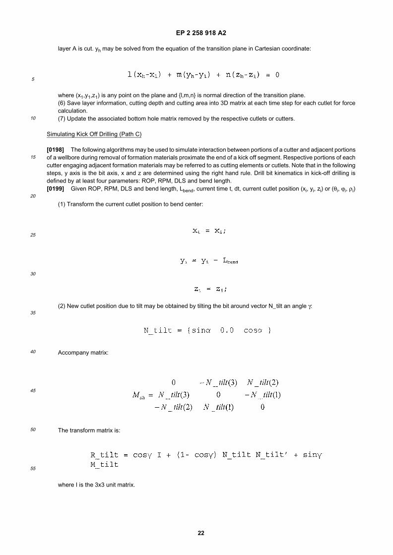
EP 2 258 918 A2
22
5
10
15
20
25
30
35
40
45
50
55
layer A is cut. yh may be solved from the equation of the transition plane in Cartesian coordinate:
where (x1,y1,z1) is any point on the plane and {l,m,n} is normal direction of the transition plane.(6) Save layer information, cutting depth and cutting area into 3D matrix at each time step for each cutlet for forcecalculation.(7) Update the associated bottom hole matrix removed by the respective cutlets or cutters.
Simulating Kick Off Drilling (Path C)
[0198] The following algorithms may be used to simulate interaction between portions of a cutter and adjacent portionsof a wellbore during removal of formation materials proximate the end of a kick off segment. Respective portions of eachcutter engaging adjacent formation materials may be referred to as cutting elements or cutlets. Note that in the followingsteps, y axis is the bit axis, x and z are determined using the right hand rule. Drill bit kinematics in kick-off drilling isdefined by at least four parameters: ROP, RPM, DLS and bend length.[0199] Given ROP, RPM, DLS and bend length, Lbend, current time t, dt, current cutlet position (xi, yi, zi) or (θi, ϕi, ρi)
(1) Transform the current cutlet position to bend center:
(2) New cutlet position due to tilt may be obtained by tilting the bit around vector N_tilt an angle γ:
Accompany matrix:
The transform matrix is:
where I is the 3x3 unit matrix.

EP 2 258 918 A2
23
5
10
15
20
25
30
35
40
45
50
55
New cutlet position after tilting is:
(3) Cutlet position due to bit rotation around the new bit axis may be obtained as follows:
N_rot = {sinycosθ cos γ sinysinθ }
Accompany matrix:
The transform matrix is:
I is 3x3 unit matrix and ω is bit rotation speedNew cutlet position after tilting is:
(4) Cutlet position due to penetration along new bit axis may be obtained
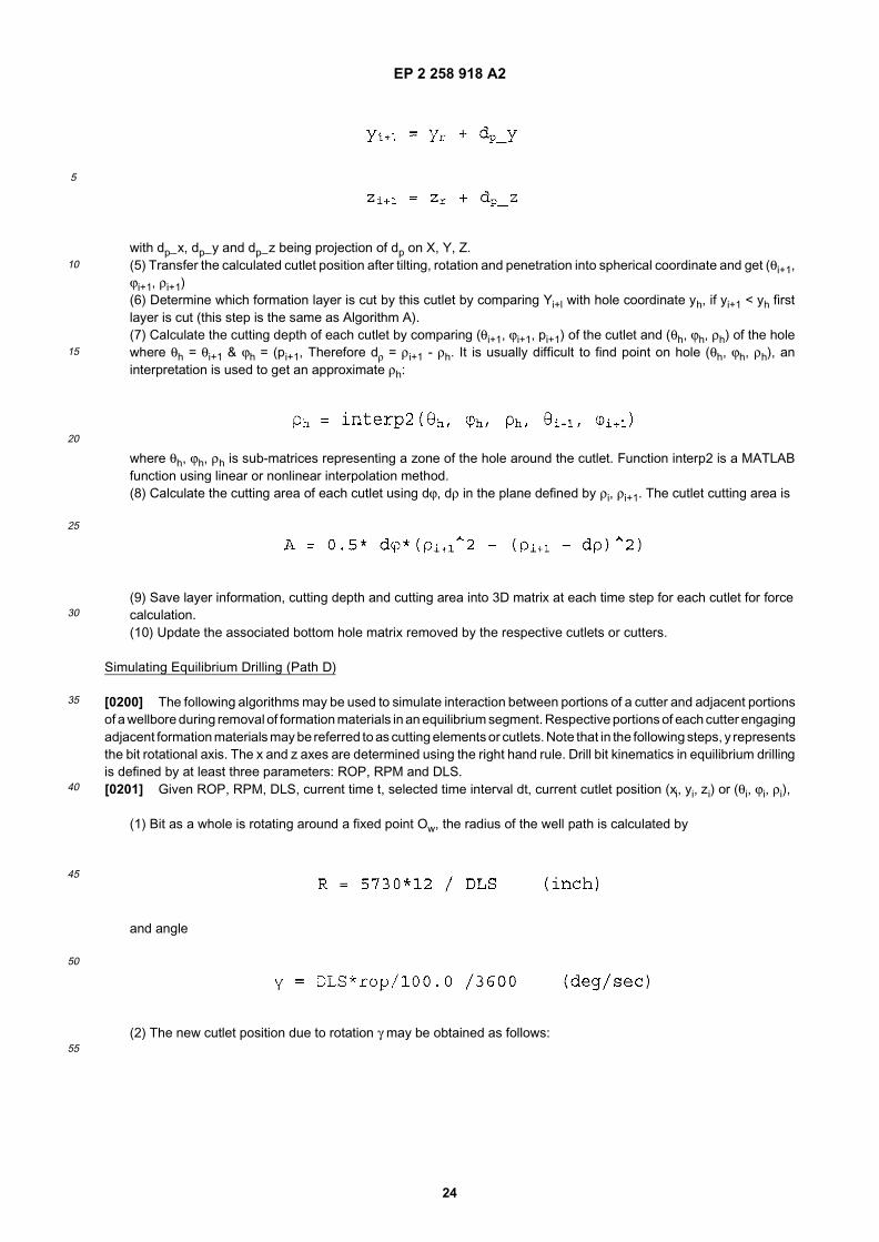
EP 2 258 918 A2
24
5
10
15
20
25
30
35
40
45
50
55
with dp_x, dp_y and dp_z being projection of dp on X, Y, Z.(5) Transfer the calculated cutlet position after tilting, rotation and penetration into spherical coordinate and get (θi+1,ϕi+1, ρi+1)(6) Determine which formation layer is cut by this cutlet by comparing Yi+l with hole coordinate yh, if yi+1 < yh firstlayer is cut (this step is the same as Algorithm A).(7) Calculate the cutting depth of each cutlet by comparing (θi+1, ϕi+1, pi+1) of the cutlet and (θh, ϕh, ρh) of the holewhere θh = θi+1 & ϕh = (pi+1, Therefore dρ = ρi+1 - ρh. It is usually difficult to find point on hole (θh, ϕh, ρh), aninterpretation is used to get an approximate ρh:
where θh, ϕh, ρh is sub-matrices representing a zone of the hole around the cutlet. Function interp2 is a MATLABfunction using linear or nonlinear interpolation method.(8) Calculate the cutting area of each cutlet using dϕ, dρ in the plane defined by ρi, ρi+1. The cutlet cutting area is
(9) Save layer information, cutting depth and cutting area into 3D matrix at each time step for each cutlet for forcecalculation.(10) Update the associated bottom hole matrix removed by the respective cutlets or cutters.
Simulating Equilibrium Drilling (Path D)
[0200] The following algorithms may be used to simulate interaction between portions of a cutter and adjacent portionsof a wellbore during removal of formation materials in an equilibrium segment. Respective portions of each cutter engagingadjacent formation materials may be referred to as cutting elements or cutlets. Note that in the following steps, y representsthe bit rotational axis. The x and z axes are determined using the right hand rule. Drill bit kinematics in equilibrium drillingis defined by at least three parameters: ROP, RPM and DLS.[0201] Given ROP, RPM, DLS, current time t, selected time interval dt, current cutlet position (xi, yi, zi) or (θi, ϕi, ρi),
(1) Bit as a whole is rotating around a fixed point Ow, the radius of the well path is calculated by
and angle
(2) The new cutlet position due to rotation γ may be obtained as follows:
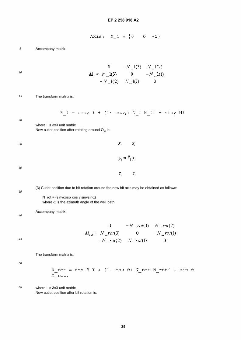
EP 2 258 918 A2
25
5
10
15
20
25
30
35
40
45
50
55
Accompany matrix:
The transform matrix is:
where I is 3x3 unit matrixNew cutlet position after rotating around Ow is:
(3) Cutlet position due to bit rotation around the new bit axis may be obtained as follows:
N_rot = {sinycosα cos γ sinysinα}where α is the azimuth angle of the well path
Accompany matrix:
The transform matrix is:
where I is 3x3 unit matrixNew cutlet position after bit rotation is:
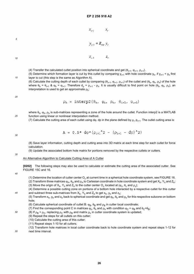
EP 2 258 918 A2
26
5
10
15
20
25
30
35
40
45
50
55
(4) Transfer the calculated cutlet position into spherical coordinate and get (θi+1, ϕi+1, ρi+1).(5) Determine which formation layer is cut by this cutlet by comparing yi+1 with hole coordinate yh, if yi+1 < yh firstlayer is cut (this step is the same as Algorithm A).(6) Calculate the cutting depth of each cutlet by comparing (θi+1, ϕi+1, ρi+1) of the cutlet and (θh, ϕh, ρh) of the holewhere θh = θi+1 & ϕh = ϕi+1. Therefore dρ = ρi+1 - ρh. It is usually difficult to find point on hole (θh, ϕh, ρh), aninterpretation is used to get an approximate ρh:
where θh, ϕh, ρh is sub-matrices representing a zone of the hole around the cutlet. Function interp2 is a MATLABfunction using linear or nonlinear interpolation method.(7) Calculate the cutting area of each cutlet using dϕ, dp in the plane defined by ρi, pi+1. The cutlet cutting area is:
(8) Save layer information, cutting depth and cutting area into 3D matrix at each time step for each cutlet for forcecalculation.(9) Update the associated bottom hole matrix for portions removed by the respective cutlets or cutters.
An Alternative Algorithm to Calculate Cutting Area of A Cutter
[0202] The following steps may also be used to calculate or estimate the cutting area of the associated cutter. SeeFIGURE 15C and 16.
(1) Determine the location of cutter center Oc at current time in a spherical hole coordinate system, see FIGURE 16.(2) Transform three matrices ϕH, θH and ρH to Cartesian coordinate in hole coordinate system and get Xh, Yh and Zh;(3) Move the origin of Xh, Yh and Zh to the cutter center Oc located at (ϕc, θc and ρc);(4) Determine a possible cutting zone on portions of a bottom hole interacted by a respective cutlet for this cutterand subtract three sub-matrices from Xh, Yh and Zh to get xh, yh and zh;(5) Transform xh, yh and zh back to spherical coordinate and get ϕh, θh and ρh for this respective subzone on bottomhole;(6) Calculate spherical coordinate of cutlet B: ϕB, θB and ρB in cutter local coordinate;(7) Find the corresponding point C in matrices ϕh, θh and ρh with condition ϕC = ϕB and θC=θB;(8) If ρB > ρC, replacing ρC with ρB and matrix ρh in cutter coordinate system is updated;(9) Repeat the steps for all cutlets on this cutter;(10) Calculate the cutting area of this cutter;(11) Repeat steps 1-10 for all cutters;(12) Transform hole matrices in local cutter coordinate back to hole coordinate system and repeat steps 1-12 fornext time interval.
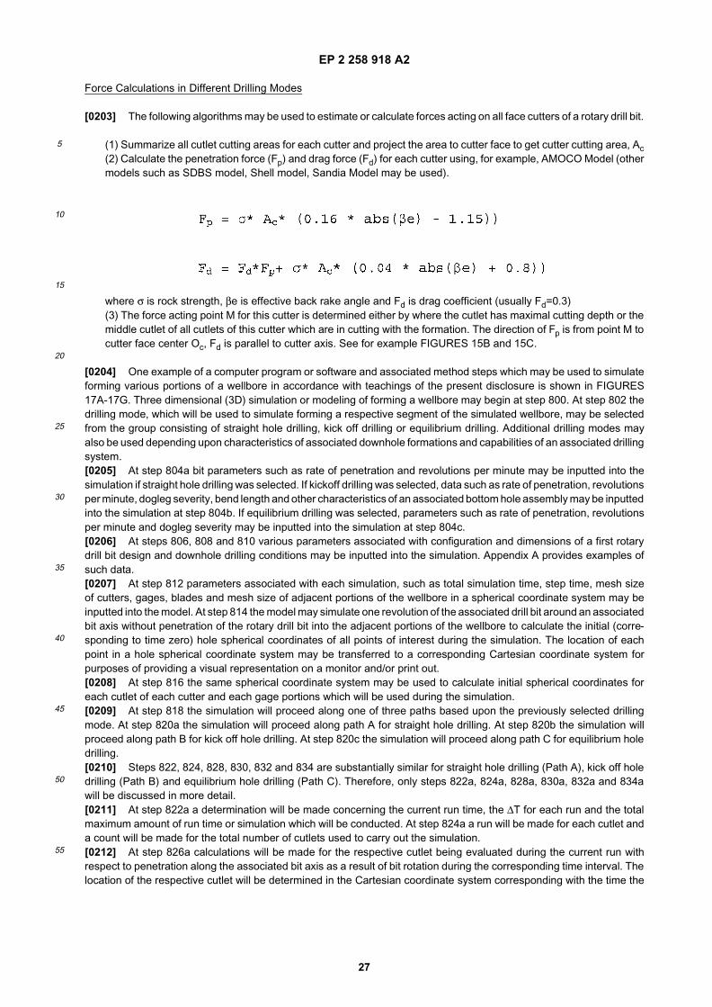
EP 2 258 918 A2
27
5
10
15
20
25
30
35
40
45
50
55
Force Calculations in Different Drilling Modes
[0203] The following algorithms may be used to estimate or calculate forces acting on all face cutters of a rotary drill bit.
(1) Summarize all cutlet cutting areas for each cutter and project the area to cutter face to get cutter cutting area, Ac(2) Calculate the penetration force (Fp) and drag force (Fd) for each cutter using, for example, AMOCO Model (othermodels such as SDBS model, Shell model, Sandia Model may be used).
where σ is rock strength, βe is effective back rake angle and Fd is drag coefficient (usually Fd=0.3)(3) The force acting point M for this cutter is determined either by where the cutlet has maximal cutting depth or themiddle cutlet of all cutlets of this cutter which are in cutting with the formation. The direction of Fp is from point M tocutter face center Oc, Fd is parallel to cutter axis. See for example FIGURES 15B and 15C.
[0204] One example of a computer program or software and associated method steps which may be used to simulateforming various portions of a wellbore in accordance with teachings of the present disclosure is shown in FIGURES17A-17G. Three dimensional (3D) simulation or modeling of forming a wellbore may begin at step 800. At step 802 thedrilling mode, which will be used to simulate forming a respective segment of the simulated wellbore, may be selectedfrom the group consisting of straight hole drilling, kick off drilling or equilibrium drilling. Additional drilling modes mayalso be used depending upon characteristics of associated downhole formations and capabilities of an associated drillingsystem.[0205] At step 804a bit parameters such as rate of penetration and revolutions per minute may be inputted into thesimulation if straight hole drilling was selected. If kickoff drilling was selected, data such as rate of penetration, revolutionsper minute, dogleg severity, bend length and other characteristics of an associated bottom hole assembly may be inputtedinto the simulation at step 804b. If equilibrium drilling was selected, parameters such as rate of penetration, revolutionsper minute and dogleg severity may be inputted into the simulation at step 804c.[0206] At steps 806, 808 and 810 various parameters associated with configuration and dimensions of a first rotarydrill bit design and downhole drilling conditions may be inputted into the simulation. Appendix A provides examples ofsuch data.[0207] At step 812 parameters associated with each simulation, such as total simulation time, step time, mesh sizeof cutters, gages, blades and mesh size of adjacent portions of the wellbore in a spherical coordinate system may beinputted into the model. At step 814 the model may simulate one revolution of the associated drill bit around an associatedbit axis without penetration of the rotary drill bit into the adjacent portions of the wellbore to calculate the initial (corre-sponding to time zero) hole spherical coordinates of all points of interest during the simulation. The location of eachpoint in a hole spherical coordinate system may be transferred to a corresponding Cartesian coordinate system forpurposes of providing a visual representation on a monitor and/or print out.[0208] At step 816 the same spherical coordinate system may be used to calculate initial spherical coordinates foreach cutlet of each cutter and each gage portions which will be used during the simulation.[0209] At step 818 the simulation will proceed along one of three paths based upon the previously selected drillingmode. At step 820a the simulation will proceed along path A for straight hole drilling. At step 820b the simulation willproceed along path B for kick off hole drilling. At step 820c the simulation will proceed along path C for equilibrium holedrilling.[0210] Steps 822, 824, 828, 830, 832 and 834 are substantially similar for straight hole drilling (Path A), kick off holedrilling (Path B) and equilibrium hole drilling (Path C). Therefore, only steps 822a, 824a, 828a, 830a, 832a and 834awill be discussed in more detail.[0211] At step 822a a determination will be made concerning the current run time, the ∆T for each run and the totalmaximum amount of run time or simulation which will be conducted. At step 824a a run will be made for each cutlet anda count will be made for the total number of cutlets used to carry out the simulation.[0212] At step 826a calculations will be made for the respective cutlet being evaluated during the current run withrespect to penetration along the associated bit axis as a result of bit rotation during the corresponding time interval. Thelocation of the respective cutlet will be determined in the Cartesian coordinate system corresponding with the time the
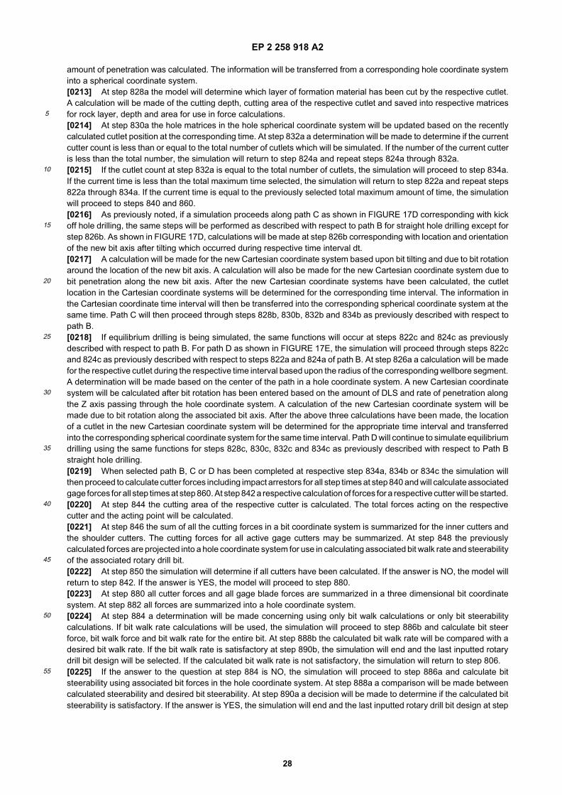
EP 2 258 918 A2
28
5
10
15
20
25
30
35
40
45
50
55
amount of penetration was calculated. The information will be transferred from a corresponding hole coordinate systeminto a spherical coordinate system.[0213] At step 828a the model will determine which layer of formation material has been cut by the respective cutlet.A calculation will be made of the cutting depth, cutting area of the respective cutlet and saved into respective matricesfor rock layer, depth and area for use in force calculations.[0214] At step 830a the hole matrices in the hole spherical coordinate system will be updated based on the recentlycalculated cutlet position at the corresponding time. At step 832a a determination will be made to determine if the currentcutter count is less than or equal to the total number of cutlets which will be simulated. If the number of the current cutteris less than the total number, the simulation will return to step 824a and repeat steps 824a through 832a.[0215] If the cutlet count at step 832a is equal to the total number of cutlets, the simulation will proceed to step 834a.If the current time is less than the total maximum time selected, the simulation will return to step 822a and repeat steps822a through 834a. If the current time is equal to the previously selected total maximum amount of time, the simulationwill proceed to steps 840 and 860.[0216] As previously noted, if a simulation proceeds along path C as shown in FIGURE 17D corresponding with kickoff hole drilling, the same steps will be performed as described with respect to path B for straight hole drilling except forstep 826b. As shown in FIGURE 17D, calculations will be made at step 826b corresponding with location and orientationof the new bit axis after tilting which occurred during respective time interval dt.[0217] A calculation will be made for the new Cartesian coordinate system based upon bit tilting and due to bit rotationaround the location of the new bit axis. A calculation will also be made for the new Cartesian coordinate system due tobit penetration along the new bit axis. After the new Cartesian coordinate systems have been calculated, the cutletlocation in the Cartesian coordinate systems will be determined for the corresponding time interval. The information inthe Cartesian coordinate time interval will then be transferred into the corresponding spherical coordinate system at thesame time. Path C will then proceed through steps 828b, 830b, 832b and 834b as previously described with respect topath B.[0218] If equilibrium drilling is being simulated, the same functions will occur at steps 822c and 824c as previouslydescribed with respect to path B. For path D as shown in FIGURE 17E, the simulation will proceed through steps 822cand 824c as previously described with respect to steps 822a and 824a of path B. At step 826a a calculation will be madefor the respective cutlet during the respective time interval based upon the radius of the corresponding wellbore segment.A determination will be made based on the center of the path in a hole coordinate system. A new Cartesian coordinatesystem will be calculated after bit rotation has been entered based on the amount of DLS and rate of penetration alongthe Z axis passing through the hole coordinate system. A calculation of the new Cartesian coordinate system will bemade due to bit rotation along the associated bit axis. After the above three calculations have been made, the locationof a cutlet in the new Cartesian coordinate system will be determined for the appropriate time interval and transferredinto the corresponding spherical coordinate system for the same time interval. Path D will continue to simulate equilibriumdrilling using the same functions for steps 828c, 830c, 832c and 834c as previously described with respect to Path Bstraight hole drilling.[0219] When selected path B, C or D has been completed at respective step 834a, 834b or 834c the simulation willthen proceed to calculate cutter forces including impact arrestors for all step times at step 840 and will calculate associatedgage forces for all step times at step 860. At step 842 a respective calculation of forces for a respective cutter will be started.[0220] At step 844 the cutting area of the respective cutter is calculated. The total forces acting on the respectivecutter and the acting point will be calculated.[0221] At step 846 the sum of all the cutting forces in a bit coordinate system is summarized for the inner cutters andthe shoulder cutters. The cutting forces for all active gage cutters may be summarized. At step 848 the previouslycalculated forces are projected into a hole coordinate system for use in calculating associated bit walk rate and steerabilityof the associated rotary drill bit.[0222] At step 850 the simulation will determine if all cutters have been calculated. If the answer is NO, the model willreturn to step 842. If the answer is YES, the model will proceed to step 880.[0223] At step 880 all cutter forces and all gage blade forces are summarized in a three dimensional bit coordinatesystem. At step 882 all forces are summarized into a hole coordinate system.[0224] At step 884 a determination will be made concerning using only bit walk calculations or only bit steerabilitycalculations. If bit walk rate calculations will be used, the simulation will proceed to step 886b and calculate bit steerforce, bit walk force and bit walk rate for the entire bit. At step 888b the calculated bit walk rate will be compared with adesired bit walk rate. If the bit walk rate is satisfactory at step 890b, the simulation will end and the last inputted rotarydrill bit design will be selected. If the calculated bit walk rate is not satisfactory, the simulation will return to step 806.[0225] If the answer to the question at step 884 is NO, the simulation will proceed to step 886a and calculate bitsteerability using associated bit forces in the hole coordinate system. At step 888a a comparison will be made betweencalculated steerability and desired bit steerability. At step 890a a decision will be made to determine if the calculated bitsteerability is satisfactory. If the answer is YES, the simulation will end and the last inputted rotary drill bit design at step
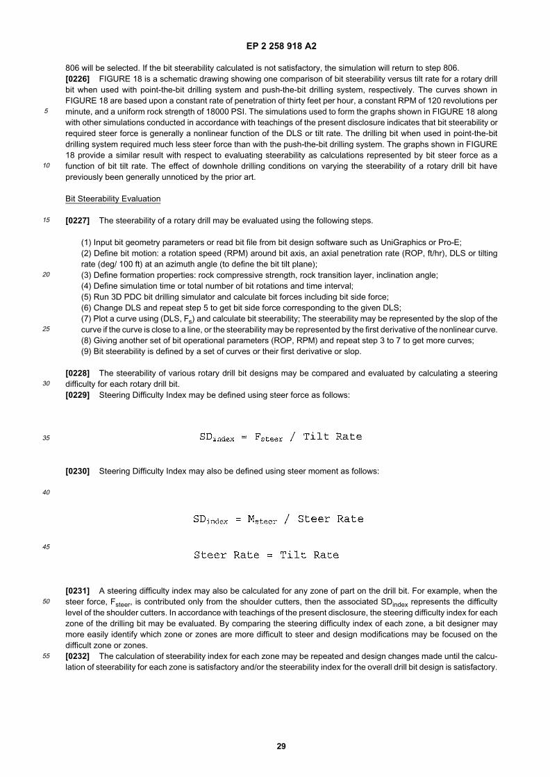
EP 2 258 918 A2
29
5
10
15
20
25
30
35
40
45
50
55
806 will be selected. If the bit steerability calculated is not satisfactory, the simulation will return to step 806.[0226] FIGURE 18 is a schematic drawing showing one comparison of bit steerability versus tilt rate for a rotary drillbit when used with point-the-bit drilling system and push-the-bit drilling system, respectively. The curves shown inFIGURE 18 are based upon a constant rate of penetration of thirty feet per hour, a constant RPM of 120 revolutions perminute, and a uniform rock strength of 18000 PSI. The simulations used to form the graphs shown in FIGURE 18 alongwith other simulations conducted in accordance with teachings of the present disclosure indicates that bit steerability orrequired steer force is generally a nonlinear function of the DLS or tilt rate. The drilling bit when used in point-the-bitdrilling system required much less steer force than with the push-the-bit drilling system. The graphs shown in FIGURE18 provide a similar result with respect to evaluating steerability as calculations represented by bit steer force as afunction of bit tilt rate. The effect of downhole drilling conditions on varying the steerability of a rotary drill bit havepreviously been generally unnoticed by the prior art.
Bit Steerability Evaluation
[0227] The steerability of a rotary drill may be evaluated using the following steps.
(1) Input bit geometry parameters or read bit file from bit design software such as UniGraphics or Pro-E;(2) Define bit motion: a rotation speed (RPM) around bit axis, an axial penetration rate (ROP, ft/hr), DLS or tiltingrate (deg/ 100 ft) at an azimuth angle (to define the bit tilt plane);(3) Define formation properties: rock compressive strength, rock transition layer, inclination angle;(4) Define simulation time or total number of bit rotations and time interval;(5) Run 3D PDC bit drilling simulator and calculate bit forces including bit side force;(6) Change DLS and repeat step 5 to get bit side force corresponding to the given DLS;(7) Plot a curve using (DLS, Fs) and calculate bit steerability; The steerability may be represented by the slop of thecurve if the curve is close to a line, or the steerability may be represented by the first derivative of the nonlinear curve.(8) Giving another set of bit operational parameters (ROP, RPM) and repeat step 3 to 7 to get more curves;(9) Bit steerability is defined by a set of curves or their first derivative or slop.
[0228] The steerability of various rotary drill bit designs may be compared and evaluated by calculating a steeringdifficulty for each rotary drill bit.[0229] Steering Difficulty Index may be defined using steer force as follows:
[0230] Steering Difficulty Index may also be defined using steer moment as follows:
[0231] A steering difficulty index may also be calculated for any zone of part on the drill bit. For example, when thesteer force, Fsteer, is contributed only from the shoulder cutters, then the associated SDindex represents the difficultylevel of the shoulder cutters. In accordance with teachings of the present disclosure, the steering difficulty index for eachzone of the drilling bit may be evaluated. By comparing the steering difficulty index of each zone, a bit designer maymore easily identify which zone or zones are more difficult to steer and design modifications may be focused on thedifficult zone or zones.[0232] The calculation of steerability index for each zone may be repeated and design changes made until the calcu-lation of steerability for each zone is satisfactory and/or the steerability index for the overall drill bit design is satisfactory.
EP 2 258 918 A2
30
5
10
15
20
25
30
35
40
45
50
55
Bit Walk Rate Evaluation
[0233] Bit walk rate may be calculated using bit steer force, tilt rate and walk force:
[0234] Bit walk rate may also be calculated using bit steer moment, tilt rate and walk moment:
[0235] The walk rate may be applied to any zone of part on the drill bit. For example, when the steer force, Fsteer andwalk force, Fwalk are contributed only from the shoulder cutters, then the associated walk rate represents the walk rateof the shoulder cutters. In accordance with teachings of the present disclosure, the walk rate for each zone of the drillingbit can be evaluated. By comparing the walk rate of each zone, the bit designer can easily identify which zone is theeasiest zone to walk and modifications may be focused on that zone.[0236] Although the present disclosure and its advantages have been described in detail, it should be understood thatvarious changes, substitutions and alternations may be made herein without departing from the scope of the disclosureas defined by the following claims.
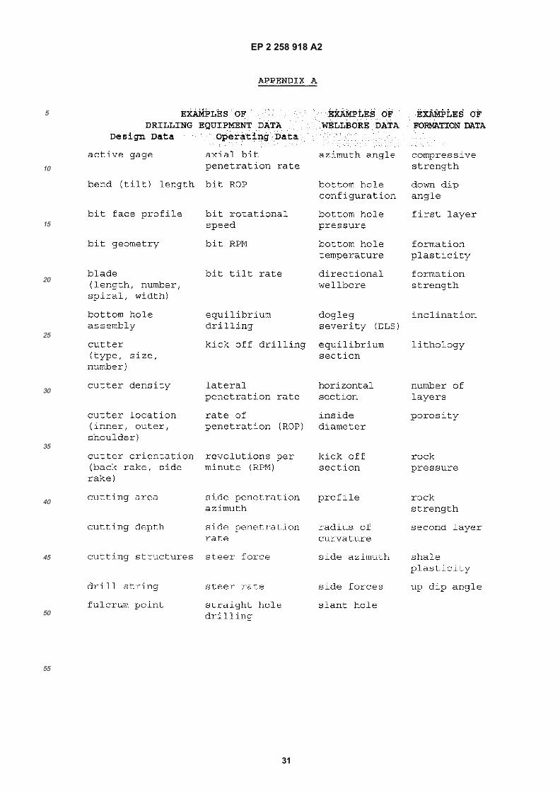
EP 2 258 918 A2
31
5
10
15
20
25
30
35
40
45
50
55
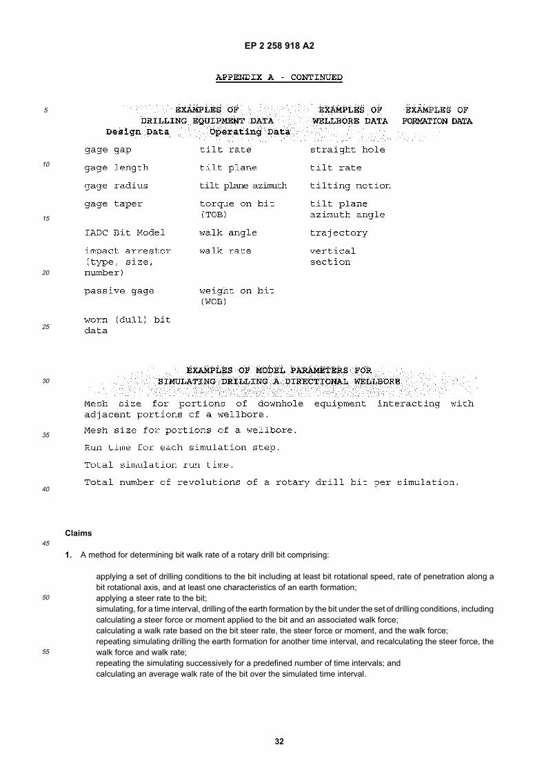
EP 2 258 918 A2
32
5
10
15
20
25
30
35
40
45
50
55
Claims
1. A method for determining bit walk rate of a rotary drill bit comprising:
applying a set of drilling conditions to the bit including at least bit rotational speed, rate of penetration along abit rotational axis, and at least one characteristics of an earth formation;applying a steer rate to the bit;simulating, for a time interval, drilling of the earth formation by the bit under the set of drilling conditions, includingcalculating a steer force or moment applied to the bit and an associated walk force;calculating a walk rate based on the bit steer rate, the steer force or moment, and the walk force;repeating simulating drilling the earth formation for another time interval, and recalculating the steer force, thewalk force and walk rate;repeating the simulating successively for a predefined number of time intervals; andcalculating an average walk rate of the bit over the simulated time interval.
EP 2 258 918 A2
33
5
10
15
20
25
30
35
40
45
50
55
2. The method of Claim 1 wherein calculating the average walk rate of the bit further comprises using an average steerrate and an average steer force, and/or wherein applying the steer rate further comprises applying the steer rate ina vertical plane passing through the bit rotational axis, and/or wherein the method further comprises
- calculating the walk rate by:
and/or- determining a bit walk angle of a rotary drill bit by calculating the average bit walk rate over a pre-defined timeinterval under a pre-defined drilling conditions where at least the magnitude of the given steer rate is not equalto zero;- if the average bit walk rate is negative, bit walk left;- if the average bit walk rate is positive, bit walk right; and- if the average bit walk rate is substantially close to zero, bit does not walk.
3. The method of Claim 1 wherein applying the steer rate further comprises applying the steer rate in a vertical planepassing through the bit rotational axis, and/or wherein the walk rate, at time t, of the bit is calculated by:
and/or wherein calculating the average walk rate of the bit further comprises using an average steer rate and anaverage steer force over the simulated time interval.
4. A method to design a rotary drill bit with a desired bit walk rate comprising:
(a) determining drilling conditions and formation characteristics of a wellbore;(b) simulating drilling at least one portion of the wellbore using drill bit design data, operating data associatedwith the drill bit, wellbore data and formation data associated with the wellbore;(c) calculating an average bit walk rate;(d) comparing the calculated average bit walk rate to a desired bit walk rate;(e) if the calculated average bit walk rate does not approximately equal the desired bit walk rate, modifying atleast one bit geometry of the rotary drill bit selected from the group consisting of bit profile, cutter location, cutterorientation, cutter density, gauge length and gage diameter; and(f) repeating steps (a) through (e) until the calculated average bit walk rate approximately equals the desiredbit walk rate.
5. The method of Claim 4 further comprising:
checking the calculation of the average bit walk rate by changing at least one of the drilling conditions; andrepeating steps (a) to (e), if necessary,and/or further comprising designing an energy balanced fixed cutter drill bit,and/or further comprising:
calculating the average walk rate using an average walk moment and average steer moment over a simulatedtime interval,and/or further comprising:
calculating the average walk rate of the bit over a simulated time interval,and/or further comprising:
calculating the average walk rate of the rotary drill bit further comprises using an average steer rate, anaverage steer force and an average walk force over a simulated time interval,and/or further comprising:

EP 2 258 918 A2
34
5
10
15
20
25
30
35
40
45
50
55
modifying design data associated with an active gauge of the rotary drill selected from the group consisting ofthe active gauge, number of blades, width of each blade, spiral angle of each blade, diameter of the activegauge and aggressiveness of the active gauge,and/or further comprising:
modifying design data associated with a passive gauge of the rotary drill selected from the group consistingof the passive gauge, number of blades, the width of each blade, spiral angle of each blade, diameter ofthe passive gauge, and taper angle of the passive gauge.
6. A method to find and optimize operational parameters to control bit walk of a rotary drill bit during drilling of at leastone portion of a wellbore comprising:
(a) determining a bit path deviation for the at least one portion of the wellbore;(b) determining a desired bit walk rate to compensate for the bit path deviation;(c) determining downhole formation properties at a first location and at a second location ahead of the firstlocation in the at least one portion of the wellbore;(d) simulating drilling with the rotary drill bit between the first location and the second location;(e) during the simulation applying to the rotary drill bit an initial set of bit operational parameters selected fromthe group consisting of ROP, RPM and steer rate;(f) calculating a walk rate of the rotary drill bit and comparing the calculated walk rate with the desired walk rate;(g) changing at least one set of the bit operational parameters and repeating steps (d) through (f) until thecalculated walk rate approximately equals the desired walk rate; and(h) determining optimum operational parameters to control bit walk rate of a fixed cutter rotary drill bit.
7. A method to select a rotary drill bit to drill at least one portion of a wellbore having at least one desired trajectorycomprising:
(a) determining a desired walk rate to compensate for the desired trajectory of the at least one portion of thewellbore;(b) determining at least one formation property of the at least one portion of the wellbore;(c) determining a first set of bit operational parameters according to capability of an associated drilling systemand experience gained by drilling other wellbores with similar formation properties;(d) choosing a first rotary drill bit;(e) calculating a walk rate for the first rotary drill bit under the first set of bit operational parameters and comparingthe calculated walk rate with the desired walk rate;(f) choosing a second rotary drill bit; and(g) repeating steps (e) and (f) until the calculated walk angle for at least one rotary drill bit is approximatelyequal to the desired walk rate under the first set of bit operational parameters.
8. The method of Claim 7 further comprising:
monitoring the trajectory of the at least one rotary drill bit during simulated drilling of the at least one portion ofthe wellbore; andif the simulated trajectory of the at least one rotary drill bit does not correspond with the desired trajectory,finding an optimal set of bit operational parameters by repeating steps (c) through (g) of Claim 19 for the atleast one rotary drill bit,and/or further comprising:
selecting a fixed cutter rotary drill bit from existing fixed cutter rotary drill bit designs.
9. A method for designing a rotary drill bit having a gauge comprising:
(a) determining formation properties such as transition layer strength and inclination angle for use in simulatingdrilling with the rotary drill bit;(b) determining drilling conditions for use in simulating drilling with the rotary drill bit;(c) determining if the rotary drill bit will be used with a point-the-bit or push-the-bit drilling system;(d) simulating applying a steering motion, a relative shorter bent length, axial penetration and rotation forces tothe rotary drill bit when used with a point-the-bit drilling system;

EP 2 258 918 A2
35
5
10
15
20
25
30
35
40
45
50
55
(e) simulating applying steering motion, a relative longer bent length, axial penetration and rotation forces tothe rotary drill bit when used with a push-the-bit drilling system;(f) calculating a walk rate based on the simulated drilling;(g) comparing the calculated walk rate with a desired walk rate;(h) if the calculated walk rate is not approximately equal to the desired walk rate, changing a bit geometry suchas bit profile, cutter locations and orientations, cutter density or changing a geometric parameter of the gaugesuch as gauge length, gauge radius, gauge taper angle and gauge blade spiral angle; and(i) repeating steps (c) to (h) until the calculated walk rate approximately equals the desired walk rate.
10. The method of Claim 9 further comprising:
- checking the calculation of the walk rate by changing at least one drilling condition according to variations ofactual drilling conditions; andrepeating step (c) to (h) of Claim 22, if necessary; and/or- calculating the walk rate based on steer force and walk force, and/or- calculating the walk rate based on steer moment and walk moment, and/or- calculating the walk rate based on an average of the walk rate calculated from steer force and walk force, andthe walk rate calculated from steer moment and walk moment.
11. A method according to any one of Claims 1 to 10, further comprising the step of recording the resulting design ofthe rotary drill bit and optimally manufacturing a drill bit in accordance with the recorded drill bit design.
12. A rotary drill bit with desired walk characteristics comprising:
a bit face profile designed for use in a directional drilling system;the bit face profile defined in part by a plurality of blades with a plurality of cutters disposed on each blade;the bit face profile further defined by a recessed portion disposed on one end of the rotary drill bit;a nose disposed adjacent to the recessed portion with a shoulder portion extending outward from the nose portion;a plurality of inner cutters disposed within the recessed portion and a plurality of cutters disposed on the shoulderportion of the rotary drill bit; andthe ratio between the number of inner cutters and the number of outer cutters based upon calculation andcomparison of various walk rates for the rotary drill bit corresponding with respective ratios of inner cutters andshoulder cutters.
13. The drill bit of Claim 12 further comprising:
- a gage portion disposed on the exterior of the rotary drill bit adjacent to the shoulder portion;- a plurality of gage cutters disposed on the blades adjacent to the gage portion; and- the number, location and type of gage cutters based upon comparing the results of one or more simulationsof forming a directional wellbore using the rotary drill bit, and/or- a passive gage portion having a negative taper angle optimized for use in forming a directional wellbore, and/or- the bit face profile providing means for optimizing use of the drill bit with a push-the-bit steerable drilling system,and/or- the bit face profile providing means for optimizing use of the drill bit with a point the bit steerable drilling system.
14. A rotary drill bit with a walk rate comprising:
a bit body having a plurality of blades extending therefrom;each blade having a plurality of cutters disposed thereon; andthe location, number, size and type of cutter disposed on each blade providing means for optimizing the walkrate of the rotary drill bit while forming a directional wellbore.
15. The rotary drill bit of Claim 14 further comprising at least one feature selected from the group consisting of bit faceprofile, cutter size and location, cutter orientation(back rake and side rake), number of blades and number of cutters,geometric parameters of an associated active or passive gage including gage length, gage taper angle and bladespiral angle designed to provide at least part of the means for optimizing the walk rate of the rotary drill bit.
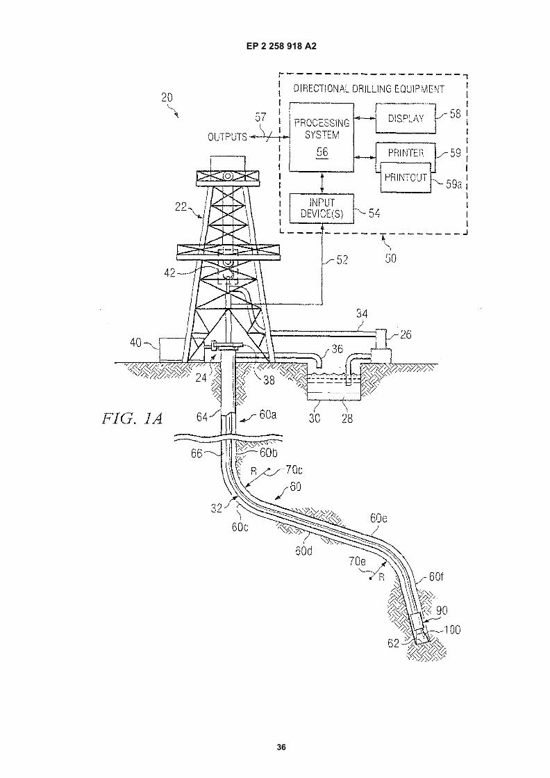
EP 2 258 918 A2
36
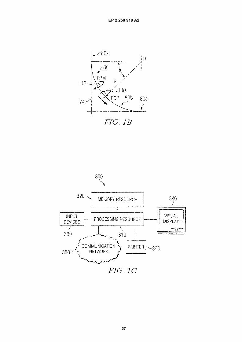
EP 2 258 918 A2
37
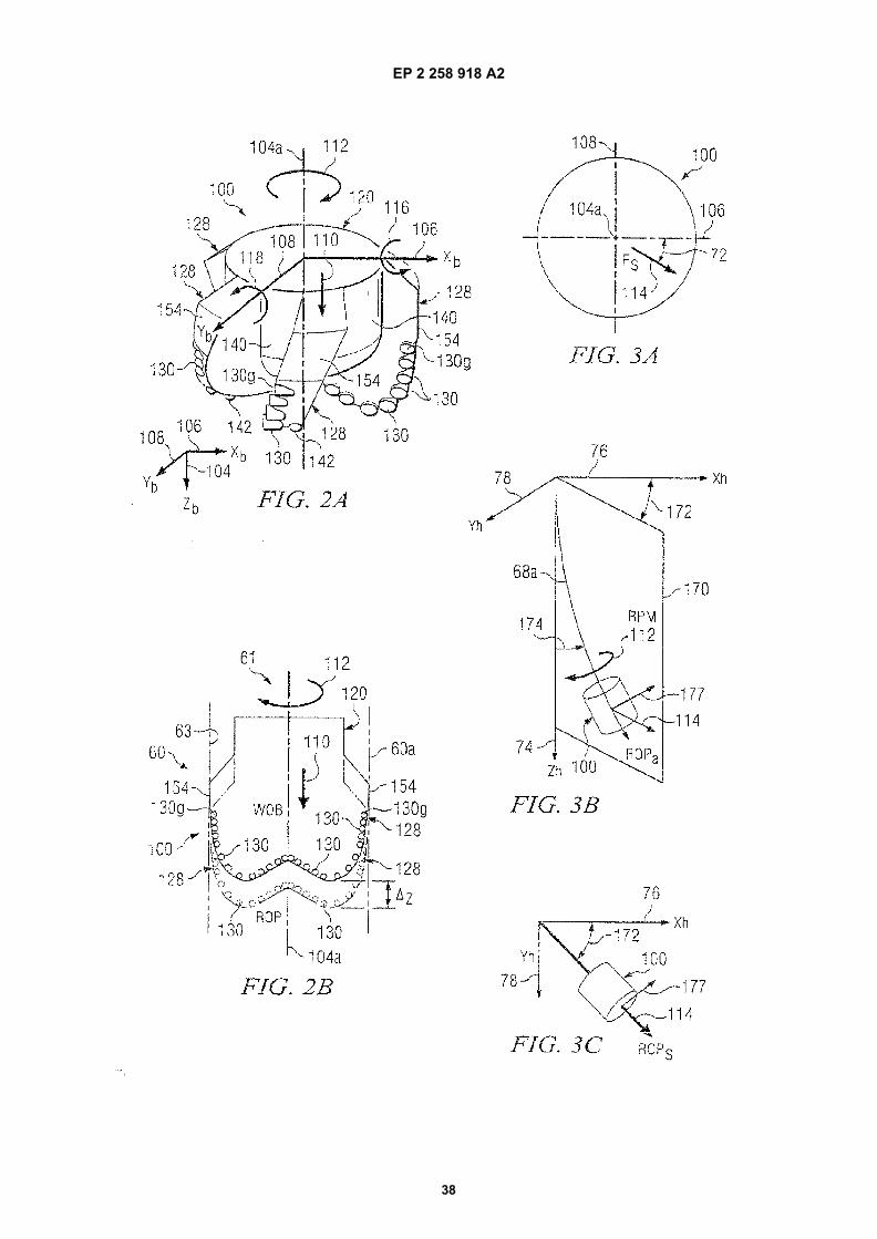
EP 2 258 918 A2
38
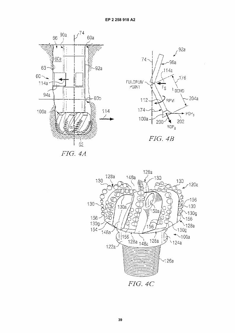
EP 2 258 918 A2
39
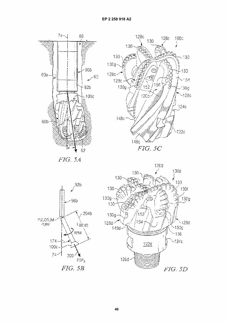
EP 2 258 918 A2
40
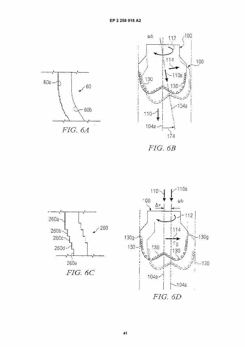
EP 2 258 918 A2
41
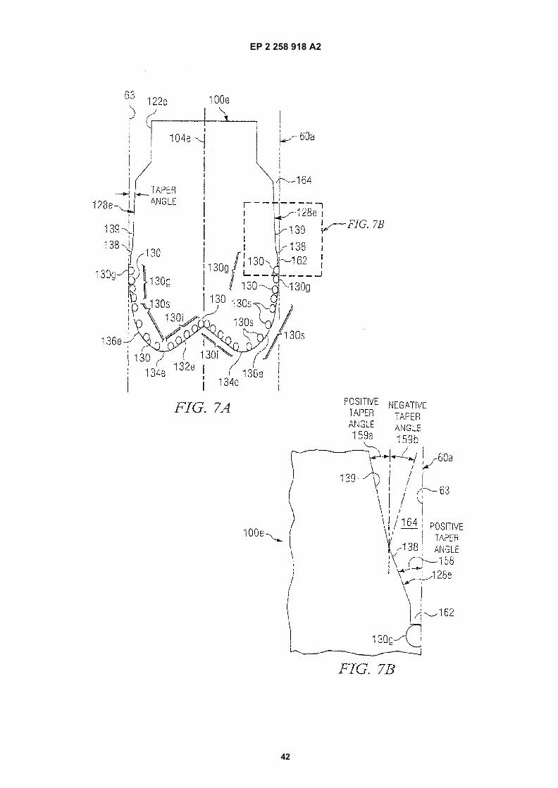
EP 2 258 918 A2
42
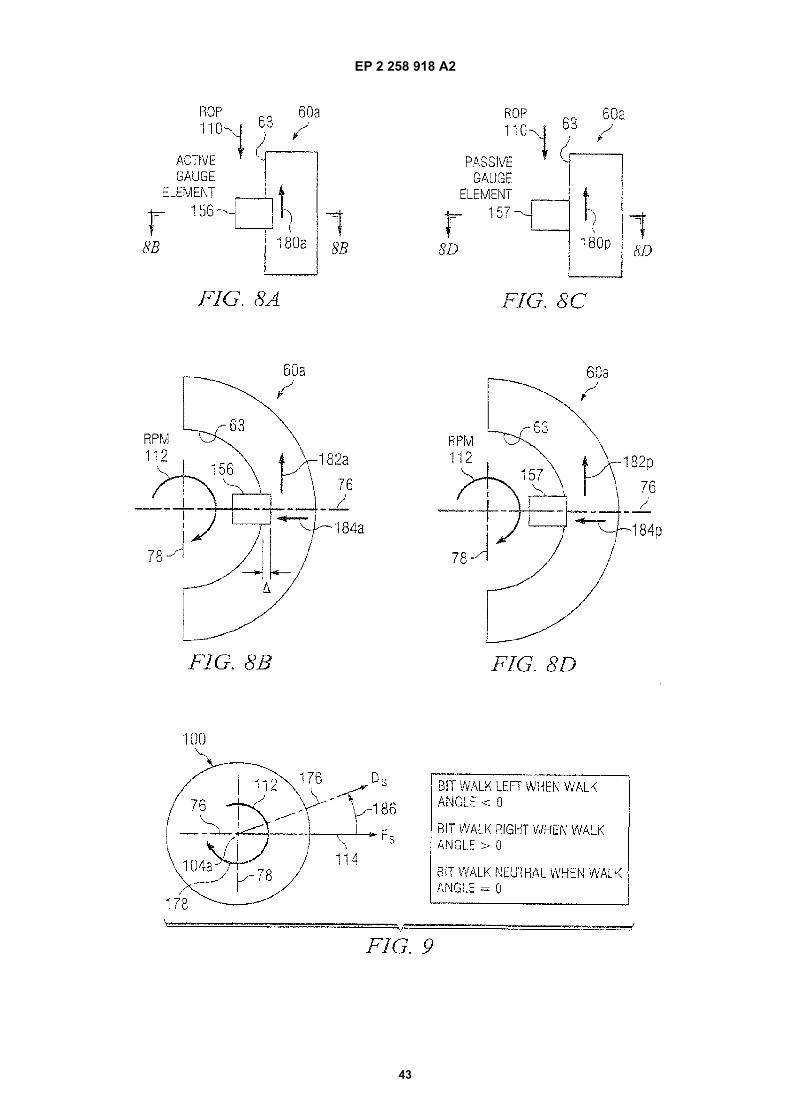
EP 2 258 918 A2
43
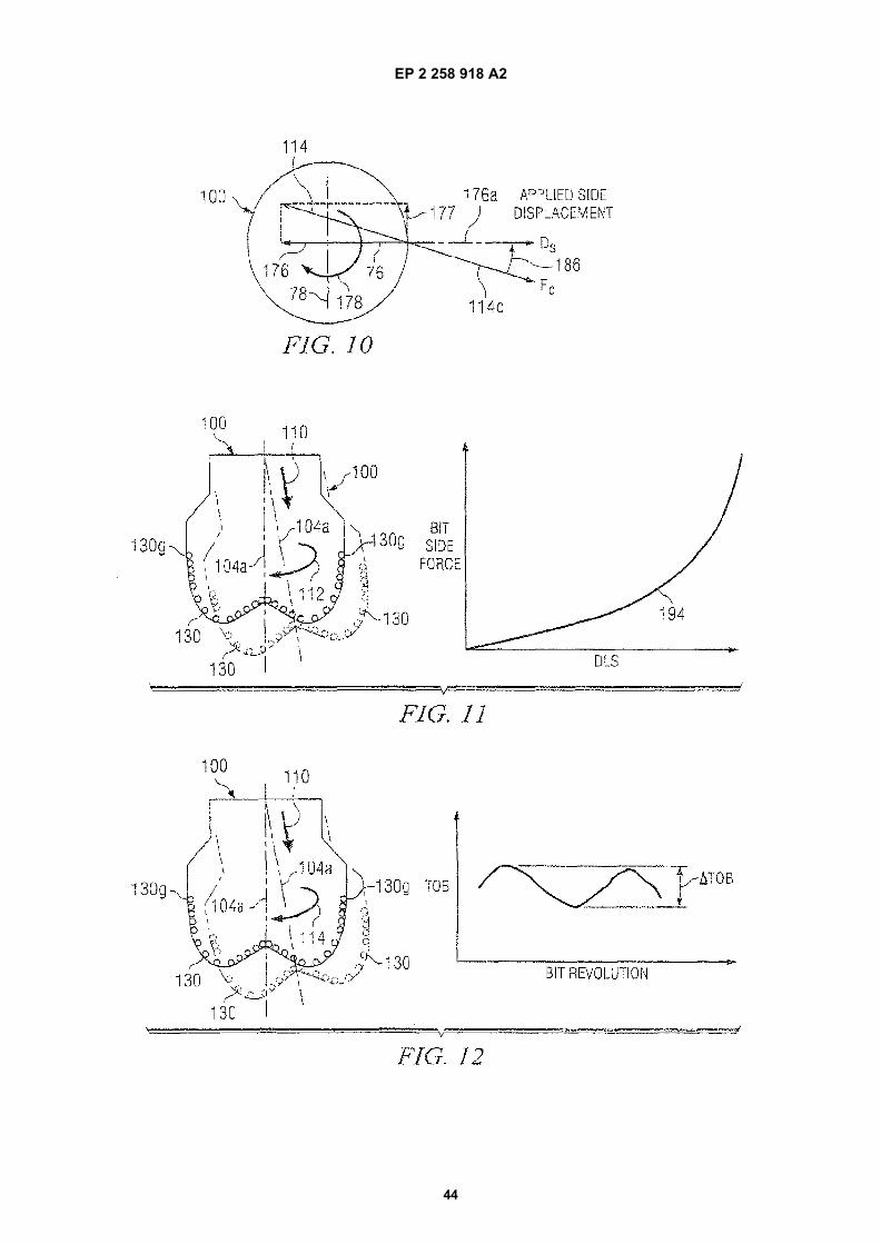
EP 2 258 918 A2
44
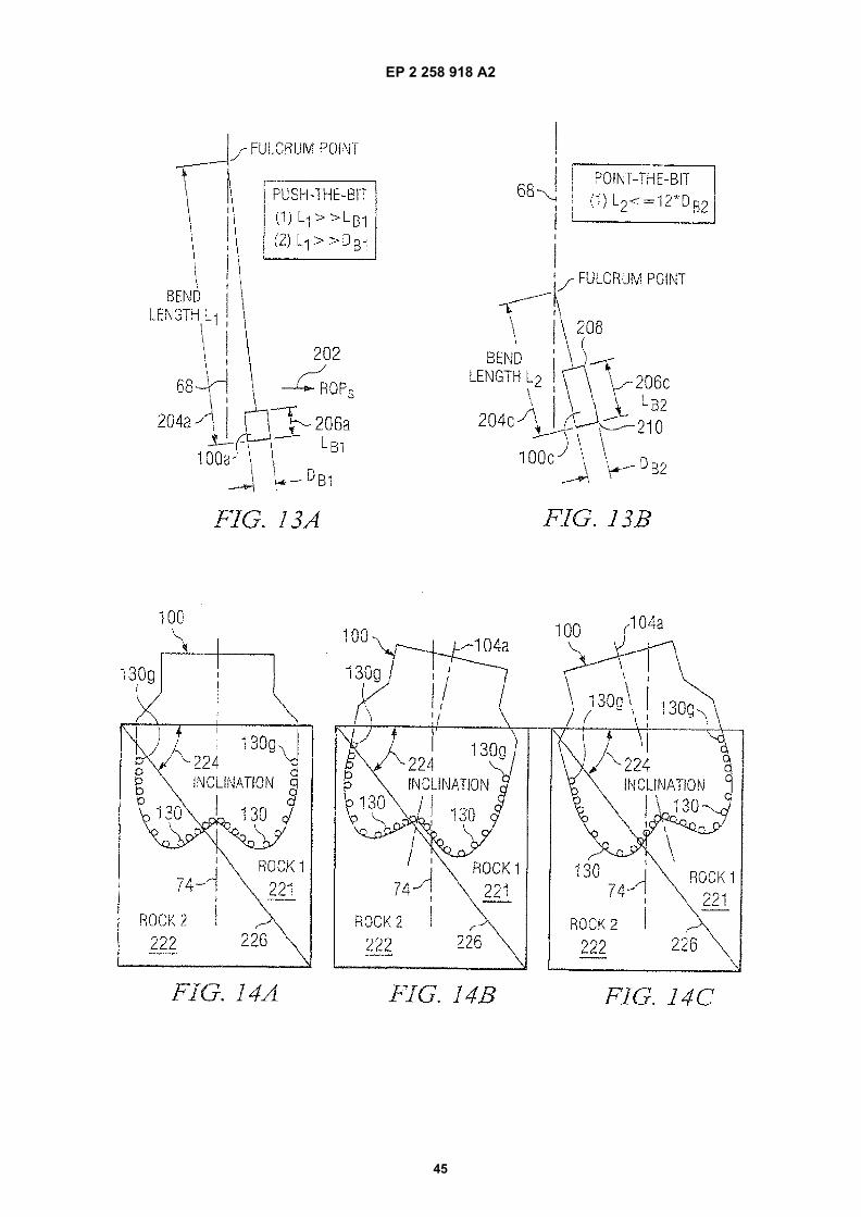
EP 2 258 918 A2
45
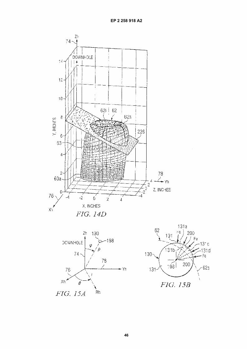
EP 2 258 918 A2
46
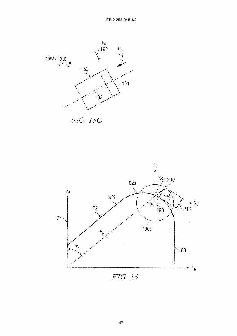
EP 2 258 918 A2
47

EP 2 258 918 A2
48
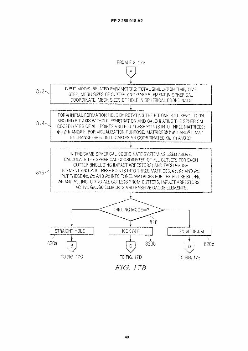
EP 2 258 918 A2
49
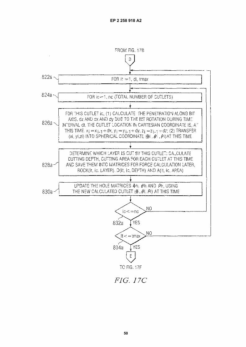
EP 2 258 918 A2
50
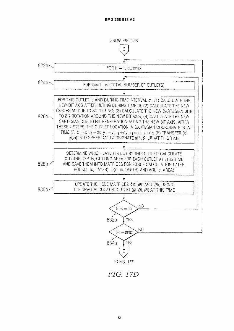
EP 2 258 918 A2
51
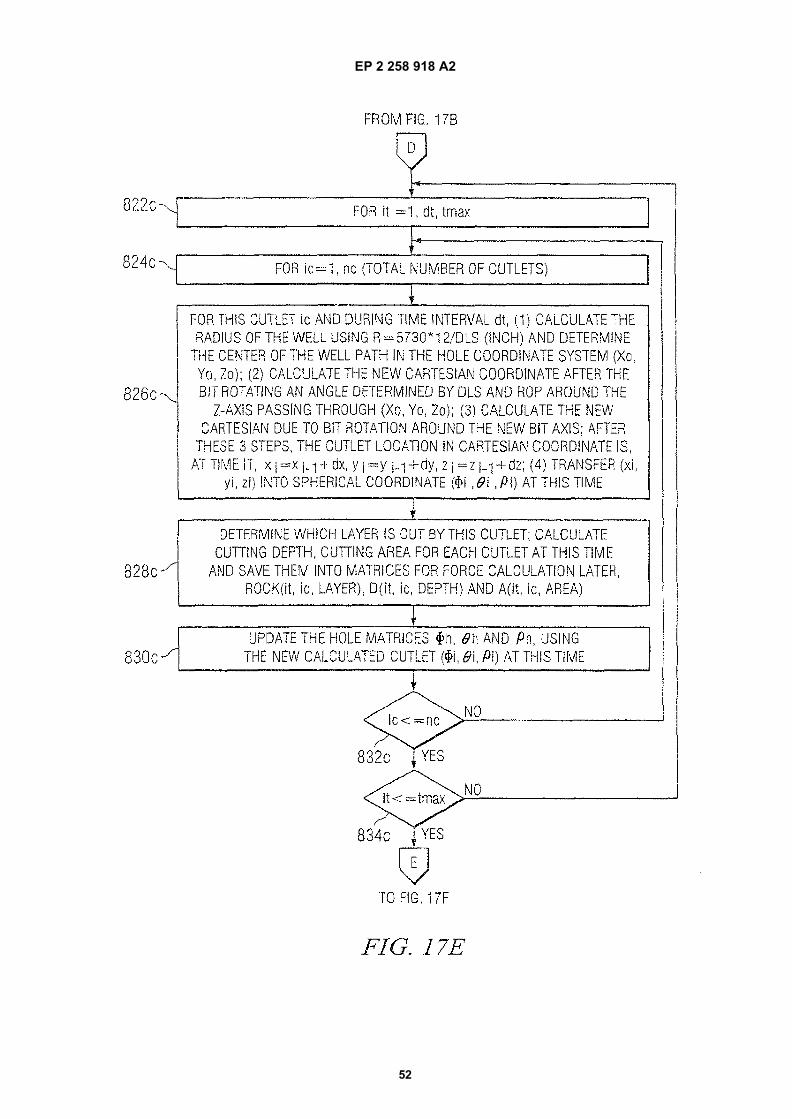
EP 2 258 918 A2
52
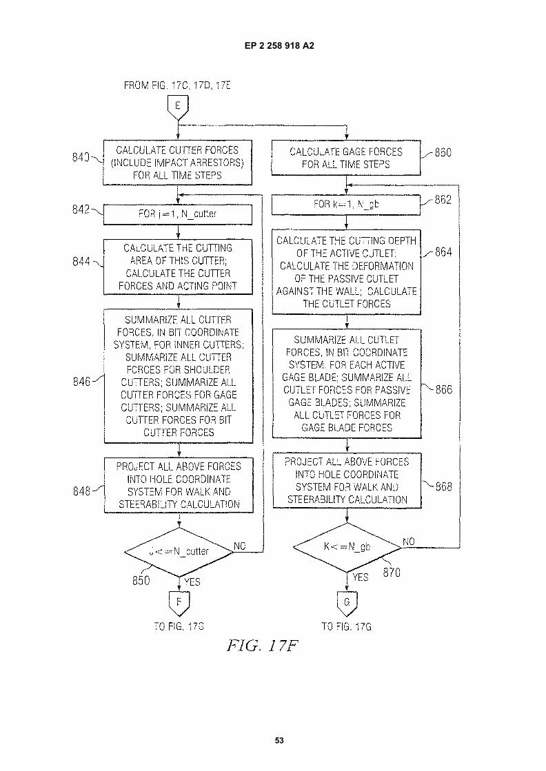
EP 2 258 918 A2
53
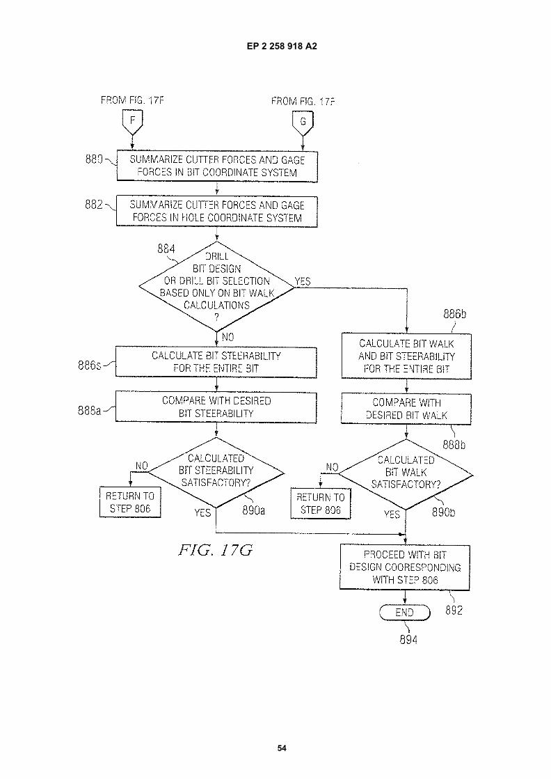
EP 2 258 918 A2
54
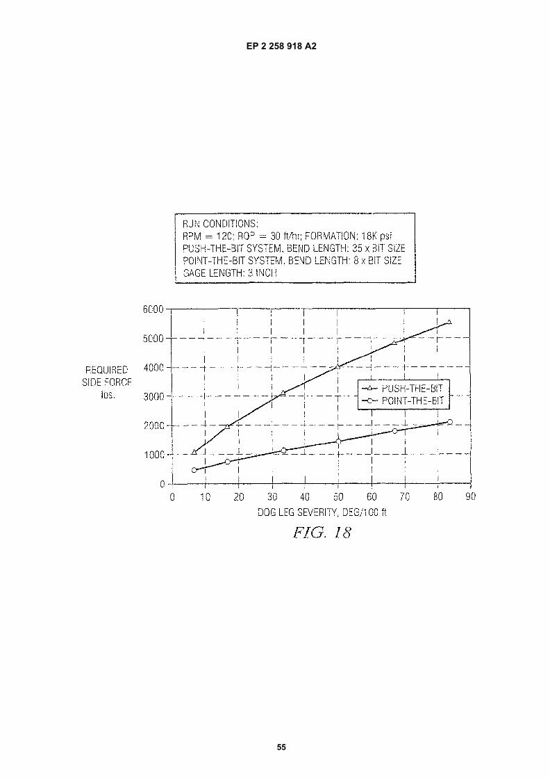
EP 2 258 918 A2
55

EP 2 258 918 A2
56
REFERENCES CITED IN THE DESCRIPTION
This list of references cited by the applicant is for the reader’s convenience only. It does not form part of the Europeanpatent document. Even though great care has been taken in compiling the references, errors or omissions cannot beexcluded and the EPO disclaims all liability in this regard.
Patent documents cited in the description
• US 46289806 A [0001]• US 60706321 B [0001]• US 60738431 B [0002]• US 60706323 B [0003]• US 60738453 B [0004]
• US 6003623 A [0064]• US 5595252 A [0064]• US 4889017 A [0064]• US 4696354 A [0124]• US 5099929 A [0124]