Merged Description of Iub Interface - 3GPP
66
TSG-RAN Working Group 3 meeting #2 TSGR3#2(99)151 Nynäshamn (Stockholm), Sweden 15 th – 19 th March, 1999 Agenda Item: Source: Editor Title: Merged Description of Iub Interface, Version 0.0.2 Document for: Merged Description of I ub Interface
-
Upload
khangminh22 -
Category
Documents
-
view
0 -
download
0
Transcript of Merged Description of Iub Interface - 3GPP

TSG-RAN Working Group 3 meeting #2 TSGR3#2(99)151Nynäshamn (Stockholm), Sweden15th – 19th March, 1999
Agenda Item:
Source: Editor
Title: Merged Description of Iub Interface, Version 0.0.2
Document for:
Merged Description of Iub Interface

22
Contents
1. INTELLECTUAL PROPERTY RIGHTS ........................................................................................................... 44
2. FOREWORD ......................................................................................................................................................... 44
3. SCOPE .................................................................................................................................................................... 44
4. REFERENCES ....................................................................................................................................................... 44
5. DEFINITIONS, ABBREVIATIONS AND NOTATION .................................................................................... 55
5.1 DEFINITIONS ..................................................................................................................................................... 555.2 ABBREVIATIONS ............................................................................................................................................... 555.3 NOTATION ......................................................................................................................................................... 55
6. GENERAL ASPECTS ........................................................................................................................................... 55
6.1 UTRAN ARCHITECTURE .................................................................................................................................. 556.2 IUB -INTERFACE GENERAL PRINCIPLES AND SPECIFICATION OBJECTIVES ........................................................... 556.3 IUB -INTERFACE CAPABILITIES ........................................................................................................................... 666.4 IUB -INTERFACE CHARACTERISTICS .................................................................................................................... 66
7. IUB -INTERFACE PROTOCOL FUNCTIONS ................................................................................................... 77
7.1 INTERFACE FUNCTIONS ..................................................................................................................................... 77
8. IUB -INTERFACE PROTOCOL STRUCTURE.................................................................................................. 77
9. IUB -INTERFACE PROTOCOL LAYER SPECIFICATION FOR RADIO NETWORK CONTROLPLANE ............................................................................................................................................................................. 99
9.1 INTRODUCTION ................................................................................................................................................. 999.2 RADIO NETWORK LAYER .................................................................................................................................. 99
9.2.1 General ..................................................................................................................................................... 999.2.2 NBAP Procedures ..................................................................................................................................... 99
9.2.2.1 NBAP Common Procedures ................................................................................................................................... 999.2.2.2 NBAP Dedicated Procedures .............................................................................................................................. 1111
9.2.3 NBAP Messages .................................................................................................................................... 16169.2.3.1 Message Contents ............................................................................................................................................... 1616
9.2.4 Signalling Element Coding ................................................................................................................... 21219.3 TRANSPORT LAYER ...................................................................................................................................... 2727
9.3.1 General ................................................................................................................................................. 27279.3.2 Signalling Bearer .................................................................................................................................. 2727
10. IUB-INTERFACE PROTOCOL LAYER SPECIFICATION FOR TRANSPORT NETWORKCONTROL PLANE .................................................................................................................................................... 2727
10.1 INTRODUCTION .............................................................................................................................................. 272710.2 TRANSPORT LAYER ....................................................................................................................................... 2828
10.2.1 General ................................................................................................................................................. 282810.2.2 ALCAP .................................................................................................................................................. 282810.2.3 Signalling Bearer .................................................................................................................................. 2828
11. IUB -INTERFACE PROTOCOL LAYER SPECIFICATION FOR USER PLANE ................................ 2828
11.1 INTRODUCTION .............................................................................................................................................. 282811.2 RADIO NETWORK LAYER ............................................................................................................................... 2828
11.2.1 General ................................................................................................................................................. 282811.2.2 Dedicated Channel Frame Protocol ..................................................................................................... 2929
11.2.2.1 Dedicated Channel Procedures ....................................................................................................................... 292911.2.2.2 Iur / Iub DCH Data Stream Synchronisation .................................................................................................. 3030

32
11.2.3 FACH Frame Protocol.......................................................................................................................... 313111.2.4 RACH Frame Protocol.......................................................................................................................... 313111.2.5 DSCH Frame Protocol......................................................................................................................... 3131
11.3 TRANSPORT LAYER ....................................................................................................................................... 3131
12. PHYSICAL LAYER ...................................................................................................................................... 3131
13. EXAMPLE SEQUENCES .............................................................................................................................. 3131
14. HISTORY ........................................................................................................................................................ 3232
ANNEX IUB PARAMETERS LIST ........................................................................................................................ 3333
1. INTELLECTUAL PROPERTY RIGHTS.............................................................................................................3
2. FOREWORD ...........................................................................................................................................................3
3. SCOPE......................................................................................................................................................................3
4. REFERENCES.........................................................................................................................................................3
5. DEFINITIONS, ABBREVIATIONS AND NOTATION......................................................................................4
5.1 DEFINITIONS .......................................................................................................................................................45.2 ABBREVIATIONS .................................................................................................................................................45.3 NOTATION...........................................................................................................................................................4
6. GENERAL ASPECTS.............................................................................................................................................4
6.1 UTRAN ARCHITECTURE ....................................................................................................................................46.2 IUB -INTERFACE GENERAL PRINCIPLES AND SPECIFICATION OBJECTIVES.............................................................46.3 IUB -INTERFACE CAPABILITIES .............................................................................................................................56.4 IUB -INTERFACE CHARACTERISTICS......................................................................................................................5
7. IUB -INTERFACE PROTOCOL FUNCTIONS.....................................................................................................6
7.1 INTERFACE FUNCTIONS.......................................................................................................................................6
8. IUB -INTERFACE PROTOCOL STRUCTURE....................................................................................................6
9. IUB -INTERFACE PROTOCOL LAYER SPECIFICATION FOR RADIO NETWORK CONTROLPLANE...............................................................................................................................................................................8
9.1 INTRODUCTION ...................................................................................................................................................89.2 RADIO NETWORK LAYER ....................................................................................................................................8
9.2.1 General .......................................................................................................................................................89.2.2 NBAP Procedures .......................................................................................................................................8
9.2.2.1 NBAP Common Procedures .....................................................................................................................................89.2.2.2 NBAP Dedicated Procedures..................................................................................................................................10
9.2.3 NBAP Messages ........................................................................................................................................139.2.3.1 Message Contents ...................................................................................................................................................14
9.2.4 Signalling Element Coding .......................................................................................................................199.3 TRANSPORT LAYER ..........................................................................................................................................24
9.3.1 General .....................................................................................................................................................249.3.2 Signalling Bearer ......................................................................................................................................24
10. IUB-INTERFACE PROTOCOL LAYER SPECIFICATION FOR TRANSPORT NETWORKCONTROL PLANE........................................................................................................................................................25
10.1 INTRODUCTION ..................................................................................................................................................2510.2 TRANSPORT LAYER ...........................................................................................................................................25
10.2.1 General .....................................................................................................................................................2510.2.2 ALCAP ......................................................................................................................................................2510.2.3 Signalling Bearer ......................................................................................................................................25
11. IUB -INTERFACE PROTOCOL LAYER SPECIFICATION FOR USER PLANE ....................................25

42
11.1 INTRODUCTION ..................................................................................................................................................2511.2 RADIO NETWORK LAYER ...................................................................................................................................26
11.2.1 General .....................................................................................................................................................2611.2.2 Dedicated Channel Frame Protocol .........................................................................................................26
11.2.2.1 Dedicated Channel Procedures...........................................................................................................................2711.2.2.2 Iur / Iub DCH Data Stream Synchronisation......................................................................................................28
11.2.3 FACH Frame Protocol..............................................................................................................................2811.2.4 RACH Frame Protocol..............................................................................................................................2811.2.5 DSCH Frame Protocol.............................................................................................................................28
11.3 TRANSPORT LAYER ...........................................................................................................................................28
12. PHYSICAL LAYER..........................................................................................................................................29
13. EXAMPLE SEQUENCES..................................................................................................................................29
14. HISTORY............................................................................................................................................................29
ANNEX IUB PARAMETERS LIST ............................................................................................................................30
1. Intellectual Property Rights
2. Foreword
3. ScopeThis document shall provide a description of the UTRAN RNC-NodeB (Iub) interface as agreed within 3GPP RANworking group #3.
4. ReferencesReferences may be made to:
a) specific versions of publications (identified by date of publication, edition number, version number, etc.), inwhich case, subsequent revisions to the referenced document do not apply;
b) all versions up to and including the identified version (identified by “up to and including” before the versionidentity);
c) all versions subsequent to and including the identified version (identified by “onwards” following the versionidentity); or
d) publications without mention of a specific version, in which case the latest version applies.
A non-specific reference to an ETS shall also be taken to refer to later versions published as an EN with the samenumber.
[1] [1] ZZ.01, UTRAN Architecture Description, Editor (Nortel)[2] [2] UMTS 23.10 UMTS Access Stratum Services and Function[3] [3] Tdoc SMG2 UMTS-L23 110/98, Vocabulary used in the UMTS L2&L3 Expert Group[4] [4] ZZ.12, Description of Iur Interface, Editor (Ericsson)[5] [5] ZZ.11, Description of Iu Interface, Editor (Nokia)[6] [6] YY.01, MS-UTRAN Radio Interface Protocol Architecture, Editor (Ericsson)[7] [7] ITU-T I.363.2 B-ISDN ATM Adaptation Layer Specification: Type 2 AAL[8] [8] ITU-T I.366.1 Segmentation and Reassembly Service Specific Convergence Sublayer for AAL Type2[9] [9] ITU-T Draft new ITU-T Recommendation Q.aal2 AAL Type2 Signalling Protocol, November 1998

52
5. Definitions, Abbreviations and Notation
5.1 Definitions[Editor´s note: For list of definitions, see [1].]
5.2 Abbreviations[Editor´s note: For list of abbreviations, see [1].]
5.3 Notation[Editor´s note: This text has been copied from [1].]
Parts of the document apply only to one mode, FDD or TDD. Any such area will be tagged by [FDD — xxxxxxxxx] and[TDD — yyyyyyyyyyy] respectively. The tag applies to the text until the closing bracket.
6. General Aspects
6.1 UTRAN Architecture[Editor´s note: This chapter should describe the UTRAN architecture from Iub point of view. The RNS architecture withits elements RNC and NodeB is described to facilitate the description of functional split in chapter 7.In order to avoid inconsistency between documents, reference to [1], chapter 8, has been made.]
For the description of the UTRAN architecture see [1], chapter 8.
6.2 Iub -Interface General Principles and Specification ObjectivesThe Iub interface specifications shall facilitate the following:- Inter-connection of RNCs and NodeBs from different manufacturers;- Separation of Iub interface Radio Network functionality and Transport Network functionality to facilitate
introduction of future technology.
The general principles for the specification of the Iub interface are as follows:- Transmission sharing between the GSM/GPRS Abis interface and the Iub interface shall not be precluded.- The functional division between RNC and NodeB shall have as few options as possible;- Iub should be based on a logical model of NodeB;- NodeB controls a number of cells and can be ordered to add/remove radio links in those cells;- Neither the physical structure nor any internal protocols of the NodeB shall be visible over Iub and are thus not
limiting factors, e.g., when introducing future technology.- Operation and Maintenance of NodeB hardware and software resources is not a part of the Iub standardisation.
Note: It is FFS which functions belong to this group.- Complex functionality shall as far as possible be avoided over Iub. This is important so that the Iub specification is
ready on time. Advanced optimisation solutions may be added in later versions of the standard.- The Iub functional split shall take into account the probability of frequent switching between different channel
types.
The Iub parts to be standardised by TSG-RAN are:1. User data
2. Signalling for handling the user data

62
3. Management of logical resources of Node BNote: The definition of logical resources is FFS.
It should be possible to transport the O&M information via the Iub interface and, hence, the lower layer transportmechanisms should be standardised to this effect. The content of the O&M information is not specified in this documentbut will be described in an external document which is tbd.
6.3 Iub -Interface Capabilities
The Iub interface connects a RNC and a Node B.The information transferred over the Iub reference point can be categorised as follows:
1. Radio application related signalling
The Iub interface allows the RNC and the Node B to negotiate about radio resources, for example to add and deletecells controlled by the Node B to support communication of the dedicated connection between UE and SRNC.Information used to control the broadcast and paging channels, and information to be transported on the broadcastand paging channels, belong to this category also.
2. Iub/Iur DCH data stream
The Iub interface provides means for transport of uplink and downlink DCH Iub frames between RNC and Node B.The DCH Iub frame header includes uplink quality estimates and synchronisation information. The DCH Iub framebody comprises of data to be transferred over the radio interface. The DCH Iub frames can be carried on pre-defined transmission links or switched connections.One Iub/Iur DCH data stream is carried on one transport bearer.
3. Iub RACH data stream
The Iub interface provides means for transport of uplink RACH transport frames between RNC and Node B. TheRACH transport frame header includes synchronisation information. The RACH transport frame body includes thedata received over radio interface. The transport frames can be carried on pre-defined transmission links orswitched connections. One Iub RACH data stream is carried on one transport bearer.For each RACH in a cell, a Iub RACH data stream must be established over the Iub interface.
4. Iub FACH data stream
The Iub interface provides means for transport of downlink FACH transport frames between RNC and Node B. TheFACH transport frame header includes synchronisation information. The FACH transport frame body includes thedata to be sent over radio interface. The transport frames can be carried on pre-defined transmission links orswitched connections. One Iub FACH data stream is carried on one transport bearer.For each FACH in a cell, a Iub FACH data stream must be established over the Iub Interface.
5. Iub DSCH data stream
The Iub interface provides the means for transport of downlink shared channel, DSCH, data frames between RNCand Node B. The DSCH Iub frame body comprises of data to be transferred over the radio interface. The DSCH Iubframes can be carried on pre-defined transmission links or switched connections.One Iub DSCH data stream is carried on one transport bearer.
6.4 Iub -Interface Characteristics[Editor´s note: This chapter should shortly describe the Iub -Interface Characteristics.]

72
7. Iub -Interface Protocol Functions[Editor´s note: This chapter should describe the functions of the Iub interface. For information about the Iub interfacefunctional division, see [1].]
7.1 Interface FunctionsThe list of functions on the Iub interface is the following:1. Management of Iub Transport Resources2. Logical OA&M of Node B
• Iub Signalling Bearer Management• Cell Configuration Management• Interference Measurements• Notification of Available Logical Resources• Common Channels Management• Radio Resource Management
3. Physical OA&M Transport4. Traffic Management of Common Channels
• Admission Control• Power Management• Data Transfer
5. Traffic Management of Dedicated Channels• Channel Allocation / De-allocation• Power Management• Measurement Reporting• Dedicated Transport Channel Management• Data Transfer
6. Traffic Management of Downlink Shared Channels (FFS)• Channel Allocation / Deallocation• Power Management• Transport Channel Management• Data Transfer
7. Timing and Synchronisation Management
8. Iub -Interface Protocol Structure[Editor´s note: This chapter should provide an introduction to the structure of the Iub interface protocols.

82
Node BApplication
Protocol (NBAP)
AAL Type 2
TransportSignalling(ALCAP)
TransportLayer
Physical Layer
RadioNetworkLayer
Radio NetworkControl Plane
TransportNetwork
Control Plane
DC
H FP
RA
CH
FP
ATM
FAC
H FP
DSC
H FP
SignallingBearer
SignallingBearer
User Plane
Figure 1: Iub Interface Protocol Structure.Note: The possibility to share AAL2 needs further clarification; the FAUSCH FP is FFS.
The Iub interface protocol architecture consists of two functional layers:1. Radio Network Layer, defines procedures related to the operation of Node B. The radio network layer consists of a
radio network control plane and a radio network user plane.2. Transport Layer, defines procedures for establishing physical connections between Node B and the RNC.
Figure 2 shows the TTC/ARIB proposal for the Iub interface protocol structure. This proposal is FFS.
USERPLANE
RADIO NETWORKCONTROLPLANE
NBAP
SSCF-UNI
BEARERCONVERTER
Q.AAL2(FFS) *1
SSCOP
AAL5
ATM AAL 2/5 *3
TRANSPORT NETWORKCONTROL PLANE
Figure 2: TTC/ARIB Iub Interface Protocol Structure. Note *1: It is FFS which signalling protocol sets up AAL5 connections. Note *3: It is FFS whether AAL5 is
applied to User plane. Note: It is FFS how to distinguish NBAP from signalling protocol.

92
9. Iub -Interface Protocol Layer Specification for RadioNetwork Control Plane
9.1 Introduction[Editor´s note: This chapter should give and introduction to the protocol layer specification for Radio Network ControlPlane.]
9.2 Radio Network Layer
9.2.1 General
[Editor´s note: This chapter should describe requirements on protocol capabilities, principles, etc. .]
Node B Application protocol, NBAP, includes common procedures and traffic handling procedures. It coversprocedures for paging distribution, broadcast system information, request / complete / release of dedicated resources andmanagement of logical resources.
Note that the issue of transport layer addressing is FFS.
9.2.2 NBAP Procedures
NBAP procedures are divided into common procedures and dedicated procedures.
• NBAP common procedures are procedures that request initiation of a UE context for a specific UE in Node B or arenot related to a specific UE.
• NBAP dedicated procedures are procedures that are related to a specific UE context in Node B. This UE context isidentified by a UE context identity.
The two types of procedures may be carried on separate signalling links.
9.2.2.1 NBAP Common Procedures
9.2.2.1.1 Common Channels Management
This procedure provides the capability to activate common channel resources such as [cell broadcast channels and]random access channels. The ability to control, for example, paging retransmission should also be provided. Informationon common channel performance (eg overload) should be provided by node B to the RNC.
9.2.2.1.2 Radio Resource Management
This procedure controls the physical radio system, eg transmitter tuning and output power control functions. Procedures[will], for example, also provide for the RNC to be informed of the automatic reconfiguration of node B in the case ofpartial failures and the availability of redundant radio equipment.
9.2.2.1.3 Iub Signalling Bearer Management
This procedure shall deal with the management of the Iub link. This will address not only initial link establishment, butalso the ongoing monitoring of link health, link recovery, load sharing and distribution.
9.2.2.1.4 Interference Measurements
102
9.2.2.1.5 Cell Configuration Management
This procedure provides the means for the RNC to configure some of the parameters of the node B and also the meansfor the node B to transfer the values of these and other parameters to the RNC. Examples are: RF parameters, systeminformation parameters and, channel configuration data.
9.2.2.1.6 Notification of Available Logical Resources
When the resources of node B which are available to the RNC change (eg due to failures within Node B or due tointeractions with OMC-B), this procedure provides the means to inform the RNC of this change and/or to warn the RNCof the impending change.
9.2.2.1.7 Radio Link Setup
This NBAP common procedure is used when there is no Radio Link for this UE in the Node B.
ControllingRNC
Node B
Radio Link SetupRequest
Radio Link SetupResponse
a) Successful case
ControllingRNC
Node B
Radio Link SetupRequest
Radio Link SetupFailure
b) Unsuccessful case
The RADIO LINK SETUP message contains the following information (the identification of the UE is FFS):• UL Radio Resource (UL Scrambling Code, UL Channelisation Code)• DL Radio Resource (DL Channelisation Codes per Radio Link, DL Scrambling Code is FFS)• DCH Information (DCH Identifier, Transmission Rate, Transport Format Set) (for each DCH in the UE)• Transport Format Combination Set• Power control information• Frequency• RL identifier #1• Target cell identifier #• RL identifier #2• Target cell identifier #• Soft combining indication (may, must, or must not be combined with already existing radio links)…..• RL identifier #n• Target cell identifier #• Soft combining indication (may, must, or must not be combined with already existing radio links)
The RADIO LINK SETUP RESPONSE message contains• Transport layer addressing information (AAL2 address) per RL
9.2.2.1.8 Paging
Note that this procedure is FFS.Study item Iub/1: Which identity (e.g., location identity, URA id, or a list of cells) to use in order to know which cells topage is FFS.

112
This NBAP common procedure is used by the RNC to page UE which is in RRC idle state with UE identity; it is alsoused to page UE which is in URA connected state with RNTI. This message also includes Location Identity or URA idor a list of cells (which method is being selected is FFS) for Node B to know which cell to page and an information forcalculating the paging group.
RNC Node B
PAGING
9.2.2.2 NBAP Dedicated Procedures
9.2.2.2.1 Radio Link Addition
This procedure is used when there is already one or more existing Radio Link(s) for this UE in the Node B.
ControllingRNC
Node B
Radio Link Addition
Radio Link AdditionResponse
a) Successful case
ControllingRNC
Node B
Radio Link Addition
Radio Link AdditionFailure
b) Unsuccessful case
The RADIO LINK ADDITION message contains the following information (the identification of the UE is FFS):• DL Radio Resource (DL channelisation codes) per RL• Power control information• the parameter “OFF” (frame offset information)• Frequency• RL identifier #n+1• Target cell identifier #• Soft combining indication (may, must, or must not be combined with already existing radio links)• RL identifier #n+2• Target cell identifier #• Soft combining indication (may, must, or must not be combined with already existing radio links)….
Other parameters are already known in the Node B, therefore there is no need to send them.
The RADIO LINK ADDITION RESPONSE message contains• Transport layer addressing information (AAL2 address, AAL2 binding ID) per RL
If the transport layer addressing information is not needed in case Node B decides to use an existing AAL2 connection,then the AAL2 address is not needed and the AAL2 binding ID of the already existing AAL2 connection is sent. If theControlling RNC receives the AAL2 binding ID of an already existing AAL2 connection, the ControllingRNC does not execute the setting of the AAL2 connection.
122
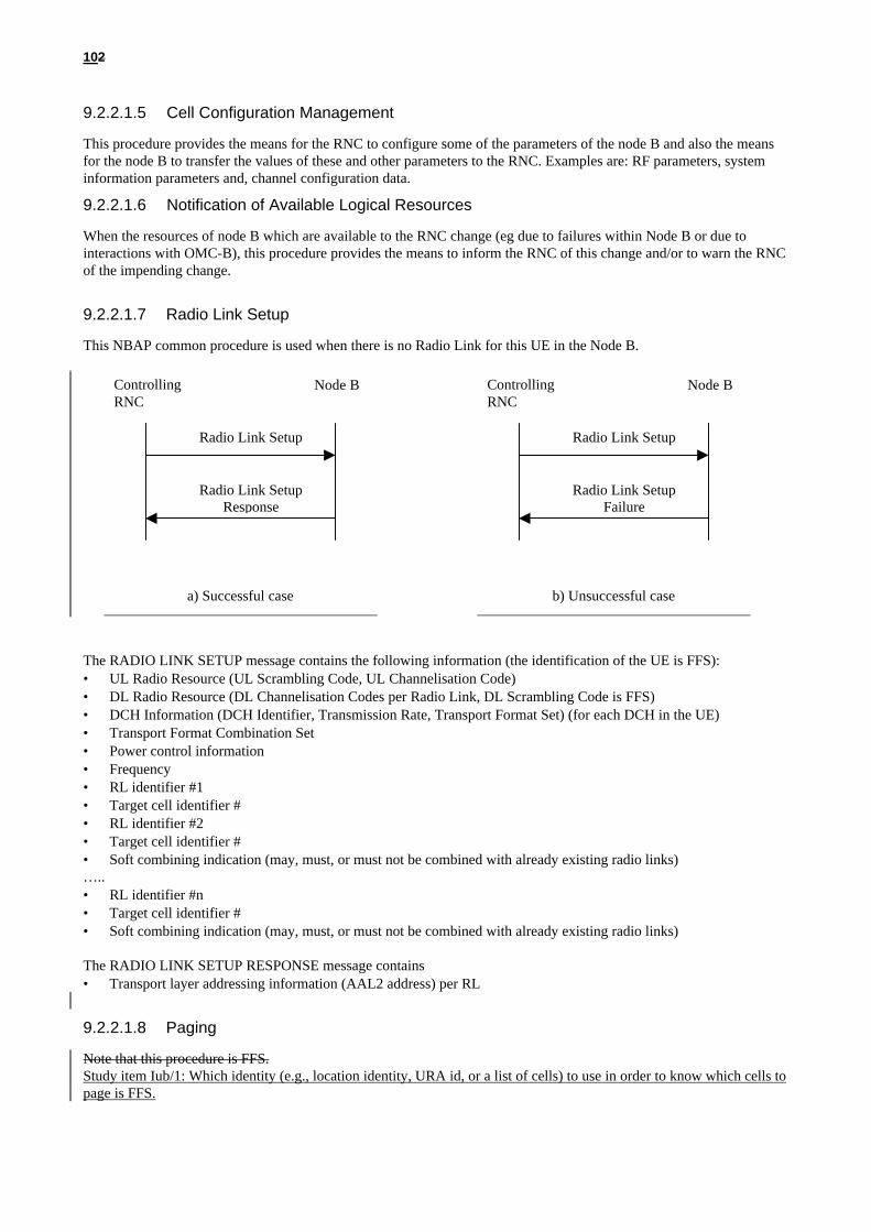
9.2.2.2.2 Radio Link Reconfiguration (Synchronised)
The Radio Link Reconfiguration (Synchronised) procedure is used to reconfigure radio links related to one UE-UTRANconnection within Node B. The procedure can be used to add, delete or reconfigure a DCH. The Radio LinkReconfiguration procedure is initiated by the Controlling RNC by sending the message RADIO LINKRECONFIGURATION PREPARE to the Node B. The message is sent using the relevant signalling connection. Itincludes the desired radio link parameters for the radio links to be used continuously after completion of this procedure(no change in active set). If the proposed modifications are approved by the Node B resource management algorithms,and when the Node B has successfully reserved the required resources, it responds to the Controlling RNC with theRADIO LINK RECONFIGURATION READY message. In the unsuccessful case a NBAP message RADIO LINKRECONFIGURATION FAILURE is returned, indicating among other things the reason for failure. The ControllingRNC informs the UE about the changes in the RL with the relevant RRC message(s) after sending the RADIO LINKRECONFIGURATION COMMIT message to the Node Bs. If necessary (for example when the new L1/L2configuration cannot coexist with the old one), the SRNC selects the most suitable CFN for the switching between theold and new configuration and includes it in the RRC message and in the RADIO LINK RECONFIGURATIONCOMMIT message. The Controlling RNC is responsible for releasing unnecessary Iub transport bearers (in case ofDCH deletion).This procedure is not used for adding or deleting radio links.
Radio Link ReconfiguationCommit
Radio Link ReconfiguationReady
Radio Link ReconfiguationPrepare
ControllingRNC Node B
a) Successful case
RADIO LINK RECONFIGURATION PREPARE
ControllingRNC
RADIO LINKRECONFIGURATION PREPARE
RADIO LINKRECONFIGURATION READY
Node B #1
b) Unsuccessful case
Node B #2
RADIO LINK RECONFIGURATION FAILURE
RADIO LINKRECONFIGURATION
CANCEL
The RADIO LINK RECONFIGURATION PREPARE message contains:• UL Radio Resources (UL Channelisation code type)• DL Radio Resources (DL Channelisation code per RL) (if changed)• Transport Format Combination Set
In case of DCH addition, this message also contains• DCH Information (new DCH ID to add, Transmission Rate, Transport Format Combination Set)• Priority of DCH (How is it used?)
In case of DCH reconfiguration, this message also contains• DCH Information (existing DCH ID to modify, Transmission Rate, Transport Format Combination Set)• Priority of modified DCH (How is it used?)
In case of DCH deletion, this message also contains• DCH Information (DCH ID to delete)
The RADIO LINK RECONFIGURATION PREPARE message may consist of a combination of DCH addition,deletion, and reconfiguration.

132
The RADIO LINK RECONFIGURATION READY message contains:• FFS
In case of DCH addition, this message also contains• Transport layer addressing information (AAL2 address, AAL2 binding ID) for added DCH
In case of DCH reconfiguration, this message also contains• Transport layer addressing information (AAL2 address, AAL2 binding ID) for modified DCH (if needed)
The RADIO LINK RECONFIGURATION FAILURE message contains• CAUSE
The RADIO LINK RECONFIGURATION COMMIT message contains• Timing information to change old resource to new resource (FFS)
The RADIO LINK RECONFIGURATION CANCEL message contains• Cancel information to reconfigure resources
Note: A mechanism for synchronising the switching from the old to the new configuration in the UE and in theControlling RNC is needed and FFS.
9.2.2.2.3 Radio Link Reconfiguration (Unsynchronised)
The Radio Link Reconfiguration (Unsynchronised) procedure is used to reconfigure radio links related to one UE-UTRAN connection within Node B. The procedure can be used to add, delete or reconfigure a DCH.
The Unsynchronised RL Reconfiguration is used when there is no need to synchronise the time of the switching from theold to the new configuration in the node-Bs used by the UE-UTRAN connection. This is the case when new TFCs areadded or old TFCs are deleted without changing the TFCI values of the TFCs that are maintained during thereconfiguration.
The Radio Link Reconfiguration procedure is initiated by the Controlling RNC by sending the message RADIO LINKRECONFIGURATION to the Node B. The message is sent using the relevant signalling connection. It includes thedesired radio link parameters for the radio links to be used continuously after completion of this procedure (no change inactive set).
If the proposed modifications are approved by the Node B resource management algorithms, and when the Node B hassuccessfully reserved the required resources, it responds to the Controlling RNC with the RADIO LINKRECONFIGURATION RESPONSE message.
In the unsuccessful case a NBAP message RADIO LINK RECONFIGURATION FAILURE is returned, indicatingamong other things the reason for failure.
The Controlling RNC is responsible for releasing unnecessary Iub transport bearers (in case of DCH deletion).
This procedure is not used for adding or deleting radio links.

142
Radio Link ReconfiguationResponse
Radio Link Reconfiguation
ControllingRNC Node B
The RADIO LINK RECONFIGURATION message contains:• Transport Format Combination Set
In case of DCH addition, this message also contains• DCH Information (new DCH ID to add, Transmission Rate, Transport Format Combination Set)• Priority of DCH (How is it used?)
In case of DCH reconfiguration, this message also contains• DCH Information (existing DCH ID to modify, Transmission Rate, Transport Format Combination Set)• Priority of modified DCH (How is it used?)
In case of DCH deletion, this message also contains• DCH Information (DCH ID to delete)
The RADIO LINK RECONFIGURATION message may consist of a combination of DCH addition, deletion, andreconfiguration.
The RADIO LINK RECONFIGURATION RESPONSE message contains:• FFS
In case of DCH addition, this message also contains• Transport layer addressing information (AAL2 address, AAL2 binding ID) for added DCH
In case of DCH reconfiguration, this message also contains• Transport layer addressing information (AAL2 address, AAL2 binding ID) for modified DCH (if needed)
The RADIO LINK RECONFIGURATION FAILURE message contains• CAUSE
9.2.2.2.43 Radio Link Deletion
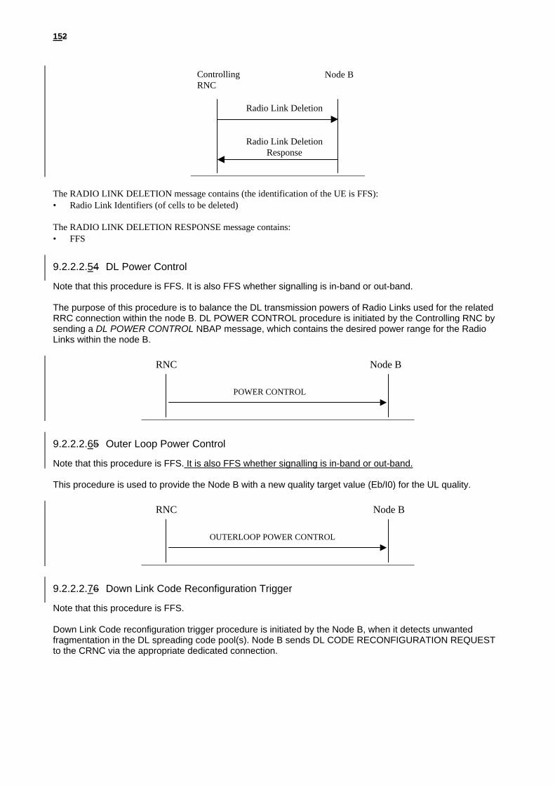
When the Controlling RNC is asked by Node B to delete a cell from the active set of a specific RRC connection, themessage RADIO LINK DELETION is sent to the corresponding Node B. The message contains essentially the RadioLink identifier of the Radio Link to be deleted. Upon reception of the message, Node B should delete immediately theradio link and all related allocations within the Node B and acknowledge the deletion to the Controlling RNC with themessage RADIO LINK DELETION RESPONSE.The Controlling RNC is responsible to release the corresponding Iub transport bearers if they are not used by other radiolinks.
152
ControllingRNC
Node B
Radio Link Deletion
Radio Link DeletionResponse
The RADIO LINK DELETION message contains (the identification of the UE is FFS):• Radio Link Identifiers (of cells to be deleted)
The RADIO LINK DELETION RESPONSE message contains:• FFS
9.2.2.2.54 DL Power Control
Note that this procedure is FFS. It is also FFS whether signalling is in-band or out-band.
The purpose of this procedure is to balance the DL transmission powers of Radio Links used for the relatedRRC connection within the node B. DL POWER CONTROL procedure is initiated by the Controlling RNC bysending a DL POWER CONTROL NBAP message, which contains the desired power range for the RadioLinks within the node B.
RNC Node B
POWER CONTROL
9.2.2.2.65 Outer Loop Power Control
Note that this procedure is FFS. It is also FFS whether signalling is in-band or out-band.
This procedure is used to provide the Node B with a new quality target value (Eb/I0) for the UL quality.
RNC
OUTERLOOP POWER CONTROL
Node B
9.2.2.2.76 Down Link Code Reconfiguration Trigger
Note that this procedure is FFS.
Down Link Code reconfiguration trigger procedure is initiated by the Node B, when it detects unwantedfragmentation in the DL spreading code pool(s). Node B sends DL CODE RECONFIGURATION REQUESTto the CRNC via the appropriate dedicated connection.

162
RNC Node B
DL CODE RECONFIGURATION REQUEST
9.2.3 NBAP Messages
Note that the content of this chapter is FFS.
This chapter defines the structure of the messages required for the NBAP protocols.
For each message there is, a table listing the signaling elements in their order of appearance in thetransmitted message.
All the NBAP messages are listed in the following table :[Note : All of these message name are tentative, these can be changed after complete discussion]
Message name ReferenceRADIO LINK SETUP 9.2.3.1.1RADIO LINK SETUP RESPONSE 9.2.3.1.2
RADIO LINK SETUP FAILURE 9.2.3.1.3RADIO LINK ADDITION 9.2.3.1.4RADIO LINK ADDITION RESPONSE 9.2.3.1.5RADIO LINK ADDITION FAILURE 9.2.3.1.6RADIO LINK DELETION 9.2.3.1.7RADIO LINK DELETION RESPONSE 9.2.3.1.8RADIO LINK RECONFIGURATION PREPARE 9.2.3.1.9RADIO LINK RECONFIGURATION READY 9.2.3.1.10RADIO LINK RECONFIGURATION COMMIT 9.2.3.1.11RADIO LINK RECONFIGURATION FAILURE 9.2.3.1.12RADIO LINK RECONFIGURATION CANCEL 9.2.3.1.13DL CODE RECONFIGURATION REQUEST 9.2.3.1.14POWER CONTROL 9.2.3.1.15OUTER LOOP POWER CONTROL 9.2.3.1.16PAGING 9.2.3.1.17RESET (FFS) 9.2.3.1.18RESET ACKNOWLEDGE (FFS) 9.2.3.1.19CONFUSION (FFS) 9.2.3.1.20
9.2.3.1 Message Contents
[Note: INFORMATION ELEMENT for each message shall be described in detail with each TYPEM/O.]
9.2.3.1.1 RADIO LINK SETUP
INFORMATION ELEMENT REFERENCE DIRECTION TYPE LENLink Reference DRNC-NodeB MMessage Identifier MLength M

172
Message Compatibility Information MNo. of DCHs MDCH ID (# 1) MTFS (for DCH ID# 1) MDCH ID (# n) MTFS (for DCH ID# n) MTFCS (for DCHs) MRadio Frequency MUL scrambling code MUL spreading code type MNo. of UL spreading code MUL spreading code id(s) MDL spreading code type MNo. of DL spreading code MNo. of Radio Links MRadio Link ID MCell ID MPhase Difference MRadio Link ID OCell ID OSoft Combination Indication OPhase Difference OSlot offset MFrame offset MInitial DL Power MTarget UL Eb/Io M
9.2.3.1.2 RADIO LINK SETUP RESPONSE
INFORMATION ELEMENT REFERENCE DIRECTION TYPE LENLink Reference NodeB-DRNC MMessage Identifier MLength MMessage Compatibility Information MNo. of DCHs MDCH ID (# 1) MATM Binding ID MATM Address ODCH ID (# n) MATM Binding ID MATM Address OUL Interference Level MNo. of Radio Links MRadio Link ID MNeighbor Cell Information MNo. of DL spreading code MDL spreading code id #1 MDL spreading code id #m MRadio Link ID ONeighbor Cell Information ONo. of DL spreading code ODL spreading code id #1 ODL spreading code id #m O
9.2.3.1.3 RADIO LINK SETUP FAILURE
INFORMATION ELEMENT REFERENCE DIRECTION TYPE LENLink Reference NodeB-DRNC M

182
Message Identifier MLength MMessage Compatibility Information MCause M
9.2.3.1.4 RADIO LINK ADDITION
INFORMATION ELEMENT REFERENCE DIRECTION TYPE LENLink Reference DRNC-NodeB MMessage Identifier MLength MMessage Compatibility Information MRadio Frequency ONo. of Radio Links MRadio Link ID MCell ID MSoft Combination Indication MPhase Difference MRadio Link ID OCell ID OSoft Combination Indication OPhase Difference O
9.2.3.1.5 RADIO LINK ADDITION RESPONSE
INFORMATION ELEMENT REFERENCE DIRECTION TYPE LENLink Reference NodeB-DRNC MMessage Identifier MLength MMessage Compatibility Information MNo. of DCHs MDCH ID (# 1) MATM Binding ID MATM Address ODCH ID (# n) MATM Binding ID MATM Address OUL Interference Level ONo. of Radio Links MRadio Link ID MNeighbor Cell Information MNo. of DL spreading code MDL spreading code id #1 MDL spreading code id #m MRadio Link ID ONeighbor Cell Information ONo. of DL spreading code ODL spreading code id #1 ODL spreading code id #m O
9.2.3.1.6 RADIO LINK ADDITION FAILURE
INFORMATION ELEMENT REFERENCE DIRECTION TYPE LENLink Reference NodeB-DRNC MMessage Identifier MLength MMessage Compatibility Information M
192
Cause M
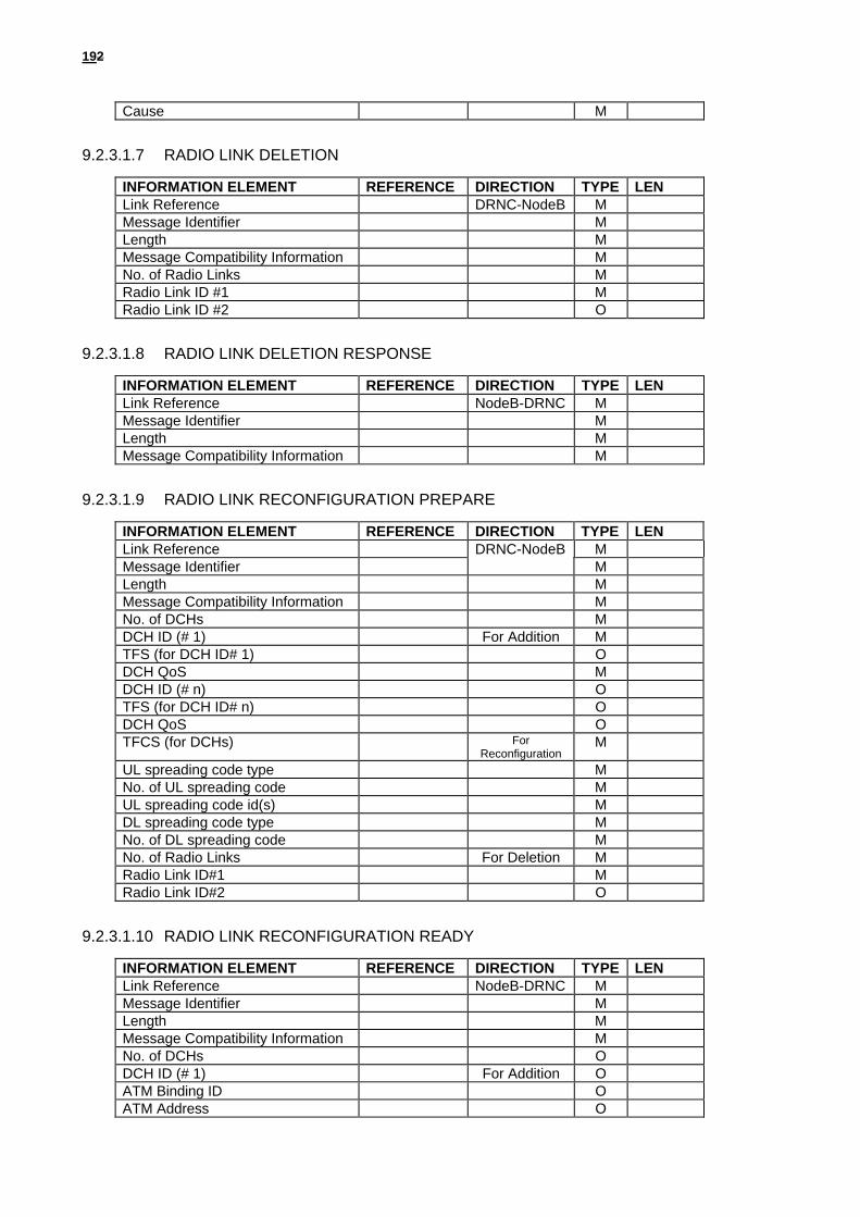
9.2.3.1.7 RADIO LINK DELETION
INFORMATION ELEMENT REFERENCE DIRECTION TYPE LENLink Reference DRNC-NodeB MMessage Identifier MLength MMessage Compatibility Information MNo. of Radio Links MRadio Link ID #1 MRadio Link ID #2 O
9.2.3.1.8 RADIO LINK DELETION RESPONSE
INFORMATION ELEMENT REFERENCE DIRECTION TYPE LENLink Reference NodeB-DRNC MMessage Identifier MLength MMessage Compatibility Information M
9.2.3.1.9 RADIO LINK RECONFIGURATION PREPARE
INFORMATION ELEMENT REFERENCE DIRECTION TYPE LENLink Reference DRNC-NodeB MMessage Identifier MLength MMessage Compatibility Information MNo. of DCHs MDCH ID (# 1) For Addition MTFS (for DCH ID# 1) ODCH QoS MDCH ID (# n) OTFS (for DCH ID# n) ODCH QoS OTFCS (for DCHs) For
ReconfigurationM
UL spreading code type MNo. of UL spreading code MUL spreading code id(s) MDL spreading code type MNo. of DL spreading code MNo. of Radio Links For Deletion MRadio Link ID#1 MRadio Link ID#2 O
9.2.3.1.10 RADIO LINK RECONFIGURATION READY
INFORMATION ELEMENT REFERENCE DIRECTION TYPE LENLink Reference NodeB-DRNC MMessage Identifier MLength MMessage Compatibility Information MNo. of DCHs ODCH ID (# 1) For Addition OATM Binding ID OATM Address O

202
DCH ID (# n) OATM Binding ID OATM Address ONo. of Radio Links For
ReconfigurationM
Radio Link ID MNo. of DL spreading code MDL spreading code id #1 MDL spreading code id #m MRadio Link ID For Deletion ONo. of DL spreading code ODL spreading code id #1 ODL spreading code id #m O
9.2.3.1.11 RADIO LINK RECONFIGURATION COMMIT
INFORMATION ELEMENT REFERENCE DIRECTION TYPE LENLink Reference DRNC-NodeB MMessage Identifier MLength MMessage Compatibility Information MExecution Time M
9.2.3.1.12 RADIO LINK RECONFIGURATION FAILURE
INFORMATION ELEMENT REFERENCE DIRECTION TYPE LENLink Reference NodeB-DRNC MMessage Identifier MLength MMessage Compatibility Information M
9.2.3.1.13 RADIO LINK RECONFIGURATION CANCEL
INFORMATION ELEMENT REFERENCE DIRECTION TYPE LENLink Reference DRNC-NodeB MMessage Identifier MLength MMessage Compatibility Information M
9.2.3.1.14 POWER CONTROL
INFORMATION ELEMENT REFERENCE DIRECTION TYPE LENLink Reference DRNC-NodeB MMessage Identifier MLength MMessage Compatibility Information MDL Power Range M
9.2.3.1.15 OUTER LOOP POWER CONTROL
INFORMATION ELEMENT REFERENCE DIRECTION TYPE LENLink Reference DRNC-NodeB MMessage Identifier MLength MMessage Compatibility Information MTarget UL Eb/Io M

212
9.2.3.1.16 DL CODE RECONFIGURATION REQUEST
INFORMATION ELEMENT REFERENCE DIRECTION TYPE LENLink Reference NodeB-DRNC MMessage Identifier MLength MMessage Compatibility Information M
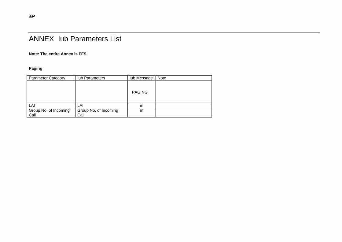
9.2.3.1.17 PAGING
INFORMATION ELEMENT REFERENCE DIRECTION TYPE LENPaged UE Identifier DRNC-NodeB MLink Reference MMessage Identifier MLength MLAI MGroup number of Incoming Call M
9.2.3.1.18 RESET (FFS)
9.2.3.1.19 RESET ACKNOWLEDGE (FFS)
9.2.3.1.20 CONFUSION (FFS)
9.2.4 Signalling Element Coding
Note that the content of this chapter is FFS. Furthermore, it is also FFS whether to use abstract or explicit coding (seestudy item Iu/7).
This paragraph contains the CODING of the signaling elements used.The following convention are assumned for the sequence of transmission of bits and bytes:
Each bit position is marked as 1 to 8. Bit 1 is the least significant bit and is transmitted first.In an element aoctets are identified by number, octet 1 is transmitted first, then octet 2 etc.
Length IndicatorIt is desirable to have Length for messages and parameters because future version of protocol may haveextension to the present message or parameter, and also variable size can be present in someparameters as well.
In case of message size exceeding 256 byte it is better to have 2 bytes for message LENGTH. However it is enough to have 1 byte for parameter LENGTH.
Compatibility InformationCompatibility Information is used in the situation of unrecognized messages or parameter. Thisparameter should be placed at a certain place then it is easy to pick up this parameter in anycircumstances.
Consequently, the format can be as follow: Message Identifier / Length / Compatibility Info / parameters

222
Parameter Identifier / Length / Compatibility Info / FieldsFigure 3 shows the coding format of message and Figure 4 shows the coding format of parameter.
Fixed size data and Variable size data in FieldIt may have two types of filed i.e. with variable size or fixed size in data of field. It has no any problem tospecify the fixed size field. Figure5 shows an example of fixed size data in field.
Regarding the variable size of data
The elements used and their CODING are:
ElementIdentifierCoding
Element name Reference
ATM Binding IDATM AddressNo of DCHsDCH IDTFS(for DCH)TFCS(for DCHs)Radio FrequencyUL scrambling codeUL spreading code type

232
No. of UL spreading codeUL spreading code IDUL Interference LevelDL spreading code typeNo. of DL spreading codeDL spreading code idCell IDNeighbor Cell InformationSoft Combination IndicationPhase DifferenceRadio Link IDNo. of Radio LinksExecution TimeSlot offsetFrame offsetInitial DL PowerDL Power RangeTarget UL Eb/IoDCH QoSLAIGroup number of incoming callCause
Message Identifier
Message Identifier uniquely identifies the message being sent. It is a single octet element, mandatoryin all messages.
8765 4321RADIO LINK SETUPRADIO LINK SETUP RESPONSERADIO LINK SETUP FAILURERADIO LINK ADDITIONRADIO LINK ADDITION RESPONSERADIO LINK ADDITION FAILURERADIO LINK DELETIONRADIO LINK DELETION RESPONSE
RADIO LINK RECONFIGURATION PREPARERADIO LINK RECONFIGURATION READYRADIO LINK RECONFIGURATION COMMITRADIO LINK RECONFIGURATION FAILURERADIO LINK RECONFIGURATION CANCELPOWER CONTROLOUTER LOOP POWER CONTROLDL CODE RECONFIGURATION REQUESTPAGINGRESET (FFS)RESET ACKNOWLEDGE (FFS)RESET (FFS)
Message Compatibility Information
Message Compatibility Information is used in the situation of unrecognized messages.
8 7 6 5 4 3 2 1Message Compatibility Information 1(oct)
Figure: Message Compatibility Information
Table: Message Compatibility Information octet Bit
8 Reserved

242
:4 Pass On not possible321
Discard MessageSend Notify (1)Release Indicator
1. It should be used in CONFUSION message
Parameter Compatibility Information
Parameter Compatibility Information is used in the situation of unrecognized messages.
8 7 6 5 4 3 2 1Parameter Compatibility Information 1(oct)
Figure: Parameter Compatibility Information
Table: Parameter Compatibility Information octet ( The detail is FFS.) Bit
8 Reserved:4 Pass On not possible321
Discard MessageSend Notify (1)Release Indicator
1. It should be used in CONFUSION message
ATM Address
This element is included ATM address.
[Note: The following should be described the cording format.(The detail is FFS.)]
ATM Binding ID
This element is included ATM Binding ID.
[Note: The following should be described the cording format.(The detail is FFS.)]
Cell ID
This element uniquely identifies cell which a RNC and is of variable length containing.
8 7 6 5 4 3 2 1Parameter Identifier 1 (oct)
Length 2Compatibility Information 3
Spare Cell identificationdiscriminator
4
Cell IdentificationFigure: format of Cell Identifier

252
Neighbour Cell information
No of DCHs
DCH ID
TFS(for DCH)
TFCS(for DCHs)
Soft Combination Indication
Phase Difference
Radio Frequency
UL Interference level
UL scrambling code
UL spreading code type
No. of UL spreading codes
UL spreading code ID
DL spreading code type
No. of Radio Links
Radio Link ID
No. of DL spreading codes
DL spreading code ID
262
Execution Timer
Initial DL Power
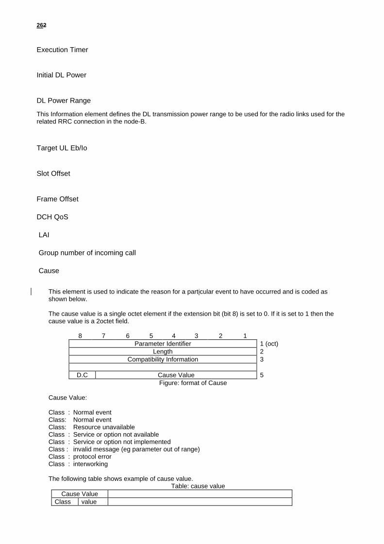
DL Power Range
This Information element defines the DL transmission power range to be used for the radio links used for therelated RRC connection in the node-B.
Target UL Eb/Io
Slot Offset
Frame Offset
DCH QoS
LAI
Group number of incoming call
Cause
This element is used to indicate the reason for a particular event to have occurred and is coded asshown below.
The cause value is a single octet element if the extension bit (bit 8) is set to 0. If it is set to 1 then thecause value is a 2octet field.
8 7 6 5 4 3 2 1Parameter Identifier 1 (oct)
Length 2Compatibility Information 3
D.C Cause Value 5 Figure: format of Cause
Cause Value:
Class : Normal eventClass: Normal eventClass: Resource unavailableClass : Service or option not availableClass : Service or option not implementedClass : invalid message (eg parameter out of range)Class : protocol errorClass : interworking
The following table shows example of cause value.Table: cause value
Cause ValueClass value

272
765 4321Normal terminationMobile illegal (ex. Authentication NG) O & M interventionEquipment failureProtocol errorMessage type non-existent or not implementedInformation element/parameter non-existent or notimplementedRadio link failureBS approach link failureTimer expiredCiphering algorithm not supportedResource unavailableOther values are reserved
9.3 Transport Layer
9.3.1 General
[Editor´s note: This chapter should e.g. describe Radio Network Layer requirements on Transport Layer protocols.]
9.3.2 Signalling Bearer
The Signalling Bearer for the NBAP is a point-to-point protocol. There may be multiple point-to-point links between anRNC and a Node B.
Two alternatives have been identified for the signalling bearer in the Radio Network Control Plane, SAAL-UNI overATM and TCP/IP / AAL5. The current working assumption is to use SAAL-UNI as the signalling bearer for NBAP.
10. Iub-Interface Protocol Layer Specification for TransportNetwork Control Plane
10.1 Introduction[Editor´s note: This chapter should describe general requirements and structure of the Transport Network ControlPlane.]

282
10.2 Transport Layer
10.2.1 General
RANAP
Control plane Access link control plane
Layer 2
Layer 1
RANMAP DTAP
Figure 2: Transport Network Control plane protocol structure on Iub.
10.2.2 ALCAP
Working assumption: Q.aal2 under development by ITU SG11 [9] is selected as that standard AAL2 signalling protocolfor Iub.
10.2.3 Signalling Bearer
Working assumption: SAAL-UNI is the standard signalling bearer for the AAL Type Signalling protocol (Q.aal2) onIub.Note: A signalling bearer converter needs to be added to the protocol stack; Q.aal2 does not include this. The converterrelevant for Iub is Q.21MT (needs to be checked).
11. Iub -Interface Protocol Layer Specification for UserPlane
11.1 Introduction[Editor´s note: This chapter should describe the structure of the User Plane.The description of the structure of Iur and Iub data frames is included here, but not in [4]. The Iur data stream shallfollow the same specification as the Iub data stream [1].]
11.2 Radio Network Layer
11.2.1 General
[Editor´s note: This chapter should describe structure of Iub data streams]

292
For the user plane of the radio network layer there are four protocols:• Dedicated Channel Frame Protocol (DCH FP) for transport of Iub data streams carried on dedicated channels on the
Uu-interface.• Random Access Channel Frame Protocol (RACH FP) for transport of Iub data streams carried on RACH on the Uu-
interface.• Forward Access Channel Frame Protocol (FACH FP) for transport of Iub data streams carried on FACH on the Uu-
interface.• Downlink Shared Channel Frame Protocol (DSCH FP) for transport of Iub data streams carried on DSCH on the
Uu-interface.
Note: FAUSCH frame protocol is FFS (depending on the decision of Layer 1 Expert Group).
11.2.2 Dedicated Channel Frame Protocol
The specification of Iub DCH data streams is also valid for Iur DCH data streams.
The parameters to be included in the Iub frames to be transported between Node B and Serving RNC (i.e., they applyfor Iur and Iub data stream) are:
1. User data - a block of user data.
2. Connection ID - used by soft combining function to identify multiple paths of the same call.
3. Quality Indication - used by soft combining function.
4. Length Indicator - used to allow different frame sizes and different user rates.
5. CRC - error check for the frame.
6. Rx power - indication of received power level in uplink only.
7. Frame Type - e.g. signalling or data.
8. CFN – the connection frame number is the indicator as to which radio frame the data should be transmitted / wasreceived. It is also needed for synchronisation purposes in DL channel frames.
9. Timing adjustment command – needed for synchronisation purposes in UL channel frames.
[Note: This list of parameters is the starting assumption and not necessarily comprehensive.]
Two different message types are to be used for both the downlink and uplink DCH Transport Channel Frame protocol inthe Iur and Iub interfaces.• DCH data frame• DCH control frame
The DCH control frame shall be used for inband signalling between SRNC and Node B in cases where the normal DCHdata frame can not be utilised. The DCH control frame shall not carry any data targeted to or received from the airinterface. Typical use for the DCH control frame would be synchronisation of the user plane and transport of DL outerloop power control commands.
11.2.2.1 Dedicated Channel Procedures
11.2.2.1.1 General
The SRNC is responsible for creating communications inside the SRNS. The SRNC provides to the Node B thecomplete configuration of the Transport channels to be provided by the Node B for a given communication.The parameters of a Transport channel are described in [6]. These Transport channels are multiplexed on the downlinkby the Node B on radio physical channels, and de-multiplexed on the uplink from radio physical channels to Transportchannels.
302
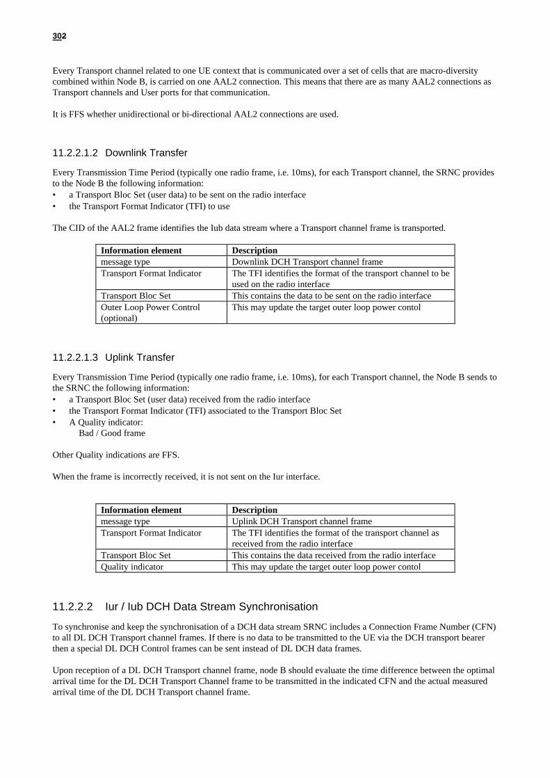
Every Transport channel related to one UE context that is communicated over a set of cells that are macro-diversitycombined within Node B, is carried on one AAL2 connection. This means that there are as many AAL2 connections asTransport channels and User ports for that communication.
It is FFS whether unidirectional or bi-directional AAL2 connections are used.
11.2.2.1.2 Downlink Transfer
Every Transmission Time Period (typically one radio frame, i.e. 10ms), for each Transport channel, the SRNC providesto the Node B the following information:• a Transport Bloc Set (user data) to be sent on the radio interface• the Transport Format Indicator (TFI) to use
The CID of the AAL2 frame identifies the Iub data stream where a Transport channel frame is transported.
Information element Descriptionmessage type Downlink DCH Transport channel frameTransport Format Indicator The TFI identifies the format of the transport channel to be
used on the radio interfaceTransport Bloc Set This contains the data to be sent on the radio interfaceOuter Loop Power Control(optional)
This may update the target outer loop power contol
11.2.2.1.3 Uplink Transfer
Every Transmission Time Period (typically one radio frame, i.e. 10ms), for each Transport channel, the Node B sends tothe SRNC the following information:• a Transport Bloc Set (user data) received from the radio interface• the Transport Format Indicator (TFI) associated to the Transport Bloc Set• A Quality indicator:
Bad / Good frame
Other Quality indications are FFS.
When the frame is incorrectly received, it is not sent on the Iur interface.
Information element Descriptionmessage type Uplink DCH Transport channel frameTransport Format Indicator The TFI identifies the format of the transport channel as
received from the radio interfaceTransport Bloc Set This contains the data received from the radio interfaceQuality indicator This may update the target outer loop power contol
11.2.2.2 Iur / Iub DCH Data Stream Synchronisation
To synchronise and keep the synchronisation of a DCH data stream SRNC includes a Connection Frame Number (CFN)to all DL DCH Transport channel frames. If there is no data to be transmitted to the UE via the DCH transport bearerthen a special DL DCH Control frames can be sent instead of DL DCH data frames.
Upon reception of a DL DCH Transport channel frame, node B should evaluate the time difference between the optimalarrival time for the DL DCH Transport Channel frame to be transmitted in the indicated CFN and the actual measuredarrival time of the DL DCH Transport channel frame.

312
According to the measured time difference, node B should set a proper value for the Timing adjustment command in theUL DCH transport channel frame. If there is no UL data to be transmitted to the SRNC via the DCH transport bearerthen a special UL DCH Control frame can be sent.
(The initial value for the parameters is FFS)
11.2.3 FACH Frame Protocol
The parameters to be included in the Iub FACH frames are:
1. CELL FN – the cell frame number is needed for synchronisation purposes.
11.2.4 RACH Frame Protocol
The parameters to be included in the Iub RACH frames are:
1. CELL FN – the cell frame number is needed for synchronisation purposes.
11.2.5 DSCH Frame Protocol
11.3 Transport Layer[Editor´s note: This chapter should refer to specifications of the Transport Layer protocol(s). Limitations in usage ofoptions of the protocol(s) should be described.]
Iub / Iur DCH data stream for soft handover [FDD]:ATM and AAL2 is used as a standard transport layer for DCH data streams across the Iur and Iub interfaces. Otherprotocols such as Frame Relay and ATM AAL5 are FFS.
Iub / Iur DCH data stream for soft handover [TDD]:FFS
ATM and AAL2 type 2 (I363.2 and I366.1) is used at the standard transport layer for Iub RACH and FACH datastreams.Note: This assumes that MAC scheduling is in the RNC. This decision is to be confirmed when protocol terminationpoints are decided.
12. Physical Layer [Editor´s note: This chapter should refer to specifications of the Physical Layer. Limitations in usage of options of theprotocol(s) should be described.]
Working assumption:When using multiple low speed links in the Iub interface, the Node B shall support IMA (Inverse Multiplexing forATM).
13. Example Sequences [Editor’s note: This chapter should contain examples of sequences including both Radio Network Signalling andTransport Signalling.]

322
14. History
Document history
Date Version Comment
February 4, 1999 0.0.1 First draft of merged Iub description document
February 19, 1999 0.0.2 All revision marks from Tdoc R3-99094 were accepted.
New changes:
• Section 9.2.2.1.8 Paging: Remark that the procedureis FFS is removed; note on Study item Iub/1 isincluded.
• Note added to Section 9.2.4 saying that it is FFSwhether to use abstract or explicit coding (study itemIu/7).
• Section 9.2.2.2.2: Procedure name is changed to“Radio Link Reconfiguration (Synchronised).
• New procedure 9.2.2.2.3 “Radio LinkReconfiguration (Unsynchronised)” included withtext proposed from Nokia. Section 9.2.3 NBAPmessages still needs to be updated accordingly.
• A note is added to Section 10.2.3, saying the asignalling bearer converter is needed, but not shownin the current protocol stack.
Urs BernhardLucent Technologies
Tel. : +49 911 526 2728Fax : +49 911 526 3856Email : Error! Bookmark not [email protected]
This document is written in Microsoft Word version 7.0/97.
332
ANNEX Iub Parameters List
Note: The entire Annex is FFS.
Paging
Parameter Category Iub Parameters Iub Message Note
PAGING
LAI LAI mGroup No. of IncomingCall
Group No. of IncomingCall
m

342
RRC Connection Setup
Parameter Category Iub Parameters Iub Message NoteIDLE to DCH
RADIOLINKSETUP
RADIOLINKSETUPRESPONSE
RADIOLINKSETUPFAILURE
Transport CH Info No. of DCHs m - -DCH ID (# 1) m - - DCH ID or each DCHTFS (for DCH ID# 1) m - - Set TFS when it is required :DCH ID (# n) m - -TFS (for DCH ID# n) m - -TFCS (for DCHs) m - - Set TFCS per UE
Transport LayerAddressing Information
No. of DCHs - m -
DCH ID (# 1) - m -ATM Binding ID - m - (TTC) 1 Binding ID for 1 DCH *1ATM Address - o - :DCH ID (# n) - m -ATM Binding ID - m -ATM Address - o -
Radio Frequency Info Radio Frequency m - - Set Radio Frequency per UEUL Interference Level - m -
UL Radio Resources UL scrambling code m - - Set UL Scrambling Code per UEUL spreading code type m - -No. of UL spreading code m - -UL spreading code id(s) m - -
DL Radio Resources DL spreading code type m - - Same code type for all Radio LinksNo. of DL spreading code m - - Same number of codes for all
Radio Links

352
No. of Radio Links m - -Radio Link ID m - -Cell ID m - -Soft Combination Indicator - - - Indicates May, Must, Must notPhase Difference m - - :Radio Link ID o - -Cell ID o - -Soft Combination Indicator o - -Phase Difference o - -
DL Radio Resources No. of Radio Links - m -Radio Link ID - m -Neighbor Cell Information - m - FFS*2No. of DL spreading code - m -DL spreading code id #1 - m - :DL spreading code id #m - m - :Radio Link ID - o -Neighbor Cell Information - o - FFSNo. of DL spreading code - o -DL spreading code id #1 - o - :DL spreading code id #m - o -
Execution Time Execution Time - - -Offset Values Slot offset m - -
Frame offset m - -Power Control Info Initial DL Power m - - For Initial DL Power Setting
DL Power Range - - - For Correcting DL Power Driftingduring DHO
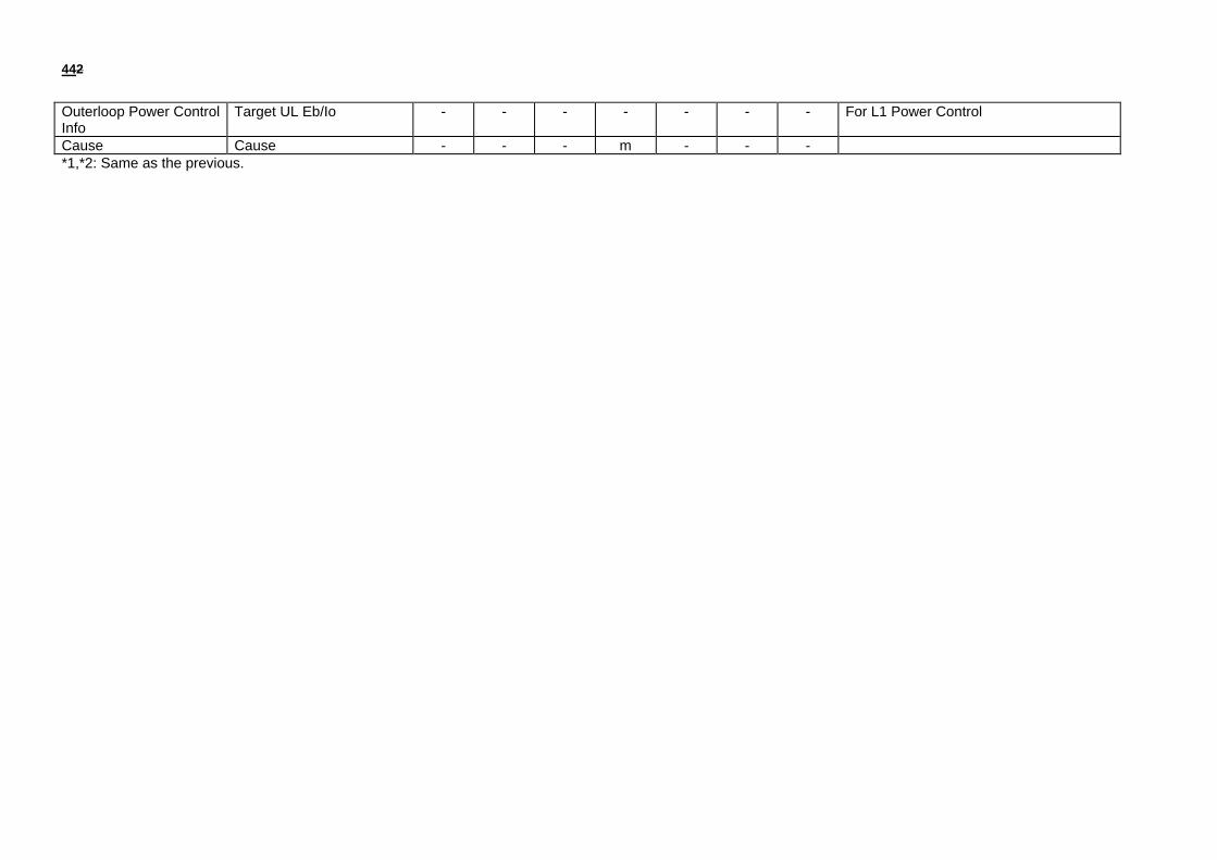
Outerloop Power ControlInfo
Target UL Eb/Io m - - For L1 Power Control
Cause Cause - - mm: mandatory, o: optional*1: In TTC assumption, in the case of intra RFTR RL addition in intra-frequency, it is always soft combined in RFTR. Also in the case of intra RFTR RL addition in inter-frequency, same Iub ATM connection is used. Therefore, in case of RADIO LINK ADDITION resp.conf.(Inter RFTR), RFTR send existing binding ID to RACFd.*2: Contents of this information is FFS. It is related to BS addressing scheme.

362
RAB Setup
Parameter Category Iub Parameters Iub Message NoteRA/FACH toDCH
DCH to DCH DCH toRA/FACH
RADIO
LINKSETUP
RADIOLINKSETUPRESPONSE
RADIOLINKSETUPFAILURE
RADIOLINKRECONFIGURATIONPREPARE
RADIOLINKRECONFIGURATIONREADY
RADIOLINKRECONFIGURATIONCOMMIT
RADIOLINKRECONFIGURATIONFAILURE
RADIOLINKRECONFIGURATIONCANCEL(FFS)
RADIO
LINKDELETION
RADIOLINKDELETIONRESPONSE
Transport CH Info No. of DCHs m - - m - - - - - -DCH ID (# 1) m - - m - - - - - - DCH ID or each DCHTFS (for DCH ID# 1) m - - m - - - - - - Set TFS when it is required :DCH ID (# n) m - - m - - - - - -TFS (for DCH ID# n) m - - m - - - - - -TFCS (for DCHs) m - - m - - - - - - Set TFCS per UE
Transport LayerAddressing Information
No. of DCHs - m - - m - - - - -
DCH ID (# 1) - m - - m - - - - -ATM Binding ID - m - - m - - - - - (TTC) 1 Binding ID for 1 DCH *1ATM Address - o - - o - - - - - :DCH ID (# n) - m - - m - - - - -ATM Binding ID - m - - m - - - - -

372
ATM Address - o - - o - - - - -Radio Frequency Info Radio Frequency m - - - - - - - - - Set Radio Frequency per UE
UL Interference Level - m - - - - - - - -UL Radio Resources UL scrambling code m - - - - - - - - - Set UL Scrambling Code per
UEUL spreading code type m - - m - - - - - -No. of UL spreading code m - - m - - - - - -UL spreading code id(s) m - - m - - - - - -
DL Radio Resources DL spreading code type m - - m - - - - - - Same code type for all RadioLinks
No. of DL spreading code m - - m - - - - - - Same number of codes for allRadio Links
No. of Radio Links m - - m - - - - m -Radio Link ID m - - m - - - - m -Cell ID m - - - - - - - - -Soft Combination Indicator - - - - - - - - - - Indicates May, Must, Must notPhase Difference m - - - - - - - - - :Radio Link ID o - - o - - - - o -Cell ID o - - - - - - - - -Soft Combination Indicator o - - - - - - - - -Phase Difference o - - - - - - - - -
DL Radio Resources No. of Radio Links - m - - m - - - - -Radio Link ID - m - - m - - - - -Neighbor Cell Information - m - - - - - - - - FFS*2No. of DL spreading code - m - - m - - - - -DL spreading code id #1 - m - - m - - - - - :DL spreading code id #m - m - - m - - - - - :Radio Link ID - o - - o - - - - -Neighbor Cell Information - o - - - - - - - - FFSNo. of DL spreading code - o - - o - - - - -DL spreading code id #1 - o - - o - - - - - :DL spreading code id #m - o - - o - - - - -
Execution Time Execution Time - - - - - m - - - -

382
Offset Values Slot offset m - - - - - - - - -Frame offset m - - - - - - - - -
Power Control Info Initial DL Power m - - - - - - - - - For Initial DL Power SettingDL Power Range - - - - - - - - - - For Correcting DL Power
Drifting during DHOOuterloop Power ControlInfo
Target UL Eb/Io m - - - - - - - - - For L1 Power Control
Cause Cause - - m - - - m - - -*1,*2: Same as the previous.

392
RAB Reconfiguration
Parameter Category Iub Parameters Iub Message NoteDCH to DCH
RADIOLINKRECONFIGURATIONPREPARE
RADIOLINKRECONFIGURATIONREADY
RADIOLINKRECONFIGURATIONCOMMIT
RADIOLINKRECONFIGURATIONFAILURE
RADIOLINKRECONFIGURATIONCANCEL(FFS)
Transport CH Info No. of DCHs m - - - -DCH ID (# 1) m - - - - DCH ID or each DCHTFS (for DCH ID# 1) m - - - - Set TFS when it is required :DCH ID (# n) m - - - -TFS (for DCH ID# n) m - - - -TFCS (for DCHs) m - - - - Set TFCS per UE
Transport LayerAddressing Information
No. of DCHs - m - - -
DCH ID (# 1) - m - - -ATM Binding ID - m - - - (TTC) 1 Binding ID for 1 DCH *1ATM Address - o - - - :DCH ID (# n) - m - - -ATM Binding ID - m - - -ATM Address - o - - -
Radio Frequency Info Radio Frequency - - - - - Set Radio Frequency per UEUL Interference Level - - - - -
UL Radio Resources UL scrambling code - - - - - Set UL Scrambling Code per UE

402
UL spreading code type m - - - -No. of UL spreading code m - - - -UL spreading code id(s) m - - - -
DL Radio Resources DL spreading code type m - - - - Same code type for all Radio LinksNo. of DL spreading code m - - - - Same number of codes for all
Radio LinksNo. of Radio Links m - - - -Radio Link ID m - - - -Cell ID - - - - -Soft Combination Indicator - - - - - Indicates May, Must, Must notPhase Difference - - - - - :Radio Link ID o - - - -Cell ID - - - - -Soft Combination Indicator - - - - -Phase Difference - - - - -
DL Radio Resources No. of Radio Links - m - - -Radio Link ID - m - - -Neighbor Cell Information - - - - - FFS*2No. of DL spreading code - m - - -DL spreading code id #1 - m - - - :DL spreading code id #m - m - - - :Radio Link ID - o - - -Neighbor Cell Information - - - - - FFSNo. of DL spreading code - o - - -DL spreading code id #1 - o - - - :DL spreading code id #m - o - - -
Execution Time Execution Time - - m - -Offset Values Slot offset - - - - -
Frame offset - - - - -Power Control Info Initial DL Power - - - - - For Initial DL Power Setting
DL Power Range - - - - - For Correcting DL Power Driftingduring DHO

412
Outerloop Power ControlInfo
Target UL Eb/Io - - - - - For L1 Power Control
Cause Cause - - - m -*1,*2: Same as the previous.

422
RAB Release
Parameter Category Iub Parameters Iub Message NoteDCH to DCH DCH to
RA/FACHRADIOLINKRECONFIGURATIONPREPARE
RADIOLINKRECONFIGURATIONREADY
RADIOLINKRECONFIGURATIONCOMMIT
RADIOLINKRECONFIGURATIONFAILURE
RADIOLINKRECONFIGURATIONCANCEL(FFS)
RADIOLINKDELETION
RADIOLINKDELETIONRESPONSE
Transport CH Info No. of DCHs m - - - - - -DCH ID (# 1) m - - - - - - DCH ID or each DCHTFS (for DCH ID# 1) - - - - - - - Set TFS when it is required :DCH ID (# n) m - - - - - -TFS (for DCH ID# n) - - - - - - -TFCS (for DCHs) m - - - - - - Set TFCS per UE
Transport LayerAddressing Information
No. of DCHs - - - - - - -
DCH ID (# 1) - - - - - - -ATM Binding ID - - - - - - - (TTC) 1 Binding ID for 1 DCH *1ATM Address - - - - - - - :DCH ID (# n) - - - - - - -ATM Binding ID - - - - - - -ATM Address - - - - - - -
Radio Frequency Info Radio Frequency - - - - - - - Set Radio Frequency per UEUL Interference Level - - - - - - -

432
UL Radio Resources UL scrambling code - - - - - - - Set UL Scrambling Code per UEUL spreading code type m - - - - - -No. of UL spreading code m - - - - - -UL spreading code id(s) m - - - - - -
DL Radio Resources DL spreading code type m - - - - - - Same code type for all Radio LinksNo. of DL spreading code m - - - - - - Same number of codes for all Radio
LinksNo. of Radio Links m - - - - m -Radio Link ID m - - - - m -Cell ID - - - - - - -Soft Combination Indicator - - - - - - - Indicates May, Must, Must notPhase Difference - - - - - - - :Radio Link ID o - - - - o -Cell ID - - - - - - -Soft Combination Indicator - - - - - - -Phase Difference - - - - - - -
DL Radio Resources No. of Radio Links - m - - - - -Radio Link ID - m - - - - -Neighbor Cell Information - - - - - - - FFS*2No. of DL spreading code - m - - - - -DL spreading code id #1 - m - - - - - :DL spreading code id #m - m - - - - - :Radio Link ID - o - - - - -Neighbor Cell Information - - - - - - - FFSNo. of DL spreading code - o - - - - -DL spreading code id #1 - o - - - - - :DL spreading code id #m - o - - - - -
Execution Time Execution Time - - m - - - -Offset Values Slot offset - - - - - - -
Frame offset - - - - - - -Power Control Info Initial DL Power - - - - - - - For Initial DL Power Setting
DL Power Range - - - - - - - For Correcting DL Power Drifting duringDHO
442
Outerloop Power ControlInfo
Target UL Eb/Io - - - - - - - For L1 Power Control
Cause Cause - - - m - - -*1,*2: Same as the previous.

452
RRC Connection Release
Parameter Category Iub Parameters Iub Message NoteDCH to IDLE
RADIOLINKDELETION
RADIOLINKDELETIONRESPONSE
Transport CH Info No. of DCHs - -DCH ID (# 1) - - DCH ID or each DCHTFS (for DCH ID# 1) - - Set TFS when it is required :DCH ID (# n) - -TFS (for DCH ID# n) - -TFCS (for DCHs) - - Set TFCS per UE
Transport LayerAddressing Information
No. of DCHs - -
DCH ID (# 1) - -ATM Binding ID - - (TTC) 1 Binding ID for 1 DCH *1ATM Address - - :DCH ID (# n) - -ATM Binding ID - -ATM Address - -
Radio Frequency Info Radio Frequency - - Set Radio Frequency per UEUL Interference Level - -
UL Radio Resources UL scrambling code - - Set UL Scrambling Code per UEUL spreading code type - -No. of UL spreading code - -UL spreading code id(s) - -
DL Radio Resources DL spreading code type - - Same code type for all Radio Links

462
No. of DL spreading code - - Same number of codes for allRadio Links
No. of Radio Links m -Radio Link ID m -Cell ID - -Soft Combination Indicator - - Indicates May, Must, Must notPhase Difference - - :Radio Link ID o -Cell ID - -Soft Combination Indicator - -Phase Difference - -
DL Radio Resources No. of Radio Links - -Radio Link ID - -Neighbor Cell Information - - FFS*2No. of DL spreading code - -DL spreading code id #1 - - :DL spreading code id #m - - :Radio Link ID - -Neighbor Cell Information - - FFSNo. of DL spreading code - -DL spreading code id #1 - - :DL spreading code id #m - -
Execution Time Execution Time - -Offset Values Slot offset - -
Frame offset - -Power Control Info Initial DL Power - - For Initial DL Power Setting
DL Power Range - - For Correcting DL Power Driftingduring DHO
Outerloop Power ControlInfo
Target UL Eb/Io - - For L1 Power Control
*1,*2: Same as the previous.

472
Transport CH Reconfiguration
Parameter Category Iub Parameters Iub Message NoteRA/FACH toDCH
DCH to DCH DCH toRA/FACH
RADIO
LINKSETUP
RADIOLINKSETUPRESPONSE
RADIOLINKSETUPFAILURE
RADIOLINKRECONFIGURATIONPREPARE
RADIOLINKRECONFIGURATIONREADY
RADIOLINKRECONFIGURATIONCOMMIT
RADIOLINKRECONFIGURATIONFAILURE
RADIOLINKRECONFIGURATIONCANCEL(FFS)
RADIO
LINKDELETION
RADIOLINKDELETIONRESPONSE
Transport CH Info No. of DCHs m - - m - - - - - -DCH ID (# 1) m - - m - - - - - - DCH ID or each DCHTFS (for DCH ID# 1) m - - m - - - - - - Set TFS when it is required :DCH ID (# n) m - - m - - - - - -TFS (for DCH ID# n) m - - m - - - - - -TFCS (for DCHs) m - - m - - - - - - Set TFCS per UE
Transport LayerAddressing Information
No. of DCHs - m - - m - - - - -
DCH ID (# 1) - m - - m - - - - -ATM Binding ID - m - - m - - - - - (TTC) 1 Binding ID for 1 DCH *1ATM Address - o - - o - - - - - :DCH ID (# n) - m - - m - - - - -ATM Binding ID - m - - m - - - - -

482
ATM Address - o - - o - - - - -Radio Frequency Info Radio Frequency m - - - - - - - - - Set Radio Frequency per UE
UL Interference Level - m - - - - - - - -UL Radio Resources UL scrambling code m - - - - - - - - - Set UL Scrambling Code per
UEUL spreading code type m - - m - - - - - -No. of UL spreading code m - - m - - - - - -UL spreading code id(s) m - - m - - - - - -
DL Radio Resources DL spreading code type m - - m - - - - - - Same code type for all RadioLinks
No. of DL spreading code m - - m - - - - - - Same number of codes for allRadio Links
No. of Radio Links m - - m - - - - m -Radio Link ID m - - m - - - - m -Cell ID m - - - - - - - - -Soft Combination Indicator - - - - - - - - - - Indicates May, Must, Must notPhase Difference m - - - - - - - - - :Radio Link ID o - - o - - - - o -Cell ID o - - - - - - - - -Soft Combination Indicator o - - - - - - - - -Phase Difference o - - - - - - - - -
DL Radio Resources No. of Radio Links - m - - m - - - - -Radio Link ID - m - - m - - - - -Neighbor Cell Information - m - - - - - - - - FFS*2No. of DL spreading code - m - - m - - - - -DL spreading code id #1 - m - - m - - - - - :DL spreading code id #m - m - - m - - - - - :Radio Link ID - o - - o - - - - -Neighbor Cell Information - o - - - - - - - - FFSNo. of DL spreading code - o - - o - - - - -DL spreading code id #1 - o - - o - - - - - :DL spreading code id #m - o - - o - - - - -
Execution Time Execution Time - - - - - m - - - -
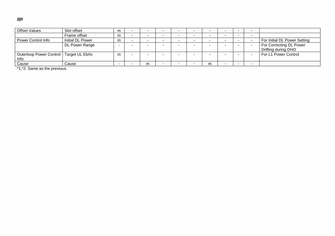
492
Offset Values Slot offset m - - - - - - - - -Frame offset m - - - - - - - - -
Power Control Info Initial DL Power m - - - - - - - - - For Initial DL Power SettingDL Power Range - - - - - - - - - - For Correcting DL Power
Drifting during DHOOuterloop Power ControlInfo
Target UL Eb/Io m - - - - - - - - - For L1 Power Control
Cause Cause - - m - - - m - - -*1,*2: Same as the previous.

502
Physical CH Reconfiguration
Parameter Category Iub Parameters Iub Message NoteRA/FACH toDCH
DCH to DCH DCH toRA/FACH
RADIO
LINKSETUP
RADIOLINKSETUPRESPONSE
RADIOLINKSETUPFAILURE
RADIOLINKRECONFIGURATIONPREPARE
RADIOLINKRECONFIGURATIONREADY
RADIOLINKRECONFIGURATIONCOMMIT
RADIOLINKRECONFIGURATIONFAILURE
RADIOLINKRECONFIGURATIONCANCEL(FFS)
RADIO
LINKDELETION
RADIOLINKDELETIONRESPONSE
Transport CH Info No. of DCHs m - - - - - - - - -DCH ID (# 1) m - - - - - - - - - DCH ID or each DCHTFS (for DCH ID# 1) m - - - - - - - - - Set TFS when it is required : -DCH ID (# n) m - - - - - - - -TFS (for DCH ID# n) m - - - - - - - - -TFCS (for DCHs) m - - - - - - - - - Set TFCS per UE
Transport LayerAddressing Information
No. of DCHs - m - - - - - - - -
DCH ID (# 1) - m - - - - - - - -ATM Binding ID - m - - - - - - - - (TTC) 1 Binding ID for 1 DCH *1ATM Address - o - - - - - - - - :DCH ID (# n) - m - - - - - - - -ATM Binding ID - m - - - - - - - -

512
ATM Address - o - - - - - - - -Radio Frequency Info Radio Frequency m - - - - - - - - - Set Radio Frequency per UE
UL Interference Level - m - - - - - - - -UL Radio Resources UL scrambling code m - - o - - - - - - Set UL Scrambling Code per
UEUL spreading code type m - - o - - - - - -No. of UL spreading code m - - o - - - - - -UL spreading code id(s) m - - o - - - - - -
DL Radio Resources DL spreading code type m - - o - - - - - - Same code type for all RadioLinks
No. of DL spreading code m - - o - - - - - - Same number of codes for allRadio Links
No. of Radio Links m - - o - - - - m -Radio Link ID m - - o - - - - m -Cell ID m - - - - - - - - -Soft Combination Indicator - - - - - - - - - - Indicates May, Must, Must notPhase Difference m - - - - - - - - - :Radio Link ID o - - o - - - - o -Cell ID o - - - - - - - - -Soft Combination Indicator o - - - - - - - - -Phase Difference o - - - - - - - - -
DL Radio Resources No. of Radio Links - m - - m - - - - -Radio Link ID - m - - m - - - - -Neighbor Cell Information - m - - - - - - - - FFS*2No. of DL spreading code - m - - m - - - - -DL spreading code id #1 - m - - m - - - - - :DL spreading code id #m - m - - m - - - - - :Radio Link ID - o - - o - - - - -Neighbor Cell Information - o - - - - - - - - FFSNo. of DL spreading code - o - - o - - - - -DL spreading code id #1 - o - - o - - - - - :DL spreading code id #m - o - - o - - - - -
Execution Time Execution Time - - - - - m - - - -

522
Offset Values Slot offset m - - - - - - - - -Frame offset m - - - - - - - - -
Power Control Info Initial DL Power m - - - - - - - - - For Initial DL Power SettingDL Power Range - - - - - - - - - - For Correcting DL Power
Drifting during DHOOuterloop Power ControlInfo
Target UL Eb/Io m - - - - - - - - - For L1 Power Control
Cause Cause - - m - - - m - - -*1,*2: Same as the previous.

532
Hard Handover (Inter-NodeB)
Parameter Category Iub Parameters Iub Message NoteRADIOLINKSETUP
RADIOLINKSETUPRESPONSE
RADIOLINKSETUPFAILURE
RADIOLINKDELETION
RADIOLINKDELETIONRESPONSE
Transport CH Info No. of DCHs m - - - -DCH ID (# 1) m - - - - DCH ID or each DCHTFS (for DCH ID# 1) m - - - - Set TFS when it is required :DCH ID (# n) m - - - -TFS (for DCH ID# n) m - - - -TFCS (for DCHs) m - - - - Set TFCS per UE
Transport LayerAddressing Information
No. of DCHs - m - - -
DCH ID (# 1) - m - - -ATM Binding ID - m - - - (TTC) 1 Binding ID for 1 DCH *1ATM Address - o - - - :DCH ID (# n) - m - - -ATM Binding ID - m - - -ATM Address - o - - -
Radio Frequency Info Radio Frequency m - - - - Set Radio Frequency per UEUL Interference Level - m - - -
UL Radio Resources UL scrambling code m - - - - Set UL Scrambling Code per UEUL spreading code type m - - - -No. of UL spreading code m - - - -UL spreading code id(s) m - - - -
DL Radio Resources DL spreading code type m - - - - Same code type for all Radio LinksNo. of DL spreading code m - - - - Same number of codes for all
Radio Links
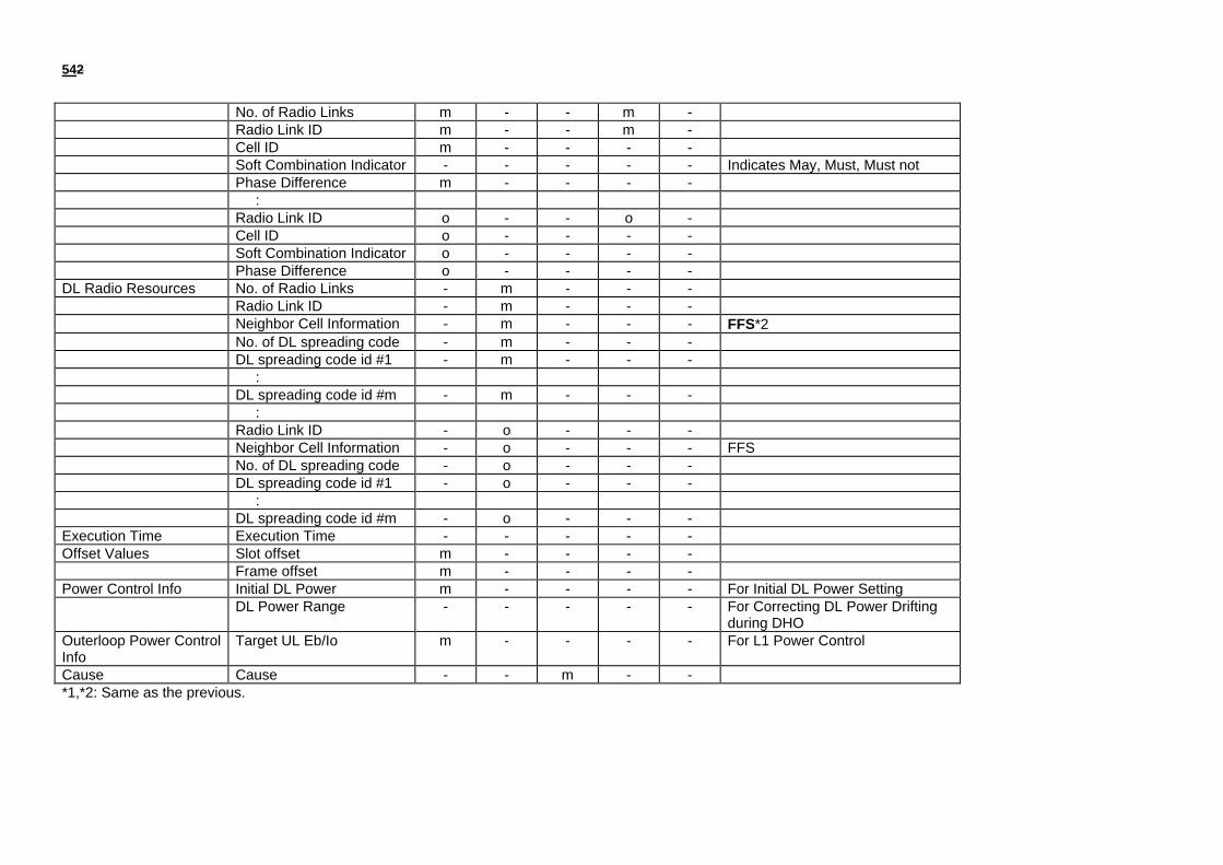
542
No. of Radio Links m - - m -Radio Link ID m - - m -Cell ID m - - - -Soft Combination Indicator - - - - - Indicates May, Must, Must notPhase Difference m - - - - :Radio Link ID o - - o -Cell ID o - - - -Soft Combination Indicator o - - - -Phase Difference o - - - -
DL Radio Resources No. of Radio Links - m - - -Radio Link ID - m - - -Neighbor Cell Information - m - - - FFS*2No. of DL spreading code - m - - -DL spreading code id #1 - m - - - :DL spreading code id #m - m - - - :Radio Link ID - o - - -Neighbor Cell Information - o - - - FFSNo. of DL spreading code - o - - -DL spreading code id #1 - o - - - :DL spreading code id #m - o - - -
Execution Time Execution Time - - - - -Offset Values Slot offset m - - - -
Frame offset m - - - -Power Control Info Initial DL Power m - - - - For Initial DL Power Setting
DL Power Range - - - - - For Correcting DL Power Driftingduring DHO
Outerloop Power ControlInfo
Target UL Eb/Io m - - - - For L1 Power Control
Cause Cause - - m - -*1,*2: Same as the previous.
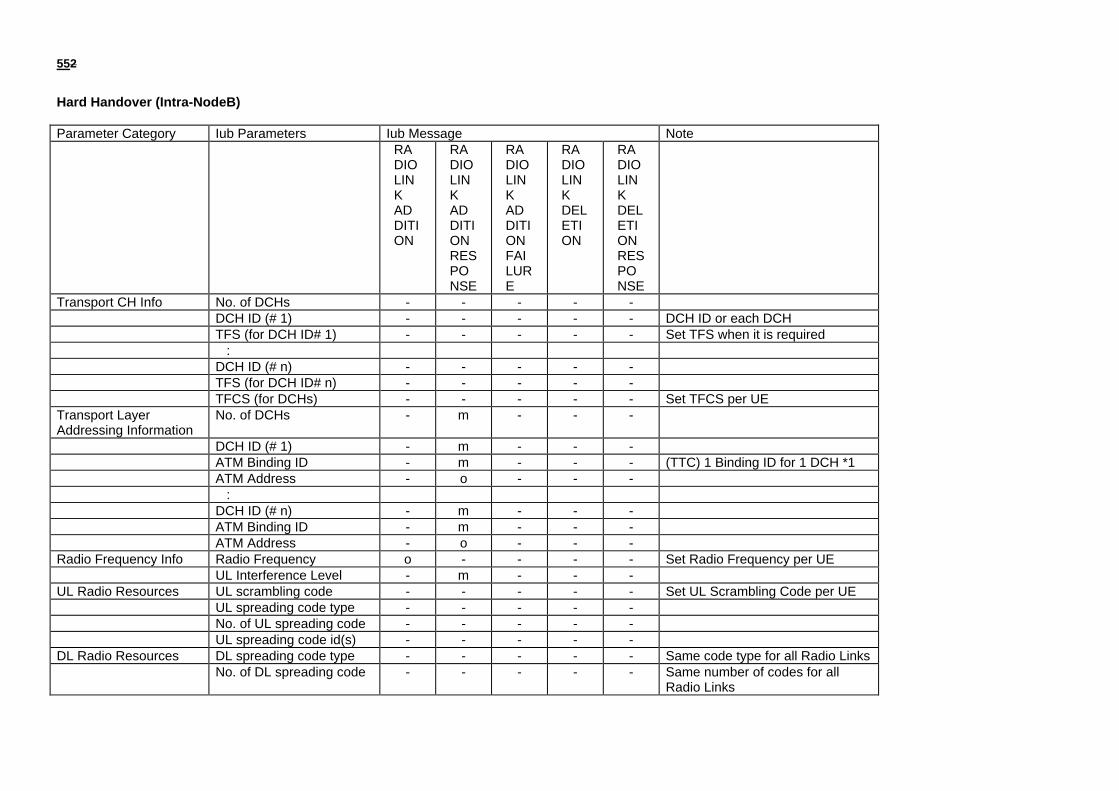
552
Hard Handover (Intra-NodeB)
Parameter Category Iub Parameters Iub Message NoteRADIOLINKADDITION
RADIOLINKADDITIONRESPONSE
RADIOLINKADDITIONFAILURE
RADIOLINKDELETION
RADIOLINKDELETIONRESPONSE
Transport CH Info No. of DCHs - - - - -DCH ID (# 1) - - - - - DCH ID or each DCHTFS (for DCH ID# 1) - - - - - Set TFS when it is required :DCH ID (# n) - - - - -TFS (for DCH ID# n) - - - - -TFCS (for DCHs) - - - - - Set TFCS per UE
Transport LayerAddressing Information
No. of DCHs - m - - -
DCH ID (# 1) - m - - -ATM Binding ID - m - - - (TTC) 1 Binding ID for 1 DCH *1ATM Address - o - - - :DCH ID (# n) - m - - -ATM Binding ID - m - - -ATM Address - o - - -
Radio Frequency Info Radio Frequency o - - - - Set Radio Frequency per UEUL Interference Level - m - - -
UL Radio Resources UL scrambling code - - - - - Set UL Scrambling Code per UEUL spreading code type - - - - -No. of UL spreading code - - - - -UL spreading code id(s) - - - - -
DL Radio Resources DL spreading code type - - - - - Same code type for all Radio LinksNo. of DL spreading code - - - - - Same number of codes for all
Radio Links

562
No. of Radio Links m - - m -Radio Link ID m - - m -Cell ID m - - - -Soft Combination Indicator m - - - - Indicates May, Must, Must notPhase Difference m - - - - :Radio Link ID o - - o -Cell ID o - - - -Soft Combination Indicator o - - - -Phase Difference o - - - -
DL Radio Resources No. of Radio Links - m - - -Radio Link ID - m - - -Neighbor Cell Information - m - - - FFS*2No. of DL spreading code - m - - -DL spreading code id #1 - m - - - :DL spreading code id #m - m - - - :Radio Link ID - o - - -Neighbor Cell Information - o - - - FFSNo. of DL spreading code - o - - -DL spreading code id #1 - o - - - :DL spreading code id #m - o - - -
Execution Time Execution Time - - - - -Offset Values Slot offset - - - - -
Frame offset - - - - -Power Control Info Initial DL Power - - - - - For Initial DL Power Setting
DL Power Range - - - - - For Correcting DL Power Driftingduring DHO
Outerloop Power ControlInfo
Target UL Eb/Io - - - - - For L1 Power Control
Cause Cause - - m - -*1,*2: Same as the previous.

572
Handover Radio Link Addition (Inter-NodeB)
Parameter Category Iub Parameters Iub Message NoteRADIOLINKSETUP
RADIOLINKSETUPRESPONSE
RADIOLINKSETUPFAILURE
Transport CH Info No. of DCHs m - -DCH ID (# 1) m - - DCH ID or each DCHTFS (for DCH ID# 1) m - - Set TFS when it is required :DCH ID (# n) m - -TFS (for DCH ID# n) m - -TFCS (for DCHs) m - - Set TFCS per UE
Transport LayerAddressing Information
No. of DCHs - m -
DCH ID (# 1) - m -ATM Binding ID - m - (TTC) 1 Binding ID for 1 DCH *1ATM Address - o - :DCH ID (# n) - m -ATM Binding ID - m -ATM Address - o -
Radio Frequency Info Radio Frequency m - - Set Radio Frequency per UEUL Interference Level - m -
UL Radio Resources UL scrambling code m - - Set UL Scrambling Code per UEUL spreading code type m - -No. of UL spreading code m - -UL spreading code id(s) m - -
DL Radio Resources DL spreading code type m - - Same code type for all Radio LinksNo. of DL spreading code m - - Same number of codes for all
Radio LinksNo. of Radio Links m - -

582
Radio Link ID m - -Cell ID m - -Soft Combination Indicator - - - Indicates May, Must, Must notPhase Difference m - - :Radio Link ID o - -Cell ID o - -Soft Combination Indicator o - -Phase Difference o - -
DL Radio Resources No. of Radio Links - m -Radio Link ID - m -Neighbor Cell Information - m - FFS*2No. of DL spreading code - m -DL spreading code id #1 - m - :DL spreading code id #m - m - :Radio Link ID - o -Neighbor Cell Information - o - FFSNo. of DL spreading code - o -DL spreading code id #1 - o - :DL spreading code id #m - o -
Execution Time Execution Time - - -Offset Values Slot offset m - -
Frame offset m - -Power Control Info Initial DL Power m - - For Initial DL Power Setting
DL Power Range - - - For Correcting DL Power Driftingduring DHO
Outerloop Power ControlInfo
Target UL Eb/Io m - - For L1 Power Control
Cause Cause - - m*1,*2: Same as the previous.

592
Handover Radio Link Addition (Intra-NodeB)
Parameter Category Iub Parameters Iub Message NoteRADIOLINKADDITION
RADIOLINKADDITIONRESPONSE
RADIOLINKADDITIONFAILURE
Transport CH Info No. of DCHs - - -DCH ID (# 1) - - - DCH ID or each DCHTFS (for DCH ID# 1) - - - Set TFS when it is required :DCH ID (# n) - - -TFS (for DCH ID# n) - - -TFCS (for DCHs) - - - Set TFCS per UE
Transport LayerAddressing Information
No. of DCHs - m -
DCH ID (# 1) - m -ATM Binding ID - m - (TTC) 1 Binding ID for 1 DCH *1ATM Address - o - :DCH ID (# n) - m -ATM Binding ID - m -ATM Address - o -
Radio Frequency Info Radio Frequency o - - Set Radio Frequency per UEUL Interference Level - m -
UL Radio Resources UL scrambling code - - - Set UL Scrambling Code per UEUL spreading code type - - -No. of UL spreading code - - -UL spreading code id(s) - - -
DL Radio Resources DL spreading code type - - - Same code type for all Radio LinksNo. of DL spreading code - - - Same number of codes for all
Radio Links

602
No. of Radio Links m - -Radio Link ID m - -Cell ID m - -Soft Combination Indicator m - - Indicates May, Must, Must notPhase Difference m - - :Radio Link ID o - -Cell ID o - -Soft Combination Indicator o - -Phase Difference o - -
DL Radio Resources No. of Radio Links - m -Radio Link ID - m -Neighbor Cell Information - m - FFS*2No. of DL spreading code - m -DL spreading code id #1 - m - :DL spreading code id #m - m - :Radio Link ID - o -Neighbor Cell Information - o - FFSNo. of DL spreading code - o -DL spreading code id #1 - o - :DL spreading code id #m - o -
Execution Time Execution Time - - -Offset Values Slot offset - - -
Frame offset - - -Power Control Info Initial DL Power - - - For Initial DL Power Setting
DL Power Range - - - For Correcting DL Power Driftingduring DHO
Outerloop Power ControlInfo
Target UL Eb/Io - - - For L1 Power Control
Cause Cause - - m*1,*2: Same as the previous.

612
Handover Radio Link Deletion (Inter-NodeB)
Parameter Category Iub Parameters Iub Message NoteRADIOLINKDELETION
RADIOLINKDELETIONRESPONSE
Transport CH Info No. of DCHs - -DCH ID (# 1) - - DCH ID or each DCHTFS (for DCH ID# 1) - - Set TFS when it is required :DCH ID (# n) - -TFS (for DCH ID# n) - -TFCS (for DCHs) - - Set TFCS per UE
Transport LayerAddressing Information
No. of DCHs - -
DCH ID (# 1) - -ATM Binding ID - - (TTC) 1 Binding ID for 1 DCH *1ATM Address - - :DCH ID (# n) - -ATM Binding ID - -ATM Address - -
Radio Frequency Info Radio Frequency - - Set Radio Frequency per UEUL Interference Level - -
UL Radio Resources UL scrambling code - - Set UL Scrambling Code per UEUL spreading code type - -No. of UL spreading code - -UL spreading code id(s) - -
DL Radio Resources DL spreading code type - - Same code type for all Radio LinksNo. of DL spreading code - - Same number of codes for all
Radio Links
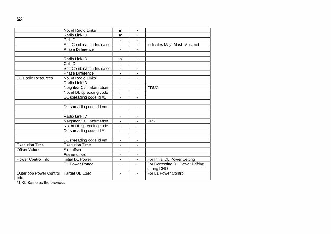
622
No. of Radio Links m -Radio Link ID m -Cell ID - -Soft Combination Indicator - - Indicates May, Must, Must notPhase Difference - - :Radio Link ID o -Cell ID - -Soft Combination Indicator - -Phase Difference - -
DL Radio Resources No. of Radio Links - -Radio Link ID - -Neighbor Cell Information - - FFS*2No. of DL spreading code - -DL spreading code id #1 - - :DL spreading code id #m - - :Radio Link ID - -Neighbor Cell Information - - FFSNo. of DL spreading code - -DL spreading code id #1 - - :DL spreading code id #m - -
Execution Time Execution Time - -Offset Values Slot offset - -
Frame offset - -Power Control Info Initial DL Power - - For Initial DL Power Setting
DL Power Range - - For Correcting DL Power Driftingduring DHO
Outerloop Power ControlInfo
Target UL Eb/Io - - For L1 Power Control
*1,*2: Same as the previous.

632
Handover Radio Link Deletion (Intra-NodeB)
Parameter Category Iub Parameters Iub Message NoteRADIOLINKDELETION
RADIOLINKDELETIONRESPONSE
Transport CH Info No. of DCHs - -DCH ID (# 1) - - DCH ID or each DCHTFS (for DCH ID# 1) - - Set TFS when it is required :DCH ID (# n) - -TFS (for DCH ID# n) - -TFCS (for DCHs) - - Set TFCS per UE
Transport LayerAddressing Information
No. of DCHs - -
DCH ID (# 1) - -ATM Binding ID - - (TTC) 1 Binding ID for 1 DCH *1ATM Address - - :DCH ID (# n) - -ATM Binding ID - -ATM Address - -
Radio Frequency Info Radio Frequency - - Set Radio Frequency per UEUL Interference Level - -
UL Radio Resources UL scrambling code - - Set UL Scrambling Code per UEUL spreading code type - -No. of UL spreading code - -UL spreading code id(s) - -
DL Radio Resources DL spreading code type - - Same code type for all Radio LinksNo. of DL spreading code - - Same number of codes for all
Radio Links

642
No. of Radio Links m -Radio Link ID m -Cell ID - -Soft Combination Indicator - - Indicates May, Must, Must notPhase Difference - - :Radio Link ID o -Cell ID - -Soft Combination Indicator - -Phase Difference - -
DL Radio Resources No. of Radio Links - -Radio Link ID - -Neighbor Cell Information - - FFS*2No. of DL spreading code - -DL spreading code id #1 - - :DL spreading code id #m - - :Radio Link ID - -Neighbor Cell Information - - FFSNo. of DL spreading code - -DL spreading code id #1 - - :DL spreading code id #m - -
Execution Time Execution Time - -Offset Values Slot offset - -
Frame offset - -Power Control Info Initial DL Power - - For Initial DL Power Setting
DL Power Range - - For Correcting DL Power Driftingduring DHO
Outerloop Power ControlInfo
Target UL Eb/Io - - For L1 Power Control
*1,*2: Same as the previous.

652
Power Control
Parameter Category Iub Parameters Iub Message Note
POWRCONTROL
Power Control Info Initial DL Power - For Initial DL Power SettingDL Power Range o For Correcting DL Power
Drifting during DHO
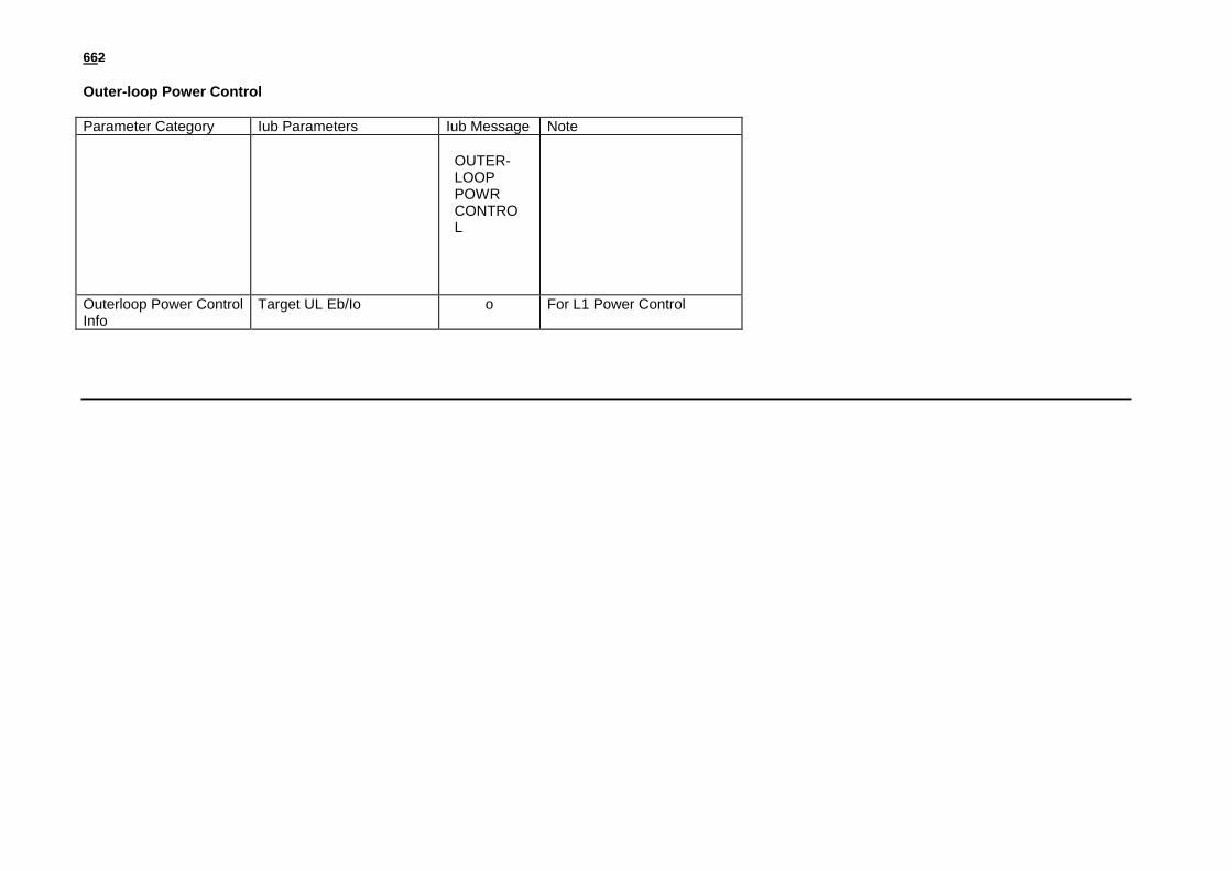
662
Outer-loop Power Control
Parameter Category Iub Parameters Iub Message Note
OUTER-LOOPPOWRCONTROL
Outerloop Power ControlInfo
Target UL Eb/Io o For L1 Power Control