Mercedes-Benz Fuel Systems Multilink Suspensions Dealer ...
32
Information for the Mercedes-Benz Service Professional Mercedes-Benz Fuel Systems Multilink Suspensions Dealer Listings November 2001 U.S. $6.00 DM 12.50 Volume 1 Number 2
-
Upload
khangminh22 -
Category
Documents
-
view
2 -
download
0
Transcript of Mercedes-Benz Fuel Systems Multilink Suspensions Dealer ...

Information for the Mercedes-Benz Service Professional
Mercedes-Benz Fuel Systems
Multilink Suspensions
Dealer Listings
November 2001 U.S. $6.00 DM 12.50
Volume 1 Number 2

Welcome to StarTuned, a new magazine
for independent service technicians working
on Mercedes-Benz vehicles. Mercedes-Benz
both sponsors StarTuned and provides the
information coming your way in each issue.
The worldwide carmaker wants to present
what you need to know to diagnose and repair
Mercedes-Benz cars accurately, quickly and
the first time. Text, graphic, on-line and other
internal information sources combine to make
this possible.
Feature articles, derived from official
company information sources, focus on being
useful and interesting. Our digest of service
bulletins will help you solve unanticipated
problems quickly and expertly. Our list of
Mercedes-Benz dealers can help you find
original, Mercedes-Benz factory parts.
We want StarTuned to be both useful and
interesting, so please let us know just what
kinds of features and other information
services you’d like to see in it. We’ll continue
to bring you selected service bulletins from
the Mercedes-Benz company and articles
covering different systems on these vehicles.
Send your suggestions, questions or
comments to us at:
StarTuned
306 North Cleveland-Massillon Road,
Akron, Ohio 44333,
or e-mail us at:
Our phone is 330-666-9553,
fax 330-666-8912.
TO OUR READERS

MERCEDES-BENZ FUEL INJECTIONOurpurpose here is to explain how two Mercedes-Benz systems work in overall view.
MULTILINK SUSPENSIONSWe’ll explain why the multilink design is used,how it works and how to discern, diagnoseand repair problems when they occur.
PARTSNEWSMercedes-Benz service manual information in CDformat, as well as an expanded line of remanufac-tured parts, are featured in this issue’s PartsNews.
FACTORYSERVICE BULLETINSThese suggestions and solutions for technical problems are taken from service bulletins publishedby Mercedes-Benz. They have been selected andadapted for use by independent repair shops.
MERCEDES-BENZ PARTS DEALERSA state, city and telephone number listing ofMercedes-Benz dealers in the United States andPuerto Rico. These dealers are ready to serve the wholesale parts needs of the independentrepair shop.
November 2001 U.S. $6.00 DM 12.50
DEPARTMENTS
Information for the Mercedes-Benz Service Professional
20
22
27
FEATUREARTICLES
14
StarTuned is a quarterly publication of Mercedes-Benz. No part of this newsletter may be reproduced without the express written permission of Mercedes-Benz. Editorial andCirculation Offices: 306 North Cleveland-Massillon Road, Akron, OH 44333, Phone 330-666-9553. Fax 330-666-8912 Caution: Vehicle servicing performed by untrained personscould result in serious injury to those persons or others. Information contained in this newsletter is intended for use by trained, professional auto repair technicians ONLY. Thisinformation is provided to inform these technicians of conditions which may occur in some vehicles or to provide information which could assist them in proper servicing of thesevehicles. Properly trained technicians have the equipment, tools, safety instructions, and know-how to perform repairs correctly and safely. If a condition is described, DO NOTassume that a topic covered in these pages automatically applies to your vehicle or that your vehicle has that condition. StarTuned is a registered trademark of Mercedes-Benz.
04
How two M-B systems work in overall view
FEATUREARTICLE
04
K-Jetronic Fuel Injection
Mercedes-Benz cars have a long history with vari-ous gasoline injection systems, including exotic ver-sions as the Diesel-like direct injection used in theGullwing SL of the early 1950’s, spraying fuel rightinto the combustion chambers themselves. The M-Bfuel injection system you’re most likely to find inyour workbay today, however, is one generation oranother of the Bosch K-Jet series, beginning on somecars in the 1970’s and continuing well into the1990’s. Shortly after emissions regulations began torequire engine management systems that adjustair/fuel mixtures in response to a feedback signalfrom the exhaust system’s oxygen sensor, the fuelinjection system underwent a major evolution intothe KE-Jet. K stands for the German word for contin-uous; E stands for the German word for electronic.We won’t cover every detail of every variation of the
K- and KE-Jet systems. The purpose here is toexplain how the systems work in overall view. If youunderstand the overall system, you can diagnose andrepair it if it fails.
FUEL INJECTION SYSTEMS
Injector and bracket
The hallmark of the K-Jet systems, alone amongfuel injection systems in widespread distribution, isthis: As long as the engine runs, they spray fuelthrough their nozzles continuously. The injectorsare entirely mechanical, opening at about 3.8 barfuel pressure (gradually declining to 3.0 bar withuse) and delivering whatever volume the systemsends them, mechanically corresponding to the vol-ume of intake air. There are no electrical parts orconnections to these injectors; nothing turns themon or off; nothing pulses or cycles them in any wayexcept the hydraulic force of the gasoline. Highspeed photography sometimes shows the nozzles‘chattering’ at a frequency of about 1500 Hz, but thatis entirely a consequence of the resonances of theneedle, of the spring and of the viscosity and deliv-ery speed of the fuel. Certain K-Jet injectors weremicroscopically formed so the needle ‘walks’ aroundthe opening, further atomizing and vaporizing thefuel. To insulate the injectors from the engine’s heatand vibration, they don’t thread into the manifoldbut are just pressed in by hand, held by nonconduc-tive rubber collars. The hex head only serves tosteady the injector while you connect or disconnectthe fuel line. Many injectors include an air shroudaround the tip. Particularly at idle speeds, this airshroud insulates the fuel spray cone from the sidesof the manifold where it might condense. Thefocused, high-speed airstream also helps vaporizethe fuel even when the engine is turning slowly withno load.
But let’s start where the fuel starts, at the fuelpump. For the earliest and simplest form of the K-Jet,this was the only electrical component, toggled onand off by the fuel pump relay on the firewall. Therewere no sensors, no computer, no actuators. Some ofthe technical literature at the time referred to the“airflow sensor,” but as we’ll see, the word sensormeant something entirely different from the way weordinarily use it now. In principle, the fuel pumpcould have been mechanical, driven by a crankshaftpulley. But you want the pump away from the heat
and near or inside the fuel tank to minimize vaporlock, while the engine and accessory drive is at theother end of the car.
The basic K-Jet fuel pump has become the de factoautomotive standard for all fuel injection systems.It’s a small but powerful electric motor with a posi-tive displacement hydraulic pump on one end of theshaft. Fuel fills and runs through the pump as itruns, cooling the armature windings. While the car-bon brushes and copper commutator are surroundedwith gasoline (recall that fuel bathes everythinginside the motor), there is no room for air or oxygen,and thus nothing can catch fire. Sparking from anelectric motor’s carbon brushes could ignite fuelvapor in air, but sparking submerged in liquid gaso-line can’t.
Early versions had two speeds: on or off. All thefuel not injected into the intake runners recycledback to the tank, keeping the underhood fuel plumb-ing relatively cool. Some later versions includedsuch complications as an additional, lower-currentpump delivery rate for quiet low-speed driving, vehi-cle-speed limits by electronic control of the groundcircuit, multiple pumps in series (one for pressure,the other for volume) and so on.
The first pumps worked by ‘roller cells,’ cylindri-cal bearing rollers held captive in channels aroundthe outside of a drivewheel slightly eccentric withrespect to the housing. As the rollers moved towardand away from the center as the drivewheel rotated,they drew the fuel from the tank and drove it towardthe engine by displacement. ‘Gerotor’ pumps, inter-nal/external gearsets that work like engine or trans-mission oil pumps, replaced them. Additionaldesigns include cycling-vane and peripheral-pumpdesigns and, on current M-B’s, counterrotating heli-cal spindles, forcing the fuel through with a geome-try just like a scroll-supercharger’s. In each case, theobject is to move the fuel and build the pressurequickly and reliably. Changes in pump design havefrequently been to make the pumps quieter. Becausethe fuel cools them so effectively, fuel pump electricmotors can be surprisingly small for their power.You’ll find most K-Jet pumps draw between 6 and 10amps. A lower current should flag resistance in thecircuit; a higher current means an internal short ora fluid block slowing the pump and making it workharder. A representative good pump for a six-cylin-der engine delivers a liter in 40 seconds. Larger dis-placement engines get more fuel.
The pump for any given model can deliver morefuel than the engine could burn under the mostadverse fuel-demand conditions: wide-open throttleat 40-below. This excess pump capacity guaranteesfull engine function and full fuel pressure evenunder extreme conditions. About the only factors
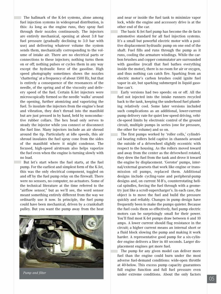
05Pump and filter

FUEL SYSTEMS
06
Once it was standard practice to replace a fuel fil-ter with every ‘tune-up.’ But there haven’t been‘tune-ups’ since the demise of ignition contactpoints, back in the 1970’s. Modern fuel filters con-tain a large area of super-fine-mesh, accordion-foldfilter paper capable of removing particles down tosingle-digit-micron sizes and of absorbing or neu-tralizing most gums and tars.
A filter actually cleans more effectively after ithas been in use for some time and has collected apatina of dirt on the active filter surface. Unlessthere is clear, demonstrated need to replace a fuelfilter – that is, a failure of a good fuel pump to deliv-er the volume and pressure specified by the car-maker for that model – it is a mistake to replace theone on the car.
After the fuel pump and filter on the hydraulic cir-cuit comes the accumulator (these three elementsare often lined together in a row on early systems).The accumulator consists of a container with adiaphragm separating the fuel and the air chambersand a spring to hold pressure from the air side of thediaphragm. The functional analogy to accumulatorsin automatic transmissions is close, but not exact. In
that can prevent a mechanically and electricallyfunctional K-Jet pump from delivering enough fuelto the engine are a completely plugged fuel filter(very rare) or a crimped or blocked fuel line. Theseproblems ordinarily cause a noisy pump since it hasto work harder while they’re present, and you’ll hearthe pressure pulses. If rust formed in the systemafter the fuel filter (because of moisture in the gas,perhaps), there can also be clogs at the small filtersinternal to the fuel distributor and to the injectorsthemselves.
In the fuel outlet of each pump there is a fluidcheck valve. Its function is to retain fuel in the injec-tion lines to prevent vapor lock and to keep theplumbing full of pressurized liquid fuel for the nextengine-start. The check valve merely seals the fuel inthe system; the pressure derives from the pressureaccumulator (see below). Long cranking times arethe first symptom of a failure in the check valve orthe pressure accumulator. For diagnostic purposes,a ‘long cranking time’ is more than four secondsbefore the engine fires.
The fuel goes directly from the pump to the fuelfilter. While this is the standard layout now, it isworth recalling that when carburetors walked theearth, fuel filters were often between the tank andthe pump. Such an arrangement would often meanvapor lock with modern fuels in a fuel-injected vehi-cle (it often meant vapor lock with older fuels in car-bureted vehicles, too!). Putting the fuel pump aheadof the filter, however, means the cleanliness of thefuel from the filling station is more important thanever. Any particles of grit or rust go through the fuelpump largely unfiltered, except for the coarse-meshscreen just ahead of the pump inlet. That screenserves mostly to block particles large enough to jamthe pump.
Commutator and brushes
Pump and screen
Accordian paper
an automatic transmission, an accumulator absorbsand stores the hydraulic application pressure to soft-en and extend clutch or band engagement time. Ona K-Jet, the fuel pressure accumulator absorbs andstores the fuel pressure, but to smooth out the pres-sure peaks resulting from pressure pulses from thepump (reducing noise and smoothing fuel flow) andto retain pressure in the system when the pumpturns off. If you measure the system pressure afterthe engine shuts off, you should find at least 2.7 barafter 10 minutes and 2.6 after twenty. Not all K-Jetsystems require fuel pressure accumulators becausein some vehicles there is enough volume in the linesand components.
As mentioned earlier, K-Jet injectors release fuelanytime the pressure is greater than about 3.8 bar(varies somewhat by model and year). But thatleaves sufficient residual pressure in the system tokeep it primed for a quick restart and to preventvapor lock in almost any ambient or underhood tem-perature.
If you find a K-Jet system that does not hold pres-sure after shutdown, especially if it makes audible‘electric-motor’ noise corresponding to pump speed,check the pressure accumulator for a broken springor ruptured diaphragm. A direct pressure check isthe test procedure, and you can measure that mostconveniently at the fuel distributor inlet. Inspect thepump’s check valve as well by confirming that thesystem holds pressure after engine shutdown. Ifthose components are good, look for a dribblinginjector.
As the gasoline continues through the line, itencounters one of the most interesting devices inautomotive technical history, the K-Jet fuel distribu-tor. The name suggests that, like an ignition distrib-utor sorting high-voltage spark to the appropriateplug in firing order, the fuel distributor sortsmetered quantities of fuel to the correspondingcylinders. But it doesn’t work this way: Instead, allthe cylinders get fuel all the time. The distributionin question is sorting the same quantity of fuel toeach cylinder simultaneously. A K-Jet bank of injec-tors can hold the cylinder-to-cylinder mixture varia-tion to six percent or lower. Carburetors typicallyvaried by 40 to 60 percent (see “What Happened toCarburetors?” p. 12).
The fuel distributor has a separate delivery tubefor each cylinder’s injector. Inside the distributor,each fuel line ends in a differential-pressure regula-tor metering fuel into its line, based on the fuel pres-sure and on the amount of deflection of the spring-steel diaphragm below it. While all the pressure reg-ulators share the same hydraulic force in the con-joined lower chambers, they have separate chambers
07
above, each filled through its own laser-cut meteringslot. They deliver a precisely equal quantity of fuelto each cylinder because of the precisely equalmachining of the components (the control plungerand its sleeve, a matched set, are machined to anaccuracy of 0.00025-in).
This level of precision depends critically on theassembly conditions and controls at the factory, soyou are most unlikely to succeed in reassembling afuel distributor on a workbench and have it workproperly – or even just not leak. It’s interesting topop a defective one open just to see what’s inside,but don’t count on using that one again! If you findone plugged internally, get a replacement and returnthat one for remanufacture. You can remove the inletfilter (if present) or the control plunger and the filtersurrounding it and the metering slots for cleaning,but these are not standard maintenance procedures.If you do find particles in those filters, replace themain filter because it’s leaking grit through.
Each of the fuel injection lines ends in the centerof a small, fuel-filled chamber with a steeldiaphragm on the bottom. Below that diaphragm isanother chamber of the same dimensions but with-out an injection line. When there is higher pressureabove the diaphragm than below, the force bends thediaphragm slightly down and drives fuel throughthe fuel line and (assuming it exceeds the opening-pressure threshold) out the fuel injector tip. Whenthe pressure difference between the two matchingchambers is lower, the diaphragm moves back upand reduces the amount of fuel injected. If the pres-sure in the lower chambers is greater, the steeldiaphragm rises and shuts off fuel flow entirely. Thepressure of the fuel and the vacuum in the intakemanifold also affect the fuel volume. Keep in mind,it is the pressure differential between the chambersthat determines the diaphragm position, not thepressure itself. But for a given diaphragm position
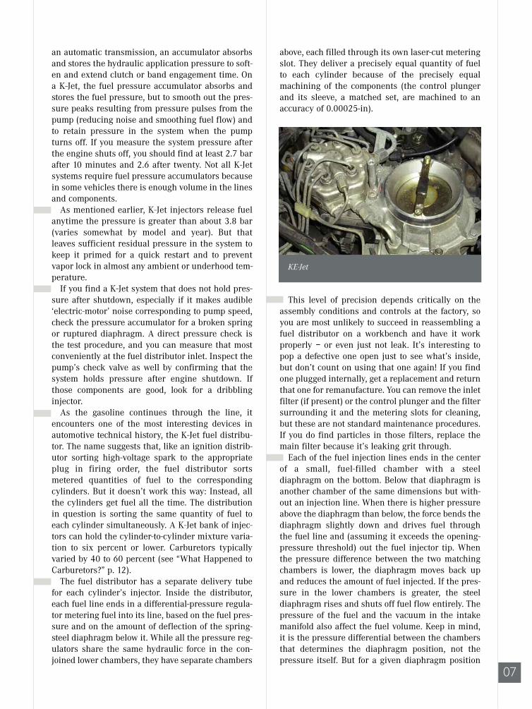
KE-Jet
08
FUEL SYSTEMS
There is seldom any reason to loosen or removethe K-Jet airflow plate from its lever because its pre-cise centering is so critical (if it touches, it can snagand stick in the funnel bore). If you need access toany part of the airflow sensor below the plate, youhave to remove the sensor from the intake tract any-way. Unless you have a special tool for the purpose,a good way to re-center the plate if you have removedit is to fit paper around the perimeter while youtighten the positioning bolt. If you use paper of theuniform, correct thickness, you’ll then have a uni-form, correct gap all around the sensor plate. Absentthat perfect paper, use toilet paper: It will be too thinalone, but you can build up enough for the right gapwith further wraparounds.
Mercedes-Benz K-Jet airflow plates usually havecurved or shaped top surfaces, not a feature of allBosch K-Jet systems. The effect of the curved surfaceis to aerodynamically allow through greater airflowcompared to a flat sensor plate of the same diameter.Each airflow sensor plate also has a stop bar aboveit, combined with a rubber bump-stop. The purposeof those elements is to allow the lever and plate tobounce above the center of the funnel and spill back-pressure should there be a backfire through theintake manifold. With these elements, the airflowplate and lever can survive a backfire, usually with-out damage. The funnel is tapered above, partly toorient the incoming air around the plate and partlyto provide pressure relief should there be a backfire.
While Bosch K-Jet systems on many cars draw theintake air up through the airflow sensor andthrough a tube to the throttle body, on mostMercedes-Benz vehicles the air flows down throughthe air funnel and into the engine. Among otheradvantages, this eliminates ‘false air’ coming
or injection-line opening, the upper chamber pres-sure (with the intake manifold vacuum) determinesthe momentary volume of fuel flow.
The K-Jet airflow sensor is unlike any intake-airmeasurement device on any other system, even theswinging-door sensor on Bosch L-Jet systems, whichit vaguely resembles. The fuel distributor and theairflow sensor are one assembly, described jointly asthe mixture-control unit. The K-Jet airflow sensorphysically, mechanically determines the fuel flow bychanging the pressure in the upper chambers of thefuel distributor.
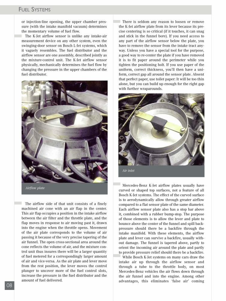
The airflow side of that unit consists of a finelymachined air cone with an air flap in the center.This air flap occupies a position in the intake airflowbetween the air filter and the throttle plate, and theflap moves in response to air moving past it, drawninto the engine when the throttle opens. Movementof the air plate corresponds to the volume of airpassing it because of the very precise tapering of theair funnel. The open cross-sectional area around thecone reflects the volume of air, and the mixture con-trol unit thus insures there will be a larger quantityof fuel metered for a correspondingly larger amountof air and vice-versa. As the air plate and lever movefrom the rest position, the lever moves the controlplunger to uncover more of the fuel control slots,increase the pressure in the fuel distributor and theamount of fuel delivered.
Air inlet
Airflow plate
through a cracked, porous or loose air hose.Functionally, the system works the same way withjust a change in the geometry of the air sensor leverand fulcrum. While the air flap does present anobstruction to the intake airflow, its aerodynamicresistance is quite low, so there is no vacuum tospeak of generated between it and the throttle plate.All of the intake, except for what comes through thePCV and EGR, passes the airflow sensor. Idle air, inparticular, transits the sensor.
At engine-shutoff rest, with no air passingthrough the sensor, the spring tension and weighton the arm bring the lever to a position in which itmoves the control plunger of the fuel distributor toshut off all fuel flow. While early and late fuel dis-tributors have different internal plumbing, most ofthem have fuel system pressure above the controlplunger, and the return force of the airflow arm mustbe enough to overcome this as well. Depending onthe application, this return force comes either froma spring or from a counterweight on the oppositeend of the lever.
As emissions requirements tightened, there was alate version of the K-Jet system, sometimes calledthe K-Lambda, that used an oxygen sensor for mix-ture feedback information and a separate frequencyvalve on the fuel return circuit. By duty-cycling thereturn flow, the system could fine-tune intake mix-ture by fine-tuning the fuel pressure in the fuel dis-tributor. But to achieve the combustion controlrequired for the next set of emissions standards, thesystem had to evolve into the KE-Jet.
KE-Jetronic Fuel Injection and the EHA
What distinguish the basic K-Jet injection systemfrom the KE-Jet are the electrohydraulic actuator(EHA) and the subsystems and components involvedin making it work. Because of a pressure regulatorin the fuel distributor, the pressure differencebetween the upper and lower chambers stays about0.4 bar, the same as the earlier K-jet. As the airflowlever moves, the control plunger routes fuel into thefuel distributor. What the EHA does is to modify thelower chamber pressure in response to the oxygensensor feedback signal, independently of the rest ofthe fuel distributor. Modifying the lower chamberpressure changes the pressure differential betweenthe chambers, changes the position of the spring-steel diaphragm and thus changes the volume of fueldelivered for the amount of air passing the airflowsensor.
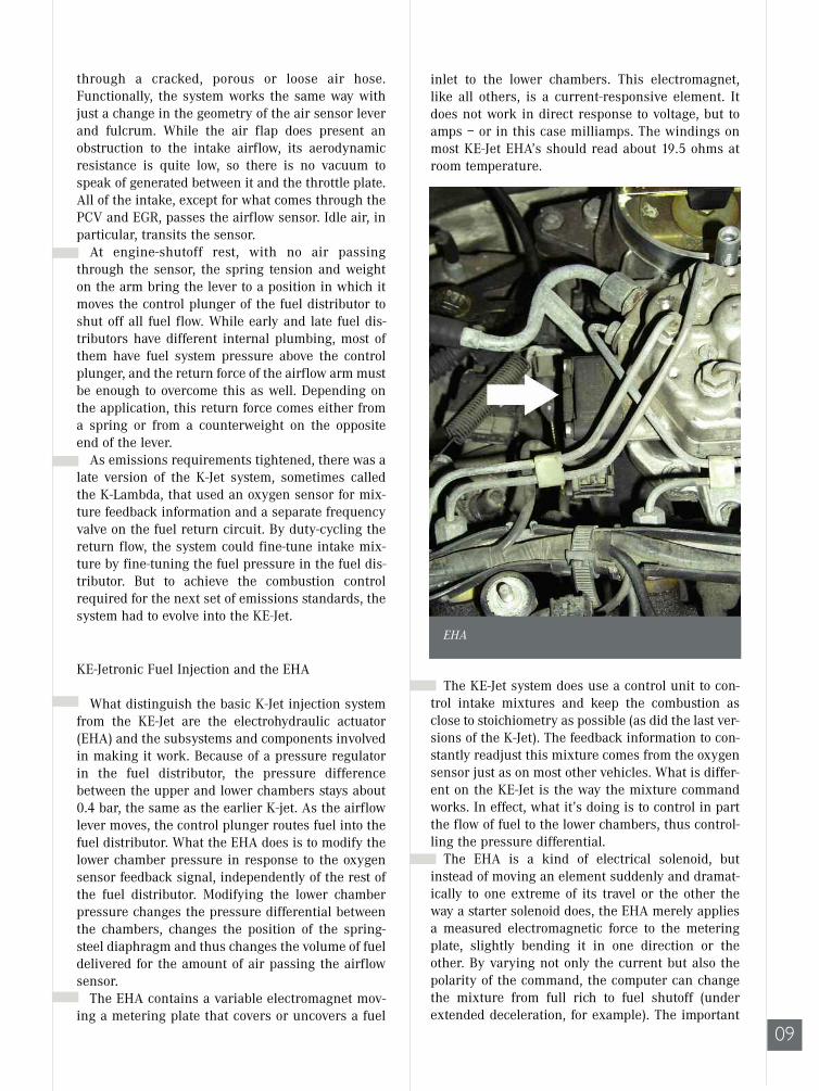
The EHA contains a variable electromagnet mov-ing a metering plate that covers or uncovers a fuel
inlet to the lower chambers. This electromagnet,like all others, is a current-responsive element. Itdoes not work in direct response to voltage, but toamps – or in this case milliamps. The windings onmost KE-Jet EHA’s should read about 19.5 ohms atroom temperature.
The KE-Jet system does use a control unit to con-trol intake mixtures and keep the combustion asclose to stoichiometry as possible (as did the last ver-sions of the K-Jet). The feedback information to con-stantly readjust this mixture comes from the oxygensensor just as on most other vehicles. What is differ-ent on the KE-Jet is the way the mixture commandworks. In effect, what it’s doing is to control in partthe flow of fuel to the lower chambers, thus control-ling the pressure differential.
The EHA is a kind of electrical solenoid, butinstead of moving an element suddenly and dramat-ically to one extreme of its travel or the other theway a starter solenoid does, the EHA merely appliesa measured electromagnetic force to the meteringplate, slightly bending it in one direction or theother. By varying not only the current but also thepolarity of the command, the computer can changethe mixture from full rich to fuel shutoff (underextended deceleration, for example). The important
09
EHA

FUEL SYSTEMS
thing to keep in mind is that electromagnetism here,as in all solenoids, functions by current, by amper-age alone. The voltage does not matter at all, exceptthat polarity cycles back and forth under closed-loopdriving; and if polarity changes, voltage does, too.
Check an EHA for continuity as described aboveand then for dynamic function. When the enginefirst starts cold, there will be a steady current of sev-eral milliamps to richen the mixture for the coldengine. Once the system is running in closed loop(two minutes after startup, at the longest), youshould see the current cycling, reflecting the signalfrom the oxygen sensor cycling. Many testers dis-play this as an on-off signal, but it’s actually currentin milliamps reversing polarity.
If the EHA current cycles, but not within the mil-liamp-or-two range, check first for air leaks. If theyare eliminated, you can open the ‘tamper-proof’ capand have access to the mixture adjustment screw.This should not be a regular service – if the enginehas not been apart or the fuel distributor replaced,keep looking for a vacuum leak first. If you use asensitive amp-clamp to check the EHA at work, besure to separate the two wires. It doesn’t matterwhich you measure, but if you catch them both inthe clamp, the currents in opposite directions willcancel out your measurement.
The KE-Jet ECU employs several parameters whencalculating the EHA control current. These include:
Cranking signal – an electrical signal parallel to the starter solenoid current,
Engine temperature – a reference signal dropped toa voltage corresponding to the engine coolant’stemperature,
Intake air temperature – from a sensor in the air intake duct,
Engine speed (TD or crankshaft position signal) –from an inductive signal generator at the flywheel,
Engine load – from a MAP (manifold absolute pressure) sensor,
Airflow sensor position signal and movement –from a sensor at the end of the airflow sensor lever pivot,
Oxygen sensor or Lambda signal – from a conven-tional heated oxygen sensor in the exhaust stream.
For warmup, the computer sends a command cur-rent that moves the EHA valve plate to somewhatrestrict fuel flow. That allows pressure to drop in thelower chambers, and the pressure differential bends
the metal diaphragm down, allowing relatively morefuel to flow. When the engine reaches normal oper-ating temperature and runs in closed loop, the ECUsends commands of varying polarity and current,causing the valve plate to cycle back and forth acrossits travel, thus richening or leaning the intake mix-ture as the need reflected in the oxygen sensor sig-nal requires. A scope, set to monitor the EHA cur-rent and the oxygen sensor signal simultaneously,graphically indicates this interdependence.
When the computer’s sensors indicate decelera-tion (closed throttle, high engine rpm, strong intakemanifold vacuum or low MAP), the ECU sends cur-rent in a polarity to pull the metering valve plate allthe way back, allowing pressure to equalize betweeneach of the chambers. The additional pressure of thesmall spring in the lower chamber is then enough tostop fuel flow.
The system has an inherent and transparent ‘limp-home’ mode. If one or more circuit failures mean thecomputer can’t send a signal to the EHA, spring ten-sion on the valve plate brings it to a center position;and the engine continues to run just as if it had ordi-nary K-Jet instead of feedback-modulated KE-Jet. Onmost models this circumstance trips the CEL and, ifthe car has self-diagnostics, sets a code for whatevercircuit has failed. Because the KE-Jet uses an electri-cally triggered cold-start injector spraying into theintake manifold log, the engine can ordinarily stillstart when cold.
The computer control system on KE-Jet is almostentirely for the fuel mixture; its purpose is to calcu-late and send the current command current to theEHA. While it has an input signal from the crank-shaft position sensor and in some models from thespeedometer, while on some models it includes atransmission upshift delay function (to speed enginewarmup), this is not yet a complete engine manage-ment system, coordinating fuel, spark, A/C compres-sor engagement, cruise control and other functionsinto one (that comes with the next system,Motronic). Control of the ignition system rests withthe EZL/AKR control unit, with only minor intercon-nections with the fuel system. KE-Jet is a fuel injec-tion system only. Nonetheless, do not connect or dis-connect the control unit with the ignition key on.That can yield damaging voltage spikes.
Rich and Lean Mixtures
You need more fuel during cranking and the firstsecond or two running. Fuel enrichment continuesfor as long as two minutes, depending on coolanttemperature. It also occurs during acceleration toaccommodate the fact that air accelerates into the
10
ground-return circuit. For each type of sensor,though, check the continuity of the harness back tothe computer as well as the variable resistancethrough the sensor.
There is no throttle position sensor, but there is athrottle switch with two outputs, corresponding toidle position, WOT position or (in the absence ofeither) any position in between. Because of the waythe KE-Jet airflow sensor and fuel distributor work,there is no need for a fine-discrimination throttle-position potentiometer. Test these switches, simpleon-off devices, for continuity in one position andopen circuit in the other.
As important as K-Jet and KE-Jet are in the devel-opment of Mercedes-Benz fuel injection systems (andfor other carmakers, actually), it’s critical to under-stand how the original systems worked to understandthe later variations, what the changes were for, whatthey meant. What a good thing that every new tech-nology has to start with the simplest version!
11
intake manifold more quickly than fuel. Finally, athigh speeds and high loads, at or near WOT, the mix-ture also goes rich. In that latter mode, there is nomixture feedback function and no EHA control cur-rent; the engine runs in open loop.
The mixture goes lean not only during decelera-tion fuel shutoff (a throttle-closed microswitch pro-vides the enabling signal) but, on many models, toprevent over-revving the engine into redline territo-ry. It’s also the first tactic in the vehicle maximumspeed limit, followed by shutoff of the fuel pump.Since the vehicle maximum speed is a voluntarylimit agreed among Mercedes-Benz and severalother German carmakers for vehicles intended forthe unlimited-speed German autobahns, the limit isas high as 250 km/h, about 155 mph. On Americanroads, this should rarely inconvenience a driver.Deceleration fuel shutoff is disabled whenever thecar is under cruise control.
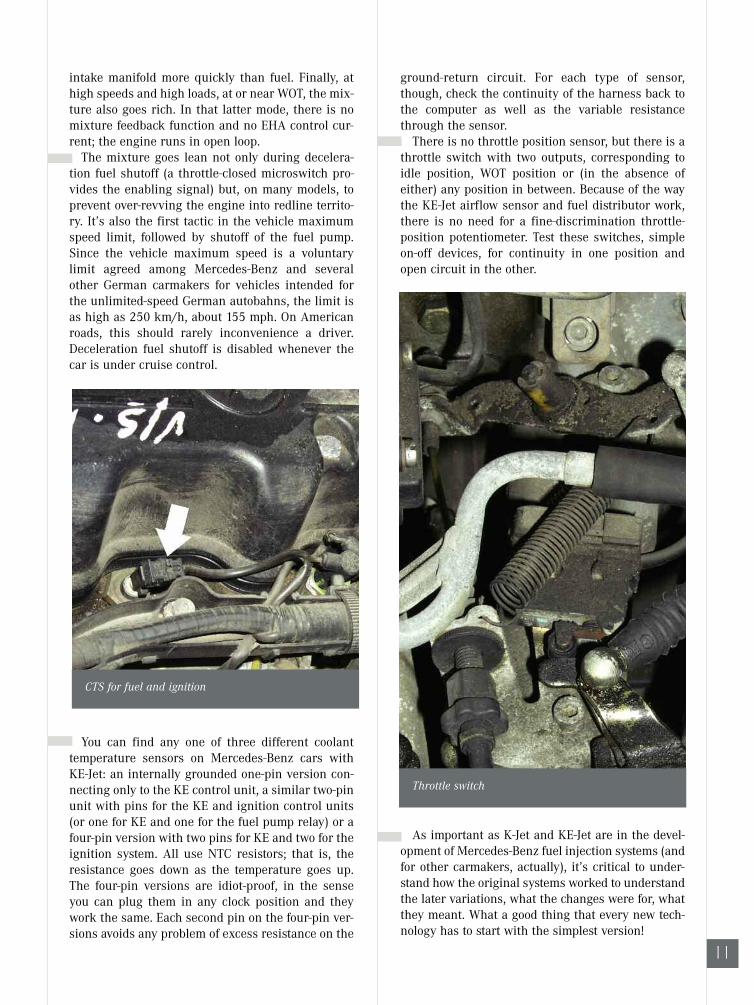
You can find any one of three different coolanttemperature sensors on Mercedes-Benz cars withKE-Jet: an internally grounded one-pin version con-necting only to the KE control unit, a similar two-pinunit with pins for the KE and ignition control units(or one for KE and one for the fuel pump relay) or afour-pin version with two pins for KE and two for theignition system. All use NTC resistors; that is, theresistance goes down as the temperature goes up.The four-pin versions are idiot-proof, in the senseyou can plug them in any clock position and theywork the same. Each second pin on the four-pin ver-sions avoids any problem of excess resistance on the
CTS for fuel and ignition
Throttle switch

12
FUEL SYSTEMS
Why did carburetors goaway? They were essentialparts of cars practically aslong as tires, and (like everything else) they’d become morecomplex even as the demandsof fuel economy, power andemissions friendliness in-creased. Even on the mostcomplicated carburetors, the vacu-um and evaporation technologyinvolved were well understood, andmost vehicles could run well enough withthem, even if overhaul and readjustmentprocedures became gradually more difficult.
The carburetor’s insoluble problems were with mix-ture control and fuel distribution. The proper fuel/airratio for an engine varies considerably over load,speed and temperature. It varies also with the ‘recenthistory’ of the throttle, too, so you need a richer mix-ture at a given throttle position if the driver is in theprocess of rapidly opening it, and you need a muchleaner mixture at the corresponding throttle positionsas the throttle rapidly closes. Most carburetors usedan acceleration pump or its equivalent to briefly richenthe intake mixture as the driver moved the pedaltoward the floor. The enrichment provided by theaccelerator pump, however, was imprecise andchanged over time with wear of the pump.
Carburetors could vary mixture inresponse to oxygen sensor feed-back signals, but at the cost ofincreased complexity and vulnera-bility to dirt or contaminants.
Carmakers used duty-cycled sole-noids to modulate either the fuel inthe main circuits or the air in theemulsion tubes. A feedback car-buretor, however, could not makemixture changes rapidly enoughto follow rapid openings or clos-ings of the throttle with the preci-sion required. What’s more, since
the carburetor sits on ‘top’ of the intakemanifold, there is no way to prevent the fuel just atom-ized and vaporized from condensing back into liquidon the manifold walls when pressure and temperatureconditions favored that. Even the most sophisticatedmixture-adjusting carburetor could hold total mixturewithin the desired range only at steady speeds, notunder the quick changes of driving in ordinary traffic.But even if the mixture problem were perfectly
solved for carburetors, there is still the fuel distribu-tion problem. This is most dramatic on inline engineswith single carburetors and ‘log’ manifolds: Imagine asix-cylinder engine with a single-barrel carburetor atthe midpoint of an intake manifold running parallelwith the camshaft. Because the heavier droplets offuel resist turning when the airflow does, most blow tothe extreme ends of the manifold. The smallestdroplets and the properly vaporized fuel make theturns easiest. In every such engine, then, cylindersone and six will get the richest mixtures and cylindersthree and four will get the leanest.This is more than a slight or theoretic problem, actu-
ally. According to Bosch experiments, a typical carbu-reted four-cylinder engine will have mixture variationsof about 60 percent. Clearly, you have to send thecylinders getting the leanest mixture enough fuel tofire dependably; thus the richest cylinders mustalways run overrich. This condition means increasedwear in those rich cylinders because of cylinder wallwashdown from the excess fuel. It is typical in inlineengines to find the first and last cylinders have themost wear (though there are other factors, like varia-tions in coolant temperature as you get closer to orfarther from the water pump).The richer mixture naturally enough means more
hydrocarbons in the exhaust, too. Multipoint fuel injec-tion systems like the K-Jets reduce both mixture anddistribution problems by a factor of about 90 percent.
Mixture control tower
WHAT HAPPENED TOCARBURETORS?

13
AD

MULTILINKSUSPENSIONSHow to discern, diagnose and repair suspension problemswhen they occur . . .
FEATUREARTICLE
14
Almost all Mercedes-Benz cars built since themiddle 1980’s have used similar suspension geome-try, particularly for the rear suspension. This geom-etry, beginning with models 201 and 124, is amongthe simplest and most successful of all multilinksuspensions (though perhaps it is odd to describeany multilink suspension as simple). Here we’lllook at why the design is used, at how it works andhow to discern, diagnose and repair problems whenthey occur.
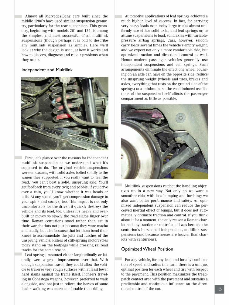
Independent and Multilink
First, let’s glance over the reasons for independentmultilink suspension so we understand what it’ssupposed to do. The original vehicle suspensionswere on oxcarts, with solid axles bolted solidly to thewagon they supported. If you really want to ‘feel theroad,’ you can’t beat a solid, unsprung axle: You’llget feedback from every twig and pebble; if you driveover a coin, you’ll know whether it was heads ortails. At any speed, you’ll get compression damage toyour spine and coccyx, too. This impact is not onlyuncomfortable for the driver, it quickly destroys thevehicle and its load, too, unless it’s heavy and over-built or moves so slowly the road-slams linger overtime. Roman centurions stood rather than sat intheir war chariots not just because they were machoand studly, but also because that let them bend theirknees to accommodate the jolts and lurches of theunsprung vehicle. Riders of stiff-sprung motorcyclestoday stand on the footpegs while crossing railroadtracks for the same reason.
Leaf springs, mounted either longitudinally or lat-erally, were a great improvement over that. Withenough suspension travel, they could allow the vehi-cle to traverse very rough surfaces with at least fewerhard slams against the frame itself. Pioneers travel-ing in Conestoga wagons, however, preferred to walkalongside, and not just to relieve the horses of someload – walking was more comfortable than riding.
Automotive applications of leaf springs achieved amuch higher level of success. In fact, for carryingvery heavy loads even today large trucks almost uni-formly use either solid axles and leaf springs or, toattune suspensions to load, solid axles with variable-pressure airbag springs. Cars, however, seldomcarry loads several times the vehicle’s empty weight;and we expect not only a more comfortable ride, butoptimized traction and directional control as well.Hence modern passenger vehicles generally useindependent suspensions and coil springs. Sucharrangements eliminate the effect one wheel bounc-ing on an axle can have on the opposite side, reducethe unsprung weight (wheels and tires, brakes andaxles, everything that rests on the ground side of thesprings) to a minimum, so the road-induced oscilla-tions of the suspension itself affects the passengercompartment as little as possible.
Multilink suspensions ratchet the handling objec-tives up in a new way. Not only do we want asmoother ride, with less bumping and lurching; wealso want better performance and safety. An opti-mized independent suspension can reduce the per-ceived inertial effect of bumps, but it does not auto-matically optimize traction and control. If you thinkabout it for a moment, the only reason a Roman char-iot had any traction or control at all was because thecenturion’s horses had independent, multilink sus-pensions (and because horses are heavier than char-iots with centurions).
Optimized Wheel Position
For any vehicle, for any load and for any combina-tion of speed and radius in a turn, there is a unique,optimal position for each wheel and tire with respectto the pavement. This position maximizes the tread-patch contact area with the pavement and sustains apredictable and continuous influence on the direc-tional control of the car. 15

16
MUTILINKSUSPENSIONS
While you can predict some of these positions(we’ll surely want the wheels pointing straightahead and angled perpendicular to the pavementwhen driving in a straight line), determining most ofthe others requires extensive testing and experi-ment. For example, you want the rear outside wheelto gradually angle inward, to toe inward, as the vehi-cle leans to that side in an increasingly steep turn.You want this because the contact patch in a turndoes not move parallel to the centerline of the wheel,but gradually angles inboard as the turn steepens,up to the point when traction goes away. This keepsthe turning angle of the vehicle kinetically or tactu-ally predictable to the driver. However, you don’twant that toe change to continue up to the pointwhen the vehicle suddenly spins. Rear wheel trac-tion must always exceed front wheel traction forobvious reasons of safety.
Similarly, most cars corner somewhat better if theoutside wheels pick up a few degrees of negativecamber in a turn, to offset the effect of the tilting tiresidewalls. Engineers specify the dynamic suspen-sion angles like caster only after extensive research.When you do your first Mercedes-Benz alignment,you’ll be surprised at the specified caster angle ifyou learned alignment on domestic vehicles. Someof the older models called for as much as 12 degreespositive. The higher speeds at which people drive inGermany require a much larger caster angle than iscommon here to ratchet the steering stability highenough for those speeds.
Traction in turns is not the only objective of multi-link design. With careful design of the geometry, thefront suspension can resist dips under braking, andthe rear can resist dips under acceleration. Brakingand acceleration forces also raise the suspensionwith a force proportional to the acceleration changeby the twisting effect they have on the knuckle.Keeping the suspension height level keeps the tire-tread geometry straight and square with the roadunder both acceleration and braking, optimizingtraction for both. An anti-dive suspension, in otherwords, can actually reduce braking distance since itkeeps the tiretread flat against the pavement.Similarly, antisquat rear-suspension geometry canimprove traction for acceleration. In each case, theheight correction maintains the camber on that axleconstant. Finally, the right multilink geometry allowsthe effective employment of truly effective, activesuspension systems taking the control of tractionand handling to yet a new level (largely quick-adjust-ing dampers, but also some height adjustment).
Rear Suspension
Enough for the theory and the objectives, let’s lookat the parts on the car. The rear suspensions of allcurrent Mercedes-Benz cars share the same five-linkgeometry. The parts, to be sure, are not interchange-able between models, but the geometry is, as welearned in high school, congruent.
The five links are:
Spring Link
This is the lowest and largest link in the suspension,pivoted inboard at the differential/rear axle sub-frame and outboard where it forms a yoke with theknuckle of the axle. A bit inboard of the center of thelink is the cavity for the bottom of the coil spring,the cavity that gives the link its name. A protectivecover bolts to the underside of the spring link, fend-ing off road debris. That protective cover also worksas a reliable indicator if there has been collisiondamage: Since it is the lowest part of the suspension,it is the most likely to encounter an obstacle, andbeing lighter it will bend or crack before the springlink will.
17
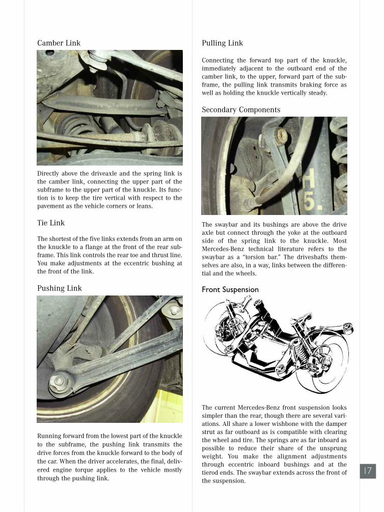
Camber Link
Directly above the driveaxle and the spring link isthe camber link, connecting the upper part of thesubframe to the upper part of the knuckle. Its func-tion is to keep the tire vertical with respect to thepavement as the vehicle corners or leans.
Tie Link
The shortest of the five links extends from an arm onthe knuckle to a flange at the front of the rear sub-frame. This link controls the rear toe and thrust line.You make adjustments at the eccentric bushing atthe front of the link.
Pushing Link
Running forward from the lowest part of the knuckleto the subframe, the pushing link transmits thedrive forces from the knuckle forward to the body ofthe car. When the driver accelerates, the final, deliv-ered engine torque applies to the vehicle mostlythrough the pushing link.
Pulling Link
Connecting the forward top part of the knuckle,immediately adjacent to the outboard end of thecamber link, to the upper, forward part of the sub-frame, the pulling link transmits braking force aswell as holding the knuckle vertically steady.
Secondary Components
The swaybar and its bushings are above the driveaxle but connect through the yoke at the outboardside of the spring link to the knuckle. MostMercedes-Benz technical literature refers to theswaybar as a “torsion bar.” The driveshafts them-selves are also, in a way, links between the differen-tial and the wheels.
Front Suspension
The current Mercedes-Benz front suspension lookssimpler than the rear, though there are several vari-ations. All share a lower wishbone with the damperstrut as far outboard as is compatible with clearingthe wheel and tire. The springs are as far inboard aspossible to reduce their share of the unsprungweight. You make the alignment adjustmentsthrough eccentric inboard bushings and at thetierod ends. The swaybar extends across the front ofthe suspension.

18
MUTILINKSUSPENSIONS
Certain models, beginning with the 140, use asmall control arm at the top of the damper strut tobetter optimize caster and camber in certain drivingmodes. Some experienced mechanics find the angleof that small control arm is the quickest indicationof any problem with suspension height, such as sag-ging springs. It pivots back as well as up in its nor-mal travel, so once you’ve seen a few ‘known-good’s’one that’s out of adjustment will leap out at you.
Alignment procedures
The linkage geometry may be complex, but adjust-ment procedures generally are not. You set casterand camber, front and rear, with the eccentrics(changing both at the same time!). Then you set therear toe with the eccentric on the tie link, and oncethe thrust line is correct, set the front toe with theadjustable tierods.. If an eccentric adjustment can’tbring the system into specification, something iseither worn beyond use or broken. Damaged strutsare visible by comparison to the mirror-image struton the other side; worn bushings will be visibly dif-ferent from the others. Oil and heat damage shouldbe evident to an experienced eye.
Subframes
The suspension does not support the body of thecar directly. In each Mercedes-Benz, the suspensionconnects to a subframe through hard-rubber bush-ings, which in turn supports the body through otherhard-rubber bushings. Much of the vehicles’ quietrunning comes from this suspension and drivetrainbushing design. The engine and drivetrain also reston the subframes on a third set of hard-rubberblocks, and this separation of the body from the sus-
pension and drivetrain and their isolation from oneanother reduces the transmission of vibrations fromthe engine and from the road. Rubber andrubber/antifreeze bushings hold the major compo-nents at an effective, vibration-damping setoff. Theantifreeze retains the advantages of liquid dampingwhen temperatures fall below freezing.
The rear suspension shares the same indirect con-nection to the body through a bushed subframe. Therear subframe supports the body, but it also sup-ports the differential with separate rubber bushings.The suspension links attach to the same subframe inseveral positions, as we’ll see below.
Critical as the subframes are, you should inspectthem carefully for damage, especially for cracks,which can sometimes close up and hide when theweight is off the wheels. Rustproofing and accumu-lated dirt can conceal such cracks. Ball joints aresubject to normal wear. Mercedes-Benz carries asimple go/no-go gauge to test them.
Sometimes people decide to add their own ‘edge’to the alignment specifications to give a car a partic-ular ride, by tweaking the front camber and the like.This is not a particularly good idea with Mercedes-Benz cars. The company does a great deal ofresearch in handling and suspension, and theirGerman domestic customers expect the cars to drivein control even at high speeds and under challeng-ing road conditions. Unless your customer weighs400 pounds and always rides alone or is an anvilpeddler with a trunk full of samples, you should

19
probably stick with the book settings.
There are a large number of accessories that, onone model or the other, connect to different suspen-sion links and components. Some are as familiar asABS wheelspeed sensors; some are as unusual asthe switch on the 129 (SL) rear linkage that triggersthe roll bar up if the rear wheels leave the ground.Many Mercedes-Benz cars have different forms ofactive suspension (varying the shock damper rates),suspension height adjustment (some cars crouchdown an inch or so closer to the highway for betteraerodynamics at high speeds), sensors for lockingdifferentials and more. If you find such a componentin your way, determine what it is and how to removeit without causing unexpected problems later. Insubsequent articles and issues, we’ll get to all theMercedes-Benz vehicle systems, but for now we’rejust looking at the multilink suspension basicgeometry.
There are several other safety-related issues:Many Mercedes-Benz vehicles have diagonal cross-braces below the floor, particularly roadsters andconvertibles. These function to keep the body stiffand square under driving stresses. Be sure you havethe body supported equally and level at the desig-nated jacking points before you remove these cross-braces. If not, there could be body damage in someother area of the car, and you may find it very diffi-cult to get the cross-braces and their fastener boltsback into the right positions.
That applies to potential damage to the vehicle.This applies, in addition, to potential personalinjury. Remember, only the damper struts hold thesprings in place on these suspensions, when the caris on a lift and the suspension is at full extension.The front geometry vaguely resembles aMacPherson strut, but that’s not what it is. If youremove the damper strut without restraining thespring in a spring compressor, the spring can fly outof the seat with unexpectedly great force. Mercedes-Benz dealers carry spring compressors and model-specific end flanges that make this critical step safeand easy.
Finally, here’s a general precaution that doesn’tapply to vehicle or personal safety, but could makethe difference between a satisfactory job and oneyou have to do over free. Multilink suspensionsinclude a large number of bushings, at least one ateither end of each link. Many of these links areclock-position specific, and many such specific clockpositions are very easy to confuse with others forsimilar vehicles. For instance, suppose you’rereplacing front control arm bushings on a 201 andusing the clamping sleeve replacement bushing. Onthe forward front control arm bushing, the flat spotsin the bushing go vertical [position for line drawingP33-2053-13] and the rear flats go horizontal, towardthe center of the car. On a 124 or 129, however, youput the rubber flats vertical on the rear pivot of thecontrol arm, and turn the front bushing flats hori-zontal toward the center of the car, just the oppositeof what you do on the 201.
Now, nobody can remember all this accurately.That’s why we have reference materials and techni-cal libraries. The point is, when you see a Mercedes-Benz bushing that is not perfectly symmetrical inevery orientation, that means there is one correctand many incorrect ways to install it. Failing to findand observe that right orientation means the bush-ing will have a different and unpredictable elasticitythan the engineers designed for that linkage pivot.The car will drive measurably worse than it didwhen new.
If you’ve worked on suspensions for any length oftime, think of this as a reminder, not as nagging:When you’ve replaced a suspension bushing – anysuspension bushing – lower the car’s weight ontothe wheels so the bushing is under its normal restload before you tighten the fastener (to the propertorque specification). This avoids giving the bushingan unintended twist, which can shorten its usefullife as well as make it behave oddly. Bushings are themost important parts of any multilink suspension,and their correct assembly is the most importantpart of suspension work.

20
PARTSNEWS
DEPARTMENT
Classic Car Service Manual CD’s
When this project is complete, there won’t be anydifficulty getting full service manual information forany model Mercedes-Benz, going back to 1947. TheMercedes-Benz technical information departmenthas prepared CD’s with all the information formerlyavailable only through books and microfiche. CD’sfor models 107, 114/115, 116, 123, 124 and 201 areready now, and more will be ready in the nearfuture, beginning with model 126.
The information has been scanned from the originalsources and can be accessed from any computerusing Microsoft Internet Explorer 4.0 or later orNetscape Navigator 4.0 or later. The information con-tained on the disks includes all the information rel-ative to the carmodel throughout its entire produc-tion run. While the focus is on vehicles built to thespecifications of the American market, there is addi-tional information for features of vehicles built forthe European roads.
The CD’s contain all the pages from the appropriateengine manuals, electrical troubleshooting manuals,maintenance manuals, owners manuals, climatecontrol manuals and chassis/body manuals. Thiscombines in one place all the information previouslyavailable from many sources. The CD’s can thus beof advantage not only to shops performing repairsand service on these models, but to those engaged inrestoration or other detailed work on the cars.
Mercedes-Benz Remanufactured PartsLineup Gets Even Larger
Mercedes-Benz USA is pleased to announce thatwe have made an already impressive lineup ofremanufactured parts even stronger with the addi-tion of wiper motors and brake calipers.
Our goal is to be your first and last source forreplacement parts for Mercedes-Benz vehicles.Expanding our already impressive line of remanu-factured parts is just another tool we can give you tosatisfy your customers.
Because the reputation of our cars rests on the qual-ity of our parts, you can be assured that GenuineRemanufactured Mercedes-Benz parts are carefullybuilt in tightly controlled factory conditions. When acomponent is replaced, it is replaced with a newGenuine part, not an aftermarket knockoff. If youaren’t buying your remanufactured parts from us,you don’t know what you are getting. Why takechances with unknown quality control?
The warranty on Mercedes-Benz remanufacturedparts is for 12 months, unlimited mileage from thedate of purchase. Remanufactured automatic trans-missions are warranted for 24 months or 24,000miles, whichever comes first, from the date of pur-chase. Engines and long blocks are warranted for 48months or 50,000 miles, whichever comes first, fromdate of installation as of May 20, 1996.

21
AD
22
DEPARTMENT
FACTORY SERVICE BULLETINSThese suggestions and solu-
tions for technical problemscome from service bulletins pub-lished by Daimler-Benz,selected and rewritten for inde-pendent repair shops.
Restart delay relayModels 201, 124 and 126
To prevent clash between thestarter drive and the ringgear/flexplate teeth, many butnot all models 201, 124 and 125,beginning in 1989, have a timerrelay that prevents a secondcranking attempt for a period oftwo seconds after one that failsto start the engine. The purposeis to allow the crankshaft tocome to a complete stop beforethe starter drive re-engages thering gear/flexplate teeth. OK, sofar so good. But here’s the prob-lem: If the relay fails, you can getanother relay from yourMercedes-Benz parts supplier. Ifthe harness fails, however, youmust either repair the harness,or if that proves impossible forsome reason, you must wirearound the relay. There is noreplacement harness.
First, confirm that you have a carwith the crank-delay relay. Ineach of these line drawings, it isrelay N38.
If you want more detail on howto wire around the relay, seeElectrical TroubleshootingManual, p. 113 model 124, p. 105model 126.
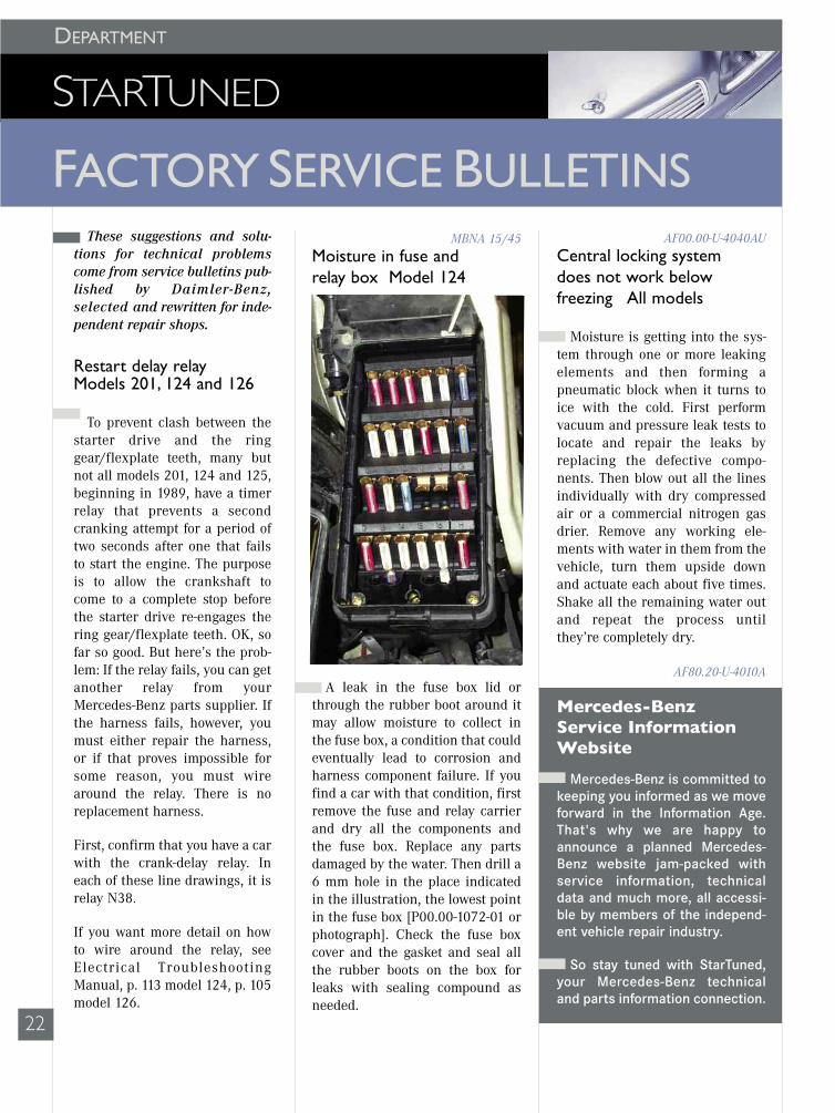
MBNA 15/45Moisture in fuse and relay box Model 124
A leak in the fuse box lid orthrough the rubber boot around itmay allow moisture to collect inthe fuse box, a condition that couldeventually lead to corrosion andharness component failure. If youfind a car with that condition, firstremove the fuse and relay carrierand dry all the components andthe fuse box. Replace any partsdamaged by the water. Then drill a6 mm hole in the place indicatedin the illustration, the lowest pointin the fuse box [P00.00-1072-01 orphotograph]. Check the fuse boxcover and the gasket and seal allthe rubber boots on the box forleaks with sealing compound asneeded.
AF00.00-U-4040AUCentral locking system does not work below freezing All models
Moisture is getting into the sys-tem through one or more leakingelements and then forming apneumatic block when it turns toice with the cold. First performvacuum and pressure leak tests tolocate and repair the leaks byreplacing the defective compo-nents. Then blow out all the linesindividually with dry compressedair or a commercial nitrogen gasdrier. Remove any working ele-ments with water in them from thevehicle, turn them upside downand actuate each about five times.Shake all the remaining water outand repeat the process untilthey’re completely dry.
AF80.20-U-4010A
Mercedes-BenzService InformationWebsite
Mercedes-Benz is committed tokeeping you informed as we moveforward in the Information Age.That's why we are happy toannounce a planned Mercedes-Benz website jam-packed withservice information, technicaldata and much more, all accessi-ble by members of the independ-ent vehicle repair industry.
So stay tuned with StarTuned,your Mercedes-Benz technicaland parts information connection.

23
works actively as well. Once you’veconfirmed the diaphragm is intact,release the vacuum suddenly. Ifthe valve works as it is supposedto, you’ll hear an audible pop fromthe valve as the pintle snapsclosed.
MBNA 14/6
Hood hinge testAll models
Here’s a quick and accurate test tosee whether a hood hinge has beendamaged on a Mercedes-Benzvehicle: Place a short (150 mm)ruler or straightedge against theoutside surface of the hinge, withthe hood at the 45-degree position.If the gap between the hinge andyour straightedge is 0.0 to 0.2 mmor less, the hinge is good. If thegap is greater, the hinge is bent.
MBNA 88/32
Too clean for safetyAll models
Keeping a car clean and pol-ished not only makes it easier onthe eye and a source of greater sat-isfaction for the owner; it alsohelps prevent rust and abrasion to
the converter up. The distortiontakes the form of thickening thetorque converter, this making itinterfere with the front transmis-sion pump and damage the frontseal. If an engine has sustainedoverrevving damage, check thetorque converter by placing it on aflat surface with the pump-driveside down. Measure the thicknessfrom the surface to the attachmentbolt surface as shown in the illus-tration [p27-2371-13]. As long asthe thickness is 121.5 mm or less,the torque converter is satisfacto-ry; if it is thicker than 121.5 mm,replace the converter.
MBNA 27/82
Oxygen sensorsAll models
If an oxygen sensor doesn’t senda proper cycling signal or the vehi-cle’s self-diagnostic memoryrecords an oxygen sensor fault,confirm that the oxygen sensor isproperly grounded before youreplace it. Not only must the sen-sor make a secure electrical con-nection to the exhaust system; theexhaust system must also make asecure electrical connectionthrough the engine cylinder headto the negative terminal of the bat-tery. Confirm also that the comput-er shares the same ground as theoxygen sensor does. Only if thegroundside of the circuit is goodbut you don’t find a signal fromthe sensor, should you replace thesensor.
MBNA 07.3/11
EGR functional testAll models with EGR
Everybody knows that thediaphragm on an EGR valve musthold vacuum built with a handpump or else the valve is defective,but you’d like to know the valve
Cylinder head bolt notesAll models
Everyone knows not to useimpact wrenches to tighten cylin-der head bolts, but on Mercedes-Benz engines don’t use them toremove the bolts, either, to protectthe threads in the block. Manyengines are aluminum or otherthinwall castings, so it is also crit-ical to insure the boltholes arecompletely emptied of oil andantifreeze before head bolts are re-installed. Blowing such residue outwith compressed air is usually asatisfactory technique, but inspecteach hole to confirm removal ofany dirt or liquid. If fluids are leftat the bottom of the bore, tighten-ing the bolt could create enoughhydraulic pressure to crack theblock.
MBNA 01/6
Overrevving damage to torque converterAll models with automatictransmissions
Running an engine beyond red-line can damage the engine byfloating or bending valves, twist-ing connecting rods and otherequally dire consequences. To pre-vent that, Mercedes-Benz engineshave included maximum enginespeed limiters for many years.Those protective measures, howev-er, can only prevent redlining theengine using the throttle. If a driv-er manually downshifts the trans-mission at too high a speed, thiscould result in the vehicle’smomentum spinning the crank-shaft above a safe speed.
Besides the damage to the enginepotentially resulting from a speedabove redline, the torque convertercan also distort by centrifugalforce acting on the transmissionfluid in the converter, ‘ballooning’

24
FACTORYSERVICEBULLETINS
the paint and other surfaces. Butsome people get carried away withvehicular tidiness. If you use apressure washer to clean thewheels and tires, use only a wide,fan-shaped nozzle and keep the tipof the tool constantly moving andat least 12 inches from the tire. Around or pencil blast nozzle cancause pinpoint overheating of thesidewall rubber from high-speedvibration, causing hardening anddamage that will not appear untillater. Such a nozzle can causeinvisible tire damage even at a dis-tance of 30 inches. And a sidewallblowout is not something tidy!
MBNA 40/99
Steering idler freeplayModels 124, 126, 129 and 201
You should only replace steeringlinkage idler gear rubber bushingsunder one of two conditions:• The bushings are making noisewhen you turn the steering fromlock to lock.• The total freeplay in the idlerarm is more than 0.5 mm as meas-ured at the point where the tie rodconnects to the outer end of theidler arm. Use a suitable clamp-ondial indicator to make the meas-urement.
MBNA 46/72
Engine shuts off, can’t restartVehicles with gasoline engines
It is possible for the oxygen sen-sor signal wire to rub against thedriveshaft on some Mercedes-Benzvehicles. If the spinning driveshaftwears through the insulation onthe wire, this can damage the oxy-gen sensor and short the printedcircuit in the fuel pump relay.Repair requires replacement bothof the sensor and the relay. Be sureto route the sensor wire so theproblem cannot recur.
07.3-88041
No startEngines 102 and 103
Add to your no-start checks thisone: If there was a backfire the lasttime the engine was running, it ispossible the molded hose at the
idle air valve (above) fell off, allow-ing excessive unmeasured air intothe intake manifold. While you’reinspecting that hose, confirm thatit does not have damage frombeing swollen or cracked.
07.3-90011
Panel bulb breaks speedocable? Models 124 and 201
It’s not a very plausible claim, isit? But any attempt to remove theinstrument panel, even partially,can damage the accelerator cable,even if you’re just tilting it enoughto reach in and swap a burned-outindicator bulb. Before you pull theinstrument panel loose, discon-nect the speedometer from behind.You don’t want to have to try toexplain how the burned out bulbbroke the speedometer cable!
MBNA 54/58
Trunk hard to close in winterModel 201
If it becomes difficult to closethe trunk lid on a Model 210 dur-ing very cold weather, inspect thecondition of the two rubberbumpers at the trunk latch. Therubber bumpers can become veryhard at low temperatures, makingthe trunk difficult to close. Justremove one of the rubber trunklatch bumpers to reduce the prob-lem by exactly half!
AF88.50-U-60001A
25
Headliner removal/replacementModel 124
The traditional way to remove acar’s headliner is through the rearwindow, or ‘backlight.’ The one-piece headliner installed in the M-B 124 from January 1991 on comesout the front passenger door,instead. Here’s how:
• Remove the door frame protec- tion edge from all four doors.
• Remove the windshield moldings from the A-pillars.
• Remove the roof frame panel trim above the windshield.
• Remove the trim panels from the B-pillars.
• Remove the trim panels from the C-pillars.
• Remove the rear interior lamp and assist handles above the doors.
• Move the front seats to their rearmost position and lower the backrests completely.
• Put the gear selector lever in Park.
• Slide the headliner rearward and unhook it from the roof frame. There are two retaining clips.
• Remove the headliner through the front passenger door.
SI 68/18 March 1991
Wood console removalModel 129
You really, really don’t want todamage the wood paneling on M-Bconsoles and dashboards becausethey actually are wood, all fromthe same tree for a given car. Thelikelihood of finding a panel thatwill match exactly is exactly zilch.This means it’s important to use
the proper techniques whenremoving these panels. We’ll fillyou in on them in future issues.Here’s how to remove the centerconsole of the Model 129 withoutputting yourself in the market forsome very expensive lumber:
With the ignition off and theparking brake applied, pull theradio using the radio removal keys.Disconnect the electrical connec-tors. Reach through the radio openingand push the climate control push-button unit outward. Disconnect itselectrical connectors. With an automatic transmis-sion, remove the plastic trim ringaround the selector lever and movethe lever to position 2. With a man-ual transmission, disengage thebottom of the shift boot and movethe lever into a rearward gate posi-tion such as third gear. Remove the screw in the centerof the storage compartment. Bendthe upper corners of the storagecompartment inward (arrows) andpress the compartment forward,removing it by the corners. Don’tuse a sharp edged tool whenremoving the compartment toavoid damaging the wooden cover.Lift the cover only with a smallremoval hook on the screw hole ofthe compartment housing. Remove screws 2 and 3 belowthe storage compartment. Press the rear of the consolewooden cover left to disengage thecatch and lift the right side. Pressthe rear right to disengage thecatch and lift the left side. Lift therear cover and pull downward outof the upper catches. Disconnect the wiring connec-tors from the switches. Remove the wooden cover.
When reassembling everything,check that all the switches andcomponents work. You’ll have torecode the radio.
MBNA 68/4
Convertible top care and neglectAll models with soft top
Here are a few useful rules forM-B soft top owners:
• Never take the car through anautomatic car wash. Never usehigh-pressure cleaning equipmentto wash the soft top.
• Remove all bird droppings immediately. Acids can quickly damage both soft-top material and even body paint.
• Never use ice or snow scrapers or other tools with sharp edges.
• Normally just rinse the soft top with water. Wash it only if it is “significantly” dirty.
• Do not use gasoline, thinners, tar removers, stain removers or other organic solvents when cleaning the soft top.
If the soft top must be cleaned, do the following:
• Clean the top only when it is closed and locked.
• Sweep the soft top with a soft brush while dry.
• Mask all adjacent paint and glass surfaces, including plastic windows.
• Wash with a generous amount of lukewarm water and a neu- tral detergent.
• Always brush or sponge in the same direction, front to rear.
• Use detergent concentrate only on extremely dirty areas or white/grey patches where there has been contact or chafing.
• Thoroughly rinse with clean water.
• Let the soft top dry completely before putting it down.
MBNA 77/37

26
FACTORYSERVICEBULLETINS
the 13 mm locknuts.Adjust the rear guide rail throughthe oblong hole so when the doorcloses completely the vertical edgeof the window touches the hardtoprubber seal for its entire length.Adjust the lower travel limit byfirst adjusting the stop on the win-dow lifter and then on the lifter railso the upper edge of the windowcloses flush with the sealing rails.Adjust the stop on the windowlifter rail so the limit switches onthe right and left in the bottomdoor recess engage simultaneouslywhen you lower the window com-pletely.
Adjust the guide piece by movingthe screw in the oblong hole sowhen the window is in the upmostposition the vertical edge of thewindow just touches the guidepiece. Once the adjustments arecomplete, lubricate the sliding sur-faces with M-B lubricating paste(part number 001 989 14 51).Finally, reinstall all the door trimpieces.
Selective unlockingModel 163
Before attempting to repair aradio frequency key or the lockingsystem with which it works, it iswell to understand how the systemfunctions since it is not possible toalter the system to behave in someother, possibly simpler way. Hereis how it works: If you press theunlock button once, the driver’sdoor and the fuel filler flap unlock.If you press the unlock button asecond time, all the doors plus thetailgate and fuel filler flap unlock.An attempt to make the system dosomething other than what it wasdesigned to do is not likely to besatisfactory.
T-SI-MBNA-80.35/10
Soft top control modulesModels 124 and 129
It may sometimes happen thatsoft top control modules fail andmust be replaced. But this is notthe case, in general, with modulesthat have various DTC’s stored inmemory, DTC’s that suspend oper-ation of the soft top. DTC’s that canhave this effect are:
DTC’s 3, 18, 20-24
DTC’s 21,22, 26, 30
Before replacing a soft top controlmodule, always record what is infault memory, erase the memory,test drive the vehicle for more than10 seconds, open and close the softtop. Then read out the DTC memo-ry again.
If there is a problem during softtop operation, hold the switch untilthe indicator lamp begins blink-ing. If the previous DTC’s can beerased, soft top operation is possi-ble; that is, the fault is no longerpresent. DTC 30, however, can bestored again while driving.
MBNA 77/9
Window adjustmentModel 129
Air and water leaks around thewindows can often be corrected byreadjusting the position of thewindows in the doors. Install thehardtop to provide a fixed surfaceto adjust the window to. Thenremove the inner door panel, thelower body protection panel andthe speaker group and air passage.Remove the protective plastic linerfrom the door as well as the innerand outer sealing rail. If the door isnot perfectly square in its frame,adjust the door so it is in the cor-rect position.
That done, loosen the guide piecescrew and push it downward.Remove the rubber plugs andloosen both 13 mm nuts. Turn the5.5 mm adjustment bolts so thescrews of the guide rail are in themiddle of the bracket.
Adjust the window with the frontand rear sliding blocks so the win-dow rests parallel and in the mid-dle of the window channel in thelowered position. It should be 9mm from the door inner metalpanel. The later gap (which trans-lates into the tension) increases asyou push the blocks upward anddecreases as you lower them.
Loosen the front and rear upperstop bracket nuts. Close the win-dow until the leading edge is flushwith the rearview mirror bracket.If the window is correctly adjusted,the upper edge should contact theinner lip of the window seal alongits entire length. Tighten the frontand rear nuts on the upper stopbracket. Check the window posi-tion did not change when you re-tightened things. You make theadjustments by moving the rearscrew of the window lifting guiderail and at the front stop for theupper travel limit.
Adjust the angle and lengthwiseposition of the window by loosen-ing the three screws on the win-dow-lifting rail. Once that adjust-ment is correct, tighten the frontand rear screws on the window-lifting rail. Re-install the outer andinner sealing rail.
Adjust the later inclination, thepreload, of the window against thesealing frame of the hardtop usingthe 5.5 mm adjustment screws onthe front and rear bearing block ofthe vertical guide rail. The upperleading edge of the window shoulddirectly touch he window seal withthe window fully up and the doorengaged to the first latch. Tighten

27
MERCEDES-BENZ PARTS DEALERS
DEPARTMENT
Alabama
DothanRahal-Schmitz334-794-6716
HooverCrown Automobile Company, Inc.205-985-4200
HuntsvilleRegal Auto Plaza256-837-5752
MobileMcConnell Automotive Corporation334-476-4141
MontgomeryJack Ingram Motors, Inc.334-277-5700
TuscaloosaLeigh Automotive205-556-1111
Alaska
AnchorageMercedes-Benz of Anchorage907-277-3383
FairbanksA & B Auto, Inc.907-456-6161
Arizona
PhoenixPhoenix Motor Company602-264-4791
ScottsdaleSchumacher European480-991-1155
TucsonMercedes-Benz of Tucson520-886-1311
Arkansas
FayettevilleJones Motorcars, Inc.501-521-7281
Little RockRiverside Motors, Inc.501-666-9457
California
AnaheimCaliber Motors, Inc.714-777-1900
BakersfieldMercedes-Benz of Bakersfield661-836-3737
BelmontAutobahn Motors650-637-2333
Beverly HillsBeverly Hills, Ltd.310-659-2980
Buena ParkHouse of Imports714-562-1100
CalabasasCalabasas Motorcars, Inc.818-591-2377
CarlsbadHoehn Motors, Inc.760-438-4454
ChicoCourtesy Motors Auto Center, Inc. 530-893-1300
EncinoAuto Stiegler, Inc.818-788-0234
EscondidoMercedes-Benz of Escondido760-745-5000
FremontClaridge’s Ltd.510-623-1111
FresnoHerwaldt Motors559-438-0300
GlendaleCalstar Motors, Inc.818-246-1800
Laguna NiguelMercedes-Benz of Laguna Niguel949-347-3700
La JollaHeinz Gietz Autohaus, Inc.858-454-7137
Long BeachMercedes-Benz of Long Beach562-426-7301
Los AngelesDowntown L.A. Motors213-748-8951
ModestoModesto European209-522-8100
MontereyStahl Motor Company, Inc.831-375-2456
Newport BeachFletcher Jones Motor Cars, Inc.949-718-3000
OaklandMercedes-Benz of Oakland510-832-6030
Palm SpringsMercedes-Benz of Palm Springs760-328-6525
Palo AltoPark Avenue Motors650-494-0311
PasadenaRusnak/Pasadena626-795-8004
PleasantonMercedes-Benz of Pleasanton925-463-2525
RiversideWalter’s Auto Sales & Service, Inc.909-688-3332
RocklinVan Housen Motors916-924-8000
SacramentoMercedes-Benz of Sacramento916-924-8000
San DiegoMercedes-Benz of San Diego858-279-7202
San FranciscoMercedes-Benz of San Francisco415-673-2000
San JoseSmythe European, Inc.408-983-5200
San Luis ObispoKimball Motor Company805-543-5752
San RafaelR.A.B. Motors, Inc.415-454-0582
Santa BarbaraCutter Motors805-682-2000
Santa MonicaW.I. Simonson, Inc.310-829-4511
Santa RosaSmothers European707-542-4810
StocktonBerberian European Motors209-944-5511
Thousand OaksSilver Star A.G. Ltd.805-371-5400
TorranceMercedes-Benz of South Bay310-534-3333
Van Nuys Keyes European818-997-8700
West CovinaPenske Motorcars626-859-1200
Walnut CreekStead Motors of Walnut Creek925-937-1655
Colorado
Colorado SpringsPhil Long European Imports L.L.C.719-575-7950
DenverMurray Motor Imports Company303-759-3400
LittletonMercedes-Benz of Littleton303-738-7700
Connecticut
FairfieldMercedes-Benz of Fairfield203-368-6725
GreenwichMercedes-Benz of Greenwich203-869-2850
HartfordNew Country Motor Cars, Inc.860-522-6134
New LondonCarriage House of New London, Inc.860-447-3361
North HavenMercedes-Benz of North Haven203-239-1313
Delaware
MilfordI.G. Burton & Company, Inc.302-424-3042
WilmingtonWilmington Motor Cars, Inc.302-995-2211
Florida
ClearwaterLokey Motor Company727-530-1661
Coral GablesBill Ussery Motors, Inc.305-445-8593
Daytona BeachMercedes-Benz of Daytona Beach386-274-4775
Ft. LauderdaleMercedes-Benz of Fort Lauderdale954-462-4381
Ft. MyersMercedes-Benz of Fort Meyers941-433-8300

28
Ft. PierceCoggin Motor Mall561-466-7000
Ft. Walton BeachQuality Imports, Inc.850-863-2161
GainesvilleKraft Motorcar Co., Inc.352-332-7571
JacksonvilleBrumos Motor Cars, Inc.904-724-1080
LakelandRobert G. Waters, Inc.863-688-8111
MaitlandMercedes-Benz of Orlando407-645-4222
MelbourneContinental Motorcars, Inc.321-956-0600
MiamiMercedes-Benz of Miami305-919-8000
NaplesRegency Autohaus, Inc.941-643-5006
PensacolaCentennial Imports, Inc.850-432-9903
Pompano BeachAutohaus Pompano954-943-5000
SarasotaGlauser, Inc.941-923-3441
St. PetersburgCrown Eurocars, Inc.727-526-3738
TallahasseeCapital Eurocars, Inc.850-574-3777
TampaMercedes-Benz of Tampa813-870-0010
West Palm BeachMercedes-Benz of Palm Beach561-689-6363
Guam
TamuningAtkins Kroll, Inc.671-646-2360
Georgia
AlbanyHentschel Motorcars, Inc.912-883-2040
AthensMercedes-Benz of Athens706-549-6600
AtlantaCarriage House Imports, Inc.770-964-1600
AtlantaRBM of Atlanta, Inc.770-390-0700
AugustaRader, Inc.706-860-1111
ColumbusColumbus Motor Company706-327-3636
DecaturAtlanta Classic Cars, Inc.404-296-1313
MaconJackson Automotive Group, Inc.478-477-4858
SavannahCritz, Inc.912-354-7000
Hawaii
HiloTheo Davies Euromotors, Ltd.808-961-6087
Kailua-KonaTheo Davies Euromotors, Ltd.808-329-7616
HonoluluTheo Davies Euromotors, Ltd.808-592-5600
Idaho
BoiseLyle Pearson Company, Inc.208-377-3900
PocatelloPark Price Motor Company208-232-1062
Illinois
Arlington HeightsMark Motors, Inc.847-259-4455
BarringtonMotor Werks of Barrington847-381-8900
BourbonnaisNapleton’s Autowerks815-933-8221
ChampaignSullivan-Parkhill Imports, Inc.217-352-4161
ChicagoLoeber Motors, Inc.312-944-0500
DeKalbSawyer Auto Imports, Inc.815-758-5451
Lake Bluff Knauz Continental Autos, Inc.847-234-1700
LincolnwoodLoeber Motors, Inc.847-675-1000
Loves ParkNapleton’s Autowerks, Inc.815- 636-6600
MarionFoley-Sweitzer Motor Sales, Inc.618-997-1313
NapervilleMercedes-Benz of Naperville630-305-4560
NormalSud’s Motor Car Company, Inc.309-454-1101
NorthbrookAutohaus on Edens, Inc.847-272-7900
Orland ParkMercedes-Benz of Orland Park708-460-0400PekinMid/Town Imports Incorporated309-347-3191
PeruJ.P. Chevrolet GEO Nissan Company815-223-7000
SpringfieldIsringhausen Imports, Inc.217-528-2277
WestmontLaurel Motors, Inc.630-654-8100
Indiana
EvansvilleD-Patrick, Inc.812-473-6500
Fort WayneShaver Imports219-432-7200
HighlandTerry Shaver Imports, Inc.219-924-2400
IndianapolisWorld Wide Motors, Inc.317-580-6800
LafayetteMike Raisor Imports765-448-4582
MishawakaGurley Leep Motorwerks, Inc.219-256-1500
Iowa
Center PointAreson Motors319-849-1233
DavenportLujack’s Northpark Auto Plaza563-388-8610
Des MoinesEuropean Motorcars Des Moines515-278-4808
Kansas
Shawnee MissionAristocrat Motors913-677-3300
TopekaSunflower Motors, Inc.785-266-8480
WichitaScholfield Auto Plaza, L.L.C.316-688-5000
Kentucky
AshlandSim Fryson Motor Co., Inc.606-329-2288
Bowling GreenBowling Green Imports270-745-0001
LexingtonJames Motor Company606-268-1150
LouisvilleTafel Motors, Inc.502-896-4411
Louisiana
AlexandriaWalker Automotive318-445-6421
Baton RougeAudubon Imports225-296-7290
LafayetteMoss Motors337-235-9086
MetairieBenson Motor Company504-456-3727
ShreveportHolmes European Motors, Inc.318-212-1212
Maine
BangorQuirk Auto Park of Bangor207-941-1017
FalmouthPerformance Motors207-781-3207
Maryland
AnnapolisMercedes-Benz of Annapolis410-268-2222
BethesdaEuro Motorcars, Inc.301-986-8800
CockeysvilleValley Motors, Inc.410-666-7777
HagerstownMercedes-Benz of Hagerstown301-733-2301
Owings MillsR & H Motor Cars, Ltd.410-363-3900
SalisburyPohanka TM, Inc.410-543-3411
Silver SpringHerb Gordon Auto Group, Inc.301-890-3030
Massachusetts
BostonClair International, Inc.617-469-1000
BoylstonWagner Motor Sales508-869-6766
HaverhillSmith Motor Sales of Haverhill, Inc.978-372-2552
HyannisTrans-Atlantic Motors, Inc.508-775-4526
LynnfieldFlagship Motorcars781-596-9700
Natick.Foreign Motors West, Inc.508-655-5350

29
SomervilleChambers Motorcars of Boston617-666-4100
West SpringfieldLewbar Imports, Inc.413-733-5102
Michigan
AcmeBlack Forest Motors231-938-2840
Ann Arbor Auto-Strasse, Ltd.734-663-3300
Bloomfield HillsMercedes-Benz of Bloomfield Hills248-644-8400
Grand BlancGrand Blanc Motorcars, Ltd.810-695-4400
Grand RapidsBetten Imports, Inc.616-241-2671
KalamazooOrrin B. Hayes, Inc.616-345-0167
NoviMercedes-Benz of Novi248-426-9600
OkemosWilliams Auto World517-484-1341
RochesterMercedes-Benz of Rochester248-652-3800
Minnesota
BloomingtonTerry Feldmann’s Imports, Inc.612-837-6300
MaplewoodMaplewood Imports651-483-2681
MinnetonkaSears Imported Autos, Inc.952-546-5301
Mississippi
GulfportBert Allen Imports228-864-6622
JacksonHigginbotham Automobiles, L.L.C.601-956-4211
Missouri
ColumbiaLegend Automotive Group, Inc.573-875-5000
Creve CoeurPlaza Motor Company314-301-1715
EllisvilleTri-Star Imports, Inc.636-458-5222
JoplinTri-State Import Cars, Inc.417-781-1177
SpringfieldElite Automotive Group417-889-5750
Montana
MissoulaDeMarois Olds-GMC Company406-721-4000
Nebraska
LincolnHusker Auto Group. Inc.402-434-5100
OmahaMercedes-Benz of Omaha402-384-9999
Nevada
Las VegasFletcher Jones Imports702-364-2700
RenoStreeter Imports775-322-3700
New Hampshire
GreenlandDreher-Holloway, Inc.603-431-8585
ManchesterHolloway Motor Cars of Manchester, LLC603-669-6788
New Jersey
BridgewaterMillennium Automotive Group908-685-0800
Cherry HillMercedes-Benz of Cherry Hill856-663-3200
EdisonRay Catena Motor Car Corp.732-549-6600
EnglewoodBenzel-Busch Motor Car Corp.201-567-1400
FairfieldGlobe Motor Car Company973-227-3600
FreeholdDavid Michael Motor Car Corp.732-462-5300
LawrencevilleMercedes-Benz of Princeton609-771-8040
Little SilverContemporary Motor Cars, Inc.732-842-5353
MillvilleJoseph Pontiac-GMC-Oldsmobile609-825-7070
MorristownMercedes-Benz of Morristown973-267-9200
NewtonIntercar, Inc.973-383-8300
ParamusPrestige Motors, Inc.201-265-7800
UnionRay Catena Motor Car Corp.908-964-4000
W. Atlantic CityPrecision Cars of Atlantic City Corp.609-645-9000
New Mexico
AlbuquerquePremier Motorcars, L.P.505-821-4000
New York
BaysideHelms Brothers, Inc.718-631-8181
BinghamtonFeduke Motors, Inc.607-772-0700
BrooklynSovereign Motor Cars, Ltd.718-258-5100
FayettevilleRomano Motors, Ltd.315-637-4500
Goldens BridgeEstate Motors, Inc.914-232-8122
LathamKeeler Motor Car Company518-785-4197
Long Island CitySilver Star Motors, Inc.718-361-2332
NanuetMercedes-Benz of Nanuet845-623-1500
New YorkMercedes-Benz Manhattan, Inc.212-629-1600
RochesterHoltz House of Vehicles, Inc.716-424-4740
Rockville CentreLakeview Auto Sales & Service516-766-6900
RoslynRallye Motors, L.L.C.516-625-1600
SmithtownCompetition Imports, Inc.631-265-2204
SouthamptonMercedes-Benz of Southampton631-283-0888
Wappingers FallsFriendly Motorcars845-298-0600
White PlainsMercedes-Benz of White Plains914-949-4000
WilliamsvilleMercedes-Benz of Buffalo716-633-0088
North Carolina
AshevillleSkyland Automotive, Inc.828-667-5213
CharlotteBeck Imports of the Carolinas704-535-6400
FayettevilleValley Motors, Inc.910-487-0000
GreensboroMercedes-Benz of the Triad336-856-1552
HickoryHendrick Motors828-322-5640
RaleighLeith, Inc.919-876-5432
WilmingtonBob King Autohaus888-469-2369
Winston-SalemMercedes-Benz of the Triad336-760-4580
North Dakota
FargoValley Imports, Inc.701-277-1777
Ohio
AkronGanley Akron, Inc.330-733-7511
BedfordMotorcars East440-439-0100
CantonKempthorn Motors330-452-6511
CentervilleRoss Motor Cars937-433-0990
CincinnatiMercedes-Benz of Cincinnati513-984-9000
ColumbusEd Potter, Inc.614-299-2144
DublinCrown Eurocars614-799-4666
MansfieldWeidner Motors419-529-7800
North OlmstedMotorcars West440-716-2700
SylvaniaVin Devers, Inc.419-885-5111
TiffinCoppus Motors, Inc.419-447-8131
WilloughbyLeikin Motor Companies440-946-6900
YoungstownFred Martin Ford, Inc.330-793-2444
Oklahoma
Oklahoma CityMercedes-Benz of Oklahoma City405-236-1224
TulsaJackie Cooper Imports918-249-9393

30
LynchburgKenneth Hammersley Motors, Inc.804-385-6226
RichmondDavid R. McGeorge Car Co., Inc.804-755-9300
RoanokeWest Motor Sales540-344-6284
ViennaH.B.L., Inc.703-442-8200
Virginia BeachPhillips Automotive, Inc.757-499-3771
Washington
BellevueMercedes-Benz of Bellevue425-455-8535
BellinghamWilson Toyota360-676-0600
FifeMercedes-Benz of Tacoma253-922-6820
PascoMcCurley Imports509-547-5555
SeattlePhil Smart, Inc.206-324-5959
SpokaneSutherland Motors, Ltd.509-455-9100
YakimaHahn Motor Company509-453-9171
West Virginia
CharlestonSmith Company Motor Cars304-746-0600
MorgantownUniversity Motors, Ltd.304-296-4401
ParkersburgAstorg Motor Company304-422-6403
Wisconsin
AppletonEnterprise Motorcars, Inc.920-749-2020
GlendaleConcours Motors, Inc.414-290-1400
MadisonZ European608-258-4000
WausauRosemurgy International Auto Mall, Inc.715-675-7775
West AllisInternational Autos, Inc.414-543-3000
Oregon
BendDave Holt, Inc.541-382-4040
EugeneMercedes-Benz of Eugene541-687-8888
MedfordCrater Lake Motors, Inc.541-773-3673
PortlandMercedes-Benz of Portland503-228-8351
SalemValley Motor Company503-585-1231
WilsonvilleMercedes-Benz of Wilsonville503-454-5000
Pennsylvania
AllentownKnopf Automotive610-439-1555
Camp Hill Sun Motor Cars, Inc.717-737-3030
DevonMercedes-Benz of Devon610-687-1500
DoylestownKeenan Motors215-348-0800
ErieContemporary Motorcar Ltd.814-868-8622
Ft. WashingtonR & S Imports, Ltd.215-646-7700
LancasterMercedes-Benz of Lancaster717-569-2100
GreensburgBud Smail Motorcars, Ltd.724-838-1200
ReadingTom Masano, Inc.610-777-6587
State CollegeLeitzinger Imports, Inc.814-238-2447
WashingtonJohn Sisson Motors, Inc.724-206-6000
West ChesterBrandywine Motor Cars610-696-1220
WexfordBobby Rahal Motorcar Company724-935-9300
Wilkes-BarreMotorworld Auto Group, Inc.570-829-3500
Puerto Rico
CarolinaGarage Isla Verde, Inc.787-620-1313
Rhode Island
Tiverton Viti, Inc.401-624-6181
WarwickInskip Autocenter401-821-1515
South Carolina
CharlestonBaker Motor Co. of Charleston, Inc.843-852-4000
ColumbiaDick Dyer and Associates, Inc.803-786-8888
ConwayFowler Motors, Inc.843-347-4271
FlorenceNewsome Automotive843-662-8711
GreenvilleCarlton Motorcars, Inc.864-213-8000
Hilton Head IslandModern Classic Motors, Inc.843-681-8500
South Dakota
Sioux FallsVern Eide Motorcars, Inc.605-362-9500
Tennessee
ChattanoogaLong of Chattanooga423-855-3726
KingsportRick Hill Imports, Inc.423-224-2660
KnoxvilleMercedes-Benz of Knoxville865-777-2222
MemphisMercedes-Benz of Memphis901-345-6211
NashvilleMercedes-Benz of Nashville615-742-8000
Texas
AustinMercedes-Benz of Austin512-454-6821
BeaumontMike Smith AutoplexGerman Imports, Inc.409-840-2000
BedfordPark Place Motorcars Mid-Cities, Ltd.817-571-3737
Corpus ChristiEd Hicks Imports361-854-1955
DallasPark Place Motorcars214-526-8701El PasoMercedes-Benz of El Paso915-778-5341
HarlingenCardenas Autoplex, Inc.956-425-6000
HoustonMercedes-Benz of Houston Greenway713-986-6400
HoustonMercedes-Benz of Houston North281-885-6000
HoustonStar Motor Cars713-868-6800
LaredoPowell Watson Motors, Inc.956-722-5182
MidlandBritt Imports, Inc.915-699-7993
PlanoEwing Autohaus972-599-0909
San AntonioMercedes-Benz of San Antonio210-366-9600
TempleGarlyn Shelton Imports254-771-0128
TexarkanaPete Mankins Pontiac-Cadillac, Inc.254-793-5661
TylerClassic-Tyler Motors, Inc.903-581-0600
WacoAllen Samuels Chevrolet-GEO254-772-8850
Wichita FallsPatterson Auto Center940-766-0293
Utah
Salt Lake CityKen Garff Imports801-521-6111
Vermont
ShelburneThe Automaster802-985-8482
Virginia
ArlingtonAmerican Service Center Associates703-525-2100
CharlottesvilleBrown European Imports804-817-3380
FredericksburgNoble Cars, Inc.540-373-5200
HamptonTysinger Motor Company, Inc.757-865-8000

31
AD

AD