Mercedes-Benz CLA 2019 Coupé MBUX Owner's Manual ...
645
Disclaimer The following version of the Owner‘s Manual describes all models, series and special equipment of your vehicle. Country-specific language variations are possible. Please note that your vehicle might not be equipped with all the described functions. This also affects safety-relevant systems and functions. Please contact your authorised Mercedes-Benz dealership if you would like to receive a printed Owner‘s Manual for other vehicle models and vehicle model years. The online Owner‘s Manual is the current and valid version. It is possible that deviations affecting your specific vehicle could not be taken into account as Mercedes-Benz constantly adapts its vehicles according to the latest technology and makes changes to the form and the equipment. Please also read the printed Owner‘s Manual, supplementary documents and the digital Owner‘s Manual in the vehicle. Copyright All rights reserved. All texts, images and graphics are subject to copyright and other laws for the protection of intellectual property. They may not be copied or changed for any commercial use or for the purpose of being passed on nor used on other webistes.
-
Upload
khangminh22 -
Category
Documents
-
view
0 -
download
0
Transcript of Mercedes-Benz CLA 2019 Coupé MBUX Owner's Manual ...

Disclaimer
Das folgende PDF-Dokument für dieses Fahrzeugmodell bezieht sich in allen Sprachversionen nur auf die Fahrzeuge, die für den deutschen Markt bestimmt sind und die den deutschen Vorschriften entsprechen. Bitte wenden Sie sich an Ihren autorisierten Mercedes-Benz Servicestützpunkt, um ein gedrucktes Exemplar für andere Fahrzeugmodelle und Fahrzeugmodelljahre zu erhalten.
Dieses PDF-Dokument stellt die aktuelle Version dar. Mögliche Abweichungen zu Ihrem konkreten Fahrzeug könnten nicht berücksichtigt sein, da Mercedes-Benz seine Fahrzeuge ständig dem neuesten Stand der Technik anpasst, sowie Änderungen in Form und Ausstattung vornimmt. Bitte beachten Sie daher, dass dieses PDF-Dokument in keinem Fall das gedruckte Exemplar ersetzt, das mit dem Fahrzeug ausgeliefert wurde.
Internal use only
Disclaimer
All language versions of the following PDF document for this vehicle model relate solely to vehicles intended for sale on the German market and which correspond to German regulations.
Please contact your authorised Mercedes-Benz Service Centre to obtain a printed version for other vehicle models and vehicle model years. This PDF document is the latest version. Possible variations to your vehicle may not be taken into account as Mercedes-Benz constantly updates their vehicles to the state of the art and introduces changes in design and equipment. Please therefore note that this PDF document in no way replaces the printed version which was delivered with your vehicle.
Internal use only
Disclaimer
The following version of the Owner‘s Manual describes all models, series and special equipment of your vehicle. Country-specific language variations are possible. Please note that your vehicle might not be equipped with all the described functions. This also affects safety-relevant systems and functions. Please contact your authorised Mercedes-Benz dealership if you would like to receive a printed Owner‘s Manual for other vehicle models and vehicle model years.
The online Owner‘s Manual is the current and valid version. It is possible that deviations affecting your specific vehicle could not be taken into account as Mercedes-Benz constantly adapts its vehicles according to the latest technology and makes changes to the form and the equipment.
Please also read the printed Owner‘s Manual, supplementary documents and the digital Owner‘s Manual in the vehicle.
CopyrightAll rights reserved. All texts, images and graphics are subject to copyright and other laws for the protection of intellectual property. They may not be copied or changed for any commercial use or for the purpose of being passed on nor used on other webistes.


Welcome to the world of Mercedes-BenzBefore you first drive off, read this Owner's Man‐ual carefully and familiarise yourself with yourvehicle. For your own safety and a longer operat‐ing lifespan, follow the instructions and warningnotices in this Owner's Manual. Disregardingthem may lead to damage to the vehicle or per‐sonal injury.The equipment or model designation of yourvehicle may vary according to:R ModelR orderR national versionR availability
The illustrations in this Owner's Manual show aleft-hand drive vehicle. On right-hand-drive vehi‐cles, the layout of components and control ele‐ments differs accordingly.Mercedes-Benz is constantly developing its vehi‐cles further.
Mercedes-Benz therefore reserves the right tointroduce changes in the following areas:R designR equipmentR technical features
The equipment in your vehicle may therefore dif‐fer from that shown in the descriptions and illus‐trations.The following are integral parts of the vehicle:R Digital Owner's ManualR Printed Owner's ManualR service bookletR equipment-dependent Supplements
Keep these documents in the vehicle at alltimes. If you sell the vehicle, always pass all ofthe documents on to the new owner.
1185849100Z102
1185849100Z102

Symbols ........................................................ 5
At a glance .................................................... 6Cockpit ........................................................... 6Warning and indicator lamps ........................ 10Warning and indicator lamps ........................ 12Overhead control panel ................................ 14Door control panel and seat adjustment ....... 16Emergencies and breakdowns ...................... 18
Digital Owner's Manual ............................. 20Calling up the Digital Owner's Manual .......... 20
General notes ............................................. 21Protection of the environment ...................... 21Take-back of end-of-life vehicles ................... 21Mercedes-Benz Genuine Parts ...................... 22Owner's Manual ........................................... 23Operating safety ........................................... 23Declaration of Conformity ............................. 24Diagnostics connection ................................ 28Qualified specialist workshop ....................... 29Vehicle registration ....................................... 29
Correct use of the vehicle ............................ 30Information on the REACH regulation ........... 30Implied warranty ........................................... 30QR code for rescue card ............................... 30Data storage ................................................. 30Copyright ...................................................... 33
Occupant safety ......................................... 34Restraint system ........................................... 34Seat belts ..................................................... 36Airbags .......................................................... 41PRE-SAFE® system ....................................... 48Safely transporting children in the vehi‐cle ................................................................ 50Notes on pets in the vehicle ......................... 75
Opening and closing .................................. 76Key ................................................................ 76Doors ............................................................ 80Boot .............................................................. 85Side windows ............................................... 88Sliding sunroof ............................................. 92Anti-theft protection ..................................... 97
Seats and stowing ................................... 100Notes on the correct driver's seat posi‐tion ............................................................. 100Seats .......................................................... 101Steering wheel ............................................ 106Easy entry and exit feature ......................... 107Operating the memory function .................. 109Stowage areas ............................................. 110Cup holders ................................................. 116Ashtray and cigarette lighter ....................... 120Sockets ....................................................... 121Wireless charging of the mobile phoneand connection with the exterior aerial ....... 124Fitting/removing the floor mats ................. 126
Light and sight ......................................... 128Exterior lighting .......................................... 128Interior lighting ........................................... 136Changing bulbs (only for vehicles withhalogen headlamps) .................................... 137Windscreen wipers and windscreenwasher system ............................................ 140Mirrors ........................................................ 142Operating the sun visors ............................. 145
2 Contents

Climate control ........................................ 146Overview of climate control systems .......... 146Operating the climate control system ......... 147
Driving and parking ................................. 156Driving ........................................................ 156DYNAMIC SELECT switch ............................ 166Manual transmission .................................. 168Automatic transmission .............................. 170Function of the 4MATIC .............................. 175Refuelling .................................................... 175Parking ........................................................ 181Driving and driving safety systems .............. 191Trailer hitch ................................................ 252Bicycle rack function .................................. 255Vehicle towing instructions ......................... 257
Instrument Display and on-boardcomputer .................................................. 258Instrument display overview ....................... 258Overview of the buttons on the steeringwheel .......................................................... 259Operates the on-board computer ............... 260
Adjusting the design of the instrumentdisplay ........................................................ 261Showing display content on the instru‐ment cluster ............................................... 262Overview of displays on the multifunc‐tion display ................................................. 263Adjusting the instrument lighting ............... 264Menus and submenus ................................ 264Head-up Display .......................................... 271
LINGUATRONIC ......................................... 272Notes on operating safety ........................... 272Operation ................................................... 272Using LINGUATRONIC effectively ................ 275Essential voice commands .......................... 276
MBUX multimedia system ...................... 290Overview and operation .............................. 290System settings .......................................... 326Fit & Healthy ............................................... 336Navigation ................................................... 341Telephone ................................................... 386Online and Internet functions ..................... 421Media ......................................................... 430
Radio .......................................................... 438Sound ......................................................... 441
Maintenance and care ............................. 445ASSYST PLUS service interval display ........ 445Engine compartment .................................. 446Cleaning and care ....................................... 452
Breakdown assistance ............................ 462Emergency .................................................. 462Flat tyre ...................................................... 464Battery (vehicle) ......................................... 470Tow-starting or towing away ....................... 476Electrical fuses ........................................... 482
Wheels and tyres ..................................... 485Notes on noise or unusual handling char‐acteristics ................................................... 485Notes on regularly inspecting wheels andtyres ........................................................... 485Notes on snow chains ................................ 485Tyre pressure .............................................. 486Wheel change ............................................. 495
Contents 3

Emergency spare wheel .............................. 504Collapsible spare wheel .............................. 507
Technical data ........................................... 510Notes on technical data .............................. 510On-board electronics .................................. 510Vehicle identification plate, VIN andengine number ............................................ 512Operating fluids .......................................... 514Vehicle data ................................................ 523Trailer hitch ................................................. 524
Display messages and warning/indi‐cator lamps .............................................. 527Display messages ....................................... 527Warning and indicator lamps ...................... 581
Index ......................................................... 596
4 Contents

In this Owner's Manual, you will find the follow‐ing symbols:
& DANGER Danger due to not observingthe warning notices
Warning notices draw your attention to haz‐ards that may endanger your health or life, orthe health or life of others.# Observe the warning notices.
+ ENVIRONMENTAL NOTE Environmentaldamage due to failure to observe envi‐ronmental notes
Environmental notes include information onenvironmentally responsible behaviour orenvironmentally responsible disposal.# Observe environmental notes.
* NOTE Damage to property due to failureto observe notes on material damage
Notes on material damage inform you ofrisks which may lead to your vehicle beingdamaged.
# Observe notes on material damage.
% Useful instructions or further informationthat could be helpful to you.
X Instruction(Q page) Further information on a topicDisplay Information on the multifunction dis‐
play/media display+ Highest menu level, which is to be
selected in the multimedia system* Corresponding submenus, which are
to be selected in the multimedia sys‐tem
* Marks a cause
Symbols 5

Left-hand-drive vehicles
6 At a glance – Cockpit

1 Steering wheel gearshift paddles → 172
2 Combination switch → 130
3 DIRECT SELECT lever → 170
4 Start/stop button → 157
5 Media display → 294
6 Climate control systems → 147
7 Hazard warning lights → 131
8 PASSENGER AIR BAG indicator lamp → 46
9 Glove compartment → 111
A Stowage compartment → 111
B Cup holder → 116
C Control knob
Adjusts the volume and switches the soundon/off
→ 290
Switches the MBUX multimedia systemon/off
→ 290
D Calls up navigation → 341
E Calls up the radio → 439
Calls up media → 433
F Calls up the telephone → 387
G Calls up favourites → 311
H Calls up vehicle functions → 303
I Active Parking Assist → 236
J DYNAMIC SELECT switch → 166
K Touchpad → 294
L Control panel for the MBUX multimedia sys‐tem (steering wheel)
→ 259
M Adjusts the steering wheel → 106
N Control panel for:
On-board computer → 259
Cruise control or variable limiter → 205
Active Distance Assist DISTRONIC → 209
O Diagnostics connection → 28
P Unlocks the bonnet → 447
At a glance – Cockpit 7

Q Electric parking brake → 187 R Light switch → 128
8 At a glance – Cockpit


Instrument display (standard)
10 At a glance – Warning and indicator lamps

1 ! ABS malfunction → 583
2 #! Turn signal lights → 130
3 h Tyre pressure monitoring system → 592
4 Speedometer → 258
5 Multifunction display → 263
6 # Electrical fault → 590
7L Distance warning → 589
8 J Brakes (red) → 583
9 J Brakes (yellow) → 583
A ! Electric parking brake applied (red) → 583
B ! Electric parking brake (yellow) → 583
C % Diesel engine: preglow
D ; Engine diagnostics → 590
E R Rear fog light → 129
F K High beam → 130
L Low beam → 128
T Standing lights → 128
G å ESP® OFF → 583
÷ ESP® → 583
H 6 Restraint system → 583
I Fuel level indicator
J æ Fuel reserve with fuel filler cap locationindicator
→ 590
KÙ Electric power steering malfunction → 594
L ü Seat belt not fastened → 588
Mï Trailer hitch not operational → 594
At a glance – Warning and indicator lamps 11

Instrument display in the widescreen cockpit
12 At a glance – Warning and indicator lamps

1 Speedometer → 258
2 #! Turn signal lights → 130
3ï Trailer hitch not operational → 594
4 Multifunction display → 263
5 6 Restraint system → 583
6 Rev counter → 258
7 å ESP® OFF → 583
÷ ESP® → 583
8 R Rear fog light → 129
9 K High beam → 130
L Low beam → 128
T Standing lights → 128
A ? Coolant too hot/cold → 590
B Coolant temperature display → 258
C ! Electric parking brake (yellow) → 583
D J Brakes (yellow) → 583
E # Electrical fault → 590
FL Distance warning → 589
G ! ABS malfunction → 583
HÙ Electric power steering malfunction → 594
I h Tyre pressure monitoring system → 592
J % Diesel engine: preglow
K æ Fuel reserve with fuel filler cap locationindicator
→ 590
L Fuel level indicator
M ! Electric parking brake applied (red) → 583
N ü Seat belt not fastened → 588
O J Brakes (red) → 583
P ; Engine diagnostics → 590
At a glance – Warning and indicator lamps 13

14 At a glance – Overhead control panel

1 Sun visors → 145
2 p Switches the left-hand reading lampon/off
→ 136
3 | Switches automatic light control on/off → 136
4 c Switches the front interior lightingon/off
→ 136
5 u Switches the rear interior lightingon/off
→ 136
6 p Switches the right-hand reading lampon/off
→ 136
7 Service call button (Mercedes me connect)
8 SOS emergency call system (Mercedes-Benzemergency call system)
9 3 Opens/closes the panorama slidingsunroof
→ 92
Opens/closes the roller sunblinds → 92
A Spectacles compartment → 112
B Inside rear-view mirror → 143
At a glance – Overhead control panel 15

16 At a glance – Door control panel and seat adjustment

1 Operates the memory function → 109
2 Adjusts the seats electrically → 101
3 Switches the seat heater on/off → 104
4 Switches the seat ventilation on/off → 105
5 &% Locks/unlocks the vehicle → 81
6 Opens the door → 80
7 Opens the boot lid → 85
8 Operates the outside mirrors → 142
9 W Opens/closes the right side window → 88
A W Opens/closes the rear right side win‐dow
→ 88
B Child safety lock for the rear side windows → 74
C W Opens/closes the rear left side window → 88
D W Opens/closes the left side window → 88
E Adjusts the head restraints → 102
F Seat adjustment using the multimedia system → 104
G Adjusts the seat backrest inclination → 101
H Adjusts the seat height → 101
I Adjusts the seat cushion inclination → 101
J Sets the seat fore-and-aft adjustment → 101
K Adjusts the seat cushion length → 101
At a glance – Door control panel and seat adjustment 17

18 At a glance – Emergencies and breakdowns

1 Safety vests → 462
2 Fire extinguisher → 464
3 Buttons for the SOS emergency call systemand breakdown assistance
4 Hazard warning lights → 131
5 Glove compartment → 111
6 Starting assistance → 474
7 To check and top up operating fluids → 514
8 To tow-start and tow away → 477
9 Flat tyre → 464
A QR code for accessing the rescue card → 30
B To tow-start and tow away → 477
C TIREFIT kit → 466
D First-aid kit (soft sided) → 463
E Fuel filler flap with instruction labels for tyrepressure, fuel type and QR code for accessingthe rescue card
→ 175
F Warning triangle → 463
At a glance – Emergencies and breakdowns 19

Calling up the Digital Owner's ManualMultimedia system:4© 5 Info 5 Owner's Manual 5Õ
The Digital Owner's Manual describes the func‐tion and operation of:R the vehicleR the multimedia system
# Select one of the following menu items in theDigital Owner's Manual:R Search: search for keywords in order to find
quick answers to questions about the opera‐tion of the vehicle.
R Quick start: find the first steps towards set‐ting up your vehicle.R Tips: find information that prepares you for
certain everyday situations with your vehicle.R Animations: watch animations of selected
vehicle functions.R Messages: receive additional information
about the messages in the instrument dis‐play.R Bookmarks: gain access to your personally
saved bookmarks.R Language: select the language for the Digital
Owner's Manual.
Some sections in the Digital Owner's Manual,e.g. warning notes, can be opened and closed.Additional methods of calling up the DigitalOwner's Manual:Direct access: open the required content in theDigital Owner's Manual by pressing and holdingan entry on the tab bar in the multimedia sys‐tem:
Instrument display: call up brief information asdisplay messages in the instrument cluster.LINGUATRONIC: call up via the voice controlsystemGlobal search: call up search results for con‐tents of the Digital Owner's Manual in the homescreenFor safety reasons, the Digital Owner's Manual isdeactivated while driving.% The Owner's Manual can also be found in the
Mercedes-Benz Guides app in all commonapp stores.
20 Digital Owner's Manual
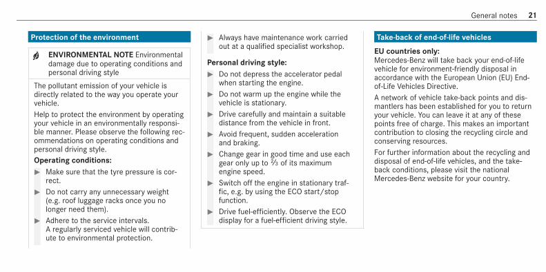
Protection of the environment
+ ENVIRONMENTAL NOTE Environmentaldamage due to operating conditions andpersonal driving style
The pollutant emission of your vehicle isdirectly related to the way you operate yourvehicle.Help to protect the environment by operatingyour vehicle in an environmentally responsi‐ble manner. Please observe the following rec‐ommendations on operating conditions andpersonal driving style.Operating conditions:# Make sure that the tyre pressure is cor‐
rect.# Do not carry any unnecessary weight
(e.g. roof luggage racks once you nolonger need them).
# Adhere to the service intervals.A regularly serviced vehicle will contrib‐ute to environmental protection.
# Always have maintenance work carriedout at a qualified specialist workshop.
Personal driving style:# Do not depress the accelerator pedal
when starting the engine.# Do not warm up the engine while the
vehicle is stationary.# Drive carefully and maintain a suitable
distance from the vehicle in front.# Avoid frequent, sudden acceleration
and braking.# Change gear in good time and use each
gear only up toÔ of its maximumengine speed.
# Switch off the engine in stationary traf‐fic, e.g. by using the ECO start/stopfunction.
# Drive fuel-efficiently. Observe the ECOdisplay for a fuel-efficient driving style.
Take-back of end-of-life vehicles
EU countries only:Mercedes-Benz will take back your end-of-lifevehicle for environment-friendly disposal inaccordance with the European Union (EU) End-of-Life Vehicles Directive.A network of vehicle take-back points and dis‐mantlers has been established for you to returnyour vehicle. You can leave it at any of thesepoints free of charge. This makes an importantcontribution to closing the recycling circle andconserving resources.For further information about the recycling anddisposal of end-of-life vehicles, and the take-back conditions, please visit the nationalMercedes-Benz website for your country.
General notes 21
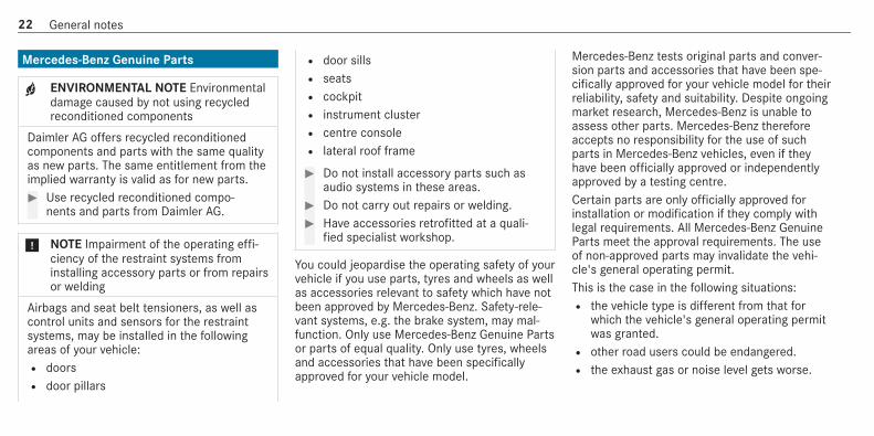
Mercedes-Benz Genuine Parts
+ ENVIRONMENTAL NOTE Environmentaldamage caused by not using recycledreconditioned components
Daimler AG offers recycled reconditionedcomponents and parts with the same qualityas new parts. The same entitlement from theimplied warranty is valid as for new parts.# Use recycled reconditioned compo‐
nents and parts from Daimler AG.
* NOTE Impairment of the operating effi‐ciency of the restraint systems frominstalling accessory parts or from repairsor welding
Airbags and seat belt tensioners, as well ascontrol units and sensors for the restraintsystems, may be installed in the followingareas of your vehicle:R doorsR door pillars
R door sillsR seatsR cockpitR instrument clusterR centre consoleR lateral roof frame
# Do not install accessory parts such asaudio systems in these areas.
# Do not carry out repairs or welding.# Have accessories retrofitted at a quali‐
fied specialist workshop.
You could jeopardise the operating safety of yourvehicle if you use parts, tyres and wheels as wellas accessories relevant to safety which have notbeen approved by Mercedes-Benz. Safety-rele‐vant systems, e.g. the brake system, may mal‐function. Only use Mercedes-Benz Genuine Partsor parts of equal quality. Only use tyres, wheelsand accessories that have been specificallyapproved for your vehicle model.
Mercedes-Benz tests original parts and conver‐sion parts and accessories that have been spe‐cifically approved for your vehicle model for theirreliability, safety and suitability. Despite ongoingmarket research, Mercedes-Benz is unable toassess other parts. Mercedes-Benz thereforeaccepts no responsibility for the use of suchparts in Mercedes-Benz vehicles, even if theyhave been officially approved or independentlyapproved by a testing centre.Certain parts are only officially approved forinstallation or modification if they comply withlegal requirements. All Mercedes-Benz GenuineParts meet the approval requirements. The useof non-approved parts may invalidate the vehi‐cle's general operating permit.This is the case in the following situations:R the vehicle type is different from that for
which the vehicle's general operating permitwas granted.R other road users could be endangered.R the exhaust gas or noise level gets worse.
22 General notes

Always specify the vehicle identification number(VIN) (/ page 512) when ordering Mercedes-Benz Genuine Parts.
Owner's ManualThis Owner's Manual describes all models andall standard and optional equipment available foryour vehicle at the time of this Owner's Manualgoing to press. Country-specific differences arepossible. Note that your vehicle may not be fit‐ted with all features described. This is also thecase for systems and functions relevant tosafety. Therefore, the equipment on your vehiclemay differ from that in the descriptions and illus‐trations.The original purchase agreement for your vehiclecontains a list of all of the systems in your vehi‐cle.Should you have any questions concerningequipment and operation, please consult aMercedes-Benz Service Centre.The Owner's Manual and Service Booklet areimportant documents and should be kept in thevehicle.
Operating safety
& WARNING Risk of accident due to mal‐functions or system failures
If you do not have the prescribed service/maintenance work or any required repairscarried out, this could result in malfunctionsor system failures.# Always have the prescribed service/
maintenance work as well any requiredrepairs carried out at a qualified spe‐cialist workshop.
& WARNING Risk of accident and injury asa result of incorrect modifications toelectronic component parts
Modification to electronic components, theirsoftware or wiring could impair their functionand/or the function of other networked com‐ponent parts. In particular, systems relevantto safety could also be affected.
As a result, they may no longer function asintended and/or endanger the operatingsafety of the vehicle.# Never tamper with the wiring and elec‐
tronic component parts or their soft‐ware.
# You should have all work on electricaland electronic components carried outat a qualified specialist workshop.
If you modify the on-board electronics, the gen‐eral operating permit is rendered invalid.Observe the "On-board electronics" section in"Technical data".
& WARNING Risk of fire due to flammablematerials on hot parts of the exhaustsystem
Flammable material such as leaves, grass ortwigs may ignite if they come into contactwith hot parts of the exhaust system.
General notes 23

# When driving on unpaved roads or off-road, regularly check the vehicle under‐side.
# Remove trapped plants or other flam‐mable material, in particular.
# If there is damage, consult a qualifiedspecialist workshop immediately.
* NOTE Damage to the vehicle
In the following situations, in particular, thereis a risk of damage to the vehicle:R the vehicle becomes grounded, e.g. on a
high kerb or an unpaved roadR the vehicle is driven too fast over an
obstacle, e.g. a kerb, speed bump or pot‐holeR a heavy object strikes the underbody or
chassis components
In situations such as this, the body, theunderbody, chassis components, wheels ortyres could be damaged without the damagebeing visible. Components damaged in this
way can unexpectedly fail or, in the case ofan accident, may not absorb the loads thatarise as intended.If the underbody panelling is damaged, flam‐mable materials such as leaves, grass ortwigs can collect between the underbody andthe underbody panelling. These materialsmay ignite if they come into contact with hotparts on the exhaust system.# Have the vehicle checked and repaired
immediately at a qualified specialistworkshop.
or# If driving safety is impaired while con‐
tinuing your journey, pull over and stopthe vehicle immediately in accordancewith the traffic conditions, and contacta qualified specialist workshop.
Declaration of ConformityElectromagnetic compatibility
The electromagnetic compatibility of the vehiclecomponents has been checked and certifiedaccording to the currently valid version of Regu‐lation UN R10.
Wireless vehicle components
The following information applies to all compo‐nents of the vehicle and the information systemsand communication devices integrated into thevehicle that receive and/or transmit radiowaves:The components of this vehicle that receiveand/or transmit radio waves are compliant withthe basic requirements and all other relevantconditions of Directive 2014/53/EU. You canobtain further information from a Mercedes-BenzService Centre.Below are the addresses of the manufacturers ofwireless components. The addresses cannot bedisplayed on the equipment due to its size ortype.
24 General notes

Tyre pressure monitoring sensorsSchrader Electronics Ltd, 11 Technology Park,Belfast Road, Antrim BT41 1QS, Northern Ireland
Remote locking systemMarquardt GmbH, Schloßstraße 16, 78604 Rie‐theim, GermanyHuf Hülsbeck & Fürst GmbH & Co. KG, SteegerStraße 17, 42551 Velbert, GermanyHella KGaA Hueck & Co., Rixbecker Straße 75,59552 Lippstadt, Germany
Remote locking system control unitMarquardt GmbH, Schloßstraße 16, 78604 Rie‐theim, GermanyLeopold Kostal GmbH & Co. KG, Hauert 11,44227 Dortmund, GermanyContinental Automotive GmbH, Siemens‐straße 12, 93055 Regensburg, Germany
Aerial modulesHirschmann Car Communication GmbH,Stuttgarter Straße 45-51, 72654 Neckartenzlin‐gen, Germany
Kathrein Automotive GmbH & Co. KG, Römer‐ring 1, 31137 Hildesheim, Germany
Door handles with near-field communicationfunctionHuf Hülsbeck & Fürst GmbH & Co. KG, SteegerStraße 17, 42551 Velbert, Germany
Garage door openerGenteX Corporation, 600 North CentennialStreet, Zeeland MI 49464, USA
Sensor for interior motion sensorMETA Systems, Via Galimberti 9, 42124 ReggioEmilia, Italy
Radar sensorsAutoliv Electronics ASP Inc., 26545 AmericanDrive, Southfield, MI 48034, USAADC Automotive Distance Control SystemsGmbH, Peter-Dornier-Straße 10, 88131 Lindau,GermanyRobert Bosch GmbH, Daimlerstraße 6,71229 Leonberg, Germany
Mobile communication and telematicsHarman Becker Automotive Systems GmbH,Postfach 2260, 76303 Karlsbad, GermanyPanasonic Automotive & Industrial SystemsEurope GmbH, Robert-Bosch-Straße 27-29,63225 Langen, GermanyMitsubishi Electric Corporation, 2-3-33 Miwa,Sanda-City, 669-1513 Hyogo, Japan
Wireless headphonesHarman Becker Automotive Systems GmbH,Postfach 2260, 76303 Karlsbad, Germany
Remote controlRuwido Austria GmbH, Köstendorfer Straße 8,5202 Neumarkt, AustriaValeo, 43 rue Bayen, 75017 Paris, France
Remote control heater booster functionDigades GmbH, Äußere Weberstraße 20,02763 Zittau, Germany
Wireless applications in the vehicleBesides the typical frequencies for mobile com‐munications, Mercedes-Benz vehicles use thefollowing wireless applications.
General notes 25

Wireless applications in the vehicle
Frequency range Technology Transmission output/magnetic fieldstrength
20 kHz (9–90 kHz) Remote locking system ≤ 72 dBμA/m at 10 m
125 kHz (119–135 kHz) Remote locking system ≤ 42 dBμA/m at 10 m
13.553–13.567 MHz Near-field communication ≤ 42 dBμA/m at 10 m
433 MHz (433.05–434.79 MHz) Remote locking system, garage door opener,tyre pressure monitoring system
≤ 10 mW e.r.p.
868 MHz (868.0–868.6 MHz) Remote control heater booster function, garagedoor opener
≤ 25 mW e.r.p.
869 MHz (868.7–869.2 MHz) Remote control heater booster function, garagedoor opener
≤ 25 mW e.r.p.
2.4 GHz ISM band (2400–2483.5 MHz) Bluetooth®, Kleer, RLAN, remote controls, wire‐less headphones
≤ 100 mW e.i.r.p.
5.8 GHz UNII-3 (5725–5875 MHz) Sensor for interior motion sensor, RLAN ≤ 25 mW e.i.r.p.
24.05–24.25 GHz* 24 GHz ISM radar ≤ 100 mW e.i.r.p.
26 General notes

Frequency range Technology Transmission output/magnetic fieldstrength
24.25–26.65 GHz* 24 GHz UWB radar ≤ -41.3 dBm/MHz e.i.r.p. mean ≤ 0 dBm/50 MHz peak e.i.r.p.
76–77 GHz 76 GHz radar ≤ 55 dBm peak e.i.r.p.
* Model series launched on the market beforeApril 2016.
Jack
Copy and translation of the original declarationof conformity:EC declaration of conformity1.The signatory, as a representativeManufacturer:BRANO a.s.74741 Hradec nad Moravicí, Opavská 1000,Czech RepublicID No.: 64-387-5933
VAT Reg. No.: CZ64-387-5933declares, as our sole responsibility, that theproduct:2. a)Designation:JackType, number:A) A 164 580 02 18, A 166 580 01 18B) A 240 580 00 18C) A 639 580 02 18Year of manufacture: 2015Fulfils all relevant conditions
Directive No. 2006/42/ECb)Description and purpose of use:The jack is only intended for raising the specifiedvehicle in accordance with the operating instruc‐tions affixed to the jack.3.Reference data of the harmonised standards orspecificationsA) ISO 4063, EN ISO 14341-A, DBL 7382.20,MBN 10435, AS 2693
General notes 27

B) ISO 4063, ISO 14341-A, DBL 7392.10, MBN10435C) DBL 7392.10, DBL 8230.10The technical documentation of the product isstored at the manufacturer's plant. Representa‐tive for the compilation of the technical docu‐mentation: Director of the Technical DepartmentBrano a.s.4.Hradec nad MoravicíCity5.05.05.2015DateSigned byDirector of Quality
TIREFIT kit
Copy and translation of the original declarationof conformity:EC declaration of conformity
In accordance with EC Directive 2006/42/ECWe hereby declare that the productProduct designation: Daimler electric air pumpModel designation: 0851ve, DT/UW 200046MB part no.: A 000 583 8200complies with the following relevant regulations:2004/108/ECApplied harmonised standards, in particular:DIN EN 55014-1DIN EN 55014-2:2009-06Manufacturer: Dunlop Tech GmbHAddress: Birkenhainerstrasse 77, 63450 Hanau,GermanyAuthorised representative: IMS dept.Date: June 2015Signature: IMS-AM, IMS-AE-L
Diagnostics connectionThe diagnostics connection is only intended forthe connection of diagnostic devices at a quali‐fied specialist workshop.
& WARNING Risk of accident due to con‐necting devices to the diagnostics con‐nection
If you connect equipment to a diagnosticsconnection in the vehicle, it may affect theoperation of vehicle systems.As a result, the operating safety of the vehi‐cle could be affected.# Only connect equipment to a diagnos‐
tics connection in the vehicle which isapproved for your vehicle by Mercedes-Benz.
& WARNING Risk of accident due toobjects in the driver's footwell
Objects in the driver's footwell may impedepedal travel or block a depressed pedal.
28 General notes

This jeopardises the operating and roadsafety of the vehicle.# Stow all objects in the vehicle securely
so that they cannot get into the driver'sfootwell.
# Always fit the floor mats securely andas prescribed in order to ensure thatthere is always sufficient room for thepedals.
# Do not use loose floor mats and do notplace floor mats on top of one another.
* NOTE Battery discharging from usingdevices connected to the diagnosticsconnection
Using devices at the diagnostics connectiondrains the battery.# Check the charge level of the battery.# If the charge level is low, charge the
battery, e.g. by driving a considerabledistance.
Connecting equipment to the diagnostics con‐nection can lead to emissions monitoring infor‐mation being reset, for example. This may leadto the vehicle failing to meet the requirements ofthe next emissions inspection during the maininspection.
Qualified specialist workshopA qualified specialist workshop has the neces‐sary special skills, tools and qualifications tocorrectly carry out any necessary work on yourvehicle. This particularly applies to safety-rele‐vant works.Always have the following work carried out onyour vehicle at a qualified specialist workshop:R safety-relevant worksR service and maintenance workR repair workR modifications as well as installations and
conversionsR work on electronic components
Mercedes‑Benz recommends a Mercedes‑Benzservice centre.
Vehicle registrationMercedes-Benz may ask its service centres tocarry out technical inspections on certain vehi‐cles. The quality or safety of the vehicle isimproved as a result of the inspection.Mercedes-Benz can only inform you about vehi‐cle checks if Mercedes-Benz has your registra‐tion data.It is possible that your vehicle has not yet beenregistered in your name in the following cases:R if your vehicle was not purchased at an
authorised specialist dealer.R if your vehicle has not yet been examined at
a Mercedes-Benz service centre.
It is advisable to register your vehicle with aMercedes-Benz service centre.Inform Mercedes-Benz as soon as possibleabout any change in address or vehicle owner‐
General notes 29

ship. You can do this at a Mercedes-Benz servicecentre, for example.
Correct use of the vehicleIf you remove any warning stickers, you or otherscould fail to recognise certain dangers. Leavewarning stickers in position.Observe the following information in particularwhen driving your vehicle:R the safety notes in this manualR technical data for the vehicleR traffic rules and regulationsR laws and safety standards pertaining to
motor vehicles
Information on the REACH regulationEU and EFTA countries only:The REACH Regulation (Regulation (EC) No.1907/2006, Article 33) stipulates an informa‐tion obligation for substances of very high con‐cern (SVHC).
Daimler AG is acting to the best of its knowledgeto avoid the use and application of these SVHCsand to enable the customer to handle thesessubstances safely. According to supplier infor‐mation and internal product information ofDaimler AG, SVHCs are known which are morethan 0.1 percent by weight in individual productsof this vehicle.Further information can be found at:R http://www.daimler.com/reachR http://www.daimler.com/reach/en
Implied warranty
* NOTE Damage to the vehicle arisingfrom violation of these operating instruc‐tions.
Damage to the vehicle can arise from viola‐tion of these operating instructions.This damage is not covered either by theMercedes-Benz implied warranty or by theNew‑ or Used-Vehicle Warranty.
# Follow the instructions in these operat‐ing instructions on proper operation ofyour vehicle as well as on possible vehi‐cle damage.
QR code for rescue cardThe QR code is secured in the fuel filler flap andon the opposite side on the B-pillar. In the eventof an accident, rescue services can use the QRcode to quickly find the appropriate rescue cardfor your vehicle. The current rescue card con‐tains the most important information about yourvehicle in a compact form, e.g. the routing of theelectric lines.Further information can be obtained at http://www.mercedes-benz.de/qr-code.
Data storageElectronic control units
Electronic control units are fitted in your vehicle.Some of these are necessary for the safe opera‐tion of your vehicle, while some assist you when
30 General notes

driving (driver assistance systems). In addition,your vehicle provides comfort and entertainmentfunctions, which are also made possible by elec‐tronic control units.Electronic control units contain data memorieswhich can temporarily or permanently storetechnical information about the vehicle's operat‐ing state, component loads, maintenancerequirements and technical events or faults.In general, this information documents the stateof a component part, a module, a system or thesurroundings such as:R operating status of system components (e.g.
fill levels, battery status, tyre pressure)R status messages concerning the vehicle or
its individual components (e.g. number ofwheel revolutions/speed, longitudinal accel‐eration, lateral acceleration, display of fas‐tened seat belts)R malfunctions or faults in important system
components (e.g. lights, brakes)R information on events leading to vehicle
damage
R system reactions in special driving situations(e.g. airbag deployment, intervention of sta‐bility control systems)R ambient conditions (e.g. temperature, rain
sensor)
In addition to providing the actual control unitfunction, this data assists the manufacturer indetecting and rectifying faults and optimisingvehicle functions. The majority of this data istemporary and is only processed in the vehicleitself. Only a small portion of the data is storedin the event or fault memory.When your vehicle is serviced, technical datafrom the vehicle can be read out by service net‐work employees (e.g. workshops, manufactur‐ers) or third parties (e.g. breakdown services).Services include repair services, maintenanceprocesses, warranty claims and quality assur‐ance measures, for example. The read out is per‐formed via the legally prescribed port for thediagnostics connection in the vehicle. Therespective service network locations or thirdparties collect, process and use the data. Theydocument technical statuses of the vehicle,
assist in finding faults and improving quality andare transmitted to the manufacturer, if neces‐sary. Furthermore, the manufacturer is subjectto product liability. For this, the manufacturerrequires technical data from vehicles.Fault memories in the vehicle can be reset by aservice outlet as part of repair or maintenancework.Depending on the selected equipment, you canimport data into the vehicle's comfort and info‐tainment functions yourself.This includes, for example:R multimedia data such as music, films or pho‐
tos for playback in an integrated multimediasystemR address book data for use in connection with
an integrated hands-free system or an inte‐grated navigation systemR entered navigation destinationsR data about the use of Internet services
This data can be saved locally in the vehicle or itis located on a device which you have connectedto the vehicle (e.g. smartphone, USB flash drive
General notes 31

or MP3 player). If this data is stored in the vehi‐cle, you can delete it at any time. This data issent to third parties only at your request, partic‐ularly when you use online services in accord‐ance with the settings that you have selected.You can store or change convenience settings/individualisations in the vehicle at any time.Depending on the equipment, this includes, forexample:R settings for the seat and steering wheel posi‐
tionsR suspension and climate control settingsR customisations such as interior lighting
If your vehicle is accordingly equipped, you canconnect your smartphone or another mobile enddevice to the vehicle. You can control this bymeans of the control elements integrated in thevehicle. Images and audio from the smartphonecan be output via the multimedia system. Cer‐tain information is simultaneously transferred toyour smartphone.
Depending on the type of integration, this caninclude:R general vehicle dataR position data
This allows you to use selected apps on yoursmartphone, such as navigation or music play‐back. There is no further interaction between thesmartphone and the vehicle; in particular, vehi‐cle data is not directly accessible. Which type offurther data processing occurs is determined bythe provider of the specific app used. Which set‐tings you can make, if any, depends on the spe‐cific app and the operating system of yoursmartphone.
Online services
Wireless network connectionIf your vehicle has a wireless network connec‐tion, it enables data to be exchanged betweenyour vehicle and additional systems. The wire‐less network connection is enabled via the vehi‐cle's transmission and reception unit or via con‐nected mobile end devices (e.g. smartphones).
Online functions can be used via the wirelessnetwork connection. This includes online serv‐ices and applications/apps provided by the man‐ufacturer or other providers.
Manufacturer's servicesRegarding online services of the manufacturer,the individual functions are described by themanufacturer in a suitable place (e.g. Owner'sManual, website of the manufacturer) along withthe relevant data protection information. Per‐sonal data may be used for the provision ofonline services. Data is exchanged via a secureconnection, e.g. the manufacturer's designatedIT systems. Personal data is collected, pro‐cessed and used via the provision of servicesexclusively on the basis of legal permissions orwith prior consent.The services and functions (sometimes subjectto a fee) can usually be activated or deactivated.In some cases, this also applies to the entirevehicle's data connection. This excludes, in par‐ticular, legally prescribed functions and services.
32 General notes

Third party servicesIf it is possible to use online services from otherproviders, these services are subject to the dataprotection and terms of use of the responsibleprovider. The manufacturer has no influence onthe content exchanged.Please enquire, therefore, about the type, scopeand purpose of the collection and use of per‐sonal data as part of third party services fromtheir respective provider.
CopyrightInformation on free and open-source softwarelicences for your vehicle's software can be foundon the data storage medium in your vehicledocument wallet and on the Internet togetherwith updates at:http://www.mercedes-benz.com/opensource
General notes 33

Restraint systemProtection by the restraint system
The restraint system includes the following com‐ponents:R Seat belt systemR AirbagsR Child restraint systemR Child seat securing systems
The restraint system can help prevent the vehi‐cle occupants from coming into contact withparts of the vehicle interior in the event of anaccident. In the event of an accident, therestraint system can also reduce the forces towhich the vehicle occupants are subjected.A seat belt can only provide the best level of pro‐tection if it is worn correctly. Depending on thedetected accident situation, seat belt tensionersand/or airbags supplement the protectionoffered by a correctly worn seat belt. Seat belttensioners and/or airbags are not deployed inevery accident.
In order for the restraint system to provide theintended level of protection, each vehicle occu‐pant must observe the following information:R Fasten seat belts correctly.R Sit in an almost upright seat position with
their back against the seat backrest.R Sit with their feet resting on the floor, if pos‐
sible.R Always secure persons under 1.50 m tall in
an additional restraint system suitable forMercedes-Benz vehicles.
However, no system available today can com‐pletely eliminate injuries and fatalities in everyaccident situation. In particular, the seat beltand airbag generally do not protect againstobjects penetrating the vehicle from the outside.It is also not possible to completely rule out therisk of injury caused by the airbag deploying.
Limited protection from the restraint system
& WARNING Risk of injury or death frommodifications to the restraint system
The restraint system can no longer functioncorrectly after alterations have been made.The restraint system may then not protectthe vehicle occupants as intended by failingin an accident or triggering unexpectedly, forexample# Never alter the parts of the restraint
system.# Never tamper with the wiring or any
electronic component parts or theirsoftware.
If it is necessary to adjust the vehicle to accom‐modate a person with disabilities, contact aqualified specialist workshop.Mercedes-Benz recommends that you only usedriving aids which have been approved specifi‐cally for your vehicle by Mercedes-Benz.
34 Occupant safety

Restraint system functionality
When the ignition is switched on, a self-test isperformed, during which the 6 restraint sys‐tem warning lamp lights up. It goes out no laterthan a few seconds after the vehicle is started.The components of the restraint system are thenfunctional.
Malfunctioning restraint system
A malfunction has occurred in the restraint sys‐tem if:R the 6 restraint system warning lamp does
not light up when the ignition is switched onR the 6 restraint system warning lamp
lights up continuously or repeatedly during ajourney
& WARNING Risk of injury due to malfunc‐tions in the restraint system
If the restraint system is malfunctioning,restraint system components may be trig‐gered unintentionally or may not deploy as
intended during an accident. This may affectthe seat belt tensioner or airbag, for exam‐ple.# Have the restraint system checked and
repaired immediately at a qualified spe‐cialist workshop.
Function of the restraint system in an acci‐dent
How the restraint system works is determined bythe severity of the impact detected and the typeof accident anticipated:R Frontal impactR Rear impactR Side impactR Only for certain countries: rollover
The activation thresholds for the components ofthe restraint system are determined based onthe evaluation of the sensor values measured atvarious points in the vehicle. This process is pre-emptive in nature. The triggering/deployment ofthe components of the restraint system must
take place in good time at the start of the colli‐sion.Factors which can only be seen and measuredafter a collision has occurred do not play a deci‐sive role in the deployment of an airbag. Nor dothey provide an indication of airbag deployment.The vehicle may be deformed significantly with‐out an airbag being deployed. This is the case ifonly parts which are relatively easily deformedare affected and the rate of vehicle decelerationis not high. Conversely, an airbag may bedeployed even though the vehicle suffers onlyminor deformation. If very rigid vehicle partssuch as longitudinal members are hit, for exam‐ple, this may result in sufficiently high levels ofvehicle deceleration.
Occupant safety 35

The components of the restraint system canbe activated or deployed independently ofeach other:
Component Detected deploy‐ment situation
Seat belt tensioners Frontal impact, rearimpact, side impact,rollover1)
Driver's airbag, frontpassenger front air‐bag
Frontal impact
Knee airbag Frontal impact
Side impact airbag Side impact
Window airbag Side impact, roll‐over1), frontal impact
1) Only for certain countries.The front passenger front airbag can only bedeployed in an accident if the PASSENGER AIRBAG OFF indicator lamp is off. If the frontpassenger seat is occupied, make sure, both
before and during the journey, that the status ofthe front passenger front airbag is correct(/ page 46).
& WARNING Rick of burns from hot airbagcomponents
The airbag parts are hot after an airbag hasbeen deployed.# Do not touch the airbag parts.# Have a deployed airbag replaced at a
qualified specialist workshop as soonas possible.
Mercedes-Benz recommends that you have thevehicle towed to a qualified specialist workshopafter an accident. Take this into account, partic‐ularly if a seat belt tensioner is triggered or anairbag deployed.If the seat belt tensioners are triggered or an air‐bag is deployed, you will hear a bang, and asmall amount of powder may also be released:R The bang will not generally affect your hear‐
ing.
R In general, the powder released is not haz‐ardous to health but may cause short-termbreathing difficulties to persons sufferingfrom asthma or other pulmonary conditions.Provided it is safe to do so, leave the vehicleimmediately or open the window in order toprevent breathing difficulties.
Seat beltsProtection provided by the seat belt
Always fasten your seat belt correctly beforestarting a journey. A seat belt can only providethe best level of protection if it is worn correctly.
& WARNING Risk of injury or death due toincorrectly fastened seat belt
If the seat belt is not worn correctly, it can‐not perform its intended protective function.In addition, an incorrectly fastened seat beltcan also cause injuries, for example, in theevent of an accident or when braking orchanging direction suddenly.
36 Occupant safety

# Always ensure that all vehicle occu‐pants have their seat belts fastenedcorrectly and are sitting properly.
Always observe the instructions about the cor‐rect driver's seat position and adjusting theseats (/ page 100).In order for the correctly worn seat belt to pro‐vide the intended level of protection, each vehi‐cle occupant must observe the following infor‐mation:R The seat belt must not be twisted and must
fit tightly and snugly across the body.R The seat belt must be routed across the
centre of the shoulder and as low downacross the hips as possible.R The shoulder section of the seat belt should
not touch your neck nor be routed underyour arm or behind your back.R Avoid wearing bulky clothing, e.g. a winter
coat.R Push the lap belt down as far as possible
across your hips and pull tight with the shoul‐
der section of the belt. Never route the lapbelt across your abdomen.Pregnant women must also take particularcare with this.R Never route the seat belt across sharp, poin‐
ted, abrasive or fragile objects.R Only one person may use each seat belt at
any one time. Infants and children mustnever travel sitting on the lap of a vehicleoccupant.R Never secure objects with a seat belt if the
seat belt is being used by one of the vehi‐cle's occupants. Always observe the instruc‐tions for loading the vehicle when securingobjects, luggage or loads (/ page 110).Also ensure that no objects, e.g. a cushion,are ever placed between a person and theseat.
If children are travelling in the vehicle, be sure toobserve the instructions and safety notes on"Children in the vehicle" (/ page 51).
Limitations of the protection provided by theseat belt
& WARNING Risk of injury or death due toincorrect seat position
The seat belt does not offer the intendedlevel of protection if you have not moved theseat backrest to an almost vertical position.When braking or in the event of an accident,you could slide underneath the seat belt andsustain abdominal or neck injuries, for exam‐ple.# Adjust the seat properly before begin‐
ning your journey.# Always ensure that the seat backrest is
in an almost vertical position and thatthe shoulder section of your seat belt isrouted across the centre of your shoul‐der.
Occupant safety 37

& WARNING Risk of injury or death whenadditional restraint systems are not usedfor persons with a smaller build
Persons under 1.50 m tall cannot wear theseat belt correctly without a suitable addi‐tional restraint system.If the seat belt is not worn correctly, it can‐not perform its intended protective function.In addition, an incorrectly fastened seat beltcan also cause injuries, for example, in theevent of an accident or when braking orchanging direction suddenly.# Always secure persons under 1.50 m
tall in a suitable restraint system.
& WARNING Risk of injury or death due todamaged or modified seat belts
Seat belts cannot provide protection in thefollowing situations:R the seat belt is damaged, has been modi‐
fied, is extremely dirty, bleached or dyed
R the seat belt buckle is damaged orextremely dirtyR modifications have been made to the seat
belt tensioner, seat belt anchorage orseat belt retractor
Seat belts may sustain non-visible damage inan accident, e.g. due to glass splinters.Modified or damaged seat belts could tear orfail in the event of an accident, for example.Modified belt tensioners may be deployedunintentionally or not function as intended.# Never modify the seat belts, seat belt
tensioners, seat belt anchorages orseat belt retractors.
# Make sure that the seat belts are notdamaged, are not worn and are clean.
# Always have the seat belts checkedimmediately after an accident at aqualified specialist workshop.
Mercedes-Benz recommends that you only useseat belts that have been approved for your vehi‐cle by Mercedes-Benz.
The sport seat is designed for the standardthree-point seat belt. If you fit a different multi‐point seat belt, e.g. sport or racing seat belt, therestraint system cannot provide the intendedlevel of protection.Depending on the type of seat, there may beopenings in the seat backrest. These openingshave no function.
& WARNING Risk of injury or fatal injurydue to modified seat belt systems
If you feed seat belts through the opening inthe seat backrest, the seat backrest may bedamaged or may even break in the event ofan accident.# Only use the standard three-point seat
belt.# Never modify the seat belt system.
38 Occupant safety

& WARNING Risk of injury or death fromdeployed pyrotechnic seat belt tension‐ers
Pyrotechnic seat belt tensioners that havebeen deployed are no longer operational andare unable to perform their intended protec‐tive function.# Therefore, have deployed pyrotechnic
seat belt tensioners immediatelyreplaced at a qualified specialist work‐shop.
Mercedes-Benz recommends that you have thevehicle towed to a qualified specialist workshopafter an accident.
* NOTE Damage caused by trapping theseat belt
If an unused seat belt is not fully retracted, itmay become trapped in the door or in theseat mechanism.# Always ensure that an unused seat belt
is fully retracted.
Fastening seat belts
If the seat belt is pulled quickly or sharply, theseat belt retractor locks. The seat belt strap can‐not be pulled out any further.
# Always engage seat belt tongue2 of theseat belt into seat belt buckle1 of the cor‐responding seat.
Vehicles with automatic front passengerfront airbag shutoff:
* NOTE Deployment of the seat belt ten‐sioner and side impact airbag when thefront passenger seat is unoccupied
If the seat belt tongue is engaged in the seatbelt buckle of the unoccupied frontpassenger seat, the seat belt tensioner andthe side impact airbag may also deploy in theevent of an accident along with other sys‐tems.# Only one person should use each seat
belt at any one time.
Vehicles without automatic front passengerfront airbag shutoff:
* NOTE Deployment of the seat belt ten‐sioner when the front passenger seat isunoccupied
If the seat belt tongue is engaged in the seatbelt buckle of the unoccupied frontpassenger seat, the seat belt tensioner may
Occupant safety 39
also deploy in the event of an accident alongwith other systems.# Only one person should use each seat
belt at any one time.
Seat belt adjustment function
Vehicles with PRE-SAFE®: if the front seat beltis not pulled tight across your body, the seat beltadjustment may automatically apply a certaintightening force. Do not hold the seat belt tightlywhile it is adjusting.You can activate and deactivate the seat beltadjustment function using the multimedia sys‐tem (/ page 40).
Releasing a seat belt
# Press the release button in the seat beltbuckle and guide the seat belt back with theseat belt tongue.
Activating/deactivating seat belt adjustmentvia the multimedia system
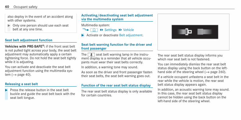
Multimedia system:4© 5 Settings 5 Vehicle# Activate or deactivate Belt adjustment.
Seat belt warning function for the driver andfront passenger
The ü seat belt warning lamp in the instru‐ment display is a reminder that all vehicle occu‐pants must wear their seat belts correctly.In addition, a warning tone may sound.As soon as the driver and front passenger fastentheir seat belts, the seat belt warning goes out.
Function of the rear seat belt status display
The rear seat belt status display is only availablefor certain countries.
The rear seat belt status display informs youwhich rear seat belt is not fastened.You can immediately dismiss the rear seat beltstatus display using the back button on the left-hand side of the steering wheel (/ page 260).If a vehicle occupant unfastens a seat belt in therear while the vehicle is motion, the rear seatbelt status display appears again.In addition, an acoustic warning tone may sound.In this case, the rear seat belt status displaycannot be hidden using the back button on theleft-hand side of the steering wheel.
40 Occupant safety

AirbagsOverview of airbags
1 Knee airbag2 Driver's airbag3 Front passenger front airbag4 Window airbag5 Side impact airbag
The installation location of an airbag is identifiedby the AIRBAG symbol.When enabled, an airbag can provide additionalprotection for the respective vehicle occupant.
Potential protection from each airbag:
AIRBAG Potential protection for:
Knee airbag Thigh, knee and lower leg
Driver's airbag,front passengerfront airbag
Head and ribcage
Window airbag Head
Side impact air‐bag
Ribcage and pelvis
Mercedes-AMG vehicles: observe the notes inthe Supplement. Otherwise, you may fail to rec‐ognise dangers.
& WARNING Risk of injury or fatal injuriesif the front passenger airbag is enabled
If the front passenger front airbag is enabled,a child on the front passenger seat may bestruck by the front passenger airbag duringan accident.
NEVER use a rearward-facing child restraintsystem on a seat with an ENABLED FRONTAIRBAG, DEATH or SERIOUS INJURY to theCHILD can occur.
When fitting a child restraint system to the frontpassenger seat, observe the vehicle-specificinformation (/ page 71). Also, always observethe notes on rearward-facing or forward-facingchild restraint systems on the front passengerseat.Vehicles with automatic front passengerfront airbag shutoff:The front passenger front airbag can only bedeployed in an accident if the PASSENGER AIRBAG OFF indicator lamp is off. If the frontpassenger seat is occupied, make sure, bothbefore and during the journey, that the status ofthe front passenger front airbag is correct(/ page 46).
Occupant safety 41

* NOTE Important points to remember ifthe front passenger seat is unoccupied
In an accident, the components of therestraint system may deploy unnecessarilyon the front passenger side if:R There are heavy objects on the front
passenger seat.R The seat belt tongue is engaged in the
seat belt buckle of the front passengerseat and the front passenger seat isunoccupied.
# Stow objects in a suitable place.# Only one person should use each seat
belt at any one time.
Depending on the detected accident situation,the window airbag on the front passenger sidemay deploy. The airbag is deployed regardless ofwhether the front passenger seat is occupied.
Protection by the airbags
Depending on the accident situation, an airbagmay supplement the protection offered by a cor‐rectly fastened seat belt.
& WARNING Risk of injury or death due toincorrect seat position
If you deviate from the correct seat position,the airbag cannot perform its intended pro‐tective function and deployment may evencause further injuries.In order to avoid risks, each vehicle occupantmust always make sure of the following:R Fasten seat belts correctly. Pregnant
women must take particular care toensure that the lap belt never lies acrossthe abdomen.R Adopt the correct seat position and keep
as far away as possible from the airbags.R Observe the following information.
# Always make sure that there are noobjects between the airbag and vehicleoccupant.
To avoid the risks resulting from the deploymentof an airbag, each vehicle occupant mustobserve the following information in particular:R Before starting your journey, adjust your seat
correctly; the driver's seat and frontpassenger seat should be moved as far backas possible.When doing so, always observe the informa‐tion on the correct driver's seat position(/ page 100).R Only hold the steering wheel by the steering
wheel rim. This allows the airbag to be fullydeployed.R Always lean against the seat backrest when
the vehicle is in motion. Do not lean forwardsor against the door or side window. You mayotherwise be in the deployment area of theairbags.R Always keep your feet on the floor. Do not
put your feet on the cockpit, for example.
42 Occupant safety
Your feet may otherwise be in the deploy‐ment area of the airbag.R If children are travelling in the vehicle,
observe the additional notes (/ page 51).R Always stow and secure objects correctly.
Objects in the vehicle interior may prevent anairbag from functioning correctly. Each vehicleoccupant must always make sure of the follow‐ing in particular:R There are no people, animals or objects
between the vehicle occupants and an air‐bag.R There are no objects between the seat, door
and door pillar (B-pillar).R There are no hard objects, e.g. coat hangers,
hanging on the grab handles or coat hooks.R There are no accessory parts, such as mobile
navigation devices, mobile phones or cupholders, attached to the vehicle within thedeployment area of an airbag, e.g. on thecockpit, on the door, on the side window oron the side wall trim.
In addition, no connecting cables, tensioningstraps or retaining straps must be routed orattached to the vehicle within the deploy‐ment area of an airbag. Always comply withthe accessory manufacturer's installationinstructions and, in particular, the notes onsuitable places for installation.R There are no heavy, sharp-edged or fragile
objects in the pockets of your clothing. Storesuch objects in a suitable place.
Limited protection from airbags
& WARNING Risk of injury due to modifi‐cations to the airbag cover
If you modify the cover of an airbag or affixobjects such as stickers to it, the airbag mayno longer function correctly.# Never modify the cover of an airbag and
do not affix objects to it.
The installation location of an airbag is identifiedby the AIRBAG symbol (/ page 41).
& WARNING Risk of injury or death due tothe use of unsuitable seat covers
Unsuitable seat covers can obstruct or pre‐vent the deployment of the airbags integra‐ted into the seats.Consequently, the airbags cannot protectvehicle occupants as they are designed todo. In addition, the operation of the auto‐matic front passenger airbag shutoff couldbe restricted.# You should only use seat covers that
have been approved for the correspond‐ing seats by Mercedes-Benz.
& WARNING Risk of injury due to malfunc‐tions of the sensors in the door panelling
Sensors to control the airbags are located inthe doors. Modifications or work not per‐formed correctly to the doors or door panel‐ling, as well as damaged doors, can lead tothe function of the sensors being impaired.The airbags might therefore not functionproperly any more.
Occupant safety 43

Consequently, the airbags cannot protectvehicle occupants as they are designed todo.# Never modify the doors or parts of the
doors.# Always have work on the doors or door
panelling carried out at a qualified spe‐cialist workshop.
& WARNING Risk of injury due to deployedairbag
A deployed airbag no longer offers any pro‐tection and cannot provide the intended pro‐tective function in the event of an accident.# Have the vehicle towed to a qualified
specialist workshop in order to have thedeployed airbag replaced.
Have deployed airbags replaced immediately.
Status of the front passenger front airbag
Function of the automatic front passengerfront airbag shutoffThe automatic front passenger front airbag shut‐off is able to detect whether the front passengerseat is occupied by a person or a child restraintsystem. The front passenger front airbag is ena‐bled or disabled accordingly.When fitting a child restraint system to the frontpassenger seat, always make sure of the follow‐ing:R Ensure that the child restraint system is posi‐
tioned correctly (/ page 56).R Always observe the child restraint system
manufacturer's installation instructions.R Never place objects, e.g. cushions, under or
behind the child restraint system.R Fully retract the seat cushion length adjust‐
ment.R The entire base of the child restraint system
must always rest on the sitting surface of thefront passenger seat.
R The backrest of the forward-facing childrestraint system must, as far as possible, beresting on the seat backrest of the frontpassenger seat.R The child restraint system must not touch the
roof or be put under strain by the headrestraints. Adjust the seat backrest inclina‐tion and the head restraint setting accord‐ingly.
& WARNING Risk of injury or death due toobjects between the seat surface andthe child restraint system
Objects between the seat surface and thechild restraint system could affect the func‐tion of the automatic front passenger frontairbag shutoff.This could result in the front passenger frontairbag not functioning as intended during anaccident.# Do not place any objects between the
sitting surface and the child restraintsystem.
44 Occupant safety

# The entire base of the child restraintsystem must always rest on the sittingsurface of the front passenger seat.
# The backrest of the forward-facing childrestraint system must, as far as possi‐ble, be resting on the seat backrest ofthe front passenger seat.
# Always comply with the child restraintsystem manufacturer's installationinstructions.
A person on the front passenger seat mustobserve the following information:R Fasten seat belts correctly (/ page 36).R Sit in an almost upright seat position with
their back against the seat backrest.R Sit with their feet resting on the floor, if pos‐
sible.
The front passenger front airbag may otherwisebe disabled by mistake, for example in the fol‐lowing situations:R The front passenger transfers their weight by
supporting themselves on a vehicle armrest.
R The front passenger sits in such a way thattheir weight is raised from the sitting sur‐face.
& WARNING Risk of injury or death due todeactivated front passenger airbag
If the PASSENGER AIRBAG OFF indicatorlamp is lit, the front passenger airbag is disa‐bled. It will not be deployed in the event ofan accident and cannot perform its intendedprotective function.A person in the front passenger seat couldthen, for example, come into contact withthe vehicle interior, especially if the person issitting too close to the cockpit.If the front passenger seat is occupied,always ensure that:R The classification of the person in the
front passenger seat is correct and thefront passenger airbag is enabled or disa‐bled in accordance with the person in thefront passenger seat.
R The front passenger seat has been movedas far back as possible.R The person is seated correctly.
# Ensure, both before and during the jour‐ney, that the status of the frontpassenger airbag is correct.
If the front passenger seat is occupied, the clas‐sification of the person or child restraint systemon the front passenger seat takes place after thefront passenger front airbag shutoff self-test.The PASSENGER AIR BAG indicator lamps dis‐play the status of the front passenger front air‐bag.Always observe the notes on the function of thePASSENGER AIR BAG indicator lamps(/ page 46).
Occupant safety 45

Function of the PASSENGER AIR BAG indica‐tor lamps
Vehicles without automatic front passenger frontairbag shutoff have a special sticker affixed tothe side of the cockpit on the front passengerside (/ page 70).
Self-test of automatic front passenger frontairbag shutoffWhen the ignition is switched on, a self-test isperformed during which the two PASSENGERAIR BAG ON and OFF indicator lamps light upsimultaneously.The status of the front passenger front airbag isdisplayed after the self-test:R PASSENGER AIR BAG ON lights up for
60 seconds, subsequently both indicatorlamps are off (PASSENGER AIR BAG ON andOFF): the front passenger front airbag is ableto deploy in the event of an accident.R PASSENGER AIR BAG OFF lights up continu‐
ously: the front passenger front airbag is dis‐abled. It will then not be deployed in theevent of an accident.
If the PASSENGER AIR BAG ON indicator lamp isoff, only the PASSENGER AIR BAG OFF indicatorlamp shows the status of the front passengerfront airbag. The PASSENGER AIR BAG OFF indi‐cator lamp may be lit continuously or be off.If the PASSENGER AIR BAG OFF indicator lampand the 6 restraint system warning lamp
light up simultaneously, the front passenger seatmay not be used. Also in this case, do not fit achild restraint system to the front passengerseat. Have automatic front passenger front air‐bag shutoff checked and repaired immediately ata qualified specialist workshop.
Status displayIf the front passenger seat is occupied, ensure,both before and during the journey, that the sta‐tus of the front passenger front airbag is correctfor the current situation.After fitting a rearward-facing child restraintsystem to the front passenger seat:PASSENGER AIR BAG OFF must be lit continu‐ously.
& WARNING Risk of injury or death fromusing a rearward-facing child restraintsystem when the front passenger frontairbag is enabled
If you secure a child in a rearward-facingchild restraint system on the front passengerseat and the PASSENGER AIR BAG OFF indi‐
46 Occupant safety

cator lamp is off, the front passenger airbagcan deploy in the event of an accident.The child could be struck by the airbag.Always ensure that the front passenger air‐bag is disabled. The PASSENGER AIR BAGOFF indicator lamp must be lit.NEVER use a rearward-facing child restraintsystem on a seat protected by an ENABLEDFRONT AIRBAG in front of it, DEATH or SERI‐OUS INJURY to the CHILD can occur.
When fitting a child restraint system to the frontpassenger seat, observe the vehicle-specificinformation (/ page 71).Depending on the child restraint system and thestature of the child, the PASSENGER AIR BAGOFF indicator lamp may be off. In this case, donot fit the rearward-facing child restraint systemto the front passenger seat.Instead, fit the rearward-facing child restraintsystem to a suitable rear seat.After fitting a forward-facing child restraintsystem to the front passenger seat: depend‐ing on the child restraint system and the stature
of the child, PASSENGER AIR BAG OFF may be litcontinuously or be off. Always observe the fol‐lowing information.
& WARNING Risk of injury or death due toincorrect positioning of the forward-facing child restraint system
If you secure a child in a forward-facing childrestraint system on the front passenger seatand you position the front passenger seat tooclose to the dashboard, in the event of anaccident, the child could:R come into contact with parts of the vehi‐
cle's interior if the PASSENGER AIR BAGOFF indicator lamp is lit, for exampleR be struck by the airbag if the PASSENGER
AIR BAG OFF indicator lamp is off
# Always move the front passenger seatas far back as possible and fully retractthe seat cushion length adjustment.Always make sure that the shoulder beltstrap is correctly routed from the seatbelt outlet on the vehicle to the shoul‐der belt guide on the child restraint sys‐
tem. The shoulder belt strap must berouted forwards and downwards fromthe seat belt outlet. If necessary, adjustthe front passenger seat accordingly.
# Always observe the child restraint sys‐tem manufacturer's installation instruc‐tions.
When fitting a child restraint system to the frontpassenger seat, observe the vehicle-specificinformation (/ page 71).If a person is sitting on the front passengerseat: PASSENGER AIR BAG OFF may be lit con‐tinuously or be off, depending on the person'sstature.A person on the front passenger seat mustalways observe the following information:R If the front passenger seat is occupied by an
adult or a person with a stature correspond‐ing to that of an adult, the PASSENGER AIRBAG OFF indicator lamp must be off. Thisindicates that the front passenger front air‐bag is enabled.
Occupant safety 47

If the PASSENGER AIR BAG OFF indicatorlamp is lit continuously, an adult or personwith a build corresponding to that of an adultshould not use the front passenger seat.Instead, they should use a rear seat.R If the front passenger seat is occupied by a
person of smaller stature (e.g. a teenager orsmall adult), the PASSENGER AIR BAG OFFindicator lamp either lights up continuouslyor remains off, depending on the result of theclassification.- If the PASSENGER AIR BAG OFF indicator
lamp is off: move the front passengerseat as far back as possible, or the per‐son of smaller stature should use a rearseat.
- If the PASSENGER AIR BAG OFF indicatorlamp is lit continuously: the person ofsmaller stature should not use the frontpassenger seat.
& WARNING Risk of injury or death whenthe PASSENGER AIR BAG OFF indicatorlamp is lit
If the PASSENGER AIR BAG OFF indicatorlamp remains lit after the system self-test,the front passenger airbag is disabled. It willnot be deployed in the event of an accident.In this case, the front passenger airbag can‐not perform its intended protective function,e.g. when a person is seated in the frontpassenger seat.That person could, for example, come intocontact with the vehicle interior, especially ifthe person is sitting too close to the cockpit.If the front passenger seat is occupied,always ensure that:R The classification of the person in the
front passenger seat is correct and thefront passenger airbag is enabled or disa‐bled in accordance with the person in thefront passenger seat.
R The person is seated properly with a cor‐rectly fastened seat belt.R The front passenger seat has been moved
as far back as possible.
Be sure to also observe the following furtherrelated subjects:R Child restraint system on the front passenger
seat (/ page 71).R Suitable positioning of the child restraint sys‐
tem (/ page 56).
PRE-SAFE® systemPRE-SAFE® (anticipatory occupant protec‐tion)
PRE-SAFE® is able to detect certain critical driv‐ing situations and implement pre-emptive meas‐ures to protect the vehicle occupants.
PRE-SAFE® can implement the following meas‐ures independently of each other:R Tightening the seat belts on the driver's seat
and front passenger seat.
48 Occupant safety

R Closing the side windows.R Vehicles with sliding sunroof: closing the
sliding sunroof.R Vehicles with memory function: moving
the front passenger seat to a more favoura‐ble seat position.R PRE-SAFE® Sound: provided that the multi‐
media system is switched on, generates abrief noise signal to stimulate the innate pro‐tective mechanism of a person's hearing.
* NOTE Damage caused by objects in thefootwell or behind the seat
The automatic adjustment of the seat posi‐tion may result in damage to the seat and/orthe object.# Stow objects in a suitable place.
Reversing the PRE-SAFE® system measures
If an accident did not occur, the pre-emptivemeasures that were taken are reversed.
You will need to perform certain settings your‐self.# If the seat belt pre-tensioning is not reduced,
move the seat backrest back slightly.The locking mechanism releases.
Function of PRE-SAFE® PLUS (anticipatoryoccupant protection plus)
PRE-SAFE® PLUS can detect certain impacts,particularly an imminent rear impact, and takepre-emptive measures to protect the vehicleoccupants. These measures cannot necessarilyprevent an imminent impact.
PRE-SAFE® PLUS can implement the followingmeasures independently of each other:R Tightening the seat belts on the driver's seat
and front passenger seat.R Activating the rear hazard warning lights at a
higher flashing frequency.R Increasing brake pressure when the vehicle
is stationary. This brake application is cancel‐led automatically when the vehicle pullsaway.
If an accident did not occur, the pre-emptivemeasures that were taken are reversed.
System limitationsThe system will not initiate any action in the fol‐lowing situations:R when reversing
orR when the vehicle is towing a trailer and there
is a risk of a rear impact
The system will not initiate any braking applica‐tion in the following situations:R whilst driving
orR when entering or exiting a parking space
while using Active Parking Assist
Occupant safety 49

Safely transporting children in the vehicleAlways observe when children are travellingin the vehicle
% Also strictly observe the safety notes for thespecific situation. In this way you can recog‐nise potential risks and avoid dangers if chil‐dren are travelling in the vehicle(/ page 51).
Be diligentBear in mind that neglecting to secure a child inthe child restraint system may have serious con‐sequences. Always be diligent in securing a childcarefully before every journey.To improve protection for children younger than12 years old or under 1.50 m in height,Mercedes-Benz recommends you observe thefollowing information:R Always secure the child in a child restraint
system suitable for this Mercedes-Benz vehi‐cle.R The child restraint system must be appropri‐
ate to the age, weight and size of the child.
R The vehicle seat must be suitable for fitting achild restraint system (/ page 56).
Accident statistics show that children securedon the rear seats are generally safer than chil‐dren secured on the front seats. For this reason,Mercedes-Benz strongly advises that you fit achild restraint system to a rear seat.
Generic term "child restraint system"The generic term child restraint system is usedin this Owner's Manual. A child restraint systemis, for example:R a baby car seatR a rearward-facing child seatR a forward-facing child seatR a child booster seat with a backrest and seat
belt guideMercedes-Benz recommends using a childbooster seat with a backrest.
The child restraint system must be appropriateto the age, weight and size of the child.
Observing laws and legal requirementsAlways observe the legal requirements whenusing a child restraint system in the vehicle.Make sure that the child restraint system isapproved in accordance with the valid test speci‐fications and guidelines. Further information canbe obtained at a qualified specialist workshop.Mercedes-Benz recommends that you use aMercedes-Benz Service Centre for this purpose.
Only use approved child restraint systemsOnly child restraint systems that meet the fol‐lowing UNECE standards are permitted for use inthe vehicle:R UN-R44R UN-R129 (i-Size child restraint systems)
Information on child restraint system approvalcategories and details on the approval label onthe child restraint system (/ page 57).
50 Occupant safety

Detecting risks, avoiding danger
Securing systems for child restraint systemsin the vehicleOnly use the following securing systems for childrestraint systems:R the ISOFIX or i-Size mounting bracketsR the vehicle's seat belt systemR the Top Tether anchorages
Fitting an ISOFIX or an i-Size child restraint sys‐tem is preferred.Simply attaching to the securing rings on thevehicle can reduce the risk of fitting the childrestraint system incorrectly.When securing a child with the integrated seatbelt of the ISOFIX or i-Size child restraint sys‐tem, always comply with the permissible grossweight for the child and child restraint system(/ page 63).
Advantage of a rearward-facing childrestraint systemIt is preferable to transport a baby or a smallchild in a suitable rearward-facing child restraint
system. In this case, the child sits in the oppo‐site direction to the direction of travel and facesbackwards.Babies and small children have comparativelyweak neck muscles in relation to the size andweight of their head. The risk of injury to the cer‐vical spine during an accident can be reduced ina rearward-facing child restraint system.
Always secure a child restraint system cor‐rectly
& WARNING Risk of injury or death causedby incorrect installation of the childrestraint system
If the child restraint system is incorrectlyinstalled on a suitable seating position, itcannot perform its intended protective func‐tion.The child cannot be restrained in the event ofan accident, heavy braking or a suddenchange of direction.
# Always comply with the manufacturer'sinstallation instructions for the childrestraint system and its correct use.
# Make sure that the entire base of thechild restraint system always rests onthe sitting surface of the seat.
# Never place objects under or behindthe child restraint system, e.g. cush‐ions.
# Always use child restraint systems withthe original cover designed for them.
# Always replace damaged covers withgenuine covers.
& WARNING Risk of injury or death fromunsecured child restraint systems in thevehicle
If the child restraint system is not correctlyinstalled or secured, it could release in theevent of an accident, sudden braking or asudden change in direction.The child restraint system could be flungaround and hit vehicle occupants.
Occupant safety 51

# Always fit child restraint systems cor‐rectly, even when not in use.
# Always comply with the child restraintsystem manufacturer's installationinstructions.
R Always observe the child restraint systemmanufacturer's installation and operatinginstructions as well as the vehicle-specificinformation:- Fit the ISOFIX or i-Size child restraint sys‐
tem to the rear seat (/ page 63).- Secure the child restraint system with the
seat belt on the rear seat (/ page 69).- Secure the child restraint system with the
seat belt on the front passenger seat(/ page 72). Observe the specificinstructions for the rearward-facing andforward-facing child restraint systems(/ page 71).If the front passenger seat is occupied,ensure, both before and during the jour‐ney, that the status of the front
passenger front airbag is correct for thecurrent situation (/ page 46).
R Observe the warning labels in the vehicleinterior and on the child restraint system.R Also secure Top Tether if present.
Do not alter the child restraint system
& WARNING Risk of injury due to altera‐tions to the child restraint system
The child restraint system may no longerfunction as it is supposed to if you makealterations or attach objects to it, e.g. toys orunsuitable accessories. This poses anincreased risk of injury!Never alter the child restraint system. Onlyattach accessories which the manufacturerof the child restraint system has authorisedespecially for this child restraint system.
Mercedes‑Benz recommends Mercedes-Benzcare products for cleaning child restraint sys‐tems recommended by Mercedes-Benz.
Only use child restraint systems which are inproper working condition
& WARNING Risk of injury or death causedby the use of damaged child restraintsystems
Child restraint systems or their retaining sys‐tems that have been subjected to a load inan accident may then not be able to performtheir intended protective function.The child cannot be restrained in the event ofan accident, heavy braking or a suddenchange of direction.# Always replace child restraint systems
immediately that have been damaged orinvolved in an accident.
# Have the securing systems for the childrestraint systems checked at a qualifiedspecialist workshop before installing achild restraint system again.
52 Occupant safety

Avoiding direct sunlight
& WARNING Risk of burns when the childseat is exposed to direct sunlight
If the child restraint system is exposed todirect sunlight or heat, parts could heat up.Children could suffer burns on these parts,particularly on metallic parts of the childrestraint system.# Always make sure that the child
restraint system is not exposed todirect sunlight.
# Protect it with a blanket, for example.# If the child restraint system has been
exposed to direct sunlight, allow it tocool before securing a child into it.
# Never leave children unattended in thevehicle.
Observe when stopping or parking
& WARNING Risk of accident and injurydue to children left unattended in thevehicle
If children are left unattended in the vehicle,they could:R Open doors, thereby endangering other
persons or road users.R Get out and be struck by oncoming traf‐
fic.R Operate vehicle equipment and become
trapped, for example.
In addition, the children could also set thevehicle in motion, for example by:R Releasing the parking brake.R Changing the transmission position.R Starting the vehicle.
# Never leave children unattended in thevehicle.
# When leaving the vehicle, always takethe key with you and lock the vehicle.
# Keep the vehicle key out of reach ofchildren.
This also applies to the Digital Vehicle Key if the"Digital Vehicle Key" function is activated viaMercedes me connect.
& WARNING Risk of fatal injury due toexposure to extreme heat or cold in thevehicle
If people –particularly children – are exposedto extreme temperatures over an extendedperiod of time, there is a risk of serious oreven fatal injury!# Never leave anyone – particularly chil‐
dren – unattended in the vehicle.# Never leave animals in the vehicle unat‐
tended.
Occupant safety 53

Overview of recommended child restraint systems
Further information on the correct child restraint system can be obtained at a qualified specialist workshop. Mercedes-Benz recommends that you usea Mercedes-Benz Service Centre for this purpose.
Securing with ISOFIX
Weight categorySize category
Type1
Type approval numberOrder number2
1 Manufacturer: Britax Römer 2 With colour code 9H95
Category 0+:up to 13 kg and up to approx. 15 monthsSize category E
BABY SAFE plusE1 04 301 146
B6 6 86 8224
Category I:9 to 18 kgSize category B1
DUO plusE1 04 301 133
A 000 970 17 02
54 Occupant safety

Recommended child restraint systems for attaching with the vehicle seat belt
Weight category Type1
Type approval numberOrder number2
1 Manufacturer: Britax Römer 2 With colour code 9H95
Category 0:up to 10 kg and up to approx. 6 months
BABY SAFE plus IIE1 04 301 146
A 000 970 13 02
Category 0+:up to 13 kg and up to approx. 15 months
BABY SAFE plus IIE1 04 301 146
A 000 970 13 02
Category I:9 to 18 kg and from approximately 9 months to4 years
DUO plusE1 04 301 133
A 000 970 17 02
Category II/III:15 to 36 kg and from approximately 4 to 12years
KIDFIXE1 04 301 198
A 000 970 20 02
Category II/III:15 to 36 kg and from approximately 4 to 12years
KIDFIX XPE1 04 301 304
A 000 970 23 02
Occupant safety 55

Overview of suitable seats in the vehicle for fitting a child restraint system
Securing systems for child restraint systems
Vehicle seat
Left/right rear seat Preferred securing system:ISOFIX child seat securing system(/ page 59)ori-Size child seat securing system(/ page 62)
Also secure Top Tether if present(/ page 65)
Alternative securing system:R Vehicle seat belt (/ page 67)
Front passenger seat Securing system:R Vehicle seat belt (/ page 67)
Be sure to observe:R If the front passenger seat is occupied, ensure,
both before and during the journey, that the sta‐tus of the front passenger front airbag is correctfor the current situation (/ page 46).R Notes on automatic front passenger front airbag
shutoff (/ page 44).
56 Occupant safety

Vehicle seat
Centre rear seat Securing system:R Vehicle seat belt (/ page 67)
Approval categories for child restraint sys‐tems
Only use approved child restraint systemsOnly child restraint systems that meet the fol‐lowing UNECE standards are permitted for use inthe vehicle:R UN-R44R UN-R129 (i-Size child restraint systems)
Identification on the child restraint systemInformation about the approval category, weightcategory and approval number, for example, ison the approval label on the child restraint sys‐tem.There may be further information such as theISOFIX size categories, depending on theapproval category of the child restraint system.
Approval categories in accordance with UN-R44
Example of an approval label
R Universal: child restraint systems in the"Universal" category are approved for instal‐lation in vehicles. They can be used, inaccordance with overviews of the suitabilityof seats for securing child restraint systems,on seats labelled U, UF or IUF.The identification IUF refers to ISOFIX childrestraint systems in the "Universal" category.These child restraint systems must also besecured using Top Tether or support points.R Semi-Universal: child restraint systems in
the "Semi-Universal" category may only beused if the vehicle and vehicle seat are listedin the child restraint system manufacturer'svehicle model list.R Vehicle-specific: child restraint systems in
the "vehicle-specific" category may only beused if the vehicle and vehicle seat are listed
Occupant safety 57

in the child restraint system manufacturer'svehicle model list.
Approval categories in accordance with UN-R129
Example of an approval label
R i‑Size: child restraint systems in the "i‑Size"category are approved for installation in vehi‐cles with i‑Size mounting brackets. They canbe used, in accordance with overviews of thesuitability of seats for securing child restraintsystems, on seats labelled i‑U.The identification i‑U refers to i‑Size childrestraint systems in the "Universal" category.These child restraint systems must also besecured using Top Tether or support points.
Observe the suitability of vehicle seatsDepending on the approval category, there areforward-facing and rearward-facing childrestraint systems. Their use can be restricted forcertain vehicle seats:R Suitability of seats for securing ISOFIX child
restraint systems (/ page 59).R Suitability of seats for securing i‑Size child
restraint systems (/ page 62).
R Suitability of seats for securing belt-securedchild restraint systems (/ page 67)
58 Occupant safety

Fitting the ISOFIX or i-Size child restraint system on the rear seat
Overview of suitability of the seats for attaching ISOFIX child restraint systems
ISOFIX identification
ISOFIX is a standardised securing system for specially designed restraint systems.R The symbol indicates seats suitable for attaching an ISOFIX child restraint system in accordance with UN R44 (/ page 57).R Attach only child restraint systems that are approved in accordance with UN R44 as per the following ISOFIX tables.
Carry cot
Size class: Equipment: Left/right rear seat
F ISO/L1 X
G ISO/L2 X
X Not suitable for an ISOFIX child restraint system in this weight group and/or size class.
Occupant safety 59

Weight group 0 (up to 10 kg and up to approx. 6 months)
Size class: Equipment: Left/right rear seat
E ISO/R1 IL
IL Suitable for ISOFIX child restraint systems according to the table in "Overview of the recommended child restraint systems", or if the
vehicle and the seat are listed on the child restraint system manufacturer's vehicle model list.
Weight group 0+ (up to 13 kg and up to approx. 15 months)
Size class: Equipment: Left/right rear seat
E ISO/R1 IL
D ISO/R2, ISO/R2X IL
C ISO/R3 IL (1)
IL Suitable for ISOFIX child restraint systems according to the table in "Overview of the recommended child restraint systems", or if the
vehicle and the seat are listed on the child restraint system manufacturer's vehicle model list.
(1) When using a child restraint system of size category (ISO/R3), move the front seat to the highest position. Make sure that the seat
backrest of the front seat does not rest against the child restraint system.
60 Occupant safety

Weight group 1 (9–18 kg and approx. 9 months to 4 years)
Size class: Equipment: Left/right rear seat
D ISO/R2, ISO/R2X IL
C ISO/R3 IL (1)
B ISO/F2 IUF
B1 ISO/F2X IUF
A ISO/F3 IUF
IL Suitable for ISOFIX child restraint systems according to the table in "Overview of the recommended child restraint systems", or if the
vehicle and the seat are listed on the child restraint system manufacturer's vehicle model list.
IUF Suitable for forward-facing ISOFIX child restraint systems of the "Universal" category in this weight group.
(1) When using a child restraint system of size category (ISO/R3), move the front seat to the highest position. Make sure that the seat
backrest of the front seat does not rest against the child restraint system.
Occupant safety 61

Overview of suitability of the seats for attaching i‑Size child restraint systems
i-Size identification
i‑Size is a standardised securing system for specially designed restraint systems.R The symbol indicates seats suitable for attaching an i‑Size child restraint system in accordance with UN R129 (/ page 57).R It is possible to attach child restraint systems that are permitted in accordance with
- UN R44 as per the ISOFIX tables (/ page 59), or- UN R129 as per the following i‑Size tables
Front passenger seat Left/right rear seat
i-Size child restraint system(ISO/R2, ISO/F2X, ISO/B2,ISO/B3)
X i‑U
X Not suitable for an i-Size child restraint system in the "Universal" category. i-U Suitable for forward-facing and rearward-facing i-Size child restraint systems
in the "Universal" category.
62 Occupant safety

Fitting the ISOFIX or i‑Size child restraintsystem on the rear seat
& WARNING Risk of injury if the rearbench seat/rear seat and seat backrestare not engaged
If the rear bench seat/rear seat and seatbackrest are not engaged they could fold for‐wards, e.g. when braking suddenly or in theevent of an accident.R If this is the case, the vehicle occupant
would be forced into the seat belt by therear bench seat/rear seat or by the seatbackrest. The seat belt cannot protect asintended and could result in additionalinjury.R Objects or loads in the boot/load com‐
partment cannot be restrained by theseat backrest.
# Make sure that the seat backrest andthe rear bench seat/rear seat areengaged before every trip.
If the rear seat backrest is not engaged andlocked in place, the red lock verification indica‐tor will be visible.
& WARNING ‑Risk of injury or death if thepermissible gross mass of the child andchild restraint system is exceeded
For ISOFIX or i‑Size child restraint systems inwhich the child is secured using the seat beltintegrated in the child restraint system, thepermissible gross mass of the child and childrestraint system is 33 kg.If the child and the child restraint systemtogether weigh more than 33 kg, the ISOFIXor i‑Size child restraint system with integra‐ted seat belt does not offer sufficient protec‐tion. Too much load may be placed on theISOFIX or i‑Size child restraint systems andthe child may not be restrained correctly inthe event of an accident, for example.# If the child and the child restraint sys‐
tem together weigh more than 33 kg,use only an ISOFIX or i‑Size child
restraint system with which the child issecured with the vehicle seat belt.
# Also secure the child restraint systemwith the Top Tether belt, if available.
Always comply with the information about themass of the child restraint system:R in the manufacturer's installation and operat‐
ing instructions for the child restraint systemusedR on a label on the child restraint system, if
present
Regularly check that the permissible gross massof the child and child restraint system is stillcomplied with.When you are fitting a child restraint system,observe the following:O Always observe the correct use of the seats
and consider their suitability for attaching achild restraint system.ISOFIX child seat securing system(/ page 59)
Occupant safety 63

i‑Size child seat securing system(/ page 62)
O Always comply with the manufacturer'sinstallation and operating instructions forthe child restraint system used.
O Make sure that the child's feet do not touchthe front seat. If necessary, move the frontseat forward slightly.
When fitting an ISOFIX child restraint sys‐tem, observe the following:O When you are using a Group 0/0+ baby
car seat and a Group 1 rearward-facingchild restraint system on a rear seat:adjust the front seat so that the seat doesnot touch the child restraint system.
O When you are using a Group 1 forward-facing child restraint system: remove thehead restraint from the respective seat, ifpossible. In addition, the seat backrest ofthe child restraint system must, as far aspossible, lie flat against the backrest of thevehicle seat.
After the child restraint system has beenremoved, replace the head restraints againimmediately and adjust them correctly.
O For certain child restraint systems in weightgroup 2 or 3, there may be limitations forthe maximum size setting, e.g. due to possi‐ble contact with the roof.
O The child restraint system must not be ten‐sioned between the roof and the seat cush‐ion and/or be fitted facing the wrong direc‐tion. Where possible, adjust the seat cush‐ion inclination accordingly.
O The child restraint system must not be putunder strain by the head restraints. Adjustthe head restraints accordingly.
When fitting an i‑Size child restraint sys‐tem, observe the following:O When you are using a rearward-facing
child restraint system: adjust the frontseat so that it does not touch the childrestraint system.
O When you are using a forward-facingchild restraint system: remove the headrestraint from the respective seat, if possi‐ble. In addition, the seat backrest of thechild restraint system must, as far as possi‐ble, lie flat against the backrest of the vehi‐cle seat.After the child restraint system has beenremoved, replace the head restraints againimmediately and adjust them correctly.
64 Occupant safety

1 ISOFIX mounting bracket2 i‑Size mounting bracket
Before every trip, make sure that the ISOFIXchild restraint system or the i‑Size child restraintsystem is engaged correctly in both mountingbrackets in the vehicle.
* NOTE Be careful not to damage the seatbelt for the centre seat when fitting thechild restraint system
# Make sure that the seat belt is not trap‐ped.
# Attach the ISOFIX or i‑Size child restraint sys‐tem to both mounting brackets in the vehicle.
Securing a Top Tether
& WARNING Risk of injury or death if therear seat backrests are not locked afterfitting Top Tether belts
If the rear seat backrests are not locked, theycould fold forwards in the event of an acci‐dent, heavy braking or sudden changes ofdirection.As a result, child restraint systems cannotperform their intended protective function.Rear seat backrests that are not locked canalso cause additional injuries, e.g. in theevent of an accident.
# Always lock rear seat backrests afterfitting Top Tether belts.
# Observe the lock verification indicator.
If the rear seat backrest is not engaged andlocked in place, the red lock verification indica‐tor will be visible.
If the child restraint system is equippedwith a Top Tether belt:The risk of injury can be reduced by aTop Tether. The Top Tether belt facilitatesan additional connection between thechild restraint system attached with ISO‐FIX or i‑Size and the vehicle.
Occupant safety 65

# If necessary, slide the head restraint1upwards (/ page 103).
# Fold up the cover2 of the Top Tetheranchorage3.
# Fit the ISOFIX or i‑Size child restraint systemwith Top Tether. Always comply with the childrestraint system manufacturer's installationinstructions when doing so.
# Guide the Top Tether belt4 under the headrestraint1 between the two head restraintbars.
# Hook the Top Tether hook5 of the TopTether belt4 into the Top Tether anchorage3 without twisting.
# Tension the Top Tether belt4. Always com‐ply with the child restraint system manufac‐turer's installation instructions when doingso.
# Fold down the cover2 of the Top Tetheranchorage3.
# If necessary, slide the head restraint1downwards (/ page 103). Make sure thatyou do not interfere with the correct routingof the Top Tether belt4.
66 Occupant safety

Securing the child restraint system with the seat belt
Notes on the suitability of seats for attaching belt-secured child restraint systemsRear seats
Weight category Left/right rear seat Centre rear seat1
1 Child restraint systems with a supporting bracket are not suitable for this seat.
Category 0: up to 10 kg U, L U, L
Category 0+: up to 13 kg U, L U, L
Category I: 9 to 18 kg U, L U, L
Category II: 15 to 25 kg U, L U, L
Category III: 22 to 36 kg U, L U, L
U Suitable for child restraint systems of the "Universal" category in this weight category.
L Suitable for semi-universal child restraint systems according to the table in "Recommended child restraint systems", or if the vehicle and the seat are listed in the
child restraint system manufacturer's vehicle model list.
Occupant safety 67

Front passenger seat – Notes
Notes on child restraint systems on the front passenger seat
R If it is absolutely necessary for you to fit a child restraint system to the front passenger seat, be sure to observe the information on child restraintsystems on the front passenger seat (/ page 72).Observe the specific instructions for the rearward-facing and forward-facing child restraint systems. If the front passenger seat is occupied, ensure,both before and during the journey, that the status of the front passenger front airbag is correct for the current situation (/ page 46).
Front passenger seat
Weight category Front passenger front airbag enabled1 Front passenger front airbag disabled1, 2
1 Adjust the seat cushion inclination so that the front edge of the seat cushion is
in the highest position and the rear edge of the seat cushion is in the lowest posi‐
tion.
2 The vehicle is equipped with automatic front passenger front airbag shutoff. The
PASSENGER AIR BAG OFF indicator lamp must be lit.
Category 0: up to 10 kg X U, L
Category 0+: up to 13 kg X U, L
Category I: 9 to 18 kg UF, L U, L
Category II: 15 to 25 kg UF, L U, L
68 Occupant safety

Weight category Front passenger front airbag enabled1 Front passenger front airbag disabled1, 2
Category III: 22 to 36 kg UF, L U, L
X Not suitable for children in this weight category.
UF Suitable for forward-facing child restraint systems of the "Universal" category
in this weight category.
L Suitable for semi-universal child restraint systems according to the table in "Rec‐
ommended child restraint systems", or if the vehicle and the seat are listed in the
child restraint system manufacturer's vehicle model list.
U Suitable for child restraint systems of the "Universal" category in this weight cat‐
egory.
Securing the child restraint system with theseat belt on the rear seat
& WARNING Risk of injury if the rearbench seat/rear seat and seat backrestare not engaged
If the rear bench seat/rear seat and seatbackrest are not engaged they could fold for‐wards, e.g. when braking suddenly or in theevent of an accident.R If this is the case, the vehicle occupant
would be forced into the seat belt by the
rear bench seat/rear seat or by the seatbackrest. The seat belt cannot protect asintended and could result in additionalinjury.R Objects or loads in the boot/load com‐
partment cannot be restrained by theseat backrest.
# Make sure that the seat backrest andthe rear bench seat/rear seat areengaged before every trip.
If the rear seat backrest is not engaged andlocked, the red lock verification indicator will bevisible.When fitting a belt-secured child restraint sys‐tem, observe the following:O Be sure to observe the installation and oper‐
ating instructions provided by the manufac‐turer for the child restraint system beingused.
O For a child restraint system in the "Univer‐sal" or "Semi-Universal" category, makesure that the system has been approved forthe vehicle seat.
Occupant safety 69

Observe the notes under "Suitability ofseats for attaching belt-secured childrestraint systems" (/ page 67).
O When using a category 0/0+ baby carseat and a category I rearward-facingchild restraint system on a rear seat:adjust the front seat so that the seat doesnot touch the child restraint system.
O When using a category I forward-facingchild restraint system: remove the headrestraint from the respective seat, if possi‐ble.After removing the child restraint system,replace the head restraints again immedi‐ately and adjust them correctly.
O The backrest of the forward-facing childrestraint system must, as far as possible, beresting on the seat backrest of the rearseat.
O For certain child restraint systems of weightcategory II or III there may be limitations forthe maximum size setting, e.g. due to possi‐ble contact with the roof.
O The child restraint system must not be putunder strain between the roof and the seatcushion and/or be fitted facing the wrongdirection. If possible, adjust the seat cush‐ion angle as appropriate.
O The child restraint system must not be putunder strain by the head restraint. Adjustthe head restraints accordingly.
O Make sure that the child's feet do not touchthe front seat. If necessary, move the frontseat slightly forwards.
# Fit the child restraint system.The entire base of the child restraint systemmust always rest on the sitting surface of therear seat.
# Always make sure that the shoulder beltstrap is correctly routed from the seat beltoutlet of the vehicle to the shoulder beltguide on the child restraint system.The shoulder belt strap must be routed for‐wards and downwards from the seat belt out‐let.
Notes on vehicles without automatic frontpassenger front airbag shutoff
Sticker visible when the front passenger dooris open
Vehicles without automatic front passenger frontairbag shutoff have a special sticker affixed tothe side of the cockpit on the front passengerside.
70 Occupant safety

Make sure you observe the following informa‐tion:R Never fit a rearward-facing child restraint
system to the front passenger seatR Always fit a rearward-facing child restraint
system to a suitable rear seat- Suitability of seats for attaching belt-
secured child restraint systems(/ page 67)
- Secure the child restraint system with theseat belt on the rear seat (/ page 69).
R Notes on rearward-facing and forward-facingchild restraint systems on the frontpassenger seat (/ page 71)
Notes on rearward-facing and forward-facingchild restraint systems on the frontpassenger seat
& WARNING Risk of injury or death fromusing a rearward-facing child restraintsystem when the front passenger frontairbag is enabled
If you secure a child in a rearward-facingchild restraint system on the front passengerseat and the PASSENGER AIR BAG OFF indi‐cator lamp is off, the front passenger airbagcan deploy in the event of an accident.The child could be struck by the airbag.Always ensure that the front passenger air‐bag is disabled. The PASSENGER AIR BAGOFF indicator lamp must be lit.NEVER use a rearward-facing child restraintsystem on a seat protected by an ENABLEDFRONT AIRBAG in front of it, DEATH or SERI‐OUS INJURY to the CHILD can occur.
Observe the specific instructions for the rear‐ward-facing and forward-facing child restraintsystems (/ page 72).
Warning notice on the front passenger sun visor
Always observe the status of the front passengerfront airbag on the PASSENGER AIR BAG OFFindicator lamp:R If it is absolutely necessary to fit a child
restraint system to the front passenger seat,always observe the information on automaticfront passenger front airbag shutoff(/ page 44).
Occupant safety 71

R When using a rearward-facing child restraintsystem on the front passenger seat, the frontpassenger front airbag must always be disa‐bled. This is only the case if the PASSENGERAIR BAG OFF indicator lamp is lit continu‐ously (/ page 46).R If the PASSENGER AIR BAG OFF indicator
lamp is off, the front passenger front airbagis enabled. The front passenger front airbagmay deploy during an accident.
Securing the child restraint system with theseat belt on the front passenger seatWhen fitting a belt-secured child restraint sys‐tem on the front passenger seat, always observethe following:O Observe the child restraint system manufac‐
turer's installation and operating instruc‐tions.
O For a child restraint system in the "Univer‐sal" or "Semi-Universal" category, makesure that the system has been approved forthe vehicle seat.
Observe the notes under "Suitability ofseats for attaching belt-secured childrestraint systems" (/ page 67).
O When using a forward-facing child restraintsystem in Group I: remove the headrestraint from the respective seat, if possi‐ble.After the child restraint system has beenremoved, replace the head restraints againimmediately and adjust them correctly.
O The backrest of the forward-facing childrestraint system must, as far as possible, beresting on the seat backrest of the frontpassenger seat.
O For certain child restraint systems of weightcategory II or III there may be limitations forthe maximum size setting, e.g. due to possi‐ble contact with the roof.
O The child restraint system must not be ten‐sioned between the roof and the seat cush‐ion and/or be fitted facing the wrong direc‐tion. Adjust the seat backrest inclinationaccordingly.
O The child restraint system must not be putunder strain by the head restraints. Adjustthe head restraints accordingly.
O Never place objects under or behind thechild restraint system, e.g. cushions.
# Set the front passenger seat as far back aspossible and move the seat into the highestposition.
# Fully retract the seat cushion length adjust‐ment.
# Adjust the seat cushion inclination so thatthe front edge of the seat cushion is in thehighest position and the rear edge of theseat cushion is in the lowest position.
# Set the seat backrest to an almost verticalposition.
# Fit the child restraint system.The entire base of the child restraint systemmust always rest on the sitting surface of thefront passenger seat.
# Always make sure that the shoulder beltstrap is correctly routed from the seat belt
72 Occupant safety

outlet of the vehicle to the shoulder beltguide on the child restraint system.The shoulder belt strap must be routed for‐wards and downwards from the seat belt out‐let.
# If necessary, adjust the front passenger seataccordingly.
Child safety locks
Activating/deactivating the child safety lockfor the rear doors
& WARNING Risk of accident and injurydue to children left unattended in thevehicle
If children are left unattended in the vehicle,they could:R Open doors, thereby endangering other
persons or road users.R Get out and be struck by oncoming traf‐
fic.
R Operate vehicle equipment and becometrapped, for example.
In addition, the children could also set thevehicle in motion, for example by:R Releasing the parking brake.R Changing the transmission position.R Starting the vehicle.
# Never leave children unattended in thevehicle.
# When leaving the vehicle, always takethe key with you and lock the vehicle.
# Keep the vehicle key out of reach ofchildren.
This also applies to the Digital Vehicle Key if the"Digital Vehicle Key" function is activated viaMercedes me connect.
& WARNING Risk of fatal injury due toexposure to extreme heat or cold in thevehicle
If people –particularly children – are exposedto extreme temperatures over an extendedperiod of time, there is a risk of serious oreven fatal injury!# Never leave anyone – particularly chil‐
dren – unattended in the vehicle.# Never leave animals in the vehicle unat‐
tended.
& WARNING Risk of accident and injurydue to children left unattended in thevehicle
If children are travelling in the vehicle, theycould, in particular:R open doors, thereby endangering other
persons or road usersR get out and be struck by oncoming trafficR operate vehicle equipment and become
trapped, for example
Occupant safety 73

# Always activate the child safety locksinstalled if children are travelling in thevehicle.
# Never leave children unattended in thevehicle.
# When leaving the vehicle, always takethe key with you and lock the vehicle.This also applies to the Digital VehicleKey if the "Digital Vehicle Key" functionis activated via Mercedes me connect.
Vehicles for the United Kingdom: observe theimportant safety notes in the "Notes on the addi‐tional door lock" section.There are child safety locks for the rear doorsand the rear side windows.The child safety lock on the rear doors secureseach door separately. The doors can no longerbe opened from the inside.
# Press the lever in direction1 (activate) or2 (deactivate).
# Make sure that the child safety locks areworking properly.
Activating/deactivating the child safety lockfor the rear side windows
# To activate/deactivate: press button2.The rear side window can be opened orclosed in the following cases:R With indicator lamp1 lit: via the switch
on the driver's door.
74 Occupant safety

R With indicator lamp1 off: via the switchon the corresponding rear door or driv‐er's door.
Notes on pets in the vehicle
& WARNING Risk of accident and injurydue to animals left unsecured or unat‐tended in the vehicle
If you leave animals in the vehicle unatten‐ded or unsecured, they could possibly pressdown buttons or switches.Thereby an animal may:R activate vehicle equipment and become
trapped, for exampleR switch systems on or off and endanger
other road users
Unsecured animals may be thrown around inthe vehicle in the event of an accident orsudden steering and braking manoeuvresand injure vehicle occupants in the process.
# Never leave animals in the vehicle unat‐tended.
# Always correctly secure animals whiledriving, e.g. using a suitable animal car‐rier.
Occupant safety 75

KeyOverview of key functions
& WARNING Risk of accident and injurydue to children left unattended in thevehicle
If children are left unattended in the vehicle,they could:R Open doors, thereby endangering other
persons or road users.R Get out and be struck by oncoming traf‐
fic.R Operate vehicle equipment and become
trapped, for example.
In addition, the children could also set thevehicle in motion, for example by:R Releasing the parking brake.R Changing the transmission position.R Starting the vehicle.
# Never leave children unattended in thevehicle.
# When leaving the vehicle, always takethe key with you and lock the vehicle.
# Keep the vehicle key out of reach ofchildren.
This also applies to the Digital Vehicle Key if the"Digital Vehicle Key" function is activated viaMercedes me connect.
* NOTE Damage to the key caused bymagnetic fields
# Keep the key away from strong mag‐netic fields.
1 Locks2 Battery check lamp3 Unlocks4 Opening the boot lid
% The key may vary from the one shown in thediagram, depending on the vehicle equip‐ment.
The key locks and unlocks the following compo‐nents:R the doorsR the boot lidR the fuel filler flap
76 Opening and closing

The indicator lamp in the door trim on the driv‐er's side flashes when the vehicle is locked fromoutside. The indicator lamp goes out if the vehi‐cle is locked from inside or while the vehicle is inmotion.If the vehicle is not opened within approximately40 seconds after unlocking, it locks again. Anti-theft protection is primed again.Do not keep the key together with electronicdevices or metal objects. This can affect thekey's functionality.% If battery check lamp2 does not light up
after pressing theÜ orß button, thebattery is discharged.
Changing the key battery (/ page 78).
Activating/deactivating the acoustic lockingverification signal
Multimedia system:4© 5 Settings 5 Vehicle# Activate or deactivate Acoustic lock.% Please note:
The selected setting for the acoustic lockingverification signal must comply with the rele‐vant national road and traffic regulations. Insome countries, including Germany, usingthe acoustic locking verification signal is for‐bidden by traffic laws (in accordance with§16 Para. 1 and §30 Para. 1 of the Germannational road traffic regulations). The driverof the vehicle must comply with these regu‐lations. In countries where the use of thisfunction is forbidden, this function is notactivated in the vehicle and must not be acti‐vated.
Changing the unlocking settings
Possible unlocking functions of the key:R central unlockingR unlocking the driver's door and fuel filler flap
# To switch between settings: press theÜ andß buttons simultaneously forapproximately six seconds until the batterycheck lamp flashes twice.
If the unlocking function for the driver's doorand fuel filler flap has been selected:R pressing theÜ button a second time cen‐
trally unlocks the vehicleR Vehicles with KEYLESS-GO: if you touch
the inner surface of the door handle on thedriver's door, only the driver's door and fuelfiller flap are unlocked.
Deactivating the key functions
If you do not use the vehicle or a key for anextended period of time, you can reduce theenergy consumption of the respective key. To doso, deactivate the key functions.# To deactivate: press theß button on the
key twice in quick succession.The battery check lamp of the key flashestwice briefly and lights up once.
# To activate: press any button on the key.% When the vehicle is started with the key in
the stowage compartment of the centre con‐sole, the key functions are automaticallyactivated (/ page 159).
Opening and closing 77

Removing/inserting the emergency key
# To remove: press release knob1.Emergency key2 is pushed out slightly.
# Pull out emergency key2 until it engages inthe intermediate position.
% You can use the intermediate position ofemergency key2 to attach the key to a keyring.
# Press release knob1 again and fullyremove emergency key2.
# To insert: press release knob1.# Insert emergency key2 to the intermediate
position or fully until it engages.
Replacing the key battery
& DANGER Serious damage to healthcaused by swallowing batteries
Batteries contain toxic and corrosive sub‐stances. Swallowing batteries may causeserious damage to health.There is a risk of fatal injury.# Keep batteries out of the reach of chil‐
dren.# If batteries are swallowed, seek medical
attention immediately.
+ ENVIRONMENTAL NOTE Environmentaldamage due to improper disposal of bat‐teries
Batteries contain pollutants. It isillegal to dispose of them with the householdrubbish.
#
Dispose of batteries in anenvironmentally responsible manner.Take discharged batteries to a qualifiedspecialist workshop or to a collectionpoint for used batteries.
Requirements:R You require a CR 2032 3 V cell battery.
Mercedes-Benz recommends that you have thebattery replaced at a qualified specialist work‐shop.# Remove the emergency key (/ page 78).
78 Opening and closing

# Press release button2 down fully and slidecover1 in the direction of the arrow.
# Fold out cover1 in the direction of thearrow and remove.
# Remove battery compartment3 and takeout the discharged battery.
# Insert the new battery into battery compart‐ment3. Observe the positive pole marking
in the battery compartment and on the bat‐tery when doing this.
# Push in battery compartment3.# Re-attach cover1 and push it until it
engages.
Problems with the key
Problem Possible causes/consequences and MM Solutions
You can no longer lock or unlock thevehicle.
Possible causes:R The key battery is weak or discharged.R There is interference from a powerful radio signal source.R The key is faulty.
# Check the battery using the battery check lamp and replace if necessary (/ page 78).# Use the emergency key to lock or unlock (/ page 78).# Have the key checked at a qualified specialist workshop.
You have lost a key. # Have the key deactivated at a qualified specialist workshop.
Opening and closing 79

Problem Possible causes/consequences and MM Solutions
# If necessary, have the mechanical lock changed as well.
DoorsNotes on the additional door lock
The additional door lock is only available forvehicles for the United Kingdom.
& WARNING Risk of injury to personsinside the vehicle when the additionaldoor lock is activated
If the additional door lock is activated, thedoors can no longer be opened from theinside.If there are persons in the vehicle, they canno longer leave the vehicle, e.g. in hazardoussituations.# Never leave persons unattended in the
vehicle, particularly children, elderlypersons or persons in need of help.
# If there are persons in the vehicle, donot activate the additional door lock.
The additional door lock is automatically activa‐ted in the following situations:R The vehicle is locked using the key.R The vehicle is locked using KEYLESS-GO.
If the vehicle has been locked via Mercedes meconnect, the additional door lock is not activa‐ted.If the additional door lock is activated, the doorscannot be opened from the inside.% After locking you can issue a signal with the
horn.You can prevent the additional door lock frombeing activated by deactivating interior protec‐tion before locking the vehicle (/ page 99).
Unlocking/opening the doors from the inside
# United Kingdom only: observe the notes onthe additional door lock (/ page 80).
# Pull door handle1.
80 Opening and closing

Centrally locking and unlocking the vehiclefrom the inside
# To unlock: press button1.# To lock: press button2.
The indicator lamp lights up.
This does not lock or unlock the fuel filler flap.
The vehicle is not unlocked:R If you have locked the vehicle using the key.R If you have locked the vehicle using KEY‐
LESS-GO.
Locking/unlocking the vehicle with a DigitalVehicle Key
Requirements:R one of the following versions of the Digital
Vehicle Key is available:- suitable mobile phone- Digital Vehicle Key stickerR the vehicle is equipped with the "Digital Vehi‐
cle Key" function.R the "Digital Vehicle Key" function is activated
via Mercedes me connect: http://www.mercedes.me.R the mobile phone is sufficiently charged.
% You can check the suitability of your mobilephone by entering the phone number athttp://www.mercedes.me.
Information about suitable mobile phonescan be obtained from your Mercedes-Benzservice centre or at http://www.mercedes-benz.com/connect.
% Mercedes-Benz recommends that you carrythe emergency key in case of functionrestrictions.
% The function is only available in combinationwith Mercedes me connect and only in cer‐tain countries.
% Protective cases around the mobile phonecan impair the functionality.
If the vehicle has been parked for longer thantwo weeks, the NFC aerial in the door handle isdeactivated.# Pull the door handle.
The NFC aerial is activated.
Opening and closing 81

# Touch the door handle on the driver's door inthe area where NFC aerial1 is located withthe part of the Digital Vehicle Key where theNFC aerial is located.The vehicle is locked or unlocked alternately.
If you lose your Digital Vehicle Key, deactivatethe "Digital Vehicle Key" service in Mercedes meconnect via http://www.mercedes.me.
Locking/unlocking the vehicle with KEY‐LESS-GO
Requirements:R The key is outside the vehicle.R The distance between the key and the vehicle
does not exceed 1 m.R The driver's door and the door at which the
door handle is used are closed.
# To unlock the vehicle: touch the inner sur‐face of the door handle.
# To lock the vehicle: touch sensor surface1 or2.
# Convenience closing: touch recessed sen‐sor surface2 until the closing process hasbeen completed.
% Further information on convenience closing(/ page 91).
82 Opening and closing

If you open the boot lid from outside, the boot lidis automatically unlocked.
Problems with KEYLESS-GO
Problem Possible causes/consequences and MM Solutions
You can no longer lock or unlock thevehicle using KEYLESS-GO.
Possible causes:R The key functions have been deactivated (/ page 77).R The key battery is weak or discharged.R There is interference from a powerful radio signal source.R The key is faulty.
# Activate the key functions (/ page 77).# Check the battery using the battery check lamp and replace if necessary (/ page 78).# Use the emergency key to unlock or lock the vehicle (/ page 78).# Have the vehicle and key checked at a qualified specialist workshop.
Activating/deactivating the automatic lock‐ing feature
The vehicle is locked automatically when theignition is switched on and the wheels are turn‐ing faster than walking pace.
Opening and closing 83
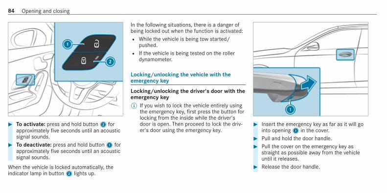
# To activate: press and hold button2 forapproximately five seconds until an acousticsignal sounds.
# To deactivate: press and hold button1 forapproximately five seconds until an acousticsignal sounds.
When the vehicle is locked automatically, theindicator lamp in button2 lights up.
In the following situations, there is a danger ofbeing locked out when the function is activated:R While the vehicle is being tow started/
pushed.R If the vehicle is being tested on the roller
dynamometer.
Locking/unlocking the vehicle with theemergency key
Locking/unlocking the driver's door with theemergency key% If you wish to lock the vehicle entirely using
the emergency key, first press the button forlocking from the inside while the driver'sdoor is open. Then proceed to lock the driv‐er's door using the emergency key.
# Insert the emergency key as far as it will gointo opening1 in the cover.
# Pull and hold the door handle.# Pull the cover on the emergency key as
straight as possible away from the vehicleuntil it releases.
# Release the door handle.
84 Opening and closing

# To unlock: turn the emergency key anti-clockwise to position1.
# To lock: turn the emergency key clockwise toposition1.
# Carefully press the cover onto the lock cylin‐der until it engages and is seated firmly.
Locking the front passenger door and reardoors with the emergency key
# Insert a suitable object, e.g. the emergencykey, into opening1 on the door lock.
# To lock the left-hand side of the vehicle:turn the emergency key anti-clockwise as faras it will go.
# To lock the right-hand side of the vehicle:turn the emergency key clockwise as far as itwill go.
If the locked door is then closed, it can no longerbe opened from outside.
BootOpens the boot lid
& DANGER Risk of exhaust gas poisoning
Combustion engines emit poisonous exhaustgases such as carbon monoxide. Exhaustgases can enter the vehicle interior if theboot lid is open when the engine is running,especially if the vehicle is in motion.# Always switch off the engine before
opening the boot lid.# Never drive with the boot lid open.
Opening and closing 85

* NOTE Damage to the boot lid by obsta‐cles above the vehicle
The boot lid swings upwards when it isopened.# Therefore, make sure that there is suffi‐
cient clearance above the boot lid.
You have the following options for openingthe boot lid:
# Pull the boot lid remote operating switch1.# Press and hold thep button on the key.
# With the boot lid unlocked, press the top ofthe Mercedes star2.
% To open, pull on the folded-out Mercedesstar when the boot lid is unlocked.
# Vehicles with HANDS-FREE ACCESS: makea kicking movement with your foot below thebumper (/ page 87).
86 Opening and closing

Closing the boot lid
& WARNING Risk of injury from unsecureditems in the vehicle
If objects, luggage or loads are not securedor not secured sufficiently, they could slip,tip over or be thrown around and thereby hitvehicle occupants.There is a risk of injury, particularly in theevent of sudden braking or a sudden changein direction.# Always stow objects in such a way that
they cannot be thrown around.# Before the journey, secure objects, lug‐
gage or loads against slipping or tippingover.
Comply with the loading guidelines when you areloading the vehicle.You have the following options for closingthe boot lid:# Pull the boot lid down using the handle
recess and push it closed.
HANDS-FREE ACCESS function
With HANDS-FREE ACCESS you can open theboot lid by performing a kicking movementunder the bumper.Observe the notes when opening the boot lid(/ page 85).
& WARNING Risk of burns caused by a hotexhaust system
The vehicle exhaust system can become veryhot. If you use HANDS-FREE ACCESS, youcould burn yourself by touching the exhaustsystem.# Always ensure that you only make a
kicking movement within the detectionrange of the sensors.
* NOTE Damage to the vehicle caused byunintentionally opening the boot lid:
R when using an automatic car washR when using a high pressure cleaner
# Deactivate KEYLESS-GO or make surethat the key located is at least 3 maway from the vehicle in such situa‐tions.
When making the kicking movement, make surethat your feet are firmly on the ground, other‐wise you could lose your balance, e.g. on ice.
Opening and closing 87

Requirements:R The key is behind the vehicle.R Stand at least 30 cm away from the vehicle
while performing the kicking movement.R Do not come into contact with the bumper
while making the kicking movement.R Do not carry out the kicking movement too
slowly.R The kicking movement must be towards the
vehicle and back again.
1 Detection range of the sensors
If several consecutive kicking movements arenot successful, wait ten seconds.
System limitsThe system may be impaired or may not functionin the following cases:R The area around the sensor is dirty, e.g. due
to road salt or snow.R The kicking movement is made using a pros‐
thetic leg.
The boot lid could be opened unintentionally, inthe following situations:R If a person's arms or legs are moving in the
sensor detection range, e.g. when polishingthe vehicle or picking up objects.R If objects are moved or placed behind the
vehicle, e.g. tensioning straps or luggage.R If clamping straps, tarpaulins or other cover‐
ings are pulled over the bumper.R If a protective mat with a length reaching
over the boot sill down into the detectionrange of the sensors is used.R If the protective mat is not secured correctly.
Deactivate the key functions (/ page 77) or donot carry the key about your person in such sit‐uations.
Side windowsOpening and closing the side windows
& WARNING Risk of becoming trappedwhen opening a side window
When you open a side window, parts of thebody could be drawn in or become trappedbetween the side window and window frame.# When opening, make sure that nobody
is touching the side window.# If someone is trapped, release the but‐
ton immediately or pull it in order toclose the side window again.
88 Opening and closing

& WARNING Risk of becoming trappedwhen closing a side window
When closing a side window, body partscould be trapped in the closing area in theprocess.# When closing, make sure that no body
parts are in the closing area.# If someone is trapped, release the but‐
ton immediately or press the button inorder to reopen the side window.
& WARNING Risk of becoming trappedwhen children operate the side windows
Children could become trapped if they oper‐ate the side windows, particularly when unat‐tended.# Activate the override feature for the
rear side windows.# When leaving the vehicle, always take
the key with you and lock the vehicle.# Never leave children unattended in the
vehicle.
Requirements:R The power supply or the ignition is switched
on.
1 Closing2 Opening
The buttons on the driver's door take prece‐dence.
# To start automatic operation: press theW button beyond the point of resistanceor pull and release it.
# To interrupt automatic operation: press orpull theW button again.
When the vehicle is switched off, the side win‐dows can continue being operated.The function is available for around five minutesor until a front door is opened.
Automatic reversing function of the side win‐dowsIf an object blocks a side window during theclosing process, the side window opens againautomatically. The automatic reversing functionis only an aid and is not a substitute for yourattentiveness.# During the closing process, make sure that
no body parts are in the closing area.
Opening and closing 89

& WARNING Risk of becoming trappeddespite there being reversing protectionon the side window
The reverse function does not react:R to soft, light and thin objects, e.g. fingersR during resetting
This means that the reverse function cannotprevent someone from becoming trapped inthese situations.# When closing, make sure that no body
parts are in the closing area.# If someone becomes trapped, press the
W button to open the side windowagain.
Automatic function of the side windows
The side windows are closed automatically whenthe vehicle is switched off:R if it starts to rain (detection by the rain sen‐
sor on the windscreen)R in extreme temperatures
R after six hoursR if there is a malfunction in the power supply
The side windows are closed as far as the venti‐lation position.Vehicles with a sliding sunroof: the side win‐dows are closed completely if the sliding sunroofis open.If the side windows are blocked during auto‐matic closing, the side window concerned willopen again slightly. The automatic function forthe sliding sunroof and the side windows is thendeactivated.
Convenience opening (ventilating the vehiclebefore starting a journey)
& WARNING Risk of entrapment whenopening a side window
When opening a side window, parts of thebody could be drawn in or become trappedbetween the side window and window frame.
# When opening, make sure that nobodyis touching the side window.
# Release the button immediately ifsomebody becomes trapped.
# Press and hold theÜ button on the key.The following functions are performed:R The vehicle is unlocked.R The side windows are opened.R The panoramic sliding sunroof is opened.R The seat ventilation of the driver's seat is
switched on.
If the roller sunblinds of the panoramic slidingsunroof are closed, the roller sunblinds areopened first.# To interrupt convenience opening: release
theÜ button.# To continue convenience opening: press
and hold theÜ button again.
90 Opening and closing

Convenience closing (closing the vehiclefrom outside)
& WARNING Risk of entrapment caused byinadvertent convenience closing
When the convenience closing feature isoperating, parts of the body could becometrapped in the closing area of the side win‐dow and the sliding sunroof.# Observe the complete closing proce‐
dure when using convenience closing.# When closing, make sure that no body
parts are in the closing area.
# Press and hold theß button on the key.The following functions are performed:R The vehicle is locked.
R The side windows are closed.R The panoramic sliding sunroof is closed.
# To interrupt convenience closing: releasetheß button.
# To close the roller sunblinds: press andhold theß button again.
% Convenience closing can also be operatedwith KEYLESS-GO (/ page 82).
Problems with the side windows
& WARNING Risk of becoming trapped orfatally injured if reversing protection isnot activated
If you close a side window again immediatelyafter it has been blocked, the side windowwill close with increased or maximum force.The reversing feature will then not be active.Parts of the body could become trapped inthe closing area in the process.# Make sure that no parts of the body are
in the closing area.# To stop the closing process, release the
button or press the button again to re-open the side window.
Problem Possible causes/consequences and MM Solutions
A side window cannot be closed andyou cannot see the cause.
# Check to see whether any objects are in the window guide.# Adjust the side windows.
Opening and closing 91

Problem Possible causes/consequences and MM Solutions
Adjusting the side windowsIf a side window is obstructed during closing and reopens again immediately:# Immediately after this, pull the corresponding button again until the side window has closed, and hold
the button for at least one more second (re-adjustment).The side window is closed without the automatic reversing function.
If the side window is obstructed again and reopens again immediately:# Immediately after this, pull the corresponding button again until the side window has closed, and hold
the button for at least one more second (follow-up adjustment).The side window is closed without the automatic reversing function.
The side windows cannot be opened orclosed using the convenience openingfeature.
The key battery is weak or discharged.# Check the battery using the battery check lamp and replace if necessary (/ page 78).
Sliding sunroofOpening and closing the sliding sunroof
% The term "sliding sunroof" also refers to thepanorama sliding sunroof.
& WARNING Risk of becoming trappedwhile opening and closing the slidingsunroof
During opening and closing, parts of thebody could get caught in the sweep of thesliding sunroof.
# When opening or closing, make surethat no body parts are in the sweep.
# Release the button immediately ifsomebody becomes trapped.
or
92 Opening and closing

# Press the button in any direction duringthe automatic opening/closing process.The opening/closing process is stop‐ped.
& WARNING Risk of entrapment if the slid‐ing sunroof is operated by children
Children operating the sliding sunroof couldget caught in the moving parts, particularly ifunattended.# Never leave children unattended in the
vehicle.# When leaving the vehicle, always take
the key with you and lock the vehicle.
& WARNING Risk of entrapment whileopening and closing the roller sunblinds
When opening or closing, make sure that nobody parts become trapped between theroller sunblind and frame or sliding sunroof.
# When opening or closing, make surethat no body parts are in the sweep ofthe roller sunblind.
# Release the switch immediately ifsomebody becomes trapped.
or# Press the switch in any direction during
the automatic opening/closing process.The opening/closing process is stop‐ped.
* NOTE Malfunction caused by snow andice
Snow and ice may lead to a malfunction ofthe sliding sunroof.# Only open the sliding sunroof if it is free
of snow and ice.
* NOTE Damage caused by protrudingobjects
Objects that protrude from the sliding sun‐roof may damage the sealing strips.
# Do not allow anything to protrude fromthe sliding sunroof.
* NOTE Important points to rememberwhen a roof rack is fitted
When a roof rack is fitted, raising or openingthe sliding sunroof may be limited.# Check whether the sliding sunroof can
be raised or opened when a roof rack isfitted.
# If in doubt, do not raise or open thesliding sunroof.
Opening and closing 93
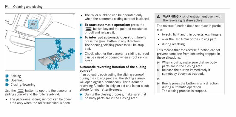
1 Raising2 Opening3 Closing/lowering
Use the3 button to operate the panoramasliding sunroof and the roller sunblind.R The panorama sliding sunroof can be oper‐
ated only when the roller sunblind is open.
R The roller sunblind can be operated onlywhen the panorama sliding sunroof is closed.
# To start automatic operation: press the3 button beyond the point of resistanceor pull and release it.
# To interrupt automatic operation: brieflypress the3 button in any direction.The opening/closing process will be stop‐ped.
# Check whether the panorama sliding sunroofcan be raised or opened when a roof rack isfitted.
Automatic reversing function of the slidingsunroofIf an object is obstructing the sliding sunroofduring the closing process, the sliding sunroofwill open again automatically. The automaticreversing function is only an aid and is not a sub‐stitute for your attentiveness.# During the closing process, make sure that
no body parts are in the closing area.
& WARNING Risk of entrapment even withthe reversing feature active
The reverse function does not react in partic‐ular:R to soft, light and thin objects, e.g. fingersR over the last 4 mm of the closing pathR during resetting
This means that the reverse function cannotprevent someone from becoming trapped inthese situations.# When closing, make sure that no body
parts are in the closing area.# Release the button immediately if
somebody becomes trapped.or# Briefly press the button in any direction
during automatic operation.The closing process is stopped.
94 Opening and closing

Automatic reversing function of the rollersunblindIf an object is obstructing the roller sunblind dur‐ing the closing process, the roller sunblind willopen again automatically. The automatic revers‐ing function is only an aid and is not a substitutefor your attentiveness.# When closing the roller sunblind, make sure
that no body parts are in the range of move‐ment.
& WARNING Risk of becoming trappeddespite reversing function
In particular, the reversing function does notreact to soft, light and thin objects, e.g. fin‐gers.This means that the reversing function can‐not prevent entrapment in these situations.# When closing the roller sunblind, make
sure that no body parts are in the rangeof movement.
# Release the button immediately ifsomebody becomes trapped.
or# Press the button in any direction during
the automatic closing process.The closing process is stopped.
Automatic functions of the sliding sunroof
% The term "sliding sunroof" also refers to thepanoramic sliding sunroof.
By pushing or pulling the3 button, you caninterrupt the automatic functions: "Rain closingfunction when driving" and "Automatic lower‐ing".The sliding sunroof is automatically closed whenthe vehicle has been switched off:R if it starts to rain (detection by the rain sen‐
sor on the windscreen)R in the event of extreme outside temperaturesR after six hoursR if there is a malfunction in the power supply
The sliding sunroof then rises at the rear in orderto continue ventilating the vehicle interior.
If the sliding sunroof is blocked during an auto‐matic closing procedure, the roof is openedslightly again. The automatic function for thesliding sunroof and the side windows is thendeactivated.
Rain closing function when drivingVehicles with a panoramic sliding sunroof: ifit starts to rain, the raised sliding sunroof isautomatically lowered while the vehicle is inmotion.
Automatic lowering functionVehicles with a panoramic sliding sunroof: ifthe sliding sunroof is raised at the rear, it isautomatically lowered slightly at higher speeds.At low speeds, it is raised again automatically.
& WARNING Risk of entrapment by auto‐matic lowering of the sliding sunroof
At high speeds the raised sliding sunroofautomatically lowers slightly at the rear.This could trap you or other persons.
Opening and closing 95

# Make sure that nobody reaches into thesweep of the sliding sunroof whilst thevehicle is in motion.
# If somebody becomes trapped, brieflypush the sliding sunroof button for‐wards or backwards.The sliding sunroof lifts during opening.
Problems with the sliding sunroof
% The term "sliding sunroof" also refers to thepanorama sliding sunroof.
Problem Possible causes/consequences and MM Solutions
The sliding sunroof cannot be closedand you cannot see the cause.
& WARNING Risk of becoming trapped or fatal injury by closing the sliding sunroof again
If you close the sliding sunroof again immediately after it has been blocked or reset, the sliding sunroofcloses with increased force.Parts of the body could become trapped in the closing area in the process.# Make sure that no parts of the body are in the closing area.# Release the button immediately if somebody becomes trapped.or# Press the button in any direction during the automatic closing process.
The closing process is stopped.
If the sliding sunroof is obstructed during closing and reopens again slightly:
96 Opening and closing

Problem Possible causes/consequences and MM Solutions
# Immediately after automatic reversing, pull and hold the3 button down again to the point of resist‐ance until the sliding sunroof is closed.The sliding sunroof will be closed with increased force.
If the sliding sunroof is obstructed again and reopens again slightly:# Repeat the previous step.
The sliding sunroof will be closed again with increased force.
Vehicles with a panoramic slidingsunroof: the sliding sunroof or theroller sunblind does not operatesmoothly.
# Pull and hold the3 button little by little until the sliding sunroof is fully closed.# Pull and hold the3 button little by little until the roller sunblind is fully closed.# Use automatic operation to fully open and then close the sliding sunroof.
Anti-theft protectionFunction of the immobiliser
The immobiliser prevents your vehicle frombeing started without the correct key.The immobiliser is automatically activated whenthe ignition is switched off and deactivated whenthe ignition is switched on.
ATA (Anti-Theft Alarm system)
Function of the ATA systemIf the ATA system is primed, a visual and audiblealarm is triggered in the following situations:R when a door is openedR when the boot lid is openedR when the bonnet is opened
R when interior protection is triggered(/ page 99)R when tow-away protection is triggered
(/ page 98)
The ATA system is primed automatically afterapproximately ten seconds in the following situa‐tions:R after locking the vehicle with the key
Opening and closing 97

R after locking the vehicle using KEYLESS-GO
Indicator lamp1 flashes when the ATA systemis primed.The ATA system is deactivated automatically inthe following situations:R after unlocking the vehicle with the key
R after unlocking the vehicle using KEYLESS-GOR after pressing the start/stop button with the
key in the stowage compartment(/ page 159)
% When the Mercedes‑Benz emergency callsystem is active and the alarm stays on formore than 30 seconds, a message is auto‐matically sent to the Customer AssistanceCentre (/ page 416).
Deactivating the ATA# Press theÜ,ß orp button on the
key.or# Press the start/stop button with the key in
the stowage compartment (/ page 159)
Deactivating the alarm using KEYLESS-GO:# Grasp the outside door handle with the key
outside the vehicle.
Function of tow-away protection
An audible and visual alarm is triggered if analteration to your vehicle's angle of inclination isdetected while tow-away protection is primed.Tow-away protection is automatically primedafter about 60 seconds:R after locking the vehicle with the keyR after locking the vehicle using KEYLESS-GO
Tow-away protection is only primed when the fol‐lowing components are closed:R the doorsR the boot lid
Tow-away protection is automatically deactiva‐ted:R after pressing theÜ orp button on
the keyR after pressing the start/stop button with the
key in the stowage compartment(/ page 159)R after unlocking the vehicle using KEYLESS-
GO
98 Opening and closing

R when using HANDS-FREE ACCESS
Information on detecting damage on a parkedvehicle (/ page 189).
Priming/deactivating tow-away protection
Multimedia system:4© 5 Settings5 Schnellzugriff (Quick access)# Prime or deactivate Tow-away protection.Tow-away protection is primed again in the fol‐lowing cases:R The vehicle is unlocked again.R A door is opened.R The vehicle is locked again.
% If quick access is unavailable, select theVehicle submenu in the Settings main menuto prime or deactivate tow-away protection.
Function of interior protection
When interior protection is primed, a visual andaudible alarm is triggered if movement is detec‐ted in the vehicle interior.Interior protection is primed automatically afterapproximately ten seconds:R after locking the vehicle with the keyR after locking the vehicle using KEYLESS-GO
Interior protection is only primed when the fol‐lowing components are closed:R the doorsR the boot lid
Interior protection is automatically deactivated:R after pressing theÜ orp button on
the keyR after pressing the start/stop button with the
key in the stowage compartment(/ page 159)R after unlocking the vehicle using KEYLESS-
GOR when using HANDS-FREE ACCESS
The following situations can lead to a falsealarm:R moving objects such as mascots in the vehi‐
cle interiorR when the side window is openR when the panoramic sliding sunroof is open
Priming/deactivating interior protection
Multimedia system:4© 5 Settings5 Schnellzugriff (Quick access)# Prime or deactivate Interior motion sensor.Interior protection is primed again in the follow‐ing cases:R The vehicle is unlocked again.R A door is opened.R The vehicle is locked again.
% If quick access is unavailable, select theVehicle menu under Settings to prime ordeactivate interior protection.
Opening and closing 99

Notes on the correct driver's seat position
& WARNING Risk of injury through adjust‐ing vehicle settings while the vehicle is inmotion
You could lose control of the vehicle in thefollowing situations:R if you adjust the driver's seat, the head
restraints, the steering wheel or the mir‐ror while the vehicle is in motionR if you fasten your seat belt while the vehi‐
cle is in motion
# Before starting the engine: adjust thedriver's seat, the head restraints, thesteering wheel or the mirror and fastenyour seat belt.
Ensure the following when adjusting the steeringwheel1, seat belt2 and driver's seat3:R you are as far away from the driver's airbag
as possibleR you are sitting in an upright positionR your thighs are slightly supported by the seat
cushion
R your legs are not fully extended and you candepress the pedals properlyR the back of your head is supported at eye
level by the centre of the head restraintR you can hold the steering wheel with your
arms slightly bentR you can move your legs freelyR you can see all the displays on the instru‐
ment cluster clearlyR you have a good overview of the traffic con‐
ditionsR your seat belt is pulled snugly against your
body and is routed across the centre of yourshoulder and across your hips in the pelvicarea
100 Seats and stowing
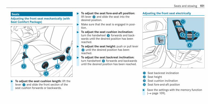
SeatsAdjusting the front seat mechanically (withSeat Comfort Package)
# To adjust the seat cushion length: lift thelever1 and slide the front section of theseat cushion forwards or backwards.
# To adjust the seat fore-and-aft position:lift lever2 and slide the seat into thedesired position.
# Make sure that the seat is engaged in posi‐tion.
# To adjust the seat cushion inclination:turn the handwheel3 forwards and back‐wards until the desired position has beenreached.
# To adjust the seat height: push or pull lever4 until the desired position has beenreached.
# To adjust the seat backrest inclination:turn handwheel5 forwards and backwardsuntil the desired position has been reached.
Adjusting the front seat electrically
1 Seat backrest inclination2 Seat height3 Seat cushion inclination4 Seat fore-and-aft position
# Save the settings with the memory function(/ page 109).
Seats and stowing 101

Adjusting the 4-way lumbar support
1 Raise2 Soften3 Lower4 Harden
# Using buttons1 to4, adjust the contourof the backrest individually to suit your back.
Head restraints
Adjusting the front seat head restraintsmechanically
& WARNING Risk of injury through adjust‐ing vehicle settings while the vehicle is inmotion
You could lose control of the vehicle in thefollowing situations:R if you adjust the driver's seat, the head
restraints, the steering wheel or the mir‐ror while the vehicle is in motionR if you fasten your seat belt while the vehi‐
cle is in motion
# Before starting the engine: adjust thedriver's seat, the head restraints, thesteering wheel or the mirror and fastenyour seat belt.
& WARNING Risk of injury due to headrestraints which are not fitted or areadjusted incorrectly
If head restraints are not fitted or are adjus‐ted incorrectly, they cannot provide protec‐tion as intended.There is an increased risk of injury in thehead and neck area, e.g. in the event of anaccident or when braking.# Always drive with the head restraints
fitted.# Before driving off, make sure for every
vehicle occupant that the centre of thehead restraint supports the back of thehead at about eye level.
Do not interchange the head restraints of thefront and rear seats. Otherwise, you will not beable to adjust the height and angle of the headrestraints correctly.Adjust the head restraint fore-and-aft position sothat it is as close as possible to the back of yourhead.
102 Seats and stowing

For vehicles with sports seats, it is not possibleto adjust the front head restraints.
# To raise: pull the head restraint up.# To lower: press release knob1 in the direc‐
tion of the arrow and push the head restraintdown.
# To move forwards: press release knob2and pull the head restraint forwards.
# To move backwards: press release knob2and push the head restraint backwards.
Adjusting the head restraints of the rearseats mechanicallyFor vehicles with sports seats, it is not possibleto adjust the outer head restraints.
# To raise: pull the head restraint up.
# To lower: press release knob1 in the direc‐tion of the arrow and push the head restraintdown.
Fitting/removing the rear seat headrestraints
Removal
Seats and stowing 103

# Release the rear seat backrest and fold it for‐wards slightly (/ page 112).
# Pull the head restraint upwards as far as itwill go.
# Push release knob1 in the direction of thearrow and pull out the head restraint.
Fitting# Insert the head restraint such that the
notches on the bar are on the left whenviewed in the direction of travel.
# Push the head restraint down until itengages.
# Fold the rear seat backrest back until itengages.
Configuring the seat settings
Multimedia system:4© 5 Comfort 5 Seat comfort
Adjusting the seat contour in the lumbarregion of the seat backrest (lumbar)# Select Lumbar.
# Select the settingsZ for the desired seat.# Adjust the air cushions.
Adjusting the backrest side bolsters# Select Side bolsters.# Adjust the air cushion for the desired seat.
Mercedes-AMG vehicles: observe the notes inthe Supplement. Otherwise, you may fail to rec‐ognise dangers.
Selecting the massage program for the frontseats
Multimedia system:4© 5 Comfort 5 Massage# Select a seat.# Select Wave Massage or Pulsating Massage.
The selected program will start.# To set the massage intensity: switch High
intensity on or off .
Resetting seat settings
Multimedia system:4© 5 Comfort 5 Seat comfort# Select Reset.# Selectß for the desired seat.
The settings for the selected seat are reset.
Switching the seat heater on/off
& WARNING Risk of burns due to repeat‐edly switching on the seat heater
Repeatedly switching on the seat heater cancause the seat cushion and seat backrestpadding to become very hot.The health of persons with limited tempera‐ture sensitivity or a limited ability to react tohigh temperatures may be affected or theymay even suffer burn-like injuries.# Do not repeatedly switch on the seat
heater.
104 Seats and stowing

To protect against overheating, the seat heatermay be temporarily deactivated after it isswitched on repeatedly.
* NOTE Damage to the seats caused byobjects or documents when the seatheater is switched on
When the seat heater is switched on, over‐heating can occur due to objects or docu‐ments placed on the seats e.g. seat cushionsor child seats. This could cause damage tothe seat surface.# Make sure that no objects or docu‐
ments are on the seats when the seatheater is switched on.
Requirements:R The power supply is switched on.
# To switch on/increase the level: press but‐ton1 repeatedly until the desired heatinglevel is set.Depending on the heating level, up to threeindicator lamps will light up.
# To switch off/reduce the level: press but‐ton1 repeatedly until the desired heatinglevel is set.If all indicator lamps are off, the seat heateris switched off.
% The seat heater will automatically switchdown from the three heating levels after 8,10 and 20 minutes until the seat heaterswitches off.
Switching the seat ventilation on/off
Requirements:R The power supply is switched on.
Seats and stowing 105

# To switch on/increase the level: press but‐ton1 repeatedly until the desired ventila‐tion level is set.Depending on the ventilation level, up tothree indicator lamps will light up.
# To switch off/reduce the level: press but‐ton1 repeatedly until the desired ventila‐tion level is set.If all indicator lamps are off, the seat ventila‐tion is switched off.
Steering wheelAdjusts the steering wheel manually
& WARNING Risk of injury through adjust‐ing vehicle settings while the vehicle is inmotion
You could lose control of the vehicle in thefollowing situations:R if you adjust the driver's seat, the head
restraints, the steering wheel or the mir‐ror while the vehicle is in motionR if you fasten your seat belt while the vehi‐
cle is in motion
# Before starting the engine: adjust thedriver's seat, the head restraints, the
steering wheel or the mirror and fastenyour seat belt.
& WARNING Risk of entrapment for chil‐dren when adjusting the steering wheel
Children could injure themselves if theyadjust the steering wheel.# Never leave children unattended in the
vehicle.# When leaving the vehicle, always take
the key with you and lock the vehicle.This also applies to the digital vehiclekey if the "Digital Vehicle Key" functionis activated via Mercedes me connect.
106 Seats and stowing

# Push release lever1 down as far as it willgo.The steering column is unlocked.
# Adjust height2 and distance3 to thesteering wheel.
# Push release lever1 up as far as it will go.The steering column is locked.
# Check and make sure that the steering col‐umn is locked by moving the steering wheel.
Switching the steering wheel heater on/off
Requirements:R The ignition is switched on.
# Push the switch to position1 or2.If indicator lamp3 lights up, the steeringwheel heater is switched on.
When you switch the ignition off, the steeringwheel heater will switch off.
Easy entry and exit featureUsing the easy entry and exit feature
& WARNING Risk of accident when pullingaway during the adjustment process ofthe easy exit feature
‑ If you pull away while the easy entry andexit feature is making adjustments, you couldlose control of the vehicle.# Always wait until the adjustment proc‐
ess is complete before pulling away.
& WARNING Risk of becoming trappedwhile adjusting the easy entry and exitfeature
When the easy entry and exit feature adjuststhe driver's seat, you and other vehicle occu‐pants – particularly children – could becometrapped.# During the adjustment process of the
easy entry and exit feature, make sure
Seats and stowing 107

that no one has any body parts in thesweep of the driver's seat.
If there is a risk of becoming trapped by thedriver's seat:# Press the seat adjustment switch.
The adjustment process is stopped.# Never leave children unattended in the
vehicle.# When leaving the vehicle, always take
the key with you and lock the vehicle.This also applies to the Digital VehicleKey if the "Digital Vehicle Key" functionis activated via Mercedes me connect.
You can stop the adjustment process by press‐ing one of the memory function positionswitches.
& WARNING Risk of becoming trappedduring activation of the easy entry andexit feature by children
If children activate the easy entry and exitfeature, they can become trapped, particu‐larly when unattended.# Never leave children unattended in the
vehicle.# When leaving the vehicle, always take
the key with you and lock the vehicle.
This also applies to the Digital Vehicle Key if the"Digital Vehicle Key" function is activated viaMercedes me connect.When the easy entry and exit feature is active,the driver's seat will move backwards and thebackrest will be moved to a steeper positionwhen:R you switch the ignition off with the driver's
door openR you open the driver's door with the ignition
switched off
% The driver's seat will move backwards only ifit is not already in the rearmost position.The seat backrest will move forwards only ifit is not already in the frontmost position.
The driver's seat will move back to the last driveposition when:R you switch the ignition on with the driver's
door closedR you close the driver's door with the ignition
switched on
The last drive position will be stored when:R you switch the ignition offR you call up the seat settings via the memory
functionR you save the seat setting using the memory
function
Setting the easy entry and exit feature
Multimedia system:4© 5 Settings 5 Fahrzeug (Vehicle)5 Easy Entry/Exit# Activate or deactivate the function.
108 Seats and stowing

Operating the memory function
& WARNING Risk of an accident if thememory function is used while driving
If you use the memory function on the driv‐er's side while driving, you could lose controlof the vehicle as a result of the adjustmentsbeing made.# Only use the memory function on the
driver's side when the vehicle is station‐ary.
& WARNING Risk of entrapment when set‐ting the seat with the memory function
When the memory function adjusts the seator steering wheel, you and other vehicleoccupants – particularly children – couldbecome trapped.# During the setting procedure of the
memory function, ensure that no bodyparts are in the sweep of the seat orthe steering wheel.
# If somebody becomes trapped, immedi‐ately release the memory function posi‐tion button.The adjustment process is stopped.
& WARNING Risk of entrapment if thememory function is activated by children
Children could become trapped if they acti‐vate the memory function, particularly whenunattended.# Never leave children unattended in the
vehicle.# When leaving the vehicle, always take
the key with you and lock the vehicle.
This also applies to the Digital Vehicle Key if the"Digital Vehicle Key" function is activated viaMercedes me connect.The memory function can be used when the igni‐tion is switched off.
StoringSeat adjustments for up to three people can bestored and called up using the memory function.
The following systems can be selected:R Seat, backrest and head restraintR Outside mirrorsR Head-up display
# Set the seat, the head-up display and theoutside mirror to the desired position.
Seats and stowing 109

# Press memory button M together with one ofpreset position buttons 1, 2 or 3.An acoustic signal sounds. The settings arestored.
# To call up: press and briefly hold memoryposition switch 1, 2 or 3.After releasing the button, the front seat,head-up display and outside mirrors aremoved into the stored position.
Stowage areasNotes on loading the vehicle
& DANGER Risk of exhaust gas poisoning
Combustion engines emit poisonous exhaustgases such as carbon monoxide. Exhaustgases can enter the vehicle interior if theboot lid is open when the engine is running,especially if the vehicle is in motion.# Always switch off the engine before
opening the boot lid.# Never drive with the boot lid open.
& WARNING Risk of injury from unsecureditems in the vehicle
If objects, luggage or loads are not securedor not secured sufficiently, they could slip,tip over or be thrown around and thereby hitvehicle occupants.There is a risk of injury, particularly in theevent of sudden braking or a sudden changein direction.# Always stow objects in such a way that
they cannot be thrown around.# Before the journey, secure objects, lug‐
gage or loads against slipping or tippingover.
& WARNING Risk of injury due to objectsbeing stowed incorrectly
If you inadequately stow objects in the vehi‐cle interior, they could slip or be tossedaround and thereby strike vehicle occupants.In addition, cup holders, open stowagespaces and mobile phone brackets cannot
always restrain the objects they contain inthe event of an accident.There is a risk of injury, particularly in theevent of sudden braking or a sudden changein direction.# Always stow objects in such a way that
they cannot be tossed about in these orsimilar situations.
# Always make sure that objects do notproject from stowage spaces, luggagenets or stowage nets.
# Close the lockable stowage spacesbefore starting a journey.
# Always stow and secure objects thatare heavy, hard, pointed, sharp-edged,fragile or too large in the boot.
& WARNING Risk of burning from the tail‐pipe or tailpipe trim
The tailpipe and tailpipe trim can becomevery hot. If you come into contact with thesecar parts, you could burn yourself.
110 Seats and stowing

# Always be particularly careful when inthe vicinity of the tailpipe and tailpipetrims and supervise children veryclosely when in this area.
# Before any contact, allow the car partsto cool down.
The driving characteristics of your vehicle aredependent on the distribution of the load withinthe vehicle. You should bear the following inmind when loading the vehicle:R never exceed the permissible gross mass or
the permissible axle loads for the vehicle(including occupants).Information can be found on the vehicle iden‐tification plate (/ page 512).R the load must not protrude above the upper
edge of the seat backrests.R always place the load behind unoccupied
seats if possible.R secure the load using the tie-down eyes and
distribute the load evenly.
Stowage spaces in the vehicle interior
Overview of the front stowage compart‐ments
1 Stowage space in the doors2 Stowage compartment in the armrest with a
multimedia and USB connection3 Stowage compartment in the front centre
console with a USB connection and chargingmodule for wireless charging of a mobilephone (not available in all countries)
4 Glove compartment
Locking and unlocking the glove compart‐ment
# Turn the emergency key a quarter turn clock‐wise2 (to lock) or anti-clockwise1 (tounlock).
Seats and stowing 111

Stowage compartment for customer litera‐ture
# To open: turn the handle to the left or right.
Opening the spectacles compartment
# Press button1.
Through-loading feature in the rear benchseat
Folding the rear seat backrest forwards
& WARNING Risk of injury if the rearbench seat/rear seat and seat backrestare not engaged
If the rear bench seat/rear seat and seatbackrest are not engaged they could fold for‐wards, e.g. when braking suddenly or in theevent of an accident.R If this is the case, the vehicle occupant
would be forced into the seat belt by therear bench seat/rear seat or by the seatbackrest. The seat belt cannot protect asintended and could result in additionalinjury.R Objects or loads in the boot/load com‐
partment cannot be restrained by theseat backrest.
# Make sure that the seat backrest andthe rear bench seat/rear seat areengaged before every trip.
112 Seats and stowing

If the seat backrests are not engaged and lockedin place, the lock verification indicator will bered.The centre and outer seat backrests can be fol‐ded forwards separately.
# Vehicles with a memory function: if atleast one section of the rear seat backrest isfolded forwards, the corresponding front seat
will move forwards slightly, if necessary, toavoid a collision.
# If necessary, fully insert the rear seat back‐rest head restraints.
# Left and right seat backrests: pull the leftor right release handle1 and fold the corre‐sponding seat backrest forwards.
# Centre seat backrest: pull the release catch3 of the seat backrest2 forwards.
# Fold seat backrest2 forwards.# If necessary, reset the driver's or front
passenger seat.
Folding the rear seat backrest back
* NOTE Damage to the seat belt
The seat belt could become trapped and thusdamaged when folding back the seat back‐rest.# Make sure that the seat belt is not trap‐
ped when folding back the seat back‐rest.
# Move the driver's or front passenger seat for‐wards, if necessary.
Seats and stowing 113

# Fold the corresponding seat backrest1back until it engages.Left and right seat backrest: if the seatbackrest is not engaged and locked, the redlock verification indicator2 will be visible.Centre seat backrest: if the seat backrest isnot engaged and locked, the red lock verifi‐cation indicator3 will be visible.
Locking the release catch of the centre rearseat backrest
Requirements:R The left and centre seat backrests are
engaged and joined together.
You can lock the centre seat backrest releasecatch if you want to secure the boot againstunauthorised access. The centre seat backrestcan then be folded forwards only together withthe left seat backrest.
# Fold the centre and left seat backrests for‐wards.
# To lock: slide catch1 upwards.The release catch of the centre seat backrestwill be locked.
# To unlock: slide catch1 downwards.
114 Seats and stowing

Overview of the tie-down eyes
Observe the notes on loading the vehicle(/ page 110).
1 Tie-down eyes (vehicles with through-loadingfeature in the rear bench seat)
Opening or closing the stowage space underthe boot floor
# To open: lift the boot floor at contact1 andswing it upwards.
# To close: fold the boot floor downwards.
Attaching a roof rack
& WARNING Risk of injury if the maximumroof load is exceeded
When you load the roof, the centre of gravityof the vehicle rises and the usual drivingcharacteristics as well as the steering andbraking characteristics change. During cor‐nering, the vehicle tilts more strongly andmay react more sluggishly to steering move‐ments.If you exceed the maximum roof load, thedriving characteristics, as well as the steer‐ing and braking characteristics, will begreatly impaired.# Always comply with the maximum roof
load and adjust your driving style.
You will find information on the maximum roofload in the "Technical data" section.
Seats and stowing 115

* NOTE Vehicle damage from non-approved roof racks
The vehicle could be damaged by roof rackswhich have not been tested and approved byMercedes-Benz.# Only use roof racks tested and
approved by Mercedes-Benz.# Depending on the vehicle equipment,
ensure that when the roof rack is fitted:R the sliding sunroof can be fully
raised.R the boot lid can be fully opened.
# Position the load on the roof rack insuch a way that the vehicle will not sus‐tain damage even when it is in motion.
* NOTE Damage to the panoramic slidingsunroof when a roof rack is fitted
The panoramic sliding sunroof may be dam‐aged by the roof rack if you attempt to openit when the roof rack is fitted.
# Do not open the panoramic sliding sun‐roof if a roof rack is fitted.
In order to allow ventilation of the vehicleinterior, you can raise the panoramic slidingsunroof.
* NOTE Damage to the covers
The covers may be damaged and scratchedwhen being opened.# Do not use metallic or hard objects.
# Carefully fold the covers1 upwards in thedirection of the arrow.
# Secure the roof rack to the anchorage pointsunder the covers1.
# Comply with the roof rack manufacturer'sinstallation instructions.
# Secure the load on the roof rack.
Cup holdersFitting the cup holder in or removing it fromthe centre console (automatic transmission)
& WARNING ‑ Risk of accident or injurywhen using the cup holder while thevehicle is in motion
The cup holder cannot hold a containersecure while the vehicle is in motion.
116 Seats and stowing

If you use a cup holder while the vehicle is inmotion, the container may be flung aroundand liquids could be spilled. The vehicleoccupants may come into contact with theliquid and if it is hot, they could be scalded.You could be distracted from traffic condi‐tions and you may lose control of the vehicle.# Only use the cup holder when the vehi‐
cle is stationary.# Only use the cup holder for containers
of the right size.# Always close the container, particularly
if the liquid is hot.
Cup holder in the stowage compartment with cover Cup holder in the stowage compartment withoutcover
# To remove: slide snap-in brackets1 of thecup holder inwards until they are unlocked.
# Move the cup holder upwards out of thestowage compartment.
Seats and stowing 117

% The cup holder and the rubber mat beneathit can be removed for cleaning, e.g. withclean, lukewarm water.
Cup holder in the stowage compartment with cover
Cup holder in the stowage compartment withoutcover
# To fit: if necessary, open the stowage com‐partment cover and insert the cup holder, asshown, into the stowage compartment withthe imprint facing the vehicle interior.
# Slide the cup holder onto the bars in thestowage compartment.
# Slide snap-in brackets1 outwards until theyengage.
# Cup holder in the stowage compartmentwith cover: press button2.
or# Cup holder in the stowage compartment
without cover: press button2 and/or4.The wings3 will fold upwards.
% The cup holder wings can be folded down‐wards and locked. The cup holder's holdingfunction will then not be available.
Fitting the cup holder in and removing itfrom the centre console (manual transmis‐sion)
& WARNING ‑ Risk of accident or injurywhen using the cup holder while thevehicle is in motion
The cup holder cannot hold a containersecure while the vehicle is in motion.If you use a cup holder while the vehicle is inmotion, the container may be flung around
118 Seats and stowing

and liquids could be spilled. The vehicleoccupants may come into contact with theliquid and if it is hot, they could be scalded.You could be distracted from traffic condi‐tions and you may lose control of the vehicle.# Only use the cup holder when the vehi‐
cle is stationary.# Only use the cup holder for containers
of the right size.# Always close the container, particularly
if the liquid is hot.
# To remove: slide snap-in brackets1 of thecup holder inwards until they are unlocked.
# Move the cup holder upwards out of thestowage compartment.
% The cup holder and the rubber mat beneathit can be removed for cleaning, e.g. withclean, lukewarm water.
# To fit: insert the cup holder, as shown, intothe stowage compartment with the imprintfacing the vehicle interior.
# Slide the cup holder onto the bars in thestowage compartment.
# Slide snap-in brackets1 outwards until theyengage.
# Press button2 and/or4.The wings3 will fold upwards.
Seats and stowing 119

% The cup holder wings can be folded down‐wards and locked. The cup holder's holdingfunction will then not be available.
Opening or closing the cup holder in the reararmrest
* NOTE Damage to the rear armrest due tobody weight
When folded out, the rear armrest can bedamaged due to body weight.# Do not sit or support yourself on the
rear seat armrest.
* NOTE Damage to the cup holder
When the rear armrest is folded back the cupholder could become damaged.# Only fold the rear armrest back when
the cup holder is closed.
# To open: press cup holder1 or2.Cup holder1 or2 extends automatically.
# To close: push cup holder1 or2 backuntil it engages.
Ashtray and cigarette lighterUsing the ashtray
# While driving: place the closed ashtray inthe front door stowage compartment whiledriving.
# Check that it is secure.# Comply with the notes on loading the vehicle
(/ page 110).
120 Seats and stowing

# To open: fold the lid1 upwards.% Twist the top part of the ashtray to remove it
for cleaning, e.g. with clean, lukewarm water,or for emptying.
Using the cigarette lighter in the front centreconsole
& WARNING ‑ Risk of fire and injury fromthe hot cigarette lighter
You can burn yourself if you touch the hotheating element or the socket of the ciga‐rette lighter.In addition, flammable materials may igniteif:R you drop the hot cigarette lighterR a child holds the hot cigarette lighter to
objects, for example
# Always hold the cigarette lighter by theknob.
# Always make sure that the cigarettelighter is out of reach of children.
# Never leave children unattended in thevehicle.
Requirements:R The ignition is switched on.
# Press in cigarette lighter1.The cigarette lighter will pop out automati‐cally when the heating element is red-hot.
SocketsUsing the 12 V socket in the front centreconsole
Requirements:R Only devices up to a maximum of 180 W
(15 A) are permissible.
# Lift up socket cap1.# Insert the plug of the device.
12 V socket in the stowage compartmentwith cover: if you have connected a device tothe 12 V socket, leave the cover of the stowagecompartment open.
Seats and stowing 121

Using the 115 V socket in the rear
& DANGER Risk of fatal injury due to dam‐aged connecting cables or sockets
If a suitable device is connected, the 115 Vsocket will be carrying a high voltage. If theconnecting cable or the 115 V socket ispulled out of the trim or is damaged or wet,you could receive an electric shock.# Use only connecting cables that are dry
and free of damage.# When the ignition is switched off,
ensure that the 115 V socket is dry.# If the 115 V socket is damaged or gets
pulled out of the trim, immediately havethe socket checked or replaced at aqualified specialised workshop.
# Never plug the connecting cable into a115 V socket that is damaged or hasbeen pulled out of the trim.
& DANGER Risk of fatal injury due to incor‐rect handling of the socket
You could receive an electric shock:R if you reach into the socket.R if you insert unsuitable devices or objects
into the socket.
# Do not reach into the socket.# Only connect suitable devices to the
socket.
Requirements:R Devices are equipped with a suitable plug
which conforms to the standards specific tothe country you are in.R A device up to a maximum of 150 W is used.R Do not use multiple socket outlets.
# Open flap3.# Insert the plug of the device into 115 V
socket1.When the on-board electrical system voltageis sufficient, indicator lamp2 lights up.
122 Seats and stowing

Using the 230 V socket in the rear
& DANGER Risk of fatal injury due to dam‐aged connecting cables or sockets
When a suitable device is connected, the230 V power socket will be carrying a highvoltage. You could receive an electric shockif the connecting cable or the 230 V powersocket is pulled out of the trim or is damagedor wet.# Use only connecting cables that are dry
and free of damage.# When the ignition is switched off, make
sure that the 230 V power socket is dry.# Immediately have the 230 V power
socket checked or replaced at a quali‐fied specialised workshop if it is dam‐aged or has been pulled out of the trim.
# Never plug the connecting cable into a230 V power socket that is damaged orhas been pulled out of the trim.
& DANGER Risk of fatal injury due to incor‐rect handling of the socket
You could receive an electric shock:R if you reach into the socket.R if you insert unsuitable devices or objects
into the socket.
# Do not reach into the socket.# Only connect suitable devices to the
socket.
Requirements:R Devices are equipped with a suitable plug
which conforms to the standards specific tothe country you are in.R A device up to a maximum of 150 W is used.R Do not use multiple socket outlets.
# Open flap3.# Insert the plug of the device into 230 V
socket1.When the on-board electrical system voltageis sufficient, indicator lamp2 lights up.
Seats and stowing 123

Using the 12 V socket in the boot
Requirements:R Only connect devices up to a maximum of
180 W (15 A).
# Lift up cap1 of the socket and insert theplug of the device.
USB port in the rear
If the ignition is switched on you can charge aUSB device, e.g. a mobile phone, at USB ports1 using a suitable charging cable.
Wireless charging of the mobile phone andconnection with the exterior aerialNotes on wirelessly charging the mobilephone
& WARNING Risk of injury due to objectsbeing stowed incorrectly
If objects in the vehicle interior are stowedincorrectly, they can slide or be thrownaround and hit vehicle occupants. In addi‐tion, cup holders, open stowage spaces andmobile phone receptacles cannot alwaysretain all objects they contain.There is a risk of injury, particularly in theevent of sudden braking or a sudden changein direction.# Always stow objects so that they can‐
not be thrown around in such situa‐tions.
# Always make sure that objects do notprotrude from stowage spaces, luggagenets or stowage nets.
124 Seats and stowing
# Close the lockable stowage spacesbefore starting a journey.
# Always stow and secure heavy, hard,pointed, sharp-edged, fragile or bulkyobjects in the boot/load compartment.
Observe the notes on loading the vehicle.
& WARNING Risk of fire from placingobjects in the mobile phone stowagecompartment
If you place objects in the mobile phonestowage compartment, they may heat upexcessively and even catch fire.# Do not place additional objects, espe‐
cially those mode of metal, in themobile phone stowage compartment.
* NOTE Damage to objects caused byplacing them in the mobile phone stow‐age compartment
If objects are placed in the mobile phonestowage compartment, they may be dam‐aged by electromagnetic fields.# Do not place credit cards, storage
media or other objects sensitive toelectromagnetic fields in the mobilephone stowage compartment.
* NOTE Damage to the mobile phonestowage compartment caused by liquids
If liquids enter the mobile phone stowagecompartment, the compartment may bedamaged.# Ensure that no liquids enter the mobile
phone stowage compartment.
R Depending on the vehicle equipment, themobile phone is connected to the vehicle'sexterior aerial via the charging module.
R The charging function and wireless connec‐tion of the mobile phone to the vehicle'sexterior aerial are only available if the ignitionis switched on.R Small mobile phones may not be able to be
charged in every position of the mobilephone stowage compartment.R Large mobile phones which do not rest flat in
the mobile phone stowage compartment maynot be able to be charged or connected withthe vehicle's exterior aerial.R The mobile phone may heat up during the
charging process. This depends on the appli‐cations (apps) currently open in the back‐ground.R To ensure more efficient charging and con‐
nection with the vehicle's exterior aerial,remove the protective cover from the mobilephone. Protective covers which are neces‐sary for wireless charging are excluded.
Seats and stowing 125

Wireless charging of the mobile phone
Requirements:R The mobile phone is suitable for wireless
charging. You can find a list of compatiblemobile phones at:http://www.mercedes-benz.com/connect
# Place the mobile phone as close to thecentre of the marked surface on mat1 aspossible with the display facing upwards.When a message is shown in the multimediasystem, the mobile phone is being charged.Malfunctions during the charging process areshown in the media display.
% The mat can be removed for cleaning, e.g.using clean, lukewarm water.
Stowage compartment without coverMake sure the mobile phone is properly storedand secured to prevent it from falling out whileyou are driving.
# To secure the mobile phone: swing lever2 out.
Radio type approval numbers for BrazilThis device operates on a secondary basis, thatis to say it has no protection against harmfulinterference, not even from the same type of
stations, and must not cause interference withsystems operating on a primary basis.This product is permitted in accordance with theprocedure defined in Directive 242/2000 by theBrazilian telecommunications agency ANATELand meets the applicable technical require‐ments.Further information is available on the ANATELwebsite. www.anatel.gov.br# Further information on the declaration of
conformity for wireless vehicle components(/ page 24).
Fitting/removing the floor mats
& WARNING Risk of accident due toobjects in the driver's footwell
Objects in the driver's footwell may impedepedal travel or block a depressed pedal.This jeopardises the operating and roadsafety of the vehicle.
126 Seats and stowing

# Stow all objects in the vehicle securelyso that they cannot get into the driver'sfootwell.
# Always fit the floor mats securely andas prescribed in order to ensure thatthere is always sufficient room for thepedals.
# Do not use loose floor mats and do notplace floor mats on top of one another.
# To fit: slide the corresponding seat back‐wards and lay the floor mat in the footwell.
# Press the studs1 onto the holders2.# Adjust the corresponding seat.# To remove: pull the floor mat off the holders2.
# Remove the floor mat.
Seats and stowing 127

Exterior lightingNotes on changing the lights when drivingabroad
It is not necessary to change the headlamps.The legal requirements are also met in countriesin which traffic drives on the other side of theroad.
Information about lighting systems and yourresponsibility
The various lighting systems of the vehicle areonly aids. The driver of the vehicle is responsiblefor correct vehicle illumination in accordancewith the prevailing light and visibility conditions,legal requirements and traffic situation.
Light switch
Operating the light switch
1 W Left-hand parking lights2 X Right-hand parking lights3 T Standing lights and licence plate light‐
ing4 Ã Automatic driving lights (preferred light
switch position)
5 L Low beam / high beam6 R Switches the rear fog lights on/off
When low beam is activated, the indicator lampfor the standing lights T is deactivated andreplaced by the low beam indicator lamp L.# Always park your vehicle safely and in a well-
lit area, in accordance with the relevant legalstipulations.
* NOTE Battery discharging by operatingthe standing lights
Operating the standing lights over a period ofhours puts a strain on the battery.# Where possible, switch on the
right X or left W parking light.
In the case of severe battery discharging, thestanding lights or parking lights are automati‐cally switched off to facilitate the next enginestart.The exterior lighting (except standing and park‐ing lights) switches off automatically when thedriver's door is opened.
128 Light and sight

R Observe the notes on surround lighting(/ page 136).
Automatic driving lights functionThe standing lights, low beam and daytime run‐ning lights are switched on automaticallydepending on the ignition status and the lightconditions.
& WARNING Risk of accident when thedipped beam is switched off in poor visi‐bility
When the light switch is set toÃ, thedipped beam may not be switched on auto‐matically if there is fog, snow or other causesof poor visibility such as spray.# In such cases, turn the light switch to
L.
The automatic driving lights are only an aid. Youare responsible for vehicle lighting.
Switching the rear fog lights on or off
Requirements:R The light switch is in the L orà posi‐
tion.
# Press the R button.
Please observe the country-specific laws on theuse of rear fog lamps.
Adjusting the headlamp range (halogenheadlamps)The headlamp range adjuster allows you toadjust the cone of light from the headlamps inrelation to the vehicle's load condition.
g Driver's seat and front passenger seat occu‐pied
1 Driver's seat, front passenger seat and rearseats occupied
2 Driver's seat, front passenger seat and rearseats occupied, boot laden
3 Driver's seat and front passenger seat occu‐pied and maximum permissible rear axleload utilised
Light and sight 129

# Turn the headlamp range adjuster to theposition that corresponds to the load condi‐tion of your vehicle.
Operating the combination switch for thelights
1 High beam2 Turn signal indicator, right
3 Headlamp flasher4 Turn signal indicator, left
# Use the combination switch to activate thedesired function.
High beam# To switch on: turn the light switch to the
L orà position.# Press the combination switch in the direction
of arrow1.When the high beam is activated, the indica‐tor lamp for low beam L will be deactiva‐ted and replaced by the indicator lamp forhigh beam K.
# To switch off: press the combination switchin the direction of arrow1 or pull in thedirection of arrow3.
Headlamp flasher# Pull the combination switch in the direction
of arrow3.
Turn signal indicators# To indicate briefly: press the combination
switch briefly to the point of resistance in thedirection of arrow2 or4.The corresponding turn signal indicator willflash three times.
# To indicate permanently: press the combi‐nation switch beyond the point of resistancein the direction of arrow2 or4.Vehicles with Active Lane Change Assist:R Indicator operation activated by the driver
can extend for the duration of the lanechange.R If the driver indicated directly beforehand
but a lane change was not immediatelypossible, the turn signal indicator mayactivate automatically.
130 Light and sight
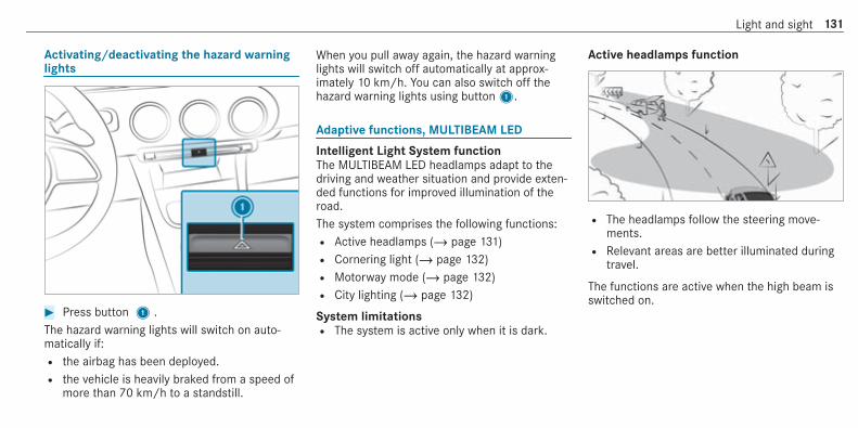
Activating/deactivating the hazard warninglights
# Press button 1 .The hazard warning lights will switch on auto‐matically if:R the airbag has been deployed.R the vehicle is heavily braked from a speed of
more than 70 km/h to a standstill.
When you pull away again, the hazard warninglights will switch off automatically at approx‐imately 10 km/h. You can also switch off thehazard warning lights using button1.
Adaptive functions, MULTIBEAM LED
Intelligent Light System functionThe MULTIBEAM LED headlamps adapt to thedriving and weather situation and provide exten‐ded functions for improved illumination of theroad.The system comprises the following functions:R Active headlamps (/ page 131)R Cornering light (/ page 132)R Motorway mode (/ page 132)R City lighting (/ page 132)
System limitationsR The system is active only when it is dark.
Active headlamps function
R The headlamps follow the steering move‐ments.R Relevant areas are better illuminated during
travel.
The functions are active when the high beam isswitched on.
Light and sight 131

Cornering light function
The cornering light improves the illumination ofthe carriageway over a wide angle in the turningdirection, enabling better visibility on tightbends, for example. It can be activated onlywhen the low beam is switched on.The function is active in the following cases:R at speeds below 40 km/h when the turn sig‐
nal indicator is switched on or the steeringwheel is turnedR at speeds between 40 km/h and 70 km/h
when the steering wheel is turned
Roundabout and intersection function: thecornering light will be activated on both sidesbased on an evaluation of the current GPS posi‐tion of the vehicle. It will remain active until afterthe vehicle has left the roundabout or the inter‐section.
Motorway mode functionMotorway mode increases the range and bright‐ness of the cone of light, enabling better visibil‐ity.
The function is enabled if a motorway journey isdetected by:R the vehicle's speed
R the multifunction cameraR the GPS
The function will not be enabled in the followingcases:R at speeds below 80 km/h.
Function of city lightingCity lighting improves the illumination of road‐sides within built-up areas using broader distri‐bution of light.The function is active in the following cases:R at low speedsR in illuminated parts of built-up areas
Switching the Intelligent Light Systemon/off
Requirements:R the ignition is switched on.
Multimedia system:4© 5 Settings 5 Lights5 Intelligent Light System# Activate or deactivate the function.
132 Light and sight

Adaptive Highbeam Assist
Adaptive Highbeam Assist function
& WARNING Risk of accident despiteAdaptive Highbeam Assist
Adaptive Highbeam Assist does not recog‐nise the following road users:R Road users without lights, e.g. pedes‐
triansR Road users with poor lighting, e.g.
cyclistsR Road users whose lighting is obstructed,
e.g. by a barrier
On very rare occasions, Adaptive HighbeamAssist may fail to recognise other road userswith their own lighting, or may recognisethem too late.In this, or in similar situations, the automaticmain beam will not be deactivated or will beactivated despite the presence of other roadusers.
# Always observe the traffic carefully andswitch off the main beam in good time.
Adaptive Highbeam Assist cannot take intoaccount road, weather or traffic conditions.Detection may be restricted in the followingcases:R In poor visibility, e.g. fog, heavy rain or snowR If there is dirt on the sensors or the sensors
are obscured
Adaptive Highbeam Assist is only an aid. You areresponsible for adjusting the vehicle's lighting tothe prevailing light, visibility and traffic condi‐tions.
The Adaptive Highbeam Assist automaticallyswitches between the following types of light:R Low beamR High beam
At speeds above 30 km/h:R If no other road users are detected, the high
beam will be switched on automatically.
Light and sight 133

The high beam switches off automatically in thefollowing cases:R At speeds below 25 km/h.R If other road users are detected.R If street lighting is sufficient.
At speeds above approximately 50 km/h:R The headlamp range of the low beam is regu‐
lated automatically based on the distance toother road users.
The system's optical sensor is located behindthe windscreen near the overhead control panel.
Switching Adaptive Highbeam Assist on/off# To switch on: turn the light switch to the
à position.# Switch on the main beam using the combina‐
tion switch.When the main beam is switched on auto‐matically in the dark, the _ indicatorlamp on the multifunction display comes on.
# To switch off: switch off the main beamusing the combination switch.
Adaptive Highbeam Assist Plus
Adaptive Highbeam Assist Plus function
& WARNING Risk of accident despiteAdaptive Highbeam Assist Plus
Adaptive Highbeam Assist Plus does not rec‐ognise the following road users:R Road users without lights, e.g. pedes‐
triansR Road users with poor lighting, e.g.
cyclistsR Road users whose lighting is obstructed,
e.g. by a barrier
On very rare occasions, Adaptive HighbeamAssist Plus may fail to recognise other roadusers that have lights, or may recognisethem too late.In this, or in similar situations, the automaticmain beam will not be deactivated or will beactivated despite the presence of other roadusers.
# Always observe the traffic carefully andswitch off the main beam in good time.
Adaptive Highbeam Assist Plus cannot take intoaccount road, weather or traffic conditions.Detection may be restricted in the followingcases:R in poor visibility, e.g. fog, heavy rain or snowR if there is dirt on the sensors or the sensors
are obscured
Adaptive Highbeam Assist Plus is only an aid.You are responsible for adjusting the vehicle'slighting to the prevailing light, visibility and traf‐fic conditions.
134 Light and sight

The Adaptive Highbeam Assist Plus automati‐cally switches between the following types oflight:R Low beamR Partial high beamR High beam
Partial high beam uses the high beam to shinepast other road users rather than dazzling them.
The vehicle in front will be illuminated by the lowbeam.At speeds above 30 km/h:R If no other road users are detected, the high
beam will be switched on automatically.R If other road users are detected, the partial
high beam will be switched on automatically.
At speeds below 25 km/h or when there is suffi‐cient street lighting:R The high beam will switch off automatically.R The partial high beam will switch off auto‐
matically.
The system's optical sensor is located behindthe windscreen near the overhead control panel.
Switching Adaptive Highbeam Assist Pluson/off# To switch on: turn the light switch to the
à position.# Switch on the main beam using the combina‐
tion switch.When the main beam is switched on auto‐matically in the dark, the _ indicator
lamp on the multifunction display will lightup.
# To switch off: switch off the main beamusing the combination switch.
Setting the dipped beam (only vehicles withMULTIBEAM LED headlamps)
Multimedia system:4© 5 Settings 5 Lights5 Dipped-beams# Select Right-side traffic, Left-side traffic or
Automatic.
Setting the exterior lighting switch-off delaytime
Requirements:R the light switch is in theà position.
Light and sight 135

Multimedia system:4© 5 Settings 5 Lights5 Ext. light. del. sw. offThe exterior lighting is activated for the config‐ured time when the vehicle is parked.# Set the switch-off delay time.
Switching the surround lighting on/off
Multimedia system:4© 5 Settings 5 Lights5 Surround lightingWhen Surround lighting is active, the exteriorlighting lights up for 40 seconds after the vehicleis unlocked. When you start the vehicle, the sur‐round lighting is deactivated and the automaticdriving lights are activated.# Activate or deactivate the function.
Interior lightingAdjusting the interior lighting
Front overhead control panel
1 p Front left reading lamp2 | Automatic interior lighting control3 c Front interior lighting4 u Rear interior lighting5 p Front right reading lamp
# To switch on or off: press button1 –5accordingly.
Control panel in the grab handle
1 p Rear reading lamp
# To switch on or off: press button1.
Adjusting the ambient lighting
Multimedia system:4© 5 Comfort 5 Ambient lighting
Setting the colour# Select Colour.# Set the desired colour.% There are 64 colours available.
136 Light and sight

Adjusting the brightness# Select Brightness.# Adjust the brightness.
Activating the brightness for zones# Select Brightness.# Select Brightness zones.# Activate or deactivate the function.
The EMPHASIS, AMBIENT and VENTS zonescan be set separately.
Activating multi-coloured lighting# Select Colour.# Select Multi-colour.
There are ten preset colour combinationsavailable.
# Select a colour combination.
Activating multi-coloured animation# Select Colour.# Select Multi-colour animat..
The chosen colour combination will changeat predefined intervals.
Activating welcome lighting# Select Colour.# Select Welcome.
When the vehicle is unlocked, a special ambi‐ent lighting sequence will run.
Activating dependency on air conditioningsettings# Select Colour.# Select Climate.
If changes are made to the temperature set‐ting in the vehicle, the colour of the ambientlighting will change briefly.
Switching the interior lighting switch-offdelay time on/off
Multimedia system:4© 5 Settings 5 Lights5 Int. light. del. sw. off# Switch the lighting switch-off delay time on
or off.When this function is active, the interior light‐ing is lit up for short time after the vehiclehas been locked.
Changing bulbs (only for vehicles with halo‐gen headlamps)Notes on changing bulbs
& WARNING Risk of burns from hot com‐ponent parts whilst replacing a bulb
Bulbs, lamps and plugs can become very hotduring operation.When replacing a bulb, you could burn your‐self on these component parts.
Light and sight 137

# Allow the component parts to cooldown before replacing the bulb.
R Do not use a bulb if it has been dropped or ifits glass has been scratched. The bulb mayotherwise explode.R Do not touch the glass bulb with your bare
hands.R Protect bulbs from moisture and do not allow
bulbs to come into contact with liquids.
Overview of the bulbs to be changed
Halogen headlamps
1 Main beam: H7 55 W bulb2 Dipped beam: H7 55 W bulb
Tail lamps
1 Turn signal indicator: PY 21 W bulb
138 Light and sight

Changing the front bulbs (vehicles with halo‐gen headlamps)
Fitting/removing the cover on the frontwheel arch
Requirements:R The lighting system is switched off.R The appropriate front wheel is turned
inwards.
# To remove: turn cover1 to the left andremove it from the wheel arch liner.
# To install: insert cover1 into the wheelarch liner and turn it to the right until itengages.
Replacing bulbs in the halogen headlamp
Requirements:R Dipped beam: a H7 55 W light bulb is availa‐
ble.R Highbeam: a H7 55 W light bulb is available.
1 Dipped beam housing cover2 Main beam housing cover
# Switch the lighting system off.# Remove the cover in the front wheel arch
(/ page 139).# Turn the relevant housing cover anti-clock‐
wise and remove it.# Turn the socket anti-clockwise and remove it.# Pull the bulb out of the socket.# Insert the new bulb into the socket such that
the entire base of the bulb is resting on thebottom of the socket.
# Insert the socket and turn it clockwise.# Press on the housing cover and turn it clock‐
wise.# Replace the cover in the front wheel arch
(/ page 139).
Changing the rear bulbs (vehicles with halo‐gen headlamps)
Replacing the tail lamp bulbs# Due to their locations, have the bulbs for the
turn signal light and reversing light changedat a qualified specialist workshop.
Light and sight 139

Windscreen wipers and windscreen washersystemSwitching the windscreen wipers on/off
1 g Windscreen wipers off2 Ä Automatic wiping, normal3 Å Automatic wiping, frequent
4 ° Continuous wiping, slow5 ¯ Continuous wiping, fast
# Turn the combination switch to the correctposition1 -5.
# Single wipe/washing: push the button onthe combination switch in the direction ofarrow1.R í Single wipeR î Wipes with washer fluid
Replacing the windscreen wiper blades
& WARNING Risk of becoming trapped ifthe windscreen wipers are switched onwhile wiper blades are being replaced
If the windscreen wipers begin to move whileyou are changing the wiper blades, you canbe trapped by the wiper arm.# Always switch off the windscreen wip‐
ers and ignition before changing thewiper blades.
Moving the wiper arms to the change posi‐tion# Switch the ignition on and switch off again
immediately.# Within around 15 seconds, press the î
button on the combination switch for approx‐imately three seconds (/ page 140).The wiper arms will move into the changeposition.
Removing the wiper blades# Fold the wiper arms away from the wind‐
screen.
140 Light and sight

# Hold the wiper arm with one hand. With theother hand, turn the wiper blade in the direc‐tion of arrow1 away from the wiper arm asfar as it will go.
# Slide catch2 in the direction of arrow3until it engages in the removal position.
# Remove the wiper blade from the wiper armin the direction of arrow4.
Fitting the wiper blades
# Insert the new wiper blade into the wiperarm in the direction of arrow1.
# Slide catch2 in the direction of arrow3until it engages in the locking position.
# Make sure that the wiper blade sits correctly.# Fold the wiper arms back onto the wind‐
screen.
# Switch on the ignition.# Press the î button on the combination
switch (/ page 140).The wiper arms will move into the originalposition.
# Switch off the ignition.
Maintenance display
Light and sight 141
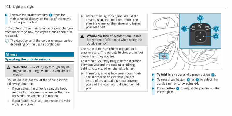
# Remove the protective film1 from themaintenance display on the tip of the newlyfitted wiper blades.
If the colour of the maintenance display changesfrom black to yellow, the wiper blades should bereplaced.% The duration until the colour changes varies
depending on the usage conditions.
MirrorsOperating the outside mirrors
& WARNING Risk of injury through adjust‐ing vehicle settings while the vehicle is inmotion
You could lose control of the vehicle in thefollowing situations:R if you adjust the driver's seat, the head
restraints, the steering wheel or the mir‐ror while the vehicle is in motionR if you fasten your seat belt while the vehi‐
cle is in motion
# Before starting the engine: adjust thedriver's seat, the head restraints, thesteering wheel or the mirror and fastenyour seat belt.
& WARNING Risk of accident due to mis‐judgement of distances when using theoutside mirror
The outside mirrors reflect objects on asmaller scale. The objects in view are in factcloser than they appear.As a result, you may misjudge the distancebetween you and the road user drivingbehind you, e.g. when changing lanes.# Therefore, always look over your shoul‐
der in order to ensure that you areaware of the actual distance betweenyou and the road users driving behindyou.
# To fold in or out: briefly press button2.# To set: press button1 or3 to select the
outside mirror to be adjusted.# Press button4 to adjust the position of the
mirror glass.
142 Light and sight

% If the battery has been disconnected or com‐pletely discharged, you will have to reset theoutside mirrors. Only then will the automaticmirror folding function work properly.
# To adjust: briefly press button2.An outside mirror that has been pushed out ofposition can be engaged in position again as fol‐lows:# Vehicles without electrically folding out‐
side mirrors: manually move the outsidemirror into the correct position.
# Vehicles with electrically folding outsidemirrors: press and hold button2.You will hear a click and the mirror will audi‐bly engage in position. The outside mirror willnow be set to the correct position.
Automatic anti-dazzle mirrors function
& WARNING Risk of burns and poisoningdue to the anti-dazzle mirror electrolyte
Electrolyte may escape if the glass in anautomatic anti-dazzle mirror breaks.
The electrolyte is harmful and causes irrita‐tion. It must not come into contact with yourskin, eyes, respiratory organs or clothing orbe swallowed.# If you come into contact with electro‐
lyte, observe the following:R Rinse the electrolyte from your skin
and seek medical attention immedi‐ately.R If electrolyte comes into contact
with your eyes, rinse them thor‐oughly with clean water and seekmedical attention immediately.R If the electrolyte is swallowed,
immediately rinse your mouth outthoroughly. Do not induce vomiting.Seek medical attention immediately.R Immediately change out of clothing
which has come into contact withelectrolyte.R If an allergic reaction occurs, seek
medical attention immediately.
The inside rearview mirror and the outside mir‐ror on the driver's side automatically go intoanti-dazzle mode if light from a headlamp hitsthe sensor on the inside rearview mirror.
System limitationsThe system does not go into anti-dazzle mode inthe following situations:R the engine is switched offR reverse gear is engagedR the interior lighting is switched on
Front-passenger outside mirror parking posi‐tion function
The parking position makes parking easier.In the following situations, the front-passengeroutside mirror will swivel downwards in thedirection of the rear wheel on the front passeng‐er's side:R the parking position is stored (/ page 144)R the front-passenger mirror is selectedR reverse gear is engaged
Light and sight 143

The front-passenger outside mirror will moveback to its original position in the following sit‐uations:R you shift the transmission to another trans‐
mission positionR you are travelling at speeds greater than
15 km/hR you press the button for the outside mirror
on the driver's side
Storing the parking position of the front-passenger outside mirror using reverse gear
Storing
# Press button1 to select the front-passenger outside mirror.
# Engage reverse gear.# Move the passenger outside mirror into the
desired parking position using button2.
Calling up# Press button1 to select the front-
passenger outside mirror.# Engage reverse gear.
The front-passenger outside mirror will moveto the stored parking position.
Activating/deactivating the automatic mirrorfolding function
Multimedia system:4© 5 Settings 5 Vehicle# Switch Automatic fold-in on or off.
144 Light and sight

Operating the sun visors
# Glare from the front: fold sun visor1down.
# Glare from the side: swing sun visor1 tothe side.
Light and sight 145

Overview of climate control systemsNotes on climate control
An interior air filter in combination with the pre‐filter in the engine compartment must always beused so that the air conditioning system, pollu‐tion lebuttonvel monitoring and the air filtrationwork correctly. Make sure that the filter is instal‐led correctly and the filter housing in the enginecompartment is closed correctly using the capand always tightly sealed when in operation. Usefilters recommended and approved byMercedes-Benz. Always have service work car‐ried out at a qualified specialist workshop.
THERMATIC control panel overview
The indicator lamps in the buttonsÃ,¬,¤,g,¿ and& indicate that thecorresponding function is activated.
1 w Sets the temperature2 Vehicles with a stationary heater only:t
calls up the air conditioning menu3H Sets the airflow or switches off climate
control4 Ã Sets climate control to automatic
mode(/ page 148)5 ¬ Defrosts the windscreen6 ¤ Switches the rear window heater
on/off7 g Switches air-recirculation mode on/off
(/ page 149)8 ¿ Switches the A/C function on/off
(/ page 147)
9 Vehicles with a stationary heater only:&switches the stationary heater on/off(/ page 150)
A _ Sets the air distribution
THERMOTRONIC control panel overview
The indicator lamps in the buttonsÃ,¬,¤,g,Á,0 and& indicate thatthe corresponding function is activated.
146 Climate control

1 w Sets the temperature on the driver'sside
2 Vehicles without a stationary heater:_sets the air distributionVehicles with a stationary heater:t callsup the air conditioning menu
3H Sets the airflow or switches off climatecontrol
4 Ã Sets climate control to automaticmode (/ page 148)
5 ¬ Defrosts the windscreen6 ¤ Switches the rear window heater
on/off7 g Switches air-recirculation mode on/off
(/ page 149)8 Á Switches the A/C function on/off
(/ page 147)Switches residual heat on/off (/ page 149)
9 Vehicles without a stationary heater:0switches synchronisation on/off(/ page 149)Vehicles with a stationary heater:&switches the stationary heater on/off(/ page 150)
A w Sets the front passenger side tempera‐ture
Operating the climate control systemSwitching climate control on/off
# To switch on: set the airflow to level 1 orhigher using theH button.
# To switch off: set the airflow to level 0 usingtheH button.
% If climate control is switched off, the win‐dows may mist up more quickly. Switch offclimate control only briefly.
Switching the A/C function on or off via thecontrol panel
The A/C function heats, cools and dehumidifiesthe vehicle's interior air.# Press the¿/Á button.
Switch off the A/C function only briefly; other‐wise, the windows may mist up more quickly.Condensation may drip from the underside ofthe vehicle when cooling mode is active. This isnot a sign that there is a malfunction.
Climate control 147
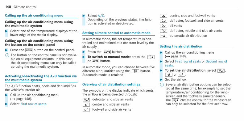
Calling up the air conditioning menu
Calling up the air conditioning menu usingthe multimedia system# Select one of the temperature displays at the
lower edge of the media display.
Calling up the air conditioning menu usingthe button on the control panel# Press thet button on the control panel.% The button on the control panel is not availa‐
ble on all equipment variants. In this case,the air conditioning menu can only be calledup using the multimedia system.
Activating/deactivating the A/C function viathe multimedia system
The A/C function heats, cools and dehumidifiesthe vehicle's interior air.# Call up the air conditioning menu
(/ page 148).# Select First row of seats.
# Select A/C.Depending on the previous status, the func‐tion is activated or deactivated.
Setting climate control to automatic mode
In automatic mode, the set temperature is con‐trolled and maintained at a constant level by theair supply.# Press the à button.# To switch to manual mode: press the _
orà button.
In automatic mode, you can choose between fivedifferent air quantities using theH button.Automatic mode is retained.
Overview of air distribution settings
The symbols on the display indicate which ventsthe airflow is being directed through:¯ defroster and side air ventsP centre and side air ventsO footwell and side air vents
S centre, side and footwell ventsa defroster, footwell and side air vents_ all ventsb defroster, middle and side air ventsW automatic air distribution
Setting the air distribution
# Call up the air conditioning menu(/ page 148).
# Select First row of seats or Second row ofseats.
# To set the air distribution: select¯,P orO.
# Set the airflow.% Several air distribution options can be selec‐
ted at the same time, for example to set thetemperature/air conditioning for the wind‐screen and the footwells simultaneously.The¯ climate control for the windscreencan only be selected for the first seat row.
148 Climate control

Activating/deactivating the climate controlsynchronisation function via the controlpanel
Climate control can be set centrally using thesynchronisation function. The temperature andair distribution setting for the driver side is adop‐ted automatically for the front passenger side.# Press the0 button.
The synchronisation function is deactivated ifthe settings for one of the other climate zonesare changed.
Activating/deactivating the climate controlsynchronisation function using the multime‐dia system
Climate control can be set centrally using thesynchronisation function. The driver's settingsfor temperature, air quantity and air distributionare adopted automatically for all climate zones.# Call up the air conditioning menu
(/ page 148).# Select First row of seats.
# Select SYNC.Depending on the previous status, the func‐tion is activated or deactivated.
Demisting the windows
Windows misted up on the inside# Press theà button.# If the windows continue to mist up: press the
¬ button.
Windows misted up on the outside# Switch on the windscreen wipers.# Press theà button.
Switching air-recirculation mode on/off
# Press theg button.The interior air will be recirculated.
Air-recirculation mode automatically switches tofresh air mode after some time.% If air-recirculation mode is switched on, the
windows may mist up more quickly. Switchon air-recirculation mode only briefly.
Switches the residual heat on/off
Requirements:R The vehicle is parked.
It is possible to make use of the residual heatfrom the engine to continue heating or ventilat‐ing the front compartment of the vehicle forapproximately 30 minutes, depending on thetemperature set.# To switch on: press theÁ button.
Residual heat is switched off automatically.
Stationary heater/ventilation
Stationary heater/stationary ventilationfunctionR The air inside the vehicle is heated or ventila‐
ted to the set temperature.R The air inside the vehicle cannot be cooled
down to temperatures below the outsidetemperature.R If the outside temperature changes, ventila‐
tion mode automatically switches to heating
Climate control 149

mode or heating mode automaticallyswitches to ventilation mode.
The stationary heater and the exhaust gas outletare situated in front of the right-hand frontwheel.
Switching the stationary heater/stationaryventilation on/off via the control panel
& DANGER Risk of fatal injury due to poi‐sonous exhaust gases
If the tailpipe is blocked or sufficient ventila‐tion is not possible, poisonous exhaust gasessuch as carbon monoxide may enter the vehi‐cle. This is the case in enclosed spaces or ifthe vehicle gets stuck in snow, for example.# Always switch the stationary heater off
in enclosed spaces without an airextraction systems, e.g. in garages.
# Keep the tailpipe and the area aroundthe vehicle free from snow when theengine or the stationary heater are run‐ning.
# Open a window on the windward side ofthe vehicle to ensure an adequate sup‐ply of fresh air.
& WARNING Risk of fire due to hot station‐ary heater components
When the stationary heater is switched on,parts of the vehicle can become very hot,e.g. the stationary heater exhaust system.Flammable materials such as leaves, grass ortwigs may ignite if they come into contactwith:R hot parts of the stationary heater exhaust
systemR the exhaust gas itself
There is a risk of fire.# When the stationary heater is switched
on, make sure that:R hot vehicle parts do not come into
contact with flammable materials.
R the exhaust gas can flow out of thestationary heater exhaust pipeunhindered.R the exhaust gas does not come into
contact with flammable materials.
* NOTE Battery discharge caused by sta‐tionary heater or stationary ventilationoperation
Operating the stationary heater or stationaryventilation drains the battery.# After heating or ventilating the vehicle
twice, drive for a longer period of time.
Requirements:R The fuel tank has been filled to at leastÕ.
150 Climate control

# Set the desired temperature using thewbutton.
# Press button 1.The red or blue indicator lamp on button1will light up or go out.
The indicator lamp colours mean the following:R Blue: stationary ventilation is switched on.R Red: the stationary heater is switched on.
R Yellow: the departure time is preselected.
The stationary heater/stationary ventilation willswitch off automatically after 50 minutes.Operation using the app: the stationaryheater/ventilation can also be operated via theMercedes me connect app. Further informationcan be found in the separate Owner's Manualunder http://manuals.daimler.com/baix/cars/connectme/en_GB/index.html.
Setting the stationary heater / stationaryventilation via the multimedia system# Call up the air conditioning menu
(/ page 148).# Select Auxiliary heating.
Selecting the departure time# Select the time TIME A: XX, TIME B: XX or
TIME C: XX.
Setting the departure time# Select the time TIME A: XX, TIME B: XX or
TIME C: XX.# Select the pen beside the time.
# Set a time.
Setting the stationary heater/stationary ven‐tilation via remote control
Requirements:R The fuel tank has been filled to at leastÕ.
Switching on immediately
# Press and hold theu button.
Climate control 151

Setting the departure time# Briefly press theu switch.# Press the, or. button repeatedly
until the time to be changed appears on thedisplay.
# Press theu and^ buttons simultane‐ously.TheÎ symbol will flash on the remote con‐trol display.
# Press the, and. buttons to set thedesired departure time.
# Press theu and^ buttons simultane‐ously.The new departure time will be stored.
Up to three departure times can be stored.# To activate the departure time: select the
desired departure time and press and holdtheu button.TheÍ symbol, the departure time and,depending on the selected departure time,the letter A, B or C will appear on the display.
# To deactivate the departure time: selectthe desired departure time and press andhold the^ button.OFF will appear on the display.
# To check the status of the stationaryheater: briefly press theu button.
Switching off immediately# Press and hold the^ button.
Overview of the remote control displays (sta‐tionary heater/stationary ventilation)
1 Stationary ventilation switched on2 Stationary heater switched on
3 Selected departure time4 Remaining time for the stationary heater/
stationary ventilation (in minutes)5 Stationary heater/stationary ventilation
active6 Departure time activated7 Signal strength
Further possible displays:R Time: activated departure time.R Zero minutes: the running time for the sta‐
tionary heater is increased, as the engine hasnot yet reached operating temperature whenit is started.R OFF: the stationary heater/stationary venti‐
lation is switched off.
152 Climate control

Replacing the remote control battery (sta‐tionary heater)
& DANGER Serious damage to healthcaused by swallowing batteries
Batteries contain toxic and corrosive sub‐stances. Swallowing batteries may causeserious damage to health.There is a risk of fatal injury.# Keep batteries out of the reach of chil‐
dren.# If batteries are swallowed, seek medical
attention immediately.
+ ENVIRONMENTAL NOTE Environmentaldamage due to improper disposal of bat‐teries
Batteries contain toxic and corro‐sive substances.
#
Take discharged batteries to aqualified specialist workshop or to acollection point for used batteries.
Requirements:R a CR2450 lithium battery
# Push a pointed object into recess1.# Slide battery cover2 backwards in the
direction of the arrow.
# Insert new battery3 with the letteringfacing upwards.
# Slide battery cover2 in the opposite direc‐tion to the arrow onto the remote controluntil the battery cover engages.
Climate control 153

Problems with the remote control for the stationary heater/stationary ventilation
Problem Possible causes/consequences and MM Solutions
FAIL¨ The signal transmission between the transmitter and the vehicle is faulty.# Change your position in relation to the vehicle, moving closer if necessary.
FAIL The starter battery is not sufficiently charged.# Charge the starter battery.
The fuel tank content is below the reserve fuel level.# Refuel at the nearest filling station.
FAIL¯ The stationary heater is malfunctioning.# Have the stationary heater checked at a qualified specialist workshop.
Air vents
Adjusting the front air vents
& WARNING ‑ Risk of burns/frostbite dueto not maintaining a sufficient distanceto the air vents
Very hot or very cold air can flow from the airvents.
This could result in burns or frostbite in theimmediate vicinity of the air vents.# Always ensure that all vehicle occu‐
pants maintain a sufficient distance tothe air vents.
# If necessary, redirect the airflow toanother area of the vehicle interior.
To guarantee the flow of fresh air through the airvents into the vehicle interior, comply with thefollowing:R Always keep the vents and the ventilation
grille in the vehicle interior free.R Keep the air inlet free of deposits
(/ page 452).
154 Climate control

# To open or close: hold air vent1 in thecentre and turn it to the left (open) or right(closed) as far as it will go.
# To adjust the air direction: hold air vent1in the centre and move it up or down or tothe left or right.
Adjusting the rear air vents
# To open or close: hold air vent1 in thecentre and turn it to the left (open) or right(closed) as far as it will go.
# To adjust the air direction: hold air vent1in the centre and move it up or down or tothe left or right.
Climate control 155

DrivingNotes on Mercedes-AMG vehicles
Observe the notes on the following topics in theSupplement, as you may otherwise fail to recog‐nise dangers:R Mercedes-AMG CLA 45 4MATIC and CLA
45 S 4MATIC: front axle locking differentialR AMG Performance exhaust systemR RACE STARTR AMG RIDE CONTROL
Switching the power supply or ignition onwithout starting the engine
& DANGER Risk of fatal injuries due toexhaust gases
Combustion engines emit poisonous exhaustgases such as carbon monoxide. Inhalingthese exhaust gases is hazardous to healthand can lead to poisoning.
# Never leave the engine running in anenclosed space without sufficient venti‐lation.
& WARNING Risk of fire caused by flam‐mable material on the exhaust system
Flammable materials brought in by either ani‐mals or environmental influences may igniteif they come into contact with hot parts ofthe engine or exhaust system.# Therefore, check regularly that there
are no flammable materials in theengine compartment or on the exhaustsystem.
& WARNING Risk of accident and injurydue to children left unattended in thevehicle
If children are left unattended in the vehicle,they could:R Open doors, thereby endangering other
persons or road users.
R Get out and be struck by oncoming traf‐fic.R Operate vehicle equipment and become
trapped, for example.
In addition, the children could also set thevehicle in motion, for example by:R Releasing the parking brake.R Changing the transmission position.R Starting the vehicle.
# Never leave children unattended in thevehicle.
# When leaving the vehicle, always takethe key with you and lock the vehicle.
# Keep the vehicle key out of reach ofchildren.
This also applies to the Digital Vehicle Key if the"Digital Vehicle Key" function is activated viaMercedes me connect.
Requirements:R the key is in the vehicle and is recognised.
156 Driving and parking

R or: a Digital Vehicle Key is located in themarked space (/ page 158).R Vehicles with automatic transmission: the
brake pedal is not depressed.R Vehicles with manual transmission: the
clutch pedal is not depressed.
# To switch on the power supply: press but‐ton1 once.You can activate the windscreen wiper, forexample.
The power supply is switched off again if the fol‐lowing conditions are met:R you open the driver's door.R you press button1 twice more.
# To switch on the ignition: press button1twice.The indicator lamps in the instrument clusterlight up.
The ignition is switched off again if one of thefollowing conditions is met:R vehicles with automatic transmission:
you do not start the vehicle within15 minutes.R vehicles with automatic transmission: the
transmission is in positionj or the electricparking brake has been applied.
R vehicles with manual transmission: youdo not start the vehicle within 15 minutesand the electric parking brake is applied.R you press button1 once.
Starting the vehicle
Starting the vehicle with the start/stop but‐ton
Requirements:R the key is in the vehicle and is recognised.R or: a Digital Vehicle Key is located in the
marked space and is recognised(/ page 158).
# Vehicles with manual transmission:depress the clutch pedal.
# Vehicles with automatic transmission:shift the transmission to positionj ori.
# depress the brake pedal and press button1once.
# If the vehicle does not start: switch off non-essential consumers and press button1once.
Driving and parking 157

If the vehicle still does not start, one of the fol‐lowing display messages appears in the multi‐function display:# Place the key in the marked space See Own-
er's Manual: start the vehicle in emergencyoperation mode (/ page 159).
or# Key not detected Place smartphone in charg-
ing bracket: place the mobile phone in themarked space (/ page 126).
You can switch off the engine while driving bypressing button1 for about three seconds orby pressing button1 three times within a sec‐ond. Be sure to observe the safety notes under"Driving tips".
Starting the vehicle with a Digital VehicleKey
Requirements:R one of the following versions of the Digital
Vehicle Key is available:- suitable mobile phone- Digital Vehicle Key sticker
R the vehicle is equipped with the "Digital Vehi‐cle Key" function.R the "Digital Vehicle Key" function is activated
via Mercedes me connect: http://www.mercedes.me.R the mobile phone is sufficiently charged.
% You can check the suitability of your mobilephone by entering the phone number athttp://www.mercedes.me.Information about suitable mobile phonescan be obtained from your Mercedes-BenzService Centre or at http://www.mercedes-benz.com/connect.
% Mercedes-Benz recommends that you carrythe emergency key in case of functionrestrictions.
% The function is only available in combinationwith Mercedes me connect and only in cer‐tain countries.
% Protective cases around the mobile phonecan impair the functionality.
Using the Digital Vehicle Key for the firsttime
# Deactivate the key2 (/ page 77).# Place key2 in marked space3 on the
symbol4.# Place the mobile phone or Digital Vehicle Key
sticker in the marked space1.# Start the vehicle using the start/stop button.
158 Driving and parking

Any further starts with the Digital VehicleKeyThe key is not needed for any further starts.# Place the mobile phone or Digital Vehicle Key
sticker in the marked space1.# Start the vehicle using the start/stop button.
The "Digital Vehicle Key" service can be deacti‐vated in Mercedes me connect at http://www.mercedes.me. The function is then deacti‐vated in the mobile phone via an online connec‐tion. If connection to the Internet is not possible,e.g. after the mobile phone or the Digital VehicleKey sticker has been stolen, the key function canbe deactivated at a Mercedes-Benz servicecentre.
Starting the vehicle with key in the markedspace (emergency operation mode)If the vehicle does not start and the Place thekey in the marked space See Owner's Manualmessage appears in the multifunction display,you can start the vehicle in emergency operationmode.
Marked space (example with cup holder withoutcover)
# Open the cover of marked space2 if neces‐sary.
# Make sure that marked space2 is empty.# Remove key1 from the key ring.
# Place key1 in marked space2 on thesymbol3.The vehicle will start after a short time.If you remove key1 from marked space2the engine continues running. For furtherengine starts however, key1 must be loca‐ted in marked space2 on symbol3 duringthe entire journey.
# Have the key1 checked at a qualified spe‐cialist workshop.
If the vehicle does not start:# place key1 in marked space2 and leave
it there.# Vehicles with manual transmission:
depress the clutch pedal.# Depress the brake pedal and start the vehi‐
cle using the start/stop button.% You can also switch on the power supply or
the ignition with the start/stop button.
Driving and parking 159

Starting the vehicle via Remote Online serv‐ices
Cooling or heating the vehicle interior beforecommencing your journey% This function is not available in all countries.If you start the vehicle via your smartphone, thepreviously selected air conditioning adjustmentis active.Ensure the following before starting the engine:R the legal stipulations in the area where your
vehicle is parked allow engine starting viasmartphone.R it is safe to start and run the engine where
your vehicle is parked.R the fuel tank is sufficiently filled.R the starter battery is sufficiently charged.
% You can also set the temperature with yoursmartphone. Information on Mercedes meconnect and other services: http://www.mercedes.meThis function is not available for all models.
Charging the battery before commencingyour journeyIf the vehicle battery is discharged, you receive amessage on your smartphone. You can thenstart the vehicle with the smartphone to chargethe battery. The vehicle is automaticallyswitched off after ten minutes.Ensure the following before starting the engine:R the legal stipulations in the area where your
vehicle is parked allow engine starting viasmartphone.R it is safe to start and run the engine where
your vehicle is parked.R the fuel tank is sufficiently filled.
Starting the vehicle (Remote Online)
& WARNING Risk of crushing or entrap‐ment due to unintentional starting of theengine
Limbs could be crushed or trapped if theengine is started unintentionally duringservice or maintenance work.
# Always secure the engine against unin‐tentional starting before carrying outmaintenance or repair work.
Requirements:R park positionj is selected.R the anti-theft alarm system is not activated.R the panic alarm is not activated.R the hazard warning lights are switched off.R the bonnet is closed.R the doors are closed and locked.R the windows and sliding sunroof are closed.
# Start the vehicle using the smartphone:after every vehicle start, the engine runs forten minutes.
you can carry out a maximum of two consecu‐tive starting attempts. The vehicle must be star‐ted once with the key before trying to start thevehicle again with the smartphone. you can stopthe vehicle again at any time.% further information can be found in the
smartphone app.
160 Driving and parking

Securing the engine against starting beforecarrying out maintenance or repair work:# switch on the hazard warning lights.or# unlock the doors.or# open a side window or the sliding sunroof.
Running-in notes
Mercedes-AMG vehicles: observe the notes inthe Supplement. Otherwise, you may fail to rec‐ognise dangers.To preserve the engine during the first 1,500 km:R drive at varying road speeds and engine
speeds.R drive the vehicle in drive programA
or;.R change gear before the rev counter needle is
Ô of the way to the red area of the rev coun‐ter.R do not shift down a gear manually in order to
brake.
R avoid overstraining the vehicle, e.g. driving atfull throttle.R vehicles with automatic transmission: do
not depress the accelerator pedal beyond thepressure point (kickdown).R only increase the engine speed gradually and
accelerate the vehicle to full speed after1,500 km.
This also applies when the engine or parts of thedrivetrain have been replaced.Please also observe the following running-innotes:R in certain driving and driving safety systems,
the sensors adjust automatically while a cer‐tain distance is being driven after the vehiclehas been delivered or after repairs. Full sys‐tem effectiveness is not reached until theend of this teach-in process.R brakepads, brake discs and tyres that are
either new or have been replaced only ach‐ieve optimum braking effect and grip afterseveral hundred kilometres of driving. Com‐
pensate for the reduced braking effect byapplying greater force to the brake pedal.
Notes on driving
& WARNING Risk of accident due toobjects in the driver's footwell
Objects in the driver's footwell may impedepedal travel or block a depressed pedal.This jeopardises the operating and roadsafety of the vehicle.# Stow all objects in the vehicle securely
so that they cannot get into the driver'sfootwell.
# Always fit the floor mats securely andas prescribed in order to ensure thatthere is always sufficient room for thepedals.
# Do not use loose floor mats and do notplace floor mats on top of one another.
Driving and parking 161

& WARNING Risk of accident due tounsuitable footwear
Operating the pedals may be impaired bywearing unsuitable footwear, e.g.:R platform shoesR high-heeled shoesR slippers
# Always wear suitable footwear whendriving so that you can operate the ped‐als safely.
& WARNING Risk of accident when switch‐ing off the ignition when driving
If you switch off the ignition while driving,safety functions are restricted or no longeravailable. This may affect the power steeringsystem and the brake force boosting, forexample.You will then need to use considerably moreforce to steer and brake.
# Do not switch off the ignition while driv‐ing.
& DANGER Risk of fatal injuries due toexhaust gases
Combustion engines emit poisonous exhaustgases such as carbon monoxide. Inhalingthese exhaust gases is hazardous to healthand can lead to poisoning.# Never leave the engine running in an
enclosed space without sufficient venti‐lation.
& WARNING Risk of skidding and of anaccident due to shifting down on slipperyroad surfaces
If you shift down on slippery road surfaces toincrease the engine braking effect, the drivewheels may lose traction.# Do not shift down on slippery road sur‐
faces to increase the engine brakingeffect.
& DANGER Risk of fatal injuries due to poi‐sonous exhaust gases
If the tailpipe is blocked or sufficient ventila‐tion is not possible, poisonous exhaust gasessuch as carbon monoxide may enter the vehi‐cle. This is the case, for example, if the vehi‐cle is stuck in snow.# When the engine or the stationary
heater are running, keep the tailpipeand the area around the vehicle clear ofsnow.
# Open a window on the side of the vehi‐cle facing the wind to ensure an ade‐quate supply of fresh air.
& WARNING Risk of accident due to thebrake system overheating
If you leave your foot on the brake pedalwhen driving, the brake system may over‐heat.This increases the braking distance and thebrake system may even fail.
162 Driving and parking

# Never use the brake pedal as a footrest.# Do not depress the brake pedal and the
accelerator pedal at the same timewhile driving.
* NOTE Causing wear to the brake liningsby permanently depressing the brakepedal
# Do not permanently depress the brakepedal while driving.
# To use braking effect of the engine,shift to a lower gear in good time.
* NOTE Damage to the drivetrain andengine when pulling away
# Do not warm up the engine while thevehicle is stationary. Pull away immedi‐ately.
# Avoid high engine speeds and driving atfull throttle until the engine has reachedits operating temperature.
* NOTE Damage to the catalytic converterdue to non-combusted fuel
The engine is not running smoothly and ismisfiring.Non-combusted fuel may get into the cata‐lytic converter.# Only depress the accelerator pedal
slightly.# Have the cause rectified immediately at
a qualified specialist workshop.
Limited braking effect on salt-treated roads:R due to salt build-up on the brake disks and
brakepads, the braking distance can increaseconsiderably or result in braking only on onesideR maintain a much greater safe distance to the
vehicle in front
To prevent salt build-up:R brake occasionally while paying attention to
the traffic conditions
R carefully depress the brake pedal at the endof the journey and when starting the nextjourney
ECO start/stop function
Operation of the ECO start/stop functionMercedes-AMG vehicles: observe the notes inthe Supplement. Otherwise, you may fail to rec‐ognise dangers.The engine is switched off automatically in thefollowing situations if all vehicle conditions foran automatic engine stop are met:R vehicles with manual transmission: you
brake the vehicle, shift into neutrali whentravelling at a low speed and then release theclutch pedal.R vehicles with automatic transmission:
you brake the vehicle to a standstill in trans‐mission positionh ori.
Vehicles with automatic transmission:
Driving and parking 163

if you switch on the HOLD function in transmis‐sion positionh ori, the engine will automati‐cally stop in the following situations:R you stop behind a vehicle that is pulling
away.R you stop at a stop sign when there is no vehi‐
cle in front of you.R you turn the steering wheel hard at a low
speed.
% In transmission positionk, the engine isnot switched off automatically even whenthe HOLD function is switched on.
The engine is restarted automatically if:R vehicles with automatic transmission: in
transmission positionh, you release thebrake pedal when the HOLD function is notactive.R vehicles with automatic transmission:
you shift into transmission positionh ork.R you depress the accelerator pedal.R you change the vehicle level.
R an automatic engine start is necessary.
ECO start/stop function symbols in the multi‐function display:R the symbolè (green) appears when the
vehicle is at a standstill: the engine wasswitched off by the ECO start/stop function.R the symbolç (yellow) appears when the
vehicle is at a standstill: not all vehicle condi‐tions for an engine stop have been met.R neither the symbolè norç appears
when the vehicle is at a standstill: an intelli‐gent stop inhibitor was detected, e.g. a stopsign.R the symbolç (yellow) appears: the ECO
start/stop function is deactivated or there isa malfunction.
% If, in spite of an intelligent stop inhibitor, theengine should be switched off by the ECOstart/stop function, you have the followingoptions:R switch on the HOLD function in transmis‐
sion positionh ori.R engage transmission positionj.
If the engine was switched off by the ECO start/stop function and you leave the vehicle, a warn‐ing tone sounds and the engine is not restarted.The display message Vehicle is operationalSwitch off the ignition before exiting alsoappears in the multifunction display. If you donot switch off the ignition, the ignition is auto‐matically switched off after three minutes.
164 Driving and parking

Deactivating or activating the ECO start/stop function
# Press button1.A display appears in the instrument clusterwhen switching the ECO start/stop functionoff/on.
% A continuous display appears in the instru‐ment cluster while the ECO start/stop func‐tion is deactivated.
ECO display function
The ECO display summarises your driving char‐acteristics from the start of the journey to itscompletion and assists you in achieving themost economical driving style.You can influence consumption if you:R drive with particular careR drive the vehicle in drive program;R observe the gearshift recommendations
The lettering in the segment will light up brightly,the outer edge will light up and the segment willfill up where the following driving style is adop‐ted:R 1 steady speedR 2 gentle deceleration and rollingR 3 moderate acceleration
The lettering in the segment will be grey, theouter edge will be dark and the segment willempty where the following driving style is adop‐ted:R 1 fluctuations in speedR 2 heavy brakingR 3 sporty acceleration
The ECO display will show you when you havedriven economically:R the three segments fill up completely at the
same timeR the edge around all three segments lights up
The additional range achieved as a result of yourdriving style in comparison with a driver with a
Driving and parking 165

very sporty driving style is shown in the centreof the display4. The range displayed does notindicate a fixed reduction in consumption.
DYNAMIC SELECT switchFunction of the DYNAMIC SELECT switch
Mercedes-AMG vehicles: observe the notes inthe Supplement. Otherwise, you may fail to rec‐ognise dangers.Use the DYNAMIC SELECT switch to changebetween the following drive programs:= (Individual): individual settingsC (Sport): sporty driving styleA (Comfort): comfortable and economical
driving style; (Eco): particularly economical driving
style
% The drive program selected appears in themultifunction display of the on-board com‐puter.
Depending on the drive program, the followingsystems change their characteristics:R drive
- engine and transmission management- Active Distance Assist DISTRONICR ESP®
R vehicles with adaptive damping adjust‐ment: suspensionR electric power steering
Notes on the roof load display
Certain drive programs and ESP® settings areunsuitable for transporting a roof load.When setting or selecting these drive programs,a crossed-through vehicle with a roof load isshown as a warning. When this symbol is shown,the selected drive program is not suitable fortransporting a load on the roof.The following drive programs are affected:R Sport drive program
R Individual drive program with the SportESP® setting
% The symbol is also shown in the following sit‐uations:R Within the themes if a corresponding
drive program is savedFor more information on themes see(/ page 307).R Within the reset display if the previously
active drive program is unsuitable for thetransport of a roof loadFor further information on the reset dis‐play, see (/ page 167).
Selecting the drive program
% Depending on the equipment, the vehicle isfitted with either a switch or a button.
166 Driving and parking

# Press DYNAMIC SELECT switch1 forwardsor backwards.The drive program selected appears in themultifunction display.
or# Press DYNAMIC SELECT button2.
The DYNAMIC SELECT menu appears in themultifunction display.
# Press DYNAMIC SELECT button2 again.The chosen drive program appears.
Configuring DYNAMIC SELECT (multimediasystem)
Multimedia system:4© 5 Settings 5 Vehicle5 DYNAMIC SELECT
Setting drive program I# Select Individual config..# Select and set a category.
Switching the reset display on/off# Switch Ask when starting on or off.
Function on: the next time the vehicle is starteda prompt appears asking whether the drive pro‐gram last active should be restored. If the ECOstart/stop function was deactivated, an addi‐tional prompt appears asking if the functionshould remain deactivated.
Driving and parking 167

% The prompt appears only if the previouslyactive settings deviate from the standardsettings.
Function off: the next time the vehicle is star‐ted the Comfort drive program is set automati‐cally. The ECO start/stop function is activatedautomatically.% This function must be activated for each user
profile separately. Only when this function isactivated will the drive program and Ecostart/stop setting for the previous journeybe saved for the respective user profile.
Displaying vehicle data
Multimedia system:4© 5 Info# Select Vehicle.
The vehicle data is displayed.
Displaying engine data
Multimedia system:4© 5 Info# Select Engine.
The engine data is displayed.% The values for engine output and engine tor‐
que may deviate from the nominal values.Items that can influence this are, for exam‐ple:R Sea levelR Fuel gradeR Outside temperature
Calling up fuel consumption indicator
Multimedia system:4© 5 Info# Select Consumption.
The current and average fuel consumption isdisplayed.
Manual transmissionOperating the gearshift lever
& WARNING Risk of accident and injurydue to children left unattended in thevehicle
If children are left unattended in the vehicle,they could:R Open doors, thereby endangering other
persons or road users.R Get out and be struck by oncoming traf‐
fic.R Operate vehicle equipment and become
trapped, for example.
In addition, the children could also set thevehicle in motion, for example by:R Releasing the parking brake.R Changing the transmission position.R Starting the vehicle.
# Never leave children unattended in thevehicle.
168 Driving and parking

# When leaving the vehicle, always takethe key with you and lock the vehicle.
# Keep the vehicle key out of reach ofchildren.
This also applies to the Digital Vehicle Key if the"Digital Vehicle Key" function is activated viaMercedes me connect.
* NOTE Damage to the engine and trans‐mission by shifting to a gear that is toolow
# When changing between gears5 and6 push the gearshift lever to the right.
# Do not shift down at high speeds.
* NOTE Damage to the transmission byshifting to reverse geark while thevehicle is in motion
# Only shift into reverse geark whenthe vehicle is stationary.
k Reverse gear1 -6 Forward gearsi Neutral
# Depress the clutch pedal fully and shift thegearshift lever into the desired position.
Gearshift recommendation
The gearshift recommendation assists you inadopting an economical driving style.
# If gearshift recommendation message1 isshown on the multifunction display, shift tothe recommended gear.
Driving and parking 169

Automatic transmissionDIRECT SELECT lever
Function of the DIRECT SELECT lever
& WARNING Risk of accident due to incor‐rect gearshifting
If the engine speed is higher than the idlespeed and you engage the transmission posi‐tionh ork, the vehicle may acceleratesharply.# If you engage the transmission position
h ork always depress the brakepedal firmly and do not accelerate atthe same time.
& WARNING Risk of accident and injurydue to children left unattended in thevehicle
If children are left unattended in the vehicle,they could:R Open doors, thereby endangering other
persons or road users.R Get out and be struck by oncoming traf‐
fic.R Operate vehicle equipment and become
trapped, for example.
In addition, the children could also set thevehicle in motion, for example by:R Releasing the parking brake.R Changing the transmission position.R Starting the vehicle.
# Never leave children unattended in thevehicle.
# When leaving the vehicle, always takethe key with you and lock the vehicle.
# Keep the vehicle key out of reach ofchildren.
This also applies to the Digital Vehicle Key if the"Digital Vehicle Key" function is activated viaMercedes me connect.Use the DIRECT SELECT lever to shift the trans‐mission position. The current transmission posi‐tion is displayed in the multifunction display.
170 Driving and parking

j Park positionk Reverse geari Neutralh Drive position
Engaging reverse gear R# Depress the brake pedal and push the
DIRECT SELECT lever upwards past the firstpoint of resistance.The transmission position display showskin the multifunction display.
Engaging neutral N# Depress the brake pedal and push the
DIRECT SELECT lever up or down to the firstpoint of resistance.The transmission position display showsiin the multifunction display.
Subsequently releasing the brake pedal willallow you to move the vehicle freely, e.g. to pushit or tow it away.
Proceed as follows if you want the automatictransmission to remain in neutralii even ifthe ignition is switched off:# Start the vehicle.# Depress the brake pedal and engage neutral
i.# Release the brake pedal.# Switch off the ignition.
% If you then exit the vehicle leaving the key inthe vehicle, the automatic transmissionremains in neutrali.
Engaging park position P# Observe the notes on parking the vehicle
(/ page 181).# Depress the brake pedal until the vehicle is
stationary.# When the vehicle is stationary, press button
j.Park position is only engaged when thetransmission position displayj is shown inthe multifunction display. If no transmissionposition displayj appears, secure the vehi‐cle to prevent it from rolling away.
Park positionj is engaged automatically if oneof the following conditions is met:R you switch off the ignition when the vehicle
is stationary and the transmission is in posi‐tionh ork.R you open the driver's door when the vehicle
is stationary or when driving at a very low
Driving and parking 171

speed and the transmission is in positionhork.
% To manoeuvre with an open driver's door,open the driver's door while stationary andengage transmission positionh orkagain.
% At very low outside temperatures fromapprox. -20 °C you may not be able to shiftthe transmission fromj to another trans‐mission position when the engine isswitched off. If this is the case, only changethe transmission position while the engine isrunning.
Engaging drive position D# Depress the brake pedal and push the
DIRECT SELECT lever down past the firstpoint of resistance.The transmission position display showshin the multifunction display.
When the automatic transmission is in transmis‐sion positionh, it shifts the gears automati‐cally. This depends on the following factors:R the selected drive program
R the position of the accelerator pedalR the driving speed
Manual gearshifting
& WARNING Risk of skidding and of anaccident due to shifting down on slipperyroad surfaces
If you shift down on slippery road surfaces toincrease the engine braking effect, the drivewheels may lose traction.# Do not shift down on slippery road sur‐
faces to increase the engine brakingeffect.
When the automatic transmission is shifted topositionh, you can manually shift it with thesteering wheel gearshift paddle. If permitted, theautomatic transmission shifts to the next gearup or down depending on the steering wheelgearshift paddle being pulled.You have two options to manually shift the auto‐matic transmission:R temporary settingR permanent setting
The gears shift automatically when manual gear‐shifting is deactivated.Temporary setting:
172 Driving and parking

# to activate: pull steering wheel gearshiftpaddle1 or2.Manual gearshifting is activated for a shorttime. The current gear is displayed in themultifunction display.
% How long the manual gearshifting stays acti‐vated is dependant on the driving style.
# to shift up: pull steering wheel gearshiftpaddle2.
# to shift down: pull steering wheel gearshiftpaddle1.If you pull and hold the steering wheel gear‐shift paddle1, the transmission shifts tothe lowest possible gear.
# to deactivate: pull steering wheel gearshiftpaddle2 and hold it in place.The transmission positionh appears in themultifunction display.
Permanent setting:# change to drive program=(/ page 166).# select drive program Manual (/ page 167).
Mercedes-AMG vehicles: observe the notes inthe Supplement. Otherwise, you may fail to rec‐ognise dangers.
Gearshift recommendation
Mercedes-AMG vehicles: observe the notes inthe Supplement. Otherwise, you may fail to rec‐ognise dangers.The gearshift recommendation assists you inadopting an economical driving style.
# If gearshift recommendation message1 isshown on the multifunction display, shift tothe recommended gear.
Using kickdown
Mercedes-AMG vehicles: observe the notes inthe Supplement. Otherwise, you may fail to rec‐ognise dangers.# Maximum acceleration: depress the accel‐
erator pedal beyond the pressure point.
The automatic transmission shifts up to the nextgear when the maximum engine speed isreached to protect the engine from overrevving.
Glide mode function
Mercedes-AMG vehicles: observe the notes inthe Supplement. Otherwise, you may fail to rec‐ognise dangers.With an anticipatory driving style, Glide modehelps you to reduce fuel consumption.Glide mode is characterised by the following:R the combustion engine is disconnected from
the drivetrain and the engine continues torun in neutral.R the transmission positionh is displayed in
green in the multifunction display.
Driving and parking 173

Glide mode is activated if the following condi‐tions are met:R drive program; is selected.R the speed is within a suitable range.R the road's course is suitable, e.g. no steep
uphill or downhill inclines or tight bends.R there is no trailer coupled to the trailer hitch,
and no bicycle rack fitted.R you are no longer depressing the accelerator
or brake pedal.
% Glide mode can also be activated if you haveselected the "Eco" setting for the drive in thedrive program=.
Glide mode is deactivated again if one of theconditions is no longer met.Vehicles with Active Distance AssistDISTRONIC: when Active Distance AssistDISTRONIC is active, the glide mode function isnot available.Glide mode can also be prevented by the follow‐ing parameters:R inclineR downhill gradientR temperatureR height
R SpeedR operating status of the engineR traffic situation
% Glide mode can be ended by pressing theright-hand steering wheel gearshift paddle(/ page 172).
Problems with the transmission
Problem Possible causes/consequences and MM Solutions
The transmission has a faulty gearshift.
The transmission is losing oil.# Have the transmission checked at a qualified specialist workshop immediately.
The acceleration characteristics aredeteriorating.
The transmission is in emergency operation mode.# Pull over and stop the vehicle, paying attention to road and traffic conditions.
174 Driving and parking

Problem Possible causes/consequences and MM Solutions
The transmission no longer shifts gear. # Switch the transmission to positionj.# Switch off the engine.# Wait at least ten seconds before restarting the engine.# Switch the transmission to positionh.# Have the transmission checked at a qualified specialist workshop immediately.
Function of the 4MATIC4MATIC ensures that all four wheels are drivenwhen needed. Together with ESP® and 4ETS,4MATIC improves the traction of your vehiclewhenever a driven wheel spins due to insuffi‐cient traction.If you fail to adapt your driving style, 4MATIC canneither reduce the risk of an accident nor over‐ride the laws of physics. 4MATIC cannot takeaccount of road, weather and traffic conditions.4MATIC is only an aid. You are responsible espe‐cially for maintaining a safe distance from thevehicle in front, for vehicle speed, for braking ingood time and for staying in lane.
% In wintry road conditions, the maximumeffect of 4MATIC can be achieved only if youuse winter tyres (M+S tyres), with snowchains if necessary.
RefuellingRefuelling the vehicle
& WARNING Risk of fire or explosion fromfuel
Fuels are highly flammable.# Fire, naked flames, smoking and crea‐
tion of sparks must be avoided.
# Switch off the ignition and, if available,the stationary heater, before and whilerefuelling the vehicle.
& WARNING Risk of injury from fuels
Fuels are poisonous and hazardous to yourhealth.# Do not swallow fuel or let it come into
contact with skin, eyes or clothing.# Do not inhale fuel vapour.# Keep children away from fuel.# Keep doors and windows closed during
the refuelling process.
Driving and parking 175

If you or other people come into contact withfuel, observe the following:# Immediately rinse fuel off your skin with
soap and water.# If fuel comes into contact with your
eyes, immediately rinse them thor‐oughly with clean water. Seek medicalattention immediately.
# If you swallow fuel, seek medical atten‐tion immediately. Do not induce vomit‐ing.
# Change immediately out of clothing thathas come into contact with fuel.
& WARNING Risk of fire or explosion fromelectrostatic charge
Electrostatic charge can create sparks andthereby ignite fuel vapours.
# Before opening the fuel filler cap or tak‐ing hold of the pump nozzle, touch themetallic body of the vehicle.This discharges any electrostatic chargethat may have built up.
# Do not get into the vehicle again duringthe refuelling process.Otherwise, electrostatic charge couldbuild up again.
& WARNING Risk of fire from fuel mixture
Vehicles with a diesel engine:If you mix diesel fuel with petrol, the flashpoint of the fuel mixture is lower than that ofpure diesel fuel.While the engine is running, componentparts in the exhaust system may overheatwithout warning.# Never refuel using petrol.# Never mix petrol with diesel fuel.
* NOTE Damage caused by the wrong fuel
Vehicles with a petrol engine:Even small amounts of the wrong fuel couldresult in damage to the fuel system, theengine and the emission control system.# Only refuel using unleaded, sulphur-free
fuel that conforms to European EN 228,or an equivalent specification.
# The RON requirement is located in thefuel filler flap.
Fuel of this specification may contain up to10% ethanol. Your vehicle is suitable for usewith E10 fuel.Never refuel using any of the following fuels:R dieselR regular petrol with an octane number
lower than 91 RONR petrol with more than 10% ethanol by vol‐
ume, e.g. E15, E30, E85, E100
176 Driving and parking

R petrol with more than 3% methanol byvolume, e.g. M15, M30R petrol with additives containing metal
If you accidentally refuel with the wrong fuel:# Do not switch the ignition on.# Consult a qualified specialist workshop.
* NOTE Damage caused by the wrong fuel
Vehicles with a diesel engine:Even small amounts of the wrong fuel couldresult in damage to the fuel system, theengine and the emission control system.# Only refuel using sulphur-free diesel
fuel that conforms to European stand‐ard EN 590, or an equivalent specifica‐tion.In countries without sulphur-free dieselfuel, refuel using only low-sulphur dieselfuel with a sulphur content less than50 ppm.
# Vehicles without diesel particulatefilter: refuel using only diesel fuel witha sulphur content less than 500 ppm.
Never refuel using any of the following fuels:R petrolR marine dieselR heating oilR pure bio-diesel fuel or vegetable oilR paraffin or kerosene
If you accidentally refuel with the wrong fuel:# Do not switch the ignition on.# Consult a qualified specialist workshop.
* NOTE Do not use diesel to refuel vehi‐cles with a petrol engine.
If you accidentally refuel with the wrong fuel:R Do not switch the ignition on. Otherwise
fuel can enter the engine.
Even small amounts of the wrong fuelcould result in damage to the fuel systemand the engine. The repair costs are high.
# Consult a qualified specialist workshop.# Have the fuel tank and fuel lines
drained completely.
* NOTE Do not use petrol to refuel vehi‐cles with a diesel engine.
If you accidentally refuel with the wrong fuel:R Do not switch the ignition on. Otherwise,
fuel can enter the fuel system.Even small amounts of the wrong fuelcould result in damage to the fuel systemand the engine. The repair costs are high.
# Consult a qualified specialist workshop.# Have the fuel tank and fuel lines
drained completely.
Driving and parking 177

* NOTE Damage to the fuel system causedby overfilled fuel tanks.
# Only fill the fuel tank until the pumpnozzle switches off.
If you have added too much fuel because of adefective filling pump, for instance:# Do not switch the ignition on.# Consult a qualified specialist workshop.
* NOTE Fuel may spray out when youremove the fuel pump nozzle.
# Only fill the fuel tank until the pumpnozzle switches off.
Requirements:R The vehicle or the fuel filler flap is unlocked
(/ page 77).
% Do not get into the vehicle again during therefuelling process. Otherwise, electrostaticcharge could build up again.
Observe the notes on operating fluids(/ page 514).
1 Fuel filler flap2 Bracket for the fuel filler cap3 Fuel type4 Tyre pressure table5 QR code for rescue card
# Press on the back area of fuel filler flap1.# Turn the fuel filler cap anti-clockwise and
remove it.# Insert the fuel filler cap into bracket2.# Completely insert the pump nozzle into the
tank filler neck, hook in place and refuel.# Only fill the fuel tank until the pump nozzle
switches off.
% Vehicles with a diesel engine: the tankfiller neck is designed for refuelling at dieselfilling pumps.
% Vehicles with a diesel engine: when thefuel tank is completely empty, top up with atleast 5 litres of diesel.
% Vehicles with a diesel engine: use a fillerneck with a large diameter for vehicles witha diesel engine when topping up fuel from afuel can. Otherwise, the filler neck cannotslide into the tank.
# Replace the cap on the filler neck and turnclockwise until it engages audibly.
# Close the fuel filler flap.
178 Driving and parking

AdBlue® (vehicles with a diesel engine only)
Notes on refilling AdBlue®
* NOTE When you open the AdBlue® tank,small amounts of ammonia vapour mayescape.
# Only fill the AdBlue® tank in well-venti‐lated areas.
# Do not let AdBlue® come into contactwith skin, eyes or clothes.
# Keep AdBlue® away from children.
* NOTE Do not ingest AdBlue®.
If AdBlue® is swallowed:# Immediately rinse out your mouth thor‐
oughly.# Drink plenty of water.# Seek medical attention immediately.
Observe the notes on operating fluids(/ page 514).
AdBlue® is a water-soluble fluid for the NOxexhaust gas aftertreatment of diesel engines. Inorder for the exhaust gas aftertreatment to func‐tion properly, only use AdBlue® in accordancewith ISO 22241.
AdBlue® is characterised by the following:R non-toxicR colourless and odourlessR non-flammable
AdBlue® is available here:R AdBlue® may be topped up by fast service at
a qualified specialist workshop, e.g. aMercedes-Benz Service Centre.R AdBlue® is available at many filling stations
from AdBlue® filling pumps.R Alternatively, AdBlue® is available at qualified
specialist workshops, e.g. Mercedes-BenzService Centres, and at many filling stationsin AdBlue® refill canisters or AdBlue® refillbottles.
% Ensure the connection between the refillcontainer and vehicle filler neck does notdrip.
Topping up AdBlue®
* NOTE Engine damage due to AdBlue®being in the fuel
# AdBlue® must not be used to fill thefuel tank.
# Only use AdBlue® to fill the AdBlue®tank.
# Do not overfill the AdBlue® tank.
* NOTE Contamination of the vehicle inte‐rior due to AdBlue® leakage
# After topping up, carefully close theAdBlue® refill container.
# Avoid carrying AdBlue® refill containerspermanently in the vehicle.
Requirements:R The vehicle is unlocked.
Driving and parking 179

R Refill AdBlue See Owner’s Manual. TheAdBlue® tank is down to the reserve level.R AdBlue system fault Perf. reduced in XXX
miles See Owner's Manual. You can onlydrive the vehicle over the distance shown.The AdBlue® tank is down to the reservelevel.R Top up AdBlue Perf. reduced: XXX km/h No
start in XXX km You can only drive the vehi‐cle at the speed shown and over the distanceshown. Refill AdBlue® as soon as possible.R Refill AdBlue No start in XXX miles. You can
only drive the vehicle over the distanceshown. Refill AdBlue® as soon as possible.R Refill AdBlue Engine start not possible. The
vehicle can no longer be started.
You can see the AdBlue® range and level in themultifunction display (/ page 264).% The AdBlue® range shown depends strongly
on the driving style and operating condi‐tions. The actual range can therefore deviatefrom the calculated range.
Opening the AdBlue® filler cap
# Press on the back area of fuel filler flap1.# Turn AdBlue® filler cap2 anti-clockwise and
remove it.% You can also store the AdBlue® filler cap in
the fuel filler cap holder in the fuel filler flaphinge arm.
Preparing the AdBlue® refill canister
# Screw on the fastener of AdBlue® refill canis‐ter2.
# Screw disposable hose1 onto the openingof AdBlue® refill canister2 until hand-tight.
180 Driving and parking

Topping up AdBlue®
# Screw disposable hose1 onto the fillerneck of the vehicle until hand-tight.
# Lift up and tip AdBlue® refill canister2.The filling process stops when the AdBlue®tank is completely full.
AdBlue® refill canister2 can be removedwhen it has been only partially emptied.
# Unscrew and close disposable hose1 andAdBlue® refill canister2 in reverse order.
# Replace the AdBlue® fuel filler cap and turn itclockwise.
# Close the fuel filler flap.# Switch on the ignition for at least 60 sec‐
onds.
% If the vehicle could not be started as theAdBlue® tank was empty, it can take up to60 seconds for the refill to be detected.
# Start the vehicle.% Avoid storing AdBlue® refill containers per‐
manently in the vehicle.
ParkingParking the vehicle
& WARNING Risk of accident and injurycaused by an insufficiently secured vehi‐cle rolling away.
If the vehicle is not securely parked suffi‐ciently, it can roll away in an uncontrolledway even at a slight downhill gradient.# Ensure that the parked vehicle is always
properly secured against rolling away asfollows:R on uphill or downhill gradients, turn
the front wheels so that the vehiclerolls towards the kerb if it startsmoving.R apply the parking brake.R vehicles with automatic transmis‐
sion: shift the transmission to posi‐tionj.R vehicles with manual transmission:
engage first1 or reverse geark.
Driving and parking 181

& WARNING Risk of fire caused by hotexhaust system parts
Flammable material such as leaves, grass ortwigs may ignite if they come into contactwith hot parts of the exhaust system orexhaust gas flow.# Park the vehicle so that no flammable
material can come into contact with hotvehicle components.
# In particular, do not park on dry grass‐land or harvested grain fields.
& WARNING Risk of accident and injurydue to children left unattended in thevehicle
If children are left unattended in the vehicle,they could:R Open doors, thereby endangering other
persons or road users.R Get out and be struck by oncoming traf‐
fic.
R Operate vehicle equipment and becometrapped, for example.
In addition, the children could also set thevehicle in motion, for example by:R Releasing the parking brake.R Changing the transmission position.R Starting the vehicle.
# Never leave children unattended in thevehicle.
# When leaving the vehicle, always takethe key with you and lock the vehicle.
# Keep the vehicle key out of reach ofchildren.
This also applies to the Digital Vehicle Key if the"Digital Vehicle Key" function is activated viaMercedes me connect.
* NOTE Damage to the vehicle due to itrolling away
# Always secure the vehicle against roll‐ing away.
# Bring the vehicle to a standstill by applyingthe brake pedal.
# On uphill or downhill gradients, turn the frontwheels so that the vehicle rolls towards thekerb if it starts moving.
# Apply the electric parking brake.# Vehicles with manual transmission:
engage first1 or reverse geark.
182 Driving and parking

# Vehicles with automatic transmission:engage transmission positionj in a station‐ary vehicle with the brake pedal applied(/ page 171).
# Switch off the engine and the ignition bypressing the1 button.
# Release the service brake slowly.# Get out of the vehicle and lock it.% When you park the vehicle, you can still
operate the side windows and the panoramicsliding sunroof for approximately fiveminutes if the driver's door is closed.
Garage door opener
Programming buttons for the garage dooropener
& DANGER Risk of fatal injuries due toexhaust gases
Combustion engines emit poisonous exhaustgases such as carbon monoxide. Inhalingthese exhaust gases is hazardous to healthand can lead to poisoning.
# Never leave the engine running in anenclosed space without sufficient venti‐lation.
& WARNING Risk of injury when openingor closing a door with the garage dooropener
When you operate or program the door withthe integrated garage door opener, people inthe range of movement of the door maybecome trapped or struck by the door.# When using the integrated garage door
opener, always make sure that nobodyis within the range of movement of thedoor.
Requirements:R The vehicle has been parked outside the
garage or outside the range of movement ofthe door.R The engine is switched off.R the ignition is switched on.
% The garage door opener function is alwaysavailable when the ignition is switched on.
# Press and hold button1,2 or3 that youwish to program.Indicator lamp4 flashes yellow.
% It can take up to 20 seconds before the indi‐cator lamp flashes yellow.
Driving and parking 183

# Release the previously pressed button.Indicator lamp4 continues to flash yellow.
# Point remote control5 from a distance of1 cm to 8 cm towards buttons1,2 or3.
# Press and hold button6 of remote control5 until one of the following signals appears:R Indicator lamp4 lights up green contin‐
uously. Programming is complete.R Indicator lamp4 flashes green. Pro‐
gramming was successful. Additionally,synchronisation of the rolling code withthe door system must also be carried out.
# If indicator lamp4 does not light up or flashgreen: repeat the procedure.
# Release all of the buttons.% The remote control for the door drive is not
included in the scope of delivery of thegarage door opener.
Synchronising the rolling code
Requirements:R The door system uses a rolling code.
R The vehicle must be within range of thegarage door or door drive.R The vehicle as well as persons and objects,
are located outside the range of movementof the door.
# Press the programming button on the doordrive unit.Initiate the next step within approximately30 seconds.
# Press previously programmed button1,2or3 repeatedly until the door closes.When the door closes, programming is com‐pleted.
% Please also read the operating instructionsfor the door drive.
Troubleshooting when programming theremote control
184 Driving and parking

# Check if the transmitter frequency of remotecontrol5 is supported.
# Replace the batteries in remote control5.# Hold remote control5 at various angles at
a distance between 1 cm to 8 cm in front ofthe inside rearview mirror. You should testevery position for at least 25 seconds beforetrying another position.
# Hold remote control5 at the same anglesat various distances in front of the inside rearview mirror. You should test every positionfor at least 25 seconds before trying anotherposition.
# Note that some remote controls transmitonly for a limited period, press button6 onremote control5 again before transmissionends.
# Align the aerial line of the door opener unitwith the remote control.
% Support and additional information on pro‐gramming:R On the HomeLink® Hotline on (0) 08000
466 354 65 or +49 (0) 6838 907-277.
R On the Internet at http://www.homelink.com.
Opening/closing a garage door
Requirements:R The corresponding button is programmed to
operate the door.
# Press and hold buttons1,2 or3 untilthe door opens or closes.
# If indicator lamp4 flashes yellow afterapproximately 20 seconds: press and holdthe previously pressed button again until thedoor opens or closes.
Clearing the garage door opener memory
Driving and parking 185

# Press and hold buttons1 and3.Indicator lamp4 lights up yellow.
# If indicator lamp4 flashes green: releasebuttons1 and3.The entire memory has been deleted.
Radio equipment approval numbers for thegarage door opener
Radio equipment approval numbers
Brazil
Este equipamento opera em caráter secundário,isto é, não tem direito à proteção contra interfer‐ência prejudicial, mesmo de estações do mesmo
tipo, e não pode causar interferência a sistemasoperando em caráter primário.Para maiores informações acessarwww.anatel.gov.br
Radio equipment approval numbers
Country Radio equipment approvalnumber
Egypt TAC.2511151293.WIR
Andorra CE
Australia R-NZ
Barbados MED1578
Chile 2488/DFRS20576/F-74
EuropeanUnion
CE
Gibraltar CE
Iceland CE
Jordan TRC/LPD/2015/299
Country Radio equipment approvalnumber
Canada IC: 4112A-MUAHL5
Kuwait CE
Liechten‐stein
CE
Mexico RCPGEMU15-0448
Monaco CE
New Zea‐land
R-NZ
Norway CE
RussianFedera‐tion
Not required
Saudi Ara‐bia
TA 10525
Switzer‐land
CE
186 Driving and parking

Country Radio equipment approvalnumber
SouthAfrica
TA-2015/1386
Turkey Not required
UnitedArab Emi‐rates
ER41849/15Dealer No: DA35176/14
UnitedStates
FCC ID: NZLMUAHL5
Further information on the declaration of con‐formity for wireless vehicle components(/ page 24).
Electric parking brake
Electric parking brake function (applyingautomatically)
& WARNING Risk of accident and injurydue to children left unattended in thevehicle
If children are left unattended in the vehicle,they could:R Open doors, thereby endangering other
persons or road users.R Get out and be struck by oncoming traf‐
fic.R Operate vehicle equipment and become
trapped, for example.
In addition, the children could also set thevehicle in motion, for example by:R Releasing the parking brake.R Changing the transmission position.R Starting the vehicle.
# Never leave children unattended in thevehicle.
# When leaving the vehicle, always takethe key with you and lock the vehicle.
# Keep the vehicle key out of reach ofchildren.
This also applies to the Digital Vehicle Key if the"Digital Vehicle Key" function is activated viaMercedes me connect.Vehicles with manual transmission:When the vehicle comes to a standstill, the elec‐tric parking brake is applied if one of the follow‐ing conditions is fulfilled:R The engine is switched off.R The driver's door is opened.
The electric parking brake is also applied whilethe vehicle is kept stationary by the HOLD func‐tion if one of the following conditions is fulfilled:R The engine is switched off.R The seat belt tongue is not inserted in the
seat belt buckle of the driver's seat and thedriver's door is opened.
Driving and parking 187

R There is a system malfunction.R The power supply is insufficient.R The vehicle is stationary for a lengthy period.
When the electric parking brake is applied, thered! indicator lamp appears in the instru‐ment cluster.If the electric parking brake is not applied whenthe driver's door is opened, the Risk of vehiclerolling away Apply parking brake See Owner'sManual message appears.The electric parking brake is not automaticallyapplied if the engine is switched off by the ECOstart/stop function.% To prevent application: pull the handle of the
electric parking brake.Vehicles with automatic transmission:The electric parking brake is applied if the trans‐mission is in positionj and one of the follow‐ing conditions is fulfilled:R The engine is switched off.
R The seat belt tongue is not inserted in theseat belt buckle of the driver's seat and thedriver's door is opened.
% To prevent application: pull the handle of theelectric parking brake.
In the following situations, the electric parkingbrake is also applied:R Active Distance Assist DISTRONIC is bringing
the vehicle to a standstill.R The HOLD function is keeping the vehicle sta‐
tionary.R Active Parking Assist is keeping the vehicle
stationary.
This is the case if one of the following conditionsis also fulfilled:R The engine is switched off.R The seat belt tongue is not inserted in the
seat belt buckle of the driver's seat and thedriver's door is opened.R There is a system malfunction.R The power supply is insufficient.R The vehicle is stationary for a lengthy period.
When the electric parking brake is applied, thered! indicator lamp appears in the instru‐ment cluster.The electric parking brake is not automaticallyapplied if the engine is switched off by the ECOstart/stop function.
Electric parking brake function (releasingautomatically)The electric parking brake is released when thefollowing conditions are fulfilled:R The driver's door is closed.R The engine is running.R Vehicles with manual transmission: a gear
has been selected, you release the clutchpedal and depress the accelerator pedal.R Or: you apply the brakes and shift from neu‐
trali into reverse geark or a forwardgear (1 -6).R Vehicles with automatic transmission: the
transmission is in positionh ork and youdepress the accelerator pedal or you shiftfrom transmission positionj toh ork.
188 Driving and parking

R If the transmission is in positionk, the bootlid must be closed.
If the seat belt tongue is not inserted into theseat belt buckle of the driver's seat, the follow‐ing conditions must be fulfilled:R The driver's door is closed.R Vehicles with automatic transmission:
you move the transmission out of transmis‐sion positionj or you have previouslydriven faster than 3 km/h.
When the electric parking brake is released, thered! indicator lamp in the instrument clus‐ter goes out.
Applying/releasing the electric parkingbrake manually
Applying
# Push handle1.The red! indicator lamp appears in theinstrument cluster.
% The electric parking brake is only securelyapplied if the indicator lamp is lit continu‐ously.
Releasing# Switch on the ignition.# Pull handle1.
The red! indicator lamp in the instru‐ment cluster goes out.
Emergency braking# Press and hold handle1.
When the vehicle has been braked to astandstill, the electric parking brake isapplied. The red! indicator lamp appearsin the instrument cluster.
Information on detecting damage on aparked vehicle
If a collision is detected when the tow-away pro‐tection is primed on a locked vehicle, you willreceive a notification in the multimedia systemwhen you switch on the ignition.
Driving and parking 189

You will receive information about the followingpoints:R The area of the vehicle that may have been
damaged.R The force of the impact.
The following situations can lead to inadvertentactivation:R The parked vehicle is moved, e.g. in a two-
storey garage.
% Deactivate tow-away protection in order toprevent inadvertent activation. If you deacti‐vate tow-away protection, damage detectionwill also be deactivated.
System limitationsDetection may be restricted in the following sit‐uations:R The vehicle is damaged without impact, e.g.
if an outside mirror is torn off or the paint isdamaged by a key.R Impact occurs at low speed.R The electric parking brake is not applied.
Notes on parking up the vehicle
If you leave the vehicle parked up for longer thanfour weeks, the disconnected battery may bedamaged by deep discharge.If you leave the vehicle parked up for longer thansix weeks, it may suffer disuse damage.% Further information can be obtained at a
qualified specialist workshop.
Standby mode (extension of the starter bat‐tery's period out of use)
Standby mode function% This function is not available for all models.If standby mode is activated, the vehicle can beparked for an extended period of time withoutlosing power.Standby mode is characterised by the following:R the starter battery is preserved.R the maximum non-operational time appears
in the media display.R the connection to online services is interrup‐
ted.
R the ATA (anti-theft alarm system) is not avail‐able.R the interior protection and tow-away protec‐
tion functions are not available.R the function for detecting damage on a
parked vehicle is not available.
If the following conditions are fulfilled, standbymode can be activated or deactivated using themultimedia system:R the engine is switched off.R the ignition is switched on.
Exceeding the vehicle's displayed non-opera‐tional time may cause inconvenience, i.e. it can‐not be guaranteed that the starter battery willreliably start the engine.The starter battery must be charged first in thefollowing situations:R The vehicle's non-operational time must be
extended.R The Battery charge insufficient for standby
mode message appears in the media display.
190 Driving and parking

% Standby mode is automatically deactivatedwhen the ignition is switched on.
Activating/deactivating standby mode (park‐ing up the vehicle)
Requirements:R The engine is switched off.
Multimedia system:4© 5 Settings 5 Fahrzeug (Vehicle)# Activate or deactivate Standby mode.
When you activate the function, a promptappears.
# Select Yes.Standby mode is activated.
Driving and driving safety systemsDriving systems and your responsibility
Your vehicle is equipped with driving systemswhich assist you in driving, parking and manoeu‐vring the vehicle. The driving systems are aidsand do not relieve you of your responsibility per‐taining to road traffic law. Pay attention to the
traffic conditions at all times and intervenewhen necessary. Be aware of the limitationsregarding the safe use of these systems.
Information about radar sensors
Some driving and driving safety systems useradar sensors to monitor the area in front of,behind or next to the vehicle (depending on thevehicle's equipment).Depending on the vehicle's equipment, the radarsensors are integrated behind the bumpersand/or behind the Mercedes star. Keep theseparts free of dirt, ice and slush (/ page 458).The sensors must not be covered, for exampleby cycle racks, overhanging loads, stickers, foilor foils to protect against stone chipping. In theevent of damage to the bumpers or radiatorgrille, or following a collision impacting thebumpers or radiator grille, have the function ofthe radar sensors checked at a qualified special‐ist workshop. The driving systems and drivingsafety systems may no longer function properlyin such cases.
Overview of driving systems and drivingsafety systems
In this section, you will find information aboutthe following driving systems and driving safetysystems:R 360° Camera (/ page 230)R ABS (Anti-lock Braking System)
(/ page 192)R Active Distance Assist DISTRONIC
(/ page 207)R Adaptive Brake Lights (/ page 203)R Active Brake Assist (/ page 197)R Active Lane Keeping Assist (/ page 249)R ATTENTION ASSIST (/ page 240)R BAS (Brake Assist System) (/ page 192)R Hill Start Assist (/ page 219)R Suspension with adaptive damping adjust‐
ment (/ page 221)R EBD (Electronic Brakeforce Distribution)
(/ page 196)
Driving and parking 191

R ESP® (Electronic Stability Program)(/ page 193)R Speed Limit Assist (/ page 242)R Active Speed Limit Assist (/ page 211)R HOLD function (/ page 219)R STEER CONTROL (/ page 196)R Active Steering Assist (/ page 213)R Limiter (/ page 204)R Active Parking Assist (/ page 234)R Parking Assist PARKTRONIC (/ page 222)R Reversing camera (/ page 227)R Cruise control (/ page 203)R Blind Spot Assist and Active Blind Spot Assist
with exit warning (/ page 246)R Traffic Sign Assist (/ page 244)
Function of ABS (Anti-lock Braking System)
ABS regulates the brake pressure in critical driv‐ing situations:R During braking, e.g. at full brake application
or insufficient tyre traction, the wheels areprevented from locking.R Vehicle steerability while braking is ensured.
If ABS intervenes when braking, you will feel apulsing in the brake pedal. The pulsating brakepedal can be an indication of hazardous roadconditions and can serve as a reminder to takeextra care while driving.
System limitationsR ABS is active from speeds of approx.
8 km/h.R ABS may be impaired or may not function if a
malfunction has occurred and the yel‐low ! ABS warning lamp lights up contin‐uously in the instrument cluster after theengine is started.
Function of BAS (Brake Assist System)
& WARNING Risk of an accident caused bya malfunction in BAS (Brake Assist Sys‐tem)
If BAS is malfunctioning, the braking distancein an emergency braking situation isincreased.# Depress the brake pedal with full force
in emergency braking situations. ABSprevents the wheels from locking.
BAS supports your emergency braking situationwith additional brake force.If you depress the brake pedal quickly, BAS isactivated:R BAS automatically boosts the brake pres‐
sure.R BAS can shorten the braking distance.R ABS prevents the wheels from locking.
The brakes will function as usual once yourelease the brake pedal. BAS is deactivated.
192 Driving and parking

Functions of ESP® (Electronic Stability Pro‐gram)
& WARNING Risk of skidding if ESP® ismalfunctioning
If ESP® is malfunctioning, ESP® cannot carryout vehicle stabilisation. In addition, otherdriving safety systems are switched off.# Drive on carefully.# Have ESP® checked at a qualified spe‐
cialist workshop.
& WARNING Risk of skidding if ESP® isdeactivated
If you deactivate ESP®, ESP® cannot carryout vehicle stabilisation.# ESP® should only be deactivated in the
following situations.
Mercedes‑AMG vehicles: always observe thenotes in the Supplement. Otherwise, you mayfail to recognise dangers.
ESP® can monitor and improve driving stabilityand traction in the following situations, withinphysical limits:R When pulling away on wet or slippery carria‐
geways.R When braking.R Vehicles with trailer hitch: in trailer opera‐
tion from speeds of 65 km/h, if the vehicle/trailer combination begins to sway from sideto side.R In strong side winds when you are driving
faster than 80 km/h.
If the vehicle deviates from the direction desiredby the driver, ESP® can stabilise the vehicle byintervening in the following ways:R One or more wheels are braked.R The engine output is adapted according to
the situation.
ESP® is deactivated if the å ESP® OFF warn‐ing lamp lights up continuously in the instrumentcluster.
Observe the following points when ESP® is deac‐tivated:R Driving stability will no longer be improved.R Vehicles with trailer hitch: stabilisation of
the vehicle/trailer combination is no longeractive.R Crosswind Assist is no longer active.R The drive wheels could spin.R ETS/4ETS traction control is still active.
% When ESP® is deactivated, you are still assis‐ted by ESP® when braking.
If the ÷ ESP® warning lamp flashes in theinstrument cluster, one or several vehicle wheelshas reached its grip limit:R Adapt the driving style to suit the prevailing
road and weather conditions.R Do not deactivate ESP® under any circum‐
stances.R Only depress the accelerator pedal as far as
is necessary.
Driving and parking 193

It may be best to deactivate ESP® in the follow‐ing situations:R When using snow chains.R In deep snow.R On sand or gravel.
% Spinning the wheels results in a cuttingaction, which enhances traction.
If the ÷ ESP® warning lamp lights up continu‐ously, ESP® is not available due to a malfunction.
Observe the following information:R Warning and indicator lamps (/ page 581)R Display messages (/ page 527)
ETS/4ETS (Electronic Traction System)ETS/4ETS traction control is part of ESP® andmakes it possible to pull away and accelerate ona slippery carriageway.ETS/4ETS can improve the vehicle's traction byintervening in the following ways:R The drive wheels are braked individually if
they spin.
R More drive torque is transferred to the wheelor wheels with traction.
Influence of drive programs on ESP®
The drive programs enable ESP® to adapt to dif‐ferent weather and road conditions as well asthe driver's preferred driving style. You canselect the drive programs using the DYNAMICSELECT switch (/ page 166).
194 Driving and parking
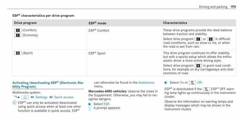
ESP® characteristics per drive program
Drive program ESP® mode Characteristics
A (Comfort); (Economy)
ESP® Comfort These drive programs provide the ideal balancebetween traction and stability.Select drive program; orA in difficultroad conditions, such as snow or ice, or whenthe road is wet from rain.
C (Sport) ESP® Sport This drive program continues to offer stabilitybut with a sporty setup which allows the enthu‐siastic driver a more active driving style.Select drive programC in good road condi‐tions, for example on dry carriageways and clearstretches of road.
Activating/deactivating ESP® (Electronic Sta‐bility Program)
Multimedia system:4© 5 Settings 5 Quick access% ESP® can only be activated/deactivated
using quick access when at least one otherfunction is available in quick access. ESP®
can otherwise be found in the Assistancemenu.
Mercedes‑AMG vehicles: observe the notes inthe Supplement. Otherwise, you may fail to rec‐ognise dangers.# Select ESP.
A prompt appears.
# Select On or å Off.
ESP® is deactivated if the å ESP® OFF warn‐ing lamp lights up continuously in the instrumentcluster.Observe the information on warning lamps anddisplay messages which may be shown in theinstrument cluster.
Driving and parking 195

Function of ESP® Crosswind Assist
ESP® Crosswind Assist detects sudden gusts ofside wind and helps the driver to keep the vehi‐cle in the lane:R ESP® Crosswind Assist is active at vehicle
speeds between 80 km/h and 200 km/hwhen driving straight ahead or corneringslightly.R The vehicle is stabilised by means of individ‐
ual brake application on one side.
Function of ESP® trailer stabilisation
& WARNING Risk of accident in poor roadand weather conditions
In poor road and weather conditions, thetrailer stabilisation cannot prevent lurching ofthe vehicle/trailer combination. Trailers witha high centre of gravity may tip over beforeESP® detects this.
# Always adapt your driving style to suitthe current road and weather condi‐tions.
When driving with a trailer, ESP® can stabiliseyour vehicle if the trailer begins to swerve fromside to side:R ESP® trailer stabilisation is active above
speeds of 65 km/h.R Slight swerving is reduced by means of a tar‐
geted, individual brake application on oneside.R In the event of severe swerving, the engine
output is also reduced and all wheels arebraked.
ESP® trailer stabilisation may be impaired ormay not function if:R The trailer is not connected correctly or is
not detected properly by the vehicle.
Function of EBD (Electronic Brake force Dis‐tribution)
EBD is characterised by the following:R Monitoring and regulating the brake pressure
on the rear wheels.R Improved driving stability when braking,
especially on bends.
Function of STEER CONTROL
STEER CONTROL helps you by transmitting anoticeable steering force to the steering wheel inthe direction required for vehicle stabilisation.This steering recommendation is given particu‐larly in the following situations:R both right wheels or both left wheels are on a
wet or slippery road surface when you brakeR the vehicle starts to skid
System limitationsSTEER CONTROL may be impaired or may notfunction in the following situations:R ESP® is deactivated
196 Driving and parking

R ESP® is malfunctioningR the steering is malfunctioning
If ESP® is malfunctioning, you will be assistedfurther by the electric power steering.
Function of Active Brake Assist
Active Brake Assist consists of the followingfunctions:R Distance warning functionR Autonomous braking functionR Situation-dependent braking assistanceR Vehicles with Driving Assistance Pack‐
age: Evasive Steering Assist
Active Brake Assist can help you to minimise therisk of a collision with vehicles, cyclists orpedestrians, or reduce the effects of such a colli‐sion.If Active Brake Assist has detected a risk of colli‐sion, a warning tone sounds and theL dis‐tance warning lamp lights up in the instrumentcluster.
If you do not react to the warning, autonomousbraking can be initiated in critical situations.In especially critical situations, Active BrakeAssist can initiate autonomous braking directly.In this case, the warning lamp and warning toneoccur simultaneously with the braking applica‐tion.If you apply the brake yourself in a critical situa‐tion or apply the brake during autonomous brak‐ing, situation-dependent braking assistanceoccurs. The brake pressure increases up to max‐imum full-stop braking if necessary.
If autonomous braking or situation-dependentbraking assistance has occurred, display1
appears in the multifunction display and thenautomatically goes out after a short time.If the autonomous braking function or the situa‐tion-dependent braking assistance is triggered,additional preventive measures for occupantprotection (PRE-SAFE®) may also be initiated.
& WARNING Risk of an accident caused bylimited detection performance of ActiveBrake Assist
Active Brake Assist cannot always clearlyidentify objects and complex traffic situa‐tions.In such cases, Active Brake Assist might:R Give a warning or brake without reasonR Not give a warning or not brake
# Always pay careful attention to the traf‐fic situation; do not rely on Active BrakeAssist alone. Active Brake Assist is onlyan aid. The driver is responsible formaintaining a suitable distance to thevehicle in front, vehicle speed and forbraking in good time.
Driving and parking 197

# Be prepared to brake or swerve if nec‐essary.
Also observe the system limitations of ActiveBrake Assist.
The individual subfunctions are available inthe following speed ranges:The distance warning function issues a warningin the following situations:R From approximately 30 km/h, if over several
seconds the distance maintained to the vehi‐
cle travelling in front is insufficient for thedriven speed, theL distance warninglamp lights up in the instrument cluster.R From approximately 7 km/h, if your vehicle
is critically close to a vehicle or pedestrian,you will hear an intermittent warning toneand theL distance warning lamp lightsup in the instrument cluster.
Brake immediately or take evasive action, provi‐ded it is safe to do so and the traffic situationallows this.
198 Driving and parking

The distance warning function can aid you in the following situations with an intermittent warning tone and a warning lamp:
Vehiclestravelling infront
Stationaryvehicles
Crossingvehicles
Movingpedestrians
Stationarypedestrians
Crossingcyclists
Cyclists travel‐ling in front
Stationarycyclists
Vehicleswithout Driv‐ing Assis‐tance Pack‐age
Up to approx.250 km/h
Up to approx.80 km/h
No reaction Up to approx.80 km/h
No reaction Up to approx.60 km/h
Up to approx.80 km/h
No reaction
Vehicles withDriving Assis‐tance Pack‐age
Up to approx.250 km/h
Up to approx.100 km/h
Up to approx.70 km/h
Up to approx.80 km/h
Up to approx.70 km/h
Up to approx.70 km/h
Up to approx.80 km/h
Up to approx.70 km/h
Driving and parking 199
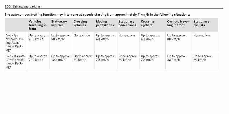
The autonomous braking function may intervene at speeds starting from approximately 7 km/h in the following situations:
Vehiclestravelling infront
Stationaryvehicles
Crossingvehicles
Movingpedestrians
Stationarypedestrians
Crossingcyclists
Cyclists travel‐ling in front
Stationarycyclists
Vehicleswithout Driv‐ing Assis‐tance Pack‐age
Up to approx.200 km/h
Up to approx.50 km/h
No reaction Up to approx.60 km/h
No reaction Up to approx.60 km/h
Up to approx.80 km/h
No reaction
Vehicles withDriving Assis‐tance Pack‐age
Up to approx.250 km/h
Up to approx.100 km/h
Up to approx.70 km/h
Up to approx.70 km/h
Up to approx.70 km/h
Up to approx.70 km/h
Up to approx.80 km/h
Up to approx.70 km/h
200 Driving and parking

Situation-dependent braking assistance may intervene at speeds starting from approximately 7 km/h in the following situations:
Vehiclestravelling infront
Stationaryvehicles
Crossingvehicles
Movingpedestrians
Stationarypedestrians
Crossingcyclists
Cyclists travel‐ling in front
Stationarycyclists
Vehicleswithout Driv‐ing Assis‐tance Pack‐age
Up to approx.250 km/h
Up to approx.80 km/h
No reaction Up to approx.60 km/h
No reaction Up to approx.60 km/h
Up to approx.80 km/h
No reaction
Vehicles withDriving Assis‐tance Pack‐age
Up to approx.250 km/h
Up to approx.100 km/h
Up to approx.70 km/h
Up to approx.70 km/h
Up to approx.70 km/h
Up to approx.70 km/h
Up to approx.80 km/h
Up to approx.70 km/h
Cancelling a brake application of ActiveBrake AssistYou can cancel a brake application of ActiveBrake Assist at any time by:R Fully depressing the accelerator pedal or
with kickdown.R Releasing the brake pedal.
Active Brake Assist may cancel the brake appli‐cation when one of the following conditions isfulfilled:R You manoeuvre to avoid the obstacle.R There is no longer a risk of collision.R An obstacle is no longer detected in front of
your vehicle.
Evasive Steering Assist (only vehicles withDriving Assistance Package)Evasive Steering Assist has the following charac‐teristics:R The ability to detect stationary or moving
pedestrians.R Assistance through power-assisted steering if
it detects a swerving manoeuvre.
Driving and parking 201

R Activation by an abrupt steering movementduring a swerving manoeuvre.R Assistance during swerving and straightening
of the vehicle.R Reaction from a speed of approximately
20 km/h up to a speed of approximately70 km/h.
You can prevent the assistance at any time byactively steering.
& WARNING Risk of an accident despiteEvasive Steering Assist
Evasive Steering Assist cannot always clearlyidentify objects and complex traffic situa‐tions.In addition, the steering support of EvasiveSteering Assist is generally not sufficient toavoid a collision.In such cases Evasive Steering Assist can:R give an unnecessary warning or provide
assistance
R not give a warning or not provide assis‐tance
# Always pay careful attention to the traf‐fic situation; do not rely on EvasiveSteering Assist alone.
# Be ready to brake and take evasiveaction, if necessary.
# Prevent the assistance by activelysteering in non-critical driving situa‐tions.
# Drive at an appropriate speed if pedes‐trians are close to the path of your vehi‐cle.
System limitsFull system performance is not available for afew seconds after switching on the ignition orafter driving off.The system may be impaired or may not functionin the following situations:R In snow, rain, fog, heavy spray, if there is
glare, in direct sunlight or in greatly varyinglight conditions.
R If the sensors are dirty, misted up, damagedor covered.R If the sensors are impaired due to interfer‐
ence from other radar sources, e.g. strongradar reflections in multi-storey car parks.R If a loss of tyre pressure or a defective tyre
has been detected and displayed.R In complex traffic situations where objects
cannot always be clearly identified.R If pedestrians or vehicles move quickly into
the sensor detection range.R If pedestrians are hidden by other objects.R If the typical outline of a pedestrian cannot
be distinguished from the background.R If a pedestrian is not detected as such, e.g.
due to special clothing or other objects.R On bends with a tight radius.
Setting Active Brake Assist
Requirements:R The ignition is switched on.
202 Driving and parking

Multimedia system:4© 5 Settings 5 Assistance5 Active Brake AssistThe following settings are available:R EarlyR MediumR Late# Select a setting.
The setting is retained when the engine isnext started.
Deactivating Active Brake Assist% It is recommended that you always leave
Active Brake Assist activated.# Select Off.
The distance warning function, the autono‐mous braking function and the Evasive Steer‐ing Assist are deactivated.When the vehicle is next started, the middlesetting is automatically selected.
% If Active Brake Assist is deactivated, theæ symbol appears in the status bar of themultifunction display.
Function of Adaptive Brake Lights
Adaptive Brake Lights warn following traffic in anemergency braking situation with the followingactions:R By flashing the brake lampsR By activating the hazard warning lights
If the vehicle is braked sharply from speedsabove 50 km/h, the brake lamps flash rapidly.This provides traffic travelling behind you with aneven more noticeable warning.If the vehicle is travelling at speeds of more than70 km/h at the beginning of the brake applica‐tion, the hazard warning lights switch on oncethe vehicle is stationary. When you pull awayagain, the hazard warning lights will switch offautomatically at approximately 10 km/h. Youcan also switch off the hazard warning lightsusing the hazard warning button.
Cruise control and limiter
Function of cruise controlCruise control regulates the speed to the valueselected by the driver.
If you accelerate to overtake, for example, thestored speed is not deleted. If you remove yourfoot from the accelerator pedal after overtaking,cruise control will resume speed regulation backto the stored speed.Cruise control is operated using the correspond‐ing steering wheel buttons. You can store anyspeed above 20 km/h up to the maximum speedor up to the set winter tyre limit.If you fail to adapt your driving style, cruise con‐trol can neither reduce the risk of an accidentnor override the laws of physics. It cannot takeinto account road, weather or traffic conditions.Cruise control is only an aid. The driver isresponsible for the distance to the vehicle infront, for vehicle speed, for braking in good timeand for staying in lane.
Displays on the multifunction displayThe status of cruise control and the storedspeed are shown in the multifunction display.
Driving and parking 203

1 Cruise control is selected2 Speed is saved, cruise control is deactivated3 Speed is saved, cruise control is activated
% The segments extending from the currentstored speed to the end of the scale, or tothe set winter tyre limit, light up in thespeedometer.
System limitsCruise control may be unable to maintain thestored speed on uphill gradients. The storedspeed is resumed when the gradient evens out.Change into a lower gear in good time on longand steep downhill gradients. Take particular
note of this when driving a laden vehicle. Bydoing so, you will make use of the engine's brak‐ing effect. This relieves the load on the brakesystem and prevents the brakes from overheat‐ing and wearing too quickly.Do not use cruise control in the following situa‐tions:R In traffic situations which require frequent
changes of speed, e.g. in heavy traffic, onwinding roads.R On slippery roads. Accelerating can cause
the drive wheels to lose traction and thevehicle could then skid.R If you are driving when visibility is poor.
Function of the limiterThe limiter restricts the speed of the vehicle. Toreduce the speed to the set speed, the limiterapplies the brakes automatically.You can limit the speed as follows:R Variable: for speed restrictions, e.g. in built-
up areas.R Permanent: for long-term speed restrictions,
e.g. when driving in winter tyre mode.
The variable limiter is operated using the corre‐sponding steering wheel buttons. You can storeany speed above 20 km/h up to the maximumspeed or up to the set winter tyre limit. You canalso perform settings while the vehicle is station‐ary if the vehicle has been started.If you fail to adapt your driving style, the limitercan neither reduce the risk of an accident noroverride the laws of physics. It cannot take intoaccount road, weather or traffic conditions. Thelimiter is only an aid. The driver is responsiblefor the distance to the vehicle in front, for vehi‐cle speed, for braking in good time and for stay‐ing in lane.Mercedes‑AMG vehicles: the limiter is availableup to a maximum speed of 250 km/h.
Displays on the multifunction displayThe status of the limiter and the stored speedare shown in the multifunction display.
204 Driving and parking

1 Limiter is selected2 Speed is stored, limiter is deactivated3 Speed is stored, limiter is activated
% The segments in the speedometer light up,up to the currently stored speed.
% When the driving speed is greater than thestored speed, display3 flashes.
KickdownIf you depress the accelerator pedal beyond thepressure point (kickdown), the variable limiterswitches to passive mode. The Limiter passivemessage appears in the multifunction display.
After completion of kickdown, the variable lim‐iter is activated again in the following situations:R If the driven speed drops below the stored
speed.R If the stored speed is called up.R If you store a new speed.
Operating cruise control or the variable lim‐iter
& WARNING Risk of accident due to storedspeed
If you call up the stored speed and this islower than your current speed, the vehicledecelerates.# Take into account the traffic situation
before calling up the stored speed.
Requirements:Cruise controlR Cruise control is selected.R ESP® must be activated, but not intervening.R The driven speed is at least 20 km/h.
R The transmission is in positionh.
Variable limiterR The vehicle has been started.R The variable limiter is selected.
Switching between cruise control and thevariable limiter
Driving and parking 205

# To select cruise control: press rockerswitch1 up.
# To select the variable limiter: press rockerswitch1 down.
% Vehicles with Active Distance AssistDISTRONIC: the variable limiter is selectedby a different button (/ page 209).
Activating cruise control or the variable lim‐iter# Press rocker switch2 up (SET+) or down
(SET-).The current driven speed is stored and thevehicle maintains this speed (cruise control)or does not exceed it (limiter).
or# Press rocker switch3 up (RES).
The last stored speed is called up and thevehicle maintains this speed (cruise control)or does not exceed it (limiter).If the last stored speed has previously beendeleted, the currently driven speed is stored.
% When you switch off the vehicle, the lastspeed stored is cleared.
When you activate cruise control or ActiveDistance Assist DISTRONIC, the last speedstored for the variable limiter is cleared.
Increasing/decreasing the stored speed# Press rocker switch2 up (SET+) or down
(SET-) to the pressure point.The stored speed is increased or reduced by1 km/h.
or# Press and hold rocker switch2 up (SET+) or
down (SET-) to the pressure point.The stored speed is increased or reduced inincrements of 1 km/h.
or# Press rocker switch2 up (SET+) or down
(SET-) beyond the pressure point.The stored speed is increased or reduced by10 km/h.
or# Press and hold rocker switch2 up (SET+) or
down (SET-) beyond the pressure point.The stored speed is increased or reduced inincrements of 10 km/h.
or# Accelerate the vehicle to the desired speed.# Press rocker switch2 up (SET+).
Adopting the detected speedIf cruise control/variable limiter is activated andSpeed Limit Assist or Traffic Sign Assist hasdetected a speed restriction sign with a maxi‐mum permissible speed and this is displayed inthe instrument cluster, you can choose betweenthe following options:# Press rocker switch3 up (RES).
The maximum permissible speed shown bythe traffic sign is stored and the vehiclemaintains or does not exceed this speed.
# To deactivate cruise control:press rocker switch3 down (CNCL).
# To deactivate cruise control: press rockerswitch1 down.
Deactivating cruise control or the variablelimiter# Press rocker switch3 down (CNCL).
206 Driving and parking

% If you brake, deactivate ESP® or if ESP®intervenes, cruise control is deactivated. Thevariable limiter is not deactivated.
Permanent limiterIf the vehicle should never exceed a specificspeed (e.g. for driving in winter tyre mode), youcan set this speed with the permanent limiter.You do this by limiting the speed to a valuebetween 160 km/h and 240 km/h in the multi‐media system (/ page 207).Shortly before the set speed is reached, itappears in the multifunction display. When youconfirm the message with%, display mes‐sages no longer appear until you switch off thevehicle. The speed will only be displayed againonce the vehicle has been restarted or if the setspeed is changed.The permanent limiter does not switch to pas‐sive mode even during kickdown and the drivenspeed remains below the set speed.
Setting the speed limitation for winter tyresMultimedia system:4© 5 Settings 5 Fahrzeug (Vehicle)5 Winter tyres limit# Select a speed or deactivate the function.
Active Distance Assist DISTRONIC
Function of Active Distance AssistDISTRONIC
Active Distance Assist DISTRONIC maintains theset speed on free-flowing roads. If vehicles infront are detected, the set distance is main‐tained, if necessary, until the vehicle comes to a
halt. The vehicle accelerates or brakes depend‐ing on the distance to the vehicle in front andthe set speed. The speed and distance to thevehicle in front are set and saved on the steeringwheel on vehicles without the Driving AssistancePackage, in the range between 20 km/h and200 km/h and, on vehicles with the DrivingAssistance Package, in the range between20 km/h and 210 km/h.Other features of Active Distance AssistDISTRONIC:R Adjusts the driving style depending on the
selected drive program (fuel-saving, comfort‐able or dynamic) (/ page 166)R Vehicles with Driving Assistance Pack‐
age: reacts to stationary vehicles detected inurban speed ranges (except bicycles andmotorcycles).R Initiates acceleration to the stored speed if
the turn signal indicator is switched on tochange to the overtaking lane.R Vehicles with Driving Assistance Pack‐
age: takes one-sided overtaking restrictionsinto account on motorways or on multi-lane
Driving and parking 207

roads with separate carriageways (country-dependent).
Vehicles with Active Parking Assist and Driv‐ing Assistance Package: if the vehicle hasbeen braked to a standstill on multi-lane, sepa‐rate carriageways by Active Distance AssistDISTRONIC, it can automatically follow the vehi‐cle in front driving off again within 30 seconds. Ifa critical situation is detected when driving off, avisual and acoustic warning is given indicatingthat the driver must now take control of the vehi‐cle. The vehicle is not accelerated any further.Active Distance Assist DISTRONIC is only an aid.The driver is responsible for keeping a safe dis‐tance to the vehicle in front, for vehicle speedand for braking in good time.
System limitsThe system may be impaired or may not functionin the following situations:R In snow, rain, fog, heavy spray, if there is
glare, in direct sunlight or in greatly varyinglight conditions.
R The windscreen in the area of the camera isdirty, misted up, damaged or covered.R If the radar sensors are dirty or covered.R In multi-storey car parks or on roads with
steep uphill or downhill gradients.R If there are narrow vehicles in front, such as
bicycles or motorcycles.
In addition, on slippery roads, braking or accel‐erating can cause one or several wheels to losetraction and the vehicle could then skid.Do not use Active Distance Assist DISTRONIC inthese situations.
& WARNING Risk of accident from acceler‐ation or braking by Active DistanceAssist DISTRONIC
Active Distance Assist DISTRONIC may accel‐erate or brake in the following cases, forexample:R If the vehicle pulls away using Active Dis‐
tance Assist DISTRONIC.
R If the stored speed is called up and isconsiderably faster or slower than thecurrently driven speed.R If Active Distance Assist DISTRONIC no
longer detects a vehicle in front or doesnot react to relevant objects.
# Always carefully observe the traffic con‐ditions and be ready to brake at alltimes.
# Take into account the traffic situationbefore calling up the stored speed.
& WARNING Risk of accident due to insuf‐ficient deceleration by Active DistanceAssist DISTRONIC
Active Distance Assist DISTRONIC brakesyour vehicle with up to 50 % of the maximumpossible deceleration. If this deceleration isnot sufficient, Active Distance AssistDISTRONIC alerts you with a visual andacoustic warning.
208 Driving and parking

# In these cases, adjust your speed andkeep a sufficient distance.
# Brake the vehicle yourself and/or takeevasive action.
& WARNING Risk of accident if detectionfunction of Active Distance AssistDISTRONIC is impaired
Active Distance Assist DISTRONIC does notreact or has a limited reaction:R when driving on a different lane or when
changing lanesR to pedestrians, animals, bicycles or sta‐
tionary vehicles, or unexpected obstaclesR to complex traffic conditionsR to oncoming vehicles and crossing traffic
As a result, Active Distance AssistDISTRONIC may neither give warnings norintervene in such situations.# Always observe the traffic conditions
carefully and react accordingly.
Operating Active Distance Assist DISTRONIC
Requirements:R The vehicle has been started.R The electric parking brake is released.R ESP® is activated and is not intervening.R The transmission is in positionh.R All doors and the bonnet are closed.R Check of the radar sensor system has been
successfully completed.R Parking Assist PARKTRONIC is not being
used to park the vehicle or to exit from aparking space.R The vehicle does not skid.
Switching between Active Distance AssistDISTRONIC and the limiter
# Press button1.
Activating the variable limiter or Active Dis‐tance Assist DISTRONIC# To activate without a stored speed: press
rocker switch3 up (SET+) or down (SET-),or press rocker switch4 up (RES). Remove
Driving and parking 209

your foot from the accelerator pedal (ActiveDistance Assist DISTRONIC).The current driven speed is stored and main‐tained (Active Distance Assist DISTRONIC) orlimited (variable limiter) by the vehicle.
or# To activate with a stored speed: press
rocker switch4 up (RES). Remove your footfrom the accelerator pedal (Active DistanceAssist DISTRONIC).
% If rocker switch4 is pressed up (RES) againafter activation with a stored speed, ActiveDistance Assist DISTRONIC or the variablelimiter is activated with the speed restrictiondisplayed in the instrument cluster.
Accepting the displayed speed restrictionwhen Distance Assist DISTRONIC or the lim‐iter is activated# Press rocker switch4 up (RES).
The speed limit displayed in the instrumentcluster is adopted as the stored speed. Thevehicle adapts its speed to that of the vehiclein front, but only up to the stored speed.
Pulling away with Active Distance AssistDISTRONIC# Remove your foot from the brake pedal and
activate Active Distance Assist DISTRONIC.# Press rocker switch4 up (RES).or# Depress the accelerator pedal briefly and
firmly.The functions of Active Distance AssistDISTRONIC continue to be carried out.
Deactivating Active Distance AssistDISTRONIC
& WARNING Risk of accident due to ActiveDistance Assist DISTRONIC still beingactivated when you leave the driver'sseat
If you leave the driver's seat while the vehicleis being braked by Active Distance AssistDISTRONIC only, the vehicle can roll away.# Always deactivate Active Distance
Assist DISTRONIC and secure the vehi‐
cle to prevent it from rolling awaybefore you leave the driver's seat.
# Press rocker switch4 down (CNCL).% If you brake, deactivate ESP® or if ESP®
intervenes, Active Distance AssistDISTRONIC is deactivated.
Increasing or reducing the speed# Press rocker switch3 up (SET+) or down
(SET-) to the pressure point.The stored speed is increased or reduced by1 km/h.
or# Press and hold rocker switch3 up (SET+) or
down (SET-) to the pressure point.The stored speed is increased or reduced inincrements of 1 km/h.
or# Press rocker switch3 up (SET+) or down
(SET-) beyond the pressure point.The stored speed is increased or reduced by10 km/h.
or
210 Driving and parking

# Press and hold rocker switch3 up (SET+) ordown (SET-) beyond the pressure point.The stored speed is increased or reduced inincrements of 10 km/h.
Reducing or increasing the specified dis‐tance from the vehicle in front# To increase the specified distance: press
rocker switch2 down.# To reduce the specified distance: press
rocker switch2 up.
Function of Active Speed Limit Assist
% The following function is country-dependentand only available in conjunction with theDriving Assistance Package. If a change in the speed limit is detected and
Active Distance Assist DISTRONIC is activated,Active Distance Assist DISTRONIC adapts thisnew speed as the stored speed.The driven speed is adjusted when the vehicle islevel with the traffic sign at the latest. In thecase of signs indicating entry into an urban area,the speed is adapted according to the speedpermitted within the urban area. The speed limit
display in the Instrument Display is always upda‐ted when the vehicle is level with the traffic sign.If there is no speed restriction on an unlimitedstretch of road (e.g. on a motorway), the recom‐mended speed is automatically adopted as thestored speed. The system uses the speed storedon an unlimited stretch of road as the recom‐mended speed. If you do not alter the storedspeed on an unlimited stretch of road, the rec‐ommended speed is 130 km/h.If Active Distance Assist DISTRONIC has beenput into passive mode by pressing the accelera‐tor pedal, only speed limits which are higherthan the set speed are adopted.Active Speed Limit Assist is only an aid. Thedriver is responsible for keeping a safe distanceto the vehicle in front, for vehicle speed and forbraking in good time. The maximum permissiblespeed also depends on factors such as the roadsurface and traffic conditions.
System limitsTemporary speed restrictions (e.g. for a certaintime or due to weather conditions) cannot beproperly detected by the system. The maximum
Driving and parking 211

permissible speed applying to a vehicle with atrailer is not detected by the system. In these sit‐uations you must adjust your speed yourself.
& WARNING Risk of accident due to ActiveSpeed Limit Assist adapting the vehicle'sspeed
The speed adopted by Active Speed LimitAssist may be too high or incorrect in someindividual cases, such as:R In the wet or in fogR When towing a trailer
# Ensure that the driven speed complieswith traffic regulations.
# Adjust the driving speed to suit currenttraffic and weather conditions.
Function of route-based speed adaptation
% The following function is country-dependentand only available in conjunction with theDriving Assistance Package.
When Distance Assist DISTRONIC is active, thefunction adjusts the speed depending on theroute events ahead. Depending on the drive pro‐gram selected, the vehicle negotiates the routeevent ahead in a fuel-saving, comfortable ordynamic manner. When the route event has beenpassed, the vehicle accelerates again to thestored speed. The set distance to the vehicle infront, vehicles detected ahead and speed restric‐tions ahead are taken into account.Route-based speed adjustment can be config‐ured in the multimedia system (/ page 213).Route events ahead are:R BendsR T-junctions, roundabouts and toll stationsR Turns and exits
% When the toll station is reached, Active Dis‐tance Assist DISTRONIC adopts the speed asthe stored speed.
Also, the speed is reduced if the turn signal tochange lanes is switched on and one of the fol‐lowing situations is detected:R Turning off at junctions
R Driving on slowing-down lanesR Driving on lanes adjacent to slowing-down
lanes
The driver is responsible for choosing the rightspeed and observing other road users. Thisapplies in particular to junctions, roundaboutsand traffic lights, as route-based speed adapta‐tion does not brake the vehicle to a standstill.When route guidance is active, the first speedadjustment is carried out automatically. If theturn signal indicator is switched on, the selectedroute is confirmed and further speed adjustmentis activated.Speed adjustment is cancelled in the followingcases:R If the turn signal indicator is switched off
before the route event.R If the driver depresses the accelerator or
brake pedal during the process.
System limitsRoute-based speed adaptation does not takeright of way regulations into account. The driver
212 Driving and parking

is responsible for complying with road trafficregulations and driving at a suitable speed.In difficult conditions (e.g. unclear roads, lanenarrowing, wet road surfaces, snow or ice) orwhen driving with a trailer, the speed adjustmentmade by the system may not always be suitable.In these situations the driver must interveneaccordingly.
& WARNING Risk of accident in spite ofroute-based speed adjustment
Route-based speed adjustment might mal‐function or be temporarily unavailable in thefollowing situations:R If map data is not up to date or availableR If you do not follow the selected route
guidanceR If the set route is re-plannedR In road construction areasR When towing a trailerR In bad weather or road conditionsR If the accelerator pedal is depressed
# Adjust the speed to the traffic situation.
Setting route-based speed adjustment
Requirements:R Active Distance Assist DISTRONIC is activa‐
ted.
Multimedia system:4© 5 Settings 5 Assistance5 Route-based speed adapt.# Activate or deactivate the function.
When the function is active, the vehiclespeed is adjusted depending on the routeevents ahead.
% Further information on the route-basedspeed adaptation (/ page 212).
Active Steering Assist
Function of Active Steering Assist% The following function is country-dependent
and only available in conjunction with theDriving Assistance Package.
Active Steering Assist is only available up to aspeed of 210 km/h. The system helps you tostay in the centre of the lane by means of mod‐erate steering interventions. Depending on thespeed driven, Active Steering Assist uses thevehicles ahead and lane markings as a refer‐ence.% Depending on the country, in the lower
speed range Active Steering Assist can usethe surrounding traffic as a reference. If nec‐essary, Active Steering Assist can then alsoprovide assistance with a driving style out‐side the centre of the lane.
When the system is actively steering, theàsymbol is shown in green in the multifunctiondisplay.If the detection of lane markings and vehiclesahead is impaired, Active Steering Assistswitches to passive mode. The system providesno support in this case. During the transitionfrom active to passive status, theà symbol isshown as enlarged and flashing. Once the sys‐tem is passive, theà symbol is shown asgrey in the multifunction display.
Driving and parking 213

Steering and touch detectionThe driver is required to keep their hands on thesteering wheel at all times and be able to inter‐vene at any time to correct the course of thevehicle and keep it in lane. The driver mustexpect a change from active to passive mode orvice versa at any time.
If the driver has not steered the vehicle for aconsiderable period of time or has removed theirhands from the steering wheel, an optical warn‐ing is given first. Display1 appears in the mul‐tifunction display. If the driver still does not steerthe vehicle, or gives no confirmation to the sys‐tem, a warning tone sounds in addition to thevisual warning message.
The warning is not issued, or is stopped, whenthe driver gives confirmation to the system:R The driver steers the vehicle.R The driver presses a steering wheel button or
operates Touch Control.
If Active Steering Assist detects that a systemlimit has been reached, a visual and acousticwarning is issued.Active Steering Assist is only an aid. The driver isresponsible for the distance to the vehicle infront, for vehicle speed, for braking in good timeand for staying in lane. Before changing lanes,the driver must make sure that the neighbouringlane is free (glance over the shoulder).
System limitsActive Steering Assist has a limited steering tor‐que for lateral guidance. In some cases, thesteering intervention is not sufficient to keep thevehicle in the lane or to drive through exits.
The system may be impaired or may not functionin the following instances:R There is poor visibility, e.g. due to snow, rain,
fog, heavy spray, greatly varying light condi‐tions or strong shadows on the carriageway.R There is glare, e.g. from oncoming traffic,
direct sunlight or reflections.R Insufficient road illumination.R The windscreen is dirty, misted up, damaged
or covered in the vicinity of the camera, e.g.by a sticker.R No, or several, unclear lane markings are
present for one lane, or the markings changequickly, e.g. in a construction area or junc‐tions.R The lane markings are worn away, dark or
covered up, e.g. by dirt or snow.R The distance to the vehicle in front is too
small and the lane markings thus cannot bedetected.R The road is narrow and winding.R There are obstacles on the lane or projecting
out into the lane, such as object markers.
214 Driving and parking

The system does not provide assistance in thefollowing conditions:R On tight bends and when turning.R When crossing junctions.R At roundabouts or toll stations.R When towing a trailer.R When actively changing lane without switch‐
ing on the turn signal indicator.R When the tyre pressure is too low.
Depending on the selected vehicle settings,Active Steering Assist may be unavailable.Observe the status display of Active SteeringAssist in the multifunction display(/ page 217).
& WARNING Risk of accident if ActiveSteering Assist unexpectedly stops func‐tioning
If the system limitations of Active SteeringAssist are reached there is no guarantee thatthe system will remain active or will keep thevehicle in lane.
# Always keep your hands on the steeringwheel and observe the traffic carefully.
# Always steer the vehicle paying atten‐tion to traffic conditions.
& WARNING Risk of accident if ActiveSteering Assist unexpectedly intervenes
A malfunction in the detection of lane mark‐ings and objects can occur.This could cause unexpected steering inter‐vention.# Steer according to traffic conditions.
Activating/deactivating Active SteeringAssist
Requirements:R ESP® is activated, but is not intervening.R Active Distance Assist DISTRONIC is activa‐
ted.
Multimedia system:4© 5 Settings5 Schnellzugriff (Quick access)# Selecta Act. Steer. Asst.
Function of Active Lane Change Assist% The following function is country-dependent
and only available in conjunction with theDriving Assistance Package.
Active Lane Change Assist supports the driverwhen changing lanes by applying steering torqueif the driver operates a turn signal indicator.Assistance when changing lanes is provided if allthe following conditions are met:R You are driving on a motorway or road with
multiple lanes in the direction of travel.R The neighbouring lane is separated by a bro‐
ken lane marking.R No vehicle is detected in the adjacent lane.R The driven speed is between 80 km/h and
180 km/h.R Active Lane Change Assist is switched on in
the multimedia system.
Driving and parking 215

R Active Steering Assist is switched on andactive.
If no vehicle is detected in the adjacent lane anda lane change is permitted, the lane changebegins after the driver has activated the turn sig‐nal indicator. This is shown to the driver with agreen arrow2 next to the steering wheel sym‐bol. The Lane change to the left message alsoappears, for example. If Active Lane ChangeAssist has been activated with the turn signalindicator but a lane change is not immediatelypossible, a grey arrow1 appears next to thesteering wheel symbol, which remains green.
When the lane change assistance starts, the turnsignal indicator is automatically activated alongwith the display in the multifunction display.If the assistance graphic is shown when chang‐ing lanes, the lane change display appears withan additional arrow pointing towards the adja‐cent lane (/ page 217).If a lane change is not possible, the arrow fadesout after a few seconds and a new lane changemust be initiated. An immediate lane change isonly possible on motorway sections withoutspeed limits.If the system is impaired, Active Lane ChangeAssist may be cancelled. If it is cancelled, theLane change cancelled message appears in themultifunction display and a warning tone sounds.
& WARNING Risk of accident from chang‐ing lane to an occupied adjacent lane
Lane Change Assist cannot always detectclearly if the adjacent lane is free.The lane change might be initiated althoughthe adjacent lane is not free.
# Before changing lanes, make sure thatthe neighbouring lane is free and thereis no danger to other road users.
# Monitor the lane change.
& WARNING Risk of accident if LaneChange Assist unexpectedly stops func‐tioning
If the system limitations for Lane ChangeAssist have been reached, there is no guar‐antee that the system will remain active.Lane Change Assist cannot then assist youby applying steering torques.# Always monitor the lane change and
keep your hands on the steering wheel.Observe the traffic conditions and steerand/or brake if necessary.
System limitsThe system limits of Active Steering Assist applyto Active Lane Change Assist (/ page 213).
216 Driving and parking

The system may also be impaired or may notfunction in the following situations:R The sensors in the rear bumper are dirty,
damaged or covered, for instance by asticker or ice and snow.R The exterior lighting is malfunctioning.
Activating/deactivating Active Lane ChangeAssistMultimedia system:4© 5 Settings 5 Assistance5 Active Lane Change Assist# Activate or deactivate the function.
Function of Active Emergency Stop AssistIf the driver continually ignores the visual oracoustic warning to put their hands on the steer‐ing wheel, the Beginning emergency stop mes‐sage appears in the multifunction display. If thedriver still does not respond, Active DistanceAssist DISTRONIC reduces the speed. The vehi‐cle is decelerated in stages to a standstill.Depending on the country, at speeds below60 km/h the hazard warning lights switch onautomatically.
When the vehicle is stationary, the followingactions are carried out:R the vehicle is secured with the electric park‐
ing brakeR Active Distance Assist DISTRONIC is endedR the vehicle is unlockedR if possible, an emergency call is placed to
the Mercedes-Benz emergency call centre
The driver can cancel the deceleration at anytime by performing one of the following actions:R steeringR braking or acceleratingR pressing a steering-wheel buttonR operating Touch ControlR activating or deactivating Active Distance
Assist DISTRONIC
Overview of Active Distance AssistDISTRONIC displays in the instrument clus‐ter
The assistance graphic and the status displayshow the status of the following functions in theinstrument cluster:R Active Distance Assist DISTRONICR Route-based speed adaptationR Active Steering Assist
Driving and parking 217

Assistant display
1 Route-based speed adaptation (type of routeevent)
2 Vehicle in front3 Distance indicator4 Set specified distance5 Active Lane Change Assist lane change dis‐
play
Active Distance Assist DISTRONIC status dis‐play and route-based speed adaptation
1 Active Distance Assist DISTRONIC selected,set specified distance (number of segmentsbelow the vehicle)
2 Active Distance Assist DISTRONIC deactiva‐ted, speed stored
3 Active Distance Assist DISTRONIC active,speed stored, no vehicle detected (brightvehicle symbol)
4 Active Distance Assist DISTRONIC active,speed stored, vehicle detected (green vehi‐cle symbol)
5 Active Distance Assist DISTRONIC and route-based speed adaptation active, speed stored
% On motorways or high-speed major roads,the greenç vehicle symbol is displayedcyclically when the vehicle is ready to pullaway.
% If you depress the accelerator pedal beyondthe setting of the Active Distance AssistDISTRONIC, the system is switched to pas‐sive mode. Theç suspended messageappears in the multifunction display.
SpeedometerThe stored speed is highlighted on the speedom‐eter. If the speed of the vehicle in front or thespeed adjustment is less than the stored speeddue to the route event ahead, the segments inthe speedometer light up. Deactivation of ActiveDistance Assist DISTRONIC, as well as altera‐
218 Driving and parking

tions to the speed due to manual or automaticadoption of the speed limit, are displayed in thecontrol feedback of the multifunction display ona single line.
Active Steering Assist status display
1 Grey steering wheel: Active Steering Assistswitched on and passive
2 Green steering wheel: Active Steering Assistswitched on and active
3 Flashing steering wheel: prompt to the driverto actively confirm or transition from activeto passive status, system limits detected
During the transition from active to passive sta‐tus, symbol3 is shown as enlarged and flash‐ing. Once the system is passive, symbol1 isshown in grey in the multifunction display.
Function of Hill Start Assist
Hill Start Assist holds the vehicle for a shorttime when pulling away on a hill under the fol‐lowing conditions:R Vehicles with automatic transmission: the
transmission is in positionh ork.R The electric parking brake is released.
This gives you enough time to move your footfrom the brake pedal to the accelerator pedaland depress it before the vehicle begins to rollaway.
& WARNING Risk of accident and injurydue to the vehicle rolling away
After a short time, Hill Start Assist no longerholds the vehicle and it can roll away.# Therefore, swiftly move your foot from
the brake pedal to the accelerator
pedal. Never attempt to leave the vehi‐cle if it is being held by Hill Start Assist.
HOLD function
HOLD functionThe HOLD function holds the vehicle at a stand‐still without requiring you to depress the brakepedal, e.g. while waiting in traffic.The HOLD function is only an aid. The responsi‐bility for the vehicle safely standing still remainswith the driver.
System limitationsThe HOLD function is only intended to provideassistance when driving and is not a sufficientmeans of safeguarding the vehicle against rollingaway when stationary.R The incline must not be greater than 30%.
Driving and parking 219

Activating/deactivating the HOLD function
& WARNING Risk of an accident due to theHOLD function being activated when youleave the vehicle
If you leave the vehicle while only the HOLDfunction is braking the vehicle, the vehiclecan roll away in the following situations:R If there is a malfunction in the system or
in the power supply.R If the HOLD function is deactivated by
depressing the accelerator pedal or brakepedal, e.g. by a vehicle occupant.
# Always deactivate the HOLD functionand secure the vehicle against rollingaway before leaving the vehicle.
* NOTE Damage from automatic braking
If one of the following functions is switchedon, the vehicle brakes automatically in cer‐tain situations:R Active Brake AssistR Active Distance Assist DISTRONICR HOLD functionR Active Parking Assist
To avoid damage to the vehicle, deactivatethese systems in the following or similar sit‐uations:# During towing# In a car wash
Requirements:R The vehicle is stationary.R The driver's door is closed or the seat belt on
the driver's side is fastened.R The engine is running or has been automati‐
cally switched off by the ECO start/stopfunction.
R The electric parking brake is released.R Active Distance Assist DISTRONIC is deacti‐
vated.R The transmission is in positionh,k ori.
Activating the HOLD function# Depress the brake pedal and after a short
time quickly depress further until theëdisplay appears in the multifunction display.
# Release the brake pedal.
Deactivating the HOLD function# Depress the accelerator pedal to pull away.or# Depress the brake pedal until theë dis‐
play disappears from the multifunction dis‐play.
The HOLD function is deactivated in the follow‐ing situations:R Active Distance Assist DISTRONIC is activa‐
ted.R The transmission is switched to positionj.
220 Driving and parking

R The vehicle is secured with the electric park‐ing brake.
In the following situations, the vehicle is held bythe transmission positionj or by the electricparking brake:R The seat belt is unfastened and the driver's
door is opened.R The vehicle is switched off.R There is a malfunction in the system or the
power supply is insufficient.
Start-off assist
Function of the start-off assistThe start-off assist enables optimal vehicleacceleration from a standstill. For this, a suitablyhigh-grip road surface is required, the tyres andvehicle must also be in good condition.Do not activate the start-off assist on publicroads.Be sure to observe the safety notes and informa‐tion on ESP® .
Activating the start-off assist
& WARNING Risk of skidding and havingan accident from wheels spinning
When you use start-off assist, individualwheels could spin and you could lose controlof the vehicle.
If ESP® is deactivated, there is a risk of skid‐ding and accident!# Make sure that no persons or obstacles
are in the close vicinity of your vehicle.
# Deactivating ESP® (/ page 195).# Move the steering wheel to the straight-
ahead position.# Depress the brake pedal firmly with your left
foot and keep it depressed.# Engage theh drive position (/ page 172).# Select the sportiest available drive programB orC(/ page 166).
# Rapidly depress the accelerator pedal fully.
# Take your foot off the brake, but keep theaccelerator pedal depressed.The vehicle pulls away at maximum accelera‐tion.
# Switch on ESP® once the acceleration proce‐dure is complete. ESP® will otherwise not beable to stabilise the vehicle if the vehiclestarts to skid or a wheel starts to spin.
Cancelling the start-off assist# Remove your foot from the accelerator pedal.# Reactivate the ESP®.
Function of adaptive damping adjustment
Suspension with adaptive damping adjustmentcontinuously adjusts the characteristics of thesuspension dampers to the current operatingand driving conditions.The damping is tuned individually for each wheeland is affected by the following factors:R the road surface conditionsR vehicle loadR the drive program selected
Driving and parking 221

R the driving style
The drive program can be adjusted using theDYNAMIC SELECT switch.
Parking Assist PARKTRONIC
Function of Parking Assist PARKTRONIC
Parking Assist PARKTRONIC is an electronicparking assistance system with ultrasound. Itmonitors the area around your vehicle using mul‐tiple sensors1 on the front bumper and on therear bumper. Parking Assist PARKTRONIC showsyou the distance between your vehicle and adetected obstacle visually and audibly.
Parking Assist PARKTRONIC is only an aid. It isnot a substitute for your attention to the sur‐roundings. The responsibility for safe manoeu‐vring and parking remains with you. Make surethat there are no persons, animals or objects inthe manoeuvring area while manoeuvring andparking in/exiting parking spaces.In the standard setting, an intermittent warningtone sounds from a distance of approximately0.3 m to an obstacle in front and approximately1.0 m to an obstacle behind. A continuous tonesounds from a distance of approximately 0.2 m.Using the Warn early all-round setting in the mul‐timedia system, the warning tones for front andside impact protection can be set to sound at agreater distance of approximately 1.0 m in frontand 0.6 m on the sides (/ page 226).% The Warn early all-round setting is always
active in the rear of the vehicle.If Parking Assist PARKTRONIC is deactivated,Active Parking Assist is unavailable.
Parking Assist PARKTRONIC display in themultimedia system
Vehicles with Active Parking Assist without a360° Camera
222 Driving and parking
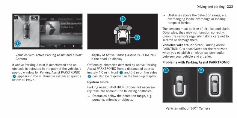
Vehicles with Active Parking Assist and a 360°Camera
If Active Parking Assist is deactivated and anobstacle is detected in the path of the vehicle, apop-up window for Parking Assist PARKTRONIC1 appears in the multimedia system at speedsbelow 10 km/h.
Display of Active Parking Assist PARKTRONICin the head-up display
Optionally, obstacles detected by Active ParkingAssist PARKTRONIC from a distance of approx‐imately 1.0 m in front1 and 0.6 m on the sides2 can also be displayed in the head-up display.
System limitsParking Assist PARKTRONIC does not necessa‐rily take into account the following obstacles:R Obstacles below the detection range, e.g.
persons, animals or objects.
R Obstacles above the detection range, e.g.overhanging loads, overhangs or loadingramps of lorries.
The sensors must be free of dirt, ice and slush.Otherwise, they may not function correctly.Clean the sensors regularly, taking care not toscratch or damage them.Vehicles with trailer hitch: Parking AssistPARKTRONIC is deactivated for the rear zonewhen you establish an electrical connectionbetween your vehicle and a trailer.
Problems with Parking Assist PARKTRONIC
Vehicles without 360° Camera
Driving and parking 223

Vehicles with 360° Camera
Problem Possible causes/consequences and MM Solutions
Rear1 or all-round2 segments lightup red. Theé symbol appears inthe multifunction display.
Parking Assist PARKTRONIC is malfunctioning and has been deactivated due to signal interference.# Start the vehicle again.# Check if Parking Assist PARKTRONIC is working at a different location.
Rear1 or all-round2 segments lightup red. At the same time, a warningtone sounds for approximately 2 sec‐onds every time the vehicle is started.Theé symbol appears in the multi‐function display.
The sensors are dirty.# Clean the sensors and observe the notes on care of vehicle parts (/ page 458).
Parking Assist PARKTRONIC has been deactivated due to a malfunction.# Start the vehicle again.
224 Driving and parking

Problem Possible causes/consequences and MM Solutions
# If the problem persists, consult a qualified specialist workshop.
Function of the passive side impact protec‐tionPassive side impact protection is an additionalParking Assist PARKTRONIC function whichwarns the driver about obstacles at the side ofthe vehicle. A warning is issued when obstaclesare detected between the front and rear detec‐tion range. In order for an object on the side tobe detected, the sensors in the front and rearbumper must first detect the object while youare driving past it.During the parking procedure or manoeuvring,objects are detected as the vehicle drives past.If you steer in the direction of a detected obsta‐cle and there is a risk of a lateral collision, awarning is issued. The segments on the sideslight up yellow or red, depending on the distanceto the obstacle.
Segment colour depending on distance
Colour Lateral distance
Yellow Approx. 30 - 60 cm
Red Approx. < 30 cm
In order for lateral front or rear segments to bedisplayed, the vehicle must first travel a distanceof at least half of the vehicle length. Once thevehicle has travelled the length of the vehicle, allof the lateral front and rear segments can be dis‐played.
Vehicles without 360° Camera1 Parking Assist PARKTRONIC is only opera‐
tional in the front and rear2 Parking Assist PARKTRONIC is operational
and can also warn the driver about obstaclesat the side of the vehicle
3 Obstacle detected at the front right (yellow)and rear (red)
Driving and parking 225

Vehicles with 360° Camera1 Parking Assist PARKTRONIC is only opera‐
tional in the front and rear2 Parking Assist PARKTRONIC is operational
and can also warn the driver about obstaclesat the side of the vehicle
3 Obstacle detected at the front right (red)
Saved obstacles on the sides are deleted in thefollowing situations, for example:R You park the vehicle and switch off the igni‐
tion.R You open the doors.
After the engine is restarted, obstacles must bedetected again before a new warning can beissued.
System limitsThe system limits for Parking AssistPARKTRONIC apply for passive side impact pro‐tection.The following objects are not detected, for exam‐ple:R Pedestrians who approach the vehicle from
the sideR Objects placed next to the vehicle
Activating/deactivating Parking AssistPARKTRONIC
* NOTE Risk of an accident from objectsat close range
Parking Assist PARKTRONIC may not detectcertain objects at close range.# When parking or manoeuvring the vehi‐
cle, pay particular attention to anyobjects which are above or below thesensors, e.g. flowerpots or drawbars.
The vehicle or other objects could oth‐erwise be damaged.
If theé symbol is shown in the multifunctiondisplay, Parking Assist PARKTRONIC is notactive.Multimedia system:4 Settings 5 Quick access5 PARKTRONIC# Activate or deactivate the function.% Parking Assist PARKTRONIC is automatically
activated when the vehicle is started.
Adjusting the warning tones of ParkingAssist PARKTRONICMultimedia system:4© 5 Settings 5 Assistance5 Camera & parking 5 Set warning tone
Adjusting the volume of the warning tones# Select Warning tone volume.# Set a value.
226 Driving and parking

Adjusting the pitch of the warning tones# Select Warning tone pitch.
Set a value.
Specifying the starting point for the warningtonesYou can specify whether the Parking AssistPARKTRONIC warning tones should commencewhen the vehicle is further away from an obsta‐cle.# Select Warn early all-round.# Activate or deactivate the function.
Activating/deactivating audio fadeoutYou can specify whether the volume of a mediasource in the multimedia system is to bereduced when Parking Assist PARKTRONICsounds a warning tone.# Select Audio fadeout during warning tones.# Activate or deactivate the function.
Reversing camera
Function of the reversing camera
If you have activated the function in the multime‐dia system, the image from reversing camera1is shown in the media display when reverse gearis engaged. Dynamic guide lines show the paththe vehicle will take with the steering wheel in its
current position. This helps you to orient your‐self and to avoid obstacles when reversing.The reversing camera is only an aid. It is not asubstitute for your attention to the surroundings.The responsibility for safe manoeuvring andparking remains with you. Make sure that thereare no persons, animals or objects etc., in themanoeuvring area while manoeuvring and park‐ing.Depending on the vehicle equipment, you canselect from the following views:R Normal viewR Wide-angle viewR Trailer view
The area behind the vehicle is displayed as amirror image, as in the inside rearview mirror.
Vehicles without Active Parking AssistThe following camera views are available in themultimedia system:
Driving and parking 227

Normal view1 Yellow guide line, vehicle width (driven sur‐
face) depending on the current steeringwheel angle (dynamic)
2 Yellow guide line at a distance of approx‐imately 1.0 m from the rear area
3 Yellow lane marking the course the tyres willtake at the current steering wheel angle(dynamic)
4 Bumper5 Red guide line at a distance of approximately
0.3 m from the rear area
Wide-angle view
Trailer view (vehicles with a trailer hitch)1 Yellow guide line, locating aid
2 Red guide line at a distance of approximately0.3 m from the ball head of the trailer hitch
3 Ball head of the trailer hitch
Vehicles with Active Parking AssistThe following camera views are available in themultimedia system:
Normal view1 Yellow lane marking the course the tyres will
take at the current steering wheel angle(dynamic)
2 Yellow guide line, vehicle width (driven sur‐face) depending on the current steeringwheel angle (dynamic)
228 Driving and parking

3 Red guide line at a distance of approximately0.3 m from the rear area
4 Yellow warning display of Parking AssistPARKTRONIC: obstacles are at a distance ofbetween approximately 0.6 m and 1.0 m
5 Red warning display of Parking AssistPARKTRONIC: obstacles are very close(approximately 0.3 m or less)
6 Orange warning display of Parking AssistPARKTRONIC: obstacles are a medium dis‐tance away (between approximately 0.3 mand 0.6 m)
% If the entire system fails, the internal seg‐ments of the warning display are shown inred and theé symbol appears in the mul‐tifunction display in the instrument cluster.If the system fails at the rear, the rear seg‐ments are shown in red when reversing andare hidden when driving forwards.When Active Parking Assist is active, lanemarkings1 are displayed in green.If Parking Assist PARKTRONIC is deactivated,the warning display fades out.
Wide-angle view
Trailer view (vehicles with a trailer hitch)1 Yellow guide line, locating aid
2 Red guide line at a distance of approximately0.3 m from the ball head of the trailer hitch
3 Ball head of the trailer hitch
System failure
If there is no operational readiness, a messageappears in the multimedia system.
System limitsThe reversing camera will not function or willonly partially function in the following situations:R The boot lid is open.R There is heavy rain, snow or fog.R The light conditions are poor, e.g. at night.
Driving and parking 229

R The camera lens is obstructed, dirty or mis‐ted up. Observe the notes on cleaning thereversing camera (/ page 458).R The camera or rear of your vehicle is dam‐
aged. In this case, have the camera and itsposition and setting checked at a qualifiedspecialist workshop.
% Do not use the reversing camera in thesetypes of situation. You could otherwise injureothers or collide with objects when parkingthe vehicle.
The field of vision and other functions of thereversing camera may be restricted due to addi‐tional accessories on the rear of the vehicle (e.g.licence plate bracket or bicycle rack).% The contrast of the display may be impaired
by direct sunlight or by other light sources,e.g. when driving out of a garage. In thiscase, pay particular attention.
% Have the display repaired or replaced if, forexample, pixel errors considerably restrict itsuse.
360° Camera
Function of the 360° CameraThe 360° Camera is a system that consists offour cameras. The cameras cover the immediatevehicle surroundings. The system assists you,e.g. when parking or at exits with reduced visibil‐ity.The 360° Camera is only an aid. It is not a sub‐stitute for your attention to the surroundings.The responsibility for safe manoeuvring andparking remains with you. Make sure that thereare no persons, animals or objects etc., in themanoeuvring area while manoeuvring and park‐ing.The system evaluates images from the followingcameras:R Reversing cameraR Front cameraR Two side cameras in the outside mirrors
Views of the 360° CameraYou can select from different views:
1 Wide-angle view, front2 Top view with image from the front camera3 Top view with images from the side cameras
in the outside mirrors4 Wide-angle view, rear5 Top view with image from the reversing cam‐
era6 Top view with trailer view (vehicles with a
trailer hitch)
230 Driving and parking

Top view
1 Lane indicating the route the vehicle willtake at the current steering wheel angle
2 Yellow warning display of Parking AssistPARKTRONIC: obstacles at a distance ofapproximately 1.0 m or less
3 Your vehicle from above
If the distance to the object lessens, the colourof warning display2 changes:R From approx. 1.0 m: yellowR From approx. 0.6 m: orangeR From approx. 0.3 m: red
When Parking Assist PARKTRONIC is operationaland no object is detected, the segments of thewarning display are shown in grey.% If the entire system fails, the segments of
the warning display are shown in red and theé symbol appears in the multifunctiondisplay in the instrument cluster.If the system fails at the rear, the display ofthe segments changes as follows:R The rear segments are shown in red
when reversing.R The rear segments are hidden when driv‐
ing forwards.
If Parking Assist PARKTRONIC is deactivated,the warning display fades out.
Guide lines
1 Yellow lane marking the course the tyres willtake at the current steering wheel angle(dynamic)
2 Yellow guide line, vehicle width (driven sur‐face) depending on the current steeringwheel angle (dynamic)
3 Red guide line at a distance of approximately0.3 m from the rear area
4 Mark at a distance of approx. 1.0 m
% When Active Parking Assist is active, lanemarkings1 are displayed in green.
Driving and parking 231

The guide lines in the media display showthe distances to your vehicle. The distancesapply to road level.In trailer mode, the guide lines are shown atthe level of the trailer hitch.
Trailer view (vehicles with a trailer hitch)If you select trailer view and no trailer is coupledto the vehicle, the following display appears:
1 Yellow guide line, locating aid2 Red guide line at a distance of approximately
0.3 m to the ball head of the trailer hitch3 Ball head of the trailer hitch
When the electrical connection is establishedbetween the vehicle and the trailer, the displaychanges to the side camera view.This view supports manoeuvring procedures witha trailer.
Side view of the mirror camerasThe sides of the vehicle can be seen in this view.
1 Guide line of external vehicle dimensionswith outside mirrors folded out
2 Marker of the wheel contact points
System failureIf there is no operational readiness, the followingmessage appears in the multimedia system:
232 Driving and parking

System limitsThe 360° Camera will not function or will onlypartially function in the following situations:R The doors are open.R The side mirrors are folded in.R The boot lid is open.R There is heavy rain, snow or fog.R The light conditions are poor, e.g. at night.R The camera lens is obstructed, dirty or mis‐
ted up.R If cameras or vehicle components in which
the cameras are fitted are damaged. In thisevent, have the cameras, their positions and
their setting checked at a qualified specialistworkshop.
% Do not use the 360° Camera under such cir‐cumstances. You could otherwise injure oth‐ers or collide with objects when parking thevehicle.
If the vehicle is carrying a heavy load, leaving thestandard height can result in inaccuracies in theguide lines and in the display of the generatedimages, depending on technical conditions.The field of vision and other functions of thecamera system may be restricted due to addi‐tional attachments on the vehicle (e.g. licenceplate bracket, bicycle rack).% The contrast of the display may be impaired
by abrupt direct sunlight or by other lightsources, e.g. when driving out of a garage. Inthis case, pay particular attention.
% Have the display repaired or replaced if, forexample, pixel errors considerably restrict itsuse.
See the notes on cleaning the 360° Camera(/ page 458).
Selecting a view for the 360° Camera
Requirements:R The Auto reversing camera function is activa‐
ted in the multimedia system (/ page 233).
# Engage reverse gear.# Select the desired view in the multimedia
system (/ page 230).
Switching reversing camera automatic modeon/offThe reversing camera is only an aid. It is not asubstitute for your attention to the surroundings.The responsibility for safe manoeuvring andparking remains with you. Make sure that nopersons, animals or objects etc. are in themanoeuvring range. Pay attention to your sur‐roundings and be ready to brake at all times.Multimedia system:4© 5 Settings 5 Assistance5 Camera & parking# Switch Auto reversing camera on or off.
Driving and parking 233

Opening the camera cover of the reversingcameraMultimedia system:4© 5 Settings 5 Assistance5 Camera & parking# Select Open camera cover.% The camera cover closes automatically after
some time or after an ignition cycle.
Setting the camera as a favouriteYou can call up the camera view directly in themultimedia system by setting it as a favourite.# Press theò button on the touchpad.
The main functions are displayed.# Navigate downwards twice.
The Favourites menu appears.# Select New favourite.# Select Vehicle.# Select Camera.
Active Parking Assist
Function of Active Parking AssistActive Parking Assist is an electronic parkingassistance system which uses ultrasound and isautomatically activated during forward travel.The system is operational at speeds belowapproximately 35 km/h.If all requirements are met, theÇ displayappears in the multifunction display. The systemthen independently locates and measures paral‐lel and perpendicular parking spaces on bothsides of the vehicle.When Active Parking Assist has detected parkingspaces, theÈ display appears in the multi‐function display. The arrows show on which sideof the road detected parking spaces are located.They are then shown in the media display. Theparking space and, if necessary, the parkingdirection can be selected as desired. ActiveParking Assist calculates a suitable vehicle path,switches on the turn signal indicator and assistsyou in parking and exiting the parking space.
Vehicles with automatic transmission: ActiveParking Assist supports with changing gear,accelerating, braking and steering the vehicle.Vehicles with manual transmission: the activebrake application and automatic gear change areonly available on vehicles with automatic trans‐mission. You must therefore brake the vehicleand change gear yourself when parking or exit‐ing a parking space.Active Parking Assist is only an aid. It is not asubstitute for your attention to the surroundings.The responsibility for safe manoeuvring andparking remains with you. Make sure that nopersons, animals or objects etc. are in themanoeuvring range.Active Parking Assist is cancelled if, amongother things, one of the following actions is car‐ried out:R Parking Assist PARKTRONIC is deactivated.R Active Parking Assist is deactivated.R You begin steering.R You apply the parking brake.
234 Driving and parking
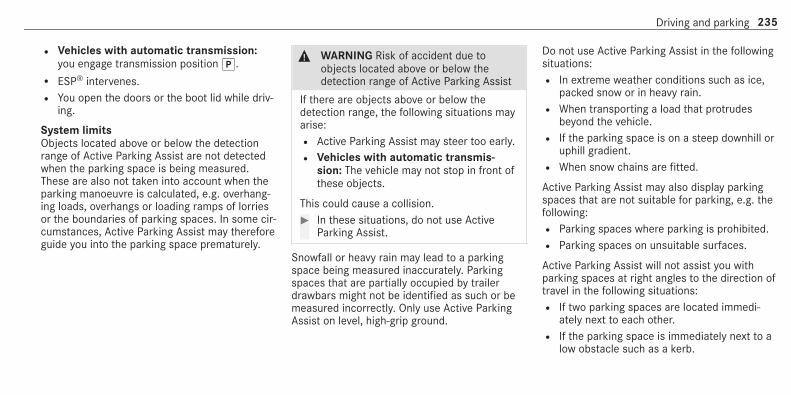
R Vehicles with automatic transmission:you engage transmission positionj.R ESP® intervenes.R You open the doors or the boot lid while driv‐
ing.
System limitsObjects located above or below the detectionrange of Active Parking Assist are not detectedwhen the parking space is being measured.These are also not taken into account when theparking manoeuvre is calculated, e.g. overhang‐ing loads, overhangs or loading ramps of lorriesor the boundaries of parking spaces. In some cir‐cumstances, Active Parking Assist may thereforeguide you into the parking space prematurely.
& WARNING Risk of accident due toobjects located above or below thedetection range of Active Parking Assist
If there are objects above or below thedetection range, the following situations mayarise:R Active Parking Assist may steer too early.R Vehicles with automatic transmis‐
sion: The vehicle may not stop in front ofthese objects.
This could cause a collision.# In these situations, do not use Active
Parking Assist.
Snowfall or heavy rain may lead to a parkingspace being measured inaccurately. Parkingspaces that are partially occupied by trailerdrawbars might not be identified as such or bemeasured incorrectly. Only use Active ParkingAssist on level, high-grip ground.
Do not use Active Parking Assist in the followingsituations:R In extreme weather conditions such as ice,
packed snow or in heavy rain.R When transporting a load that protrudes
beyond the vehicle.R If the parking space is on a steep downhill or
uphill gradient.R When snow chains are fitted.
Active Parking Assist may also display parkingspaces that are not suitable for parking, e.g. thefollowing:R Parking spaces where parking is prohibited.R Parking spaces on unsuitable surfaces.
Active Parking Assist will not assist you withparking spaces at right angles to the direction oftravel in the following situations:R If two parking spaces are located immedi‐
ately next to each other.R If the parking space is immediately next to a
low obstacle such as a kerb.
Driving and parking 235

Active Parking Assist will not assist you withparking spaces parallel or at right angles to thedirection of travel in the following situations:R If the parking space is on a kerb.R If the parking space is bordered by an obsta‐
cle, e.g. a tree, a post or a trailer.
Parking with Active Parking Assist% Depending on the vehicle's equipment, the
button may also be located at a differentposition in the centre console.
# Press button1.
The media display shows the view of Active Park‐ing Assist. Area2 displays detected parkingspaces4 and vehicle path3.% Vehicle path3 shown on the media display
may differ from the actual vehicle path.# If you have driven past a parking space: bring
the vehicle to a standstill.# Select desired parking space4.# Where necessary, select the parking direc‐
tion: forwards or reverse.Vehicle path3 is shown, depending onselected parking space4 and the parkingdirection.
236 Driving and parking
# Confirm selected parking space4.
% The turn signal indicator is switched on auto‐matically when the parking procedurebegins. The turn signal indicator is switchedoff automatically when you switch toh.
You are responsible for selecting the turn signalindicator in accordance with the traffic condi‐tions. If necessary, select the turn signal indica‐tor accordingly.
& WARNING Risk of accident due to vehi‐cle swinging out while parking or pullingout of a parking space
While parking or exiting a parking space, thevehicle swings out and can drive onto areasof the oncoming lane.This could cause you to collide with objectsor other road users.# Pay attention to objects and other road
users.# Where necessary, stop the vehicle or
cancel the parking procedure withActive Parking Assist.
# If, for example, the Please engage reversegear message appears in the media display:select the corresponding transmission posi‐tion.Vehicles with automatic transmission: thevehicle drives into the selected parkingspace.
# Vehicles with manual transmission: stopas soon as Parking Assist PARKTRONICsounds the continuous warning tone, if notbefore. Depending on the message or asrequired, engage forward or reverse gear.
On completion of the parking procedure, theParking Assist finished, take control of vehicledisplay message appears. Further manoeuvringmay still be necessary.# After completion of the parking procedure,
safeguard the vehicle against rolling away.When required by legal requirements or localconditions: turn the wheels towards the kerb.
% You can stop the vehicle and change thetransmission position during the parking pro‐cedure. The system then calculates a newvehicle path. The parking procedure can
then be continued. If no new vehicle path isavailable, the transmission position will bechanged again. If the vehicle has not yetreached the parking space, the parking pro‐cedure will be cancelled, should a gear bechanged.
Exiting a parking space with Active ParkingAssist
Requirements:R The vehicle has been parked with Active
Parking Assist.
% Depending on the vehicle's equipment, thebutton may also be located at a differentposition in the centre console.
Please note that you are responsible for the vehi‐cle and surroundings during the entire parkingprocedure.# Start the vehicle.
Driving and parking 237

# Press button1.The media display shows the view of ActiveParking Assist.
# If the vehicle has been parked at right anglesto the direction of travel: in area2, selectdirection of travel3.
% The vehicle path shown on the media displaymay differ from the actual vehicle path.
# Confirm direction of exit3 to drive out ofthe parking space.
% The turn signal indicator is switched on auto‐matically when the exiting procedure begins.
You are responsible for selecting the turn signalindicator in accordance with the traffic condi‐tions. If necessary, select the turn signal indica‐tor accordingly.
& WARNING Risk of accident due to vehi‐cle swinging out while parking or pullingout of a parking space
While parking or exiting a parking space, thevehicle swings out and can drive onto areasof the oncoming lane.This could cause you to collide with objectsor other road users.# Pay attention to objects and other road
users.# Where necessary, stop the vehicle or
cancel the parking procedure withActive Parking Assist.
# If, for example, the Please engage forwardgear message appears in the media display:select the corresponding transmission posi‐tion.The vehicle moves out of the parking space.The turn signal indicator is switched off auto‐matically.
238 Driving and parking
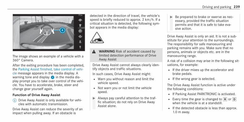
The image shows an example of a vehicle with a360° Camera.After the exiting procedure has been completed,the Parking Assist finished, take control of vehi-cle message appears in the media display. Awarning tone and display4 in the media dis‐play prompt you to take over control of the vehi‐cle. You have to accelerate, brake, steer andchange gear yourself again.
Function of Drive Away Assist% Drive Away Assist is only available for vehi‐
cles with automatic transmission.Drive Away Assist can reduce the severity of animpact when pulling away. If an obstacle is
detected in the direction of travel, the vehicle'sspeed is briefly reduced to approx. 2 km/h. If acritical situation is detected, the following sym‐bol appears in the media display:
& WARNING Risk of accident caused bylimited detection performance of DriveAway Assist
Drive Away Assist cannot always clearly iden‐tify objects and traffic situations.In such cases, Drive Away Assist might:R Warn you without reason and limit the
vehicle speed.R Not warn you or not limit the vehicle
speed.
# Always pay careful attention to the traf‐fic situation; do not rely on Drive AwayAssist alone.
# Be prepared to brake or swerve as nec‐essary, provided the traffic situationpermits and that it is safe to take eva‐sive action.
Drive Away Assist is only an aid. It is not a sub‐stitute for your attention to the surroundings.The responsibility for safe manoeuvring andparking remains with you. Make sure that nopersons, animals or objects etc. are in themanoeuvring range.A risk of a collision may arise in the following sit‐uations, for example:R If the driver mixes up the accelerator and
brake pedals.R If the wrong gear is selected.
The Drive Away Assist function is active underthe following conditions:R If Parking Assist PARKTRONIC is activated.R Every time the gear is changed tok orh
when the vehicle is at a standstill.R If the detected obstacle is less than approx.
1.0 m away.
Driving and parking 239

R If the manoeuvring assistance function isactivated in the multimedia system.
System limitsThe performance of Drive Away Assist is limitedon inclines.When driving with a trailer, Drive Away Assist isnot available.
Function of Cross Traffic Alert% Also read the instructions on Blind Spot
Assist (/ page 246).
Vehicles with Blind Spot Assist: the CrossTraffic Alert function can warn drivers of anycrossing traffic when reversing out of a parking
space. The radar sensors in the bumper alsomonitor the area adjacent to the vehicle. If a crit‐ical situation is detected, symbol1 appears inthe media display. If the driver does not respondto the warning, the vehicle's brakes can beapplied automatically.If the radar sensors are obstructed by vehiclesor other objects, detection is not possible.The Cross Traffic Alert function is active underthe following conditions:R If Blind Spot Assist is activated.R If the vehicle is reversing at walking pace.R If the manoeuvring assistance function is
activated in the multimedia system.
System limitationsThe Cross Traffic Alert function is not availableon inclines and when driving with a trailer.
Activating/deactivating manoeuvring assis‐tanceMultimedia system:4© 5 Settings 5 Assistance5 Camera & parking# Activate or deactivate Manoeuvring assis-
tance.% Manoeuvring assistance must be active for
the function of Drive Away Assist(/ page 239) and Cross Traffic Alert(/ page 240).
ATTENTION ASSIST
Function of ATTENTION ASSISTATTENTION ASSIST assists you on long, monoto‐nous journeys, e.g. on motorways and trunkroads. If ATTENTION ASSIST detects indicatorsof fatigue or increasing lapses in concentrationon the part of the driver, it suggests taking abreak.ATTENTION ASSIST is only an aid. It cannotalways detect fatigue or lapses in concentrationin time. The system is not a substitute for a well-
240 Driving and parking
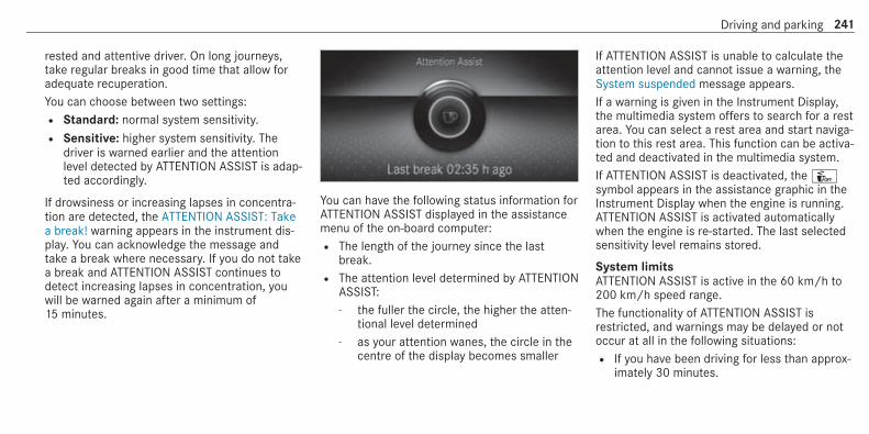
rested and attentive driver. On long journeys,take regular breaks in good time that allow foradequate recuperation.You can choose between two settings:R Standard: normal system sensitivity.R Sensitive: higher system sensitivity. The
driver is warned earlier and the attentionlevel detected by ATTENTION ASSIST is adap‐ted accordingly.
If drowsiness or increasing lapses in concentra‐tion are detected, the ATTENTION ASSIST: Takea break! warning appears in the instrument dis‐play. You can acknowledge the message andtake a break where necessary. If you do not takea break and ATTENTION ASSIST continues todetect increasing lapses in concentration, youwill be warned again after a minimum of15 minutes.
You can have the following status information forATTENTION ASSIST displayed in the assistancemenu of the on-board computer:R The length of the journey since the last
break.R The attention level determined by ATTENTION
ASSIST:- the fuller the circle, the higher the atten‐
tional level determined- as your attention wanes, the circle in the
centre of the display becomes smaller
If ATTENTION ASSIST is unable to calculate theattention level and cannot issue a warning, theSystem suspended message appears.If a warning is given in the Instrument Display,the multimedia system offers to search for a restarea. You can select a rest area and start naviga‐tion to this rest area. This function can be activa‐ted and deactivated in the multimedia system.If ATTENTION ASSIST is deactivated, theÛsymbol appears in the assistance graphic in theInstrument Display when the engine is running.ATTENTION ASSIST is activated automaticallywhen the engine is re-started. The last selectedsensitivity level remains stored.
System limitsATTENTION ASSIST is active in the 60 km/h to200 km/h speed range.The functionality of ATTENTION ASSIST isrestricted, and warnings may be delayed or notoccur at all in the following situations:R If you have been driving for less than approx‐
imately 30 minutes.
Driving and parking 241

R If the road condition is poor (uneven roadsurface or potholes).R If there is a strong side wind.R If you adopt a sporty driving style (high cor‐
nering speeds or high rates of acceleration).R If the Steering Assist function of Active Dis‐
tance Assist DISTRONIC is active.R If the time has been set incorrectly.R In active driving situations, if you change
lanes and vary your speed frequently.
The ATTENTION ASSIST tiredness or alertnessassessment is deleted and restarted when con‐tinuing the journey in the following situations:R If you switch off the engine.R If you unfasten your seat belt and open the
driver's door (e.g. changing drivers or takinga break).
Setting ATTENTION ASSISTMultimedia system:4© 5 Settings 5 Assistance5 Attention Assist
Setting options# Select Standard, Sensitive or Off.
Suggesting a rest area# Select Suggest rest area.# Activate or deactivate the function.
If ATTENTION ASSIST detects fatigue orincreasing lack of attention, it suggests arest area in the vicinity.
# Select the suggested rest area.You are guided to the selected rest area.
Speed Limit Assist
Function of Speed Limit Assist% The availability of the following function is
country-dependent.
Speed Limit Assist detects speed limits withmultifunction camera1 and displays them inthe instrument cluster and optionally in thehead-up display. The camera also detects speedlimits with a restriction indicated by an addi‐tional sign (e.g. in wet conditions). The systemdetects stop signs, thereby preventing theengine from being switched off by the ECOstart/stop function.Speed Limit Assist is only an aid. The driver isresponsible for keeping a safe distance to thevehicle in front, for vehicle speed and for brakingin good time.
242 Driving and parking

Warning when the maximum permissiblespeed is exceededThe system can warn you if you unintentionallyexceed the maximum permissible speed. To dothis, you can specify in the multimedia systemby how much the maximum permissible speedcan be exceeded before a warning is issued. Youcan specify whether the warning is to be just avisual warning or an acoustic one as well.
Display in the instrument display% The illustrations show the instrument display
in the widescreen cockpit.
1 Permissible speed2 Permissible speed when there is a restriction3 Additional sign with restriction
Speed Limit Assist is not available in all coun‐tries. If it is unavailable, display1 is shown inthe speedometer.
System limitationsThe system may be impaired or may not functionin the following situations:R If there is poor visibility, e.g. due to insuffi‐
cient illumination of the road, if there arehighly variable shade conditions or in rain,snow, fog or heavy spray.R If there is glare, e.g. from oncoming traffic,
direct sunlight or reflections.R If the windscreen in the area of the multi‐
function camera is dirty, or if the camera ismisted up, damaged or covered.R If the traffic signs are hard to detect, e.g. due
to dirt or snow, or because they are coveredor due to insufficient lighting.R If you turn sharply when passing traffic signs
outside the camera's field of vision
Driving and parking 243

Setting Speed Limit AssistMultimedia system:4© 5 Settings 5 Assistance5 Speed Limit Assist
Adjusting the type of warning# Select Visual & audible, Visual or None.
Adjusting the warning thresholdThis value determines the speed at which awarning is issued when exceeded.# Select Warning threshold.# Set the desired speed.% If one of the following systems is activated,
the speed detected can be manually adoptedas the speed limit:R Active Distance Assist DISTRONICR Cruise controlR Variable limiter
Further information (/ page 209).
Traffic Sign Assist
Function of Traffic Sign Assist
Traffic Sign Assist detects traffic signs with mul‐tifunction camera1. It assists you by display‐ing detected speed limits and overtaking restric‐tions in the instrument cluster and optionally inthe head-up display or central display.Since Traffic Sign Assist also uses the datastored in the navigation system, it can updatethe display in the following situations withoutdetecting traffic signs:R When the vehicle changes roads, e.g. slip
road or motorway exit.
R When a village or town boundary which isstored in the digital map is passed.
If the system detects that you are driving onto asection of road in the wrong direction of travel, ittriggers a warning.The camera also detects traffic signs with arestriction indicated by an additional sign (e.g. inwet conditions).Traffic Sign Assist is only an aid. The driver isresponsible for keeping a safe distance to thevehicle in front, for vehicle speed and for brakingin good time.
Warning when the maximum permissiblespeed is exceededThe system can warn you if you unintentionallyexceed the maximum permissible speed. To dothis, you can specify in the multimedia systemby how much the maximum permissible speedcan be exceeded before a warning is issued. Youcan specify whether the warning is to be just avisual warning or an acoustic one as well.
244 Driving and parking
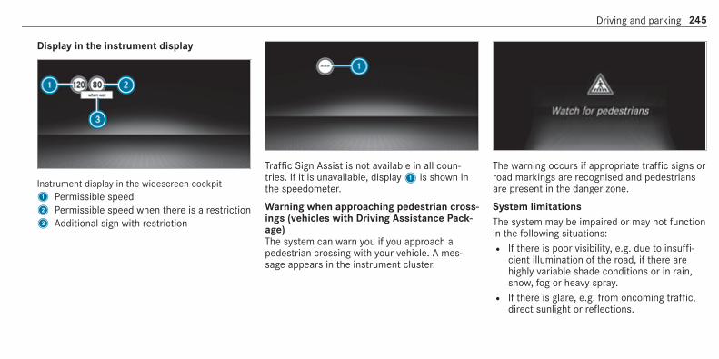
Display in the instrument display
Instrument display in the widescreen cockpit1 Permissible speed2 Permissible speed when there is a restriction3 Additional sign with restriction
Traffic Sign Assist is not available in all coun‐tries. If it is unavailable, display1 is shown inthe speedometer.
Warning when approaching pedestrian cross‐ings (vehicles with Driving Assistance Pack‐age)The system can warn you if you approach apedestrian crossing with your vehicle. A mes‐sage appears in the instrument cluster.
The warning occurs if appropriate traffic signs orroad markings are recognised and pedestriansare present in the danger zone.
System limitationsThe system may be impaired or may not functionin the following situations:R If there is poor visibility, e.g. due to insuffi‐
cient illumination of the road, if there arehighly variable shade conditions or in rain,snow, fog or heavy spray.R If there is glare, e.g. from oncoming traffic,
direct sunlight or reflections.
Driving and parking 245

R If the windscreen in the area of the multi‐function camera is dirty, or if the camera ismisted up, damaged or covered.R If the traffic signs are hard to detect, e.g. due
to dirt or snow, or because they are coveredor due to insufficient lighting.R If the information in the navigation system's
digital map is incorrect or out-of-date.R If the signs are ambiguous, e.g. traffic signs
on construction sites or in adjacent lanes.R If you turn sharply, when passing traffic signs
outside the camera's field of vision.
Setting Traffic Sign Assist
Requirements:R For automatic adoption of speed limits:
Active Distance Assist DISTRONIC is activa‐ted.
Multimedia system:4© 5 Settings 5 Assistance5 Traffic Sign Assist
Activating/deactivating automatic adoptionof speed limits# Select Adopt limit.# Activate or deactivate the function.
The speed limits detected by Traffic SignAssist are automatically adopted by ActiveDistance Assist DISTRONIC.
% If one of the following systems is activated,the speed detected can be manually adoptedas the speed limit:R Active Distance Assist DISTRONICR Cruise controlR Variable limiter
Further information (/ page 209).
Displaying detected traffic signs in themedia display# Select Display in head unit.# Activate or deactivate the function.
Adjusting the type of warning# Select Visual & audible, Visual or None.
Adjusting the warning thresholdThis value determines the speed at which awarning is issued when exceeded.# Select Warning threshold.# Set the desired speed.
Blind Spot Assist and Active Blind SpotAssist with exit warning
Function of Blind Spot Assist and ActiveBlind Spot Assist with exit warningBlind Spot Assist and Active Blind Spot Assistuse two lateral, rear-facing radar sensors tomonitor the area up to 40 m behind your vehicleand 3 m directly next to your vehicle.If a vehicle is detected at speeds above approx‐imately 12 km/h and this vehicle subsequentlyenters the monitoring range directly next to yourvehicle, the warning lamp in the outside mirrorlights up red.
246 Driving and parking

If a vehicle is detected close to the side of yourvehicle, the red warning lamp in the outside mir‐ror flashes. If you switch on the turn signal indi‐cator in the corresponding direction, a warningtone sounds once. If the turn signal indicatorremains switched on, all other detected vehiclesare indicated only by the flashing of the redwarning lamp.If you overtake a vehicle quickly, no warning isgiven.
& WARNING Risk of accident despite BlindSpot Assist
Blind Spot Assist does not react to vehiclesapproaching and overtaking you at a greatlydifferent speed.As a result, Blind Spot Assist cannot warndrivers in this situation.# Always pay careful attention to the traf‐
fic situation and maintain a safe dis‐tance at the side of the vehicle.
Blind Spot Assist and Active Blind Spot Assistare only aids. They may fail to detect some vehi‐
cles and are no substitute for attentive driving.Always ensure that there is sufficient distance tothe side for other road users and obstacles.
Exit warningThe exit warning is an additional function ofBlind Spot Assist and can warn vehicle occu‐pants about approaching vehicles when leavingthe vehicle when stationary.
& WARNING Risk of accident despite exitwarning
The exit warning reacts neither to stationaryobjects nor to vehicles approaching you at agreatly different speed.As a result, the exit warning cannot warndrivers in these situations.# Always pay particular attention to the
traffic situation when opening the doorsand make sure there is sufficient clear‐ance.
If there is a vehicle in the monitoring range, thisis indicated in the outside mirror. If a vehicleoccupant opens the door on the side with the
warning, a warning tone sounds and the warninglamp in the outside mirror starts to flash.This additional function is only available whenBlind Spot Assist is activated and up to a maxi‐mum of three minutes after the ignition hasbeen switched off. The exit warning is no longeravailable once the warning lamp in the outsidemirror flashes three times.The exit warning is only an aid and not a substi‐tute for the attention of vehicle occupants. Theresponsibility for opening and closing the doorsand for leaving the vehicle remains with the vehi‐cle occupants.
System limitsBlind Spot Assist and Active Blind Spot Assistmay be limited in the following situations:R if there is dirt on the sensors or the sensors
are obscuredR in poor visibility, e.g. due to fog, heavy rain or
snowR if there are narrow vehicles, e.g. bicycles or
motorbikesR if the road has very wide or narrow lanes
Driving and parking 247

R if vehicles are not driving in the middle oftheir lane
Warnings may be issued in error when drivingclose to crash barriers or similar solid lane bor‐ders. Always make sure that there is sufficientdistance to the side for other traffic or obsta‐cles.Warnings may be interrupted when driving along‐side long vehicles, for example lorries, for a pro‐longed time.Blind Spot Assist is not operational when reversegear is engaged.Blind Spot Assist is not operational when atrailer is coupled to the vehicle and the electricalconnection has been correctly established.The exit warning may be limited in the followingsituations:R when the sensors are covered by adjacent
vehicles in narrow parking spacesR when people approach the vehicleR in the event of stationary or slowly moving
objects
Function of brake application (Active BlindSpot Assist)% The brake application function is only availa‐
ble for vehicles with a Driving AssistancePackage.
If Active Blind Spot Assist detects a risk of a sideimpact in the monitoring range, a course-cor‐recting brake application is carried out. This isdesigned to help you avoid a collision.The course-correcting brake application is availa‐ble in the speed range between approximately30 km/h and 200 km/h.
& WARNING Risk of accident despitebrake application of Active Blind SpotAssist
A course-correcting brake application cannotalways prevent a collision.# Always steer, brake or accelerate your‐
self, especially if Active Blind SpotAssist warns you or makes a course-correcting brake application.
# Always maintain a safe distance at thesides.
& WARNING Risk of accident despiteActive Blind Spot Assist
Active Blind Spot Assist does not react to thefollowing:R if vehicles overtake too closely on the
side, placing them in the blind spot areaR vehicles approaching and overtaking you
at a greatly different speed
As a result, Active Blind Spot Assist may nei‐ther give warnings nor intervene in such sit‐uations.# Always pay careful attention to the traf‐
fic situation and maintain a safe dis‐tance at the side of the vehicle.
248 Driving and parking

If a course-correcting brake application occurs,the red warning lamp flashes in the outside mir‐ror and a warning tone sounds. In addition, a dis‐play1 indicating the danger of a side collisionappears in the multifunction display.In rare cases, the system may make an inappro‐priate brake application. This brake applicationmay be interrupted at any time if you steerslightly in the opposite direction or accelerate.
System limitsEither a course-correcting brake applicationappropriate to the driving situation, or none atall, may occur in the following situations:R Vehicles or obstacles, e.g. crash barriers, are
located on both sides of your vehicle.R A vehicle approaches too closely on the side.R You have adopted a sporty driving style with
high cornering speeds.R You brake or accelerate significantly.R A driving safety system intervenes, e.g. ESP®
or Active Brake Assist.R ESP® is deactivated.R A loss of tyre pressure or a defective tyre is
detected.R You are driving with a trailer and the electri‐
cal connection to the trailer hitch has beencorrectly established.
Activating/deactivating Blind Spot Assist orActive Blind Spot AssistMultimedia system:4© 5 Settings 5 Assistance# Activate or deactivate Blind Spot Assist.
Active Lane Keeping Assist
Function of Active Lane Keeping Assist
Active Lane Keeping Assist monitors the area infront of your vehicle by means of multifunctioncamera1. It serves to protect you against unin‐tentionally leaving your lane. You will be warnedby vibration pulses in the steering wheel and gui‐
Driving and parking 249

ded by a course-correcting brake applicationback into your lane.You are warned by vibration pulses in the steer‐ing wheel in the following circumstances:R Active Lane Keeping Assist detects a lane
marking.R A front wheel drives over this lane marking.
You will also be guided back into your lane bymeans of a course-correcting brake applicationif the following conditions are met:R Active Lane Keeping Assist detects lane
markings on both edges of the lane.R A front wheel drives over a solid lane mark‐
ing.
You can activate or deactivate the Active LaneKeeping Assist warning.Active Lane Keeping Assist can neither reducethe risk of an accident if you fail to adapt yourdriving style nor override the laws of physics. Itcannot take into account road, weather or trafficconditions. Active Lane Keeping Assist is only anaid. You are responsible for maintaining a safedistance to the vehicle in front, for vehicle
speed, for braking in good time and for stayingin lane.Active Lane Keeping Assist can bring the vehicleback into the lane with a lane-correcting brakeapplication. In the case of a broken lane markingbeing detected, a brake application will only bemade if a vehicle has been detected in the adja‐cent lane. Oncoming traffic can be detected.Vehicles with Driving Assistance Package orDriving Assistance Plus Package: overtakingvehicles and vehicles in adjacent lanes can alsobe detected.Active Lane Keeping Assist is available in thespeed range between 60 km/h and 200 km/h.
If a lane-correcting brake application occurs, dis‐play1 appears in the multifunction display.
Sensitivity of Active Lane Keeping Assist% The availability of the following function is
country-dependent.A lane-correcting brake application also occursin the Sensitive setting in the following situa‐tions:R Active Lane Keeping Assist detects a solid
lane marking.R A front wheel drives over this lane marking.
System limitsNo lane-correcting brake application occurs inthe following situations:R You clearly and actively steer, brake or accel‐
erate.R You have switched on the turn signal indica‐
tor (situation-dependent).R A driving safety system intervenes, such as
ESP®, Active Brake Assist or Active BlindSpot Assist.
250 Driving and parking

R You have adopted a sporty driving style withhigh cornering speeds or high rates of accel‐eration.R When ESP® is deactivated.R When driving with a trailer, the electrical con‐
nection to the trailer has been correctlyestablished.R If a loss of tyre pressure or a defective tyre
has been detected and displayed.
The system may be impaired or may not functionin the following situations:R If there is poor visibility, e.g. due to insuffi‐
cient illumination of the road, if there arehighly variable shade conditions or in rain,snow, fog or heavy spray.R If there is glare, e.g. from oncoming traffic,
the sun or reflections.R If the windscreen in the area of the multi‐
function camera is dirty, or if the camera ismisted up, damaged or covered.R If there are no lane markings, or several
unclear lane markings are present for onelane, e.g. around roadworks.
R If the lane markings are worn, dark or cov‐ered.R If the distance to the vehicle in front is too
short and thus the lane markings cannot bedetected.R If the lane markings change quickly, e.g.
lanes branch off, cross one another ormerge.R If the carriageway is very narrow and wind‐
ing.
Vehicles with Driving Assistance Package:Active Lane Keeping Assist uses radar sensorsto monitor several areas around the vehicle. Ifthe radar sensors in the rear bumper are dirty orcovered with snow, the system may be impairedor may not function. If an obstacle in the lane inwhich you are driving has been detected, nolane-correcting brake application occurs.
Activating/deactivating Active Lane KeepingAssistMultimedia system:4© 5 Settings5 Schnellzugriff (Quick access)5 Active Lane Keeping Assist# Activate or deactivate the function.
Setting Active Lane Keeping AssistMultimedia system:4© 5 Settings 5 Assistance5 Active Lane Keeping Assist
Setting the sensitivity% The availability of this function is dependent
on the country.# Select Standard, Sensitive or Off.
Activating/deactivating the haptic warning# Select Warning.
Activate or deactivate the function.
Driving and parking 251

Trailer hitchNotes on trailer operation
Mercedes‑AMG vehicles: be sure to observethe notes in the Supplement. Otherwise, youmay fail to recognise dangers.Observe the following notes on the tongueweight:R do not use a tongue weight that exceeds or
falls below the permissible tongue weightR use a tongue weight as close as possible to
the maximum tongue weight
Do not exceed the following values:R permissible towing weightR permissible rear axle load of the towing vehi‐
cleR permissible gross mass of the towing vehicleR permissible gross mass of the trailerR maximum permissible speed of the trailer
Ensure the following before starting a journey:R the tyre pressure on the rear axle of the tow‐
ing vehicle is set for a maximum load
R the lighting of the connected trailer is opera‐tionalR vehicles without LED headlamps or MUL‐
TIBEAM LED headlamps: the headlampshave been set correctly
In the event of increased rear axle load, the car/trailer combination may not exceed a maximumspeed of 100 km/h for reasons concerning theoperating permit. This also applies in countriesin which the permissible maximum speed forcar/trailer combinations is above 100 km/h.
Folding the ball neck out/in
& WARNING Risk of accident due to theball neck not being engaged
If the ball neck is not engaged, the trailermay come loose.# Always engage the ball neck as descri‐
bed.
& WARNING Risk of injury from ball neckswinging outwards
The ball neck may swing outwards whenunlocking or when it has not been properlyengaged.There is a risk of injury within the ball neck'srange of movement!# Unlock the ball neck only when its
range of movement is unobstructed.# Always be sure the ball neck is engaged
when folding inwards.
Requirements:R The vehicle is secured against rolling away.R The range of movement is clear.R The trailer cables or adapter plugs have been
removed.
252 Driving and parking

Folding the ball neck out
# Pull release switch2 until the ball neckunlocks.The ball neck will fold out from under therear bumper.Indicator lamp1 will flash.
# Pull the ball neck in the direction of thearrow until it engages audibly in a verticalposition.Indicator lamp1 on the ball neck releaseswitch will go out.If the ball neck is not securely locked inplace, the Trailer coupling Check lockdisplaymessage will appear on the multifunction dis‐play.
# Remove the cover from the ball head andstore it in a safe place.
Make sure that the ball on the ball neck is clean.Check that it is either greased or dry (grease-free), depending on the instructions for thetrailer.
Folding the ball neck in# Pull release switch2 until the ball neck
unlocks.The ball neck will fold up under the rearbumper.Indicator lamp1 flashes.
# Push the ball neck in the direction of thearrow until it engages audibly behind thebumper.Indicator lamp1 will go out and the mes‐sage on the multifunction display will disap‐pear.
Observe the information on the displays on theinstrument cluster:R Warning and indicator lamps (/ page 581)R Display messages (/ page 527)
Driving and parking 253

Coupling up / uncoupling a trailer
Requirements:R the ball neck must be extended and engaged
in a securely locked position
Trailers with a 7-pin plug can be connected tothe vehicle with the following adapters:R adapter plugR adapter cable
The trailer will be correctly detected by the vehi‐cle only if the following conditions are met:R the trailer is connected correctlyR the trailer lighting system is in working order
The functions of the following systems are affec‐ted by a correctly connected trailer:R Active Lane Keeping AssistR ESP® trailer stabilisationR Parking Assist PARKTRONICR Active Parking AssistR Blind Spot Assist or Active Blind Spot AssistR Drive Away Assist
R Cross Traffic AlertR Reversing cameraR 360° Camera
Coupling up a trailer
* NOTE Damage to the vehicle battery dueto full discharge
Charging the trailer battery using the powersupply of the trailer can damage the vehiclebattery.# Do not use the vehicle's power supply
to charge the trailer battery.
# Remove the cover from the ball head andstore it in a safe place (/ page 110).
# Position the trailer on a level surface behindthe vehicle and couple it up to the vehicle.
# Open the socket cap.# Insert the plug with lug1 in groove3 on
the socket.# Turn the bayonet coupling2 to the right as
far as it will go.# Let the cap engage.# Secure the cable to the trailer with cable ties
(only if you are using an adapter cable).# Make sure that the cable is always slack for
ease of movement during cornering.
254 Driving and parking

A display message may appear on the multifunc‐tion display even if the trailer has been connec‐ted correctly:R LEDs have been installed in the trailer light‐
ing systemR the current has fallen below the trailer light‐
ing system's minimum current (50 mA)
% Accessories can be connected to the perma‐nent power supply up to 180 W, and to thepower supply that is switched on via the igni‐tion lock.
Uncoupling a trailer
& WARNING Risk of being crushed andbecoming trapped when uncoupling atrailer
When uncoupling a trailer with an engagedinertia-activated brake, your hand maybecome trapped between the vehicle and thetrailer drawbar.# Do not uncouple trailers with an
engaged overrun brake.
* NOTE Damage when uncoupling in astate of overrun
Uncoupling in a state of overrun can damagethe vehicle.# Do not uncouple trailers with an
engaged overrun brake.
# Secure the trailer against rolling away.# Disconnect the electrical connection
between the vehicle and the trailer.# Uncouple the trailer.# Place the cover on the ball head.
Bicycle rack function
& WARNING Risk of an accident whenusing the bicycle rack incorrectly
The bicycle rack may become detached fromthe vehicle in the following cases:R the permissible load capacity of the
trailer hitch is exceeded.
R the bicycle rack is used incorrectly.R the bicycle rack is secured to the ball
neck beneath the ball head.
Observe the following for your own safetyand that of other road users:# always adhere to the permissible load
capacity of the trailer hitch.# only use the bicycle rack to transport
bicycles.# always properly secure the bicycle rack
by attaching it to the ball head.# only use bicycle racks approved by
Mercedes-Benz.# always observe the bicycle rack operat‐
ing instructions.
* NOTE Damage to, or cracks on, thetrailer hitch due to unsuitable bicycleracks or bicycle racks being used incor‐rectly
# use only bicycle racks approved byMercedes-Benz.
Driving and parking 255

Depending on the bicycle rack's design, up tothree bicycles can be transported on the bicyclerack.When mounted by attaching to ball head1, themaximum load capacity is 75 kg.The load capacity is calculated from the weightof the bicycle rack and the bicycle rack load.The vehicle's driving characteristics will changewhen a bicycle rack is fitted. Adapt your driving
style accordingly. Drive carefully and maintain asafe distance.When using a bicycle rack, set the tyre pressurefor maximum load on the rear axle of the vehicle.Further information on the tyre pressure can befound in the tyre pressure table (/ page 487).
Notes on loadingThe larger the distance between the load'scentre of gravity and the ball head, the greaterthe load on the trailer hitch.Therefore, observe the following notes:R mount heavy bicycles as close to the vehicle
as possibleR always distribute the load on the bicycle rack
as evenly as possible across the vehicle'slongitudinal axis
Mercedes-Benz recommends removing alldetachable parts from bicycles (e.g. baskets,child seats, rechargeable batteries) before load‐ing them onto the bicycle rack. This will improvethe aerodynamic resistance and centre of gravityof the bicycle rack.
Always secure the bicycles to prevent them frommoving around and check that they are secure atregular intervals.Do not use tarpaulins or other covers. The driv‐ing characteristics and rear view may beimpaired. In addition, aerodynamic resistanceand the load on the trailer hitch will increase.
Load distribution on the bicycle rack1 Vertical distance between centre of gravity
and ball head2 Horizontal distance between centre of grav‐
ity and ball head3 The centre of gravity is on the vehicle's
centre axis
256 Driving and parking

Observe the following information when you areloading the bicycle rack with up to three bicy‐cles:
Loading the bicycle rack
Total weightof bicyclerack andload
Max. dis‐tance11
Max. dis‐tance22
Up to 75 kg 420 mm 300 mm
Vehicle towing instructionsThe vehicle is not suitable for the use of tow barsystems that are used for flat towing or dinghytowing, for example. Attaching and using tow barsystems can lead to damage on the vehicle.When you are towing a vehicle with tow bar sys‐tems, safe driving characteristics cannot beguaranteed for the towing vehicle or the towedvehicle. The vehicle-trailer combination mayswerve from side to side. Comply with the per‐mitted towing methods (/ page 476) and theinstructions for towing with both axles on theground (/ page 477).
Driving and parking 257

Instrument display overviewMercedes-AMG vehicles: be sure to observethe information in the Supplement. Otherwise,you may fail to recognise dangers.
& WARNING Risk of accident due to aninstrument display malfunction
If the Instrument Display has failed or mal‐functioned, you may not recognise functionrestrictions applying to safety relevant sys‐tems.The operating safety of your vehicle may beimpaired.# Drive on carefully.# Have the vehicle checked immediately
at a qualified specialist workshop.
If the operating safety of your vehicle isimpaired, park the vehicle safely as soon as pos‐sible. Contact a qualified specialist workshop.
Instrument display (standard)
1 Speedometer (example)2 Digital speedometer3 Fuel level and fuel filler cap location indica‐
tor4 Multifunction display
Further content can be shown on the multifunc‐tion display4:R Assistant displayR TelephoneR NavigationR Trip
R RadioR MediaR Vehicle dynamicsR StylesR Service
Instrument display in the widescreen cockpit
1 Speedometer (example)2 Multifunction display3 Rev counter (example)4 Coolant temperature display5 Fuel level and fuel filler cap location indica‐
tor
258 Instrument Display and on-board computer

% In addition to the multifunction display2,further content can be shown on displays1and3 (/ page 262).
The segments on the speedometer1 indicatethe system status for the following:R Cruise control(/ page 203)R Limiter (/ page 204)R Active Distance Assist
DISTRONIC(/ page 207)
* NOTE Engine damage due to excessivelyhigh engine speeds
The engine will be damaged if you drive withthe engine in the overrevving range.# Do not drive with the engine in the over‐
revving range.
The fuel supply will be interrupted to protect theengine when the red mark on the rev counter(overrevving range) is reached.Vehicles with widescreen cockpit: during nor‐mal operating conditions, the coolant tempera‐ture display may rise to 120°C.
& WARNING Danger of burns when open‐ing the bonnet
If you open the engine bonnet when theengine has overheated or during a fire in theengine compartment, you could come intocontact with hot gases or other escapingoperating fluids.# Before opening the bonnet, allow the
engine to cool down.# In the event of a fire in the engine com‐
partment, keep the engine bonnetclosed and call the fire service.
Overview of the buttons on the steeringwheel
1¤ Back/Home button (press and hold),on-board computer
2 Touch Control, on-board computer3 Control panel for cruise control/limiter or
Active Distance Assist DISTRONIC4 Control panel for MBUX multimedia system:£ LINGUATRONICß Displays favouritesVOL: control knob, adjusts the volume orswitches the sound off8 (press)6 Makes/accepts a call
Instrument Display and on-board computer 259

~ Rejects/ends a call5 ò Calls up the home screen6 Touch Control multimedia system7 % Back button (press and hold)
Operates the on-board computer
& WARNING Risk of distraction from infor‐mation systems and communicationsequipment
If you operate information and communica‐tion equipment integrated in the vehiclewhen driving, you will be distracted from thetraffic situation. This could also cause you tolose control of the vehicle.# Only operate this equipment when the
traffic situation permits.# If you cannot be sure of this, stop the
vehicle whilst paying attention to roadand traffic conditions and operate theequipment with the vehicle stationary.
Observe the legal requirements for the countryin which you are currently driving when youoperate the on-board computer.% The on-board computer displays appear on
the multifunction display (/ page 263).
The on-board computer can be operated usingthe left-hand Touch Control2 and the left-handback/home button1.
When the on-board computer is being operated,different acoustic signals will sound as operatingfeedback, e.g. when the end of a list is reachedor when you are scrolling through a list.The following menus are available:R AssistanceR TelephoneR NavigationR TripR RadioR MediaR Styles & displayR Service
The menus can be called up from the menu baron the multifunction display.# To call up the menu bar: press the back
button on the left1 until the menu bar isdisplayed.
% Vehicles without Active Distance AssistDISTRONIC: press theò button to callup the menu bar of the on-board computer.
260 Instrument Display and on-board computer

% The illustration shows the instrument displayin the widescreen cockpit.
# To scroll in the menu bar: swipe left orright on the left-hand Touch Control2.
# To call up a menu or confirm a selection:press the left-hand Touch Control2.
# To scroll through displays or lists on themenu: swipe upwards or downwards on theleft-hand Touch Control2.
# To call up a submenu or confirm a selec‐tion: press the left-hand Touch Control2.
# To exit a submenu: press the back buttonon the left1.
Selecting the head-up display# If the head-up display is switched on:
swipe upwards on the left-hand Touch Con‐trol2.
# Swipe upwards on the left-hand Touch Con‐trol2 to switch to the head-up display.
or# If the head-up display is switched off:
press the left-hand Touch Control2.
Full-surface menu displayVehicles with an instrument display in thewidescreen cockpit: the following menus canbe shown in full on the instrument display:R AssistanceR TripR Navigation# In the corresponding menu, use the left-hand
Touch Control2 to scroll to the end of thelist.
# Press left-hand Touch Control2.The selected menu will be displayed in full.
Adjusting the design of the instrument dis‐playOn-board computer:4 Styles & display
Setting the design# Swipe upwards or downwards on the left-
hand Touch Control.# Press the left-hand Touch Control.
The instrument display is shown in the selec‐ted design.
The following designs can be selected, depend‐ing on the vehicle equipment:R ClassicR SportR ProgressiveR UnderstatedR Standard displays
Instrument Display and on-board computer 261

Showing display content on the instrumentclusterVehicles with an instrument display in thewidescreen cockpit: additional display contentcan be shown on the instrument cluster.# To select display content: swipe to the
right on the left-hand Touch Control.# Swipe upwards or downwards on the left-
hand Touch Control to select the requireddisplay content.When the display content is selected, it willbriefly be highlighted.
1 Display content, left (example: speedometer)2 The index points show the selected display
content.
Display content selection, left:R SpeedometerR Time/dateR Trip computer From start and From resetR RangeR Audio
3 Display content, centre (example: media)
Display content selection, centre:R Assistance graphicR TelephoneR NavigationR TripR RadioR MediaR Styles and displayR Service
262 Instrument Display and on-board computer

4 Display content, right (example: rev counter)
Display content selection, right:R Rev counterR Average fuel consumptionR ECO displayR NavigationR G-meterR Assistance graphic
Overview of displays on the multifunctiondisplay
1 Outside temperature2 Time3 Digital speedometer4 Display section5 Drive program6 Transmission position
% Vehicles with standard instrument dis‐play: the position of the displays differs fromthose shown here.
Further displays on the multifunction display:Z Gearshift recommendation (/ page 173)u Active Parking Assist activated
(/ page 236)é Parking Assist PARKTRONIC deactivated
(/ page 226)¯ Cruise control (/ page 203)È Limiter (/ page 204)ç Active Distance Assist DISTRONIC
(/ page 207)æ Active Brake Assist (/ page 202)à Active Steering Assist (/ page 213)Ã Active Lane Keeping Assist (/ page 249)± Active Lane Change Assist (/ page 215)è ECO start/stop function (/ page 163)ë HOLD function (/ page 219)_ Adaptive Highbeam Assist (/ page 133)
Instrument Display and on-board computer 263

Adaptive Highbeam Assist Plus(/ page 134)
ð Maximum permissible speed exceeded(for certain countries only)
Vehicles with Speed Limit Assist: detectedinstructions and traffic signs (/ page 242).Vehicles with Traffic Sign Assist: detectedinstructions and traffic signs (/ page 244).
Adjusting the instrument lighting
# Turn brightness control1 up or down.The lighting of the instrument display and inthe control elements of the vehicle interior isadjusted.
Menus and submenusFunctions on the service menu of the on-board computer
On-board computer:4 Service# To select the function: swipe upwards or
downwards on the left-hand Touch Control.# Press the left-hand Touch Control.Functions on the Service menu:R Message memory (/ page 527)R AdBlue: Adblue® range and fill levelR Tyres:
- Restarting the tyre pressure loss warningsystem (/ page 494)
- Checking tyre pressure with the tyrepressure monitor (/ page 488)
- Restarting the tyre pressure monitor(/ page 489)
R ASSYST PLUS: calls up the service due date(/ page 445)R Coolant: coolant temperature display
264 Instrument Display and on-board computer

R Engine oil level: engine oil levelR Consumption info: fuel life cycle consump‐
tion
Calling up the assistant display
On-board computer:4 AssistanceThe following displays are available on the assis‐tant display menu:R Assistant displayR Attention level (/ page 240)R Vehicles with an instrument display in
the widescreen cockpit: full-surface menudisplay
# To switch between the displays: swipeupwards or downwards on the left-handTouch Control.
% The illustration shows the instrument displayin the widescreen cockpit.
Status displays on the assistant display:RÛ ATTENTION ASSIST: deactivatedR Light lane markings: Active Lane Keeping
Assist enabledR Green lane markings: Active Lane Keeping
Assist activeR¸ Grey radar waves next to vehicle: Blind
Spot Assist or Active Blind Spot Assist ena‐bled
R¸ Green radar waves next to vehicle:Blind Spot Assist or Active Blind Spot AssistactiveR Active Distance Assist DISTRONIC displays
(/ page 207)
Calling up displays on the trip menu
On-board computer:4 Trip# To select a display: swipe upwards or down‐
wards on the left-hand Touch Control.Trip menu in the standard cockpit:R SpeedometerR Digital speedometerR Rev counterR Range and current fuel consumptionR ECO display (/ page 165)R Trip computer From start and From reset
Trip menu in the widescreen cockpit:R Standard display
Instrument Display and on-board computer 265

R Digital speedometerR Current fuel consumptionR ECO display (/ page 165)R Trip computer From start and From resetR Full-surface menu display
Example: standard display1 Trip distance2 Total distance
Example: trip computer1 Total distance2 Driving time3 Average speed4 Average fuel consumption
% The illustrations show the Instrument Displayin the Widescreen Cockpit.
Resetting values on the trip menu of the on-board computer
On-board computer:4 TripYou can reset the values of the following func‐tions:R Trip distanceR Trip computer From start and From resetR ECO display(/ page 165)
# To select the function to be reset: swipeupwards or downwards on the left-handTouch Control.
# Press the left-hand Touch Control.# Select Yes .# Press the left-hand Touch Control.
If you press and hold the left-hand Touch Con‐trol, the values of the function will be resetimmediately.
266 Instrument Display and on-board computer

Calling up navigation instructions on the on-board computer
On-board computer:4 NavigationThe following displays are available in the naviga‐tion menu:R Navigation viewR Map viewR Full-surface map view
Example: no change of direction announced1 Distance to the next change of direction2 Distance to the next destination
3 Estimated arrival time at next destination4 Current road
Example: change of direction announced1 Distance to the change of direction2 Road to which the change of direction leads3 Change-of-direction symbol4 Recommended lane (white)5 Possible lane6 Lane not recommended (dark grey)
Further possible displays on the Navigationmenu:R Direction of travel: display of direction of
travel and road currently being travelled on.R New route... or Calculating route…: a new
route is being calculated.R Road not mapped: the road is unknown, e.g.
for newly built roads.R No route: no route could be calculated to the
selected destination.R Off map: the map for the current location is
not available.R Area of destination reached: when an inter‐
mediate destination is reached, the inter‐mediate destination flag will be displayedwith the number of the intermediate destina‐tionÎ. After this, route guidance will con‐tinue. Once the destination is reached, thechequered flagÍ will be displayed. Routeguidance will now be complete
# To exit the menu: press the back button onthe left.
Instrument Display and on-board computer 267

Vehicles with the MBUX multimedia system:You can also start navigation to one of therecent destinations on the Navigation menu:# Press the left-hand Touch Control.# To select a destination: swipe upwards or
downwards on the left-hand Touch Control.# Press the left-hand Touch Control.
Route guidance will start.If route guidance has already been activated,a request will appear asking whether youwish to end the current route guidance.
# Select Yes.# Press the left-hand Touch Control.
Route guidance will start.
Selecting radio stations using the on-boardcomputer
On-board computer:4 Radio
1 Frequency range2 Station3 Name of track
% The illustration shows the Instrument Displayin the Widescreen Cockpit.
When you select a station from the memory pre‐sets, the preset will appear next to the stationname. When you select a saved station in the
frequency range, an asterisk will appear next tothe station name.# To select a radio station: swipe upwards or
downwards on the left-hand Touch Control.
Selecting the frequency range or memorypreset# Press the left-hand Touch Control.# Swipe upwards or downwards on the left-
hand Touch Control.# Press the left-hand Touch Control.
268 Instrument Display and on-board computer

Media playback using the on-board computer
On-board computer:4 Media
1 Media source2 Track number and current track3 Name of artist (example)
% The illustration shows the Instrument Displayin the Widescreen Cockpit.
# To change tracks on an active mediasource: swipe upwards or downwards on theleft-hand Touch Control.
Changing a media source# Press the left-hand Touch Control.# To select a media source: swipe upwards
or downwards on the left-hand Touch Con‐trol.
# Press the left-hand Touch Control.
Dialling telephone numbers using the on-board computer
& WARNING Risk of distraction from infor‐mation systems and communicationsequipment
If you operate information and communica‐tion equipment integrated in the vehiclewhen driving, you will be distracted from thetraffic situation. This could also cause you tolose control of the vehicle.# Only operate this equipment when the
traffic situation permits.# If you cannot be sure of this, stop the
vehicle whilst paying attention to road
and traffic conditions and operate theequipment with the vehicle stationary.
When using the phone, you must observe thelegal requirements for the country in which youare currently driving.
Requirements:R the mobile phone is connected to the multi‐
media system.
On-board computer:4 TelephoneThe most recent telephone calls (dialled,received and missed calls) are displayed on theTelephone menu.The most recent telephone calls (dialled,received and missed calls) are displayed on theTelephone menu.# To select an entry: swipe upwards or down‐
wards on the left-hand Touch Control.
Instrument Display and on-board computer 269

# Press the left-hand Touch Control.If there is only one telephone numbersaved to an entry: the telephone numberwill be selected.
# If there are multiple telephone numberssaved to an entry: swipe upwards or down‐wards on the left-hand touch control toselect the desired telephone number.
# Press the left-hand Touch Control.The telephone number will be dialled.
The following displays may appear instead of thetelephone numbers dialled:R Please wait: the application is starting. If a
Bluetooth® connection to the mobile phoneis not established, the menu for authorisingand connecting a mobile phone will be dis‐played on the multimedia system(/ page 388).R Updating data: the call list is being updated.R Importing contacts: contacts are being
imported from the mobile phone or a storagemedium.
Accepting/rejecting an incoming callVehicles with head-up display: when youreceive a call, the Incoming call message willappear on the head-up display.# Swipe upwards or downwards on the left-
hand Touch Control and select6 (accept)or~ (reject).
# Press the left-hand Touch Control.
You may accept/reject the call using the6or~ button on the steering wheel.
Setting the head-up display using the on-board computer
On-board computer:4 HEAD-UP DISPLAYThe following head-up display settings can beselected:R PositionR BrightnessR Displays
# To select a setting: swipe upwards or down‐wards on the left-hand Touch Control.
# Press the left-hand Touch Control.# To adjust the position: swipe upwards or
downwards on the left-hand Touch Control.# To adjust the brightness: swipe to the left
or right on the left-hand Touch Control.# Press the left-hand Touch Control.
Selecting what the head-up display shows
(Example)1 To switch the head-up display on/off2 Left display area
Navigation system
270 Instrument Display and on-board computer
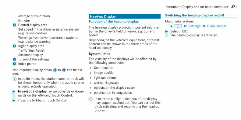
Average consumptionG-meter
3 Central display areaSet speed in the driver assistance system(e.g. cruise control)Warnings from driver assistance systems(e.g. distance warning)
4 Right display areaTraffic Sign AssistAssistant display
5 To select the settings6 Index points
Non-required display areas2 to4 can be hid‐den.% In audio mode, the station name or track will
be shown temporarily when the audio sourceis being actively operated.
# To select a display: swipe upwards or down‐wards on the left-hand Touch Control.
# Press the left-hand Touch Control.
Head-up DisplayFunction of the head-up display
The head-up display projects important informa‐tion in the driver's field of vision, e.g. currentspeed.Depending on the vehicle's equipment, differentcontent can be shown in the three areas of thehead-up display.
System limitsThe visibility of the displays will be affected bythe following conditions:R Seat positionR image positionR light conditionsR wet carriagewaysR objects on the display coverR polarisation in sunglasses
% In extreme sunlight, sections of the displaymay appear washed out. You can correct thisby deactivating and reactivating the head-updisplay.
Switching the head-up display on/off
Multimedia system:4© 5 Settings 5 Quick access# Select HUD.
The head-up-display is activated.
Instrument Display and on-board computer 271

Notes on operating safety
& WARNING Risk of distraction from infor‐mation systems and communicationsequipment
If you operate information and communica‐tion equipment integrated in the vehiclewhen driving, you will be distracted from thetraffic situation. This could also cause you tolose control of the vehicle.# Only operate this equipment when the
traffic situation permits.# If you cannot be sure of this, stop the
vehicle whilst paying attention to roadand traffic conditions and operate theequipment with the vehicle stationary.
& WARNING Risk of an accident fromoperating mobile communication equip‐ment while the vehicle is in motion
Mobile communications devices distract thedriver from the traffic situation. This could
also cause the driver to lose control of thevehicle.# As the driver, only operate mobile com‐
munications devices when the vehicle isstationary.
# As a vehicle occupant, only use mobilecommunications devices in the areasintended for this purpose, e.g. in therear passenger compartment.
For your own safety, always observe the follow‐ing points when operating mobile communica‐tions equipment and especially your voice con‐trol system:R Observe the legal requirements for the coun‐
try in which you are driving.R While driving, only operate mobile communi‐
cations equipment and your voice controlsystem when the traffic conditions permit it.You may otherwise be distracted from thetraffic conditions and cause an accident,injuring yourself and others.R If you use the voice control system in an
emergency your voice can change and your
telephone call, e.g. an emergency call, canthereby be unnecessarily delayed.R Familiarise yourself with the voice control
system functions before starting the journey.
OperationOverview of operating the multifunctionsteering wheel
LINGUATRONIC is operational approximatelythirty seconds after the ignition is switched on.
272 LINGUATRONIC

1 Press the rocker switch up:£ starts thedialogue
2 Press the control knob:8 switches thesound off or on (ends the dialogue)Turn the control knob up/down: increases/decreases the volume
3 Press the rocker switch down:~ rejects/ends a call (ends the dialogue)
Conducting a dialogue
For the dialogue with LINGUATRONIC, you canuse complete sentences of colloquial languageas voice commands, such as, for example,"Please show me the list of the last calls" or"How warm is it outside?". It is not necessary tofirst change to the relevant application such as"Telephone" or "Vehicle function".# To activate or continue dialogue by using
a keyword: say "Hello Mercedes" to activateLINGUATRONIC. Voice activation must beswitched on in the multimedia system(/ page 274). For this, it is not necessary topress up the£ rocker switch on the mul‐tifunction steering wheel.Voice activation can also be directly com‐bined with a voice command, e.g. "HiMercedes, how fast can I drive?".
or# Press the£ rocker switch up on the mul‐
tifunction steering wheel.You can say a voice command after anacoustic signal.
# To correct an entry: say the Correctionvoice command.
# To select an entry from the selection list:say the line number or the contents.
# To browse the selection list: say the Nextor Back voice command.
# To interrupt the dialogue: say the Pausevoice command.The dialogue can be continued with the"Hello Mercedes" voice command or bypressing up the£ rocker switch on themultifunction steering wheel.
# To jump to the preceding dialogue: say theBack voice command.
# To jump back to the top dialogue level:say the Home voice command.
# To cancel the dialogue: say the Close voicecommand or press the8 or~ buttonon the multifunction steering wheel.
LINGUATRONIC 273

# To interrupt a voice output: speak in themiddle of a voice dialogue when the systemis still answering.The voice output is shortened and the con‐clusion is reached more quickly.
% The Voice barge-in option must be switchedon in the multimedia system for this(/ page 274).
Overview of operable functions in LINGUA‐TRONIC
You can use the LINGUATRONIC voice controlsystem to operate the following functionsdepending on the vehicle equipment:R TelephoneR Text message and e-mailR NavigationR Address bookR RadioR MediaR Vehicle functionsR Weather
Full functionality is only available for you withactivation of online voice control (/ page 274).
Notes on the language setting
You can change the language of LINGUATRONICvia the system language settings. If the set sys‐tem language is not supported by LINGUA‐TRONIC, English will be selected.LINGUATRONIC is available in the following lan‐guages:R GermanR EnglishR FrenchR ItalianR DutchR PolishR PortugueseR RussianR SwedishR SpanishR Czech
R Turkish
Setting LINGUATRONIC (multimedia system)
Requirements:R For online voice control: your vehicle is
connected with your Mercedes me useraccount (/ page 413).R There is an Internet connection
(/ page 421).R For online use of contacts: online voice
control is activated.
Multimedia system:4© 5 Settings 5 System5 LINGUATRONIC
Switching voice activation of LINGUATRONICon/off# Select Voice activation "Hi Mercedes".
Depending on the previous status, the func‐tion is activated or deactivated.
274 LINGUATRONIC

When the function is active, the "HiMercedes" voice command can activate thedialogue.
Switching on voice interruption# Select Voice barge-in.
If the function is active, a command can beinterjected during voice output of the sys‐tem.
Activating/deactivating online voice control# Activate Online recognition.
% Online voice control is activated at the fac‐tory.
# Select Online recognition subscrip..You will be connected with the Mercedes meportal.
# Activate online voice control in the Mercedesme portal.
Activating contacts for online use# Select Contact upload for online recognition.
When the function is active, contacts will befound more easily and accurately using voiceinput. The quality of the enunciation of con‐
tact names by the system will also beimproved.
Using LINGUATRONIC effectivelyLINGUATRONIC audible help functions
Using the corresponding voice commands youreceive the following information and assistancein the following cases:R For optimal operation: say the Voice con-
trol tutorial voice command or call up theDigital Owner's Manual with Could you go tothe LINGUATRONIC tutorial please?, forexample. The full extent of the Digital Own‐er's Manual is available when the vehicle isstationary. Here you can also find explana‐tory videos which introduce you to the func‐tions of LINGUATRONIC.R Current application: on the multifunction
steering wheel, press the£ rocker switchup and say the Help voice command. You willreceive suggestions and information aboutoperation of LINGUATRONIC for the currentapplication.
R Continued dialogue: say the Help voicecommand during a voice dialogue. For everystep of the dialogue you receive matchinginformation.R Specific function: say the voice command
for the desired function, e.g. with "HelloMercedes, I need help with the radio" or afterpressing the£ rocker switch on the multi‐function steering wheel up, say the Help forthe telephone voice command, for example.
Notes on optimal use of LINGUATRONIC
Notes on how to improve recognition:R Activate online voice control (/ page 274).R Only operate LINGUATRONIC from the driv‐
er's seat.R Say the voice commands coherently and
clearly, but do not exaggerate the words.R Avoid loud noises that cause interference
while making a voice command entry, e.g.the entertainment in the rear-passengercompartment.R For telephone or address book entries:
LINGUATRONIC 275

- Only create sensible address book entriesin the system/mobile phone, e.g. entersurname and first name in the correctfield.
- Do not use any abbreviations, unneces‐sary spaces or special characters.
R For radio programme names: say the Readout station list voice command and say thedesired station name in the way the voiceoutput reads aloud to you.
% To improve recognition, depending on theoutside temperature, either the blowers forventilation or heating are reduced when LIN‐GUATRONIC is started.
Notes on online voice control
Online voice control improves recognition andmakes additional results available as a result of
external information, e.g. information about POIsand about the weather. We therefore recom‐mend that you activate online voice control.You will need a Mercedes me user account forthis. If you do not yet have a user account youhave to create one and connect it with your vehi‐cle (/ page 413).Then call up your Mercedes me user account.The Mercedes me services are shown and canbe activated (/ page 413).In addition, online voice control must be activa‐ted (/ page 274).
Essential voice commandsNotes on the voice commands
Aside from the exact voice commands (see the"Voice command" column in the following tables)
to call up specific functions, in most cases LIN‐GUATRONIC also understands a great many par‐aphrases from daily usage. Examples of theseare listed in the "Colloquial examples" column.For some languages however these examplesare only available to a limited extent.% Content in angled brackets, e.g. <POI> or
<contact>, is a placeholder which has to becompleted by you with the desired term. Thevoice command: Set <POI> as intermediatedestination could, for example, be completedwith: Set Mercedes-Benz Arena as intermedi-ate destination.
Overview of switch voice commands
Switch voice commands can be used to opencertain applications.
276 LINGUATRONIC

Switch voice commands
Voice command Colloquial example Function
Switch to navigation I would like to go to navigation Switches to navigation
Switch to address book I would like to switch to theaddress book
Switches to the address book
Switch to telephone I would like to switch to the phone Switches to the telephone
Switch to messages Can you switch to messagesplease?
Switches to the text message application.
Switch to e-mail I would like to go to the e-mailapplication
Switches to the e-mail application
Switch to radio I would like to switch to the radio Switches to radio
Switch to media I would like to switch to the mediaapplication
Switches to media
Switch to comfort I would like to go to the comfortapplication
Switches to the comfort settings
LINGUATRONIC 277

Voice command Colloquial example Function
Switch to vehicle info I would like to go to the vehicleapplication
Switches to vehicle information
Switch to settings I would like to go to the settingsmenu
Switches to the menu with the setting options
% It is not necessary to first call up a menu inorder to operate a function it contains withLINGUATRONIC. You can operate the func‐tion directly using voice input, e.g. call acontact or enter a destination for navigation.
You can find further information in the over‐view tables for voice commands.
Overview of navigation voice commands
Using the navigation voice commands you canenter POIs and conventional addresses or navi‐
gate to your own contacts. You can also carryout important navigation settings directly. Thefollowing list offers just a small selection of thepossible navigation commands. You will receiveadditional suggestions if you say Help for naviga-tion.
Navigation voice commands
Voice command Colloquial example Function
Navigate to <address> Navigate to Cambridge in the KingStreet
Starts route guidance to the desired address.
Navigate to <contact> Drive/bring me to the contactaddress of John Smith
Starts route guidance to a contact from the address book.
278 LINGUATRONIC

Voice command Colloquial example Function
Navigate to <3 word address> The example is for the German lan‐guage:Drive to Tapfer.Gebäude.Verliehen
Starts route guidance to a 3 word address from what3words.The example mentioned navigates you to the Brandenburg Gate.Observe the following information:R 3 word addresses are language dependent.R Searching for a destination using 3 word addresses is not possible in
all countries and in all languages. Additional information on 3 wordaddresses from what3words can be found in the Navigation sectionunder "Entering the destination as a 3 word address".
The Brandenburg Gate, for example, has the following 3 word addresses:R German: tapfer.gebäude.verliehenR English: that.lands.winningR French: posteaux.bobineur.ombrant
Home I would like to go home/I want todrive to my home address
Starts route guidance to the home address.
Work I would like to navigate to work Starts route guidance to work.
Enter POI Take me to a POI Enters a POI, e.g. Brandenburg Gate.
Navigate to <POI> Navigate to "McDonald's" Starts route guidance to a POI.
LINGUATRONIC 279

Voice command Colloquial example Function
Navigate to the online POI <POI> Navigate to online POI "McDonald's Searches online for a POI and starts route guidance.
Start route guidance Begin route guidance/Can youstart route guidance?
Starts route guidance to a destination.
Cancel route guidance Can you quit route guidance? Cancels route guidance.
Restart route guidance I would like to resume route guid-ance
Continues route guidance after a break.
Set <address> as intermediate des-tination
Set "Stratton Road in Swindon" asan intermediate destination
Selects an intermediate destination for the route.
Set <contact> as intermediate des-tination
Set "John Smith" as intermediatedestination
Selects an intermediate destination from the contacts for the route.
Set <POI> as intermediate destina-tion
Set "Buckingham Palace" as anintermediate destination
Selects a POI as an intermediate destination for the route.
Enter address in <country> I would like to enter a new addressin "France"
Selects a destination in another country.
Enter postcode Start route guidance to a new post-code
Enters a postcode.
Last destinations Show the previous destinations Selects a destination from the previous destinations.
280 LINGUATRONIC

Voice command Colloquial example Function
Show alternative routes Search for alternative routes Shows one of the alternative routes calculated.
Driving recommendations on Switch on driving recommendations Switches on voice output for route guidance.
Driving recommendations off Mute the driving instructions Switches off voice output for route guidance.
Show traffic map Switch on traffic jam info Displays traffic information on the map.
Hide traffic map Switch off the traffic jam messages Hides the traffic information.
POI icons on Show me point of interest icons onthe map please
Displays the POI symbols on the map.
Hide POI icons I would like to hide all POI symbols Hides the POI symbols.
Overview of telephone voice commands
You can use the telephone voice commands tomake phone calls or search through the address
book. The following list offers just a small selec‐tion of the possible telephone commands. You
will receive additional suggestions if you sayHelp for phone.
LINGUATRONIC 281

Telephone voice commands
Voice command Colloquial example Function
Call <telephone number> I would like you to dial 0171xxxxxxx Makes a telephone call by entering the telephone number directly.
Call <contact> Call Jane Smith on her mobile Makes a telephone call directly by entering a name from the addressbook.
Call Mercedes-Benz emergencycall centre
Could you call the Mercedes-Benzemergency centre?
Triggers an emergency call to the Mercedes-Benz emergency call centre.
Call Mercedes me I’d like you to call the MB break-down assistance please
Places a call with Mercedes-Benz breakdown assistance.
Latest calls Show me the list of missed calls Shows the list of missed calls.
Previous calls Show me the last calls The list shows all outgoing, incoming and missed calls.
Incoming calls Show me the calls received Shows the list of incoming calls.
Outgoing calls Show me the list of outgoing calls Shows the list of outgoing calls.
Search for <contact> Could you open the contact "JohnSmith"?
Opens the contact data of a contact in the address book.
282 LINGUATRONIC

Voice command Colloquial example Function
Redial Redial/Call last phone number Makes a call to the last telephone number dialled.
Change phone Could you please switch to the sec-ond phone?
Changes the primary telephone
Overview of media player voice commands
Media player voice commands can also be usedwhen the media player application runs in the
background and another application is visible inthe foreground. The following list offers just asmall selection of the possible media player
voice commands. You will receive additional sug‐gestions if you say Help for media or Help forplayer.
Media player voice commands
Voice command Colloquial example Function
Play <track/albums/artists/composers/music genres>
Play "Yellow Submarine" The names of all available tracks, albums, artists, composers or genresare accepted during the search. In the case of a clear search result thetrack found is played back immediately.
Play track <track> Play song "So What" The available tracks are played back.
Play album <album> Play album "A Night at the Opera" The available albums are played back.
Play artist <artist> I want to listen to the artist"Madonna"
The available artists are played back.
LINGUATRONIC 283

Voice command Colloquial example Function
Play composer <composer> I'd like to hear the composer "Lud-wig van Beethoven"
The available composers are played back.
Play music genre <music genre> I'd like to hear the music genre"Rock"
The available music genres are played back.
Search for track <track> I would like to search for the song"Sailing"
The names of all available tracks are accepted during the search. A selec‐tion list appears from which you can select the desired music. If you wishto play all the tracks in a selection list, say "Play all tracks".
Search for album <album> Search for album "A Night at theOpera"
The names of all available albums are accepted during the search. Aselection list appears from which you can select the desired music. If youwish to play all the tracks in a selection list, say "Play all tracks".
Search for artist <artist> I would like to search for the artist"Elton John"
The names of all available artists are accepted during the search. A selec‐tion list appears from which you can select the desired music. If you wishto play all the tracks in a selection list, say "Play all tracks".
Search for composer <composer> Search for composer "Beethoven" The names of all available composers are accepted during the search. Aselection list appears from which you can select the desired music. If youwish to play all the tracks in a selection list, say "Play all tracks".
Search for music genre <musicgenre>
Search for music genre "Pop" The names of all available music genres are accepted during the search. Aselection list appears from which you can select the desired music. If youwish to play all the tracks in a selection list, say "Play all tracks".
284 LINGUATRONIC

Voice command Colloquial example Function
Next track Start the next song/video clip/film Plays back the next track.
Previous track Play the last song/track/clip again Plays back the previous track.
Repeat this track I'd like to listen to this track again The current track is played back from the beginning.
Play similar music I'd like to hear similar music Plays back similar tracks.
Play random music Play me a random track Plays back random tracks.
Random playback on Turn random playback on Switches to random mode.
Random track list off Switch off shuffle mode Switches off random mode.
What am I listening to? Which music is currently playing? The information about the track currently playing is read aloud.
Overview of message voice commands
Messages can be created, edited and listened tousing the message voice commands. The follow‐
ing list offers just a small selection of the possi‐ble message commands. You will receive addi‐tional suggestions if you say Help for messaging.
LINGUATRONIC 285

Message voice commands
Voice command Colloquial example Function
Text message to <Name> I would like to write a new text toJohn Smith's mobile number
Creates a text message. All address book names are available.
Text message to <Name> <Text> Write a new text message to Ms.Anne Harvey, business: "When isthe next meeting?"
Writes a text message to the person called up. The content of the text canbe spoken immediately if online voice control has been activated.
Read out new text messages Read out all new texts Reads out new text messages.
Read out the last text messagefrom <Name>
Read out last text message from"Jane Jones, private"
Reads out the last text message from the person mentioned.
E-mail to <Name> I would like you to write a new textto James Smith
Creates an e-mail.
E-mail to <Name><Text> New email to John: "See you todayat lunch."
To write a email message to the person called up. The content of the textcan be spoken immediately if online voice control has been activated.
Forward e-mail Forward electronic mail Forwards the selected or open e-mail.
Read out new e-mails I would like you to read out thenew email
Reads out the new e-mails.
286 LINGUATRONIC

Voice command Colloquial example Function
Read out the last e-mail from<Name>
Read out last text message fromJane Jones
Reads out the last e-mail from the person mentioned.
E-mail in English to <Name> Write a mail in English to JamesSmith
Writes an email in English to the person mentioned.
Overview of vehicle voice commands
You can use the vehicle voice commands todirectly call up the corresponding menus for thevehicle settings and operate vehicle functions.
The following list offers just a small selection ofthe possible vehicle voice commands. You willreceive additional suggestions if you say Helpfor vehicle settings or Help for vehicle functions.% If no seat or side is mentioned for com‐
mands that relate to a seat or side of vehicle
then all actions are carried out automaticallyfor the driver's seat.
Vehicle voice commands
Voice command Colloquial example Function
Temperature colder I would like to reduce the tempera-ture
Lowers the temperature of the air conditioning system.
Air recirculation on I would like to activate the air circu-lation
Switches on air recirculation mode for the air conditioning system.
LINGUATRONIC 287

Voice command Colloquial example Function
Automatic climate control driver on I would like to switch on the auto-matic climate control for the driv-er's seat
Switches on automatic climate control for the driver's or front passengerside.
Ambient light blue Switch ambient light to blue Switches the ambiance light, e.g. to blue.
Wave massage driver on I would like to switch on the wavemassage for the driver's seat
Switches on the wave massage for the driver's or front passenger seat.
Massage driver's seat off Switch the driver's side massageoff
Switches off the massage function for the driver's or front passenger seat.
Seat heating driver on I would like to switch on the seatheating for the driver's seat
Switches on the seat heating for the driver's or front passenger seat.
Seat heating front passenger level2
Seat heating front-passenger onlevel 2
Sets the seat heating for the driver's or front passenger seat to level 2.
Current speed limit I would like to hear the speed limit Calls up the current speed limit.
Outside temperature I would like to find out what thetemperature outside is like
Calls up the outside temperature.
Average consumption I would like to know the averagefuel consumption
Calls up average consumption.
288 LINGUATRONIC

Voice command Colloquial example Function
Vehicle data Can you please display the vehicledata menu?
Calls up the vehicle data.
Range Tell me the current range Calls up the current range data.
Assistance menu Show me the driver assistance set-tings
Displays the assistance settings.
Climate control menu Jump to the climate control menu Displays the climate control settings.
Light menu Switch to the light settings Displays the light settings.
Seats menu I would like to switch to seat menu Displays the seat adjustment settings.
Massage menu Could you please switch to themassage seat menu?
Displays the massage settings.
Next service Tell me my next service appoint-ment
Calls up the next service due date.
LINGUATRONIC 289

Overview and operationOverview of the MBUX multimedia system
& WARNING Risk of distraction from infor‐mation systems and communicationsequipment
If you operate information and communica‐tion equipment integrated in the vehiclewhen driving, you will be distracted from thetraffic situation. This could also cause you tolose control of the vehicle.# Only operate this equipment when the
traffic situation permits.# If you cannot be sure of this, stop the
vehicle whilst paying attention to roadand traffic conditions and operate theequipment with the vehicle stationary.
You must observe the legal requirements for thecountry in which you are currently driving whenoperating the multimedia system.
1 Touch Control and control panel for theMBUX multimedia systemOperating Touch Control(/ page 294)
2 Media display with touch functionalityHome screen overview(/ page 292)Operating the touchscreen (/ page 295)
3 TouchpadOperating the touchpad(/ page 296)
4 Control knobPress and hold: switches the multimedia sys‐tem or media display on or offPress briefly: switches the mute functionon/offTurn: adjusts the volume
5 Buttons for navigation, radio/media andtelephoneCalling up applications(/ page 303)
6 Buttons for vehicle functions/system set‐tings and favourites/themesCalling up applications(/ page 303)
You can operate the MBUX multimedia systemwith the following central control elements:R Touch Control1 and touchpad3
The operation for both control elements isachieved by cursor control.R Media display2
% Alternatively, you can conduct a dialoguewith LINGUATRONIC (/ page 273).
Numerous application, online services, servicesand apps are available for you. You can call
290 MBUX multimedia system

these up using the home screen or using buttons5 and6 next to the touchpad.You can conveniently call up and add favouritesusing theß rocker switch on the steeringwheel or using theß button next to thetouchpad. Quick-access in the home screen andin the applications serve to select functionsmore quickly.If you use the learn function of the multimediasystem, you will receive suggestions during oper‐ation of the most probable navigation destina‐tions, radio stations and contacts. The configu‐ration of the suggestions takes place in your pro‐file. You can compile your profile from variousvehicle settings and settings of the multimediasystem. You can create themes for various driv‐ing situations in the home screen as well as
using theß rocker switch or theß but‐ton.The Notifications Centre collects incoming notifi‐cations, e.g. about an available software update.Depending on the type of notification it offersvarious actions. You can call up the NotificationsCentre on the home screen and in the applica‐tion menus.With the global search in the vehicle you cansearch on-board across many categories as wellas online in the Internet. You can use the globalsearch in the home screen and in the notifica‐tions.
Anti-theft protectionThis device is equipped with technical provisionsto protect it against theft. More detailed informa‐
tion about anti-theft protection can be obtainedat a qualified specialist workshop.
Notes on the media display
Observe the notes on caring for the interior(/ page 460).Automatic temperature-controlled switch-off feature: if the temperature is too high, thebrightness is initially reduced automatically. Themedia display may then switch off completely fora while.% If you are wearing polarised sunglasses, it
may be difficult to read the multimedia sys‐tem display.
MBUX multimedia system 291

Home screen overview
1 On the home screen: displays the first threeapplicationsIn other displays: calls up the home screen
2 Calls up the profile3 Calls up the global search
4 SOS NOT READY display only when theMercedes-Benz emergency call system is notavailable
5 Displays, for example network display, bat‐tery status of the mobile phone connected,
signal strength of the mobile phone network,time
6 Calls up the Notifications CentreThe star indicates new notifications.
7 Calls up an application using the symbol
292 MBUX multimedia system

8 Name of the application, beneath the currentselection or information
9 Quick-access (in the example: calls up desti‐nation entry, enters the destination addressfor home)
A Number of applications and currently selec‐ted display area
B Calls up the air conditioning menu(/ page 148)
C Calls up SUGGESTIONS, THEMES andFAVOURITES
MBUX multimedia system 293

Central control elements overview
1 Touch Control2 Media display with touch functionality3 Touchpad
Touch Control
Operating Touch Control (MBUX multimediasystem)
1© buttonShows the home screen and calls up appli‐cations
Shows suggestions, themes and favourites:when the home screen is shown, swipedown on Touch Control2.
2 Touch Control3G button
Press briefly: returns to the previous display4 Control panel for MBUX multimedia system:ß rocker switchPress down briefly: shows favouritesPress down and hold: adds favourites andthemesControl knobTurn: adjusts the volume VOLPress: switches off the sound86 rocker switchPress up: makes or accepts a call~ rocker switchPress down: rejects or ends a call
You can navigate in menus and lists via thetouch-sensitive surface of Touch Control2 byusing a single-finger swipe.
294 MBUX multimedia system

# To select the menu item or entry: swipeup, down, left or right.
# Press Touch Control2.# To enter a character: enter a character
using the keyboard.# To move the digital map: swipe in any
direction.
Setting the sensitivity for the Touch ControlMultimedia system:4© 5 Settings 5 System5 Controls 5 Touch Control sensitivity# Select Fast, Medium or Slow.
Setting acoustic operating feedback for theTouch ControlMultimedia system:4© 5 Settings 5 System5 ControlsThe function is supported by the selection in alist.# Select Acoustic operating feedback.
# Set Normal, Loud or Off.If the function is activated you will hear aclicking sound when scrolling in a list. Whenthe beginning or end of the list is reachedyou will hear another clicking sound.
Touchscreen
Operating the touchscreen
Tapping# To select a menu item or entry: tap on a
symbol or an entry.# To increase the map scale: tap twice
quickly with one finger.# To reduce the map scale: tap with two fin‐
gers.# To enter characters with the keypad: tap
on a button.
Single-finger swipe# To navigate in menus: swipe up, down, left
or right.
# To move the digital map: swipe in anydirection.
# To use handwriting to enter characters:write the character with one finger on thetouchscreen.
Two-finger swipe# To zoom in and out of the map: move two
fingers together or apart.# To enlarge or reduce the size of a section
of a website: move two fingers together orapart.
# To turn the map: turn anti-clockwise orclockwise using two fingers.
Touching, holding and moving# To move the map: touch the touchscreen
and move your finger in any direction.# To set the volume on a scale: touch the
touchscreen and move the finger to the leftor right.
MBUX multimedia system 295

Touching and holding# To save the destination in the map: touch
the touchscreen and hold until a message isshown.
# To call up a global menu in the applica‐tions: touch the touchscreen and hold untilthe OPTIONS menu appears.
Setting acoustic operation feedback for thetouchscreenMultimedia system:4© 5 Settings 5 System5 ControlsThe function is supported by the selection in alist.# Select Acoustic operating feedback.# Set Normal, Loud or Off.
If the function is activated you will hear aclicking sound when scrolling in a list. Whenthe beginning or end of the list is reachedyou will hear another clicking sound.
Touchpad
Operating the touchpad
1G buttonPressing briefly: returns to the previous dis‐play
2~ button
Pressing: calls up the control menu of thelast active audio source
Swiping to the left of right across~:selects the previous or next radio station/music track
3© buttonPressing: shows the home screen and callsup applications
4 Touchpad
% Calls up suggestions, themes and favourites:when the home screen is shown, swipedown on touchpad4.
You can navigate in menus and lists via thetouch-sensitive surface of touchpad4 by usinga single-finger swipe.# To select the menu item or entry: swipe
up, down, left or right.# Press touchpad4.# To enter a character: enter a character
using the keyboard.or# Write a character on the touchpad.
296 MBUX multimedia system
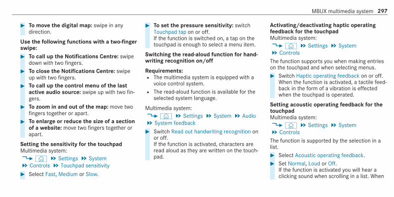
# To move the digital map: swipe in anydirection.
Use the following functions with a two-fingerswipe:# To call up the Notifications Centre: swipe
down with two fingers.# To close the Notifications Centre: swipe
up with two fingers.# To call up the control menu of the last
active audio source: swipe up with two fin‐gers.
# To zoom in and out of the map: move twofingers together or apart.
# To enlarge or reduce the size of a sectionof a website: move two fingers together orapart.
Setting the sensitivity for the touchpadMultimedia system:4© 5 Settings 5 System5 Controls 5 Touchpad sensitivity# Select Fast, Medium or Slow.
# To set the pressure sensitivity: switchTouchpad tap on or off.If the function is switched on, a tap on thetouchpad is enough to select a menu item.
Switching the read-aloud function for hand‐writing recognition on/off
Requirements:R The multimedia system is equipped with a
voice control system.R The read-aloud function is available for the
selected system language.
Multimedia system:4© 5 Settings 5 System 5 Audio5 System feedback# Switch Read out handwriting recognition on
or off.If the function is activated, characters areread aloud as they are written on the touch‐pad.
Activating/deactivating haptic operatingfeedback for the touchpadMultimedia system:4© 5 Settings 5 System5 ControlsThe function supports you when making entrieson the touchpad and when selecting menus.# Switch Haptic operating feedback on or off.
When the function is activated, a tactile feed‐back in the form of a vibration is effectedwhen the touchpad is operated.
Setting acoustic operating feedback for thetouchpadMultimedia system:4© 5 Settings 5 System5 ControlsThe function is supported by the selection in alist.# Select Acoustic operating feedback.# Set Normal, Loud or Off.
If the function is activated you will hear aclicking sound when scrolling in a list. When
MBUX multimedia system 297

the beginning or end of the list is reachedyou will hear another clicking sound.
Selecting a station and track using thetouchpad# Swipe to the left or right over the~ but‐
ton.Radio: the previous or next station is set.Media source: the previous or next track isselected.
or# To show the control menu: press the~
button on the touchpad.or# Swipe upwards using two fingers on the
touchpad.The control menu appears for the audiosource that was last selected.
# Swipe left or right using one finger.Radio: the previous or next station is set.Media source: the previous or next track isselected.
# To hide the control menu: swipe down onthe touchpad using two fingers.
MBUX in-car assistant
Notes on lasers and laser classification
& WARNING Risk of injury from laser radi‐ation from the camera
This product uses a laser system. If the hous‐ing is opened or damaged, invisible laserbeams can escape in an uncontrolled man‐ner.Laser radiation can damage your retina.
# Do not open the housing.# Always have maintenance work and
repairs carried out by a qualified spe‐cialist workshop.
This device is a class 1 laser product in accord‐ance with DIN EN 60825-1:2014
Overview of the MBUX in-car assistantIf the vehicle is fitted with the MBUX in-carassistant, selected functions of the multimediasystem can be operated contact-free. In addi‐tion, the reading light or search light can beswitched on or off contact-free.The MBUX in-car assistant can differentiatebetween driver and front passenger interactions.The MBUX in-car assistant recognises certainhand positions (poses).
298 MBUX multimedia system

The MBUX in-car assistant supports the following interactions:
Interaction area Interaction Description
In front of the media display/above the touch‐pad
Proximity to the control element The MBUX in-car assistant recognises the approach of thehand towards a control element.Depending on the active application, the display will beadjusted in the media display. Some functions differentiatebetween driver and front passenger.No specific hand position is required.
Above the centre console Defined poses With defined poses a function is triggered depending on theapplication active.
Below the inside rearview mirror Brief up and down movements With brief vertical up and down movements below the insiderearview mirror the reading light for the driver or the frontpassenger is switched on and off.
Front passenger seat Stretching out the hand above thefront passenger seat
By stretching out the hand above the front passenger seatthe search light is switched on. If the hand is withdrawn fromthis area, the search light is switched off again.
MBUX multimedia system 299

Operating functions by proximity of the handto the touchscreen and touchpad
Requirements:R One of the following applications appears in
the media display:- Seat settings with displays for the driver
and front passenger seat, e.g. Seat com-fort
- Home screen- Radio menu or media menu- Map in the navigation- Active Parking AssistR Recognition occurs as the hand approaches
to approximately 10 cm from the touchpad orthe touchscreen.
Seat adjustments by the driver or frontpassengerIn the seat settings menu, the MBUX in-carassistant detects proximity to various controlelements of the multimedia system. In addition,the MBUX in-car assistant detects from whichseat the action emanates.
Hand approaching the touchscreen
Hand approaching the touchpad
# With the seat setting display active, move thehand towards the touchscreen or touchpad.The seat of the person operating, driver'sseat or front passenger seat, is enlarged inthe media display.The appropriate control elements are pre-selected automatically.
# Depending on the function, the person oper‐ating can either switch the function on or offdirectly or make other settings.
Highlighting an application on the homescreenThe MBUX in-car assistant detects in which areathe hand is in front of the touchscreen. The dis‐play of objects shown is adjusted to improve ori‐entation.# Move a hand towards the touchscreen.
The symbol for the application is enlarged.The quick-access applications will be high‐lighted.
# Continue operation, e.g. select a quick-access application.
% Further information about the home screen(/ page 292).
300 MBUX multimedia system
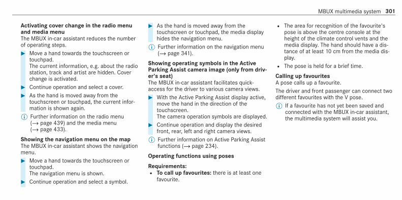
Activating cover change in the radio menuand media menuThe MBUX in-car assistant reduces the numberof operating steps.# Move a hand towards the touchscreen or
touchpad.The current information, e.g. about the radiostation, track and artist are hidden. Coverchange is activated.
# Continue operation and select a cover.# As the hand is moved away from the
touchscreen or touchpad, the current infor‐mation is shown again.
% Further information on the radio menu(/ page 439) and the media menu(/ page 433).
Showing the navigation menu on the mapThe MBUX in-car assistant shows the navigationmenu.# Move a hand towards the touchscreen or
touchpad.The navigation menu is shown.
# Continue operation and select a symbol.
# As the hand is moved away from thetouchscreen or touchpad, the media displayhides the navigation menu.
% Further information on the navigation menu(/ page 341).
Showing operating symbols in the ActiveParking Assist camera image (only from driv‐er's seat)The MBUX in-car assistant facilitates quick-access for the driver to various camera views.# With the Active Parking Assist display active,
move the hand in the direction of thetouchscreen.The camera operation symbols are displayed.
# Continue operation and display the desiredfront, rear, left and right camera views.
% Further information on Active Parking Assistfunctions (/ page 234).
Operating functions using poses
Requirements:R To call up favourites: there is at least one
favourite.
R The area for recognition of the favourite'spose is above the centre console at theheight of the climate control vents and themedia display. The hand should have a dis‐tance of at least 10 cm from the media dis‐play.R The pose is held for a brief time.
Calling up favouritesA pose calls up a favourite.The driver and front passenger can connect twodifferent favourites with the V pose.% If a favourite has not yet been saved and
connected with the MBUX in-car assistant,the multimedia system will assist you.
MBUX multimedia system 301

Carrying out the V pose
# Position the hand above the centre consoleand in the direction of the media display. Theback of the hand is facing upwards. In doingso the index and middle finger are extendedwith the other fingers bent inwards.The favourite is called up.
Switching the reading light for the driver andfront passenger on/off
Requirements:R The function is available when it is dark.R The gesture is carried out in the interaction
area (under the inside rearview mirror).
Briefly moving the hand up and down under theinside rearview mirror switches the reading lightspecifically for the driver or front passenger onor off.
Carrying out operation of the reading light
# Move the hand up and down vertically underthe reading light.The reading light is switched on or off.
Settings for the MBUX in-car assistantMultimedia system:4© 5 Settings 5 System5 Interior assistant# To switch on full functionality of the
MBUX in-car assistant: select On.The option is activated #.
# To activate additional functions for read‐ing and search lights: select Including read-ing light.When the option is switched on, the displaybutton is activated.The functions for the reading and searchlights are activated in addition to the proxim‐ity functions.
# To switch off the MBUX in-car assistant:select Off.The option is activated #.
302 MBUX multimedia system
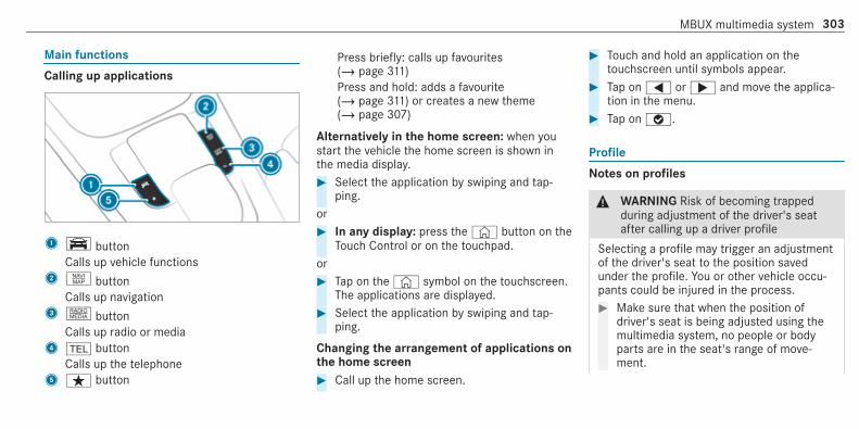
Main functions
Calling up applications
1y buttonCalls up vehicle functions
2z buttonCalls up navigation
3| buttonCalls up radio or media
4 % buttonCalls up the telephone
5ß button
Press briefly: calls up favourites(/ page 311)Press and hold: adds a favourite(/ page 311) or creates a new theme(/ page 307)
Alternatively in the home screen: when youstart the vehicle the home screen is shown inthe media display.# Select the application by swiping and tap‐
ping.or# In any display: press the© button on the
Touch Control or on the touchpad.or# Tap on the© symbol on the touchscreen.
The applications are displayed.# Select the application by swiping and tap‐
ping.
Changing the arrangement of applications onthe home screen# Call up the home screen.
# Touch and hold an application on thetouchscreen until symbols appear.
# Tap on= or; and move the applica‐tion in the menu.
# Tap onø.
Profile
Notes on profiles
& WARNING Risk of becoming trappedduring adjustment of the driver's seatafter calling up a driver profile
Selecting a profile may trigger an adjustmentof the driver's seat to the position savedunder the profile. You or other vehicle occu‐pants could be injured in the process.# Make sure that when the position of
driver's seat is being adjusted using themultimedia system, no people or bodyparts are in the seat's range of move‐ment.
MBUX multimedia system 303

If there is a risk of someone becoming trap‐ped, stop the adjustment process immedi‐ately:# a) Tap the warning message on the
media display.or# b) Press a memory position button or a
seat adjustment switch on the driver'sdoor.The adjustment process is stopped.
The driver's seat is equipped with an anti-entrap‐ment feature.If the driver's door is open, the driver's seat willnot be set after calling up the driver's profile.
Overview of profilesUsing the multimedia system up to seven pro‐files can be created in the vehicle.Profiles store your personal vehicle settings andsettings for the multimedia system.If the vehicle is used by several drivers, thedriver can select their profile before the journey,without changing the settings of other drivers.
You can select the profile:R when entering (/ page 306)R using the home screen (/ page 292)
The profile settings are activated as soon as aprofile is selected.% If you call up your profile when driving then
the driver's seat position will not be adjus‐ted.You can cancel the setting process with thefollowing actions:R Tap on the Positioning seat and steering
wheel. Please tap to cancel. warning onthe media display.R Press one of the seat operating buttons
in the driver's door.
Profile contentDepending on the vehicle equipment, the follow‐ing settings can be stored in your profile, forexample:R Driver's seat memoryR Radio (including station list)
R Last destinationsR Climate controlR Ambient lightingR DYNAMIC SELECT I (individual)R Instrument Display, Head-up Display and
style (display style of the multimedia system)R Themes, suggestions and favourites
% Settings for driver assistance systems can‐not be saved in the profile.
Mercedes me connect profileIf you use a profile from Mercedes me connect,the following online functions are available, forexample:R You can configure the settings in the vehicle
using the Mercedes me app and theMercedes me portal.R You can synchronise your profile on
Mercedes me connect with the profile in thevehicle (/ page 306).R You can add a personal profile photo that is
shown in the vehicle.
304 MBUX multimedia system
R You can take your profile and some of yoursettings with you in new vehicles.
Requirements for using Mercedes me con‐nect profiles:For the vehicle owner:R You have a Mercedes me user account.R The vehicle has been connected with the
user account.R The personalisation service is activated.
For additional users of the vehicle:R You have a Mercedes me user account.R The vehicle owner has invited you to connect
your user account on Mercedes me with thatof his vehicle.R You have accepted the invitation.
Creating a new profileMultimedia system:4© 5f Profiles# SelectW Create profile.# Select an avatar.
# Enter the name and confirm witha.# Select Continuer.# To save the current settings in a profile:
select Current settings.# Select Save.or# To adopt the factory settings: select Fac-
tory settings.# Select Save.% Further information on setting a user profile
(/ page 305).# Activate Bluetooth® and select Connect
phone, to connect a mobile phone with theuser profile (/ page 388).
You can also set up a user profile without regis‐tering a mobile phone.# Select Finished.
The user profile is saved.
Selecting profile optionsMultimedia system:4© 5f Profiles# Select Ä for a profile.# To edit a profile: select Edit profile.# Select an avatar.# Change the name, if necessary.# Select Save.# To configure suggestions: select Sugges-
tions settings (/ page 310).# To reset favourites or themes: select
Reset favourites to factory settings or Resetthemes to factory settings.
# Select Yes.# To reset a profile: select Reset profile to
factory settings.# Select Yes.# To delete a profile: select Delete profile.# Select Yes.% The guest profile cannot be deleted.
MBUX multimedia system 305

Protecting profile contentTo protect your profile content and settings youcan create a PIN in the Mercedes me portal foryour profile. When PIN protection is active, youhave to enter the PIN to select your profile.# Select Protect content.# Select Mercedes me portal.
The browser opens and you are transferredto the Mercedes me portal.
Selecting a profileMultimedia system:4© 5f Profiles% You can cancel the setting process with the
following actions:R Tap on the Positioning seat and steering
wheel. Please tap to cancel. warning onthe media display.R Press one of the seat operating buttons
in the driver's door.# Select a profile.# Press thea button to confirm the mes‐
sage.The profile is loaded and activated.
% Alternatively, the profile can already beselected when the vehicle is entered(/ page 306).
Synchronising a profile
Requirements:R You have a Mercedes me user account.R The vehicle is connected with your Mercedes
me user account.R The personalisation service is activated on
Mercedes me connect.
Multimedia system:4© 5f Profiles5 General settingsSynchronisation enables the following:R You can configure the vehicle settings using
the Mercedes me app.R The profile on Mercedes me connect and the
profile in the vehicle are aligned (profile man‐agement).
# Activate Synchronise profiles automatically.The profiles in the vehicle are automaticallysynchronised with the profiles on Mercedesme connect when the ignition is switched onand off.
or# Select Synchronise profiles now.
After selecting this option, the profiles in thevehicle are synchronised with the profiles onMercedes me connect.
% During synchronisation the profile list andthe profile functions are blocked.
% Note on data protection: if you do not wishto share your data with Mercedes me, makesure that the automatic synchronisation isswitched off and do not select Synchroniseprofiles now.
Showing the profile selection when entering
Requirements:R At least one profile has been created.
306 MBUX multimedia system

Multimedia system:4© 5f ProfilesIf the option is activated, you can see a profile assoon as you get in.# Select General settings.# Activate Show profile selection when enter-
ing.When the vehicle is started, the media dis‐play shows the active profile.
Themes
Overview of themesYou can configure the vehicle settings accordingto your preferences and save as a theme. Atheme can be called up any time via the homescreen. There is then no need to make thedesired settings again.There are pre-defined themes available, e.g.Journey, Efficiency and Lounge.
Example for the use of themesFor recurring driving situations, such as longdrives on the motorway, you can save you prefer‐red settings in a theme in the vehicle.You can save the following settings in a theme,for example:R Displays (e.g. navigation map or tachometer)R Preferred radio stationR Favoured drive program
These settings are saved under the name youwish when setting up a theme (/ page 307). Onthe next motorway journey you can select thistheme and thereby restore your settings.
Content of a themeDepending on vehicle equipment the followingsettings can be saved in a theme:R Setting of the Instrument Display
(/ page 258)R Setting of the Head-up Display (/ page 270)R Setting of the ambient lighting (/ page 136)R Active audio source, e.g. radio or USB
R Starting screen for the media displayR Visual style (/ page 326)R DYNAMIC SELECT drive program
(/ page 166)R Eco start/stop setting (/ page 165)R Navigation system settings
% A theme contains the currently active set‐tings in the vehicle.
Calling up themesMultimedia system:4©
# When the home screen is shown, swipe upuntil THEMES appears.
# Select a theme.
Creating new themes
Requirements:R The settings which are to be saved in the
theme are active.The overview shows the settings which canbe saved in a theme (/ page 307).
MBUX multimedia system 307

Multimedia system:4© 5 THEMES# SelectW Set theme.
The settings which are saved in the themeare shown.
# Select Continuer.# Select additional settings which are to be
saved in the theme.R Select Audio, to save the active audio set‐
tings in the theme.R Select Navigation (Navigation), to save
the active navigation settings in thetheme.
# Select Continuer.# Select an entry screen.# Select Continuer.# Select an image.# Enter the names into the entry field and con‐
firm witha.# To save a theme: select Save.
When the maximum number that can besaved is reached:# Selecta from the prompt.# Select a theme that should be overwritten.
The settings which are saved in the themeare shown.
# Select Continuer.# Select additional settings which are to be
saved in the theme.R Select Audio, to save the active audio set‐
tings in the theme.R Select Navigation (Navigation), to save
the active navigation settings in thetheme.
# Select Continuer.# Select an entry screen.# Select Continuer.# Select an image.# Enter the names into the entry field and con‐
firm witha.# To save a theme: select Save.
Creating using theßß rocker switch or but‐ton# Press and hold the bottom section of theß rocker switch on the steering wheel.
or# Press and hold theß button next to the
touchpad.# SelectW Set theme.
The settings which are saved in the themeare shown.
# Select Continuer.# Select additional settings which are to be
saved in the theme.R Select Audio, to save the active audio set‐
tings in the theme.R Select Navigation (Navigation), to save
the active navigation settings in thetheme.
# Select Continuer.# Select an image.# Enter the names into the entry field and con‐
firm witha.# To save a theme: select Save.
308 MBUX multimedia system

Modifying themesMultimedia system:4©
# When the home screen is shown, swipe upuntil THEMES appears.
# Press on a theme until the OPTIONS menu isshown.
# Selecta.# Select an image.# Enter the name.# Selecta.# To save a theme: select Save✓.
Moving themesMultimedia system:4©
# When the home screen is shown, swipe upuntil THEMES appears.
# Press on a theme until the OPTIONS menu isshown.
# Select Move.# Tap on= or;.
# Tap onø.
Moving the themes menu in the home screen# Select©.# Swipe upwards and select Set new order.# Select Themes.# Tap on9 or:.# Tap onø.
Deleting themesMultimedia system:4©
# When the home screen is shown, swipe upuntil THEMES appears.
# Press on a theme until the OPTIONS menu isshown.
# Select Delete.# Select Yes.
Showing information about themesMultimedia system:4©
# When the home screen is shown, swipe upuntil THEMES appears.
# Press on a theme until the OPTIONS menu isshown.
# Select Owner's Manual.
Suggestions
Suggestions overviewThe vehicle can learn the habits of the driver.Based on previously used functions, the mostlikely navigation destinations, media sources,radio stations or contacts are offered underSUGGESTIONS.Suggestions are shown when the followingrequirements are fulfilled:R A profile has been created (/ page 305).R A profile has been selected.R You have accepted data recording.
MBUX multimedia system 309

R From the beginning of usage, the multimediasystem must analyse the user habits. Whensufficient data is collected then the sugges‐tions are available.
If the requirements mentioned are not fulfilled, apreview with a description of the functionappears in the SUGGESTIONS menu.You can configure data recording (/ page 310)or delete the suggestions recorded(/ page 311).
Calling up suggestions
Requirements:R A profile has been created and is selected
(/ page 306).
# Tap on© in the media display.The home screen is shown.
# Swipe up until the SUGGESTIONS menu isshown.
# Select a navigation destination, a mediasource, a radio station or a contact.If route guidance is already active, you can‐not start a new route guidance or set an
intermediate destination for the existingroute.
Configuring suggestionsMultimedia system:4© 5f Profiles# SelectZ for a profile.# Select Suggestions settings.# To switch suggestions display on/off:
switch Allow destination suggestions, Allowmusic suggestions and Allow contact sugges-tions on or off.If an option is switched on, suggestions fornavigation destinations, media sources, radiostations or contacts are shown.If the option is switched off, no suggestionsare shown.
# To deactivate the learn function for oneday: activate Deact. learn. for 24h.For 24 hours no new actions will be trainedand no data recorded for the active profile.Suggestions will continue to be shown. Theremaining time is shown next to Deact.learn. for 24h.
Before the time runs out, a message isshown that the multimedia system will con‐tinue the learn function shortly.Example: if the option is switched on and aroute to a new destination has been calcula‐ted, this destination would not be taken intoaccount for the learn function.
# To reset the suggestion history: selectReset suggestion history.
% This process cannot be reversed.# Select Yes.# To protect settings with a PIN: switch on
PIN protection.If PIN protection is switched on, you mustenter the Mercedes me PIN to set the sug‐gestions. This PIN will be set in the Mercedesme portal for the personalisation service toprotect your personal settings.
Renaming suggestionsOnly navigation destinations can be renamed.# Tap on the© symbol in the media display.
The home screen is shown.
310 MBUX multimedia system

# Swipe up until the SUGGESTIONS menu isshown.
# Highlight a navigation destination and pressuntil the OPTIONS menu is shown.
# Select Rename.# Enter the name.# To confirm the entry: select Yes.
Deleting a suggestion# Tap on© in the media display.
The home screen is shown.# Swipe up until the SUGGESTIONS menu is
shown.# Highlight a suggestion and press until the
OPTIONS menu is shown.# Select Delete.
The query as to whether the suggestion isdeleted temporarily or permanently appears.
# If the suggestion should be shown againat a later time: select Not now.
# If the suggestion should not be shownagain: select Never.
Favourites
Overview of favouritesFavourites offer you quick access to frequentlyused applications. It is possible to create 20favourites in total.You can select favourites from categories or youadd favourites directly from an application.
Calling up favourites
In the media display# Tap on©.
The home screen is shown.# Swipe up until FAVOURITES is shown.
On the steering wheel or the touchpad# Press theß rocker switch on the steering
wheel down.or# Press theß button next to the touchpad.
Adding favourites
Selecting favourites from categories# Tap on© in the media display.
The home screen is shown.# Swipe up until FAVOURITES is shown.# SelectW Create favourite.
The categories are displayed.# Select the category.
The favourites are displayed.# Select a favourite.
The favourite is stored at the next availableposition.
# All positions in the favourites are taken:confirm the message shown with OK.A list shows all the favourites.
# Select a favourite which should be overwrit‐ten.
Adding a favourite from an applicationExamples of adding from an application are:R Saving a contact.R Storing a radio station.
MBUX multimedia system 311

R Adding a media source.R Saving a navigation destination.R Adding an ENERGIZING comfort program (if
available).
# To save a contact as a global favourite:select a contact (/ page 394).The details are displayed.
# Press on a telephone number until theOPTIONS menu is shown.
# Select Save as favourite.The contact is added as a favourite.
# To store a radio station as a global favour‐ite: set a radio station (/ page 440).
# Press on the radio station until the OPTIONSmenu is shown.
# Select Save as favourite.The radio station is added as a favourite.
Renaming favourites# Tap on© in the media display.
The home screen is shown.# Swipe up until FAVOURITES is shown.
# Press on a favourite until the OPTIONS menuis shown.
# Select Rename.# Enter the name.# Select OK.
Moving favourites
Moving favourites in the favourites menu# Tap on© in the media display.
The home screen is shown.# Swipe up until FAVOURITES is shown.# Press on a favourite until the OPTIONS menu
is shown.# Select Move.# Move the favourite to the new position.# Tap onø.
Moving the favourites menu in the personali‐sation# Tap on© in the media display.
The home screen is shown.# Swipe up until Set new order is shown.
# Select Set new order.# Move Favourites to the new position.# Tap onø.# To close the menu: select Close.
Deleting favourites# Tap on© in the media display.
The home screen is shown.# Swipe up until FAVOURITES is shown.# Press on a favourite until the OPTIONS menu
is shown.# Select Delete.# Select Yes.
Notifications Centre
Overview of the Notifications CentreThe following communications are collected inthe Notifications Centre:R Communications which are generated by the
vehicle or from multimedia system.R Communications which are received through
the use of services.
312 MBUX multimedia system

The following notification types are available foryou:R Navigable destinations and routesR Messages (text messages)R Calendar entries and reminders, e.g. from In-
Car OfficeThis function is not available in all countries.R System information, e.g. Important software
update available.R Other notifications, e.g. from additional
online services that can be subscribed to
Thej Notifications Centre can be found onthe home screen, in menus and at the top rightof the navigation map (/ page 292).A star in thej symbol informs you of newnotifications.Notifications are normally briefly shown as theyare received. This occurs for nearly every appli‐cation that you are currently using. If you takeno action, these are stored for future access inthe Notifications Centre.
The notifications are sorted chronologically. Themost recent notifications are at the top.
A notification shows the following information:R Symbol or image1 for the applicationR Title2, which contains the name, a tele‐
phone number or a navigation destination,for exampleR The service and additional information3R A time stamp5R If several actions are available, symbol4 to
open or close the notification.
Depending on the type of notification, up to fourdifferent actions6 are available.Examples of actions include:R Read aloudR Placing a callR ReplyR Calling up a web pageR Navigation
Some notifications, e.g. a navigation destination,are stored longer. Therefore, it is not necessaryto carry out available actions directly on thereceipt of the notifications. A route guidance canbe started at a later time.% You can start a global search in the Notifica‐
tions Centre (/ page 315).
Calling up notifications
Opening the Notifications Centre# On the touchpad: swipe down with two fin‐
gers.or
MBUX multimedia system 313

# On the touchscreen: tap on thej sym‐bol for the Notifications Centre.
or# On the Touch Control and on the touch‐
pad: mark thej symbol for the Notifica‐tions Centre by swiping.
# Press on the control element.
Selecting a notification# Swipe up or down.# Tap or press on the control element.
Calling up old notificationsIf notifications have not been called up after fourhours, these are stored in the archive.# Swipe upwards and select Archive.# Select the notification.
Closing the Notifications Centre# On the touchpad: swipe up with two fingers.
Selecting actions for a notificationThe following options are available:R Select the action directly in an application
after a notification is received and shown.R Select the action later after calling up in the
Notifications Centre.
# An action is available: select the action.# Several actions are available: if the notifi‐
cation is not open, select theV symbol.# Select the action.
The notification is still available.# If Additional information is available, select
the action.Additional information is shown in a windowas text, image or text and image.
# To close the window: select OK.
Editing notifications# Call up the Notifications Centre
(/ page 313).# To make settings: selectZ.
% If no settings can be made, a messageappears.
# Select the service.# Switch the options on or off.
The following options are available:R Allow notificationsR Display in notification centreR Show notificationsR Acoustic feedback
When Allow notifications is switched on, theother options cannot be selected.
# To delete: touch a message on thetouchscreen and slide to the left or right.
or# Select the recycle bin.# Select Delete or Delete all.
Delete deletes a single notification.Delete all deletes all notifications currentlyshown.
# With O you will exit delete mode.
314 MBUX multimedia system

Global search
Global search overviewYou can use the global search in the homescreen and in the notifications.The global search provides search results for thefollowing categories and their sub-categories:R NavigationR MediaR Telephone, social media, In-Car Office
In-Car Office is not available in all countries.R User interface and Digital Owner's ManualR Internet
This enables you to search for towns, roads andtourist attractions with the navigation system,for example.% You can also search for 3 word addresses
(/ page 349).When you enter a 3 word address in theglobal search, separate each of the wordswith a space or a full stop.
During the entry process the most likely sugges‐tions are shown beneath the search field. When
you enter "S", "Stuttgart", "Steak" and "Sandra"are shown, for example. If you select "Stuttgart",you receive the suggestions "Starbucks", "Steak"and "City railway", for example.The search results in the list are shown, sortedaccording to category. Next to the category isthe number of results. You will be shown thebest results from each category. Additionalresults can be found after selecting the respec‐tive category.If you confirm an entry with OK, all categoriesand the number of results will be shown in asummary. After selecting a category you canselect the search results within the category.When you select a search result the detailedview opens. In the detailed view you can choosewhether and which actions you want to carry outwith the respective search result. For example,you can start route guidance or place a call tosomebody. The actions are named correspond‐ingly.
The search can be carried out with the followinginput methods:R Entering characters using the on-screen key‐
padR Entering characters with handwriting recog‐
nitionR Dictation function
Using the global searchMultimedia system:4©
# Selectª Search.or# Call up the notifications (/ page 313).# Select Search.# Enter the search term into the search field.
During the entry process the three mostlikely suggestions are offered beneath thesearch field.In the list on the right, the top two searchresults are shown for each category.
% Use the character input function
MBUX multimedia system 315

Alternatively, you can use thep dictationfunction for the search.
# To accept a suggestion: select the sugges‐tion.The three most likely suggestions areoffered.
# Continue the search or accept a suggestion.# To accept the second search result: select
the search result.An action starts or a list is shown.
# Select a search result or an action in the list.# To show all categories: select OK.# To show search results for a category:
select a category.# To show details: select a search result.# To start an action: select an action.
After selection of an action, a track is playedback or the route to a destination is calcula‐ted, for example.
Switching the sound on/off
On the multifunction steering wheel
On the multimedia system
# To mute: press volume control1.The8 symbol appears in the status lineof the media display.You will also hear traffic announcements andnavigation announcements even when thesound is muted.
316 MBUX multimedia system

# To switch on: turn volume control1 orchange the media source.
Adjusting the volume
Adjusting with the control knob
On the multifunction steering wheel
On the multimedia system
# Turn volume control1.The volume of the current radio or mediasource is set. The volume of other audiosources can be adjusted separately.Adjust the volume in the following situations:R during a traffic announcementR during a navigation announcement
The volume of the current media sourcechanges in accordance with the volumeof the navigation announcement.R during a telephone callR when entering or exiting a parking space
while using Active Parking Assist
Setting in the menu# Press the© button on the Touch Control
or on the touchpad.# Select Settings.# Select System.# Select Audio.# Select a volume setting.# Set the volume.
MBUX multimedia system 317

Entering characters
Using the character input function
& WARNING Risk of distraction from infor‐mation systems and communicationsequipment
If you operate information and communica‐tion equipment integrated in the vehiclewhen driving, you will be distracted from thetraffic situation. This could also cause you tolose control of the vehicle.# Only operate this equipment when the
traffic situation permits.# If you cannot be sure of this, stop the
vehicle whilst paying attention to roadand traffic conditions and operate theequipment with the vehicle stationary.
You must observe the legal requirements for thecountry in which you are currently driving whenoperating the multimedia system.
Requirements:R For the handwriting recognition read-
aloud function: the multimedia system isequipped with a voice control system.R The read-aloud function is available for the
selected system language.R The handwriting recognition read-aloud func‐
tion is activated.
Character entry can be carried out with thesecontrol elements:R Touch ControlR Touchscreen (media display)R Touchpad
Character input can be started with a controlelement and resumed with another.# When the keypad is shown, enter the charac‐
ters on the control element by swiping andpressing or by tapping (touchscreen).
or# Write the characters on the touchpad or the
touchscreen.
Character input on the touchpad is supported bythe following functions:R The handwriting recognition supports charac‐
ter entry with character suggestions.R If the read aloud function is activated for
handwriting recognition then the enteredcharacters are read aloud.
Examples of character entry:R Renaming a favouriteR Entering a destination address in the naviga‐
tion systemR Entering a web address
Entering characters on the touchpad
Requirements:R If you wish to have the character input read
aloud: the read aloud function of the hand‐writing recognition is switched on(/ page 297).R An online connection is required for some
functions.
318 MBUX multimedia system

Using the keyboard1 Input line2 Shows suggestions during input (if available)3 Deletes an entry4 Deletes
Pressing or pressing briefly deletes the lastcharacter enteredPressing and holding deletes the entry
5 Accepts an entry6 Switches to handwriting input7 Enters a space8 Changes the keyboard language9 Switches to special charactersA Switches to digits and additional special
characters (if available for the current char‐acter set)
ABC Switches to letters (level 2)B Pressing or pressing briefly switches
between upper-case and lower-case letters(if available for the current character set)Pressing and holding switches to upper-caseletters permanently
MBUX multimedia system 319

If available, thep symbol allows you tochange to voice input.% When Touchpad tap is switched onD,
tapping is sufficient to select a character oran option (/ page 297).
# Call up the character entry to rename afavourite, for example (/ page 312).
# Select the character by swiping and pressing.The character is entered in input line1.Suggestions are shown in2.
# To select a suggestion: select one of theentries.
# If available, display additional suggestionswithq orr.
# Resume character input.# To enter an alternative character: press
and hold a character.# Select the character.
# To end character input: press theG but‐ton.
% The available editing functions depend onthe editing task, the language set and thecharacter level.
% Entry using the keyboard can also be com‐pleted using the Touch Control.
320 MBUX multimedia system
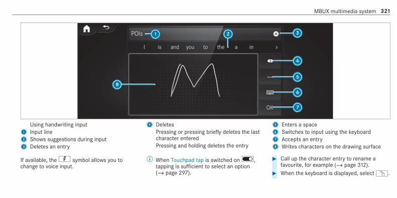
Using handwriting input1 Input line2 Shows suggestions during input3 Deletes an entry
4 DeletesPressing or pressing briefly deletes the lastcharacter enteredPressing and holding deletes the entry
5 Enters a space6 Switches to input using the keyboard7 Accepts an entry8 Writes characters on the drawing surface
If available, thep symbol allows you tochange to voice input.
% When Touchpad tap is switched onD,tapping is sufficient to select an option(/ page 297).
# Call up the character entry to rename afavourite, for example (/ page 312).
# When the keyboard is displayed, selectv.
MBUX multimedia system 321

# Write the character on the touchpad with afinger.The character is entered in input line1.Suggestions are shown in2.
# To select a suggestion: select one of theentries.
# If available, display additional suggestionswithq orr.
# Resume character input. The letters can bewritten next to each other or above eachother.
# To end character input: press theG but‐ton.
Entering characters on the touchscreen
Requirements:R If you wish to have the character input read
aloud: the read aloud function of the hand‐writing recognition is switched on(/ page 297).R An online connection is required for some
functions.
322 MBUX multimedia system

Using the keyboard1 Input line2 Shows suggestions during input (if available)3 Deletes an entry4 Deletes
Pressing or pressing briefly deletes the lastcharacter enteredPressing and holding deletes the entry
5 Accepts an entry6 Switches to handwriting input7 Enters a space8 Changes the keyboard language9 Switches to special charactersA Switches to digits and additional special
characters (if available for the current char‐acter set)
ABC Switches to letters (level 2)B Pressing or pressing briefly switches
between upper-case and lower-case letters(if available for the current character set)Pressing and holding switches to upper-caseletters permanently
MBUX multimedia system 323

If available, thep symbol allows you tochange to voice input.# Call up the character entry to rename a
favourite, for example (/ page 312).The keyboard is shown.
# Press briefly on a character key.The character is entered in input line1.Suggestions are shown in2.
# To select a suggestion: select one of theentries.
# If available, display additional suggestionswithq orr.
# Resume character input.# To enter an alternative character: press
and hold a character.
# Select the character.# To end character input: press theG but‐
ton.% The available editing functions depend on
the editing task, the language set and thecharacter level.
324 MBUX multimedia system

Using handwriting input1 Input line2 Shows suggestions during input3 Deletes an entry
4 DeletesPressing or pressing briefly deletes the lastcharacter enteredPressing and holding deletes the entry
5 Enters a space6 Switches to input using the keyboard7 Accepts an entry8 Writes characters on the drawing surface
If available, thep symbol allows you tochange to voice input.# Call up the character entry to rename a
favourite, for example (/ page 312).
# When the keyboard is displayed, selectv. # Write the character with one finger on thetouchscreen.The character is entered in input line1.Suggestions are shown in2.
MBUX multimedia system 325
# To select a suggestion: select one of theentries.
# If available, display additional suggestionswithq orr.
# Resume character input. The letters can bewritten next to each other or above eachother.
# To end character input: press theG but‐ton.
Setting the keyboard for character entryMultimedia system:4 Settings 5 System 5 Controls5 Keyboards and handwriting# Confirm Select keyboards.
Select the keyboard language in the list.
System settingsDisplay
Configuring display settingsMultimedia system:4© 5 Settings 5 System5 Styles & display
Setting the design# Select Styles.# Select Classic, Sport or Progressive.
The multimedia system display changesdepending on the style selected. If you revertto the factory settings, the Classic style isset.
# To adjust the ambient lighting to a style:select Ambient lighting adjustment.This function adjusts the ambient lighting forthe selected display style.
Setting the display brightness# Select Display brightness.# Select a brightness value.
Switching the display off/on# Off: select Display off.# On: press a button, %, for example.
Selecting the display design# Select Day/night design.# Select Automatic, Day design or Night
design.
Switching the temperature display on/off# Select Temperature display.# Select Outside temp. or Coolant temp..
The selected temperature is displayed in theinstrument cluster.
326 MBUX multimedia system

Time and date
Setting the time and date automaticallyMultimedia system:4© 5 Settings 5 System5 Time and date# Deactivate Manual time adjustment.
The time and date are set automatically forthe selected time zone and summer timeoption.
% The correct time is required for the followingfunctions:R Route guidance with time-dependent
traffic guidance.R Calculation of expected time of arrival.
Setting the time zone
Requirements:R For the manual time zone: Automatic time
zone is switched off.
Multimedia system:4© 5 Settings 5 System5 Time and date
Setting the time zone manually# Select Time zone:.
The list of countries is displayed.
% If there are several time zones available in acountry, these will be shown after the coun‐try is selected.
# Select a country and, if required, a timezone.The time zone set is displayed after Timezone:.
Setting the time zone automatically# Activate Automatic time zone.
Setting the time and date formatMultimedia system:4© 5 Settings 5 System5 Time and date 5 Set format# Set the date and time format #.
Setting the time and date manually
Requirements:R The Manual time adjustment function is
switched on.R For setting the date manually: no GPS is
installed in the vehicle.
Multimedia system:4© 5 Settings 5 System5 Time and date
Setting the time (without time zone)# Select Set time.# Set a time.
Setting the time (with time zone)# Select Set time.
If a time zone is set the time is set automaticallyusing the time zone. The time can be adjusted bya maximum of plus or minus 60 minutes.# Adjust the time using the slide control.
MBUX multimedia system 327

Setting the date# Select Set date.# Set a date.% In vehicles with GPS, a date cannot be set
even with active manual time adjustments.The date is then set automatically throughthe selected time zone.
Connectivity
Switching transmission of the vehicle posi‐tion on/offMultimedia system:4© 5 Settings 5 System5 Wi-Fi & Bluetooth# Select Transmit vehicle position.# Activate or deactivate the function.
Bluetooth®
Information about Bluetooth®
Bluetooth® technology is a standard for short-range wireless data transfer up to approximately10 m.
You can use Bluetooth® to connect your mobilephone to the multimedia system and use the fol‐lowing functions, for example:R Hands-free system with access to the follow‐
ing options:- Contacts (/ page 394)- Call lists (/ page 397)- Text messages (/ page 398)R Internet connection (/ page 421)R Listening to music via Bluetooth® audio
(/ page 434)R Transferring business cards (vCards) into the
vehicle
Bluetooth® is a registered trademark of Blue‐tooth Special Interest Group (SIG) Inc.
% Internet connection via Bluetooth® is notavailable in all countries.
Activating/deactivating Bluetooth®Multimedia system:4© 5 Settings 5 System5 Wi-Fi & Bluetooth# To switch on Bluetooth®: select Connect
via Bluetooth.# Activate Bluetooth.# To switch off Bluetooth®: select Settings.# Deactivate Bluetooth.
Wi-Fi
Wi-Fi connection overviewYou can use Wi-Fi to establish a connection witha Wi-Fi network and to access the Internet orother network devices.The following connection options are available:R Wi-Fi connection
328 MBUX multimedia system

The Wi-Fi connection to a Wi-Fi-capabledevice, e.g. the customer's mobile phone ora tablet PC is established.R Multimedia system as a Wi-Fi hotspot
Using this function, a tablet PC or notebookcan be connected, for example. The connec‐ted device can use the data tariff of the vehi‐cle. A maximum of three devices can be con‐nected with the hotspot at the same time.
% The use of the vehicle data tariff by externaldevices is not available in all countries.
To establish a connection, you can use the fol‐lowing methods:R WPS PIN
The connection to a secure Wi-Fi network ismade via a PIN.R WPS PBC
The connection to a secure Wi-Fi network ismade by pressing a button (push button).R Security key
The connection to a secure Wi-Fi network ismade via a security key.
Setting up Wi-Fi
Requirements:R The device to be connected supports one of
the three means of connection described.
Multimedia system:4© 5 Settings 5 System5 Wi-Fi & Bluetooth
Switching on Wi-Fi# Select Wi-Fi.
The Wi-Fi is switched on and you can con‐nect the multimedia system with externalhotspots.
Switching off Wi-Fi# Select Settings.# Deactivate Wi-Fi.
If Wi-Fi is deactivated, communication via Wi-Fi to all devices is interrupted. This alsomeans that a connection to the communica‐tion module cannot be established. Thensome functions such as dynamic route guid‐ance with Live Traffic Information are notavailable.
Connecting the multimedia system with anew device via Wi-FiThis function is available if a communicationmodule is not installed.The type of connection established must beselected on the multimedia system and on thedevice to be connected.% The connection procedure may differ
depending on the device. Follow the instruc‐tions that are shown in the display. Furtherinformation (see the manufacturer's operat‐ing instructions).
# Select Connect via Wi-Fi.# Select Add hotspot.
Connecting using a security key# Select the optionsr of the desired Wi-Fi
network.# Select Connect using security key.# Have the security key displayed on the device
to be connected (see the manufacturer'soperating instructions).
MBUX multimedia system 329

# Enter this security key on the multimedia sys‐tem.
# Confirm the entry with¡.% All devices support a security key as a
means of connection.
Connecting using a WPS PIN# Select the optionsr of the desired Wi-Fi
network.# Select Connect using WPS PIN input.
The multimedia system generates an eight-digit PIN.
# Enter this PIN on the device to be connected.# Confirm the entry.
Connecting using a button# Select the optionsr of the desired Wi-Fi
network.# Select Connect via WPS PBC.# Select "Connect via WPS PBC" in the options
on the device to be connected (see the man‐ufacturer's operating instructions).
# Press the WPS button on the device to beconnected.
# Select Continue in the multimedia system.
Activating automatic connection# Select Connect via Wi-Fi.# Select the optionsr of the desired Wi-Fi
network.# Activate Permanent Internet connection.
Connecting with a known Wi-Fi# Select Connect via Wi-Fi.# Select a Wi-Fi network.
The connection is established again.
Setting up a Wi-Fi hotspotMultimedia system:4© 5 Settings 5 System5 Wi-Fi & Bluetooth
Configuring the multimedia system as a Wi-Fi hotspotThe type of connection established depends onthe device to be connected. The function mustbe supported by the multimedia system and by
the device to be connected. The type of connec‐tion established must be selected on the multi‐media system and on the device to be connec‐ted.# Select Vehicle hotspot.# Select Connect device to vehicle hotspot.
Connecting using WPS PIN generation# Select Connect using WPS PIN generation.# Enter the PIN shown in the media display on
the device to be connected and confirm.
Connecting using WPS PIN entry# Select Connect using WPS PIN input.# Enter the PIN that is shown on the external
device's display on the multimedia system.
Connecting using a button# Select Connect via WPS PBC.# Press the push button on the device to be
connected (see the manufacturer's operatinginstructions).
# Select Continue.
330 MBUX multimedia system

Connecting using a security key# Select Connect device to vehicle hotspot.
A security key is displayed.# Select the vehicle from the device to be con‐
nected. The vehicle is displayed with the MBHotspot XXXXX network name.
# Enter the security key which is shown in themedia display on the device to be connected.
# Confirm the entry.
Connecting using NFC# Select Connect via NFC.# Activate NFC on the mobile device (see the
manufacturer's operating instructions).# Bring the mobile device into the NFC area of
the vehicle (/ page 391).# Select Finished.
The mobile device is now connected to themultimedia system hotspot via NFC.
Generating a new security key# Select Vehicle hotspot.
# Select Generate security key.A connection will be established with thenewly created security key.
# To save a security key: select Save.When a new security key is saved, all existingWi-Fi connections are then disconnected. Ifthe Wi-Fi connections are being re-estab‐lished, the new security key must be entered.
Managing MBUX Touch devices
Requirements:R The MBUX Touch app is installed on the
external device (e.g. tablet or smartphone).R Wi-Fi is activated (/ page 329) and the mul‐
timedia system is configured as a Wi-Fi hot‐spot (/ page 330).
Multimedia system:4© 5 Settings 5 System5 MBUX Touch
Connecting and authorising a new device# Select Authorise a new device.
# Select Add new device to list.# Enter the security key in the external device.
The Please start MBUX Touch on your deviceand follow the instructions. messageappears.
# Select Continue.# Accept the connection request from the new
device.# Enter the PIN shown on the external device.
The device is authorised.
Authorising a connected device# Select Authorise a new device.# Continue using connected devices
The Please start MBUX Touch on your deviceand follow the instructions. messageappears.
# Select Continue.# The connection request from the device
Accept.# Enter the PIN shown on the external device.
The device is authorised.
MBUX multimedia system 331

De-authorising the device# Select De-authorize device.# Select an authorised device from the list.
A prompt will appear asking whether youwould like to de-authorise the selecteddevice.
# Select Continue.# Select Yes.
The device is de-authorised.
Activating/deactivating child safety lock
Multimedia system:4 System 5 Parental control
Locking an external device# Select an external device.# Select Lock.
The device connected via the MBUX Touchapp is locked or unlocked.
System language
Notes on the system languageThis function allows you to determine the lan‐guage for the menu displays and the navigationannouncements. The selected language affectsthe characters available for entry. The navigationannouncements are not available in all lan‐guages. If a language is not available, the naviga‐tion announcements will be in English.
Setting the system languageMultimedia system:4© 5 Settings 5 System5 Language# Set the language.% If you are using Arabic map data, the text
information can also be shown in Arabic onthe navigation map. To do so, select asthe language from the language list. Naviga‐tion announcements are then also made inArabic.
Setting the distance unit
Multimedia system:4© 5 Settings 5 System 5 Units# Select km or mi.# In the multifunction display of the Instrument
Display, switch the Additional speedometerdisplay on.
Data import and export
Data import/export functionThe following functions are possible:R Transferring data from one system or vehicle
to another system or vehicle.R Creating a backup copy of your personal data
and loading it again.R Protecting your personal data against unwan‐
ted export with PIN protection.
% Please note that the NTFS file system is notsupported. The FAT32 file system is recom‐mended.
332 MBUX multimedia system

Importing/exporting data
* NOTE Loss of data due to prematureremoval
# Do not remove the data storagemedium when data is being exported.
Mercedes-Benz is not liable for any loss ofdata.
Requirements:R the vehicle is stationaryR The ignition is switched on.R A USB device is connected.
Multimedia system:4© 5 Settings 5 System5 System backup# Select Import data or Export data.
Importing# Select a data storage medium.
A prompt appears asking whether you reallywish to overwrite the current data. If data
originates from another vehicle, this is recog‐nised during data reading.
# Confirm the prompt.
The files are imported. The multimedia system isrestarted once the data has been imported.% Current vehicle settings can be edited after
the import.
ExportingIf PIN protection is activated, your PIN is reques‐ted.# Enter the four-digit PIN.# Select a data storage medium.
A prompt appears asking whether you reallywish to carry out the export.
# Confirm the prompt.The data is exported. The data export maytake several minutes.
% After successful export, the data is saved inthe "MyMercedesBackup" directory whichcan be found on the storage medium.
Activating/deactivating PIN protection
Requirements:R To unlock the PIN: there is an Internet con‐
nection.R A Mercedes me account exists at http://
www.mercedes.me.R An individual user profile is active
(/ page 306).
Multimedia system:4© 5 Settings 5 System5 PIN protection
Setting the PIN# Select Set PIN.# Enter a four-digit PIN.# Enter the four-digit PIN again.
If both PINs match, PIN protection is active.
Changing the PIN# Select Change settings.# Enter the current PIN.# Select Change PIN.
MBUX multimedia system 333

# Set a new PIN.
Activating PIN protection for data export# Select Protect data export.
Activate or deactivate the function.
Unblocking the PIN via the Mercedes me por‐talIf the PIN has been entered incorrectly threetimes, the PIN will be blocked. You can have asingle-use password sent to you via theMercedes me connect online portal to reset thePIN protection.# Select Unblock PIN.# Enter the single-use password.
PIN protection is reset, and you can set anew PIN.
Software update
Information on software updatesA software update consists of three steps:R Downloading or copying of the data required
for installationR Installation of the update
R Activation of the update by restarting thesystem
The multimedia system provides a messagewhen an update is available.Depending on the source, you can perform vari‐ous updates:
Software updates
Source of theupdate
Update type
Internet Navigation map, sys‐tem updates, DigitalOwner's Manual
External storagemedium, e.g. USBflash drive
Navigation maps
% Installation can take several minutes andcancellation is not possible. If you do notinstall the software updates then the statusof your vehicle will not be up-to-date. Duringthe installation, individual functions or con‐
trol elements are not available or only availa‐ble to a limited degree.
Advantages of updating softwareSoftware updates ensure your vehicle's technol‐ogy is always up-to-date.In order to improve the quality of our servicesyou will receive future updates for your multime‐dia system, the Mercedes me connect servicesand your vehicle's communication module.These will conveniently be sent to you via themobile phone connection in your vehicle and, inmany cases, installed automatically. You canmonitor the status of your updates at any timeon the Mercedes me portal and find informationabout potential innovations.Your advantages at a glance:R conveniently receive software updates via
the mobile phone networkR improves the quality and availability of
Mercedes me connect servicesR keeps your multimedia system and communi‐
cation module up-to-date
334 MBUX multimedia system

Further information about software updates canbe found at http://me.mercedes-benz.com
Performing a software update
Requirements:R For online updates: an Internet connection
is established (/ page 421).R For automatic online updates: your vehicle
has a permanently installed communicationmodule.
Multimedia system:4© 5 Settings 5 System5 Software update
Automatically# Activate Automatic online updates.
The updates will be downloaded and installedautomatically.The current status of the updates is dis‐played.
Manually# Deactivate Automatic online updates.
# Select an update from the list and start theupdate.
Activating the software update# Restart the system.
The modifications from the software updatewill be active.
Function of important system updatesImportant system updates may be necessary forthe security of your multimedia system's data.Install these updates, or else the security of yourmultimedia system cannot be ensured.% If automatic software updates are activated,
the system updates will be downloaded auto‐matically (/ page 335).
As soon as an update is available for download,a corresponding message appears on the mediadisplay.You have the following selection options:R Accept and install
The update will be downloaded in the back‐ground.R Information
Information about the pending systemupdate is displayed.R Later
The update can be downloaded manually at alater time (/ page 335).
Deep system updatesDeep system updates access vehicle or systemsettings and can therefore only be carried outwhen the vehicle is stationary and the ignition isswitched off.If the download of a deep system update is com‐pleted and the update is ready for installation,you will be informed of this after the next igni‐tion cycle, for example.% Park the vehicle safely in a suitable location
before starting the installation.Requirements for the installation:R The ignition is switched off.R Notes and warnings have been read and
accepted.R The electric parking brake is applied.
MBUX multimedia system 335

If all requirements are met, the update will beinstalled. The multimedia system cannot beoperated while the update is being installed andvehicle functions are restricted.If errors should occur during the installation, themultimedia system automatically attempts torestore the previous version. If restoration of theprevious version is not possible, a symbolappears on the media display. Please consult aqualified specialist workshop to resolve theproblem.
Resetting the multimedia system (reset func‐tion)
Multimedia system:4© 5 Settings 5 System 5 ResetPersonal data is deleted, for example:R Station presetsR Connected mobile phonesR individual user profiles
% The guest profile is reset when the settingsare restored to the factory settings.
A prompt appears again asking whether youreally wish to reset.# Select Yes.
The multimedia system is reset to the factorysettings. If you have set a PIN for your sys‐tem, this will also be reset.
Fit & HealthySetting ENERGIZING seat kinetics
Requirements:R These functions are available only for fully
electric seats with a memory function.
Multimedia system:4© 5 Comfort 5 Seat comfort# Select Seat kinetics.
ENERGIZING seat kinetics can support backhealth by changing the seat position during driv‐ing. The muscles and joints are repeatedlystressed and relieved by means of minor move‐ments of the cushion and backrest.
Starting seat kinetics# SelectÌ for the desired seat.# The program will run for the set duration.
Configuring seat kinetics# SelectZ for the desired seat.# Select Backrest or Backrest and seat sur-
face.# Select the desired setting.
Vehicles with a multicontour seat:In addition to the seat backrest and seat cush‐ion, the lumbar function can be activated for thefunction.# Switch Including lumbar on or off.
Setting the duration# SelectZ for the desired seat.
The following running times are available:R Short (16 minutes)R Medium (32 minutes)R Long (96 minutes)
336 MBUX multimedia system

# Select a running time.The selected program will start.
ENERGIZING comfort
ENERGIZING comfort programme overviewProgramme overview:
Programmes Function
Refresh Can make targeted changes to the interior climate to refresh vehicle occupants. Cooling airflow and ionisa‐tion purify the air. The vehicle interior is illuminated with cool colours and the seats are ventilated.
Warmth Can increase the comfort level of the vehicle occupants. The vehicle's panel, seat and steering wheel heat‐ing produce a cosy warmth. The air is purified using ionisation and a pleasant fragrance is released. Thevehicle interior is illuminated with warm lighting.
Vitality Can counteract diminishing attentiveness in monotonous driving situations. Fast-paced music and a vitaliz‐ing massage provide invigorating stimulation for the vehicle occupants. The air is purified using ionisationand a pleasant fragrance is released. The vehicle interior is illuminated in a stimulating hue and the seat isventilated.
Pleasure Can promote a positive mood in the vehicle occupants as well as mental and physical regeneration. Moder‐ately fast music is played and a massage programme is activated. The air is purified using ionisation and apleasant fragrance is released. The vehicle interior is illuminated with amicable lighting.
MBUX multimedia system 337

Programmes Function
Well being Can aid the physical and mental relaxation of vehicle occupants. A back massage combined with localwarmth provide relaxation. The air is purified using ionisation and a pleasant fragrance is released. Themusic player plays selections of calming music and the vehicle interior is illuminated with pleasant lighting.
Training Can counteract the onset of muscle tension, limbs falling asleep or stress with targeted relaxation or stim‐ulation exercises. The exercises are demonstrated in short videos. The air is purified using ionisation and apleasant fragrance is released. The vehicle interior is illuminated with lighting appropriate to the exercise.The training consists of audio content and a brief animation. The audio content is conceived so that it canalso be played back when you are driving. The animation is only shown when the vehicle is driving slowerthan 5 km/h. The animation is hidden at higher speeds. Always observe the traffic conditions if you aretraining when driving.
Tips The system gives tips for possible exercises or measures for improving the comfort level of the vehicleoccupants. Playback is purely aural. By selecting the desired area of the body you can receive targeted tipsfor the comfort level of this area.
% Please note that the available programmesand the associated functions are dependanton your vehicle equipment. Depending onyour equipment, fewer functions may beavailable.
338 MBUX multimedia system

Starting the ENERGIZING comfort pro‐gramme
& WARNING Increased risk of an accidentwhen using the ENERGIZING comfortprogramme Tips and Training
If you use the ENERGIZING comfort pro‐gramme Tips and Training when you are driv‐ing, you could be distracted from the trafficsituation.# Only carry out exercises when the traf‐
fic circumstances permit.# Make sure that you are always aware of
the traffic situation around you whenlistening to the tips.
Requirements:R The ignition is switched on.
Multimedia system:4 Comfort 5 ENERGIZING COMFORT
Starting the programmeThe following programmes are available:R RefreshR WarmthR VitalityR JoyR Well-being# Select a programme.# Select Start.
The selected programme will run for tenminutes.
If, during an active programme, a functionrequirement is no longer met, a correspondingmessage appears. The active programme is can‐celled.
Selecting a seat# Select a programme.# Select Seats.
# Select the desired seat.
Configuring a programme# Select a programme.# SelectZ.# Switch the functions included in the pro‐
gramme on or off.
Starting the training programme# Select Training.
The following training programmes are available:R Muscle stimul.R Muscle relax.R Balance# Select a programme.
The programme starts.% The animation for demonstration of the exer‐
cises is only shown when the vehicle is sta‐tionary or when you are driving slower than5 km/h. At higher speeds the picture is hid‐den and you will only be able to hear theinstructions.
MBUX multimedia system 339

Starting tips# Select Tips.
The following categories are available:R Upper bodyR Lower backR HeadR ShouldersR Pelvis# Select the desired area of the bodyÌ.
Playback of the tip for this area of the bodystarts.
# SelectÉ to stop playback of the tip.% You receive a tip for each option. To listen to
the next tip, again select a desired category.
ENERGIZING COACH
Function of the ENERGIZING COACHRequirements:R The ENERGIZING COACH (ENERGIZING
COACH) service is activated in the Mercedesme portal or the Mercedes me app .
With ENERGIZING COACH you can evaluate thedriving and driver situation. Depending on thesituation, it offers recommendations for the startof an appropriate ENERGIZING comfort program.The following programs could be suggested:R Vitality
As an activating program in monotonous driv‐ing situations or for long journey times, forexample.Information on the vitality program see(/ page 337).R Joy
As a balancing program in demanding drivingsituations.Information on the pleasure program see(/ page 337).
By connecting a GARMIN fitness tracker, forexample the GARMIN vívosmart® 3, additionalinformation can be entered into the evaluationfor the recommendation of an ENERGIZING com‐fort program. The additional informationincludes the stress level, that is calculated bythe fitness tracker. The stress level is based pri‐marily on the pulse.Requirements for the integration of additionalinformation via a GARMIN fitness tracker:R Your fitness tracker is connected with your
GARMIN account.R Your GARMIN account is connected with your
Mercedes me account.
If you wear your GARMIN fitness tracker at nightalso, the sleep data is included in the evaluationof the ENERGIZING COACH.Requirement for the integration of the sleepdata:R The GARMIN fitness tracker is synchronised
with the GARMIN account before the begin‐ning of the journey.
340 MBUX multimedia system

% If ATTENTION ASSIST determines an exces‐sive lack of attention, ENERGIZING COACHmakes no further suggestions. Further infor‐mation about ATTENTION ASSIST(/ page 242).
Calling up the ENERGIZING COACH displayMultimedia system:4© 5 Comfort# Select ENERGIZING COACH.
Your current pulse as well as an evaluation ofyour pulse for the last 30 minutes drivingtime are shown.A corresponding error message is shown ifthere is no mobile phone connected or nopulse can be sent to the system for an exten‐ded period.
% Only pulse values in the range of30‑140 bpm are shown on the media display.The pulse values have no medical validity but
are only informative in nature and are there‐fore also not required to be accurate.
# In the event of an error message make surethat the following requirements are fulfilled:R The fitness tracker is connected with your
GARMIN account.R Your GARMIN account is connected with
your Mercedes me account on yourmobile phone.R The mobile phone is connected as the
main phone to the multimedia system(/ page 388).
NavigationSwitching navigation on
Multimedia system:4© 5 Navigation (Navigation)# Alternatively: press thez button.
The map appears. The current vehicle posi‐tion is shown. The navigation menu is shown.
The navigation menu is hidden if route guid‐ance is active.
Showing/hiding the navigation menu
4© 5 NavigationIf route guidance is not active the map appears.The navigation menu is shown.The navigation menu is hidden if route guidanceis active.# To show: tap on the touchscreen.or# Press the Touch Control or the touchpad.# To hide: the navigation menu is hidden auto‐
matically.
MBUX multimedia system 341

Navigation overview
Example: digital map with navigation menu1 To enter a POI or address and additional des‐
tination entry options2 To interrupt route guidance (if route guid‐
ance is active)
3 To repeat a navigation announcement andswitch navigation announcements on or off
4 To call up the ON ROUTE menu• To show Route overview• To select Alternative routes• Report traffic incident (Car-to-X)
• To call up the TRAFFIC menu♢ To show Traffic announcements♢ To show Area announcements♢ To show Live Traffic Subscription Info• To show Route list• To call up the POSITION menu
342 MBUX multimedia system

♢ Store position♢ To show Compass♢ To show Qibla (available in selected coun‐tries)
5 Quick-access and settings• To show Traffic• To show Parking
• To show Motorway information• Via Advanced options to use View,Announcements and Route
% The options are not available in all countries.% You can enter 3 word addresses in the online
search (/ page 349). This option is notavailable in all countries.
Destination entry
Notes on destination entry
& WARNING Risk of distraction from oper‐ating integrated communication equip‐ment while the vehicle is in motion
If you operate communication equipmentintegrated in the vehicle when driving, youwill be distracted from the traffic situation.This could also cause you to lose control ofthe vehicle.
# Only operate this equipment when thetraffic situation permits.
# If you cannot be sure of this, stop thevehicle whilst paying attention to roadand traffic conditions and operate theequipment with the vehicle stationary.
You must observe the legal requirements for thecountry in which you are currently driving whenoperating the multimedia system.
Entering a POI or address
& WARNING Risk of distraction from infor‐mation systems and communicationsequipment
If you operate information and communica‐tion equipment integrated in the vehiclewhen driving, you will be distracted from the
traffic situation. This could also cause you tolose control of the vehicle.# Only operate this equipment when the
traffic situation permits.# If you cannot be sure of this, stop the
vehicle whilst paying attention to roadand traffic conditions and operate theequipment with the vehicle stationary.
You must observe the legal requirements for thecountry in which you are currently driving whenoperating the multimedia system.
Requirements:R For the online search: Mercedes me con‐
nect is available.R You have a user account for the Mercedes
me portal.R The service is activated.
MBUX multimedia system 343
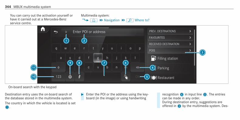
You can carry out the activation yourself orhave it carried out at a Mercedes-Benzservice centre.
Multimedia system:4© 5 Navigation 5ª Where to?
On-board search with the keypad
Destination entry uses the on-board search ofthe database stored in the multimedia system.The country in which the vehicle is located is set1.
# Enter the POI or the address using the key‐board (in the image) or using handwriting
recognition6 in input line2. The entriescan be made in any order.During destination entry, suggestions areoffered in3 by the multimedia system. Des‐
344 MBUX multimedia system

tination selection takes place in list3 orwitha5.If the multimedia system is equipped with asmall display, calling up list3 is carried outusing a list symbol at the top right.The following entries can be made, for exam‐ple:R City, street, house numberR Street, townR PostcodeR POI nameR POI categories, e.g. Filling stationR Town, POI nameR Telephone number, if this is available for
the POIR Contact name
Example of quick address entry:R If you are searching for Königsstraße in
Stuttgart, for example, you can enterSTUT and KÖN.
R If you are searching for a POI in the Uni‐ted Kingdom, for example, you can enterTHE SHARD.If you would like to try out both examples,you may also need to change the country.
# Alternatively, use voice input8.# To switch to handwriting recognition:
select6.# Write the character on the touchpad. The let‐
ters can be written next to each other orabove each other (/ page 318).
# To return to entry using the keyboard:select_.
or# Press the touchpad.# To delete an entry: select4.
The characters are deleted individually.or# If characters have been entered in2, select£ next to the input line.The complete entry is deleted.
# To switch to upper-case or lower-case let‐ters: selectB.
# To switch to digits, special charactersand symbols: selectA.123 changes to ABC.DisplayB changes to #+=.
# SelectB and switch to additional specialcharacters.
# To enter a space: select7.# To set the language: select9.# Select the language.
% This function is useful for countries in whichseveral character sets are supported. Anexample is Russia, which uses Cyrillic andLatin characters.
# To change the country: select country indi‐cator1.
# Enter the country indicator, e.g. F for France.The list is filtered.
# Select the country on list3.The destination can be entered.
# To accept a destination: select the destina‐tion in list3.
MBUX multimedia system 345

# If the destination is ambiguous, select thedestination in the list.The destination address is shown. The routecan be calculated.
Using online search% Requirements: there is an Internet connec‐
tion.Further information on Mercedes me:http://www.mercedes.me
Online search is not available in all countries.Destination entry uses online map services. Ifthe on-board search finds no suitable destina‐tions or if you change countries, the onlinesearch is available.For the destination you can enter an address, aPOI or a 3 word address.% Enter a 3 word address (/ page 349).# Select country indicator1.# Select the provider for the online service
from the countries list.or
# If the on-board search delivers no results,enter the destination in the input line. Theentry order is not relevant, e.g. street andtown. Use the functions described for the on-board search.The search results are displayed.
# Select the destination in the list.The detailed view for the route is displayed.
Selecting previous destinations
Requirements:R Previous destinations are stored.R For destination suggestions: you have cre‐
ated a profile (/ page 305).R The Allow destination suggestions option is
switched on (/ page 310).R The multimedia system has already gathered
sufficient data in order to show destinationsuggestions.
Multimedia system:4© 5 Navigation 5ª Where to?5 PREV. DESTINATIONSThe following entries can be selected in the pre‐vious destinations:R Destination suggestions (/ page 366)R DestinationsR Routes
# Select the destination or routeThe destination address is shown. The routecan be calculated.
% You can save a previous destination or a des‐tination suggestion as a favourite(/ page 366).You have fast access to the destinations viathe favourites (/ page 350).
Selecting a POI
Requirements:R For use of personal POIs: a USB device is
connected with the multimedia system.
346 MBUX multimedia system

R Personal POIs with the GPS Exchange format(.gpx) have been saved in the "PersonalPOI"folder on the USB device.
Multimedia system:4© 5 Navigation 5ª Where to?5 POIS
Searching using categories (no route guid‐ance)# Select the category, for example Filling sta-
tion.or# Select All categories.# Select the category and the sub-category (if
available).The search takes place in the vicinity of thevehicle's current position. The search resultare sorted by distance in ascending order.The POIs show the following information:R direction of the linear distance to the POI
(arrow)R name of POIR linear distance to the POI
# To filter according to categories or insearch results: enter a search entry in theª Search text field.
# Select a POI from the list.The destination address is shown. The routecan be calculated.
Searching using categories (route guidanceactive)# Select the category, for example Filling sta-
tion.or# Select All categories.# Select the category and the sub-category (if
available).# To filter according to categories or in
search results: enter a search entry in theª Search text field.
# Select the search positions In the vicinity,Near destination or Along the route.
# If there are intermediate destinations for theroute and Near destination has been selec‐
ted, select the search position in the routeoverview.
# Select a POI from the list.The destination address is shown. The routecan be calculated.
Searching for personal POIs# Select Personal POIs.# Select a category.# If route guidance is active, select a search
position In the vicinity, Near destination orAlong the route.
# Select a personal POI.The destination address is shown. The routecan be calculated.
or# Enter a search entry into the search field and
filter the list.# Select a personal POI.
Editing personal POI categories# Select a personal POI category from the list
s.A menu opens.
MBUX multimedia system 347

# To change a name: select Change name.# Enter the name.# Selecta.# To change a symbol: select Change icon.# Select a symbol.# To delete a personal POI category: select
Delete.# Select Yes.
Configuring categories for quick-accessYou can configure the categories for quick-access.If you calculate the route, for example, the firstthree of these categories can be selected assymbols.# Select All categories.# Select the category and the sub-category (if
available).# Selectf orß.f adds the category.ß removes the category.
# If all available quick-access positions are full,select the category to be replaced.
Selecting a contact for destination entry
Requirements:R A mobile phone is connected to the multime‐
dia system (/ page 388).
Multimedia system:4© 5 Navigation 5ª Where to?5 CONTACTS
Using the contact list# Select a contact.
The contact details are displayed.# Select the address.
Using search entry# Enter a name or telephone number, for exam‐
ple, into the search field.# Selecta.# Select the contact.
# Select the address.The destination address is shown. The routecan be calculated.
% Route guidance to a contact address is relia‐ble in the following cases:R the contact address is complete.R the contact data matches the map data
in the digital map.
Entering geo-coordinatesMultimedia system:4© 5 Navigation 5ª Where to?5 GEO-COORDINATES# Select Latitude or Longitude.# Select geo-coordinates as latitude and longi‐
tude coordinates in degrees, minutes andseconds. To do this swipe up or downrespectively.The map shows the position.
# Confirm the entry witha.# To set the destination: select¥ or¦.
# Calculate the route (/ page 351).
348 MBUX multimedia system

Entering the destination as a 3 word address
Requirements:R Searching for a destination using 3 word
addresses is possible in the online search(/ page 343).R The media display shows an Internet connec‐
tion with a double-arrow symbol in the statusline.
% Searching for a destination using 3 wordaddresses is not possible in all countries andin all languages.
Multimedia system:4© 5 Navigation 5ª Where to?# Select the country indicator.# Select the provider for the online service
from the countries list.or# If the on-board search delivers no search
results, enter the destination address as a 3word address. Separate each of the wordswith a full stop.The search results are displayed.
# Select the destination in the list.The destination address is shown. The routecan be calculated.
% 3 word addresses from what3words are analternative addressing system for multilin‐gual georeferencing of global locations witha resolution of three metres. Using this grid,locations on the Earth's surface are includedwhich do not have a building address suchas street and house number, for example.The Brandenburg Gate has this languagedependent 3 word address:R German: tapfer.gebäude.verliehenR English: that.lands.winningR French: posteaux.bobineur.ombrant
3 word addresses are unique, easy toremember and suffice for most routine appli‐cations.You can convert addresses to 3 wordaddresses and back again:R at the website http://what3words.comR in the what3words apps
Selecting a destination on the mapMultimedia system:4© 5 Navigation# Move the map (/ page 375).# Using the touchscreen: press and hold on
the touchscreen.The destination address is shown.If several destinations are located at theselected position, a list shows the availableroads and POIs.
# Select the destination in the list.The destination address is shown. The routecan be calculated.
# Using the touchpad: when the crosshairmarks the destination, press and hold on thecontrol element.The destination address is shown.If several destinations are located around thecrosshair, a list shows the available roadsand POIs.
# Select the destination in the list.The destination address is shown. The routecan be calculated.
MBUX multimedia system 349

Showing POIs in the vicinity of the mapIf several destinations are located around thecrosshair, the function is available.# Select Ä.# Select POIs in the vicinity.
The map appears.# Swipe left or right on the control element.
The previous or next POI is highlighted on themap. The name or the address is shown.
# Select the POI symbol.or# To filter the display according to the POI
category: scroll on the control element.# Select the POI category.
Selecting a destination from favourites
Requirements:R Destinations are saved as favourites.
Save a previous destination or a destinationsuggestion as a favourite (/ page 366).
Multimedia system:4© 5 Navigation 5ª Where to?5 FAVOURITES# Select a favourite.
The destination address is shown. The routecan be calculated.
The following options are available in the favour‐ites menu:R Saving addresses for home and workR Creating favouritesR Deleting favourites
# If no address has been saved for homeand work: select Home or Work.
# Confirm the prompt with Yes.# Enter the favourite as a POI or address
(/ page 343).# To save a favourite: select Add favourites.# Enter the favourite as a POI or address
(/ page 343).or
# If all the positions in the favourites are full,first select a favourite which is to be over‐written (/ page 311).
# Follow the instructions provided.# To delete a favourite: selectV for a des‐
tination.# Select Delete.or# Press on a favourite until the OPTIONS menu
is shown.# Select Delete.
Selecting received destinations
Requirements:R There is an Internet connection.R A destination has been sent to the vehicle.
Multimedia system:4© 5 Navigation 5ª Where to?5 RECEIVED DESTINAT.The vehicle can receive destinations from serv‐ices or apps.
350 MBUX multimedia system

# Select a destination.The destination address is shown. The routecan be calculated.
% You can save a received destination in thefavourites (/ page 366).You have fast access to the destinations viathe favourites (/ page 350).
Deleting a received destination# To delete a destination: selectV for a
destination.# Select Delete.# Select Yes.# To delete all destinations: select Ä.# Select Delete all.# Select Yes.
Route
Calculating a route
Requirements:R The destination has been entered.R The destination address is shown.
1¥ No route yet
¦ A route has been mapped
# Select¥.The route to the destination is calculated.The map shows the route. Route guidancethen begins.
or# Select¦.
If a route is already mapped, a prompt isshown.
# Select Set as intermediate dest..The selected destination address is set asthe next intermediate destination. Routeguidance begins.If there are already four intermediate destina‐tions, the multimedia system asks whetherintermediate destination 4 should be deleted.Confirm the prompt with Yes.
or# Select Start new route guidance.
The selected destination address is set as anew destination. The previous destinationand the intermediate destinations aredeleted. Route guidance to the new destina‐tion begins.
Searching for POIs in the vicinity of the des‐tination shown% The POI symbols to the right of POIs in the
vicinity show the first three categories forquick-access. You can configure these cate‐gories (/ page 346).
# Select a POI symbol.The search results are displayed.
MBUX multimedia system 351

# Select a POI.The destination address is shown. The routecan be calculated.
or# Select POIs in the vicinityr.# Search using categories, enter a search entry
or search for a personal POI (/ page 346).# Select a POI.
The destination address is shown. The routecan be calculated.
Other menu functions# To save the destination: selectf .# Select an option.
The following options are available:R Save in "Previous destinations"R Save as favouriteR Save as "Home"R Save as "Work"
# To call the destination: if a telephone num‐ber is available, select Call.
# To share the destination using NFC or QRcode: select Share via NFC or QR code.
# Hold the NFC area of the mobile phone (seemanufacturer's operating instructions) on themat or place the mobile phone on it(/ page 391).
or# Hold the mobile phone near to the multime‐
dia system and scan the QR code.# To call up an Internet address: if a web
address is available, select www.# To show on the map: select Display on the
map.
Selecting a route typeMultimedia system:4© 5 Navigation 5Z5 Advanced 5 Route# Select the route type.
If no route has been created, the next routeis calculated on the basis of the new routetype.
If a route has already been created, the routeis calculated on the basis of the new routetype.
The following route types are available:R Fast
A route with a quick journey time is calcula‐ted.R Short
A route with a short driving distance is calcu‐lated.R Eco
An economical route is calculated. The jour‐ney time may be somewhat longer than forquicker routes.R Trailer
The option is available if a trailer has beencoupled with the vehicle.A prompt is shown in the multimedia system.Confirm the prompt.The route is optimised for trailer operation.
352 MBUX multimedia system

For these route types you can select the fol‐lowing dynamic route guidance options:# Select Dynamic route guidancer.# Select Automatic, After asking or Off.Explanation of the options:R Automatic
The route is calculated with the currently setroute type.Traffic messages via Live Traffic Informationor FM RDS-TMC are taken into account(/ page 367).Live Traffic Information and FM RDS-TMC arenot available in all countries.R After asking
A prompt appears when a new route is detec‐ted with a shorter journey time based on traf‐fic reports. You can continue to use the cur‐rent route or use the dynamic route instead(/ page 353).R Off
No traffic reports are taken into account forthe route.
Calculating alternative routes# Activate Suggest alternative route.
The display button is activated. Alternativeroutes are calculated for every route.
# Select an alternative route (/ page 357).
Accepting a detour recommendation after aprompt
Requirements:R After asking is switched on # in the
DYNAMIC ROUTE GUIDANCE menu(/ page 352).R Route guidance is active.R There are traffic reports for the current
route.
If a new route with a shorter driving time isdetermined, the current and new routes will beshown.The notification is shown in another application.Confirm the notification.# To accept the new route: select Accept rec-
ommended detour.
# To maintain the current route: select Keepto current route.
Selecting route optionsMultimedia system:4© 5 Navigation 5Z5 Advanced 5 Route
Avoiding areas# Select Avoid options.# Select Avoid areas (/ page 378).
Avoiding or using motorways, ferries, tun‐nels, motorail trains, unpaved roads# Select Avoid options.# Activate or deactivate the avoid option.
To avoid: the display button is activated. Theroute avoids motorways, for example.To use: the display button is off. The routetakes motorways into consideration, forexample.These route options are not available in everycountry.
MBUX multimedia system 353

The selected route options cannot always betaken into account. Therefore, a route mayinclude a ferry, for instance, even though theAvoid ferries avoid option is enabled. A mes‐sage then appears and you will hear a corre‐sponding message.
Avoiding or using toll roads# Select Avoid options.# Select Toll roads.# Switch Avoid all on or off.
To avoid: the display button is activated. Theroute avoids all toll roads.To use: the display button is off. The routetakes into account all roads that require thepayment of a usage fee (toll).
or# To avoid a type of payment: select Avoid.
The route avoids all toll roads with the selec‐ted method of payment.
# To use a type of payment: select Use.The route takes into account all toll roadswith the selected method of payment.
These route options are not available in everycountry.
Avoiding or using roads requiring a specialtoll sticker# Select Avoid options.# Select Vignette roads.# Switch All on or off.or# Activate or deactivate the countries.
To avoid: the display button is activated. Theroute avoids roads requiring a special tollsticker in the selected countries.To use: the display button is off. The routetakes into account roads in the selectedcountry which require you to pay a time-based fee (vignette). A vignette allows for theuse of a route network for a limited timeperiod.
% These route options are not available inevery country.
Selecting notifications for the route
Requirements:R For an audible indication when approach‐
ing a personal POI: the USB device containspersonal POIs.R The USB device is connected with the multi‐
media system.R The category in which the personal POI
belongs is activated.
Multimedia system:4© 5 Navigation 5Z5 Advanced 5 Announcements# Switch No driving recomm. on or off.
No navigation announcements are issuedwhen the display button is switched on.
# To select a navigation announcement:select an option # under the DRIVING REC-OMMEND. category.The following options are available:R Acoustic signal only
In place of the spoken navigationannouncement you hear a gong. The
354 MBUX multimedia system

gong signals an upcoming drivingmanoeuvre and also sounds during thedriving manoeuvre.R Reduced driving recomm.
If a navigation announcement is available,you hear a brief announcement, e.g. "turnright".R Detailed driving recomm.
If a navigation announcement is availableand the Announce street names option isswitched on, you hear a completeannouncement, e.g. "In 200 m at the endof the street turn right into Station Road".
# To have street names announced duringa driving manoeuvre: switch on Announcestreet names.
# Select Reduced driving recomm. or Detaileddriving recomm..The name of the street into which you shouldturn is announced.
% The options in the DRIVING RECOMMEND.category are not available in every countryand in all languages.
Selecting messages for TRAFFIC# Activate a message.
The display button is activated.The following options are available:R Traffic incidents
Traffic incidents are announced, e.g.roadworks and road blocks.This function is not available in all coun‐tries and languages.R Announce warnings
Warning messages are announced, e.g.before tailbacks that pose a risk (if availa‐ble).This function is not available in all coun‐tries and languages.
Audible indication when approaching a per‐sonal POI# Select the Personal POIs option in the
ALERTS category.
# Activate a category.The display button is activated. Whenapproaching a personal POI in this categoryan audible indication will be issued.
Showing destination information for theroute
Requirements:R A destination is entered.
Multimedia system:4© 5 Navigation 5¡
# Select Route overview.When route guidance is active, the destina‐tion and intermediate destinations areshown, if these have been entered and notyet been passed.The route can include up to four intermediatedestinations.
# Select a destination or an intermediate desti‐nation.The following information is displayed:R Remaining driving distanceR Time of arrival
MBUX multimedia system 355

R Remaining journey timeR Name, destination addressR Phone number (if available)R Web address (if available)
Planning routesMultimedia system:4© 5 Navigation5¡ 5 Route overview# Select Set intermediate destination.# Enter the intermediate destination as a POI
or address, for example (/ page 343).# Select the intermediate destination.
After selection of an intermediate destina‐tion, the route overview is shown again.
# Calculate the route with intermediate desti‐nations(/ page 356)
% If there are already four intermediate desti‐nations, delete an intermediate destination(/ page 356).
Editing a route with intermediate destina‐tionsMultimedia system:4© 5 Navigation5¡ 5 Route overview# To change the sequence of destinations:
selectV for a destination.A menu opens.
# Select Move.ø is highlighted.
# Move the intermediate destination or thedestination with4 ors to the desiredposition.
# Tap onø.# To delete a destination: selectV for an
intermediate destination or destination.# Select Delete.
The destination is deleted.
Calculating a route with intermediate desti‐nations
Requirements:R The destination and at least one intermediate
destination have been entered.
Multimedia system:4© 5 Navigation5¡ 5 Route overview# Select Start route guidance.or# If the route has been edited, select To Navi-
gationG.# Confirm the prompt with Yes.
The route is calculated. Route guidancebegins.
Displaying the route listMultimedia system:4© 5 Navigation 5¡
# Select Route list.The route sections are displayed. The currentvehicle position is marked on the map.
356 MBUX multimedia system

The current vehicle position is shown withthe following information:R Thea symbol for the current vehicle
position is displayed.R The name of the road on which you are
currently driving is shown.R The road number of the road on which
you are currently driving is shown.
The route list is updated during the journey.# To show route sections: swipe up or down
on the control element.The route section is shown on the map.
Selecting an alternative route
Requirements:R The Suggest alternative route option is
switched on (/ page 352).
Multimedia system:4© 5 Navigation 5¡
# Select Alternative routes.The routes are displayed in accordance withthe setting made in the route settings.
The routes are numbered.# Select the alternative route.# To show the route on the map: select Dis-
play on the map.# Move the map (/ page 375).# Set the map scale (/ page 374).# To avoid or use route options: select Ä.# Switch the route option, e.g. Motorways, on
or off.To avoid: the display button is activated. Thealternative route avoids motorways.To use: the display button is off. The alterna‐tive route uses motorways.
Activating a commuter route
Requirements:R You have created a profile (/ page 305).R The Allow destination suggestions option is
switched on (/ page 310).R The Activate commuter route option is
switched on.
R The multimedia system has gathered suffi‐cient data in order to show destination sug‐gestions.R Routes have been learned for these destina‐
tion suggestions.
% This commuter route is not available in allcountries.
Multimedia system:4© 5 Navigation 5Z5 Advanced 5 Route# Activate Activate commuter route.
The display button is activated. The naviga‐tion system automatically detects that thevehicle is on a commuter route. It automati‐cally starts a route guidance without voiceoutput.For the daily commuter route, traffic inci‐dents on the route are also reported whendriving without active route guidance.
MBUX multimedia system 357

Switching the automatic filling stationsearch on/offMultimedia system:4© 5 Settings 5 Vehicle# Switch Filling station search on or off.
When the fuel reserve level is reached, andthe display button is switched on, a messageappears to start searching for filling stations.
Starting an automatic filling station search
Requirements:R The automatic filling station search is activa‐
ted (/ page 358) .
Driving situationThe fuel level in the fuel tank reaches thereserve fuel level.The following notification is shown in the mediadisplay Reserve fuel Tap here to search for fill-ing stations.# Confirm the notification.
The automatic filling station search begins.The available filling stations along the route
or in the vicinity of the vehicle's current posi‐tion are displayed.
# Select a filling station.The address of the filling station is displayed.
# Calculate the route (/ page 351).The filling station is set as the destination orthe next intermediate destination.
# If there are already four intermediate des‐tinations: select Yes in the prompt.The filling station is entered in the routeoverview. Intermediate destination 4 isdeleted. Route guidance begins.
Starting the automatic service stationsearch
Requirements:R ATTENTION ASSIST and the Suggest rest
area function are activated (/ page 242).R There are service stations along the route
section ahead.
Driving situationThe following notification is shown in the mediadisplay ATTENTION ASSIST Tap here to searchfor rest areas.
# Confirm the notification.The service station search starts. The availa‐ble service stations along the route or in thevicinity of the vehicle's current position aredisplayed.
# Select a service station.The service station address is displayed.
# Calculate the route (/ page 351).The service station is set as the destinationor the next intermediate destination.
# If there are already four intermediate des‐tinations: select Yes in the prompt.The service station is entered in the routeoverview. Intermediate destination 4 isdeleted. Route guidance begins.
Showing a stored route on the map
Requirements:R A USB device with stored routes is connec‐
ted with the multimedia system(/ page 434).R The route is stored in the "Routes" folder
with the GPS Exchange format (.gpx).
358 MBUX multimedia system

Multimedia system:4© 5 Navigation 5ª Where to?5 STORED ROUTES# Select a route.# Select Display on the map.# Move the map (/ page 375).
Starting a saved route
Requirements:R A USB device with stored routes is connec‐
ted with the multimedia system(/ page 434).R The route is stored in the "Routes" folder
with the GPS Exchange format (.gpx).
Multimedia system:4© 5 Navigation 5ª Where to?5 STORED ROUTES# Select a route.# Select Start route guidance from the begin-
ning or Start route guidance from currentlocation.Route guidance starts.
% The route can be saved withf in themenu (/ page 351).
Recording a route
Requirements:R A USB device is connected with the multime‐
dia system (/ page 434).
Multimedia system:4© 5 Navigation 5ª Where to?5 STORED ROUTES# To start recording: select Start to record
new route.A red recording symbol is shown.The route is stored on the USB device.
# To stop recording: select End recording.
Saving a recorded route
Requirements:R A USB device is connected with the multime‐
dia system (/ page 434).
Multimedia system:4© 5 Navigation 5ª Where to?5 STORED ROUTES# Select a route.# Selectf.# Select Save in "Previous destinations".
The route is stored in the "Previous destina‐tions" memory and can be called up fromthere for route guidance.
Editing a stored route
Requirements:R A USB device with stored routes is connec‐
ted with the multimedia system(/ page 434).
Multimedia system:4© 5 Navigation 5ª Where to?5 STORED ROUTES# Select a route withV.# To enter a name: select Change name.# Enter the name.
MBUX multimedia system 359

# Select OK.or# When the name has been changed, press theG button.
# Select Yes.# To delete a route: select Delete.# Select Yes.
Route guidance
Notes on route guidance
& WARNING Risk of distraction from oper‐ating integrated communication equip‐ment while the vehicle is in motion
If you operate communication equipmentintegrated in the vehicle when driving, youwill be distracted from the traffic situation.This could also cause you to lose control ofthe vehicle.# Only operate this equipment when the
traffic situation permits.
# If you cannot be sure of this, stop thevehicle whilst paying attention to roadand traffic conditions and operate theequipment with the vehicle stationary.
You must observe the legal requirements for thecountry in which you are currently driving whenoperating the multimedia system.Route guidance begins once a route has beencalculated.The road and traffic rules and regulations alwayshave priority over multimedia system drivinginstructions.Driving instructions are:R Navigation announcementsR Route guidance displaysR Lane recommendations
If you do not follow the driving instructions or ifyou leave the calculated route, a new route iscalculated automatically.Driving instructions may differ from the actualroad and traffic conditions if:R The route is diverted
R The direction of a one-way street has beenchanged
For this reason, you must always observe roadand traffic rules and regulations during yourjourney as well as the prevailing traffic condi‐tions.The route may differ from the ideal route due tothe following:R RoadworksR Incomplete digital map data
Notes on GPS receptionThe correct function of the navigation systemdepends amongst other things on GPS recep‐tion. In certain situations GPS reception can beimpaired, defective or even not possible, e.g. intunnels or in multi-storey car parks.
Changing direction overviewChanges of direction are shown in the followingdisplays:R Detailed image of the junction
The display appears when you drive into ajunction.
360 MBUX multimedia system

R 3D imageThe display appears when driving on junc‐tion-free, multi-lane roads, for example onmotorway exits and motorway interchanges.
Detailed image of the junction
1 Current distance to the change of direction2 Driving manoeuvre3 Current vehicle position4 Manoeuvre point
3D image
1 Current distance to the change of direction2 Driving manoeuvre3 Current vehicle position4 Manoeuvre point
There are three phases when changing direction:R Preparation phase
If there is enough time between the changesof direction, the multimedia system preparesyou for the upcoming change of direction. Anavigation announcement is issued depend‐ing on the settings for driving recommenda‐tions, e.g. "Prepare to turn right".
Select navigation announcements for drivingrecommendations (/ page 354).The map appears in full-screen mode.The status line shows: the direction informa‐tion or the name of the road which is to beturned into and the distance to the change ofdirection.R Announcement phase
The multimedia system announces theupcoming change of direction depending onthe settings for driving recommendations,e.g. by announcing "In 200 m at the end ofthe street turn right into Station Road".The display is split into two parts. The map isdisplayed on the left; on the right, there is adetailed image of the junction or a 3D imageof the upcoming change of direction.R Change-of-direction phase
The multimedia system announces the immi‐nent change of direction depending on thesettings for driving recommendations, e.g. byannouncing "Now turn right".The display is split into two parts.
MBUX multimedia system 361

The change of direction takes place when thedistance to manoeuvre point4 is shownwith 0 m and the symbol for vehicle position3 has reached manoeuvre point4.When the change of direction is complete,the map appears in full-screen mode.
% Changes of direction are also shown in theInstrument Display.
Lane recommendations overviewThis display appears for multi-lane roads.The multimedia system can show lane recom‐mendations if the digital map contains the rele‐vant data.
1 Recommended lane (white arrow, blue back‐ground)
2 Possible lanes (white arrow)3 Lanes not recommended (grey arrow)
Explanation of the displayed lanes:R Recommended lane1
In this lane, you will be able to complete boththe next change of direction and the oneafter that.R Possible lane2
In this lane, you will only be able to completethe next change of direction.R Lane not recommended3
In this lane, you will not be able to completethe next change of direction without chang‐ing lane.
During the change of direction, new lanes maybe added.Bus lanes are also shown.% Lane recommendations can also be dis‐
played in the Instrument Display and in theHead-up Display.
Using motorway information
Requirements:R The Motorway information option is switched
on (/ page 377).
362 MBUX multimedia system
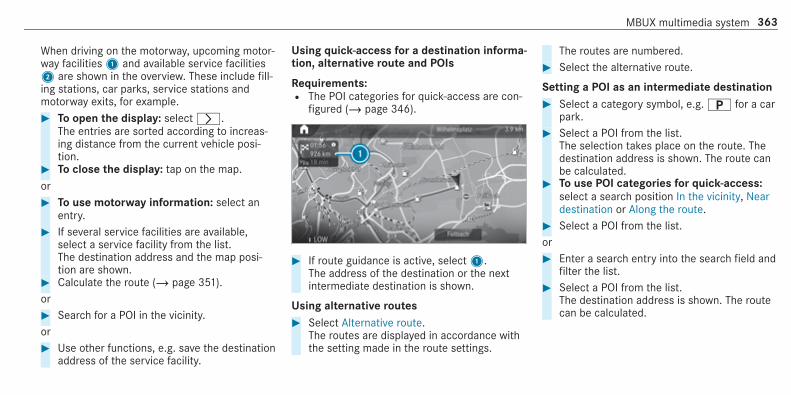
When driving on the motorway, upcoming motor‐way facilities1 and available service facilities2 are shown in the overview. These include fill‐ing stations, car parks, service stations andmotorway exits, for example.# To open the display: selectr.
The entries are sorted according to increas‐ing distance from the current vehicle posi‐tion.
# To close the display: tap on the map.or# To use motorway information: select an
entry.# If several service facilities are available,
select a service facility from the list.The destination address and the map posi‐tion are shown.
# Calculate the route (/ page 351).or# Search for a POI in the vicinity.or# Use other functions, e.g. save the destination
address of the service facility.
Using quick-access for a destination informa‐tion, alternative route and POIs
Requirements:R The POI categories for quick-access are con‐
figured (/ page 346).
# If route guidance is active, select1.The address of the destination or the nextintermediate destination is shown.
Using alternative routes# Select Alternative route.
The routes are displayed in accordance withthe setting made in the route settings.
The routes are numbered.# Select the alternative route.
Setting a POI as an intermediate destination# Select a category symbol, e.g.B for a car
park.# Select a POI from the list.
The selection takes place on the route. Thedestination address is shown. The route canbe calculated.
# To use POI categories for quick-access:select a search position In the vicinity, Neardestination or Along the route.
# Select a POI from the list.or# Enter a search entry into the search field and
filter the list.# Select a POI from the list.
The destination address is shown. The routecan be calculated.
MBUX multimedia system 363

Saving the current vehicle position# Select Store position.
The current vehicle position is saved to the"Previous destinations" memory.
Destination reachedOnce the destination is reached, you will see theÍ chequered flag. Route guidance is finished.The Navigation menu is shown.When an intermediate destination has beenreached, you will see the intermediate destina‐tion flag with the number of yourÎ inter‐mediate destination. Route guidance is contin‐ued.
Switching navigation announcements on/off# To switch off: turn the volume control on
the steering wheel or next to the touchpadduring a navigation announcement(/ page 316).The Spoken driving recommendations havebeen deactivated. message appears.
or# Show the navigation menu (/ page 341).
# Select!.The symbol changes to#.
# To activate: select# .The current navigation announcement isplayed.The symbol changes to!.
% This function can be added and called upfrom the favourites within the navigation cat‐egory.
Switching navigation announcements on oroff during a phone call# Press the© button on the steering wheel
or on the touchpad.or# Tap on© in the media display.# Select Settings.# Select System.# Select Audio.# Select Navigation and traffic announce-
ments.
# Switch Driving recommendations during callon or off.When the option is switched on, the displaybutton is activated.
# To leave the menu: selectq.
Adjusting the volume of navigationannouncementsMultimedia system:4© 5 Settings 5 System 5 Audio5 Navigation and traffic announcements# Select Driving recommendation vol..# Set the volume.# To leave the menu: selectq.
Route guidance is active# Turn the volume control on the steering
wheel or next to the touchpad during a navi‐gation announcement.
Switching audio fadeout on or off during nav‐igation announcements# Press the© button on the steering wheel
or on the touchpad.
364 MBUX multimedia system

or# Tap on© in the media display.# Select Settings.# Select System.# Select Audio.# Switch Audio fadeout on or off.
When the option is switched on, the displaybutton is activated.
# To leave the menu: selectq.
Repeating navigation announcements
Requirements:R a route has already been created.R route guidance is active.
Multimedia system:4 Navigation (Navigation)# Select!.# Select#.
The current navigation announcement isrepeated.
% This function can be added and called upfrom the favourites within the navigation cat‐egory.
Cancelling route guidance
Requirements:R a route has already been created.R route guidance is active.
# Show the navigation menu.# Select¤ in the navigation menu
(/ page 342).
Overview of route guidance to an off-roaddestinationAn off-road destination is within the digital map.The map contains no roads that lead to the des‐tination.You can enter geo-coordinates or a 3 wordaddress for off-road destinations on the map.Route guidance guides you for as long as possi‐ble with navigation announcements and displayson roads that are known to the multimedia sys‐tem.
Shortly before you reach the last known positionon the map, you will hear the "Please follow thedirection arrow" announcement, for example.The display shows a direction arrow and the lin‐ear distance to the destination.
Overview of route guidance from an off-roadlocation to a destinationIn an off-road position, the current vehicle posi‐tion is located within the digital map on roadsthat are not available.The following displays appear when route guid‐ance begins:R A message appears that the road is not on
the map.R A direction arrow showing the linear direc‐
tion to the POI.
When the vehicle is back on a road known to themultimedia system, route guidance continues asnormal.
Overview of off-road status during routeguidanceDue to roadworks, for example, there may be dif‐ferences between the data on the digital map
MBUX multimedia system 365
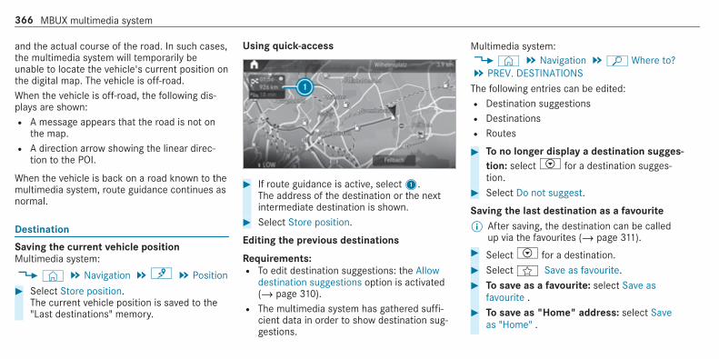
and the actual course of the road. In such cases,the multimedia system will temporarily beunable to locate the vehicle's current position onthe digital map. The vehicle is off-road.When the vehicle is off-road, the following dis‐plays are shown:R A message appears that the road is not on
the map.R A direction arrow showing the linear direc‐
tion to the POI.
When the vehicle is back on a road known to themultimedia system, route guidance continues asnormal.
Destination
Saving the current vehicle positionMultimedia system:4© 5 Navigation 5¡ 5 Position# Select Store position.
The current vehicle position is saved to the"Last destinations" memory.
Using quick-access
# If route guidance is active, select1.The address of the destination or the nextintermediate destination is shown.
# Select Store position.
Editing the previous destinations
Requirements:R To edit destination suggestions: the Allow
destination suggestions option is activated(/ page 310).R The multimedia system has gathered suffi‐
cient data in order to show destination sug‐gestions.
Multimedia system:4© 5 Navigation 5ª Where to?5 PREV. DESTINATIONSThe following entries can be edited:R Destination suggestionsR DestinationsR Routes
# To no longer display a destination sugges‐tion: selectV for a destination sugges‐tion.
# Select Do not suggest.
Saving the last destination as a favourite% After saving, the destination can be called
up via the favourites (/ page 311).# SelectV for a destination.# Selectf Save as favourite.# To save as a favourite: select Save as
favourite .# To save as "Home" address: select Save
as "Home" .
366 MBUX multimedia system

# To save as "Work" address: select Save as"Work" .
Deleting a previous destination# To delete a destination: selectV for a
destination.# Select Delete.# Select Yes.# To delete all destinations: select Ä.# Select Delete all.# Select Yes.
Using external destinations and routesExternal destinations and routes can be receivedfrom the following sources, for example:R Mercedes-Benz AppsR door-to-door navigation
A prompt appears on the media display.Received destinations and routes are saved inthe previous destinations.# A destination has been received: select
Yes.
# Calculate the route.# If route guidance is already active, select Set
as intermediate dest. or Start new routeguidance.
or# If a destination was received with photo
information, select Start route guidance.# Calculate the route.or# If a destination has been received from an
app, select Details.# Calculate the route.# A route has been received: select Yes.# Select Start route guidance from the begin-
ning or Start route guidance from currentlocation.Route guidance starts from the selectedposition.
Route guidance with current traffic reports
Traffic information overview% The services are not available in every coun‐
try.Traffic reports can be received with the followingservices:R Live Traffic InformationR FM RDS-TMC
It is not possible to use both services simul‐taneously.Live Traffic Information or FM RDS-TMC isdisplayed with a symbol.
% Hazard warnings can be received using theCar-to-X service.
% There may be differences between the trafficreports received and the actual road andtraffic conditions.
Important information on Live Traffic Informa‐tion:R Current traffic reports are received via the
Internet connection (for selected countries).
MBUX multimedia system 367

R The traffic situation is updated at short, regu‐lar intervals.R In selected countries, the subscription
service is available free of charge for a periodof three years from the manufacturing date.Subscription information shows the status(/ page 368).
Registering Live Traffic Information:R The service must be registered with
Mercedes me (/ page 368).This secures the free-of-charge period ofthree years.
Information on the vehicle's position is regularlysent to Daimler AG. The data is immediately ren‐dered anonymous by Daimler AG and forwardedto the traffic data provider. Using this data, traf‐fic reports relevant to the vehicle's position aresent to the vehicle. The vehicle acts as a sensorfor the flow of traffic and helps to improve thequality of the traffic reports.
If you do not want to transmit the vehicle posi‐tion, you have the following options:R You deactivate the service in the Mercedes
me portal.R You have the service deactivated at a
Mercedes-Benz service centre.
Useful information on FM RDS-TMC:R A FM RDS-TMC radio station broadcasts traf‐
fic reports alongside the radio programme.R FM RDS-TMC is not available in all countries.
Showing information from the service pro‐vider for Live Traffic Information
Requirements:R The vehicle is equipped with Live Traffic
Information.
Multimedia system:4© 5 Navigation 5¡ 5 Traffic# Select Provider information.
The logo of the service provider for Live Traf‐fic Information is shown.
When the subscription for Live Traffic Infor‐mation has expired then in selected coun‐tries FM RDS-TMC is available.
% Further information on Live Traffic Informa‐tion can be called up on the home screenusing Mercedes me & Apps (/ page 413).
Registering Live Traffic Information
Requirements:R The vehicle is equipped with Live Traffic
Information.R You have a user account on the Mercedes
me website.
The Live Traffic Information service must be reg‐istered. This secures the full period of threeyears.# Create a user account at Mercedes me at:
http://www.mercedes.me. A valid emailaddress is required for this.
# Register the vehicle using the vehicle identifi‐cation number (VIN).
368 MBUX multimedia system

# To carry out the registration yourself: con‐nect the vehicle with your Mercedes me useraccount in the Mercedes me portal.A code is sent to the multimedia system.
# Enter the code into the multimedia system.# Accept the general and specific terms of use.# Registration in the Mercedes-Benz
service centre: have the connection carriedout at a Mercedes-Benz service centre.
Extending a Live Traffic Information sub‐scription
Requirements:R The vehicle is equipped with Live Traffic
Information.R You have a user account on the Mercedes
me website.
# Call up the Mercedes me website.# Call up the Mercedes me user account.# Switch to the Mercedes me connect online
store via the linked vehicle.# Select the Live Traffic Information service.
# Select the renewal period.# Add the product to the shopping basket.# Accept the general and specific terms of use.
Live Traffic Information remains activated forthe selected extension period. Activationbegins on the date of extension.
Showing traffic information
Requirements:R The Traffic display is switched on
(/ page 370).R The following traffic displays are switched on
(/ page 370):Traffic incidentsFree-flowing trafficDelay
Multimedia system:4©
# Select Navigation.The map shows the following traffic information:R traffic incidents, for example:
- roadworks
- road blocks- warning messages
When route guidance is active, the symbolsfor traffic incidents will be shown in colouron the route. Off the route they are grey.R warning message symbols:
- symbold- road safety notes, e.g. when approaching
the end of a traffic jamIf the vehicle approaches a danger areaon the route, a warning message is dis‐played on the map. In addition, an audiblenotification can follow a hazard warning.
R traffic flow information:- traffic jam (red line)- slow-moving traffic (orange line)- heavy traffic (yellow line)- free-flowing traffic (green line)R display for traffic delays on the route lasting
at least one minute
MBUX multimedia system 369

Displaying traffic incidents
Requirements:R The Traffic incidents display is switched on
(/ page 370).
Multimedia system:4© 5 Navigation 5¡ 5 Traffic# Select Traffic announcements.
If there are traffic reports, you will see a list.Traffic reports include accidents and othertraffic events, for example. The list is sortedaccording to distance and shows the trafficreports received both on and off the route.A traffic report shows the following informa‐tion:R Street numberR Traffic incident symbol
On the route: colouredOff the route: greyR CauseR Street symbol for a traffic incident on the
route
R Distance from current vehicle position# Select a traffic reportr.
The detailed information is shown, for exam‐ple the route section.
Showing traffic incidents in the vicinity ofthe map# Select a traffic incident symbol on the map.
The details about the traffic incident are dis‐played.
# Select Ä.# Select Traffic incidents in vicinity.
The map shows the traffic incident symbolsin the vicinity.Traffic incident information is displayed inthe status line:R Traffic incident symbolR Cause of the traffic incident, e.g. con‐
struction workR Warning message (highlighted red)
# To select a traffic incident symbol: selectq orr.
# To select a map section: tap on thetouchscreen.
or# Press the Touch Control or the touchpad.# Move the map.# To return to the navigation map: tap onG.
or# Press theG button on the Touch Control
or on the touchpad.
Switching the traffic information display onMultimedia system:4© 5 Navigation 5Z
# Activate Traffic.The display button is activated.
Activating Incidents, Free Flow and Delay# Select Advanced.# Select View.# Select Map elements.
370 MBUX multimedia system

# In the TRAFFIC category, activate the Trafficincidents, Free-flowing traffic and Delayentries.The display buttons are activated.If traffic information has been received, thentraffic incidents such as roadworks, roadblocks, local area reports (e.g. fog) and warn‐ing messages are displayed.The traffic delay is displayed for the currentroute. Traffic delays lasting one minute orlonger are taken into consideration.
Showing local area messagesMultimedia system:4© 5 Navigation 5¡ 5 Traffic# Select Area announcements.
Local area messages are shown, for examplefog or heavy rain.
# Select a local area message.The details are displayed.
Car-to-X-Communication
Car-to-X-Communication overviewThe following requirements apply for using Car-to-X-Communication:R The vehicle is equipped with a multimedia
system featuring navigation and a communi‐cation module with an activated, integratedSIM card.R Car-to-X-Communication is activated.
% Car-to-X-Communication is available inselected countries.
The communication module automatically estab‐lishes an Internet connection once the ignition isswitched on. If there are any hazard warnings,they will be provided shortly thereafter. Depend‐ing on the mobile phone connection, the provi‐sion takes place from within a second up toabout a minute.Benefits of Car-to-X-Communication:R Hazards are recognised automatically in the
background by the vehicle or may be repor‐ted by the driver. These are then sent to vehi‐
cles with Car-to-X-Communication in theimmediate vicinity.R If available, current details relating to hazard
spots near the vehicle's current position arereceived.This gives you sufficient time to adapt yourdriving style to the traffic conditions.
The use of Car-to-X-Communication requires theregular transmission of vehicle data to DaimlerAG. The data is then immediately pseudony‐mised by Daimler AG. The vehicle data is deletedafter an appropriate amount of time has elapsed(several weeks) and is not stored permanently.% Data which serves as identification is
replaced during the pseudonymisation proc‐ess. In this way, your identity is protectedagainst access by unauthorised third parties.
Displaying hazard warningsMultimedia system:4© 5 Navigation (Navigation)If hazard warnings are available these can beshown as symbols on the map. The display
MBUX multimedia system 371
depends on the settings for the Traffic and Traf-fic incidents options.# Set the options (/ page 370).The following displays are available:R Show all symbols
The Traffic and Traffic incidents options areswitched on.R Only show symbols on the expected route
The Traffic option is switched off, the Trafficincidents option is switched on.R Show no symbols
The Traffic incidents option is switched off.
The following hazard warnings are shown on themap:R Broken-down vehiclesR AccidentsR Hazardous weatherR General hazardsR Hazard warning lights, when switched onR Crosswind warning
R Mobile roadworksThe display is not available in all countriesand regions.In the Federal Republic of Germany the dis‐play is currently available in the Federal Stateof Hesse.
% If the vehicle is approaching a hazard spotwith a vehicle speed of at least 60 km/h, thevoice output "Traffic incident ahead" isissued.The voice output is not issued for hazardousweather.
Sending hazard warningsAutomatically detected hazard warnings are sentby the vehicle.# To send a hazard warning yourself: tap on
the media display when the map is shown.The navigation menu is shown.
# Select¡.# Select Report traffic incident.
A prompt is shown.
# Select Yes.The Thank you for supporting accident pre-vention. message appears.
Route guidance with augmented reality
Overview of route guidance with augmentedreality
& WARNING Risk of accident and injurycaused by distraction, incorrect image orinterpretation of the display
The distance to other road users or informa‐tion, such as traffic lights, can be incorrectlyassessed from the camera image. The cam‐era image of the augmented reality display isnot suitable to be used for driving.# Always keep your eyes on the actual
traffic situation. Only glance briefly atthe camera image.
# Be aware that depending on the drivingsituation there may be hazards that arenot captured in the camera image, e.g.
372 MBUX multimedia system

when turning. Avoid observing the cam‐era image for extended periods.
During route guidance with augmented reality acamera image with the real traffic scene isshown in the media display before a turningmanoeuvre.
1 Street name2 House number3 Change of direction arrow
Route guidance with augmented reality is notavailable in all countries.
Route guidance with augmented reality is cur‐rently not available on motorways.The camera image can contain the followingadditional information:R Change of direction arrowR Street namesR House numbers
Activating route guidance with augmentedreality
& WARNING Risk of accident and injurycaused by inaccurate positioning of addi‐tional information
The additional information indicated with theaugmented reality display can be incorrectlypositioned in the camera image. For this rea‐son, the camera image cannot replace theneed to observe the actual driving situation.# Maintain the actual driving situation in
view for all driving manoeuvres , e.g.when turning and when changing lanes.
Requirements:R Route guidance is active.
Multimedia system:4© 5 Navigation# If the detailed junction view appears during
route guidance, tap on the camera symbol.The display button is activated. The cameraimage is shown in the media display depend‐ing on the situation.The camera image will be shown instead ofthe navigation map before a turning manoeu‐vre and will show the additional information.
# To return to the navigation map: tap onthe camera symbol again.The display button is off.
Activating displays of street names andhouse numbers for route guidance with aug‐mented reality
Requirements:R Augmented reality is activated
(/ page 373).
MBUX multimedia system 373

Multimedia system:4© 5 Navigation 5Z5 Advanced 5 Augmented Reality# Activate Street names and House numbers.
The display buttons are activated. Duringroute guidance, street names and housenumbers are shown as additional informationin the video image.
Switching on display of traffic lights withaugmented reality
Requirements:R Augmented reality is activated
(/ page 373).R The Traffic light zoom option is switched on.
When the vehicle is standing in first position at ajunction, the camera image will show anenlarged traffic lights display.% When the vehicle pulls away the navigation
map is shown again.
Multimedia system:4© 5 Navigation 5Z5 Advanced 5 Augmented Reality# Activate Traffic light zoom.
The display button is activated.# Under TRAFFIC LIGHT VIEW select one of the
Off, After asking or Automatic options.If After asking is set, the Traffic light indica-tor available message is shown. The cameraimage is shown after confirmation of themessage.If Automatic is set, the traffic lights display isshown automatically in the camera imagewhen available.
# To return to the navigation map: press theG button.
Map and compass
Setting the map scaleMultimedia system:4© 5 Navigation
Zooming in# When the map is shown, tap twice quickly
with one finger on the media display or thetouchpad.
or# Move two fingers apart on the media display
or on the touchpad.
Zooming out# Tap with two fingers on the media display or
the touchpad.or# Move two fingers together on the media dis‐
play or on the touchpad.% You can set the unit of measurement of the
map scale (/ page 332).
374 MBUX multimedia system

Moving the mapMultimedia system:4© 5 Navigation
# On the touchscreen: move the finger in anydirection when the map is shown.
# On the touchpad: call up the navigationmenu by pressing.
# Swipe your finger up.# Press the touchpad.
Crosshair1 appears. The map can bemoved.
# Touch the touchpad and move your finger inany direction.The map moves in the opposite directionunder crosshair1.
When the map has been moved the followinginformation appears in the status line, for exam‐ple:R Distance2 from the vehicle's current posi‐
tion is shown.R Information about the current map position
is shown, e.g. the name of the road.
The following functions are available:R Select a destination on the map
(/ page 349).R Select a POI (/ page 346).R Show traffic incidents on the map
(/ page 370).
# To reset the map to the current vehicleposition: select3.
Rotating the map# With two fingers, rotate anti-clockwise or
clockwise on the media display or the touch‐pad.
Selecting the map orientationMultimedia system:4© 5 Navigation 5Z5 Advanced# Select View.# Select Map orientation.# Select an option.
The # dot indicates the current setting.The following options are available:R 2D heading up option: the 2D map view is
aligned to the direction of travel.R 2D north up option: the 2D map view is
displayed so that north is always at thetop.R 3D option: the 3D map view is aligned to
the direction of travel.or
MBUX multimedia system 375

# Using quick-access: repeatedly tap or presson theÄ compass symbol on the map.The view changes in the sequence 3D, 2Dheading up to 2D north up.If the map is moved, it can switch between3D and 2D north up.
Selecting POI symbols for the map displayMultimedia system:4© 5 Navigation 5Z
POIs include filling stations and hotels, for exam‐ple. These can be displayed as symbols on themap. Not all POIs are available everywhere.Personal POIs are destinations which you havesaved on a USB device, for example.% The display of POI symbols on the map can
be activated or deactivated as a favourite.# To switch on/off using quick-access: if
available, switch POI symbols on or off.The POI symbols for the selected categoriesare shown on the map.
or
# To switch on/off in the menu: selectAdvanced.
# Select View.# Select Map elements.# Select POI symbolsr.
The POI SYMBOLS menu is shown.# Switch Display POIs on or off.
Selecting categories# Selectr All categories in the POI SYM-
BOLS menu.# Switch Show all on or off.
When the option is switched on, the POI sym‐bols for all categories are shown on the map.
or# Select the categories and sub-categories (if
available)r.# Activate or deactivate the categories.
The POI symbols for the selected categoriesare shown on the map.
Selecting personal POI categories# Selectr Personal POIs in the POI SYM-
BOLS menu.# Select a categoryr.# Switch Display on the map on or off.
When the display is switched on and thevehicle approaches a personal POI in thiscategory, a visual and audible notificationcan be issued.
# To set a notification when approaching:select a category or a personal POIV.
# Switch Visual warning and Acoustic notifica-tion on or off.
Switching display of categories for quick-access on/off# Switch a category on or off in the POI SYM-
BOLS menu.
Resetting the POI symbol display# Select in the POI SYMBOLSReset POIs
menu .The settings are reset to the standard set‐tings.
376 MBUX multimedia system

Selecting the display of text information inthe mapMultimedia system:4© 5 Navigation 5Z5 Advanced# Select View.# Select Text information.# Select an option in the FOOTER category.
The # dot indicates the current setting.The following options are available:R Current street option
The street you are currently on is shown inthe bottom bar.When the map is moved, the street name,the POI name or the area name appearsunder the crosshair.R The Geo-coordinates option shows the fol‐
lowing information in the bottom bar:- longitude and latitude- elevation
The elevation shown may deviate fromthe actual elevation.
R None optionThe media display shows no text informationin the bottom bar.
Switching motorway information on/offMultimedia system:4© 5 Navigation 5Z
# Using quick-access: switch Motorway infor-mation on or off.The display button is activated or off.
or# Using the menu: select Advanced.# Select View.# Select Text information.# Switch Motorway information on or off.
When the display button is switched on, addi‐tional information about the motorway facili‐ties ahead appears during the motorwayjourney. These include car parks, service sta‐tions and motorway exits, for example.
Displaying the next intersecting street
Requirements:R Route guidance is not active.
Multimedia system:4© 5 Navigation 5Z5 Advanced# Select View.# Select Text information.# Activate Next intersecting street.
The display button is activated. If the optionis switched on and the journey continueswithout route guidance, the name of the nextintersecting street will be displayed at theupper edge of the display.
Displaying the map versionMultimedia system:4© 5 Navigation 5Z5 Advanced# Select View.# Select Map version.
The detail information is displayed.
MBUX multimedia system 377

% The online map update service fromMercedes me connect can be used toupdate the map data (/ page 379).A message is shown in the media displaywhen a new map version is available.
% Information about new versions of the digitalmap can be obtained from a Mercedes-Benzservice centre.
Overview of avoiding an area for the routeYou can define areas along a route that youwould like to avoid.Motorways or multi-lane expressways, which arerouted through an area to be avoided are takeninto account for the route.
Avoiding a new area for the routeMultimedia system:4© 5 Navigation 5Z5 Advanced 5 Route 5 Avoid options5 Avoid areas# Select Avoid new area.# To start in the map: select Using map.# Move the map (/ page 375).
# To start via destination search: select Viaaddress entry.
# Enter the address (/ page 343).# Select the destination in the list or accept
witha.The map appears.
# To show an area: tap or press on the controlelement.A red rectangle appears. This designates thearea that should be avoided.
# To change the map scale: move two fingersapart or together on the media display or onthe touchpad.The map is zoomed in or out.
# To set an area: selecta.The Avoid area has been set. messageappears. The area is entered into the list.
Changing an area to be avoidedMultimedia system:4© 5 Navigation 5Z5 Advanced 5 Route 5 Avoid options5 Avoid areas# Select an area in the list.# Select Edit.# To move an area on the map: swipe in any
direction on the control element.# To change the size of the area: tap or press
on the control element.# Swipe up or down on the control element.# Selecta.
The Avoid area has been set. messageappears. The area is entered into the list.
# To take account of an area for the route:select an area from the list.
# Activate Avoid area.The display button is activated.If route guidance is active, a new route is cal‐culated.
378 MBUX multimedia system

If there is no route yet, the setting is carriedover to the next route guidance.The route can include an area that is to beavoided in the following cases:R the destination is located in an area that
is to be avoided.R the route includes motorways or multi-
lane expressways which pass through anarea to be avoided.R there is no sensible alternative route.
Deleting an areaMultimedia system:4© 5 Navigation 5Z5 Advanced 5 Route 5 Avoid options5 Avoid areas# To delete an area: select an area in the list.# Select Delete.# Confirm the prompt with Yes.# To delete all areas: if at least two areas to
avoid are set, select Delete all.# Confirm the prompt with Yes.
Map data update overview
Updating at the Mercedes-Benz servicecentreThe digital maps generated by the map softwarebecome outdated in the same way as conven‐tional road maps. Optimal route guidance canonly be provided by the navigation system inconjunction with the most up-to-date map data.Information about new versions of the digitalmap can be obtained from a Mercedes-Benzservice centre.You can receive updates to the digital map there.
Online map updateThe online map update service from Mercedesme connect can be used to update the mapdata.% The online map update service is not availa‐
ble in all countries.The following options are available for theupdate:R for one region (automatic map update)
For automatic map updates the Automaticonline updates system setting must be acti‐vated (/ page 335).R for several or all regions (manual map
update)The map data will first be downloaded onto astorage medium and then updated on themultimedia system.
Further information on online map updates isavailable here:R at any Mercedes-Benz service centreR at: http://www.mercedes.me
Further information on updates can be found at:http://manuals.daimler.com/baix/cars/connectme/en_GB/index.html.
Overview of map dataYour vehicle is supplied with map data at the fac‐tory. Depending on the country, map data foryour region is either pre-installed or the mapdata is supplied on a data storage medium.
MBUX multimedia system 379

If the map data on your vehicle has been instal‐led at the factory and you wish to reinstall it, youdo not need to enter the activation code.For map data that you have purchased in theform of a data storage medium, you must enterthe accompanying activation code.% If you save the map data on a data storage
medium with the online map update service,no entry is required. The activation code isstored on the data storage medium duringthe downloading process.
Observe the following when entering the activa‐tion code:R The activation code can be used for one vehi‐
cleR The activation code is not transferableR The activation code has six digits
In the event of the following problems, pleasecontact a Mercedes-Benz service centre:R The multimedia system does not accept the
activation codeR You have lost the activation code
Displaying the compassMultimedia system:4© 5 Navigation 5¡ 5 Position# Select Compass.
The compass display shows the followinginformation:R the current direction of travel with bear‐
ing (360° format) and compass directionR longitude and latitude coordinates in
degrees, minutes and secondsR height (rounded)R number of satellites from which a signal
can be received
The information is not available in every country.
Displaying QiblaMultimedia system:4© 5 Navigation 5¡ 5 Position# Select Qibla.
The arrow on the compass shows the direc‐tion to Mecca in relation to the current direc‐tion of travel.
The number of satellites received is shown.% This function is not available in all countries.
Setting the map scale automaticallyMultimedia system:4© 5 Navigation 5Z5 Advanced# Select View.# Select Map orientation.# Activate Auto zoom.
The display button is activated. The mapscale is set automatically depending on yourdriving speed and the type of road.
% The automatically selected map scale can bechanged manually. After a few seconds, thisis automatically reset.
Displaying the satellite mapMultimedia system:4© 5 Navigation 5Z5 Advanced# Select View.# Select Map elements.
380 MBUX multimedia system

# Switch Satellite map on or off.If the display button is activated, satellitemaps are displayed in map scales from 2 km.If the display button is deactivated, satellitemaps are not displayed in map scales from2 km to 20 km.
% The satellite maps for these map scales arenot available in all countries.
Displaying the range
Requirements:R The multimedia system supports the func‐
tion.
Multimedia system:4© 5 Navigation 5Z5 Advanced# Select View.# Select Map elements.# Activate Range.
The display button is activated.
The range is shown on the map with the follow‐ing displays:R For petrol and diesel vehicles: green display
When the lower reserve capacity is reached thenthe range display on the map is switched off.% The range display on the map is not available
in all countries.
Displaying weather information and othermap contents
Requirements:R Mercedes me connect is available.R You have a user account for the Mercedes
me portal.R The service is available.R The service has been activated.
Multimedia system:4© 5 Navigation 5Z5 Advanced# Select View.# Select Map elements.
# Scroll up and show the ONLINE MAP CON-TENTS category.The available services are displayed. Theservices are provided by Mercedes me con‐nect.
# Switch on a service, e.g. Weather.Current weather information is displayed onthe navigation map, e.g. temperature orcloud cover. The service information is notshown in all map scales, e.g. weather sym‐bols.
Further information about available services andabout displaying information in the map scalescan be found at: http://www.mercedes.me% Weather information is not available in all
countries.
Showing map view in the multifunction dis‐play of the instrument clusterMultimedia system:4© 5 Navigation 5Z5 Advanced# Select View.
MBUX multimedia system 381

# Select Map orientation.# Scroll up and show the INSTRUMENT CLUS-
TER VIEW category.# To set the map scale automatically: switch
on Auto zoom.The display button is activated. The mapscale is set automatically depending on yourdriving speed and the type of road.
# To select map orientation: select an option.The # dot indicates the current selection.The following options are available:R 2D heading up option: the 2D map view is
aligned to the direction of travel.R 2D north up option: the 2D map view is
displayed so that north is always at thetop.R 3D option: the 3D map view is aligned to
the direction of travel.
Parking service
Notes on the parking service
& WARNING Risk of accident and injurydue to not observing the maximum per‐mitted access height
If the vehicle height exceeds the maximumpermitted access height for multi-storey carparks and underground car parks, the vehicleroof as well as other vehicle parts could bedamaged.There could be a risk of injury to the vehicleoccupants.# Before driving into a multi-storey car
park or underground car park observethe locally signposted access height.
# If the vehicle height, including any addi‐tional equipment, exceeds the maxi‐mum permitted access height, do notdrive into the multi-storey car park orunderground car park.
This service is not available in all countries.
Selecting parking options
* NOTE Before selecting the parkingoption
The data is based on the information madeavailable by the respective service provider.# Always pay attention to the local infor‐
mation and circumstances.
Requirements:R The navigation services option is available,
subscribed to and activated in the Mercedesme portal.R The parking service is within the scope of the
navigation service.R Parking is activated (/ page 383).
Multimedia system:4© 5 Navigation# Tap onj in the map.# Select a parking option.
The map shows the parking options in thevicinity.
382 MBUX multimedia system

The following information is displayed (ifavailable):R Destination address, distance from cur‐
rent vehicle position and arrival timeR Information on the multi-storey car
park/car parkFor example, opening times, parkingcharges, current occupancy, maximumparking time,maximum access height.The maximum access height shown bythe parking service does not replace theneed for observation of the actual cir‐cumstances.R Available payment options (Mercedes
pay, coins, bank notes, cards)R Details on parking tariffsR Number of available parking spacesR Payment method (e.g. at the parking
machine)R Services/facilities at the parking optionR Telephone number
# Calculate the route (/ page 351).
The following functions can also be selected (ifavailable):R Search for POIs in the vicinity.R Save the destination.R Place a call at the destination.R Share the destination using NFC or QR code.R Call up the web address.R Show the destination on the map.
Displaying parking options on the map
Requirements:R The navigation services option is available,
subscribed to and activated in the Mercedesme portal.R The parking service is within the scope of the
navigation service.
Multimedia system:4© 5 Navigation 5Z
# Activate Parking.The display button is activated. The parkingoptions within the vicinity of the current vehi‐cle position are shown.
Paying parking charges
Requirements:R The navigation services option is available
and activated in the Mercedes me portal.The parking service is within the scope of thenavigation service.R You have registered with your payment
details for the payment of parking in theMercedes me portal with Mercedes Pay andthe respective contract partner.R Parking is activated (/ page 383).
Multimedia system:4© 5 NavigationThis option is not available in all countries.# Select a parking option on the map.# If a car park that can be paid for has been
selected, scroll down in the parking details.# Select Pay.or
MBUX multimedia system 383
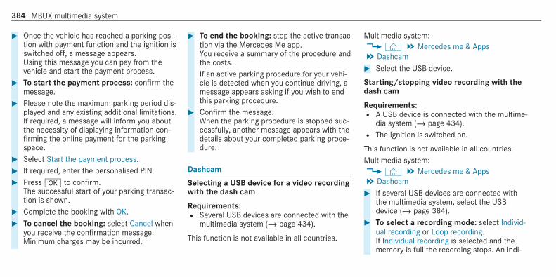
# Once the vehicle has reached a parking posi‐tion with payment function and the ignition isswitched off, a message appears.Using this message you can pay from thevehicle and start the payment process.
# To start the payment process: confirm themessage.
# Please note the maximum parking period dis‐played and any existing additional limitations.If required, a message will inform you aboutthe necessity of displaying information con‐firming the online payment for the parkingspace.
# Select Start the payment process.# If required, enter the personalised PIN.# Pressa to confirm.
The successful start of your parking transac‐tion is shown.
# Complete the booking with OK.# To cancel the booking: select Cancel when
you receive the confirmation message.Minimum charges may be incurred.
# To end the booking: stop the active transac‐tion via the Mercedes Me app.You receive a summary of the procedure andthe costs.If an active parking procedure for your vehi‐cle is detected when you continue driving, amessage appears asking if you wish to endthis parking procedure.
# Confirm the message.When the parking procedure is stopped suc‐cessfully, another message appears with thedetails about your completed parking proce‐dure.
Dashcam
Selecting a USB device for a video recordingwith the dash cam
Requirements:R Several USB devices are connected with the
multimedia system (/ page 434).
This function is not available in all countries.
Multimedia system:4© 5 Mercedes me & Apps5 Dashcam# Select the USB device.
Starting/stopping video recording with thedash cam
Requirements:R A USB device is connected with the multime‐
dia system (/ page 434).R The ignition is switched on.
This function is not available in all countries.Multimedia system:4© 5 Mercedes me & Apps5 Dashcam# If several USB devices are connected with
the multimedia system, select the USBdevice (/ page 384).
# To select a recording mode: select Individ-ual recording or Loop recording.If Individual recording is selected and thememory is full the recording stops. An indi‐
384 MBUX multimedia system

vidual recording is automatically protectedagainst being overwritten.If Loop recording has been selected, severalshort video files are recorded. When thememory limit is reached, the oldest video fileis deleted and recording is continued auto‐matically.
# To start: select Start recording.The length of the recording is shown. ThePlease do not remove the storage medium.message appears. The video file is stored onthe USB device.
# To end: select End recording .A report may appear in the following cases:R For the Individual recording recording mode:
the memory is full or there are only a fewminutes recording time available. The videorecording stops or will be stopped immi‐nently.Change the USB device or delete a video file.R If a video recording has started and a
national border is detected, the National bor-der crossed. Please observe the countryspe-
cific regulations regarding video recording.message appears.This function is not available in all countries.R The camera is not functional, the Camera
unavailable message appears.Have the camera checked in a Mercedes-Benz service centre.
Deleting a dash cam video recording
Requirements:R A USB device with video recordings is con‐
nected with the multimedia system(/ page 434).
This function is not available in all countries.Multimedia system:4© 5 Mercedes me & Apps5 Dashcam# Select thep symbol.
The RECORDINGS menu appears.# SelectV for a video file.# Select Delete.# Select Yes.
# To delete all video files: select Ä.# Select Delete all entries.
Configuring dash cam settings
Requirements:R A USB device is connected with the multime‐
dia system (/ page 434).
This function is not available in all countries.Multimedia system:4© 5 Mercedes me & Apps5 Dashcam# SelectZ.# To show messages after passing a
national border: switch on National borderalert.The display button is activated.A message appears under the following con‐ditions:R A video is being recorded.R The vehicle has passed a national border.
% This function is not available in all countries.
MBUX multimedia system 385

# To start automatic video recording: selectAutomatic video recording.
# Activate Automatic video recording.The display button is activated. When thevehicle is started, video recording startsautomatically.
% This function is not available in all countries.
TelephoneTelephony
Notes on telephony
& WARNING Risk of distraction from oper‐ating integrated communication equip‐ment while the vehicle is in motion
If you operate communication equipmentintegrated in the vehicle when driving, you
will be distracted from the traffic situation.This could also cause you to lose control ofthe vehicle.# Only operate this equipment when the
traffic situation permits.# If you cannot be sure of this, stop the
vehicle whilst paying attention to roadand traffic conditions and operate theequipment with the vehicle stationary.
& WARNING Risk of an accident fromoperating mobile communication equip‐ment while the vehicle is in motion
Mobile communications devices distract thedriver from the traffic situation. This couldalso cause the driver to lose control of thevehicle.
# As the driver, only operate mobile com‐munications devices when the vehicle isstationary.
# As a vehicle occupant, only use mobilecommunications devices in the areasintended for this purpose, e.g. in therear passenger compartment.
You must observe the legal requirements for thecountry in which you are currently driving whenoperating mobile communication equipment inthe vehicle.Further information can be obtained from aMercedes-Benz service centre or at: http://www.mercedes-benz.com/connect.
386 MBUX multimedia system

Telephone menu overview
1 Bluetooth® device name of the currentlyconnected mobile phone/of the mobilephone
2 Bluetooth® device name of the currentlyconnected mobile phone/of the mobilephone (two phone mode)
3 Battery status of the connected mobilephone
4 Signal strength of the mobile phone network5 Options6 Device manager
7 Messages8 Numerical pad9 Contact search
MBUX multimedia system 387

Bluetooth® profile overview
Bluetooth® profileof the mobile phone
Function
PBAP (Phone BookAccess Profile)
Contacts are auto‐matically displayed inthe multimedia sys‐tem
MAP (MessageAccess Profile)
Message functionscan be used
Telephony operating modes overviewDepending on your equipment, the following tel‐ephony operating modes are available:R A mobile phone is connected to the multime‐
dia system via Bluetooth® (/ page 388).R Two mobile phones are connected with the
multimedia system via Bluetooth® (twophone mode) (/ page 389).- You can use all the functions of the multi‐
media system with the mobile phone inthe foreground.
- You can receive incoming calls and mes‐sages with the mobile phone in the back‐ground.You can interchange the mobile phone inthe foreground and background any time(/ page 389).
% Irrespective of this, Bluetooth® audio func‐tionality can by used with any mobile phone(/ page 434).
Information on telephonyThe following situations can lead to the callbeing disconnected while the vehicle is inmotion:R there is insufficient network coverage in the
areaR you move from one transmission/reception
station to another and no communicationchannels are freeR the SIM card used is not compatible with the
network availableR a mobile phone with "Twincard" is logged into
the network with the second SIM card at thesame time
The multimedia system supports calls in HDVoice® for improved speech quality. A require‐ment for this is that the mobile phone and themobile phone network provider of the personyou are calling support HD Voice® .Depending on the quality of the connection, thevoice quality may fluctuate.
Connecting a mobile phone
Requirements:R Bluetooth® is activated on the mobile phone
(see the manufacturer's operating instruc‐tions).R Bluetooth® is activated on the multimedia
system (/ page 328).
Multimedia system:4© 5 Phone
Searching for a mobile phone#
Select .# Select Connect new device.
388 MBUX multimedia system

Connecting a mobile phone (authorisationusing Secure Simple Pairing)# Select a mobile phone.# A code is displayed in the multimedia system
and on the mobile phone.# If the codes match: confirm the code on
the mobile phone.% For older mobile phone models, enter a one
to sixteen-digit number code on the mobilephone and on the multimedia system forauthorisation.
% Up to 15 mobile phones can be authorisedon the multimedia system.Authorised mobile phones are reconnectedautomatically.
% The connected mobile phone can also beused as Bluetooth® audio equipment(/ page 434).
Connecting a second mobile phone (twophone mode)
Requirements:R At least one mobile phone is already connec‐
ted to the multimedia system via Bluetooth®.
Multimedia system:4© 5 Phone#
Select .# Select Connect new device.# Select the mobile phone.# Select <Mobile phone> + <Mobile phone>.
The selected mobile phone is connected tothe multimedia system.
Functions of the mobile phone in two phonemode
Functions overview
Mobile phone in theforeground
Mobile phone in thebackground
Full range of func‐tions
Incoming calls andmessages
Interchanging mobile phones (two phonemode)Multimedia system:4© 5 PhoneBoth mobile phones are shown individually inseparate tabs.# Select the tab with the desired mobile
phone.The mobile phone in the selected tab is themobile phone in the foreground.With the exception of telephone settings, thesubmenus in the telephone menu relate tothe mobile phone in the foreground. In thetelephone settings, settings can be made forboth mobile phones.
MBUX multimedia system 389
Changing the function of a mobile phoneMultimedia system:4© 5 Phone
Activating a function#
Select .# Select a grey symbol in the line of a mobile
phone.The corresponding function is activated.
Deactivating a function#
Select .# One function is active: select the coloured
symbol in the line of a mobile phone.The mobile phone is disconnected from themultimedia system.
# Several functions are active: select a col‐oured symbol in the line of a mobile phone.The corresponding function is deactivated.
Replacing mobile phonesMultimedia system:4© 5 Phone#
Select .# No authorised mobile phone available:
select Connect new device.# Select a mobile phone.# Newly authorised mobile phone: confirm
the number code on the mobile phone.
Using in single telephone mode# Select <Mobile phone>.
A newly authorised mobile phone is connec‐ted in single telephone mode.If the mobile phone has already been author‐ised and connected in single telephonemode, it is connected again in single tele‐phone mode.If a mobile phone has already been author‐ised and connected in two phone mode withanother mobile phone, it will be connected infuture in single telephone mode.
Using in two phone mode# Select <Mobile phone> + <Mobile phone>.
A newly authorised mobile phone is connec‐ted with the selected mobile phone in twophone mode.If the mobile phone has already been author‐ised and connected in single telephonemode, it will be connected in future with theselected mobile phone in two phone mode.If the mobile phone was previously connec‐ted with another mobile phone, this connec‐tion is cancelled.
Disconnecting/de-authorising a mobilephoneMultimedia system:4© 5 Phone#
Select .# Select Ä in the line of the mobile phone.
390 MBUX multimedia system

# To disconnect: select Disconnect.If applicable, the mobile phone will be auto‐matically reconnected when the vehicle isnext started.
# To de-authorise: select Deauthorise.
Information on Near Field Communication(NFC)NFC enables short-range wireless data transferor (re)connection of a mobile phone with themultimedia system.The following functions are available withouthaving authorised a mobile phone:R Transferring a URL or a contact to be viewed
in the multimedia system (see the manufac‐turer's operating instructions).R Setting up the vehicle's Wi-Fi access data via
the system settings (/ page 330).
Further information can be obtained at: http://www.mercedes-benz.com/connect
Using the mobile phone with Near Field Com‐munication (NFC)
Requirements:R NFC is activated on the mobile phone (see
the manufacturer's operating instructions)R The mobile phone's screen is switched on
and unlocked (see the manufacturer's oper‐ating instructions)
# To connect a mobile phone: hold the NFCarea of the mobile phone (see manufactur‐er's operating instructions) on mat1 orplace the mobile phone on it.
# Follow the additional prompts on the mediadisplay to connect the mobile phone. Con‐nect the mobile phone in single telephonemode (/ page 388). Connect the mobilephone in two phone mode (/ page 389).
# To replace a mobile phone: hold the NFCarea of the mobile phone (see manufactur‐er's operating instructions) on mat1 orplace the mobile phone on it.
# Follow the additional prompts on the mediadisplay to replace the mobile phone in one ortwo phone mode (/ page 389).
# If required, confirm the prompts on yourmobile phone (see the manufacturer's oper‐ating instructions).
% If your mobile phone supports wirelesscharging, it will be automatically charged viaNFC when it is connected or replaced. Arequirement for this is that the mobile phoneis on the mat (/ page 126).
If you want to charge a mobile phone withoutconnecting it to the multimedia system, lay it onthe mat without beforehand unblocking thescreen.
MBUX multimedia system 391

Further information can be found at: http://www.mercedes-benz.com/connect
Setting the reception and transmission vol‐ume
Requirements:R A mobile phone is connected (/ page 388).
Multimedia system:4© 5 Phone 5 <device name>5Z
This function ensures optimal language quality.% Please note that the respective mobile
phone must be selected for adjustment ofthe reception and transmission volume.
# Select Volume.# Set Reception volume and Transmission vol-
ume.
Further information on the recommended recep‐tion and transmission volume: http://www.mercedes-benz.com/connect
Setting the ringtoneMultimedia system:4© 5 Phone 5 <device name>5Z
# Select Ringtones.# Set the ringtone.% If the mobile phone supports the transfer of
the ringtone, you will hear the ringtone ofthe mobile phone instead of that of the vehi‐cle.
Starting/stopping mobile phone voice recog‐nition
Requirements:R The mobile phone in the foreground is con‐
nected with the multimedia system(/ page 388).
Starting mobile phone voice recognition# Press and hold the£ button on the multi‐
function steering wheel for more than onesecond.You can use mobile phone voice recognition.
Stopping mobile phone voice recognition# Press the8 or~ button on the multi‐
function steering wheel.% If a mobile phone is connected via Smart‐
phone Integration, the voice recognition ofthis mobile phone is started or stopped.
Calls
Telephone operationMultimedia system:4© 5 Phone
Making a call by entering the numbers# Select_.# Enter a number.# SelectR.
The call is made.
Accepting a call# SelectR Accept.
Rejecting a call# Selectk Reject.
392 MBUX multimedia system

Ending a call# Selectk.
Activating functions during a callThe following functions are available during acall:
k End callm Microphone off_ Numerical keypad (show to send DTMF
tones)W Add callh Transfer to phone (an active call in hands-
free mode is transferred over to the tele‐phone)
# Select a function.
Conducting calls with several participants
Requirements:R There is an active call (/ page 392).R Another call is being made.
Switching between calls# Select the contact.
The selected call is active. The other call ison hold.
Activating a call on hold# Select the contact of the call on hold.
Conducting a conference call# Selecti Create conferen. call.
The new participant is included in the confer‐ence call.
Ending an active call# Selectk End call.% On some mobile phones, the call on hold is
activated as soon as the active call is ended.
Accepting/rejecting a waiting call
Requirements:R There is an active call (/ page 392).
If you receive a call while already in a call, amessage is displayed.
Depending on the mobile phone and mobile net‐work operator you will hear a call-waiting sound.In addition, in two phone mode you will hear anacoustic signal when the call goes through to theother (not yet active) mobile phone.# SelectR Accept.
The incoming call is active.If only one mobile phone is connected withthe multimedia system, the previous call willbe put on hold.If during a call you accept a call with theother mobile phone when in two phone modethen the existing call is ended.
# Selectk Reject.% This function and behaviour depends on your
mobile phone network provider and themobile phone (see the manufacturer's oper‐ating instructions).
MBUX multimedia system 393
Contacts
Information about the contacts menuThe contacts menu contains all contacts fromexisting data sources, e.g. mobile phone or datastorage medium.Depending on the data source, you have the fol‐lowing number of contacts:R Permanently saved contacts: 3,000 entriesR Contacts loaded from the mobile phone:
5,000 entries per mobile phone
From the contacts menu, you can perform thefollowing actions:R Make a call, for example call a contact
(/ page 395)R Navigation (/ page 348)R Compose messages (/ page 399)R Additional options (/ page 396)
If a mobile phone is connected to the multimediasystem (/ page 388) and automatic calling up(/ page 394) is activated, the mobile phone'scontacts are displayed in the address book.
The multimedia system can show suggestionsbased on frequently used contacts as well asincoming and outgoing calls (/ page 310).These are shown at the top of the contact list.
Downloading mobile phone contactsMultimedia system:4© 5 Phone 5 <device name>5Z
# Select Contacts & call list.
Automatically# To switch Synchronise contacts automati-
cally on: activate the LED symbol.
Manually# To deactivate Synchronise contacts automat-
ically: deactivate the LED symbol.# Select Synchronise contacts.
Calling up contactsMultimedia system:4© 5 Phone 5g
The following options can be used to search forcontacts:R searching by initialsR searching by nameR searching by phone number
# Enter characters into the search field.# Select the contact.A contact can contain the following details:R phone numbersR navigation addressesR geo-coordinatesR Internet addressR e-mail addressesR voice tag (if set)R relation (if set)
394 MBUX multimedia system

Editing the format of a contact's nameMultimedia system:4© 5 Phone 5Z
# Select General.# Select Name format.The following options are available:R Surname, First nameR Surname First nameR First name Surname# Select an option.
Overview of importing contacts
Contacts from various sources
Source Requirements:
ò USB device The USB device isconnected with theUSB port.
ñ Bluetooth® con‐nection
If the sending ofvCards via Bluetooth®is supported, vCardscan be received onmobile phones or net‐books, for example.
Bluetooth® is activa‐ted in the multimediasystem and on therespective device(see the manufactur‐er's operating instruc‐tions).
Importing contacts into the contacts menuMultimedia system:4© 5 Phone 5Z 5 General5 Import contacts# Select a mobile phone <device name>, from
which the contacts should be imported.# Select an option.
Saving a mobile phone contactMultimedia system:4© 5 Phone 5g
# Selectór in the line of the mobilephone contact.
# Select Ä.# Select Save in vehicle.# Select Yes.
The contact saved in the multimedia systemis identified by theq symbol.
Calling a contactMultimedia system:4© 5 Phone 5g
# Selectª Search contacts.
MBUX multimedia system 395

# Enter characters into the search field.# Select the contact.# Select the telephone number.
The number is dialled.
Selecting further options in the contactsmenuMultimedia system:4© 5 Phone 5g
# Selectr in the line of the contact.# Select Ä.
Depending on the stored data, the followingoptions are available:R Add voice tag/Delete voice tagR Set relation/Remove relationR Send DTMF tones (for a number with DTMF
tones)The function is available when a call is active.
# Select an option.
Selecting options for suggestions in the con‐tacts menu
Requirements:R A profile has been created (/ page 305).R The Allow contact suggestions setting is
switched on (/ page 310).
Multimedia system:4© 5 Phone# Select+ Call list.# SelectV in the line of a suggested con‐
tact.The following options are available:R Save as favourite
The suggestions are saved as globalfavourites and do not appear on the homescreen.R Do not suggest
# Select an option.
Deleting contacts
Requirements:R The contacts are saved in the vehicle.R To delete an individual contact, this has been
imported manually into the vehicle.
Multimedia system:4© 5 Phone
Deleting all contacts# SelectZ.# Select General.# Select Delete contacts.# Select an option.
Deleting a contact# Selectg.# Selectr in the line of the contact.# Select Ä.# Select Delete contact.# Select Yes.
396 MBUX multimedia system

Saving a contact as a favouriteMultimedia system:4© 5 Phone 5 f Add favourites# Select a contact.# Selectr in the line of the contact.# Select the telephone number.
The contact is stored as a favourite in thetelephone menu overview.
Deleting favourites in the telephone menuoverviewMultimedia system:4©
# Select a favourite in the telephone menuoverview (/ page 397).
# Press and hold the favourite.# Select Delete.# Select Yes.
Deleting all favourites# Tap on© in the media display.# Select Phone.
# SelectZ.# Select the connected telephone.# Select Contacts & call list.# Select Do you want to delete all favourites?.# Select Yes.
Call list
Overview of the call listDepending on whether your mobile phone sup‐ports the PBAP Bluetooth® profile or not, thiscan have different effects on the presentationand functions of the call list.
If the PBAP Bluetooth® profile is supported, theeffects are as follows:R The call lists from the mobile phone are dis‐
played in the multimedia system.R When connecting the mobile phone, you may
have to confirm the connection for the PBAPBluetooth® profile.
If the PBAP Bluetooth® profile is not supported,the effects are as follows:R The multimedia system generates a call list
independently as soon as calls are made inthe vehicle.R The call list is not synchronised with the call
lists in the mobile phone.
The multimedia system can show suggestionsbased on frequently used contacts as well asincoming and outgoing calls (/ page 310).These are shown at the top of the call list.
Making a call from the call listMultimedia system:4© 5 Phone# Select+ Call list.# Select an entry.
The call is made.
Calling up additional options in the call listMultimedia system:4© 5 Phone# Select+ Call list.
MBUX multimedia system 397

# For previously stored contacts: selectrin the line of an entry.The search results are displayed.
# For contacts who have not been stored:selecti.
Selecting options for suggestions in the calllist
Requirements:R A profile has been created (/ page 305).R The Allow contact suggestions setting is
switched on (/ page 310).
Multimedia system:4© 5 Phone# Select+ Call list.# SelectV in the line of a suggested entry.
The following options are available:R Save as favouriteR Do not suggest
# Select an option.
Deleting the call listMultimedia system:4© 5 Phone 5 <device name>5Z
# Select Contacts & call list.# Select Delete call list.# Select Yes.% This function is only available if your mobile
does not support the PBAP Bluetooth® pro‐file.
Text messages
Overview of message functionsIn the messages menu you can receive and sendtext messages.If the connected mobile phone supports theBluetooth® MAP profile, the message functioncan be used on the multimedia system.You can obtain further information about set‐tings and supported functions of Bluetooth®-capable mobile phones from a Mercedes-Benz
service centre or at: http://www.mercedes-benz.com/connectSome mobile phones require further settingsafter being connected to the multimedia system(see manufacturer's operating instructions).
Setting message displaysMultimedia system:4© 5 Phone 5 <device name>5Z
# Select Message display.The following options are available:R All messagesR New and unread messagesR Messages while the vehicle is in motionR Off (The message function is no longer
available.)# Select a setting.
398 MBUX multimedia system

Reading messagesMultimedia system:4© 5 Phone 5 <device name>5l
Using the read-aloud function# Select a contact.# Select¬ read aloud.
The message is read aloud.
Dictating and sending a new message
Requirements:R There is an Internet connection.
Multimedia system:4© 5 Phone 5 <device name>5l
# r selects a new message.
Adding a recipient# Selectf.# Select a contact.
Dictating text# Selectp.
The dictating function is started.# Say the message.
After the voice message has been processed,it is shown as text.
Sending a message# Select Send.% When the vehicle is stationary you can use
the keyboard to write a message. No Inter‐net connection is required to use the key‐board.
Replying to a message in the messaging his‐toryMultimedia system:4© 5 Phone 5 <device name>5l
A message list is shown.# Selectr next to a contact.
The messaging history with this contact isshown.
# Selectp.The dictating function is started.
# Say the message.After the voice message has been processed,it is shown as text.
# Select Send.
Using message templatesMultimedia system:4© 5 Phone 5 <device name>5l
Using a template as a new message# Selectr to write a new message.# Add a recipient usingf.# Select a0 template.
Answering a message with a template# Select a message sequence with a contact.# Select aª template.# Select a0 template.
MBUX multimedia system 399

Forwarding a messageMultimedia system:4© 5 Phone 5 <device name>5l
A message list is shown.# Selectr next to a contact.
The messaging history with this contact isshown.
# Press and hold on a message.# To forward a message: select Forward.
Calling a message senderMultimedia system:4© 5 Phone 5 <device name>5l
A message list is shown.# Selectr next to a contact.
The messaging history with this contact isshown.
# Select Ä.# Select Call.
Using telephone numbers or URLs from atext message
Requirements:R An Internet connection is available to call up
a URL.
Multimedia system:4© 5 Phone 5 <device name>5l
A message list is shown.# Selectr next to a contact.
The messaging history with this contact isshown.
# Select a telephone number or a URL in themessage.If a URL is selected the web browser opens.If a telephone number is selected the follow‐ing options are available:R CallR Write new text message
# Select an option.
Deleting a messageMultimedia system:4© 5 Phone 5 <device name>5l
# Select a contact.# Press and hold on a message.# To delete the message: select Delete.
In Car Office
In-Car Office functionsUsing In-Car Office, you can connect your onlineservices with the multimedia system.The following functions are available:R Display of the upcoming appointments in the
calendarR Selection of an appointment as a destination
in the navigationR Display of upcoming telephone conferencesR Display of participants in a telephone confer‐
ence
400 MBUX multimedia system

R Display and selection of tasks and calls tocomplete
% Please note that certain functions are onlyavailable when the vehicle is stationary.
Calling up In-Car Office
Requirements:R A mobile phone is connected as the main
phone to the multimedia system.R You have a user account in the Mercedes me
portal: https://me.secure.mercedes-benz.comR The In-Car Office service is activated in the
Mercedes me portal.R You have a user account with an online
service, e.g. with Office 365, and have con‐nected this with In-Car Office via theMercedes me portal.
Multimedia system:4© 5 Mercedes me & Apps# Select In-Car Office.
You will see an appointments overview forthe current day.
You can find the following displays in theappointments overview:R All day: all day appointment
Selecting a calendar entry function in In-CarOfficeMultimedia system:4© 5 Mercedes me & Apps5 In-Car Office 5 Calendar# Select an appointment.
The following functions are available:
Read aloudR CallZ Navigate
Delete# Select a function.% Some functions are only available when
additional information about the appoint‐ment is entered. Functions which are notavailable are not shown.
The Call function is only available if a num‐ber for the appointment has been saved.The Navigate function is only available, if anavigable location for the appointment hasbeen saved in the associated online account.
Selecting the functions of Tasks & CallsMultimedia system:4© 5 Mercedes me & Apps5 In-Car Office 5 Tasks & calls# Select an entry.
The following functions are available:R Read aloudR Call
This option is only available for tasks if atelephone number has been saved.R Delete
# Select an option.
MBUX multimedia system 401

Marking an entry as completed in Tasks &CallsMultimedia system:4© 5 Mercedes me & Apps5 In-Car Office 5 Tasks & calls# Select the Tasks & calls symbol.
An overview of the tasks and calls appears.# Individual task or call: mark the selected
entry as completed O.
Noting an incoming callWhen you receive an incoming call a promptappears asking whether the call should beaccepted, rejected or noted.# Select Reminder.
The call is declined and added to the In-CarOffice Tasks & calls automatically.
Creating a new task in the calendarMultimedia system:4© 5 Mercedes me & Apps5 In-Car Office 5 Tasks & calls
Using the dictation function% The dictation function is not available every‐
where nor without limitation. For initial acti‐vation of the function it may be necessary toselect the terms of use in the Mercedes meportal.
# Activatep voice entry.The dictation function is started and you areguided by the dialogue.
# Enter the details.
Using voice control# Use the LINGUATRONIC Create a task voice
command.The task can be spoken directly.
% Additional information on operation of LIN‐GUATRONIC (/ page 272).
Managing e-mailsMultimedia system:4© 5 Mercedes me & Apps5 In-Car Office 5 E-mail
Showing/reading e-mail# Select an e-mail.
The e-mail is opened.Additional functions are available:R Creating e-mail.(/ page 402)R Answering e-mail (/ page 403)R Forwarding e-mail(/ page 403)
Writing new e-mailMultimedia system:4© 5 Mercedes me & Apps5 In-Car Office 5 E-mail
Using the keyboard# SelectW.# Add recipients usingf.# Enter the subject and text of the e-mail in the
corresponding fields with the keypad.
402 MBUX multimedia system

# Select Send.
Using the dictation function% The dictation function is not available every‐
where nor without limitation. For initial acti‐vation of the function it may be necessary toselect the terms of use in the Mercedes meportal.
# Selectp.The dictating function is started.
# Dictate the details and text of the e-mail.After the voice entry has been processed, itis shown as text.
# Select Send.
Using voice control# Use the LINGUATRONIC Write an e-mail voice
command.You are guided by the dialogue.
% Additional information on operation of LIN‐GUATRONIC (/ page 272).
Answering e-mailMultimedia system:4© 5 Mercedes me & Apps5 In-Car Office 5 E-mail
Using the keyboard# Select an e-mail.# Select Reply.# Enter the e-mail text in the corresponding
field.# Select Send.
Using the dictation function% The dictation function is not available every‐
where nor without limitation. For initial acti‐vation of the function it may be necessary toselect the terms of use in the Mercedes meportal.
# Select an e-mail.# Select Reply.# Selectp.
The dictating function is started.
# Dictate the text of the e-mail.After the voice entry has been processed, itis shown as text.
# Select Send.
Using voice control# Use the LINGUATRONIC Answer e-mail voice
command.You are guided by the dialogue.
% Additional information on operation of LIN‐GUATRONIC (/ page 272).
Forwarding e-mailMultimedia system:4© 5 Mercedes me & Apps5 In-Car Office 5 E-mail
Using the keyboard# Select an e-mail.# Select Forward.# To forward with attachment: select
Forward.# To forward without attachment: select
Forward without attachment.
MBUX multimedia system 403

# Enter the e-mail text in the correspondingfield using the keypad.
# Select Send.
Mercedes-Benz link
Overview of Mercedes-Benz Link
& WARNING Risk of distraction from infor‐mation systems and communicationsequipment
If you operate information and communica‐tion equipment integrated in the vehiclewhen driving, you will be distracted from thetraffic situation. This could also cause you tolose control of the vehicle.# Only operate this equipment when the
traffic situation permits.# If you cannot be sure of this, stop the
vehicle whilst paying attention to roadand traffic conditions and operate theequipment with the vehicle stationary.
You must observe the legal requirements for thecountry in which you are currently driving whenoperating the multimedia system.With Mercedes-Benz Link you can use mobilephone functions via the multimedia system. It isoperated using the touchscreen or the voice-operated control system. You can activate thevoice-operated control system by pressing andholding the£ button on the multifunctionsteering wheel.When using Mercedes-Benz Link via the voice-operated control system, the multimedia systemcan still be operated via LINGUATRONIC(/ page 272).The Mercedes-Benz Link control box supplemen‐tary equipment is required for this. This is availa‐ble at a Mercedes-Benz service centre.Only one mobile phone at a time can be connec‐ted via Mercedes-Benz Link to the multimediasystem.When a mobile phone is connected withMercedes-Benz Link, only one additional mobilephone can be connected using Bluetooth® with
the multimedia system when in two phonemode.% The Mercedes-Benz Link control box uses
the Android operating system.% The service provider is responsible for these
apps and the services and content connec‐ted to it.
Notes on Mercedes-Benz LinkIf a mobile phone is used with Mercedes-BenzLink, USB access using the media menu is possi‐ble for this mobile phone.% Only one route guidance can be active at a
time. If route guidance is active on the multi‐media system, it is closed when route guid‐ance is started on the mobile phone.
Connecting Mercedes-Benz Link with themultimedia system
Requirements:R The vehicle is fitted with the Mercedes-Benz
Link control box.R The Mercedes-Benz Link app is installed on
the mobile phone.
404 MBUX multimedia system

R The mobile phone is switched on.R Mercedes-Benz Link is connected to the mul‐
timedia system via theç USB port usinga suitable cable (/ page 434).
% The first activation of Mercedes-Benz Linkon the multimedia system must be carriedout when the vehicle is stationary for safetyreasons.
Multimedia system:4© 5 Mercedes me & Apps5 Smartphone 5 Mercedes-Benz Link5 Start Mercedes-Benz Link
Accepting/rejecting the data protection reg‐ulationsFor the initial start of the application: a messagewith the data protection provisions appears.# Select Accept & start.
Quitting Mercedes-Benz Link# Press theò button.% Mercedes-Benz Link starts automatically
when it is connected with the system using acable. If Mercedes-Benz Link was not dis‐
played in the foreground before disconnect‐ing, the application starts in the backgroundwhen reconnected. You can call upMercedes-Benz Link using the main menu.
You can find more information in the Mercedes-Benz Link control box operating instructions.
Calling up Mercedes-Benz Link sound set‐tingsMultimedia system:4© 5 Mercedes me & Apps5 Smartphone 5 Mercedes-Benz Link5Z
# Select sound settings.
Ending Mercedes-Benz Link# Disconnect the connecting cable between
Mercedes-Benz Link and the multimedia sys‐tem.
% Mercedes-Benz recommends disconnectingthe connecting cable only when the vehicleis stationary.
Apple CarPlay™
Overview of Apple CarPlay™
& WARNING Risk of distraction from infor‐mation systems and communicationsequipment
If you operate information and communica‐tion equipment integrated in the vehiclewhen driving, you will be distracted from thetraffic situation. This could also cause you tolose control of the vehicle.# Only operate this equipment when the
traffic situation permits.# If you cannot be sure of this, stop the
vehicle whilst paying attention to roadand traffic conditions and operate theequipment with the vehicle stationary.
You must observe the legal requirements for thecountry in which you are currently driving whenoperating the multimedia system.iPhone® functions can be used via the multime‐dia system using Apple CarPlay™. They are oper‐ated using the touchscreen, touchpad, Touch
MBUX multimedia system 405

Control or the Siri® voice-operated control sys‐tem. You can activate the voice-operated controlsystem by pressing and holding the£ buttonon the multifunction steering wheel.When using Apple CarPlay™ via the voice-oper‐ated control system, the multimedia system canstill be operated via LINGUATRONIC(/ page 272).
Only one iPhone® at a time can be connected viaApple CarPlay™ with the multimedia system.Also for use of Apple CarPlay™ with two phonemode, only one additional mobile phone can beconnected using Bluetooth® with the multimediasystem.The availability of Apple CarPlay™ may varyaccording to the country.The service provider is responsible for this appli‐cation and the services and content connectedto it.
Information on Apple CarPlay™When Apple CarPlay™ is being used, the iPod®media source is not available for the respectiveiPhone®.
Only one route guidance can be active at a time.If route guidance is active on the multimedia sys‐tem, it is closed when route guidance is startedon the mobile phone.
Connecting an iPhone® via Apple CarPlay™(cable)
Requirements:R The current version of your device's operat‐
ing system is being used (see the manufac‐turer's operating instructions).R There is an Internet connection for the full
range of functions for Apple CarPlay™.R The iPhone® is connected to the multimedia
system via the USB portç using a suita‐ble cable (/ page 434).
Multimedia system:4© 5 Mercedes me & Apps5 Smartphone 5 Apple CarPlay5 Start Apple CarPlay# Alternative: If an Apple CarPlay™ application
is active (e.g. when music is being played orroute guidance is active), you can call up the
active application using the|,z or% application buttons (/ page 303).
% Control using the application buttons can beswitched on or off (/ page 407).
Accepting/rejecting the data protection reg‐ulationsFor the initial start of the application: a messagewith the data protection provisions appears.# Select Accept & start.
Exiting Apple CarPlay™# Press theò button.% Apple CarPlay™ starts automatically when
the iPhone® is connected with the systemusing a cable. If Apple CarPlay™ was not dis‐played in the foreground before disconnect‐ing, the application starts in the backgroundwhen reconnected. You can call up AppleCarPlay™ in the main menu.
406 MBUX multimedia system

Calling up Apple CarPlay™ sound settingsMultimedia system:4© 5 Mercedes me & Apps5 Smartphone 5 Apple CarPlay 5Z
# Select sound settings.
Setting control of the application buttons(Apple CarPlay™)Multimedia system:4© 5 Mercedes me & Apps5 Smartphone 5 Apple CarPlay 5Z5 General# To switch Control via application buttons on:
activate the LED symbol.# To deactivate Control via application buttons:
deactivate the LED symbol.
Ending Apple CarPlay™# To end the connection of Apple CarPlay™
(with cable): disconnect the connection viathe connecting cable between the mobilephone and multimedia system.
% Mercedes-Benz recommends disconnectingthe connecting cable only when the vehicleis stationary.
Android Auto
Android Auto overview
& WARNING Risk of distraction from infor‐mation systems and communicationsequipment
If you operate information and communica‐tion equipment integrated in the vehiclewhen driving, you will be distracted from thetraffic situation. This could also cause you tolose control of the vehicle.# Only operate this equipment when the
traffic situation permits.# If you cannot be sure of this, stop the
vehicle whilst paying attention to roadand traffic conditions and operate theequipment with the vehicle stationary.
You must observe the legal requirements for thecountry in which you are currently driving whenoperating the multimedia system.Mobile phone functions can be used withAndroid Auto using the Android operating sys‐tem on the multimedia system. It is operatedusing the touchscreen or the voice-operatedcontrol system. You can activate the voice-oper‐ated control system by pressing and holding the£ button on the multifunction steering wheel.When using Android Auto via the voice-operatedcontrol system, the multimedia system can stillbe operated via LINGUATRONIC (/ page 272).Only one mobile phone at a time can be connec‐ted via Android Auto with the multimedia sys‐tem.Also for use of Android Auto with two phonemode, only one additional mobile phone can beconnected using Bluetooth® with the multimediasystem.The availability of Android Auto and Android Autoapps may vary according to the country.
MBUX multimedia system 407

The service provider is responsible for this appli‐cation and the services and content connectedto it.
Information on Android AutoIf a mobile phone is used with Android Auto,USB access using the media menu is not possi‐ble for this mobile phone.Only one route guidance can be active at a time.If route guidance is active on the multimedia sys‐tem, it is closed when route guidance is startedon the mobile phone.
Connecting a mobile phone via Android Auto
Requirements:R The mobile phone supports Android Auto
from Android 5.0.R The Android Auto app is installed on the
mobile phone.R In order to use the telephone functions, the
mobile phone must be connected to the mul‐timedia system via Bluetooth®(/ page 388).
If there was no prior Internet connection, thisis established with the use of the mobilephone with Android Auto.R The mobile phone is connected to the multi‐
media system via theç USB port using asuitable cable (/ page 434).R There is an Internet connection for the full
range of functions for Android Auto.
Multimedia system:4© 5 Mercedes me & Apps5 Smartphone 5 Android Auto5 Start Android Auto# Alternative: If an Android Auto application is
active (e.g. when music is being played orroute guidance is active), you can call up theactive application using the|,z or% application buttons (/ page 303).
% Control using the application buttons can beswitched on or off (/ page 409).
% The first activation of Android Auto on themultimedia system must be carried outwhen the vehicle is stationary for safety rea‐sons.
Accepting/rejecting the data protection reg‐ulationsFor the initial start of the application: a messagewith the data protection provisions appears.# Select Accept & start.
Exiting Android Auto# Press theò button.% Android Auto starts automatically when the
mobile phone is connected with the systemusing a cable. If Android Auto was not dis‐played in the foreground before disconnect‐ing, the application starts in the backgroundwhen reconnected. You can call up AndroidAuto in the main menu.
Calling up the Android Auto sound settingsMultimedia system:4© 5 Mercedes me & Apps5 Smartphone 5 Android Auto 5Z
# Select sound settings.
408 MBUX multimedia system

Setting control of the application buttons(Android Auto)Multimedia system:4© 5 Mercedes me & Apps5 Smartphone 5 Android Auto 5Z5 General# To switch Control via application buttons on:
activate the LED symbol.# To deactivate Control via application buttons:
deactivate the LED symbol.
Ending Android Auto# To end the connection of Android Auto
(with cable): disconnect the connection viathe connecting cable between the mobilephone and multimedia system.
% Mercedes-Benz recommends disconnectingthe connecting cable only when the vehicleis stationary.
Transferred vehicle data with Android Autoand Apple CarPlay™
Overview of transferred vehicle dataWhen using Android Auto or Apple CarPlay™,certain vehicle data is transferred to the mobilephone. This enables you to get the best out ofselected mobile phone services. Vehicle data isnot directly accessible.The following system information is transmitted:R Software release of the multimedia systemR System ID (anonymised)
The transfer of this data is used to optimisecommunication between the vehicle and themobile phone.To do this, and to assign several vehicles to themobile phone, a vehicle identifier is randomlygenerated.This has no connection to the vehicle identifica‐tion number (VIN) and is deleted when the multi‐media system is reset (/ page 336).The following driving status data is transmitted:R Transmission position engaged
R Distinction between parked, standstill, rollingand drivingR Day/night mode of the instrument cluster
The transfer of this data is used to alter howcontent is displayed to correspond to the drivingsituation.The following position data is transmitted:R CoordinatesR SpeedR Compass directionR Acceleration direction
This data is only transferred while the navigationsystem is active, in order to improve it (e.g. so itcan continue functioning when in a tunnel).
Mercedes me connect
Notes on Mercedes me connectMercedes me connect consists of multiple serv‐ices.
MBUX multimedia system 409
Depending on whether the services are activatedand on the vehicle equipment, you can use thefollowing services via the multimedia system andthe overhead control panel, for example:R Accident and breakdown management (me
button)R If the service is activated: Concierge Service
(me button)R Mercedes-Benz emergency call system (auto‐
matic emergency call or SOS button)
Mercedes me connect accident and breakdownmanagement, the Mercedes me connect Con‐cierge Service (if service is activated) and theMercedes-Benz emergency call centre are availa‐ble for you around the clock.The me button and the SOS button can be foundon the vehicle's overhead control panel .You can also call the Mercedes-Benz CustomerCentre using the multimedia system .Please note that Mercedes me connect is aMercedes-Benz service. In emergencies, alwayscall the national emergency services first usingthe standard national emergency service phone
numbers. In emergencies, you can also use theMercedes-Benz emergency call system(/ page 416).Observe the conditions of use for Mercedes meconnect and other services. These can beobtained in the Mercedes me portal: https://me.secure.mercedes-benz.comFurther information on Mercedes me connect,the provided service scope and operation:http://manuals.daimler.com/baix/cars/connectme/en_GB/index.html
Calling the Mercedes-Benz Customer Centreusing the multimedia system
Requirements:R Access to a GSM network is available.R The contract partner's GSM network cover‐
age is available in the respective region.R The ignition must be switched on so that
vehicle data can be transferred automati‐cally.
Multimedia system:4© 5 Phone 5g
# Call Mercedes me connect.After confirmation, the multimedia systemsends the required vehicle data. The datatransfer is shown in the media display.
Then, you can select a service and be connectedto a specialist at the Mercedes-Benz CustomerCentre.Further information on Mercedes me connect,the provided service scope and operation areavailable at: http://manuals.daimler.com/baix/cars/connectme/en_GB/index.html
410 MBUX multimedia system

Making a call via the overhead control panel
1 me button for service, concierge or informa‐tion calls
2 SOS button cover3 SOS button (emergency call system)
# To make a Mercedes me call: press mebutton1.
# To make an emergency call: press SOSbutton cover2 briefly to open.
# Press and hold SOS button3 for at leastone second.
If a Mercedes me call is active, an emergencycall can still be triggered. This has priority overall other active calls.
Information about the Mercedes me callusing the me buttonA call to the Mercedes-Benz Customer Centrehas been initiated via the me button in the over‐head control panel or the multimedia system .Using the voice dialogue system you access thedesired service:R Concierge Service (if the service is activated)R Accident and breakdown management
(/ page 411)R Mercedes-Benz Customer Centre for general
information about the vehicle
You can find information on the following topics:R Activation of Mercedes me connectR Operating the vehicle
R Nearest Mercedes-Benz service centreR Other products and services from Mercedes-
Benz
Data is transferred during the connection to theMercedes-Benz Customer Centre (/ page 412).
Information on Mercedes me connect acci‐dent and breakdown managementThe accident and breakdown management caninclude the following functions:R Supplement to the Mercedes-Benz emer‐
gency call system (/ page 416)If necessary, the contact person at theMercedes-Benz emergency call centre for‐wards the call to Mercedes me connectbreakdown and accident management. For‐warding the call is however not possible in allcountries.R Breakdown assistance by a mechanic on
location and/or the towing away of the vehi‐cle to the nearest Mercedes-Benz servicecentreYou may be charged for these services.
MBUX multimedia system 411

More information about Mercedes me connectservices can be obtained in the Mercedes meportal: https://me.secure.mercedes-benz.com
Arranging a service appointment viaMercedes me connectIf you have activated the maintenance manage‐ment service, relevant vehicle data is transferredautomatically to the Mercedes-Benz CustomerCentre. You will then receive individual recom‐mendations regarding the maintenance of yourvehicle.Regardless of whether you have consented tothe maintenance management service, the multi‐media system reminds you after a certainamount of time that a service is due. A promptappears asking if you would like to make anappointment.# To arrange a service appointment: select
Call.After your agreement the vehicle data is sentand a Mercedes-Benz Customer Centreemployee deals with your appointment. Theinformation is then sent to your desiredservice outlet.
This will contact you to confirm the appoint‐ment and if necessary consult about thedetails.
% If you select Later after the service messageappears, the message is hidden and reap‐pears after a certain period of time.
Giving consent to data transfer for Mercedesme connect
Requirements:R There is an active Mercedes me call via the
multimedia system or the me button in theoverhead control panel .
% In certain countries you must confirm thedata transfer.
If the accident and breakdown service andMercedes me connect Concierge Service are notactivated on Mercedes me, the Do you want totransmit vehicle data and the vehicle's positionto the Mercedes-Benz Customer Centre in orderto improve the processing of your request? mes‐sage appears.
# Select Yes.Relevant identification data is transmittedautomatically.
More information on Mercedes me: http://www.mercedes.me
Transferred data during a Mercedes me call
The data transferred when calling depends onthe services activated and the type of call made:R General information about the vehicleR Concierge ServiceR Accident and breakdown assistanceR Service appointment arrangement
Which data is transferred for the services, canbe taken from the currently valid terms of use.These can be obtained in the Mercedes me por‐tal: https://me.secure.mercedes-benz.comThe following data is transmitted if no service isactivated and the data protection prompt hasbeen confirmed:R Vehicle identification number
412 MBUX multimedia system

R Mercedes me customer identification num‐berR Reason for the initiation of the callR Language set in the multimedia systemR Confirmation of the data protection prompt
During the service appointment arrangement viathe service reminder, the current mileage andmaintenance data can also be transferred,assuming the required data transfer technologyis supported by the mobile service operator andthe quality of the mobile connection is sufficient.In addition, the current location of the vehiclecan be demanded by the Mercedes-Benz Cus‐tomer Centre from the vehicle, if accident andbreakdown management is called via the voicecontrol system and no service has been activa‐ted, but the data protection query has been con‐firmed.% At the time of going to press, this function is
technically not yet available but can be sup‐ported in the future.
The following data is transmitted if the data pro‐tection prompt has been rejected:R Reason for the initiation of the callR Rejection of the data protection prompt
Mercedes me and apps
Information about Mercedes meWhen you log in with a user account to theMercedes me portal, then services and offersfrom Mercedes-Benz will be available to you.Availability is country-dependent.For more information consult a Mercedes-Benzservice centre or visit the Mercedes me portal:http://me.secure.mercedes-benz.com% Make sure you always keep the Mercedes
me apps updated.
Calling up the Mercedes me user accountMultimedia system:4© 5 Mercedes me & Apps
Your vehicle is connected with a useraccount# Select Mercedes me.
Information about the connected useraccount appears.
Your vehicle is not yet connected with a useraccount# Select Mercedes me.# The instructions for creating a user account
and connecting the vehicle with this followon the media display.
% If the Mercedes me app is available on amobile phone, the vehicle connection can beaccomplished using the QR code shown.
Calling up the Mercedes me services
Requirements:R The vehicle is connected with the user
account.
MBUX multimedia system 413

Multimedia system:4© 5 Mercedes me & Apps# Select Services.
Within the various categories you can see theMercedes me services you have already pur‐chased and also those still available to pur‐chase.To activate or deactivate the services, log into your user account in the Mercedes meportal.
Deleting a connection between a useraccount and the vehicle
Requirements:R The (vehicle) profile of the user account that
was initially connected with the vehicle isselected.R The profile is synchronised (/ page 306).R A PIN has been set.
Multimedia system:4© 5 Mercedes me & Apps5 Mercedes me# Select Delete vehicle assignment.# Enter the PIN of the connected user account.% Only the user, whose user account was ini‐
tially connected with the vehicle can deletethe connection between all user accountsand the vehicle.
Mercedes-Benz emergency call system
Information on available emergency call sys‐temsTwo types of emergency call system are availa‐ble to you in the vehicle:R Mercedes-Benz emergency call systemR 112 emergency call system (EU eCall)
The following applies for both emergency callsystems:R The transfer of specific data is required for
the intended function of both emergency callsystems. This will be explained in the "Datatransfer" section (/ page 417).R Both emergency call systems are included as
standard equipment in your vehicle and areactivated at the factory.R The use of both emergency call systems is
exempt from charges.R Both emergency call systems only function in
areas in which the wireless service providersoffer mobile phone coverage.For both systems, insufficient network cover‐age from the wireless service providers canresult in an emergency call not being trans‐mitted.
414 MBUX multimedia system

Differences between the Mercedes-Benz emergency call system and 112 emergency call system (EU eCall)
Mercedes-Benz emergency call system 112 emergency call system (EU eCall)
R The Mercedes-Benz emergency call system is permanently logged in tothe mobile phone network.R Automatic and manual Mercedes-Benz emergency calls are transmit‐
ted to a Mercedes-Benz emergency call centre.In the event that the emergency call centre of the Mercedes-Benzemergency call system cannot be reached (e.g. due to a lack of net‐work coverage), the 112 emergency call is carried out automatically.
R If you decide on the 112 emergency call system (EU eCall), then thesystem only logs in to the mobile phone network after the triggering ofa manual or automatic emergency call.R The 112 emergency call system (EU eCall) transmits automatic and
manual emergency calls directly to public coordination centres.
% The 112 emergency call system (EU eCall) inyour vehicle meets the delegated regulationEU 2017/79. Proper and full functionality ofthe 112 emergency call system (EU eCall)depends on circumstances beyond the influ‐ence of Daimler AG. This includes mobilenetwork coverage and the technical infra‐structure of the public reception centres inthe respective countries.
% Please observe that in the event of a repairgenuine Mercedes-Benz batteries must beused which have been certified pursuant tothe delegated regulation EU 2017/79
(Appendix I). Other manufacturers are alsopermitted provided their batteries are certi‐fied according to the delegated regulationEU 2017/79.
You can find more information on the regionalavailability of the Mercedes-Benz emergency callsystem at: http://www.mercedes-benz.com/connect_ecall.There is the option of deactivating theMercedes-Benz emergency call system andusing only the 112 emergency call system (EUeCall). Contact address for carrying out deacti‐
vation of the Mercedes-Benz emergency call sys‐tem are the local dealers.Mercedes-Benz recommends the activation ofthe Mercedes-Benz emergency call system forthe following reasons:R In emergency situations when abroad, you
can also get support in a language youspeak.R Several transmission technologies are used
to accelerate the transfer of the accidentdata and improve reliability of the transmis‐sion.
MBUX multimedia system 415
R The Mercedes-Benz emergency call system ispermanently logged in to the mobile phonenetwork, which ensures faster placement ofthe emergency call and faster transfer of theaccident data.Measures for rescue, recovery or towingaway can then be initiated in quickly.R With a Mercedes-Benz emergency call, the
accident data is only transferred to the pub‐lic coordination centre with the approval ofthe customer.In the event of an automatically triggeredemergency call in which there is no voicecontact, the accident data is transmittedimmediately to the public emergency callcentre.R Should the Mercedes-Benz emergency call
centre not be available, the 112 emergencycall is carried out automatically.
Overview of emergency call systemsBoth the Mercedes-Benz emergency call systemas well as the 112 emergency call system (EUeCall) can help to reduce the time between anaccident and the arrival of emergency services
at the site of the accident. They help locate anaccident site in places that are difficult toaccess.Both emergency call systems can initiate anemergency call automatically (/ page 416) ormanually .Only make emergency calls if you or others arein need of rescue. Do not make an emergencycall in the event of a breakdown or a similar sit‐uation.
Messages on the displayThe following messages appear in the media dis‐play of both emergency call systems:R SOS NOT READY: the ignition is not on or
there is a malfunction with the emergencycall system. This does not necessarily indi‐cate complete failure of the emergency callsystem. Emergency calls call still be trans‐mitted.The display only refers to the vehicle anddoes not take account of the availability ofmobile phone networks and the Mercedes-Benz emergency call centre.
The functional readiness of the emergencycall system on the vehicle can be seen whenthe SOS NOT READY display disappears oncethe ignition is switched on.R G: The icon appears in the display during
an active emergency call.
% If there is a malfunction in the emergencycall system (e.g. a fault with the speaker,microphone, airbag, SOS button), a corre‐sponding message appears in the multifunc‐tion display of the instrument cluster.
Triggering an automatic emergency call
Requirements:R The ignition is switched on.R The starter battery is sufficiently charged.
Both the Mercedes-Benz emergency call systemas well as the 112 emergency call system (EUeCall) automatically initiate an emergency call inthe following situations:R After activation of the restraint systems such
as airbags or seat belt tensioners after anaccident.
416 MBUX multimedia system
R After an automatically initiated emergencystop by Active Emergency Stop Assist.
The emergency call has been made:R A voice connection is established with the
emergency call centre.R A message with accident data is transmitted
to the emergency call centre.
The SOS button in the overhead control panelflashes until the emergency call is finished.If no connection can be made to the publicemergency services, a corresponding messageappears in the display.# Dial the 112 emergency number or an appro‐
priate local emergency call number on yourmobile phone.
If an emergency call has been initiated:R Remain in the vehicle if the road and traffic
conditions permit you to do so until a voiceconnection is established with the emer‐gency call centre.
R On the basis of the call, the emergency callcentre decides whether it is necessary to callrescue teams and/or the police to the acci‐dent site.R If no vehicle occupant answers, an ambu‐
lance is sent to the vehicle immediately.
Triggering a manual emergency call# To use the SOS button in the overhead
control panel: press the SOS button at leastone second long .
# To use voice control: use the LINGUA‐TRONIC voice commands (/ page 281).
The emergency call has been made:R A voice connection is established with an
emergency call centre.R Remain in the vehicle if the road and traffic
conditions permit you to do so until a voiceconnection is established with the emer‐gency call centre.
R On the basis of the call, the emergency callcentre decides whether it is necessary to callrescue teams and the police to the accidentsite.R A message with accident data is transmitted
to the emergency call centre.
If no connection can be made to the publicemergency services, a corresponding messageappears in the media display.# Dial the 112 emergency number or an appro‐
priate local emergency call number on yourmobile phone.
Emergency call system data transmissionFor both the Mercedes-Benz emergency call sys‐tem as well as the 112 emergency call system(EU eCall) data is transferred to the Mercedes-Benz emergency call centre or the public emer‐gency call centre.Depending on the emergency call system activa‐ted (/ page 414) different data is transmitted tothe appropriate emergency call centre.
MBUX multimedia system 417

Transferred data according to activated emergency call system:
Mercedes-Benz emergency call 112 emergency call
R GPS position data of the vehicleR GPS position data on the route (a few hundred metres before the acci‐
dent)R Direction of travelR Vehicle identification numberR Drive type of the vehicle (e.g. petrol, diesel, CNG, LPG, electric or
hydrogen)R Number of people determined to be in the vehicleR Whether the emergency call was initiated manually or automaticallyR Time of the accidentR Language setting on the multimedia systemR Whether Mercedes me connect is available or not
This is a requirement for the option of forwarding the call to theMercedes-Benz Customer Centre if necessary.
R Vehicle's GPS position dataR GPS position data on the route (a few hundred metres before the acci‐
dent)R Direction of travelR Vehicle identification numberR Drive type of the vehicle (e.g. petrol, diesel, CNG, LPG, electric or
hydrogen)R Number of people determined to be in the vehicleR Whether the emergency call was initiated manually or automaticallyR Time of the accident
% If only the 112 emergency call system (EUeCall) is activated in the vehicle, the acci‐dent data is transmitted directly to the pub‐lic emergency call centre.
418 MBUX multimedia system

For accident clarification purposes, the followingmeasures can be taken up to an hour after theemergency call has been initiated:R The current vehicle position can be called up.R A voice connection to the vehicle occupants
can be established.R Emergency call data as described above can
be called up.
% For Russia: various functions, e.g. receivingtraffic information, cannot be performed forup to two hours after sending an emergencycall.
Function of the emergency call system self-diagnosis (Russia)Your car verifies the operability of the emer‐gency call system each time the ignition is ON.In case of system failure, you will be informedwith text message on the instrument cluster andwith red indicator SOS NOT READY on the mediadisplay.Please, make sure, that during 30 seconds afterswitching ignition ON the red indicator SOSNOT READY in the upper right corner of the
media display is switched OFF, this means theemergency call system passed diagnostics suc‐cessfully. If necessary, switch ON the media dis‐play, if it was switched OFF before.
Starting/ending ERA-GLONASS test mode(Russia)
Requirements:R The starter battery is sufficiently charged.R The ignition is switched on.R The vehicle has been stationary for at least
one minute.
# To start the test mode: press and hold the~ button on the multifunction steeringwheel for at least five seconds.The test mode is started and automaticallyends after the language test has been per‐formed.
# To end the test mode manually: switch offthe ignition.The test mode is ended.
Information on data processing
Processing of personal data via theMercedes-Benz emergency call systemAll processing of personal data via theMercedes-Benz emergency call system corre‐sponds with the specifications in the EU Regula‐tion 2016/79 "on the protection of individualswith regard to the processing of personal data(GDPR)"The data is solely used by the Mercedes-Benzemergency call system for rescue and recoveryin the event of an accident.The owner of a vehicle, that is equipped with aMercedes-Benz emergency call system in addi‐tion to the 112 emergency call system (EU eCall),has the right to use the 112 emergency call sys‐tem instead of the Mercedes-Benz emergencycall system.Contact address for carrying out deactivation ofthe Mercedes-Benz emergency call system arethe local dealers.
MBUX multimedia system 419

Processing of personal data via the 112emergency call system (EU eCall)All processing of personal data via the 112 emer‐gency call system (EU eCall) corresponds withthe specifications in the EU Regulation 2016/79"on the protection of individuals with regard tothe processing of personal data (GDPR)" and isbased particularly on the necessity of upholdingthe vital interests of the affected person inaccordance with Article 6, Clause1, Letter d ofthe GDPR.The processing of this type of data is strictlylimited to the purpose of operating the emer‐gency calls to the standard European emergencycall number 112.
Data recipientThe recipients of data that is processed usingthe 112 emergency call system (EU eCall) are therelevant emergency call inquiry terminals thatare specified to first receive and handle emer‐gency calls to the standard European emergencycall number 112 by the respective countryauthorities in whose territory you are located.
Arrangements for data processingBoth emergency call systems are designed sothat the following requirements are fulfilled:R The data contained in the system memory is
not accessible outside the system prior tothe initiation of an emergency call.R Both emergency call systems cannot be
traced and there is no continuous tracking innormal operation.R The data in the system's internal memory is
automatically and continuously deleted.R The location data of the vehicle is continu‐
ously overwritten in the system's internalmemory, so that no more than the last threecurrent locations required for the normalfunction of the system are available.R The record of the activity data of both emer‐
gency call systems is only kept for as long asis required to fulfil the purpose of handlingthe emergency call, and under no circum‐stances for more than 13 hours after thetime that an emergency call is initiated.
Rights of persons affected by the data pro‐cessingThe person affected by the data processing (thevehicle owner) has the right to access the dataand if applicable can demand the correction,deletion or barring of data that affects him orher and that the processing of which does notcorrespond with the GDPR regulations. Each cor‐rection, deletion or barring carried out accordingto this regulation must be shared with the thirdparty to which the data has been transmitted,provided this does not prove to be infeasible anddoes not incur disproportionate expenditure.The person affected by the data processing hasthe right to complain to the appropriate dataprotection authority should they be of the opin‐ion that their rights have been infringed by theprocessing of their personal data.Responsible contact point for the processing ofaccess rights: Authorised company representa‐tive for data protection, Daimler AG, HPC G353,D-70546 Stuttgart, Germany
420 MBUX multimedia system

Online and Internet functionsInternet connection
Information on connecting to the Internet
& WARNING Risk of distraction from infor‐mation systems and communicationsequipment
If you operate information and communica‐tion equipment integrated in the vehiclewhen driving, you will be distracted from thetraffic situation. This could also cause you tolose control of the vehicle.# Only operate this equipment when the
traffic situation permits.# If you cannot be sure of this, stop the
vehicle whilst paying attention to roadand traffic conditions and operate theequipment with the vehicle stationary.
You must observe the legal requirements for thecountry in which you are currently driving whenoperating the multimedia system.
& WARNING Risk of an accident fromoperating mobile communication equip‐ment while the vehicle is in motion
Mobile communications devices distract thedriver from the traffic situation. This couldalso cause the driver to lose control of thevehicle.# As the driver, only operate mobile com‐
munications devices when the vehicle isstationary.
# As a vehicle occupant, only use mobilecommunications devices in the areasintended for this purpose, e.g. in therear passenger compartment.
You must observe the legal requirements for thecountry in which you are currently driving whenoperating mobile communication equipment inthe vehicle.
Depending on the vehicle's equipment, you canestablish an Internet connection in the followingways:R Vehicles with a communication module:
Internet use including Mercedes me connectservices and data roaming (/ page 421).R Vehicles without a communication mod‐
ule:- via Wi-Fi with a data-enabled mobile
phone (/ page 422)- via Bluetooth® with a data-enabled
mobile phone (/ page 422)
The Internet functions can only be used to a limi‐ted degree whilst driving.
Function of the communication moduleOn vehicles with a built-in communication mod‐ule, the Internet connection is established via anintegrated SIM card.To use Internet access via the communicationmodule the following conditions must be met:R Mercedes me connect is active and ready for
operation.
MBUX multimedia system 421

R Mercedes me connect is activated for Inter‐net access.R In some countries: data volume via Mercedes
me connect is available.
In some countries: if the data volume limit isreached, the availability of Mercedes me con‐nect services is limited. The data volume mustbe purchased via Mercedes me connect.% Contact a Mercedes-Benz service centre to
find out whether it is possible to purchasedata volume in your country.
Setting up an Internet connection via Wi-Fi
Requirements:R the Wi-Fi function is activated on the multi‐
media system (/ page 329).R the Wi-Fi function is activated on the mobile
phone (see the manufacturer's operatinginstructions).R Internet access via Wi-Fi is activated (see the
manufacturer's operating instructions).
The Internet connection via Wi-Fi is restricted ordoes not function if:R the mobile phone is switched offR mobile data use is deactivated on the mobile
phoneR the Wi-Fi function is deactivated on the multi‐
media systemR the Wi-Fi function is deactivated on the
mobile phoneR Internet access via Wi-Fi is deactivated on
the mobile phone
Multimedia system:4© 5 Settings 5 System5 Wi-Fi & Bluetooth 5 Internet settings5 Connect via Wi-Fi# Select the network.# Log in to the Wi-Fi network (/ page 329).
Setting up an Internet connection via Blue‐tooth®
Requirements:R The mobile phone supports the Bluetooth®
profile PAN (Personal Area Network).R The mobile phone is connected to the multi‐
media system via Bluetooth® (/ page 388).
The Internet connection via Bluetooth® is restric‐ted or does not function if:R the mobile phone is switched offR the mobile phone is connected a an addi‐
tional mobile phoneR the mobile phone network coverage is insuf‐
ficientR mobile data use is deactivated on the mobile
phoneR the Bluetooth® function on the multimedia
system is switched off and the mobile phoneis to be connected via Bluetooth®
422 MBUX multimedia system

R the Bluetooth® function is switched off onthe mobile phone and the mobile phone is tobe connected via Bluetooth®
R neither the mobile phone network nor themobile phone allow simultaneous use of atelephone and an Internet connectionR the mobile phone has not been enabled for
Internet access via Bluetooth®
If a mobile phone is connected to the multimediasystem for the first time via Bluetooth®, you willbe assisted through the process of setting up anInternet connection.The Internet connection can also be configuredmanually.Further information can be obtained at http://www.mercedes-benz.com/connect or from aMercedes-Benz service centre.
Multimedia system:4© 5 Settings 5 System5 Wi-Fi & Bluetooth 5 Internet settings5 Connect via Bluetooth# Select the mobile phone.
The Internet connection is established.
Establishing an automatic Internet connec‐tionMultimedia system:4© 5 Settings 5 System5 Wi-Fi & Bluetooth 5 Internet settings# Highlight the mobile phone.# Selectr.# Activate Permanent Internet connectionD.
Cancelling Internet access permission for amobile phoneMultimedia system:4© 5 Settings 5 System5 Wi-Fi & Bluetooth 5 Internet settings# Selectr in the line of the mobile phone.
# Select Delete configuration.# Select Yes.
Displaying mobile phone detailsMultimedia system:4© 5 Settings 5 System5 Wi-Fi & Bluetooth 5 Internet settings# Selectr in the line of the mobile phone.# Select Details.
Establishing an Internet connectionMultimedia system:4© 5 Mercedes me & Apps# For example, selectz Browser.% The multimedia system usually establishes
the Internet connection automatically. If themultimedia system is not connected to theInternet, the Internet connection is estab‐lished when an Internet application is used.
% The availability of web browsers is country-dependent.
MBUX multimedia system 423

Setting automatic disconnection of the Inter‐net connectionMultimedia system:4© 5 Settings 5 System5 Wi-Fi & Bluetooth 5 Internet settings# Selectr in the line of the mobile phone.# Select Disconnect when inactive.
The following options are available:R 5 minutesR 10 minutesR 20 minutesR Unlimited# Select an option.
Connection status
Connection status overview
1 Display of existing connection (double arrow)and reception field strength of the communi‐cation module or of the connected Blue‐tooth® device
% The function is country-dependent.
Displaying the connection statusMultimedia system:4© 5 Settings 5 System5 Wi-Fi & Bluetooth# Select Internet status.R When connected via Wi-Fi or a Bluetooth®
device, the approximate data volume trans‐mitted is displayed. The exact values can berequested from your mobile phone networkprovider.R In the case of a connection via the communi‐
cation module the following status informa‐tion is shown:- Type of network- Status online/offline
424 MBUX multimedia system

Web browser
Calling up a web page
& WARNING Risk of distraction from infor‐mation systems and communicationsequipment
If you operate information and communica‐tion equipment integrated in the vehiclewhen driving, you will be distracted from thetraffic situation. This could also cause you tolose control of the vehicle.# Only operate this equipment when the
traffic situation permits.
# If you cannot be sure of this, stop thevehicle whilst paying attention to roadand traffic conditions and operate theequipment with the vehicle stationary.
You must observe the legal requirements for thecountry in which you are currently driving whenoperating the multimedia system.Multimedia system:4© 5 Mercedes me & Apps5z Browser
Calling up a new web page# Selectä.
# Entering a web address# Select ¬.% The function is country-dependent.% Websites cannot be shown while the vehicle
is in motion.
Calling up a website from the browser his‐tory# To call up the previous or next page from the
history: select X or Y.
MBUX multimedia system 425

Web browser overview
1 URL entry2 Bookmarks
3 Web page, back4 Web page, forwards
5 To refresh/stop6 Options
426 MBUX multimedia system

Calling up web browser optionsMultimedia system:4© 5 Mercedes me & Apps5z Browser 5ZThe following functions are available:R BookmarksR Options with the settings:
- Browser settings- Delete browser data
# Select an option.# Change the settings.
Calling up the web browser settingsMultimedia system:4© 5 Mercedes me & Apps5z Browser 5Z 5 Browser settingsThe following functions are available:R Block popupsR Enable JavascriptR Enable cookies
# To switch a function on: activate the LEDsymbol.
# To switch a function off: deactivate theLED symbol.
Deleting Internet historyMultimedia system:4© 5 Mercedes me & Apps5z Browser 5Z5 Delete browser dataThe following options are available:R AllR CacheR CookiesR Entered URLs# Select an option.# Select Yes.
Managing bookmarksMultimedia system:4© 5 Mercedes me & Apps5z Browser# Select?.
Selecting a bookmark# Select an entry.
Creating a bookmark# Select Add current site to bookmarks.
The bookmark is created.
Editing a bookmark# Selectr after a bookmark.# Select Edit.# Enter the name.# Selecta.
Deleting a bookmark# Selectr after a bookmark.# Select Delete.# Select Yes.
MBUX multimedia system 427

Closing the browserMultimedia system:4© 5 Mercedes me & Apps5z Browser# Select©.
Internet radio
Calling up Internet radio
Requirements:R There is an account on http://
www.mercedes.me.
R The Internet radio service is activated.R The data volume is available.
Depending on the country, data volume mayneed to be purchased.R A fast Internet connection for data transmis‐
sion free of interference.
% The functions and services are country-dependent. For more information, consult aMercedes-Benz service centre.
Multimedia system:4© 5 Radio# Select TuneIn radio.
The Internet radio menu appears. The laststation set starts playing.
% The connection quality depends on the localmobile phone reception.
428 MBUX multimedia system
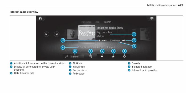
Internet radio overview
1 Additional information on the current station2 Display (if connected to private user
account)3 Data transfer rate
4 Options5 Favourites6 To start/end7 To browse
8 Search9 Selected categoryA Internet radio provider
MBUX multimedia system 429

Selecting and connecting Internet radio sta‐tionsMultimedia system:4© 5 Radio 5 TuneIn radio# Select=.# Select a category.# Select a station.
The connection is established automatically.or# Select the search field.# Enter a station name.% A relatively large volume of data can be
transmitted when using Internet radio.
Saving/deleting an Internet radio station asa favouriteMultimedia system:4© 5 Radio 5 TuneIn radio# Select a station.# Selectß.
The list of saved favourite stations appears.# Select Add to favourites.
or# Create an account for the online provider
(TuneIn radio) and then log in on the multi‐media system.Your favourites are imported to the multime‐dia system.
Deleting favourites# Select a station.# Selectß.# Select Delete favourite.
Setting Internet radio optionsMultimedia system:4© 5 Radio 5 TuneIn radio 5Z5 TuneInThe following options are available:R Select stream: select the stream quality.R Login to TuneIn account: log in to your
TuneIn user account.R Log out of account: log out of your TuneIn
user account.
# Select an option.
Showing the station list for the last categoryselectedMultimedia system:4© 5 Radio 5 TuneIn radio# Press the cover of the current station.
Depending on how the station was selected,a station list is shown.
MediaInformation about media mode
Information about supported formats anddata storage media
& WARNING Risk of distraction when han‐dling data storage media
If you handle a data storage medium whiledriving, your attention is diverted from thetraffic conditions. This could also cause youto lose control of the vehicle.# Only handle a data storage medium
when the vehicle is stationary.
430 MBUX multimedia system

The multimedia system supports the follow‐ing formats and data media:
Permissiblefile systems
FAT32, exFAT, NTFS
Permissibledata carriers
USB devices, iPod®/iPhone®,MTP devices, Bluetooth®audio equipment
Supportedaudio formats
MP3, WMA, AAC, WAV, FLAC,ALAC
Supportedvideo formats
MPEG, AVI, DivX, MKV, MP4,M4V, WMV
% Observe the following notes:R The multimedia system supports a total
of up to 50,000 files.R Data storage media up to 2 TB are sup‐
ported (32‑bit address space).R Due to the large variety of available
music and video files regarding encod‐ers, sampling rates and data transferrates, playback cannot be guaranteed.
R Due to the wide range of USB devicesavailable on the market, playback cannotbe guaranteed for all USB devices.R Videos up to FullHD (1920x1080) are
supported.R Copy-protected music and video files or
DRM (Digital Rights Management)encrypted files cannot be played back.R MP3 players must support Media Trans‐
fer Protocol (MTP).
Information on copyright protection andtrademarksAudio files which you create yourself (e.g. copiesof data storage media you make yourself) aregenerally subject to copyright protection. Inmany countries, reproductions are not permittedwithout the prior consent of the copyrightholder, even for private use. Make sure that youknow about the applicable copyright regulationsand that you comply with these.
Manufactured under license from Dolby Labora‐tories. Dolby, Dolby Audio and the double-D sym‐bol are trademarks of Dolby Laboratories.
MBUX multimedia system 431

Gracenote, the Gracenote logo and logotype,"Powered by Gracenote", MusicID and PlaylistPlus are either registered trademarks or trade‐marks of Gracenote, Inc. in the United Statesand/or other countries.
TIDAL and TIDAL logo are registered trademarkof Aspiro AB in the European Union and othercountries.
For DTS Patents, see http://patents.dts.com.Manufactured under license from DTS LicensingLimited. DTS, the Symbol, & DTS and the Symboltogether are registered trademarks, and DTS Tru‐Volume is a trademark of DTS, Inc.©. DTS, Inc.All rights reserved.
432 MBUX multimedia system

Overview of the media menu
1 Previous track or fast rewind2 Next track or fast forward3 Album cover4 Active media source5 Track and artist
6 Current track number/track in playback listand active data storage medium
7 Repeat8 Settings9 Additional options
A Controls playbackB TimelineC CategoriesD Music searchE Random playback
MBUX multimedia system 433

Connecting the data storage medium to themultimedia system
Connecting USB devices
* NOTE Damage caused by high tempera‐tures
High temperatures can damage USB devices.# Remove the USB device after use and
take it out of the vehicle.
The multimedia connection unit is found in thestowage compartment under the armrest andhas two type C USB ports. Depending on thevehicle's equipment, additional USB ports canbe found in the stowage compartment of thecentre console or rear folding compartment.# Connect the USB device to the USB port.% When connecting several Apple® devices
simultaneously, pay attention to the order in
which the devices are connected. The multi‐media system only connects with the devicethat is connected first. Additional Apple®devices that are connected at the same timeare only supplied with power.
Searching for and authorising a Bluetooth®audio device
Requirements:R Bluetooth® is activated on the multimedia
system and audio equipment.R The audio equipment supports the Blue‐
tooth® audio profiles A2DP and AVRCP.R The audio equipment is "visible" for other
devices.
Multimedia system:4© 5 Media 5 Bluetooth 5 ª
Authorising a new Bluetooth® audio device# Select Connect new device.
Detected equipment is displayed in thedevice list.
434 MBUX multimedia system

# Select an audio device.Authorisation starts. A code is displayed onthe multimedia system and on the mobilephone.
# If the codes are identical, confirm on theaudio equipment.
# Select Only as Bluetooth audio device.The Bluetooth® audio equipment is connec‐ted with the multimedia system.
Connecting previously authorised Bluetooth®audio equipment# Select a Bluetooth® audio device from the
list.The connection is established.
Starting media playback
Requirements:R A data storage medium is connected to the
multimedia system.
Multimedia system:4© 5 Media# Select USB or Bluetooth as the media
source.
Controlling media playback
Multimedia system:4© 5 Media# To pause playback: select8.# To continue playback: select6.# To repeat a track: select:.
For the repeat function there are the follow‐ing settings:R Select once: the active playlist is repea‐
ted.R Select twice: the current track is repea‐
ted.R Select three times: the repeat function
is deactivated.
# To play back tracks in random order:select9.
# To wind a track forwards or backwards:tap on the desired point on the timeline.
# To select the next track: select ü.# To select the previous track: select û.# To scroll through tracks quickly: press and
hold û or ü.# To show the current track list: select the
track image shown.
Additional options for setting media play‐back
Multimedia system:4© 5 Media
Calling up additional options# Selectß.
The additional options are shown.
The following options are available:R Play similar tracks
MBUX multimedia system 435

Select during playback of a track in order tocreate a playlist with similar tracks.R Surprise mix
A playlist with randomly selected tracks iscreated.R Add to favourite songs
The current track is added to the favouritesongs.R Delete from favourite songs
The current track is removed from the favour‐ite songs.
# Select an option.
Music online
Calling up music online
Requirements:R There is an account for the music streaming
service.R A subscription for the music streaming
service has been obtained.R The data volume is available.
Depending on the country, data volume mayneed to be purchased.R A fast Internet connection for data transmis‐
sion free of interference.
% The functions and services are country-dependent. For more information, consult aMercedes-Benz service centre.
Multimedia system:4© 5 Media# Select Online music.
With Online music you can listen to music viaa streaming service.
Music playback can be controlled with the TouchControl, the touchscreen, the touchpad or usingthe media application.
Searching for music in online musicMultimedia system:4© 5 Media 5 Online music
Searching for categories in online musicThe media content of the streaming provider canbe scanned through in the category search. The
available categories depend on the streamingprovider.# Select5.
The list of available categories appears.# Select a category.
Keyword search in online musicYou can look for content using the keywordsearch with free text input.# Selectª.
A keyboard for character entry appears.# Enter the term searched for.
% The search begins from the first three char‐acters entered. The more characters enteredthe more concrete the search resultsbecome.
# Select the desired entry from the result list.If the selected result is an album, song or aplayback list then playback is started. If theselected result is a new category then this isopened in the search.
436 MBUX multimedia system

Configuring online music optionsMultimedia system:4© 5 Media 5 Online music# During media playback, pressß in the
Media menu.Three options appear:R Adding the song to your own favourites.R Adding the song to a playback list.R The Title Radio option.
# Select one of the three options.% If Title Radio is selected, a playback list with
similar music tracks is created.The available options depend on what isoffered by the provider of the streamingservice.
Media search
Notes about the search function in catego‐riesUnder5 you can search through all availablemedia files. There are several categories availa‐
ble for selection. The categories shown dependon the connected device and data format.
Available categories with Bluetooth® audio:R Current tracklist
The folders and categories of the connecteddevice are shown.
Available categories with audio files:R Current tracklistR PlaylistsR FolderR AlbumsR ArtistsR TracksR Favourite songsR Frequently playedR Most recently addedR Mood (/ page 438)R Music genresR YearR Composers
R Select by coverR Podcasts (Apple® devices)R Audiobooks (Apple® devices)
Available categories with video files:R FolderR Videos
% The categories are available as soon as theentire media content has been read in andanalysed.
Starting a search in categoriesMultimedia system:4© 5 Media 55
# Select a category.# Selectª and enter a search term.
Sorting results shown or playing back allmedia found# Select Ä.
MBUX multimedia system 437

# To play back all results found in the cate‐gory: select Play all.If, for example, the Albums category isactive, all albums found by the desired artistwill be played back.
# To sort results alphabetically: select Sortfrom A-Z.
# To sort results in reverse alphabeticalorder: select Sort from Z-A.
% The available options depend on the selec‐ted category and the connected device.
Using the keyword searchMultimedia system:4© 5 MediaYou can look for content using the keywordsearch with free text input.# Selectª.
A keyboard for character entry appears.# Enter the term searched for.
% The search begins with the first characterentered. The more characters entered themore concrete the search results become.
# Select the desired entry from the result list.If the selected result is an album, song or aplayback list then playback is started. If theselected result is a new category then this isopened in the search.
Searching for a track according to moodMultimedia system:4© 5 Media 55
By searching in categories, you can find musictracks suitable for a mood.# Select Mood.
A grid with the following moods appears:R PositiveR CalmR DarkR Energetic
# Pull the controller to the desired position.The system searches for tracks that are suit‐able for the mood entered.
Making video settings
Multimedia system:4© 5 Media 5Z 5 General# Select Video settings.# Select an aspect ratio.
Setting full screen# SelectG.
RadioSwitching on the radio
Multimedia system:4© 5 Radio# Alternatively: press the| button.
The radio display appears. You will hear thelast station played on the last frequencyband selected.
438 MBUX multimedia system

Radio overview
1 Active frequency band2 Station name or set frequency3 Artist, title, album and radio text
4 Options5 Full screen/DAB slideshow6 Mute function
7 Station list8 Search
MBUX multimedia system 439
Setting the frequency band
Multimedia system:4© 5 Radio# Select a frequency band.
Selecting a radio station
Multimedia system:4© 5 Radio# Swipe to the left or right on the control ele‐
ment.
Calling up the radio station list
Multimedia system:4© 5 Radio#
Select .The station list appears.
# Select a station.
Searching for radio stations using stationnames or frequency entry
Multimedia system:4© 5 Radio# Selectè.# Enter a station name or frequency.# Select a station.
Storing radio stations
Multimedia system:4© 5 Radio# Select a radio station.
Memory slots are available in station presets# Selectf.or# Press and hold on the radio station.
Replacing an entry in the station presets# Press and hold on an entry in the station pre‐
sets.# Select Yes.
Editing station presets
Multimedia system:4© 5Þ Radio
Moving stations# Press and hold a stored station.# Select Move.# Move the station to the new position.
Deleting channels# Press and hold a station.# Select Delete.
Replacing a station# Press and hold a station.# Select Replace radio station.
Calling up a slide show (FM/DAB radio mode)
Multimedia system:4© 5 RadioThe slide show displays additional informationprovided by the station as an image. This can
440 MBUX multimedia system

include logos, album covers, music tracks, pro‐grammes, news or service information, for exam‐ple.# Select#.
Activating/deactivating the frequency fixfunction
Multimedia system:4© 5 Radio 5Z
# Switch Frequency fix on or off.If the function is activated, the set frequencyis kept even if the reception is poor.
Activating/deactivating traffic announce‐ments
Multimedia system:4© 5 Radio 5Z
# Switch Traffic announcements on or off.
Setting the traffic information service vol‐ume increase
Multimedia system:4© 5 Radio 5Z 5 Sound# Select Navigation and traffic announce-
ments.# Set a value for Traffic announc. vol. increase.# Set a value.# Accept the value withq.
Displaying radio text
Multimedia system:4© 5 Radio 5Z
# Switch Display radio text information on oroff.
SoundTone settings
Information about the sound systemThe sound system has a total output of 100 Wand is equipped with six speakers. It is availablefor all functions in the radio and media modes.
Calling up the sound menuMultimedia system:4© 5 Media 5Z 5 SoundThe following functions are available:R EqualiserR Balance and FaderR Volume# Select a function.
Adjusting treble, mid-range and bass set‐tingsMultimedia system:4© 5 Media 5Z 5 Sound5 Equaliser# Set TREBLE, MID or BASS.
MBUX multimedia system 441

Activating/deactivating automatic volumeadjustmentMultimedia system:4© 5 Media 5Z 5 Sound5 VolumeAutomatic volume adjustment compensates fordiffering volumes when changing between audiosources and within an audio source.# Switch Automatic adjustment on or off.
Adjusting the balance/faderMultimedia system:4© 5 Media 5Z 5 Sound5 Balance and Fader
Adjusting the balance# Move the volume distribution between the
right and left sides of the vehicle in the gridshown.The volume is distributed between the speak‐ers on the left and right sides in the vehicle.
Adjusting the fader# Move the volume distribution between the
front and rear of the vehicle in the gridshown.The volume is distributed between the speak‐ers in the front and rear of the vehicle.
Burmester® surround sound system
Information about the Burmester® surroundsound systemThe Burmester® surround sound system has atotal output of 590 W and is equipped with 12speakers. It is available for all functions in theradio and media modes.
Calling up the sound menu in theBurmester® surround sound systemMultimedia system:4© 5 Media 5Z 5 BurmesterThe following functions are available:R EqualiserR Balance and FaderR Sound focus
R Sound profilesR Volume# Select a function.
Adjusting the treble, mid and bass settingson the Burmester® surround sound systemMultimedia system:4© 5 Media 5Z 5 Burmester5 Equaliser# Set TREBLE, MID or BASS.
Activating/deactivating volume adjustmentin the Burmester® surround sound systemMultimedia system:4© 5 Media 5Z 5 Burmester5 VolumeAutomatic volume adjustment compensates fordiffering volumes when changing between audiosources and within an audio source.# Switch Automatic adjustment on or off.
442 MBUX multimedia system

Adjusting the balance/fader in theBurmester® surround sound systemMultimedia system:4© 5 Media 5Z 5 Burmester5 Balance and Fader
Adjusting the balance# Move the volume distribution between the
right and left sides of the vehicle in the gridshown.The volume is distributed between the speak‐ers on the left and right sides in the vehicle.
Adjusting the fader# Move the volume distribution between the
front and rear of the vehicle in the gridshown.The volume is distributed between the speak‐ers in the front and rear of the vehicle.
Selecting a sound profile in the Burmester®surround sound systemMultimedia system:4© 5 Media 5Z 5 Burmester5 Sound profilesThe following profiles are available:R PureR Surround# Select a sound profile.
Adjusting the sound focus in the Burmester®surround sound systemMultimedia system:4© 5 Media 5Z 5 Burmester5 Sound focus# Select a position for the sound focus or All
seats.
Advanced sound system
Information about the Advanced sound sys‐temThe Advanced sound system has a total outputof 225 W and is equipped with ten speakers. It isavailable for all functions in the radio and mediamodes.
Calling up the sound menu in the Advancedsound systemMultimedia system:4© 5 Media 5Z 5 SoundThe following functions are available:R EqualiserR Balance and FaderR Volume# Select a function.
MBUX multimedia system 443

Adjusting treble, mid-range and bass set‐tings in the Advanced sound systemMultimedia system:4© 5 Media 5Z 5 Sound5 Equaliser# Set TREBLE, MID or BASS.
Switching volume adjustment in theAdvanced sound system on/offMultimedia system:4© 5 Media 5Z 5 Sound5 VolumeAutomatic volume adjustment compensates fordiffering volumes when changing between audiosources and within an audio source.# Switch Automatic adjustment on or off.
Setting the balance/fader in the Advancedsound systemMultimedia system:4© 5 Media 5Z 5 Sound5 Balance and Fader
Adjusting the balance# Move the volume distribution between the
right and left sides of the vehicle in the gridshown.The volume is distributed between the speak‐ers on the left and right sides in the vehicle.
Adjusting the fader# Move the volume distribution between the
front and rear of the vehicle in the gridshown.The volume is distributed between the speak‐ers in the front and rear of the vehicle.
444 MBUX multimedia system

ASSYST PLUS service interval displayFunction of the ASSYST PLUS service intervaldisplay
The ASSYST PLUS service interval display on theinstrument display provides information on theremaining time or distance before the nextservice due date.You can hide this service display using the backbutton on the left-hand side of the steeringwheel.Depending on how the vehicle is used, theASSYST PLUS service interval display mayshorten the service interval, e.g. in the followingcases:R mainly short-distance drivingR when the engine is often left idling for long
periodsR in the event of frequent cold start phasesR vehicles with a diesel particulate filter: in
the event of frequently interrupted regenera‐tion of the diesel particulate filter
Mercedes-Benz recommends avoiding suchoperating conditions.You can obtain information concerning the serv‐icing of your vehicle from a qualified specialistworkshop, e.g. a Mercedes-Benz Service Centre.
Displaying the service due date
On-board computer:4 Service 5 ASSYST PLUSThe next service due date is displayed.# To exit the display: press the back button
on the left-hand side of the steering wheel.Make sure to observe the following further rela‐ted subject:R Operating the on-board computer
(/ page 260).
Information on regular maintenance work
* NOTE Premature wear through failure toobserve service due dates
Service work which is not carried out at theright time or incompletely can lead toincreased wear and damage to the vehicle.# Always observe the prescribed service
intervals.# Always have the prescribed service
work carried out at a qualified specialistworkshop.
Special service requirements
The prescribed service interval is based on nor‐mal operation of the vehicle. Maintenance workwill need to be performed more often if the vehi‐cle is operated under arduous conditions orincreased loads.The ASSYST PLUS service interval display is onlyan aid. The driver of the vehicle bears responsi‐bility as regards to whether maintenance workneeds to be performed more often than speci‐
Maintenance and care 445

fied based on the actual operating conditionsand/or loads.Examples of arduous operating conditions:R regular city driving with frequent intermedi‐
ate stopsR mainly short-distance drivingR frequent operation in mountainous terrain or
on poor road surfacesR when the engine is often left idling for long
periodsR operation in particularly dusty conditions
and/or if air-recirculation mode is frequentlyused
In these or similar operating conditions, have theinterior air filter, engine air cleaner, engine oiland oil filter etc. changed more frequently. Thetyres must be checked more frequently if thevehicle is operated under increased loads. Fur‐ther information can be obtained at a qualifiedspecialist workshop.
Battery disconnection periods
The ASSYST PLUS service interval displaycan only calculate the service due date whenthe battery is connected.# Note down the service due date displayed on
the instrument display before disconnectingthe battery (/ page 445).
Engine compartmentActive bonnet (pedestrian protection)
Operation of the active bonnet (pedestrianprotection)In certain accident situations, the risk of injuryto pedestrians can be reduced by the actuationof the active bonnet. The rear area of the enginebonnet is raised by approximately 70 mm.For the drive to the workshop, reset the trig‐gered active bonnet yourself. After the activebonnet has been triggered, pedestrian protectionmay be limited.A qualified specialist workshop must re-instatethe full functionality of the active bonnet.
The active bonnet is not available in all coun‐tries.
Resetting the active bonnet
& WARNING Risk of burns from hot com‐ponent parts in the engine compartment
Certain components in the engine compart‐ment can be very hot, e.g. the engine, theradiator and parts of the exhaust system.# Allow the engine to cool down and only
touch component parts described inthe following.
446 Maintenance and care

# With your hand flat, push down active bonnet1 in the area around the hinges on bothsides (arrows).In doing so, the actuator is depressurisedand you may hear a hissing sound.The engine bonnet must engage in position.
# If active bonnet1 can be raised slightly atthe rear in the area of the hinges, repeat thestep until it engages correctly.
Opening/closing the bonnet
& WARNING Risk of accident due to driv‐ing with the engine bonnet unlocked
An unlocked engine bonnet may open upwhen the vehicle is in motion and block yourview.# Never unlock the engine bonnet when
driving.# Before every trip, ensure that the
engine bonnet is locked.
& WARNING Risk of accident and injurywhen opening and closing the enginebonnet
When opening or closing the engine bonnet,it may suddenly drop into the end position.There is a risk of injury for anyone in theengine bonnet's range of movement.# Only open or close the engine bonnet
when there are no persons in theengine bonnet's range of movement.
& WARNING Danger of burns when open‐ing the bonnet
If you open the engine bonnet when theengine has overheated or during a fire in theengine compartment, you could come intocontact with hot gases or other escapingoperating fluids.# Before opening the bonnet, allow the
engine to cool down.
# In the event of a fire in the engine com‐partment, keep the engine bonnetclosed and call the fire service.
& WARNING Risk of injury due to movingparts
Certain components in the engine compart‐ment may continue to move or suddenlymove again even after the ignition has beenswitched off, e.g. the cooler fan.Make sure of the following before performingtasks in the engine compartment:# Switch the ignition off.# Never touch the danger zone surround‐
ing moving component parts, e.g. therotation area of the fan.
# Remove jewellery and watches.# Keep items of clothing and hair away
from moving parts.
Maintenance and care 447

& WARNING Risk of injury from touchingcomponent parts under voltage
The ignition system and the fuel injectionsystem work under high voltage. If you touchcomponent parts which are under voltage,you could receive an electric shock.# Never touch components of the ignition
system or the fuel injection systemwhen the ignition is switched on.
& WARNING Risk of burns from hot com‐ponent parts in the engine compartment
Certain components in the engine compart‐ment can be very hot, e.g. the engine, theradiator and parts of the exhaust system.# Allow the engine to cool down and only
touch component parts described inthe following.
& WARNING Risk of injury from using thewindscreen wipers while the engine bon‐net is open
When the engine bonnet is open, and thewindscreen wipers are set in motion, you canbe trapped by the wiper linkage.# Always switch off the windscreen wip‐
ers and ignition before opening theengine bonnet.
# To open: pull lever1 to release the bonnet.
448 Maintenance and care

# Push yellow handle1 on the bonnet catchto the left as far as it will go (palm down‐wards). Lift the bonnet until it is automati‐cally raised by the pneumatic strut.
# To close: lower the bonnet and let it fall froma height of approximately 20 cm.
# If the bonnet can still be lifted slightly, openthe bonnet again and close it with a littleforce until it engages correctly.
Engine oil
Checking the engine oil level using the on-board computer
Requirements:The engine oil level is determined during driving.Determining the engine oil level can take up to30 minutes with a normal driving style and evenlonger with an active driving style.In order to receive a result as quickly as possi‐ble:R warm up the engineR park the vehicle on a level surfaceR leave the engine running at idling speed
On-board computer:4 Service 5 Engine oil levelYou will see one of the following messages onthe multifunction display:R Engine oil level Measuring now: measure‐
ment of the oil level is not yet possible.
# Repeat the request after a maximum of30 minutes driving.
R Engine oil level OK and the bar display forindicating the oil level on the multifunctiondisplay is green and is between "min" and"max": the oil level is correct.
R Engine oil level Add 1,0 l and the bar displayfor indicating the oil level on the multifunc‐tion display is orange and is below "min":
# Top up with 1 l engine oil.R Reduce engine oil level and the bar display
for indicating the oil level on the multifunc‐tion display is orange and is above "max":
# Drain off excess engine oil that has beenadded. Consult a qualified specialist work‐shop.R For engine oil level turn on ignition:# switch on the ignition to check the engine oil
level.R Engine oil level System inoperative: sensor
faulty or not inserted.
# Consult a qualified specialist workshop.R Engine oil level System currently unavail.:
Maintenance and care 449

# close the bonnet.
Topping up engine oil
& WARNING Risk of burns from hot com‐ponent parts in the engine compartment
Certain components in the engine compart‐ment can be very hot, e.g. the engine, theradiator and parts of the exhaust system.# Allow the engine to cool down and only
touch component parts described inthe following.
& WARNING Risk of fire and injury fromengine oil
If engine oil comes into contact with hotcomponent parts in the engine compart‐ment, it may ignite.# Make sure that no engine oil is spilled
next to the filler opening.# Allow the engine to cool off and thor‐
oughly clean the engine oil from compo‐nent parts before starting the vehicle.
* NOTE Engine damage caused by anincorrect oil filter, incorrect oil or addi‐tives
# Do not use engine oils or oil filterswhich do not correspond to the specifi‐cations explicitly prescribed for theservice intervals.
# Do not alter the engine oil or oil filter inorder to achieve longer change intervalsthan prescribed.
# Do not use additives.# Follow the instructions in the service
interval display regarding the oilchange.
* NOTE Damage caused by topping up toomuch engine oil
Too much engine oil can damage the engineor the catalytic converter.# Have excess engine oil removed at a
qualified specialist workshop.
# Turn cap1 anti-clockwise and remove it.# Top up the engine oil.# Replace cap1 and turn it clockwise as far
as it will go.# Check the oil level again (/ page 449).
450 Maintenance and care

Checking the coolant level
& WARNING Risk of burns from hot com‐ponent parts in the engine compartment
Certain components in the engine compart‐ment can be very hot, e.g. the engine, theradiator and parts of the exhaust system.# Allow the engine to cool down and only
touch component parts described inthe following.
& WARNING Risk of scalding from hotcoolant
The engine cooling system is pressurised,particularly when the engine is warm. If youopen the cap, you could be scalded by hotcoolant spraying out.# Let the engine cool down before open‐
ing the cap.# When opening the cap, wear protective
gloves and safety glasses.# Open the cap slowly to release pres‐
sure.
# Park the vehicle on a level surface.# Check the coolant temperature display in the
instrument cluster.The coolant temperature must be below70 °C.
# Slowly turn cap1 anti-clockwise to releaseoverpressure.
# Continue turning cap1 anti-clockwise andremove it.
The coolant level is correct in the followingcases:R if the engine is cold, the coolant is up to
marker bar2.R if the engine is warm, the coolant is up to
1.5 cm over the marker bar2.
# If necessary, top up with coolant that hasbeen approved for Mercedes-Benz.R Further information on coolant
(/ page 521).
Topping up the windscreen washer system
& WARNING Risk of burns from hot com‐ponent parts in the engine compartment
Certain components in the engine compart‐ment can be very hot, e.g. the engine, theradiator and parts of the exhaust system.
Maintenance and care 451

# Allow the engine to cool down and onlytouch component parts described inthe following.
& WARNING Danger of burns when open‐ing the bonnet
If you open the engine bonnet when theengine has overheated or during a fire in theengine compartment, you could come intocontact with hot gases or other escapingoperating fluids.# Before opening the bonnet, allow the
engine to cool down.# In the event of a fire in the engine com‐
partment, keep the engine bonnetclosed and call the fire service.
& WARNING ‑ Risk of fire and injury due towindscreen washer concentrate
Windscreen washer concentrate is highlyflammable. It could ignite if it comes intocontact with hot engine component parts orthe exhaust system.
# Make sure that no windscreen washerconcentrate spills out next to the filleropening.
# Remove the cap1 by the tab.# Top up the washer fluid.
Keeping the air-water duct free
# Keep the area between the bonnet and thewindscreen free of deposits, e.g. ice, snowand leaves.
Cleaning and careInformation on washing the vehicle in a carwash
& WARNING Risk of an accident due toreduced braking power after washing thevehicle
Braking efficiency is reduced after washingthe vehicle.# After the vehicle has been washed,
brake carefully while paying attention tothe traffic conditions until brakingpower has been fully restored.
452 Maintenance and care

* NOTE Damage due to unsuitable carwash
# Before driving into a car wash makesure that the car wash is suitable forthe vehicle dimensions.
# Ensure there is sufficient ground clear‐ance between the underbody and theguide rails of the car wash.
# Ensure that the clearance width of thecar wash, in particular the width of theguide rails, is sufficient.
To avoid damage to your vehicle when using acar wash, ensure the following beforehand:R Active Distance Assist DISTRONIC and the
HOLD function are deactivated.R the 360° Camera or the reversing camera is
switched off.R the side windows and sliding sunroof are
completely closed.R the blower for the ventilation/heating is
switched off.
R the windscreen wiper switch is in positiong.R in car washes with a conveyor system: neu‐
trali is engaged.R the key is at a minimum distance of 3 m
away from the vehicle, otherwise the boot lidcould open unintentionally.
% If you would like to leave the vehicle while itis being washed, make sure the key is loca‐ted in the vehicle. Thej gear is otherwiseautomatically engaged.
% If, after the car wash, you remove the waxfrom the windscreen and wiper rubbers, thiswill prevent smearing and reduce wipernoise.
Activating/deactivating automatic car washmode
Requirements:R the vehicle is stationaryR the engine is running.
Multimedia system:4© 5 Settings5 Schnellzugriff (Quick access)
Activating automatic car wash mode# Select Automatic car wash mode.# Select Start.
If one of the settings cannot be selected, this isdisplayed by a% behind the respective set‐ting.% For an overview of the settings made when
activating automatic car wash mode(/ page 452).
Deactivating automatic car wash mode# Select Stop.
The automatic car wash settings are reset.% The automatic car wash mode is automati‐
cally deactivated as soon as a speed of10 km/h is exceeded.
Maintenance and care 453

Information on using a high-pressure cleaner
& WARNING Risk of an accident whenusing high-pressure cleaners with circu‐lar jet nozzles
The water jet of a circular jet nozzle (dirtgrinder) can cause externally invisible dam‐age to the tyres or chassis parts.Components damaged in this way may unex‐pectedly fail.# Do not use high-pressure cleaners with
circular jet nozzles to clean the vehicle.# Have damaged tyres or chassis parts
replaced immediately.
To avoid damage to your vehicle, observe the fol‐lowing when using a high-pressure cleaner:R keep the key at least 3 m away from the vehi‐
cle. Otherwise the boot lid could open unin‐tentionally.
R maintain a distance of at least 30 cm to thevehicle.R vehicles with decorative foil: parts of your
vehicle are covered with a decorative foil.Maintain a distance of at least 70 cmbetween the foil-covered parts of the vehicleand the nozzle of the high-pressure cleaner.Move the high-pressure cleaner nozzlearound whilst cleaning. The water tempera‐ture of the high-pressure cleaner must notexceed 60 °C.R observe the information on the correct dis‐
tance in the equipment manufacturer's oper‐ating instructions.R do not point the nozzle of the high-pressure
cleaner directly at sensitive parts such astyres, slits, electrical components, batteries,light bulbs and ventilation slots.
Washing the vehicle by hand
Observe the legal requirements, e.g. in a numberof countries, washing by hand is only permittedin specially designated wash bays.# Use a mild cleaning agent, e.g. car shampoo.# Wash the vehicle with lukewarm water using
a soft car sponge. When doing so, do notexpose the vehicle to direct sunlight.
# Carefully hose the vehicle off with water anddry using a chamois. Take care not to pointthe water jet directly towards the air inletgrille below the bonnet.
454 Maintenance and care

Notes on paintwork/matt finish paintwork care
Observe the following information:
Cleaning and care Avoiding paintwork damage
Paintwork R Insect remains: soak with insect remover and rinse off thetreated areas afterwards.R Bird droppings: soak with water and rinse off afterwards.R Tree resin, oils, fuels and greases: remove by rubbing gen‐
tly with a cloth soaked in petroleum ether or lighter fluid.R Coolant and brake fluid: remove with a damp cloth and
clean water.R Tar stains: use tar remover.R Wax: use silicone remover.
R Do not attach stickers, films or similar.R Remove dirt immediately, where possible.
Maintenance and care 455
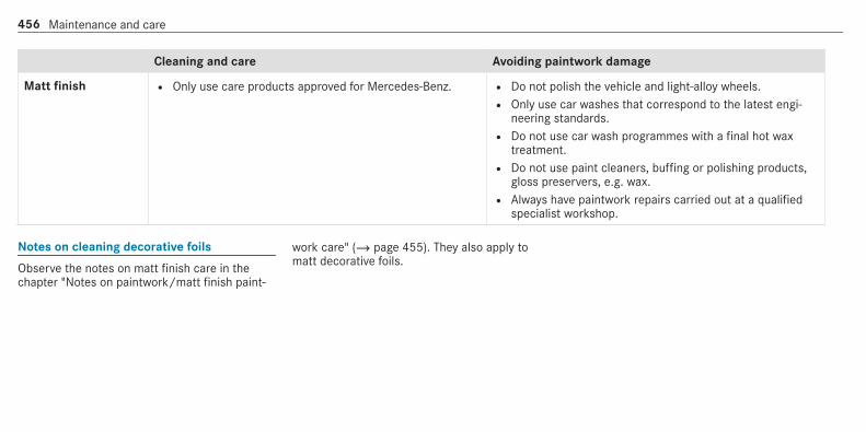
Cleaning and care Avoiding paintwork damage
Matt finish R Only use care products approved for Mercedes-Benz. R Do not polish the vehicle and light-alloy wheels.R Only use car washes that correspond to the latest engi‐
neering standards.R Do not use car wash programmes with a final hot wax
treatment.R Do not use paint cleaners, buffing or polishing products,
gloss preservers, e.g. wax.R Always have paintwork repairs carried out at a qualified
specialist workshop.
Notes on cleaning decorative foils
Observe the notes on matt finish care in thechapter "Notes on paintwork/matt finish paint‐
work care" (/ page 455). They also apply tomatt decorative foils.
456 Maintenance and care

Observe the following information:
Cleaning Avoiding damage to the decorative foil
R For cleaning, use plenty of water and a mild cleaning agent withoutadditives or abrasive substances, e.g. a car shampoo approved forMercedes-Benz.R Remove dirt immediately, where possible, whilst avoiding rubbing
too hard. There is otherwise a risk of damaging the decorative foilirreparably.R If there is dirt on the finish or if the decorative foil is dull: use the
Paint Cleaner recommended and approved for Mercedes-Benz.R Insect remains: soak with insect remover and rinse off the treated
areas afterwards.R Bird droppings: soak with water and rinse off afterwards.R To prevent water stains, dry a foil-wrapped vehicle with a soft,
absorbent cloth after every car wash.
R The service life and colouring of decorative foils are impaired by:- sunlight- temperature, e.g. hot air blower- weather conditions- stone chippings and dirt- chemical cleaning agents- oily productsR Do not use polish on matt decorative foil. Polishing will have the effect of
shining the foil-wrapped surface.R Do not treat matt or structured decorative foils with wax. Permanent
stains may occur.
Scratches, corrosive deposits, areas affected bycorrosion and damage caused by incorrect carecannot always be completely repaired. In suchcases, visit a qualified specialist workshop.You can obtain more information on care andcleaning products from the manufacturer.
In the case of foil-wrapped surfaces, optical dif‐ferences may occur between the surfaces thatwere not protected by a decorative foil afterremoving a decorative foil.
% Have work or repairs to decorative foils car‐ried out at a qualified specialist workshop,e.g. in a Mercedes-Benz Service Centre.
Maintenance and care 457

Notes on care of car parts
& WARNING Risk of entrapment if thewindscreen wipers are switched on whilethe windscreen is being cleaned
If the windscreen wipers are set in motionwhile you are cleaning the windscreen orwiper blades, you can be trapped by thewiper arm.
# Always switch off the windscreen wip‐ers and the ignition before cleaning thewindscreen or wiper blades.
& WARNING Risk of burning from the tail‐pipe or tailpipe trim
The tailpipe and tailpipe trim can becomevery hot. If you come into contact with thesecar parts, you could burn yourself.
# Always be particularly careful when inthe vicinity of the tailpipe and tailpipetrims and supervise children veryclosely when in this area.
# Before any contact, allow the car partsto cool down.
Observe the following information:
Notes on cleaning and care Avoiding vehicle damage
Wheels/rims Use water and acid-free wheel cleaners. R Do not use acidic wheel cleaners to remove brake dust.This could damage wheel bolts and brake components.R To avoid corrosion of the brake discs and brakepads, drive
the vehicle for a few minutes after cleaning before parkingit. The brake discs and brakepads warm up and dry out.
Windows Clean windows inside and outside with a damp cloth and witha cleaning agent recommended for Mercedes-Benz.
Do not use dry cloths or abrasive or solvent-based cleaningagents to clean the inside of windows.
Wiper blades Fold out the wiper blades and clean them using a damp cloth. Do not clean the wiper blades too often.
458 Maintenance and care

Notes on cleaning and care Avoiding vehicle damage
Exterior lighting Clean the lenses with a wet sponge and mild cleaning agent,e.g. car shampoo.
Only use cleaning agents or cleaning cloths that are suitablefor plastic lenses.
Sensors Clean the sensors in the front and rear bumper and in theradiator grille with a soft cloth and car shampoo.
When using a high-pressure cleaner, maintain a minimum dis‐tance of 30 cm.
Reversing cameraand 360° Camera
R Open the camera cover with the multimedia system(/ page 234) .R Use clean water and a soft cloth to clean the camera lens.
Do not use a high-pressure cleaner.
Tailpipes Clean with a cleaning agent recommended for Mercedes-Benz, especially in the winter and after washing the vehicle.
Do not use acidic cleaning agents.
Trailer hitch R Remove traces of rust on the ball, e.g. with a wire brush.R Remove dirt with a lint-free cloth.R After cleaning, oil or grease the ball head lightly.R Observe the notes on care in the trailer hitch manufactur‐
er's operating instructions.
Do not clean the ball neck with a high-pressure cleaner or sol‐vent.
Maintenance and care 459

Notes on care of the interior
& WARNING Risk of injury from plasticparts breaking off after the use of sol‐vent-based care products
Care and cleaning products containing sol‐vents can cause surfaces in the cockpit tobecome porous.
When the airbags are deployed, plastic partsmay break away.# Do not use any care or cleaning prod‐
ucts containing solvents to clean thecockpit.
& WARNING Risk of injury or death frombleached seat belts
Bleaching or dyeing seat belts can severelyweaken them.This can, for example, cause seat belts totear or fail in an accident.# Never bleach or dye seat belts.
Observe the following information:
Cleaning and care Avoiding vehicle damage
Seat belts Clean with lukewarm and soapy water. R Do not use chemical cleaning agents.R Do not dry seat belts by heating them to over 80 °C or
exposing them to direct sunlight.
Display Clean the surface carefully with a microfibre cloth and a suit‐able display care product (TFT/LCD).
R Switch off the display and let it cool down.R Do not use any other cleaning products.
Plastic trim R Clean with a damp microfibre cloth.R For heavy soiling: use care product recommended for
Mercedes-Benz.
R Do not attach stickers, films or similar materials.R Do not allow cosmetics, insect repellent or sun cream to
come in contact with the plastic trim.
460 Maintenance and care

Cleaning and care Avoiding vehicle damage
Real wood/triminserts
R Clean with a microfibre cloth.R Black piano-lacquer look: clean with a damp cloth and
soapy water.R For heavy soiling: use care product recommended for
Mercedes-Benz.
Do not use solvent-based cleaning agents, polishes or waxes.
Roof lining Clean with a brush or dry shampoo.
Carpet Use carpet and textile cleaning agents recommended forMercedes-Benz.
Genuine leatherseat covers
R Clean with a damp cloth and then wipe with a dry cloth.R Leather care: use leather care agents that have been rec‐
ommended for Mercedes-Benz.
R Do not allow the leather to become too damp.R Do not use a microfibre cloth.
DINAMICA seat cov‐ers
Clean with a damp cloth. Do not use a microfibre cloth.
Imitation leatherseat covers
Clean with a damp cloth and 1% soapy water. Do not use a microfibre cloth.
Cloth seat covers Clean with a damp microfibre cloth and 1% soapy water andallow to dry.
Maintenance and care 461

EmergencyRemoving the safety vest
The safety vests are located in the safety vestcompartments in the driver's and frontpassenger door stowage compartments.
# To remove: pull out safety vest bag1 byloop2.
# Open safety vest bag1 and pull out thesafety vest.
% There are also safety vest compartments inthe rear door stowage compartments inwhich safety vests can be stored.
1 Maximum number of washes2 Maximum wash temperature3 Do not bleach4 Do not iron5 Do not tumble dry6 Do not dry clean7 Class 2 safety vest
The requirements defined by the legal standardare only fulfilled if the safety vest is the correctsize and is fully closed.The safety vest must be replaced in the followingsituations:R the reflective strips are damaged or dirtyR the maximum permissible number of washes
is exceededR the fluorescence has faded
462 Breakdown assistance

Warning triangle
Removing the warning triangle
# Push both sides of warning triangle holder1 in the direction of the arrow and open it.
# Remove warning triangle2.
Setting up the warning triangle
# Fold side reflectors1 upwards to form a tri‐angle and attach at the top using upperpress-stud2.
# Fold legs3 down and out to the side.
First-aid kit (soft-sided) overview
First-aid kit (soft sided)1 is in the boot in theleft-hand stowage net.
Breakdown assistance 463

Removing the fire extinguisher
& WARNING Risk of accident due to anincorrectly secured fire extinguisher inthe driver's footwell
A fire extinguisher in the driver's footwellmay impede pedal travel or block adepressed pedal.This jeopardises the operating and roadsafety of the vehicle.Moreover, the fire extinguisher can be flungaround in the driver's footwell and injure thedriver or other vehicle occupants.# Always store and secure the fire extin‐
guisher in the bracket during the jour‐ney.
# Do not remove the fire extinguisherwhile driving.
# Left-hand drive vehicle: pull tab1upwards.
# Remove fire extinguisher2.
Flat tyreNotes on flat tyres
& WARNING Risk of accident due to a flattyre
A flat tyre severely affects the driving charac‐teristics as well as the steering and brakingof the vehicle.
Tyres without run-flat characteristics:# Do not drive on with a flat tyre.# Change the flat tyre immediately with
an emergency spare wheel or sparewheel. Alternatively, consult a qualifiedspecialist workshop.
Tyres with run-flat characteristics:# Observe the information and warning
notes on MOExtended tyres (run-flattyres).
In the event of a flat tyre, the following optionsare available depending on your vehicle's equip‐ment:R Vehicles with MOExtended tyres: it is pos‐
sible to continue the journey for a shortperiod of time. Make sure you observe thenotes on MOExtended tyres (run-flat tyres)(/ page 465).R Vehicles with a TIREFIT kit: you can repair
the tyre so that it is possible to continue thejourney for a short period of time. To do this,use the TIREFIT kit (/ page 466).
464 Breakdown assistance

R Vehicles with Mercedes me connect: youcan make a call for breakdown assistance viathe overhead control panel in the case of abreakdown .R All vehicles: change the wheel
(/ page 500).
% The emergency spare wheel is only availablein certain countries.
Notes on MOExtended tyres (run-flat tyres)
& WARNING Risk of accident when drivingin emergency mode
When driving in emergency mode, the han‐dling characteristics are impaired. e.g. whencornering, when accelerating strongly andwhen braking.# Do not exceed the permissible maxi‐
mum speed.# Avoid any abrupt steering and driving
maneuvers as well as driving overobstacles (curbs, pot holes, off-road).
This applies, in particular, to a loadedvehicle.
# Stop driving in the emergency mode ifyou notice:R banging noiseR vehicle vibrationR smoke which smells like rubberR continuous ESP® interventionR cracks in tire side walls
# After driving in emergency mode havethe rims checked by a qualified special‐ist workshop with regard to their furtheruse.
# The defective tire must be replaced inevery case.
With MOExtended tyres (run-flat tyres), you cancontinue to drive your vehicle even if there is atotal loss of pressure in one or more tyres. How‐ever, the tyre affected must not show any clearlyvisible damage.
You can recognise MOExtended tyres by theMOExtended marking which appears on the sidewall of the tyre.Vehicles with tyre pressure loss warning sys‐tem: MOExtended tyres may only be used inconjunction with an activated tyre pressure losswarning system.Vehicles with tyre pressure monitoring sys‐tem: MOExtended tyres may only be used inconjunction with an activated tyre pressure mon‐itoring system.If a pressure loss warning message appears inthe multifunction display, proceed as follows:R Check the tyre for damage.R If driving on, observe the following notes.
Breakdown assistance 465

Driving distance possible in emergencymode after the pressure loss warning:
Load condition Driving distance pos‐sible in emergency
mode
Partially laden 80 km
Fully laden 30 km
The driving distance possible in emergencymode may vary depending on the driving style.Observe the maximum permissible speed of80 km/h.If a tyre has gone flat and cannot be replacedwith an MOExtended tyre, you can use a stand‐ard tyre as a temporary measure.
TIREFIT kit storage location
The TIREFIT kit is located under the boot floor.
1 Tyre sealant bottle2 Tyre inflation compressor
% You can find information on the power cate‐gory (LK) and/or electrical data on the backof the tyre inflation compressor:R LK2 – 12 V/15 A, 180 W, 0.8 kg
At a distance of approximately 1 m to thetyre inflation compressor and approximately1.6 m above the ground, the following soundpressure levels apply:R Emissions sound pressure level
LPA 83 dB (A)
R Sound power level LWA 91 dB (A)
The tyre inflation compressor is mainte‐nance-free. If there is a malfunction, pleasecontact a qualified specialist workshop.
Using the TIREFIT kit
Requirements:R Tyre sealant bottleR TIREFIT stickerR Tyre inflation compressorR Gloves (depending on the vehicle equipment)
TIREFIT kit storage location: (/ page 466)You can use TIREFIT tyre sealant to seal perfora‐tion damage of up to 4 mm, particularly those inthe tyre contact surface. You can use TIREFIT inoutside temperatures down to -20 °C.
& WARNING Risk of accident when usingtyre sealant
In the following situations in particular, thetyre sealant is unable to provide sufficient
466 Breakdown assistance

breakdown assistance, as it is unable to sealthe tyre properly:R there are cuts or punctures in the tyre
larger than those previously mentioned.R the wheel rim is damaged.R you have driven at very low tyre pres‐
sures or on a flat tyre.
# Do not drive on.# Consult a qualified specialist workshop.
& WARNING Risk of injury and poisoningfrom tyre sealant
Tyre sealant is hazardous to health and cau‐ses irritation. Do not allow it to come intocontact with your skin, eyes or clothing, anddo not swallow it. Do not inhale any vapours.Keep the tyre sealant away from children.Observe the following if you come into con‐tact with the tyre sealant:# Rinse off the tyre sealant from your skin
using water immediately.
# If tyre sealant gets into your eyes, thor‐oughly rinse them using clean waterimmediately.
# If tyre sealant has been swallowed,thoroughly rinse out your mouth imme‐diately and drink plenty of water. Do notinduce vomiting and seek medicalattention immediately.
# Change out of clothing which has comeinto contact with tyre sealant immedi‐ately.
# If an allergic reaction occurs, seek med‐ical attention immediately.
* NOTE Overheating due to the tyre infla‐tion compressor running too long
# Do not run the tyre inflation compres‐sor for longer than ten minutes withoutinterruption.
Comply with the manufacturer's safety notes onthe sticker on the tyre inflation compressor.
Have the tyre sealant bottle replaced in a quali‐fied specialist workshop every five years.# Do not remove any foreign objects which
have entered the tyre.
# Affix part1 of the TIREFIT sticker to theinstrument cluster within the driver's field ofvision.
# Affix part2 of the TIREFIT sticker near thevalve on the wheel with the defective tyre.
Breakdown assistance 467

# Pull plug4 with the cable and hose5 outof the tyre inflation compressor housing.
# Push the plug of hose5 into flange6 oftyre sealant bottle1 until the plug engages.
# Place tyre sealant bottle1 head downwardsinto recess2 of the tyre inflation compres‐sor.
# Remove the valve cap from valve7 on thefaulty tyre.
# Screw filling hose8 onto valve7.# Insert plug4 into a 12 V socket in your
vehicle.# Switch on the ignition.# Press on and off switch3 on the tyre infla‐
tion compressor.The tyre inflation compressor is switched on.The tyre is inflated. First, tyre sealant is pum‐ped into the tyre. The pressure may brieflyrise to approximately 500 kPa (5 bar/73 psi).
Do not switch off the tyre inflation compres‐sor during this phase!# Let the tyre inflation compressor run for a
maximum of ten minutes.The tyre should then have attained a tyrepressure of at least 200 kPa (2.0 bar/29 psi).
If tyre sealant leaks out, make sure you clean theaffected area as quickly as possible. It is prefera‐ble to use clean water.If you get tyre sealant on your clothing, have itcleaned as soon as possible with perchloroethy‐lene.
If, after ten minutes, a tyre pressure of200 kPa (2.0 bar/29 psi) has not been ach‐ieved:# Switch off the tyre inflation compressor.# Unscrew the filling hose from the valve of the
defective tyre.
Please note that tyre sealant may leak out whenunscrewing the filling hose.
468 Breakdown assistance
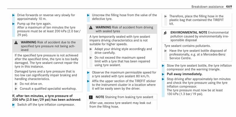
# Drive forwards or reverse very slowly forapproximately 10 m.
# Pump up the tyre again.After a maximum of ten minutes the tyrepressure must be at least 200 kPa (2.0 bar/29 psi).
& WARNING Risk of accident due to thespecified tyre pressure not being ach‐ieved
If the specified tyre pressure is not achievedafter the specified time, the tyre is too badlydamaged. The tyre sealant cannot repair thetyre in this instance.Damaged tyres and a tyre pressure that istoo low can significantly impair braking andhandling characteristics.# Do not drive on.# Consult a qualified specialist workshop.
If, after ten minutes, a tyre pressure of200 kPa (2.0 bar/29 psi) has been achieved:# Switch off the tyre inflation compressor.
# Unscrew the filling hose from the valve of thedefective tyre.
& WARNING Risk of accident from drivingwith sealed tyres
A tyre temporarily sealed with tyre sealantimpairs driving characteristics and is notsuitable for higher speeds.# Adapt your driving style accordingly and
drive carefully.# Do not exceed the maximum speed
limit with a tyre that has been repairedusing tyre sealant.
# Observe the maximum permissible speed fora tyre sealed with tyre sealant 80 km/h.
# Affix the upper section of the TIREFIT stickerto the instrument cluster in a location whereit will be easily seen by the driver.
* NOTE Staining from leaking tyre sealant
After use, excess tyre sealant may leak outfrom the filling hose.
# Therefore, place the filling hose in theplastic bag that contained the TIREFITkit.
+ ENVIRONMENTAL NOTE Environmentalpollution caused by environmentally irre‐sponsible disposal
Tyre sealant contains pollutants.# Have the tyre sealant bottle disposed of
professionally, e.g. at a Mercedes-BenzService Centre.
# Stow the tyre sealant bottle, the tyre inflationcompressor and the warning triangle.
# Pull away immediately.# Stop driving after approximately ten minutes
and check the tyre pressure using the tyreinflation compressor.The tyre pressure must now be at least130 kPa (1.3 bar/19 psi).
Breakdown assistance 469

& WARNING Risk of accident due to thespecified tyre pressure not being ach‐ieved
If the specified tyre pressure is not achievedafter a brief drive, the tyre is too badly dam‐aged. The tyre sealant cannot repair the tyrein this instance.Damaged tyres and a tyre pressure that istoo low can significantly impair braking andhandling characteristics.# Do not drive on.# Consult a qualified specialist workshop.
Countries that have Mercedes-BenzService24h: you will find a sticker with the tele‐phone number, e.g. on the B‑pillar on the driver'sside.# To increase the tyre pressure: switch on
the tyre inflation compressor.
# To reduce the tyre pressure: press pres‐sure release button1 next to manometer2.
# When the tyre pressure is correct, unscrewthe filling hose from the valve of the sealedtyre.
# Screw the valve cap onto the valve of thesealed tyre.
# Pull the tyre sealant bottle out of the tyreinflation compressor.The filling hose stays on the tyre sealant bot‐tle.
# Drive to the nearest qualified specialist work‐shop and have the tyre, tyre sealant bottleand filling hose replaced there.
Battery (vehicle)Notes on the 12 V battery
& WARNING Risk of an accident due towork carried out incorrectly on the bat‐tery
Work carried out incorrectly on the batterycan, for example, lead to a short circuit. Thiscan lead to function restrictions in safety-rel‐evant systems, e.g. the lighting system, ABS(anti-lock braking system) or ESP® (Elec‐tronic Stability Program). The operatingsafety of your vehicle may be restricted.You could lose control of the vehicle in thefollowing situations:R when brakingR in the event of abrupt steering manoeu‐
vres and/or when the vehicle's speed isnot adapted to the road conditions
470 Breakdown assistance
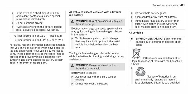
# In the event of a short circuit or a simi‐lar incident, contact a qualified special‐ist workshop immediately.
# Do not continue driving.# Always have work on the battery carried
out at a qualified specialist workshop.
R Further information on ABS (/ page 192)R Further information on ESP® (/ page 193)
For safety reasons, Mercedes-Benz recommendsthat you only use batteries which have been tes‐ted and approved for your vehicle by Mercedes-Benz. These batteries provide increased impactprotection to prevent vehicle occupants fromsuffering acid burns should the battery be dam‐aged in the event of an accident.
All vehicles except vehicles with a lithium-ion battery
& WARNING Risk of explosion due to elec‐trostatic charge
Electrostatic charge can cause sparks whichmay ignite the highly flammable gas mixturein the battery.# To discharge any electrostatic charge
that may have built up, touch the metalvehicle body before handling the bat‐tery.
The highly flammable gas mixture is createdwhile the battery is charging and during startingassistance.
& WARNING Danger of chemical burnsfrom the battery acid
Battery acid is caustic.# Avoid contact with the skin, eyes or
clothing.# Do not lean over the battery.
# Do not inhale battery gases.# Keep children away from the battery.# Immediately rinse battery acid off thor‐
oughly with plenty of clean water andseek medical attention immediately.
All vehicles
+ ENVIRONMENTAL NOTE Environmentaldamage due to improper disposal of bat‐teries
Batteries contain pollutants. It isillegal to dispose of them with the householdrubbish.#
Dispose of batteries in anenvironmentally responsible manner.Take discharged batteries to a qualified
Breakdown assistance 471
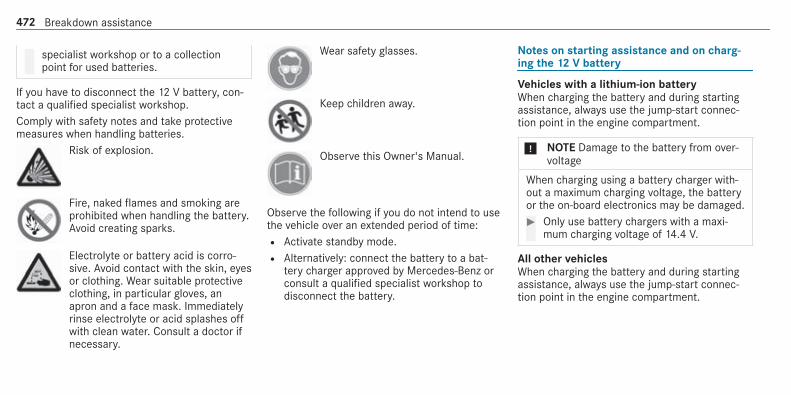
specialist workshop or to a collectionpoint for used batteries.
If you have to disconnect the 12 V battery, con‐tact a qualified specialist workshop.Comply with safety notes and take protectivemeasures when handling batteries.
Risk of explosion.
Fire, naked flames and smoking areprohibited when handling the battery.Avoid creating sparks.
Electrolyte or battery acid is corro‐sive. Avoid contact with the skin, eyesor clothing. Wear suitable protectiveclothing, in particular gloves, anapron and a face mask. Immediatelyrinse electrolyte or acid splashes offwith clean water. Consult a doctor ifnecessary.
Wear safety glasses.
Keep children away.
Observe this Owner's Manual.
Observe the following if you do not intend to usethe vehicle over an extended period of time:R Activate standby mode.R Alternatively: connect the battery to a bat‐
tery charger approved by Mercedes-Benz orconsult a qualified specialist workshop todisconnect the battery.
Notes on starting assistance and on charg‐ing the 12 V battery
Vehicles with a lithium-ion batteryWhen charging the battery and during startingassistance, always use the jump-start connec‐tion point in the engine compartment.
* NOTE Damage to the battery from over‐voltage
When charging using a battery charger with‐out a maximum charging voltage, the batteryor the on-board electronics may be damaged.# Only use battery chargers with a maxi‐
mum charging voltage of 14.4 V.
All other vehiclesWhen charging the battery and during startingassistance, always use the jump-start connec‐tion point in the engine compartment.
472 Breakdown assistance
* NOTE Damaging the battery throughovervoltage
When using a battery charger without a maxi‐mum charging voltage, the battery or thevehicle electronics may be damaged.# Only use battery chargers with a maxi‐
mum charging voltage of 14.8 V.
& WARNING Risk of explosion from hydro‐gen gas igniting
A battery generates hydrogen gas during thecharging process. If there is a short circuit orsparks start to form, there is a danger of thehydrogen gas igniting.# Make sure that the positive terminal of
the connected battery does not comeinto contact with vehicle parts.
# Never place metal objects or tools on abattery.
# When connecting and disconnecting thebattery, you must observe the descri‐bed order for the battery clamps.
# When giving starting assistance, alwaysmake sure that you only connect bat‐tery terminals with identical polarity.
# During starting assistance, you mustobserve the described order for con‐necting and disconnecting the jumplead.
# Do not connect or disconnect the bat‐tery clamps while the engine is running.
& WARNING Risk of explosion duringcharging process and starting assistance
During the charging process and startingassistance, the battery may release an explo‐sive gas mixture.# Avoid fire, naked flames, creating
sparks and smoking.# Make sure that there is sufficient venti‐
lation during the charging process andduring starting assistance.
# Do not lean over a battery.
& WARNING Risk of explosion from a fro‐zen battery
A discharged battery may freeze at tempera‐tures slightly above or below freezing point.During starting assistance or battery charg‐ing, battery gas may be released.# Always thaw a frozen battery out first
before charging it or performing start‐ing assistance.
If the indicator/warning lamps in the instrumentcluster do not light up at low temperatures, it isvery likely that the discharged battery has fro‐zen. In this case you may neither jump-start thevehicle nor charge the battery.The service life of a battery that has beenthawed may be dramatically shortened. Thestarting characteristics may be impaired, espe‐cially at low temperatures.It is recommended that you have a thawed bat‐tery checked at a qualified specialist workshop.
Breakdown assistance 473

All vehicles
* NOTE Damage caused by numerous orextended attempts to start the engine
Numerous or extended attempts to start theengine may damage the catalytic converterdue to non-combusted fuel.# Avoid numerous and extended attempts
to start the engine.
Observe the following points during startingassistance and when charging the battery:R Only use undamaged jump lead/charging
cables with a sufficient cross-section andinsulated terminal clamps.R Non-insulated parts of the terminal clamps
must not come into contact with other metalparts while the jump lead/charging cable isconnected to the battery/jump-start connec‐tion point.R The jump lead/charging cable must not
come into contact with any parts which maymove when the engine is running.
R Always make sure that neither you nor thebattery is electrostatically charged.R Keep away from fire and naked flames.R Do not lean over the battery.
Observe the additional following points whencharging the battery:R Only use battery chargers tested and
approved for Mercedes-Benz.R Read the battery charger's operating instruc‐
tions before charging the battery.
Observe the additional following points duringstarting assistance:R Starting assistance may only be provided
using batteries with a nominal voltage of12 V.R The vehicles must not touch.R Petrol engine: only accept starting assis‐
tance if the engine and exhaust system arecold.
Starting assistance and charging the 12 Vbattery
Requirements:R The vehicle is secured with the electric park‐
ing brake.R Vehicles with automatic transmission: the
transmission is in positionj.R Vehicles with manual transmission: the
transmission is in neutral.R The ignition and all electrical consumers are
switched off.R The bonnet is open.
474 Breakdown assistance
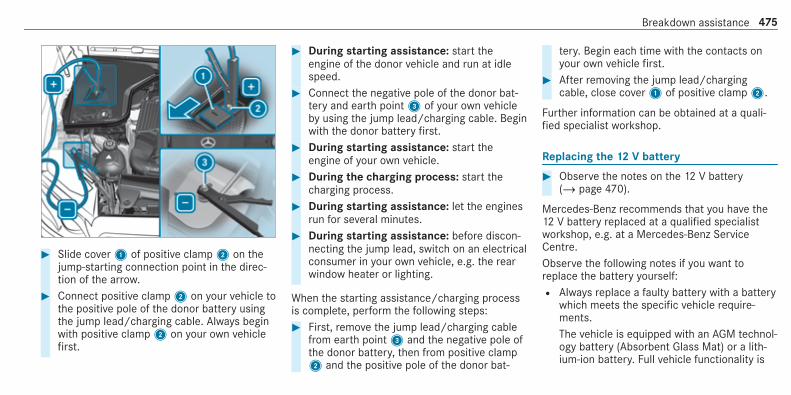
# Slide cover1 of positive clamp2 on thejump-starting connection point in the direc‐tion of the arrow.
# Connect positive clamp2 on your vehicle tothe positive pole of the donor battery usingthe jump lead/charging cable. Always beginwith positive clamp2 on your own vehiclefirst.
# During starting assistance: start theengine of the donor vehicle and run at idlespeed.
# Connect the negative pole of the donor bat‐tery and earth point3 of your own vehicleby using the jump lead/charging cable. Beginwith the donor battery first.
# During starting assistance: start theengine of your own vehicle.
# During the charging process: start thecharging process.
# During starting assistance: let the enginesrun for several minutes.
# During starting assistance: before discon‐necting the jump lead, switch on an electricalconsumer in your own vehicle, e.g. the rearwindow heater or lighting.
When the starting assistance/charging processis complete, perform the following steps:# First, remove the jump lead/charging cable
from earth point3 and the negative pole ofthe donor battery, then from positive clamp2 and the positive pole of the donor bat‐
tery. Begin each time with the contacts onyour own vehicle first.
# After removing the jump lead/chargingcable, close cover1 of positive clamp2.
Further information can be obtained at a quali‐fied specialist workshop.
Replacing the 12 V battery
# Observe the notes on the 12 V battery(/ page 470).
Mercedes-Benz recommends that you have the12 V battery replaced at a qualified specialistworkshop, e.g. at a Mercedes-Benz ServiceCentre.Observe the following notes if you want toreplace the battery yourself:R Always replace a faulty battery with a battery
which meets the specific vehicle require‐ments.The vehicle is equipped with an AGM technol‐ogy battery (Absorbent Glass Mat) or a lith‐ium-ion battery. Full vehicle functionality is
Breakdown assistance 475

only guaranteed with an AGM battery or lith‐ium-ion battery. For safety reasons,Mercedes-Benz recommends that you onlyuse batteries which have been tested andapproved for your vehicle by Mercedes-Benz.R Carry over detachable parts, such as vent
hoses, elbow fittings or terminal covers fromthe battery being replaced.R Make sure that the vent hose is always con‐
nected to the original opening on the side ofthe battery.Fit any existing or supplied cell caps.Otherwise, gases or battery acid couldescape.
R Make sure that detachable parts are recon‐nected in the same way.
Tow-starting or towing awayPermitted towing methods
Mercedes-Benz recommends transporting yourvehicle in the case of a breakdown, rather thantowing it away.For towing, use a tow rope or tow bar with bothaxles on the ground. Do not use tow bar sys‐tems.
& WARNING Risk of accident when towingwith steering wheel lock
You will no longer be able to steer the vehicleif the steering wheel lock is engaged.# Always switch on the ignition when tow‐
ing the vehicle with a tow cable or a towbar.
* NOTE Damage to the vehicle due to tow‐ing away incorrectly
# Observe the instructions and notes ontowing away.
476 Breakdown assistance

Permitted towing methods
Vehicle equipment/towingmethod
Both axles on the ground Front axle raised Rear axle raised
Vehicles with manual transmission Yes, maximum 50 km at 50 km/h Yes, maximum 50 km at 50 km/h Yes, maximum 50 km at 50 km/h
Vehicles with automatic transmis‐sion
Yes, maximum 50 km at 50 km/h Yes, maximum 50 km at 50 km/h Yes, maximum 50 km at 50 km/h ifthe steering wheel is fixed in thecentre position with a steeringwheel lock
4MATIC vehicles Yes, maximum 50 km at 50 km/h No No
Towing with a raised axle: towing should beperformed by a towing company.
Towing the vehicle with both axles on theground
# Observe the notes on the permitted towingmethods (/ page 476).
# Make sure that the battery is connected andcharged.
Observe the following points when the battery isdischarged:R the engine cannot be startedR the electric parking brake cannot be released
or applied
R vehicles with automatic transmission: theautomatic transmission cannot be shifted topositioni orj.
Breakdown assistance 477

% Vehicles with automatic transmission: ifthe automatic transmission cannot be shif‐ted to positioni, or the multifunction dis‐play in the instrument cluster does not showanything, have the vehicle transported away(/ page 479). A towing vehicle with liftingequipment is required for vehicle transporta‐tion.
* NOTE Damage due to towing away atexcessively high speeds or over long dis‐tances
The drivetrain could be damaged when tow‐ing at excessively high speeds or over longdistances.# A towing speed of 50 km/h must not
be exceeded.# A towing distance of 50 km must not be
exceeded.
& WARNING Risk of accident when towinga vehicle which is too heavy
If the vehicle being tow-started or towedaway is heavier than the permissible grossmass, the following situations can occur:R the towing eye may become detached.R the car/trailer combination may swerve
or even overturn.
# If another vehicle is tow-started ortowed away, its weight must not exceedthe permissible gross mass of your ownvehicle.
If a vehicle must be tow started or towed away,its permissible gross mass must not exceed thepermissible gross mass of the towing vehicle.# Information on the permissible gross mass of
the vehicle can be found on the vehicle iden‐tification plate (/ page 512).
# Vehicles with automatic transmission: donot open the driver's door or front passengerdoor, otherwise the automatic transmissionautomatically shifts to positionj.
# Fit the towing eye (/ page 481).# Fasten the tow bar.
* NOTE Damage due to incorrect connec‐tion
# Only connect the tow rope or tow bar tothe towing eyes.
# Deactivate the automatic locking mechanism(/ page 83).
# Do not activate the HOLD function.# Deactivate tow-away protection
(/ page 99).# Deactivate Active Brake Assist
(/ page 202).# Vehicles with automatic transmission:
shift the automatic transmission to positioni.
# Vehicles with manual transmission: shiftto neutrali.
# Release the electric parking brake.
478 Breakdown assistance

& WARNING Risk of accident due to limi‐ted safety-related functions during thetowing process
Safety-related functions are limited or no lon‐ger available in the following situations:R the ignition is switched off.R the brake system or power steering sys‐
tem is malfunctioning.R the energy supply or the on-board electri‐
cal system is malfunctioning.
When your vehicle is then towed away, signif‐icantly more effort may be required to steerand brake than is normally required.# Use a tow bar.# Make sure that the steering wheel can
move freely, before towing the vehicleaway.
* NOTE Damage due to excessive tractivepower
If you pull away sharply, the tractive powermay be too high and the vehicles could bedamaged.# Pull away slowly and smoothly.
Loading the vehicle for transport
# Observe the notes on towing away(/ page 477).
# Connect the tow bar to the towing eye inorder to load the vehicle.
% You can also attach the tow bar to the trailerhitch.
# Vehicles with automatic transmission:shift the automatic transmission to positioni.
% Vehicles with automatic transmission:the automatic transmission may be locked inpositionj in the event of damage to theelectrical system. To shift toi, provide the
on-board electrical system with power(/ page 474).
# Vehicles with manual transmission: shiftto neutral.
# Load the vehicle onto the transporter.# Vehicles with automatic transmission:
shift the automatic transmission to positionj.
# Vehicles with manual transmission:engage first or reverse gear.
# Use the electric parking brake to secure thevehicle against rolling away.
# Only secure the vehicle by the wheels.
AMG vehicles with ADS PLUS (AdaptiveDamping System PLUS)
& WARNING Risk of an accident whentransporting vehicles with AdaptiveDamping System PLUS
The reduced damping forces on the vehiclebeing transported can cause the vehicle/trailer combination to start to swing.
Breakdown assistance 479

As a result, when transporting vehicles withthe Adaptive Damping System PLUS, thevehicle/trailer combination may start to skid.Consequently, you could lose control of yourvehicle.# When transporting, ensure that:R the vehicle has been loaded onto
the transporter correctlyR the vehicle is secured at all four
wheels with suitable tensioningstrapsR the maximum permissible speed of
60 km/h is not exceeded whentransporting
* NOTE Damage to the vehicle from secur‐ing it incorrectly
# After loading, the vehicle must besecured on all four wheels. Otherwise,the vehicle could be damaged.
# A minimum distance of 20 cm upwardsand 10 cm downwards must be kept tothe transport platform.
# Secure the vehicle on all four wheels afterloading.
4MATIC vehicles/vehicles with automatictransmission
# Make sure that the front and rear axles cometo rest on the same transportation vehicle.
* NOTE Damage to the drivetrain due toincorrect positioning
# Do not position the vehicle above theconnection point of the transport vehi‐cle.
Towing eye storage location
The towing eye1 is located in the stowagespace under the boot floor.
480 Breakdown assistance

Installing the towing eye
# Press the mark on cover1 inwards andremove.
# Screw in the towing eye clockwise as far as itwill go and tighten.
Vehicles with a trailer hitch: vehicles with atrailer hitch do not have a rear bracket for the
towing eye. Fasten the tow bar to the trailerhitch.% Make sure that cover1 engages in the
bumper when you remove the towing eye.
* NOTE Damage due to incorrect use ofthe towing eye
When a towing eye is used to recover a vehi‐cle, the vehicle may be damaged in the proc‐ess.# Only use the towing eye to tow away or
tow start the vehicle.
Tow starting the vehicle (emergency enginestart)
Vehicles with automatic transmission
* NOTE Damage to the automatic trans‐mission due to tow-starting
The automatic transmission may be damagedin the process of tow-starting vehicles withautomatic transmission.
# Vehicles with automatic transmissionmust not be tow-started.
# Vehicles with automatic transmission mustnot be tow-started.
Vehicles with manual transmission# Observe the notes on towing away
(/ page 477).# If necessary, allow the engine and exhaust
system to cool down.# Switch the ignition on.# Engage second gear.# Release the electric parking brake.# Tow-start the vehicle while the clutch pedal
is fully depressed.# Slowly release the clutch pedal.# Immediately shift to neutral if the engine
starts.# Pull over and stop the vehicle, paying atten‐
tion to road and traffic conditions.# Remove the tow bar.
Breakdown assistance 481

# Remove the towing eye.# Have the vehicle checked at a qualified spe‐
cialist workshop.
Electrical fusesNotes on electrical fuses
& WARNING Risk of accident and injurydue to overloaded lines
If you manipulate or bridge a faulty fuse or ifyou replace it with a fuse with a higheramperage, the electric line could be overloa‐ded.This could result in a fire.# Always replace faulty fuses with speci‐
fied new fuses containing the correctamperage.
* NOTE Damage due to incorrect fuses
Electrical components or systems may bedamaged by incorrect fuses, or their func‐tionality may be significantly impaired.
# Only use fuses that have been approvedby Mercedes-Benz and which have thecorrect fuse rating.
Blown fuses must be replaced with fuses of thesame rating, which you can recognise by the col‐our and fuse rating. The fuse ratings and furtherinformation to be observed are listed in the fuseassignment diagram.Fuse assignment diagram: on the fuse box inthe engine compartment (/ page 482).
* NOTE Damage or malfunctions causedby moisture
Moisture may cause damage to the electricalsystem or cause it to malfunction.# When the fuse box is open, make sure
that no moisture can enter the fusebox.
# When closing the fuse box, make surethat the seal of the lid is positioned cor‐rectly on the fuse box.
If the newly inserted fuse also blows, have thecause traced and rectified at a qualified special‐ist workshop.Ensure the following before replacing a fuse:R The vehicle is secured against rolling away.R All electrical consumers are switched off.R The ignition is switched off.
The electrical fuses are located in various fuseboxes:R Fuse box in the engine compartment on the
left-hand side of the vehicle, when viewed inthe direction of travel (/ page 482)R Fuse box in the front passenger footwell
(/ page 483)R Fuse box in the centre of the boot
(/ page 484)
Opening and closing the fuse box in theengine compartment
Requirements:R A dry cloth and a screwdriver are available.
482 Breakdown assistance

Observe the notes on electrical fuses(/ page 482).
Opening
& WARNING Risk of injury from using thewindscreen wipers while the engine bon‐net is open
When the engine bonnet is open, and thewindscreen wipers are set in motion, you canbe trapped by the wiper linkage.# Always switch off the windscreen wip‐
ers and ignition before opening theengine bonnet.
# Open the bonnet.# Remove any existing moisture from the fuse
box using a dry cloth.# Loosen screws1.# Press clamps2 and lift the fuse box lid up
and out.
The fuse allocation chart is in a recess on theside of the fuse box.
Closing# Check whether the seal is positioned cor‐
rectly in the lid.# Place the lid on the fuse box.# Make sure that clamps2 engage.# Tighten screws1.# Close the bonnet.
Opening and closing the fuse box in the frontpassenger footwell
Observe the notes on electrical fuses(/ page 482).
Breakdown assistance 483

Opening
# Lift carpet1 in the direction of the arrow.
# Loosen screws2, remove fuse box lid fromthe top.
Opening and closing the fuse box in the boot
Observe the notes on electrical fuses(/ page 482).# Open the boot floor (/ page 115).
Fuse box1 is located in the centre underneaththe boot floor.
484 Breakdown assistance

Notes on noise or unusual handling charac‐teristicsWhile driving, pay attention to vibrations, noisesand unusual handling characteristics, e.g. pullingto one side. This may indicate that the wheels ortyres are damaged. If you suspect that a tyre isdefective, reduce your speed immediately. Stopthe vehicle as soon as possible to check thewheels and tyres for damage. Hidden tyre dam‐age could also be causing the unusual handlingcharacteristics. If you find no signs of damage,have the tyres and wheels checked at a qualifiedspecialist workshop.
Notes on regularly inspecting wheels andtyres
& WARNING Risk of accident from dam‐aged tyres
Damaged tyres can cause tyre pressure loss.As a result, you could lose control of yourvehicle.
# Check the tyres regularly for signs ofdamage and replace any damaged tyresimmediately.
Carry out the following checks on all wheels reg‐ularly, at least once a month or as required, e.g.prior to a long journey or driving off-road:R Check the tyre pressure (/ page 486).R Visually inspect tyres and wheels for dam‐
age.R Check the valve caps.
The valves must be protected against mois‐ture and dirt by the valve caps approvedespecially for your vehicle by Mercedes-Benz.R Visual check of the tyre tread depth and the
tyre contact surface across the entire width.The minimum tread depth for summer tyresis 3 mm and for winter tyres 4 mm.
Notes on snow chains
& WARNING Risk of accident due to incor‐rect snow chain fitting
If you fit snow chains to the rear wheels, thesnow chains may grind against the vehiclebody or chassis components.This could cause damage to the vehicle orthe tyres.# Never fit snow chains to the rear
wheels.# Always fit snow chains to the front
wheels in pairs.
* NOTE Damage to components of thevehicle body or chassis due to fittedsnow chains
If you fit snow chains to the front wheels of4MATIC vehicles, you may damage compo‐nents of the vehicle body or chassis.# Only fit snow chains to the rear wheels
of 4MATIC vehicles.
Wheels and tyres 485

* NOTE Damage to the wheel trim from fit‐ted snow chains
If snow chains are fitted to steel wheels, thewheel trims can be damaged.# Remove the wheel trims of steel wheels
before fitting snow chains.
Observe the following notes when using snowchains:R Snow chains are only permissible for certain
wheel/tyre combinations. You can obtaininformation about this from a Mercedes-BenzService Centre.R For safety reasons, only use snow chains that
have been specifically approved for yourvehicle by Mercedes-Benz, or snow chainswith the same quality standard.R If snow chains are fitted, the maximum per‐
missible speed is 50 km/h.R Vehicles with Active Parking Assist: do
not use Active Parking Assist when snowchains are fitted.
% You can permanently limit the maximumvehicle speed for driving with winter tyres(/ page 207).
% You can deactivate ESP® to pull away(/ page 195). This allows the wheels tospin, achieving an increased driving force.
Tyre pressureNotes on tyre pressure
& WARNING Risk of accident due to insuf‐ficient or excessive tyre pressure
Underinflated or overinflated tyres pose thefollowing risks:R The tyres may burst, especially as the
load and vehicle speed increase.R The tyres may wear excessively and/or
unevenly, which may greatly impair tyretraction.R The driving characteristics, as well as
steering and braking, may be greatlyimpaired.
# Comply with the recommended tyrepressure and check the tyre pressure ofall tyres including the spare wheel regu‐larly:R at least once a monthR when the load changesR before embarking on a longer journeyR if operating conditions change, e.g. off-
road driving
# Adjust the tyre pressure as necessary.
Tyre pressure which is too high or too low can:R Shorten the service life of the tyres.R Cause increased tyre damage.R Adversely affect driving characteristics and
thus driving safety, e.g. due to aquaplaning.
& WARNING Risk of accident from repea‐ted tyre pressure drop
If the tyre pressure drops repeatedly, thewheel, valve or tyre may be damaged.
486 Wheels and tyres

Insufficient tyre pressure can cause the tyresto burst.# Inspect the tyre for signs of foreign
objects.# Check whether the wheel or valve has a
leak.# If you are unable to rectify the damage,
contact a qualified specialist workshop.
Information on the recommended tyre pressurefor the vehicle's factory-fitted tyres can be foundon the tyre pressure table on the inside of thefuel filler flap (/ page 487).Use a suitable pressure gauge to check the tyrepressure. The outer appearance of a tyre doesnot permit any reliable conclusion about the tyrepressure.Vehicles with a tyre pressure monitoring sys‐tem: you can also check the tyre pressure usingthe on-board computer.
Only correct tyre pressures when the tyres arecold. Conditions for cold tyres:R The vehicle has been parked with the tyres
out of direct sunlight for at least three hours.R The vehicle has travelled less than 1.6 km.
A rise in the tyre temperature of 10 °C increasesthe tyre pressure by approx. 10 kPa (0.1 bar/1.5 psi). Take this into account when checkingthe tyre pressure of warm tyres.
Trailer operation notesAlways inflate the rear axle tyres to the recom‐mended tyre pressures on the tyre pressuretable for increased load.
Tyre pressure table
The tyre pressure table is on the inside of thefuel filler flap.
The tyre pressure table shows the recommendedtyre pressure for all tyres approved for this vehi‐cle. The recommended tyre pressures apply forcold tyres under various operating conditions,i.e. loading and/or speed of the vehicle.If one or more tyre sizes precede a tyre pres‐sure, the tyre pressure information following isonly valid for those tyre sizes.
Wheels and tyres 487

If the preceding tyre sizes are complemented bythe + symbol, the tyre pressure informationfollowing shows alternative tyre pressures.These tyre pressures may improve your vehicle'sride comfort. Fuel consumption may thenincrease slightly.The load conditions "partially laden" and "fullyladen" are defined in the table for different num‐bers of passengers and amounts of luggage. Theactual number of seats may differ from this.Be sure to also observe the following furtherrelated subjects:R Notes on tyre pressure (/ page 486)
Tyre pressure monitoring system
Function of the tyre pressure monitoring sys‐temThe system checks the tyre pressure and thetyre temperature of the tyres fitted to the vehicleby means of a tyre pressure sensor.New tyre pressure sensors, e.g. in winter tyres,are automatically taught-in during the first jour‐ney they are used.
The tyre pressure and the tyre temperatureappear in the multifunction display(/ page 488).If there is a substantial pressure loss or if thetyre temperature is excessive, you will bewarned in the following ways:R via display messages
(/ page565)R via theh warning lamp in the instrument
cluster (/ page 592)
The tyre pressure monitoring system is only anaid. It is the driver's responsibility to set the tyrepressure to the recommended cold tyre pressuresuitable for the operating situation. Set the tyrepressure for cold tyres using a tyre pressuregauge. Note that the correct tyre pressure forthe current operating situation must first betaught-in to the tyre pressure monitoring sys‐tem.In most cases, the tyre pressure monitoring sys‐tem will automatically update the new referencevalues after you have changed the tyre pressure.You can, however, also update the reference val‐
ues by restarting the tyre pressure monitoringsystem manually (/ page 489).
System limitsThe system may be impaired or may not functionin the following situations:R The tyre pressure has been set incorrectly.R There is a sudden pressure loss caused, for
example, by a foreign object penetrating thetyre.R There is a malfunction caused by another
radio signal source.
Make sure to observe the following further rela‐ted subject:R Notes on tyre pressure (/ page 486)
Checking the tyre pressure with the tyrepressure monitoring system
Requirements:R The ignition is switched on.
488 Wheels and tyres

On-board computer:4 Service 5 TyresOne of the following displays appears:R Current tyre pressure and tyre temperature
of the individual wheels:
R Tyre pressures will be displayed after a fewminutes of drivingR Tyre pressure monitor active: the teach-in
process of the system is not yet complete.The tyre pressures are already being moni‐tored.
# Compare the tyre pressure with the recom‐mended tyre pressure for the current operat‐
ing condition (/ page 487). Observe thenotes on tyre temperature (/ page 486).
% The values displayed in the multifunction dis‐play may deviate from those of the tyre pres‐sure gauge as they refer to sea level. At highaltitudes, the tyre pressure values indicatedby a pressure gauge are higher than thoseshown by the on-board computer. In thiscase, do not reduce the tyre pressure.
Make sure to observe the following further rela‐ted subject:R Notes on tyre pressure (/ page 486)
Restarting the tyre pressure monitoring sys‐tem
Requirements:R The recommended tyre pressure is correctly
set for the respective operating status oneach of the four wheels (/ page 486).
Restart the tyre pressure monitoring system inthe following situations:R The tyre pressure has changed.
R The wheels or tyres have been changed ornewly fitted.
On-board computer:4 Service 5 Tyres# Swipe downwards on Touch Control on the
left-hand side of the steering wheel.The Use current pressures as new referencevalues?message is shown in the multifunc‐tion display.
# To begin restart, press Touch Control on theleft-hand side of the steering wheel.The Tyre press. monitor restartedmessage isshown in the multifunction display.Current warning messages are deleted andthe yellowh warning lamp goes out.After you have been driving for a fewminutes, the system checks whether the cur‐rent tyre pressures are within the specifiedrange. The current tyre pressures are thenaccepted as reference values and monitored.
Make sure to observe the following further rela‐ted subject:R Notes on tyre pressure (/ page 486)
Wheels and tyres 489

Radio equipment approval of the tyre pres‐sure monitoring system
Radio equipment approval numbers
Country Radio equipment approvalnumber
Argentina see below
Australia
Country Radio equipment approvalnumber
Brazil
MODELO: TSSRE4AANATEL: 05181-17-06643Este equipamento opera emcaráter secundário, isto é, nãotem direito à proteção contrain‐terferência prejudicial, mesmo deestações do mesmo tipo e nãopode causar interferência a siste‐mas operando em caráter pri‐mário.
Country Radio equipment approvalnumber
EuropeanUnion
Hiermit erklärt Huf Hülsbeck &Fürst GmbH & Co. KG, dass derFunkanlagentyp TSSRE4A &TSSSG4G6 der Richtlinie2014/53/EU entspricht.Der vollständige Text der EU-Kon‐formitätserklärung ist unter derfolgenden Internetadresse ver‐fügbar: http://www.huf-group.com/eudocFrequenzband: 433,92 MHzAbgestrahlte maximale Sende‐leistung: <10 mWHersteller:Huf Electronics Bretten GmbHGewerbestr. 40
490 Wheels and tyres

Country Radio equipment approvalnumber
75015 BrettenGermany
Indonesia 52166/SDPPI/20173533
Israel A. The use of this product doesnot need a wireless operationlicense.B. The product does not includean RF disturbance protection,and should not disturb otherlicensed products.C. It is forbidden to replace theantenna or to make any changein this product.
Country Radio equipment approvalnumber
Jordan Kingdom of Jordan Type approvalfor Tyre Pressure Sensor and ECUManufacturer: Huf ElectronicsBretten GmbHModel: TSSRE4AType Approval Number:TRC/LPD/2017/421Model: TSSSG4G6Type Approval Number:TRC/LPD/2017/422
Malaysia
CIDF17000184Model: TSSRE4A & TSSSG4G6RAQP/57A/0817/S(17-2424)
Country Radio equipment approvalnumber
Morocco AGREE PAR L'ANRT MAROCModele: TSSRE4ANumero d'agrement: MR 14320ANRT 2017Date d'agrement: 07/07/2017Modele: TSSSG4G6Numero d'agrement: MR 14319ANRT 2017Date d'agrement: 07/07/2017
Mexico Model: TSSRE4AIFETEL: RLVHUTS17-0806
Moldova
Oman TRAR/4516/17D100428
Wheels and tyres 491

Country Radio equipment approvalnumber
Philip‐pines
NTCType ApprovedNo: ESD-1715393C
Russia
Serbia
Singapore Complies with IDA StandardsDA103787
Country Radio equipment approvalnumber
SouthAfrica
TA-2017/1393TA-2017/1391
Country Radio equipment approvalnumber
Taiwan
CCAO17LP0380T4CCAO17LP0390T7經型式認證合格之低功率射頻電機,非經許可,公司、商號或使用者均
不得擅自變更頻率、加大功率或變更原設計之特性及功能。低功率射
頻電機之使用不得影響飛航安全及干擾合法通信;經發現有干擾現象
時,應立即停用,並改善至無干擾時方得繼續使用。前項合法通信,指依
492 Wheels and tyres

Country Radio equipment approvalnumber
電信法規定作業之無線電通信。低功率射頻電機須忍受合法通信或工
業、科學及醫療用電波輻射性電機設備之干擾。
According to “Administrative Reg‐ulations on Low Power RadioWaves Radiated Devices”.Without permission granted bythe DGT, any company, enter‐prise, or user is not allowed tochange frequency, enhancetransmitting power or alter origi‐nal characteristic as well as per‐formance to a approved lowpower radio-frequency devices.The low power radio-frequencydevices shall not influence air‐craft security and interfere legalcommunications; If found, theuser shall cease operating imme‐
Country Radio equipment approvalnumber
diately until no interference isachieved.The said legal communicationsmeans radio communications isoperated in compliance with theTelecommunications Act.The low power radio-frequencydevices must be susceptible withthe interference from legal com‐munications or ISM radio waveradiated devices.
Thailand This telecommunication equip‐ment conforms to NTC technicalrequirement.
Ukraine
Model: TSSRE4A & TSSSG4G6UA.TR.109.0109-17
Country Radio equipment approvalnumber
UnitedArab Emi‐rates(UAE)
TRARegistered No: ER57806/17Dealer No: DA36976/14TRARegistered No: ER57807/17Dealer No: DA36976/14
Vietnam
Huf Hülsbeck & Fürst GmbH &Co. KGModel: TSSRE4ANo: C0112200717AF04A2
Wheels and tyres 493

Argentina
CNC ID: H-20027
Tyre pressure loss warning system
Function of the tyre pressure loss warningsystemThe tyre pressure loss warning system warns thedriver by means of display messages when thereis a severe tyre pressure loss.After a change in tyre pressure, a wheel rotationor a tyre change, or if you have refitted wheelsor tyres, the tyre pressure loss warning systemhas to be restarted (/ page 494).
The tyre pressure loss warning system does notreplace the need to regularly check the tyrepressures.
System limitationsThe system may be impaired or may not functionparticularly in the following situations:R incorrectly set tyre pressureR sudden pressure loss caused, for example,
by a foreign object penetrating the tyreR steady pressure loss in several tyres
The system has a restricted or delayed functionparticularly in the following situations:R poor ground conditions, e.g. snow or gravelR driving with snow chainsR when adopting a very sporty driving style
with high cornering speeds or sudden accel‐erationR driving with a very heavy or large trailerR driving with a high load
Be sure to also observe the following furtherrelated subjects:R Notes on tyre pressure (/ page 486)R Display messages about the tyres
(/ page565)
Restarting the tyre pressure loss warningsystem
Requirements:R The recommended tyre pressure is correctly
set for the respective operating status oneach of the four wheels (/ page 486).
Restart the tyre pressure loss warning system inthe following situations:R The tyre pressure has changed.R The wheels or tyres have been changed or
newly fitted.
494 Wheels and tyres

On-board computer:4 Service 5 Tyres# Swipe downwards on Touch Control on the
left-hand side of the steering wheel.The Run Flat Indicator activeRestart messageis shown in the multifunction display.
Restart the tyre pressure loss warning system inthe following situations:R The tyre pressure has changed.R The wheels or tyres have been changed or
newly fitted.
# To begin restart, press Touch Control on theleft-hand side of the steering wheel.The Tyre pressure now OK? message isshown in the multifunction display.
# Select Yes .# To confirm restart, press Touch Control on
the left-hand side of the steering wheel.The Run Flat Indicator restarted message isshown in the multifunction display.
After you have driven for a few minutes, thetyre pressure loss warning system monitorsthe set tyre pressures of all the tyres.
Be sure to also observe the following furtherrelated subjects:R Notes on tyre pressure (/ page 486)
Wheel changeNotes on selecting, fitting and replacingtyres
Mercedes-AMG vehicles: observe the notes inthe Supplement. Otherwise, you may fail to rec‐ognise dangers.You can ask for information regarding permittedwheel/tyre combinations at a Mercedes-BenzService Centre.
& WARNING Risk of accident due to incor‐rect dimensions of wheels and tyres
If wheels and tyres of the wrong size areused, the wheel brakes or wheel suspensioncomponents may become damaged.
# Always replace wheels and tyres withthose that fulfil the specifications of theoriginal part.
When replacing wheels, make sure to fit thecorrect:R DesignationR Type
When replacing tyres, make sure to fit thecorrect:R DesignationR ManufacturerR Type
& WARNING Risk of injury through exceed‐ing the specified tyre load-bearing capa‐city or the permissible speed rating
Exceeding the specified tyre load-bearingcapacity or the permissible speed rating maylead to tyre damage and to the tyres burst‐ing.
Wheels and tyres 495

# Therefore, only use tyre types and sizesapproved for your vehicle model.
# Observe the tyre load-bearing capacityrating and speed rating required foryour vehicle.
* NOTE Vehicle and tyre damage throughtyre types and sizes that have not beenapproved
For safety reasons, only use tyres, wheelsand accessories which have been speciallyapproved by Mercedes-Benz for your vehicle.These tyres are specially adapted to the con‐trol systems, such as ABS, ESP® and4MATIC, and marked as follows:R MO = Mercedes-Benz OriginalR MOE = Mercedes-Benz Original Extended
(run-flat tyres only for certain wheels)R MO1 = Mercedes-Benz Original (only cer‐
tain AMG tyres)
Certain characteristics, such as handling,vehicle noise emissions, fuel consumption,etc. may otherwise be adversely affected.Furthermore, other tyre sizes could result inthe tyres rubbing against the body and axlecomponents when loaded. This could resultin damage to the tyre or the vehicle.Only use tyres, wheels and accessories thathave been checked and recommended byMercedes-Benz.
* NOTE Risk to driving safety from retrea‐ded tyres
Retreaded tyres are neither tested nor rec‐ommended by Mercedes-Benz, since previ‐ous damage cannot always be detected onretreaded tyres.For this reason driving safety cannot be guar‐anteed.# Do not use used tyres if you have no
information about their previous usage.
* NOTE Possible damage to wheels ortyres when driving over obstacles
Large wheels have a lower tyre section width.The lower the tyre section width, the greateris the risk of damage to wheels or tyres whendriving over obstacles.# Avoid obstacles or drive particularly
carefully.
* NOTE Damage to electronic componentparts from the use of tyre-fitting tools
Vehicles with a tyre pressure monitoringsystem: electronic component parts arelocated in the wheel. Tyre-fitting tools shouldnot be applied in the area of the valve.The tools could damage the electronic com‐ponent parts.# Have the tyres changed at a qualified
specialist workshop only.
496 Wheels and tyres

* NOTE Damage to summer tyres at lowambient temperatures
At low ambient temperatures, tears couldform when driving with summer tyres, caus‐ing permanent damage to the tyre.# At temperatures below 7 °C, use M+S
tyres.
Accessory parts that are not approved for yourvehicle by Mercedes-Benz or are not being usedcorrectly can impair the operating safety.Before purchasing and using non-approvedaccessories, visit a qualified specialist workshopand enquire about:R SuitabilityR Legal stipulationsR Factory recommendations
& WARNING Risk of accident with highperformance tyres
The special tyre tread in combination withthe optimised tyre compound, means that
the risk of skidding or hydroplaning on wetroads is increased.In addition, the tyre grip is greatly reduced ata low outside temperature and tyre runningtemperature.# Switch on the ESP® and adapt your
driving style accordingly.# Use M+S tyres at outside temperatures
of less than 50 °F.
Observe the following when selecting, fitting andreplacing tyres:R Country-specific requirements for tyre
approval that define a specific tyre type foryour vehicle.Furthermore, the use of certain tyre types incertain regions and areas of operation canbe highly beneficial.R Only use tyres and wheels of the same type
(summer tyres, winter tyres, MOExtendedtyres) and the same make.R Only fit wheels of the same size on one axle
(left and right).
It is only permissible to fit a different wheelsize in the event of a flat tyre in order todrive to the specialist workshop.R Only fit tyres of the correct size onto the
wheels.R Do not make any modifications to the brake
system, the wheels or the tyres.The use of shims or brake dust shields is notpermitted and may invalidate the vehicle'sgeneral operating permit.R Vehicles with a tyre pressure monitoring
system: all fitted wheels must be equippedwith functioning sensors for the tyre pres‐sure monitoring system.R At temperatures below 7 °C, use winter tyres
or all-season tyres marked M+S for allwheels.Winter tyres bearing thei snowflakesymbol in addition to the M+S marking pro‐vide the best possible grip in wintry roadconditions.R For M+S tyres, only use tyres with the same
tread.
Wheels and tyres 497
R Observe the maximum permissible speed forthe M+S tyres fitted.If this is below the vehicle's maximum speed,this must be indicated by an appropriatelabel in the driver's field of vision.R Run in new tyres at moderate speeds for the
first 100 km.R Replace the tyres after six years at the latest,
regardless of wear.R When replacing with tyres that do not
feature run-flat characteristics: vehicleswith MOExtended tyres are not equippedwith a TIREFIT kit at the factory. Equip thevehicle with a TIREFIT kit after replacing withtyres that do not feature run-flat characteris‐tics, e.g. winter tyres.
% You can permanently limit the maximumvehicle speed for driving with winter tyres(/ page 207).
For more information on wheels and tyres, con‐tact a qualified specialist workshop.
Be sure to also observe the following furtherrelated subjects:R Notes on tyre pressure (/ page 486)R Tyre pressure table (/ page 487)R Notes on the emergency spare wheel
(/ page 504)
Notes on interchanging wheels
& WARNING Risk of injury through differ‐ent wheel sizes
Interchanging the front and rear wheels if thewheels or tyres have different dimensionsmay severely impair the driving characteris‐tics.The disk brakes or wheel suspension compo‐nents may also be damaged.# Rotate front and rear wheels only if the
wheels and tyres are of the samedimensions.
Interchanging the front and rear wheels if thewheels or tyres have different dimensions canrender the general operating permit invalid.The wear patterns on the front and rear wheelsdiffer:R Front wheels wear more on the shoulder of
the tyreR Rear wheels wear more in the centre of the
tyre
On vehicles with the same front and rear wheelsize, you can interchange the wheels every5,000 to 10,000 km, depending on the wear.Ensure the direction of rotation is maintained forthe wheels.It is imperative to observe the instructions andsafety notes on "Changing a wheel" when doingso Preparing the vehicle for a wheelchange(/ page 500).
498 Wheels and tyres

Notes on storing wheels
When storing wheels, observe the followingnotes:R After removing wheels, store them in a cool,
dry and preferably dark place.R Protect the tyres from contact with oil,
grease or fuel.
Overview of the tyre-change tool kit
Apart from some country-specific variants, vehi‐cles are not equipped with a tyre-change tool kit.For more information on which tyre-changingtool kits are required and approved for perform‐ing a wheel change on your vehicle, consult aqualified specialist workshop.You require the following tools, for instance, tochange a wheel:R JackR ChockR Wheel wrench
% The jack weighs approximately 3.4 kg.
The maximum load capacity of the jack canbe found on the sticker affixed to the jack.The jack is maintenance-free. If there is amalfunction, please contact a qualified spe‐cialist workshop.
The tyre-change tool kit is located in tool bag1in the boot.
1 Tool bag
Tool bag1 contains:R JackR GlovesR Wheel wrench
R Folding chockR Ratchet for jack
Setting up the folding chock
Wheels and tyres 499

Preparing the vehicle for a wheel change
Requirements:R The required tyre-change tool kit is available.
If your vehicle is not equipped with the tyre-change tool kit, consult a qualified specialistworkshop to find out about suitable tools.R The vehicle is not on a slope.R The vehicle is on solid, non-slippery and level
ground.
# Apply the electric parking brake manually.# Move the front wheels to the straight-ahead
position.# Vehicles with manual transmission:
engage first or reverse gear.# Vehicles with automatic transmission:
shift into positionj.# Switch off the engine.# Make sure that the engine cannot be started.# Place chocks or other suitable items under
the front and rear of the wheel that is diago‐nally opposite the wheel you wish to change.
# Remove the hub caps if necessary(/ page 500).
# Raise the vehicle (/ page 500).
Removing and fitting hub caps
Requirements:R The vehicle is prepared for a wheel change
(/ page 500).
Vehicles with steel wheelsThe wheel trim covers the wheel bolts. Beforeyou can unscrew the wheel bolts, you mustremove the wheel trim.
# To remove: using both hands, carefully reachinto two wheel trim openings and remove thewheel trim.
Plastic hub cap# To remove: turn the centre cover of the hub
cap anti-clockwise and remove the hub cap.# To fit: make sure that the centre cover of the
hub cap is turned anti-clockwise.# Position the hub cap and turn the centre
cover clockwise until the hub cap engagesphysically and audibly.
Raising the vehicle when changing a wheel
Requirements:R There are no persons in the vehicle.R The vehicle has been prepared for a wheel
change (/ page 500).
Important notes on using the jack:R Only use the vehicle-specific jack that has
been tested and approved by Mercedes-Benzto raise the vehicle.
500 Wheels and tyres

R The jack is only designed for raising andholding the vehicle for a short time while awheel is being changed and not for mainte‐nance work under the vehicle.R The jack must be placed on a firm, flat and
non-slip surface. If necessary, use a large,flat, load-bearing, non-slip underlay.R The foot of the jack must be positioned verti‐
cally under the jack support point.
Rules of conduct when the vehicle is raised:R Never place your hands or feet under the
vehicle.R Never lie under the vehicle.
R Do not start the engine and do not releasethe electric parking brake.R Do not open or close any doors or the boot
lid.
# Using the wheel wrench, loosen the wheelbolts on the wheel you wish to change byabout one full turn. Do not unscrew the boltscompletely.
Position of jack support points
Mercedes-AMG vehicles: observe the notes inthe Supplement. Otherwise, you may fail to rec‐ognise dangers.
& WARNING Risk of injury from incorrectpositioning of the jack
If you do not position the jack correctly atthe appropriate jacking point of the vehicle,the jack could tip with the vehicle raised.# Only position the jack at the appropri‐
ate jacking point of the vehicle. Thebase of the jack must be positioned
Wheels and tyres 501

vertically under the jacking point of thevehicle.
* NOTE Vehicle damage from the jack
If you do not position the jack correctly atthe appropriate jack support point of thevehicle, the jack could tip over with the vehi‐cle raised.# The jack is designed exclusively for
jacking up the vehicle at the jack sup‐port points.
# Take the ratchet out of the tyre-change toolkit and place it on the hexagon nut of thejack so that the letters "AUF" are visible.
# Position jack2 at jack support point1.# Turn ratchet3 clockwise until jack2 sits
completely on jack support point1 and thebase of the jack lies evenly on the ground.
# Turn ratchet3 until the tyre is raised a max‐imum of 3 cm from the ground.
# Loosen and remove the wheel (/ page 502).
Removing a wheel
Requirements:R The vehicle is raised (/ page 500).
Mercedes-AMG vehicles: observe the notes inthe Supplement. Otherwise, you may fail to rec‐ognise dangers.When changing a wheel, avoid applying any forceto the brake discs, since this could impair thelevel of comfort when braking.
* NOTE Damage to threading from dirt onwheel bolts
# Do not place wheel bolts in sand or ona dirty surface.
# Unscrew the uppermost wheel bolt com‐pletely.
# Unscrew the remaining wheel bolts fully.# Remove the wheel.# Fit the new wheel (/ page 503).
502 Wheels and tyres

Fitting a new wheel
Requirements:R The wheel is removed (/ page 502).
Mercedes-AMG vehicles: observe the notes inthe Supplement. Otherwise, you may fail to rec‐ognise dangers.
& WARNING Risk of accident from losing awheel
Oiled, greased or damaged wheel bolt/wheelnut threads or wheel hub/wheel mountingbolt threads can cause the wheel bolts/wheel nuts to come loose.As a result, you could lose a wheel while driv‐ing.# Never oil or grease the threads.# In the event of damage to the threads,
contact a qualified specialist workshopimmediately.
# Have the damaged wheel bolts or dam‐aged hub threads replaced.
# Do not continue driving.
# Observe the information on the choice oftyres (/ page 495).
For tyres with a specified direction of rotation,an arrow on the side wall of the tyre indicatesthe correct direction of rotation. Observe thedirection of rotation when fitting.
& WARNING Risk of injury from tighteningwheel bolts and nuts
If you tighten the wheel bolts or wheel nutswhen the vehicle is raised, the jack could tip.# Only tighten wheel bolts or wheel nuts
when the vehicle is on the ground.
# Be sure to observe the instructions andsafety notes on "Changing a wheel"(/ page 495).
# For safety reasons, only use wheel boltswhich have been approved by Mercedes-Benz and for the wheel in question.
# Tighten the wheel bolts evenly in a diagonalpattern in the order indicated until they arefinger-tight.
# If the collapsible emergency spare wheel hasbeen fitted, inflate the collapsible emergencyspare wheel (/ page 508).
# Lower the vehicle (/ page 503).
Lowering the vehicle after a wheel change
Requirements:R The new wheel has been fitted
(/ page 503).
* NOTE Damage to the emergency sparewheel when lowering the vehicle
Lowering the vehicle without previouslyinflating the emergency collapsible sparewheel can damage its rim.# Inflate the emergency collapsible spare
wheel using the tyre inflation compres‐sor before lowering the vehicle.
# Place the ratchet onto the hexagon nut of thejack so that the letters "AB" are visible.
# To lower the vehicle: turn the ratchet of thejack anti-clockwise.
Wheels and tyres 503

# Tighten the wheel bolts evenly in a diagonalpattern in the order indicated1 to5 witha maximum of 80 Nm.
# Then tighten the wheel bolts evenly in a diag‐onal pattern in the order indicated1 to5to the specified tightening torque of 130 Nm.
& WARNING Risk of injury through incor‐rect tightening torque
The wheels could come loose if the wheelbolts or wheel nuts are not tightened to theprescribed tightening torque.
# Make sure the wheel bolts or wheelnuts are tightened to the prescribedtightening torque.
# If you are not sure, do not move thevehicle. Consult a qualified specialistworkshop and have the tightening tor‐que checked immediately.
# Check the tyre pressure of the newly moun‐ted wheel and adjust accordingly.
# Vehicles with tyre pressure loss warningsystem: restart the tyre pressure loss warn‐ing system (/ page 494).Exception: the new wheel is an emergencyspare wheel.
# Vehicles with a tyre pressure monitoringsystem: restart the tyre pressure monitoringsystem (/ page 489).Exception: the new wheel is an emergencyspare wheel.
Make sure to observe the following further rela‐ted subject:R Notes on tyre pressure (/ page 486)
Emergency spare wheelNotes on the emergency spare wheel
& WARNING Risk of accident caused byincorrect wheel and tyre dimensions
The wheel or tyre size and the tyre type ofthe emergency spare wheel or spare wheeland the wheel to be replaced may differ.Mounting an emergency spare wheel/sparewheel may severely impair the driving char‐acteristics.To prevent hazardous situations:# Adapt your driving style accordingly and
drive carefully.# Never fit more than one emergency
spare wheel or spare wheel that differsin size.
# Only use an emergency spare wheel orspare wheel of a different size briefly.
# Do not switch off ESP®.# Have the emergency spare wheel or
spare wheel of a different size replaced
504 Wheels and tyres

at the nearest qualified specialist work‐shop. The new wheel must have thecorrect dimensions.
Check the tyre pressure of the emergency sparewheel fitted. Correct the pressure as necessary.The maximum permissible speed with an emer‐gency spare wheel fitted is 80 km/h.Do not fit the emergency spare wheel with snowchains.Replace the emergency spare wheel after sixyears at the latest, regardless of wear.% Vehicles with a tyre pressure loss warn‐
ing system: if an emergency spare wheel isfitted the tyre pressure loss warning systemcannot function reliably. Only restart the sys‐tem again when the emergency spare wheelhas been replaced with a new wheel.Vehicles with a tyre pressure monitoringsystem: if an emergency spare wheel is fit‐ted the tyre pressure monitoring system can‐not function reliably. For a few minutes afteran emergency spare wheel is fitted, the sys‐tem may still display the tyre pressure of the
removed wheel. Only restart the systemagain when the emergency spare wheel hasbeen replaced with a new wheel.
Be sure to also observe the following furtherrelated subjects:R Notes on tyre pressure (/ page 486)R Tyre pressure table (/ page 487)
Removing the emergency spare wheel
The deflated emergency spare wheel is securedin the emergency spare wheel bag in the boot.# Observe the information on mounting tyres
(/ page 495).# Open the boot.# Detach the fastening straps.# Unhook the retaining spring hooks of the fas‐
tening straps from the brackets.# Remove the emergency spare wheel bag with
the emergency spare wheel.# Open the emergency spare wheel bag and
remove the emergency spare wheel.
Inflating the emergency spare wheel
* NOTE Overheating due to the tyre infla‐tion compressor running too long
# Do not run the tyre inflation compres‐sor for longer than ten minutes withoutinterruption.
Requirements:R Comply with the manufacturer's safety notes
on the sticker of the emergency spare wheeland on the tyre inflation compressor.R Remove the tyre inflation compressor from
the stowage space under the boot floor(/ page 466).
Wheels and tyres 505

# Remove sticker1 from the tyre inflationcompressor housing and affix it to the instru‐ment cluster within the driver's field ofvision.
# Pull filling hose2 and plug4 out of thetyre inflation compressor housing.
# Insert plug8 of filling hose2 in the socketon the tyre inflation compressor and thenturn it until plug8 engages.
# Unscrew the cap from the valve on the emer‐gency spare wheel.
# Screw union nut3 of filling hose2 ontothe valve.
# Make sure on and off switch5 of the tyreinflation compressor is set to 0.
# Insert plug4 in a socket in your vehicle.R Cigarette lighter socket (/ page 121)R 12 V socket (/ page 121).
R Observe the notes on the cigarette lighter(/ page 121).R Observe the notes on sockets (/ page 121).
# Turn the key to position1 in the ignitionlock.
# Press on and off switch5 on the tyre infla‐tion compressor to I.The tyre inflation compressor is switched on.The tyre is inflated. The tyre pressure isshown on manometer6.
# Pump the tyre to the specified tyre pressure.The specified tyre pressure is stated on thelabel of the emergency spare wheel.
# When the specified tyre pressure has beenreached, press on and off switch5 on thetyre inflation compressor to 0.The tyre inflation compressor is switched off.
# Turn the key to positiong in the ignitionlock.
# If the tyre pressure is higher than the speci‐fied pressure, press pressure release valvebutton7 until the correct tyre pressure hasbeen reached.
# Unscrew union nut3 of filling hose2 fromthe valve.
# Screw the valve cap of the emergency sparewheel onto the valve again.
506 Wheels and tyres

# Stow filling hose2 and plug4 in the lowersection of the compressor housing.
# Stow the tyre inflation compressor in thevehicle.
Collapsible spare wheelNotes on the collapsible spare wheel
& WARNING Risk of accident caused byincorrect wheel and tyre dimensions
The wheel or tyre size and the tyre type ofthe emergency spare wheel or spare wheeland the wheel to be replaced may differ.Mounting an emergency spare wheel/sparewheel may severely impair the driving char‐acteristics.To prevent hazardous situations:# Adapt your driving style accordingly and
drive carefully.# Never fit more than one emergency
spare wheel or spare wheel that differsin size.
# Only use an emergency spare wheel orspare wheel of a different size briefly.
# Do not switch off ESP®.# Have the emergency spare wheel or
spare wheel of a different size replacedat the nearest qualified specialist work‐shop. The new wheel must have thecorrect dimensions.
The collapsible spare wheel is an emergencywheel which is only suitable for use for a limitedperiod of time and in a restricted manner in theevent of a flat tyre (e.g. until the nearest work‐shop).The tyre sidewalls are folded when in transportmode. Before use, the collapsible spare wheelhas to be inflated with the accompanying com‐pressor.Check the tyre pressure of the collapsible sparewheel once fitted. Correct the pressure as nec‐essary.The maximum permissible speed with a collapsi‐ble spare wheel fitted is 80 km/h.
Do not fit snow chains with the collapsible sparewheel.Replace the collapsible spare wheel after sixyears at the latest, regardless of wear.% Vehicles with a tyre pressure loss warn‐
ing system: if a collapsible spare wheel isfitted, the tyre pressure loss warning systemcannot function reliably. Only restart the sys‐tem again when the collapsible spare wheelhas been replaced with a new wheel.Vehicles with a tyre pressure monitoringsystem: if a collapsible spare wheel is fittedthe tyre pressure monitoring system cannotfunction reliably. For a few minutes after anemergency spare wheel is fitted, the systemmay still display the tyre pressure of theremoved wheel. Only restart the systemagain when the collapsible spare wheel hasbeen replaced with a new wheel.
Be sure to also observe the following furtherrelated subjects:R Notes on tyre pressure (/ page 486)R Tyre pressure table (/ page 487)
Wheels and tyres 507

Removing the collapsible spare wheel
The collapsible spare wheel is secured in the col‐lapsible spare wheel bag in the boot.# Observe the information on mounting tyres
(/ page 495).# Open the boot.# Detach the securing straps.# Unhook the retaining spring hooks of the
securing straps from the brackets.# Remove the collapsible spare wheel bag
together with the collapsible spare wheel.# Open the collapsible spare wheel bag and
remove the collapsible spare wheel.
Inflating the collapsible spare wheel
Requirements:R Mount the collapsible spare wheel as descri‐
bed. (/ page 503)R Remove the tyre inflation compressor from
the stowage space under the boot floor.(/ page 466)
* NOTE Damage to the collapsible sparewheel when lowering the vehicle
Lowering the vehicle without previouslyinflating the collapsible spare wheel candamage its rim.# Inflate the collapsible spare wheel using
the tyre inflation compressor beforelowering the vehicle.
* NOTE Overheating due to the tyre infla‐tion compressor running too long
# Do not run the tyre inflation compres‐sor for longer than ten minutes withoutinterruption.
# Pull connector4 and the hose out of thehousing.
# Unscrew the cap from the valve on the col‐lapsible spare wheel.
# Screw union nut1 of the hose onto thevalve.Make sure on and off switch3 of the tyreinflation compressor is set to 0.
# Insert plug4 into the cigarette lightersocket (/ page 121) or into a 12 V socket(/ page 121) in your vehicle.
# Switch on the power supply (/ page 156).
508 Wheels and tyres

# Press on and off switch3 on the tyre infla‐tion compressor to I.The tyre inflation compressor is switched on.The tyre is inflated. The tyre pressure isshown on manometer2.
# Pump the tyre to the specified tyre pressure.The specified tyre pressure is printed on theyellow label of the collapsible spare wheel.
# When the specified tyre pressure has beenreached, press on and off switch3 on thetyre inflation compressor to 0.
# If the tyre pressure is higher than the speci‐fied pressure, press pressure release valvebutton5 until the correct tyre pressure hasbeen reached.
Wheels and tyres 509

Notes on technical dataMercedes-AMG vehicles: be sure to observethe notes in the Supplement. Otherwise, youmay fail to recognise dangers.The technical data was determined in accord‐ance with EU Directives. The data stated onlyapplies to vehicles with standard equipment. Youcan obtain further information from a Mercedes-Benz Service Centre.Only for certain countries: you can find vehi‐cle-specific vehicle data in the EC-Certificate ofConformity (CERTIFICATE OF CONFORMITY).These documents are delivered with your vehi‐cle.
On-board electronicsNotes on tampering with the engine elec‐tronics
* NOTE Premature wear through impropermaintenance
Improper maintenance may cause vehiclecomponents to wear more quickly and thevehicle's operating permit may be invalida‐ted.# Always have work on the engine elec‐
tronics and related components carriedout at a qualified specialist workshop.
Two-way radios
Notes on fitting two-way radios
& WARNING Risk of accident due toimproper work on two-way radios
The electromagnetic radiation from two-wayradios can interfere with the on-board elec‐
tronics if RF transmitters are manipulated orretrofitted incorrectly.This could jeopardise the operating safety ofthe vehicle.# You should have all work on electrical
and electronic components carried outat a qualified specialist workshop.
& WARNING Risk of accident from incor‐rect operation of two-way radios
If you operate two-way radios incorrectly inthe vehicle, the electromagnetic radiationcould interfere with the on-board electronics,e.g.:R if the two-way radio is not connected to
an exterior aerialR if the exterior aerial is not correctly
mounted or is not of low reflection
This could jeopardise the operating safety ofthe vehicle.# Have the low-reflection exterior aerial
fitted at a qualified specialist workshop.
510 Technical data

# When operating two-way radios in thevehicle, always connect them to thelow-reflection exterior aerial.
* NOTE Invalidation of the operating per‐mit due to failure to comply with theinstructions for installation and use
The operating permit may be invalidated ifthe instructions for installation and use oftwo-way radios are not observed.# Only use approved frequency bands.# Observe the maximum permissible out‐
put power in these frequency bands.# Only use approved aerial positions.
1 Front roof area2 Rear roof area3 Rear wings4 Boot lid
On vehicles with a panoramic sliding sunroof, fit‐ting an aerial to the front or rear roof area is notpermitted.
On the rear wings, it is recommended that youfit the aerial on the side of the vehicle closest tothe centre of the road.Use Technical Specification ISO/TS 21609 (RoadVehicles – "EMCs for installation of aftermarketradio frequency transmitting equipment") whenretrofitting two-way radios. Comply with thelegal requirements for detachable parts.If your vehicle has fittings for two-way radioequipment, use the power supply and aerial con‐nectors provided in the pre-installation. Be sureto observe the manufacturer's supplementswhen fitting.
Two-way radio transmission outputThe maximum transmission output (PEAK) at thebase of the aerial must not exceed the values inthe following table.
Technical data 511

Frequency band and maximum transmissionoutput
Frequency band Maximum transmis‐sion output
Short wave3 - 54 MHz
100 W
4 m frequency band74 - 88 MHz
30 W
2 m frequency band144 - 174 MHz
50 W
Trunked radio sys‐tem/Tetra380 - 460 MHz
10 W
70 cm frequencyband420 - 450 MHz
35 W
Two-way radio(2G/3G/4G)
10 W
The following devices can be used in the vehiclewithout restrictions:R two-way radios with a maximum transmission
output of up to 100 mWR two-way radios with transmitter frequencies
in the 380 - 410 MHz frequency band and amaximum transmission output of up to 2 W(trunked radio system/Tetra)R mobile phones (2G/3G/4G)
There are no restrictions when positioning theaerial on the outside of the vehicle for the follow‐ing frequency bands:R Trunked radio system/TetraR 70 cm frequency bandR 2G/3G/4G
Vehicle identification plate, VIN and enginenumber
Vehicle identification plate
512 Technical data

Vehicle identification plate (example: Kuwait)1 Vehicle manufacturer2 Place of manufacture3 Manufacturing date4 Vehicle model5 VIN
Vehicle identification plate (example: allother countries)
1 Vehicle manufacturer2 EU general operating permit number (only
for certain countries)3 VIN (vehicle identification number)4 Maximum permissible gross vehicle weight
(kg)
5 Maximum permissible gross weight of vehi‐cle combination (kg) (only for specific coun‐tries)
6 Maximum permissible front axle load (kg)7 Maximum permissible rear axle load (kg)8 Paint code
% The data shown in the illustration is exampledata.
Technical data 513

VIN and engine number
1 Engine number stamped into the crankcase2 VIN (vehicle identification number) stamped
into the crossmember3 VIN (vehicle identification number) as a label
at the lower edge of the windscreen
The VIN as a label at the lower edge of wind‐screen3 is only available in some countries.You can obtain further information from anyqualified specialist workshop.
Operating fluidsNotes on operating fluids
Mercedes-AMG vehicles: be sure to observethe information in the Supplement. Otherwise,you may fail to recognise dangers.
& WARNING Risk of injury from operatingfluids harmful to your health
Operating fluids may be poisonous and harm‐ful to your health.# Observe the text on the original con‐
tainers when using, storing or disposingof operating fluids.
# Always store operating fluids sealed intheir original containers.
# Always keep children away from operat‐ing fluids.
+ ENVIRONMENTAL NOTE Environmentalpollution caused by environmentally irre‐sponsible disposal
# Dispose of operating fluids in an envi‐ronmentally responsible manner.
Operating fluids include the following:R fuelsR DeNOx agent AdBlue® for exhaust gas after‐
treatmentR lubricantsR coolantR brake fluidR windscreen washer fluidR climate control system refrigerant
Only use products approved by Mercedes-Benz.Damage caused by the use of products that havenot been approved is not covered by theMercedes-Benz warranty or goodwill gestures.You can identify operating fluids approved byMercedes-Benz by the following inscriptions onthe container:
514 Technical data

R MB-Freigabe (e.g. MB-Freigabe 229.51)R MB-Approval (e.g. MB-Approval 229.51)
Further information on approved operating fluidsis available at the following locations:R in the Mercedes-Benz Specifications for
Operating Fluids by entering the designation- at http://bevo.mercedes-benz.com- in the Mercedes-Benz BeVo AppR at a qualified specialist workshop
& WARNING Risk of fire or explosion fromfuel
Fuels are highly flammable.# Fire, naked flames, smoking and crea‐
tion of sparks must be avoided.# Switch off the ignition and, if available,
the stationary heater, before and whilerefuelling the vehicle.
& WARNING Risk of injury from fuels
Fuels are poisonous and hazardous to yourhealth.# Do not swallow fuel or let it come into
contact with skin, eyes or clothing.# Do not inhale fuel vapour.# Keep children away from fuel.# Keep doors and windows closed during
the refuelling process.
If you or other people come into contact withfuel, observe the following:# Immediately rinse fuel off your skin with
soap and water.# If fuel comes into contact with your
eyes, immediately rinse them thor‐oughly with clean water. Seek medicalattention immediately.
# If you swallow fuel, seek medical atten‐tion immediately. Do not induce vomit‐ing.
# Change immediately out of clothing thathas come into contact with fuel.
Fuel
Information on fuel grades for vehicles withpetrol enginesObserve the notes on operating fluids(/ page 514).
* NOTE Damage caused by the wrong fuel
Even small amounts of the wrong fuel couldresult in damage to the fuel system, theengine and the emission control system.# Only refuel using unleaded, sulphur-free
fuel that conforms to European EN 228,or an equivalent specification.
Fuel of this specification may contain up to10% ethanol by volume. Your vehicle is suita‐ble for use with E10 fuel.
Technical data 515

Never refuel with one of the following fuels:R dieselR regular petrol with an octane number
lower than 91 RONR petrol with more than 10% ethanol by vol‐
ume, e.g. E15, E20, E85, E100R petrol with more than 3% methanol by
volume, e.g. M15, M30R petrol with additives containing metal
If you have accidentally refuelled with thewrong fuel:# do not switch on the ignition.# consult a qualified specialist workshop.
The following compatibility indications for fuelapply to your vehicle:
1 For petrol with maximum 5% ethanol by vol‐ume
2 For petrol with maximum 10% ethanol by vol‐ume
According to European standard EN 16942 youcan find the compatibility indications at the fol‐lowing locations:R on the instruction label on the fuel filler flapR on the fuel pump or pump nozzle suitable for
your vehicle throughout Europe
If the available fuel is not sufficiently low in sul‐phur, this can produce unpleasant odours.
The recommended octane number for your vehi‐cle can also be found on the instruction label inthe fuel filler flap (/ page 175).As a temporary measure, if the recommendedfuel is not available, you may also use regularunleaded petrol with at least 91 RON. This mayreduce engine output and increase fuel con‐sumption.Never refuel using petrol with an even lowerRON.Further information on fuel can be obtained at afilling station or a qualified specialist workshop.
Information on additives in petrolObserve the notes on operating fluids(/ page 514).
* NOTE Damage from use of unsuitableadditives
Even small amounts of the wrong additivemay lead to malfunctions occurring.# Only add cleaning additives recommen‐
ded by Mercedes-Benz to the fuel.
516 Technical data

Mercedes-Benz recommends that you use fuelbrands that have additives.In some countries, the fuel available may nothave sufficient additives. Residue could build upin the fuel injection system as a result. In thiscase, in consultation with a Mercedes-Benzservice centre, the fuel may be mixed with thecleaning additive recommended by Mercedes-Benz. Be sure to observe the notes and mixingratios specified on the container.
Information on fuel grades for vehicles witha diesel engine
General notesObserve the notes on operating fluids(/ page 514).
& WARNING Risk of fire from fuel mixture
If you mix diesel fuel with petrol, the flashpoint of the fuel mixture is lower than that ofpure diesel fuel.While the engine is running, componentparts in the exhaust system may overheatwithout warning.
# Never refuel using petrol in dieselengines.
# Never mix petrol with diesel fuel.
* NOTE Damage caused by the wrong fuel
Even small amounts of the wrong fuel couldresult in damage to the fuel system, theengine and the emission control system.# Only refuel using sulphur-free diesel
fuel that conforms to European stand‐ard EN 590, or an equivalent specifica‐tion.In countries without sulphur-free dieselfuel, refuel using only low-sulphur dieselfuel with a sulphur content less than50 ppm.
# Vehicles without diesel particulatefilter: refuel using only diesel fuel witha sulphur content less than 500 ppm.
Never refuel with one of the following fuels:R petrol
R marine dieselR heating oilR pure bio-diesel fuel or vegetable oilR paraffin or kerosene
If you have accidentally refuelled with thewrong fuel:# Do not switch the ignition on.# Consult a qualified specialist workshop.
The following compatibility indication for fuelapplies to your vehicle:
Technical data 517

1 For diesel fuel with a maximum of 7% by vol‐ume bio-diesel (fatty acid methyl ester)
According to European standard EN 16942 youcan find the compatibility indications at the fol‐lowing locations:R on the instruction label on the fuel filler flapR on the fuel pump or pump nozzle suitable for
your vehicle throughout Europe
Information on low outside temperaturesRefuel your vehicle with as much winter dieselfuel as possible at the beginning of winter.Before changing over to winter diesel fuel, thefuel tank should be empty, if possible. When first
refuelling with winter diesel fuel, only refuelusing a small amount, e.g. to reserve level. Thefuel tank can be filled as usual when next refuel‐ling.Further information on fuel can be obtained at afilling station or a qualified specialist workshop.
Tank content and fuel reserveThe total capacity of the fuel tank may vary,depending on the vehicle equipment.
Capacity
Model Total capacity
CLA 220CLA 220 d
43.0 litresor
51.0 litres
CLA 220 4MATICCLA 250CLA 250 4MATIC
51.0 litres
All other models 43.0 litres
Model of which reservefuel
All models 5.0 litres
AdBlue®
Notes on AdBlue®Observe the notes on operating fluids(/ page 514).
AdBlue® is a water-soluble fluid for the NOxexhaust gas aftertreatment of diesel engines.
518 Technical data

* NOTE Malfunctions due to the dilution ofAdBlue® or the use of additive-enhancedAdBlue®
The function of the NOx exhaust gas after‐treatment can be impaired by the use ofunsuitable denoxification agents.# Only use AdBlue® in accordance with
ISO 22241.# Do not dilute AdBlue® with water.# Do not use additive-enhanced AdBlue®.
* NOTE Damage and malfunctions due toimpurities in AdBlue®
Consequences of impurities in AdBlue®:R increased emission valuesR damage to the catalytic converterR NOx exhaust gas aftertreatment malfunc‐
tions
# Avoid impurities in AdBlue®.
AdBlue® residues crystallise after a period oftime, and contaminate the surfaces with whichthey come into contact. Clean the dirty surfaceswith water as soon as possible.
When you open the AdBlue® tank, smallamounts of ammonia vapour may escape. Donot inhale any ammonia vapours that may bereleased. Only fill the AdBlue® tank in well-venti‐lated areas.
AdBlue® capacity
Total capacity of AdBlue® tank
Model Total capacity
All models 23.8 l
AdBlue® consumptionLike fuel consumption, AdBlue® consumption ishighly dependent upon driving style and operat‐ing conditions. For this reason, your vehicle'sactual consumption figures under normal operat‐ing conditions may differ from the consumptionfigures calculated. AdBlue® consumption isbetween 1% and 5% of fuel consumption. Have
the AdBlue® supply checked at a qualified spe‐cialist workshop before making journeys outsideof Europe. Before a longer stay outside ofEurope, consult a qualified specialist workshop.
Display the AdBlue® range and level(/ page 264).
Engine oil
Notes on engine oilObserve the notes on operating fluids(/ page 514).
Technical data 519

* NOTE Engine damage caused by anincorrect oil filter, incorrect oil or addi‐tives
# Do not use engine oils or oil filterswhich do not correspond to the specifi‐cations explicitly prescribed for theservice intervals.
# Do not alter the engine oil or oil filter inorder to achieve longer change intervalsthan prescribed.
# Do not use additives.# Have the engine oil renewed at regular
intervals.
Mercedes-Benz recommends that you have theoil change carried out at a qualified specialistworkshop.Only Mercedes-Benz approved engine oils maybe used in Mercedes-Benz engines.Further information on engine oil and oil filters isavailable at the following locations:R in the Mercedes-Benz Specifications for
Operating Fluids by entering the designation
- at http://bevo.mercedes-benz.com- in the Mercedes-Benz BeVo appR at a qualified specialist workshop
Petrol engines: for certain countries, differentengine oils can be used in conjunction withreduced maintenance intervals.% Further information on different engine oils
can be obtained at a qualified specialistworkshop.
Quality and capacity of engine oil
MB-Freigabe or MB-Approval
Petrol engines MB-Freigabe or MB-Approval
CLA 180CLA 200
229.51, 229.52,229.61, 229.71
CLA 220CLA 220 4MATICCLA 250CLA 250 4MATIC
229.71
MB-Freigabe or MB-Approval
Diesel engines MB-Freigabe or MB-Approval
CLA 180 d 226.51, 229.31,229.51, 229.52,229.61, 229.71
CLA 200 dCLA 220 d
228.51, 229.31,229.51, 229.52,229.61, 229.71
% If the engine oils listed in the table are notavailable, you may add a maximum of1.0 litre of the following engine oils onceonly.
Engine oils for one-time filling only in exceptionalcases:R petrol engines: MB-Freigabe or MB-Approval
229.31 or ACEA C3R diesel engines: ACEA C3
The following values refer to an oil change,including the oil filter.
520 Technical data

Replacement amount
Model Replacementamount
CLA 180CLA 200
5.1 litres
CLA 200 dCLA 220 d
6.8 litres
All other models 5.5 litres
Notes on brake fluid
Observe the notes on operating fluids(/ page 514).
& WARNING Risk of an accident due tovapour pockets forming in the brake sys‐tem
The brake fluid constantly absorbs moisturefrom the air. This lowers the boiling point ofthe brake fluid. If the boiling point is too low,vapour pockets may form in the brake sys‐tem when the brakes are applied hard.
This impairs the braking effect.# Have the brake fluid renewed at the
specified intervals.
Have the brake fluid regularly replaced at aqualified specialist workshop.Only use brake fluid approved by Mercedes-Benzaccording to MB-Freigabe or MB-Approval 331.0.You can obtain further information on brake fluidin the following places:R in the Mercedes-Benz Specifications for
Operating Fluids- at http://bevo.mercedes-benz.com- in the Mercedes-Benz BeVo AppR at a qualified specialist workshop
Coolant
Notes on coolantObserve the notes on operating fluids(/ page 514).
& WARNING Risk of fire‑ and injury fromantifreeze
If antifreeze comes into contact with hotcomponent parts in the engine compart‐ment, it may ignite.# Allow the engine to cool down before
you top up the antifreeze.# Make sure that no antifreeze spills out
next to the filler opening.# Thoroughly clean the antifreeze from
component parts before starting thevehicle.
* NOTE Damage caused by incorrect cool‐ant
# Only add coolant that has been pre‐mixed with the required antifreeze pro‐tection.
Technical data 521

Information on coolant is available at the fol‐lowing locations:R in the Mercedes-Benz Specification for
Operating Fluids 310.1- at http://bevo.mercedes-benz.com- in the Mercedes-Benz BeVo appR at a qualified specialist workshop
* NOTE Overheating at high outside tem‐peratures
If an inappropriate coolant is used, theengine cooling system is not sufficiently pro‐tected against overheating and corrosion athigh outside temperatures.# Always use coolant approved by
Mercedes-Benz.# Observe the instructions in the
Mercedes-Benz Specifications for Oper‐ating Fluids 310.1.
Have the coolant regularly replaced at a qualifiedspecialist workshop.
The proportion of corrosion inhibitor/antifreezeconcentrate in the engine cooling system shouldbe:R a minimum of 50% (antifreeze protection
down to approximately -37 °C)R a maximum of 55% (antifreeze protection
down to -45 °C)
Notes on windscreen washer fluid
Observe the notes on operating fluids(/ page 514).
& WARNING ‑ Risk of fire and injury due towindscreen washer concentrate
Windscreen washer concentrate is highlyflammable. It could ignite if it comes intocontact with hot engine component parts orthe exhaust system.# Make sure that no windscreen washer
concentrate spills out next to the filleropening.
* NOTE Damage to the exterior lightingdue to unsuitable windscreen washerfluid
Unsuitable windscreen washer fluids maydamage the plastic surface of the exteriorlighting.# Only use windscreen washer fluids
which are also suitable for use on plas‐tic surfaces, e.g. MB SummerFit or MBWinterFit.
* NOTE Blocked spray nozzles caused bymixing windscreen washer fluids
# Do not mix MB SummerFit and MB Win‐terFit with other windscreen washer flu‐ids.
Do not use distilled or de-ionised water as the filllevel sensor may be triggered erroneously.Recommended windscreen washer fluid:R Above freezing point: e.g. MB SummerFitR Below freezing point: e.g. MB WinterFit
522 Technical data

For the correct mixing ratio, refer to the informa‐tion on the antifreeze container.Mix the washer fluid with the windscreen washerfluid all year round.
Vehicle dataVehicle dimensions
The heights specified may vary as a result of thefollowing factors:R tyresR loadR condition of the suspensionR optional equipment
Height when opened
Model 11 Heightwhenopened
CLA 180CLA 180 dCLA 200CLA 200 d
1836 mm
All other models 1841 mm
Vehicle dimensions
All models
Vehicle length 4688 mm
Vehicle width including out‐side mirrors
1999 mm
Vehicle width excluding out‐side mirrors
1830 mm
Wheelbase 2729 mm
Vehicle height
Model
CLA 180CLA 180 dCLA 200CLA 200 d
1439 mm
All other models 1444 mm
Technical data 523

Weights and loads
Please observe the following notes for the speci‐fied vehicle data:R items of optional equipment increase the
unladen weight and reduce the payload.R vehicle-specific weight information can be
found on the vehicle identification plate(/ page 512).
Roof load
All models
Maximum roof load 100 kg
Trailer hitchGeneral notes on the trailer hitch
Not all models can be used for trailer operation(/ page 252).Modifications to the engine cooling system maybe necessary, depending on the vehicle model.The retrofitting of a trailer hitch is only permissi‐ble if a towing capacity is specified in your vehi‐cle documents.
Further information can be obtained at a quali‐fied specialist workshop.
Mounting dimensions
1 Fastening points2 Overhang dimension3 Rear axle centre line
524 Technical data
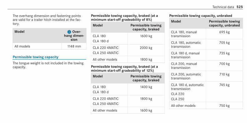
The overhang dimension and fastening pointsare valid for a trailer hitch installed at the fac‐tory.
Model 22 Over‐hang dimen‐
sion
All models 1148 mm
Permissible towing capacity
The tongue weight is not included in the towingcapacity.
Permissible towing capacity, braked (at aminimum start-off gradeability of 8%)
Model Permissible towingcapacity, braked
CLA 180CLA 180 d
1600 kg
CLA 220 4MATICCLA 250 4MATIC
2000 kg
All other models 1800 kg
Permissible towing capacity, braked (at aminimum start-off gradeability of 12%)
Model Permissible towingcapacity, braked
CLA 180CLA 180 d
1400 kg
CLA 220 4MATICCLA 250 4MATIC
1800 kg
All other models 1600 kg
Permissible towing capacity, unbraked
Model Permissible towingcapacity, unbraked
CLA 180, manualtransmission
695 kg
CLA 180, automatictransmission
705 kg
CLA 180 d, manualtransmission
735 kg
CLA 200, manualtransmission
700 kg
CLA 200, automatictransmission
710 kg
CLA 180 d, automatictransmissionCLA 220CLA 250
745 kg
All other models 750 kg
Technical data 525

Maximum tongue weight
* NOTE Damage caused by the trailercoming loose
If the tongue weight used is too low, thetrailer may come loose.# The tongue weight must not be below
50 kg.# Use a tongue weight that is as close as
possible to the maximum permissibletongue weight.
Tongue weight
Model Maximum tongueweight
All models 80 kg
Permissible rear axle load (trailer operation)
Axle load
Model Axle load
CLA 180, automatictransmission
1025 kg
CLA 180, manualtransmissionCLA 200
1030 kg
CLA 180 d, automatictransmission
1050 kg
CLA 180 d, manualtransmissionCLA 200 d, automatictransmission
1055 kg
CLA 220CLA 250
1035 kg
Model Axle load
CLA 220 d, automatictransmission
1060 kg
CLA 220 4MATICCLA 250 4MATIC
1075 kg
526 Technical data

Display messagesIntroduction
Notes on display messagesDisplay messages appear on the multifunctiondisplay.Display messages with graphic symbols are sim‐plified in the Owner's Manual and may differfrom the symbols on the multifunction display.The multifunction display shows high-priority dis‐play messages in red. Certain display messagesare accompanied by a warning tone.Please respond in accordance with the displaymessages and follow the additional notes in thisOwner's Manual.For some display messages, a symbol is alsoshown:R¤ Further information
RO Hide display message
You can select the desired symbol by swipingleft or right on the left-hand Touch Control.Press the¤ symbol to show further informa‐tion on the multifunction display. Press theOsymbol to hide the display message.You can hide low-priority display messages bypressing the¤ button or the left-hand TouchControl. The display messages are then stored inthe message memory.Rectify the cause of a display message asquickly as possible.High-priority display messages cannot be hid‐den. The multifunction display shows these dis‐play messages continuously until the cause ofthe message has been rectified.
Calling up stored display messagesOn-board computer:4 Service 5 1 messageIf there are no display messages, No messagesappears on the multifunction display.# Scroll through the display messages by swip‐
ing upwards or downwards on the left-handTouch Control.
# To exit the message memory: press the¤ button.
Display messages and warning/indicator lamps 527

Safety systems
Display messages Possible causes/consequences and MM Solutions
!÷currently unavailable SeeOwner's Manual
* ABS and ESP® are temporarily unavailable.Other driving systems and driving safety systems may also be temporarily unavailable.The brake system continues to operate normally. The braking distance may increase in an emergency braking situa‐tion.
& WARNING Risk of skidding if ABS and ESP® are malfunctioning
If ABS and ESP® are malfunctioning, the wheels could lock when braking and ESP® cannot carry out vehiclestabilisation.The steering capability and braking characteristics are thus severely impaired. The braking distance mayincrease in an emergency braking situation. In addition, other driving safety systems are switched off.# Drive on carefully.# Have ABS and ESP® checked immediately at a qualified specialist workshop.
# Carefully drive on a suitable stretch of road, making slight steering movements at a speed above 30 km/h.# If the display message does not disappear, consult a qualified specialist workshop immediately. Drive carefully.
528 Display messages and warning/indicator lamps

Display messages Possible causes/consequences and MM Solutions
!÷inoperative See Owner'sManual
* ABS and ESP® are malfunctioning.Other drive systems and driving safety systems may also be malfunctioning.The brake system continues to operate normally. The braking distance may increase in an emergency braking situa‐tion.
& WARNING Risk of skidding if ABS and ESP® are malfunctioning
If ABS and ESP® are malfunctioning, the wheels could lock when braking and ESP® cannot carry out vehiclestabilisation.The steering capability and braking characteristics are thus severely impaired. The braking distance mayincrease in an emergency braking situation. In addition, other driving safety systems are switched off.# Drive on carefully.# Have ABS and ESP® checked immediately at a qualified specialist workshop.
# Drive on carefully.# Consult a qualified specialist workshop immediately.
÷currently unavailable SeeOwner's Manual
* ESP® is temporarily unavailable.Other drive systems and driving safety systems may also be malfunctioning.
Display messages and warning/indicator lamps 529

Display messages Possible causes/consequences and MM Solutions
& WARNING Risk of skidding if ESP® is malfunctioning
If ESP® is malfunctioning, ESP® cannot carry out vehicle stabilisation. In addition, other driving safety systemsare switched off.# Drive on carefully.# Have ESP® checked at a qualified specialist workshop.
# Carefully drive on a suitable stretch of road, making slight steering movements at a speed above 30 km/h.# If the display message does not disappear, consult a qualified specialist workshop immediately. Drive carefully.
÷inoperative See Owner'sManual
* ESP® is malfunctioningOther drive systems and driving safety systems may also be malfunctioning.The brake system continues to operate normally. The braking distance may increase in an emergency braking situa‐tion.
& WARNING Risk of skidding if ESP® is malfunctioning
If ESP® is malfunctioning, ESP® cannot carry out vehicle stabilisation. In addition, other driving safety systemsare switched off.# Drive on carefully.# Have ESP® checked at a qualified specialist workshop.
530 Display messages and warning/indicator lamps

Display messages Possible causes/consequences and MM Solutions# Drive on carefully.# Consult a qualified specialist workshop immediately.
T!÷inoperative See Owner'sManual
* EBD, ABS and ESP® are malfunctioning.Other drive systems and driving safety systems may also be malfunctioning.
& WARNING Risk of skidding if EBD, ABS and ESP® are malfunctioning
If EBD, ABS and ESP® are malfunctioning, the wheels can lock when braking and ESP® cannot carry out vehiclestabilisation.The steering capability and braking characteristics are thus severely impaired. The braking distance mayincrease in an emergency braking situation. In addition, other driving safety systems are switched off.# Drive on carefully.# Have the brake system checked immediately at a qualified specialist workshop.
# Drive on carefully.# Consult a qualified specialist workshop immediately.
!Turn on the ignition torelease the parking brake
* The red! indicator lamp is lit.You have attempted to release the electric parking brake with the ignition switched off.# Switch on the ignition.
Display messages and warning/indicator lamps 531

Display messages Possible causes/consequences and MM Solutions
!Release parking brake
* The red! indicator lamp flashes.The electric parking brake is applied while you are driving:R A condition for automatic release of the electric parking brake is not fulfilled (/ page 188).R You are performing emergency braking using the electric parking brake (/ page 189).
# Check that the conditions for automatic release of the electric parking brake are fulfilled.# Release the electric parking brake manually.
!Parking brake See Owner'sManual
* The yellow! indicator lamp is lit. The electric parking brake is malfunctioning.To apply:# Switch off the ignition and switch it back on.# Apply the electric parking brake manually (/ page 189).
If it is not possible to apply the electric parking brake:# Consult a qualified specialist workshop.# Where necessary, also safeguard the parked vehicle against rolling away.The yellow! indicator lamp and the red! indicator lamp are lit. The electric parking brake is malfunction‐ing.To release:# Switch off the ignition and switch it back on.# Release the electric parking brake manually (/ page 189).
532 Display messages and warning/indicator lamps

Display messages Possible causes/consequences and MM Solutions
or# Release the electric parking brake automatically (/ page 188).If it is still not possible to release the electric parking brake:# Do not continue driving under any circumstances. Consult a qualified specialist workshop.The yellow! indicator lamp is lit and the red! indicator lamp is flashing. The electric parking brake is mal‐functioning.The electric parking brake could not be applied or released.# Switch off the ignition and switch it back on.
To apply:# Release and then apply the electric parking brake manually (/ page 189).
To release:# Apply and then release the electric parking brake manually.
If it is not possible to apply the electric parking brake or the red! indicator lamp continues to flash:# Do not continue driving under any circumstances. Consult a qualified specialist workshop.# Where necessary, also safeguard the parked vehicle against rolling away.The yellow! indicator lamp is lit and the red! indicator lamp flashes for approximately ten seconds afterthe electric parking brake has been applied or released. It then remains lit or goes out. The electric parking brake ismalfunctioning.
Display messages and warning/indicator lamps 533

Display messages Possible causes/consequences and MM Solutions
If the battery charge level is too low:# Charge the battery.
To apply:# Switch off the ignition.
The electric parking brake is applied automatically.
If the electric parking brake should not be applied, e.g. when washing the vehicle in an automatic car wash or whenhaving the vehicle towed, leave the ignition switched on. This does not include having the vehicle towed with therear axle raised.If the electric parking brake is not applied automatically:# Switch off the ignition and switch it back on.# Release and then apply the electric parking brake manually (/ page 189).
If it is still not possible to apply the electric parking brake:# Consult a qualified specialist workshop.# Where necessary, also safeguard the parked vehicle against rolling away.
To release:# If the conditions for automatic release are fulfilled and the electric parking brake is not released automatically,
release the electric parking brake manually (/ page 189).
534 Display messages and warning/indicator lamps

Display messages Possible causes/consequences and MM Solutions
If it is still not possible to release the electric parking brake:# Do not continue driving under any circumstances. Consult a qualified specialist workshop.
Risk of vehicle rolling awayParking brake not appliedSee Owner's Manual
* Vehicles with manual transmission: the electric parking brake has not been applied and you open the driver'sdoor.# Apply the electric parking brake.
Brake immediately * Vehicles with manual transmission: a malfunction has occurred while the HOLD function was activated.A tone may also sound at regular intervals. If you attempt to lock the vehicle, the tone will become louder.You cannot start the engine.# Immediately depress the brake pedal firmly until the display message disappears.
You can restart the engine.
JCheck brake fluid level
* There is insufficient brake fluid in the brake fluid reservoir.
& WARNING Risk of an accident due to low brake fluid level
If the brake fluid level is too low, the braking effect and the braking characteristics may be impaired.# Stop the vehicle as soon as possible, paying attention to road and traffic conditions. Do not continue driv‐
ing.# Consult a qualified specialist workshop.# Do not top up the brake fluid.
Display messages and warning/indicator lamps 535

Display messages Possible causes/consequences and MM Solutions# Pull over and stop the vehicle safely as soon as possible in accordance with the traffic conditions. Do not con‐
tinue driving under any circumstances.# Do not top up the brake fluid.# Consult a qualified specialist workshop.
Check brake pads SeeOwner's Manual
* The brake pads have reached the wear limit.
& WARNING Risk of accident due to restricted braking power
When the brake pads have reached their wear limit, the braking power may be restricted.# Drive on carefully.# Have the brake system checked immediately at a qualified specialist workshop.
# Consult a qualified specialist workshop.
6Restraint sys. malfunctionConsult workshop
* The restraint system is faulty (/ page 35).
& WARNING Risk of injury due to malfunctions in the restraint system
If the restraint system is malfunctioning, restraint system components may be triggered unintentionally or maynot deploy as intended during an accident. This may affect the seat belt tensioner or airbag, for example.# Have the restraint system checked and repaired immediately at a qualified specialist workshop.
536 Display messages and warning/indicator lamps

Display messages Possible causes/consequences and MM Solutions
Recognition of a restraint system fault:R The restraint system warning lamp 6 does not light up when the ignition is switched on.R The restraint system warning lamp 6 lights up continuously or repeatedly during a journey.# Consult a qualified specialist workshop immediately.
6Front left malfunction Con-sult workshop (Example)
* The corresponding restraint system is faulty (/ page 35).
& WARNING Risk of injury due to malfunctions in the restraint system
If the restraint system is malfunctioning, restraint system components may be triggered unintentionally or maynot deploy as intended during an accident. This may affect the seat belt tensioner or airbag, for example.# Have the restraint system checked and repaired immediately at a qualified specialist workshop.
Detection of a restraint system fault:R The restraint system warning lamp 6 does not light up when the ignition is switched on.R The restraint system warning lamp 6 lights up continuously or repeatedly during a journey.
# Consult a qualified specialist workshop immediately.
Display messages and warning/indicator lamps 537

Display messages Possible causes/consequences and MM Solutions
6Left windowbag malfunc-tion Consult work-shop (Example)
* The corresponding windowbag is malfunctioning (/ page 35).
& WARNING Risk of injury or fatal injury due to a malfunction in the window airbag
The window airbag might be triggered unintentionally or might not be triggered at all in the event of an accidentwith high deceleration.# Have the window airbag checked and repaired immediately at a qualified specialist workshop.
# Consult a qualified specialist workshop immediately.
Front-passenger airbag dis-abled See Owner's Manual
* The front passenger airbag has been deactivated although an adult or a person with an adult stature is on the frontpassenger seat. If additional forces are applied to the seat, the weight the system detects may be too low.
& WARNING ‑ Risk of injury or even fatal injury when the front passenger airbag is disabled
If the front passenger airbag is disabled, It will not be deployed in the event of an accident and cannot performits intended protective function.A person in the front passenger seat could then, for example, come into contact with the vehicle interior, espe‐cially if the person is sitting too close to the dashboard.# Be aware of the status of the front passenger airbag both before and during the journey.
# Pull over and stop the vehicle safely as soon as possible in accordance with the traffic conditions.# Check the status of the automatic front passenger airbag shutoff (/ page 46).# If necessary, consult a qualified specialist workshop immediately.
538 Display messages and warning/indicator lamps

Display messages Possible causes/consequences and MM Solutions
Front-passenger airbagenabled See Owner's Man-ual
* The front passenger airbag is enabled while the vehicle is in motion:R even when a child, a small adult or an object weighing less than the system weight threshold is located on the
front passenger seatR even when the front passenger seat is not occupied
The system may detect objects or forces that are adding to the weight applied to the seat.
& WARNING Risk of injury or fatal injury when using a child restraint system while the front passenger airbagis enabled
If you secure a child in a child restraint system on the front passenger seat and the front passenger airbag isenabled, the front passenger airbag can deploy in the event of an accident.The child could be struck by the airbag.# Ensure, both before and during the journey, that the status of the front passenger airbag is correct.
NEVER use a rearward facing child restraint on a seat protected by an ACTIVE FRONT AIRBAG in front of it;DEATH or SERIOUS INJURY to the CHILD can occur.
# Pull over and stop the vehicle safely as soon as possible in accordance with the traffic conditions.# Check the status of the automatic front passenger airbag shutoff (/ page 46).# If necessary, consult a qualified specialist workshop immediately.
Display messages and warning/indicator lamps 539

Display messages Possible causes/consequences and MM Solutions
Active Brake Assist Func-tions currently limited SeeOwner's Manual
* Vehicles with the Driving Assistance Package: Active Brake Assist with cross-traffic function, Evasive SteeringAssist or PRE‑SAFE® PLUS are temporarily unavailable or only partially available.Vehicles without the Driving Assistance Package: Active Brake Assist is temporarily unavailable or only partiallyavailable.The ambient conditions are outside the system limits (/ page 197).# Drive on.
As soon as the ambient conditions are within the system limits, the system will become available again.# If the display message does not disappear, stop the vehicle in accordance with the traffic conditions and restart
the engine.
Active Brake Assist Func-tions limited See Owner'sManual
* Vehicles with Driving Assistance Package: Active Brake Assist with cross-traffic function, Evasive SteeringAssist or PRE‑SAFE® PLUS is malfunctioning.Vehicles without Driving Assistance Package: Active Brake Assist is malfunctioning.# Consult a qualified specialist workshop.
PRE-SAFE inoperative SeeOwner's Manual
* PRE‑SAFE® functions are malfunctioning.# Consult a qualified specialist workshop.
Mercedes me connectServices limited See Own-er's Manual
* Service limited.At least one of the main functions of the Mercedes me connect system is malfunctioning.# Observe the notes on the diagnostics connection (/ page 28).# Consult a qualified specialist workshop.
540 Display messages and warning/indicator lamps

Display messages Possible causes/consequences and MM Solutions
GInoperative
* At least one of the main functions of the Mercedes me connect system or of the SOS emergency call system ismalfunctioning.# Consult a qualified specialist workshop.
Driving systems
Display messages Possible causes/consequences and MM Solutions
ÀATTENTION ASSIST: Take abreak!
* ATTENTION ASSIST has detected fatigue or an increasing lack of concentration on the part of the driver(/ page 240).# If necessary, take a break.
ÀATTENTION ASSIST inoper-ative
* ATTENTION ASSIST is malfunctioning.# Consult a qualified specialist workshop.
Display messages and warning/indicator lamps 541

Display messages Possible causes/consequences and MM Solutions
Fault Drive at max. 80km/h
* The adjustable damping is malfunctioning. The vehicle's handling characteristics may be affected.# Do not drive at speeds greater than 80 km/h.# Consult a qualified specialist workshop.
Active Steering Assist cur-rently unavailable See Own-er's Manual
* Active Steering Assist is temporarily unavailable.The ambient conditions are outside the system limits (/ page 213).# Drive on.
As soon as the ambient conditions are within the system limits, the system will become available again.# If necessary, clean the windscreen in the camera's field of vision.# Check the tyre pressure if necessary.
Active Steering Assist inop-erative
* Active Steering Assist is malfunctioning. Active Distance Assist DISTRONIC remains available.# Consult a qualified specialist workshop.
Ø * Active Steering Assist has reached the system limits(/ page 213).You have not steered independently for a considerable period of time.# Take over the steering and drive on in accordance with the traffic conditions.
Beginning emergency stop * Your hands are not on the steering wheel. Emergency stop is initiated (/ page 217).# Put your hands back on the steering wheel.You can cancel the deceleration at any time by performing one of the following actions:R steering
542 Display messages and warning/indicator lamps

Display messages Possible causes/consequences and MM Solutions
R braking or acceleratingR pressing a steering wheel buttonR operating Touch ControlR deactivating Active Distance Assist DISTRONIC
Active Steering Assist cur-rently unavailable due tomultiple emergency stops
* Active Steering Assist is temporarily unavailable due to multiple emergency stops.# Take over the steering and stop in accordance with the traffic conditions.# Switch off the ignition and switch it back on.
Active Steering Assist is available once more.
Active Lane Keeping Assistcurrently unavailable SeeOwner's Manual
* Active Lane Keeping Assist is temporarily unavailable.The ambient conditions are outside the system limits (/ page 249).# Drive on.
As soon as the ambient conditions are within the system limits, the system will become available again.
Active Lane Keeping Assistinoperative
* Active Lane Keeping Assist is malfunctioning.# Consult a qualified specialist workshop.
Blind Spot Assist currentlyunavailable See Owner'sManual
* Blind Spot Assist is temporarily unavailable.The system limits have been reached (/ page 246).# Drive on.
Once the cause of the problem is no longer present, the system will be available again.
Display messages and warning/indicator lamps 543

Display messages Possible causes/consequences and MM Solutions
or# If the display message does not disappear, stop the vehicle in accordance with the traffic conditions and restart
the engine.
Blind Spot Assist inopera-tive
* Blind Spot Assist is malfunctioning.# Consult a qualified specialist workshop.
Blind Spot Assist not availa-ble when towing a trailerSee Owner's Manual
* When you establish the electrical connection to the trailer, Blind Spot Assist is unavailable.# Press the left-hand Touch Control and acknowledge the display message.
Active Blind Spot Assistcurrently unavailable SeeOwner's Manual
* Active Blind Spot Assist is temporarily unavailable.The system limits have been reached (/ page 246).# Drive on.
Once the cause of the problem is no longer present, the system will be available again.or# If the display message does not disappear, stop the vehicle in accordance with the traffic conditions and restart
the engine.
Active Blind Spot Assistinoperative
* Active Blind Spot Assist is malfunctioning.# Consult a qualified specialist workshop.
544 Display messages and warning/indicator lamps

Display messages Possible causes/consequences and MM Solutions
Active Blind Spot Assistnot available when towinga trailer See Owner's Man-ual
* When you establish the electrical connection to the trailer, Active Blind Spot Assist is unavailable.# Press the left-hand Touch Control and acknowledge the display message.
Active Parking Assist andPARKTRONIC inoperativeSee Owner's Manual
* Active Parking Assist and Parking Assist PARKTRONIC are malfunctioning.# Stop the vehicle, paying attention to road and traffic conditions, and restart the engine.# If the display message continues to be displayed, consult a qualified specialist workshop.
Traffic Sign Assist currentlyunavailable See Owner'sManual
* Traffic Sign Assist is temporarily unavailable.# Drive on.
Once the cause of the problem is no longer present, the system will be available again.
Traffic Sign Assist inopera-tive
* Traffic Sign Assist is malfunctioning.# Consult a qualified specialist workshop.
KPlease check direction oftravel
* You have turned the wrong way onto a one-way street.# Check the direction of travel.# Turn as soon as possible, in accordance with the traffic conditions.
Display messages and warning/indicator lamps 545
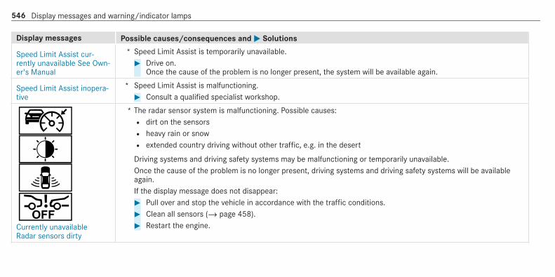
Display messages Possible causes/consequences and MM Solutions
Speed Limit Assist cur-rently unavailable See Own-er's Manual
* Speed Limit Assist is temporarily unavailable.# Drive on.
Once the cause of the problem is no longer present, the system will be available again.
Speed Limit Assist inopera-tive
* Speed Limit Assist is malfunctioning.# Consult a qualified specialist workshop.
çê¸æCurrently unavailableRadar sensors dirty
* The radar sensor system is malfunctioning. Possible causes:R dirt on the sensorsR heavy rain or snowR extended country driving without other traffic, e.g. in the desert
Driving systems and driving safety systems may be malfunctioning or temporarily unavailable.Once the cause of the problem is no longer present, driving systems and driving safety systems will be availableagain.If the display message does not disappear:# Pull over and stop the vehicle in accordance with the traffic conditions.# Clean all sensors (/ page 458).# Restart the engine.
546 Display messages and warning/indicator lamps

Display messages Possible causes/consequences and MM Solutions
_êàæáCurrently unavailable Cam-era view restricted
* The camera view is restricted. Possible causes:R dirt on the windscreen in the camera's field of visionR heavy rain, snow or fogR mist on the windscreen in front of the camera
% Mist detected on the windscreen is automatically removed using a built-in heater within approximately 12minutes.
Driving systems and driving safety systems may be malfunctioning or temporarily unavailable.Once the cause of the problem is no longer present, driving systems and driving safety systems will be availableagain.If the display message does not disappear:# Pull over and stop the vehicle in accordance with the traffic conditions.# Clean the windscreen if necessary.
ëOff
* The HOLD function is deactivated because the vehicle is skidding or a condition for activation is not met.# Reactivate the HOLD function later or check the activation conditions for the HOLD function (/ page 219).
Display messages and warning/indicator lamps 547
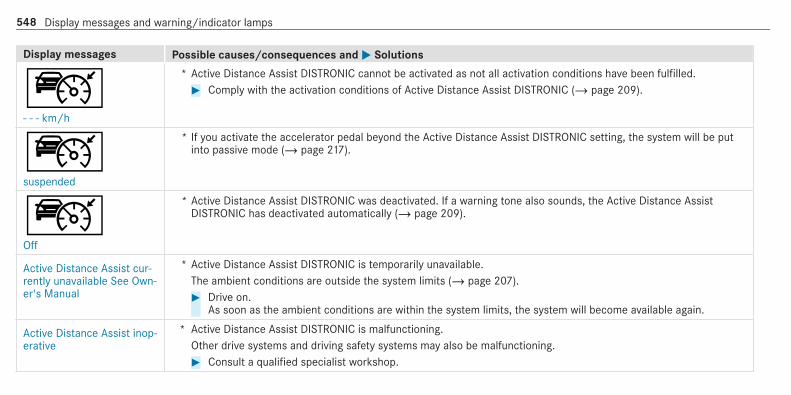
Display messages Possible causes/consequences and MM Solutions
ç- - - km/h
* Active Distance Assist DISTRONIC cannot be activated as not all activation conditions have been fulfilled.# Comply with the activation conditions of Active Distance Assist DISTRONIC (/ page 209).
çsuspended
* If you activate the accelerator pedal beyond the Active Distance Assist DISTRONIC setting, the system will be putinto passive mode (/ page 217).
çOff
* Active Distance Assist DISTRONIC was deactivated. If a warning tone also sounds, the Active Distance AssistDISTRONIC has deactivated automatically (/ page 209).
Active Distance Assist cur-rently unavailable See Own-er's Manual
* Active Distance Assist DISTRONIC is temporarily unavailable.The ambient conditions are outside the system limits (/ page 207).# Drive on.
As soon as the ambient conditions are within the system limits, the system will become available again.
Active Distance Assist inop-erative
* Active Distance Assist DISTRONIC is malfunctioning.Other drive systems and driving safety systems may also be malfunctioning.# Consult a qualified specialist workshop.
548 Display messages and warning/indicator lamps

Display messages Possible causes/consequences and MM Solutions
Active Distance Assistavailable again
* Active Distance Assist DISTRONIC is operational again and can be activated (/ page 209).
¯- - - km/h
* Cruise control cannot be activated as not all activation conditions are fulfilled.# Observe the activation conditions for cruise control (/ page 205).
Cruise control inoperative * Cruise control is malfunctioning.# Consult a qualified specialist workshop.
Cruise control and Limiterinoperative
* Cruise control and the limiter are malfunctioning.# Consult a qualified specialist workshop.
Cruise control off * Cruise control has been deactivated.If there is an additional warning tone, cruise control has been deactivated automatically (/ page 203).
È- - - km/h
* The limiter cannot be activated as not all activation conditions have been fulfilled.# Observe the activation conditions of the limiter (/ page 205).
Limiter inoperative * The limiter is malfunctioning.# Consult a qualified specialist workshop.
Display messages and warning/indicator lamps 549

Display messages Possible causes/consequences and MM Solutions
Limiter passive * If you depress the accelerator pedal beyond the pressure point (kickdown), the limiter is switched to passive mode(/ page 205).
Speed limit (winter tyres)XXX km/h
* You have reached the stored maximum speed for winter tyres. It is not possible to exceed this speed.
ðMaximum speed exceeded
* The maximum permissible speed has been exceeded (for certain countries only).# Drive more slowly.
Engine
Display messages Possible causes/consequences and MM Solutions
?Coolant Stop vehicleSwitch engine off
* The coolant is too hot.# Stop the vehicle immediately, paying attention to road and traffic conditions, and switch off the engine.
& WARNING Danger of burns when opening the bonnet
If you open the engine bonnet when the engine has overheated or during a fire in the engine compartment, youcould come into contact with hot gases or other escaping operating fluids.
550 Display messages and warning/indicator lamps

Display messages Possible causes/consequences and MM Solutions
# Before opening the bonnet, allow the engine to cool down.# In the event of a fire in the engine compartment, keep the engine bonnet closed and call the fire service.
# Wait until the engine has cooled down.# Make sure that the air supply to the radiator is not obstructed.# Avoiding high loads on the engine, drive to the nearest qualified specialist workshop. In doing so, ensure that
the coolant temperature display remains below 120 °C.
Top up coolant See Own-er’s Manual
* The coolant level is too low.
* NOTE Engine damage due to insufficient coolant
# Avoid long journeys with insufficient coolant.
# Add coolant (/ page 451).
? * The fan motor is defective.# Avoiding high loads on the engine, drive to the nearest qualified specialist workshop. In doing so, ensure that
the coolant temperature display remains below 120 °C.
#See Owner's Manual
* The battery is not being charged.
Display messages and warning/indicator lamps 551

Display messages Possible causes/consequences and MM Solutions
* NOTE Possible engine damage if you continue driving
# Do not continue driving under any circumstances.# Consult a qualified specialist workshop.
# Stop the vehicle immediately, paying attention to road and traffic conditions, and switch off the engine.# Consult a qualified specialist workshop.
#Stop vehicle See Owner'sManual
* The battery is no longer being charged and the battery charge level is too low.
* NOTE Possible engine damage if you continue driving
# Do not continue driving under any circumstances.# Consult a qualified specialist workshop.
# Pull over and stop the vehicle safely as soon as possible in accordance with the traffic conditions. Do not con‐tinue driving under any circumstances.
# Switch off the engine.# Consult a qualified specialist workshop.
552 Display messages and warning/indicator lamps

Display messages Possible causes/consequences and MM Solutions
#12 V battery See Owner'sManual
* The engine is off and the battery charge level is too low.# Switch off electrical consumers that are not required.# Leave the engine running for a few minutes, or drive for a longer distance.
The battery will charge.If the message appears while the engine is running, this indicates an on-board electrical system malfunction.# Consult a qualified specialist workshop.
#Stop vehicle Leave enginerunning
* The battery charge level is too low.# Pull over and stop the vehicle safely as soon as possible in accordance with the traffic conditions. Do not con‐
tinue driving under any circumstances.# Leave the engine running.# Wait until the display message disappears before pulling away.
æReserve fuel level
* The fuel supply has dropped into the reserve range.# Refuel.
!Clean the fuel filter
* Vehicles with diesel engines: the fuel filter is dirty or the water in the fuel filter needs to be drained.# Consult a qualified specialist workshop.
Display messages and warning/indicator lamps 553

Display messages Possible causes/consequences and MM Solutions
¸Replace air cleaner
* Vehicles with diesel engines: the engine air filter is dirty and must be replaced.# Consult a qualified specialist workshop.
Drive system MalfunctionVisit workshop
* The drive system is malfunctioning.# Consult a qualified specialist workshop.
Drive system MalfunctionStop Switch engine off
* The drive system is malfunctioning.# Stop the vehicle immediately, paying attention to road and traffic conditions, and switch off the engine.# Consult a qualified specialist workshop.
Engine oil
Display messages Possible causes/consequences and MM Solutions
4Add 1 litre engine oil whennext refuelling
* Display message only for certain engines:The engine oil level has dropped to the minimum level.
* NOTE Engine damage caused by driving with insufficient engine oil
# Avoid long journeys with insufficient engine oil.
554 Display messages and warning/indicator lamps

Display messages Possible causes/consequences and MM Solutions# When next refuelling, add 1 litre of engine oil.
Top up engine oil (/ page 450).Notes on engine oil (/ page 519).
4Engine oil level Stop vehi-cle Switch engine off
* Display message only for certain engines:The engine oil level is too low.
* NOTE Engine damage caused by driving with insufficient engine oil
# Avoid long journeys with insufficient engine oil.
# Pull over and stop the vehicle safely as soon as possible in accordance with the traffic conditions. Do not con‐tinue driving under any circumstances.
# Switch off the engine.# Top up with 1 l engine oil.# Check the engine oil level.
Top up engine oil (/ page 450).Notes on engine oil (/ page 519).
Display messages and warning/indicator lamps 555

Display messages Possible causes/consequences and MM Solutions
4Engine oil level Reduce oillevel
* Display message only for certain engines:The engine oil level is too high.
* NOTE Engine damage caused by driving with excess engine oil
# Avoid long journeys with excess engine oil.
# Consult a qualified specialist workshop immediately and have the engine oil siphoned off.
4Engine oil pressure StopSwitch off engine
* Display message only for certain engines:The engine oil pressure is too low.
* NOTE Engine damage caused by driving with insufficient engine oil pressure
# Avoid driving with insufficient engine oil pressure.
# Pull over and stop the vehicle safely as soon as possible in accordance with the traffic conditions. Do not con‐tinue driving under any circumstances.
# Consult a qualified specialist workshop.
556 Display messages and warning/indicator lamps
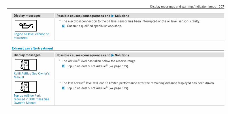
Display messages Possible causes/consequences and MM Solutions
5Engine oil level cannot bemeasured
* The electrical connection to the oil level sensor has been interrupted or the oil level sensor is faulty.# Consult a qualified specialist workshop.
Exhaust gas aftertreatment
Display messages Possible causes/consequences and MM Solutions
ÚRefill AdBlue See Owner’sManual
* The AdBlue® level has fallen below the reserve range.# Top up at least 5 l of AdBlue® (/ page 179).
ÚTop up AdBlue Perf.reduced in XXX miles SeeOwner's Manual
* The low AdBlue® level will lead to limited performance after the remaining distance displayed has been driven.# Top up at least 5 l of AdBlue® (/ page 179).
Display messages and warning/indicator lamps 557

Display messages Possible causes/consequences and MM Solutions
ÚTop up AdBlue Perf.reduced: XXX km/h Nostart in XXX km
* The low AdBlue® level will lead to limited performance above the speed displayed.After the displayed remaining distance has been covered, it will no longer be possible to start the engine.# Top up at least 5 l of AdBlue® (/ page 179).
ÚRefill AdBlue Engine startnot possible
* The AdBlue® tank is empty. You can no longer start the engine.# Top up at least 5 l of AdBlue® (/ page 179).# Switch on the ignition.
You can restart the engine after approximately one minute.
¯AdBlue system fault SeeOwner's Manual
* The AdBlue® system is malfunctioning.# Consult a qualified specialist workshop immediately.
558 Display messages and warning/indicator lamps

Display messages Possible causes/consequences and MM Solutions
¯AdBlue system fault Perf.reduced in XXX miles SeeOwner's Manual
* The AdBlue® system is malfunctioning. Performance will be reduced after the remaining distance displayed hasbeen covered.# Consult a qualified specialist workshop immediately.
¯AdBlue system fault Perf.reduced: XXX km/h Nostart in XXX km
* Power reduction due to the AdBlue® system fault. After the distance displayed has been covered, it will no longerbe possible to start the engine.# Consult a qualified specialist workshop immediately.
¯AdBlue system fault Enginestart not possible
* The AdBlue® system is malfunctioning. You can no longer start the engine.# Consult a qualified specialist workshop immediately.
Display messages and warning/indicator lamps 559

Transmission
Display messages Possible causes/consequences and MM Solutions
Apply brake to deselectPark (P) position
* You have attempted to shift the transmission out of positionj and into another transmission position.# Depress the brake pedal.# Shift the transmission to positionk,i orh.
To shift out of P or N,depress brake and startengine
* You have attempted to shift the transmission out of positionj ori into another transmission position.# Depress the brake pedal.# Start the engine.
Risk of vehicle rollingDriver door open and trans-mission not in P
* The driver's door is not fully closed and the transmission is in positionk,i orh.# Shift the transmission to positionj when you park the vehicle.
N permanently active Riskof vehicle rolling
* While the vehicle is rolling or while you are driving, the transmission has been shifted to positioni.# Depress the brake pedal to stop and, when the vehicle is stationary, shift the transmission to positionj.# To continue your journey, shift the transmission to positionh ork.
Only select Park (P) whenvehicle is stationary
* The transmission can only be shifted to positionj when the vehicle is stationary.
Apply brake to select R * You have tried to switch to transmission positionk.# Depress the brake pedal.
560 Display messages and warning/indicator lamps

Display messages Possible causes/consequences and MM Solutions# Shift the transmission to positionk.
Without changing gear,consult workshop
* The transmission is malfunctioning. The transmission position can no longer be shifted.# When the transmission is in positionh, consult a qualified specialist workshop and do not change the trans‐
mission position.# For all other transmission positions, park the vehicle safely.# Consult a qualified specialist workshop.
Reversing not poss. Con-sult workshop
* The transmission is malfunctioning. The transmission positionk cannot be engaged.# Consult a qualified specialist workshop.
Transmission MalfunctionStop
* The transmission is malfunctioning. The transmission shifts to positioni automatically.# Pull over and stop the vehicle safely as soon as possible in accordance with the traffic conditions.# Switch the transmission to positionj.# Consult a qualified specialist workshop.
Auxiliary battery malfunc-tion
* The auxiliary battery for the transmission is no longer being charged.# Consult a qualified specialist workshop.# Until then, manually set the transmission to positionj before you switch off the engine.# Before leaving the vehicle, apply the electric parking brake.
Transmission Malfunction * The transmission is malfunctioning. The cause could be an overheated clutch or blocked gears.
Display messages and warning/indicator lamps 561

Display messages Possible causes/consequences and MM Solutions# Let the transmission cool down.# If the display message still appears following a restart, consult a qualified specialist workshop.
Trans. oil overheated Driveon with care
* The transmission is overheating. When the display message is active, start-up and driving characteristics may betemporarily impaired.# Drive at low speeds.# Avoid sporty driving.# Before starting up on uphill gradients, let the transmission cool down until the display message disappears.
Parking lock malfunct.Apply parking brake
* The transmission is malfunctioning. The transmission positionj cannot be engaged.# Park the vehicle safely.# Use the electric parking brake to secure the vehicle against rolling away.
Teaching in transmissionOperate selector leverBrake for XX seconds Riskof vehicle rolling
* The transmission is being taught in. There is a risk of the vehicle rolling away.# Depress and hold the brake pedal until the teach-in procedure has been completed.
The electric parking brake is applied automatically during the teach-in procedure.# Switch on the ignition.# Select transmission positionj,k ori.
Risk of vehicle rolling awayApply parking brake SeeOwner's Manual
* The transmission position cannot be identified securely.# Use the electric parking brake to secure the vehicle against rolling away.
562 Display messages and warning/indicator lamps

Display messages Possible causes/consequences and MM Solutions
Teaching in transmissioncomplete
* The transmission's teach-in process is complete. All transmission positions can be engaged again.
Transmission MalfunctionVisit workshop
* The transmission is malfunctioning.Consult a qualified specialist workshop.
_Before starting the engine,turn the steering wheel.
* The electric steering lock has not unlocked the steering.# Switch off the ignition.# To unlock the steering, move the steering wheel slightly to the left and right.# Switch the ignition back on.
ÙSteering malfunction SeeOwner's Manual
* The electric steering lock is malfunctioning. The steering may be locked by the electric steering lock.
& WARNING Risk of accident if steering capability is impaired
If the steering does not function as intended, the vehicle's operating safety is jeopardised.# Pull over and stop the vehicle safely as soon as possible, paying attention to road and traffic conditions.
Do not continue driving under any circumstances.# Consult a qualified specialist workshop.
# Pull over and stop the vehicle safely as soon as possible in accordance with the traffic conditions. Do not con‐tinue driving under any circumstances.
# Consult a qualified specialist workshop.
Display messages and warning/indicator lamps 563

Display messages Possible causes/consequences and MM Solutions
Depress clutch fully tostart engine
* You have attempted to start the engine without depressing the clutch pedal.# Depress the clutch pedal and then start the engine.The engine has stalled while the vehicle was pulling away, e.g. because the clutch pedal was released too quickly.# Depress the clutch pedal again.
The engine will start automatically.# Slowly release the clutch pedal to pull away.
Clutch overheated Avoidpulling away for XX:XX mins
* The clutch is under considerable load and is overheating.Avoid frequent pulling away and driving at walking pace over longer distances.# Stop the vehicle, paying attention to road and traffic conditions, and leave the engine running.
The clutch will cool more quickly when the engine is running.or# If possible, continue driving at a steady speed and remove your foot from the clutch pedal. Do not ride the
clutch.The clutch will cool while the vehicle is in motion.When the clutch has cooled down, the display message will disappear.
564 Display messages and warning/indicator lamps
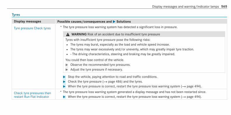
Tyres
Display messages Possible causes/consequences and MM Solutions
Tyre pressure Check tyres * The tyre pressure loss warning system has detected a significant loss in pressure.
& WARNING Risk of an accident due to insufficient tyre pressure
Tyres with insufficient tyre pressure pose the following risks:R The tyres may burst, especially as the load and vehicle speed increase.R The tyres may wear excessively and/or unevenly, which may greatly impair tyre traction.R ‑ The driving characteristics, steering and braking may be greatly impaired.
You could then lose control of the vehicle.# Observe the recommended tyre pressures.# Adjust the tyre pressure if necessary.
# Stop the vehicle, paying attention to road and traffic conditions.# Check the tyre pressure (/ page 486) and the tyres.# When the tyre pressure is correct, restart the tyre pressure loss warning system (/ page 494).
Check tyre pressures thenrestart Run Flat Indicator
* The tyre pressure loss warning system generated a display message and has not been restarted since.# When the tyre pressure is correct, restart the tyre pressure loss warning system (/ page 494).
Display messages and warning/indicator lamps 565
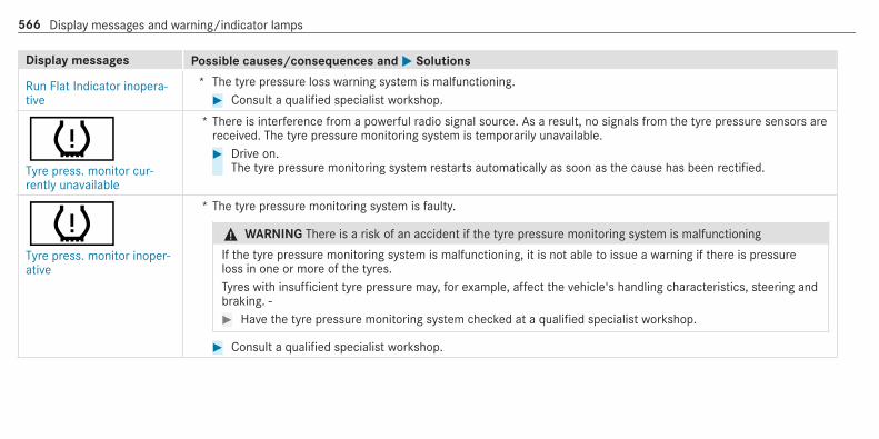
Display messages Possible causes/consequences and MM Solutions
Run Flat Indicator inopera-tive
* The tyre pressure loss warning system is malfunctioning.# Consult a qualified specialist workshop.
hTyre press. monitor cur-rently unavailable
* There is interference from a powerful radio signal source. As a result, no signals from the tyre pressure sensors arereceived. The tyre pressure monitoring system is temporarily unavailable.# Drive on.
The tyre pressure monitoring system restarts automatically as soon as the cause has been rectified.
hTyre press. monitor inoper-ative
* The tyre pressure monitoring system is faulty.
& WARNING There is a risk of an accident if the tyre pressure monitoring system is malfunctioning
If the tyre pressure monitoring system is malfunctioning, it is not able to issue a warning if there is pressureloss in one or more of the tyres.Tyres with insufficient tyre pressure may, for example, affect the vehicle's handling characteristics, steering andbraking. ‑# Have the tyre pressure monitoring system checked at a qualified specialist workshop.
# Consult a qualified specialist workshop.
566 Display messages and warning/indicator lamps

Display messages Possible causes/consequences and MM Solutions
hTyre press. monitor inoper-ative No wheel sensors
* The wheels fitted do not have suitable tyre pressure sensors. The tyre pressure monitoring system is deactivated.# Fit wheels with suitable tyre pressure sensors.
hWheel sensor(s) missing
* There is no signal from the tyre pressure sensor of one or more wheels. The pressure of the affected tyre is notdisplayed.# Have the faulty tyre pressure sensor replaced at a qualified specialist workshop.
hCheck tyre(s)
* The tyre pressure in one or more tyres has dropped significantly. The wheel position is displayed.
& WARNING Risk of an accident due to insufficient tyre pressure
Tyres with insufficient tyre pressure pose the following risks:R The tyres may burst, especially as the load and vehicle speed increase.R The tyres may wear excessively and/or unevenly, which may greatly impair tyre traction.R ‑ The driving characteristics, steering and braking may be greatly impaired.
You could then lose control of the vehicle.# Observe the recommended tyre pressures.# Adjust the tyre pressure if necessary.
Display messages and warning/indicator lamps 567

Display messages Possible causes/consequences and MM Solutions# Stop the vehicle, paying attention to road and traffic conditions.# Check the tyre pressure (/ page 486) and the tyres.
hRectify tyre pressure
* The tyre pressure is too low in at least one of the tyres, or the tyre pressure difference between the wheels is toogreat.# Check the tyre pressure and add air, if necessary.# When the tyre pressure is correct, restart the tyre pressure monitoring system (/ page 489).
hWarning tyre defect
* The tyre pressure in one or more tyres has dropped suddenly. The wheel position is displayed.
& WARNING Risk of an accident from driving with a flat tyre
Flat tyres are dangerous in the following ways:R The tyres can overheat and cause a fire.R ‑ The driving characteristics, steering and braking may be greatly impaired.
You could then lose control of the vehicle.# Do not drive with a flat tyre.# Observe the notes on flat tyres.
Notes on flat tyres (/ page 464).# Stop the vehicle, paying attention to road and traffic conditions.# Check the tyres.
568 Display messages and warning/indicator lamps

Display messages Possible causes/consequences and MM Solutions
Tyre(s) overheated * At least one tyre is overheating. The affected tyres are displayed in red. At temperatures close to the limit value,the tyres are displayed in yellow.# Drive more slowly.
Reduce speed * At least one tyre is overheating. The affected tyres are displayed in red. At temperatures close to the limit value,the tyres are displayed in yellow.
& WARNING Risk of an accident from driving with overheated tyres
Overheated tyres may burst, particularly at high speeds.# Reduce speed so that the tyres cool down.
# Reduce speed so that the tyres cool down.
Key
Display messages Possible causes/consequences and MM Solutions
ÀReplace key See Owner'sManual
* Vehicles with a digital vehicle key: only a few or no authorisations remain for starting the engine.# Make sure that the internet connection is not limited by certain mobile phone settings.# Open the Mercedes me connect http://www.mercedes.me and call up the digital vehicle key service.# Deactivate the service first and then activate it again.# If the display message still appears, contact the Mercedes-Benz Customer Assistance Center (CAC).
Display messages and warning/indicator lamps 569

Display messages Possible causes/consequences and MM Solutions
Vehicles with a digital vehicle key sticker: only a few or no authorisations remain for starting the engine.# Order a new digital vehicle key sticker from a Mercedes-Benz Service Centre or at http://www.mercedes-
benz.com/connect.
ÁReplace key
* The key needs to be replaced.# Consult a qualified specialist workshop.
ÁChange key batteries
* The key battery is discharged.# Replace the battery (/ page 78).
ÁKey not detected (whitedisplay message)
* The key is currently undetected.# Change the location of the key in the vehicle.# If the key is still not recognised, place it in the slot for starting with the key (/ page 159).
570 Display messages and warning/indicator lamps

Display messages Possible causes/consequences and MM Solutions
ÁKey not detected (red dis‐play message)
* The key cannot be detected and may no longer be in the vehicle.The key is no longer in the vehicle and you switch off the engine:R You can no longer start the engine.R You cannot centrally lock the vehicle.
# Ensure that the key is in the vehicle.
If the key detection function has a malfunction due to a strong radio signal source:# Pull over and stop the vehicle safely as soon as possible in accordance with the traffic conditions.# Place the key in the slot for starting the engine with the key (/ page 159).
ÁPlace the key in themarked space See Owner'sManual
* The key detection function is malfunctioning.# Change the location of the key in the vehicle.# Place the key in the slot for starting the engine with the key (/ page 159).
Display messages and warning/indicator lamps 571
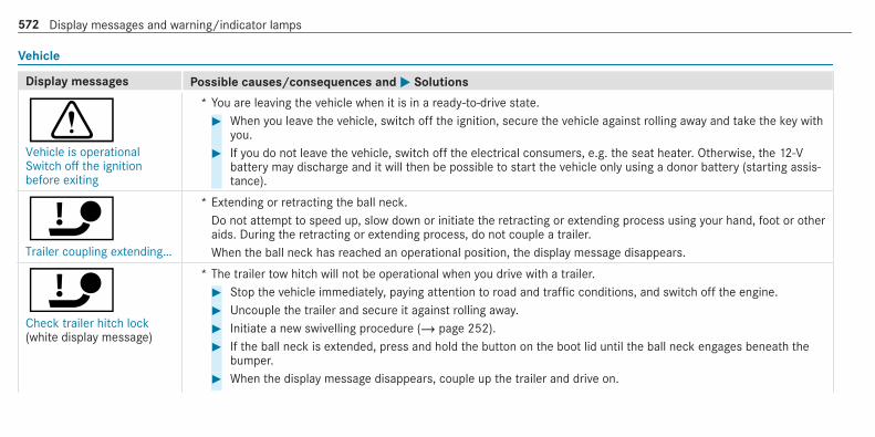
Vehicle
Display messages Possible causes/consequences and MM Solutions
dVehicle is operationalSwitch off the ignitionbefore exiting
* You are leaving the vehicle when it is in a ready-to-drive state.# When you leave the vehicle, switch off the ignition, secure the vehicle against rolling away and take the key with
you.# If you do not leave the vehicle, switch off the electrical consumers, e.g. the seat heater. Otherwise, the 12‑V
battery may discharge and it will then be possible to start the vehicle only using a donor battery (starting assis‐tance).
ïTrailer coupling extending…
* Extending or retracting the ball neck.Do not attempt to speed up, slow down or initiate the retracting or extending process using your hand, foot or otheraids. During the retracting or extending process, do not couple a trailer.When the ball neck has reached an operational position, the display message disappears.
ïCheck trailer hitch lock(white display message)
* The trailer tow hitch will not be operational when you drive with a trailer.# Stop the vehicle immediately, paying attention to road and traffic conditions, and switch off the engine.# Uncouple the trailer and secure it against rolling away.# Initiate a new swivelling procedure (/ page 252).# If the ball neck is extended, press and hold the button on the boot lid until the ball neck engages beneath the
bumper.# When the display message disappears, couple up the trailer and drive on.
572 Display messages and warning/indicator lamps

Display messages Possible causes/consequences and MM Solutions
& WARNING Risk of an accident if the ball neck is not locked
If the ball neck is not in the locked position, the trailer may come loose.# Pull over and stop the vehicle safely as soon as possible, paying attention to road and traffic conditions.
Do not continue driving under any circumstances.# Uncouple the trailer and secure it against rolling away.# Initiate a new swivelling procedure and do not re-couple the trailer until the display message disappears.
If the display message does not disappear, the trailer tow hitch is defective and the ball neck is not locked.# Do not couple up the trailer. Drive on without the trailer. Note the reduced ground clearance due to the
unlocked ball neck.# Consult a qualified specialist workshop.The trailer tow hitch will not be operational when the vehicle is at a standstill.# Uncouple the coupled trailer and secure it against rolling away.# Initiate a new swivelling procedure (/ page 252).# If the ball neck is retracted: press and hold the button on the boot lid until the ball neck engages vertically in
the locked position and then engages beneath the bumper.# If the ball neck is extended: press and hold the button on the boot lid until the ball neck engages beneath the
bumper.
If the display message does not disappear, the trailer tow hitch is defective and the ball neck is not locked.
Display messages and warning/indicator lamps 573

Display messages Possible causes/consequences and MM Solutions# Do not couple up the trailer. Drive on without the trailer. Note the reduced ground clearance due to the
unlocked ball neck.# Consult a qualified specialist workshop.
ïOperation only possible intransmission position P
* You have attempted to displace the ball neck and the transmission is in positionk,i orh.# Depress the brake pedal.# Shift the transmission to positionj.
ïOperation only possible intransmission position N
* Vehicles with manual transmission: you attempted to swivel the ball neck and the transmission is not in neutrali.# Shift the transmission to neutrali.
ÙSteering malfunctionIncreased physical effortSee Owner's Manual
* The power assistance for the steering is malfunctioning.
& WARNING Risk of an accident due to altered steering characteristics
If the power assistance of the steering fails partially or completely, you will need to use more force to steer.# If safe steering is possible, drive on carefully.# Visit or consult a qualified specialist workshop immediately.
574 Display messages and warning/indicator lamps

Display messages Possible causes/consequences and MM Solutions# If safe steering is possible, drive on carefully.# Visit or consult a qualified specialist workshop immediately.
ÙSteering malfunction Stopimmediately See Owner'sManual
* The steering is malfunctioning. Steering capability is considerably impaired.
& WARNING Risk of accident if steering capability is impaired
If the steering does not function as intended, the vehicle's operating safety is jeopardised.# Pull over and stop the vehicle safely as soon as possible, paying attention to road and traffic conditions.
Do not continue driving under any circumstances.# Consult a qualified specialist workshop.
# Pull over and stop the vehicle safely as soon as possible in accordance with the traffic conditions. Do not con‐tinue driving under any circumstances.
# Consult a qualified specialist workshop.
Active bonnet malfunctionSee Owner's Manual
* The active bonnet (pedestrian protection) is malfunctioning or inoperative after having already been triggered.# Consult a qualified specialist workshop.
C * At least one door is open.# Close all doors.
M * The bonnet is open.
Display messages and warning/indicator lamps 575

Display messages Possible causes/consequences and MM Solutions
& WARNING Risk of accident due to driving with the engine bonnet unlocked
An unlocked engine bonnet may open up when the vehicle is in motion and block your view.# Never unlock the engine bonnet when driving.# Before every trip, ensure that the engine bonnet is locked.
# Stop the vehicle immediately, paying attention to road and traffic conditions.# Close the bonnet.
N * The boot lid is open.
& DANGER Risk of exhaust gas poisoning
Combustion engines emit poisonous exhaust gases such as carbon monoxide. Exhaust gases can enter thevehicle interior if the boot lid is open when the engine is running, especially if the vehicle is in motion.# Always switch off the engine before opening the boot lid.# Never drive with the boot lid open.
# Close the boot lid.
Anti-theft alarm systemMalfunction
* The anti-theft alarm system is malfunctioning.# Consult a qualified specialist workshop.
576 Display messages and warning/indicator lamps

Display messages Possible causes/consequences and MM Solutions
¥Top up washer fluid
* The washer fluid level in the washer fluid reservoir has dropped below the minimum.# Top up the washer fluid (/ page 451).
Climate control
Display messages Possible causes/consequences and MM Solutions
&inoperative See Owner'sMan.
* The stationary heater is temporarily malfunctioning.# When the vehicle is on a level surface and the engine has cooled down, make up to four attempts to switch on
the stationary heater, waiting several minutes between each attempt.# If the stationary heater does not switch on, consult a qualified specialist workshop.
&inoperative Battery low
* The on-board electrical system voltage is too low.The stationary heater has switched itself off.# Drive for an extended period until the battery has reached a sufficient charge level again.
Display messages and warning/indicator lamps 577

Display messages Possible causes/consequences and MM Solutions
&inoperative Refuel vehicle
* There is too little fuel in the fuel tank. The stationary heater cannot be switched on.# Refuel the vehicle.
Lights
Display messages Possible causes/consequences and MM Solutions
bLeft dipped beam (Example)
* The corresponding light source is defective.# Drive on carefully.# Consult a qualified specialist workshop immediately.
or# Check whether you are permitted to replace the light source yourself (/ page 138).% LED light bulbs: the display message for the corresponding lamp appears only when all the light-emitting diodes
in the lamp have failed.
578 Display messages and warning/indicator lamps
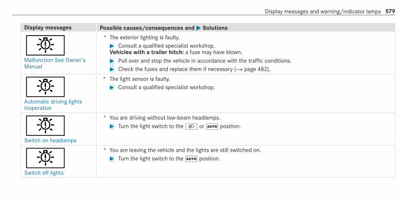
Display messages Possible causes/consequences and MM Solutions
bMalfunction See Owner'sManual
* The exterior lighting is faulty.# Consult a qualified specialist workshop.Vehicles with a trailer hitch: a fuse may have blown.# Pull over and stop the vehicle in accordance with the traffic conditions.# Check the fuses and replace them if necessary (/ page 482).
bAutomatic driving lightsinoperative
* The light sensor is faulty.# Consult a qualified specialist workshop.
bSwitch on headlamps
* You are driving without low-beam headlamps.# Turn the light switch to the L orà position.
bSwitch off lights
* You are leaving the vehicle and the lights are still switched on.# Turn the light switch to theà position.
Display messages and warning/indicator lamps 579

Display messages Possible causes/consequences and MM Solutions
bHazard warning lamps mal-functioning
* The hazard warning lamp switch is faulty.# Consult a qualified specialist workshop.
bIntelligent Light Systeminoperative
* The Intelligent Light System is faulty. The lighting system continues to function properly without the functions ofthe Intelligent Light System.# Consult a qualified specialist workshop.
bActive Light System inoper-ative
* The active headlamps are faulty.# Consult a qualified specialist workshop.
Adaptive Highbeam Assistcurrently unavailable SeeOwner's Manual
* Adaptive Highbeam Assist is temporarily unavailable.The system limits have been reached (/ page 133).# Drive on.
Once the cause of the problem is no longer present, the system will be available again. The Adaptive HighbeamAssist available again display message appears.
580 Display messages and warning/indicator lamps

Display messages Possible causes/consequences and MM Solutions
Adaptive Highbeam Assistinoperative
* Adaptive Highbeam Assist is malfunctioning.# Consult a qualified specialist workshop.
Adaptive Highbeam AssistPlus currently unavailableSee Owner's Manual
* Adaptive Highbeam Assist Plus is temporarily unavailable.The system limits have been reached (/ page 134).# Drive on.
Once the cause of the problem is no longer present, the system will be available again. The Adaptive HighbeamAssist Plus available again display message appears.
Adaptive Highbeam AssistPlus inoperative
* Adaptive Highbeam Assist Plus is faulty.# Consult a qualified specialist workshop.
Warning and indicator lampsOverview of warning and indicator lamps
Some systems will perform a self-test when theignition is switched on. Some warning and indi‐cator lamps may briefly light up or flash. Thisbehaviour is non-critical. These warning and indi‐cator lamps indicate a malfunction only if theylight up or flash after the engine has been star‐ted or during a journey.
Display messages and warning/indicator lamps 581

Instrument display (standard)
Instrument display in the widescreen cockpit
Depending on the display setting, the positionsof the indicator lamps on the instrument displaymay differ from the example shown.
Warning and indicator lamps:L Low beam(/ page 128)T Standing lights(/ page 128)K High beam(/ page 130)#! Turn signal lights(/ page 130)R Rear fog light(/ page 128)6 Restraint system(/ page 583)ü Seat belt not fastened(/ page 588)J Brakes (yellow)(/ page 583)J Brakes (red)(/ page 583)! Electric parking brake (yellow)
(/ page 583)! Electric parking brake (red)
(/ page 583)! ABS malfunction(/ page 583)
÷ ESP®(/ page 583)å ESP® OFF(/ page 583)L Distance warning(/ page 589)Ù Electric power steering malfunction
(/ page 594); Engine diagnostics(/ page 590)% Preglow# Electrical fault(/ page 590)æ Fuel reserve with fuel filler cap loca‐
tion indicator(/ page 590)? Vehicles with a widescreen cock‐
pit: Coolant too hot/cold(/ page 590)
h Tyre pressure monitor(/ page 592)ï Trailer hitch is not operational or is
swiveling(/ page 594)
582 Display messages and warning/indicator lamps

Safety systems
Warning/indicator lamp Possible causes/consequences and MM Solutions
!ABS warning lamp
The yellow ABS warning lamp is lit while the engine is running.ABS is malfunctioning.If there is an additional warning tone, EBD is malfunctioning.Other drive systems and driving safety systems may also be malfunctioning.
& WARNING There is risk of skidding if EBD or ABS is malfunctioning
If EBD or ABS is malfunctioning, the wheels could lock when brakingThe steering capability and braking characteristics are thus severely impaired. The braking distance may increase inan emergency braking situation. In addition, other driving safety systems are switched off.# Drive on carefully.# Have the brake system checked immediately at a qualified specialist workshop.
# Drive on carefully.# Observe the messages on the multifunction display.# Consult a qualified specialist workshop.
Display messages and warning/indicator lamps 583

Warning/indicator lamp Possible causes/consequences and MM Solutions
÷ESP® warning lamp flashes
The yellow ESP® warning lamp flashes while the vehicle is in motion.At least one wheel and tyre assembly has reached its traction limit (/ page 193).# Adapt your driving style to suit the road and weather conditions.
÷ESP® warning lamp lightsup
The yellow ESP® warning lamp is lit while the engine is running.
ESP® is malfunctioningOther drive systems and driving safety systems may also be malfunctioning.
& WARNING Risk of skidding if ESP® is malfunctioning
If ESP® is malfunctioning, ESP® cannot carry out vehicle stabilisation. In addition, other driving safety systems areswitched off.# Drive on carefully.# Have ESP® checked at a qualified specialist workshop.
# Drive on carefully.# Observe the messages on the multifunction display.# Consult a qualified specialist workshop.
584 Display messages and warning/indicator lamps

Warning/indicator lamp Possible causes/consequences and MM Solutions
åESP® OFF warning lamp
The yellow ESP® OFF warning lamp is lit while the engine is running.
ESP® is deactivated.
& WARNING Risk of skidding when driving with ESP® deactivated
If ESP® is deactivated, ESP® cannot carry out vehicle stabilisation. The availability of further driving safety systemsis also limited.# Drive on carefully.# Only deactivate ESP® for as long as the situation requires.
If ESP® cannot be activated, ESP® is malfunctioning.# Have ESP® checked immediately at a qualified specialist workshop.
# Observe the notes on deactivating ESP® (/ page 193).
JBrake system warning lamp(yellow)
The yellow brake system warning lamp is lit while the engine is running.
& WARNING Risk of an accident due to a brake system malfunction
If the brake system is malfunctioning, braking characteristics may be impaired.# Drive on carefully.# Have the brake system checked immediately at a qualified specialist workshop.
Display messages and warning/indicator lamps 585

Warning/indicator lamp Possible causes/consequences and MM Solutions# Adjust your speed and continue to drive carefully, leaving a suitable distance to the vehicle in front.# If the multifunction display shows a display message, please observe it.# Consult a qualified specialist workshop.
JBrake system warning lamp(red)
The red brake system warning lamp is lit while the engine is running.Possible causes:R The brake force boosting is malfunctioning and the braking characteristics may be affected.R There is insufficient brake fluid in the brake fluid reservoir.
& WARNING Risk of accident and injury if brake force boosting is malfunctioning
If brake force boosting is malfunctioning, increased brake pedal force may be necessary for braking. The brakingcharacteristics may be impaired. The braking distance can increase in emergency braking situations.# Stop in a safe location immediately. Do not continue driving!# Consult a qualified specialist workshop.
& WARNING Risk of an accident due to low brake fluid level
If the brake fluid level is too low, the braking effect and the braking characteristics may be impaired.# Stop the vehicle as soon as possible, paying attention to road and traffic conditions. Do not continue driving.# Consult a qualified specialist workshop.
586 Display messages and warning/indicator lamps

Warning/indicator lamp Possible causes/consequences and MM Solutions
# Do not top up the brake fluid.
# Pull over and stop the vehicle safely as soon as possible, paying attention to road and traffic conditions. Do notcontinue driving under any circumstances.
# Observe the messages on the multifunction display.# Consult a qualified specialist workshop.
!Red indicator lamp, electricparking brake applied
!Yellow electric parkingbrake indicator lamp is mal‐functioning
The red electric parking brake indicator lamp flashes or is lit. The yellow indicator lamp is also lit if the electric parkingbrake malfunctions.# Observe the messages on the multifunction display.
Display messages and warning/indicator lamps 587

Warning/indicator lamp Possible causes/consequences and MM Solutions
6Restraint system warninglamp
The red restraint system warning lamp is lit while the engine is running.The restraint system is faulty (/ page 35).
& WARNING Risk of injury due to malfunctions in the restraint system
If the restraint system is malfunctioning, restraint system components may be triggered unintentionally or may notdeploy as intended during an accident. This may affect the seat belt tensioner or airbag, for example.# Have the restraint system checked and repaired immediately at a qualified specialist workshop.
# Drive on carefully.# Observe the messages on the multifunction display.# Consult a qualified specialist workshop immediately.
Seat belt
Warning/indicator lamp Possible causes/consequences and MM Solutions
7Seat belt warning lamplights up
The red seat belt warning lamp will light up once the engine has started.In addition, a warning tone may sound.The seat belt warning lamp reminds the driver and front passenger to fasten their seat belts.# Fasten your seat belt (/ page 39).
588 Display messages and warning/indicator lamps
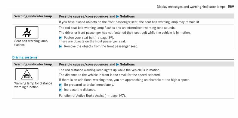
Warning/indicator lamp Possible causes/consequences and MM Solutions
If you have placed objects on the front passenger seat, the seat belt warning lamp may remain lit.
7Seat belt warning lampflashes
The red seat belt warning lamp flashes and an intermittent warning tone sounds.The driver or front passenger has not fastened their seat belt while the vehicle is in motion.# Fasten your seat belt(/ page 39).There are objects on the front passenger seat.# Remove the objects from the front passenger seat.
Driving systems
Warning/indicator lamp Possible causes/consequences and MM Solutions
LWarning lamp for distancewarning function
The red distance warning lamp lights up while the vehicle is in motion.The distance to the vehicle in front is too small for the speed selected.If there is an additional warning tone, you are approaching an obstacle at too high a speed.# Be prepared to brake immediately.# Increase the distance.
Function of Active Brake Assist (/ page 197).
Display messages and warning/indicator lamps 589

Engine
Warning/indicator lamp Possible causes/consequences and MM Solutions
;Engine diagnosis warninglamp
The yellow engine diagnostics warning lamp is lit while the engine is running.A malfunction has occurred in the engine, the exhaust system or the fuel system.The emissions limit value may have been exceeded and the engine may be running in emergency operation mode.# Have the vehicle checked as soon as possible at a qualified specialist workshop.Vehicles with a diesel engine: the fuel tank may have been run dry.# Start the engine three to four times after refuelling.
If the yellow engine diagnosis warning lamp goes out, emergency operation mode is cancelled. The vehicle need notbe checked.
#Electrical fault warninglamp
The red electrical fault warning lamp is lit.There is a fault in the electrics.# Observe the messages on the multifunction display.
æFuel reserve warning lamp
The yellow fuel reserve warning lamp lights up while the engine is running.The fuel supply has dropped into the reserve range.# Refuel.
590 Display messages and warning/indicator lamps

Warning/indicator lamp Possible causes/consequences and MM Solutions
?Coolant warning lamp
The red coolant warning lamp is lit while the engine is running.Possible causes:R The temperature sensor is malfunctioningR The coolant level is too lowR The air supply to the radiator is obstructedR The radiator fan is faulty
If there is an additional warning tone, the coolant temperature has exceeded 120 °C.
& WARNING Danger of burns when opening the bonnet
If you open the engine bonnet when the engine has overheated or during a fire in the engine compartment, youcould come into contact with hot gases or other escaping operating fluids.# Before opening the bonnet, allow the engine to cool down.# In the event of a fire in the engine compartment, keep the engine bonnet closed and call the fire service.
# Stop the vehicle immediately, paying attention to road and traffic conditions, and switch off the engine. Do not con‐tinue driving under any circumstances.
# Observe the messages on the multifunction display.
If the coolant temperature display is at the lower end of the temperature scale:# Consult a qualified specialist workshop.
Display messages and warning/indicator lamps 591

Warning/indicator lamp Possible causes/consequences and MM Solutions
or# Exit the vehicle and keep a safe distance from it until the engine has cooled down.# Check the coolant level (/ page 451).# Make sure that the air supply to the radiator is not obstructed.# Avoiding high loads on the engine, drive to the nearest qualified specialist workshop. In doing so, ensure that the
coolant temperature display remains below 120 °C.
Tyres
Warning/indicator lamp Possible causes/consequences and MM Solutions
hTyre pressure monitoringsystem warning lamp lightsup
The yellow tyre pressure monitoring system warning lamp (pressure loss/malfunction) is lit.The tyre pressure monitoring system has detected tyre pressure loss in at least one of the tyres.
& WARNING Risk of an accident due to insufficient tyre pressure
Tyres with insufficient tyre pressure pose the following risks:R The tyres may burst, especially as the load and vehicle speed increase.R The tyres may wear excessively and/or unevenly, which may greatly impair tyre traction.R ‑ The driving characteristics, steering and braking may be greatly impaired.
592 Display messages and warning/indicator lamps

Warning/indicator lamp Possible causes/consequences and MM Solutions
You could then lose control of the vehicle.# Observe the recommended tyre pressures.# Adjust the tyre pressure if necessary.
# Stop the vehicle, paying attention to road and traffic conditions.# Check the tyre pressure and the tyres.
hTyre pressure monitoringsystem warning lampflashes
The yellow tyre pressure monitoring system warning lamp (pressure loss/malfunction) flashes for approximately oneminute and then remains lit.The tyre pressure monitoring system is faulty.
& WARNING There is a risk of an accident if the tyre pressure monitoring system is malfunctioning
If the tyre pressure monitoring system is malfunctioning, it is not able to issue a warning if there is pressure loss inone or more of the tyres.Tyres with insufficient tyre pressure may, for example, affect the vehicle's handling characteristics, steering andbraking. ‑# Have the tyre pressure monitoring system checked at a qualified specialist workshop.
# Consult a qualified specialist workshop.
Display messages and warning/indicator lamps 593

Vehicle
Warning/indicator lamp Possible causes/consequences and MM Solutions
ïTrailer tow hitch warninglamp
The red trailer tow hitch warning lamp is on.The trailer tow hitch is not operational or swivels.
& WARNING Risk of an accident if the ball neck is not locked
If the ball neck is not in the locked position, the trailer may come loose.# Pull over and stop the vehicle safely as soon as possible, paying attention to road and traffic conditions. Do
not continue driving under any circumstances.# Uncouple the trailer and secure it against rolling away.# Initiate a new swivelling procedure and do not re-couple the trailer until the display message disappears.
# Observe the messages on the multifunction display.
If the trailer hitch swivels:# Wait until the ball coupling has reached the operational position.
ÙWarning lamp for electricpower steering
The red warning lamp for electric power steering is lit while the engine is running.The power-assisted steering or the steering itself is malfunctioning.
& WARNING Risk of accident if steering capability is impaired
If the steering does not function as intended, the vehicle's operating safety is jeopardised.
594 Display messages and warning/indicator lamps

Warning/indicator lamp Possible causes/consequences and MM Solutions
# Pull over and stop the vehicle safely as soon as possible, paying attention to road and traffic conditions. Donot continue driving under any circumstances.
# Consult a qualified specialist workshop.
# Observe the messages on the multifunction display.
Display messages and warning/indicator lamps 595

1, 2, 3 ...4MATIC ..................................................... 175
Function ............................................... 17512 V battery
see Battery (vehicle)12 V socket
see Socket (12 V)115 V socket
see Socket (115 V)230 V socket
see Socket (230 V)360° Camera ........................................... 230
Care .................................................... 458Function .............................................. 230Opening the camera cover (reversingcamera) ............................................... 234Selecting a view .................................. 233Setting favourites ................................ 234Switching automatic operationon/off (reversing camera) ................... 233
AA/C function
Activating/deactivating (multimediasystem) ................................................ 148Switching on/off (control panel) .......... 147
ABS (Anti-lock Braking System) ............. 192Acceleration
see KickdownAccess data
Setting (Bluetooth®) ............................ 422Accident and breakdown manage‐ment
Mercedes me connect .......................... 411Acoustic locking verification signal
Activating/deactivating ......................... 77Activating/deactivating automaticvolume adjustment
Advanced sound system ...................... 444Burmester® surround sound system ... 442
Active Blind Spot Assist .......................... 246Activating/deactivating ....................... 249Brake application ................................. 248Function .............................................. 246
System limitations ............................... 246Trailer operation .................................. 248
Active bonnet (pedestrian protection) .. 446Operation ............................................ 446Resetting ............................................. 446
Active Brake AssistFunction/notes .................................... 197Setting ................................................. 202
Active Distance Assist DISTRONIC ........ 207Active Emergency Stop Assist .............. 217Active Lane Change Assist ................... 215Calling up a speed ............................... 209Displays in the instrument display ....... 217Function .............................................. 207Increasing/decreasing speed .............. 209Requirements: ..................................... 209Route-based speed adaptation ............ 212Selecting ............................................. 209Steering wheel buttons ....................... 209Storing a speed ................................... 209Switching off/deactivating .................. 209Switching on/activating ...................... 209System limitations ............................... 207
Active Emergency Stop Assist ................ 217
596 Index

Active headlamps .................................... 131Active Lane Change Assist ...................... 215
Activating/deactivating ....................... 217Function ............................................... 215
Active Lane Keeping Assist .................... 249Activating/deactivating ....................... 251Activating/deactivating the warning .... 251Function .............................................. 249Setting the sensitivity .......................... 251System limitations ............................... 249Trailer operation .................................. 249
Active Parking Assist .............................. 234Cross Traffic Alert ................................ 240Drive Away Assist ................................ 239Exiting a parking space ....................... 237Function .............................................. 234Manoeuvring assistance ...................... 240Parking ................................................ 236System limitations ............................... 234
Active Service System PLUSsee ASSYST PLUS
Active Speed Limit Assist ....................... 211Display ................................................. 211Function ............................................... 211
Active Steering Assist ............................. 213Activating/deactivating ....................... 215Active Emergency Stop Assist .............. 217Active Lane Change Assist ................... 215Displays in the instrument display ....... 217Function ............................................... 213System limitations ............................... 213
Adaptive brake lights .............................. 203Adaptive cruise control
see Active Distance Assist DISTRONICAdaptive functions, MULTIBEAM LED
see Intelligent Light SystemAdaptive Highbeam Assist
Function .............................................. 133Switching on/off ................................. 134
Adaptive Highbeam Assist PlusFunction .............................................. 134Switching on/off ................................. 135
AdBlue® .................................................... 518Additives .............................................. 518Capacity ............................................... 519Fill level ............................................... 264Notes ................................................... 179Purity ................................................... 518
Range .................................................. 264Topping up ........................................... 179
Additional door lock .................................. 80Additives ................................................... 519
AdBlue® ............................................... 518Engine oil ............................................. 519Fuel ...................................................... 516
Additives (AdBlue®)see AdBlue®
Additives (engine oil)see Additives
Additives (fuel)see Fuel
Address booksee Contacts
Adjusting the balance/faderAdvanced sound system ...................... 444Burmester® surround sound system ... 443
Adjusting the headlamp range ............... 129Adjusting the sound focus
Burmester® surround sound system ... 443
Index 597
Adjusting treble, mid-range and basssettings
Advanced sound system ...................... 444Burmester® surround sound system ... 442
Advanced sound systemActivating/deactivating automaticvolume adjustment .............................. 444Adjusting the balance/fader ............... 444Adjusting treble, mid-range and basssettings ............................................... 444Calling up the sound menu .................. 443Information .......................................... 443
After-sales service centresee ASSYST PLUS
Air conditioning menuCalling up ............................................ 148
Air conditioning systemsee Climate control
Air distributionSetting ................................................. 146Setting (multimedia system) ................ 148
Air inletsee Air-water duct
Air pressuresee Tyre pressure
Air vents ................................................... 154Adjusting (front) .................................. 154Adjusting (rear) .................................... 155
Air ventssee Air vents
Air-recirculation mode ............................ 149Air-water duct .......................................... 452
Keeping free ........................................ 452Airbag ......................................................... 41
Activation .............................................. 35Front airbag (driver, front passenger) ..... 41Installation locations .............................. 41Knee airbag ............................................ 41Overview ................................................ 41PASSENGER AIR BAG indicator lamp ..... 46Protection .............................................. 42Reduced protection ............................... 43Side impact airbag ................................. 41Window airbag ....................................... 41
AirflowSetting ................................................. 146
Alarm systemsee ATA (anti-theft alarm system)
All-wheel drivesee 4MATIC
Alternative routesee Route
Ambient lightingSetting (multimedia system) ................ 136
Android Auto ............................................ 407Connecting a mobile phone ................. 408Ending ................................................. 409Information .......................................... 408Overview ............................................. 407Sound settings .................................... 408Transferred vehicle data ...................... 409
Android Auto™Control using the application buttons............................................................. 409
AnimalsPets in the vehicle ................................. 75
Anti-lock braking systemsee ABS (Anti-lock Braking System)
598 Index

Anti-skid chainssee Snow chains
Anti-theft alarm systemsee ATA (anti-theft alarm system)
Anti-theft protectionAdditional door lock .............................. 80Immobiliser ............................................ 97
Anti-theft protectionsee ATA (anti-theft alarm system)
Anticipatory occupant protectionsee PRE-SAFE® (anticipatory occu‐pant protection)see PRE-SAFE® PLUS (anticipatoryoccupant protection plus)
Apple CarPlay™ ....................................... 405Connecting an iPhone® ....................... 406Control using the application buttons............................................................. 407Ending ................................................. 407Notes .................................................. 406Overview ............................................. 405Sound settings .................................... 407Transferred vehicle data ...................... 409
AshtrayUsing ................................................... 120
Assistance systemssee Driving safety system
Assistant displayMenu (on-board computer) .................. 265
ASSYST PLUS ........................................... 445Battery disconnection periods ............ 446Displaying the service due date .......... 445Function/notes ................................... 445Regular maintenance work .................. 445Special service requirements .............. 445
ATA (anti-theft alarm system) ................... 97Deactivating the alarm .......................... 98Function ................................................ 97Function of interior protection ............... 99Priming/deactivating interior protec‐tion ........................................................ 99Priming/deactivating tow-away pro‐tection ................................................... 99Tow-away protection function ................ 98
ATTENTION ASSIST .......................... 240, 242Function .............................................. 240Setting ................................................. 242
System limitations ............................... 240Attention assistant
see ATTENTION ASSISTAugmented reality
see Route guidance with augmented realityAuthorised workshop
see Qualified specialist workshopAutomatic car wash mode
Activating ............................................ 453Automatic distance control
see Active Distance Assist DISTRONICAutomatic driving lights ......................... 129Automatic engine start (ECO start/stop function) .......................................... 163Automatic engine stop (ECO start/stop function) .......................................... 163Automatic front passenger front air‐bag deactivation system
see Automatic front passenger frontairbag shutoff
Index 599

Automatic front passenger front air‐bag shutoff .......................................... 44, 46
Function of the automatic frontpassenger front airbag deactivationsystem ................................................... 44PASSENGER AIR BAG indicator lamp ..... 46
Automatic mirror folding functionActivating/deactivating ....................... 144
Automatic transmissionDIRECT SELECT lever ........................... 170Drive program display .......................... 166Drive programs .................................... 166DYNAMIC SELECT switch .................... 166Engaging drive position ........................ 172Engaging neutral .................................. 171Engaging park position ........................ 171Engaging reverse gear .......................... 171Kickdown ............................................. 173Manual gear changing .......................... 172Steering wheel gearshift paddles ......... 172Transmission position display .............. 170Transmission positions ........................ 170
Automatic transmission (problem)see Transmission (problem)
Axle loadPermissible .......................................... 512Trailer operation .................................. 526
BBaidu CarLife
Transferred vehicle data ...................... 409Ball neck
Folding out/in ..................................... 252BAS (Brake Assist System) ..................... 192Battery
Charging (Remote Online) .................... 160Key ........................................................ 78Remote control (stationary heater) ...... 153
Batterysee Battery (vehicle)
Battery (vehicle) ...................................... 475Charging .............................................. 474Charging (Remote Online) .................... 160Notes ................................................... 470Notes (starting assistance andcharging) ............................................. 472Replacing ............................................. 475Starting assistance .............................. 474
Beltsee Seat belt
Bicycle rackTrailer operation .................................. 255
Blind Spot Assist ..................................... 246Activating/deactivating ....................... 249Function .............................................. 246System limitations ............................... 246
Blowersee Climate control
BlueTECsee AdBlue®
Bluetooth® ............................................... 328Information .......................................... 328Setting up an Internet connection ....... 422Switching on/off ................................. 328
BonnetResetting (active bonnet) .................... 446
Boot lidClosing .................................................. 87HANDS-FREE ACCESS ........................... 87Opening ................................................. 85Opening dimensions ............................ 523
600 Index

Brake Assist Systemsee BAS (Brake Assist System)
Brake fluidNotes ................................................... 521
Brake force distributionEBD (Electronic Brake force Distribu‐tion) ..................................................... 196
BrakesABS (Anti-lock Braking System) ........... 192Active Brake Assist .............................. 197Adaptive brake lights ........................... 203BAS (Brake Assist System) .................. 192Driving tips ........................................... 161EBD (Electronic Brake force Distribu‐tion) ..................................................... 196HOLD function ..................................... 219Limited braking effect (salt-treatedroads) ................................................... 161New/replaced brakepads/brakediscs .................................................... 161Running-in notes .................................. 161
Braking assistancesee BAS (Brake Assist System)
BreakdownOverview of the help functions .............. 18Tow-starting ......................................... 481Towing away ........................................ 477Transporting the vehicle ...................... 479Wheel change ...................................... 500
Breakdownsee Flat tyre
Burmester® surround sound system ..... 442Adjusting the balance/fader ............... 443Adjusting the sound focus ................... 443Adjusting treble, mid-range and basssettings ............................................... 442Automatic volume adjustment ............. 442Calling up the sound menu .................. 442Information .......................................... 442Selecting the sound profile ................. 443
ButtonsSteering wheel .................................... 259
CCall list
Deleting ............................................... 398Making a call ....................................... 397
Overview ............................................. 397Selecting options ................................. 397Selecting options for suggestions ........ 398
Calling up the sound menuAdvanced sound system ...................... 443Burmester® surround sound system ... 442
Calls .......................................................... 392Accepting ............................................ 392Activating functions during a call ........ 393Calls with several participants ............. 393Declining ............................................. 392Ending a call ........................................ 392In-Car Office ........................................ 401Incoming call during an existing call .... 393Making ................................................ 392Mercedes me connect .......................... 411
Camerasee 360° Camerasee Reversing camera
Car keysee Key
Car washsee Care
Car wash (care) ....................................... 452
Index 601

Car-to-X-CommunicationDisplaying hazard warnings ................. 371Overview .............................................. 371Sending hazard warnings ..................... 372
Care .......................................................... 460Air-water duct ...................................... 452Car wash ............................................. 452Carpet ................................................. 460Decorative foil ..................................... 456Display ................................................ 460Exterior lighting ................................... 458High-pressure cleaner ......................... 454Matt finish ........................................... 455Paintwork ............................................ 455Plastic trim .......................................... 460Real wood/trim elements ................... 460Reversing camera ................................ 458Reversing camera/360° Camera ........ 458Roof lining ........................................... 460Seat belt .............................................. 460Seat cover ........................................... 460Sensors ............................................... 458Tailpipes .............................................. 458Trailer hitch ......................................... 458Washing by hand ................................. 454
Wheels/rims ....................................... 458Windows .............................................. 458Wiper blades ....................................... 458
Carpet (Care) ........................................... 460Changing bulbs ........................................ 137
Dipped beam ....................................... 139Fitting/removing cover (front wheelarch) .................................................... 139Main beam ........................................... 139Notes ................................................... 137Overview ............................................. 138Reversing lights ................................... 139Turn signal lights (rear) ........................ 139
Changing gears ........................................ 172Manually .............................................. 172
Changing hub caps ................................. 500Changing the lights
Driving abroad (symmetrical dippedbeam) .................................................. 128
ChargingBattery (vehicle) ................................... 474USB port .............................................. 124
Child safety lockActivating/deactivating (multimediasystem) ............................................... 332Rear door ............................................... 73Rear side windows ................................. 74
Child seatApproval categories ............................... 57Attaching (notes) ................................... 56Basic instructions .................................. 50Front passenger seat (notes) ................. 71Front passenger seat (without auto‐matic airbag shutoff) ............................. 70ISOFIX/i-Size (fitting) ............................ 63Notes on risks and dangers ................... 51Recommended child restraint sys‐tems ...................................................... 54Seats suitable for belt-secured childrestraint systems ................................... 67Seats suitable for i‑Size childrestraint systems ................................... 62Seats suitable for ISOFIX childrestraint systems ................................... 59Securing on the front passenger seat .... 72Securing on the rear seat ...................... 69Top Tether .............................................. 65
602 Index

ChildrenAvoiding dangers in the vehicle .............. 51Basic instructions .................................. 50
Chock ....................................................... 499Storage location .................................. 499
Chocksee Chock
Cigarette lighterFront centre console ............................ 121
City lighting ............................................. 132Cleaning
see CareClimate control ........................................ 146
Activating/deactivating the A/Cfunction (control panel) ....................... 147Activating/deactivating the A/Cfunction (multimedia system) .............. 148Activating/deactivating the synchro‐nisation function (control panel) .......... 149Activating/deactivating the synchro‐nisation function (multimedia sys‐tem) ..................................................... 149Air distribution settings ....................... 148Air-recirculation mode ......................... 149
Automatic control ................................ 148Calling up the air conditioning menu ... 148Defrosting the windscreen ................... 146Demisting windows ............................. 149Front air vents ..................................... 154Note .................................................... 146Rear air vents ...................................... 155Residual heat ....................................... 149Sets the airflow ................................... 146Setting (multimedia system) ................ 148Setting the air distribution ................... 146Setting the temperature ...................... 146Stationary heater/ventilation .............. 149Switching on/off ................................. 147Switching the rear window heateron/off ................................................. 146THERMATIC control panel .................... 146THERMOTRONIC control panel ............ 146Ventilating the vehicle (convenienceopening) ................................................ 90
Cockpit ......................................................... 6Overview ................................................. 6
Coffee cup symbolsee ATTENTION ASSIST
Collapsible spare wheel .......................... 507Inflating ............................................... 508Notes ................................................... 507Removing ............................................ 508
Combination switch ................................ 130Compass .................................................. 380Computer
see On-board computerConnection status
Displaying ............................................ 424Overview ............................................. 424
ConnectivitySwitching transmission of the vehicleposition on/off .................................... 328
Contacts ................................................... 394Calling up ............................................ 394Deleting ............................................... 396Deleting favourites .............................. 397Downloading (from mobile phone) ....... 394Importing ............................................ 395Importing (overview) ........................... 395Information .......................................... 394Making a call ....................................... 395Name format ....................................... 395
Index 603

Options ................................................ 396Saving as a favourite ........................... 397Selecting options for suggestions ........ 396Storing ................................................ 395
Convenience closing ................................. 91Convenience opening ................................ 90Coolant (engine)
Check level .......................................... 451Notes ................................................... 521
Coolingsee Climate control
Copyright ................................................... 33Cornering light ......................................... 132Cross Traffic Alert ................................... 240Crosswind Assist
Function/notes ................................... 196Cruise control .......................................... 203
Activating ............................................ 205Buttons ................................................ 205Calling up a speed ............................... 205Deactivating ........................................ 205Function .............................................. 203Requirements ...................................... 205
Selecting ............................................. 205Setting a speed ................................... 205Storing a speed ................................... 205System limitations ............................... 203
Cup holder ......................................... 116, 118Fitting/removing (centre console)....................................................... 116, 118Rear ..................................................... 120
DDamage detection (parked vehicle) ....... 189Damping adjustment ............................... 221Dash cam
Starting/ending a video recording ...... 384Dashboard
see CockpitDashboard lighting
see Instrument lightingDashcam
Configuring the settings ...................... 385Deleting a video recording ................... 385Selecting a USB device ....................... 384
Data acquisitionVehicle .................................................. 30
Data import/export ................................ 332Function/notes ................................... 332Importing/exporting ........................... 333
Data storageElectronic control units ......................... 30Online services ...................................... 32Vehicle .................................................. 30
DateSetting the time and date automati‐cally ..................................................... 327
Deactivating the alarm (ATA) .................... 98Dealership
see Qualified specialist workshopDeclaration of conformity
Electromagnetic compatibility ............... 24Jack ....................................................... 27TIREFIT kit ............................................. 28Wireless vehicle components ................ 24
Decorative foil (cleaning instructions)................................................................... 456
604 Index

DeNOx agentsee AdBlue®
DesignsMenu (on-board computer) .................. 261
Destination .............................................. 366Editing intermediate destinations ........ 356Editing the previous destinations ........ 366External ............................................... 367Quick-access to destination informa‐tion ...................................................... 363Saving (current vehicle position) ......... 366Saving as global favourite .................... 366
Destination entry .................................... 343Entering 3 word addresses .................. 349Entering a POI or address .................... 343Entering an intermediate destination .. 356Entering geo-coordinates .................... 348Notes .................................................. 343Selecting a contact ............................. 348Selecting a POI .................................... 346Selecting a received destination ......... 350Selecting from favourites .................... 350Selecting from the map ....................... 349Selecting previous destinations ........... 346
Detecting inattentivenesssee ATTENTION ASSIST
Diagnostics connection ............................ 28Diesel
Low outside temperatures ................... 517Notes ................................................... 517
Digital Owner's Manual ............................ 20Digital speedometer ............................... 265Digital Vehicle Key sticker
Locking the vehicle ................................ 81Starting the vehicle ............................. 158Unlocking the vehicle ............................ 81
Dinghy towingsee Tow-bar system
Dipped beamChanging bulbs .................................... 139Setting ................................................. 135
DIRECT SELECT lever ............................... 170Engaging drive position ........................ 172Engaging neutral .................................. 171Engaging park position ........................ 171Engaging park position automatically .. 171Engaging reverse gear .......................... 171
Function .............................................. 170Display
Care .................................................... 460Display (multimedia system) ................. 295
Home screen ....................................... 292Operating ............................................ 295Setting acoustic operating feedback ... 296Settings ............................................... 326
Display (on-board computer)Displays on the multifunction display .. 263
Display contentDisplaying ............................................ 262
Display message ..................................... 527Calling up (on-board computer) ........... 527Notes ................................................... 527
Display messages¯ - - - km/h ................................... 549ç - - - km/h ................................... 548È - - - km/h ................................... 549#12 V battery See Owner's Man‐ual ....................................................... 553
Index 605

Active Blind Spot Assist currentlyunavailable See Owner's Manual ......... 544Active Blind Spot Assist inoperative .... 544Active Blind Spot Assist not availablewhen towing a trailer See Owner'sManual ................................................ 545Active bonnet malfunction See Own‐er's Manual .......................................... 575Active Brake Assist Functions cur‐rently limited See Owner's Manual ...... 540Active Brake Assist Functions limitedSee Owner's Manual ........................... 540Active Distance Assist availableagain ................................................... 549Active Distance Assist currentlyunavailable See Owner's Manual ......... 548Active Distance Assist inoperative ...... 548Active Lane Keeping Assist currentlyunavailable See Owner's Manual ......... 543
Active Lane Keeping Assist inopera‐tive ...................................................... 543bActive Light System inoperative .. 580Active Parking Assist andPARKTRONIC inoperative See Own‐er's Manual ......................................... 545Active Steering Assist currentlyunavailable due to multiple emer‐gency stops ......................................... 543Active Steering Assist currentlyunavailable See Owner's Manual ......... 542Active Steering Assist inoperative ....... 542Adaptive Highbeam Assist currentlyunavailable See Owner's Manual ......... 580Adaptive Highbeam Assist inopera‐tive ...................................................... 581Adaptive Highbeam Assist Plus cur‐rently unavailable See Owner's Man‐ual ....................................................... 581
Adaptive Highbeam Assist Plus inop‐erative ................................................. 581¯ AdBlue system fault Enginestart not possible ................................ 559¯AdBlue system fault Perf.reduced in XXX miles See Owner'sManual ................................................ 559¯ AdBlue system fault Perf.reduced: XXX km/h No start in XXXkm ....................................................... 559¯ AdBlue system fault See Own‐er's Manual ......................................... 5584Add 1 litre engine oil when nextrefuelling ............................................. 554Anti-theft alarm system Malfunction .... 576Apply brake to deselect Park (P)position ............................................... 560Apply brake to select R ....................... 560ÀATTENTION ASSIST inoperative ... 541
606 Index
ÀATTENTION ASSIST: Take abreak! .................................................. 541bAutomatic driving lights inoper‐ative .................................................... 579Auxiliary battery malfunction ............... 561_Before starting the engine, turnthe steering wheel. .............................. 563Beginning emergency stop .................. 542Blind Spot Assist currently unavaila‐ble See Owner's Manual ...................... 543Blind Spot Assist inoperative ............... 544Blind Spot Assist not available whentowing a trailer See Owner's Manual ... 544Brake immediately ............................... 535ÁChange key batteries ................... 570JCheck brake fluid level ................ 535Check brake pads See Owner's Man‐ual ....................................................... 536ïCheck trailer hitch lock (whitedisplay message) ................................. 572
Check tyre pressures then restartRun Flat Indicator ................................ 565hCheck tyre(s) ............................... 567!Clean the fuel filter ..................... 553Clutch overheated Avoid pulling awayfor XX:XX mins .................................... 564?Coolant Stop vehicle Switchengine off ............................................ 550Cruise control and Limiter inopera‐tive ...................................................... 549Cruise control inoperative ................... 549Cruise control off ................................ 549_Currently unavailable Cameraview restricted ..................................... 547çCurrently unavailable Radarsensors dirty ....................................... 546!currently unavailable See Own‐er's Manual ......................................... 528÷currently unavailable See Own‐er's Manual ......................................... 529
Depress clutch fully to start engine ..... 564Drive system Malfunction StopSwitch engine off ................................ 554Drive system Malfunction Visit work‐shop .................................................... 5545Engine oil level cannot bemeasured ............................................ 5574Engine oil level Reduce oil level ... 5564Engine oil level Stop vehicleSwitch engine off ................................ 5554Engine oil pressure Stop Switchoff engine ............................................ 556Fault Drive at max. 80 km/h ............... 5426Front left malfunction Consultworkshop (Example) ............................ 537Front-passenger airbag disabled SeeOwner's Manual .................................. 538Front-passenger airbag enabled SeeOwner's Manual .................................. 539
Index 607

b Hazard warning lamps mal‐functioning .......................................... 580&inoperative Battery low ............... 577&inoperative Refuel vehicle ............ 578&inoperative See Owner's Man. ..... 577!inoperative See Owner's Man‐ual ....................................................... 529÷inoperative See Owner's Man‐ual ....................................................... 530Tinoperative See Owner's Man‐ual ....................................................... 531GInoperative .................................. 541bIntelligent Light System inoper‐ative .................................................... 580ÁKey not detected (red displaymessage) ............................................. 571ÁKey not detected (white displaymessage) ............................................. 570bLeft dipped beam (Example) ........ 578
6Left windowbag malfunctionConsult workshop (Example) ............... 538Limiter inoperative .............................. 549Limiter passive .................................... 550bMalfunction See Owner's Man‐ual ....................................................... 579ðMaximum speed exceeded .......... 550Mercedes me connect Services limi‐ted See Owner's Manual ..................... 540N permanently active Risk of vehiclerolling .................................................. 560çOff ............................................... 548ëOff ............................................... 547Only select Park (P) when vehicle isstationary ............................................ 560ïOperation only possible intransmission position N ....................... 574ïOperation only possible intransmission position P ....................... 574
!Parking brake See Owner'sManual ................................................ 532Parking lock malfunct. Apply parkingbrake ................................................... 562ÁPlace the key in the markedspace See Owner's Manual ................. 571KPlease check direction of travel ...... 545PRE-SAFE inoperative See Owner'sManual ................................................ 540hRectify tyre pressure ................... 568Reduce speed ...................................... 569ÚRefill AdBlue Engine start notpossible ............................................... 558ÚRefill AdBlue See Owner’s Man‐ual ....................................................... 557!Release parking brake ................. 532¸Replace air cleaner ...................... 554ÀReplace key See Owner's Man‐ual ....................................................... 569ÁReplace key ................................. 570
608 Index

æReserve fuel level ........................ 5536Restraint sys. malfunction Con‐sult workshop ...................................... 536Reversing not poss. Consult work‐shop ..................................................... 561Risk of vehicle rolling away Applyparking brake See Owner's Manual ..... 562Risk of vehicle rolling away Parkingbrake not applied See Owner's Man‐ual ....................................................... 535Risk of vehicle rolling Driver dooropen and transmission not in P ........... 560Run Flat Indicator inoperative ............. 566#See Owner's Manual .................... 551Speed limit (winter tyres) XXX km/h ... 550Speed Limit Assist inoperative ............ 546ÙSteering malfunction Increasedphysical effort See Owner's Manual .... 574ÙSteering malfunction See Own‐er's Manual ......................................... 563
ÙSteering malfunction Stopimmediately See Owner's Manual ........ 575#Stop vehicle Leave engine run‐ning ..................................................... 553#Stop vehicle See Owner's Man‐ual ....................................................... 552çsuspended .................................. 548bSwitch off lights .......................... 579bSwitch on headlamps .................. 579Teaching in transmission complete ..... 563Teaching in transmission Operateselector lever Brake for XX secondsRisk of vehicle rolling .......................... 562To shift out of P or N, depress brakeand start engine .................................. 560ÚTop up AdBlue Perf. reduced inXXX miles See Owner's Manual ........... 557Ú Top up AdBlue Perf. reduced:XXX km/h No start in XXX km ............ 558Top up coolant See Owner’s Manual .... 551
¥Top up washer fluid ..................... 577Traffic Sign Assist currently unavaila‐ble See Owner's Manual ...................... 545Traffic Sign Assist inoperative ............. 545ïTrailer coupling extending… ......... 572Trans. oil overheated Drive on withcare ..................................................... 562Transmission Malfunction .................... 561Transmission Malfunction Stop ............ 561Transmission Malfunction Visit work‐shop .................................................... 563!Turn on the ignition to releasethe parking brake ................................ 531hTyre press. monitor currentlyunavailable .......................................... 566hTyre press. monitor inoperativeNo wheel sensors ................................ 567hTyre press. monitor inoperative ... 566Tyre pressure Check tyres ................... 565Tyre(s) overheated ............................... 569
Index 609

dVehicle is operational Switchoff the ignition before exiting ............... 572hWarning tyre defect ..................... 568hWheel sensor(s) missing .............. 567Without changing gear, consult work‐shop ..................................................... 561
Display on the windscreensee Head-up display
Distance controlsee Active Distance Assist DISTRONIC
Distance recordersee Trip distance
DISTRONICsee Active Distance Assist DISTRONIC
DoorAdditional door lock .............................. 80Child safety lock (rear door) .................. 73Locking (emergency key) ....................... 84Opening (from the inside) ...................... 80Unlocking (emergency key) ................... 84Unlocking (from the inside) ................... 80
Door control panel ..................................... 16
Drawbarsee Tow-bar system
Drinks holdersee Cup holder
Drive Away Assist .................................... 239Drive Away Assist
see Protection against collisionDrive position
Engaging .............................................. 172Drive program display ............................. 166Drive programs
see DYNAMIC SELECTDriver's seat
see SeatDriving abroad
Symmetrical dipped beam ................... 128Driving lights
see Automatic driving lightsDriving safety system ............................. 191
ABS (Anti-lock Braking System) ........... 192Active Brake Assist .............................. 197Adaptive brake lights ........................... 203BAS (Brake Assist System) .................. 192
EBD (Electronic Brake force Distribu‐tion) ..................................................... 196ESP® Crosswind Assist ........................ 196ESP® trailer stabilisation ..................... 196Overview .............................................. 191Radar sensors ...................................... 191Responsibility ...................................... 191STEER CONTROL ................................. 196
Driving systemSuspension with adaptive dampingadjustment .......................................... 221
Driving systemsee 360° Camerasee Active Blind Spot Assistsee Active Distance Assist DISTRONICsee Active Emergency Stop Assistsee Active Lane Change Assistsee Active Lane Keeping Assistsee Active Parking Assistsee Active Speed Limit Assistsee Active Steering Assistsee ATTENTION ASSISTsee Blind Spot Assistsee Cruise controlsee Driving safety system
610 Index

see HOLD functionsee Limitersee Parking Assist PARKTRONICsee Reversing camerasee Speed Limit Assistsee Traffic Sign Assist
Driving tipsDriving abroad (symmetrical dippedbeam) .................................................. 128General driving tips .............................. 161Running-in notes .................................. 161
Drowsiness detectionsee ATTENTION ASSIST
Dynamic handling control systemsee ESP® (Electronic Stability Program)
DYNAMIC SELECT .................................... 166Configuring drive program I ................. 167Displaying engine data ........................ 168Displaying vehicle data ........................ 168Drive program display .......................... 166Drive programs .................................... 166Function .............................................. 166Operating (DYNAMIC SELECT switch)............................................................. 166
Selecting the drive program ................ 166DYNAMIC SELECT switch
Damping adjustment ........................... 221
EE10 ............................................................ 515Easy entry feature
Function/notes ................................... 107Setting ................................................. 108
Easy exit featureFunction/notes ................................... 107Setting ................................................. 108
EBD (Electronic Brake force Distribu‐tion)
Function/notes ................................... 196ECO display
Function .............................................. 165Resetting ............................................. 266
ECO start/stop function ......................... 163Automatic engine start ........................ 163Automatic engine stop ......................... 163Operation ............................................ 163Switching off/on ................................. 165
Electric parking brake ............................. 187Applying automatically ......................... 187Applying or releasing manually ............ 189Emergency braking .............................. 189Releasing automatically ....................... 188
Electrical fusessee Fuses
Electromagnetic compatibilityDeclaration of conformity ...................... 24
Electronic Stability Programsee ESP® (Electronic Stability Program)
EmergencyFire extinguisher .................................. 464First-aid kit (soft sided) ....................... 463Overview of the help functions .............. 18Removing the warning triangle ............ 463Safety vest .......................................... 462Setting up the warning triangle ........... 463
Emergency braking ................................. 189Emergency braking
see BAS (Brake Assist System)Emergency call system
see Mercedes-Benz emergency call system
Index 611

Emergency engine start .......................... 481Emergency key
Inserting/removing ............................... 78Locking a door ....................................... 84Unlocking a door ................................... 84
Emergency operation modeStarting the vehicle ............................. 159
Emergency spare wheel ......................... 504Inflating ............................................... 505Notes .................................................. 504Removing ............................................ 505
ENERGIZING CoachCalling up ............................................. 341Function .............................................. 340
ENERGIZING comfort .............................. 336Overview of programs ......................... 337Starting the program ........................... 339
ENERGIZING seat kineticsSetting ................................................. 336
ENERGIZING seat kineticssee ENERGIZING comfort
EngineECO start/stop function ...................... 163
Engine number ..................................... 512Starting (Digital Vehicle Key sticker) .... 158Starting (emergency operationmode) .................................................. 159Starting (mobile phone) ....................... 158Starting (Remote Online) ..................... 160Starting (start/stop button) ................. 157Starting assistance .............................. 474Switching off (start/stop button) ......... 181
Engine bonnetFunction (active bonnet) ...................... 446Opening/closing ................................. 447
Engine dataDisplaying ............................................ 168
Engine electronicsNotes ................................................... 510
Engine number ......................................... 512Engine oil ................................................. 450
Additives .............................................. 519Capacity .............................................. 520Checking the oil level using the on-board computer ................................... 449MB-Freigabe or MB-Approval ............... 520Quality ................................................. 520
Topping up ........................................... 450Entering characters ................................. 318
Function/notes .................................... 318On the touchpad .................................. 318On the touchscreen (media display) .... 322Setting the keyboard ........................... 326
ERA-GLONASS test modeStarting/ending ................................... 419
ESC (Electronic Stability Control)see ESP® (Electronic Stability Program)
ESP®Crosswind Assist ................................. 196Trailer stabilisation .............................. 196
ESP® (Electronic Stability Program) ...... 193Activating/deactivating ....................... 195Function/notes ................................... 193
EU general operating permit number .... 512Exterior lighting
Care .................................................... 458Exterior lighting
see LightsExternal device
Locking (child safety lock) ................... 332
612 Index

FFatigue detection
see ATTENTION ASSISTFault message
see Display messageFavourites
Adding .................................................. 311Adding a destination ........................... 350Calling up ............................................. 311Deleting ............................................... 312Home address ..................................... 350Moving ................................................. 312Overview .............................................. 311Renaming ............................................. 312Work address ...................................... 350
Fill levelAdBlue® ............................................... 264
Filling station searchStarting automatic search ................... 358Switching automatic search on/off ..... 358
Fire extinguisher ..................................... 464First-aid kit (soft sided) .......................... 463
Flat towingsee Tow-bar system
Flat tyre .................................................... 464MOExtended tyres ............................... 465Notes ................................................... 464TIREFIT kit ........................................... 466Wheel change ...................................... 500
Floor mats ................................................ 126Foil covering
Radar sensors ...................................... 191Free software ............................................ 33Frequencies
Mobile phone ....................................... 511Two-way radio ...................................... 511
Frequency bandDialling (on-board computer) ............... 268
Front airbag (driver, front passenger) ...... 41Front passenger seat
see SeatFront wheel arch ..................................... 139
Fitting/removing the cover .................. 139
Front wheel arch coverFitting/removing ................................. 139
Fuel ........................................................... 516Additives .............................................. 516Diesel ................................................... 517E10 ...................................................... 515Fuel reserve ......................................... 518Low outside temperatures ................... 517Petrol ................................................... 515Quality (diesel) ..................................... 517Quality (petrol) ..................................... 515Refuelling ............................................. 175Sulphur content ................................... 515Tank content ........................................ 518
Fuel consumptionOn-board computer ............................. 265
Fuel consumption indicatorCalling up ............................................ 168
Function seatsee Door control panel
Fuses ........................................................ 482Before replacing a fuse ........................ 482Fuse assignment diagram ................... 482Fuse box in the boot ............................ 484
Index 613

Fuse box in the engine compartment .. 482Fuse box in the front passenger foot‐well ...................................................... 483Notes .................................................. 482
GGarage door opener
Clearing the memory ........................... 185Opening or closing the door ................ 185Programming buttons .......................... 183Radio equipment approval numbers .... 186Resolving problems ............................. 184Synchronising the rolling code ............ 184
Gearshift recommendation ............. 169, 173General operating permit number(EU) ........................................................... 512Genuine parts ............................................ 22Glide mode ............................................... 173Global search
Function ............................................... 315Overview .............................................. 315
Glove boxLocking/unlocking ............................... 111
HHandbrake
see Electric parking brakeHandling characteristics (unusual) ....... 485HANDS-FREE ACCESS ................................ 87Hazard warning lights ............................. 131Head restraint
Front (adjusting mechanically) ............. 102Rear (adjusting) ................................... 103Rear (fitting/removing) ........................ 103
Head-up display ....................................... 270Adjusting display elements (on-boardcomputer) ............................................ 270Adjusting the brightness (on-boardcomputer) ............................................ 270Function .............................................. 271Menu (on-board computer) .................. 270Operating the memory function .......... 109Setting the position (on-board com‐puter) .................................................. 270Switching on/off ................................. 271
Headlamp flasher .................................... 130
Heatingsee Climate control
High beamAdaptive Highbeam Assist ................... 133Adaptive Highbeam Assist Plus ........... 134Switching on/off ................................. 130
High-pressure cleaner (care) ................. 454Hill Start Assist ........................................ 219HOLD function ......................................... 219
Function/notes .................................... 219Switching on/off ................................. 220
Home screen (media display)Overview ............................................. 292
HotspotSetting up (Wi-Fi) ................................. 330
Ii-Size child seat securing system
Fitting .................................................... 63Seats suitable for attaching ................... 62
Identification plateEngine .................................................. 512Vehicle ................................................. 512
614 Index

IgnitionSwitching on (Start/Stop button) ........ 156
Ignition keysee Key
Immobiliser ................................................ 97Implied warranty
Vehicle .................................................. 30In-Car Office ............................................. 400
Answering e-mail ................................. 403Calling up ............................................ 401Creating a new entry ........................... 402Features .............................................. 400Forwarding e-mail ................................ 403Managing e-mails ................................ 402Marking a task as completed .............. 402Noting an incoming call ....................... 402Selecting functions (calendar entry) .... 401Selecting functions (Tasks & Calls) ...... 401Writing e-mail ...................................... 402
Increase in traffic information volumeSetting ................................................. 441
Indicator lampssee Warning/indicator lamps
Individual drive programConfiguring .......................................... 167Selecting ............................................. 166
Inspectionsee ASSYST PLUS
Instrument clustersee Instrument display
Instrument display .................................. 258Adjusting the lighting .......................... 264Function/notes ................................... 258Instrument cluster ................................. 10Warning/indicator lamps ..................... 581
Instrument lighting ................................. 264Intelligent Light System .......................... 131
Active headlamps ................................ 131Adaptive Highbeam Assist ................... 133Adaptive Highbeam Assist Plus ........... 134City lighting ......................................... 132Cornering light ..................................... 132Motorway mode ................................... 132Overview .............................................. 131Switching on/off ................................. 132
Interior lighting ........................................ 136Ambient lighting .................................. 136
Reading light ........................................ 136Setting ................................................. 136Switch-off delay time ........................... 137
Interior protectionFunction ................................................ 99Priming/deactivating ............................. 99
Intermediate destinationCalculating a route with intermediatedestinations ........................................ 356Entering ............................................... 356Modifying ............................................ 356Starting an automatic filling stationsearch ................................................. 358Starting the automatic service sta‐tion search .......................................... 358
InternetCalling up a web page ......................... 425Closing the browser ............................ 428Deleting a bookmark ........................... 427Deleting history ................................... 427Managing bookmarks .......................... 427
Internet connectionCancelling permission (mobilephone) ................................................. 423
Index 615
Communication module function ......... 421Connection status ............................... 424Displaying the connection status ......... 424Establishing ......................................... 423Establishing automatically ................... 423Information .......................................... 421Mobile phone details ........................... 423Restrictions ......................................... 421Setting access data (Bluetooth®) ........ 422Setting automatic disconnection ......... 424Setting up (Bluetooth®) ....................... 422Setting up (Wi-Fi) ................................. 422
Internet radioCalling up ............................................ 428Calling up the station list (categorylast selected) ....................................... 430Deleting stations ................................. 430Logging out ......................................... 430Overview ............................................. 429Registering .......................................... 430Saving stations .................................... 430Selecting and connecting to a station............................................................. 430Selecting stream ................................. 430Setting options .................................... 430
Terms of use ........................................ 430
iPhone®see Apple CarPlay™see Mercedes-Benz Link
ISOFIX child seat securing systemFitting .................................................... 63Seats suitable for attaching ................... 59
JJack
Declaration of conformity ...................... 27Storage location .................................. 499
Jump-start connection ............................ 474General notes ...................................... 472
KKey .............................................................. 76
Acoustic locking verification signal ........ 77Battery ................................................... 78Emergency key ...................................... 78Energy consumption .............................. 77Features ................................................ 76Key ring attachment .............................. 78Overview ................................................ 76
Problem ................................................. 79Unlocking setting .................................. 77
Key functionsDeactivating .......................................... 77
KEYLESS-GOLocking the vehicle ................................ 82Problem ................................................. 83Unlocking setting .................................. 77Unlocking the vehicle ............................ 82
Kickdown .................................................. 173Using ................................................... 173
Knee airbag ................................................ 41
LLamp
see Interior lightingLamps (instrument display)
see Warning/indicator lampsLane detection (automatic)
see Active Lane Keeping AssistLane Keeping Assist
see Active Lane Keeping Assist
616 Index

Language ................................................. 332Notes .................................................. 332Setting ................................................. 332
LED lightsee Intelligent Light System
Light switchOverview ............................................. 128
Lightingsee Interior lightingsee Lights
Lights ........................................................ 128Active headlamps ................................ 131Adaptive Highbeam Assist ................... 133Adaptive Highbeam Assist Plus ........... 134Adjusting the instrument lighting ........ 264Automatic driving lights ....................... 129Changing bulbs .................................... 137City lighting ......................................... 132Combination switch ............................. 130Cornering light ..................................... 132Driving abroad (symmetrical dippedbeam) .................................................. 128Hazard warning lights .......................... 131Headlamp flasher ................................ 130
Headlamp range .................................. 129High beam ........................................... 130Intelligent Light System ....................... 131Light switch ......................................... 128Low beam ............................................ 128Motorway mode ................................... 132Parking lights ....................................... 128Rear fog light ....................................... 128Responsibility for lighting systems ....... 128Setting the dipped beam ..................... 135Setting the exterior lighting switch-off delay time ...................................... 135Standing lights ..................................... 128Switching the surround lightingon/off ................................................. 136Turn signal lights ................................. 130
Limiter ...................................................... 204Activating ............................................ 205Buttons ................................................ 205Calling up a speed ............................... 205Deactivating ........................................ 205Function .............................................. 204Passive mode ...................................... 204Permanent setting ............................... 207Requirements: ..................................... 205
Selecting ............................................. 205Setting a speed ................................... 205Storing a speed ................................... 205System limitations ............................... 204
Limiting speedsee Limiter
LINGUATRONIC ........................................ 272Audible help functions ......................... 275Improving speech quality ..................... 275Language setting ................................. 274Media player voice commands ............ 283Message voice commands .................. 285Multifunction steering wheel (operat‐ing) ...................................................... 272Navigation voice commands ................ 278Notes on the voice commands ............ 276Online voice control ............................. 276Operable functions .............................. 274Operating safety .................................. 272Setting (multimedia system) ................ 274Switch voice commands ...................... 276Telephone voice controls ..................... 281Text message voice commands ........... 285Vehicle voice commands ..................... 287Voice prompting .................................. 273
Index 617

Live Traffic InformationDisplaying the traffic map ................... 369Displaying traffic incidents .................. 370Extending a subscription ..................... 369Provider information ............................ 368Registering on Mercedes me ............... 368Showing local area messages .............. 371Switching the traffic information dis‐play on ................................................. 370
Loading ..................................................... 115Notes ................................................... 110Roof rack ............................................. 115Stowage space under the boot floor .... 115Tie-down eyes ...................................... 115
Loading guidelines ................................... 110Loads
Securing ............................................... 110Locking/unlocking
Activating/deactivating the auto‐matic locking feature ............................. 83Additional door lock .............................. 80Digital Vehicle Key sticker ...................... 81Emergency key ...................................... 84KEYLESS-GO .......................................... 82
Mobile phone ......................................... 81Smartphone ........................................... 81Unlocking/opening the doors fromthe inside .............................................. 80
Low beam(symmetrical dipped beam) ................. 128Switching on/off ................................. 128
Lubricant additivessee Additives
LuggageSecuring ............................................... 110
Lumbar supportsee Lumbar support (4-way)
Lumbar support (4-way) ......................... 102
MMain beam
Changing bulbs .................................... 139Maintenance
see ASSYST PLUSMalfunction
Parking Assist PARKTRONIC ................ 223Restraint system ................................... 35
Manual transmissionOperating the gearshift lever ............... 168
Map ................................................... 369, 374Avoiding an area .................................. 378Avoiding an area (overview) ................. 378Changing an area ................................. 378Deleting an area .................................. 379Displaying Qibla .................................. 380Displaying the compass ....................... 380Displaying the map version .................. 377Displaying the next intersectingstreet ................................................... 377Displaying the range ............................ 381Displaying the satellite map ................ 380Displaying the traffic map ................... 369Displaying weather information ........... 381Map data ............................................. 379Moving ................................................. 375Selecting POI symbols ......................... 376Selecting text information ................... 377Selecting the map orientation ............. 375Setting the map scale .......................... 374Setting the map scale automatically .... 380Showing in the multifunction displayof the instrument cluster ..................... 381
618 Index
Switching motorway informationon/off ................................................. 377Updating .............................................. 379
Massage programmesResetting the settings .......................... 104
Massage programsSelecting the front seats ..................... 104
Massage settingsResetting ............................................. 104
Matt finish (cleaning instructions) ........ 455Maximum gross vehicle weight .............. 512Maximum speed
see LimiterMBUX in-car assistant (multimediasystem) .................................................... 298
Notes .................................................. 298Operating functions through proxim‐ity of the hand ..................................... 300Operating functions using poses ......... 301Overview ............................................. 298Selecting settings ................................ 302Switching the reading light for thedriver and front passenger on/off ....... 302
MBUX Touch ............................................. 331Managing devices ................................ 331
Mecca ....................................................... 380Media
Menu (on-board computer) .................. 269Media display
Notes ................................................... 291Media mode
Adding a favourite song ....................... 435Connecting Bluetooth® audio equip‐ment .................................................... 434Connecting USB devices ..................... 434Controlling media playback ................. 435Copyright and trademarks ................... 431Making video settings ......................... 438Notes about the search function incategories ........................................... 437Overview of the media menu ............... 433Playing back similar music tracks ........ 435Removing a favourite song .................. 435Searching for a music track accord‐ing to mood ......................................... 438Starting a search in categories ............ 437Starting media playback ...................... 435
Supported format and data storagemedia .................................................. 430Surprise mix ........................................ 435Using the keyword search ................... 438
Media playbackOperating (on-board computer) ........... 269
Media sourceSelecting (on-board computer) ............ 269
Memory functionHead-up display — Calling up storedsettings ............................................... 109Head-up display — Storing settings ...... 109Operating ............................................ 109Outside mirrors — Calling up storedsettings ............................................... 109Outside mirrors — Storing settings ...... 109Seat — Calling up stored settings ......... 109Seat — Storing settings ........................ 109
Menu (on-board computer)Assistant display ................................. 265Designs ................................................ 261Head-up display ................................... 270Media .................................................. 269Navigation ........................................... 267
Index 619

Overview ............................................. 260Radio ................................................... 268Service ................................................ 264Telephone ............................................ 269Trip ...................................................... 265
Mercedes meCalling up services ............................... 413Calling up your user account ................ 413Deleting a connection .......................... 414Information .......................................... 413
Mercedes me connectAccident and breakdown manage‐ment ..................................................... 411Arranging a service appointment ......... 412Call with the me button ........................ 411Calling the Mercedes-Benz CustomerCentre .................................................. 410Consenting to data transfer ................. 412Information .......................................... 409Making a call via the overhead con‐trol panel .............................................. 411Transferred data ................................... 412
Mercedes-AMG vehiclesNotes ................................................... 156
Mercedes-Benz emergency call sys‐tem ............................................................ 414
Automatic emergency call .................... 416Information .......................................... 414Information on data transfer ......... 417, 419Manual emergency call ........................ 417Overview .............................................. 416Self-diagnosis (Russia) ......................... 419Starting/ending ERA-GLONASS testmode .................................................... 419
Mercedes-Benz Link ................................ 404Connecting .......................................... 404Ending ................................................. 405Note .................................................... 404Overview ............................................. 404Sound settings .................................... 405
Mercedes-Benz service centresee Qualified specialist workshop
Message (multifunction display)see Display message
Message memory .................................... 527Messages ................................................. 398
Calling a message sender .................... 400Composing .......................................... 399
Configuring the displayed text mes‐sages ................................................... 398Deleting ............................................... 400Forwarding .......................................... 400Overview ............................................. 398Reading ............................................... 399Replying .............................................. 399Sending ............................................... 399Using a number/URL .......................... 400Using templates .................................. 399Voice commands (LINGUATRONIC) ..... 285
Mirrorssee Outside mirrors
Mobile phoneCancelling permission for Internetconnection .......................................... 423Damage detection (parked vehicle) ..... 189Frequencies ......................................... 511Locking the vehicle ................................ 81Starting the vehicle ............................. 158Transmission output (maximum) .......... 511Unlocking the vehicle ............................ 81Wireless charging ................................ 126see Apple CarPlay™
620 Index

Mobile phonesee Android Autosee Mercedes-Benz Linksee Second telephonesee Telephone
Mobile phone voice recognitionStarting ............................................... 392Stopping .............................................. 392
Model seriessee Vehicle identification plate
MOExtended tyres .................................. 465Motorway mode ....................................... 132MULTIBEAM LED
see Intelligent Light SystemMultifunction display
Overview of the displays ...................... 263Multifunction steering wheel
Overview of buttons ............................ 259Multifunction steering wheel
see Steering wheelMultimedia system
Activating/deactivating standbymode ................................................... 191
Adjusting the volume ........................... 317Central control elements ..................... 294Configuring display settings ................ 326Configuring drive program I ................. 167ENERGIZING comfort program (over‐view) .................................................... 337ENERGIZING seat kinetics ................... 336Favourites ............................................ 311Main functions .................................... 303MBUX in-car assistant (notes) ............. 298Overview ............................................. 290Restoring the factory settings ............. 336Standby mode function ....................... 190Starting the ENERGIZING comfortprogram .............................................. 339Switching the sound on/off ................. 316
Multimedia systemsee Display (multimedia system)see Entering characterssee MBUX in-car assistant (multime‐dia system)see Notifications Centresee Profilesee Suggestionssee Themes
see Touch Controlsee Touchpad
Music onlineCalling up ............................................ 436Configuring options ............................. 437Search function ................................... 436
NNavigation
Menu (on-board computer) .................. 267Overview ............................................. 342Showing/hiding the menu ................... 341Switching on ........................................ 341Updating the map data ........................ 379Voice commands (LINGUATRONIC) ..... 278
Navigationsee Destinationsee Destination entrysee Mapsee Parking servicesee Routesee Route guidancesee Traffic information
Index 621

Navigation announcementsActivating/deactivating ....................... 364Adjusting the volume ........................... 364Repeating ............................................ 365Switching audio fadeout on/off .......... 364
Navigation messagesOn-board computer ............................. 267
Near Field Communication (NFC) .......... 391Connecting the mobile phone to themultimedia system .............................. 391General information ............................. 391Locking the vehicle (digital vehiclekey sticker) ............................................ 81Locking the vehicle (mobile phone) ....... 81Starting the vehicle (Digital VehicleKey sticker) .......................................... 158Starting the vehicle (mobile phone) ..... 158Switching mobile phones ..................... 391Unlocking the vehicle (digital vehiclekey sticker) ............................................ 81Unlocking the vehicle (mobile phone) .... 81Using a mobile phone .......................... 391
NeutralEngaging .............................................. 171
NFCsee Near Field Communication (NFC)
Non-operational timeActivating/deactivating standbymode ................................................... 191Standby mode function ....................... 190
Notifications Centre ................................ 312Calling up a notification ....................... 313Editing a notification ............................ 314Global search (overview) ...................... 315Notification types ................................ 312Overview .............................................. 312Selecting actions for a notification ...... 314Using the global search ....................... 315
OOccupant safety
Pets in the vehicle ................................. 75Occupant safety
see Airbagsee Automatic front passenger frontairbag shutoffsee PRE-SAFE® (anticipatory occu‐pant protection)
see PRE-SAFE® PLUS (anticipatoryoccupant protection plus)see Restraint systemsee Seat belt
Odometersee Total distance
Oilsee Engine oil
On-board computer ................................. 260Assistant display menu ........................ 265Displaying the service due date .......... 445Head-up display menu ......................... 270Media menu ........................................ 269Menu designs ...................................... 261Menu overview .................................... 260Multifunction display ........................... 263Navigation menu .................................. 267Operating ............................................ 260Radio menu ......................................... 268Service menu ...................................... 264Telephone menu .................................. 269Trip menu ............................................ 265
On-board diagnostics interfacesee Diagnostics connection
622 Index

On-board electronicsEngine electronics ............................... 510Notes ................................................... 510Two-way radios .................................... 510
Online servicessee In-Car Office
Open-source software .............................. 33Opening the boot lid using your foot
HANDS-FREE ACCESS ........................... 87Operating fluids
AdBlue® ............................................... 518Additives (fuel) ..................................... 516Brake fluid ........................................... 521Coolant (engine) .................................. 521Engine oil ............................................. 519Fuel (diesel) ......................................... 517Fuel (petrol) ......................................... 515Notes ................................................... 514Windscreen washer fluid ..................... 522
Operating safetyDeclaration of conformity (electro‐magnetic compatibility) ......................... 24Declaration of conformity (jack) ............ 27Declaration of conformity (TIREFIT kit) .. 28
Declaration of conformity (wirelessvehicle components) ............................. 24Information ............................................ 23
Operating systemsee On-board computer
Outside mirrors ............................... 142, 143Anti-dazzle mode (automatic) .............. 143Automatic mirror folding function ........ 144Folding in/out ..................................... 142Operating the memory function .......... 109Parking position ................................... 143Setting ................................................. 142
Overhead control panelOverview ................................................ 14
Owner's ManualVehicle equipment ................................. 23
Owner's Manual (digital) .......................... 20
PPaint code ................................................. 512Paintwork (cleaning instructions) ......... 455Panoramic sliding sunroof
see Sliding sunroof
Park positionInserting .............................................. 171Selecting automatically ........................ 171
Parkingsee Electric parking brake
Parking aidsee Parking Assist PARKTRONIC
Parking Assist PARKTRONIC .................. 222Activating ............................................ 226Adjusting warning tones ...................... 226Deactivating ........................................ 226Function .............................................. 222Problems ............................................. 223Side impact protection ........................ 225System limitations ............................... 222
Parking assistance systemssee Active Parking Assist
Parking brakesee Electric parking brake
Parking lights ........................................... 128Parking options
see Parking service
Index 623

Parking positionOutside mirrors ................................... 143Storing the position of the passengeroutside mirror using reverse gear ........ 144
Parking service ........................................ 382Notes .................................................. 382Paying parking charges ....................... 383Selecting parking options .................... 382Showing a parking option on themap ..................................................... 383
Parking up ................................................ 190PARKTRONIC
Malfunction ......................................... 223Particulates status display ..................... 148PASSENGER AIR BAG status display
see Automatic front passenger frontairbag shutoff
Pedestrian protectionsee Active bonnet (pedestrian protection)
Permissible axle load .............................. 512Permitted towing methods ..................... 476Petrol ........................................................ 515
Pets in the vehicle ..................................... 75Phone book
see ContactsPIN protection
Switching on/off ................................. 333Plastic trim (Care) ................................... 460POI
Quick access ....................................... 363Selecting ............................................. 346
POI symbolsSelecting .............................................. 376
Power supplySwitching on (Start/Stop button) ........ 156
Power windowssee Side windows
PRE-SAFE® (anticipatory occupantprotection) ................................................. 48
Function ................................................ 48PRE-SAFE® Sound ................................. 48Reversing measures .............................. 49
PRE-SAFE® PLUS (anticipatory occu‐pant protection plus) ................................ 49
Function ................................................ 49Reversing measures .............................. 49
Preventative occupant protection sys‐tem
see PRE-SAFE® (anticipatory occu‐pant protection)
Previous destinationsSelecting ............................................. 346
Profile ............................................... 303, 304Creating a new profile ......................... 305Maximum number of profiles .............. 304Notes .................................................. 303Overview ............................................. 304Selecting a profile ............................... 306Selecting profile options ..................... 305Showing the profile selection whenentering ............................................... 306Synchronising ...................................... 306
Programssee DYNAMIC SELECT
Protection against collision ................... 239
624 Index

Protection of the environmentNotes ..................................................... 21Take-back of end-of-life vehicles ............ 21
QQibla ......................................................... 380QR code
Rescue card .......................................... 30Qualified specialist workshop ................. 29
RRadar sensors
Foil covering ........................................ 191Radio
Activating/deactivating radio text ....... 441Activating/deactivating trafficannouncements ................................... 441Calling up a slide show ........................ 440Calling up the station list ..................... 440Deleting channels ................................ 440Direct frequency entry ........................ 440Displaying information ......................... 441Displaying radio text ............................ 441Editing station presets ........................ 440
Frequency fix ....................................... 441Menu (on-board computer) .................. 268Moving stations ................................... 440Overview ............................................. 439Searching for stations ......................... 440Setting a channel ................................ 440Setting station tracking ....................... 441Setting the frequency band ................. 440Setting the traffic informationservice volume increase ...................... 441Storing radio stations .......................... 440Switching on ....................................... 438
Radio stationsDialling (on-board computer) ............... 268
Rain closing functionSliding sunroof ...................................... 95
Rain-closing featureSide windows ........................................ 90
RangeAdBlue® ............................................... 264Displaying ............................................ 265
REACH regulation ...................................... 30Reading light
see Interior lighting
Real wood (Care) ..................................... 460Rear door (child safety lock) .................... 73Rear fog light
Switching on/off ................................. 129Rear seat
see SeatRear seat belt
Status display ........................................ 40Rear seat belt status display .................... 40Rear window heater ................................ 146Rear-view mirror
see Outside mirrorsRecycling
see Take-back of end-of-life vehiclesReducing agent
see AdBlue®
RefuellingRefuelling the vehicle ........................... 175Topping up AdBlue® ............................. 179
RegistrationVehicle .................................................. 29
Index 625

Remote control (stationary heater/ventilation)
Displays ............................................... 152Problems ............................................. 154Replacing the battery .......................... 153Setting ................................................. 151
Remote OnlineCharging the battery ............................ 160Cooling or heating the vehicle inte‐rior ....................................................... 160Starting the vehicle ............................. 160
Replacing a bulbsee Changing bulbs
Rescue card ............................................... 30Reserve
Fuel ...................................................... 518Reset function (multimedia system) ..... 336Residual heat ........................................... 149Restoring (factory settings)
see Reset function (multimedia system)Restraint system ....................................... 34
Basic instructions for children ............... 50Function in an accident ......................... 35
Functionality .......................................... 35Malfunction ........................................... 35Protection .............................................. 34Reduced protection ............................... 34Self-test ................................................. 35Warning lamp ........................................ 35
Reverse gearInserting .............................................. 171
Reversing camera .................................... 227Care .................................................... 458Function .............................................. 227Opening the camera cover (360°Camera) .............................................. 234Setting favourites (360° Camera) ....... 234Switching automatic operationon/off (360° Camera) ......................... 233
Reversing lights (changing bulbs) ......... 139Rims (Care) .............................................. 458Roll away protection
see HOLD functionRoof lining (care) ..................................... 460Roof load .................................................. 524
Roof load displayInformation .......................................... 166
Roof rackAttaching ............................................. 115Loading ................................................ 115
Route ................................................ 351, 357Accepting a detour recommendationafter a prompt ..................................... 353Activating a commuter route ............... 357Alternative route (quick-access) .......... 363Calculating ........................................... 351Displaying destination information ...... 355Displaying the route list ....................... 356Editing a stored route .......................... 359External ............................................... 367Planning .............................................. 356Recording a route ................................ 359Saving a recorded route ...................... 359Selecting a type .................................. 352Selecting an alternative route .............. 357Selecting notifications ......................... 354Selecting options ................................ 353Showing a stored route on the map .... 358Starting a saved route ......................... 359
626 Index

Starting the automatic service sta‐tion search .......................................... 358Switching the automatic filling sta‐tion search on/off ............................... 358With intermediate destinations ........... 356
Route guidance ....................................... 360Cancelling ........................................... 365Changing direction .............................. 360Destination reached ............................ 364From an off-road location .................... 365Lane recommendations ....................... 362Motorway information ......................... 362Notes .................................................. 360Off-road ............................................... 365To an off-road destination ................... 365
Route guidance with augmented real‐ity .............................................................. 372
Activating ............................................ 373Displaying street names and housenumbers .............................................. 373Overview ............................................. 372Switching on display of traffic lights .... 374
Route-based speed adaptationDisplays in the instrument display ....... 217Function ............................................... 212
Route-based speed adjustmentSetting ................................................. 213
Run-flat characteristicsMOExtended tyres ............................... 465
Running-in notes ...................................... 161
SSafety systems
see Driving safety systemSafety vest ............................................... 462Satellite map ........................................... 380Seat ................................................... 100, 112
4-way lumbar support .......................... 102Adjusting (electrically) ......................... 101Adjusting (Seat Comfort) ..................... 101Backrest (rear) locking ......................... 114Configuring the settings ...................... 104Correct driver's seat position .............. 100ENERGIZING seat kinetics ................... 336Folding the backrest (rear) back .......... 113Folding the backrest (rear) forwards .... 112Operating the memory function .......... 109Resetting the settings .......................... 104Setting options ...................................... 16
Seat belt ............................................... 36, 40Activating/deactivating seat beltadjustment ............................................ 40Care .................................................... 460Fastening ............................................... 39Protection .............................................. 36Rear seat belt status display ................. 40Reduced protection ............................... 37Releasing ............................................... 40Seat belt adjustment (function) ............. 40Warning lamp ........................................ 40
Seat belt adjustmentActivating/deactivating ......................... 40Function ................................................ 40
Seat belt tensionersActivation .............................................. 35
Seat belt warningsee Seat belt
Seat cover (Care) ..................................... 460Seat heater
Activating/deactivating ....................... 104Seat kinetics
Setting ................................................. 336
Index 627

Seat kineticssee ENERGIZING comfort
Seat ventilationActivating/deactivating ....................... 105
Second telephone ................................... 389Connecting .......................................... 389Features .............................................. 389
Selecting a gearsee Changing gears
Selecting the sound profileBurmester® surround sound system ... 443
Selector leversee DIRECT SELECT lever
Self-testAutomatic front passenger front air‐bag shutoff ............................................ 46
Sensors (Care) ......................................... 458Service
Menu (on-board computer) .................. 264Service
see ASSYST PLUS
Service centresee Qualified specialist workshop
Service interval displaysee ASSYST PLUS
Service station searchStarting automatic search ................... 358
Setting a speedsee Cruise control
Setting the date format .......................... 327Setting the distance unit ........................ 332Setting the map scale
see MapShift paddles
see Steering wheel gearshift paddlesShifting gears
Gearshift recommendation .......... 169, 173Short messages
see MessagesSide impact airbag ..................................... 41Side impact protection ........................... 225Side windows ............................................. 88
Automatic function ................................ 90
Child safety lock in the rear ................... 74Closing .................................................. 88Closing using the key ............................. 91Convenience closing .............................. 91Convenience opening ............................ 90Opening ................................................. 88Opening with the key ............................. 90Problem ................................................. 91Rain-closing feature ............................... 90
Sliding sunroof .......................................... 92Automatic functions .............................. 95Closing .................................................. 92Closing using the key ............................. 91Opening ................................................. 92Opening with the key ............................. 90Problem ................................................. 96Rain closing function ............................. 95
SmartphoneLocking the vehicle ................................ 81Unlocking the vehicle ............................ 81
Smartphonesee Android Autosee Apple CarPlay™see Mercedes-Benz Linksee Telephone
628 Index

Snow chains ............................................ 485Socket (12 V) ............................................ 121
Boot ..................................................... 124Front centre console ............................ 121
Socket (115 V) .......................................... 122Rear ..................................................... 122
Socket (230 V) ......................................... 123Rear ..................................................... 123
Software update ...................................... 334Important system updates .................. 335Information .......................................... 334Performing .......................................... 335
SoundPRE-SAFE® Sound ................................. 48Wheels and tyres ................................. 485
Soundsee Burmester® surround sound systemsee Tone settings
Sound settingsAdjusting the balance/fader ............... 442Adjusting treble, mid-range and basssettings ................................................ 441Automatic volume adjustment ............. 442
Spare wheelsee Collapsible spare wheelsee Emergency spare wheel
Spectacles compartment ........................ 112Speech dialogue system
see LINGUATRONICSpeed Limit Assist .................................. 242
Function/notes ................................... 242Setting ................................................. 244System limitations ............................... 242
Speed limitation for winter tyresSetting ................................................. 207
SpeedometerDigital .................................................. 265
Standby modeActivating/deactivating ....................... 191Function .............................................. 190
Standing lights ........................................ 128Start-off assist
Activating ............................................ 221Function .............................................. 221
Start/stop buttonParking the vehicle .............................. 181
Starting the vehicle .............................. 157Switching on the power supply orignition ................................................ 156
Start/stop functionsee ECO start/stop function
Starting assistancesee Jump-start connection
Starting the enginesee Vehicle
Starting-off aidsee Hill Start Assist
StationDeleting ............................................... 440Direct frequency entry ........................ 440Frequency fix ....................................... 441Moving ................................................ 440Searching ............................................ 440Setting ................................................. 440Storing ................................................ 440
Station listCalling up ............................................ 440
Station presetsModifying ............................................ 440
Index 629

Station trackingSetting ................................................. 441
Stationary heater/ventilationDisplays (remote control) .................... 152Problems (remote control) ................... 154Replacing the battery (remote con‐trol) ...................................................... 153Setting (multimedia system) ................ 151Setting (remote control) ....................... 151Switching on/off (control panel) ......... 150
STEER CONTROLFunction/notes ................................... 196
Steering wheel ........................................ 259Adjusting (manually) ............................ 106Buttons ................................................ 259Steering wheel heater .......................... 107
Steering wheel gearshift paddles .......... 172Steering wheel heater
Switching on/off ................................. 107Stowage areas
see Loadingsee Stowage compartment
Stowage compartment ............................ 111Armrest ................................................ 111Centre console ..................................... 111Door ..................................................... 111Glove box ............................................. 111Spectacles compartment ..................... 112
Stowage compartmentssee Loadingsee Stowage compartment
Stowage space under the boot floor ...... 115Suggestions ............................................. 309
Calling up ............................................. 310Configuring .......................................... 310Deleting ............................................... 311Overview ............................................. 309Renaming ............................................. 310
Sulphur content ....................................... 515Sun visor
Operating ............................................ 145Surround lighting
Switching on/off ................................. 136Surround View
see 360° Camera
SuspensionAdaptive damping adjustment ............. 221Damping characteristics ...................... 221
SVHC (substances of very high con‐cern) ........................................................... 30Switch-off delay time
Exterior ................................................ 135Interior ................................................. 137
Synchronisation functionActivating/deactivating (multimediasystem) ................................................ 149Switching on/off (control panel) ......... 149
System settingsActivating/deactivating PIN protec‐tion ...................................................... 333Reset function (multimedia system) .... 336Setting the distance unit ..................... 332Setting the time and date automati‐cally ..................................................... 327Setting the time zone .......................... 327Setting the time/date format .............. 327Switching transmission of the vehicleposition on/off .................................... 328
630 Index

System settingssee Bluetooth®see Data import/exportsee Languagesee MBUX Touchsee Software updatesee Wi-Fi
TTailpipes (Care) ........................................ 458Take-back of end-of-life vehicles .............. 21
Protection of the environment ............... 21Tank content
AdBlue® ............................................... 519Fuel ...................................................... 518Reserve (fuel) ....................................... 518
Technical dataAxle load (trailer operation) ................. 526Fastening points (trailer hitch) ............. 524Information .......................................... 510Mounting dimensions (trailer hitch) ..... 524Notes (trailer hitch) ............................. 524Overhang dimension (trailer hitch) ...... 524Tongue weight ..................................... 526
Towing capacity (trailer operation) ...... 525Tyre pressure monitoring system ........ 490Vehicle identification plate ................... 512
Telephone ........................................ 269, 387Activating functions during a call ........ 393Changing a function ............................ 390Connecting a mobile phone (NearField Communication (NFC)) ................ 391Connecting a mobile phone (Pass‐key) ..................................................... 388Connecting a mobile phone (SecureSimple Pairing) .................................... 388Disconnecting a mobile phone ............ 390Importing contacts .............................. 395Importing contacts (overview) ............. 395Incoming call during an existing call .... 393Information .......................................... 388Interchanging mobile phones .............. 389Locking the vehicle (mobile phone) ....... 81Menu (on-board computer) .................. 269Mobile phone voice recognition .......... 392Notes .................................................. 386Operating modes ................................. 388Reception and transmission volume .... 392Replacing mobile phones .................... 390
Setting the ringtone ............................ 392Starting the vehicle (mobile phone) ..... 158Switching mobile phones (Near FieldCommunication (NFC)) ........................ 391Telephone menu overview ................... 387Telephone operation ............................ 392Unlocking the vehicle (mobile phone) .... 81Using Near Field Communication(NFC) ................................................... 391Voice commands (LINGUATRONIC) ...... 281Wireless charging (mobile phone) ........ 126
Telephonesee Second telephone
Telephone numberDialling (on-board computer) ............... 269
Telephone operationsee Calls
Telephony operating modesBluetooth® Telephony .......................... 388
Telephony operating modessee Second telephone
Temperature ............................................ 146
Index 631

Text messagesVoice commands (LINGUATRONIC) ..... 285
Text messagessee Messages
Themes ..................................................... 307Calling up ............................................ 307Deleting ............................................... 309Displaying information (DIBA) .............. 309Fastening ............................................. 307Modifying ............................................ 309Moving ................................................ 309Overview ............................................. 307
Through-loading featuresee Seat
Tie-down eyes ........................................... 115Time
Manual time setting ............................. 327Setting the time and date automati‐cally ..................................................... 327Setting the time zone .......................... 327Setting the time/date format .............. 327
TIREFIT kit ................................................ 466Declaration of conformity ...................... 28Storage location .................................. 466
Using ................................................... 466Tone settings ............................................ 441
Calling up the sound menu .................. 441Information .......................................... 441
Tongue weight ......................................... 526Tool
see Vehicle tool kitTop Tether .................................................. 65Total distance .......................................... 265
Displaying ............................................ 265Touch Control .......................................... 294
On-board computer ............................. 260Operating ............................................ 294Setting acoustic operating feedback ... 295Setting the sensitivity .......................... 295
Touchpad .................................................. 296Activating/deactivating haptic oper‐ating feedback ..................................... 297Operating ............................................ 296Reading the handwriting recognitionaloud ................................................... 297Selecting a station and track ............... 298Setting acoustic operating feedback ... 297
Setting the sensitivity .......................... 297Touchscreen (media display)
Entering characters ............................. 322Operating ............................................ 295Setting acoustic operating feedback ... 296
Tow-away protectionFunction ................................................ 98Priming/deactivating ............................. 99
Tow-bar system ....................................... 257Tow-starting ............................................. 481Towing away ............................................ 477Towing eye
Installing .............................................. 481Storage location .................................. 480
Towing methods ....................................... 476Traffic announcements
Switching on/off ................................. 441Traffic information .................................. 367
Car-to-X-Communication ..................... 371Displaying the traffic map ................... 369Displaying traffic incidents .................. 370Extending a Live Traffic Informationsubscription ........................................ 369
632 Index

Live Traffic Information ....................... 368Overview ............................................. 367Registering Live Traffic Information ..... 368Switching on the display ...................... 370
Traffic mapsee Map
Traffic Sign Assist ................................... 244Function/notes ................................... 244Setting ................................................. 246System limitations ............................... 244
Trailer hitchAxle load ............................................. 526Bicycle rack ......................................... 255Care .................................................... 458Coupling up/uncoupling a trailer ........ 254Fastening points .................................. 524Folding the ball neck out/in ................ 252General notes ...................................... 524Mounting dimensions .......................... 524Notes .................................................. 252Overhang dimension ............................ 524Socket ................................................. 254Tongue weight ..................................... 526Towing capacity ................................... 525
Trailer operationActive Blind Spot Assist ....................... 248Active Lane Keeping Assist .................. 249Bicycle rack ......................................... 255Coupling up/uncoupling a trailer ........ 254Folding the ball neck out/in ................ 252Notes .................................................. 252Socket ................................................. 254
Trailer stabilisationFunction/notes ................................... 196
Transferred vehicle dataAndroid Auto ....................................... 409Apple CarPlay™ ................................... 409Baidu CarLife ....................................... 409
Transmission (problem) .......................... 174Transmission position display ................ 170Transporting
Vehicle ................................................. 479Trim element (Care) ................................ 460Trip
Menu (on-board computer) .................. 265Trip computer
Displaying ............................................ 265
Resetting ............................................. 266Trip distance ............................................ 265
Displaying ............................................ 265Resetting ............................................. 266
Trip metersee Trip distance
Turn signal indicatorsee Turn signal lights
Turn signal lights ..................................... 130Changing bulbs (rear) .......................... 139Switching on/off ................................. 130
Two phone modesee Second telephone
Two-way radiosFrequencies ......................................... 511Notes on installation ............................ 510Transmission output (maximum) .......... 511
Tyre inflation compressorsee TIREFIT kit
Tyre pressure ........................................... 487Checking (tyre pressure monitoringsystem) ............................................... 488Notes .................................................. 486
Index 633

Restarting the tyre pressure losswarning system ................................... 494Restarting the tyre pressure monitor‐ing system ........................................... 489TIREFIT kit ........................................... 466Tyre pressure loss warning system(function) ............................................. 494Tyre pressure monitoring system(function) ............................................. 488Tyre pressure table .............................. 487
Tyre pressure loss warning systemFunction .............................................. 494Restarting ............................................ 494
Tyre pressure monitoring systemChecking the tyre pressure ................. 488Function .............................................. 488Restarting ............................................ 489Technical data ..................................... 490
Tyre pressure table ................................. 487Tyre temperature
Tyre pressure monitoring system(function) ............................................. 488
Tyre tread ................................................. 485
Tyre-change tool kitOverview ............................................. 499
TyresChanging hub caps .............................. 500Checking ............................................. 485Checking the tyre pressure (tyrepressure monitoring system) ............... 488Fitting .................................................. 503Flat tyre ............................................... 464Interchanging ...................................... 498MOExtended tyres ............................... 465Noise ................................................... 485Notes on fitting ................................... 495Removing ............................................ 502Replacing .................................... 495, 500Restarting the tyre pressure losswarning system ................................... 494Restarting the tyre pressure monitor‐ing system ........................................... 489Selection ............................................. 495Snow chains ........................................ 485Storing ................................................ 499TIREFIT kit ........................................... 466Tyre pressure (Notes) .......................... 486
Tyre pressure loss warning system(function) ............................................. 494Tyre pressure monitoring system(function) ............................................. 488Tyre pressure table .............................. 487Unusual handling characteristics ........ 485
UUnits of measurement
Setting ................................................. 332Unlocking setting ...................................... 77USB port ................................................... 124User profile
see Profile
VVehicle ...................................................... 159
Activating/deactivating standbymode ................................................... 191Additional door lock .............................. 80Correct use ........................................... 30Damage detection (parking) ................ 189Data acquisition .................................... 30Data storage .......................................... 30
634 Index

Diagnostics connection ......................... 28Equipment ............................................. 23Implied warranty ................................... 30Locking (automatically) ......................... 83Locking (digital vehicle key sticker) ....... 81Locking (from the inside) ....................... 81Locking (KEYLESS-GO) .......................... 82Locking (mobile phone) ......................... 81Locking/unlocking (emergency key) ..... 84Lowering ............................................. 503Parking up ........................................... 190QR code rescue card ............................. 30Qualified specialist workshop ................ 29Raising ................................................ 500REACH regulation .................................. 30Registration ........................................... 29Standby mode function ....................... 190Starting (Digital Vehicle Key sticker) .... 158Starting (emergency operationmode) .................................................. 159Starting (mobile phone) ....................... 158Starting (Remote Online) ..................... 160Starting (start/stop button) ................. 157Switching off (start/stop button) ......... 181Towing ................................................. 257Unlocking (digital vehicle key sticker) .... 81
Unlocking (from the inside) .................... 81Unlocking (KEYLESS-GO) ....................... 82Unlocking (mobile phone) ...................... 81Ventilating (convenience opening) ......... 90Voice commands (LINGUATRONIC) ..... 287
Vehicle dataDisplaying (DYNAMIC SELECT) ............ 168Roof load ............................................. 524Transferring to Android Auto ............... 409Transferring to Apple CarPlay™ ........... 409Transferring to Baidu CarLife ............... 409Vehicle height ...................................... 523Vehicle length ...................................... 523Vehicle width ....................................... 523Wheelbase ........................................... 523
Vehicle dimensions ................................. 523Vehicle identification number
see VINVehicle identification plate ..................... 512
EU general operating permit number ... 512Paint code ............................................ 512Permissible axle load ........................... 512Permissible gross mass ....................... 512VIN ....................................................... 512
Vehicle interiorCooling or heating (Remote Online) ..... 160
Vehicle keysee Key
Vehicle maintenancesee ASSYST PLUS
Vehicle positionSwitching transmission on/off ............ 328
Vehicle tool kit ........................................ 466TIREFIT kit ........................................... 466Towing eye .......................................... 480
VentilatingConvenience opening ............................ 90
Ventilationsee Climate control
Ventssee Air vents
VIN ............................................................ 512Engine compartment ........................... 512Identification plate ............................... 512Windscreen .......................................... 512
VisionDemisting windows ............................. 149
Index 635

Voice control systemsee LINGUATRONIC
WWarning lamps
see Warning/indicator lampsWarning system
see ATA (anti-theft alarm system)Warning triangle
Removing ............................................ 463Setting up ............................................ 463
Warning/indicator lamp!ABS warning lamp ....................... 583JBrake system warning lamp(red) .................................................... 586JBrake system warning lamp(yellow) ................................................ 585?Coolant warning lamp .................. 591#Electrical fault warning lamp ....... 590;Engine diagnosis warning lamp ... 590
åESP® OFF warning lamp .............. 585
÷ESP® warning lamp flashes ......... 584
÷ESP® warning lamp lights up ....... 584æFuel reserve warning lamp .......... 590!Red indicator lamp, electricparking brake applied .......................... 5876Restraint system warning lamp ... 5887Seat belt warning lamp flashes ... 5897Seat belt warning lamp lightsup ........................................................ 588ïTrailer tow hitch warning lamp .... 594hTyre pressure monitoring sys‐tem warning lamp flashes ................... 593hTyre pressure monitoring sys‐tem warning lamp lights up ................. 592LWarning lamp for distancewarning function ................................. 589ÙWarning lamp for electric powersteering ............................................... 594!Yellow electric parking brakeindicator lamp is malfunctioning .......... 587
Warning/indicator lamps ....................... 581Overview .............................................. 581PASSENGER AIR BAG ............................ 46
Warranty .................................................... 30Washer fluid
see Windscreen washer fluidWashing by hand (care) .......................... 454Water tank
see Air-water ductWeather information ............................... 381Web browser
Calling up a web page ......................... 425Calling up options ................................ 427Calling up the settings ......................... 427Deleting a bookmark ........................... 427Deleting Internet history ...................... 427Ending ................................................. 428Managing bookmarks .......................... 427Overview ............................................. 426
WebsiteCalling up ............................................ 425
Wheel changeFitting a new wheel ............................. 503
636 Index
Lowering the vehicle ........................... 503Preparation ......................................... 500Raising the vehicle .............................. 500Removing a wheel ............................... 502Removing/fitting hub caps .................. 500
Wheel changesee Emergency spare wheel
Wheel rotation ......................................... 498Wheels
Care .................................................... 458Changing hub caps .............................. 500Checking ............................................. 485Checking the tyre pressure (tyrepressure monitoring system) ............... 488Fitting .................................................. 503Flat tyre ............................................... 464Interchanging ...................................... 498MOExtended tyres ............................... 465Noise ................................................... 485Notes on fitting ................................... 495Removing ............................................ 502Replacing .................................... 495, 500Restarting the tyre pressure losswarning system ................................... 494
Restarting the tyre pressure monitor‐ing system ........................................... 489Selection ............................................. 495Snow chains ........................................ 485Storing ................................................ 499TIREFIT kit ........................................... 466Tyre pressure (Notes) .......................... 486Tyre pressure loss warning system(function) ............................................. 494Tyre pressure monitoring system(function) ............................................. 488Tyre pressure table .............................. 487Unusual handling characteristics ........ 485
Wi-Fi ......................................................... 328Overview ............................................. 328Setting ................................................. 329Setting up a hotspot ............................ 330Setting up an Internet connection ....... 422
Widescreen cockpit instrument dis‐play
Instrument cluster ................................. 12Window airbag ........................................... 41Windows
see Side windows
Windows (Care) ....................................... 458Windscreen .............................................. 146
Defrosting ............................................ 146Windscreen
see Windscreensee Windshield
Windscreen washer fluid ........................ 522Notes .................................................. 522
Windscreen washer systemTopping up ........................................... 451
Windscreen wipersChanging the wiper blades .................. 140Switching on/off ................................. 140
Windshield ............................................... 140Changing the wiper blades .................. 140
Wingsee Front wheel arch
Winter operationSnow chains ........................................ 485
Winter tyresSetting the permanent speed limita‐tion ...................................................... 207
Index 637

Wiper bladesCare .................................................... 458Replacing ............................................. 140
Wireless chargingFunction/notes .................................... 124Mobile phone ....................................... 126
Wireless vehicle componentsDeclaration of conformity ...................... 24
Workshopsee Qualified specialist workshop
638 Index